the role of organic intertile layer in abalone nacre
TRANSCRIPT

Materials Science and Engineering C 29 (2009) 2398–2410
Contents lists available at ScienceDirect
Materials Science and Engineering C
j ourna l homepage: www.e lsev ie r.com/ locate /msec
The role of organic intertile layer in abalone nacre
M.A. Meyers a,⁎, C.T. Lim b, A. Li b, B.R. Hairul Nizam b, E.P.S. Tan b, Y. Seki a, J. McKittrick a
a University of California, San Diego, La Jolla, California, USAb National University of Singapore, Singapore, Republic of Singapore
⁎ Corresponding author. Tel.: +1 858 534 4719; fax: +E-mail address: [email protected] (M.A. Meyers)
0928-4931/$ – see front matter © 2009 Elsevier B.V. Aldoi:10.1016/j.msec.2009.07.005
a b s t r a c t
a r t i c l e i n f oArticle history:Received 17 June 2009Accepted 3 July 2009Available online 13 July 2009
Keywords:ChitinAbaloneNacre
Characterization of the growth surfaces removed from red and green abalone (Haliotis) shells shows aterraced cone mode of mineralization in which the organic layer is deposited periodically and regulates theformation of tiles with ~500 nm thickness. The details of the mineral and organic layer surface are revealedby atomic force microscopy; the surface roughness and the thickness of the tiles in the terraces and organicintertile layer were measurement. Nanoindentation experiments at the top of the terraced cones confirm ahardness of the same order as that of completely mineralized surfaces. Indentation of the organic layerprovides a force-deflection curve that can be expressed as tension on a centrally-loaded membrane. Theresults show that the dry organic layer is very stiff and deforms inelastically or cracks under the indenter,whereas in the fully hydrated state it shows a low modulus and strength and great extensibility. This stronglysuggests that this organic interlayer acquires considerable strength and stiffness as a result of the dryingprocess, which is consistent with a Tg of approximately 200 °C for chitin. The chitin network that forms thestructural component of the intertile layer is revealed and the orientation and spacing are measured.Terraced cones broken under the force of a flexing and shrinking organic layer enable the estimation of thetensile strength of the abalone when loaded through the fracture of the mineral bridges. Calculations showconsistency with earlier tensile strength measurements of b10 MPa.
© 2009 Elsevier B.V. All rights reserved.
1. Introduction
The process by which shells are formed constitutes one of themostfascinating and complex topics of biomineralization (e.g., Mann [1]).With rare exceptions (such as in the case of the Lingula shell) calciumcarbonate is the mineral component of shells, in both the calcitic andaragonitic forms. The microstructures observed vary greatly (e.g.,Kobayashi and Samata [2]) and have been classified into prismatic,nacreous, foliated, and cross-lamellar. Four typical structures areshown in Fig. 1. A fibrous structure consisting of long rods has beenobserved in a Patella shell from Jeju Island, South Korea (Fig. 1a). Thecross-lamellar structure characteristic of the conch shell (Strombusgigas, also found in bivalves, such as Saxidomus purpuratus is shown inFig. 1b. The giant conch (Tridacna gigas) has been found to contain, inthe inside, long aragonite crystals that can grow rapidly (Fig. 1c).However, by far the most studied microstructure is the nacreousplatelet arrangement characteristic of the abalone shell (Haliotis,Fig. 1d). This article will focus on this shell, and primarily on the rolethat the organic intertile layer plays in the structure and growth.
The growthof nacre (structure seen in Fig.1d)wasfirst characterizedby scanning electron microscopy by Bevelander and Nakahara [3,4]),Wada [5], Nakahara et al. [6–9], and Mutvei [10]. Additional contribu-
1 858 534 5698..
l rights reserved.
tions of note are the work by Fritz et al. [11,12]; Belcher et al. [13–15];Shen et al. [16]; Schäffer et al. [17]; Zaremba et al. [18]; Sarikaya et al.[19–22]; and Nakahara [9]. There are significant differences among thedifferent mollusks, but it is generally accepted that in most of thegastropods shells the “terraced cone” growth mode is prevalent,whereas bivalves are characterized by the “growth terraces” mode.More recently, Cartwright and Checa [23], Lin et al. [23–26] and Meyerset al. [27] investigated the detailed mechanisms of the ‘terraced cone’growth throughwhich the inter-digitatedmorphology of parallel tiles isformed. The identification of bridges between adjacent layers originat-ing from subsurface tiles and extending through the organic matrixcarried out by Song et al. [28,29] confirms the presence of mineralbridges; a growth model was first proposed by Schäffer et al. [17].Indeed, Sarikaya et al. [19] identified the crystallographic orientations ofdifferent tiles on a stack and found them to be identical.
The objective of the researchwhose results are presented herein is touse novel characterization methods, viz., scanning electron microscopy,atomic force microscopy and nanoindentation, to further our under-standing of the growth process.
2. Experimental techniques
For the purposes of this investigation, Haliotis shells from twosources were used:
Scripps Institution of Oceanography. Tanks with direct access tocontinuouslycirculating seawaterandproviding freshseawaterprovided

Fig. 1. Different structural morphologies encountered in shells; (a) fibrous structure, Jeju Island Patella shell; (b) cross lamellar structure, Strombus conch; (c) prismatic growth,Tridacnas, giant conch; (d) nacreous structure, Haliotis, abalone.
2399M.A. Meyers et al. / Materials Science and Engineering C 29 (2009) 2398–2410
a natural environment with steady pH and realistic temperaturefluctuations around a mean temperature of approximately 16˚C. Allanimals were fed giant kelp (Macrocystis pyrifera) on a regular schedule.These shells were preserved in sea water after extraction of the animaland transported to Singapore. Approximately three specimens werecharacterizedwithin 10days of extraction from the tanks. These shells arefrom red abalone (Haliotis rufescens) that were described in earlier workby Lin et al. [24,25] and Meyers et al. [27]. They were characteristically90 mm in maximum diameter. A typical shell being prepared for theextraction of specimens is shown in Fig. 2a.
Jeju Island, Korea. These are specimens of green abalone (Haliotisfulgens), which grow faster than red abalone but have a thinner shell.These shells were characteristically 40–60 mm inmaximum diameter.
There are minor differences between the red (rufescens) and green(fulgens) abalone (Haliotis) shells. The green abalone tends to have asmaller thickness and 5–7 open respiratory holes; the red abalone has3 or 4 open holes. Characteristically, the red abalone lives at greaterdepth.
Three methods (shown in Fig. 2b) were used to extract specimensfrom the growth surfaces of abalone. The growth surface is the oneopposite to the exterior surface. Schäffer et al. [17], Zaremba et al.[18], and Lin et al. [24,26] used the flat pearl technique to extractspecimens for growth observations; this consists of withdrawing themantle with the epithelial layer, gluing a glass slide to the nacreousgrowth surface, and removing it after periods of 1–6 weeks. Thesecond method, introduced by Lin et al. [26] consists of trepanningthe shell with a coring drill, removing the core, and reinserting it.This core can then be re-extracted easily for observation afterprescribed periods. The third method, which proved to be the easiest,
is to simply saw off triangular sections of the growth region anddirectly observe them.
Scanning electron microscopy was conducted both in the environ-mental mode with specimens that had been dried for 2 h after beingremoved fromwet shell and in the high vacuum mode, on specimensthat had been carbon coated for increased resolution. Atomic forcemicroscopy (Digital Instruments) was used to image the surfacemorphology of the specimens in contact mode. The latter experimentswere conducted both in the wet and dry modes. Nanoindentationwascarried out using a Berkovich tip on a Hysitron nanoindentationsystem.
3. Results and discussion
3.1. Characterization of growth surfaces
The discussion in this section is based on SEM observations. Fig. 3shows the top view of the growth surface in the red abalone viewed inthe environmental mode. Two features are evident: lighter roundregions spaced approximately 5–10 µm apart, and a darker back-ground. The light regions are the tops of the ‘terraced growth’ conesand the darker region is the organic layer. In some places, there arelighter streaks between the round features (marked with arrows).These segments have been previously been identified by Lin et al. [26]as tent-like folds in the organic layer. Fig. 3(c and d) show cracks in theorganic layer which reveal the terraced cone growth underneath.There is growth of 2–3 layers above the organic layer, indicated byarrows 1, 2, 3 in Fig. 3d. This is evidence that the organic layer sagsbetween growth cones. Meyers et al. [27] used this sag to estimate the

Fig. 2. (a) Abalone shell being manipulated for sample extraction; (b)schematicrepresentation of extraction of specimens for observation and testing of growth surfaces.
2400 M.A. Meyers et al. / Materials Science and Engineering C 29 (2009) 2398–2410
elastic modulus of the organic layer. It should be noted that thissagging does not occur in water when growth is taking place.
Coating of the surface and observation in the high vacuum modeproduced two significant changes: (a) it improved the resolutionsignificantly, as expected; (b) it produced a shrinking of the organiclayer, increasing the incidence of cracks significantly. In some casesthese cracks grew during observation. Fig. 4a shows three convergentcracks. These cracks, which were more open than in the environ-mental mode observation, enabled the excellent observation ofterraced growth cones, as shown in Fig. 4(b and c). The three conesin Fig. 4b have approximately 15–18 layers each. This is consistentwith their length of 7.5 μm, originating from subsurface tiles andextending through the organic matrix, taking into account that eachlayer has a thickness of ~0.5 µm. In Fig. 4c one cone is imaged. It wasbroken off its stem by the force of the shrinking organic layer, asdiscussed in Section 3.4. Several such incidents were observed. InFig. 4d the bottom of several cones are seen. An interesting feature isthat they all have a central hole. This will be discussed later.
Fig. 5 shows the growth surface in the green (Jeju Island) abalone.In general, the morphology is similar, with the exception that the toptiles are larger as if the top portion of the growth cone had beenremoved. This presumably happened in the process of extracting thegastropod. The general view, Fig. 5a, shows the folding of organic layermarked by arrows A. It also shows a few tiles that have been bumpedoff their positions (arrows B). The fact that the tiles can be so easily
detached from their neighbors is further evidence that the bondingbetween neighboring tiles is very weak in the dry condition, as shownbyMeyers et al. [27]. Fig. 5(b, c and d) shows details of the top view ofindividual tiles. It is interesting to note that that none of them have acentral hole. The organic layer, which is stretched at the edges of thetiles, shows profuse perforations, as was the case with the observa-tions of Belcher and Gooch [15], and Lin et al. [26]. Another featurethat can be seen, albeit barely, is the presence of asperities in thecentral area of the tile shown in Fig. 5d. The greater occurrence ofbridges in the central region as opposed to the periphery wasrecorded by Song et al. [28,29], Barthelat et al. [13–15], and Tang et al.[30].
This hole in the center of the tile has been a matter of somespeculation and it has been proposed by Sarikaya [31] that it houses anorganic core that is responsible for providing the genetic message forgrowth. The idea of a central organic chord transmitting theinformation for growth up the terraces is attractive. However, theabsence of these holes in many specimens (e. g., the green abalone inFig. 5 and the red abalone grown by the flat pearl method by Lin et al.[24,26] suggests an alternative, simpler mechanism. This is shown inthe sequence i–iv of Fig. 6. This alternative view is consistent with theexistence of bridges between adjacent layers. As one organic layer isdeposed by the inner surface (epithelium) of the mantle, it rests onthe top layers of the cones. The growth of the mineral proceedsthrough the orifices in the organic layer (Fig. 6i), possibly caused bylocal stretching. Several mineral bridges are simultaneously formedand growth in the new layer radiates from them (Fig. 6ii). Theformation of the initial protrusions anchors the organic layereffectively, as shown in Fig. 6iii and v. These growth regions expandlaterally as well as away from the interface. A new organic layer isdeposited by the mantle every time the thickness is ~0.5 μm (Fig. 6iiiand v). A void is trapped in Fig. 6iv, since calcium and carbonate ionscan longer reach it. The sequence in Fig. 7 shows a top view of theinitiation of growth from three points (bridges that cross the organiclayer) and their growth. When the three regions connect a hole is‘trapped’ in center (Fig. 7b). It is proposed that the inner layer of themantle (epithelium) possesses sensors that trigger the deposition ofthis organic layer periodically (or at every 0.5 µm). At that point, thehole between different growth regions is formed when they toucheach other. This region is therefore separated from the externalgrowth regions, which are fed by transport of the Ca+2 and CO3
−2 ionsthrough the organic layer (Fig. 7c).
3.2. Atomic force microscopy
Atomic force microscopy confirmed all the features observed byscanning electron microscopy and allowed, additionally, detailedobservation of the organic layer. Fig. 8a shows the three-dimensionalview of the growth surface of the red abalone. The contrast betweenthe higher mineral growth extremities and the underlying organiclayer is clear. These mineral protrusions are a few μm high,consistently with the SEM observations. The shapes are somewhatdistorted because of the AFM tip, that does not capture very well thelateral details. In a few places lateral ridges due to successive tile layerscan be seen and are marked by arrows. The tops of the cones arerounded, consistently with SEM observations. Fig. 8b shows analogousobservations for the green abalone. Again, the mineral regionsprotrude through a flat organic layer. The steps on the lateral surfaceof the mineral indicate boundaries between tiles and are marked byarrows.
The organic layers of the red and green abalone were also imagedin the dry condition. Fig. 9a shows a region from the red abalone thathas significant surface irregularities. However, since the organic layeris in the dried condition, it cannot be ascertained whether this is thereal shape. The roughness of the surface could account for the bumpsin the surface of the mineral surface. Fig. 9b shows the surface of the

Fig. 3. Growth surface in red abalone (environmental SEM); (a) overall view showing mineral apexes and flat organic layer; (b) detailed view showing top layer of mineral growth;(c, d) cracked organic layer revealing partial details of terraced growth mode. In (a) arrows denote organic ‘folds’ between adjacent terraced cones. In (b) arrows 1, 2, 3 denotepresumed mineral layers under cover of organic layer.
2401M.A. Meyers et al. / Materials Science and Engineering C 29 (2009) 2398–2410
organic layer for the (green) abalone. It has a mottled appearancewhich could be due to the fact that it is dried. The depth of theseirregularities is in the 5 nm range. This is consistent with the bumpsobserved on the surface of the tiles. The irregularities are of the sameorder as those in Fig. 6a (red abalone). Thus, one can conclude that,over a distance of 1 μm, they are in the order of 2–10 nm. A possiblecrack in the organic layer is seen and marked with an arrow in Fig. 9c.
In stark contrast with Fig. 9, the demineralized organic surfaceimaged in the wet condition reveals a structure of fibrils seen inFig. 10a. These fibrils have been discussed by Crenshaw and Ristedt[32], Weiner and Traub [33,34], Lowenstein andWeiner [35], Sarikaya[21], Mann [1], and Zentz et al. [36]. There is a consensus that they arethe structural component of the intertile organic layer and consist ofchitin macromolecules. They are visible in Fig. 10 because the materialwas demineralized and the acidic macromolecules forming theoutside layers were removed, exposing the chitin network. Thisfibrous network was first identified through AFM by Lin et al. [26]. Thechitin fibrils are randomly oriented as shown from the orientationdistribution plot in Fig. 10b. Fig. 11 shows the schematic structure ofthe intertile layer. The chitin fibrils are sandwiched between twolayers of acidic molecules. These layers are present in the AFMspecimens of Fig. 9 and were dissolved away in Fig. 10. Thus thedifference. It should be noted that a more complex structure with twochitin layers has been recently proposed (Pereira-Mouriés [37]);however, it is not discussed here.
The morphologies observed here confirm the growth mechanismbased on the formation of bridges that was first proposed by Schäfferet al. [17]. Fig. 12 shows the mechanism operating by the growth ofthe crystal through holes existing in the organic intertile layer. Theepithelial layer that comprises the inside surface of the mantleproduces, periodically, the organic intertile layer. This layer slowsdown the growth of the aragonite in the c direction (which is thedirection of rapid growth). It proceeds by the propagation of mineralbridges through holes in the layer. At the same time, lateral growthof the tiles continues because the calcium and carbonate ions cantraverse the organic layer through the holes and ion-exchangechannels. The cross section is imaged by SEM using the back-scattered mode in the bottom of Fig. 12; the organic intertile layersare darker as a direct consequence of their lower atomic number.Arrows A designate organic interlayers imaged by SEM; arrow Bdesignates a lateral boundary of tile. It is clear that the lateralsurfaces of the tiles only possess a much thinner layer of organicmaterial. In the insert, only a faint vertical line indicates the positionwhere two tiles abut. This observation refutes the tridimensionaltemplating mechanism.
Fig. 13a shows a depth profile traced though the line marked inthe AFM micrograph of Fig. 13b. This area is also imaged inperspective in Fig. 8b. The depth profile shows steps that correspondto the individual tiles and are marked by the three arrows. Thecorresponding depth differences are ~500 nm (more exactly, 422

Fig. 4. Growth surface in red abalone (coated specimen, high vacuum SEM); (a) overall view showing mineral apexes and flat organic layer; (b) cracked organic layer; (c) detailedview of three terraced growth sequences; (d) top viewof fractured terraced growth sequences exposing incompletely grown tiles with central holes. Arrow in (c) denotes central coreorifice revealed by fracture of terraced cone.
2402 M.A. Meyers et al. / Materials Science and Engineering C 29 (2009) 2398–2410
and 456 nm). This corresponds to the tile thickness. The differenttile layers can also be seen in the AFM micrograph of Fig. 8b. Thetops of the tiles are flat, in agreement with the SEM of Fig. 5. Thisproved to be quite useful for nanoindentation testing, reported inSection 3.3.
The drastic difference in mechanical response between wet anddry organic intertile layer is attributed to two factors:
a) The chitin network is at a temperature below its glass transitiontemperature, which is around 200 °C for chitosan (Sakurai et al.[38]). This is a macromolecule that is a deacetilated form of chitinwhich has a storage modulus E′ ~10 GPa and a loss modulus E″~0.1 GPa at ambient temperature.
b) The organic intertile layer acts essentially like a hydrogel. Thestrength of chitosan-based hydrogels has been established (Leeet al. [39]) and varies from 0.06 MPa, in the fully hydratedcondition, whereas that of the dry compound is ~5 MPa. This isclose to a hundred-fold increase.
Hence, the mantle of the abalone deposits the organic intertilelayer when the growth of the tops of the terraced cones has reached0.5 µm. This layer is anchored by the growth of minerals throughpores. The growth of the aragonite crystals is retarded in the cdirection, creating the tiled configuration.
3.3. Nanoindentation testing
The primary objective of nanoindentation testing was to obtainsome information on the mechanical response of the organic layer.The Berkovich indenter was used on three areas in the dry condition:fully grown shell; top of growth cones; organic region. The fully grownregion is located behind the growth front in the shell and correspondsto the layer that can be visually identified by the mother-of-pearlappearance. The results of several indentation tests are shown inFig. 14a. The average hardness and Young's modulus, from five tests,are ~2.7 and 34 GPa, respectively. The results are consistent with theones obtained by Barthelat et al. [41–43] on red abalone. Theyperformed nanoindentation tests at different loads (and indentationdepths) and observed an effect of load. For a depth of ~100 nm, theyreport a best fit result for the hardness and Young's modulus of 1.1 GPaand 33 GPa, respectively. These results are considerably lower thanthe ones reported by Bruet and coworkers [40] for the gastropodmollusc Trochus niloticus: 9 and 79 GPa, respectively, for samplessoaked in salt water. However, the latter results are from FEM analysiswhile the Barthelat et al. [41–43] results are from direct conversion ofthe measurements using the standard Oliver-Pharr equation. Byeliminating the effect of the organic layer through FEM, Barthelat et al.[41–43] arrived at E=80 GPa, in agreement with Bruet et al. [40]. Thedry samples exhibited values that were even higher: 11 and 92 GPa.

Fig. 5. Growth surface in green abalone (environmental SEM); (a) overall view showing mineral apexes and flat organic layer; (b, c) stretched organic layer around tile exposingpattern of holes; (d) top view of individual tile with surface irregularities. In (a) arrows A denote organic ‘folding’ between adjacent mineral stacks; arrows B denotemineral tiles thatwere knocked off their original positions.
Fig. 6. Growth of mineral through the organic interlayer that is periodically deposited by the epithelial layer of the mantle (as described by Mann [1], p. 78); multiple penetration ofmineral bridges through organic layer and connection, trapping the void.
2403M.A. Meyers et al. / Materials Science and Engineering C 29 (2009) 2398–2410

Fig. 7. Proposed sequence of formation of central hole in red abalone through trapping of growth by sequential growth; (a) mineral bridges that just traversed holes in the organiclayer; (b) lateral growth of mineral bridges; (c) outward expansion of tile growth leaving internal void trapped.
2404 M.A. Meyers et al. / Materials Science and Engineering C 29 (2009) 2398–2410
However, this shell has thicker tiles (~0.9 µm). The green (Jeju)abalone in which the tests were made was out of water for, at most,7days. The accuracy of the measurement was established by using afused quartz standard with the same support consisting of Tack-it. Thevalue, 61.2 GPa, was 10% below the standard elastic modulus, which is69.6 GPa. However, it cannot account for the large difference betweenthe current results and those of Bruet et al. [40].
Indentations on the tops of the terraced cones for the Jeju (green)abalone were made, since they provided flat platforms of sufficientsize, as shown in Fig. 5. The average indentation diameter was 2 μm,and there was sufficient space for the measurement. On the otherhand, such measurements could not be made on the top of the
Fig. 8. Atomic force microscopy of (a) red and (b) green abalone in tridimensionalrepresentation; arrowsdenoteboundarybetweensuccessive layers in stacks (terracedcones).
terraces in the red abalone. Typical nanoindentation curves are shownin Fig. 14b. The average hardness and elastic moduli from three testsare, respectively, 2.12 and 23.2 GPa. This is somewhat lower butconsistent with the results on the shiny, mother-of-pearl portion ofthe shells. One of the curves shows a shift to the right at constant loadthat is attributed to the fracture of the tile.
Themeasurement of themechanical properties of the organic layeris much more challenging. Meyers et al. [27] used the sag of theorganic layer to estimate the elastic modulus and obtained a value of100 Pa. In the current investigation, the Berkovich indenter wascentered on the regions between mineral cones. The descendingindenter encountered an organic membrane and deflected it down-ward until it deformed inelastically, ruptured, met a lower membrane,or encountered the underlying mineral. Examples of these threeevents were observed. Experiments were carried out for both thegreen and red abalone, and typical curves are shown in Fig. 15. Thechange in slope in the indentation curves for both red and greenabalone specimens in Fig. 15 indicates two regimes, the firstcorresponding to membrane deformation, and the second contactwith the mineral. For the red abalone specimen, the change ofresponse occurred for three tests at ~500 nm. For the green abalone,Fig. 15b, the change of slope occurs at a deflection of approximately300–400 nm. One should also consider that there is some ‘sag’ in themembranes which decreases the distance. These values correspondapproximately to one tile layer. If one recalculates the load-deflectioncurve subtracting this quantity, one obtains a hardness value closer tothe mechanical response of the mineral: 0.5 GPa.
Fig. 16a shows a schematic configuration of an indenter deformingthe organic intertile layer. The membrane is supported by threemineral columns. Fig. 16b and c show the situations where the organiclayer is deflected. In Fig. 16b the indenter encounters the mineral at adepth of 400–500 nm, whereas in Fig. 16c the gap is such that theindenter continues to descend, touching the underlying organic layer.It is felt that for the green abalone the situation of Fig. 16b is prevalent,whereas for the red abalone the configuration is such that the indentercan encounter themineral after two or three layers of organic (1000 or1500 nm, respectively), shown in Fig. 16a.
The schematic in Fig. 17 assumes that the organic layer deflects as amembrane. It is possible to relate the indentation force to thedeflection through the elastic modulus of the membrane. A two-dimensional analysis is given below, following the schematic ofFig. 17a. It is possible to obtain a relationship between the force F anddeflection δ assuming that the membrane is replaced by a strip with awidth equal to the separation between mineral cones and having anelastic modulus E. We have, in Fig. 17b:
F = 2F1 cos θ ð1Þ
The deflection is:
BD = δ = AB cos θ ð2Þ

Fig. 9. Surface irregularities in organic layer of red and green abalone; (a) red abalone,max. deflection 10 nm; (b) green abalone, max. deflection 2 nm; (c) crack formed atfold, max. deflection 2 nm.
2405M.A. Meyers et al. / Materials Science and Engineering C 29 (2009) 2398–2410
The strain in segments AB and BC can be expressed as:
ε =AB−L = 2
L= 2ð3Þ
where L is the initial length of the beam and AB its instantaneous half-length. The force F1 can be equated to the strain through the modulusof the spring, E, and its cross-sectional area, A:
F1 = EAε: ð4Þ
By using Eq. (3) one obtains:
F1 = EAAB−L= 2
L = 2ð5Þ
But:
cos θ =δAB
: ð6Þ
Substitution of Eqs. (5) and (6) into Eq. (1) yields:
F = 2EAAB−L = 2
L = 2cosθ = 2EAδ
1L = 2
− 1AB
� �ð7Þ
But:
AB =ffiffiffiffiffiffiffiffiffiffiffiffiffiffiffiffiffiffiffiffiffiffiffiffiδ2 + L2 = 4
q:
Thus:
F = 2EAδ1
L = 2− 1ffiffiffiffiffiffiffiffiffiffiffiffiffiffiffiffiffiffiffiffiffiffiffiffi
δ2 + L2 = 4q
0B@
1CA: ð8Þ
One can estimate the elastic modulus of the membrane assumingthat its cross-sectional area is Lt, where t is the membrane thickness.This assumes that a width of L contributes to the deflection. Fig. 17bshows a plot of force vs. deflection. The following characteristic valueswere used:
L = 5μmt = 30nmA = Lt:
The elastic modulus that had to be assumed to obtain valuesreasonably close to those in Fig. 15 is exceedingly high: 100 GPa.This value is typical of minerals and much higher than the one forchitin that is on the order of 1–3 GPa, if one considers that it is thesame as chitosan. Neither the shape of the curve nor the magnitudeof the elastic modulus are consistent with an elastic membranedeflection.
Thus, one cannot attribute the response to elastic deformation ofthe membrane. Indeed, the indentation curves in Fig. 15 showsignificant non-elastic (permanent) deformation upon unloading.The only alternative mechanism that can be envisaged is deformationof the organic either generalized as in Fig. 16c or localized under theindenter, as shown in Fig. 18. The deformation of the organic layer islocalized under the indenter.
The current results suggest that the organic layer becomes verystiff once it dries. This is consistent with the fact that it has a Tg of~200 °C. The response observed here is in stark contrast with theearlier estimate by Meyers et al. [27] and with the large maximum

Fig. 10. (a) Chitin fibrils exposed in organic intertile layer obtained by demineralizing nacre (wet AFM); (b) distribution of angle θ of fibrils.
2406 M.A. Meyers et al. / Materials Science and Engineering C 29 (2009) 2398–2410
extension measured by Belcher and Gooch [15]. One must concludethat as the organic layer dries, its mechanical response changesdrastically. Lee et al. [39] created a polymer networkwith chitosan anddemonstrated that it is a hydrogel, with an equilibriumwater contentof 74–94%. The tensile strength of a mixture with 75% chitosan in theswollen statewas ~60 kPa, whereas in the dry state it is around 5 MPa.This is a decrease of close to hundred fold. Indeed, this had asignificant effect on our understanding of the mechanical response ofthe abalone. Cross polymerization must take place and in this respectthe organic layer can play a significant role in the tensile strength ofthe shell when the force is applied parallel to the shell surface. The factthat the organic layer cracks when dried and/or when it is observed bySEM is further evidence that it hardens significantly.
3.4. Breaking of terraced cones
The observation of broken-off terraced cones can be explained bythe schematic plot of Fig. 19 that shows the force F exerted by the
shrinking organic layer. It is possible to estimate the resistance tofracture of the cone, since the tensile strength of the mineral bridgesas well as their number has been estimated byMeyers et al. [27] basedon measurements by Song et al. (2002, 2003). Fig. 19b shows theresistance to the flexure momentMm=Fmh applied to the cone by theorganic layer. The maximum stress that each bridge can withstand is(see Meyers et al. [27] and Gao and coworkers [44–46]:
σth =E30
: ð9Þ
The resisting moment from the bridges is:
Mr = ∑n
i=1FiXi ð10Þ
where Fi is the force exerted by the i'th bridge, which is at a distance Xi
from pivoting point O (Fig. 19b). There are n bridges per tile,

Fig. 11. Schematic representation of organic intertile layer consisting of central layer with randomly oriented chitin fibrils sandwiched between.
Fig. 12. Mechanism of growth of nacreous tiles by formation of mineral bridges; organic layer is permeable to calcium and carbonate ions which nourish lateral growth as periodisecretion and deposition of the organic intertile membranes restricts their flux to the lateral groth surfaces. Arrows A designate organic interlayer imaged by SEM; arrow B designatelateral boundary of tile.
2407M.A. Meyers et al. / Materials Science and Engineering C 29 (2009) 2398–2410
cs

Fig.13. Atomic forcemicroscopy of green abalone: mineral tiles protruding from surfaceprofile along line indicated in micrograph (vertical distances, between lines ~500 nm).
Fig. 14. Nanoindentation hardness of (a) completely mineralized region (red abalone);(b) tops of terraced cones (green abalone).
Fig. 15. Nanoindentation hardness for organic layer; (a) red abalone; (b) green abalone.
2408 M.A. Meyers et al. / Materials Science and Engineering C 29 (2009) 2398–2410
concentrated in the central region. We assume that they are uniformlydistributed in a central region with radius R0 such that:
D= 2 + R0 ≥ Xi ≥D= 2−R0: ð11Þ
Fig. 16. Representation of nanoindenter deforming organic layer; (a) tridimensionalrepresentation of indenter deforming organic layer; (b) configuration of single organiclayer with a mineral underneath; (c) configuration of organic layer that is joined withlower level by deflection.
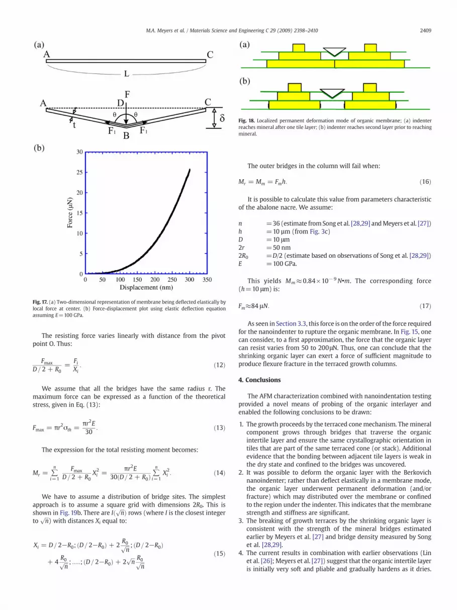
Fig. 17. (a) Two-dimensional representation of membrane being deflected elastically bylocal force at center. (b) Force-displacement plot using elastic deflection equationassuming E=100 GPa.
Fig. 18. Localized permanent deformation mode of organic membrane; (a) indenterreaches mineral after one tile layer; (b) indenter reaches second layer prior to reachingmineral.
2409M.A. Meyers et al. / Materials Science and Engineering C 29 (2009) 2398–2410
The resisting force varies linearly with distance from the pivotpoint O. Thus:
Fmax
D= 2 + R0=
FiXi
: ð12Þ
We assume that all the bridges have the same radius r. Themaximum force can be expressed as a function of the theoreticalstress, given in Eq. (13):
Fmax = πr2σth =πr2E30
: ð13Þ
The expression for the total resisting moment becomes:
Mr = ∑n
i=1
Fmax
D= 2 + R0X2i =
πr2E30ðD= 2 + R0Þ
∑n
i=1X2i : ð14Þ
We have to assume a distribution of bridge sites. The simplestapproach is to assume a square grid with dimensions 2R0. This isshown in Fig. 19b. There are Ið ffiffiffi
np Þ rows (where I is the closest integer
toffiffiffin
p) with distances Xi equal to:
Xi = D = 2−R0; ðD= 2−R0Þ + 2R0ffiffiffin
p ; ðD = 2−R0Þ
+ 4R0ffiffiffin
p ; :::::; ðD= 2−R0Þ + 2ffiffiffin
p R0ffiffiffin
pð15Þ
The outer bridges in the column will fail when:
Mr = Mm = Fmh: ð16Þ
It is possible to calculate this value from parameters characteristicof the abalone nacre. We assume:
n =36 (estimate fromSong et al. [28,29] andMeyers et al. [27])h =10 µm (from Fig. 3c)D =10 μm2r =50 nm2R0 =D/2 (estimate based on observations of Song et al. [28,29])E =100 GPa.
This yields Mm≈0.84×10− 9N•m. The corresponding force(h=10 μm) is:
Fm≈84 μN: ð17Þ
As seen in Section 3.3, this force is on the order of the force requiredfor the nanoindenter to rupture the organic membrane. In Fig. 15, onecan consider, to a first approximation, the force that the organic layercan resist varies from 50 to 200μN. Thus, one can conclude that theshrinking organic layer can exert a force of sufficient magnitude toproduce flexure fracture in the terraced growth columns.
4. Conclusions
The AFM characterization combined with nanoindentation testingprovided a novel means of probing of the organic interlayer andenabled the following conclusions to be drawn:
1. The growth proceeds by the terraced conemechanism. Themineralcomponent grows through bridges that traverse the organicintertile layer and ensure the same crystallographic orientation intiles that are part of the same terraced cone (or stack). Additionalevidence that the bonding between adjacent tile layers is weak inthe dry state and confined to the bridges was uncovered.
2. It was possible to deform the organic layer with the Berkovichnanoindenter; rather than deflect elastically in a membrane mode,the organic layer underwent permanent deformation (and/orfracture) which may distributed over the membrane or confinedto the region under the indenter. This indicates that the membranestrength and stiffness are significant.
3. The breaking of growth terraces by the shrinking organic layer isconsistent with the strength of the mineral bridges estimatedearlier by Meyers et al. [27] and bridge density measured by Songet al. [28,29].
4. The current results in combination with earlier observations (Linet al. [26]; Meyers et al. [27]) suggest that the organic intertile layeris initially very soft and pliable and gradually hardens as it dries.

Fig. 19. (a) Schematic representation of terraced cone subjected to force F exerted by organic layer; (b) bridges subjected to tension; (d) schematic arrangement of bridges; (d)idealized arrangement in 6×6 matrix.
2410 M.A. Meyers et al. / Materials Science and Engineering C 29 (2009) 2398–2410
This factor is significant and explains how the mantle can mold theinitially soft material that subsequently hardens into a high-toughness ceramic-organic composite. The major structural com-ponent of the interlayer, chitin, has a glass transition temperatureof approximately 200 °C. It also has great ability to absorb water,forming a hydrogel that stiffens upon being dehydrated.
Acknowledgement
This research is supported by the National Science FoundationGrant DMR 0510138. Discussions with Dr. A. Y. M. Lin and Mr. P.-Y.Chen are gratefully acknowledged. Julie Muyco provided the AFMpicture of Fig. 11a.
References
[1] S. Mann, Biomineralization: Principles and Concepts in Bioinorganic MaterialsChemistry, Oxford U. Press, 2001.
[2] I. Kobayashi, T. Samata, Mater. Sci. Eng. C 26 (2006) 692.[3] G. Bevelander, H. Nakahara, Calc. Tissue 3 (1969) 84.[4] G. Bevelander, H. Nakahara, in: M. Omori, N. Watabe (Eds.), The Mechanisms of
Biomineralization in Animals and Plants, Tokai University Press, Tokyo, 1980, p. 19.[5] K. Wada, Biomineralization 6 (1972) 84.[6] H. Nakahara, Venus 38 (1979) 205.[7] G. Bevelander, H. Nakahara, M. Kakei, Venus Jpn. J. Malac. 41 (1982) 33.[8] H. Nakahara, in: P. Westbroek, E.W. De Jong (Eds.), Biomineralization and
Biological Metal Accumulation, D. Reidel Publishing Company, Dordrecht, Holland,1982, p. 225.
[9] H. Nakahara, in: S. Suga, H. Nakahara (Eds.), Mechanisms and Phylogeny ofMineralization in Biological Systems, Springer-Verlag, New York, 1991, p. 343.
[10] H. Mutvei, in: M. Omori, N.Watabe (Eds.), TheMechanisms of Biomineralization inAnimals and Plants, Tokai Univ. Press, 1980.
[11] M. Fritz, A.M. Belcher, M. Radmacher, D.A. Walters, P.K. Hansma, G.D. Strucky, D.E.Morse, Nature 371 (1994) 49.
[12] M. Fritz, D.E. Morse, Col. Int. Sci. 3 (1998) 55.[13] A.M. Belcher, X.H. Wu, R.J. Christensen, P.K. Hansma, G.D. Stucky, D.E. Morse,
Nature 381 (1996) 56.[14] A.M. Belcher, PhD thesis: Spatial and temporal resolution of interfaces, phase
transitions and isolation of three families of proteins in calcium carbonate basedbiocomposite materials, University of California, Santa Barbara 1997.
[15] A.M. Belcher, E.E. Gooch, in: E. Bauerlein (Ed.), Biomineralization: from biology tobiotechnology andmedical application, Wiley-Interscience, Germany, 2000, p. 221.
[16] X.Y. Shen, A.M. Belcher, P.K. Hansma, G.D.S. Stucky, D.E. Morse, J. Biol. Chem. 272(1997) 32472.
[17] T.E. Schäffer, C. Ionescu-Zanetti, R. Proksch, M. Fritz, D.A. Walters, N. Almqvist, C.M.Zaremba, A.M. Belcher, B.L. Smith, B.L. Smith, G.D. Stucky, D.E. Morse, P.K. Hansma,Chem. Mater. 9 (1997) 1731.
[18] C.M. Zaremba, A.M. Belcher, M. Fritz, Y. Li, S. Mann, P.K. Hansma, D.E. Morse, J.S.Speck, G.D. Stucky, Chem. Mater. 8 (1996) 679.
[19] M. Sarikaya, K.E. Gunnison, M. Yasrebi, J.A. Aksay, Mater. Res. Soc. 174 (1990) 109.[20] M. Sarikaya, J.A. Aksay, in: S. Case (Ed.), Results and Problems in ‘Cell
Differentiation in Biopolymers’, Springer, Amsterdam, 1992, p. 1.[21] M. Sarikaya, Microsc. Res. Tech. 27 (1994) 360.[22] M. Sarikaya, J. Microsc. Res. Technol. 427 (1994) 360.[23] J.H.E. Cartwright, A.G. Checa, J. R. Soc. Interface 4 (2007) 491.[24] A. Lin, M.A. Meyers, Mater. Sci. Eng. A 390 (2005) 27.[25] A.Y.M. Lin, M.A. Meyers, K.S. Vecchio, Mater. Sci. Eng. C 26 (2006) 1380.[26] A.Y.M. Lin, P.Y. Chen, M.A. Meyers, Acta Biomater. 4 (2008) 131–138.[27] M.A. Meyers, A.Y.M. Lin, P.Y. Chen, J. Muyco, J. Mech. Behav. Biol. Mater. 1 (2008)
76.[28] F. Song, X.H. Zhang, Y.L. Bai, J. Mater. Res. 17 (2002) 1567.[29] F. Song, A.K. Soh, Y.L. Bai, Biomaterials 24 (2003) 3623.[30] H. Tang, F. Barthelat, H.D. Espinosa, J. Mech. Phys. Solids 55 (2007) 1410.[31] M. Sarikaya, private communication, 2001.[32] M.A. Crenshaw, H. Ristedt, in: N. Omori, N. Watabe (Eds.), The mechanisms of
Biomineralization in Animals and Plants, Tokay U. Press, 1976.[33] S. Weiner, W. Traub, FEBS Lett. 111 (1980) 311.[34] S. Weiner, W. Traub, Philos. Trans. R. Soc. B 304 (1984) 421.[35] H.A. Lowenstam, S. Weiner, On Biomineralization, Oxford U Press, 1989.[36] F. Zentz, L. Bedouet, M.J. Almeida, C. Milet, E. Lopez, M. Giraud, Mar. Biotechnol. 3
(2001) 36.[37] L. Pereira-Mouriés, M.-J. Almeida, C. Ribweiro, J. Peduzzi, M. Barthélemy, C. Milet,
E. Lopez, Eur. J. Biochem. 269 (2002) 4994.[38] K. Sakurai, T. Maegawa, T. Takahashi, Polymer 41 (2000) 7051–7056.[39] S.J. Lee, S.S. Kim, Y.M. Lee, Carbohydr. Polym. 41 (2000) 197.[40] B.J.F. Bruet, H.J. Qi, M.C. Boyce, R. Panas, K. Tai, L. Frick, C. Ortiz, J. Mater. Res. 20
(2005) 2400.[41] F. Barthelat, C.M. Li, C. Comi, H.D. Espinosa, J. Mater. Res. 21 (2006) 1977.[42] F. Barthelat, H.D. Espinosa, Exp. Mech. 47 (2007) 311–324.[43] F. Barthelat, H. Tang, P.D. Zavattieri, C.-M. Li, H.D. Espinosa, J. Mech. Phys. Solids 55
(2007) 306.[44] H.J. Gao, B.H. Ji, I.L. Jäger, E. Arzt, P. Fratzl, Proc. Natl. Acad. Sci. U. S. A. 100 (2003)
5597.[45] B.H. Ji, H.J. Gao, K.J. Hsia, Philos. Mag. Lett. 84 (2004) 631.[46] B.H. Ji, H.J. Gao, J. Mech. Phys. Solids 52 (2004) 1963.