the msu ebit at nscl
TRANSCRIPT
The MSU EBIT at NSCL
This article has been downloaded from IOPscience. Please scroll down to see the full text article.
2010 JINST 5 c07001
(http://iopscience.iop.org/1748-0221/5/07/C07001)
Download details:
IP Address: 35.9.61.245
The article was downloaded on 29/03/2013 at 17:13
Please note that terms and conditions apply.
View the table of contents for this issue, or go to the journal homepage for more
Home Search Collections Journals About Contact us My IOPscience
2010 JINST 5 C07001
PUBLISHED BY IOP PUBLISHING FOR SISSA
RECEIVED: May 31, 2010ACCEPTED: June 28, 2010PUBLISHED: July 16, 2010
INTERNATIONAL SYMPOSIUM ON ELECTRON BEAM ION SOURCES AND TRAPS,APRIL 7th–10th 2010,STOCKHOLM, SWEDEN
The MSU EBIT at NSCL
A. Lapierre,a,1 G. Bollen,a J.R. Crespo Lopez-Urrutia,b M. Doleans,a S. Geyer,a
O. Kester,a K. Kittimanapun,a M. Portilloa and S. Schwarza
aNational Superconducting Laboratory (NSCL), Michigan State University (MSU),East Lansing, MI 48824, U.S.A.
bMax-Planck Institute for Nuclear Physics,Saupfercheckweg 1, Heidelberg, 69117, Germany
E-mail: [email protected]
ABSTRACT: The National Superconducting Cyclotron Laboratory (NSCL) at Michigan State Uni-versity (MSU) is constructing ReA3 to reaccelerate rare-isotope beams available from gas stoppingof fast radio-nuclides produced by projectile fragmentation to energies of ∼0.3-3 MeV/nucleon.Such beams are unavailable worldwide, but are in demand for Coulomb excitation and transferreaction studies as well as for the study of astrophysical reactions. ReA3 consists of four maincomponents: an electron-beam ion trap (EBIT), an achromatic mass separator, a radio-frequencyquadrupole (RFQ) pre-accelerator, and a superconducting radio-frequency linear accelerator (SRF-LINAC). By increasing the charge of ions injected into the RFQ and SRF-LINAC, the EBIT chargebreeder is a key component to provide a compact and cost-efficient reaccelerator for short-livedisotopes. The MSU EBIT will be equipped with an electron-gun cathode yielding a few amperes.A unique EBIS-EBIT hybrid magnet configuration, composed of Helmholtz coils and a solenoid,will provide a maximum magnetic field strength of 6 T. The combination of a high-current cathodeand strong magnetic field will allow the MSU EBIT to reach high electron-beam current densitiesof 104 A/cm2. This will make it well suited to rapidly increase the charge state of short-lived iso-topes within tens of milliseconds or less. The unique extended magnet configuration will guaranteehigh-beam acceptance. This publication will present an overview and status of the MSU EBIT.
KEYWORDS: Instrumentation for radioactive beams (fragmentation devices; fragment and isotope,separators incl. ISOL; isobar separators; ion and atom traps; weak-beam diagnostics; radioactive-beam ion sources); Ion sources (positive ions, negative ions, electron cyclotron resonance (ECR),electron beam (EBIS))
1Corresponding author.
c© 2010 IOP Publishing Ltd and SISSA doi:10.1088/1748-0221/5/07/C07001
2010 JINST 5 C07001
Contents
1 Introduction 1
2 The MSU EBIT at NSCL 12.1 Electron gun and collector 22.2 The EBIS-EBIT hybrid magnet configuration 32.3 The trap 3
3 Commissioning with test coils: electron-gun perveance 4
4 Present status 9
1 Introduction
Experiments with exotic radioactive ion beams (RIBs) are at the very edge of nuclear physicsresearch. RIBs allow, for instance, the study of the nuclear structure far from stability and reactionsin nuclear astrophysics for a better understanding of the synthesis of super-heavy elements. Withthe development of gas-stopping cells, RIBs in the energy range from hundreds of keV to severalMeV per nucleon are becoming available at projectile-fragmentation facilities from reaccelerationof low-energy beams. A reacceleration scheme based on a charge-state breeder eliminates theneed for a large-size accelerator using conventional electron stripping and its losses in efficiencyand hence has been recognized as the most promising option for reacceleration of rare isotopes.Moreover, such a scheme allows for a much simpler accelerator structure and is therefore morecost effective. Owing to its efficiency, breeding time, good beam quality and purity, an EBIS/Tshows a high potential for such a purpose.
2 The MSU EBIT at NSCL
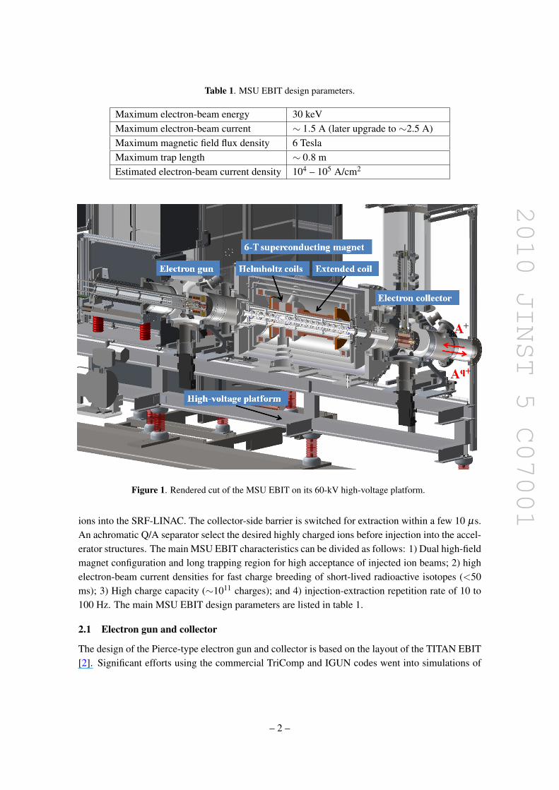
The ReA3 reaccelerator project at the NSCL/MSU (see ref. [1]) employs a high-current EBIS-EBIT charge-state breeder. The MSU breeder is mounted on a high-voltage platform (figure1) thatcan be biased at a potential of up to 60 kV to decelerate singly charged radioactive ions extractedfrom the NSCL gas-stopper cell. Ions from the gas stopper are supplied by a vertical beam line,sent towards the EBIT via an electrostatic switchyard, and injected along the EBIT magnetic axisafter passing through the collector.
The EBIT is operated in the so-called over-the-barrier accumulation mode. Ions are contin-uously injected over the collector-side potential barrier After a large portion of them are capturedby being ionized before returning back to the barrier, those ions are then charge bred to the desireddegree of ionization. The platform potential is changed prior to extraction to deliver highly chargedions with the correct injection energy (20 - 60 keV·Q) into the RFQ, which, subsequently, injects
– 1 –
2010 JINST 5 C07001
Table 1. MSU EBIT design parameters.
Maximum electron-beam energy 30 keVMaximum electron-beam current ∼ 1.5 A (later upgrade to ∼2.5 A)Maximum magnetic field flux density 6 TeslaMaximum trap length ∼ 0.8 mEstimated electron-beam current density 104 – 105 A/cm2
Figure 1. Rendered cut of the MSU EBIT on its 60-kV high-voltage platform.
ions into the SRF-LINAC. The collector-side barrier is switched for extraction within a few 10 µs.An achromatic Q/A separator select the desired highly charged ions before injection into the accel-erator structures. The main MSU EBIT characteristics can be divided as follows: 1) Dual high-fieldmagnet configuration and long trapping region for high acceptance of injected ion beams; 2) highelectron-beam current densities for fast charge breeding of short-lived radioactive isotopes (<50ms); 3) High charge capacity (∼1011 charges); and 4) injection-extraction repetition rate of 10 to100 Hz. The main MSU EBIT design parameters are listed in table 1.
2.1 Electron gun and collector
The design of the Pierce-type electron gun and collector is based on the layout of the TITAN EBIT[2]. Significant efforts using the commercial TriComp and IGUN codes went into simulations of
– 2 –
2010 JINST 5 C07001
the TITAN electron gun to modify the electrode structure in order to increase the output current.The MSU electron gun can be equipped with two interchangeable cathode assemblies each builtwith a Macor-ceramic base and plug-type connectors. The anode and Wehnelt (focus) electrodes ofthe first assembly were designed to provide an electron-beam current of 1.5 A with a Ba-dispensercathode (2 - 4 A/cm2 @ 950oC) of 6.35 mm in diameter. The second assembly was designed forup to 2.5 A with a larger 12.7-mm cathode. The outer shell of the electron gun houses a soft-ironshield and a set of four water-cooled bucking coils to cancel out the superconducting-magnet fringefield and fine tune the residual field near the cathode for a high electron-beam compression ratio.More details of the electron gun and results of simulations are presented in ref. [3].
The design of the electron collector allows for the absorption of up to 5A of continuous elec-tron beam current at final energies of 4 keV. The collector incorporates a bucking coil to cancelout the superconducting fringe field as well as shape the residual field so that electrons hit a largefraction of the collector surface to distribute the heat load.
2.2 The EBIS-EBIT hybrid magnet configuration
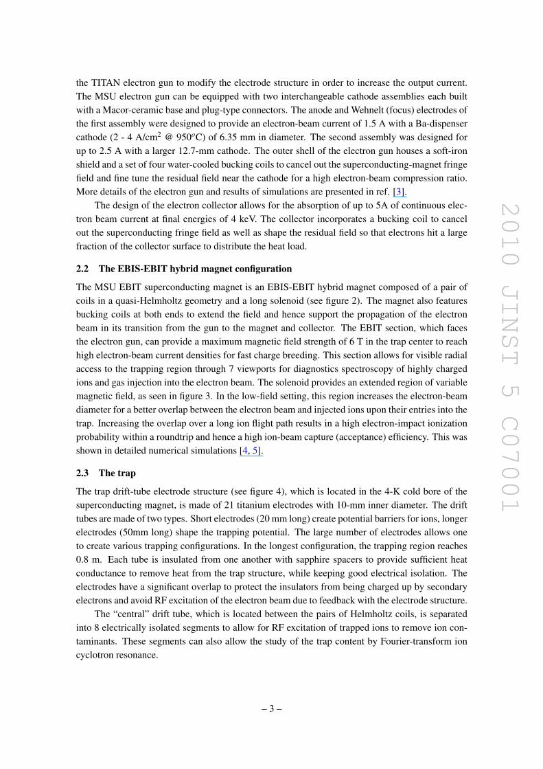
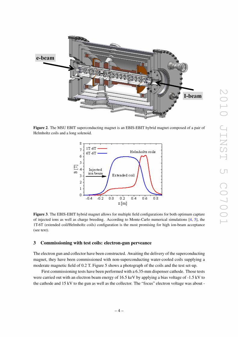
The MSU EBIT superconducting magnet is an EBIS-EBIT hybrid magnet composed of a pair ofcoils in a quasi-Helmholtz geometry and a long solenoid (see figure 2). The magnet also featuresbucking coils at both ends to extend the field and hence support the propagation of the electronbeam in its transition from the gun to the magnet and collector. The EBIT section, which facesthe electron gun, can provide a maximum magnetic field strength of 6 T in the trap center to reachhigh electron-beam current densities for fast charge breeding. This section allows for visible radialaccess to the trapping region through 7 viewports for diagnostics spectroscopy of highly chargedions and gas injection into the electron beam. The solenoid provides an extended region of variablemagnetic field, as seen in figure 3. In the low-field setting, this region increases the electron-beamdiameter for a better overlap between the electron beam and injected ions upon their entries into thetrap. Increasing the overlap over a long ion flight path results in a high electron-impact ionizationprobability within a roundtrip and hence a high ion-beam capture (acceptance) efficiency. This wasshown in detailed numerical simulations [4, 5].
2.3 The trap
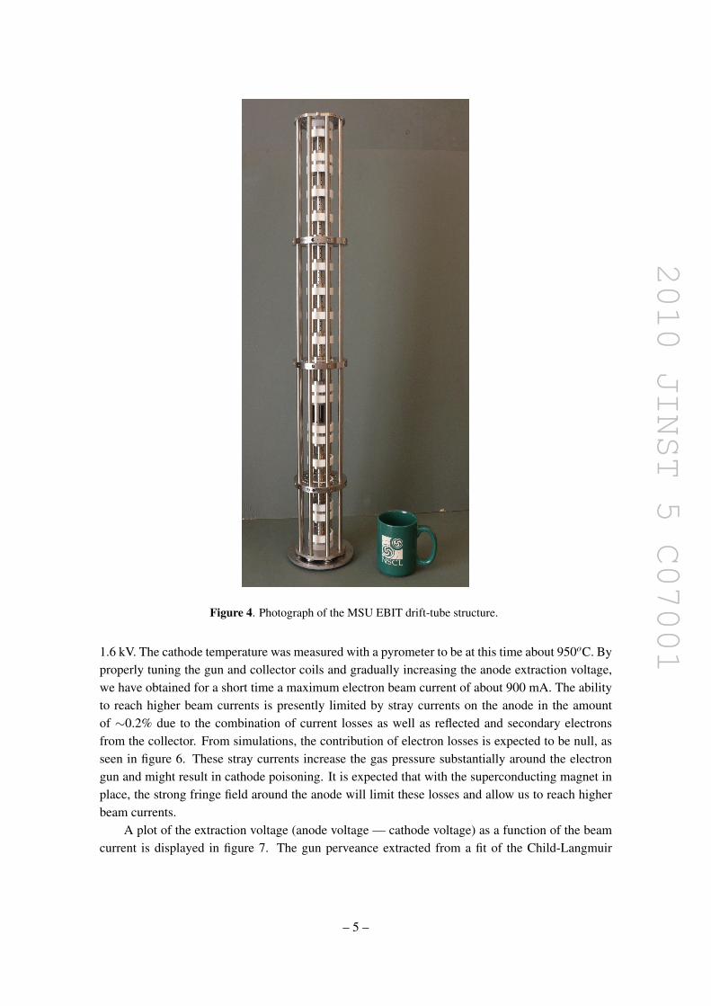
The trap drift-tube electrode structure (see figure 4), which is located in the 4-K cold bore of thesuperconducting magnet, is made of 21 titanium electrodes with 10-mm inner diameter. The drifttubes are made of two types. Short electrodes (20 mm long) create potential barriers for ions, longerelectrodes (50mm long) shape the trapping potential. The large number of electrodes allows oneto create various trapping configurations. In the longest configuration, the trapping region reaches0.8 m. Each tube is insulated from one another with sapphire spacers to provide sufficient heatconductance to remove heat from the trap structure, while keeping good electrical isolation. Theelectrodes have a significant overlap to protect the insulators from being charged up by secondaryelectrons and avoid RF excitation of the electron beam due to feedback with the electrode structure.
The “central” drift tube, which is located between the pairs of Helmholtz coils, is separatedinto 8 electrically isolated segments to allow for RF excitation of trapped ions to remove ion con-taminants. These segments can also allow the study of the trap content by Fourier-transform ioncyclotron resonance.
– 3 –
2010 JINST 5 C07001
Figure 2. The MSU EBIT superconducting magnet is an EBIS-EBIT hybrid magnet composed of a pair ofHelmholtz coils and a long solenoid.
Figure 3. The EBIS-EBIT hybrid magnet allows for multiple field configurations for both optimum captureof injected ions as well as charge breeding. According to Monte-Carlo numerical simulations [4, 5], the1T-6T (extended coil/Helmholtz coils) configuration is the most promising for high ion-beam acceptance(see text).
3 Commissioning with test coils: electron-gun perveance
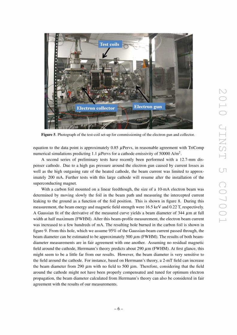
The electron gun and collector have been constructed. Awaiting the delivery of the superconductingmagnet, they have been commissioned with non-superconducting water-cooled coils supplying amoderate magnetic field of 0.2 T. Figure 5 shows a photograph of the coils and the test set-up.
First commissioning tests have been performed with a 6.35-mm dispenser cathode. Those testswere carried out with an electron beam energy of 16.5 keV by applying a bias voltage of -1.5 kV tothe cathode and 15 kV to the gun as well as the collector. The “focus” electron voltage was about -
– 4 –
2010 JINST 5 C07001
Figure 4. Photograph of the MSU EBIT drift-tube structure.
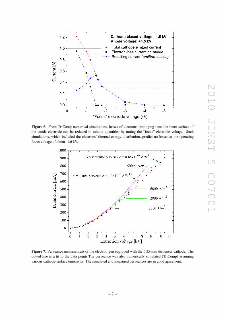
1.6 kV. The cathode temperature was measured with a pyrometer to be at this time about 950oC. Byproperly tuning the gun and collector coils and gradually increasing the anode extraction voltage,we have obtained for a short time a maximum electron beam current of about 900 mA. The abilityto reach higher beam currents is presently limited by stray currents on the anode in the amountof ∼0.2% due to the combination of current losses as well as reflected and secondary electronsfrom the collector. From simulations, the contribution of electron losses is expected to be null, asseen in figure 6. These stray currents increase the gas pressure substantially around the electrongun and might result in cathode poisoning. It is expected that with the superconducting magnet inplace, the strong fringe field around the anode will limit these losses and allow us to reach higherbeam currents.
A plot of the extraction voltage (anode voltage — cathode voltage) as a function of the beamcurrent is displayed in figure 7. The gun perveance extracted from a fit of the Child-Langmuir
– 5 –
2010 JINST 5 C07001
Figure 5. Photograph of the test-coil set-up for commissioning of the electron gun and collector.
equation to the data point is approximately 0.85 µPervs, in reasonable agreement with TriCompnumerical simulations predicting 1.1 µPervs for a cathode emissivity of 50000 A/m2.
A second series of preliminary tests have recently been performed with a 12.7-mm dis-penser cathode. Due to a high gas pressure around the electron gun caused by current losses aswell as the high outgasing rate of the heated cathode, the beam current was limited to approx-imately 200 mA. Further tests with this large cathode will resume after the installation of thesuperconducting magnet.
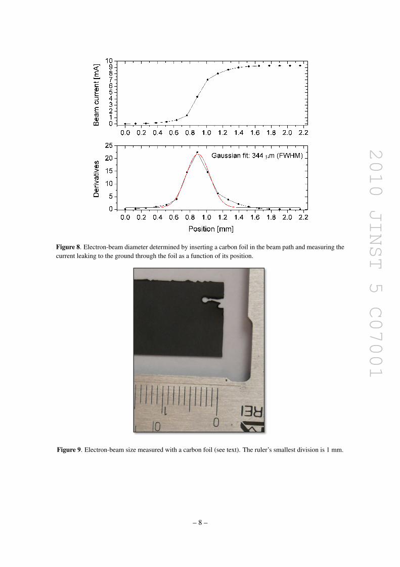
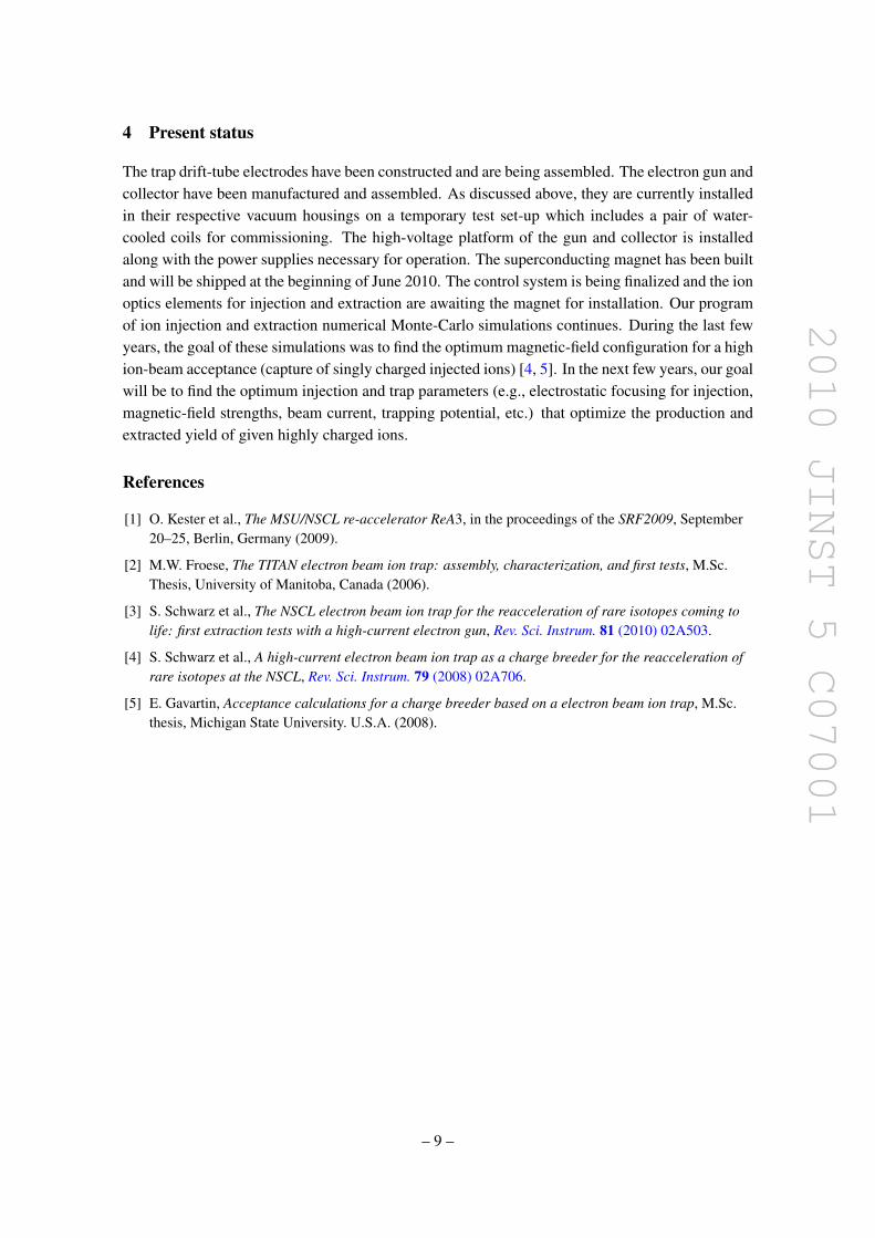
With a carbon foil mounted on a linear feedthough, the size of a 10-mA electron beam wasdetermined by moving slowly the foil in the beam path and measuring the intercepted currentleaking to the ground as a function of the foil position. This is shown in figure 8. During thismeasurement, the beam energy and magnetic field strength were 16.5 keV and 0.22 T, respectively.A Gaussian fit of the derivative of the measured curve yields a beam diameter of 344 µm at fullwidth at half maximum (FWHM). After this beam-profile measurement, the electron beam currentwas increased to a few hundreds of mA. The resulting hole burned in the carbon foil is shown infigure 9. From this hole, which we assume 95% of the Gaussian-beam current passed through, thebeam diameter can be estimated to be approximately 500 µm (FWHM). The results of both beam-diameter measurements are in fair agreement with one another. Assuming no residual magneticfield around the cathode, Herrmann’s theory predicts about 290 µm (FWHM). At first glance, thismight seem to be a little far from our results. However, the beam diameter is very sensitive tothe field around the cathode. For instance, based on Herrmann’s theory, a 2-mT field can increasethe beam diameter from 290 µm with no field to 500 µm. Therefore, considering that the fieldaround the cathode might not have been properly compensated and tuned for optimum electronpropagation, the beam diameter calculated from Herrmann’s theory can also be considered in fairagreement with the results of our measurements.
– 6 –
2010 JINST 5 C07001
Figure 6. From TriComp numerical simulations, losses of electrons impinging onto the inner surface ofthe anode electrode can be reduced to minute quantities by tuning the “focus” electrode voltage. Suchsimulations, which included the electrons’ thermal energy distribution, predict no losses at the operatingfocus voltage of about -1.6 kV.
Figure 7. Perveance measurement of the electron gun equipped with the 6.35-mm dispenser cathode. Thedotted line is a fit to the data points.The perveance was also numerically simulated (TriComp) assumingvarious cathode-surface emissivity. The simulated and measured perveances are in good agreement.
– 7 –
2010 JINST 5 C07001
Figure 8. Electron-beam diameter determined by inserting a carbon foil in the beam path and measuring thecurrent leaking to the ground through the foil as a function of its position.
Figure 9. Electron-beam size measured with a carbon foil (see text). The ruler’s smallest division is 1 mm.
– 8 –
2010 JINST 5 C07001
4 Present status
The trap drift-tube electrodes have been constructed and are being assembled. The electron gun andcollector have been manufactured and assembled. As discussed above, they are currently installedin their respective vacuum housings on a temporary test set-up which includes a pair of water-cooled coils for commissioning. The high-voltage platform of the gun and collector is installedalong with the power supplies necessary for operation. The superconducting magnet has been builtand will be shipped at the beginning of June 2010. The control system is being finalized and the ionoptics elements for injection and extraction are awaiting the magnet for installation. Our programof ion injection and extraction numerical Monte-Carlo simulations continues. During the last fewyears, the goal of these simulations was to find the optimum magnetic-field configuration for a highion-beam acceptance (capture of singly charged injected ions) [4, 5]. In the next few years, our goalwill be to find the optimum injection and trap parameters (e.g., electrostatic focusing for injection,magnetic-field strengths, beam current, trapping potential, etc.) that optimize the production andextracted yield of given highly charged ions.
References
[1] O. Kester et al., The MSU/NSCL re-accelerator ReA3, in the proceedings of the SRF2009, September20–25, Berlin, Germany (2009).
[2] M.W. Froese, The TITAN electron beam ion trap: assembly, characterization, and first tests, M.Sc.Thesis, University of Manitoba, Canada (2006).
[3] S. Schwarz et al., The NSCL electron beam ion trap for the reacceleration of rare isotopes coming tolife: first extraction tests with a high-current electron gun, Rev. Sci. Instrum. 81 (2010) 02A503.
[4] S. Schwarz et al., A high-current electron beam ion trap as a charge breeder for the reacceleration ofrare isotopes at the NSCL, Rev. Sci. Instrum. 79 (2008) 02A706.
[5] E. Gavartin, Acceptance calculations for a charge breeder based on a electron beam ion trap, M.Sc.thesis, Michigan State University. U.S.A. (2008).
– 9 –