the leverone field house and thompson arena
TRANSCRIPT
Nervi's Design and Construction Methods for Two
Thin-Shell Structures:
The Leverone Field House and Thompson Arena
by
Momo T. Sun
BASc., University of Toronto (2014)
Submitted to the Department of Civil and Environmental Engineeringin partial fulfillment of the requirements for the degree of
Master of Engineering in Civil Engineering
at the
MASSACHUSETTS INSTITUTE OF TECHNOLOGY
June 2017
Momo T. Sun, MMXVII. All rights reserved.
The author hereby grants to MIT permission to reproduce and todistribute publicly paper and electronic copies of this thesis document
in whole or in part in any medium now known or hereafter created.
Signature EedactedSignature of Author ... .......Signature.re
Department of Civil and Environme al EngineeriMay- 12,K
Certified by............... Signature redacted/~ John A. Ochsendorf
Class of 1942 Professor of Civil and Env. Engineering & Architecture7Thvsi Supervisor
Accepted by.......Signature redacted ...........y Jesse Kroll
Associate Professor of Civil and Environmental EngineeringMASS CH NSTITUTE Chair, Graduate Program Committee
JUN 14 2017
LIBRARIFS

2

Nervi's Design and Construction Methods for Two
Thin-Shell Structures:
The Leverone Field House and Thompson Arena
by
Momo T. Sun
Submitted to the Department of Civil and Environmental Engineeringon May 12, 2017, in partial fulfillment of the
requirements for the degree ofMaster of Engineering in Civil Engineering
Abstract
This thesis studies two major thin-shell concrete structures by Pier Luigi Nervi (1891-1979) - the Leverone Field House and Thompson Arena. These two similar parabolicvaults are two of the few international structures he has completed in the UnitedStates. Situated across the street from each other at Dartmouth College, these twothin-shell concrete structures designed only a few years apart and in a such maturestage of Nervi's engineering career deserve a closer look.
Access to Nervi's original calculations, specifications, and correspondences withDartmouth College reveal a new level of refinement in his design methods and deci-sions. This study analyzes his structural design methods and compares them withapproximated hand calculations assuming an asymmetric load on a 3-hinged parabolicarch. The maximum moment was calculated to be within 7% of Nervi's results. Anarch was also explored by building a Finite Element (FE) model in SAP2000, how-ever, the results proved the model to be an unreliable representation of the behaviorof the funicular concrete arch.
Furthermore, never before published construction photos give clues to the con-struction of the first structure built with the "Nervi System" in the United States.Slight changes were made to the construction method from his previous structureswith the Nervi System in Rome. The types of different precast panels were reducedto increase repetition and refinement was made to the multi-step formwork systemto reduce the amount of wooden formwork while keeping a high level of accuracy forthe shape of the precast panels.
Thesis Supervisor: John A. OchsendorfTitle: Class of 1942 Professor of Civil and Env. Engineering & Architecture
3

4
Acknowledgments
I'd like to thank my adviser John for his direction for this thesis and Gordana for her
continued support throughout the year. The MEng class has become my friends and
family, I couldn't have done this without them all.
In addition, I'd like to thank my parents for moving to three continents to allow
me the best possible upbringing, exposing me to different opportunities at each place.
It's been a long journey but well worth it.
I'd also like to thank Tullia Iori and her students at University of Rome Tor
Vergata, MAXXI archives, Tom Leslie, and Dartmouth College, for their guidance
and resources.
5
6
Contents
1 Introduction 13
1.1 Pier Luigi Nervi and His Structures . . . . . . . . . . . . . . . . . . . 13
1.2 Literature Review . . . . . . . . . . . . . . . . . . . . . . . . . . . . . 14
1.3 Problem Statement . . . . . . . . . . . . . . . . . . . . . . . . . . .. . 15
2 Case Studies 17
2.1 Leverone Field House . . . . . . . . . . . . . . . . . . . . . . . . . . . 18
2.2 Thompson Arena . . . . . . . . . . . . . . . . . . . . . . . . . . . . . 22
2.3 D iscussion . . . . . . . . . . . . . . . . . . . . . . . . . . . . . . . . . 26
2.3.1 R oof . . . . . . . . . . . . . . . . . . . . . . . . . . . . . . . . 27
2.3.2 B uttress . . . . . . . . . . . . . . . . . . . . . . . . . . . . . . 27
2.3.3 Exterior and Front Face . . . . . . . . . . . . . . . . . . . . . 28
2.3.4 Antonio Nervi's Learning Experience . . . . . . . . . . . . . . 28
2.4 Summary of Case Studies . . . . . . . . . . . . . . . . . . . . . . . . 29
3 Structural Analysis 31
3.1 Nervi's Method . . . . . . . . . . . . . . . . . . . . . . . . . . . . . . 31
3.2 Approximation Using Hand Calculations . . . . . . . . . . . . . . . . 38
3.3 Finite Element (FE) Model . . . . . . . . . . . . . . . . . . . . . . . 39
3.4 Summary of Structural Analysis . . . . . . . . . . . . . . . . . . . . . 41
4 Construction Methods 43
4.1 Precast Panels . . . . . . . . . . . . . . . . . . . . . . . . . . . . . . . 44
7
4.2 In-Situ Concrete . . . . . . . . . . . . . . . . . . . . . . . . . . . . . 45
4.3 Construction Sequence Photos . . . . . . . . . . . . . . . . . . . . . . 46
4.4 Summary of Construction Methods . . . . . . . . . . . . . . . . . . . 50
5 Conclusion 51
A Nervi's Original Calculations and Documents 55
B Moment of Three-Hinged Arch Derivation 101
8

List of Figures
2-1 Leverone Field House's front face [Photo by author, 2017] . . . . . . . 20
2-2 Leverone Field House's interior view [Photo by author, 2017] . . . . . 20
2-3 Leverone Field House's A-shaped columns [Photo by author, 2017] . 21
2-4 Leverone Field House's exterior side view [Photo by author, 2017] . 21
2-5 Thompson Arena's front and side view [Photo by author, 2017] . . . . 24
2-6 Thompson Arena's interior view [Photo by author, 2017] . .. . . . . . 24
2-7 Thompson Arena's Y-shaped buttress [Photo by author, 2017] . . . . 25
2-8 Thompson Arena's exterior side view of buttresses [Photo by author,
20 17] . . . . . . . . . . . . . . . . . . . . . . . . . . . . . . . . . . . . 2 5
2-9 Roof plan for Thompson Arena showing precast panels and Y-buttresses
[Dartmouth College, 1962b] . . . . . . . . . . . . . . . . . . . . . . . 27
3-1 Elementary arch broken into segments for analysis, from Calcoli Statici,
05-05-1961 [StudioNervi, 1961] . . . . . . . . . . . . . . . . . . . . . . 33
3-2 Leverone Field House, T-section for design of reinforcement, from Cal-
coli Statici, 05-05-1961 [StudioNervi, 1961] . . . . . . . . . . . . . . . 33
3-3 Leverone Field House, gravity loading conditions from Calcoli Statici,
05-05-1961 [StudioNervi, 1961] . . . . . . . . . . . . . . . . . . . . . . 34
3-4 Leverone Field House, gravity loading schemes for structural analysis
from Calcoli Statici, 05-05-1961 [StudioNervi, 1961] . . . . . . . . . . 35
3-5 Thompson Arena, scaled resin model under seismic loading in the elas-
tic range, 1:50 [Cassinello et al., 2010] . . . . . . . . . . . . . . . . . . 37
9
3-6 Thompson Arena, Model displayed at Polytechnic University of the
Marches, 1971 [Cassinello et al., 2010] . . . . . . . . . . . . . . . . . . 37
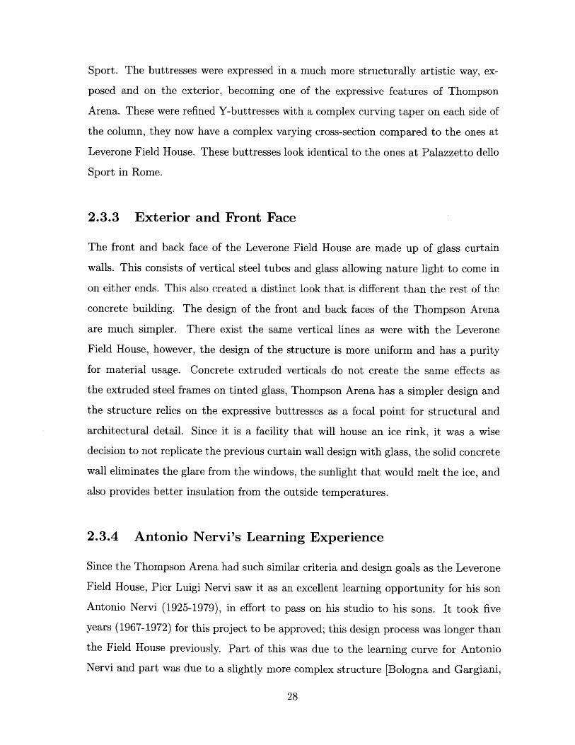
3-7 Leverone Field House, section of rib for end arch reinforcement, draw-
ing from 01-19-1962 [Dartmouth College, 1962a] . . . . . . . . . . . . 38
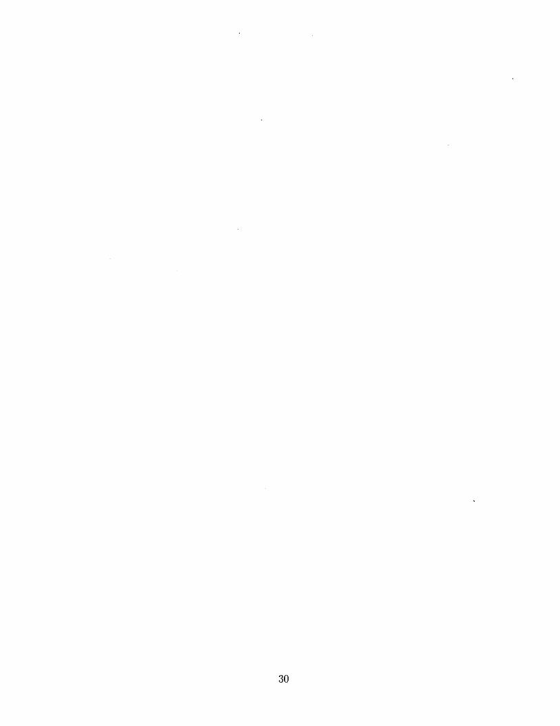
3-8 Leverone Field House, arch contour truss spacing detail, drawing from
03-11-1961 [Dartmouth College, 1962a] . . . . . . . . . . . . . . . . . 38
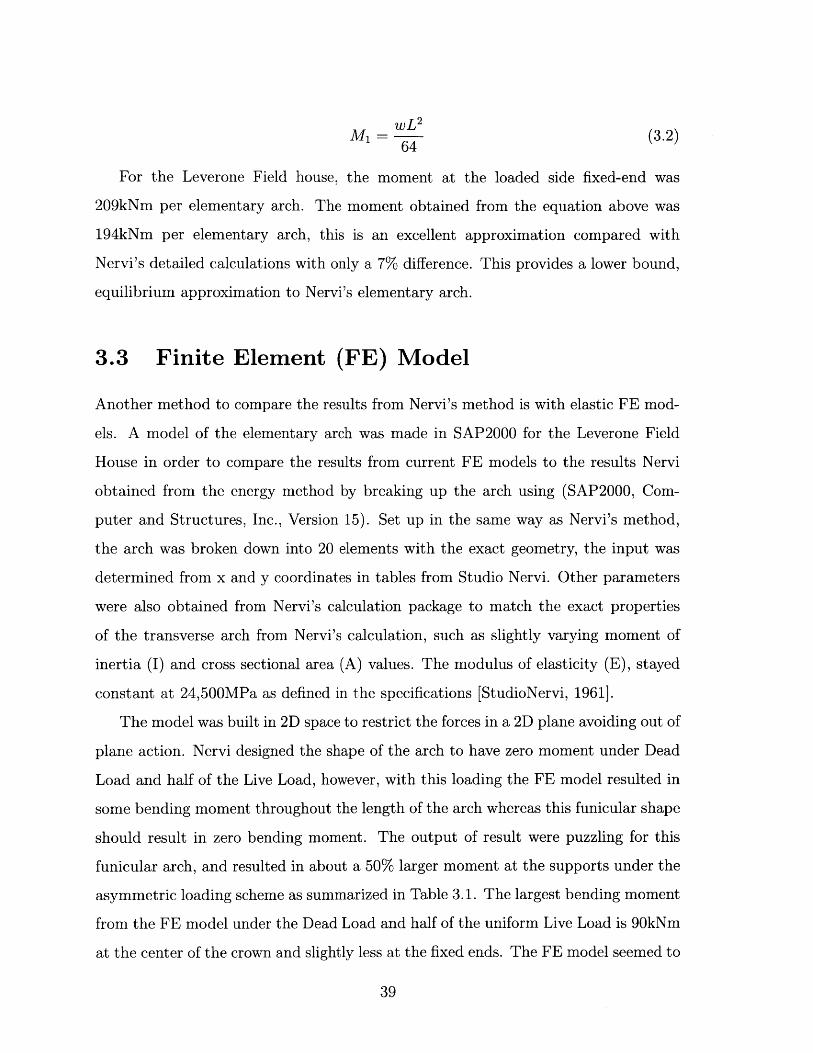
3-9 Leverone Field House, exaggerated deflection under uniform symmetric
loading of DL+LL, model from SAP2000 . . . . . . . . . . . . . . . . 41
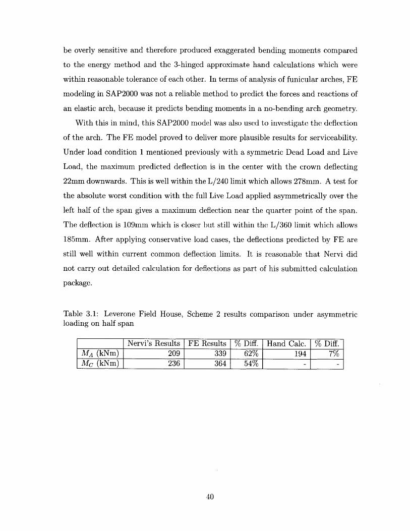
3-10 Leverone Field House, exaggerated deflection under asymmetric load-
ing on half span of LL, model from SAP2000 . . . . . . . . . . . . . . 41
4-1 Brick formwork on curved scaffolding surface [Dartmouth College, 1962b] 46
4-2 Concrete negative mold [Dartmouth College, 1962a] . . . . . . . . . . 46
4-3 Forming reinforcement around negative mold for precast panel
[Dartmouth College, 1962a] . . . . . . . . . .. . . . . . . . . . . . . . 47
4-4 Precast panel enclosed in wooden formwork ready to be poured
[Dartmouth College, 1962a] . . . . . . . . . . . . . . . . . . . . . . . 47
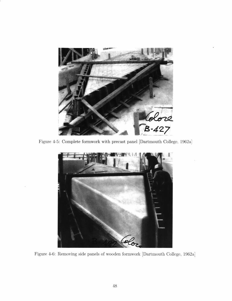
4-5 Complete formwork with precast panel [Dartmouth College, 1962a] . 48
4-6 Removing side panels of wooden formwork [Dartmouth College, 1962a] 48
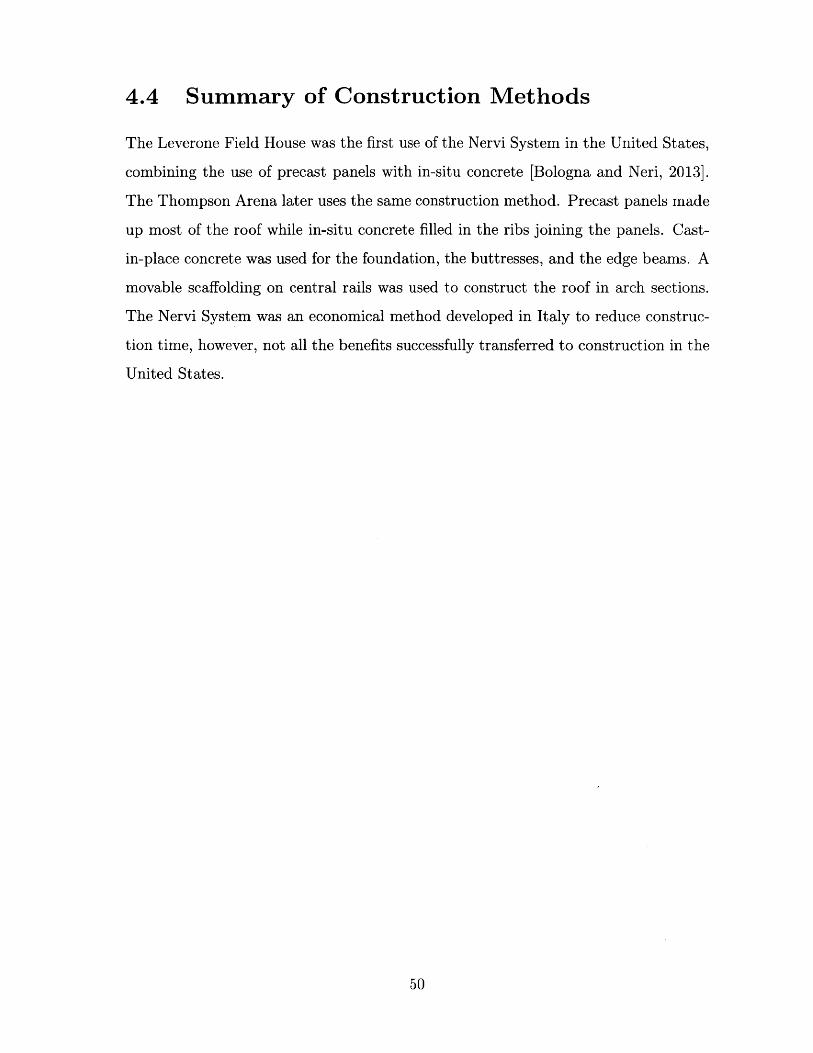
4-7 Precast panel hoisted and removed from formwork, moving to storage
[Dartmouth College, 1962a] . . . . . . . . . . . . . . . . . . . . . . . 49
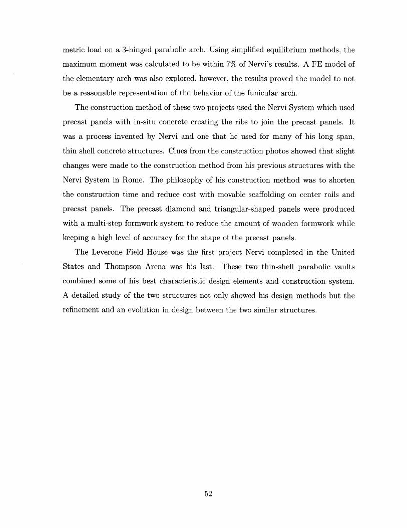
4-8 Scaffolding on center rails, continuing to pour in-situ concrete forming
ribs between laid out precast panels, some ribs are already filled from
previous pours [Dartmouth College, 1962a] . . . . . . . . . . . . . . . 49
B-i Asymmetric load on a three-hinged parabolic arch . . . . . . . . . . . 101
10
List of Tables
1.1 Nervi's projects in the United States . . . . . . . . . . . . . . . . . . 14
2.1 Basic information on geometry and cost . . . . . . . . . . . . . . . . 18
3.1 Leverone Field House, Scheme 2 results comparison under asymmetric
loading on half span . . . . . . . . . . . . . . . . . . . . . . . . . . . 40
11
12
Chapter 1
Introduction
1.1 Pier Luigi Nervi and His Structures
Pier Luigi Nervi (1891-1979) was a famous Italian structural engineer known for his
economic and pragmatic innovation in reinforced concrete shell structures. He was
one of the few designers of his time to bridge the gap between art and technology,
in essence, architecture and structural engineering [Nervi, 1965]. He began his ca-
reer by designing and building in Italy then developed his own innovative precast
concrete system named the "Nervi system", which was a very effective way of build-
ing thin-shell barrel vaults. He first used the system to build hangars which created
long-spanned structures economically. The Nervi System used precast diamond or
triangular-shaped panels as formwork which were connected by casting a thin layer
of in-situ concrete, creating ribs between the precast panels. He continued to de-
velop this system and gained international recognition for his elegant design and
building techniques especially after the construction of one of his most iconic struc-
tures, Palazzetto dello Sport, a thin-shell dome used for the 1960 Olympics in Rome
[Bologna and Neri, 2013].
While Nervi's projects were widely celebrated among engineers, architects, and
the general public for their daring and elegant designs, the two specific structures to
be discussed in this thesis have received very little publicity. These were two of the
few structures Nervi has ever built using his own system outside of Italy and arguably
13
the most involved international projects illustrated by his personal licensure. In the
archives at Dartmouth College there were six professional engineering (PE) licenses for
New Hampshire, one for each year from 1970 to 1976 for the design and construction
duration of Thompson Arena, the same were likely obtained for earlier years for the
Leverone Field House [Dartmouth College, 1962b]. This was the only licensure Nervi
obtained outside of Italy [Leslie, 2018].
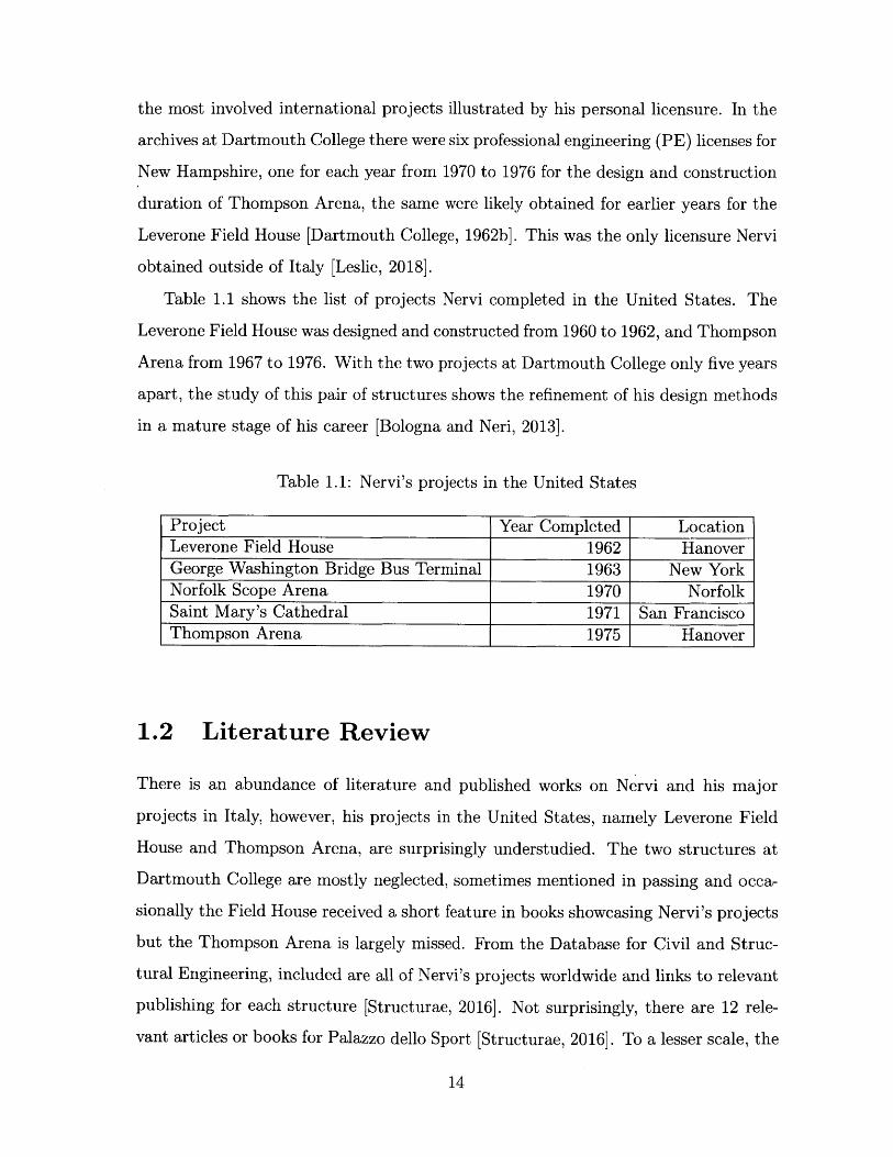
Table 1.1 shows the list of projects Nervi completed in the United States. The
Leverone Field House was designed and constructed from 1960 to 1962, and Thompson
Arena from 1967 to 1976. With the two projects at Dartmouth College only five years
apart, the study of this pair of structures shows the refinement of his design methods
in a mature stage of his career [Bologna and Neri, 2013].
Table 1.1: Nervi's projects in the United States
Project Year Completed LocationLeverone Field House 1962 HanoverGeorge Washington Bridge Bus Terminal 1963 New YorkNorfolk Scope Arena 1970 NorfolkSaint Mary's Cathedral 1971 San FranciscoThompson Arena 1975 Hanover
1.2 Literature Review
There is an abundance of literature and published works on Nervi and his major
projects in Italy, however, his projects in the United States, namely Leverone Field
House and Thompson Arena, are surprisingly understudied. The two structures at
Dartmouth College are mostly neglected, sometimes mentioned in passing and occa-
sionally the Field House received a short feature in books showcasing Nervi's projects
but the Thompson Arena is largely missed. From the Database for Civil and Struc-
tural Engineering, included are all of Nervi's projects worldwide and links to relevant
publishing for each structure [Structurae, 2016]. Not surprisingly, there are 12 rele-
vant articles or books for Palazzo dello Sport [Structurae, 2016]. To a lesser scale, the
14
Leverone Field House has three relevant articles [Structurae, 2016]. Lastly, Thomp-
son Arena has zero listed relevant articles or books [Structurae, 2016]. Of course
this is not an exhaustive list for all published works on each project but it shows a
stark contrast between the detailed analyses that have gone into other similar Nervi
projects and the two thin-shells at Dartmouth College.
There have been no in-depth analyses on the design methodology for the Leverone
Field House and Thompson Arena or on the construction process. This warrants fur-
ther study because Nervi was a great designer who paid equal attention to architec-
ture, structural expression, construction, and economics and yet these two important
projects have not been studied. Nervi passed away in 1979, and arguably since the
1975 Thompson Arena is one of Nervi's last projects, it has some of the most im-
proved and refined elements of design, making this project even more of a target to
study [Britannica, 2016].
1.3 Problem Statement
Visits to Dartmouth College uncovered first hand materials found in the archives and
seeing the structures themselves gave new insight into the otherwise poorly published
structures. This thesis uses Nervi's original calculations and documents to analyze
his design methods and decisions. With the addition of these new resources, this
thesis seeks to answer the following questions:
1. What is the historical significance of the two structures?
" What materials are available in the Dartmouth Archives and the MAXXI
Archives?
" What generalizations can be made from the material?
2. What was the structural design process for the two thin-shell concrete struc-
tures?
* How did Nervi determine the shape of the structures?
15
* What methods did Nervi use to analyze the structures? What assumptions
did he make?
3. What was the construction method of the two structures?
* How did Nervi adjust his design and methodology for building in the US?
16
Chapter 2
Case Studies
Dartmouth's Business Manager Richard W. Olmsted (Dartmouth '32) attended the
1960 Olympic Games at Palazzetto dello Sport. After seeing the elegant crystalline
geometric units that made up the stadium, he decided to hire Nervi to design a similar
sports facility for the college [Meacham, 2008]. From 1960 to 1962, Nervi designed
and constructed the Leverone Field House, then he was rehired in 1967 to design the
Thompson Arena. Both are parabolic vaults constructed with precast concrete panels
from Nervi's system.
The design philosophies were the same for both structures. A visit to the facilities
showed how strikingly similar they were both on the exterior and interior. Located
across the street and with the front of the stadiums facing each other, it could have
created a unique mirroring effect with the near identical structures. However, this
effect was never achieved because Thompson Arena hides behind a row of preserved
early-twentieth-century houses and can barely be seen from the street. Records and
sketches from college planning at Dartmouth showed that there were several attempts
to join the two structures to make one large sports plaza, however, this was never
realized due to the preservation of the historic houses [Dartmo., 2012].
Table 2.1 show details about geometry and cost for each of the two structures. No-
tably, the Thompson Arena costs significantly more per square area than the Leverone
Field House. Although Thompson Arena is smaller in terms of area, it is a more com-
plex facility in terms of functionality and encloses a significantly larger volume for
17

more capacity. The ice surface and seating are completely below grade which resulted
in increased costs from excavation. The hockey rink, cooling facilities, and seating
itself also added largely to the total cost compared to the simple open field, on grade
design for the Leverone Field House. A crude estimation of the excavation costs with
the approximate volume of soil excavated and an assumed cost of $300/m2 yields
$2.8 million USD in 2017 [Homewyse, 2017]. With this excavation cost and other
additional costs for the facility, the cost for the two structures are fairly comparable.
Table 2.1: Basic information on geometry and cost
Leverone Field House Thompson ArenaSpan (m) 66.75 54.254Height (m) 13.335 9.576Length (m) 109 97.5Area (M2 ) 7,276 (91,800ft 2) 5,290 (57,000ft 2 )Number of Precast Units 1,240 1,024Total Cost at Time of Construction (USD) 1.5mil 4.4milTotal Cost Adjusted* (2017 USD) 14.3mil 34.8milCost per Unit Area (2017 USD/m 2 ) 1,970 6,580Seats N/A 3,620
*[RSMeans, 2017]
2.1 Leverone Field House
The Leverone Field House, shown in Figure 2-1, is the better known of the two
facilities. Nervi had already gained international recognition by this point and had
worked on several projects abroad, however, none were entirely in his iconic style
of curved thin-shell concrete structures with interlacing ribs. Though he was an
acclaimed and sought after designer, it was unexpectedly difficult for Nervi to convince
owners to design and build purely using his precast system. Richard W. Olmsted
being an admirer of Nervi's unique style, was the first to take the risk and approve the
never-before used precast design to be constructed in the US at Dartmouth College.
The vaulted long-span barrel roof created a large uninterrupted surface for indoor
18
track facilities, and an indoor practice ground for football and other field sports as
shown in Figure 2-2. The field of the structure is on grade with buttresses propping
up the barrel roof hidden along the length of the building creating offices and storage
areas. Typical of Nervi's iconic thin-shell concrete designs, the roof is made up of a
variation of four different types of precast panels, diamond-shaped near the crown and
triangular panels closer to the landing edge beams. The roof consists of a slab with
uniform thickness and ribs with tapering thickness from 0.8m at the spandrel to 0.5m
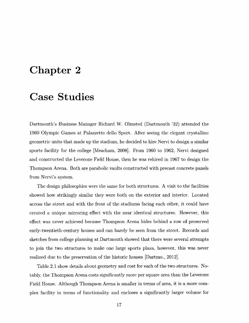
at the crown [StudioNervi, 1973]. The edge beams are connected to sets of vertical
and angled, A-shaped buttresses as shown in Figure 2-3. These buttresses have a
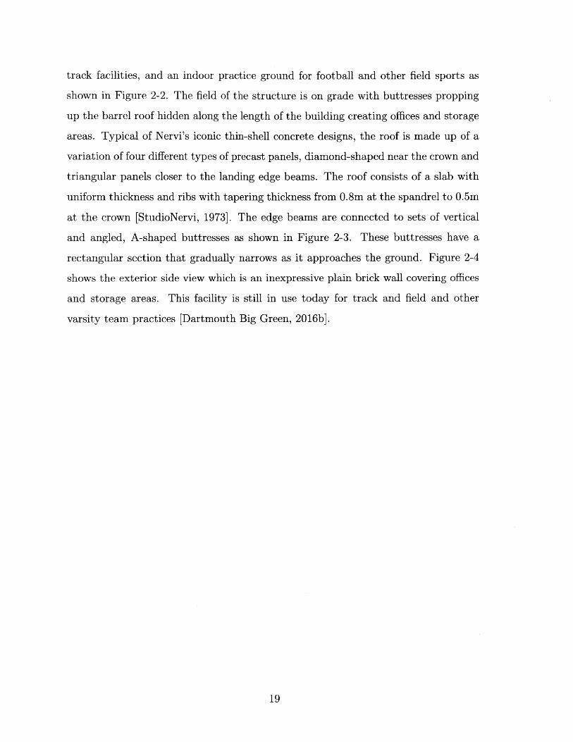
rectangular section that gradually narrows as it approaches the ground. Figure 2-4
shows the exterior side view which is an inexpressive plain brick wall covering offices
and storage areas. This facility is still in use today for track and field and other
varsity team practices [Dartmouth Big Green, 2016b].
19

Figure 2-1: Leverone Field House's front face [Photo by author, 2017]
-4
Figure 2-2: Leverone Field House's interior view [Photo by author, 2017]
20
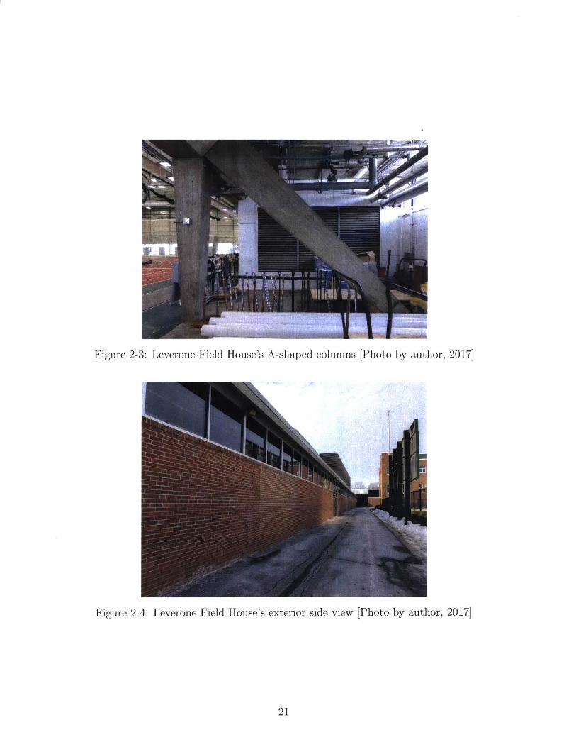
Figure 2-3: Leverone Field House's A-shaped columns [Photo by author, 2017]
Figure 2-4: Leverone Field House's exterior side view [Photo by author, 2017]
21
2.2 Thompson Arena
The lesser known Thompson Arena started its lengthy design process in 1965 shortly
after the completion of the Leverone Field House in 1962. Construction began in 1973
and the arena was open for its first game in 1975. When completed, the ice arena was
the largest venue of its kind among US colleges to host varsity hockey games [Dart-
mouth College, 1962b]. It gained some attention amongst hockey programs, however
as one of the last structures Nervi ever designed, it received very little attention in
the structural world. Nervi passed away in 1979, only four years after the comple-
tion of this project, leaving this to be his final complete project in the US [Bologna,
2013]. His son Antonio Nervi, the apprentice designer on this project passed away
later in the same year [Bologna, 2013]. Perhaps it is because the structure is hidden
behind from the street view, or perhaps because it is so similar to the Leverone Field
House, it went unnoticed. The Thompson Arena is rarely mentioned in publications
on Nervi's works and sometimes even missed in lists of his completed works.
Figure 2-5 shows the Thompson Arena, it is a parabolic vault of 54m by 90m made
up of 1,024 triangular precast concrete units, each weighing one ton [Dartmouth Big
Green, 2016a]. At first glance it may seem that the Thompson Arena is virtually
identical to its precedent across the street, however, upon closer examination, it is
clear that Nervi has made many refinements to this second sports facility. Pier Luigi
Nervi negli Stati Uniti in 2013 is the only publication with a dedicated passage for
the Thompson Arena [Bologna, 2013].
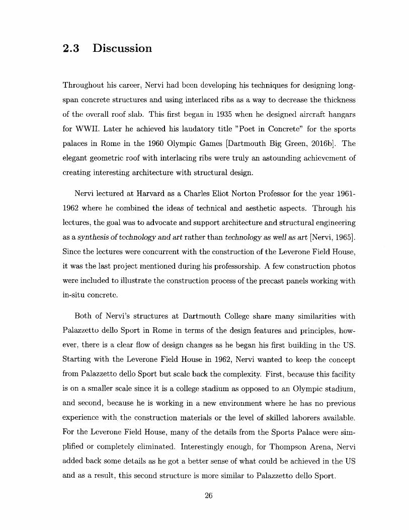
This structure contains Nervi's two most distinctive styles: columns with vari-
able cross-section which twists and tapers, and ribbed shell with precast geometric
elements. It has the Y-shaped buttresses on the exterior, shown in Figures 2-7 and
2-8, transfer gravity and thrust loads to foundation, they are visually identical to the
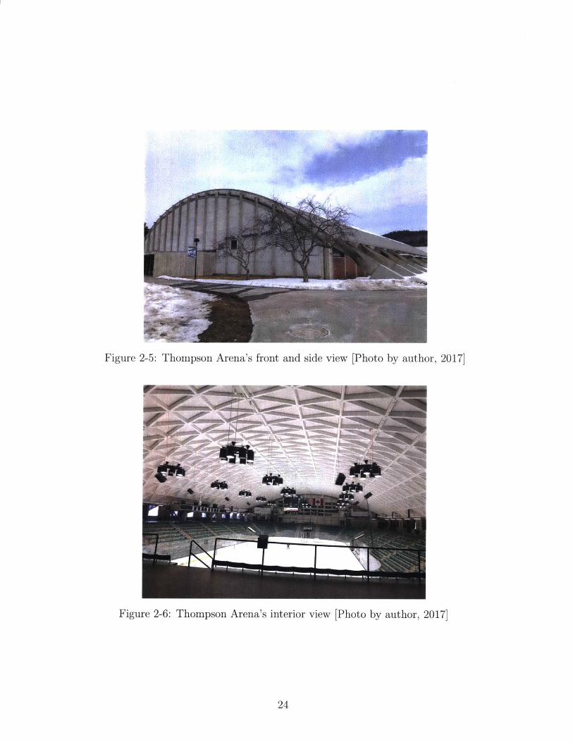
buttresses at the famous Palazzetto dello Sport. As shown in Figure 2-6, the arena
is more grand than it appears from the outside, the building is excavated so that the
ice surface and all the stadium seats sit below grade. This created a much larger
space than what can be seen or expected from the square footage of the building. It
22
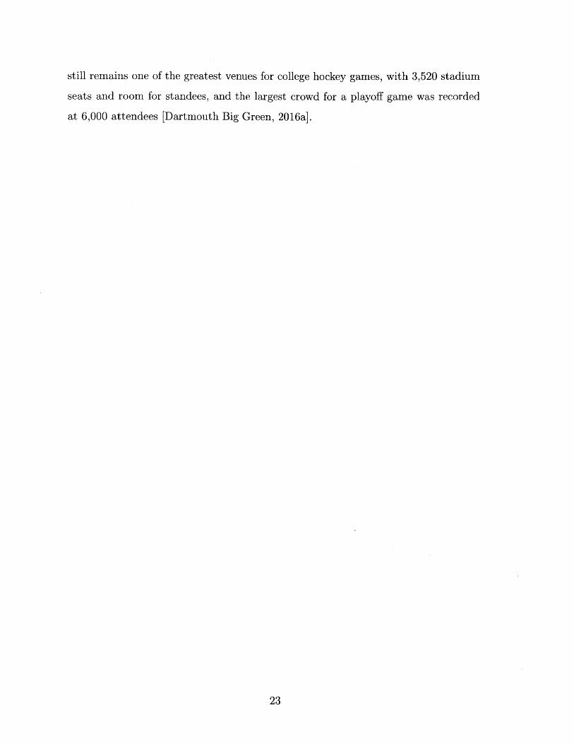
still remains one of the greatest venues for college hockey games, with 3,520 stadium
seats and room for standees, and the largest crowd for a playoff game was recorded
at 6,000 attendees [Dartmouth Big Green, 2016a].
23
1!
Figure 2-5: Thompson Arena's front and side view [Photo by author, 20171
IM~ --. A*N 4-
......
Figure 2-6: Thompson Arena's interior view [Photo by author, 2017]
24
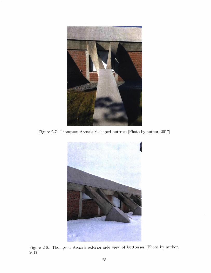
Figure 2-7: Thompson Arena's Y-shaped buttress [Photo by author, 2017]
1
Figure 2-8: Thompson Arena's exterior side view of buttresses [Photo by author,2017]
25
-ww.....im.
~: , .. -WI
2.3 Discussion
Throughout his career, Nervi had been developing his techniques for designing long-
span concrete structures and using interlaced ribs as a way to decrease the thickness
of the overall roof slab. This first began in 1935 when he designed aircraft hangars
for WWII. Later he achieved his laudatory title "Poet in Concrete" for the sports
palaces in Rome in the 1960 Olympic Games [Dartmouth Big Green, 2016b]. The
elegant geometric roof with interlacing ribs were truly an astounding achievement of
creating interesting architecture with structural design.
Nervi lectured at Harvard as a Charles Eliot Norton Professor for the year 1961-
1962 where he combined the ideas of technical and aesthetic aspects. Through his
lectures, the goal was to advocate and support architecture and structural engineering
as a synthesis of technology and art rather than technology as well as art [Nervi, 1965].
Since the lectures were concurrent with the construction of the Leverone Field House,
it was the last project mentioned during his professorship. A few construction photos
were included to illustrate the construction process of the precast panels working with
in-situ concrete.
Both of Nervi's structures at Dartmouth College share many similarities with
Palazzetto dello Sport in Rome in terms of the design features and principles, how-
ever, there is a clear flow of design changes as he began his first building in the US.
Starting with the Leverone Field House in 1962, Nervi wanted to keep the concept
from Palazzetto dello Sport but scale back the complexity. First, because this facility
is on a smaller scale since it is a college stadium as opposed to an Olympic stadium,
and second, because he is working in a new environment where he has no previous
experience with the construction materials or the level of skilled laborers available.
For the Leverone Field House, many of the details from the Sports Palace were sim-
plified or completely eliminated. Interestingly enough, for Thompson Arena, Nervi
added back some details as he got a better sense of what could be achieved in the US
and as a result, this second structure is more similar to Palazzetto dello Sport.
26

2.3.1 Roof
The roof geometry was simplified from a double curvature dome to a single curvature
parabolic vault. This allowed a moving arch scaffolding on rails to construct the roof
one strip at a time. Construction methods and further details will be explained in
Chapter 4. The precast elements were also simplified from an array of various sized
diamonds and other geometric shapes to only four different types of panels, these were
either diamonds or triangles. For the Thompson Arena designed a few years later, all
the basic concepts of a parabolic vault stayed the same except he further simplified
the precast panels eliminating the diamonds and having only triangles. Only one
single size precast element was used for the entire vault [StudioNervi, 1973.
Figure 2-9: Roof plan for Thompson Arena showing precast panels and Y-buttresses[Dartmouth College, 1962b]
2.3.2 Buttress
The buttresses supporting the roof of the Leverone Field House had the same struc-
tural concept as Palazzetto dello Sport, transferring load from the roof directly to
the ground on the perimeter leaving an unobstructed field in the interior. However,
the details of the buttresses were largely simplified. The buttresses protrude through
interior storage areas and have a rectangular section that linearly narrows as it ap-
proaches the ground. These are hidden within an exterior wall. The shape of the first
buttress can be seen through the front face of the building while the others along the
length of the building are unceremoniously hidden within storage area surrounded by
gym equipment. By the time Nervi got to designing the Thompson Arena, he brought
back many of the details for the buttresses he had previously used at Palazzetto dello
27
Sport. The buttresses were expressed in a much more structurally artistic way, ex-
posed and on the exterior, becoming one of the expressive features of Thompson
Arena. These were refined Y-buttresses with a complex curving taper on each side of
the column, they now have a complex varying cross-section compared to the ones at
Leverone Field House. These buttresses look identical to the ones at Palazzetto dello
Sport in Rome.
2.3.3 Exterior and Front Face
The front and back face of the Leverone Field House are made up of glass curtain
walls. This consists of vertical steel tubes and glass allowing nature light to come in
on either ends. This also created a distinct look that is different than the rest of the
concrete building. The design of the front and back faces of the Thompson Arena
are much simpler. There exist the same vertical lines as were with the Leverone
Field House, however, the design of the structure is more uniform and has a purity
for material usage. Concrete extruded verticals do not create the same effects as
the extruded steel frames on tinted glass, Thompson Arena has a simpler design and
the structure relies on the expressive buttresses as a focal point for structural and
architectural detail. Since it is a facility that will house an ice rink, it was a wise
decision to not replicate the previous curtain wall design with glass, the solid concrete
wall eliminates the glare from the windows, the sunlight that would melt the ice, and
also provides better insulation from the outside temperatures.
2.3.4 Antonio Nervi's Learning Experience
Since the Thompson Arena had such similar criteria and design goals as the Leverone
Field House, Pier Luigi Nervi saw it as an excellent learning opportunity for his son
Antonio Nervi (1925-1979), in effort to pass on his studio to his sons. It took five
years (1967-1972) for this project to be approved; this design process was longer than
the Field House previously. Part of this was due to the learning curve for Antonio
Nervi and part was due to a slightly more complex structure [Bologna and Gargiani,
28

2006]. Although the intentions were for Antonio to complete most of the design work
for this project, instead, he mainly handled correspondences with the client in the
US. Nervi made all the design decisions. Therefore, in literature and in this paper,
the name "Nervi" simply refers to Pier Luigi Nervi and not his sons.
2.4 Summary of Case Studies
In some aspects, the design of the Thompson Arena was simplified. For example, the
types of different precast panels were reduced from diamond and triangular-shaped
to only triangular-shaped, to streamline the construction process.
There are other ways the Thompson Arena was more refined. Compared to the
earlier Leverone Field House, the Thompson Arena is more expressive and is aesthet-
ically superior. The multi-dimensionally tapered buttresses on the exterior greatly
added to the structural expression and aesthetics of the structure. The concrete end
walls with the accented extrusions is an improvement from the steel members and
curtain wall design of the Leverone Field House in terms of purity in material usage.
Lastly, the Thompson Arena is a better use of space, hosting a larger venue with
more capacity in a smaller footprint.
29
30
Chapter 3
Structural Analysis
This research uncovered design documents at Dartmouth College archives with orig-
inal calculations, specifications, and letters from Studio Nervi. There was one design
package, "Calcoli Statici" of 77 pages for the Leverone Field House [StudioNervi,
1961]. The Thompson Arena has one main package of 72 pages which is clearly a
copy from the design package from Leverone Field House. There were also additional
packages B and C which were only a few pages each on the design of the buttresses
[StudioNervi, 1973].
These design packages contain some diagrams and numerous detailed tables with
precise values for each step of his calculation. How did he design the shape of the
structures? What assumptions did he make to carry out his analyses? Deciphering
the calculations showed Nervi's strategic design decisions. Not surprisingly, the de-
sign packages revealed that he used the same methods for the two structures. For
comparison, the following subsections will also show approximate hand calculations
and FE models in SAP2000 (Computer and Structures, Inc., Version 15) to check
against Nervi's analyses.
3.1 Nervi's Method
The structural analysis was carried out by assuming a transverse portion of the vault
as a fix-fixed arch. Nervi establishes an "elementary arch" of just under 3m width
31

to analyze for each of the structures. Because the ribs of the roof are diagonally
interlaced and complex, there are no constant transverse sections to simplify the
analysis. He chose the elementary arch in such a way so that there is always at least
one rib through the transverse section, see Figure 3-8. This way, he was able to design
the roof in strips, approximating an elementary arch with a T-section.
The design philosophy was to minimize moment with the shape of the arch. Nervi
approximated the dead load and live load for the roof, then designed the curve of
the arch to coincide with the curve of pressures from the Dead Load and half of
the Live Load. This results in zero moment for the fix-fixed arch under a uniform
load of DL+0.5LL. The elementary arch was subdivided into 20 segments with equal
horizontal projection, working with 10 segments for the half arch when analyzing
symmetric uniform loads. Instead of using an approximate parabolic shape, Nervi
spent an immense amount of effort to determine the exact shape using an elastic
equation from "Belluzzi Vol. II, page 217",
1 As
AX = X" E A- (3.1)E y 2AW
The original "Belluzzi" publication has not been identified as of now.
32

87 V
® 9
Figure 3-1: Elementary arch broken into segments for analysis, from Calcoli Statici,05-05-1961 [StudioNervi, 1961]
Figure 3-2: Leverone Field House, T-section for design of reinforcement, from CalcoliStatici, 05-05-1961 [StudioNervi, 1961]
The calculation packages show many tables with geometric and section properties
for each segment on the half arch, such as x- and y-coordinates, area, section modulus,
moment of inertia, etc. These were used by Nervi to produce the moments, normal
forces, and shear forces of each segment.
Nervi defined two load conditions that were applied to an elementary arch with
fixed-end conditions:
1. Symmetric Dead Load + Symmetric Live Load
2. Symmetric Dead Load + Asymmetric !(Live Load)
The Dead Load is not a constant uniform distributed load because it largely
33

consists of self-weight, the loading increases closer to the ends of the arch as the
projected self-weight increases, as seen in Figure 3-3. Instead of calculating the two
complex loading conditions, two simpler loading schemes, as shown in Figure 3-4,
were analyzed so they can be superimposed in ways to achieve the results of the
loading conditions above.
9~;7o
Figure 3-3: Leverone Field House, gravity loading conditions from Calcoli Statici,05-05-1961 [StudioNervi, 1961]
34

* dal 2* schema ehe sark studlate-appresso
Figure 3-4: Leverone Field House, gravity loading schemes for structural analysisfrom Calcoli Statici, 05-05-1961 [StudioNervi, 1961]
After defining these load schemes and conditions, he analyzed the fix-fixed arch as
a pin-pinned arch with moments constraints counteracting at each reaction. This is
what he used to calculate the reactions for the fixed-end arch for the loading schemes
in Figure 3-4. Results from loading Schemes 1 and 2 were superimposed in various
ways such as adding a reflection of a loading scheme or subtracting a loading scheme
to arrive at the two loading conditions. The moments obtained from the asymmetric
loading condition, condition #2, was governing for the moment resistance design for
the buttresses.
Lateral resistance was analyzed in both transverse and longitudinal direction of
the building. For the transverse direction, wind load governed over seismic. There
was only one load case with a uniform lateral wind force applied to an elementary
arch with fixed supports. Similar to the gravity calculations, the arch was divided
into 20 segments and the moments, normal forces, and shear forces were found for
each segment. In the longitudinal direction, seismic forces governed over wind. The
35

columns were designed to resist the lateral load in the longitudinal direction.
Furthermore, Nervi was known to test scaled models to find the capacity and
safety factor of his complex structures towards the end of his career. Figure 3-5
shows the scaled 1:50 resin model being tested under seismic loading in the elastic
range. This was Nervi's last model tested at the Bergamo in 1970-1971 [Cassinello
et al., 2010].
In addition to the load cases, Nervi checked the effects of horizontally displacing
the columns by 25mm (1 in) to allow for construction tolerance [Long, 1967]. Since
the buildings were located in New Hampshire where the weather is more frigid than
the weather in Italy where he is used to working, he determined the effects of a
38*C(100*F) decrease in temperature [Long, 1967]. These two additional requirements
were known to be evaluated for the Leverone Field House through correspondences,
however, the calculations were not included in the package submitted to Dartmouth
College. One obvious area missing from the calculations were serviceability checks.
In the specifications at the beginning of each calculation package, there are precise
instructions to make sure that construction would be carried out as precisely as
possible. This is in line with the detailed calculations he for both the structures.
There were no mention or calculations of deflection of the roof, it is likely that Nervi
knew from the experience of his previous projects that deflection would be minimal.
Deflection will be explored in Section 3.3 with a finite element model.
36

3-5: Thompson Arena, scaled resin model under seismic loading in the elastic1:50 [Cassinello et al., 2010]
Figure 3-6: Thompson Arena, Model displayed at PolytechnicMarches, 1971 [Cassinello et al., 2010]
University of the
37
Figurerange,
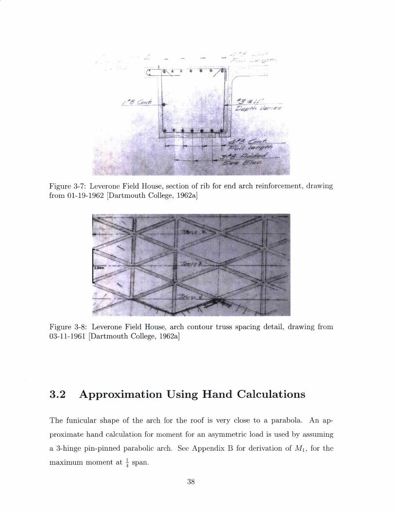
Figure 3-7: Leverone Field House, section of rib for end arch reinforcement, drawingfrom 01-19-1962 [Dartmouth College, 1962a]
Figure 3-8: Leverone Field House, arch contour truss spacing detail, drawing from03-11-1961 [Dartmouth College, 1962a]
3.2 Approximation Using Hand Calculations
The funicular shape of the arch for the roof is very close to a parabola. An ap-
proximate hand calculation for moment for an asymmetric load is used by assuming
a 3-hinge pin-pinned parabolic arch. See Appendix B for derivation of M1, for the
maximum moment at .1 span.
38
M1 = (3.2)64
For the Leverone Field house, the moment at the loaded side fixed-end was
209kNm per elementary arch. The moment obtained from the equation above was
194kNm per elementary arch, this is an excellent approximation compared with
Nervi's detailed calculations with only a 7% difference. This provides a lower bound,
equilibrium approximation to Nervi's elementary arch.
3.3 Finite Element (FE) Model
Another method to compare the results from Nervi's method is with elastic FE mod-
els. A model of the elementary arch was made in SAP2000 for the Leverone Field
House in order to compare the results from current FE models to the results Nervi
obtained from the energy method by breaking up the arch using (SAP2000, Com-
puter and Structures, Inc., Version 15). Set up in the same way as Nervi's method,
the arch was broken down into 20 elements with the exact geometry, the input was
determined from x and y coordinates in tables from Studio Nervi. Other parameters
were also obtained from Nervi's calculation package to match the exact properties
of the transverse arch from Nervi's calculation, such as slightly varying moment of
inertia (I) and cross sectional area (A) values. The modulus of elasticity (E), stayed
constant at 24,500MPa as defined in the specifications [StudioNervi, 1961].
The model was built in 2D space to restrict the forces in a 2D plane avoiding out of
plane action. Nervi designed the shape of the arch to have zero moment under Dead
Load and half of the Live Load, however, with this loading the FE model resulted in
some bending moment throughout the length of the arch whereas this funicular shape
should result in zero bending moment. The output of result were puzzling for this
funicular arch, and resulted in about a 50% larger moment at the supports under the
asymmetric loading scheme as summarized in Table 3.1. The largest bending moment
from the FE model under the Dead Load and half of the uniform Live Load is 90kNm
at the center of the crown and slightly less at the fixed ends. The FE model seemed to
39
be overly sensitive and therefore produced exaggerated bending moments compared
to the energy method and the 3-hinged approximate hand calculations which were
within reasonable tolerance of each other. In terms of analysis of funicular arches, FE
modeling in SAP2000 was not a reliable method to predict the forces and reactions of
an elastic arch, because it predicts bending moments in a no-bending arch geometry.
With this in mind, this SAP2000 model was also used to investigate the deflection
of the arch. The FE model proved to deliver more plausible results for serviceability.
Under load condition 1 mentioned previously with a symmetric Dead Load and Live
Load, the maximum predicted deflection is in the center with the crown deflecting
22mm downwards. This is well within the L/240 limit which allows 278mm. A test for
the absolute worst condition with the full Live Load applied asymmetrically over the
left half of the span gives a maximum deflection near the quarter point of the span.
The deflection is 109mm which is closer but still within the L/360 limit which allows
185mm. After applying conservative load cases, the deflections predicted by FE are
still well within current common deflection limits. It is reasonable that Nervi did
not carry out detailed calculation for deflections as part of his submitted calculation
package.
Table 3.1: Leverone Field House, Scheme 2 results comparison under asymmetricloading on half span
Nervi's Results FE Results % Diff. Hand Calc. % Diff.MA (kNm) 209 339 62% 194 7%Mc (kNm) 236 364 54% - -
40
Figure 3-9: Leverone Field House, exaggerated deflection under uniform symmetricloading of DL LL, model from SAP2000
Figure 3-10: Leverone Field House, exaggerated deflection under asymmetric loadingon half span of LL, model from SAP2000
3.4 Summary of Structural Analysis
The structural design packages show that Nervi used an energy method to analyze
an elementary arch. The shape of the arch was designed for zero bending moment
under DL+0.5LL loading. A quick approximate hand calculations using a 3-hinged
arch provided the closest resulting moments to Nervi's results. The FE model did
not provide a good prediction for the arch because it produced moments for a zero-
moment arch geometry. However, the deflections were reasonable estimates compared
to the predicted deflected shape deflection limits.
41
42

Chapter 4
Construction Methods
The Nervi System is a construction method invented and tested by Pier Luigi Nervi
through his projects beginning in the 1940s. It is an economical and rapid way to
construct large concrete shell structures by use of prefabrication of concrete panels in
addition to traditional in-situ concrete. He improved this method through his many
projects in Italy but the Leverone Field House was the first time he brought his new
construction method to the United States [Long, 1967].
At such a mature stage in Nervi's career, he continued to make changes to per-
fect his construction system. As well, he made a few changes to adjust to the new
environment in the US. Two major advantages of the system that minimized cost in
Italy were lost in the US. First, this system significantly saved on cost from nearly
eliminating the use of wooden formwork for the roof. Second, this system required
more skilled laborers which were less expensive and more plentiful in Italy. Both
benefits were lost in the US where timber was plentiful and inexpensive while skilled
laborers were a struggle to find. Those reasons combined with not being able to su-
pervise onsite to direct construction as he did with his previous projects prompted
Nervi to make many changes to reduce the complexity of both Leverone Field House
and Thompson Arena.
Many advantages to the Nervi System still remained, working with precast panels
and in situ concrete greatly reduced the length of the construction process. This
allowed the construction site to be divided into two parts that could operate simul-
43
taneously. The prefabrication was done in a different area onsite with the precast
panels laid out ready to be placed and assembled. At the same time, excavation and
the erection of the perimeter columns were underway uninterrupted on the building's
footprint [Iori, 2009].
4.1 Precast Panels
The precast panels were key to the rapid construction process of the Nervi System.
Two thirds of the concrete for the roof were precast meaning they could be prepared
while other concrete elements were cast to reduce wait time for curing [Long, 1967].
An intricate, multi-step process was developed for the precast panels which varied
slightly from what was done previously in Palazzetto dello Sport. An arch scaffolding
to full scale was erected to match the exact curvature for the intrados of the roof
vault, the formwork was then built on this arch to achieve the proper curvature for
the precast panels. Multiple sets of formwork were used to achieve the precast panels
which can be described as inverted reinforced concrete pans.
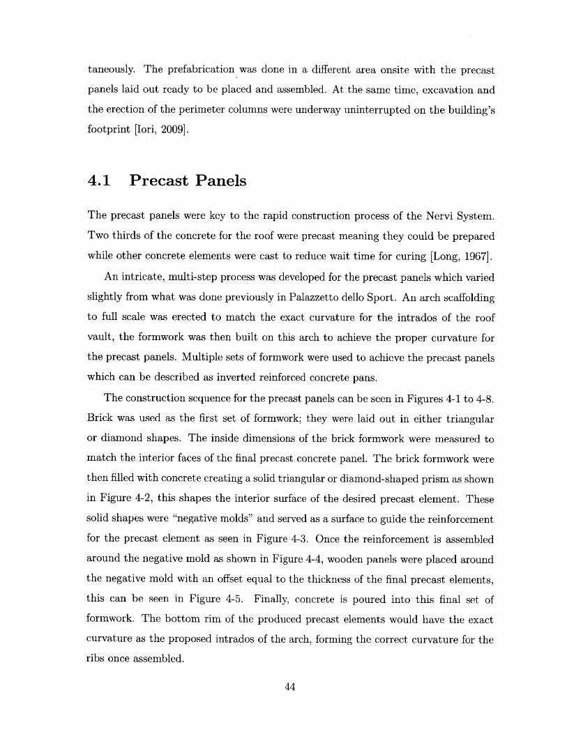
The construction sequence for the precast panels can be seen in Figures 4-1 to 4-8.
Brick was used as the first set of formwork; they were laid out in either triangular
or diamond shapes. The inside dimensions of the brick formwork were measured to
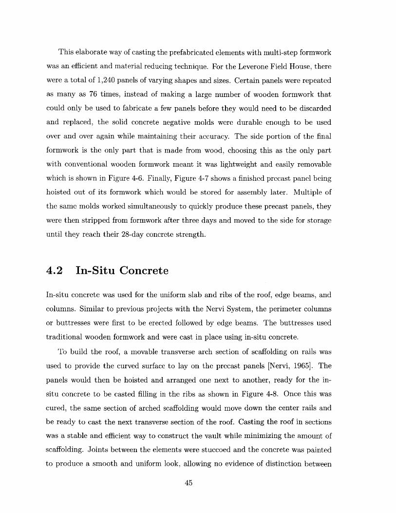
match the interior faces of the final precast concrete panel. The brick formwork were
then filled with concrete creating a solid triangular or diamond-shaped prism as shown
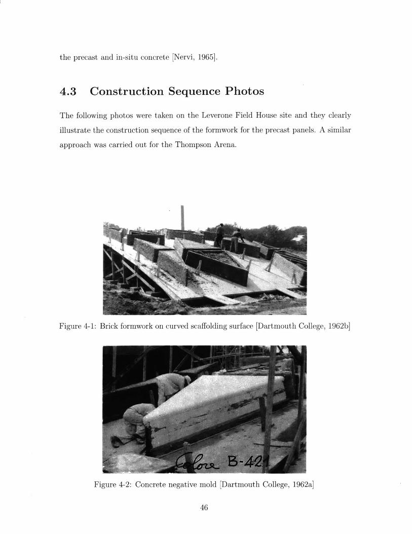
in Figure 4-2, this shapes the interior surface of the desired precast element. These
solid shapes were "negative molds" and served as a surface to guide the reinforcement
for the precast element as seen in Figure 4-3. Once the reinforcement is assembled
around the negative mold as shown in Figure 4-4, wooden panels were placed around
the negative mold with an offset equal to the thickness of the final precast elements,
this can be seen in Figure 4-5. Finally, concrete is poured into this final set of
formwork. The bottom rim of the produced precast elements would have the exact
curvature as the proposed intrados of the arch, forming the correct curvature for the
ribs once assembled.
44
This elaborate way of casting the prefabricated elements with multi-step formwork
was an efficient and material reducing technique. For the Leverone Field House, there
were a total of 1,240 panels of varying shapes and sizes. Certain panels were repeated
as many as 76 times, instead of making a large number of wooden formwork that
could only be used to fabricate a few panels before they would need to be discarded
and replaced, the solid concrete negative molds were durable enough to be used
over and over again while maintaining their accuracy. The side portion of the final
formwork is the only part that is made from wood, choosing this as the only part
with conventional wooden formwork meant it was lightweight and easily removable
which is shown in Figure 4-6. Finally, Figure 4-7 shows a finished precast panel being
hoisted out of its formwork which would be stored for assembly later. Multiple of
the same molds worked simultaneously to quickly produce these precast panels, they
were then stripped from formwork after three days and moved to the side for storage
until they reach their 28-day concrete strength.
4.2 In-Situ Concrete
In-situ concrete was used for the uniform slab and ribs of the roof, edge beams, and
columns. Similar to previous projects with the Nervi System, the perimeter columns
or buttresses were first to be erected followed by edge beams. The buttresses used
traditional wooden formwork and were cast in place using in-situ concrete.
To build the roof, a movable transverse arch section of scaffolding on rails was
used to provide the curved surface to lay on the precast panels [Nervi, 1965]. The
panels would then be hoisted and arranged one next to another, ready for the in-
situ concrete to be casted filling in the ribs as shown in Figure 4-8. Once this was
cured, the same section of arched scaffolding would move down the center rails and
be ready to cast the next transverse section of the roof. Casting the roof in sections
was a stable and efficient way to construct the vault while minimizing the amount of
scaffolding. Joints between the elements were stuccoed and the concrete was painted
to produce a smooth and uniform look, allowing no evidence of distinction between
45
the precast and in-situ concrete [Nervi, 1965].
4.3 Construction Sequence Photos
The following photos were taken on the Leverone Field House site and they clearly
illustrate the construction sequence of the formwork for the precast panels. A similar
approach was carried out for the Thompson Arena.
Figure 4-1: Brick formwork on curved scaffolding surface [Dartmouth College, 1962b]
Figure 4-2: Concrete negative mold [Dartmouth College, 1962a]
46
Figure 4-3: Forming[Dartmouth College,
reinforcement around negative mold for precast panel1962a]
Figure 4-4: Precast panel enclosed in wooden formwork ready to be poured[Dartmouth College, 1962a]
47
t,427Figure 4-5: Complete formwork with precast panel [Dartmouth College, 1962a]
'bi
Figure 4-6: Removing side panels of wooden formwork [Dartmouth College, 1962a]
48
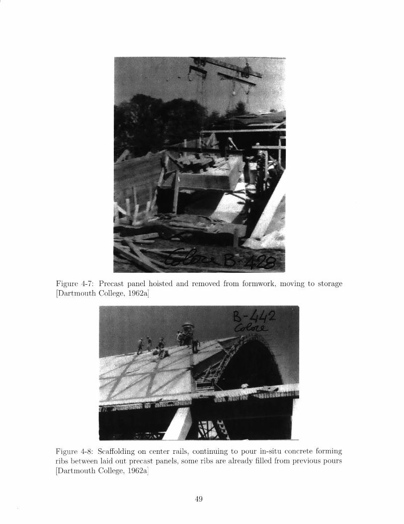
Figure 4-7:[Dartmouth
Precast panel hoisted and removed from formwork, moving to storageCollege, 1962a]
-442
7M_
Figure 4-8: Scaffolding on center rails, continuing to pour in-situ concrete formingribs between laid out precast panels, some ribs are already filled from previous pours[Dartmouth College, 1962a]
49
4.4 Summary of Construction Methods
The Leverone Field House was the first use of the Nervi System in the United States,
combining the use of precast panels with in-situ concrete [Bologna and Neri, 2013].
The Thompson Arena later uses the same construction method. Precast panels made
up most of the roof while in-situ concrete filled in the ribs joining the panels. Cast-
in-place concrete was used for the foundation, the buttresses, and the edge beams. A
movable scaffolding on central rails was used to construct the roof in arch sections.
The Nervi System was an economical method developed in Italy to reduce construc-
tion time, however, not all the benefits successfully transferred to construction in the
United States.
50

Chapter 5
Conclusion
The Leverone Field House and Thompson Arena are a unique pair of structures to
be celebrated. These two projects are the last of their kind. The Thompson Arena
completed in 1975 was the last legacy Pier Luigi Nervi left in the United States
before he passed away in 1979. These two structures perfectly show the evolution of
the design process of two similar parabolic vaults, two years apart. The Dartmouth
Rauner Special Collections Reference Library contains valuable design calculation
packages for both Leverone Field House and Thompson Arena [StudioNervi, 1973],
[StudioNervi, 1961]. It also has various correspondences between Studio Nervi and
Dartmouth College, some construction documents, and a collection of construction
photos for the Leverone Field House [Dartmouth College, 1962b]. Similarly, the
MAXXI (Museo nazionale delle arti del XXI secolo, or National Museum of the 21st
Century Arts) Archives has a collection of construction photos for the Leverone Field
House. In addition, it has some sketches and drawings for both of the projects
[Dartmouth College, 1962a].
The shape of the roof in the transverse direction is close to a parabola. Nervi
designed the funicular shape of the curve by minimizing the moment under a basic
uniform dead and live load. He used an elastic method to analyze the structures,
assuming an elementary arch of a certain unit width with fix-fixed supports. The
arch was divided into 20 segments and detailed calculations were completed for each
of the segments. A hand calculation approximation was made assuming an asym-
51
metric load on a 3-hinged parabolic arch. Using simplified equilibrium methods, the
maximum moment was calculated to be within 7% of Nervi's results. A FE model of
the elementary arch was also explored, however, the results proved the model to not
be a reasonable representation of the behavior of the funicular arch.
The construction method of these two projects used the Nervi System which used
precast panels with in-situ concrete creating the ribs to join the precast panels. It
was a process invented by Nervi and one that he used for many of his long span,
thin shell concrete structures. Clues from the construction photos showed that slight
changes were made to the construction method from his previous structures with the
Nervi System in Rome. The philosophy of his construction method was to shorten
the construction time and reduce cost with movable scaffolding on center rails and
precast panels. The precast diamond and triangular-shaped panels were produced
with a multi-step formwork system to reduce the amount of wooden formwork while
keeping a high level of accuracy for the shape of the precast panels.
The Leverone Field House was the first project Nervi completed in the United
States and Thompson Arena was his last. These two thin-shell parabolic vaults
combined some of his best characteristic design elements and construction system.
A detailed study of the two structures not only showed his design methods but the
refinement and an evolution in design between the two similar structures.
52
Bibliography
Bologna and Gargiani (2006). The Rhetoric oflated from the Italian by Juliet Haydock.
Pier Luigi Nervi. EPEL Press. Trans-
Bologna, A. (2013). Pier Luigi Nervi negli Stati Uniti : 1952-1979 : master builderof the modern age. Firenze University Press, Italy.
Bologna, A. and Neri, G. (2013). Structures and Architecture: Concepts, Applicationand Challenges, chapter 235: Pier Luigi Nervi in the United States. The height anddecline of a master builder. Taylor and Francis Group.
Britannica (2016). Pier luigi nervi - italian engineer and architect.https://www.britannica.com/biography/Pier-Luigi-Nervi.
Retrieved from
Cassinello, P., Huerta, S., Miguel, J., and Lampreave, R. (2010). Geometry andproportion in structural design : essays in Ricardo Aroca's honour. Madrid. Essay:Reduced Scale Mechanical Models 20th Century Structural Architecture, the casestudy of Pier Luigi Nervi by Mario Chiorino.
Chiorino, C. (2010). Eminent structural engineer:Structural Engineering International Journal, pages 107-109.
Pier luigi nervi.
Chiorino, M. A. (2012). Art and science of building in concrete: The work of pierluigi nervi. Concrete International.
Dartmo. (2012). Piazza nervi. Retrieved fromhttp://www.dartmo.com/archives/category/leverone-field-house.
Dartmouth College (1962a). Construction photos and drawings. Museo nazionaledelle arti del XXI secolo, or National Museum of the 21st Century Arts Archives.
Dartmouth College (1962b). Construction photos, drawings, and correspondences.Rauner Special Collections Reference Library, Dartmouth College.
Dartmouth Big Green (2016a). Dartmouth sports facilities, thompson arena. Re-trieved from http://www.dartmouthsports.com.
Dartmouth Big Green (20161)).https://dartix.dartmouth.edu.
Leverone field house. Retrieved from
Heimsath, C. B. (1960). Nervi's methodology. Architectural Forum.
53

Homewyse (2017). Cost to excavate land. Retrieved fromhttps://www.homewyse.com/services/costtoexcavateand.html.
Iori, T. (2009). Casabella, chapter Pier Luigi Nervi, The Palazzetto dello Sport in Rome.Architettura e struttura.
J. IASS (2013). International Association for Shell and Spacial Structures, 54(177).Special Double Issue on Pier Luigi Nervi. Guest Editors: John F. Abel, Gorun Arun,Mario A. Chiorino.
Jacobus, J. (1976). Nervi's concrete aesthetic, rupert thompson arena. DartmouthAlumni Magazine, pages 22-26.
Leslie, T. (2003). Form as diagram of forces, the equiangular spiral in the work of pierluigi nervi. Journal of Architectural Education, pages 45-54.
Leslie, T. (2018). Beauty's rigor. University of Illinois (unpublished manuscript, March2017).
Long, C. F. (1967). The nathaniel leverone field house.From Dartmouth, with a special supplement for Thayer School Alumni Journal.
Meacham, S. (2008). Dartmouth College. Princeton Architectural Press.
Morrison, H. (1961). Nervi designs a field house. Dartmouth Alumni Magazine, pages20-23.
Nervi, P. L. (1956). Structures. McGraw-Hill Book Company. Translated by Giuseppinaand Mario Salvadori.
Nervi, P. L. (1965). Aesthetics and technology in building. Harvard University Press.Translated from the Italian by Robert Einaudi.
RSMeans (2017). RSMeans Cost Data. John Wiley and Sons.
Structurae (2016). International database and gallery of structures. Retrieved fromhttps://structurae.net/index.cfm.
StudioNervi (1961). Leverone field house calcoli statici. Rauner Special CollectionsReference Library, Dartmouth College.
StudioNervi (1973). Thompson arena calcoli statici. Rauner Special Collections Refer-ence Library, Dartmouth College.
Tullia Iori (2009). Pier Luigi Nervi. Milano : Motta architettura.
54
Appendix A
Nervi's Original Calculations and
Documents
This appendix includes the calculations from Studio Nervi for the Leverone Field
House. It shows the detailed methods Nervi used to design the structure, a very
similar set of calculations are available for the Thompson Arena at Dartmouth's
Rauner Special Collections Library.
55
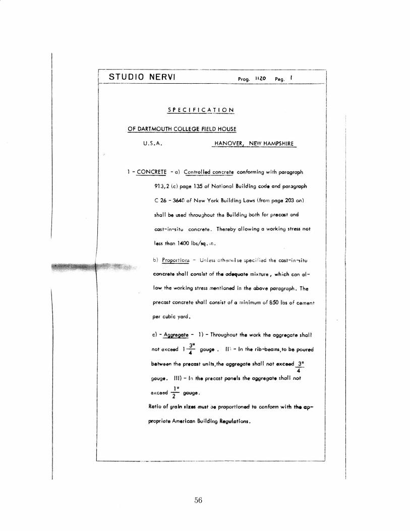
STUDIO NERVI Prog. IIZO Peg. I
S P E C I FI C A T IO N
OF DARTMOUTH COLLEGE FIELD HOUSE
U.S.A. HANOVER, NEW HAMPSHIRE
1 - CONCRETE - a) Controlled concrete conforming with paragraph
913,2 (c) page 135 of National Building code and paragraph
C 26 - 3640 of New York Building Laws (from page 203 on)
shall be used throughout the Building both for precast and
cast-in-situ concrete. Thereby allowing a working stress not
less than 1400 lbs/sq. in.
b) Proportions - Unless otherwise specified the cost-in-situ
concrete shall consist of the adequate mixture , which can al-
low the working stress mentioned in the above paragraph. The
precast concrete shall consist of a minimum of 850 lbs of cement
per cubic yard.
c) - Aggregate - 1) - Throughout the work the aggregate shall
not exceed 1 gauge . I1) - In the rib-beams,to be poured4
between the precast units,the aggregate shall not exceed 3"4
gauge. I1) - In th precast panels the aggregate shall not
1"5exceed gauge.
Ratio of grain sizes must 0e proportioned to conform with the ap-
propriate American Building Regulations.
56
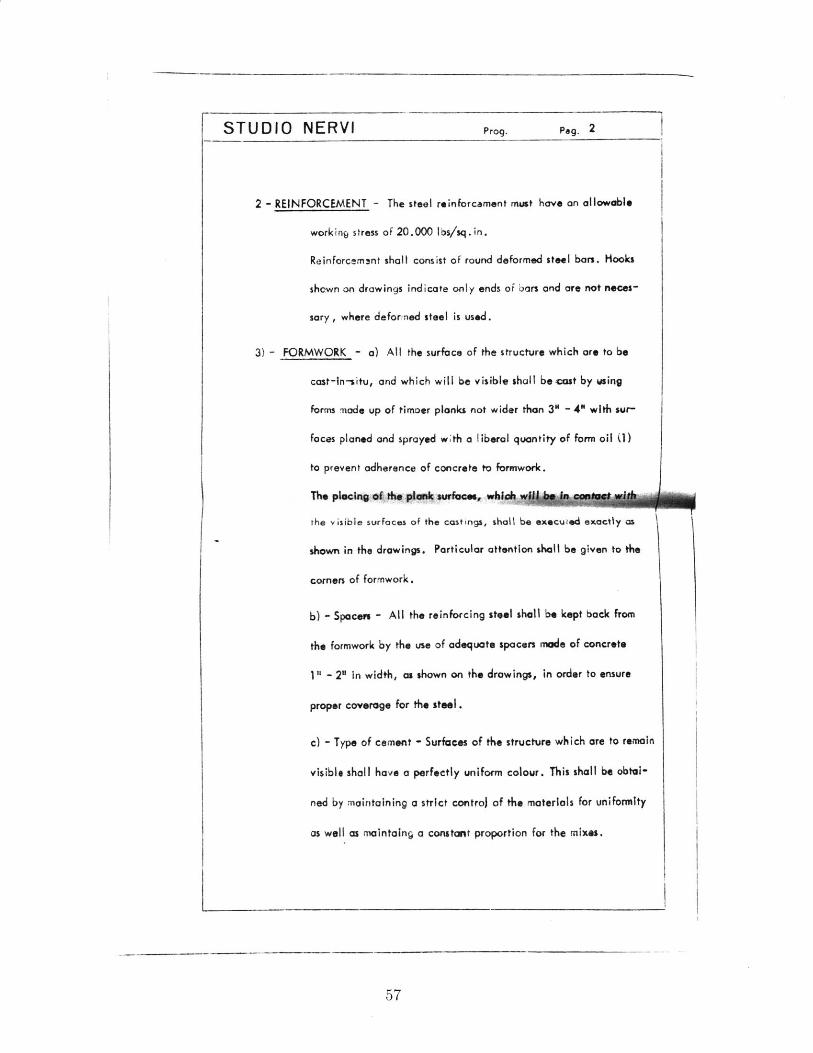
STUDIO NERVI Prog. Pag. 2
2 - REINFORCEMENT - The steel reinforcement must have an allowable
working stress of 20.000 lbs/sq.in.
Reinforcemsnt shall consist of round deformed steel bars. Hooks
shown on drawings indicate only ends of bars and are not neces-
sary, where deformed steel is used.
3) - FORMWORK - a) All the surface of the structure which are to be
cast-in-situ, and which will be visible shall be cast by wsing
forms mode up of timoer planks not wider than 3" - 4" with sur-
faces planed and sprayed with a liberal quantity of form oil (1)
to prevent adherence of concrete to formwork.
The plsochVgof, the pa* surface., whilol
the visible surfaces of the castings, shall be executed exactly as
shown in the drawings. Particular attention shall be given to the
corners of formwork.
b) - Spacers - All the reinforcing steel shall be kept back from
the formwork by the use of adequate spacers made of concrete
1" - 2" In width, as shown on the drawings, in order to ensure
proper coverage for the steel.
c) - Type of cement - Surfaces of the structure which are to remain
visible shall have a perfectly uniform colour. This shall be obtal-
ned by maintaining a strict contro) of the materials for uniformity
as well as maintoing a constant proportion for the mixes.
57
STUDIO NERVI Prog. Peg. 3 , I
Further the concrete mint be continuously controled to avoid any
irregularity of the surface finish. A light vibration must be given to the oon-
crete.
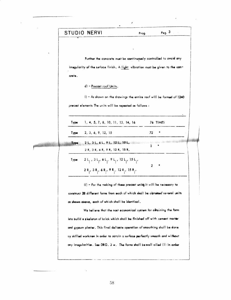
d) - Precast roof Units.
I) - As shown on the drawings the entire roof will be formed of 1240
precast elements The units will be repeated as follows :
Type 1, 4, 5, 7, 8, 10, 11, 13, 14, 16
Type 2, 3, 6, 9, 12, 15
76 TIMf
72 "
2 %2 R, 3 R, 6 R, 9 R, 12 t, 15 R,
Type 2 L. , 3 Li 6 L 61 9 L 12 L, 15 L ,I I' I I' I I
2 -
S
2 R., 3 R., 6 R., 91 ., 12 R., 15R.,I I I I I I
Ii) - For the making of these precast uniq it will be necessary to
construct 26 different formn from each of which shall be obtavei several units
as shfws abOve, eath of which shall be identical.
We believe that the nost economical system for oitaining the form
Isto buIld a skeleton of brick which shall be finished off with cement mortar
and gypsum plaster. This final delleate operation of smoothing shall be dons
oy skilled workmen in order to obtain a surfac, perfectly smooth and without
any irregularities. See DRG. 3 w. The forms shall be well oiled (1) in order
58
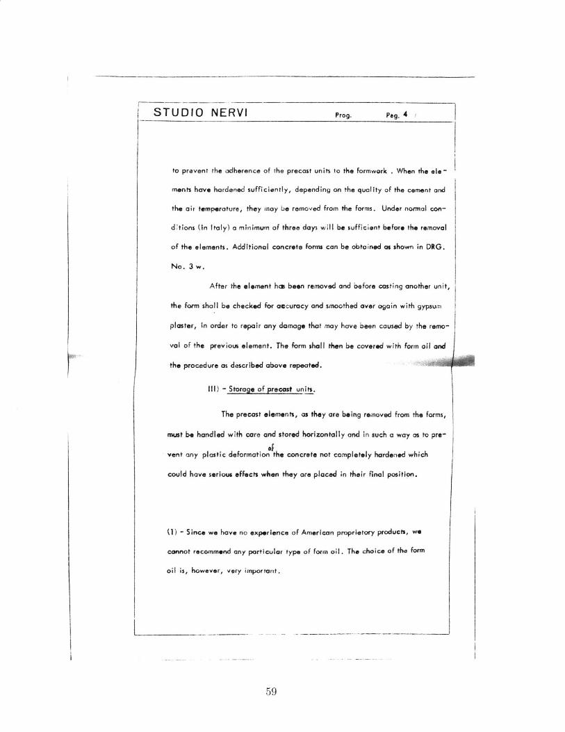
STUDIO NERVI Prog. P,,. 4 1
to prevent the adherence of the precast units to the formwork . When the Ole
ments have hardened sufficiently, depending on the quality of the cement and
the air temperature, they may be removed from the forms. Under normal con-
dltions (in Italy) a minimum of three day3 will be sufficient before the removal
of the elements. Additional concrete forms can be obtained as shown in DRG.
No. 3 w.
After the element ha been removed and before casting another unit,
the form shall be checked for accuracy and smoothed over again with gypsum
plaster, in order to repair any damage that may have been caused by the remo-
val of the previous element. The form shall then be covered with form oil and
the procedure as described above repeated.
Ill) - Storage of precast units.
The precast elements, as they are being removed from the forms,
mwt be handled with care and stored horizontally and in such a way as to pre-
ofvent any plastic deformation the concrete not completely hardened which
could have serious effects when they are placed in their final position.
(1) - Since we hove no experience of American proprietary products, we
cannot recommend any particular type of form oil. The choice of the form
oil is, however, very important.
59

STUDIO NERVIPROF OOTT MOi PIER LUIGI R E R vjG0OT A"CH ANTO0 0 5 sV AN soIT .vU ..A . S 11CMIC A 801.5IA
DOTT VITT C O L A T A L. 0.044
CALCOLI STATICI
LAVO RO;
DARTMOUTH COLLEGE
FIELD - HOUSE
U.S.A. HANOVER, NEW HAMPSHIRE
Prog. N. 1120
Calcohl
Rome, 5 Magglo
STUDIO NERVI Prog. 1120 Pag. 1.'
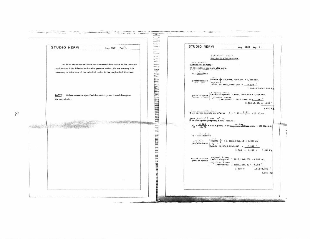
STRUCTURAL ANALYSIS
The roof conslshof a ribbed cylindrical vault with slab of uniform
thickness and ribs tapering from a thickness of 2' -0' (at the spandrel) to
a thickness of 1' - 0 (at the crown).
The longitudinal spOndreT beam has a considerable flexural rigidity.
Thereby an arch behaviour is prevailing along the cram section.
The structural analysis has been made by assuming a tiinsverse por-
tion of the vault as a fixed-end arch.
The central curve of the arch has been deenelned re e vnF
res due to the dead load and to half the live fead.
It has Deen calculated also the very light flexural interference, which
asises In the fixed end arch Indicated above, because of the deformation work
of the normal strain.
Therefore the stresses corresponding to the various loading conditions
have been calculated separately as follows :
1) - Uniform load over half the vault (see scheme 2 page 18)
2) - Horiazontal force uniformly acting only In one direction (see action
of wind pressure page 49)
Thus, by properly combining the above loading conditions with the live
load conditions, the most critical stresses have been obtained for each section
of the arch. These sections have been checked for stability accordingly.
L I
I
STUDIO NERVI Prog. 1120 Peg. STUDIO NERVI
VOLTA
I forces are concerned their action in the troarver- -7An-lici dl cariehto the wind pressure action. On the contrary it is La poLezaione normele eU&
* seismical action in the longitudinal direction. ) Ia) - In chLave
prefabbricato &Glett-
~brdol1
specified the metric system is used throughout getto in operajtravettl
A--. .C-pph-."- i.
Tale carico insate asu un'
U Leare (peso proprio) a* -. 4. 0110
PB 1080 .308 /
b) - All'imposta
solettaprefabbricato IC436
bordo
travetti dgetto in opera
tras
2 8 4 4 . 6 6 0 K.
S7. 25 x 2 2 10. 30 mq,
ta
mp.rwe Lu aaxion. - 470 Kg/mq.
x6, 70x0. 10 - 0. 870 me.
x0.045 0. 522 "
2.500 x 1. 392 - 3.480 Kg
7, S0x. I5x0, 755 * 0. 860 mc.
1, 30x0, 24x0, 80 - 0, 250 "
2.500 a 1.110-2.780
6.260 Kg
'~-~-
Prog. 1120 Peg. I
.a, vso.t
DJ COPERTURA
selta.
It
1- X2, lxit, 70x0, 10. - 0. 870 me.
4.5OxO. 0x0. 045 - 0. 326 "1, 196 z2. 500*2. 980 K4 I
Liagonali 7, 60z0. ISxO, 456 - 0, 18 rc.
aevereajj 1, 30x0. 24x0. 50 - 0, 156
2.500 xO, 674 z 1.680
As for as the seismica
se direction is for inferior tnecessary to take care of th
NOTE : Untees otherwisethe calculation.
Karea A
mq. risul
mq. + 204
x 2,60
4. SMx. 8C
b-.,
aganali
versall
ril
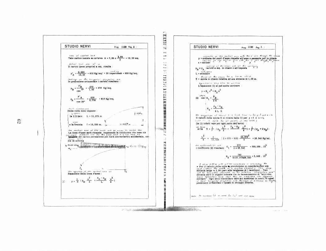
STUDIO NERVI Prog. 1120 Pa.2
A^e -f /~ r4.s I... 2,84
Tale carico insiste mu un'area A a 7, 25 x 2 10, 30 mq.
'eq._ 1. /_d , q ,S
11 carico (peso proprie) a mq. rimulta:
61260 '''p'A 10.30 . 610 Kg/mq/ + 20 imperntab 630 Kg/mq.
In .p .a "; .-. m riata c,In pro;esimne orisaoatam I cartehi' rieltano :
p'B 470_ .pB * * 470 Kg/mq.
Ces
A A 6 - 810 Kg/mq.A 0 776coo 39'
(- .~-- ..Delia volta sono imposteks 1/2 itce L 33,375 m
Sla frcea f 1s, 335 m. .,
f= I,3~,,,
b=33~25.. -- -~
+0,. ".$,-1Jam -... #.hC -jf-I*.,t b' -. - --- #,A #.A,.La linea d'asse mar& ricavata :imponendo I& condizione che essa sia
ilmases del carico permanente pio mett sovraccarico accidentale,
me da schema
ft,ea. 1 ' Mk.' '00 ,7o . I
Pac 4. / i 4 ./ a.Equa zone della Unea dasse
x 2 pA B x 3C0 Y) X B 2 L
on -
in
STUDIO NERVI Prog. 1120 Pe.3 /
-''.+s..+enr~ - 0 A.+ A-i -ws tA ,4 #4 .
y - ordinata del punti d'asse rispetto alU'asse x passanto er Ia him
x a actame y I. . y
pB A c .richia mq. in chiave E all'impostaJr'-.
L - semiluce
X - spinta in chilave relativa ad una striscia di 1, 00 m.
E ('si) -- / ./J. 1-e wr4f,
L'equazione (1) al pub anche scrivere2 3
y . Ki x + 122
j. P(2) Con (K, B
2 X
6 L X' 1'2= 4'- x .. Lr.X..
11 valore della spinta X Si ricava dalla (1) per y = e x L-1- .~. I .J r., .j..-.
(la (1) infattl vale per ogni punto dell'arco) :
1 L2 PA -EB L Iat ha X B 2 ( 6- x-- 7- -(p +2 pB.
2 B- AL 1 332375
S , ( 2 x 570 + 910) 2 28.540 Kg/ml.
0M .. e. - (" a-'' K 2 570 - on9s si coefficenti (2) risultano 1 2 x 28.540
340 -52 6 x33, 375M8. $40 ,4 .U
- Per U1 calcolo della volta a prenderemo in considerazitne une
striscia larga m 2, 84 (part &lla largbeaa di I tavellone) . Tale;dlsb here-9 m u! t ~a- e--- kutrieta sark in seguito indicate con Ia denominazione di "arco ele-
mentart
". Ogni arco elementare sarA poi suddivieo in conci; di ugual.4 p.y..., h...z#..I p,..+,.. .. d
A .
,'-e ./ . . AA.
protezione ori montele e quisdi di sviluppo diverso.
144 _ =.A"' G) '-% .- '.j I.(l..
()
M M IIII
a....e

STUDIO NERVI Pro
T ELLA 1 T--
1 2 3Sezione x x- x
0 - B 0,001 00o 0,00
3.31L9131. _3411-2a, 8T 5D 44.SR 558 _.297-408U
-3 1-0-01M 1109 i . 003, ? kl4
1 3. 31101 __78. 2225 2.L 379.,2704
I I -7 1784271 A-4L 8132
20, 4f L0MA. 03D.031f
7 _"_3 54, 8064 12. 751, 402
-L70OL 72L81PQ J03 1q30
S ID 9 302 2)0 t-27, .0L 37410
10 A 33.375 1.113,8906 37.176,0988
-- - - -- - ~
g. 1120 p,. 4
I x 2 1K 2 .3
0,00" 0,00 0,0o
9.11.1. Q.00; o'.114
-1,001 0, 060 .0_61
LiiQ QA4g JAjl
2.71 0.2?1 .. 0h7
5.45. 675 t e, 209
7, L I9 _J13-a AM25
9,010 1,61 1, 62
11,123 2,21 13 335
rho
STUDIO NERVI Prog. 1120 Peg 5
A I' ~ IA~'~ LAL4..
3, 337 0, t13 0,0338. 1- 57' 11,139 0,013. 11,152 3495
k33375 0,1350 0,1047 5- 59' 11,139 0422. 11,261 3. 3M
8 3371 0. 598 . 0.1792 10" 10' . 11. 139. 0,358 1LA97. 3.3908
1-4371M40 , D.2&7l JA 27'. 1L 13-. 2.740 .l1l m1.AUI
3, 337(l1A38. 044Q4 19* 49' ._1L139 1.290 . l429t 3Aa5..5, - 2Q13_L_11 LARS 027213* ' . 13. 01 . ali17 LS L_
4 , 3, 33_7 ,727 0,5174 2 22' _11,139 2,982 14,121 3,7572
(.41 Lu .61 1 A31-' 24' .l013U- C1 . 5,109-3,41M022
- 1 3.3375 2,371 C.7104 35- 24' .1LLU 5.52 121l 4.02 0.4
-. 13314713 0, 812 -I 0W. 1L139. L 310 11. ,49 ._4,3l1
Z1 38, 752
7I
8I
I I '
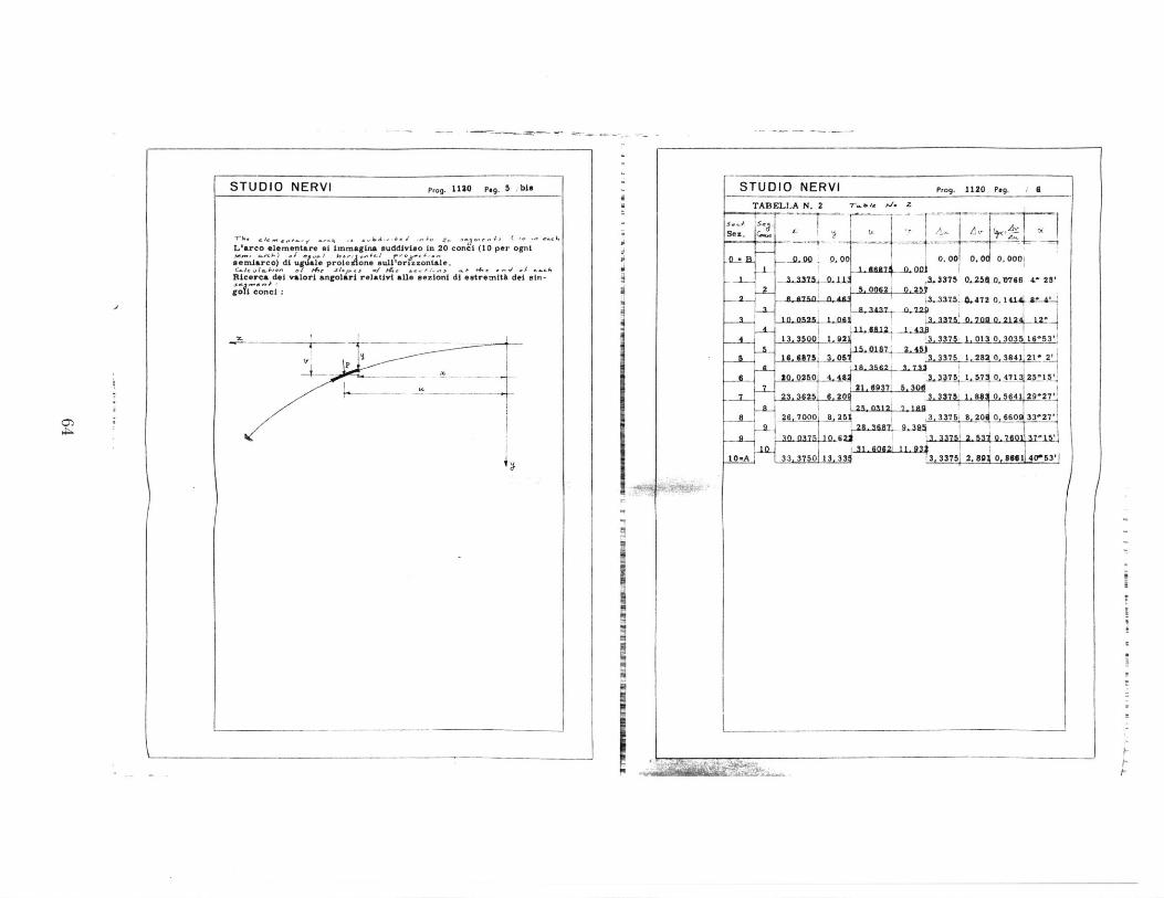
Prg. 1120 peg. 5 ! e
Llarco elementare si immagina suddiviso in 20 conci (10 per ogni
smiarco) di ugale proieneAuUor;.zontale.c..l Acm S/w,./.P., -1 Ar,,,, -0 .- ,.. .,( e.-.4
Ricerea dei valor angolari relativi ale sezioni di estremit dei sin -
.$ I .n :
I __
STUDIO NERVI STUDIO NERVI Prog. 1120 Peg. 6
TABELLA N. 2 7 it il. Z
-0-l -- ]-o XL 1 ,oo 0, 0001I116873 0. on
- 3. 3373 0.11 02 3375 0.M2 -. , 716 41 28'
. a 3-n n At 35. 472 0. 1 1. "* 4
4 1~" 1 A7 1432
4 13.3500 1. 2i 3. 3375 1, 013 0. 3035 16-53'5 15. 0187: 2. 45j
a 16. 6875 3. 0 3. 3375 1. 28a 0,1841 21_
20. 050 . 3.337 1. 57 0 471 3315S21. 9937 5. 30d
? 2. 6256.203.3375, 1. 884 0. 36411 29'27'.12-t. 1121 7. 1fig
8 _Z6, 11000 8, 25$ 3 ,3375i 8.,200 0, 6600 33-27'929. 3687 9 3
31..46 11.7v
10wA 33,3750113,33 t3, 33751 2, 89 0, IGI1 40-53'1
(
STUDIO NERVIe Tabella N. 2 -r . M.
0-B 0 00 1.000
2
S 0.3149 0. 933
3 -8
4 _1. 202, 0,978A 0. 20 0. 957
_L ,- 0, 359 0, 93$
g o. 4200. 904
, 0.379
05 0 0, 831
10jo . 0 0 79
10Ai0.631 0.?751
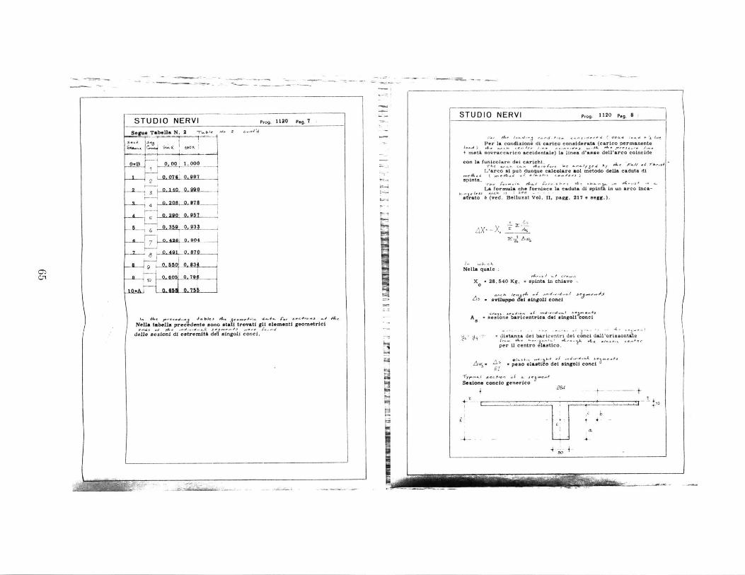
1. 44 ..... 4.Awes 4CNella tab*J1a precedents sono at
delle aezionl di eatremitk d aL
Prog. 1130 Peg. 7
2 c..,'d
al trovatl g~l elementi geornetrici
rgol conci.
ERVI Prog. I1STUDIO N
Per l+ met& sovra
con la funicolL'arc
"'eA. (spinta.
La fo
6tat (ved
Nella quale
x . 28.
A5.vi
A 0 sezi
. S
-y.A sos-+
s~aione conc
4-
540 Kg. = spinta in chiave -
,,, /,, P4 -C rd-d-fM Jegs--iuppo singoli conci
one baricentrica dei vingoll conci
distanza dei baricentri del conci dall'orisaontale
per U centro elastico.
speso elasti dei igli co.ci
.. ;s e..-
to generico
- 4 -,CLT
Cfl
C
a condizione di carico considerata (carico permanente
ccarico accidentale) 1. linea d'asse dell'arco coincide
are dei carichi.,-,, . b" , &e 4...// -f 7.sf
o si pub dunque calcolare aol metodo della caduta di
rmula che fornisce La caduta di spinkin un arco inca-'s S C - - - -. Belluzzi Vol. 11. pagg. 217 e segg.).
s
L - - --- - Mgm-,
120 pag. 8!
- ~
STUDIO NERVI Prog. 1120 p,. 9 /
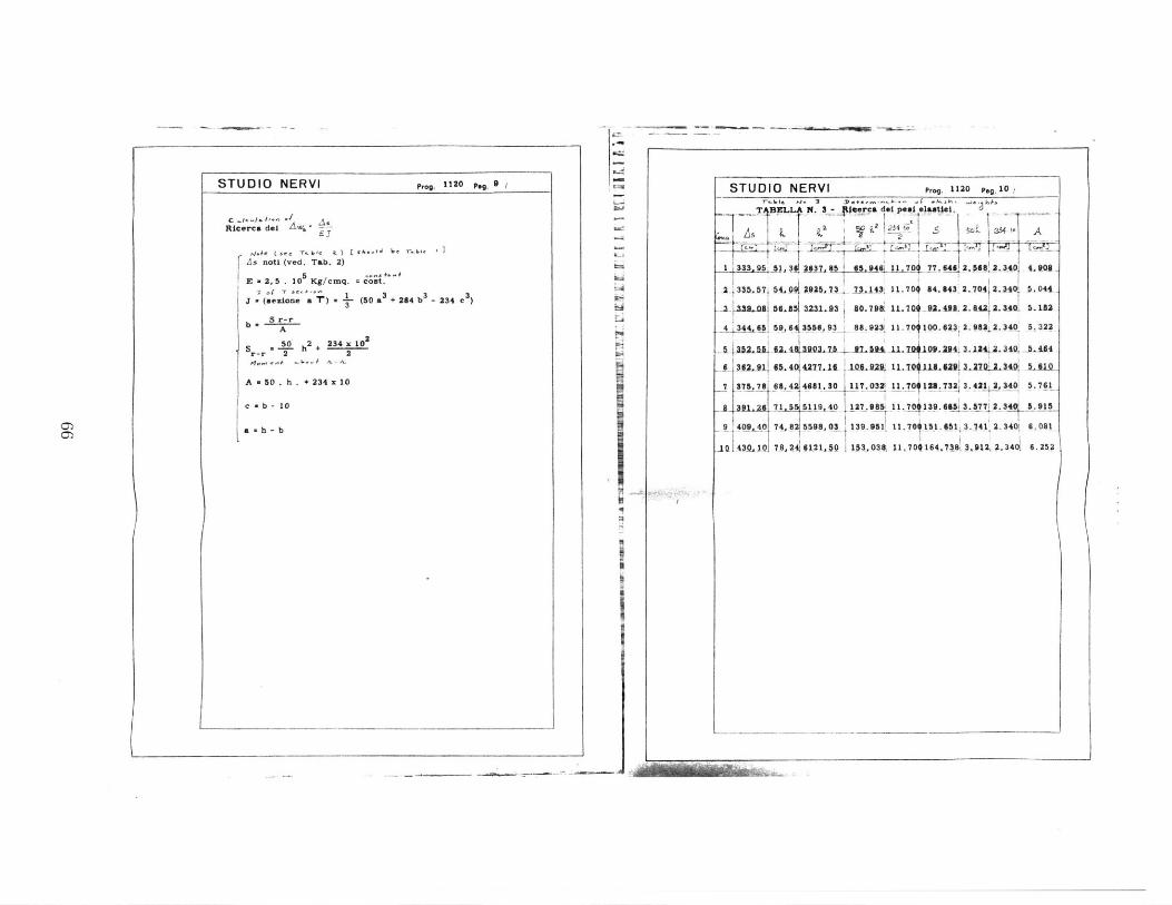
Ricerca del A%* -
4.s ( se -T..be a) L sem M 'As noti (ved. Tab. 2)
E s2 5 . 105 Kg/cmq. - cost.
J(etone a ") (50 a + 284 b -234 c3
S r-rA
S 0 h 2
+ 234 x 10 2
r-r 2 2
A * 50 . h . + 234 x 10
c e b - 10
a h - b
I
L;
I.
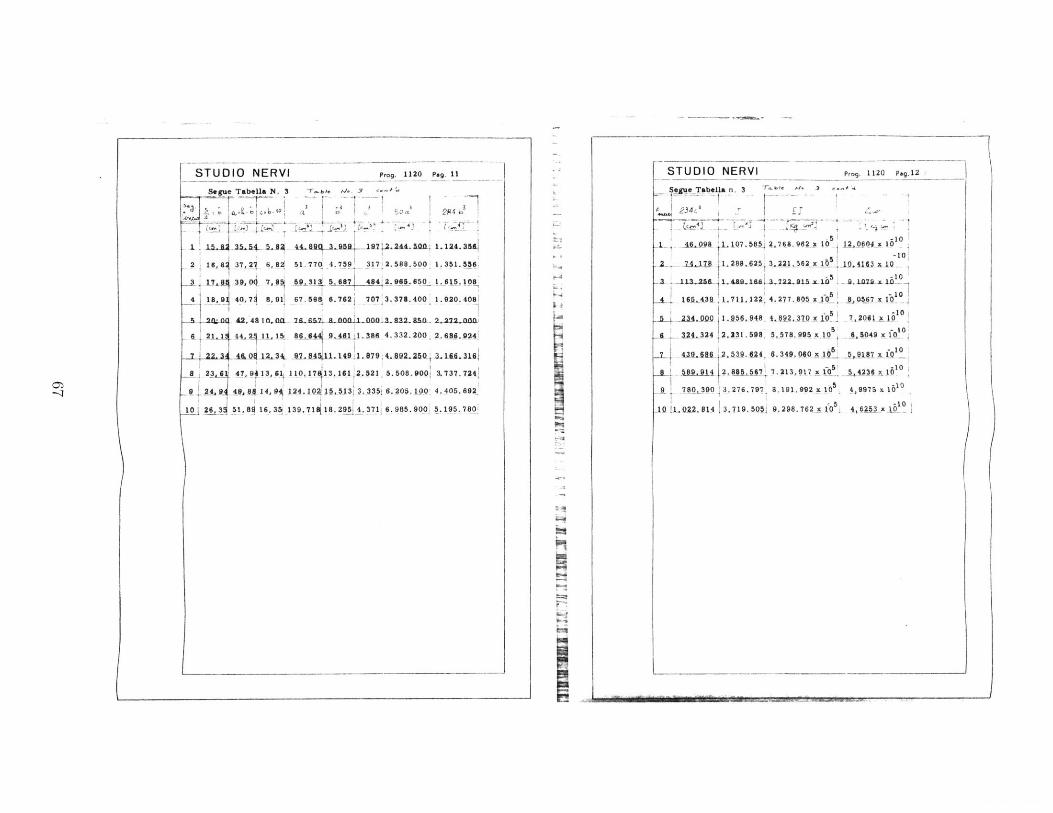
STUDIO NERVI Prog. 1120 Pag.10
'r 61 ". 9 e e n.n . fl e.-." - = jTABELLA f. 3 4 ca del peo elasti
1 333 95 Sh3 2S3L85 $5.946 11. 70 77,646 2.Jf 4 2 .0#7-
I 3SLI7f54.9 192.5114 R1 . 1.704 84.43 2.704 2.340 . 044_
L jiIn MA 56.5 3231-R3 30. 79i 11. 7 92- 4L2. RAi 2. 340 5.111
4 344,46 4 59,64 3W56, 93 84. 923 11.70 100. 823 2.3982 2.340 5.322
6 4e,-Mt 3903.17, _7.U9 09.244 3.1244234 --DA4
_L362. 91 CL4 4277. 16 1L0L U*- I .L0I 18. MPI 3.7 2.4 LU
7 375,78 68, 42 4681,30 117.032i 11.70 123.732 3.421 2,340 5.761
-. B-"1.26 71 5 119.40 _12_.98S 11.7 139.6 .53.77 2. 340 5.915
9 40940 74.8215598,03 139.951 11.704151.6513.741. 2.3401 6.081
11 A I9,1 78, 624 0 1. 1 153,0381 1.70164.7
14 3912,3.3401 6.252
A
'0-
0O9 x SL66') Sq Zee'~B Tel's LOLa i 00~ i
01- SO
'ol LOm g u -n r --g -wt
!01-
0T WHOUA~ 't 08'199f, Iow
a _ u _ ___ -I!-
ol Q
0_____ Ilf'TOIxeg f c a -fnN f
I4I
Flp-I
r08L~~~~~~6T~~ 00686 isC9~T181~'1B'g ~ 0
61016 tT61 :OILSmO bsg'L t89 P L -U9
IGOV-090- OOgs-LS t O IZOLi' b~L ' 16-9 L~L 6,91 1
-S ru-Vq -VL u- T 16f ~Li~'i -C9KI:9i -1.
11 6
@d OZIT -6-d IAJJN 6o i~.s

STUDIO NERVI Pr. 1120 Pag.13/
TABELLA N. 4 - T-m- ^/- 4
Determnsnaxlono del centro elastico e dell& caduta dI apinta.
- O2, 004 _ _0 -- x 1__ 320. 9 103.fl1
10413 25, 267,699 x 110 295,36 87. 23
A07x1 7_9 S_3. 96 x 1610 14LJ.A 61.52
S 1 145. 1 1158. 55. x 10 177.26
_ 7,2061 x 10 245, 1 1766,215 x 10 75, 96 5.770
-1o -10-t_6 6.04J xD .b0 73.3 2428. 279 x 110 - 52,2a 4 2.2
7 5, 9187 x 10 .30, 6 3140. 462 x 110 -209,54 43.90
-10 -108 5413 x10 718,9 3899 026 x 10 397. t_ 158.A"
9 4,9975 x 1-010 939,5 4695, 151 x 110 61.8, 44 302.46411035 -10
10 5x 10 193, 2 5518,908 x 10 -872,144 760.628---0
Edw.73,3174 x10 ZAe'-235139,465 1 10x 0
ii
4
STUDIO NERVI Prog. 1120 Pa. 14
Segue Tabella N. 4
SA5 . .A
10
2 908.686 16jj30
50441335, 57 0. 060553'
1a b0 I&1149S- D&._. n01L4.&
4 53.I49 x 1~0 532444,j_ 0, Og$-
-1051-76 x 10- A464 P52,0 06q452
a -7 51 x - 10 91 006469L
251. 72z 100761 75.78 0,06230.1L. 431 x 10 M1 1U.. 0- 0 L
- t- n 10 081 09. 40 0. 0&732.
10 3.518.132 x 110 6252 430, 10 .0.O6879
Z' 4--9.572. 276x10 A -0,66146
. _ w. 23.539, 45 -321,06 cm.y Z 73,3174
00
(
I orw-,
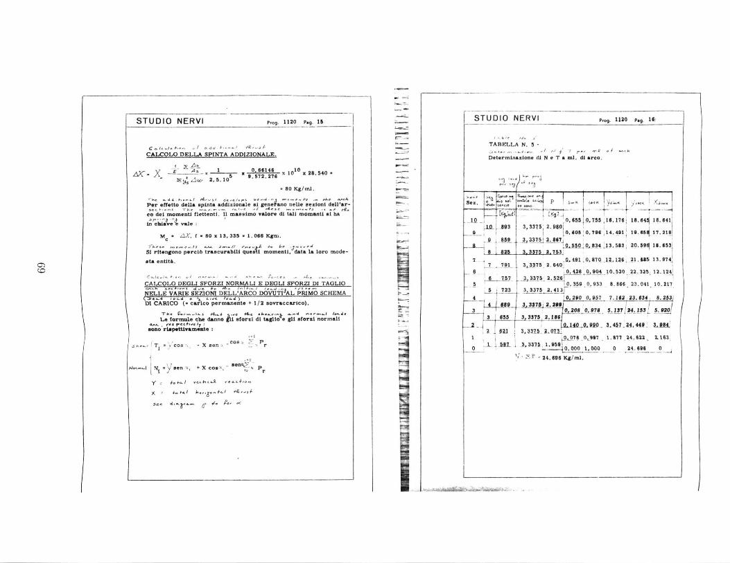
P,,g. 1120 Peg. IS N
CALCOLO DELLA SPINTA ADDIZIONALE.
AS- I 0 66146 10 x 28.540W 2, 5. 105 9. 572.276
8 0 Kg/mi.
Per effetto della spinta addizionale mi gen.~ano neUe sezioni dell'ar-
co del momenti flettenti. 11 massimo Yalore di tali momwnti at ha
in "haevLt.:
Mc . 4aX. f - 60 x 13, 335 - 1. 066 Kgm.
n-rh ,C....i ' .sm // e_','A _ 11 ,. dSI ritengono percib trascurabili quei momenti, data a loro mode-
sta entit&.
CALCOLO DEGLI SFORZI NORMAL! E DEOL! SFORZI DI TAGLIO
NELLE VARIE SEZIONI DELL-ARCO DOVUTI9AL PRIMO SCHEMAMC-.1 00 . + , L..,c. 1- JDI CARICO ( carico permanente + 1/2 sovraccarico).
-rhe ~...Au f,. .. e Acs.k...-.k- .. d4 n-_.. /.,.sLe formule che danno 1li sforzi di taglio e glf eforsi normali
&.A. . fez j-CG+1.C jy :mono rispettivamente:
Tvcos -X eon.- CO84 Pr
.-N son (x, + X coo a P
y .a hJLre&C4-,.
TABELLA N. 5 -
Determinazione di N e T a ml. di arco.
IS TU D IO N E RVI
Ie
I.-
to a ,337 2,730 5500_8634 33.3 20.591 1:.7317 825_.7Q1.f 31, I37 .. 4
2 .410A7Q-lka6 21 35 1 3.'
74A
791 3,33752. 6406 0, 426 0,904 10.520 22. 325. 12. 1241
6 757 ____ 252
5 0,359 0,933 8.866, 23.041 10.217S 4723 3,3375 2.413
4 _ :0,290 0,957 7.162 23.634, 8.2534 089 3 3375 2.209
3 0,208 0,978 5.137 24.153 5.23 655 3, 3375 2.166
La.. .4 _c.w_. - 4&.. 44P 3.84fa 3,31.20
.
1 O 076 0 907 1.277 24.622, 2.163
0 0 .000 1,000 0 24.696 0
2 F24.696 Kg/ml.
()
sez. 4 M C.i
L 8930 886
Prog. 1120 Pa..1
0, 655.0,755 416.176 16.644 16.6413, 3375 2.960 5 ,796 14.491' 19..417.218
3 33751 2 667
[ iTi ,
0)
Q0
I
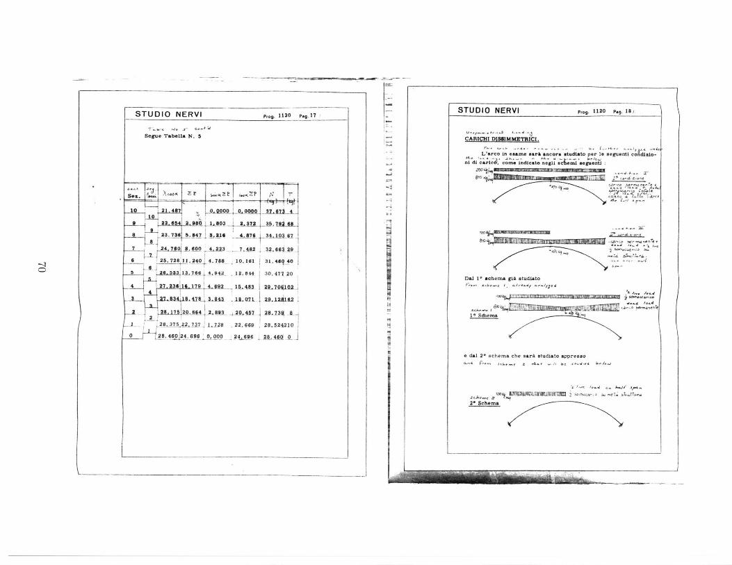
STUDIO NERVI Prog. 1120 Po,.17
Segue Tabella N. 5
21.487 . 0,0000 0, ONO .f7
2, 604 2. 980 1. 803 2,3 4 . 5,7916823. 736 5.847 8.316 4.876 10 6?
7 24 .o 600 42A3 . S$ 32.0433t6 25. 728'11. 240 4 788 10.161 31. 46"0i
5 4LIU31i,766 A 942 12. 844 30.477 20
4 27 6 12.17Q 4. 92 "A- _24m 1O7 02
8 1 43 1I.01L 29.A1 62
28 7 20.q64 2 410 - 49-A0 -. -Z8-j75247j7 1-198 .22.669 28.524210
28.46O24.696 ,00_0 24.e 6 28.46
(
STUDIO NERVI Prog. 1120 Pag., 18. )-
.1
CARICHI DISSIMMETRICI.
Larco in *same ear& ancora utudiato per le seguenti condillo-ni di cart6& come Indicate negli eami seguenti
8o4 r"r ..o e e
-.
Del 1' acheme giA etudieto
e del 2* echema che sarA studiato appresno
'. ... . .,. .....,, Cv1sp
Dal 11IE~allili!~ scem sgIAr stue d djrto
2* Schema
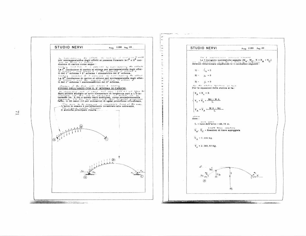
STUDIO NERVI Prog. 1120 peg. 19
b1
4, A. /.d.per sovragposiziane degli effetti si possono ricavare la I e Il con-
diaione di carico come segue
La I condizione di carico si ottiene per savrapposiione degli effet-f Seh- / __a s -hr a + At . l<. .0t eh'-a
ti del 1 schema + 2' schema + simmetrico del 2- schema.
La IX condisione di carico si ottiene r .ovrapposisione degli effet-
ti del I^ schema + emisimnvtrico del 2- .chema.
.-. io..1/A tA~ W ., -d- .SA.,, -d-
STUDIO DELL'ARCO CON IL 2^ SCHEMA DI CA CHI.-q ile r/...-of -j-5 /. -1 0 A- f /-- ( ... _ ^
Sark ancora studiato un arco elementare di larghezza pari a 1 2 in-.. orJ'A <-4a -411 -,// &e 'f.-d"drd -1 betde -ne. .'
terasse (m. 2. 84) e questo sari suddiviso. come precedentemente~.S n~ --f ,- /- h..14 S/.- ) 0 1 h -' -Q d. e - *-$
;dto, in 20 conci (10 per oemiarco) dl ug;&l pro;eione ortz.zoae,
L'arco In esame 6 per tiamente incastrato alle estremIth.
* ale
C
XA ~XC
CI
STUDIO NERVI Prog. 1120 pag. 20
Le 3 Incognite iperstatiche assunte (MA, M , XA C
;aranno determinate Lm;;.endo le 3 condlU;Pni seguenti
1) - A 0
2) - A . 0
3) - . - 0
Per le equazioni della statica *I ha
x A = c X
- Mc -M Ay Yc y c + L
-- M A - Mey A A L
dove
L * luce dell'arco - 66, 75 m.
- - S''k k.. r -
YA' YC Reazioni di trave appoggiata
Y A 7.109Kg.
Y = 2. 369,50 Kg.
xA x
-K!I,
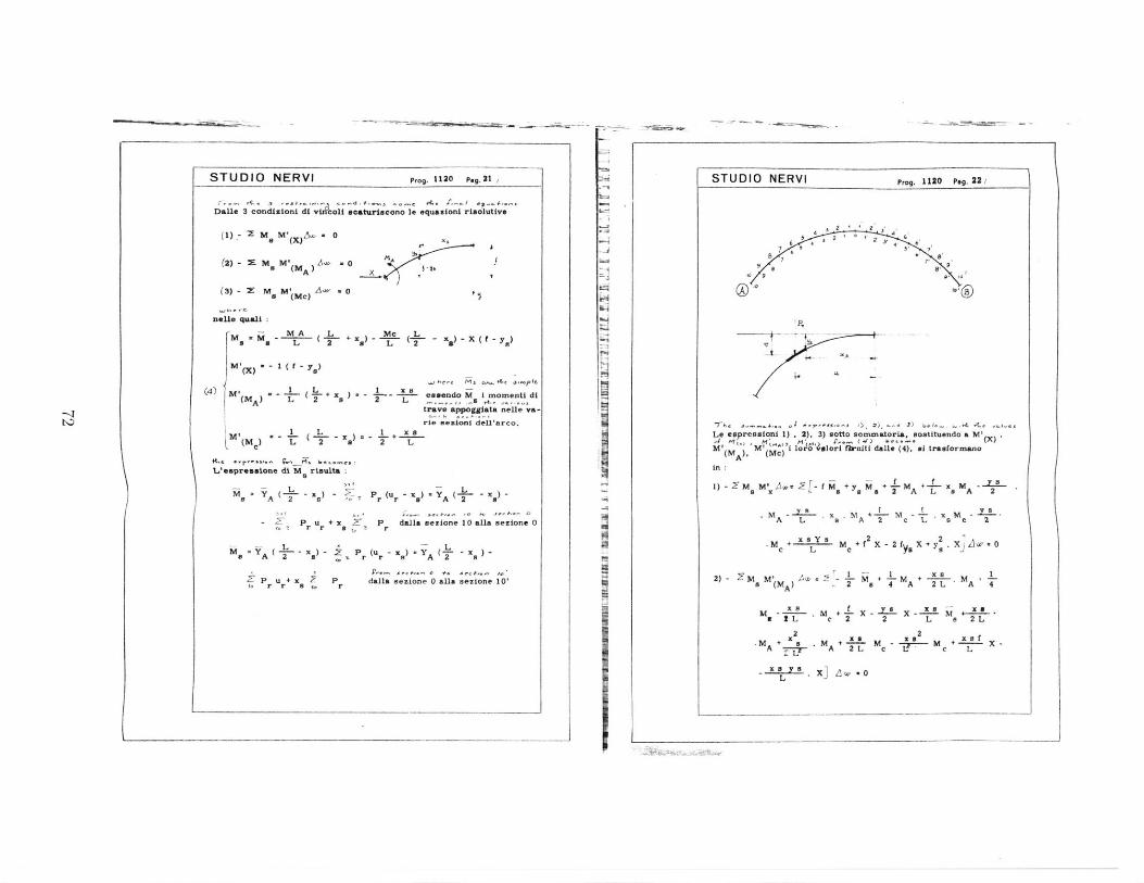
- -~-~- -
I:
STUDIO NERVI Prog. I1130 peg. 21 1
Da t 3 condizioni di vizlcoUi acatariacono 1. oquationt riaolutive
(1) -- -M amM X" 0
(2) -7-M aM (MA)' ws' o
(3 :ma M(Mc) A
uieU. quai
x 4, i
M - M A L Me L--x)-X S~ M-L 2 L 2 5-~-
M () a
(4) IM -, I L1 a''* j1
3
(MA) (+ X9 i- easandoM I nomenti ditrav. appoggiata nelle va-
ri sejn debarco.
( L ~2 2 1 L
Leaprostone dt M 8 rioulta
M- - - P (u -K - x ) -a A 2 B '0' r r a A '2 a
-Zt pr Ur + x P rdalla sezione 10alaaezione 0
L La". A l2 x.) s 2: r (ur - xe) -YA (T~ - x
P-5
U +x Pr
p..., ge0. . f.. 's3 0
,. - .1dalla sezione 0 alla sezione 10'
STUDIO NERVI prog. 1120 Pog. 22
/
4 2 2'
47 7,
30 9
3) 6,- .- 4 - - -
Le eapresalont 1) .2), 3) sotto sommatoria, aotituendo a MI
14 M ) M C) "i 1oro4 4sori fh-nlti dall (4), al traaformana
in
1) m MM'AW -f Mi + y M +-LM +~ MA-a L a a a 2 A L a A 2
A L 'a , A 2 c L a c 2
+xay8m +f 2X-2 I X+Y .X '.c L c Ya a X V
a (MA) ~2 a 4 A 2 L A 4
a 2L c 2 2 L a 2L
2 2.M + x MA +~L Ma m--y-M + -a XA A 2 L c L c L
- L '-7 0
I M - - - - - - IN - -
4

STUDIO NERVI prog. 1120 pg.23
3)- I' M jw+--M -m + *-M +(MC) -2 a 4 A 2 L A 4
m - m + x - X + - m2
- M --- M + 2 a f X +L2 A L 2 L2 L
+ L a u
STUDIO NERVI ,rog. 1120 P.g. 24
-r- l . ,Y .TABELLA N. 6. 2,30 3,375, 947,85
SesloX VS - t -
_0 .. 33.37150 13.333 .00.lfL.-31,_7A= 11-.2,12 247, Al
-9-- 30. 0375 10. 922 . 21792R. SR27 O sAL a&-
-- -A 267000 A,25.1 2 _ 650- 2025.. 312 '
_ __ 23,3M2 IL209 1A.Am25
. 20.U021 4.AU I3.5an11.32562 -2.. U3 14.5.
- 1 6AL _051 75IR M27 2 AR "i as
A. . 1. 3500L 01 .. 0250.~L 6212 1 31 942.853.
. 3437 .129M - 14 L kS_ $.750 0. 443j2.7,2M2 n.M 25'.I
4.-W, 0,001 94z,850.0000 0.-000 3),47 .S . 1,6685 0, 001
1' - 3315 0, 113 3S0 1252 - 5,0062 0,251
-21 6,6750 . 0 - 4. 0500-_S. 3437 U 1.3
-100125 1,061 43,3754r'-11. 6812 1, 438
A 1 -1.3500 J.321 46 7250,51. -13.0187 2.451
5' 16,6875 3.057 50.045-18,3562 3.733
-20 0250 4,482 53 4000- 21. 6037 5 3Q06
7'.4 - ~2.3L 610 56,758 - 25,03L318
8' 267000 8 251 .60 0750
9' - 30.0375 1 0.622, 63. 4125
375 13,33 11,932 667500
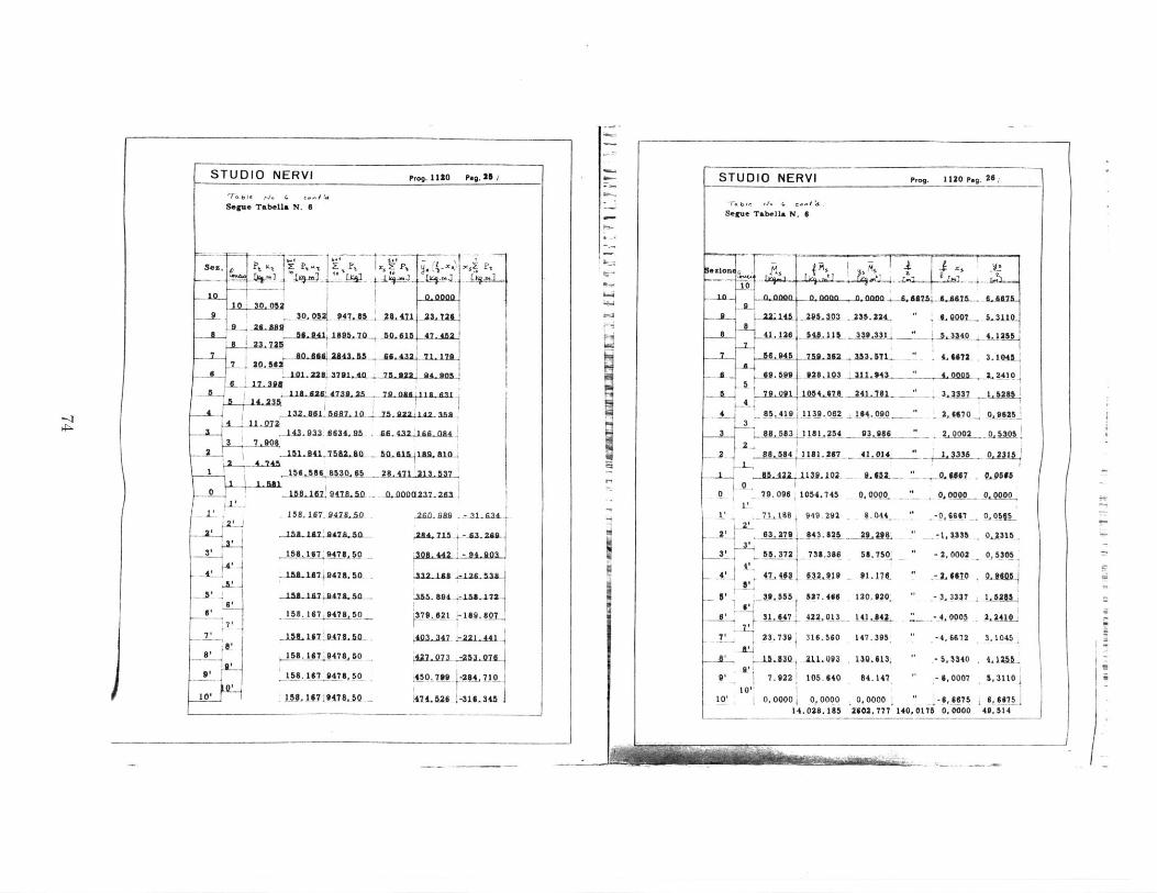
STUDIO NERVI Prog. li0 peg. 25
Segue Tabella N. 6
se -. r
10 30. 052.. L_ - Q~I1 47.6 1 3 76-2-..-0
56.941, 1595.70 . 1f 4. 2
4.- 2432
_11, 26 47324 25 7-2.42 112.3110.221L81.14 Th2 14. 2AL,
17. 08
2 71 1518.2 47l32.2Lak5 7m .a a s It I
1 .566 '530S5 . 8. ~
0 15.2 5K 1
102.A8I61, 01L4fl 0_.002123- 281 141 109,442
-- 51 .197124714,% . SS 9".4. 18 n46. 158. 187 J lL 50 . 210. i
v152 14.47 LS156. 167 !47.5L ... n , .39a.2.L2 i.
AL. JILIS824AIL50- .2.453
158.167,9478,50 35.6 1
6 1Al. 1$-7 19478,50 61a, F 4 .167]47825 47.7O
'I .A8. 1!7 9476, 5O 45O.79 -
10, LSJetI1947A0s 141.11 -
Xc P
- .903
441
204, 7.10
31.34S I
STUDIO NERVI Prog. 1120 Peg. 26/
I-a
II
71,1S8e 949, 29212
21 63,2791 643.825
55.3721 732.386
A 474l 1a12 19
5 39 555 827.466
S31.447 4--2 qL3
V 3.739 316.560
A 111. Q93
91 7. 922 105.640.
10, 0, 0000 10,000014. 028. 185
6.044
-Ac N L58.750'
61. 17l
120. 920'
147.395,
10.613
84. 147
00335
- 2,0002
6610
-4,6702
-5.3340
- 6,0007
0.2315
0,5305
;2410_
1.1045
5,31101
49.67549. 514
Segue Tabella N. 6
in a n m,00 .nan ,G 517B I . sA SA , A87%
F22a4L AiO2- .230 . 22. L1 Q90_ SAIL
41.128 548. # 339.$31 5.3340 _.tl lL7
7 66,2nJ945 5j4 A M51j _ " 4,9672 L.M
65AA.O3 316.4. 4.0005 2. 2410
7901 1054,674 3 26 3. 3;37 1584
4 85.419-11139.062 _164.090 2._ 47 0x. $kS_3
3 88.583 ! 1 24 93.986 2,0002 05305
".584 1181.297 41.014 13336 0.2315
S 85.422 JLJH-102- "02 607966
- 79.096 1054.745 0,0000 9_ 0 _ _.0000
0.0000 -6, 66752602.777 140,0175 0,0000
W-

Prog. 1120 peg. 27,
-r.be Ta.. e.-l
Segue TabeUa N, 6
4 .. 2o 220,30170 3.30012
145.05776 2.17296
89.75s205 ,44 "
__ a - _0,76418
14 55 Da4L ".. 10.62326 0.15914
. 37714 - 0, 00565
2' J 09052 0, 04630
_ -10,62326 - 0,15914
4 -2.64535 - 0,38417
-51. 01369 - 0,76418
6 -9,75205 - 1,34449
-145,05776 - 2,17296 "
IL 220 170 - - 3,30012 "
' -319, 0532 - 4,77949
10
19' -M0A 0000 3734,"
.242.._35L4A4 1
283.2687
220. 0542
165, 5940
119. 5349
81. 5302
51.2331
28, 2969
*12,5462
3.01.37
M Q000
13. 0137
12.,3482
28, 2969
51. 233 1
81, 5302
119, 5349
165, 5940
220, 0542.
263,2867
2662 2641.0766
11!1!269
68.0790
36, ss 17 -
20,0883
9, 3452
3, 6902
1,1257
0;144--
0.0128
0,0128
0,2144
1,.1257
3,96902
963452
20, 0883
38. 5517,
68, 0790.
112, 8269
I 7-L0;_2 j
a-.
~1
HHI-- 1I
STUDIO NERVI STUDIO NERVI Prog. 1120 p.g. 28
Segue Tabe*a N. 8
Box. s
-10- A 0.A1OQ 99 9 . A- 999AL-1.1=ahI 0.2100-, -0.-000.
1102 PMU~oAAMIL - 202.151 0. 202 A 4-
0- loon IS1.20.7M9fl1. JAMII .110 11 - 142
7 28. 472 0. 17498 0,34997 545.806 0,1225 13929 0
6 34.79 014 999 0, 2999I 49.0AQ0 A P3jQ 3OU.7.
.L S~a..i4 1240s_ ,24Afl .-. 22s1. .0,0423. .2*7
42,709 O -99S9 9.993 ._ . 16222 . N.0400 1
3 44 291 -097499 _0,91 .1.as0...0oaa 3283
44.202 -. ,21 .. 4 Q 09999-.09 -- A . - 0.o a 011L.. A.
[2
4I 711 -. 7J 0, 0210 . 0491 11.131 -0.0=25 -427
- S.4B. %4.. .00 0,lo 00000 0.000 010000 - 01
3. 5.594 - 0.02199 -,.04999 1.1.133 0.00n5 35518,
2 . 31 639 -0,04909 -0,09999 44,5 . Q O00 :MITI 27
r3,3' 27.686 -0,07499 - 0, 14996 100.250 0.0225 L 4, AU
4s 23.731 -0,09393 - 0,19998 178,222. 0.0400 -8411.1
19.777 -0, 12495 -0.2497 278,472 0,0625 0 9137. 05
6' .. A.9 Oas . MI:9 OmASI .401.000.. 00, 0 .ann 8423,5-17v 11.869 -0,17498 0,34917 . 545,006 . -. 122. -. 1024
at 7.915 Q., 19998 199- 7 6 712,6!90 01600 -A343.
of 3.961 10,22498 -9,44996 902,251 0,202 ,
10' 0.0000 O-, 22496 -0 ,40996 1. 113. 991 0.2500 0.0000
-4cTq
I
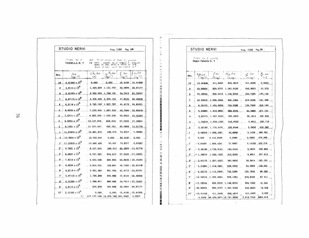
00010 cote I'Iit
lIT' I 9 OizL 'M
It I'Li it ro
-Z'16 ~1flL '91
Tog IT Ofor'fs
Tel c 11T MVio'
C1-09 OmttlO
955 00at 'O -
006 0- 909 9
4T --
17it VW WTL7 Ts L s' E
e T1T-Lgt ILSS'oft-C98 0000 0
910'99 '1 1 1'IV
90'991 g 9398
a3U9'666son lifttote 4'of
M 1999'01
0000' 0
-004 t
906OSE
909665'-
)991 8'LI-
.01
.6
F -
9999s 00'IW aise't -
I89 *91 1I L110'9 -I
tou'Itt'; t9Ott'9 -tX
9LT'ss3 9UT tiU-
-0C1'98't 6LC90'1 +
-*!,r6.'1- Ol19V0 --1~
1fl9'966'! L6999'0 -1
0909'I9 TE 000'0
iT'-66, 1os6eo0
[9!6'9EVI O t-gYso
1918 vLC'T VSLIf,6
tZEWOLSE'l QLIOYZ
0
9
-o -9 wu To0go-c I I-otz ' --
tool 9u1se 6 1 , Uw 'U L
' 910so it 18199i 'i 5 'A1
vs ' LCLU93 t ' U
L *N vjleq' et~aSL -/ t V4
/ oc-6-d 0:11 -0M IA 3N olanis
((
0000.0 r :zo'ieo 39Lt'9T'-91'LLI'-L1- -
ssw i99 961't1SI 00Vi0 0000 ' x 9Tt'g .01
LL L1'9Z- 0090'99 19909 U*L9Og H 0 19 to
6C3999- 9 19'LC 6I9 19 1e6''T 80119! 'L9
I~~ ~ ~ ~ -tt 1XOflTOM 07 4 Me"II'Tt S60 '98 l9X'19' z
3FOT9O9U rff t L 69T?'VZU OW'0tU' t 60P 9M11 be
_10"O it ft 0-Vi 60I'l gO-0999 lot -fXfg11 --- 9-
11;001 90 = 0T0'9I5 9d9'LWO 'l -Txln T
T Lwt' I l ut r9 14090 t 1C''O i fT fi T T T
-10'- EWU 10D 0 L990L U1 01 f9T0~'T
1SS9L~t6~-L90 -bOI 01 969C'IT1.091'Cl 9990 '99 EBE'009 099O' 0111:91 i t
I-
ve (t 0g -9'93'I 9x983'9 't T , _is~ F
-,iw rar -06LV W io~ -019'1.99 T- SV -M-Z
rotit : iiiif t Vi 0'L , 0 ~ 9 0 ! x W1to 'V 6O~u~l~ 9113LC 991009991909'
[6,ILlrtIw TOu T l mn'
6 ., t a OIW .OOS , .' o.,, . j v-n9 7 13C -l N Ln IA LN VI 10 V .L
id ' 0.11 f. IA -N 010 fLS
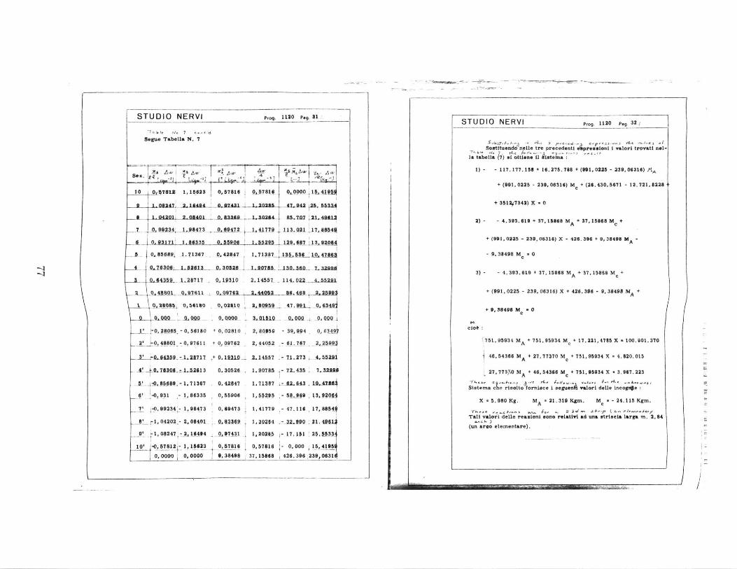
- - - _
Pog. 1120 Peg. 81
I"gb: Tbe, 7 . 4 4
Begue Tabells N. 7
10 0U7612 1,15625 0,57816 0,57810 I L0000' O -419M
2.A 24 2 421 h 1.2n. 47.942 2 5
3 ~ ~ ~ I L.im1 .040 ,ae I , 20244 115.797 4M41
0. 99472Q1 41779 . 1A13. .2
.0.0Ait0h6 1 5. 95 129. 687
-- 0QA85689 1.71367 , 42847 . 13.87_21 L
4 0.70306t "281.3_ 0,30528- i.fi-8 1 ign6
" U_43 1.38717 0.19310 2.14557 114.02
2 0, 48801 0,9761k 0,09762 2. 44052 M. 4-8
1 080 0,56180 0,02810- 2A0959 7, 9j
-A-000 -!9m-- _ 0-0 - 11 1- 0 000
I' -O, 28085 0, 56180 + 0, 02810 2,80359 - 39, 994
2' 0.48801-0,+97611 +0, q9762 2,44052 - 61. 767
1L64.3D8 -1.21717 + 0.1 31D. 1.14557 71.273
A!40.713D6 1.52 13 0.30526. 1.20785 - 72.415
-t 5 09 - 1.71367 . 142647 1,71387 -M6L43
6 -0,931 _- 1,86335 0, 55906 1, 55295 - 58,099
7' -0,99234 1.98473 0.69473 1,41779 - 47.116
*'r1 0 4 2 0 2
- 2,09401 0.1319 10264 -3L110
9 61, 08247 -2,l164 0,97431 1,20285 17. 101
10' -0, 57812 1. 15623 0, 57816 0,57616 0, 0000, 000 0 .0000 9,38498 37. 15868 426. 396
11_854U
4. F5291
2. 2591J
0,63 9
0. Q-00
7.zlaae
.10,42*4
*17, 8654
21. 496.1
15, 4195%
1239, 0631
STUDIO NERVI
-V
STUDIO NERVI Prog. 1120 peg. 3 2
Sostituendo nell. tre precedenti pr*eionl i valori trovati nol-
la tabella (7) ii ottisne Il Mste :
1) - - 117. 177. 158 + 16.275.788 + (191, 0225 - 239, 06316) Al,
+ (991, 0225 - 239, 06316) MC + (26. 430, 5671 - 12. 721, 82263
+ 3512 7842) X - 0
2) - - 4. 393. 619 + 37, 18868 MA + 37,15868 M0 +
+ (991, 0225 - 239, 00316) X - 426. 326 + 9. 38438 M -
- 9. 38498 M a 0
3)- -4
.3 9 3
.619 + 3 7
, 158 M A + 37 , 15868 MC +
+ (991. 0225 - 239. 06316) X + 426. 396 - 9, 38498 MA +
+ 9, 38498 Me a 0
ciob
751.95934 MA + 751,95934 MC + 17. 221, 4785 X - 100.901. 370
46,54366 MA + 27, 77370 M + 751,95934 X - 4.820.015
27.77370 MA + 46. 54366 MC + 751.95934 X - 3.967.223
Slatema e risolto fornisce i segu;nA valori delle incogloe
X - 5.980 Kg. MA * 21.319 Kgm. Mc * - 24.115 Kgm.
Tks - - g (r/ &- fI- AgyTali valori delle reasioni sono relativi ad una wtriscLa larga in. 2,84
(un arco elementare).
K
F.
__tJ ,99234: 1,984_7_3_
S0. 03171; 1, 863 35
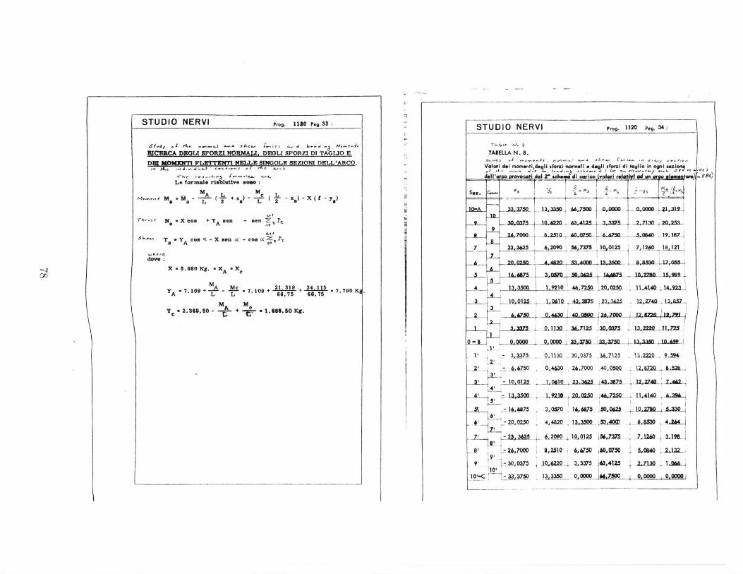
STUDIO NERVI Pr,. 1120 P,. 3S i
RICURCA DpOLI SFORZI NORMAl. D5GLI SFORZI DI TAGLJO E
FLETTUNTI ML3 IWOLE 3ZIONI DELL'ARCO.-f# e ev .,
Le formale riS" sme
MA L M fM.~e M,= ~M iL 2 ~ ) - -L (2 y
.S+4
7i~*+ No X con + YAen - son 2t
S&.~ To 'A con (-XWsn o( -cOS&ZIcA 10
X a 5.980 Kg. 'XA -x
MA MC 21. 19 + 24.115 7.790 K4A L L 66.75 66,75
ye 2.39,50 - + c 1.688,50 Kg.
STUDIO NERVI Prog. 1120 Peg. 34 /
TABELLA N. 8.
Voarl ai elmotldgli sfonl iormlt s degl sforzi di tello in I1aio"
dowaj provocaii l _^ r c---- dl boricw valwr Ir)
10-A2.75&L 13,3350 M.,7.0 ,1 0 0,n00m 41 1
9,7 1030220 h3.A12A . 1s. ,21M0 20,253
7 23,3625 6,2090 56,7373 j9 ,0125 7 _120 18,121
2,2 4,42 AR -MAQtM 12,24M AAn 17,055
4 13,35__ 2 AL0 14.923
-- QA125 -1,061Al3 5 A 23.3"5 12.270 13,&573
S,50 0.4A30 40.O 2A,7000 i 12.B2 1C,791
1 ,375L AQlQ---L 625_ -03Q7= M2220- UM,22
LI .,
-1 32732 -~ 36.75
34
6' -- 767
7 23, 3W25
-l' Z -700D
10' 304mJ0-C - 33,375
- A1 3Q 30.0375 .367125 13.20 9J94
. 4430, .J0QQ 40,0500 12.270 _4.
1 M 32.A3,3Z7- 12,-27AD 7.4
1,9210 20.=2W. 4",7250 11,4140 - it3A0 11-4M7- &Qj 10.27Mo &3M
.2a 10A125 L6J7 L12hW L1U2
6,2510 6,A5 M 0.'5O 5,040 2-.22
1Q,6L20 4 33WS M,41M .13,3350 9,000 rWJ 5Z 0,0000 0,0000 1
-KI00 K
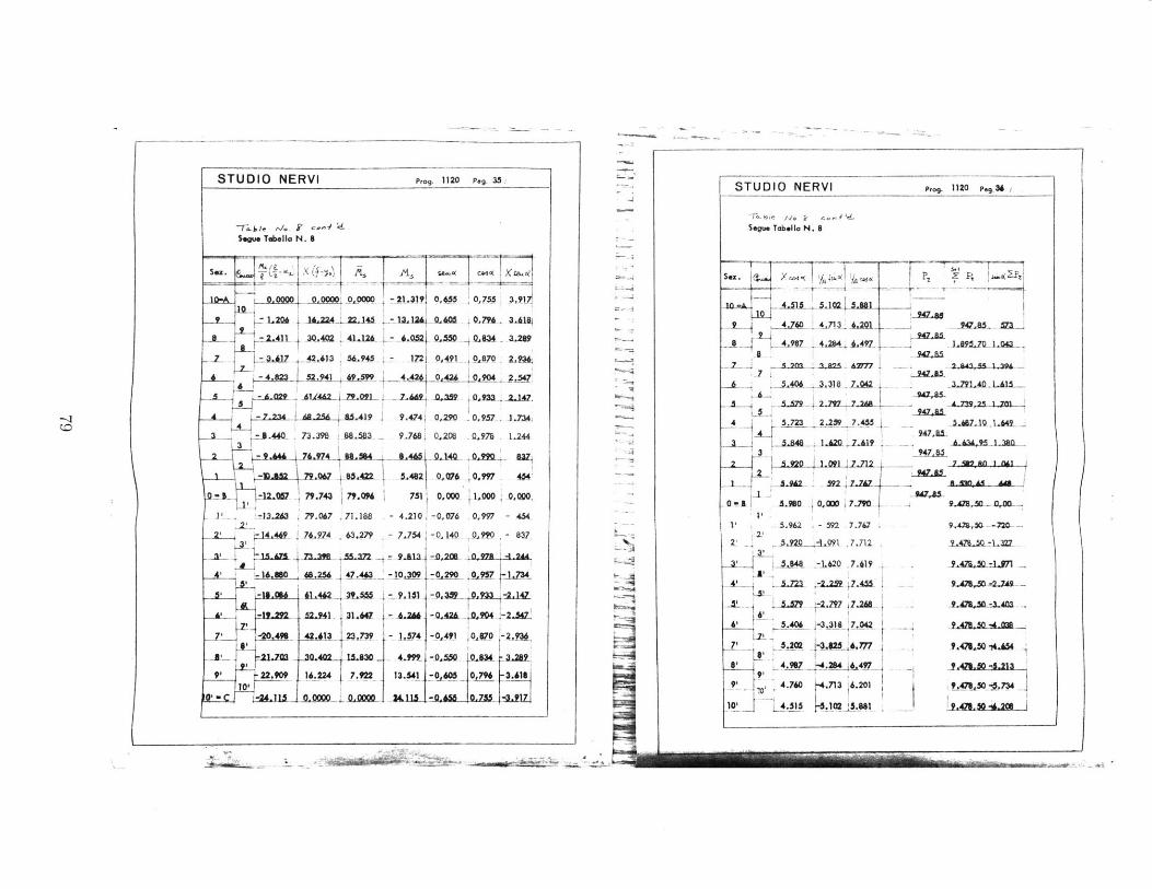
> 40
to t
;4
117
4, 0
I 0
I .
w
I kt
C',j
79
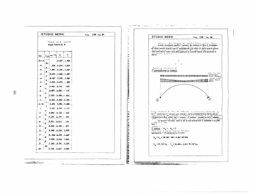
STUDIO NERVI Prog. Ino Peg. 37/
See". Tdeile N. S
-- - - - -.
10- 9,617 964
9 Z5 a sn 1 8"
'1 .45 .. 1 .
A489- -.- 1143 32
*9,450 .6.090 .229*2!-- 2-
3 9.270 A.199 - 40741
' a
7' . 8. .43 .12 572 _
IL '8.501 6.126 -1,020
8 7.905 Z L916 1-81
_5 I .2,IV15Z--"LA21-
STUDIO NERVI prog. 1120 Peg. 38/
Avendo coiiderato p I1y I momentl che tendono I* fibr. di Intradoo,
g91 sfori normall quando sono di compressione e gl forazi di tagllo quando provo-
CanO ucotrimento vO. I'alto della pelsone di sinls rispetto alla ponuicne di
,. ECAd.,.
1 a SONDI IONE Dl CAlICO.
.CAO os&r --
La I1 condizione d carocast ub otteners, some procedenteamnte detto p., so-Acrne +#e eJ.c~ -4 xek-e i +. Se-;- ~4 + " A esi-,4-
vropposizione &gli effetti del I^ schema + 2' schema + slaufefrico del 2 Schaeme.Jshe-~ 1 -Frh P,-4 w,.. F.- -. , elf-e,,wy me.4 C Ir *
Le reazioni vincolori relative ad un arco elementor. (1 tavellen -m.2,84)
10150 I
1^ schema g M - M -0... A.. I. c-f J
(permanent. + 1/2 sovroccarico In tutto)
XA - X - (26.540 - 60) x 2,84 - 10.126
yA - 70.1 37 Kg. Y - 24.696 x 2,84 - 70.137 Kg.
00
-
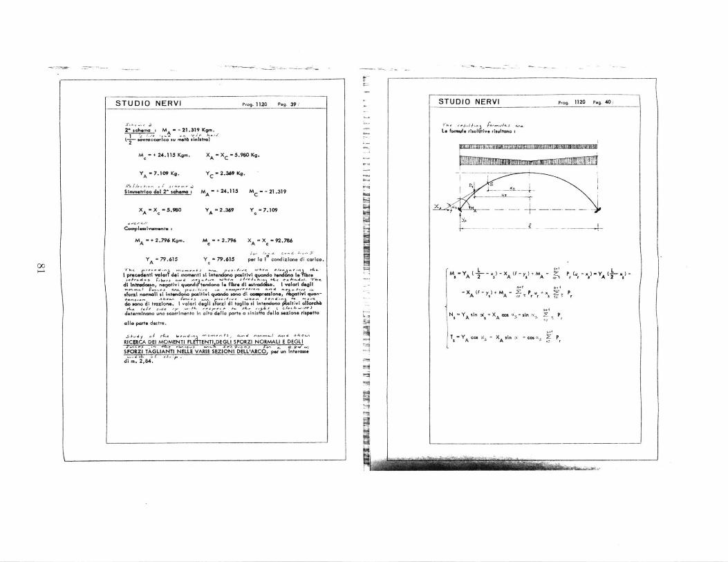
STUDIO NERVI Prog. 1120 Peg. 39/
26 schema i M -- 21.319Kgm.
(2 "Wroccarico su metb cllaytro)
Me - + 24.115 Kgm.
Y - 7.109 Ka.
XA - Xc . 5.90 Kg.
Y - 2.309 Kv.
Slmmatrico del Z' schema I m. + 24.115 M - - 21.319C
XA - Xc - 5.960 YA - 2.369 Y -7.109
Complessivament. s
MA - + 2.796 Kgm.
YA - 79.615
M - + 2.79 - X - 92.786c XA c
Y -79.615 per la I condizione di carico.
I prUCedOntI wierT del momentI at Intendano positivi quando tendono l.%hw
di Intodosso, negatlvi 1uand t .ndana I. flbre di estQ;&;. I valorI delsforal normCill ti ntencldc positivi quando son di acmpreasIone, fIgatIvI quan-
do sana 4i trazione. I valori degli sforzi dl taglo ml i nndono ilstlvl allaech
determnal uno scarrimento In alto dilia parts a Cinia della sealone rispetto
all, parts destra.
RIC!ACA DEl MOMENTI FLtTENTI DEGLI SPORZI NORMALI E DEGLI- -F -- -* * F*677
SFORZI TAGLIANTI NELLE VARIE SEZIONI DELL'ARCO, per un interasa.E -. 4 -
di m. 2,64.
3--
STUDIO NERVI Prog. 1120 Pag. 40
X ro i. )+ - -
L* Formuls rl: , ilvo rissutano I
P't
-- 4-
M YA 2 -) A r r a A (I-
-XA (f ) + MA tr Or
+ x Pr
N a- Y A in 0(2 + x An co '_ - sin n , 2 P,
,
4
N- A s AOCSIf s 1
T - Y Cos s - XAsIn N -cos k 5 PrA A r
00
PINION.- 77"RI
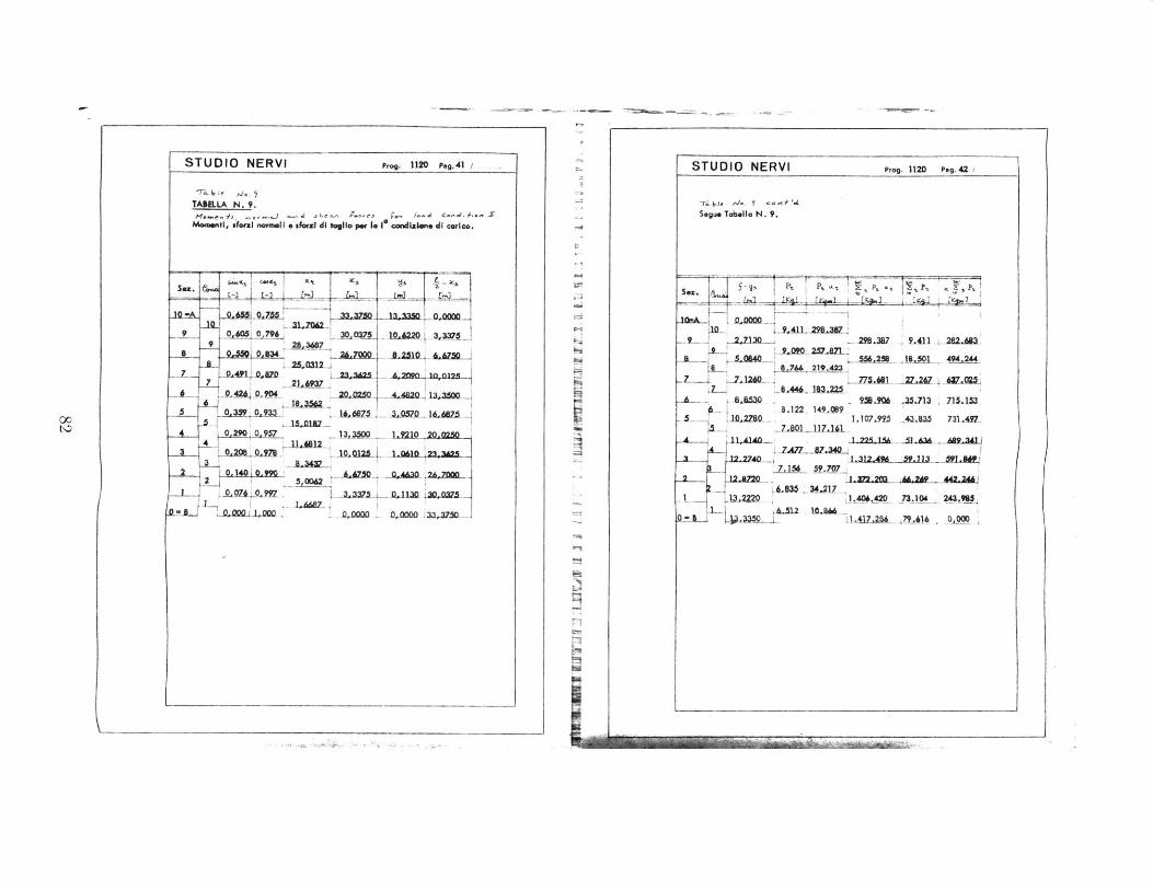
o 6
F lit
[H
lws-
C,,4
L8

C61
0
II
0 0
I, a
uft
i83

STUDIO NERVI Prog. 1120 pog. 4 5
L..d- -. C-,-L
go CONDIZIONE D1 CARICO.
A. ar F "'- , 'A. - '. a ,M .- , "'a V- - Y k- -1 0- -La 2 cardizion. di corico si puo attenere come precedentemen edetto,
per svrappasionsdegli effetti del 1' schema + esmiimmstgico del 2 schema.1z I.. I-
.sopRACCARICO__
"ZCO P~eMlfAN(N7e
1^ Schema (Iorloo prmnte 1 savroccarcoo su tutto I'arco).
MA - 0,00 Kgm. M -0,00 Kgm. XA - 80.826 Kg.
Xc - 00.B26 Kg. Y - 70.130 Kg. Ye . 70.130 Kg.
s..I. .eG .she.r'e [ E 'Phwc 1-1 C -**Elisumaseeriao del r scheom (meth sovroccarloo negative su metb arco)
khi. jt
M A-U.115Kgm. M -+21.319 Kgm. X A -5
.960Kg.A c A
Xc - 5.90 Kg. YA - - 1.8 Kg. Y c 7.790 Kg.
Complessivam. MA 24.115 Kgm. Mc - + 21.319 XA - 74.846 Kg.
XC - 74.6 K9. Y A- 6 8
.4
2 K9. Y c 62.340 Kg.
I precedenti volori del momenti si intendono poitivi quando tendono Ia
fibre di Intradosso, negativi quando tendono Is Fibre di estradoss .
I valori degll sforzi normall si Intondono positivi quando son 9 di com-
pressione, negativi quando san di trazlone.
I valori degil sfarzi di togilo si meendonAo positivi allorchb determinano
STUDIO NERVI Prog. 12O Peg.46
woe scorilmento veno lalto dello parte a slnistra delic sezione rispetto alla
parts jestre.
RICERCA DEI MOMENT PLEWTENTI. DEGLI SFORZI NORMALI E DEGLI
SFORZ DI TAGUO NELLE VANIE SEZION1 DELLARCO.
0 A
Per quota c4n;z; di corico s i rice se 2 moment; Pl*entl,A I% .sea 4' .ce S ! - 1 de #er-.-ea r4 -~
gli sforzi nosmalI a gli sforzi di togilo per savrsjszle .(ii *FettI
mu 1^ o dell'emsimestrico dell. schesa 2-, somarodo aigebrl'oeente I valori
d1 dtte sol ctozioni Azione p.. sezione.
Da tener preoente che it primo schema di crI fst-s n o dc 'e. dc j +&
tenti nelie soxilas solo in virf delta caduta lspt
00
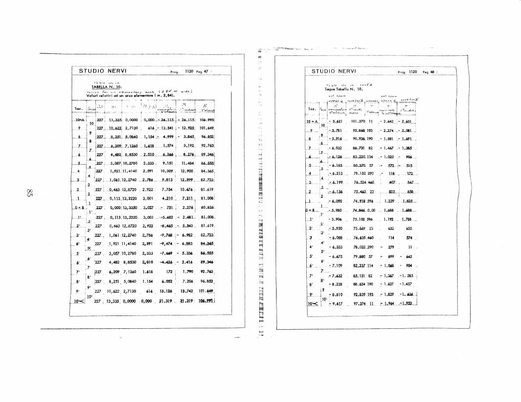
0L J
~ ~
I
II I
I I
mE
l
3 7.7
--9 T
rsm
m
C1
Xff
r -.
2 V
17
1
l W1rfj
I1A
111
iti
"IN
2 C
4 C4c1 cz
I -
z 1z-
.4 jA
A,
k A
85
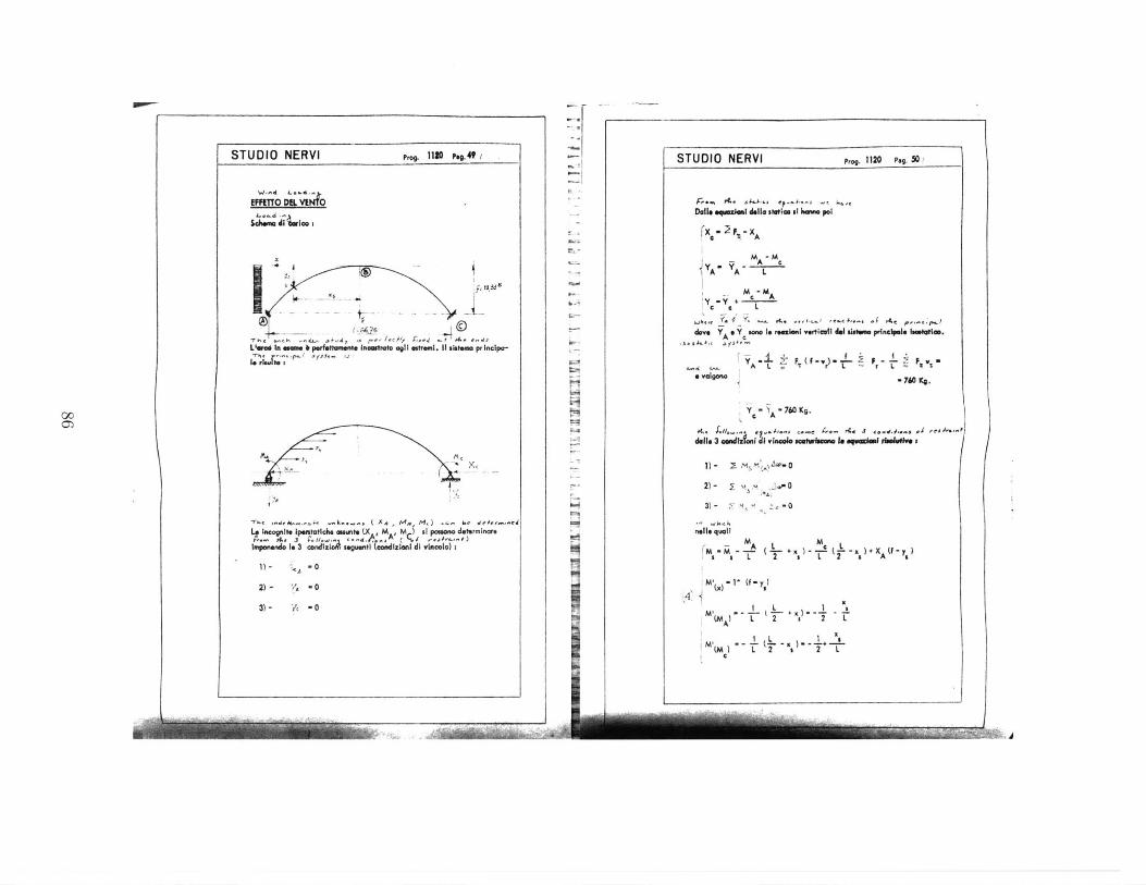
STUDIO NERVI p . 1 .
EF0T mE VEAO
I 2' t~L'rd In 4a.s 6 perfestament inamtrato al I tweat. It aiste pr Incipa-
Ingnite Ipustatich. Ountg S , ill pomona determinare-. Ae39. 1/ .sVN , I..,4. ,,A ( ,j,i,-,
Ipuon.nd. 1. 3 ;.XdlzIA l (Wti 1tizlant di viRColo) S
1)- . 0
2)- 'A -o
3)- 'I -0
STUDIO NERVI Prog. 1120 Pg. 501
-:
is
jiuj-~.--
00
;-eo . AC JAAS f.-" - ,Doll. .q-zwlm dell. setloe ni h m pol
fX, 2F. - XA
A - MS'A A A L
-M MAy y + cA
'Dov YA eye Sa * reezient verticull e@e prinedpole hlms'* .
A L. rL rL.-
-760 Ke.
Y A -760 Kg.
"- A,0
dells 3 oeadlz I i v -n=mw sc mu wIs I. eqeinuiin -oleffe
1) - I m M,) '- 0
2)- -2 . =* 0-
3)- 0
nells quail
rN - AL N6A~ (j +x) - -T (j- x,) +XA(U - y)M M L 2 , T 2 a A (
N -- (-x)---+ml L 2 a 2 I(M A2 L
I C
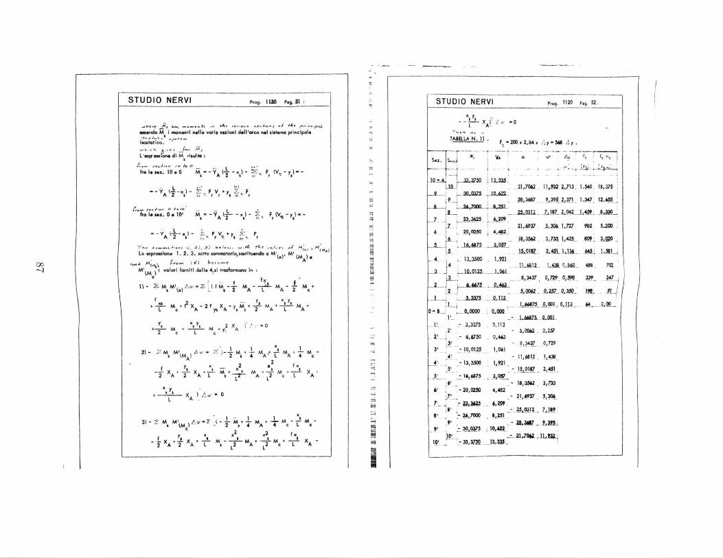
STUDIO NERVI Frog. 1U0 P49.51I
wkere .. 0is 4C ... h ~ . nn wA - J( r p.toendo M I momentl nelle varie slaina dell'arco net sistma principale
luostatico.
L'usrms one dI M risud :
.-- - 10 4 . - Lfro le sex. 10 . 0 M -YA s F
L $4
A I x r 2 I*fr Isn . "0'm V, ,
-- YA (,-x)- F V + y Z FAa A 2 a lI r
La esprouulne 1. 2. 3. sotto sommatorisastituendo a M' ,). M ' MA
M ) Ivalori forniti dalle 4,sI trasformano In ic fiE M' M - 7 M ( - -- M -- M +
W (x) L .2 A L= A 2 c
yy x y.+ M f X- 2 X-y M+ -*- M + - -- M +
L c A Ys A - , 2 A L A
+ yl M 2 X A ) -02 c L c
I' 12)- .M M' ,+-M +M -
S(MA) 2 4 A 2 A 4 4c
f 2 x 2 K -T x + L.x - + m - 2mc - Lx2A 2 AL F MA L A
+ -" x )A-0L A.
3)-E N'1 - 1 + ~ - 4 -3) - 2 M M4 A -(c I +
I Kc L- K2 1 4 A c2fi A+ A2 A 2
I AMA + 's - + X 2,A, ~ A A T L 2 L 2 L- A
.-1
UU
N
'-4
I
STUDIO NERVI prog. 1120 pag. 52/
x ) Ii -O- AT le L . .1A
TABILLA N. 11 F, 20Dx 2,84 x Y54 Ay.F~~~ - x,4 y-~ _____y
Sez.
10- A .750 13,335-11.7082 ii43mzJu. 1.$40 18,375
9 1300375 1.2
3W1 9 -39 ,%371 1.347 12.k5S 2 72000A,5A _1
5,127,187 L20 4AW JA.33S23,3625 6,9
2 4 2JMV A5.3 1M2 980 5.200u20,0250 4,482,
.. 18,32 3,73 425 MI! 3.0
"13,3500 1,92L
4J 0.2~O L -AAL l 1. Q,8&l 488 7(23 10.0123 -J-d L ll A .U . 40. 7
3 0.8343 O7 9 0,59 339 247-2 .475-- Q.463
.11 -. A A 75- 0J .Lv- 3375 . 0,113
2 - 6.90 .463.6,7Q ,43 - 8,37 0,729
3' 0125 1,0614 - 11,6812 1,4*_
4' -13,3500 . I921,5 , - 15,0187 2,451
- 18,352 3,73320, 2MM 4.482
7' - 21,9 5,306B' 26.3005,251
' 3 , 575 t k ,IM-_
10. --
(
00-KI
I I

C,11
IL I
I' V1~
I 1Y'S
Luv*~t~III~I
v~~ IIuIv[ir ir I4 I
'ruwar
-IRS
to
e u
cxz ,
>
~.
III
88
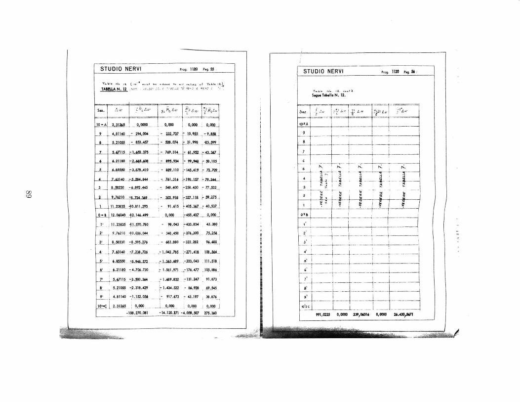
L1--
-!
II
~~1~
SA
QA
4-
~5A-
~IA
-
[AKY
1 Ii
-74
K
4-is
II
-,.. I ~
-~
v~
I.ai...'
-~
Em
2~a~
P~
T
1
~i4
~4IN4
K-A
I -
1I 14~
-r
; 14
~~W
Cl4*1
:
~ L
89
K
~ V77E#V. Ma
wcn
[c~-4'I)
-z
IK
il-I
I
I4-
zr
TZ~Z
wCf,
U
.1
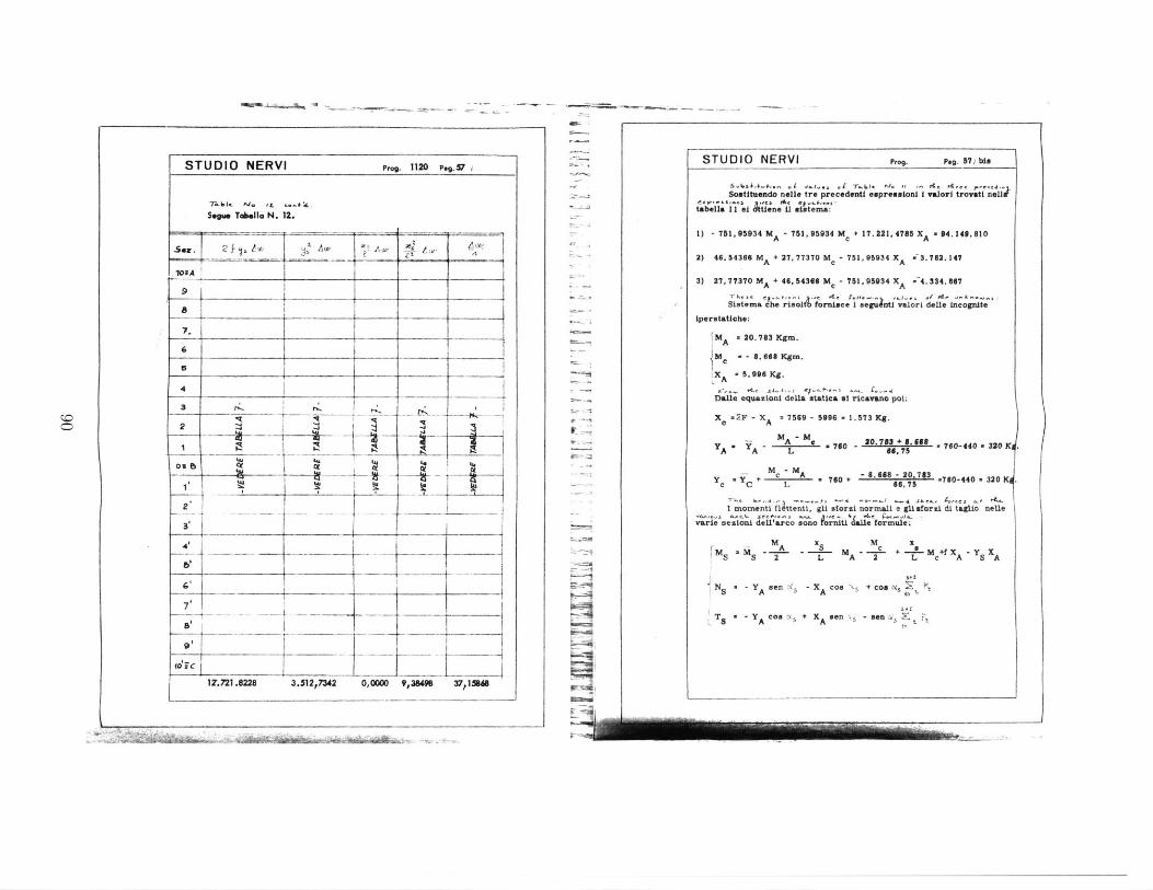
STUDIO NERVI Pg. 112 p.,. V
Sor&6 Tb.Ila N. 12.
Ax'
7.
e A
3
2
Oukb L7 - "_
- A
-- -1 -0
tO ~12'.721.8228 3.512,7342 0,0000 9,28498 37,1U4S
o-
5.
STUDIO NERVI Prog. Peg. 57/ his
Sostituendo nollo tre precodenti espresmioni i valori trovatin;Z4
tabalallsi .3tiene i1 iatema:
1) - 751, 95934 MA - 751,95934 Mc + 17. 2 2 1.4785 XA - $4.149. 810
2) 46.54366 MA + 27,77370 Me - 751,95934 XA W-3.762.147
3) 27, 77370 MA + 46, 54366 Mc - 751. 95934 XA -4.334.667
Siatema che risol fornice isguntI valori doll, incognito
iperstaticho:
MA 20.783 Kgm.
M - - 8.66$ gm.
XA -5.996 Kg.
Dalle equazioni della statica o1 ricavno poi.
X .2-F - X - 7569 - 5996 - 1.573 Kg.SA
A A MAL- Us . 760 - 20.783 + 8.668 .760-440 320 KA A- L 8 6.75
ye C L+ M M . 760 + - 8.6886620713 .760-440 320
I momenti flttenti. gli storsi normali e gli forzi di taglio nelle
vare sezioni dell'orco sono orniti dall. foruwl.!
M M A x S M M + xaMr- A S Mc a2 S --L A 2 L c A S XA
N - Y en - X co + cosn P
T Acos N + XA sen s - ien.5 P
I
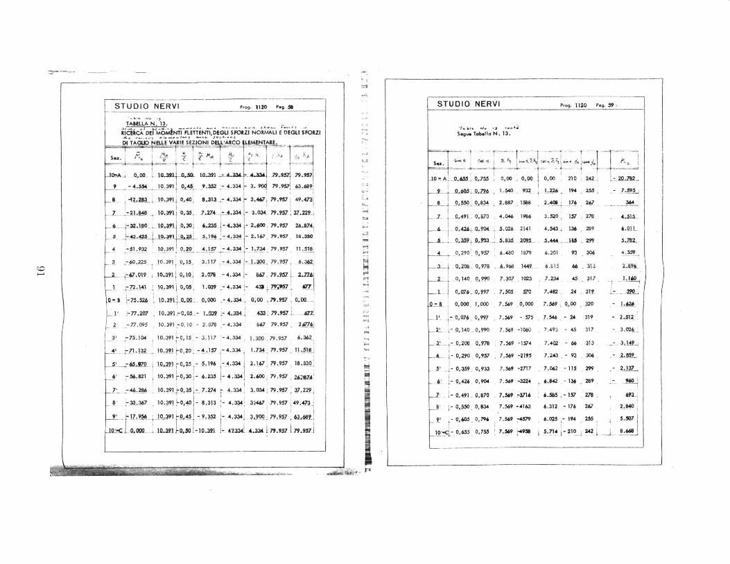
rii
--V
I.g
4:-4D
I',
:8
N
N
N, Nz
N0
wz0FEM.
'C>SzC
;
a
gWI'
0.,
a0
0.*
0
iF0.
00
111111
10
9 z
Ro
0
0
o
a
0
-A.
i 1-4
1
~~~~~.rn ~ ~ ~ ~ ~ ~
~ -- Tf 1:1 ',XX ~'~:~
i~jr~v!r~Ti i IVi.W
I ri
i, N
C
7 2j
R
;
c-4-
.4 4 0
--
C;
t;a c
t' A
I
I
aI
'.1 ,%
col' -
--
91
C>
C;
Ii
II .
-

STUDIO NERVI Prog. 1120 Peg. 60/
-1b.Ta "i. ,3 C..4 SSegue T.tle N. 13.
K YA C"' X,~AA~ T,
4 4.2lI 2.440
LM.9 j0.1 - 3.J-0- 1Aa
S 2.214 .4 .03 124. 2.2 5, W4 2 -241
S 1.247 L64 885,-
839 5.936 1.25 501
S se 1.470 - 4331
0-SI 00 5.99 sL5? - 3__
I - 239 _S.9. J.A02> Q
31 .247 5.864 1.404 14
' 2. 153 ._4 L3L
2.354 5.420 1.5% 381
.9d4 5.216 1.526 49
8, 3.296 5.000 1.488 596
t 3.427 4.773 1.446 697
10 3.927 4.527 1.397 -89j
STUDIO NERVI Prog. 1120 Peg. 61 /.
Me~.f- -cr -%"~nr 41-1-+' -j,,.f.. e-j.S ;.be-, .enej
I momenti sI intendono positivi qrcfdo le f'. di ntvMso, gil
sforzi normall quando sono di aompresione, gli sforzi di ogIlIo quor provecono
cotrrlment vwo l pat dell d p di sinistra risetto a qllada destr.
VUItIMCA SEZIONI.-S.bo.. I* L.. .d ' 0
Sezion. 10 - 20 condizione dl c.rico.
M - 24.115 Kgm. N .101.370 K.
I-.
4.
S4P
If centro di presione code entro 11 nocclolo del intera sezlane omogenelaa-se'-
4'.
to.
La sollecitozione a d 0 C mi iultenoc ax c mln
N + Ney1 oflembo lnferere~c mx A + 4, I
N No y 2 -4A .amfn + loo Seriorsc f
I)
M -24.115.37 -0,238 .- 23,S ca.
"44 co
ND
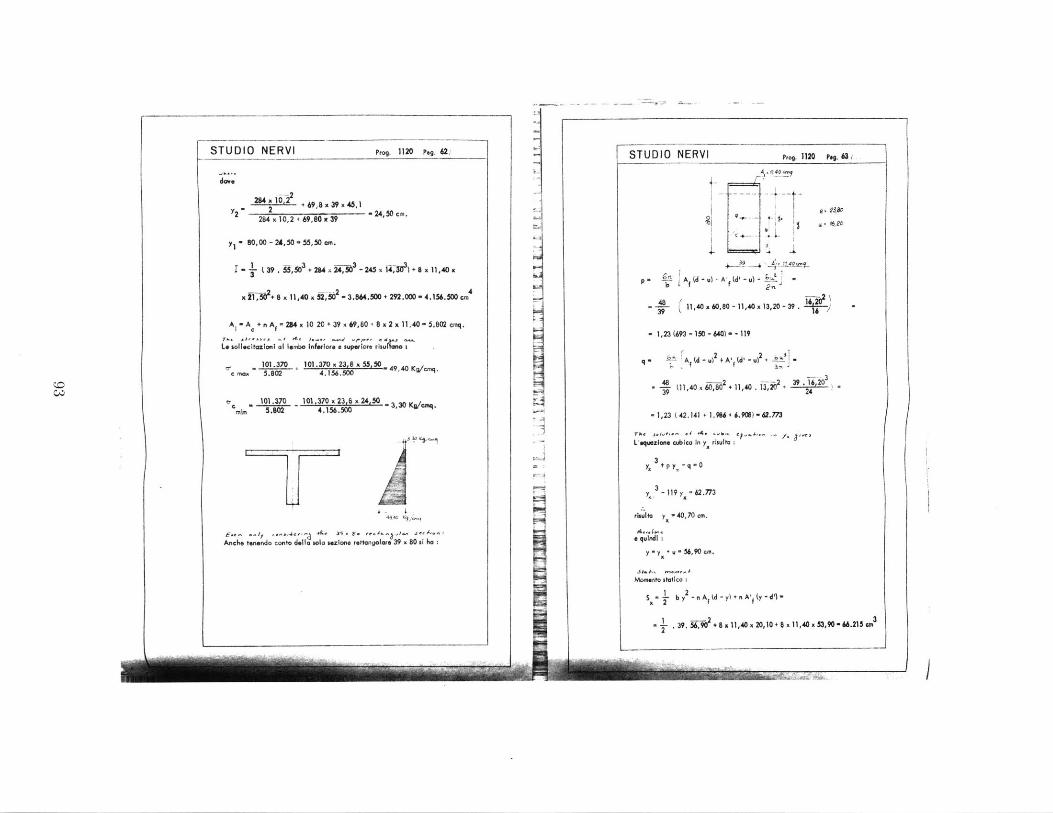
gP.g. 1120 peg. 63 /
do.
2 64 x W2 2 + 69,8 x 39 x 45,1Y2- 2 -24,50 cm.
284 x 10,2 + 69,80 i 39
y- 80,00 - 24,50 - 55,50 am.
- ( 39 .4 - 245 i + 8 x 11,40 x
x 21,5 8 x 11,40 x j2,s53 - 3.84.500 + 292.000 - 4.156.500 cm4
Ai - A + n A, - 294 x 10 20 + 39 x 69,60 + 8 x 2 x 11,40 - 5.802cmq.
1. sollctaziln al lembo Inferior. a superior. ru ,
- 101.370 101.370 x 23.8 x 55,50Omax 5.802 4.156.500 49,4Kg/mq.
c - 101.370 101,370 x 23.8 x 24,50 -3,30 Kg/mq.min 5.802 4.156.500
4-
4q940
AMcli tonondo conto dolla sola sexin rettangolare 39 x 80 sl ho
,,og. 1120 peg. 62;,S TUD IO NE RVI
Iul
RVI
-21.. I - -
ST UDIO NEl 40,o"
+ 2--4 AjJ1ou~
2"29
p E~A (d -u) +A' (d', )f fn
-W-- (11,40 x 60,o0 - 11,40 x 13,20 - 39 -
- 1,23 (693 - 150 - 640) - - 119
r 2 + A', (d' - u)248 -21,40 iF- -
-T (11,40x,802 . 11,40 . 133+ .1203
-1,23 ( 42.141 + 1.96 + 6.9) - 42.773
L'quazione cubica In y risulta
y + p y - q - 0
3 - 119 y - 62.773
rinulta y 40,70 cm.
a qul:
y I Y + u - 56,90 cm.
Momento statico 1
12S - b y - nA (d-y)+nA (y-d')"
I . 39. "9, + 8 x 11,40 x 20, 10 + 6 x 11,40 x $3,90 6 6.215 GM 3
ii
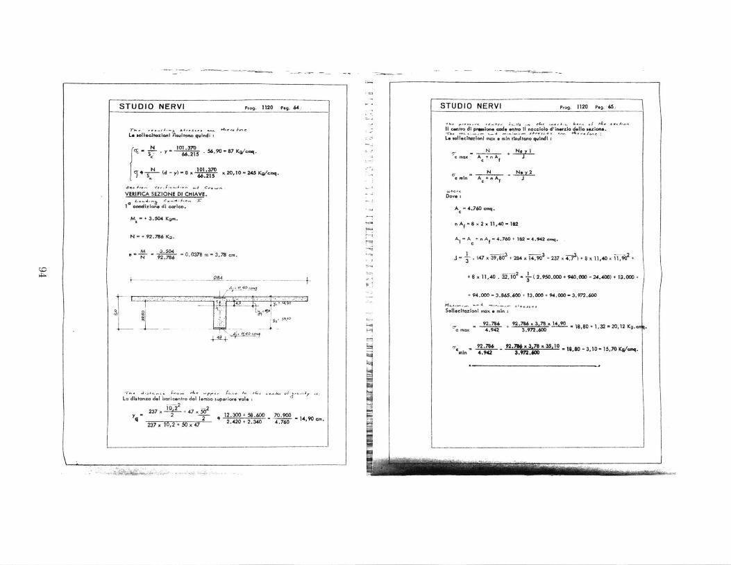
STUDIO NERVI Prog. 1120 Peg. 64/
, . ,,,,,. s,.,- + A.. weLe sollealtonziont sultano qoundi t
- . - 15 . 56,90 - 87 Ko/cmq.
~lS'~'~~ " .215 1-4K'o
0 N W,)-8 $3 x 20,10 -245 Kg/cxq.
VERIFICA SEZIONE DI CHIAVE.
1 oandizion di carico.
M - + 3.504 Kgm.
N + 92.756 Kg.
Mi -9 0,0378m -3,78 co.N 92.786
- 84
A 40
La distanza dol baricentro dal Iembo svpeior* vale .-2
237 x "-+ 47 x 02yq* _ 2 --- 12.300 4 58.600 70.900
237 x 1U,2 + 50 x 47 2 _ 2.420 + 2.340 4 . 7 60 14
'90 cm.
STUDIO NERVI Prog. 1120 Peg. 65
I centro di prelone code entro 1i nocciolo d'ierzla della cezione.
Le sllecitazioni max min rsultano quindi :
, . N + Nec Max A + n Ac f
S N N y 2cain A+nA; J
Dove :
A 4
.760 oq.
n Af - 8 x 2 x 11,40 - 162
A -A + n A - 4.760 + 102 - 4.942 cmq.I e I
J- . 47 x9,8 + 284 x14,90 -237x4$ +8 x 11,40x x 90A +
+ 8 x 11,40 . 52102 - -L( 2.950.000 + 940.00 - 24.400) + 13.00 +3
+ 94.000 - 3.865.600 + 13.000 + 94.000 - 3.972.600
Solleclazioni max a mln i
92.78 + 92.78 x 3,78 14, 18,80 + 1,32 - 20,12 Kg.cac nax 4.942 3.972.600
on 9'8 - .f x 30 7 8x35r 18,80 - 3,10 - 15,70 Ko/emq.In 4.942 3.9W2.
I.

Prog. 1120 Peg. 66/
DARTMOUTH COLLEGE
V..,,4 'edi er /3..e,TRAVE DI IMPOSTA DELLA VOLTA
If-,,-.- 13... -,# -. q , sr-s
Trave continua con campate da ml. 5, 69 -
ir" & .- b- .' '. f-t Pa ,*,ee/- ' -Je e ALa travddi imposta I sollecitata , nel piano taente all'arco nella
sez.Ione d . ad una azione N asuliae. it cui valore massimo ai ha
nella 2- condizione di carico eal.
N 122. 201 Kg.V*.. -/ -- -' * a -,' -""'''' ""' (' -" 1-0 t4quosto valore di N 6 relattvo ad una fascia di arco larga m. 2,84 (pari
Z er- ) -r-h.. -.. e I d IF+. - eaw.tnalia Iargbesta di un tammlone) . Il corrits ointe carico equivalente a
metro 1jneare risult : .
S 1222 1 43. 000 Kg/ml.2.84
Componendo tale carco con il peso a metro lineare della suddetdtra-Ve di imposta part a P - 3.600 Kg/ml. e con il carico dovuto alla pen
silina laterale di valore P 2. 280 Kg/ml.Tk #.#.I I .. .. ,, 21.._s,_,a _ *_*6.,-3
11 totale del carico a metro lineare viene a riaultare:
S - 47. 000 Kg/ml.
In corrispondenaa agli appoggi e sempre nel piano inclinato corAenente S,of avrk:
M x 47. 000 x 5 2 =127. 000 Kgm.1 12
d a 0, 362 127.000 * 145 (f) 0.80
A 55 x 80 x 145 - 69 cmq.r 100
L~a verifica &l taglio lomporta:;
150 cm.) 63/140C
T' x 47.000 x 5,6 134. 000 Kg.2
134. 000., 4004 a 12. 80 Kg/cmq.0. 9x80X145
II
STUDIO NERVI Prog. 1120 Peg. 67
o quindi:
Mt
max xh
2. 411,500 9.900.0004, 12 x - x 15, 00302 x 150 960.000
co,1111 1
STUDIO NERVI
C.-C-I
Ammettendo aicora il cartco uniformemento ripartito, lo sfopsedi acorA mlnto risulta:
S - 2 1 12, 80 x 80 x 145. 000 Kg.2 2
12 ferri 0 1" piegati assorbono ano stol purl a:
S = 12x4,90x*F2 x 1440 - 116.000 Kg.
Tht., -, .- ;- f4Lo sfo*o rim lmente, part a 145.000 - 116.000 * 29. 000 Kg. vie
ne largamente assorbito dalle staffe.
-,,., v .i. 46..
VERIFICA A TOAMONE
U valore massimo del momento in corrispondenza deUa sezioned'imposta rimulta:
M - 24.115 Kgm.
11 valore retivo a 1 ml. vale
-24.115 * Olg/lM' . 2.8 . 8. 500 Km/ml.2,h 4 '- it *
4 . tIU momente torcente Ama.simo auglf appoggf b di conseguenxa pa
a:
Mt *5.500 x 2.84 - 24.115 Km. * 2.411.500 Kglem.max
. acendo hidamento suun szione retanmgoiare 60x150 cm. at
ha per quewta sezione:
' - 3 + 2.6 3 + 2, 4A. 4,120, 45 +h 0,45 +150- .b s0
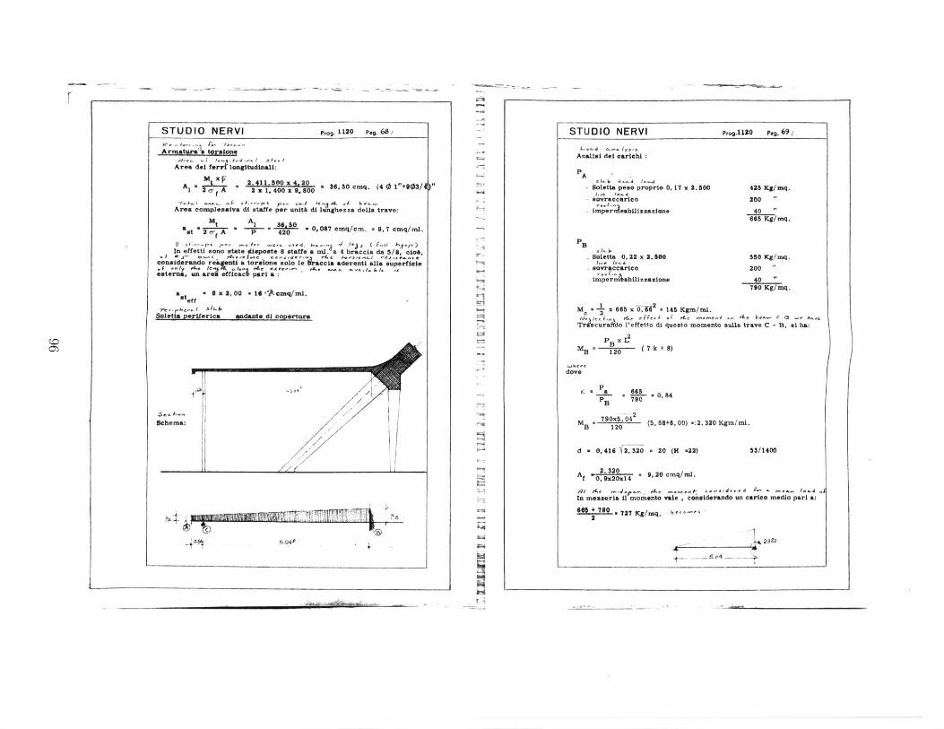
STUDIO NERVI P,o. 1120 Peg. 68/
Area del ferir lagttudinali:
A r 2,411.50X4.20 36, S0cmq. (40 1"+903/4J f0 T 2 2 . 400 x 9. 800
Area compleusnva di staffe per unit di lunghezza deUa trave:
a 2Mi A 3460 . 0,087 eaq/cm. * 8,7 cmq/ml.
In effetti Bono state diapoSte 8 staffe a ml. a 4 braccia da 3/8, cio*,considerando reagenti a toraione 210 le racia aderenti alla superfiele
.1.y AtC It M8L. . e ae- , 4. .,e ;e3icc partaeaterna, un ar effic
aat - 8 x 2, 00 - I $"Acmq/m.&ff
PC e . 1 5-1.deF.let 5, !eIc
4/72~
7 4~T'rJ!n[~
5.04e I-
STUDIO NERVI Prog.1 80 peg. 6 9i
Analisi del carichi :
P A-
Soletta peso proprie 0. 17 x 2.500J,-i I...L&
- uovraccarieo
. imperrleabillzmaione
t'-J
ad
. Soletta 0, 22 x 2.500 550 Kg/mq.* sovraccarico 200r.. r,
imper abilizzazione 40790 Kg/mq.
M 2 x 665 1xO. .l45 Kgm/ml.
Trscura~do 1'effetto di questo momento sulla trave C - B. at ha:
1 B B 120 (7k +8)
whe c.dove
K a 665
B
-2
M 790X 5.4 (5.88+8,00) -:2.320 Kgm/mI.B 120
d - 0. 416 6. 320 20 ( -22) 53/1400
A 0 .20x14 * 9,20 cmq/ml.
Rt ir As- +, _ .. _ ,- It ud , * .u ,ar .In messeria il moment* vale , considerando un carico medio part a:
66 + 790 727 Kg/mq. b'*''2
2320
CO0
-J*l'F
Schema:
I)p 3 p! u a
425 Kg/mq.
200
40665 Kg/mq.
ndante di co rt r
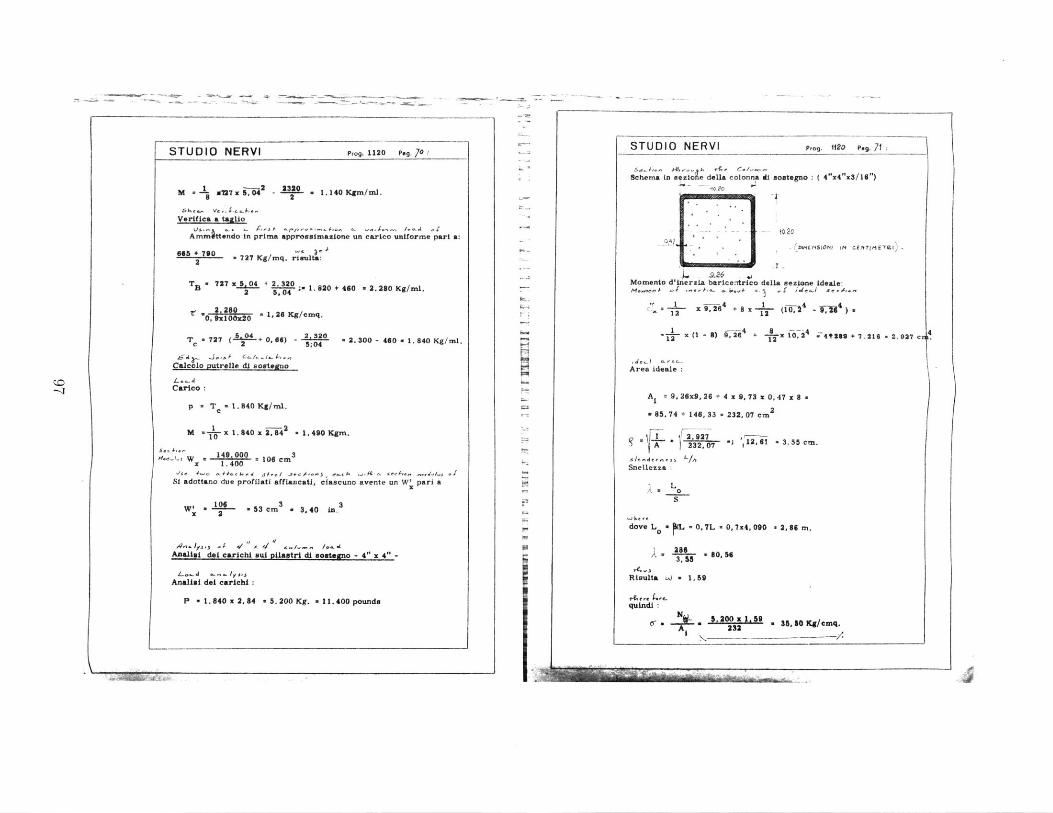
STUDIO NERVI Prog. 1120 Pag. 70
M M7 . 5;R - 2 1.140 Kgm/mI.1 2
Verifies a taillo
Ammittendo in prima approssimazione un carico uniforme part a:
sob +790 ,) .
2 727 Kg/mq. rista:
TS 727 x50 + 2. 320 + 460 - 2.280 Kg/mI.2 5,04
,. 26 Kg/cmq.0. x100x20
T 727 ( + 0, 66) - 2 2. 300 - 460 1. 840 Kg/MIl.
,A-a - J. , a.c.t ,Calcolo Putrelle di sostogno
Carico:
p T e1.840 Kg/mI.
S -2M I x 1. 840 x 2.4 1. 490 Kgm.
W - 140 000 * 106 cm3
x 1.400
Si adottano due profilati affianesti, ciascuno avente un W' pari a
W' . - 53 cm 3 3,40 in. 3
Analial del carichi sul pilastri di uoutegno - 4" x 4" -
Analiul del carichi
P a 1.840 x 2, 84 . 5. 200 Kg. a 11.400 pounds
STUDIO NERVI Prog. W2O Peg. 71
Schema in szIe della colonna di sostegno: ( 4"x4"xS/16")
--- o 20- 47msn - (NI S0 I lt C E
. 9. e6Momento d'lnerzia barice-itrico della sezione Ideale:
.,264 + 8 - - (10 - 412 -4 1-4 4)12 192 2u-~~-~~ 1~)
tITIM T2RI
9.26- - 4 8 -z 412 =21-B , 6 +g 0 i4 .41282 7.216 -2.927 c
Area ideale
A, 9. 26x9, 26 + 4 x 9, 73 x 0. 47 z 8
' 85. 74 + 146, 33 - 232. 07 cm2
2.927Y
A 232,07 -J 12, 61 -3, 55 cm.Snellezza
sA 0
dove L a - 0. 7L - 0, 7 x4, 090 *2, 86 m.
2,6 . 80,563.55
Risulta W a 1 59
quindi
C*N ,200 x 1.9 So 35. 50 Kg/cmq.232-
-1
I I !V9www=!1M -
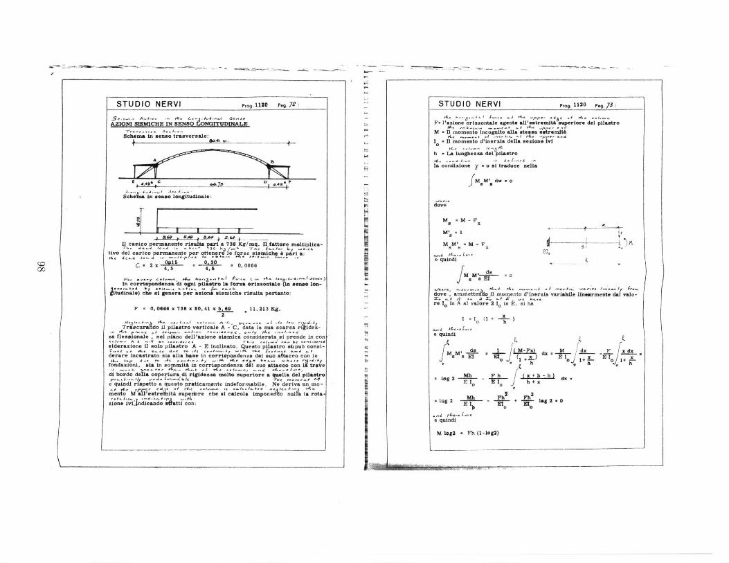
STUDIO NERVI Prog.11ZO Peg7.
-- 4.. '& "-'- - ' 1- ejAZXON SiSMICUE l(SENSO &&;nVDMNLX
Schema in senso treaversale: 4Ia. in -
D 6
schiLn longituenale:
Jr'iv U I U K
ado , 5A f 8.4011 carico'permanente risulta pari a 736 Kg/mq. n fattore moltiplica-
Uva del carico permanente per ottenre trze jismcht part a:, 1., 1e,.. , ~-i4.p e., . - t5 io _tear~ , 'I a
C= 2x 015 - - ., = 0.06664, 5 4,5
In corrispondensa di ogni pilastro la forca erissotale ; mense lon-*tudnle) cbe at genera per aione sismiche risulta pertento:
F - 0. 0668 x 736 x 80. 41 x 5.6 11.213 Kg.2
Tr;;c;raidl p"tstro verticale A - C, data la sue scarsa Ajde.-
flea I* , nl dell'axione sismics considerata vi prende in con1-- A 4i a il b .,s, . -r ' -. I.,., .. e,...ee
eiderazione ii solo pilastro A - E inclinato. Questo pilastro sfpub consi-f... . #&., -S. d-., +. ,";s am . -. +K +#-f . . , _#s a
derare incastrato sia all* base in corritpondenta del sue atcco con lefondationi, *La in sommith In cOrrlapondenza del suo attacco con 1 trave
di bordo decopertura di rigidzsa molto superiore a quella del pilastro,,, . //,.r ,- 4. 1.a _2 1. t e ,,... . M
e quindi ripetto a questo pratieamente indeforffabile. Ne deriva un mo-
mento b i 'estrelnitA supexbre che i calcola impone nul a Ia rota-
Zione ivi ndicendo aatti con:
STUDIO NERVI Prog.1 1 2 0
Peg.73
/
F. l'azione orisontale agent* al1'estremith superior. del pilastroM . 11 momento Incognito alla steasa estremita
I . fl momento d'Lneraia della bezione Ivi
h n La lungbezca del pilastro
Ia condixione = a ml traduce nella
fMM', dw a o
dove
M 1M-F
=v .1MM' M-F
e quindi
d0
JM1 a EZ
dove, arnettedo 11 momenta d'inerzla variable linewrment* de valo-. . / +. a r. .. # , - h
re 1, In A al valore 2 10 in E, si ha
I -I (1 + -- )
e quindi
do M-x M If dx F d,J M sET uJm( x ) El] r E0 1+- X, 0 1+- + -h 0 , h
" log 2 P b x4+h)dx -E 1 0 E I, h+ x
0 0Mh.! -Ph Ph
2
So 0
e quindi
M l6g2 a *h (1-log2)
21,
00
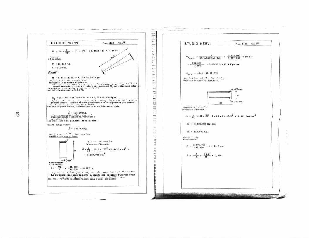
STUDIO NERVI Prog.1120 Peg. 74,
M uFh ( -1- - 1) v Fh (14426 - 1) = 0.44 Fh10g2
ed ese do
F - 11. 213 Kg.
M - 0. 44 x 11. 213 x 5, 70 - 28. 000 Kgz1.
I..., -k A. .. 1 -o- i-rMomento In sommith a pilastro.
Immeadtamente mA ricava i valore del momento M all'extremiti tnfrii
re del pilamtro par a ',8 Ph:
m M - Fh a 28. 000 - 11. 213 x 5. 70 *36. 00 Kgm.
D'altra parte it carico assial. provnlent della copertura per effetto
del carico permanente, relativau nte ad un interasse, vale
E 183.200Kg.
Decornponendo secodo Z verticale a
secondo lasse del pilastro. si ha in defi-
nitiva lungo quasto
S = 192.000Kg.
Verifica sezione di base
Momen441
9t12
Eccentricjtk:
M. 36.000N 192. 000 * 0,187m.
to d'inerzia:
-- 3 -235,5x 101 +2xx2Ox48
.000 cm4
La rsuwltark cade ratteanmente al Umit. del nocciolo d'lnerzia delLa
sesione . Pertanto le L scitazioni max e min. risultano:
AIMI
STUDIO NERVI Prog. 1120 Pag.75
-4
Ls16f90 C".
Momento d'inerzia:
x 91 x i13
+ 2 x 20 x 8 x ii, 52 _ 1. #27. 000 cm
M * 2.800.000 Kg/cm.
N * 192.000 Kg.
,. -, ,Eccentricitu
e a 2.800.000 14.6cm.192.000
2 . - .1 406 0, 239h 61
I
N _.___.__Ie ,5x101+8x4,9x8 + 3.600.000 x 50, 5max 5 5II+84 x 3.787.000
192. 000 + 0, 95.50, 5 - 97, 4 Kg/en-A.
S49, 4 - 48. 00 -" 0
Verifica sezione di sommitA
n a , 0.1m.
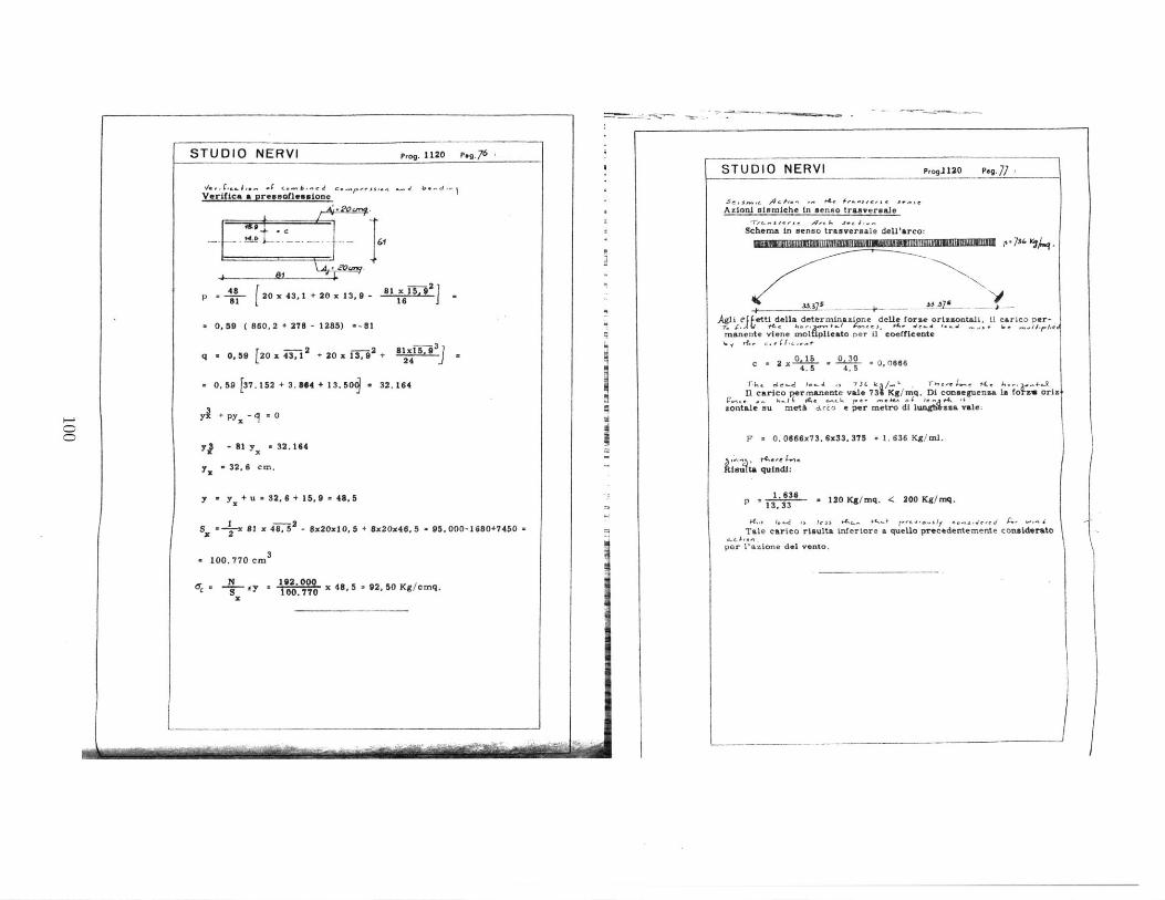
Prog. 1120 P.g.76
/
Verifica a preesoflessione
p 4 20 x 43,1 + 20 x 13, 9 - 161 16
0,59 ( 860.2 + 278 - 1285) =-81
q 0,59 [20 x 41 2 + 20 x 13i 2
+ - 24 .93
- 0.59 [37.152+3. W4+13.50 a 32.164
Y1+ py -1 * 0
yj - 81 y a 32.164
y = 32. 6 cm.
y * y +u a 32.6 + 15,9 a 48.5
*-- 1x65-8x20x10, 5 + Wz2046, 3 - 95.000-1680+7450 -
w 100.770 cm3
6c . dy ,19000 x 48, 5 - 92, 50 Kg/cmq.3 1-.7
STUDIO NERVIISTUDIO NERVI Prog.1120 P4g.77 0
Azioni sismiehe in senso trasvereale
Schema in aenso trauversale dell'arco:P73" 4A
Agli ltetti della dethrminasione delle fors. orizzontali, i1 carico per-
manente viene molpliesto per U coefficente
0.15 0,30c =2 x 4 00666
T-), dc" - A la s 73L .T m-- ~-
2l carico permanente vale 731 Kg/mq. Di conseguenza Ilso isI- AeX $, -- _. 4.L 1 #.,,4es
sontale su met& arco e per metro di 1w4aaa. vale:
F = 0, 0666x73. 6x33, 375 . 1. 636 Kg/ml.
Rimilta quindi:
p 1. 636 130 Kg/mq. < 200 Kg/mq.
1."s ~. less 4<.. - 0 tr .- 11f ns~eed E, nTale carico rioulta inferiore a quello precedentemente considerate
per lazione del vento.
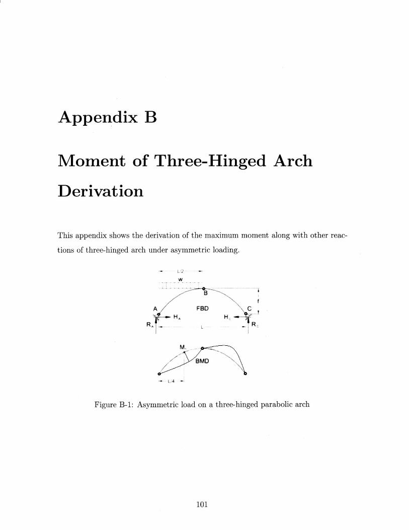
Appendix B
Moment of Three-Hinged Arch
Derivation
This appendix shows the derivation of the maximuni moment along with other reac-
tions of three-hinged arch under asymmetric loading.
A FBDH,
RA L
M,
BMD
LA 4
Figure B-1: Asymmetric load on a three-hinged parabolic arch
101
C,H, 4
-R,
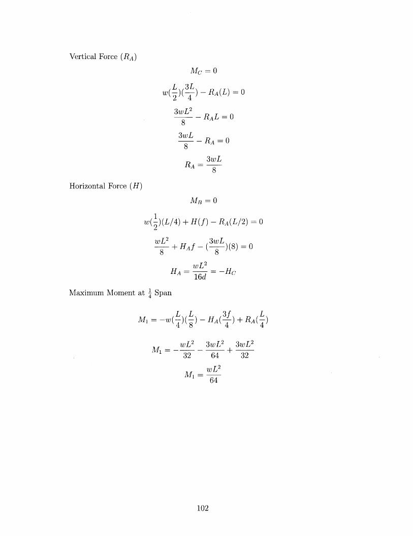
Vertical Force (RA)
MC = 0
W )(R(L) = 0
3wL 2 RAL=0
8
3wL -R8
3wLRA= 8
Horizontal Force (H)
MB = 0
w( ) (L/4)2
+ H(f) - RA(L/2) =0
wL2
8 +HAf
3wL-(8 )(8)=0
8
HA = = -Hc16d
Maximum Moment at -1 Span
M = -w( )( )4 8- HA( )
4+RA( )
4
wL2 3wL 2 3wL 2
32 64 32
64
102