the international journal of science
TRANSCRIPT
The International Journal Of Science & Technoledge (ISSN 2321 – 919X) www.theijst.com
50 Vol 3 Issue 4 April, 2015
THE INTERNATIONAL JOURNAL OF SCIENCE & TECHNOLEDGE
A Direct Buck-Boost Converter Based on Flyback Topology for Photovoltaic Application without Using Centre Tapped Transformer
1. Introduction Most of the developing countries are always abundant with the use of renewable energy resources like solar energy, wind energy, geothermal energy, biomass energy etc. Developing countries can reduce their dependence on oil and natural gas by developing such energy sources, and thereby creating energy that are less affected to price rises. In isolated rural areas, extensions of electricity grid are not economical. The diesel generators in rural areas are effectively replaced with the cost effective renewable energy resources. Renewable technologies can also help to replace other energy sources such as kerosene lamps and traditional biomass energy. However, if the technology and the infrastructure improve, renewable energy is potentially reliable and will be very cheap, It consists of solar energy, wind energy, geothermal energy, hydropower, biomass energy and tidal energy. All these forms of energies can harvested without fossil fuels. Conventional non-renewable energy sources like coal, natural gas and oil are limited and hidden. An unknown and finite amount of each resource is buried under the ocean or in the deep underground. In order to obtain them, we require costly explorations and potentially dangerous mining and drilling. So they will become more expensive as supplies and demand increases. If more and more is harvested, it becomes very difficult to find new sources. The political stability in historically volatile regions is an important factor that affects the daily price of oil. But renewable energy can be locally produced and therefore it is not influenced to distant political upheavals. Also, there are so many safety concerns surrounding with fossil fuels, such as explosions on oil platforms and collapsing coal mines etc. that do not exist with renewable energy. Moreover, renewable energy is much cleaner than fossil fuels. Renewable energy sources are so called because; they are replenished constantly by sunlight aside from geothermal and tidal energies. The wind is produced due to the solar heating of the Earth's surface. Sunlight also fuels the water cycle, which is harnessed through hydropower, including hydroelectric dams and less invasive systems that harness streams or ocean currents. Biofuels are grown using the sunlight. Geothermal energy is considered as a renewable energy source because the radioactive decay in the Earth's core is not expected to cool down immediately. The tides are caused due to the gravitational pull of the sun and moon. Among the various ambient energy resources discussed, solar energy has become the most popular and primary source of all forms of energy. Since the solar energy is clean, inexhaustible and free it is widely used in many applications. But the main problem is the availability of solar energy depends on the climatic conditions. Even if it is periodic, we prefer it because it has a higher power density compared to the remaining supplementary renewable energy sources which makes it more popular. There for numerous methods are available for extracting solar energy.
Saifunnisa P. P. G. Scholar, Kathir College of Engineering, Coimbatore, Tamil Nadu, India
R. Shunmugam
Assistant Professor, Kathir College of Engineering, Tamil Nadu, India
Abstract: Nowadays photovoltaic system is most commonly used in industrial and residential application for the purpose of electrification. The main reason for using the solar energy is the lack of non- renewable energy resources. Even if the utilization of solar energy is not cost effective, we are making the use of it due to its availability in nature. There are so many researches going on in order to reduce the cost and efficiency. Among these a flyback inverter is an important solution. The flyback inverter when operated in discontinuous conduction mode (DCM) has a better efficiency and low cost. But unfortunately, the current is distorted to non-linear loads. Also the Transformer Utilization Factor (TUF) is less and the mismatch in winding will leads to the production of unsymmetrical output voltage waveform. In this paper, a flyback transformer without centre tapping is introduced in order to reduce the above mentioned drawbacks. The simulations are done for both open loop and closed loop system. The distortion in the output voltage and current is reduced. Keywords: Distributed power generation, flyback inverter, photovoltaic ac module systems, solar energy, unfolding h-bridge
The International Journal Of Science & Technoledge (ISSN 2321 – 919X) www.theijst.com
51 Vol 3 Issue 4 April, 2015
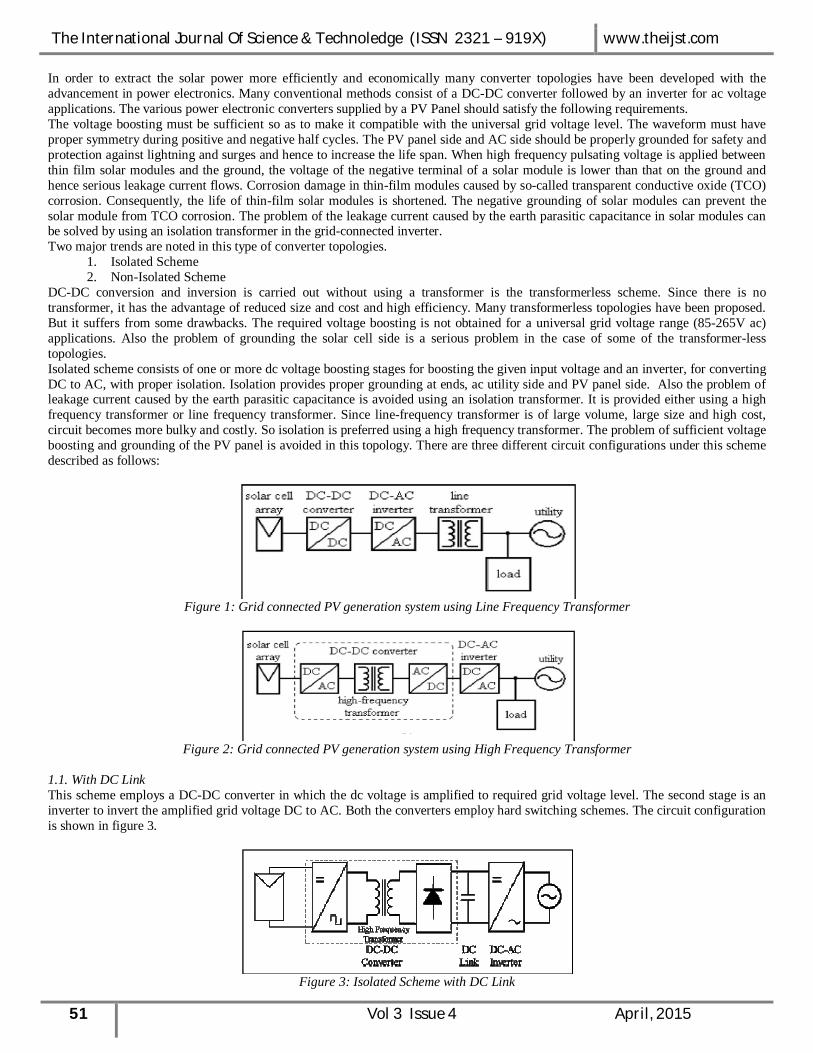
In order to extract the solar power more efficiently and economically many converter topologies have been developed with the advancement in power electronics. Many conventional methods consist of a DC-DC converter followed by an inverter for ac voltage applications. The various power electronic converters supplied by a PV Panel should satisfy the following requirements. The voltage boosting must be sufficient so as to make it compatible with the universal grid voltage level. The waveform must have proper symmetry during positive and negative half cycles. The PV panel side and AC side should be properly grounded for safety and protection against lightning and surges and hence to increase the life span. When high frequency pulsating voltage is applied between thin film solar modules and the ground, the voltage of the negative terminal of a solar module is lower than that on the ground and hence serious leakage current flows. Corrosion damage in thin-film modules caused by so-called transparent conductive oxide (TCO) corrosion. Consequently, the life of thin-film solar modules is shortened. The negative grounding of solar modules can prevent the solar module from TCO corrosion. The problem of the leakage current caused by the earth parasitic capacitance in solar modules can be solved by using an isolation transformer in the grid-connected inverter. Two major trends are noted in this type of converter topologies.
1. Isolated Scheme 2. Non-Isolated Scheme
DC-DC conversion and inversion is carried out without using a transformer is the transformerless scheme. Since there is no transformer, it has the advantage of reduced size and cost and high efficiency. Many transformerless topologies have been proposed. But it suffers from some drawbacks. The required voltage boosting is not obtained for a universal grid voltage range (85-265V ac) applications. Also the problem of grounding the solar cell side is a serious problem in the case of some of the transformer-less topologies. Isolated scheme consists of one or more dc voltage boosting stages for boosting the given input voltage and an inverter, for converting DC to AC, with proper isolation. Isolation provides proper grounding at ends, ac utility side and PV panel side. Also the problem of leakage current caused by the earth parasitic capacitance is avoided using an isolation transformer. It is provided either using a high frequency transformer or line frequency transformer. Since line-frequency transformer is of large volume, large size and high cost, circuit becomes more bulky and costly. So isolation is preferred using a high frequency transformer. The problem of sufficient voltage boosting and grounding of the PV panel is avoided in this topology. There are three different circuit configurations under this scheme described as follows:
Figure 1: Grid connected PV generation system using Line Frequency Transformer
Figure 2: Grid connected PV generation system using High Frequency Transformer
1.1. With DC Link This scheme employs a DC-DC converter in which the dc voltage is amplified to required grid voltage level. The second stage is an inverter to invert the amplified grid voltage DC to AC. Both the converters employ hard switching schemes. The circuit configuration is shown in figure 3.
Figure 3: Isolated Scheme with DC Link
The International Journal Of Science & Technoledge (ISSN 2321 – 919X) www.theijst.com
52 Vol 3 Issue 4 April, 2015
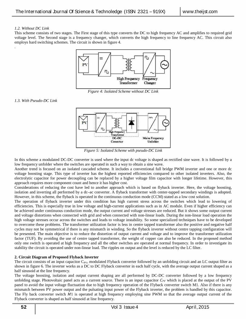
1.2. Without DC Link This scheme consists of two stages. The First stage of this type converts the DC to high frequency AC and amplifies to required grid voltage level. The Second stage is a frequency changer, which converts the high frequency to line frequency AC. This circuit also employs hard switching schemes. The circuit is shown in figure 4. .
Figure 4: Isolated Scheme without DC Link
1.3. With Pseudo-DC Link
Figure 5: Isolated Scheme with pseudo-DC Link
In this scheme a modulated DC-DC converter is used where the input dc voltage is shaped as rectified sine wave. It is followed by a low frequency unfolder where the switches are operated in such a way to obtain a sine wave. Another trend is focused on an isolated cascaded scheme. It includes a conventional full bridge PWM inverter and one or more dc voltage boosting stage. This type of inverter has the highest reported efficiencies compared to other isolated inverters. Also, the electrolytic capacitor for power decoupling can be replaced by a higher voltage film capacitor with longer lifetime. However, this approach requires more component count and hence it has higher cost. Considerations of reducing the cost have led to another approach which is based on flyback inverter. Here, the voltage boosting, isolation and inverting all performed by a dc–ac converter. A flyback transformer with center-tapped secondary windings is adopted. However, in this scheme, the flyback is operated in the continuous conduction mode (CCM) stated as a low cost solution. The operation of flyback inverter under this condition has high current stress across the switches which lead to lowering of efficiencies. This is especially true in low voltage and high-current applications such as in AC module. Even if higher efficiency can be achieved under continuous conduction mode, the output current and voltage stresses are reduced. But it shows some output current and voltage distortions when connected with grid and when connected with non-linear loads. During the non-linear load operation the high voltage stresses occur across the switches and leads to voltage instability. So some specialized techniques have to be developed to overcome these problems. The transformer utilization factor is less in centre tapped transformer also the positive and negative half cycles may not be symmetrical if there is any mismatch in winding. So the flyback inverter without centre tapping configuration will be presented. The main objective is to reduce the distortion of output current and voltage and to improve the transformer utilization factor (TUF). By avoiding the use of centre tapped transformer, the weight of copper can also be reduced. In the proposed method only one switch is operated at high frequency and all the other switches are operated at normal frequency. In order to investigate its stability the circuit is operated under non-linear load. The ripples on output and the level is reduced by the LC filter. 2. Circuit Diagram of Proposed Flyback Inverter The circuit consists of an input capacitor CPV, modulated Flyback converter followed by an unfolding circuit and an LC output filter as shown in figure 6. The inverter works as a DC to DC Flyback converter in each half cycle, with the average output current shaped as a half sinusoid at the line frequency. The voltage boosting, isolation and output current shaping are all performed by DC-DC converter followed by a low frequency unfolding stage. Photovoltaic panel acts as a current source. There is an input capacitor ܥ which is placed at the output of the PV panel to avoid the input voltage fluctuation due to high frequency operation of the Flyback converter switch M1. Also if there is any mismatch between PV power output and the pulsating input power of the Flyback inverter, the problem is handled by this capacitor. The Fly back converter switch 1ܯ is operated at high frequency employing sine PWM so that the average output current of the Flyback converter is shaped as half sinusoid at line frequency.

The International Journal Of Science & Technoledge (ISSN 2321 – 919X) www.theijst.com
53 Vol 3 Issue 4 April, 2015
Figure 6: Proposed Flyback Inverter
resulting in high current stress and lower efficiencies. This is particularly true in low voltage and high current applications such as the ac module under consideration. Switches 1, 2, 3 and 4 are operated at normal frequency to unfold the waveform to obtain a sinusoidal current waveform. The problems of TCO corrosion and leakage current are avoided by double grounding arrangement. The presence of Flyback transformer provides the necessary isolation and moreover the unfolding arrangement reduces switching stresses and switching losses and hence efficiency can also be improved. If the flyback inverter is operated under CCM mode of operation, it will possess a higher efficiency than DCM operation. But when it is connected with the grid, it produces some unintended distortions in the output current and voltage. The voltage instability also occurs if the grid contains the non-linear loads like power electronic equipments. 3. Modes of Operation The circuit operation of the converter is explained in different modes. During positive half cycle of the ac output voltage, S1 and S2 are kept ON and M1 is operated. All other switches are kept OFF. 3.1. Mode 1
Figure 7: Current path in Mode 1
The current path is shown in figure 7. When M1 is turned ON, primary is connected directly to the PV panel, current flows from the PV panel and energy is stored in the primary of the Flyback converter. The induced voltage in the secondary makes the diode D1 reverse biased and the load is supplied by the dc capacitor at the output side. 3.2. Mode 2 The current path is shown in figure 8. When M1 is turned OFF, there is no current path in the primary of the Flyback converter. Diode D1 is forward biased and the energy stored in the secondary of the transformer during previous mode supplies the load through S1 and S2. Since M1 is at high frequency switching, these two modes repeats many times for half of the line period. During the negative half cycle of the ac output voltage, S3 and S4 are kept ON and M1 is operated. All other switches are kept OFF.

The International Journal Of Science & Technoledge (ISSN 2321 – 919X) www.theijst.com
54 Vol 3 Issue 4 April, 2015
Figure 8: Current path in Mode 2
3.3. Mode 3 The current path is shown in figure 9. When M1 is turned ON, primary is connected directly to the PV panel, current flows from the PV panel and energy is stored in the primary of the Flyback converter. The induced voltage in the secondary makes the diode D2 reverse biased and the dc capacitor at the output supplies the load.
Figure 9: Current path in Mode 3
3.4. Mode 4 The current path is shown in figure 4.5. When M1 is turned OFF, there is no current path through the primary of the Flyback converter. Diode D2 is forward biased and the energy stored in the secondary in the previous mode supplies the load through S3 and S4. These two modes repeat many times for next half cycle of the line period and an ac waveform is obtained.
Figure 10: Current path in Mode 4
4. Analysis of Circuit Average primary current over a switching period is given by,
(1) From the power balance equation in each switching cycle,
(2) Since the duty cycle is varied sinusoidally,
(3)

The International Journal Of Science & Technoledge (ISSN 2321 – 919X) www.theijst.com
55 Vol 3 Issue 4 April, 2015
Where, DDCM : duty cycle in DCM mode the magnetizing inductance of flyback transformer is
(4) where Ipv is the current output of PV panel fs is the switching frequency N2/N1 is the turns ratio of transformer 5. Design of Circuit Components 5.1. Designing Steps
Step 1: Identify the PV panel specifications. Measure the voltage Vpv and current Ipv. A constant Vpv is used for design purposes, and considered that the variation of power is due to current change.
Step 2: Choose a switching frequency fs considering the switching losses and the transformer size. Here 12 KHz is chosen. Step 3: In core type transformers, the size and the core type must be selected in order to meet the given power requirements.
So the transformer magnetizing inductance for DCM operation is given as
(5) For PV panel voltage of 24V, Ipv is calculated by assuming lossless operation, i.e input power = output power. Assuming a suitable value of duty cycle and switching frequency, the maximum value of magnetizing inductance is calculated. Step 4: select the turn’s ratio, n of the transformer by ignoring the leakage inductance. Step 5: select the value of output capacitor. Its value depends on the output voltage ripple. Consider DCM mode of operation. When the Flyback converter switch M is ON, current flows through the primary of the transformer and during this time, the load current is the same as the capacitor current and is given by
Io = Ic = C (6) Since the load current is sinusoidal, it can be represented as
Io =Imax Sinwt = * Irms Sin wt (7) Equating above two equations, we have
(8) Assuming a suitable value for output ripple voltage , value of C can be calculated. Step 6: Choose the filter inductance value such that only 50Hz sine wave is allowed to pass through it.. Assuming a suitable cut-off frequency, we have
(9) Substituting the value of C obtained from above, we get the value of filter inductor. Step 7: select he power switches and power diodes. MOSFETS and IGBT’s are used as power switches for high frequency operation. Here MOSFET is used.
Transformer Design Turns Ratio 1:4
Primary turns 6 Secondary turns 24
Magnetizing Inductance 30 µH Airgap 0.8mm
Circuit Design Output Capacitance 1 µF
Inductance 633×10-3 mH Resistance 529Ω
Switches and Diodes Switches (IRF 640) 4 Diodes (MUR 460) 2
Table 1: Design of flyback inverters for operation in DCM (Specifications Vpv = 24 V, Vrms = 230 V)
The International Journal Of Science & Technoledge (ISSN 2321 – 919X) www.theijst.com
56 Vol 3 Issue 4 April, 2015
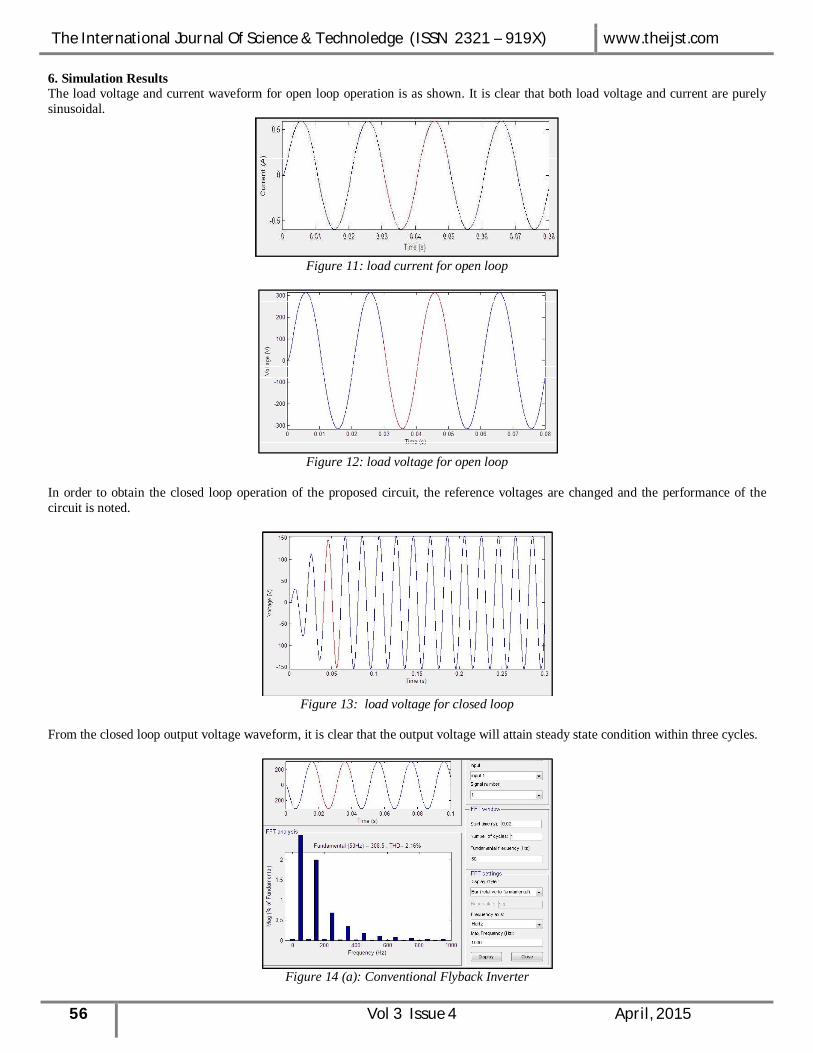
6. Simulation Results The load voltage and current waveform for open loop operation is as shown. It is clear that both load voltage and current are purely sinusoidal.
Figure 11: load current for open loop
Figure 12: load voltage for open loop
In order to obtain the closed loop operation of the proposed circuit, the reference voltages are changed and the performance of the circuit is noted.
Figure 13: load voltage for closed loop
From the closed loop output voltage waveform, it is clear that the output voltage will attain steady state condition within three cycles.
Figure 14 (a): Conventional Flyback Inverter
The International Journal Of Science & Technoledge (ISSN 2321 – 919X) www.theijst.com
57 Vol 3 Issue 4 April, 2015
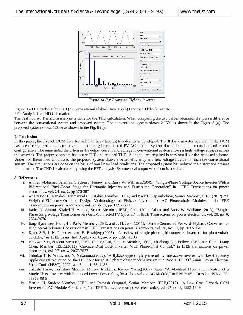
Figure 14 (b): Proposed Flyback Inverter
Figure. 14 FFT analysis for THD (a) Conventional Flyback Inverter (b) Proposed Flyback Inverter FFT Analysis for THD Calculation The Fast Fourier Transform analysis is done for the THD calculation. When comparing the two values obtained, it shows a difference between the conventional system and proposed system. The conventional system shows 2.16% as shown in the Figure 8 (a). The proposed system shows 1.63% as shown in the Fig. 8 (b). 7. Conclusion In this paper, the flyback DCM inverter without centre tapping transformer is developed. The flyback inverter operated under DCM has been recognized as an attractive solution for grid connected PV-AC module system due to its simple controller and circuit configuration. The unintended distortion in the output current and voltage in conventional system shows a high voltage stresses across the switches. The proposed system has better TUF and reduced THD. Also the area required is very small for the proposed scheme. Under non linear load conditions, the proposed system shows a better efficiency and less voltage fluctuation than the conventional system. The simulations are done on the basis of non linear load conditions. The proposed system has reduced the distortions present in the output. The THD is calculated by using the FFT analysis. Symmetrical output waveform is obtained. 8. References
i. Ahmed Mohamed Salamah, Stephen J. Finney, and Barry W. Williams,(2009), “Single-Phase Voltage Source Inverter With a Bidirectional Buck-Boost Stage for Harmonic Injection and Distributed Generation” in IEEE Transactions on power electronics, vol. 24, no. 2, pp 376-387
ii. Anastasios C. Nanakos, Emmanuel C. Tatakis, Member, IEEE, and Nick P. Papanikolaou, Senior Member, IEEE,(2012), “A Weighted-Efficiency-Oriented Design Methodology of Flyback Inverter for AC Photovoltaic Modules,” in IEEE Transactions on power electronics, vol. 27, no. 7, pp 3221-3233
iii. Bader N. Alajmi, Khaled H. Ahmed, Senior Member, IEEE, Grain Philip Adam, and Barry W. Williams,(2013), “Single-Phase Single-Stage Transformer less Grid-Connected PV System,” in IEEE Transactions on power electronics, vol. 28, no. 6, 2664-2676
iv. Jong-Hyun Lee, Joung-Hu Park, Member, IEEE, and J. H. Jeon,(2011), “Series-Connected Forward–Flyback Converter for High Step-Up Power Conversion,” in IEEE Transactions on power electronics, vol. 26, no. 12, pp 3037-3040
v. Kjaer S.B, J. K. Pedersen, and F. Blaabjerg,(2005), “A review of single-phase grid-connected inverters for photovoltaic modules,” in IEEE Trans. Ind. Appl., vol. 41, no. 5, pp. 1292–1306.
vi. Pengwei Sun, Student Member, IEEE, Chuang Liu, Student Member, IEEE, Jih-Sheng Lai, Fellow, IEEE, and Chien-Liang Chen, Member, IEEE,(2012) “Cascade Dual Buck Inverter With Phase-Shift Control,” in IEEE transactions on power electronics, vol. 27, no. 4, 2067-2077
vii. Shimizu T, K. Wada, and N. Nakamura,(2002), “A flyback-type single phase utility interactive inverter with low-frequency ripple current reduction on the DC input for an AC photovoltaic module system,” in Proc. IEEE 33rd Annu. Power Electron. Spec. Conf. (PESC), 2002, vol. 3, pp. 1483–1488.
viii. Takashi Hirao, Toshihisa Shimizu Mutsuo Ishikawa, Kiyoto Yasui,(2005), Japan “A Modified Modulation Control of a Single-Phase Inverter with Enhanced Power Decoupling for a Photovoltaic AC Module,” in EPE 2005 – Dresden, ISBN : 90-75815-08-5.
ix. Yanlin Li, Student Member, IEEE, and Ramesh Oruganti, Senior Member, IEEE,(2012), “A Low Cost Flyback CCM Inverter for AC Module Application,” in IEEE Transactions on power electronics, vol. 27, no. 3, 1295-1309

The International Journal Of Science & Technoledge (ISSN 2321 – 919X) www.theijst.com
58 Vol 3 Issue 4 April, 2015
x. Young-Ho Kim, Young-Hyok Ji, Jun-Gu Kim, Yong-Chae Jung, and Chung-Yuen Won,(2013), “A New Control Strategy for Improving Weighted Efficiency in Photovoltaic AC Module-Type Interleaved Flyback Inverters,” in IEEE Transactions on power electronics, vol. 28, no. 6, 2688-2699
xi. Young-Hyok Ji, Doo-Yong Jung, Jae-Hyung Kim1, Tae-Won Lee, and Chung-Yuen Won,(2011), “A Current Shaping Method for PV-AC Module DCM-Flyback Inverter under CCM Operation,” in 8th International Conference on Power Electronics - ECCE Asia, The Shilla Jeju, Korea. Pp 2598-2605.
xii. F. Schimpf, and L. E, Norum,(2008), “Grid connected Converters for Photovoltaic, State of the Art, Ideas for Improvement of Transfomerless Inverters”, in Nordic Workshop on Power. Ind. Electronics.
xiii. S. J. Strong, J. H. Wohlgemuth, and R. H. Wills,(1997), “The AC photovoltaic module is here!”, in National renewable energy laboratory and sandia national laboratories photovoltaics program review meeting, AIP Conf. Proceedings, vol. 394, pp. 867-871.
xiv. Q. Li and P. Wolfs,(2008), “A Review of the Single Phase Photovoltaic Module Integrated Converter Topologies with Three Different DC Link Configurations”, in IEEE Trans. On Power Electronics., vol. 23, no. 3, pp.1320-1333.
xv. Saravana Selvan. D, Faculty of Engineering and Computer Technology, AIMST University, Bedong- 08100, kedah, Malaysia,(2013), “Modeling and Simulation of Incremental Conductance MPPT Algorithm for Photovoltaic Applications,” in International Journal of Scientific Engineering and Technology (ISSN : 2277-1581) Volukme No.2, Issue No.7.
xvi. Toshihisa Shimizu, Keiji Wada, and Naoki Nakamura “Flyback-Type Single-Phase Utility Interactive Inverter With Power Pulsation Decoupling on the DC Input for an AC Photovoltaic Module System” IEEE transactions on power electronics, vol. 21, no. 5, september 2006.
xvii. A. Ch. KyritsisE. C. Tatakis, and N. P. Papanikolaou “Optimum Design of the Current-Source Flyback Inverter for Decentralized Grid-Connected Photovoltaic Systems” IEEE transactions on energy conversion, vol. 23, no. 1, march 2008.
xviii. Quan Li, and Peter Wolfs “A Review of the Single Phase Photovoltaic Module Integrated Converter Topologies With Three Different DC Link Configurations” IEEE transactions on power electronics, vol. 23, no. 3, may 2008.
xix. O´ scar Lo´pez, Francisco D. Freijedo, Alejandro G. Yepes, Pablo Fern´andez-Comesa˜na, Jano Malvar, Remus Teodorescu, and Jes´us Doval-Gandoy “Eliminating Ground Current in a TransformerlessPhotovoltaic Application” IEEE transactions on energy conversion, vol. 25, no. 1, march 2010.
xx. Jia-Min Shen, Hurng-Liahng Jou, and Jinn-Chang Wu “Novel Transformerless Grid-Connected Power Converter With Negative Grounding for Photovoltaic Generation System” IEEE transactions on power electronics, vol. 27, no. 4, april 2012
xxi. S. B. Kjaer, J. K. Pedersen, and F. Blaabjerg, “A review of single-phase grid-connected inverters for photovoltaic modules,” IEEE trans. ind. appl., vol. 41, no. 5, pp. 1292–1306, sep./oct. 2005.