the effects of yaw and finite length upon the vortex wakes of stationary and vibrating circular...
TRANSCRIPT
J . Fluid Mech. (1983), 001. 128, p p . 81-107
Printed in Great Britain
81
The effects of yaw and finite length upon the vortex wakes of stationary and vibrating circular cylinders
By S . E. RAMBERG Marine Technology Division, Naval Research Laboratory, Washington, DC 20375
(Received 27 April 1982 and in revised form 28 July 1982)
The present investigation considers the vortex wakes behind finite-length yawed cylinders that are stationary or vibrating transversly in a uniform flow. I n the Reynolds-number range 160-103 a number of three-dimensional and nominally two-dimensional wake flows are observed and attributed to the dominance of end conditions over rather large spans of the cylinder (aspect ratios up to 100).
1. Introduction Over the years various and sometimes conflicting reports have been made for the
characteristics of the classical vortex wakes behind circular cylinders in uniform flows. The variety of reported results and the number of conflicts tend to increase for cylinders that are inclined to the incoming flow. As a result there is significant uncertainty in such basic characteristics as the shedding frequency, the base pressure and the steady drag for yawed cylinders. Traditionally, differences that have arisen between reported results are attributed to three-dimensional features governed by end effects, but rarely have these influences been quantified or studied in sufficient detail.
A recent paper by Slaouti & Gerrard (1981) is one of these rare papers in that the mechanisms of end effects for cylinders towed in water a t low Reynolds numbers are examined in some detail. There i t was concluded that, in the absence of spanwise nonuniformities, three-dimensional flow features can occur over rather large spans, and will depend entirely upon the end conditions. This important observation is in agreement with the present results; however, Slaouti & Gerrard also concluded that slantwise shedding was not an intrinsic feature of vortex wakes, which does not agree with the present findings for yawed cylinders.
The present results show that certain relationships exist between the angle of the shed vortex filaments and the shedding frequency, the base pressure, and therefore the drag. Moreover, i t is shown through observation and simple physical arguments that slantwise shedding a t angles other than the cylinder yaw angle is intrinsic to inclined cylinders in the absence of end effects. The present experiments were also conducted at low Reynolds numbers, but comparisons with other results a t higher Reynolds numbers, together with a fit to a ‘universal’ Strouhal-number - Reynolds- number curve (Griffin 1978, 1981) serve to extend the findings to other Reynolds- number ranges. The results also reconcile many previous results for both stationary and vibrating inclined cylinders in uniform flows, as is discussed during the presentation of results.
The standard against which the yawed-cylinder results of this study and most others are considered is the so-called Independence Principle, wherein the flow over the yawed cylinder is likened to the normal-incidence case through the use of the
82 S. E. Ramberg
component of free-stream velocity normal to the cylinder axis (cf. Schlichting 1968). This empiricism for flow-separation and wake-formation processes has found wide- spread practical application, not only because of the simple ‘cosine laws’ which result but also because no better practical alternative exists. Not surprisingly, this simple approach is found to have no validity except in certain cases, the most notable being vibrating cylinders, where the use of the normal component of velocity is appropriate for reasons of ‘capture’ of the shedding angle as well as the shedding frequency.
2. Experimental systems and methods The experiments were performed in an open-jet wind tunnel with a 16 cm square
exit. Immediately preceding the exit was a 15 cm long clear acrylic test section that was employed to minimize changes in the free-stream flow over the length of a yawed cylinder. The cylinders were so mounted a t the end of the test section that a zero yaw angle corresponded to a cylinder normal to the free jet. Various yaw angles were obtained by tipping one end of each cylinder into the acrylic test section, +8, or occasionally away from the test section, -8. This sign convention is made clearer by noting that the fixed end of each cylinder was imbedded in an extension of the test section floor that could be rotated to obtain the desired yaw angle up to a maximum of 60’. The cylinders themselves were either solid steel drill rods or precision brass tubes. The brass tubes were used in conjunction with endplates that could be soldered onto the tubes a t various positions and orientations. The streamwise dimension of the endplates was always greater than 5 cylinder diameters, and was usually greater than 8 cylinder diameters. No attempt was made to polish the cylinder or endplate surfaces beyond their manufactured smoothness since i t has been shown that slight-to-moderate surface roughness is not a significant variable under the present conditions (Votaw & Griffin 1971).
The essential feature of the flow-visualization system is a thin sheet of aerosol that spans the central vertical plane of the test section. The aerosol was injected into the free-stream flow by means of a slender airfoil located in the contraction section of the wind tunnel. The airfoil spanned the centre of the converging tunnel vertically, and the aerosol emanated from the trailing edge along both sides of a wake-splitter plate. Two strobe lights, located on the opposite side of the sheet from the viewing position, illuminated the aerosol. This arrangement took advantage of the good forward-scattering characteristics of the aerosol. Flow-visualization photographs were obtained using a 35 mm camera with a f/2*8, 35 mm lens mounted to one side of the test section. I n a fully darkened room the strobe lights were flashed once while the shutter was held open.
Two channels of linearized constant-temperature hot-wire anemometers (DISA types 55D05 and 55K) were employed in the experiments. The hot-wire probes were single-element sensors (DISA type 55Pl) with 5 pm diameter platinum-plated tungsten wires. The calibrations and the linearization of the anemometers were undertaken in several ranges that spanned the experimental tunnel speed require- ments of 0.2-3.0 m/s. The calibrations were obtained by placing one of several unyawed reference cylinders into the wind tunnel and computing the flow speed from Roshko’s empirical relations (Roshko 1954a, 6 ) and the observed vortex-shedding frequency. The calibration cylinder for a particular set of experiments was always of a different diameter than the test cylinders for $hat set. The shedding frequencies were determined from spectra of the anemometer signal when the probes were positioned in or near the wake. The spectra were obtained from a 200-line Honeywell-

Vortex wakes of circular cylinders 83
Saicor Realtime Spectrum Analyzer and Digital Averager. The resulting spectrum in each instance was an average of eight or more sample spectra.
Pressure measurements were taken with a null balance micromanometer whose vernier adjustment had a resolution of 0.01 mm of water column or about 1.4 x lop4 p.s.i. (095 Pa). Base pressures were obtained from a single tap a t the rear of the cylinder about midway along the span.
The forced-vibration experiments were performed by oscillating a cylinder that was cantilevered from a traversing beam located at the top end of the acrylic test section. The beam was flush with the roof of the test section and had holes drilled to produce six yaw angles of 8 = 0, loo, 20°, 30°, 40°, and 50'. The beam was driven side-to-side by an electromagnetic shaker connected to one end of the beam. The shaker/beam system had a limited oscillation amplitude in the frequency range of interest (2040 Hz), so the cylinders were occasionally tuned to respond in a fundamental natural mode in order to obtain larger amplitudes. As a result, the amplitude of vibration sometimes varied along the cylinder span. The variation in amplitude along the span was not a handicap since it has been shown that locked-in vortex shedding depends largely on local amplitude (Ramberg & Griffin 1974). The amplitude of motion at any point along the cylinder was measured by an optical tracking device located about 1 metre downstream from the test section. The experimental systems and methods have been described in greater detail by Ramberg (1978).
3. Presentation and discussion of stationary cylinder results The results discussed here were obtained during a series of experiments covering a
range of Reynolds numbers from Re = 160 to 1100, yaw angles from 8 = - 10' to 60' and aspect ratios from AID x 20 to x 100. The experiments included a variety of end conditions with and without endplates to control the flow. Measurements of shedding frequency, shedding angle, base pressure, and near-wake dimensions were combined with flow visualization in order to identify various flow patterns, to associate these patterns with changes in the independent variables (Re, 8, LID, etc.), and to obtain methods for estimating fluid forces in the presence of three-dimensional flow effects. The results are presented and discussed in the following subsections, beginning with the identification of several different wake patterns behind inclined cylinders.
3.1. Wake-$ow regimes and modes An early observation, owing to the ability to visualize the flow, was that the wakes were not always of the von Karm6n street or vortex-shedding type. In a number of instances, most noticeably a t low Reynolds numbers and large yaw angles, a steady, trailing vortex pattern emerged, as shown in the photographs of figure 1 . This particular flow-visualization series was obtained using a flat-ended cylinder in a constant free-stream flow, Re = 160, and i t serves to illustrate the changes in wake pattern that occurred as the cylinder, initially vertical, was tipped into the flow. The process can be described as follows. A t normal incidence, or very small 6, the vortex lines were curved and the pattern was unsteady. As the yaw angle was increased slightly the pattern stabilized, the vortex filaments straightened and were typically inclined to a greater degree than the cylinder itself. For larger yaw angles the wake would often divide into two shedding modes distinguished by a difference in the angle a of the shed vortices. When this occurred, the strobe lights could be made to 'freeze'

84 X. E. Ramberg
FIGURE 1. A series of flow-visualization photographs of the vortex wake behind a finite-length yawed cylinder in a wind tunnel, Re = 160.
Vortex wakes of circular cylinders 85
one mode but not both, which indicated a difference in shedding frequency between the modes. This was verified by later measurement and is discussed further in $3.2.
While this was occurring in the midst of the wake, the vortex filaments a t the ‘top ’ of the wake appear to loop over after the fashion postulated by Gerrard (1966a, b ) some years ago. If the yaw angle was increased further these loops eventually de- tached from the shedding vortex filaments and formed a wavy line that streamed out behind the cylinder. The looping process then occurred ‘lower’ in the wake. At still larger yaw angles the looping process continued to move down, more wavy lines were formed, and the first wavy lines straightened to form a steady trailing pattern. The wavy lines alternated in such a way that the resultant steady training vortices would emanate from alternating sides of the cylinder with opposing circulation. This flow pattern is of the type studied by a number of investigators concerned with the forces on a missile a t an angle of attack to the oncoming flow. The significance of the present results is the low-Reynolds-number occurrence of the steady flow and an ability to delineate flow regimes as functions of the experimental conditions. Three regimes have been identified : the steady pattern discussed above, the unsteady vortex- shedding patterns, and a transition between the other two.
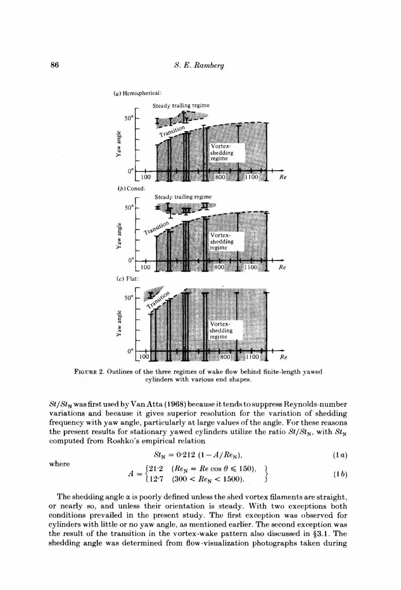
The outlines of the regimes as functions of Reynolds number, yaw angle and aspect ratio are presented in figures 2 (u-c) for cylinders with a hemispherical, a coned and a flat end. Each vertical bar on the graphs represents one series of wake photographs a t one Reynolds number and various yaw angles. For example, consider the leftmost bar in figure 2 ( a ) , which corresponds to a cylinder with a hemispherical end at a Reynolds number of about 200. For yaw angles from - 10’ to 25’ the wake is of the unsteady von Karman vortex pattern. For angles between 25’ and 40’ there is a transition to the steady trailing pattern, which becomes clearly established for B > 45O. A t other Reynolds numbers two or three adjacent bars are used to represent two or three series at the same Reynolds number and end condition but with different diameters to produce different aspect ratios. The three bars a t Re x 460 correspond to a 2: 1 range in aspect ratio and demonstrate that the transition between vortex patterns is not dependent on the aspect ratio and is indeed an end effect. I n the case of different aspect ratios it was the onset of each regime that is indicated in the graphs because the ‘longer’ cylinder (in diameters) will have to be rotated to a larger yaw angle before the steady trailing pattern encompasses the entire span. I n other words, the transition starts at the free end, progresses along the cylinder, and is followed by the formation of a steady trailing pattern over the upper portion of the cylinder.
The similarities between the hemispherically ended and cone-ended cylinders is to be noted, along with the apparent lack of Reynolds-number influence beyond Re = 9OCk1000. Unfortunately, the transition regime for flat-ended cylinders was beyond the maximum possible yaw angle when Re > 500, so less information is available in that case. Within the vortex-shedding regime several possible modes exist, which are discussed in the following subsections.
3.2. Shedding frequency and shedding angle
A principal characteristic of vortex shedding is the non-dimensional frequency or Strouhal number St = f,D/U,, where D is the cylinder diameter and U, is the free-stream velocity. For a yawed cylinder U, = U, cos 6’ is often used as the characteristic velocity on the premise that only the ‘cross-flow ’ component governs the vortex shedding. If the measured Strouhal number St is divided by the computed value of Xt, = f s D / U N , then the ratio Xt/St, should vary as cos B regardless of the Reynolds number so long as the so-called Independence Principle is valid. The ratio
86 8. E. Ramberg
(a) Hemispherical:
- Steady trailing regime
5 oo
e, M - 5 5 t
O0
( b ) Coned:
Steady trailing regime
50'
Qi
M - 5 5 t
0"
( c ) Flat:
0
5 0'
- OL m
$ >.
o' e
FIQURE 2. Outlines of the three regimes of wake flow behind finite-length yawed cylinders with various end shapes.
StlSt, was first used by Van Atta (1968) because i t tends to suppress Reynolds-number variations and because it gives superior resolution for the variation of shedding frequency with yaw angle, particularly a t large values of the angle. For these reasons the present results for stationary yawed cylinders utilize the ratio XtlSt,, with St, computed from Roshko's empirical relation
where St, = 0.212 ( 1 -A/Re,) ,
21.2 12.7
(Re, = Re COB 0 Q 150), (300 < Re, < 1500).
A = {
The shedding angle a is poorly defined unless the shed vortex filaments are straight, or nearly so, and unless their orientation is steady. With two exceptions both conditions prevailed in the present study. The first exception was observed for cylinders with little or no yaw angle, as mentioned earlier. The second exception was the result of the transition in the vortex-wake pattern also discussed in $3.1. The shedding angle was determined from flow-visualization photographs taken during

Vortex wakes of circular cylinders 87
1 .o
Van Atta's 0.9
0'8
0.7
0.6
0.5 t cos 8 > P
I I I I I I I 0' 10" 20" 30" 40' 50' 60'
Yaw angle, 0
FIGURE 3. A plot of the normalized Strouhal numbers as a function of yaw angle for a variety of free-ended inclined cylinders. Legend for data: ., Re = 210, LID = 2 M O ; b ,320,20-40; A, 460, 2 M O ; 0, 0 , 160, 90; X , 460, 90; 0, 700, 90; A, 900, 90; V, 1100, 90.
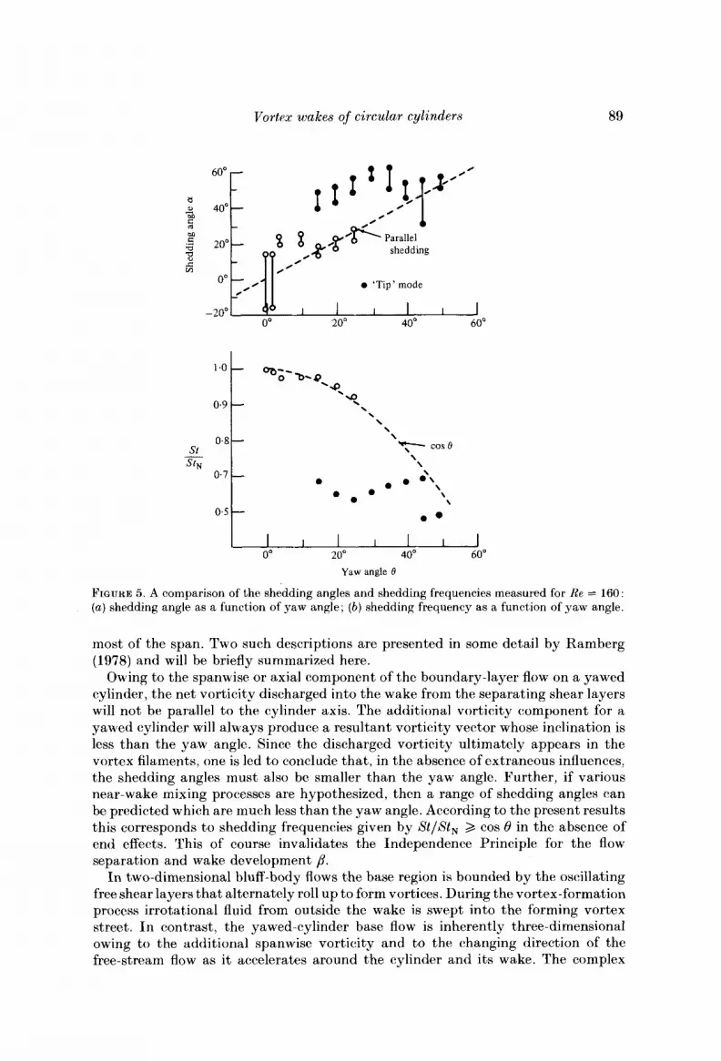
each shedding-frequency measurement. When the vortex filaments were straight it was a simple matter to measure their inclination angle with respect to the vertical (0 = 0). If the filaments were not straight a median value was estimated and a solid line was drawn connecting data points to encompass the entire range of observed angles, as will be seen in figure 5.
The initial experiments were designed to examine the vortex-shedding wake behind free-ended cylinders as it was influenced by yaw angle, aspect ratio and free-end geometry for various Reynolds numbers. Figures 3 contains all of the shedding- frequency measurements obtained with free-ended cylinders. The aspect ratio LID extends from about 20 to nearly 100 and the Reynolds number from about 160 to 1100. For yaw angles greater than 10" the spread in results is large, despite a frequency resolution of f 4 yo or better depending on the shape of the spectrum and on the analyser range setting. It is interesting to note that a simple curve fit would probably pass close to the cos0 curve, but such an approach is not appropriate because it does not take into account the different modes of vortex shedding that were observed. An example of the variations introduced by different modes is shown in the photograph of figure 4 and in figure 5. For yaw angles between 0 = 10' and 30° there are two shedding frequencies a t each yaw angle, which correspond to the two shedding modes as indicated by the difference in measured shedding angles. A careful examination of all the data represented in figure 3, along with the flow- visualization photographs, revealed that most of the apparent scatter in figure 3 was due to variations in the shedding angle. Moreover, the data suggested that a shedding angle less than the yaw angle corresponded to a StlSt, ratio greater than cos 0 and vice versa. This can be seen in figure 5. Subsequent tests with endplated cylinders verified this observation.
The endplated-cylinder tests were conducted by setting the endplate at various

88 S. E. Ramberg
FIGURE 4. A flow-visualization photograph of the two modes of vortex shedding behind an inclined cylinder at Re = 160.
angles /3 (see sketch in figure 4) to the free stream while keeping the Reynolds number and yaw angle constant. I n this way i t was possible to vary only the flow about the end. As a practical matter this approach is a simple extension of a common experimental technique (Graham 1969). Some representative results are shown in figure 6 for a Reynolds number Re = 160 and two yaw angles 8 = 30' and 50'. The most striking feature of the graphs is the nearly inverse relationship between the shedding angle and the StlSt, ratio, or, equivalently, between the shedding angle and the shedding frequency since the remaining parameters are constant. Careful examination of this figure along with similar data a t other Reynolds numbers has led to the conclusion that, for values of StlSt, 2 cos 8, the shedding angles are less than or equal to the yaw angle. There is also an indication that StlSt, = cos 8 corresponds closely to a = 8, which will be important in the interpretation of the vibrating-cylinder results of $4.
Another feature of the endplated-cylinder results was the large sensitivity to small changes in endplate inclination near /3 5 = go", or in other words endplates approximately aligned with free-stream flow or tipped slightly down a t the leading edge. Since this particular configuration is a common experimental arrangement, the present results may account for many of the discrepancies in reports of shedding frequencies for inclined cylinders (Hanson 1966; Smith, Moon & Kao 1972). In any case, the potential for strong end effects over large spans is quite evident. I n order to generalize the present results somewhat a description is required of the wake conditions to be expected in the absence of end effects, as is a description ofa possible mechanism by which the end condition can control the vortex shedding over all or
Vortex wakes of circular cylinders
60'
40"
20°
-20°
89
0 - 0
- 0 -
8 8 , g O f i Parallel % shedding -
' 00: /' OdyO 'Tip' mode
9 I I I I J
O0 20" 40' 60"
Yaw angle 0
FIGURE 5. A comparison of the shedding angles and shedding frequencies measured for Re = 160: (a ) shedding angle as a function of yaw angle; (b ) shedding frequency as a function of yaw angle.
most of the span. Two such descriptions are presented in some detail by Ramberg (1978) and will be briefly summarized here.
Owing to the spanwise or axial Component of the boundary-layer flow on a yawed cylinder, the net vorticity discharged into the wake from the separating shear layers will not be parallel to the cylinder axis. The additional vorticity component for a yawed cylinder will always produce a resultant vorticity vector whose inclination is less than the yaw angle. Since the discharged vorticity ultimately appears in the vortex filaments, one is led to conclude that, in the absence of extraneous influences, the shedding angles must also be smaller than the yaw angle. Further, if various near-wake mixing processes are hypothesized, then a range of shedding angles can be predicted which are much less than the yaw angle. According to the present results this corresponds to shedding frequencies given by St lS t , 2 cos 8 in the absence of end effects. This of course invalidates the Independence Principle for the flow separation and wake development /3.
In two-dimensional bluff-body flows the base region is bounded by the oscillating free shear layers that alternately roll up to form vortices. During the vortex-formation process irrotational fluid from outside the wake is swept into the forming vortex street. I n contrast, the yawed-cylinder base flow is inherently three-dimensional owing to the additional spanwise vorticity and to the changing direction of the free-stream flow as i t accelerates around the cylinder and its wake. The complex

90
1.0
0.8
0.6
0.4
S. E . Ramberg
r - 80'
- II 60" ~
- 40"
.c- c o s 5 0 ~
- -
-
- B B - - 20° 5
- - - - 0"
- - 1 1 1 1 1 1 1 1 1 1 1
FIGURE 6. The influence of endplate inclination angle /3 upon the vortex-shedding frequency and shedding angle a for Re = 160 and two yaw angles: (a) 0 = 30'; (b ) 50'.
nature of this flow can be seen in the flow-visualization photographs taken by Chiu (1966). An axial flow within the base region is intuitively expected and is, in fact, equal to U , = U, sin 0 according to the Independence Principle. Whether the base flow is equal to U, or to some other value is of lesser importance than the fact that it must exist and it ought to be 'down' the cylinder.
If the flow about an infinitely long cylinder is to be modelled with a finite-length cylinder, then the spanwise flow in the base region must be provided by the termination(s) of the cylinder. Near the end this must be a result of a pressure gradient driving the fluid into and then down through the base region. In the case of a cylinder with an endplate, the driving pressure gradient will be the result of the difference between the pressure on the plate and the pressure within the base region. This type of flow was one aspect of the problem studied by Etzold & Fiedler (1976) for cantilevered circular cylinders (LID < 10) at normal incidence.
The pressure difference between the endplate and the base region may be written in an obvious notation as

Vortex wakes of circular cylinders 91
or AP
2P 0
-- I u2 - c,-cbN cos2 e,
where C, is a pressure coefficient for the endplate and CbN is the base-pressure coefficient for the yawed cylinder. Accordingly, we have
c, > c,,, cos2 e, c, < c,,, cos2 e
(3a)
( 3 b )
as condiLons for flow into or out of the base region, respectively. This is an interesting result because i t is applicable to the normal-incidence case as well. In that case C,, = C, and in order to prevent axial flow on a two-dimensional model we require cp = c b , or, since c b is negative, the endplate ought to be tipped into the flow
Support for this notion can be found in the careful experiments of Graham (1969), who studied the two-dimensionality of the wake flow behind a D-section bluff body fitted with endplates. His spanwise velocity correlations improved markedly for endplates with an inclination of slightly greater than 4' with respect to the free stream, i.e. p = 94'. It is interesting to note that Gerrard's (1966a, b) experi- mental configuration tipped the endplates in the other direction, which was probably responsible for many of the three-dimensional phenomena he observed, including steady, slantwise vortex shedding for an unyawed cylinder. Similar results can be obtained for yawed cylinders if the variations of C, and C,, are known for p and 0 respectively. The latter can be found from experimental results but it is sufficient in this analysis to take CbN = - 1. The variation of C, with p has been estimated from the experimental measurements of Fage & Johansen (1927) for the pressure distributions on inclined flat plates. The essential result is that Cp(p) = - cos2 0 gives the endplate inclination angles for which the flow in the base region ought to change direction according to the criteria of (3a, b). For the two yaw angles 0 = 30' and 50' the corresponding endplate angles are /3 = 1 10' and 105'. Within the accuracy of /3 in figure 6 these values of p correspond fairly well with the locations where the ob- served shedding frequency changes from below to above the value predicted by the Independence Principle and the shedding angle goes from a > 8 to a < 8. Moreover, the sensitivity of this mechanism to small changes in /3 is greatest for 90' 6,8 5 120°, which compares very well with the data in figures 6 (a, b). As a final observation, this mechanism will not only be sensitive to Reynolds number because the base flow is influenced by turbulence but also because the endplate pressure coefficients are themselves Reynolds-number dependent.
We can also use this approach to help select the endplate orientation(s) that best correspond to an infinitely long yawed cylinder. On one hand, the flow must be 'down ' the cylinder, so that we require
(4)
On the other hand, the pressure on the plate ought to be less than the free-stream stagnation pressure Po to prevent excessive flow down the cylinder, and therefore
(p > 90').
Cp > c b N COB2 8.
o > c, > c,, cos2 e.
s tp , > cos e,
( 5 )
According to all of the endplate experiments this inequality corresponds to the
(6a) conditions
4

92 8. E. Ramberg
\ 0 R e = 160
- X R e = 4 6 0 \ \ \ 0 see text
0 . 5 1 1 1 I I I I j O0 1 oo 20' 30" 40' SO" 60'
Yaw angIe 0
FIGURE 7 . Shedding-frequency measurements for a bent circular cylinder a t two Reynolds numbers: Re = 160 and 460.
This reasoning complements the vorticity-discharge considerations that were em- ployed earlier to select 01 < I9 as the condition appropriate to an infinitely long yawed cylinder. Use of either line of reasoning with the data of the present experiments contradicts the Independence Principle for separated flows.
A final series of flow-visualization tests was undertaken with a bent cylinder. This geometry offered two advantages: no 'upstream end' and a symmetry much like the experiments of Dale & Holler (1970). A bent section that formed a 120' angle was selected since i t was possible to obtain a zero yaw angle for each leg. No particular attention was given to the bend itself and the result was a smooth, curved section of 3 4 diameters radius between the two legs that each had an exposed (to the flow) length of a t least 44 diameters. The shedding frequencies were normalized by the zero yaw frequency and are plotted in figure 7 for the two Reynolds numbers of 160 and 460. The corresponding flow-visualization photographs are shown in figure 8. The photographs are arranged in columns according to Reynolds number and inclination angle. The shedding angle is essentially constant near 01 = 0 and the shedding frequency shows some symmetry about 0 = 30' while never dropping below 96 yo of the I9 = 0 value. For Re = 460 the shedding angles conform more to the cylinder shape and the shedding frequency ratio drops to a minimum of about 089 a t a yaw angle near I9 = 32'.
These observations are consistent with a strong influence of symmetry over rather large spans and compare well with the flow-visualization photographs of Dale & Holler. These results may have a bearing on experiments performed with yawed cylinders in a water channel where the free surface introduces symmetry by virtue of the image cylinder above the free surface. Out of curiosity the cylinder was rotated about the axis of the lower leg a t I9 = 30' to destroy the symmetry. The new shedding frequency in this instance is represented by the square symbol in figure 7 and compares well to the earlier free-ended cylinder results.

Vortex wakes of circular cylinders 93
FIQURE 8. A flow visualization series for the bent-cylinder experiments. The left-hand column corresponds to Re = 160 and the right-hand column to Re = 460.
4-2

94 8. E. Ramberg
3.3. Vortex-wake parameters and base pressure The previous experiments provided a study of the influence of yaw angle and finite cylinder length upon the shedding frequency and the wake geometry. In order to infer the fluid-force variations the base pressures together with several characteristic wake dimensions were also measured. It was not possible to measure pressures accurately for combinations of velocities and diameters less than a Reynolds number Re of about 500. Thus some of the large changes observed in the flow at low Reynolds numbers could not be matched with base-pressure measurements. Nonetheless, trends were matched that can account for all of the phenomena seen and discussed previously.
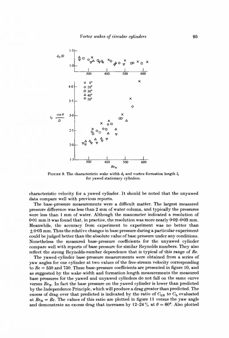
The vortex-formation region length I , and the wake width d , at formation were measured behind several free-ended cylinders with a flat free end. This geometry was selected for simplicity and because the data in the earlier sections showed that StlSt, 2 cos 8 and a < 0 for this configuration when Re > 400. The formation length 1, is defined as the distance from the cylinder axis to the initial position of a fully formed vortex and can be measured by any one of several criteria (see Griffin & Ramberg 1975).
The location of the maximum of the second harmonic of velocity fluctuation on the wake axis was employed in the present study. The linearized output from the anemometer was bandpass filtered a t a centre frequency of 2fs with upper and lower cutoffs (3 dB down) at k&fs, respectively. The probe traversed in the free-stream direction. Once the value of I , was determined, the filter was removed from the circuit and an r.m.s. velocity profile was measured across the wake a t x = IF. The transverse distance between the maxima of the r.m.8. profile was taken as the wake width d , at formation. This width is not precisely equal to the distance between the free shear layers that has been called dF elsewhere, but the differences are small and it has become customary to use the two quantities interchangeably. According to the Independence Principle, the wake width ought not to be influenced by yaw angle, and the formation length, measured normal to the cylinder axis, should also be independent of yaw angle. In the present range of Reynolds numbers both d , and IF are dependent on Re, and this introduces some additional complication. However, i t should be possible to reconcile this with the use of Re, if the Independence Principle is assumed.
The measured values of d , and 1, cos 0 are presented in figure 9 as function of Re,. Clearly, the cosine laws have again failed to scale the results properly. Both the wake width and the formation length become less than expected as the yaw angle is increased. The free-stream Reynolds number Re tends to scale the wake-width results better than Re,, but this is probably peculiar to this range of Reynolds number because Smith et al. (1972) have also reported a narrowing of the wake with increasing yaw angle. Based on Roshko’s (1955) free-streamline theory one would expect increasing base pressure to be associated with decreasing wake width. On the other hand, experience with other bluff-body flows has shown that the base pressure decreases as the formation length shrinks. The apparent paradox presented by figure 9 can be resolved by noting that this representation of the formation length has included a cos 0 owing to the Independence Principle. Dividing the data in figure 9 ( b ) by cos 8 removes the Independence-Principle influence so that I , , measured in the free-stream direction, increases with yaw angle and the two wake measurements become consistent. This also suggests that possibly the free-stream flow direction may be the dominating influence and perhaps U, ought to be discarded altogether. However, the use of Re, appears necessary to appropriately shift the curve shapes in the figure. Therefore the normal component of velocity remains a proper
Vortex wakes of circular cylinders
300 400 500 600
X x 0"
0 30' A 40'
50°
4.0 o 200
X 3.5
0
X
X * A : x 0 0
cose 3.0 IF -
D
95
3 00 400 500 600 1.5
Re,
FIQURE 9. The characteristic wake width d, and vortex-formation length I, for yawed stationary cylinders.
characteristic velocity for a yawed cylinder. It should be noted that the unyawed data compare well with previous reports.
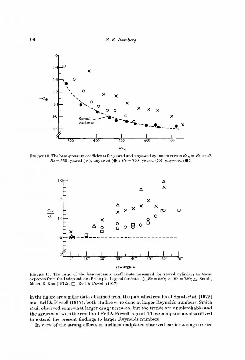
The base-pressure measurements were a difficult matter. The largest measured pressure difference was less than 2 mm of water column, and typically the pressures were less than 1 mm of water. Although the manometer indicated a resolution of 001 mm it was found that, in practice, the resolution was more nearly 0.02-0.03 mm. Meanwhile, the accuracy from experiment to experiment was no better than - + 003 mm. Thus the relative changes in base pressure during a particular experiment could be judged better than the absolute value of base pressure under any conditions. Nonetheless the measured base-pressure coefficients for the unyawed cylinder compare well with reports of base pressure for similar Reynolds numbers. They also reflect the strong Reynolds-number dependence that is typical of this range of Re.
The yawed-cylinder base-pressure measurements were obtained from a series of yaw angles for one cylinder at two values of the free-stream velocity corresponding to Re = 550 and 750. These base-pressure coefficients are presented in figure 10, and as suggested by the wake-width and formation-length measurements the measured base pressures for the yawed and unyawed cylinders do not fall on the same curve versus Re,. In fact the base pressure on the yawed cylinder is lower than predicted by the Independence Principle, which will produce a drag greater than predicted. The excess of drag over that predicted is indicated by the ratio of CbN to c b evaluated at Re, = Re. The values of this ratio are plotted in figure 11 versus the yaw angle and demonstrate an excess drag that increases by 12-24% at 0 = 60'. Also plotted
96 8. E . Ramberg
-cbN
1.5
0
1.1
0.9
X
I 1 I I I 300 400 500 600 700
ReN
FIGURE 10. The base-pressure coefficients for yawed and unyawed cylinders versus Re, = Re cos 8. Re = 550: yawed ( x ) , unyawed (0 ) ; Re = 750: yawed ( O ) , unyawed (0) .
A A X
X A x x X x x 3
0 0
o n X
o A. 0 0 0 8
n
t 0' 10" 20" 30" 40" SOo 60' 70'
~ ] l j l l l ] l ] , l l ] , l
Yaw angle 0
FIGURE 11. The ratio of the base-pressure coefficients measured for yawed cylinders to those expected from the Independence Principle. Legend for data: 0, Re = 550; x , Re = 750; A, Smith, Moon, & Kao (1972); 0, Relf & Powell (1917).
in the figure are similar data obtained from the published results of Smith et al. (1972) and Relf & Powell (1917); both studies were done a t larger Reynolds numbers. Smith et al. observed somewhat larger drag increases, but the trends are unmistakable and the agreement with the results of Relf & Powell is good. These comparisons also served to extend the present findings to larger Reynolds numbers.
In view of the strong effects of inclined endplates observed earlier a single series

Vortex wakes of circular cylinders 97
1 .o c i 80'
0' 60" 1 20' 180' Endplate inclination angle 6
FIGURE 12. The influence of endplate inclination angle upon the vortex-shedding frequency, the shedding angle and the base pressure for a Reynolds number Re = 550 and a yaw angle 0 = 30°.
of tests was undertaken at the upper limit of the flow-visualization capability and the lower limit of the base-pressure range. The data, obtained for a Reynolds number Re = 550 and the yaw angle 0 = 30°, are presented in figure 12. The results for the Strouhal-number ratio St/St, and the shedding angle a compare well with earlier data. The base pressure coefficient C,, also varies, and reflects the frequency variation, including an unexplained ' bump' near p = 100'. This figure conclusively demonstrates the strong interaction that occurs between the end conditions and the wake flow of finite-length yawed cylinders. This result also serves as a further warning that spanwise uniformity is not an indication of the absence of end effects; Stansby (1 974) demonstrated this for the normal incidence case. Lastly, this data demonstrates that a multitude of flows can be realized for finite-length yawed cylinders; the particular flow in any case is determined by the end conditions, in agreement with Slaouti & Gerrard's (1981) conclusion.
The present stationary yawed-cylinder experiments have shown that the cosine laws fail to describe the observed shedding frequency fs, the observed wake width d,, and the measured base pressure CbN. However, i t was observed that the variations could be offsetting within the concept of a universal Strouhal number S* (Griffin 1978, 1981). For the unyawed cylinder values of

98 S. E. Ramberg
t
Rk = R e N k dFID
FIQURE 13. The 'universal ' Strouhal number S* as a function of the Reynolds number RZ for yawed and unyawed bluff-body flows. Legend for data: A, unyawed, present experiments; 0, yawed, Re = 550, present experiments; x , yawed, Re = 750, present experiments; 0, previous data for nominally two-dimensional bluff-body flows (stationary and vibrating cylinder).
were computed using the measured quantities fs, rJo, c b and dF. For the yawed cylinder, values of 8; were also computed using fs, uN, Cb,, dF and D. Some difficulty was encountered with the wake width dF. This difficulty was caused by the dependence of dF on both the yaw angle 8 and the Reynolds number Re,, which changed together in a single experiment. Rather than impose a small variation in dF that was not warranted by experimental accuracy it was decided to set dF/D = 1.1 throughout the computations. This implies that the effects of Re, and 8 are completely balancing, which upon reference to figure 9 ( a ) is a fair approximation that may slightly overestimate dF at the largest yaw angles, i.e. the lowest Re,. It must be emphasized that this approximation is valid only in this particular range of Re,. The universal Strouhal numbers X* and Xg, computed according to the above method, are plotted in figure 13 versus Reg = ReN(dF/D) K and agree well with one another for both yawed and unyawed cylinders. Moreover, the results of both yawed and unyawed cylinders agree very well with the results of previous investigations of normal-incidence bluff-body flows that include both wake interference and resonant vibrations. To appreciate the degree of collapse of the data one might consider that in the present yawed-cylinder experiments the base-pressure coefficients varied by as much as SOY0, the wake widths by as much as Z0%, and the Strouhal numbers X t , by as much as 50 % . Despite these large changes virtually all of the values of X* and Sg obtained in the present investigation are within 6 % of the mean and within 10 yo oftheS*versusR* relation found previouslyforawidevarietyoftwo-dimensional bluff-body flows.
4. Presentation and discussion of vibrating-cylinder results The stationary-cylinder experiments demonstrated that the separated flow is very
sensitive to end conditions and that the conditions most representative of an infinitely long cylinder do not produce wake flows in accordance with the Independence Principle. King's (1977) data for vortex-excited vibrating yawed cylinders were also influenced by end conditions. For one of two sets of conditions King was able to scale both the onset and magnitude of yawed cylinder vibrations by using the normal

Vortex wakes of circular cylinders 99
f" - fd
0 0
FIQURE 14. Wake-frequency measurements as a function of the reduced velocity V, for stationary and vibrating yawed cylinders for a Reynolds number Re = 160 and a yaw angle 0 = 50'. Legend for data: endplate angleb = Go, A, vibrating ( a / D = 1.0); endplate angle /3 = 95', 0, stationary, 0, vibrating ( a / D = 1.0); endplate angle p = 105', 0, stationary, D, vibrating ( a / D = 1.0).
velocity component in the reduced velocity V, = uN/fdD, where f d is the body vibration frequency. For the second set only the onset of vibrations could be scaled, and then only approximately; the vibration amplitudes were greatly reduced in the latter case. Therefore, one aim of the present study was to reconcile the differences in King's two sets of results and to assess which set of results is representative of the general response of yawed cylinders that are resonantly excited by vortex shedding.
4.1. Lock-in regimes The onset of vortex-induced vibrations corresponds to the 'capture ' of the natural vortex shedding by the cylinder motion. Identification of these 'locked-in ' or synchronized conditions for yawed cylinders was the first objective of the forced- vibration experiments. The procedure was to oscillate a yawed cylinder a t particular values of frequency fd and amplitude a/D and then to vary the flow speed in search of the wake capture. The capture of the vortex shedding was evidenced by a suppression of the natural shedding frequency f , = f , in favour off, = fd or some multiple of fd. This was determined by positioning a hot-wire probe to one side of the wake and recording the fluctuating velocity spectrum a t each flow speed. The question of end effects was addressed by performing a number of tests with different end conditions. For comparison purposes the stationary-cylinder shedding frequencies were also recorded in a number of cases.
Representative data from the a series of tests a t Re = 160 and 8 = 50' are plotted in figure 14 in terms of the frequency ratio fv / fd and the reduced velocity V,. The open symbols correspond to the stationary-cylinder results (f, = f,) and are essentially

100 S. E. Ramberg
the same for the three end conditions. Again, the frequencies are greater than those expected from the Independence Principle; these are indicated by the solid lines in the figure. The solid lines are presented in two segements corresponding to ReN from 50 to 150 and from 300 to about 500. The solid symbols in the figure represent the forced-vibration responses for fd = 37 Hz and a peak-to-peak amplitude a / D = 1.0. Below V,. = 4.0 the wake-frequency response is essentially that of the stationary cylinder(s). For V , 2 4.0 the wake frequency fv jumps to the oscillation frequency f d , which is characteristic of lock-in or wake capture. Until V, x 6.5 the frequency remains locked onto fd . At v, x 6 the second harmonic of fd becomes pronounced, and by V, z 7.0 it is the dominant response. Further increases in the flow speed evoke similar changes involving frequencies a t fv = 2fd, fv = 3fd and so forth. The responses for the three end configurations are similar for V,. < 15 except that the /3 = 8 5 O case appears slightly shifted toward the larger V,.. I n all cases lock-in was observed to occur for f v / f d = 1 in the range V, x 4-0 to V, = 6.5, which does include the typical range of V, for self-excited two-dimensional lock-in, i.e. V, = 5-6 (King 1977).
At this point i t is necessary to identify which subranges of the forced wake responses are likely to coincide with resonant vortex-excited conditions. In the two-dimensional normal-incidence case, forced vibrations are known to capture the vortex shedding for frequencies above and below the stationary-cylinder or ‘natural ’ shedding frequency. However, self-excited oscillations only occur for frequencies below the natural structural frequency because in that range the phase between the motion and the fluctuating lift force is such that energy is transferred to the cylinder by the fluid forces. Without identifying a natural shedding frequency for yawed cylinders for the moment it is possible to apply this concept to the yawed-cylinder responses of the present study by noting that self-excited conditions a t f v / f d = 1 , 2, 3, 4, etc. will correspond to the larger values of V,.
A number of similar experiments were conducted for other yaw angles and Reynolds numbers, as described by Ramberg (1978). The amplitudes of vibration for these experiments varied from a / D = 0.15 to 1.0. The results at amplitudes a / D = 1-0 and 0.50 were quite similar to the above data, so that only the a / D = 0.15 results are presented here in figure 15 for a yaw angle of 0 = 50° and Re = 460. This vibration amplitude is insufficient to capture the shedding process for conditions other than f v / f d = 1 . The extent of lock-in is quite small, encompassing a narrow span of only V, x 4.5-6.0, but this still includes V, = 5-6 as before.
The preceding forced-vibration experiments have shown that lock-in occurred for many conditions and in a number of modes. At the same time the wake responses a t fv / fd = 1 were largely insensitive to end conditions in that the yawed-cylinder values of the reduced velocity corresponding to lock-in always included the corres- ponding range of normal incidence values for self-excited vibrations, However, a difficulty in defining a ‘natural’ shedding frequency for the yawed cylinder and the influence of vibration amplitude made i t difficult to compare the yawed and unyawed lock-in regimes directly.
The latter difficulties were overcome by some detailed lock-in experiments a t Re = 460 using a free-ended cylinder. Five yaw angles, 0 = Oo, 20°, 30°, 40° and 50°, were examined for amplitudes ranging from 0.lD to 1.0D. In addition to the frequency criterion fv = nfd, n = 1 , 2 , 3 , . . . , a second criterion was employed to account for the phase between the motion and the lift force. This was done by observing the phase between the vortex-shedding signal in the wake and the motion signal. It was required that frequency capture be accompanied by a fixed phase relationship between the signals, as evidenced by a steady Lissajous pattern on an

Vortex wakes of circular cylinders 101
f" - fd
= u N / f d D
FIGURE 15. Wake-frequency measurements as a function of the reduced velocity V, for stationary and vibrating yawed cylinders. Reynolds number Re = 460, yaw angle 6 = 50'. 0, stationary; @, vibrating (a /D = 015).
oscilloscope. This is, of course, a necessary condition for sustained large-amplitude self-excited vibrations to occur, and is always the case for lock-in at normal incidence. A visual confirmation of the lock-in that met the above criteria was produced by the flow-visualization system, which 'froze ' the vibrating-cylinder wake. Satisfying these two simultaneous criteria typically ruled out wake responses for fv/fd > 1, but, on those occasions when f,/fd = 2 and a steady Lissajous pattern was established, flow visualization of the wake revealed a very complex three-dimensional wake structure.
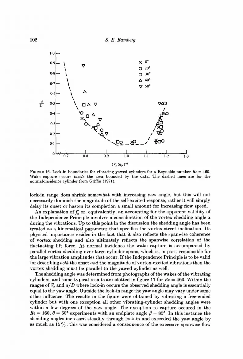
Since most self-excited oscillations occur for f, x fd, further experiments were restricted to the lowest lock-in regime. An onset and a terminal velocity for the lock-in could be determined for each yaw angle and amplitude by slowly varying the flow speed. In order to compare the present results with previous normal-incidence results it was necessary to define an appropriate 'natural' shedding frequency. Use of the corresponding measured stationary-cylinder frequency did not scale the data as well as the use of the expected frequency based on the use of U, cos 8. Therefore the results for the boundaries of the locked-in vortex shedding for yawed cylinders are plotted in figure 16 as functions of the vibration amplitude and the parameter ( K N t N ) - l . The Strouhal number S t N was computed from Roshko's relation using the Reynolds number Re,. The Strouhal number S t N defines a frequency f i , which is to be expected from the cosine laws, so that
A direct comparison with the normal-incidence case is possible as indicated by the dashed lines in figure 16. An interpretation of f i will be taken up shortly, but first the essential similarity between the yawed and unyawed results is to be noted. The
102
1.0
8. E. Ramberg
x oo 0 20°
0 30' A 40'
v soo
FIGURE 16. Lock-in boundaries for vibrating yawed cylinders for a Reynolds number Re = 460. Wake capture occurs inside the area bounded by the data. The dashed lines are for the normal-incidence cylinder from Griffin (1971).
lock-in range does shrink somewhat with increasing yaw angle, but this will not necessarily diminish the magnitude of the self-excited response, rather it will simply delay its onset or hasten its completion a small amount for increasing flow speed.
An explanation off,' or, equivalently, an accounting for the apparent validity of the Independence Principle involves a consideration of the vortex-shedding angle a during the vibrations. Up to this point in the discussion the shedding angle has been treated as a kinematical parameter that specifies the vortex-street inclination. Its physical importance resides in the fact that it also reflects the spanwise coherence of vortex shedding and also ultimately reflects the spanwise correlation of the fluctuating lift force. At normal incidence the wake capture is accompanied by parallel vortex shedding over large cylinder spans, which is, in part, responsible for the large vibration amplitudes that occur. If the Independence Principle is to be valid for describing both the onset and the magnitude of vortex-excited vibrations then the vortex shedding must be parallel to the yawed cylinder as well.
The shedding angle was determined from photographs of the wakes of the vibrating cylinders, and some typical results are plotted in figure 17 for Re = 460. Within the ranges of V, and a / D where lock-in occurs the observed shedding angle is essentially equal to the yaw angle. Outside the lock-in range the yaw angle may vary under some other influence. The results in the figure were obtained by vibrating a free-ended cylinder but with one exception all other vibrating-cylinder shedding angles were within a few degrees of the yaw angle. The exception to capture occured in the Re = 160, 6 = 50' experiments with an endplate angle p = 85'. In this instance the shedding angles increased steadily through lock-in and exceeded the yaw angle by as much as 15 yo ; this was considered a consequence of the excessive spanwise flow
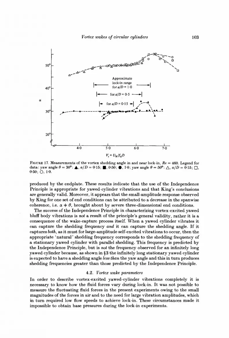
Vortex wakes of circular cylinders
soo
40'
(Y
30"
20"
103
- P-ey-o- ~~
0'0 cb, o\ O
\ 0'0
- 4- -8- - @ n o m & . o B ~ o ~ A \ \
0 P OAc w -
Approximate lock-in range
- I- fora/D = 1.0 -I 1- foru/D=O.S -1
- 1- for ~ / L J = 0.1 s +I ,t-*\
A' \ ,. ___- .--. ------- ---- *wm.&+DA'D- I -- rc :cc - .- 4- A
- 0 00
P -
-
produced by the endplate. These results indicate that the use of the Independence Principle is appropriate for yawed-cylinder vibrations and that King's conclusions are generally valid. Moreover, it appears that the small-amplitude response observed by King for one set of end conditions can be attributed to a decrease in the spanwise coherence, i.e. 01 =k 0, brought about by severe three-dimensional end conditions.
The success of the Independence Principle in characterizing vortex-excited yawed bluff body vibrations is not a result of the principle's general validity, rather it is a consequence of the wake-capture process itself. When a yawed cylinder vibrates it can capture the shedding frequency and it can capture the shedding angle. If it captures both, as it must for large-amplitude self-excited vibrations to occur, then the appropriate 'natural ' shedding frequency corresponds to the shedding frequency of a stationary yawed cylinder with parallel shedding. This frequency is predicted by the Independence Principle, but is not the frequency observed for an infinitely long yawed cylinder because, as shown in $3 the infinitely long stationary yawed cylinder is expected to have a shedding angle less than the yaw angle and this in turn produces shedding frequencies greater than those predicted by the Independence Principle.
4.2. Vortex wake parameters In order to describe vortex-excited yawed-cylinder vibrations completely it is necessary to know how the fluid forces vary during lock-in. It was not possible to measure the fluctuating fluid forces in the present experiments owing to the small magnitudes of the forces in air and to the need for large vibration amplitudes, which in turn required low flow speeds to achieve lock-in. These circumstances made it impossible to obtain base pressures during the lock-in experiments.

1 04 S. E. Ramberg
e = 50' (a)
I I I I I I 0.2 0.4 0.6 0.8 1 .o 1.2
a D
e = 40" alD = 0.3
I I I 5.0 5 5 6.0
*
V , = UNlfdD
FIGURE 18. Measurements of the vortex-formation-region length 2, for vibrating yawed cylinders as a function of ( a ) the reduced velocity V, (at constant amplitude of vibration), ( b ) the amplitude of vibration (at constant reduced velocity).

Vortex wakeB of circular cylinders 105
Based on a known correspondence between the fluid forces and the characteristic wake lengthscales I , and d,, it is possible to infer changes in the former by measuring variations in one or both of the latter. The correspondence between changes in wake dimensions and fluid forces is the basis of Roshko's (1955) analyses and was observed in the present study for stationary yawed-cylinder flows. Also, the formation-region length is known to vary in relation to the amplitude and frequency of vibration during locked-in vortex shedding at normal incidence. Therefore it is reasonable to suppose that if thc formation-region length I , behind vibrating yawed cylinders was observed to vary in the same manner as behind vibrating unyawed cylinders then a corres- pondence in the fluid-force amplification can be inferred.
Measurements of the formation region length were obtained for yaw angles of B = 40' and 50' over a small range of Reynolds numbers near Re = 460. The data are plotted in figure 18 as functions of the reduced velocity V, and the vibration displacement a / D respectively. At a fixed amplitude of oscillation, as in figure 19(a) , the formation length I, increases with reduced velocity V,. This can be compared with the known results a t normal incidence by recalling that V;l K f/fL from $4.1, so that I, is indeed inversely proportional to f / f S , for cylinder vibrations a t both yawed and normal incidence. The vortex-formation-region lengths measured in the wakes of yawed vibrating cylinders can be compared with the stationary cylinder measure- ments a t the same Reynolds number Re,. The latter results appear in $3. At V, = 5.0 the formation lengths are I , = 1-260 and 2-60 for the vibrating and stationary cylinders respectively. At V, = 6.0 the two formation lengths become 2.160 and 2.90 respectively. This reduction in the length of the formation region is direct evidence of an amplification in fluid forces during the locking-on.
At fixed values of the reduced velocity the length of the formation region also decreases with vibration amplitude in the same manner as has been found for a cylinder a t normal incidence. The formation-region length for the vibrating cylinder in figure 18(b) can be compared with the stationary-cylinder results that are listed on the figure. Once again the decrease in 1, with inreasing amplitude of oscillations is a measure of the amplification in the fluid forces during the locking-in or wake capture.
Although these results imply a direct correspondence between the amplification of the fluid forces during lock-in for both yawed and unyawed cylinders, the absolute magnitudes of the fluid forces are not determined here. The logical deduction is that, given the same amplification of fluid forces for both yawed and unyawed vibrations, the actual force magnitudes for the two cases can be related through their stationary- cylinder counterparts. After all, these are the force values that are being amplified by the vibrations. The difficulty with this conclusion is that it is not possible to decide whether the appropriate stationary yawed-cylinder forces are the measured values or those predicted by the cosine laws. The existence of this choice is analogous to the earlier problem in selecting a 'natural ' shedding frequency f,' for the vibrations of yawed cylinders and stems from the capture of the shedding angle during the oscillations. The selection that is consistent with the earlier interpretation is to use the stationary-cylinder forces predicted by the cosine laws. I n this case all facets of the vortex-excited vibrations or yawed cylinders can be scaled from the vibrations a t normal incidence via the cosine laws, even though these fail for the stationary cylinder.

106 S. E. Rarnberg
5. Summary and conclusions Measurements of the vortex-shedding frequency, the shedding angle, the base
pressure, the vortex-formation-region length and the wake width were obtained for stationary yawed circular cylinders (0 = 0'-60') in the Reynolds-number range Re = 15Ck1100. The experiments were performed for various end conditions, including free-ended cylinders and cylinders fitted with endplates. The results were very sensitive to end conditions, especially at the lower Reynolds numbers of the present study.
An intrinsic interdependence between the shedding frequency and the shedding angle was observed and was used to determine, from simple discharged vorticity considerations, the type( s) of end conditions appropriate to the simulation of an infinitely long cylinder. Consideration of the interaction between the end flow and the base-region flow yielded similar conclusions. I n the case of a cylinder with endplates, the appropriate configuration involves inclined endplates ; the amount of inclination depends on the yaw angle but is not precisely specified. Nevertheless, for these configurations the shedding frequency is always greater than expected from the so-called Independence Principle, while the shedding angle, the vortex-formation length, the base pressure and the wake width are all less than expected. Within the framework of a universal Strouhal number S* these variations are offsetting, and the present results for yawed cylinders agree quite well with previous reports of S* for a wide variety of bluff bodies at normal incidence. It is concluded that a number of flows could be realized for finite-length yawed cylinders; the flow in any particular case is dictated by the end conditions.
Measurements of the wake response frequency, the shedding angle and the vortex-formation-region length were obtained for vibrating yawed cylinders in the range of Reynolds numbers between Re = 160 and 460. Wake capture was accom- panied by a frequency lock-in between the vortex wake and the cylinder motion and was also accompanied by vortex shedding parallel to the cylinder axis unless the end flows were severely three-dimensional. Owing to the parallel shedding the appropriate characteristic stationary-cylinder frequency is equal to the shedding frequency predicted by the cosine laws. Therefore the locked-in vortex wakes of vibrating yawed cylinders in the majority of cases can be described by means of the Independence Principle, even though the Principle fails for the stationary cylinder. Measurements of the bounds of the lock-in regime for yawed cylinders compare well with the normal-incidence case as do effects of vibration upon the characteristic wake dimensions.
The author acknowledges the support of the Naval Research Laboratory for the work reported in this paper. A special debt is owed to Dr Mario 6. Casarella of CUA and Dr Owen M. Griffin of NRL for their contributions and advice. This research was submitted to the Catholic University of America, Washington, D.C., in partial fulfilment of the author's Ph.D. dissertation.
REFERENCES
BURSNALL, W. J. & LOFTINQ, L. W. 1951 NACA T N 2463. CHiu, W. S. 1966 Washington State University, College 6s Engineering Bulletin 299. DALE, J. & HOLLER, R. A. 1970 USNADC Rep. AE-7011.

Vortex wakes of circular cylinders 107
DAVIES, M. E. 1976 J . Fluid Mech. 75, 209-231. ETZOLD, F. & FIEDLER, H . 1976 2. Flugwiss. 24, 77-82. FAGE, A. & JOHANSEN, F. C. 1927 Proc. R. SOC. Lond. A 116, 17Ck197. GERRARD, J. H. 1966n J . Fluid Mech. 25, 143-164. GERRARD, J. H. 1966b J . Fluid Mech. 25, 401413. GERRARD, J . J. 1978 Phil. Trans. R. SOC. Lond. A 288, 351. GRAHAM, J. M. R. 1969 Aero. Q. 20, 237-247. GRIFFIN, 0. M. 1971 Trans. A.S.M.E. E: J . Appl . Mech. 38, 729-738. GRIFFIN, 0. M. 1978 J . Fluid Mech. 85, 591-607. GRIFFIN, 0. M. 1981 Trans. A.S.M.E. I: J . Fluids Engng 103, 52-58. GRIFFIN, 0. M. & RAMBERG, S. E. 1974 J . Fluid Mech. 66, 553-.576. GRIFFIN, 0. M. & RAMBERG, S. E. 1975 J . Fluid Mech. 69, 721-728. HANSON, A. R. 1966 A.I.A.A. J . 4, 738-740. KING, R. 1977 Trans. A.S.M.E. I : J . Fluids Engng 99, 49,5502. RAMBERG, S. E. 1978 Naval Research Lab. Memo. Rep. 3822. RAMBERG, S. E. & GRIFFIN, 0. M. 1974 Trans. A.S.M.E. I : J . Fluids Engng 96, 317-322. ROSHKO, A. 1954a N A C A Rep. 1191. ROSHKO, A. 19543 N A C A T N 3168. ROSHKO, A. 1955 J . Aero. Sci. 22, 124-132. RELF, E. H. & POWELL, C. H. 1917 British A.R.C. SCHLICHTING, H. 1968 Boundary Layer Theory, 6th edn. McGraw-Hill. SLAOUTI, A. & GERRARD, J. H. 1981 J . Fluid. Mech. 112, 297-314. SMITH, R. A. , MOON, W. T. & KAO, T. W. 1972 Trans. A.S.M.E. D: J . Basic Engng 94, 7 1 1-776. STANSBY, P. K. 1974 Aero. J . 78, 3G37. VAN ATTA, C. W. 1968 A.Z.A.A. J . 6, 931-933. VOTAW, C. W. & GRIFFIN, 0. M. 1971 Trans. A.S.M.E. D : J . Basic Engng 93, 457-460.