terracan-electrical-troubelshooting-manual.pdf - terry on tour
TRANSCRIPT
<E/)HYUnDRI CONTENTS
Terracan TITLE 10
Electrical HOWTO USE GI THISMANUAL
Troubleshooting Manual
SCHEMATIC so FOREWORD OIAGRAMS
This manual is intended for use by service technicians of authorized Hyundai dealers to help them provide efficient and correct service and maintenance on Hyundai vehicle.
T 0 ensure customer satisfaction with Hyundai products, prop~r COMPONENT service and maintenanca by Hyundai technicians is essential. CL
Consequently, it is important that service personnel fully LOCATIONS understand the contents of this manual, which should be kept in a handy place for quiCk and easy reference.
All the contents of this manual, including photographs, drawings, and specifications, are the latest available at the time of printing. As modifications affecting service occur,
CONNECTOR dealers will be provided technical service bulletins or supple- CC mentary volumes. This manual should be kept carefully up-to- CONFIGURATIONS date upon receipt of the new information.
Hyundai Motor Company reserves the right to make changes in design or to make additions to or improvements in its products without imposing any obligations upon itself to install them on its products previously manufactured.
HARNESS LAYOUTS HL
AUG. 2003, Printed in Korea
All rights reserved. No part of this publication may be reproduced, stored in any retrieval system or transmitted in any form or by any means without the prior written permission of Hyundai Motor Company.
HARNESS LAYOUTS
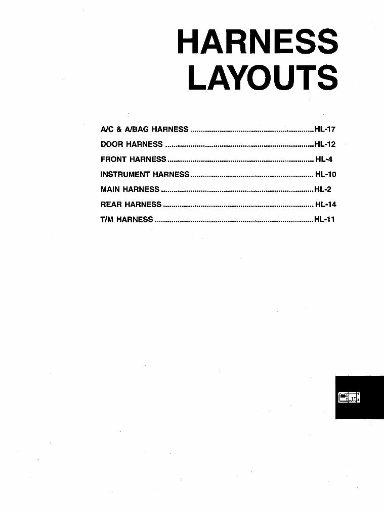
Ale & AlBAG HARNESS ........................................................... HL·17
DOOR HARNESS ........................................................................ HL-12
FRONT HARNESS .....•.......•..•....•........•.........•••.•.....•.......•........... HL .. 4
INSTRUMENT HARNESS ........................................................... HL .. 10
MAIN HARNESS ......................................................................... HL .. 2
REAR HARNESS ........................................................................ HL .. 14
TIM HARNESS ............................................................................ HL .. 11
HL-2 HARNESS LAYOUTS
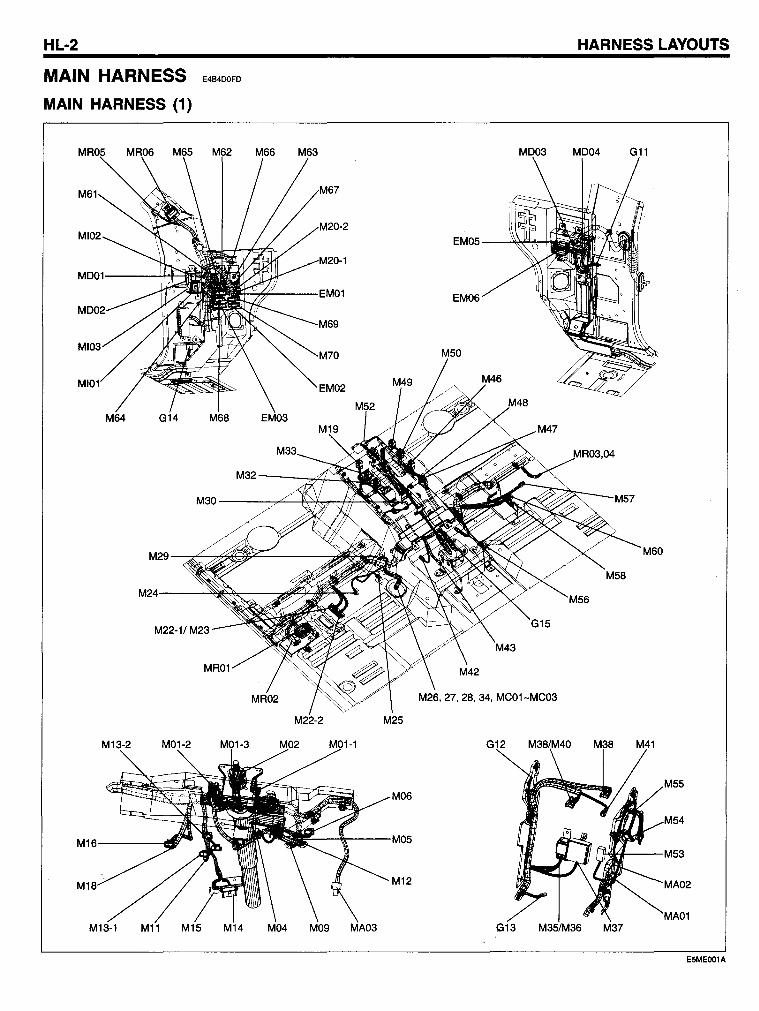
MAIN HARNESS E4B4DOFD
MAIN HARNESS (1)
MD03 MD04 G11
EM05 ----"~(-+io ..
M60
M22-2 M25
G12 M38/M40 M38 M41
M55 M06
M54
M05
M53
M1 M12 MA02
MA01 G13 M35/M36 M37
E5MEOO1A
MAIN HARNESS HL-3
MAIN HARNESS (2)
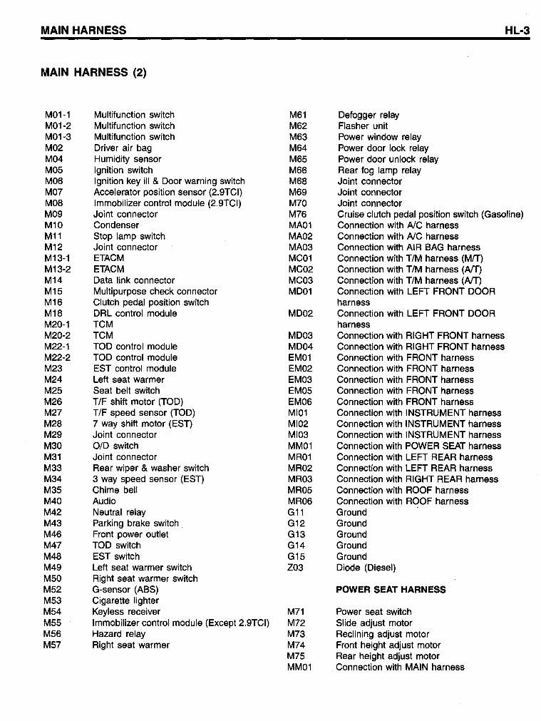
M01-1 Multifunction switch M61 Defogger relay M01-2 Multifunction switch M62 Flasher unit M01-3 Multifunction switch M63 Power window relay M02 Driver air bag M64 Power door lock relay M04 Humidity sensor M65 Power door unlock relay M05 Ignition switch M66 Rear fog lamp relay M06 Ignition key iII & Door warning switch M68 Joint connector M07 Accelerator position sensor (2.9TCI) M69 Joint connector M08 Immobilizer contral module (2.9TCI) M70 Joint connector M09 Joint connector M76 Cruise clutch pedal position switch (Gasoline) M10 Condenser MA01 Connection with AlC harness M11 Stop lamp switch MA02 Connection with AlC harness M12 Joint connector MA03 Connection with AIR SAG harness M13-1 ETACM MC01 Connection with TIM harness (MIT) M13-2 ETACM MC02 Connection with TIM harness (AlT) M14 Data link connector MC03 Connection with TIM harness (AlT) M15 Multipurpose check connector MD01 Connection with LEFT FRONT DOOR M16 Clutch pedal position switch harness M18 DRL control module MD02 Connection with LEFT FRONT DOOR M20-1 TCM harness M20-2 TCM MD03 Connection with RIGHT FRONT harness M22-1 TOD contra I module MD04 Connection with RIGHT FRONT harness M22-2 TOD control module EM01 Connection with FRONT harness M23 EST control module EM02 Connection with FRONT harness M24 Left seat warmer EM03 Connection with FRONT harness M25 Seat belt switch EM05 Connection with FRONT harness M26 TIF shift motor (TOD) EM06 Connection with FRONT harness M27 TIF speed sensor (TOD) MI01 Connection with INSTRUMENT harness M28 7 way shift motor (EST) MI02 Connection with INSTRUMENT harness M29 Joint connector MI03 Connection with INSTRUMENT harness M30 0/0 switch MM01 Connection with POWER SEAT harness M31 Joint connector MR01 Connection with LEFT REAR harness M33 Rear wiper & washer switch MR02 Connection with LEFT REAR harness M34 3 way speed sensor (EST) MR03 Connection with RIGHT REAR harness M35 Chime bell MR05 Connection with ROOF harness M40 Audio MR06 Connection with ROOF harness M42 Neutral relay G11 Ground M43 Parking brake switch G12 Ground M46 Front power outlet G13 Ground M47 TOD switch G14 Ground M48 EST switch G15 Ground M49 Left seat warmer switch 203 Diode (Diesel) M50 Right seat warmer switch M52 G-sensor (ASS) POWER SEAT HARNESS M53 Cigarette lighter M54 Keyless receiver M71 Power seat switch M55 Immobilizer control module (Except 2.9TCI) M72 Slide adjust motor M56 Hazard relay M73 Reclining adjust motor M57 Right seat warmer M74 Front height adjust motor
M75 Rear height adjust motor MM01 Connection with MAIN harness
HL-4
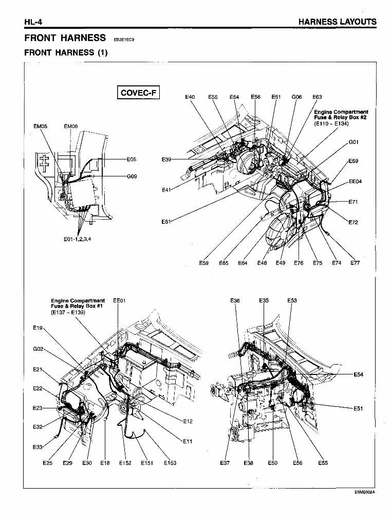
FRONT HARNESS
FRONT HARNESS (1)
EB3E1EC9
I COVEC-F I
EM05 EM06
"""""FI-+---E05
1"'~-++----G09
E01-1,2,3,4
Engine Compartment EE01 Fuse & Relay Box #1 (E137 - E139)
E19
E21
E23-----tII~
E32
E4
E6
E25 E29 E30 E18 E152 E151 E153
E65
E12
HARNESS LAYOUTS
Englne Compartment Fuse & Relay Box #2 (E110-E134)
G01
EE04
E5MEOO2A
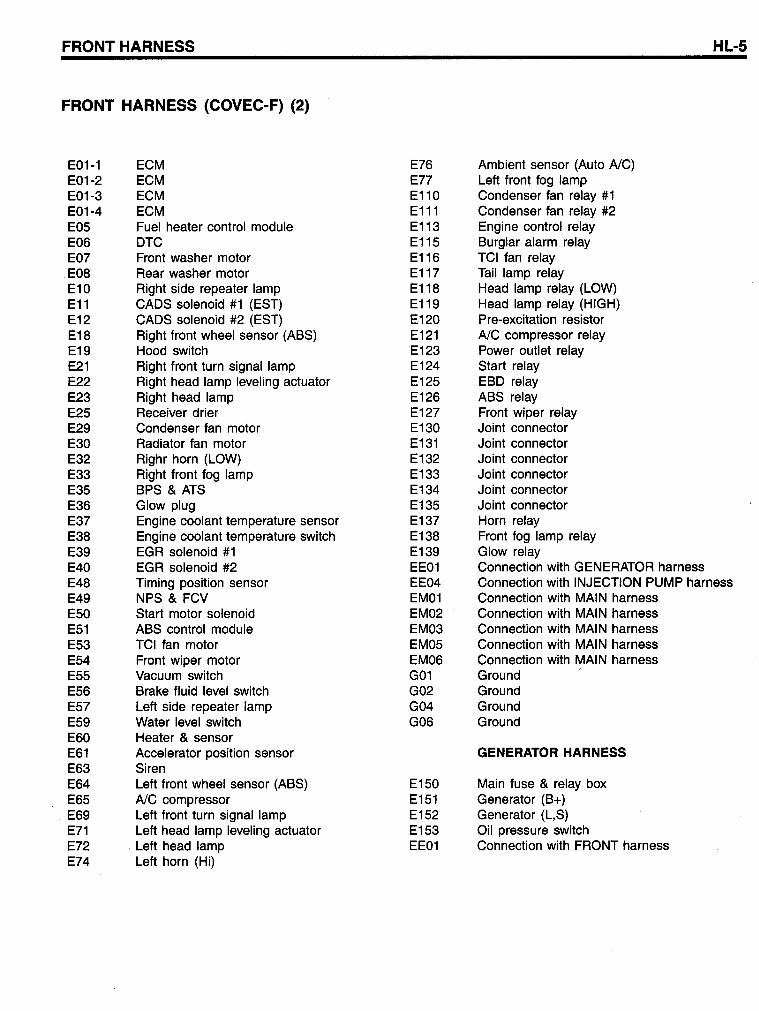
FRONT HARNESS HL-5
FRONT HARNESS (COVEC-F) (2)
E01-1 ECM E76 Ambient sensor (Auto AlC) E01-2 ECM E77 Left front fog lamp E01-3 ECM E110 Condenser fan relay #1 E01-4 ECM E111 Condenser fan relay #2 E05 Fuel heater control module E113 Engine control relay E06 DTC E115 Burglar alarm relay E07 Front washer motor E116 TCI fan relay E08 Rear washer motor E117 Tail lamp relay E10 Right side repeater lamp E118 Head lamp relay (LOW) E11 CADS solenoid #1 (EST) E119 Head lamp relay (HIGH) E12 CADS solenoid #2 (EST) E120 Pre-excitation resistor E18 Right front wheel sensor (ABS) E121 AlC compressor relay E19 Hood switch E123 Power outlet relay E21 Right front turn signal lamp E124 Start relay E22 Right head lamp leveling actuator E125 EBD relay E23 Right head lamp E126 ABS relay E25 Receiver drier E127 Front wiper relay E29 Condenser fan motor E130 Joint connector E30 Radiator fan motor E131 Joint connector E32 Righr horn (LOW) E132 Joint connector E33 Right front fog lamp E133 Joint connector E35 BPS & ATS E134 Joint connector E36 Glow plug E135 Joint connector E37 Engine coolant temperature sensor E137 Horn relay E38 Engine coolant temperature switch E138 Front fog lamp relay E39 EGR solenoid #1 E139 Glow relay E40 EGR solenoid #2 EE01 Connection with GENERATOR harness E48 Timing position sensor EE04 Connection with INJECTION PUMP harness E49 NPS & FCV EM01 Connection with MAIN harness E50 Start motor solenoid EM02 Connection with MAIN harness E51 ABS control module EM03 Connection with MAIN harness E53 TCI fan motor EM05 Connection with MAIN harness E54 Front wiper motor EM06 Connection with MAIN harness E55 Vacuum switch G01 Ground E56 Brake fluid level switch G02 Ground E57 Left side repeater lamp G04 Ground E59 Water level switch G06 Ground E60 Heater & sensor E61 Accelerator position sensor GENERATOR HARNESS E63 Siren E64 Left front wheel sensor (ABS) E150 Main fuse & relay box E65 AlC compressor E151 Generator (B+) E69 Left front turn signal lamp E152 Generator (L,S) E71 Left head lamp leveling actuator E153 Oil pressure switch E72 Left head lamp EE01 COhnection with FRONT harness E74 Left horn (Hi)
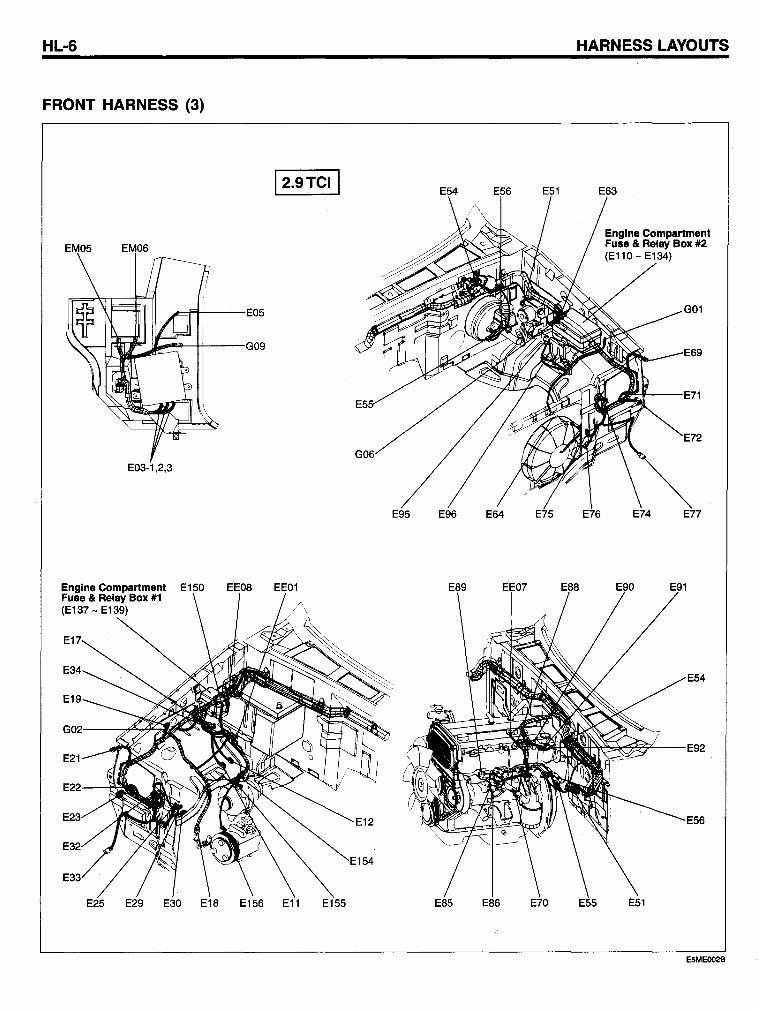
HL-6
FRONT HARNESS (3)
EM05 EM06
~fl1---E05
JJ.o,o----,\-+---G09 f-!-..J .... ".~'
E03-1,2,3
Englne Compartment Fuse & Relay Box #1 (E137 - E139)
12.9TCII E54
G06
E95 E96
E56 E51
E64 E75
HARNESS LAYOUTS
E63
E76
Englne Compartment Fuse & Relay Box #2 (E110 - E134)
G01
E69
""""'--E71
E72
E74 E77
E5MEOO28
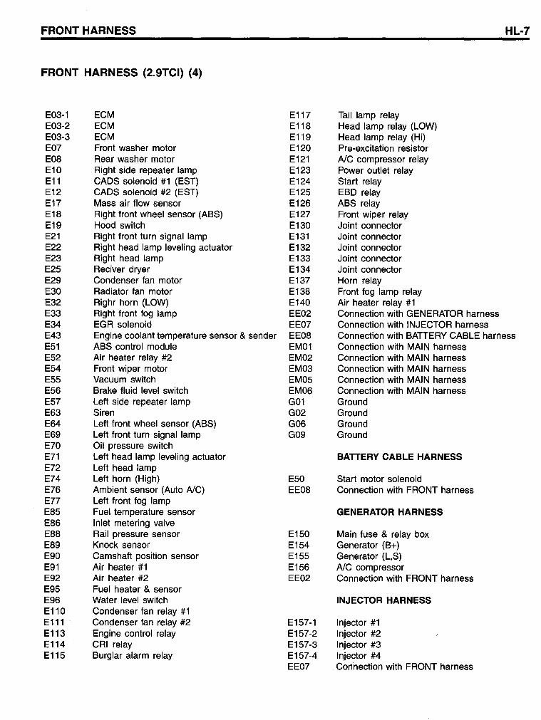
FRONT HARNESS HL-7
FRONT HARNESS (2.9TCI) (4)
E03-1 ECM E117 Tail lamp relay E03-2 ECM E118 Head lamp relay (LOW) E03-3 ECM E119 Head lamp relay (Hi) E07 Front washer motor E120 Pre-excitation resistor E08 Rear washer motor E121 AlC compressor relay E10 Right side repeater lamp E123 Power outlet relay E11 CADS solenoid #1 (EST) E124 Start relay E12 CADS solenoid #2 (EST) E125 ESD relay E17 Mass air flow sensor E126 ASS relay E18 Right front wheel sensor (ASS) E127 Front wiper relay E19 Hood switch E130 Joint connector E21 Right front turn signal lamp E131 Joint connector E22 Right head lamp leveling actuator E132 Joint connector E23 Right head lamp E133 Joint connector E25 Reciver dryer E134 Joint connector E29 Condenser fan motor E137 Horn relay E30 Radiator fan motor E138 Front fog lamp relay E32 Righr horn (LOW) E140 Air heater relay #1 E33 Right front fog lamp EE02 Connection with GENERATOR harness E34 EGR solenoid EE07 Connection with INJECTOR harness E43 Engine coolant temperature sensor & sender EE08 Connection with SATTERY CASLE harness E51 ASS control module EM01 Connection with MAIN harness E52 Air heater relay #2 EM02 Connection with MAIN harness E54 Front wiper motor EM03 Connection with MAIN harness E55 Vacuum switch EM05 Connection with MAIN harness E56 Srake fluid level switch EM06 Connection with MAIN harness E57 Leff side repeater lamp G01 Ground E63 Siren G02 Ground E64 Leff front wheel sensor (ASS) G06 Ground E69 Leff front turn signal lamp G09 Ground E70 Oil pressure switch E71 Leff head lamp leveling actuator BATTERV CABLE HARNESS E72 Left head lamp E74 Left horn (High) E50 Start motor solenoid E76 Ambient sensor (Auto AlC) EE08 Connection with FRONT harness E77 Left front fog lamp E85 Fuel temperature sensor GENERATOR HARNESS E86 Inlet metering valve E88 Rail pressure sensor E150 Main fuse & relay box E89 Knock sensor E154 Generator (S+) E90 Camshaff position sensor E155 Generator (L,S) E91 Air heater #1 E156 AlC compressor E92 Air heater #2 EE02 Connection with FRONT harness E95 Fuel heater & sensor E96 Water level switch INJECTOR HARNESS E110 Condenser fan relay #1 E111 Condenser fan relay #2 E157-1 Injector #1 E113 Engine control relay E157-2 Injector #2 E114 CRI relay E157-3 Injector #3 E115 Surglar alarm relay E157-4 Injector #4
EE07 Connection with FRONT harness
HL-8
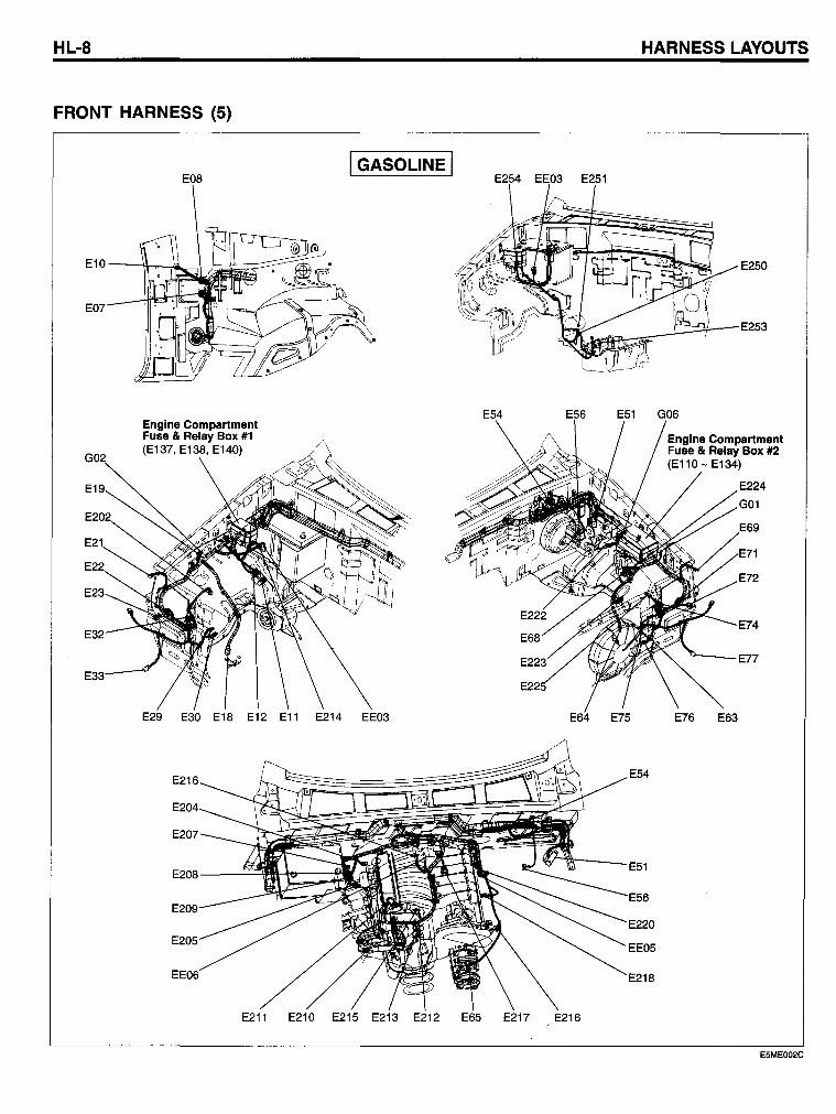
FRONT HARNESS (5)
G02
E19
E21
E22
E23
E32
E33
Engine Compartment Fuse & Relay Box #1 (E137, E138, E140)
I GASOLINE I E254 EE03 E251
E54 E56
HARNESS LAYOUTS
E250
~"""--E253
E51 G06
Engine Compartment Fuse & Relay Box #2 (E110 - E134)
E224
G01
E69
E71
E72
E74
'+---E77
E29 E30 E18 E12 E11 E214 EE03 E64 E75 E76 E63
E211 E210 E215 E213 E212 E65 E217 E216
E5ME002C
FRONT HARNESS HL-9
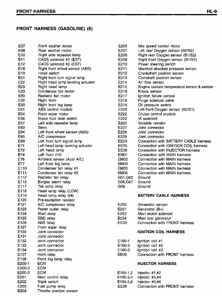
FRONT HARNESS (GASOLINE) (6)
E07 Front was her motor E205 Idle speed control motor E08 Rear washer motor E207 Left rear Oxygen sensor (B2/S2) E10 Right side repeater lamp E208 Right rear Oxygen sensor (B1/S2) E11 CADS solenoid #1 (EST) E209 Right front Oxygen sensor (B 1 /S 1 ) E12 CADS solenoid #2 (EST) E210 Power steering switch E18 Right front wheel sensor (ABS) E211 Manifold absolute pressure sensor E19 Hood switch E212 Crankshaft position sensor E21 Right front turn signal lamp E213 Camshaft position sensor E22 Right head lamp leveling actuator E214 Air flow sensor E23 Right head lamp E215 Engine coolant temperature sensor & sender E29 Condenser fan motor E216 Knock sensor E30 Radiator fan motor E217 Ignition failure sensor E32 Right horn E218 Purge solenoid valve E33 Right front fog lamp E219 Oil pressure switch E51 ABS control module E220 Left front Oxygen sensor (B2/S1) E54 Front wiper motor E222 Cruise control module E56 Brake fluid level switch E223 VI solenoid E57 Left side repeater lamp E225 Variable resistor E63 Siren E227 Joint connector E64 Left front wheel sensor (ABS) E228 Joint connector E65 AlC compressor E229 Joint connector E69 Left front turn signal lamp EE03 Connection with BATTERY CABLE harness E71 Left head lamp leveling actuator EE05 Connection with IGNITIOB COIL harness E72 Left head lamp EE06 Connection with INJECTOR harness E74 Left horn (Hi) EM01 Connection with MAIN harness E76 Ambient sensor (Auto AlC) EM02 Connection with MAIN harness E77 Left front fog lamp EM03 Connection with MAIN harness E110 Condenser fan relay #1 EM05 Connection with MAIN harness E111 Condenser fan relay #2 EM06 Connection with MAIN harness E112 Radiator fan relay G01,G02 Ground E115 Burglar alarm relay G06,G07 Ground E117 Tail lamp relay G08 Ground E118 Head lamp relay (LOW) E119 Head lamp relay (Hi) BATTERY CABLE HARNESS E120 Pre-excitation resistor E121 AlC compressor relay E250 Generator sensor E123 Power outlet relay E251 Generator (B+) E124 Start relay E253 Start motor solenoid E125 EBD relay E254 Main box generator E126 ABS relay EE03 Connection with FRONT harness E127 Front wiper relay E130 Joint connector IGNITION COIL HARNESS E131 Joint connector E132 Joint connector E160-1 Ignition coil #1 E133 Joint connector E160-2 Ignition coil #2 E134 Joint connector E160-3 Ignition coil #3 E137 , Horn relay EE05 Connection with FRONT harness E138 Front fog lamp relay E200-1 ECM INJECTOR HARNESS E200-2 ECM E200-3 ECM E165-1,2 Injector #1,#2 E201 Main control relay E165-3,4 Injector #3,#4 E202 Tripie switch E165-5,6 Injector #5,#6 E203 Fuel pump relay EE06 Connection with FRONT harness E204 Throttle position sensor
HL-10
INSTRUMENT HARNESS
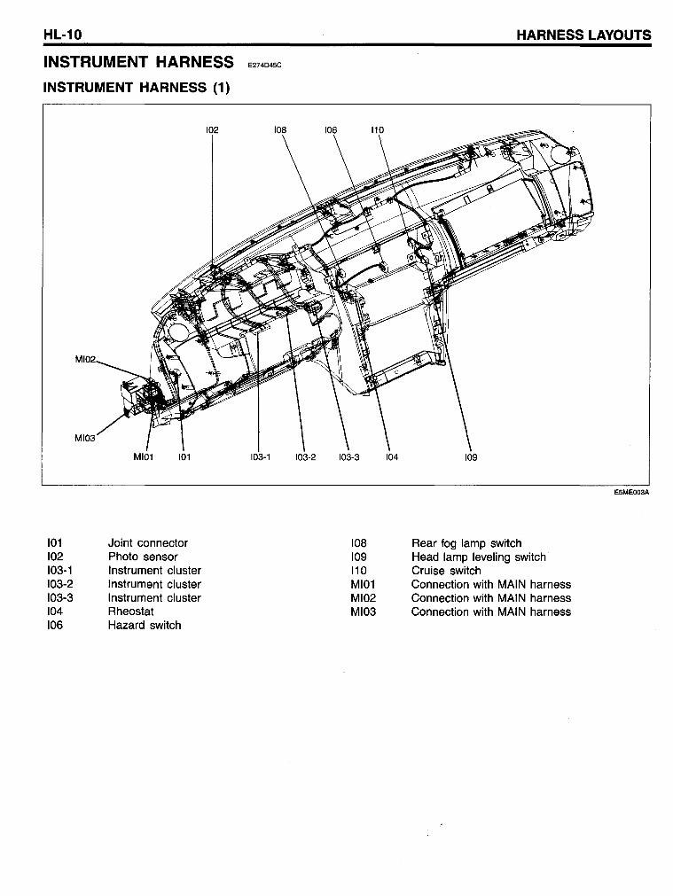
INSTRUMENT HARNESS (1)
101 Joint connector 102 Photo sensor 103-1 Instrument cluster 103-2 Instrument cluster 103-3 Instrument cluster 104 Rheostat 106 Hazard switch
HARNESS LAYOUTS
E274D4SC
ESMEOO3A
108 Rear fog lamp switch 109 Head lamp leveling switch 110 Cruise switch MI01 Connection with MAIN harness MI02 Connection with MAIN harness MI03 Connection with MAIN harness
TIM HARNESS
TIM HARNESS
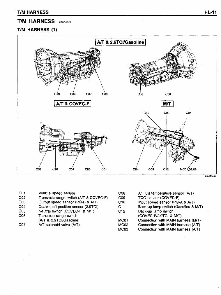
TIM HARNESS (1)
EBDCAC72
I AlT & 2.9TCI/Gasoline I
C01 C02 C03 C04 COS C06
C07
C10 C04 CO? COS
I AlT & COVEC-F I
COg C10 CO? C03 C01
Vehicle speed sensor Transaxle range switch (Aff & COVEC-F) Output speed sensor (PG-B & Aff) Crankshaft position sensor (2.9TCI) Neutral switch (COVEC-F & MIT) Transaxle range switch (Aff & 2.9TCI/Gasoline) Aff solenoid valve (Aff)
COB C09 C10 C11 C12
MC01 MC02 MC03
C03 C06
C01
C04 COg C12 MC01,02,03
Aff Oil temperature sensor (Aff) TDC sensor (COVEC-F) Input speed sensor (PG-A & Aff) Back-up lamp switch (Gasoline & MIT) Back-up lamp switch (COVEC-F/2.9TCI & MIT) Connection with MAIN harness (MIT) Connection with MAIN harness (Aff) Connection with MAIN harness (Aff)
HL-11
E5MEOO4A
HL-12
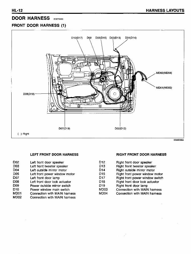
DOOR HARNESS ECE75850
FRONT COOR HARNESS (1)
008(018) ---H\-'r--\\IIIH
( ): Right
002 003 004 005 007 008 009 010 MOOl M002
~~~~
007(019)
LEFT FRONT DOOR HARNESS
Left front door speaker Left front tweeter speaker Left outside mirror motor Left front power window motor Left front door lamp Left front door lock actuator Power outside mirror switch Power window main switch Connection with MAIN harness Connection with MAIN harness
012 013 014 015 017 018 019 M003 M004
HARNESS LAYOUTS
004(014)
M002(M004)
M001(M003)
002(012)
RIGHT FRONT DOOR HARNESS
Right front door speaker Right front tweeter speaker Right outside mirror motor Right front power window motor Right front power window switch Right front door lock actuator Right front door lamp Connection with MAIN harness Connection with MAIN harness
E5MEOO5A
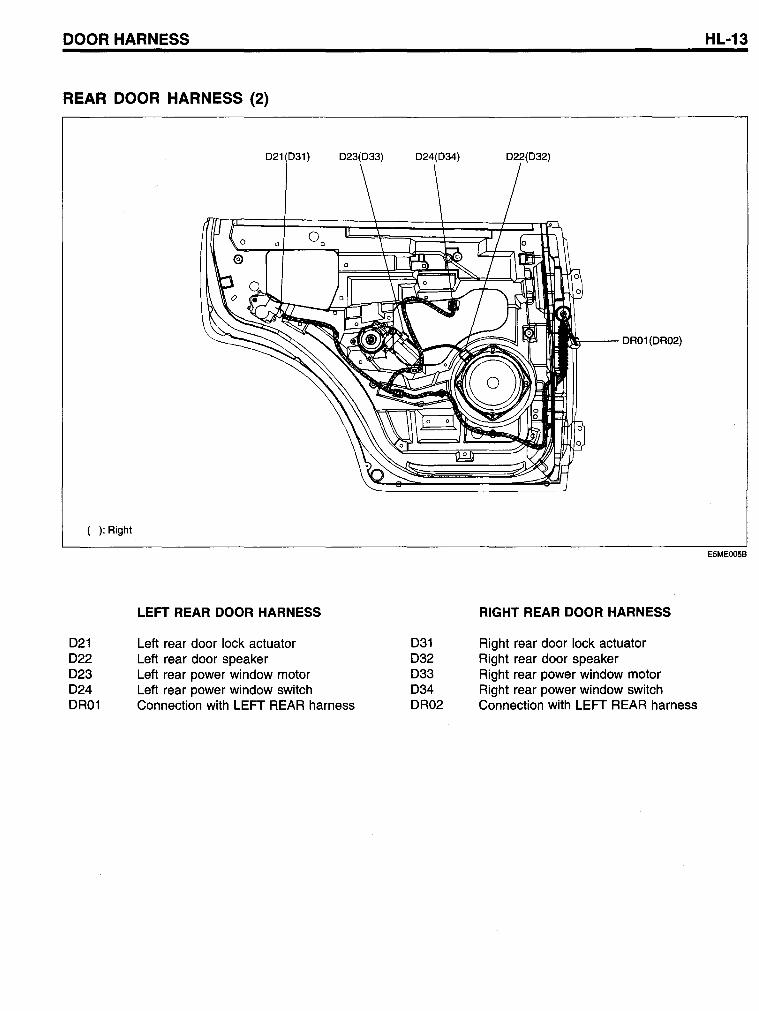
COOR HARNESS
REAR COOR HARNESS (2)
( ): Right
021 022 023 024 OR01
021 031)
LEFT REAR DOOR HARNESS
Left rear door lock actuator Left rear door speaker Left rear power window motor
023(033)
Left rear power window switch Connection with LEFT REAR harness
024(034)
031 032 033 034 OR02
022(032)
:&--- OR01 (OR02)
RIGHT REAR DOOR HARNESS
Right rear door lock actuator Right rear door speaker Right rear power window motor Right rear power window switch Connection with LEFT REAR harness
HL-13
E5MEOO5B
HL-14
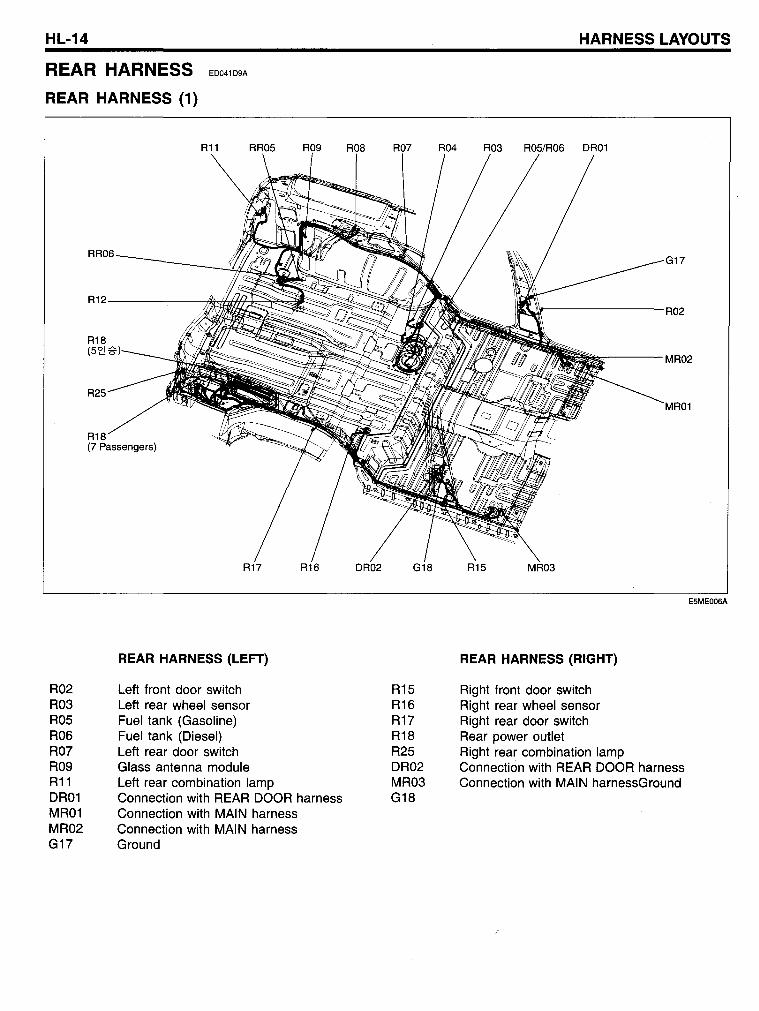
REAR HARNESS
REAR HARNESS (1)
ED041D9A
R02 R03 R05 R06 R07 R09 R11 DR01 MR01 MR02 G17
RR06
R12
R18 (5~
R25
R18 (7 Passengers)
REAR HARNESS (LEFT)
Left front door switch Left rear wheel sensor Fuel tank (Gasoline) Fuel tank (Diesel) Left rear door switch Glass anten na module Left rear combination lamp Connection with REAR DOOR harness Connection with MAIN harness Connection with MAIN harness Ground
R15 R16 R17 R18 R25 DR02 MR03 G18
HARNESS LAYOUTS
G17
R02
MR02
MR01
REAR HARNESS (RIGHT)
Right front door switch Right rear wheel sensor Right rear door switch Rear power outlet Right rear combination lamp Connection with REAR DOOR harness Connection with MAIN harnessGround
E5ME006A
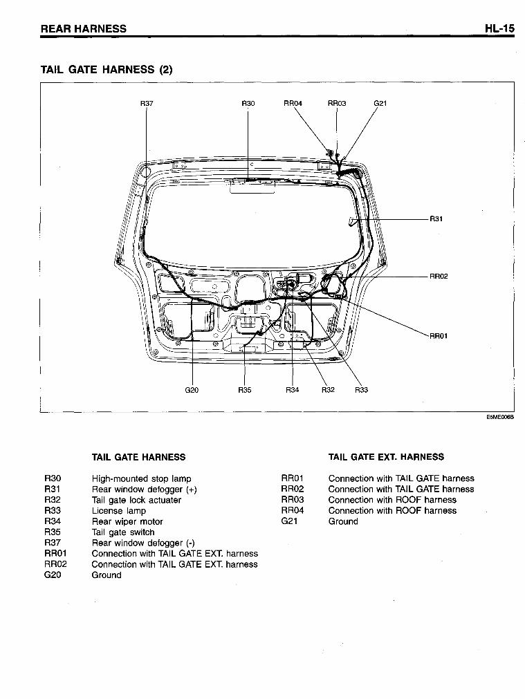
REAR HARNESS
TAIL GATE HARNESS (2)
R30 R31 R32 R33 R34 R35 R37 RR01 RR02 G20
R37
G20
TAIL GATE HARNESS
High-mounted stop lamp Rear window defogger (+) Tail gate lock actuater License lamp Rear wiper motor Tail gate switch Rear window defogger (-)
R30
R35
Connection with TAIL GATE EXT. harness Connection with TAIL GATE EXT. harness Ground
RR04
R34
RR01 RR02 RR03 RR04 G21
RR03 G21
~H'I-'\\\\-----R31
RR01
R32 R33
TAIL GATE EXT. HARNESS
Connection with TAIL GATE harness Connection with TAIL GATE harness Connection with ROOF harness Connection with ROOF harness Ground
HL-15
E5ME006B
HL-16
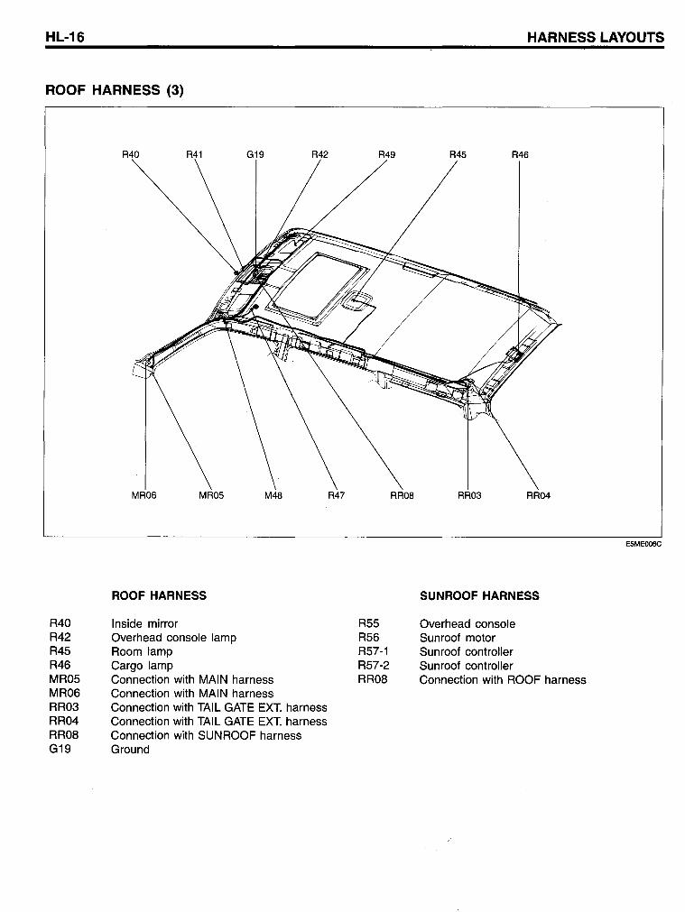
ROOF HARNESS (3)
R40 R42 R45 R46 MR05 MR06 RR03 RR04 RR08 G19
MRD6
ROOF HARNESS
Inside mirror Overhead console lamp Room lamp Cargo lamp
M48
Connection with MAIN harness Connection with MAI N harness Connection with TAIL GATE EXT. harness Connection with TAIL GATE EXT. harness Connection with SUNROOF harness Ground
R47
R55 R56 R57-1 R57-2 RR08
RRD8
HARNESS LAYOUTS
RRD3 RRD4
SUNROOF HARNESS
Overhead console Sunroof motor Sunroof controller Sunroof controller Connection with ROOF harness
E5ME006C
AlC & AlBAG HARNESS
Ale & AlBAG HARNESS
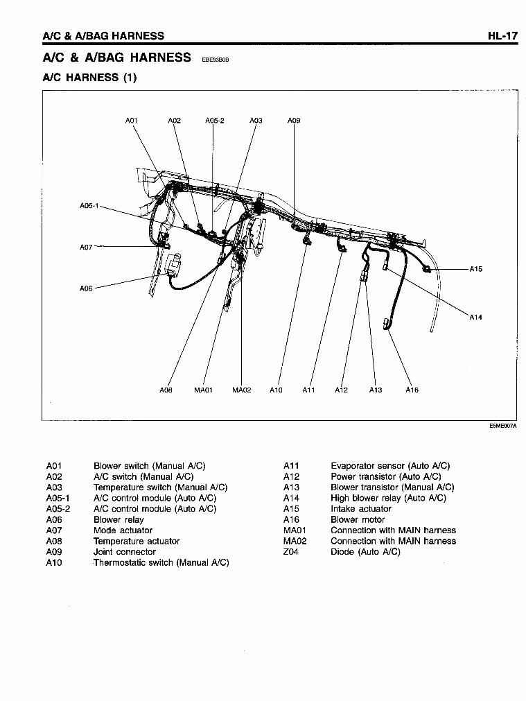
AlC HARNESS (1)
EBE93BOB
A01 A02 A03 A05-1 A05-2 A06 A07 AOS A09 A10
A01 A02 A05-2
A05-1
A07----~~
A06
Blower switch (Manual AlC) AlC switch (Manual AlC) Temperature switch (Manual AlC) AlC control module (Auto AlC) AlC control module (Auto AlC) Blower relay Mode actuator Temperature actuator Joint connector Thermostatic switch (Manual AlC)
A03 A09
A11 A12 A13 A14 A15 A16 MA01 MA02 Z04
'M-\\----A 15
Evaporator sensor (Auto AlC) Power transistor (Auto AlC) Blower transistor (Manual AlC) High blower relay (Auto AlC) Intake actuator Blower motor Connection with MAIN harness Connection with MAIN harness Diode (Auto AlC)
A14
HL-17
E5MEOO7A
HL-18
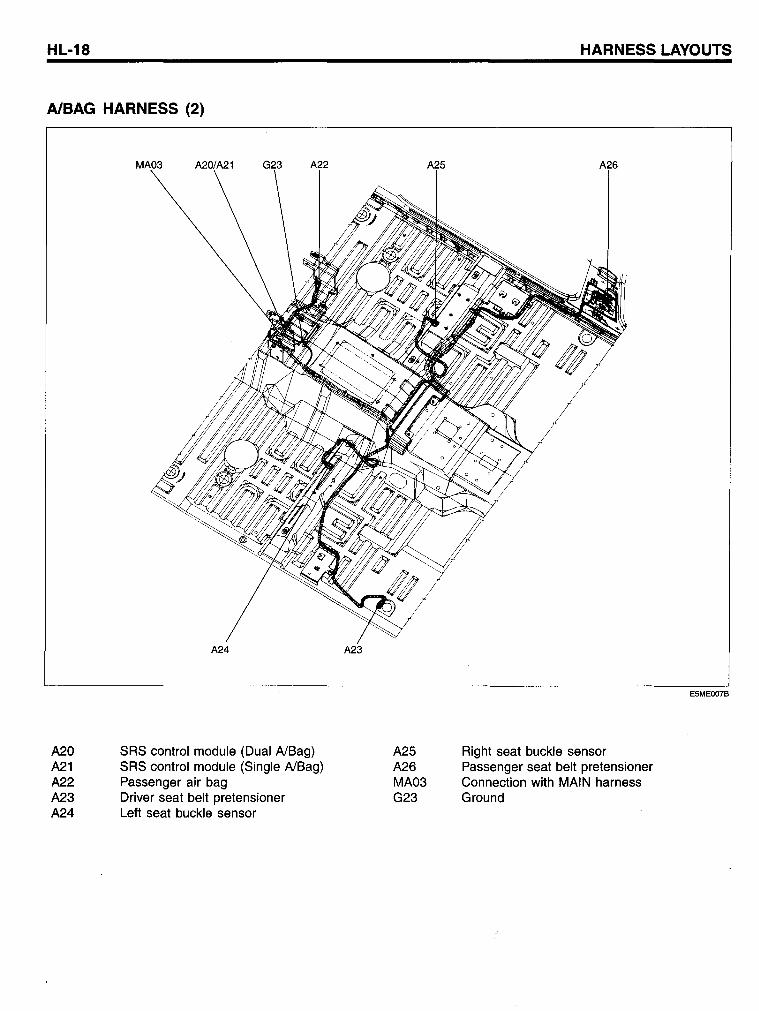
AlBAG HARNESS (2)
A20 A21 A22 A23 A24
A24
SRS control module (Dual AlBag) SRS control module (Single AlBag) Passenger air bag Driver seat belt pretensioner Left seat buckle sensor
A25 A26 MA03 G23
HARNESS LAYOUTS
Right seat buckle sensor Passenger seat belt pretensioner Connection with MAIN harness Ground
E5MEOO7B
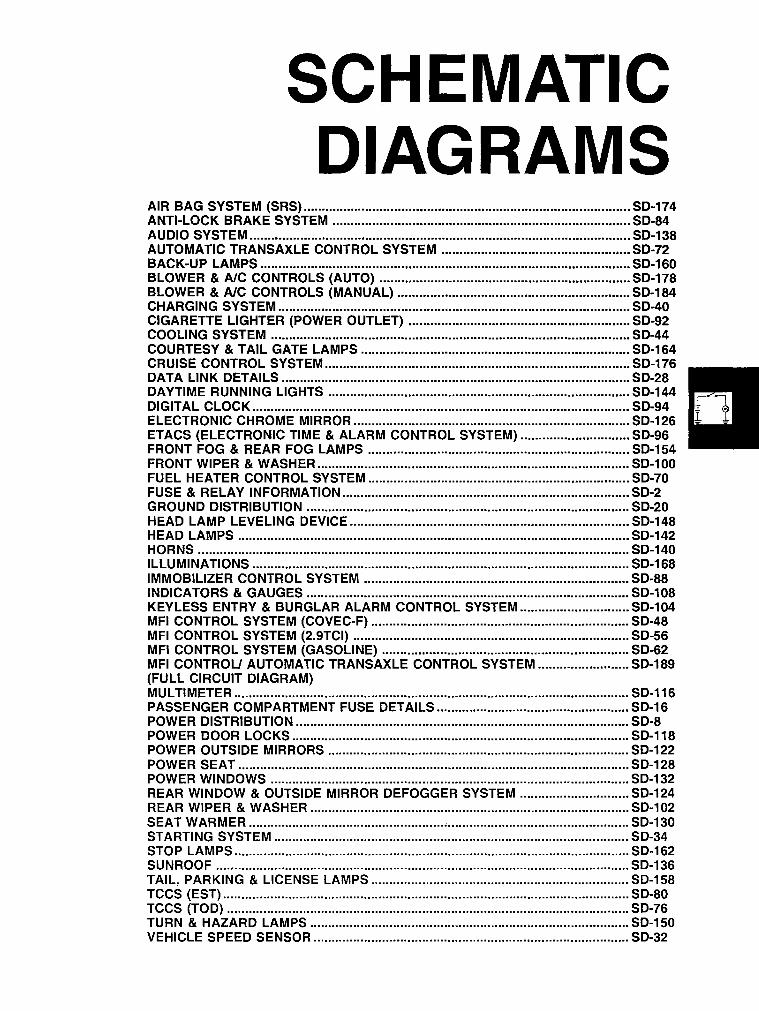
SCHEMATIC DIAGRAMS
AIR BAG SYSTEM (SRS) .......................................................................................... SO-174 ANTI-LOCK BRAKE SYSTEM ........................................................................•......... SO-84 AUOIO SySTEM .....................................•.........................................................•.....•... SO-138 AUTOMATIC TRANSAXLE CONTROL SYSTEM .................................................... SO-72 BACK-UP LAMPS ...................................................................................................... SO-160 BLOWER & AlC CONTROLS (AUTO) ......................................................•..........•... SO-178 BLOWER & AlC CONTROLS (MANUAL) ................................................................ SO-184 CHARGING SYSTEM ..........................•...................................................................... SO-40 CIGARETTE LlGHTER (POWER OUTLET) ............................................................. SO-92 COOLING SYSTEM .....................................................................................•............. SO-44 COURTESY & TAIL GATE LAMPS .......................................................................... SO-164 CRUISE CONTROL SYSTEM .................................................................................... SO-176 OATA LINK DETAILS ................................................................................................ SO-28 OAYTIME RUNNING LIGHTS ................................................................................... SO-144 DIGITAL CLOCK ........................................................................................................ SO-94 ELECTRONIC CHROME MIRROR ............................................................................ SO-126 ETACS (ELECTRONIC TIME & ALARM CONTROL SYSTEM) .............................. SO-96 FRONT FOG & REAR FOG LAMPS ........................................................................ SO-154 FRONT WIPER & WASHER .....................•................................................................ SO-100 FUEL HEATER CONTROL SYSTEM ........................................................................ SO-70 FUSE & RELAY INFORMATION ............................................................................... SO-2 GROUNO DISTRIBUTION ......................................................................................... SO-20 HEAO LAMP LEVELING OEVICE ............................................................................. SO-148 HEAO LAMPS ............................................................................................................ SO-142 HORNS ....................................................................................................................... SO-140 ILLUMINATIONS ........................................................................................................ SO-168 IMMOBILIZER CONTROL SYSTEM ......................................................................... SO-88 INOICATORS & GAUGES ......................................................................................... SO-108 KEYLESS ENTRY & BURGLAR ALARM CONTROL SYSTEM .............................. SO-l04 MFI CONTROL SYSTEM (COVEC-F) ....................................................................... SO-48 MFI CONTROL SYSTEM (2.9TCI) ............................................................................ SO-56 MFI CONTROL SYSTEM (GASOLINE) .................................................................... SO-62 MFI CONTROU AUTOMATIC TRANSAXLE CONTROL SYSTEM ......................... SO-189 (FULL CIRCUIT DIAGRAM) MULTIMETER ............................................................................................................. SO-116 PASSENGER COMPARTMENT FUSE DETAILS ..................................................... SO-16 POWER DISTRIBUTION ............................................................................................ SO-8 POWER OOOR LOCKS ............................................................................................. SO-118 POWER OUTSIDE MIRRORS ................................................................................... SO-122 POWER SEAT ............................................................................................................ SO-128 POWER WINOOWS ..........................................................................................•........ SO-132 REAR WINOOW & OUTSIDE MIRROR OEFOGGER SYSTEM .............................. SO-124 REAR WIPER & WASHER ........................................................................................ SO-102 SEAT WARMER ......................................................................................................... SO-130 STARTING SYSTEM .................................................................................................. SO-34 STOP LAMPS ............................................................................................................. SO-162 SUNROOF .................................................................................................................. SO-136 TAIL, PARKING & LlCENSE LAMPS ....................................................................... SO-158 TCCS (EST) ................................................................................................................ SO-80 TCCS (TOD) ............................................................................................................... SO-76 TURN & HAZARO LAMPS ........................................................................................ SO-150 VEHICLE SPEED SENSOR ....................................................................................... SO-32
50-2
FUSE & RELAY INFORMATION EDC20C5D
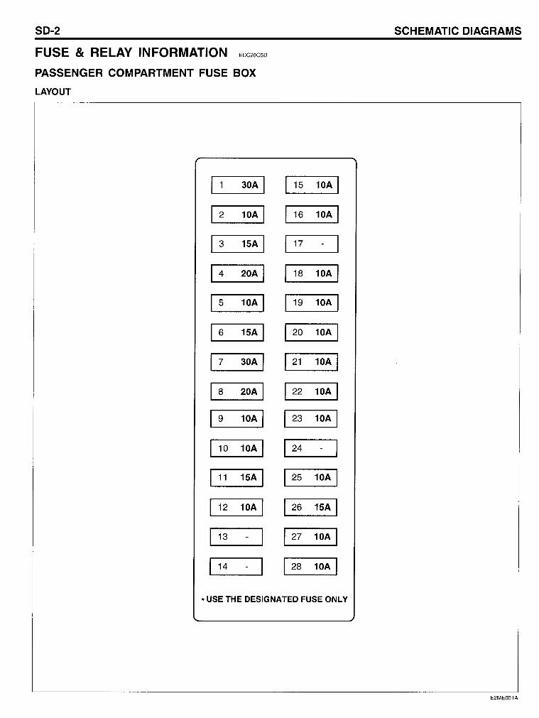
PA55ENGER COMPARTMENT FU5E BOX
LAYOUT
1 1 30A 1
1 2 10A 1
1 3 15A 1
1 4 20A 1
1 5 10A 1
1 6 15A 1
1 7 30A 1
1 8 20A 1
1 9 10A 1
110 10A 1
1 11 15A 1
112 10A 1
113 -
1
114 -
1
115 10A 1
116 10A 1
117 -
1
118 10A 1
119 10A 1
1 20 10A 1
1 21 10A 1
1 22 10A 1
1 23 10A 1
1 24 -1
1 25 10A 1
1 26 15A 1
1 27 10A 1
1 28 10A 1
* USE THE DESIGNATED FUSE ONLY
5CHEMATIC 0lAGRAM5
E2ME001A
FUSE & RELAY INFORMATION SO-3
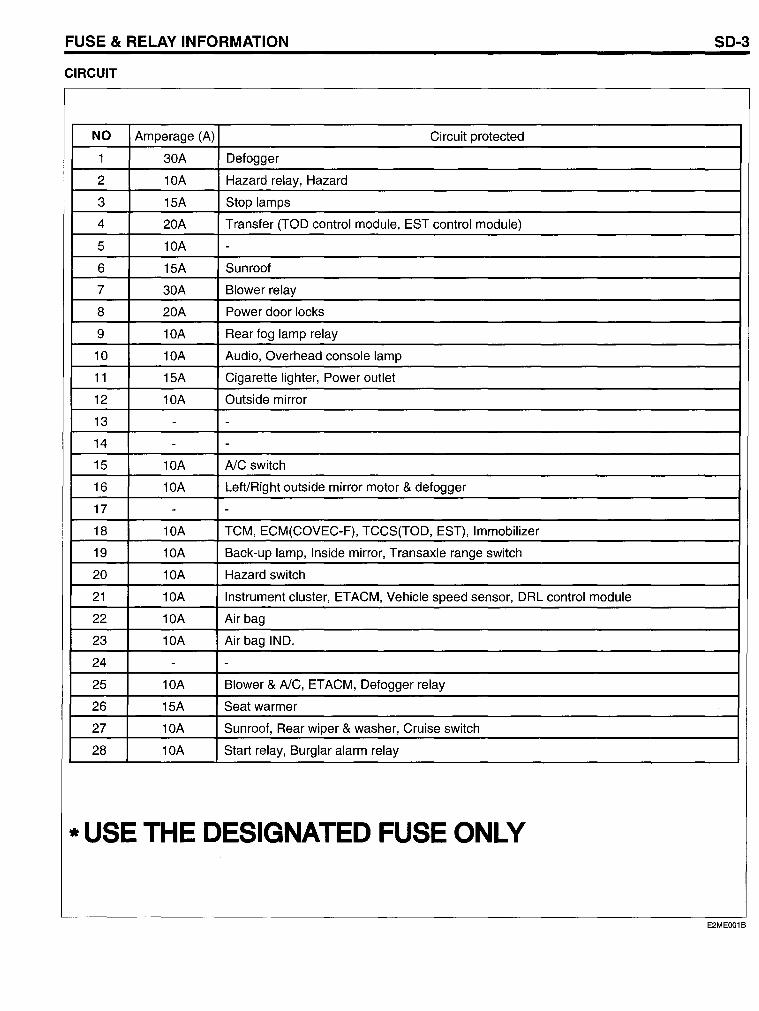
CIRCUIT
NO Amperage (A) Circuit protected
1 30A Defogger
2 10A Hazard relay, Hazard
3 15A Stop lamps
4 20A Transfer (TOD control module, EST control module)
5 10A -6 15A Sunroof
7 30A Blower relay
8 20A Power door locks
9 10A Rear fog lamp relay
10 10A Audio, Overhead console lamp
11 15A Cigarette lighter, Power outlet
12 10A Outside mirror
13 - -14 - -15 10A AlC switch
16 10A Left/Right outside mirror motor & defogger
17 - -18 10A TCM, ECM(COVEC-F), TCCS(TOD, EST), Immobilizer
19 10A Back-up lamp, Inside mirror, Transaxle range switch
20 10A Hazard switch
21 10A Instrument cluster, ETACM, Vehicle speed sensor, DRL control module
22 10A Air bag
23 10A Air bag IND.
24 - -25 10A Blower & AlC, ETACM, Defogger relay
26 15A Seat warmer
27 10A Sunroof, Rear wiper & washer, Cruise switch
28 10A Start relay, Burglar alarm relay
* USE THE DESIGNATED FUSE ONLY
E2ME001B
SO-4 SCHEMATIC OIAGRAMS
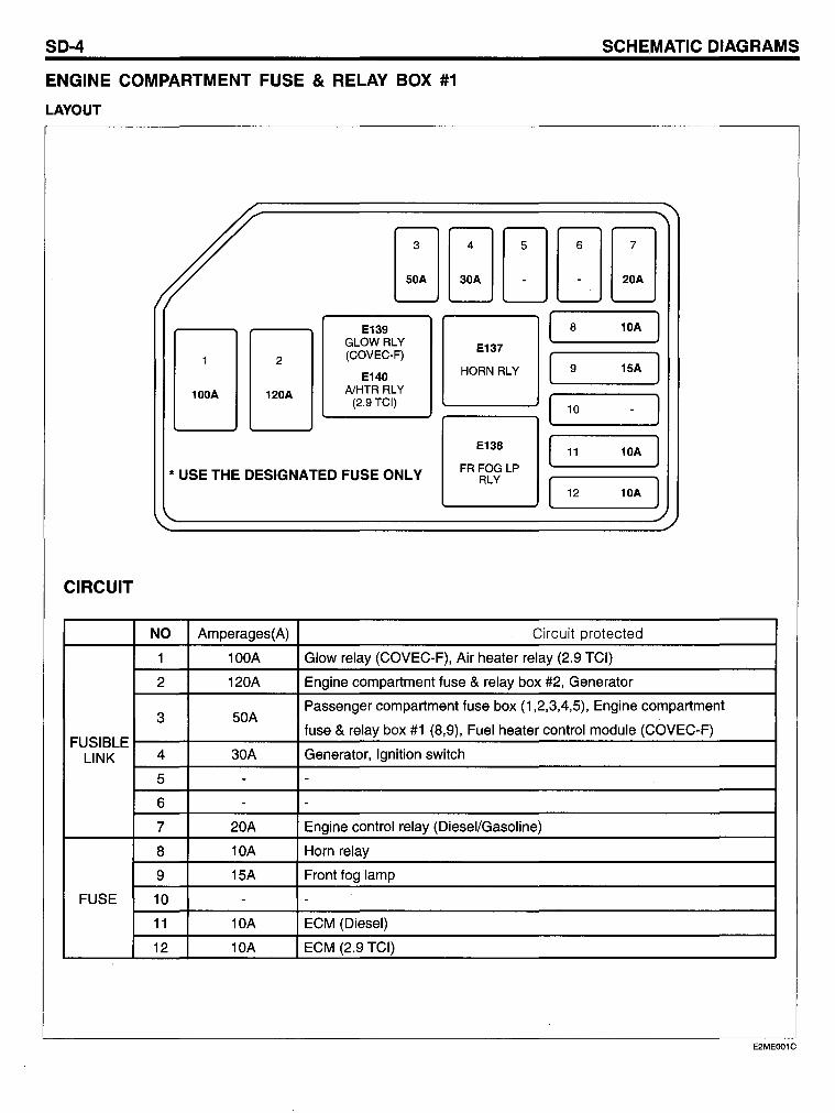
ENGINE COMPARTMENT FUSE & RELAV BOX #1
LAYOUT
CIRCUIT
NO Amperages(A) Circuit protected
100A Glow relay (COVEC-F), Air heater relay (2.9 TCI)
2 120A Engine compartment fuse & relay box #2, Generator
3 50A Passenger compartment fuse box (1,2,3,4,5), Engine compartment
FUSIBLE fuse & relay box #1 (8,9), Fuel heater control module (COVEC-F)
LINK 4 30A Generator, Ignition switch
5
6
7 20A Engine control relay (Diesel/Gasoline)
8 10A Horn relay
9 15A Front fog lamp
FUSE 10
11 10A ECM (Diesel)
12 10A ECM (2.9 TCI)
E2MEOO1C
Il) I
C cn
z 0
!ce ::2: c: 0 u. Z -~ ..J W c: ~ W cn ::J u.
N '#:
X 0 ID
~ ..J W c: ~
w cn ::J u. I-z w ::2: I-c: ~ ::2: 0 ()
W Z I-
:J (!) 0 Z ~ W ...J
ß
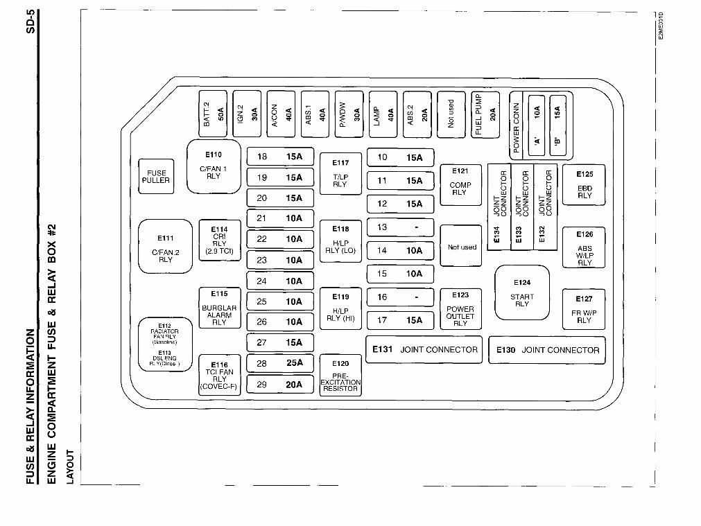
FUSE PULLER
El12 RADIATOR FAN RLY (Gasoline)
El13 DSL ENG
RL Y(Diesel )
"'-
a.
~~~~~~~rn ::2 :::> a.
«Il) (!}(') ~0:I' ~0:I' ~(') «0:1' ~N Ö -I LU III - a. -I Z :::> LL
[ 1 [ 1 E110 18 15A 10 15A
E117 C/FAN 1 [ 1 [ )
E121 RLY 19 15A T/LP 11 15A RLY COMP
[ ) RLY 20 15A [ ) 12 15A
[ ) 21 10A [ JE:] E114 E118 13
[ ) CRI 22 10A RLY H/LP
( 1 Not used (2.9 TCI)
[ ) RLY (LO) 14 10A
23 10A
( 1 [ ) 15 10A
24 10A
( 1 E115
( ) E119 16 E123 25 10A
BURGLAR H/LP POWER ALARM
[ ) RLY (HI) [ 17 15A 1 OUTLET
RLY 26 10A RLY
[ ) 15A 27 E131 JOINT CONNECTOR
( 1 28 25A E120 E116 TCI FAN
RLY [ 29 20A ] PRE-
(COVEC-F) EXCITATION RESISTOR
\
Z <C Z <C <C e 0 e Il) N ... ...
Ü a: LU S ~ ~ 0 a.
a: a: a: E125 0 0 0 I- I- I-Ü Ü ü EBD LU LU LU RLY I-Z I-Z I-Z
Zz Zz Zz -0 -0 -0 Qü Qü Qü 0:1' (') N (') (') (') E126 ... W W LU
ABS W/LP RLY
E124
START RLY
E127
FRW/P RLY
E130 JOINT CONNECTOR
/"
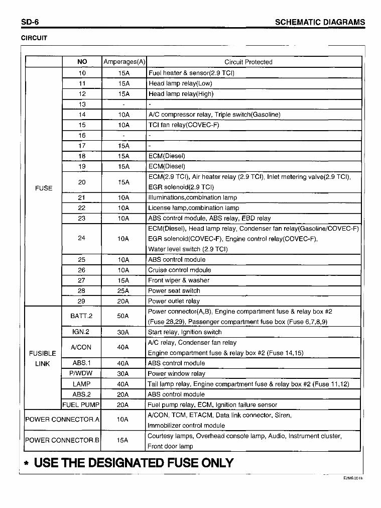
SO-6 SCHEMATIC OIAGRAMS
CIRCUIT
NO Amperages(A) Circuit Protected
10 15A Fuel heater & sensor(2.9 TCI)
11 15A Head lamp relay(Low)
12 15A Head lamp relay(High)
13 - -14 10A AlC compressor relay, Tripie switch(Gasoline)
15 10A TCI fan relay(COVEC-F)
16 - -17 15A -18 15A ECM(Diesel)
19 15A ECM(Diesel)
20 15A ECM(2.9 TCI), Air heater relay (2.9 TCI), Inlet metering valve(2.9 TCI),
FUSE EGR solenoid(2.9 TCI)
21 10A Illuminations,combination lamp
22 10A License lamp,combination lamp
23 10A ABS control module, ABS relay, EBD relay
ECM(Diesel), Head lamp relay, Condenser fan relay(Gasoline/COVEC-F)
24 10A EGR solenoid(COVEC-F), Engine control relay(COVEC-F),
Water level switch (2.9 TCI)
25 10A ABS control module
26 10A Cruise control mdoule
27 15A Front wiper & washer
28 25A Power seat switch
29 20A Power outlet relay
BATT.2 50A Power connector(A,B), Engine compartment fuse & relay box #2
(Fuse 28,29), Passenger compartment fuse box (Fuse 6,7,8,9)
IGN.2 30A Start relay, Ignition switch
AlCON 40A AlC relay, Condenser fan relay
FUSIBLE Engine compartment fuse & relay box #2 (Fuse 14,15)
LINK ABS.1 40A ABS contra I module
P/WDW 30A Power window relay
LAMP 40A Taillamp relay, Engine compartment fuse & relay box #2 (Fuse 11,12)
ABS.2 20A ABS contra I module
FUEL PUMP 20A Fuel pump relay, ECM, Ignition failure sensor
POWER CONNECTOR.A 10A AlCON, TCM, ETACM, Data link connector, Siren,
Immobilizer control module
POWER CONNECTOR.B 15A Courtesy lamps, Overhead console lamp, Audio, Instrument cluster,
Front door lamp
* USE THE DESIGNATED FUSE ONLY E2ME001E
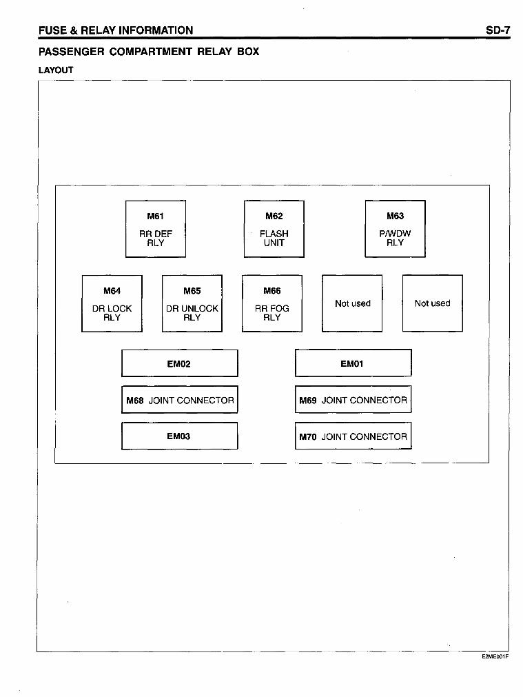
FUSE & RELAY INFORMATION
PASSENGER COMPARTMENT RELAY BOX
LAYOUT
M64
DR LOCK RLY
M61
RR DEF RLY
M65
DR UNLOCK RLY
EM02
M68 JOINT CONNECTOR
EM03
M62
FLASH UNIT
M66
RRFOG RLY
Not used
EM01
M63
PIWDW RLY
M69 JOINT CONNECTOR
M70 JOINT CONNECTOR
SO-7
Not used
E2MEOO1F
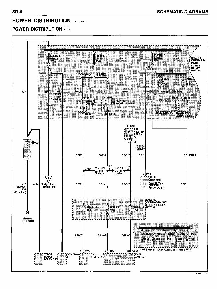
SD-8
POWER DISTRIBUTION
POWER DISTRIBUTION (1)
15R
(Gasoline)
40R To Ignition.2 Fusible Link
ENGINE GROUND
E14C81FA
5.0B/L
2.0B/L 2.0B/L
O.5W/Y O.5W/R
23 E01-1 ECM (COVEC-F)
5.0B/Y
SCHEMATIC DIAGRAMS
3.0R
4 E05 FUEL HEATER CONTROL MODULE (COVEC-F)
4 EM01
3.0R
E2ME002A
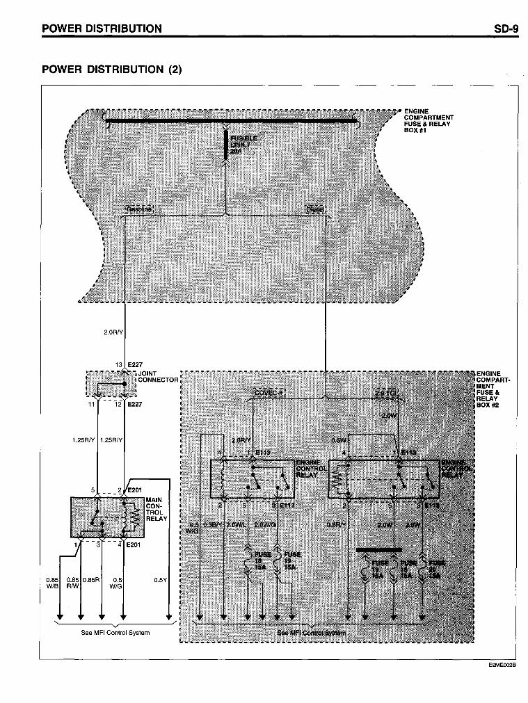
POWER DISTRIBUTION
POWER DISTRIBUTION (2)
2.0R/Y
13 E227 JOINT CONNECTOR
11 12 E227
1.25R/Y 1.25R/Y
0.85 0.85R 0.5Y RNV W/G
See MFI Control System
ENGINE COMPARTMENT FUSE& RELAY BOX #1
SD-9
E2MEOO2B
SD-10
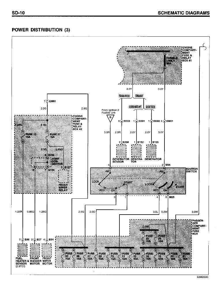
POWER DISTRIBUTION (3)
1.25R 0.85G 1.25G
FUEL FRONT FRONT HEATER & WASHER WIPER SENSOR MOTOR MOTOR (2.9TCI)
2.0G 2.00
SCHEMATIC DIAGRAMS
From Ignition.2 Fusible Link
6 EE03 1
2.0R 2.0Y 2.0Y 3.0Y
2 E250 1 E152 1 E155
GENERATOR GENERA- GENERATOR SENSOR TOR
EM01
3.0L 3.OW
ENGINE COMPARTMENT FUSE& RELAY BOX #1
3.0W
PASSENGER COMPARTMENT FUSE BOX
E2ME002C
POWER DISTRIBUTION
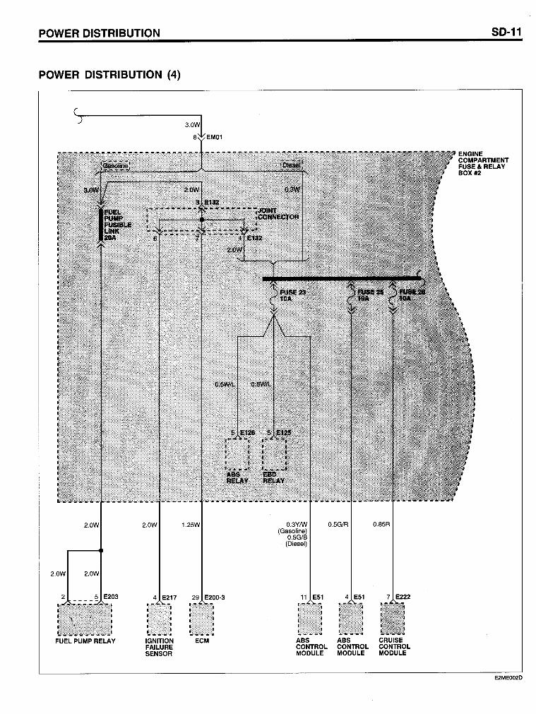
POWER DISTRIBUTION (4)
2.0W
2.0W 2.0W
FUEL PUMP RELAY
2.0W
4 E217
IGNITION FAllURE SENSOR
1.25W
29 E200-3
ECM
O.3Y/w (Gasoline)
O.5GfB (Diesel)
11 E51
ABS CONTROL MODULE
O.5GfR
4 E51
ABS CONTROL MODULE
O.85R
7 E222
CRUISE CONTROL MODULE
SD-11
E2MEOO2D
SD-12
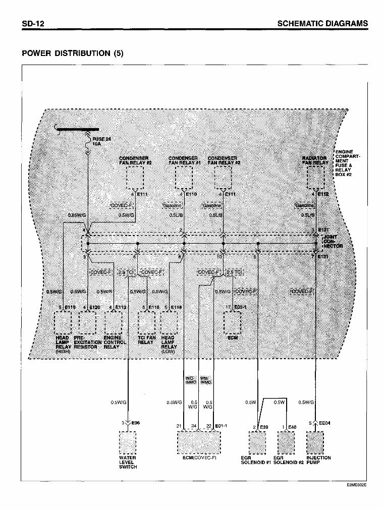
POWER DISTRIBUTION (5)
0.5W/G
WATER LEVEL SWITCH
0.5W/G 0.5 0.5 W/G W/G
21 24 22 E01-1
ECM(COVEC-F)
SCHEMATIC DIAGRAMS
0.5W 0.5W/G
1 E40
EGR EGR INJECTION SOLENOID #1 SOLENOID #2 PUMP
E2ME002E
POWER DISTRIBUTION
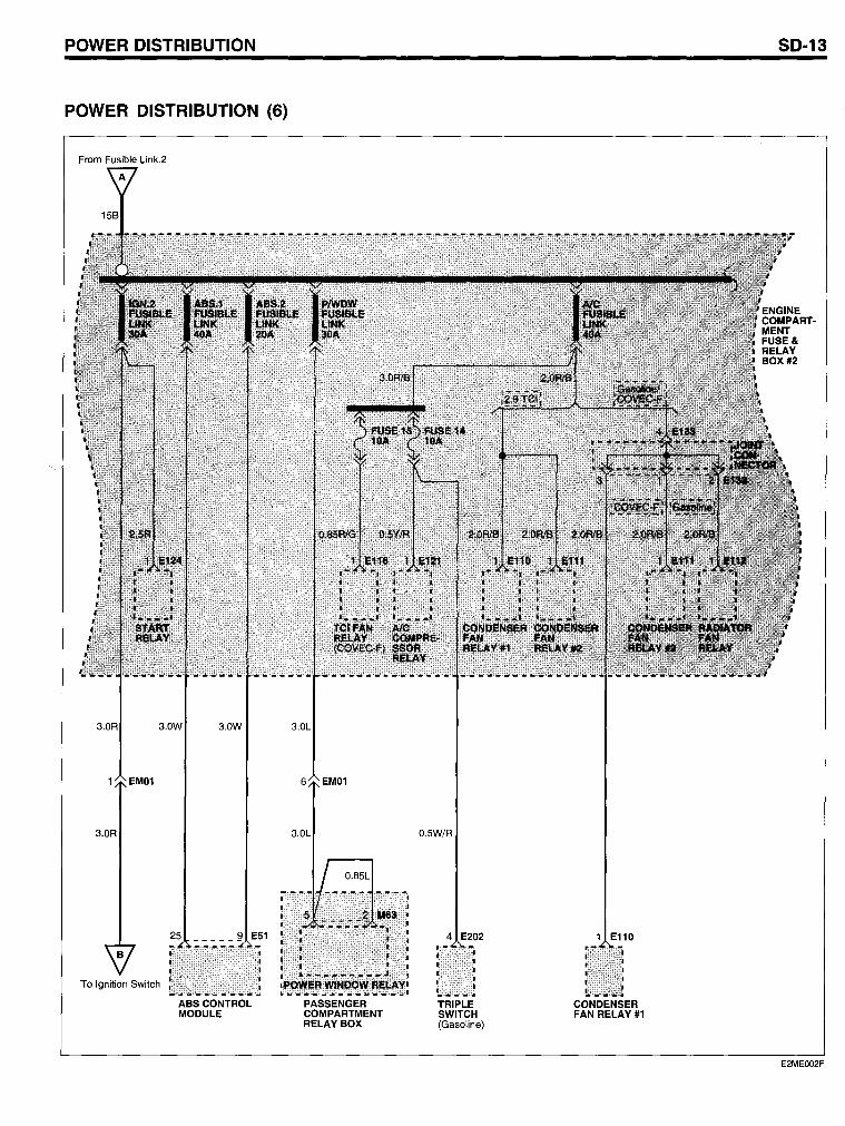
POWER DISTRIBUTION (6)
From Fusible Link.2
3.0R 3.0W 3.0W
EM01
3.0R
To Ignition Switch
ABSCONTROL MODULE
3.0L
EM01
3.0L
PASSENGER COMPARTMENT RELAY BOX
O.5W/R
4 E202
TRIPLE SWITCH (Gasoline)
1 E110
CONDENSER FAN RELAY#1
SD-13
E2MEOO2F
SD-14 SCHEMATIC DIAGRAMS
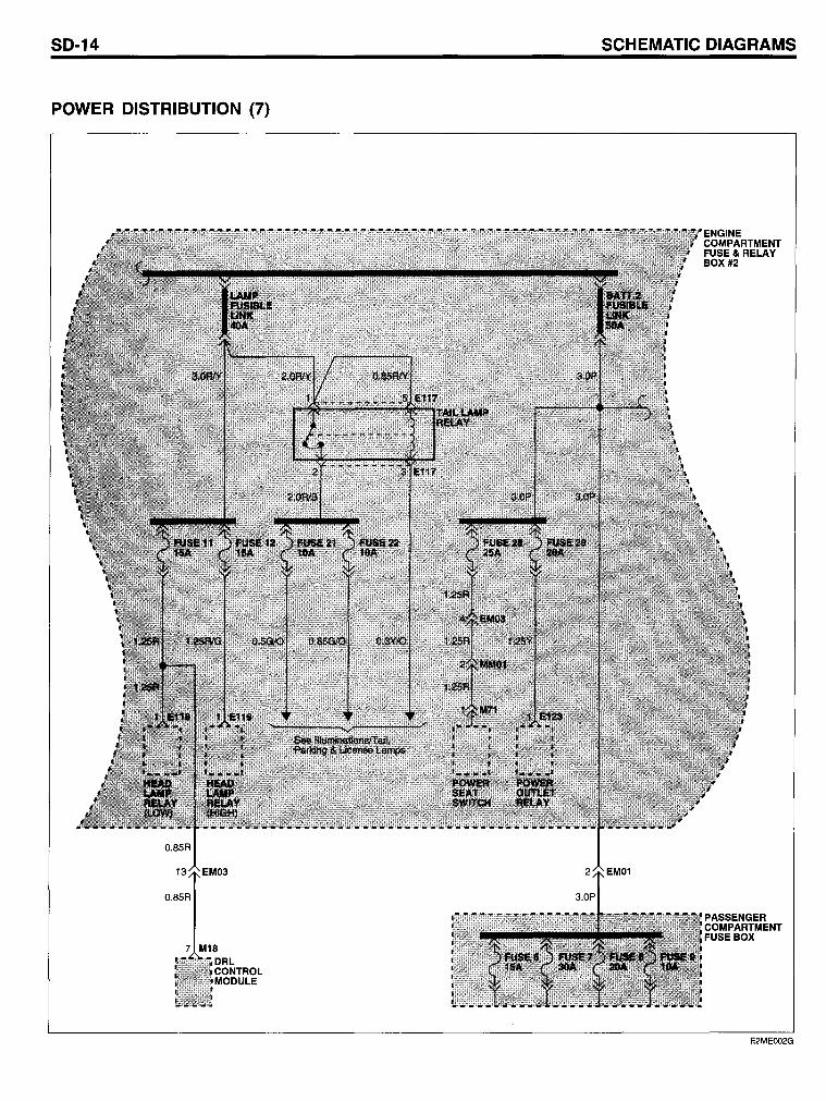
POWER DISTRIBUTION (7)
POWER DISTRIBUTION
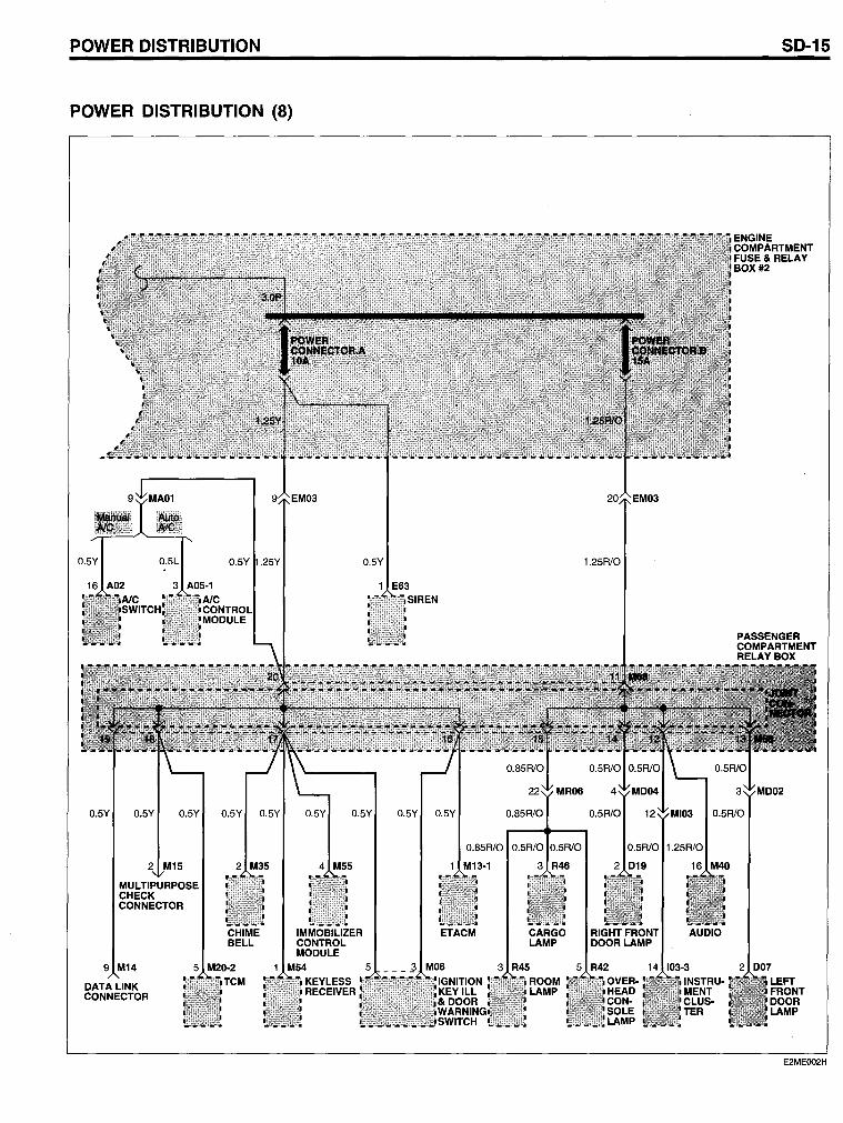
POWER DISTRIBUTION (8)
O.5Y .25Y O.5Y
1 E63
O.5Y O.5Y O.5Y O.5Y O.5Y O.5Y O.5Y O.5Y O.5Y O.85R10
2 5
MULTIPURPOSE CHECK CONNECTOR
2 M35
CHIME BELL
9 M14
DATALINK CONNECTOR
5 M20-2 TCM
4 M55
IMMOBILIZER CONTROL MODULE
1 M54 KEYLESS RECEIVER
O.85R10 O.5R10 O.5R10
1 M13-1 3 R46
ETACM CARGO LAMP
5 ___ ll M06 3 R45
ROOM LAMP
1.25R10
SD-15
ENGINE COMPARTMENT FUSE& RELAY BOX #2
O.5R/O O.5R10
O.5R10 1.25R10
2 D19 16 M40
RIGHTFRONT AUDIO DOOR LAMP
14 103-3 2 D07 INSTRU- LEFT MENT FRONT CLUS- DOOR TER LAMP
E2MEOO2H
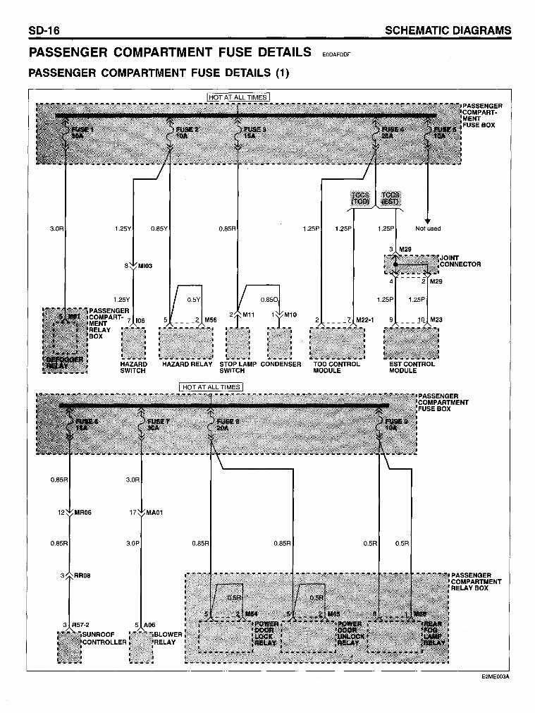
SD-16
PASSENGER COMPARTMENT FUSE DETAILS
PASSENGER COMPARTMENT FUSE DETAILS (1)
3.0R 1.25Y O.85Y
MI03
1.25Y
PASSENGER COMPART- 7 106 MENT RELAY BOX
O.85R 1.25P
EODAFDBF
1.25P
HAZARD HAZARD RELAY STOP LAMP CONDENSER TOD CONTROL SWITCH SWITCH MODULE
SCHEMATIC DIAGRAMS
Not used
ESTCONTROL MODULE
PASSENGER COMPARTMENT RELAYBOX
E2ME003A
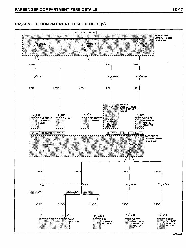
PASSENGER COMPARTMENT FUSE DETAILS
PASSENGER COMPARTMENT FUSE DETAILS (2)
4 R42
O.5R
7 M40
AUDIO
O.5R/O
7 -----------------2 MA01
O.5R/B O.5R/O
3 _________ ~2 A02
O.5R/B
11 A05-1
AlC CONTROL MODULE
O.5R/B
4
O.5R/B
POWER OUTSIDE MIRROR SWITCH
PASSENGER COMPARTMENT FUSE BOX
O.5R/B
O.5R/B
SD-17
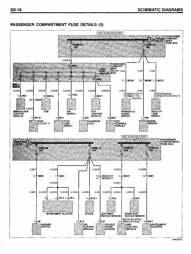
SD-18
PASSENGER COMPARTMENT FUSE DETAILS (3)
4 M11
0.50/8
STOP LAMP SWITCH
0.5R/O
0.85Y 0.50/8 0.50/8 0.50/8 0.50/8 0.50/8 0.58 0.5R/O 0.5R/O
9 ____ 4 103-3 14 103-1
INSTRUMENT CLUSTER
16 M13-1 2 A24
ETACM LEFT SEAT BUCKLE SENSOR
0.5R/O
SCHEMATIC DIAGRAMS
1 R40
0.5W/8
BACK-UP LAMP SWITCH
E2ME003C
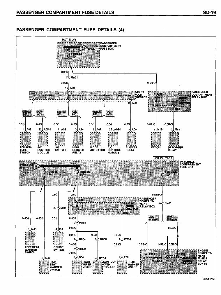
PASSENGER COMPARTMENT FUSE DETAILS
PASSENGER COMPARTMENT FUSE DETAILS (4)
TEMPERTURE SWITCH
3 M49
AlC AlC CONTROL SWITCH MODULE
4 110
LEFT SEAT CRUISE WARMER SWITCH SWITCH
3 M50
HIGH BLOWER RELAY
0.85G
MODE AlC BLOWER ACTUATOR CONTROL RELAY
MODULE
ETACM
SD-19
PASSEN GER COMPARTMENT RELAY BOX
DEFOGGER RELAY
0.56/0
PASSENGER COMPARTMENT FUSE BOX
ENGINE COMPARTMENT FUSE& RELAY BOX #2
E2ME003D
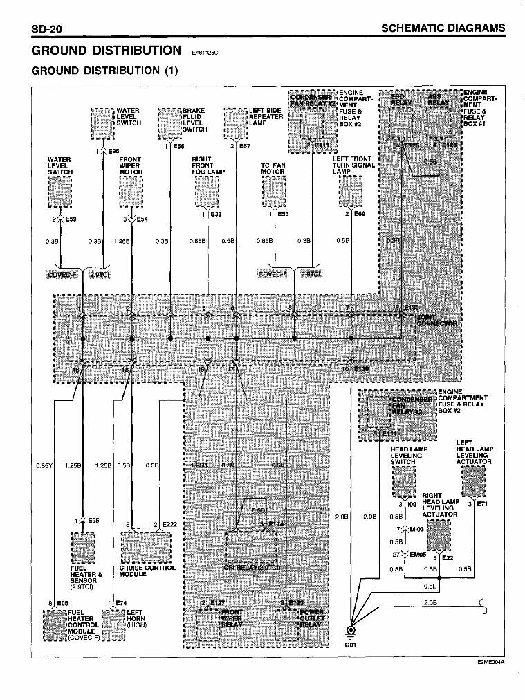
SD-20
GROUND DISTRIBUTION
GROUND DISTRIBUTION (1)
WATER LEVEL SWITCH
E4B1126C
8RAKE FLUID LEVEL SWITCH
LEFT BIDE REPEATER LAMP
1 E56 2 E57
0.85Y 1.258
FRONT WIPER MOTOR
0.38 1.258
1.258 0.58
0.38
8 2
8 E05
FUEL HEATER& SENSOR (2.9TCI)
FUEL HEATER CONTROL MODULE (COVEC-F)
RIGHT FRONT FOG LAMP
1 E33
0.858 0.58
TCI FAN MOTOR
1 E53
0.858
2 E69
0.38 0.58
G01
SCHEMATIC DIAGRAMS
0.58
RIGHT
LEFT HEADLAMP LEVELING ACTUATOR
HEAD LAMP 3 E71 LEVELING ACTUATOR
E22
0.58 0.58
0.58
2.08
E2MEOO4A
GROUND DISTRIBUTION
GROUND DISTRIBUTION (2)
INJECTION ACCELERATOR PUMP NPS POSITION ABS CONTROL
ECM SHIELD SHIELD SENSOR MODULE ECM r - - -. r - - -. I I I
I
I
I __ J
5 E61 8 ES1 93 108 112 E03-34
0.58
RIGHTSIDE REPEATER LAMP
2 E10
0.858 O. O.
G04(COVEC-F)
FAN MOTOR
E29 CADS SOLNENOID #1
I __ J
DATA LINK CONNECTOR
4 M14
0.5B 0.58 0.858 3.0B
CADS SOLNENOID #2
1 E32
-:-G02
10 EMOS
0.85B
-:-G06(ABS)
GLOW RELAY
4 E139 RIGHT FRONT 4 TURN SIGNAL LAMP
2 E21
0.58 0.858
0.858
2.08
RIGHT HEAD LAMP
G09(2.9 TCI)
3 E23 LEFT FRONT FOG LAMP
1 E77
0.858
0.85B
SD-21
8 E03-1
DATA LINK CONNECTOR
4 M14
0.858
0.858
EMOS
LEFT HEAD LAMP
E2MEOO48
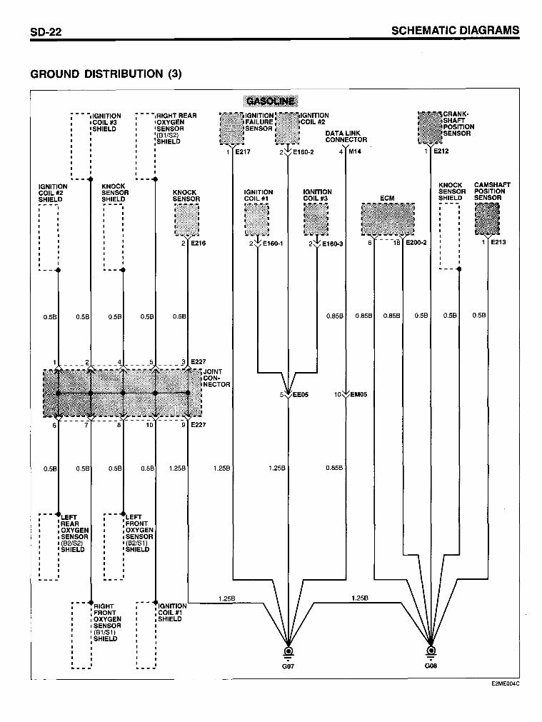
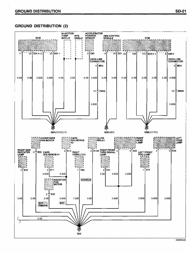
SD-22
GROUND DISTRIBUTION (3)
- • ·dGNITION •• ·,RIGHT REAR
IGNITION COIL#2 SHIELD
'REAR :OXYGEN ,SENSOR , (82182) 'SHIELD ,
'COIL#3 'SHIELD ,
KNOCK SENSOR SHIELD
FRONT OXYGEN SENSOR (81/81) SHIELD
0.58
0.58
'FRONT :OXYGEN ,SENSOR 1(82/81) 'SHIELD ,
'OXYGEN 'SENSOR '(81/82) :SHIELD
KNOCK SENSOR
2 E216
0.58
1.258
COIL#1 SHIELD
1.258
1.258
SCHEMATIC DIAGRAMS
IGNITION COIL#2
DATA LINK CONNECTOR
60-2 4 M14 1 E212
KNOCK CAMSHAFT IGNITION IGNITION SENSOR POSITION COIL#1 COIL#3 ECM SHIELD SENSOR
6 - - -18 E200-2 1 E213
0.858 0.858 0.858 0.58 0.58 0.58
10
1.258 0.858
1.258
G07 GOB
E2MEOO4C
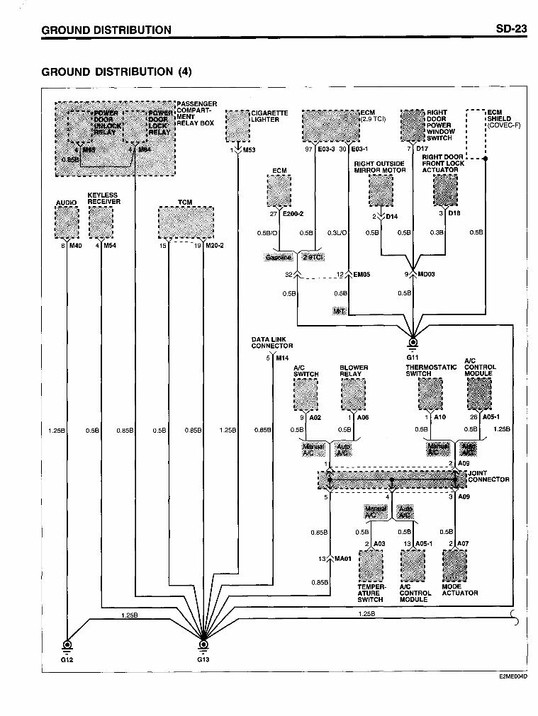
GROUND DISTRIBUTION
GROUND DISTRIBUTION (4)
KEYLESS RECEIVER TCM
8 M40 4 M54 15 - - - -f9 M20-2
1.258 0.58 0.858 0.58 0.858 1.258
G12 G13
CIGARETTE LIGHTER
ECM (2.9 TCI)
RIGHT DOOR POWER WINDOW SWITCH
SD-23
~ •• ·,ECM , ,SHIELD
: (COVEC-F)
97 E03-3 30 E03-1 7 017 ' RIGHT DOOR ~ ••
RIGHT OUTSIDE FRONT LOCK ECM MIRROR MOTOR ACTUATOR
27 E200-2
0.58/0
32
DATALINK CONNECTOR
5 M14
0.858
AlC SWITCH
EM05
8LOWER RELAY
TEMPERATURE SWITCH
0.58
G11 AlC THERMOSTATIC CONTROL SWITCH MODULE
AlC MODE CONTROL ACTUATOR MODULE
E2MEOO4D
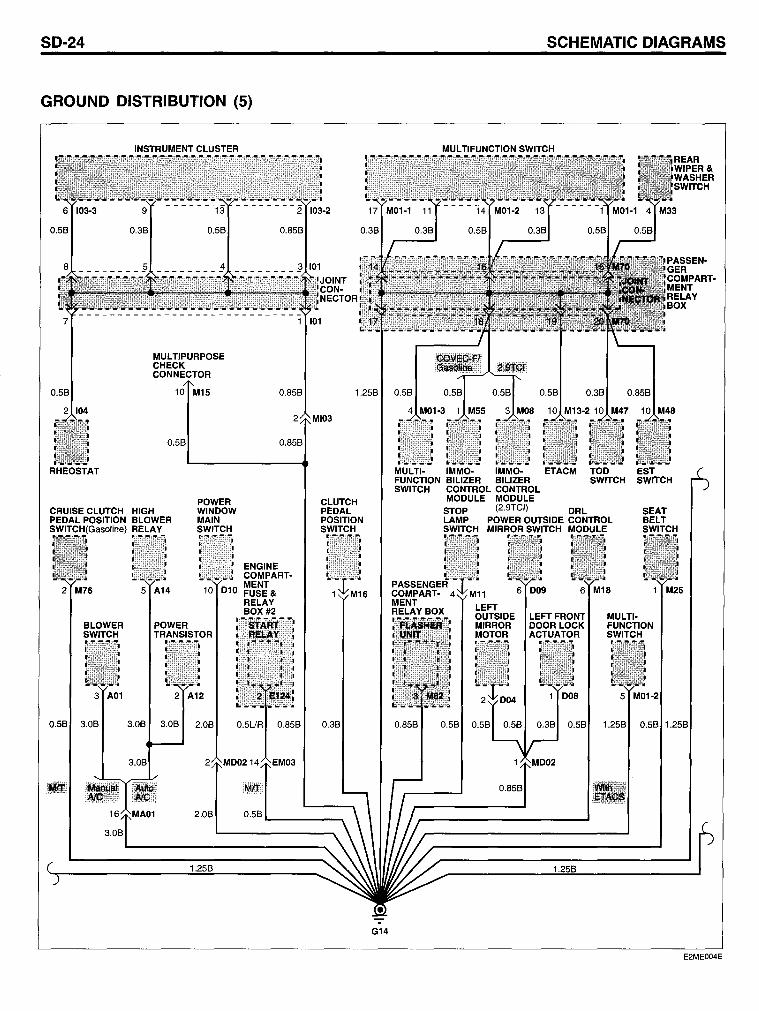
50-24
GROUND DISTRIBUTION (5)
7
INSTRUMENT CLUSTER
MULTIPURPOSE CHECK CONNECTOR
101
5CHEMATIC DIAGRAM5
MUL TIFUNCTION SWITCH REAR WIPER& WASHER SWITCH
0.858 1.258 0.58 0.58 0.38 0.858
RHEOSTAT
CRUISE CLUTCH HIGH PEDAL POSITION BLOWER
·CHIGalsolinel RELAY
POWER WINDOW MAIN SWITCH
2 M76
BLOWER SWITCH
3 A01
0.58 3.08
5 A14 10 D10
POWER TRANSISTOR
2 A12
3.08 3.08 2.08
3.08
2 MI03
0.858
ENGINE COMPARTMENT FUSE & RELAY 80X#2
CLUTCH PEDAL POSITION SWITCH
0.38
2.08 0.58'--____ ___.
G14
10 M13-2 10 M47 10 M48
MULTI- IMMO- IMMO- ETACM TOD EST FUNCTION 81LIZER BILIZER SWITCH SWITCH SWITCH CONTROL CONTROL
MODULE MODULE STOP (2.9TCI) DRL LAMP POWER OUTSIDE CONTROL SWITCH MIRROR SWITCH MODULE
6 M18 1 M25
MULTIFUNCTION SWITCH
5 M01-2
1.258 0.58 1.258
E2ME004E
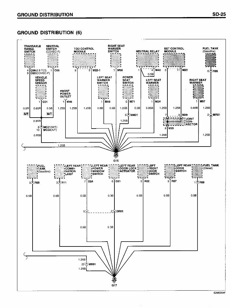
GROUND DISTRIBUTION
GROUND DISTRIBUTION (6)
TRANSAXLE RANGE SWITCH
NEUTRAL SWITCH (COVEC-F)
VEHICLE SPEED SENSOR
FRONT POWER OUTLET
M46
0.5R 0.58 1.258
IIIIIt!I!I
TODCONTROL MODULE
RIGHTSEAT WARMER SWITCH
M50
LEFT SEAT WARMER SWITCH
POWER SEAT SWITCH
1 M49
0.58 0.58
-G15
LEFT REAR r,r:ffi:ffi'fi"I LEFT REAR LEFT REAR
NEUTRAL RELA Y
LEFT SEAT WARMER
1 M24
ESTCONTROL MODULE
0.858 1.258 1.258
6 M29
1.258
LEFT
RIGHTSEAT WARMER
M57
0.858 1.258
JOINT CON-NECTOR
1.258
~:~~~ I!wlill!lli;j~~~!w DOOR LOCK FRONT
LEFTREAR DOOR SWITCH ACTUATOR DOOR
SWITCH
7 024 6 021 3 R02 3 R07
0.58 0.58 0.58 0.38 0.58 0.58 0.58
5
0.58 0.38
1.258
1.2581..-___ ---...
G17
SD-25
MR01
E2ME004F
SD-26 SCHEMATIC DIAGRAMS
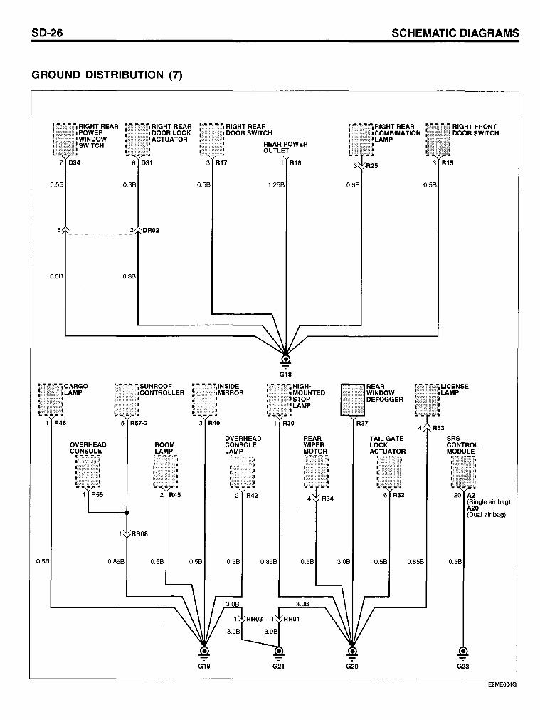
GROUND DISTRIBUTION (7)
i i RIGHT REAR RIGHTREAR RIGHTREAR RIGHTFRONT POWER DOORSWITCH COMBINATION DOORSWITCH WINDOW LAMP SWITCH REAR POWER
OUTLET
7 D34 3 R17 1 R18 3 R15
0.58 0.58 1.258 0.58 0.58
5
0.58 0.38
G18
• -,SUNROOF INSIDE HIGH- REAR LICENSE • CONTROLLER MIRROR MOUNTED WINDOW LAMP
STOP DEFOGGER . LAMP
1 R46 5 R57-2 3 R40 1 R30 R37 R33
OVERHEAD REAR TAILGATE SRS OVERHEAD ROOM CONSOLE WIPER LOCK CONTROL CONSOLE LAMP LAMP MOTOR ACTUATOR MODULE • Ir ~ :-.-•• ~ • ,
1 R55 2 R45 2 R42 6 R32 20 A21 (Single air bag) A20 (Dual air bag)
RR08
0.858 0.58 0.58 0.58 0.858 0.58 3.08 0.58 0.858
G19 G21 G20 G23
E2ME004G
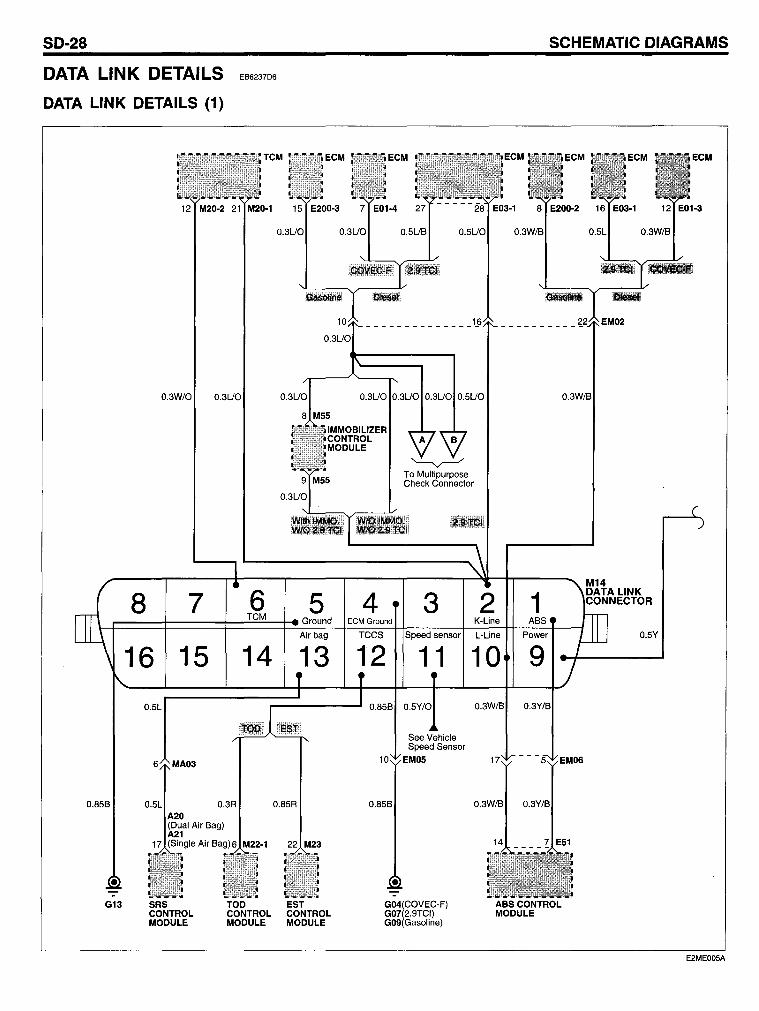
SD-28
DATA LINK DETAILS
DATA LINK DETAILS (1)
EB6237D6
TCM
12 M20-2 21 M20-1
0.3UO
SCHEMATIC DIAGRAMS
ECM
EM02
0.3UO
0.3W/O 0.3UO 0.3UO
8 M55
8 7 6 5 TCM Ground
Airbag
16 15 14 13 0.5L
0.85B 0.3R 0.85R
Air Bag)6 M22-1 22 M23
-G13 SRS TOD EST
CONTROL CONTROL CONTROL MODULE MODULE MODULE
4 ECM Ground
TCCS
To Multipurpose Check Connector
3 Speed sensor
2 1 K-Line ABS
L-Line Power
12 11 10 9
0.85B 0.5Y/O 0.3W/B
See Vehicle Speed Sensor
10 EM05
0.85B
• -:-G04(COVEC-F) ABSCONTROL G07(2.9TCI) MODULE G09(Gasoline)
0.5Y
E2MEOO5A
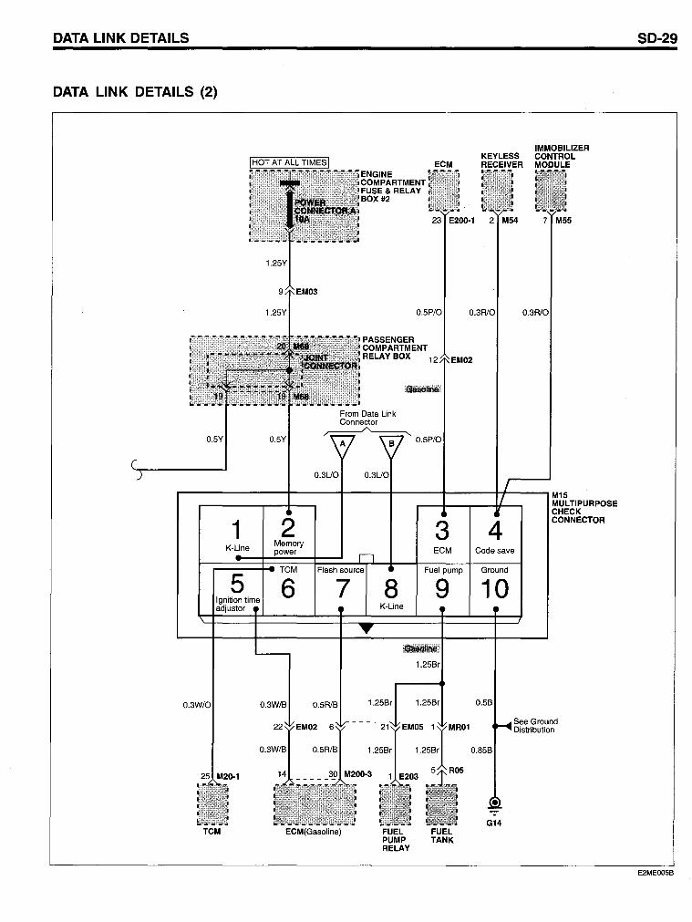
DATA LINK DETAILS
DATA LINK DETAILS (2)
0.5Y 0.5Y
1 K-Line
5 Ignition time adjustor
TCM
0.3UO
2 Memory
0.3W/B 0.5R1B
ECM(Gasoline)
IMMOBILIZER KEYLESS CONTROL
ECM RECEIVER MODULE ENGINE COMPARTMENT FUSE & RELAY BOX #2
23 E200-1 2 M54 7 M55
0.5P/O
PASSENGER COMPARTMENT RELAY BOX 12
3 ECM
Fuel pump
8 9 K-Line
.~t!"lIiMil!
1.25Br
1.25Br
FUEL PUMP RELAY
1.25Br
FUEL TANK
M15 MULTIPURPOSE CHECK
4 CONNECTOR
Code save
Ground
10
0.5B
0.85B
G14
See Ground Distribution
SD-29
E2MEOOSB
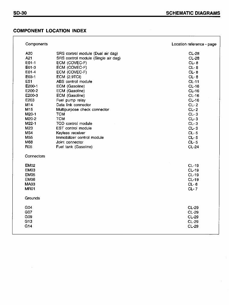
80-30
COMPONENT LOCATION INDEX
Components
A20 A21 E01-1 E01-3 E01-4 E03-1 E51 E200-1 E200-2 E200-3 E203 M14 M15 M20-1 M20-2 M22-1 M23 M54 M55 M68 R05
Connectors
EM02 EM03 EM05 EM06 MA03 MR01
Grounds
G04 GO? G09 G13 G14
SRS control module (Dual air dag) SRS control module (Single air dag) ECM (COVEC-F) ECM (COVEC-F) ECM (COVEC-F) ECM (2.9TCI) ASS control module ECM (Gasoline) ECM (Gasoline) ECM (Gasoline) Fuel pump relay Data link connector Multipurpose check connector TCM TCM TOD control module EST control module Keyless receiver Immobilizer control module Joint connector Fuel tank (Gasoline)
8CHEMATIC DIAGRAM8
Location reference - page
CL-28 CL-28 CL- 8 CL- 8 CL- 8 CL- 8 CL-11 CL-16 CL-16 CL-16 CL-16 CL- 2 CL- 2 CL- 3 CL- 3 CL- 3 CL- 3 CL- 5 CL- 5 CL- 5 CL-24
CL-19 CL-19 CL-19 CL-19 CL- 6 CL-?
CL-29 CL-29 CL-29 CL-29 CL-29
SD-32
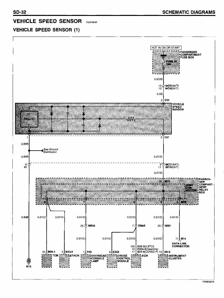
VEHICLE SPEED SENSOR
VEHICLE SPEED SENSOR (1)
See Ground .... --~Distribution
0.85B
E25FB640
0.5Y/O
• G15
24 M20-1 TCM
4 M13-2 1 R42
0.5Y/O 0.5Y/O
100 10
6 E222 17
0.5Y/O
0.5Y/O
E03-3(2.9TCI) E200-3(Gasoline) E01-4(COVEC-F) 13
ECM
SCHEMATIC DIAGRAMS
11 M14
DATA LINK CONNECTOR
103-3
INSTRUMENT CLUSTER
PASSENGER COMPARTMENT RELAY BOX
E2ME007A
VEHICLE SPEED SENSOR
COMPONENT LOCATION INDEX
Components
C01 E01-4 E03-3 E200-3 E222 103-3 M13-2 M14 M20-1 M22-1 M23 M70 R42
Connectors
EM05 MC01 MC02 MI01 MR06
Graunds
G15
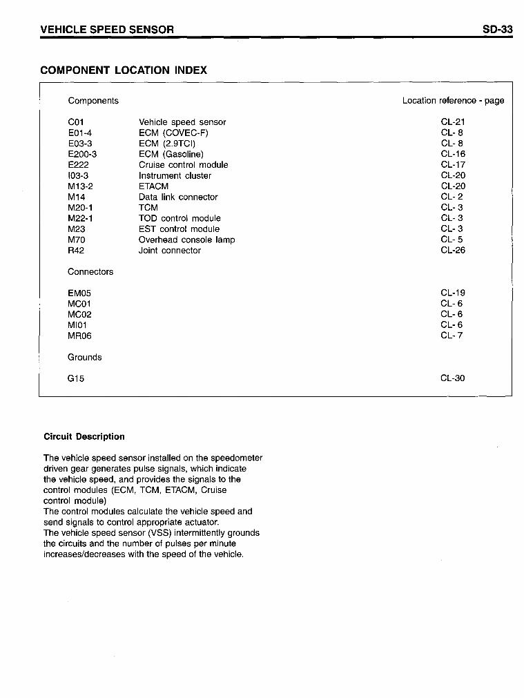
Circuit Description
Vehicle speed sensor ECM (COVEC-F) ECM (2.9TCI) ECM (Gasoline) Cruise control module Instrument cluster ETACM Data link connector TCM TOD control module EST control module Overhead console lamp Joint connector
The vehicle speed sensor installed on the speedometer driven gear generates pulse signals, which indicate the vehicle speed, and pravides the signals to the control modules (ECM, TCM, ETACM, Cruise contral module) The control modules calculate the vehicle speed and send signals to control appropriate actuator. The vehicle speed sensor (VSS) intermittently grounds the circuits and the number of pulses per minute increases/decreases with the speed of the vehicle.
50-33
Location reference - page
CL-21 CL- 8 CL- 8 CL-16 CL-17 CL-20 CL-20 CL- 2 CL- 3 CL- 3 CL- 3 CL- 5 CL-26
CL-19 CL- 6 CL- 6 CL- 6 CL-7
CL-30
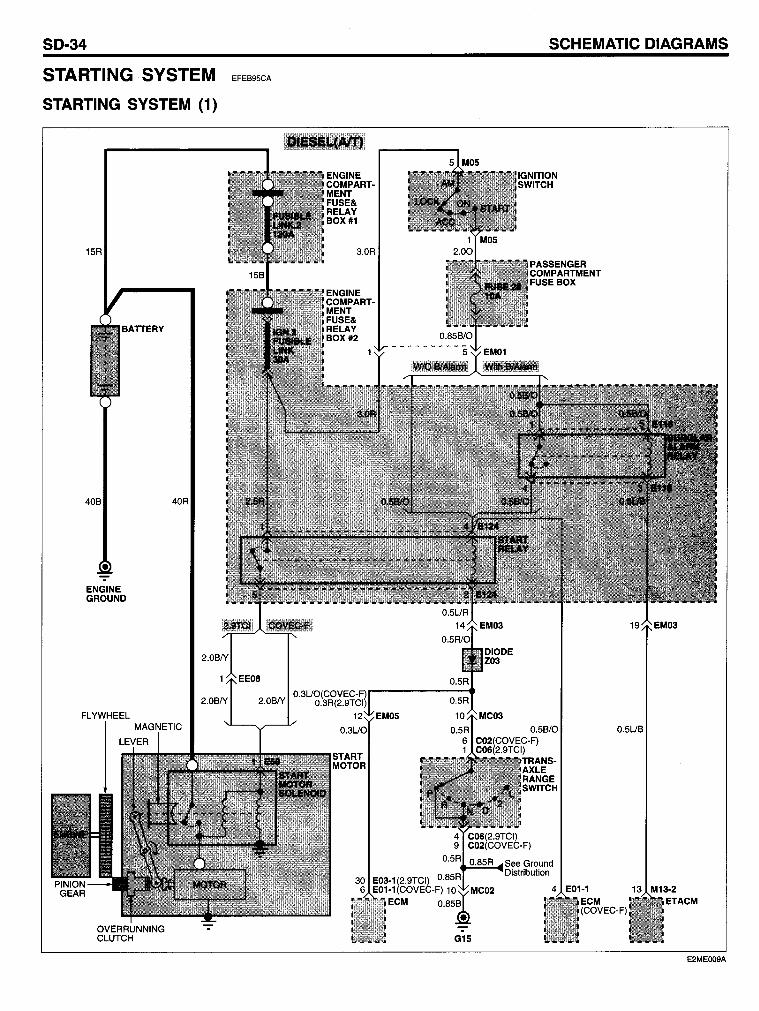
SD-34
STARTING SYSTEM
STARTING SYSTEM (1)
15R
BATTERY
ENGINE GROUND
OVERRUNNING CLUTCH
40R
EFEB95CA
SCHEMATIC DIAGRAMS
See Ground ~~ ..... Distribution
4 E01-1
G15
O.5UB
13 M13-2 ETACM
E2ME009A
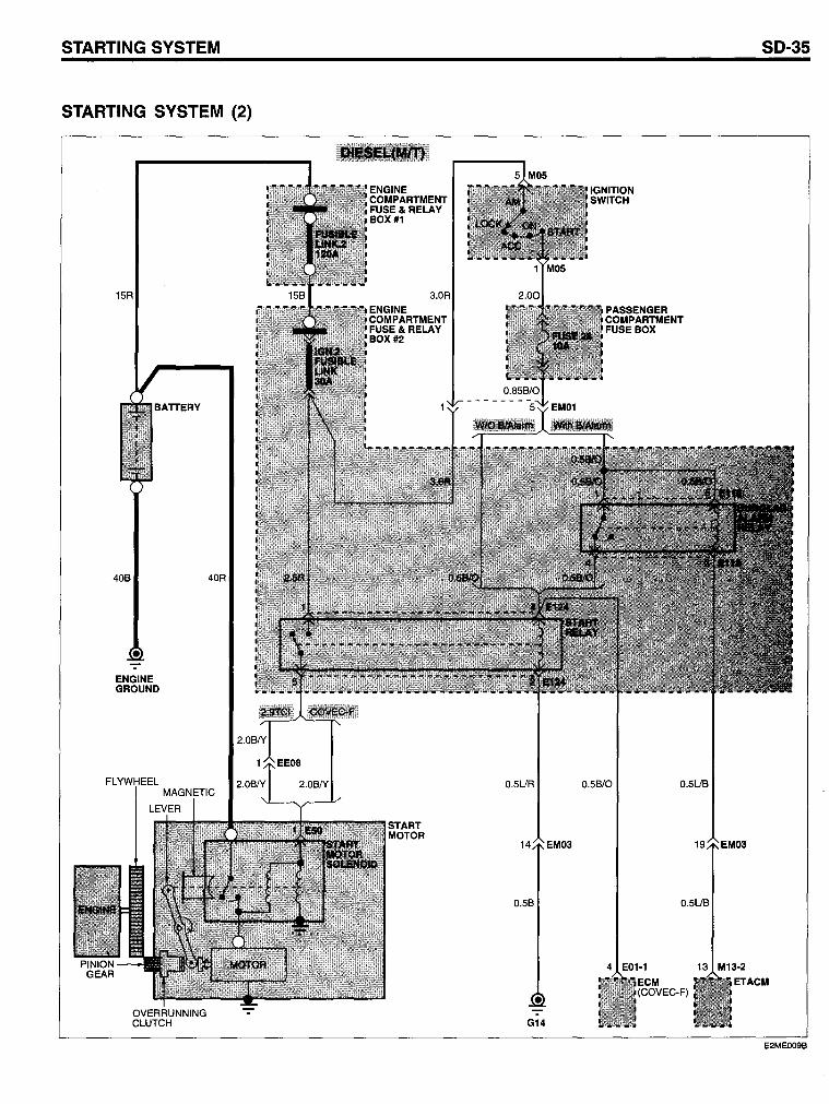
STARTING SYSTEM
STARTING SYSTEM (2)
15R
40B
ENGINE GROUND
FL
OVERRUNNING CLUTCH
40R
0.5UR
14 EM03
0.5B
G14
0.5B/0
4 E01-1
SO-35
0.5UB
19 EM03
0.5UB
13 M13-2
ETACM
E2MEOO9B
SO-36
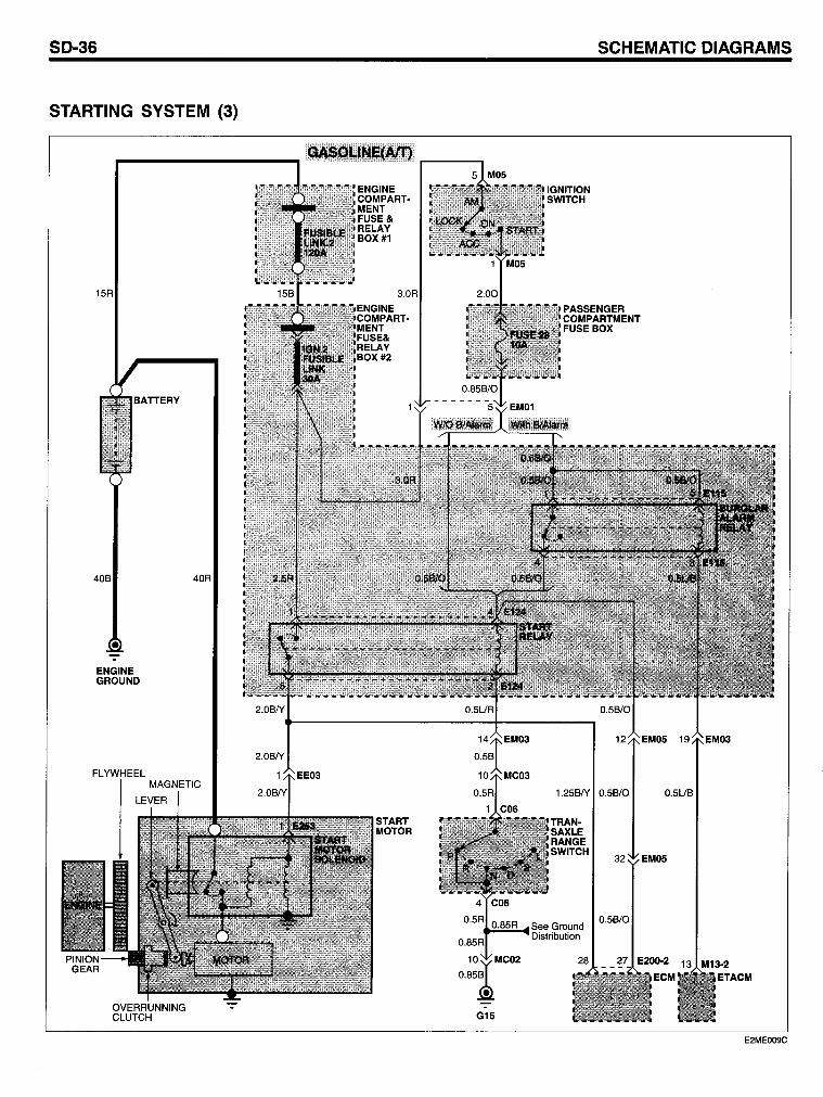
STARTING SYSTEM (3)
15R
40B
ENGINE GROUND
OVERRUNNING CLUTCH
40R
SCHEMATIC DIAGRAMS
1.25BIY 0.5B/0 0.5UB
See Ground ~=~Distribution
G15
32 EM05
0.5B/0
E2ME009C
50-38 SCHEMATIC DIAGRAMS
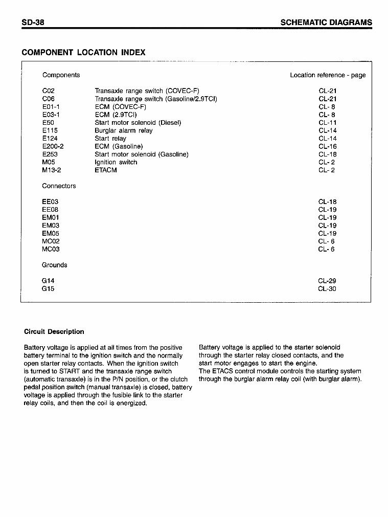
COMPONENT LOCATION INDEX
Components Location reference - page
C02 C06 E01-1 E03-1 E50 E115 E124 E200-2 E253 M05 M13-2
Transaxle range switch (COVEC-F) Transaxle range switch (Gasoline/2.9TCI) ECM (COVEC-F)
CL-21 CL-21 CL- 8 CL- 8 CL-11 CL-14 CL-14 CL-16 CL-18 CL- 2 CL- 2
Connectors
EE03 EE08 EM01 EM03 EM05 MC02 MC03
Grounds
G14 G15
Circuit Description
ECM (2.9TCI) Start motor solenoid (Diesel) Burglar alarm relay Start relay ECM (Gasoline) Start motor solenoid (Gasoline) Ignition switch ETACM
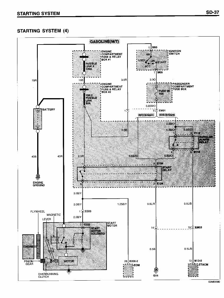
Battery voltage is applied at all times fram the positive battery terminal to the ignition switch and the normally open starter relay contacts. When the ignition switch is turned to START and the transaxle range switch (automatie transaxle) is in the P/N position, or the clutch pedal position switch (manual transaxle) is closed, battery voltage is applied through the fusible link to the starter relay coils, and then the coil is energized.
CL-18 CL-19 CL-19 CL-19 CL-19 CL- 6 CL- 6
CL-29 CL-30
Battery voltage is applied to the starter solenoid thraugh the starter relay closed contacts, and the start motor engages to start the engine. The ETACS contral module controls the starting system through the burglar alarm relay coil (with burglar alarm).
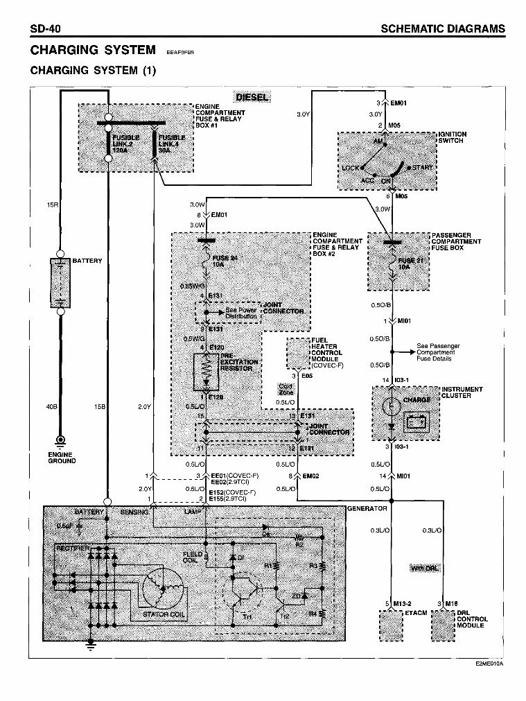
SO-40
CHARGING SYSTEM
CHARGING SYSTEM (1)
15R
BATTERY
408
ENGINE GROUND
158 2.0Y
EEAE9FB9
ENGINE COMPARTMENT FUSE & RELAY BOX #1
SCHEMATIC OIAGRAMS
0.50/8
0.50/8
IGNITION SWITCH
See Passenger Compartment Fuse Details
INSTRUMENT CLUSTER
0.3UO 0.3UO
5 M13-2 3 M18 ETACM DRL
CONTROL MODULE
E2ME010A
CHARGING SYSTEM
CHARGING SYSTEM (2)
15R
BATTERY
ENGINE GROUND
15W
ENGINE COMPARTMENT FUSE & RELAY BOX #1
3.0Y
0.50/8
0.50/8
0.5UO
0.3UO
IGNITION SWITCH
SO-41
See Passen ger ..--~. Compartment
Fuse Details
MI01
INSTRUMENT CLUSTER
5 M13·2 3 M18
ETACM DRL CONTROL MODULE
E2ME010B
SD-42
COMPONENT LOCATION INDEX
Components
E05 E120 E131 E132 E152 E155 E200-1 E200-2 E250 103-1 M05 M13-2 M18
Connectors
EE01 EE02 EE03 EM01 EM02 MI01
Circuit Description
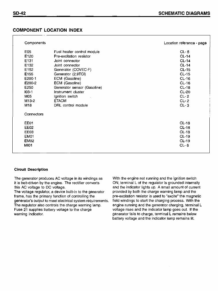
Fuel heater control module Pre-excitation resistor Joint connector Joint connector Generator (COVEC-F) Generator (2.9TCI) ECM (Gasoline) ECM (Gasoline) Generator sensor (Gasoline) Instrument cluster Ignition switch ETACM DRL control module
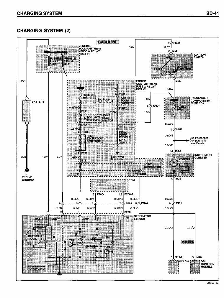
The generator produces AC voltage in its windings as it is belt-driven by the engine. The rectifier converts this AC voltage to DC voltage. The voltage regulator, a device built-in to the generator frame, has the primary function of controlling the generator's output to meet electrical system requirements. The regulator also controls the charge warning lamp. Fuse 21 supplies battery voltage to the charge warning indicator.
SCHEMATIC DIAGRAMS
Location reference - page
CL- 8 CL-14 CL-14 CL-14 CL-15 CL-15 CL-16 CL-16 CL-18 CL-20 CL- 2 CL- 2 CL- 3
CL-18 CL-18 CL-18 CL-19 CL-19 CL- 6
With the engine not running and the ignition switch ON, terminal L of the regulator is grounded internally and the indicator lights up. A small amount of current provided by both the charge warning lamp and the pre-excitation resistor is used to "excite" the magnetic field windings to start the charging process. With the engine running and the generator charging, terminal L voltage rises and the indicator lamp goes out. If the generator fails to charge, terminal L remains below battery voltage and the indicator lamp remains lit.
SD-44
COOLING SYSTEM
COOLING SYSTEM (1)
0.5Gr/0
EDD3D3BB
0.3Y/6
5 E01-4
ECM
SCHEMATIC DIAGRAMS
2.06
G02
E2ME011A
COOLING SYSTEM
COOLING SYSTEM (2)
2.0W/G
104 E03-3 5 E03-1 107
0.5UY
E03-3
ECM
G02
THERMOSTATIC SWITCH
3 A10 2 A05-2
0.50/B
2.0B
G01
SO-45
ENGINE COMPARTMENT FUSE& RELAY BOX #2
E2ME011B
SO-46 SCHEMATIC OIAGRAMS
COOLING SYSTEM (3)
G01 G02
E2ME011C
COOLING SYSTEM
COMPONENT LOCATION INDEX
Components
A05-1 A05-2 A10 E01-4 E03-1 E03-3 E25 E29 E30 E110 E111 E112 E113 E121 E130 E131 E132 E133 E200-1
Connectors
EM01 EM02 MA01 MA02
Grounds
G01 G02
Circuit Description
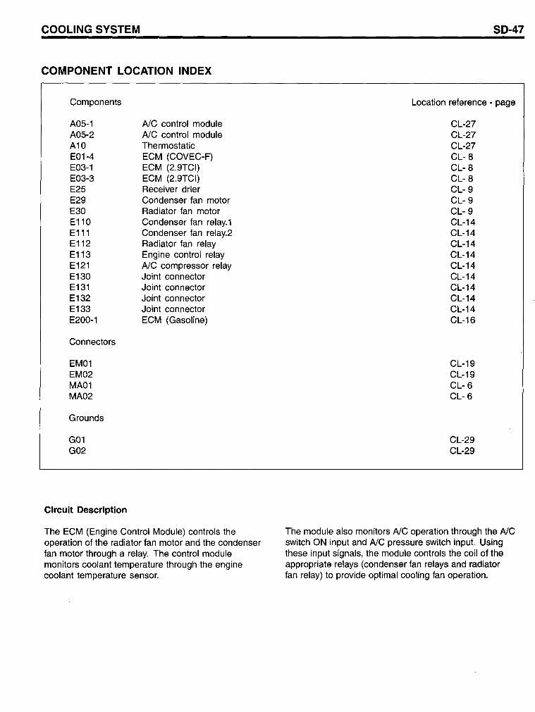
AlC control module AlC contral module Thermostatic ECM (COVEC-F) ECM (2.9TCI) ECM (2.9TCI) Receiver drier Condenser fan motor Radiator fan motor Condenser fan relay.1 Condenser fan relay.2 Radiator fan relay Engine contral relay AlC compressor relay Joint connector Joint connector Joint connector Joint connector ECM (Gasoline)
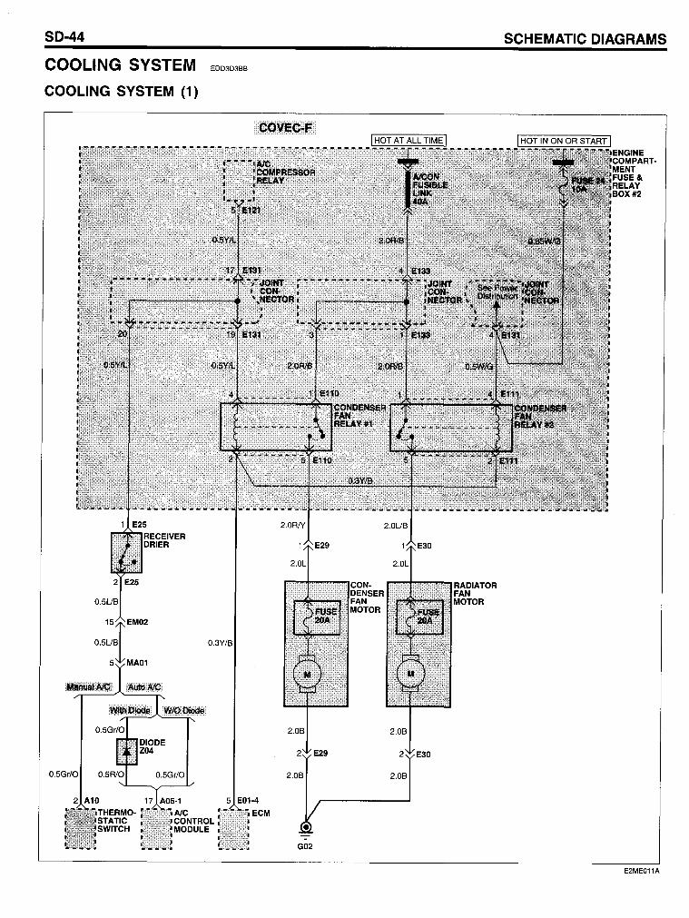
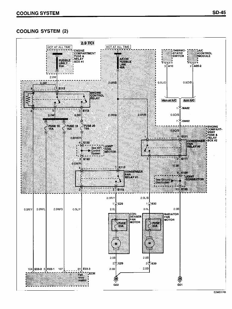
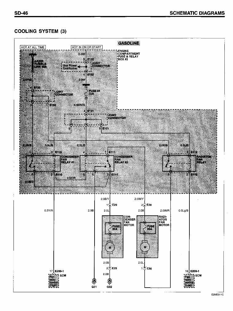
The ECM (Engine Contral Module) controls the operation of the radiator fan motor and the condenser fan motor through a re I ay. The control module monitors coolant temperature through the engine coolant temperature sensor.
SD-47
Location reference - page
CL-27 CL-27 CL-27 CL- 8 CL- 8 CL- 8 CL- 9 CL- 9 CL- 9 CL-14 CL-14 CL-14 CL-14 CL-14 CL-14 CL-14 CL-14 CL-14 CL-16
CL-19 CL-19 CL- 6 CL- 6
CL-29 CL-29
The module also monitors AlC operation thraugh the AlC switch ON input and AlC pressure switch input. Using these input signals, the module controls the coil of the apprapriate relays (condenser fan relays and radiator fan relay) to pravide optimal cooling fan operation.
SO-48 SCHEMATIC OIAGRAMS
MFI CONTROL SYSTEM (COVEC-F) EDE9A583
MFI CONTROL SYSTEM (COVEC-F) (1)
O.5W/G O.5W/G O.5W/G
G02
E2ME013A
MFI CONTROL SYSTEM (COVEC-F)
MFI CONTROL SYSTEM (COVEC-F) (2)
2 E06
DTC
0.5Y/O
See Vehicle Speed Sensor
0.3Y/B
0.3Y/B 0.3Y/B
6 M22·2
TOD CONTROL MODULE
2.0B
G01
SD-49
ENGINE COMPARTMENT FUSE& RELAY BOX #2
E2ME013B
SO-50
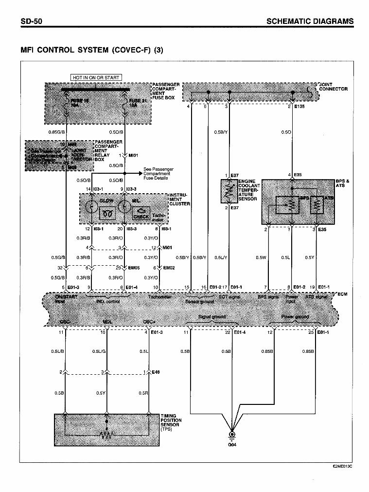
MFI CONTROL SYSTEM (COVEC-F) (3)
0.5UB
See Passenger ...-----4 ..... -.Compartment Fuse Details
0.5UG
2 ________ ~
0.5B 0.5Y
0.5BN
1 E37
0.5BN 0.5BN 0.5UY
0.5B
G04
SCHEMATIC OIAGRAMS
0.50
4 E35
0.5W 0.5L
0.85B
0.5Y
0.85B
BPS& ATS
E2ME013C
MFI CONTROL SYSTEM (COVEC-F)
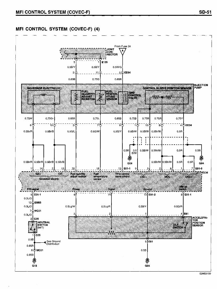
MFI CONTROL SYSTEM (COVEC-F) (4)
0.5Br/R 0.5Br/R 0.5Br/B 0.5Br/B
See Ground ..... ----4 Distribution
G15
From Fuse 24
I I
O$F B/W
• G04
SO-51
I I I I I I
- I 1_ -------- -:1 0.5B/W 0.5Br/W 0.5R
0.5R 0.5R G04
0.5G/R
G04
E2ME013D
SO-52
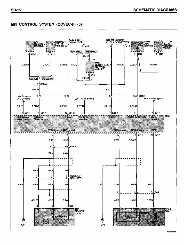
MFI CONTROL SYSTEM (COVEC-F) (5)
2 A05-2 3 A10
0.50/8 0.5UO
0.5R/0
0.5R
11
G11
DATALINK THERMO- CONNECTOR STATIC SWITCH 10 - - - - - -"2 M14
0.3W/8
See Cooling System
0.3W/8 0.3Y/B
0.58
_____ ~g_~EMI05
0.5W
0.5W
3 MC02 (AlT) (MIT)
0.5W
-, , -'
SCHEMATIC DIAGRAMS
MULTIPURPOSE CHECK CONNECTOR
IMMO-BILIZER 0.3UO CONTROL MODULE
0.3UO
0.58
• G04
- - - - -8 M15
0.3UO
0.5W/8
r- --------
See Starting System
-'
ECM
NPS& FCV
E2ME013E
MFI CONTROL SYSTEM (COVEC-F)
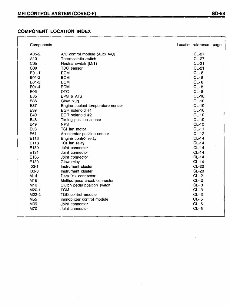
COMPONENT LOCATION INDEX
Components
A05-2 A10 C05 C09 E01-1 E01-2 E01-3 E01-4 E06 E35 E36 E37 E39 E40 E48 E49 E53 E61 E113 E116 E130 E131 E135 E139 103-1 103-3 M14 M15 M16 M20-1 M22-2 M55 M69 M70
AlC control module (Auto AlC) Thermostatic switch Neutral switch (MfT) TDC sensor ECM ECM ECM ECM DTC BPS & ATS Glow plug Engine coolant temperature sensor EGR solenoid #1 EGR solenoid #2 Timing position sensor NPS TCI fan motor Accelerator position sensor Engine control relay TCI fan relay Joint connector Joint connector Joint connector Glow relay Instrument cluster Instrument cluster Data link connector Multipurpose check connector Clutch pedal position switch TCM TOD control module Immobilizer control module Joint connector Joint connector
SO-53
Location reference - page
CL-27 CL-27 CL-21 CL-21 CL- 8 CL- 8 CL- 8 CL- 8 CL- 8 CL-10 CL-10 CL-10 CL-10 CL-10 CL-10 CL-10 CL-11 CL-12 CL-14 CL-14 CL-14 CL-14 CL-14 CL-14 CL-20 CL-20 CL- 2 CL- 2 CL- 3 CL- 3 CL- 3 CL- 5 CL- 5 CL- 5
SO-54
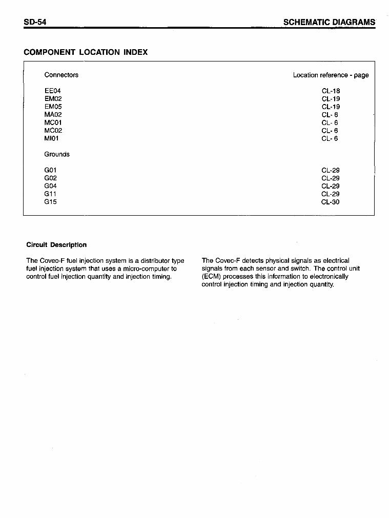
COMPONENT LOCATION INDEX
Connectors
EE04 EM02 EM05 MA02 MC01 MC02 MI01
Grounds
G01 G02 G04 G11 G15
Circuit Description
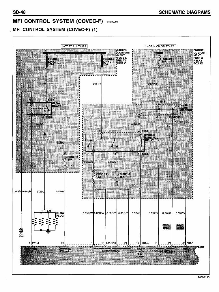
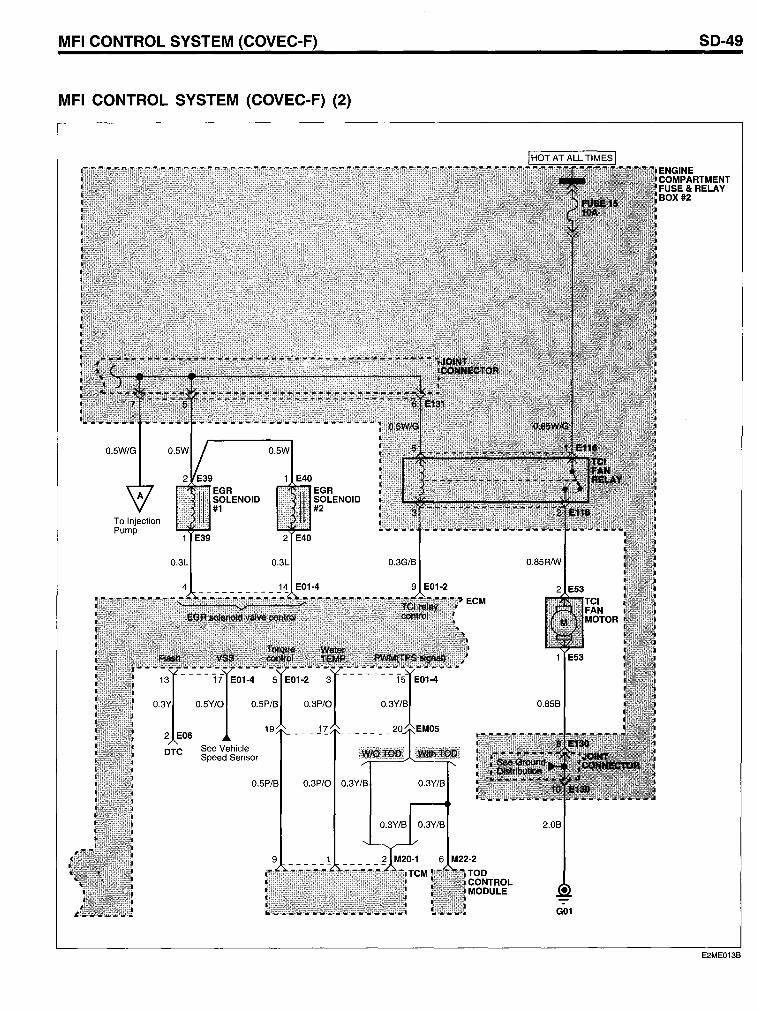
The Covec-F fuel injection system is a distributor type fuel injection system that uses a micro-computer to control fuel injection quantity and injection timing.
SCHEMATIC DIAGRAMS
Location reference - page
CL-18 CL-19 CL-19 CL- 6 CL- 6 CL- 6 CL- 6
CL-29 CL-29 CL-29 CL-29 CL-30
The Covec-F detects physical signals as electrical signals from each sensor and switch. The control unit (ECM) processes this information to electronically control injection timing and injection quantity.

SO-56 SCHEMATIC OIAGRAMS
MFI CONTROL SYSTEM (2.9TCI) EF86AFD8
MFI CONTROL SYSTEM (2.9TCI) (1)
0.5B
G11 GOS
ENGINE
MENT FUSE& RELAY BOX #1
E2ME012A
MFI CONTROL SYSTEM (2.9TCI)
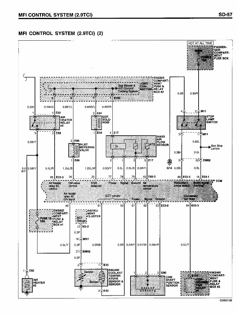
MFI CONTROL SYSTEM (2.9TCI) (2)
0.5B 0.85R
5.0W
5.0BN 0.85L
5.0 2.0BN BN
AIR HEATER #2
0.5UR
46
ENGINE COMPARTMENT FUSE& RELAY BOX #1
0.5LN
0.5Br 0.5L
0.5R/B 0.5R 0.5RN 0.5Y/w 0.5Br/R 0.5LN
SO-57
PASSENGER COMPARTMENT FUSEBOX
ENGINE COMPARTMENT FUSE& RELAY BOX #2
E2ME012B
SO-58
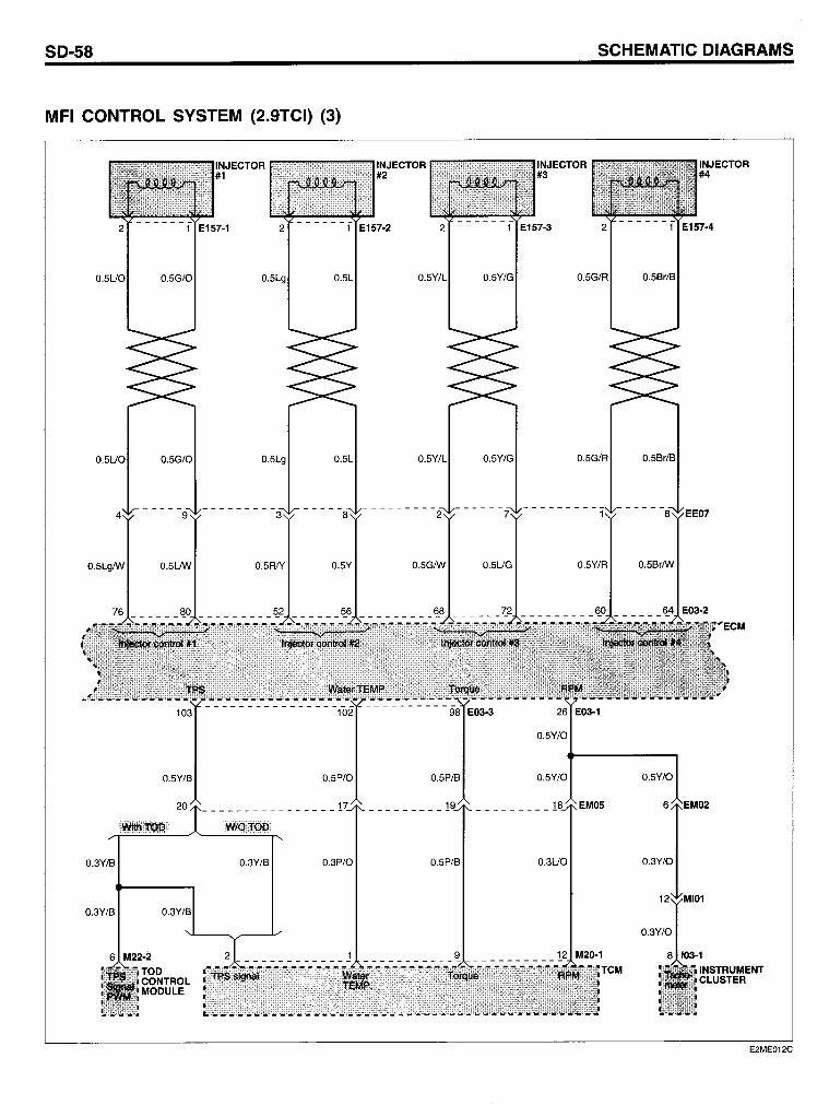
MFI CONTROL SYSTEM (2.9TCI) (3)
0.5LgIW 0.5L!W
0.5Y/B
20
0.3Y/B
0.3Y/B 0.3Y/B
6 M22-2
TOD CONTROL MODULE
0.5RIY 0.5Y
0.5P/O
0.3Y/B 0.3P/O
0.5GIW 0.5UG
0.5P/B
0.5P/B
SCHEMATIC DIAGRAMS
INJECTOR #3
0.5Y/R
0.5Y/O
0.5Y/O
EM05
0.3UO
0.5BrIW
0.5Y/O
6
0.3Y/O
INJECTOR #4
E2ME012C
MFI CONTROL SYSTEM (2.9TCI)
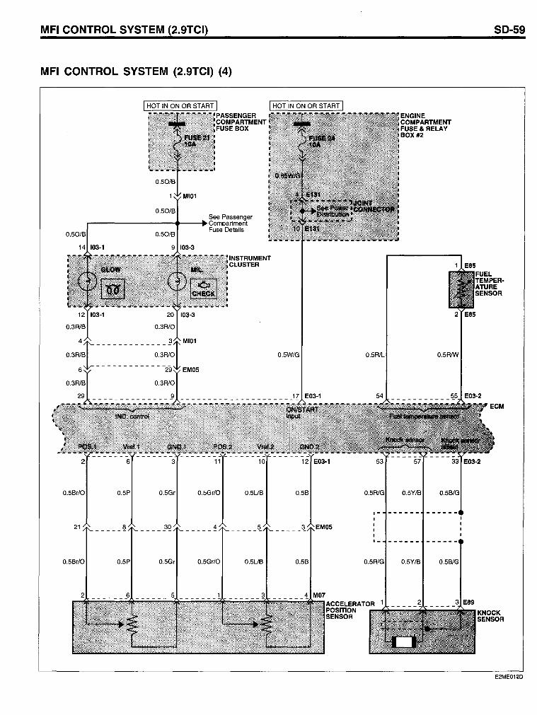
MFI CONTROL SYSTEM (2.9TCI) (4)
0.50/B
0.50/B
PASSENGER COMPARTMENT FUSE BOX
See Passenger .....--------_ ..... - ..... Compartment
0.50/B Fuse Details
14 103·1 9 103·3
0.5Br/0 0.5P 0.5Gr 0.5Gr/0 0.5UB
21 _____ !1 30 4 5 ------ ------ ------
0.5Br/0 0.5P 0.5Gr 0.5Gr/0 0.5UB
0.5B
,-
0.5B 0.5R1G
ENGINE COMPARTMENT FUSE& RELAY BOX #2
------ ------
------
0.5Y/B 0.5B/G
2 3 E89
SO-59
KNOCK SENSOR
E2ME012D
SO-60
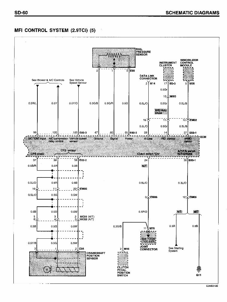
MFI CONTROL SYSTEM (2.9TCI) (5)
See Blower & AlC Controls See Vehicle ~ Speed Sensor
0.5R1L 0.5Y 0.5Y/O
0.5B/R 0.5B
0.5B
0.5W
0.5W
2
0.5W
-------
0.5G/B 0.5G/R
--I I I --
EM05
-I
I --
MC01 (MIT)
-I
(AlT)
CRANKSHAFT POSITION SENSOR
0.5G
0.3G/B
2 M16
CLUTCH PEDAL POSITION SWITCH
RAIL PRESSURE SENSOR
DATA LINK CONNECTOR
2 M14
0.5UO
le
0.5UO
EM06
0.5P/O
JOINT CONNECTOR
SCHEMATIC OIAGRAMS
IMMOBILIZER INSTRUMENT CONTROL CLUSTER MODULE
17 103·3 5 MOa
0.5Gr
0.5Gr 0.5UB
0.3UO
0.3R
See Starting System
0.5B
ECM
G11
E2ME012E
MFI CONTROL SYSTEM (2.9TCI)
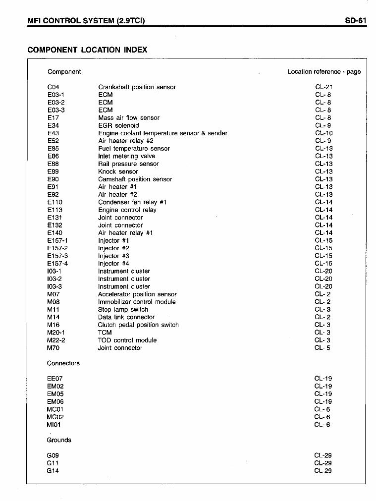
COMPONENT LOCATION INDEX
Component
C04 E03-1 E03-2 E03-3 E17 E34 E43 E52 E85 E86 E88 E89 E90 E91 E92 E110 E113 E131 E132 E140 E157-1 E157-2 E157-3 E157-4 103-1 103-2 103-3 M07 M08 M11 M14 M16 M20-1 M22-2 M70
Connectors
EE07 EM02 EM05 EM06 MC01 MC02 MI01
Grounds
G09 G11 G14
Crankshaft position sensor ECM ECM ECM Mass air flow sensor EGR solenoid Engine coolant temperature sensor & sender Air heater relay #2 Fuel temperature sensor Inlet metering valve Rail pressure sensor Knock sensor Camshaft position sensor Air heater #1 Air heater #2 Condenser fan relay #1 Engine control relay Joint connector Joint connector Air heater relay #1 Injector #1 Injector #2 Injector #3 Injector #4 Instrument cluster Instrument cluster Instrument cluster Accelerator position sensor Immobilizer control module Stop lamp switch Data link connector Clutch pedal position switch TCM TOD control module Joint connector
SO-61
Location reference - page
CL-21 CL- 8 CL- 8 CL- 8 CL- 8 CL- 9 CL-10 CL- 9 CL-13 CL-13 CL-13 CL-13 CL-13 CL-13 CL-13 CL-14 CL-14 CL-14 CL-14 CL-14 CL-15 CL-15 CL-15 CL-15 CL-20 CL-20 CL-20 CL- 2 CL- 2 CL- 3 CL- 2 CL- 3 CL- 3 CL- 3 CL- 5
CL-19 CL-19 CL-19 CL-19 CL- 6 CL- 6 CL- 6
CL-29 CL-29 CL-29
SO-62 SCHEMATIC DIAGRAMS
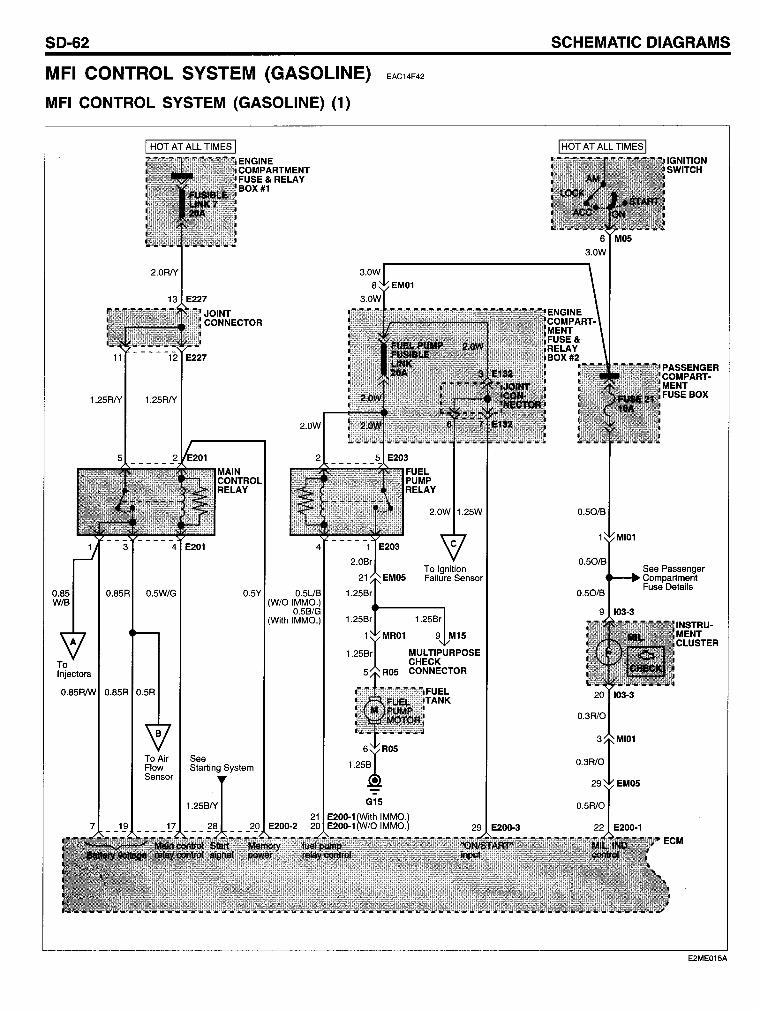
MFI CONTROL SYSTEM (GASOLINE) EAC14F42
MFI CONTROL SYSTEM (GASOLINE) (1)
0.85 W/B
11 12 E227
1.25R/Y 1.25R/Y
0.85R 0.5W/G
0.85R 0.5R
ToAir Flow Sensor
ENGINE
FUSE& RELAY BOX #1
MAIN CONTROL RELAY
0.5Y 0.5UB (W/OIMMO.)
0.5B/G (With IMMO.)
2.0W 1.25W
To Ignition Failure Sensor
E2ME015A
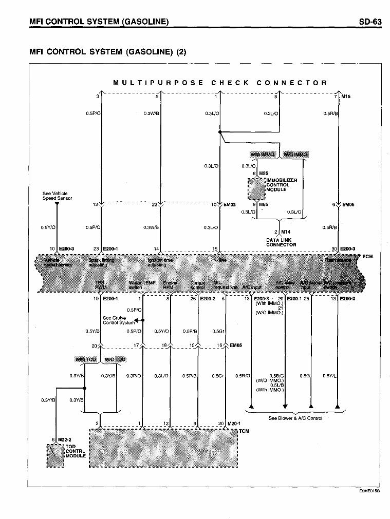
MFI CONTROL SYSTEM (GASOLINE)
MFI CONTROL SYSTEM (GASOLINE) (2)
MULTIPURPOSE CHECK CONNECTOR
See Vehicle Speed Sensor
O.5Y/O
O.3YIB
3 5 8
O.3W/B 0.3UO 0.3UO
0.3UO
------------
O.3W/B
0.5Y/O 0.5P/B
18 1
O.3Y/B O.3P/O 0.3UO 0.5P/B
10 EMD2
0.3UO
0.5Gr
16 EMDS
0.5Gr 0.5R/O 0.5B/G (W/OIMMO.)
0.5UB (With IMMO.)
0.5R1B
0.5G
EMDS
'~----------~~~----------~/
6 M22·2
TOD CONTRL MODULE
See Blower & AlC Control
SO-63
E2ME015B
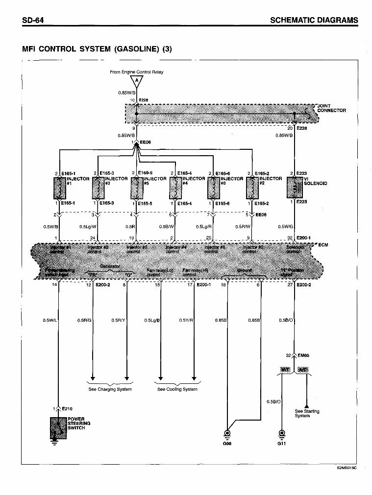
SO-64
MFI CONTROL SYSTEM (GASOLINE) (3)
From Engine Control Relay
0.5R1G 0.5RIY
~ See Charging System
POWER STEERING SWITCH
0.5Lg/B 0.5Y/R
~ See Cooling System
0.85B
-G08
SCHEMATIC OIAGRAMS
2 E223 VI SOLENOID
1 E223
0.5W/G
0.5B/0
0.5B/0
Gll
See Starling System
E2ME015C
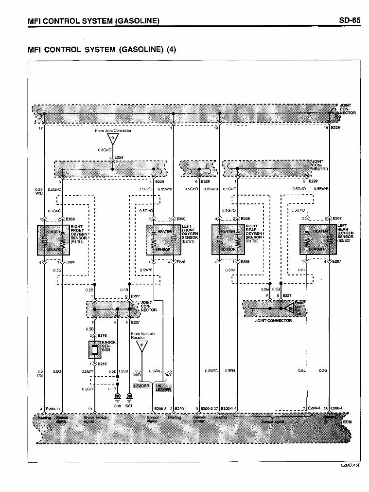
MFI CONTROL SYSTEM (GASOLINE)
MFI CONTROL SYSTEM (GASOLINE) (4)
17
0.85 0.5Gr/O W/B
0.5 Y/G
.- - - - - - - --, 0.5Gr/O
From Joint Connector
0.5W/R
0.5Gr/O 0.85W/B 0.5Gr/O
.- - - - - -- - -
0.5Gr/O
0.5R/L
'-
0.5W/G 0.5R/L
RIGHT , REAR , OXYGEN' SENSOR' (B1/82) ,
JOINT CONNECTOR
SO-65
0.5G
E2ME015D
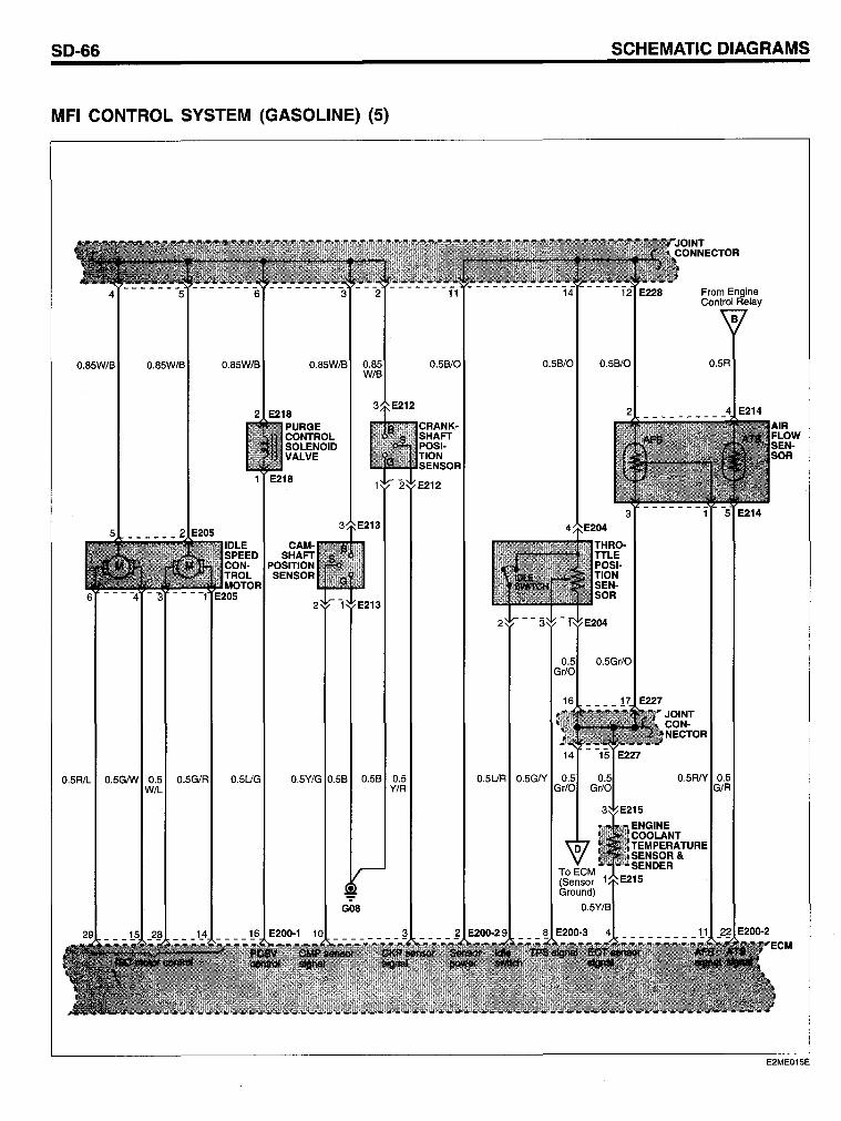
SO-66
MFI CONTROL SYSTEM (GASOLINE) (5)
0.85W/B 0.85W/B 0.85W/B 0.85W/B
2 E218
1
0.5R/L 0.5GIW 0.5 0.5G/R 0.5UG W/L
PURGE CONTROL SOLENOID VALVE
E218
CAMSHAFT
POSITION SENSOR
0.5Y/G
G08
0.85 W/B
0.5B 0.5 Y/R
0.5B/0 0.5B/0
CRANK-SHAFT POSI-TION SENSOR
E212
SCHEMATIC OIAGRAMS
0.5B/0
From Engine Control Relay
0.5R
0.5Gr/0
0.5R/Y 0.5
ENGINE COOLANT TEMPERATURE SENSOR & SENDER
E215
E2ME015E
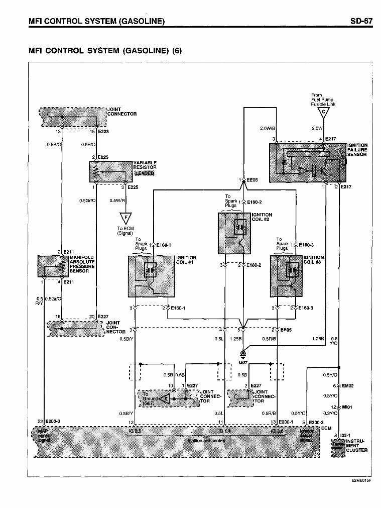
MFI CONTROL SYSTEM (GASOLINE)
MFI CONTROL SYSTEM (GASOLINE) (6)
ToECM (Signal)
0.5B/Y
,-
IGNITION COIL#1
0.5L
-, -
IGNITION COIL#2
G07r---_"'" -,
From Fuel Pump Fusible Link
IGNITION COIL#3
1.258 0.5 Y/O
SO-67
IGNITION FAllURE SENSOR
E2ME015F
50-68
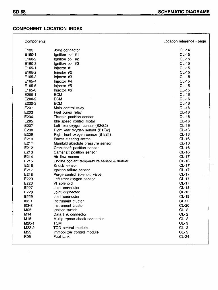
COMPONENT LOCATION INDEX
Components
E132 E160-1 E160-2 E160-3 E165-1 E165-2 E165-3 E165-4 E165-5 E165-6 E200-1 E200-2 E200-3 E201 E203 E204 E205 E207 E208 E209 E210 E211 E212 E213 E214 E215 E216 E217 E218 E220 E223 E227 E228 E229 103-1 103-3 M05 M14 M15 M20-1 M22-2 M55 R05
Joint connector Ignition coil #1 Ignition coil #2 Ignition coil #3 Injector #1 Injector #2 Injector #3 Injector #4 Injector #5 Injector #6 ECM ECM ECM Main control relay Fuel pump relay Throttle position sensor Idle speed control motor Left rear oxygen sensor (82/52) Right rear oxygen sensor (81/52) Right frant oxygen sensor (81/51) Power steering switch Manifold absolute pressure sensor Crankshaft position sensor Camshaft position sensor Air flow sensor Engine coolant temperature sensor & sender Knock sensor Ignition failure sensor Purge contral solenoid valve Left front oxygen sensor VI solenoid Joint connector Joint connector Joint connector Instrument cluster Instrument cluster Ignition switch Data link connector Multipurpose check connector TCM TOD contral module Immobilizer control module Fuel tank
SCHEMATIC DIAGRAMS
Location reference - page
CL-14 CL-15 CL-15 CL-15 CL-15 CL-15 CL-15 CL-15 CL-15 CL-15 CL-16 CL-16 CL-16 CL-16 CL-16 CL-16 CL-16 CL-16 CL-16 CL-16 CL-16 CL-16 CL-16 CL-16 CL-17 CL-16 CL-17 CL-17 CL-17 CL-17 CL-17 CL-18 CL-18 CL-18 CL-20 CL-20 CL- 2 CL- 2 CL- 2 CL- 3 CL- 3 CL- 5 CL-24
MFI CONTROL SYSTEM (GASOLINE)
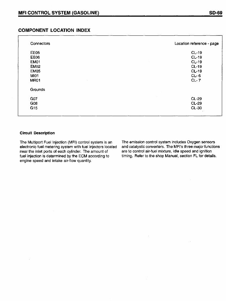
COMPONENT LOCATION INDEX
Connectors
EE05 EE06 EM01 EM02 EM05 MI01 MR01
Graunds
G07 GOB G15
Circuit Description
The Multiport Fuellnjection (MFI) control system is an electronic fuel metering system with fuel injectors located near the inlet ports of each cylinder. The amount of fuel injection is determined by the ECM according to engine speed and intake air-flow quantity.
SO-69
Location reference - page
CL-19 CL-19 CL-19 CL-19 CL-19 CL- 6 CL-7
CL-29 CL-29 CL-30
The emission contral system includes Oxygen sensors and catalystic converters. The MFI's three major functions are to contral air-fuel mixture, idle speed and ignition timing. Refer to the shop Manual, section FL for details.
SO-70
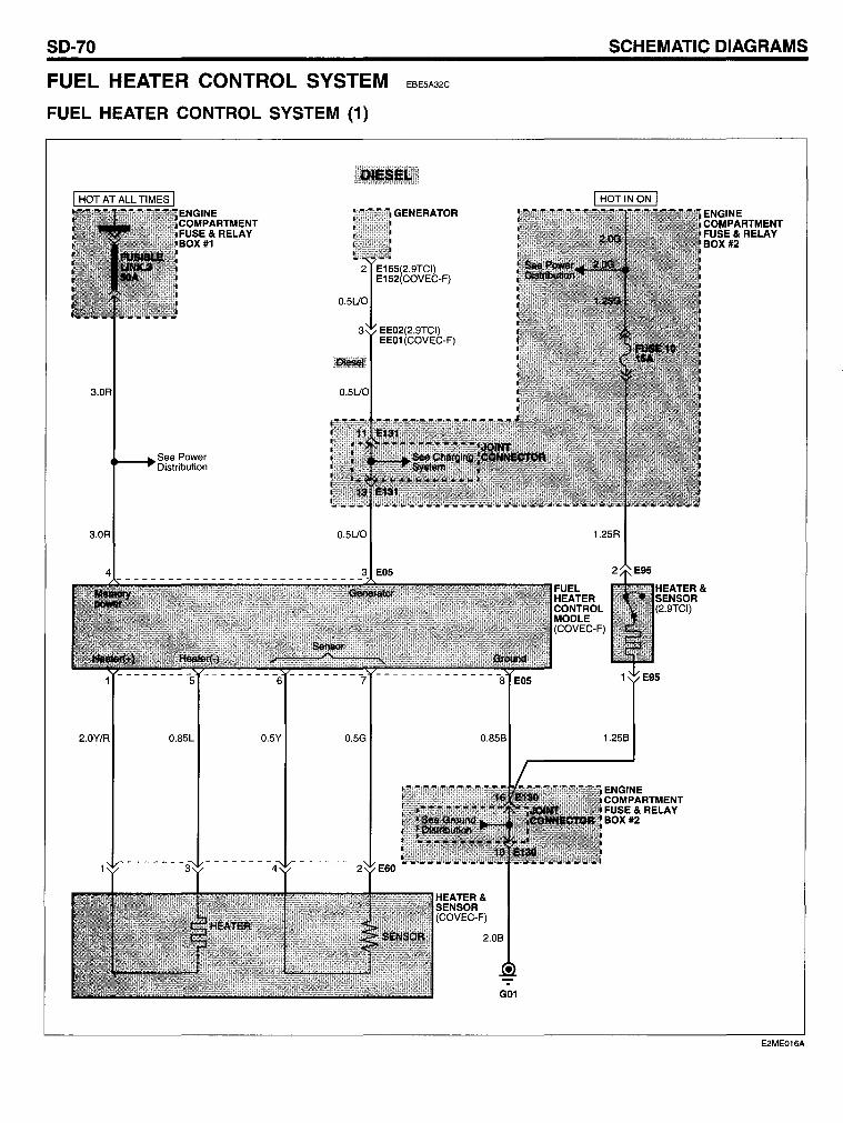
FUEL HEATER CONTROL SYSTEM
FUEL HEATER CONTROL SYSTEM (1)
3.0R
3.0R
2.0Y/R
See Power ..... -·Distribution
0.85L 0.5Y 0.5G
EBE5A32C
0.85B
HEATER& SENSOR (COVEC-F)
2.0B
GOI
SCHEMATIC OIAGRAMS
1.25B
ENGINE COMPARTMENT FUSE& RELAY BOX #2
ENGINE COf./lPARTMENT FUSE& RELAY BOX #2
E2ME016A
FUEL HEATER CONTROL SYSTEM
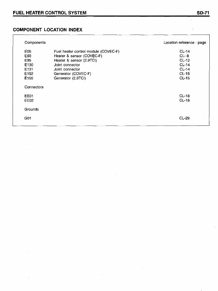
COMPONENT LOCATION INDEX
Components
E05 E60 E95 E130 E131 E152 E155
Connectors
EE01 EE02
Grounds
G01
Fuel heater control module (COVEC-F) Heater & sensor (COVEC-F) Heater & sensor (2.9TCI) Joint connector Joint connector Generator (COVEC-F) Generator (2.9TCI)
SD-71
Location reference - page
CL-14 CL- 8 CL-12 CL-14 CL-14 CL-15 CL-15
CL-18 CL-18
CL-29
SO-72
AUTOMATIC TRANSAXLE CONTROL SYSTEM
AUTOMATIC TRANSAXLE CONTROL SYSTEM (1)
See Starting System /~ __ ~A,-__ ~,
O.5R
O.3P/O O.3L
O.3P/O O.5L
O.
G13
EADBCB2E
SCHEMATIC OIAGRAMS
See Indicators Gauges
O.3P/B
O.5G 1IM30
0/0 SWITCH
See Illuminations
E2ME019A
AUTOMATIC TRANSAXLE CONTROL SYSTEM
AUTOMATIC TRANSAXLE CONTROL SYSTEM (2)
98 - - - - - - - - - - - - - - - - - - - - f02 E03·3
ECM ECM
5 E200·3 26 E200·2 5 E01·2 3 E01·4
0.5Gr 0.5P/8 0.5P/8 0.5P/8 0.3P/O 0.5P/O 0.5P/O 0.5Y/O
26 E03·1
ECM
0.5Y/O
See Indicators Gauges
0.50/8
0.50/8
14 103·1
SO-73
PASSENGER COMPART· MENT FUSE BOX
See Pa5lse,me,
Fuse Details
E2ME019B
SO-74 SCHEMATIC OIAGRAMS
AUTOMATIC TRANSAXLE CONTROL SYSTEM (3)
1.25Y
1.25Y
0.5Y
ENGINE COMPARTMENT FUsE& RELAY BOX #2
ECM
19 E200-1 15 E01-4 103 E03-3
0.5Y/B 0.3Y/B 0.5Y/B
0.3Y/B
See Stop Lamps DATA LINK CONNECTOR
6 - - - - - - -2 M14
0.85L 0.3W/O 0.3UO
0.3Y/B
0.3Y/B 0.3Br
MULTI PUR POSE See Cruise CHECK CONNECTOR Control System
0.5UO
See Indicators Gauges
0.5R
EsT CONTROL MODULE
TCM
E2ME019C
AUTOMATIC TRANSAXLE CONTROL SYSTEM
COMPONENT LOCATION INDEX
Components
Vehicle speed sensor Transaxle range switch (COVEC-F) Output speed sensor (PG-B)
SD-75
Location reference - page
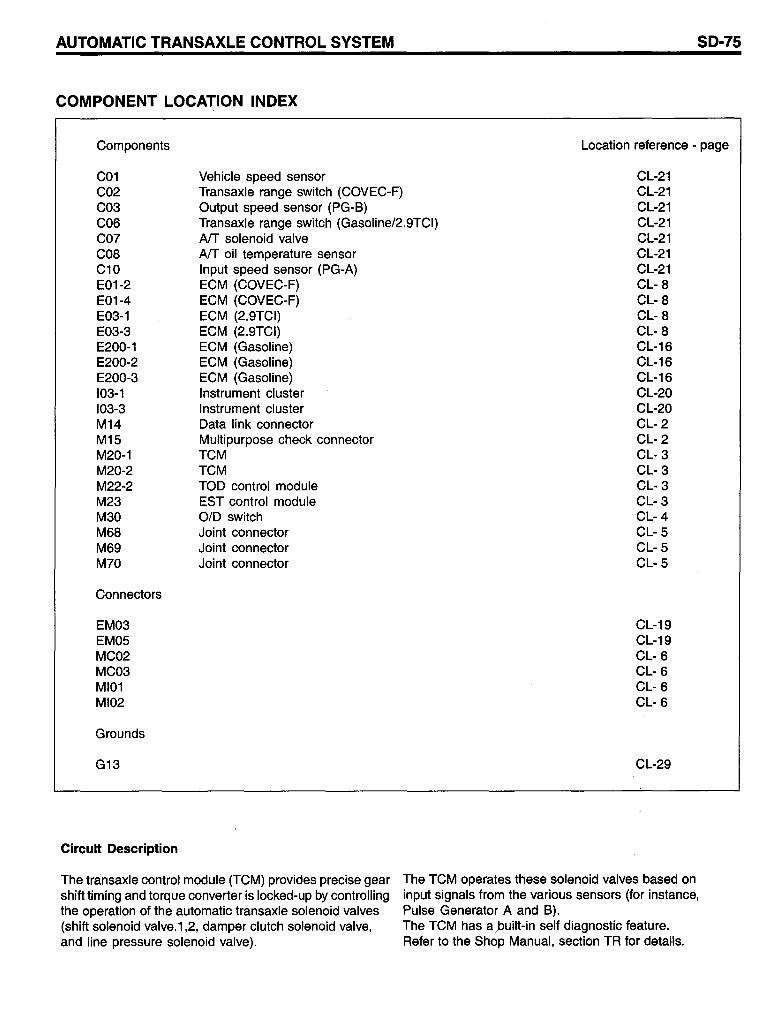
C01 C02 C03 C06 C07 C08 C10 E01-2 E01-4 E03-1 E03-3 E200-1 E200-2 E200-3 103-1 103-3 M14 M15 M20-1 M20-2 M22-2 M23 M30 M68 M69 M70
Transaxle range switch (Gasoline/2.9TCI) AlT solenoid valve
CL-21 CL-21 CL-21 CL-21 CL-21 CL-21 CL-21 CL- 8 CL- 8 CL- 8 CL- 8 CL-16 CL-16 CL-16 CL-20 CL-20 CL- 2 CL- 2 CL- 3 CL- 3 CL- 3 CL- 3 CL-4 CL- 5 CL- 5 CL- 5
Connectors
EM03 EM05 MC02 MC03 MI01 MI02
Grounds
G13
Circuit Description
AlT oil temperature sensor Input speed sensor (PG-A) ECM (COVEC-F) ECM (COVEC-F) ECM (2.9TCI) ECM (2.9TCI) ECM (Gasoline) ECM (Gasoline) ECM (Gasoline) Instrument cluster Instrument cluster Data link connector Multipurpose check connector TCM TCM TOD control module EST control module 0/0 switch Joint connector Joint connector Joint connector
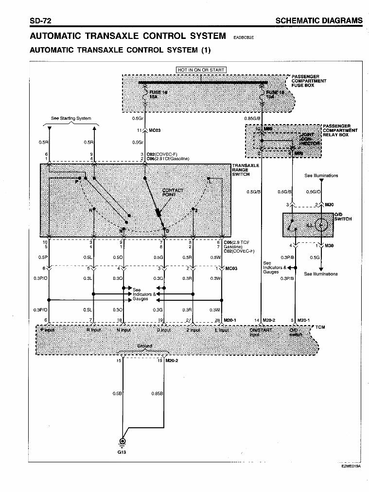
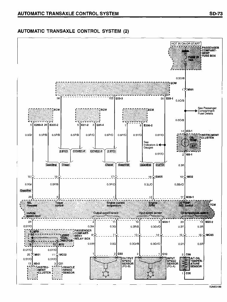
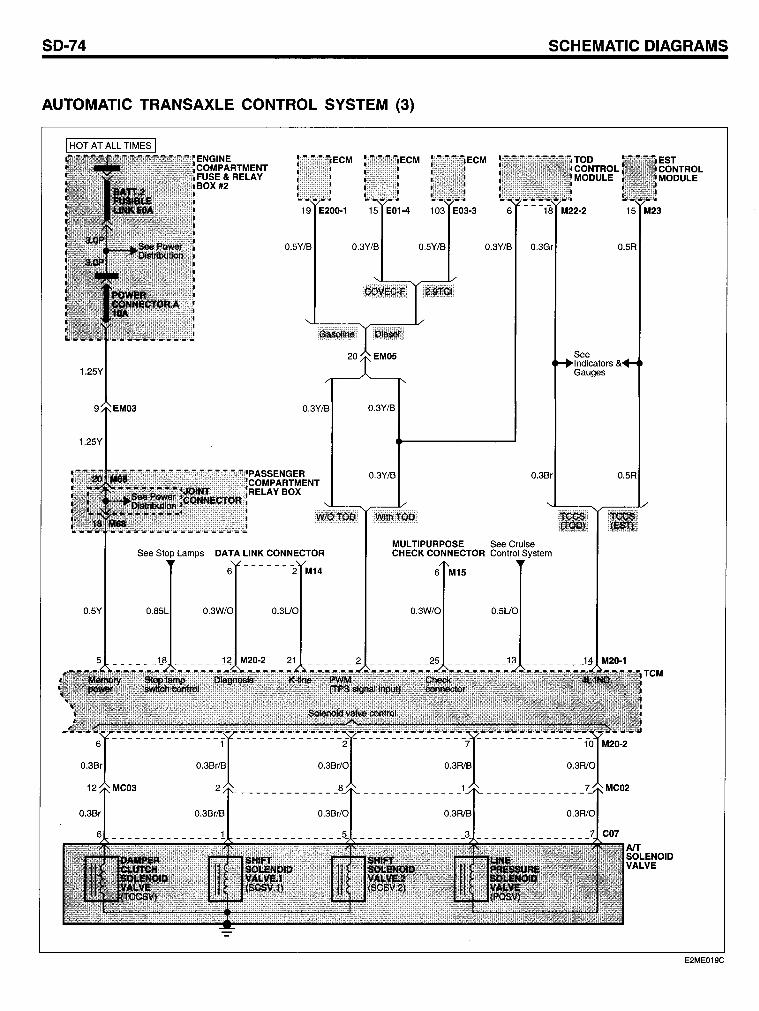
The transaxle control module (TCM) provides precise gear shift timing and torque converter is locked-up by controlling the operation of the automatie transaxle solenoid valves (shift solenoid valve.1 ,2, damper clutch solenoid valve, and line pressure solenoid valve).
CL-19 CL-19 CL- 6 CL- 6 CL- 6 CL- 6
CL-29
The TCM operates these solenoid valves based on input signals from the various sensors (for instance, Pulse Generator A and B). The TCM has a/built-in self diagnostic feature. Refer to the Shop Manual, section TR for details.
SO-76 SCHEMATIC DIAGRAMS
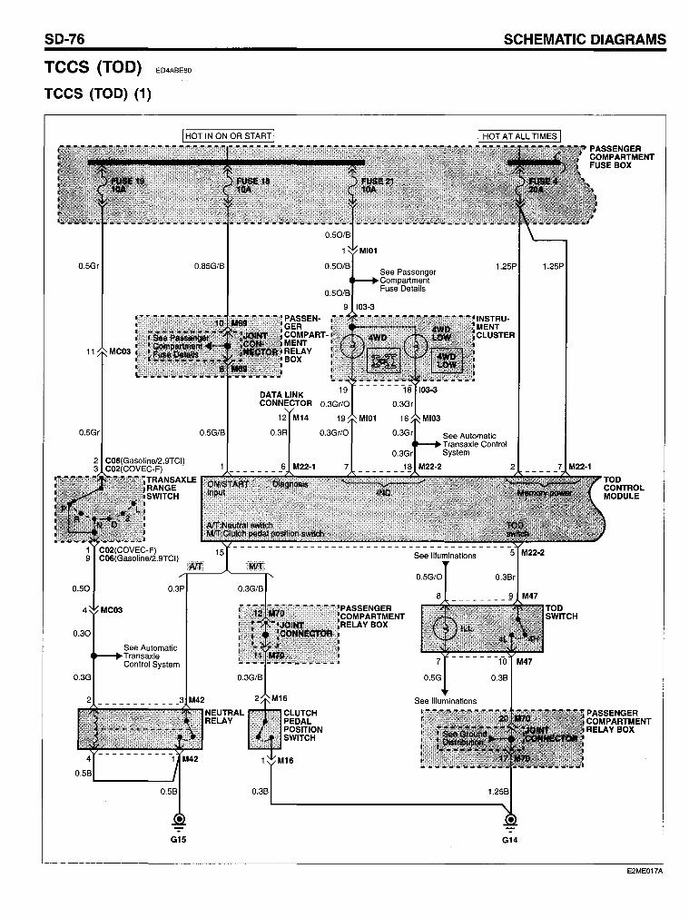
TCCS (TOD) ED4ABE80
TCCS (TOD) (1)
I HOT IN ON OR START I
O.5Gr
11 MC03
0.5Gr
0.30
0.3G
See Automatie Transaxle Control System
G15
O.85G/B
0.5G/B
PASSEN· GER COMPART· MENT RELAY BOX
DATALINK CONNECTOR
0.3B
12 M14
O.3R
See Passenger Compartment Fuse Details
M22·2
1.25P
See Automatie Transaxle Control System
G14
1.25P
E2ME017A
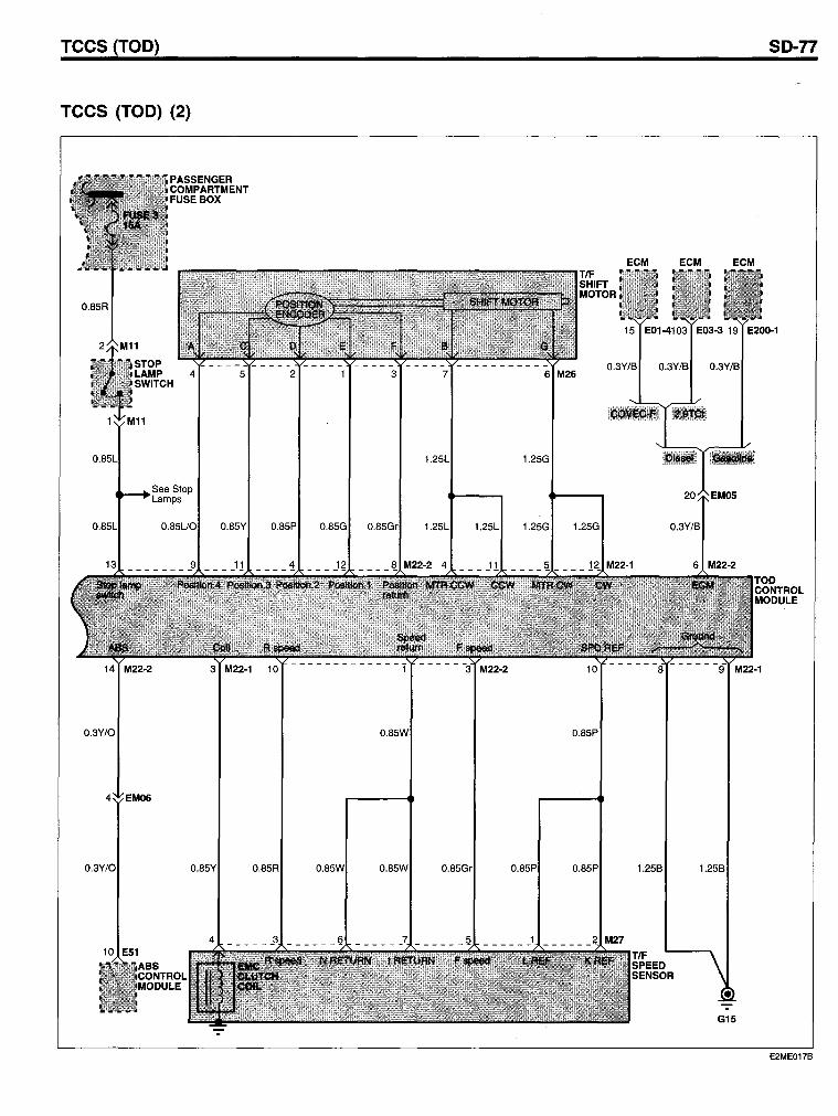
Tees (TOD) SO-77
Tees (TOD) (2)
ECM ECM
15 E20o-1
4 5 2 3 7 6 M26 O.3Y/B
1.25L 1.25G
1.25L 1.25G 1.25G
O.3Y/O O.85W
E2ME017B
SD-78
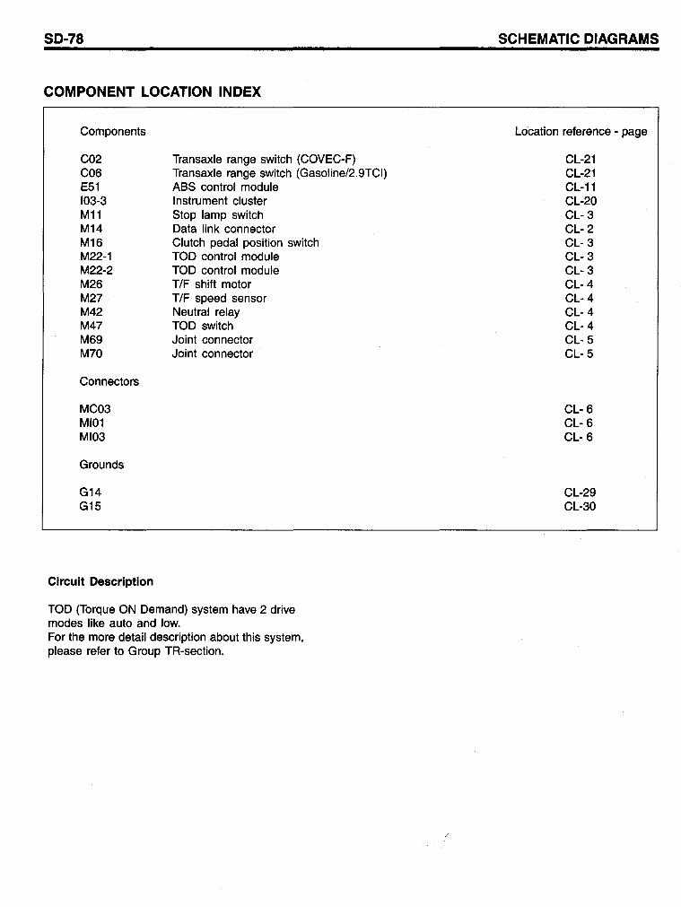
COMPONENT LOCATION INDEX
Components
C02 C06 E51 103-3 M11 M14 M16 M22-1 M22-2 M26 M27 M42 M47 M69 M70
Connectors
MC03 MI01 MI03
Grounds
G14 G15
Clrcuit Description
Transaxle range switch (COVEC-F) Transaxle range switch (Gasoline/2.9TCI) ASS control module Instrument cluster Stop lamp switch Data link connector Clutch pedal position switch TOD control module TOD control module T/F shift motor T/F speed sensor Neutral relay TOD switch Joint connector Joint connector
TOD (Torque ON Demand) system have 2 drive modes like auto and low. For the more detail description about this system, please reter to Group TR-section.
SCHEMATIC DIAGRAMS
Location reterence - page
CL-21 CL-21 CL-11 CL-20 CL- 3 CL- 2 CL- 3 CL- 3 CL- 3 CL- 4 CL- 4 CL- 4 CL- 4 CL- 5 CL- 5
CL- 6 CL- 6 CL- 6
CL-29 CL-30
SO-80 SCHEMATIC OIAGRAMS
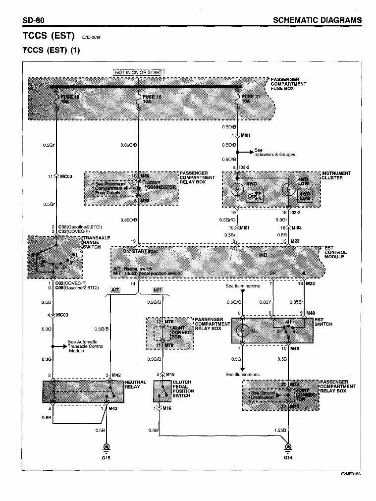
TCCS (EST) E7EF2C9F
TCCS (EST) (1)
0.5Gr
11 MC03
0.5Gr
0.30
0.3G
2 C06(Gasoline/2.9TCI) 3 C02(COVEC-F)
0.5G/B
See Automatie Transaxle Control Module
0.85G/B
0.850/B
2 3 M42
G15
NEUTRAL RELAY
0.3B
PASSENGER COMPARTMENT RELAYBOX
-:-G14
E2ME01BA
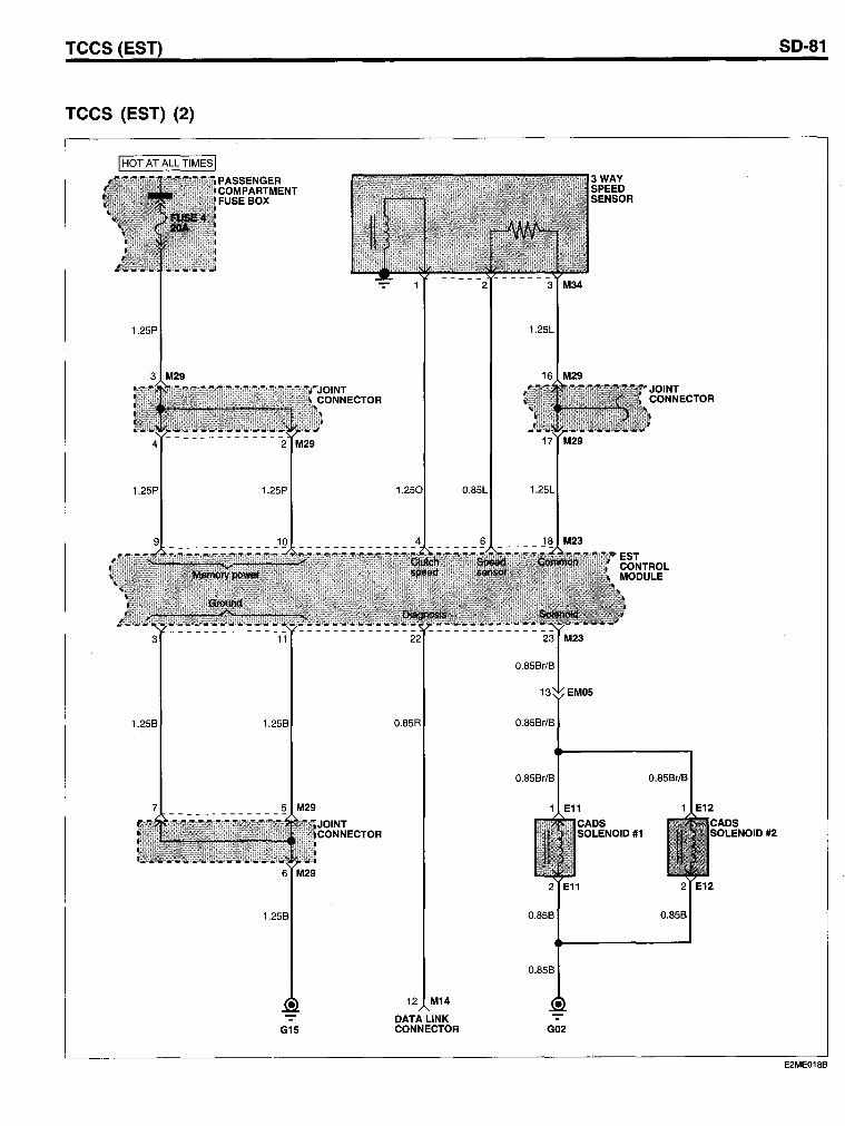
Tees (EST)
Tees (EST) (2)
1.25P
3 M29
1.258 1.258
G15
0.85R
12 M14
DATALINK CONNECTOR
0.85L
1.25L
16 M29
0.858r/8
0.858r/8
1 E11
3WAY SPEED SENSOR
SOILENIOID #1
2 E11
0.858
0.858
G02
JOINT CONNECTOR
0.858r/8
1 E12
2 E12
0.858
SD-81
E2ME018B
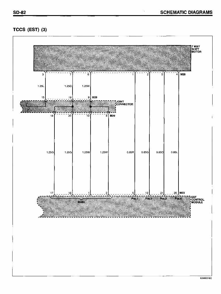
SO-82
TCCS (EST) (3)
1.25L 1.25G
15 19
1.25G 1.25G
1.25W
9 M29
1.25W O.85R O.85G
SCHEMATIC OIAGRAMS
O.85L
EST CONTROL MODULE
E2ME018C
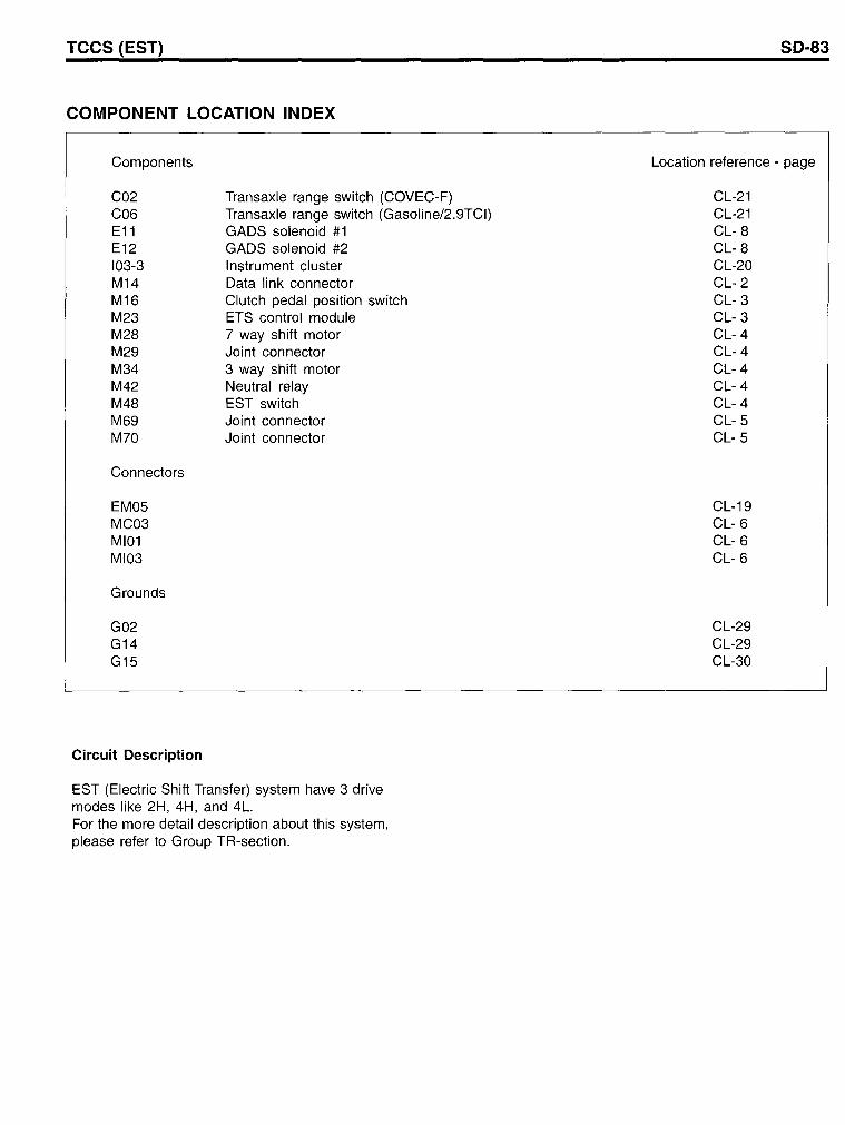
TCCS (EST)
COMPONENT LOCATION INDEX
Components
C02 C06 E11 E12 103-3 M14 M16 M23 M28 M29 M34 M42 M48 M69 M70
Connectors
EM05 MC03 MI01 MI03
Grounds
G02 G14 G15
Circuit Description
Transaxle range switch (COVEC-F) Transaxle range switch (Gasoline/2.9TCI) GADS solenoid #1 GADS solenoid #2 Instrument cluster Data link connector Clutch pedal position switch ETS control module 7 way shift motor Joint connector 3 way shift motor Neutral relay EST switch Joint connector Joint connector
EST (Electric Shift Transfer) system have 3 drive modes like 2H, 4H, and 4L. For the more detail description about this system, please refer to Group TR-section.
SD-83
Location reference - page
CL-21 CL-21 CL- 8 CL- 8 CL-20 CL- 2 CL- 3 CL- 3 CL- 4 CL- 4 CL- 4 CL- 4 CL- 4 CL- 5 CL- 5
CL-19 CL- 6 CL- 6 CL- 6
CL-29 CL-29 CL-30
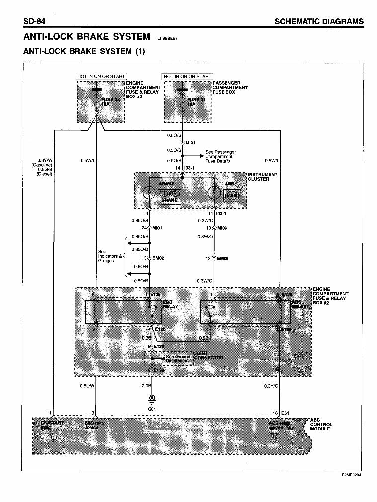
SO-84
ANTI-LOCK BRAKE SYSTEM
ANTI-LOCK BRAKE SYSTEM (1)
O.3YIW (Gasoline)
O.5GIB (Diesel)
See I ndicators & Gauges
EFBEBEE8
See Passenger ..... - .... Compartment
Fuse Details
SCHEMATIC OIAGRAMS
O.
E2ME020A
ANTI-LOCK BRAKE SYSTEM
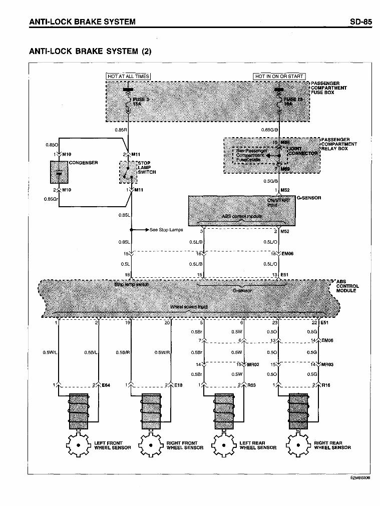
ANTI-LOCK BRAKE SYSTEM (2)
O.5W/L
O.85L
"'-.~3ee Stop Lamps
O.85L
LEFTFRONT WHEEL SENSOR
n RIGHT FRONT Y WHEEL SENSOR n LEFTREAR Y WHEEL SENSOR
SO-85
RIGHTREAR WHEEL SENSOR
E2ME020B
SO-86
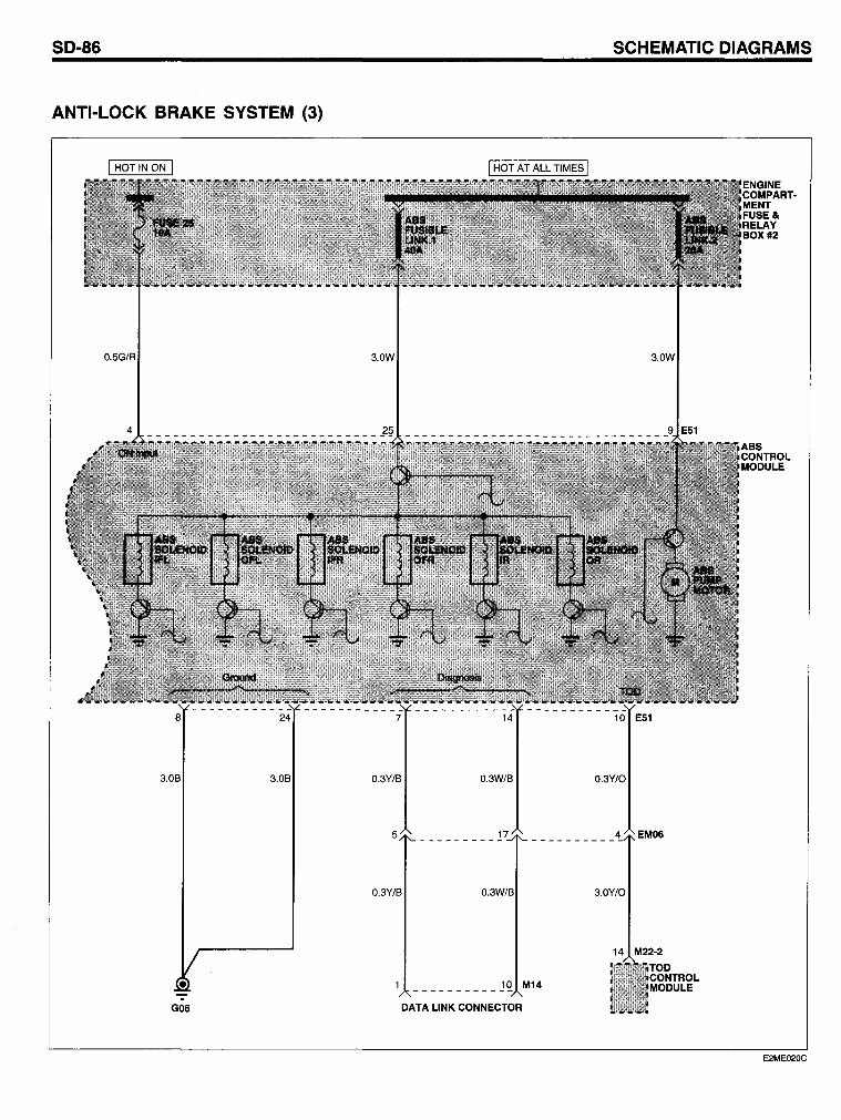
ANTI-LOCK BRAKE SYSTEM (3)
0.5G/R 3.0W
8 24 7 14
3.0B 3.0B 0.3Y/B 0.3W/B
5
0.3Y/B
10 M14 -----------
G06 DATA LINK CONNECTOR
SCHEMATIC OIAGRAMS
3.0W
10 E51
0.3Y/O
4 EM06
3.0Y/O
14 M22·2
ENGINE COMPART· MENT FUSE& RELAY BOX #2
E2ME020C
ANTI-LOCK BRAKE SYSTEM
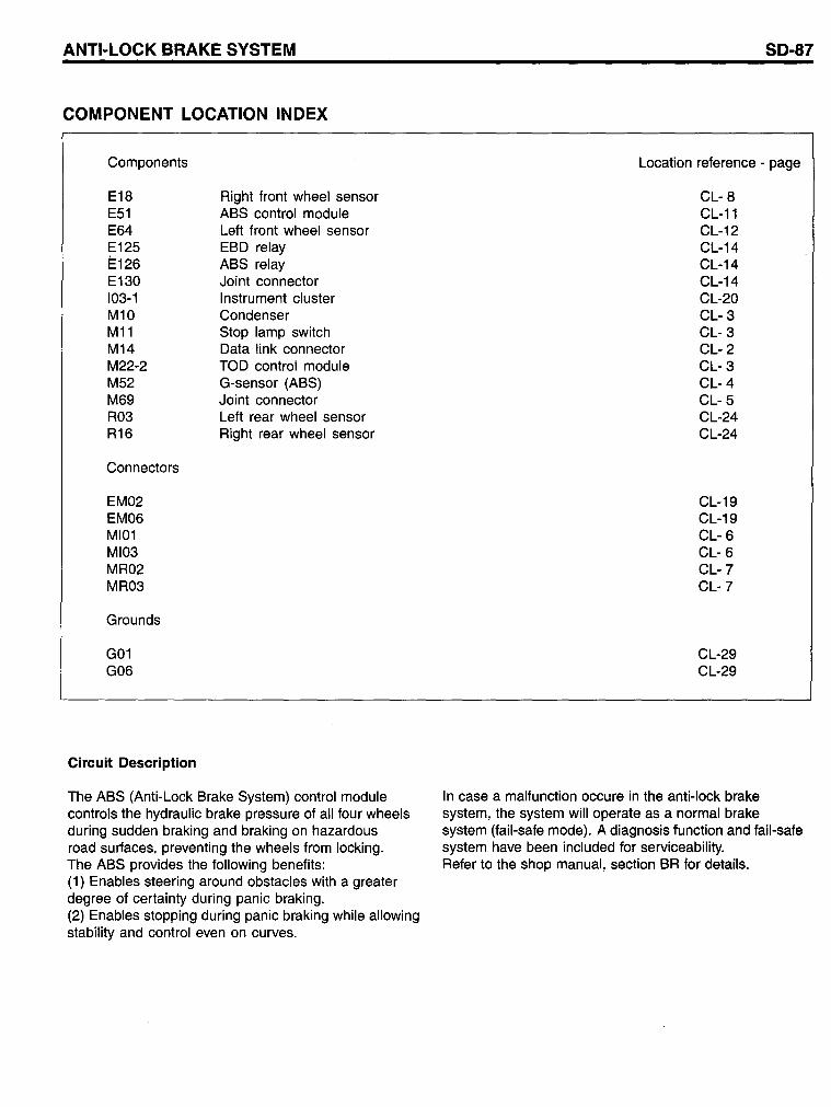
COMPONENT LOCATION INDEX
Components
E18 E51 E64 E125 1=126 E130 103-1 M10 M11 M14 M22-2 M52 M69 R03 R16
Connectors
EM02 EM06 MI01 MI03 MR02 MR03
Grounds
G01 G06
Circuit Description
Right front wheel sensor ABS control module Left front wheel sensor EBD relay ABS relay Joint connector Instrument cluster Condenser Stop lamp switch Data link connector TOD control module G-sensor (ABS) Joint connector Left rear wheel sensor Right rear wheel sensor
The ABS (Anti-Lock Brake System) control module controls the hydraulic brake pressure of all four wheels during sudden braking and braking on hazardous road surfaces, preventing the wheels from locking. The ABS provides the following benefits: (1) Enables steering around obstacles with a greater degree of certainty during panic braking. (2) Enables stopping during panic braking while allowing stability and control even on curves.
SD-87
Location reference - page
CL- 8 CL-11 CL-12 CL-14 CL-14 CL-14 CL-20 CL- 3 CL- 3 CL- 2 CL- 3 CL- 4 CL- 5 CL-24 CL-24
CL-19 CL-19 CL- 6 CL- 6 CL-7 CL-7
CL-29 CL-29
In case a malfunction occure in the anti-lock brake system, the system will operate as anormal brake system (fail-safe mode). A diagnosis function and fail-safe system have been included for serviceability. Refer to the shop manual, section BR for details.
50-88
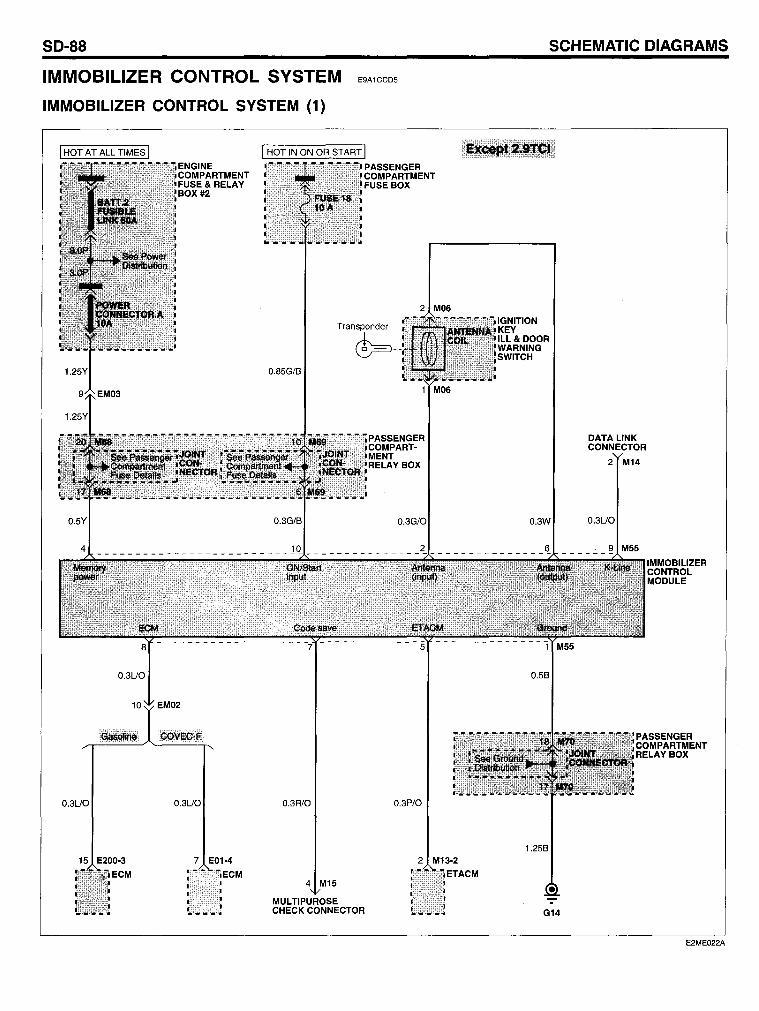
IMMOBILIZER CONTROL SYSTEM
IMMOBILIZER CONTROL SYSTEM (1)
0.3UO 0.3UO 0.3R10
15 E200-3 7 E01-4
ECM 4 M15
MUL TIPUROSE
E9A1CCD5
PASSENGER COMPARTMENT FUSE BOX
0.3G/O
0.3P/O
2 M13-2
CHECK CONNECTOR
SCHEMATIC OIAGRAMS
0.3W
0.58
1.258
-G14
DATA L/NK CONNECTOR
2 M14
0.3UO
IMMOBIL/ZER CONTROL MODULE
PASSENGER COMPARTMENT RELAYBOX
E2ME022A
IMMOBILIZER CONTROL SYSTEM
IMMOBILIZER CONTROL SYSTEM (2)
O.5R10
ENGINE COMPARTMENT FUSE & RELAY BOX #2
See Power ..... --+Distribution
Transponder
~--
EM02
2 M06
0.58/0
5 -------------------------------------------~ M~
0.5U8 0.58
10 EM02
0.5U8 1.258
27 E03-1
G14
IMMOBILIZER CONTROL MODULE
PASSENGER COMPARTMENT RELAYBOX
SO-89
E2ME022B
SD-90
COMPONENT LOCATION INDEX
Components
ECM (COVEC-F) ECM (2.9TCI) ECM (Gasoline)
SCHEMATIC DIAGRAMS
Location reference - page
E01-4 E03-1 E200-3 M06 M08 M13-2 M14 M15 M55 M68 M69 M70
Ignition key ill & door warning switch Immobilizer control module (2.9TCI) ETACM
CL- 8 CL- 8 CL-16 CL- 2 CL- 2 CL- 2 CL- 2 CL- 2 CL- 5 CL- 5 CL- 5 CL- 5
Data link connector Multipurpose check connector Immobilizer control module (Except 2.9TCI) Joint connector
Connectors
EM02 EM03
Grounds
G14
Circuit Description
Joint connector Joint connector
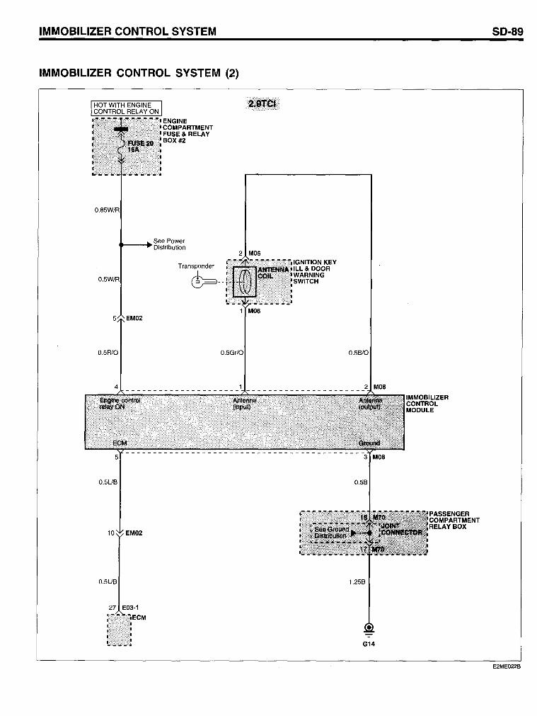
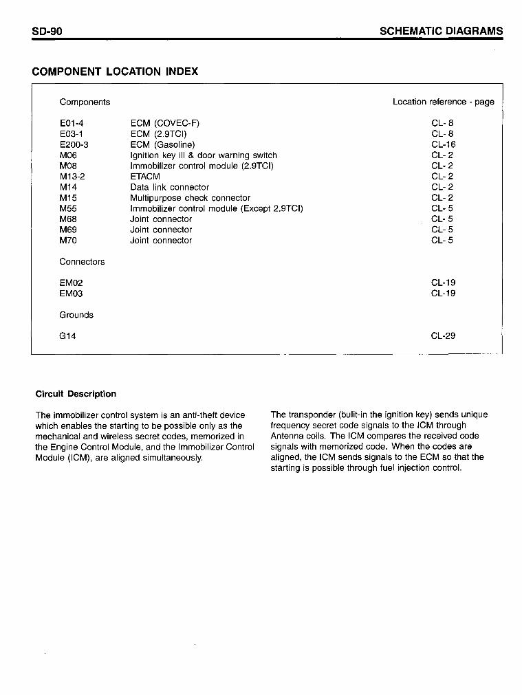
The immobilizer contral system is an anti-theft device wh ich enables the starting to be possible only as the mechanical and wireless secret codes, memorized in the Engine Control Module, and the Immobilizer Control Module (ICM), are aligned simultaneously.
CL-19 CL-19
CL-29
The transponder (bulit-in the ignition key) sends unique frequency secret code signals to the ICM through Antenna coils. The ICM compares the received code signals with memorized code. When the codes are aligned, the ICM sends signals to the ECM so that the starting is possible thraugh fuel injection controL
SO-92 SCHEMATIC OIAGRAMS
CIGARETTE LlGHTER (POWER OUTLET) EBB774DC
CIGARETTE LlGHTER (POWER OUTLET) (1)
See Illumination
1.25B
• -G13
CIGARETTE LlGHTER
ASHTRAY ILL.
0.5L
0.5L
2.0B
-:-GOI
1.250
1.250
1.250
2 M46
REAR FRONT POWER POWER OUTLET OUTLET
f" 1.25B. I~ 1.25B.
-:- -GIB GIS
E2ME023A
CIGARETTE LIGHTER (POWER OUTLET)
COMPONENT LOCATION INDEX
Components
E123 E130 M46 M53 R18
Connectors
EM05 MR03
Grounds
G01 G13 G15 G18
Circuit Description
Power outlet relay Joint connector Front power outlet Cigarette lighter Rear power outlet
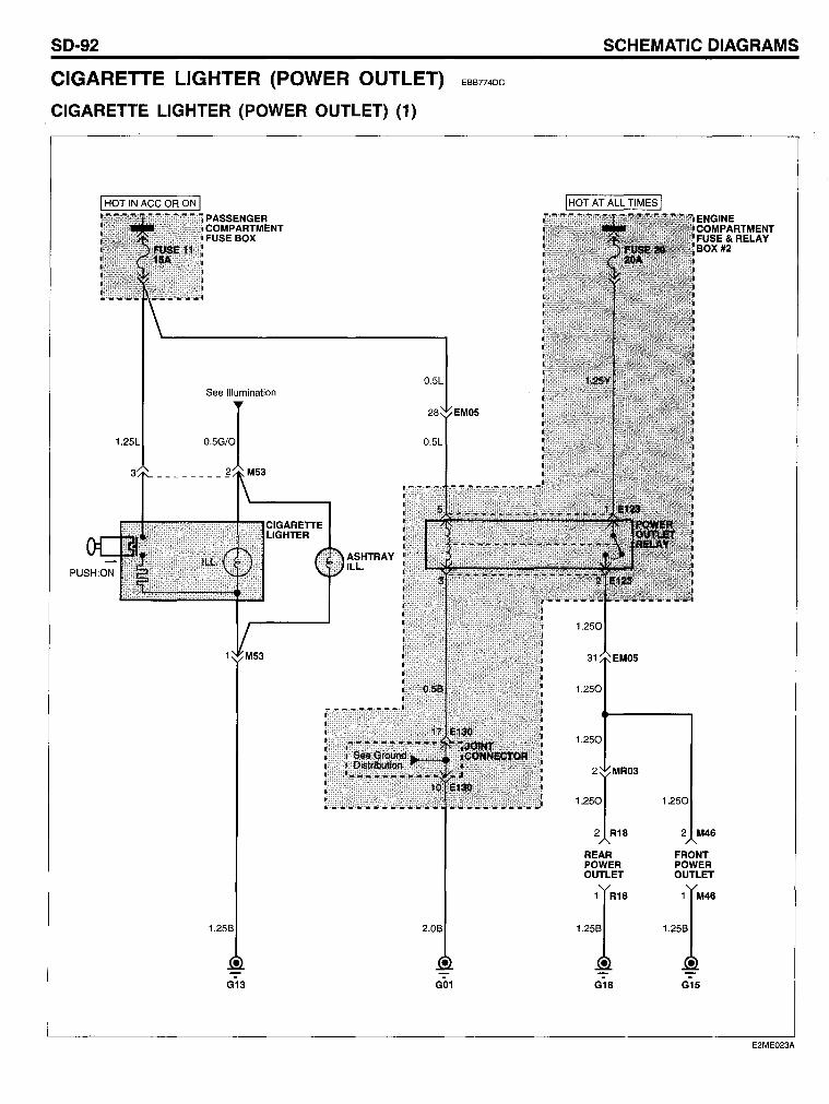
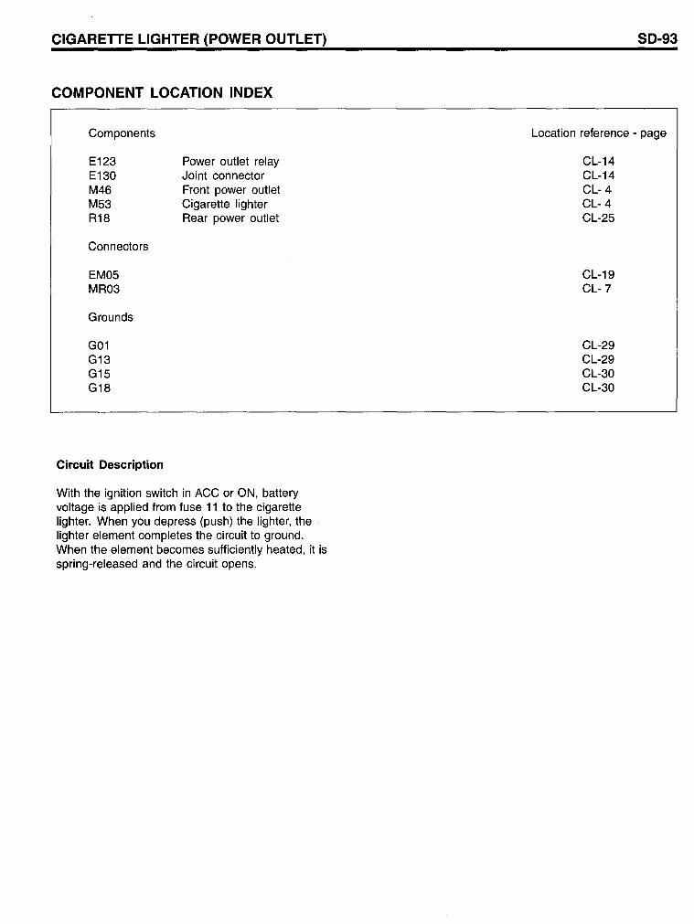
With the ignition switch in ACC or ON, battery voltage is applied from fuse 11 to the cigarette lighter. When you depress (push) the lighter, the lighter element completes the circuit to ground. When the element becomes sufficiently heated, it is spring-released and the circuit opens.
50-93
Location reference - page
CL-14 CL-14 CL- 4 CL- 4 CL-25
CL-19 CL-7
CL-29 CL-29 CL-30 CL-30
SD-94
DIGITAL CLOCK
DIGITAL CLOCK (1)
G19
EF5DABBB
O.5Br
------------------------------------------31
O.5Br
SCHEMATIC DIAGRAMS
PASSENGER COMPARTMENT FUSEBOX
See Illuminations
E2ME024A
DIGITAL CLOCK
COMPONENT LOCATION INDEX
Components
M68 R42
Connectors
EM03 MR06
Grounds
G19
Circuit Description
Joint connector Overhead console lamp
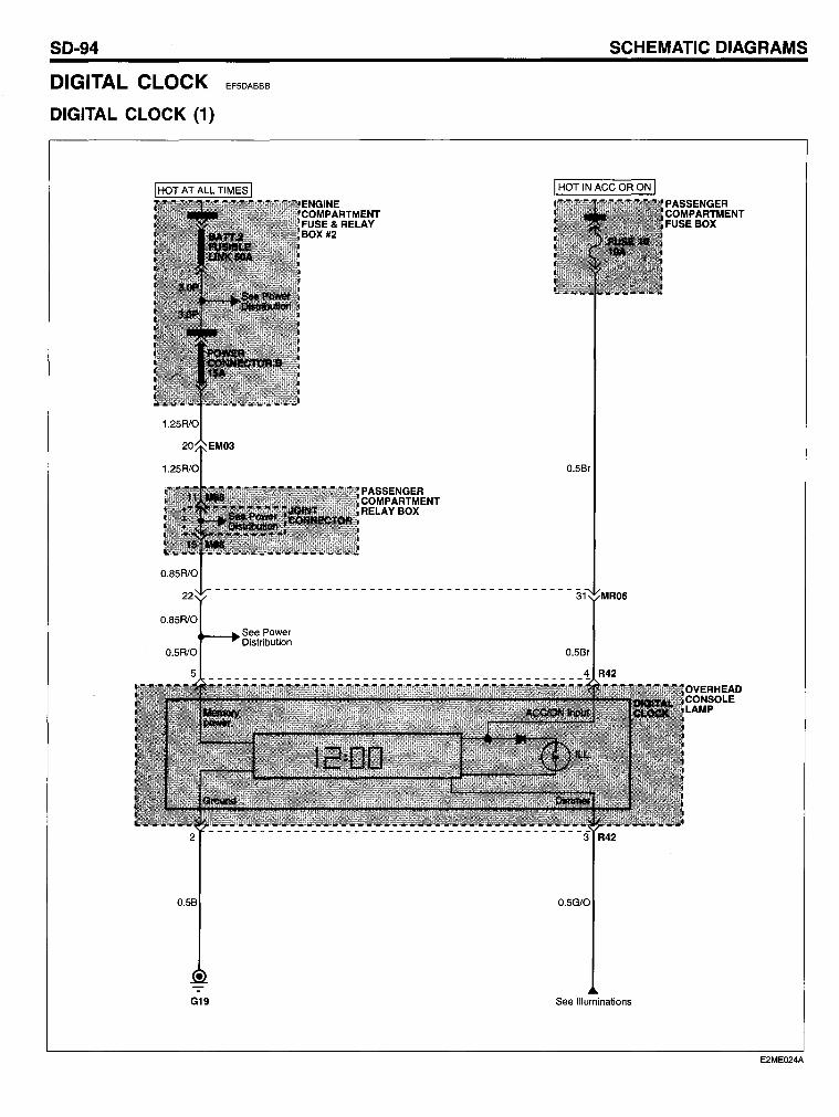
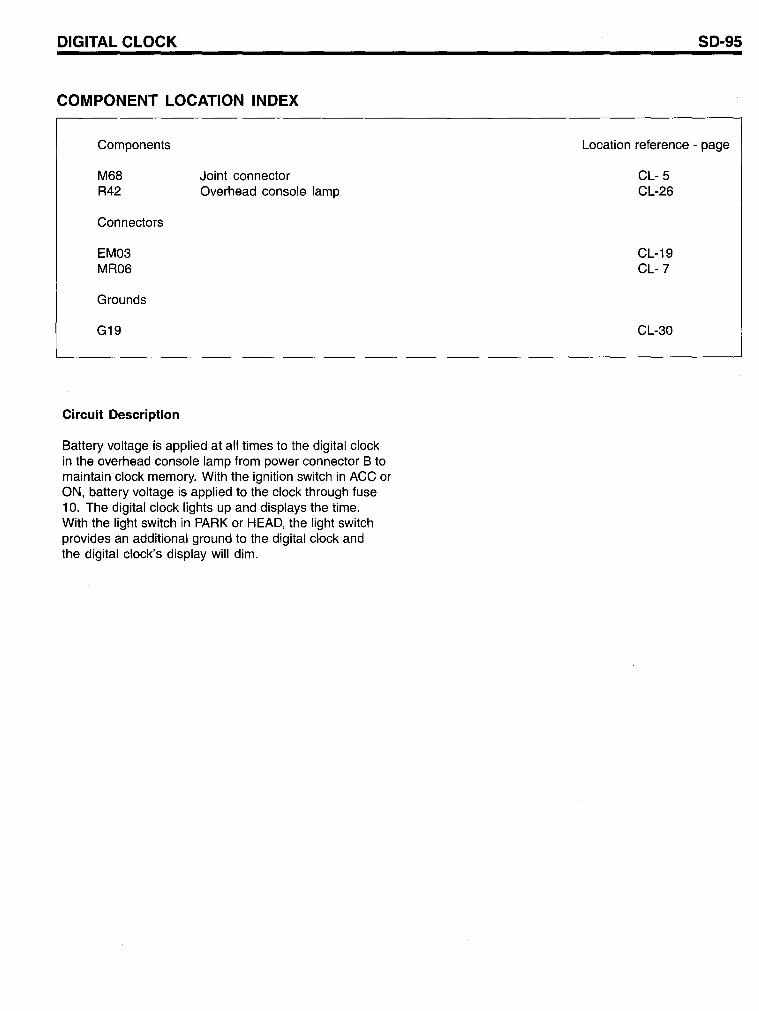
Battery voltage is applied at all times to the digital clock in the overhead console lamp from power connector B to maintain clock memory. With the ignition switch in ACC or ON, battery voltage is applied to the clock through fuse 10. The digital clock lights up and displays the time. With the light switch in PARK or HEAD, the light switch provides an additional ground to the digital clock and the digital clock's display will dim.
SD-95
Location reference - page
CL- 5 CL-26
CL-19 CL-?
CL-30
SO-96 SCHEMATIC OIAGRAMS
ETACS (ELECTRONIC TIME & ALARM CONTROL SYSTEM) E6E3COA7
ETACS (ELECTRONIC TIME & ALARM CONTROL SYSTEM) (1)
I HOT AT ALL TIMES I
0.5Y
0.5Br/0 0.3B/0 0.3R1B
~--------------~~~----------------~/
See Front Wiper & Washer
0.5R10
0.5W/0
See Daytime Running Lights
0.3Y/B
PASSEN GER COMPARTMENT FUSE BOX
See Starting System
See Tail, Parking & License Lamps/ See Illuminations
E2ME025A
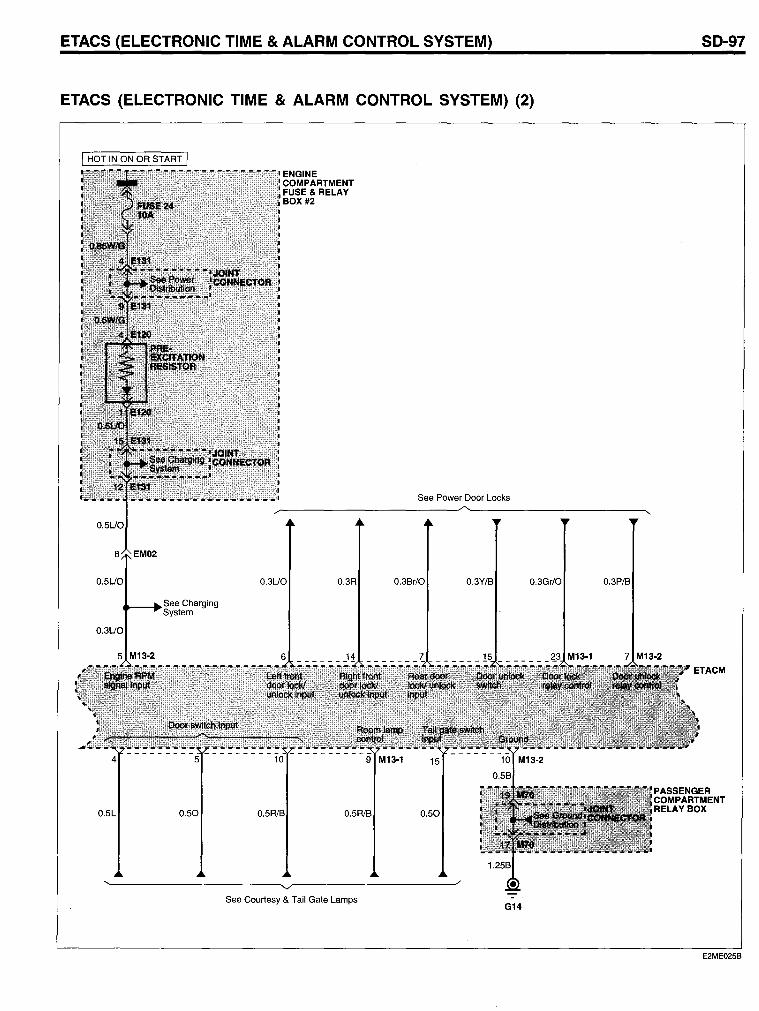
ETACS (ELECTRONIC TIME & ALARM CONTROL SYSTEM)
ETACS (ELECTRONIC TIME & ALARM CONTROL SYSTEM) (2)
;,',; ENGINE . COMPARTMENT
FUSE & RELAY BOX #2
See Power Door Locks
~--------------------~~~--------------------~,
0.5UO
0.5UO
0.3UO
0.5L
See Charging System
0.50
0.3UO 0.3Br/0
0.5R1B 0.5R/B 0.50
~ ____________________ ~~ ___________________ --J/
See Courtesy & Tail Gate Lamps
0.3Y/B 0.3Gr/0 0.3P/B
G14
SO-97
E2ME025B
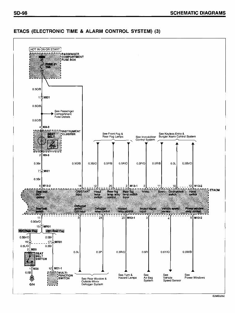
SO-98 SCHEMATIC OIAGRAMS
ETACS (ELECTRONIC TIME & ALARM CONTROL SYSTEM) (3)
0.56r/0
I HOT IN ON OR START I
0.50/6
PASSENGER COMPARTMENT FUSE BOX
See Passenger .... - .... Compartment
Fuse Details 0.50/6
4 103·3
See Front Fog & See Keyless Entry & Rear Fog Lamps See Immobilizer 6urglar Alarm Control System
G14
~~ ____ ~ ___ ~.... Control System __ /"0. ....
0.50/B 0.36/0 0.5P/6
0.3L 0.3P
12 M01·1
MULTI· FUNCTION SWITCH
~--~",r--~--
See Rear Window & Outside Mirror Defogger System
o
0.5P/0 0.3P/0 0.5R/6
See Turn & Hazard Lamps
0.5R
See Air6ag System
0.3L 0.56r/0
0.5Y/0 0.3W/6
See See Vehicle Power Windows Speed Sensor
ETACM
E2ME025C
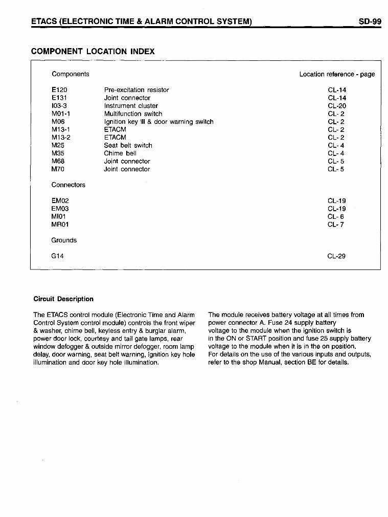
ETACS (ELECTRONIC TIME & ALARM CONTROL SYSTEM) SD-99
COMPONENT LOCATION INDEX
Components
Pre-excitation resistor Joint connector Instrument cluster Multifunction switch
Location reference - page
E120 E131 103-3 M01-1 M06 M13-1 M13-2 M25 M35 M68 M70
Ignition key iII & door warning switch ETACM
CL-14 CL-14 CL-20 CL- 2 CL- 2 CL- 2 CL- 2 CL- 4 CL- 4 CL- 5 CL- 5
Connectors
EM02 EM03 MI01 MR01
Grounds
G14
Circuit Description
ETACM Seat belt switch Chime bell Joint connector Joint connector
The ETACS control module (Electronic Time and Alarm Control System control module) controls the front wiper & washer, chime bell, keyless entry & burglar alarm, power door lock, courtesy and tail gate lamps, rear window defogger & outside mirror defogger, room lamp delay, door warning, seat belt warning, ignition key hole illumination and door key hole illumination.
CL-19 CL-19 CL- 6 CL-7
CL-29
The module receives battery voltage at all times from power connector A. Fuse 24 supply battery voltage to the module when the ignition switch is in the ON or START position and fuse 25 supply battery voltage to the module when it is in the on position. For details on the use of the various inputs and outputs, refer to the shop Manual, section BE for details.
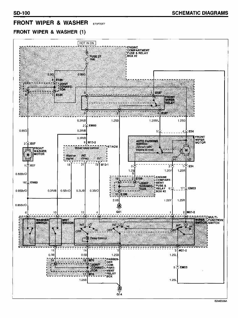
SO-100
FRONT WIPER & WASHER
FRONT WIPER & WASHER (1)
0.85G
0.85Br/0 0.3R1B 0.5Br/0 0.3UB
0.85Br/0
SCHEMATIC OIAGRAMS
E7BF7DE7
1.25L
G14
E2ME028A
FRONT WIPER & WASHER
COMPONENT LOCATION INDEX
Components
E07 E54 E127 E130 E134 M01-2 M13-1 M13-2 M70
Connectors
EM03
Grounds
G01 G14
Circuit Description
Front washer motor Front wiper motor Front wiper relay Joint connector Joint connector Multifunction switch ETACM ETACM Joint connector
All functions of the front wiper and washer circuit are controlled by the position of the front wiper and washer switch. The wiper switch has 4 positions: OFF, INT, LO and HI. Wiper Operation 1. Low (LO) and High (HI) position The front wiper motor has two separate brushes for low and high speed operation. When the wiper switch is in LO or HI, ground is applied to the appropriate brushes through the wiper switch in the multifunction switch. 2. INT position When the wiper switch is turned to I NT, the ETACM receives the INT signal and INT delay time signa!. According to these signals, the control module controls the operation of the front wiper through wiper motor relay coil contro!. Ground is applied to the low speed brush of the front wiper motor through the closed contact of the wiper motor relay.
SD-101
Location reference - page
CL- 8 CL-11 CL-14 CL-14 CL-14 CL- 2 CL- 2 CL- 2 CL- 5
CL-19
CL-29 CL-29
The remainder of the wiper's sweep is controlled by the auto parking circuit. The cycle repeats as long as the wiper switch is in INT and the pause interval between sweeps is determined by the ETACM. 3. OFF position When the wiper switch is turned to OFF from other position (INT, LO and HI) and the wiper is not at rest (out of park) position, the low speed brush of the front wiper motor is grounded through the auto parking switch in the front wiper motor and then the wiper goes to the rest (park) position. Washer Operation The front wiper motor operates as long as the washer switch is in ON. When the washer switch is pulled, the control module controls the low speed operation of the front wiper motor through the wiper motor relay contro!.
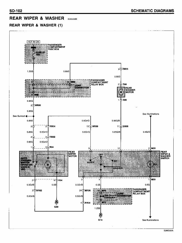
SO-102
REAR WIPER & WASHER
REAR WIPER & WASHER (1)
0.85G
See Sllnrnnl· ... - ..
0.85G
G20
EOASASBE
SCHEMATIC OIAGRAMS
0.5Gr/0
PASSENGER COMPARTMENT RELAYBOX
13 MR06
See Illuminations
0.85G/B
tl EM06
0.5Gr/0 0.85G/B 0.5G/O
9 10 2 M33 --------------- ---------------
G14 See Illuminations
REAR WIPER& WASHER SWITCH
E2ME029A
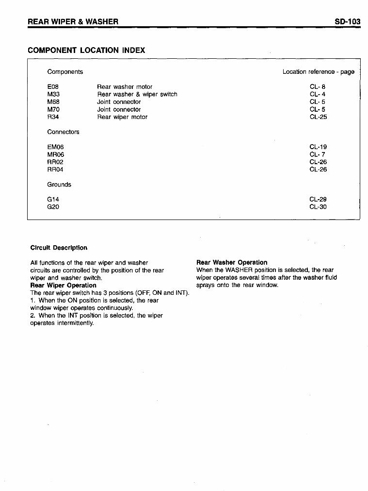
REAR WIPER & WASHER
COMPONENT LOCATION INDEX
Components
E08 M33 M68 M70 R34
Connectors
EM06 MR06 RR02 RR04
Grounds
G14 G20
Circuit Description
Rear was her motor Rear washer & wiper switch Joint connector Joint connector Rear wiper motor
All functions of the rear wiper and washer circuits are controlled by the position of the rear wiper and washer switch. Rear Wiper Operation The rear wiper switch has 3 positions (OFF, ON and INT). 1. When the ON position is selected, the rear window wiper operates continuously. 2. When the INT position is selected, the wiper operates intermittently.
Rear Washer Operation
SD-103
Location reference - page
CL- 8 CL-4 CL- 5 CL- 5 CL-25
CL-19 CL-7 CL-26 CL-26
CL-29 CL-30
When the WASHER position is selected, the rear wiper operates several times after the washer fluid sprays onto the rear window.
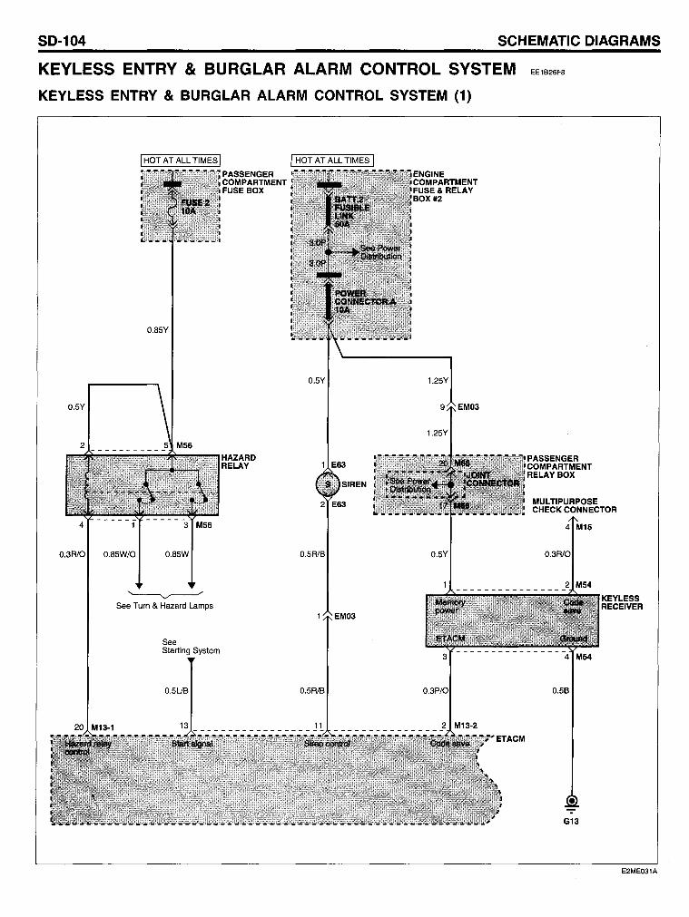
SO-104 SCHEMATIC OIAGRAMS
KEYLESS ENTRY & BURGLAR ALARM CONTROL SYSTEM
KEYLESS ENTRY & BURGLAR ALARM CONTROL SYSTEM (1)
EE1826FB
0.85Y
0.3R10 0.85W/O 0.85W
~ See Turn & Hazard Lamps
See Starting System
0.5UB
PASSENGER COMPARTMENT FUSE BOX
HAZARD RELAY
0.5Y
1 E63
SIREN
2 E63
0.5R/B
EM03
0.5R/B
1.25Y
PASSENGER COMPARTMENT RELAY BOX
MULTIPURPOSE CHECK CONNECTOR
----------------
KEYLESS RECEIVER
3 4 M54
0.3P/O 0.5B
G13
E2ME031A
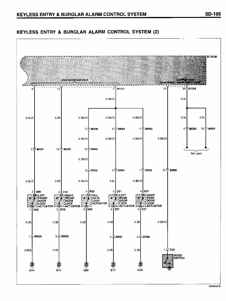
KEYLESS ENTRY & BURGLAR ALARM CONTROL SYSTEM SD-105
KEYLESS ENTRY & BURGLAR ALARM CONTROL SYSTEM (2)
ETACM
0.3Br/0 0.3L
0.3UO 0.3R 0.3Br/0 0.3Br/0 0.3Br/0 0.3L
MR06 5 MR01 MR03 4 M003 M001
0.3Br/0 0.3Br/0 0.5Br/0
5 M001 12 M003 RR04 '------v----"" Not used
RR02 3 OR01 OR02 10 EM03
0.3UO 3.0R 0.3Br/0 0.3L 0.3Br/0
2 008 2 018 4 R32 5 021 4 031
LEFT RIGHT LEFT FRONT FRONT REAR OOOR OOOR OOOR LOCK LOCK TOR LOCK ACTUATOR ACTUATOR ACTUATOR
1 008 3 018 6 021 6 031
0.3B 0.3B 0.3B 0.5Br/0
M002 9 M003 2 OR02
0.85B 0.5B 0.3B
HOOO SWITCH
. -:- -:- -:- . G14 G11 G20 G17 G18 .
E2ME031B
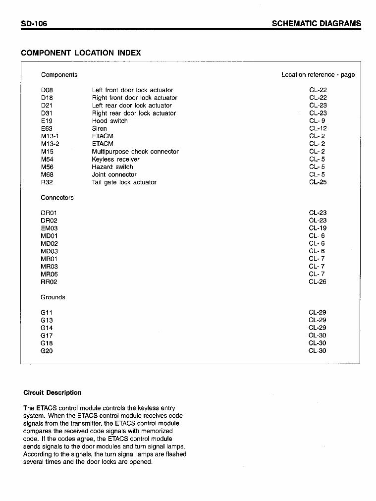
SD-106
COMPONENT LOCATION INDEX
Components
008 018 021 031 E19 E63 M13-1 M13-2 M15 M54 M56 M68 R32
Connectors
OR01 OR02 EM03 M001 M002 M003 MR01 MR03 MR06 RR02
Grounds
G11 G13 G14 G17 G18 G20
Circuit Description
Left front door lock actuator Right front door lock actuator Left rear door lock actuator Right rear door lock actuator Hood switch Siren ETACM ETACM Multipurpose check connector Keyless receiver Hazard switch Joint connector Tail gate lock actuator
The ETACS control module controls the keyless entry system. When the ETACS control module receives code signals from the transmitter, the ETACS control module compares the received code signals with memorized code. If the codes agree, the ETACS control module sends signals to the door modules and turn signal lamps. According to the signals, the turn signallamps are flashed several times and the door locks are opened.
SCHEMATIC DIAGRAMS
Location reference - page
CL-22 CL-22 CL-23 CL-23 CL- 9 CL-12 CL- 2 CL- 2 CL- 2 CL- 5 CL- 5 CL- 5 CL-25
CL-23 CL-23 CL-19 CL- 6 CL- 6 CL- 6 CL-7 CL-7 CL-7 CL-26
CL-29 CL-29 CL-29 CL-30 CL-30 CL-30
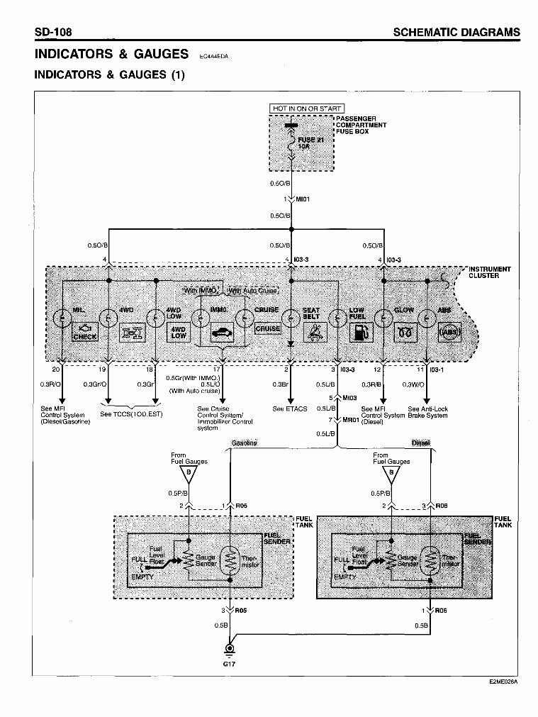
SO-108
INDICATORS & GAUGES
INOICATORS & GAUGES (1)
EC4A4EDA
0.3R10 0.3Gr/O 0.3Gr
See MFI Control System See TCCS(TOD,EST) (Diesel/Gasoline)
0.5Gr(With IMMO.) 0.5UO
(With Auto cruise)
See Cruise Control System/ Immobilizer Control system
G17
SCHEMATIC OIAGRAMS
0.3Sr
See ETACS See MFI See Anti-Lock
FUEL TANK
0.5US
M Control System Srake System
R01 (Diesel)
From
::~-2
0.5S
FUEL TANK
E2ME026A
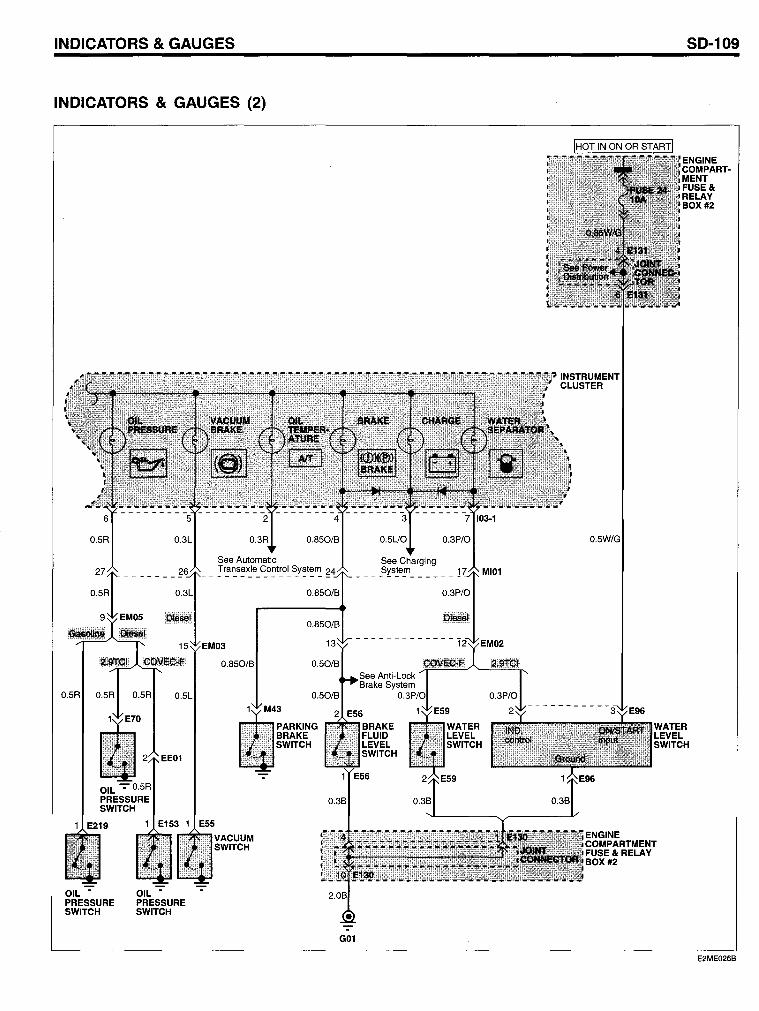
INOICATOR5 & GAUGE5
INOICATOR5 & GAUGE5 (2)
0.5R
0.3R
See Automatie Transaxle Control System
0.850/B
PAR KING BRAKE SWITCH
G01
0.5UO
See Charging ____ S~s~e~ ______ 1
0.3P/0
- - - - - - - - - - - - -12~EMI~2
0.5W/G
50-109
ENGINE COMPART· MENT FUSE& RELAY BOX #2
WATER LEVEL SWITCH
E2ME026B
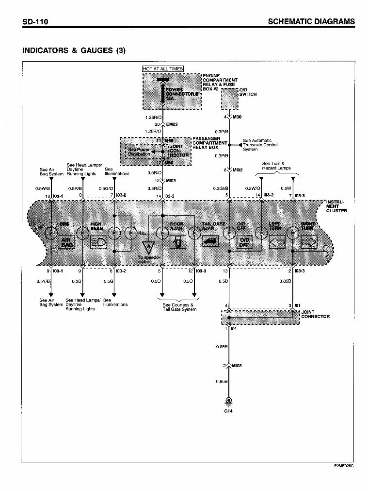
SO-110
INOICATORS & GAUGES (3)
See Head Lamps/ Daytime Running Lights
0.5G/0
See Air See Head Lamps/ See 6ag System Daytime Illuminations
Running Lights
0.50 0.50
~ See Courtesy & Tail Gate System
0.56
1 101
0.856
G14
SCHEMATIC OIAGRAMS
See Automatie T ransrude Control System
See Turn & Hazard Lamps ~
0.5W
0.856
JOINT CONNECTOR
E2ME026C
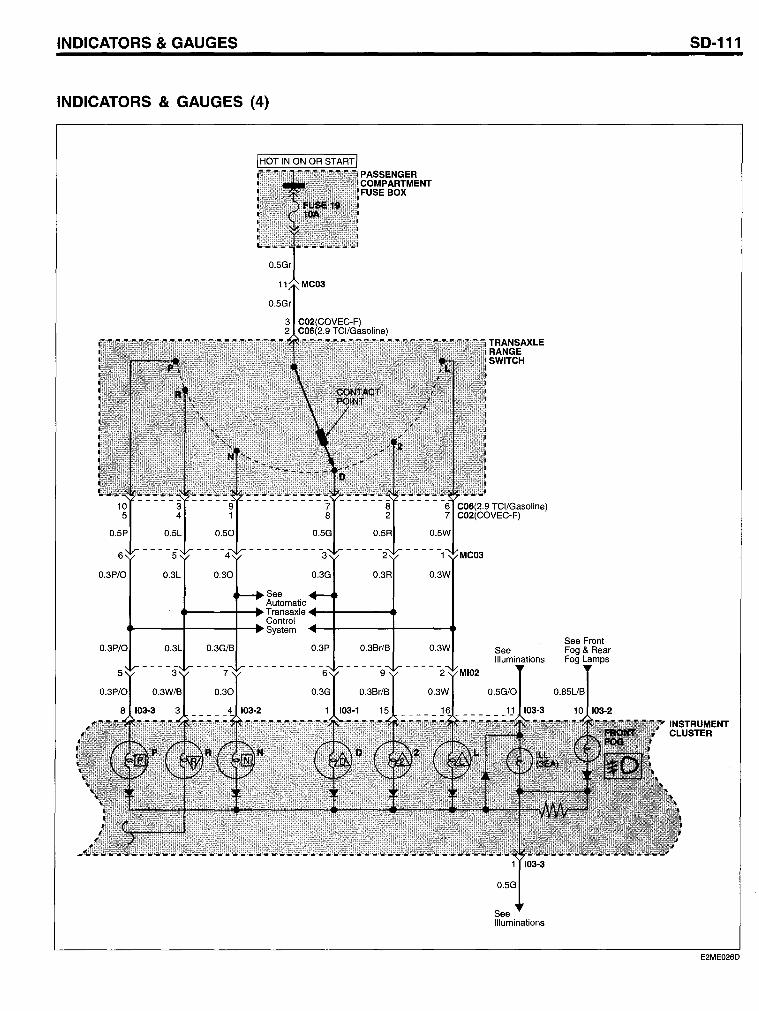
INOICATORS & GAUGES
INOICATORS & GAUGES (4)
See Automatie ""--___ 1-"" Transaxle +--11----.. Control .... ---+----+-...... System
0.3P/O 0.3P 0.3Br/B 0.3W
TRANSAXLE RANGE SWITCH
See Illuminations
0.5G/O
103-3
0.5G
See Illuminations
See Front Fog & Rear Fog Lamps
0.85UB
SO-111
E2ME026D

SO-112
INOICATORS & GAUGES (5)
I HOT IN ON OR START I
0.5B 0.5B
3 8 4 101 0.3P
JOINT CONNEC-TOR
1 101
0.85B
-:- . -
G14
SCHEMATIC OIAGRAMS
0.3Y/O
INSTRUMENT CLUSTER
- - - - - - - - - - - - - - - 6~IEM02
0.5Y/O
0.5P 0.3P 0.5Y/O
ENGINE COOLANT TEMPER-ATURE SENSOR & SENDER
-ENGINE COOLANT TEMPERATURE SWITCH
See MFI Control System
0.3Y/O
ECM
0.5Y/O
ECM
See MFI I
System
E2ME026E
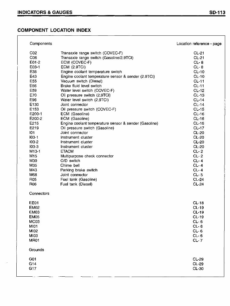
INDICATORS & GAUGES
COMPONENT LOCATION INDEX
Components
C02 C06 E01-2 E03-1 E38 E43 E55 E56 E59 E70 E96 E130 E153 E200-1 E200-2 E215 E219 101 103-1 103-2 103-3 M13-1 M15 M30 M35 M43 M68 R05 R06
Connectors
EE01 EM02 EM03 EM05 MC03 MI01 MI02 MI03 MR01
Grounds
G01 G14 G17
Transaxle range switch (COVEC-F) Transaxle range switch (Gasoline/2.9TCI) ECM (COVEC-F) ECM (2.9TCI) Engine coolant temperature switch Engine coolant temperature sensor & sender (2.9TCI) Vacuum switch (Diesel) Brake fluid level switch Water level switch (COVEC-F) Oil pressure switch (2.9TCI) Water level switch (2.9TCI) Joint connector Oil pressure switch (COVEC-F) ECM (Gasoline) ECM (Gasoline) Engine coolant temperature sensor & sender (Gasoline) Oil pressure switch (Gasoline) Joint connector Instrument cluster Instrument cluster Instrument cluster ETACM Multipurpose check connector 0/0 switch Chime bell Parking brake switch Joint connector Fuel tank (Gasoline) Fuel tank (Diesel)
SD-113
Location reference - page
CL-21 CL-21 CL- 8 CL- 8 CL-10 CL-10 CL-11 CL-11 CL-12 CL-13 CL-14 CL-14 CL-15 CL-16 CL-16 CL-16 CL-17 CL-20 CL-20 CL-20 CL-20 CL- 2 CL- 2 CL- 4 CL- 4 CL- 4 CL- 5 CL-24 CL-24
CL-18 CL-19 CL-19 CL-19 CL- 6 CL- 6 CL- 6 CL- 6 CL-7
CL-29 CL-29 CL-30
50-114
Circuit Description
Gauges Operation When the ignition switch is in the ON or START position, battery voltage is applied to the gauges (speedometer, tachometer, fuel gauge and engine coolant temperature gauge) from fuse 21. Speedometer The speedometer drive circuit receives pulses fram the vehicle speed sensor (VSS). The pulse rate increases as the car accelerates. The frequency and duration of these input pulses are measured and displayed by the speedometer. Tachometer The tachometer displays engine speed in rpm. Voltage pulses are taken from the ignition system and sent to the tachometer. The tachometer res ponds to the frequency of the voltage pulses, which vary according to engine speed. The ECM process these pulses into a signal that causes the gauge needle to move. Fuel Gauge The pointer of the fuel gauge is moved by the magnetic fields of two coils. The coils are at right angles to each other. The magnetic field contralIed by the fuel gauge sender causes the gauge needle to move. As the resistance in the sender varies, current through the gauge coils changes. When the fuel level is below the thermistor, the resistance of thermistor drops, providing a graund for the low fuel indicator bulb. Engine Coolant Temperature Gauge The pointer of the engine coolant temperature gauge is moved by the magnetic field of two coils. The coils are at right angles to each other. The magnetic fields controlled by the engine coolant temperature sender cause the gauge needle to move. As the resistance in the sender varies, current through the gauge coils changes.
5CHEMATIC 0lAGRAM5
Indicator Operation When the ignition switch is in the ON or START position, battery voltage is applied to the indicator bulb from fuse 21. Oil Pressure Indicator When the oil pressure is low (oil pressure switch is closed), ground is provided to the oil pressure indicator bulb. The oil pressure light comes on when the engine is not running and the ignition is in ON. In that case, the pressure switch remains closed and the indicator light stays on. Low Fuel Indicator The thermister in the fuel gauge sender is located near the bottom of the tank. When the fuel level is below the thermister, the resistance of thermister lowers, providing a ground for the indicator. Check ENGINE Indicator The ground of the indicator lamp is controlled by the Engine Control Module. The control module will light the indicator when the ignition switch is turned ON (system check) or when the ECM detects engine problems.
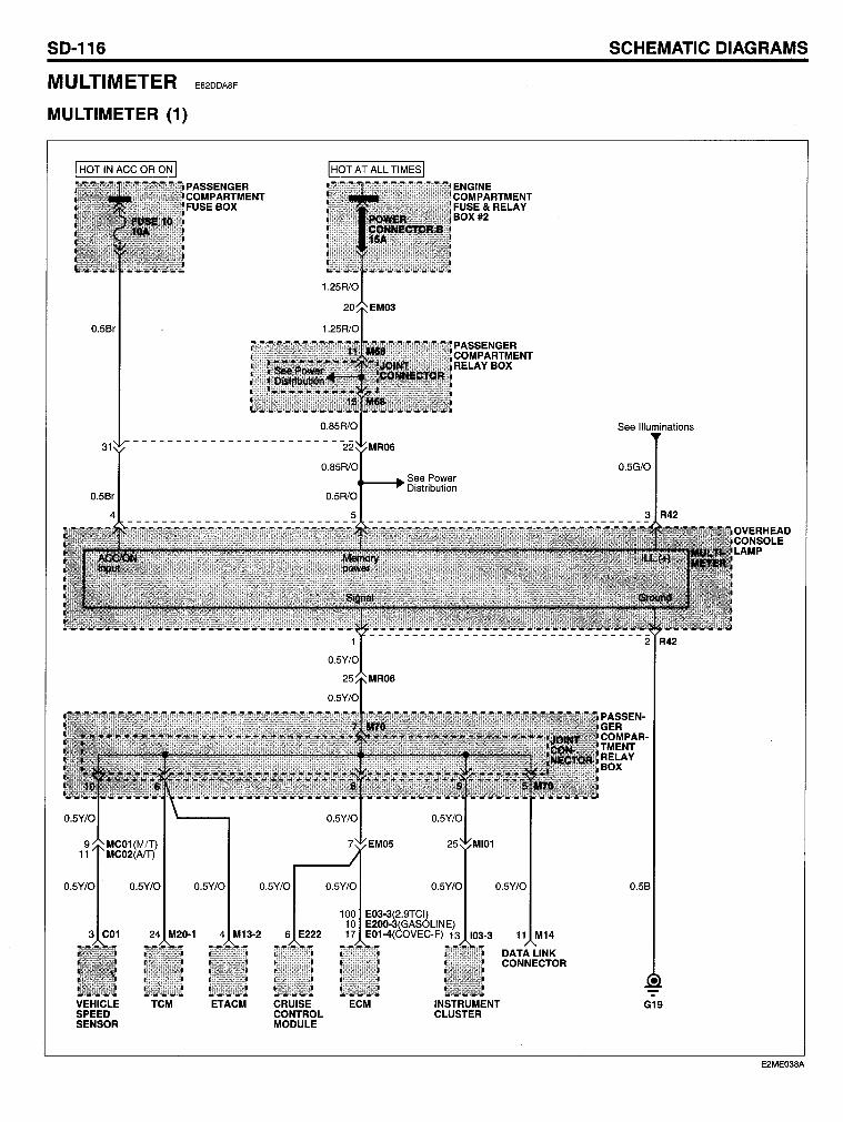
SO-116
MULTIMETER
MULTIMETER (1)
E62DDA8F
0.58r
PASSENGER COMPARTMENT FUSE BOX
0.5Y/O 0.5Y/O 0.5Y/O 0.5Y/O
3 C01 24 M20-1 4 M13-2 6 E222
VEHICLE TCM ETACM CRUISE SPEED CONTROL SENSOR MODULE
0.5Y/O
100 10 17
See Power t---+ Distribution
0.5Y/O
E03-3(2.9TCI) E200-3(GASOLlNE) E01-4(COVEC-F) 13
0.5Y/O
103-3 11 M14
DATALINK CONNECTOR
ECM INSTRUMENT CLUSTER
SCHEMATIC OIAGRAMS
See Illuminations
0.5G/O
0.58
G19
E2ME038A
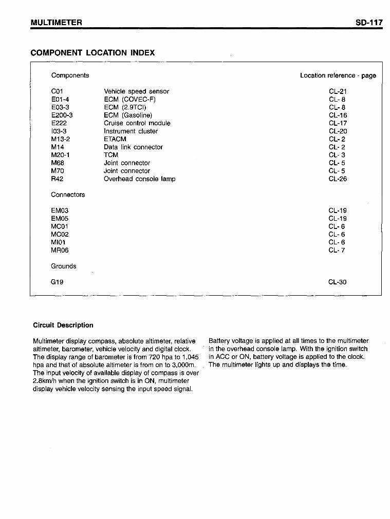
MULTIMETER
COMPONENT LOCATION INDEX
Components
C01 E01-4 E03-3 E200-3 E222 103-3 M13-2 M14 M20-1 M68 M70 R42
Connectors
EM03 EM05 MC01 MC02 MI01 MR06
Grounds
G19
Circuit Description
Vehicle speed sensor ECM (COVEC-F) ECM (2.9TCI) ECM (Gasoline) Cruise control module Instrument cluster ETACM Data link connector TCM Joint connector Joint connector Overhead console lamp
Multimeter display compass, absolute altimeter, relative altimeter, barometer, vehicle velocity and digital clock. The display range of barometer is from 720 hpa to 1,045 hpa and that of absolute altimeter is from on to 3,000m. The input velocity of available display of compass is over 2.8km/h when the ignition switch is in ON, multimeter display vehicle velocity sensing the input speed signal.
SD-117
Location reference - page
CL-21 CL- 8 CL- 8 CL-16 CL-17 CL-20 CL- 2 CL- 2 CL- 3 CL- 5 CL- 5 CL-26
CL-19 CL-19 CL- 6 CL- 6 CL- 6 CL-7
CL-30
Battery voltage is applied at all times to the multimeter in the overhead console lamp. With the ignition switch in ACC or ON, battery voltage is applied to the clock. The multimeter lights up and displays the time.
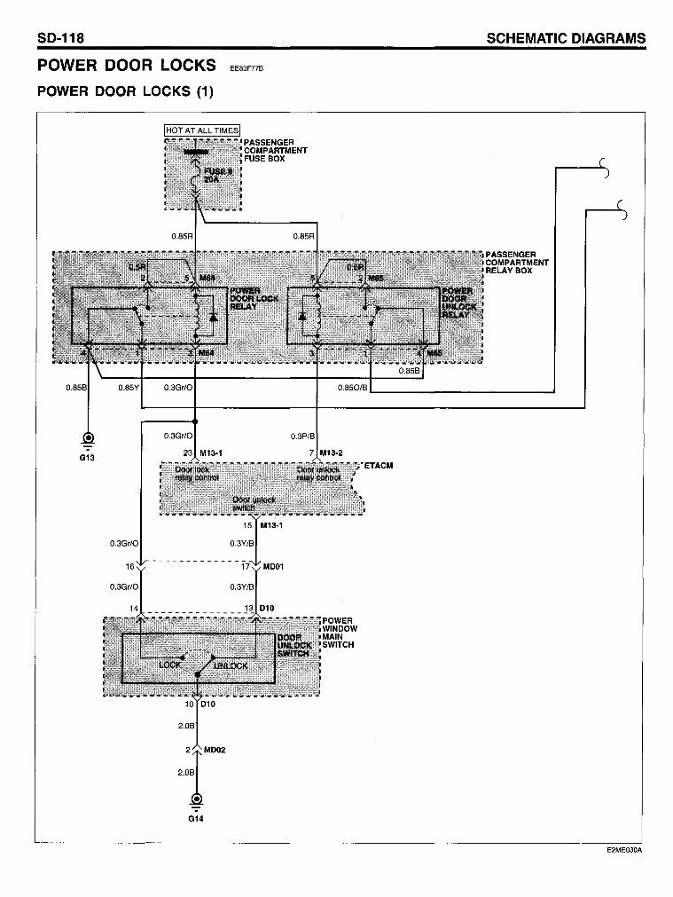
SO-118
POWER COOR LOCKS
POWER OOOR LOCKS (1)
G13 23 M13·1
2.08
2 MD02
2.08
G14
EE83F77B
7 M13·2
ACM
SCHEMATIC OIAGRAMS
PASSENGER COMPARTMENT RELAV BOX
E2ME030A
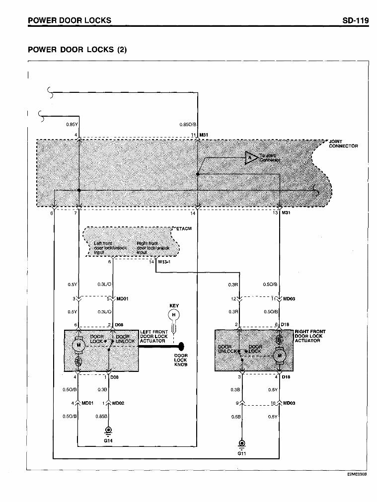
POWER OOOR LOCKS
POWER OOOR LOCKS (2)
0.85Y
0.5Y 0.3LJO
G14
0.850/B
KEY
LEFTFRONf ~ DOOR LOCK I
ACTUATOR I
DOOR LOCK KNOB
0.3R 0.50/B
0.5B 0.5Y
RIGHTFRONT DOORLOCK ACTUATOR
SO-119
E2ME030B
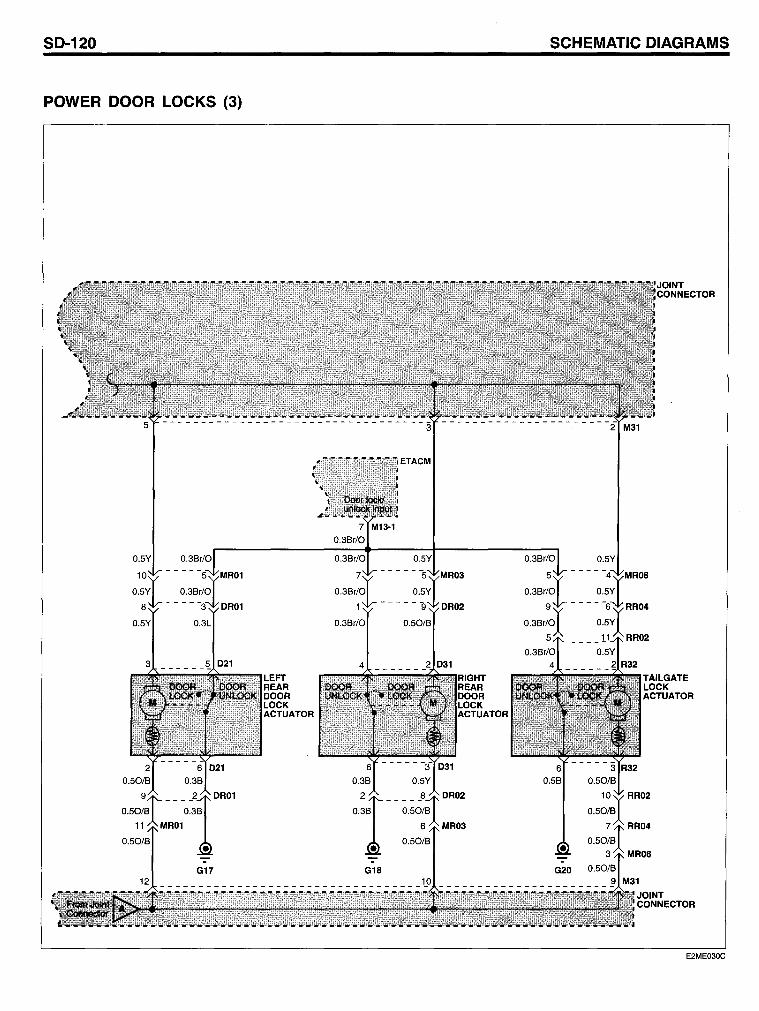
SO-120 SCHEMATIC OIAGRAMS
POWER OOOR LOCKS (3)
E2ME030C
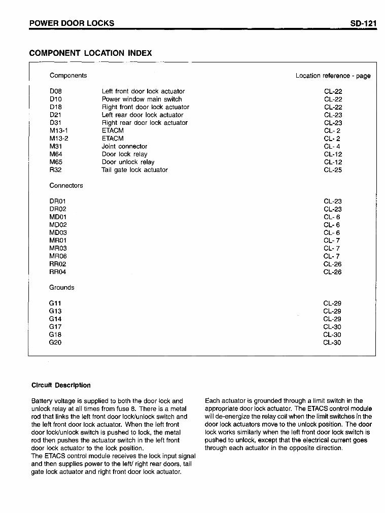
POWER DOOR LOCKS
COMPONENT LOCATION INDEX
Components
008 010 018 021 031 M13-1 M13-2 M31 M64 M65 R32
Connectors
OR01 OR02 M001 M002 M003 MR01 MR03 MR06 RR02 RR04
Grounds
G11 G13 G14 G17 G18 G20
Circuit Description
Left front door lock actuator Power window main switch Right front door lock actuator Left rear door lock actuator Right rear door lock actuator ETACM ETACM Joint connector Ooor lock relay Ooor unlock relay Tail gate lock actuator
Battery voltage is supplied to both the door lock and unlock relay at all times from fuse 8. There is a metal rod that links the left front door locl<lunlock switch and the left front door lock actuator. When the left front door locklunlock switch is pushed to lock, the metal rod then pushes the actuator switch in the left front door lock actuator to the lock position. The ETACS control module receives the lock input signal and then supplies power to the left! right rear doors, tail gate lock actuator and right front door lock actuator.
SD-121
Location reference - page
CL-22 CL-22 CL-22 CL-23 CL-23 CL- 2 CL- 2 CL- 4 CL-12 CL-12 CL-25
CL-23 CL-23 CL- 6 CL- 6 CL- 6 CL-7 CL-7 CL-7 CL-26 CL-26
CL-29 CL-29 CL-29 CL-30 CL-30 CL-30
Each actuator is grounded through a limit switch in the appropriate door lock actuator. The ETACS control module will de-energize the relay coil when the limit switches in the door lock actuators move to the unlock position. The door lock works similarly when the left front door lock switch is pushed to unlock, except that the electrical current goes through each actuator in the opposite direction.
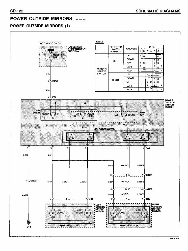
SD-122
POWER OUTSIDE MIRRORS
POWER OUTSIDE MIRRORS (1)
0.5P 0.5UY
0.858
EC214DBO
TABLE
MIRRORD SELECTD SWITCH
0.5UG
:'l~~~~~~~~~~~~i~LE~ j OUTSIDE MIRROR MOTOR
G14
SELECTOR SWITCH
POSITION
LEFT
RIGHT
SCHEMATIC DIAGRAMS
POSITION 7 8
UP
DOWN
OFF
LEFT
RIGHT
UP
DOWN
OFF
LEFT
RIGHT
1
Pin No.
4 5 3 6
RIGHT OUTSIDE MIRROR MOTOR
POWER OUTSIDE MIRROR SWITCH
E2ME032A
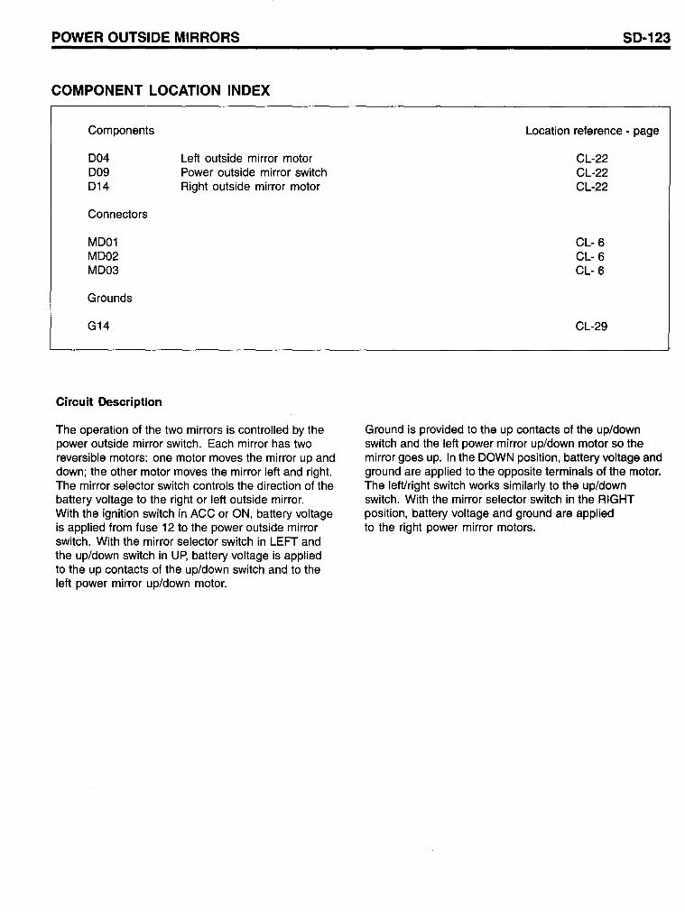
POWER OUTSIDE MIRRORS
COMPONENT LOCATION INDEX
Components
004 009 014
Connectors
M001 M002 M003
Grounds
G14
Circuit Description
Left outside mirror motor Power outside mirror switch Right outside mirror motor
The operation of the two mirrors is controlled by the power outside mirror switch. Each mirror has two reversible motors: one motor moves the mirror up and down; the other motor moves the mirror left and right. The mirror selector switch controls the direction of the battery voltage to the right or left outside mirror. With the ignition switch in ACC or ON, battery voltage is applied from fuse 12 to the power outside mirror switch. With the mirror selector switch in LEFT and the up/down switch in Up, battery voltage is applied to the up contacts of the up/down switch and to the left power mirror up/down motor.
S0-123
Location reference - page
CL-22 CL-22 CL-22
CL- 6 CL- 6 CL- 6
CL-29
Ground is provided to the up contacts of the up/down switch and the left power mirror up/down motor so the mirror goes up. In the DOWN position, battery voltage and ground are applied to the opposite terminals of the motor. The leftlright switch works similarly to the up/down switch. With the mirror selector switch in the RIGHT position, battery voltage and ground are applied to the right power mirror motors.
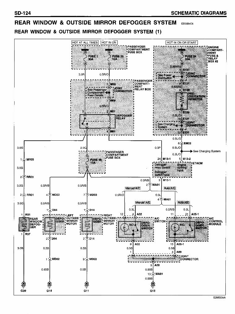
SD-124 SCHEMATIC DIAGRAMS
REAR WINDOW & OUTSIDE MIRROR DEFOGGER SYSTEM
REAR WINDOW & OUTSIDE MIRROR DEFOGGER SYSTEM (1)
EB05B4C6
3.0G
G20 G14 G11
PASSEN GER COMPARTMENT RELAYBOX
G13
I HOT IN ON OR START I
_-.See Charging System
E2ME034A
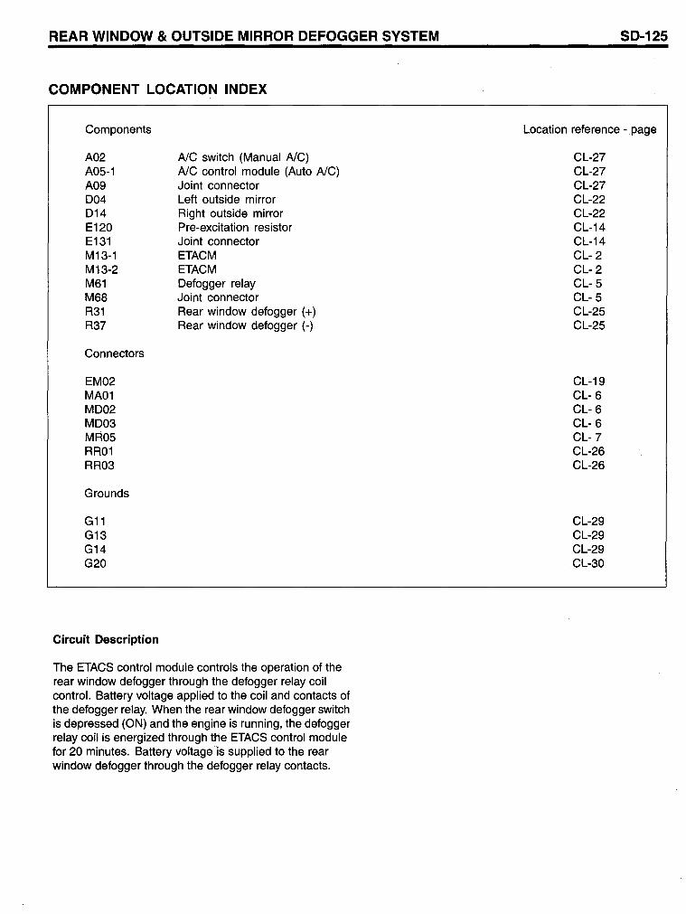
REAR WINDOW & OUTSIDE MIRROR DEFOGGER SYSTEM
COMPONENT LOCATION INDEX
Components
A02 A05-1 A09 004 014 E120 E131 M13-1 M13-2 M61 M68 R31 R37
Connectors
EM02 MA01 M002 M003 MR05 RR01 RR03
Grounds
G11 G13 G14 G20
Circuit Description
AlC switch (Manual AlC) AlC control module (Auto AlC) Joint connector Left outside mirror Right outside mirror Pre-excitation resistor Joint connector ETACM ETACM Oefogger relay Joint connector Rear window defogger (+) Rear window defogger (-)
The ETACS control module controls the operation of the rear window defogger through the defogger relay coil contro!. Battery voltage applied to the coil and contacts of the defogger relay. When the rear window defogger switch is depressed (ON) and the engine is running, the defogger relay coil is energized through the ETACS control module for 20 minutes. Battery voltage is supplied to the rear window defogger through the defogger relay contacts.
SD-125
Location reference - page
CL-27 CL-27 CL-27 CL-22 CL-22 CL-14 CL-14 CL- 2 CL- 2 CL- 5 CL- 5 CL-25 CL-25
CL-19 CL- 6 CL- 6 CL- 6 CL-7 CL-26 CL-26
CL-29 CL-29 CL-29 CL-30
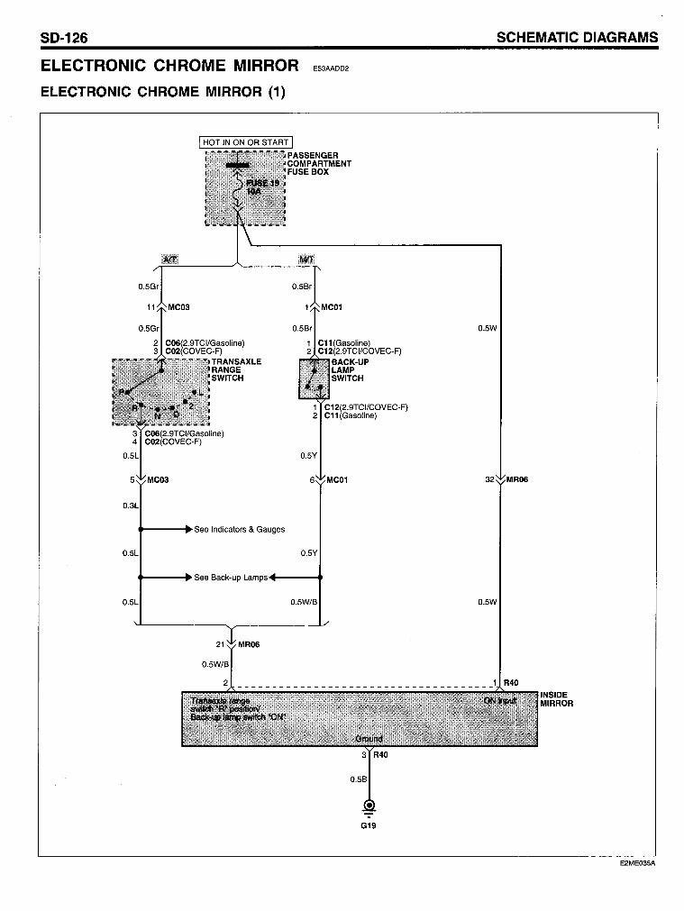
SO-126
ELECTRONIC CHROME MIRROR
ELECTRONIC CHROME MIRROR (1)
C06(2.9TCI/Gasoline) C02(COVEC-F)
TRANSAXLE RANGE SWITCH
.----+See Indicators & Gauges
E53AADD2
C11(Gasoline) C12(2.9TCI/COVEC-F)
BACK-UP LAMP SWITCH
1 C12(2.9TCIICOVEC-F) 2 C11 (Gasoline)
O.5Y
6 MC01
O.5Y
.----+See Back-up Lan1ps·4----t
O.5W/B
G19
SCHEMATIC OIAGRAMS
O.5W
O.5W
INSIDE MIRROR
E2ME035A
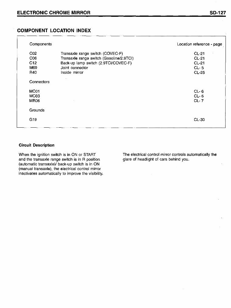
ELECTRONIC CHROME MIRROR
COMPONENT LOCATION INDEX
Components
C02 C06 C12 M69 R40
Connectors
MC01 MC03 MR06
Grounds
G19
Circuit Description
Transaxle range switch (COVEC-F) Transaxle range switch (Gasoline/2.9TCI) Back-up lamp switch (2.9TCI/COVEC-F) Joint connector Inside mirror
SD-127
Location reference - page
CL-21 CL-21 CL-21 CL- 5 CL-25
CL- 6 CL- 6 CL-7
CL-30
When the ignition switch is in ON or START and the transaxle range switch is in R position (automatie transaxle)/ back-up switch is in ON (manual transaxle), the electrical control mirror inactivates automatically to improve the visibility.
The electrical control mirror controls automatically the glare of headlight of cars behind you.
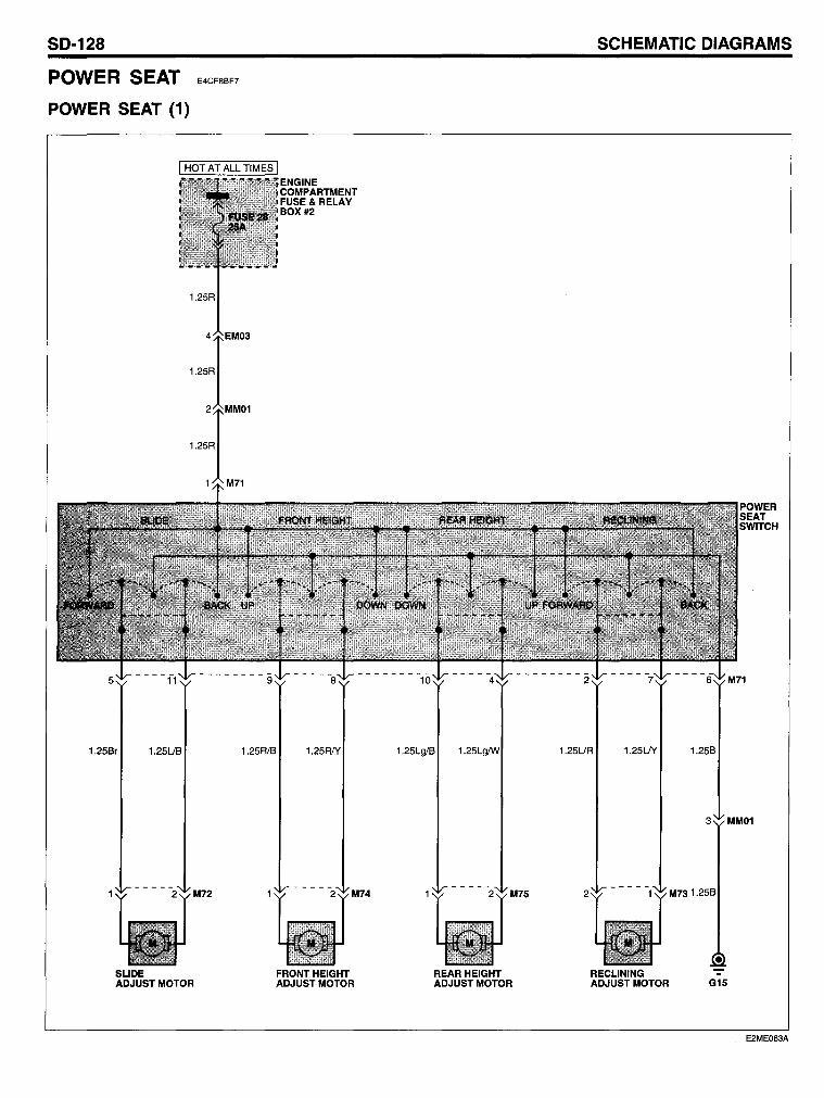
SO-128
POWER SEAT
POWER SEAT (1)
E4CF8BF7
I HOT AT ALL TIMES I
1.25R
1.25R
1.25R
1.25Br 1.25UB
M72
SLIDE ADJUST MOTOR
ENGINE COMPARTMENT FUSE& RELAY BOX #2
1.25R1B 1.25RIY
M74
FRONT HEIGHT ADJUST MOTOR
1.25Lg/B
M75
REAR HEIGHT ADJUST MOTOR
SCHEMATIC OIAGRAMS
1.25UR 1.25UY
2
RECLINING ADJUST MOTOR
1.25B
3 MM01
M731.25B
• G15
E2ME063A
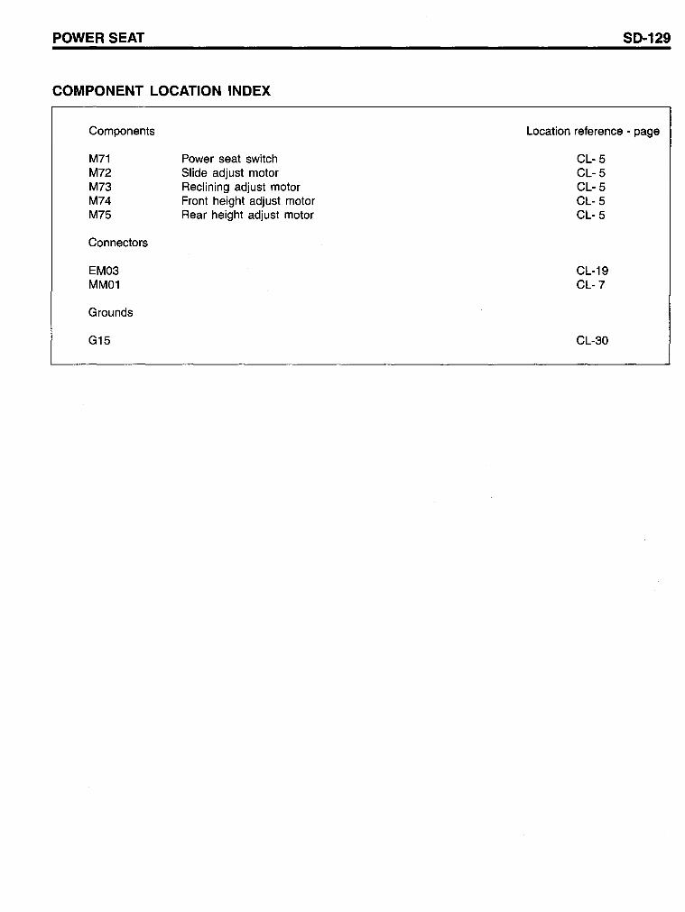
POWERSEAT
COMPONENT LOCATION INDEX
Components
M71 M72 M73 M74 M75
Connectors
EM03 MM01
Grounds
G15
Power seat switch Slide adjust motor Reclining adjust motor Front height adjust motor Rear height adjust motor
SD-129
Location reference - page
CL- 5 CL- 5 CL- 5 CL- 5 CL- 5
CL-19 CL-7
CL-30
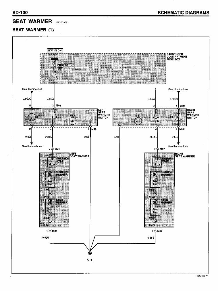
SO-130
SEAT WARMER
SEAl WARMER (1)
See Illuminations
See Illuminations
0.859
E73FCA32
SCHEMAllC OIAGRAMS
See Illuminations
See Illuminations
WARMER
0.859
G15
E2ME037A
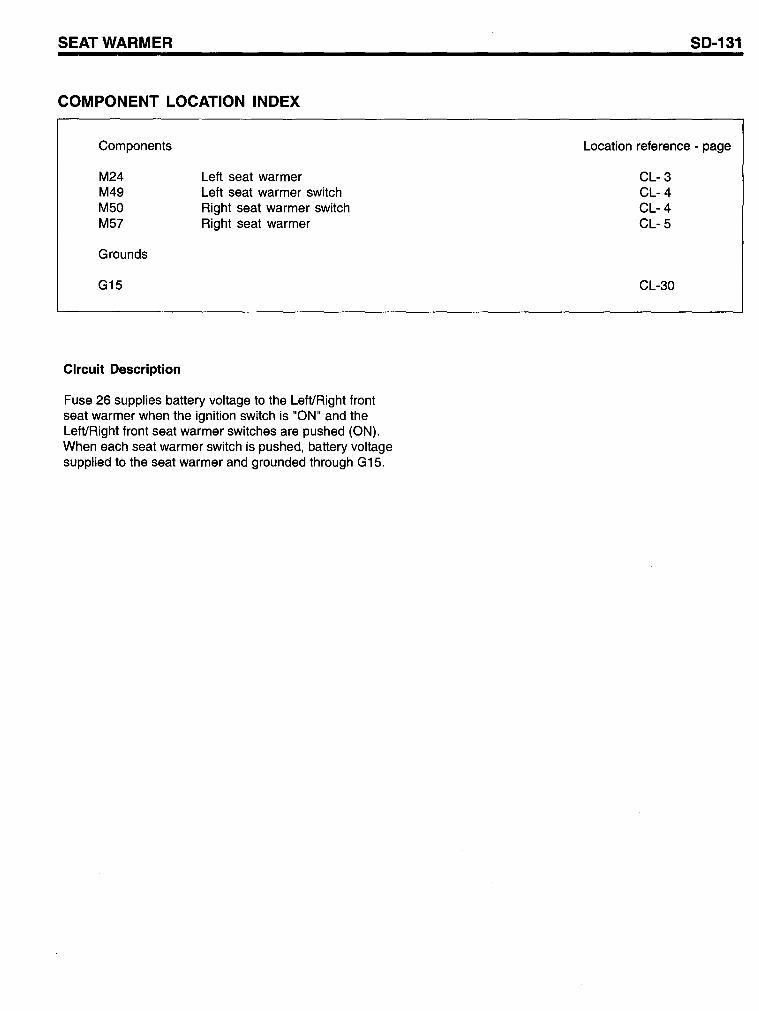
SEATWARMER
COMPONENT LOCATION INDEX
Components
M24 M49 M50 M57
Grounds
G15
Circuit Description
Left seat warmer Left seat warmer switch Right seat warmer switch Right seat warmer
Fuse 26 supplies battery voltage to the LefVRight front seat warmer when the ignition switch is "ON" and the LefVRight front seat warmer switches are pushed (ON). When each seat warmer switch is pushed, battery voltage supplied to the seat warmer and grounded through G15.
SD-131
Location reference - page
CL- 3 CL- 4 CL- 4 CL- 5
CL-3D
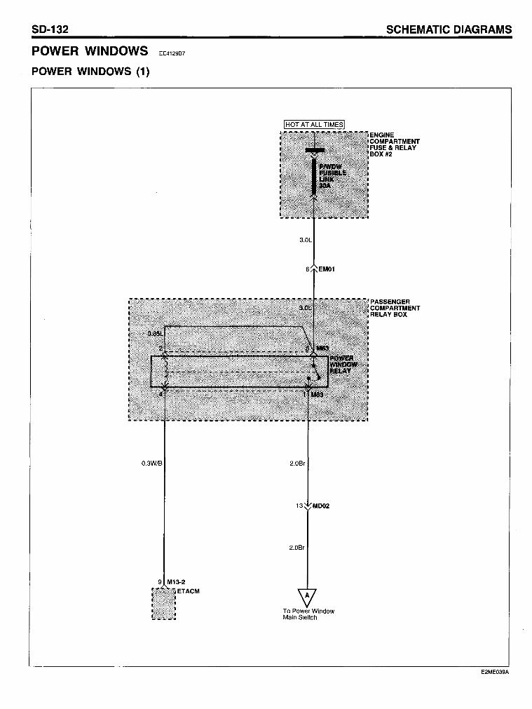
SO-132
POWER WINDOWS
POWER WINOOWS (1)
EE4129B7
O.3W/B
9 M13-2
ETACM
2.0Br
2.0Br
To Power Window Main Switch
SCHEMATIC OIAGRAMS
E2ME039A
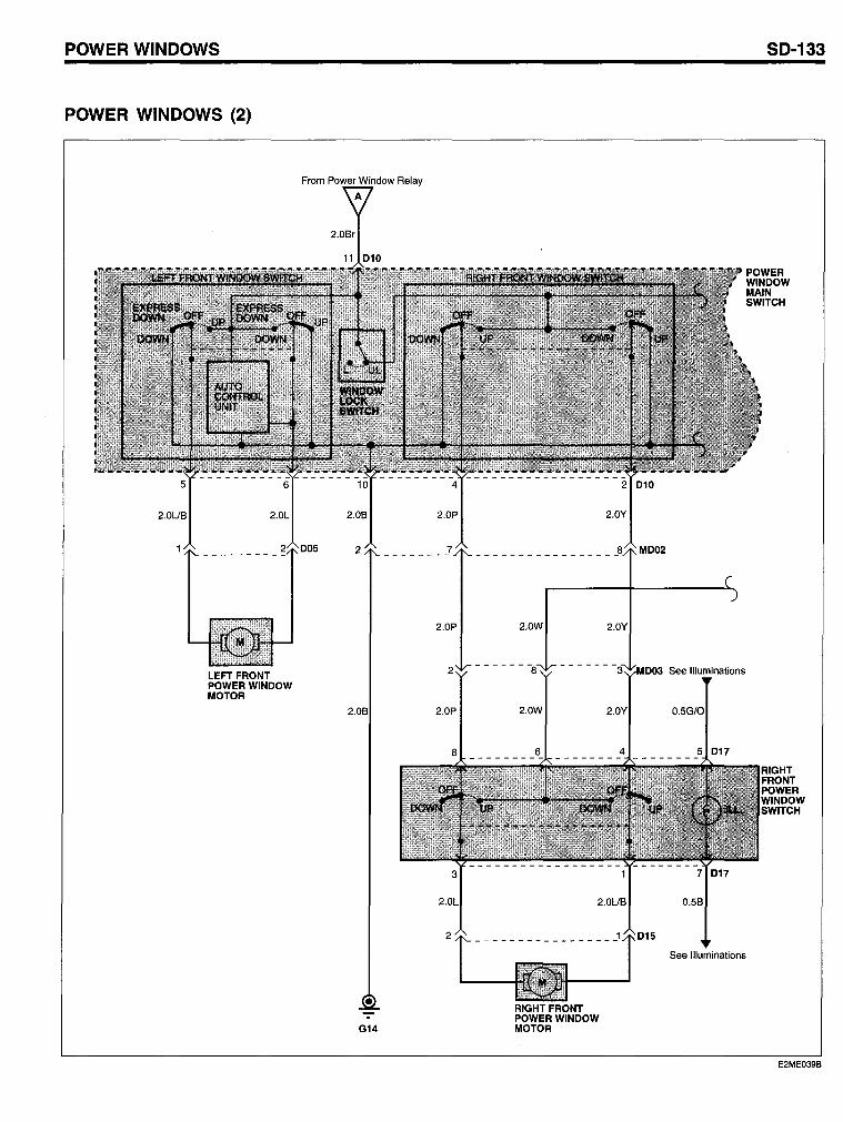
POWER WINOOWS
POWER WINOOWS (2)
LEFT FRONT POWER WINDOW MOTOR
From Power Window Relay
G14
2.0P
2
2.0P
2.0W
RIGHTFRONT POWER WINDOW MOTOR
2.0Y
SO-133
See Illuminations
0.58
See Illuminations
E2ME039B
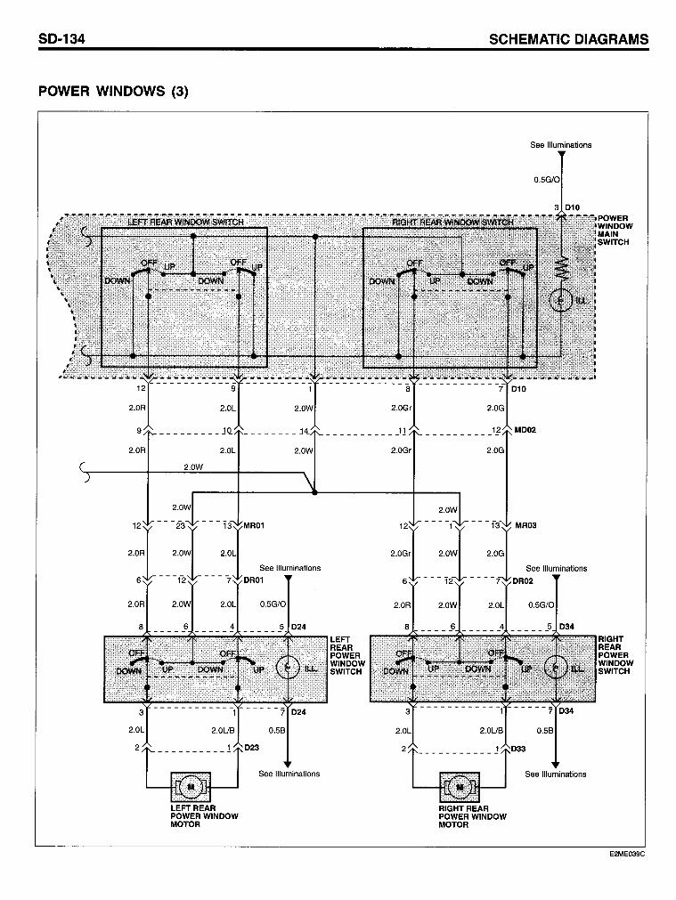
50-134
POWER WINOOW5 (3)
LEFTREAR POWER WINDOW MOTOR
See Illuminations
5CHEMATIC 0lAGRAM5
RIGHTREAR POWER WINDOW MOTOR
See Illuminations
See Illuminations
See Illuminations
RIGHT REAR POWER WINDOW SWITCH
E2ME039C
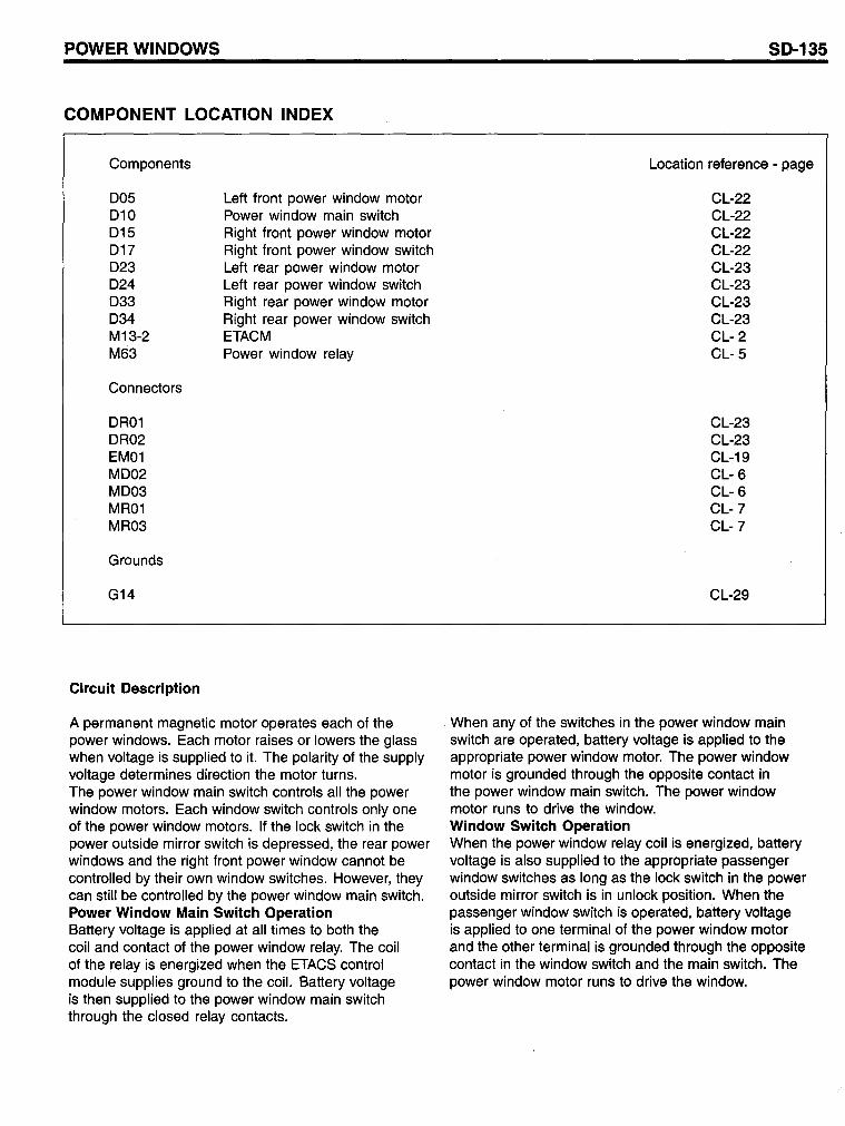
POWER WINDOWS
COMPONENT LOCATION INDEX
Components
005 010 015 017 023 024 033 034 M13-2 M63
Connectors
OR01 OR02 EM01 M002 M003 MR01 MR03
Grounds
G14
Circuit Description
Left front power window motor Power window main switch Right front power window motor Right front power window switch Left rear power window motor Left rear power window switch Right rear power window motor Right rear power window switch ETACM Power window relay
A permanent magnetic motor operates each of the power windows. Each motor raises or lowers the glass when voltage is supplied to it. The polarity of the supply voltage determines direction the motor turns. The power window main switch controls all the power window motors. Each window switch controls only one of the power window motors. If the lock switch in the power outside mirror switch is depressed, the rear power windows and the right front power window cannot be controlled by their own window switches. However, they can still be controlled by the power window main switch. Power Window Main Switch Operation Battery voltage is applied at all times to both the coil and contact of the power window relay. The coil of the relay is energized when the ETACS control module supplies ground to the coil. Battery voltage is then supplied to the power window main switch through the closed relay contacts.
SD-135
Location reference - page
CL-22 CL-22 CL-22 CL-22 CL-23 CL-23 CL-23 CL-23 CL- 2 CL- 5
CL-23 CL-23 CL-19 CL- 6 CL- 6 CL-7 CL-7
CL-29
When any of the switches in the power window main switch are operated, battery voltage is applied to the appropriate power window motor. The power window motor is grounded through the opposite contact in the power window main switch. The power window motor runs to drive the window. Window Switch Operation When the power window relay coil is energized, battery voltage is also supplied to the appropriate passenger window switches as long as the lock switch in the power outside mirror switch is in unlock position. When the passenger window switch is operated, battery voltage is applied to one terminal of the power window motor and the other terminal is grounded through the opposite contact in the window switch and the main switch. The power window motor runs to drive the window.
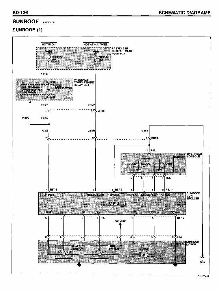
SO-136
SUNROOF EBE5C4DF
SUNROOF (1)
0.85G 0.85G
0.5G
PASSENGER COMPARTMENT FUSE BOX
0.858
SCHEMATIC OIAGRAMS
E2ME04OA
5UNROOF
COMPONENT LOCATION INDEX
Components
M68 R55 R56 R57-1 R57-2
Connectors
MR06 RR08
Grounds
G19
Circuit Description
Joint connector Overhead console Sunroof motor Sunroof controller Sunroof controller
Battery voltage is supplied at all times to open/tilt down and close/tiit up sunroof relay contacts. Open/tilt down relay and close/tilt up relay coils are also supplied battery voltage when the ignition switch is in ON. When the ignition key is turned on and the open switch is depressed, the open/tilt down relay is energized. Battery voltage is then supplied to the sunroof motor through the open/tilt down relay contacts. The motor is grounded through close/tilt up relay contact.
50-137
Location reference - page
CL- 5 CL-26 CL-26 CL-26 CL-26
CL-7 CL-26
CL-30
When the ignition key is turned on and the close switch is depressed, the close/tilt up relay is energized through roof open/close limit switch. When the sunroof is open, the roof open/close limit switch always contacts the open position. The tilt up and tilt down switch works similarly to the open switch. The polarity of the voltage applied to the sunroof motor through sunroof relay contacts is changed according to the switch positions.
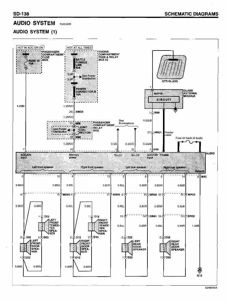
SO-138
AUDIO SYSTEM
AUOIO SYSTEM (1)
EOA55AB8
1.25Br
O.85G
PASSENGER COMPARTMENT".'." FUSE BOX
SCHEMATIC OIAGRAMS
See O.5G/B ';';,!,', . PASSENGER Illuminations
... COMPARTMENT ·RELAY ~
BOX
O.5G O.5G/O O.5G/B
O.85R
G12
E2ME042A
AUDIO SYSTEM
COMPONENT LOCATION INDEX
Components
002 003 012 013 022 032 M40 M68 R09
Connectors
EM03 OR01 OR02 M002 M003 MR01 MR02 MR03
Grounds
G12
Circuit Description
Left front door speaker Left front tweeter speaker Right front door speaker Right front tweeter speaker Left rear door speaker Right rear door speaker Audio Joint connector Glass antenna module
The audio unit receives battery voltage at all times from power connector B to maintain the memory function and antenna operation. Fuse 10 supplies battery voltage to the audio when the ignition switch is in ACC or ON for audio operation and the display. The audio is grounded at G12 and a noise filter is installed on the rear side of the audio case.
SD-139
Location reference - page
CL-22 CL-22 CL-22 CL-22 CL-23 CL-23 CL- 4 CL- 5 CL-24
CL-19 CL-23 CL-23 CL- 6 CL- 6 CL-7 CL-7 CL-7
CL-29
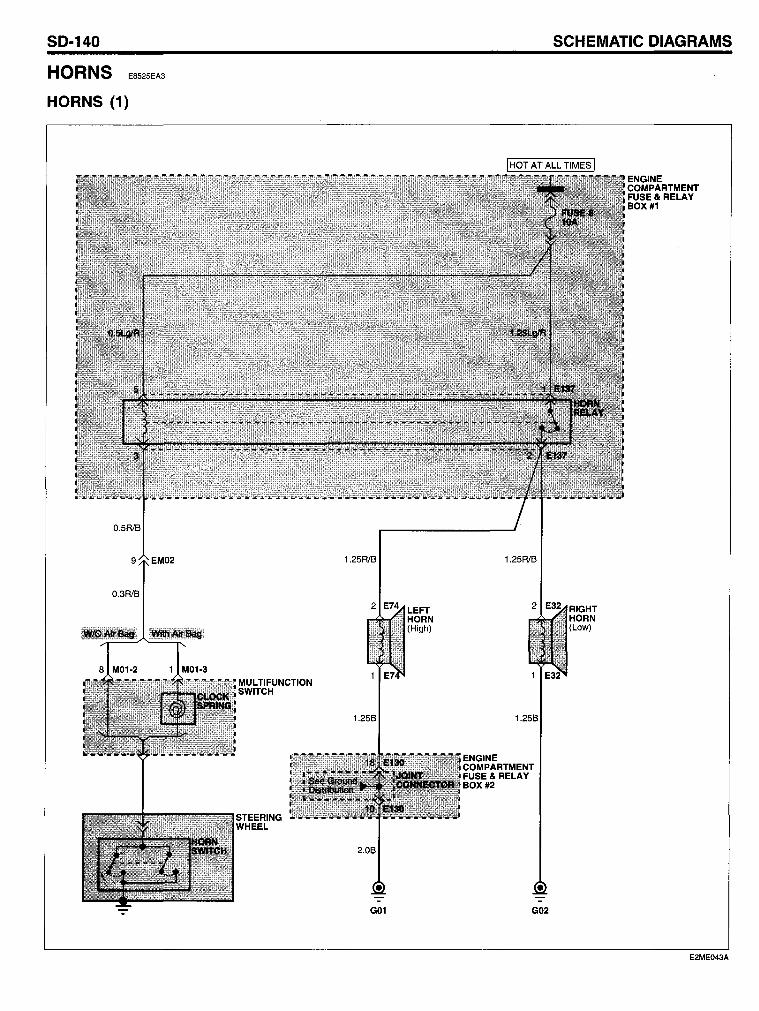
SO-140
HORNS E8525EA3
HORNS (1)
O.3R/B
1.25R/B
1.25B
G01
LEFT HORN (High)
SCHEMATIC OIAGRAMS
IHOT AT ALL TIMES I
1.25R!B
ENGINE COMPARTMENT FUSE& RELAY BOX #2
G02
RIGHT HORN (Low)
ENGINE COMPARTMENT FUSE& RELAY BOX #1
E2ME043A
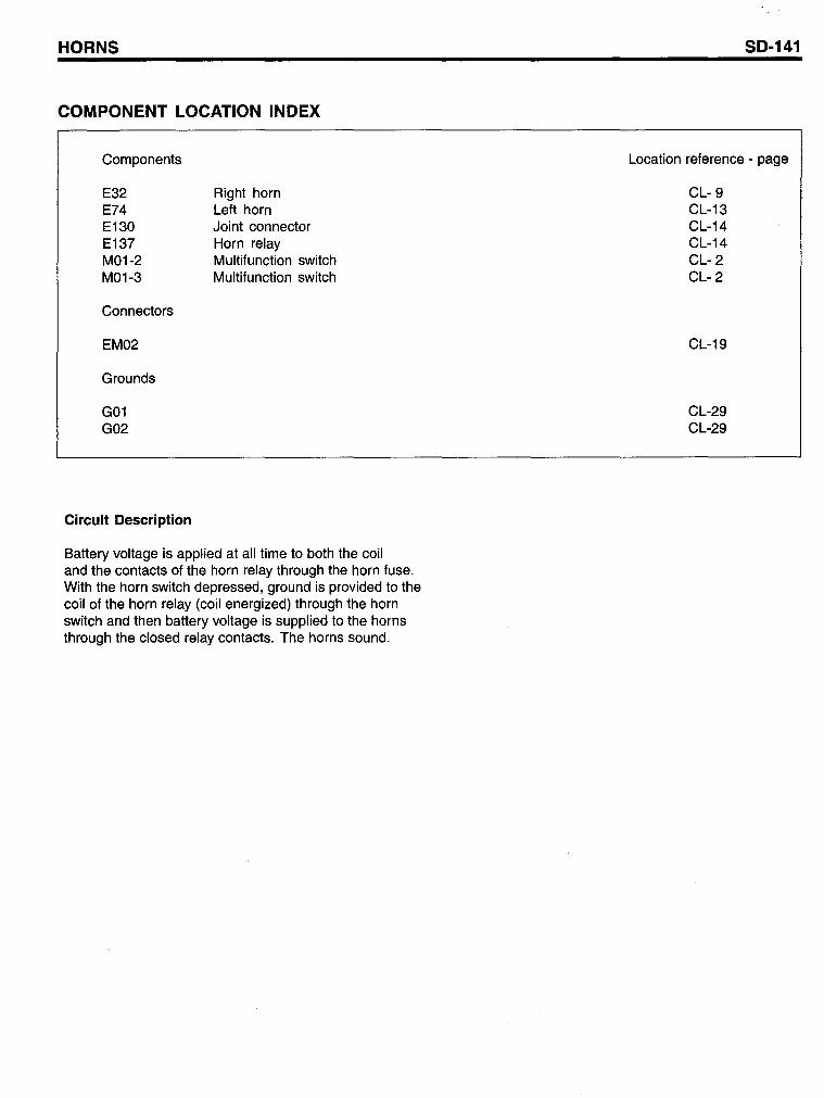
HORNS
COMPONENT LOCATION INDEX
Components
E32 E74 E130 E137 M01-2 M01-3
Connectors
EM02
Grounds
G01 G02
Circuit Description
Right horn Left horn Joint connector Horn relay Multifunction switch Multifunction switch
Battery voltage is applied at all time to both the coil and the contacts of the horn relay through the horn fuse. With the horn switch depressed, ground is provided to the coil of the horn relay (coil energized) through the horn switch and then battery voltage is supplied to the horns through the closed relay contacts. The horns sound.
SO-141
Location reference - page
CL- 9 CL-13 CL-14 CL-14 CL- 2 CL- 2
CL-19
CL-29 CL-29
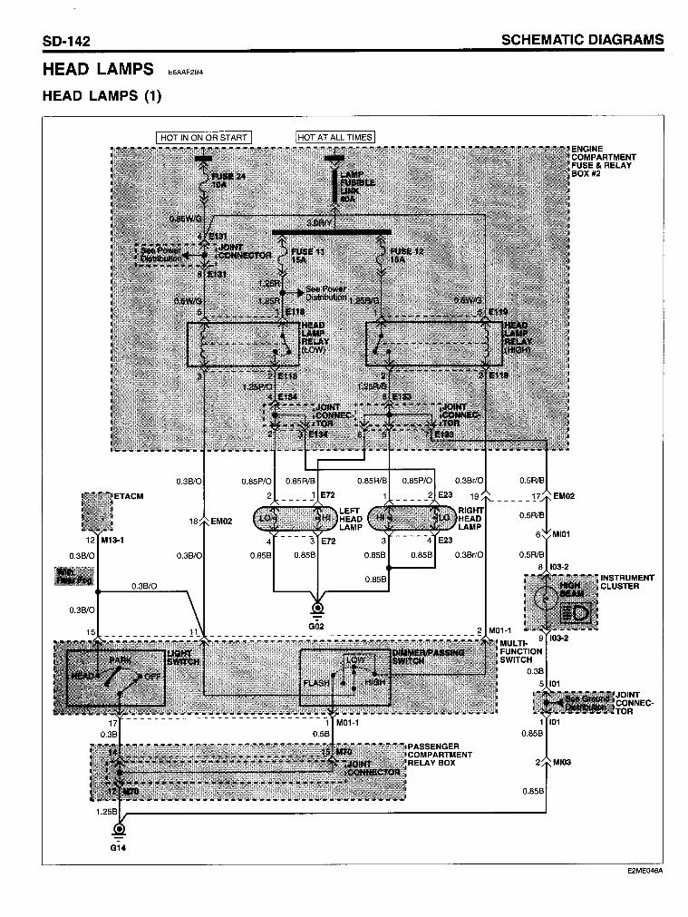
SO-142
HEAD LAMPS
HEAO LAMPS (1)
G14
SCHEMATIC OIAGRAMS
E6AAF2B4
E2ME046A
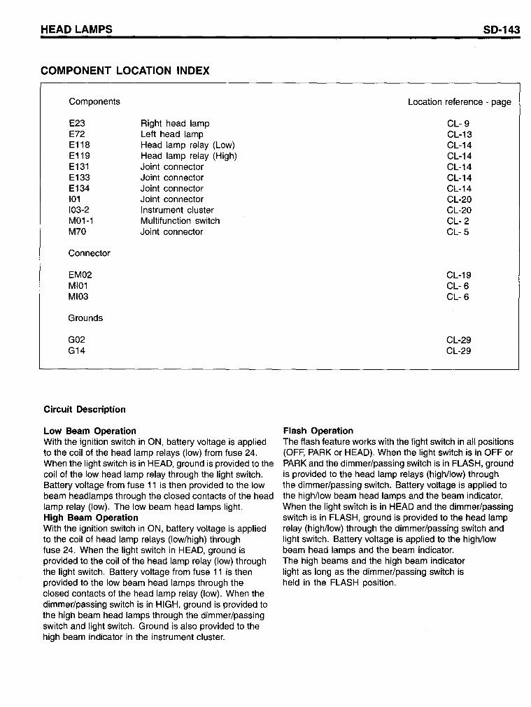
HEAD LAMPS
COMPONENT LOCATION INDEX
Components
E23 E72 E118 E119 E131 E133 E134 101 103-2 M01-1 M70
Connector
EM02 MI01 MI03
Grounds
G02 G14
Circuit Description
Low Beam Operation
Right head lamp Left head lamp Head lamp relay (Low) Head lamp relay (High) Joint connector Joint connector Joint connector Joint connector Instrument cluster Multifunction switch Joint connector
With the ignition switch in ON, battery voltage is applied to the coil of the head lamp relays (Iow) from fuse 24. When the light switch is in HEAD, ground is provided to the coil of the low head lamp relay through the light switch. Battery voltage from fuse 11 is then provided to the low beam headlamps through the closed contacts of the head lamp relay (Iow). The low beam head lamps light. High Beam Operation With the ignition switch in ON, battery voltage is applied to the coil of head lamp relays (Iow/high) through fuse 24. When the light switch in HEAD, ground is provided to the coil of the head lamp relay (Iow) through the light switch. Battery voltage from fuse 11 is then provided to the low beam head lamps through the closed contacts of the head lamp relay (low). When the dimmer/passing switch is in HIGH, ground is provided to the high beam head lamps through the dimmer/passing switch and light switch. Ground is also provided to the high beam indicator in the instrument cluster.
SD-143
Location reference - page
Flash Operation
CL- 9 CL-13 CL-14 CL-14 CL-14 CL-14 CL-14 CL-20 CL-20 CL- 2 CL- 5
CL-19 CL- 6 CL- 6
CL-29 CL-29
The flash feature works with the light switch in all positions (OFF, PARK or HEAD). When the light switch is in OFF or PARK and the dimmer/passing switch is in FLASH, ground is provided to the head lamp relays (high/low) through the dimmer/passing switch. Battery voltage is applied to the high/low beam head lamps and the beam indicator. When the light switch is in HEAD and the dimmer/passing switch is in FLASH, ground is provided to the head lamp relay (high/low) through the dimmer/passing switch and light switch. Battery voltage is applied to the high/low beam head lamps and the beam indicator. The high beams and the high beam indicator light as long as the dimmer/passing switch is held in the FLASH position.
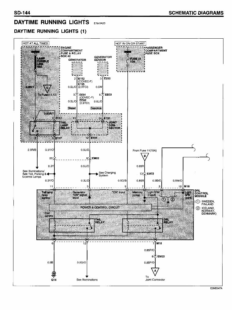
SO-144
DAYTIME RUNNING LlGHTS
OAYTIME RUNNING LlGHTS (1)
2.0Rl6
See Illuminationsl See Tail, Parking License Lamps
0.56 0.5G/0
-
E7940A2D
See Charging System
G14 See Illuminations
0.50/6
From Fuse 11(15A)
i 0.85R
13 EM03
To Joint Connector
SCHEMATIC OIAGRAMS
0.5W/0
DRL CONTROL MODULE
(CD: SWEDEN, FINLAND
@:ICELAND, NORWAY, DENMARK)
E2ME047A
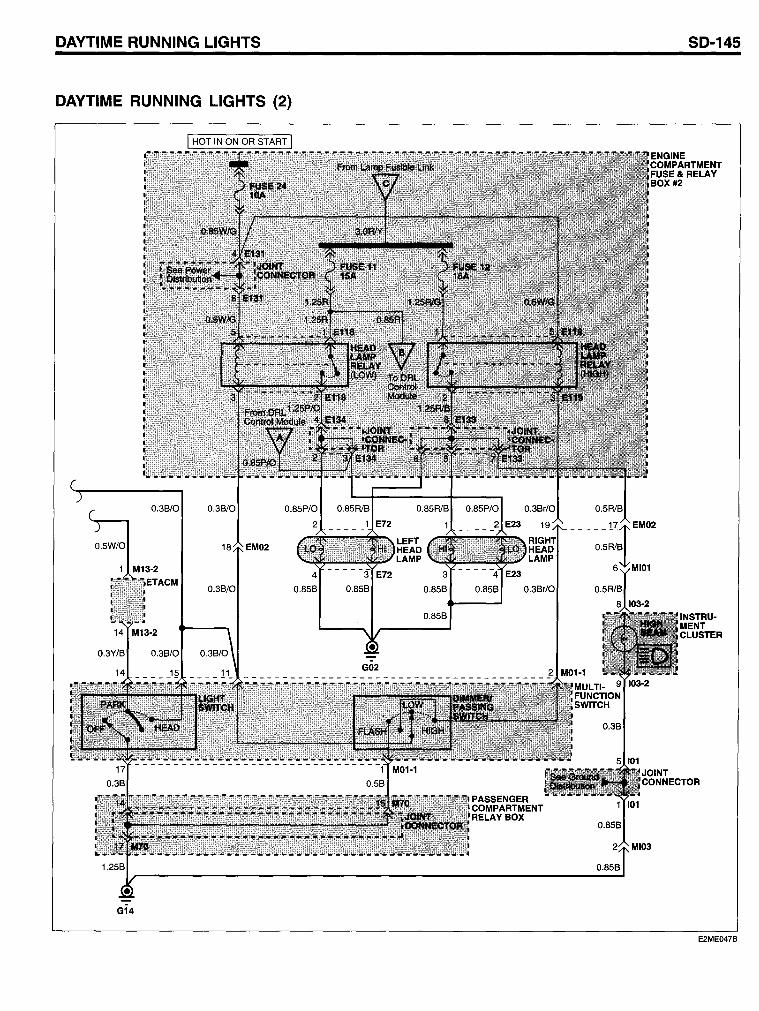
OAYTIME RUNNING LlGHTS SO-145
OAYTIME RUNNING LlGHTS (2)
E2ME047B
SD-146
COMPONENT LOCATION INDEX
Components
E23 E72 E117 E118 E119 E131 E133 E134 E152 E155 E250 101 103-2 M01-1 M13-2 M18 M70
Connectors
EE01 EE02 EE03 EM02 EM03 MI01 MI03
Grounds
G02 G14
Circuit Description
Right head lamp Left head lamp Tail lamp relay Head lamp relay (Low) Head lamp relay (High) Joint connector Joint connector Joint connector Generator (L,S) (COVEC-F) Generator (L,S) (2.9TCI) Generator sensor (Gasoline) Joint connector Instrument cluster Multifunction switch ETACM DRL control module Joint connector
For the visibility and safty of drivers, the daytime running lights will turn on automatically when the engine is running. Under this condition, the head lamps will illuminate with a minimal amount of load on the charging system. As the DRL control module detects the generator running signals (engine running signal), the DRL control module controls the operation of the low beam head lamps through DRL relay coil contro!. Battery voltage from fusible link is then provided to the low beam head lamps through the DRL relay contact.
SCHEMATIC DIAGRAMS
Location reference - page
CL- 9 CL-13 CL-14 CL-14 CL-14 CL-14 CL-14 CL-14 CL-15 CL-15 CL-18 CL-20 CL-20 CL- 2 CL- 2 CL- 3 CL- 5
CL-18 CL-18 CL-18 CL-19 CL-19 CL- 6 CL- 6
CL-29 CL-29
In addition to the DRL relay control, the DRL control module controls the tail relay (built in to the DRL control module) coi!. Battery voltage is applied to the closed contact of the tail lamp relay and the interior illumination lamps turn on. When the DRL module detects the engine running OFF signal, the DRL control module turns the lights oft. When the DRL module detects the light switch in ON (PARK or HEAD) signal, the DRL control module stops it's functions.
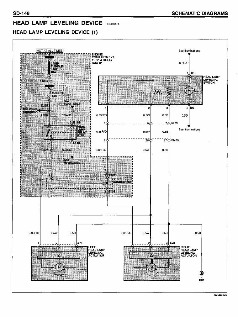
SO-148
HEAD LAMP LEVELING DEVICE
HEAO LAMP LEVELING OEVICE (1)
EE42CAF6
0.85P/O
0.5W 0.58
0.5W 0.58
SCHEMATIC OIAGRAMS
0.5G
See Illuminations
0.58
HEAD LAMP LEVELING SWITCH
E2ME050A
HEAD LAMP LEVELING DEVICE
COMPONENT LOCATION INDEX
Components
E22 E71 E118 E134 109
Connectors
EM05 MI03
Grounds
G01
Circuit Description
Right head lamp leveling actuator Left head lamp leveling actuator Head lamp relay (Low) Joint connector Head lamp leveling switch
The head lamps should be aimed properly according to the number of the passengers and the loading weight in the luggage area. To adjust the head lamps beam level, turn the head lamp leveling switch. The higher the number of the switch position, the lower the head lamp beam level. Always keep the head lamps beam at the proper leveling position, or head lamp may dazzle other road users.
5D-149
Location reference - page
CL- 9 CL-13 CL-14 CL-14 CL-20
CL-19 CL- 6
CL-29
Battery voltage is supplied to the leftlright head lamp leveling actuators in the head lamps from fuse 11 and the beam level can be controlled through a variable resistor (bulit-in to the head lamp leveling switch)
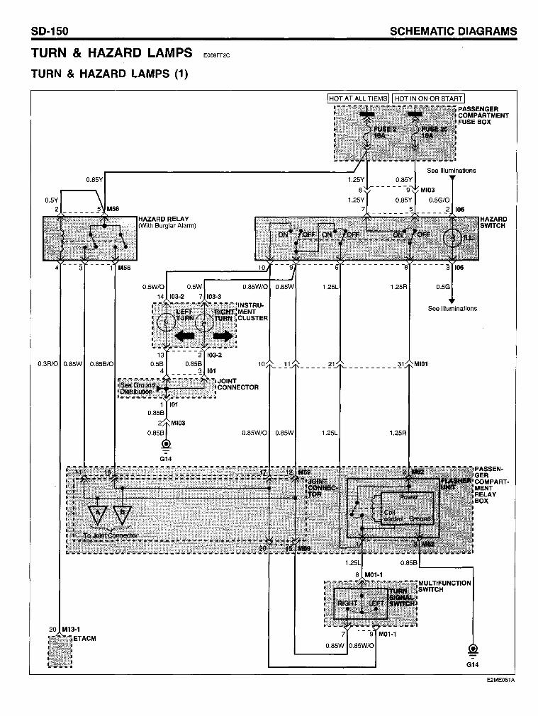
SO-150
TURN & HAZARD LAMPS
TURN & HAZARO LAMPS (1)
O.85Y
O.3R/O O.85W
HAZARD RELA Y (With Burglar Alarm)
G14
E068FF2C
O.85W/O
INSTRU· MENT CLUSTER
11
O.85W/O O.85W
SCHEMATIC OIAGRAMS
1 HOT AT ALL TIEMS 11 HOT IN ON OR START 1
1.25L 1.25R
See Illuminations
_________ ~ MI01
1.25L 1.25R
G14
E2ME051A
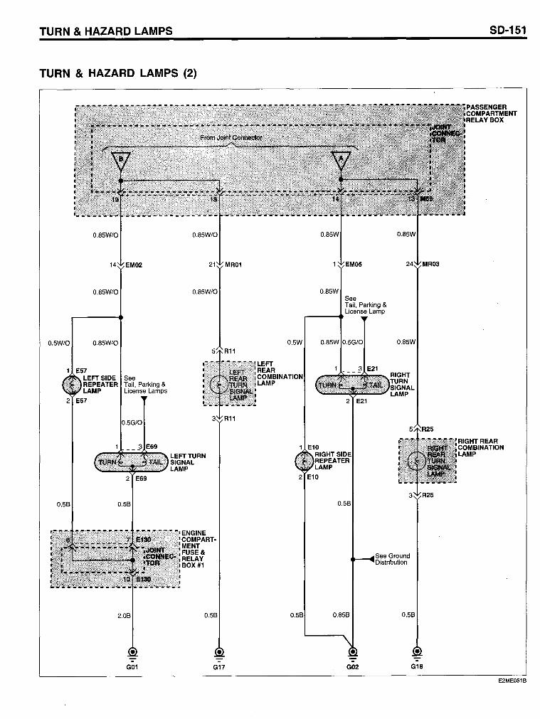
TURN & HAZARO LAMPS
TURN & HAZARO LAMPS (2)
0.85W/O
0.5W/O 0.85W/O
E57 LEFTSIDE See REPEATER Tail, Parking & LAMP License Lamps
2 E57
2 E69
0.58 0.58
2.08
G01
0.85W/O
LEFTTURN SIGNAL LAMP
ENGINE COMPARTMENT FUSE& RELAY BOX #1
0.58
G17
0.5W
LEFT REAR COMBINA LAMP
0.85W See Tail, Parking &
...--__ ..... License Lamp
0.58
See Ground Distribution
0.858 0.58
G02 G18
SO-151
RIGHTREAR COMBINATION LAMP
E2ME051B
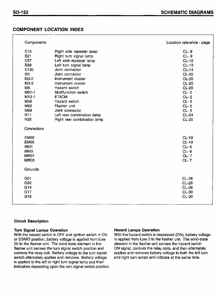
SD-152
COMPONENT LOCATION INDEX
Components
E10 E21 E5? E69 E130 101 103-2 103-3 106 M01-1 M13-1 M56 M62 M69 R11 R25
Connectors
EM02 EM05 MI01 MI03 MR01 MR03
Grounds
G01 G02 G14 G1? G18
Circuit Description
Right side repeater lamp Right turn signal lamp Left side repeater lamp Left turn signal lamp Joint connector Joint connector Instrument cluster Instrument cluster Hazard switch Multitunction switch ETACM Hazard switch Flasher unit Joint connector Left rear combination lamp Right rear combination lamp
Turn Signal Lamps Operation With the hazard switch in OFF and ignition switch in ON or START position, battery voltage is applied trom tuse 20 to the flasher unit. The solid-state element in the tlasher unit senses the turn signal switch position and controls the relay coil. Battery voltage to the turn signal switch alternately applies and removes. Battery voltage is applied to the left or right turn signal lamp and their indicators depending upon the turn signal switch position.
Hazard Lamps Operation
SCHEMATIC DIAGRAMS
Location reterence - page
CL- 8 CL- 9 CL-12 CL-13 CL-14 CL-20 CL-20 CL-20 CL-20 CL- 2 CL- 2 CL- 5 CL- 5 CL- 5 CL-24 CL-25
CL-19 CL-19 CL- 6 CL- 6 CL-? CL-?
CL-29 CL-29 CL-29 CL-30 CL-30
With the hazard switch is depressed (ON), battery voltage is applied trom tuse 2 to the flasher unit. The soild-state element in the tlasher unit senses the hazard switch ON signal, controls the relay coils, and then alternately applies and removes battery voltage to both the left turn and right turn lamps and indicate at the same time.
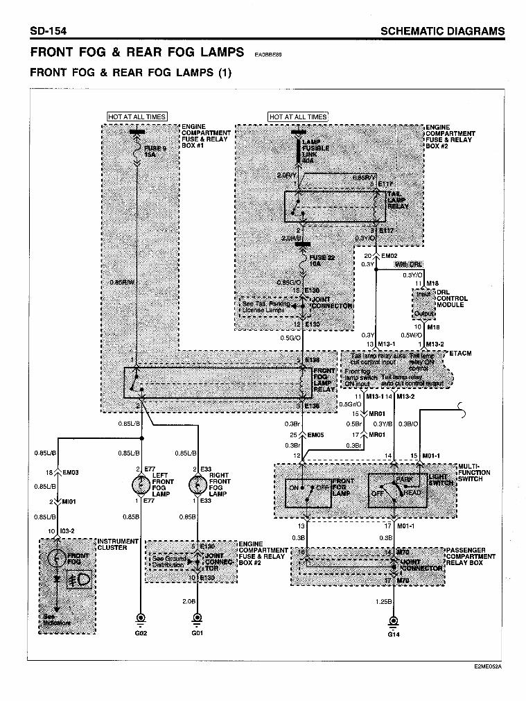
SO-154
FRONT FOG & REAR FOG LAMPS
FRONT FOG & REAR FOG LAMPS (1)
EAOBBE89
ENGINE COMPARTMENT FUSE& RELAY BOX #2
SCHEMATIC OIAGRAMS
0.38/0
G14
E2ME052A
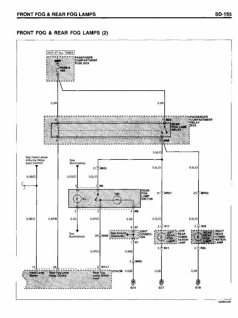
FRONT FOG & REAR FOG LAMP5
FRONT FOG & REAR FOG LAMP5 (2)
See Head Lamps (H/Lamp Relay (Iow) Contral)
0.3B/0
0.3B/0
0.5R
O.
PASSENGER COMPARTMENT FUSE BOX
See Illuminations
See Illuminations
0.5P/0
0.5P/0
G14
0.5R
0.5UO
31 MR01
0.5UO
G17
LEFT REAR COMBINATION LAMP
PASSENGER COMPARTMENT RELAY BOX
0.5UO
MR03
0.5UO
0.5B
G18
50-155
RIGHT REAR COMBINATION LAMP
E2ME052B
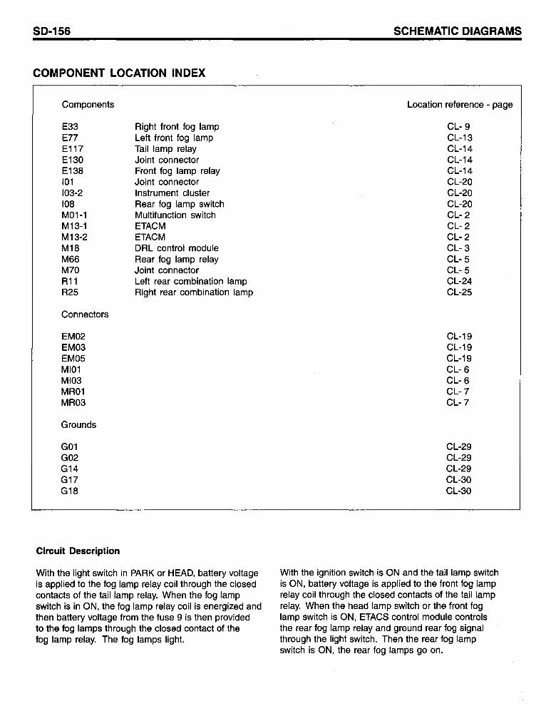
SD-156
COMPONENT LOCATION INDEX
Components
E33 E77 E117 E130 E138 101 103-2 108 M01-1 M13-1 M13-2 M18 M66 M70 R11 R25
Connectors
EM02 EM03 EM05 MI01 MI03 MR01 MR03
Grounds
G01 G02 G14 G17 G18
Circuit Description
Right front fog lamp Leff front fog lamp Tail lamp relay Joint connector Front fog lamp relay Joint connector Instrument cluster Rear fog lamp switch Multifunction switch ETACM ETACM DRL control module Rear fog lamp relay Joint connector Leff rear combination lamp Right rear combination lamp
With the light switch in PARK or HEAD, battery voltage is applied to the fog lamp relay coil through the closed contacts of the tail lamp relay. When the fog lamp switch is in ON, the fog lamp relay coil is energized and then battery voltage from the fuse 9 is then provided to the fog lamps through the closed contact of the fog lamp relay. The fog lamps light.
SCHEMATIC DIAGRAMS
Location reference - page
CL- 9 CL-13 CL-14 CL-14 CL-14 CL-20 CL-20 CL-20 CL- 2 CL- 2 CL- 2 CL- 3 CL- 5 CL- 5 CL-24 CL-25
CL-19 CL-19 CL-19 CL- 6 CL- 6 CL-7 CL-7
CL-29 CL-29 CL-29 CL-30 CL-30
With the ignition switch is ON and the tail lamp switch is ON, battery voltage is applied to the front fog lamp relay coil through the closed contacts of the tail lamp relay. When the head lamp switch or the front fog lamp switch is ON, ETACS control module controls the rear fog lamp relay and ground rear fog signal through the light switch. Then the rear fog lamp switch is ON, the rear fog lamps go on.
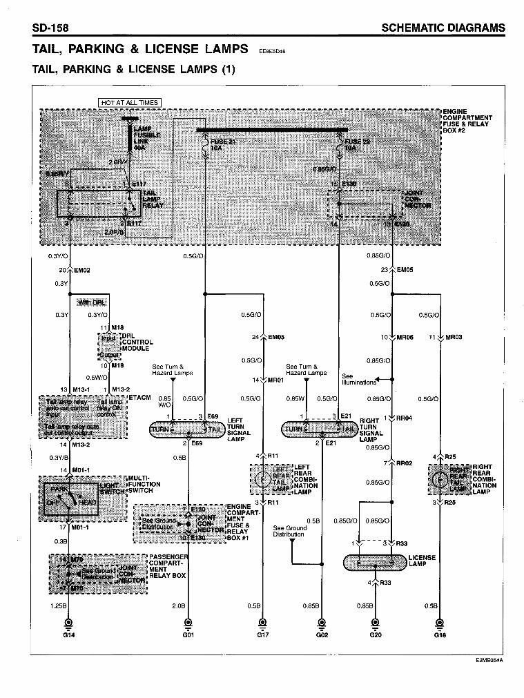
SD-158 SCHEMATIC DIAGRAMS
TAIL, PARKING & LlCENSE LAMPS EE9E5D46
TAIL, PARKING & LlCENSE LAMPS (1)
0.3Y/O
0.3Y
0.3Y/O
11 M18
0.5G/O
See Turn & Hazard Lamps
0.85 0.5G/O W/O
0.5G/O
24 EMOS
See Turn & Hazard Lamps
14 MR01
0.5G/O
LEFT TURN SIGNAL LAMP
0.85W
0.85G/O
0.85G/O
0.85G/O
0.58 0.85G/O 0.85G/O
2.08 0.58
G14 G01 G17
See Ground Distribution
0.858
G02 G20
0.5G/O
11 MR03
0.5G/O
RR04
LICENSE LAMP
0.58
G18
E2ME054A
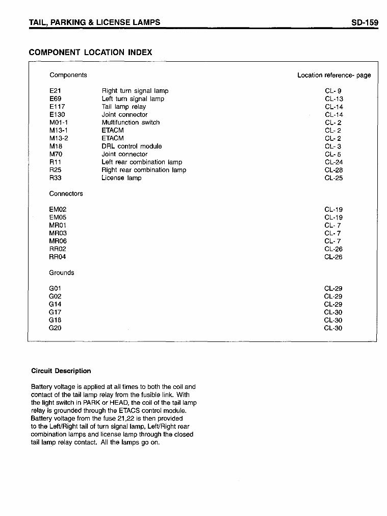
TAIL, PARKING & LlCENSE LAMPS
COMPONENT LOCATION INDEX
Components
E21 E69 E117 E130 M01-1 M13-1 M13-2 M18 M70 R11 R25 R33
Connectors
EM02 EM05 MR01 MR03 MR06 RR02 RR04
Grounds
G01 G02 G14 G17 G18 G20
Circuit Description
Right turn signal lamp Left turn signal lamp Tail lamp relay Joint connector Multifunction switch ETACM ETACM DRL control module Joint connector Left rear combination lamp Right rear combination lamp License lamp
Battery voltage is applied at all times to both the coil and contact of the tail lamp relay from the fusible link. With the light switch in PARK or HEAD, the coil of the tail lamp relay is grounded through the ETACS contral module. Battery voltage from the fuse 21,22 is then provided to the Left/Right tail of turn signal lamp, Left/Right rear combination lamps and license lamp through the closed taillamp relay contact. All the lamps go on.
SD-159
Location reference- page
CL- 9 CL-13 CL-14 CL-14 CL- 2 CL- 2 CL- 2 CL- 3 CL- 5 CL-24 CL-28 CL-25
CL-19 CL-19 CL-7 CL-7 CL-7 CL-26 CL-26
CL-29 CL-29 CL-29 CL-30 CL-30 CL-30
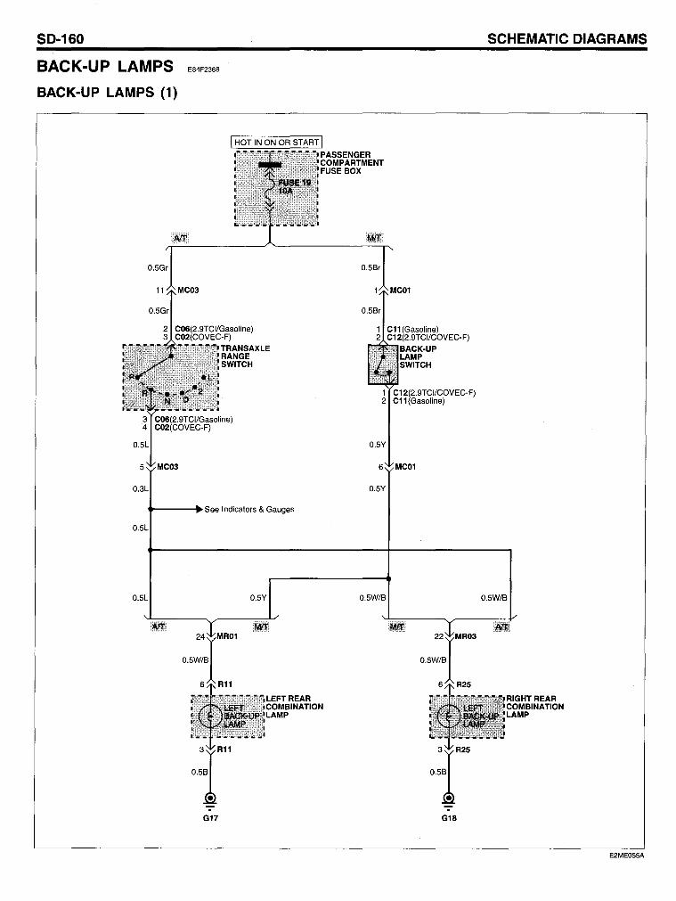
SO-160
BACK-UP LAMPS
BACK-UP LAMPS (1)
E84F2368
I HOT IN ON OR START I
C06(2.9TCI/Gasoline) C02(COVEC-F)
TRANSAXLE RANGE SWITCH
PASSENGER COMPARTMENT FUSE BOX
1 C12(2.9TCI/COVEC-F) 2 C11(Gasoline)
O.3L
t----.See Indicators & Gauges
O.5l
O.5l
24
IMR01
O.5W/B
6 R11
G17
O.5Y
LEFT REAR COMBINATION LAMP
O.5Y
6 MC01
O.5Y
O.5W/B
22
IMR03
O.5W/B
6 R25
G18
SCHEMATIC OIAGRAMS
O.5W/B
E2ME055A
BACK-UP LAMPS
COMPONENT LOCATION INDEX
Components
C02 C06 C12 M69 R11 R25
Connectors
MC01 MC03 MR01 MR03
Grounds
G17 G18
Circuit Description
Transaxle range switch (COVEC-F) Transaxle range switch (Gasoline/2.9TCI) Back-up lamp switch (2.9TCI/COVEC-F) Joint connector Left rear combination lamp Right rear combination lamp
With the ignition switch in ON or START, battery voltage is applied from Fuse 19 to the transaxle range switch (Automatie transaxle) and back-up lamp switch (Manual transaxle). When the transaxle is in reverse, battery voltage is applied to the back-up lamps and the back-up lamps go on.
SD-161
Location reference - page
CL-21 CL-21 CL-21 CL- 5 CL-24 CL-25
CL- 6 CL- 6 CL-7 CL-7
CL-30 CL-30
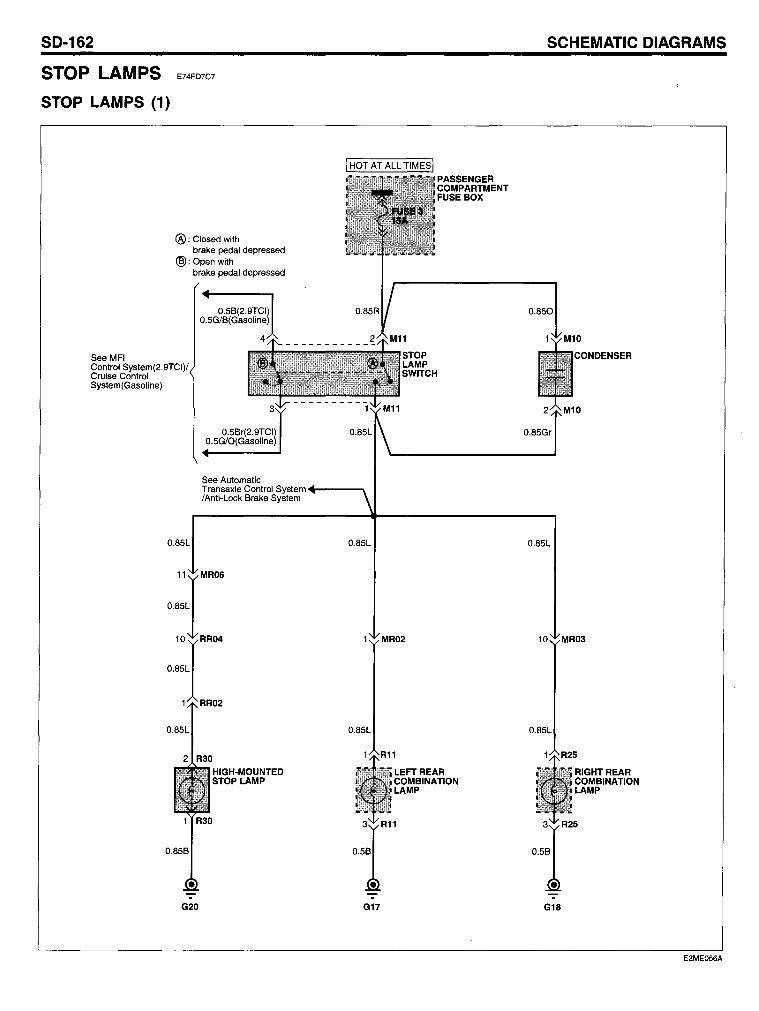
SO-162
STOP LAMPS
STOP LAMPS (1)
See MFI
E74FD7C7
®: Closed with brake pedal depressed
@:Openwith brake pedal depressed
0.5B(2.9TCI) 0.5G/B(Gasoline)
Control System(2.9TCI)/ Cruise Control System(Gasoline)
0.5Br(2.9TCI) 0.5G/O(Gasoline)
See Automatie Transaxle Control System .... -----,. /Anti-Loek Brake System
0.85L
11
JMR06
0.85L
10
IRR04
0.85L
1 RR02
G20
HIGH-MOUNTED STOP LAMP
0.85L
0.85L
G17
MR02
LEFT REAR COMBINATION LAMP
SCHEMATIC OIAGRAMS
0.850
CONDENSER
0.85Gr
0.85L
10 MR03
0.85L
G18
RIGHTREAR COMBINATION LAMP
E2ME056A
STOP LAMPS
COMPONENT LOCATION INDEX
Components
M10 M11 R11 R25 R30
Connectors
MR02 MR03 MR06 RR02 RR04
Grounds
G17 G18 G20
Circuit Description
Condenser Stop lamp switch Left rear combination lamp Right rear combination lamp High-mounted stop lamp
Battery voltage is applied to the stop lamp switch at all times from fuse 3. With the brake pedal depressed, the stop lamp switch is closed and battery voltage is applied to all the stop lamps (Ieftlright stop lamps and center high-mounted stop lamp) and the lamps go on.
SD-163
Location reference - page
CL- 3 CL- 3 CL-24 CL-25 CL-25
CL-7 CL-7 CL-7 CL-26 CL-26
CL-30 CL-30 CL-30
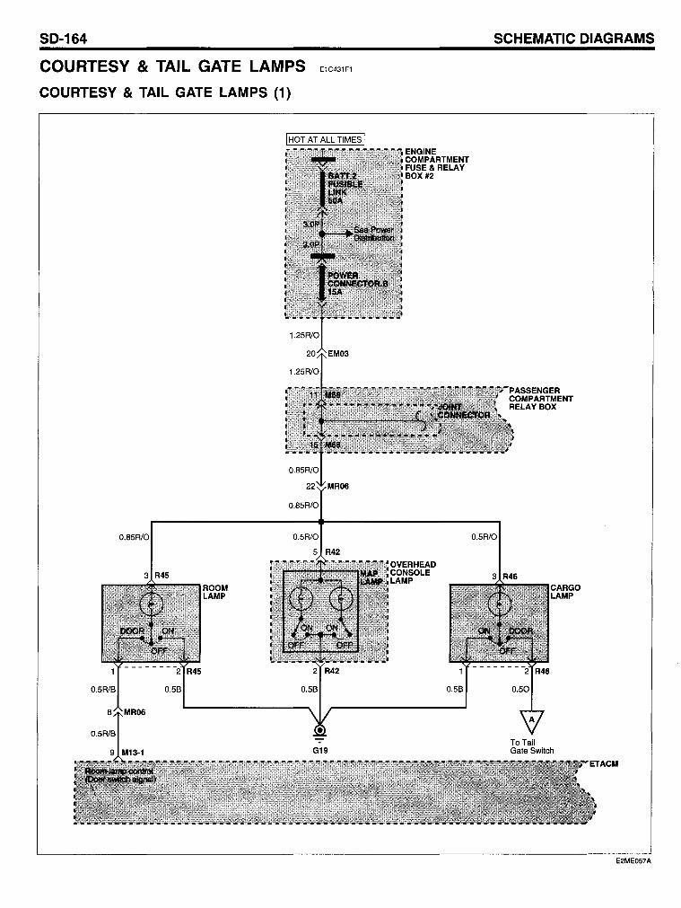
SO-164
COURTESY & TAIL GATE LAMPS
COURTESY & TAIL GATE LAMPS (1)
E1C431Fl
0.5R1B 0.5B
0.5R1B
9 M13-1
ROOM LAMP
0.85R/O
0.5R10
5 R42
G19
SCHEMATIC OIAGRAMS
0.5R/O
PASSENGER COMPARTMENT RELAYBOX
3 R46
ToTaii Gate Switch
E2ME057A
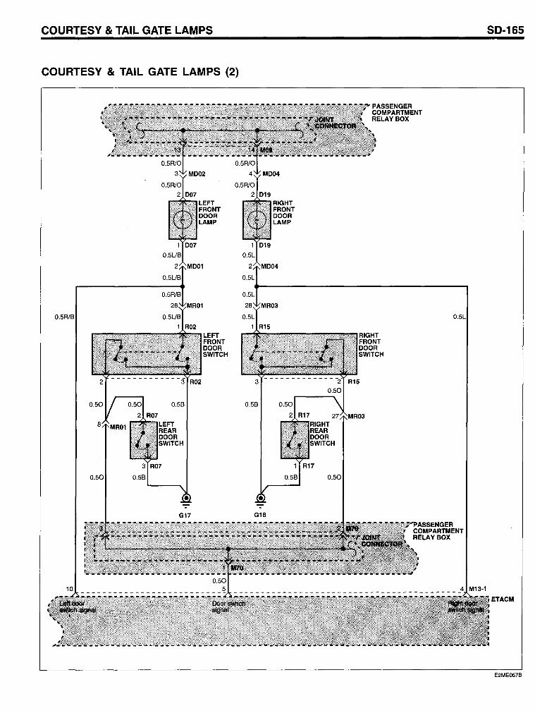
COURTESY & TAIL GATE LAMPS SO-165
COURTESY & TAIL GATE LAMPS (2)
ETACM
E2ME057B
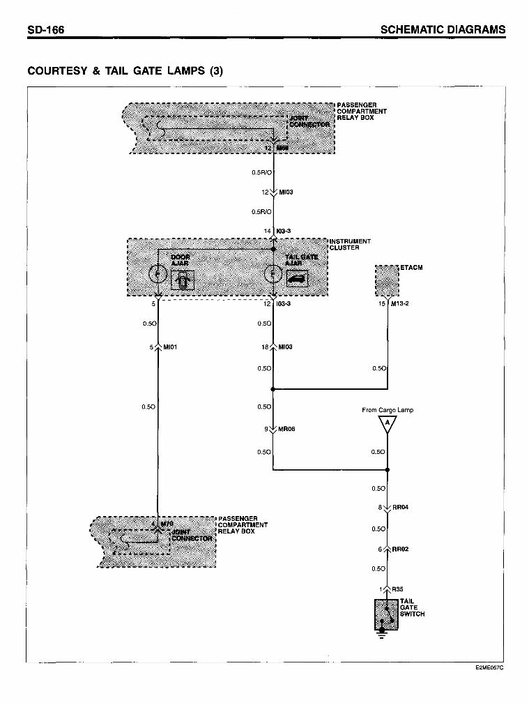
SO-166
COURTESY & TAIL GATE LAMPS (3)
0.50
0.50 0.50
9 MR06
SCHEMATIC OIAGRAMS
ETACM
0.50
From Cargo Lamp
A
0.50 0.50
PASSENGER COMPARTMENT RELAYBOX
0.50
8 RR04
1 R35
TAIL GATE SWITCH
E2ME057C
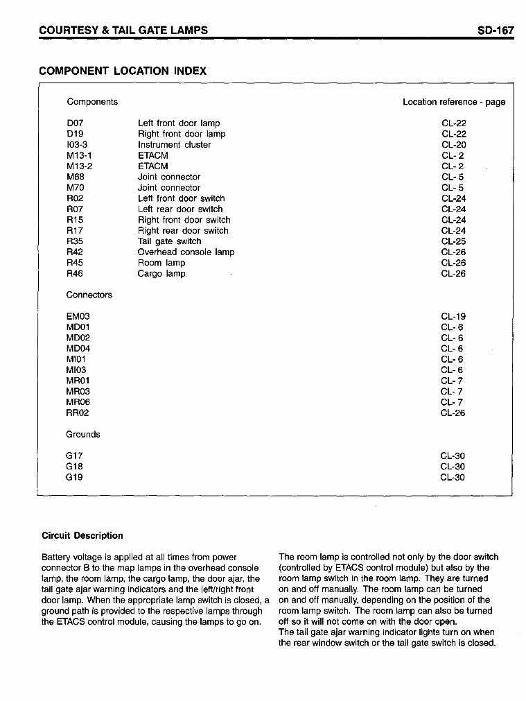
COURTE5Y & TAIL GATE LAMP5
COMPONENT LOCATION INDEX
Components
D07 D19 103-3 M13-1 M13-2 M68 M70 R02 R07 R15 R17 R35 R42 R45 R46
Connectors
EM03 MD01 MD02 MD04 MI01 MI03 MR01 MR03 MR06 RR02
Grounds
G17 G18 G19
Circuit Description
Left front door lamp Right front door lamp Instrument cluster ETACM ETACM Joint connector Joint connector Left front door switch Left rear door switch Right front door switch Right rear door switch Tail gate switch Overhead console lamp Room lamp Cargo lamp
Battery voltage is applied at all times from power connector B to the map lamps in the overhead console lamp, the room lamp, the cargo lamp, the door ajar, the tail gate ajar warning indicators and the left/right front door lamp. When the appropriate lamp switch is closed, a ground path is provided to the respective lamps through the ETACS control module, causing the lamps to go on.
50-167
Location reference - page
CL-22 CL-22 CL-20 CL- 2 CL- 2 CL- 5 CL- 5 CL-24 CL-24 CL-24 CL-24 CL-25 CL-26 CL-26 CL-26
CL-19 CL- 6 CL- 6 CL- 6 CL- 6 CL- 6 CL-7 CL-7 CL-7 CL-26
CL-30 CL-30 CL-30
The room lamp is controlled not only by the door switch (controlled by ETACS control module) but also by the room lamp switch in the room lamp. They are turned on and off manually. The room lamp can be turned on and off manually, depending on the position of the room lamp switch. The room lamp can also be turned off so it will not come on with the door open. The tail gate ajar warning indicator lights turn on when the rear window switch or the tail gate switch is closed.
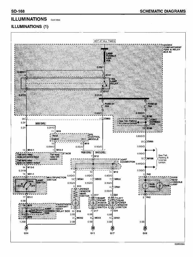
SO-168
ILLUMINATIONS
ILLUMINATIONS (1)
G14
E64F33BE
G11
SCHEMATIC OIAGRAMS
G17 G19
E2ME058A
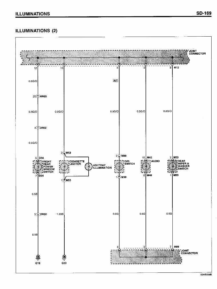
ILLUMINATIONS
ILLUMINATIONS (2)
0.5G/O
25 MR03
0.5G/O 0.5G/O
OR02
0.5G/O
5 034
0.59
1.259
• G18 G13
0.5G/O
ASHTRAY ILLUMINATION
0.5G
0.5G/O
15 M40
0.5G
0.5G/O
SO-169
JOINT CONNECTOR
2 M33 REAR WIPER& WASHER SWITCH
1 M33
0.5G
JOINT CONNECTOR
E2ME058B
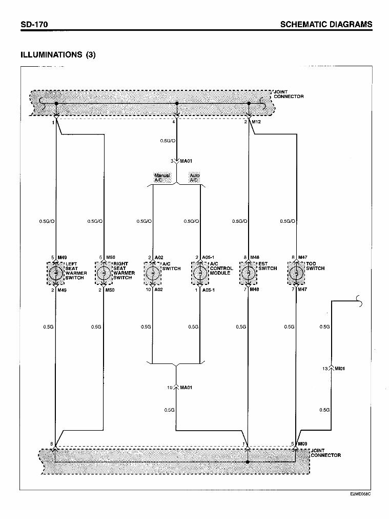
SO-170
ILLUMINATIONS (3)
0.5G/O
0.5G/O 0.5G/O 0.5G/O
5 M50 RIGHT SEAT WARMER SWITCH
2 M49 2 M50 10 A02
0.5G 0.5G 0.5G
0.5G
0.5G/O 0.5G/O
2 A05-1 8 M48 AlC CONTROL MODULE
1 A05-1
0.5G 0.5G
MA01
SCHEMATIC OIAGRAMS
0.5G/O
8 M47
0.5G O.5G
13 MI01
0.5G
JOINT CONNECTOR
E2ME058C
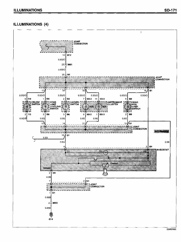
ILLUMINATIONS
ILLUMINATIONS (4)
o
G14
SO-171
JOINT CONNECTOR
0.59
RHEOSTAT
E2ME058D
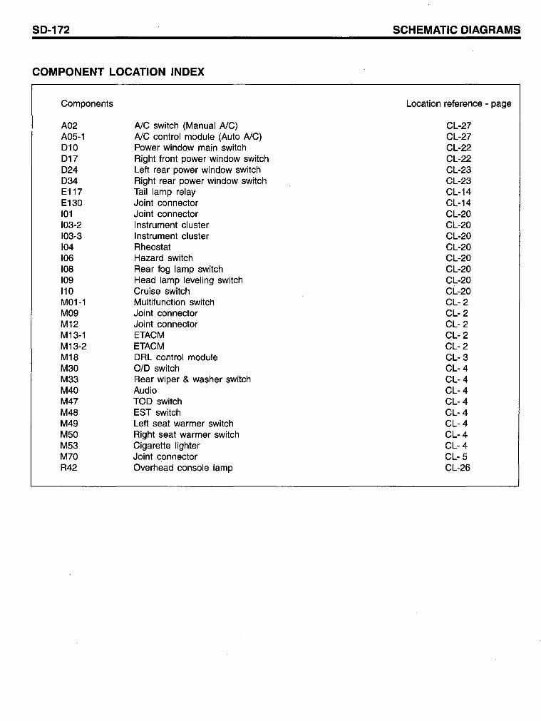
SD-172
COMPONENT LOCATION INDEX
Components
A02 A05-1 010 017 024 034 E117 E130 101 103-2 103-3 104 106 108 109 110 M01-1 M09 M12 M13-1 M13-2 M18 M30 M33 M40 M47 M48 M49 M50 M53 M70 R42
AlC switch (Manual AlC) AlC control module (Auto AlC) Power window main switch Right front power window switch Left rear power window switch Right rear power window switch Tail lamp relay Joint connector Joint connector Instrument cluster Instrument cluster Rheostat Hazard switch Rear fog lamp switch Head lamp leveling switch Cruise switch Multifunction switch Joint connector Joint connector ETACM ETACM ORL control module 0/0 switch Rear wiper & washer switch Audio TOO switch EST switch Left seat warmer switch Right seat warmer switch Cigarette lighter Joint connector Overhead console lamp
SCHEMATIC DIAGRAMS
Location reference - page
CL-27 CL-27 CL-22 CL-22 CL-23 CL-23 CL-14 CL-14 CL-20 CL-20 CL-20 CL-20 CL-20 CL-20 CL-20 CL-20 CL- 2 CL- 2 CL- 2 CL- 2 CL- 2 CL- 3 CL- 4 CL- 4 CL- 4 CL- 4 CL- 4 CL- 4 CL- 4 CL- 4 CL- 5 CL-26
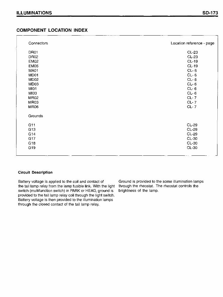
ILLUMINATIONS
COMPONENT LOCATION INDEX
Connectors
DR01 DR02 EM02 EM05 MA01 MD01 MD02 MD03 MI01 MI03 MR02 MR03 MR06
Grounds
G11 G13 G14 G1? G18 G19
Circuit Description
Battery voltage is applied to the coil and contact of the taillamp relay from the lamp fusible link. With the light switch (multifunction switch) in PARK or HEAD, ground is provided to the taillamp relay coil through the light switch. Battery voltage is then provided to the illumination lamps through the closed contact of the tail lamp relay.
50-173
Location reference - page
CL-23 CL-23 CL-19 CL-19 CL- 6 CL- 6 CL- 6 CL- 6 CL- 6 CL- 6 CL-? CL-? CL-?
CL-29 CL-29 CL-29 CL-30 CL-30 CL-30
Ground is provided to the some illumination lamps through the rheostat. rrhe rheostat controls the brightness of the lamp.
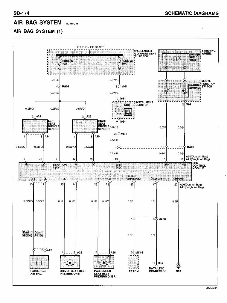
SO-174
AIR BAG SYSTEM
AIR BAG SYSTEM (1)
0.5R10
0.5R/0 0.5R/0
0.5Br/0
EC58DC3E
0.5Gr/0
------3 A25
0.5W/B
SCHEMATIC OIAGRAMS
0.5G
STEERING WHEEL
MULTI· FUNCTION SWITCH
A20(Dual Air Bag) A21 (Single Air Bag)
~~~~~~~~~~~~~~~~~~~~~~~~~~~~~~~~~~~~~~~~SRS CONTROL MODULE
0.5W/0 0.5G/B
PASSENGER AIR BAG
25 24
0.5L 0.50
DRIVER SEAT BELT PRETENSIONER
0.5B 0.5W
2 ___ 1 A26
PASSENGER SEAT BELT PRETENSIONER
0.5R
7
0.5R
3 M13·2
ETACM
0.5L
13 M14
DATA LINK CONNECTOR
0.5B
G23
E2ME059A
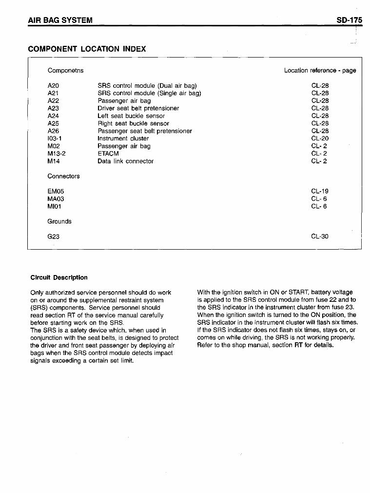
AIR BAG SYSTEM SO-175
COMPONENT LOCATION INDEX
Componetns Location reference - page
A20 A21 A22 A23 A24 A25 A26 103-1 M02 M13-2 M14
SRS contra I module (Dual air bag) SRS control module (Single air bag) Passenger air bag
CL-28 CL-28 CL-28 CL-28 CL-28 CL-28 CL-28 CL-20 CL- 2 CL- 2 CL- 2
Connectors
EM05 MA03 MI01
Graunds
G23
Circuit Description
Driver seat belt pretensioner Left seat buckle sensor Right seat buckle sensor Passenger seat belt pretensioner Instrument cluster Passenger air bag ETACM Data link connector
Only authorized service personnel should do work on or around the supplemental restraint system (SRS) components. Service personnel should read section RT of the service manual carefully before starting work on the SRS. The SRS is a safety device which, when used in conjunction with the seat belts, is designed to protect the driver and front seat passenger by deploying air bags when the SRS control module detects impact signals exceeding a certain set limit.
CL-19 CL- 6 CL- 6
CL-30
With the ignition switch in ON or START, batlery voltage is applied to the SRS control module fram fuse 22 and to the SRS indicator in the instrument cluster from fuse 23. When the ignition switch is turned to the ON position, the SRS indicator in the instrument cluster will flash six times. If the SRS indicator does not flash six times, stays on, or comes on while driving, the SRS is not working properly. Refer to the shop manual, section RT for details.
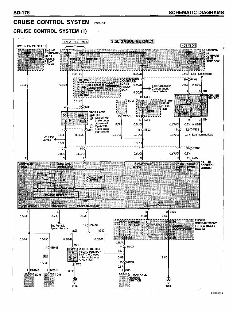
SO-176
CRUISE CONTROL SYSTEM EC2BB593
~
CRUISE CONTROL SYSTEM (1)
0.85R
0.5P/O
0.5P/O
ENGINE COMPARTMENT FUSE& RELAY BOX #2
See Stop Lamps +-.....
0.5P/O
See Vehicle Speed Sensor
G14
STOP LAMP SWITCH (@ : Closed with
brake pedal depressed
@:Openwith M11 brake pedal
depressed)
SCHEMATIC OIAGRAMS
See Passenger Compartment Fuse Details
2.0B
G01
E2ME065A
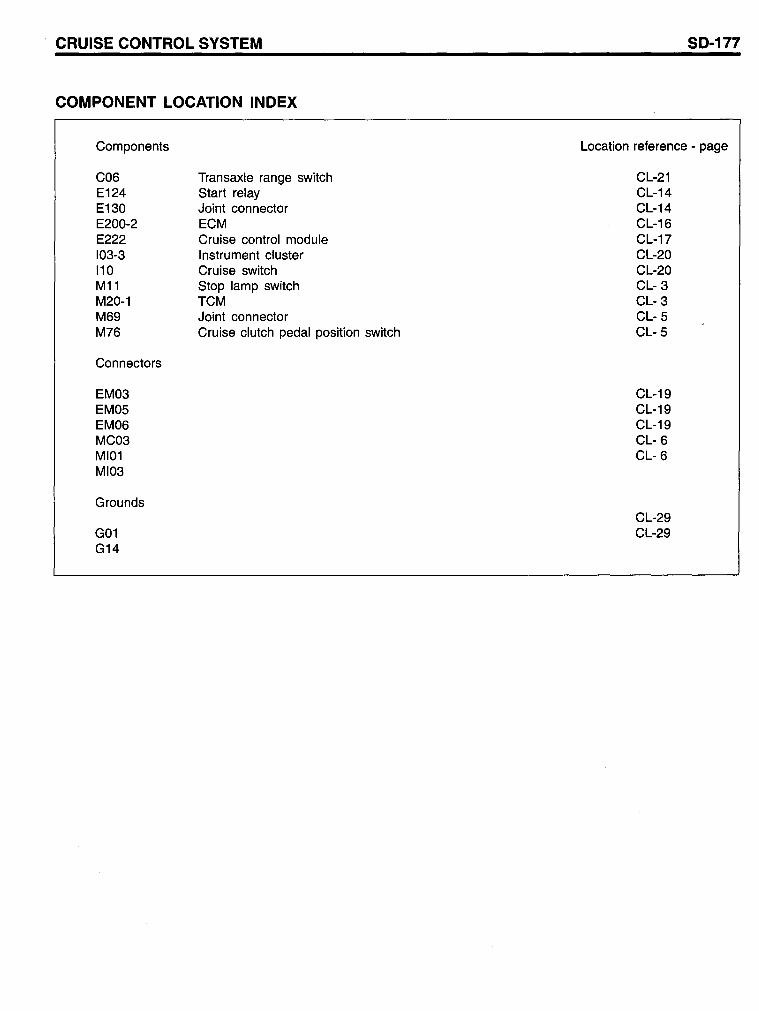
CRUISE CONTROL SYSTEM
COMPONENT LOCATION INDEX
Components
C06 E124 E130 E200-2 E222 103-3 110 M11 M20-1 M69 M76
Connectors
EM03 EM05 EM06 MC03 MI01 MI03
Grounds
G01 G14
Transaxle range switch Start relay Joint connector ECM Cruise control module Instrument cluster Cruise switch Stop lamp switch TCM Joint connector Cruise clutch pedal position switch
SD-177
Location reference - page
CL-21 CL-14 CL-14 CL-16 CL-17 CL-20 CL-20 CL- 3 CL- 3 CL- 5 CL- 5
CL-19 CL-19 CL-19 CL- 6 CL- 6
CL-29 CL-29
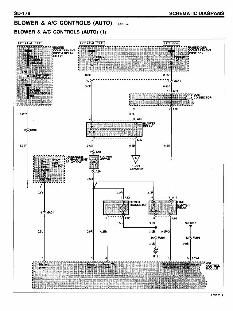
SO-178 SCHEMATIC OIAGRAMS
BLOWER & AlC CONTROLS (AUTO) ED90DCA6
BLOWER & AlC CONTROLS (AUTO) (1)
I HOT AT ALL TIME I
1.25Y
0.5Y
ENGINE COMPARTMENT FUSE& RELAY BOX #2
I HOT AT ALL TIME I
3.0P
PASSENGER COMPARTMENT RELAYBOX
9 MA01
0.5L 0.3Br
2.0R
1 A12
3.0B
POWER TRANSISTOR
0.5G
HIGH BLOWER RELAY
JOINT CONNECTOR
Not used
E2ME061A
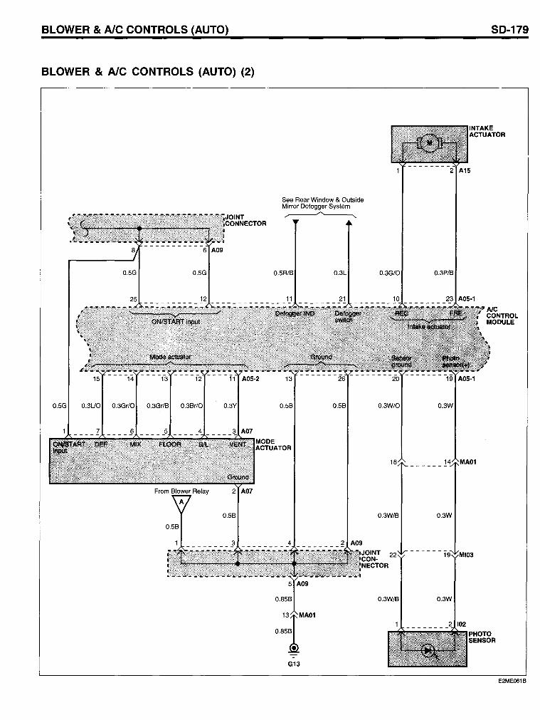
BLOWER & AlC CONTROLS (AUTO)
BLOWER & AlC CONTROLS (AUTO) (2)
0.5G
0.5B
See Rear Window & Outside Mirror Defogger System
0.5R/B 0.3L
0.5B
G13
SO-179
2 AlS
0.3G/O 0.3P/B
0.3W/O 0.3W
18
0.3W/B 0.3W
-------1
0.3W/B 0.3W
PHOTO SENSOR
E2ME061B
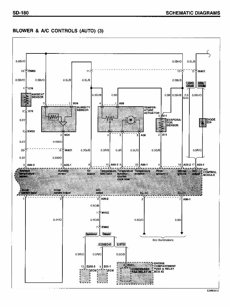
SO-180 SCHEMATIC OIAGRAMS
BLOWER & AlC CONTROLS (AUTO) (3)
0.5Br/O 0.5Br/O 0.5UB
11 -----------------------------------1
0.3UB
0.3Gr/B 0.5B
_________ ! M04 4 1 Aoe
3 ---"2 ------6 Aoe 2 All
0.5Y
0.3Gr/B 0.3R/B 0.3R 0.3UO 0.3G/B 0.5R10
0.3Y/O 0.5G/O 0.5G
'~------~~~------~/
See Illuminations
0.5R/O 0.5R/O
13 E200-3 5 E01-l ECM
E2ME061C
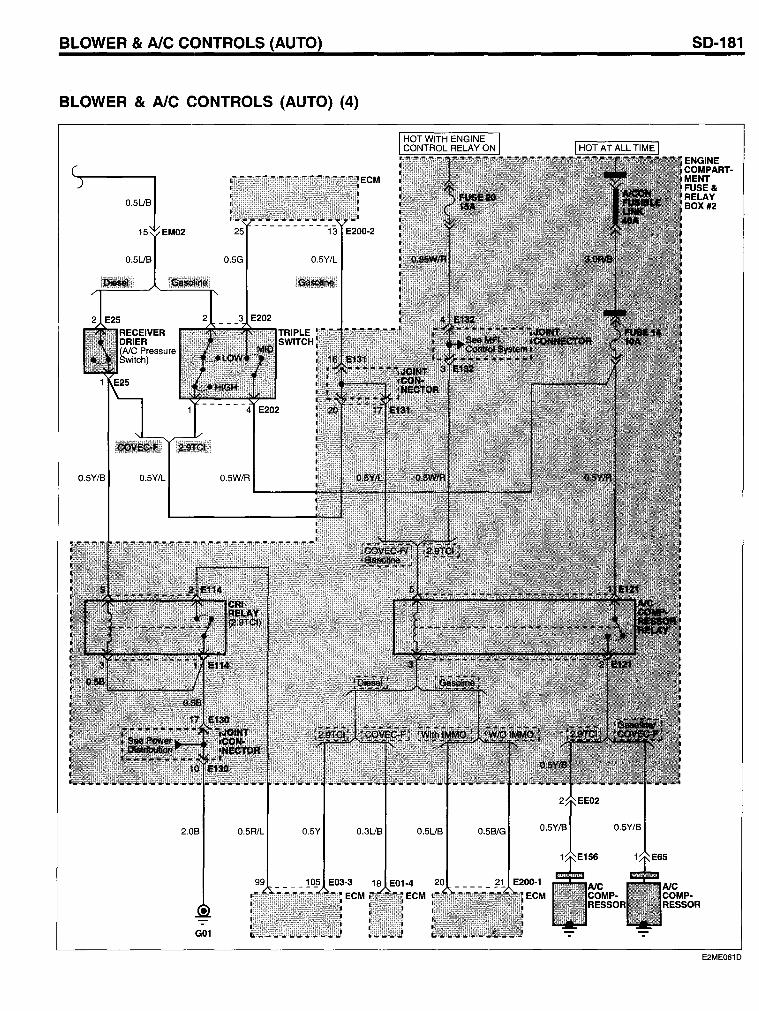
BLOWER & AlC CONTROLS (AUTO)
BLOWER & AlC CONTROLS (AUTO) (4)
0.5UB
15 EM02'
0.5UB
0.5Y/B 0.5Y/L
2.0B
G01
25
0.5G
0.5W/R
0.5R1L
13 E200·2
0.5Y/L
0.5Y 0.3UB 0.5UB
18 E01·4 ECM
0.5B/G
SO-181
ENGINE COMPART· MENT FUSE& RELAY BOX #2
E2ME061D
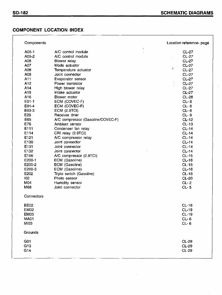
SD-182
COMPONENT LOCATION INDEX
Components
A05-1 A05-2 A06 A07 A08 A09 A11 A12 A14 A15 A16 E01-1 E01-4 E03-3 E25 E65 E76 E111 E114 E121 E130 E131 E132 E156 E200-1 E200-2 E200-3 E202 102 M04 M68
Connectors
EE02 EM02 EM03 MA01 MI03
Grounds
G01 G13 G14
AlC control module AlC control module Blower relay Mode actuator Temperature actuator Joint connector Evaporator sensor Power transistor High blower relay Intake actuator Blower motor ECM (COVEC-F) ECM (COVEC-F) ECM (2.9TCI) Receiver drier AlC compressor (Gasoline/COVEC-F) Ambient sensor Condenser fan relay CRI relay (2.9TCI) AlC compressor relay Joint connector Joint connector Joint connector AlC compressor (2.9TCI) ECM (Gasoline) ECM (Gasoline) ECM (Gasoline) Tripie switch (Gasoline) Photo sensor Humidity sensor Joint connector
SCHEMATIC DIAGRAMS
Location reference- page
CL-27 CL-27 CL-27 CL-27 CL-27 CL-27 CL-27 CL-27 CL-27 CL-27 CL-28 CL- 8 CL- 8 CL- 8 CL- 9 CL-12 CL-13 CL-14 CL-14 CL-14 CL-14 CL-14 CL-14 CL-15 CL-16 CL-16 CL-16 CL-16 CL-20 CL- 2 CL- 5
CL-18 CL-19 CL-19 CL- 6 CL- 6
CL-29 CL-29 CL-29
BLOWER & AlC CONTROLS (AUTO)
Circuit Description
The AlC control module receives input signals (for instance, photo sensor, evaporator sensor, water temperature sensor, ambient temperature sensor, etc) and controls the operation of air conditioning system. The AlC control module and various sensor signals provide accurate control of air mixture using mode actuator, temperature actuator and intake actuator under all operating conditions. The blower motor runs at the highest speed when the high blower relay coil is energized through AlC control module.
With the AlC switch in ON, the engine control module (ECM) will ground the coil of the AlC control relay after a short delay to adjust idle speed.
SO-183
The function of the power transistor is that of the blower resister in manual AlC. The power transistor is controlled by the input currents applied to the power transistor BASE terminal.
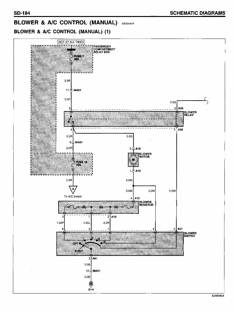
SO-184 SCHEMATIC OIAGRAMS
BLOWER & AlC CONTROL (MANUAL) EEAD4ASF
BLOWER & AlC CONTROL (MANUAL) (1)
3.0W
G14
6
BLOWER MOTOR
BLOWER RELAY
E2ME062A
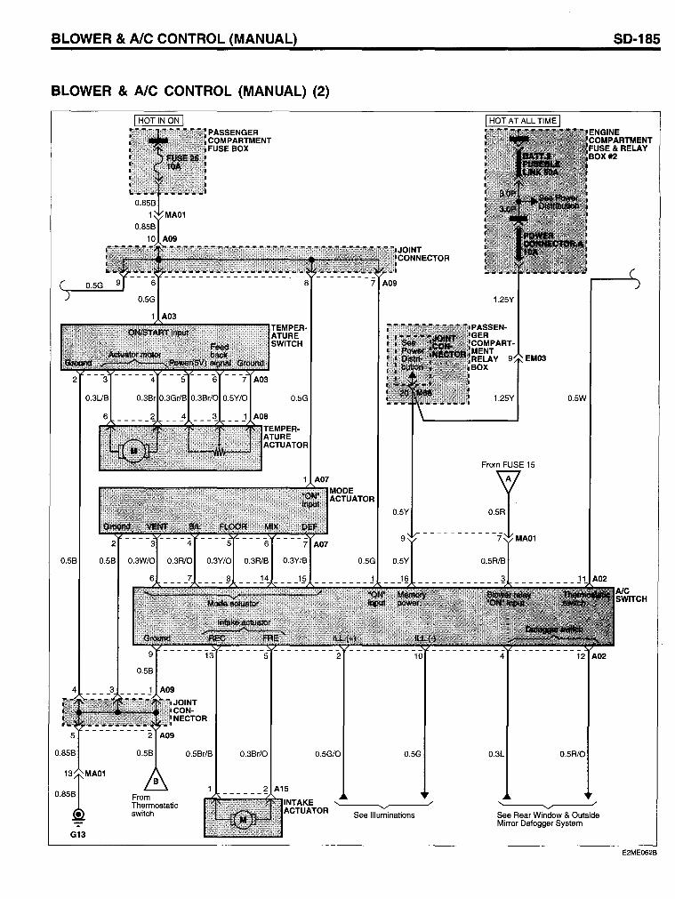
BLOWER & AlC CONTROL (MANUAL)
BLOWER & AlC CONTROL (MANUAL) (2)
0.5B
0.5Br/B 0.3Br/O 0.5G/O 0.5G
G13
A15
INTAKE ACTUATOR
~-~'-'~--~/
See Illuminations
1.25Y
PASSENGER COMPARTMENT RELAY EM03 BOX
1.25Y 0.5W
From FUSE 15
0.3L 0.5R10
,~--~ ........ ~----,/
See Rear Window & Outside Mirror Defogger System
50-185
E2ME062B
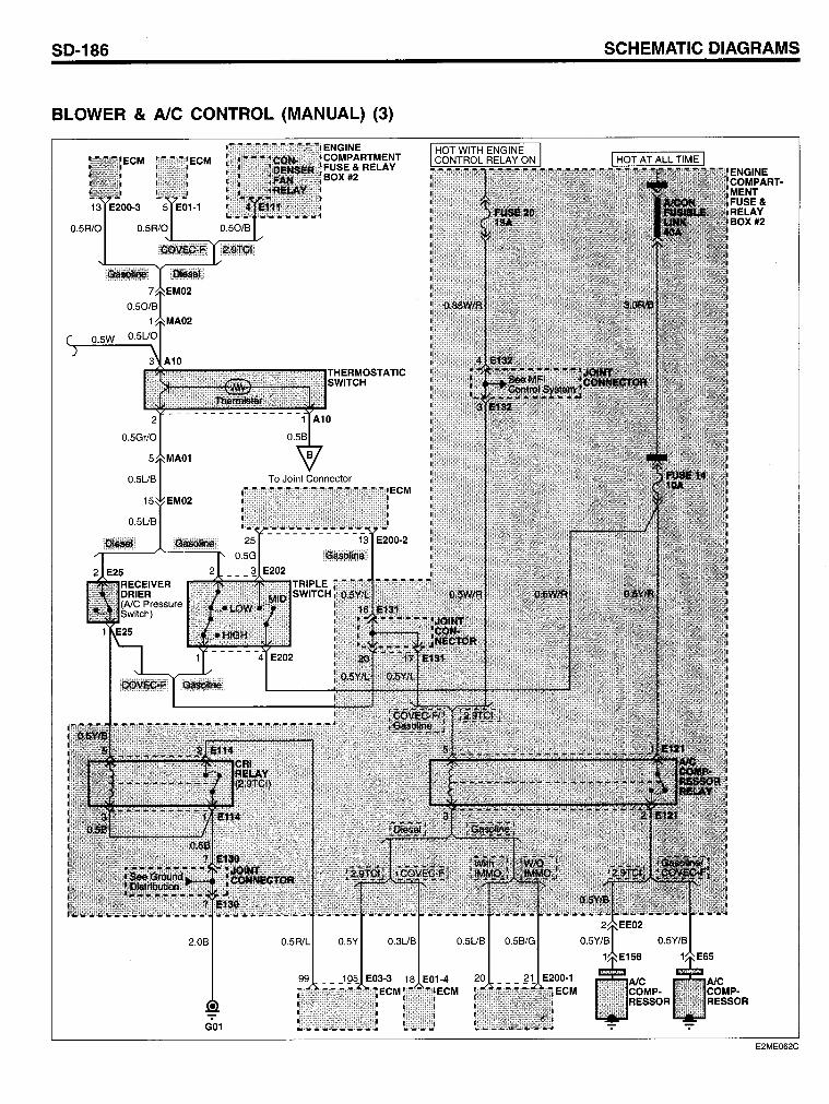
SO-186 SCHEMATIC OIAGRAMS
BLOWER & AlC CONTROL (MANUAL) (3)
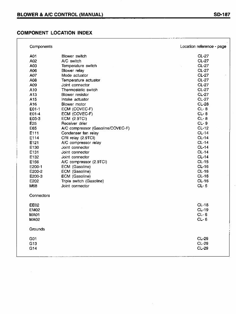
BLOWER & AlC CONTROL (MANUAL)
COMPONENT LOCATION INDEX
Components
A01 A02 A03 A06 A07 A08 A09 A10 A13 A15 A16 E01-1 E01-4 E03-3 E25 E65 E111 E114 E121 E130 E131 E132 E156 E200-1 E200-2 E200-3 E202 M68
Connectors
EE02 EM02 MA01 MA02
Grounds
G01 G13 G14
Blower switch AlC switch Temperature switch Blower relay Mode actuator Temperature actuator Joint connector Thermostatic switch Blower resistor Intake actuator Blower motor ECM (COVEC-F) ECM (COVEC-F) ECM (2.9TCI) Receiver drier AlC compressor (Gasoline/COVEC-F) Condenser fan relay CRI relay (2.9TCI) AlC compressor relay Joint connector Joint connector Joint connector AlC compressor (2.9TCI) ECM (Gasoline) ECM (Gasoline) ECM (Gasoline) Tripie switch (Gasoline) Joint connector
50-187
Location reference - page
CL-27 CL-27 CL-27 CL-27 CL-27 CL-27 CL-27 CL-27 CL-27 CL-27 CL-28 CL- 8 CL- 8 CL- 8 CL- 9 CL-12 CL-14 CL-14 CL-14 CL-14 CL-14 CL-14 CL-15 CL-16 CL-16 CL-16 CL-16 CL- 5
CL-18 CL-19 CL- 6 CL- 6
CL-29 CL-29 CL-29
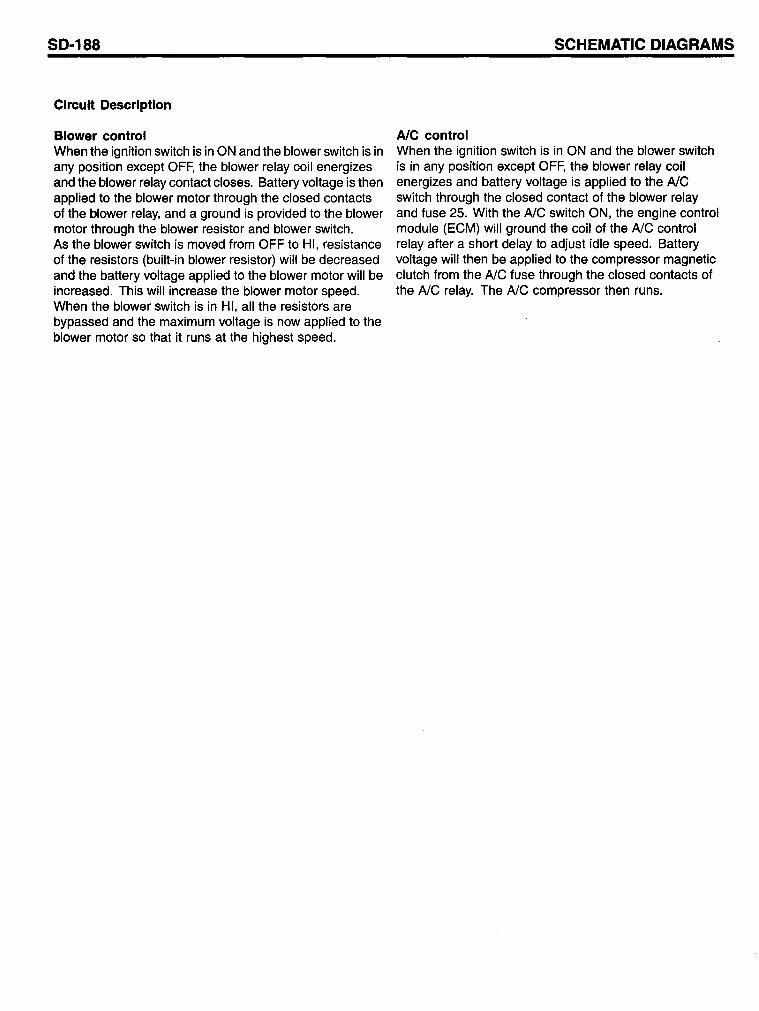
SO-188
Circuit Description
Blower control When the ignition switch is in ON and the blower switch is in any position except OFF, the blower relay coil energizes and the blower relay contact closes. Battery voltage is then applied to the blower motor through the closed contacts of the blower relay, and a ground is provided to the blower motor through the blower resistor and blower switch. As the blower switch is moved from OFF to HI, resistance of the resistors (built-in blower resistor) will be decreased and the battery voltage applied to the blower motor will be increased. This will increase the blower motor speed. When the blower switch is in HI, all the resistors are bypassed and the maximum voltage is now applied to the blower motor so that it runs at the highest speed.
SCHEMATIC OIAGRAMS
AlC control When the ignition switch is in ON and the blower switch is in any position except OFF, the blower relay coil energizes and battery voltage is applied to the AlC switch through the closed contact of the blower relay and fuse 25. With the AlC switch ON, the engine control module (ECM) will ground the coil of the AlC control relay after a short delay to adjust idle speed. Battery voltage will then be applied to the compressor magnetic clutch from the AlC fuse through the closed contacts of the AlC relay. The AlC compressor then runs.
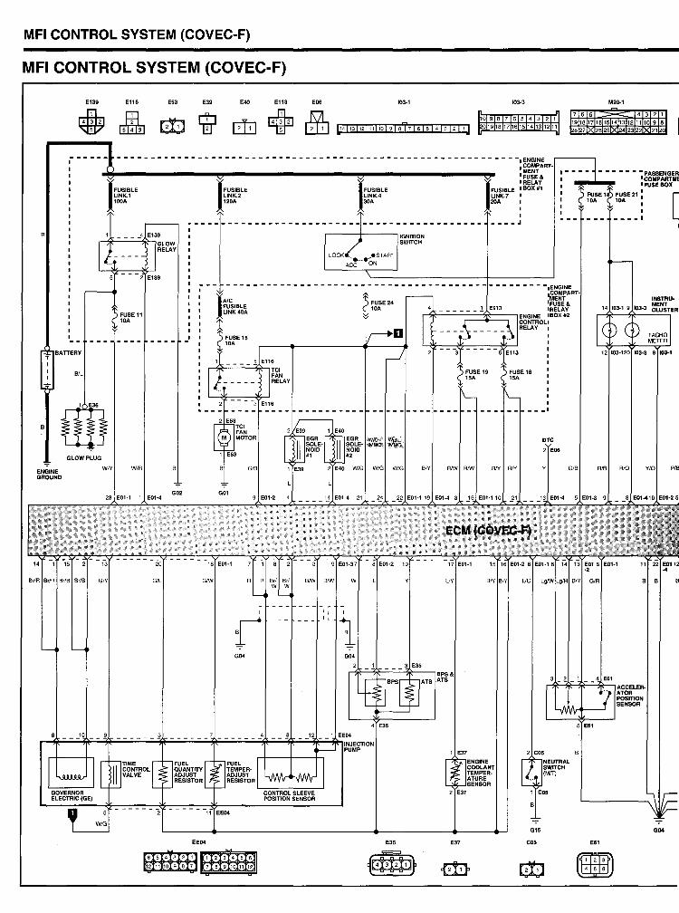
MFI CONTROL SYSTEM (COVEC-F)
MFICONTROLSYSTEM(COVEC-~
E139 EIl. E53 E39 E40 E113
~ ~ + E06 103-1 103-3
10 9 8 7 6 5 4 3 2 1 0191817161514131211
-----------------------------------------------------------~
R
BlL
FUSE 11 10A
G/L
GO< GO<
r~~-~~";""~-----~----~~--';;"'-~-~~;;';;~~~~INJECTION
EE04
654321123456
12 11 10 9 8 7 7 8 9 10 11 12
PUMP
wut! IMMO,
W/G
E35
BIV
L/Y
1 E37
E37
I
- - - _.I
- _.1
G15
C05
M20-1
7 6 5 4 3 2 1
918171615141312 11 10 9 8 8272625 42322212
E61
~ ~
I
_---I
GO<
[
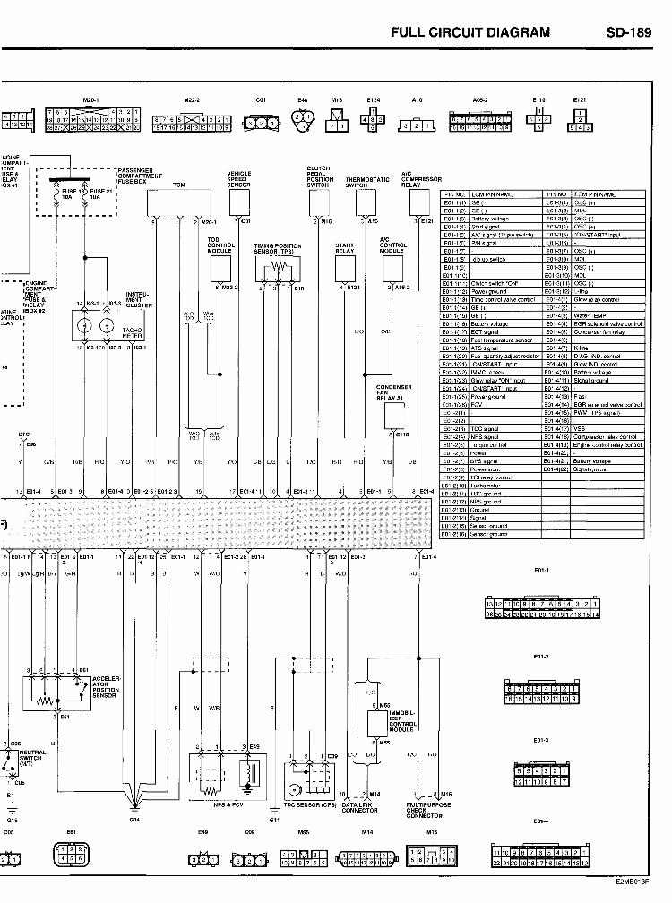
FULL CIRCUIT OIAGRAM 50-189
M20-1 M22-2 COl E48 M16 E124 Al0 A05-2 E11D E121
7 6 5 >< 4 3 2 1
~ &fu + 14m21 ~ 4 3 2 1 191817161514131211109 B 8 7 6 5 >< 4 3 2 1 ~ f312lTL
8 7 5 1 14131211
128 271X. 26 251X 24 23 221X 21 20 1817 1615141312 11 10 9 1161514131211109
:NGINE ~OMPART-
'ENT I - - - - i -------PASSENGER CLUTCH USE & I I COMPARTMENT VEHIClE PEDAL AlC IElAY
I IFUSE BOX SPEED POSITION THERMOSTATIC CQMPRE$SOR IQX#1 TCM SENSOR SWITCH SWITCH RELAY
I ~ FUSE '~ FUSE 21 :
I I I 10A 10A I PIN NO. ECM PIN NAME PINNQ. ECM PINNAME
I E01-1 1 GE + E01-J 1 ase + I I
EOl-12 GE - E01-J 2 MDL --- --- - - - - I 9 - - 1 2 M20-1 3 COl 2 M16 3 Al0 3 E121 E01-' 3 Batterv vallace EOl-33 OSC -
E01-14 Start si nal EOl-34 ase +
EOl-15 Ale si nal Tri le swilch EOl-35 'ON/Sr ART" inpl,ll TOD AlC
E01-16 P/N si nal EOl-36 CONTROL TIMING POSITION START CONTROL MODULE SENSOR (TPS) RELAY MODULE EOl-17 EOl-37 ase +
~
I rY'tt- I E01-18 Idle up switch E01-38 MOL
E01-19 E01-39 ose -- E01-1 10 E01-310 MOL • - - -.ENGINE
6 M22-2 - - 4 E124 2 A05-2 E01-1 11 Clutch switch "ON" E01-311 ose -
.COMPART- 2 3 1 E48 E01-' 12 Power around E01-312 L-tine MENT INSTRU-
'FUSE & 14 103-1 9 103-3
MENT E01-1 13 Time control valve control E01-41 G!ow relay control IRELAY CLUSTER E01-1 14 GE + E01-42
IGINE IBOXII2
Je W/O With
)NTROLI
D C ~ TO~.A..'.OO
E01-1 15 GE - E01-43 WaterTEMP.
:LAY E01-1 16 Batterv voltaae E01-44 EGR solenoid valve contral TACH~ I UO O/B E01-1 17 ECT slonal E01-45 Condenser fan relav METER
E01-1 18 Fuel temoerature sensor E01-46
12 103-120 103-3 8 103-1 E01-1 19 ATS sianal E01-47 K-line
E01-120 Fuel auanti ad·ust resistor E01-48 DIAG. fND. control
18 E01-121 'ON/START" inout EOl-49 Glow IND. control
~ ~ E01-122 IMMO. check E01-410 Batl~ry voltage
EOI-123 Glow relay 'ON" input E01-411 SjgDal ground CONDENSER E01-124 "ONJST ART" input E01-412 FAN
EOI-125 Power ground E01-413 Flash RELAY #1 ---' E01-126 FCV EQ1-414 EGR solenoid valve control
E01-21 EOI-415 PWM TPS si nal
E01-22 EOI-416
E01-23 TDC siana! E01-417 VSS DTC WIO Wlth 2 El10 EQ1-24 NPS sianal E01-418 Compressor relav control TOD TOD 2 E06 E01-25 Torque control E01-419 Enaine control relav control
E01-26 Power EOI-420
Y GIB RIB RIO YIO PIB PIO Y/B YIO UB UG L UO BIO RIO YIB UB E01-27 BPS sianal E01-421 Batlerv voltaoe
E01-28 Power inout E01-422 Si nal around
E01-29 TCI relav control
E01-210 Tachometer ___ '3 E01-4 5 EOl-3 9 - -8 E01-410 EOl-25 E01-23 __ 1~ ___ _ IZ EOI-411 JO - 4 E01-311 4 _.2 E01-1 5 - - 8 EOI-4 E01-211 TDC ground
.. EOl-2(12) NPS ground
EOl-2(13) Ground
:) EOl-2(14) Si nal
EOl-2(15) Sensor ground
EOl-2(16) Sensor ground
•
6 EOl-16 14 13 E01B E01-1 11 22 E0112 25 E01-1 12 4 EOI-226 E01-1 3 11 EOl 12 EOI-3 7 EOI-4 -2 -4 -2
JO LglW g1R BIY GIR B B B B W WIB Y R B WIB UO E01-l
113112 1110 9 8 7 6 5 4 31211 1
262524232221201911817161151,41
- - - - r--- - - - I EOI-2
I I I I 3 _;S_ 1 - - 4 E61 ---+ - - I - - - -
I~CCELER- ~ ~ .. ATOR POSITION UO
8 7 6 5 413 2 1
_A, SENSOR ~6 15 141312 11109
B W WIB B 9 M55
S E61 IMMOBIL-IZER CONTROL MODULE
2 cos B 8 M55 E01-3
~ 2 - .! __ 3 E49
NEUTRAL UO UO UO UO SWITCH
[j 3 - 2 _l C09
(MfT) ~
-- I - - I 4 - -- 6 5 4 3 2 1 ---;
I I I 1 C05
~ fC= - - - - ~2 1110 9 8 7
YNv- o [t::I:D B 10 _.1 M14 1 V- _ 8 M15
NPS & FCV TDC SENSOR (CPS) DATA LINK MUL TIPUAPOSE "7 "7 "7 CONNECTOR CHECK
CONNECTOA G15 G04 G11 E01-4
C05 E61 E49 C09 M55 M14 M15
n n
~ • ~ I4'T3llVll'2T1l IfiT2l" 3T4I1 111110 9 8 7 6 5 4 3 2 11 ~
8 7 6 5 4 3 2 1 4 5 6
10 9 8 7 6 5 ~6151413121110.9f 115 6 7 8 9 1011 1221212019181716 151413121
E2ME013F
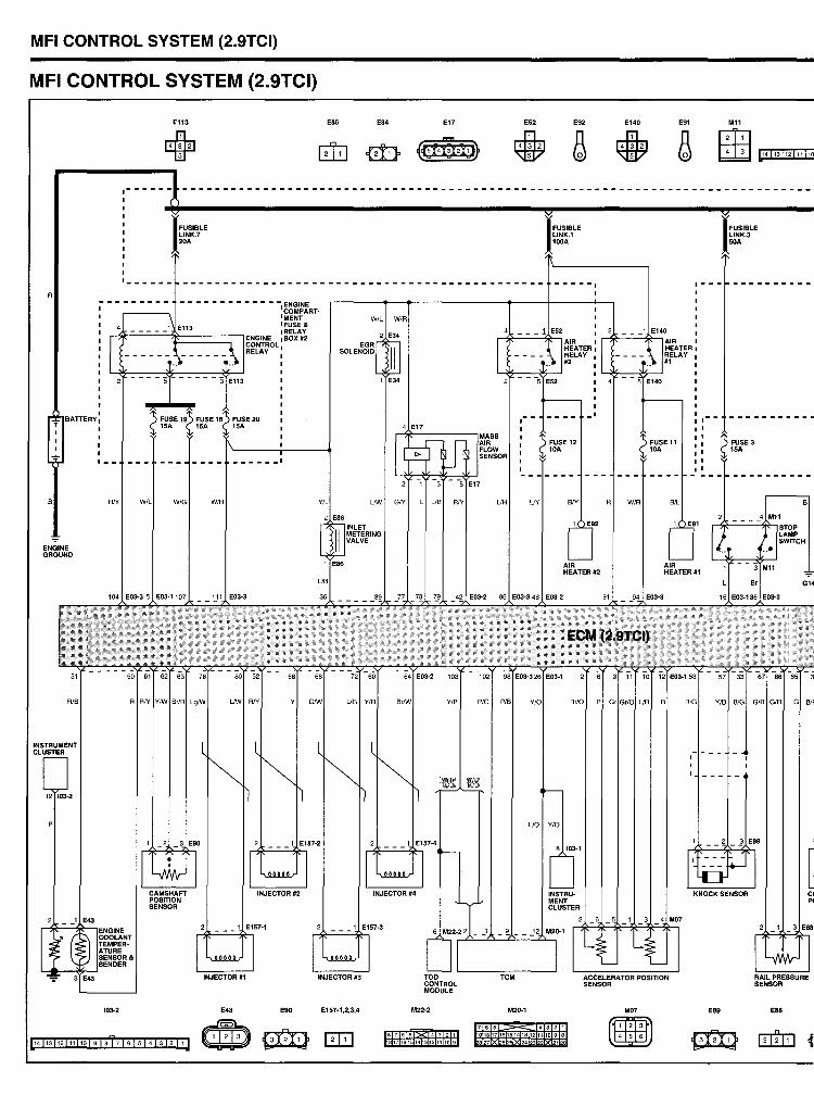
MFI CONTROL SYSTEM (2.9TCI)
MFI CONTROL SYSTEM (2.9TCI)
R
T BATTERY.
E113
+ .------
1 _____ -
IFUS,BLE LINK.7 20A
.................................... -ENGINE 'COMPART. IMENT IFUSE &
11:-=-.=....:=--=-=-~====::;-l IRELAY ENGINE I BOX #2 CONTROL RELAY
~ FUSE 191) FUSE 181) FUSE 20
E86 E34
W/L WIR
EGR SOLENOID
2 E34
E17 E52 E92 E140 E91 M11
~ ~ ß ffiB
IFUSIBLE LlNK.1 100A
1 E140
IFUS,BLE LINK.3 50A
I"'''' ...
ri~c.:::...=...::~-, AIR ,rlK--~~-'AIR , HEATER I HEATER I RELAY RELAV #2 #1
E52 5 E140
,- - -' ~ 1SA ~ 15A ~ 1SA
~~------'MASS 1) FUSE 12 ~ 10A
1) FUSE 11 ~ 10A
'1) FUSE3 ~ 15A
S
ENGINE GROUND
AlB
INSTRUMENT CLUSTER
12 103-2
,- -
RIY WIL WIG
RRIY Y/W Br/R
103-2
______ 1
WIR YIL LlW GlY L UB RIY
2 E86
Sr/W Yla
With TOD
E43 E90 E157-1,2,3,4 M22·2
817161514131211109
AIR FLOW SENSOR
UR UY aN R WIR SIL
E91
AIR HEATEA #2
AIR HEATER #1
PIO PIS YIO
t'6~
ua Yla
B
TCM
M20-1
765 4321 918171615141312111098 827 262 242322 212
Br/O P Gr Gr/O UB S
103-1
ACCELERATOR POSITION SENSOR
M07
~ ~
AlG YIB BlG GIS
_ 1 E89
E89
S
G14
GIR G BlF
E88
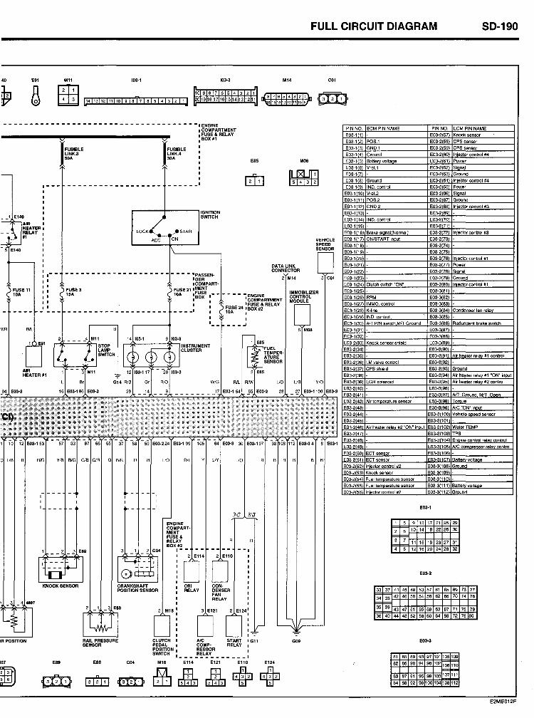
40 E91 M11 103·1 103-3 M14
~ ß ffiE 10 9 8 7 6 5 4 3 2 1 4 3 L14113 j 12111110 I 9 la 17 I 6 I 5 141 3 12 11 J 0191817161514131211
8 7 6 5 4 3 2 1
61514131211109
- - - - - - - - - - - - - - - - - - - - - - - - - - - - - - - - - - - - -. ENGINE
V1R
FUSE 11 10A
AIR HEATER .1
IR POSITION
107 E89
FUSIBLE LlNK.3 50A
HID 5 6 ~
E88 C04
ITI!E1 ~
FUSIBlE LINK.4 30A
I COMPARTMENT I FUSE & RELA Y .BOX#1
I
- - - - ·PASSENIGER ICOMPART·
FUSE 21 • MENT
E85
DATALINK CONNECTOR
10A :~~~E . __ ,
- - __ I
- - - - ENGINE • COMPARTMENT
FUSE 24 :~~~EJ RELAY 10A I ,
' .. ---~
UO AlL lJY UD
--:-
M08
AlC G09 COMP· ,
POSInON RESSOR I SWITCH 1 ____ R:L~Y _______ I
M16 E114 E121 E110 E124
~ rMfu rMfu + +
FULL CIRCUIT OIAGRAM 50-190
C01
~
VEHICLE SPEED SENSOR
PIN NO. ECM PIN NAME PIN NO. ECM PIN NAME
E03-1 1 E03-2 57 Knock sensor
E03-1 2 POS.1 E03-2 58 CPS sensor E03-13 GND.1 E03-2 59 CPS sensor E03-1 4 Ground E03-2 60 In'eeter control #4
E03-1 5 Batte volta e E03-2 61 Power
E03-1 6 Vref.1 E03-2 62 Si nal E03-17 E03-2 63 Ground
E03-1 8 Ground E03-2 64 In'eeter contral #4
E03-1 9 IND. contral E03-2 65 Power
E03-1 10 Vref.2 E03-2 66 Si nal
Eü3·1 11 POS.2 E03-2 67 Ground
E03-1 12 GND.2 E03-2 68 In'aeter contral #3
E03-' 13 E03-269
E03-1 14 IND. control E03-270
E03-1 15 E03·271
E03·1 16 Srake si nal Normal E03·2 2 In"ector contral #3
E03·1 17 ON/START in ut E03·273
E03·1 18 E03·274
E03·1 19 E03-275
E03·1 20 E03·2 76 In"ector control #1
E03·121 E03-2 77 Power
E03-1 22 E03·2 78 Si nal
E03·1 23 E03-279 Ground
E03·1 24 Clulch switch 'ON" E03-280 In"eclor conlrol #1
E03·1 25 E03-381
E03·126 RPM E03·382
E03·1 271MMO" control E03·383 E03·1 28 K-line E03-3 84 Condenser fan rela
E03·1 29 IND" control E03·385 E03·1 30 ArT:PIN sWItch Mrr Ground E03·3 86 Radundent brake switch
E03·131 E03-387
E03·1 32 E03·388
E03·2 33 Knack sensor shield E03-389
E03·234 E03·390
E03-235 E03·3 91 Air heater rela #1 control E03·236 I.M valve control E03·392
E03-2 37 CPS shield E03·3 93 Ground
E03·2(38) - E03'3(94) Air heater relay #1 "ON" input
E03-2(39) EGR solenoid E03·3(95) Air heater relay #2 control
E03·240) • E03·398) -
E03-241 E03-3 97 ArT: Ground MIT: 0 en
E03-2 42 Air tem erature sensor E03-398 To ue
E03·243 - E03-3 99 AlC "ON" in ut E03-2(44) • E03·3100 Vehicle speed sensor
E03·245 E03-3101
E03-246 Air heater rela #2 "ON" in ut E03-3102 WaterTEMP
E03·247 E03-3103 TPS
E03·248 E03-3104 En ine control rela contral
E03·249 E03·3105 AlC com ressor rela contral
E03-250 ECT sensor E03-3106
E03-251 ECT sensor E03·3107 Batte volta e
E03-252 In"ector contral #2 E03-3108 Ground
E03-253 Knack sensor E03·3109 E03-254 Fuel tem erature sensor E03-3110
E03-255 Fuel tem erature sensor E03·3111 Batte volta e
E03-256 In"ector contral #2 E03-3112 Ground
E03·1
1 5 9 13 17 21 25 29
2 6 10 14 18 22 26 30
3'=;" 11 15 19 23 27 31
4 8 12 16 20 24 28 32
E03--2
33 37 41 45 49 53 57 61 65 69 73 77
34 38 42 46 50 54 58 62 65 70 74 78
S5'3s 43 47 51 55 59 63 67 71 75 79
36 40 44 48 52 56 60 64 68 72 76 80
E03--3
81 85 89 93 97 101105 109
82 8690 94 98 102,06 110 = F=-
83 87 91 95 99 103 107 111
84 86 92 96 00 104108 12
E2ME012F
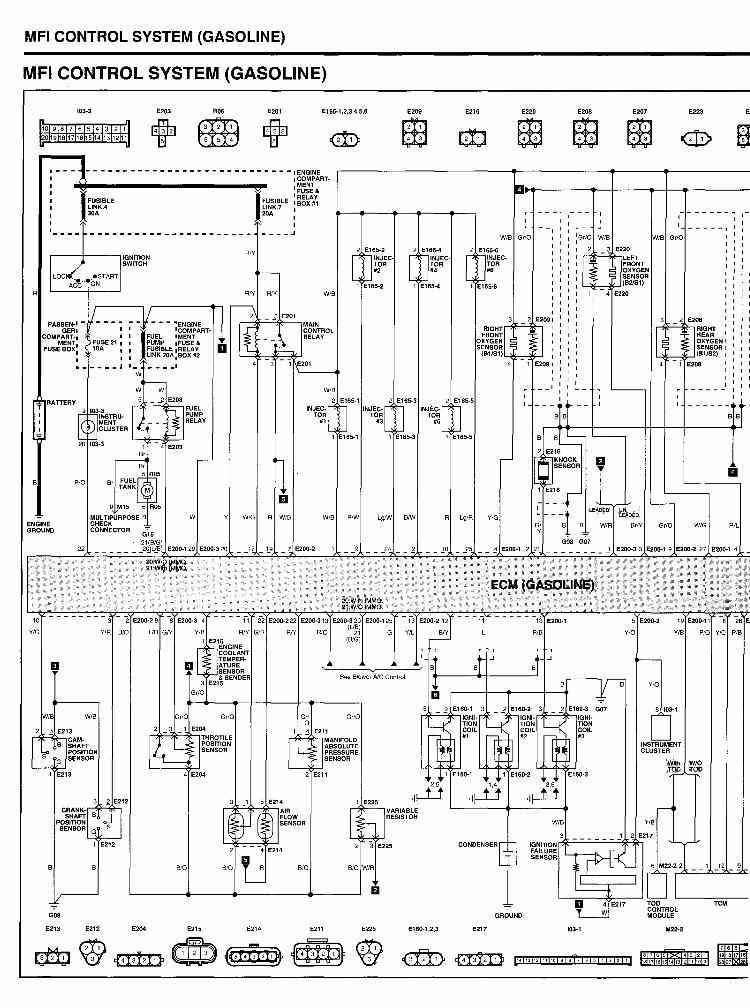
MFI CONTROL SYSTEM (GASOLINE)
MFI CONTROL SYSTEM (GASOLINE)
8
E203 R05 E201 E165-1,2,3,4,5,6
n n 10 9 8 7 6 5 4 3 2 1
120191817161514131211 M M
~ ~
...... - - .. - ............ - .. - .. - ................ - - I ENGINE I I I , , , , IFUSIBLE
LlNK.4 30A
.COMPART-
I~~~J&
I 'RELAY FUSIBLE I BOX #1
~~~K.7 :
I 1_ ...... ---------------------- ----~
PASSEN-I -1- ...... GER I I
MENT I FUSE 21 I COMPART-I ~ I
FUSE BOX. 10A I
I I ... ---_.1
RN
RIY RN WIB
l~ -.§ E201
~ -1- --~~~~"~ÄRT. I I :~~~';-ROL I FUEL IMENT RELAY
: ~~re:LE :~~IÄ: a --~ I LINK 20A.BOX #2 L-~f-::_~::-::~ I .. .. .... _I 4 3 - 1 E201
W L-____ + ~
W W WIB
[
2 nE1~~~EC. TOR #2
1 E165-2
E209
~ ~
2 E165-4
D'NJECTOR #.
1 E165-4
E216 E220
~ ~
"l'"-
E208 E207
~ ~ ~ ~
- - -, .- - -, , - -. I I ... - ~
wIe Gr/O
[
2 nE1f~~~c. TOR #6
1 E165-S
: : : :Gr/O W/S
, ' , : G2~nE2~~FT ::'1 FRONT
I I ~ OXYGEN I I 1 ? SENSOR : : r-=-:l (821S1)
, 3 2 E2091
F':lg~i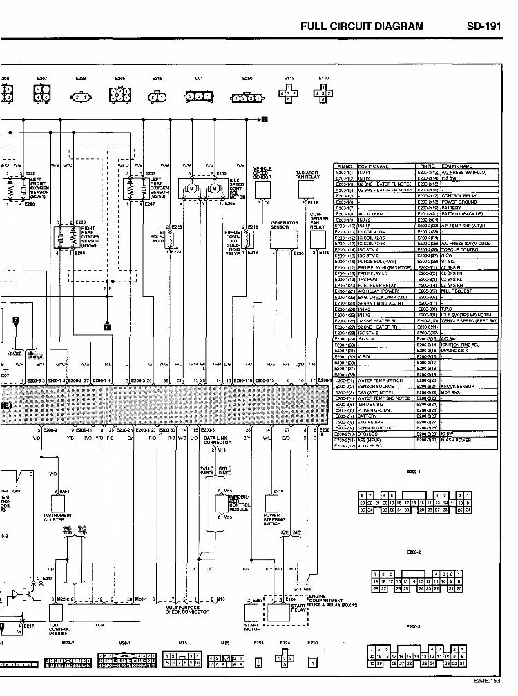
:208 E207
~ ~ ~ ~
;0-3 G07 IGNI· TION COIL 03
;0-3
·1
8765
E223
M22-2
817161514131211109
E205
[3"ttJ ~
E218 C01
G W/G AlL
TCM
M20·1
918171615141312111098 8 7 262 42322 212
MULTIPURPOSE CHECK CONNECTOR
M15
FULL CIRCUIT OIAGRAM 50-191
E250 E112 E110
Hm 21 l-m 21
E2OIJ.1
E2OIJ.2
E2CJO.3
M55 E253 E124 E210
+ E2ME015G
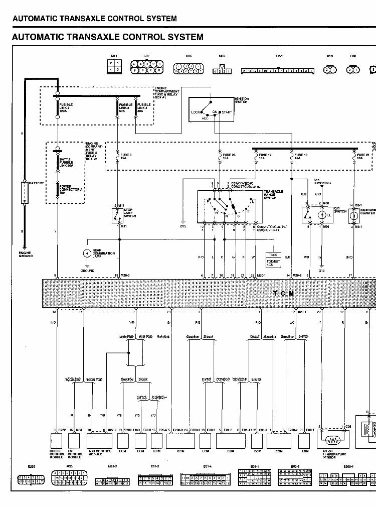
AUTOMATIC TRANSAXLE CONTROL SYSTEM
AUTOMATIC TRANSAXLE CONTROL SYSTEM
ENGINE GROUND
E222
6 5 4 3
1211 10 9
2 8
Ml1
lTI:2J ~
C02
- - - - - - - - - - - - - - - - - - - - - - - - -ENGINE 'COMPARTMENT I FUSE & RELA Y IBOX#1
FUSIBLE LlNK.2 120A
I. __ _
1
7
- - - - - - IENGINE 1- - -ICOMPART- I IMENT .FUSE & .RELAY BOX #2
, . ---
REAR COMBINATION LAMP
GROUND
uo
R
CRUI$E EST CONTROL CONTROL MODULE MODULE
M23 M22-2
8 7 • 5 4 3 2 1
1514131211109
FUSIBLE LINK.3 SOA
FUSE 3 ISA
YIB
2322 21 20 19 18 17 16 817161514131211109
- - _.1
Gr
E01-2
61514131211109
C06
015 10 5
PIB
E01-4
M30
FUSE 28 10A
1110 9 8 7 6 5 4 3 2 1
22 2120 1918 716 1514 1312
FUSE 19 10A
PIO
E03-1 159131721252&
101418222630
111519232731
48121620242832
103·1 Cl0 C03
---------------------I~
UO
FU$E 18 10A
E03·3 8185899397101'05
82869094961°,061
See Illuminations
G
,ce ,FU
FUSE21 I 10A
, - - __ I
14 103-1
Br/O
R Sr
E200-1
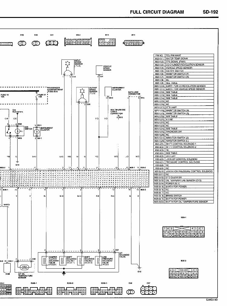
Cl0 C03 COI 103-3
10 9 8 7 6 5 4 3 2 1
0191817161514131211
INPUT
Ö SPEED SENSOR (PG-A)
M15
VEHICLE SPEED SENSOR
- -2 Cl0 3 C01
- - - - - - - - - - - - - - - - - - - - - 'PASSENGER
, FUSE 18 10A
GIB
See Illuminations
G/O
rlr-~--, O!D SWITCH
M30
PIB G
G14
.COMPARTMENT
~)( I FUSE BOX
FUSE 21 I 10A I
I
I ---_.
14 103-1
INSTRUMENT CLUSTER
2 103-'
Br/O Gr/O AlB
Ö OUTPUT SPEED SENSOR (PG-BI
- -2 C03
Y/O
W G Y/O
M2Q-2 __________ 1~ ___________ ~ _!..O __ 4 __ 11 ____ ~4
M20-1 20
Y Br Br/B BrlO RIB
2.9TCI
'0-2 26 E03-1 ~~-'--'-~lh
ECM
~03-3 E200-1 E200-2
INSTRUMENT CLUSTER
13 103-3
MULTIPURPOSE CHECK CONNECTOR
Y/O 6 M15
W/O
RIO
LlNE PRESSURE SOLANOIO VALVE (PCSV)
E200-3
FULL CIRCUIT OIAGRAM SO-192
M14
8 7 6 5 4 3 2 1
61514131211109
DATALINK CONNECTOR
- - - '6 M14
UO WIO
12 M20-2
M20-2
G13
COß
PINNO. M20-i(i) M20-1(2)
M20-1(3)
M20-'4 M20-' 5
M20-'6 M20-'7 M20-i(8) M20-1(9)
M20-' '0 M20-' 11
M20-' '2
M20-' '3 M20-' '4 M20-1('5
M20-1('6 M20-',7 M20-118
M20-' '9 M20-' 20
M20-12' M20-1(22
M20-1(23 M20-1 24
M20-1 25 M20-126 M20-1(271
M20-1(28 M20-:i(I)
M20-2(2)
M20-23 M20-24 M20-25
M20-2I6l M20-Wi M20-28
M20-29
M20-2('0) M20-2(11) M20-2(12)
M20-2(13) M20-2(14) M20-2(15)
M20-2(16)
M20-2('7) M20-2(18)
M20-2('9) M20-2(20)
C07
~ ~
TCU PIN NAME WATER TEMP SIGNAL
TPS SIGNAL IPWM) CO CYLINDER REVOLUTION SENSOR
VEHICLE SPEED SENSOR
OID OFF SWITCH INHIBITOR SWITCH P INHIBITOR SWITCH R NC SEE TABLE EARTH FOR CO REVOLUTION SENSOR
EARTH FOR VEHICLE SPEED SENSOR
SEE TABLE SEE TABLE
SEE TABLE NC
NC OTS LAMP INHIBITOR SWITCH N
INHIBITOR SWITCH D SEETABLE K-LlNE
NC
NC SEE TABLE DIAGNOSIS SW.
NC INHIBITOR SWITCHI2l INHIBITOR SWITCHfU
SHIFT CONTROL SOLENOID 1
SHIFT CONTROL SOLENOID 2 NC
SEETABLE BATIERY LOCK-UP CONTROL SOLENOID PRESSURE CONTROL SOLENOID
Ne NC
EARTH FOR PRESS URE CONTROL SOLENOID
NC DTC CLEAR SW OlL TEMPERATURE SENSOR (OTS) POWER (IG.l)
EARTH FOR POWER NC
NC BRAKE SWITCH
EARTH FOR POWER EARTH FOR OlL TEMPERATURE SENSOR
M20-1
M20-2
E2ME019D
CONNECTOR CONFIGURATIONS
AlC & AlBAG HARNESS ........................................................... CC-25
DOOR HARNESS ....................................................................... CC-20
FRONT HARNESS ...................................................................... CC-9
INSTRUMENT HARNESS ........................................................... CC-18
MAIN HARNESS ......................................................................... CC-2
REAR HARNESS ........................................................................ CC-22
TIM HARNESS ............................................................................ CC-19
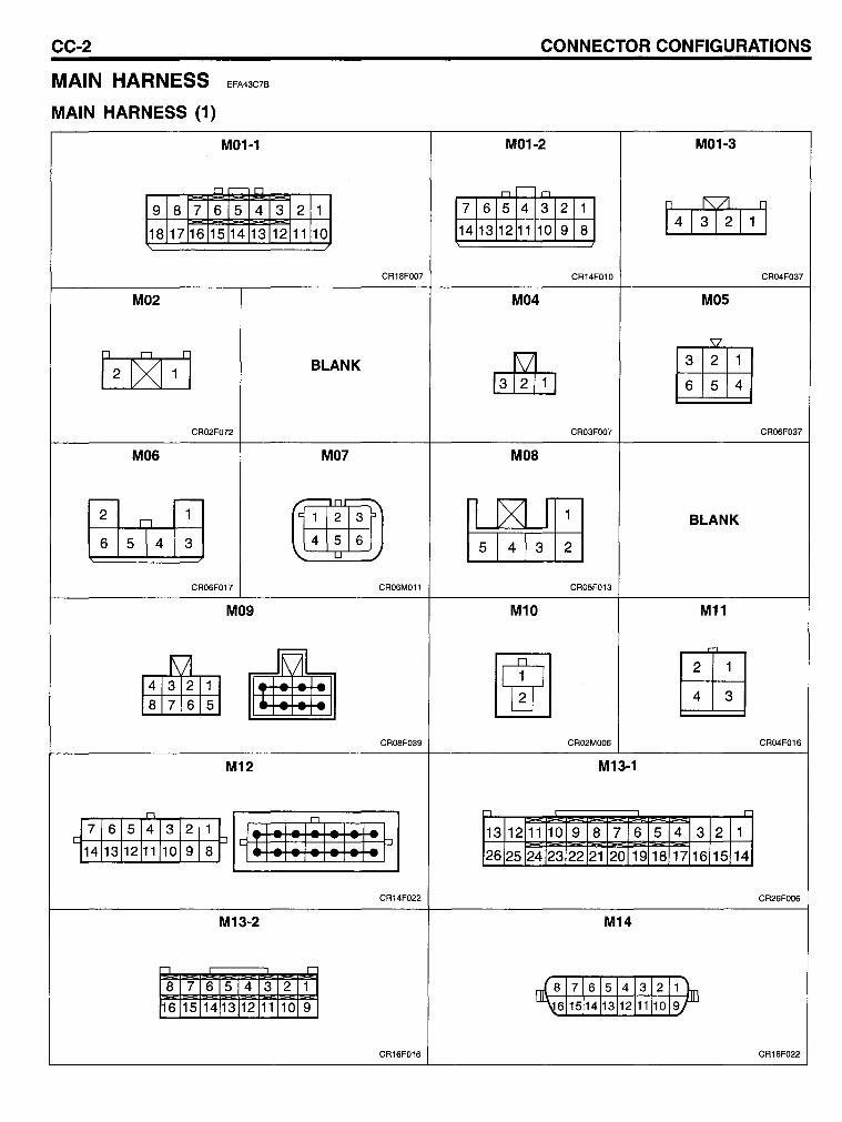
CC-2
MAIN HARNESS
MAIN HARNESS (1)
EFA43C7B
M01-1
or-o
9 8 7 6 5 4
18 17 16 15 14 13
M02
[2 c>(1 11
CR02F072
M06
~ 6 5 4 3
CR06F017
M09
3 2 1
12 11 10
CR1BFOO7
BLANK
M07
ß 456
CR06M011
• 876 5 ~ CROBF039
M12
n
: ~HII~I~I:I~I*H 7 6 5 4 3 2
14 13 12 11 10 9
CR14F022
M13-2
--, r
8 7 6 5 4 3 2 1 16 15 14 13 12 11 10 9
CR16F016
CONNECTOR CONFIGURATIONS
M01-2 M01-3
nr- n 7 6 5 4 3 2 1
[41ffl111 14 13 12 11 10 9 8
CR14F010 CR04F037
M04 M05
~ tmE 6 5 4
CR03FOO7 CR06F037
MOa
~ BLANK
CR05F013
M10 M11
~ tffiJ 4 3
CR02MOO6 CR04F016
M13-1
..., c
13 12 11 10 9 8 7 6 5 4 3 2 1
26 25 24 23 22 21 20 19 18 17 16 15 14
CR26FOO6
M14
~ 71615 41312 1 j6 15114113 12111110 9
CR16F022
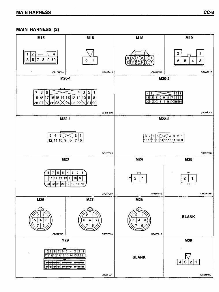
MAIN HARNESS CC-3
MAIN HARNESS (2)
M15 M16 M18 M19
~ I1l2ln[3l4 / ;---" ITh!ffi (6 5 4 J::S 2 (l 51617181910 6 5 4 3 (12 11 1019 8 7)
, CR10MOO3 CR02F011 CR12F012 CR06F017
M20-1 M20-2
r--l
7 6 5 ~ 4 3 2 1 4 3 ::::::::==-:::: 2 1
19 18 17 1611511413112 11 10 9 8 13 12 11110191817 6 5
28 27 C>< 26125[>( 24123 22 C>< 21 20 20 19 1XI181171161X 15 14
CR28FOO4 CR20F043
M22-1 M22-2
15 1 4 1 3 1.><.12 11 1 81 7 16 15 1;><]41312111
/1211111019181716/ 181171161151141311211111019 J
CR12FOO9 CR18FOO3
M23 M24 M25
r 8 71615 4131211~
{iliJ $ 115114113112111110191
,23 22121120 19118117116../
CR23FOO3 CR02F046 CR02F049
M26 M27 M28
~ .& ~
ml) m~ g) BLANK
543 543 ,( 5 4 3
7 6 ~ 7 6 'j , 7 6 ~ ~ ......:: "" .//
CR07F013 CR07F013 CR07F013
M29 M30
101918 716 5141312 11 201191181711615114113112111
BLANK ~ 11 : 1 : 1 : 1 : I:r:t: I:tt: 11
CR20F034 CR04F010
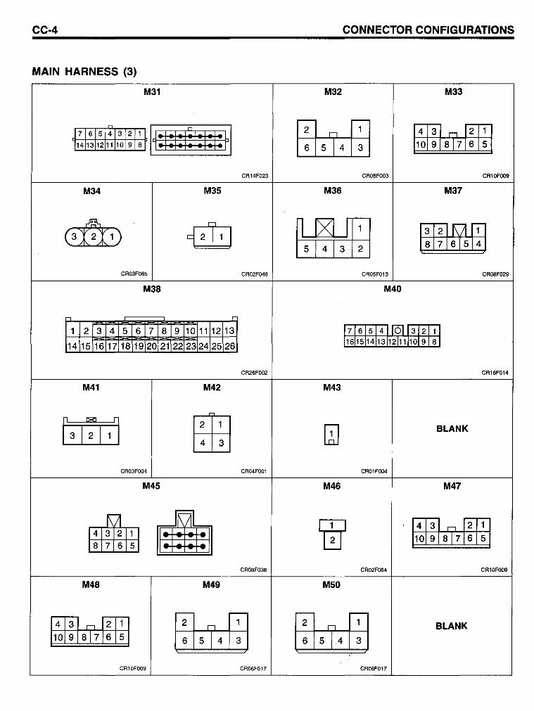
CC-4 CONNECTOR CONFIGURATIONS
MAIN HARNESS (3)
M31 M32 M33
M r-r:;-I, :I: I : I: I : I : I : F 1 ~ J71615431211 4 3 n 2
114[1311211 1019 18 6 5 4 3 10 9 817 6 5
CR14F023 CR06FOO3 CR10FOO9
M34 M35 M36 M37
~
(3r:I1) ~ ~ [illH't1ffi CR03F085 CR02F046 CR05F013 CR08F029
M38 M40
--, 1:
1 2 3 4 5 6 7 8 9 10 11 12 13 1716151411011312 1 14 15 16 17 18 19 20 21 22 23 24 25 26 116115114113112111/10/9 8
CR26FOO2 CR16F014
M41 M42 M43
0ill tffij QJ BLANK
4 3
CR03FOO4 CR04FOO1 CR01FOO4
M45 M46 M47
~ B -r- -1" 4 3 n 2 • 10 9 817 6 5
876 5
CR08F038 CR02F064 CR10FOO9
M48 M49 M50
r-r-4 3 n 2 1
~ ~ BLANK 10 9 817 6 5 6 5 4 3 6 5 4.3
CR10FOO9 CR06F017 CR06F017
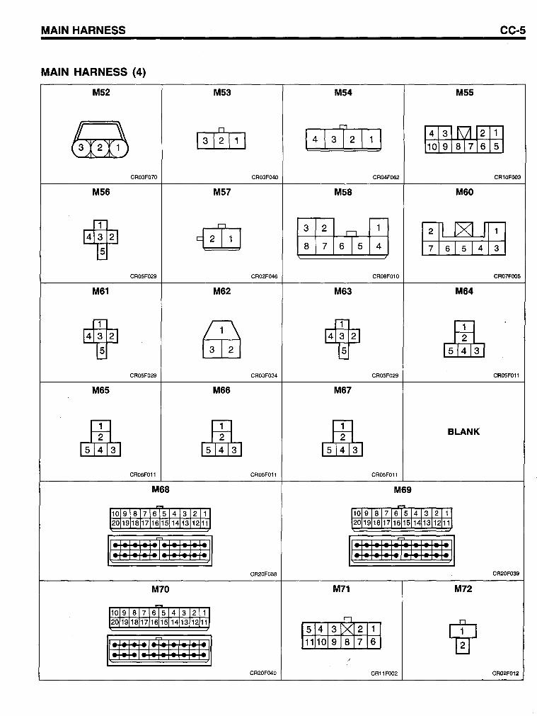
MAIN HARNESS CC-5
MAIN HARNESS (4)
M52 M53 M54 M55
~ 0
\4\31 2 \1) ~~fffi1 13 1 211 1 1öf 87ß5 CR03F070 CR03F040 CR04F062 CR10FOO3
M56 M57 M58 M60
14~2J ~ l:I~16T5rn m6~4m CR05F029 CR02F046 CR08F010 CR07FOO5
M61 M62 M63 M64
14~2J ~ 14W ,),H, CR05F029 CR03F034 CR05F029 CR05FOll
M65 M66 M67
1)ln, 1)1!113 ] ~ BLANK
CR05FOll CR05FOll CR05F011
M68 M69
- .... 11019181716 5141312111 11019 181716 5 14 13 12 111 12°119118117116151141131121111 12°11911811711615[14113[121111
1[:1: I: I: IU: I: I: I: l:ll 1[:1: I: I: I:r: I: I: I: I: JI CR20F038 CR20F039
M70 M71 M72
~
11019181716151413 12111 n 12°119118117116[15114/131121111
W Is1413JXl2J1 J
1[#1:1*1:1: 1:1: JI 1111101918171 6 1 ,
CR20F040 CR11 F002 CR02F012
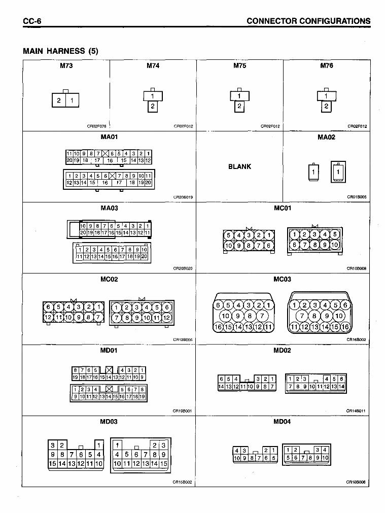
CC-6 CONNECTOR CONFIGURATIONS
MAIN HARNESS (5)
M73 M74 M75 M76
rn W W W CR02F076 CR02F012 CR02F012 CR02F012
MA01 MA02
BLANK
CR20B019 CR01BOO5
MA03 MC01
~
5 4 3 2 1 1 2 3 4 5
10 9 8 7 6 6 7 8 9 10 ....J L..
....J L-
CR20B020 CR10BOO8
MC02 MC03
"- i'J1
6 5 4 3 2 1 1 2 3 4 5 6
12 11 10 9 8 7 7 8 9 10 11 12 '-' '-'
L.J L.J
CR12B005 CR16BOO2
MD01 MD02
1 2 3 n 4 516 7 8 9 10111 12 13114
CR19B001 CR14BOll
MD03 MD04
r-- - r---
3 2 n 1 1 D 2 3
9 8 71615 4 4 51617 8 9 15 14 13112111 10 10 11112113 14 15
CR15B002 CR10BOO6
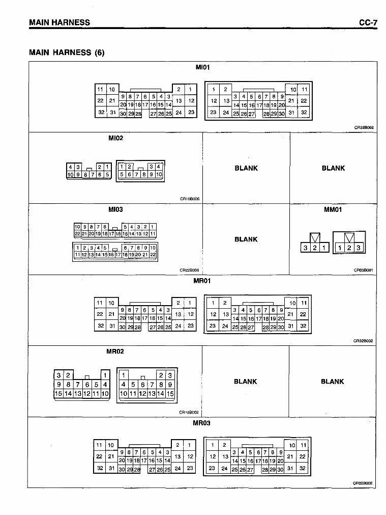
MAIN HARNESS CC-7
MAIN HARNESS (6)
MI01
11 10 2 1 1 2 10 11 9 8 7 6 5 4 3 3 4 5 6 7 8 9
22 21 13 12 12 13 21 22 20 19 18 17 16 15 14 14 15 16 1718 19 20
32 31 30 2~ 28 27 26 25 24 23 23 24 25 26 27 28 29 30 31 32
CR328002
MI02
r4l3l " f2TTl I IT12l " l3T4l BLANK BLANK 110 9 81716 151 5 6 7 8 9 101
CR10BOO6
MI03 MM01
101918 761-=1543 2 11 2212112019181171611514131211
BLANK ~~ Ir 1 12 13 4 51 Cl 16 7 8 9 1011 11111121131415116171181912021 2211
CR22BOO6 CR03BOOl
MR01
11 10 2 1 1 2 10 11 9 8 7 6 5 4 3 3 4 5 6 7 8 9
22 21 13 12 12 13 16 17
21 22 20 1918 17 16 15 14 1415 18 19 20
32 31 30 2~ 28 27 26 25 24 23 23 24 25 26 27 28 29 30 31 32
CR32BOO2
MR02
r-- r- -;--
3 2 D 1 1 n 2 3 9 8 7 615 4 4 516 7 8 9 BLANK BLANK
15 14 13 12111 10 10 1111213 14 15
CR15BOO2
MR03
11 10 2 1 1 2 10 11 9 8 7 6 5 4 3 3 4 5 6 7 8 9
22 21 13 12 12 13 21 22 20 19 18 17 16 15 14 14 15 16 1718 19 20
32 31 30 2~ 28 27 26 25 24 23 23 24 25 26 27 28 29 30 31 32
CR32BOO2
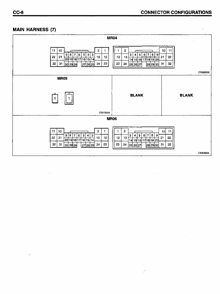
CC-8 CONNECTOR CONFIGURATIONS
MAIN HARNESS (7)
MR04
11 10 2 1 1 2 10 11 9 8 7 6 5 4 3 3 4 5 6 7 8 9
22 21 13 12 12 13 21 22 20 19 18 17 16 15 14 14 15 16 1/18 19 20
32 31 30 25 28 27 26 25 24 23 23 24 25 26 27 28 29 30 31 32
CR32BOO2
MR05
8 [!] BLANK BLANK
CR01BOO5
MR06
11 10 2 1 1 2 10 11 9 8 7 6 5 4 3 3 4 5 6 7 8 9
22 21 20
13 12 12 13 17
21 22 19 18 17 16 15 14 14 15 16 18 19 20
32 31 30 29 28 27 26 25 24 23 23 24 25 26 27 28 29 30 31 32
CR32BOO2
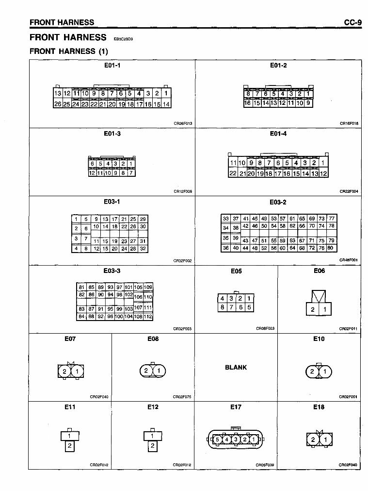
FRONT HARNESS
FRONT HARNESS
FRONT HARNESS (1)
EB3C23D3
E01-1
n
13 12 11 10 9 8 7 6 5 4 3
26 25 24 23 22 21 20 19 18 17 16
E01-3
6 5 4 3 2 1
12 11 10 9 8 7
E03-1
1 5 9 13 17 21 25 29
2 6 10 14 18 22 26 30
3 7 11 15 19 23 27 31 4 8 12 15 20 24 28 32
E03-3
81 85 89 93 97 101 105 109 82 86 90 94 98 102 106 110
83 87 91 95 99 103 107 111
84 88 92 96 00 104 108 112
2
15
E07 E08
r1
1
14
~ 0:D CR02F040
E11 E12
W W CR02F012
CC-9
E01-2
" .-8 7 6 5 4 3 2 1
16 15 14 13 12 11 10 9
CR26F013 CR16F016
E01-4
n r
11 10 9 8 7 6 5 4 3 2 1
22 21 20 19 18 17 16 15 14 13 12
CR12FOO6 CR22FOO4
E03-2
33 37 41 45 49 53 57 61 65 69 73 77
34 38 42 46 50 54 58 62 66 70 74 78
35 39 43 47 51 55 59 63 67 71 75 79 36 40 44 48 52 56 60 64 68 72 76 80
CR32FOO2 CR48FOO1
E05 E06
-8 7 6 5 &ib CR32FOO3 CR08FOO3 CR02F011
E10
BLANK ~ CR02F075 CR02FOO1
E17 E18
{~4a2!W ~ CR02F012 CR05F039 CR02F04O
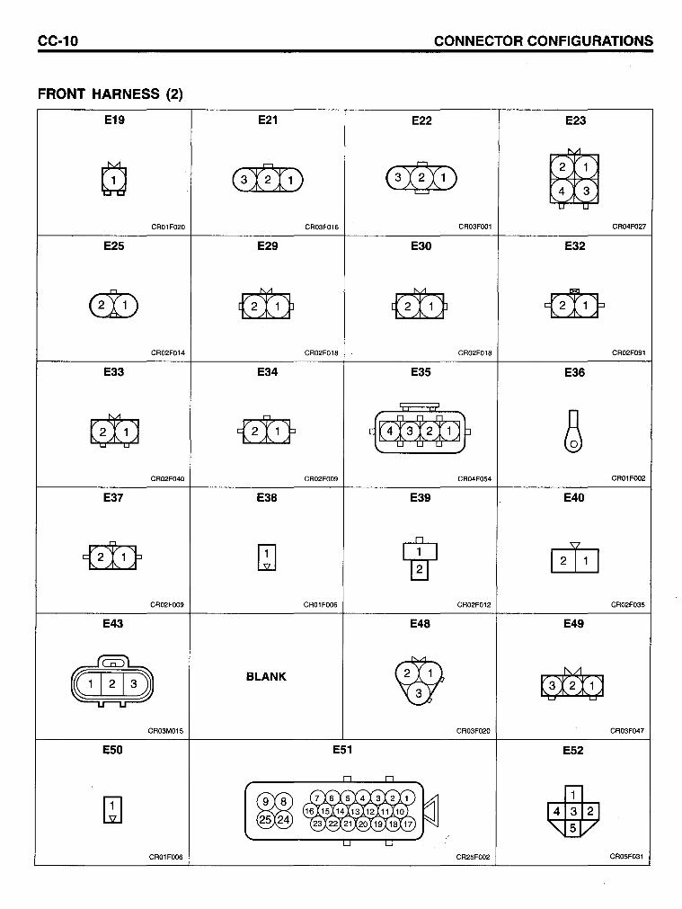
CC-10 CONNECTOR CONFIGURATIONS
FRONT HARNESS (2)
E19 E21 E22 E23
Q (3X2l1) (3:0:1) BE 4 3 CR01F020 CR03F016 CR03FOO1 CR04F027
E25 E29 E30 E32
@) ~ ~ {2!1}
CR02F014 CR02F018 CR02F018 CR02F091
E33 E34 E35 E36
~ {<!(r {1a~t1~ & CR02F040 CR02FOO9 CR04F054 CR01FOO2
E37 E38 E39 E40
{<!1} QJ 1Ir ~ CR02FOO9 CR01FOO6 CR02F012 CR02F035
E43 E48 E49
d~lb BLANK W ~ CR03M015 CR03F020 CR03F047
E50 E51 E52
n n
~~ ---y1)
• QJ ~ 7 6 5 41312 1
~ 25 24 16l!5l!4~3~21111101 ~21X20X19X18XH)
~~~~-
u U
CR01FOO6 CR25FOO2 CR05F031
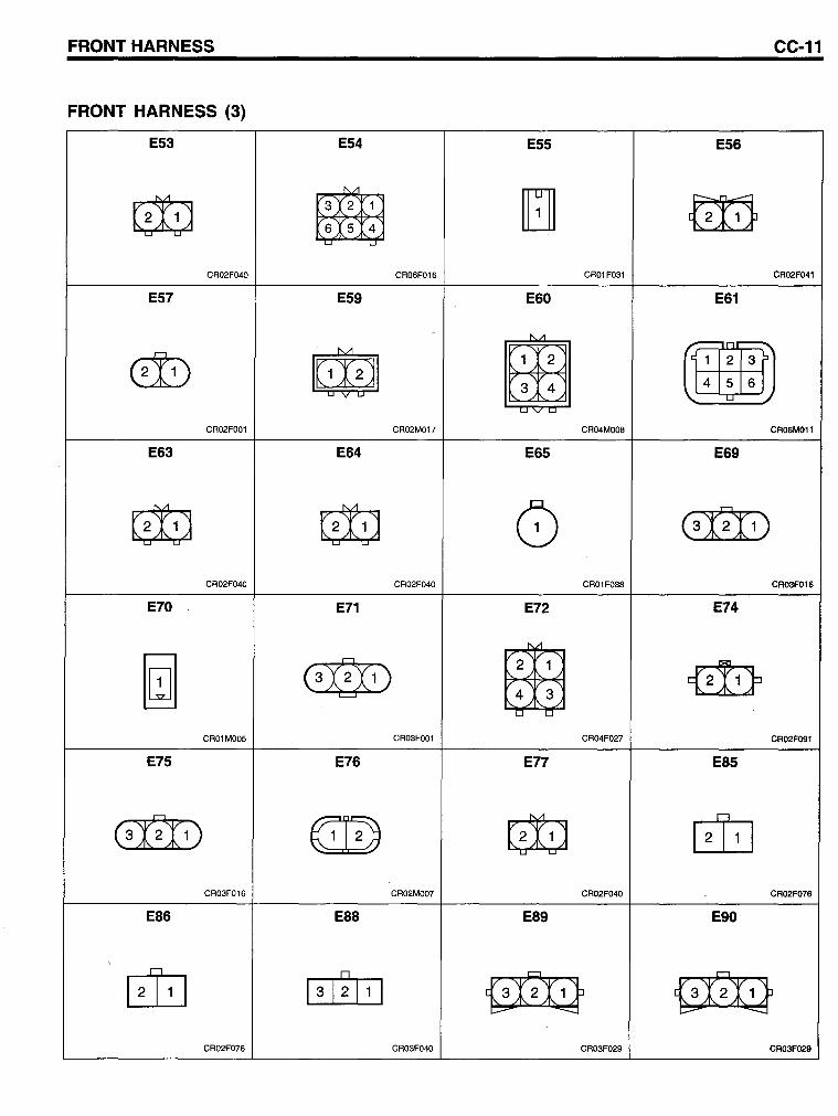
FRONT HARNESS CC-11
FRONT HARNESS (3)
E53 E54 E55 E56
G!iJ tffiiE 654 [1 ~
CR02F040 CR06F016 CR01F031 CR02F041
E57 E59 E60 E61
@) ~ Em • 456
CR02FOO1 CR02M017 CR04MOO8 CR06M011
E63 E64 E65 E69
G!iJ G!iJ 0 (3'fl1)
CR02F040 CR02F040 CR01F038 CR03F016
E70 E71 E72 E74
[a (3:QX1) .tffij 4 3 {2!1}
CR01MOO5 CR03FOO1 CR04F027 CR02F091
E75 E76 E17 E85
(3n» ~ G!iJ rn CR03F016 CR02MOO7 CR02F040 CR02F076
E86 E88 E89 E90
rn D
ß~ ~ 13\2\ 1 1
CR02F076 CR03F040 CR03F029 CR03F029
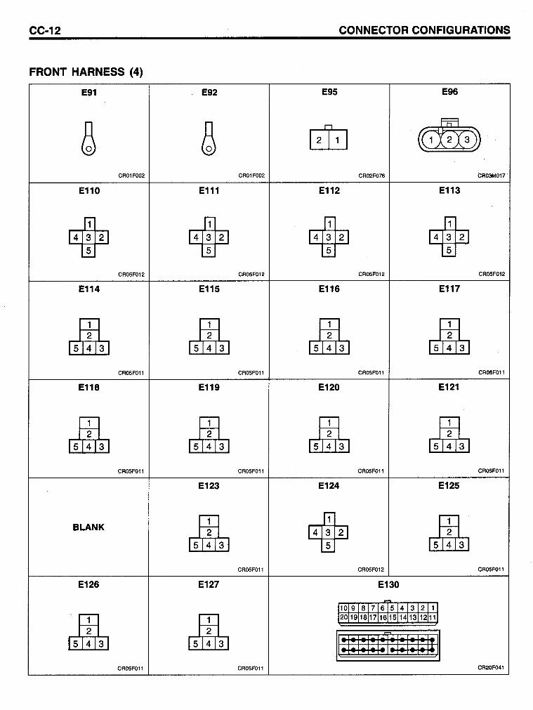
CC-12 CONNECTOR CONFIGURATIONS
FRONT HARNESS (4)
E91 E92 E95 E96
~ ~ ~ ~ CR01FOO2 CR01FOO2 CR02F076 CR03M017
E110 E111 E112 E113
14W21 14W2 1 14m21 14m21
CR05F012 CR05F012 CR05F012 CR05F012
E114 E115 E116 E117
1)1!1'31 15'1! 1'31 15'lnl 1)1!1'31 CR05F011 CR05F011 CR05F011 CR05F011
E118 E119 E120 E121
15'1! 1'31 15'1!lt l 1)1!lt I 1)1!1'31 CR05FOll CR05F011 CR05FOll CR05F011
E123 E124 E125
BLANK
15'1!1'31 14W2 1 1)1!lt l CR05F011 CR05F012 CR05F011
E126 E127 E130
1101918171615141312111
I)IUI 1)1!lt l 1201191181171161151141131121111
Il;I;1 ;1;1* I; I; I; IIJI CR05F011 CR05F011 CR20F041
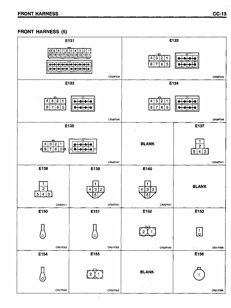
FRONT HARNESS CC-13
FRONT HARNESS (5)
E131 E132
110191817165J41312J1) 120119118117116151141131121111
• • Il;I;IOI; I~I;I; I; I;JI 876 5
CR20F039 CR08F045
E133 E134
• 876 5 • • 876 5 E CR08F046 CR08F048
E135 E137
J:I*I~~ I~Ilij:I:~1 BLANK I)r!rtl CR08F047 CR05FOll
E138 E139 E140
l)rUI 6 6 BLANK
CR05FOll CROSF031 CR05F031
E150 E151 E152 E153
ß ß ~ ~ CR01FOO2 CR01FOO2 CR02F040 CR01Fooe
E154 E155 E156
ß ~ BLANK 8 CR01FOO2 CR02FOO2 CR01F038
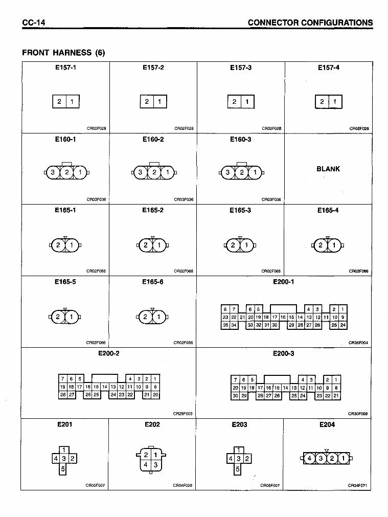
CC-14 CONNECTOR CONFIGURATIONS
FRONT HARNESS (6)
E157-1 E157-2 E157-3 E157-4
~ ~ ~ ~ CR02F028 CR02F028 CR02F028 CR02F028
E160-1 E160-2 E160-3
,-----, ,-----, ,-----,
(3r2J1) (3r2J1) (3r2J1) BLANK
CR03F036 CR03F036 CR03F036
E165-1 E165-2 E165-3 E165-4
~ ~ ~ ~ CR02F066 CR02F066 CR02F066 CR02F066
E165-5 E165-6 E200-1
r-r- r-- -- -r-
«t1 ) ~ 8 7 6 5 4 3 2 1
23 22 21 20 19 18 17 1161 15 14 13 12 11 10 9
35 34 33 32 31 30 1 129 28 27 26 25 24 -'-- "--"--
CR02F066 CR02F066 CR35FOO4
E200-2 E200-3
r-- r-r-7 6 5 4 3 2 1 7 6 5 4 3 2 1
19 18 17 16 15114 13 12 11 10 9 8 20 19 18 17 161 15 114 13 12 11 10 9 8 28 27 ~~ 24 23 22 21 20 30 29 28 27 126 1 25 24 23 22 21 -- "--'-- -- --
CR28FOO3 CR30FOO9
E201 E202 E203 E204
14~121 iffif 4 3 14~121. {4I312I(JJ
CR05FOO7 CR04F026 CR05FOO7 CR04F071
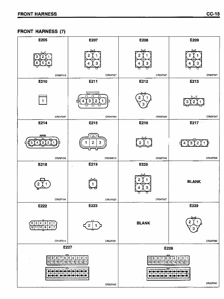
FRONT HARNESS CC-15
FRONT HARNESS (7)
E205 E207 E208 E209
~ 654 BE 4 3 BE 4 3 BE 4 3
CR06F016 CR04F027 CR04F027 CR04F027
E210 E211 E212 E213
[TI m~tl~ ~ ~ CR01F047 CR04F054 CR03F020 CR03F047
E214 E215 E216 E217
(0Xffi 2!W d~lDJ ~ (413!2X(jl
CR05F039 CR03M015 CR02F040 CR04FOO5
E218 E219 E220
W Q BE BLANK
4 3
CR02F104 CR01F020 CR04F027
E222 E223 E225
M
@> ~ 11'61514 131 21 1 'jl BLANK l12[11j10191 B 17)
CR12F014 CR02F061 CR03F020
E227 E228
- -11019 I 8 I 7 16 5 14 I 3 12 11 1 11019 1817 16 5 14 13 12 11 1 120119118117116151141131121111 120119118117116151141131121111
Ilttl;lfl;l; I; I;JI ~; I; I; I; I ffi I; I; I; 1111
CR20F042 CR20F041
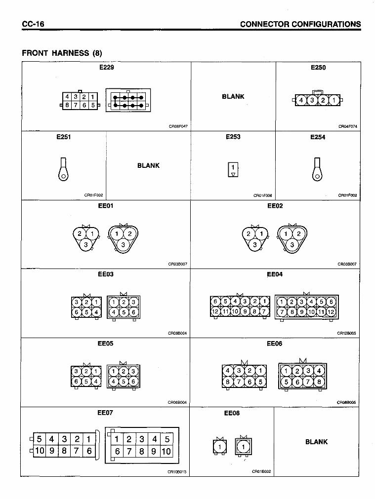
CC-16
FRONT HARNESS (8)
E251
E229
BLANK
CR01F002
EE01
EE03
~~ ~~
EE05
~~ ~~
EE07
CR08F047
CR03B007
CR06B004
CR06B004
[5 4 3 2 1 [10 9 8 7 6
IL 1 2 3 4 5
6 7 8 9 10 ..J
CR10B013
CONNECTOR CONFIGURATIONS
E250
BLANK
E253 E254
CR01FOO6
6 5 4 3 2 1
12 11 10 9 8 7 L..J
~ ~
EE08
EE02
~E04
1 2 3 4 5 6
7 8 9 10 11 12
EE06
M
~ ~
L..J L.J
BLANK
CR01B002
CR04F074
CR01FOO2
CR03BOO7
CR12BOO5
CR08BOO5
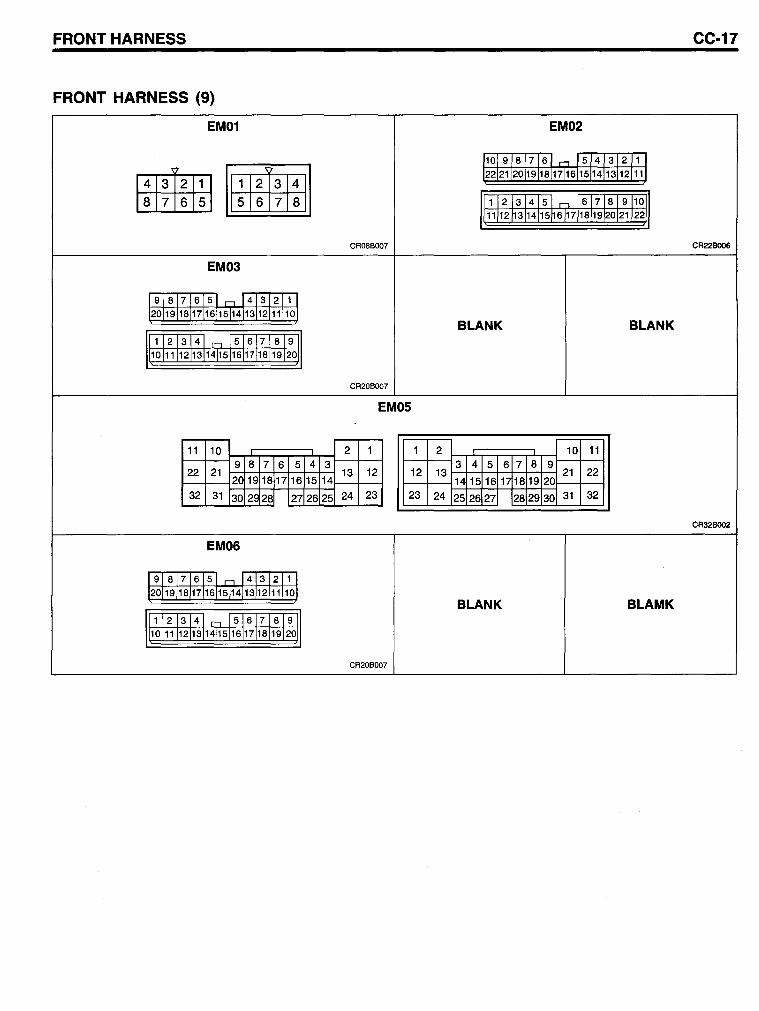
FRONT HARNESS CC-17
FRONT HARNESS (9)
EM01 EM02
109 8 7161,...., 514312J1J
• • 222120191181171615114131121111
8 765 5 6 7 8 1 2 3 4151,...., 617 819110~1 11121314115~61718l1920121l22
CR08BOO7 CR22BOO6
EM03
918171651,...., 41312111 2°119118117161151413j12J111101
BLANK BLANK 1121314 r--, 56171819
10111112113141151617118 119120
CR20BOO7
EM05
11 10 2 1 1 2 10 11 9 8 7 6 5 4 3 3 4 5 6 7 8 9
22 22 21 13 12 12 13 21 20 19 18 17 16 15 14 14 15 16 1, 18 19 20
32 31 30 29 28 27 26 25 24 23 23 24 25 26 27 28 29 30 31 32
CR32B002
EM06
9181 7 16 51-=- 4l3J211\ 201191181171611514131121111101
BLANK BLAMK 111 12 13 14 n 5 6171 8 19 11
WOl1111211314115161711811912oli
CR20BOO7
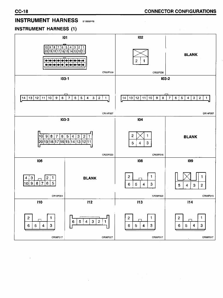
CC-18
INSTRUMENT HARNESS
INSTRUMENT HARNESS (1)
E1BBBFFB
101
~
11019 18 17 16 5 14 13 12 11 1 12011911811 7116151141131121111
Il*I*I*I~I~I~I~ll 103-1
CR20F039
[14\13\12\11\10 \ 9 \ 8 T 7\ 6 \ 5 \ 4 1 3 12 \ 1 J
CR14FOO7
103-3
, r 101 91s 17 16 514 13 1211 2011911S117116 15114113112111 J L
CR20F020
106
~~ 1OisT7j5 BLANK
CR10FOO4
110 112
[fuclI] 6 5 4 3 L6 1 ~ 14
13
1 ~ 11 J
CR06F017 CR06F027
CONNECTOR CONFIGURATIONS
102
~ BLANK
CR02F038
103-2
[14 113 \12\11\10 \ 9 \ 8 T 7 1 6 1 5 1 4 \ 3 12 \ 1 J
CR14FOO7
104
~ BLANK
5 4 3
CR05F016
108 109
~ 6 5 4 3 ~ CR06FOO3 CR05F013
113 114
[fuclI] 6 5 4 3 [fuclI] 6 5 4 3
CR06F017 CR06F017
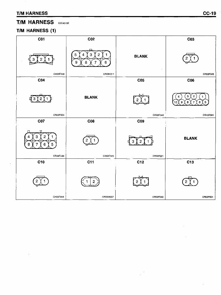
TIM HARNESS
TIM HARNESS
TIM HARNESS (1)
E3C4015E
C01
{iI2Ii} CR03F038
C04
c(3N1}
CR03FOO3
C07
rr 4
(3 2 1 8\
./ 7 6 S
CR08F048
C10
@) CR02F043
CC-19
C02 C03
r1
SX4:t»:>11 @) BLANK
9X 8 A7 )(6..;
CR09F011 CR02F043
C05 C06
G!J ~ BLANK
1098765
CR02F040 CR10F021
C08 C09
@) {3I~f11 BLANK
CR02F043 CR03F021
C11 C12 C13
~ G!J @) CR02MOO7 CR02F040 CR02FOO1
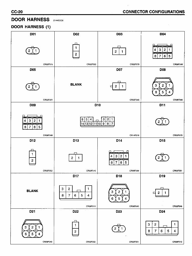
CC-20
COOR HARNESS
DOOR HARNESS (1)
001
G!D CR02F075
005
@)
CR02FOO1
009
• 8 7 6 5
CR08F049
012
ffi CR02F052
BLANK
021
~ 654
CR06F040
CONNECTOR CONFIGURATIONS
E144ECC6
002 003 004
ffi rn • 8 7 6 5
CR02F052 CR02F076 CROSF049
007 008
BLANK €8 ~ 654
CR02F046 CROSF04O
010 011
61s14LoJ312111 G!D 14113112111101918171
CR14F019 CR02F075
013 014 015
rn • @) 8 7 6 5
CR02F076 CR08F049 CR02FOO1
017 018 019
l:I~16T5m ~ €8 654
CR08F010 CR06F040 CR02F046
022 023 024
ffi @) l:I~16T5m CR02F052 CR02FOO1 CR08F010
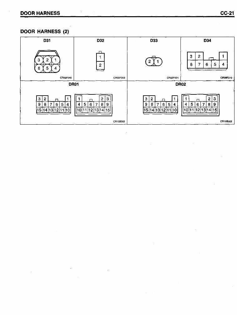
DOOR HARNESS CC-21
DOOR HARNESS (2)
031 032 033 034
ffi l:I~16T5m ~ ~ 654
CR06F040 CR02F052 CR02FOO1 CR08F010
OR01 OR02
.-- ,- -,- .-- ,- ,-,-3 2 n 1 1 n 2 3 3 2 D 1 1 n 2 3
9 8 71615 4 4 51617 8 9 9 8 71615 4 4 51617 8 9 15 14 13112111 10 10 11J12 113 14 15 15 14 13112111 10 10 11112113 14 15
CR15BOO2 CR15BOO2
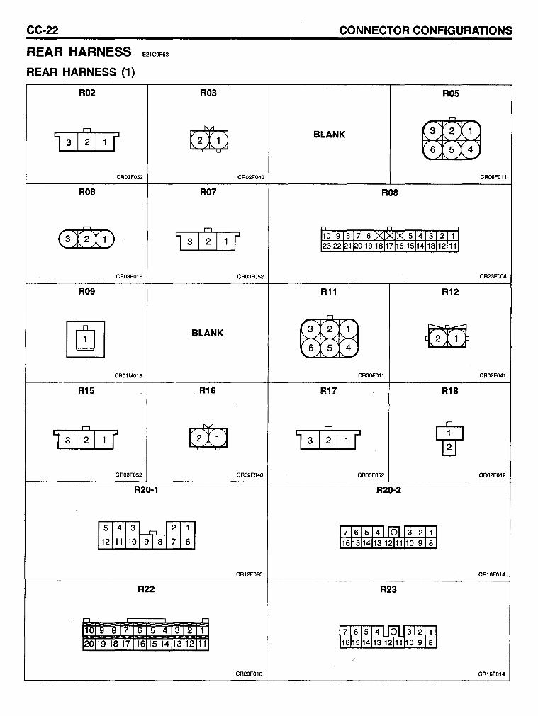
CC-22
REAR HARNESS
REAR HARNESS (1)
E21C9F63
R02
1 I I:J
F 3 2 I 1
CR03F052
R06
(3);1»
CR03F016
R09
~ CR01M013
R1S
1 3 I~I 1 (
CR03F052
R20-1
5 4 3 r--,
12 11 10 91 S
R22
-,
10 9 8 7 6 5 4 20 19 18 17 16 15 14
1
2
7
3 13
CONNECTOR CONFIGURATIONS
R03 ROS
~ BLANK ~ 654
CR02F040 CR06F011
R07 ROS
I~I ,., ,., ..,
3 1 F 1101 9 I 8 I 7 I 6 [x..IXIXI 5 I 4 I 3 I 2 I 1 1 1231221211201191181171161151141131121111
CR03F052 CR23FOO4
R11 R12
BLANK ~ ~ 6 5 4
CR06F011 CR02F041
R16 R17 R18
~ 1 3 I~I 1 F W CR02F040 CR03F052 CR02F012
R20-2
1 17161514~312111 6 11611511411311211111019181
CR12F020 CR16F014
R23
r
2 1 17161514~312111 12 11 11611511411311211111019181
CR20F013 CR16F014
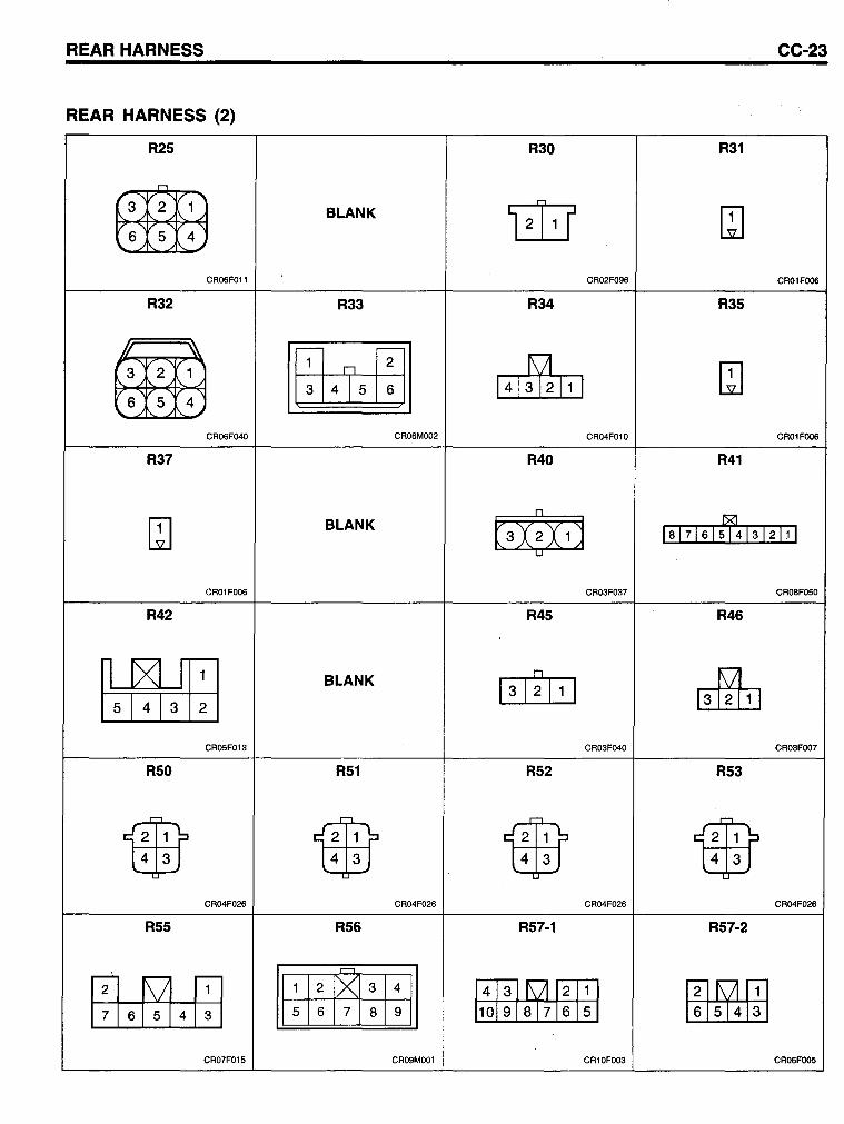
REAR HARNESS CC-23
REAR HARNESS (2)
R25 R30 R31
6NB BLANK LiliJ ~ 654
CR06F011 CR02F096 CR01FOO6
R32 R33 R34 R35
Bttffi ~ ~ ~ 3 4 5 6 654
CR06F040 CR06MOO2 CR04F010 CR01F006
R37 R40 R41
~ BLANK ~ Is1716159f413121 1 1
CR01FOO6 CR03F037 CR08F050
R42 R45 R46
~ BLANK D
13121 1 1 ~ CR05F013 CR03F040 CR03FOO7
R50 R51 R52 R53
iffij 4 3 iffij 4 3 iffij 4 3 iffij 4 3
CR04F026 CR04F026 CR04F026 CR04F026
R55 R56 R57-1 R57-2
msFA.rn 1 2 [>( 3 4
~~~ -5 6 7 8 9 6 5 4 3 1Ofä7J5 CR07F015 CR09MOO1 CR10FOO3 CR06FOO5
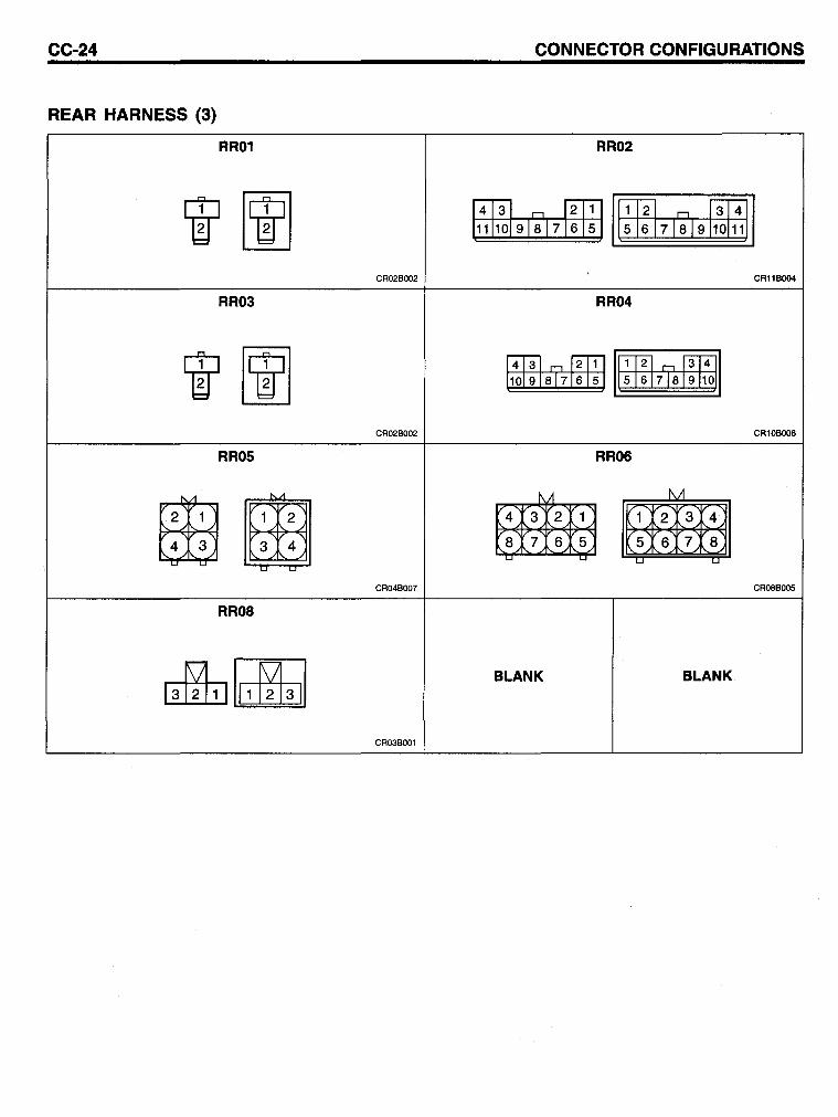
CC-24
REAR HARNESS (3)
RR01
RR03
RROS
(2!1Jrrn ~~
RROS
CR02B002
CR02B002
CR04BOO7
CR03B001
CONNECTOR CONFIGURATIONS
RR02
RR04
RR06
~ ~
BLANK
~ ~
BLANK
CR11BOO4
CR10BOO6
CR08BOO5
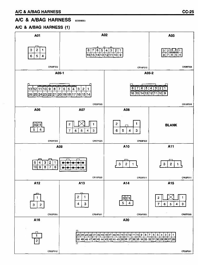
AlC & AlBAG HARNESS
Ale & AlBAG HARNESS
AlC & AlBAG HARNESS (1)
A01
tllifE 654
CR06FOO2
A05-1
n
13 12 11 10 9 8 7 6 5
26 25 24 23 22 21 20 19 18
A06
EEBB6BB3
4 3 2
17 16 15
A07
CC-25
A02 A03
n n
8 71615 4131211 I [ffiJijl[I] 1615114113 12111J1O[9 J
CR16F015 CR08FOO4
A05-2
r ::J --'= 1 8 7 6 5 4 3 2 1
14 16 15 14 13 12 11 10 9
CR26FOO5 CR16F016
AOS
~ rH6pa.hl ~ BLANK 5 4 6 5 4 3
CR05FOO3 CR07FOO5 CR06FOO3
A09 A10 A11
-"""1 ~
11:1:1: el:11 ; 31 r; I t::J 5 4 3 2 1 1 ~ ; 31 2 I 1 ~ 10 9 8 7 6
CR10F020 CR03FOll CR03FOll
A12 A13 A14 A15
dIb tffi] 4 3 ~ 5 4 [TI6pa.hl CR03FOO5 CR04FOOl CR05FOO3 CR07FOO5
A16 A20
1IT -, 2512412312212112011918117116115114113112111109 87161514132111 504914847146145444314214140139138371363534 3332131130129128271261 .J
CR02F012 CR50FOOl
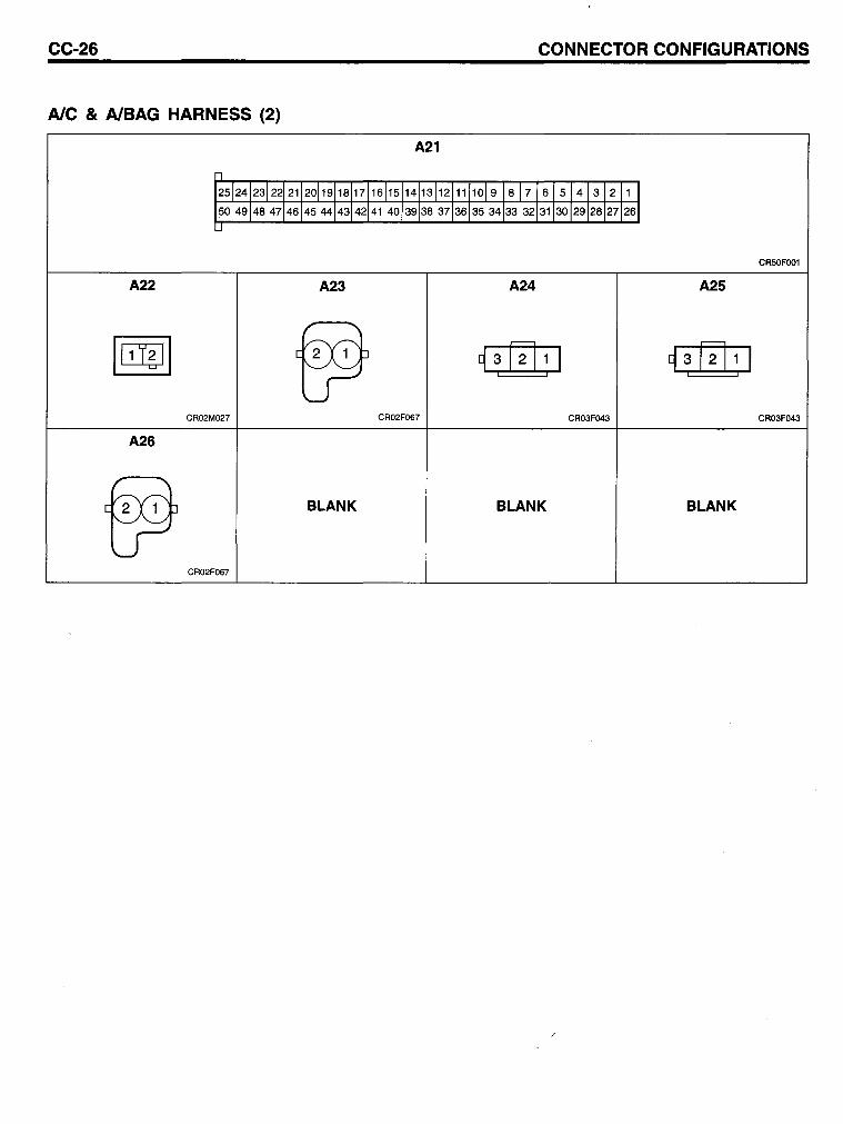
CC-26 CONNECTOR CONFIGURATIONS
AlC & AlBAG HARNESS (2)
A21
1
2512412312212112011911811711611511411311211111019 18 J 7161514131211 I 504914847146145 44143142141 4013913837136-'3534133 321311301291281271261 .J
CR50FOO1
A22 A23 A24 A25
~ ~ 93 [!]11 i i
~ 3 ~ 1 I i i
CR02M027 CR02F067 CR03F043 CR03F043
A26
~ BLANK BLANK BLANK
CR02F067
COMPONENT LOCATIONS
AlC &. AlBAG HARNESS ........................................................... CL-27
DOOR HARNESS ..••••....•.........•...•••••••..••••.....•........••••.••..••••••••••. CL-22
FRONT HARNESS ....•.••......•.••.•..••••••.••.••••••••.••.•••••..•••.••.••.•.••••.•• CL-8
GROUNDS .................................................................................... CL-29
INSTRUMENT HARNESS ........................................................... CL-20
MAIN HARNESS ......................................................................... CL-2
REAA HARNESS ........................................................................ CL-24
TIM HARNESS-.-... ::-..................................................................... CL-21
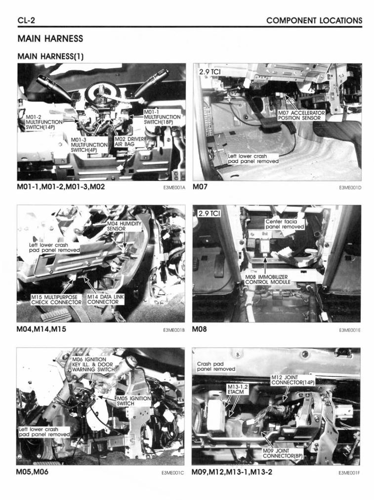
CL-2
MAIN HARNESS
MAIN HARNESS(l)
M04,M14,M15
M05,M06
COMPONENT LOCATIONS
E3MEOO10
E3MEOO1B MOa EJMEOO1E
EJMEOO1C M09,M12,M13-1 ,M13-2 EJMEOO1F
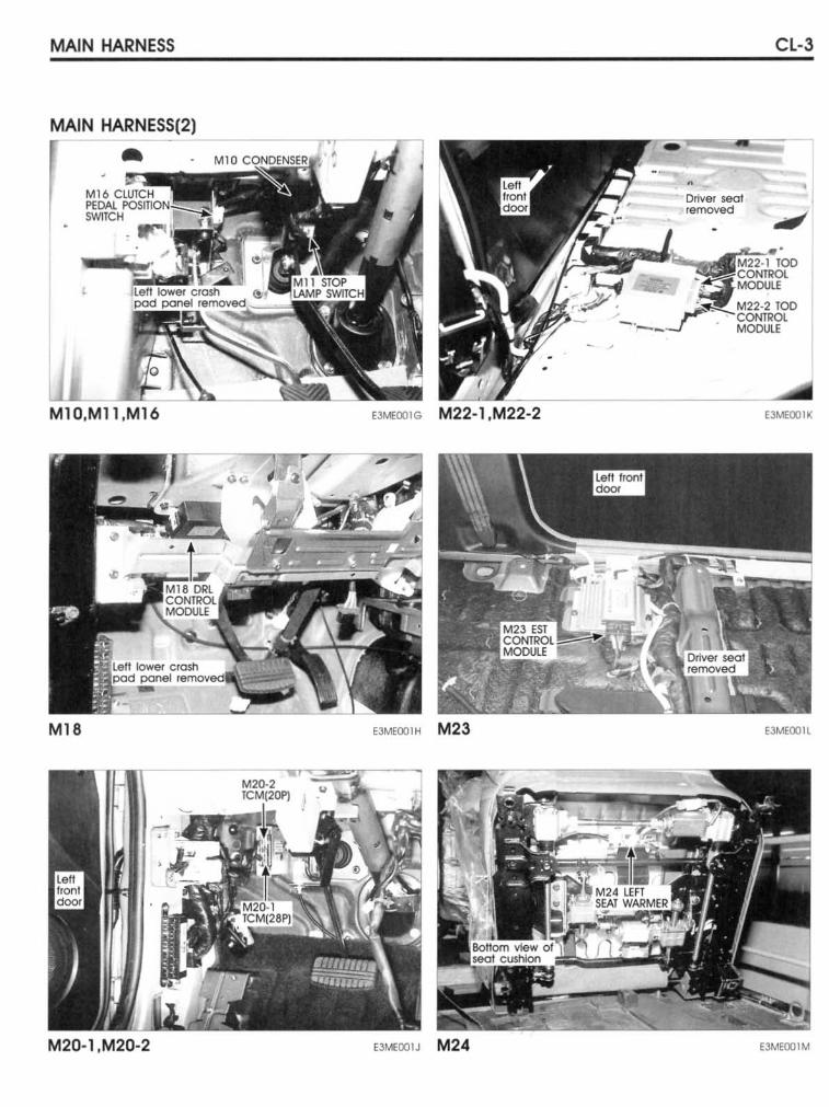
MAIN HARNESS
MAIN HARNESS(2)
,
M10.Mll .M16 EJMEOOIG M22-l.M22-2
M18 E3MEOO1H M23
M20-1 .M20-2 E3MEOO IJ M24
• Driver seal removed
Cl-3
E3MEOO1K
E3MEOOll
E3MEOO1M
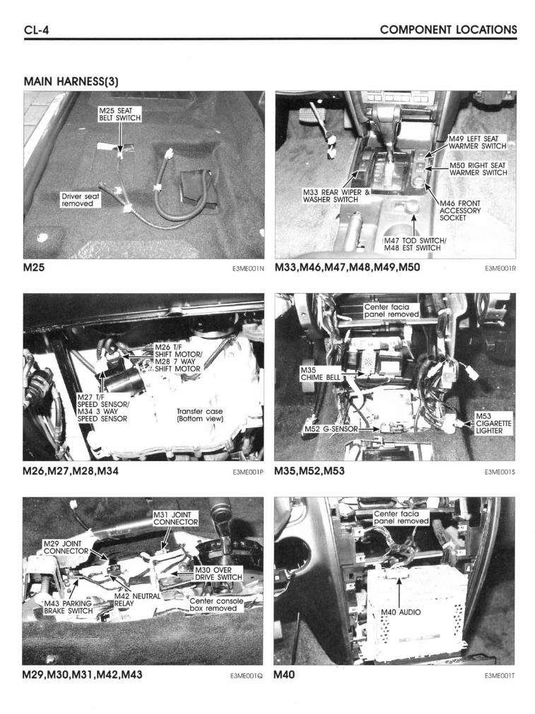
CL-4
MAIN HARNESS(3)
M25
M26.M27.M28.M34
M29.M30.M31.M42.M43
Transfer cose (Bol10m view)
\
COMPONENT LOCATIONS
EJMEOOlN M33.M46.M47.M48.M49.M50
EJMEOO" M35.M52.M53
EJMEOO1Q M40
\ ~40 AUDIO .. ': . . - -.'
E3MEOO1R
E3MEOO1S
EJMEOOlT
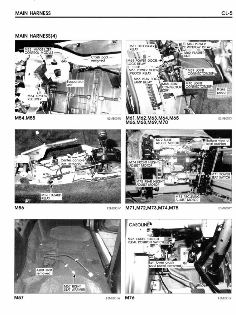
MAIN HARNESS CL-5
MAIN HARNESS(4 .. ) ---=:=ir""-~IiWl
"M""lU M61,M62,M63,M64,M65 E3MEOOIX M66,M68,M69,M70
M56 "MEOO" M71,M72,M73,M74,M75 E3MEOO1Y
M57 EJMEOO1W M76 E3MEOO1Z
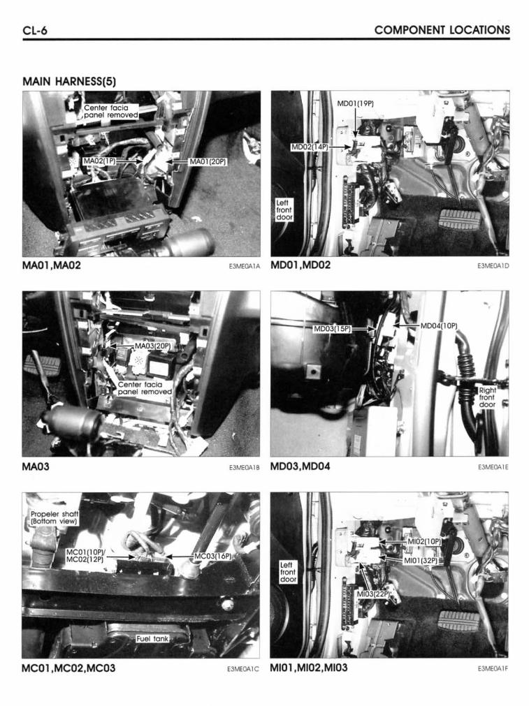
CL-6 COMPONENT LOCATIONS
MAIN HARNESS(5)
E3MEOAIO
MA03 EJM:OAIB MD03.MD04 EJMEOAIE
MC01 ,MC02,MC03 "M,,,,,e MIOI ,MI02,MI03 EJMEQ,6,1F
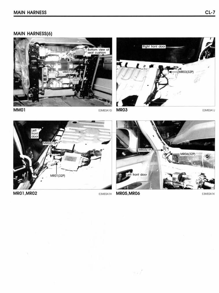
MAlN HARNESS CL-7
MAIN HARNESS(6)
,
'. 7
MMOl E3MEOAlJ
MROl,MR02 E3"-'EOAIH MR05,MR06 EJMEOAIK
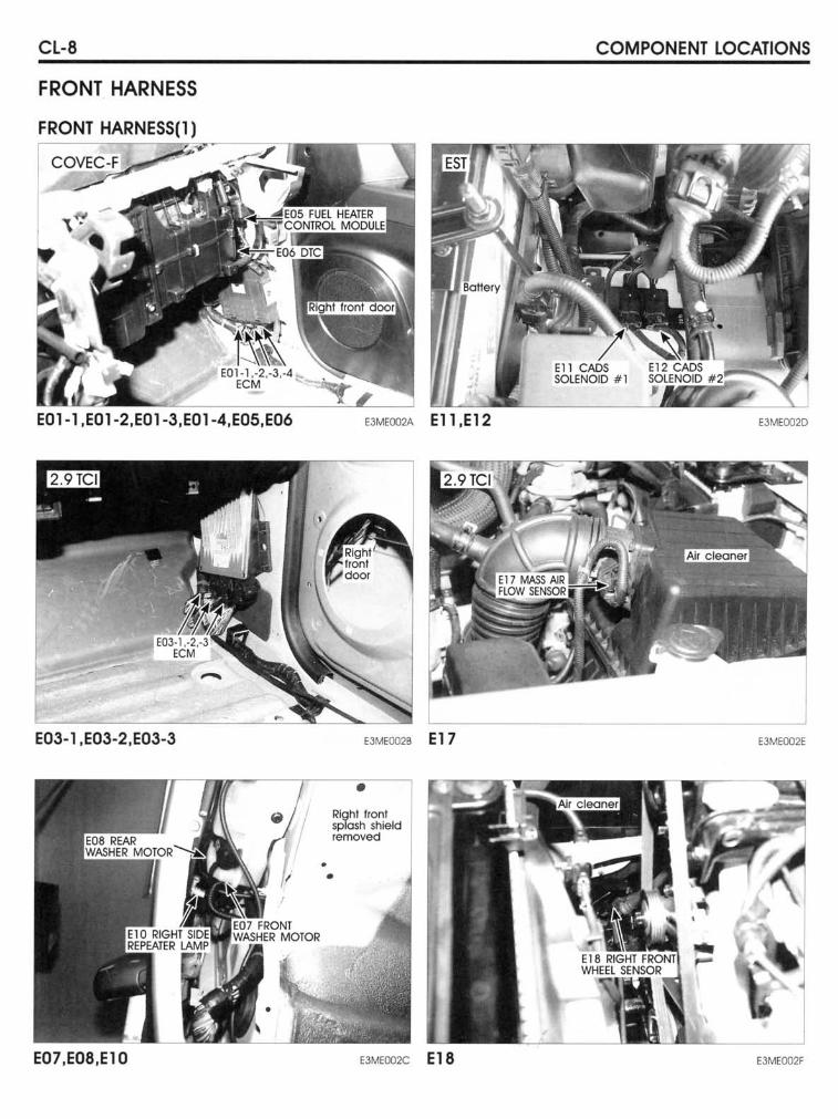
CL-8
FRONT HARNESS
FRONT HARNESS(l)
E01-l,EOl-2,EOl-3,EOl-4,E05,E06
E03-1 ,E03-2,E03-3
E07,E08,E10
E3MEOO2A El1 .E12
E3MEOO2B E 1 7
• Righl Ifon! splosh shleld removed
• •
E3MCOO2C E 18
COMPONENT LOCATIONS
E3MEOO20
EJMEcmE
EJMEOO2F
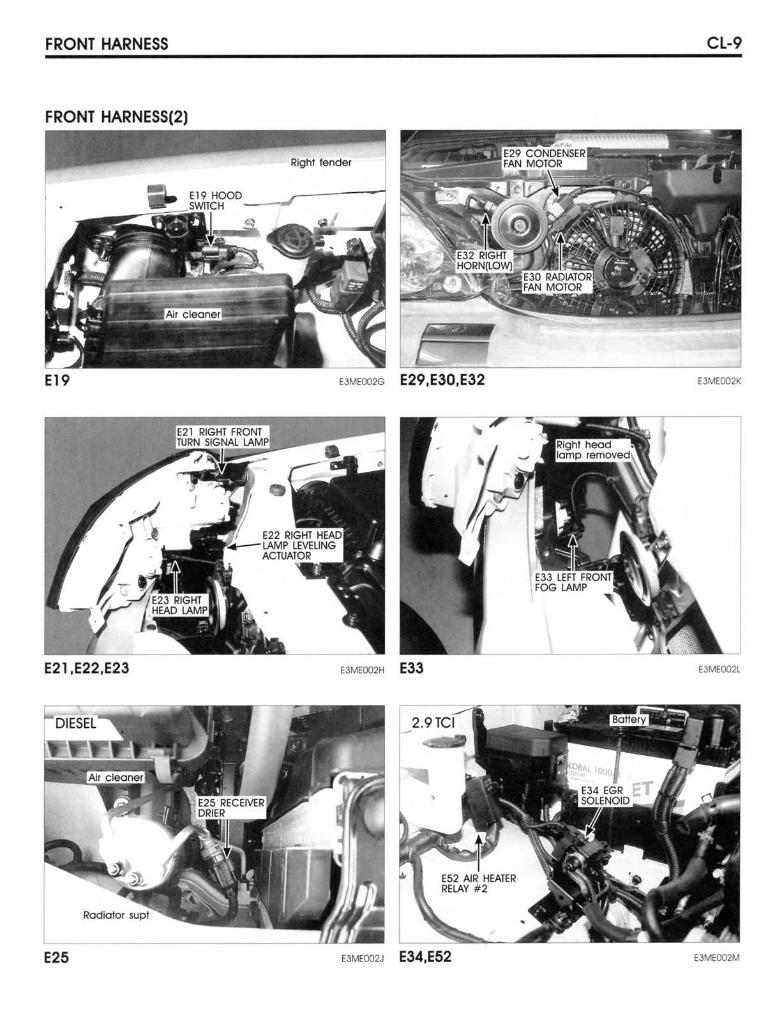
FRONT HARNESS CL-9
FRONT HARNESS(2)
E19 E3MEOO2G E29,E30,E32 EJMEOO2K
E21,E22,E23 EJMEOO2H E33 EJMEOO2l
E25 EJMEOO2J E34,E52 E3MEOO2M
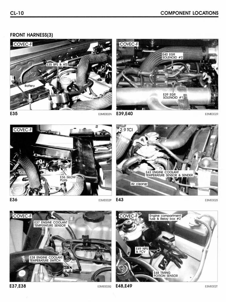
CL-IO COMPONENT LOCATIONS
FRONT HARNESS(3)
E35 E3MEOO2N E39,E40 E3MEOO2R
E36 E3MEOO2P E43 EJMEOO2S
E37 ,E38 E3MEOO2Q E48,E49 E3MEOO2T
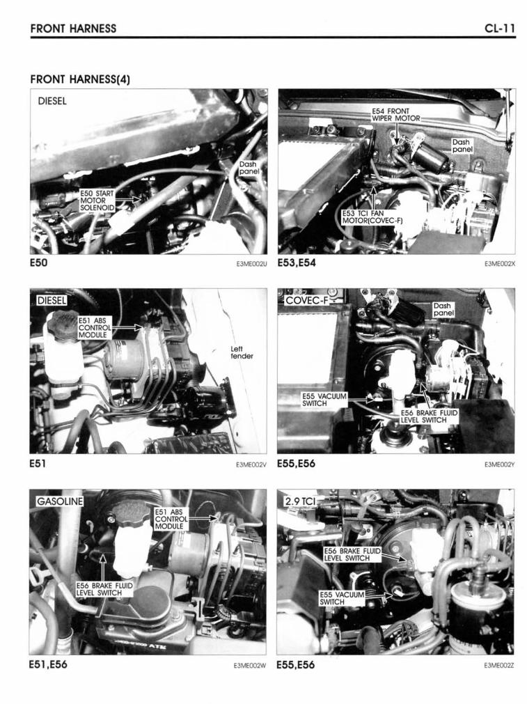
FRONT HARNESS
FRONT HARNESS(4)
DIESel
E50
E51
E51.E56
E3MEOO2IJ E53.E54
'a' fendef
E3MEOO2V E55,E56
EJMEOO2W E55.E56
CL-ll
E""'OO2X
E3MEOO2V
E3MEOO2Z
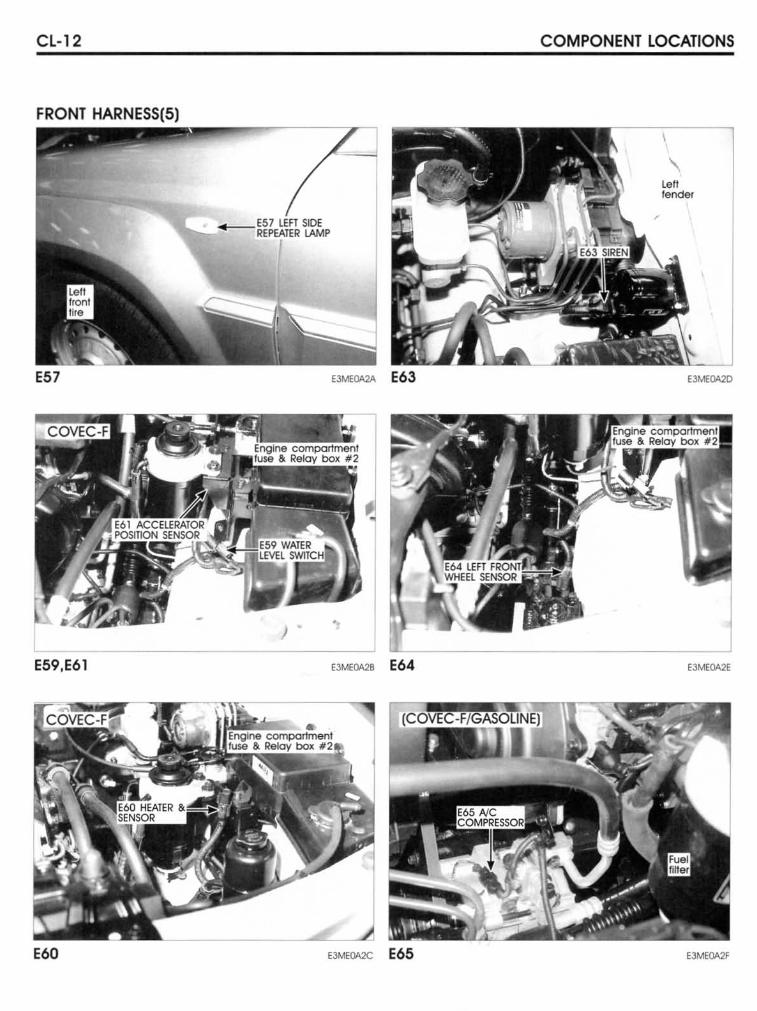
Cl-12
FRONT HARNESS(5)
"'~--7I
E57 SlDf 'Y'o_'-RfPEATER lAMP
I
E59.E61 E3ME0A28 E64
E60 E3MEOA2C E65
COMPONENT lOCATIONS
\ left fender
'JMfOOO
E3Me0A2E
EJMEQA2f
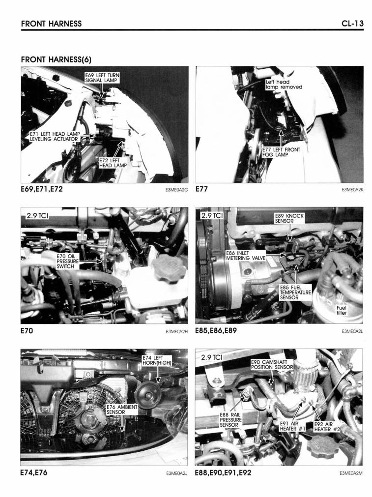
FRONT HARNESS CL-13
FRONT HARNESS(6)
!I!!I!!!I!!I!!!
EJME0A2K
E70 E3ME0A2H E85,E86.E89 EJME0A2L
E74,E76 "ME"'J E88,E90,E91 ,E92 EJME0A2M
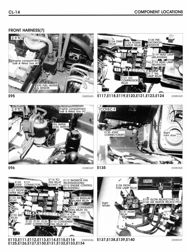
CL-14 COMPONENT LOCATIONS
FRONT HARNESS(7)
E95
E96
"ME0A2N El17,Ell B,El19,E120,E121 ,E123,E124
E3ME0A2P E 135
Rlght fender
EllO,Elll,El12,El13,E1l4,E1l5,El16 "ME0A2Q E137 ,E13B,E139,E140 E125,E126,E127,E130,E131 ,E132,E133,E134
E3MEQA2R
E3ME0A2S
EJME0A2T
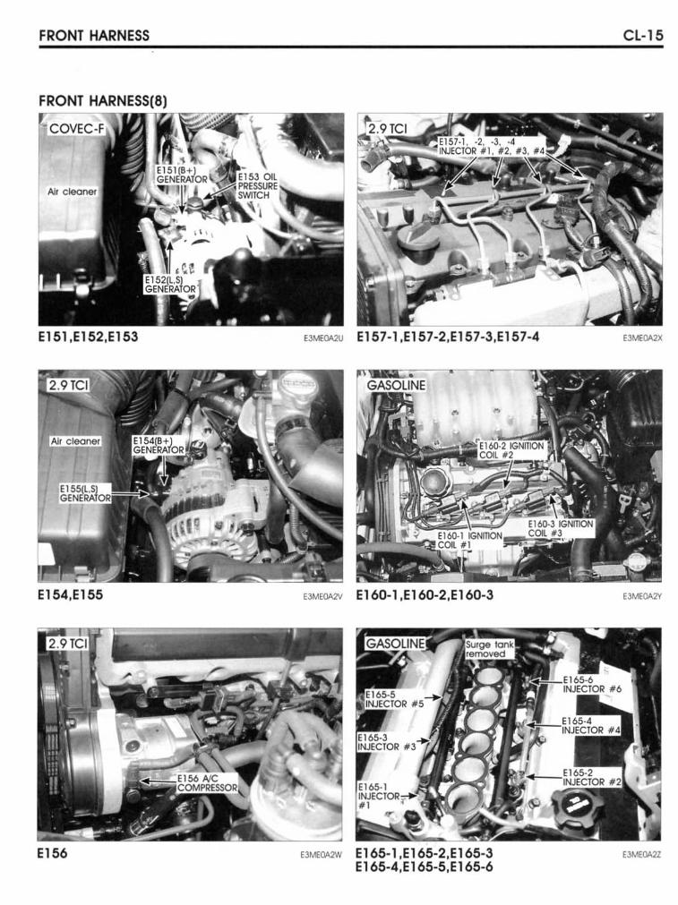
FRONT HARNESS
FRONT
Al. c~ne'J
EI51,EI52,EI53
E154,E155
E156
EJMEQA2U EI57-1,EI57-2,EI57-3,EI57-4
EJMEOA2V EI60-1,EI60-2,EI60-3
EJMEM2W EI65-1,EI65-2,EI65-3 EI65-4,EI65-5,EI65-6
CL-15
E3MEOA2X
E3MEOA2Y
E3ME0A2Z
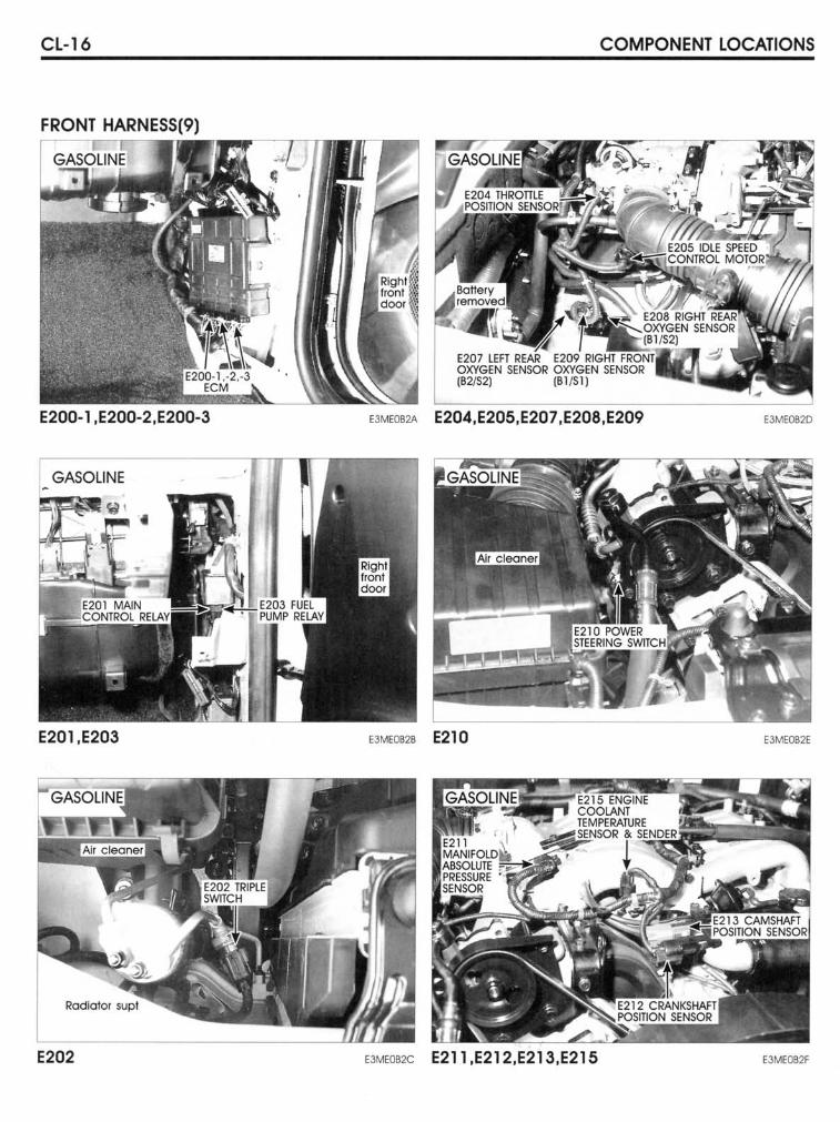
CL-16 COMPONENT LOCATIONS
FRONT HARNESS(9)
E200-1,E200-2 ,E200-3 "ME"'2A E204,E205,E207,E208,E209 E3ME082D
GASOLI NE
E201,E203 E3ME0628 E210 E3ME082E
E202 "MEOB2C E211,E212,E213,E215 E3MEOB2F
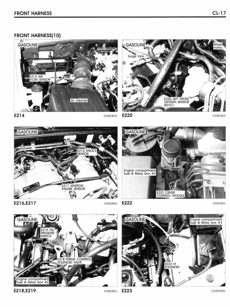
FRONT HARNESS CL-17
FRONT HARNESS(l 0)
E214 E3MEOB2G E220 E3MEOB2IC
E216.E217 EJMEOO2H E222 E3ME082L
_J E218.E219 E3MEOB2J E223 E3MEOB2M
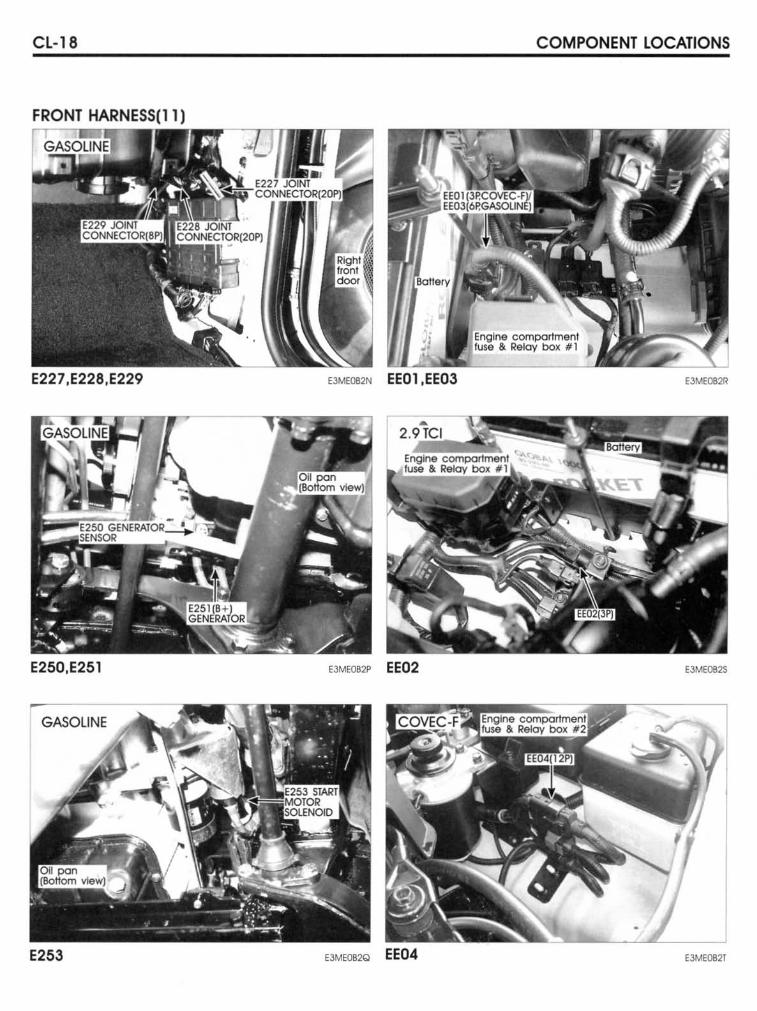
CL-18 COMPONENT LOCATIONS
FRONT HARNESS(ll)
E227,E228 ,E229 EJMEOB2N EE01,EE03 E3ME082R
E250,E251 E3ME082P EE02 E3ME082S
GASOLINE
E253 EJMEOB2Q EE04 EJME082T
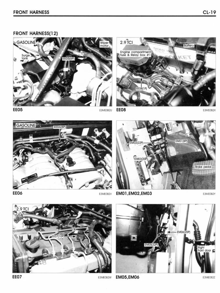
FRONT HARNESS CL-19
FRONT HARNESS(12)
EE05 EJMEOB2U EE08 '3ME082X
EE06 EJM'OB2V EM01,EM02,EM03 E3MEOB2Y
EE07 '3MEOB2W EM05,EM06 EJME082Z
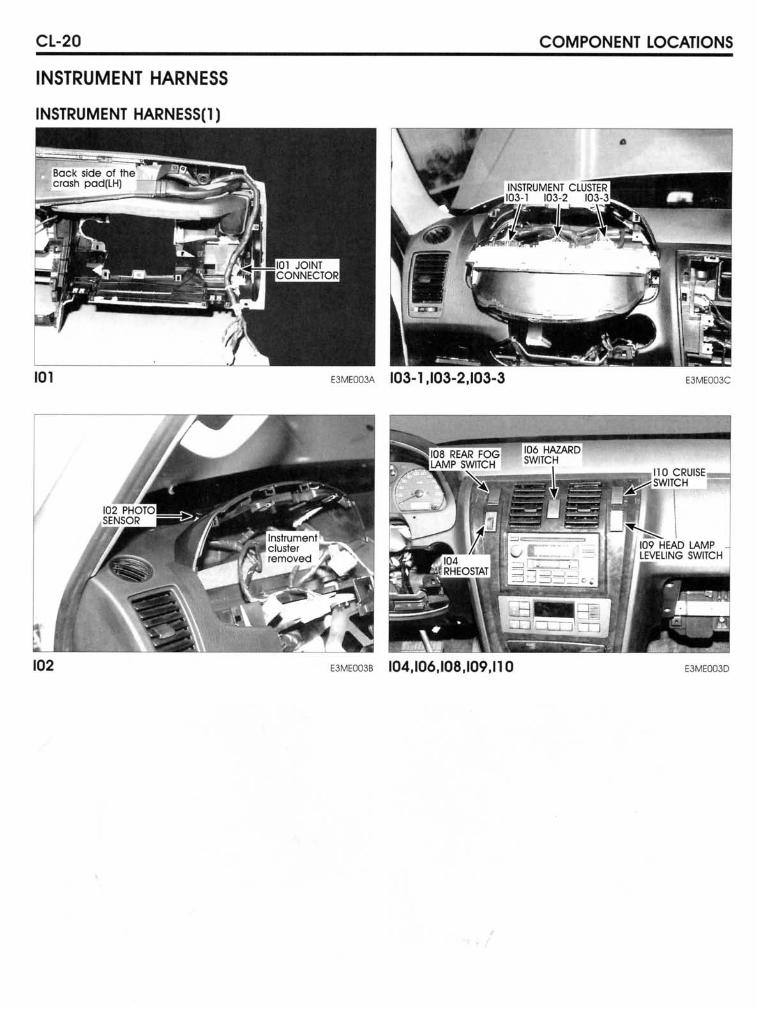
Cl-20
INSTRUMENT HARNESS
INSTRUMENT HARNESS(l)
ICl
102
COMPONENT lOCATIONS
EJM'OO3A 103-1,103-2,103-3 E3MEOOOC
EJM'OO3' 104,106,108,109,11 0 E3ME0030
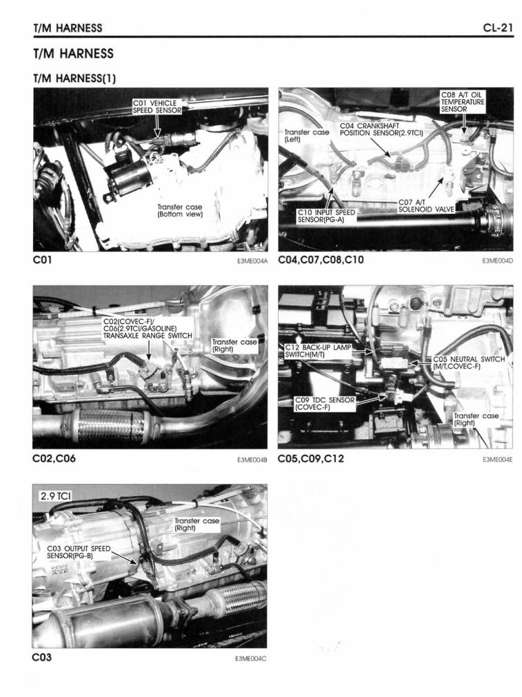
TIM HARNESS
TIM HARNESS
TIM HARNESS(l)
COl
C02,C06
Transfer case (Bol10m vlew)
,
CL-21
EJMEOO4< C04,C07,C08,ClO E3MEOO<D
E3MEQ04B C05,C09,C12 E3MEOO4E
EJMEOO4C
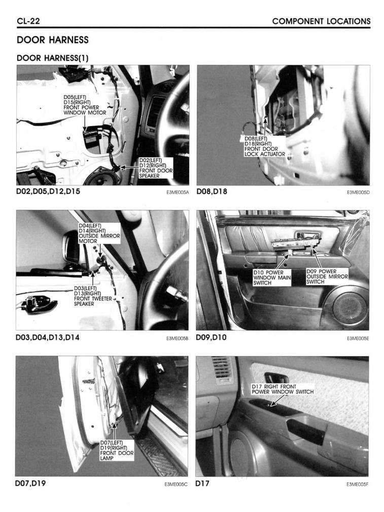
CL-22
DOOR HARNESS
OOOR HARNESS(I) ,~,---=
002,005,012 ,015
003,004,013 ,014
007,019
COMPONENT LOCATIONS
E3MEOO5A 008,018 E3MEQ05D
E3MEOO58 009,010 EJM€OO5E
E3MEOO5C 01 7 E3MEOO5F
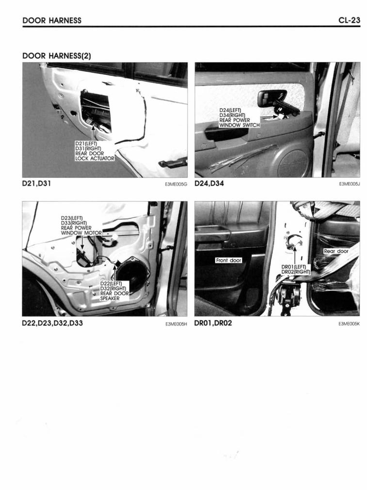
OOOR HARNESS Cl-23
OOOR HARNESS(2)
021.031 EJMEOO5G 024,034
022,023,032,033 EJMEOO5H OR01 ,OR02 E3MEOOSK
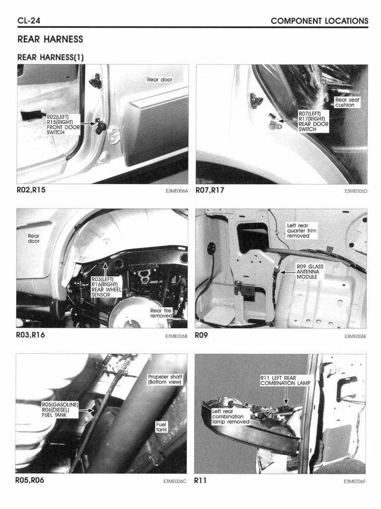
CL-24
REAR HARNESS
REAR HARNESS(l) _~ _____ ~
R02,R15
Rea< doO<
R03,R16
R05,R06
Real door
""H'O" R07,R17
E3MEOO6B R09
E3MEOO6C Rll
COMPONENT LOCATIONS
leU real quarler hirn
• removed
11:09 GLASS '~_ANTENNA
MODULE
E3MEOO6D
•
E3MEOO6C
E3MEOO6F
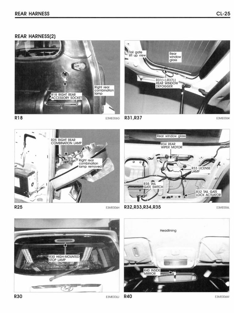
REAR HARNESS CL-25
REAR HARNESS(2)
R18 EJMfOO6G R31 ,R3 7 E3MEOO6K
R25 E3MEOO6H R32,R33 ,R34,R35 E3ME~
Heodlining
----,
R30 EJMEOCl6J R40 E3MEOO6M
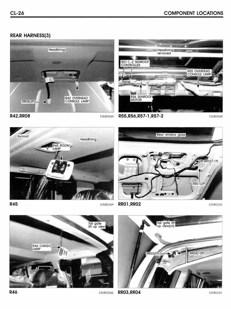
CL-26 COMPONENT LOCATIONS
REAR HARNESS(3)
R42,RR08 EJMEOO6N R55,R56,R57-1 ,R57-2 E3MEOO6R
Heodllnlng
.... ~ .
R45 E3MEOO6P RR01,RR02 E3MEOO6S
R46 E3MEOO6Q RR03,RR04 E3MEOO6T
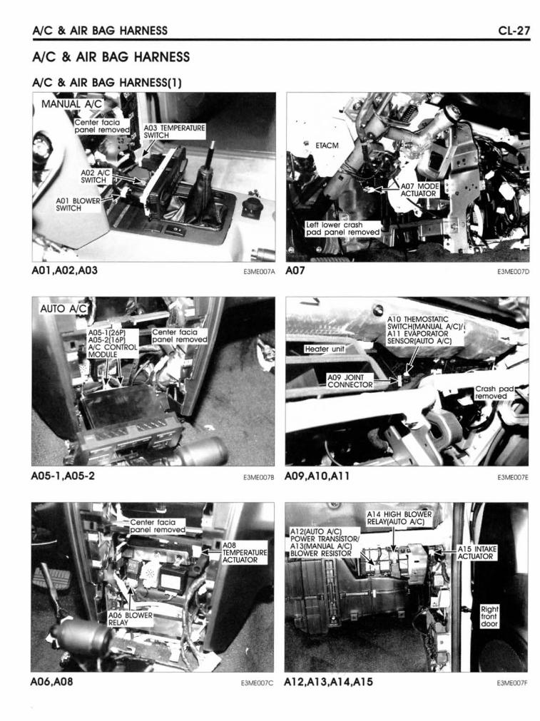
AlC & AIR BAG HARNESS
Ale & AIR BAG HARNE55
AlC & AIR BAG HARNESS(l)
A01,A02,A03
A05-1 ,A05-2
A06,A08
CL-27
E3MEOO7A A07 EJMEOO1D
'''''OO7B A09,Al0,All E3MEOO7E
EJME007C A12,A13,A14,A15 E3MEOO7F
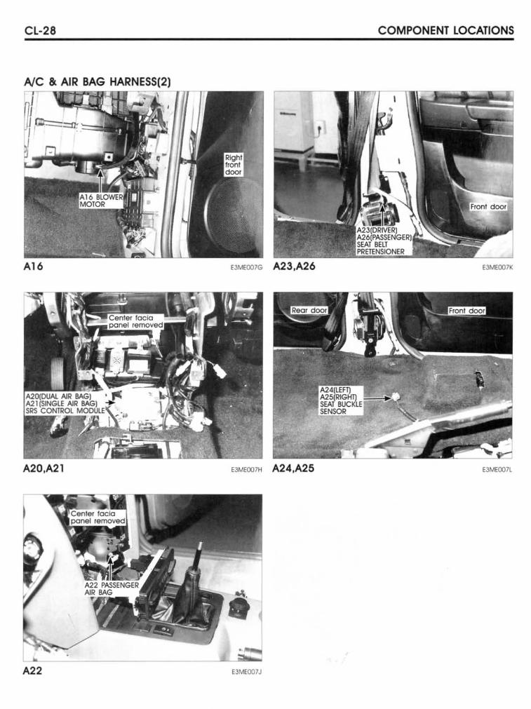
CL-28 COMPONENT LOCATIONS
NC & AI~RiBiA;G~fi~~~~rrr.n
A16 '3M<OO7G A23,A26 EJMEOO7K
A20,A21 E3MEOO7H A24.A25 E3MEOO7L
I ..
A22 e3MEOO7J
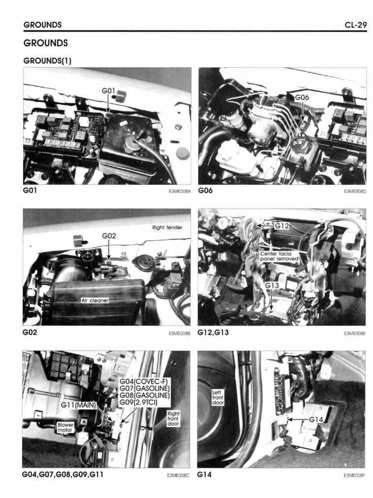
GROUNDS
GROUNDS
GROUNDS(l)
GOI
G02
G04,G07,G08 ,G09,GII
CL-29
E3MEOOSA G06 E3MEOO8D
Righl lendef
E3ME0086 G12,G13 EJMEOO8E
E3MEOOSC G 14 EJMEOO8F
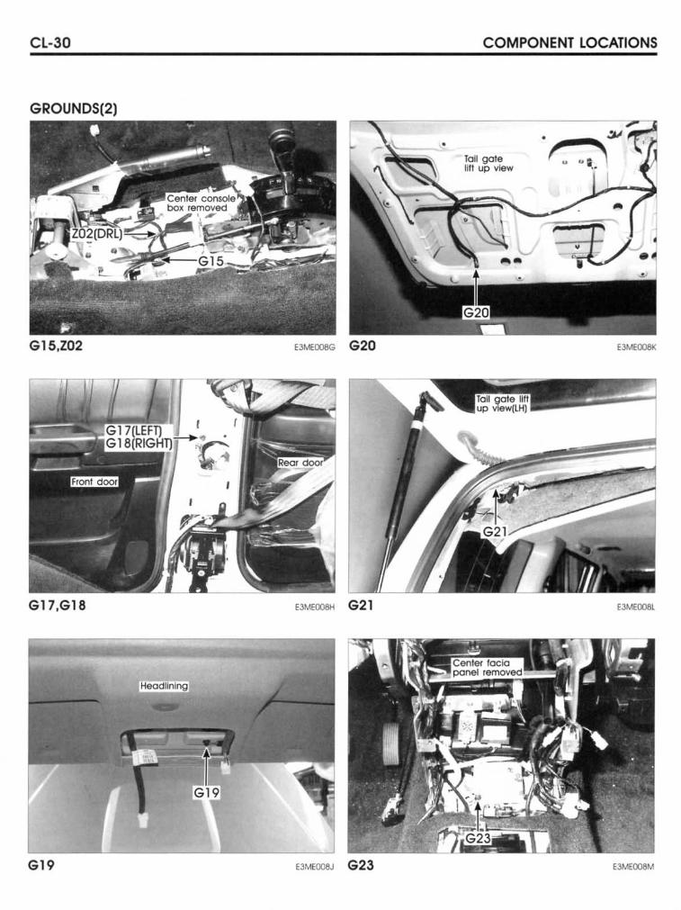
CL-30 COMPONENT LOCATIONS
GROUNDS(2)
• Tail gate litt up view
G15,Z02 '''''ooeG G20
G17,G18 E3MEOO8Ii G 21 E3MEOO8L
G19 .JMEOO8J G23 E3.'.1EOOBM
HOWTO USE THIS MANUAL
INTRODUCTION ........................................................................... GI -2
SYMBOLS ..................................................................................... GI -6
TROUBLESHOOTING INSTRUCTIONS ...................................... GI-10
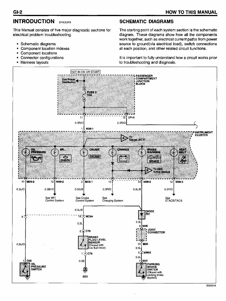
GI-2
INTRODUCTION EF4CEAFB
This Manual consists of five major diagnostic sections for electrical problem troubleshooting.
• Schematic diagrams • Component location indexes • Component locations • Connector configurations • Harness layouts
See
HOW TO THIS MANUAL
SCHEMATIC DIAGRAMS
The starting point of each system section is the schematic diagram. These diagrams show how all the components work together, such as electrical current paths from power source to ground(via electrical load), switch connections at each position, and other related circuit functions.
It is important to fully understand how a circuit works prior to troubleshooting and diagnosis.
See MFI Contra I System
See Cruise Contral System Charging System
See ETACSfTACS
9
O.5UO
G23
JOINT CONNECTOR
EGI001A
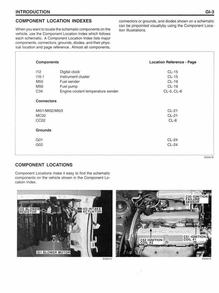
INTRODUCTION
COMPONENT LOCATION INDEXES
When you want to locate the schematic components on the vehicle, use the Component Location Index which follows each schematic. A Component Location Index lists major components, connectors, grounds, diodes, and their physical location and page reference. Almost all components,
Components
112 116-1 M55 M56 C34
Connectors
Digital clock Instrument cluster Fuelsender Fuel pump Engine coolant temperature sender
MI01 /MI02/MI03 MC02 CC02
Grounds
G01 G02
COMPONENT LOCATIONS
Component Locations make it easy to find the schematic components on the vehicle shown in the Component Location Index.
GI-3
connectors or grounds, and diodes shown on a schematic can be pinpointed visuallyby using the Component Location Illustrations.
Location Reference - Page
CL-15 CL-15 CL-19 CL-19
CL-5, CL-8
CL-21 CL-21 CL-8
CL-24 CL-24
EGI001B
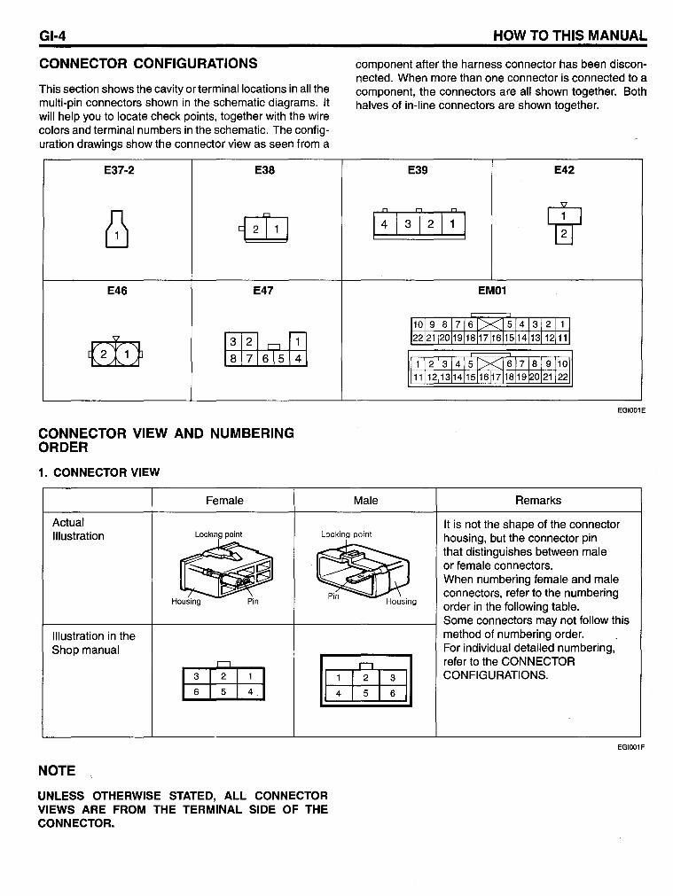
GI-4
CONNECTOR CONFIGURATIONS
This section shows the cavity or terminallocations in all the multi-pin connectors shown in the schematic diagrams. It will help you to locate check points, together with the wire colors and terminal numbers in the schematic. The configuration drawings show the connector view as seen from a
E37-2 E38
~ {iliJ
E46 E47
~ ~ ~ 8 7 615 4
CONNECTOR VIEW AND NUMBERING ORDER
1. CONNECTOR VIEW
Female
HOW TO THIS MANUAL
component after the harness connector has been disconnected. When more than one connector is connected to a component, the connectors are all shown together. 80th halves of in-line connectors are shown together.
E39 E42
I: 1312
1
1:1
I W 1
EM01
101 9 18 1716 1><..15141312 11 I 22121120119118117161151141131121111
1 12 131415l><J 617181 91101 11112113114115116171181191201211221
EGI001E
Male Remarks
Actual Illustration Locking point Locking point
It is not the shape of the connector housing, but the connector pin that distinguishes between male or female connectors. When numbering female and male connectors, refer to the numbering order in the following table.
f---------+----------t------------l Some connectors may not follow this Illustration in the Shop manual
NOTE
UNLESS OTHERWISE STATED, ALL CONNECTOR VIEWS ARE FROM THE TERMINAL SIDE OF THE CONNECTOR.
method of numbering order. For individual detailed numbering, refer to the CONNECTOR CONFIGURATIONS.
EGI001F
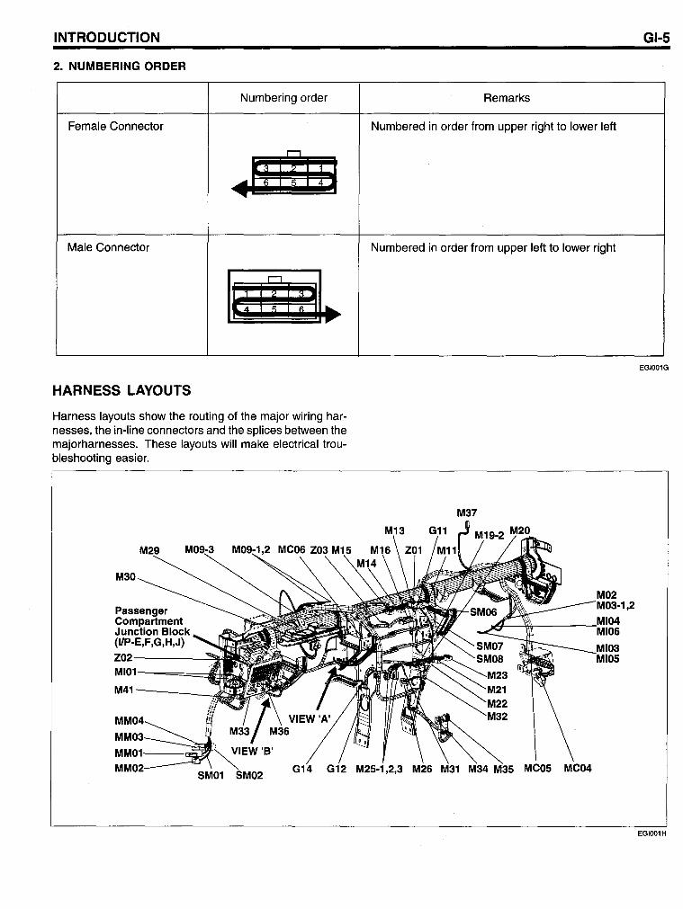
INTRODUCTION
2. NUMBERING ORDER
Numbering order
Female Connector
.!! lil li Male Connector
li! I i I i !I~ HARNESS LAYOUTS
Harness layouts show the routing of the major wiring harnesses, the in-li ne connectors and the splices between the majorharnesses. These layouts will make electrical troubleshooting easier.
M30
Passenger Compartment Junction Block (IIP-E,F,G,H,J)
Z02-----~
M41--___ ....d
SM02
GI-5
Remarks
Numbered in order from upper right to lower left
Numbered in order from upper left to lower right
EGI001G
M37
,2
EGlOO1H
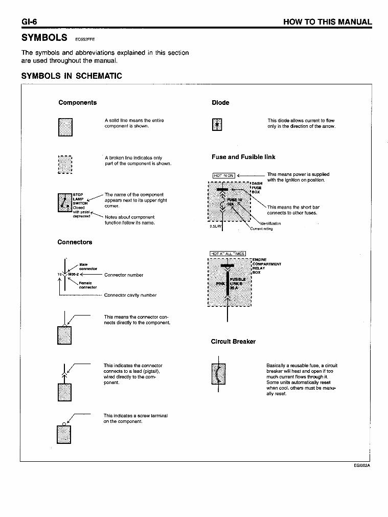
GI-6
SYMBOLS EC552FFE
The symbols and abbreviations explained in this section are used throughout the manual.
SYMBOLS IN SCHEMATIC
Components
Asolid line means the entire component is shown.
A broken line indicates only part 01 the component is shown.
STOP ~ The name 01 the component ~:'~:CH appears next to its upper right Closed corner. with pedal"'"-. depressed· .......... Notes about component
lunction lollow its name.
Connectors
I ..--Male ~_'l connector
tOTM05.2 ( "-Female
connector
Connector number
L.... ______ Connector cavity number
This means the connector con· nects directly to the component.
This indicates the connector connects to a lead (pigtail), wired directly to the com· ponent.
This indicates a screw terminal on the component.
HOW TO THIS MANUAL
Diode
This diode allows current to Ilow only in the direction 01 the arrow.
Fuse and Fusible link
(,-____ This means power is supplied c:..:.::c.:..:.:.':""=':.:..J with the ignition on position.
This means the short bar connects to other luses.
ENGINE COMPARTMENT RELAY BOX
Circuit Breaker
Basically a reusable luse, a circuit breaker will heat and open il too much current flows through it. Some units automatically reset when cool, others must be manu· ally reset.
EGlOO2A
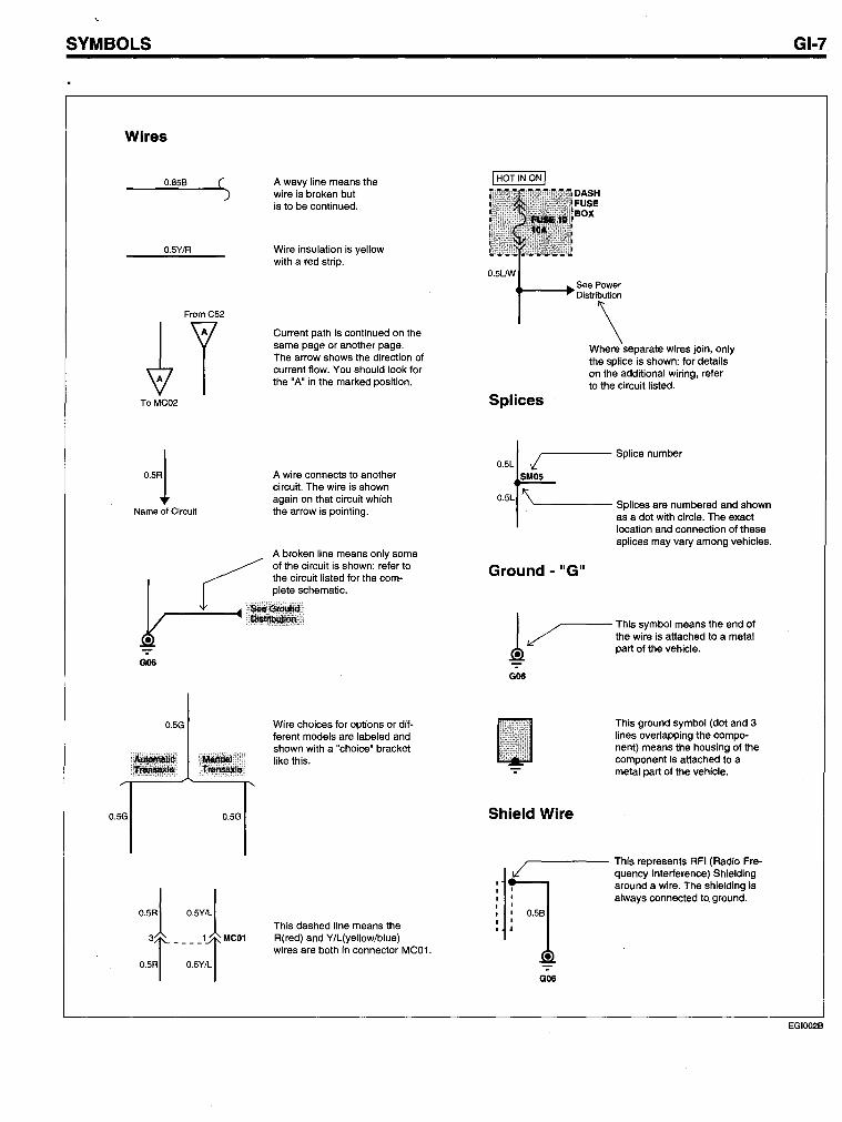
SYMBOLS
Wires
0.6S8 ( )
O.SY/R
From CS2
tl To MC02
'~l Name of Circuit
G06
O.SG
O.SG O.SG
o.sRI O.SyJ
't +'" O.SRI O.SY/L I
A wavy line means the wire is broken but is to be continued.
Wire insulation is yellow with a red strip.
Current path is continued on the same page or another page. The arrow shows the direction of current flow. You should look for the "A" in the marked position.
A wire connects to another circuit. The wire is shown again on that circuit which the arrow is pointing.
A broken line means only some of the circuit is shown: refer to the circuit listed for the complete schematic.
Wire choices for options or different models are labeled and shown with a "choice" bracket like this.
This dashed line means the R(red) and Y/L(yellowiblue) wires are both in connector MCOt.
DASH FUSE BOX
O.suw See Power
.... ---~Distribution
\ Where separate wires join, only the splice is shown: for details on the additional wiring, refer to the circuit listed.
Splices
~ Splice number
::~~ -- Splices are numbered and shown as a dot with circle. The exact location and connection of these splices may vary among vehicles.
Ground - "G"
1 ~ This symbol means the end of ~ the wire is attached to a metal
• part of the vehicle.
G06
Shield Wire
This ground symbol (dot and 3 lines overlapping the component) means the housing of the component is attached to a metal part of the vehicle.
~----- This represents RFI (Radio Fre-
j .,/ quency Interference) Shielding
: I around a wire. The shielding is : : always connected to. ground. I I 0.S8 I I ..
• -:-G06
GI-7
EGlOO28
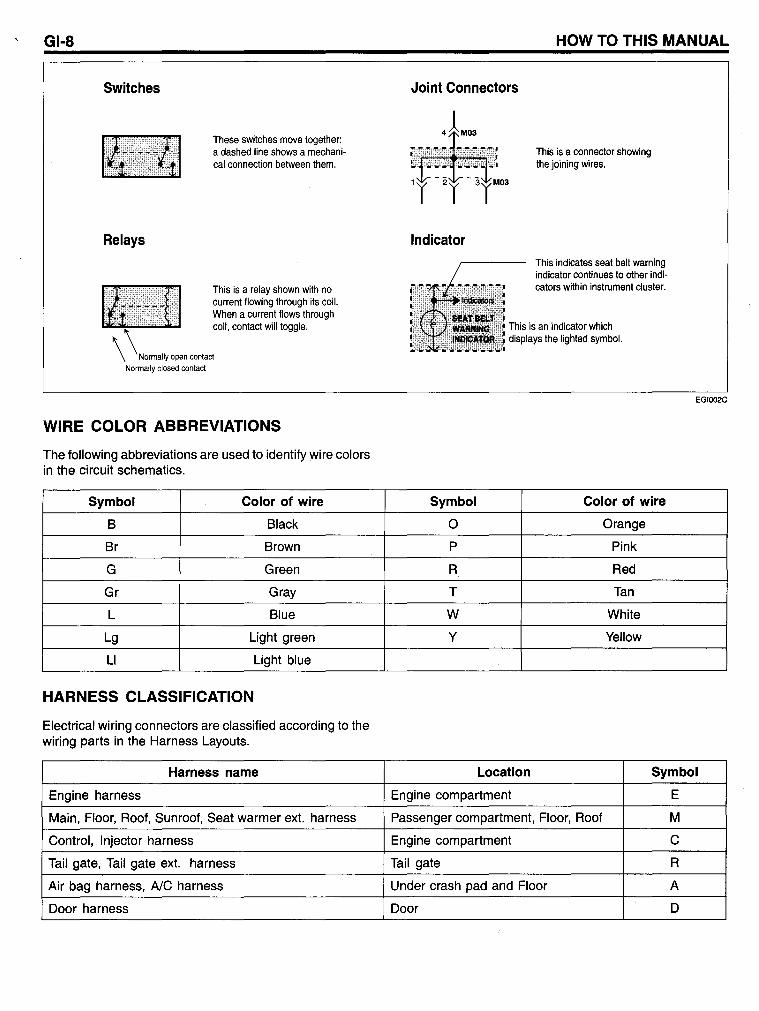
GI-8
Switches
Relays
These switches move together: a dashed line shows a mechanical connection between them.
This is a relay shown with no current flowing through its coil. When a current flows through coil. conlact will loggle.
Normally open contact Normally closed contact
WIRE COLOR ABBREVIATIONS
The following abbreviations are used to identify wire colors in the circuit schematics.
Symbol Color of wire
B Black
Br Brown
G Green
Gr Gray
L Blue
Lg Light green
LI Light blue
HARNESS CLASSIFICATION
Electrical wiring connectors are classified according to the wiring parts in the Harness Layouts.
Harness name
Engine harness
Main, Floor, Roof, Sunroof, Seat warmer ext. harness
Control, Injector harness
Tail gate, Tail gate ext. harness
Air bag harness, AlC harness
Door harness
HOW TO THIS MANUAL
Joint Connectors
Indicator
Symbol
0
P
R
T
W
Y
This is a connector showing the joining wires.
This indicates seat belt warning indicator continues to other indicators within instrument cluster.
This is an indicator which displays the lighted symbol.
Color of wire
Orange
Pink
Red
Tan
White
Yellow
EGlOO2C
Location Symbol
Engine compartment E
Passenger compartment, Floor, Roof M
Engine compartment C
Tail gate R
Under crash pad and Floor A
Door D
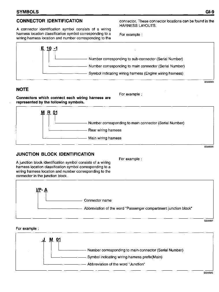
SYMBOLS GI-9
CONNECTOR IDENTIFICATION connector. These connector locations can be found in the HARNESS LAYOUTS.
A connector identification symbol consists of a wiring harness location classification symbol corresponding to a wiring harness location and number corresponding to the
For example :
~-r t'-1 ______ Number corresponding to sub-connector (Serial Number)
'---------- Number corresponding to main connector (Se rial Number)
L-________ Symbol indicating wiring harness (Engine wiring harness)
NOTE
Connectors which connect each wiring harness are represented by the following symbols.
For example :
M f T'-1 ______ Number corresponding to main connector (Se rial Number)
'---------- Rear wiring harness
L-________ Main wiring harness
JUNCTION BLOCK IDENTIFICATION
A junction block identification symbol consists of a wiring harness location classification symbol corresponding to a wiring harness location and number corresponding to the connector in the junction block.
For example :
r T'--_______ Connector name
'----------- Abbreviation of the word "Passenger compartment junction block"
For example :
r T'-1 _____ Number corresponding to main connector (Serial Number)
'--------- Symbol indicating wiring harness prefix(Main)
'---------- Abbreviation of the word "Junction"
EGlOO2D
EGlOO2E
EGlOO2F
EGlOO2G
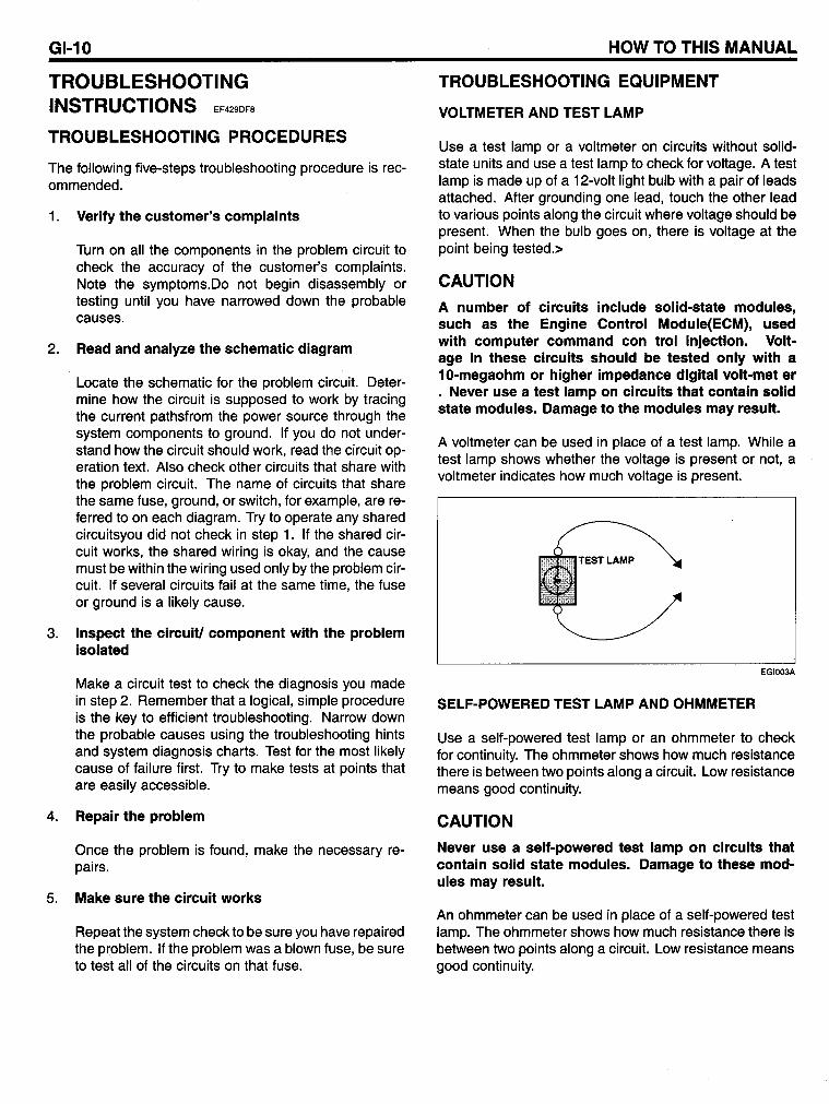
GI-10
TROUBLESHOOTING INSTRUCTIONS EF429DF8
TROUBLESHOOTING PROCEDURES
The following five-steps troubleshooting procedure is recommended.
1. Verify the customer's complaints
Turn on all the components in the problem circuit to check the accuracy of the customer's complaints. Note the symptoms.Oo not begin disassembly or testing until you have narrowed down the probable causes.
2. Read and analyze the schematic diagram
Locate the schematic for the problem circuit. Oetermine how the circuit is supposed to work by tracing the current pathsfrom the power source through the system components to ground. If you do not understand how the circuit should work, read the circuit operation text. Also check other circuits that share with the problem circuit. The name of circuits that share the same fuse, ground, or switch, for example, are referred to on each diagram. Try to operate any shared circuitsyou did not check in step 1. If the shared circuit works, the shared wiring is okay, and the cause must be within the wiring used only by the problem circuit. If several circuits fail at the same time, the fuse or ground is a likely cause.
3. Inspect the circuit/ component with the problem isolated
Make a circuit test to check the diagnosis you made in step 2. Remember that a logical, simple procedure is the key to efficient troubleshooting. Narrow down the probable causes using the troubleshooting hints and system diagnosis charts. Test for the most likely cause of failure first. Try to make tests at points that are easily accessible.
4. Repair the problem
Once the problem is found, make the necessary repairs.
5. Make sure the circuit works
Repeat the system check to be sure you have repaired the problem. If the problem was a blown fuse, be sure to test all of the circuits on that fuse.
HOW TO THIS MANUAL
TROUBLESHOOTING EQUIPMENT
VOLTMETER AND TEST LAMP
Use a test lamp or a voltmeter on circuits without solidstate units and use a test lamp to check for voltage. A test lamp is made up of a 12-volt light bulb with a pair of leads attached. After grounding one lead, touch the other lead to various points along the circuit where voltage should be present. When the bulb goes on, there is voltage at the point being tested.>
CAUTION
A number of circuits include solid-state modules, such as the Engine Control MOdule(ECM), used with computer command con trol injection. Voltage in these circuits should be tested only with a 10-megaohm or higher impedance digital volt-met er . Never use a test lamp on circuits that contain solid state modules. Damage to the modules may result.
A voltmeter can be used in place of a test lamp. While a test lamp shows whether the voltage is present or not, a voltmeter indicates how much voltage is present.
LAMP
EGI003A
SELF-POWERED TEST LAMP AND OHMMETER
Use a self-powered test lamp or an ohmmeter to check for continuity. The ohmmeter shows how much resistance there is between two points along a circuit. Low resistance means good continuity.
CAUTION
Never use a self-powered test lamp on circuits that contain solid state modules. Damage to these modules may result.
An ohmmeter can be used in place of a self-powered test lamp. The ohmmeter shows how much resistance there is between two points along a circuit. Low resistance means good continuity.
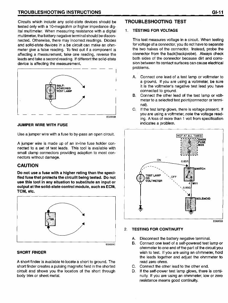
TROUBLESHOOTING INSTRUCTIONS
Circuits wh ich include any solid-state devices should be tested only with a 10-megaohm or higher impedance digital multimeter. When measuring resistance with a digital multimeter, the battery negative terminal should be disconnected. Otherwise, there may incorrect readings. Diodes and solid-state devices in a be circuit can make an ohmmeter give a false reading. To find out if a component is affecting a measurement, take one reading, reverse the leads and take a second reading. If different the solid-state device is affecting the measurement.
SELFPOWERED TESTLAMP
JUMPER WIRE WITH FUSE
EGI003B
Use a jumper wire with a fuse to by-pass an open circuit.
A jumper wire is made up of an in-line fuse holder connected to a set of test leads. This tool is available with sm all clamp connectors providing adaption to most connectors without damage.
CAUTION
00 not use a fuse with a higher rating than the specified fuse that protects the circuilt being tested_ 00 not use this tool in any situation to substitute an input or output at the solid-state control module, such as ECM, TCM, etc.
EGI003C
SHORT FINDER
A short finder is available to locate a short to ground. The short finder creates a pulsing magnetic field in the shorted circuit and shows you the location of the short through body trim or sheet meta!.
GI-11
TROUBLESHOOTING TEST
1. TESTING FOR VOLTAGE
2.
This test measures voltage in a circuit. When testing for voltage at a connector, you do not have to separate the two halves of the connector. Instead, probe the connector fram the back(backprobe). Always check both sides of the connector because dirt and corrasion between its contact surtaces can cause electrical problems.
A. Connect one lead of a test lamp or voltmeter to a ground. If you are using a voltmeter, be sure it is the voltmeter's negative test lead you have connected to ground.
B. Connect the other lead of the test lamp or voltmeter to a selected test point(connector or terminal).
C. If the test lamp glows, there is voltage present. If you are using a voltmeter, note the voltage reading. A loss of more than 1 volt from specification indicates a problem.
ON
... -----TESTLAMP OR VOLTMETER
, ,
TESTING FOR CONTINUITY
A. Disconnect the battery negative terminal.
EGlOO3D
B. Connect one lead of a self-powered test lamp or ohmmeter to one end of the part of the circuit you wish to test. If you are using an ohmmeter, hold the leads together and adjust the ohmmeter to read zero ohms.
C. Connect the other lead to the other end. D. If the self-power test lamp glows, there is conti
nuity. If you are using an ohmmeter, low or zero resistance means good continuity.
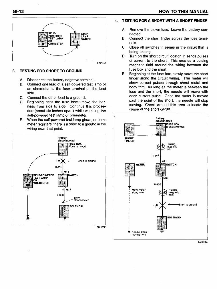
GI-12 Haw Ta THIS MANUAL
STOP LAMP SWITCH
EGI003E
3. TESTING FOR SHORT TO GROUND
A. Disconnect the battery negative terminal. B. Connect one lead of a self-powered test lamp or
an ohmmeter to the fuse terminal on the load side.
C. Connect the other lead to a ground. D. Beginning near the fuse block move the har
ness from side to side. Continue this proceedure(about six inches apart) while watching the self-powered test lamp or ohmmeter.
E. When the self-powered test lamp glows, or ohmmeter registers, there is a short to a ground in the wiring near that point.
Battery disconnected
EGI003F
4. TESTING FOR A SHORT WITH A SHORT FINDER
A.
B.
C.
D.
Remove the blown fuse. Leave the battery connected. Connect the short finder ac ross the fuse terminals. Close all switches in se ries in the circuit that is being testing. Turn on the short circuit locator. It sends pulses of current to the short. This creates a pulsing magnetic field around the wiring between the fuse box and the short.
E. Beginning at the fuse box, slowly move the short finder along the circuit wiring. The meter will show current pulses through sheet metal and body trim. As long as the meter is between the fuse and the short, the needle will move with each current pulse. Once the meter is moved past the point of the short, the needle will stop moving. Check around this area to locate the cause of the short circuit.
SHORT FINDER
METER
Move meier along wire
" Needle slops moving here
Battery disconnected
FUSE BOX (Fuse removed)
Pulsing magnelic field
Pulsing magnetic field
~Short 10 ground
SOLENOID
EGlOO3G