technická příručka kalibrace softwaru pro zavoli alisei di
TRANSCRIPT

Technická příručka kalibrace softwaru pro
ZAVOLI ALISEI DI
AUTOGAS - CENTRUM, spol. s r.o.
Heydukova1269
386 01 Strakonice
Mail: [email protected]
Web: www.lpg-autogascentrum.cz
Telefon: +420 383 324 912
GSM: +420 606 659 530
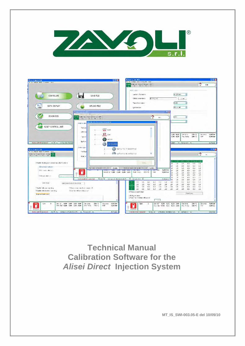
Technical Manual Calibration Software for the
Alisei Direct Injection System
MT_IS_SWI-003.05-E del 10/09/10
Technical Manual Calibration Software for the
Alisei Direct Injection System
MT-IS-SWI-DR-001.00-E del 28/09/12
Pag. 2 di 28
ZAVOLI s.r.l. Via Pitagora n° 400 47521 CESENA Fr. Case Castagnoli (FC) Italy Tel. 0547/ 646409 – Telefax 0547 / 646411
Web site: www.zavoli.com E-mail: [email protected]
Document Technical ID:
MT-IS-SWI-DR-001.00-E Rev. Date Review n. Issued by Reviewed/Approval
by 0 28/09/2012 First
Issue Ufficio Tecnico
MT Direttore Tecnico
R&D
PREFACE
This manual is not a comprehensive guide on the calibration and management of the Alisei system. These operations require the support of specific equipment and specialized personnel. Therefore, the goal of this manual is to provide general guidelines for the management and calibration of the Alisei injection system. ZAVOLI S.r.l. disclaims any responsibility for system malfunctions due to alterations performed by non-authorized personnel. Illegal tampering with the system will cause its warranty to become null and void. ZAVOLI S.r.l. reserves the right to revise its software in accordance with new applications and techniques available in the future. ZAVOLI S.r.l. disclaims any responsibility for system malfunctions caused by failure to update this manual.
Technical Manual Calibration Software for the
Alisei Direct Injection System
MT-IS-SWI-DR-001.00-E del 28/09/12
Pag. 3 di 28
ZAVOLI s.r.l. Via Pitagora n° 400 47521 CESENA Fr. Case Castagnoli (FC) Italy Tel. 0547/ 646409 – Telefax 0547 / 646411
Web site: www.zavoli.com E-mail: [email protected]
Indice Generale Introduction ……………………………………………………. ……4
1. ……………….. System Requirements………...….…………………………..…. ……4
1.1
………… Installation of the Software…………………………………… ……4
2.
……………….. Main Menu……..……………………...……………………….. ……5
3. ……………….
Vehicle Configuration…….………….………………………… ……8
3.1
………… Vehicle F1…..…………………….………………………….…. ……11
3.2
………… Switch Over F2………..………….….……………………..…. ……13
3.3
………… Sensors F3……….………………………………………………. ……14
3.4
…………. Gas Map F4………………………….…………………………. ……16
3.5
…………. OBD F5…..………………………………..…….……………… ……18
4. ………………...
Data Display………………………………………………….…. ……20
5. ………………..
Diagnosis………….....…………………………………………… ……22
6. ………………..
Reset Control Unit..……………………………………………. ……24
7. ………………..
Save File……………...………………………………………… ……24
8. ………………..
Upload File…………….………………………………………… ……25
9. ………………..
Reprogram……………….……………………………………… ……26
10. ………………..
Program Error Codes…………...……………………………… ……28
Technical Manual Calibration Software for the
Alisei Direct Injection System
MT-IS-SWI-DR-001.00-E del 28/09/12
Pag. 4 di 28
ZAVOLI s.r.l. Via Pitagora n° 400 47521 CESENA Fr. Case Castagnoli (FC) Italy Tel. 0547/ 646409 – Telefax 0547 / 646411
Web site: www.zavoli.com E-mail: [email protected]
Introduction The calibration software can be launched without having to be connected directly to the control unit. To connect to the control unit it is necessary that the PC and the ECU are duly connected through one of the following interfaces: • USB Interface cable (not included in the kit. To be purchased separately) • WIRELESS INTERFACE KIT (not included in the kit. To be purchased separately The control unit must also be connected to the +12 volt battery (red – black wire) and to the ground (black wire). ATTENTION: The USB and wireless interfaces require the USB drivers included in the CD-rom.
DO NOT USE THE OBD HAND TESTER WHILE THE VEHICLE IS RUNNING ON GAS
1. System Requirements Operating system - Windows XP or later versions Memory (RAM) - At least 32 Mbyte free Hard drive - At least 30 Mbyte free at time of installation Display resolution - 1024 x 768 or greater 1.1 Installation of the software To install the calibration software, put the CD-ROM in the computer drive and wait for the guided installation window to open. If the installation program does not start, select “Start” in the “Taskbar”. Choose “Run” and enter: "D:\setup.exe" (where D stands for the CD-ROM drive). During installation you will be asked in which directory you want to install the program. We recommend you do not change the pre-set directory. The program icon will be created on the desktop when installation is complete. ATTENTION: For software installation, some systems may require Administrator privileges
Technical Manual Calibration Software for the
Alisei Direct Injection System
MT-IS-SWI-DR-001.00-E del 28/09/12
Pag. 5 di 28
ZAVOLI s.r.l. Via Pitagora n° 400 47521 CESENA Fr. Case Castagnoli (FC) Italy Tel. 0547/ 646409 – Telefax 0547 / 646411
Web site: www.zavoli.com E-mail: [email protected]
2.
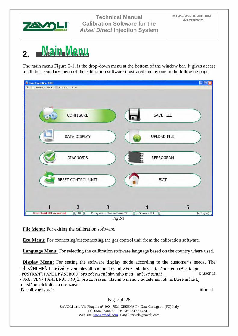
The main menu Figure 2-1, is the drop-down menu at the bottom of the window bar. It gives access to all the secondary menu of the calibration software illustrated one by one in the following pages:
Fig 2-1
File Menu: For exiting the calibration software. Ecu Menu: For connecting/disconnecting the gas control unit from the calibration software. Language Menu: For selecting the calibration software language based on the country where used. Display Menu: For setting the software display mode according to the customer’s needs. The display modes available are: • MAIN MENU : for displaying the main menu at any moment, regardless of the menu the user is working in. • SIDE TOOLBAR: for displaying the main menu on the left side of the setting menu • UNDOCKED TOOLBAR: for displaying the main menu in a separate window that can positioned
1 2 3 4 5

Technical Manual Calibration Software for the
Alisei Direct Injection System
MT-IS-SWI-DR-001.00-E del 28/09/12
Pag. 6 di 28
ZAVOLI s.r.l. Via Pitagora n° 400 47521 CESENA Fr. Case Castagnoli (FC) Italy Tel. 0547/ 646409 – Telefax 0547 / 646411
Web site: www.zavoli.com E-mail: [email protected]
anywhere on the PC screen at user’s choice. • ZOOM: for displaying the calibration software in window (default setting) or full-screen mode. Acquisition Menu: For storing the GAS control unit operation parameters in a fi le that can be displayed via a chart. • START/STOP AQUIRING: For starting/stopping the data saving operation. • GRAPH: For viewing the trend of the saved data in a chart (see chapter "Data Display"). About Menu: For retrieving details about the version of the installed software and of the system libraries in use as: A Configurable vehicles settings library. B Configurable vehicles list library. C Configurable injectors list library.
In order to allow the gas conversion of new generation vehicles, it is advisable to check the release of these libraries updates periodically.
At the bottom of the page shows the following information:
Fig. 2-3
1 Indicates whether the control unit is connected or disconnected to the calibration software. In case the control unit is connected through a wireless interface, the signal strength is displayed through vertical red lines .
2 Indicates whether the configuration currently loaded in the control unit uses the operation parameters for natural gas or for LPG; to select the fuel type, go to the submenu "CONFIGURE". 3 Is the name of the configuration in the control unit (max. 28 characters displayed). To upload a pre-existing configuration in the control unit, it must be connected to the configuration software (see chapter "Upload file")
Fig.2-2
A
B C
Technical Manual Calibration Software for the
Alisei Direct Injection System
MT-IS-SWI-DR-001.00-E del 28/09/12
Pag. 7 di 28
ZAVOLI s.r.l. Via Pitagora n° 400 47521 CESENA Fr. Case Castagnoli (FC) Italy Tel. 0547/ 646409 – Telefax 0547 / 646411
Web site: www.zavoli.com E-mail: [email protected]
4 Is the firmware version of the control unit connected; to update it, go to the submenu “REPROGRAM CONTROL UNIT” and select the desired firmware from those proposed.
5 Indicates the specific configuration parameters of the vehicle selected from the program library. It is important to remember that all the settings made on the disconnected control unit will be lost when it is connected, unless they are previously saved in a configuration file. If the program does not connect, an error window will open. At this point check: - the serial interface connection, - that the control unit is connected to the battery and ground, - if the sub key has been disconnected for more than an hour, to connect it will be necessary to connect the panel for a few seconds and check that the switch turns on at the same time, or start the vehicle. To attempt connection again, open the “Connection” window and select “Connect”.
Technical Manual Calibration Software for the
Alisei Direct Injection System
MT-IS-SWI-DR-001.00-E del 28/09/12
Pag. 8 di 28
ZAVOLI s.r.l. Via Pitagora n° 400 47521 CESENA Fr. Case Castagnoli (FC) Italy Tel. 0547/ 646409 – Telefax 0547 / 646411
Web site: www.zavoli.com E-mail: [email protected]
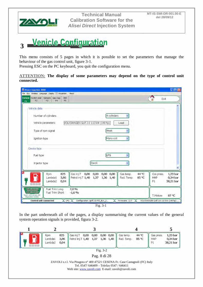
3 This menu consists of 5 pages in which it is possible to set the parameters that manage the behaviour of the gas control unit, figure 3-1. Pressing ESC on the PC keyboard, you quit the configuration menu. ATTENTION: The display of some parameters may depend on the type of control unit connected.
Fig. 3-1
In the part underneath all of the pages, a display summarising the current values of the general system operation signals is provided, figura 3-2. 1 2 3 4 5
Fig. 3-2
Technical Manual Calibration Software for the
Alisei Direct Injection System
MT-IS-SWI-DR-001.00-E del 28/09/12
Pag. 9 di 28
ZAVOLI s.r.l. Via Pitagora n° 400 47521 CESENA Fr. Case Castagnoli (FC) Italy Tel. 0547/ 646409 – Telefax 0547 / 646411
Web site: www.zavoli.com E-mail: [email protected]
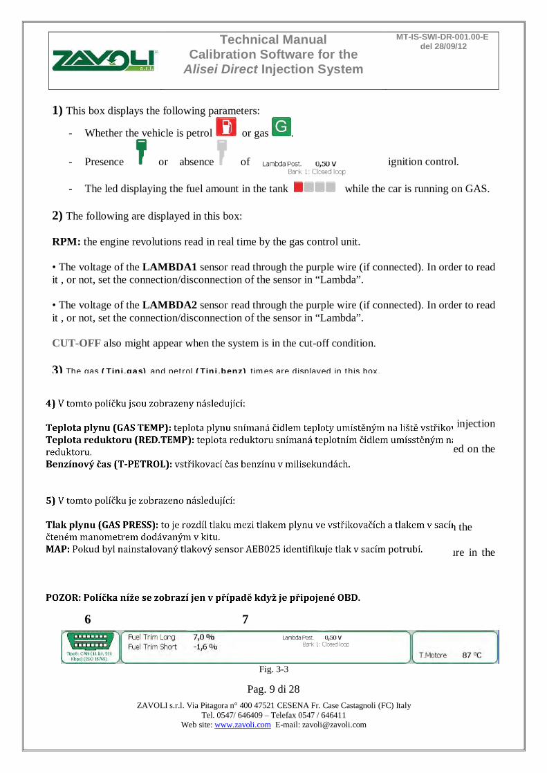
1) This box displays the following parameters:
- Whether the vehicle is petrol or gas .
- Presence or absence of ignition control. - The led displaying the fuel amount in the tank while the car is running on GAS.
2) The following are displayed in this box: RPM: the engine revolutions read in real time by the gas control unit. • The voltage of the LAMBDA1 sensor read through the purple wire (if connected). In order to read it , or not, set the connection/disconnection of the sensor in “Lambda”. • The voltage of the LAMBDA2 sensor read through the purple wire (if connected). In order to read it , or not, set the connection/disconnection of the sensor in “Lambda”. CUT-OFF also might appear when the system is in the cut-off condition. 3) The gas (Tinj.gas) and petrol (Tinj.benz) times are displayed in this box. 4) The following are displayed in this box: GAS TEMP: gas temperature detected by the temperature sensor positioned on the gas injection rail. RED.TEMP: gas reduction gear temperature detected by the temperature sensor positioned on the gas reduction gear. T- PETROL: petrol injection time in milliseconds. 5) The following are displayed in this box: GAS PRESS: this is the pressure difference between the gas in the gas injectors and that in the intake manifolds read by the pressure gauge supplied in the kit. MAP: If an AEB025 pressure sensor has been installed, it identifi es the intake pressure in the manifolds. ATTENTION: the box below is displayed only in case of OBD connection enabled. 6 7
Fig. 3-3

Technical Manual Calibration Software for the
Alisei Direct Injection System
MT-IS-SWI-DR-001.00-E del 28/09/12
Pag. 10 di 28
ZAVOLI s.r.l. Via Pitagora n° 400 47521 CESENA Fr. Case Castagnoli (FC) Italy Tel. 0547/ 646409 – Telefax 0547 / 646411
Web site: www.zavoli.com E-mail: [email protected]
6) This box displays the connected/disconnected status of the OBD communication protocol and the type of protocol used for the connection (value displayed below the OBD connector):
OBD connected correctly. OBD disconnected.
Moreover, in case OBD errors are detected, the following symbols may be displayed:
OBD error detected
OBD error deleted
7) This box displays:
- The long fuel trim value (FUEL TRIM LONG) in percentage.
- The short fuel trim value (FUEL TRIM SHORT) in percentage.
- The BACK LAMBDA SENSOR voltage.
- The message (BANK1:CLOSED LOOP) when the PETROL control unit manages the injection time according to the values read by the lambda probe.
- The message (BANK1:OPEN LOOP) when the PETROL control unit manages the
injection time regardless to the values read by the lambda probe.
- The message (BANK1:TRANSIENT OPEN LOOP) when the PETROL control unit manages the injection time regardless to the values read by the lambda probe for a temporary time before switching to CLOSED LOOP management.
Technical Manual Calibration Software for the
Alisei Direct Injection System
MT-IS-SWI-DR-001.00-E del 28/09/12
Pag. 11 di 28
ZAVOLI s.r.l. Via Pitagora n° 400 47521 CESENA Fr. Case Castagnoli (FC) Italy Tel. 0547/ 646409 – Telefax 0547 / 646411
Web site: www.zavoli.com E-mail: [email protected]
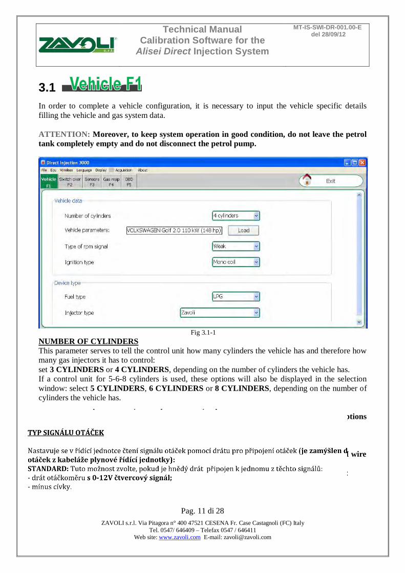
3.1 In order to complete a vehicle configuration, it is necessary to input the vehicle specific details filling the vehicle and gas system data. ATTENTION: Moreover, to keep system operation in good condition, do not leave the petrol tank completely empty and do not disconnect the petrol pump.
Fig 3.1-1
NUMBER OF CYLINDERS This parameter serves to tell the control unit how many cylinders the vehicle has and therefore how many gas injectors it has to control: set 3 CYLINDERS or 4 CYLINDERS, depending on the number of cylinders the vehicle has. If a control unit for 5-6-8 cylinders is used, these options will also be displayed in the selection window: select 5 CYLINDERS, 6 CYLINDERS or 8 CYLINDERS, depending on the number of cylinders the vehicle has. ATTENTION: Depending on the type of unit connected will be displayed only options allowed. TYPE OF REVOLUTION SIGNAL It sets up the control unit for reading the rev signal through the RPM wire (meant as the RPM wire of the gas control unit cable): STANDARD: select this option when the BROWN2 wire is connected to one of these signals: - rev counter wire with 0 ÷ 12 V square wave signal; - negative coil.
Technical Manual Calibration Software for the
Alisei Direct Injection System
MT-IS-SWI-DR-001.00-E del 28/09/12
Pag. 12 di 28
ZAVOLI s.r.l. Via Pitagora n° 400 47521 CESENA Fr. Case Castagnoli (FC) Italy Tel. 0547/ 646409 – Telefax 0547 / 646411
Web site: www.zavoli.com E-mail: [email protected]
WEAK SIGNAL: select this option when the RPM wire is connected to one of these signals: - rev counter wire with 0 ÷ 5 V square wave signal; - static ignition control with 0 ÷ 5 V square wave signal; These signals can be identified only by using an oscilloscope. IGNITION TYPE The control unit uses this parameter for correctly calculating the engine speed, which varies based on the type of ignition on which the BROWN2 wire is connected. Set: MONO COIL: for vehicles with one coil per cylinder if the BROWN2 wire is connected to the negative terminal of one of the coils; DOUBLE COIL: for vehicles with one coil every 2 cylinders if the BROWN2 wire is connected to the negative terminal of one of the coils; REV COUNTER: for vehicles with one coil and mechanical distributor if the BROWN2 wire is connected to the negative terminal of this coil, or in all vehicles where the BROWN2 wire is connected to the rev counter signal wire. REV COUNTER 2: set this option when the engine’s speed is not read correctly on a 6 or 8-cylinder vehicle with the BROWN2 wire connected to the rev counter. FUEL TYPE This selection serves to initialise the control unit with the typical parameters set ahead of time for correct operation with the type of fuel used. Select: LPG: for LPG-powered vehicles NATURAL GAS (CNG): for NATURAL GAS-powered vehicles. When LPG or NATURAL GAS is selected, also the directory where the configuration files are saved changes (see "Upload file"). INJECTOR TYPE This window is used to select the type of GAS injectors that are supplied with the conversion kit. When a previously saved configuration is loaded, this window indicates the type of injectors that are used in the configuration. If the GAS injectors installed on the vehicle do not correspond to the type shown in the window, then you will need to load a configuration that uses the correct type of injector. If the installed injectors do not correspond to the type that have been selected on the software, then the injectors will be piloted with incorrect parameters and may cause malfunctions during gas operation.
Technical Manual Calibration Software for the
Alisei Direct Injection System
MT-IS-SWI-DR-001.00-E del 28/09/12
Pag. 13 di 28
ZAVOLI s.r.l. Via Pitagora n° 400 47521 CESENA Fr. Case Castagnoli (FC) Italy Tel. 0547/ 646409 – Telefax 0547 / 646411
Web site: www.zavoli.com E-mail: [email protected]
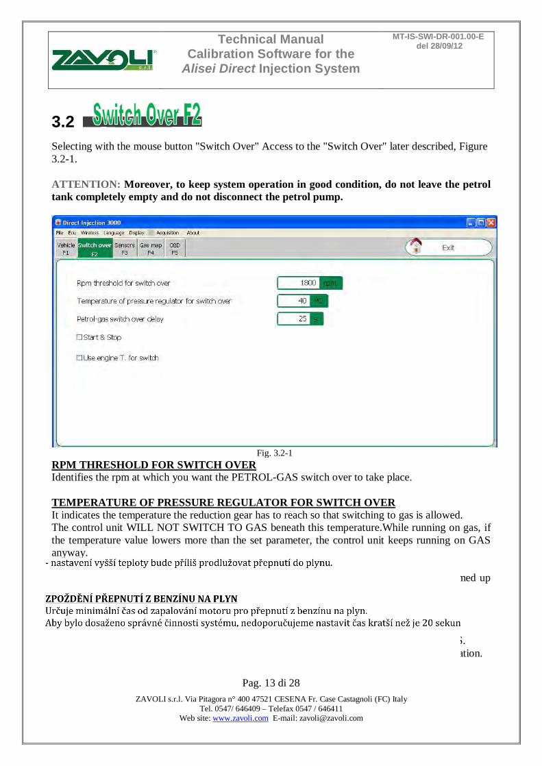
3.2 Selecting with the mouse button "Switch Over" Access to the "Switch Over" later described, Figure 3.2-1. ATTENTION: Moreover, to keep system operation in good condition, do not leave the petrol tank completely empty and do not disconnect the petrol pump.
Fig. 3.2-1
RPM THRESHOLD FOR SWITCH OVER Identifies the rpm at which you want the PETROL-GAS switch over to take place. TEMPERATURE OF PRESSURE REGULATOR FOR SWITCH OVER It indicates the temperature the reduction gear has to reach so that switching to gas is allowed. The control unit WILL NOT SWITCH TO GAS beneath this temperature.While running on gas, if the temperature value lowers more than the set parameter, the control unit keeps running on GAS anyway. It is recommended to set a temperature between 20°C and 45°C since: - setting a lower temperature could trigger the fuel change over if the reducer has not warmed up enough for a correct Gas output. - setting a higher temperature would postpone too long the change over to Gas. PETROL-GAS SWITCH OVER DELAY It indicates the minimum time from engine ignition for switching over from PETROL to GAS. We recommend you set a time no less than 20 seconds in order to ensure correct system operation.
Technical Manual Calibration Software for the
Alisei Direct Injection System
MT-IS-SWI-DR-001.00-E del 28/09/12
Pag. 14 di 28
ZAVOLI s.r.l. Via Pitagora n° 400 47521 CESENA Fr. Case Castagnoli (FC) Italy Tel. 0547/ 646409 – Telefax 0547 / 646411
Web site: www.zavoli.com E-mail: [email protected]
START & STOP It enables the START AND STOP device if available on the vehicle. If a STOP is detected, the gas electro valves are closed after 3 seconds and opened again at the following START. USE ENGINE T.FOR SWITCH It indicates the temperature the engine needs to reach for switching to GAS. Enabling this function, the control unit uses the engine temperature as well as a reference for switching to GAS. Since this parameter is detected via OBD, it is necessary to connect the OBD cables before enabling this function. With values below this engine temperature, the control unit does not switch to GAS.
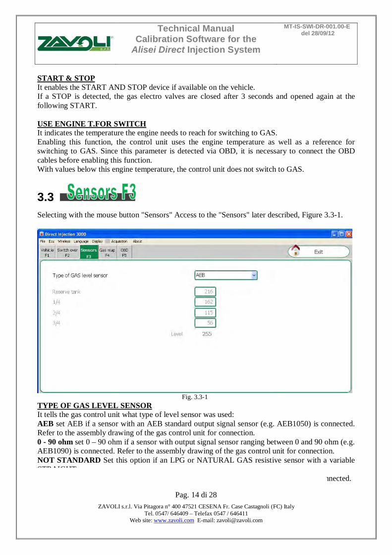
3.3 Selecting with the mouse button "Sensors" Access to the "Sensors" later described, Figure 3.3-1.
Fig. 3.3-1
TYPE OF GAS LEVEL SENSOR It tells the gas control unit what type of level sensor was used: AEB set AEB if a sensor with an AEB standard output signal sensor (e.g. AEB1050) is connected. Refer to the assembly drawing of the gas control unit for connection. 0 - 90 ohm set 0 – 90 ohm if a sensor with output signal sensor ranging between 0 and 90 ohm (e.g. AEB1090) is connected. Refer to the assembly drawing of the gas control unit for connection. NOT STANDARD Set this option if an LPG or NATURAL GAS resistive sensor with a variable STRAIGHT signal (lower (Ohm) value with higher vacuum level and value (Ohm) with full level) is connected.
Technical Manual Calibration Software for the
Alisei Direct Injection System
MT-IS-SWI-DR-001.00-E del 28/09/12
Pag. 15 di 28
ZAVOLI s.r.l. Via Pitagora n° 400 47521 CESENA Fr. Case Castagnoli (FC) Italy Tel. 0547/ 646409 – Telefax 0547 / 646411
Web site: www.zavoli.com E-mail: [email protected]
NOT STANDARD INVERTED Set this option if an LPG or NATURAL GAS resistive sensor with a variable REVERSED signal (higher (Ohm) value with lower vacuum level and value (Ohm) with full level) is connected. ATTENTION: Setting NON STANDARD or NON STANDARD INVERTED in the “TYPE OF GAS LEVEL SENSOR” box, you enable the settings necessary to set the level sensor as follows: Set the reference values necessary for setting the level sensor as follows: - manually move the sensor indicator starting from the full level and note the value indicated in “Level” for each reference (RESERVE, 1/4, 2/4, 3/4). - enter the values noted in the corresponding boxes. We can then see the following changes on the switch: RESERVE = LEVEL value when the red reserve LED turns on and the 1/4 LED turns off. 1/4 REFERENCE = LEVEL value when the 2/4 LED turns off. 2/4 REFERENCE = LEVEL value when the 3/4 LED turns off. 3/4 REFERENCE = LEVEL value when the 4/4 LED turns off.
Technical Manual Calibration Software for the
Alisei Direct Injection System
MT-IS-SWI-DR-001.00-E del 28/09/12
Pag. 16 di 28
ZAVOLI s.r.l. Via Pitagora n° 400 47521 CESENA Fr. Case Castagnoli (FC) Italy Tel. 0547/ 646409 – Telefax 0547 / 646411
Web site: www.zavoli.com E-mail: [email protected]
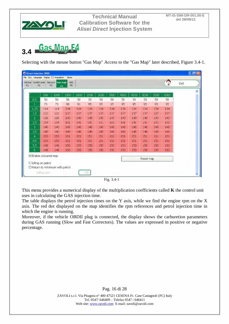
3.4 Selecting with the mouse button "Gas Map" Access to the "Gas Map" later described, Figure 3.4-1.
Fig. 3.4-1
This menu provides a numerical display of the multiplication coefficients called K the control unit uses in calculating the GAS injection time. The table displays the petrol injection times on the Y axis, while we find the engine rpm on the X axis. The red dot displayed on the map identifies the rpm references and petrol injection time in which the engine is running. Moreover, if the vehicle OBDII plug is connected, the display shows the carburetion parameters during GAS running (Slow and Fast Correctors). The values are expressed in positive or negative percentage.
Technical Manual Calibration Software for the
Alisei Direct Injection System
MT-IS-SWI-DR-001.00-E del 28/09/12
Pag. 17 di 28
ZAVOLI s.r.l. Via Pitagora n° 400 47521 CESENA Fr. Case Castagnoli (FC) Italy Tel. 0547/ 646409 – Telefax 0547 / 646411
Web site: www.zavoli.com E-mail: [email protected]
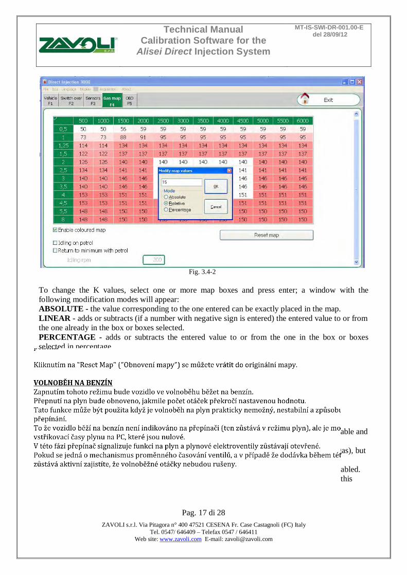
Fig. 3.4-2
To change the K values, select one or more map boxes and press enter; a window with the following modification modes will appear: ABSOLUTE - the value corresponding to the one entered can be exactly placed in the map. LINEAR - adds or subtracts (if a number with negative sign is entered) the entered value to or from the one already in the box or boxes selected. PERCENTAGE - adds or subtracts the entered value to or from the one in the box or boxes selected in percentage. Clicking on “Enable colours on the map”, all the modifi ed boxes will be highlighted. Clicking on “Reset Map” you may go back to the original map. IDLING ON PETROL Enabling this mode, the vehicle will be running on PETROL while on idle. Gas function is restored when the number of revolutions exceeds the set value. This function can only be used if running on gas at idle speed is practically impossible, unstable and causes the vehicle to switch off frequently. The fact that the system is running on petrol is not indicated on the switch (which stays on gas), but by reading the gas injection time on the computer (which becomes nil). In this phase, the switch continues to signal gas function and the gas solenoid valves stay enabled. If there is an advance variable valve timing mechanism, if the supply remains active during this phase, ensure the idle speed advance does not disturb the system.

Technical Manual Calibration Software for the
Alisei Direct Injection System
MT-IS-SWI-DR-001.00-E del 28/09/12
Pag. 18 di 28
ZAVOLI s.r.l. Via Pitagora n° 400 47521 CESENA Fr. Case Castagnoli (FC) Italy Tel. 0547/ 646409 – Telefax 0547 / 646411
Web site: www.zavoli.com E-mail: [email protected]
3.5 Selecting with the mouse button "OBD" Access to the "OBD" later described, Figure 3.5-1.
Fig. 3.5-1
Enabling the diagnostic OBD connection ( ) the user can select the control unit connection mode to the OBD protocol: • AUTOMATIC SELECTION: thought this option, the software automatically tries to connect to the vehicle testing all the existing OBD connections and selecting the correct one. • MANUAL SELECTION: though this option, the user selects the OBD connection of the vehicle from a list of possible connections.
The VWOPTION check ( ) and the value indicated in the Scan Mode box (1) are parameters of the vehicle configuration set for the correct reading of OBD values. The parameters are not to be modified without consulting and obtaining the approval of our technicians Zavoli.
1
2
Technical Manual Calibration Software for the
Alisei Direct Injection System
MT-IS-SWI-DR-001.00-E del 28/09/12
Pag. 19 di 28
ZAVOLI s.r.l. Via Pitagora n° 400 47521 CESENA Fr. Case Castagnoli (FC) Italy Tel. 0547/ 646409 – Telefax 0547 / 646411
Web site: www.zavoli.com E-mail: [email protected]
Moreover, the software allows the selection of the cancellation mode of the OBD errors eventually detected:
ENABLE FULL ERROR CANCELLING: through this option, all the OBD errors detected by the control unitare cancelled.
ENABLE SELECTIVE ERROR CANCELLING: through this mode, only a selection of errors are automatically deleted. This list of errors is selected by AEB technicians and is not further customizable.
ENABLE ERROR CANCELLING WITH ENGINE OFF: though this option, all the OBD errors detected by the ECU will be deleted once the engine is turned off.
CONNECT WITH OR WITHOUT RPM: through this option, the OBD connection is enableb even when the RPM signal is not detected. ATTENTION: Regardless of the state of the check CONNECTION EVEN IN THE ABSENCE OF REVOLUTIONS, the GAS unit will attempt to connect only if the switch is set to operate GAS. 2) This area contains the list of the detected OBD errors
Technical Manual Calibration Software for the
Alisei Direct Injection System
MT-IS-SWI-DR-001.00-E del 28/09/12
Pag. 20 di 28
ZAVOLI s.r.l. Via Pitagora n° 400 47521 CESENA Fr. Case Castagnoli (FC) Italy Tel. 0547/ 646409 – Telefax 0547 / 646411
Web site: www.zavoli.com E-mail: [email protected]
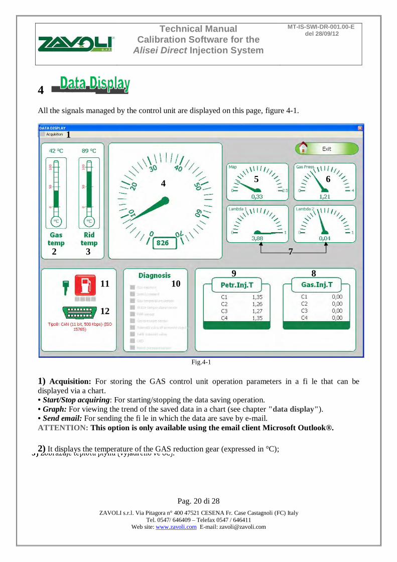
4 All the signals managed by the control unit are displayed on this page, figure 4-1.
Fig.4-1
1) Acquisition: For storing the GAS control unit operation parameters in a fi le that can be displayed via a chart. • Start/Stop acquiring: For starting/stopping the data saving operation. • Graph: For viewing the trend of the saved data in a chart (see chapter "data display"). • Send email: For sending the fi le in which the data are save by e-mail. ATTENTION: This option is only available using the email client Microsoft Outlook®. 2) It displays the temperature of the GAS reduction gear (expressed in °C); 3) It displays the gas temperature (expressed in °C);
1
2 3
4 5 6
7
8 9 10 11
12
Technical Manual Calibration Software for the
Alisei Direct Injection System
MT-IS-SWI-DR-001.00-E del 28/09/12
Pag. 21 di 28
ZAVOLI s.r.l. Via Pitagora n° 400 47521 CESENA Fr. Case Castagnoli (FC) Italy Tel. 0547/ 646409 – Telefax 0547 / 646411
Web site: www.zavoli.com E-mail: [email protected]
4) It displays the number of engine revolutions in real time (rpm); 5) It displays the pressure in the intake manifolds (expressed in Bar); 6) It is the pressure difference between the gas in the gas injectors and that in the intake manifolds read by the pressure gauge supplied in the kit (expressed in Bar); 7) It is the voltage of the lambda probe(s). If the wires of the lambda probe(s) are not connected, there will be no display; 8) It displays the Gas injection time in real time (ms); 9) It displays the PETROL injection time in real time (ms); 10) If the connection vehicle diagnostics is enabled, displays the errors found; 11) Indicates whether the car is running on GAS or PETROL; 12) It indicates the OBDII plug status (connected/disconnected) and displays the type of connection to the communication protocol; ATTENTION: Pressing the spacebar will execute the request for switching GAS/PETROL
Technical Manual Calibration Software for the
Alisei Direct Injection System
MT-IS-SWI-DR-001.00-E del 28/09/12
Pag. 22 di 28
ZAVOLI s.r.l. Via Pitagora n° 400 47521 CESENA Fr. Case Castagnoli (FC) Italy Tel. 0547/ 646409 – Telefax 0547 / 646411
Web site: www.zavoli.com E-mail: [email protected]
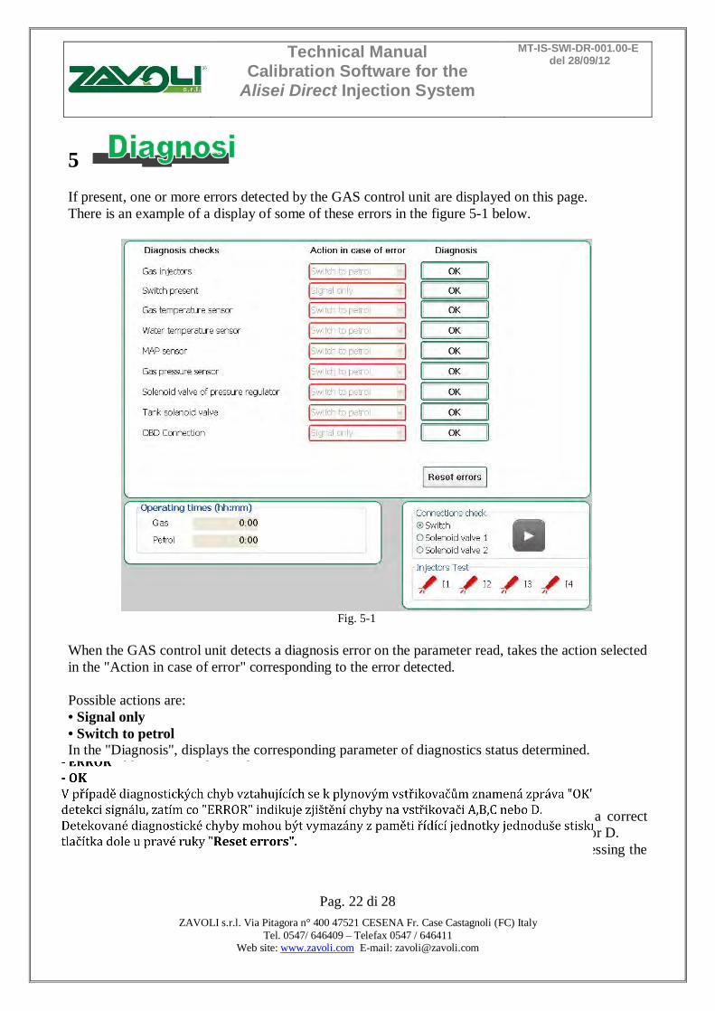
5 If present, one or more errors detected by the GAS control unit are displayed on this page. There is an example of a display of some of these errors in the figure 5-1 below.
Fig. 5-1
When the GAS control unit detects a diagnosis error on the parameter read, takes the action selected in the "Action in case of error" corresponding to the error detected. Possible actions are: • Signal only • Switch to petrol In the "Diagnosis", displays the corresponding parameter of diagnostics status determined. The possible states are detected: • ERROR • OK In case of diagnostic errors related to the gas INJECTORS the message “OK” means a correct detection of the signal, while “ERROR” indicates a detection error on the injector A,B,C or D. The diagnostic errors detected can be deleted from the control unit memory simply by pressing the lower righthand button “Reset errors”.
Technical Manual Calibration Software for the
Alisei Direct Injection System
MT-IS-SWI-DR-001.00-E del 28/09/12
Pag. 23 di 28
ZAVOLI s.r.l. Via Pitagora n° 400 47521 CESENA Fr. Case Castagnoli (FC) Italy Tel. 0547/ 646409 – Telefax 0547 / 646411
Web site: www.zavoli.com E-mail: [email protected]
By enabling or disabling the check in the "Enable the diagnosis connection with the vehicle" (see "OBD F5" menu) display of the diagnostic errors will be activated or deactivated. The error detected will be signalled to the driver by the yellow LED coming on and remaining steady, and by the slow blinking of the green LED on the switch. Moreover, the buzzer inside the switch will be enabled to simplify identification of the alarm status. To deactivate the audible alarm, just press the switch button to change the car from Gas set-up to the Petrol position. ATTENTION: Switching over to petrol is envisaged for some errors. In this case, the GAS control unit will automatically switch over when the error is detected. To return to GAS operation, it is necessary to shut down and re-start the vehicle.
Fig. 5-2
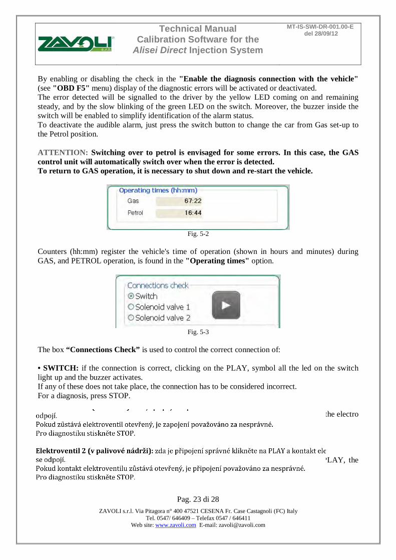
Counters (hh:mm) register the vehicle's time of operation (shown in hours and minutes) during GAS, and PETROL operation, is found in the "Operating times" option.
Fig. 5-3
The box “Connections Check” is used to control the correct connection of: • SWITCH: if the connection is correct, clicking on the PLAY, symbol all the led on the switch light up and the buzzer activates. If any of these does not take place, the connection has to be considered incorrect. For a diagnosis, press STOP. • SOLENOID VALVE 1 (REDUCER): If the connection is correct, clicking on PLAY, the electro valve contact is disconnected. If the electro valve contact stays open, the connection needs to be considered incorrect. For a diagnosis, press STOP. • SOLENOID VALVE 2 (FUEL TANK): If the connection is correct, clicking on PLAY, the electro valve contact is disconnected. If the electro valve contact stays open, the connection needs to be considered incorrect. For a diagnosis, press STOP.
Technical Manual Calibration Software for the
Alisei Direct Injection System
MT-IS-SWI-DR-001.00-E del 28/09/12
Pag. 24 di 28
ZAVOLI s.r.l. Via Pitagora n° 400 47521 CESENA Fr. Case Castagnoli (FC) Italy Tel. 0547/ 646409 – Telefax 0547 / 646411
Web site: www.zavoli.com E-mail: [email protected]
6
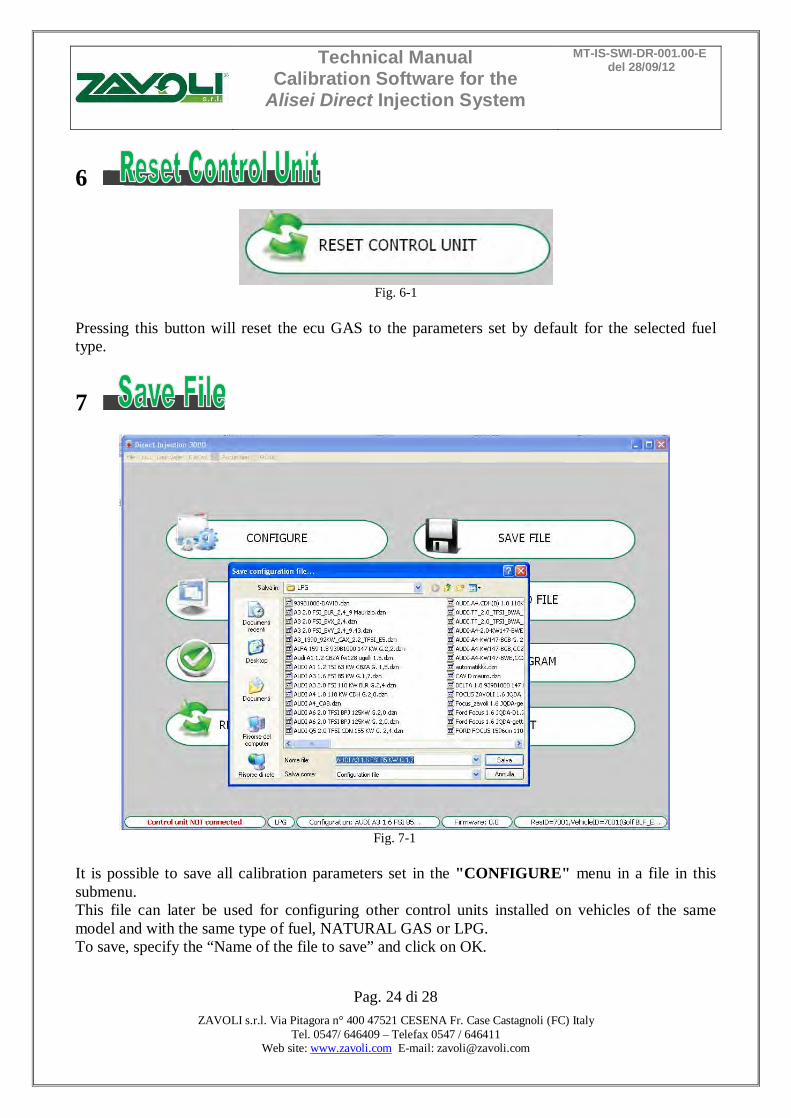
Fig. 6-1
Pressing this button will reset the ecu GAS to the parameters set by default for the selected fuel type.
7
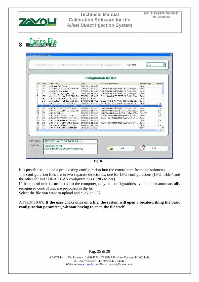
Fig. 7-1
It is possible to save all calibration parameters set in the "CONFIGURE" menu in a file in this submenu. This file can later be used for configuring other control units installed on vehicles of the same model and with the same type of fuel, NATURAL GAS or LPG. To save, specify the “Name of the file to save” and click on OK.
Technical Manual Calibration Software for the
Alisei Direct Injection System
MT-IS-SWI-DR-001.00-E del 28/09/12
Pag. 25 di 28
ZAVOLI s.r.l. Via Pitagora n° 400 47521 CESENA Fr. Case Castagnoli (FC) Italy Tel. 0547/ 646409 – Telefax 0547 / 646411
Web site: www.zavoli.com E-mail: [email protected]
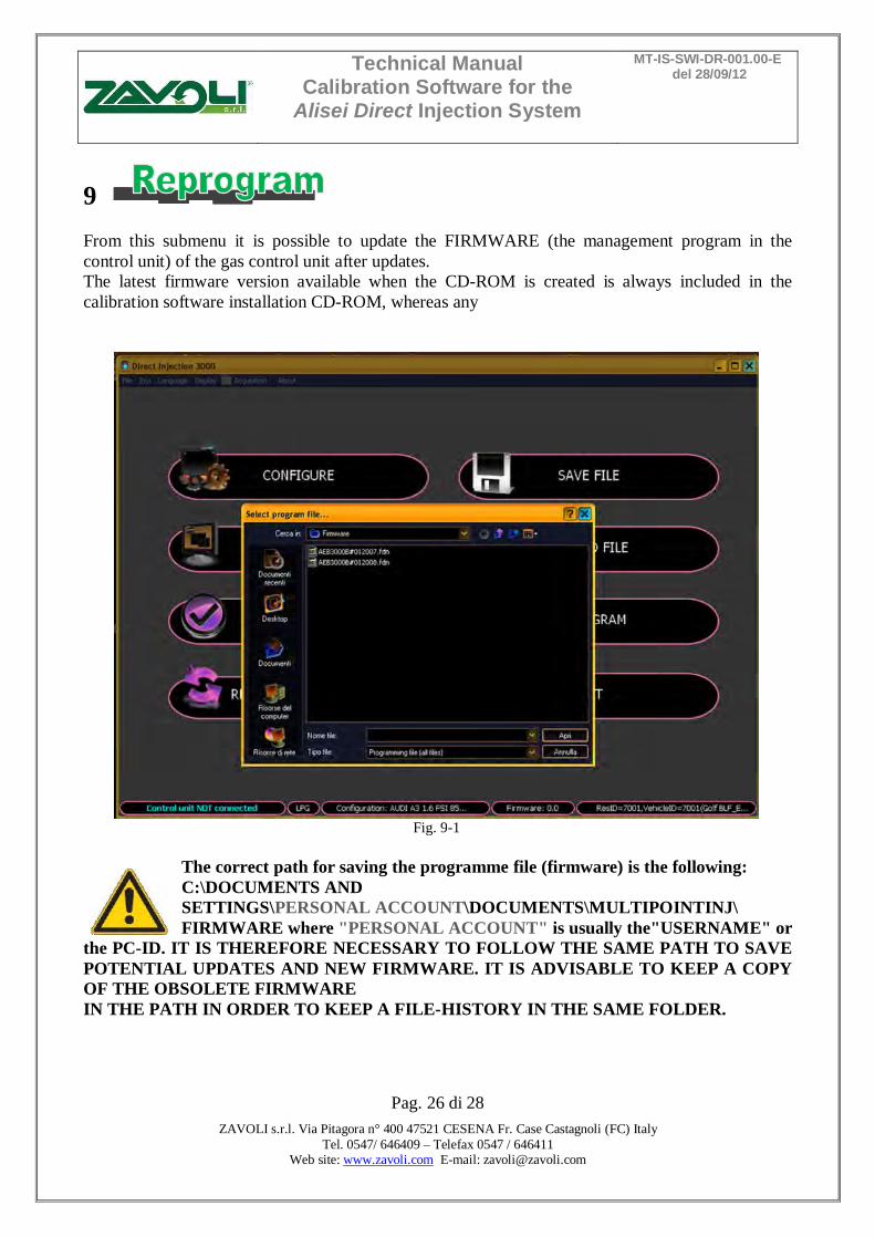
8
Fig. 8-1
It is possible to upload a pre-existing configuration into the control unit from this submenu. The configuration files are in two separate directories: one for LPG configurations (LPG folder) and the other for NATURAL GAS configurations (CNG folder). If the control unit is connected to the computer, only the configurations available for automatically recognised control unit are proposed in the list. Select the file you want to upload and click on OK. ATTENTION: If the user clicks once on a file, the system will open a boxdescribing the basic configuration parameter, without having to open the file itself.
Technical Manual Calibration Software for the
Alisei Direct Injection System
MT-IS-SWI-DR-001.00-E del 28/09/12
Pag. 26 di 28
ZAVOLI s.r.l. Via Pitagora n° 400 47521 CESENA Fr. Case Castagnoli (FC) Italy Tel. 0547/ 646409 – Telefax 0547 / 646411
Web site: www.zavoli.com E-mail: [email protected]
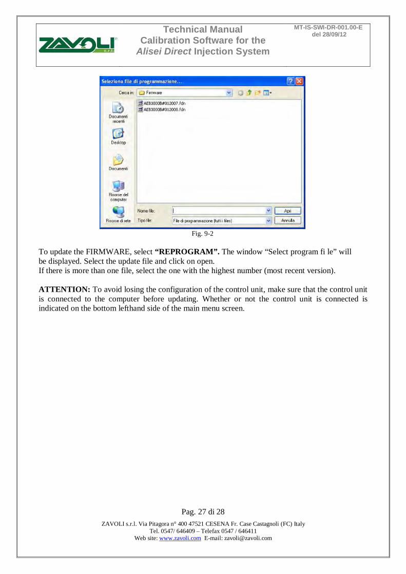
9 From this submenu it is possible to update the FIRMWARE (the management program in the control unit) of the gas control unit after updates. The latest firmware version available when the CD-ROM is created is always included in the calibration software installation CD-ROM, whereas any
Fig. 9-1
The correct path for saving the programme file (firmware) is the following: C:\DOCUMENTS AND SETTINGS\PERSONAL ACCOUNT\DOCUMENTS\MULTIPOINTINJ\ FIRMWARE where "PERSONAL ACCOUNT" is usually the"USERNAME" or
the PC-ID. IT IS THEREFORE NECESSARY TO FOLLOW THE SAME PATH TO SAVE POTENTIAL UPDATES AND NEW FIRMWARE. IT IS ADVISABLE TO KEEP A COPY OF THE OBSOLETE FIRMWARE IN THE PATH IN ORDER TO KEEP A FILE-HISTORY IN THE SAME FOLDER.
Technical Manual Calibration Software for the
Alisei Direct Injection System
MT-IS-SWI-DR-001.00-E del 28/09/12
Pag. 27 di 28
ZAVOLI s.r.l. Via Pitagora n° 400 47521 CESENA Fr. Case Castagnoli (FC) Italy Tel. 0547/ 646409 – Telefax 0547 / 646411
Web site: www.zavoli.com E-mail: [email protected]
Fig. 9-2
To update the FIRMWARE, select “REPROGRAM”. The window “Select program fi le” will be displayed. Select the update file and click on open. If there is more than one file, select the one with the highest number (most recent version). ATTENTION: To avoid losing the configuration of the control unit, make sure that the control unit is connected to the computer before updating. Whether or not the control unit is connected is indicated on the bottom lefthand side of the main menu screen.
Technical Manual Calibration Software for the
Alisei Direct Injection System
MT-IS-SWI-DR-001.00-E del 28/09/12
Pag. 28 di 28
ZAVOLI s.r.l. Via Pitagora n° 400 47521 CESENA Fr. Case Castagnoli (FC) Italy Tel. 0547/ 646409 – Telefax 0547 / 646411
Web site: www.zavoli.com E-mail: [email protected]
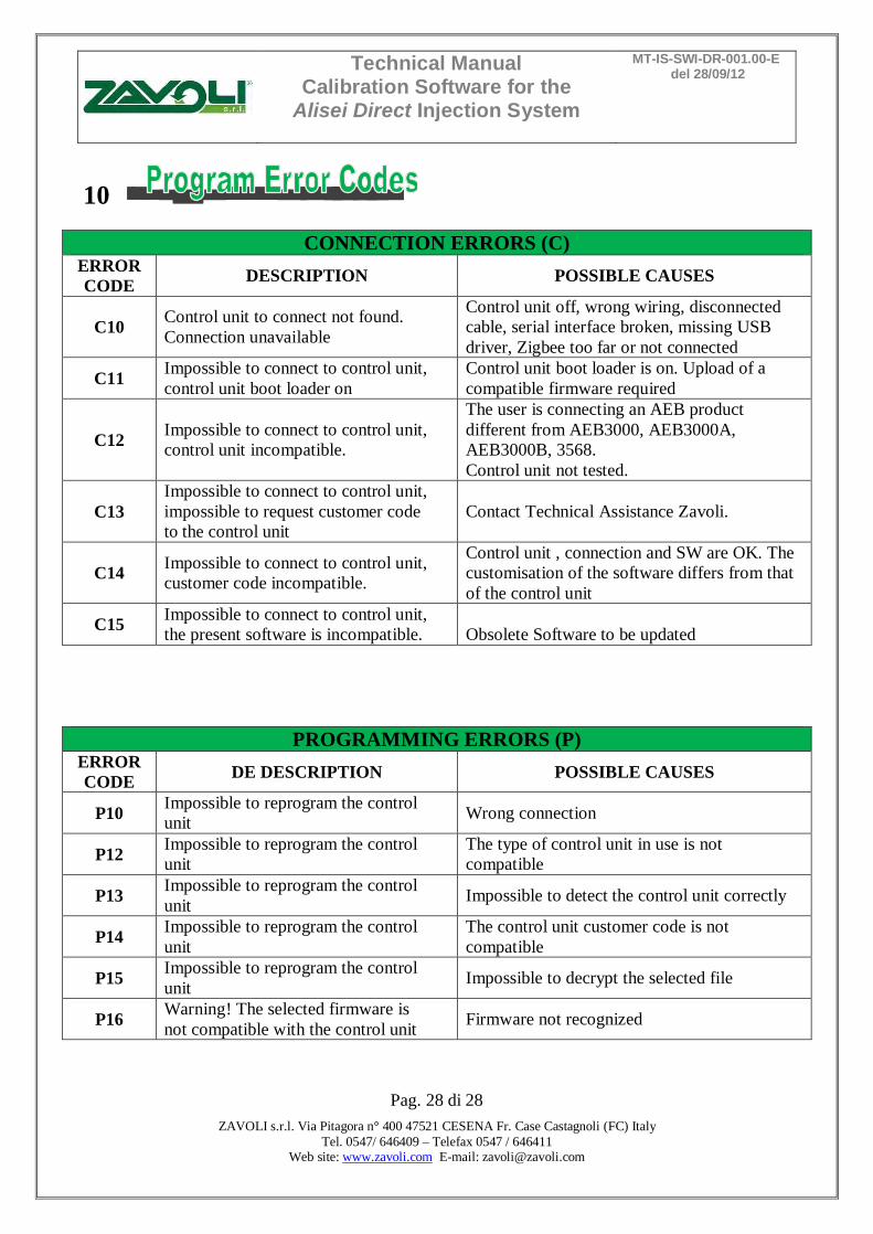
10
CONNECTION ERRORS (C) ERROR CODE DESCRIPTION POSSIBLE CAUSES
C10 Control unit to connect not found. Connection unavailable
Control unit off, wrong wiring, disconnected cable, serial interface broken, missing USB driver, Zigbee too far or not connected
C11 Impossible to connect to control unit, control unit boot loader on
Control unit boot loader is on. Upload of a compatible firmware required
C12 Impossible to connect to control unit, control unit incompatible.
The user is connecting an AEB product different from AEB3000, AEB3000A, AEB3000B, 3568. Control unit not tested.
C13 Impossible to connect to control unit, impossible to request customer code to the control unit
Contact Technical Assistance Zavoli.
C14 Impossible to connect to control unit, customer code incompatible.
Control unit , connection and SW are OK. The customisation of the software differs from that of the control unit
C15 Impossible to connect to control unit, the present software is incompatible.
Obsolete Software to be updated
PROGRAMMING ERRORS (P) ERROR CODE DE DESCRIPTION POSSIBLE CAUSES
P10 Impossible to reprogram the control unit Wrong connection
P12 Impossible to reprogram the control unit
The type of control unit in use is not compatible
P13 Impossible to reprogram the control unit Impossible to detect the control unit correctly
P14 Impossible to reprogram the control unit
The control unit customer code is not compatible
P15 Impossible to reprogram the control unit Impossible to decrypt the selected file
P16 Warning! The selected firmware is not compatible with the control unit Firmware not recognized