technical stuff for power plant engineers
TRANSCRIPT
Compile January 14, 1997 ContentsData Printout 10/10/2022
Data Compiled byDavid C. FarthingVoice 405-728-6709
Page 1
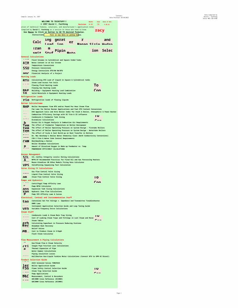
WELCOME TO TECHSTUFF!! Month Year Date of Rev.© 1997 David C. Farthing Revision 4.11 11 4.28.11
A Compilation of technical formula, solutions, and manufacturer's application notes.
Instructions Fill in new data in yellow boxes.
General CalculationsFluid Volumes in Cylindrical and Square Sided TanksWater Content in an Air StreamTemperature ConversionsPressure ConversionsEnergy Conversions BTU/KW KW/BTUFinancial Analysis of a Project
Heating LoadsCalculating BTU Load of liquid in Square & Cylindrical tanksSteam Load Across Fan CoilsFlowing Fluid Heating LoadsFlowing Gas Heating LoadsBuilding + Equipment Heating Load CombinationSolid Materials & Equipment Heating Loads
Refrigeration LoadsRefrigeration loads of flowing liquids
Boiler CalculationsBoiler Horsepower from BTU and/or Pound Per Hour Steam FlowFan Laws for Boiler Burner Applications and Fuel BTU Content ConversionsEVO Approach Calcs and Rite Boiler Index for Stack & Boiler, Atmospheric & Power Burner Combustion Efficiency Savings with O2 Trim & CO influenceCondensate & Feedwater Tank SizingEconomizer CalculationsExcess Air & Oxygen Analysis & Combustion Air RequirementsThe effect of Feedwater Temperature on Boiler HorsepowerThe effect of Boiler Operating Pressure on System Design - Firetube BoilersThe effect of Boiler Operating Pressure on System Design - Watertube BoilersThe effect of Scale & Soot Build-up on Heat Transfer in BoilersDr. Mac Brockway's Boiler Water Chemistry Class (With Conductivity Conversions)CSD-1 Fire & Water Side Control RequirementsBenchmarking a BoilerBoiler Blowdown CalculationsAmount of Dissolved Oxygen in Make-up Feedwater vs. Temp.POWERHOUSE EFFICIENCY CALCULATIONS
Burner ManagementSIL (Safety Integrity Levels) Rating CalculationsNFPA-87 Recommended Practices for Fired Oil and Gas Processing HeatersMaxon Kinedizer OR Other Models Firing Rate CalculatorValveProving Sequencing Test Calculation
Valve Sizing CV CalculationsGas Flow Control Valve SizingLiquid Flow Control Valve SizingSteam Flow Control Valve Sizing
Pumps and HydronicsCentrifugal Pump Affinity LawsPump NPSH CalculatorExpansion Tank Sizing CalculationsHydronic Zone Flow CalculationsPump VFD Affinity Laws & Curves
Electrical, Control and Instrumentation StuffController Out Put Voltage v. Impedance and Transmitter TroubleshooterOHMS LawsInstrument Application Selection Guide and Loop Tuning GuideVariable Frequency Drive Calculations
Steam StuffCondensate Loads & Steam Main Trap SizingCost of Leaking Steam Traps and Fittings in Lost Steam and RevenueSteam TablesCalculating Superheat in Pressure Reducing StationsBlowdown Heat RecoveryRelief ValvesCost to Produce Steam in $/KpphFlash Steam Calculator
Flow Measurement & Piping Calculations Gas/Steam Flow & Steam Velocity Single Pipe Friction Loss CalculationsThermal Expansion of Pipe Water Hammer CalculationsPiping Insulation LossesHalliburton Gas/Liquid Turbine Meter Calculations (Convert BTU to GPM #2 Diesel)
Product Selection GuideASCO Solenoid Valves TOMSPAVEBoiler Application GuideFlame Safety Control Selection GuideSteam Trap Selection GuidePump ApplicationsMeasurement, Control & RecordersUDC3000 Cross Reference (DC300#)UDC3000 Cross Reference (DC300X)
Compiled by David C. Farthing as a service to those who need to know.Use Mouse to Click on Button to GO TO desired formulas.
Volume
BTU
Refrig.
STACKS
BHP
FFHL
AIR
Gas
Valve
Liquid
Val
Steam Val
Fan
Coil
Pumps
Voltage
Pipe T.
MainsLeaks
Flow Calcs
OHMS
TEMP
Tables
FrictionHammerASCOBoilersFSGTrapsPumpsM&CDC300#
Tank Size
O2/CO Trim
Back To Contents
Back To Contents
General Calculations
Heating Loads
RefrigerationLoads
BoilerBurnerCalculations
Valve
Sizing
PumpsandHydronics
Controls -Transmitters & VFD
Steam
Stuff
Flow &
Piping
Data
RevisionNotes
Electric
Motor Data
Product
SelectionGuide
Back To Contents
Financial
IASG
Econo
B&EEquip Ht
Comb Air
Expansion
Hallibutron
Hydronics
Superheat
Heat Recovery
FW TempSCALEMKUP O2
PRESSURE
DC300X
BENCHMK
Systems
WarrantyAccuracyContact Info
Back To Contents
Back To Contents
CSD1
ENERGY
BLDOWN
VFDRelief
Val
Recovery
FAN & FUEL
DR.MAC
Pump NPSH
PUMP VFD
Systems-W
Steam $$
VPS
EFFICEINCY
Insulation
FLASH
MAXON
SIL
Burner
Management
NFPA 87
FGHL
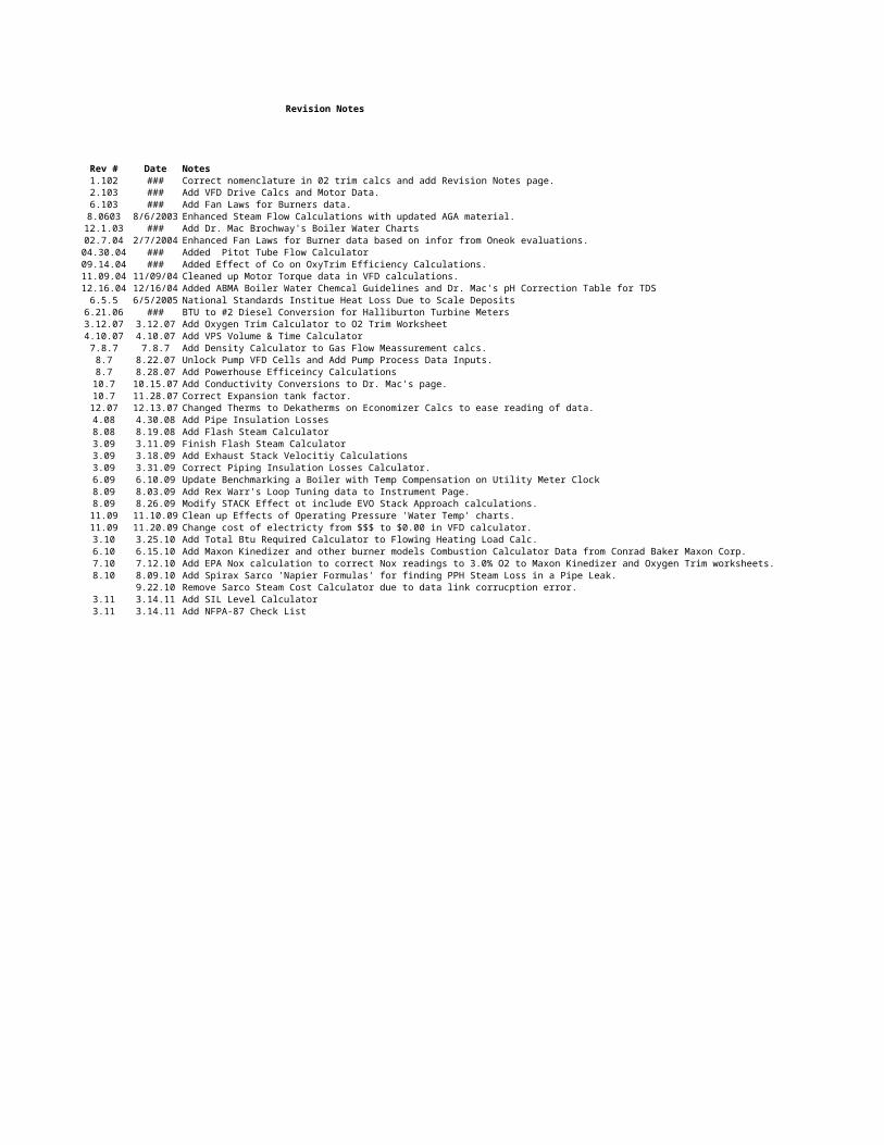
Revision Notes
Rev # Date Notes1.102 ### Correct nomenclature in 02 trim calcs and add Revision Notes page.2.103 ### Add VFD Drive Calcs and Motor Data.6.103 ### Add Fan Laws for Burners data.8.0603 8/6/2003 Enhanced Steam Flow Calculations with updated AGA material.12.1.03 ### Add Dr. Mac Brochway's Boiler Water Charts02.7.04 2/7/2004 Enhanced Fan Laws for Burner data based on infor from Oneok evaluations.04.30.04 ### Added Pitot Tube Flow Calculator09.14.04 ### Added Effect of Co on OxyTrim Efficiency Calculations.11.09.04 11/09/04 Cleaned up Motor Torque data in VFD calculations.12.16.04 12/16/04 Added ABMA Boiler Water Chemcal Guidelines and Dr. Mac's pH Correction Table for TDS6.5.5 6/5/2005 National Standards Institue Heat Loss Due to Scale Deposits
6.21.06 ### BTU to #2 Diesel Conversion for Halliburton Turbine Meters3.12.07 3.12.07 Add Oxygen Trim Calculator to O2 Trim Worksheet4.10.07 4.10.07 Add VPS Volume & Time Calculator7.8.7 7.8.7 Add Density Calculator to Gas Flow Meassurement calcs.8.7 8.22.07 Unlock Pump VFD Cells and Add Pump Process Data Inputs.8.7 8.28.07 Add Powerhouse Efficeincy Calculations10.7 10.15.07 Add Conductivity Conversions to Dr. Mac's page.10.7 11.28.07 Correct Expansion tank factor.12.07 12.13.07 Changed Therms to Dekatherms on Economizer Calcs to ease reading of data.4.08 4.30.08 Add Pipe Insulation Losses8.08 8.19.08 Add Flash Steam Calculator3.09 3.11.09 Finish Flash Steam Calculator3.09 3.18.09 Add Exhaust Stack Velocitiy Calculations3.09 3.31.09 Correct Piping Insulation Losses Calculator.6.09 6.10.09 Update Benchmarking a Boiler with Temp Compensation on Utility Meter Clock8.09 8.03.09 Add Rex Warr's Loop Tuning data to Instrument Page.8.09 8.26.09 Modify STACK Effect ot include EVO Stack Approach calculations.11.09 11.10.09 Clean up Effects of Operating Pressure 'Water Temp' charts.11.09 11.20.09 Change cost of electricty from $$$ to $0.00 in VFD calculator.3.10 3.25.10 Add Total Btu Required Calculator to Flowing Heating Load Calc.6.10 6.15.10 Add Maxon Kinedizer and other burner models Combustion Calculator Data from Conrad Baker Maxon Corp.7.10 7.12.10 Add EPA Nox calculation to correct Nox readings to 3.0% O2 to Maxon Kinedizer and Oxygen Trim worksheets.8.10 8.09.10 Add Spirax Sarco 'Napier Formulas' for finding PPH Steam Loss in a Pipe Leak.
9.22.10 Remove Sarco Steam Cost Calculator due to data link corrucption error.3.11 3.14.11 Add SIL Level Calculator3.11 3.14.11 Add NFPA-87 Check List
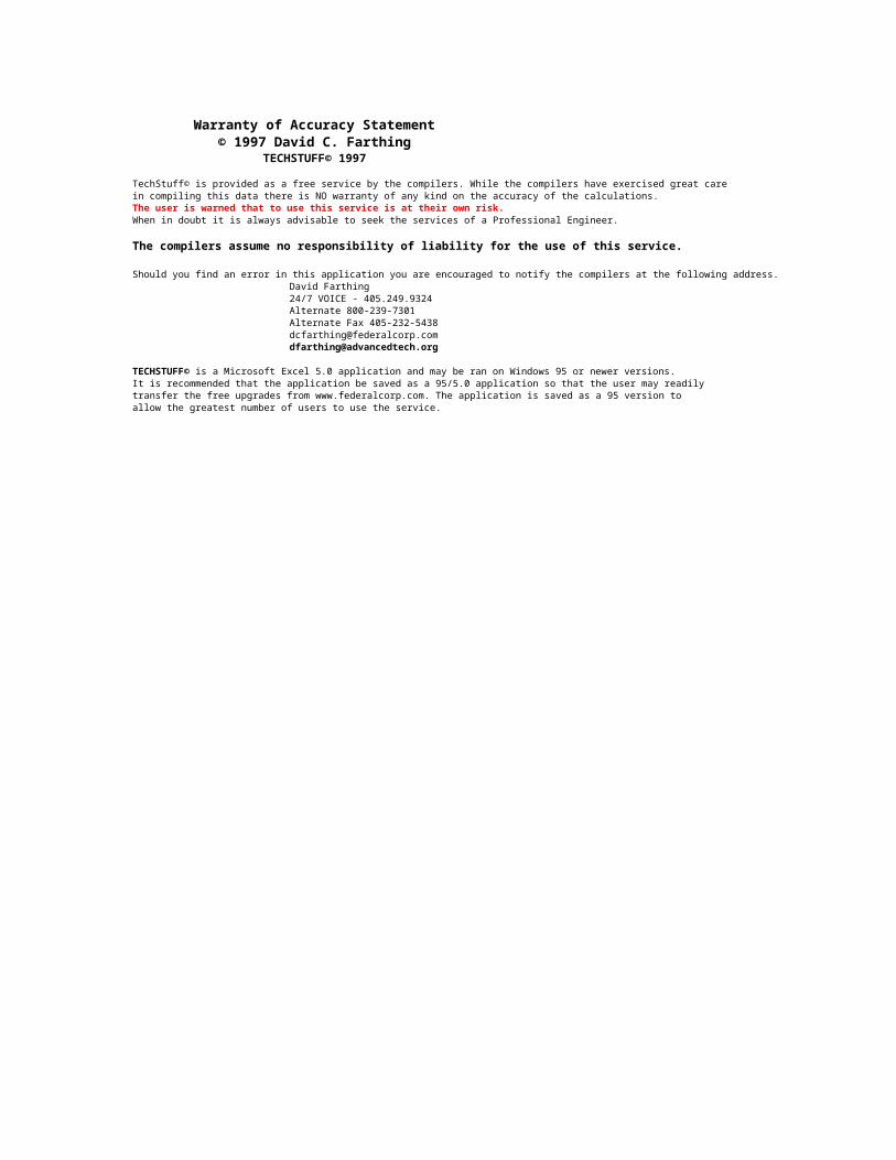
Warranty of Accuracy Statement© 1997 David C. Farthing
TECHSTUFF© 1997
TechStuff© is provided as a free service by the compilers. While the compilers have exercised great care in compiling this data there is NO warranty of any kind on the accuracy of the calculations.The user is warned that to use this service is at their own risk.When in doubt it is always advisable to seek the services of a Professional Engineer.
The compilers assume no responsibility of liability for the use of this service.
Should you find an error in this application you are encouraged to notify the compilers at the following address.David Farthing24/7 VOICE - 405.249.9324Alternate 800-239-7301Alternate Fax [email protected]@advancedtech.org
It is recommended that the application be saved as a 95/5.0 application so that the user may readilytransfer the free upgrades from www.federalcorp.com. The application is saved as a 95 version to allow the greatest number of users to use the service.
TECHSTUFF© is a Microsoft Excel 5.0 application and may be ran on Windows 95 or newer versions.
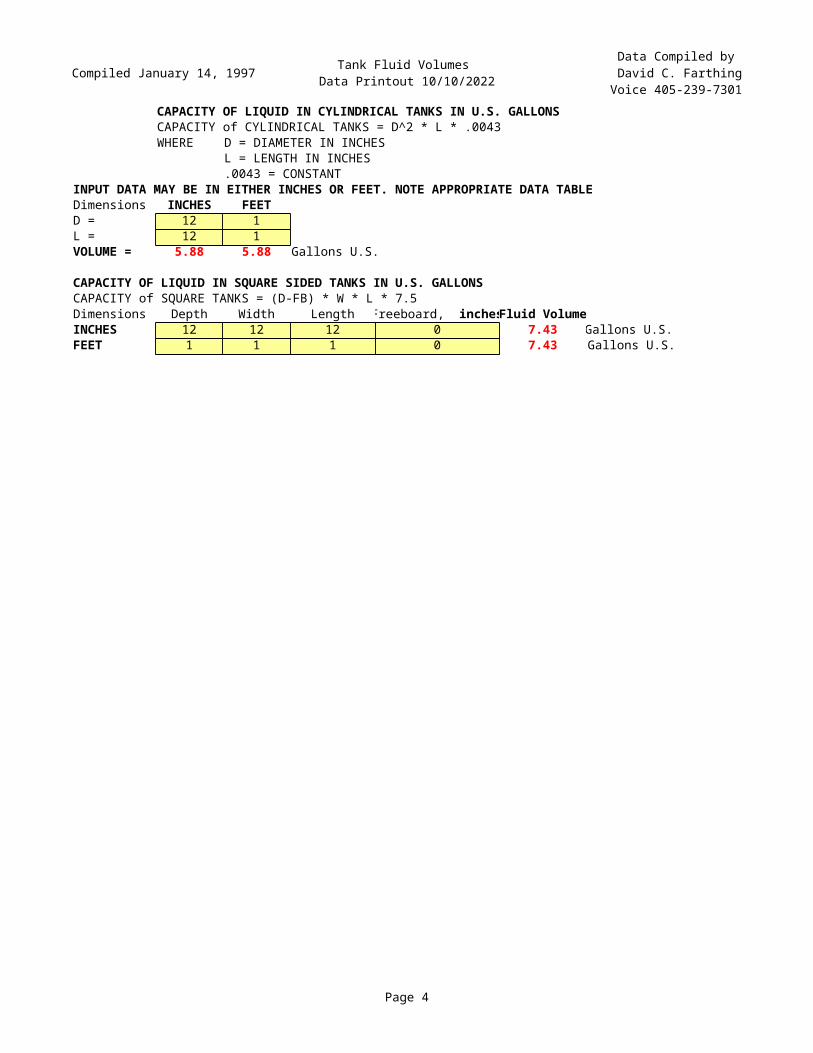
Compiled January 14, 1997 Tank Fluid Volumes Data Printout 10/10/2022
Data Compiled by David C. FarthingVoice 405-239-7301
Page 4
CAPACITY OF LIQUID IN CYLINDRICAL TANKS IN U.S. GALLONSCAPACITY of CYLINDRICAL TANKS = D^2 * L * .0043WHERE D = DIAMETER IN INCHES
L = LENGTH IN INCHES.0043 = CONSTANT
INPUT DATA MAY BE IN EITHER INCHES OR FEET. NOTE APPROPRIATE DATA TABLEDimensions INCHES FEETD = 12 1L = 12 1VOLUME = 5.88 5.88 Gallons U.S.
CAPACITY OF LIQUID IN SQUARE SIDED TANKS IN U.S. GALLONSCAPACITY of SQUARE TANKS = (D-FB) * W * L * 7.5Dimensions Depth Width Length Fluid VolumeINCHES 12 12 12 0 7.43 Gallons U.S.FEET 1 1 1 0 7.43 Gallons U.S.
Freeboard, inches
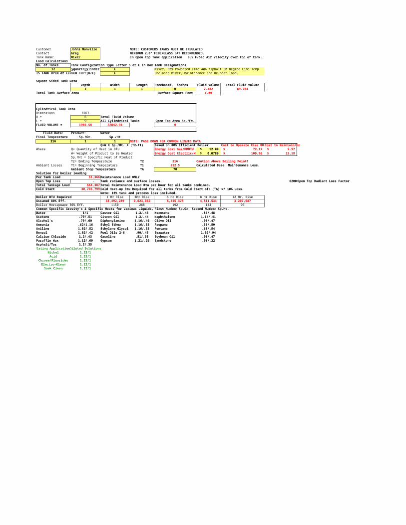
Customer Johns Manville NOTE: CUSTOMERS TANKS MUST BE INSULATEDContact Greg MINIMUM 2.0" FIBERGLASS BAT RECOMMENDED.Tank Name: Mixer In Open Top Tank application. 0.5 F/Sec Air Velocity over top of tank.Load CalculationsNo. of Tanks Tank Configuration Type Letter S or C in box Tank Designations
12 C Mixer, 60% Powdered Lime 40% Asphalt 50 Degree Lime TempIS TANK OPEN or CLOSED TOP?(O/C) C Enclosed Mixer, Maintenance and Re-heat load.
Square Sided Tank DataDepth Width Length Freeboard, inches Fluid Volume Total Fluid Volume1 1 1 0 7.482 89.784
Total Tank Surface Area Surface Square Feet 1.00
Cylindrical Tank DataDimensions FEETD = 6 Total Fluid VolumeL = 9 All Cylindrical Tanks Open Top Area Sq./Ft.FLUID VOLUME = 1903.58 22842.94 0
Fluid Data: Product: WaterFinal Temperature Sp./Gr. Sp./Ht
216 1 1 NOTE: PAGE DOWN FOR COMMON LIQUID DATAQ=W X Sp./Ht. X (T2-T1) Based on 80% Efficient Boiler Cost to Operate Rise 8HrCost to Maintain/Hr
Where Q= Quantity of Heat in BTU Energy Cost Gas/MMBTU $ 12.00 $ 72.17 $ 9.97 W= Weight of Product to Be Heated Energy Cost Electric/KW $ 0.0780 $ 109.96 $ 15.18 Sp./Ht = Specific Heat of ProductT2= Ending Temperature T2 216 Caution Above Boiling Point!
Ambient Losses T1= Beginning Temperature T1 212.5 Calculated Base Maintenance Loss.Ambient Shop Temperature TA 70
Solution for boiler loadingPer Tank Load 55,366 Maintenance Load ONLY 218 55,366Open Top Loss - Tank radiance and surface losses. 6200 Open Top Radiant Loss FactorTotal Tankage Load 664,387 Total Maintenance Load Btu per hour for all tanks combined.Cold Start 30,793,799 Cold Heat-up Btu Required for all tanks from Cold Start of: (TA) w/ 10% Loss. 121,035 ###
Note: 10% tank and process loss included.Boiler BTU Required 1 Hr Rise 4Hr Rise 6 Hr Rise 8 Hr Rise 12 Hr. RiseAssumed 80% Eff. 38,492,249 9,623,062 6,415,375 4,811,531 3,207,687Boiler Horsepower 80% Eff. 1150 288 192 144 96Common Specific Gravity's & Specific Heats for Various Liquids. First Number Sp.Gr. Second Number Sp.Ht.Water 1/1 Castor Oil 1.2/.43 Kerosene .86/.48Acetone .79/.51 Citron Oil 1.2/.44 Naphthalene 1.14/.41Alcohol's .79/.60 Diphenylamine 1.16/.46 Olive Oil .93/.47Ammonia .62/1.16 Ethyl Ether 1.16/.53 Propane .50/.59Aniline 1.02/.52 Ethylene Glycol 1.16/.53 Pentane .63/.54Benzol 1.02/.42 Fuel Oils 2-6 .90/.45 Seawater 1.02/.94Calcium Chloride 1.2/.43 Gasoline .81/.53 Soybean Oil .93/.47Paraffin Wax 1.12/.69 Gypsum 1.21/.26 Sandstone .93/.22Asphalt/Tar 1.2/.35Plating ApplicationsDiluted Solutions
Nickel 1.23/1Acid 1.23/1
Chrome/Fluorides 1.23/1Electro-Klean 1.12/1Soak Clean 1.12/1
Square/Cylinder
Data Compiled January 14, 1997 Refrigeration LoadsData Printout 10/10/2022
Data Compiled byDavid C. Farthing
Voice 405-728-6709
Page 6
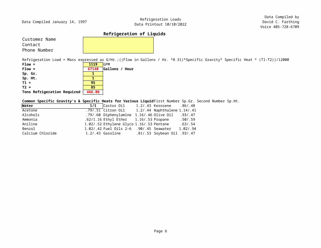
Refrigeration of LiquidsCustomer NameContactPhone Number
Refrigeration Load = Mass expressed as G/Hr.;((Flow in Gallons / Hr. *8.31)*Specific Gravity* Specific Heat * (T1-T2))/12000Flow = 1119 GPMFlow = 67140 Gallons / HourSp. Gr. 1Sp. Ht. 1T1 = 95T2 = 85Tons Refrigeration Required = 466.06
Common Specific Gravity's & Specific Heats for Various LiquidFirst Number Sp.Gr. Second Number Sp.Ht.Water 1/1 Castor Oil 1.2/.43 Kerosene .86/.48Acetone .79/.51 Citron Oil 1.2/.44 Naphthalene 1.14/.41Alcohols .79/.60 Diphenylamine 1.16/.46 Olive Oil .93/.47Ammonia .62/1.16 Ethyl Ether 1.16/.53 Propane .50/.59Aniline 1.02/.52 Ethylene Glyco 1.16/.53 Pentane .63/.54Benzol 1.02/.42 Fuel Oils 2-6 .90/.45 Seawater 1.02/.94Calcium Chloride 1.2/.43 Gasoline .81/.53 Soybean Oil .93/.47
Data Compiled January 14, 1997 Rite Boiler Chimney EffectData Printout 10/10/2022
Data Compiled byDavid C. Farthing
Voice 405-728-6709
Page 7
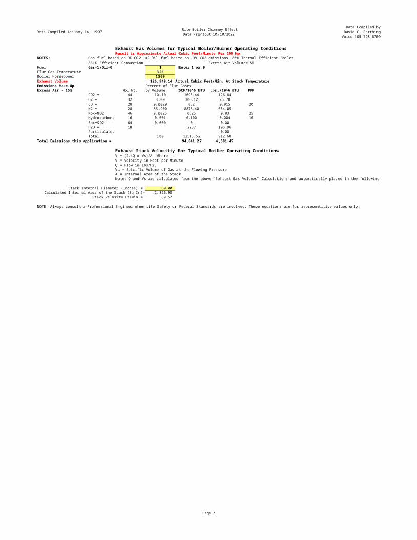
Exhaust Gas Volumes for Typical Boiler/Burner Operating ConditionsResult is Approximate Actual Cubic Feet/Minute Per 100 Hp.
NOTES: Gas fuel based on 9% CO2, #2 Oil fuel based on 13% CO2 emissions. 80% Thermal Efficient Boiler85+% Efficient Combustion Excess Air Volume=15%
Fuel Gas=1/Oil=0 1 Enter 1 or 0Flue Gas Temperature 325Boiler Horsepower 1200Exhaust Volume 126,949.14 Actual Cubic Feet/Min. At Stack TemperatureEmissions Make-Up Percent of Flue GasesExcess Air = 15% Mol Wt. by Volume SCF/10^6 BTU Lbs./10^6 BTU PPM
CO2 = 44 10.10 1095.44 126.84O2 = 32 3.00 306.12 25.78CO = 28 0.0020 0.2 0.015 20N2 = 28 86.900 8876.40 654.05Nox=NO2 46 0.0025 0.25 0.03 25Hydrocarbons 16 0.001 0.100 0.004 10Sox=SO2 64 0.000 0 0.00H2O = 18 2237 105.96Particulates 0.00Total 100 12515.52 912.68
Total Emissions this application = 94,841.27 4,581.45
Exhaust Stack Velocitiy for Typical Boiler Operating ConditionsV = (2.4Q x Vs)/A Where ...V = Velocity in Feet per MinuteQ = Flow in Lbs/Hr.Vs = Spicific Volume of Gas at the Flowing PressureA = Internal Area of the StackNote: Q and Vs are calculated from the above "Exhaust Gas Volumes" Calculations and automatically placed in the following equation.
Stack Internal Diameter (Inches) = 60.00 Calculated Internal Area of the Stack (Sq In)= 2,826.90
Stack Velosity Ft/Min = 80.52
NOTE: Always consult a Professional Engineer when Life Safety or Federal Standards are involved. These equations are for representitive values only.
Compiled January 14, 1997 Boiler HorsepowerData Printout 10/10/2022
Data Compiled byDavid C. FarthingVoice 405-728-6709
Page 8
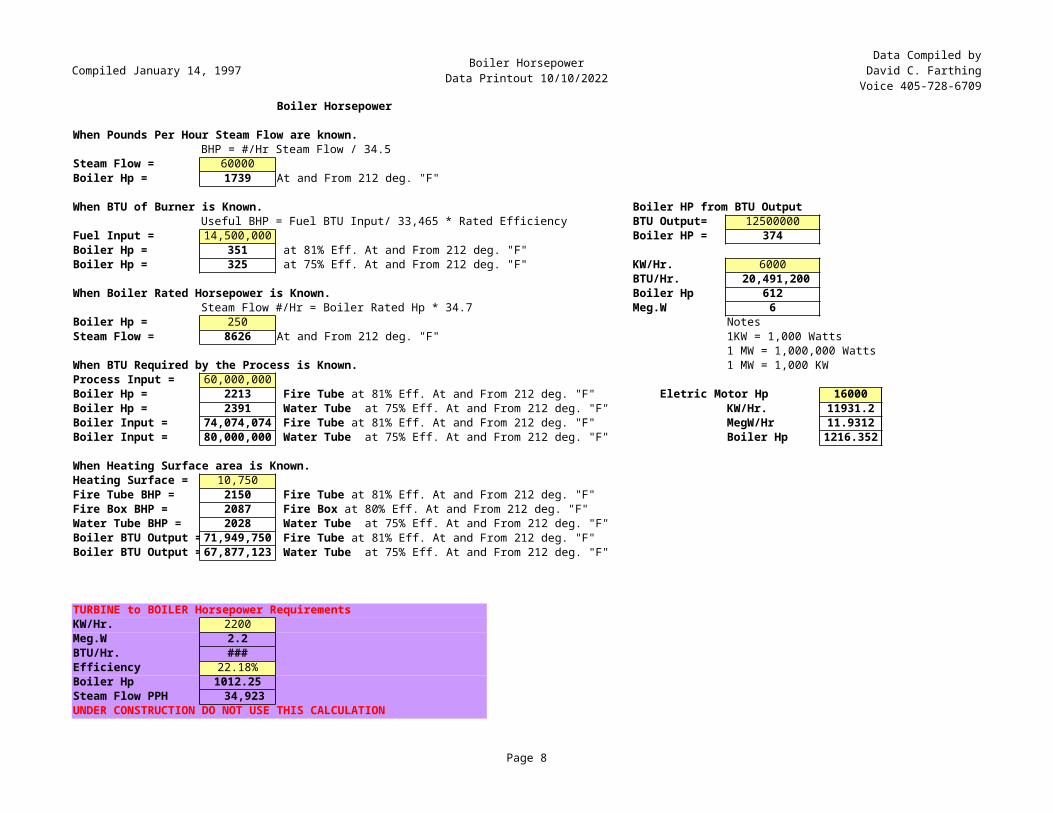
Boiler Horsepower
When Pounds Per Hour Steam Flow are known.BHP = #/Hr Steam Flow / 34.5
Steam Flow = 60000Boiler Hp = 1739 At and From 212 deg. "F"
When BTU of Burner is Known. Boiler HP from BTU OutputUseful BHP = Fuel BTU Input/ 33,465 * Rated Efficiency BTU Output= 12500000
Fuel Input = 14,500,000 Boiler HP = 374Boiler Hp = 351Boiler Hp = 325 KW/Hr. 6000
BTU/Hr. 20,491,200 When Boiler Rated Horsepower is Known. Boiler Hp 612
Steam Flow #/Hr = Boiler Rated Hp * 34.7 Meg.W 6Boiler Hp = 250 NotesSteam Flow = 8626 At and From 212 deg. "F" 1KW = 1,000 Watts
1 MW = 1,000,000 WattsWhen BTU Required by the Process is Known. 1 MW = 1,000 KWProcess Input = 60,000,000Boiler Hp = 2213 Eletric Motor Hp 16000Boiler Hp = 2391 KW/Hr. 11931.2Boiler Input = 74,074,074 MegW/Hr 11.9312Boiler Input = 80,000,000 Boiler Hp 1216.352
When Heating Surface area is Known.Heating Surface = 10,750 5.28Fire Tube BHP = 2150 5.33Fire Box BHP = 2087 5.35Water Tube BHP = 2028 5.38Boiler BTU Output =71,949,750 5.51Boiler BTU Output =67,877,123 5.32
5.174.92
TURBINE to BOILER Horsepower RequirementsKW/Hr. 2200Meg.W 2.2BTU/Hr. ###Efficiency 22.18%Boiler Hp 1012.25Steam Flow PPH 34,923 UNDER CONSTRUCTION DO NOT USE THIS CALCULATION
at 81% Eff. At and From 212 deg. "F" at 75% Eff. At and From 212 deg. "F"
Fire Tube at 81% Eff. At and From 212 deg. "F" Water Tube at 75% Eff. At and From 212 deg. "F" Fire Tube at 81% Eff. At and From 212 deg. "F" Water Tube at 75% Eff. At and From 212 deg. "F"
Fire Tube at 81% Eff. At and From 212 deg. "F" Fire Box at 80% Eff. At and From 212 deg. "F" Water Tube at 75% Eff. At and From 212 deg. "F" Fire Tube at 81% Eff. At and From 212 deg. "F" Water Tube at 75% Eff. At and From 212 deg. "F"
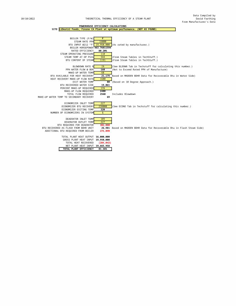
10/10/2022 THEORETICAL THERMAL EFFICIENCY OF A STEAM PLANTData Compiled by
David FarthingFrom Manufacturer's Data
POWERHOUSE EFFICIENCY CALCULATIONSSITE LiDestri Foods, Fresno CA Plant at optimum performance. (NOT AS FOUND)
BOILER TYPE (F/W) FSTEAM RATE PPH 16000
BTU INPUT @212 "f" 19,950,000 (As rated by manufacturer.)BOILER HORSEPOWER 463.76811594RATED EFFICIENCY 80.20%
STEAM OPERATING PRESSURE 110STEAM TEMP AT OP PSIG 344 (From Steam Tables in TechStuff.)BTU CONTENT OF STEAM 1191 (From Steam Tables in TechStuff.)
BLOWDOWN RATE % 1% (See BLDOWN Tab in Techstuff for calculating this number.)PPH WATER FLOW @ BD% 160 (Not to Exceed Rated PPH of Manufacture)MAKE-UP WATER TEMP 68
BTU AVAILABLE FOR HEAT RECOVERY 21,179 Based on MADDEN BDHR Data for Recoverable Btu in Water Side)HEAT RECOVERY MAKE-UP FLOW RATE 1600
EXIT WATER TEMP 80 (Based on 10 Degree Approach.)BTU RECOVERED WATER SIDE 19,061 PERCENT MAKE-UP REQUIRED 15%
MAKE-UP FLOW REQUIRED 2400TOTAL FLOW REQUIRED 2560 Includes Blowdown
MAKE-UP WATER TEMP TO SECONDARY RECOVERY 69
ECONOMIZER INLET TEMP 227ECONOMIZER BTU RECOVERY 238000 (See ECONO Tab in Techstuff for calculating this number.)ECONOMIZER EXITING TEMP 320
NUMBER OF ECONOMIZERS IN SYSTEM 1
DEAERATOR INLET TEMP 109DEAERATOR OUTLET TEMP 227
BTU REQUIRED FOR DEAERATOR 302,080 BTU RECOVERED AS FLASH FROM BDHR UNIT 26,981 Based on MADDEN BDHR Data for Recoverable Btu in Flash Steam Side)ADDITIONAL BTU REQUIRED FROM BOILER 275,099
TOTAL PLANT HEAT OUTPUT 16,000,000 GROSS PLANT HEAT INPUT 19,950,000 TOTAL HEAT RECOVERED (284,042)NET PLANT HEAT INPUT 19,665,958
TOTAL PLANT EFFICIENCY 81.36%
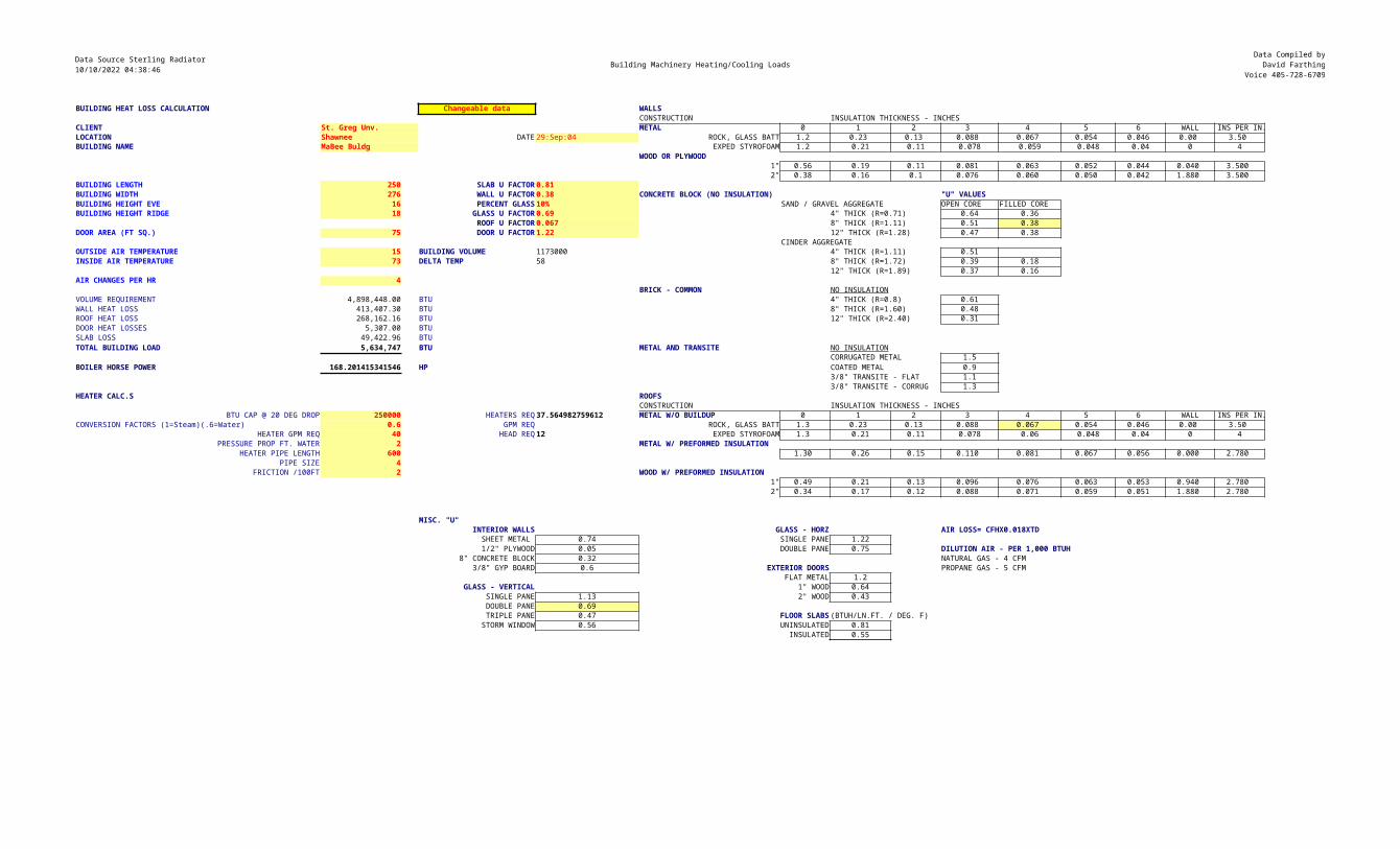
Data Source Sterling Radiator10/10/2022 04:38:46 Building Machinery Heating/Cooling Loads
Data Compiled byDavid Farthing
Voice 405-728-6709
BUILDING HEAT LOSS CALCULATION Changeable data WALLSCONSTRUCTION INSULATION THICKNESS - INCHES
CLIENT St. Greg Unv. METAL 0 1 2 3 4 5 6 WALL INS PER IN.LOCATION Shawnee DATE 29:Sep:04 ROCK, GLASS BATT 1.2 0.23 0.13 0.088 0.067 0.054 0.046 0.00 3.50 BUILDING NAME MaBee Buldg EXPED STYROFOAM 1.2 0.21 0.11 0.078 0.059 0.048 0.04 0 4
WOOD OR PLYWOOD1" 0.56 0.19 0.11 0.081 0.063 0.052 0.044 0.040 3.500
2" 0.38 0.16 0.1 0.076 0.060 0.050 0.042 1.880 3.500 BUILDING LENGTH 250 SLAB U FACTOR 0.81 BUILDING WIDTH 276 WALL U FACTOR 0.38 CONCRETE BLOCK (NO INSULATION) "U" VALUESBUILDING HEIGHT EVE 16 PERCENT GLASS 10% SAND / GRAVEL AGGREGATE OPEN CORE FILLED COREBUILDING HEIGHT RIDGE 18 GLASS U FACTOR 0.69 4" THICK (R=0.71) 0.64 0.36
ROOF U FACTOR 0.067 8" THICK (R=1.11) 0.51 0.38DOOR AREA (FT SQ.) 75 DOOR U FACTOR 1.22 12" THICK (R=1.28) 0.47 0.38
CINDER AGGREGATEOUTSIDE AIR TEMPERATURE 15 BUILDING VOLUME 1173000 4" THICK (R=1.11) 0.51INSIDE AIR TEMPERATURE 73 DELTA TEMP 58 8" THICK (R=1.72) 0.39 0.18
12" THICK (R=1.89) 0.37 0.16AIR CHANGES PER HR 4
BRICK - COMMON NO INSULATIONVOLUME REQUIREMENT 4,898,448.00 BTU 4" THICK (R=0.8) 0.61WALL HEAT LOSS 413,407.30 BTU 8" THICK (R=1.60) 0.48ROOF HEAT LOSS 268,162.16 BTU 12" THICK (R=2.40) 0.31DOOR HEAT LOSSES 5,307.00 BTUSLAB LOSS 49,422.96 BTUTOTAL BUILDING LOAD 5,634,747 BTU METAL AND TRANSITE NO INSULATION
CORRUGATED METAL 1.5BOILER HORSE POWER 168.201415341546 HP COATED METAL 0.9
3/8" TRANSITE - FLAT 1.13/8" TRANSITE - CORRUG 1.3
HEATER CALC.S ROOFSCONSTRUCTION INSULATION THICKNESS - INCHES
BTU CAP @ 20 DEG DROP 250000 HEATERS REQ 37.564982759612 METAL W/O BUILDUP 0 1 2 3 4 5 6 WALL INS PER IN.CONVERSION FACTORS (1=Steam)(.6=Water) 0.6 GPM REQ ROCK, GLASS BATT 1.3 0.23 0.13 0.088 0.067 0.054 0.046 0.00 3.50
HEATER GPM REQ 40 HEAD REQ 12 EXPED STYROFOAM 1.3 0.21 0.11 0.078 0.06 0.048 0.04 0 4PRESSURE PROP FT. WATER 2 METAL W/ PREFORMED INSULATION
HEATER PIPE LENGTH 600 1.30 0.26 0.15 0.110 0.081 0.067 0.056 0.000 2.780 PIPE SIZE 4
FRICTION /100FT 2 WOOD W/ PREFORMED INSULATION 1" 0.49 0.21 0.13 0.096 0.076 0.063 0.053 0.940 2.780 2" 0.34 0.17 0.12 0.088 0.071 0.059 0.051 1.880 2.780
MISC. "U"INTERIOR WALLS GLASS - HORZ AIR LOSS= CFHX0.018XTDSHEET METAL 0.74 SINGLE PANE 1.221/2" PLYWOOD 0.05 DOUBLE PANE 0.75 DILUTION AIR - PER 1,000 BTUH
8" CONCRETE BLOCK 0.32 NATURAL GAS - 4 CFM3/8" GYP BOARD 0.6 EXTERIOR DOORS PROPANE GAS - 5 CFM
FLAT METAL 1.2GLASS - VERTICAL 1" WOOD 0.64
SINGLE PANE 1.13 2" WOOD 0.43DOUBLE PANE 0.69TRIPLE PANE 0.47 FLOOR SLABS (BTUH/LN.FT. / DEG. F)STORM WINDOW 0.56 UNINSULATED 0.81
INSULATED 0.55
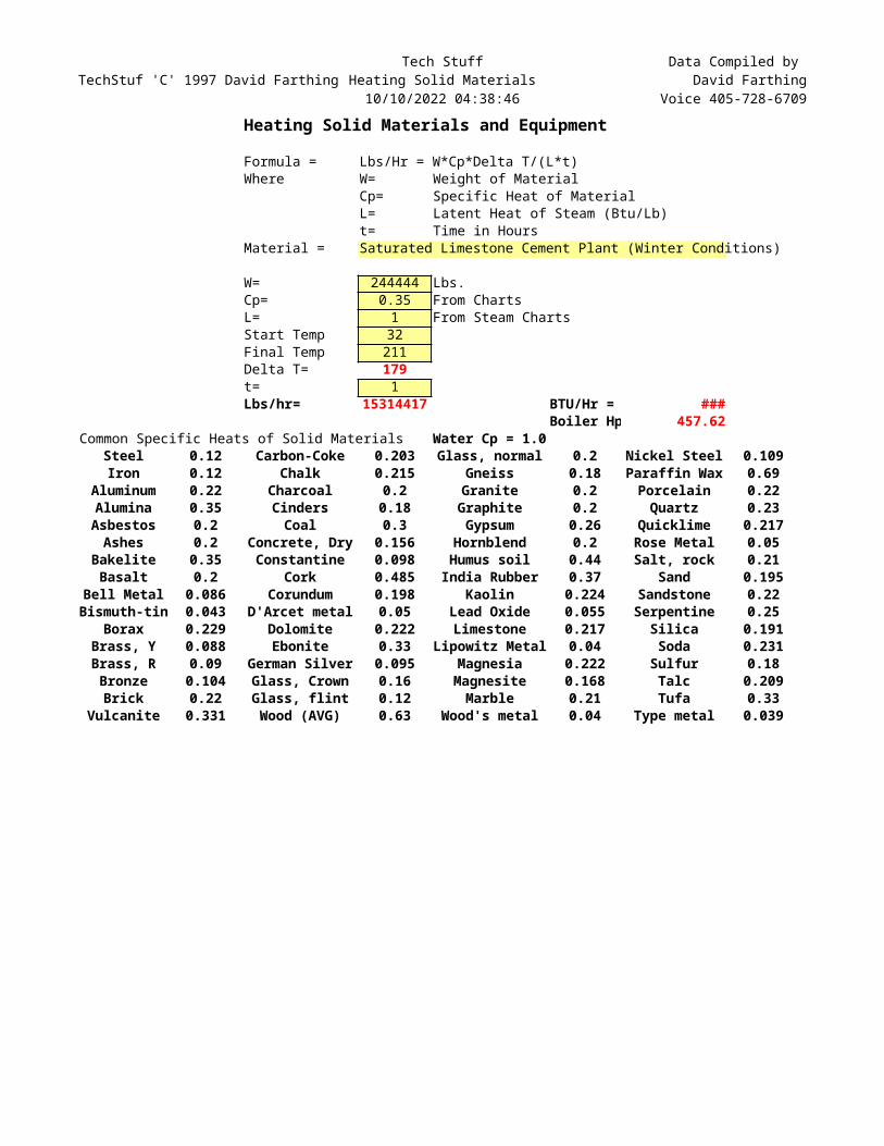
TechStuf 'C' 1997 David FarthingTech Stuff
Heating Solid Materials10/10/2022 04:38:46
Data Compiled by David Farthing
Voice 405-728-6709Heating Solid Materials and Equipment
Formula = Lbs/Hr = W*Cp*Delta T/(L*t)Where W= Weight of Material
Cp= Specific Heat of MaterialL= Latent Heat of Steam (Btu/Lb)t= Time in Hours
Material = Saturated Limestone Cement Plant (Winter Conditions)
W= 244444 Lbs.Cp= 0.35 From ChartsL= 1 From Steam ChartsStart Temp 32Final Temp 211Delta T= 179t= 1Lbs/hr= 15314417 BTU/Hr = ###
Boiler Hp 457.62Common Specific Heats of Solid Materials Water Cp = 1.0
Steel 0.12 Carbon-Coke 0.203 Glass, normal 0.2 Nickel Steel 0.109Iron 0.12 Chalk 0.215 Gneiss 0.18 Paraffin Wax 0.69
Aluminum 0.22 Charcoal 0.2 Granite 0.2 Porcelain 0.22Alumina 0.35 Cinders 0.18 Graphite 0.2 Quartz 0.23Asbestos 0.2 Coal 0.3 Gypsum 0.26 Quicklime 0.217Ashes 0.2 Concrete, Dry 0.156 Hornblend 0.2 Rose Metal 0.05
Bakelite 0.35 Constantine 0.098 Humus soil 0.44 Salt, rock 0.21Basalt 0.2 Cork 0.485 India Rubber 0.37 Sand 0.195
Bell Metal 0.086 Corundum 0.198 Kaolin 0.224 Sandstone 0.22Bismuth-tin 0.043 D'Arcet metal 0.05 Lead Oxide 0.055 Serpentine 0.25
Borax 0.229 Dolomite 0.222 Limestone 0.217 Silica 0.191Brass, Y 0.088 Ebonite 0.33 Lipowitz Metal 0.04 Soda 0.231Brass, R 0.09 German Silver 0.095 Magnesia 0.222 Sulfur 0.18Bronze 0.104 Glass, Crown 0.16 Magnesite 0.168 Talc 0.209Brick 0.22 Glass, flint 0.12 Marble 0.21 Tufa 0.33
Vulcanite 0.331 Wood (AVG) 0.63 Wood's metal 0.04 Type metal 0.039
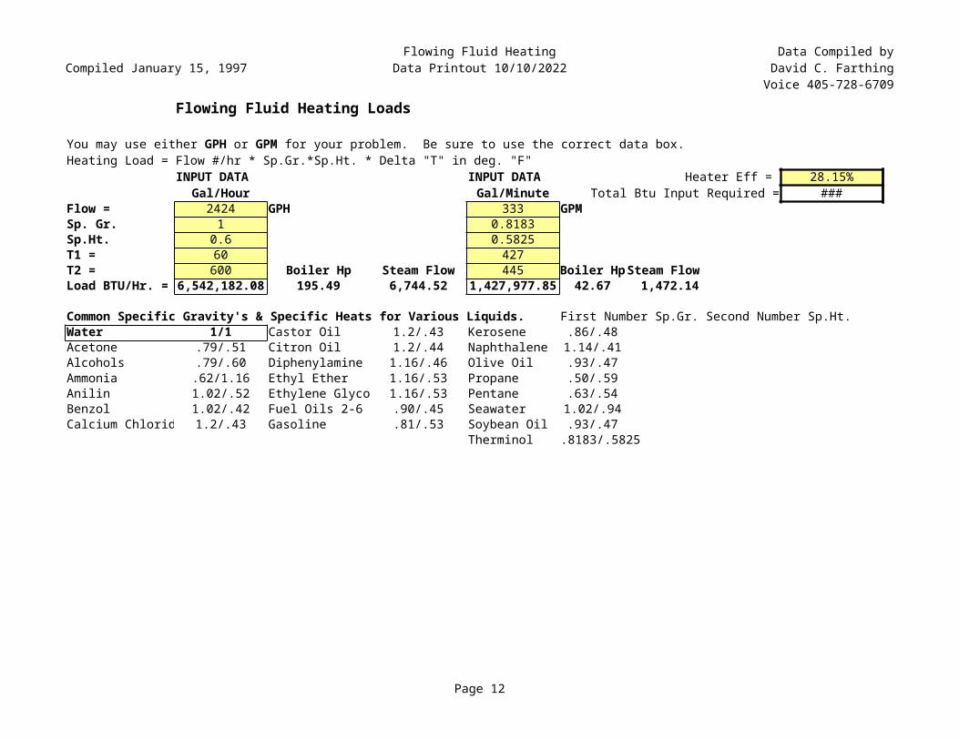
Compiled January 15, 1997Flowing Fluid Heating
Data Printout 10/10/2022Data Compiled byDavid C. FarthingVoice 405-728-6709
Page 12
Flowing Fluid Heating Loads
Heating Load = Flow #/hr * Sp.Gr.*Sp.Ht. * Delta "T" in deg. "F"INPUT DATA INPUT DATA Heater Eff = 28.15%
Gal/Hour Gal/Minute Total Btu Input Required = ###Flow = 2424 GPH 333 GPMSp. Gr. 1 0.8183Sp.Ht. 0.6 0.5825T1 = 60 427T2 = 600 Boiler Hp Steam Flow 445 Boiler HpSteam FlowLoad BTU/Hr. = 6,542,182.08 195.49 6,744.52 1,427,977.85 42.67 1,472.14
Common Specific Gravity's & Specific Heats for Various Liquids. First Number Sp.Gr. Second Number Sp.Ht.Water 1/1 Castor Oil 1.2/.43 Kerosene .86/.48Acetone .79/.51 Citron Oil 1.2/.44 Naphthalene 1.14/.41Alcohols .79/.60 Diphenylamine 1.16/.46 Olive Oil .93/.47Ammonia .62/1.16 Ethyl Ether 1.16/.53 Propane .50/.59Anilin 1.02/.52 Ethylene Glyco 1.16/.53 Pentane .63/.54Benzol 1.02/.42 Fuel Oils 2-6 .90/.45 Seawater 1.02/.94Calcium Chlorid 1.2/.43 Gasoline .81/.53 Soybean Oil .93/.47
Therminol .8183/.5825
You may use either GPH or GPM for your problem. Be sure to use the correct data box.
Water Content In Air Stream
Page 13
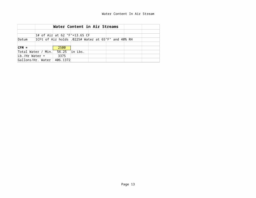
Water Content in Air Streams
1# of Air at 62 "F"=13.65 CFDatum 1CFt of Air holds .0225# Water at 65"F" and 40% RH
CFM = 2500Total Water / Min. 56.25 in Lbs.Lb./Hr Water = 3375Gallons/Hr. Water 406.1372
David Farthing'sTechStuff Valves
Gas ValveOrifice -Regulated Pilot Train
10/10/2022Thanks to Honeywell for the basic CV calculator
Page 14
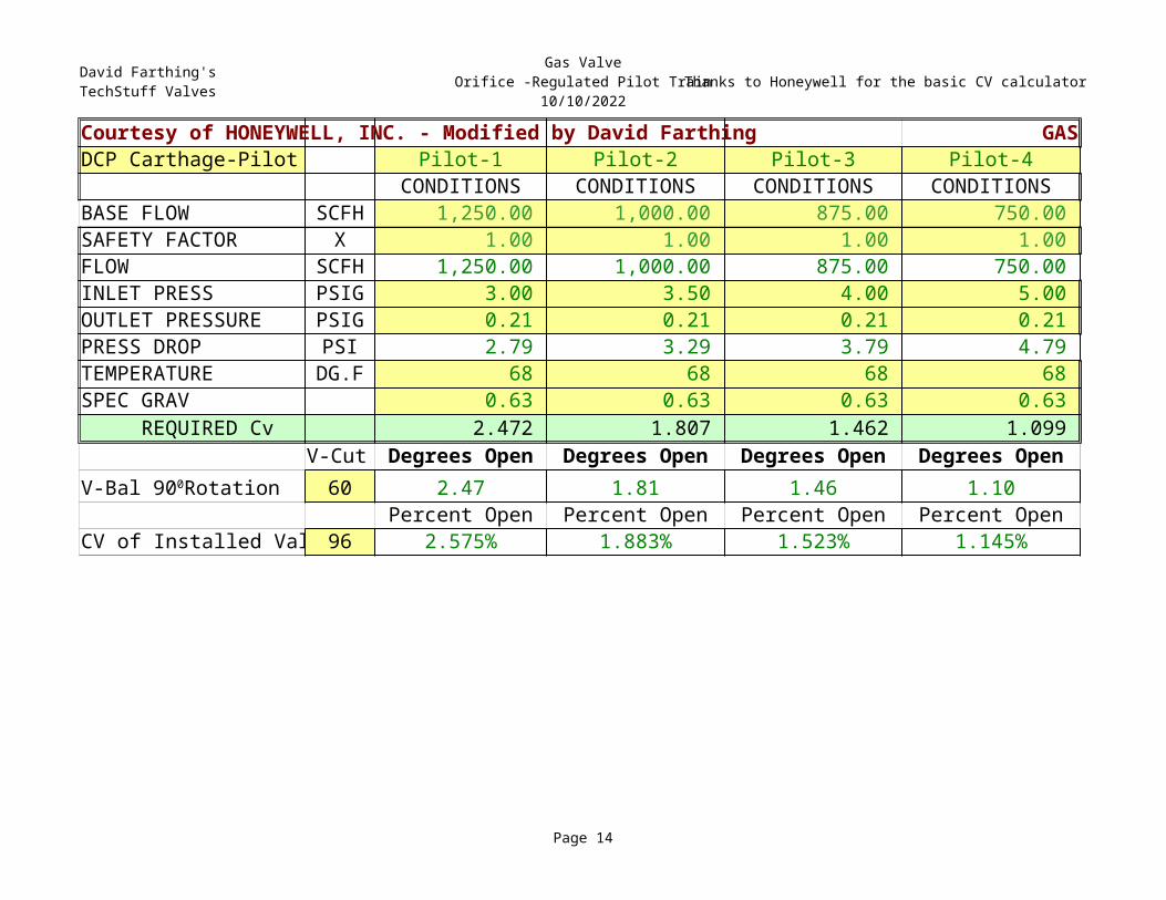
Courtesy of HONEYWELL, INC. - Modified by David Farthing GASDCP Carthage-Pilot Pilot-1 Pilot-2 Pilot-3 Pilot-4
CONDITIONS CONDITIONS CONDITIONS CONDITIONSBASE FLOW SCFH 1,250.00 1,000.00 875.00 750.00 SAFETY FACTOR X 1.00 1.00 1.00 1.00 FLOW SCFH 1,250.00 1,000.00 875.00 750.00 INLET PRESS PSIG 3.00 3.50 4.00 5.00 OUTLET PRESSURE PSIG 0.21 0.21 0.21 0.21 PRESS DROP PSI 2.79 3.29 3.79 4.79 TEMPERATURE DG.F 68 68 68 68 SPEC GRAV 0.63 0.63 0.63 0.63 REQUIRED Cv 2.472 1.807 1.462 1.099
V-Cut Degrees Open Degrees Open Degrees Open Degrees Open60 2.47 1.81 1.46 1.10
Percent Open Percent Open Percent Open Percent OpenCV of Installed Val 96 2.575% 1.883% 1.523% 1.145%
V-Bal 900Rotation
David Farthing'sTechStuff Valves Liquid Valve Thanks to Honeywell for the basic CV Calculator
Page 15
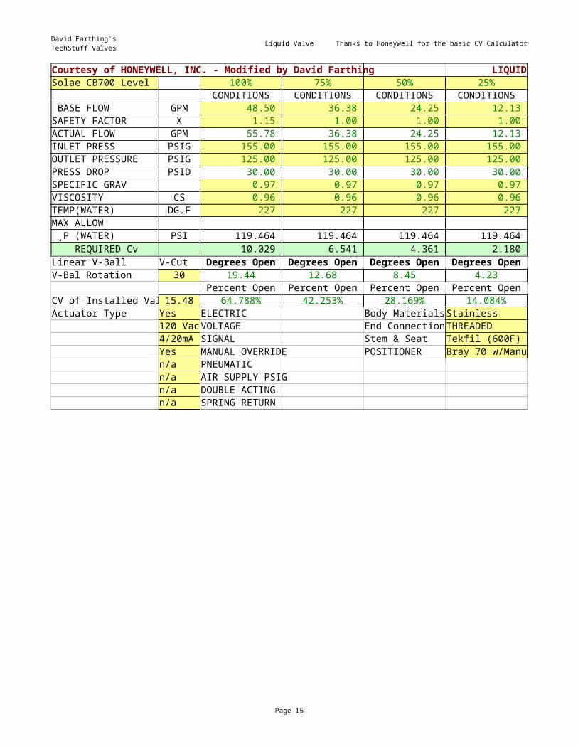
Courtesy of HONEYWELL, INC. - Modified by David Farthing LIQUIDSolae CB700 Level 100% 75% 50% 25%
CONDITIONS CONDITIONS CONDITIONS CONDITIONS BASE FLOW GPM 48.50 36.38 24.25 12.13 SAFETY FACTOR X 1.15 1.00 1.00 1.00 ACTUAL FLOW GPM 55.78 36.38 24.25 12.13 INLET PRESS PSIG 155.00 155.00 155.00 155.00 OUTLET PRESSURE PSIG 125.00 125.00 125.00 125.00 PRESS DROP PSID 30.00 30.00 30.00 30.00 SPECIFIC GRAV 0.97 0.97 0.97 0.97 VISCOSITY CS 0.96 0.96 0.96 0.96 TEMP(WATER) DG.F 227 227 227 227 MAX ALLOW | ¸P (WATER) PSI 119.464 119.464 119.464 119.464 REQUIRED Cv 10.029 6.541 4.361 2.180 Linear V-Ball V-Cut Degrees Open Degrees Open Degrees Open Degrees Open
30 19.44 12.68 8.45 4.23Percent Open Percent Open Percent Open Percent Open
CV of Installed Val 15.48 64.788% 42.253% 28.169% 14.084%Actuator Type Yes ELECTRIC Body MaterialsStainless
120 VacVOLTAGE End ConnectionTHREADED4/20mA SIGNAL Stem & Seat Tekfil (600F)Yes MANUAL OVERRIDE POSITIONER Bray 70 w/Manualn/a PNEUMATICn/a AIR SUPPLY PSIGn/a DOUBLE ACTINGn/a SPRING RETURN
V-Bal Rotation
David Farthing'sTechStuff Valves Steam Valve Thanks to Honeywell for the basic CV Calculator
Page 16
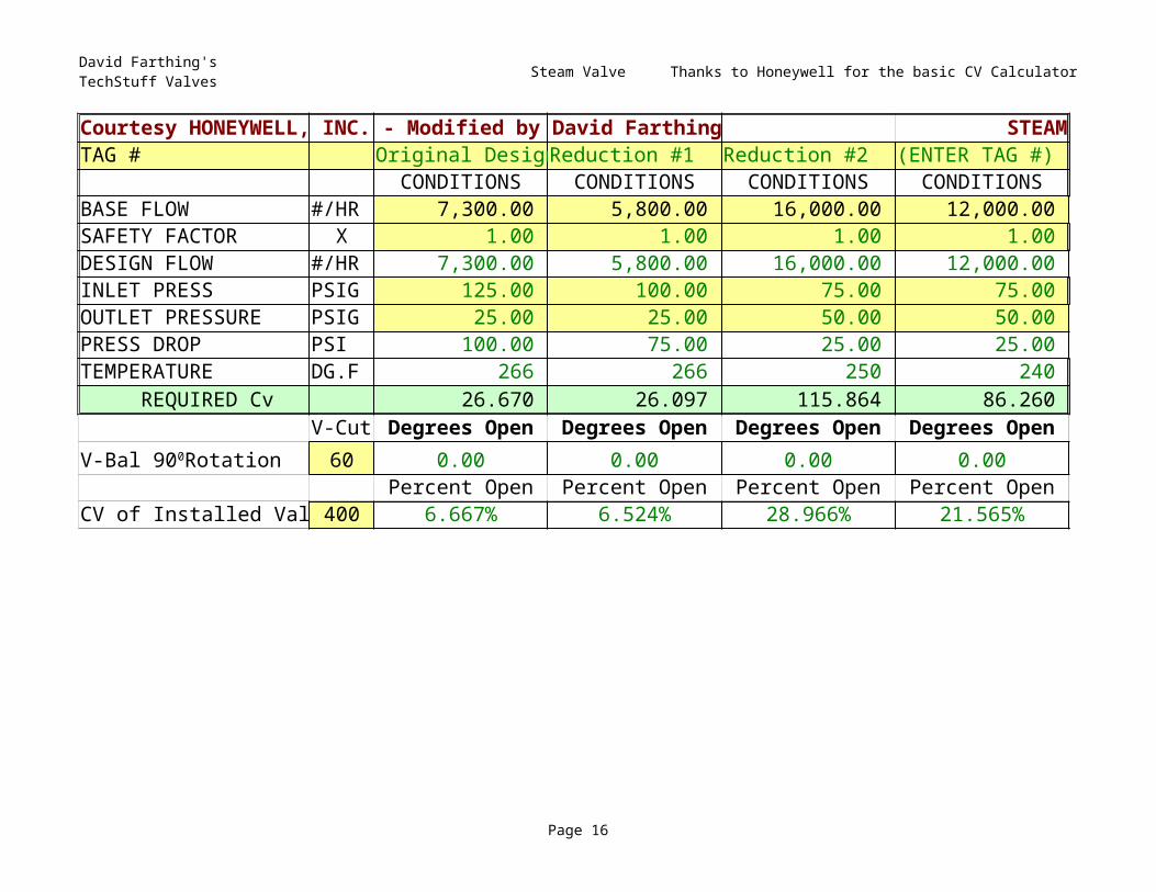
Courtesy HONEYWELL, INC. - Modified by David Farthing STEAMTAG # Original DesignReduction #1 Reduction #2 (ENTER TAG #)
CONDITIONS CONDITIONS CONDITIONS CONDITIONSBASE FLOW #/HR 7,300.00 5,800.00 16,000.00 12,000.00 SAFETY FACTOR X 1.00 1.00 1.00 1.00 DESIGN FLOW #/HR 7,300.00 5,800.00 16,000.00 12,000.00 INLET PRESS PSIG 125.00 100.00 75.00 75.00 OUTLET PRESSURE PSIG 25.00 25.00 50.00 50.00 PRESS DROP PSI 100.00 75.00 25.00 25.00 TEMPERATURE DG.F 266 266 250 240 REQUIRED Cv 26.670 26.097 115.864 86.260
V-Cut Degrees Open Degrees Open Degrees Open Degrees Open60 0.00 0.00 0.00 0.00
Percent Open Percent Open Percent Open Percent OpenCV of Installed Val 400 6.667% 6.524% 28.966% 21.565%
V-Bal 900Rotation
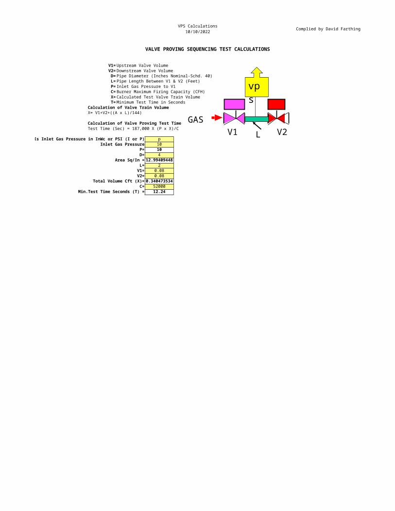
VPS Calculations10/10/2022 Complied by David Farthing
VALVE PROVING SEQUENCING TEST CALCULATIONS
V1= Upstream Valve VolumeV2= Downstream Valve VolumeD= Pipe Diameter (Inches Nominal-Schd. 40)L= Pipe Length Between V1 & V2 (Feet)P= Inlet Gas Pressure to V1C= Burner Maximum Firing Capacity (CFH)X= Calculated Test Valve Train VolumeT= Minimum Test Time in Seconds
Calculation of Valve Train VolumeX= V1+V2+((A x L)/144)
Calculation of Valve Proving Test TimeTest Time (Sec) = 187,000 X (P x X)/C
Is Inlet Gas Pressure in InWc or PSI (I or P) pInlet Gas Pressure 10
P= 10D= 4
Area Sq/In = 12.99409448L= 2V1= 0.08V2= 0.08
Total Volume Cft (X)= 0.340473534C= 52000
Min.Test Time Seconds (T) = 12.24
GASV2V1
vps
L
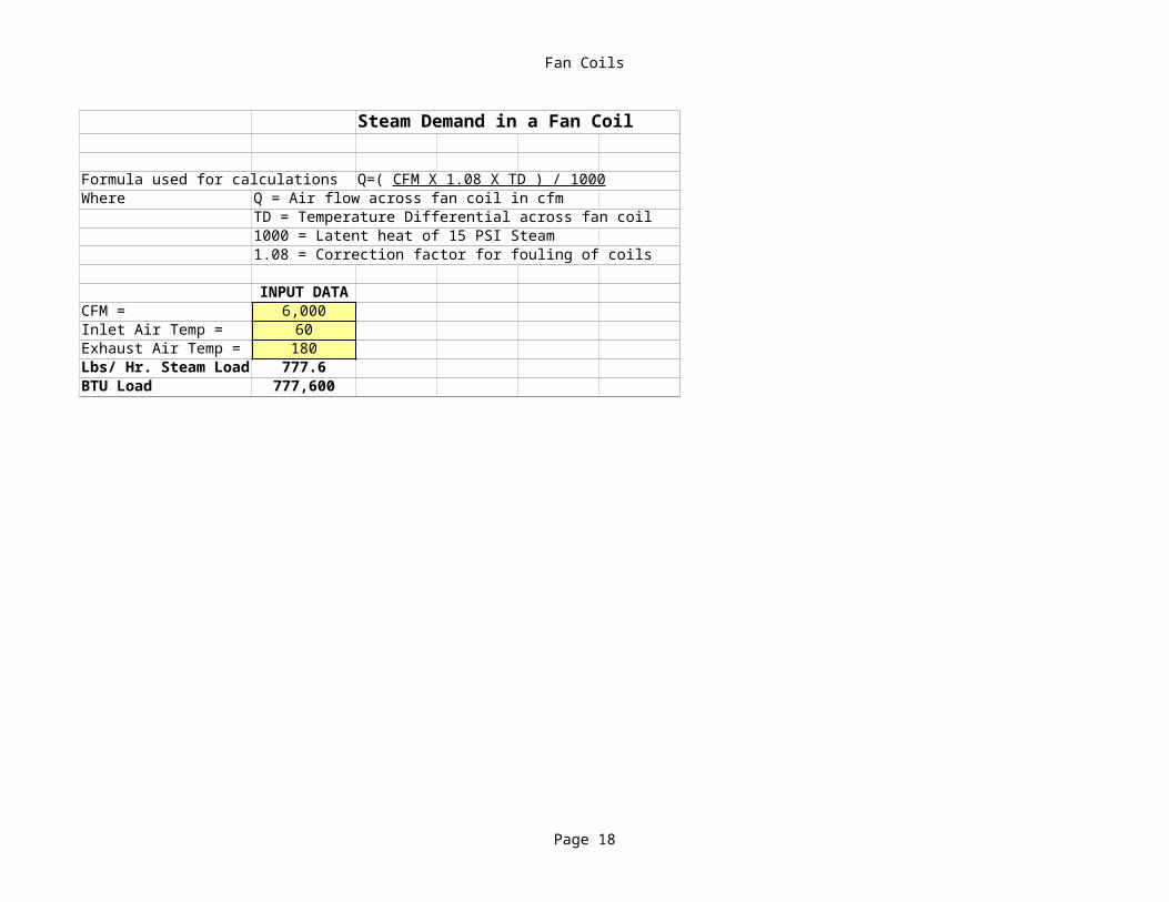
Fan Coils
Page 18
Steam Demand in a Fan Coil
Formula used for calculationsWhere Q = Air flow across fan coil in cfm
TD = Temperature Differential across fan coil1000 = Latent heat of 15 PSI Steam1.08 = Correction factor for fouling of coils
INPUT DATACFM = 6,000Inlet Air Temp = 60Exhaust Air Temp = 180Lbs/ Hr. Steam Load 777.6BTU Load 777,600
Q=( CFM X 1.08 X TD ) / 1000
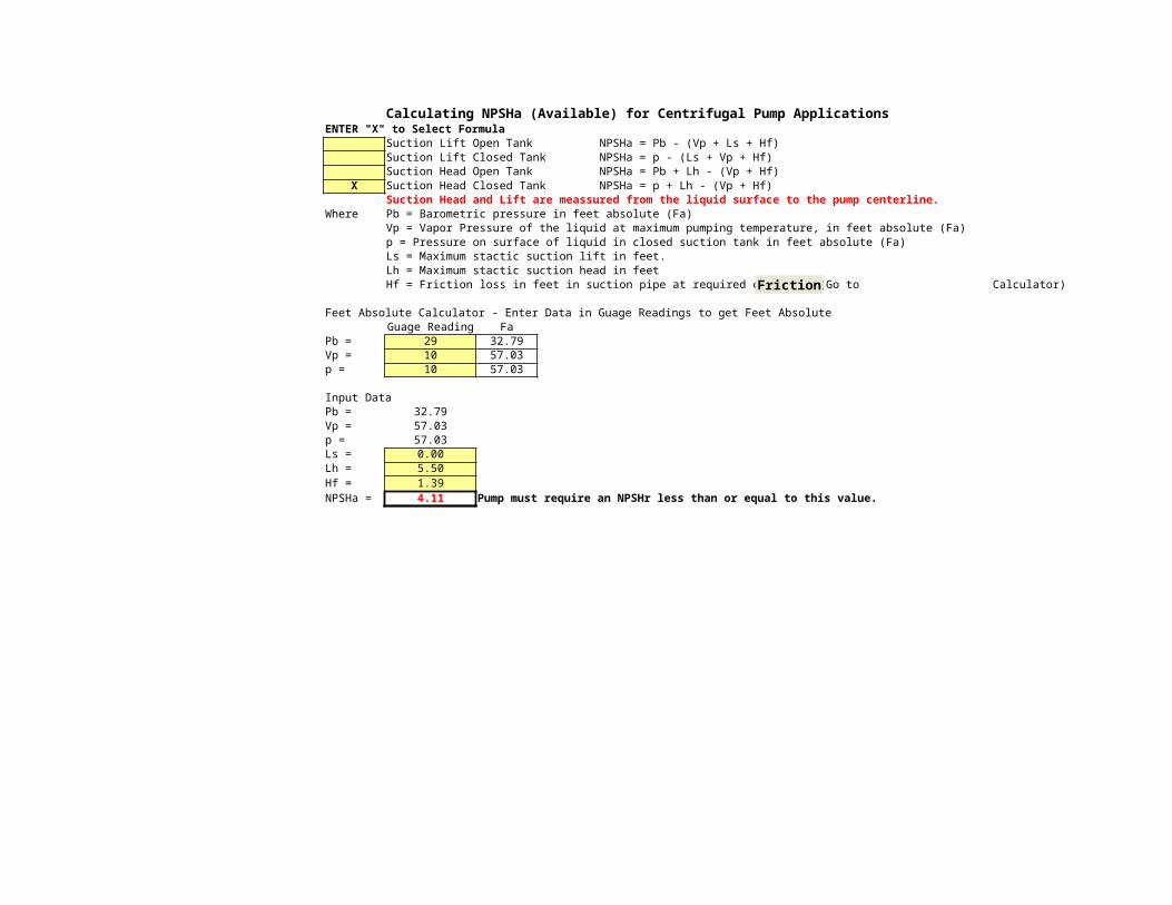
Calculating NPSHa (Available) for Centrifugal Pump ApplicationsENTER "X" to Select Formula
Suction Lift Open Tank NPSHa = Pb - (Vp + Ls + Hf)Suction Lift Closed Tank NPSHa = p - (Ls + Vp + Hf)Suction Head Open Tank NPSHa = Pb + Lh - (Vp + Hf)
X Suction Head Closed Tank NPSHa = p + Lh - (Vp + Hf)Suction Head and Lift are meassured from the liquid surface to the pump centerline.
Where Pb = Barometric pressure in feet absolute (Fa)Vp = Vapor Pressure of the liquid at maximum pumping temperature, in feet absolute (Fa)p = Pressure on surface of liquid in closed suction tank in feet absolute (Fa)Ls = Maximum stactic suction lift in feet.Lh = Maximum stactic suction head in feetHf = Friction loss in feet in suction pipe at required capacity. (Go to Calculator)
Feet Absolute Calculator - Enter Data in Guage Readings to get Feet AbsoluteGuage Reading Fa
Pb = 29 32.79Vp = 10 57.03p = 10 57.03
Input DataPb = 32.79Vp = 57.03p = 57.03Ls = 0.00Lh = 5.50Hf = 1.39NPSHa = 4.11 Pump must require an NPSHr less than or equal to this value.
Friction
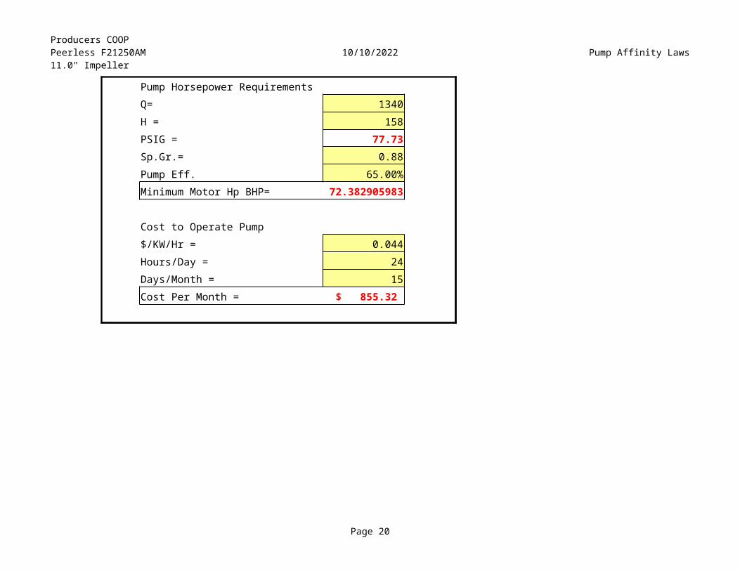
Producers COOPPeerless F21250AM11.0" Impeller
10/10/2022 Pump Affinity Laws
Page 20
Pump Horsepower RequirementsQ= 1340H = 158PSIG = 77.73Sp.Gr.= 0.88Pump Eff. 65.00%Minimum Motor Hp BHP= 72.382905983
Cost to Operate Pump$/KW/Hr = 0.044Hours/Day = 24Days/Month = 15Cost Per Month = $ 855.32

Burner Fan Lawsby David Farthing
10/10/2022 David Farthing'sTechStuffFan Laws for ESTIMATING Boiler Burner Fan Performance
Q = Assumed DataD = Fan Diameter in Inches Air Density =0.0584N = Fan Shaft RPM Air Temp = 100H = Static Pressure of Fan at Design Point, In Elevation =<1700 Ft/ASL
Enter known data in Yellow Box Bhp = Fan Horsepower = Q X H / (6356* Eff)BuzziUnicem Diff P = Differential Pressure Across Windbox at Firing RateTodd Heater -1 Eff =Pryor OK Plant Burner Input 15,000,000.00 BTU/Hr from Burner Data Plate21MM Btu Input Max Gas Flow 15,000.00
Min Gas Flow 1,500.00 Max Air Flow @15% EA. 2,844.12
Min Air Flow 284.41 CFM at LOW (10%) FIRE.Fan Motor HP 60.00 Taken from Fan Motor Data Plate
Fan Static Pressure H 18.00 *At Stall 0 Flow Fan Damper CLOSED taken at fan discharge ahead of dampers.Calculated Fan Eff. 16.212% As a check this number should be above 72-75% w/80% Average)
Calculated Fan HP 49.68 Check against actual Fan Motor Data PlateExpected Fan Eff Performance? Within expected performance
Original Fan Speed 1770 RPM at Shaft FAN LAWS FUEL CONVERSIONS & ENERGY CONTENTNew Fan Speed 1150 RPM at Shaft Q1/Q2 = N1/N2 (N) NATURAL GAS (C/Ft) AveragedNew Fan Flow 1848 CFM H1/H2 = (N1/N2)^2 (2) #2 DIESEL (RED) (1-Gallon) API Spec.
New Fan Max SP 7.60 Inch WC Bhp1/Bhp2 = (N1/N2)^3 (1) #1 DIESEL(AUTO) (1-Gallon) API Spec.New Fan Bhp 3.33 Bhp at the shaft. Q1/Q2 = D1/D2 (BV) BIO-GAS VEGATABLE (C/Ft) Averaged
Original Boiler Output PPH 12,371.13 Saturated H1/H2 = (D1/D2)^2 (BL) BIO-GAS LANDFILL (C/Ft) AveragedOriginal Boiler Output PPH 10,391.75 Superheated <700 Deg F Bhp1/Bhp2 = (D1/D2)^3 BTU Input of Burner =
New Boiler Output PPH 8,037.65 SaturatedNew Boiler Output PPH 6,751.62 Superheated <700 Deg F EQUEVELENT Fuel Flow Units/Hour
EQUEVELENT Fuel Flow Units/Minute Note1 Data marked with an asterisk * may also be taken from manufacturer's data sheets. NOTE: 1 D/Therm = 1,000,000 Btu
CFM Estimates based on 950 But/ft^3 fuel, 9.67 ft^3 Air per 1 ft^3 Fuel at Sea Level and 100 deg "F" Combustion Air.Fan Volume Flow Rate CFM or ft^3/Min
(ft^3/min X H) / (5263 X Motor Hp)
Ft^3/HrFt^3/HrCFM base on 9.67 Ft^3 Air/1Ft^3 Gas at Sea Level & 80 deg "F". 15% Excess Air.
TechStuff C1997 Combustion Efficiency Calculations
Printout 10/10/2022 04:38:46
Data Compiled byDavid Farthing
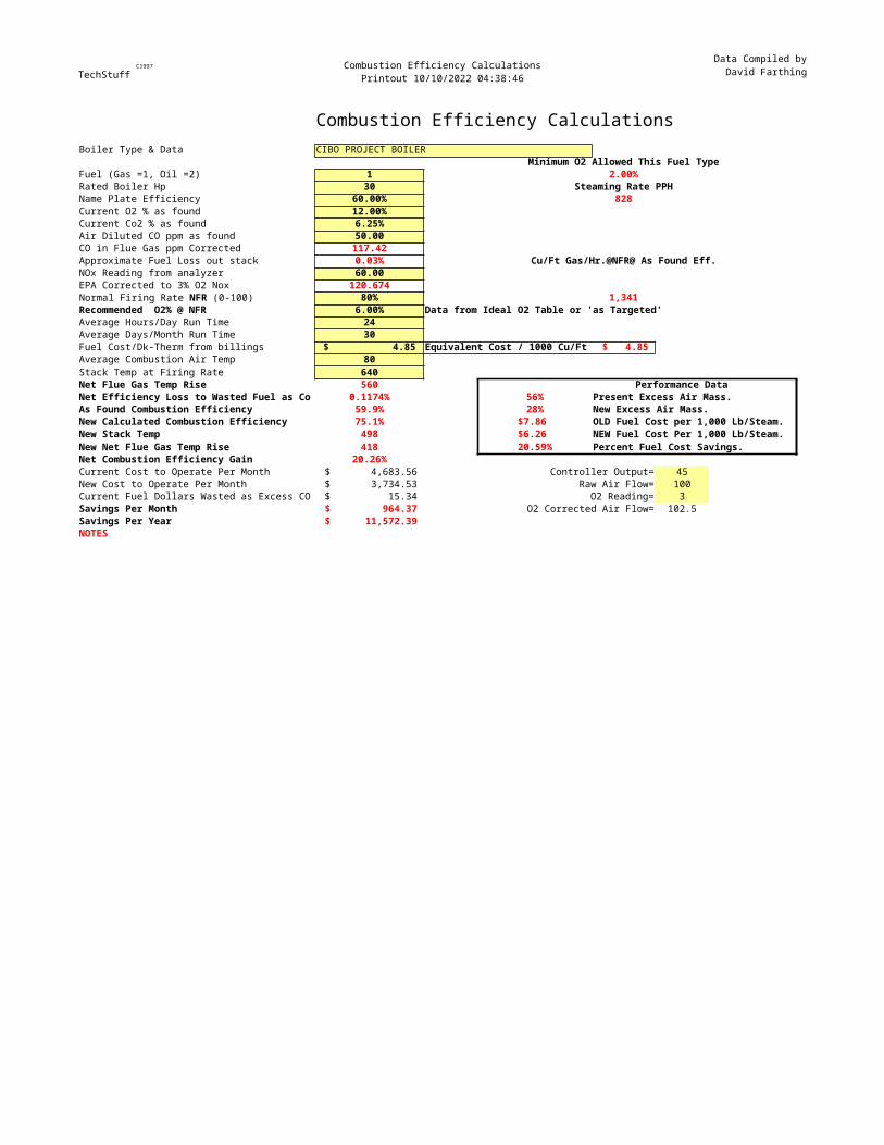
Combustion Efficiency CalculationsBoiler Type & Data CIBO PROJECT BOILER
Minimum O2 Allowed This Fuel TypeFuel (Gas =1, Oil =2) 1 2.00%Rated Boiler Hp 30 Steaming Rate PPHName Plate Efficiency 60.00% 828Current O2 % as found 12.00%Current Co2 % as found 6.25%Air Diluted CO ppm as found 50.00CO in Flue Gas ppm Corrected 117.42Approximate Fuel Loss out stack 0.03% Cu/Ft Gas/Hr.@NFR@ As Found Eff.NOx Reading from analyzer 60.00EPA Corrected to 3% O2 Nox 120.674
80% 1,341Recommended O2% @ NFR 6.00% Data from Ideal O2 Table or 'as Targeted'Average Hours/Day Run Time 24Average Days/Month Run Time 30Fuel Cost/Dk-Therm from billings $ 4.85 Equivalent Cost / 1000 Cu/Ft $ 4.85 Average Combustion Air Temp 80Stack Temp at Firing Rate 640Net Flue Gas Temp Rise 560 Performance DataNet Efficiency Loss to Wasted Fuel as Co 0.1174% 56% Present Excess Air Mass.As Found Combustion Efficiency 59.9% 28% New Excess Air Mass.New Calculated Combustion Efficiency 75.1% $7.86 OLD Fuel Cost per 1,000 Lb/Steam.New Stack Temp 498 $6.26 NEW Fuel Cost Per 1,000 Lb/Steam.New Net Flue Gas Temp Rise 418 20.59% Percent Fuel Cost Savings.Net Combustion Efficiency Gain 20.26%Current Cost to Operate Per Month $ 4,683.56 Controller Output= 45New Cost to Operate Per Month $ 3,734.53 Raw Air Flow= 100Current Fuel Dollars Wasted as Excess CO $ 15.34 O2 Reading= 3Savings Per Month $ 964.37 O2 Corrected Air Flow= 102.5Savings Per Year $ 11,572.39 NOTES
Normal Firing Rate NFR (0-100)
Voltage
Page 23
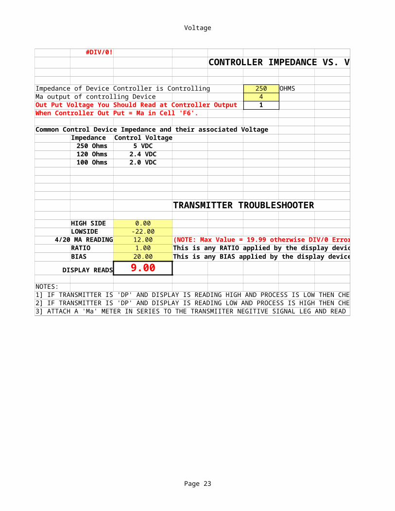
#DIV/0!CONTROLLER IMPEDANCE VS. VOLTAGE
Impedance of Device Controller is Controlling 250 OHMSMa output of controlling Device 4Out Put Voltage You Should Read at Controller Output 1When Controller Out Put = Ma in Cell 'F6'.
Common Control Device Impedance and their associated VoltageImpedance Control Voltage250 Ohms 5 VDC120 Ohms 2.4 VDC100 Ohms 2.0 VDC
TRANSMITTER TROUBLESHOOTERHIGH SIDE 0.00LOWSIDE -22.00
4/20 MA READING 12.00 (NOTE: Max Value = 19.99 otherwise DIV/0 Error)RATIO 1.00 This is any RATIO applied by the display device.BIAS 20.00 This is any BIAS applied by the display device.
DISPLAY READS 9.00NOTES:1] IF TRANSMITTER IS 'DP' AND DISPLAY IS READING HIGH AND PROCESS IS LOW THEN CHECK LOW (REFERENCE) SIDE FOR PLUGGED LEG.2] IF TRANSMITTER IS 'DP' AND DISPLAY IS READING LOW AND PROCESS IS HIGH THEN CHECK HIGH SIDE FOR PLUGGED LEG.3] ATTACH A 'Ma' METER IN SERIES TO THE TRANSMIITER NEGITIVE SIGNAL LEG AND READ Ma. INCERT IN 4/20 MA CELL IN FORMULA
Voltage
Page 24
CONTROLLER IMPEDANCE VS. VOLTAGE
(NOTE: Max Value = 19.99 otherwise DIV/0 Error)This is any RATIO applied by the display device.This is any BIAS applied by the display device.
1] IF TRANSMITTER IS 'DP' AND DISPLAY IS READING HIGH AND PROCESS IS LOW THEN CHECK LOW (REFERENCE) SIDE FOR PLUGGED LEG.2] IF TRANSMITTER IS 'DP' AND DISPLAY IS READING LOW AND PROCESS IS HIGH THEN CHECK HIGH SIDE FOR PLUGGED LEG.3] ATTACH A 'Ma' METER IN SERIES TO THE TRANSMIITER NEGITIVE SIGNAL LEG AND READ Ma. INCERT IN 4/20 MA CELL IN FORMULA
Pipe Expansion
Page 25
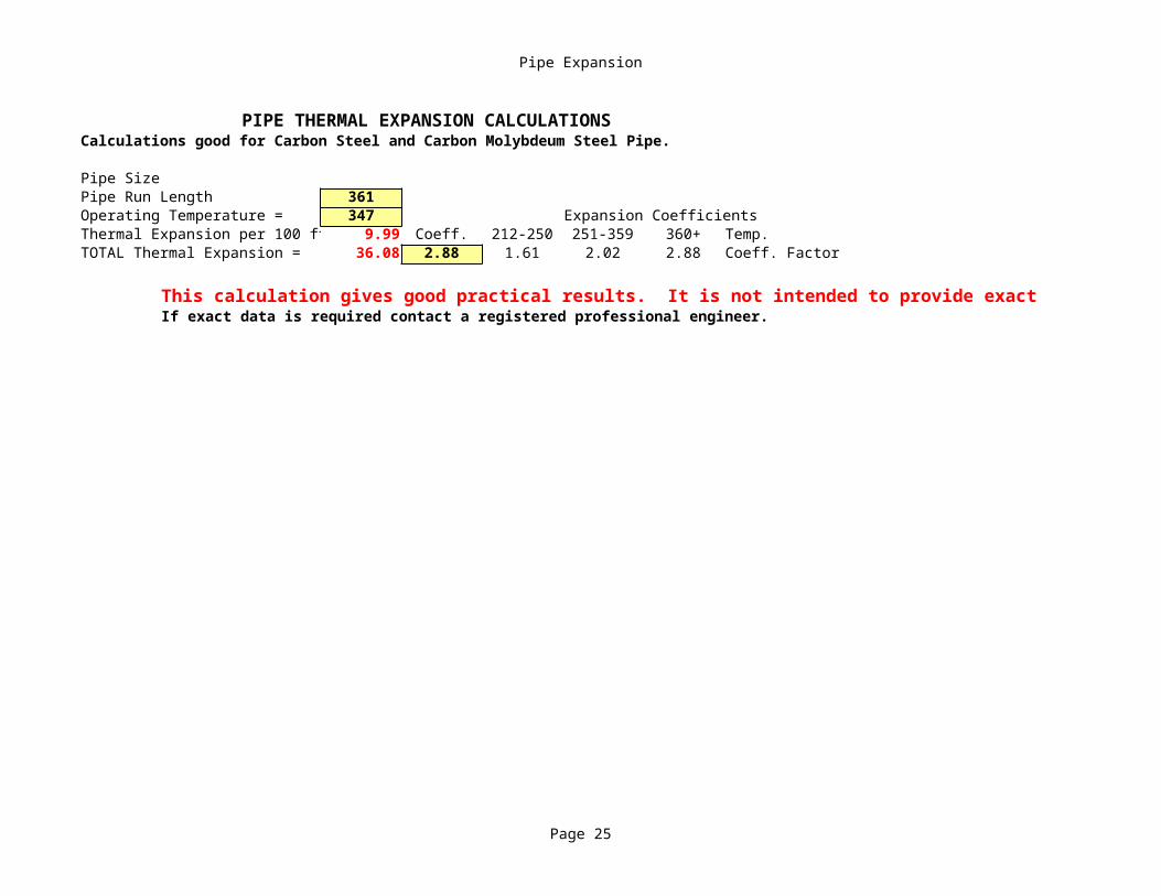
PIPE THERMAL EXPANSION CALCULATIONSCalculations good for Carbon Steel and Carbon Molybdeum Steel Pipe.
Pipe SizePipe Run Length 361Operating Temperature = 347 Expansion CoefficientsThermal Expansion per 100 ft 9.99 Coeff. 212-250 251-359 360+ Temp.TOTAL Thermal Expansion = 36.08 2.88 1.61 2.02 2.88 Coeff. Factor
This calculation gives good practical results. It is not intended to provide exact data.If exact data is required contact a registered professional engineer.

Pipe Expansion
Page 26
This calculation gives good practical results. It is not intended to provide exact data.
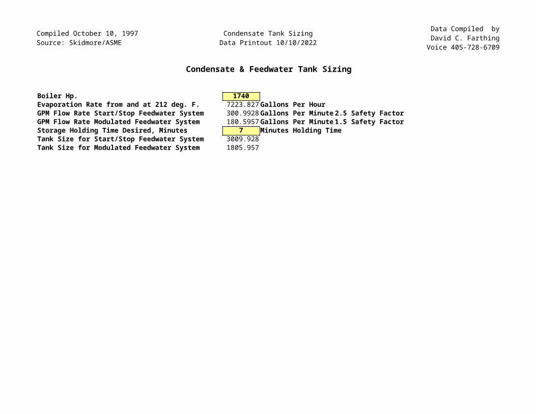
Compiled October 10, 1997Source: Skidmore/ASME
Condensate Tank SizingData Printout 10/10/2022
Data Compiled byDavid C. FarthingVoice 405-728-6709
Condensate & Feedwater Tank Sizing
Boiler Hp. 1740Evaporation Rate from and at 212 deg. F. 7223.827 Gallons Per HourGPM Flow Rate Start/Stop Feedwater System 300.9928 Gallons Per Minute 2.5 Safety FactorGPM Flow Rate Modulated Feedwater System 180.5957 Gallons Per Minute 1.5 Safety FactorStorage Holding Time Desired, Minutes 7 Minutes Holding TimeTank Size for Start/Stop Feedwater System 3009.928Tank Size for Modulated Feedwater System 1805.957
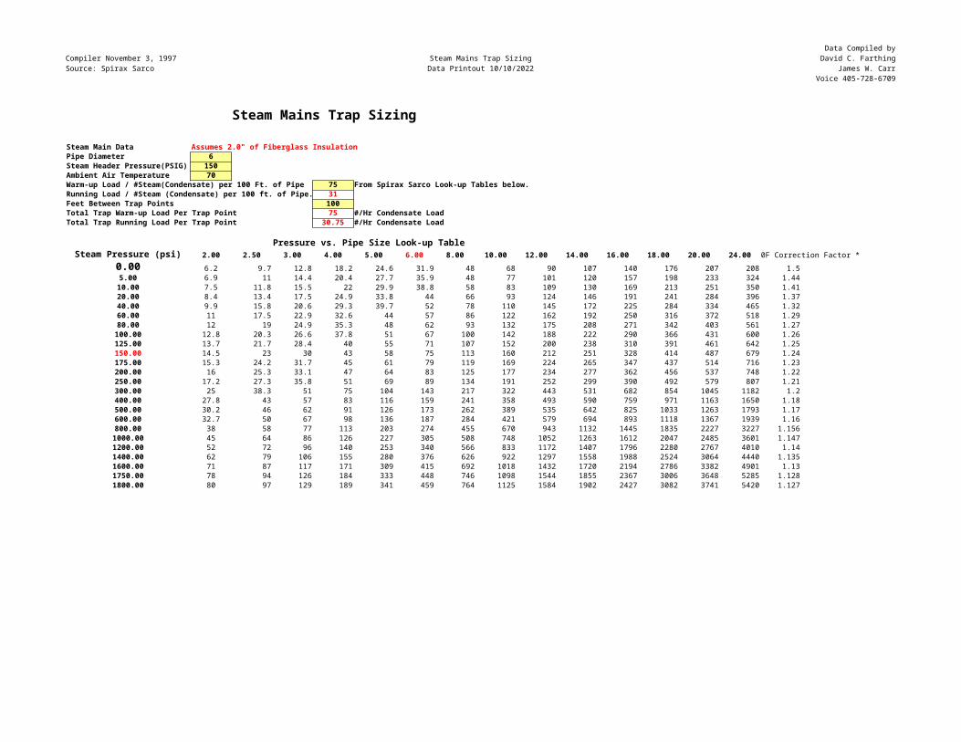
Compiler November 3, 1997Source: Spirax Sarco
Steam Mains Trap SizingData Printout 10/10/2022
Data Compiled byDavid C. Farthing
James W. CarrVoice 405-728-6709
Steam Mains Trap Sizing
Steam Main Data Assumes 2.0" of Fiberglass InsulationPipe Diameter 6Steam Header Pressure(PSIG) 150Ambient Air Temperature 70Warm-up Load / #Steam(Condensate) per 100 Ft. of Pipe 75 From Spirax Sarco Look-up Tables below.Running Load / #Steam (Condensate) per 100 ft. of Pipe. 31Feet Between Trap Points 100Total Trap Warm-up Load Per Trap Point 75 #/Hr Condensate LoadTotal Trap Running Load Per Trap Point 30.75 #/Hr Condensate Load
Pressure vs. Pipe Size Look-up Table Steam Pressure (psi) 2.00 2.50 3.00 4.00 5.00 6.00 8.00 10.00 12.00 14.00 16.00 18.00 20.00 24.00 0F Correction Factor *
0.00 6.2 9.7 12.8 18.2 24.6 31.9 48 68 90 107 140 176 207 208 1.55.00 6.9 11 14.4 20.4 27.7 35.9 48 77 101 120 157 198 233 324 1.4410.00 7.5 11.8 15.5 22 29.9 38.8 58 83 109 130 169 213 251 350 1.4120.00 8.4 13.4 17.5 24.9 33.8 44 66 93 124 146 191 241 284 396 1.3740.00 9.9 15.8 20.6 29.3 39.7 52 78 110 145 172 225 284 334 465 1.3260.00 11 17.5 22.9 32.6 44 57 86 122 162 192 250 316 372 518 1.2980.00 12 19 24.9 35.3 48 62 93 132 175 208 271 342 403 561 1.27100.00 12.8 20.3 26.6 37.8 51 67 100 142 188 222 290 366 431 600 1.26125.00 13.7 21.7 28.4 40 55 71 107 152 200 238 310 391 461 642 1.25150.00 14.5 23 30 43 58 75 113 160 212 251 328 414 487 679 1.24175.00 15.3 24.2 31.7 45 61 79 119 169 224 265 347 437 514 716 1.23200.00 16 25.3 33.1 47 64 83 125 177 234 277 362 456 537 748 1.22250.00 17.2 27.3 35.8 51 69 89 134 191 252 299 390 492 579 807 1.21300.00 25 38.3 51 75 104 143 217 322 443 531 682 854 1045 1182 1.2400.00 27.8 43 57 83 116 159 241 358 493 590 759 971 1163 1650 1.18500.00 30.2 46 62 91 126 173 262 389 535 642 825 1033 1263 1793 1.17600.00 32.7 50 67 98 136 187 284 421 579 694 893 1118 1367 1939 1.16800.00 38 58 77 113 203 274 455 670 943 1132 1445 1835 2227 3227 1.1561000.00 45 64 86 126 227 305 508 748 1052 1263 1612 2047 2485 3601 1.1471200.00 52 72 96 140 253 340 566 833 1172 1407 1796 2280 2767 4010 1.141400.00 62 79 106 155 280 376 626 922 1297 1558 1988 2524 3064 4440 1.1351600.00 71 87 117 171 309 415 692 1018 1432 1720 2194 2786 3382 4901 1.131750.00 78 94 126 184 333 448 746 1098 1544 1855 2367 3006 3648 5285 1.1281800.00 80 97 129 189 341 459 764 1125 1584 1902 2427 3082 3741 5420 1.127
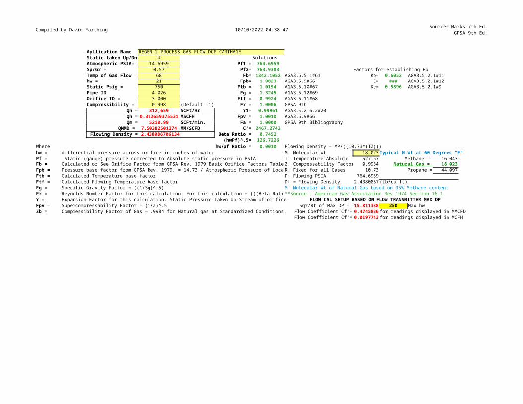
Compiled by David Farthing 10/10/2022 04:38:47 Sources Marks 7th Ed.GPSA 9th Ed.
Apllication Name REGEN-2 PROCESS GAS FLOW DCP CARTHAGEU Solutions
Atmospheric PSIA= 14.6959 Pf1 = 764.6959Sp/Gr = 0.57 Pf2= 763.9383 Factors for establishing FbTemp of Gas Flow 68 Fb= 1842.1052 AGA3.6.5.1#61 Ko= 0.6052 AGA3.5.2.1#11hw = 21 Fpb= 1.0023 AGA3.6.9#66 E= ### AGA3.5.2.1#12Static Psig = 750 Ftb = 1.0154 AGA3.6.10#67 Ke= 0.5896 AGA3.5.2.1#9Pipe ID 4.026 Fg = 1.3245 AGA3.6.12#69Orifice ID = 3.000 Ftf = 0.9924 AGA3.6.11#68Compressibility = 0.998 (Default =1) Fr = 1.0006 GPSA 9th
Qh = 312,659 SCFt/Hr Y1= 0.99961 AGA3.5.2.6.2#20Qh = 0.312659375531 MSCFH Fpv = 1.0010 AGA3.6.9#66Qm = 5210.99 SCFt/min. Fa = 1.0000 GPSA 9th Bibliography
QMMD = 7.50382501274 MM/SCFD C'= 2467.2743Flowing Density = 2.438086706134 Beta Ratio = 0.7452
(hwPf)^.5= 126.7226Where hw/pf Ratio = 0.0010 Flowing Density = MP/((10.73*(TZ)))hw = differential pressure across orifice in inches of water M. Molecular Wt 18.023 Typical M.Wt at 60 Degrees "F"Pf = Static (gauge) pressure corrected to Absolute static pressure in PSIA T. Temperature Absolute 527.67 Methane = 16.043Fb = Calculated or See Orifice Factor from GPSA Rev. 1979 Basic Orifice Factors Table Z. Compressability Factor 0.9984 Natural Gas = 18.023Fpb = Pressure base factor from GPSA Rev. 1979, = 14.73 / Atmospheric Pressure of LocatR. Fixed for all Gases 10.73 Propane = 44.097Ftb = Calculated Temperature base factor P. Flowing PSIA 764.6959Ftf = Calculated Flowing Temperature base factor Df = Flowing Density 2.4380867 (lb/cu ft)Fg = Specific Gravity Factor = ((1/Sg)^.5) M. Molecular Wt of Natural Gas based on 95% Methane contentFr = Reynolds Number Factor for this calculation. For this calculation = (((Beta Ratio**Source - American Gas Association Rev 1974 Section 16.1Y = Expansion Factor for this calculation. Static Pressure Taken Up-Stream of orifice. FLOW CAL SETUP BASED ON FLOW TRANSMITTER MAX DPFpv = Supercompressability Factor = (1/Z)^.5 Sqr/Rt of Max DP = 15.811388 250 Max hwZb = Compressibility Factor of Gas = .9984 for Natural gas at Standardized Conditions. Flow Coefficient Cf'= 0.4745836 for readings displayed in MMCFD
Flow Coefficient Cf'= 0.0197743 for readings displayed in MCFH
Static taken Up/Dn
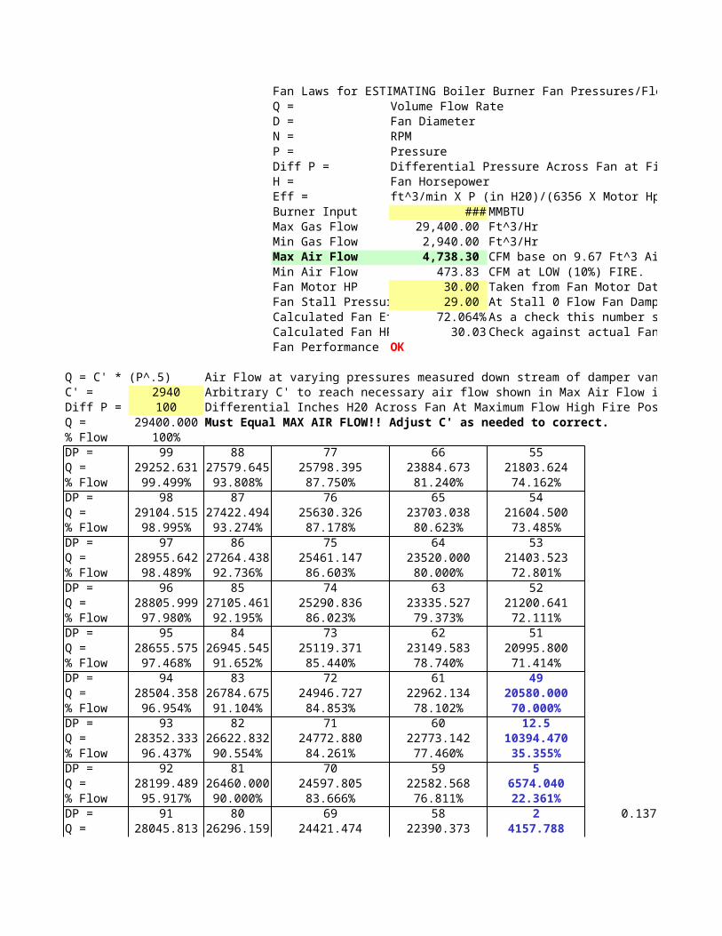
Fan Laws for ESTIMATING Boiler Burner Fan Pressures/FlowsQ = Volume Flow RateD = Fan DiameterN = RPMP = PressureDiff P = Differential Pressure Across Fan at Firing RateH = Fan HorsepowerEff = ft^3/min X P (in H20)/(6356 X Motor Hp)Burner Input ### MMBTUMax Gas Flow 29,400.00 Ft^3/HrMin Gas Flow 2,940.00 Ft^3/HrMax Air Flow 4,738.30 CFM base on 9.67 Ft^3 Air/1Ft^3 Gas.Min Air Flow 473.83 CFM at LOW (10%) FIRE.Fan Motor HP 30.00 Taken from Fan Motor Data PlateFan Stall Pressur 29.00 At Stall 0 Flow Fan Damper CLOSEDCalculated Fan Ef 72.064% As a check this number should be 72-75% w/72% Average)Calculated Fan HP 30.03 Check against actual Fan Motor Data PlateFan Performance OK
Q = C' * (P^.5) Air Flow at varying pressures measured down stream of damper vanesC' = 2940 Arbitrary C' to reach necessary air flow shown in Max Air Flow in above cell.Diff P = 100 Differential Inches H20 Across Fan At Maximum Flow High Fire Position of Fan DamperQ = 29400.000 Must Equal MAX AIR FLOW!! Adjust C' as needed to correct.% Flow 100%DP = 99 88 77 66 55Q = 29252.631 27579.645 25798.395 23884.673 21803.624% Flow 99.499% 93.808% 87.750% 81.240% 74.162%DP = 98 87 76 65 54Q = 29104.515 27422.494 25630.326 23703.038 21604.500% Flow 98.995% 93.274% 87.178% 80.623% 73.485%DP = 97 86 75 64 53Q = 28955.642 27264.438 25461.147 23520.000 21403.523% Flow 98.489% 92.736% 86.603% 80.000% 72.801%DP = 96 85 74 63 52Q = 28805.999 27105.461 25290.836 23335.527 21200.641% Flow 97.980% 92.195% 86.023% 79.373% 72.111%DP = 95 84 73 62 51Q = 28655.575 26945.545 25119.371 23149.583 20995.800% Flow 97.468% 91.652% 85.440% 78.740% 71.414%DP = 94 83 72 61 49Q = 28504.358 26784.675 24946.727 22962.134 20580.000% Flow 96.954% 91.104% 84.853% 78.102% 70.000%DP = 93 82 71 60 12.5Q = 28352.333 26622.832 24772.880 22773.142 10394.470% Flow 96.437% 90.554% 84.261% 77.460% 35.355%DP = 92 81 70 59 5Q = 28199.489 26460.000 24597.805 22582.568 6574.040% Flow 95.917% 90.000% 83.666% 76.811% 22.361%DP = 91 80 69 58 2 0.137Q = 28045.813 26296.159 24421.474 22390.373 4157.788
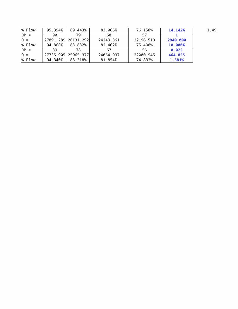
% Flow 95.394% 89.443% 83.066% 76.158% 14.142% 1.49DP = 90 79 68 57 1Q = 27891.289 26131.292 24243.861 22196.513 2940.000% Flow 94.868% 88.882% 82.462% 75.498% 10.000%DP = 89 78 67 56 0.025Q = 27735.905 25965.377 24064.937 22000.945 464.855% Flow 94.340% 88.318% 81.854% 74.833% 1.581%
Fan Laws for ESTIMATING Boiler Burner Fan Pressures/Flows
Differential Pressure Across Fan at Firing Rate
ft^3/min X P (in H20)/(6356 X Motor Hp)
CFM base on 9.67 Ft^3 Air/1Ft^3 Gas.
Taken from Fan Motor Data PlateAt Stall 0 Flow Fan Damper CLOSEDAs a check this number should be 72-75% w/72% Average)Check against actual Fan Motor Data Plate
Air Flow at varying pressures measured down stream of damper vanesArbitrary C' to reach necessary air flow shown in Max Air Flow in above cell.Differential Inches H20 Across Fan At Maximum Flow High Fire Position of Fan Damper
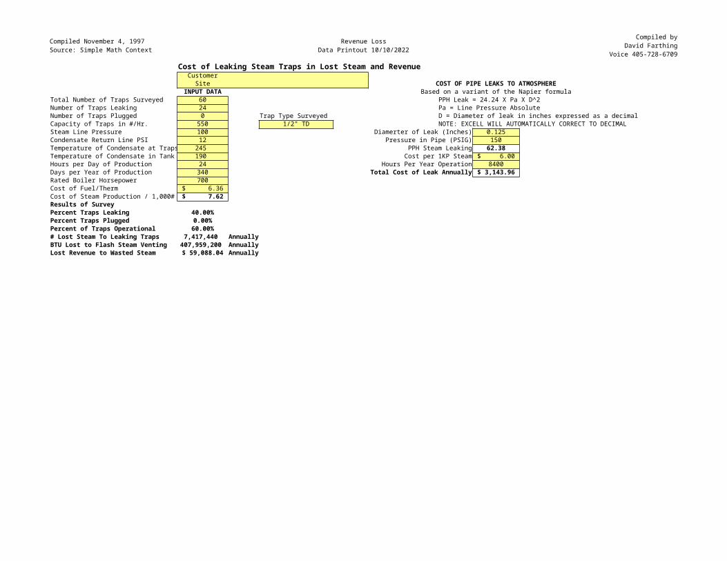
Compiled November 4, 1997Source: Simple Math Context
Revenue LossData Printout 10/10/2022
Compiled byDavid Farthing
Voice 405-728-6709Cost of Leaking Steam Traps in Lost Steam and Revenue
CustomerSite COST OF PIPE LEAKS TO ATMOSPHERE
INPUT DATA Based on a variant of the Napier formulaTotal Number of Traps Surveyed 60 PPH Leak = 24.24 X Pa X D^2Number of Traps Leaking 24 Pa = Line Pressure AbsoluteNumber of Traps Plugged 0 Trap Type Surveyed D = Diameter of leak in inches expressed as a decimalCapacity of Traps in #/Hr. 550 1/2" TD NOTE: EXCELL WILL AUTOMATICALLY CORRECT TO DECIMALSteam Line Pressure 100 Diamerter of Leak (Inches) 0.125Condensate Return Line PSI 12 Pressure in Pipe (PSIG) 150Temperature of Condensate at Traps 245 PPH Steam Leaking 62.38Temperature of Condensate in Tank 190 Cost per 1KP Steam $ 6.00 Hours per Day of Production 24 Hours Per Year Operation 8400Days per Year of Production 340 Total Cost of Leak Annually $ 3,143.96 Rated Boiler Horsepower 700Cost of Fuel/Therm $ 6.36 Cost of Steam Production / 1,000# $ 7.62 Results of SurveyPercent Traps Leaking 40.00%Percent Traps Plugged 0.00%Percent of Traps Operational 60.00%# Lost Steam To Leaking Traps 7,417,440 AnnuallyBTU Lost to Flash Steam Venting 407,959,200 AnnuallyLost Revenue to Wasted Steam $ 59,088.04 Annually
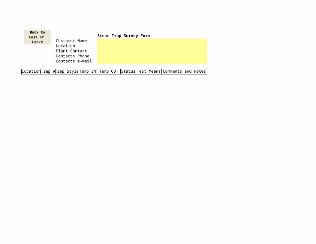
Steam Trap Survey FormCustomer NameLocationPlant ContactContacts PhoneContacts e-mail
LocationTrap #Trap StyleTemp IN Temp OUT Status Test Means Comments and Notes
Back toCost of Leaks
Compiled January 16, 1998 Ohms LawData Printout 10/10/2022
Data Compiled byDavid C. FarthingVoice 405-728-6709
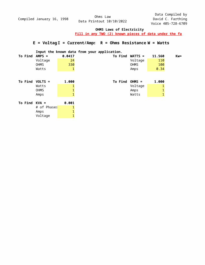
OHMS Laws of ElectricityFill in any TWO (2) known pieces of data under the factor you are looking for.
E = VoltagI = Current/Amps R = Ohms Resistance W = Watts
Input the known data from your application.To Find AMPS = 0.0417 To Find WATTS = 11.560 Kw=
Voltage 24 Voltage 110OHMS 330 OHMS 100Watts 1 Amps 0.34
To Find VOLTS = 1.000 To Find OHMS = 1.000Watts 1 Voltage 1OHMS 1 Amps 1Amps 1 Watts 1
To Find KVA = 0.001# of Phases 1Amps 1Voltage 1

Compiled January 16, 1998 Ohms LawData Printout 10/10/2022
Data Compiled byDavid C. FarthingVoice 405-728-6709
Fill in any TWO (2) known pieces of data under the factor you are looking for.
0.01156
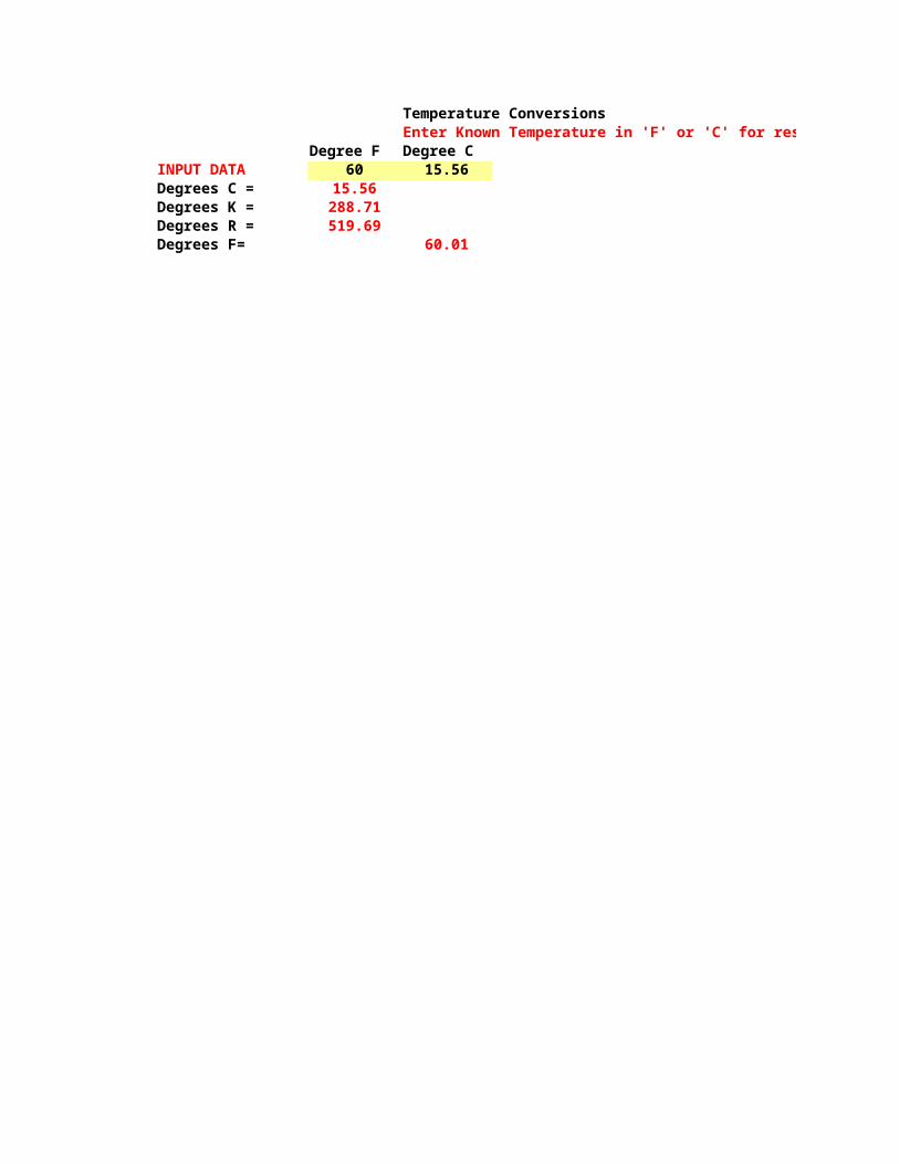
Temperature ConversionsEnter Known Temperature in 'F' or 'C' for results.
Degree F Degree CINPUT DATA 60 15.56Degrees C = 15.56Degrees K = 288.71Degrees R = 519.69Degrees F= 60.01

Enter Known Temperature in 'F' or 'C' for results.
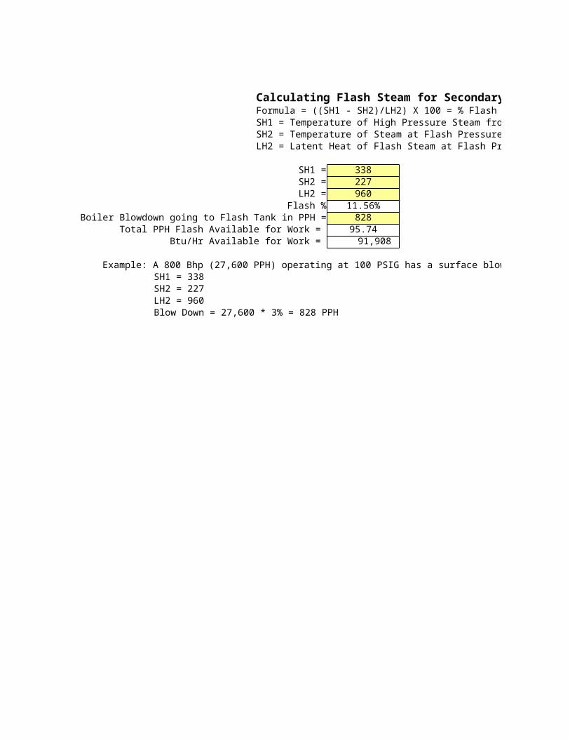
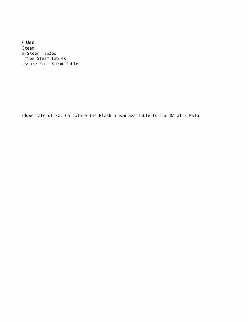
Calculating Flash Steam for Secondary UseFormula = ((SH1 - SH2)/LH2) X 100 = % Flash SteamSH1 = Temperature of High Pressure Steam from Steam TablesSH2 = Temperature of Steam at Flash Pressure from Steam TablesLH2 = Latent Heat of Flash Steam at Flash Pressure From Steam Tables
SH1 = 338SH2 = 227LH2 = 960
Flash % 11.56%Boiler Blowdown going to Flash Tank in PPH = 828
Total PPH Flash Available for Work = 95.74Btu/Hr Available for Work = 91,908
Example: A 800 Bhp (27,600 PPH) operating at 100 PSIG has a surface blowdown rate of 3%. Calculate the Flash Steam available to the DA at 5 PSIG.SH1 = 338SH2 = 227LH2 = 960Blow Down = 27,600 * 3% = 828 PPH
Calculating Flash Steam for Secondary UseFormula = ((SH1 - SH2)/LH2) X 100 = % Flash SteamSH1 = Temperature of High Pressure Steam from Steam TablesSH2 = Temperature of Steam at Flash Pressure from Steam TablesLH2 = Latent Heat of Flash Steam at Flash Pressure From Steam Tables
Example: A 800 Bhp (27,600 PPH) operating at 100 PSIG has a surface blowdown rate of 3%. Calculate the Flash Steam available to the DA at 5 PSIG.
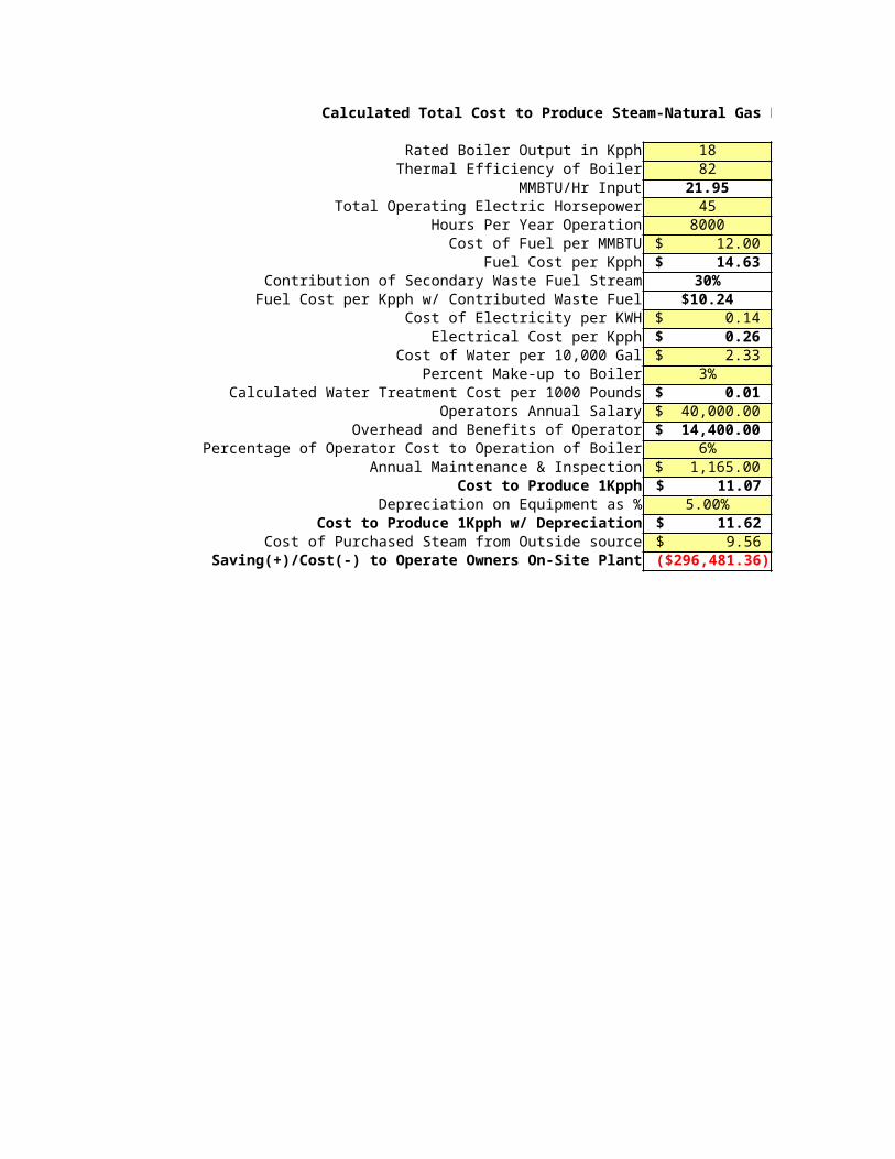
Calculated Total Cost to Produce Steam-Natural Gas Fired Plant w/ Possible Secondary Waste Fuel Stream
Rated Boiler Output in Kpph 18Thermal Efficiency of Boiler 82
MMBTU/Hr Input 21.95Total Operating Electric Horsepower 45
Hours Per Year Operation 8000Cost of Fuel per MMBTU $ 12.00
Fuel Cost per Kpph $ 14.63 Contribution of Secondary Waste Fuel Stream 30%
Fuel Cost per Kpph w/ Contributed Waste Fuel $10.24Cost of Electricity per KWH $ 0.14
Electrical Cost per Kpph $ 0.26 Cost of Water per 10,000 Gal $ 2.33
Percent Make-up to Boiler 3%Calculated Water Treatment Cost per 1000 Pounds $ 0.01
Operators Annual Salary $ 40,000.00 Overhead and Benefits of Operator $ 14,400.00
Percentage of Operator Cost to Operation of Boiler 6%Annual Maintenance & Inspection $ 1,165.00
Cost to Produce 1Kpph $ 11.07 Depreciation on Equipment as % 5.00%
Cost to Produce 1Kpph w/ Depreciation $ 11.62 Cost of Purchased Steam from Outside source $ 9.56
Saving(+)/Cost(-) to Operate Owners On-Site Plant ($296,481.36)

Calculated Total Cost to Produce Steam-Natural Gas Fired Plant w/ Possible Secondary Waste Fuel Stream
at Stated Boiler Thermal EfficiencyFan and Feedwater Pumps
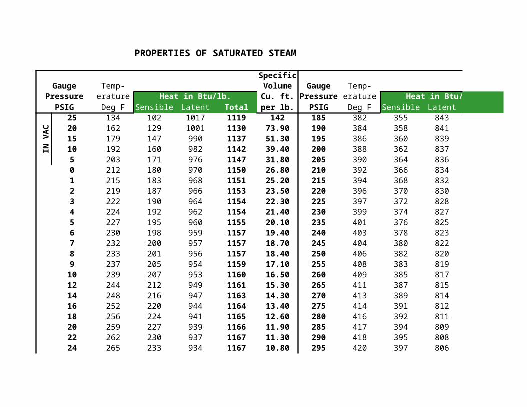
PROPERTIES OF SATURATED STEAM
SpecificGauge Temp- Volume Gauge Temp-
Pressure erature Heat in Btu/lb. Cu. ft. Pressure erature Heat in Btu/lb.PSIG Deg F Sensible Latent Total per lb. PSIG Deg F Sensible Latent
IN V
AC
25 134 102 1017 1119 142 185 382 355 84320 162 129 1001 1130 73.90 190 384 358 84115 179 147 990 1137 51.30 195 386 360 83910 192 160 982 1142 39.40 200 388 362 8375 203 171 976 1147 31.80 205 390 364 8360 212 180 970 1150 26.80 210 392 366 8341 215 183 968 1151 25.20 215 394 368 8322 219 187 966 1153 23.50 220 396 370 8303 222 190 964 1154 22.30 225 397 372 8284 224 192 962 1154 21.40 230 399 374 8275 227 195 960 1155 20.10 235 401 376 8256 230 198 959 1157 19.40 240 403 378 8237 232 200 957 1157 18.70 245 404 380 8228 233 201 956 1157 18.40 250 406 382 8209 237 205 954 1159 17.10 255 408 383 81910 239 207 953 1160 16.50 260 409 385 81712 244 212 949 1161 15.30 265 411 387 81514 248 216 947 1163 14.30 270 413 389 81416 252 220 944 1164 13.40 275 414 391 81218 256 224 941 1165 12.60 280 416 392 81120 259 227 939 1166 11.90 285 417 394 80922 262 230 937 1167 11.30 290 418 395 80824 265 233 934 1167 10.80 295 420 397 806
SpecificGauge Temp- Volume Gauge Temp-
Pressure erature Heat in Btu/lb. Cu. ft. Pressure erature Heat in Btu/lb.PSIG Deg F Sensible Latent Total per lb. PSIG Deg F Sensible Latent
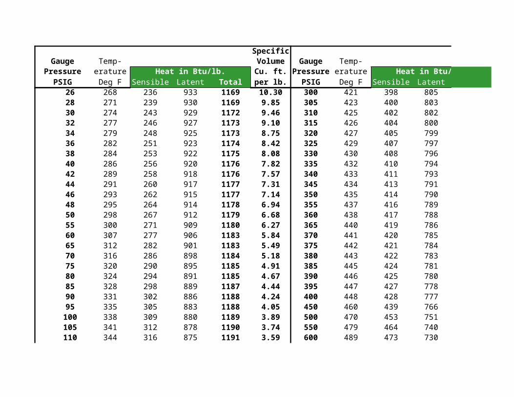
26 268 236 933 1169 10.30 300 421 398 80528 271 239 930 1169 9.85 305 423 400 80330 274 243 929 1172 9.46 310 425 402 80232 277 246 927 1173 9.10 315 426 404 80034 279 248 925 1173 8.75 320 427 405 79936 282 251 923 1174 8.42 325 429 407 79738 284 253 922 1175 8.08 330 430 408 79640 286 256 920 1176 7.82 335 432 410 79442 289 258 918 1176 7.57 340 433 411 79344 291 260 917 1177 7.31 345 434 413 79146 293 262 915 1177 7.14 350 435 414 79048 295 264 914 1178 6.94 355 437 416 78950 298 267 912 1179 6.68 360 438 417 78855 300 271 909 1180 6.27 365 440 419 78660 307 277 906 1183 5.84 370 441 420 78565 312 282 901 1183 5.49 375 442 421 78470 316 286 898 1184 5.18 380 443 422 78375 320 290 895 1185 4.91 385 445 424 78180 324 294 891 1185 4.67 390 446 425 78085 328 298 889 1187 4.44 395 447 427 77890 331 302 886 1188 4.24 400 448 428 77795 335 305 883 1188 4.05 450 460 439 766100 338 309 880 1189 3.89 500 470 453 751105 341 312 878 1190 3.74 550 479 464 740110 344 316 875 1191 3.59 600 489 473 730
SpecificGauge Temp- Volume Gauge Temp-
Pressure erature Heat in Btu/lb. Cu. ft. Pressure erature Heat in Btu/lb.PSIG Deg F Sensible Latent Total per lb. PSIG Deg F Sensible Latent
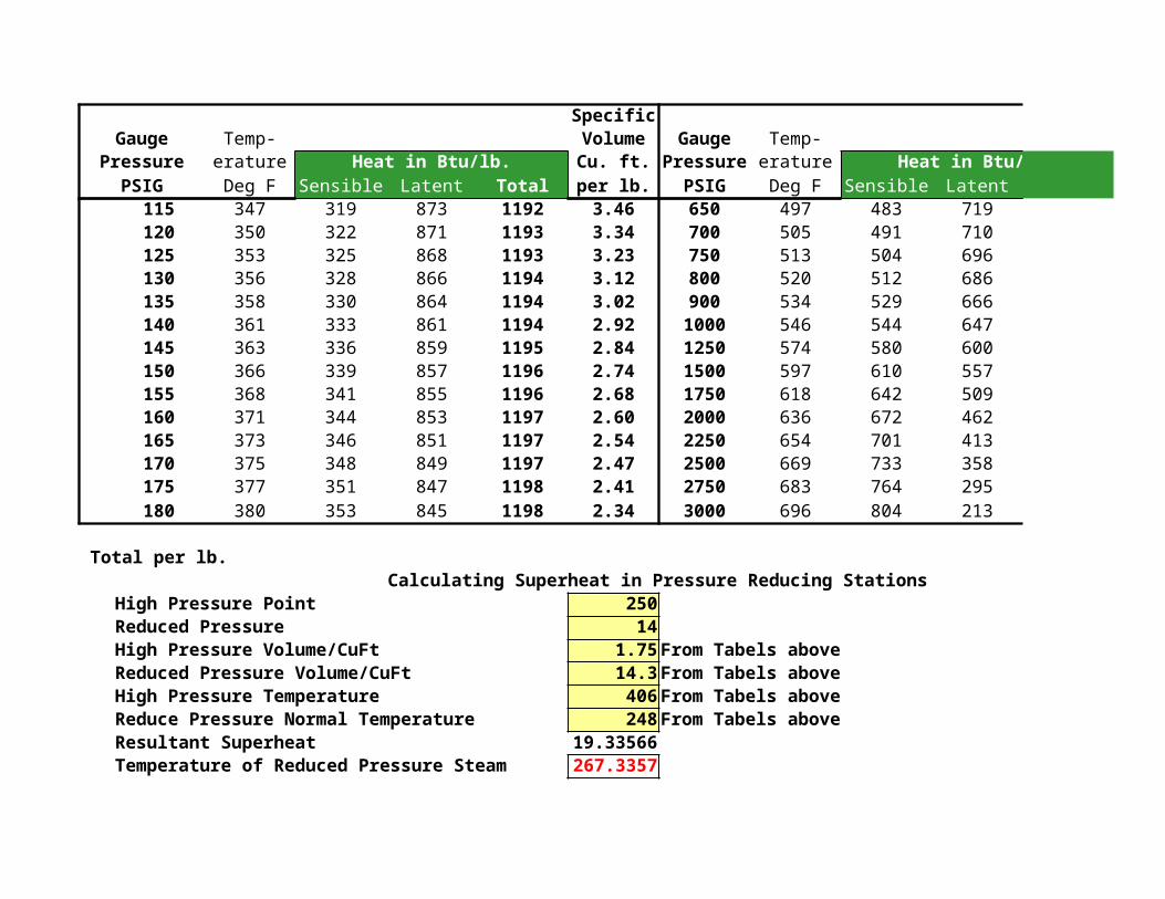
115 347 319 873 1192 3.46 650 497 483 719120 350 322 871 1193 3.34 700 505 491 710125 353 325 868 1193 3.23 750 513 504 696130 356 328 866 1194 3.12 800 520 512 686135 358 330 864 1194 3.02 900 534 529 666140 361 333 861 1194 2.92 1000 546 544 647145 363 336 859 1195 2.84 1250 574 580 600150 366 339 857 1196 2.74 1500 597 610 557155 368 341 855 1196 2.68 1750 618 642 509160 371 344 853 1197 2.60 2000 636 672 462165 373 346 851 1197 2.54 2250 654 701 413170 375 348 849 1197 2.47 2500 669 733 358175 377 351 847 1198 2.41 2750 683 764 295180 380 353 845 1198 2.34 3000 696 804 213
Total per lb.Calculating Superheat in Pressure Reducing Stations
High Pressure Point 250Reduced Pressure 14High Pressure Volume/CuFt 1.75From Tabels aboveReduced Pressure Volume/CuFt 14.3From Tabels aboveHigh Pressure Temperature 406From Tabels aboveReduce Pressure Normal Temperature 248From Tabels aboveResultant Superheat 19.33566Temperature of Reduced Pressure Steam 267.3357
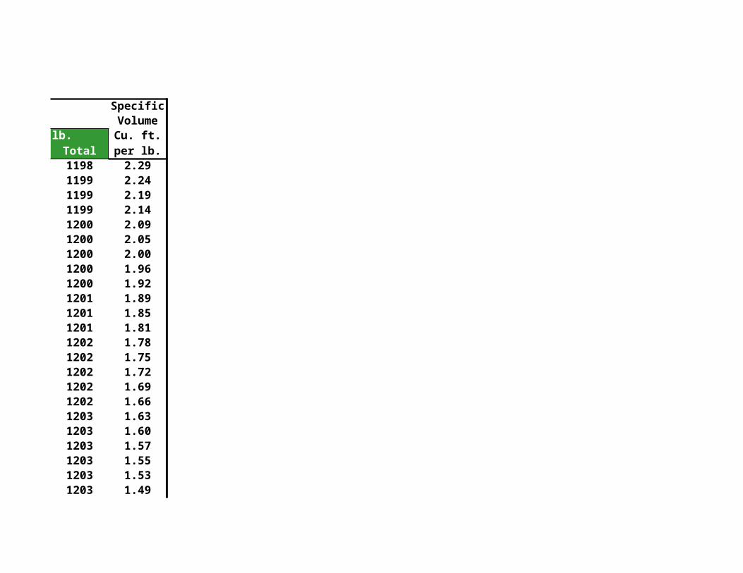
SpecificVolume
Heat in Btu/lb. Cu. ft.Total per lb.1198 2.291199 2.241199 2.191199 2.141200 2.091200 2.051200 2.001200 1.961200 1.921201 1.891201 1.851201 1.811202 1.781202 1.751202 1.721202 1.691202 1.661203 1.631203 1.601203 1.571203 1.551203 1.531203 1.49
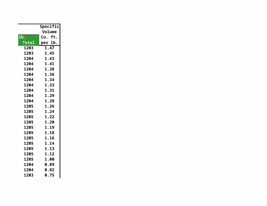
SpecificVolume
Heat in Btu/lb. Cu. ft.Total per lb.1203 1.471203 1.451204 1.431204 1.411204 1.381204 1.361204 1.341204 1.331204 1.311204 1.291204 1.281205 1.261205 1.241205 1.221205 1.201205 1.191205 1.181205 1.161205 1.141205 1.131205 1.121205 1.001204 0.891204 0.821203 0.75

SpecificVolume
Heat in Btu/lb. Cu. ft.Total per lb.1202 0.691201 0.641200 0.601198 0.561195 0.491191 0.441180 0.341167 0.231151 0.221134 0.191114 0.161091 0.131059 0.111017 0.08
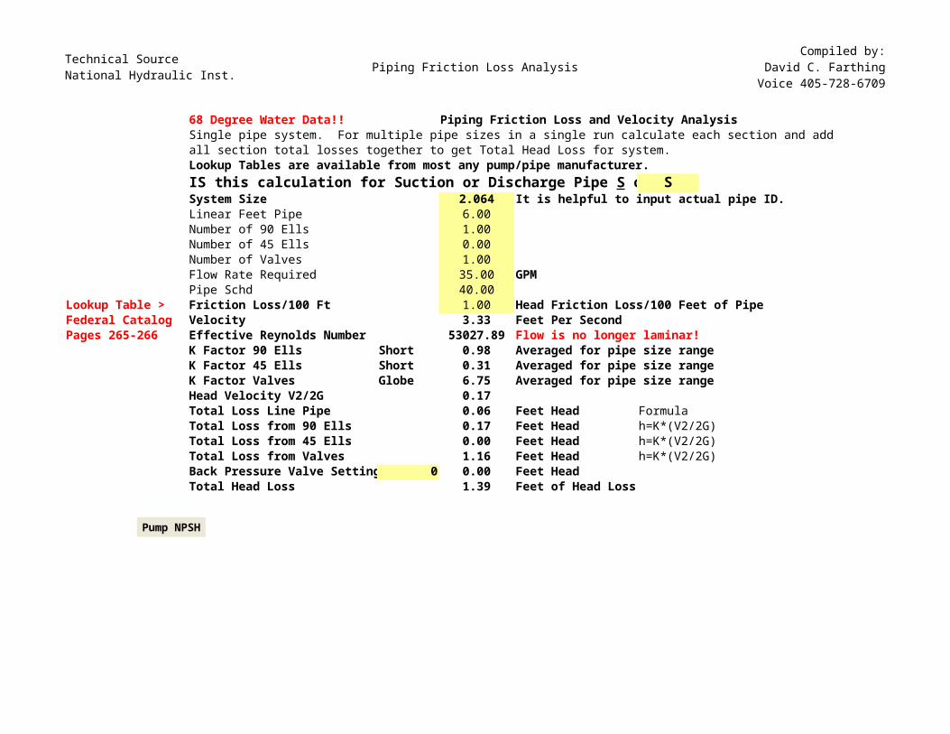
Technical SourceNational Hydraulic Inst. Piping Friction Loss Analysis
Compiled by:David C. Farthing
Voice 405-728-6709
68 Degree Water Data!! Piping Friction Loss and Velocity AnalysisSingle pipe system. For multiple pipe sizes in a single run calculate each section and addall section total losses together to get Total Head Loss for system.Lookup Tables are available from most any pump/pipe manufacturer.
SSystem Size 2.064 It is helpful to input actual pipe ID.Linear Feet Pipe 6.00Number of 90 Ells 1.00Number of 45 Ells 0.00Number of Valves 1.00Flow Rate Required 35.00 GPMPipe Schd 40.00
Lookup Table > Friction Loss/100 Ft 1.00 Head Friction Loss/100 Feet of PipeFederal Catalog Velocity 3.33 Feet Per SecondPages 265-266 Effective Reynolds Number 53027.89 Flow is no longer laminar!
K Factor 90 Ells Short 0.98 Averaged for pipe size rangeK Factor 45 Ells Short 0.31 Averaged for pipe size rangeK Factor Valves Globe 6.75 Averaged for pipe size rangeHead Velocity V2/2G 0.17Total Loss Line Pipe 0.06 Feet Head FormulaTotal Loss from 90 Ells 0.17 Feet Head h=K*(V2/2G)Total Loss from 45 Ells 0.00 Feet Head h=K*(V2/2G)Total Loss from Valves 1.16 Feet Head h=K*(V2/2G)Back Pressure Valve Setting 0 0.00 Feet HeadTotal Head Loss 1.39 Feet of Head Loss
IS this calculation for Suction or Discharge Pipe S or
Pump NPSH
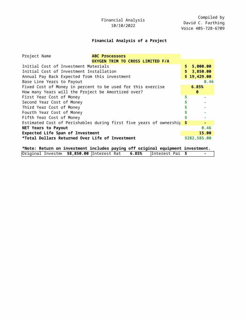
Financial Analysis10/10/2022
Compiled byDavid C. FarthingVoice 405-728-6709
Financial Analysis of a Project
Project Name ABC ProcessorsOXYGEN TRIM TO CROSS LIMITED F/A
Initial Cost of Investment Materials $ 5,000.00 Initial Cost of Investment Installation $ 3,850.00 Annual Pay Back Expected from this investment $ 19,429.00 Base Line Years to Payout 0.46Fixed Cost of Money in percent to be used for this exercise 6.85%How many Years will the Project be Amortized over? 0First Year Cost of Money $ - Second Year Cost of Money $ - Third Year Cost of Money $ - Fourth Year Cost of Money $ - Fifth Year Cost of Money $ - Estimated Cost of Perishables during first five years of ownership $ - NET Years to Payout 0.46 Expected Life Span of Investment 15.00 *Total Dollars Returned Over Life of Investment $282,585.00
*Note: Return on investment includes paying off original equipment investment.Original Investme $8,850.00 Interest Rat 6.85% Interest Pai $ -
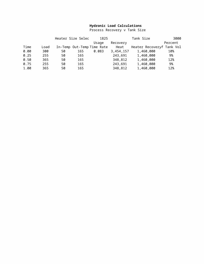
Hydronic Load CalculationsProcess Recovery v Tank Size
Heater Size Selec 1825 Tank Size 3000Usage Recovery Percent
Time Load In-Temp Out-Temp Time Rate Heat Heater Recoveryof Tank Vol.0.00 300 50 165 0.083 3,454,157 1,460,000 10%0.25 255 50 165 243,691 1,460,000 9%0.50 365 50 165 348,812 1,460,000 12%0.75 255 50 165 243,691 1,460,000 9%1.00 365 50 165 348,812 1,460,000 12%
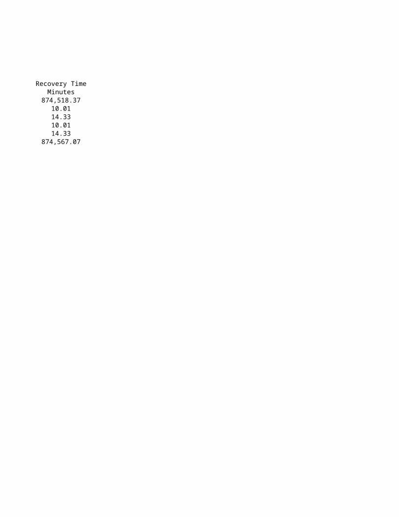
Recovery TimeMinutes
874,518.3710.0114.3310.0114.33
874,567.07
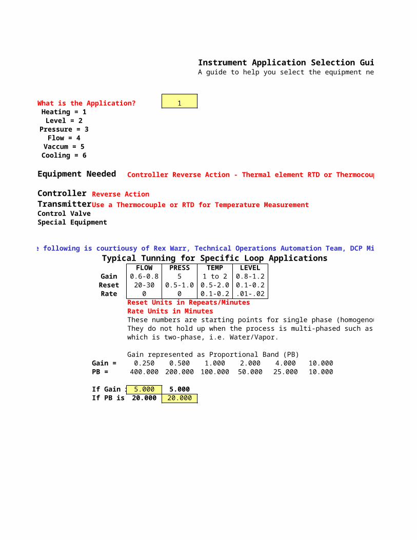
Instrument Application Selection Guide and Application Tuning SuggestionsA guide to help you select the equipment needed to accomplish an instrument application.
What is the Application? 1Heating = 1Level = 2
Pressure = 3Flow = 4
Vaccum = 5Cooling = 6
Equipment Needed Controller Reverse Action - Thermal element RTD or Thermocouple - Control Valve and thermal extionsion wire
Controller Reverse ActionTransmitterUse a Thermocouple or RTD for Temperature MeasurementControl ValveSpecial Equipment
The following is courtiousy of Rex Warr, Technical Operations Automation Team, DCP MidstreamTypical Tunning for Specific Loop Applications
FLOW PRESS TEMP LEVELGain 0.6-0.8 5 1 to 2 0.8-1.2Reset 20-30 0.5-1.0 0.5-2.0 0.1-0.2Rate 0 0 0.1-0.2 .01-.02
Reset Units in Repeats/MinutesRate Units in MinutesThese numbers are starting points for single phase (homogenous) materials.They do not hold up when the process is multi-phased such as Steam Boiler Levelwhich is two-phase, i.e. Water/Vapor.
Gain represented as Proportional Band (PB)Gain = 0.250 0.500 1.000 2.000 4.000 10.000PB = 400.000 200.000 100.000 50.000 25.000 10.000
If Gain i 5.000 5.000If PB is 20.000 20.000
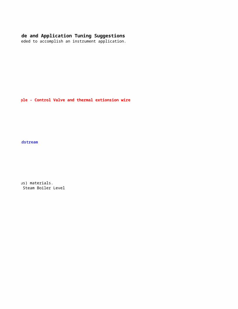
Instrument Application Selection Guide and Application Tuning SuggestionsA guide to help you select the equipment needed to accomplish an instrument application.
Controller Reverse Action - Thermal element RTD or Thermocouple - Control Valve and thermal extionsion wire
The following is courtiousy of Rex Warr, Technical Operations Automation Team, DCP Midstream
These numbers are starting points for single phase (homogenous) materials.They do not hold up when the process is multi-phased such as Steam Boiler Level
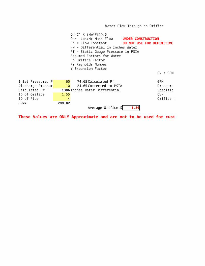
Water Flow Through an Orifice
Qh=C' X (Hw*Pf)^.5Qh= Lbs/Hr Mass Flow UNDER CONSTRUCTIONC' = Flow Constant DO NOT USE FOR DEFINITIVE DATA!!Hw = Differential in Inches WaterPf = Static Gauge Pressure in PSIAAssumed Factors for WaterFb Orifice FactorFr Reynolds NumberY Expansion Factor
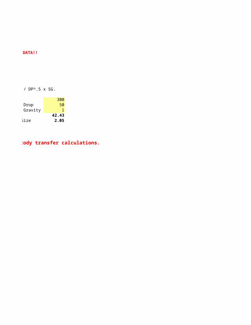
CV = GPM / DP^.5 x SG.
Inlet Pressure, P 60 74.65 Calculated Pf GPMDischarge Pressur 10 24.65 Corrected to PSIA Pressure DropCalculated HW 1386 Inches Water Differential Specific GravityID of Orifice 1.55 CV=ID of Pipe 4 Orifice SizeGPM= 299.82
Average Orifice S 1.80
These Values are ONLY Approximate and are not to be used for custody transfer calculations.
DO NOT USE FOR DEFINITIVE DATA!!
CV = GPM / DP^.5 x SG.
300Pressure Drop 50Specific Gravity 1
42.43Orifice Size 2.05
These Values are ONLY Approximate and are not to be used for custody transfer calculations.
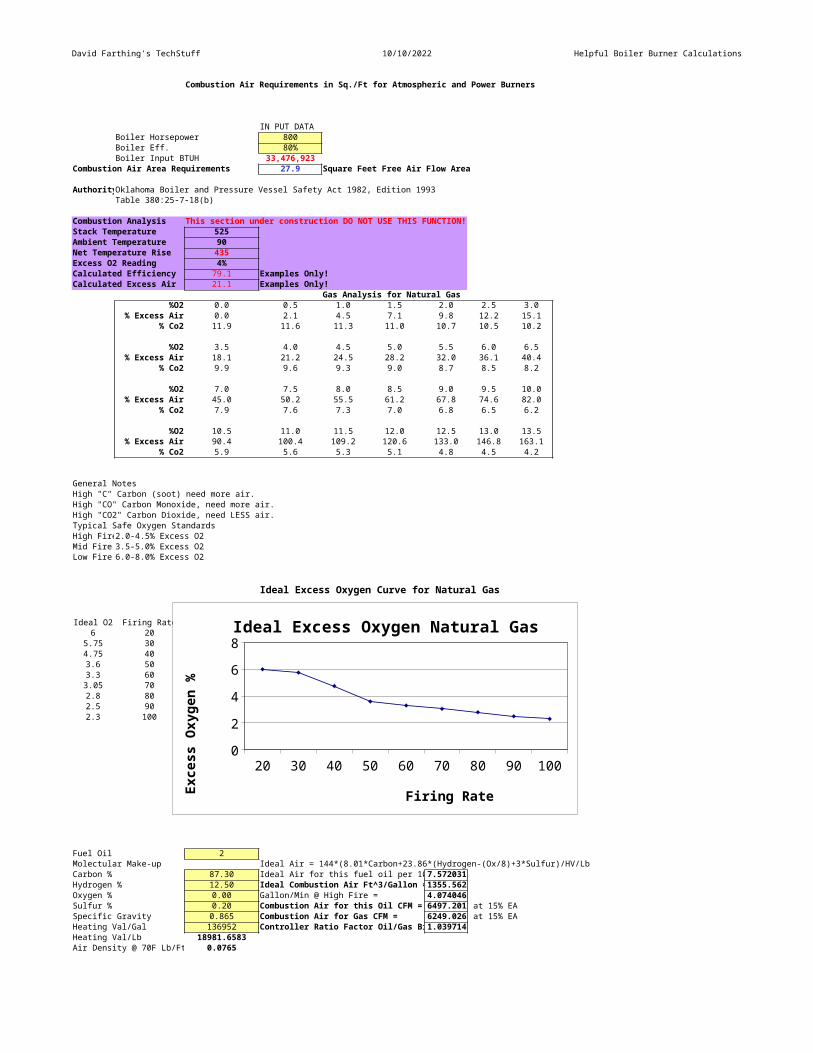
David Farthing's TechStuff 10/10/2022 Helpful Boiler Burner Calculations
Combustion Air Requirements in Sq./Ft for Atmospheric and Power Burners
IN PUT DATABoiler Horsepower 800Boiler Eff. 80%Boiler Input BTUH 33,476,923
Combustion Air Area Requirements 27.9 Square Feet Free Air Flow Area
AuthorityOklahoma Boiler and Pressure Vessel Safety Act 1982, Edition 1993Table 380:25-7-18(b)
Combustion Analysis This section under construction DO NOT USE THIS FUNCTION!Stack Temperature 525Ambient Temperature 90Net Temperature Rise 435Excess O2 Reading 4%Calculated Efficiency 79.1 Examples Only!Calculated Excess Air 21.1 Examples Only!
Gas Analysis for Natural Gas%O2 0.0 0.5 1.0 1.5 2.0 2.5 3.0
% Excess Air 0.0 2.1 4.5 7.1 9.8 12.2 15.1% Co2 11.9 11.6 11.3 11.0 10.7 10.5 10.2
%O2 3.5 4.0 4.5 5.0 5.5 6.0 6.5% Excess Air 18.1 21.2 24.5 28.2 32.0 36.1 40.4
% Co2 9.9 9.6 9.3 9.0 8.7 8.5 8.2
%O2 7.0 7.5 8.0 8.5 9.0 9.5 10.0% Excess Air 45.0 50.2 55.5 61.2 67.8 74.6 82.0
% Co2 7.9 7.6 7.3 7.0 6.8 6.5 6.2
%O2 10.5 11.0 11.5 12.0 12.5 13.0 13.5% Excess Air 90.4 100.4 109.2 120.6 133.0 146.8 163.1
% Co2 5.9 5.6 5.3 5.1 4.8 4.5 4.2
General NotesHigh "C" Carbon (soot) need more air.High "CO" Carbon Monoxide, need more air.High "CO2" Carbon Dioxide, need LESS air.Typical Safe Oxygen StandardsHigh Fire2.0-4.5% Excess O2Mid Fire 3.5-5.0% Excess O2Low Fire 6.0-8.0% Excess O2
Ideal Excess Oxygen Curve for Natural Gas
Ideal O2 Firing Rate6 20
5.75 304.75 403.6 503.3 603.05 702.8 802.5 902.3 100
Fuel Oil 2Molectular Make-up Ideal Air = 144*(8.01*Carbon+23.86*(Hydrogen-(Ox/8)+3*Sulfur)/HV/LbCarbon % 87.30 Ideal Air for this fuel oil per 107.572031Hydrogen % 12.50 Ideal Combustion Air Ft^3/Gallon =1355.562Oxygen % 0.00 Gallon/Min @ High Fire = 4.074046Sulfur % 0.20 Combustion Air for this Oil CFM = 6497.201 at 15% EASpecific Gravity 0.865 Combustion Air for Gas CFM = 6249.026 at 15% EAHeating Val/Gal 136952 Controller Ratio Factor Oil/Gas Bi1.039714Heating Val/Lb 18981.6583Air Density @ 70F Lb/Ft 0.0765
20 30 40 50 60 70 80 90 10002468Ideal Excess Oxygen Natural Gas
Firing RateExce
ss Oxy
gen
%
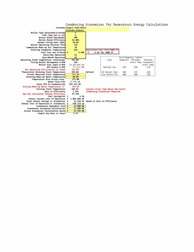
Condensing Economizer for Deaerators Energy CalculationsCustomer Cargill Feed Mills
Firetube DrybackFG
Boiler Rated Horsepower 700Boiler Rated Efficiency 82.00%
Normal Firing Rate (NFR) 50.0%Boiler Operating Pressure PSIG 110
Combustion Make-up Air Temperature 70Entering Feedwater Temperature 240 Equivalent Fuel Cost/1000 CF
Fuel Cost per D/Therm $ 9.500 $ 9.50 Per 1000 CFHours/Day Operation 22Days/Month Operation 28 Acid Dewpoint Tables
Operating Steam Temperature (Saturated) 344.00 Fuel Dewpoint Minimum MinimumFiring Boiler Horsepower @ NFR 350 Stack Temp Feedwater
Boiler Fuel Input @ NFR 14,283,841.46 Inlet Temp.BTU Output @ NFR 11,712,750 Natural Gas 150 250 210
Net Operating Efficiencies as found 84.37%Theoretical Entering Stack Temperature 399.00 Default #2 Diesel Fuel 180 275 210
Actual Observed Stack Temperature 341.00 Low Sulfur Oil 200 300 220Entering Make-Up Water Temperature 68.00
Temperature Rise Across Econ. 273.00Water Flow #/Hr 12,075.00
Gross BTU to Feedwater/Hr 921,315.96 Exiting Make-Up Water Temperature "F" 144.30
Exiting Stack Temperature 182.83 Caution Stack Temp Below Dew Point!Gain in Efficiency 3.23% Condensing Economizer Required
New Net Calculated Thermal Efficiency 87.59%Fuel Savings/Hr $ 4.38
Annual Current Cost of Operation $ 1,003,068.48 Total Annual Savings w/ Economizer $ 32,349.25 Based on Gain in Efficiency
Annual Cost of Operation w/ Economizer $ 970,719.24 Economizer Equipment Cost $ 23,000.00
Economizer Estimated Installation $ 11,500.00 Actual Economizer Installation Quote $ 13,785.00
Simple Pay-Back in Years 1.14
Boiler Type Watertube/FiretubeFuel Type Gas or Oil
Economizer Heat Recovery Calculations 10/10/2022 04:38:47Data Compiled byDavid Farthing
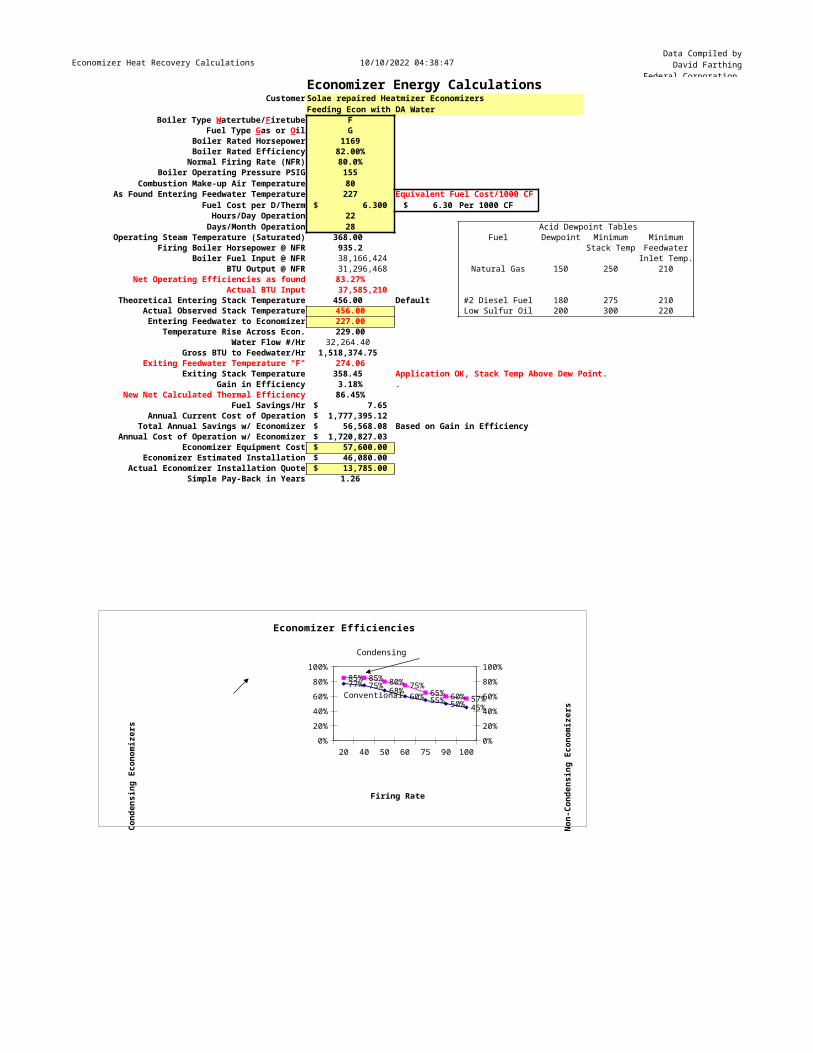
Federal Corporation Economizer Energy CalculationsCustomer Solae repaired Heatmizer Economizers
Feeding Econ with DA WaterFG
Boiler Rated Horsepower 1169Boiler Rated Efficiency 82.00%Normal Firing Rate (NFR) 80.0%
Boiler Operating Pressure PSIG 155Combustion Make-up Air Temperature 80
As Found Entering Feedwater Temperature 227 Equivalent Fuel Cost/1000 CFFuel Cost per D/Therm $ 6.300 $ 6.30 Per 1000 CFHours/Day Operation 22Days/Month Operation 28 Acid Dewpoint Tables
Operating Steam Temperature (Saturated) 368.00 Fuel Dewpoint Minimum MinimumFiring Boiler Horsepower @ NFR 935.2 Stack Temp Feedwater
Boiler Fuel Input @ NFR 38,166,424 Inlet Temp.BTU Output @ NFR 31,296,468 Natural Gas 150 250 210
Net Operating Efficiencies as found 83.27%Actual BTU Input 37,585,210
Theoretical Entering Stack Temperature 456.00 Default #2 Diesel Fuel 180 275 210Actual Observed Stack Temperature 456.00 Low Sulfur Oil 200 300 220Entering Feedwater to Economizer 227.00
Temperature Rise Across Econ. 229.00Water Flow #/Hr 32,264.40
Gross BTU to Feedwater/Hr 1,518,374.75 Exiting Feedwater Temperature "F" 274.06
Exiting Stack Temperature 358.45 Application OK, Stack Temp Above Dew Point.Gain in Efficiency 3.18% .
New Net Calculated Thermal Efficiency 86.45%Fuel Savings/Hr $ 7.65
Annual Current Cost of Operation $ 1,777,395.12 Total Annual Savings w/ Economizer $ 56,568.08 Based on Gain in Efficiency
Annual Cost of Operation w/ Economizer $ 1,720,827.03 Economizer Equipment Cost $ 57,600.00
Economizer Estimated Installation $ 46,080.00 Actual Economizer Installation Quote $ 13,785.00
Simple Pay-Back in Years 1.26
Condensing VerticalEfficiency Firetube Firing Rate
85% 77% 2085% 75% 4080% 68% 5075% 60% 6065% 55% 7560% 50% 9057% 45% 100
Boiler Type Watertube/FiretubeFuel Type Gas or Oil
20 40 50 60 75 90 1000%20%40%60%80%100%
0%20%40%60%80%100%
85% 85% 80% 75%65% 60% 57%
77% 75% 68% 60% 55% 50% 45%
Economizer Efficiencies
Firing Rate
Cond
ensi
ng E
cono
mize
rs
Non-
Cond
ensi
ng E
cono
mize
rs
Conventional
Condensing
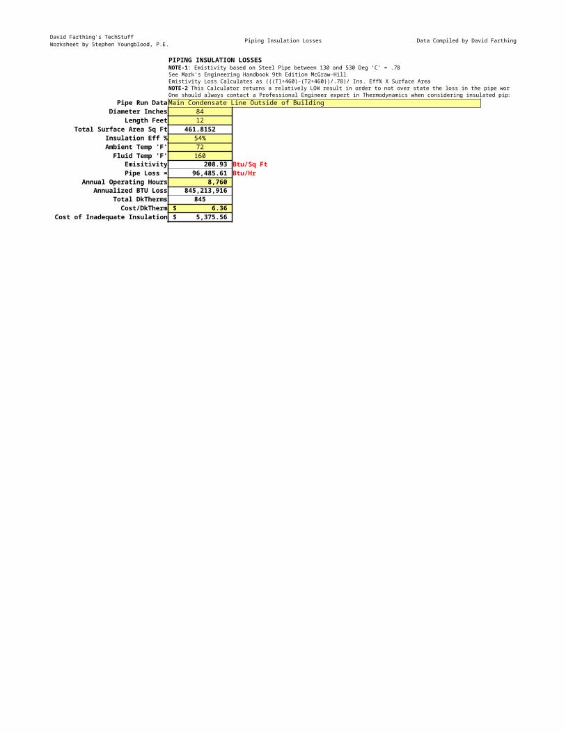
David Farthing's TechStuffWorksheet by Stephen Youngblood, P.E. Piping Insulation Losses Data Compiled by David Farthing
PIPING INSULATION LOSSES
See Mark's Engineering Handbook 9th Edition McGraw-HillEmistivity Loss Calculates as (((T1+460)-(T2+460))/.78)/ Ins. Eff% X Surface Area
One should always contact a Professional Engineer expert in Thermodynamics when considering insulated piping losses.Pipe Run DataMain Condensate Line Outside of Building
Diameter Inches 84Length Feet 12
Total Surface Area Sq Ft 461.8152Insulation Eff % 54%Ambient Temp 'F' 72Fluid Temp 'F' 160
Emisitivity 208.93 Btu/Sq FtPipe Loss = 96,485.61 Btu/Hr
Annual Operating Hours 8,760 Annualized BTU Loss 845,213,916
Total DkTherms 845Cost/DkTherm $ 6.36
Cost of Inadequate Insulation $ 5,375.56
NOTE-1: Emistivity based on Steel Pipe between 130 and 530 Deg 'C' = .78
NOTE-2 This Calculator returns a relatively LOW result in order to not over state the loss in the pipe work.
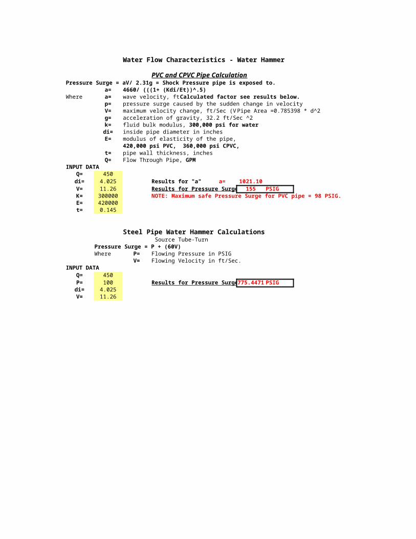
Water Flow Characteristics - Water Hammer
PVC and CPVC Pipe CalculationPressure Surge = aV/ 2.31g = Shock Pressure pipe is exposed to.
a= 4660/ (((1+ (Kdi/Et))^.5)Where a= wave velocity, ftCalculated factor see results below.
p= pressure surge caused by the sudden change in velocityV= maximum velocity change, ft/Sec (VPipe Area =0.785398 * d^2 g= acceleration of gravity, 32.2 ft/Sec ^2k=di= inside pipe diameter in inchesE= modulus of elasticity of the pipe,
420,000 psi PVC, 360,000 psi CPVC, t= pipe wall thickness, inchesQ=
INPUT DATAQ= 450di= 4.025 Results for "a" a= 1021.10V= 11.26 Results for Pressure Surge 155 PSIGK= 300000 NOTE: Maximum safe Pressure Surge for PVC pipe = 98 PSIG.E= 420000t= 0.145
Steel Pipe Water Hammer Calculations Source Tube-Turn
Pressure Surge = P + (60V)Where P= Flowing Pressure in PSIG
V= Flowing Velocity in ft/Sec.INPUT DATA
Q= 450P= 100 Results for Pressure Surge775.4471 PSIGdi= 4.025V= 11.26
fluid bulk modulus, 300,000 psi for water
Flow Through Pipe, GPM
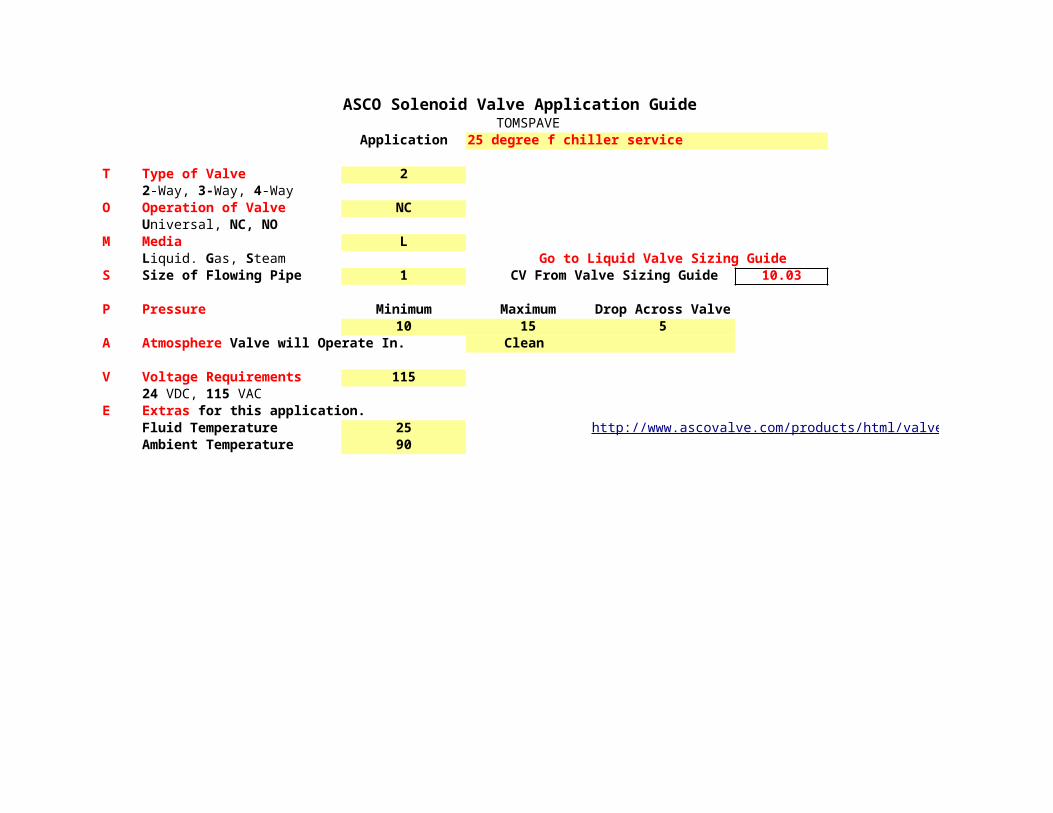
ASCO Solenoid Valve Application GuideTOMSPAVE
Application 25 degree f chiller service
T Type of Valve 2
O Operation of Valve NC
M Media LGo to Liquid Valve Sizing Guide
S Size of Flowing Pipe 1 CV From Valve Sizing Guide 10.03
P Pressure Minimum Maximum Drop Across Valve10 15 5
A Clean
V Voltage Requirements 115
EFluid Temperature 25Ambient Temperature 90
2-Way, 3-Way, 4-Way
Universal, NC, NO
Liquid. Gas, Steam
Atmosphere Valve will Operate In.
24 VDC, 115 VACExtras for this application.
http://www.ascovalve.com/products/html/valve_selector.htm

http://www.ascovalve.com/products/html/valve_selector.htm
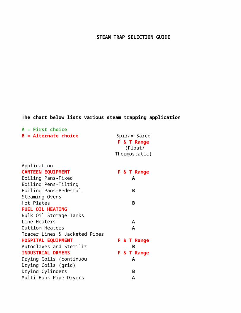
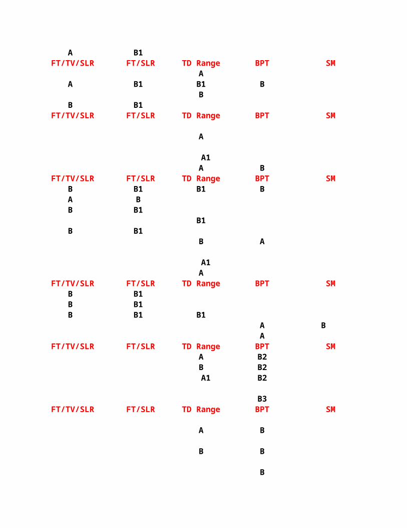
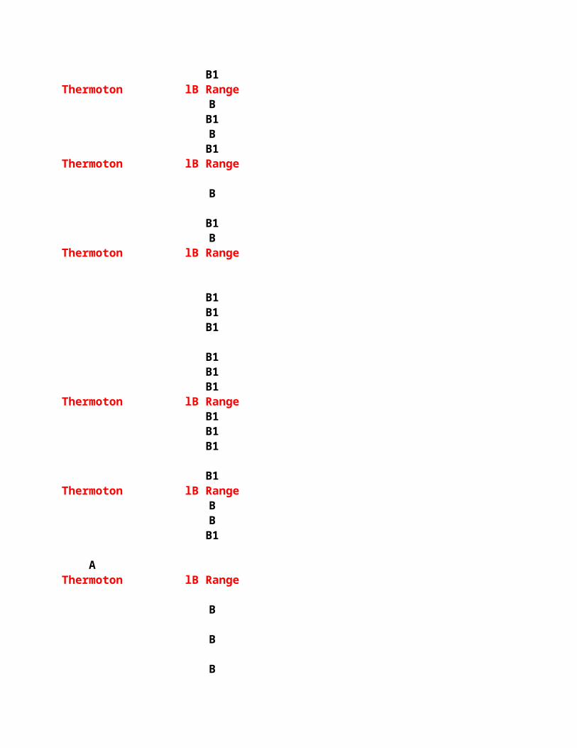
STEAM TRAP SELECTION GUIDE
The chart below lists various steam trapping applications and enables the correct choice of trap to be made.
A = First choiceB = Alternate choice Spirax Sarco
F & T Range (Float/
Thermostatic)
ApplicationCANTEEN EQUIPMENT F & T RangeBoiling Pans-Fixed ABoiling Pens-TiltingBoiling Pans-Pedestal BSteaming OvensHot Plates BFUEL OIL HEATINGBulk Oil Storage TanksLine Heaters AOuttlom Heaters ATracer Lines & Jacketed PipesHOSPITAL EQUIPMENT F & T RangeAutoclaves and Steriliz BINDUSTRIAL DRYERS F & T RangeDrying Coils (continuou ADrying Coils (grid)Drying Cylinders BMulti Bank Pipe Dryers A
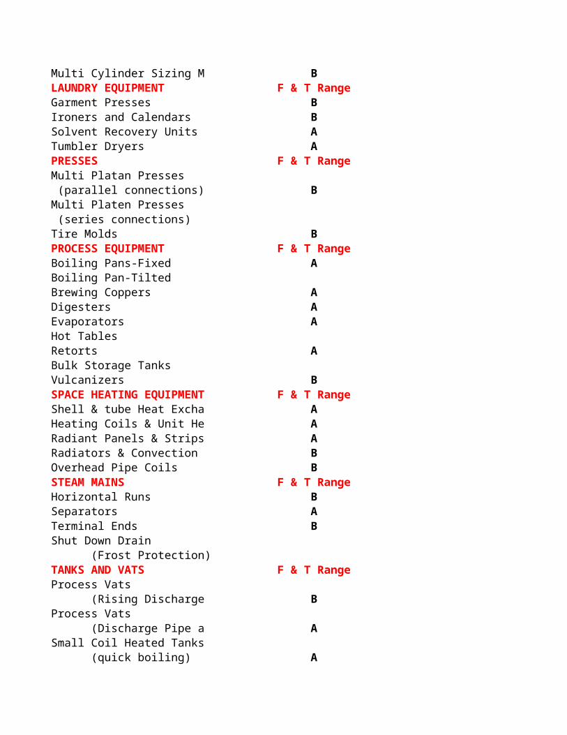
Multi Cylinder Sizing M BLAUNDRY EQUIPMENT F & T RangeGarment Presses BIroners and Calendars BSolvent Recovery Units ATumbler Dryers APRESSES F & T RangeMulti Platan Presses (parallel connections) BMulti Platen Presses (series connections)Tire Molds BPROCESS EQUIPMENT F & T RangeBoiling Pans-Fixed ABoiling Pan-TiltedBrewing Coppers ADigesters AEvaporators AHot TablesRetorts ABulk Storage TanksVulcanizers BSPACE HEATING EQUIPMENT F & T RangeShell & tube Heat Excha AHeating Coils & Unit He ARadiant Panels & Strips ARadiators & Convection BOverhead Pipe Coils BSTEAM MAINS F & T RangeHorizontal Runs BSeparators ATerminal Ends BShut Down Drain (Frost Protection)TANKS AND VATS F & T RangeProcess Vats (Rising Discharge BProcess Vats (Discharge Pipe a ASmall Coil Heated Tanks (quick boiling) A
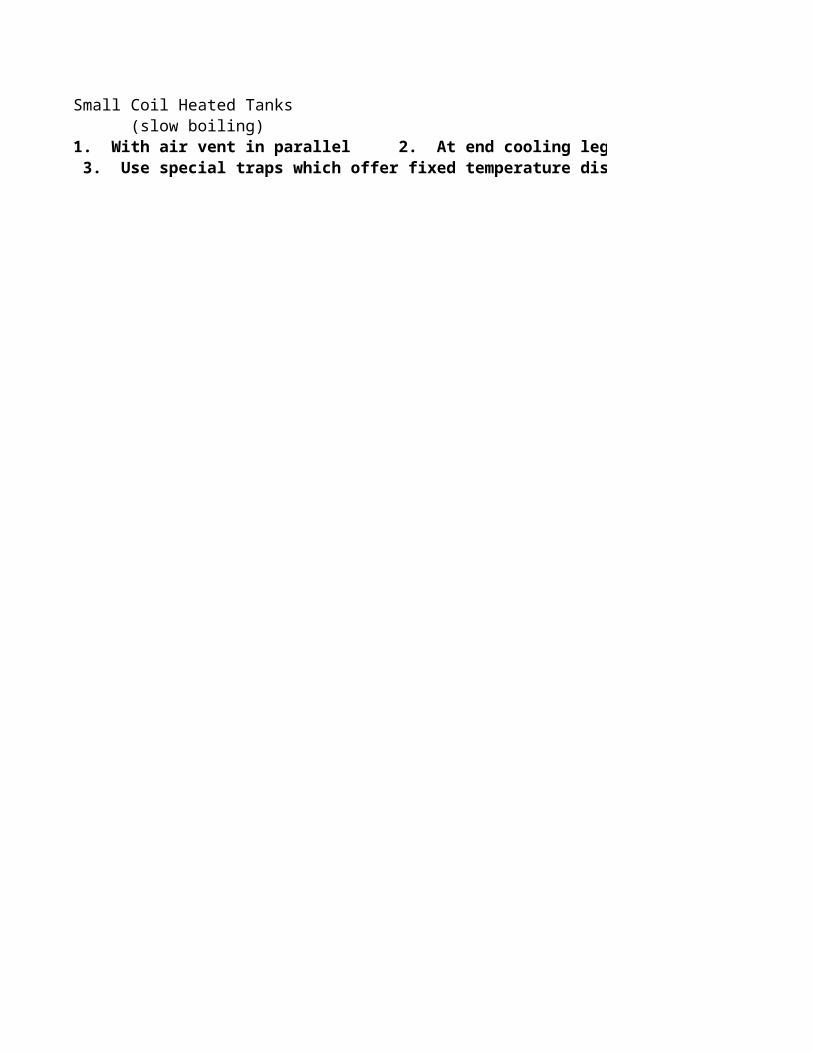
Small Coil Heated Tanks (slow boiling)1. With air vent in parallel 2. At end cooling leg Minimum length 3 ft (1m) 3. Use special traps which offer fixed temperature discharge option.
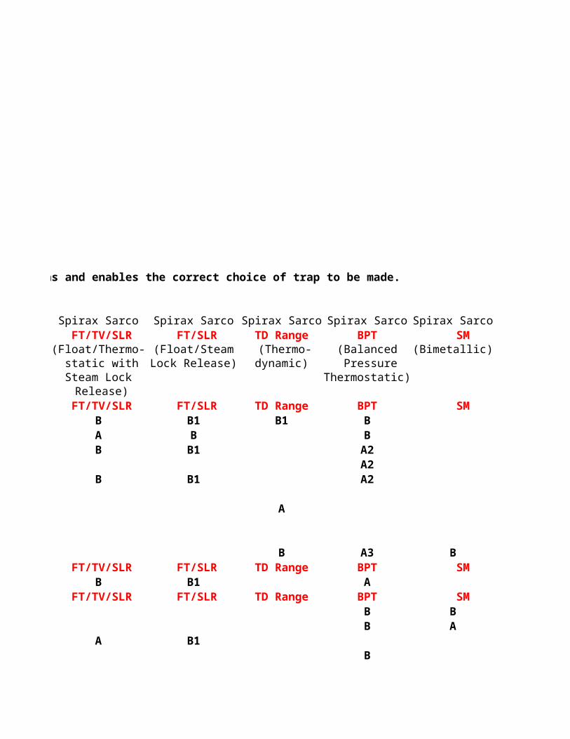
The chart below lists various steam trapping applications and enables the correct choice of trap to be made.
Spirax Sarco Spirax Sarco Spirax Sarco Spirax Sarco Spirax Sarco FT/TV/SLR FT/SLR TD Range BPT SM
(Float/Thermo- (Float/Steam (Thermo- (Balanced (Bimetallic) static with Lock Release) dynamic) PressureSteam Lock Thermostatic) Release) FT/TV/SLR FT/SLR TD Range BPT SM
B B1 B1 BA B BB B1 A2
A2B B1 A2
A
B A3 B FT/TV/SLR FT/SLR TD Range BPT SM
B B1 A FT/TV/SLR FT/SLR TD Range BPT SM
B BB A
A B1B
A B1 FT/TV/SLR FT/SLR TD Range BPT SM
AA B1 B1 B
BB B1
FT/TV/SLR FT/SLR TD Range BPT SM
A
A1A B
FT/TV/SLR FT/SLR TD Range BPT SMB B1 B1 BA BB B1
B1B B1
B A
A1A
FT/TV/SLR FT/SLR TD Range BPT SMB B1B B1B B1 B1
A BA
FT/TV/SLR FT/SLR TD Range BPT SMA B2B B2
A1 B2
B3 FT/TV/SLR FT/SLR TD Range BPT SM
A B
B B
B

1. With air vent in parallel 2. At end cooling leg Minimum length 3 ft (1m) 3. Use special traps which offer fixed temperature discharge option.
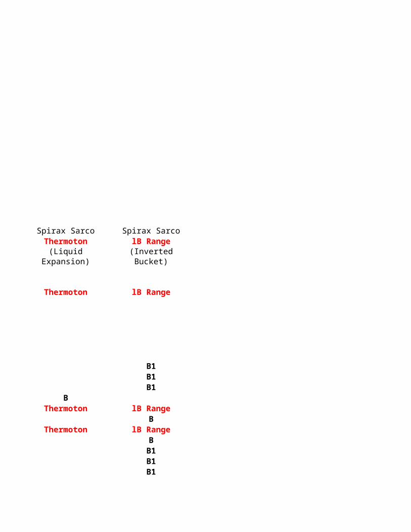
Spirax Sarco Spirax SarcoThermoton lB Range(Liquid (Inverted
Expansion) Bucket)
Thermoton lB Range
B1B1B1
BThermoton lB Range
BThermoton lB Range
BB1B1B1
B1Thermoton lB Range
BB1BB1
Thermoton lB Range
B
B1B
Thermoton lB Range
B1B1B1
B1B1B1
Thermoton lB RangeB1B1B1
B1Thermoton lB Range
BBB1
AThermoton lB Range
B
B
B

A
Courtesy of Spirax-Sarco
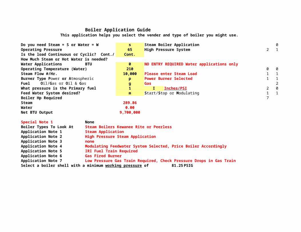
Boiler Application GuideThis application helps you select the vender and type of boiler you might use.
Do you need Steam = S or Water = W s Steam Boiler Application 0Operating Pressure 65 High Pressure System 2 1Is the load Continuous or Cyclic? Cont./ Cont.How Much Steam or Hot Water is needed?Water Applications BTU 0 NO ENTRY REQUIRED Water applications onlyOperating Temperature (Water) 210 0 0Steam Flow #/Hr. 10,000 Please enter Steam Load 1 1
p Power Burner Selected 1 1Fuel g Gas 2What pressure is the Primary fuel 1 I Inches/PSI 2 0Feed Water System desired? m 1 1Boiler Hp Required 7Steam 289.86Water 0.00Net BTU Output 9,700,000
Special Note 1 NoneBoiler Types To Look At Steam Boilers Kewanee Rite or PeerlessApplication Note 1 Steam ApplicationApplication Note 2 High Pressure Steam ApplicationApplication Note 3 noneApplication Note 4 Modulating Feedwater System Selected, Price Boiler AccordinglyApplication Note 5 IRI Fuel Train RequiredApplication Note 6 Gas Fired BurnerApplication Note 7 Low Pressure Gas Train Required, Check Pressure Drops in Gas Train
81.25 PSIG
Burner Type Power or AtmosphericOil/Gas or Oil & Gas
Start/Stop or Modulating
Select a boiler shell with a minimum working pressure of
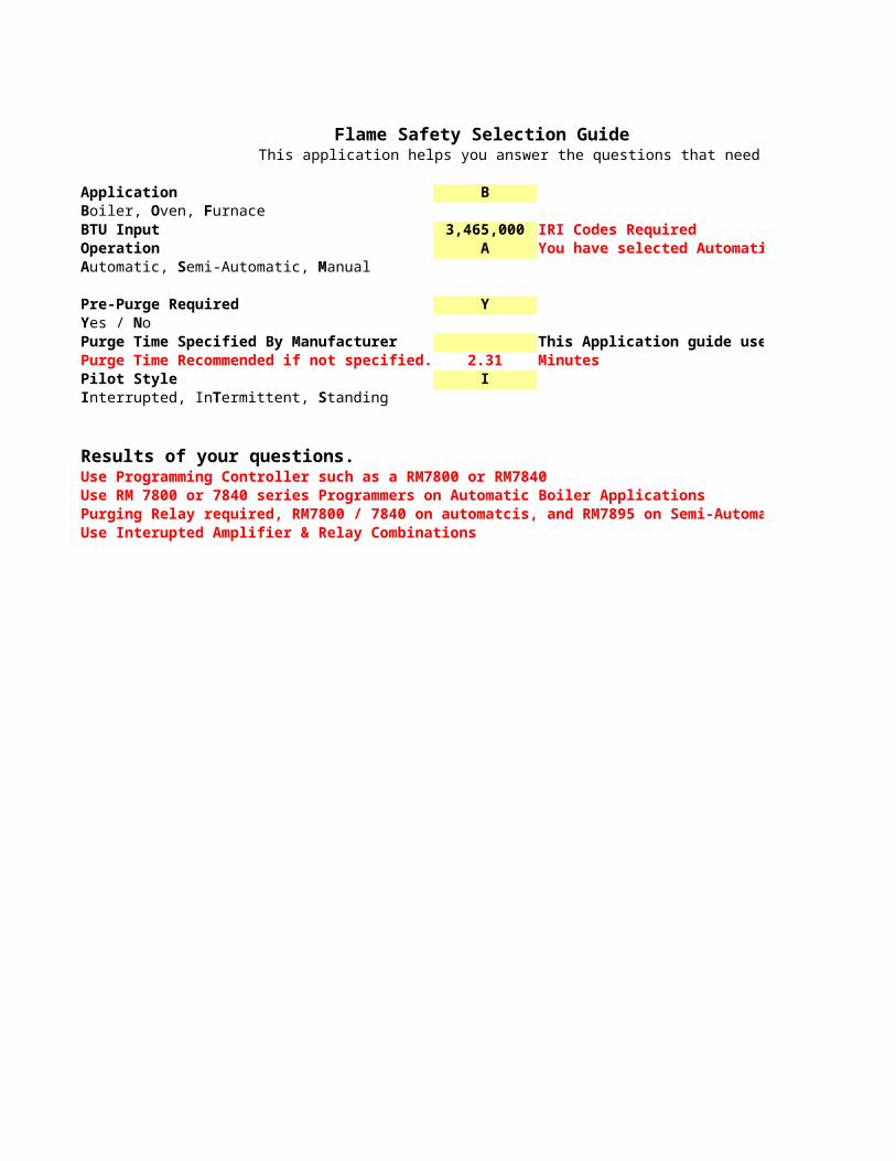
Flame Safety Selection GuideThis application helps you answer the questions that need to be answered to select FSG.
Application B
BTU Input 3,465,000 IRI Codes RequiredOperation A You have selected Automatic Operation
Pre-Purge Required Y
Purge Time Specified By Manufacturer This Application guide uses gas flow to determine purge time.Purge Time Recommended if not specified. 2.31 MinutesPilot Style I
Results of your questions.Use Programming Controller such as a RM7800 or RM7840Use RM 7800 or 7840 series Programmers on Automatic Boiler ApplicationsPurging Relay required, RM7800 / 7840 on automatcis, and RM7895 on Semi-AutomaticsUse Interupted Amplifier & Relay Combinations
Boiler, Oven, Furnace
Automatic, Semi-Automatic, Manual
Yes / No
Interrupted, InTermittent, Standing

This application helps you answer the questions that need to be answered to select FSG.
You have selected Automatic Operation
1
This Application guide uses gas flow to determine purge time.
Purging Relay required, RM7800 / 7840 on automatcis, and RM7895 on Semi-Automatics

Suction Piping Calculations68 Degree Water Data!! Piping Friction Loss and Velocity AnalysisSingle pipe system. For multiple pipe sizes in a single run calculate each section and addall section total losses together to get Total Head Loss for system.Lookup Tables are available from most any pump/pipe manufacturer.System Size 3.068 It is helpful to input actual pipe ID.Specific Gravity for other than 68 deg Water 1.000 1.0 is default for 68 degree water.Linear Feet Suction Pipe 6.00Number of 90 Ells 1.00Number of 45 Ells 0.00Number of Valves 0.00Flow Rate Required GPM 330.00 From Pump work sheetPipe Schd 40.00
Lookup Table Friction Loss/100 Ft from look-up tables 26.30 Head Friction Loss/100 Feet of PipeFederal Catalog Velocity 14.32 Feet Per SecondPages 265-266 Effective Reynolds Number 339025.26 Flow is no longer laminar!
K Factor 90 Ells Short 0.8 Averaged for pipe size rangeK Factor 45 Ells Short 0.25 Averaged for pipe size rangeK Factor Valves Globe 5.25 Averaged for pipe size rangeHead Velocity V2/2G 3.19Total Loss Line Pipe 1.58 Feet Head FormulaTotal Loss from 90 Ells 2.55 Feet Head h=K*(V2/2G)Total Loss from 45 Ells 0.00 Feet Head h=K*(V2/2G)Total Loss from Valves 0.00 Feet Head h=K*(V2/2G)Total Head Loss 4.13 Feet of Head LossTotal Head loss corrected for Specific Gravity 4.13
Discharge Piping Calculations68 Degree Water Data!! Piping Friction Loss and Velocity AnalysisSingle pipe system. For multiple pipe sizes in a single run calculate each section and addall section total losses together to get Total Head Loss for system.Lookup Tables are available from most any pump/pipe manufacturer.System Size 3.068 It is helpful to input actual pipe ID.Linear Feet Discharge Pipe 100.00Number of 90 Ells 4.00Number of 45 Ells 0.00Number of Valves 1.00Flow Rate Required 330.00 GPMPipe Schd 40.00
Lookup Table Friction Loss/100 Ft 26.30 Head Friction Loss/100 Feet of PipeFederal Catalog Velocity 14.32 Feet Per SecondPages 265-266 Effective Reynolds Number 339025.26 Flow is no longer laminar!
K Factor 90 Ells Short 0.8 Averaged for pipe size rangeK Factor 45 Ells Short 0.25 Averaged for pipe size rangeK Factor Valves Globe 5.25 Averaged for pipe size rangeHead Velocity V2/2G 3.19Total Loss Line Pipe 26.30 Feet Head FormulaTotal Loss from 90 Ells 10.20 Feet Head h=K*(V2/2G)Total Loss from 45 Ells 0.00 Feet Head h=K*(V2/2G)Total Loss from Valves 16.74 Feet Head h=K*(V2/2G)Back Pressure Valve Setting 0 0.00 Feet HeadTotal Head Loss 53.24 Feet of Head LossTotal Head loss corrected for Specific Gravity 53.24
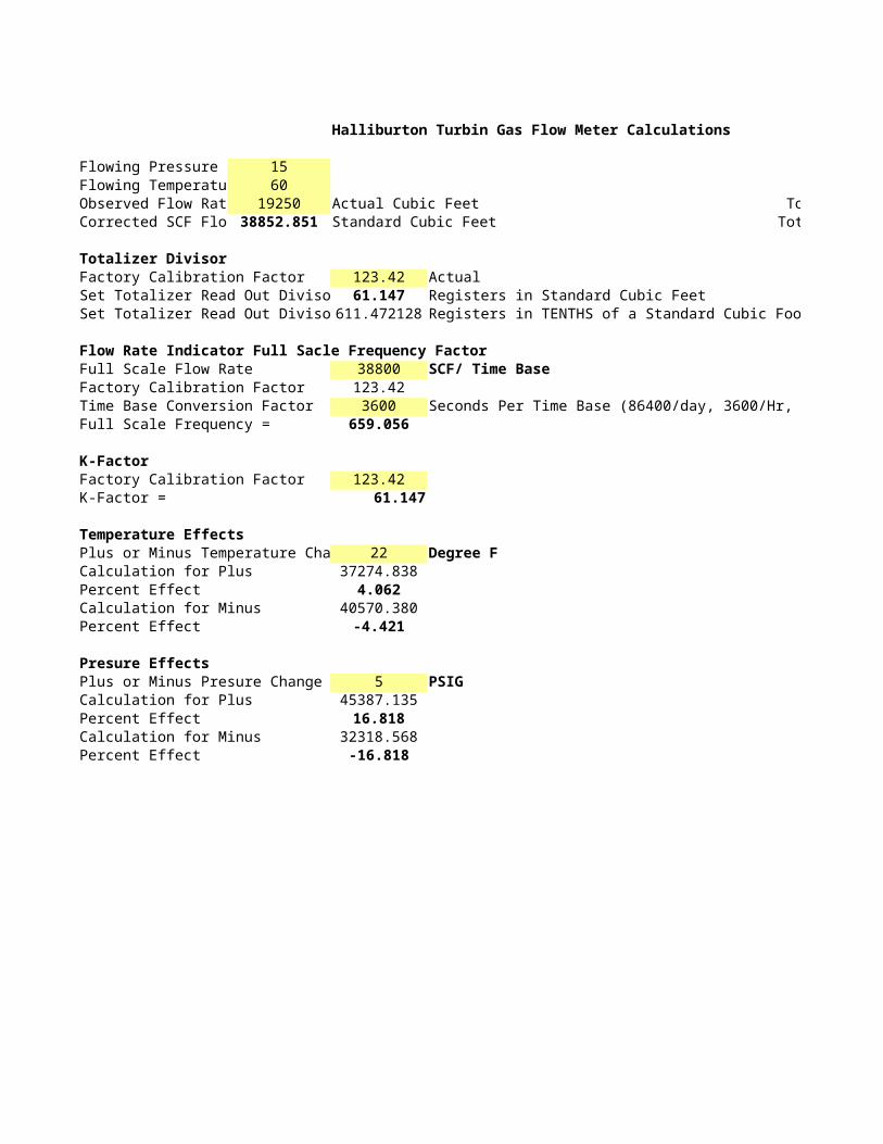
Halliburton Turbin Gas Flow Meter Calculations
Flowing Pressure 15Flowing Temperatu 60Observed Flow Rat 19250 Actual Cubic Feet Total Gal/OilCorrected SCF Flo 38852.851 Standard Cubic Feet Total Lbs./Oil
Totalizer DivisorFactory Calibration Factor 123.42 ActualSet Totalizer Read Out Diviso 61.147 Registers in Standard Cubic FeetSet Totalizer Read Out Diviso 611.472128 Registers in TENTHS of a Standard Cubic Foot
Flow Rate Indicator Full Sacle Frequency FactorFull Scale Flow Rate 38800 SCF/ Time BaseFactory Calibration Factor 123.42Time Base Conversion Factor 3600 Seconds Per Time Base (86400/day, 3600/Hr, 60/Min)Full Scale Frequency = 659.056
K-FactorFactory Calibration Factor 123.42K-Factor = 61.147
Temperature EffectsPlus or Minus Temperature Cha 22 Degree FCalculation for Plus 37274.838Percent Effect 4.062Calculation for Minus 40570.380Percent Effect -4.421
Presure EffectsPlus or Minus Presure Change 5 PSIGCalculation for Plus 45387.135Percent Effect 16.818Calculation for Minus 32318.568Percent Effect -16.818
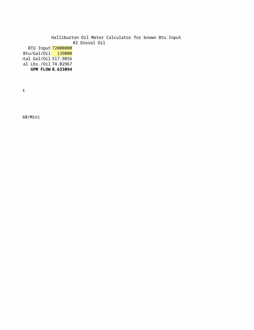
Halliburton Oil Meter Calculator for known Btu Input#2 Diesel Oil
BTU Input 72000000Btu/Gal/Oil 139000
Total Gal/Oil 517.9856Total Lbs./Oil 74.02967
GPM FLOW 8.633094
Registers in TENTHS of a Standard Cubic Foot
Seconds Per Time Base (86400/day, 3600/Hr, 60/Min)
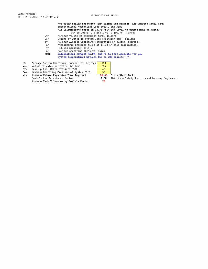
ASME formulaRef: Marks9th, p12-69/12.4.2 10/10/2022 04:38:48
Hot Water Boiler Expansion Tank Sizing Non-Bladder Air Charged Steel TankInternational Mechanical Code 1009.2 and ASMEAll Calculations based on 14.73 PSIA Sea Level 40 degree make-up water.
Vt=((0.00041T-0.0466) X Vs) / (Pa/Pf)-(Pa/Po)Vt= Minimum volume of expansion tank, gallonsVs= Volume of water in system less expansion tank, gallonsT= Maximum Average Operating Temperature of system, degrees 'F'Pa= Atmospheric pressure fixed at 14.73 in this calculation.Pf= Filling pressure (psig).Po= Maximum operating pressure (psig).NOTE Calculations correct Pa,Pf, and Po to Feet Absolute for you.
System Temperatures between 160 to 280 degrees 'F'.
T= Average System Operating Temperature, Degrees 160Vs= Volume of Water in System, Gallons 265Pf= Make-up Fill Water Pressure PSIG 45Po= Maximum Operating Pressure of System PSIG 50Vt= Minimum Volume Expansion Tank Required 26.43 Plain Steel Tank
Boyle's Law Acceptance Factor 1.08 This is a Safety Factor used by many Engineers Minimum Tank Volume using Boyle's Factor 28
Measurement, Controllers & Recorders
UNDER CONSTRUCTION - APPLICATION NOT YET AVAILABLE
MeasurementLevel, Pressure, Temperature or Flo F L,P,T,FFlow Measurement uses either a Differential Pressure Transmitter or Flow MeterAreyou using a Differential Transmitter or a Meter? Selece DT or M in the yellow box below
DTDifferential Transmitters meassure flow in inches water pressure across an orifice plate

UNDER CONSTRUCTION - APPLICATION NOT YET AVAILABLE
Flow Measurement uses either a Differential Pressure Transmitter or Flow MeterAreyou using a Differential Transmitter or a Meter? Selece DT or M in the yellow box below
Differential Transmitters meassure flow in inches water pressure across an orifice plate
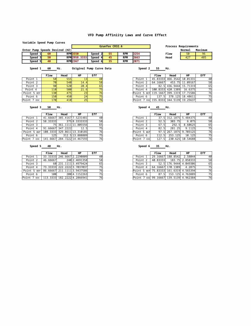
VFD Pump Affiniity Laws and Curve Effect
Variable Speed Pump Curves Grunfos CR32.6 Process Requirements
Enter Pump Speeds Desired (HZ) Normal MaximumSpeed 1 60 RPM 3550 Speed 2 55 RPM 3254 Flow 50 96Speed 3 50 RPM 2958.3333 Speed 4 45 RPM 2663 Head 427 485Speed 5 40 RPM 2367 Speed 6 35 RPM 2071
Speed 1 60 Hz. Original Pump Curve Data Speed 2 55 Hz.
Flow Head HP Eff Flow Head HP Eff Point 1 50 555 13 40 Point 1 45.83333 466.3542 10.01331 40Point 2 70 540 14.4 58 Point 2 64.16667 453.75 11.09167 58Point 3 90 520 20.4 65 Point 3 82.5 436.9444 15.71319 65Point 4 110 500 21.6 75 Point 4 100.8333 420.1389 16.6375 75
130 475 23 76 119.1667 399.1319 17.71586 76Point 6 150 450 24 75 Point 6 137.5 378.125 18.48611 75
170 410 25 76 155.8333 344.5139 19.25637 76
Speed 3 50 Hz. Speed 4 45 Hz.
Flow Head HP Eff Flow Head HP Eff Point 1 41.66667 385.4167 7.5231481 40 Point 1 37.5 312.1875 5.484375 40Point 2 58.33333 375 8.3333333 58 Point 2 52.5 303.75 6.075 58Point 3 75 361.1111 11.805556 65 Point 3 67.5 292.5 8.60625 65Point 4 91.66667 347.2222 12.5 75 Point 4 82.5 281.25 9.1125 75
108.3333 329.8611 13.310185 76 97.5 267.1875 9.703125 76Point 6 125 312.5 13.888889 75 Point 6 112.5 253.125 10.125 75
141.6667 284.7222 14.467593 76 127.5 230.625 10.54688 76
Speed 5 40 Hz. Speed 6 35 Hz.
Flow Head HP Eff Flow Head HP Eff Point 1 33.33333 246.6667 2.2290809 40 Point 1 29.16667 188.8542 2.58044 40Point 2 46.66667 240 2.4691358 58 Point 2 40.83333 183.75 2.858333 58Point 3 60 231.1111 3.4979424 65 Point 3 52.5 176.9444 4.049306 65Point 4 73.33333 222.2222 3.7037037 75 Point 4 64.16667 170.1389 4.2875 75
86.66667 211.1111 3.9437586 76 75.83333 161.6319 4.565394 76Point 6 100 200 4.1152263 75 Point 6 87.5 153.125 4.763889 75
113.3333 182.2222 4.2866941 76 99.16667 139.5139 4.962384 76
Point 5 BEP Point 5 BEP
Point 7 EOC Point 7 EOC
Point 5 BEP Point 5 BEP
Point 7 EOC Point 7 EOC
Point 5 BEP Point 5 BEP
Point 7 EOC Point 7 EOC
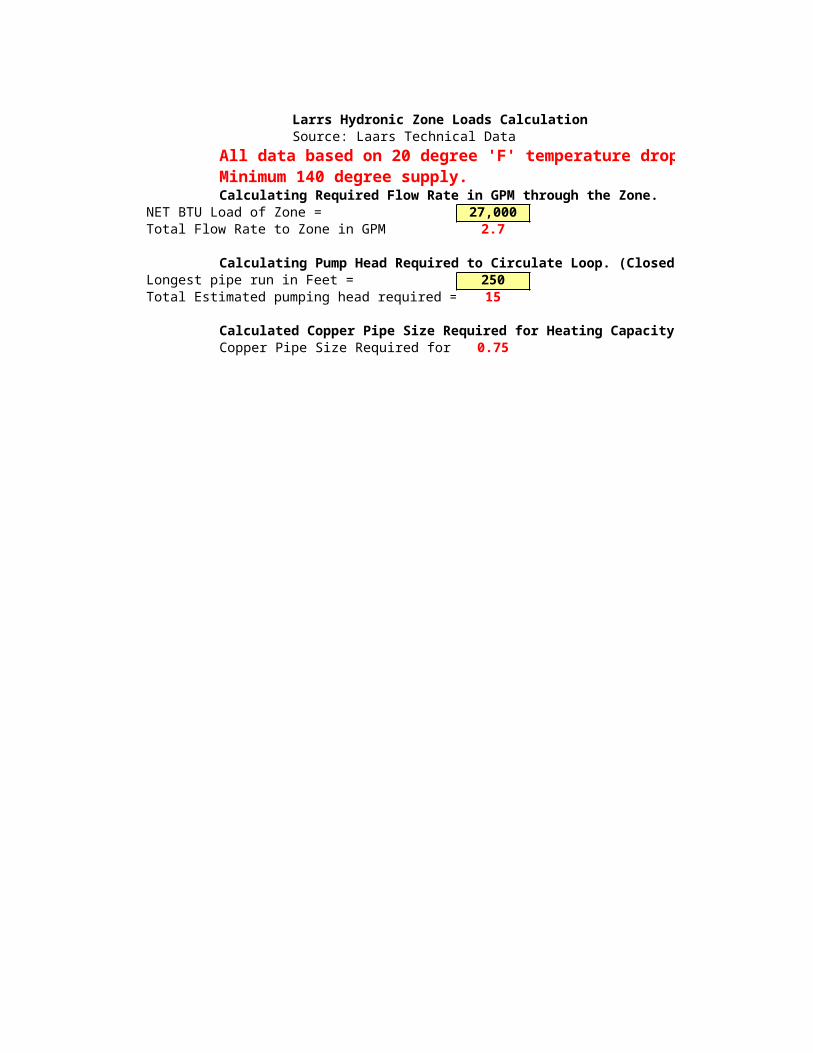
Larrs Hydronic Zone Loads CalculationSource: Laars Technical Data
All data based on 20 degree 'F' temperature drop across coil.Minimum 140 degree supply.Calculating Required Flow Rate in GPM through the Zone.
NET BTU Load of Zone = 27,000Total Flow Rate to Zone in GPM 2.7
Calculating Pump Head Required to Circulate Loop. (Closed Loop Application)Longest pipe run in Feet = 250Total Estimated pumping head required = 15
Calculated Copper Pipe Size Required for Heating CapacityCopper Pipe Size Required for 0.75

All data based on 20 degree 'F' temperature drop across coil.
Calculating Pump Head Required to Circulate Loop. (Closed Loop Application)
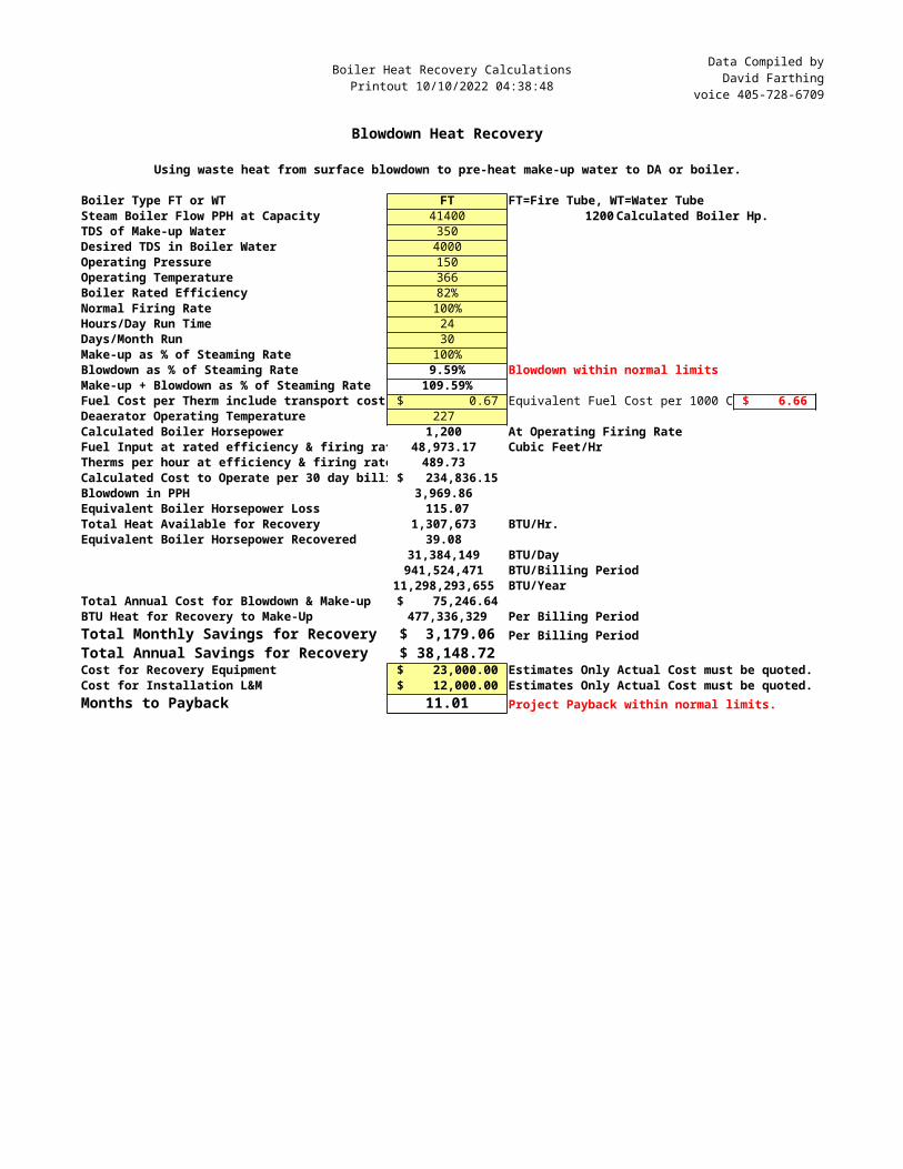
Boiler Heat Recovery CalculationsPrintout 10/10/2022 04:38:48
Data Compiled byDavid Farthing
voice 405-728-6709
Blowdown Heat Recovery
Using waste heat from surface blowdown to pre-heat make-up water to DA or boiler.
Boiler Type FT or WT FT FT=Fire Tube, WT=Water TubeSteam Boiler Flow PPH at Capacity 41400 1200 Calculated Boiler Hp.TDS of Make-up Water 350Desired TDS in Boiler Water 4000Operating Pressure 150Operating Temperature 366Boiler Rated Efficiency 82%Normal Firing Rate 100%Hours/Day Run Time 24Days/Month Run 30Make-up as % of Steaming Rate 100%Blowdown as % of Steaming Rate 9.59% Blowdown within normal limitsMake-up + Blowdown as % of Steaming Rate 109.59%Fuel Cost per Therm include transport cost $ 0.67 Equivalent Fuel Cost per 1000 C $ 6.66 Deaerator Operating Temperature 227 Calculated Boiler Horsepower 1,200 At Operating Firing RateFuel Input at rated efficiency & firing rat 48,973.17 Cubic Feet/HrTherms per hour at efficiency & firing rate 489.73 Calculated Cost to Operate per 30 day billi $ 234,836.15 Blowdown in PPH 3,969.86 Equivalent Boiler Horsepower Loss 115.07Total Heat Available for Recovery 1,307,673 BTU/Hr.Equivalent Boiler Horsepower Recovered 39.08
31,384,149 BTU/Day941,524,471 BTU/Billing Period
11,298,293,655 BTU/YearTotal Annual Cost for Blowdown & Make-up $ 75,246.64 BTU Heat for Recovery to Make-Up 477,336,329 Per Billing PeriodTotal Monthly Savings for Recovery $ 3,179.06 Per Billing PeriodTotal Annual Savings for Recovery $ 38,148.72 Cost for Recovery Equipment $ 23,000.00 Estimates Only Actual Cost must be quoted.Cost for Installation L&M $ 12,000.00 Estimates Only Actual Cost must be quoted.Months to Payback 11.01 Project Payback within normal limits.
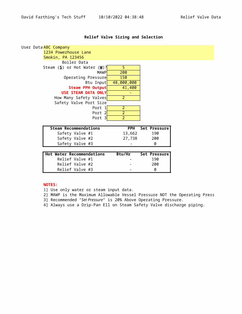
David Farthing's Tech Stuff 10/10/2022 04:38:48 Relief Valve Data
Relief Valve Sizing and Selection
User Data ABC Company1234 Powerhouse LaneSmokin, PA 123456
Boiler DataS
MAWP 200Operating Pressure 150
Btu Input 48,000,000 Steam PPH Output 41,400
USE STEAM DATA ONLY - How Many Safety Valves 2Safety Valve Port Size
Port 1 2Port 2 2Port 3 2
Steam Recommendations PPH Set PressureSafety Valve #1 13,662 190Safety Valve #2 27,738 200Safety Valve #3 - 0
Hot Water Recommendations Btu/Hr Set PressureRelief Valve #1 - 190Relief Valve #2 - 200Relief Valve #3 - 0
NOTES:1] Use only water or steam input data.2] MAWP is the Maximum Allowable Vessel Pressure NOT the Operating Pressure
4] Always use a Drip-Pan Ell on Steam Safety Valve discharge piping.
Steam (S) or Hot Water (W)?
3] Recommended "Set Pressure" is 20% Above Operating Pressure.

David Farthing's Tech Stuff 10/10/2022 04:38:48 Relief Valve Data
2] MAWP is the Maximum Allowable Vessel Pressure NOT the Operating Pressure
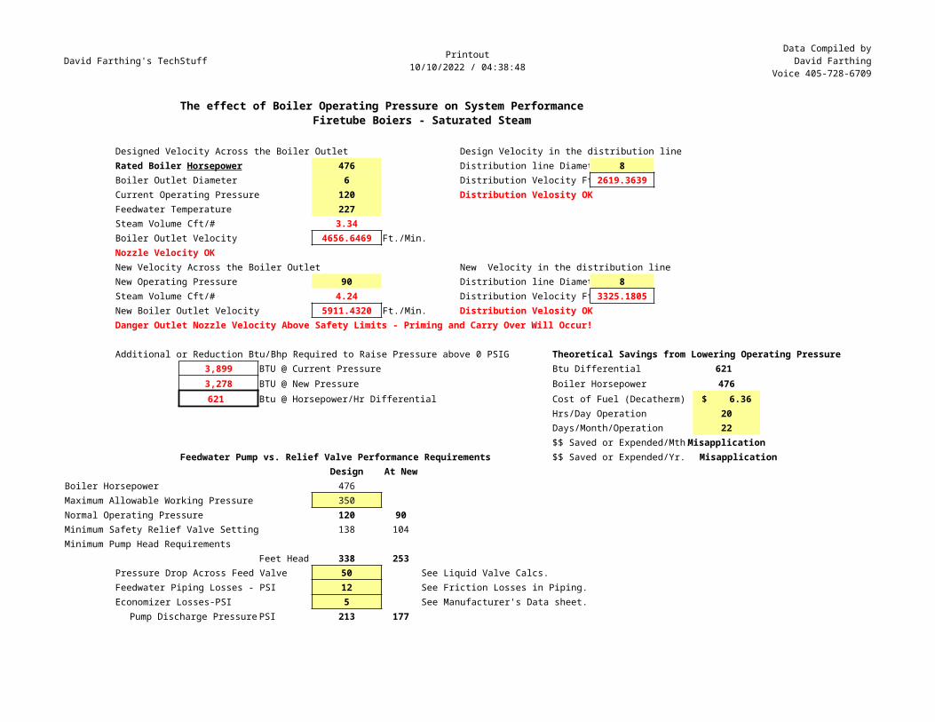
David Farthing's TechStuff Printout10/10/2022 / 04:38:48
Data Compiled byDavid Farthing
Voice 405-728-6709
The effect of Boiler Operating Pressure on System PerformanceFiretube Boiers - Saturated Steam
Designed Velocity Across the Boiler Outlet Design Velocity in the distribution line476 Distribution line Diamet 8
Boiler Outlet Diameter 6 Distribution Velocity Ft 2619.3639Current Operating Pressure 120 Distribution Velosity OKFeedwater Temperature 227Steam Volume Cft/# 3.34Boiler Outlet Velocity 4656.6469 Ft./Min.Nozzle Velocity OKNew Velocity Across the Boiler Outlet New Velocity in the distribution lineNew Operating Pressure 90 Distribution line Diamet 8Steam Volume Cft/# 4.24 Distribution Velocity Ft 3325.1805New Boiler Outlet Velocity 5911.4320 Ft./Min. Distribution Velosity OKDanger Outlet Nozzle Velocity Above Safety Limits - Priming and Carry Over Will Occur!
Additional or Reduction Btu/Bhp Required to Raise Pressure above 0 PSIG Theoretical Savings from Lowering Operating Pressure3,899 BTU @ Current Pressure Btu Differential 621 3,278 BTU @ New Pressure Boiler Horsepower 476621 Btu @ Horsepower/Hr Differential Cost of Fuel (Decatherm) $ 6.36
Hrs/Day Operation 20Days/Month/Operation 22$$ Saved or Expended/Mth. Misapplication
Feedwater Pump vs. Relief Valve Performance Requirements $$ Saved or Expended/Yr. Misapplication Design At New
Boiler Horsepower 476Maximum Allowable Working Pressure 350Normal Operating Pressure 120 90Minimum Safety Relief Valve Setting 138 104Minimum Pump Head Requirements
Feet Head 338 253Pressure Drop Across Feed Valve 50 See Liquid Valve Calcs.Feedwater Piping Losses - PSI 12 See Friction Losses in Piping.Economizer Losses-PSI 5 See Manufacturer's Data sheet.
Pump Discharge Pressure PSI 213 177
Rated Boiler Horsepower
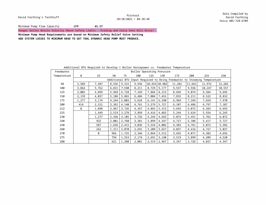
David Farthing's TechStuff Printout10/10/2022 / 04:38:48
Data Compiled byDavid Farthing
Voice 405-728-6709
Minimum Pump Flow Capacity GPM 41.17Danger Outlet Nozzle Velocity Above Safety Limits - Priming and Carry Over Will Occur!Minimum Pump Head Requirements are based on Minimum Safety Relief Valve SettingADD SYSTEM LOSSES TO MINIMUM HEAD TO GET TOAL DYNAMIC HEAD PUMP MUST PRODUCE.
Additional BTU Required to Develop 1 Boiler Horsepower vs. Feedwater TemperatureFeedwater Boiler Operating Pressure
Temperature 0 25 50 75 100 125 150 175 200 225 250 Additional BTU Input Required to Bring Feedwater to Steaming Temperature
50 5,589 7,487 8,556 9,315 9,936 10,454 10,902 11,282 11,661 11,972 12,282100 3,864 5,762 6,831 7,590 8,211 8,729 9,177 9,557 9,936 10,247 10,557125 3,002 4,899 5,969 6,728 7,349 7,866 8,315 8,694 9,074 9,384 9,695150 2,139 4,037 5,106 5,865 6,486 7,004 7,452 7,832 8,211 8,522 8,832175 1,277 3,174 4,244 5,003 5,624 6,141 6,590 6,969 7,349 7,659 7,970200 414 2,312 3,381 4,140 4,761 5,279 5,727 6,107 6,486 6,797 7,107212 0 1,898 2,967 3,726 4,347 4,865 5,313 5,693 6,072 6,383 6,693225 1,449 2,519 3,278 3,899 4,416 4,865 5,244 5,624 5,934 6,245230 1,277 2,346 3,105 3,726 4,244 4,692 5,072 5,451 5,762 6,072240 932 2,001 2,760 3,381 3,899 4,347 4,727 5,106 5,417 5,727250 587 1,656 2,415 3,036 3,554 4,002 4,382 4,761 5,072 5,382260 242 1,311 2,070 2,691 3,209 3,657 4,037 4,416 4,727 5,037270 0 966 1,725 2,346 2,864 3,312 3,692 4,071 4,382 4,692275 794 1,553 2,174 2,691 3,140 3,519 3,899 4,209 4,520280 621 1,380 2,001 2,519 2,967 3,347 3,726 4,037 4,347
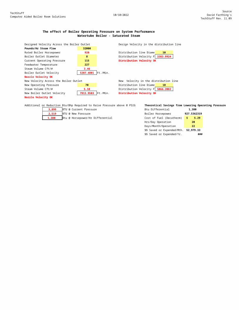
TechStuffComputer Aided Boiler Room Solutions 10/10/2022
SourceDavid Farthing's
TechStuff Rev. 11.09
The effect of Boiler Operating Pressure on System PerformanceWatertube Boiler - Saturated Steam
Designed Velocity Across the Boiler Outlet Design Velocity in the distribution linePounds/Hr Steam Flow 32000Rated Boiler Horsepower 928 Distribution line Diamet 10Boiler Outlet Diameter 8 Distribution Velocity Ft 3383.9924Current Operating Pressure 115 Distribution Velosity OKFeedwater Temperature 227Steam Volume Cft/# 3.46Boiler Outlet Velocity 5287.4881 Ft./Min.Nozzle Velocity OKNew Velocity Across the Boiler Outlet New Velocity in the distribution lineNew Operating Pressure 70 Distribution line Diamet 10Steam Volume Cft/# 5.18 Distribution Velocity Ft 5066.2082New Boiler Outlet Velocity 7915.9503 Ft./Min. Distribution Velosity OKNozzle Velocity OK
Additional or Reduction Btu/Bhp Required to Raise Pressure above 0 PSIG Theoretical Savings from Lowering Operating Pressure3,899 BTU @ Current Pressure Btu Differential 1,380 2,519 BTU @ New Pressure Boiler Horsepower 927.53623191,380 Btu @ Horsepower/Hr Differential Cost of Fuel (Decatherm) $ 5.29
Hrs/Day Operation 20Days/Month/Operation 22$$ Saved or Expended/Mth. $2,979.33 $$ Saved or Expended/Yr. ###
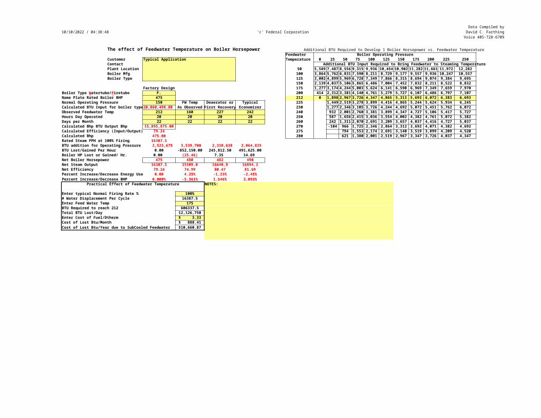
10/10/2022 / 04:38:48 'c' Federal CorporationData Compiled byDavid C. FarthingVoice 405-728-6709
The effect of Feedwater Temperature on Boiler Horsepower Additional BTU Required to Develop 1 Boiler Horsepower vs. Feedwater TemperatureFeedwater Boiler Operating Pressure
Customer Typical Application Temperature 0 25 50 75 100 125 150 175 200 225 250Contact Additional BTU Input Required to Bring Feedwater to Steaming Temperature Plant Location 50 5,589 7,487 8,556 9,315 9,936 10,454 10,902 11,282 11,661 11,972 12,282Boiler Mfg 100 3,864 5,762 6,831 7,590 8,211 8,729 9,177 9,557 9,936 10,247 10,557Boiler Type 125 3,002 4,899 5,969 6,728 7,349 7,866 8,315 8,694 9,074 9,384 9,695
150 2,139 4,037 5,106 5,865 6,486 7,004 7,452 7,832 8,211 8,522 8,832Factory Design 175 1,277 3,174 4,244 5,003 5,624 6,141 6,590 6,969 7,349 7,659 7,970
F. 200 414 2,312 3,381 4,140 4,761 5,279 5,727 6,107 6,486 6,797 7,107Name Plate Rated Boiler BHP 475 212 0 1,898 2,967 3,726 4,347 4,865 5,313 5,693 6,072 6,383 6,693Normal Operating Pressure 150 FW Temp Deaerator or Typical 225 1,449 2,519 3,278 3,899 4,416 4,865 5,244 5,624 5,934 6,245Calculated BTU Input for boiler type20,060,498.80 As Observed First Recovery Economizer 230 1,277 2,346 3,105 3,726 4,244 4,692 5,072 5,451 5,762 6,072Observed Feedwater Temp 212 160 227 242 240 932 2,001 2,760 3,381 3,899 4,347 4,727 5,106 5,417 5,727Hours Day Operated 20 20 20 20 250 587 1,656 2,415 3,036 3,554 4,002 4,382 4,761 5,072 5,382Days per Month 22 22 22 22 260 242 1,311 2,070 2,691 3,209 3,657 4,037 4,416 4,727 5,037Calculated Bhp BTU Output Bhp 15,895,875.00 270 -104 966 1,725 2,346 2,864 3,312 3,692 4,071 4,382 4,692Calculated Efficiency (Input/Output) 79.24 275 794 1,553 2,174 2,691 3,140 3,519 3,899 4,209 4,520Calculated Bhp 475.00 280 621 1,380 2,001 2,519 2,967 3,347 3,726 4,037 4,347Rated Steam PPH at 100% Firing 16387.5BTU addition for Operating Pressure 2,523,675 3,539,700 2,310,638 2,064,825 BTU Lost/Gained Per Hour 0.00 -852,150.00 245,812.50 491,625.00Boiler HP Lost or Gained/ Hr. 0.00 (25.46) 7.35 14.69 Net Boiler Horsepower 475 450 482 490Net Steam Output 16387.5 15509.0 16640.9 16894.3Net Efficiency 79.24 74.99 80.47 81.69Percent Increase/Decrease Energy Use 0.00 4.25% -1.23% -2.45%Percent Increase/Decrease BHP 0.000% -5.361% 1.546% 3.093%
Practical Effect of Feedwater Temperature NOTES:
Enter typical Normal Firing Rate % 100%# Water Displacement Per Cycle 16387.5Enter Feed Water Temp 175BTU Required to reach 212 606337.5Total BTU Lost/Day 12,126,750 Enter Cost of Fuel/Dtherm $ 3.33 Cost of Lost Btu/Month $ 888.41 Cost of Lost Btu/Year due to SubCooled Feedwater $10,660.87
Boiler Type Watertube/Firetube
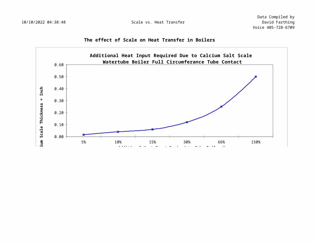
10/10/2022 04:38:48 Scale vs. Heat TransferData Compiled byDavid Farthing
Voice 405-728-6709
The effect of Scale on Heat Transfer in Boilers
5% 10% 15% 30% 66% 150%0.00
0.10
0.20
0.30
0.40
0.50
0.60
Additional Heat Input Required Due to Calcium Salt Scale Watertube Boiler Full Circumferance Tube Contact
Additional Heat Input Reqired to Make Boiler HorsepowerSource: Cooper Tool Mfg.Ca
lciu
m Sc
ale
Thic
knes
s =
Inch
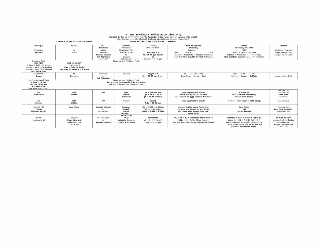
Dr. Mac Brockway's Boiler Water Chemistry(Contact Dr Mac at 405-737-3740 for the Companion White Paper that accompanies this chart)
(Dr. Brockway is a Phd Chemical Engineer specializing in water chemistry.)1 Grain = 17 PPM of soluable hardness Steam Boiler (<300 PSI) Water Treatment
Principle Benefit Pre- Internal Testing Want to Prevent Action CommentTreatment Treatment What You Want Chemistry Chemistry YOU WANT
Eliminate No Water HARDNESS SOFT Good Heat TransferHardness Scale Softner Precipitation Hardness = 0 Lower Energy Cost
Removes Calcium or Calcium + Carbonate = Calcium Carbonate Calcium + Phosphate = Soft Sludge Longer Boiler lifeand Magnesium Chelant or Slow Reaction results in hard formation Fast reaction results in a soft formationsalts only Solubilizer Chelant = 10-30 ppm
Hardness Test Treat at the Feedwater TankSOAP TEST HACH 5B REAGENT
1 Drop = Soft (<1 Grain) Pink = Hard2 Drops = Hard (1-2 Grains) Blue = Soft <1 Grain3 Drops = Hard (2-3 Grains) Each drop of reagent = 1 Grain
Run Sample COLDEliminate No Deareate Sulfite Oxygen = 0 Fe + 1/2O2 = FeOOxygen Corrosion or Iron Metal + Oxygen = Rust Sulfite + Oxygen = Sulfate Longer Boiler Life
Hot FeedwaterSulfite Residual Test Treat at the Feedwater Tank
1 Drop = 10 ppm May be injected directly into the boilerDesired 30-60 ppm but don't forget the feedwater tankRun Sample HOT
Run this TEST FIRST!Save Fuel $$
Add Soft N/A NaOH OH = 300-600 ppm Hard Crystalline solids Elevate pH Clean BoilerAlkalinity Solids Sodium pH = 11.0 - 12.0 Avoid runing pH too low this OH = Elevated Alkalinity Good Heat
Hydroxide pH = 11.56 Perfect Result Soft Solids Transfer
Add Soft N/A Polymer Normal Hard Crystalline solids Polymer + Hard Soild = Soft Sludge Clean BoilerPolymer Solids Poly = 10-50 ppm
Control TDS Pure Steam Reverse Osmosis Blowdown TDS = 3,000 - 5,000ppm Prevent Boiler Water Carry Over Pure Steam Clean Boiler"Total or Manual TDS <= 3,000 Great! Priming and Impure or Wet Steam and Good Heat Treansfer
Disolved Solids" De-Ionizer and/or uMhos = 4,000 - 6,0000 Wet Steam robs energy from your Solids Removal Saved Fuel $$$Automatic steam line!Nutralizing
Boost Eliminate De-Alkalizer Amine Condensate No Rust or ironCondensate pH Steam Line and or Volatile Chemical pH = 8 - 9.0 Great! brought back to boiler
Condensate Line Reverse Osmosis travels with steam Iron Test <0.1ppm Rot out distribution and condensate lines! by condensate.Corrosion the acid and raise the pH to 8-9 and Longer distribution
protects condensate lines. line life.
Phosphate (PO4)Ca++ +CO3 = CaCO 3 3Ca++ + 2PO4 = Cay(PO4)2
PO4 =30-60 ppm Great!
2SO3 + O2 = 2SO4
SO3 = 30-60 ppm Great!
will result in Hard Calcium Phosphate
CO2 + H20 = H2CO3 (Carbonic Acid! pH=4-6) Amine(A) + H2CO3 = A~H+HCO3 (pH=8-9)H2CO3 + Fe = FeCO3 (Iron Scale!) Amine(A) + H2O = A~H+OH (pH = 8-9)
Amine combines with H2CO3 to nutralize
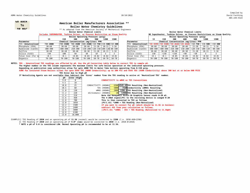
ABMA Water Chemistry Guidelines 10/10/2022Compiled by
David Farthing405-249-9324
American Boiler Manufacturers Association **Boiler Water Chemistry Guidelines
** As adopted from the American Society of Mechanical EngineersBoiler Water Chemical Limits Boiler Water Chemical Limits
Includes SUPERHEATER, Turbine Drives, or Process Restriction on Steam Quality NO Superheater, Turbine Drives, or Process Restrictions on Steam Quality.Boiler Operating Pressure (psig) Boiler Operating Pressure (psig)
15 150 300 600 900 1200 1500 15 150 300 600 900 1200 1500Parameter Chemical Concentration (mg/liter) PPM Parameter Chemical Concentration (mg/liter) PPM
Phosphate (PO4) 30-60 30-60 30-60 20-40 15-20 10-15 5-10 Phosphate (PO4) 30-60 30-60 30-60 20-40 15-20 10-15 5-10Hydroxide (CaCO3) 300-400 300-400 250-300 150-200 120-150 100-120 80-100 Hydroxide (CaCO3) 300-400 300-400 250-300 150-200 120-150 100-120 80-100Sulfite 30-60 30-60 30-40 20-30 15-20 10-15 5-10 Sulfite 30-60 30-60 30-40 20-30 15-20 10-15 5-10Silica (SiO2) 150 100 50 30 10 5 3 Silica (SiO2) 150 <150 <150 <90 <30 5 3Total Iron (Fe) mg <0.1 <0.1 <0.05 <0.03 <0.02 <0.02 <0.01 Total Iron (Fe) <0.1 <0.1 <0.05 <0.03 <0.02 <0.02 <0.01Organics 70-100 70-100 70-100 70-100 50-70 50-70 50-70 Organics 70-100 70-100 70-100 70-100 50-70 50-70 50-70
NOTES: TDS - Unnutralized TDS readings are affected by pH. Use the pH Correction table below to correct TDS to sample pH.The Higher number in the TDS column represents the maximum limits for safe boiler operation at the indicated operating pressure.Depending on publication some authorities allow for upto 4000 TDS in Water Tube boilers operating from 0-150 psig.ASME for Saturated Steam Boilers allows for upto 5595 TDS (8000 Conductivity) up to 300 PSI and 4545 TDS (6500 Conductivity) above 300 but at or below 600 PSIG
TDS Error due to High pHIf Nutralizing Agents are not available then Subtract the 'Error' number from the TDS reading to arrive at 'Neutralized TDS' number.
pH Error (High)9.0 0 CONDUCTIVITY to mMHO or TDS Converstions9.5 1010.0 25 CONDUCTIVITY (KNOWN) 6500 4545.45 TDS Resulting (Non-Neutralized)10.5 60 TDS (KNOWN) 5000 7150 Conductivity (mMHO) Resulting11.0 150 mMHO (KNOWN) 2000 1398.6 TDS Resulting (Non-Neutralized)11.2 220 mS(Siemans) (KNOWN) 20 13986 TDS Resulting (Non-Neutralized)11.4 310 Note the Honeywell DL423-10 Graphite Sensor reads 0-20 mS.11.6 460 The 4-20mA signal(PV) to the recvieing device is ranged 0-2011.8 700 This is then converted to TDS as follows12.0 1050 (PV/1.43) *1000 = TDS Reading (Non-Nutralized)12.2 1500 If you want to correct for pH (which should be 11.56 in boilers)12.4 2400 subtract 455 from your calculation as follows.12.6 3800 ((PV/1.43) *1000) - 455 = TDS Reading (Nutralized to 11.56pH)12.8 610013.0 10,000
EXAMPLE
* NOTE a pH of 9.0 is considered LOW. Normal Operating pH is recommended to be at 11.56.
TDS (Unnutralized) 700-2800 700-3500 700-3500 500-2500 150-750 150-500 150-300 TDS (Unnutralized) 700-5595 700-5505 700-4545 500-4545 150-750 150-500 150-300
1] TDS Reading of 2850 and an operating pH of 11.56 (normal) would be corrected to 2390 (I.e. 2850-460=2390)2] TDS Reading of 2850 and an operating pH of 9.0* (low) would be corrected to 2850 (I.e. 2850-0=2850)
Go Back To
DR.MAC
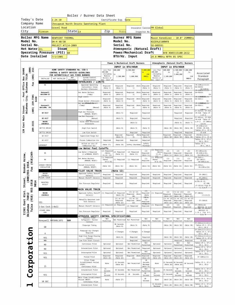
Print Out 10/10/2022Boiler / Burner Data SheetToday's Date 2.24.10 Certificate Exp. DateCompany Name Chesapeak North Desoto Sweetening PlantLocation Gravel Road Insurance CarrierFM GlobalCity Fireson State La Zip 71111 Inspector No.
Boiler MFG Name NEWPOINT THERMAL Burner MFG Name Maxon Kenedizer - 10.0" 25MMBtuModel No. DH-H 40/30 Model No. KDZERLE100NFBSerial No. PROJECT #7114-2009 Serial No. SO-809591Hot Water OIL Steam Atmosperic (Natural Draft)Operating Pressure (PSI) 80 Power/Mechanical Draft NYB #D03115100-2612Date Installed 7/1/1905 BTU/Hr. Input 24.8 MMBtu NFPA 85 SPEC
Power & Mechanical Draft Burners Atmospheric (Natural Draft) Burners
INPUT in BTU/HOUR INPUT in BTU/HOURASME SAFETY STANDARDS No. CSD-1
CONTROL & SAFETY DEVICES GUIDELINESFOR AUTOMATICALLY GAS FIRED BURNERS
INSTALLED NOT INSTALLED
INTERLOCKS / LIMITSNA
NA
UE H117 (Note 5) Required Required Required Required
UE H117 (Note 5) Required Required Required Required
(Note 6) (Note 6) (Note 7)
BETTIS EM110 High Fire Switch (Note 8) (Note 9) (Note 9) (Note 10) (Note 10) (Note 10)
BETTIS EM110 Low Fire Switch Required Required Required Required CF-610
UE H117 Supervised Purge Air
UE H117 Proven Combustion Air Required Required Required Required
LOCKOUT (Note 17) (Note 18) Safety Shutdown
Low Water Fuel CutoffsNA
NA (1) Required (1) Required
(Note 16) (Note 16) (Note 16) (Note 16) (Note 16) (Note 16) (Note 16)
PILOT VALVE TRAIN (Note 12)Required Required Required Required Required Required Required Required CR-180(C)
Pilot Cock Manual Shutoff Valve(s) Required Required Required Required Required Required Required Required CF-150(C)
Gas Pressure Regulator Required Required Required Required Required Required Required Required
MAIN VALVE TRAIN
YESCF-150(d)
1-Gas Cock 1-Ball Manual Shutoff Valve(s) (2) Required
Gas Pressure Regulator Required Required Required Required Required Required Required Required
APPROVED SAFETY CONTROL SPECIFICATIONS
Federa
l Corp
oratio
n
Honeywell RM7840L1075 OEM Not Permitted
60 Prepurge Timing (Note 9) (Note 9) (Note 10) (Note 10) (Note 10)
44 Changes 4 Changes 4 Changes
YES (Note 8) Required Required (Note 10) (Note 10) (Note 10)
YES Low Fire Start Circuit Required Required Required Required CF-610
NO Continuous Pilot Optional Optional Not Permitted Optional Optional
NO Intermittent Pilot Optional Optional Not Permitted Required Optional Optional Optional Optional
YES Interrupted Pilot Optional Optional Not Permitted Optional Optional Optional Optional
YES Proved Pilot CF-320(a)(1)
15None Not Permitted None 10 Seconds
Intermittent Pilot 15 Seconds Not Permitted 15 Seconds
YES Interrupted Pilot 15 Seconds 10 Seconds 15 Seconds
10 SECNone (Note 27) None (Note 28) (Note 29) (Note 30)
Intermittent Pilot (Note 28) (Note 29) (Note 30)
120
East
Mai
n St
reet
-
- Po
st O
ffic
e Bo
x 26
408
Okla
homa
Cit
y, O
klah
oma
7312
6
(8
00)
289-
3331
(40
5) 2
39-7
301
Fax
(40
5) 2
32-
5438
Less Than 400,000 (Including Modular
Boilers w/ max. input of
400,000 to 2,500,000
2,500,000 to
5,000,000
5,000,000 to 250 MMBtu
Less Than 400,000 (Including Modular
Boilers w/ max. input of
400,000 to
2,500,000
2,500,000 to
5,000,000
5,000,000 to 250 MMBtU
Associated Standard ParagraphNOT
REQUIRED System Control Specifications
Approved Operating Controllers Steam Boilers (Pressure)
Required (Note 1)
Required (Note 1)
Required (Note 1)
Required (Note 1)
Required (Note 1)
Required (Note 1)
Required (Note 1)
Required (Note 1)
CR-220(a)(1)(2) CW-310(b)
CW-620(b)
Honeywell UDC2500-CE
Hot Water Boilers (Temp)
Required (Note 2)
Required (Note 2)
Required (Note 2)
Required (Note 2)
Required (Note 2)
Required (Note 2)
Required (Note 2)
Required (Note 2)
CR-220(b)(1)(2) CW-410(b) CW-
640(b)High Limits
Steam boiler (Pressure) (Manual Reset)
Required (Note 3)
Required (Note 3)
Required (Note 3)
Required (Note 3)
Required (Note 3)
Required (Note 3)
Required (Note 3)
Required (Note 3)
CR-220(a)(1)(3) CW-310(c)
CW-620(a)
Honeywell UDC1200L -FM
Hot Water Boilers (Temp) (Manual
Reset)
Required (Note 4)
Required (Note 4)
Required (Note 4)
Required (Note 4)
Required (Note 4)
Required (Note 4)
Required (Note 4)
Required (Note 4)
CR-220(b)(1)(3) CW-410(c)
CW-640(a)
High Gas Pressure (MANUAL RESET)
CF-162(a), CF-910, CR-410 Table CF-
1,CF-2Low Gas Pressure (Manual
Reset) CF-162(a), CF-910, CR-410 Table CF-1,CF-2 CF-180(b)
(2)(3)MAXON
250CMA12Valve Seal Overtravel
InterlocksCF-210(a)(2) CF910, CR-410,
Tables CF-1, CF-2
Required (Note 9)
Required (Note 9)
Required (Note 9)
Required (Note 10)
Required (Note 10)
Required (Note 10)
CR210(a)(b)(c) Tables CF-1, CF-2Tables CF-1, CF-2
CR-1, CR-2Action on Loss of Combustion Air
Safety Shutdown
Tables CF-1, CR-1, CR-2
11361
East 6
1st. S
treet,
Brok
en Arr
ow,
Oklaho
ma 74
012
(80
0)955-
1918,
Tul
sa (91
8) 955
-1918
Fa
x (918
)249-
9014
Low Water 2 Required (1 w/MANUAL RESET)
(2) Required (Notes
11,12, 13)
(2) Required (Note 11)
(2) Required (Note 11)
(2) Required (Note 11)
(2) Required (Notes 11,12,
13)
(2) Required (Note 11)
(2) Required (Note 11)
(2) Required (Note 11)
CE-120(a)(b) CR-210(a)(b), CW-610(a)(b)
Hot Water Boilers (MANUAL RESET)
(1) Required (Notes 14 & 15)
(1) Required
(1) Required (Notes 14 & 15)
(1) Required
(1) Required
(1) Required
CR-210(c), CW-130(a),
CW-630(a)(b)
UE8W2D FORCED CIRCULATION
Forced Circulation (MANUAL RESET) (Note 16) CR-210(e),
CW-210(a)(b)
MAXON 150CMA12
Approved Safety Shutoff Valve(s)
MAXATROL RV12LT
CF-110(a)(1), UL795-25 15, CF-180,
cf-161(b) Figs B-1, 2,3,4
MAXON 250CMA12
Approved Safety Shutoff Valve(s)
(1) Required
(2) Required (Note 19)
(1) or (2) Required (Note
20)
(2) Required (Note 21)
(1) Required
(2) Required (Note 19)
(1) or (2) Required (Note 20)
(2) Required (Note 21)
CF-180(b) (1)(2)(3)
Manually Operated Leak Test Valve(s)
(1) or (2) Required (Note 22)
(1) or (2) Required (Note
22)
(1) or (2)
Required (Note 22)
(1) or (2) Required (Note 22)
(1) or (2) Required (Note 22)
(1) or (2) Required (Note 22)
(1) Required
(2) Required
(2) Required
(1) Required
(2) Required
(2) Required
(2) Required
CF-150(b)(d) ANSI221.13 1114
FISHER 1098-EDR
CF-160, CF-161(b), ANSI221.13
1.15.1 Fig. B-1, 2,3, 4
Rebuilt Flame Safeguard / Burner
Control
Not Permitted Not Permitted Not
Permitted Not
Permitted Not
Permitted Not
Permitted Not
Permitted
90 Seconds (Note 8)
CF-210(a)(1)(2)(c) Tables CF-1, CF-2
CR-1, CR-2
Prepurge Air Changes Required
CF-210(a)(1)(2)(c) Tables CF-1, CF-2
CR-1, CR-2High Fire Purge Proving
CircuitCF-210(a)(1)(2)(c) Tables CF-1, CF-2
Not Permitted
Not Permitted
Not Permitted
Tables CF-1, CF-2 CR-1, CR-2
Tables CF-1, CF-2 CR-1, CR-2
Not Permitted
Tables CF-1, CF-2 CR-1, CR-2
Required (Note 25)
Required (Note 25)
Required (Note 25)
Required (Note 25)
Required (Note 25)
Required (Note 25)
Required (Note 25)
Required (Note 25)
Pilot Flame Establishment Period (PFEP)
Continuous Pilot
15 Seconds (Note 26)
10 Seconds Maximum (Note 31)
15 Seconds (Note 26)
10 Seconds (Note 26)
Tables CF-1, CF-2 CR-1, CR-2
15 Seconds
Not Permitted
15 Seconds
10 Seconds
10 Seconds
Tables CF-1, CF-2 CR-1, CR-2
15 Seconds
10 Seconds
15 Seconds
10 Seconds
10 Seconds
Tables CF-1, CF-2 CR-1, CR-2
Main Flame Establishment Period (MFEP) Continuous Pilot
10 Seconds
Tables CF-1, CF-2 CR-1, CR-2
15 Seconds Maximum
Tables CF-1, CF-2 CR-1, CR-2
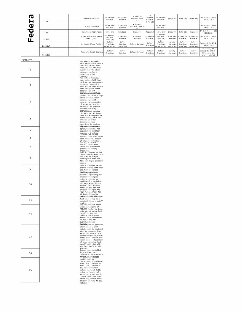
Print Out 10/10/2022
Fede
ral Co
rporat
ion
YESInterrupted Pilot (Note 28) (Note 29) (Note 30)
Direct Ignition
YES Supervised Main Flame (Note 34) Required Required Required (Note 34) (Note 34) (Note 33) Required
3 Sec
LockoutAction on Flame Failure Safety Shutdown
RecycleAction On Limit Opening Safety Shutdown
FOOTNOTES:
1
2
3
4
5
6
7
8
9
10
11
12
13
14
15
15 Seconds Maximum
15 Seconds Maximum
10 Seconds Maximum (Note
31)
10 Seconds Maximum (Note 31)
15 Seconds Maximum
Tables CF-1, CF-2 CR-1, CR-2
15 Seconds Maximum
4 Seconds Maximum
4 Seconds Maximum (Note
32)
15 Seconds Maximum
Tables CF-1, CF-2 CR-1, CR-2
CF-310(d) (1)(2)(3)(4)
Flame Failure Response Time (FFRT)
4 Seconds Maximum
(Note 36)
4 Seconds Maximum
4 Seconds Maximum
4 Seconds Maximum
4 Seconds Maximum (Note 35,
36)
4 Seconds Maximum
4 Seconds Maximum
4 Seconds Maximum
Tables CF-1, CF-2 CR-1, CR-2
Safety Shutdown
(Note 37,38)
Safety Shutdown (Note 39)
Safety Shutdown
Safety Shutdown
(Note 37,38)
Safety Shutdown (Note 40)
Safety Shutdown (Note 40)
Safety Shutdown (Note 40)
Tables CF-1, CF-2 CR-1, CR-2
Safety Shutdown
Safety Shutdown
Safety Shutdown
Safety Shutdown
Safety Shutdown
Safety Shutdown
Safety Shutdown
CF-162(a), CR-220(a) CW-130(d), CE-310(c), CW-410(c), CF-910
For modular boilers, each module shall have a pressure control that will shut off the fuel supply when the steam pressure reaches a preset operating pressureFor modular boilers, each module shall have at least one temperature actuated control to shut off the fuel supply when the system water reaches a preset operating temperature. The assembled modular boiler shall have a high steam pressure limit control that will prevent the generation of steam pressure in excess of the maximum allowable working pressure.The assembled modular hot water boiler shall have a high temperature limit control that will prevent the water temperature from exceeding the maximum allowable temperature. Required for direct ignition systems. Not required for ignition systems with pilotsOptional one safety shutoff valve with valve seal overtravel (Proof-of-closure) interlock. One of the safety shutoff valves with valve seal overtravel (Proof-of-closure) interlock. Four air changes at 60% damper opening with both air flow and damper opening with both air flow and damper position proven.Four air changes at 60% damper opening with both air flow and damper position proven.Units equipped with automatic operating air shutters or dampers which are closed or positioned to restrict air when burner is not firing, shall provide means to open the air shutter or damper the high fire position for at least 90 seconds prior to light off. One of the two low-water fuel cutoffs may be a combined feeder / cutoff device.For low pressure steam units with inputs of 400,000 Btu/Hr. or less, only one low-water fuel cutoff is required gravity return units installed in residences as defined by the authority having jurisdiction. For modular low pressure steam boilers, each module shall be equipped with an automatic low-water fuel cutoff. The assembled modular boiler shall have a second low-water cutoff. Operation of this low-water fuel cutoff shall shut off the fuel supply to all modules. Except those installed in residences (as defined by the authority having jurisdiction).An assembled modular boiler shall be protected by a low-water fuel cutoff located so that it will detect a low-water condition before the level falls below the lowest safe waterline in any module. Operation of the low-water fuel cutoff shall shutoff the fuel to all modules.
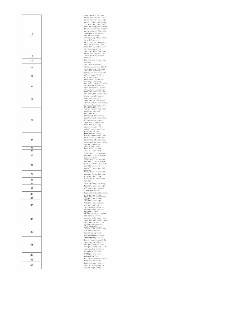
Print Out 10/10/2022
16
1718
19
20
21
22
23
24
25 When pilot is used.26 Initial start only.
27
28
29
3031 Interrupted pilot only.
32
3334
35
36
37
38
3940
41
requirements for low-water fuel cutoff in a water tube or coil-type boiler requiring forced circulation, they shall have an accepted sensing device to prevent burner operational a flow rate inadequate to protect the boiler from overheating. Where there is a definitive waterline, a low-water fuel cutoff shall be provided in addition to the sensing device. Functioning of the low-water fuel cutoff shall Close main valve and recycle.One recycle for piloted systems. Two safety shutoff valves in series. May be in single control body. Two safety shutoff valves in series on one safety shutoff valve with valve seal overtravel (Proof-of-closure) interlock. One safety shutoff valve to incorporate valve seal overtravel (Proof-of-closure) interlock.When two safety valves are provided in the fuel train, an additional leak test valve is required so that each safety shutoff valve may be tested independently of the other. Gas pressure relief valves, where required, shall be located upstream of all operating and safety controls and downstream of the gas pressure regulator I both the main and pilot gas supply systems. The relief valve in is to directed to the atmosphere.Water level control alarms, when used, shall be distinctly audible above the ambient noise level and may be used in conjunction with indicating lights.
Pilot only: 15 seconds maximum if interrupted pilot is used. Pilot only: 15 seconds maximum if interrupted pilot is used. 25 to 30 seconds if safety shutoff valve has full opening. Pilot only: 10 seconds maximum for modulating or high-low firing.Pilot only: 10 seconds maximum.
Maximum input at light off shall not exceed 2,500,000 Btu/Hr. Required with modulating or high-low firing.Required if interrupted pilot. If ignition system includes a relight feature, the relight attempt shall be initiated within 0.8 seconds upon loss of flame. For power, and mechanical draft, burner and natural draft burners with inputs less than 400,000 Btu/Hr. and continuos pilot, 180 seconds maximum for pilot flame failure. If system has intermittent pilot, wait 5 minutes before resetting ignition system (Instructional requirement).If system has interrupted pilot or direct ignition and the ignition includes a relight feature, the relight attempt shall be initiated within 0.8 seconds of loss of flame. A single recycle is allowed on forOr, recylce once after 5 minute time delay.Select proper safety control according to system requirements.
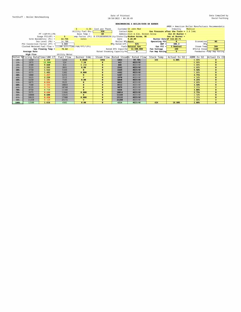
TechStuff - Boiler Benchmarking Date of Printout10/10/2022 / 04:38:49
Data Compiled byDavid Farthing
Voice 405-760-2831BENCHMARKING A BOILER/OVEN OR BURNER
AMBR = American Boiler Manufactuers Recommendations $ 6.36 Cost per Therm Customer St John Med Industry Medical
Utility Fuel Btu = 950 Contact Adam Gas Pressure after the Train = 3.8 InWcPf =(GP+Pc)/Pb Base Temp = 60 Address 61st & Elm, Broken Arrow Air At Burner =
Guage PSI(GP) = 5 Temp Factor (Pt) =0.9763058090196 ity/State/Zip Broken Arrow, OK Gas at Burner = Site Barometric (Pc) = 14.735 notes Date 9.28.09 Burner Data GP S16-GO-75
Sea Level (Pb) = 14.700 Boiler Mfg Hurst Operating PSI 0 Economizer NOPSI Correction Factor (Pf) = 1.343 Mfg Rated Eff. 82% BHP = 306.3 MfgClocked Metered Fuel Flow = (((100 SCFt/Time)*60)*Pf)*(Pt) Fuels Natural Gas Gas PSI = 5 Nominal Steam Temp 366
Gas Flowing Temp = 72.62 Rated BTU Input/Hr 12,500,000 Fan Voltage 480 BTU/Lb Steam 1100Average Rate Rated Steaming Capacity/Hr 0 Fan Amp Rating 9 Feedwater Pump Amp Rating
High Fire Utility MeterValve % Firing Rate Time/100 Cf Fuel Flow Burner InWc Steam Flow Rated Steam%/ Rated Flow Stack Temp Actual Ex O2 ABMR Ex O2 Actual Ex CO
10% 1250 6.250 1258 0.0000 1066 1064 99.78% 345 6.00% 6.00% 015% 1875 15.000 524 7.50 0 443 #DIV/0! 6.00% 020% 2500 9.660 814 8.250 0 688 #DIV/0! 6.00% 025% 3125 2.595 3031 0.00 0 2562 #DIV/0! 6.00% 030% 3750 1.522 5169 0 0 4369 #DIV/0! 5.50% 035% 4375 1.483 5302 0.000 0 4482 #DIV/0! 5.00% 040% 5000 1.257 6255 0 0 5287 #DIV/0! 4.75% 045% 5625 2.239 3513 0 0 2970 #DIV/0! 4.50% 050% 6250 1.101 7145 0.00 0 6040 #DIV/0! 4.25% 055% 6875 0.826 9525 0 0 8052 #DIV/0! 4.00% 060% 7500 0.800 10069 0 0 8512 #DIV/0! 3.50% 065% 8125 0.750 10740 0 0 9079 #DIV/0! 3.25% 070% 8750 0.720 11188 0 0 9458 #DIV/0! 3.00% 075% 9375 0.680 11846 0.000 0 10014 #DIV/0! 2.75% 080% 10000 0.600 13425 0 0 11349 #DIV/0! 2.50% 085% 10625 0.450 17900 0.000 0 15132 #DIV/0! 2.25% 090% 11250 0.320 25172 0 0 21280 #DIV/0! 2.00% 0100% 12500 1.616 4985 0.00 0 4214 #DIV/0! 424 18.80% 2.00% 0
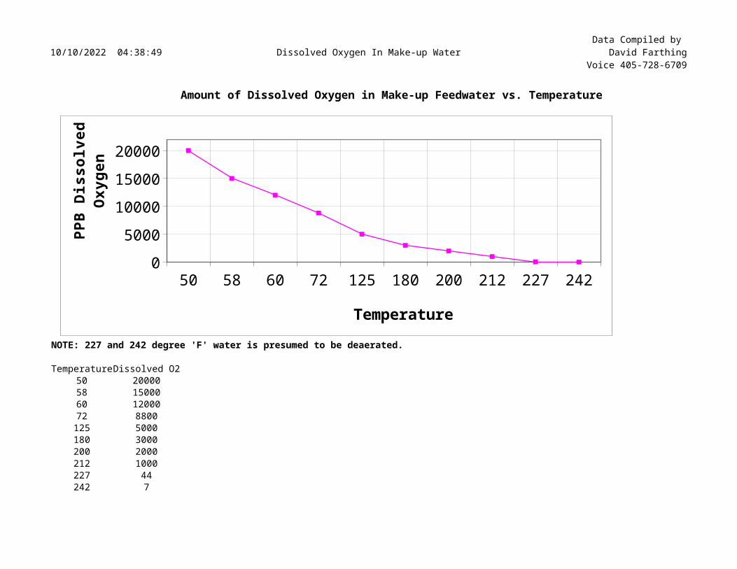
10/10/2022 04:38:49 Dissolved Oxygen In Make-up WaterData Compiled by
David FarthingVoice 405-728-6709
Amount of Dissolved Oxygen in Make-up Feedwater vs. Temperature
NOTE: 227 and 242 degree 'F' water is presumed to be deaerated.
TemperatureDissolved O250 2000058 1500060 1200072 8800125 5000180 3000200 2000212 1000227 44242 7
50 58 60 72 125 180 200 212 227 2420
5000100001500020000
Temperature
PPB
Diss
olve
d Ox
ygen
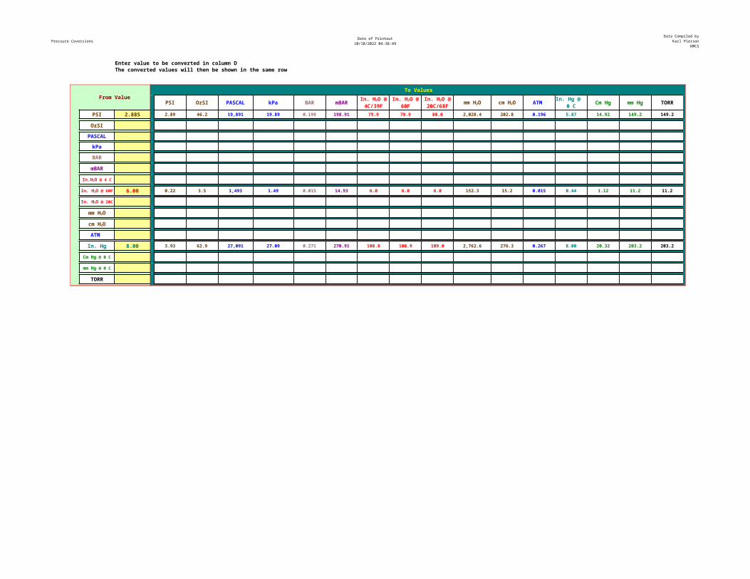
Pressure Coversions Date of Printout10/10/2022 04:38:49
Data Compiled byKarl Pierson
KMCS
Enter value to be converted in column D The converted values will then be shown in the same row
From ValueTo Values
PSI OzSI PASCAL kPa BAR mBAR ATM Cm Hg mm Hg TORR
PSI 2.885 2.89 46.2 19,891 19.89 0.199 198.91 79.9 79.9 80.0 2,028.4 202.8 0.196 5.87 14.92 149.2 149.2
OzSI
PASCAL
kPa
BAR
mBAR
6.00 0.22 3.5 1,493 1.49 0.015 14.93 6.0 6.0 6.0 152.3 15.2 0.015 0.44 1.12 11.2 11.2
ATM
In. Hg 8.00 3.93 62.9 27,091 27.09 0.271 270.91 108.8 108.9 109.0 2,762.6 276.3 0.267 8.00 20.32 203.2 203.2
TORR
In. H2O @ 4C/39F
In. H2O @ 60F
In. H2O @ 20C/68F mm H2O cm H2O In. Hg @
0 C
In.H2O @ 4 C
In. H2O @ 60F
In. H2O @ 20C
mm H2O
cm H2O
Cm Hg @ 0 C
mm Hg @ 0 C
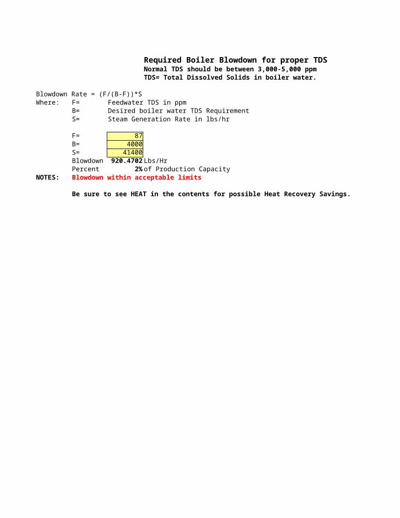
Required Boiler Blowdown for proper TDSNormal TDS should be between 3,000-5,000 ppmTDS= Total Dissolved Solids in boiler water.
Blowdown Rate = (F/(B-F))*SWhere: F= Feedwater TDS in ppm
B= Desired boiler water TDS RequirementS= Steam Generation Rate in lbs/hr
F= 87B= 4000S= 41400Blowdown 920.4702 Lbs/HrPercent 2% of Production Capacity
NOTES: Blowdown within acceptable limits
Be sure to see HEAT in the contents for possible Heat Recovery Savings.
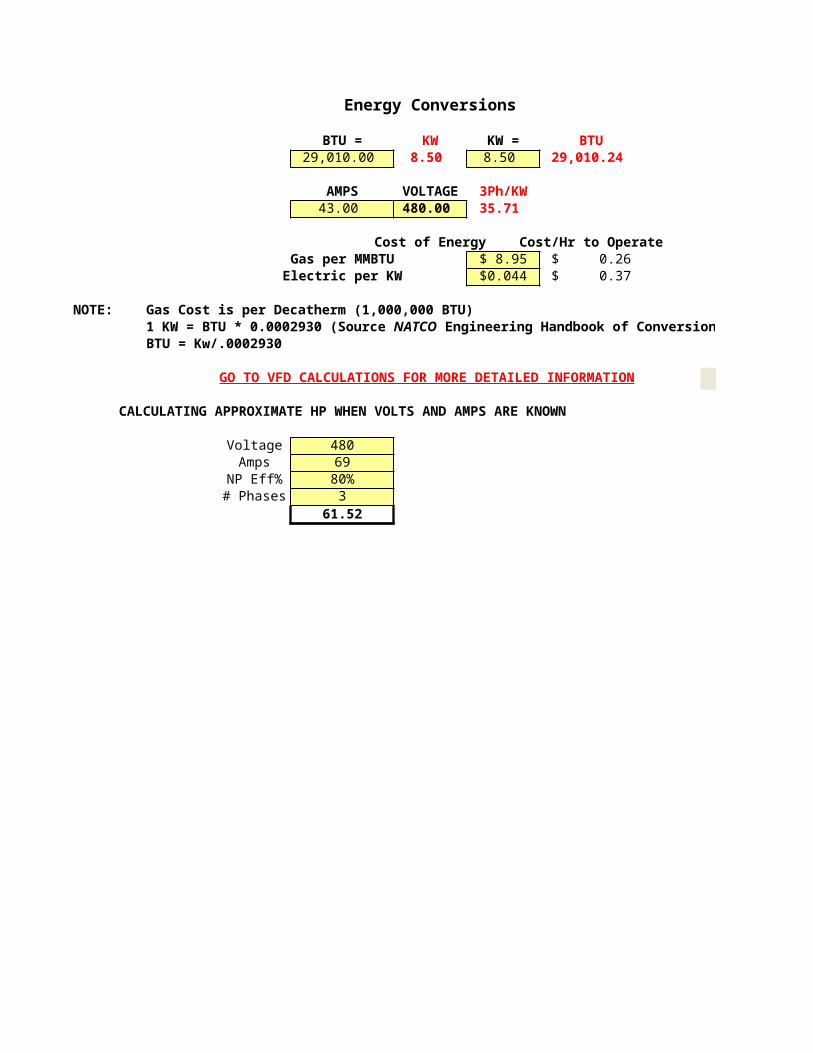
Energy Conversions
BTU = KW KW = BTU29,010.00 8.50 8.50 29,010.24
AMPS VOLTAGE 3Ph/KW43.00 480.00 35.71
Cost of Energy Cost/Hr to OperateGas per MMBTU $ 8.95 $ 0.26
Electric per KW $0.044 $ 0.37
NOTE: Gas Cost is per Decatherm (1,000,000 BTU)
BTU = Kw/.0002930
GO TO VFD CALCULATIONS FOR MORE DETAILED INFORMATION
CALCULATING APPROXIMATE HP WHEN VOLTS AND AMPS ARE KNOWN
Voltage 480Amps 69
NP Eff% 80%# Phases 3
61.52
1 KW = BTU * 0.0002930 (Source NATCO Engineering Handbook of Conversion Factors 1988)
VFD

Engineering Handbook of Conversion Factors 1988)
VFD
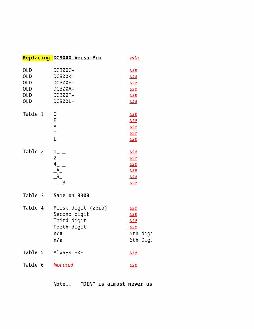
Replacing DC3000 Versa-Pro with
OLD DC300C- useOLD DC300K- useOLD DC300E- useOLD DC300A- useOLD DC300T- useOLD DC300L- use
Table 1 O useE useA useT useL use
Table 2 1_ _ use2_ _ use4_ _ use_A_ use_B_ use_ _3 use
Table 3 Same on 3300
Table 4 First digit (zero) useSecond digit useThird digit useForth digit usen/a 5th digin/a 6th Digi
Table 5 Always -0- use
Table 6 Not used use
Note…. "DIN" is almost never used on replacement controllers.!!!
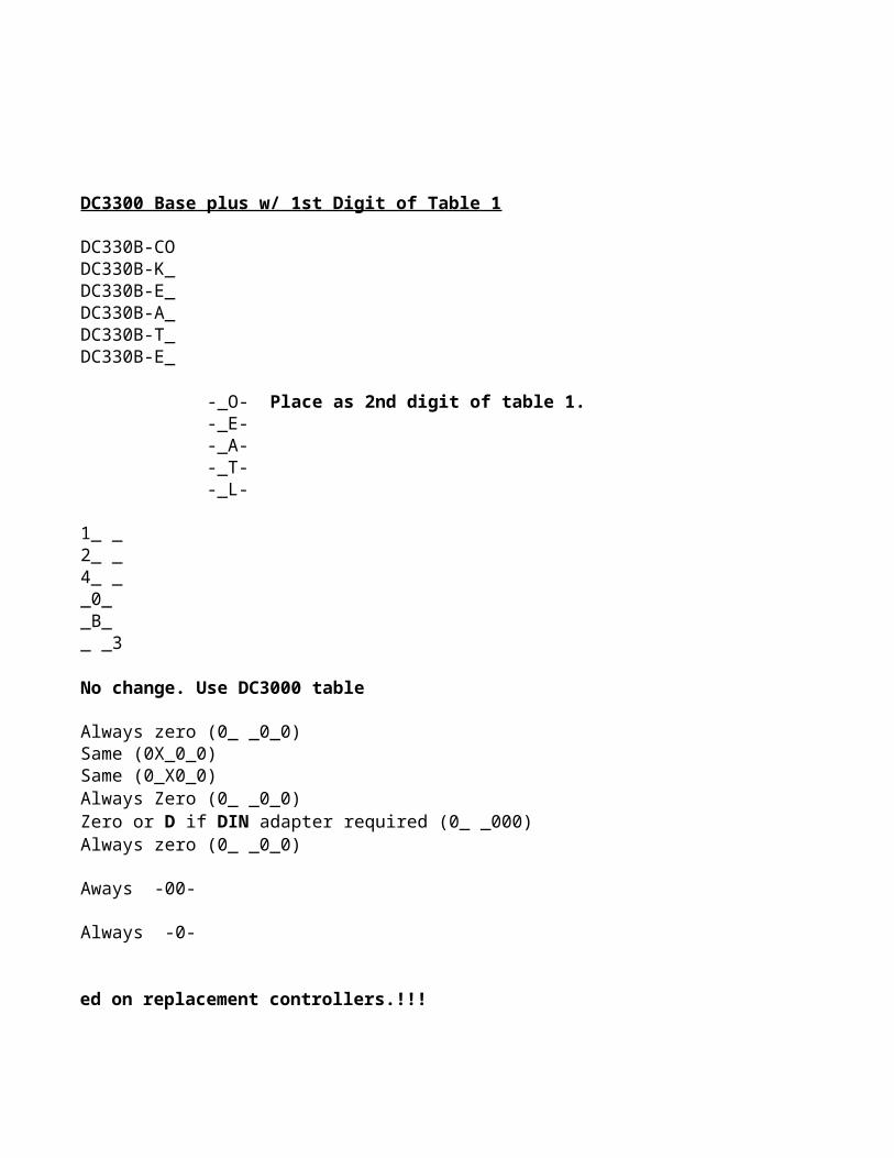
DC3300 Base plus w/ 1st Digit of Table 1
DC330B-CODC330B-K_DC330B-E_DC330B-A_DC330B-T_DC330B-E_
-_E- -_A- -_T- -_L-
1_ _2_ _4_ __0__B__ _3
No change. Use DC3000 table
Always zero (0_ _0_0)Same (0X_0_0)Same (0_X0_0)Always Zero (0_ _0_0)
Always zero (0_ _0_0)
Aways -00-
Always -0-
Note…. "DIN" is almost never used on replacement controllers.!!!
-_O- Place as 2nd digit of table 1.
Zero or D if DIN adapter required (0_ _000)
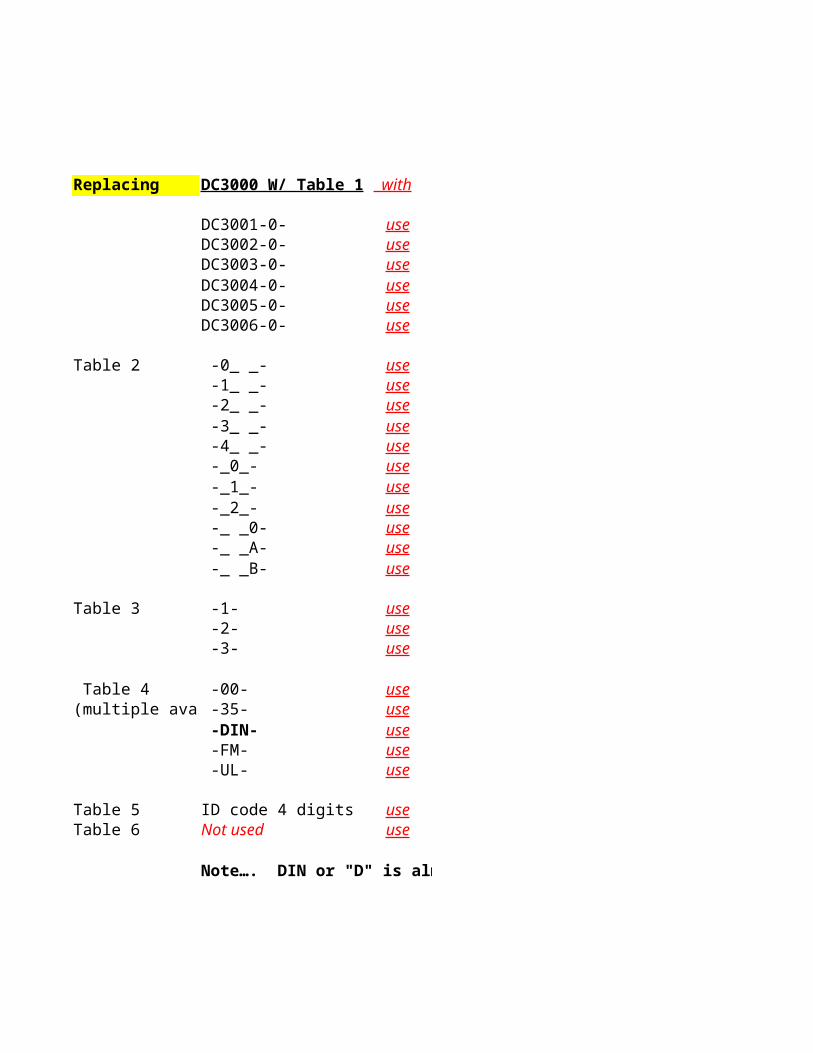
Replacing DC3000 W/ Table 1 with
DC3001-0-DC3002-0-DC3003-0-DC3004-0-DC3005-0-DC3006-0-
Table 2 -0_ _- -1_ _- -2_ _- -3_ _- -4_ _-
-_0_- -_1_- -_2_-
-_ _0- -_ _A- -_ _B-
Table 3 -1- -2- -3-
Table 4 -00-(multiple avai -35-
-DIN- -FM- -UL-
Table 5 ID code 4 digitsTable 6 Not used
Note…. DIN or "D" is almost never used on replacement controllers.!!!
use use use use use use
use use use use use use use use use use use
use use use
use use use use use
use use
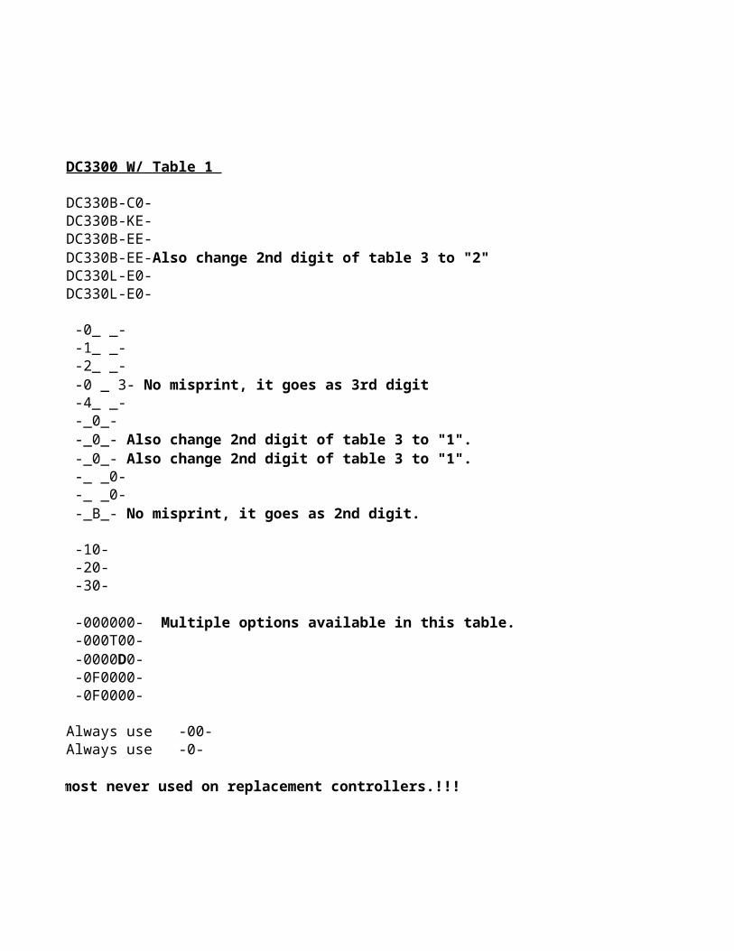
DC3300 W/ Table 1
DC330B-C0-DC330B-KE-DC330B-EE-
DC330L-E0-DC330L-E0-
-0_ _- -1_ _- -2_ _-
-4_ _- -_0_-
-_ _0- -_ _0-
-10- -20- -30-
-000T00-
-0F0000- -0F0000-
Always use -00-Always use -0-
Note…. DIN or "D" is almost never used on replacement controllers.!!!
DC330B-EE-Also change 2nd digit of table 3 to "2"
-0 _ 3- No misprint, it goes as 3rd digit
-_0_- Also change 2nd digit of table 3 to "1". -_0_- Also change 2nd digit of table 3 to "1".
-_B_- No misprint, it goes as 2nd digit.
-000000- Multiple options available in this table.
-0000D0-
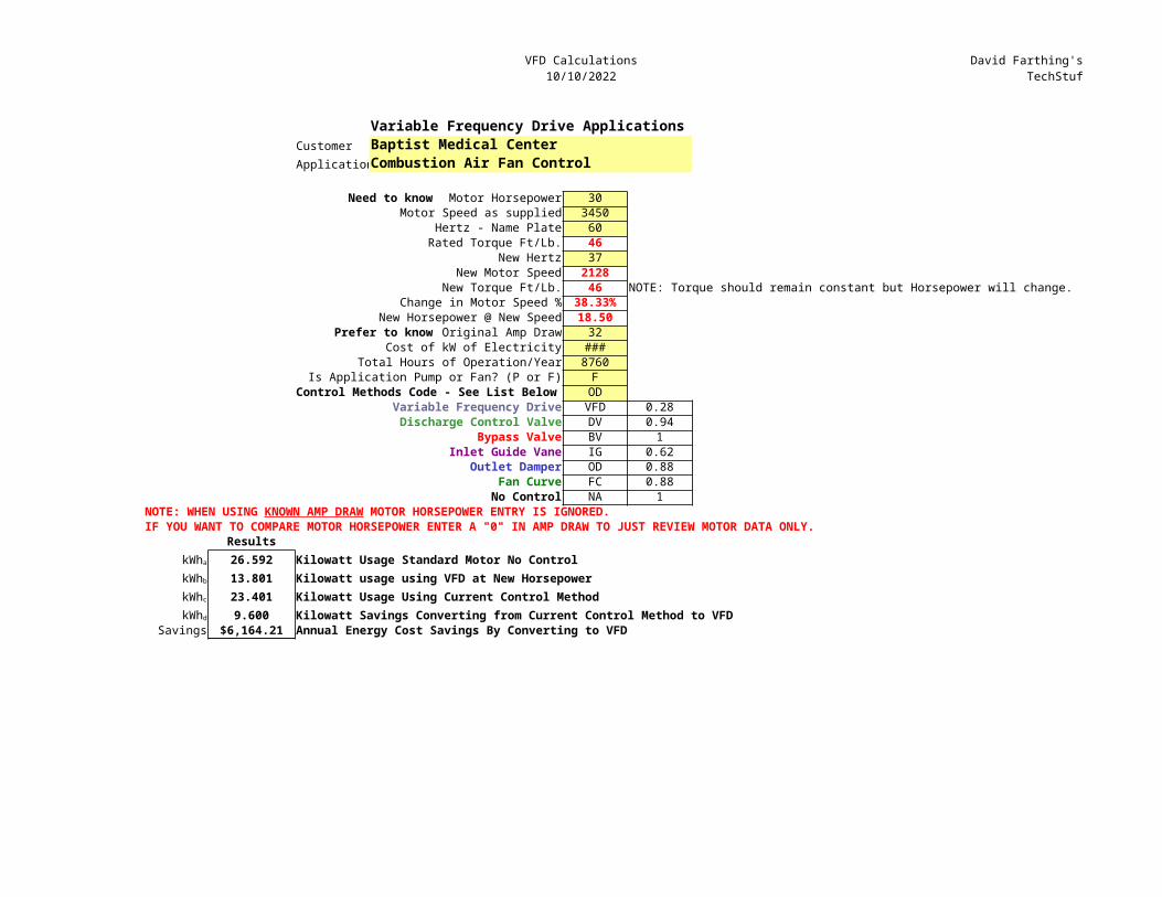
VFD Calculations10/10/2022
David Farthing'sTechStuf
Variable Frequency Drive ApplicationsCustomer Baptist Medical CenterApplicationCombustion Air Fan Control
Need to know Motor Horsepower 30Motor Speed as supplied 3450
Hertz - Name Plate 60Rated Torque Ft/Lb. 46
New Hertz 37New Motor Speed 2128
New Torque Ft/Lb. 46 NOTE: Torque should remain constant but Horsepower will change.Change in Motor Speed % 38.33%
New Horsepower @ New Speed 18.50Prefer to know Original Amp Draw 32
Cost of kW of Electricity ###Total Hours of Operation/Year 8760
Is Application Pump or Fan? (P or F) FControl Methods Code - See List Below OD
Variable Frequency Drive VFD 0.28Discharge Control Valve DV 0.94
Bypass Valve BV 1Inlet Guide Vane IG 0.62
Outlet Damper OD 0.88Fan Curve FC 0.88
No Control NA 1
IF YOU WANT TO COMPARE MOTOR HORSEPOWER ENTER A "0" IN AMP DRAW TO JUST REVIEW MOTOR DATA ONLY.Results26.592 Kilowatt Usage Standard Motor No Control13.801 Kilowatt usage using VFD at New Horsepower23.401 Kilowatt Usage Using Current Control Method9.600 Kilowatt Savings Converting from Current Control Method to VFD
Savings $6,164.21 Annual Energy Cost Savings By Converting to VFD
NOTE: WHEN USING KNOWN AMP DRAW MOTOR HORSEPOWER ENTRY IS IGNORED.
kWha
kWhb
kWhc
kWhd
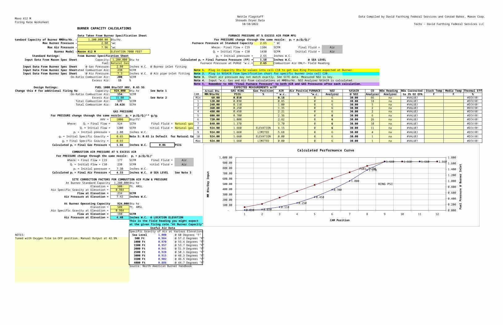
Maxo 412 MFiring Rate Worksheet
Nestle FlagstaffShreads Dryer Data
10/10/2022
Data Compiled by David Farthing Federal Services and Conrad Baker, Maxon Corp.
Techs - David Farthing Federal Services LLC BURNER CAPACITY CALCULATIONS
Data Taken From Burner Specification Sheet FURNACE PRESSURE AT % EXCESS AIR FROM MFGtandard Capacity of Burner MMBtu/Hr. - 1,200,000.00 Btu/Hr.
Max Burner Pressure - 2.80 "wc Furnace Pressure at Standard Capacity 2.65 " WCMax Air Pressure - 7.96 "wc Where: 1104 SCFM Final Fluid = Air
Burner Model - Maxon 412 M ELEVATION 7000 FEET 1430 SCFM Initial Fluid = AirStandard Ratings: From Burner Specification Sheet 2.65 Inches W.C.
Input Data From Maxon Spec Sheet Capacity: 1,200,000 Btu hr 1.58 Inches W.C. @ SEA LEVELFuel: Natural Gas Furnace Pressure at PURGE "w.c.= 2.65 Combustion Air ONLY- Field Reading
Input Data From Burner Spec Sheet @ Gas Pressure: 2.80 Inches W.C. @ Burner inlet fittingInput Data From Burner Spec Sheetated Combustion Air: 230 SCFMInput Data From Burner Spec Sheet @ Air Pressure: 7.3 Inches W.C. @ Air pipe inlet fitting
On-Ratio Combustion Air: 200 SCFMExcess Air: 15 %
Design Ratings: FUEL 1000 Btu/SCF HHV, 0.65 SG EXPECTED MEASUREMENTS w/FPChange this # for additional firing Ra Capacity: 924,000 Btu hr See Note 1 Actual Btu GAS RING Gas Position AIR Air Positio FURNACE %O2 %XSAIR CO NOx Reading NOx Corrected Stack Temp Media Temp Thermal Eff
On-Ratio Combustion Air: 154 SCFM CAM MM/Btu/Hr PSIG % " w.c. % "w.c. Analyzer @ %O2 Analyzer Analyzer to 3% O2 EPA F F %Excess Air: 15.00 % See Note 2 Min 60.00 0.010 0.18 0 6 30.00 66 na #VALUE! #DIV/0!
Total Combustion Air: 177 SCFM 1 120.00 0.030 0.85 0 6 30.00 18 na #VALUE! #DIV/0!Total Combustion Air: 10,626 SCFH 2 240.00 0.110 1.00 0 6 30.00 5 na #VALUE! #DIV/0!
3 360.00 0.250 1.35 0 6 30.00 2 na #VALUE! #DIV/0! GAS PRESSURE 4 480.00 0.450 2.21 0 6 30.00 2 na #VALUE! #DIV/0!
5 600.00 0.700 2.36 0 6 30.00 6 na #VALUE! #DIV/0!HHV = 1000 6 720.00 1.000 2.82 0 6 30.00 26 na #VALUE! #DIV/0!
Where: 924 SCFH Final Fluid = Natural gas 7 840.00 1.370 3.70 0 6 30.00 10 na #VALUE! #DIV/0!1200 SCFH nitial Fluid = Natural gas 8 924.00 1.660 ELEVATION 4.15 0 6 30.00 11 na #VALUE! #DIV/0!2.80 Inches W.C. 9 924.00 1.660 LIMITED 5.68 0 6 30.00 4 na #VALUE! #DIV/0!0.65 Note 5: 0.65 is Default for Natural Ga 10 924.00 1.660 ELEVATION 0.00 0 6 30.00 1 na #VALUE! #DIV/0!0.65 Max 924.00 1.660 LIMITED 0.00 0 6 30.00 1 na #VALUE! #DIV/0!1.66 Inches W.C. 0.06 PSIG
COMBUSTION AIR PRESSURE AT % EXCESS AIR
Where: 177 SCFM Final Fluid = Air230 SCFM nitial Fluid = Air7.30 Inches W.C.4.33 Inches W.C. @ SEA LEVEL See Note 3
SITE CORRECTION FACTORS FOR COMBUSTION AIR FLOW & PRESSUREAt Burner Standard Capacity 1,200,000 Btu hr
Elevation = 500 ft. AMSLAir Specific Gravity at Elevation = 0.984
Flow at Elevation = 234 SCFMAir Pressure at Elevation = 7.42 Inches W.C.
At Burner Operating Capacity 924,000 Btu hrElevation = 500 ft. AMSL
Air Specific Gravity at Elevation = 0.984Flow at Elevation = 180 SCFM
Air Pressure at Elevation = 4.40 Inches W.C. @ LOCATION ELEVATIONThis is the Field Reading you might expectat the given firing rate "At Burner Capacity"
Useful Air DataSpecific Gravity of Air at Various Elevations
NOTES: Sea Level 1.000 @ 60 Degrees "F"Tuned with Oxygen Trim in OFF position. Manual Output at 42.9% 500 Ft 0.984 @ 57.2 Degrees "F"
1000 Ft 0.970 @ 55.4 Degrees "F"1500 Ft 0.957 @ 53.7 Degrees "F"2000 Ft 0.941 @ 51.9 Degrees "F"2500 Ft 0.928 @ 50.1 Degrees "F"3000 Ft 0.915 @ 48.3 Degrees "F"3500 Ft 0.902 @ 46.5 Degrees "F"4000 Ft 0.886 @ 44.7 Degrees "F"
Source: North American Burner Handbook
For PRESSURE change through the same nozzle: p2 = p1(Q2/Q1)2
Q2 = Final Flow = C19 Q1 = Initial Flow = C10 p1 = Initial pressure =
Calculated p2 = Final Furnace Pressure (FP) =
Note 1. Plug in Capacity Btu hr values into cell C18 to get Gas Ring Pressure expected at Burner.Note 2. Plug in %XSAIR from Specification chart for specific burner into cell C20.Note 3. Chart air pressure may not match exactly. See SITE data. Measured %O2 is key.Note 4. Input "w.c. Gas and Air from calculations at MMBtu/Hr. %O2 Analyzer %XSAIR is calculated.Note 5. Remember to ADD "Final Furnace Pressure" to both AIR and GAS Pressures after each calculation.
For PRESSURE change through the same nozzle: p2 = p1(Q2/Q1)2 * g2/g1
Btu/ft3
Q2 = Final Flow =Q1 = Initial Flow =
p1 = Initial pressure =g1 = Initial Specific Gravity =
g2 = Final Specific Gravity = Calculated p2 = Final Gas Pressure =
For PRESSURE change through the same nozzle: p2 = p1(Q2/Q1)2
Q2 = Final Flow = C19 Q1 = Initial Flow = C10 p1 = Initial pressure =
Calculated p2 = Final Air Pressure =
1 2 3 4 5 6 7 8 9 10 11 12 -
100.00 200.00 300.00 400.00 500.00 600.00 700.00 800.00 900.00
1,000.00
0.000
0.200
0.400
0.600
0.800
1.000
1.200
1.400
1.600
1.800
0.010 0.0300.110
0.250
0.450
0.700
1.000
1.370
1.660 1.660 1.660 1.660
Calculated Performance Curve
CAM Position
MM B
tu/Day Input
Fuel Press
ure @ Burn
er Inlet
FUEL FLOW
RING PSI
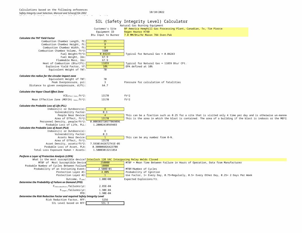
Calculations based on the following referencesSafety Integrity Level Selection, Marszal and Scharpf,ISA 2002SIL Selection for BMS Systems, Mike D. Scott, P.E., Principal Safety System SpecialistAE Solutions, Greenville, SC 29616
10/10/2022
SIL (Safety Integrity Level) CalculatorNatural Gas Burning Equipment
Customer's Site BP America Hemphill Gas Processing Plant, Canadian, Tx, Tim PierceEquipment ID Regen Heater H740
Btu Input to Burner 7.0 MM/Btu/Hr Maxon 784 Oven-PakCalculate the TNT Yield Factor
Combustion Chamber Length, ft: 25Combustion Chamber Height, ft: 8Combustion Chamber Width, ft: 8
Combustion Chamber Volume, ft^3: 1600Fuel Weight/ft^3: 0.04243 Typical for Natural Gas = 0.04243Fuel Weight, lbs: 67.9
Flammable Mass, lbs: 67.9Heat of Combustion (Btu/Cft): 11859 Typical for Natural Gas = 11859 Btu/ CFt.
Explosive Yield Factor, Yf: 10% EPA defined at 10%Equivalent Weight of TNT: 70
Calculate the radius for the circular impact zoneEquivalent Weight of TNT: 70Peak Overpressure, psi: 3 Pressure for calculation of fatalities
Distance to given overpressure, d(ft): 64.7
Calculate the Vapor Cloud Effect Zone13170 ft^213170 ft^2
Calculate the Probable Loss of Life (PLL)Indoors(i) or Outdoors(o): O
Vulnerability Factor: 0.3People Near Device: 4 This can be a fraction such as 0.25 for a site that is visited only 4 time per day and is otherwise un-manned.
Area of Effect, ft^2: 13170 This is the area in which the blast is contained. The area of a building if the blast is indoors or the MEFZA if an outdoor location.Personnel Density, people/ft^2: 0.000303720577069096
Probable Loss of Life, PLL: 1.20002410569483Calculate the Probable Loss of Asset (PLA)
Indoors(i) or Outdoors(o): OVulnerability Factor: 0.3Assets Near Device: 1 This can be any number from 0-N.
Area of Effect, ft^2: 13170Asset Density, assets/ft^2: 7.59301442672741E-05
Probable Loss of Asset, PLA: 0.300006026423708Total Loss Exposure Human + Assets: 1.50003013211854
Perform a Layer of Protection Analysis (LOPA)What is the most susceptible device? Interlock 120 VAC Interposing Relay Welds Closed
MTBF of Most Susceptible Device 250000 MTBF = Mean Time Between Failure in Hours of Operation, Data from ManufacturerProbable Number of Cycles Between Failure 10000
Probability of an Initiating Event: 2.500E+01 MTBF/Number of Cycles Protection Layer #1: 4.00% Probability of IgnitionProtection Layer #2: 1 Use Factor, 1= Every Day, 0.75=Regularly, 0.5= Every Other Day, 0.25= 2 Days Per Week
1.00E+00 Expected Explosions/Yr.Determine the Probability of Failure on Demand (PFD)
2.85E-041.90E-04
PFD: 1.90E-04Determine the Risk Reduction Factor and required Safety Integrity Level
Risk Reduction Factor, RFF: 5256SIL Level based on RFF: SIL 3
VCEEffect Zone,ft^2:Mean Effective Zone (MEFZA) Area,ft^2:
Outcome, FLOPA:
FIndividualRisk,failures/yr:FTarget,failures/yr:
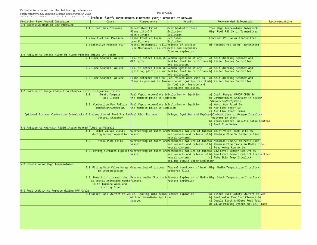
Calculations based on the following referencesSafety Integrity Level Selection, Marszal and Scharpf,ISA 2002SIL Selection for BMS Systems, Mike D. Scott, P.E., Principal Safety System SpecialistAE Solutions, Greenville, SC 29616
10/10/2022
MINIMUM 'SAFETY INSTRUMENTED FUNCTIONS (SIF)' REQUIRED BY NFPA-87Deviation From Normal Operation Cause Consequence Result Recommended Safeguards Recommendations1.0 Excessive High or Low Pressure
1.1 Hi Fuel Gas Pressure Burner Over Fired Over heated furnace *See High Temperature InterlockFlame Lift-Off Explosion High Fuel PSI Sw or TransmitterRich Furnace Explosion
1.2 Low Fuel Gas Pressure Flame front collapse Explosion Low Fuel PSI Sw or TransmitterLean Furnace Explosion
1.3 Excessive Process PSI Vessel Mechanical FailurRelease of process Hi Process PSI SW or TransmitterTube Mechanical Failure media and secondary
fire or explosion.2.0 Failure to Detect Flame or Flame Present during OFF Cycle
2.1 Flame Scanner Failure Fail to detect flame durSudden ignition of any a] Self-Checking Scanner andOFF cycle leaking fuel in to furnace b] Listed Burner Controller
and explosion.2.2 Flame Scanner Failure Fail to detect flame durSudden ignition of any a] Self-Checking Scanner and
ignition, pilot, or run leaking fuel in to furnace b] Listed Burner Controllerand explosion.
2.3 Flame Scanner Failure Flame detected when no Fuel Valves open with no a] Self-Checking Scanner andflame is present in furnsource of ignition resultinb] Listed Burner Controller
in fuel rich furnace andsubsequent explosion.
3.0 Failure to Purge Combustion Chamber prior to Ignition Trials3.1 Draft Dampers Fuel Vapor accumulate inExplosion on Ignition a] Draft Damper PROOF OPEN Sw
Fail Closed the furnace prior to ignition b] Combustibles Analyzer in Stack* *(Natural Drafted Systems)
3.2 Combustion Fan Failure Fuel Vapor accumulate inExplosion on Ignition a] Motor Run Proof SwMechanically Drafted Sys. the furnace prior to ignition b] Air Flow Proof Sw
c] Air Flow Proof Trans Optional Process Combustion Interlocks 3.3Interruption of Fuel/Air RatioFuel Rich Furnace Delayed Ignition and Explosa]Combustibles or Oxygen Interlock
Control Strategy Analyzer in Stackb] Cross Limited Fuel/Air Ratio Controlc] Fuel Flow Meter
4.0 Failure to Maintain Fluid Inside Heated Tubes or Vessels4.1 Inlet Valves CLOSED Overheating of tubes andMechanical failure of tubesa] Inlet Valve PROOF OPEN Sw
during burner operation vessel and vessels and release of b] Minimum Flow Sw in Media linevessel contents
4.2 Media Pump Fails Overheating of tubes andMechanical failure of tubesa] Minimum Flow Sw in Media linevessel and vessels and release of b] Minimum Flow Trans in Media Line
vessel contents c] Pump Motor Run Ax Sw.4.3 Heating Surfaces Exposed Overheating of tubes andMechanical failure of tubesa] Low Level Burner Cut-Off Sw
vessel and vessels and release of b] Low Level Burner Cut-Off Transmittervessel contents c] Tube Skin Temp InterlockBoiling Liquid Vapor Explosion
5.0 Excessive or High Temperatures5.1 Firing Rate Valve Hangs Overheating of process fThermal breakdown of heat High Media Temperature Interlock
in OPEN position transfer fluid.
5.2 Breach in process tube Process media fire insidFurnace Explosion or Media High Stack Temperature Interlockor vessel releasing media furnace. Process Explosionin to furnace area and
catching fire.6.0 Fuel Leak in to Furnace during OFF Cycle
6.1 Failed Fuel Shutoff Valve Fuel leaking into furnacFurnace Explosion a] Listed Fuel Safety Shutoff Valveswith no immediate ignition b] Fuel Valve Proof of Closure Swsource. c] Double Block & Bleed Fuel Train
d] Valve Proving System on Fuel Train

Calculations based on the following referencesSafety Integrity Level Selection, Marszal and Scharpf,ISA 2002SIL Selection for BMS Systems, Mike D. Scott, P.E., Principal Safety System SpecialistAE Solutions, Greenville, SC 29616
10/10/2022
This can be a fraction such as 0.25 for a site that is visited only 4 time per day and is otherwise un-manned. This is the area in which the blast is contained. The area of a building if the blast is indoors or the MEFZA if an outdoor location.
Calculations based on the following referencesSafety Integrity Level Selection, Marszal and Scharpf,ISA 2002SIL Selection for BMS Systems, Mike D. Scott, P.E., Principal Safety System SpecialistAE Solutions, Greenville, SC 29616
10/10/2022
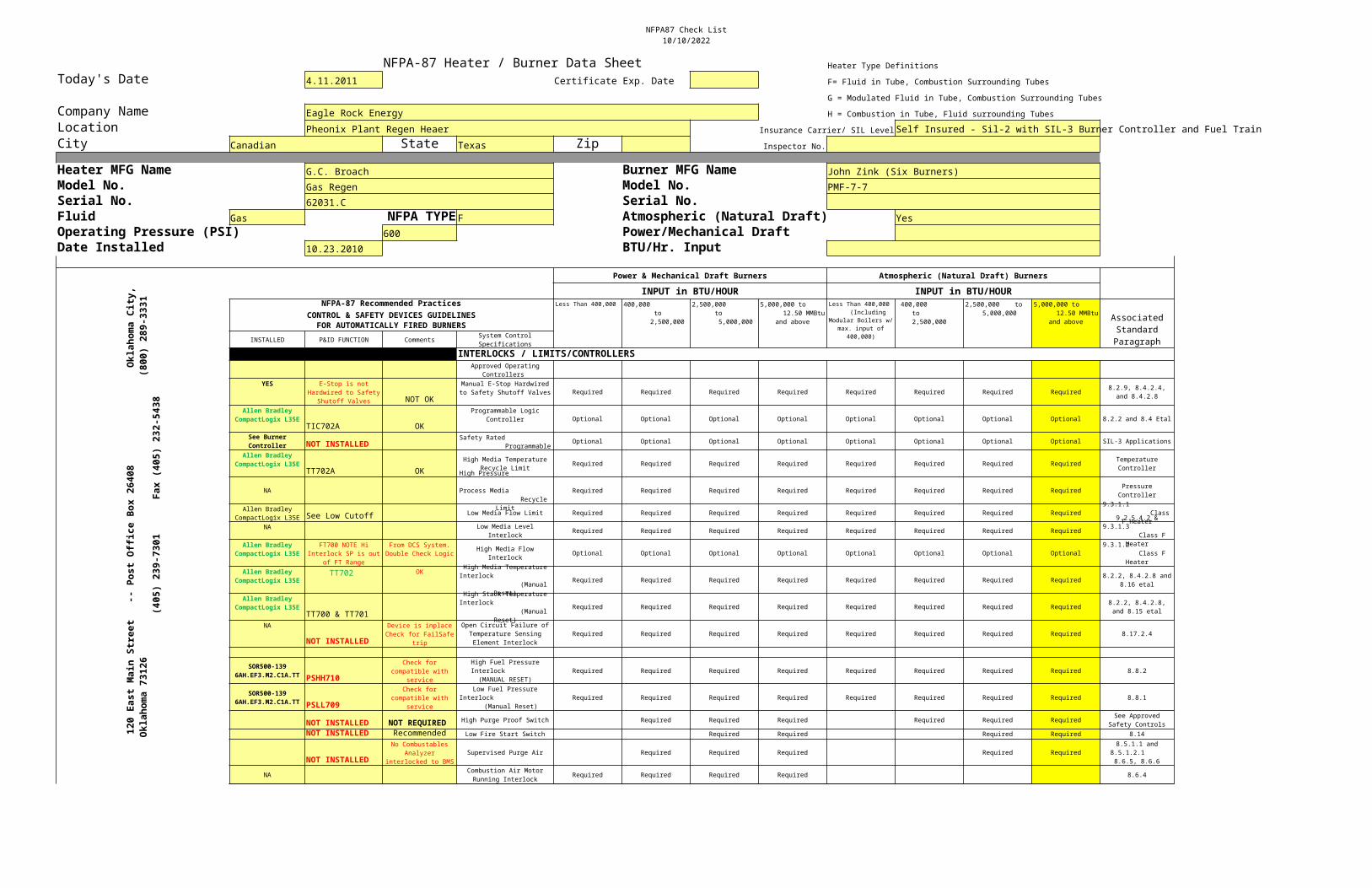
NFPA87 Check List10/10/2022
NFPA-87 Heater / Burner Data Sheet Heater Type DefinitionsToday's Date 4.11.2011 Certificate Exp. Date F= Fluid in Tube, Combustion Surrounding Tubes
G = Modulated Fluid in Tube, Combustion Surrounding TubesCompany Name Eagle Rock Energy H = Combustion in Tube, Fluid surrounding TubesLocation Pheonix Plant Regen Heaer Insurance Carrier/ SIL LevelSelf Insured - Sil-2 with SIL-3 Burner Controller and Fuel TrainCity Canadian State Texas Zip Inspector No.
Heater MFG Name G.C. Broach Burner MFG Name John Zink (Six Burners)Model No. Gas Regen Model No. PMF-7-7Serial No. 62031.C Serial No.Fluid Gas NFPA TYPE F Atmospheric (Natural Draft) YesOperating Pressure (PSI) 600 Power/Mechanical DraftDate Installed 10.23.2010 BTU/Hr. Input
Power & Mechanical Draft Burners Atmospheric (Natural Draft) Burners
INPUT in BTU/HOUR INPUT in BTU/HOURNFPA-87 Recommended Practices
CONTROL & SAFETY DEVICES GUIDELINESFOR AUTOMATICALLY FIRED BURNERS
INSTALLED P&ID FUNCTION Comments
INTERLOCKS / LIMITS/CONTROLLERS
YES
NOT OKRequired Required Required Required Required Required Required Required
TIC702A OKOptional Optional Optional Optional Optional Optional Optional Optional 8.2.2 and 8.4 Etal
NOT INSTALLED Optional Optional Optional Optional Optional Optional Optional Optional SIL-3 Applications
TT702A OKRequired Required Required Required Required Required Required Required
NA Required Required Required Required Required Required Required Required
See Low Cutoff Low Media Flow Limit Required Required Required Required Required Required Required Required
NA Required Required Required Required Required Required Required Required
Optional Optional Optional Optional Optional Optional Optional Optional
TT702 OKRequired Required Required Required Required Required Required Required
TT700 & TT701Required Required Required Required Required Required Required Required
NA
NOT INSTALLEDRequired Required Required Required Required Required Required Required 8.17.2.4
PSHH710Required Required Required Required Required Required Required Required 8.8.2
PSLL709Required Required Required Required Required Required Required Required 8.8.1
NOT INSTALLED NOT REQUIRED High Purge Proof Switch Required Required Required Required Required Required
NOT INSTALLED Recommended Low Fire Start Switch Required Required Required Required 8.14
NOT INSTALLEDSupervised Purge Air Required Required Required Required Required
NA Required Required Required Required 8.6.4
120
East
Mai
n St
reet
-
- Po
st O
ffice
Box
26408
Ok
laho
ma C
ity,
Ok
laho
ma 7
3126
(80
0) 2
89-333
1
(4
05)
239-
7301
Fa
x (4
05) 23
2-54
38
Less Than 400,000
400,000 to 2,500,000
2,500,000 to 5,000,000
5,000,000 to 12.50 MMBtu
and above
Less Than 400,000 (Including
Modular Boilers w/ max. input of
400,000)
400,000 to 2,500,000
2,500,000 to 5,000,000
5,000,000 to 12.50 MMBtu
and above Associated Standard ParagraphSystem Control
Specifications
Approved Operating Controllers
E-Stop is not Hardwired to Safety
Shutoff Valves
Manual E-Stop Hardwired to Safety Shutoff Valves 8.2.9, 8.4.2.4,
and 8.4.2.8
Allen Bradley CompactLogix L35E
Programmable Logic Controller
See Burner Controller
Safety Rated Programmable
Allen Bradley CompactLogix L35E High Media Temperature
Recycle LimitTemperature ControllerHigh Pressure
Process Media Recycle
Limit
Pressure Controller
Allen Bradley CompactLogix L35E
9.3.1.1 Class
F HeaterLow Media Level Interlock
9.2.5.4.2 & 9.3.1.3 Class F
HeaterAllen Bradley CompactLogix L35E
FT700 NOTE Hi Interlock SP is out
of FT Range
From DCS System. Double Check Logic High Media Flow
Interlock9.3.1.2 Class F
HeaterAllen Bradley
CompactLogix L35E
High Media Temperature Interlock (Manual
Reset)
8.2.2, 8.4.2.8 and 8.16 etal
Allen Bradley CompactLogix L35E
High Stack Temperature Interlock (Manual
Reset)
8.2.2, 8.4.2.8, and 8.15 etal
Device is inplace Check for FailSafe
trip
Open Circuit Failure of Temperature Sensing Element Interlock
SOR500-139 6AH.EF3.M2.C1A.TT
Check for compatible with
service
High Fuel Pressure Interlock (MANUAL RESET)
SOR500-139 6AH.EF3.M2.C1A.TT
Check for compatible with
service
Low Fuel Pressure Interlock
(Manual Reset) See Approved
Safety Controls
No Combustables Analyzer
interlocked to BMS
8.5.1.1 and 8.5.1.2.1 8.6.5, 8.6.6
Combustion Air Motor Running Interlock
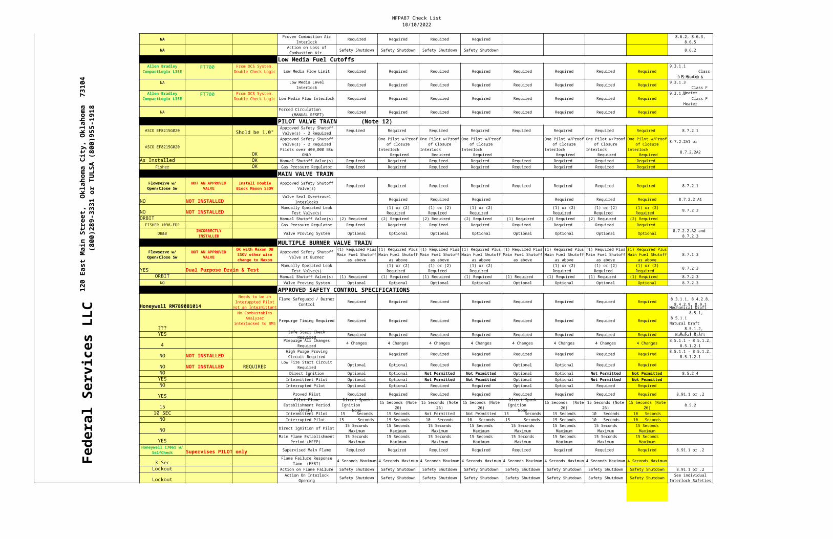
NFPA87 Check List10/10/2022
NA Required Required Required Required
NA Safety Shutdown Safety Shutdown Safety Shutdown Safety Shutdown 8.6.2
Low Media Fuel CutoffsFT700
Low Media Flow Limit Required Required Required Required Required Required Required Required
NA Required Required Required Required Required Required Required Required
FT700 Low Media Flow Interlock Required Required Required Required Required Required Required Required
NA Required Required Required Required Required Required Required Required
PILOT VALVE TRAIN (Note 12)ASCO EF8215G020 Shold be 1.0" Required Required Required Required Required Required Required Required 8.7.2.1
ASCO EF8215G020OK
As Installed OK Manual Shutoff Valve(s) Required Required Required Required Required Required Required Required Fisher OK Gas Pressure Regulator Required Required Required Required Required Required Required Required
MAIN VALVE TRAIN Required Required Required Required Required Required Required Required 8.7.2.1
NO NOT INSTALLED Required Required Required Required Required Required 8.7.2.2.A1
NO NOT INSTALLED 8.7.2.3
ORBIT Manual Shutoff Valve(s) (2) Required (2) Required (2) Required (2) Required (1) Required (2) Required (2) Required (2) Required FISHER 1098-EDR Gas Pressure Regulator Required Required Required Required Required Required Required Required
DB&B Valve Proving System Optional Optional Optional Optional Optional Optional Optional Optional
MULTIPLE BURNER VALVE TRAIN 8.7.1.3
YES Dual Purpose Drain & Test 8.7.2.3
ORBIT Manual Shutoff Valve(s) (1) Required (1) Required (1) Required (1) Required (1) Required (1) Required (1) Required (1) Required 8.7.2.3NO Valve Proving System Optional Optional Optional Optional Optional Optional Optional Optional 8.7.2.3
APPROVED SAFETY CONTROL SPECIFICATIONS
Federal Services LLC Honeywell RM7890B1014
Required Required Required Required Required Required Required Required
???Prepurge Timing Required Required Required Required Required Required Required Required Required
YES Required Required Required Required Required Required Required Required Natural Draft
4 4 Changes 4 Changes 4 Changes 4 Changes 4 Changes 4 Changes 4 Changes 4 Changes
NO NOT INSTALLED Required Required Required Required Required Required Required
NO NOT INSTALLED REQUIRED Optional Optional Required Required Optional Optional Required Required
NO Direct Ignition Optional Optional Not Permitted Not Permitted Optional Optional Not Permitted Not Permitted 8.5.2.4YES Intermittent Pilot Optional Optional Not Permitted Not Permitted Optional Optional Not Permitted Not PermittedNO Interrupted Pilot Optional Optional Required Required Optional Optional Required Required
YES Proved Pilot Required Required Required Required Required Required Required Required 8.91.1 or .2
15 8.5.2
10 SEC Intermittent Pilot 15 Seconds 15 Seconds Not Permitted Not Permitted 15 Seconds 15 Seconds 10 Seconds 10 SecondsNO Interrupted Pilot 15 Seconds 15 Seconds 10 Seconds 10 Seconds 15 Seconds 15 Seconds 10 Seconds 10 Seconds
NO Direct Ignition of Pilot
YES
Supervises PILOT only Supervised Main Flame Required Required Required Required Required Required Required Required 8.91.1 or .2
3 Sec 4 Seconds Maximum 4 Seconds Maximum 4 Seconds Maximum 4 Seconds Maximum 4 Seconds Maximum 4 Seconds Maximum 4 Seconds Maximum 4 Seconds Maximum
Lockout Action on Flame Failure Safety Shutdown Safety Shutdown Safety Shutdown Safety Shutdown Safety Shutdown Safety Shutdown Safety Shutdown Safety Shutdown 8.91.1 or .2
Lockout Safety Shutdown Safety Shutdown Safety Shutdown Safety Shutdown Safety Shutdown Safety Shutdown Safety Shutdown Safety Shutdown
Proven Combustion Air Interlock
8.6.2, 8.6.3, 8.6.5
Action on Loss of Combustion Air
120
East
Mai
n St
reet
, O
klah
oma
City
, Ok
laho
ma
7310
4
(
800)
289-
3331
or
TULS
A (8
00)9
55-1
918
Allen Bradley CompactLogix L35E
From DCS System. Double Check Logic
9.3.1.1 Class
F HeaterLow Media Level
Interlock
9.2.5.4.2 & 9.3.1.3 Class F
HeaterAllen Bradley CompactLogix L35E
From DCS System. Double Check Logic
9.3.1.2 Class F
HeaterForced Circulation
(MANUAL RESET)
Approved Safety Shutoff Valve(s) - 2 RequiredApproved Safety Shutoff Valve(s) - 2 Required Pilots over 400,000 Btu
ONLY
One Pilot w/Proof of Closure
Interlock Required
One Pilot w/Proof of Closure
Interlock Required
One Pilot w/Proof of Closure
Interlock Required
One Pilot w/Proof of Closure
Interlock Required
One Pilot w/Proof of Closure
Interlock Required
One Pilot w/Proof of Closure
Interlock Required
8.7.2.2A1 or
8.7.2.2A2
Flowserve w/ Open/Close Sw
NOT AN APPROVED VALVE
Install Double Block Maxon SSOV
Approved Safety Shutoff Valve(s)
Valve Seal Overtravel Interlocks
Manually Operated Leak Test Valve(s)
(1) or (2) Required
(1) or (2) Required
(1) or (2) Required
(1) or (2) Required
(1) or (2) Required
(1) or (2) Required
INCORRECTLY INSTALLED
8.7.2.2.A2 and 8.7.2.3
Flowserve w/ Open/Close Sw
NOT AN APPROVED VALVE
OK with Maxon DB SSOV other wise change to Maxon
Approved Safety Shutoff Valve at Burner
(1) Required Plus Main Fuel Shutoff
as above
(1) Required Plus Main Fuel Shutoff
as above
(1) Required Plus Main Fuel Shutoff
as above
(1) Required Plus Main Fuel Shutoff
as above
(1) Required Plus Main Fuel Shutoff
as above
(1) Required Plus Main Fuel Shutoff
as above
(1) Required Plus Main Fuel Shutoff
as above
(1) Required Plus Main Fuel Shutoff
as aboveManually Operated Leak
Test Valve(s)(1) or (2) Required
(1) or (2) Required
(1) or (2) Required
(1) or (2) Required
(1) or (2) Required
(1) or (2) Required
Needs to be an Interuppted Pilot not an Intermittant
Flame Safeguard / Burner Control
8.3.1.1, 8.4.2.8, 8.4.2.9, 8.9.1
No Combustables Analyzer
interlocked to BMS
Mechanical Draft 8.5.1,
8.5.1.1 Natural Draft
8.5.1.2, 8.5.1.2.1Safe Start Check
RequiredPrepurge Air Changes
Required8.5.1.1 - 8.5.1.2,
8.5.1.2.1High Purge Proving Circuit Required
8.5.1.1 - 8.5.1.2, 8.5.1.2.1
Low Fire Start Circuit Required
Pilot Flame Establishment Period
(PFEP)
Direct Spark Ignition
None
15 Seconds (Note 26)
15 Seconds (Note 26)
15 Seconds (Note 26)
Direct Spark Ignition
None
15 Seconds (Note 26)
15 Seconds (Note 26)
15 Seconds (Note 26)
15 Seconds Maximum
15 Seconds Maximum
15 Seconds Maximum
15 Seconds Maximum
15 Seconds Maximum
15 Seconds Maximum
15 Seconds Maximum
15 Seconds Maximum
Main Flame Establishment Period (MFEP)
15 Seconds Maximum
15 Seconds Maximum
15 Seconds Maximum
15 Seconds Maximum
15 Seconds Maximum
15 Seconds Maximum
15 Seconds Maximum
15 Seconds Maximum
Honeywell C7061 w/ SelfCheck
Flame Failure Response Time (FFRT)
Action On Interlock Opening
See individual Interlock Safeties
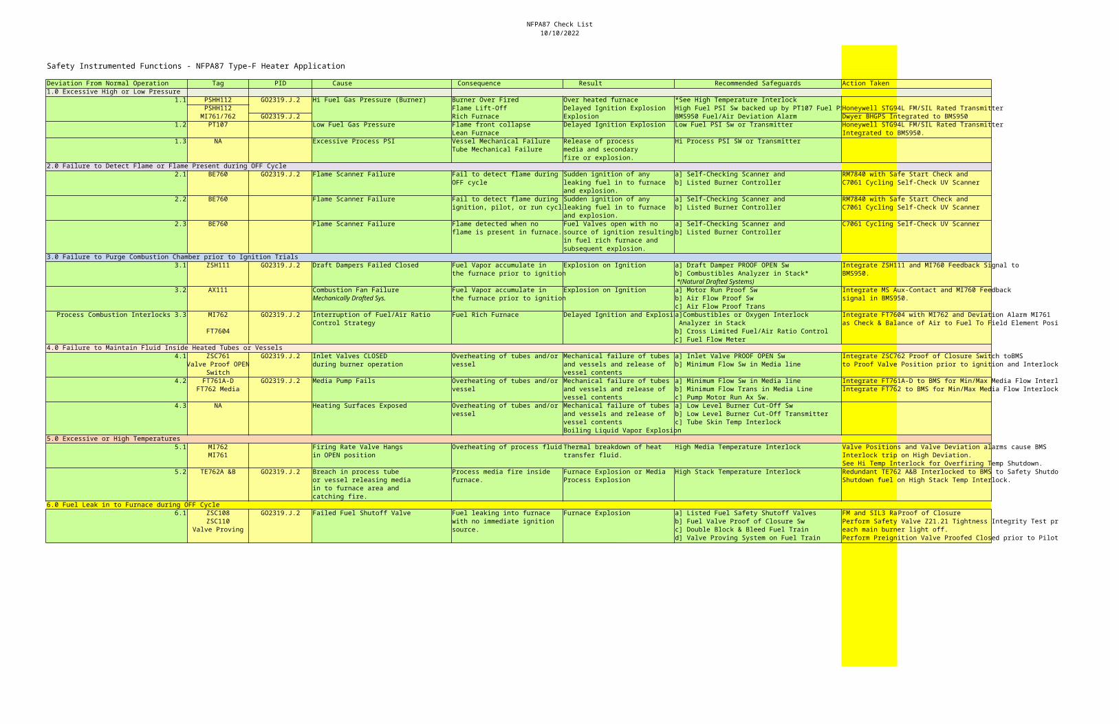
NFPA87 Check List10/10/2022
Safety Instrumented Functions - NFPA87 Type-F Heater Application
Deviation From Normal Operation Tag PID Cause Consequence Result Recommended Safeguards Action Taken1.0 Excessive High or Low Pressure
1.1 PSHH112 GO2319.J.2 Hi Fuel Gas Pressure (Burner) Burner Over Fired Over heated furnace *See High Temperature InterlockPSHH112 Flame Lift-Off Delayed Ignition Explosion High Fuel PSI Sw backed up by PT107 Fuel PSHoneywell STG94L FM/SIL Rated Transmitter
MI761/762 GO2319.J.2 Rich Furnace Explosion BMS950 Fuel/Air Deviation Alarm Dwyer BHGPS Integrated to BMS9501.2 PT107 Low Fuel Gas Pressure Flame front collapse Delayed Ignition Explosion Low Fuel PSI Sw or Transmitter Honeywell STG94L FM/SIL Rated Transmitter
Lean Furnace Integrated to BMS950.1.3 NA Excessive Process PSI Vessel Mechanical Failure Release of process Hi Process PSI SW or Transmitter
Tube Mechanical Failure media and secondaryfire or explosion.
2.0 Failure to Detect Flame or Flame Present during OFF Cycle2.1 BE760 GO2319.J.2 Flame Scanner Failure Fail to detect flame during Sudden ignition of any a] Self-Checking Scanner and RM7840 with Safe Start Check and
OFF cycle leaking fuel in to furnace b] Listed Burner Controller C7061 Cycling Self-Check UV Scannerand explosion.
2.2 BE760 Flame Scanner Failure Fail to detect flame during Sudden ignition of any a] Self-Checking Scanner and RM7840 with Safe Start Check andignition, pilot, or run cycleleaking fuel in to furnace b] Listed Burner Controller C7061 Cycling Self-Check UV Scanner
and explosion.2.3 BE760 Flame Scanner Failure Flame detected when no Fuel Valves open with no a] Self-Checking Scanner and C7061 Cycling Self-Check UV Scanner
flame is present in furnace. source of ignition resulting b] Listed Burner Controllerin fuel rich furnace andsubsequent explosion.
3.0 Failure to Purge Combustion Chamber prior to Ignition Trials3.1 ZSH111 GO2319.J.2 Draft Dampers Failed Closed Fuel Vapor accumulate in Explosion on Ignition a] Draft Damper PROOF OPEN Sw Integrate ZSH111 and MI760 Feedback Signal to
the furnace prior to ignition b] Combustibles Analyzer in Stack* BMS950. *(Natural Drafted Systems)
3.2 AX111 Combustion Fan Failure Fuel Vapor accumulate in Explosion on Ignition a] Motor Run Proof Sw Integrate MS Aux-Contact and MI760 FeedbackMechanically Drafted Sys. the furnace prior to ignition b] Air Flow Proof Sw signal in BMS950.
c] Air Flow Proof Trans Process Combustion Interlocks 3.3 MI762 GO2319.J.2 Interruption of Fuel/Air Ratio Fuel Rich Furnace Delayed Ignition and Explosioa]Combustibles or Oxygen Interlock Integrate FT7604 with MI762 and Deviation Alarm MI761
Control Strategy Analyzer in Stack as Check & Balance of Air to Fuel To Field Element Position.FT7604 b] Cross Limited Fuel/Air Ratio Control
c] Fuel Flow Meter4.0 Failure to Maintain Fluid Inside Heated Tubes or Vessels
4.1 ZSC761 GO2319.J.2 Inlet Valves CLOSED Overheating of tubes and/or Mechanical failure of tubes a] Inlet Valve PROOF OPEN Sw Integrate ZSC762 Proof of Closure Switch toBMSValve Proof OPEN during burner operation vessel and vessels and release of b] Minimum Flow Sw in Media line to Proof Valve Position prior to ignition and Interlock on ESD.
Switch vessel contents4.2 FT761A-D GO2319.J.2 Media Pump Fails Overheating of tubes and/or Mechanical failure of tubes a] Minimum Flow Sw in Media line Integrate FT761A-D to BMS for Min/Max Media Flow Interlock
FT762 Media vessel and vessels and release of b] Minimum Flow Trans in Media Line Integrate FT762 to BMS for Min/Max Media Flow Interlockvessel contents c] Pump Motor Run Ax Sw.
4.3 NA Heating Surfaces Exposed Overheating of tubes and/or Mechanical failure of tubes a] Low Level Burner Cut-Off Swvessel and vessels and release of b] Low Level Burner Cut-Off Transmitter
vessel contents c] Tube Skin Temp InterlockBoiling Liquid Vapor Explosion
5.0 Excessive or High Temperatures5.1 MI762 Firing Rate Valve Hangs Overheating of process fluid Thermal breakdown of heat High Media Temperature Interlock Valve Positions and Valve Deviation alarms cause BMS
MI761 in OPEN position transfer fluid. Interlock trip on High Deviation.See Hi Temp Interlock for Overfiring Temp Shutdown.
5.2 TE762A &B GO2319.J.2 Breach in process tube Process media fire inside Furnace Explosion or Media High Stack Temperature Interlock Redundant TE762 A&B Interlocked to BMS to Safety Shutdowns.or vessel releasing media furnace. Process Explosion Shutdown fuel on High Stack Temp Interlock.in to furnace area and catching fire.
6.0 Fuel Leak in to Furnace during OFF Cycle6.1 ZSC108 GO2319.J.2 Failed Fuel Shutoff Valve Fuel leaking into furnace Furnace Explosion a] Listed Fuel Safety Shutoff Valves FM and SIL3 RaProof of Closure
ZSC110 with no immediate ignition b] Fuel Valve Proof of Closure Sw Perform Safety Valve Z21.21 Tightness Integrity Test prior toValve Proving source. c] Double Block & Bleed Fuel Train each main burner light off.
d] Valve Proving System on Fuel Train Perform Preignition Valve Proofed Closed prior to Pilot ignition.
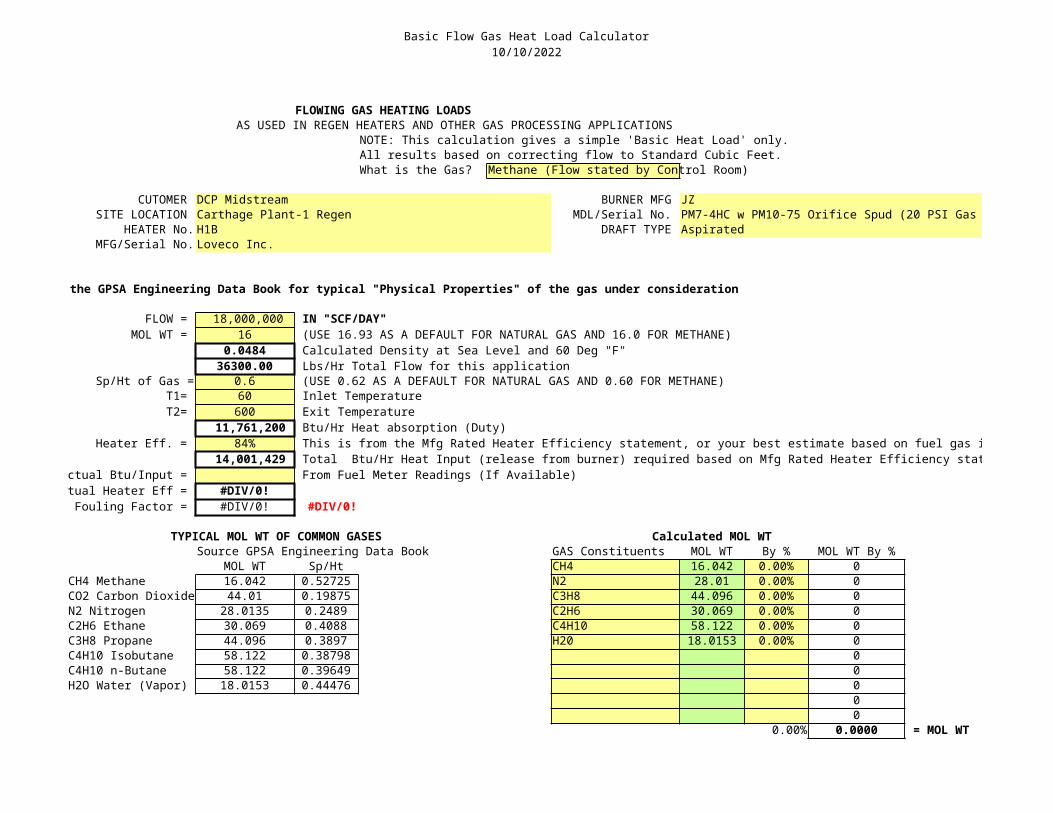
Basic Flow Gas Heat Load Calculator10/10/2022
FLOWING GAS HEATING LOADSAS USED IN REGEN HEATERS AND OTHER GAS PROCESSING APPLICATIONS
NOTE: This calculation gives a simple 'Basic Heat Load' only.All results based on correcting flow to Standard Cubic Feet.What is the Gas? Methane (Flow stated by Control Room)
CUTOMER DCP Midstream BURNER MFG JZSITE LOCATION Carthage Plant-1 Regen MDL/Serial No. PM7-4HC w PM10-75 Orifice Spud (20 PSI Gas Pressure)
HEATER No. H1B DRAFT TYPE AspiratedMFG/Serial No. Loveco Inc.
Use the GPSA Engineering Data Book for typical "Physical Properties" of the gas under consideration
FLOW = 18,000,000 IN "SCF/DAY"MOL WT = 16 (USE 16.93 AS A DEFAULT FOR NATURAL GAS AND 16.0 FOR METHANE)
0.0484 Calculated Density at Sea Level and 60 Deg "F"36300.00 Lbs/Hr Total Flow for this application
Sp/Ht of Gas = 0.6 (USE 0.62 AS A DEFAULT FOR NATURAL GAS AND 0.60 FOR METHANE)T1= 60 Inlet TemperatureT2= 600 Exit Temperature
11,761,200 Btu/Hr Heat absorption (Duty)Heater Eff. = 84% This is from the Mfg Rated Heater Efficiency statement, or your best estimate based on fuel gas input readings.
14,001,429 Total Btu/Hr Heat Input (release from burner) required based on Mfg Rated Heater Efficiency statement.ctual Btu/Input = From Fuel Meter Readings (If Available)tual Heater Eff = #DIV/0!Fouling Factor = #DIV/0! #DIV/0!
TYPICAL MOL WT OF COMMON GASES Calculated MOL WTSource GPSA Engineering Data Book GAS Constituents MOL WT By % MOL WT By %
MOL WT Sp/Ht CH4 16.042 0.00% 0CH4 Methane 16.042 0.52725 N2 28.01 0.00% 0CO2 Carbon Dioxide 44.01 0.19875 C3H8 44.096 0.00% 0N2 Nitrogen 28.0135 0.2489 C2H6 30.069 0.00% 0C2H6 Ethane 30.069 0.4088 C4H10 58.122 0.00% 0C3H8 Propane 44.096 0.3897 H20 18.0153 0.00% 0C4H10 Isobutane 58.122 0.38798 0C4H10 n-Butane 58.122 0.39649 0H2O Water (Vapor) 18.0153 0.44476 0
00
0.00% 0.0000 = MOL WT