t2750 foxboro pac - user guide - vsp-co.org
TRANSCRIPT

T2750 FOXBORO PACUser Guide
T2750 FOXBORO PACVersion 8
HA030047 Issue 11September 2016
T2750 FOXBORO PAC: USER GUIDE
Page iHA030047Issue 11 September 2016
T2750 Foxboro PAC
User Guide
List of Sections1 INTRODUCTION . . . . . . . . . . . . . . . . . . . . . . . . . . . . . . . . . . . . . . . . . . . . . . . . . . . . . . page 42 INSTALLATION. . . . . . . . . . . . . . . . . . . . . . . . . . . . . . . . . . . . . . . . . . . . . . . . . . . . . . . . page 83 OPERATOR INTERFACE . . . . . . . . . . . . . . . . . . . . . . . . . . . . . . . . . . . . . . . . . . . . . . . . page 544 STARTUP . . . . . . . . . . . . . . . . . . . . . . . . . . . . . . . . . . . . . . . . . . . . . . . . . . . . . . . . . . . . . page 575 CONFIGURATION . . . . . . . . . . . . . . . . . . . . . . . . . . . . . . . . . . . . . . . . . . . . . . . . . . . . . page 656 CONTROL LOOPS . . . . . . . . . . . . . . . . . . . . . . . . . . . . . . . . . . . . . . . . . . . . . . . . . . . . . page 737 TASK ORGANISATION . . . . . . . . . . . . . . . . . . . . . . . . . . . . . . . . . . . . . . . . . . . . . . . . . page 1068 EVENT LOG. . . . . . . . . . . . . . . . . . . . . . . . . . . . . . . . . . . . . . . . . . . . . . . . . . . . . . . . . . . page 1139 DATA MANAGEMENT . . . . . . . . . . . . . . . . . . . . . . . . . . . . . . . . . . . . . . . . . . . . . . . . . page 11510 SETPOINT PROGRAMMER. . . . . . . . . . . . . . . . . . . . . . . . . . . . . . . . . . . . . . . . . . . . . page 11711 ERROR CONDITIONS AND DIAGNOSTICS . . . . . . . . . . . . . . . . . . . . . . . . . . . . . . page 12412 SERVICE. . . . . . . . . . . . . . . . . . . . . . . . . . . . . . . . . . . . . . . . . . . . . . . . . . . . . . . . . . . . . page 133APPENDIX A SPECIFICATION . . . . . . . . . . . . . . . . . . . . . . . . . . . . . . . . . . . . . . . . . . . . . page 137APPENDIX B ERROR MESSAGES . . . . . . . . . . . . . . . . . . . . . . . . . . . . . . . . . . . . . . . . . . page 157APPENDIX C REFERENCE. . . . . . . . . . . . . . . . . . . . . . . . . . . . . . . . . . . . . . . . . . . . . . . . . page 165Index. . . . . . . . . . . . . . . . . . . . . . . . . . . . . . . . . . . . . . . . . . . . . . . . . . . . . . . . . . . . . . . . . . . page 183
ASSOCIATED DOCUMENTSHA082375U003 LIN Blocks reference manualHA082429 ELIN User guideHA028014 Communications manualHA028988 Modbus tools help manual (printable version of the on-line Modbus tools help system)HA029881 Store and Forward user guideHA263001U055 LIN Help manual (printable version of the on-line LINtools help system)HA030272 PAC Systems alarm suppression user guideHA030511 Raw Comms user guide
Information is also to be found in the help systems associated with the various software tools used with the product.
SOFTWARE EFFECTIVITYThis manual relates to units with software version 3.0.
T2750 FOXBORO PAC: USER GUIDE
T2750 Controller
User Guide
Contents List
ASSOCIATED DOCUMENTS . . . . . . . . . . . . . . . . . . . . . . . . . . . . . . . . . . . . . . . . . . . . . . . . iSOFTWARE EFFECTIVITY . . . . . . . . . . . . . . . . . . . . . . . . . . . . . . . . . . . . . . . . . . . . . . . . . . iSAFETY NOTES . . . . . . . . . . . . . . . . . . . . . . . . . . . . . . . . . . . . . . . . . . . . . . . . . . . . . . . . . . . 1I/O ISOLATION STRATEGY . . . . . . . . . . . . . . . . . . . . . . . . . . . . . . . . . . . . . . . . . . . . . . . . . 1EMC . . . . . . . . . . . . . . . . . . . . . . . . . . . . . . . . . . . . . . . . . . . . . . . . . . . . . . . . . . . . . . . . . . . . . 2SYMBOLS USED ON THE INSTRUMENT LABELLING . . . . . . . . . . . . . . . . . . . . . . . . . . . 2I/O ISOLATION STRATEGY . . . . . . . . . . . . . . . . . . . . . . . . . . . . . . . . . . . . . . . . . . . . . . . . . 31 INTRODUCTION . . . . . . . . . . . . . . . . . . . . . . . . . . . . . . . . . . . . . . . . . . . . . . . . . . . . . . . . 41.1 PHYSICAL STRUCTURE . . . . . . . . . . . . . . . . . . . . . . . . . . . . . . . . . . . . . . . . . . . . . . . . . 41.2 MODULES AVAILABLE . . . . . . . . . . . . . . . . . . . . . . . . . . . . . . . . . . . . . . . . . . . . . . . . . 41.3 FEATURES . . . . . . . . . . . . . . . . . . . . . . . . . . . . . . . . . . . . . . . . . . . . . . . . . . . . . . . . . . . . 5
1.3.1 LIN Communication . . . . . . . . . . . . . . . . . . . . . . . . . . . . . . . . . . . . . . . . . . . . . . . 51.3.2 ELIN Communication . . . . . . . . . . . . . . . . . . . . . . . . . . . . . . . . . . . . . . . . . . . . . . 51.3.3 Profibus Master Communication . . . . . . . . . . . . . . . . . . . . . . . . . . . . . . . . . . . . 51.3.4 Redundant working . . . . . . . . . . . . . . . . . . . . . . . . . . . . . . . . . . . . . . . . . . . . . . . 5
REDUNDANT POWER SUPPLY CONNECTION . . . . . . . . . . . . . . . . . . . . . . . . . 5REDUNDANT INSTRUMENTS . . . . . . . . . . . . . . . . . . . . . . . . . . . . . . . . . . . . . . . . . 5
1.3.5 Battery backup . . . . . . . . . . . . . . . . . . . . . . . . . . . . . . . . . . . . . . . . . . . . . . . . . . . 51.3.6 Configuration . . . . . . . . . . . . . . . . . . . . . . . . . . . . . . . . . . . . . . . . . . . . . . . . . . . . 5
SETPOINT PROGRAM . . . . . . . . . . . . . . . . . . . . . . . . . . . . . . . . . . . . . . . . . . . . . . . 5SEQUENTIAL FUNCTION CHART (SFC) . . . . . . . . . . . . . . . . . . . . . . . . . . . . . . . . 5LADDER CONFIGURATION . . . . . . . . . . . . . . . . . . . . . . . . . . . . . . . . . . . . . . . . . . 6SEQUENTIAL TEXT (ST) USER ALGORITHMS . . . . . . . . . . . . . . . . . . . . . . . . . . . 6SOFTWARE BLOCKS . . . . . . . . . . . . . . . . . . . . . . . . . . . . . . . . . . . . . . . . . . . . . . . . 6
1.3.7 Data recording . . . . . . . . . . . . . . . . . . . . . . . . . . . . . . . . . . . . . . . . . . . . . . . . . . . 61.3.8 Store and forward software . . . . . . . . . . . . . . . . . . . . . . . . . . . . . . . . . . . . . . . . 61.3.9 Time Localisation Support . . . . . . . . . . . . . . . . . . . . . . . . . . . . . . . . . . . . . . . . . 6
TIME ZONE . . . . . . . . . . . . . . . . . . . . . . . . . . . . . . . . . . . . . . . . . . . . . . . . . . . . . . . . 6SIMPLE NETWORK TIME PROTOCOL (SNTP) . . . . . . . . . . . . . . . . . . . . . . . . . . . 6
1.3.10 Health monitoring . . . . . . . . . . . . . . . . . . . . . . . . . . . . . . . . . . . . . . . . . . . . . . . 71.3.11 Watchdog . . . . . . . . . . . . . . . . . . . . . . . . . . . . . . . . . . . . . . . . . . . . . . . . . . . . . . . 71.3.12 IP (Intellectual Property) Protection . . . . . . . . . . . . . . . . . . . . . . . . . . . . . . . . 71.3.13 Front panel indicators . . . . . . . . . . . . . . . . . . . . . . . . . . . . . . . . . . . . . . . . . . . . 7
2 INSTALLATION . . . . . . . . . . . . . . . . . . . . . . . . . . . . . . . . . . . . . . . . . . . . . . . . . . . . . . . . . 82.1 UNPACKING THE INSTRUMENT . . . . . . . . . . . . . . . . . . . . . . . . . . . . . . . . . . . . . . . . . 82.2 MECHANICAL INSTALLATION . . . . . . . . . . . . . . . . . . . . . . . . . . . . . . . . . . . . . . . . . . 8
2.2.1 Base unit mounting . . . . . . . . . . . . . . . . . . . . . . . . . . . . . . . . . . . . . . . . . . . . . . . 10DIN RAIL MOUNTING . . . . . . . . . . . . . . . . . . . . . . . . . . . . . . . . . . . . . . . . . . . . . . . 10PANEL MOUNTING . . . . . . . . . . . . . . . . . . . . . . . . . . . . . . . . . . . . . . . . . . . . . . . . . 10Compliance with European EMC directive . . . . . . . . . . . . . . . . . . . . . . . . . . . . . . 10
2.2.2 Terminal unit installation . . . . . . . . . . . . . . . . . . . . . . . . . . . . . . . . . . . . . . . . . . . 11TERMINAL UNIT REMOVAL . . . . . . . . . . . . . . . . . . . . . . . . . . . . . . . . . . . . . . . . . . 11
2.2.3 Module installation . . . . . . . . . . . . . . . . . . . . . . . . . . . . . . . . . . . . . . . . . . . . . . . 12MODULE REMOVAL . . . . . . . . . . . . . . . . . . . . . . . . . . . . . . . . . . . . . . . . . . . . . . . . . 12
2.2.4 Module identification . . . . . . . . . . . . . . . . . . . . . . . . . . . . . . . . . . . . . . . . . . . . . 122.2.5 Installing the optional netHOST gateways . . . . . . . . . . . . . . . . . . . . . . . . . . . . 13
2.3 ELECTRICAL INSTALLATION . . . . . . . . . . . . . . . . . . . . . . . . . . . . . . . . . . . . . . . . . . . . 142.3.1 Controller module (IOC) terminal unit . . . . . . . . . . . . . . . . . . . . . . . . . . . . . . . 14
SUPPLY WIRING . . . . . . . . . . . . . . . . . . . . . . . . . . . . . . . . . . . . . . . . . . . . . . . . . . . . 15FUSES . . . . . . . . . . . . . . . . . . . . . . . . . . . . . . . . . . . . . . . . . . . . . . . . . . . . . . . . . . . . . 15WIRE SIZES . . . . . . . . . . . . . . . . . . . . . . . . . . . . . . . . . . . . . . . . . . . . . . . . . . . . . . . . . 15TERMINAL DETAILS . . . . . . . . . . . . . . . . . . . . . . . . . . . . . . . . . . . . . . . . . . . . . . . . . 15
Section Page
Page iiHA030047
Issue 11 September 2016
T2750 FOXBORO PAC: USER GUIDE
List of Contents (Cont.)
SAFETY EARTH . . . . . . . . . . . . . . . . . . . . . . . . . . . . . . . . . . . . . . . . . . . . . . . . . . . . . 15WATCHDOG RELAYS . . . . . . . . . . . . . . . . . . . . . . . . . . . . . . . . . . . . . . . . . . . . . . . 15COMMUNICATIONS CONNECTORS . . . . . . . . . . . . . . . . . . . . . . . . . . . . . . . . . . 16USB CONNECTOR . . . . . . . . . . . . . . . . . . . . . . . . . . . . . . . . . . . . . . . . . . . . . . . . . . 16
2.3.2 Two-channel analogue input (AI2) . . . . . . . . . . . . . . . . . . . . . . . . . . . . . . . . . . 17STATUS INDICATORS . . . . . . . . . . . . . . . . . . . . . . . . . . . . . . . . . . . . . . . . . . . . . . . 18
2.3.3 Three-channel analogue input (AI3) . . . . . . . . . . . . . . . . . . . . . . . . . . . . . . . . . 19STATUS INDICATORS . . . . . . . . . . . . . . . . . . . . . . . . . . . . . . . . . . . . . . . . . . . . . . . 19HART COMPATIBILITY . . . . . . . . . . . . . . . . . . . . . . . . . . . . . . . . . . . . . . . . . . . . . . . 20
2.3.4 Four-channel analogue input (AI4) . . . . . . . . . . . . . . . . . . . . . . . . . . . . . . . . . . 21STATUS INDICATORS . . . . . . . . . . . . . . . . . . . . . . . . . . . . . . . . . . . . . . . . . . . . . . . 21
2.3.5 High density analogue input (AI8) . . . . . . . . . . . . . . . . . . . . . . . . . . . . . . . . . . . 22STATUS INDICATORS . . . . . . . . . . . . . . . . . . . . . . . . . . . . . . . . . . . . . . . . . . . . . . . 23
2.3.5 Two-channel analogue output (AO2) . . . . . . . . . . . . . . . . . . . . . . . . . . . . . . . . 24STATUS INDICATORS . . . . . . . . . . . . . . . . . . . . . . . . . . . . . . . . . . . . . . . . . . . . . . . 24
2.3.6 Four-channel digital input (DI4) . . . . . . . . . . . . . . . . . . . . . . . . . . . . . . . . . . . . . 25STATUS INDICATORS . . . . . . . . . . . . . . . . . . . . . . . . . . . . . . . . . . . . . . . . . . . . . . . 25
2.3.7 Six-channel digital input module (DI6) . . . . . . . . . . . . . . . . . . . . . . . . . . . . . . . 26STATUS INDICATORS . . . . . . . . . . . . . . . . . . . . . . . . . . . . . . . . . . . . . . . . . . . . . . . 26
2.3.8 Eight-channel digital input module (DI8) . . . . . . . . . . . . . . . . . . . . . . . . . . . . . 27STATUS INDICATORS . . . . . . . . . . . . . . . . . . . . . . . . . . . . . . . . . . . . . . . . . . . . . . . 27
2.3.9 16-Channel digital input module (DI16) . . . . . . . . . . . . . . . . . . . . . . . . . . . . . . 28STATUS INDICATORS . . . . . . . . . . . . . . . . . . . . . . . . . . . . . . . . . . . . . . . . . . . . . . . 28
2.3.10 Four-channel digital output module (DO4) . . . . . . . . . . . . . . . . . . . . . . . . . . 29STATUS INDICATORS . . . . . . . . . . . . . . . . . . . . . . . . . . . . . . . . . . . . . . . . . . . . . . . 29
2.3.11 Eight-channel digital output module (DO8) . . . . . . . . . . . . . . . . . . . . . . . . . 30STATUS INDICATORS . . . . . . . . . . . . . . . . . . . . . . . . . . . . . . . . . . . . . . . . . . . . . . . 31
2.3.12 16-Channel digital output module (DO16) . . . . . . . . . . . . . . . . . . . . . . . . . . 32STATUS INDICATORS . . . . . . . . . . . . . . . . . . . . . . . . . . . . . . . . . . . . . . . . . . . . . . . 32
2.3.13 Two-channel frequency input module (FI2) . . . . . . . . . . . . . . . . . . . . . . . . . 33STATUS INDICATORS . . . . . . . . . . . . . . . . . . . . . . . . . . . . . . . . . . . . . . . . . . . . . . 34
2.3.14 Four output relay module (RLY4) . . . . . . . . . . . . . . . . . . . . . . . . . . . . . . . . . . . 35STATUS INDICATORS . . . . . . . . . . . . . . . . . . . . . . . . . . . . . . . . . . . . . . . . . . . . . . . 35SNUBBER CIRCUITS . . . . . . . . . . . . . . . . . . . . . . . . . . . . . . . . . . . . . . . . . . . . . . . . . 36SNUBBER CIRCUIT REMOVAL . . . . . . . . . . . . . . . . . . . . . . . . . . . . . . . . . . . . . . . . 36
2.3.15 Eight output relay module (RLY8) . . . . . . . . . . . . . . . . . . . . . . . . . . . . . . . . . . 38STATUS INDICATORS . . . . . . . . . . . . . . . . . . . . . . . . . . . . . . . . . . . . . . . . . . . . . . . 38
2.3.16 Zirconia input module (ZI) . . . . . . . . . . . . . . . . . . . . . . . . . . . . . . . . . . . . . . . . 39STATUS INDICATORS . . . . . . . . . . . . . . . . . . . . . . . . . . . . . . . . . . . . . . . . . . . . . . . 39
2.3.16 netHOST Profibus Master gateway . . . . . . . . . . . . . . . . . . . . . . . . . . . . . . . . . 40SUPPLY WIRING . . . . . . . . . . . . . . . . . . . . . . . . . . . . . . . . . . . . . . . . . . . . . . . . . . . . 40ETHERNET WIRING . . . . . . . . . . . . . . . . . . . . . . . . . . . . . . . . . . . . . . . . . . . . . . . . . 40PROFIBUS WIRING . . . . . . . . . . . . . . . . . . . . . . . . . . . . . . . . . . . . . . . . . . . . . . . . . . 41STATUS INDICATORS . . . . . . . . . . . . . . . . . . . . . . . . . . . . . . . . . . . . . . . . . . . . . . . 41
2.4 HARDWARE CONFIGURATION . . . . . . . . . . . . . . . . . . . . . . . . . . . . . . . . . . . . . . . . . 432.4.1 LIN address . . . . . . . . . . . . . . . . . . . . . . . . . . . . . . . . . . . . . . . . . . . . . . . . . . . . . . 432.4.2 LIN option switch . . . . . . . . . . . . . . . . . . . . . . . . . . . . . . . . . . . . . . . . . . . . . . . . . 43
START UP STRATEGY . . . . . . . . . . . . . . . . . . . . . . . . . . . . . . . . . . . . . . . . . . . . . . . . 43WATCHDOG RETRY . . . . . . . . . . . . . . . . . . . . . . . . . . . . . . . . . . . . . . . . . . . . . . . . . 44
2.4.3 IP Address setting . . . . . . . . . . . . . . . . . . . . . . . . . . . . . . . . . . . . . . . . . . . . . . . . 44MANUAL . . . . . . . . . . . . . . . . . . . . . . . . . . . . . . . . . . . . . . . . . . . . . . . . . . . . . . . . . . 44DHCP . . . . . . . . . . . . . . . . . . . . . . . . . . . . . . . . . . . . . . . . . . . . . . . . . . . . . . . . . . . . . 44BOOTP . . . . . . . . . . . . . . . . . . . . . . . . . . . . . . . . . . . . . . . . . . . . . . . . . . . . . . . . . . . . 44LINK-LOCAL . . . . . . . . . . . . . . . . . . . . . . . . . . . . . . . . . . . . . . . . . . . . . . . . . . . . . . . . 44SETTING PROCEDURE . . . . . . . . . . . . . . . . . . . . . . . . . . . . . . . . . . . . . . . . . . . . . . . 45SETTING PROCEDURE (FIRST USE) . . . . . . . . . . . . . . . . . . . . . . . . . . . . . . . . . . . . 45RECOVERY FROM AN UNKNOWN IP ADDRESS CONFIGURATION . . . . . . . . 48
2.4.4 USB Configuration . . . . . . . . . . . . . . . . . . . . . . . . . . . . . . . . . . . . . . . . . . . . . . . . 51USB PARAMETERS . . . . . . . . . . . . . . . . . . . . . . . . . . . . . . . . . . . . . . . . . . . . . . . . . . 51
Section Page
Page iiiHA030047Issue 11 September 2016
T2750 FOXBORO PAC: USER GUIDE
List of Contents (Cont.)
2.4.4 netHOST Profibus Master configuration . . . . . . . . . . . . . . . . . . . . . . . . . . . . . . 51SETTING THE ADR DECADE SWITCHES . . . . . . . . . . . . . . . . . . . . . . . . . . . . . . . 52SETTING THE netHOST’s IP ADDRESS . . . . . . . . . . . . . . . . . . . . . . . . . . . . . . . . . 52SETTING THE REDUNDANCY LOGIC . . . . . . . . . . . . . . . . . . . . . . . . . . . . . . . . . . 52
3 OPERATOR INTERFACE . . . . . . . . . . . . . . . . . . . . . . . . . . . . . . . . . . . . . . . . . . . . . . . . . 543.1 INTRODUCTION . . . . . . . . . . . . . . . . . . . . . . . . . . . . . . . . . . . . . . . . . . . . . . . . . . . . . . 54
3.1.1 LED interpretation . . . . . . . . . . . . . . . . . . . . . . . . . . . . . . . . . . . . . . . . . . . . . . . . 543.1.2 Switches . . . . . . . . . . . . . . . . . . . . . . . . . . . . . . . . . . . . . . . . . . . . . . . . . . . . . . . . . 55
SYNCHRONISATION . . . . . . . . . . . . . . . . . . . . . . . . . . . . . . . . . . . . . . . . . . . . . . . . 55TIME TO SYNCHRONISE . . . . . . . . . . . . . . . . . . . . . . . . . . . . . . . . . . . . . . . . . . . . . 56
4 START-UP . . . . . . . . . . . . . . . . . . . . . . . . . . . . . . . . . . . . . . . . . . . . . . . . . . . . . . . . . . . . . . 574.1 REDUNDANCY MODES . . . . . . . . . . . . . . . . . . . . . . . . . . . . . . . . . . . . . . . . . . . . . . . . 574.2 START-UP MODES . . . . . . . . . . . . . . . . . . . . . . . . . . . . . . . . . . . . . . . . . . . . . . . . . . . . . 57
4.2.1 Hot start . . . . . . . . . . . . . . . . . . . . . . . . . . . . . . . . . . . . . . . . . . . . . . . . . . . . . . . . . 574.2.2 Cold start . . . . . . . . . . . . . . . . . . . . . . . . . . . . . . . . . . . . . . . . . . . . . . . . . . . . . . . . 57
COLD START PARAMETER FILE . . . . . . . . . . . . . . . . . . . . . . . . . . . . . . . . . . . . . . . 57RESET DATA SET . . . . . . . . . . . . . . . . . . . . . . . . . . . . . . . . . . . . . . . . . . . . . . . . . . . 58
4.2.3 Hot/cold start . . . . . . . . . . . . . . . . . . . . . . . . . . . . . . . . . . . . . . . . . . . . . . . . . . . . 584.2.4 Startup flowchart . . . . . . . . . . . . . . . . . . . . . . . . . . . . . . . . . . . . . . . . . . . . . . . . . 59
4.3 STARTING THE IOC MODULES . . . . . . . . . . . . . . . . . . . . . . . . . . . . . . . . . . . . . . . . . . 614.3.1 Start-up routine . . . . . . . . . . . . . . . . . . . . . . . . . . . . . . . . . . . . . . . . . . . . . . . . . . . 61
OFF STATE . . . . . . . . . . . . . . . . . . . . . . . . . . . . . . . . . . . . . . . . . . . . . . . . . . . . . . . . . 61STARTING STATE . . . . . . . . . . . . . . . . . . . . . . . . . . . . . . . . . . . . . . . . . . . . . . . . . . . 61OPERATING STATE . . . . . . . . . . . . . . . . . . . . . . . . . . . . . . . . . . . . . . . . . . . . . . . . . 61WATCHDOG RELAYS . . . . . . . . . . . . . . . . . . . . . . . . . . . . . . . . . . . . . . . . . . . . . . . 61
4.3.2 Power-up decisions . . . . . . . . . . . . . . . . . . . . . . . . . . . . . . . . . . . . . . . . . . . . . . . 62PRIMARY/SECONDARY CRITERIA . . . . . . . . . . . . . . . . . . . . . . . . . . . . . . . . . . . . . 62REDUNDANCY DECISIONS . . . . . . . . . . . . . . . . . . . . . . . . . . . . . . . . . . . . . . . . . . 62PROFIBUS (netHOST) REDUNDANCY DECISIONS . . . . . . . . . . . . . . . . . . . . . . . 63
4.3.3 Autosynchronisation . . . . . . . . . . . . . . . . . . . . . . . . . . . . . . . . . . . . . . . . . . . . . . 64SYNCHRONISATION . . . . . . . . . . . . . . . . . . . . . . . . . . . . . . . . . . . . . . . . . . . . . . . . 64TIME TO SYNCHRONISE . . . . . . . . . . . . . . . . . . . . . . . . . . . . . . . . . . . . . . . . . . . . . 64
5 CONFIGURATION . . . . . . . . . . . . . . . . . . . . . . . . . . . . . . . . . . . . . . . . . . . . . . . . . . . . . . 655.1 TOOLS: THE AUTOMATIC I/O BUILD AND CONFIGURATION TOOLS . . . . . . . 655.2 AUTOMATIC I/O BUILD . . . . . . . . . . . . . . . . . . . . . . . . . . . . . . . . . . . . . . . . . . . . . . . . 65
5.2.1 Preparing for the Automatic I/O Build . . . . . . . . . . . . . . . . . . . . . . . . . . . . . . . 66AUTOMATIC I/O GENERATION FLOW DIAGRAM . . . . . . . . . . . . . . . . . . . . . . . 66
5.3 LINTOOLS . . . . . . . . . . . . . . . . . . . . . . . . . . . . . . . . . . . . . . . . . . . . . . . . . . . . . . . . . . . . 675.3.1 Starting LINtools . . . . . . . . . . . . . . . . . . . . . . . . . . . . . . . . . . . . . . . . . . . . . . . . . . 67
CONNECTING TO A COMPUTER . . . . . . . . . . . . . . . . . . . . . . . . . . . . . . . . . . . . . 705.4 MODBUS TOOLS . . . . . . . . . . . . . . . . . . . . . . . . . . . . . . . . . . . . . . . . . . . . . . . . . . . . . . 71
5.4.1 Introduction . . . . . . . . . . . . . . . . . . . . . . . . . . . . . . . . . . . . . . . . . . . . . . . . . . . . . . 71CONNECTING TO A COMPUTER . . . . . . . . . . . . . . . . . . . . . . . . . . . . . . . . . . . . . 71
5.4.2 Running Modbus Tools . . . . . . . . . . . . . . . . . . . . . . . . . . . . . . . . . . . . . . . . . . . . 715.4.3 Configuring Modbus-TCP Slave Communications . . . . . . . . . . . . . . . . . . . . . 72
6 CONTROL LOOPS . . . . . . . . . . . . . . . . . . . . . . . . . . . . . . . . . . . . . . . . . . . . . . . . . . . . . . 736.1 INTRODUCTION . . . . . . . . . . . . . . . . . . . . . . . . . . . . . . . . . . . . . . . . . . . . . . . . . . . . . . 73
6.1.1 Temperature control loop example . . . . . . . . . . . . . . . . . . . . . . . . . . . . . . . . . 736.2 THE LOOP PID FUNCTION BLOCK . . . . . . . . . . . . . . . . . . . . . . . . . . . . . . . . . . . . . . 74
6.2.1 Main Page . . . . . . . . . . . . . . . . . . . . . . . . . . . . . . . . . . . . . . . . . . . . . . . . . . . . . . . 75AUTOMATIC MODE . . . . . . . . . . . . . . . . . . . . . . . . . . . . . . . . . . . . . . . . . . . . . . . . . 75MANUAL MODE . . . . . . . . . . . . . . . . . . . . . . . . . . . . . . . . . . . . . . . . . . . . . . . . . . . . 75 ‘MAIN’ TAB PARAMETERS . . . . . . . . . . . . . . . . . . . . . . . . . . . . . . . . . . . . . . . . . . . 76ALARMS . . . . . . . . . . . . . . . . . . . . . . . . . . . . . . . . . . . . . . . . . . . . . . . . . . . . . . . . . . . 76
6.2.2 Set Up tab . . . . . . . . . . . . . . . . . . . . . . . . . . . . . . . . . . . . . . . . . . . . . . . . . . . . . . . 77ON/OFF CONTROL . . . . . . . . . . . . . . . . . . . . . . . . . . . . . . . . . . . . . . . . . . . . . . . . . 77PID CONTROL . . . . . . . . . . . . . . . . . . . . . . . . . . . . . . . . . . . . . . . . . . . . . . . . . . . . . . 77VALVE POSITION CONTROL . . . . . . . . . . . . . . . . . . . . . . . . . . . . . . . . . . . . . . . . . 79
Section Page
Page ivHA030047
Issue 11 September 2016
T2750 FOXBORO PAC: USER GUIDE
List of Contents (Cont.)
SETUP TAB PARAMETERS . . . . . . . . . . . . . . . . . . . . . . . . . . . . . . . . . . . . . . . . . . . . 796.2.3 Tuning tab . . . . . . . . . . . . . . . . . . . . . . . . . . . . . . . . . . . . . . . . . . . . . . . . . . . . . . . 80
LOOP RESPONSE . . . . . . . . . . . . . . . . . . . . . . . . . . . . . . . . . . . . . . . . . . . . . . . . . . . 81INITIAL SETTINGS . . . . . . . . . . . . . . . . . . . . . . . . . . . . . . . . . . . . . . . . . . . . . . . . . . . 81INITIAL SETTINGS (Cont.) . . . . . . . . . . . . . . . . . . . . . . . . . . . . . . . . . . . . . . . . . . . . 82OTHER TUNING CONSIDERATIONS . . . . . . . . . . . . . . . . . . . . . . . . . . . . . . . . . . . 82 AUTOTUNE . . . . . . . . . . . . . . . . . . . . . . . . . . . . . . . . . . . . . . . . . . . . . . . . . . . . . . . . 82AUTOTUNE (Cont.) . . . . . . . . . . . . . . . . . . . . . . . . . . . . . . . . . . . . . . . . . . . . . . . . . . 83AUTOTUNE AND SENSOR BREAK . . . . . . . . . . . . . . . . . . . . . . . . . . . . . . . . . . . . 83AUTOTUNE AND INHIBIT . . . . . . . . . . . . . . . . . . . . . . . . . . . . . . . . . . . . . . . . . . . . 83AUTOTUNE AND GAIN SCHEDULING . . . . . . . . . . . . . . . . . . . . . . . . . . . . . . . . . 83INITIAL CONDITIONS . . . . . . . . . . . . . . . . . . . . . . . . . . . . . . . . . . . . . . . . . . . . . . . 83INITIATING THE AUTOTUNE . . . . . . . . . . . . . . . . . . . . . . . . . . . . . . . . . . . . . . . . . 83TUNING FROM BELOW SP (HEAT/COOL CONTROL LOOP) . . . . . . . . . . . . . . 84TUNING FROM BELOW SP (HEAT ONLY CONTROL LOOP) . . . . . . . . . . . . . . 85TUNING AT SP (HEAT/COOL AND HEAT ONLY) . . . . . . . . . . . . . . . . . . . . . . . . 86MANUAL TUNING . . . . . . . . . . . . . . . . . . . . . . . . . . . . . . . . . . . . . . . . . . . . . . . . . . 87CUTBACK VALUES . . . . . . . . . . . . . . . . . . . . . . . . . . . . . . . . . . . . . . . . . . . . . . . . . . 88TUNE TAB PARAMETERS . . . . . . . . . . . . . . . . . . . . . . . . . . . . . . . . . . . . . . . . . . . . 88
6.2.4 PID tab . . . . . . . . . . . . . . . . . . . . . . . . . . . . . . . . . . . . . . . . . . . . . . . . . . . . . . . . . . 89PID TAB PARAMETERS . . . . . . . . . . . . . . . . . . . . . . . . . . . . . . . . . . . . . . . . . . . . . . . 89RELATIVE COOL GAIN (R2G)) . . . . . . . . . . . . . . . . . . . . . . . . . . . . . . . . . . . . . 90HIGH AND LOW CUTBACK (CBH AND CBL) . . . . . . . . . . . . . . . . . . . . . . . . . . . . 90MANUAL RESET (MR) . . . . . . . . . . . . . . . . . . . . . . . . . . . . . . . . . . . . . . . . . . . . . . . . 91LOOP BREAK . . . . . . . . . . . . . . . . . . . . . . . . . . . . . . . . . . . . . . . . . . . . . . . . . . . . . . . 91GAIN SCHEDULING . . . . . . . . . . . . . . . . . . . . . . . . . . . . . . . . . . . . . . . . . . . . . . . . . 92
6.2.5 SP tab . . . . . . . . . . . . . . . . . . . . . . . . . . . . . . . . . . . . . . . . . . . . . . . . . . . . . . . . . . . 93SETPOINT RATE LIMIT (‘RATESP’) . . . . . . . . . . . . . . . . . . . . . . . . . . . . . . . . . . . . . 94SETPOINT TRACKING (‘SPTRACK’) . . . . . . . . . . . . . . . . . . . . . . . . . . . . . . . . . . . . 94MANUAL TRACKING . . . . . . . . . . . . . . . . . . . . . . . . . . . . . . . . . . . . . . . . . . . . . . . . 95SERVO TO PV . . . . . . . . . . . . . . . . . . . . . . . . . . . . . . . . . . . . . . . . . . . . . . . . . . . . . . 95SP TAB PARAMETERS . . . . . . . . . . . . . . . . . . . . . . . . . . . . . . . . . . . . . . . . . . . . . . . 95
6.2.6 OP tab . . . . . . . . . . . . . . . . . . . . . . . . . . . . . . . . . . . . . . . . . . . . . . . . . . . . . . . . . . 96OUTPUT RATE LIMIT (‘OP.RateOP’) . . . . . . . . . . . . . . . . . . . . . . . . . . . . . . . . . . . . 97SENSOR BREAK MODE (SBRKMODE) . . . . . . . . . . . . . . . . . . . . . . . . . . . . . . . . . 97FORCED OUTPUT (FORCEDOP) . . . . . . . . . . . . . . . . . . . . . . . . . . . . . . . . . . . . . . 98POWER FEEDFORWARD . . . . . . . . . . . . . . . . . . . . . . . . . . . . . . . . . . . . . . . . . . . . . 98COOL TYPE . . . . . . . . . . . . . . . . . . . . . . . . . . . . . . . . . . . . . . . . . . . . . . . . . . . . . . . . 98FEEDFORWARD . . . . . . . . . . . . . . . . . . . . . . . . . . . . . . . . . . . . . . . . . . . . . . . . . . . . 99OP TAB PARAMETERS . . . . . . . . . . . . . . . . . . . . . . . . . . . . . . . . . . . . . . . . . . . . . . . 99
6.2.7 Diag tab . . . . . . . . . . . . . . . . . . . . . . . . . . . . . . . . . . . . . . . . . . . . . . . . . . . . . . . . . 102DIAG TAB PARAMETERS . . . . . . . . . . . . . . . . . . . . . . . . . . . . . . . . . . . . . . . . . . . . . 102
6.2.8 Alarms tab . . . . . . . . . . . . . . . . . . . . . . . . . . . . . . . . . . . . . . . . . . . . . . . . . . . . . . . 103ABSOLUTE ALARMS . . . . . . . . . . . . . . . . . . . . . . . . . . . . . . . . . . . . . . . . . . 103
6.3 EFFECT OF CONTROL ACTION, HYSTERESIS AND DEADBAND . . . . . . . . . . . . 1046.3.1 Control Action . . . . . . . . . . . . . . . . . . . . . . . . . . . . . . . . . . . . . . . . . . . . . . . . . . . 1046.3.2 Hysteresis . . . . . . . . . . . . . . . . . . . . . . . . . . . . . . . . . . . . . . . . . . . . . . . . . . . . . . . . 1046.3.3 Channel two deadband . . . . . . . . . . . . . . . . . . . . . . . . . . . . . . . . . . . . . . . . . . . 105
7 TASK ORGANISATION . . . . . . . . . . . . . . . . . . . . . . . . . . . . . . . . . . . . . . . . . . . . . . . . . . 1067.1 TASK SCHEDULING . . . . . . . . . . . . . . . . . . . . . . . . . . . . . . . . . . . . . . . . . . . . . . . . . . . 106
7.1.1 Tasks . . . . . . . . . . . . . . . . . . . . . . . . . . . . . . . . . . . . . . . . . . . . . . . . . . . . . . . . . . . . 1067.1.2 Priorities . . . . . . . . . . . . . . . . . . . . . . . . . . . . . . . . . . . . . . . . . . . . . . . . . . . . . . . . . 1067.1.3 Functions . . . . . . . . . . . . . . . . . . . . . . . . . . . . . . . . . . . . . . . . . . . . . . . . . . . . . . . . 106
USER TASKS 1 TO 4 . . . . . . . . . . . . . . . . . . . . . . . . . . . . . . . . . . . . . . . . . . . . . . . . . 106CACHE SYNC SERVER . . . . . . . . . . . . . . . . . . . . . . . . . . . . . . . . . . . . . . . . . . . . . . . 106CACHE CONN SERVER . . . . . . . . . . . . . . . . . . . . . . . . . . . . . . . . . . . . . . . . . . . . . . 106
7.2 USER TASKS . . . . . . . . . . . . . . . . . . . . . . . . . . . . . . . . . . . . . . . . . . . . . . . . . . . . . . . . . . 1087.2.1 Terminology . . . . . . . . . . . . . . . . . . . . . . . . . . . . . . . . . . . . . . . . . . . . . . . . . . . . . . 108
Section Page
Page vHA030047Issue 11 September 2016
T2750 FOXBORO PAC: USER GUIDE
List of Contents (Cont.)
USER TASK . . . . . . . . . . . . . . . . . . . . . . . . . . . . . . . . . . . . . . . . . . . . . . . . . . . . . . . . . 108BlOCK SERVER . . . . . . . . . . . . . . . . . . . . . . . . . . . . . . . . . . . . . . . . . . . . . . . . . . . . . 108
7.2.2 Execution times . . . . . . . . . . . . . . . . . . . . . . . . . . . . . . . . . . . . . . . . . . . . . . . . . . 1087.2.3 User task block servers . . . . . . . . . . . . . . . . . . . . . . . . . . . . . . . . . . . . . . . . . . . . 109
BLOCK SERVER INTERACTIONS . . . . . . . . . . . . . . . . . . . . . . . . . . . . . . . . . . . . . . 109USER TASK BLOCK SERVER OPERATION . . . . . . . . . . . . . . . . . . . . . . . . . . . . . . 110
7.3 USER TASK TUNING . . . . . . . . . . . . . . . . . . . . . . . . . . . . . . . . . . . . . . . . . . . . . . . . . . . 1117.3.1 USERTASK block . . . . . . . . . . . . . . . . . . . . . . . . . . . . . . . . . . . . . . . . . . . . . . . . . 111
STRETCH . . . . . . . . . . . . . . . . . . . . . . . . . . . . . . . . . . . . . . . . . . . . . . . . . . . . . . . . . . 1117.4 DATA COHERENCE . . . . . . . . . . . . . . . . . . . . . . . . . . . . . . . . . . . . . . . . . . . . . . . . . . . 112
7.4.1 Data flow between tasks . . . . . . . . . . . . . . . . . . . . . . . . . . . . . . . . . . . . . . . . . . . 112CONNECTIONS FROM OTHER TASKS IN THE SAME INSTRUMENT (NODE) 112CONNECTIONS FROM TASKS IN ANOTHER INSTRUMENT) . . . . . . . . . . . . . . 112CONNECTIONS OUT OF THIS TASK TO ANOTHER INSTRUMENT . . . . . . . . 112
8 EVENT LOG . . . . . . . . . . . . . . . . . . . . . . . . . . . . . . . . . . . . . . . . . . . . . . . . . . . . . . . . . . . . 1138.1 THE EVENT LOG . . . . . . . . . . . . . . . . . . . . . . . . . . . . . . . . . . . . . . . . . . . . . . . . . . . . . . 113
8.1.1 Status . . . . . . . . . . . . . . . . . . . . . . . . . . . . . . . . . . . . . . . . . . . . . . . . . . . . . . . . . . . 114NO ‘!’ CHARACTERS . . . . . . . . . . . . . . . . . . . . . . . . . . . . . . . . . . . . . . . . . . . . . . . . 114ONE ‘!’ CHARACTER (WARNING) . . . . . . . . . . . . . . . . . . . . . . . . . . . . . . . . . . . . . 114TWO ‘!’ CHARACTERS (ERROR) . . . . . . . . . . . . . . . . . . . . . . . . . . . . . . . . . . . . . . . 114THREE ‘!’ CHARACTERS (MAJOR ERROR) . . . . . . . . . . . . . . . . . . . . . . . . . . . . . . 114
9 DATA MANAGEMENT . . . . . . . . . . . . . . . . . . . . . . . . . . . . . . . . . . . . . . . . . . . . . . . . . . . 1159.1 DATA RECORDING . . . . . . . . . . . . . . . . . . . . . . . . . . . . . . . . . . . . . . . . . . . . . . . . . . . . 115
9.1.1 Data Recording (.uhh) File . . . . . . . . . . . . . . . . . . . . . . . . . . . . . . . . . . . . . . . . . 1159.1.2 Data Recording Groups . . . . . . . . . . . . . . . . . . . . . . . . . . . . . . . . . . . . . . . . . . . 115
9.2 Data Archiving . . . . . . . . . . . . . . . . . . . . . . . . . . . . . . . . . . . . . . . . . . . . . . . . . . . . . . . . 1159.2.1 File Transfer Protocol (FTP) . . . . . . . . . . . . . . . . . . . . . . . . . . . . . . . . . . . . . . . . . 115
9.3 DATA MANAGEMENT CONFIGURATION . . . . . . . . . . . . . . . . . . . . . . . . . . . . . . . . 11610 SETPOINT PROGRAMMER . . . . . . . . . . . . . . . . . . . . . . . . . . . . . . . . . . . . . . . . . . . . . . 11710.1 PROGRAM TEMPLATE CREATION . . . . . . . . . . . . . . . . . . . . . . . . . . . . . . . . . . . . . . 117
10.1.1 Template creation . . . . . . . . . . . . . . . . . . . . . . . . . . . . . . . . . . . . . . . . . . . . . . . 11710.2 PROGRAM EDITOR . . . . . . . . . . . . . . . . . . . . . . . . . . . . . . . . . . . . . . . . . . . . . . . . . . . 121
10.2.1 Introduction . . . . . . . . . . . . . . . . . . . . . . . . . . . . . . . . . . . . . . . . . . . . . . . . . . . . 12110.2.2 Editing procedure . . . . . . . . . . . . . . . . . . . . . . . . . . . . . . . . . . . . . . . . . . . . . . . 122
11 ERROR CONDITIONS AND DIAGNOSTICS . . . . . . . . . . . . . . . . . . . . . . . . . . . . . . . 12411.1 ERROR INDICATION TYPES . . . . . . . . . . . . . . . . . . . . . . . . . . . . . . . . . . . . . . . . . . . . 12411.2 LED displays . . . . . . . . . . . . . . . . . . . . . . . . . . . . . . . . . . . . . . . . . . . . . . . . . . . . . . . . . 124
11.2.1 Instrument failure modes . . . . . . . . . . . . . . . . . . . . . . . . . . . . . . . . . . . . . . . . . 12411.2.2 Power failure . . . . . . . . . . . . . . . . . . . . . . . . . . . . . . . . . . . . . . . . . . . . . . . . . . . . 12411.2.3 Watchdog failure . . . . . . . . . . . . . . . . . . . . . . . . . . . . . . . . . . . . . . . . . . . . . . . . 12511.2.4 ICM failure . . . . . . . . . . . . . . . . . . . . . . . . . . . . . . . . . . . . . . . . . . . . . . . . . . . . . . 125
ACTION IN THE EVENT OF ICM FAILURE . . . . . . . . . . . . . . . . . . . . . . . . . . . . . . 12511.2.5 LIN failure . . . . . . . . . . . . . . . . . . . . . . . . . . . . . . . . . . . . . . . . . . . . . . . . . . . . . . 125
EFFECT OF LIN FAILURE ON REDUNDANCY MODE CONTROL . . . . . . . . . . 12611.2.6 Decoupled Instruments . . . . . . . . . . . . . . . . . . . . . . . . . . . . . . . . . . . . . . . . . . 12611.2.7 Desynchronisation . . . . . . . . . . . . . . . . . . . . . . . . . . . . . . . . . . . . . . . . . . . . . . . 126
11.3 POWER-UP FAILURE . . . . . . . . . . . . . . . . . . . . . . . . . . . . . . . . . . . . . . . . . . . . . . . . . . 12611.3.1 Start-up routine . . . . . . . . . . . . . . . . . . . . . . . . . . . . . . . . . . . . . . . . . . . . . . . . . 126
11.4 POWER ON SELF TESTS (POSTs) . . . . . . . . . . . . . . . . . . . . . . . . . . . . . . . . . . . . . . 12711.4.1 POST Failure LED patterns. . . . . . . . . . . . . . . . . . . . . . . . . . . . . . . . . . . . . . . . 127
11.5 DIAGNOSTIC BLOCKS . . . . . . . . . . . . . . . . . . . . . . . . . . . . . . . . . . . . . . . . . . . . . . . . 12811.6 netHOST PROFIBUS MASTER TROUBLESHOOTING . . . . . . . . . . . . . . . . . . . . . . 12911.7 netHOST FAULT SCENARIOS . . . . . . . . . . . . . . . . . . . . . . . . . . . . . . . . . . . . . . . . . . 129
11.7.1 Fault Scenario 1: Ethernet Break between Primary’s T2750 and netHOST 13011.7.2 Fault Scenario 2: Total failure of Primary’s netHOST . . . . . . . . . . . . . . . . . . 13011.7.3 Fault Scenario 3: Ethernet break between Secondary’s T2750 and netHOST 13111.7.4 Fault Scenario 4: Total failure of Secondary’s netHOST . . . . . . . . . . . . . . . . 13111.7.5 Fault Scenario 5: Profibus break at Primary’s netHOST . . . . . . . . . . . . . . . . 131
Section Page
Page viHA030047
Issue 11 September 2016
T2750 FOXBORO PAC: USER GUIDE
List of Contents (Cont.)
11.7.6 Fault Scenario 6: Profibus break at Secondary’s netHOST . . . . . . . . . . . . . 13211.7.7 Fault Scenario 7: Profibus break in the middle of the Profibus network . . 13211.7.8 Fault Scenario 8: Profibus failure of all slaves . . . . . . . . . . . . . . . . . . . . . . . . 132
12 SERVICE . . . . . . . . . . . . . . . . . . . . . . . . . . . . . . . . . . . . . . . . . . . . . . . . . . . . . . . . . . . . . . 13312.1 PREVENTIVE MAINTENANCE SCHEDULE . . . . . . . . . . . . . . . . . . . . . . . . . . . . . . . 13312.2 REPLACEMENT PROCEDURES . . . . . . . . . . . . . . . . . . . . . . . . . . . . . . . . . . . . . . . . . 133
12.2.1 Software/Firmware upgrade . . . . . . . . . . . . . . . . . . . . . . . . . . . . . . . . . . . . . . 133Option 1 – Upgrading by copying onto the SD card . . . . . . . . . . . . . . . . . . . . . 133Option 2 – Upgrading over a network . . . . . . . . . . . . . . . . . . . . . . . . . . . . . . . . . . 133Option 3 – Upgrading using a USB memory stick . . . . . . . . . . . . . . . . . . . . . . . . 134Upgrading Duplex Systems . . . . . . . . . . . . . . . . . . . . . . . . . . . . . . . . . . . . . . . . . . 134SD CARD REPLACEMENT PROCEDURE . . . . . . . . . . . . . . . . . . . . . . . . . . . . . . . . 134SD CARD PRECAUTIONS . . . . . . . . . . . . . . . . . . . . . . . . . . . . . . . . . . . . . . . . . . . . 135
12.2.2 Live IOC Module replacement . . . . . . . . . . . . . . . . . . . . . . . . . . . . . . . . . . . . . 13512.2.3 Powered-down IOC Module replacement . . . . . . . . . . . . . . . . . . . . . . . . . . 136
Appendix A SPECIFICATION . . . . . . . . . . . . . . . . . . . . . . . . . . . . . . . . . . . . . . . . . . . . . . . 137A1 INSTALLATION CATEGORY AND POLLUTION DEGREE . . . . . . . . . . . . . . . . . . . . 137A2 GENERAL SPECIFICATION . . . . . . . . . . . . . . . . . . . . . . . . . . . . . . . . . . . . . . . . . . . . . . 137A3 IOC SPECIFICATION . . . . . . . . . . . . . . . . . . . . . . . . . . . . . . . . . . . . . . . . . . . . . . . . . . . 139A3.1 TERMINAL UNIT . . . . . . . . . . . . . . . . . . . . . . . . . . . . . . . . . . . . . . . . . . . . . . . . . . . . . . 139A3.2 IOC MODULE . . . . . . . . . . . . . . . . . . . . . . . . . . . . . . . . . . . . . . . . . . . . . . . . . . . . . . . 139
A3.2.1 Hardware . . . . . . . . . . . . . . . . . . . . . . . . . . . . . . . . . . . . . . . . . . . . . . . . . . . . . . 139A3.2.2 Software . . . . . . . . . . . . . . . . . . . . . . . . . . . . . . . . . . . . . . . . . . . . . . . . . . . . . . . 140
A4 I/O MODULE SPECIFICATIONS . . . . . . . . . . . . . . . . . . . . . . . . . . . . . . . . . . . . . . . . . . 141A4.1 AI2 MODULE . . . . . . . . . . . . . . . . . . . . . . . . . . . . . . . . . . . . . . . . . . . . . . . . . . . . . . . . 141
A4.1.1Thermocouple input variant . . . . . . . . . . . . . . . . . . . . . . . . . . . . . . . . . . . . . . . 141A4.1.2 DC input variant . . . . . . . . . . . . . . . . . . . . . . . . . . . . . . . . . . . . . . . . . . . . . . . . . 141A4.1.4 mA input variant . . . . . . . . . . . . . . . . . . . . . . . . . . . . . . . . . . . . . . . . . . . . . . . . . 142
A4.2 AI3 MODULE . . . . . . . . . . . . . . . . . . . . . . . . . . . . . . . . . . . . . . . . . . . . . . . . . . . . . . . . 142A4.3 AI4 MODULE . . . . . . . . . . . . . . . . . . . . . . . . . . . . . . . . . . . . . . . . . . . . . . . . . . . . . . . . 143
A4.3.1 Thermocouple input variant . . . . . . . . . . . . . . . . . . . . . . . . . . . . . . . . . . . . . . 143A4.3.2 mV input variant . . . . . . . . . . . . . . . . . . . . . . . . . . . . . . . . . . . . . . . . . . . . . . . . . 143A4.3.3 mA input variant . . . . . . . . . . . . . . . . . . . . . . . . . . . . . . . . . . . . . . . . . . . . . . . . 143
A4.4 AI8 MODULE . . . . . . . . . . . . . . . . . . . . . . . . . . . . . . . . . . . . . . . . . . . . . . . . . . . . . . . . 144A4.5 AO2 MODULE . . . . . . . . . . . . . . . . . . . . . . . . . . . . . . . . . . . . . . . . . . . . . . . . . . . . . . . 145A4.6 DI4 MODULE . . . . . . . . . . . . . . . . . . . . . . . . . . . . . . . . . . . . . . . . . . . . . . . . . . . . . . . . 145A4.7 DI6 MODULE . . . . . . . . . . . . . . . . . . . . . . . . . . . . . . . . . . . . . . . . . . . . . . . . . . . . . . . . 146
A4.7.1 115V ac input variant . . . . . . . . . . . . . . . . . . . . . . . . . . . . . . . . . . . . . . . . . . . . 146A4.7.2 230V ac input variant . . . . . . . . . . . . . . . . . . . . . . . . . . . . . . . . . . . . . . . . . . . . 146
A4.8 DI8 MODULE . . . . . . . . . . . . . . . . . . . . . . . . . . . . . . . . . . . . . . . . . . . . . . . . . . . . . . . . 147A4.8.1 Logic input variant . . . . . . . . . . . . . . . . . . . . . . . . . . . . . . . . . . . . . . . . . . . . . . . 147A4.8.2 Contact closure input variant . . . . . . . . . . . . . . . . . . . . . . . . . . . . . . . . . . . . . . 147
A4.9 DI 16 MODULE . . . . . . . . . . . . . . . . . . . . . . . . . . . . . . . . . . . . . . . . . . . . . . . . . . . . . . 147A4.10 DO4 . . . . . . . . . . . . . . . . . . . . . . . . . . . . . . . . . . . . . . . . . . . . . . . . . . . . . . . . . . . . . . 148A4.11 DO8 MODULE . . . . . . . . . . . . . . . . . . . . . . . . . . . . . . . . . . . . . . . . . . . . . . . . . . . . . . 148A4.12 DO16 MODULE . . . . . . . . . . . . . . . . . . . . . . . . . . . . . . . . . . . . . . . . . . . . . . . . . . . . 148A4.13 FI2 MODULE . . . . . . . . . . . . . . . . . . . . . . . . . . . . . . . . . . . . . . . . . . . . . . . . . . . . . . . 149A4.14 RLY4 MODULE . . . . . . . . . . . . . . . . . . . . . . . . . . . . . . . . . . . . . . . . . . . . . . . . . . . . . 150A4.15 RLY8 MODULE . . . . . . . . . . . . . . . . . . . . . . . . . . . . . . . . . . . . . . . . . . . . . . . . . . . . . 150A4.16 ZI MODULE . . . . . . . . . . . . . . . . . . . . . . . . . . . . . . . . . . . . . . . . . . . . . . . . . . . . . . . . 151A4.17 netHOST Profibus Master gateway . . . . . . . . . . . . . . . . . . . . . . . . . . . . . . . . . . . . 152A5 LIN BLOCKS SUPPORTED . . . . . . . . . . . . . . . . . . . . . . . . . . . . . . . . . . . . . . . . . . . . . . . 153A5.1 BATCH BLOCKS . . . . . . . . . . . . . . . . . . . . . . . . . . . . . . . . . . . . . . . . . . . . . . . . . . . . . 153A5.2 COMMUNICATIONS BLOCKS . . . . . . . . . . . . . . . . . . . . . . . . . . . . . . . . . . . . . . . . . 153A5.3 CONDITION . . . . . . . . . . . . . . . . . . . . . . . . . . . . . . . . . . . . . . . . . . . . . . . . . . . . . . . . . 153A5.4 CONFIGURATION BLOCKS . . . . . . . . . . . . . . . . . . . . . . . . . . . . . . . . . . . . . . . . . . . 153A5.5 CONTROL BLOCKS . . . . . . . . . . . . . . . . . . . . . . . . . . . . . . . . . . . . . . . . . . . . . . . . . . 153A5.6 CONVERT BLOCKS . . . . . . . . . . . . . . . . . . . . . . . . . . . . . . . . . . . . . . . . . . . . . . . . . . 154
Section Page
Page viiHA030047Issue 11 September 2016
T2750 FOXBORO PAC: USER GUIDE
List of Contents (Cont.)Section Page
A5.7 DIAGNOSTIC BLOCKS . . . . . . . . . . . . . . . . . . . . . . . . . . . . . . . . . . . . . . . . . . . . . . . 154A5.8 IO BLOCKS . . . . . . . . . . . . . . . . . . . . . . . . . . . . . . . . . . . . . . . . . . . . . . . . . . . . . . . . . 155A5.9 LOGIC BLOCKS . . . . . . . . . . . . . . . . . . . . . . . . . . . . . . . . . . . . . . . . . . . . . . . . . . . . . 155A5.10 MATHS BLOCKS . . . . . . . . . . . . . . . . . . . . . . . . . . . . . . . . . . . . . . . . . . . . . . . . . . . 155A5.11 ORGANISE BLOCKS . . . . . . . . . . . . . . . . . . . . . . . . . . . . . . . . . . . . . . . . . . . . . . . . 155A5.12 PROGRAMMER BLOCKS . . . . . . . . . . . . . . . . . . . . . . . . . . . . . . . . . . . . . . . . . . . . 155A5.13 RECORDER BLOCKS . . . . . . . . . . . . . . . . . . . . . . . . . . . . . . . . . . . . . . . . . . . . . . . . 156A5.14 SELECTOR BLOCKS . . . . . . . . . . . . . . . . . . . . . . . . . . . . . . . . . . . . . . . . . . . . . . . . 156A5.15 TIMING BLOCKS . . . . . . . . . . . . . . . . . . . . . . . . . . . . . . . . . . . . . . . . . . . . . . . . . . . 156Appendix B ERROR MESSAGES . . . . . . . . . . . . . . . . . . . . . . . . . . . . . . . . . . . . . . . . . . . . 157B1 INTRODUCTION . . . . . . . . . . . . . . . . . . . . . . . . . . . . . . . . . . . . . . . . . . . . . . . . . . . . . . . 157
B1.1 Package codes . . . . . . . . . . . . . . . . . . . . . . . . . . . . . . . . . . . . . . . . . . . . . . . . . . . 157B2 ERROR CODES . . . . . . . . . . . . . . . . . . . . . . . . . . . . . . . . . . . . . . . . . . . . . . . . . . . . . . . . 157
B2.1 Base error codes . . . . . . . . . . . . . . . . . . . . . . . . . . . . . . . . . . . . . . . . . . . . . . . . . . 157B2.2 File system codes . . . . . . . . . . . . . . . . . . . . . . . . . . . . . . . . . . . . . . . . . . . . . . . . . 157B2.3 Database system error codes . . . . . . . . . . . . . . . . . . . . . . . . . . . . . . . . . . . . . . . 158B2.4 Object system error codes . . . . . . . . . . . . . . . . . . . . . . . . . . . . . . . . . . . . . . . . . 158B2.5 Trend system error codes . . . . . . . . . . . . . . . . . . . . . . . . . . . . . . . . . . . . . . . . . . 158B2.6 Control configuration error codes . . . . . . . . . . . . . . . . . . . . . . . . . . . . . . . . . . . 159B2.7 Network error codes . . . . . . . . . . . . . . . . . . . . . . . . . . . . . . . . . . . . . . . . . . . . . . 159B2.8 Sequence database system error codes . . . . . . . . . . . . . . . . . . . . . . . . . . . . . . 159B2.9 Sequence runtime error codes . . . . . . . . . . . . . . . . . . . . . . . . . . . . . . . . . . . . . . 159B2.10 Structured text error codes . . . . . . . . . . . . . . . . . . . . . . . . . . . . . . . . . . . . . . . . 160B2.11 PCLIN error codes . . . . . . . . . . . . . . . . . . . . . . . . . . . . . . . . . . . . . . . . . . . . . . . 160B2.12 Configuration files error codes . . . . . . . . . . . . . . . . . . . . . . . . . . . . . . . . . . . . . 160B2.13 PRMT error codes . . . . . . . . . . . . . . . . . . . . . . . . . . . . . . . . . . . . . . . . . . . . . . . . 160B2.14 External database error codes . . . . . . . . . . . . . . . . . . . . . . . . . . . . . . . . . . . . . 161B2.15 Modbus error codes . . . . . . . . . . . . . . . . . . . . . . . . . . . . . . . . . . . . . . . . . . . . . . 161B2.16 Xec error codes . . . . . . . . . . . . . . . . . . . . . . . . . . . . . . . . . . . . . . . . . . . . . . . . . . 161B2.17 Kernel error codes . . . . . . . . . . . . . . . . . . . . . . . . . . . . . . . . . . . . . . . . . . . . . . . 161B2.18 Objects error codes . . . . . . . . . . . . . . . . . . . . . . . . . . . . . . . . . . . . . . . . . . . . . . 161B2.19 Locks error codes . . . . . . . . . . . . . . . . . . . . . . . . . . . . . . . . . . . . . . . . . . . . . . . . 161B2.20 MAL error codes . . . . . . . . . . . . . . . . . . . . . . . . . . . . . . . . . . . . . . . . . . . . . . . . . 162B2.21 AMC error codes . . . . . . . . . . . . . . . . . . . . . . . . . . . . . . . . . . . . . . . . . . . . . . . . 162B2.22 MMC error codes . . . . . . . . . . . . . . . . . . . . . . . . . . . . . . . . . . . . . . . . . . . . . . . . 162B2.23 Asynchronous I/O error codes . . . . . . . . . . . . . . . . . . . . . . . . . . . . . . . . . . . . . 162B2.24 Profibus error codes . . . . . . . . . . . . . . . . . . . . . . . . . . . . . . . . . . . . . . . . . . . . . . 163B2.25 Socket error codes . . . . . . . . . . . . . . . . . . . . . . . . . . . . . . . . . . . . . . . . . . . . . . . 163
Appendix C REFERENCE . . . . . . . . . . . . . . . . . . . . . . . . . . . . . . . . . . . . . . . . . . . . . . . . . . 165C1 FREQUENCY INPUT MODULE DETAILS . . . . . . . . . . . . . . . . . . . . . . . . . . . . . . . . . 165C1.1 TERMINAL CONNECTIONS, LINKS and STATUS LEDS . . . . . . . . . . . . . . . . . . . . 165C1.2 SPECIFICATION . . . . . . . . . . . . . . . . . . . . . . . . . . . . . . . . . . . . . . . . . . . . . . . . . . . . . 165C1.3 APPLICATION DETAILS . . . . . . . . . . . . . . . . . . . . . . . . . . . . . . . . . . . . . . . . . . . . . . . 165
C1.3.1 Cable selection . . . . . . . . . . . . . . . . . . . . . . . . . . . . . . . . . . . . . . . . . . . . . . . . . . 165C1.3.2 Cable shield connection . . . . . . . . . . . . . . . . . . . . . . . . . . . . . . . . . . . . . . . . . . 165C1.3.3 Choosing the appropriate output sensor type . . . . . . . . . . . . . . . . . . . . . . . 165
Open collector/drain . . . . . . . . . . . . . . . . . . . . . . . . . . . . . . . . . . . . . . . . . . . . . . . . 166Push-pull Totem-Pole output . . . . . . . . . . . . . . . . . . . . . . . . . . . . . . . . . . . . . . . . . 168
C.1.3.4 FI2 General and LinTools configuration . . . . . . . . . . . . . . . . . . . . . . . . . . . . 169C1.4 ISOLATION DIAGRAM . . . . . . . . . . . . . . . . . . . . . . . . . . . . . . . . . . . . . . . . . . . . . . . . 170C1.5 EQUIVALENT CIRCUITS . . . . . . . . . . . . . . . . . . . . . . . . . . . . . . . . . . . . . . . . . . . . . . . 170
C1.5.1 Magnetic inputs . . . . . . . . . . . . . . . . . . . . . . . . . . . . . . . . . . . . . . . . . . . . . . . . . 170C1.5.2 Voltage inputs . . . . . . . . . . . . . . . . . . . . . . . . . . . . . . . . . . . . . . . . . . . . . . . . . . 170C1.5.3 Current inputs . . . . . . . . . . . . . . . . . . . . . . . . . . . . . . . . . . . . . . . . . . . . . . . . . . 171C1.5.4 Contact inputs . . . . . . . . . . . . . . . . . . . . . . . . . . . . . . . . . . . . . . . . . . . . . . . . . . 171
C1.6 FAULT DETECTION . . . . . . . . . . . . . . . . . . . . . . . . . . . . . . . . . . . . . . . . . . . . . . . . . . 172C1.6.1 Fault Diagnostics . . . . . . . . . . . . . . . . . . . . . . . . . . . . . . . . . . . . . . . . . . . . . . . . 172
B2.2 Error codes (Cont.)
Page viiiHA030047
Issue 11 September 2016
T2750 FOXBORO PAC: USER GUIDE
C2 ZIRCONIA INPUT MODULE DETAILS . . . . . . . . . . . . . . . . . . . . . . . . . . . . . . . . . . . . 173C2.1 TERMINAL CONNECTIONS and STATUS LEDS . . . . . . . . . . . . . . . . . . . . . . . . . . 173C2.2 SPECIFICATION . . . . . . . . . . . . . . . . . . . . . . . . . . . . . . . . . . . . . . . . . . . . . . . . . . . . . 173C2.3 APPLICATION DETAILS . . . . . . . . . . . . . . . . . . . . . . . . . . . . . . . . . . . . . . . . . . . . . . . 173
C2.3.1 Temperature Control . . . . . . . . . . . . . . . . . . . . . . . . . . . . . . . . . . . . . . . . . . . . 173C2.3.2 Carbon Potential Control . . . . . . . . . . . . . . . . . . . . . . . . . . . . . . . . . . . . . . . . . 173C2.3.3 Soot Alarm . . . . . . . . . . . . . . . . . . . . . . . . . . . . . . . . . . . . . . . . . . . . . . . . . . . . . . 173C2.3.4 Probe Cleaning . . . . . . . . . . . . . . . . . . . . . . . . . . . . . . . . . . . . . . . . . . . . . . . . . 173C2.3.5 Endothermic Gas Correction . . . . . . . . . . . . . . . . . . . . . . . . . . . . . . . . . . . . . . 174
C2.4 ISOLATION DIAGRAM . . . . . . . . . . . . . . . . . . . . . . . . . . . . . . . . . . . . . . . . . . . . . . . . 174C2.5 EQUIVALENT CIRCUITS . . . . . . . . . . . . . . . . . . . . . . . . . . . . . . . . . . . . . . . . . . . . . . . 174
C2.5.1 Analogue inputs . . . . . . . . . . . . . . . . . . . . . . . . . . . . . . . . . . . . . . . . . . . . . . . . 174C2.6 FAULT DETECTION . . . . . . . . . . . . . . . . . . . . . . . . . . . . . . . . . . . . . . . . . . . . . . . . . . 175
C2.6.1 Fault Diagnostics . . . . . . . . . . . . . . . . . . . . . . . . . . . . . . . . . . . . . . . . . . . . . . . . 175C3 GLOSSARY . . . . . . . . . . . . . . . . . . . . . . . . . . . . . . . . . . . . . . . . . . . . . . . . . . . . . . . . . . . 176C4 LIN BLOCK LICENCES . . . . . . . . . . . . . . . . . . . . . . . . . . . . . . . . . . . . . . . . . . . . . . . . . . 178C4.1 FOUNDATION LEVEL . . . . . . . . . . . . . . . . . . . . . . . . . . . . . . . . . . . . . . . . . . . . . . . . . 178C4.2 STANDARD LEVEL . . . . . . . . . . . . . . . . . . . . . . . . . . . . . . . . . . . . . . . . . . . . . . . . . . . 178C4.3 CONTROL LEVEL . . . . . . . . . . . . . . . . . . . . . . . . . . . . . . . . . . . . . . . . . . . . . . . . . . . . 178C4.4 ADVANCED LEVEL . . . . . . . . . . . . . . . . . . . . . . . . . . . . . . . . . . . . . . . . . . . . . . . . . . . 178Appendix D BATTERY REPLACEMENT PROCEDURE (IF FITTED) . . . . . . . . . . . . . . . 179Index . . . . . . . . . . . . . . . . . . . . . . . . . . . . . . . . . . . . . . . . . . . . . . . . . . . . . . . . . . . . . . . . . . . . 183
Page ixHA030047Issue 11 September 2016

T2750 FOXBORO PAC: USER GUIDE
Page xHA030047
Issue 11 September 2016

T2750 FOXBORO PAC: USER GUIDE
SAFETY NOTES
WARNINGAny interruption of the protective conductor inside or outside the apparatus, or disconnection of the protective earth terminal is likely to make the apparatus dangerous under some fault conditions. In-tentional interruption is prohibited.
Note: in order to comply with the requirements of safety standard BS EN61010, the instrument shall have one of the following as a disconnecting device, fitted within easy reach of the operator, and la-belled as the disconnecting device.a. A switch or circuit breaker which complies with the requirements of IEC947-1 and IEC947-3b. A separable coupler which can be disconnected without the use of a toolc. A separable plug, without a locking device, to mate with a socket outlet in the building.
1. Before any other connection is made, the protective earth terminal shall be connected to a protective conductor. The mains (supply voltage) wiring to the PSU must be terminated in such a way that, should it slip, the Earth wire would be the last wire to become disconnected.
2. The protective earth terminal must remain connected (even if the equipment is isolated from the mains supply), if any of the I/O circuits are connected to hazardous voltages*.
3. Fuses are not user replaceable. If it is suspected that the fuse is faulty, the manufacturer’s local service centre should be contacted for advice.
4. Whenever it is likely that protection has been impaired, the unit shall be made inoperative, and secured against accidental operation. The manufacturer’s nearest service centre should be contacted for advice.
5. Any adjustment, maintenance and repair of the opened apparatus under voltage, should be avoided as far as possible and, if inevitable, shall be carried out only by a skilled person who is aware of the haz-ard involved.
6. Where conductive pollution (e.g. condensation, carbon dust) is likely, adequate air conditioning/filter-ing/sealing etc. must be installed in the recorder enclosure.
7. If the equipment is used in a manner not specified by the manufacturer, the protection provided by the equipment might be impaired.
8. In order to comply with the requirements of BS EN61010 the voltage applied across I/O terminals may not exceed the isolation voltage for those terminals. For terminals specified as having ‘no isolation’, the maximum permissible voltage is 30V ac or 50V dc.
9. Under extreme shock along the axis of the backplane, the IOC is liable to reset. Following this reset, the behaviour of the instrument is dependent upon the configuratin switches on the terminal unit. These switches determine whether the instrument is allowed to reboot, and whether it should attempt to run the strategy. See section 2.4.2 for details on the LIN Options Switch.
* A full definition of ‘Hazardous’ voltages appears under ‘Hazardous live’ in BS EN61010. Briefly, under nor-mal operating conditions, hazardous voltages are defined as being > 30V RMS (42.2V peak) or > 60V dc.
I/O ISOLATION STRATEGYIsolation is implemented in the form of a double insulation (300V) barrier separating all the I/O channels in a module from the rest of the system. This prevents hazardous voltages on any one I/O channel from introducing hazards on wiring associated with any other I/O module, or from putting the rest of the system at risk. Modules which provide channel-to-channel isolation further ensure safety and good signal quality on all channels within such modules. Refer to the relevant section of “Appendix A SPECIFICATION” on page 137 for more details.
Page 1HA030047Issue 11 September 2016
T2750 FOXBORO PAC: USER GUIDE
EMCThis instrument conforms with the essential protection requirements of the EMC Directive 89/336/EEC, amended by 93/68/EEC. It also satisfies the emissions and immunity standards for industrial environments.The earthing strip at the lower edge of the backplane also provides termination facilities for EMC, cable screens, etc.To ensure compliance with the European EMC directive certain installation precautions are necessary:
If the backplane is mounted on a DIN rail, the DIN rail must be in good electrical contact with a grounded metal (aluminium or steel) sheet which is part of the enclosure. If this contact is not possible, the ends of the DIN rail must be connected at each end to the enclosure by two substantial earth braids (10mm x 2mm) not more than 100mm in length.
If the backplane is mounted directly onto a panel, it must be in good electrical contact with a grounded met-al (steel or aluminium) sheet which is part of the enclosure. If this contact is not possible, the safety earth connections at the ends of the backplane must be connected to the enclosure by two substantial earth braids (10mm x 2mm) not more than 100mm in length.
If these connections are not practical, ferrite clamps should be clipped over the input leads, as near the ter-minal unit connector as possible. It is not necessary to have one clamp for each input pair - several input pairs may be inserted through a single clamp. Each clamp should have a minimum 200Ω impedance at 100 MHz. A suitable clamp is Richco MSFC-13K.
General guidance For general guidance refer to the EMC Installation Guide (Part no. HA025464).Relay outputs When using relay outputs it may be necessary to fit a filter suitable for suppressing
conducted emissions. The filter requirements will depend on the type of load.Routing of wires To minimise the pick-up of electrical noise, low voltage DC connections and sensor
input wiring should be routed away from high-current power cables. Where it is impractical to do this, shielded cables should be used.
Power supply The instrument must be powered from a local power supply and must not be connected to a DC distribution network. The power supply must be earthed according to manufacturers instructions in order to give best EMC performance for the system.
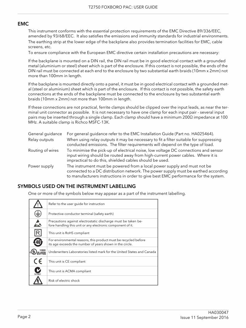
SYMBOLS USED ON THE INSTRUMENT LABELLINGOne or more of the symbols below may appear as a part of the instrument labelling.
40
Refer to the user guide for instruction
Protective conductor terminal (safety earth)
Precautions against electrostatic discharge must be taken be-fore handling this unit or any electronic component of it.
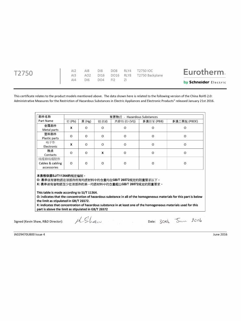
This unit is RoHS compliant
For environmental reasons, this product must be recycled beforeits age exceeds the number of years shown in the circle.
Underwriters Laboratories listed mark for the United States and Canada
This unit is CE compliant
This unit is ACMA compliant
Risk of electric shock
Page 2HA030047
Issue 11 September 2016

T2750 FOXBORO PAC: USER GUIDE
I/O ISOLATION STRATEGYIsolation is implemented in the form of a double insulation (300V) barrier separating all the I/O channels in a module from the rest of the system. This prevents hazardous voltages on any one I/O channel from introducing hazards on wiring associated with any other I/O module, or from putting the rest of the system at risk. Modules which provide channel-to-channel isolation further ensure safety and good signal quality on all channels within such modules. Refer to the relevant section of Appendix A for more details.
Page 3HA030047Issue 11 September 2016
T2750 FOXBORO PAC: USER GUIDE
T2750 Foxboro PAC user guide
1 INTRODUCTIONThe T2750 is a modular I/O controller which can be used either as a stand alone unit, or as part of a complete control system. Modbus and Raw communications protocols are supported, allowing simple connection with PCs, and other instruments. Profibus master functionality is supported by using the optional netHOST gateways.The control strategy is set up using LINTools software running on a PC.
1.1 PHYSICAL STRUCTUREThe unit consists of one or two Input/Output Controller (IOC) modules and a number of Input/Output (I/O) Modules each of which clips into its own individual terminal unit which provides termination for user wiring. The terminal units themselves are located in a base unit which is mounted on a DIN rail or on a panel, as re-quired. Base units are available in different sizes to accommodate different numbers of I/O Modules (max-imum 16).The lower front of the unit is covered by a removable flap which protects the wiring, but leaves the status LEDs open to view.Profibus master functionality, if required, is provided by the use of external netHOST gateway units. Up to two netHOSTs are required, depending on whether one of two IOC modules are installed.
1.2 MODULES AVAILABLEAI2 Two universal analogue input channelsAI3 Three analogue input channels used for current loops, either self powered or externally
poweredAI4 Two pairs of isolated analogue input channels. Terminal unit variants are available for
particular applications (thermocouples, mA or mV inputs).AI8 High density analogue input module. Terminal unit variants are available for eight chan-
nels of mA inputs (fast or standard polling), eight channels of thermocouples with cold junction compensation (also accepts mV inputs), or four channels for platinum resist-ance thermometers (RTD).
AO2 Two analogue output channels supplying 0 to 20mA or 0 to 10V signalsDI4 Four digital input channels (logic inputs)DI6HV Six digital input channels (mains input 230VRMS)DI6MV Six digital input channels (mains input 115VRMS)DI8CO Eight digital input channels (contact closure inputs)DI8LG Eight digital input channels (logic inputs)DI16 16 digital input channels (universal inputs)DO4LG Four digital output channels (0 to 10mA), externally poweredDO424 Four digital output channels (0 to 100mA), externally poweredDO8 Eight digital output channels (0 to 500mA per channel- maximum 4 Amps per module),
externally poweredDO16 16 digital output channels (0 to 700mA per channel)FI2 Two frequency input channels (logic, magnetic and contact closure up to 40kHz)RLY4 Four output relays arranged as one changeover relay and three Normally Open relaysRLY8 Eight Normally Open relays ZI2 One high impedance input channel and one thermocouple input channel suitable for
use with Zirconia oxygen probes
Page 4HA030047
Issue 11 September 2016
T2750 FOXBORO PAC: USER GUIDE
1.3 FEATURES1.3.1 LIN Communication
The unit is a Local Instrument network (LIN) instrument, where the ‘Local Instrument Network’ is a collection of LIN instruments, that together form a control system. The network communicates using ‘LIN Communi-cation’ which is a proprietary system used to connect each LIN instrument in the network.
1.3.2 ELIN CommunicationELIN Communication is LIN communication via Ethernet allowing peer-to-peer communications between in-struments and with the wider network via a standard Ethernet infrastructure.
1.3.3 Profibus Master CommunicationProfibus Master support is provided using the optional, externally mounted, netHOST gateways. Interface from the netHOST to the T2750 is via IP over Ethernet. Up to two netHOSTs are required depending on the number of IOCs installed into the T2750’s base unit.
1.3.4 Redundant working REDUNDANT POWER SUPPLY CONNECTION
Two sets of power connections allow two Power Supply Units (PSUs) to be connected so that the system can continue to run should one of the supplies fail. The system monitors the supply voltages allowing alarms to be triggered should either or both supply voltages drop below an acceptable value.
REDUNDANT INSTRUMENTSWhen operating in redundant mode, a high speed data link between the primary and secondary control modules provides exact tracking of the control database, allowing bumpless automatic changeover to the secondary module should the primary module fail. There is no loss of I/O states and no need to re-initialise I/O points. Revalidation of all attached LIN nodes is automatic.Live replacement of a failed control module can be carried out, without wiring disconnections. Full hard-ware and software status indication allows rapid verification and diagnostics. In Redundant mode operation either module can be removed leaving the remaining module to drive the I/O modules. When a replace-ment control module is fitted, it loads the control strategy and current status from the running control mod-ule.
1.3.5 Battery backupAn internal ‘supercap’ supports hot start data, and the Real-Time Clock, for a minimum of 1 hour. An external battery (3.3V ± 15%, 10μA max) can be connected in order to extend this period. An option exists for the T2750 to contain a 3V ‘coin-cell’ style battery, mounted on a small board, fitted on the inside of the plastic side panel adjacent to the IOC.
1.3.6 ConfigurationContinuous strategies and Sequences are configured, downloaded and monitored using LINtools.
The instrument is capable of creating its own LIN Database automatically (_auto.dbf and _auto.run), this database including all the necessary module and I/O Function Blocks based on the I/O modules detected.
Automatic Configuration is attempted after the instrument has determined the Hot/Cold Start switch settings. If neither cold start nor hot start is selected, the instrument detects the installed I/O, and then creates an operational database and runs automatically.
SETPOINT PROGRAMAllows a setpoint program (.uyy file) to be configured using the LIN Programmer Editor. The Programmer Wizard (available from LINtools Engineering Studio) is then used, automatically to insert and to link all the blocks needed to produce the generated Setpoint Program.
SEQUENTIAL FUNCTION CHART (SFC) The Sequential Function Chart (SFC) is the graphical way LINtools represents a LIN Sequence (.sfc file). A Sequence is employed when the process being controlled by the LIN Database can adopt several distinct states - e.g. ‘Starting Up’, ‘Full Running’, ‘Shutting Down’, etc.
Page 5HA030047Issue 11 September 2016
T2750 FOXBORO PAC: USER GUIDE
1.3.6 CONFIGURATION (Cont.)
LADDER CONFIGURATIONA ladder diagram is a type of ‘Action’ represented graphically by a column of ‘rungs’. Rungs are equivalent to program statements, with icons along them representing digital or analogue fields, constants, and logical or arithmetic functions. Each rung has only one ‘output’ or ‘objective’ - at its right-hand end - which is either a coil (digital field), variable (analogue field), or a ‘jump’ to another labelled rung. Rungs can include any number of input elements and use any complexity of wired or explicit functions to perform the rung operation - subject only to screen space limitations.
Note: A single rung that evaluates TRUE or FALSE can also be used for a Sequence Transition.
SEQUENTIAL TEXT (ST) USER ALGORITHMSSpecial Action blocks support user-algorithms written in Structured Text (ST).
SOFTWARE BLOCKSContinuous strategies are built up using function blocks selected from a library of analogue and logic elements. Diagnostic blocks are also available, for hardware and software status reporting (see section 11). The LIN Blocks Reference manual contains descriptions of each block.
Blocks are ‘license protected’ into categories that define control levels (Appendix C gives a full list):
1. Foundation blocks include I/O and Communications blocks, amongst others. 2. Standard blocks include control, timing, basic maths and logic blocks. 3. Control blocks include control loop, advanced maths and sequence control blocks. 4. Advanced blocks are natural gas concentration and AGA8 calculation blocks.
Note: Generally, a combination of Standard license blocks can be used to provide a level of instru-ment control equivalent to a single Control license block, but this has an impact on the total number of available blocks remaining.
1.3.7 Data recordingData archive (.uhh) files are saved in the unit’s flash memory (as configured in LINtools) ready for automatic archiving to a host computer via FTP. Review software can be used to display this data in chart or spread-sheet form. If ‘Store and Forward’ software is fitted at the host pc, then these dtat recording files can be in-terrogated to read any data missing from the database as a result of a break in transmission.
1.3.8 Store and forward softwareIf there is a break in the transmission line, or if any other communications problem arises, then data for the period of the break will be missing from the database. The data remains in the instrument memory, and if the instrument is configured to archive automatically to a ‘Review’ database, then ‘Store and Forward’ allows the missing data to be retrieved from the Review database, once communications have been restored. (It may take some time to download all the files, depending on the duration of the break.)More details are to be found in the ‘Store and Forward User Guide.
1.3.9 Time Localisation SupportTIME ZONE
Provides a means of configuring the instrument to use the local time zone.
SIMPLE NETWORK TIME PROTOCOL (SNTP)Allows the instrument to receive time and date from an SNTP server over the Ethernet connection.
Page 6HA030047
Issue 11 September 2016

T2750 FOXBORO PAC: USER GUIDE
1.3.10 Health monitoringAutomatic health checks, self-testing, and initialisation on power-up, with continuous checking of I/O status and external communications.
1.3.11 WatchdogA Watchdog switch on the control module allows the user to initiate a restart in the event of a watchdog failure. If required, the Watchdog Relay connections can be wired as shown in section 2.3.1.
Note: The watchdog relay can also be switched by the strategy, using the ‘Options.UsrAlm’ bit in the Tactician Header block. For synchronised systems, both primary and secondary relays are switched.
1.3.12 IP (Intellectual Property) ProtectionSpecific application file types can be password protected. This prevents the loss of the Intellectual Property to mis-use and duplication, e.g. using files on an instrument for which they were not originally intended and the copying of files for use with another instrument or process.
1.3.13 Front panel indicatorsStatus LEDs are provided to indicate communications and module I/O status. Control switches are fitted on each control module.
Page 7HA030047Issue 11 September 2016
T2750 FOXBORO PAC: USER GUIDE
2 INSTALLATION
2.1 UNPACKING THE INSTRUMENTThe instrument is despatched in a special pack, designed to give adequate protection during transit. Should the outer box show signs of damage, it should be opened immediately, and the contents exam-ined. If there is evidence of damage, the instrument should not be operated and the local representative contacted for instructions. After the instrument has been removed from its packing, the packing should be examined to ensure that all accessories and documentation have been removed. The packing should then be stored against future transport requirements.
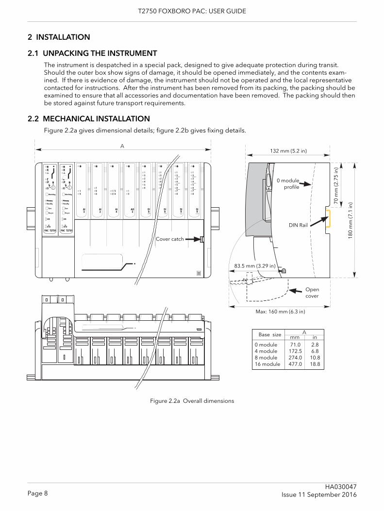
2.2 MECHANICAL INSTALLATIONFigure 2.2a gives dimensional details; figure 2.2b gives fixing details.
Figure 2.2a Overall dimensions
Primary Primary
Cover catch
DIN Rail
132 mm (5.2 in)
70 m
m (2
.75
in)
180
mm
(7.1
in)
Base size
0 module4 module8 module16 module
71.0172.5274.0477.0
2.86.8
10.818.8
0 moduleprofile
Open cover
Max: 160 mm (6.3 in)
83.5 mm (3.29 in)
Page 8HA030047
Issue 11 September 2016
T2750 FOXBORO PAC: USER GUIDE
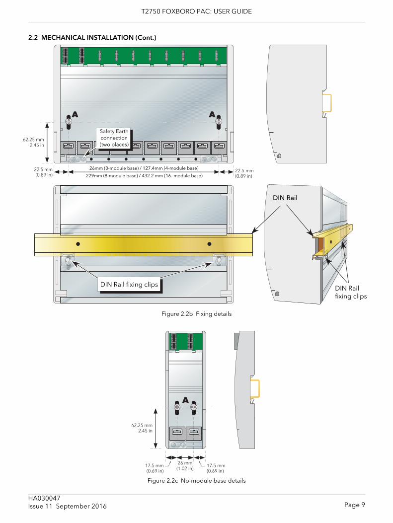
2.2 MECHANICAL INSTALLATION (Cont.)
Figure 2.2b Fixing details
Figure 2.2c No-module base details
DIN Rail
DIN Rail fixing clips DIN Rail fixing clips
26mm (0-module base) / 127.4mm (4-module base)
229mm (8-module base) / 432.2 mm (16- module base)
Safety Earth connection (two places)
Page 9HA030047Issue 11 September 2016
T2750 FOXBORO PAC: USER GUIDE
2.2.1 Base unit mounting
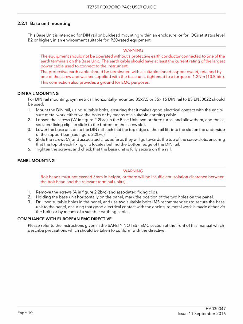
This Base Unit is intended for DIN rail or bulkhead mounting within an enclosure, or for IOCs at status level B2 or higher, in an environment suitable for IP20-rated equipment.
WARNINGThe equipment should not be operated without a protective earth conductor connected to one of the earth terminals on the Base Unit. The earth cable should have at least the current rating of the largest power cable used to connect to the instrument.The protective earth cable should be terminated with a suitable tinned copper eyelet, retained by one of the screw and washer supplied with the base unit, tightened to a torque of 1.2Nm (10.5lbin).This connection also provides a ground for EMC purposes.
DIN RAIL MOUNTINGFor DIN rail mounting, symmetrical, horizontally-mounted 35×7.5 or 35× 15 DIN rail to BS EN50022 should be used.1. Mount the DIN rail, using suitable bolts, ensuring that it makes good electrical contact with the enclo-
sure metal work either via the bolts or by means of a suitable earthing cable.2. Loosen the screws (‘A’ in figure 2.2b/c) in the Base Unit, two or three turns, and allow them, and the as-
sociated fixing clips to slide to the bottom of the screw slot.3. Lower the base unit on to the DIN rail such that the top edge of the rail fits into the slot on the underside
of the support bar (see figure 2.2b/c).4. Slide the screws (A) and associated clips as far as they will go towards the top of the screw slots, ensuring
that the top of each fixing clip locates behind the bottom edge of the DIN rail.5. Tighten the screws, and check that the base unit is fully secure on the rail.
PANEL MOUNTING
WARNINGBolt heads must not exceed 5mm in height, or there will be insufficient isolation clearance between the bolt head and the relevant terminal unit(s).
1. Remove the screws (A in figure 2.2b/c) and associated fixing clips.2. Holding the base unit horizontally on the panel, mark the position of the two holes on the panel.3. Drill two suitable holes in the panel, and use two suitable bolts (M5 recommended) to secure the base
unit to the panel, ensuring that good electrical contact with the enclosure metal work is made either via the bolts or by means of a suitable earthing cable.
COMPLIANCE WITH EUROPEAN EMC DIRECTIVE
Please refer to the instructions given in the SAFETY NOTES - EMC section at the front of this manual which describe precautions which should be taken to conform with the directive.
Page 10HA030047
Issue 11 September 2016

T2750 FOXBORO PAC: USER GUIDE
2.2.2 Terminal unit installation1. Insert the tag at the top of the terminal unit printed circuit board into the relevant slot in Base Unit (action
‘B’ in figure 2.2.2).2. Press on the bottom of the terminal unit until a ‘click’ confirms that the retention clip has sprung back
into position to secure the terminal unit (action ‘C’).
Note: If the base unit is not fully populated a blank Terminal Unit (supplied) must be fitted immedi-ately to the right of the final module position in order to maintain IP20 rating
TERMINAL UNIT REMOVAL1. Remove the terminal unit’s I/O module, if fitted (section 2.2.3, below).2. If necessary, remove all wiring from the terminal Unit.3. Press the retention clip at the bottom of the terminal Unit and lift the terminal unit out (action ‘D’).
Figure 2.2.2 Terminal unit installation/removal
Page 11HA030047Issue 11 September 2016
T2750 FOXBORO PAC: USER GUIDE
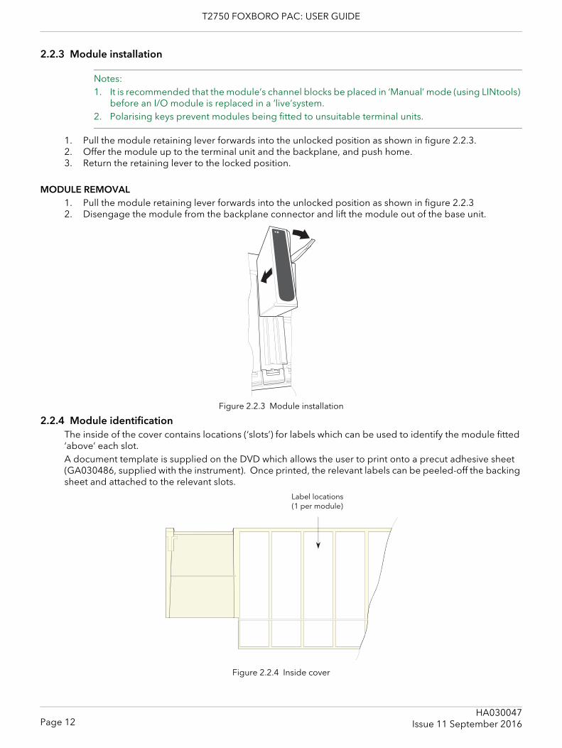
2.2.3 Module installation
Notes:1. It is recommended that the module’s channel blocks be placed in ‘Manual’ mode (using LINtools)
before an I/O module is replaced in a ‘live’system.2. Polarising keys prevent modules being fitted to unsuitable terminal units.
1. Pull the module retaining lever forwards into the unlocked position as shown in figure 2.2.3.2. Offer the module up to the terminal unit and the backplane, and push home.3. Return the retaining lever to the locked position.
MODULE REMOVAL1. Pull the module retaining lever forwards into the unlocked position as shown in figure 2.2.32. Disengage the module from the backplane connector and lift the module out of the base unit.
Figure 2.2.3 Module installation
2.2.4 Module identificationThe inside of the cover contains locations (‘slots’) for labels which can be used to identify the module fitted ‘above’ each slot. A document template is supplied on the DVD which allows the user to print onto a precut adhesive sheet (GA030486, supplied with the instrument). Once printed, the relevant labels can be peeled-off the backing sheet and attached to the relevant slots.
Figure 2.2.4 Inside cover
Label locations(1 per module)
Page 12HA030047
Issue 11 September 2016
T2750 FOXBORO PAC: USER GUIDE
Page 13HA030047
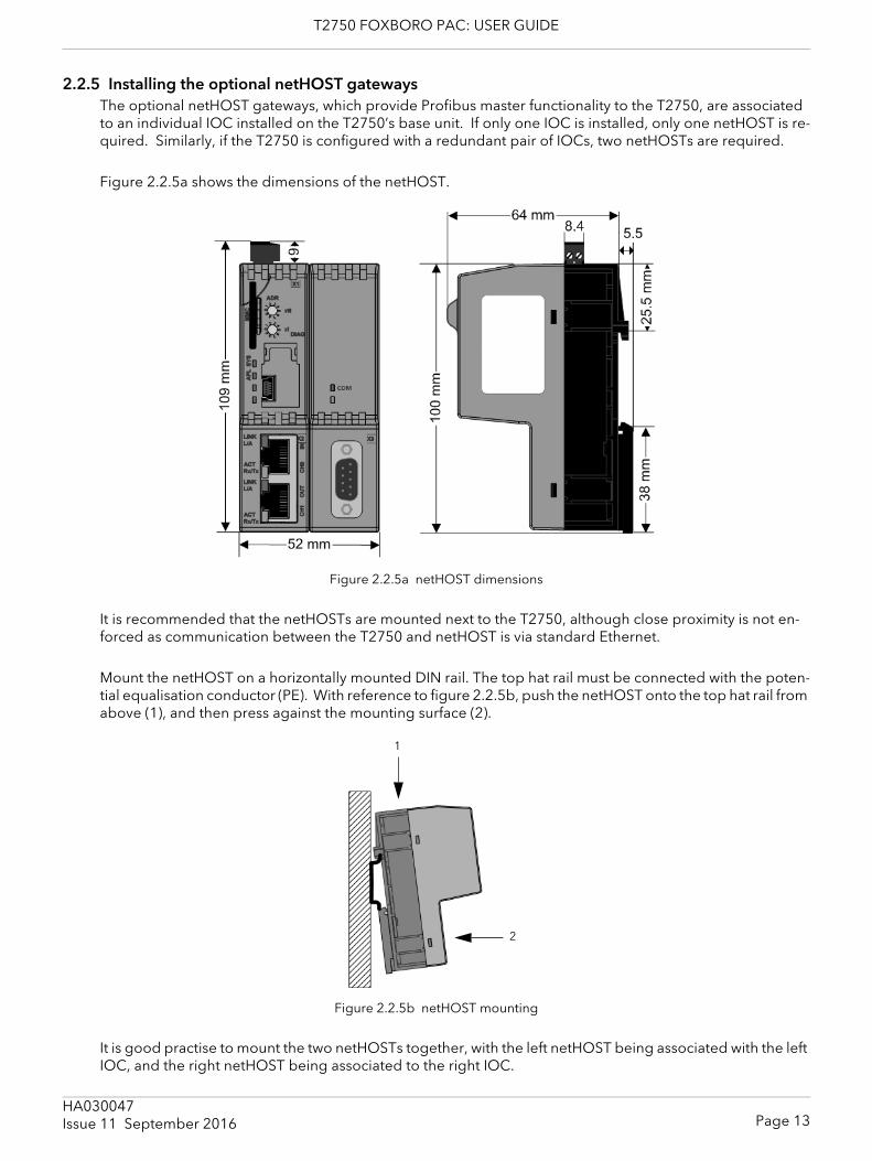
2.2.5 Installing the optional netHOST gatewaysThe optional netHOST gateways, which provide Profibus master functionality to the T2750, are associated to an individual IOC installed on the T2750’s base unit. If only one IOC is installed, only one netHOST is re-quired. Similarly, if the T2750 is configured with a redundant pair of IOCs, two netHOSTs are required.
Figure 2.2.5a shows the dimensions of the netHOST.
Figure 2.2.5a netHOST dimensions
It is recommended that the netHOSTs are mounted next to the T2750, although close proximity is not en-forced as communication between the T2750 and netHOST is via standard Ethernet.
Mount the netHOST on a horizontally mounted DIN rail. The top hat rail must be connected with the poten-tial equalisation conductor (PE). With reference to figure 2.2.5b, push the netHOST onto the top hat rail from above (1), and then press against the mounting surface (2).
Figure 2.2.5b netHOST mounting
It is good practise to mount the two netHOSTs together, with the left netHOST being associated with the left IOC, and the right netHOST being associated to the right IOC.
1
2
Issue 11 September 2016
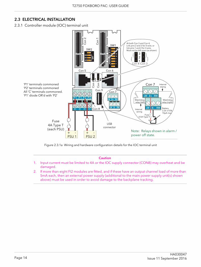
T2750 FOXBORO PAC: USER GUIDE
2.3 ELECTRICAL INSTALLATION2.3.1 Controller module (IOC) terminal unit
Figure 2.3.1a Wiring and hardware configuration details for the IOC terminal unit
Caution1. Input current must be limited to 4A or the IOC supply connector (CON8) may overheat and be
damaged. 2. If more than eight FI2 modules are fitted, and if these have an output channel load of more than
5mA each, then an external power supply (additional to the main power supply unit(s) shown above) must be used in order to avoid damage to the backplane tracking.
��
����
���
� �
PSU 1 PSU 2
Fuse4A Type T(each PSU)
Fuse:0.5A Type T
Battery3.3V ±15%10μA max
Internal wiring
Watchdogrelay (left)
Internalwiring
Watchdogrelay (right)
Note: Relays shown in alarm / power off state.
USBconnector
‘P1’ terminals commoned‘P2’ terminals commonedAll ‘C’ terminals commoned.‘P1’ diode OR’d with ‘P2’
At both Con 3 and Con 4,Link pins 2 and 3 for 5-wire, orlink pins 1 and 2 for 3-wire.Must not be left open (as shown)
Page 14HA030047
Issue 11 September 2016

T2750 FOXBORO PAC: USER GUIDE
2.3.1 CONTROLLER MODULE TERMINAL UNIT (Cont.)
SUPPLY WIRING
CautionNeither supply line may be allowed to rise above 30 Volts with respect to safety earth.
Note: should the supply voltage fall below 19.2V during startup, the instrument will not start success-fully and will attempt repeatedly to restart.
The instrument supply voltage is 24Vdc ± 20%. Typical power requirement is 150mA (3.6W) per control module, plus 1 Amp (24W) for an eight-module unit or 2 Amps (48W) for a 16-module unit.An external battery (3.3 ± 15%) may be connected in order to maintain power for the SRAM and the real time clock when supply power is not available. Typical drain current is 10μA maximum. An option exists for the T2750 to contain a 3V ‘coin-cell’ style battery, mounted on a small board, fitted on the inside of the plastic side panel adjacent to the IOC.Figure 2.3 shows the control module terminal unit with wiring details for the supply and for the battery. A suitable battery and charger are available from the manufacturer under part number LA030830.
FUSESAll positive supply lines must incorporate a fuse. Suitable types are 4A Type T for 24 Volt supplies and 0.5A Type T for an external battery.
WIRE SIZESSupply wiring: 0.25mm2 to 2.5mm2 (20 AWG to 14 AWG)External battery: 0.14mm2 to 1.5mm2 (25 AWG to 16 AWG)
Note...The above diameters relate to the total cross sectional area of the conductor(s) inserted into the terminal.
TERMINAL DETAILSRecommended screwdriver type: Supply power connector (Con8): 3 mm flat blade. Watch dog/battery connector (Con7): 2.5 mm flat blade.
Maximum tightening torque: 0.6Nm for supply power terminals; 0.25Nm for battery terminalsMaximum current carrying capability: 5A per pin for supply power terminals; 2A per pin for battery terminals.
CautionThe maximum current carrying capacity should be considered when ‘daisy chaining’.
SAFETY EARTHFigure 2.2b above, and associated text gives safety earth details.
WATCHDOG RELAYSEach control module (IOC) includes a ‘watchdog’ relay. At power up, for each IOC, the relay remains de-energised (contacts open) until a number of health checks have been completed successfully and a strategy has been loaded and is running, at which point the relay is energised and the contacts close. If during op-eration one or more health check fails, or if the strategy is stopped, the watchdog relay reverts to its de-en-ergised (contacts open) state.
Note The watchdog relays can also be controlled by the ‘Options.UsrAlm’ bit in the Tactican header block.
Page 15HA030047Issue 11 September 2016
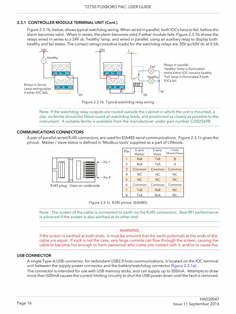
T2750 FOXBORO PAC: USER GUIDE
2.3.1 CONTROLLER MODULE TERMINAL UNIT (Cont.)
Figure 2.3.1b, below, shows typical watchdog wiring. When wired in parallel, both IOCs have to fail, before the alarm becomes valid. When in series, the alarm becomes valid if either module fails. Figure 2.3.1b shows the relays wired in series to a 24V dc ‘healthy’ lamp, and wired in parallel, using an auxiliary relay to display both healthy and fail states. The contact ratings (resistive loads) for the watchdog relays are 30V ac/60V dc at 0.5A.
Figure 2.3.1b Typical watchdog relay wiring
Note: If the watchdog relay outputs are routed outside the cabinet in which the unit is mounted, a clip- on ferrite should be fitted round all watchdog leads, and positioned as closely as possible to the instrument. A suitable ferrite is available from the manufacturer under part number CO025698
COMMUNICATIONS CONNECTORSA pair of parallel-wired RJ45 connectors, are used for EIA485 serial communications. Figure 2.3.1c gives the pinout. Master / slave status is defined in ‘Modbus tools’ supplied as a part of LINtools.
Figure 2.3.1c RJ45 pinout (EIA485)
Note: The screen of the cable is connected to earth via the RJ45 connectors. Best RFI performance is achieved if the screen is also earthed at its other end
WARNINGIf the screen is earthed at both ends, it must be ensured that the earth potentials at the ends of the cable are equal. If such is not the case, very large currents can flow through the screen, causing the cable to become hot enough to harm personnel who come into contact with it, and/or to cause fire.
USB CONNECTORA single Type-A USB connector, for redundant USB2.0 host communications, is located on the IOC terminal unit between the supply power connector and the battery/watchdog connector (figure 2.3.1a).The connector is intended for use with USB memory sticks, and can supply up to 500mA. Attempts to draw more than 500mA causes the current limiting circuitry to shut the USB power down until the fault is removed.
24V
0V 0V
Healthy
Healthy
Fail
24V
Relays in Series.Lamp extinguishesif either IOC fails
Relays in parallel.‘Healthy’ lamp is illuminated whilst either IOC remains healthy. ‘Fail’ lamp is illuminated if both IOCs fail.
Pin 1
Pin 8
Pin 5-wireMaster
5-wireSlave
3-wireMaster/Slave
1
2
3
4
5
6
7
8
RxB
RxA
Common
NC
NC
Common
TxB
TxA
TxB
TxA
Common
NC
NC
Common
RxB
RxA
B
A
Common
NC
NC
Common
NC
NC
RJ45 plug: View on underside
Page 16HA030047
Issue 11 September 2016
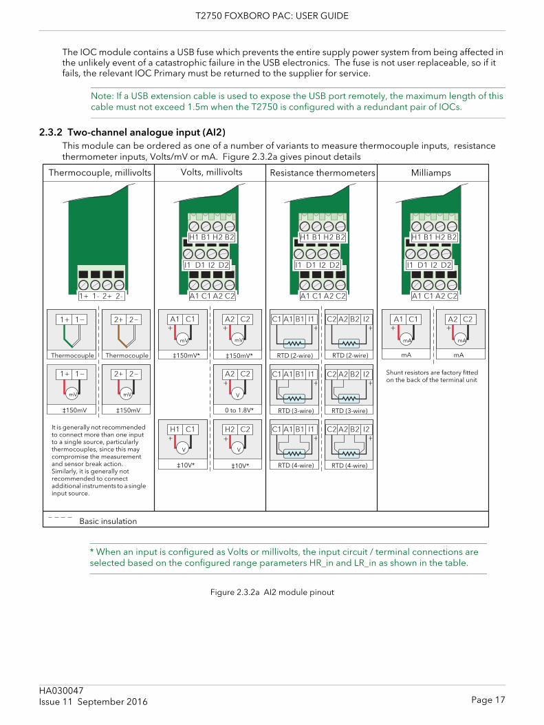
T2750 FOXBORO PAC: USER GUIDE
The IOC module contains a USB fuse which prevents the entire supply power system from being affected in the unlikely event of a catastrophic failure in the USB electronics. The fuse is not user replaceable, so if it fails, the relevant IOC Primary must be returned to the supplier for service.
Note: If a USB extension cable is used to expose the USB port remotely, the maximum length of this cable must not exceed 1.5m when the T2750 is configured with a redundant pair of IOCs.
2.3.2 Two-channel analogue input (AI2)This module can be ordered as one of a number of variants to measure thermocouple inputs, resistance thermometer inputs, Volts/mV or mA. Figure 2.3.2a gives pinout details
Figure 2.3.2a AI2 module pinout
ThermocoupleThermocouple RTD (2-wire)
Shunt resistors are factory fitted on the back of the terminal unit
Thermocouple, millivolts
RTD (2-wire)
RTD (3-wire) RTD (3-wire)
RTD (4-wire) RTD (4-wire)
Volts, millivolts Resistance thermometers Milliamps
0 to 1.8V*
Basic insulation
mV mV
mV mV
V
VV
mA mA
* When an input is configured as Volts or millivolts, the input circuit / terminal connections are selected based on the configured range parameters HR_in and LR_in as shown in the table.
‡150mV ‡150mV
‡150mV* ‡150mV*
‡10V*‡10V*
mAmA
It is generally not recommended to connect more than one input to a single source, particularly thermocouples, since this may compromise the measurement and sensor break action. Similarly, it is generally not recommended to connect additional instruments to a single input source.
Page 17HA030047Issue 11 September 2016
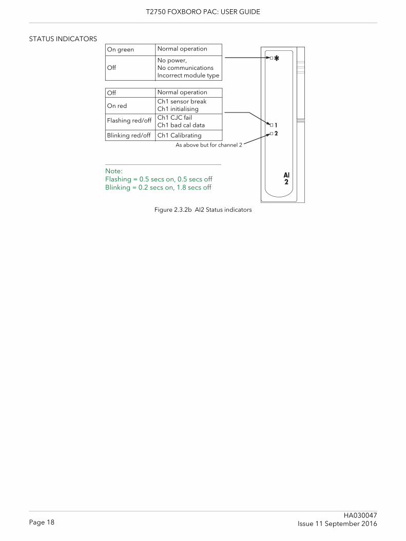
T2750 FOXBORO PAC: USER GUIDE
STATUS INDICATORS
Figure 2.3.2b AI2 Status indicators
Normal operation
No power,No communicationsIncorrect module type
On green
Off
Ch1 sensor breakCh1 initialisingCh1 CJC fail Ch1 bad cal data
On red
Flashing red/off
Ch1 CalibratingBlinking red/off
As above but for channel 2
Note:Flashing = 0.5 secs on, 0.5 secs offBlinking = 0.2 secs on, 1.8 secs off
Normal operationOff
Page 18HA030047
Issue 11 September 2016
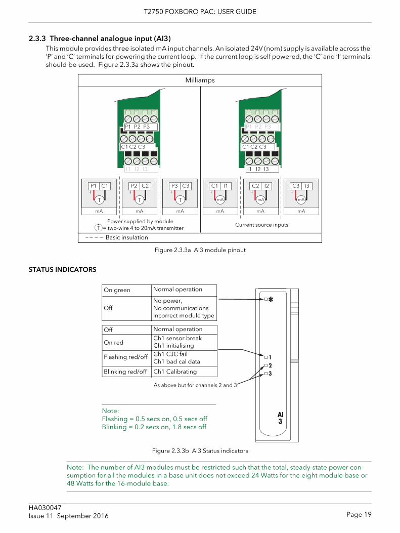
T2750 FOXBORO PAC: USER GUIDE
2.3.3 Three-channel analogue input (AI3)This module provides three isolated mA input channels. An isolated 24V (nom) supply is available across the ‘P’ and ‘C’ terminals for powering the current loop. If the current loop is self powered, the ‘C’ and ‘I’ terminals should be used. Figure 2.3.3a shows the pinout.
Figure 2.3.3a AI3 module pinout
STATUS INDICATORS
Figure 2.3.3b AI3 Status indicators
Note: The number of AI3 modules must be restricted such that the total, steady-state power con-sumption for all the modules in a base unit does not exceed 24 Watts for the eight module base or 48 Watts for the 16-module base.
Milliamps
Basic insulation
Power supplied by moduleT = two-wire 4 to 20mA transmitter
Current source inputs
Normal operation
No power,No communicationsIncorrect module type
On green
Off
As above but for channels 2 and 3
Note:Flashing = 0.5 secs on, 0.5 secs offBlinking = 0.2 secs on, 1.8 secs off
Ch1 sensor breakCh1 initialisingCh1 CJC fail Ch1 bad cal data
On red
Flashing red/off
Ch1 CalibratingBlinking red/off
Normal operationOff
Page 19HA030047Issue 11 September 2016
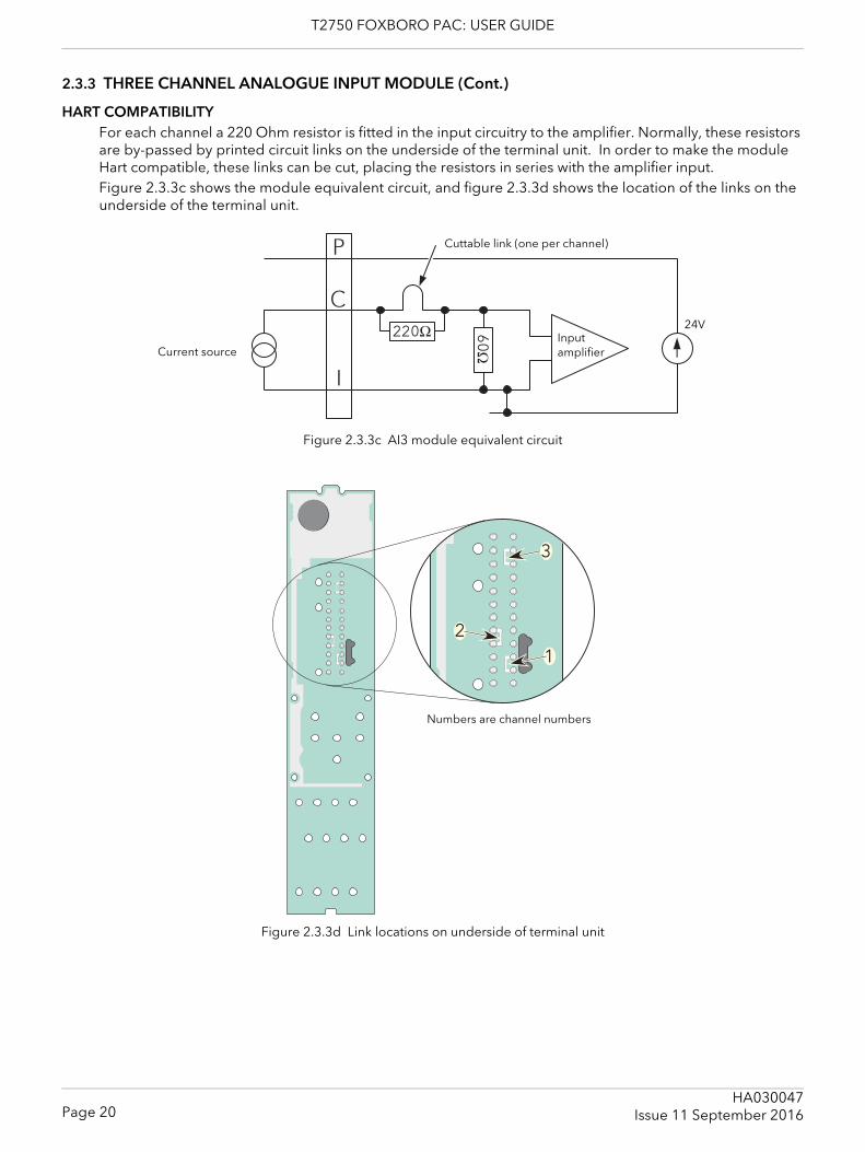
T2750 FOXBORO PAC: USER GUIDE
2.3.3 THREE CHANNEL ANALOGUE INPUT MODULE (Cont.)
HART COMPATIBILITYFor each channel a 220 Ohm resistor is fitted in the input circuitry to the amplifier. Normally, these resistors are by-passed by printed circuit links on the underside of the terminal unit. In order to make the module Hart compatible, these links can be cut, placing the resistors in series with the amplifier input.Figure 2.3.3c shows the module equivalent circuit, and figure 2.3.3d shows the location of the links on the underside of the terminal unit.
Figure 2.3.3c AI3 module equivalent circuit
Figure 2.3.3d Link locations on underside of terminal unit
Ω
Ω
Cuttable link (one per channel)
24VInput amplifierCurrent source
Numbers are channel numbers
Page 20HA030047
Issue 11 September 2016
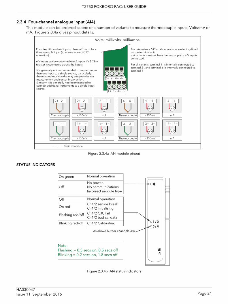
T2750 FOXBORO PAC: USER GUIDE
2.3.4 Four-channel analogue input (AI4)This module can be ordered as one of a number of variants to measure thermocouple inputs, Volts/mV or mA. Figure 2.3.4a gives pinout details.
Figure 2.3.4a AI4 module pinout
STATUS INDICATORS
Figure 2.3.4b AI4 status indicators
ThermocoupleThermocouple
Volts, millivolts, milliamps
Basic insulation
For mA variants, 5 Ohm shunt resistors are factory fitted on the terminal unit.mA variants must not have thermocouple or mV inputs connected.
For all variants, terminal 1- is internally connected toterminal 2-, and terminal 3- is internally connected to terminal 4-
For mixed t/c and mV inputs, channel 1 must be a thermocouple input (to ensure correct CJCoperation).
mV inputs can be converted to mA inputs if a 5 Ohm resistor is connected across the inputs
ThermocoupleThermocouple
It is generally not recommended to connect more than one input to a single source, particularly thermocouples, since this may compromise the measurement and sensor break action. Similarly, it is generally not recommended to connect additional instruments to a single input source.
Normal operation
No power,No communicationsIncorrect module type
On green
Off
As above but for channels 3/4
Note:Flashing = 0.5 secs on, 0.5 secs offBlinking = 0.2 secs on, 1.8 secs off
Ch1/2 sensor breakCh1/2 initialisingCh1/2 CJC fail Ch1/2 bad cal data
On red
Flashing red/off
Ch1/2 CalibratingBlinking red/off
Normal operationOff
Page 21HA030047Issue 11 September 2016
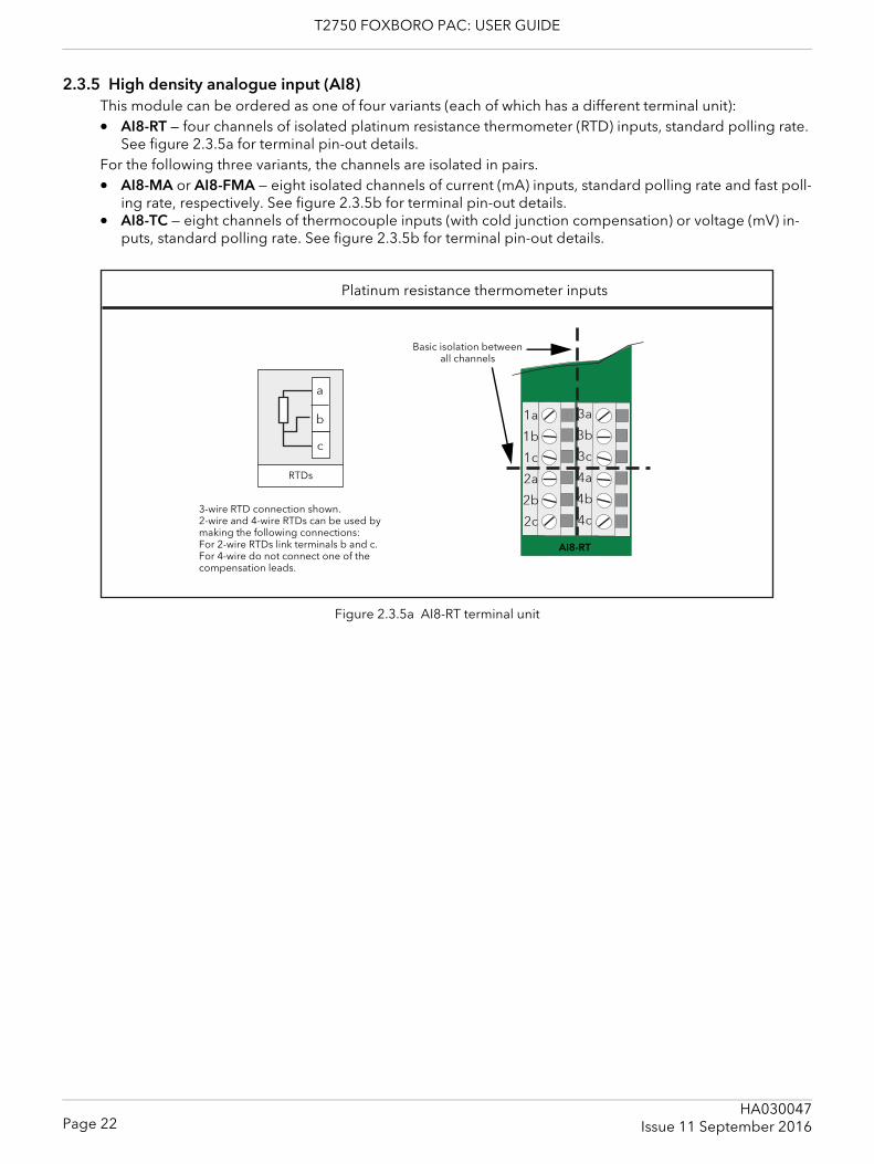
T2750 FOXBORO PAC: USER GUIDE
2.3.5 High density analogue input (AI8)This module can be ordered as one of four variants (each of which has a different terminal unit):• AI8-RT — four channels of isolated platinum resistance thermometer (RTD) inputs, standard polling rate.
See figure 2.3.5a for terminal pin-out details.For the following three variants, the channels are isolated in pairs.• AI8-MA or AI8-FMA — eight isolated channels of current (mA) inputs, standard polling rate and fast poll-
ing rate, respectively. See figure 2.3.5b for terminal pin-out details.• AI8-TC — eight channels of thermocouple inputs (with cold junction compensation) or voltage (mV) in-
puts, standard polling rate. See figure 2.3.5b for terminal pin-out details.
Figure 2.3.5a AI8-RT terminal unit
Platinum resistance thermometer inputs
3-wire RTD connection shown.2-wire and 4-wire RTDs can be used by making the following connections:For 2-wire RTDs link terminals b and c.For 4-wire do not connect one of the compensation leads.
Basic isolation between all channels
RTDs
AI8-RT
Page 22HA030047
Issue 11 September 2016
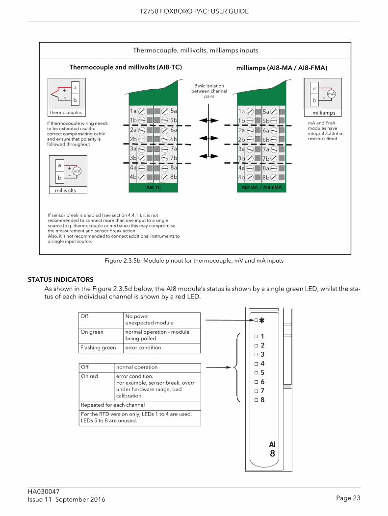
T2750 FOXBORO PAC: USER GUIDE
Figure 2.3.5b Module pinout for thermocouple, mV and mA inputs
STATUS INDICATORSAs shown in the Figure 2.3.5d below, the AI8 module’s status is shown by a single green LED, whilst the sta-tus of each individual channel is shown by a red LED.
Thermocouples
millivolts
milliamps
Thermocouple, millivolts, milliamps inputs
If thermocouple wiring needs to be extended use the correct compensating cable and ensure that polarity is followed throughout
mA and FmA modules have integral 3.33ohm resistors fitted
Basic isolation between channel
pairs
AI8-TC
If sensor break is enabled (see section 4.4.1.), it is not recommended to connect more than one input to a single source (e.g. thermocouple or mV) since this may compromise the measurement and sensor break action. Also, it is not recommended to connect additional instruments to a single input source.
AI8-MA / AI8-FMA
Thermocouple and millivolts (AI8-TC) milliamps (AI8-MA / AI8-FMA)
Off No powerunexpected module
On green normal operation - module being polled
Flashing green error condition
Off normal operation
On red error condition.For example, sensor break, over/under hardware range, bad calibration.
Repeated for each channel
For the RTD version only, LEDs 1 to 4 are used. LEDs 5 to 8 are unused.
Page 23HA030047Issue 11 September 2016
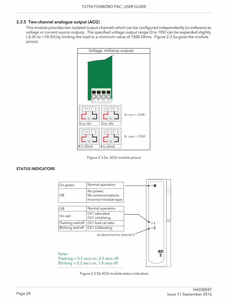
T2750 FOXBORO PAC: USER GUIDE
2.3.5 Two-channel analogue output (AO2)This module provides two isolated output channels which can be configured independently (in software) as voltage or current source outputs. The specified voltage output range (0 to 10V) can be expanded slightly (-0.3V to +10.3V) by limiting the load to a minimum value of 1500 Ohms. Figure 2.3.5a gives the module pinout.
Figure 2.3.5a AO2 module pinout
STATUS INDICATORS
Figure 2.3.5b AO2 module status indicators
0 to 10V 0 to 10V
0 to 20mA 0 to 20mA
Voltage, milliamp outputs
Normal operation
No power,No communicationsIncorrect module type
On green
Off
Note:Flashing = 0.5 secs on, 0.5 secs offBlinking = 0.2 secs on, 1.8 secs off
Ch1 saturatedCh1 initialisingCh1 bad cal data
On red
Flashing red/offCh1 CalibratingBlinking red/off
Normal operationOff
As above but for channel 2
Page 24HA030047
Issue 11 September 2016
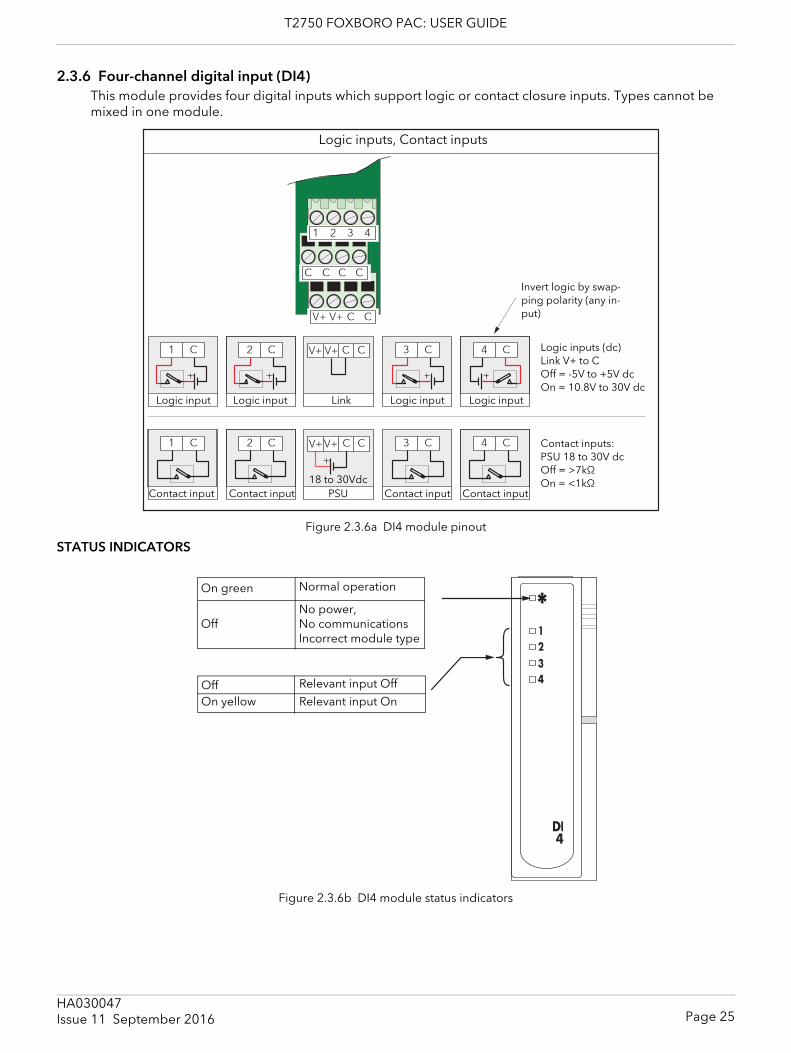
T2750 FOXBORO PAC: USER GUIDE
2.3.6 Four-channel digital input (DI4)This module provides four digital inputs which support logic or contact closure inputs. Types cannot be mixed in one module.
Figure 2.3.6a DI4 module pinout
STATUS INDICATORS
Figure 2.3.6b DI4 module status indicators
Logic input Logic input Logic input Logic input
Contact input Contact input Contact input Contact input
Invert logic by swap-ping polarity (any in-put)
Logic inputs (dc)Link V+ to COff = -5V to +5V dcOn = 10.8V to 30V dc
Contact inputs:PSU 18 to 30V dcOff = >7kΩOn = <1kΩ18 to 30Vdc
Link
PSU
Logic inputs, Contact inputs
Normal operation
No power,No communicationsIncorrect module type
On green
Off
Relevant input OnOn yellowRelevant input OffOff
Page 25HA030047Issue 11 September 2016
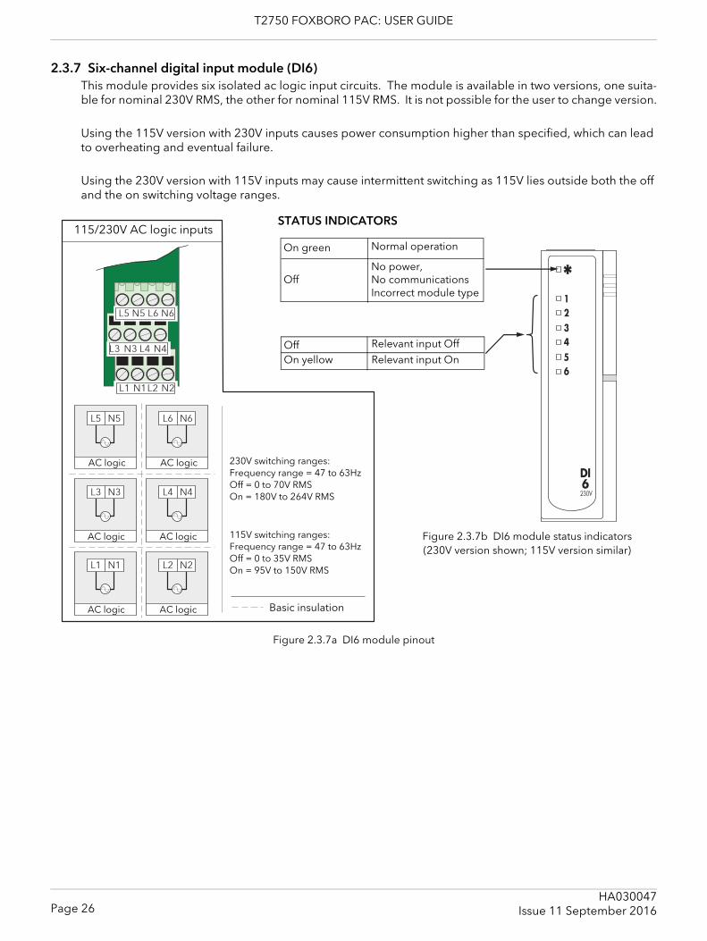
T2750 FOXBORO PAC: USER GUIDE
2.3.7 Six-channel digital input module (DI6) This module provides six isolated ac logic input circuits. The module is available in two versions, one suita-ble for nominal 230V RMS, the other for nominal 115V RMS. It is not possible for the user to change version.
Using the 115V version with 230V inputs causes power consumption higher than specified, which can lead to overheating and eventual failure.
Using the 230V version with 115V inputs may cause intermittent switching as 115V lies outside both the off and the on switching voltage ranges.
Figure 2.3.7a DI6 module pinout
AC logic AC logic
AC logic AC logic
AC logic AC logic
Normal operation
No power,No communicationsIncorrect module type
On green
Off
Relevant input OnOn yellowRelevant input OffOff
230V switching ranges:Frequency range = 47 to 63HzOff = 0 to 70V RMSOn = 180V to 264V RMS
115V switching ranges:Frequency range = 47 to 63HzOff = 0 to 35V RMSOn = 95V to 150V RMS
Figure 2.3.7b DI6 module status indicators(230V version shown; 115V version similar)
115/230V AC logic inputsSTATUS INDICATORS
Basic insulation
Page 26HA030047
Issue 11 September 2016
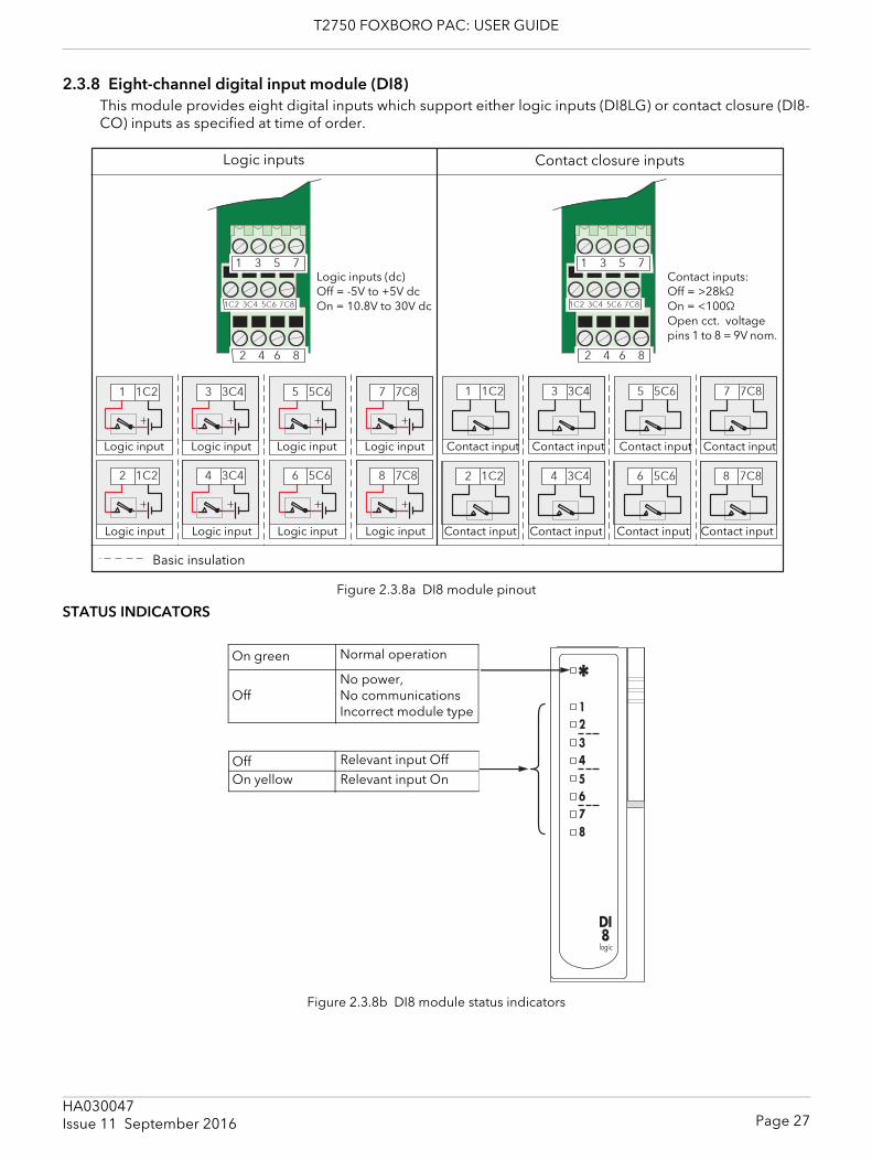
T2750 FOXBORO PAC: USER GUIDE
2.3.8 Eight-channel digital input module (DI8)This module provides eight digital inputs which support either logic inputs (DI8LG) or contact closure (DI8-CO) inputs as specified at time of order.
Figure 2.3.8a DI8 module pinout
STATUS INDICATORS
Figure 2.3.8b DI8 module status indicators
Logic input Contact input
Logic inputs (dc)Off = -5V to +5V dcOn = 10.8V to 30V dc
Contact inputs:Off = >28kΩOn = <100ΩOpen cct. voltage pins 1 to 8 = 9V nom.
Logic inputs Contact closure inputs
Logic input
Logic input
Logic input
Logic input
Logic input
Logic input
Logic input Contact input
Contact input
Contact input
Contact input
Contact input
Contact input
Contact input
Basic insulation
Normal operation
No power,No communicationsIncorrect module type
On green
Off
Relevant input OnOn yellowRelevant input OffOff
Page 27HA030047Issue 11 September 2016
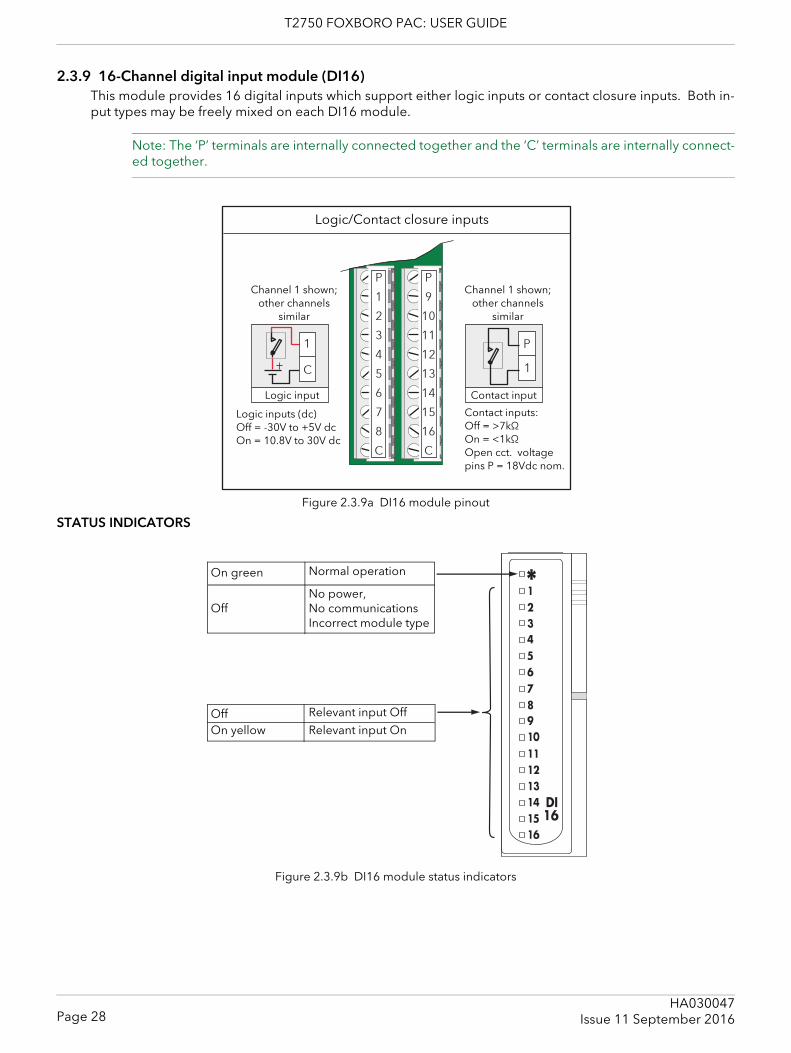
T2750 FOXBORO PAC: USER GUIDE
2.3.9 16-Channel digital input module (DI16)This module provides 16 digital inputs which support either logic inputs or contact closure inputs. Both in-put types may be freely mixed on each DI16 module.
Note: The ‘P’ terminals are internally connected together and the ‘C’ terminals are internally connect-ed together.
Figure 2.3.9a DI16 module pinout
STATUS INDICATORS
Figure 2.3.9b DI16 module status indicators
Logic/Contact closure inputs
Logic input Contact input
Channel 1 shown; other channels
similar
Channel 1 shown; other channels
similar
Logic inputs (dc)Off = -30V to +5V dcOn = 10.8V to 30V dc
Contact inputs:Off = >7kΩOn = <1kΩOpen cct. voltage pins P = 18Vdc nom.
Normal operation
No power,No communicationsIncorrect module type
On green
Off
Relevant input OnOn yellowRelevant input OffOff
Page 28HA030047
Issue 11 September 2016
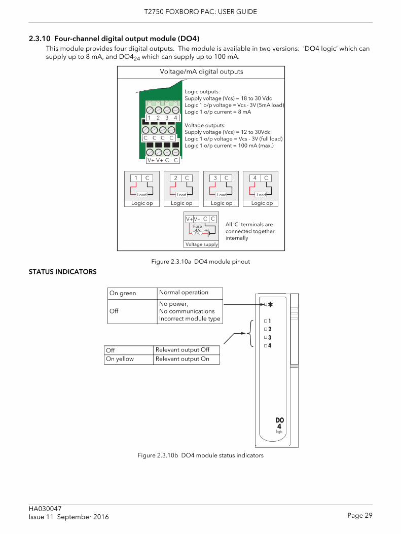
T2750 FOXBORO PAC: USER GUIDE
2.3.10 Four-channel digital output module (DO4)This module provides four digital outputs. The module is available in two versions: ‘DO4 logic’ which can supply up to 8 mA, and DO424 which can supply up to 100 mA.
Figure 2.3.10a DO4 module pinout
STATUS INDICATORS
Figure 2.3.10b DO4 module status indicators
Voltage/mA digital outputs
Logic op
Logic outputs:Supply voltage (Vcs) = 18 to 30 VdcLogic 1 o/p voltage = Vcs - 3V (5mA load)Logic 1 o/p current = 8 mA
Voltage outputs:Supply voltage (Vcs) = 12 to 30VdcLogic 1 o/p voltage = Vcs - 3V (full load)Logic 1 o/p current = 100 mA (max.)
Logic op Logic op Logic op
Voltage supply
Fuse4A
Load LoadLoadLoad
All ‘C’ terminals are connected together internally
Normal operation
No power,No communicationsIncorrect module type
On green
Off
Relevant output OnOn yellow
Relevant output OffOff
Page 29HA030047Issue 11 September 2016
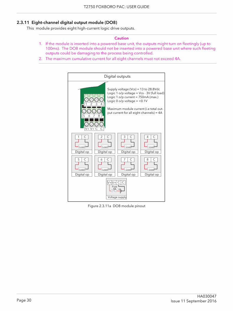
T2750 FOXBORO PAC: USER GUIDE
2.3.11 Eight-channel digital output module (DO8)This module provides eight high-current logic drive outputs.
Caution1. If the module is inserted into a powered base unit, the outputs might turn on fleetingly (up to
100ms). The DO8 module should not be inserted into a powered base unit where such fleeting outputs could be damaging to the process being controlled.
2. The maximum cumulative current for all eight channels must not exceed 4A.
Figure 2.3.11a DO8 module pinout
Digital op Digital op Digital op Digital op
Voltage supply
Fuse4A
Load LoadLoadLoad
Digital op Digital op Digital op Digital op
Load LoadLoadLoad
Supply voltage (Vcs) = 13 to 28.8VdcLogic 1 o/p voltage = Vcs - 3V (full load)Logic 1 o/p current = 750mA (max.)Logic 0 o/p voltage = <0.1V
Maximum module current (i.e total out-put current for all eight channels) = 4A
Digital outputs
Page 30HA030047
Issue 11 September 2016
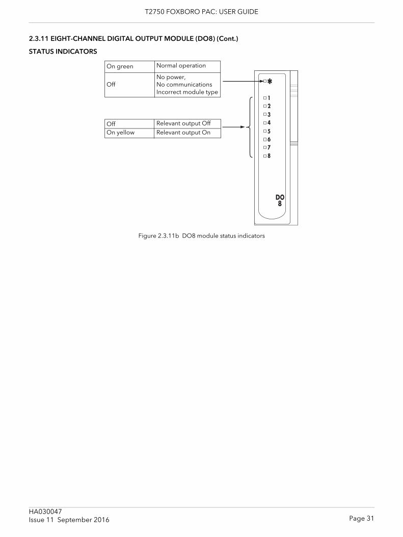
T2750 FOXBORO PAC: USER GUIDE
2.3.11 EIGHT-CHANNEL DIGITAL OUTPUT MODULE (DO8) (Cont.)
STATUS INDICATORS
Figure 2.3.11b DO8 module status indicators
Normal operation
No power,No communicationsIncorrect module type
On green
Off
Relevant output OnOn yellowRelevant output OffOff
Page 31HA030047Issue 11 September 2016
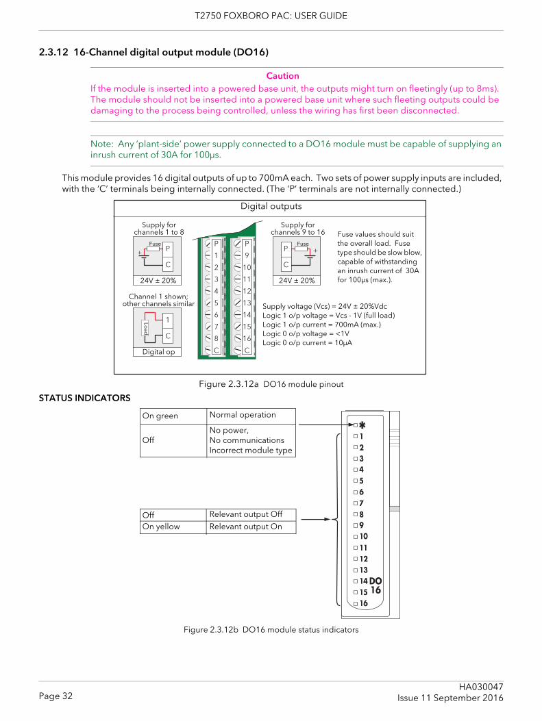
T2750 FOXBORO PAC: USER GUIDE
2.3.12 16-Channel digital output module (DO16)
CautionIf the module is inserted into a powered base unit, the outputs might turn on fleetingly (up to 8ms). The module should not be inserted into a powered base unit where such fleeting outputs could be damaging to the process being controlled, unless the wiring has first been disconnected.
Note: Any ‘plant-side’ power supply connected to a DO16 module must be capable of supplying an inrush current of 30A for 100μs.
This module provides 16 digital outputs of up to 700mA each. Two sets of power supply inputs are included, with the ‘C’ terminals being internally connected. (The ‘P’ terminals are not internally connected.)
Figure 2.3.12a DO16 module pinout
STATUS INDICATORS
Figure 2.3.12b DO16 module status indicators
Channel 1 shown; other channels similar
Supply for channels 1 to 8
Supply for channels 9 to 16
24V ± 20%24V ± 20%
Load
Digital outputs
Digital op
Supply voltage (Vcs) = 24V ± 20%VdcLogic 1 o/p voltage = Vcs - 1V (full load)Logic 1 o/p current = 700mA (max.)Logic 0 o/p voltage = <1VLogic 0 o/p current = 10μA
FuseFuse
Fuse values should suit the overall load. Fuse type should be slow blow, capable of withstanding an inrush current of 30A for 100μs (max.).
Normal operation
No power,No communicationsIncorrect module type
On green
Off
Relevant output OnOn yellow
Relevant output OffOff
Page 32HA030047
Issue 11 September 2016
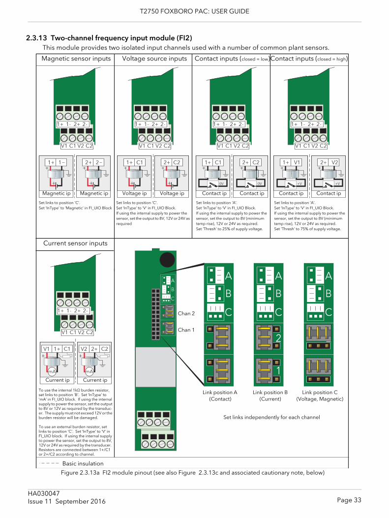
T2750 FOXBORO PAC: USER GUIDE
2.3.13 Two-channel frequency input module (FI2)This module provides two isolated input channels used with a number of common plant sensors.
Figure 2.3.13a FI2 module pinout (see also Figure 2.3.13c and associated cautionary note, below)
Magnetic sensor inputs Voltage source inputs Contact inputs (closed = low)Contact inputs (closed = high)
Current sensor inputs
Set links to position ‘C’.Set ‘InType’ to ‘Magnetic’ in FI_UIO Block
Set links to position ‘C’.Set ‘InType’ to ‘V’ in FI_UIO Block. If using the internal supply to power the sensor, set the output to 8V, 12V or 24V as required
Set links to position ‘A’.Set ‘InType’ to ‘V’ in FI_UIO Block. If using the internal supply to power the sensor, set the output to 8V (minimum temp rise), 12V or 24V as required.Set ‘Thresh’ to 25% of supply voltage.
Set links to position ‘A’.Set ‘InType’ to ‘V’ in FI_UIO Block. If using the internal supply to power the sensor, set the output to 8V (minimum temp rise), 12V or 24V as required.Set ‘Thresh’ to 75% of supply voltage.
To use the internal 1kΩ burden resistor, set links to position ‘B’. Set ‘InType’ to ‘mA’ in FI_UIO block. If using the internal supply to power the sensor, set the output to 8V or 12V as required by the transduc-er. The supply must not exceed 12V or the burden resistor will be damaged.
To use an external burden resistor, set links to position ‘C’. Set ‘InType’ to ‘V’ in FI_UIO block. If using the internal supply to power the sensor, set the output to 8V, 12V or 24V as required by the transducer. Resistors are connected between 1+/C1 or 2+/C2 according to channel.
Current ip Current ip
Magnetic ip Magnetic ip Voltage ip Voltage ip Contact ip Contact ip Contact ip Contact ip
Link position A (Contact)
Link position B (Current)
Link position C (Voltage, Magnetic)
Chan 2
Chan 1
Set links independently for each channel
Basic insulation
Page 33HA030047Issue 11 September 2016
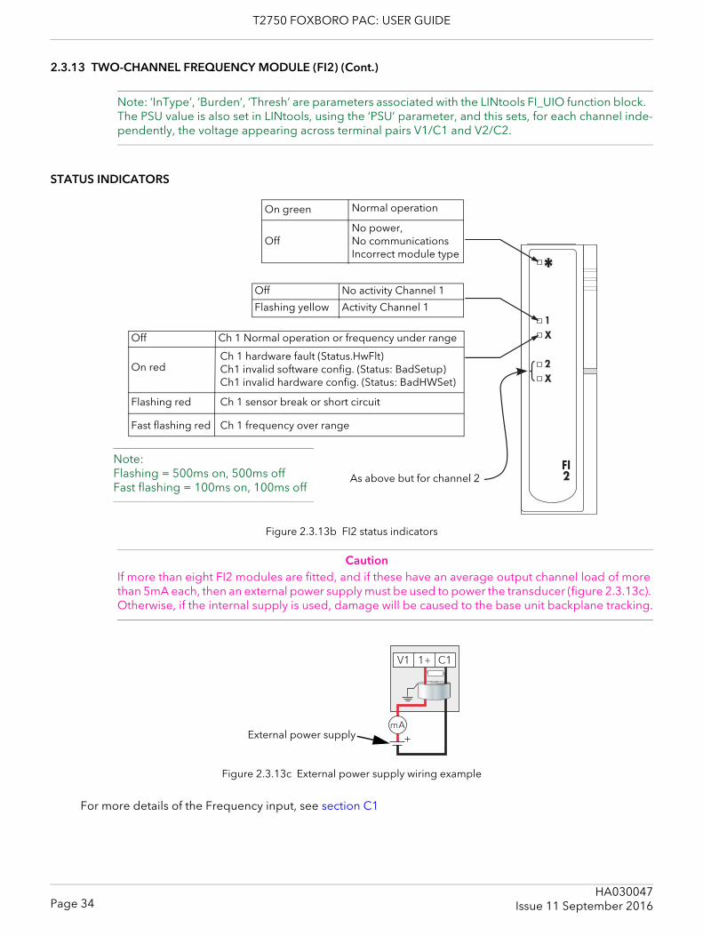
T2750 FOXBORO PAC: USER GUIDE
2.3.13 TWO-CHANNEL FREQUENCY MODULE (FI2) (Cont.)
Note: ‘InType’, ‘Burden’, ‘Thresh’ are parameters associated with the LINtools FI_UIO function block. The PSU value is also set in LINtools, using the ‘PSU’ parameter, and this sets, for each channel inde-pendently, the voltage appearing across terminal pairs V1/C1 and V2/C2.
STATUS INDICATORS
Figure 2.3.13b FI2 status indicators
CautionIf more than eight FI2 modules are fitted, and if these have an average output channel load of more than 5mA each, then an external power supply must be used to power the transducer (figure 2.3.13c). Otherwise, if the internal supply is used, damage will be caused to the base unit backplane tracking.
Figure 2.3.13c External power supply wiring example
For more details of the Frequency input, see section C1
Normal operation
No power,No communicationsIncorrect module type
On green
Off
Ch 1 hardware fault (Status.HwFlt)Ch1 invalid software config. (Status: BadSetup)Ch1 invalid hardware config. (Status: BadHWSet)
As above but for channel 2
Note:Flashing = 500ms on, 500ms offFast flashing = 100ms on, 100ms off
No activity Channel 1Off
Activity Channel 1Flashing yellow
Ch 1 Normal operation or frequency under rangeOff
On red
Flashing red Ch 1 sensor break or short circuit
Fast flashing red Ch 1 frequency over range
External power supply
Page 34HA030047
Issue 11 September 2016
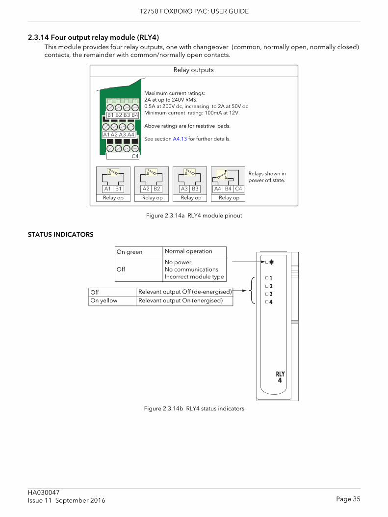
T2750 FOXBORO PAC: USER GUIDE
2.3.14 Four output relay module (RLY4)This module provides four relay outputs, one with changeover (common, normally open, normally closed) contacts, the remainder with common/normally open contacts.
Figure 2.3.14a RLY4 module pinout
STATUS INDICATORS
Figure 2.3.14b RLY4 status indicators
Maximum current ratings: 2A at up to 240V RMS.0.5A at 200V dc, increasing to 2A at 50V dcMinimum current rating: 100mA at 12V.
Above ratings are for resistive loads.
See section A4.13 for further details.
Relay outputs
Relay op Relay op Relay op Relay op
Relays shown in power off state.
Normal operation
No power,No communicationsIncorrect module type
On green
Off
On yellowRelevant output Off (de-energised)OffRelevant output On (energised)
Page 35HA030047Issue 11 September 2016
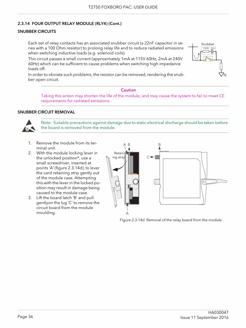
T2750 FOXBORO PAC: USER GUIDE
2.3.14 FOUR OUTPUT RELAY MODULE (RLY4) (Cont.)
SNUBBER CIRCUITS
Each set of relay contacts has an associated snubber circuit (a 22nF capacitor in se-ries with a 100 Ohm resistor) to prolong relay life and to reduce radiated emissions when switching inductive loads (e.g. solenoid coils). This circuit passes a small current (approximately 1mA at 115V 60Hz; 2mA at 240V 60Hz) which can be sufficient to cause problems when switching high impedance loads off.In order to obviate such problems, the resistor can be removed, rendering the snub-ber open circuit.
CautionTaking this action may shorten the life of the module, and may cause the system to fail to meet CE requirements for radiated emissions.
SNUBBER CIRCUIT REMOVAL
Note: Suitable precautions against damage due to static electrical discharge should be taken before the board is removed from the module.
1. Remove the module from its ter-minal unit.
2. With the module locking lever in the unlocked position*, use a small screwdriver, inserted at points ‘A’ (figure 2.3.14d), to lever the card retaining strip gently out of the module case. Attempting this with the lever in the locked po-sition may result in damage being caused to the module case.
3. Lift the board latch ‘B’ and pull gentlyon the lug ‘C’ to remove the circuit board from the module moulding.
Snubber
Retain-ing strip
Figure 2.3.14d Removal of the relay board from the module
Page 36HA030047
Issue 11 September 2016
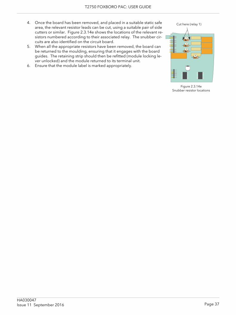
T2750 FOXBORO PAC: USER GUIDE
4. Once the board has been removed, and placed in a suitable static safe area, the relevant resistor leads can be cut, using a suitable pair of side cutters or similar. Figure 2.3.14e shows the locations of the relevant re-sistors numbered according to their associated relay. The snubber cir-cuits are also identified on the circuit board.
5. When all the appropriate resistors have been removed, the board can be returned to the moulding, ensuring that it engages with the board guides. The retaining strip should then be refitted (module locking le-ver unlocked) and the module returned to its terminal unit.
6. Ensure that the module label is marked appropriately.
Figure 2.3.14e Snubber resistor locations
Cut here (relay 1)
Page 37HA030047Issue 11 September 2016
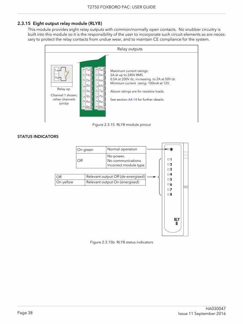
T2750 FOXBORO PAC: USER GUIDE
2.3.15 Eight output relay module (RLY8)This module provides eight relay outputs with common/normally open contacts. No snubber circuitry is built into this module so it is the responsibility of the user to incorporate such circuit elements as are neces-sary to protect the relay contacts from undue wear, and to maintain CE compliance for the system.
Figure 2.3.15 RLY8 module pinout
STATUS INDICATORS
Figure 2.3.15b RLY8 status indicators
Relay outputs
Maximum current ratings: 2A at up to 240V RMS.0.5A at 200V dc, increasing to 2A at 50V dcMinimum current rating: 100mA at 12V.
Above ratings are for resistive loads.
See section A4.14 for further details.Channel 1 shown;
other channels similar
Relay op
Normal operation
No power,No communicationsIncorrect module type
On green
Off
On yellowRelevant output Off (de-energised)OffRelevant output On (energised)
Page 38HA030047
Issue 11 September 2016
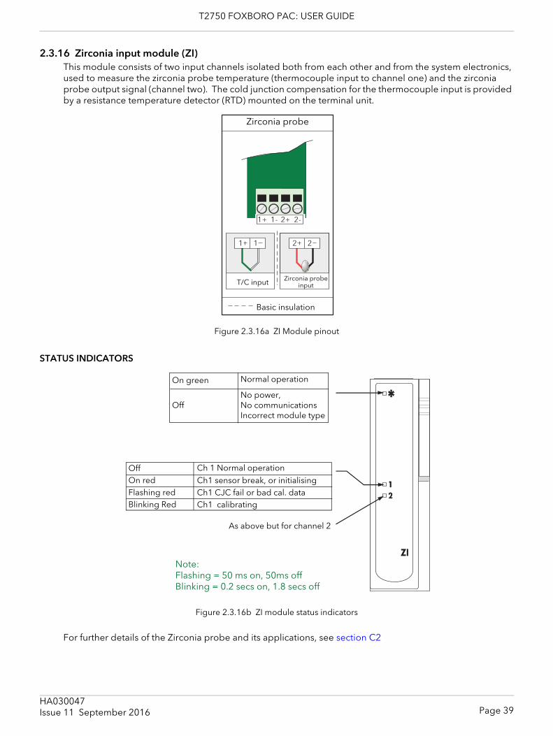
T2750 FOXBORO PAC: USER GUIDE
2.3.16 Zirconia input module (ZI)This module consists of two input channels isolated both from each other and from the system electronics, used to measure the zirconia probe temperature (thermocouple input to channel one) and the zirconia probe output signal (channel two). The cold junction compensation for the thermocouple input is provided by a resistance temperature detector (RTD) mounted on the terminal unit.
Figure 2.3.16a ZI Module pinout
STATUS INDICATORS
Figure 2.3.16b ZI module status indicators
For further details of the Zirconia probe and its applications, see section C2
Zirconia probe
T/C input Zirconia probe input
Basic insulation
1
Normal operation
No power,No communicationsIncorrect module type
On green
Off
Ch 1 Normal operationCh1 sensor break, or initialising
As above but for channel 2
OffOn redFlashing redBlinking Red
Ch1 CJC fail or bad cal. dataCh1 calibrating
Note:Flashing = 50 ms on, 50ms offBlinking = 0.2 secs on, 1.8 secs off
Page 39HA030047Issue 11 September 2016
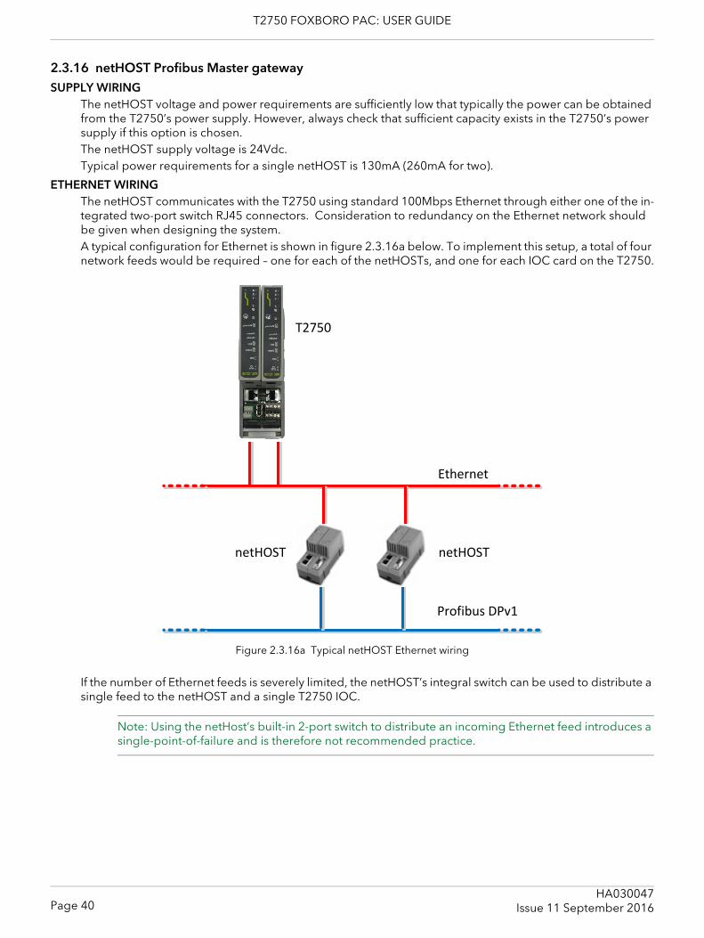
T2750 FOXBORO PAC: USER GUIDE
2.3.16 netHOST Profibus Master gatewaySUPPLY WIRING
The netHOST voltage and power requirements are sufficiently low that typically the power can be obtained from the T2750’s power supply. However, always check that sufficient capacity exists in the T2750’s power supply if this option is chosen.The netHOST supply voltage is 24Vdc.Typical power requirements for a single netHOST is 130mA (260mA for two).
ETHERNET WIRINGThe netHOST communicates with the T2750 using standard 100Mbps Ethernet through either one of the in-tegrated two-port switch RJ45 connectors. Consideration to redundancy on the Ethernet network should be given when designing the system.A typical configuration for Ethernet is shown in figure 2.3.16a below. To implement this setup, a total of four network feeds would be required – one for each of the netHOSTs, and one for each IOC card on the T2750.
Figure 2.3.16a Typical netHOST Ethernet wiring
If the number of Ethernet feeds is severely limited, the netHOST’s integral switch can be used to distribute a single feed to the netHOST and a single T2750 IOC.
Note: Using the netHost’s built-in 2-port switch to distribute an incoming Ethernet feed introduces a single-point-of-failure and is therefore not recommended practice.
Profibus DPv1
T2750
Ethernet
netHOSTnetHOST
Page 40HA030047
Issue 11 September 2016
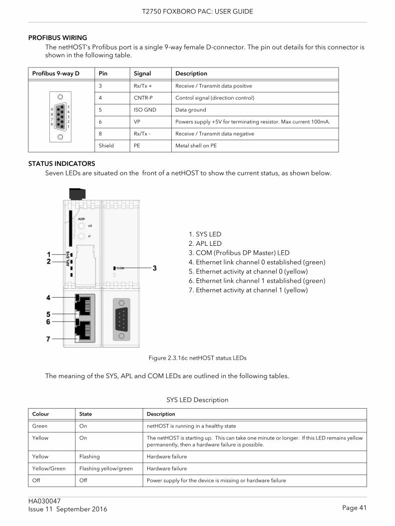
T2750 FOXBORO PAC: USER GUIDE
PROFIBUS WIRINGThe netHOST’s Profibus port is a single 9-way female D-connector. The pin out details for this connector is shown in the following table.
STATUS INDICATORSSeven LEDs are situated on the front of a netHOST to show the current status, as shown below.
Figure 2.3.16c netHOST status LEDs
The meaning of the SYS, APL and COM LEDs are outlined in the following tables.
Profibus 9-way D Pin Signal Description
3 Rx/Tx + Receive / Transmit data positive
4 CNTR-P Control signal (direction control)
5 ISO GND Data ground
6 VP Powers supply +5V for terminating resistor. Max current 100mA.
8 Rx/Tx - Receive / Transmit data negative
Shield PE Metal shell on PE
SYS LED Description
Colour State Description
Green On netHOST is running in a healthy state
Yellow On The netHOST is starting up. This can take one minute or longer. If this LED remains yellowpermanently, then a hardware failure is possible.
Yellow Flashing Hardware failure
Yellow/Green Flashing yellow/green Hardware failure
Off Off Power supply for the device is missing or hardware failure
54321
9876
1. SYS LED2. APL LED3. COM (Profibus DP Master) LED4. Ethernet link channel 0 established (green)5. Ethernet activity at channel 0 (yellow)6. Ethernet link channel 1 established (green)7. Ethernet activity at channel 1 (yellow)
Page 41HA030047Issue 11 September 2016
T2750 FOXBORO PAC: USER GUIDE
APL LED Description
Colour State Description
Green On Ethernet configured and Profibus communications running.
Green Flashing Ethernet configured, but Profibus not running.
Red On Configuration files are missing.
Red Flashing Configuration files in error, or not loaded.
Com LED Description
Colour State Description
Green On Profibus communication established to all slaves.
Green Flashing irregularly Configuration error.
Green Flashing regularly Profibus is configured, but communications not yet started (this should only be a transientcondition as the T2750 starts up).
Red Flashing Profibus communication to at least one or more slaves is disconnected.
Red On Profibus communications to all slaves is disconnected.
Page 42HA030047
Issue 11 September 2016

T2750 FOXBORO PAC: USER GUIDE
2.4 HARDWARE CONFIGURATION2.4.1 LIN address
Each LIN instrument must have an address which is unique to the network. This address is configured by means of a DIL switch (SW1) located on the IOC terminal unit. Setting an address at this switch automatically sets a pair of contiguous addresses where the set address (e.g. 7A) is associated with the primary unit and the next address (7B in this example) is associated with the secondary module. The primary always takes the even address.Figure 2.4.1 shows the detail.
Figure 2.4.1 LIN Address setting
2.4.2 LIN option switch
Figure 2.4.2 LIN option switch
A second DIP switch (SW2) on the IOC terminal unit allows the following settings:
START UP STRATEGYThis is set by the Hot Start (HS) and Cold start (CS) elements, as shown in table 2.4.2, below.
Table 2.4.2 Start up strategy setting switches
HS CS
Off Off Automatically generate new database at each start-up.Off On Attempt cold start. Halt if unsuccessful.On Off Attempt hot start. Halt if unsuccessfulOn On Attempt hot start. If unsuccessful attempt cold start. Halt if unsuccessful.
HS
CSWR
OFF
1 1
1 1
HS
CSWR
OFFHS
CSWR
OFF
Page 43HA030047Issue 11 September 2016
T2750 FOXBORO PAC: USER GUIDE
2.4.2 LIN OPTION SWITCHES (Cont.)
START UP STRATEGY (cont.)Cold start The instrument attempts to start up from a previous database, using default parameter
values.Hot start The instrument attempts to start from where it stopped running.
WATCHDOG RETRYSetting this switch element ‘On’, causes the instrument to try to start again, after a watchdog failure. Setting the switch ‘Off’ means that the instrument must be restarted manually after any watchdog failure.
2.4.3 IP Address settingEach instrument must have an IP address set which is unique to the communications network. The address is set using LINtools, and can be fixed, or automatically allocated by the network. Each instrument uses a one-to-one mapping of LIN node number and IP address, as defined in a file called the ‘network.unh’ file.It is normally necessary for the user to get advice from his or her IT department, or network administrator before attempting to set IP addresses, as setting duplicate addresses can cause severe communications problems.
MANUALThe IP Address is explicitly defined in the ‘network.unh‘ file. It is not recommended to edit this file directly. Instead, use LINtools or the Instrument Options Editor to make changes to this file. Refer to “SETTING PROCEDURE” on page 45 for further details.
DHCPA DHCP server is required that has been configured to respond correctly to IP address requests. This con-figuration depends on the company network policy.DHCP is a method whereby the instrument requests an IP Address from a DHCP server. This happens at start-up, but can be repeated during operation. DHCP includes the concept of ‘leases’ (i.e. the assigned value will ‘expire’).Using DHCP extends the processor restart time because it takes some time for the DHCP server to respond.
BOOTPBootP or Bootstrap Protocol is used by a network computer to obtain an IP Address and other network in-formation such as server address and Default Gateway. Upon startup, the client station sends out a BOOTP request to the BOOTP server, which returns the required information. A BootPtimeout period can be con-figured. If this period elapses before the IP Address, Subnet mask, and Default Gateway address are ob-tained, the values are automatically reset to 0.0.0.0.
LINK-LOCALLink-Local is used as a fallback to either DHCP or BootP, or can be used on its own as the only IP Address configuration method. Link-Local always assigns an IP Address in the range 169.254.X.Y. This IP Address range is reserved for use by Link-Local and is explicitly defined as private and non-routable.The Link-Local algorithm ensures that an instrument (IP host) on a network chooses a unique IP Address from the Link-Local range.To make a direct connection between a PC and the T2750 using Link-Local, the PC’s network port must be configured to obtain an IP address automatically using the standard Windows control panel.
Page 44HA030047
Issue 11 September 2016
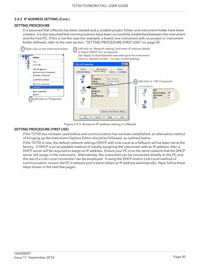
T2750 FOXBORO PAC: USER GUIDE
2.4.3 IP ADDRESS SETTING (Cont.)
SETTING PROCEDUREIt is assumed that LINtools has been started and a suitable project folder and instrument folder have been created. It is also assumed that communications have been successfully established between the instrument and the host PC. If this is not the case (for example, a brand new instrument with no project or instrument folder defined), refer to the next section, “SETTING PROCEDURE (FIRST USE)” on page 45.
Figure 2.4.3 Access to IP address setting in LINtools
SETTING PROCEDURE (FIRST USE)If the T2750 has not been used before and communication has not been established, an alternative method of bringing up the Instrument Options Editor should be followed, as outlined below.If the T2750 is new, the default network settings (DHCP with Link-Local as a fallback) will be been set at the factory. If DHCP is an acceptable method of initially assigning the instrument with an IP address, then a DHCP server will be required to assign an IP address. Ensure your PC is on the same network that the DHCP server will assign in the instrument. Alternatively, the instrument can be connected directly to the PC and the use of a Link-Local connection can be employed. If using the DHCP and/or Link-Local method of communication, ensure the PC’s network port is set to obtain an IP address automatically. Next, follow these steps shown in the next few pages.
Right click on the Instrument folder1
Left click on ‘Properties’2
Left click on ‘Network settings’ and enter IP address detailsor select ‘DHCP’ etc. as required.Use ‘Apply’ to download the new settings to the instrument.Click on ‘Upload current...’ to view current settings
3
Left click on ‘LIN’ if required4
Page 45HA030047Issue 11 September 2016
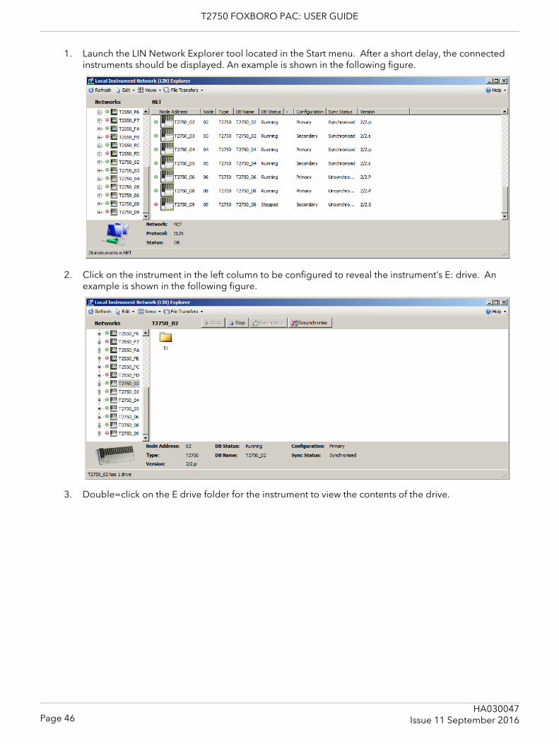
T2750 FOXBORO PAC: USER GUIDE
1. Launch the LIN Network Explorer tool located in the Start menu. After a short delay, the connected instruments should be displayed. An example is shown in the following figure.
2. Click on the instrument in the left column to be configured to reveal the instrument’s E: drive. An example is shown in the following figure.
3. Double=click on the E drive folder for the instrument to view the contents of the drive.
Page 46HA030047
Issue 11 September 2016
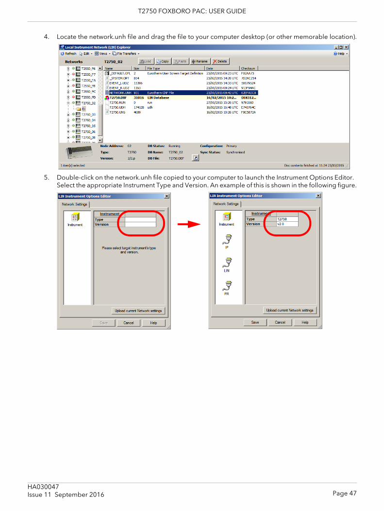
T2750 FOXBORO PAC: USER GUIDE
4. Locate the network.unh file and drag the file to your computer desktop (or other memorable location).
5. Double-click on the network.unh file copied to your computer to launch the Instrument Options Editor. Select the appropriate Instrument Type and Version. An example of this is shown in the following figure.
Page 47HA030047Issue 11 September 2016
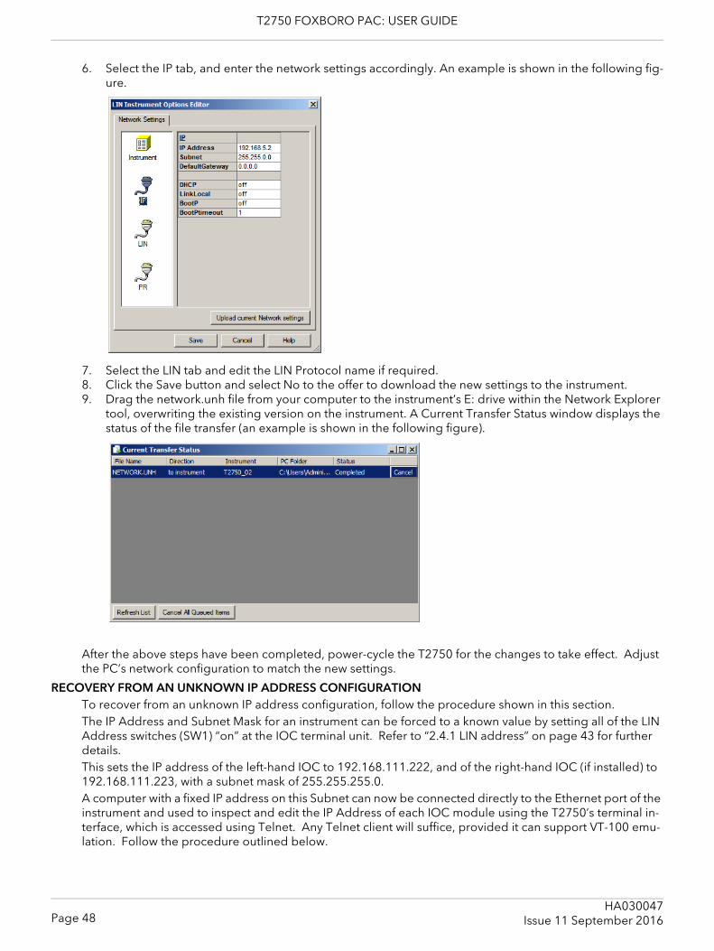
T2750 FOXBORO PAC: USER GUIDE
6. Select the IP tab, and enter the network settings accordingly. An example is shown in the following fig-ure.
7. Select the LIN tab and edit the LIN Protocol name if required.8. Click the Save button and select No to the offer to download the new settings to the instrument.9. Drag the network.unh file from your computer to the instrument’s E: drive within the Network Explorer
tool, overwriting the existing version on the instrument. A Current Transfer Status window displays the status of the file transfer (an example is shown in the following figure).
After the above steps have been completed, power-cycle the T2750 for the changes to take effect. Adjust the PC’s network configuration to match the new settings.
RECOVERY FROM AN UNKNOWN IP ADDRESS CONFIGURATIONTo recover from an unknown IP address configuration, follow the procedure shown in this section.The IP Address and Subnet Mask for an instrument can be forced to a known value by setting all of the LIN Address switches (SW1) “on” at the IOC terminal unit. Refer to “2.4.1 LIN address” on page 43 for further details.This sets the IP address of the left-hand IOC to 192.168.111.222, and of the right-hand IOC (if installed) to 192.168.111.223, with a subnet mask of 255.255.255.0.A computer with a fixed IP address on this Subnet can now be connected directly to the Ethernet port of the instrument and used to inspect and edit the IP Address of each IOC module using the T2750’s terminal in-terface, which is accessed using Telnet. Any Telnet client will suffice, provided it can support VT-100 emu-lation. Follow the procedure outlined below.
Page 48HA030047
Issue 11 September 2016
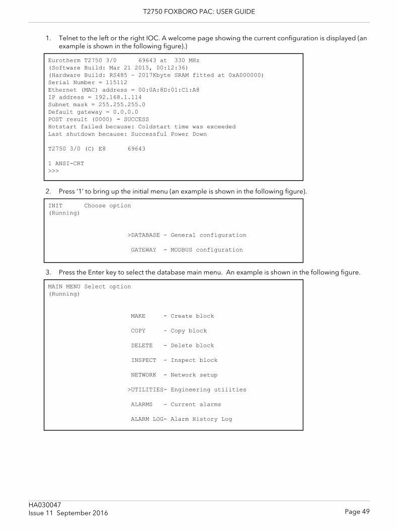
T2750 FOXBORO PAC: USER GUIDE
1. Telnet to the left or the right IOC. A welcome page showing the current configuration is displayed (an example is shown in the following figure).)
2. Press ‘1’ to bring up the initial menu (an example is shown in the following figure).
3. Press the Enter key to select the database main menu. An example is shown in the following figure.
Eurotherm T2750 3/0 69643 at 330 MHz(Software Build: Mar 21 2015, 00:12:36)(Hardware Build: RS485 - 2017Kbyte SRAM fitted at 0xA000000)Serial Number = 115112Ethernet (MAC) address = 00:0A:8D:01:C1:A8IP address = 192.168.1.114Subnet mask = 255.255.255.0Default gateway = 0.0.0.0POST result (0000) = SUCCESSHotstart failed because: Coldstart time was exceededLast shutdown because: Successful Power Down
T2750 3/0 (C) E8 69643
1 ANSI-CRT>>>
INIT Choose option(Running)
>DATABASE - General configuration
GATEWAY - MODBUS configuration
MAIN MENU Select option(Running)
MAKE - Create block
COPY - Copy block
DELETE - Delete block
INSPECT - Inspect block
NETWORK - Network setup
>UTILITIES- Engineering utilities
ALARMS - Current alarms
ALARM LOG- Alarm History Log
Page 49HA030047Issue 11 September 2016
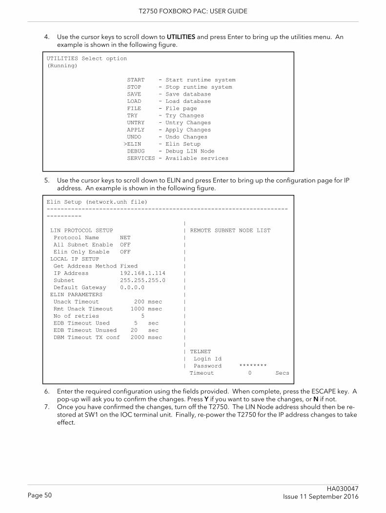
T2750 FOXBORO PAC: USER GUIDE
4. Use the cursor keys to scroll down to UTILITIES and press Enter to bring up the utilities menu. An example is shown in the following figure.
5. Use the cursor keys to scroll down to ELIN and press Enter to bring up the configuration page for IP address. An example is shown in the following figure.
6. Enter the required configuration using the fields provided. When complete, press the ESCAPE key. A pop-up will ask you to confirm the changes. Press Y if you want to save the changes, or N if not.
7. Once you have confirmed the changes, turn off the T2750. The LIN Node address should then be re-stored at SW1 on the IOC terminal unit. Finally, re-power the T2750 for the IP address changes to take effect.
UTILITIES Select option(Running)
START - Start runtime system STOP - Stop runtime system SAVE - Save database LOAD - Load database FILE - File page TRY - Try Changes UNTRY - Untry Changes APPLY - Apply Changes UNDO - Undo Changes >ELIN - Elin Setup DEBUG - Debug LIN Node SERVICES - Available services
Elin Setup (network.unh file)------------------------------------------------------------------------------- | LIN PROTOCOL SETUP | REMOTE SUBNET NODE LIST Protocol Name NET | All Subnet Enable OFF | Elin Only Enable OFF | LOCAL IP SETUP | Get Address Method Fixed | IP Address 192.168.1.114 | Subnet 255.255.255.0 | Default Gateway 0.0.0.0 | ELIN PARAMETERS | Unack Timeout 200 msec | Rmt Unack Timeout 1000 msec | No of retries 5 | EDB Timeout Used 5 sec | EDB Timeout Unused 20 sec | DBM Timeout TX conf 2000 msec | | | TELNET | Login Id | Password ******** Timeout 0 Secs
Page 50HA030047
Issue 11 September 2016
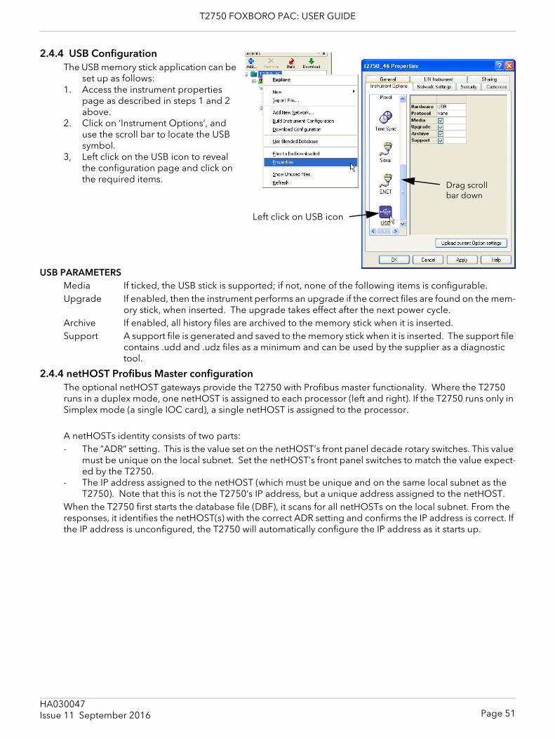
T2750 FOXBORO PAC: USER GUIDE
2.4.4 USB ConfigurationThe USB memory stick application can be
set up as follows:1. Access the instrument properties
page as described in steps 1 and 2 above.
2. Click on ’Instrument Options’, and use the scroll bar to locate the USB symbol.
3, Left click on the USB icon to reveal the configuration page and click on the required items.
USB PARAMETERSMedia If ticked, the USB stick is supported; if not, none of the following items is configurable.Upgrade If enabled, then the instrument performs an upgrade if the correct files are found on the mem-
ory stick, when inserted. The upgrade takes effect after the next power cycle.Archive If enabled, all history files are archived to the memory stick when it is inserted.Support A support file is generated and saved to the memory stick when it is inserted. The support file
contains .udd and .udz files as a minimum and can be used by the supplier as a diagnostic tool.
2.4.4 netHOST Profibus Master configurationThe optional netHOST gateways provide the T2750 with Profibus master functionality. Where the T2750 runs in a duplex mode, one netHOST is assigned to each processor (left and right). If the T2750 runs only in Simplex mode (a single IOC card), a single netHOST is assigned to the processor.
A netHOSTs identity consists of two parts:- The “ADR” setting. This is the value set on the netHOST’s front panel decade rotary switches. This value
must be unique on the local subnet. Set the netHOST’s front panel switches to match the value expect-ed by the T2750.
- The IP address assigned to the netHOST (which must be unique and on the same local subnet as the T2750). Note that this is not the T2750’s IP address, but a unique address assigned to the netHOST.
When the T2750 first starts the database file (DBF), it scans for all netHOSTs on the local subnet. From the responses, it identifies the netHOST(s) with the correct ADR setting and confirms the IP address is correct. If the IP address is unconfigured, the T2750 will automatically configure the IP address as it starts up.
Left click on USB icon
Drag scroll bar down
Page 51HA030047Issue 11 September 2016
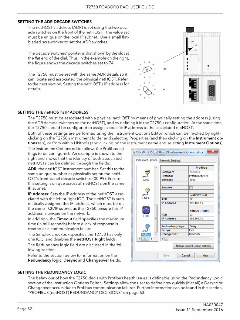
T2750 FOXBORO PAC: USER GUIDE
SETTING THE ADR DECADE SWITCHESThe netHOST’s address (ADR) is set using the two dec-ade switches on the front of the netHOST. The value set must be unique on the local IP subnet. Use a small flat-bladed screwdriver to set the ADR switches.
The decade switches’ pointer is that shown by the slot at the flat end of the dial. Thus, in the example on the right, the figure shows the decade switches set to 74.
The T2750 must be set with the same ADR details so it can locate and associated the physical netHOST. Refer to the next section, Setting the netHOST’s IP address for details.
SETTING THE netHOST’s IP ADDRESSThe T2750 must be associated with a physical netHOST by means of physically setting the address (using the ADR decade switches on the netHOST), and by defining it in the T2750’s configuration. At the same time, the T2750 should be configured to assign a specific IP address to the associated netHOST.Both of these settings are performed using the Instrument Options Editor, which can be invoked by right-clicking on the T2750’s instrument folder and selecting Properties (and then clicking on the Instrument op-tions tab), or from within LINtools (and clicking on the instrument name and selecting Instrument Options).The Instrument Options editor allows the Profibus set-tings to be configured. An example is shown to the right and shows that the identity of both associated netHOSTs can be defined through the fields:ADR: the netHOST instrument number. Set this to the same unique number as physically set on the netH-OST’s front-panel decade switches (00-99). Ensure this setting is unique across all netHOSTs on the same IP subnet.IP Address: Sets the IP address of the netHOST asso-ciated with the left or right IOC. The netHOST is auto-matically assigned this IP address, which must be on the same TCP/IP subnet as the T2750. Ensure this IP address is unique on the network.In addition, the Timeout field specifies the maximum time (in milliseconds) before a lack of response is treated as a communication failure.The Simplex checkbox specifies the T2750 has only one IOC, and disables the netHOST Right fields.The Redundancy logic field are discussed in the fol-lowing section.Refer to the section below for information on theRedundancy logic, Desync and Changeover fields.
SETTING THE REDUNDANCY LOGICThe behaviour of how the T2750 deals with Profibus health issues is definable using the Redundancy Logic section of the Instruction Options Editor. Settings allow the user to define how quickly (if at all) a Desync or Changeover occurs due to Profibus communication failures. Further information can be found in the section, “PROFIBUS (netHOST) REDUNDANCY DECISIONS” on page 63.
Page 52HA030047
Issue 11 September 2016

T2750 FOXBORO PAC: USER GUIDE
Desync: This field determines how the T2750 reacts if the secondary IOC has a worse view of the Profibus network than does the primary and when desync will occur. This is only applicable in duplex IOC configu-rations (that is, if the Simplex field is ticked, this field will not be editable). The three options are:- 'Disable'. The T2750 ignores the situation (the IOCs never desync due to a Profibus health issue).- 'Fast'. This is the default operation. The T2750 desyncs if the situation persist for 1800mS. This allows
the status of the secondary to be checked prior to desynchronising. Selecting 'Fast' prioritises Profibus health over ELIN health for desync decisions.
- 'Slow'. The T2750 desyncs if the situation persists for 8000mS. Selecting 'Slow' prioritises ELIN health over Profibus health for desync decisions. Care should be taken when setting the Desync option to 'Slow' if Profibus I/O is an essential part of the strategy.
Changeover: This field determines how the T2750 reacts if the Primary cannot see any of the configured nodes on the Profibus network and when an IOC changeover will occur. This is only applicable in duplex IOC configurations (that is, if the Simplex field is ticked, this field will not be editable). The four options are:- 'Disable'. The T2750 ignores the situation (the IOCs never changeover due to a Profibus health issue).- 'Immediate'. This is the default operation. The primary IOC effects a changeover as soon as it can no
longer communicate to any of the configured Profibus slaves, without checking whether the secondary IOC has a better view of the Profibus network.
- 'Fast'. If the primary IOC is unable to communicate with any of the configured Profibus slaves and the secondary IOC cannot view the primary on the Profibus network, then the IOCs will changeover if this situation lasts for 250mS. This prioritises Profibus health over ELIN health for changeover decisions.
- 'Slow'. If the primary IOC is unable to communicate with any of the configured Profibus slaves and the secondary IOC cannot view the primary on the Profibus network, then the IOCs will changeover if this situation lasts for 8000mS. This prioritises ELIN health over Profibus health for changeover decisions. Care should be taken when setting the changeover option to 'Slow' if Profibus I/O is an essential part of the strategy.
Page 53HA030047Issue 11 September 2016
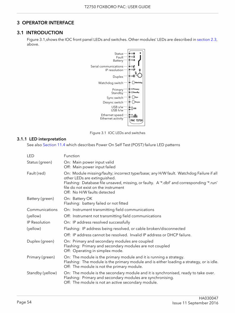
T2750 FOXBORO PAC: USER GUIDE
3 OPERATOR INTERFACE
3.1 INTRODUCTIONFigure 3.1,shows the IOC front panel LEDs and switches. Other modules’ LEDs are described in section 2.3, above.
Figure 3.1 IOC LEDs and switches
3.1.1 LED interpretationSee also Section 11.4 which describes Power On Self Test (POST) failure LED patterns
LED Function
Status (green) On: Main power input validOff: Main power input failed
Fault (red) On: Module missing/faulty; incorrect type/base; any H/W fault. Watchdog Failure if all other LEDs are extinguished.Flashing: Database file unsaved, missing, or faulty. A ‘*.dbf’ and corresponding ‘*.run’ file do not exist on the instrumentOff: No H/W faults detected
Battery (green) On: Battery OKFlashing: battery failed or not fitted
Communications On: Instrument transmitting field communications
(yellow) Off: Instrument not transmitting field communications
IP Resolution On: IP address resolved successfully
(yellow) Flashing: IP address being resolved, or cable broken/disconnected
Off: IP address cannot be resolved. Invalid IP address or DHCP failure.
Duplex (green) On: Primary and secondary modules are coupledFlashing: Primary and secondary modules are not coupledOff: Operating in simplex mode.
Primary (green) On: The module is the primary module and it is running a strategy.Flashing: The module is the primary module and is either loading a strategy, or is idle.Off: The module is not the primary module.
Standby (yellow) On: The module is the secondary module and it is synchronised, ready to take over.Flashing: Primary and secondary modules are synchronising.Off: The module is not an active secondary module.
StatusFault
Battery
Serial communicationsIP resolution
Duplex
Watchdog switch
PrimaryStandby
Sync switchDesync switch
USB s/wUSB h/w
Ethernet speedEthernet activity
Page 54HA030047
Issue 11 September 2016
T2750 FOXBORO PAC: USER GUIDE
3.1.1 LED INTERPRETATION (Cont.)
LED Function
USB s/w (green) On: USB being written to. USB device must not be removed.Flashing: Write failure has occurred. USB device may be removed.Off: USB device idle and may be removed.
USB h/w (yellow) On: an attempt is being made to draw too much current (>500mA) from the USB sock-et. USB activity suspended.Off: No hardware failure reported.
Ethernet speed On: 100MB (green) Off: 10MB
Ethernet activity On: Connected to a live Ethernet network(yellow) Flickering; Network traffic detected
Off: Ethernet connection invalidAll LEDs Flashing: A license violation has occurred within the current loaded strategy. Modify the
strategy to comply with your license level, or contact your supplier to request an additional license. Refer to Appendix C for details of function block licence levels.
3.1.2 SwitchesWatchdog If the unit is in operating normally, or if the watchdog retry switch (section 2.4.2) is set
to ‘On’, then this switch has no effect. Otherwise, if the ‘fault’ LED is on, operating this push-button switch causes the module to reset and attempt to restart.
Sync switch If primary and secondary modules are synchronised: Operation of the primary module ‘Sync’ switch has no effect. Operation of the secondary module ‘Sync’ switch causes the primary and secondary modules to swap.If primary and secondary modules are not synchronised:Operation of the primary module ‘Sync’ switch causes the modules to start synchronising. Operation of the secondary module sync switch has no effect.
Desync switch Operation of the primary module ‘Desync’ switch causes synchronised modules to de-synchronise, the Primary module remaining in control.Operation of the secondary module ‘Desync’ switch for longer than 3 seconds causes the secondary module to shutdown. When successfully shutdown (all LEDs extin-guished), the module can be safely removed from the Terminal Unit.
SYNCHRONISATIONSynchronisation means the transfer of all relevant data from the primary module to the secondary module, followed by the continuous maintenance of this data. This allows the primary and secondary modules to change over should the primary module fail.This synchronisation process takes place automatically if both modules are powered-up together, and have previously been run as a redundant synchronous pair. Should either of the above conditions not be met, then, at power-up the primary and secondary modules adopt unsynchronised states and the secondary module cannot change over to the primary in the event of failure. To synchronise the modules, the primary module ‘Sync’ switch must be operated.Once synchronisation has been achieved, the modules are said to be in primary synchronised state and sec-ondary synchronised state and the secondary can take over the primary functions if required.
Page 55HA030047Issue 11 September 2016

T2750 FOXBORO PAC: USER GUIDE
TIME TO SYNCHRONISEThe time taken to complete the synchronisation process varies according to the complexity of the control strategy and on how heavily the file system is being used. Typically, the ‘Load and Run’ part of the procedure takes a number of seconds, but if the primary and secondary file systems are identical, synchronisation is al-most instantaneous. During the synchronisation period, the primary runs the control process as normal.
Page 56HA030047
Issue 11 September 2016
T2750 FOXBORO PAC: USER GUIDE
4 START-UP
4.1 REDUNDANCY MODESTwo IOC modules (primary and secondary) are fitted and act in such a way that the secondary can take over from the primary in case of failure. The left-hand module is usually the ‘primary’ and the other the ‘second-ary’. The secondary continuously ‘tracks’ the primary so that it can take over with minimum disturbance to the controlled system. It also monitors communications to other nodes and the input/output modules.If there is only one IOC module, it acts in Duplex unsynchronised mode.
4.2 START-UP MODESThe required start-up mode is selected using the ‘Options’ switch (SW2), described in section 2.4.2, above. This allows ‘Hot’, ‘Hot/Cold’, or ‘Cold’ to be selected, using two elements of the switch. Figures 4.2.1a/b, be-low, shows a simplified flow diagram for the different modes.
4.2.1 Hot startHot start means that the instrument restarts from where it stopped running. A suitable time period (Cold Start Time) is configured in the ‘Header’ block of the control database, and if this period is exceeded after the database stops running, then a hot start is not permissible. The Cold Start Time for any process can be defined as: A pre-set duration, following power off or power failure (database stopped), after which a Hot Start is not possible, and a Cold Start must be initiated instead.A brownout time can be set in the ‘Header’ block, and if power to the instrument is lost for this duration or longer, the brownout alarm is set (also in the ‘Header’ block). This brownout time can be defined as an in-dication that a power variation or partial power failure longer than the defined Brownout Time has occurred. Any power variation or partial power failure shorter than the defined Brown out Time allows the instrument to continue operating without interruption.If the Hot start fails (because the database is corrupted or because the Cold Start Time has been exceeded) the database is cleared and the instrument enters an ‘Idle’ state and remains there until physically restarted. See also section 4.2.3 (Hot/cold start).
4.2.2 Cold startCold start means that the instrument re-starts with the previous database loaded, but with all parameter val-ues set to starting values appropriate to the process (that is, re-initialised). If the cold start fails the database is cleared and the instrument enters an ‘Idle’ state and remains there until physically restarted.
COLD START PARAMETER FILEIn the event of a cold start, the instrument searches for a file with the same name as the .dbf file just loaded, but with the exten-sion .cpf, and if such a file is found it is exe-cuted. This file is a parameter overlay file storing values that are initialised when a cold start occurs. It is created using any text editor, and uses Structured Text (ST) style comment lines, e.g. (* Comment *) and as-signment statements (one complete state-ment per line of text) that1. Allocate the current cold start parame-
ter values to database block fields2. Define the Reset Data Set (see below)
Note: LINtools can interrogate this file to determine the cold start parameters. An alarm is asserted in the instrument header block if any problem is encountered when executing the .cpf file.
(* Production plant Cold Start Initialisation --- .CPF file *)(* Ensure no automatic control until started *)PIC-023.Mode := “Manual”;XCV-124.Mode := “Manual”;
(* Ensure vent valves open *)XCV-124.Demand := “False”; (* Open *)XCV-123.Demand := “False”; (* Open *)
(* Reset profile to default *)Profile.A0 := 23.4; (* Start temp Deg C *)Profile.A1 := 34.5; (* First target temp Deg C *)Profile.A2 := 2.0; (* Ramp rate Deg C / min *)
(* Initialise totalisation block *)>COUNT-01.NTotal := 10;>COUNT-01.NTotFrac := 0.5;
Page 57HA030047Issue 11 September 2016
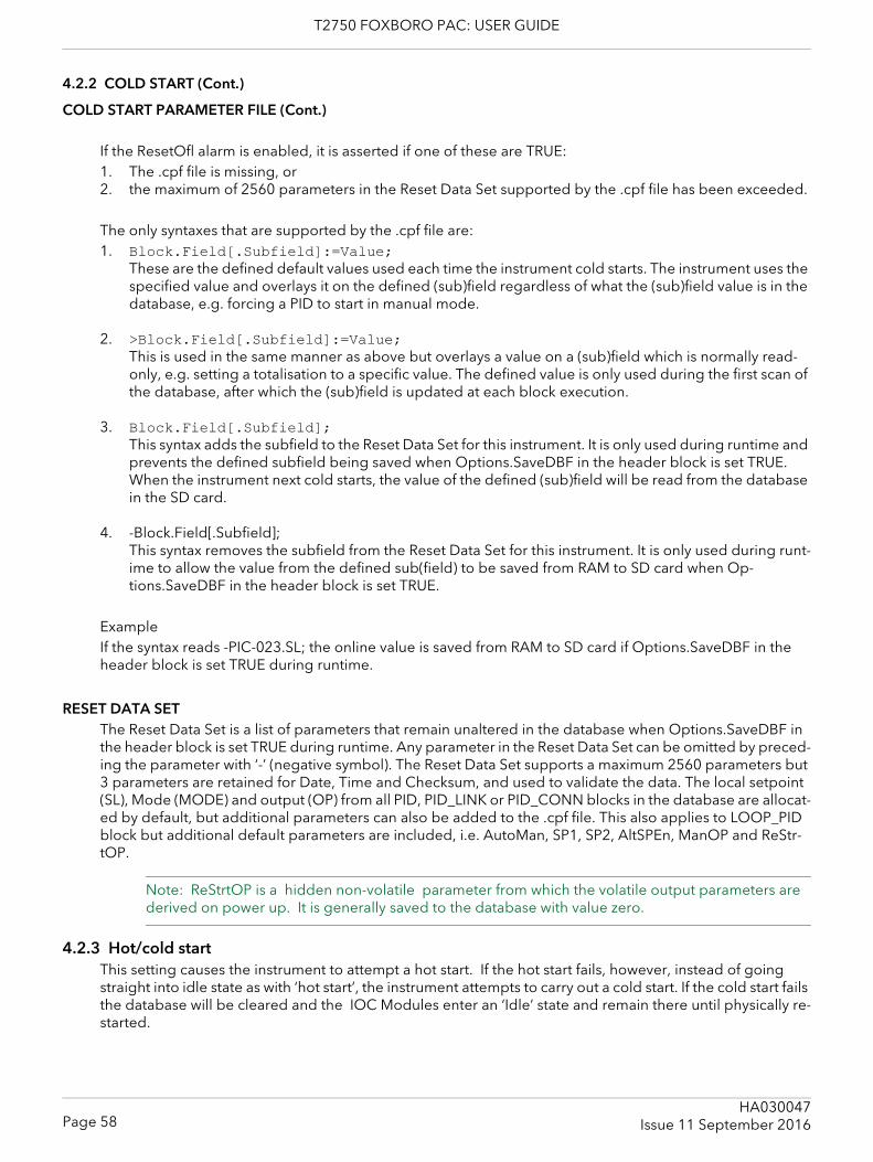
T2750 FOXBORO PAC: USER GUIDE
4.2.2 COLD START (Cont.)
COLD START PARAMETER FILE (Cont.)
If the ResetOfl alarm is enabled, it is asserted if one of these are TRUE:1. The .cpf file is missing, or2. the maximum of 2560 parameters in the Reset Data Set supported by the .cpf file has been exceeded.
The only syntaxes that are supported by the .cpf file are: 1. Block.Field[.Subfield]:=Value;
These are the defined default values used each time the instrument cold starts. The instrument uses the specified value and overlays it on the defined (sub)field regardless of what the (sub)field value is in the database, e.g. forcing a PID to start in manual mode.
2. >Block.Field[.Subfield]:=Value;This is used in the same manner as above but overlays a value on a (sub)field which is normally read-only, e.g. setting a totalisation to a specific value. The defined value is only used during the first scan of the database, after which the (sub)field is updated at each block execution.
3. Block.Field[.Subfield];This syntax adds the subfield to the Reset Data Set for this instrument. It is only used during runtime and prevents the defined subfield being saved when Options.SaveDBF in the header block is set TRUE. When the instrument next cold starts, the value of the defined (sub)field will be read from the database in the SD card.
4. -Block.Field[.Subfield];This syntax removes the subfield from the Reset Data Set for this instrument. It is only used during runt-ime to allow the value from the defined sub(field) to be saved from RAM to SD card when Op-tions.SaveDBF in the header block is set TRUE.
ExampleIf the syntax reads -PIC-023.SL; the online value is saved from RAM to SD card if Options.SaveDBF in the header block is set TRUE during runtime.
RESET DATA SETThe Reset Data Set is a list of parameters that remain unaltered in the database when Options.SaveDBF in the header block is set TRUE during runtime. Any parameter in the Reset Data Set can be omitted by preced-ing the parameter with ‘-’ (negative symbol). The Reset Data Set supports a maximum 2560 parameters but 3 parameters are retained for Date, Time and Checksum, and used to validate the data. The local setpoint (SL), Mode (MODE) and output (OP) from all PID, PID_LINK or PID_CONN blocks in the database are allocat-ed by default, but additional parameters can also be added to the .cpf file. This also applies to LOOP_PID block but additional default parameters are included, i.e. AutoMan, SP1, SP2, AltSPEn, ManOP and ReStr-tOP.
Note: ReStrtOP is a hidden non-volatile parameter from which the volatile output parameters are derived on power up. It is generally saved to the database with value zero.
4.2.3 Hot/cold startThis setting causes the instrument to attempt a hot start. If the hot start fails, however, instead of going straight into idle state as with ‘hot start’, the instrument attempts to carry out a cold start. If the cold start fails the database will be cleared and the IOC Modules enter an ‘Idle’ state and remain there until physically re-started.
Page 58HA030047
Issue 11 September 2016

T2750 FOXBORO PAC: USER GUIDE
Note: If the SD card is changed, a Hot Start for the current running database will not be possible.
4.2.4 Startup flowchart
Figure 4.2.4a Simplified start-up flow diagram
Power up
HS & CS switches both off?
Was this unit secondary
unsynch?
Valid shutdown last
time?
HS or HS & CS switches on?
Extract last known status from
memory
Doeslast loaded
database match .run file?
Run Hot Start rou-tine (figure 4.2.4b)
Was hot start
successful?
Run database(Hot Start)
Database created
Unsynchronised secondary
No database running last time
Hot start disabled
Database mismatch
Y
Y
Y
Y
Y
Y
Y
Y
N
N
N
N
N
N
N
N
Cold start disabled
Get .DBF file that matched .RUN file
in flash
Apply the values saved in the cold
start parameter file
Create empty database
CS or HS & CS switches on?
Was cold start
successful?
Run database(Cold Start) Idle Run database
HS
CSWR
OFF
OnSee figure 2.4.2 for
SW2 location
Page 59HA030047Issue 11 September 2016
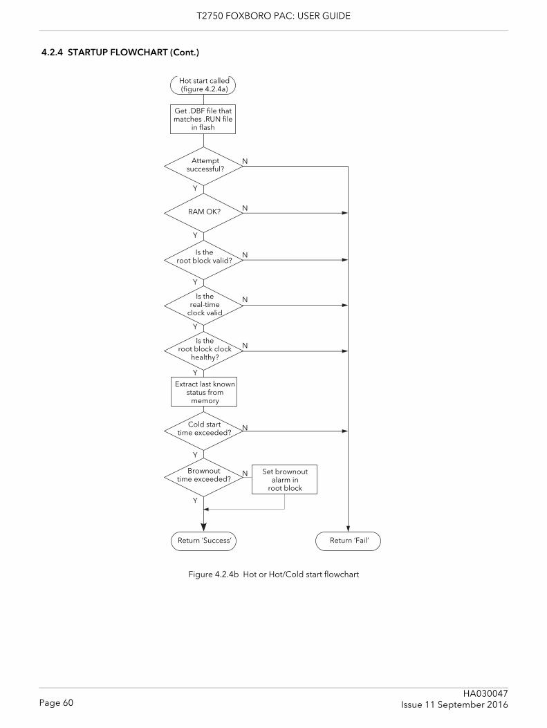
T2750 FOXBORO PAC: USER GUIDE
4.2.4 STARTUP FLOWCHART (Cont.)
Figure 4.2.4b Hot or Hot/Cold start flowchart
Extract last known status from
memory
Cold starttime exceeded?
Return ‘Success’
Brownout time exceeded?
Return ‘Fail’
Set brownout alarm in
root block
Attemptsuccessful?
RAM OK?
Is the root block valid?
Is the real-time
clock valid
Is theroot block clock
healthy?
Get .DBF file that matches .RUN file
in flash
Hot start called (figure 4.2.4a)
Y
N
Y
N
Y
N
Y
N
Y
N
Y
N
Y
N
Page 60HA030047
Issue 11 September 2016
T2750 FOXBORO PAC: USER GUIDE
4.3 STARTING THE IOC MODULES
Note: It is always possible to insert a second IOC module next to a simplex module to convert the system into a duplex (redundant) system.
4.3.1 Start-up routineThe Start-up routine is subject to the successful completion of the Power On Self Tests (POSTs) (see section 11.4 for details).
OFF STATEIn the Off state, all LEDs are extinguished.
STARTING STATEWhen power is applied, the relevant ‘Status’ LED illuminates green immediately. The ‘Primary’ and ‘Standby’ LEDs flash intermittently until the modules are initialised, at which point the ‘Pri-mary’ LED is illuminated continuously on the primary module, and the ‘Standby’ LED is illuminated continu-ously on the secondary module.The start-up procedure concludes with the establishment of Ethernet (ELIN) communications. During this period, the ‘Primary’ LED flashes on (600ms) and off (600ms).
OPERATING STATEWhen the start-up sequence is complete, then as a minimum, the ‘Status’ LED is illuminated continuously green.The ‘Primary’ (‘Standby’) LED is also illuminated green continuously if a database is running, or it flashes if a database is loading or if the Module is idle.The ‘Communications’ LEDs are illuminated yellow if the associated communications links are operating cor-rectly and flash intermittently when receiving messages.The other LEDs operate as described in section 3.1.1.
WATCHDOG RELAYSThe Watchdog relays remain in their alarm state until the software has initialised.
Page 61HA030047Issue 11 September 2016
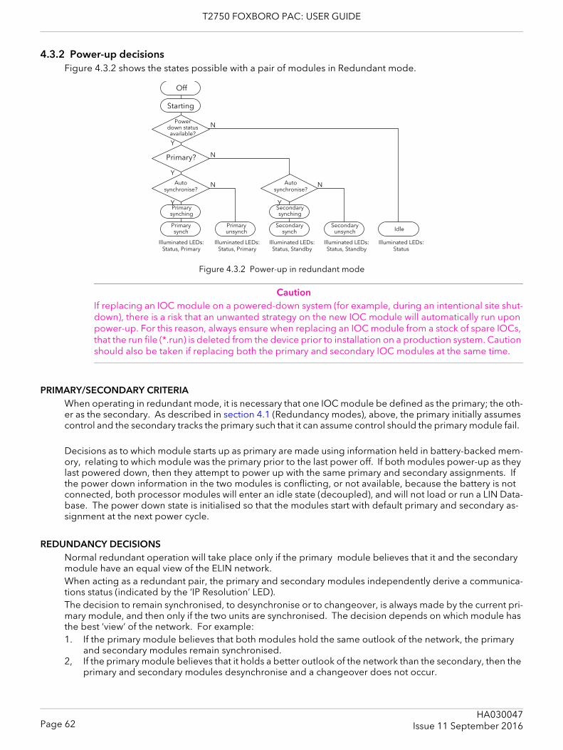
T2750 FOXBORO PAC: USER GUIDE
4.3.2 Power-up decisionsFigure 4.3.2 shows the states possible with a pair of modules in Redundant mode.
Figure 4.3.2 Power-up in redundant mode
CautionIf replacing an IOC module on a powered-down system (for example, during an intentional site shut-down), there is a risk that an unwanted strategy on the new IOC module will automatically run upon power-up. For this reason, always ensure when replacing an IOC module from a stock of spare IOCs, that the run file (*.run) is deleted from the device prior to installation on a production system. Caution should also be taken if replacing both the primary and secondary IOC modules at the same time.
PRIMARY/SECONDARY CRITERIAWhen operating in redundant mode, it is necessary that one IOC module be defined as the primary; the oth-er as the secondary. As described in section 4.1 (Redundancy modes), above, the primary initially assumes control and the secondary tracks the primary such that it can assume control should the primary module fail.
Decisions as to which module starts up as primary are made using information held in battery-backed mem-ory, relating to which module was the primary prior to the last power off. If both modules power-up as they last powered down, then they attempt to power up with the same primary and secondary assignments. If the power down information in the two modules is conflicting, or not available, because the battery is not connected, both processor modules will enter an idle state (decoupled), and will not load or run a LIN Data-base. The power down state is initialised so that the modules start with default primary and secondary as-signment at the next power cycle.
REDUNDANCY DECISIONSNormal redundant operation will take place only if the primary module believes that it and the secondary module have an equal view of the ELIN network.When acting as a redundant pair, the primary and secondary modules independently derive a communica-tions status (indicated by the ‘IP Resolution’ LED). The decision to remain synchronised, to desynchronise or to changeover, is always made by the current pri-mary module, and then only if the two units are synchronised. The decision depends on which module has the best ‘view’ of the network. For example:1. If the primary module believes that both modules hold the same outlook of the network, the primary
and secondary modules remain synchronised.2, If the primary module believes that it holds a better outlook of the network than the secondary, then the
primary and secondary modules desynchronise and a changeover does not occur.
Off
Starting
Powerdown statusavailable?
Primary synching
N
Autosynchronise?
Primary?
Autosynchronise?
Primary synch
N
N
Y
Y
Y
Primary unsynch
Secondary synching
Secondarysynch
Secondaryunsynch
N
Y
Idle
Illuminated LEDs:Status, Primary
Illuminated LEDs:Status, Primary
Illuminated LEDs:Status, Standby
Illuminated LEDs:Status, Standby
Illuminated LEDs:Status
Page 62HA030047
Issue 11 September 2016

T2750 FOXBORO PAC: USER GUIDE
3. If the primary module believes that the secondary module holds a better outlook of the network, the modules desynchronise and a changeover occurs.
If the communications status is unstable, the decision is deferred to prevent spurious desynchronisations or changeovers occurring whilst faults are introduced to or removed from the network.
PROFIBUS (netHOST) REDUNDANCY DECISIONST2750 strategies that include Profibus I/O utilise the netHOST to communicate with the Profibus network. Using the Instrument Options Editor, basic configuration can be defined for both the identity of the netHOST and the redundancy logic. As mentioned on page 52, each T2750 can be configured to handle redundancy for the Profibus network with user-definable settings for desync and changeover logic. Refer to “SETTING THE REDUNDANCY LOGIC” on page 52 for details on how to change these settings.The default behaviour of the Desync and Changeover settings make Profibus health very high priority. This matches the functionality of the T940 and T940X in that a changeover is immediate. If the Profibus I/O is an important element of your control strategy, then this default behaviour is probably the most suitable. It has the disadvantage, however, that if all Profibus slaves fail, the IOCs will changeover (because it does not wait to check the secondary's view of the Profibus network). This operation may not be desirable for control strat-egies where the Profibus health is not top priority.Setting both the Desync and Changeover settings to 'fast' will defer the desync/changeover decision until the secondary's Profibus view can also be checked. This avoids a changeover if the Profibus slaves will sill be unreachable after a changeover. Note that 'fast' prioritises Profibus health over ELIN health for desync/changeover decisions (if Profibus and ELIN health monitoring would result in opposite decisions, the Profi-bus will "win" and thus still treating Profibus as very important).Selecting 'Slow' has the effect of making ELIN health a higher priority than Profibus health. This setting is only applicable where the Profibus I/O is not an essential part of the strategy. Note that 'Slow' introduces a delay in the detection of the primary Profibus Master failing, and there will be several seconds during which Profibus is not operating before the changeover occurs.Finally, selecting 'Disable' stops all desync and changeover decisions based on the health of Profibus. This should only be used where the Profibus is used for I/O associated with very low priority monitoring, in cases where Profibus failures may be not that important.
Page 63HA030047Issue 11 September 2016
T2750 FOXBORO PAC: USER GUIDE
4.3.3 Autosynchronisation Once the primary/secondary status of the modules has been determined, the system must decide if syn-chronisation of the primary and secondary should be automatic or if it should be initiated manually by means of the ‘Sync’ switch (section 3.1.2). This decision is made as follows:If the modules are powered-up within a short time of each other, and they were running as a synchronised pair prior to power-down (data held in memory), then synchronisation will take place without operator inter-vention.If either of the above conditions is not met (or if the data held in memory is not available) then both units will enter unsynchronised states in which case the secondary cannot take over from the primary. This state will continue until the ‘Sync’ switch on the primary module is operated.
SYNCHRONISATIONDuring synchronisation (automatic or manual), the primary module:1. Copies all the primary module’s strategy files to the secondary module. 2. Instructs the secondary module to load the relevant database.3. Transfers current block data to the secondary module.During the synchronisation process, the ‘Standby’ LED on the secondary module flashes. Once synchroni-sation is complete, the ‘Standby’ LED is continuously illuminated yellow, the ‘Duplex’ LED on the primary module is illuminated green and redundant operation starts with the IOC Modules in their synchronised states.
In redundant operating mode, the secondary module does not permit any LIN database messages or any attempted writes to its filing system. It responds to all other messages.
TIME TO SYNCHRONISEThe time taken to complete the synchronisation process depends on the complexity of the control strategy and on how heavily the file system is being used. If the primary and secondary file systems are identical, syn-chronisation is almost instantaneous. If not, the ‘Load and Run’ part of the procedure can take a number of seconds, during which period the primary runs the control process as normal.Where primary and secondary filing systems have substantial differences (e.g. when attempting synchroni-sation for the first time), multiple synchronisations may be required to copy all the files to the secondary module. (The ‘Red_Ctrl’ block ‘sync’ fields can be viewed to determine the synchronisation status.)
Page 64HA030047
Issue 11 September 2016
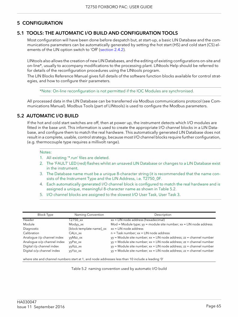
T2750 FOXBORO PAC: USER GUIDE
5 CONFIGURATION
5.1 TOOLS: THE AUTOMATIC I/O BUILD AND CONFIGURATION TOOLSMost configuration will have been done before despatch but, at start-up, a basic LIN Database and the com-munications parameters can be automatically generated by setting the hot start (HS) and cold start (CS) el-ements of the LIN option switch to ‘Off’ (section 2.4.2).
LINtools also allows the creation of new LIN Databases, and the editing of existing configurations on-site and on-line*, usually to accompany modifications to the processing plant. LINtools Help should be referred to for details of the reconfiguration procedures using the LINtools program. The LIN Blocks Reference Manual gives full details of the software function blocks available for control strat-egies, and how to configure their parameters.
*Note: On-line reconfiguration is not permitted if the IOC Modules are synchronised.
All processed data in the LIN Database can be transferred via Modbus communications protocol (see Com-munications Manual). Modbus Tools (part of LINtools) is used to configure the Modbus parameters.
5.2 AUTOMATIC I/O BUILDIf the hot and cold start switches are off, then at power up, the instrument detects which I/O modules are fitted in the base unit. This information is used to create the appropriate I/O channel blocks in a LIN Data-base, and configure them to match the real hardware. This automatically generated LIN Database does not result in a complete, usable, control strategy, because most I/O channel blocks require further configuration, (e.g. thermocouple type requires a millivolt range).
Notes: 1. All existing ‘*.run’ files are deleted.2. The ‘FAULT’ LED (red) flashes whilst an unsaved LIN Database or changes to a LIN Database exist
in the instrument. 3. The Database name must be a unique 8-character string (it is recommended that the name con-
sists of the Instrument Type and the LIN Address, i.e. T2750_0F.4. Each automatically generated I/O channel block is configured to match the real hardware and is
assigned a unique, meaningful 8-character name as shown in Table 5.2. 5. I/O channel blocks are assigned to the slowest I/O User Task, User Task 3.
Table 5.2 naming convention used by automatic I/O build
Block Type Naming Convention Description
Header T2750_xx xx = LIN node address (hexadecimal)Module Modyy_xx Mod = Module type; yy = module site number; xx = LIN node addressDiagnostic [block template name]_xx xx = LIN node addressCalibration CALn_xx n = Task number; xx = LIN node addressAnalogue i/p channel index yyMzz_xx yy = Module site number; xx = LIN node address; zz = channel numberAnalogue o/p channel index yyPzz_xx yy = Module site number; xx = LIN node address; zz = channel numberDigital i/p channel index yyXzz_xx yy = Module site number; xx = LIN node address; zz = channel numberDigital o/p channel index yyYzz_xx yy = Module site number; xx = LIN node address; zz = channel number
where site and channel numbers start at 1, and node addresses less than 10 include a leading ‘0’
Page 65HA030047Issue 11 September 2016
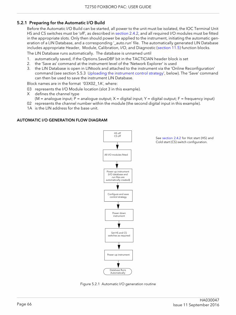
T2750 FOXBORO PAC: USER GUIDE
5.2.1 Preparing for the Automatic I/O BuildBefore the Automatic I/O Build can be started, all power to the unit must be isolated, the IOC Terminal Unit HS and CS switches must be ‘off’, as described in section 2.4.2, and all required I/O modules must be fitted in the appropriate slots. Only then should power be applied to the instrument, initiating the automatic gen-eration of a LIN Database, and a corresponding ‘_auto.run’ file. The automatically generated LIN Database includes appropriate Header, Module, Calibration, I/O, and Diagnostic (section 11.5) function blocks.The LIN Database runs automatically. The database is unnamed until1. automatically saved, if the Options.SaveDBF bit in the TACTICIAN header block is set2. the ‘Save as’ command at the instrument level of the ‘Network Explorer’ is used3. the LIN Database is open in LINtools and attached to the instrument via the ‘Online Reconfiguration’
command (see section 5.5.3 Uploading the instrument control strategy’, below). The ‘Save’ command can then be used to save the instrument LIN Database.
Block names are in the format ‘03X02_1A’, where:03 represents the I/O Module location (slot 3 in this example).X defines the channel type
(M = analogue input; P = analogue output; X = digital input; Y = digital output; F = frequency input)02 represents the channel number within the module (the second digital input in this example).1A is the LIN address for the base unit.
AUTOMATIC I/O GENERATION FLOW DIAGRAM
Figure 5.2.1 Automatic I/O generation routine
HS offCS off
Database Runs Automatically
All I/O modules fitted
Power up instrument (I/O database and
.run files are automatically created)
Configure and save control strategy
Power down instrument
Set HS and CS switches as required
Power up instrument
See section 2.4.2 for Hot start (HS) andCold start (CS) switch configuration.
Page 66HA030047
Issue 11 September 2016
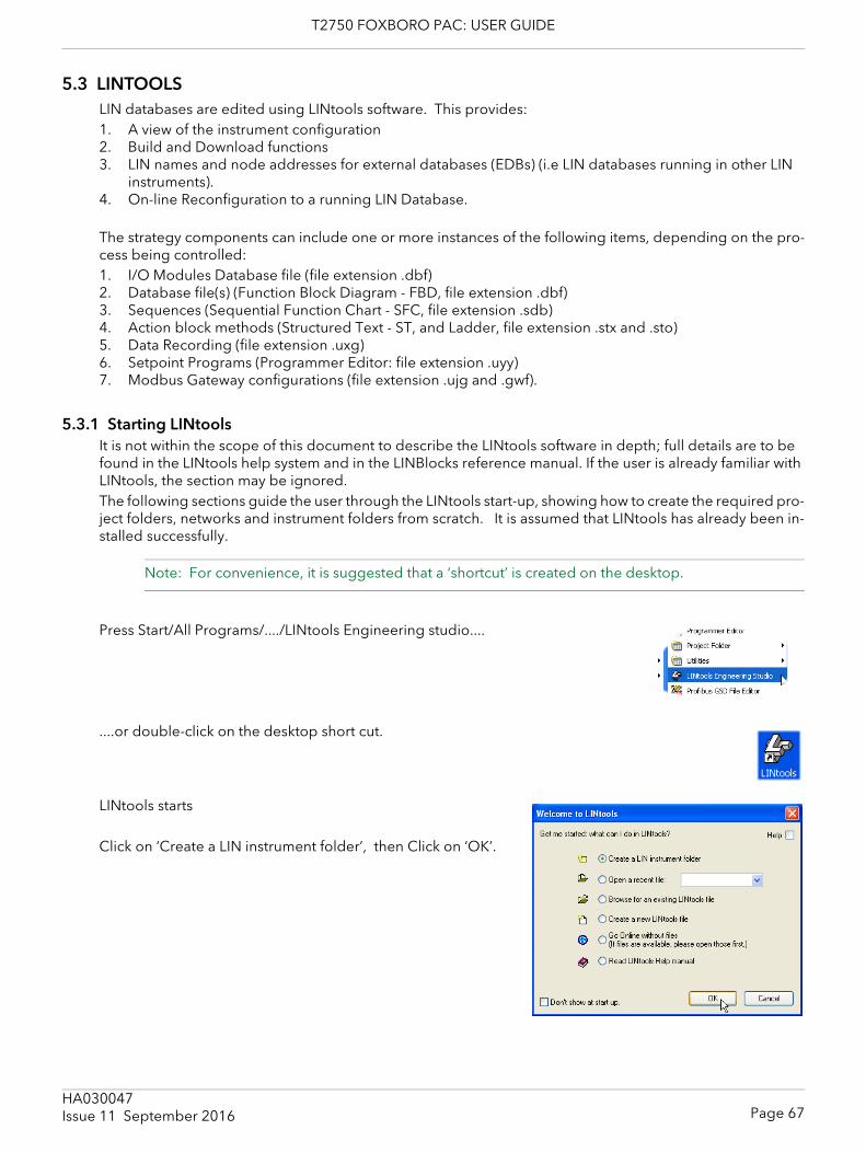
T2750 FOXBORO PAC: USER GUIDE
5.3 LINTOOLSLIN databases are edited using LINtools software. This provides: 1. A view of the instrument configuration2. Build and Download functions3. LIN names and node addresses for external databases (EDBs) (i.e LIN databases running in other LIN
instruments).4. On-line Reconfiguration to a running LIN Database.
The strategy components can include one or more instances of the following items, depending on the pro-cess being controlled:1. I/O Modules Database file (file extension .dbf)2. Database file(s) (Function Block Diagram - FBD, file extension .dbf)3. Sequences (Sequential Function Chart - SFC, file extension .sdb)4. Action block methods (Structured Text - ST, and Ladder, file extension .stx and .sto)5. Data Recording (file extension .uxg)6. Setpoint Programs (Programmer Editor: file extension .uyy)7. Modbus Gateway configurations (file extension .ujg and .gwf).
5.3.1 Starting LINtoolsIt is not within the scope of this document to describe the LINtools software in depth; full details are to be found in the LINtools help system and in the LINBlocks reference manual. If the user is already familiar with LINtools, the section may be ignored.The following sections guide the user through the LINtools start-up, showing how to create the required pro-ject folders, networks and instrument folders from scratch. It is assumed that LINtools has already been in-stalled successfully.
Note: For convenience, it is suggested that a ‘shortcut’ is created on the desktop.
Press Start/All Programs/..../LINtools Engineering studio....
....or double-click on the desktop short cut.
LINtools starts
Click on ‘Create a LIN instrument folder’, then Click on ‘OK’.
Page 67HA030047Issue 11 September 2016
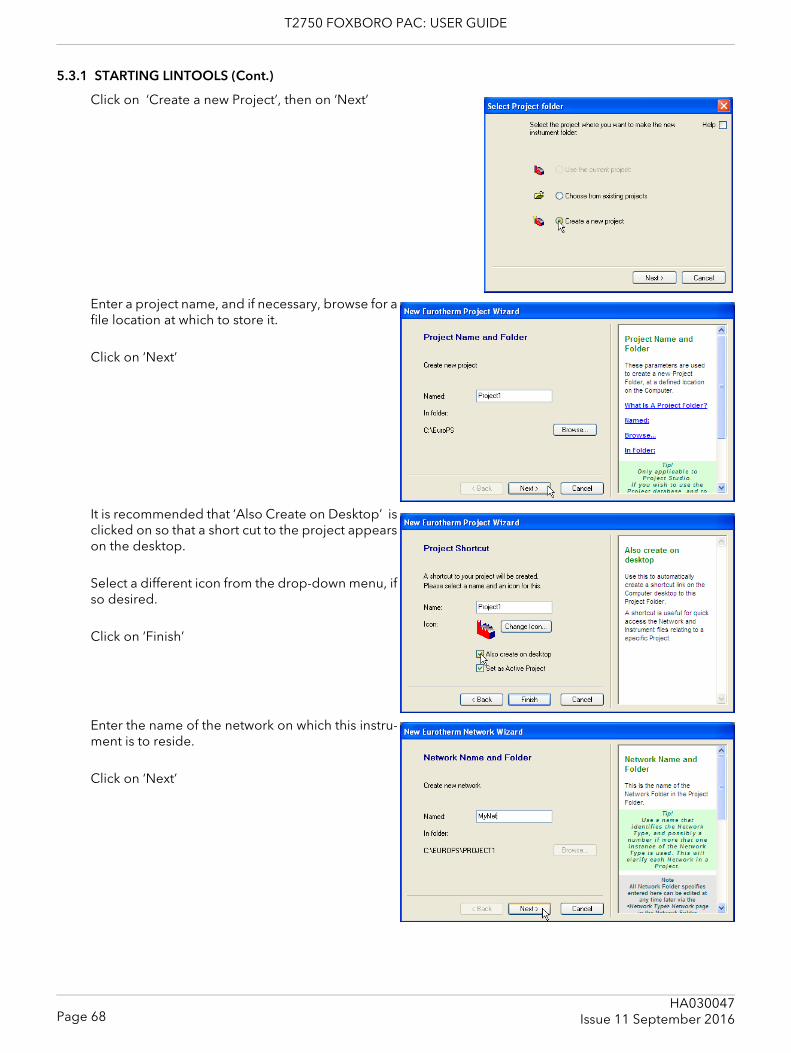
T2750 FOXBORO PAC: USER GUIDE
5.3.1 STARTING LINTOOLS (Cont.)
Click on ‘Create a new Project’, then on ‘Next’
Enter a project name, and if necessary, browse for a file location at which to store it.
Click on ‘Next’
It is recommended that ‘Also Create on Desktop’ is clicked on so that a short cut to the project appears on the desktop.
Select a different icon from the drop-down menu, if so desired.
Click on ‘Finish’
Enter the name of the network on which this instru-ment is to reside.
Click on ‘Next’
Page 68HA030047
Issue 11 September 2016
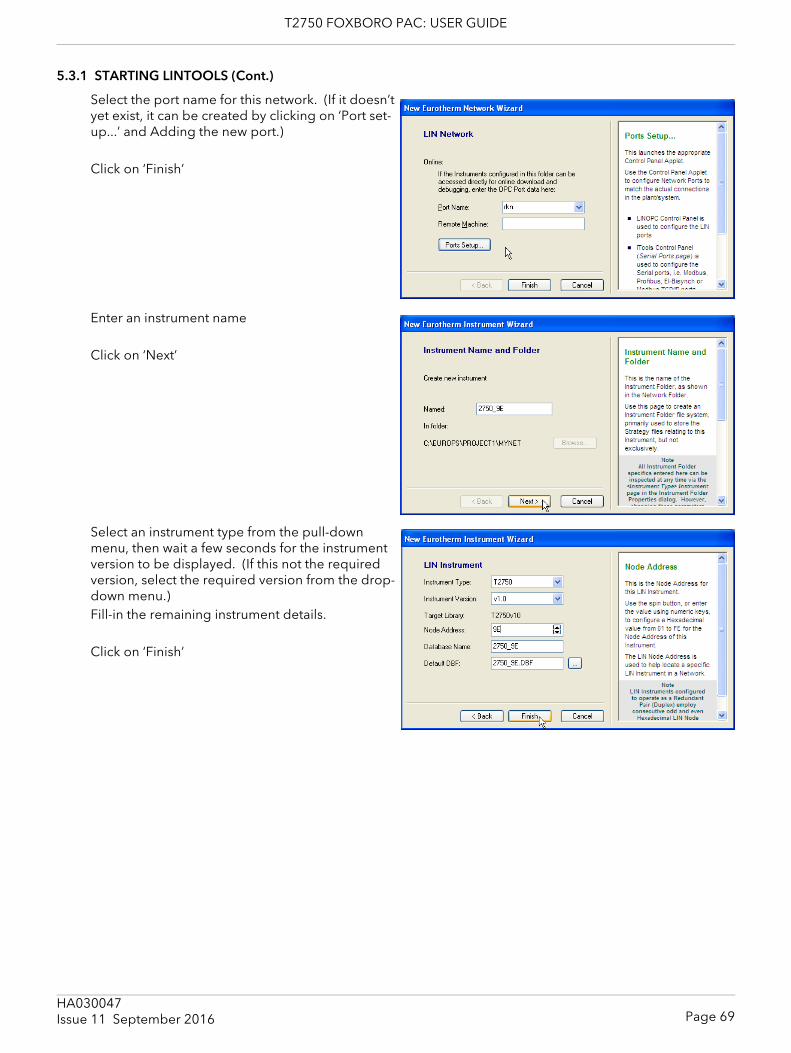
T2750 FOXBORO PAC: USER GUIDE
5.3.1 STARTING LINTOOLS (Cont.)
Select the port name for this network. (If it doesn’t yet exist, it can be created by clicking on ‘Port set-up...’ and Adding the new port.)
Click on ‘Finish’
Enter an instrument name
Click on ‘Next’
Select an instrument type from the pull-down menu, then wait a few seconds for the instrument version to be displayed. (If this not the required version, select the required version from the drop-down menu.) Fill-in the remaining instrument details.
Click on ‘Finish’
Page 69HA030047Issue 11 September 2016
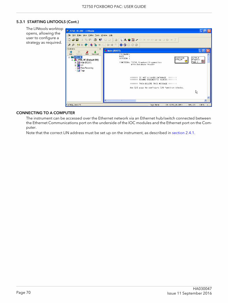
T2750 FOXBORO PAC: USER GUIDE
5.3.1 STARTING LINTOOLS (Cont.)
The LINtools worktop opens, allowing the user to configure a strategy as required.
CONNECTING TO A COMPUTERThe instrument can be accessed over the Ethernet network via an Ethernet hub/switch connected between the Ethernet Communications port on the underside of the IOC modules and the Ethernet port on the Com-puter.Note that the correct LIN address must be set up on the instrument, as described in section 2.4.1.
Page 70HA030047
Issue 11 September 2016
T2750 FOXBORO PAC: USER GUIDE
5.4 MODBUS TOOLS5.4.1 Introduction
This instrument may be configured as a Modbus Master or as a Modbus Slave, and the application supports up to three Modbus Gateway configurations.Modbus configuration data is defined in a Modbus GateWay File (.gwf), downloaded with the LIN Database file into a LIN instrument. The data in the Gateway file is used to define the transfer of data between LIN and Modbus instruments.This data includes:1. The operating mode (i.e. Master or Slave)2. The serial line set-up (or TCP)3. The mapping between fields in function blocks and the registers of a Modbus instrument4. Modbus functions, Modbus register addresses and the format in which data is to be transferred.
CONNECTING TO A COMPUTERThe instrument can be accessed over the Ethernet network via an Ethernet hub/switch connected between the Ethernet Communications port on the underside of the IOC modules and the Ethernet port on the Com-puter.
5.4.2 Running Modbus ToolsRefer to Modbus Tools Help for details of Modbus Configuration procedures using Modbus Tools.
An empty Modbus Tools window can be started 1.from the LINtools ‘Tools’ menu,2.via the Start > ... > LINtools Advanced > MODBUS Tools command. The ‘Open’ command is used to open a browse window to help locate the required .ujg file.
Alternatively, double-click the LIN MODBUS Database file (.ujg) from the required Instrument folder.
Page 71HA030047Issue 11 September 2016
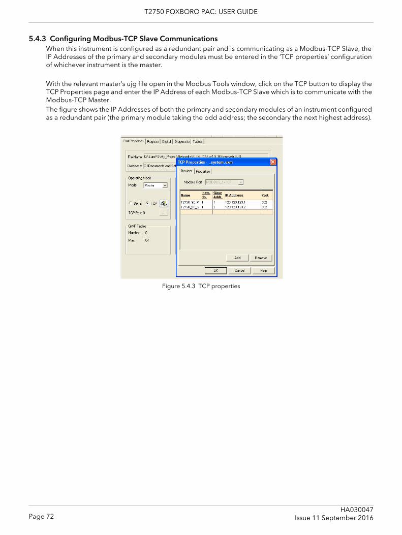
T2750 FOXBORO PAC: USER GUIDE
5.4.3 Configuring Modbus-TCP Slave CommunicationsWhen this instrument is configured as a redundant pair and is communicating as a Modbus-TCP Slave, the IP Addresses of the primary and secondary modules must be entered in the ‘TCP properties’ configuration of whichever instrument is the master.
With the relevant master’s ujg file open in the Modbus Tools window, click on the TCP button to display the TCP Properties page and enter the IP Address of each Modbus-TCP Slave which is to communicate with the Modbus-TCP Master.The figure shows the IP Addresses of both the primary and secondary modules of an instrument configured as a redundant pair (the primary module taking the odd address; the secondary the next highest address).
Figure 5.4.3 TCP properties
Page 72HA030047
Issue 11 September 2016
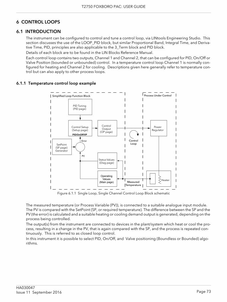
T2750 FOXBORO PAC: USER GUIDE
6 CONTROL LOOPS
6.1 INTRODUCTIONThe instrument can be configured to control and tune a control loop, via LINtools Engineering Studio. This section discusses the use of the LOOP_PID block, but similar Proportional Band, Integral Time, and Deriva-tive Time, PID, principles are also applicable to the 3_Term block and PID block.Details of each block are to be found in the LIN Blocks Reference Manual.Each control loop contains two outputs, Channel 1 and Channel 2, that can be configured for PID, On/Off or Valve Position (bounded or unbounded) control. In a temperature control loop Channel 1 is normally con-figured for heating and Channel 2 for cooling. Descriptions given here generally refer to temperature con-trol but can also apply to other process loops.
6.1.1 Temperature control loop example
Figure 6.1.1 Single Loop, Single Channel Control Loop Block schematic
The measured temperature (or Process Variable (PV)), is connected to a suitable analogue input module. The PV is compared with the SetPoint (SP, or required temperature). The difference between the SP and the PV (the error) is calculated and a suitable heating or cooling demand output is generated, depending on the process being controlled. The output(s) from the instrument are connected to devices in the plant/system which heat or cool the pro-cess, resulting in a change in the PV, that is again compared with the SP, and the process is repeated con-tinuously. This is referred to as closed loop control.In this instrument it is possible to select PID, On/Off, and Valve positioning (Boundless or Bounded) algo-rithms.
Simplified Loop Function Block
PID Tuning (PID page)
Control Setup (Setup page)
Control Output
(OP page)
SetPoint (SP page) Generator
Status Values (Diag page)
Operating Values
(Main page)
Power Regulator
Process Under Control
HeaterMeasured
Temperature
Control Loop
Error
PV
PID/OnOff/VP
Page 73HA030047Issue 11 September 2016
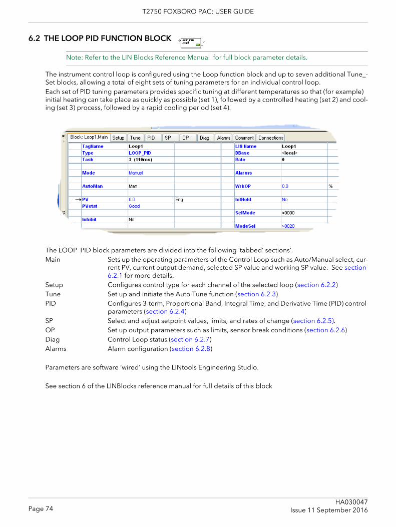
T2750 FOXBORO PAC: USER GUIDE
6.2 THE LOOP PID FUNCTION BLOCK
Note: Refer to the LIN Blocks Reference Manual for full block parameter details.
The instrument control loop is configured using the Loop function block and up to seven additional Tune_-Set blocks, allowing a total of eight sets of tuning parameters for an individual control loop.Each set of PID tuning parameters provides specific tuning at different temperatures so that (for example) initial heating can take place as quickly as possible (set 1), followed by a controlled heating (set 2) and cool-ing (set 3) process, followed by a rapid cooling period (set 4).
The LOOP_PID block parameters are divided into the following ‘tabbed’ sections’.Main Sets up the operating parameters of the Control Loop such as Auto/Manual select, cur-
rent PV, current output demand, selected SP value and working SP value. See section 6.2.1 for more details.
Setup Configures control type for each channel of the selected loop (section 6.2.2)Tune Set up and initiate the Auto Tune function (section 6.2.3)PID Configures 3-term, Proportional Band, Integral Time, and Derivative Time (PID) control
parameters (section 6.2.4)SP Select and adjust setpoint values, limits, and rates of change (section 6.2.5).OP Set up output parameters such as limits, sensor break conditions (section 6.2.6)Diag Control Loop status (section 6.2.7)Alarms Alarm configuration (section 6.2.8)
Parameters are software ‘wired’ using the LINtools Engineering Studio.
See section 6 of the LINBlocks reference manual for full details of this block
Page 74HA030047
Issue 11 September 2016
T2750 FOXBORO PAC: USER GUIDE
6.2.1 Main PageThe Main page of the Loop block provides an overview of parameters used by the overall control loop. It allows the user:1. To select ‘Auto’ or ‘Manual’ operation2. To stop the loop from controlling, for commissioning purposes3. To hold the integral action4. Read PV and SP values
AUTOMATIC MODEAutomatic indicates that PV is continuously being monitored and compared with the SP. The output power is calculated and used to minimise any difference. If a sensor break occurs whilst the control loop is in automatic mode, a configured sensor break output pow-er (OP.SbrkOP or OP.SafeOP, if Main.Inhibit is configured), can be output. The user can also switch to man-ual mode allowing the user to edit the output power. When ‘Automatic’ is returned-to, the controller again checks for sensor break.
MANUAL MODEIn manual mode:1. If ‘On/Off’ control is configured, the output power may be edited by the user but the only values avail-
able are: +100% (heat on, cool off) for positive value entries; 0% (heat off, cool off) for zero entry or -100% (heat off, cool on) for negative entries.
2. If PID control is selected, the output may be edited between =100% and (if cool is configured) -100% but the actual output is subject to limiting (both absolute value and rate-of-change of value).
3. For valve position control, the position of the valve can be adjusted by contact closure inputs into a dig-ital input module, driving the output relays directly, or by using OP.NudgeUp or OP.NudgeDn. This control can also be achieved over serial communications.
CautionManual control of valve position should be used with discretion, because, unless some position feed-back mechanism has been installed to provide an indication of valve position, the operator is working ‘blind’, and might inadvertently leave the valve in the fully open position.
During manual operation, the loop continues to be monitored, allowing a smooth change when Automatic mode is subsequently selected.
If Auto Tune is enabled (Tune.Enable = Yes) it will remain in a reset state (‘Tune.Stage’ shows ‘Reset’), until the control loop is switched to automatic control, initiating the Auto Tune process.To provide a strategy that allows both sensor break action (normally supported only in Auto mode) and the ability to write to the output (only supported in manual mode) ‘ModeSel.FManSel’ can be wired to ‘SelM-ode.SelMan’. Then, if a sensor break occurs the instrument operates in Forced Manual mode (‘Mode-Sel.FManSel’ is ‘True’ and ‘Mode’ is ‘F_Man’) and the required output can be written to OP.ManOP.
Page 75HA030047Issue 11 September 2016
T2750 FOXBORO PAC: USER GUIDE
6.2.1 MAIN PAGE (Cont.)
‘MAIN’ TAB PARAMETERSAutoMan Sets the operating mode of the loop as automatic or manualInhibit No: Loop operates normally.
Yes stops the loop and sets the output to a ‘safe’ value (SafeOP), this value being en-tered as a part of the Output configuration (section 6.2.6). If an output rate limit is set, then the output ramps to the safe level at that rate, otherwise it performs a step change. If setpoint or manual tracking is enabled (in setpoint configuration (section 6.2.5), Inhib-it overrides tracking.
IntHold Select ‘Yes’ or ‘No’. ‘Yes’ freezes the integral term at its current value. IntHold ensures that the power is reapplied smoothly after the loop has been broken for service rea-sons, for example.
ModeSel Read only value used to show requested modes. (Bit 0 is at the top of the list.)TrackSel. Bit 2 True = Loop output tracking is requested (OP.TrackEn = On).RemSel. Bit 3 True = Use alternative setpoint request (SP.AltSpEn = Yes).AutoSel. Bit 4 True = Automatic mode is requested (Main.AutoMan = Auto)ManSel. Bit 5 True = Manual mode is requested (Main.AutoMan = Man)FmanSel. Bit 7 True = Forced manual mode is requested because PV status is ‘Bad’ (Main.PVstat = Bad)TuneSel. Bit 8 True = Autotune selected (Tune.Enable = On)PCalSel. Bit 9 True = Potentiometer calibration requested (OP.PotCal = On)InhibSel. Bit 10 True = Stop the loop running and output a safe value (OP.SafeOP)
PV The value of the process variable inputPVStat ‘Good’ indicates that the PV is displaying a trusted value derived from the process via
an input block. ‘Bad’ indicates that there has been a hardware failure or that the rele-vant I/O module is missing.
SelMode Bitfields used to select controller modes via digital inputs from the strategy. (Bit 0 is at the top of the list.)EnaRem. Bit 3 True = Enable remote mode operationSelAuto. Bit 4 True = Automatic mode unless SelMan = True.SelMan. Bit 5 True = Manual mode selected
TargetSP Target setpoint. This is the expected operating setpoint value for the loop. WrkOP The actual working output value before being split into channels 1 and 2.WSP Working Setpoint. The current setpoint being used by the loop.
ALARMSSee section 6.2.8 for a description of the alarms tab.Combined Asserted if any block alarm is active.DevHi, DevLo Asserted if the error signal value is greater than DevHi or less than DevLo. Remains ac-
tive until the signal returns withing the DevHi-DevLo band by more than the hysteresis value. (DevHi and DevLo set in the Alarms tab.
Hi The alarm goes active if the PV value is greater than the ‘Hi’ value set in the Alarm tab and remains active until the value is less than ‘Hi’ - ’Hyst’.
Lo The alarm goes active if the PV value falls below the ‘Lo’ value set in the Alarm tab and remains active until the value exceeds ‘Lo’ + ’Hyst’.
HiHi (LoLo) As for Hi and Lo, above but use the HiHi and LoLo values in the alarm tab.LpBreak Active if Diag.LpBreak is ‘Yes’SensorB Asserted if Diag.SensorB is ‘Yes’Software Checksum error in the block’s RAM data
Page 76HA030047
Issue 11 September 2016
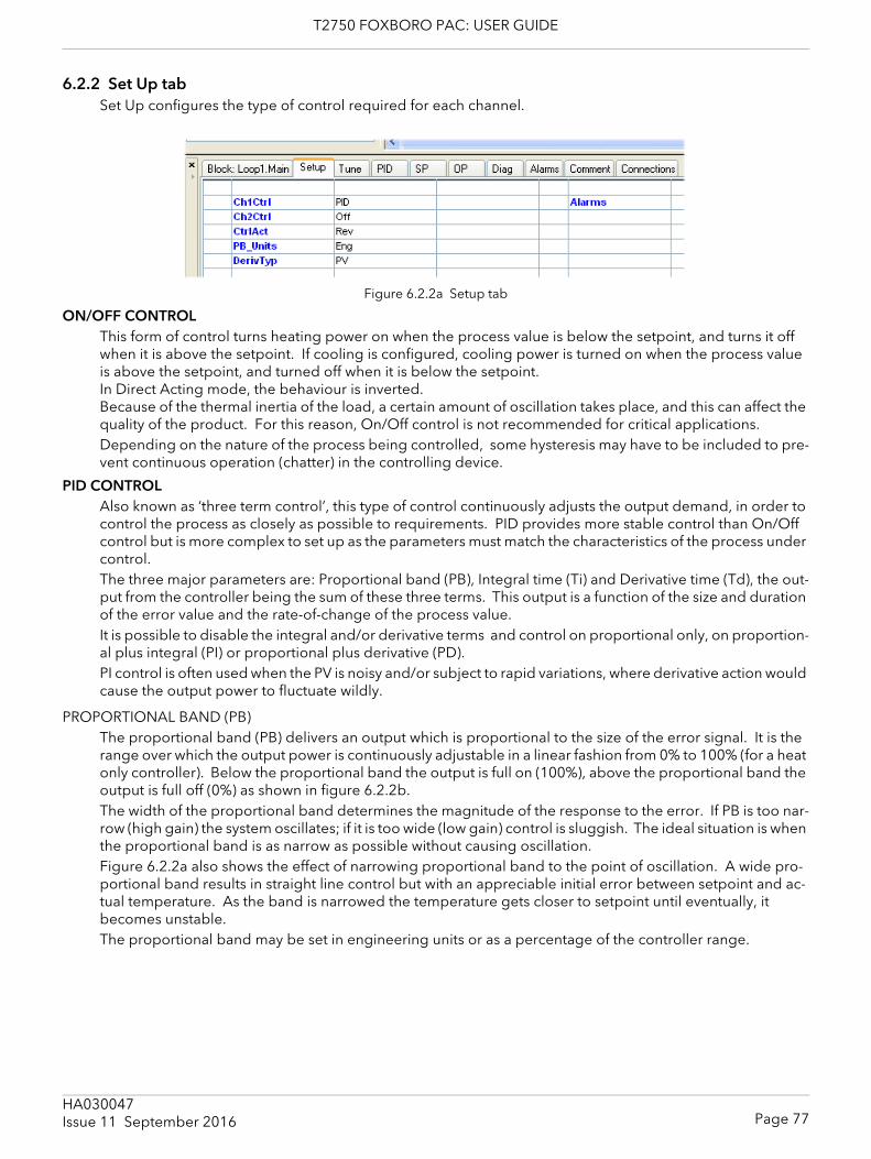
T2750 FOXBORO PAC: USER GUIDE
6.2.2 Set Up tabSet Up configures the type of control required for each channel.
Figure 6.2.2a Setup tab
ON/OFF CONTROLThis form of control turns heating power on when the process value is below the setpoint, and turns it off when it is above the setpoint. If cooling is configured, cooling power is turned on when the process value is above the setpoint, and turned off when it is below the setpoint. In Direct Acting mode, the behaviour is inverted. Because of the thermal inertia of the load, a certain amount of oscillation takes place, and this can affect the quality of the product. For this reason, On/Off control is not recommended for critical applications.Depending on the nature of the process being controlled, some hysteresis may have to be included to pre-vent continuous operation (chatter) in the controlling device.
PID CONTROLAlso known as ‘three term control’, this type of control continuously adjusts the output demand, in order to control the process as closely as possible to requirements. PID provides more stable control than On/Off control but is more complex to set up as the parameters must match the characteristics of the process under control.The three major parameters are: Proportional band (PB), Integral time (Ti) and Derivative time (Td), the out-put from the controller being the sum of these three terms. This output is a function of the size and duration of the error value and the rate-of-change of the process value. It is possible to disable the integral and/or derivative terms and control on proportional only, on proportion-al plus integral (PI) or proportional plus derivative (PD).PI control is often used when the PV is noisy and/or subject to rapid variations, where derivative action would cause the output power to fluctuate wildly.
PROPORTIONAL BAND (PB)The proportional band (PB) delivers an output which is proportional to the size of the error signal. It is the range over which the output power is continuously adjustable in a linear fashion from 0% to 100% (for a heat only controller). Below the proportional band the output is full on (100%), above the proportional band the output is full off (0%) as shown in figure 6.2.2b. The width of the proportional band determines the magnitude of the response to the error. If PB is too nar-row (high gain) the system oscillates; if it is too wide (low gain) control is sluggish. The ideal situation is when the proportional band is as narrow as possible without causing oscillation.Figure 6.2.2a also shows the effect of narrowing proportional band to the point of oscillation. A wide pro-portional band results in straight line control but with an appreciable initial error between setpoint and ac-tual temperature. As the band is narrowed the temperature gets closer to setpoint until eventually, it becomes unstable. The proportional band may be set in engineering units or as a percentage of the controller range.
Page 77HA030047Issue 11 September 2016
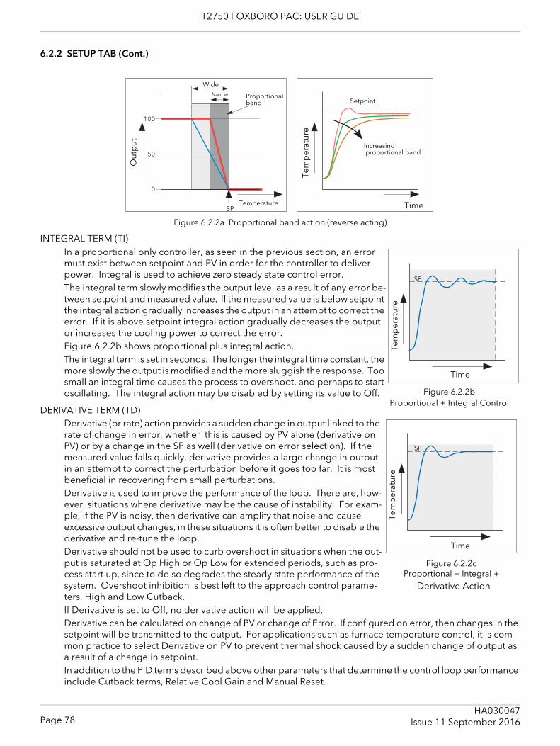
T2750 FOXBORO PAC: USER GUIDE
6.2.2 SETUP TAB (Cont.)
Figure 6.2.2a Proportional band action (reverse acting)
INTEGRAL TERM (TI)In a proportional only controller, as seen in the previous section, an error must exist between setpoint and PV in order for the controller to deliver power. Integral is used to achieve zero steady state control error. The integral term slowly modifies the output level as a result of any error be-tween setpoint and measured value. If the measured value is below setpoint the integral action gradually increases the output in an attempt to correct the error. If it is above setpoint integral action gradually decreases the output or increases the cooling power to correct the error.Figure 6.2.2b shows proportional plus integral action.The integral term is set in seconds. The longer the integral time constant, the more slowly the output is modified and the more sluggish the response. Too small an integral time causes the process to overshoot, and perhaps to start oscillating. The integral action may be disabled by setting its value to Off.
DERIVATIVE TERM (TD)Derivative (or rate) action provides a sudden change in output linked to the rate of change in error, whether this is caused by PV alone (derivative on PV) or by a change in the SP as well (derivative on error selection). If the measured value falls quickly, derivative provides a large change in output in an attempt to correct the perturbation before it goes too far. It is most beneficial in recovering from small perturbations.Derivative is used to improve the performance of the loop. There are, how-ever, situations where derivative may be the cause of instability. For exam-ple, if the PV is noisy, then derivative can amplify that noise and cause excessive output changes, in these situations it is often better to disable the derivative and re-tune the loop.Derivative should not be used to curb overshoot in situations when the out-put is saturated at Op High or Op Low for extended periods, such as pro-cess start up, since to do so degrades the steady state performance of the system. Overshoot inhibition is best left to the approach control parame-ters, High and Low Cutback.If Derivative is set to Off, no derivative action will be applied.Derivative can be calculated on change of PV or change of Error. If configured on error, then changes in the setpoint will be transmitted to the output. For applications such as furnace temperature control, it is com-mon practice to select Derivative on PV to prevent thermal shock caused by a sudden change of output as a result of a change in setpoint.In addition to the PID terms described above other parameters that determine the control loop performance include Cutback terms, Relative Cool Gain and Manual Reset.
Out
put
Narrow
Wide
Proportional band
SPTemperature Time
Increasing proportional band
Tem
per
atur
e
Setpoint
Time
Tem
per
atur
e
SP
Figure 6.2.2b Proportional + Integral Control
Time
Tem
per
atur
e
SP
Figure 6.2.2c Proportional + Integral +
Derivative Action
Page 78HA030047
Issue 11 September 2016
T2750 FOXBORO PAC: USER GUIDE
6.2.2 SETUP TAB (Cont.)
VALVE POSITION CONTROLValve Position Control is designed specifically for controlling motorised valves and can be specified either as boundless (VPU) or as bounded (VPB) mode.Boundless VP (VPU) is a velocity mode algorithm that directly controls the direction and velocity of the move-ment of the valve in order to minimise the difference between the SP and the PV. It uses triac or relay outputs to drive the valve motor.A feedback potentiometer is not required for VPU control, but can be used to provide indication of the valve position.Bounded VP (VPB) control requires a feedback potentiometer as part of the control algorithm.Control is performed by delivering a ‘raise’ pulse, a ‘lower’ pulse or no pulse in response to the control de-mand signal via relay or triac outputs.
MANUAL MODEBounded VP controls in manual mode because the inner positional loop is still running against the potenti-ometer feedback, so it is operating as a position loop.In boundless mode the algorithm is a velocity mode positioner. When manual is selected then the up and down arrow produce +100% or –100% velocity respectively for the duration of the key press. In boundless mode it is essential that the motor travel time is set accurately in order to allow the integral time to calculate correctly. Motor travel time is defined as (valve fully open – valve fully closed). This is not nec-essarily the time printed on the motor since, if mechanical stops have been set on the motor, the travel time of the valve may be different. Every time the valve is driven to its end stops the algorithm is reset to 0% or 100% to compensate for any changes which may occur due to wear in linkages or other mechanical parts.This technique makes boundless VP look like a positional loop in manual even though it is not. This enables combinations of heating and cooling e.g. PID heat, VPU cool with manual mode working as expected.
Motorised Valve Output configuration automatically configures the second channel once the first has been setup, e.g. if ‘OP.Ch2Outpt’ is wired and configured as cooling, then ‘OP.Ch1Outpt’ is automatically wired and configured as heating.
SETUP TAB PARAMETERSCh1Ctrl Select Off/On, PID, VBU or VPB from the pull down table for channel 1.Ch2Ctrl As above, but for channel 2CtrlAct ‘Rev’ = Reverse acting. This is the normal negative feedback mode of operation for
heating, where the output is increased when the PV is below SP. Dir = Direct acting. This positive feedback mode is the opposite of reverse acting, the output being decreased when the PV is below SP.
PB Units Select ‘Eng’ or ‘Percent’.DerivTyp Select ‘PV’ or ‘Error’. for ‘PV’ the loop calculations occur only when PV changes. For ‘Er-
ror’, the calculations occur when either of PV or SP changes.
Page 79HA030047Issue 11 September 2016
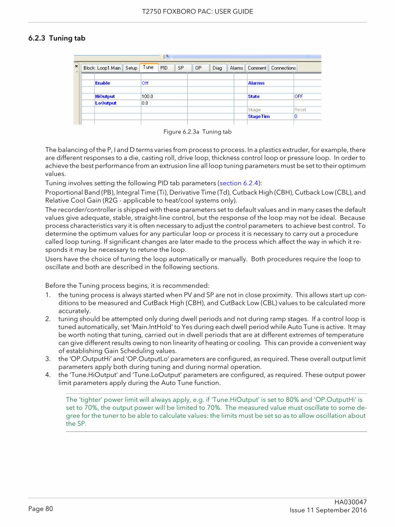
T2750 FOXBORO PAC: USER GUIDE
6.2.3 Tuning tab
Figure 6.2.3a Tuning tab
The balancing of the P, I and D terms varies from process to process. In a plastics extruder, for example, there are different responses to a die, casting roll, drive loop, thickness control loop or pressure loop. In order to achieve the best performance from an extrusion line all loop tuning parameters must be set to their optimum values. Tuning involves setting the following PID tab parameters (section 6.2.4):Proportional Band (PB), Integral Time (Ti), Derivative Time (Td), Cutback High (CBH), Cutback Low (CBL), and Relative Cool Gain (R2G - applicable to heat/cool systems only).The recorder/controller is shipped with these parameters set to default values and in many cases the default values give adequate, stable, straight-line control, but the response of the loop may not be ideal. Because process characteristics vary it is often necessary to adjust the control parameters to achieve best control. To determine the optimum values for any particular loop or process it is necessary to carry out a procedure called loop tuning. If significant changes are later made to the process which affect the way in which it re-sponds it may be necessary to retune the loop.Users have the choice of tuning the loop automatically or manually. Both procedures require the loop to oscillate and both are described in the following sections.
Before the Tuning process begins, it is recommended:1. the tuning process is always started when PV and SP are not in close proximity. This allows start up con-
ditions to be measured and CutBack High (CBH), and CutBack Low (CBL) values to be calculated more accurately.
2. tuning should be attempted only during dwell periods and not during ramp stages. If a control loop is tuned automatically, set ‘Main.IntHold’ to Yes during each dwell period while Auto Tune is active. It may be worth noting that tuning, carried out in dwell periods that are at different extremes of temperature can give different results owing to non linearity of heating or cooling. This can provide a convenient way of establishing Gain Scheduling values.
3. the ‘OP.OutputHi’ and ‘OP.OutputLo’ parameters are configured, as required. These overall output limit parameters apply both during tuning and during normal operation.
4. the ‘Tune.HiOutput’ and ‘Tune.LoOutput’ parameters are configured, as required. These output power limit parameters apply during the Auto Tune function.
The ‘tighter’ power limit will always apply, e.g. if ‘Tune.HiOutput’ is set to 80% and ‘OP.OutputHi’ is set to 70%, the output power will be limited to 70%. The measured value must oscillate to some de-gree for the tuner to be able to calculate values: the limits must be set so as to allow oscillation about the SP.
Page 80HA030047
Issue 11 September 2016
T2750 FOXBORO PAC: USER GUIDE
6.2.3 TUNING TAB (Cont.)
LOOP RESPONSEIgnoring loop oscillation, there are three categories of loop performance: Under damped, Critically damped and Over damped:
UNDER DAMPED In this situation the parameters are set to prevent oscillation but lead to an overshoot of the Process Value (PV) followed by decaying oscillation until the PV finally settles at the Setpoint. This type of response can give a minimum time to Setpoint but overshoot may cause problems in certain situations and the loop may be sensitive to sudden changes in PV, resulting in further decaying oscillations before settling once again.
CRITICALLY DAMPEDThis represents an ideal situation where noticeable overshoot to small step changes does not occur and the process responds to changes in a controlled, non oscillatory manner.
OVER DAMPEDIn this situation the loop responds in a controlled but sluggish manner which results in a non-ideal and un-necessarily slow loop performance.
INITIAL SETTINGSIn addition to the tuning parameters listed above, there are a number of other parameters which can affect loop response. These parameters must be correctly configured before tuning is initiated. Parameters in-clude, but are not limited to:-
SETPOINTBefore tuning, the loop conditions should be set as closely as practicable to the actual conditions which will be met in normal operation. For example, in a furnace or oven application a representative load should be included, an extruder should be running, etc.
OUTPUTHI, OUTPUTLOThese OP tab heat and cool limits define the overall maximum and minimum power which may be delivered to the process by the control loop. For a heat only controller the default values are 0 and 100%. For a heat/cool controller the defaults are -100 and 100%. Although most processes are designed to work between these limits there may be instances where it is desirable to limit the power delivered to the process.
REMOPL, REMOPH If these Remote Output Limits parameters (OP tab) are used, they are effective only if they lie within the Heat/Cool Limits above.
HEAT/COOL DEADBANDHeat/Cool Deadband If a second (cool) channel is configured, a parameter ‘OP.Ch2DeadB’ is also available in the Output tab which sets the distance between the heat and cool proportional bands. The default value is 0% which means that heating will cease to be available at the same time as cooling becomes available. The dead band may be set to ensure that there is no possibility of the heat and cool channels operating to-gether, particularly when cycling output stages are installed.
MINIMUM ON TIMEIf either or both of the output channels is fitted with a relay or logic output, the parameter ‘Min On Time’ ap-pears in the output menu. This is the cycling time for a time proportioning output and should be set correctly before tuning is started.
RATESPSets the maximum PID rate-of-change. The output rate limit is active during tuning and can affect the tuning results. RateSP is useful in preventing rapid changes in output from damaging the process or heater ele-ments. The parameter is found in the ‘SP’ tab (section 6.2.5) .
Page 81HA030047Issue 11 September 2016
T2750 FOXBORO PAC: USER GUIDE
6.2.3 TUNE TAB (Cont.)
INITIAL SETTINGS (Cont.)
CH1TRAVT, CH2TRAVTValve Travel Time. If the output is a motor valve positioner the ‘Ch1TravT’ and Ch2TravT’ Output tab param-eters must be set correctly. The valve travel time is the time taken for the valve to travel from 0% (closed) to 100% (open). This may be different from the motor travel time limits because the mechanical linkage be-tween the motor and the valve, setting of limit switches etc. can modify behaviour.
OTHER TUNING CONSIDERATIONSIf a process includes adjacent interactive zones, each zone should be tuned independently with the adjacent zones at operating temperature. It is recommended that a tuning process be initiated when the PV and setpoint are far apart. This allows start up conditions to be measured and cutback values to be calculated more accurately. Cutback is not set for ‘Tune at setpoint’.In a programmer/controller tuning should only be attempted during dwell periods and not during ramp stages. If a programmer/controller is tuned automatically the controller should be placed in ‘Hold’ during each dwell period whilst autotune is active.
Note: Tuning, carried out in dwell periods which are at different extremes of temperature may give different results owing to non linearity of heating (or cooling). This may provide a convenient way to establish values for Gain Scheduling.
If an auto tune is initiated two further parameters (‘High Output’ and ‘Low Output’) which must be set.High Output Sets a high output limit to be imposed during autotune. Must be ≤ Output High, set in
the Output menu.Low Output Sets a low output limit to be imposed during autotune. Must be ≥ Output Low, set in
the Output menu.The above values must be set correctly, otherwise sufficient power to achieve SP might not be available dur-ing tuning, and the tune will eventually fail.
AUTOTUNEAutotune automatically sets the following PID tab parameters (section 6.2.4):PB Proportional band.Ti Integral time. If previously set to ‘Off’ Ti will remain off after an autotune.Td Derivative time. If previously set to ‘Off’ Td will remain off after an autotune.CBH, CBL Cutback high and low values. If either is set to ‘Auto’, it will remain so after auto tuning.
In order that Autotune set the cutback values for the user, a value other than ‘Auto’ must be selected before Autotune is initiated. Autotune never returns cutback values less than 1.6 × PB
R2G Calculated only if the unit is configured as Heat/Cool. Following an Autotune, R2G lies between 0.1 and 10. If the calculated value lies outside this range, a ‘Tune Fail’ alarm is set. See ‘Relative Cool Gain’ (section 6.2.4) for more details.
LBT Loop break time. Following an autotune, LBT is set to 2 × Ti (if Ti was not previously set ‘Off’), or to 12 × Td (if Ti was previously set to ‘Off’).
Page 82HA030047
Issue 11 September 2016
T2750 FOXBORO PAC: USER GUIDE
6.2.3 TUNE TAB (Cont.)
AUTOTUNE (Cont.)Autotune can be performed at any time, but normally it is performed only once, during the initial commis-sioning of the process. However, if the process under control subsequently becomes unsatisfactory (be-cause its characteristics have changed), it may be necessary to tune again for the new conditions.The auto tune algorithm reacts in different ways depending on the initial conditions of the plant. The expla-nations given later in this section are for the following example conditions:-1. Initial PV is below the setpoint and, therefore, approaches the setpoint from below for a heat/cool con-
trol loop2. As above, but for a heat only control loop3. Initial PV is at the same value as the setpoint (tune at setpoint). That is, within 0.3% of the range of the
controller if ‘PB Units’ (Setup tab) is set to ‘Percent’, or +1 engineering unit (1 in 1000) if the ‘PB Units’ is set to ‘Eng’. Range is defined as ‘Range High’ – ‘Range Low’ for process inputs or the thermocouple or RTD range defined in section A3 for temperature inputs. If the PV is just outside the range stated above the autotune will attempt a tune from above or below SP.
AUTOTUNE AND SENSOR BREAK
When the controller is autotuning and sensor break occurs, the autotune aborts and the controller outputs the sensor break output power ‘Sbrk OP’ set up in the OP tab (section 6.2.6). Autotune must be re-started when the sensor break condition is no longer present.
AUTOTUNE AND INHIBIT
If the controller is in autotune when ‘Inhibit’ is asserted, the tune goes to the Off state (Stage = Reset). On inhibit being released the controller will re-start autotune.
AUTOTUNE AND GAIN SCHEDULING
When gain scheduling is enabled and an autotune is performed, the calculated PID values are written into the PID set that is active, on completion of the tune. Therefore, the user may tune within the boundaries of a set and the values will be written into the appropriate PID set. However, if the boundaries are close (be-cause the range of the loop is not large), then, at the completion of the tune, it cannot be guaranteed that the PID values will be written to the correct set particularly if the schedule type is PV or OP. In this situation the scheduler (‘Sched Type’) should be switched to ‘Set’ and the ‘active set’ chosen manually.
INITIAL CONDITIONS
Configure the parameters described above.
Notes:1. The ‘tighter’ power limit applies. For example, if ‘Tune.HiOutput’ is set to 80% and ‘OP.OutputHi’
is set to 70% then the output power will be limited to 70% 2. The PV must oscillate to some degree to allow the tuner to calculate the relevant values. The lim-
its must be set so as to allow oscillation about the setpoint.
INITIATING THE AUTOTUNE
In the Loop Tune tab for the relevant loop, set ‘TuneEn’ to ‘On’.
Page 83HA030047Issue 11 September 2016
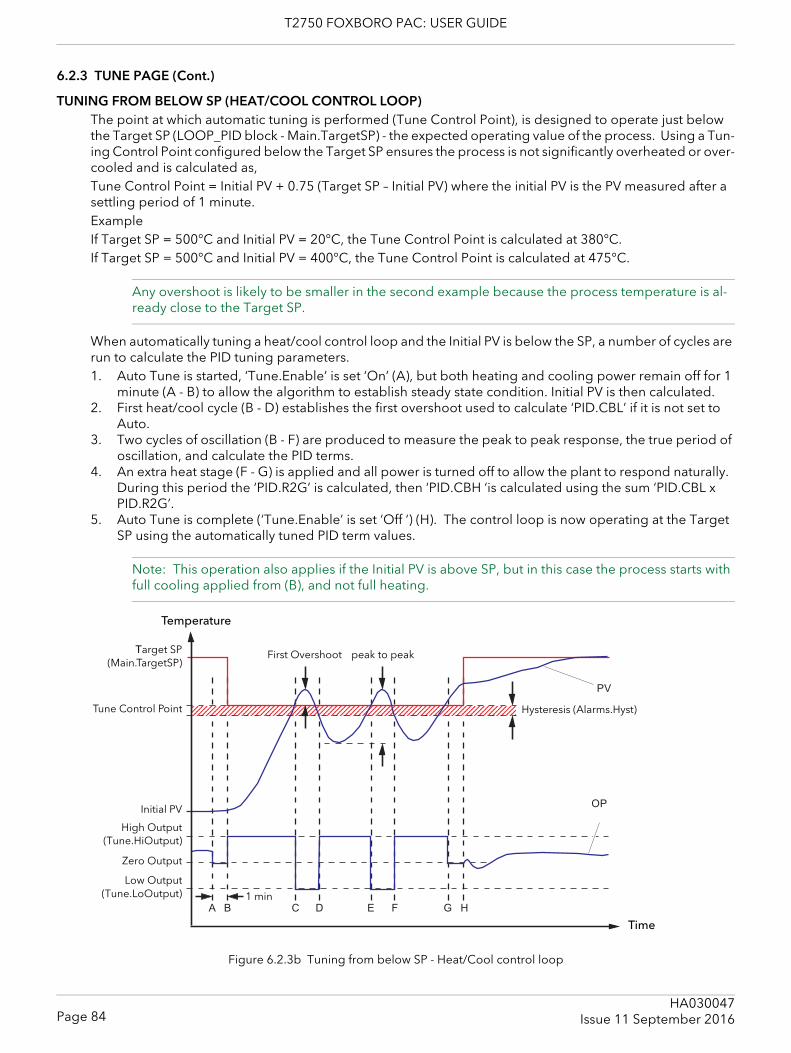
T2750 FOXBORO PAC: USER GUIDE
6.2.3 TUNE PAGE (Cont.)
TUNING FROM BELOW SP (HEAT/COOL CONTROL LOOP)The point at which automatic tuning is performed (Tune Control Point), is designed to operate just below the Target SP (LOOP_PID block - Main.TargetSP) - the expected operating value of the process. Using a Tun-ing Control Point configured below the Target SP ensures the process is not significantly overheated or over-cooled and is calculated as,Tune Control Point = Initial PV + 0.75 (Target SP – Initial PV) where the initial PV is the PV measured after a settling period of 1 minute.ExampleIf Target SP = 500°C and Initial PV = 20°C, the Tune Control Point is calculated at 380°C.If Target SP = 500°C and Initial PV = 400°C, the Tune Control Point is calculated at 475°C.
Any overshoot is likely to be smaller in the second example because the process temperature is al-ready close to the Target SP.
When automatically tuning a heat/cool control loop and the Initial PV is below the SP, a number of cycles are run to calculate the PID tuning parameters.1. Auto Tune is started, ‘Tune.Enable’ is set ‘On’ (A), but both heating and cooling power remain off for 1
minute (A - B) to allow the algorithm to establish steady state condition. Initial PV is then calculated.2. First heat/cool cycle (B - D) establishes the first overshoot used to calculate ‘PID.CBL’ if it is not set to
Auto.3. Two cycles of oscillation (B - F) are produced to measure the peak to peak response, the true period of
oscillation, and calculate the PID terms.4. An extra heat stage (F - G) is applied and all power is turned off to allow the plant to respond naturally.
During this period the ‘PID.R2G’ is calculated, then ‘PID.CBH ‘is calculated using the sum ‘PID.CBL x PID.R2G’.
5. Auto Tune is complete (‘Tune.Enable’ is set ‘Off ‘) (H). The control loop is now operating at the Target SP using the automatically tuned PID term values.
Note: This operation also applies if the Initial PV is above SP, but in this case the process starts with full cooling applied from (B), and not full heating.
Figure 6.2.3b Tuning from below SP - Heat/Cool control loop
123456789012345678901234567890121234567890123456789012345678901212345678901234567890123456789012345678901212345678901234567890123456789012123456789012345678901234567890123456789012123456789012345678901234567890121234567890
A B C D E F G H
PV
OP
Temperature
Time
First Overshoot peak to peakTarget SP(Main.TargetSP)
Initial PV
High Output(Tune.HiOutput)
1 min
Hysteresis (Alarms.Hyst)Tune Control Point
Low Output(Tune.LoOutput)
Zero Output
Page 84HA030047
Issue 11 September 2016
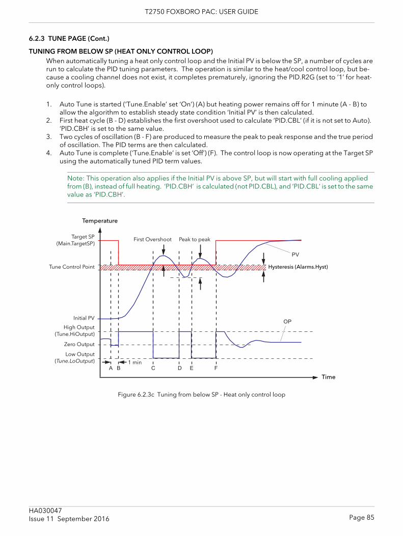
T2750 FOXBORO PAC: USER GUIDE
6.2.3 TUNE PAGE (Cont.)
TUNING FROM BELOW SP (HEAT ONLY CONTROL LOOP)When automatically tuning a heat only control loop and the Initial PV is below the SP, a number of cycles are run to calculate the PID tuning parameters. The operation is similar to the heat/cool control loop, but be-cause a cooling channel does not exist, it completes prematurely, ignoring the PID.R2G (set to ‘1’ for heat-only control loops).
1. Auto Tune is started (‘Tune.Enable’ set ‘On’) (A) but heating power remains off for 1 minute (A - B) to allow the algorithm to establish steady state condition ‘Initial PV’ is then calculated.
2. First heat cycle (B - D) establishes the first overshoot used to calculate ‘PID.CBL’ (if it is not set to Auto). ‘PID.CBH’ is set to the same value.
3. Two cycles of oscillation (B - F) are produced to measure the peak to peak response and the true period of oscillation. The PID terms are then calculated.
4. Auto Tune is complete (‘Tune.Enable’ is set ‘Off’) (F). The control loop is now operating at the Target SP using the automatically tuned PID term values.
Note: This operation also applies if the Initial PV is above SP, but will start with full cooling applied from (B), instead of full heating. ‘PID.CBH’ is calculated (not PID.CBL), and ‘PID.CBL’ is set to the same value as ‘PID.CBH’.
Figure 6.2.3c Tuning from below SP - Heat only control loop
123456789012345678901234567890121234567890123456789012345678901212345678901234567890123456789012345678901212345678901234567890123456789012123456789012345678901234567890123456789012123456789012345678901234567890121234567890
A B C D E F
PV
OP
Temperature
Time
First Overshoot Peak to peakTarget SP(Main.TargetSP)
Initial PV
High Output(Tune.HiOutput)
1 min
Hysteresis (Alarms.Hyst)Tune Control Point
Low Output(Tune.LoOutput)
Zero Output
Page 85HA030047Issue 11 September 2016
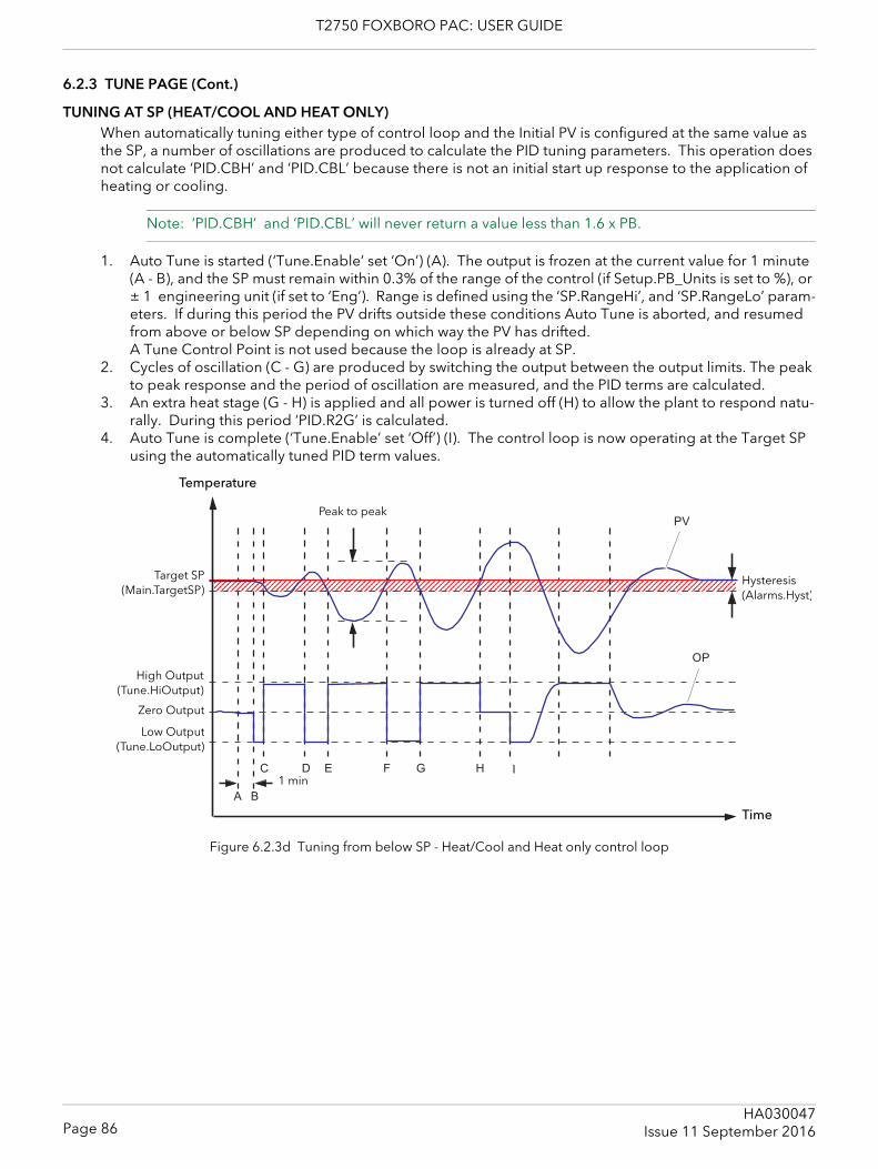
T2750 FOXBORO PAC: USER GUIDE
6.2.3 TUNE PAGE (Cont.)
TUNING AT SP (HEAT/COOL AND HEAT ONLY)When automatically tuning either type of control loop and the Initial PV is configured at the same value as the SP, a number of oscillations are produced to calculate the PID tuning parameters. This operation does not calculate ‘PID.CBH’ and ‘PID.CBL’ because there is not an initial start up response to the application of heating or cooling.
Note: ‘PID.CBH’ and ‘PID.CBL’ will never return a value less than 1.6 x PB.
1. Auto Tune is started (‘Tune.Enable’ set ‘On’) (A). The output is frozen at the current value for 1 minute (A - B), and the SP must remain within 0.3% of the range of the control (if Setup.PB_Units is set to %), or ± 1 engineering unit (if set to ‘Eng’). Range is defined using the ‘SP.RangeHi’, and ‘SP.RangeLo’ param-eters. If during this period the PV drifts outside these conditions Auto Tune is aborted, and resumed from above or below SP depending on which way the PV has drifted. A Tune Control Point is not used because the loop is already at SP.
2. Cycles of oscillation (C - G) are produced by switching the output between the output limits. The peak to peak response and the period of oscillation are measured, and the PID terms are calculated.
3. An extra heat stage (G - H) is applied and all power is turned off (H) to allow the plant to respond natu-rally. During this period ‘PID.R2G’ is calculated.
4. Auto Tune is complete (‘Tune.Enable’ set ‘Off’) (I). The control loop is now operating at the Target SP using the automatically tuned PID term values.
Figure 6.2.3d Tuning from below SP - Heat/Cool and Heat only control loop
123456789012345678901234567890121234567890123456789012345678901212345678901234567890123456789012123456789012345678901234567890123456789012123456789012345678901234567890121234567890123456789012345678901212345678901234567890123456789012345678901212345678901234567890123456789012123456789012345678901234567890121234567890
A B
D E F G H
PV
OP
C I
Temperature
Time
Peak to peak
Target SP(Main.TargetSP)
High Output(Tune.HiOutput)
1 min
Hysteresis (Alarms.Hyst)
Low Output(Tune.LoOutput)
Zero Output
Page 86HA030047
Issue 11 September 2016
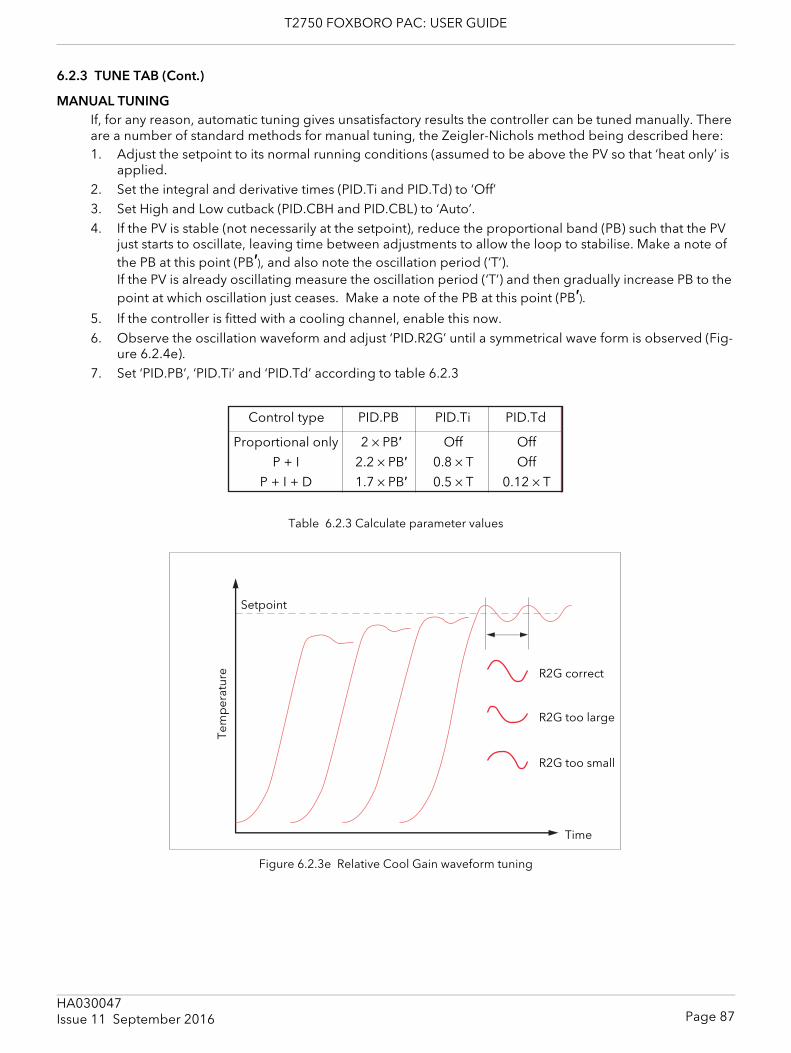
T2750 FOXBORO PAC: USER GUIDE
6.2.3 TUNE TAB (Cont.)
MANUAL TUNINGIf, for any reason, automatic tuning gives unsatisfactory results the controller can be tuned manually. There are a number of standard methods for manual tuning, the Zeigler-Nichols method being described here:1. Adjust the setpoint to its normal running conditions (assumed to be above the PV so that ‘heat only’ is
applied.2. Set the integral and derivative times (PID.Ti and PID.Td) to ‘Off’3. Set High and Low cutback (PID.CBH and PID.CBL) to ‘Auto’.4. If the PV is stable (not necessarily at the setpoint), reduce the proportional band (PB) such that the PV
just starts to oscillate, leaving time between adjustments to allow the loop to stabilise. Make a note of the PB at this point (PB′), and also note the oscillation period (‘T’).If the PV is already oscillating measure the oscillation period (‘T’) and then gradually increase PB to the point at which oscillation just ceases. Make a note of the PB at this point (PB′).
5. If the controller is fitted with a cooling channel, enable this now.6. Observe the oscillation waveform and adjust ‘PID.R2G’ until a symmetrical wave form is observed (Fig-
ure 6.2.4e).7. Set ‘PID.PB’, ‘PID.Ti’ and ‘PID.Td’ according to table 6.2.3
Table 6.2.3 Calculate parameter values
Figure 6.2.3e Relative Cool Gain waveform tuning
Control type PID.PB PID.Ti PID.Td
Proportional only
P + I
P + I + D
2 × PB′
2.2 × PB′
1.7 × PB′
Off
Off
0.12 × T
Off
0.8 × T0.5 × T
Setpoint
Time
R2G correct
R2G too large
R2G too small
Tem
per
atur
e
Page 87HA030047Issue 11 September 2016
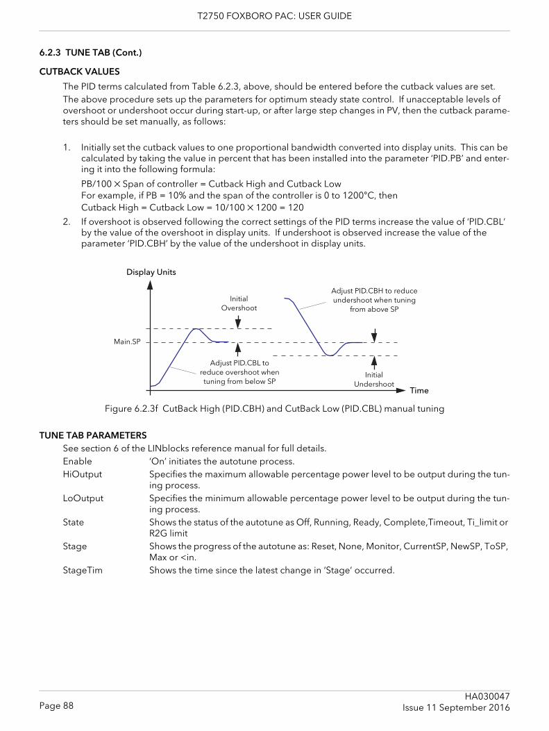
T2750 FOXBORO PAC: USER GUIDE
6.2.3 TUNE TAB (Cont.)
CUTBACK VALUES
The PID terms calculated from Table 6.2.3, above, should be entered before the cutback values are set.The above procedure sets up the parameters for optimum steady state control. If unacceptable levels of overshoot or undershoot occur during start-up, or after large step changes in PV, then the cutback parame-ters should be set manually, as follows:
1. Initially set the cutback values to one proportional bandwidth converted into display units. This can be calculated by taking the value in percent that has been installed into the parameter ‘PID.PB’ and enter-ing it into the following formula:
PB/100 × Span of controller = Cutback High and Cutback LowFor example, if PB = 10% and the span of the controller is 0 to 1200°C, thenCutback High = Cutback Low = 10/100 × 1200 = 120
2. If overshoot is observed following the correct settings of the PID terms increase the value of ‘PID.CBL’ by the value of the overshoot in display units. If undershoot is observed increase the value of the parameter ‘PID.CBH’ by the value of the undershoot in display units.
Figure 6.2.3f CutBack High (PID.CBH) and CutBack Low (PID.CBL) manual tuning
TUNE TAB PARAMETERSSee section 6 of the LINblocks reference manual for full details.Enable ‘On’ initiates the autotune process.HiOutput Specifies the maximum allowable percentage power level to be output during the tun-
ing process.LoOutput Specifies the minimum allowable percentage power level to be output during the tun-
ing process.State Shows the status of the autotune as Off, Running, Ready, Complete,Timeout, Ti_limit or
R2G limitStage Shows the progress of the autotune as: Reset, None, Monitor, CurrentSP, NewSP, ToSP,
Max or <in.StageTim Shows the time since the latest change in ‘Stage’ occurred.
Display Units
Time
Initial Overshoot
Initial Undershoot
Adjust PID.CBH to reduce undershoot when tuning
from above SP
Adjust PID.CBL to reduce overshoot when
tuning from below SP
Main.SP
Page 88HA030047
Issue 11 September 2016
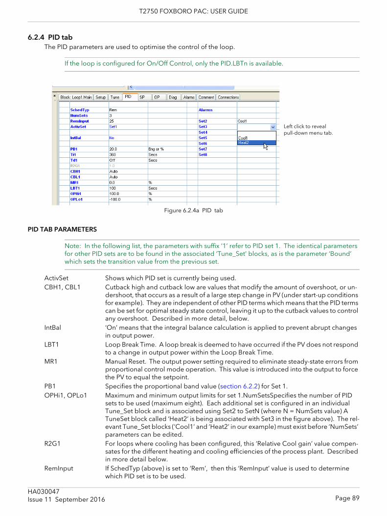
T2750 FOXBORO PAC: USER GUIDE
6.2.4 PID tabThe PID parameters are used to optimise the control of the loop.
If the loop is configured for On/Off Control, only the PID.LBTn is available.
Figure 6.2.4a PID tab
PID TAB PARAMETERS
Note: In the following list, the parameters with suffix ‘1’ refer to PID set 1. The identical parameters for other PID sets are to be found in the associated ‘Tune_Set’ blocks, as is the parameter ‘Bound’ which sets the transition value from the previous set.
ActivSet Shows which PID set is currently being used.CBH1, CBL1 Cutback high and cutback low are values that modify the amount of overshoot, or un-
dershoot, that occurs as a result of a large step change in PV (under start-up conditions for example). They are independent of other PID terms which means that the PID terms can be set for optimal steady state control, leaving it up to the cutback values to control any overshoot. Described in more detail, below.
IntBal ‘On’ means that the integral balance calculation is applied to prevent abrupt changes in output power.
LBT1 Loop Break Time. A loop break is deemed to have occurred if the PV does not respond to a change in output power within the Loop Break Time.
MR1 Manual Reset. The output power setting required to eliminate steady-state errors from proportional control mode operation. This value is introduced into the output to force the PV to equal the setpoint.
PB1 Specifies the proportional band value (section 6.2.2) for Set 1.OPHi1, OPLo1 Maximum and minimum output limits for set 1.NumSetsSpecifies the number of PID
sets to be used (maximum eight). Each additional set is configured in an individual Tune_Set block and is associated using Set2 to SetN (where N = NumSets value) A TuneSet block called ‘Heat2’ is being associated with Set3 in the figure above). The rel-evant Tune_Set blocks (‘Cool1’ and ‘Heat2’ in our example) must exist before ‘NumSets’ parameters can be edited.
R2G1 For loops where cooling has been configured, this ‘Relative Cool gain’ value compen-sates for the different heating and cooling efficiencies of the process plant. Described in more detail below.
RemInput If SchedTyp (above) is set to ‘Rem’, then this ‘RemInput’ value is used to determine which PID set is to be used.
Left click to reveal pull-down menu tab.
Page 89HA030047Issue 11 September 2016
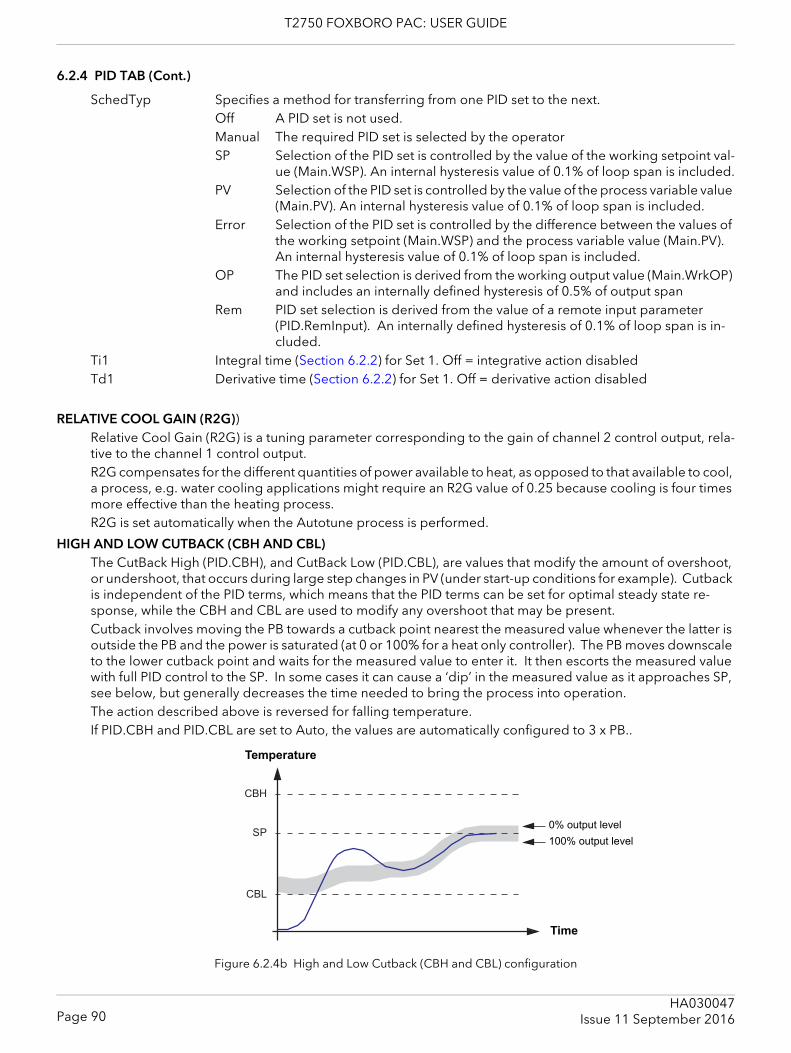
T2750 FOXBORO PAC: USER GUIDE
6.2.4 PID TAB (Cont.)
SchedTyp Specifies a method for transferring from one PID set to the next.Off A PID set is not used.Manual The required PID set is selected by the operatorSP Selection of the PID set is controlled by the value of the working setpoint val-
ue (Main.WSP). An internal hysteresis value of 0.1% of loop span is included.PV Selection of the PID set is controlled by the value of the process variable value
(Main.PV). An internal hysteresis value of 0.1% of loop span is included.Error Selection of the PID set is controlled by the difference between the values of
the working setpoint (Main.WSP) and the process variable value (Main.PV). An internal hysteresis value of 0.1% of loop span is included.
OP The PID set selection is derived from the working output value (Main.WrkOP) and includes an internally defined hysteresis of 0.5% of output span
Rem PID set selection is derived from the value of a remote input parameter (PID.RemInput). An internally defined hysteresis of 0.1% of loop span is in-cluded.
Ti1 Integral time (Section 6.2.2) for Set 1. Off = integrative action disabled Td1 Derivative time (Section 6.2.2) for Set 1. Off = derivative action disabled
RELATIVE COOL GAIN (R2G))Relative Cool Gain (R2G) is a tuning parameter corresponding to the gain of channel 2 control output, rela-tive to the channel 1 control output.R2G compensates for the different quantities of power available to heat, as opposed to that available to cool, a process, e.g. water cooling applications might require an R2G value of 0.25 because cooling is four times more effective than the heating process.R2G is set automatically when the Autotune process is performed.
HIGH AND LOW CUTBACK (CBH AND CBL)The CutBack High (PID.CBH), and CutBack Low (PID.CBL), are values that modify the amount of overshoot, or undershoot, that occurs during large step changes in PV (under start-up conditions for example). Cutback is independent of the PID terms, which means that the PID terms can be set for optimal steady state re-sponse, while the CBH and CBL are used to modify any overshoot that may be present.Cutback involves moving the PB towards a cutback point nearest the measured value whenever the latter is outside the PB and the power is saturated (at 0 or 100% for a heat only controller). The PB moves downscale to the lower cutback point and waits for the measured value to enter it. It then escorts the measured value with full PID control to the SP. In some cases it can cause a ‘dip’ in the measured value as it approaches SP, see below, but generally decreases the time needed to bring the process into operation.The action described above is reversed for falling temperature.If PID.CBH and PID.CBL are set to Auto, the values are automatically configured to 3 x PB..
Figure 6.2.4b High and Low Cutback (CBH and CBL) configuration
SP
CBH
CBL
Temperature
Time
0% output level
100% output level
Page 90HA030047
Issue 11 September 2016
T2750 FOXBORO PAC: USER GUIDE
6.2.4 PID TAB (Cont.)
MANUAL RESET (MR)In a PID control, ‘Ti’ automatically removes the steady state error from the SP. If the PID control is changed to PD control, ‘Ti’ is set to ‘OFF’ and under these conditions the measured value may not settle precisely at SP. The MR parameter represents the value of the power output that will be delivered when the error is 0 (zero). To remove the steady state error, the MR value must be configured manually.
LOOP BREAKLoop Break attempts to detect loss of restoring action in the control loop by checking the control output, the process value and its rate of change. Since response times vary from process to process, the Loop Break Time (LBT) parameter allows a time to be set before a Loop Break Alarm (LpBreak - see section 6.2.7 ‘Diag-nostics tab’) becomes active. LBT is set automatically in Autotune.The Loop Break Alarm parameter has no direct effect on control. In order to define behaviour under Loop Break conditions, the parameter must be wired, for example, to a relay, which can then activate an external indicator. It is assumed that, so long as the requested output power is within the output power limits of a control loop, the loop is operating in linear control and is therefore not in a loop break condition. If, however, the output becomes saturated then the loop is operating outside its linear control region. If the output remains saturat-ed at the same output power for a significant duration, then this might be symptomatic of a fault in the con-trol loop. The source of the loop break is not important, but the loss of control could be catastrophic. Since the worst case time constant for a given load is usually known, a worst case time can be calculated over which the load should have responded with a minimum movement in temperature. By performing this cal-culation the corresponding rate of approach towards setpoint can be used to determine if the loop can no longer control at the chosen setpoint. If the PV was drifting away from the setpoint or approaching the set-point at a rate less than that calculated, the loop break condition would be met.If an autotune is performed the loop break time is automatically set to Ti × 2 for a PI or PID loop, or to 12 × Td for a PD loop. For an On/Off controller loop break detection is based on loop range settings as 0.1 × Span where Span = Range High – Range Low. Therefore, if the output is at limit and the PV has not moved by 0.1Span in the loop break time a loop break will occur.If the loop break time is 0 (off) the loop break time can be set manually. Then, if the output is in saturation and the PV has not moved by >0.5 × Pb in the loop break time, a loop break condition is considered to have occurred.
Note: If the time configured in LBTn is 0(off), loop break detection is disabled.
Page 91HA030047Issue 11 September 2016
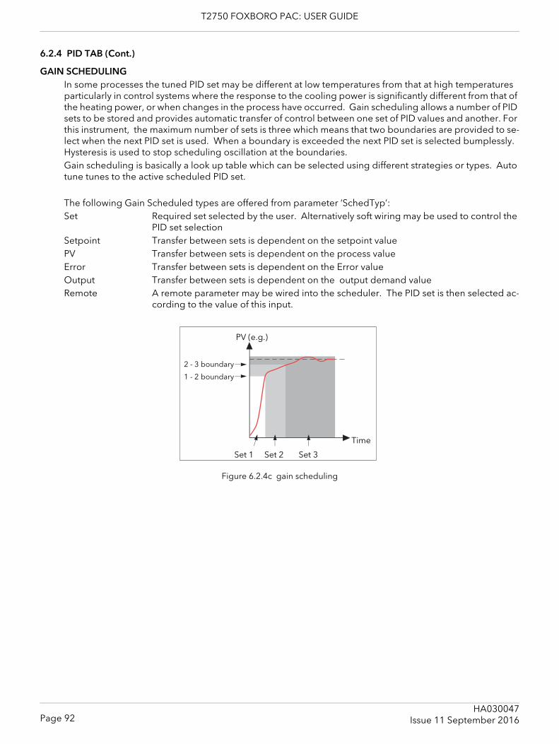
T2750 FOXBORO PAC: USER GUIDE
6.2.4 PID TAB (Cont.)
GAIN SCHEDULINGIn some processes the tuned PID set may be different at low temperatures from that at high temperatures particularly in control systems where the response to the cooling power is significantly different from that of the heating power, or when changes in the process have occurred. Gain scheduling allows a number of PID sets to be stored and provides automatic transfer of control between one set of PID values and another. For this instrument, the maximum number of sets is three which means that two boundaries are provided to se-lect when the next PID set is used. When a boundary is exceeded the next PID set is selected bumplessly. Hysteresis is used to stop scheduling oscillation at the boundaries.Gain scheduling is basically a look up table which can be selected using different strategies or types. Auto tune tunes to the active scheduled PID set.
The following Gain Scheduled types are offered from parameter ‘SchedTyp’:Set Required set selected by the user. Alternatively soft wiring may be used to control the
PID set selectionSetpoint Transfer between sets is dependent on the setpoint valuePV Transfer between sets is dependent on the process valueError Transfer between sets is dependent on the Error valueOutput Transfer between sets is dependent on the output demand valueRemote A remote parameter may be wired into the scheduler. The PID set is then selected ac-
cording to the value of this input.
Figure 6.2.4c gain scheduling
1 - 2 boundary
2 - 3 boundary
Set 3
PV (e.g.)
Time
Set 2Set 1
Page 92HA030047
Issue 11 September 2016
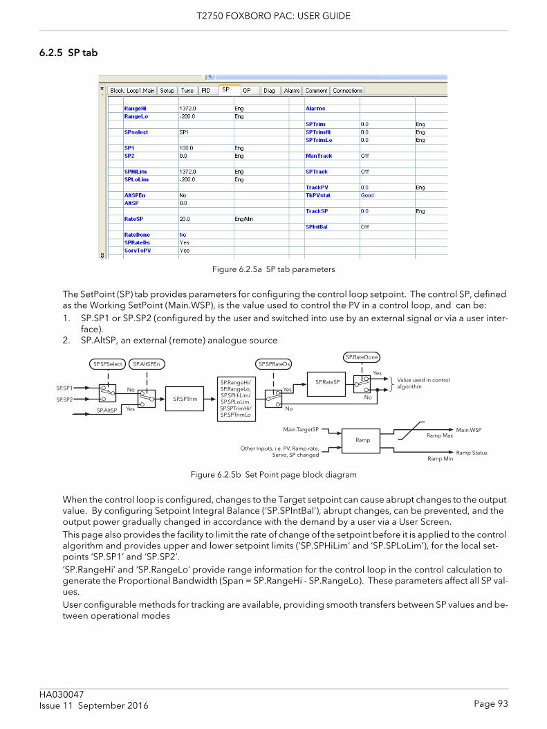
T2750 FOXBORO PAC: USER GUIDE
6.2.5 SP tab
Figure 6.2.5a SP tab parameters
The SetPoint (SP) tab provides parameters for configuring the control loop setpoint. The control SP, defined as the Working SetPoint (Main.WSP), is the value used to control the PV in a control loop, and can be:1. SP.SP1 or SP.SP2 (configured by the user and switched into use by an external signal or via a user inter-
face).2. SP.AltSP, an external (remote) analogue source
Figure 6.2.5b Set Point page block diagram
When the control loop is configured, changes to the Target setpoint can cause abrupt changes to the output value. By configuring Setpoint Integral Balance (‘SP.SPIntBal’), abrupt changes, can be prevented, and the output power gradually changed in accordance with the demand by a user via a User Screen.This page also provides the facility to limit the rate of change of the setpoint before it is applied to the control algorithm and provides upper and lower setpoint limits (‘SP.SPHiLim’ and ‘SP.SPLoLim’), for the local set-points ‘SP.SP1’ and ‘SP.SP2’.‘SP.RangeHi’ and ‘SP.RangeLo’ provide range information for the control loop in the control calculation to generate the Proportional Bandwidth (Span = SP.RangeHi - SP.RangeLo). These parameters affect all SP val-ues.User configurable methods for tracking are available, providing smooth transfers between SP values and be-tween operational modes
No
Ramp MaxMain.TargetSP
Ramp
Value used in control algorithm
Other Inputs, i.e. PV, Ramp rate,Servo, SP changed
Yes
Ramp Min
SP.SPSelect
No
YesSP.SP1
SP.SP2
SP.AltSP
SP.AltSPEn
SP.SPTrim
SP.RangeHi/SP.RangeLo, SP.SPHiLim/SP.SPLoLim, SP.SPTrimHi/SP.SPTrimLo
SP.SPRateDs
No
Yes
SP.RateDone
Ramp Status
Main.WSP
SP.RateSP
Page 93HA030047Issue 11 September 2016
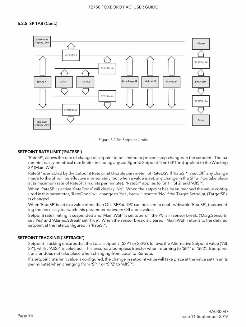
T2750 FOXBORO PAC: USER GUIDE
6.2.5 SP TAB (Cont.)
Figure 6.2.5c Setpoint Limits
SETPOINT RATE LIMIT (‘RATESP’)‘RateSP’, allows the rate of change of setpoint to be limited to prevent step changes in the setpoint. The pa-rameter is a symmetrical rate limiter including any configured Setpoint Trim (SPTrim) applied to the Working SP (Main.WSP). RateSP’ is enabled by the Setpoint Rate Limit Disable parameter ‘SPRateDS’. If ‘RateSP’ is set Off, any change made to the SP will be effective immediately, but when a value is set, any change in the SP will be take place at ta maximum rate of RateSP. (in units per minute). ‘RateSP’ applies to ‘SP1’, ‘SP2’ and ‘AltSP’.When ‘RateSP’ is active ‘RateDone’ will display ‘No’. When the setpoint has been reached the value config-ured in this parameter, ‘RateDone’ will change to ‘Yes’, but will reset to ‘No’ if the Target Setpoint, (TargetSP), is changed.When ‘RateSP’ is set to a value other than Off, ‘SPRateDS’ can be used to enable/disable ‘RateSP’, thus avoid-ing the necessity to switch this parameter between Off and a value.Setpoint rate limiting is suspended and ‘Main.WSP’ is set to zero if the PV is in sensor break, (‘Diag.SensorB’ set ‘Yes’ and ‘Alarms.SBreak’ set ‘True’. When the sensor break is cleared, ‘Main.WSP’ returns to the defined setpoint at the rate configured in ‘RateSP’.
SETPOINT TRACKING (‘SPTRACK’)Setpoint Tracking ensures that the Local setpoint (SSP1 or SSP2), follows the Alternative Setpoint value (‘Alt-SP’), whilst ‘AltSP’ is selected. This ensures a bumpless transfer when returning to ‘SP1’ or ‘SP2’. Bumpless transfer does not take place when changing from Local to Remote.If a setpoint rate limit value is configured, the change in setpoint value will take place at the value set (in units per minute) when changing from ‘SP1’ or ‘SP2’ to ‘AltSP’.
Alarms.allMain.TargetSP
+Span
SP.SPTrim
Maximum Display Units
SP.AltSP SP.SP1 SP.SP2
SP.RangeHi
-Span
SP.SPHiLim
SP.SPLoLim
SP.SPTrimLo
SP.SPTrimHi
Main.WSP
Minimum Display Units
SP.RangeLo
Page 94HA030047
Issue 11 September 2016
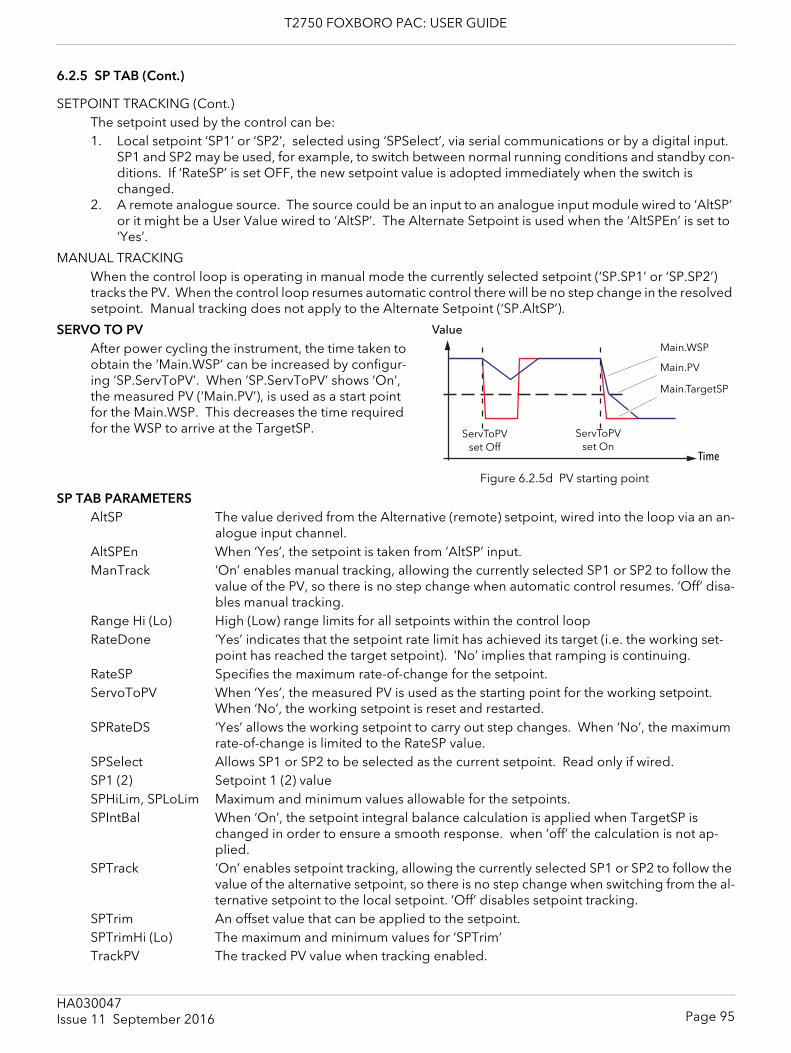
T2750 FOXBORO PAC: USER GUIDE
6.2.5 SP TAB (Cont.)
SETPOINT TRACKING (Cont.)The setpoint used by the control can be:1. Local setpoint ‘SP1’ or ‘SP2’, selected using ‘SPSelect’, via serial communications or by a digital input.
SP1 and SP2 may be used, for example, to switch between normal running conditions and standby con-ditions. If ‘RateSP’ is set OFF, the new setpoint value is adopted immediately when the switch is changed.
2. A remote analogue source. The source could be an input to an analogue input module wired to ‘AltSP’ or it might be a User Value wired to ‘AltSP’. The Alternate Setpoint is used when the ‘AltSPEn’ is set to ‘Yes’.
MANUAL TRACKINGWhen the control loop is operating in manual mode the currently selected setpoint (‘SP.SP1’ or ‘SP.SP2’) tracks the PV. When the control loop resumes automatic control there will be no step change in the resolved setpoint. Manual tracking does not apply to the Alternate Setpoint (‘SP.AltSP’).
SERVO TO PVAfter power cycling the instrument, the time taken to obtain the ‘Main.WSP’ can be increased by configur-ing ‘SP.ServToPV’. When ‘SP.ServToPV’ shows ‘On’, the measured PV (‘Main.PV’), is used as a start point for the Main.WSP. This decreases the time required for the WSP to arrive at the TargetSP.
Figure 6.2.5d PV starting point
SP TAB PARAMETERSAltSP The value derived from the Alternative (remote) setpoint, wired into the loop via an an-
alogue input channel.AltSPEn When ‘Yes’, the setpoint is taken from ‘AltSP’ input.ManTrack ‘On’ enables manual tracking, allowing the currently selected SP1 or SP2 to follow the
value of the PV, so there is no step change when automatic control resumes. ‘Off’ disa-bles manual tracking.
Range Hi (Lo) High (Low) range limits for all setpoints within the control loopRateDone ‘Yes’ indicates that the setpoint rate limit has achieved its target (i.e. the working set-
point has reached the target setpoint). ‘No’ implies that ramping is continuing.RateSP Specifies the maximum rate-of-change for the setpoint.ServoToPV When ‘Yes’, the measured PV is used as the starting point for the working setpoint.
When ‘No’, the working setpoint is reset and restarted. SPRateDS ‘Yes’ allows the working setpoint to carry out step changes. When ‘No’, the maximum
rate-of-change is limited to the RateSP value.SPSelect Allows SP1 or SP2 to be selected as the current setpoint. Read only if wired.SP1 (2) Setpoint 1 (2) valueSPHiLim, SPLoLim Maximum and minimum values allowable for the setpoints.SPIntBal When ‘On’, the setpoint integral balance calculation is applied when TargetSP is
changed in order to ensure a smooth response. when ‘off’ the calculation is not ap-plied.
SPTrack ‘On’ enables setpoint tracking, allowing the currently selected SP1 or SP2 to follow the value of the alternative setpoint, so there is no step change when switching from the al-ternative setpoint to the local setpoint. ‘Off’ disables setpoint tracking.
SPTrim An offset value that can be applied to the setpoint.SPTrimHi (Lo) The maximum and minimum values for ‘SPTrim‘TrackPV The tracked PV value when tracking enabled.
Value
Main.TargetSP
Time
Main.WSP
ServToPV set Off
ServToPV set On
Main.PV
Page 95HA030047Issue 11 September 2016
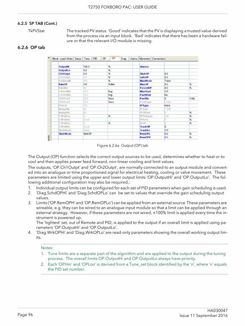
T2750 FOXBORO PAC: USER GUIDE
6.2.5 SP TAB (Cont.)
TkPVStat The tracked PV status. ‘Good’ indicates that the PV is displaying a trusted value derived from the process via an input block. ‘Bad’ indicates that there has been a hardware fail-ure or that the relevant I/O module is missing.
6.2.6 OP tab
Figure 6.2.6a Output (OP) tab
The Output (OP) function selects the correct output sources to be used, determines whether to heat or to cool and then applies power feed forward, non-linear cooling and limit values.The outputs, ‘OP.Ch1Outpt’ and ‘OP.Ch2Outpt’, are normally connected to an output module and convert-ed into an analogue or time proportioned signal for electrical heating, cooling or valve movement. These parameters are limited using the upper and lower output limits ’OP.OutputHi’ and ‘OP.OutputLo’. The fol-lowing additional configuration may also be required,:1. Individual output limits can be configured for each set of PID parameters when gain scheduling is used. 2. ‘Diag.SchdOPHi’ and ‘Diag.SchdOPLo’ can be set to values that override the gain scheduling output
values.3. Limits (‘OP.RemOPH’ and ‘OP.RemOPLo’) can be applied from an external source These parameters are
wireable, e.g. they can be wired to an analogue input module so that a limit can be applied through an external strategy. However, if these parameters are not wired, ±100% limit is applied every time the in-strument is powered up.The ‘tightest’ set, out of Remote and PID, is applied to the output if an overall limit is applied using pa-rameters ‘OP.OutputHi’ and ‘OP.OutputLo’.
4. ‘Diag.WrkOPHi’ and ‘Diag.WrkOPLo’ are read-only parameters showing the overall working output lim-its.
Notes: 1. Tune limits are a separate part of the algorithm and are applied to the output during the tuning
process. The overall limits OP.OutputHi and OP.OutputLo always have priority.2. Each ‘OPHin’ and ‘OPLon’ is derived from a Tune_set block identified by the ‘n’, where ‘n’ equals
the PID set number.
Page 96HA030047
Issue 11 September 2016
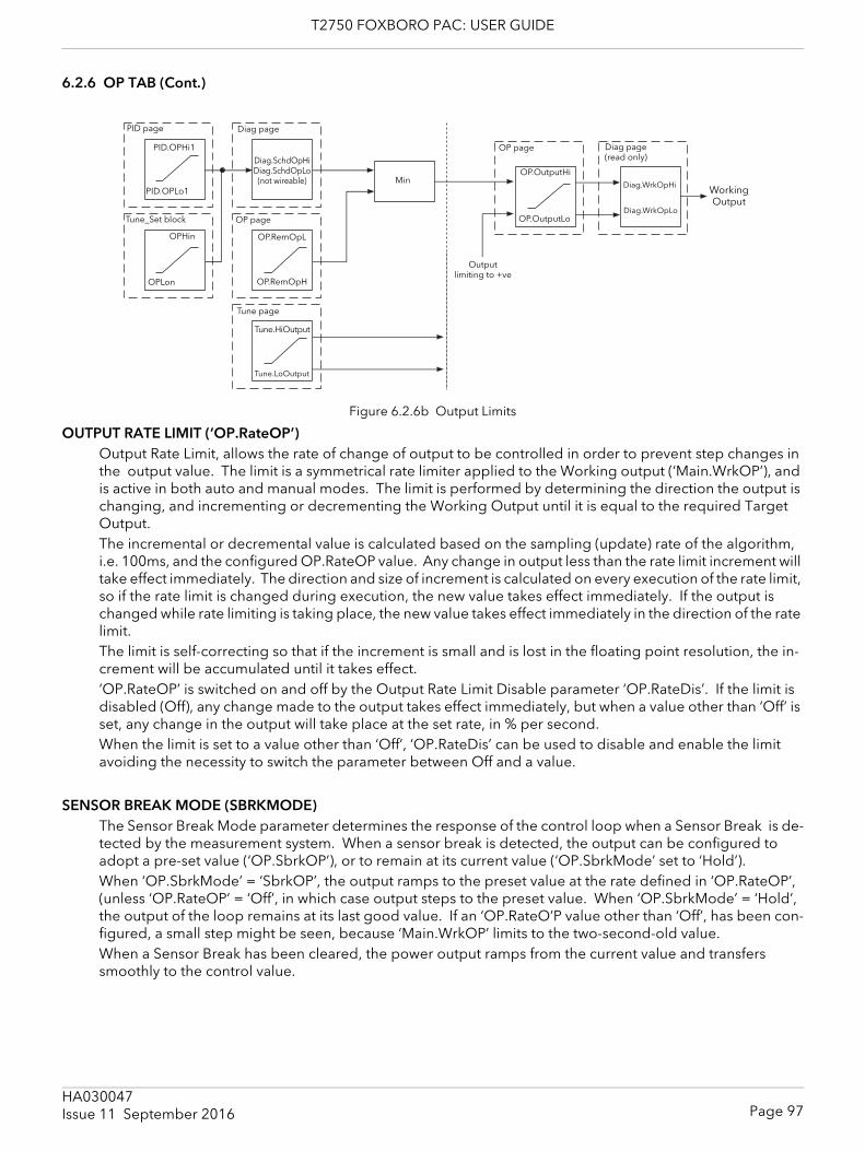
T2750 FOXBORO PAC: USER GUIDE
6.2.6 OP TAB (Cont.)
Figure 6.2.6b Output Limits
OUTPUT RATE LIMIT (‘OP.RateOP’)Output Rate Limit, allows the rate of change of output to be controlled in order to prevent step changes in the output value. The limit is a symmetrical rate limiter applied to the Working output (‘Main.WrkOP’), and is active in both auto and manual modes. The limit is performed by determining the direction the output is changing, and incrementing or decrementing the Working Output until it is equal to the required Target Output.The incremental or decremental value is calculated based on the sampling (update) rate of the algorithm, i.e. 100ms, and the configured OP.RateOP value. Any change in output less than the rate limit increment will take effect immediately. The direction and size of increment is calculated on every execution of the rate limit, so if the rate limit is changed during execution, the new value takes effect immediately. If the output is changed while rate limiting is taking place, the new value takes effect immediately in the direction of the rate limit. The limit is self-correcting so that if the increment is small and is lost in the floating point resolution, the in-crement will be accumulated until it takes effect.‘OP.RateOP’ is switched on and off by the Output Rate Limit Disable parameter ‘OP.RateDis’. If the limit is disabled (Off), any change made to the output takes effect immediately, but when a value other than ‘Off’ is set, any change in the output will take place at the set rate, in % per second.When the limit is set to a value other than ‘Off’, ‘OP.RateDis’ can be used to disable and enable the limit avoiding the necessity to switch the parameter between Off and a value.
SENSOR BREAK MODE (SBRKMODE)The Sensor Break Mode parameter determines the response of the control loop when a Sensor Break is de-tected by the measurement system. When a sensor break is detected, the output can be configured to adopt a pre-set value (‘OP.SbrkOP’), or to remain at its current value (‘OP.SbrkMode’ set to ‘Hold’).When ‘OP.SbrkMode’ = ‘SbrkOP’, the output ramps to the preset value at the rate defined in ‘OP.RateOP’, (unless ‘OP.RateOP’ = ‘Off’, in which case output steps to the preset value. When ‘OP.SbrkMode’ = ‘Hold’, the output of the loop remains at its last good value. If an ‘OP.RateO’P value other than ‘Off’, has been con-figured, a small step might be seen, because ‘Main.WrkOP’ limits to the two-second-old value.When a Sensor Break has been cleared, the power output ramps from the current value and transfers smoothly to the control value.
Tune page
Diag.SchdOpHiDiag.SchdOpLo
(not wireable) MinOP.OutputHi
PID page
PID.OPLo1
Tune_Set block OP page
PID.OPHi1
Tune.LoOutput
Diag page
OP.RemOpL
Tune.HiOutput
OP page
OP.RemOpHOPLon
OPHin
OP.OutputLo
Output limiting to +ve
Diag page(read only)
Diag.WrkOpHi
Diag.WrkOpLo
Working Output
Page 97HA030047Issue 11 September 2016
T2750 FOXBORO PAC: USER GUIDE
6.2.6 OP TAB (Cont.)
FORCED OUTPUT (FORCEDOP)This feature enables the user to specify what the output of the loop should do when moving from automatic control to manual control. The default is that the output power is maintained but it is then adjustable by the user. If Manual Mode is set to ‘Step’, the user can set a manual output power value and on transition to manual the output will be forced to that value. If Manual Mode is set to ‘Track’ the output steps to the forced manual output and then subsequent edits to the output power are tracked back into the manual output value.If Manual Mode is set to ‘Last Man. Out’ then when moving from automatic to manual mode, the output adopts the last manual output value.
POWER FEEDFORWARDPower feed forward (PFF) is used when driving an electrical heating element. It monitors the line voltage and compensates for fluctuations before they affect the process temperature, providing better steady state performance when the line voltage is not stable.PFF is mainly used for digital type outputs which drive contactors or solid state relays. Because it only has value in this type of application it can be switched off using the parameter ‘OP.PwrffEnb’. It should be disa-bled for any non-electric heating process.
ExampleConsider a process running at 25% power, with zero error and then the line voltage falls by 20%. The heater power would drop by 36% because of the square law dependence of power on voltage. A drop in temper-ature would result. After a time, the thermocouple and controller would sense this fall and increase the ON-TIME of the contactor just enough to bring the temperature back to set point. Meanwhile the process would be running a bit cooler than optimum which may cause some imperfection in the product.With power feed forward enabled the line voltage is monitored continuously and ON-TIME increased or de-creased to compensate immediately. In this way the process need never suffer a temperature disturbance caused by a line voltage change. Power FeedForward should not be confused with Feed Forward described below.
COOL TYPECooling methods vary from application to application. For example, an extruder barrel may be cooled by forced air (from a fan), or by circulating water or oil around a jacket. The cooling effect will be different de-pending on the method. CoolType is used to accommodate different types of cooling methods as follows:Linear The cooling algorithm may be set to linear where the controller output changes linearly
with the PID demand signal.Oil ‘OP.CoolType’ = ‘Oil’. As oil is essentially non-evaporative, oil cooling is pulsed in a lin-
ear manner. Water If the area being cooled is running well above 100°C, then the first few pulses of water
flash into steam giving greatly increased cooling due to the latent heat of evaporation. When the area cools, less (or even no) evaporation takes place and the cooling is less effective.Setting ‘OP.CoolType’ to ‘Water’ delivers much shortened pulses of water for the first few percent of the cooling range, when the water is likely to be flashing into steam. This compensates for the transition out of the initial strong evaporative cooling.
Fan ‘OP.CoolType’ = ‘Fan’. Fan cooling is much gentler than water cooling and not so im-mediate or decisive (because of the long heat transfer path through the process me-chanics). With fan cooling, a cool gain setting of three upwards is typical. Delivery of pulses to the blower is non linear, this non-linearity being caused by a combination of forced air movement and fan efficiency as a function of air velocity (e. g. the efficiency of a fan when producing a low speed (laminar) air flow is different from its efficiency when producing a high-speed, turbulent flow.
Page 98HA030047
Issue 11 September 2016
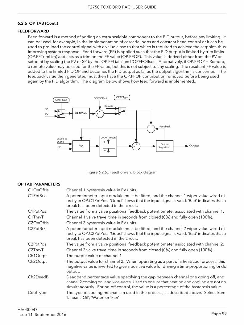
T2750 FOXBORO PAC: USER GUIDE
6.2.6 OP TAB (Cont.)
FEEDFORWARD Feed forward is a method of adding an extra scalable component to the PID output, before any limiting. It can be used, for example, in the implementation of cascade loops and constant head control or it can be used to pre-load the control signal with a value close to that which is required to achieve the setpoint, thus improving system response. Feed forward (FF) is applied such that the PID output is limited by trim limits (OP.FFTrimLim) and acts as a trim on the FF value (OP.FFOP). This value is derived either from the PV or setpoint by scaling the PV or SP by the ‘OP.FFGain’ and ‘OPFFOffset’. Alternatively, if OP.FFOP = Remote, a remote value may be used for the FF value, but this is not subject to any scaling. The resultant FF value is added to the limited PID OP and becomes the PID output as far as the output algorithm is concerned. The feedback value then generated must then have the OP.FFOP contribution removed before being used again by the PID algorithm. The diagram below shows how feed forward is implemented..
Figure 6.2.6c FeedForward block diagram
OP TAB PARAMETERSC1OnOfHs Channel 1 hysteresis value in PV units.C1PotBrk A potentiometer input module must be fitted, and the channel 1 wiper value wired di-
rectly to OP.C1PotPos. ‘Good’ shows that the input signal is valid. ‘Bad’ indicates that a break has been detected in the circuit.
C1PotPos The value from a valve positional feedback potentiometer associated with channel 1.C1TravT Channel 1 valve travel time in seconds from closed (0%) and fully open (100%). C2OnOfHs Channel 2 hysteresis value in PV units.C2PotBrk A potentiometer input module must be fitted, and the channel 2 wiper value wired di-
rectly to OP.C2PotPos. ‘Good’ shows that the input signal is valid. ‘Bad’ indicates that a break has been detected in the circuit.
C2PotPos The value from a valve positional feedback potentiometer associated with channel 2.C2TravT Channel 2 valve travel time in seconds from closed (0%) and fully open (100%).Ch1Outpt The output value of channel 1Ch2Outpt The output value for channel 2. When operating as a part of a heat/cool process, this
negative value is inverted to give a positive value for driving a time-proportioning or dc output.
Ch2DeadB Deadband percentage value specifying the gap between channel one going off, and chanel 2 coming on, and vice-versa. Used to ensure that heating and cooling are not on simultaneously. For on-off control, the value is a percentage of the hysteresis value.
CoolType The type of cooling mechanism used in the process, as described above. Select from ‘Linear’, ‘Oil’, ‘Water’ or ‘Fan’
++
-+
++
Remote
Feedback
OP.FFType
SP.SP1 or SP.SP2
PID
OP.FFGain
OP.FFOffset OP.FFType
PVOutput
Algorithm Output
OP.FFTrimLm
Hi
Lo
PV
SP
Page 99HA030047Issue 11 September 2016
T2750 FOXBORO PAC: USER GUIDE
6.2.6 OP TAB (Cont.)
OP TAB PARAMETERS (Cont.)FFGain A scaling factor for the feedforward signal.FFOffset An offset value for the feedforward signal.FFOP Shows the calculated feedforward signal.FFRem An alternative value to be applied as the feedforward signal. Gain and offset are not
applied to this input.FFTrimLim Defines symmetrical limits about the PID output which are applied to the scaled feed-
forward signal.FFType Feedforward type:
None Feedforward disabled.Remote The feedforward input comes from a remote source.SP The feedforward value is derived from the working setpoint, scaled by FF-
Gain and FFOffset.PV The feedforward value is derived from the process variable, scaled by FF-
Gain and FFOffset.ForcedOP The output power value to be adopted in manual mode operation when man-
Mode=Step.ManMode Specifies the power output during manual mode:
Track The output is derived from last control output.Step The output is the value set in ‘ForcedOP’.LastMOP the output is the value last configured by the operator in ‘ManOp’.
ManOP Manual output power. Used in manual mode when ManMode = LastMOP or Track. ManOp follows the control output in Auto mode.
ManStart If ‘On’, then Auto/Man (Main tab) is set to Man at startup. If ‘Off’ Auto/Man remains as configured.
NudgeUp (Dn) Used to open (NudgeUp) or close (NudgeDn) a valve by one minimum on time, allow-ing the valve position to be controlled over a serial link, or by contact closure inputs to a digital input module.
OutputHi (Lo) The maximum output power values delivered by channels one and two. ‘Outputlo’ would normally be set to 0% for heat only processes.
PBrkMode Defines the action to be taken in a bounded valve positioning system if the feedback potentiometer status is ‘Bad’.Raise The output raises the actuator. Lower The output lowers the actuator.Rest The actuator remains where it is.Model The output uses a model to predict actuator position.
PotCal Controls automatic calibration of the specified channel position input. A potentiometer input module must be fitted, and the wiper values wired directly to OP.C1PotPos for channel 1 or to OP.C1PotPos for channel 2.Off: Automatic pot calibration disabled.CalibrateCh1. Automatic calibration of channel 1 pot enabled. CalibrateCh2. Automatic calibration of channel 1 pot enabled.
PwrffEnb Enables Power Feed forward. Must be disabled for any load other than electric heaters. Power feed forward allows fluctuations in line voltage to be compensated for before they can affect the process.
PwrffIn Instantaneous value of the supply voltage. See ‘Power feed forward’, above.RateOP Output rate limiting. The maximum rate at which the PID output may change in % per
minute. Effective only if ‘OPRateDis’ is ‘Off’. Can be disabled by setting its value to zero.
Page 100HA030047
Issue 11 September 2016

T2750 FOXBORO PAC: USER GUIDE
6.2.6 OP TAB (Cont.)
OP TAB PARAMETERS (Cont.)RateDIS Enables/disables output rate limiting.RemOPH, REMOPL The high and low limits for loop output, derived from a remote source or calculation.SafeOP Defines the output power to be adopted if ‘Inhibit’ is enabled in the Main tab (section
6.2.1).SbrkMode Defines the output action if the PV is ‘bad’.
SbrkOP The output adopts the value entered in SbrkOP.Hold The output is maintained at the last good PV value.
SbrkOP Specifies the output value to be adopted if a sensor break is detected, and ‘SbrkMode’ = SbrkOP.
TrackEn When ‘On’, the loop output follows the track output value.TrackOP Shows the current tracked value if TrackEn = On.
Page 101HA030047Issue 11 September 2016
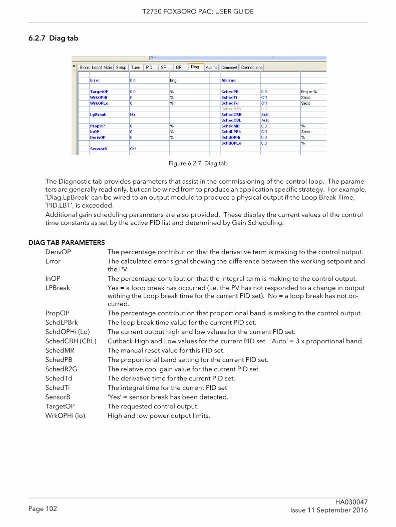
T2750 FOXBORO PAC: USER GUIDE
6.2.7 Diag tab
Figure 6.2.7 Diag tab
The Diagnostic tab provides parameters that assist in the commissioning of the control loop. The parame-ters are generally read only, but can be wired from to produce an application specific strategy. For example, ‘Diag.LpBreak’ can be wired to an output module to produce a physical output if the Loop Break Time, ‘PID.LBT’, is exceeded.Additional gain scheduling parameters are also provided. These display the current values of the control time constants as set by the active PID list and determined by Gain Scheduling.
DIAG TAB PARAMETERSDerivOP The percentage contribution that the derivative term is making to the control output.Error The calculated error signal showing the difference between the working setpoint and
the PV.InOP The percentage contribution that the integral term is making to the control output.LPBreak Yes = a loop break has occurred (i.e. the PV has not responded to a change in output
withing the Loop break time for the current PID set). No = a loop break has not oc-curred.
PropOP The percentage contribution that proportional band is making to the control output.SchdLPBrk The loop break time value for the current PID set.SchdOPHi (Lo) The current output high and low values for the current PID set.SchedCBH (CBL) Cutback High and Low values for the current PID set. ‘Auto’ = 3 x proportional band.SchedMR The manual reset value for this PID set.SchedPB The proportional band setting for the current PID set.SchedR2G The relative cool gain value for the current PID setSchedTd The derivative time for the current PID set.SchedTi The integral time for the current PID setSensorB ‘Yes’ = sensor break has been detected.TargetOP The requested control output.WrkOPHi (lo) High and low power output limits.
Page 102HA030047
Issue 11 September 2016
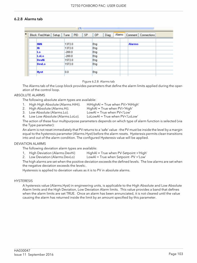
T2750 FOXBORO PAC: USER GUIDE
6.2.8 Alarms tab
Figure 6.2.8 Alarms tabThe Alarms tab of the Loop block provides parameters that define the alarm limits applied during the oper-ation of the control loop.
ABSOLUTE ALARMSThe following absolute alarm types are available:1. High High Absolute (Alarms.HiHi). HiHighAl = True when PV>’HiHigh’2. High Absolute (Alarms.Hi). HighAl = True when PV>’High’3. Low Absolute (Alarms.Lo). LowAl = True when PV<’Low’ 4. Low Low Absolute (Alarms.LoLo). LoLowAl = True when PV<’LoLow’The action of these four multipurpose parameters depends on which type of alarm function is selected (via the Type parameter): An alarm is not reset immediately that PV returns to a ‘safe’ value - the PV must be inside the level by a margin equal to the hysteresis parameter (Alarms.Hyst) before the alarm resets. Hysteresis permits clean transitions into and out of the alarm condition. The configured Hysteresis value will be applied.
DEVIATION ALARMSThe following deviation alarm types are available:1, High Deviation (Alarms.DevHi) HighAl = True when PV-Setpoint >’High’2. Low Deviation (Alarms.DevLo) LowAl = True when Setpoint -PV >’Low’The high alarms are set when the positive deviation exceeds the defined levels. The low alarms are set when the negative deviation exceeds the levels:.Hysteresis is applied to deviation values as it is to PV in absolute alarms.
HYSTERESISA hysteresis value (Alarms.Hyst) in engineering units, is applicable to the High Absolute and Low Absolute Alarm limits and the High Deviation, Low Deviation Alarm limits. This value provides a band that defines when the alarm limits are set TRUE. Once an alarm has been annunciated, it is not cleared until the value causing the alarm has returned inside the limit by an amount specified by this parameter.
Page 103HA030047Issue 11 September 2016
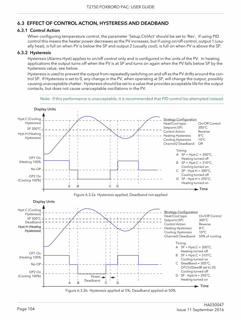
T2750 FOXBORO PAC: USER GUIDE
6.3 EFFECT OF CONTROL ACTION, HYSTERESIS AND DEADBAND6.3.1 Control Action
When configuring temperature control, the parameter ‘Setup.CtrlAct’ should be set to ‘Rev’. If using PID control this means the heater power decreases as the PV increases, but if using on/off control, output 1 (usu-ally heat), is full on when PV is below the SP and output 2 (usually cool), is full on when PV is above the SP.
6.3.2 HysteresisHysteresis (Alarms.Hyst) applies to on/off control only and is configured in the units of the PV. In heating applications the output turns off when the PV is at SP and turns on again when the PV falls below SP by the hysteresis value, see below.Hysteresis is used to prevent the output from repeatedly switching on and off as the PV drifts around the con-trol SP. If Hysteresis is set to 0, any change in the PV, when operating at SP, will change the output, possibly causing unacceptable chatter. Hysteresis should be set to a value that provides acceptable life for the output contacts, but does not cause unacceptable oscillations in the PV.
Note: If this performance is unacceptable, it is recommended that PID control be attempted instead.
Figure 6.3.2a Hysteresis applied, Deadband not applied
Figure 6.3.2b Hysteresis applied at 5%, Deadband applied at 50%
A B C D
Display Units
Time
Strategy ConfigurationHeat/Cool type On/Off ControlSetpoint (SP) 300°CControl Action ReverseHeating Hysteresis 8°CCooling Hysteresis 10°CChannel2 Deadband Off
TimingA SP + Hyst.C = 300°C,
Heating turned offB SP + Hyst.C = 310°C,
Cooling turned onC SP - Hyst.H = 300°C,
Cooling turned offD SP - Hyst.H = 292°C,
Heating turned on
Hyst.C (CoolingHysteresis)
SP 300°C
Hyst.H (HeatingHysteresis)
OP1 On(Heating 100%
No OP
OP2 On(Cooling 100%)
A B C D
Display Units
Time
Deadband
PowerDeadband
Strategy ConfigurationHeat/Cool type On/Off ControlSetpoint (SP) 300°CControl Action ReverseHeating Hysteresis 8°CCooling Hysteresis 10°CChannel2 Deadband 50% of cooling
TimingA SP + Hyst.C = 300°C,
Heating turned offB SP + Hyst.C = 310°C,
Cooling turned onC DeadBand = 305°C,
OP.Ch2DeadB set to 20,Cooling turned off
D SP - Hyst.H = 292°C, Heating turned on
Hyst.C (CoolingHysteresis)
SP 300°C
Hyst.H (HeatingHysteresis)
OP1 On(Heating 100%
No OP
OP2 On(Cooling 100%)
Page 104HA030047
Issue 11 September 2016

T2750 FOXBORO PAC: USER GUIDE
6.3.3 Channel two deadbandChannel 2 Deadband (OP.CH2DeadB) can operate in both on/off control or PID control to wide the period when no heating or cooling is applied. However, in PID control its effect is modified by both the PID.Ti and PID.Td parameters. Channel two deadband would normally be used in on/off control only. It can, however, be used in PID con-trol, in the situation where actuators take time to complete their cycle, to ensure that heating and cooling are never applied at the same time, see previous diagram.
Page 105HA030047Issue 11 September 2016
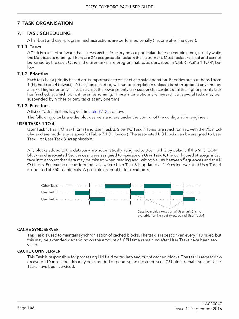
T2750 FOXBORO PAC: USER GUIDE
7 TASK ORGANISATION
7.1 TASK SCHEDULINGAll in-built and user-programmed instructions are performed serially (i.e. one after the other).
7.1.1 TasksA Task is a unit of software that is responsible for carrying out particular duties at certain times, usually while the Database is running. There are 24 recognisable Tasks in the instrument. Most Tasks are fixed and cannot be varied by the user. Others, the user tasks, are programmable, as described in ‘USER TASKS 1 TO 4’, be-low.
7.1.2 PrioritiesEach task has a priority based on its importance to efficient and safe operation. Priorities are numbered from 1 (highest) to 24 (lowest). A task, once started, will run to completion unless it is interrupted at any time by a task of higher priority. In such a case, the lower priority task suspends activities until the higher priority task has finished, at which point it resumes running. These interruptions are hierarchical; several tasks may be suspended by higher priority tasks at any one time.
7.1.3 FunctionsA list of Task functions is given in table 7.1.3a, below.The following 6 tasks are the block servers and are under the control of the configuration engineer.
USER TASKS 1 TO 4User Task 1, Fast I/O task (10ms) and User Task 3, Slow I/O Task (110ms) are synchronised with the I/O mod-ules and are module type specific (Table 7.1.3b, below). The associated I/O blocks can be assigned to User Task 1 or User Task 3, as applicable.
Any blocks added to the database are automatically assigned to User Task 3 by default. If the SFC_CON block (and associated Sequences) were assigned to operate on User Task 4, the configured strategy must take into account that data may be missed when reading and writing values between Sequences and the I/O blocks. For example, consider the case where User Task 3 is updated at 110ms intervals and User Task 4 is updated at 250ms intervals. A possible order of task execution is,
CACHE SYNC SERVERThis Task is used to maintain synchronisation of cached blocks. The task is repeat driven every 110 msec, but this may be extended depending on the amount of CPU time remaining after User Tasks have been ser-viced.
CACHE CONN SERVERThis Task is responsible for processing LIN field writes into and out of cached blocks. The task is repeat driv-en every 110 msec, but this may be extended depending on the amount of CPU time remaining after User Tasks have been serviced.
○ ○ ○ ○ ○ ○ ○ ○ ○ ○ ○ ○ ○ ○ ○ ○ ○ ○ ○ ○ ○ ○ ○ ○ ○ ○ ○ ○ ○ ○ ○ ○ ○ ○ ○ ○ ○ ○ ○ ○ ○ ○ ○
○ ○ ○ ○ ○ ○ ○ ○ ○ ○ ○ ○ ○ ○ ○ ○ ○ ○ ○ ○ ○ ○ ○ ○ ○ ○ ○ ○ ○ ○ ○ ○ ○ ○ ○ ○ ○ ○ ○ ○ ○ ○ ○
○ ○ ○ ○ ○ ○ ○ ○ ○ ○ ○ ○ ○ ○ ○ ○ ○ ○ ○ ○ ○ ○ ○ ○ ○ ○ ○ ○ ○ ○ ○ ○ ○ ○ ○ ○ ○ ○ ○ ○ ○ ○ ○
Data from this execution of User task 3 is not available for the next execution of User Task 4
Other Tasks
User Task 3
User Task 4
Page 106HA030047
Issue 11 September 2016
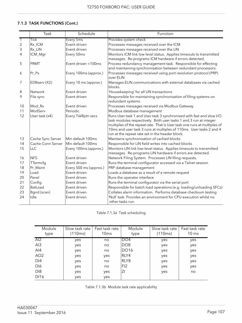
T2750 FOXBORO PAC: USER GUIDE
7.1.3 TASK FUNCTIONS (Cont.)
Table 7.1.3a Task scheduling
Table 7.1.3b Module task rate applicability
Task Schedule Function1 Tick Every 5ms Provides system check2 Rx_ICM Event driven Processes messages received over the ICM3 Rx_LIN Event driven Processes messages received over the LIN4 ICM_Mgr Every 50ms Monitors ICM link low level status. Applies timeouts to transmitted
messages. Re-programs ICM hardware if errors detected.5 PRMT Event driven <100ms Process redundancy management task. Responsible for effecting
and maintaining synchronisation between redundant processors.6 Pr_Px Every 100ms (approx.) Processes messages received using port resolution protocol (PRP)
over ELIN7 EDBserv (X2) Every 10 ms (approx.) Manages ELIN communications with external databases via cached
blocks.8 Network Event driven ‘Housekeeping’ for all LIN transactions9 File sync Event driven Responsible for maintaining synchronisation of filing systems on
redundant systems10 Mod_Rx Event driven Processes messages received via Modbus Gateway11 ModServ Periodic Modbus database management12 User task (x4) Every TskRptn secs Runs User task 1 and User task 3 synchronised with fast and slow I/O
task modules respectively. Both user tasks 1 and 3 run at integer multiples of the repeat rate. That is User task one runs at multiples of 10ms and user task 3 runs at multiples of 110ms. User tasks 2 and 4 run at the repeat rate set in the header block.
13 Cache Sync Server Min default 100ms Maintains synchronisation of cached blocks14 Cache Conn Server Min default 100ms Responsible for LIN field writes into cached blocks15 LLC Every 100ms (approx.) Monitors LIN link low-level status. Applies timeouts to transmitted
messages. Re-programs LIN hardware if errors are detected.16 NFS Event driven Network Filing System. Processes LIN filing requests.17 TTermcfg Event driven Runs the terminal configurator accessed via a Telnet session18 Pr_Maint Every 500 ms (approx.) PRP database management19 Load Event driven Loads a database as a result of a remote request20 Panel Event driven Runs the operator interface21 Config Event driven Runs the terminal configurator via the serial port22 BatLoad Event driven Responsible for batch load operations (e.g. loading/unloading SFCs)23 Bgnd (scan) Event driven Collates alarm information. Performs database checksum testing24 Idle Event driven ‘Null’ task. Provides an environment for CPU execution whilst no
other tasks run.
Moduletype
Slow task rate (110ms)
Fast task rate 10ms
Moduletype
Slow task rate (110ms)
Fast task rate 10 ms
AI2 yes no DO4 yes yesAI3 yes no DO8 yes yesAI4 yes no DO16 yes yesAO2 yes yes RLY4 yes yesDI4 yes no RLY8 yes yesDI6 yes no FI2 yes yesDI8 yes yes ZI yes noDI16 yes yes
Page 107HA030047Issue 11 September 2016
T2750 FOXBORO PAC: USER GUIDE
7.2 USER TASKS7.2.1 TerminologyUSER TASK
A User Task is a defined set of function blocks in a database that are updated at a specific tick rate. The blocks are normally associated with instrument control.
BlOCK SERVERA Block Server is a fixed software task, within this instrument, that executes a User Task, or processes cached blocks.
7.2.2 Execution timesUser Task execution times are repeat driven. User Task 1, and User Task 3 are synchronised to the fast and slow I/O task modules respectively. Both run at an integer multiple of the repeat rate, i.e. User Task 1 runs at N × 10ms, and User Task 3 runs at M × 110ms, where N and M are integers.User tasks 2 and 4 run at rates defined in the header block.User task 1 has the highest priority, followed (in descending order) by User Task 2, User Task 3 and User Task 4 (lowest priority).
Note: All I/O blocks must be configured to User Task 1 or User Task 3.
Each of the 4 User Tasks has a ‘requested repeat rate’. This can be configured using LINtools (Task n Period) or the Terminal Configurator (Block Full Description page).Each function block has a Task field used to allocate it to one of the four available User Tasks. This field can also be used to configure the ‘requested repeat rate’ of the User Tasks. If the ‘requested repeat rate’ is changed via a function block allocated to a particular User Task, this change is made to the User Task, not the function block, and it affects all other function blocks assigned to that User Task.If using the LINtools Database Editor, selecting the Task field from the function block Object Properties Pane reveals the Task dialogue which permits changes to the Task Number associated with the function block. To enable changes to the Task Period (i.e. to the ‘requested repeat rate’), click the right (next) arrow button to display the Task Period dialogue.If the requested repeat rate is not configured (LINtools Task n Period dialogue or Terminal Configurator Rate ms field set to 0) the default request repeat rate is applied i.e.10ms for User Task 1 and User Task 2, and 110ms for User Task 3 and User Task 4.
Note: Tasks must not be configured to use a faster requested repeat rate than any higher priority task. Any such configuration will be ignored by the instrument, but will be run according to the rules stated in section 7.3.1, below.
Page 108HA030047
Issue 11 September 2016
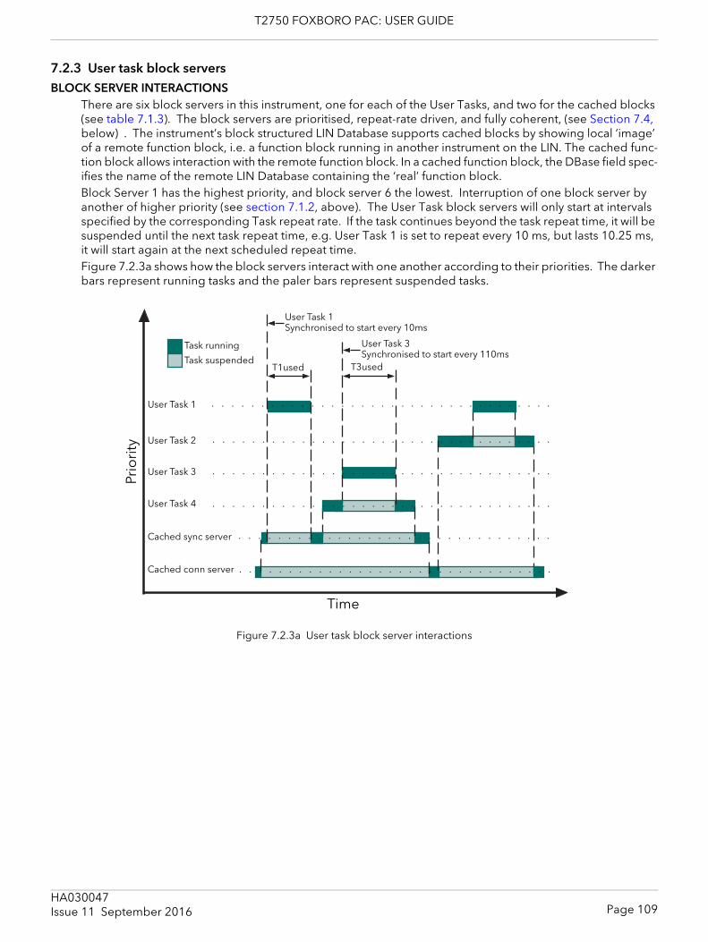
T2750 FOXBORO PAC: USER GUIDE
7.2.3 User task block serversBLOCK SERVER INTERACTIONS
There are six block servers in this instrument, one for each of the User Tasks, and two for the cached blocks (see table 7.1.3). The block servers are prioritised, repeat-rate driven, and fully coherent, (see Section 7.4, below) . The instrument’s block structured LIN Database supports cached blocks by showing local ‘image’ of a remote function block, i.e. a function block running in another instrument on the LIN. The cached func-tion block allows interaction with the remote function block. In a cached function block, the DBase field spec-ifies the name of the remote LIN Database containing the ‘real’ function block.Block Server 1 has the highest priority, and block server 6 the lowest. Interruption of one block server by another of higher priority (see section 7.1.2, above). The User Task block servers will only start at intervals specified by the corresponding Task repeat rate. If the task continues beyond the task repeat time, it will be suspended until the next task repeat time, e.g. User Task 1 is set to repeat every 10 ms, but lasts 10.25 ms, it will start again at the next scheduled repeat time.Figure 7.2.3a shows how the block servers interact with one another according to their priorities. The darker bars represent running tasks and the paler bars represent suspended tasks.
Figure 7.2.3a User task block server interactions
○ ○ ○ ○ ○ ○ ○ ○ ○ ○ ○ ○ ○ ○ ○ ○ ○ ○ ○ ○ ○ ○ ○ ○ ○ ○ ○ ○ ○ ○ ○ ○
○ ○ ○ ○ ○ ○ ○ ○ ○ ○ ○ ○ ○ ○ ○ ○ ○ ○ ○ ○ ○ ○ ○ ○ ○ ○ ○ ○ ○ ○ ○ ○
○ ○ ○ ○ ○ ○ ○ ○ ○ ○ ○ ○ ○ ○ ○ ○ ○ ○ ○ ○ ○ ○ ○ ○ ○ ○ ○ ○ ○ ○ ○ ○ ○ ○ ○
○ ○ ○ ○ ○ ○ ○ ○ ○ ○ ○ ○ ○ ○ ○ ○ ○ ○ ○ ○ ○ ○ ○ ○ ○ ○ ○ ○ ○ ○ ○ ○ ○ ○ ○
○ ○ ○ ○ ○ ○ ○ ○ ○ ○ ○ ○ ○ ○ ○ ○ ○ ○ ○ ○ ○ ○ ○ ○ ○ ○ ○ ○ ○ ○ ○ ○ ○ ○ ○
○ ○ ○ ○ ○ ○ ○ ○ ○ ○ ○ ○ ○ ○ ○ ○ ○ ○ ○ ○ ○ ○ ○ ○ ○ ○ ○ ○ ○ ○ ○ ○ ○ ○ ○
User Task 1
User Task 3
User Task 4
User Task 2
Cached sync server
Cached conn server
Task suspended
Task running
Time
T1used
Prio
rity
T3used
User Task 1Synchronised to start every 10ms
User Task 3Synchronised to start every 110ms
Page 109HA030047Issue 11 September 2016
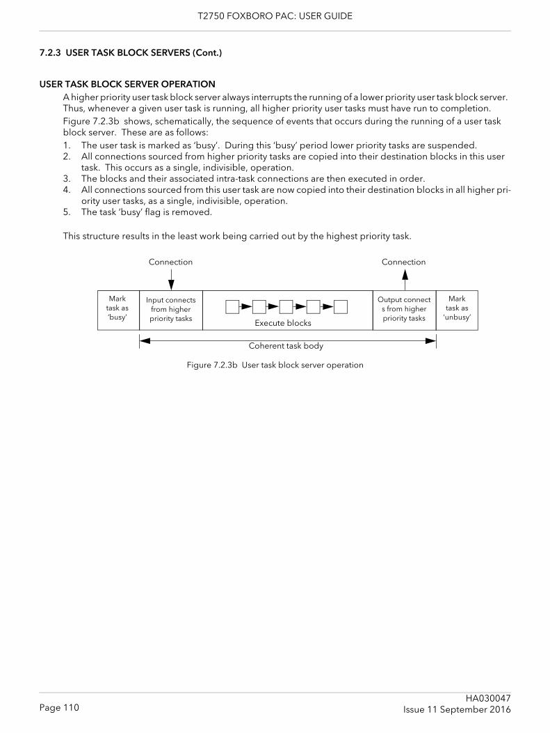
T2750 FOXBORO PAC: USER GUIDE
7.2.3 USER TASK BLOCK SERVERS (Cont.)
USER TASK BLOCK SERVER OPERATIONA higher priority user task block server always interrupts the running of a lower priority user task block server. Thus, whenever a given user task is running, all higher priority user tasks must have run to completion.Figure 7.2.3b shows, schematically, the sequence of events that occurs during the running of a user task block server. These are as follows:1. The user task is marked as ‘busy’. During this ‘busy’ period lower priority tasks are suspended.2. All connections sourced from higher priority tasks are copied into their destination blocks in this user
task. This occurs as a single, indivisible, operation.3. The blocks and their associated intra-task connections are then executed in order.4. All connections sourced from this user task are now copied into their destination blocks in all higher pri-
ority user tasks, as a single, indivisible, operation.5. The task ‘busy’ flag is removed.
This structure results in the least work being carried out by the highest priority task.
Figure 7.2.3b User task block server operation
Mark task as ‘busy’
Execute blocks
Output connects from higher priority tasks
Input connects from higher priority tasks
Coherent task body
ConnectionConnection
Mark task as
‘unbusy’
Page 110HA030047
Issue 11 September 2016
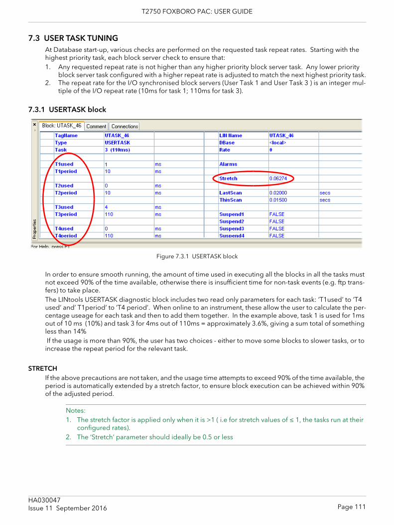
T2750 FOXBORO PAC: USER GUIDE
7.3 USER TASK TUNINGAt Database start-up, various checks are performed on the requested task repeat rates. Starting with the highest priority task, each block server check to ensure that:1. Any requested repeat rate is not higher than any higher priority block server task. Any lower priority
block server task configured with a higher repeat rate is adjusted to match the next highest priority task.2. The repeat rate for the I/O synchronised block servers (User Task 1 and User Task 3 ) is an integer mul-
tiple of the I/O repeat rate (10ms for task 1; 110ms for task 3).
7.3.1 USERTASK block
Figure 7.3.1 USERTASK block
In order to ensure smooth running, the amount of time used in executing all the blocks in all the tasks must not exceed 90% of the time available, otherwise there is insufficient time for non-task events (e.g. ftp trans-fers) to take place.The LINtools USERTASK diagnostic block includes two read only parameters for each task: ‘T1used’ to ‘T4 used’ and’ T1period’ to ‘T4 period’. When online to an instrument, these allow the user to calculate the per-centage useage for each task and then to add them together. In the example above, task 1 is used for 1ms out of 10 ms (10%) and task 3 for 4ms out of 110ms = approximately 3.6%, giving a sum total of something less than 14% If the usage is more than 90%, the user has two choices - either to move some blocks to slower tasks, or to increase the repeat period for the relevant task.
STRETCHIf the above precautions are not taken, and the usage time attempts to exceed 90% of the time available, the period is automatically extended by a stretch factor, to ensure block execution can be achieved within 90% of the adjusted period.
Notes:1. The stretch factor is applied only when it is >1 ( i.e for stretch values of ≤ 1, the tasks run at their
configured rates). 2. The ‘Stretch’ parameter should ideally be 0.5 or less
Page 111HA030047Issue 11 September 2016
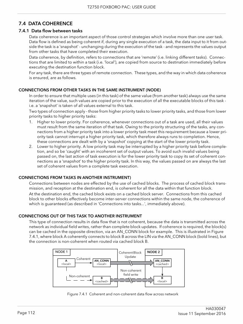
T2750 FOXBORO PAC: USER GUIDE
7.4 DATA COHERENCE7.4.1 Data flow between tasks
Data coherence is an important aspect of those control strategies which involve more than one user task. Data flow is defined as being coherent if, during any single execution of a task, the data input to it from out-side the task is a ‘snapshot’ - unchanging during the execution of the task - and represents the values output from other tasks that have completed their execution.Data coherence, by definition, refers to connections that are ‘remote’ (i.e. linking different tasks). Connec-tions that are limited to within a task (i.e. ‘local’), are copied from source to destination immediately before executing the destination function block.For any task, there are three types of remote connection. These types, and the way in which data coherence is ensured, are as follows.
CONNECTIONS FROM OTHER TASKS IN THE SAME INSTRUMENT (NODE)In order to ensure that multiple uses (in this task) of the same value (from another task) always use the same iteration of the value, such values are copied prior to the execution of all the executable blocks of this task - i.e. a ‘snapshot’ is taken of all values external to this task.Two types of connection apply - those from higher priority tasks to lower priority tasks, and those from lower priority tasks to higher priority tasks:1. Higher to lower priority. For coherence, whenever connections out of a task are used, all their values
must result from the same iteration of that task. Owing to the priority structuring of the tasks, any con-nections from a higher priority task into a lower priority task meet this requirement because a lower pri-ority task cannot interrupt a higher priority task, which therefore always runs to completion. Hence, these connections are dealt with by a ‘snapshot’ copying at the start of the lower priority task.
2. Lower to higher priority. A low priority task may be interrupted by a higher priority task before comple-tion, and so be ‘caught’ with an incoherent set of output values. To avoid such invalid values being passed on, the last action of task execution is for the lower priority task to copy its set of coherent con-nections as a ‘snapshot’ to the higher priority task. In this way, the values passed on are always the last set of coherent values from a complete task execution.
CONNECTIONS FROM TASKS IN ANOTHER INSTRUMENT)Connections between nodes are effected by the use of cached blocks. The process of cached block trans-mission, and reception at the destination end, is coherent for all the data within that function block.At the destination end, the cached block exists on a cached block server. Connections from this cached block to other blocks effectively become inter-server connections within the same node, the coherence of which is guaranteed (as described in 'Connections into tasks...', immediately above).
CONNECTIONS OUT OF THIS TASK TO ANOTHER INSTRUMENTThis type of connection results in data flow that is not coherent, because the data is transmitted across the network as individual field writes, rather than complete block updates. If coherence is required, the block(s) can be cached in the opposite direction, via an AN_CONN block for example. This is illustrated in Figure 7.4.1, where block A coherently connects to block B across the LIN via the AN_CONN block (bold lines), but the connection is non-coherent when routed via cached block B.
Figure 7.4.1 Coherent and non-coherent data flow across network
Non-coherent
Coherent Block Update
Coherent
NODE 1 NODE 2
A<local>
AN_CONN<local>
B<cached>
AN_CONN <cached>
B<local>
Non-coherent field write
Page 112HA030047
Issue 11 September 2016
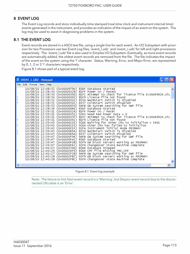
T2750 FOXBORO PAC: USER GUIDE
8 EVENT LOGThe Event Log records and store individually time stamped (real-time clock and instrument internal time) events generated in the instrument, and provides an indication of the impact of an event on the system. The log may be used to assist in diagnosing problems in the system.
8.1 THE EVENT LOGEvent records are stored in a ASCII text file, using a single line for each event. An I/O Subsystem with provi-sion for two Processors use two Event Log files, ‘event_l.udz’ and ‘event_r.udz’ for left and right processors respectively. The ‘event_l.udz’ file is also used in Simplex I/O Subsystem. Eventually, as more event records are automatically added, the oldest event records are removed from the file. The file indicates the impact of the event on the system using the ‘!’ character. Status, Warning, Error, and Major Error, are represented by 0, 1, 2 or 3 ‘!’ characters respectively. Figure 8.1 shows part of a typical event log.
Figure 8.1 Event log example
Note: The failure to Hot Start event record is a ‘Warning’, but Desync event record due to the discon-nected LIN cable is an ‘Error’.
Page 113HA030047Issue 11 September 2016
T2750 FOXBORO PAC: USER GUIDE
8.1 THE EVENT LOG (Cont.)
8.1.1 StatusThe Event Log file, supports the recording of the following events:
NO ‘!’ CHARACTERSThis indicates normal operation events such as: power up, database start, database stop, Online Reconfig-uration operations, normal synchronisation of a redundant pair, etc.
ONE ‘!’ CHARACTER (WARNING)Single ‘!’ characters indicate minor abnormalities, e.g. hot start fails due to power off time exceeded, con-trolled changeover of a redundant pair, etc.
TWO ‘!’ CHARACTERS (ERROR)Double ‘!’ characters indicate real faults on the system, for example, automated changeover of a redundant pair due to a detected fault, or the running of serial communications on unsupported versions of this instru-ment causing corruption of communications bus on power-up. If any Error is written to the Event Log file, the ‘Alarms.EventLog’ and ‘Status.EventLog’ fields of the database Tactician header block are set True and this provides an output that can be linked to a display to provide immediate identification of a problem that can have an effect on the system.
THREE ‘!’ CHARACTERS (MAJOR ERROR)Three ‘!’ characters, indicate real faults in the execution of the instrument that must be investigated before continuing. If any Major Error is written to the Event Log file, the ‘Alarms.EventLog’ and ‘Status.EventLog’ fields of the database header block are set True and this provides an output that can be linked to a display to provide immediate identification of a problem that can have an effect on the system.
Page 114HA030047
Issue 11 September 2016
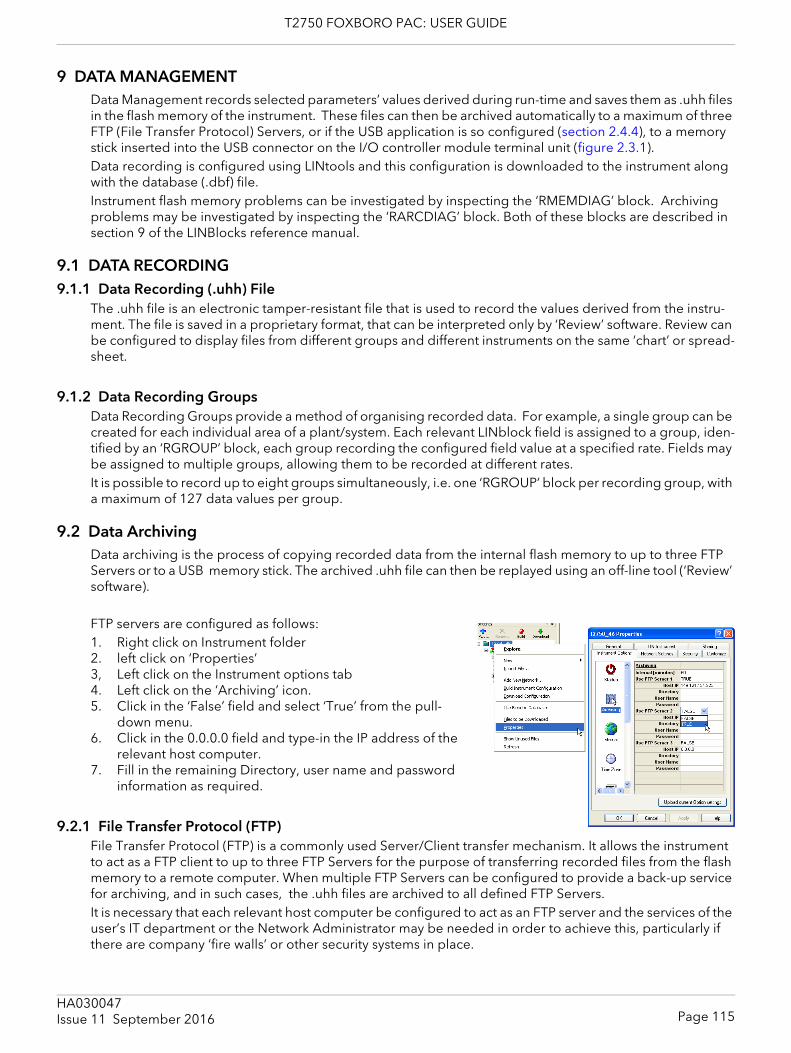
T2750 FOXBORO PAC: USER GUIDE
9 DATA MANAGEMENTData Management records selected parameters’ values derived during run-time and saves them as .uhh files in the flash memory of the instrument. These files can then be archived automatically to a maximum of three FTP (File Transfer Protocol) Servers, or if the USB application is so configured (section 2.4.4), to a memory stick inserted into the USB connector on the I/O controller module terminal unit (figure 2.3.1).Data recording is configured using LINtools and this configuration is downloaded to the instrument along with the database (.dbf) file.Instrument flash memory problems can be investigated by inspecting the ‘RMEMDIAG’ block. Archiving problems may be investigated by inspecting the ‘RARCDIAG’ block. Both of these blocks are described in section 9 of the LINBlocks reference manual.
9.1 DATA RECORDING9.1.1 Data Recording (.uhh) File
The .uhh file is an electronic tamper-resistant file that is used to record the values derived from the instru-ment. The file is saved in a proprietary format, that can be interpreted only by ‘Review’ software. Review can be configured to display files from different groups and different instruments on the same ‘chart’ or spread-sheet.
9.1.2 Data Recording GroupsData Recording Groups provide a method of organising recorded data. For example, a single group can be created for each individual area of a plant/system. Each relevant LINblock field is assigned to a group, iden-tified by an ‘RGROUP’ block, each group recording the configured field value at a specified rate. Fields may be assigned to multiple groups, allowing them to be recorded at different rates.It is possible to record up to eight groups simultaneously, i.e. one ‘RGROUP’ block per recording group, with a maximum of 127 data values per group.
9.2 Data ArchivingData archiving is the process of copying recorded data from the internal flash memory to up to three FTP Servers or to a USB memory stick. The archived .uhh file can then be replayed using an off-line tool (‘Review’ software).
FTP servers are configured as follows:1. Right click on Instrument folder2. left click on ‘Properties’3, Left click on the Instrument options tab4. Left click on the ‘Archiving’ icon.5. Click in the ‘False’ field and select ‘True’ from the pull-
down menu. 6. Click in the 0.0.0.0 field and type-in the IP address of the
relevant host computer.7. Fill in the remaining Directory, user name and password
information as required.
9.2.1 File Transfer Protocol (FTP)File Transfer Protocol (FTP) is a commonly used Server/Client transfer mechanism. It allows the instrument to act as a FTP client to up to three FTP Servers for the purpose of transferring recorded files from the flash memory to a remote computer. When multiple FTP Servers can be configured to provide a back-up service for archiving, and in such cases, the .uhh files are archived to all defined FTP Servers. It is necessary that each relevant host computer be configured to act as an FTP server and the services of the user’s IT department or the Network Administrator may be needed in order to achieve this, particularly if there are company ‘fire walls’ or other security systems in place.
Page 115HA030047Issue 11 September 2016
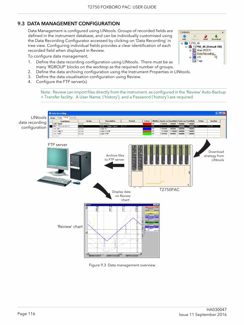
T2750 FOXBORO PAC: USER GUIDE
9.3 DATA MANAGEMENT CONFIGURATIONData Management is configured using LINtools. Groups of recorded fields are defined in the instrument database, and can be individually customised using the Data Recording Configurator accessed by clicking on ‘Data Recording’ in tree view. Configuring individual fields provides a clear identification of each recorded field when displayed in Review. To configure data management,1. Define the data recording configuration using LINtools. There must be as
many ‘RGROUP’ blocks on the worktop as the required number of groups.2. Define the data archiving configuration using the Instrument Properties in LINtools.3. Define the data visualisation configuration using Review.4. Configure the FTP server(s)
Note: Review can import files directly from the instrument, as configured in the ‘Review’ Auto-Backup + Transfer facility. A User Name, (‘history’), and a Password (‘history’) are required.
Figure 9.3 Data management overview
Primary Primary
LINtools data recording
configuration
Downloadstrategy from
LINtools
‘Review’ chart
Archive filesto FTP server
Display dataon Review
‘chart’.
T2750PAC
FTP server
Page 116HA030047
Issue 11 September 2016

T2750 FOXBORO PAC: USER GUIDE
10 SETPOINT PROGRAMMERThe Setpoint Programmer creates a profile consisting of Ramp and hold seg-ments. The output or current setpoint (PROGCHAN.Monitor.CurrSP) of the channel is the demand value, and should be wired to the setpoint of a control loop, e.g. LOOP_PID.SP.AltSP, together with the loop PV itself, so the loop can control an output, typically via an AO_UIO block, to drive the process. A program template is first created using the ‘Programmer Wizard’, accessed from the LINtools ‘Tools’ menu. This contains basic information such as the number of Channels and their names, the number of Digital Events, Wait Con-ditions, Exit Conditions, User Values, the maximum number of segments the channels are to have etc. Once the program template has been created, a Program file can be generat-ed, using the Programmer Editor, which allows the user to enter segment de-tails.
10.1 PROGRAM TEMPLATE CREATIONAs mentioned above, program template (.uyw) files are created using the Programmer Wizard. Once creat-ed, such files may be edited only via the wizard.The wizard creates a PROG_WIZ compound in the database file, containing:1. One PROGCTRL block, used to control the overall execution of the Setpoint Program2. Up to eight PROGCHAN blocks, one for each profiled setpoint in the compound,3. Up to eight SEGMENT blocks per channel, each SEGMENT block offering 4 program segmentsThe wizard can also be used to specify the maximum number of digital event outputs, user values and seg-ments allowed in the Program. The total number of digital event outputs, user values and Wait/Exit condi-tions is limited by the size of the Database file and the remaining number of PROGCHAN blocks available. Additional PROGCHAN blocks are automatically created if more than 16 digital event outputs and four user values are requested, but a maximum of eight PROGCHAN blocks can exist in a PROG_WIZ compound.The Program Template file can be referenced by a local instrument or any other instrument on the same net-work allowing the same file to apply to multiple instruments.
10.1.1 Template creationThe following sequence illustrates the creation of a simple setpoint program template, with three channels having a maximum of eight segments each. The screen ‘Help’ has been disabled in order to save space.
1. With LINtools running, click on the Tools menu, then on ‘Programmer wizard’ (figure 10, above).
2. The PROGCTRL Name display page ap-pears. Enter a four-character name for the block and click on ‘Next’
Figure 10 Tools menu
Page 117HA030047Issue 11 September 2016
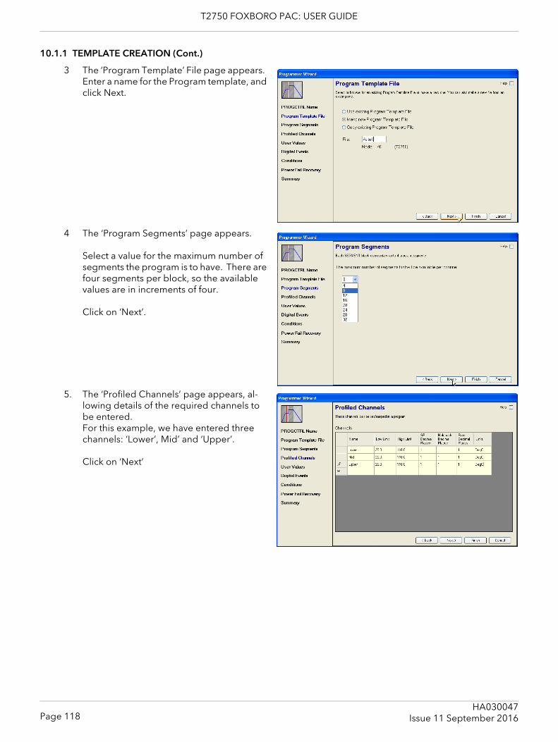
T2750 FOXBORO PAC: USER GUIDE
10.1.1 TEMPLATE CREATION (Cont.)
3 The ‘Program Template’ File page appears. Enter a name for the Program template, and click Next.
4 The ‘Program Segments’ page appears.
Select a value for the maximum number of segments the program is to have. There are four segments per block, so the available values are in increments of four.
Click on ‘Next’.
5. The ‘Profiled Channels’ page appears, al-lowing details of the required channels to be entered.For this example, we have entered three channels: ‘Lower’, Mid’ and ‘Upper’.
Click on ‘Next’
Page 118HA030047
Issue 11 September 2016
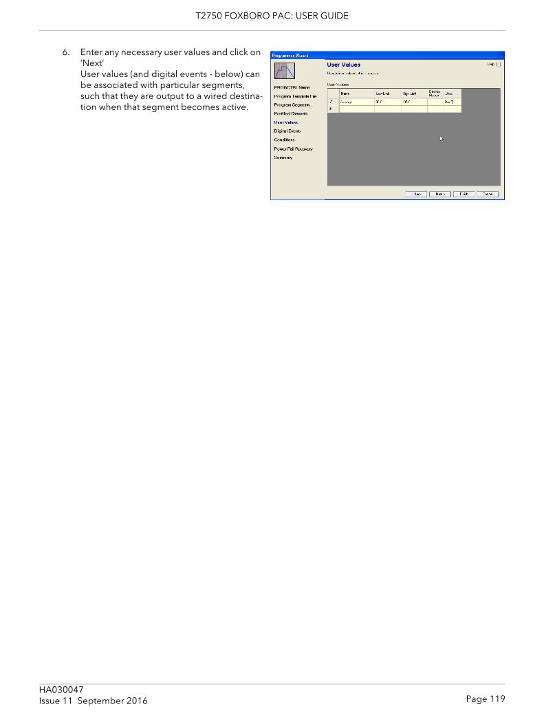
T2750 FOXBORO PAC: USER GUIDE
6. Enter any necessary user values and click on ‘Next’User values (and digital events - below) can be associated with particular segments, such that they are output to a wired destina-tion when that segment becomes active.
Page 119HA030047Issue 11 September 2016
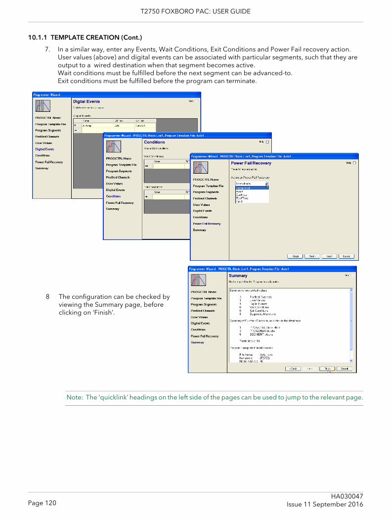
T2750 FOXBORO PAC: USER GUIDE
10.1.1 TEMPLATE CREATION (Cont.)
7. In a similar way, enter any Events, Wait Conditions, Exit Conditions and Power Fail recovery action.User values (above) and digital events can be associated with particular segments, such that they are output to a wired destination when that segment becomes active.Wait conditions must be fulfilled before the next segment can be advanced-to. Exit conditions must be fulfilled before the program can terminate.
Note: The ‘quicklink’ headings on the left side of the pages can be used to jump to the relevant page.
8 The configuration can be checked by viewing the Summary page, before clicking on ‘Finish’.
Page 120HA030047
Issue 11 September 2016
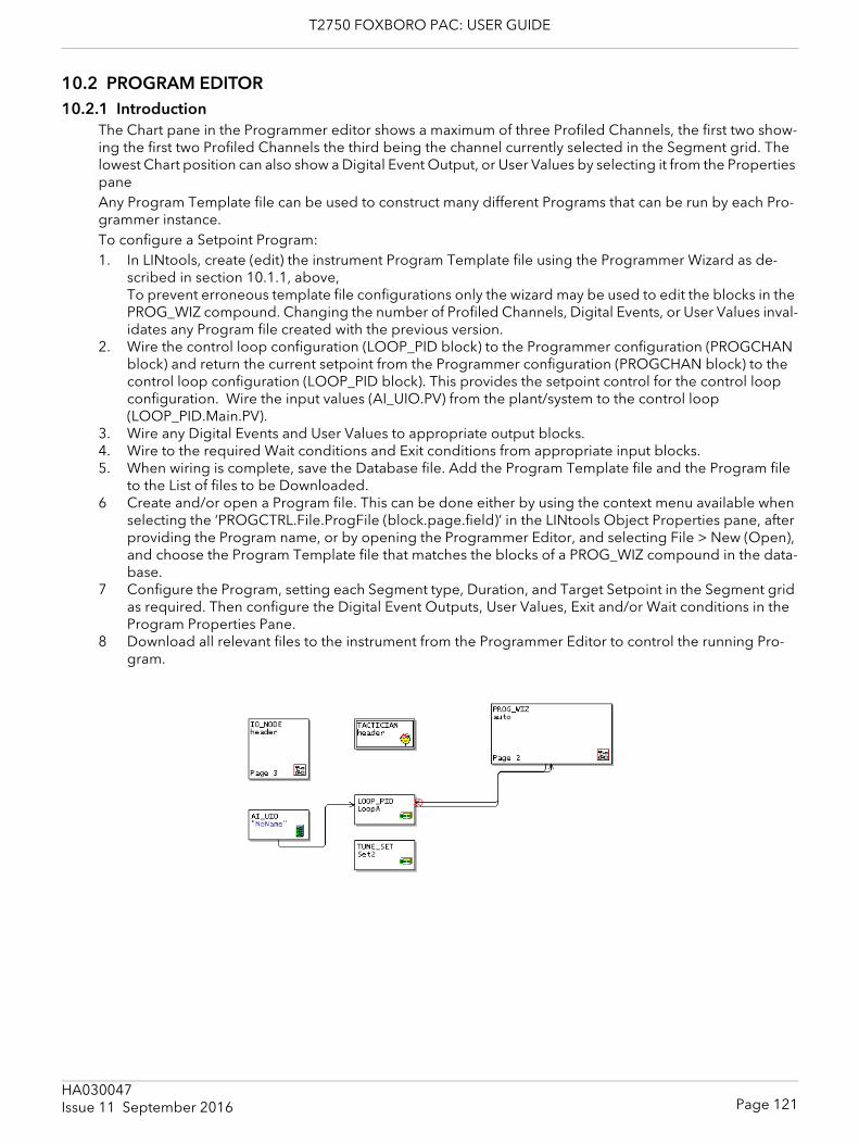
T2750 FOXBORO PAC: USER GUIDE
10.2 PROGRAM EDITOR10.2.1 Introduction
The Chart pane in the Programmer editor shows a maximum of three Profiled Channels, the first two show-ing the first two Profiled Channels the third being the channel currently selected in the Segment grid. The lowest Chart position can also show a Digital Event Output, or User Values by selecting it from the Properties paneAny Program Template file can be used to construct many different Programs that can be run by each Pro-grammer instance.To configure a Setpoint Program:1. In LINtools, create (edit) the instrument Program Template file using the Programmer Wizard as de-
scribed in section 10.1.1, above,To prevent erroneous template file configurations only the wizard may be used to edit the blocks in the PROG_WIZ compound. Changing the number of Profiled Channels, Digital Events, or User Values inval-idates any Program file created with the previous version.
2. Wire the control loop configuration (LOOP_PID block) to the Programmer configuration (PROGCHAN block) and return the current setpoint from the Programmer configuration (PROGCHAN block) to the control loop configuration (LOOP_PID block). This provides the setpoint control for the control loop configuration. Wire the input values (AI_UIO.PV) from the plant/system to the control loop (LOOP_PID.Main.PV).
3. Wire any Digital Events and User Values to appropriate output blocks.4. Wire to the required Wait conditions and Exit conditions from appropriate input blocks.5. When wiring is complete, save the Database file. Add the Program Template file and the Program file
to the List of files to be Downloaded.6 Create and/or open a Program file. This can be done either by using the context menu available when
selecting the ‘PROGCTRL.File.ProgFile (block.page.field)’ in the LINtools Object Properties pane, after providing the Program name, or by opening the Programmer Editor, and selecting File > New (Open), and choose the Program Template file that matches the blocks of a PROG_WIZ compound in the data-base.
7 Configure the Program, setting each Segment type, Duration, and Target Setpoint in the Segment grid as required. Then configure the Digital Event Outputs, User Values, Exit and/or Wait conditions in the Program Properties Pane.
8 Download all relevant files to the instrument from the Programmer Editor to control the running Pro-gram.
Page 121HA030047Issue 11 September 2016
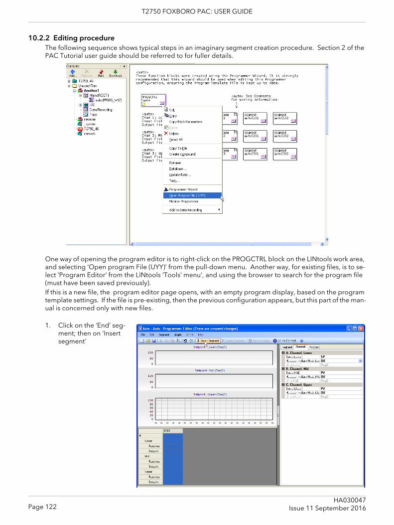
T2750 FOXBORO PAC: USER GUIDE
10.2.2 Editing procedureThe following sequence shows typical steps in an imaginary segment creation procedure. Section 2 of the PAC Tutorial user guide should be referred to for fuller details.
One way of opening the program editor is to right-click on the PROGCTRL block on the LINtools work area, and selecting ‘Open program File (UYY)’ from the pull-down menu. Another way, for existing files, is to se-lect ‘Program Editor’ from the LINtools ‘Tools’ menu’, and using the browser to search for the program file (must have been saved previously).If this is a new file, the program editor page opens, with an empty program display, based on the program template settings. If the file is pre-existing, then the previous configuration appears, but this part of the man-ual is concerned only with new files.
1. Click on the ‘End’ seg-ment; then on ‘Insert segment’
Page 122HA030047
Issue 11 September 2016
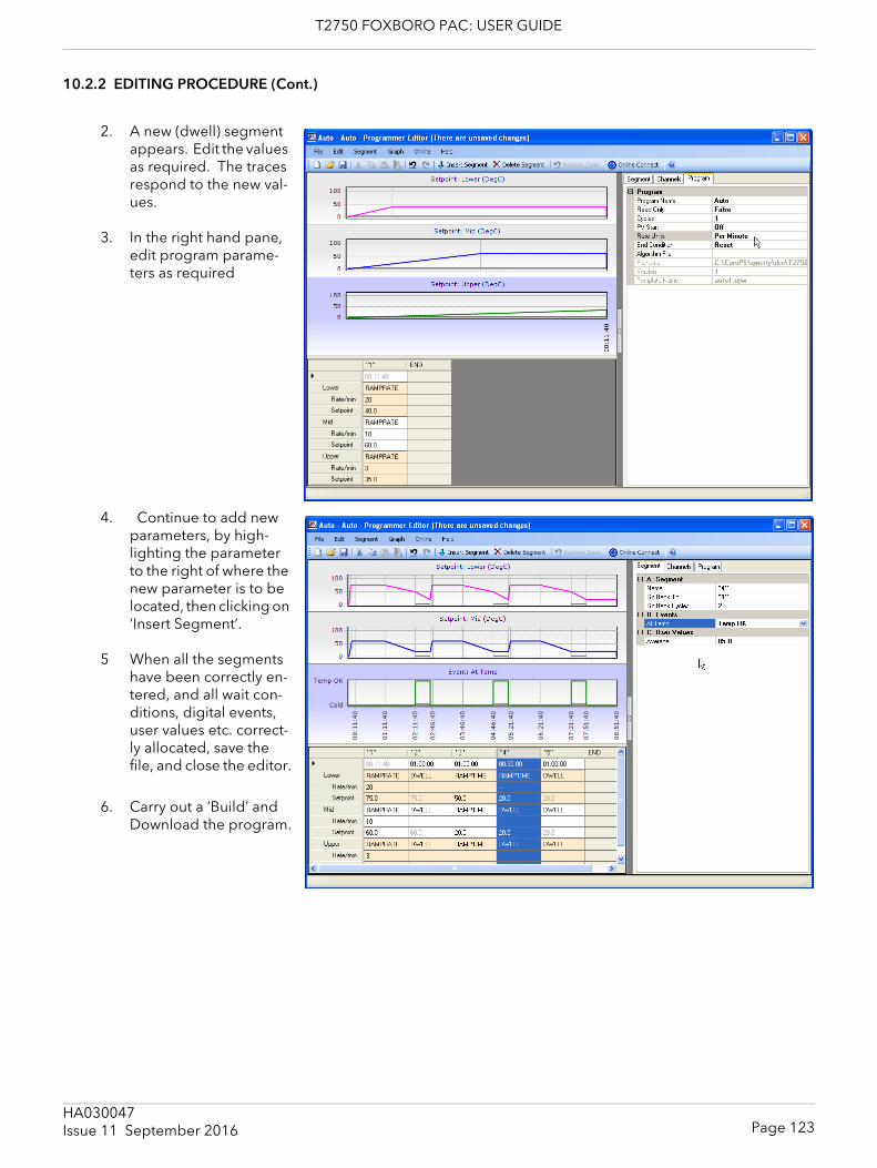
T2750 FOXBORO PAC: USER GUIDE
10.2.2 EDITING PROCEDURE (Cont.)
2. A new (dwell) segment appears. Edit the values as required. The traces respond to the new val-ues.
3. In the right hand pane, edit program parame-ters as required
4. Continue to add new parameters, by high-lighting the parameter to the right of where the new parameter is to be located, then clicking on ‘Insert Segment’.
5 When all the segments have been correctly en-tered, and all wait con-ditions, digital events, user values etc. correct-ly allocated, save the file, and close the editor.
6. Carry out a ‘Build’ and Download the program.
Page 123HA030047Issue 11 September 2016
T2750 FOXBORO PAC: USER GUIDE
11 ERROR CONDITIONS AND DIAGNOSTICSThis chapter describes the various ways to tell if a fault has occurred in the PAC instrument, (not in the pro-cess being supervised).The various subsections are:1. Error indication types (section 11.1)2. LED error displays (section 11.2)3. Power-up failures (section 11.3) ()4. Power On Self Tests (POSTs) (section 11.4)5. Diagnostic blocks (section 11.5)6. netHOST Profibus master troubleshooting (section 11.6)
11.1 ERROR INDICATION TYPESError indications include:LEDs. The LEDs are the most immediate source of error and instrument status information
concerning Basic I/O System (BIOS) start, watchdog functions and normal running. During BIOS start, the LEDs are momentarily illuminated to indicate the BIOS status. If an IOC Module start fails, the pattern that these LEDs adopt prior to the failure is helpful to service engineers, so it is recommended that this pattern is recorded (along with the unit serial number) before a service call is made.
POSTs. The results of Power On Self Tests (POSTs) can be used to pinpoint error conditions in the instrument. Refer to Power On Self Tests (POSTs) And Error Numbers section.
Diagnostic blocks. A range of function blocks can be included in the running Strategy Database to provide diagnostic information on various topics, including the redundancy mechanism, the ICM (Inter-processor Communications Mechanism), the I/O interface, and others.
11.2 LED displaysThe IOC LEDs are the primary method of displaying error, and an overview description is to be found in sec-tion 3 (Operator interface).
Additional information is included in the following subsections.
11.2.1 Instrument failure modesThe LEDs directly indicate the following IOC Module failure or potential failure modes:1. Loss of Power2. Watchdog3. Communications failure4. Loss of primary status5. Decoupling6. Desynchronisation
When either or both IOC modules, running as one of a redundant pair, fail, it usually changes its redundancy state in response to the failure, e.g. from primary to secondary, or from synchronised to desynchronised and sometimes, coupled to decoupled.
11.2.2 Power failureIn the event of a power failure, the IOC Modules enter a ‘Power fail’ state and the ’Status’ LED on the Module is extinguished. Hot Start and Real-Time Clock data are maintained if a back-up battery is fitted. An internal ‘supercap’ also maintains this data (for approximately 1 hour) should power fail without a working backup battery being fitted.
Page 124HA030047
Issue 11 September 2016
T2750 FOXBORO PAC: USER GUIDE
11.2.3 Watchdog failureIn the event of a Watchdog failure, the affected IOC Module enters a ‘Watchdog fail’ state. Initially, the ‘Fault’ LED flashes, but becomes permanently illuminated after some seconds.If the Watchdog Retry switch (section 2.3.2) is set ON, the IOC module automatically attempts to restart the CPU. If the Watchdog Retry switch is set Off, the CPU will atempt to restart only after an operation of the ‘Watchdog’ switch (figure 3.1 shows the switch location).On watchdog failure in redundant mode, the surviving IOC module adopts (or maintains) the PRIMARY UN-SYNCHRONISED state. The database can run only if the modules were synchronised before changeover, otherwise, the database halts.
11.2.4 ICM failure
An ICM failure is not associated with any single IOC Module, and so is not classed as either primary or secondary fault.
An Inter-processor Communications Mechanism (ICM) failure occurs when the primary and secondary mod-ules can no longer communicate with each other across the internal link, making database synchronisation impossible to maintain. An ICM failure causes the primary and secondary modules to decouple, but does not permit a changeover.
ACTION IN THE EVENT OF ICM FAILURE In the event of an ICM failure, the IOC Module decouples (indicated by the flashing of the ‘Duplex’ LEDs on both IOC modules). See section 11.2.6 for details of decoupling. The process strategy must be designed to send the supervisory system an appropriate alarm to annunciate this ICM failure state, (e.g. use the ‘RED_CTRL’ block’s ‘PrHWstat.ICM_Ok’ and ‘SeHWstat.ICM_Ok’ bits).
If the ICM does fail, the cause of the failure should be eliminated by replacing the secondary module. If this solves the problem the modules should be resynchronised by use of the primary ‘Sync’ button.If the fault persists, the primary module is the most likely cause and should be replaced and the original sec-ondary should be re-fitted as it is unlikely also to be faulty. If appropriate, the existing database should be restarted by powering down and then up again. Otherwise, a ‘default’ database should be loaded and started in the new primary.This last option is a Cold Start and requires manual supervision of the plant during the transition.
Note: A fault in the Terminal Unit is also a possible cause of ICM failure.
11.2.5 LIN failureA LIN failure occurs when an IOC Module is not communicating over the LIN, perhaps because the cable is damaged or disconnected or because there is a hardware (electronics) failure or there is a network commu-nications failure. A LIN failure causes the relevant ‘Ethernet (Activity)’ LED associated with the affected IOC Module to extinguish and the yellow ‘IP’ LED to flash.A LIN failure in a synchronised primary Module causes primary/secondary changeover and loss of synchro-nisation, i.e. Primary synchronised adopts Secondary unsynchronised, and Secondary synchronised adopts Primary unsynchronised.If an unsynchronised primary module suffers a LIN failure no changes of state occur.If a LIN failure occurs in a synchronised secondary module, the module adopts the Secondary unsynchro-nised state (‘Standby’ LED off), and the primary module desynchronises to the Primary unsynchronised state. If the secondary was unsynchronised at the time of the failure, no change of state occurs.
Page 125HA030047Issue 11 September 2016
T2750 FOXBORO PAC: USER GUIDE
11.2.5 LIN FAILURE (Cont.)
EFFECT OF LIN FAILURE ON REDUNDANCY MODE CONTROLLIN failure affects the ability of Primary and Secondary modules to synchronise. For example, a LIN-failed secondary IOC module cannot be synchronised successfully with the primary by pressing the primary’s ‘Sync’ switch. Attempts so to do are inhibited by the redundancy control software as indicated by the ‘Stand-by’ LED’s lack of response.
11.2.6 Decoupled InstrumentsDecoupling occurs when communication between unsynchronised primary and secondary modules is aborted because of a conflict regarding the unsynchronised state. This causes the IOC modules to become decoupled. Such decoupling can be caused by a number of faults, but generally it is due to a serious error, causing the modules to assume they should be more than unsynchronised.A decoupled state is indicated by the ‘Duplex’ LED flashing on both IOC modules. Such a state can occur on power up if the two IOC modules conflict in their outlook of how they both powered down, i.e., if the two modules power down, both as synchronised secondary modules, when powered up together, they may de-couple - because the dual power up cannot resolve the differences between them.The strategy must be designed to send the supervisory system an appropriate alarm to annunciate this state, using, for example, the ‘RED_CTRL’ block’s ‘PrSWstat.Decoupld’ and ‘SeSWstat.Decoupld’ bits.
In the event of the primary and secondary modules becoming decoupled, the IOC modules are already un-synchronised. This can be rectified by operation of the ‘Sync’ switch on the primary module, and if this is successful, both ‘Duplex’ LEDs illuminate continuously. Should the decoupled modules not re-synchronise after using the ‘Sync’ switch, further investigation must be made in order to locate and rectify the cause of the fault.
11.2.7 DesynchronisationDesynchronisation is generally caused when the database in the primary module stops running: the ‘Prima-ry’ LED flashes and the two IOC modules desynchronise. No changeover occurs and attempts to resynchro-nise are inhibited by the redundancy control software until the primary module starts running again.Only when the decision to changeover has been accepted, can the secondary IOC module assume control. Before the changeover occurs, the yellow ‘Standby’ LED of the secondary module is extinguished, and the green ‘Primary’ LED starts to flash whilst the strategy is loaded from the primary module. When the strategy has finished loading the previously secondary module assumes control, this state being indicated by the green ‘Primary’ LED being continuously illuminated. The changeover is complete when the database on the previously primary module is stopped.
11.3 POWER-UP FAILURE11.3.1 Start-up routine
A number of error conditions can occur during the power-up phase. This start-up routine is described earlier (section 4), and should be referred-to for detailed information. Various messages are generated by the IOC Module during power-up and these messages can be displayed by running a ‘Telnet’ session on a Computer via the ELIN network.
Page 126HA030047
Issue 11 September 2016
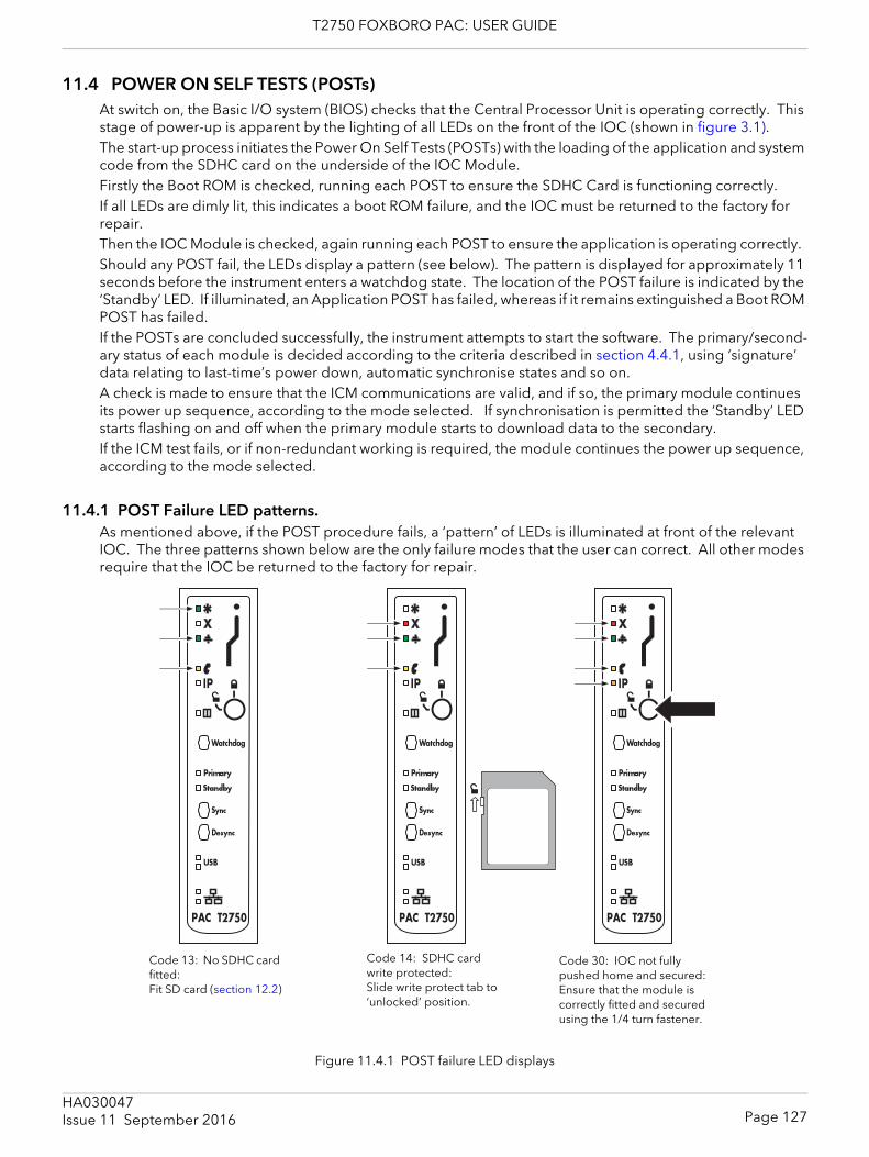
T2750 FOXBORO PAC: USER GUIDE
11.4 POWER ON SELF TESTS (POSTs)At switch on, the Basic I/O system (BIOS) checks that the Central Processor Unit is operating correctly. This stage of power-up is apparent by the lighting of all LEDs on the front of the IOC (shown in figure 3.1). The start-up process initiates the Power On Self Tests (POSTs) with the loading of the application and system code from the SDHC card on the underside of the IOC Module. Firstly the Boot ROM is checked, running each POST to ensure the SDHC Card is functioning correctly.If all LEDs are dimly lit, this indicates a boot ROM failure, and the IOC must be returned to the factory for repair.Then the IOC Module is checked, again running each POST to ensure the application is operating correctly. Should any POST fail, the LEDs display a pattern (see below). The pattern is displayed for approximately 11 seconds before the instrument enters a watchdog state. The location of the POST failure is indicated by the ‘Standby’ LED. If illuminated, an Application POST has failed, whereas if it remains extinguished a Boot ROM POST has failed.If the POSTs are concluded successfully, the instrument attempts to start the software. The primary/second-ary status of each module is decided according to the criteria described in section 4.4.1, using ‘signature’ data relating to last-time’s power down, automatic synchronise states and so on. A check is made to ensure that the ICM communications are valid, and if so, the primary module continues its power up sequence, according to the mode selected. If synchronisation is permitted the ‘Standby’ LED starts flashing on and off when the primary module starts to download data to the secondary.If the ICM test fails, or if non-redundant working is required, the module continues the power up sequence, according to the mode selected.
11.4.1 POST Failure LED patterns.As mentioned above, if the POST procedure fails, a ‘pattern’ of LEDs is illuminated at front of the relevant IOC. The three patterns shown below are the only failure modes that the user can correct. All other modes require that the IOC be returned to the factory for repair.
Figure 11.4.1 POST failure LED displays
Code 13: No SDHC card fitted: Fit SD card (section 12.2)
Code 14: SDHC card write protected: Slide write protect tab to ‘unlocked’ position.
Code 30: IOC not fully pushed home and secured: Ensure that the module is correctly fitted and secured using the 1/4 turn fastener.
Page 127HA030047Issue 11 September 2016
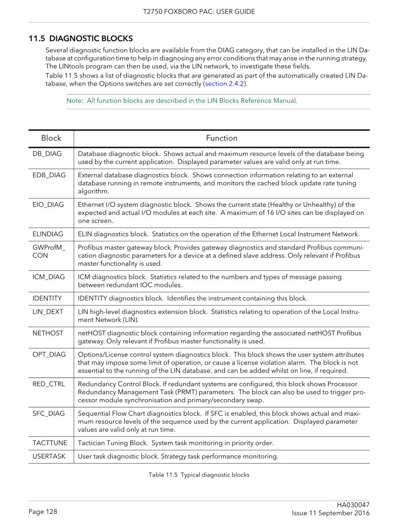
T2750 FOXBORO PAC: USER GUIDE
11.5 DIAGNOSTIC BLOCKSSeveral diagnostic function blocks are available from the DIAG category, that can be installed in the LIN Da-tabase at configuration time to help in diagnosing any error conditions that may arise in the running strategy. The LINtools program can then be used, via the LIN network, to investigate these fields.Table 11.5 shows a list of diagnostic blocks that are generated as part of the automatically created LIN Da-tabase, when the Options switches are set correctly (section 2.4.2).
Note: All function blocks are described in the LIN Blocks Reference Manual.
Table 11.5 Typical diagnostic blocks
Block Function
DB_DIAG Database diagnostic block. Shows actual and maximum resource levels of the database being used by the current application. Displayed parameter values are valid only at run time.
EDB_DIAG External database diagnostics block. Shows connection information relating to an external database running in remote instruments, and monitors the cached block update rate tuning algorithm.
EIO_DIAG Ethernet I/O system diagnostic block. Shows the current state (Healthy or Unhealthy) of the expected and actual I/O modules at each site. A maximum of 16 I/O sites can be displayed on one screen.
ELINDIAG ELIN diagnostics block. Statistics on the operation of the Ethernet Local Instrument Network.
GWProfM_CON
Profibus master gateway block. Provides gateway diagnostics and standard Profibus communi-cation diagnostic parameters for a device at a defined slave address. Only relevant if Profibus master functionality is used.
ICM_DIAG ICM diagnostics block. Statistics related to the numbers and types of message passing between redundant IOC modules.
IDENTITY IDENTITY diagnostics block. Identifies the instrument containing this block.
LIN_DEXT LIN high-level diagnostics extension block. Statistics relating to operation of the Local Instru-ment Network (LIN).
NETHOST netHOST diagnostic block containing information regarding the associated netHOST Profibus gateway. Only relevant if Profibus master functionality is used.
OPT_DIAG Options/License control system diagnostics block. This block shows the user system attributes that may impose some limit of operation, or cause a license violation alarm. The block is not essential to the running of the LIN database, and can be added whilst on line, if required.
RED_CTRL Redundancy Control Block. If redundant systems are configured, this block shows Processor Redundancy Management Task (PRMT) parameters. The block can also be used to trigger pro-cessor module synchronisation and primary/secondary swap.
SFC_DIAG Sequential Flow Chart diagnostics block. If SFC is enabled, this block shows actual and maxi-mum resource levels of the sequence used by the current application. Displayed parameter values are valid only at run time.
TACTTUNE Tactician Tuning Block. System task monitoring in priority order.
USERTASK User task diagnostic block. Strategy task performance monitoring.
Page 128HA030047
Issue 11 September 2016
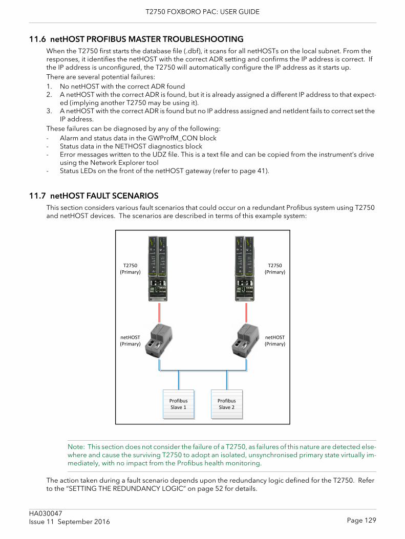
T2750 FOXBORO PAC: USER GUIDE
11.6 netHOST PROFIBUS MASTER TROUBLESHOOTINGWhen the T2750 first starts the database file (.dbf), it scans for all netHOSTs on the local subnet. From the responses, it identifies the netHOST with the correct ADR setting and confirms the IP address is correct. If the IP address is unconfigured, the T2750 will automatically configure the IP address as it starts up.There are several potential failures:1. No netHOST with the correct ADR found2. A netHOST with the correct ADR is found, but it is already assigned a different IP address to that expect-
ed (implying another T2750 may be using it).3. A netHOST with the correct ADR is found but no IP address assigned and netIdent fails to correct set the
IP address.These failures can be diagnosed by any of the following:- Alarm and status data in the GWProfM_CON block- Status data in the NETHOST diagnostics block- Error messages written to the UDZ file. This is a text file and can be copied from the instrument’s drive
using the Network Explorer tool- Status LEDs on the front of the netHOST gateway (refer to page 41).
11.7 netHOST FAULT SCENARIOSThis section considers various fault scenarios that could occur on a redundant Profibus system using T2750 and netHOST devices. The scenarios are described in terms of this example system:
Note: This section does not consider the failure of a T2750, as failures of this nature are detected else-where and cause the surviving T2750 to adopt an isolated, unsynchronised primary state virtually im-mediately, with no impact from the Profibus health monitoring.
The action taken during a fault scenario depends upon the redundancy logic defined for the T2750. Refer to the “SETTING THE REDUNDANCY LOGIC” on page 52 for details.
T2750(Primary)
netHOST(Primary)
T2750(Primary)
netHOST(Primary)
ProfibusSlave 1
ProfibusSlave 2
Page 129HA030047Issue 11 September 2016
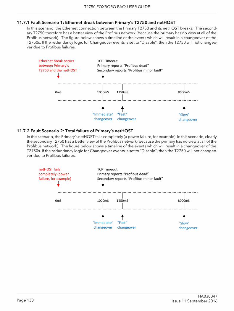
T2750 FOXBORO PAC: USER GUIDE
11.7.1 Fault Scenario 1: Ethernet Break between Primary’s T2750 and netHOSTIn this scenario, the Ethernet connection between the Primary T2750 and its netHOST breaks. The second-ary T2750 therefore has a better view of the Profibus network (because the primary has no view at all of the Profibus network). The figure below shows a timeline of the events which will result in a changeover of the T2750s. If the redundancy logic for Changeover events is set to “Disable”, then the T2750 will not changeo-ver due to Profibus failures.
11.7.2 Fault Scenario 2: Total failure of Primary’s netHOSTIn this scenario, the Primary’s netHOST fails completely (a power failure, for example). In this scenario, clearly the secondary T2750 has a better view of the Profibus network (because the primary has no view at all of the Profibus network). The figure below shows a timeline of the events which will result in a changeover of the T2750s. If the redundancy logic for Changeover events is set to “Disable”, then the T2750 will not changeo-ver due to Profibus failures.
0mS
Ethernet break occurs between Primary’s T2750 and the netHOST
1000mS
TCP Timeout:Primary reports “Profibus dead”Secondary reports “Profibus minor fault”
8000mS1250mS
“Immediate”changeover
“Fast”changeover
“Slow”changeover
0mS
netHOST fails completely (power failure, for example)
1000mS
TCP Timeout:Primary reports “Profibus dead”Secondary reports “Profibus minor fault”
8000mS1250mS
“Immediate”changeover
“Fast”changeover
“Slow”changeover
Page 130HA030047
Issue 11 September 2016
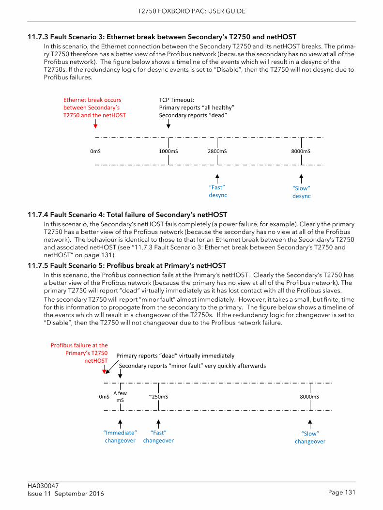
T2750 FOXBORO PAC: USER GUIDE
11.7.3 Fault Scenario 3: Ethernet break between Secondary’s T2750 and netHOSTIn this scenario, the Ethernet connection between the Secondary T2750 and its netHOST breaks. The prima-ry T2750 therefore has a better view of the Profibus network (because the secondary has no view at all of the Profibus network). The figure below shows a timeline of the events which will result in a desync of the T2750s. If the redundancy logic for desync events is set to “Disable”, then the T2750 will not desync due to Profibus failures.
11.7.4 Fault Scenario 4: Total failure of Secondary’s netHOSTIn this scenario, the Secondary’s netHOST fails completely (a power failure, for example). Clearly the primary T2750 has a better view of the Profibus network (because the secondary has no view at all of the Profibus network). The behaviour is identical to those to that for an Ethernet break between the Secondary’s T2750 and associated netHOST (see “11.7.3 Fault Scenario 3: Ethernet break between Secondary’s T2750 and netHOST” on page 131).
11.7.5 Fault Scenario 5: Profibus break at Primary’s netHOSTIn this scenario, the Profibus connection fails at the Primary’s netHOST. Clearly the Secondary’s T2750 has a better view of the Profibus network (because the primary has no view at all of the Profibus network). The primary T2750 will report “dead” virtually immediately as it has lost contact with all the Profibus slaves.The secondary T2750 will report “minor fault” almost immediately. However, it takes a small, but finite, time for this information to propogate from the secondary to the primary. The figure below shows a timeline of the events which will result in a changeover of the T2750s. If the redundancy logic for changeover is set to “Disable”, then the T2750 will not changeover due to the Profibus network failure.
0mS
Ethernet break occurs between Secondary’s T2750 and the netHOST
1000mS
TCP Timeout:Primary reports “all healthy”Secondary reports “dead”
8000mS2800mS
“Fast”desync
“Slow”desync
0mS
Profibus failure at the Primary’s T2750
netHOST
A fewmS
Primary reports “dead” virtually immediately
8000mS~250mS
“Fast”changeover
“Slow”changeover
“Immediate”changeover
Secondary reports “minor fault” very quickly afterwards
Page 131HA030047Issue 11 September 2016
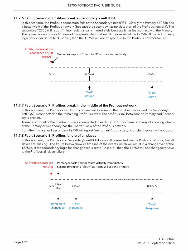
T2750 FOXBORO PAC: USER GUIDE
11.7.6 Fault Scenario 6: Profibus break at Secondary’s netHOSTIn this scenario, the Profibus connection fails at the Secondary’s netHOST. Clearly the Primary’s T2750 has a better view of the Profibus network (beacuse the seconday has no view at all of the Profibus network). The secondary T2750 will report “minor fault” virtually immediately because it has lost contact with the Primary. The figure below shows a timeline of the events which will result in a desync of the T2750s. If the redundancy logic for desync is set to “Disable”, then the T2750 will not desync due to the Profibus network failure.
11.7.7 Fault Scenario 7: Profibus break in the middle of the Profibus networkIn this scenario, the Primary’s netHOST is connected to some of the Profibus slaves, and the Seconday’s netHOST is connected to the remaining Profibus slaves. The profibus link between the Primary and Second-ary is broken.There is no count of the number of slaves connected to each netHOST, so there is no way of knowing wheth-er the Primary or Secondary has the “better” view of the Profibus network.Both the Primary and Secondary T2750 will report “minor fault”, but a desync or changeover will not occur.
11.7.8 Fault Scenario 8: Profibus failure of all slavesIn this scenario, the Primary and Secondary’s netHOSTs are still connected via the Profibus network, but all slaves are missing. The figure below shows a timeline of the events which will result in a changeover of the T2750s. If the redundancy logic for changeover is set to “Disable”, then the T2750 will not changeover due to the Profibus all-slave failure.
0mS
Profibus failure at the Secondary’s T2750
netHOSTSecondary reports “minor fault” virtually immediately
8000mS1800mS
“Fast”desync
“Slow”desync
0mS
All Profibus slaves are missing
Primary reports “minor fault” virtually immediatelySecondary reports “all OK” as it can still see the Primary
8000mS250mS
“Fast”changeover
“Slow”changeover
A fewmS
“Immediate”changeover
Page 132HA030047
Issue 11 September 2016
T2750 FOXBORO PAC: USER GUIDE
12 SERVICEThis section describes the regular preventive changing of back-up batteries etc., and shows how to replace the IOC SD card and live operating Modules.For details of how to update and change the instrument’s system software, boot ROM and libraries, please contact the manufacturer’s nearest service centre.
CAUTIONAll circuit boards associated with this unit are susceptible to damage due to static electrical discharg-es of voltages as low as 60V. All relevant personnel must be aware of correct static handling proce-dures.
12.1 PREVENTIVE MAINTENANCE SCHEDULEThe following periods are recommended to guarantee maximum availability of the instrument, for use in what the manufacturer considers to be a normal environment. Should the environment be particularly dirty, or particularly clean, then the relevant parts of the schedule may be adjusted accordingly. Whenever preventive maintenance is performed, it is recommended that a visual inspection of the instru-ment be made, and any deposits of dirt or dust removed using a low-pressure compressed ‘air duster’ such as are available from most electronics distributors.
12.2 REPLACEMENT PROCEDURES12.2.1 Software/Firmware upgrade
The T2750 software/firmware can be upgraded by putting an upgrade file onto the T2750 and cycling the power. There are three ways to do this, as outlined in this section.
Note: If the system being upgraded is configured as a duplex system, refer to the section, “Upgrading Duplex Systems” on page 134 first, and then determine which of the three upgrade options to follow.
Option 1 – Upgrading by copying onto the SD cardPerform the following steps to perform an upgrade by copying the upgrade files directly onto the SDHC card within the instrument:1. Extract the files from the upgrade zip file. The zip file contains upgrade.tgz, upgrade.bat and
upgrade.txt.2. With the power off, remove the SD card form the T2750 (refer to the “SD CARD REPLACEMENT PRO-
CEDURE” on page 134 for details).3. On a PC with a suitable card reader, copy the upgrade.tgz file into the root folder on the SD card.4. Replace the SD card in the T2750.5. Power up the T2750. Once the power has been restored, the upgrade will be applied and the LEDs on
the T2750 will cycle. Please be patient as this takes some time to complete. At the end of the upgrade, the T2750 will reset by means of a watchdog.
6. If the watchdog reset switch is in the off position, then it will be necessary to manually reset the T2750 by pressing the watchdog switch once the red fault light (X) is on constantly, indicating that the upgrade is complete.
Option 2 – Upgrading over a networkPerform the following steps to perform an upgrade using FTP (assuming the T2750’s IP address is known).1. Extract the files from the upgrade.zip file. The zip file contains upgrade.tgz, upgrade.bat and
upgrade.txt2. Copy the upgrade.tgz file onto the SD card using FTP by issuing the command “upload <ip_address>”
where <ip_address> is the IP address of the T2750 to be upgraded.3. Power cycle the T2750.
Page 133HA030047Issue 11 September 2016
T2750 FOXBORO PAC: USER GUIDE
4. Once the power has been restored, the upgrade will be applied and the LEDs on the T2750 will cycle. Please be patient as this takes some time to complete. At the end of the upgrade, the T2750 will reset by means of a watchdog.
5. If the watchdog reset switch is in the off position, then it will be necessary to manually reset the T2750 by pressing the watchdog switch once the red fault light (X) is on constantly, indicating that the upgrade is complete.
Option 3 – Upgrading using a USB memory stickIn order to upgrade using a USB memory stick, the T2750 must be configured to enable upgrades via USB. Refer to “2.4.4 USB Configuration” on page 51 for details. Then perform the following steps:1. Extract the files from the zip file. The zip file contains upgrade.tgz, upgrade.bat and upgrade.txt.2. Copy the upgrade.tgz file onto the root of a compatible USB memory stick.3. Plug the memory stick into the USB connector on the T2750 terminal unit. The green USB LED should
illuminate indicating that the file is being copied. Once the green LED has gone out, the USB memory stick can be removed. If the amber USB LED illuminates, there is an error trying to read the USB memory stick.
4. Power cycle the T2750.5. Once the power has been restored, the upgrade will be applied and the LEDs on the T2750 will cycle.
Please be patient as this takes some time to complete. At the end of the upgrade, the T2750 will reset by means of a watchdog.
6. If the watchdog reset switch is in the off position, then it will be necessary to manually reset the T2750 by pressing the watchdog switch once the red fault light (X) is on constantly, indicating that the upgrade is complete.
Note: If a USB extension cable is used to expose the USB port remotely, the maximum length of this cable must not exceed 1.5m when the T2750 is configured with a redundant pair of IOCs.
Upgrading Duplex SystemsTo upgrade a duplex configured system, upgrade options 2 and 3 above can be followed without interrupt-ing control. To do this, the following additional instructions should be followed:1. Begin by de-synchronising the processors by pressing the Desync button on the primary controller.2. Follow the above instructions (option 2 or option 3) up to, but not including the power cycling.3. Press and hold the Desync button on the secondary until all but the Ethernet LEDs go out.4. Remove and the replace the secondary processor into the backplane.5. Continue following the instructions (option 2 or option 3) above, from after the power cycling step.6. Synchronise the processors by pressing the Sync button on the primary controller.7. Changeover primary and secondary by pressing the Sync button on the secondary controller.8. Wait for the secondary to re-synchronise, indicated by the Standby LED being steady on.9. Repeat the process to upgrade the other processor by repeating steps 1-7 in this procedure.
SD CARD REPLACEMENT PROCEDUREFigure 12.2.1 shows the location of the SDHC card. The replacement procedure allows databases, user con-figurations, IP address and Network name, to be transferred from one module to another, allowing the ‘Mean Time to Replace’ to be reduced to a minimum.
Note: The Node address is set using the base unit switches and is therefore not transferred when replacing the SD card.
Page 134HA030047
Issue 11 September 2016
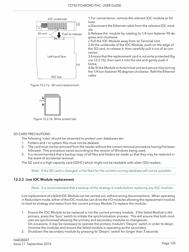
T2750 FOXBORO PAC: USER GUIDE
1.For convenience, remove the relevant IOC module as fol-lows: a.Disconnect the Ethernet cable from the relevant IOC mod-ule. b.Release the module by rotating its 1/4 turn fastener 90 de-grees anti-clockwise. c.Pull the IOC Module away from its Terminal Unit. 2.At the underside of the IOC Module, push on the edge of the SD card, to release it, then carefully pull it out of its con-nector.3.Ensure that the replacement card is not write protected (fig-ure 12.2.1b), then isert it into the slot and gently push it home.4.Re-fit the Module to its terminal unit and secure it by turning the 1/4 turn fastener 90 degrees clockwise. Refit the Ethernet cable.
SD CARD PRECAUTIONSThe following ‘rules’ should be observed to protect user databases etc:1. Folders and / or system files must not be deleted.2. The card must not be removed from the reader without the correct removal procedure having first been
followed. This procedure varies according to the version of Windows being used.3. It is recommended that a backup copy of all files and folders be made so that they may be restored in
the event of accidental removal. The SD card is a high-capacity card (SDHC) which might not be readable with older (SD) readers.
Note: If the SD card is changed, a Hot Start for the current running database will not be possible.
12.2.2 Live IOC Module replacement
Note: It is recommended that a backup of the strategy is made before replacing any IOC module.
Live replacement of a failed IOC Module can be carried out, without wiring disconnections. When operating in Redundant mode, either of the IOC modules can drive the I/O modules allowing the replacement module to load its strategy and status from the current primary Module.To replace the module:
1. Ensure the IOC Module to be replaced is not the current primary module. If the failed Module is the primary, press the ‘Sync’ switch to initiate the synchronisation process. This will ensure that both mod-ules are synchronised allowing the primary and secondary modules to changeover. On occasions, it may be necessary to operate the primary module’s ‘Desync’ switch in order to desyn-chronise the modules and ensure the failed module is operating as the secondary.
2. Shutdown the secondary module by pressing its ‘Desync’ switch for longer than 3 seconds.
Figure 12.2.1a SD card replacement
Push to release
IOC underside
SD card
IOC top
Left hand face
Figure 12.2.1b Write protect tab
Page 135HA030047Issue 11 September 2016

T2750 FOXBORO PAC: USER GUIDE
3. When successfully shutdown (all LEDs are extinguished), the module can be safely removed from its Ter-minal Unit.
4. Fit the replacement module. When the module has automatically initialised, press the ‘Sync’ switch on the primary module to resynchronise the modules.
12.2.3 Powered-down IOC Module replacementReplacement of a failed IOC Module can be carried out, without wiring disconnections, on a powered-down system. It is, however, recommended that this not be done without first ensuring that the replaced IOC Mod-ule has no RUN file on it (*.run). This is because the RUN file dictates which strategy is loaded upon power-up, and this may not be the same strategy that was previous running on the IOC Module just removed.
Page 136HA030047
Issue 11 September 2016
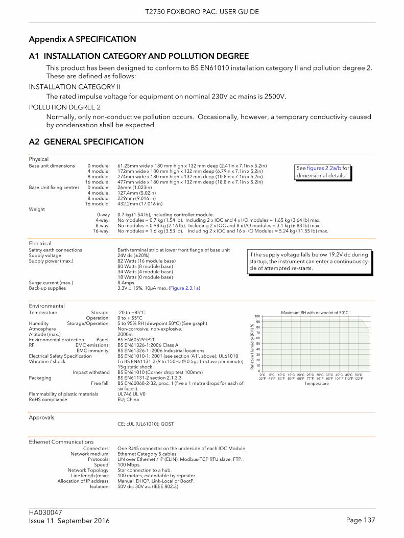
T2750 FOXBORO PAC: USER GUIDE
Appendix A SPECIFICATION
A1 INSTALLATION CATEGORY AND POLLUTION DEGREEThis product has been designed to conform to BS EN61010 installation category II and pollution degree 2. These are defined as follows:
INSTALLATION CATEGORY IIThe rated impulse voltage for equipment on nominal 230V ac mains is 2500V.
POLLUTION DEGREE 2Normally, only non-conductive pollution occurs. Occasionally, however, a temporary conductivity caused by condensation shall be expected.
A2 GENERAL SPECIFICATION
PhysicalBase unit dimensions 0 module: 61.25mm wide x 180 mm high x 132 mm deep (2.41in x 7.1in x 5.2in)
4 module: 172mm wide x 180 mm high x 132 mm deep (6.79in x 7.1in x 5.2in)8 module: 274mm wide x 180 mm high x 132 mm deep (10.8in x 7.1in x 5.2in)
16 module: 477mm wide x 180 mm high x 132 mm deep (18.8in x 7.1in x 5.2in)Base Unit fixing centres 0 module: 26mm (1.023in)
4 module: 127.4mm (5.02in)8 module: 229mm (9.016 in)
16 module: 432.2mm (17.016 in)Weight
0-way 0.7 kg (1.54 lb), including controller module.4-way: No modules = 0.7 kg (1.54 lb). Including 2 x IOC and 4 x I/O modules = 1.65 kg (3.64 lb) max.8-way: No modules = 0.98 kg (2.16 lb). Including 2 x IOC and 8 x I/O modules = 3.1 kg (6.83 lb) max.
16-way: No modules = 1.6 kg (3.53 lb). Including 2 x IOC and 16 x I/O Modules = 5.24 kg (11.55 lb) max.
ElectricalSafety earth connections Earth terminal strip at lower front flange of base unitSupply voltage 24V dc (±20%)Supply power (max.) 82 Watts (16 module base)
80 Watts (8 module base)34 Watts (4 module base)18 Watts (0 module base)
Surge current (max.) 8 AmpsBack-up supplies 3.3V ± 15%, 10μA max. (Figure 2.3.1a)
EnvironmentalTemperature Storage: -20 to +85°C
Operation: 0 to + 55°CHumidity Storage/Operation: 5 to 95% RH (dewpoint 50°C) (See graph)Atmosphere Non-corrosive, non-explosive.Altitude (max.) 2000mEnvironmental protection Panel: BS EN60529:IP20RFI EMC emissions: BS EN61326-1:2006 Class A
EMC immunity: BS EN61326-1 :2006 Industrial locationsElectrical Safety Specification BS EN61010-1: 2001 (see section ‘A1’, above); UL61010Vibration / shock To BS EN61131-2 (9 to 150Hz @ 0.5g; 1 octave per minute).
15g static shock Impact withstand BS EN61010 (Corner drop test 100mm)
Packaging BS EN61131-2 section 2.1.3.3Free fall: BS EN60068-2-32, proc. 1 (five x 1 metre drops for each of
six faces).Flammability of plastic materials UL746 UL V0RoHS compliance EU; China
ApprovalsCE; cUL (UL61010); GOST
Ethernet CommunicationsConnectors: One RJ45 connector on the underside of each IOC Module.
Network medium: Ethernet Category 5 cables.Protocols: LIN over Ethernet / IP (ELIN), Modbus-TCP RTU slave, FTP.
Speed: 100 Mbps.Network Topology: Star connection to a hub.
Line length (max): 100 metres, extendable by repeater.Allocation of IP address: Manual, DHCP, Link-Local or BootP.
Isolation: 50V dc; 30V ac. (IEEE 802.3)
See figures 2.2a/b for dimensional details
If the supply voltage falls below 19.2V dc during startup, the instrument can enter a continuous cy-cle of attempted re-starts.
� � � � � � � � � � �
����
���
���
���
���
��
��
���
���
���
�
Maximum RH with dewpoint of 50°C
Temperature
Rel
ativ
e H
umid
ity (R
H) %
Page 137HA030047Issue 11 September 2016

T2750 FOXBORO PAC: USER GUIDE
Modbus CommunicationsConnector: Parallel pair of RJ45 connectors on the Terminal unit.
Network medium: EIA485, link selectable as 3-wire or 5-wire.Protocols: MODBUS/JBUS RTU master and slave.Isolation: None.
Page 138HA030047
Issue 11 September 2016
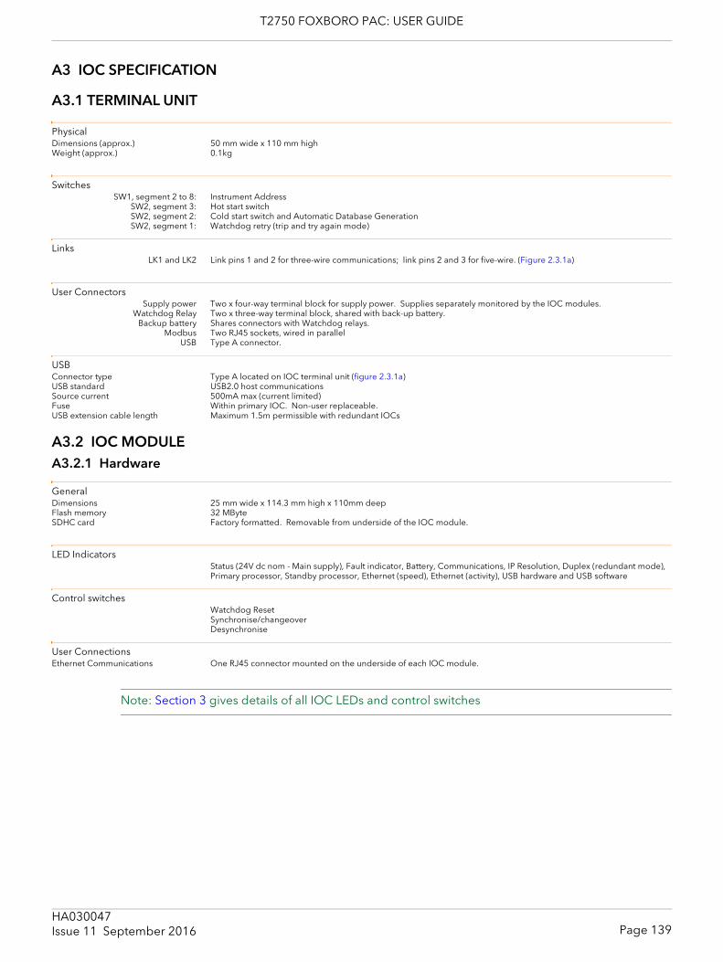
T2750 FOXBORO PAC: USER GUIDE
A3 IOC SPECIFICATION
A3.1 TERMINAL UNIT
PhysicalDimensions (approx.) 50 mm wide x 110 mm highWeight (approx.) 0.1kg
SwitchesSW1, segment 2 to 8: Instrument Address
SW2, segment 3: Hot start switchSW2, segment 2: Cold start switch and Automatic Database GenerationSW2, segment 1: Watchdog retry (trip and try again mode)
LinksLK1 and LK2 Link pins 1 and 2 for three-wire communications; link pins 2 and 3 for five-wire. (Figure 2.3.1a)
User ConnectorsSupply power Two x four-way terminal block for supply power. Supplies separately monitored by the IOC modules.
Watchdog Relay Two x three-way terminal block, shared with back-up battery.Backup battery Shares connectors with Watchdog relays.
Modbus Two RJ45 sockets, wired in parallelUSB Type A connector.
USBConnector type Type A located on IOC terminal unit (figure 2.3.1a)USB standard USB2.0 host communicationsSource current 500mA max (current limited)Fuse Within primary IOC. Non-user replaceable.USB extension cable length Maximum 1.5m permissible with redundant IOCs
A3.2 IOC MODULEA3.2.1 Hardware
GeneralDimensions 25 mm wide x 114.3 mm high x 110mm deepFlash memory 32 MByteSDHC card Factory formatted. Removable from underside of the IOC module.
LED IndicatorsStatus (24V dc nom - Main supply), Fault indicator, Battery, Communications, IP Resolution, Duplex (redundant mode), Primary processor, Standby processor, Ethernet (speed), Ethernet (activity), USB hardware and USB software
Control switchesWatchdog ResetSynchronise/changeoverDesynchronise
User ConnectionsEthernet Communications One RJ45 connector mounted on the underside of each IOC module.
Note: Section 3 gives details of all IOC LEDs and control switches
Page 139HA030047Issue 11 September 2016
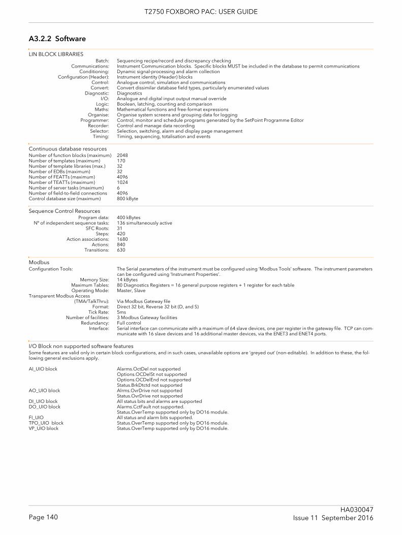
T2750 FOXBORO PAC: USER GUIDE
A3.2.2 Software
LIN BLOCK LIBRARIESBatch: Sequencing recipe/record and discrepancy checking
Communications: Instrument Communication blocks. Specific blocks MUST be included in the database to permit communicationsConditioning: Dynamic signal-processing and alarm collection
Configuration (Header): Instrument identity (Header) blocksControl: Analogue control, simulation and communicationsConvert: Convert dissimilar database field types, particularly enumerated values
Diagnostic: DiagnosticsI/O: Analogue and digital input output manual override
Logic: Boolean, latching, counting and comparisonMaths: Mathematical functions and free-format expressions
Organise: Organise system screens and grouping data for loggingProgrammer: Control, monitor and schedule programs generated by the SetPoint Programme Editor
Recorder: Control and manage data recordingSelector: Selection, switching, alarm and display page management
Timing: Timing, sequencing, totalisation and events
Continuous database resourcesNumber of function blocks (maximum) 2048Number of templates (maximum) 170Number of template libraries (max.) 32Number of EDBs (maximum) 32Number of FEATTs (maximum) 4096Number of TEATTs (maximum) 1024Number of server tasks (maximum) 6Number of field-to-field connections 4096Control database size (maximum) 800 kByte
Sequence Control ResourcesProgram data: 400 kBytes
Nº of independent sequence tasks: 136 simultaneously activeSFC Roots: 31
Steps: 420Action associations: 1680
Actions: 840Transitions: 630
ModbusConfiguration Tools: The Serial parameters of the instrument must be configured using ’Modbus Tools’ software. The instrument parameters
can be configured using ‘Instrument Properties’.Memory Size: 14 kBytes
Maximum Tables: 80 Diagnostics Registers = 16 general purpose registers + 1 register for each tableOperating Mode: Master, Slave
Transparent Modbus Access(TMA/TalkThru): Via Modbus Gateway file
Format: Direct 32 bit, Reverse 32 bit (D, and S)Tick Rate: 5ms
Number of facilities: 3 Modbus Gateway facilitiesRedundancy: Full control
Interface: Serial interface can communicate with a maximum of 64 slave devices, one per register in the gateway file. TCP can com-municate with 16 slave devices and 16 additional master devices, via the ENET3 and ENET4 ports.
I/O Block non supported software featuresSome features are valid only in certain block configurations, and in such cases, unavailable options are ‘greyed out’ (non-editable). In addition to these, the fol-lowing general exclusions apply.
AI_UIO block Alarms.OctDel not supportedOptions.OCDelSt not supportedOptions.OCDelEnd not supportedStatus.BrkDtctd not supported
AO_UIO block Alrms.OvrDrive not supportedStatus.OvrDrive not supported
DI_UIO block All status bits and alarms are supportedDO_UIO block Alarms.CctFault not supported.
Status.OverTemp supported only by DO16 module.FI_UIO All status and alarm bits supported.TPO_UIO block Status.OverTemp supported only by DO16 module.VP_UIO block Status.OverTemp supported only by DO16 module.
Page 140HA030047
Issue 11 September 2016
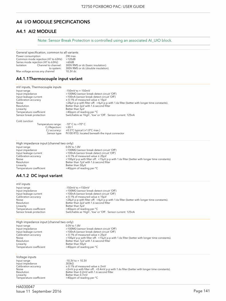
T2750 FOXBORO PAC: USER GUIDE
A4 I/O MODULE SPECIFICATIONS
A4.1 AI2 MODULE
Note: Sensor Break Protection is controlled using an associated AI_UIO block.
General specification, common to all variantsPower consumption 2W max.Common mode rejection (47 to 63Hz) >120dBSeries mode rejection (47 to 63Hz) >60dBIsolation Channel to channel: 300V RMS or dc (basic insulation).
to system: 300V RMS or dc (double insulation).Max voltage across any channel 10.3V dc
A4.1.1Thermocouple input variant
mV inputs, Thermocouple inputsInput range -150mV to + 150mVInput impedance >100MΩ (sensor break detect circuit ‘Off’)Input leakage current <100nA (sensor break detect circuit ‘Off’)Calibration accuracy ± 0.1% of measured value ± 10μVNoise <28μV p-p with filter off: <4μV p-p with 1.6s filter (better with longer time constants).Resolution Better than 2μV with 1.6 second filterLinearity Better than 5μVTemperature coefficient <40ppm of reading per °CSensor break protection Switchable as ‘High’, ‘low’ or ‘Off’. Sensor current: 125nA
Cold JunctionTemperature range: -10° C to +70° C
CJ Rejection: >30:1CJ accuracy: ±0.5°C typical (±1.0°C max.)Sensor type Pt100 RTD, located beneath the input connector
High impedance input (channel two only)Input range 0.0V to 1.8VInput impedance >100MΩ (sensor break detect circuit ‘Off’)Input leakage current <100nA (sensor break detect circuit ‘Off’)Calibration accuracy ± 0.1% of measured value ± 20μVNoise <100μV p-p with filter off: <15μV p-p with 1.6s filter (better with longer time constants).Resolution Better than 7μV with 1.6 second filterLinearity Better than 50μVTemperature coefficient <40ppm of reading per °C
A4.1.2 DC input variant
mV inputsInput range -150mV to +150mVInput impedance >100MΩ (sensor break detect circuit ‘Off’)Input leakage current <100nA (sensor break detect circuit ‘Off’)Calibration accuracy ± 0.1% of measured value ± 10μVNoise <28μV p-p with filter off: <4μV p-p with 1.6s filter (better with longer time constants).Resolution Better than 2μV with 1.6 second filterLinearity Better than 5μVTemperature coefficient <40ppm of reading per °CSensor break protection Switchable as ‘High’, ‘low’ or ‘Off’. Sensor current: 125nA
High impedance input (channel two only)Input range 0.0V to 1.8VInput impedance >100MΩ (sensor break detect circuit ‘Off’)Input leakage current <100nA (sensor break detect circuit ‘Off’)Calibration accuracy ± 0.1% of measured value ± 20μVNoise <100μV p-p with filter off: <15μV p-p with 1.6s filter (better with longer time constants).Resolution Better than 7μV with 1.6 second filterLinearity Better than 50μVTemperature coefficient <40ppm of reading per °C
Voltage inputsInput range -10.3V to + 10.3VInput impedance 303kΩCalibration accuracy ± 0.1% of measured value ± 2mVNoise <2mV p-p with filter off: <0.4mV p-p with 1.6s filter (better with longer time constants).Resolution Better than 0.2mV with 1.6 second filterLinearity Better than 0.7mVTemperature coefficient <40ppm of reading per °C
Page 141HA030047Issue 11 September 2016
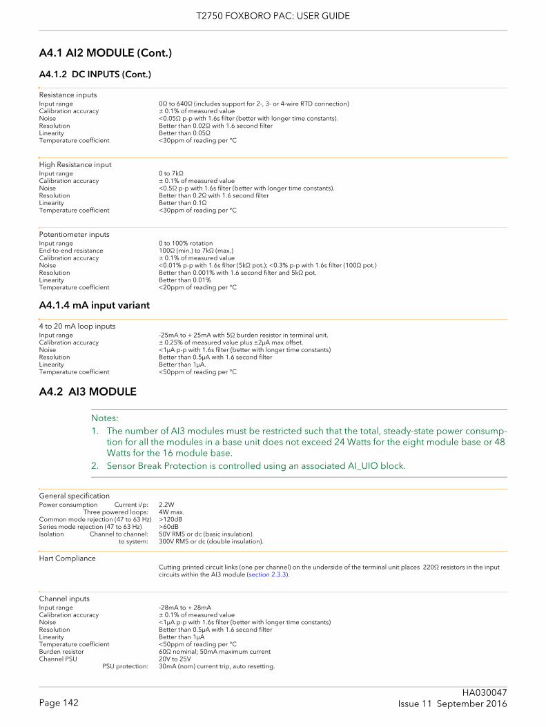
T2750 FOXBORO PAC: USER GUIDE
A4.1 AI2 MODULE (Cont.)
A4.1.2 DC INPUTS (Cont.)
Resistance inputsInput range 0Ω to 640Ω (includes support for 2-, 3- or 4-wire RTD connection)Calibration accuracy ± 0.1% of measured valueNoise <0.05Ω p-p with 1.6s filter (better with longer time constants).Resolution Better than 0.02Ω with 1.6 second filterLinearity Better than 0.05ΩTemperature coefficient <30ppm of reading per °C
High Resistance inputInput range 0 to 7kΩCalibration accuracy ± 0.1% of measured valueNoise <0.5Ω p-p with 1.6s filter (better with longer time constants).Resolution Better than 0.2Ω with 1.6 second filterLinearity Better than 0.1ΩTemperature coefficient <30ppm of reading per °C
Potentiometer inputsInput range 0 to 100% rotationEnd-to-end resistance 100Ω (min.) to 7kΩ (max.)Calibration accuracy ± 0.1% of measured valueNoise <0.01% p-p with 1.6s filter (5kΩ pot.); <0.3% p-p with 1.6s filter (100Ω pot.)Resolution Better than 0.001% with 1.6 second filter and 5kΩ pot.Linearity Better than 0.01%Temperature coefficient <20ppm of reading per °C
A4.1.4 mA input variant
4 to 20 mA loop inputsInput range -25mA to + 25mA with 5Ω burden resistor in terminal unit. Calibration accuracy ± 0.25% of measured value plus ±2μA max offset.Noise <1μA p-p with 1.6s filter (better with longer time constants)Resolution Better than 0.5μA with 1.6 second filterLinearity Better than 1μA.Temperature coefficient <50ppm of reading per °C
A4.2 AI3 MODULE
Notes: 1. The number of AI3 modules must be restricted such that the total, steady-state power consump-
tion for all the modules in a base unit does not exceed 24 Watts for the eight module base or 48 Watts for the 16 module base.
2. Sensor Break Protection is controlled using an associated AI_UIO block.
General specificationPower consumption Current i/p: 2.2W
Three powered loops: 4W max. Common mode rejection (47 to 63 Hz) >120dB Series mode rejection (47 to 63 Hz) >60dBIsolation Channel to channel: 50V RMS or dc (basic insulation).
to system: 300V RMS or dc (double insulation).
Hart ComplianceCutting printed circuit links (one per channel) on the underside of the terminal unit places 220Ω resistors in the input circuits within the AI3 module (section 2.3.3).
Channel inputsInput range -28mA to + 28mACalibration accuracy ± 0.1% of measured valueNoise <1μA p-p with 1.6s filter (better with longer time constants)Resolution Better than 0.5μA with 1.6 second filterLinearity Better than 1μATemperature coefficient <50ppm of reading per °CBurden resistor 60Ω nominal; 50mA maximum currentChannel PSU 20V to 25V
PSU protection: 30mA (nom) current trip, auto resetting.
Page 142HA030047
Issue 11 September 2016
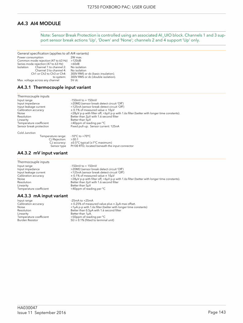
T2750 FOXBORO PAC: USER GUIDE
A4.3 AI4 MODULE
Note: Sensor Break Protection is controlled using an associated AI_UIO block. Channels 1 and 3 sup-port sensor break actions ‘Up’, ‘Down’ and ‘None’; channels 2 and 4 support ‘Up’ only.
General specification (applies to all AI4 variants)Power consumption 2W max.Common mode rejection (47 to 63 Hz) >120dB Series mode rejection (47 to 63 Hz) >60dBIsolation Channel 1 to channel 2: No isolation
Channel 3 to channel 4: No isolationCh1 or Ch2 to Ch3 or Ch4: 300V RMS or dc (basic insulation).
to system: 300V RMS or dc (double isolation).Max. voltage across any channel 5V dc
A4.3.1 Thermocouple input variant
Thermocouple inputsInput range -150mV to + 150mVInput impedance >20MΩ (sensor break detect circuit ‘Off’)Input leakage current <125nA (sensor break detect circuit ‘Off’)Calibration accuracy ± 0.1% of measured value ± 10μVNoise <28μV p-p with filter off; <6μV p-p with 1.6s filter (better with longer time constants).Resolution Better than 2μV with 1.6 second filterLinearity Better than 5μVTemperature coefficient <40ppm of reading per °CSensor break protection Fixed pull-up. Sensor current: 125nA
Cold JunctionTemperature range: -10°C to +70°C
CJ Rejection: >30:1CJ accuracy: ±0.5°C typical (±1°C maximum)Sensor type Pt100 RTD, located beneath the input connector
A4.3.2 mV input variant
Thermocouple inputsInput range -150mV to + 150mVInput impedance >20MΩ (sensor break detect circuit ‘Off’)Input leakage current <125nA (sensor break detect circuit ‘Off’)Calibration accuracy ± 0.1% of measured value ± 10μVNoise <28μV p-p with filter off; <6μV p-p with 1.6s filter (better with longer time constants).Resolution Better than 2μV with 1.6 second filterLinearity Better than 5μVTemperature coefficient <40ppm of reading per °C
A4.3.3 mA input variantInput range -25mA to +25mACalibration accuracy ± 0.25% of measured value plus ± 2μA max offset.Noise <1μA p-p with 1.6s filter (better with longer time constants)Resolution Better than 0.5μA with 1.6 second filterLinearity Better than 1μA.Temperature coefficient <50ppm of reading per °CBurden Resistor 5Ω ± 0.1% (fitted to terminal unit)
Page 143HA030047Issue 11 September 2016
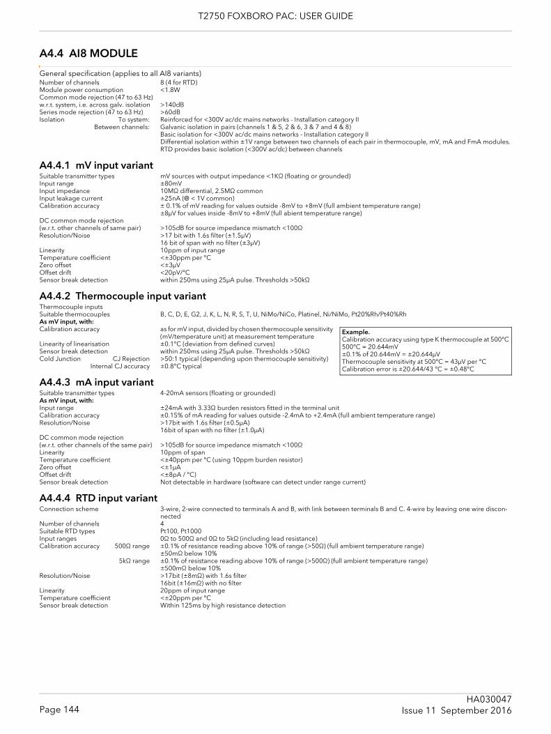
T2750 FOXBORO PAC: USER GUIDE
A4.4 AI8 MODULE
General specification (applies to all AI8 variants)Number of channels 8 (4 for RTD)Module power consumption <1.8WCommon mode rejection (47 to 63 Hz)w.r.t. system, i.e. across galv. isolation >140dBSeries mode rejection (47 to 63 Hz) >60dBIsolation To system: Reinforced for <300V ac/dc mains networks - Installation category II
Between channels: Galvanic isolation in pairs (channels 1 & 5, 2 & 6, 3 & 7 and 4 & 8)Basic isolation for <300V ac/dc mains networks - Installation category IIDifferential isolation within ±1V range between two channels of each pair in thermocouple, mV, mA and FmA modules.RTD provides basic isolation (<300V ac/dc) between channels
A4.4.1 mV input variantSuitable transmitter types mV sources with output impedance <1KΩ (floating or grounded)Input range ±80mVInput impedance 10MΩ differential, 2.5MΩ commonInput leakage current ±25nA (@ < 1V common)Calibration accuracy ± 0.1% of mV reading for values outside -8mV to +8mV (full ambient temperature range)
±8μV for values inside -8mV to +8mV (full abient temperature range)DC common mode rejection(w.r.t. other channels of same pair) >105dB for source impedance mismatch <100ΩResolution/Noise >17 bit with 1.6s filter (±1.5μV)
16 bit of span with no filter (±3μV)Linearity 10ppm of input rangeTemperature coefficient <±30ppm per °CZero offset <±3μVOffset drift <20pV/°CSensor break detection within 250ms using 25μA pulse. Thresholds >50kΩ
A4.4.2 Thermocouple input variantThermocouple inputsSuitable thermocouples B, C, D, E, G2, J, K, L, N, R, S, T, U, NiMo/NiCo, Platinel, Ni/NiMo, Pt20%Rh/Pt40%RhAs mV input, with:Calibration accuracy as for mV input, divided by chosen thermocouple sensitivity
(mV/temperature unit) at measurement temperatureLinearity of linearisation ±0.1°C (deviation from defined curves)Sensor break detection within 250ms using 25μA pulse. Thresholds >50kΩCold Junction CJ Rejection >50:1 typical (depending upon thermocouple sensitivity)
Internal CJ accuracy ±0.8°C typical
A4.4.3 mA input variantSuitable transmitter types 4-20mA sensors (floating or grounded)As mV input, with:Input range ±24mA with 3.33Ω burden resistors fitted in the terminal unitCalibration accuracy ±0.15% of mA reading for values outside -2.4mA to +2.4mA (full ambient temperature range)Resolution/Noise >17bit with 1.6s filter (±0.5μA)
16bit of span with no filter (±1.0μA)DC common mode rejection(w.r.t. other channels of the same pair) >105dB for source impedance mismatch <100ΩLinearity 10ppm of spanTemperature coefficient <±40ppm per °C (using 10ppm burden resistor)Zero offset <±1μAOffset drift <±8pA / °C)Sensor break detection Not detectable in hardware (software can detect under range current)
A4.4.4 RTD input variantConnection scheme 3-wire, 2-wire connected to terminals A and B, with link between terminals B and C. 4-wire by leaving one wire discon-
nectedNumber of channels 4Suitable RTD types Pt100, Pt1000Input ranges 0Ω to 500Ω and 0Ω to 5kΩ (including lead resistance)Calibration accuracy 500Ω range ±0.1% of resistance reading above 10% of range (>50Ω) (full ambient temperature range)
±50mΩ below 10%5kΩ range ±0.1% of resistance reading above 10% of range (>500Ω) (full ambient temperature range)
±500mΩ below 10%Resolution/Noise >17bit (±8mΩ) with 1.6s filter
16bit (±16mΩ) with no filterLinearity 20ppm of input rangeTemperature coefficient <±20ppm per °CSensor break detection Within 125ms by high resistance detection
Example.Calibration accuracy using type K thermocouple at 500°C500°C = 20.644mV±0.1% of 20.644mV = ±20.644μVThermocouple sensitivity at 500°C = 43μV per °CCalibration error is ±20.644/43 °C = ±0.48°C
Page 144HA030047
Issue 11 September 2016
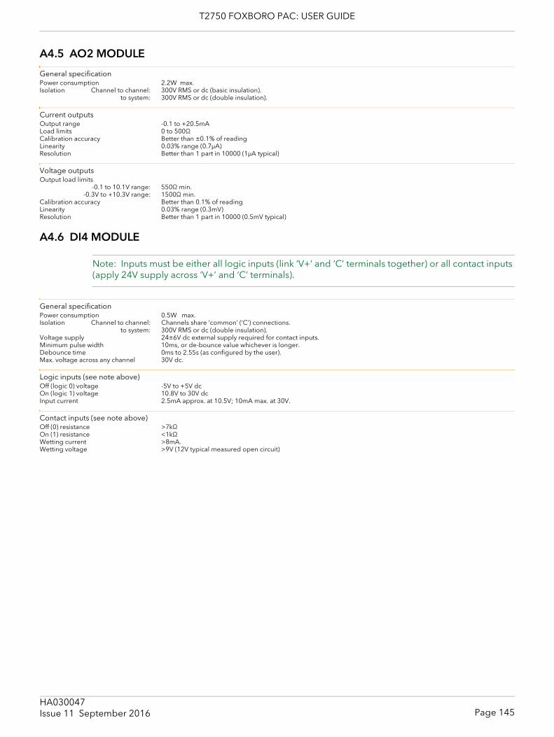
T2750 FOXBORO PAC: USER GUIDE
A4.5 AO2 MODULE
General specificationPower consumption 2.2W max.Isolation Channel to channel: 300V RMS or dc (basic insulation).
to system: 300V RMS or dc (double insulation).
Current outputsOutput range -0.1 to +20.5mALoad limits 0 to 500ΩCalibration accuracy Better than ±0.1% of readingLinearity 0.03% range (0.7μA)Resolution Better than 1 part in 10000 (1μA typical)
Voltage outputsOutput load limits
-0.1 to 10.1V range: 550Ω min.-0.3V to +10.3V range: 1500Ω min.
Calibration accuracy Better than 0.1% of readingLinearity 0.03% range (0.3mV)Resolution Better than 1 part in 10000 (0.5mV typical)
A4.6 DI4 MODULE
Note: Inputs must be either all logic inputs (link ‘V+’ and ‘C’ terminals together) or all contact inputs (apply 24V supply across ‘V+’ and ‘C’ terminals).
General specificationPower consumption 0.5W max.Isolation Channel to channel: Channels share ‘common’ (‘C’) connections.
to system: 300V RMS or dc (double insulation).Voltage supply 24±6V dc external supply required for contact inputs.Minimum pulse width 10ms, or de-bounce value whichever is longer.Debounce time 0ms to 2.55s (as configured by the user).Max. voltage across any channel 30V dc.
Logic inputs (see note above)Off (logic 0) voltage -5V to +5V dcOn (logic 1) voltage 10.8V to 30V dcInput current 2.5mA approx. at 10.5V; 10mA max. at 30V.
Contact inputs (see note above)Off (0) resistance >7kΩOn (1) resistance <1kΩWetting current >8mA.Wetting voltage >9V (12V typical measured open circuit)
Page 145HA030047Issue 11 September 2016
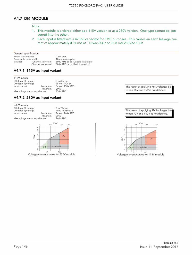
T2750 FOXBORO PAC: USER GUIDE
A4.7 DI6 MODULE
Note: 1. This module is ordered either as a 115V version or as a 230V version. One type cannot be con-
verted into the other.2. Each input is fitted with a 470pF capacitor for EMC purposes. This causes an earth leakage cur-
rent of approximately 0.04 mA at 115Vac 60Hz or 0.08 mA 230Vac 60Hz
General specificationPower consumption 0.5W max.Detectable pulse width Three mains cyclesIsolation Channel to system: 300V RMS or dc (Double insulation)
Channel to channel: 300V RMS or dc (Basic insulation)
A4.7.1 115V ac input variant
115V inputsOff (logic 0) voltage 0 to 35V ac.On (logic 1) voltage 95V to 150V acInput current Maximum: 8mA at 150V RMS
Minimum: 2mAMax voltage across any channel 150V RMS
A4.7.2 230V ac input variant
230V inputsOff (logic 0) voltage 0 to 70V ac.On (logic 1) voltage 180V to 264V acInput current Maximum: 9mA at 264V RMS
Minimum: 2mA.Max voltage across any channel 264V RMS
The result of applying RMS voltages be-tween 35V and 95V is not defined.
The result of applying RMS voltages be-tween 70V and 180 V is not defined.
Undefined
On
Off
V ac
mA
Voltage/current curves for 230V module
Undefined
On
Off
V acm
A
Voltage/current curves for 115V module
Page 146HA030047
Issue 11 September 2016
T2750 FOXBORO PAC: USER GUIDE
A4.8 DI8 MODULE
Note: This module is ordered either as a ‘logic’ version or as a ‘contact closure’ version. One type cannot be converted into the other.
General specificationPower consumption Contact i/p: 1.9W max.
Logic i/p: 0.6W max.Isolation Ch1 to Ch 2 : Channels share ‘common’ (‘1C2’) connection.
Ch3 to Ch 4 : Channels share ‘common’ (‘3C4’) connection.Ch5 to Ch 6 : Channels share ‘common’ (‘5C6’) connection.Ch7 to Ch 8 : Channels share ‘common’ (‘7C8’) connection.
Ch1/2 to other channels: 50V RMS or dc (Basic insulation).Ch3/4 to other channels: 50V RMS or dc (Basic insulation).Ch5/6 to other channels: 50V RMS or dc (Basic insulation).Ch7/8 to other channels: 50V RMS or dc (Basic insulation).
to system: 300V RMS or dc (Double insulation).Minimum pulse width 5ms (Task 1), or 10ms (Task 3), or de-bounce value whichever is longer.Debounce time 0ms to 2.55s (as configured by the user).Max. voltage across any channel 30V dc
A4.8.1 Logic input variant
Logic inputs (see note above)Off (logic 0) voltage -5V to +5V dcOn (logic 1) voltage 10.8V to 30V dcInput current 2.5mA approx. at 10.5V; 8mA max. at 30V.
A4.8.2 Contact closure input variant
Contact inputs (see note above)Off (0) resistance >7kΩOn (1) resistance <1kΩWetting current 4mA typical
A4.9 DI 16 MODULE
General specificationPower consumption Logic mode: 0.75 W max.
Contact mode: 2.0 W max.Isolation Channel to channel: Channels share ‘common’ (‘C’) connections.
to system: 300V RMS or dc (Double insulation).Minimum pulse width 5ms, or de-bounce value whichever is longer.Debounce time 0ms to 2.55s (as configured by the user)Max. voltage across any channel 30V dc
Logic inputsOff (logic 0) voltage -30V to +5V dcOn (logic 1) voltage 10.8V to 30V dcInput current 3.8mA approx. at 12Vdc; 2.8mA approx. at 24Vdc.
Contact inputsOff (0) resistance >7kΩOn (1) resistance <1kΩWetting current 4mA min.Module internal isolated power supply (terminal P voltage)
16 to 18V dcWetting voltage (effective) 12V dc min.
The result of applying voltages between +5V and +10.8V is not defined.
The result of applying contact resist-ances between 1kΩ and 7kΩ is not de-fined.
The result of applying voltages between +5V and +10.8V is not defined.
The result of applying inputs between 1kΩ and 7kΩ is not defined.
Page 147HA030047Issue 11 September 2016
T2750 FOXBORO PAC: USER GUIDE
A4.10 DO4
General specificationPower consumption 0.5W max.Isolation Channel to channel: Channels share ‘common’ (‘C’) connections.
to system: 300V RMS or dc (Double insulation).
Logic outputsVoltage supply (VCS) 24±6Vdc.Logic 1 o/p voltage (Vcs - 3)V for a 5mA load.Logic 0 o/p voltage <1VdcLogic 1 o/p current 8mA per channel (current limited)Off state leakage <0.1mA
Voltage outputsVoltage supply (VCS) 12V to 30Vdc.Logic 1 o/p voltage (Vcs - 3)V for a 5mA load.Logic 0 o/p voltage <1VdcLogic 1 o/p current 100mA per channel (current and temperature limited)
A4.11 DO8 MODULE
CAUTIONA 4 Amp fuse must be fitted in the voltage supply line in order to ensure against connector overheat
General specificationPower consumption 0.6 W max.Isolation Channel to channel: Channels share ‘common’ (‘C’) connections.
to system: 300V RMS or dc (Double insulation).
Input specificationVoltage supply (VCS) 18 to 30V dc.Supply protection Internally limited at 4A (reaction time 4ms max.).
Automatically resets 150ms after the cause of the fault has been rectified.Logic 1 o/p voltage (Vcs - 3)V for a full load.Logic 0 o/p voltage <0.1VLogic 1 o/p current 0.75A max. per channel; 4A max. per module.
A4.12 DO16 MODULE
General specificationPower consumption (max.) Module: 0.6W
Plant side: 850WIsolation Channel to channel: Channels share ‘common’ (‘C’) connections.
to system: 300V RMS or dc (Double insulation).
Input specificationVoltage supply (VCS) 24Vdc ±20%Logic 1 o/p voltage (Vcs - 1)V for a full load.Logic 0 o/p voltage <1VLogic 1 o/p current 0.7A max. per channel.Logic 0 output current 10μAShort circuit protection 0.7 to 1.7A per channelModule thermal cut-off (55°C ambient) 90±3°C (restart at 88±3°C).
Refer to section 2.3.11 for precautions to be taken when fitting DO8 modules
Refer to section 2.3.12 for precautions to be taken when fitting DO16 modules
Page 148HA030047
Issue 11 September 2016
T2750 FOXBORO PAC: USER GUIDE
A4.13 FI2 MODULE
CautionIf more than eight FI2 modules are fitted, and if these have an average output channel load of more than 5mA each, then an external power supply must be used to power the transducer (figure 2.3.13c). Otherwise, if the internal supply is used, damage will be caused to the base unit backplane tracking.
General specificationPower consumption 3.7W max.Isolation Channel to channel: 100V RMS or dc (Basic insulation).
Channel to system: 300V RMS or dc (Double insulation).Max terminal voltage ‘+’ to ‘-’ 100V peak-to-peak
‘+’ to ‘C’ 50V dc
Channel general specificationFrequency measurement Ranges: Logic: 0.01Hz to 40kHz (debounce off)
Magnetic: 10Hz to 40kHz.Resolution: <60 ppm of reading for square wave input
Accuracy: ±100 ppm of reference ± 160ppm overall ± 0.05% drift (five years)Pulse counting Ranges: Logic: DC to 40kHz (debounce off)
Magnetic: 10Hz to 40kHzResolution <600 ppm of reading for square wave input.Max-frequency derating, due to debounce
Setting = 5ms: Max frequency = 100HzSetting = 10ms: Max frequency = 50HzSetting = 20ms: Max frequency = 25HzSetting = 50ms: Max frequency = 10Hz
Magnetic sensor inputsInput range 10mV to 80V peak-peakAbsolute maximum input ±100VInput impedance >30kΩ
Logic inputsMinimum pulse width (debounce off) 1.2μs
Voltage Input range: 0 to 20V dcAbsolute maximum input: 50V dc
Input impedance: >30kΩThreshold: Settable range: 0 to 20V ± 0.2V hysteresis
Accuracy ±0.4V or ±7% of range, whichever is the greaterSensor break level: 50mV to 310mV ±10%. Active for threshold settings between 200mV and 7.4V.
Current Input range: 0 to 20mAAbsolute maximum input: 30mA dc
Input impedance: 1kΩThreshold: Settable range: 0 to 20mA ± 0.2mA hysteresis
Accuracy: ±0.4mA or ±7% of range, whichever is the greaterSensor break level: 0.05mA to 0.31mA ±10%. Active for threshold settings between 0.2mA and 7.4mA.
Sensor short circuit: when <100Ω; restored when >350Ω. Active for threshold settings between 0.2mA and 7.4mA
Contact Input impedance: 5kΩThreshold: Settable range: 0 to 20V ± 0.2V hysteresis
Accuracy ±0.4V or ±7% of range, whichever is the greater
PSU Output specificationVoltage Selectable as 8, 12 or 24Vdc at 10mAMaximum current 25mAAccuracy ±20%Voltage drop 1V at 25mACurrent limiting Output short circuit causes temporary failure of pulse input circuit.
‘+’, ‘-’ and ‘C’ are terminal identifiers
Page 149HA030047Issue 11 September 2016
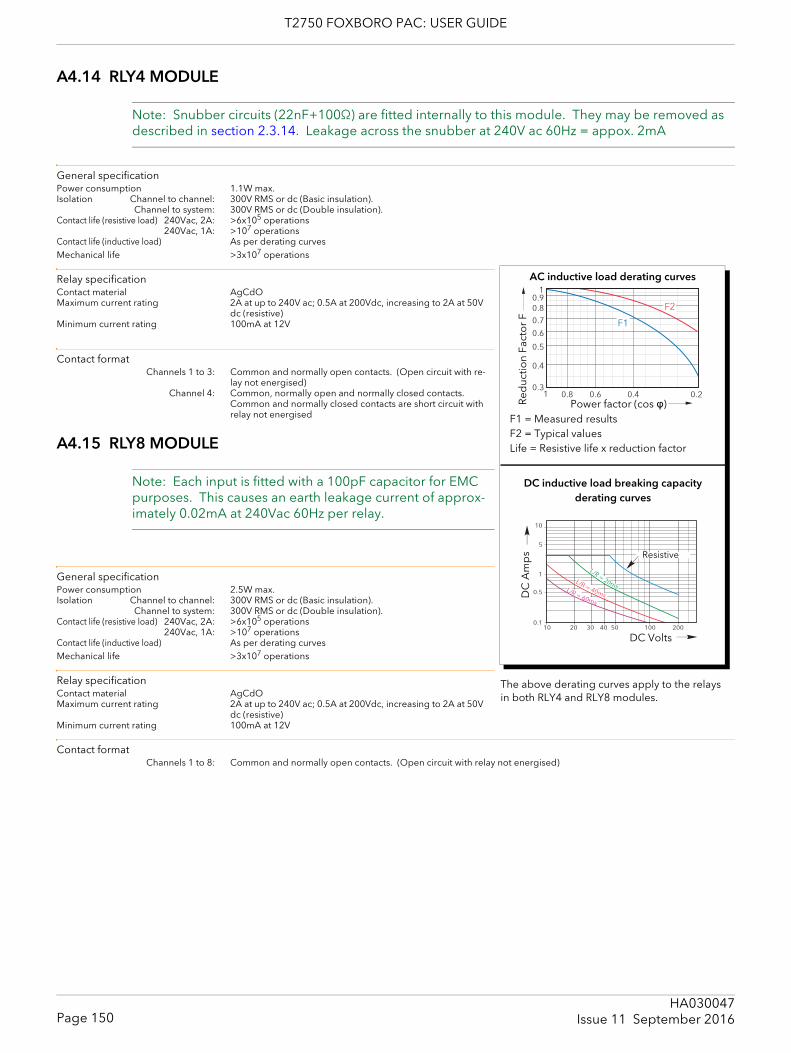
T2750 FOXBORO PAC: USER GUIDE
A4.14 RLY4 MODULE
Note: Snubber circuits (22nF+100Ω) are fitted internally to this module. They may be removed as described in section 2.3.14. Leakage across the snubber at 240V ac 60Hz = appox. 2mA
General specificationPower consumption 1.1W max.Isolation Channel to channel: 300V RMS or dc (Basic insulation).
Channel to system: 300V RMS or dc (Double insulation).Contact life (resistive load) 240Vac, 2A: >6x10⁵ operations
240Vac, 1A: >107 operations Contact life (inductive load) As per derating curvesMechanical life >3x10⁷ operations
Relay specificationContact material AgCdOMaximum current rating 2A at up to 240V ac; 0.5A at 200Vdc, increasing to 2A at 50V
dc (resistive) Minimum current rating 100mA at 12V
Contact formatChannels 1 to 3: Common and normally open contacts. (Open circuit with re-
lay not energised)Channel 4: Common, normally open and normally closed contacts.
Common and normally closed contacts are short circuit with relay not energised
A4.15 RLY8 MODULE
Note: Each input is fitted with a 100pF capacitor for EMC purposes. This causes an earth leakage current of approx-imately 0.02mA at 240Vac 60Hz per relay.
General specificationPower consumption 2.5W max.Isolation Channel to channel: 300V RMS or dc (Basic insulation).
Channel to system: 300V RMS or dc (Double insulation).Contact life (resistive load) 240Vac, 2A: >6x10⁵ operations
240Vac, 1A: >107 operations Contact life (inductive load) As per derating curvesMechanical life >3x10⁷ operations
Relay specificationContact material AgCdOMaximum current rating 2A at up to 240V ac; 0.5A at 200Vdc, increasing to 2A at 50V
dc (resistive) Minimum current rating 100mA at 12V
Contact formatChannels 1 to 8: Common and normally open contacts. (Open circuit with relay not energised)
Power factor (cos φ)Red
uctio
n Fa
cto
r F
F1 = Measured resultsF2 = Typical valuesLife = Resistive life x reduction factor
DC inductive load breaking capacityderating curves
DC Volts
Resistive
DC
Am
ps
AC inductive load derating curves
The above derating curves apply to the relays in both RLY4 and RLY8 modules.
Page 150HA030047
Issue 11 September 2016
T2750 FOXBORO PAC: USER GUIDE
A4.16 ZI MODULE
General specificationPower consumption 1.8W maxCommon mode rejection >80dB (48 to 62 Hz)Series mode rejection >60dB (48 to 62Hz)Isolation ZI Channel to T/C channel: 300V RMS or dc (Basic insulation).
Channel to system: 300V RMS or dc (Double insulation).Max. voltage across any channel 10V dc
Thermocouple input (channel 1)Input range -77mV to +100mVInput impedance 10MΩCalibration accuracy ± 0.1% of reading ±10μVNoise <5μV peak - to - peak with 1.6s filterResolution Better than 2μV with 1.6s filterLinearity ±0.1°C Temperature coefficient <±30ppm/° CSensor break protection 250nA break high, low or off
Cold JunctionTemperature range: -10°C to +70°C
CJ Rejection: >30:1CJ accuracy: ±0.5°C (typical); ±1.3°C max. (automatic CJC)Sensor type Pt100 RTD, located beneath the input connector
Zirconia input (channel 2)Input range -10mV to +1800mVInput impedance >500MΩCalibration accuracy ± 0.2% of inputNoise <0.1mV peak - to - peak with 1.6s filterResolution <50μV with 1.6s filterSensor impedance measurement 0.1kΩ to 100kΩ ±2%Input leakage current ±1na (typical) ±4nA (max.)
Page 151HA030047Issue 11 September 2016
T2750 FOXBORO PAC: USER GUIDE
A4.17 netHOST Profibus Master gateway
Electrical specificationSupply voltage 24V dc ±6V dc (with reverse voltage protection)Current consumption at 24V (typically) 130 mAPower consumption 3.2 WPower connector Mini-COMBICON, 2-pin
EnvironmentalTemperature range 0 to 60° CHumidity No condensation permitted
Diagnostic interfaceLED status for SYS (System), APL (Application), COM (Communication) and Ethernet link and activityDiagnostic LIN blocks NETHOST and GWProfM_CON
PhysicalDimensions (L x W x H) 100 x 52 x 70 mm (without connector)Weight 150g (approx)Mounting on DIN rail EN60715Protection class IP 20
ProfibusMax number of Profibus DP slaves 125Max number of total cyclic input data 3584 bytesMax number of total cyclic output data 3584 bytesMax number of cyclic input data 244 bytes/slaveMax number of cyclic output data 244 bytes/slaveConfiguration data Max 244 bytes per slaveParameterisation data per slave 7 bytes/slave standard parameters
max 237 bytes/slave application specific parametersSupported baud rates 9.6 kBit/s
19.2 kBit/s31.25 kBit/s45.45 kBit/s93.75 kBit/s187.5 kBit/s500 kBit/S1.5 MBit/s3 MBit/s6 MBit/s12 MBit/sAuto baudrate detection is not supported
Data transport layer PROFIBUS FDLLimitations DP V1 services class 1 and 2 are not supported
DP V2 services are not implementedInterface type ISO 11898, optically isolatedConnector Sub D female, 9-pin
EthernetTransmission rate 100 Mbit/sHalf duplex / Full duplex SupportedConnector RJ45 x 2
Page 152HA030047
Issue 11 September 2016
T2750 FOXBORO PAC: USER GUIDE
A5 LIN BLOCKS SUPPORTED
A5.1 BATCH BLOCKSSee LIN Blocks reference manual chapter 2 for block detailsDISCREP Discrepancy blockRECORD Record blockSFC_CON Sequential function chart control blockSFC_DISP Sequential function chart display blockSFC_MON Sequential function chart monitor block
A5.2 COMMUNICATIONS BLOCKSSee LIN Blocks reference manual chapter 3 for block detailsGW_CON Gateway configuration blockGW_TBL Gateway table blockGW_ProfM_CON Gateway Profibus Master configuration blockGWProsSCon Gateway Profibus slave configuration block (not this software release)RAW_COM Raw communications block
A5.3 CONDITIONSee LIN Blocks reference manual chapter 4 for block detailsAGA8DATA AGA8 Calculation blockAN_ALARM Analogue alarm blockCHAR Characterisation blockDIGALARM Digital alarm blockFILTER Filter blockFLOW_COMP Compensated flow blockGASCONC Natural gas concentration data blockINVERT Analogue inversion blockLEAD_LAG Lead/lag filter block (for feed-forward calculations etc.)LEADLAG Lead/lag blockRANGE Range blockTC_LIFE Thermocouple life-expectancy blockTC_SEL Thermocouple selector blockUCHAR Data storage for ‘CHAR’ blockZIRCONIA Zirconia block
A5.4 CONFIGURATION BLOCKSSee LIN Blocks reference manual chapter 5 for block detailsPROGRAM Program configuration (header) blockTACTICIAN Tactician configuration (header) block
A5.5 CONTROL BLOCKSSee LIN Blocks reference manual chapter 6 for block details3-TERM Incremental PID blockAN_CONN Analogue connections blockAN_DATA Analogue data blockANMS Analogue manual station blockDG_CON Digital connections blockDGMS Digital manual station block
Page 153HA030047Issue 11 September 2016
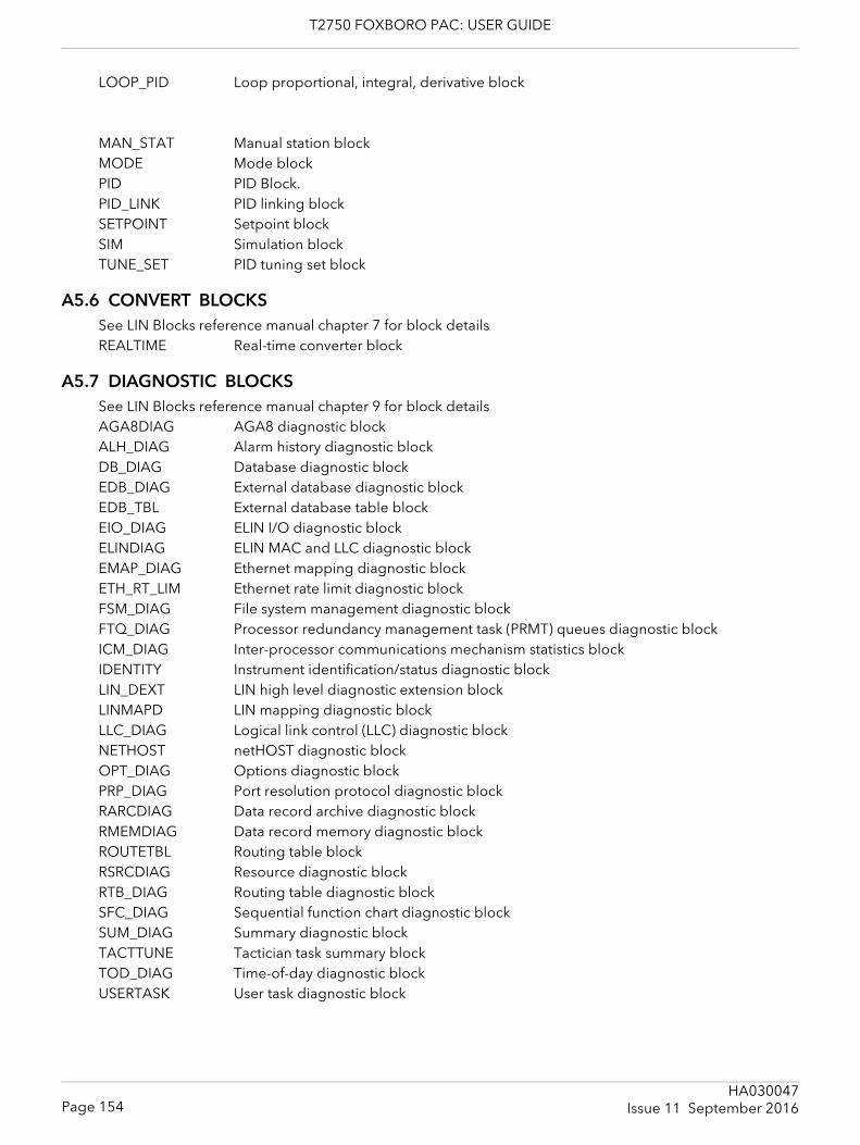
T2750 FOXBORO PAC: USER GUIDE
LOOP_PID Loop proportional, integral, derivative block
MAN_STAT Manual station blockMODE Mode blockPID PID Block. PID_LINK PID linking blockSETPOINT Setpoint blockSIM Simulation blockTUNE_SET PID tuning set block
A5.6 CONVERT BLOCKSSee LIN Blocks reference manual chapter 7 for block detailsREALTIME Real-time converter block
A5.7 DIAGNOSTIC BLOCKSSee LIN Blocks reference manual chapter 9 for block detailsAGA8DIAG AGA8 diagnostic blockALH_DIAG Alarm history diagnostic blockDB_DIAG Database diagnostic blockEDB_DIAG External database diagnostic blockEDB_TBL External database table blockEIO_DIAG ELIN I/O diagnostic blockELINDIAG ELIN MAC and LLC diagnostic blockEMAP_DIAG Ethernet mapping diagnostic blockETH_RT_LIM Ethernet rate limit diagnostic blockFSM_DIAG File system management diagnostic blockFTQ_DIAG Processor redundancy management task (PRMT) queues diagnostic blockICM_DIAG Inter-processor communications mechanism statistics blockIDENTITY Instrument identification/status diagnostic blockLIN_DEXT LIN high level diagnostic extension blockLINMAPD LIN mapping diagnostic blockLLC_DIAG Logical link control (LLC) diagnostic blockNETHOST netHOST diagnostic blockOPT_DIAG Options diagnostic blockPRP_DIAG Port resolution protocol diagnostic blockRARCDIAG Data record archive diagnostic blockRMEMDIAG Data record memory diagnostic blockROUTETBL Routing table blockRSRCDIAG Resource diagnostic blockRTB_DIAG Routing table diagnostic blockSFC_DIAG Sequential function chart diagnostic blockSUM_DIAG Summary diagnostic blockTACTTUNE Tactician task summary blockTOD_DIAG Time-of-day diagnostic blockUSERTASK User task diagnostic block
Page 154HA030047
Issue 11 September 2016
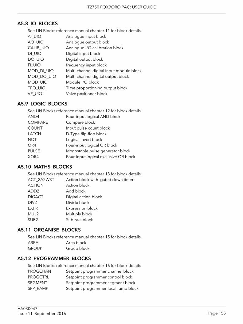
T2750 FOXBORO PAC: USER GUIDE
A5.8 IO BLOCKSSee LIN Blocks reference manual chapter 11 for block detailsAI_UIO Analogue input blockAO_UIO Analogue output blockCALIB_UIO Analogue I/O calibration blockDI_UIO Digital input blockDO_UIO Digital output blockFI_UIO frequency input blockMOD_DI_UIO Multi-channel digital input module blockMOD_DO_UIO Multi-channel digital output blockMOD_UIO Module I/O blockTPO_UIO Time proportioning output blockVP_UIO Valve positioner block.
A5.9 LOGIC BLOCKSSee LIN Blocks reference manual chapter 12 for block detailsAND4 Four-input logical AND blockCOMPARE Compare blockCOUNT Input pulse count blockLATCH D-Type flip-flop blockNOT Logical invert blockOR4 Four-input logical OR blockPULSE Monostable pulse generator blockXOR4 Four-input logical exclusive OR block
A5.10 MATHS BLOCKSSee LIN Blocks reference manual chapter 13 for block detailsACT_2A2W3T Action block with gated down timersACTION Action blockADD2 Add blockDIGACT Digital action blockDIV2 Divide blockEXPR Expression blockMUL2 Multiply blockSUB2 Subtract block
A5.11 ORGANISE BLOCKSSee LIN Blocks reference manual chapter 15 for block detailsAREA Area blockGROUP Group block
A5.12 PROGRAMMER BLOCKSSee LIN Blocks reference manual chapter 16 for block detailsPROGCHAN Setpoint programmer channel blockPROGCTRL Setpoint programmer control blockSEGMENT Setpoint programmer segment blockSPP_RAMP Setpoint programmer local ramp block
Page 155HA030047Issue 11 September 2016
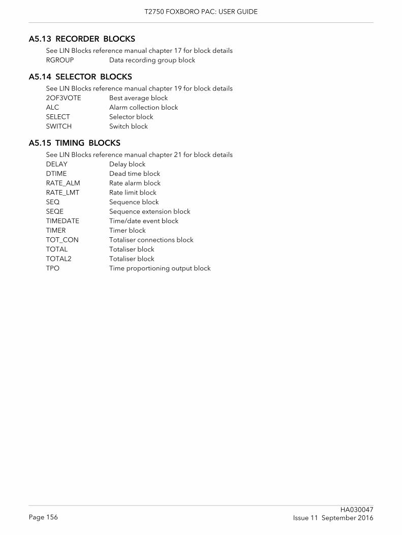
T2750 FOXBORO PAC: USER GUIDE
A5.13 RECORDER BLOCKSSee LIN Blocks reference manual chapter 17 for block detailsRGROUP Data recording group block
A5.14 SELECTOR BLOCKSSee LIN Blocks reference manual chapter 19 for block details2OF3VOTE Best average blockALC Alarm collection blockSELECT Selector blockSWITCH Switch block
A5.15 TIMING BLOCKSSee LIN Blocks reference manual chapter 21 for block detailsDELAY Delay blockDTIME Dead time blockRATE_ALM Rate alarm blockRATE_LMT Rate limit blockSEQ Sequence blockSEQE Sequence extension blockTIMEDATE Time/date event blockTIMER Timer blockTOT_CON Totaliser connections blockTOTAL Totaliser blockTOTAL2 Totaliser blockTPO Time proportioning output block
Page 156HA030047
Issue 11 September 2016
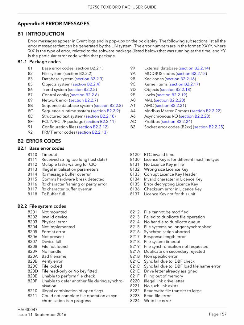
T2750 FOXBORO PAC: USER GUIDE
Appendix B ERROR MESSAGES
B1 INTRODUCTIONError messages appear in Event logs and in pop-ups on the pc display. The following subsections list all the error messages that can be generated by the LIN system. The error numbers are in the format: XXYY, where ‘XX’ is the type of error, related to the software package (listed below) that was running at the time, and YY is the particular error code within that package.
B1.1 Package codes
B2 ERROR CODESB2.1 Base error codes
B2.2 File system codes
81 Base error codes (section B2.2.1)82 File system (section B2.2.2)83 Database system (section B2.2.3)85 Objects system (section B2.2.4)86 Trend system (section B2.2.5)87 Control config (section B2.2.6)89 Network error (section B2.2.7)8B Sequence database system (section B2.2.8)8C Sequence runtime system (section B2.2.9)8D Structured text system (section B2.2.10)8F PCLIN/PC I/F package (section B2.2.11)91 Configuration files (section B2.2.12)92 PRMT error codes (section B2.2.13)
99 External database (section B2.2.14)9A MODBUS codes (section B2.2.15)9B Xec codes (section B2.2.16)9C Kernel items (section B2.2.17)9D Objects (section B2.2.18)9E Locks (section B2.2.19)A0 MAL (section B2.2.20)A1 AMC (section B2.2.21)A4 Modbus Master Comms (section B2.2.22)A6 Asynchronous I/O (section B2.2.23)AD Profibus (section B2.2.24)B2 Socket error codes (B2xx) (section B2.2.25)
8110 Timeout8111 Received string too long (lost data)8112 Multiple tasks waiting for CIO8113 Illegal initialisation parameters8114 Rx message buffer overrun8115 Comms hardware break detected8116 Rx character framing or parity error8117 Rx character buffer overrun8118 Tx Buffer full
8120 RTC invalid time.8130 Licence Key is for different machine type8131 No Licence Key in file8132 Wrong size Licence Key8133 Corrupt Licence Key Header8134 Invalid character in Licence Key8135 Error decrypting Licence Key8136 Checksum error in Licence Key8137 Licence Key not for this unit
8201 Not mounted8202 Invalid device8203 Physical error8204 Not implemented8205 Format error8206 Not present8207 Device full8208 File not found8209 No handle820A Bad filename820B Verify error820C File locked820D File read-only or No key fitted820E Unable to perform file check820F Unable to defer another file during synchro-
nisation8210 Illegal combination of open flags8211 Could not complete file operation as syn-
chronisation is in progress
8212 File cannot be modified8213 Failed to duplicate file operation8214 No handle to duplicate queue8215 File systems no longer synchronised8216 Synchronisation aborted8217 Response length error8218 File system timeout8219 File synchronisation not requested821A Duplicate on secondary rejected821B Non specific error821C Sync fail due to .DBF check821D Sync fail due to .DBF load file name error821E Drive letter already assigned821F Filing out of memory8220 Illegal link drive letter8221 No such link exists8222 Read/write file transfer to large8223 Read file error8224 Write file error
Page 157HA030047Issue 11 September 2016
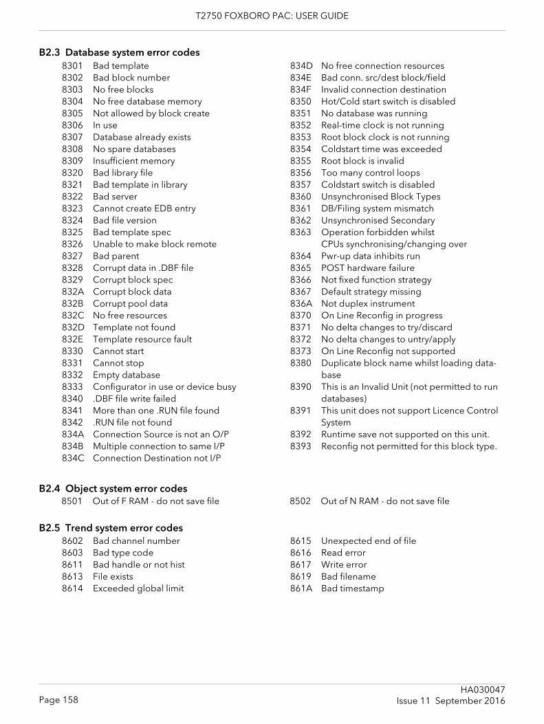
T2750 FOXBORO PAC: USER GUIDE
B2.3 Database system error codes
B2.4 Object system error codes
B2.5 Trend system error codes
8301 Bad template8302 Bad block number8303 No free blocks8304 No free database memory8305 Not allowed by block create8306 In use8307 Database already exists8308 No spare databases8309 Insufficient memory8320 Bad library file8321 Bad template in library8322 Bad server8323 Cannot create EDB entry8324 Bad file version8325 Bad template spec8326 Unable to make block remote8327 Bad parent8328 Corrupt data in .DBF file8329 Corrupt block spec832A Corrupt block data832B Corrupt pool data832C No free resources832D Template not found832E Template resource fault8330 Cannot start8331 Cannot stop8332 Empty database8333 Configurator in use or device busy8340 .DBF file write failed8341 More than one .RUN file found8342 .RUN file not found834A Connection Source is not an O/P834B Multiple connection to same I/P834C Connection Destination not I/P
834D No free connection resources834E Bad conn. src/dest block/field834F Invalid connection destination8350 Hot/Cold start switch is disabled8351 No database was running8352 Real-time clock is not running8353 Root block clock is not running8354 Coldstart time was exceeded8355 Root block is invalid8356 Too many control loops8357 Coldstart switch is disabled8360 Unsynchronised Block Types8361 DB/Filing system mismatch8362 Unsynchronised Secondary8363 Operation forbidden whilst
CPUs synchronising/changing over8364 Pwr-up data inhibits run8365 POST hardware failure8366 Not fixed function strategy 8367 Default strategy missing836A Not duplex instrument8370 On Line Reconfig in progress8371 No delta changes to try/discard8372 No delta changes to untry/apply8373 On Line Reconfig not supported8380 Duplicate block name whilst loading data-
base8390 This is an Invalid Unit (not permitted to run
databases)8391 This unit does not support Licence Control
System8392 Runtime save not supported on this unit.8393 Reconfig not permitted for this block type.
8501 Out of F RAM - do not save file 8502 Out of N RAM - do not save file
8602 Bad channel number8603 Bad type code8611 Bad handle or not hist8613 File exists8614 Exceeded global limit
8615 Unexpected end of file8616 Read error8617 Write error8619 Bad filename861A Bad timestamp
Page 158HA030047
Issue 11 September 2016
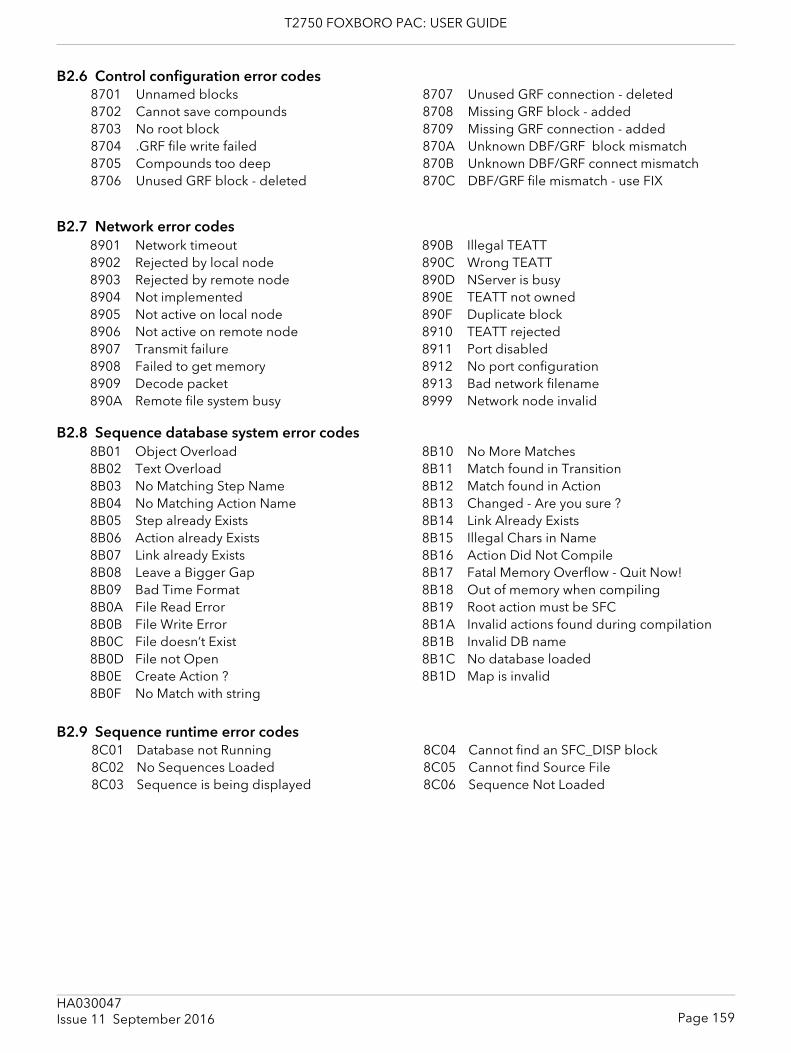
T2750 FOXBORO PAC: USER GUIDE
B2.6 Control configuration error codes
B2.7 Network error codes
B2.8 Sequence database system error codes
B2.9 Sequence runtime error codes
8701 Unnamed blocks8702 Cannot save compounds8703 No root block8704 .GRF file write failed8705 Compounds too deep8706 Unused GRF block - deleted
8707 Unused GRF connection - deleted8708 Missing GRF block - added8709 Missing GRF connection - added870A Unknown DBF/GRF block mismatch870B Unknown DBF/GRF connect mismatch870C DBF/GRF file mismatch - use FIX
8901 Network timeout8902 Rejected by local node8903 Rejected by remote node8904 Not implemented8905 Not active on local node8906 Not active on remote node8907 Transmit failure8908 Failed to get memory8909 Decode packet890A Remote file system busy
890B Illegal TEATT890C Wrong TEATT890D NServer is busy890E TEATT not owned890F Duplicate block8910 TEATT rejected8911 Port disabled8912 No port configuration8913 Bad network filename8999 Network node invalid
8B01 Object Overload8B02 Text Overload8B03 No Matching Step Name8B04 No Matching Action Name8B05 Step already Exists8B06 Action already Exists8B07 Link already Exists8B08 Leave a Bigger Gap8B09 Bad Time Format8B0A File Read Error8B0B File Write Error8B0C File doesn’t Exist8B0D File not Open8B0E Create Action ?8B0F No Match with string
8B10 No More Matches8B11 Match found in Transition8B12 Match found in Action8B13 Changed - Are you sure ?8B14 Link Already Exists8B15 Illegal Chars in Name8B16 Action Did Not Compile8B17 Fatal Memory Overflow - Quit Now!8B18 Out of memory when compiling8B19 Root action must be SFC8B1A Invalid actions found during compilation8B1B Invalid DB name8B1C No database loaded8B1D Map is invalid
8C01 Database not Running8C02 No Sequences Loaded8C03 Sequence is being displayed
8C04 Cannot find an SFC_DISP block8C05 Cannot find Source File8C06 Sequence Not Loaded
Page 159HA030047Issue 11 September 2016
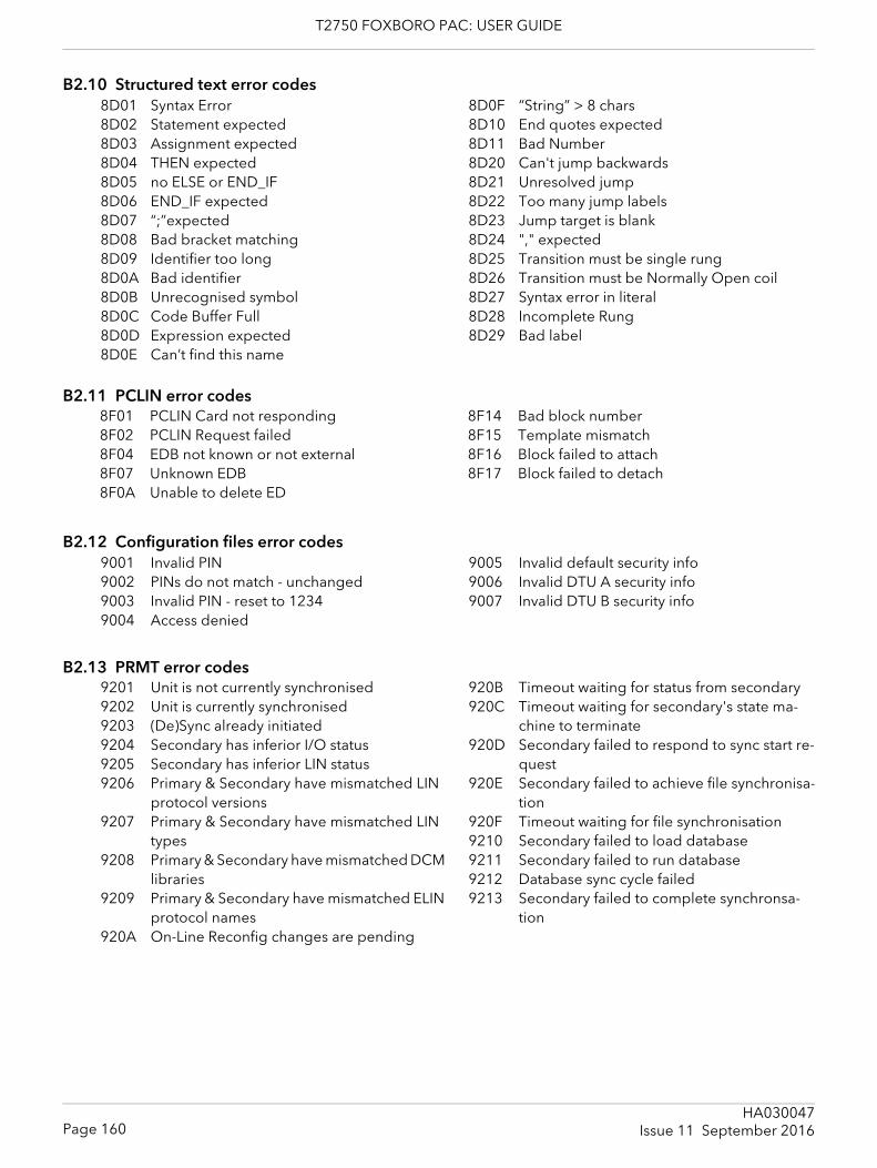
T2750 FOXBORO PAC: USER GUIDE
B2.10 Structured text error codes
B2.11 PCLIN error codes
B2.12 Configuration files error codes
B2.13 PRMT error codes
8D01 Syntax Error8D02 Statement expected8D03 Assignment expected8D04 THEN expected8D05 no ELSE or END_IF8D06 END_IF expected8D07 “;”expected8D08 Bad bracket matching8D09 Identifier too long8D0A Bad identifier8D0B Unrecognised symbol8D0C Code Buffer Full8D0D Expression expected8D0E Can’t find this name
8D0F “String” > 8 chars8D10 End quotes expected8D11 Bad Number8D20 Can't jump backwards8D21 Unresolved jump8D22 Too many jump labels8D23 Jump target is blank8D24 "," expected8D25 Transition must be single rung8D26 Transition must be Normally Open coil8D27 Syntax error in literal8D28 Incomplete Rung8D29 Bad label
8F01 PCLIN Card not responding8F02 PCLIN Request failed8F04 EDB not known or not external8F07 Unknown EDB8F0A Unable to delete ED
8F14 Bad block number8F15 Template mismatch8F16 Block failed to attach8F17 Block failed to detach
9001 Invalid PIN9002 PINs do not match - unchanged9003 Invalid PIN - reset to 12349004 Access denied
9005 Invalid default security info9006 Invalid DTU A security info9007 Invalid DTU B security info
9201 Unit is not currently synchronised9202 Unit is currently synchronised9203 (De)Sync already initiated9204 Secondary has inferior I/O status9205 Secondary has inferior LIN status9206 Primary & Secondary have mismatched LIN
protocol versions9207 Primary & Secondary have mismatched LIN
types9208 Primary & Secondary have mismatched DCM
libraries9209 Primary & Secondary have mismatched ELIN
protocol names920A On-Line Reconfig changes are pending
920B Timeout waiting for status from secondary920C Timeout waiting for secondary's state ma-
chine to terminate920D Secondary failed to respond to sync start re-
quest920E Secondary failed to achieve file synchronisa-
tion920F Timeout waiting for file synchronisation9210 Secondary failed to load database9211 Secondary failed to run database9212 Database sync cycle failed9213 Secondary failed to complete synchronsa-
tion
Page 160HA030047
Issue 11 September 2016
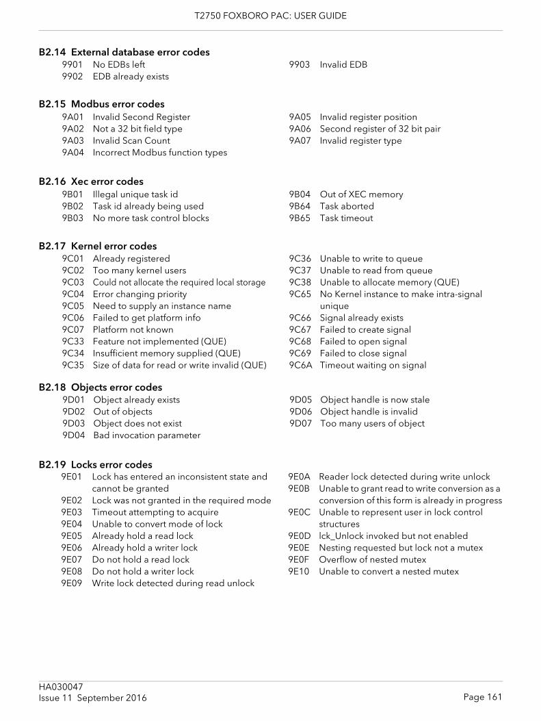
T2750 FOXBORO PAC: USER GUIDE
B2.14 External database error codes
B2.15 Modbus error codes
B2.16 Xec error codes
B2.17 Kernel error codes
B2.18 Objects error codes
B2.19 Locks error codes
9901 No EDBs left9902 EDB already exists
9903 Invalid EDB
9A01 Invalid Second Register 9A02 Not a 32 bit field type 9A03 Invalid Scan Count 9A04 Incorrect Modbus function types
9A05 Invalid register position 9A06 Second register of 32 bit pair 9A07 Invalid register type
9B01 Illegal unique task id9B02 Task id already being used9B03 No more task control blocks
9B04 Out of XEC memory9B64 Task aborted9B65 Task timeout
9C01 Already registered9C02 Too many kernel users9C03 Could not allocate the required local storage9C04 Error changing priority9C05 Need to supply an instance name9C06 Failed to get platform info9C07 Platform not known9C33 Feature not implemented (QUE)9C34 Insufficient memory supplied (QUE)9C35 Size of data for read or write invalid (QUE)
9C36 Unable to write to queue9C37 Unable to read from queue9C38 Unable to allocate memory (QUE)9C65 No Kernel instance to make intra-signal
unique9C66 Signal already exists9C67 Failed to create signal9C68 Failed to open signal9C69 Failed to close signal9C6A Timeout waiting on signal
9D01 Object already exists9D02 Out of objects9D03 Object does not exist9D04 Bad invocation parameter
9D05 Object handle is now stale9D06 Object handle is invalid9D07 Too many users of object
9E01 Lock has entered an inconsistent state and cannot be granted
9E02 Lock was not granted in the required mode9E03 Timeout attempting to acquire9E04 Unable to convert mode of lock9E05 Already hold a read lock9E06 Already hold a writer lock9E07 Do not hold a read lock9E08 Do not hold a writer lock9E09 Write lock detected during read unlock
9E0A Reader lock detected during write unlock9E0B Unable to grant read to write conversion as a
conversion of this form is already in progress9E0C Unable to represent user in lock control
structures9E0D lck_Unlock invoked but not enabled9E0E Nesting requested but lock not a mutex9E0F Overflow of nested mutex9E10 Unable to convert a nested mutex
Page 161HA030047Issue 11 September 2016
T2750 FOXBORO PAC: USER GUIDE
B2.20 MAL error codes
B2.21 AMC error codes
B2.22 MMC error codes
B2.23 Asynchronous I/O error codes
A001 Could not create user's event (MAL)A002 Could not open user's event (MAL)A003 Could not set user's event (MAL)A004 Unable to grant system wide mutex due to it
being in an inconsistent stateA005 Unable to grant system wide mutex due to a
timeoutA006 Unable to grant system wide mutex reason un-
known
A007 Unable to grant system wide mutex as not cre-ated
A008 Unable to suspend user (MAL)A009 Unable to allocate memory (MAL)A00A Unable to change priority (MAL)A00B Error waiting on signal (MAL)A00C Error releasing signal waiters (MAL)
A101 Cyclic comms enabled on node(s)A102 No memory leftA103 Bad info givenA104 Data is referencedA105 No data group installedA106 Pending messageA107 Fault external to AMCA108 Not supported
A10A ConflictA10B Task not runningA10C BugA10D Manual cyclic only (pmc reject)A10E Cannot add cyclic request A10F Slave rejected cyclicsA110 No pmc callback
A401 Out of / Bad resource(s)A402 Bad info suppliedA403 Pending messageA404 Problem external to MMCA405 Not supportedA406 TimeoutA407 Frame parity errorA408 Currupt messageA409 Link protocol errorA40A Modbus exception recvdA40B Tx failA40C No Modbus TCP configuration fileA40D Modbus TCP device already configuredA40E Modbus TCP node not configuredA40F No Modbus TCP connection
A410 Asynchronous Modbus TCP buffer appears invalid
A411 Cannot issue an asynchronous Modbus transaction over serial line
A412 Asynchronous Modbus transaction in progress to this node
A413 Modbus TCP device has disconnectedA414 Modbus TCP transaction mismatchA415 Modbus TCP error reading/writing socketA416 Asynchronous Modbus TCP not supportedA417 Out of Modbus TCP sessionsA418 TCP connection in progressA419 No instrument number to Modbus node ad-
dressA41A Waiting to form Modbus TCP connection
A601 Asynchronous I/O in progressA602 No asynchronous I/O in progressA603 Not yet implementedA604 Tx operation complete but not all characters
transferredA605 Rx operation complete, but not all characters
receivedA606 Event not uniqueA607 General CIO error
A608 No asynch. operation fetchedA609 Out of serial linesA60A Unable to allocate the requested lineA60B Failed to submit asynchronous I/OA60C Input/output timed outA60D Indeterminate error during fetchA60E I/O timed out but failed to cancel operation
in progress
Page 162HA030047
Issue 11 September 2016
T2750 FOXBORO PAC: USER GUIDE
B2.24 Profibus error codes
B2.25 Socket error codesB201 Error doing selectB202 Error accepting connectionB203 Out of connectionsB204 Error reading socketB205 Failed to initialise socketsB206 Connection has been resetB207 Unable to listen on socketB208 Could not allocate socketB209 Could not get host informationB20A Could not bind socketB20B Unable to connect socketB20C Reference is not a valid connectionB20D Failed to send data over connectionB20E Insufficient buffer for connection dataB20F Cannot peek for records
B210 Record does not contain a valid length fieldB211 Unable to read record as insufficient buffer
was suppliedB212 Incomplete record encounteredB213 Connection closedB214 Timed out receiving on socketB215 Error sending over socketB216 Send would block on socketB217 Could not establish blocking modeB218 Sockets out of memoryB219 Peek buffer is fullB21A Global initialisation failedB21B Connection timed outB21C Socket session still activeB21D The session name is being used
AD01 Cyclic data not availableAD02 Cannot make cyclic into acyclicAD03 Profibus C1 not allowedAD04 Profibus C2 not allowedAD05 Acyclic frag. limit exceededAD06 Comms line requested is not profibusAD07 Resource alloc failureAD08 PMC not initialisedAD09 No more Cyclic data spaceAD0A No more cyclic tag spaceAD0B Attempt to append while runningAD0C Data attribs. not setAD0D Data group size / type mismatchAD0E Data group size / type unknownAD0F Data group wrong line numberAD10 Data group node addr. wrongAD11 Data group addresses not contiguousAD12 Not in assembling modeAD13 Cyclics not configuredAD14 Cyclics not runningAD15 Attempt to change card stateAD16 Bad data group listAD17 Changeover not completeAD18 Acyclics not readyAD19 Too many diag. clientsAD1A Line already initialisedAD1B Comms attribs ptr failureAD1C Comms attribs data failureAD1D Cannot achieve cycle timeAD1E Master baud rate not supportedAD1F Cannot kill cards DB
AD20 Not usedAD21 Unable to set master protocol params.AD22 Unable to set master comms params.AD23 Unable to set slave comms params.AD24 Failed to start profibus line taskAD25 Failed to stop profibus line taskAD26 Bad slave diagnosticAD27 Acyclics restartedAD28 Master rejected acyclic req.AD29 Master acyclic resp. errorAD2A Slave acyclic req. rejectedAD2B Slave acyclic resp errorAD2C Acyclic timeoutAD2D No slave acyclic resp.AD2E Failed to get diags.AD2F Failed to get slave diags.AD30 No slave diags. availableAD31 Bad pointer parameterAD32 Parameter out of rangeAD33 Slave cfg overflowAD34 Slave prm overflowAD35 C1 acyclic data too bigAD3C C2 acyclic data too bigAD37 Slave not runningAD38 Pending acyclicAD39 C2 RW not supported by slaveAD3A C2 unexpected connection closeAD3B Master card startup errorAD3C Not usedAD3D Could not get slave IO dataAD3E Slave not running at changeover
Page 163HA030047Issue 11 September 2016

T2750 FOXBORO PAC: USER GUIDE
This page is deliberately left blank
Page 164HA030047
Issue 11 September 2016
T2750 FOXBORO PAC: USER GUIDE
Appendix C REFERENCE
C1 FREQUENCY INPUT MODULE DETAILSThis module provides two input channels to be used for data gathering and signal conditioning from a range of common plant sensor types, including magnetic, voltage input, current input and contact closure inputs. The module includes internal power supplies which can provide loop or wetting currents, transducer power as required.
C1.1 TERMINAL CONNECTIONS, LINKS and STATUS LEDSSection 2.3.13 gives full pinout, link setting and status LED details. For the sake of clarity, figure 2.3.13a shows the links set in the same position for both channels, but as the channel acts independently, the links should be set as appropriate for each channel.
CAUTIONIf more than eight FI2 modules are mounted in a base unit, and the channel output at 24V is greater than 5mA per channel, then an external power supply must be used. Using the normal base unit sup-ply in such a situation can cause damage to the backplane.
C1.2 SPECIFICATIONSection A4.12 gives the FI2 module specification
C1.3 APPLICATION DETAILSC1.3.1 Cable selection
The selection of appropriate cabling to connect the encoder to the FI2 is dependent upon a number of fac-tors. In all cases, it is recommended that sensor cabling does not exceed 30m, otherwise high energy surges (IEC61000-4-5) may be picked-up and applied to the module terminals. The choice of cable depends on how electrically noisy the area is, the length of cabling required, and the frequency being used. Typical ca-bling choices include:
a) Short cable length in low-noise environments: Basic shielding (a foil jacket and a drain wire) should pro-vide moderate noise protection for cost-sensitive applications.
b) Noisier environments and/or longer (more than 3m) cable runs: In potentially high-noise environments, or for cable runs >3m, it is recommended that each channel is connected to the FI2 using a low-capac-itance (<20pF/foot) shielded cable.
c) High-frequency inputs and/or longer cable runs: For high frequency applications (>5kHz), both a foil and braided shielding in a low-capacitance (<20pF/foot) cable is recommended. A foil-wrapped twist-ed shielded pair in a braided shielded cable can deliver good performance over long distances (de-pending on the type of output driver used).
d) Best immunity to noise and long cable runs: A multi-conductor cable with 22 and 24 AWG stranded tinned copper conductors, individually foil shielded (100% coverage) and an overall tinned copper braid with a capacitance of 12 pF/foot or less should be considered for longer distances. A cable similar to the Belden 3084A could be used, for example.
C1.3.2 Cable shield connectionTypically, noise immunity can be achieved by connecting the cable shield to the relevant FI2 common con-nection (C1/C2). However, in some cases connecting the shielding to the common signal return path at the encoder end may achieve better noise immunity. Under no circumstances, connect the shield at both ends.
C1.3.3 Choosing the appropriate output sensor typeThe choice of input type is heavily dependent on the distance from the encoder to the FI2 and the noise en-vironment it is operating in.
Page 165HA030047Issue 11 September 2016
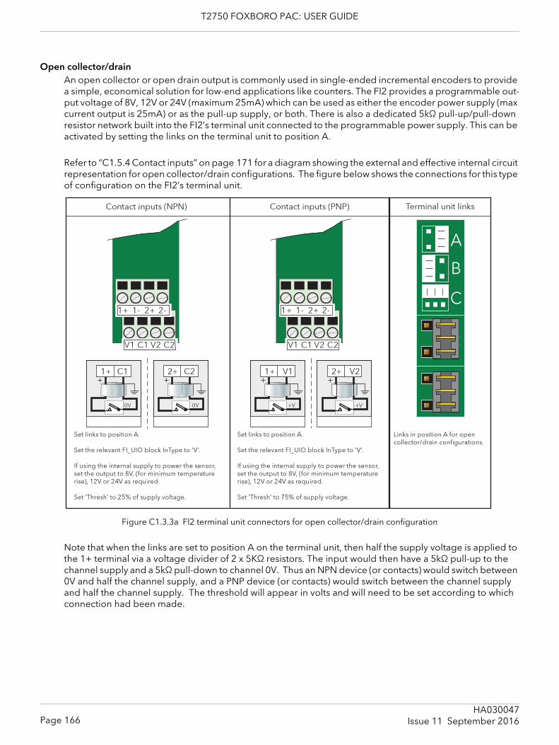
T2750 FOXBORO PAC: USER GUIDE
Open collector/drainAn open collector or open drain output is commonly used in single-ended incremental encoders to provide a simple, economical solution for low-end applications like counters. The FI2 provides a programmable out-put voltage of 8V, 12V or 24V (maximum 25mA) which can be used as either the encoder power supply (max current output is 25mA) or as the pull-up supply, or both. There is also a dedicated 5kΩ pull-up/pull-down resistor network built into the FI2’s terminal unit connected to the programmable power supply. This can be activated by setting the links on the terminal unit to position A.
Refer to “C1.5.4 Contact inputs” on page 171 for a diagram showing the external and effective internal circuit representation for open collector/drain configurations. The figure below shows the connections for this type of configuration on the FI2’s terminal unit.
Figure C1.3.3a FI2 terminal unit connectors for open collector/drain configuration
Note that when the links are set to position A on the terminal unit, then half the supply voltage is applied to the 1+ terminal via a voltage divider of 2 x 5KΩ resistors. The input would then have a 5kΩ pull-up to the channel supply and a 5kΩ pull-down to channel 0V. Thus an NPN device (or contacts) would switch between 0V and half the channel supply, and a PNP device (or contacts) would switch between the channel supply and half the channel supply. The threshold will appear in volts and will need to be set according to which connection had been made.
Page 166HA030047
Issue 11 September 2016
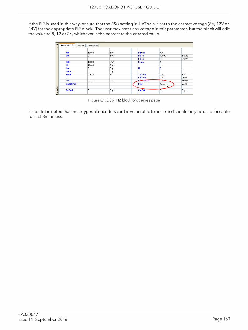
T2750 FOXBORO PAC: USER GUIDE
If the FI2 is used in this way, ensure that the PSU setting in LinTools is set to the correct voltage (8V, 12V or 24V) for the appropriate FI2 block. The user may enter any voltage in this parameter, but the block will edit the value to 8, 12 or 24, whichever is the nearest to the entered value.
Figure C1.3.3b FI2 block properties page
It should be noted that these types of encoders can be vulnerable to noise and should only be used for cable runs of 3m or less.
Page 167HA030047Issue 11 September 2016
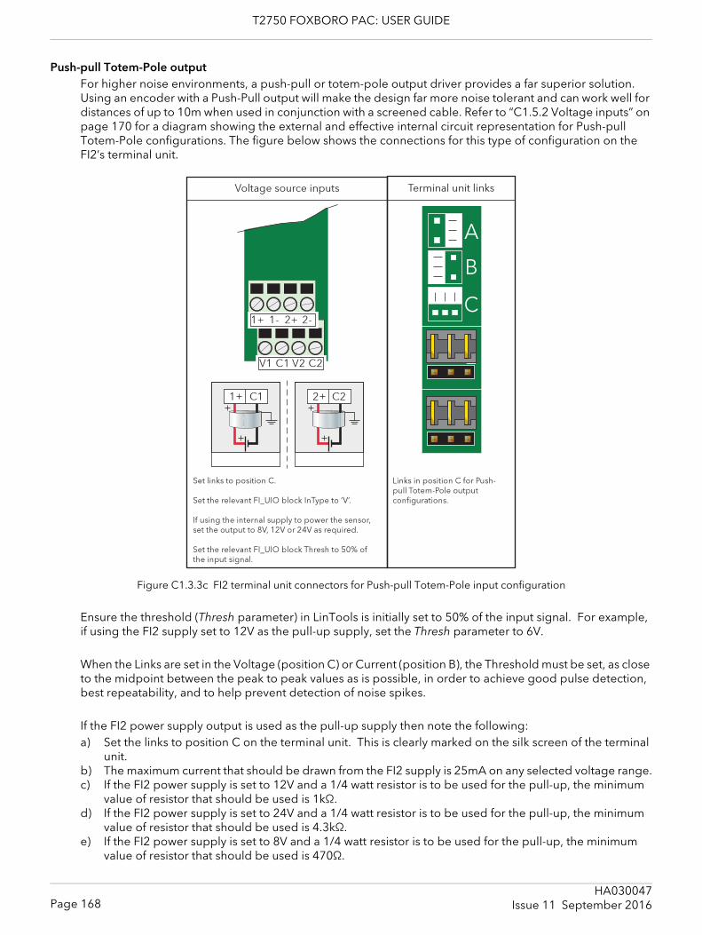
T2750 FOXBORO PAC: USER GUIDE
Push-pull Totem-Pole outputFor higher noise environments, a push-pull or totem-pole output driver provides a far superior solution. Using an encoder with a Push-Pull output will make the design far more noise tolerant and can work well for distances of up to 10m when used in conjunction with a screened cable. Refer to “C1.5.2 Voltage inputs” on page 170 for a diagram showing the external and effective internal circuit representation for Push-pull Totem-Pole configurations. The figure below shows the connections for this type of configuration on the FI2’s terminal unit.
Figure C1.3.3c FI2 terminal unit connectors for Push-pull Totem-Pole input configuration
Ensure the threshold (Thresh parameter) in LinTools is initially set to 50% of the input signal. For example, if using the FI2 supply set to 12V as the pull-up supply, set the Thresh parameter to 6V.
When the Links are set in the Voltage (position C) or Current (position B), the Threshold must be set, as close to the midpoint between the peak to peak values as is possible, in order to achieve good pulse detection, best repeatability, and to help prevent detection of noise spikes.
If the FI2 power supply output is used as the pull-up supply then note the following:a) Set the links to position C on the terminal unit. This is clearly marked on the silk screen of the terminal
unit.b) The maximum current that should be drawn from the FI2 supply is 25mA on any selected voltage range.c) If the FI2 power supply is set to 12V and a 1/4 watt resistor is to be used for the pull-up, the minimum
value of resistor that should be used is 1kΩ.d) If the FI2 power supply is set to 24V and a 1/4 watt resistor is to be used for the pull-up, the minimum
value of resistor that should be used is 4.3kΩ.e) If the FI2 power supply is set to 8V and a 1/4 watt resistor is to be used for the pull-up, the minimum
value of resistor that should be used is 470Ω.
Page 168HA030047
Issue 11 September 2016
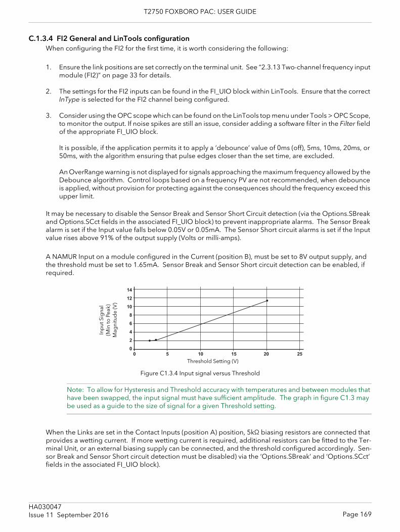
T2750 FOXBORO PAC: USER GUIDE
C.1.3.4 FI2 General and LinTools configurationWhen configuring the FI2 for the first time, it is worth considering the following:
1. Ensure the link positions are set correctly on the terminal unit. See “2.3.13 Two-channel frequency input module (FI2)” on page 33 for details.
2. The settings for the FI2 inputs can be found in the FI_UIO block within LinTools. Ensure that the correct InType is selected for the FI2 channel being configured.
3. Consider using the OPC scope which can be found on the LinTools top menu under Tools > OPC Scope, to monitor the output. If noise spikes are still an issue, consider adding a software filter in the Filter field of the appropriate FI_UIO block.
It is possible, if the application permits it to apply a ‘debounce’ value of 0ms (off), 5ms, 10ms, 20ms, or 50ms, with the algorithm ensuring that pulse edges closer than the set time, are excluded.
An OverRange warning is not displayed for signals approaching the maximum frequency allowed by the Debounce algorithm. Control loops based on a frequency PV are not recommended, when debounce is applied, without provision for protecting against the consequences should the frequency exceed this upper limit.
It may be necessary to disable the Sensor Break and Sensor Short Circuit detection (via the Options.SBreak and Options.SCct fields in the associated FI_UIO block) to prevent inappropriate alarms. The Sensor Break alarm is set if the Input value falls below 0.05V or 0.05mA. The Sensor Short circuit alarms is set if the Input value rises above 91% of the output supply (Volts or milli-amps).
A NAMUR Input on a module configured in the Current (position B), must be set to 8V output supply, and the threshold must be set to 1.65mA. Sensor Break and Sensor Short circuit detection can be enabled, if required.
Figure C1.3.4 Input signal versus Threshold
Note: To allow for Hysteresis and Threshold accuracy with temperatures and between modules that have been swapped, the input signal must have sufficient amplitude. The graph in figure C1.3 may be used as a guide to the size of signal for a given Threshold setting.
When the Links are set in the Contact Inputs (position A) position, 5kΩ biasing resistors are connected that provides a wetting current. If more wetting current is required, additional resistors can be fitted to the Ter-minal Unit, or an external biasing supply can be connected, and the threshold configured accordingly. Sen-sor Break and Sensor Short circuit detection must be disabled) via the ‘Options.SBreak’ and ‘Options.SCct’ fields in the associated FI_UIO block).
0 5 10 15 20 25
14
12
10
8
6
4
2
0
Inp
ut S
igna
l (M
into
Peak
) M
agni
tud
e (V
)
Threshold Setting (V)
Page 169HA030047Issue 11 September 2016
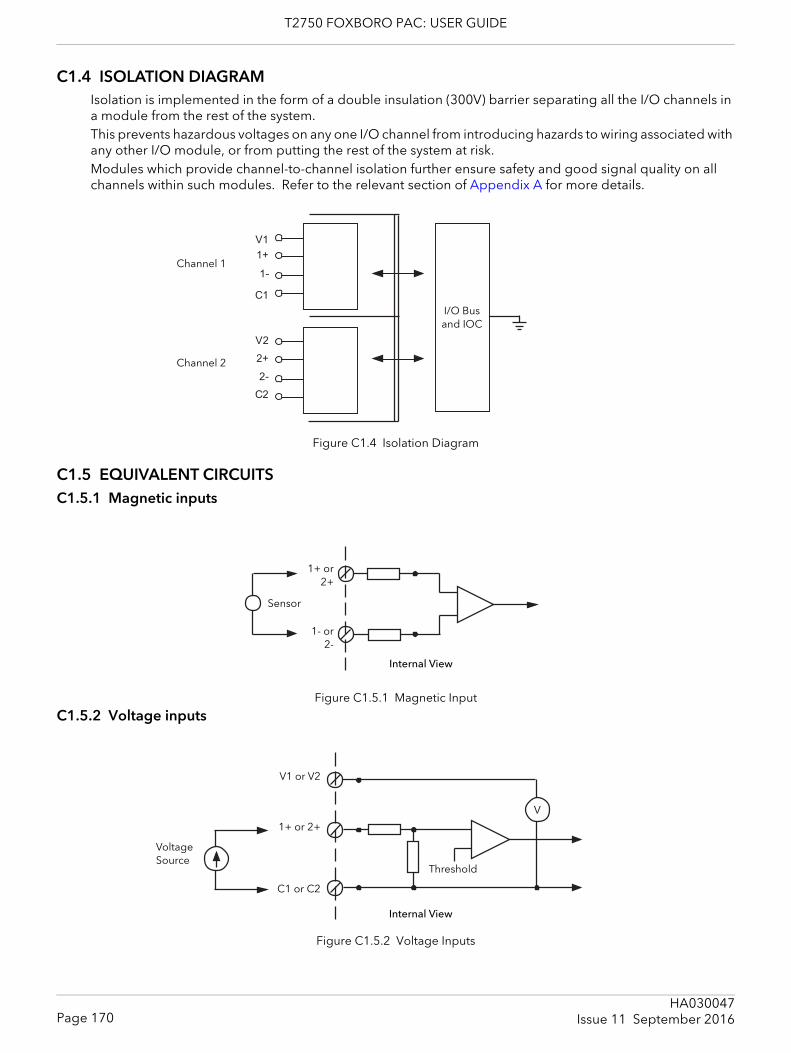
T2750 FOXBORO PAC: USER GUIDE
C1.4 ISOLATION DIAGRAMIsolation is implemented in the form of a double insulation (300V) barrier separating all the I/O channels in a module from the rest of the system. This prevents hazardous voltages on any one I/O channel from introducing hazards to wiring associated with any other I/O module, or from putting the rest of the system at risk. Modules which provide channel-to-channel isolation further ensure safety and good signal quality on all channels within such modules. Refer to the relevant section of Appendix A for more details.
Figure C1.4 Isolation Diagram
C1.5 EQUIVALENT CIRCUITSC1.5.1 Magnetic inputs
Figure C1.5.1 Magnetic Input
C1.5.2 Voltage inputs
Figure C1.5.2 Voltage Inputs
1+
V2
C1
2-
2+
C2
V1
1-
I/O Bus and IOC
Channel 1
Channel 2
Internal View
1+ or2+
Sensor
1- or2-
V
Internal View
V1 or V2
Voltage Source
1+ or 2+
C1 or C2
Threshold
Page 170HA030047
Issue 11 September 2016
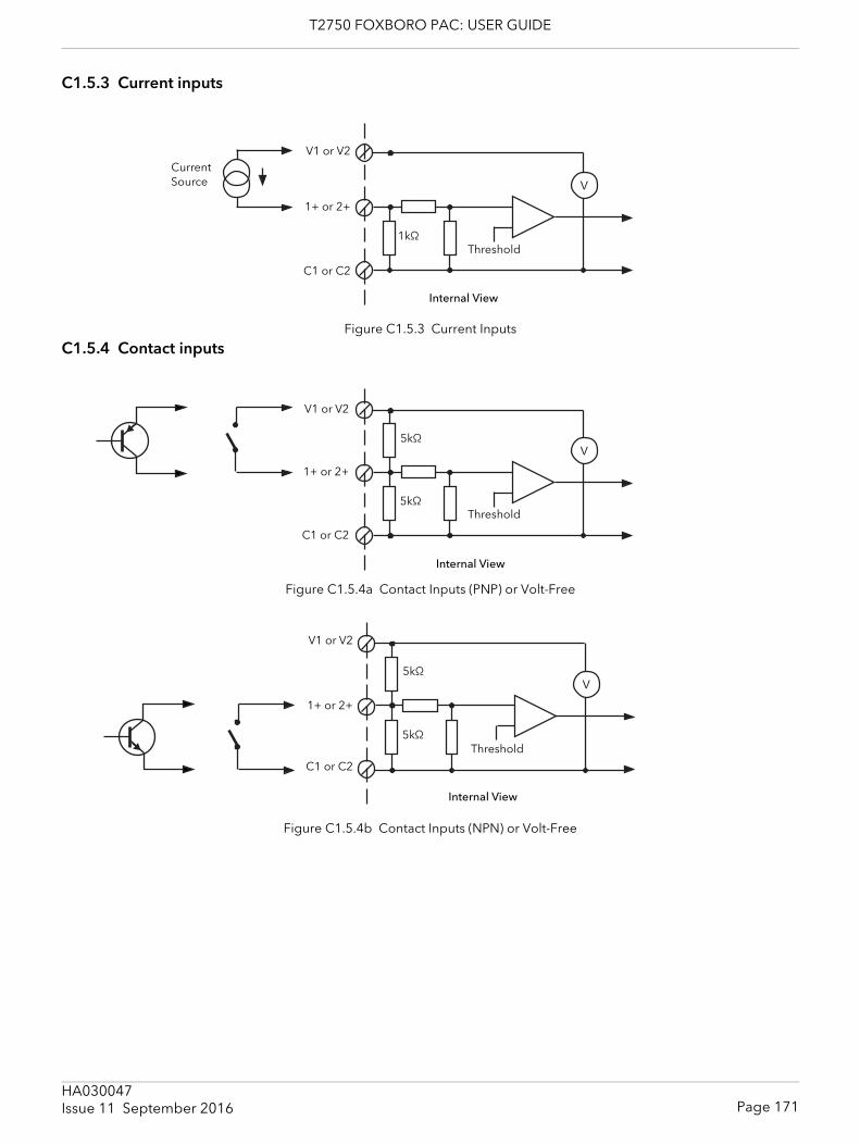
T2750 FOXBORO PAC: USER GUIDE
C1.5.3 Current inputs
Figure C1.5.3 Current Inputs
C1.5.4 Contact inputs
Figure C1.5.4a Contact Inputs (PNP) or Volt-Free
Figure C1.5.4b Contact Inputs (NPN) or Volt-Free
V
Internal View
V1 or V2Current Source
1+ or 2+
C1 or C2
Threshold1kΩ
V
Internal View
V1 or V2
1+ or 2+
C1 or C2
Threshold
5kΩ
5kΩ
V
Internal View
V1 or V2
1+ or 2+
C1 or C2
Threshold
5kΩ
5kΩ
Page 171HA030047Issue 11 September 2016
T2750 FOXBORO PAC: USER GUIDE
C1.6 FAULT DETECTIONDetected faults can be defined as Field, Setup, or Hardware faults, but any reaction will depend on the Input configuration of the associated FI_UIO block. These faults are indicated via the LEDs on the Module (figure 2.3.13b), and the Status and Alarms bits of the corresponding FI_UIO block.
C1.6.1 Fault DiagnosticsThe Status and Alarms bits of the associated FI_UIO block can be inspected in order to locate a fault.
Status InterpretationMissing The associated MOD_UIO block has not been found, caused by an incorrectly config-
ured Strategy, i.e. the MOD_UIO block does not exist in the Strategy. This sets the Alarms.ModBlock field True. To resolve the problem, ensure tat the Strategy contains the required MOD_UIO block.
BadType The Channel configured in the block, does not correspond to the module. Ensure the block and the module correspond.
Ranging The Input value is not measurable by the hardware, but a fault is not detected, i.e. the Input is currently being ranged or configured.
BadSetup An invalid setup is detected, caused by an incorrect ‘LR_in’ or ‘HR_in’ field configura-tion. This sets ‘Alarms.OutRange’ True.To resolve the problem, ensure ‘LR_in’ and ‘HR_in’ fields correspond to the range used by the installed hardware.
HwFlt A fault in the output supply is detected caused by output supply overload. This sets the Alarms.Hardware field True.
NotAuto The module is not operating in Automatic mode. This sets the ‘Alarms.NotAuto’ field True
OverRng An input value greater than the measurement circuit range is detected, generally caused by an input value greater than 40KHz, but less than 80KHz.
UnderRng An Input value less than the measurement circuit range is detected. Can be caused by input values less than 10Hz, for a Magnetic Sensor configuration, or less than 0.01Hz for the Voltage, Current, or Contact configuration.
OpenCct An Open circuit fault in the Logic Sensor is detected., setting the ‘Alarms.CctFault’ field True.
ShortCct An Short circuit fault in the Logic Sensor is detected, setting the ‘Alarms.CctFault field’ True.
BadHwSet The hardware configuration does not correspond to the Input Type configured in the FI_UIO block. To resolve the problem, ensure the Link configuration (figure 2.3.13a) corresponds with the ‘InType’ field of the FI_UIO block.
Cutoff A measured frequency value below the low threshold value (CutOff) is detected, setting ‘Alarms.CutOff’ True. The measured frequency value adopts the value defined in the ‘Default’ field.
Badtask Task Rate configured in the block does not correspond to the Task Rate of the module, this situation setting the Alarms.Hardware field True.To resolve the problem, configure the Task rate of the module and the Task rate in the block to the slow task rate (Task 3: 110ms).
Page 172HA030047
Issue 11 September 2016

T2750 FOXBORO PAC: USER GUIDE
C2 ZIRCONIA INPUT MODULE DETAILSThe Zirconia input module contains two input channels, isolated both from each other and from the system electronics, and intended to be used to measure the temperature at the measuring tip of a zirconia probe (channel 1) and the voltage generated across a zirconia pellet (channel 2).
User Calibration allows the ‘permanent’ factory calibration to be modified in order to:1. Calibrate the controller to your reference standards2. Match the calibration of the controller to that of a particular transducer or sensor3. Calibrate the controller to suit the characteristics of a particular installation
C2.1 TERMINAL CONNECTIONS and STATUS LEDSSection 2.3.16 gives full pinout and status LED details.
C2.2 SPECIFICATIONSection A4.15 gives the ZI module specification.
C2.3 APPLICATION DETAILSThis module is used to control the temperature of the process on one channel (loop) and carbon potential on the other. The module, in conjunction with the strategy, generates temperature and carbon potential pro-files synchronised to a common timebase.Channel one is a thermocouple input with automatic Cold Junction Compensation.Channel two (connected to the Zirconia pellet) offers the high-impedance low leakage 2V range used to out-put a voltage measurement allowing simple offset and scaling.To comply with EMC regulations, it is recommended that the Zirconia Probe be connected to Channel 2 of the module using screened cable with a maximum length of 30m
C2.3.1 Temperature ControlThe sensor input of the temperature channel (loop) may come from the Zirconia Probe but it is common for a separate thermocouple to be used. The strategy can then control an output which is connected to heating elements (e.g. gas burners or thyristors) to control the temperature. In some applications a cooling output may also be connected to a circulation fan or exhaust damper.
C2.3.2 Carbon Potential ControlThe Zirconia probe generates a milli-volt (mV) signal based on the ratio of oxygen concentrations on the ref-erence side of the Probe (outside the furnace) to the amount of oxygen in the furnace. The temperature and carbon potential millivolt values, read into the related block, are used to calculate the percentage of carbon in the furnace.
C2.3.3 Soot AlarmAn alarm can be triggered when the atmospheric conditions within the furnace are such that carbon will be deposited as soot on all surfaces inside the furnace.
C2.3.4 Probe CleaningA Probe clean and recovery strategy can be configured either to occur between batches or to be triggered manually. A short blast of compressed air is used to remove any soot and other particles that may have ac-cumulated on the probe. Once cleaning is complete, the time taken for the probe to recover is measured. If the recovery time is too long this indicates that the probe is ageing and replacement or refurbishment is due. During the cleaning and recovery cycle, the %C reading is frozen, ensuring continuous furnace operation.
Page 173HA030047Issue 11 September 2016
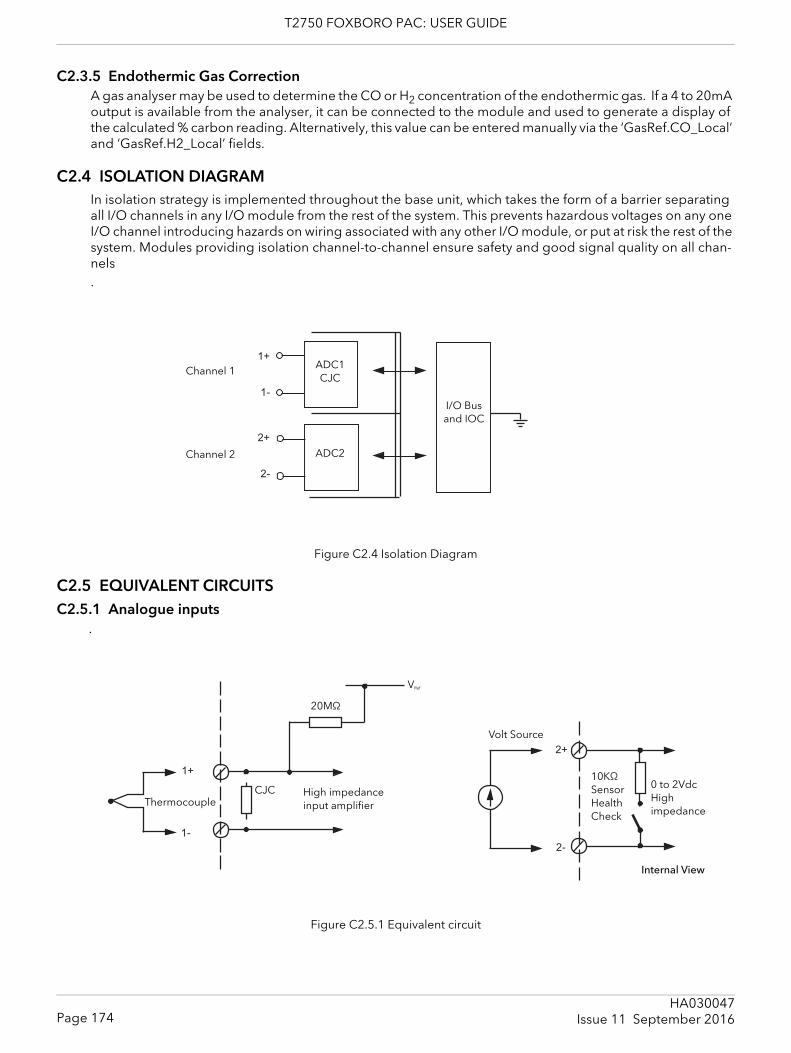
T2750 FOXBORO PAC: USER GUIDE
C2.3.5 Endothermic Gas CorrectionA gas analyser may be used to determine the CO or H2 concentration of the endothermic gas. If a 4 to 20mA output is available from the analyser, it can be connected to the module and used to generate a display of the calculated % carbon reading. Alternatively, this value can be entered manually via the ‘GasRef.CO_Local’ and ‘GasRef.H2_Local’ fields.
C2.4 ISOLATION DIAGRAMIn isolation strategy is implemented throughout the base unit, which takes the form of a barrier separating all I/O channels in any I/O module from the rest of the system. This prevents hazardous voltages on any one I/O channel introducing hazards on wiring associated with any other I/O module, or put at risk the rest of the system. Modules providing isolation channel-to-channel ensure safety and good signal quality on all chan-nels.
Figure C2.4 Isolation Diagram
C2.5 EQUIVALENT CIRCUITSC2.5.1 Analogue inputs
.
Figure C2.5.1 Equivalent circuit
1+
2+
1-
2-
I/O Bus and IOC
Channel 1 ADC1CJC
ADC2Channel 2
2+
2-
1+
1-
VRef
Internal View
20MΩ
High impedance input amplifierThermocouple
Volt Source
CJC10KΩ Sensor Health Check
0 to 2VdcHigh impedance
Page 174HA030047
Issue 11 September 2016
T2750 FOXBORO PAC: USER GUIDE
C2.6 FAULT DETECTIONDetected faults can be defined as Field, Setup, or Hardware faults, but any reaction depends on the input configuration of the associated Zirconia block. Faults are indicated via the LEDs on the Module (figure 2.3.13b), and the Status and Alarms bits of the corresponding Zirconia block.
C2.6.1 Fault DiagnosticsThe Fields and related Alarms bits of the associated ZI block can be inspected in order to locate a fault.
Status InterpretationProbeSt The Probe Input value is not measurable by the hardware (possibly caused by a Probe
failure). The fault sets the ‘Alarms.ProbeSt’ field True.TempSt The Probe Temperature Input value has failed (possibly due to a Probe failure). This
fault sets the ‘Alarms.TempS’ field True.CarbPotSt The Carbon Potential value is not measurable by the hardware. This might be, for ex-
ample, if the furnace temperature is below the configured minimum calculation tem-perature value. To resolve the problem, wait until the furnace achieves the configured minimum calculation temperature value, MinCalcT.
DewPntSt The Dewpoint value is not measurable by the hardware. This might be, for example, if the furnace temperature is below the configured minimum calculation temperature val-ue. To resolve the problem, wait until the furnace to achieve the configured minimum calculation temperature value, MinCalcT.
Oxygen.St The Oxygen value is not measurable by the hardware. This might be, for example, if the furnace temperature is below the configured minimum calculation temperature value. To resolve the problem, wait until the furnace to achieve the configured minimum cal-culation temperature value, MinCalcT.
SootWrn The Probe has detected atmospheric conditions that would cause the deposit of soot on all surfaces inside the furnace. This sets the ‘Alarms.SootWrn’ field True. To resolve the problem, launch the probe clean sequence and ensure that it completes success-fully.
ClnRcvWn The performance of the probe is degrading, as evidenced by a failure to regain 95% of its original value within the specified time. This sets the ‘Alarms.ClnRcvWn’ field True. To resolve the problem, launch the probe clean sequence and ensure that it completes successfully. If alarms continue to be generated, replace the probe.
LastClnmV The probe clean sequence failed, due (for example) to a fault in the probe. This fault sets the ‘Alarms.ClnRcvWn’ field True.
CO_remSt The Remote CO Gas value is not measurable by the hardware due (for example) to a Probe failure. This fault sets the ‘Alarms.CO_Remte’ field True.
H2_RemSt The Remote H2 Gas value is not measurable by the hardware due (for example) to a Probe failure. This fault sets the ‘Alarms.H2_Remte’ field True.
MxCnRcvT The Probe cleaning sequence is not permitted due (for example) by a failure to achieve 95% of the Input value before the defined maximum recovery time after cleaning has expired. This fault sets the ‘Alarms.ClnRcvWn’ field True. To resolve the problem, launch the cleaning process and ensure that it completes successfully. If alarms contin-ue to be generated, replace the probe.
MxImRcvT The Probe impedance measurement recovery time has been exceeded, possibly caused by a Probe failure. This fault sets the’ Alarms.ImpRcWrn field’ True. To resolve the problem, launch the probe clean sequence and ensure it completes successfully. If alarms continue to be generated, replace the probe.
PrbImpHi The maximum probe impedance threshold value has been exceeded, possibly caused by a Probe failure. This will set the Alarms.PrbImpHi field True. To resolve the problem, ensure the Probe impedance measurement sequence completes successfully or reset the impedance measurement message field (‘ImpMsgRt’ True).
C3 GLOSSARY (Cont.)
Page 175HA030047Issue 11 September 2016
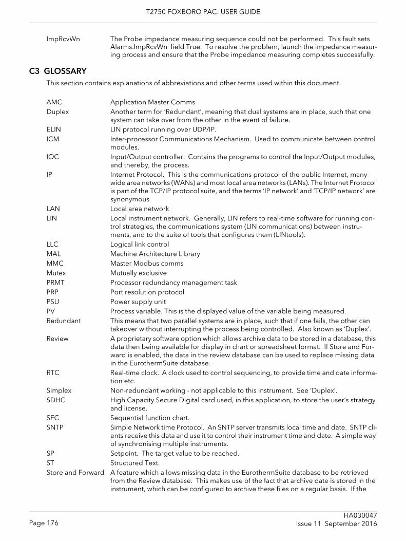
T2750 FOXBORO PAC: USER GUIDE
ImpRcvWn The Probe impedance measuring sequence could not be performed. This fault sets Alarms.ImpRcvWn field True. To resolve the problem, launch the impedance measur-ing process and ensure that the Probe impedance measuring completes successfully.
C3 GLOSSARYThis section contains explanations of abbreviations and other terms used within this document.
AMC Application Master Comms Duplex Another term for ‘Redundant’, meaning that dual systems are in place, such that one
system can take over from the other in the event of failure.ELIN LIN protocol running over UDP/IP.ICM Inter-processor Communications Mechanism. Used to communicate between control
modules.IOC Input/Output controller. Contains the programs to control the Input/Output modules,
and thereby, the process.IP Internet Protocol. This is the communications protocol of the public Internet, many
wide area networks (WANs) and most local area networks (LANs). The Internet Protocol is part of the TCP/IP protocol suite, and the terms ‘IP network’ and ‘TCP/IP network’ are synonymous
LAN Local area networkLIN Local instrument network. Generally, LIN refers to real-time software for running con-
trol strategies, the communications system (LIN communications) between instru-ments, and to the suite of tools that configures them (LINtools).
LLC Logical link controlMAL Machine Architecture LibraryMMC Master Modbus commsMutex Mutually exclusivePRMT Processor redundancy management taskPRP Port resolution protocolPSU Power supply unitPV Process variable. This is the displayed value of the variable being measured.Redundant This means that two parallel systems are in place, such that if one fails, the other can
takeover without interrupting the process being controlled. Also known as ‘Duplex’.Review A proprietary software option which allows archive data to be stored in a database, this
data then being available for display in chart or spreadsheet format. If Store and For-ward is enabled, the data in the review database can be used to replace missing data in the EurothermSuite database.
RTC Real-time clock. A clock used to control sequencing, to provide time and date informa-tion etc.
Simplex Non-redundant working - not applicable to this instrument. See ‘Duplex’.SDHC High Capacity Secure Digital card used, in this application, to store the user’s strategy
and license. SFC Sequential function chart.SNTP Simple Network time Protocol. An SNTP server transmits local time and date. SNTP cli-
ents receive this data and use it to control their instrument time and date. A simple way of synchronising multiple instruments.
SP Setpoint. The target value to be reached.ST Structured Text.Store and Forward A feature which allows missing data in the EurothermSuite database to be retrieved
from the Review database. This makes use of the fact that archive date is stored in the instrument, which can be configured to archive these files on a regular basis. If the
Page 176HA030047
Issue 11 September 2016
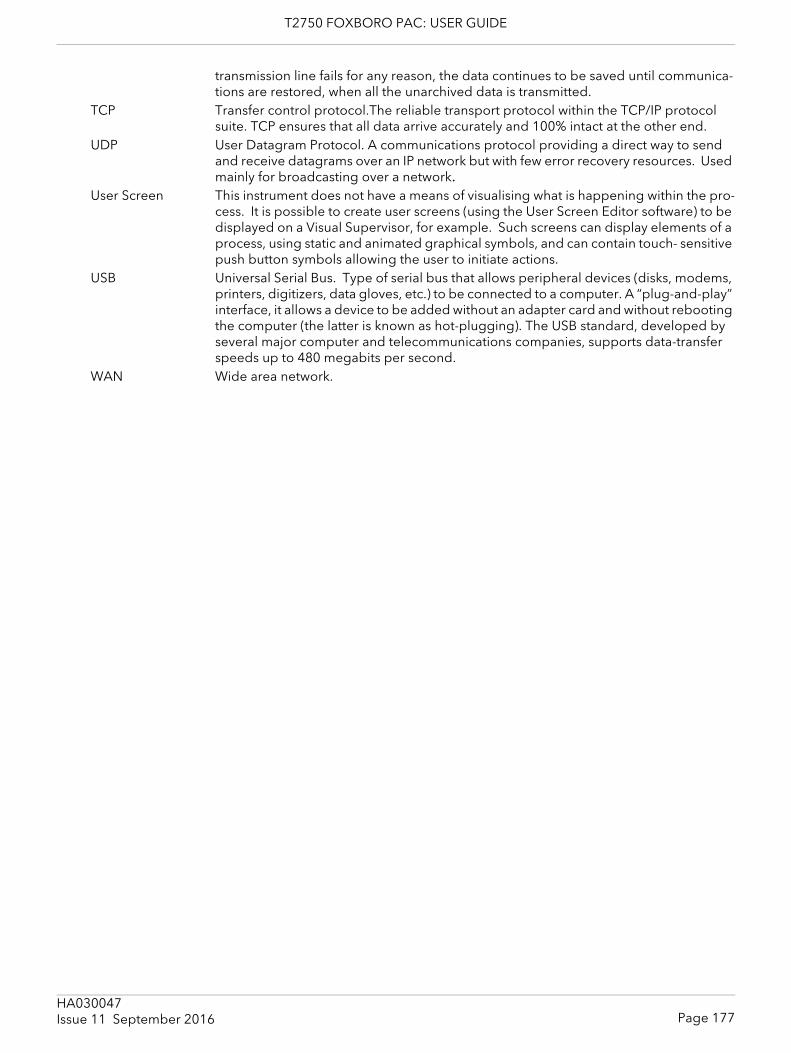
T2750 FOXBORO PAC: USER GUIDE
transmission line fails for any reason, the data continues to be saved until communica-tions are restored, when all the unarchived data is transmitted.
TCP Transfer control protocol.The reliable transport protocol within the TCP/IP protocol suite. TCP ensures that all data arrive accurately and 100% intact at the other end.
UDP User Datagram Protocol. A communications protocol providing a direct way to send and receive datagrams over an IP network but with few error recovery resources. Used mainly for broadcasting over a network.
User Screen This instrument does not have a means of visualising what is happening within the pro-cess. It is possible to create user screens (using the User Screen Editor software) to be displayed on a Visual Supervisor, for example. Such screens can display elements of a process, using static and animated graphical symbols, and can contain touch- sensitive push button symbols allowing the user to initiate actions.
USB Universal Serial Bus. Type of serial bus that allows peripheral devices (disks, modems, printers, digitizers, data gloves, etc.) to be connected to a computer. A “plug-and-play” interface, it allows a device to be added without an adapter card and without rebooting the computer (the latter is known as hot-plugging). The USB standard, developed by several major computer and telecommunications companies, supports data-transfer speeds up to 480 megabits per second.
WAN Wide area network.
Page 177HA030047Issue 11 September 2016
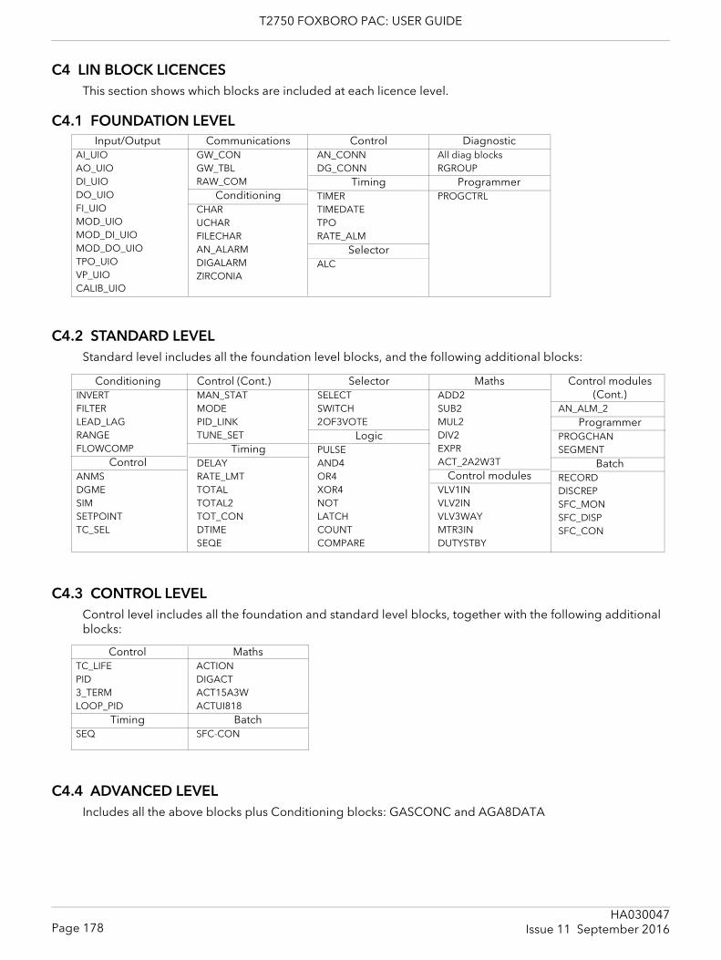
T2750 FOXBORO PAC: USER GUIDE
C4 LIN BLOCK LICENCESThis section shows which blocks are included at each licence level.
C4.1 FOUNDATION LEVEL
C4.2 STANDARD LEVELStandard level includes all the foundation level blocks, and the following additional blocks:
C4.3 CONTROL LEVELControl level includes all the foundation and standard level blocks, together with the following additional blocks:
C4.4 ADVANCED LEVELIncludes all the above blocks plus Conditioning blocks: GASCONC and AGA8DATA
Input/OutputAI_UIOAO_UIODI_UIODO_UIOFI_UIOMOD_UIOMOD_DI_UIOMOD_DO_UIOTPO_UIOVP_UIOCALIB_UIO
CommunicationsGW_CONGW_TBLRAW_COM
ConditioningCHARUCHARFILECHARAN_ALARMDIGALARMZIRCONIA
ControlAN_CONNDG_CONN
TimingTIMERTIMEDATETPORATE_ALM
SelectorALC
DiagnosticAll diag blocksRGROUP
ProgrammerPROGCTRL
ConditioningINVERTFILTERLEAD_LAGRANGEFLOWCOMP
ControlANMSDGMESIMSETPOINTTC_SEL
Control (Cont.)MAN_STATMODEPID_LINKTUNE_SET
TimingDELAYRATE_LMTTOTALTOTAL2TOT_CONDTIMESEQE
SelectorSELECTSWITCH2OF3VOTE
LogicPULSEAND4OR4XOR4NOTLATCHCOUNTCOMPARE
MathsADD2SUB2MUL2DIV2EXPRACT_2A2W3T
Control modulesVLV1INVLV2INVLV3WAYMTR3INDUTYSTBY
Control modules (Cont.)
AN_ALM_2Programmer
PROGCHANSEGMENT
BatchRECORDDISCREPSFC_MONSFC_DISPSFC_CON
ControlTC_LIFEPID3_TERMLOOP_PID
TimingSEQ
MathsACTIONDIGACTACT15A3WACTUI818
BatchSFC-CON
Page 178HA030047
Issue 11 September 2016
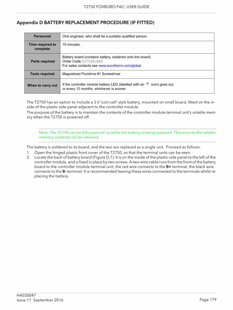
T2750 FOXBORO PAC: USER GUIDE
Appendix D BATTERY REPLACEMENT PROCEDURE (IF FITTED)
The T2750 has an option to include a 3 V ‘coin-cell’ style battery, mounted on small board, fitted on the in-side of the plastic side panel adjacent to the controller module.The purpose of the battery is to maintain the contents of the controller module terminal unit’s volatile mem-ory when the T2750 is powered off.
Note: The T2750 can be left powered up while the battery is being replaced. This ensures the volatile memory contents will be retained.
The battery is soldered to its board, and the two are replaced as a single unit. Proceed as follows:1. Open the hinged plastic front cover of the T2750, so that the terminal units can be seen.2. Locate the back of battery board (Figure D.1): It is on the inside of the plastic side panel to the left of the
controller module, and is fixed in place by two screws. A two-wire cable runs from the front of the battery board to the controller module terminal unit; the red wire connects to the B+ terminal, the black wire connects to the B- terminal. It is recommended leaving these wires connected to the terminals whilst re-placing the battery.
Personnel One engineer, who shall be a suitably qualified person.
Time required to complete
10 minutes.
Parts requiredBattery board (contains battery, soldered onto the board)Order Code T2750A/BAT For sales contacts see www.eurotherm.com/global
Tools required Magnetized Pozidrive #1 Screwdriver
When to carry out If the controller module battery LED (labelled with an icon) goes out, or every 12 months, whichever is sooner.
Page 179HA030047Issue 11 September 2016
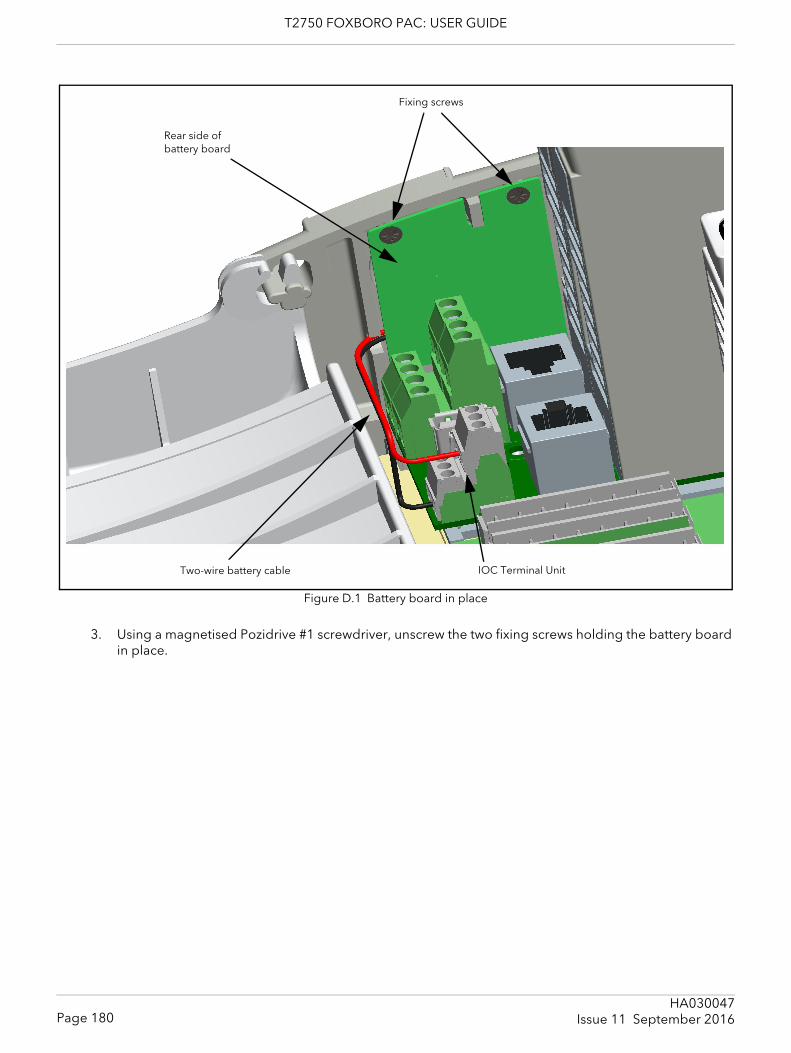
T2750 FOXBORO PAC: USER GUIDE
Figure D.1 Battery board in place
3. Using a magnetised Pozidrive #1 screwdriver, unscrew the two fixing screws holding the battery board in place.
Fixing screws
Rear side of battery board
Two-wire battery cable IOC Terminal Unit
Page 180HA030047
Issue 11 September 2016
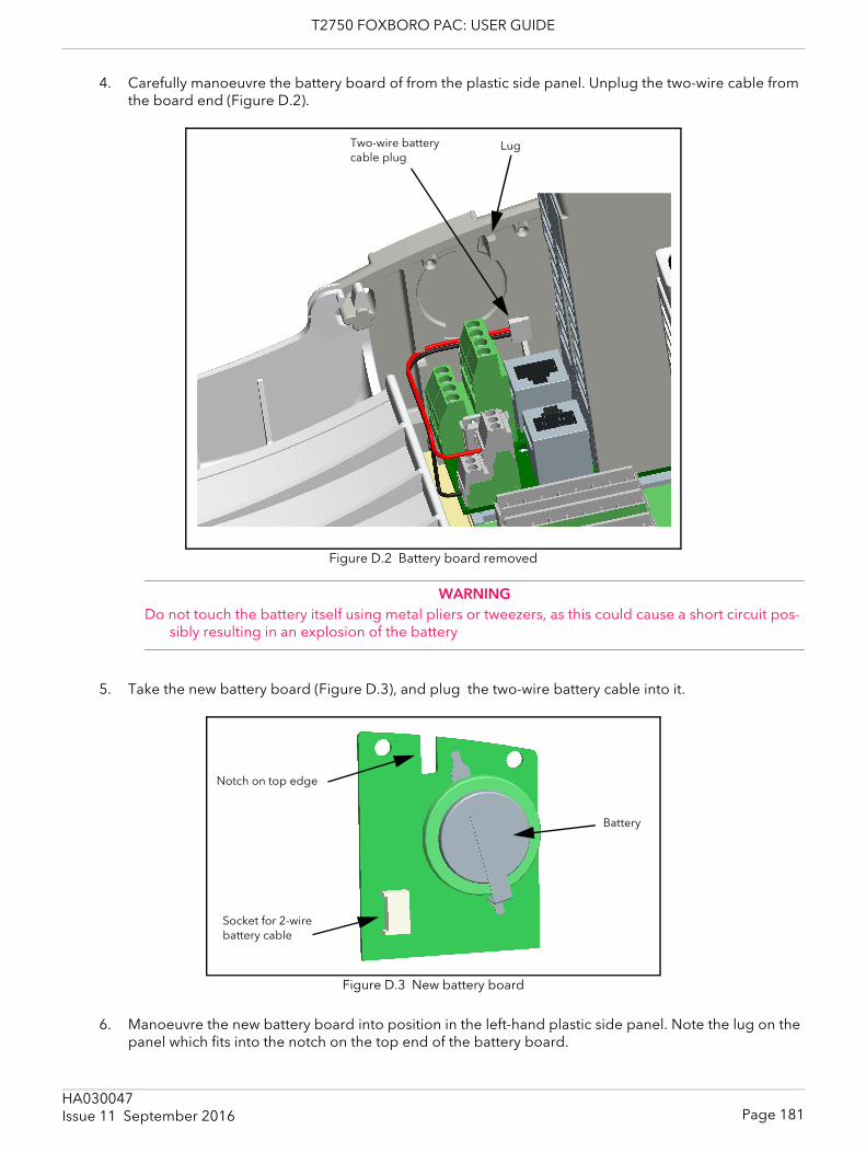
T2750 FOXBORO PAC: USER GUIDE
4. Carefully manoeuvre the battery board of from the plastic side panel. Unplug the two-wire cable from the board end (Figure D.2).
Figure D.2 Battery board removed
WARNING Do not touch the battery itself using metal pliers or tweezers, as this could cause a short circuit pos-
sibly resulting in an explosion of the battery
5. Take the new battery board (Figure D.3), and plug the two-wire battery cable into it.
Figure D.3 New battery board
6. Manoeuvre the new battery board into position in the left-hand plastic side panel. Note the lug on the panel which fits into the notch on the top end of the battery board.
Two-wire battery cable plug
Lug
Notch on top edge
Socket for 2-wire battery cable
Battery
Page 181HA030047Issue 11 September 2016

T2750 FOXBORO PAC: USER GUIDE
7. Using a magnetized Pozidrive #1 screwdriver, screw in the two fixing screws to hold the battery board in place.
8. Close the plastic top cover of the T2750. 9. Ensure the old battery board is disposed of appropriately.
Page 182HA030047
Issue 11 September 2016
T2750 FOXBORO PAC: USER GUIDE
Index
Symbols! characters . . . . . . . . . . . . . . . . . . . . . . . . . . . . . . . . . . . . . 114.cpf file . . . . . . . . . . . . . . . . . . . . . . . . . . . . . . . . . . . . . . . . . . 57.dbf file . . . . . . . . . . . . . . . . . . . . . . . . . . . . . . . . . . . . . . . . . . 67.gwf file . . . . . . . . . . . . . . . . . . . . . . . . . . . . . . . . . . . . . . 67, 71.sdb file . . . . . . . . . . . . . . . . . . . . . . . . . . . . . . . . . . . . . . . . . . 67.sfc file . . . . . . . . . . . . . . . . . . . . . . . . . . . . . . . . . . . . . . . . . . . . 5.sto file . . . . . . . . . . . . . . . . . . . . . . . . . . . . . . . . . . . . . . . . . . 67.stx file . . . . . . . . . . . . . . . . . . . . . . . . . . . . . . . . . . . . . . . . . . . 67.udz file . . . . . . . . . . . . . . . . . . . . . . . . . . . . . . . . . . . . . . . . . 113.uhh file . . . . . . . . . . . . . . . . . . . . . . . . . . . . . . . . . . . . . . . . . 115.ujg file . . . . . . . . . . . . . . . . . . . . . . . . . . . . . . . . . . . . . . . . . . 67.uys file . . . . . . . . . . . . . . . . . . . . . . . . . . . . . . . . . . . . . . . . . . 67Numerics16-channel digital i/p module
Pinout and status indicators . . . . . . . . . . . . . . . . . . . . 28Specification . . . . . . . . . . . . . . . . . . . . . . . . . . . . . . . . 147
16-channel digital o/p modulePinout and status indicators . . . . . . . . . . . . . . . . . . . . 32Specification . . . . . . . . . . . . . . . . . . . . . . . . . . . . . . . . 148
3_Term block . . . . . . . . . . . . . . . . . . . . . . . . . . . . . . . . . . . . . 733-wire/5-wire selection . . . . . . . . . . . . . . . . . . . . . . . . . . . . 14AACTION block . . . . . . . . . . . . . . . . . . . . . . . . . . . . . . . . . . . . . 6AI2 module
Pinout and status indicators . . . . . . . . . . . . . . . . . . . . 17Specification . . . . . . . . . . . . . . . . . . . . . . . . . . . . . . . . 141
AI3 modulePinout and status indicators . . . . . . . . . . . . . . . . . . . . 19Specification . . . . . . . . . . . . . . . . . . . . . . . . . . . . . . . . 142
AI4 modulePinout and status indicators . . . . . . . . . . . . . . . . . . . . 21Specification . . . . . . . . . . . . . . . . . . . . . . . . . . . . . . . . 143
AI8 modulePinout and status indicators . . . . . . . . . . . . . . . . . . . . 22Specification . . . . . . . . . . . . . . . . . . . . . . . . . . . . . . . . 144
Alarms.CctFault . . . . . . . . . . . . . . . . . . . . . . . . . . . . . . . . . . 140Alarms.OctDel . . . . . . . . . . . . . . . . . . . . . . . . . . . . . . . . . . . 140Alrms.OvrDrive . . . . . . . . . . . . . . . . . . . . . . . . . . . . . . . . . . 140AltSP . . . . . . . . . . . . . . . . . . . . . . . . . . . . . . . . . . . . . . . . . . . . 95AltSPEn . . . . . . . . . . . . . . . . . . . . . . . . . . . . . . . . . . . . . . . . . . 95AMC error codes . . . . . . . . . . . . . . . . . . . . . . . . . . . . . . . . 162AN_CONN block . . . . . . . . . . . . . . . . . . . . . . . . . . . . . . . . 112AO2 module
Pinout and status indicators . . . . . . . . . . . . . . . . . . . . 24Specification . . . . . . . . . . . . . . . . . . . . . . . . . . . . . . . . 145
ArchiveUSB stick, enable . . . . . . . . . . . . . . . . . . . . . . . . . . . . . 51
Archiving . . . . . . . . . . . . . . . . . . . . . . . . . . . . . . . . . . . . . . . 115Asynch I/O error codes . . . . . . . . . . . . . . . . . . . . . . . . . . . 162Auto mode . . . . . . . . . . . . . . . . . . . . . . . . . . . . . . . . . . . . . . . 75_auto.dbf file . . . . . . . . . . . . . . . . . . . . . . . . . . . . . . . . . . . . . . 5_auto.run file . . . . . . . . . . . . . . . . . . . . . . . . . . . . . . . . . . 5, 66AutoMan . . . . . . . . . . . . . . . . . . . . . . . . . . . . . . . . . . . . . . . . 76Automatic I/O Build . . . . . . . . . . . . . . . . . . . . . . . . . . . . . . . 65
_auto.run . . . . . . . . . . . . . . . . . . . . . . . . . . . . . . . . . . . . 66Preparing . . . . . . . . . . . . . . . . . . . . . . . . . . . . . . . . . . . . 66
Autosynchronisation . . . . . . . . . . . . . . . . . . . . . . . . . . . . . . 64Autotune . . . . . . . . . . . . . . . . . . . . . . . . . . . . . . . . . . . . . . . . 82
and gain scheduling . . . . . . . . . . . . . . . . . . . . . . . . . . . 83and inhibit . . . . . . . . . . . . . . . . . . . . . . . . . . . . . . . . . . . 83
and sensor break . . . . . . . . . . . . . . . . . . . . . . . . . . . . . 83Initiation . . . . . . . . . . . . . . . . . . . . . . . . . . . . . . . . . . . . . 83
BBase error codes . . . . . . . . . . . . . . . . . . . . . . . . . . . . . . . . 157Base Unit . . . . . . . . . . . . . . . . . . . . . . . . . . . . . . . . . . . . . . . . 10
Mounting . . . . . . . . . . . . . . . . . . . . . . . . . . . . . . . . . . . . 10Basic I/O System (BIOS) . . . . . . . . . . . . . . . . . . . . . . . . . . 124Batch blocks supported . . . . . . . . . . . . . . . . . . . . . . . . . . 153Battery . . . . . . . . . . . . . . . . . . . . . . . . . . . . . . . . . . . . . . . . . 133
LED . . . . . . . . . . . . . . . . . . . . . . . . . . . . . . . . . . . . . . . . . 54Wiring . . . . . . . . . . . . . . . . . . . . . . . . . . . . . . . . . . . . . . . 15
CC1 (C2) OnOfHs . . . . . . . . . . . . . . . . . . . . . . . . . . . . . . . . . . 99C1 (C2) PotBrk . . . . . . . . . . . . . . . . . . . . . . . . . . . . . . . . . . . 99C1 (C2) PotPos . . . . . . . . . . . . . . . . . . . . . . . . . . . . . . . . . . . 99C1 (C2) TravT . . . . . . . . . . . . . . . . . . . . . . . . . . . . . . . . . . . . 99Cached block . . . . . . . . . . . . . . . . . . . . . . . . . 106, 109, 112CBH, CBL . . . . . . . . . . . . . . . . . . . . . . . . . . . . . . . . . . . . 82, 90Central Processing Unit (CPU)
Time . . . . . . . . . . . . . . . . . . . . . . . . . . . . . . . . . . . . . . . 106Ch1 (Ch2)
TravelT . . . . . . . . . . . . . . . . . . . . . . . . . . . . . . . . . . . . . . 82Ch1 (Ch2) Outpt . . . . . . . . . . . . . . . . . . . . . . . . . . . . . . . . . . 99Ch1Ctrl, Ch2Ctrl . . . . . . . . . . . . . . . . . . . . . . . . . . . . . . . . . . 79Ch2 Deadband . . . . . . . . . . . . . . . . . . . . . . . . . . . . . . . . . . . 81Ch2DeadB . . . . . . . . . . . . . . . . . . . . . . . . . . . . . . . . . . . . . . . 99Changeover . . . . . . . . . . . . . . . . . . . . . . . . . . . . . . . . . . . . . 62Coherent Data . . . . . . . . . . . . . . . . . . . . . . . . . . . . . . . . . . 112Cold start . . . . . . . . . . . . . . . . . . . . . . . . . . . . . . . . . . . . 44, 57
Parameter file . . . . . . . . . . . . . . . . . . . . . . . . . . . . . . . . 57Switch . . . . . . . . . . . . . . . . . . . . . . . . . . . . . . . . . . . . . . . 43
Combined . . . . . . . . . . . . . . . . . . . . . . . . . . . . . . . . . . . . . . . 76Communications
Blocks . . . . . . . . . . . . . . . . . . . . . . . . . . . . . . . . . . . . . . 153LED . . . . . . . . . . . . . . . . . . . . . . . . . . . . . . . . . . . . . . . . . 54
Condition blocks . . . . . . . . . . . . . . . . . . . . . . . . . . . . . . . . 153Configuration files error codes . . . . . . . . . . . . . . . . . . . . 160Configuration Tools . . . . . . . . . . . . . . . . . . . . . . . . . . . . . . . 65
Automatic I/O Build . . . . . . . . . . . . . . . . . . . . . . . . . . . 65LINtools . . . . . . . . . . . . . . . . . . . . . . . . . . . . . . . . . . . . . 67
Configuration, automatic . . . . . . . . . . . . . . . . . . . . . . . . . . . 8Connections and Wiring
DC supply wiring . . . . . . . . . . . . . . . . . . . . . . . . . . . . . 15Safety earth . . . . . . . . . . . . . . . . . . . . . . . . . . . . . . . . . . 15
ControlBlocks . . . . . . . . . . . . . . . . . . . . . . . . . . . . . . . . . . . . . . 153Motorised Valve . . . . . . . . . . . . . . . . . . . . . . . . . . . . . . 79
Control configuration error codes . . . . . . . . . . . . . . . . . 159Convert blocks . . . . . . . . . . . . . . . . . . . . . . . . . . . . . . . . . . 154CoolType . . . . . . . . . . . . . . . . . . . . . . . . . . . . . . . . . . . . . . . . 99Create a new Project . . . . . . . . . . . . . . . . . . . . . . . . . . . . . . 68Critically damped . . . . . . . . . . . . . . . . . . . . . . . . . . . . . . . . . 81CtrlAct . . . . . . . . . . . . . . . . . . . . . . . . . . . . . . . . . . . . . . . . . . 79Cutback High and Low . . . . . . . . . . . . . . . . . . . . . . . . . . . . 90DData . . . . . . . . . . . . . . . . . . . . . . . . . . . . . . . . . . . . . . . . . . . 112
Archiving . . . . . . . . . . . . . . . . . . . . . . . . . . . . . . . . . . . 115Coherent . . . . . . . . . . . . . . . . . . . . . . . . . . . . . . . . . . . 112Management . . . . . . . . . . . . . . . . . . . . . . . . . . . . . . . . 115Non-coherent . . . . . . . . . . . . . . . . . . . . . . . . . . . . . . . 112Recording . . . . . . . . . . . . . . . . . . . . . . . . . . . . . . . . . . . . 6
Page 183HA030047Issue 11 September 2016
T2750 FOXBORO PAC: USER GUIDE
DatabaseAutomatic creation . . . . . . . . . . . . . . . . . . . . . . . . . . . . 65Diagnostic blocks . . . . . . . . . . . . . . . . . . . . . . . . . . . . 128Stop . . . . . . . . . . . . . . . . . . . . . . . . . . . . . . . . . . . . . . . . 126
Database error codes . . . . . . . . . . . . . . . . . . . . . . . . . . . . 158Decoupled Instruments . . . . . . . . . . . . . . . . . . . . . . . . . . . 126Derivative term . . . . . . . . . . . . . . . . . . . . . . . . . . . . . . . . . . . 78DerivOP . . . . . . . . . . . . . . . . . . . . . . . . . . . . . . . . . . . . . . . . 102DerivTyp . . . . . . . . . . . . . . . . . . . . . . . . . . . . . . . . . . . . . . . . . 79Desync switch . . . . . . . . . . . . . . . . . . . . . . . . . . . . . . . . . . . . 55DevHi, DevLo . . . . . . . . . . . . . . . . . . . . . . . . . . . . . . . . . . . . 76DI16 module
Pinout and status indicators . . . . . . . . . . . . . . . . . . . . 28Specification . . . . . . . . . . . . . . . . . . . . . . . . . . . . . . . . 147
DI4 modulePinout and status indicators . . . . . . . . . . . . . . . . . . . . 25Specification . . . . . . . . . . . . . . . . . . . . . . . . . . . . . . . . 145
DI6 modulePinout and status indicators . . . . . . . . . . . . . . . . . . . . 26Specification . . . . . . . . . . . . . . . . . . . . . . . . . . . . . . . . 146
DI8 modulePinout and status indicators . . . . . . . . . . . . . . . . . . . . 27Specification . . . . . . . . . . . . . . . . . . . . . . . . . . . . . . . . 147
Diagnostic function blocks . . . . . . . . . . . . . . . . . . . . . . . . 154Diagnostics . . . . . . . . . . . . . . . . . . . . . . . . . . . . . . . . . . . . . 124
Function blocks . . . . . . . . . . . . . . . . . . . . . . . . . . . . . . 128Dir . . . . . . . . . . . . . . . . . . . . . . . . . . . . . . . . . . . . . . . . . . . . . . 79DO16 module
Pinout and status indicators . . . . . . . . . . . . . . . . . . . . 32Specification . . . . . . . . . . . . . . . . . . . . . . . . . . . . . . . . 148
DO4 modulePinout and status indicators . . . . . . . . . . . . . . . . . . . . 29
DO8 modulePinout . . . . . . . . . . . . . . . . . . . . . . . . . . . . . . . . . . . . . . . 30Specification . . . . . . . . . . . . . . . . . . . . . . . . . . . . . . . . 148Status indicators . . . . . . . . . . . . . . . . . . . . . . . . . . . . . . 31
DuplexLED . . . . . . . . . . . . . . . . . . . . . . . . . . . . . . . . . . . . . 54, 64Start-up sequence
Decisions . . . . . . . . . . . . . . . . . . . . . . . . . . . . . . . . . 62EEight o/p relay module pinout . . . . . . . . . . . . . . . . . . . . . . 38Eight-channel analogue i/p module
Pinout and status indicators . . . . . . . . . . . . . . . . . . . . 22Specification . . . . . . . . . . . . . . . . . . . . . . . . . . . . . . . . 144
Eight-channel digital i/p modulePinout and status indicators . . . . . . . . . . . . . . . . . . . . 27Specification . . . . . . . . . . . . . . . . . . . . . . . . . . . . . . . . 147
Eight-channel digital o/p modulePinout . . . . . . . . . . . . . . . . . . . . . . . . . . . . . . . . . . . . . . . 30Specification . . . . . . . . . . . . . . . . . . . . . . . . . . . . . . . . 148Status indicators . . . . . . . . . . . . . . . . . . . . . . . . . . . . . . 31
Eight-channel relay o/p moduleSpecification . . . . . . . . . . . . . . . . . . . . . . . . . . . . . . . . 150
Eng . . . . . . . . . . . . . . . . . . . . . . . . . . . . . . . . . . . . . . . . . . . . . 79Error . . . . . . . . . . . . . . . . . . . . . . . . . . . . . . . . . . . 79, 90, 102
Conditions . . . . . . . . . . . . . . . . . . . . . . . . . . . . . . . . . . 126Diagnostic blocks . . . . . . . . . . . . . . . . . . . . . . . . . . 124LEDs . . . . . . . . . . . . . . . . . . . . . . . . . . . . . . . . . . . . 124POSTs . . . . . . . . . . . . . . . . . . . . . . . . . . . . . . . . . . . 124
Event log . . . . . . . . . . . . . . . . . . . . . . . . . . . . . . . . . . . 114Number . . . . . . . . . . . . . . . . . . . . . . . . . . . . . . . . . . . . 124Sched type . . . . . . . . . . . . . . . . . . . . . . . . . . . . . . . . . . . 92
Error codes81xx (Base) . . . . . . . . . . . . . . . . . . . . . . . . . . . . . . . . . 15782xx (File system) . . . . . . . . . . . . . . . . . . . . . . . . . . . . 15783xx (Database) . . . . . . . . . . . . . . . . . . . . . . . . . . . . . 15885xx (Object) . . . . . . . . . . . . . . . . . . . . . . . . . . . . . . . . 15886xx (Trend) . . . . . . . . . . . . . . . . . . . . . . . . . . . . . . . . 15887xx (Control config.) . . . . . . . . . . . . . . . . . . . . . . . . 15989xx (Network) . . . . . . . . . . . . . . . . . . . . . . . . . . . . . . 1598Bxx (Sequence system) . . . . . . . . . . . . . . . . . . . . . . 1598Cxx (Sequence runtime) . . . . . . . . . . . . . . . . . . . . . 1598Dxx (Structured text) . . . . . . . . . . . . . . . . . . . . . . . . 1608Fxx (PCLIN) . . . . . . . . . . . . . . . . . . . . . . . . . . . . . . . . 16091xx (Config files) . . . . . . . . . . . . . . . . . . . . . . . . . . . . 16092xx (PRMT) . . . . . . . . . . . . . . . . . . . . . . . . . . . . . . . . . 16099xx (External database) . . . . . . . . . . . . . . . . . . . . . . 1619Axx (Modbus) . . . . . . . . . . . . . . . . . . . . . . . . . . . . . . 1619Bxx (Xec) . . . . . . . . . . . . . . . . . . . . . . . . . . . . . . . . . . 1619Cxx (Kernel) . . . . . . . . . . . . . . . . . . . . . . . . . . . . . . . . 1619Dxx (Objects) . . . . . . . . . . . . . . . . . . . . . . . . . . . . . . 1619Exx (Locks) . . . . . . . . . . . . . . . . . . . . . . . . . . . . . . . . . 161A0xx (MAL) . . . . . . . . . . . . . . . . . . . . . . . . . . . . . . . . . 162A4xx (MMC) . . . . . . . . . . . . . . . . . . . . . . . . . . . . . . . . . 162A6xx (Asynch I/O) . . . . . . . . . . . . . . . . . . . . . . . . . . . . 162ADxx (profibus) . . . . . . . . . . . . . . . . . . . . . . . . . . . . . . 163B2xx (Socket) . . . . . . . . . . . . . . . . . . . . . . . . . . . . . . . . 163
EthernetActivity/Speed LEDs . . . . . . . . . . . . . . . . . . . . . . . . . . . 55Communications . . . . . . . . . . . . . . . . . . . . . . . . . . . . . . 5
Event Log . . . . . . . . . . . . . . . . . . . . . . . . . . . . . . . . . . . . . . . 113Execution times . . . . . . . . . . . . . . . . . . . . . . . . . . . . . . . . . 108External battery . . . . . . . . . . . . . . . . . . . . . . . . . . . . . . . . . . 15External database error codes . . . . . . . . . . . . . . . . . . . . . 161FFailure modes . . . . . . . . . . . . . . . . . . . . . . . . . . . . . . . . . . . 124
Inter-processor Communications Mechanism . . . . 125Local Instrument Network . . . . . . . . . . . . . . . . . . . . . 125Power . . . . . . . . . . . . . . . . . . . . . . . . . . . . . . . . . . . . . . 124Watchdog . . . . . . . . . . . . . . . . . . . . . . . . . . . . . . . . . . 125
Fan . . . . . . . . . . . . . . . . . . . . . . . . . . . . . . . . . . . . . . . . . . . . . 98Fault LED . . . . . . . . . . . . . . . . . . . . . . . . . . . . . . . . . . . . . . . . 54FF parameters . . . . . . . . . . . . . . . . . . . . . . . . . . . . . . . . . . . 100FI2 module
Pinout . . . . . . . . . . . . . . . . . . . . . . . . . . . . . . . . . . . . . . . 33Specification . . . . . . . . . . . . . . . . . . . . . . . . . . . . . . . . 149Status indicators . . . . . . . . . . . . . . . . . . . . . . . . . . . . . . 34
Field writes . . . . . . . . . . . . . . . . . . . . . . . . . . . . . . . . . . . . . 112File system error codes . . . . . . . . . . . . . . . . . . . . . . . . . . . 157Firmware upgrade . . . . . . . . . . . . . . . . . . . . . . . . . . . . . . . 133
FTPing an upgrade . . . . . . . . . . . . . . . . . . . . . . . . . . 133manually copying files to SD card . . . . . . . . . . . . . . 133using a USB memory stick . . . . . . . . . . . . . . . . . . . . . 134
ForcedOP . . . . . . . . . . . . . . . . . . . . . . . . . . . . . . . . . . . . . . 100Four output relay module
Pinout and status indicators . . . . . . . . . . . . . . . . . . . . 35Four-channel analogue i/p module
Pinout and status indicators . . . . . . . . . . . . . . . . . . . . 21Specification . . . . . . . . . . . . . . . . . . . . . . . . . . . . . . . . 143
Four-channel digital i/p modulePinout and status indicators . . . . . . . . . . . . . . . . . . . . 25Specification . . . . . . . . . . . . . . . . . . . . . . . . . . . . . . . . 145
Four-channel digital o/p modulePinout and status indicators . . . . . . . . . . . . . . . . . . . . 29
Page 184HA030047Issue 11 September 2016
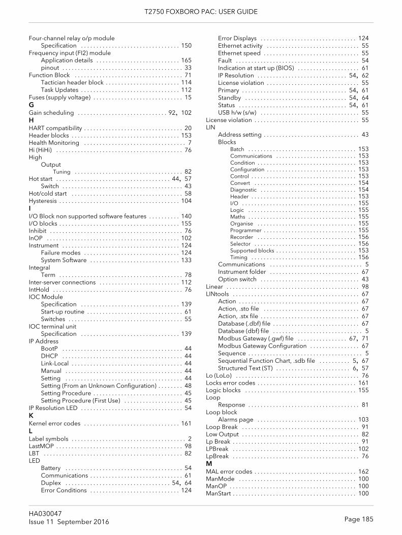
T2750 FOXBORO PAC: USER GUIDE
Four-channel relay o/p moduleSpecification . . . . . . . . . . . . . . . . . . . . . . . . . . . . . . . . 150
Frequency input (FI2) moduleApplication details . . . . . . . . . . . . . . . . . . . . . . . . . . . 165pinout . . . . . . . . . . . . . . . . . . . . . . . . . . . . . . . . . . . . . . . 33
Function Block . . . . . . . . . . . . . . . . . . . . . . . . . . . . . . . . . . . 71Tactician header block . . . . . . . . . . . . . . . . . . . . . . . . 114Task Updates . . . . . . . . . . . . . . . . . . . . . . . . . . . . . . . . 112
Fuses (supply voltage) . . . . . . . . . . . . . . . . . . . . . . . . . . . . . 15GGain scheduling . . . . . . . . . . . . . . . . . . . . . . . . . . . . . 92, 102HHART compatibility . . . . . . . . . . . . . . . . . . . . . . . . . . . . . . . . 20Header blocks . . . . . . . . . . . . . . . . . . . . . . . . . . . . . . . . . . . 153Health Monitoring . . . . . . . . . . . . . . . . . . . . . . . . . . . . . . . . . 7Hi (HiHi) . . . . . . . . . . . . . . . . . . . . . . . . . . . . . . . . . . . . . . . . . 76High
OutputTuning . . . . . . . . . . . . . . . . . . . . . . . . . . . . . . . . . . . 82
Hot start . . . . . . . . . . . . . . . . . . . . . . . . . . . . . . . . . . . . . 44, 57Switch . . . . . . . . . . . . . . . . . . . . . . . . . . . . . . . . . . . . . . . 43
Hot/cold start . . . . . . . . . . . . . . . . . . . . . . . . . . . . . . . . . . . . 58Hysteresis . . . . . . . . . . . . . . . . . . . . . . . . . . . . . . . . . . . . . . . 104II/O Block non supported software features . . . . . . . . . . 140I/O blocks . . . . . . . . . . . . . . . . . . . . . . . . . . . . . . . . . . . . . . . 155Inhibit . . . . . . . . . . . . . . . . . . . . . . . . . . . . . . . . . . . . . . . . . . . 76InOP . . . . . . . . . . . . . . . . . . . . . . . . . . . . . . . . . . . . . . . . . . . 102Instrument . . . . . . . . . . . . . . . . . . . . . . . . . . . . . . . . . . . . . . 124
Failure modes . . . . . . . . . . . . . . . . . . . . . . . . . . . . . . . 124System Software . . . . . . . . . . . . . . . . . . . . . . . . . . . . . 133
IntegralTerm . . . . . . . . . . . . . . . . . . . . . . . . . . . . . . . . . . . . . . . . 78
Inter-server connections . . . . . . . . . . . . . . . . . . . . . . . . . . 112IntHold . . . . . . . . . . . . . . . . . . . . . . . . . . . . . . . . . . . . . . . . . . 76IOC Module
Specification . . . . . . . . . . . . . . . . . . . . . . . . . . . . . . . . 139Start-up routine . . . . . . . . . . . . . . . . . . . . . . . . . . . . . . . 61Switches . . . . . . . . . . . . . . . . . . . . . . . . . . . . . . . . . . . . . 55
IOC terminal unitSpecification . . . . . . . . . . . . . . . . . . . . . . . . . . . . . . . . 139
IP AddressBootP . . . . . . . . . . . . . . . . . . . . . . . . . . . . . . . . . . . . . . . 44DHCP . . . . . . . . . . . . . . . . . . . . . . . . . . . . . . . . . . . . . . . 44Link-Local . . . . . . . . . . . . . . . . . . . . . . . . . . . . . . . . . . . . 44Manual . . . . . . . . . . . . . . . . . . . . . . . . . . . . . . . . . . . . . . 44Setting . . . . . . . . . . . . . . . . . . . . . . . . . . . . . . . . . . . . . . 44Setting (From an Unknown Configuration) . . . . . . . . 48Setting Procedure . . . . . . . . . . . . . . . . . . . . . . . . . . . . . 45Setting Procedure (First Use) . . . . . . . . . . . . . . . . . . . 45
IP Resolution LED . . . . . . . . . . . . . . . . . . . . . . . . . . . . . . . . . 54KKernel error codes . . . . . . . . . . . . . . . . . . . . . . . . . . . . . . . 161LLabel symbols . . . . . . . . . . . . . . . . . . . . . . . . . . . . . . . . . . . . . 2LastMOP . . . . . . . . . . . . . . . . . . . . . . . . . . . . . . . . . . . . . . . . . 98LBT . . . . . . . . . . . . . . . . . . . . . . . . . . . . . . . . . . . . . . . . . . . . . 82LED
Battery . . . . . . . . . . . . . . . . . . . . . . . . . . . . . . . . . . . . . . 54Communications . . . . . . . . . . . . . . . . . . . . . . . . . . . . . . 61Duplex . . . . . . . . . . . . . . . . . . . . . . . . . . . . . . . . . . 54, 64Error Conditions . . . . . . . . . . . . . . . . . . . . . . . . . . . . . 124
Error Displays . . . . . . . . . . . . . . . . . . . . . . . . . . . . . . . 124Ethernet activity . . . . . . . . . . . . . . . . . . . . . . . . . . . . . . 55Ethernet speed . . . . . . . . . . . . . . . . . . . . . . . . . . . . . . . 55Fault . . . . . . . . . . . . . . . . . . . . . . . . . . . . . . . . . . . . . . . . 54Indication at start up (BIOS) . . . . . . . . . . . . . . . . . . . . 61IP Resolution . . . . . . . . . . . . . . . . . . . . . . . . . . . . . 54, 62License violation . . . . . . . . . . . . . . . . . . . . . . . . . . . . . . 55Primary . . . . . . . . . . . . . . . . . . . . . . . . . . . . . . . . . . 54, 61Standby . . . . . . . . . . . . . . . . . . . . . . . . . . . . . . . . . 54, 64Status . . . . . . . . . . . . . . . . . . . . . . . . . . . . . . . . . . . 54, 61USB h/w (s/w) . . . . . . . . . . . . . . . . . . . . . . . . . . . . . . . . 55
License violation . . . . . . . . . . . . . . . . . . . . . . . . . . . . . . . . . . 55LIN
Address setting . . . . . . . . . . . . . . . . . . . . . . . . . . . . . . . 43Blocks
Batch . . . . . . . . . . . . . . . . . . . . . . . . . . . . . . . . . . . 153Communications . . . . . . . . . . . . . . . . . . . . . . . . . . 153Condition . . . . . . . . . . . . . . . . . . . . . . . . . . . . . . . . 153Configuration . . . . . . . . . . . . . . . . . . . . . . . . . . . . . 153Control . . . . . . . . . . . . . . . . . . . . . . . . . . . . . . . . . . 153Convert . . . . . . . . . . . . . . . . . . . . . . . . . . . . . . . . . 154Diagnostic . . . . . . . . . . . . . . . . . . . . . . . . . . . . . . . 154Header . . . . . . . . . . . . . . . . . . . . . . . . . . . . . . . . . . 153I/O . . . . . . . . . . . . . . . . . . . . . . . . . . . . . . . . . . . . . 155Logic . . . . . . . . . . . . . . . . . . . . . . . . . . . . . . . . . . . 155Maths . . . . . . . . . . . . . . . . . . . . . . . . . . . . . . . . . . . 155Organise . . . . . . . . . . . . . . . . . . . . . . . . . . . . . . . . 155Programmer . . . . . . . . . . . . . . . . . . . . . . . . . . . . . . 155Recorder . . . . . . . . . . . . . . . . . . . . . . . . . . . . . . . . 156Selector . . . . . . . . . . . . . . . . . . . . . . . . . . . . . . . . . 156Supported blocks . . . . . . . . . . . . . . . . . . . . . . . . . . 153Timing . . . . . . . . . . . . . . . . . . . . . . . . . . . . . . . . . . 156
Communications . . . . . . . . . . . . . . . . . . . . . . . . . . . . . . 5Instrument folder . . . . . . . . . . . . . . . . . . . . . . . . . . . . . 67Option switch . . . . . . . . . . . . . . . . . . . . . . . . . . . . . . . . 43
Linear . . . . . . . . . . . . . . . . . . . . . . . . . . . . . . . . . . . . . . . . . . . 98LINtools . . . . . . . . . . . . . . . . . . . . . . . . . . . . . . . . . . . . . . . . . 67
Action . . . . . . . . . . . . . . . . . . . . . . . . . . . . . . . . . . . . . . . 67Action, .sto file . . . . . . . . . . . . . . . . . . . . . . . . . . . . . . . 67Action, .stx file . . . . . . . . . . . . . . . . . . . . . . . . . . . . . . . . 67Database (.dbf) file . . . . . . . . . . . . . . . . . . . . . . . . . . . . 67Database (dbf) file . . . . . . . . . . . . . . . . . . . . . . . . . . . . . 5Modbus Gateway (.gwf) file . . . . . . . . . . . . . . . . 67, 71Modbus Gateway Configuration . . . . . . . . . . . . . . . . 67Sequence . . . . . . . . . . . . . . . . . . . . . . . . . . . . . . . . . . . . . 5Sequential Function Chart, .sdb file . . . . . . . . . . 5, 67Structured Text (ST) . . . . . . . . . . . . . . . . . . . . . . . . 6, 57
Lo (LoLo) . . . . . . . . . . . . . . . . . . . . . . . . . . . . . . . . . . . . . . . . 76Locks error codes . . . . . . . . . . . . . . . . . . . . . . . . . . . . . . . . 161Logic blocks . . . . . . . . . . . . . . . . . . . . . . . . . . . . . . . . . . . . 155Loop
Response . . . . . . . . . . . . . . . . . . . . . . . . . . . . . . . . . . . . 81Loop block
Alarms page . . . . . . . . . . . . . . . . . . . . . . . . . . . . . . . . 103Loop Break . . . . . . . . . . . . . . . . . . . . . . . . . . . . . . . . . . . . . . 91Low Output . . . . . . . . . . . . . . . . . . . . . . . . . . . . . . . . . . . . . . 82Lp Break . . . . . . . . . . . . . . . . . . . . . . . . . . . . . . . . . . . . . . . . . 91LPBreak . . . . . . . . . . . . . . . . . . . . . . . . . . . . . . . . . . . . . . . . 102LpBreak . . . . . . . . . . . . . . . . . . . . . . . . . . . . . . . . . . . . . . . . . 76MMAL error codes . . . . . . . . . . . . . . . . . . . . . . . . . . . . . . . . . 162ManMode . . . . . . . . . . . . . . . . . . . . . . . . . . . . . . . . . . . . . . 100ManOP . . . . . . . . . . . . . . . . . . . . . . . . . . . . . . . . . . . . . . . . . 100ManStart . . . . . . . . . . . . . . . . . . . . . . . . . . . . . . . . . . . . . . . . 100
Page 185HA030047Issue 11 September 2016
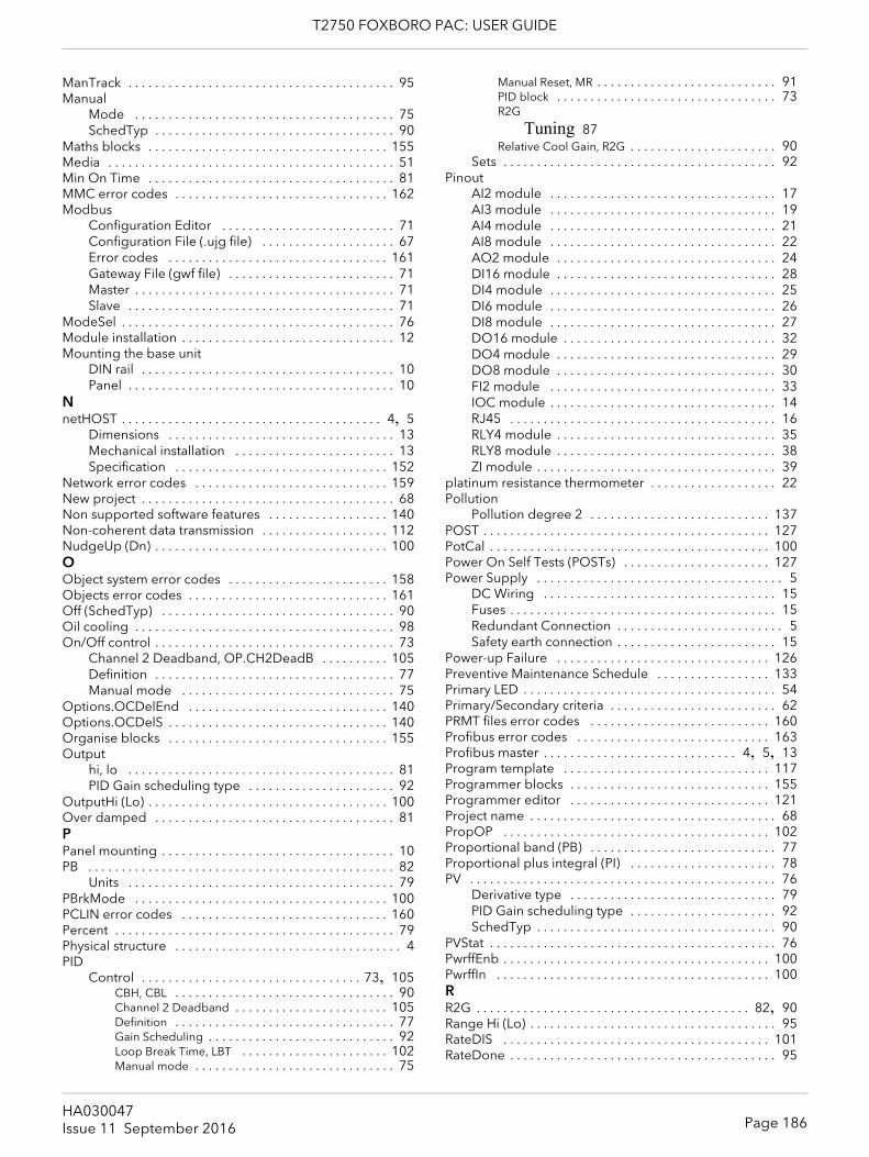
T2750 FOXBORO PAC: USER GUIDE
ManTrack . . . . . . . . . . . . . . . . . . . . . . . . . . . . . . . . . . . . . . . . 95Manual
Mode . . . . . . . . . . . . . . . . . . . . . . . . . . . . . . . . . . . . . . . 75SchedTyp . . . . . . . . . . . . . . . . . . . . . . . . . . . . . . . . . . . . 90
Maths blocks . . . . . . . . . . . . . . . . . . . . . . . . . . . . . . . . . . . . 155Media . . . . . . . . . . . . . . . . . . . . . . . . . . . . . . . . . . . . . . . . . . . 51Min On Time . . . . . . . . . . . . . . . . . . . . . . . . . . . . . . . . . . . . . 81MMC error codes . . . . . . . . . . . . . . . . . . . . . . . . . . . . . . . . 162Modbus
Configuration Editor . . . . . . . . . . . . . . . . . . . . . . . . . . 71Configuration File (.ujg file) . . . . . . . . . . . . . . . . . . . . 67Error codes . . . . . . . . . . . . . . . . . . . . . . . . . . . . . . . . . 161Gateway File (gwf file) . . . . . . . . . . . . . . . . . . . . . . . . . 71Master . . . . . . . . . . . . . . . . . . . . . . . . . . . . . . . . . . . . . . . 71Slave . . . . . . . . . . . . . . . . . . . . . . . . . . . . . . . . . . . . . . . . 71
ModeSel . . . . . . . . . . . . . . . . . . . . . . . . . . . . . . . . . . . . . . . . . 76Module installation . . . . . . . . . . . . . . . . . . . . . . . . . . . . . . . . 12Mounting the base unit
DIN rail . . . . . . . . . . . . . . . . . . . . . . . . . . . . . . . . . . . . . . 10Panel . . . . . . . . . . . . . . . . . . . . . . . . . . . . . . . . . . . . . . . . 10
NnetHOST . . . . . . . . . . . . . . . . . . . . . . . . . . . . . . . . . . . . . . . 4, 5
Dimensions . . . . . . . . . . . . . . . . . . . . . . . . . . . . . . . . . . 13Mechanical installation . . . . . . . . . . . . . . . . . . . . . . . . 13Specification . . . . . . . . . . . . . . . . . . . . . . . . . . . . . . . . 152
Network error codes . . . . . . . . . . . . . . . . . . . . . . . . . . . . . 159New project . . . . . . . . . . . . . . . . . . . . . . . . . . . . . . . . . . . . . . 68Non supported software features . . . . . . . . . . . . . . . . . . 140Non-coherent data transmission . . . . . . . . . . . . . . . . . . . 112NudgeUp (Dn) . . . . . . . . . . . . . . . . . . . . . . . . . . . . . . . . . . . 100OObject system error codes . . . . . . . . . . . . . . . . . . . . . . . . 158Objects error codes . . . . . . . . . . . . . . . . . . . . . . . . . . . . . . 161Off (SchedTyp) . . . . . . . . . . . . . . . . . . . . . . . . . . . . . . . . . . . 90Oil cooling . . . . . . . . . . . . . . . . . . . . . . . . . . . . . . . . . . . . . . . 98On/Off control . . . . . . . . . . . . . . . . . . . . . . . . . . . . . . . . . . . . 73
Channel 2 Deadband, OP.CH2DeadB . . . . . . . . . . 105Definition . . . . . . . . . . . . . . . . . . . . . . . . . . . . . . . . . . . . 77Manual mode . . . . . . . . . . . . . . . . . . . . . . . . . . . . . . . . 75
Options.OCDelEnd . . . . . . . . . . . . . . . . . . . . . . . . . . . . . . 140Options.OCDelS . . . . . . . . . . . . . . . . . . . . . . . . . . . . . . . . . 140Organise blocks . . . . . . . . . . . . . . . . . . . . . . . . . . . . . . . . . 155Output
hi, lo . . . . . . . . . . . . . . . . . . . . . . . . . . . . . . . . . . . . . . . . 81PID Gain scheduling type . . . . . . . . . . . . . . . . . . . . . . 92
OutputHi (Lo) . . . . . . . . . . . . . . . . . . . . . . . . . . . . . . . . . . . . 100Over damped . . . . . . . . . . . . . . . . . . . . . . . . . . . . . . . . . . . . 81PPanel mounting . . . . . . . . . . . . . . . . . . . . . . . . . . . . . . . . . . . 10PB . . . . . . . . . . . . . . . . . . . . . . . . . . . . . . . . . . . . . . . . . . . . . . 82
Units . . . . . . . . . . . . . . . . . . . . . . . . . . . . . . . . . . . . . . . . 79PBrkMode . . . . . . . . . . . . . . . . . . . . . . . . . . . . . . . . . . . . . . 100PCLIN error codes . . . . . . . . . . . . . . . . . . . . . . . . . . . . . . . 160Percent . . . . . . . . . . . . . . . . . . . . . . . . . . . . . . . . . . . . . . . . . . 79Physical structure . . . . . . . . . . . . . . . . . . . . . . . . . . . . . . . . . . 4PID
Control . . . . . . . . . . . . . . . . . . . . . . . . . . . . . . . . . 73, 105CBH, CBL . . . . . . . . . . . . . . . . . . . . . . . . . . . . . . . . . 90Channel 2 Deadband . . . . . . . . . . . . . . . . . . . . . . . 105Definition . . . . . . . . . . . . . . . . . . . . . . . . . . . . . . . . . 77Gain Scheduling . . . . . . . . . . . . . . . . . . . . . . . . . . . . 92Loop Break Time, LBT . . . . . . . . . . . . . . . . . . . . . . 102Manual mode . . . . . . . . . . . . . . . . . . . . . . . . . . . . . . 75
Manual Reset, MR . . . . . . . . . . . . . . . . . . . . . . . . . . . 91PID block . . . . . . . . . . . . . . . . . . . . . . . . . . . . . . . . . 73R2G
Tuning 87Relative Cool Gain, R2G . . . . . . . . . . . . . . . . . . . . . . 90
Sets . . . . . . . . . . . . . . . . . . . . . . . . . . . . . . . . . . . . . . . . . 92Pinout
AI2 module . . . . . . . . . . . . . . . . . . . . . . . . . . . . . . . . . . 17AI3 module . . . . . . . . . . . . . . . . . . . . . . . . . . . . . . . . . . 19AI4 module . . . . . . . . . . . . . . . . . . . . . . . . . . . . . . . . . . 21AI8 module . . . . . . . . . . . . . . . . . . . . . . . . . . . . . . . . . . 22AO2 module . . . . . . . . . . . . . . . . . . . . . . . . . . . . . . . . . 24DI16 module . . . . . . . . . . . . . . . . . . . . . . . . . . . . . . . . . 28DI4 module . . . . . . . . . . . . . . . . . . . . . . . . . . . . . . . . . . 25DI6 module . . . . . . . . . . . . . . . . . . . . . . . . . . . . . . . . . . 26DI8 module . . . . . . . . . . . . . . . . . . . . . . . . . . . . . . . . . . 27DO16 module . . . . . . . . . . . . . . . . . . . . . . . . . . . . . . . . 32DO4 module . . . . . . . . . . . . . . . . . . . . . . . . . . . . . . . . . 29DO8 module . . . . . . . . . . . . . . . . . . . . . . . . . . . . . . . . . 30FI2 module . . . . . . . . . . . . . . . . . . . . . . . . . . . . . . . . . . 33IOC module . . . . . . . . . . . . . . . . . . . . . . . . . . . . . . . . . . 14RJ45 . . . . . . . . . . . . . . . . . . . . . . . . . . . . . . . . . . . . . . . . 16RLY4 module . . . . . . . . . . . . . . . . . . . . . . . . . . . . . . . . . 35RLY8 module . . . . . . . . . . . . . . . . . . . . . . . . . . . . . . . . . 38ZI module . . . . . . . . . . . . . . . . . . . . . . . . . . . . . . . . . . . . 39
platinum resistance thermometer . . . . . . . . . . . . . . . . . . . 22Pollution
Pollution degree 2 . . . . . . . . . . . . . . . . . . . . . . . . . . . 137POST . . . . . . . . . . . . . . . . . . . . . . . . . . . . . . . . . . . . . . . . . . . 127PotCal . . . . . . . . . . . . . . . . . . . . . . . . . . . . . . . . . . . . . . . . . . 100Power On Self Tests (POSTs) . . . . . . . . . . . . . . . . . . . . . . 127Power Supply . . . . . . . . . . . . . . . . . . . . . . . . . . . . . . . . . . . . . 5
DC Wiring . . . . . . . . . . . . . . . . . . . . . . . . . . . . . . . . . . . 15Fuses . . . . . . . . . . . . . . . . . . . . . . . . . . . . . . . . . . . . . . . . 15Redundant Connection . . . . . . . . . . . . . . . . . . . . . . . . . 5Safety earth connection . . . . . . . . . . . . . . . . . . . . . . . . 15
Power-up Failure . . . . . . . . . . . . . . . . . . . . . . . . . . . . . . . . 126Preventive Maintenance Schedule . . . . . . . . . . . . . . . . . 133Primary LED . . . . . . . . . . . . . . . . . . . . . . . . . . . . . . . . . . . . . . 54Primary/Secondary criteria . . . . . . . . . . . . . . . . . . . . . . . . . 62PRMT files error codes . . . . . . . . . . . . . . . . . . . . . . . . . . . 160Profibus error codes . . . . . . . . . . . . . . . . . . . . . . . . . . . . . 163Profibus master . . . . . . . . . . . . . . . . . . . . . . . . . . . . . 4, 5, 13Program template . . . . . . . . . . . . . . . . . . . . . . . . . . . . . . . 117Programmer blocks . . . . . . . . . . . . . . . . . . . . . . . . . . . . . . 155Programmer editor . . . . . . . . . . . . . . . . . . . . . . . . . . . . . . 121Project name . . . . . . . . . . . . . . . . . . . . . . . . . . . . . . . . . . . . . 68PropOP . . . . . . . . . . . . . . . . . . . . . . . . . . . . . . . . . . . . . . . . 102Proportional band (PB) . . . . . . . . . . . . . . . . . . . . . . . . . . . . 77Proportional plus integral (PI) . . . . . . . . . . . . . . . . . . . . . . 78PV . . . . . . . . . . . . . . . . . . . . . . . . . . . . . . . . . . . . . . . . . . . . . . 76
Derivative type . . . . . . . . . . . . . . . . . . . . . . . . . . . . . . . 79PID Gain scheduling type . . . . . . . . . . . . . . . . . . . . . . 92SchedTyp . . . . . . . . . . . . . . . . . . . . . . . . . . . . . . . . . . . . 90
PVStat . . . . . . . . . . . . . . . . . . . . . . . . . . . . . . . . . . . . . . . . . . . 76PwrffEnb . . . . . . . . . . . . . . . . . . . . . . . . . . . . . . . . . . . . . . . . 100PwrffIn . . . . . . . . . . . . . . . . . . . . . . . . . . . . . . . . . . . . . . . . . 100RR2G . . . . . . . . . . . . . . . . . . . . . . . . . . . . . . . . . . . . . . . . . 82, 90Range Hi (Lo) . . . . . . . . . . . . . . . . . . . . . . . . . . . . . . . . . . . . . 95RateDIS . . . . . . . . . . . . . . . . . . . . . . . . . . . . . . . . . . . . . . . . 101RateDone . . . . . . . . . . . . . . . . . . . . . . . . . . . . . . . . . . . . . . . . 95
Page 186HA030047Issue 11 September 2016
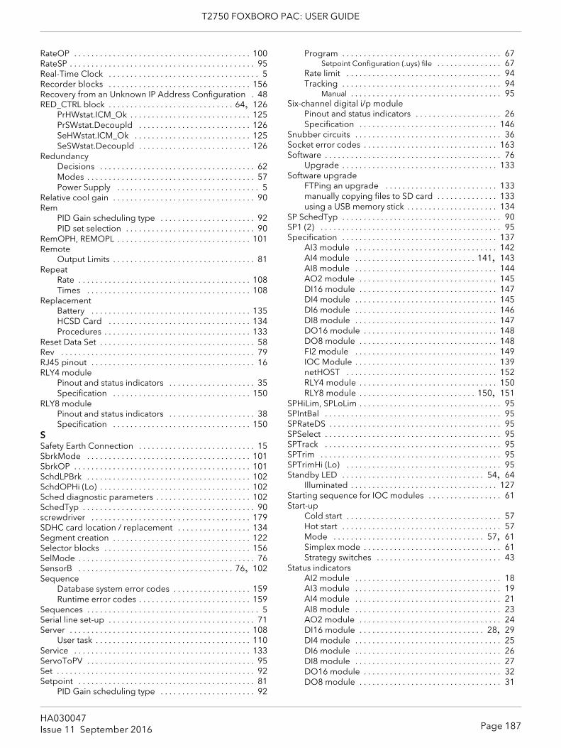
T2750 FOXBORO PAC: USER GUIDE
RateOP . . . . . . . . . . . . . . . . . . . . . . . . . . . . . . . . . . . . . . . . . 100RateSP . . . . . . . . . . . . . . . . . . . . . . . . . . . . . . . . . . . . . . . . . . . 95Real-Time Clock . . . . . . . . . . . . . . . . . . . . . . . . . . . . . . . . . . . 5Recorder blocks . . . . . . . . . . . . . . . . . . . . . . . . . . . . . . . . . 156Recovery from an Unknown IP Address Configuration . 48RED_CTRL block . . . . . . . . . . . . . . . . . . . . . . . . . . . . . 64, 126
PrHWstat.ICM_Ok . . . . . . . . . . . . . . . . . . . . . . . . . . . . 125PrSWstat.Decoupld . . . . . . . . . . . . . . . . . . . . . . . . . . 126SeHWstat.ICM_Ok . . . . . . . . . . . . . . . . . . . . . . . . . . . 125SeSWstat.Decoupld . . . . . . . . . . . . . . . . . . . . . . . . . . 126
RedundancyDecisions . . . . . . . . . . . . . . . . . . . . . . . . . . . . . . . . . . . . 62Modes . . . . . . . . . . . . . . . . . . . . . . . . . . . . . . . . . . . . . . . 57Power Supply . . . . . . . . . . . . . . . . . . . . . . . . . . . . . . . . . 5
Relative cool gain . . . . . . . . . . . . . . . . . . . . . . . . . . . . . . . . . 90Rem
PID Gain scheduling type . . . . . . . . . . . . . . . . . . . . . . 92PID set selection . . . . . . . . . . . . . . . . . . . . . . . . . . . . . . 90
RemOPH, REMOPL . . . . . . . . . . . . . . . . . . . . . . . . . . . . . . . 101Remote
Output Limits . . . . . . . . . . . . . . . . . . . . . . . . . . . . . . . . . 81Repeat
Rate . . . . . . . . . . . . . . . . . . . . . . . . . . . . . . . . . . . . . . . . 108Times . . . . . . . . . . . . . . . . . . . . . . . . . . . . . . . . . . . . . . 108
ReplacementBattery . . . . . . . . . . . . . . . . . . . . . . . . . . . . . . . . . . . . . 135HCSD Card . . . . . . . . . . . . . . . . . . . . . . . . . . . . . . . . . 134Procedures . . . . . . . . . . . . . . . . . . . . . . . . . . . . . . . . . . 133
Reset Data Set . . . . . . . . . . . . . . . . . . . . . . . . . . . . . . . . . . . . 58Rev . . . . . . . . . . . . . . . . . . . . . . . . . . . . . . . . . . . . . . . . . . . . . 79RJ45 pinout . . . . . . . . . . . . . . . . . . . . . . . . . . . . . . . . . . . . . . 16RLY4 module
Pinout and status indicators . . . . . . . . . . . . . . . . . . . . 35Specification . . . . . . . . . . . . . . . . . . . . . . . . . . . . . . . . 150
RLY8 modulePinout and status indicators . . . . . . . . . . . . . . . . . . . . 38Specification . . . . . . . . . . . . . . . . . . . . . . . . . . . . . . . . 150
SSafety Earth Connection . . . . . . . . . . . . . . . . . . . . . . . . . . . 15SbrkMode . . . . . . . . . . . . . . . . . . . . . . . . . . . . . . . . . . . . . . 101SbrkOP . . . . . . . . . . . . . . . . . . . . . . . . . . . . . . . . . . . . . . . . . 101SchdLPBrk . . . . . . . . . . . . . . . . . . . . . . . . . . . . . . . . . . . . . . 102SchdOPHi (Lo) . . . . . . . . . . . . . . . . . . . . . . . . . . . . . . . . . . . 102Sched diagnostic parameters . . . . . . . . . . . . . . . . . . . . . . 102SchedTyp . . . . . . . . . . . . . . . . . . . . . . . . . . . . . . . . . . . . . . . . 90screwdriver . . . . . . . . . . . . . . . . . . . . . . . . . . . . . . . . . . . . . 179SDHC card location / replacement . . . . . . . . . . . . . . . . . 134Segment creation . . . . . . . . . . . . . . . . . . . . . . . . . . . . . . . . 122Selector blocks . . . . . . . . . . . . . . . . . . . . . . . . . . . . . . . . . . 156SelMode . . . . . . . . . . . . . . . . . . . . . . . . . . . . . . . . . . . . . . . . . 76SensorB . . . . . . . . . . . . . . . . . . . . . . . . . . . . . . . . . . . . 76, 102Sequence
Database system error codes . . . . . . . . . . . . . . . . . . 159Runtime error codes . . . . . . . . . . . . . . . . . . . . . . . . . . 159
Sequences . . . . . . . . . . . . . . . . . . . . . . . . . . . . . . . . . . . . . . . . 5Serial line set-up . . . . . . . . . . . . . . . . . . . . . . . . . . . . . . . . . . 71Server . . . . . . . . . . . . . . . . . . . . . . . . . . . . . . . . . . . . . . . . . . 108
User task . . . . . . . . . . . . . . . . . . . . . . . . . . . . . . . . . . . . 110Service . . . . . . . . . . . . . . . . . . . . . . . . . . . . . . . . . . . . . . . . . 133ServoToPV . . . . . . . . . . . . . . . . . . . . . . . . . . . . . . . . . . . . . . . 95Set . . . . . . . . . . . . . . . . . . . . . . . . . . . . . . . . . . . . . . . . . . . . . . 92Setpoint . . . . . . . . . . . . . . . . . . . . . . . . . . . . . . . . . . . . . . . . . 81
PID Gain scheduling type . . . . . . . . . . . . . . . . . . . . . . 92
Program . . . . . . . . . . . . . . . . . . . . . . . . . . . . . . . . . . . . . 67Setpoint Configuration (.uys) file . . . . . . . . . . . . . . . 67
Rate limit . . . . . . . . . . . . . . . . . . . . . . . . . . . . . . . . . . . . 94Tracking . . . . . . . . . . . . . . . . . . . . . . . . . . . . . . . . . . . . . 94
Manual . . . . . . . . . . . . . . . . . . . . . . . . . . . . . . . . . . . 95Six-channel digital i/p module
Pinout and status indicators . . . . . . . . . . . . . . . . . . . . 26Specification . . . . . . . . . . . . . . . . . . . . . . . . . . . . . . . . 146
Snubber circuits . . . . . . . . . . . . . . . . . . . . . . . . . . . . . . . . . . 36Socket error codes . . . . . . . . . . . . . . . . . . . . . . . . . . . . . . . 163Software . . . . . . . . . . . . . . . . . . . . . . . . . . . . . . . . . . . . . . . . . 76
Upgrade . . . . . . . . . . . . . . . . . . . . . . . . . . . . . . . . . . . . 133Software upgrade
FTPing an upgrade . . . . . . . . . . . . . . . . . . . . . . . . . . 133manually copying files to SD card . . . . . . . . . . . . . . 133using a USB memory stick . . . . . . . . . . . . . . . . . . . . . 134
SP SchedTyp . . . . . . . . . . . . . . . . . . . . . . . . . . . . . . . . . . . . . 90SP1 (2) . . . . . . . . . . . . . . . . . . . . . . . . . . . . . . . . . . . . . . . . . . 95Specification . . . . . . . . . . . . . . . . . . . . . . . . . . . . . . . . . . . . 137
AI3 module . . . . . . . . . . . . . . . . . . . . . . . . . . . . . . . . . 142AI4 module . . . . . . . . . . . . . . . . . . . . . . . . . . . . 141, 143AI8 module . . . . . . . . . . . . . . . . . . . . . . . . . . . . . . . . . 144AO2 module . . . . . . . . . . . . . . . . . . . . . . . . . . . . . . . . 145DI16 module . . . . . . . . . . . . . . . . . . . . . . . . . . . . . . . . 147DI4 module . . . . . . . . . . . . . . . . . . . . . . . . . . . . . . . . . 145DI6 module . . . . . . . . . . . . . . . . . . . . . . . . . . . . . . . . . 146DI8 module . . . . . . . . . . . . . . . . . . . . . . . . . . . . . . . . . 147DO16 module . . . . . . . . . . . . . . . . . . . . . . . . . . . . . . . 148DO8 module . . . . . . . . . . . . . . . . . . . . . . . . . . . . . . . . 148FI2 module . . . . . . . . . . . . . . . . . . . . . . . . . . . . . . . . . 149IOC Module . . . . . . . . . . . . . . . . . . . . . . . . . . . . . . . . . 139netHOST . . . . . . . . . . . . . . . . . . . . . . . . . . . . . . . . . . . 152RLY4 module . . . . . . . . . . . . . . . . . . . . . . . . . . . . . . . . 150RLY8 module . . . . . . . . . . . . . . . . . . . . . . . . . . . 150, 151
SPHiLim, SPLoLim . . . . . . . . . . . . . . . . . . . . . . . . . . . . . . . . . 95SPIntBal . . . . . . . . . . . . . . . . . . . . . . . . . . . . . . . . . . . . . . . . . 95SPRateDS . . . . . . . . . . . . . . . . . . . . . . . . . . . . . . . . . . . . . . . . 95SPSelect . . . . . . . . . . . . . . . . . . . . . . . . . . . . . . . . . . . . . . . . . 95SPTrack . . . . . . . . . . . . . . . . . . . . . . . . . . . . . . . . . . . . . . . . . 95SPTrim . . . . . . . . . . . . . . . . . . . . . . . . . . . . . . . . . . . . . . . . . . 95SPTrimHi (Lo) . . . . . . . . . . . . . . . . . . . . . . . . . . . . . . . . . . . . 95Standby LED . . . . . . . . . . . . . . . . . . . . . . . . . . . . . . . . . 54, 64
Illuminated . . . . . . . . . . . . . . . . . . . . . . . . . . . . . . . . . . 127Starting sequence for IOC modules . . . . . . . . . . . . . . . . . 61Start-up
Cold start . . . . . . . . . . . . . . . . . . . . . . . . . . . . . . . . . . . . 57Hot start . . . . . . . . . . . . . . . . . . . . . . . . . . . . . . . . . . . . . 57Mode . . . . . . . . . . . . . . . . . . . . . . . . . . . . . . . . . . . 57, 61Simplex mode . . . . . . . . . . . . . . . . . . . . . . . . . . . . . . . . 61Strategy switches . . . . . . . . . . . . . . . . . . . . . . . . . . . . . 43
Status indicatorsAI2 module . . . . . . . . . . . . . . . . . . . . . . . . . . . . . . . . . . 18AI3 module . . . . . . . . . . . . . . . . . . . . . . . . . . . . . . . . . . 19AI4 module . . . . . . . . . . . . . . . . . . . . . . . . . . . . . . . . . . 21AI8 module . . . . . . . . . . . . . . . . . . . . . . . . . . . . . . . . . . 23AO2 module . . . . . . . . . . . . . . . . . . . . . . . . . . . . . . . . . 24DI16 module . . . . . . . . . . . . . . . . . . . . . . . . . . . . . 28, 29DI4 module . . . . . . . . . . . . . . . . . . . . . . . . . . . . . . . . . . 25DI6 module . . . . . . . . . . . . . . . . . . . . . . . . . . . . . . . . . . 26DI8 module . . . . . . . . . . . . . . . . . . . . . . . . . . . . . . . . . . 27DO16 module . . . . . . . . . . . . . . . . . . . . . . . . . . . . . . . . 32DO8 module . . . . . . . . . . . . . . . . . . . . . . . . . . . . . . . . . 31
Page 187HA030047Issue 11 September 2016
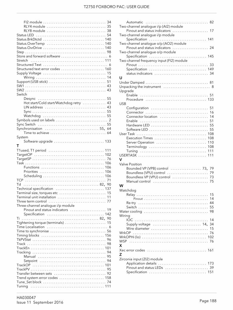
T2750 FOXBORO PAC: USER GUIDE
FI2 module . . . . . . . . . . . . . . . . . . . . . . . . . . . . . . . . . . . 34RLY4 module . . . . . . . . . . . . . . . . . . . . . . . . . . . . . . . . . 35RLY8 module . . . . . . . . . . . . . . . . . . . . . . . . . . . . . . . . . 38
Status LED . . . . . . . . . . . . . . . . . . . . . . . . . . . . . . . . . . . . . . . 54Status.BrkDtctd . . . . . . . . . . . . . . . . . . . . . . . . . . . . . . . . . . 140Status.OverTemp . . . . . . . . . . . . . . . . . . . . . . . . . . . . . . . . 140Status.OvrDrive . . . . . . . . . . . . . . . . . . . . . . . . . . . . . . . . . . 140Step . . . . . . . . . . . . . . . . . . . . . . . . . . . . . . . . . . . . . . . . . . . . . 98Store and forward software . . . . . . . . . . . . . . . . . . . . . . . . . . 6Stretch . . . . . . . . . . . . . . . . . . . . . . . . . . . . . . . . . . . . . . . . . 111Structured Text . . . . . . . . . . . . . . . . . . . . . . . . . . . . . . . . . . . . 6Structured text error codes . . . . . . . . . . . . . . . . . . . . . . . . 160Supply Voltage . . . . . . . . . . . . . . . . . . . . . . . . . . . . . . . . . . . 15
Wiring . . . . . . . . . . . . . . . . . . . . . . . . . . . . . . . . . . . . . . . 14Support (USB stick) . . . . . . . . . . . . . . . . . . . . . . . . . . . . . . . . 51SW1 . . . . . . . . . . . . . . . . . . . . . . . . . . . . . . . . . . . . . . . . . . . . . 43SW2 . . . . . . . . . . . . . . . . . . . . . . . . . . . . . . . . . . . . . . . . . . . . . 43Switch
Desync . . . . . . . . . . . . . . . . . . . . . . . . . . . . . . . . . . . . . . 55Hot start/Cold start/Watchdog retry . . . . . . . . . . . . . 43LIN address . . . . . . . . . . . . . . . . . . . . . . . . . . . . . . . . . . 43Sync . . . . . . . . . . . . . . . . . . . . . . . . . . . . . . . . . . . . . . . . . 55Watchdog . . . . . . . . . . . . . . . . . . . . . . . . . . . . . . . . . . . 55
Symbols used on labels . . . . . . . . . . . . . . . . . . . . . . . . . . . . . 2Sync Switch . . . . . . . . . . . . . . . . . . . . . . . . . . . . . . . . . . . . . . 55Synchronisation . . . . . . . . . . . . . . . . . . . . . . . . . . . . . . 55, 64
Time to achieve . . . . . . . . . . . . . . . . . . . . . . . . . . . . . . . 64System
Software upgrade . . . . . . . . . . . . . . . . . . . . . . . . . . . . 133TT1used, T1 period . . . . . . . . . . . . . . . . . . . . . . . . . . . . . . . 111TargetOP . . . . . . . . . . . . . . . . . . . . . . . . . . . . . . . . . . . . . . . 102TargetSP . . . . . . . . . . . . . . . . . . . . . . . . . . . . . . . . . . . . . . . . . 76Task . . . . . . . . . . . . . . . . . . . . . . . . . . . . . . . . . . . . . . . . . . . . 106
Functions . . . . . . . . . . . . . . . . . . . . . . . . . . . . . . . . . . . 106Priorities . . . . . . . . . . . . . . . . . . . . . . . . . . . . . . . . . . . . 106Scheduling . . . . . . . . . . . . . . . . . . . . . . . . . . . . . . . . . . 106
TCP . . . . . . . . . . . . . . . . . . . . . . . . . . . . . . . . . . . . . . . . . . . . . 71Td . . . . . . . . . . . . . . . . . . . . . . . . . . . . . . . . . . . . . . . . . . 82, 90Technical specification . . . . . . . . . . . . . . . . . . . . . . . . . . . 137Terminal size, torques etc . . . . . . . . . . . . . . . . . . . . . . . . . . 15Terminal unit installation . . . . . . . . . . . . . . . . . . . . . . . . . . . 11Three term control . . . . . . . . . . . . . . . . . . . . . . . . . . . . . . . . 77Three-channel analogue i/p module
Pinout and status indicators . . . . . . . . . . . . . . . . . . . . 19Specification . . . . . . . . . . . . . . . . . . . . . . . . . . . . . . . . 142
Ti . . . . . . . . . . . . . . . . . . . . . . . . . . . . . . . . . . . . . . . . . . . 82, 90Tightening torque (terminals) . . . . . . . . . . . . . . . . . . . . . . . 15Time Localisation . . . . . . . . . . . . . . . . . . . . . . . . . . . . . . . . . . 6Time to synchronise . . . . . . . . . . . . . . . . . . . . . . . . . . . . . . . 56Timing blocks . . . . . . . . . . . . . . . . . . . . . . . . . . . . . . . . . . . 156TkPVStat . . . . . . . . . . . . . . . . . . . . . . . . . . . . . . . . . . . . . . . . . 96Track . . . . . . . . . . . . . . . . . . . . . . . . . . . . . . . . . . . . . . . . . . . . 98TrackEn . . . . . . . . . . . . . . . . . . . . . . . . . . . . . . . . . . . . . . . . . 101Tracking . . . . . . . . . . . . . . . . . . . . . . . . . . . . . . . . . . . . . . . . . 94
Manual . . . . . . . . . . . . . . . . . . . . . . . . . . . . . . . . . . . . . . 95Setpoint . . . . . . . . . . . . . . . . . . . . . . . . . . . . . . . . . . . . . 94
TrackOP . . . . . . . . . . . . . . . . . . . . . . . . . . . . . . . . . . . . . . . . 101TrackPV . . . . . . . . . . . . . . . . . . . . . . . . . . . . . . . . . . . . . . . . . . 95Transfer between sets . . . . . . . . . . . . . . . . . . . . . . . . . . . . . 92Trend system error codes . . . . . . . . . . . . . . . . . . . . . . . . . 158Tune_Set block . . . . . . . . . . . . . . . . . . . . . . . . . . . . . . . . . . . 74Tuning . . . . . . . . . . . . . . . . . . . . . . . . . . . . . . . . . . . . . . . . . 111
Automatic . . . . . . . . . . . . . . . . . . . . . . . . . . . . . . . . . . . 82Two-channel analogue i/p (AI2) module
Pinout and status indicators . . . . . . . . . . . . . . . . . . . . 17Two-channel analogue i/p module
Specification . . . . . . . . . . . . . . . . . . . . . . . . . . . . . . . . 141Two-channel analogue o/p (AO2) module
Pinout and status indicators . . . . . . . . . . . . . . . . . . . . 24Two-channel analogue o/p module
Specification . . . . . . . . . . . . . . . . . . . . . . . . . . . . . . . . 145Two-channel frequency input (FI2) module
Pinout . . . . . . . . . . . . . . . . . . . . . . . . . . . . . . . . . . . . . . . 33Specification . . . . . . . . . . . . . . . . . . . . . . . . . . . . . . . . 149status indicators . . . . . . . . . . . . . . . . . . . . . . . . . . . . . . 34
UUnder Damped . . . . . . . . . . . . . . . . . . . . . . . . . . . . . . . . . . . 81Unpacking the instrument . . . . . . . . . . . . . . . . . . . . . . . . . . 8Upgrade
Enable . . . . . . . . . . . . . . . . . . . . . . . . . . . . . . . . . . . . . . 51Procedure . . . . . . . . . . . . . . . . . . . . . . . . . . . . . . . . . . 133
USBConfiguration . . . . . . . . . . . . . . . . . . . . . . . . . . . . . . . . 51Connector . . . . . . . . . . . . . . . . . . . . . . . . . . . . . . . . . . . 16Connector location . . . . . . . . . . . . . . . . . . . . . . . . . . . 14Enable . . . . . . . . . . . . . . . . . . . . . . . . . . . . . . . . . . . . . . 51Hardware LED . . . . . . . . . . . . . . . . . . . . . . . . . . . . . . . . 55Software LED . . . . . . . . . . . . . . . . . . . . . . . . . . . . . . . . . 55
User Task . . . . . . . . . . . . . . . . . . . . . . . . . . . . . . . . . . . . . . . 108Execution Times . . . . . . . . . . . . . . . . . . . . . . . . . . . . . 108Server Operation . . . . . . . . . . . . . . . . . . . . . . . . . . . . 110Terminology . . . . . . . . . . . . . . . . . . . . . . . . . . . . . . . . 108Tuning . . . . . . . . . . . . . . . . . . . . . . . . . . . . . . . . . . . . . 111
USERTASK . . . . . . . . . . . . . . . . . . . . . . . . . . . . . . . . . . . . . . 111VValve Position
Bounded VP (VPB) control . . . . . . . . . . . . . . . . . 73, 79Boundless (VPU) control . . . . . . . . . . . . . . . . . . . . . . . 79Boundless VP (VPU) control . . . . . . . . . . . . . . . . . . . . 73Manual control . . . . . . . . . . . . . . . . . . . . . . . . . . . . . . . 75
WWatchdog
Relay . . . . . . . . . . . . . . . . . . . . . . . . . . . . . . . . . . . . . . . . 15Pinout . . . . . . . . . . . . . . . . . . . . . . . . . . . . . . . . . . . . 14
Re-try . . . . . . . . . . . . . . . . . . . . . . . . . . . . . . . . . . . . . . . 44Switch . . . . . . . . . . . . . . . . . . . . . . . . . . . . . . . . . . . . . . . 55
Water cooling . . . . . . . . . . . . . . . . . . . . . . . . . . . . . . . . . . . . 98Wiring
IOC . . . . . . . . . . . . . . . . . . . . . . . . . . . . . . . . . . . . . . . . . 14Supply voltage . . . . . . . . . . . . . . . . . . . . . . . . . . . 14, 34Wire diameter . . . . . . . . . . . . . . . . . . . . . . . . . . . . . . . . 15
WrkOP . . . . . . . . . . . . . . . . . . . . . . . . . . . . . . . . . . . . . . . . . . 76WrkOPHi (lo) . . . . . . . . . . . . . . . . . . . . . . . . . . . . . . . . . . . . 102WSP . . . . . . . . . . . . . . . . . . . . . . . . . . . . . . . . . . . . . . . . . . . . 76XXec error codes . . . . . . . . . . . . . . . . . . . . . . . . . . . . . . . . . 161ZZirconia input (ZI2) module
Application details . . . . . . . . . . . . . . . . . . . . . . . . . . . 173Pinout and status LEDs . . . . . . . . . . . . . . . . . . . . . . . . 39Specification . . . . . . . . . . . . . . . . . . . . . . . . . . . . . . . . 151
Page 188HA030047Issue 11 September 2016


© Copyright 2016 Eurotherm Limited
Eurotherm, the Eurotherm by Schneider Electric logo, Chessell, EurothermSuite, Mini8, Eycon, Eyris, EPower, EPack nanodac, piccolo, versadac, optivis, Foxboro, and Wonderware are trademarks of Invensys plc, its subsidiaries and affiliates. All other brands may be trademarks of their re-spective owners.All rights are strictly reserved. No part of this document may be reproduced, modified or transmitted in any form by any means, neither may it be stored in a retrieval system other than for the purpose to act as an aid in operating the equipment to which the document relates, without the prior written permission of Invensys Eurotherm Limited.Eurotherm Limited pursues a policy of continuous development and product improvement. The specifications in this document may therefore be changed without notice. The information in this document is given in good faith, but is intended for guidance only. Eurotherm Limited will accept no responsibility for any losses arising from errors in this document.
HA030047/11 (CN34674) T2750 Foxboro PAC User Guide
International sales and supportEurotherm: www.eurotherm.com
Contact Information
Eurotherm Head OfficeFaraday Close DurringtonWorthingWest SussexBN13 3PL
Worldwide Offices www.eurotherm.com/global
Scan for local contactsSales EnquiriesT +44 (01903) 695888F 0845 130 9936
General Enquiries T +39 031 975 111 F +39 031 977 512