pac ht - airwell
TRANSCRIPT
English Français EspañolDeutsch Italiano
IOM PAC HT 01-N-7GBPart number / Code / Teil Nummer / Codice / Código : 3990533GBSupersedes / Annule et remplace / Annulliert und ersetzt / Annulla e sostituisce / Anula y sustituye : IOM PAC HT 01-N-6GB
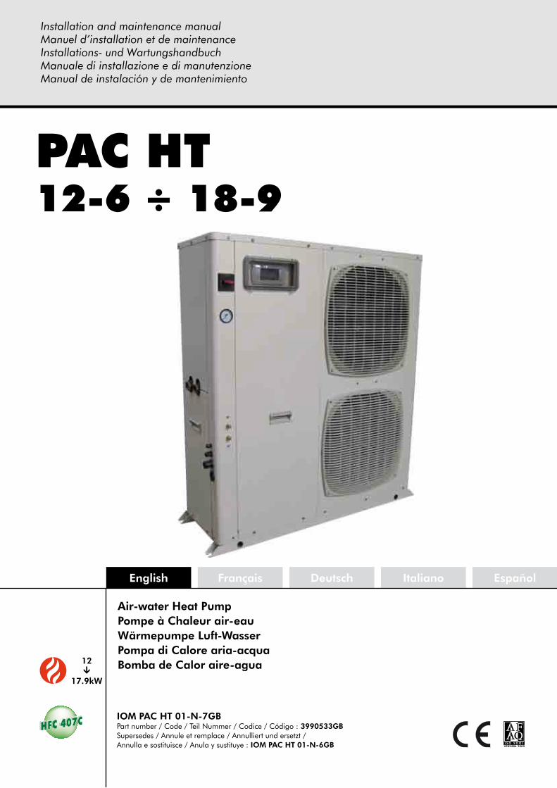
12Ü
17.9kW
PAC HT12-6 ÷ 18-9
Air-water Heat PumpPompe à Chaleur air-eauWärmepumpe Luft-WasserPompa di Calore aria-acquaBomba de Calor aire-agua
Installation and maintenance manualManuel d’installation et de maintenanceInstallations- und WartungshandbuchManuale di installazione e di manutenzioneManual de instalación y de mantenimiento
IOM PAC HT 01-N-7Part number / Code / Teil Nummer / Codice / Código : 3990533Supersedes / Annule et remplace / Annulliert und ersetzt / Annulla e sostituisce / Anula y sustituye : IOM PAC HT 01-N-6

INSTALLATION INSTRUCTION
NOTICE D’INSTALLATION
INSTALLATIONSHANDBUCH
ISTRUZIONI INSTALLAZIONE
INSTRUCCIONES DE INSTALACIÓN
2
CONTENTSGENERAL RECOMMENDATIONS ...............................................................................................................3
SAFETY DIRECTIONS ................................................................................................................................................................ 3WARNING ............................................................................................................................................................................... 3EqUIpmENT SAFETY DATA ....................................................................................................................................................... 4
INSPECTION AND STORAGE .....................................................................................................................5WARRANTY ...............................................................................................................................................5CONTENTS OF PACKAGE ..........................................................................................................................5PRODUCT PRESENTATION .........................................................................................................................5ACCESSORIES ...........................................................................................................................................6DIMENSIONS ............................................................................................................................................6HANDLING ...............................................................................................................................................6
NET WEIGHT ........................................................................................................................................................................... 6TECHNICAL SPECIFICATIONS ....................................................................................................................7
pHYSICAL CHARACTERISTICS ................................................................................................................................................... 7ELECTRICAL CHARACTERISTICS ................................................................................................................................................ 7OpERATING LImITS .................................................................................................................................................................. 7THERmODYNAmIC DOmESTIC HOT WATER pRODUCTION ...................................................................................................... 8
REFRIGERATION AND HYDRAULIC DIAGRAM ...........................................................................................9INSTALLATION ..........................................................................................................................................9
SITING THE INSTALLATION ....................................................................................................................................................... 9CLEARANCE .......................................................................................................................................................................... 10ATTACHmENT TO THE GROUND ........................................................................................................................................... 10
HYDRAULIC LINKS ..................................................................................................................................11GENERAL RECOmmENDATIONS ............................................................................................................................................ 11STANDARD CIRCUITS ............................................................................................................................................................. 12ANTI-FREEZE pROTECTION .................................................................................................................................................... 14WATER TREATmENT WARNING ............................................................................................................................................... 14CONNECTION TO THE CENTRAL HEATING LOOp ................................................................................................................. 15HEAT INSULATION ................................................................................................................................................................. 15FILLING THE SYSTEm WITH WATER ......................................................................................................................................... 15WATER FLOW CONTROLLER .................................................................................................................................................. 15DETERmINING WATER FLOW ................................................................................................................................................. 16DOmESTIC HOT WATER ......................................................................................................................................................... 17DOmESTIC HOT WATER pRODUCTION mODES ..................................................................................................................... 18DOmESTIC HOT WATER HEATING FUNCTION ACTIVATION ................................................................................................... 18IN-LINE ELECTRIC HEATER ...................................................................................................................................................... 19BOILER RELIEF ........................................................................................................................................................................ 20
WIRING DIAGRAM AND LEGEND ............................................................................................................21WIRING DIAGRAm ................................................................................................................................................................. 21LEGEND ................................................................................................................................................................................ 21
ELECTRICAL CONNECTIONS ...................................................................................................................23pHASE SEqUENCE AND CUT-OUT CONTROLLER ................................................................................................................... 24pROGRESSIVE START-Up ......................................................................................................................................................... 24CONNECTIONS .................................................................................................................................................................... 25
COMMISSIONING ...................................................................................................................................26pRE-START CHECK LIST ........................................................................................................................................................... 26
STARTING THE APPLIANCE ......................................................................................................................27USER INTERFACE .................................................................................................................................................................... 27SImpLIFIED START-Up pROCEDURE .......................................................................................................................................... 29OpERATING CHECK LIST ........................................................................................................................................................ 31
FINAL TASKS ...........................................................................................................................................32IN CASE OF WARRANTY - MATERIAL RETURN PROCEDURE ....................................................................32ORDERING SERvICE AND SPARE PARTS ORDER ......................................................................................32MAINTENANCE .......................................................................................................................................33
REGULAR mAINTENANCE ...................................................................................................................................................... 33GENERAL INSpECTION .......................................................................................................................................................... 33REFRIGERATION CIRCUIT ....................................................................................................................................................... 33ELECTRICAL SECTION ............................................................................................................................................................ 33SERVICING CHECKLIST .......................................................................................................................................................... 34
ALARM LIST AvAILABLE ON THE PAC HT DISPLAY ...................................................................................35FAULTY DIAGNOSIS GUIDE .....................................................................................................................39
3
POWER SUPPLY MUST BE SWITCHED OFF
BEFORE STARTING WORK IN THE ELECTRICCONTROL BOX
GENERAL RECOMMENDATIONSplease read the following safety precautions very carefully before installing the unit.
SAFETY DIRECTIONS
Follow the safety rules in forces when you are working on your appliance.
The installation, commissioning and maintenance of these units should be performed by qualified personnel having a good knowledge of standards and local regulations, as well as experience of this type of equipment.
This appliance has not been designed for use by persons (including children) with reduced physical, sensorial or mental faculties or by persons without any experience or knowledge of heating systems, unless they act under the safety and supervision of a responsible person or have received prior training concerning the use of the appliance.
Children should be supervised to ensure that they do not play with the appliance.
The unit should be handled using lifting and handling equipment appropriate to the unit's size and weight.
Any wiring produced on site must comply with the corresponding national electrical regulations.
make sure that the power supply and its frequency are adapted to the required electric current of operation, taking into account specific conditions of the location and the current required for any other appliance connected to the same circuit.
The unit must be EARTHED to avoid any risks caused by insulation defects.
It is forbidden to start any work on the electrical components if water or high humidity is present on the installation site.
WARNING
Cutoff power supply before starting to work on the appliance.
When making the hydraulic connections, ensure that no impurities are introduced into the pipe work.
The manufacturer declines any responsibility and the warrantly becomes void if these instructions are not respected.
If you meet a problem, please call the Technical Department of your area.
If possible, assemble the compulsory or optional accessories before placing the appliance on its final location. (see instructions provided with each accessory).
In order to become fully familiar with the appliance, we suggest to read also our Technical Instructions.
The information contained in these Instructions are subject to modification without advance notice.
4
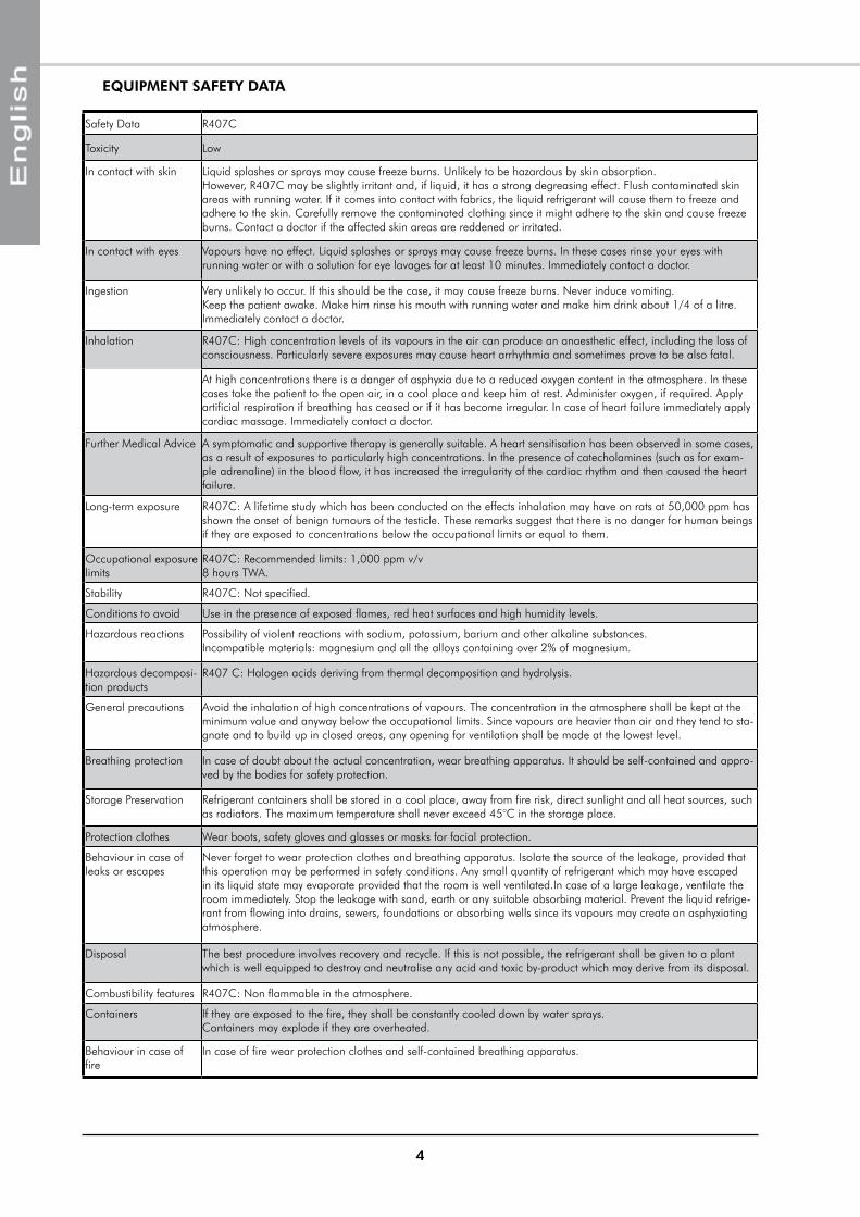
EqUIPMENT SAFETY DATA
Safety Data R407C
Toxicity Low
In contact with skin Liquid splashes or sprays may cause freeze burns. Unlikely to be hazardous by skin absorption. However, R407C may be slightly irritant and, if liquid, it has a strong degreasing effect. Flush contaminated skin areas with running water. If it comes into contact with fabrics, the liquid refrigerant will cause them to freeze and adhere to the skin. Carefully remove the contaminated clothing since it might adhere to the skin and cause freeze burns. Contact a doctor if the affected skin areas are reddened or irritated.
In contact with eyes Vapours have no effect. Liquid splashes or sprays may cause freeze burns. In these cases rinse your eyes with running water or with a solution for eye lavages for at least 10 minutes. Immediately contact a doctor.
Ingestion Very unlikely to occur. If this should be the case, it may cause freeze burns. Never induce vomiting. Keep the patient awake. make him rinse his mouth with running water and make him drink about 1/4 of a litre. Immediately contact a doctor.
Inhalation R407C: High concentration levels of its vapours in the air can produce an anaesthetic effect, including the loss of consciousness. particularly severe exposures may cause heart arrhythmia and sometimes prove to be also fatal.
At high concentrations there is a danger of asphyxia due to a reduced oxygen content in the atmosphere. In these cases take the patient to the open air, in a cool place and keep him at rest. Administer oxygen, if required. Apply artificial respiration if breathing has ceased or if it has become irregular. In case of heart failure immediately apply cardiac massage. Immediately contact a doctor.
Further medical Advice A symptomatic and supportive therapy is generally suitable. A heart sensitisation has been observed in some cases, as a result of exposures to particularly high concentrations. In the presence of catecholamines (such as for exam-ple adrenaline) in the blood flow, it has increased the irregularity of the cardiac rhythm and then caused the heart failure.
Long-term exposure R407C: A lifetime study which has been conducted on the effects inhalation may have on rats at 50,000 ppm has shown the onset of benign tumours of the testicle. These remarks suggest that there is no danger for human beings if they are exposed to concentrations below the occupational limits or equal to them.
Occupational exposure limits
R407C: Recommended limits: 1,000 ppm v/v 8 hours TWA.
Stability R407C: Not specified.
Conditions to avoid Use in the presence of exposed flames, red heat surfaces and high humidity levels.
Hazardous reactions possibility of violent reactions with sodium, potassium, barium and other alkaline substances. Incompatible materials: magnesium and all the alloys containing over 2% of magnesium.
Hazardous decomposi-tion products
R407 C: Halogen acids deriving from thermal decomposition and hydrolysis.
General precautions Avoid the inhalation of high concentrations of vapours. The concentration in the atmosphere shall be kept at the minimum value and anyway below the occupational limits. Since vapours are heavier than air and they tend to sta-gnate and to build up in closed areas, any opening for ventilation shall be made at the lowest level.
Breathing protection In case of doubt about the actual concentration, wear breathing apparatus. It should be self-contained and appro-ved by the bodies for safety protection.
Storage preservation Refrigerant containers shall be stored in a cool place, away from fire risk, direct sunlight and all heat sources, such as radiators. The maximum temperature shall never exceed 45°C in the storage place.
protection clothes Wear boots, safety gloves and glasses or masks for facial protection.
Behaviour in case of leaks or escapes
Never forget to wear protection clothes and breathing apparatus. Isolate the source of the leakage, provided that this operation may be performed in safety conditions. Any small quantity of refrigerant which may have escaped in its liquid state may evaporate provided that the room is well ventilated.In case of a large leakage, ventilate the room immediately. Stop the leakage with sand, earth or any suitable absorbing material. prevent the liquid refrige-rant from flowing into drains, sewers, foundations or absorbing wells since its vapours may create an asphyxiating atmosphere.
Disposal The best procedure involves recovery and recycle. If this is not possible, the refrigerant shall be given to a plant which is well equipped to destroy and neutralise any acid and toxic by-product which may derive from its disposal.
Combustibility features R407C: Non flammable in the atmosphere.
Containers If they are exposed to the fire, they shall be constantly cooled down by water sprays. Containers may explode if they are overheated.
Behaviour in case of fire
In case of fire wear protection clothes and self-contained breathing apparatus.
5
INSPECTION AND STORAGEAt the time of receiving the equipment carefully cross check all the elements against the shipping documents in order to ensure that all the crates and boxes have been received. Inspect all the units for any visible or hidden damage.
In the event of shipping damage, write precise details of the damage on the shipper’s delivery note and send immediately a registered letter to the shipper within 48 hours, clearly stating the damage caused. Forward a copy of this letter to the manufacturer or his representative.
Never store or transport the unit upside down. It must be stored indoors, completely protected from rain, snow etc. The unit must not be damaged by changes in the weather (high and low temperatures). Excessively high temperatures (above 60 °C) can harm certain plastic materials and cause permanent damage. moreover, the performance of certain electrical or electronic components can be impaired.
CONTENTS OF PACKAGE
WARRANTYThe units are delivered fully assembled and tested.
Any modification to the units without the manufacturer’s prior approval, shall automatically render the warranty null and void.
The following conditions must be respected in order to maintain the validity of the warranty:
² Commissioning shall be performed by specialised technicians from technical services approved by the manufacturer.
² maintenance shall be performed by technicians trained for this purpose.
² Only Original Equipment spare parts shall be used.
² All the operations listed in the present manual shall be performed within the required time limits.
THE WARRANTY SHALL BE NULL AND vOID IN THE EvENT OF NON-COMPLIANCE WITH ANY OF THE ABOvE CONDITIONS.
1 HEAT Pump PAC HT
1 Documentation pouch
4 Anti-vibration pads
1 Water filter kit
1 stop cock
1 Wired programmable ambience controller
PRODUCT PRESENTATION
This new range of air/water PAC HT (High Temperature) appliances offers the special feature of producing hot water at 65° C at outdoor temperatures between +7° C and -20° C, while guaranteeing a high COp.
Consequently, this PAC HT system is ideally suited to replace a traditional hot water boiler in producing Domestic Hot Water (DHW) without alterations to the rest of the system.
This technology uses two-stage compressors connected to a patented refrigeration circuit.
This technology ensures remarkably accurate "capacity supplied/heating needs" matching due to its ability to run each compressor independently. Depending on the demand for heating capacity and the operating temperature of heat emitters (i.e. radiators, etc.) the PAC HT regulator selects either the small or large compressor to operate on its own or in a two-stage mode.
6
DIMENSIONS
HANDLING
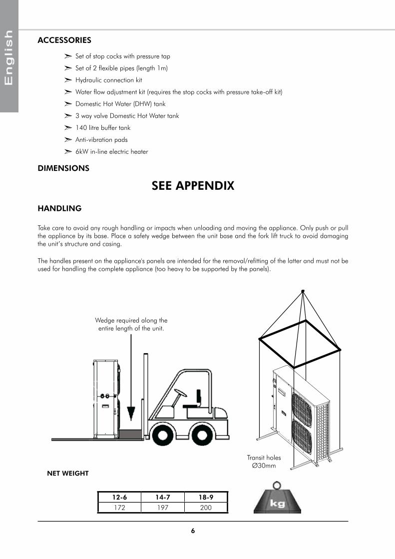
NET WEIGHT
SEE APPENDIX
ACCESSORIES
² Set of stop cocks with pressure tap
² Set of 2 flexible pipes (length 1m)
² Hydraulic connection kit
² Water flow adjustment kit (requires the stop cocks with pressure take-off kit)
² Domestic Hot Water (DHW) tank
² 3 way valve Domestic Hot Water tank
² 140 litre buffer tank
² Anti-vibration pads
² 6kW in-line electric heater
Take care to avoid any rough handling or impacts when unloading and moving the appliance. Only push or pull the appliance by its base. place a safety wedge between the unit base and the fork lift truck to avoid damaging the unit’s structure and casing.
Transit holes Ø30mm
12-6 14-7 18-9
172 197 200
The handles present on the appliance's panels are intended for the removal/refitting of the latter and must not be used for handling the complete appliance (too heavy to be supported by the panels).
Wedge required along the entire length of the unit.
7
TECHNICAL SPECIFICATIONSPHYSICAL CHARACTERISTICS
ELECTRICAL CHARACTERISTICS
12-6 14-7 18-9SUPPLY vOLTAGE 400V / 3 ph / 50Hz
Start-up current draw with limiter A < 60maximum current A 15 16 18
SUPPLY vOLTAGE 230V / 1 ph / 50HzStart-up current draw with limiter A < 45maximum current A 28 32 /
This equipment contains fluorinated gas with greenhouse gas effects covered by the Kyoto agreement.
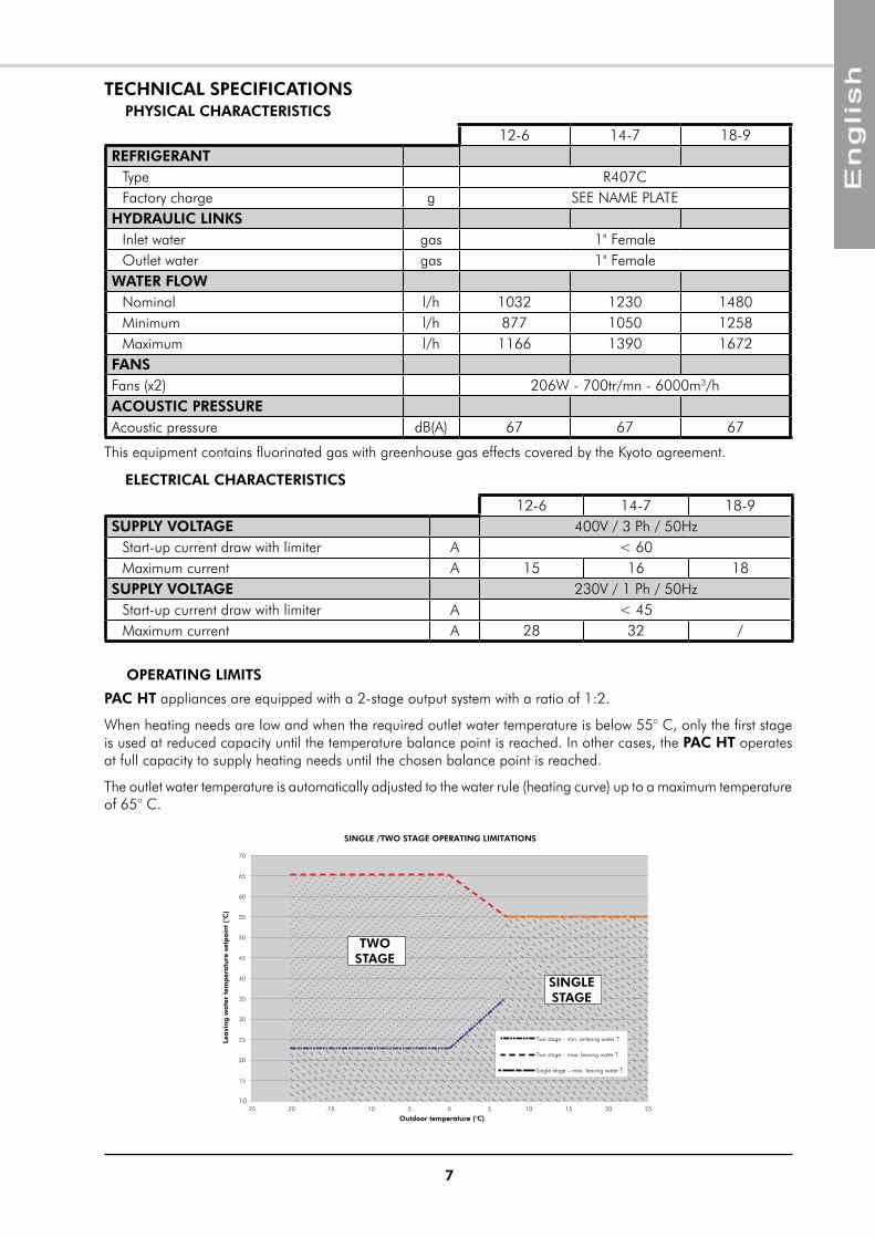
OPERATING LIMITS
PAC HT appliances are equipped with a 2-stage output system with a ratio of 1:2.
When heating needs are low and when the required outlet water temperature is below 55° C, only the first stage is used at reduced capacity until the temperature balance point is reached. In other cases, the PAC HT operates at full capacity to supply heating needs until the chosen balance point is reached.
The outlet water temperature is automatically adjusted to the water rule (heating curve) up to a maximum temperature of 65° C.
12-6 14-7 18-9REFRIGERANT
Type R407CFactory charge g SEE NAmE pLATE
HYDRAULIC LINKSInlet water gas 1" FemaleOutlet water gas 1" Female
WATER FLOWNominal l/h 1032 1230 1480minimum l/h 877 1050 1258maximum l/h 1166 1390 1672
FANSFans (x2) 206W - 700tr/mn - 6000m3/hACOUSTIC PRESSUREAcoustic pressure dB(A) 67 67 67
SINGLE /TWO STAGE OPERATING LIMITATIONS
10
15
20
25
30
35
40
45
50
55
60
65
70
-15 -10 -5 0 5 10 15 20-20-25 25
Outdoor temperature (°C)
Leavi
ng
wate
r te
mp
eratu
re s
etp
oin
t (°
C)
Two stage – min. entering water T.
Two stage – max. leaving water T.
Single stage – max. leaving water T.
TWOSTAGE
SINGLESTAGE
8
THERMODYNAMIC DOMESTIC HOT WATER PRODUCTION
12-6 Configuration C2 Compressor C1+C2 CompressorOutdoor temp. °C 40 7 0 -10pAC max. outlet temp. °C 60 60 65 65Average capacity kW 9 5.5 10.6 9.3DHW temperature °C 56 58 58 58Time [min] Initial temperature: 15°C
min 97 163 85 98
Time [min] Initial temperature: 35°C
min 49 87 45 53
Tank capacity: 300l
14-7 Configuration C2 Compressor C1+C2 CompressorOutdoor temp. °C 40 7 0 -10pAC max. outlet temp. °C 60 60 65 65Average capacity kW 11 7.1 13.6 12DHW temperature °C 54 57 56 57Time [min] Initial temperature: 15°C
min 72 124 63 73
Time [min] Initial temperature: 35°C
min 35 65 32 38
18-9 Configuration C2 Compressor C1+C2 CompressorOutdoor temp. °C 40 7 0 -10pAC max. outlet temp. °C 60 60 65 65Average capacity kW 13.3 8.3 16 14.1DHW temperature °C 53 56 55 56Time [min] Initial temperature: 15°C
min 60 103 52 61
Time [min] Initial temperature: 35°C
min 28 53 26 31
0
0.5
1
1.5
2
2.5
800 900 1000 1100 1200 1300 1400 1500 1600 1700 1800
kPa
Pres
sure
loss
Water flow (l/h)
PERFORMANCE
PRESSURE LOSS
Pres
sure
loss
Water flow (l/h)
kPa
0
0.05
0.10
0.15
0.20
0.25
0.30
0.35
0.40
0.45
800 900 1000 1100 1200 1300 1400 1500 1600 1700 1800
DHW TANK 300l
3-WAY-vALvE HEATING/DHW
The tank is equipped with a 2.5kW back-up heating element for single or three phase connection. The performances obtained and stated in the above table are without back-up heating. For higher domestic hot water temperatures or for Legionnaires disease protection treatment, the use of the back-up electric heating resistances is required.
The above performance figures are stated for a system with the Domestic Hot Water tank accessory.
9
REFRIGERATION AND HYDRAULIC DIAGRAM
SEE APPENDIX
INSTALLATIONThe unit is not designed to withstand weights or stresses from adjacent equipment, pipe work or constructions. Any foreign weight or stress on the unit structure could lead to a malfunction or a collapse with dangerous consequences for personnel and property. In such an event, the warranty shall be null and void.
SITING THE INSTALLATION
Unit operation depends on air temperature. Any recycling of air extracted by the fan lowers the air intake temperature across the exchanger fins and alters the standard operating conditions.
The outdoor unit must be installed outdoors with sufficient surrounding clearance to enable unobstructed air circulation through the appliance and access for maintenance work.
PREvAILING WIND
In the case of the unit being sited in areas exposed to high winds, you must avoid the wind hitting the fan blowing surface areas directly to avoid any risk of recycling cooled air. Strong wind can disrupt exchanger ventilation and create de-frosting problems.
The arrows show the direction of air circulation through the appliance. (Refer to Fig. § Floor location).
CONDENSATE WATER MANAGEMENT
Depending on temperature and outdoor air humidity conditions, water vapour contained in the air can condense on the finned heat exchanger and even form ice under low outdoor temperature conditions (around < 5°C). This condensate water and defrosted water runs off via outlets provided under the exchanger. To assist drainage and to prevent frozen water remaining in the appliance in winter, we recommend that the unit is installed at a height of around 10cm off the ground and placed on plastic blocks or other suitable supports. In this way, condensate and defrosted water can run off freely and be absorbed into the ground or channelled to a basin built under the appliance in order to protect the environment.
In areas where outdoor temperatures fall below 1°C, the system can be equipped with a condensate anti-freeze protection system (e.g. a heated pipe sheath).
HOW TO REDUCE NOISE POLLUTION
In order to contain noise levels, we equip our appliances with quiet fans and encase the technical compartment in sound-proofed panels. However, noise levels can be reduced even further by following a few installation precautions:
² Do not install the appliance near a bedroom window. Avoid locating the appliance in a corner (increased reverberated noise).
² Install the rubber pads supplied or anti-vibration pads (available as an option) under the appliance.
² Use flexible hoses (available as options) for connections between the appliance and the mains water network.
² Do not join the concrete slab supporting the appliance to the structure of the dwelling (structure- borne noise transmission)
10
CLEARANCE
REF. DIMENSION
A 800mm
B 500mm
C 500mm
D 400mm
E 800mm
F 100mm
ATTACHMENT TO THE GROUND
The unit location dimensions are indicated on the figure below. A slope of 1 cm/m should be created to assist rainwater drainage.
Vibration dampers must be fitted during installation to overcome any risks of vibration being transmitted due to direct contact with a rigid support surface.
AIR FLOW
THE UNIT MUST NEvER BE INSTALLED ON A WALL BRACKET.
A
B D
EC
F
349
1192.6
1%
The appliance must be sited on a level and solid floor and preferably on a masonry surface.
When choosing the location for the appliance, take care to leave sufficient free clearance on all sides to ensure easy access for maintenance work. The minimum free clearance dimensions indicated must be observed to ensure both proper system operation and allow access for maintenance and cleaning.
11
HYDRAULIC LINKS
When choosing and installing water pipes, you must consult and observe all current local standards, regulations and instructions.
GENERAL RECOMMENDATIONS
² You must design the pipe network with the minimum number of bends and keep the number of changes in height to the strict minimum. This will reduce installation costs and ensure optimum system performance. The pipe network must include:
² A vibration elimination system (e.g.: link hoses available as an accessory) on all pipes connected to the appliance in order to reduce vibrations and noise transmitted to the building fabric.
² Stop cocks to isolate the hydraulic circuit during maintenance.
² manual or automatic bleed valves at the highest point on the water circuit.
² A suitable system for maintaining water pressure in the circuit (expansion tank).
² The installation of thermometers and pressure gauges on the heat exchanger inlet and outlet to facilitate day-to-day controls and system maintenance.
ANTI-CLOGGING PROTECTION
When installing PAC HT appliances in existing water circuits, a sludge trap and a removable mesh filter should be installed upstream of the appliance.
WE STRONGLY RECOMMEND THAT YOU INSTALL THE WATER FILTER ACCESSORY on the appliance inlet pipe to prevent the entry of foreign bodies and to maintain optimum system performance.
To ensure that the system operates correctly you must use suitably sized and properly routed pipes for the hydraulic links between the Heat pump and the mains network.
The volume of water flowing through the installation must be sufficient to avoid compressor "short-cycling" and ensure adequate running times to guarantee its long service life. To ensure the PAC HT functions efficiently, available installation water volume must be:
200l < available water volume < 250l
When water circulation through heat emitters can be interrupted (thermostatic radiator valves closed) or the heating supply halted, you must ensure that:
² The heat pump maintains its nominal water flow.
² The heat pump operates in a loop with a minimum available volume of 200 litres.
The use of a 3-speed circulation pump enables water flow through the appliance to be adapted to pressure losses in the system. (pump supplied set on max position). Refer to water flow graph.
MINIMUM HEATED WATER vOLUME REqUIREMENTS – BUFFER TANK.
12
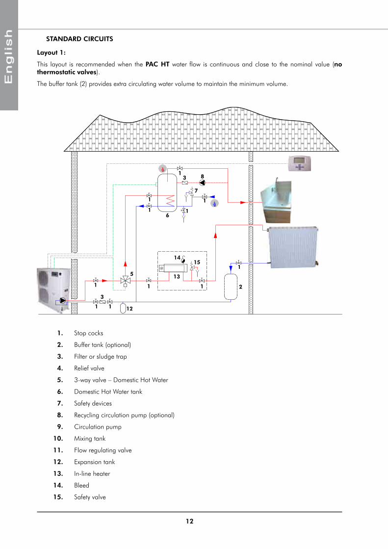
Layout 1:
This layout is recommended when the PAC HT water flow is continuous and close to the nominal value (no thermostatic valves).
The buffer tank (2) provides extra circulating water volume to maintain the minimum volume.
STANDARD CIRCUITS
1
3
2
1 1
1
1
1 1
31
5
6
7
8
1
1
12
15
1
14
13
1. Stop cocks
2. Buffer tank (optional)
3. Filter or sludge trap
4. Relief valve
5. 3-way valve – Domestic Hot Water
6. Domestic Hot Water tank
7. Safety devices
8. Recycling circulation pump (optional)
9. Circulation pump
10. mixing tank
11. Flow regulating valve
12. Expansion tank
13. In-line heater
14. Bleed
15. Safety valve
13
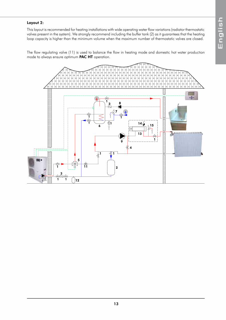
Layout 2:
This layout is recommended for heating installations with wide operating water flow variations (radiator thermostatic valves present in the system). We strongly recommend including the buffer tank (2) as it guarantees that the heating loop capacity is higher than the minimum volume when the maximum number of thermostatic valves are closed.
The flow regulating valve (11) is used to balance the flow in heating mode and domestic hot water production mode to always ensure optimum PAC HT operation.
1
3
2
4
1 1
1
1
1 1
31
5
6
7
8
9
1
1
11
12
15
1
14
13
14
ANTI-FREEZE PROTECTION
We recommend that the installation is protected against freezing by adding anti-freeze.
The chart below indicates the concentration of anti-freeze to be used relative to the minimum outdoor temperature reached.
The mixture considerably alters the installation's performances, particularly in terms of pressure losses:
² Observe the calculation method detailed in the Technical manual ref: 97 TAq 06.
WATER TREATMENT WARNING
Using untreated or inadequately treated water in this appliance can lead to a build-up of limescale, algae or sludge deposits and cause corrosion and erosion. As the manufacturer is not aware of the components used in the hydraulic network, or of the quality of water used, the installer or the owner should contact a specialised water treatment company. This issue is particularly important and every care should be taken to ensure that circuit water is properly treated in order to avoid problems associated with incorrect water distribution. A clogged water network will systematically lead to premature wear of the appliance's components.
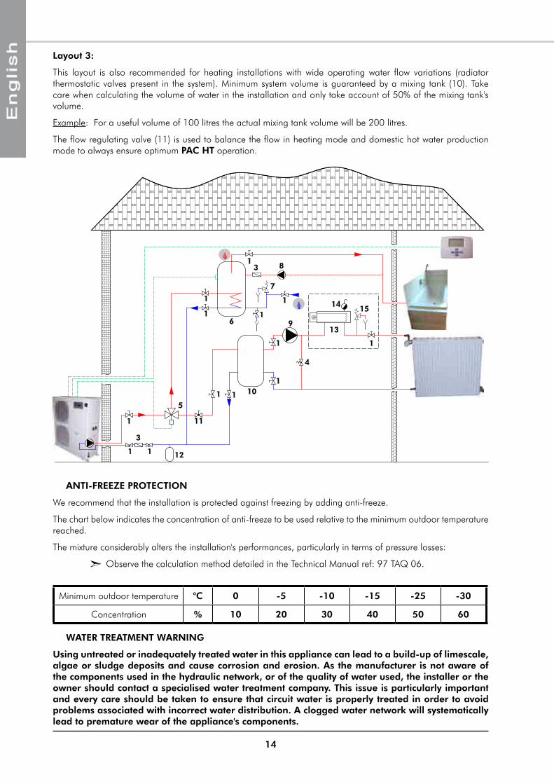
Layout 3:
This layout is also recommended for heating installations with wide operating water flow variations (radiator thermostatic valves present in the system). minimum system volume is guaranteed by a mixing tank (10). Take care when calculating the volume of water in the installation and only take account of 50% of the mixing tank's volume.
Example: For a useful volume of 100 litres the actual mixing tank volume will be 200 litres.
The flow regulating valve (11) is used to balance the flow in heating mode and domestic hot water production mode to always ensure optimum PAC HT operation.
1
3
10
4
1 1
1
1 1
31
5
6
7
8
9
1 1
1
1
1
11
12
15
1
14
13
minimum outdoor temperature °C 0 -5 -10 -15 -25 -30
Concentration % 10 20 30 40 50 60
15
CONNECTION TO THE CENTRAL HEATING LOOP
You must check water tightness and the cleanliness of the installation before connecting the PAC HT.
For the PAC HT's WATER INLET and OUTLET connections, you must install manual stop cocks with the same diameter as the main pipe work. This will enable maintenance work to be carried out on the PAC HT without having to bleed the entire system.
A link valve with pressure tap kit is available.
The PAC HT must be protected by a water filter. When connecting this device to the PAC HT, take care to keep the water filter sieve pointing downwards. A sludge trap should be fitted in the event of high sludge build-ups.
AN EXPANSION TANK ADAPTED TO THE vOLUME OF WATER IN THE INSTALLATION MUST BE INSTALLED.
It is important to ensure that the mains water supply pressure is sufficient to fill the installation.
WARNING!
Take care not to damage the hydraulic pipe links by applying too much tightening pressure. Use a second wrench to compensate for the tightening torque.
You should always use a counter-wrench for tightening valves.
HEAT INSULATION
To guarantee proper energy efficiency and compliance with current standards, water pipes passing through uninhabited zones should be properly lagged to retain heat.
To achieve correct insulation with conductivity of 0.04 W/m°K, lag the pipes with insulating material with a radial thickness between 25mm and 30 mm.
FILLING THE SYSTEM WITH WATER
All installation works must be completed and the system cleaned and drained, before filling the water circuit in accordance with current best practices. The system should be filled to obtain a service pressure not exceeding 2.5 bars.
The water supply should come either from the mains network or from the Heat pump or from any other point on the installation.
Check that the automatic bleed valve operates correctly.
You must completely bleed the circuit of all air to ensure efficient operation.
Close the inlet water valve once the hydraulic circuit is filled correctly.
WATER FLOW CONTROLLER
A paddle type water flow controller is fitted to the water circuit connected to the condenser. This safety device ensures that the water flow has been established before appliance start-up.
The appliance is equipped with a set of safety devices including a safety valve set at 3 bars and a manual pressure relief valve.
THE MANUFACTURER'S WARRANTY IS vOID IF THE FILTER SUPPLIED WITH THE PAC HT IS NOT INSTALLED TO PROTECT THE APPLIANCE
16
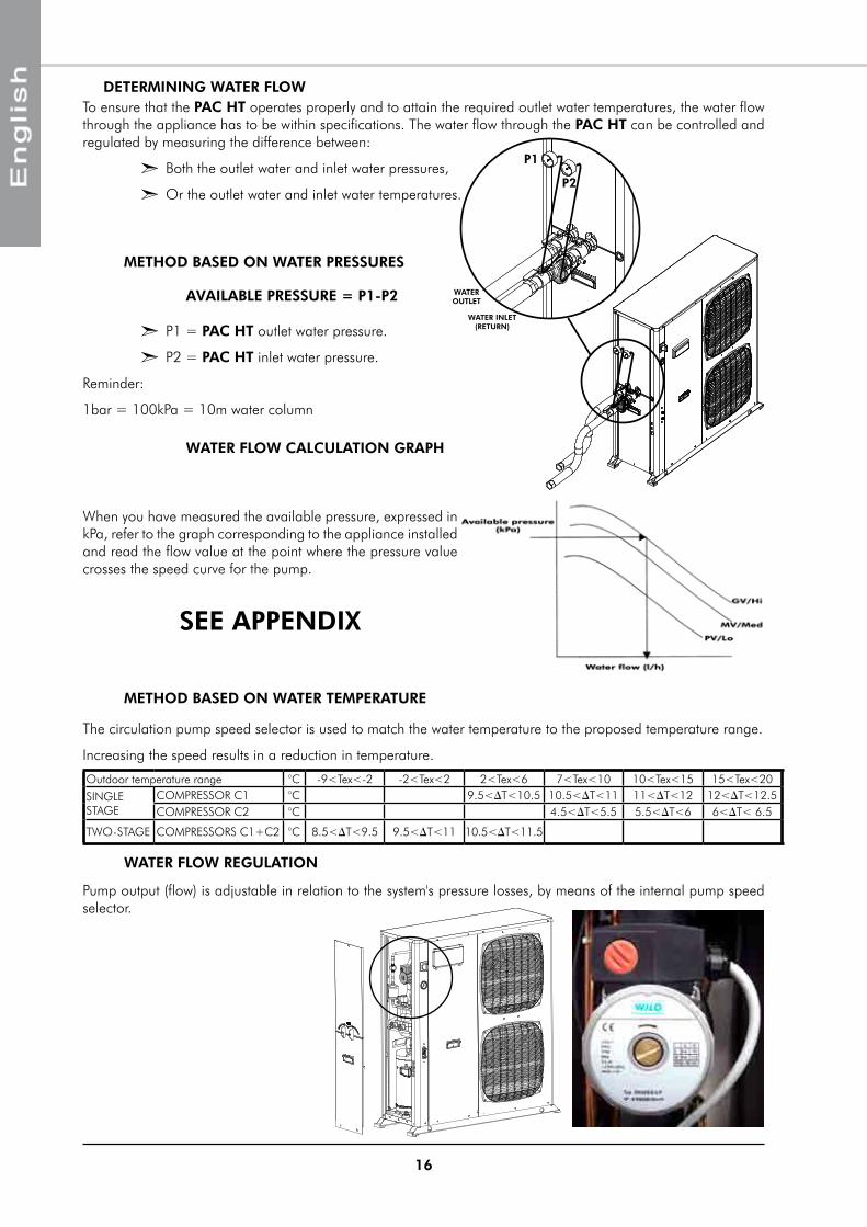
DETERMINING WATER FLOW
² p1 = PAC HT outlet water pressure.
² p2 = PAC HT inlet water pressure.
Reminder:
1bar = 100kpa = 10m water column
AvAILABLE PRESSURE = P1-P2
WATER FLOW CALCULATION GRAPH
pump output (flow) is adjustable in relation to the system's pressure losses, by means of the internal pump speed selector.
SEE APPENDIX
P2
P1
WATER OUTLET
WATER INLET (RETURN)
When you have measured the available pressure, expressed in kpa, refer to the graph corresponding to the appliance installed and read the flow value at the point where the pressure value crosses the speed curve for the pump.
To ensure that the PAC HT operates properly and to attain the required outlet water temperatures, the water flow through the appliance has to be within specifications. The water flow through the PAC HT can be controlled and regulated by measuring the difference between:
² Both the outlet water and inlet water pressures,
² Or the outlet water and inlet water temperatures.
METHOD BASED ON WATER PRESSURES
METHOD BASED ON WATER TEMPERATURE
The circulation pump speed selector is used to match the water temperature to the proposed temperature range.
Increasing the speed results in a reduction in temperature.
WATER FLOW REGULATION
Outdoor temperature range °C -9<Tex<-2 -2<Tex<2 2<Tex<6 7<Tex<10 10<Tex<15 15<Tex<20SINGLE STAGE
COmpRESSOR C1 °C 9.5<DT<10.5 10.5<DT<11 11<DT<12 12<DT<12.5COmpRESSOR C2 °C 4.5<DT<5.5 5.5<DT<6 6<DT< 6.5
TWO-STAGE COmpRESSORS C1+C2 °C 8.5<DT<9.5 9.5<DT<11 10.5<DT<11.5
17
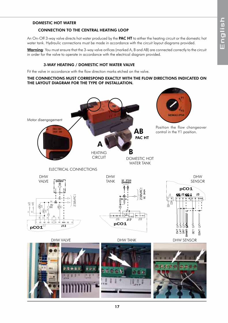
DOMESTIC HOT WATER
3-WAY HEATING / DOMESTIC HOT WATER vALvE
Fit the valve in accordance with the flow direction marks etched on the valve.
THE CONNECTIONS MUST CORRESPOND EXACTLY WITH THE FLOW DIRECTIONS INDICATED ON THE LAYOUT DIAGRAM FOR THE TYPE OF INSTALLATION.
CONNECTION TO THE CENTRAL HEATING LOOP
An On-Off 3-way valve directs hot water produced by the PAC HT to either the heating circuit or the domestic hot water tank. Hydraulic connections must be made in accordance with the circuit layout diagrams provided.
Warning: You must ensure that the 3-way valve orifices (marked A, B and AB) are connected correctly to the circuit in order for the valve to operate in accordance with the electrical diagram provided.
position the flow changeover control in the Y1 position.
AB
AB
motor disengagement
DOmESTIC HOT WATER TANK
PAC HT
HEATING CIRCUIT
ELECTRICAL CONNECTIONS
pCO1
DHWV
L
N
NO5
J13
DHW VALVE
pCO1
DHWEH
N
NO12
J17
DHW TANK
pCO1
B4
J3J2GND
DH
WT
DHW SENSOR
DHW VALVE DHW TANK DHW SENSOR
18
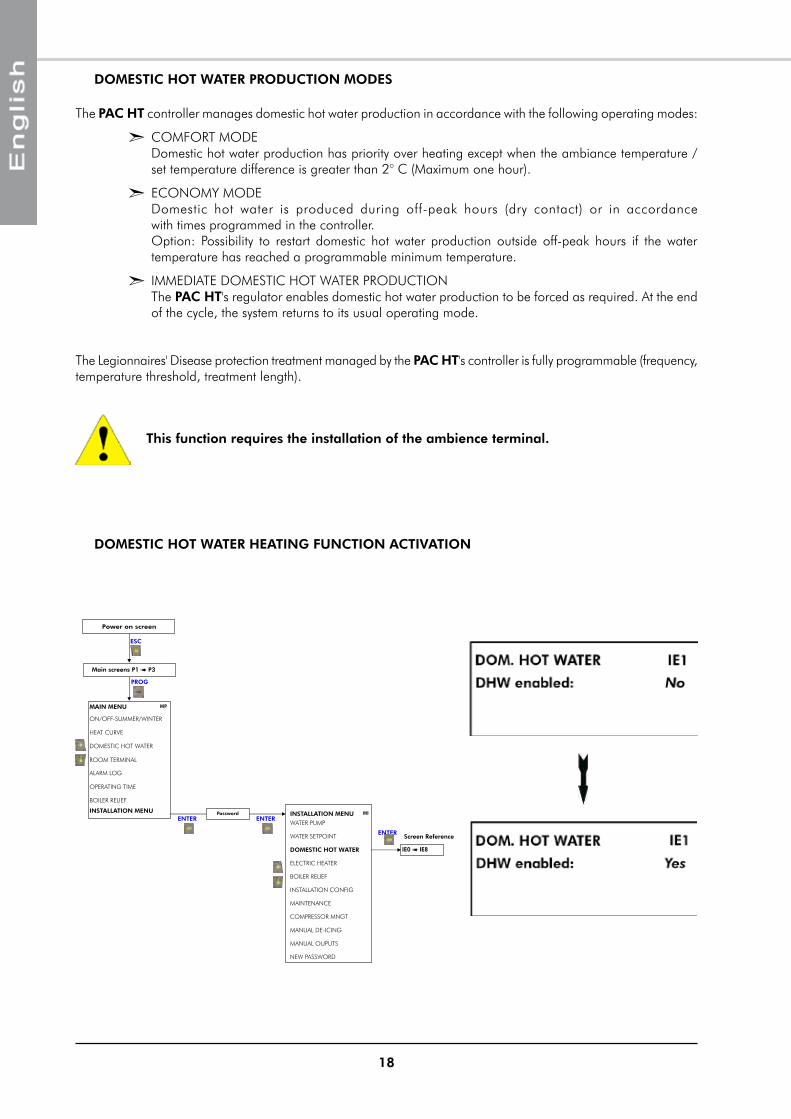
DOMESTIC HOT WATER HEATING FUNCTION ACTIvATION
PROG
Main screens P1 P3
INSTALLATION MENU
Power on screen
ESC
INSTALLATION MENU
MAIN MENU MP
ON/OFF-SUMMER/WINTER
HEAT CURVE
DOMESTIC HOT WATER
ROOM TERMINAL
ALARM LOG
OPERATING TIME
Screen Reference
Password
WATER PUMP
WATER SETPOINT
DOMESTIC HOT WATER IE0 IE8
MAINTENANCE
INSTALLATION CONFIG
COMPRESSOR MNGT
MANUAL DE-ICING
NEW PASSWORD
MANUAL OUPUTS
MIENTER ENTER
ENTER
ELECTRIC HEATER
BOILER RELIEF
BOILER RELIEF
The PAC HT controller manages domestic hot water production in accordance with the following operating modes:
² COmFORT mODE Domestic hot water production has priority over heating except when the ambiance temperature / set temperature difference is greater than 2° C (maximum one hour).
² ECONOmY mODE Domestic hot water is produced during off-peak hours (dry contact) or in accordance with times programmed in the controller. Option: possibility to restart domestic hot water production outside off-peak hours if the water temperature has reached a programmable minimum temperature.
² ImmEDIATE DOmESTIC HOT WATER pRODUCTION The PAC HT's regulator enables domestic hot water production to be forced as required. At the end of the cycle, the system returns to its usual operating mode.
The Legionnaires' Disease protection treatment managed by the PAC HT's controller is fully programmable (frequency, temperature threshold, treatment length).
DOMESTIC HOT WATER PRODUCTION MODES
This function requires the installation of the ambience terminal.
19
IN-LINE ELECTRIC HEATER
ELECTRICAL CONNECTIONS
OPERATING MODE
SEE APPENDIX
Operating parameters for these modes can be set via the display on the PAC HT.
BOOST MODE
The heater provides additional heating when the demand for heating exceeds the capacity of the PAC HT. The aim is to maintain occupier comfort while favouring operation of the PAC HT for optimal performance.
The resistances are only activated below a certain outdoor temperature (values can be set for Stage 1, AEH1 and Stage 1+2, AEH1+AEH2) and only if the PAC HT regulation system detects a lack of capacity in compressor only mode (check on water temperature and ambient temperature).
Activation of the ICS Back-up switch on the heater switches the PAC HT into Back-up mode.
BACK-UP MODE
As opposed to Booster mode, this mode operates only when the user activates the ICS Back-up switch (this supposes an alarm on the PAC HT). Outdoor temperature conditions are overridden and priority is no longer given to the thermodynamic mode but to the heating resistances that are nevertheless still controlled by the PAC HT.
ELECTRIC HEATER FUNCTION ACTIvATION
PROG
Main screens P1 P3
INSTALLATION MENU
Power on screen
ESC
INSTALLATION MENU
MAIN MENU MP
ON/OFF-SUMMER/WINTER
HEAT CURVE
DOMESTIC HOT WATER
ROOM TERMINAL
ALARM LOG
OPERATING TIME
Screen Reference
Password
WATER PUMP
WATER SETPOINT
DOMESTIC HOT WATER
MAINTENANCE
INSTALLATION CONFIG
COMPRESSOR MNGT
MANUAL DE-ICING
NEW PASSWORD
MANUAL OUPUTS
MIENTER ENTER
ENTER
ELECTRIC HEATER EH0 EH7
BOILER RELIEF
BOILER RELIEF
20
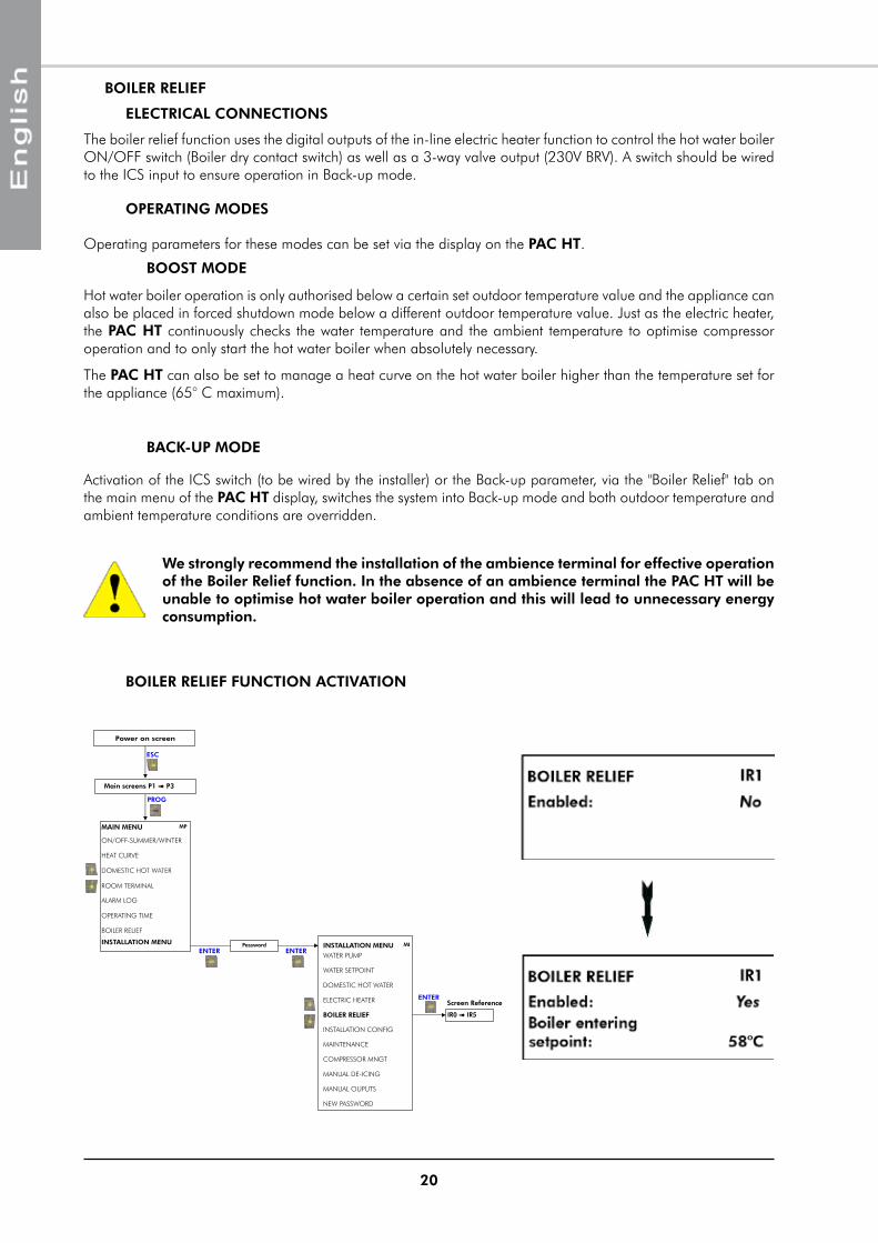
BOILER RELIEF
ELECTRICAL CONNECTIONS
The boiler relief function uses the digital outputs of the in-line electric heater function to control the hot water boiler ON/OFF switch (Boiler dry contact switch) as well as a 3-way valve output (230V BRV). A switch should be wired to the ICS input to ensure operation in Back-up mode.
We strongly recommend the installation of the ambience terminal for effective operation of the Boiler Relief function. In the absence of an ambience terminal the PAC HT will be unable to optimise hot water boiler operation and this will lead to unnecessary energy consumption.
BOILER RELIEF FUNCTION ACTIvATION
PROG
Main screens P1 P3
INSTALLATION MENU
Power on screen
ESC
INSTALLATION MENU
MAIN MENU MP
ON/OFF-SUMMER/WINTER
HEAT CURVE
DOMESTIC HOT WATER
ROOM TERMINAL
ALARM LOG
OPERATING TIME
Screen Reference
Password
WATER PUMP
WATER SETPOINT
DOMESTIC HOT WATER
MAINTENANCE
INSTALLATION CONFIG
COMPRESSOR MNGT
MANUAL DE-ICING
NEW PASSWORD
MANUAL OUPUTS
MIENTER ENTER
ENTERELECTRIC HEATER
BOILER RELIEF IR0 IR5
BOILER RELIEF
OPERATING MODES
Operating parameters for these modes can be set via the display on the PAC HT.
BOOST MODE
Hot water boiler operation is only authorised below a certain set outdoor temperature value and the appliance can also be placed in forced shutdown mode below a different outdoor temperature value. Just as the electric heater, the PAC HT continuously checks the water temperature and the ambient temperature to optimise compressor operation and to only start the hot water boiler when absolutely necessary.
The PAC HT can also be set to manage a heat curve on the hot water boiler higher than the temperature set for the appliance (65° C maximum).
BACK-UP MODE
Activation of the ICS switch (to be wired by the installer) or the Back-up parameter, via the "Boiler Relief" tab on the main menu of the PAC HT display, switches the system into Back-up mode and both outdoor temperature and ambient temperature conditions are overridden.
21
LEGEND
WIRING DIAGRAM AND LEGEND
N 773
WIRING DIAGRAM
SEE APPENDIX
POWER SUPPLY
Connection to the qG main disconnect switch230v +/-10% 50Hz
² L : phase
² N : neutral
² : ground
3N~400v +/-10% 50Hz
² L1 (L1) : phase
² L2 (L2) : phase
² L3 (L3) : phase
² N (N) : neutral
² : ground
This supply comes from a CIRCUIT BREAKER or a FUSE HOLDER equipped with am type fuses supplied by the installer. Fuse sizes are indicated on the chart on the following page.
The appliance's electrical installation and wiring must comply with the country's current standards.
WIRING DIAGRAM KEY DESCRIPTIONS
POWERqG : main cut-out switch
K1/2 : m1/2 compressors power contactor or relay
FT1/2 : m1/2 compressors thermo-magnetic relay (three phase models)
FF1/2 : m1/2 compressors protection fuse carrier (single phase models)
R1/2 : Sump resistance
COMMAND AND REGULATION
FF8 : Control circuit protection fuse
FF9 : T1 transformer protection fuse (230V primary circuit)
FF10 : T1 transformer protection fuse (24V secondary circuit)
T1 : pco1 230/24V power supply transformer
M1/2 : Compressors
CF1/2 : m1/2 compressors capacitors (single phase models)
AS1/2 : "Soft START" starter
Rv : 4-way cycle changeover valves
KA1 : phase sequence and cut-out control module (three phase models)
RAG : Anti-freezing protection electric resistance
Pco1 : Controller
FT1/2 : Thermo-magnetic relays ancillary contacts for m1/2 compressors
EWT : Inlet water probe
LWT : Outlet water probe
OCT : Condensation control probe
SE 3743 PAC HT 12-6 Control 1-phase 230V +/-10% 50Hz
SE 3742 PAC HT 12-6 power 1-phase 230V +/-10% 50Hz
SE 3529 PAC HT 14-7 Control 1-phase 230V +/-10% 50Hz
SE 3527 PAC HT 14-7 power 1-phase 230V +/-10% 50Hz
SE 3745 PAC HT 12-6/14-7 Control 3-phases 3N~400V +/-10% 50Hz
SE 3744 PAC HT 12-6/14-7 power 3-phases 3N~400V +/-10% 50Hz
SE 3435 PAC HT 18-9 Control 3-phases 3N~400V +/-10% 50Hz
SE 3434 PAC HT 18-9 power 3-phases 3N~400V +/-10% 50Hz
22
vENTILATION - FANM21 : Lower air exchanger fan motor
M22 : Upper air exchanger fan motor
FM21 : m21 motor internal safety
FM22 : m22 motor internal safety
WATER CIRCUIT
FS : Water flow detector (flow switch)
MP : Water pump
OAT : Outdoor air temperature probe
FB11 : Automatic reset low pressure switch
FH11 : Automatic reset high pressure switch
CDT1/2 : High discharge temperature (circuit 1/2)
IHP : Intermediate high pressure switch
DHP : De-icing high pressure switch
ISv : Injection valve
DRv : De-icing valve
TAG : Anti-freezing protection thermostat
ESv : Oil equalization valve
C21 : m21 motor capacitor
C22 : m22 motor capacitor
K3 : m21 fan motor relay
K4 : m22 fan motor relay
K5 : mp water pump relay
FUSE RATINGS, NOMINAL CONTACTOR AMPERAGE (IN CLASS AC3/AC1)
* These values are provided for information purposes only and must be checked and adjusted in relation to currently applicable standards. They vary depending on the type of installation and the choice of conductors.
OPTIONSDHWT : Domestic hot water temperature probe
DZWT : Dual zone water temperature probe
DZv : Dual zone modulating valve
DHWv : Domestic hot water valve
DHWEH : Domestic hot water electric heater
DZWP1/2 : Dual zone – Zones 1 and 2 water pumps
ON/OFF : On / Off switch
LS : DHW Off-peak hour
AEH : Additional electric heater
BOILER : Hot water boiler
BRv : Boiler relief valve
ICS : Back-up heating switch
Supply voltages 3N~400v +/-10% 50HzPAC HT 12-6 14-7 18-9General protection fuse rating (not supplied) 16A 16A 20AFuse ratings
FF8 am type 6A 6A 6AFF9/10 T type 1.6A 1.6A 1.6A
Thermo-magnetic cut-out switchFT1 Range 9 - 14A 9 - 14A 9 - 14A
Setting 10A 11A 13AFT2 Range 4 - 6.3A 4 - 6.3A 4 - 6.3A
Setting 4.2A 5.1A 6.3AContactors
K1 12A 12A /K2 9A 9A 9A
Supply voltages 230v +/-10% 50HzPAC HT 12-6 14-7General protection fuse rating (not supplied) 32A 32AFuse ratings
FF1 am type 25A 25AFF2 am type 12A 16AFF8 am type 6A 6AFF9/10 T type 1.6A 1.6A
ContactorsK2 12A /
23
ELECTRICAL CONNECTIONSWARNING
Before carrying out any work on the equipment, make sure that the electrical power supply is disconnected and that there is no possibility of the unit being started inadvertently.
Non-compliance with the above instructions can lead to injury or death by electrocution.
The electrical installation must be performed by a fully qualified electrician, and in accordance with local electrical standards and the wiring diagram corresponding to the unit model.
Any modification performed without our prior authorisation may result in the unit’s warranty being declared null and void.
The power supply cable section must be sufficient to provide the appropriate voltage to the unit’s power supply terminals, both at start-up and under full load operating conditions.
The power supply cable shall be selected in accordance with the following criteria:
1. power supply cable length.
2. maximum unit starting current draw – the cables shall supply the appropriate voltage to the unit terminals for starting.
3. power supply cables’ installation mode.
4. Cables’ capacity to transport the total system current draw.
Short circuit protection shall be provided. This protection shall comprise fuses or circuit breakers with high breaking capacity, mounted on the distribution board.
If the local control includes a remote ambient terminal, it shall be connected with shielded cable and shall not pass through the same conduits as the power supply cables as the voltages induced may create reliability faults in the unit’s operation.
WARNING!
On-site wiring must be performed in accordance with the wiring diagram present in the appliance's electrical connection box.
Mains power supply cables to the appliance must have copper conducting cores and be sized in compliance with currently applicable IEC standards.
The appliance must be grounded via a terminal block located inside the electrical connection box.
The power supply must not fluctuate by more than 10 %. Imbalance between phases must not exceed 3%.
24
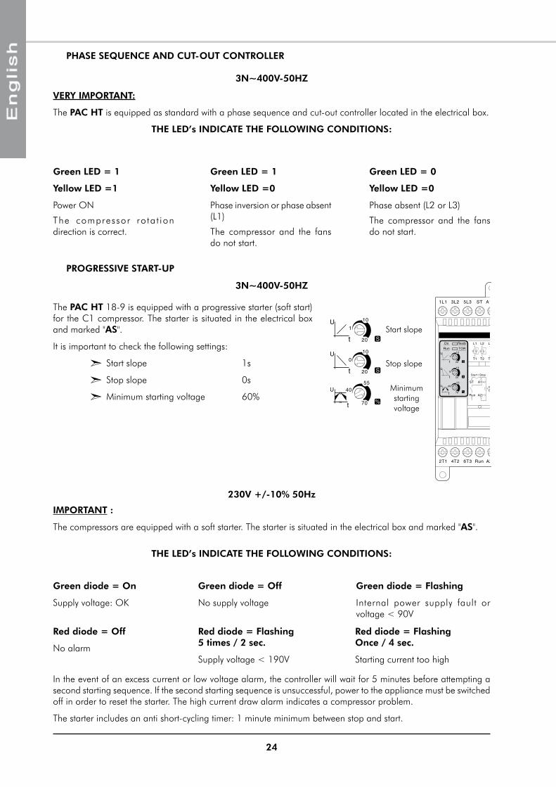
vERY IMPORTANT:
The PAC HT is equipped as standard with a phase sequence and cut-out controller located in the electrical box.
THE LED’s INDICATE THE FOLLOWING CONDITIONS:
Green LED = 1
Yellow LED =1
power ON
The compressor ro ta t ion direction is correct.
Green LED = 1
Yellow LED =0
phase inversion or phase absent (L1)
The compressor and the fans do not start.
Green LED = 0
Yellow LED =0
phase absent (L2 or L3)
The compressor and the fans do not start.
THE LED’s INDICATE THE FOLLOWING CONDITIONS:
Green diode = On
Supply voltage: OK
Green diode = Off
No supply voltage
Green diode = Flashing
Internal power supply fault or voltage < 90V
Red diode = Off
No alarm
Red diode = Flashing 5 times / 2 sec.
Supply voltage < 190V
Red diode = Flashing Once / 4 sec.
Starting current too high
In the event of an excess current or low voltage alarm, the controller will wait for 5 minutes before attempting a second starting sequence. If the second starting sequence is unsuccessful, power to the appliance must be switched off in order to reset the starter. The high current draw alarm indicates a compressor problem.
The starter includes an anti short-cycling timer: 1 minute minimum between stop and start.
IMPORTANT :
The compressors are equipped with a soft starter. The starter is situated in the electrical box and marked "AS".
The PAC HT 18-9 is equipped with a progressive starter (soft start) for the C1 compressor. The starter is situated in the electrical box and marked "AS".
It is important to check the following settings:
² Start slope 1s
² Stop slope 0s
² minimum starting voltage 60%
Start slope
Stop slope
minimum starting voltage
3N~400v-50HZ
230v +/-10% 50Hz
PHASE SEqUENCE AND CUT-OUT CONTROLLER
PROGRESSIvE START-UP
3N~400v-50HZ
25
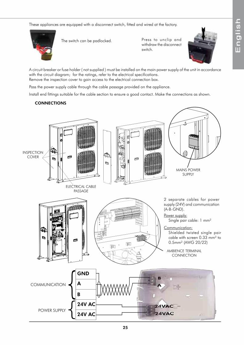
These appliances are equipped with a disconnect switch, fitted and wired at the factory.
press to unclip and withdraw the disconnect switch.
The switch can be padlocked.
A circuit breaker or fuse holder ( not supplied ) must be installed on the main power supply of the unit in accordance with the circuit diagram; for the ratings, refer to the electrical specifications.Remove the inspection cover to gain access to the electrical connection box.
pass the power supply cable through the cable passage provided on the appliance.
Install end fittings suitable for the cable section to ensure a good contact. make the connections as shown.
CONNECTIONS
ELECTRICAL CABLE pASSAGE
INSpECTION COVER
mAINS pOWER SUppLY
AmBIENCE TERmINAL CONNECTION
A
B
24V AC
24V AC
GND
COmmUNICATION
pOWER SUppLY{{
2 separate cables for power supply (24V) and communication (A-B-GND).power supply:
Single pair cable: 1 mm²
Communication: Shielded twisted single pair cable with screen 0.33 mm² to 0.5mm² (AWG 20/22)
26
COMMISSIONINGPRE-START CHECK LIST
ELECTRICAL CHECK
² Electrical installation has been carried out according to unit wiring diagram and the Supply Authority Regulations.
² Check the circuit breaker setting or the fuse rating on the mains power supply.
² Supply voltages as specified on unit wiring diagram.
² Check the tightness of wire to component connections.
² The cables and wires are clear of or protected from pipework and sharp edges.
² Check the electrical grounding of the appliance.
Before commissioning the system, you must carry out a certain number of installation checks to ensure that the appliance will operate in the best possible conditions. The following list of checks is not exhaustive and only serves as a minimum reference guide.
APPLIANCE POSITIONING
² Check free clearances around the unit, including the exchanger air intake and outlet, and access for maintenance work.
² Comply with the free clearance dimensions around the domestic hot water tank.
² Check unit assembly in accordance with specifications.
² Check presence and tightness of all screws and bolts.
² Check that the rubber anti-vibration pads are in place.
² Check that the unit is level and that condensates drain freely away from the unit.
² Check that there is no possibility of blown air being recycled through the fans due to wind exposure.
² In arduous climates (sub-zero temperature, snow, high humidity), check that the appliance is raised 10 cm off ground.
² Check that the ambience terminal is located correctly (frequently occupied area, 1.5 m above ground level, etc.).
HYDRAULIC CHECKS
² Check the presence, direction and position of the water filter upstream of the appliance. Rinse the filter after the first 2 hours of operation.
² Check that the external water circuit components are installed correctly in accordance with manufacturer's recommendations and that the water inlet and outlet connections have been made correctly.
² Check that the water quality complies with stated standards.
² Check that the hydraulic circuit is filled properly and that the fluid flows freely without any signs of leakage or air bubbles.
² Adjust water flow in accordance with the specifications.
² Check the presence and position of the stop cocks to isolate the appliance for maintenance.
² Check the presence of the air bleed valve.
² Check the protection of the installation against freezing conditions (thermal insulation, percentage of ethylene glycol in the water circuit if required...).
² Check that the bleed valve in the appliance has been opened.
27
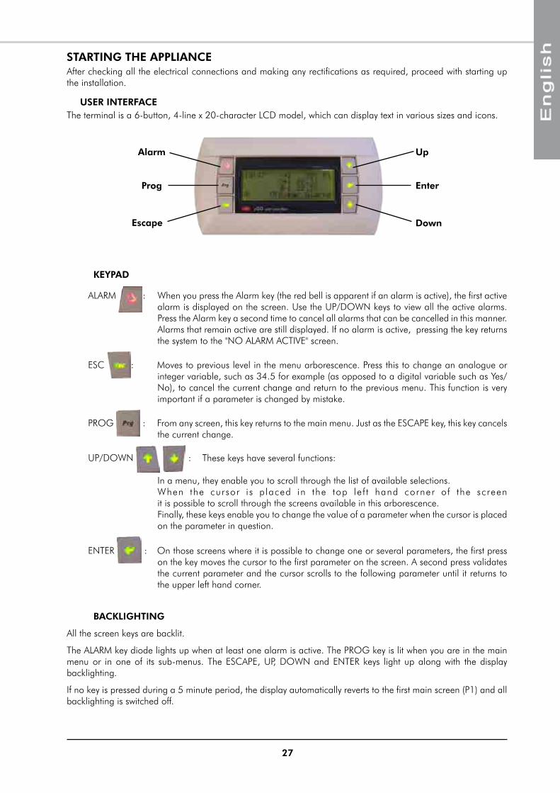
STARTING THE APPLIANCE
USER INTERFACEThe terminal is a 6-button, 4-line x 20-character LCD model, which can display text in various sizes and icons.
KEYPAD
ALARm : When you press the Alarm key (the red bell is apparent if an alarm is active), the first active alarm is displayed on the screen. Use the Up/DOWN keys to view all the active alarms. press the Alarm key a second time to cancel all alarms that can be cancelled in this manner. Alarms that remain active are still displayed. If no alarm is active, pressing the key returns the system to the "NO ALARm ACTIVE" screen.
ESC : moves to previous level in the menu arborescence. press this to change an analogue or integer variable, such as 34.5 for example (as opposed to a digital variable such as Yes/No), to cancel the current change and return to the previous menu. This function is very important if a parameter is changed by mistake.
pROG : From any screen, this key returns to the main menu. Just as the ESCApE key, this key cancels the current change.
Up/DOWN : These keys have several functions: In a menu, they enable you to scroll through the list of available selections. When the cursor i s p laced in the top le f t hand corner of the screen it is possible to scroll through the screens available in this arborescence. Finally, these keys enable you to change the value of a parameter when the cursor is placed on the parameter in question.
ENTER : On those screens where it is possible to change one or several parameters, the first press on the key moves the cursor to the first parameter on the screen. A second press validates the current parameter and the cursor scrolls to the following parameter until it returns to the upper left hand corner.
BACKLIGHTING
All the screen keys are backlit.
The ALARm key diode lights up when at least one alarm is active. The pROG key is lit when you are in the main menu or in one of its sub-menus. The ESCApE, Up, DOWN and ENTER keys light up along with the display backlighting.
If no key is pressed during a 5 minute period, the display automatically reverts to the first main screen (p1) and all backlighting is switched off.
Alarm
Prog
Escape
Up
Down
Enter
After checking all the electrical connections and making any rectifications as required, proceed with starting up the installation.
28
MENUSThe display comprises several menus. Some have unrestricted access and one (the Installation menu) is password protected.
All the screens include a reference in the top right hand corner to make it easier to navigate between the different menus.
PROG
Main screens P1 P3
Screen Reference
INSTALLATION MENU
ENTER
Power on screen
ESC
INSTALLATION MENU
MAIN MENU MP
ON/OFF-SUMMER/WINTER O0
HEAT CURVE L1 L4
DOMESTIC HOT WATER ES0 ES10
ROOM TERMINAL TH0 TH4
ALARM LOG H1 H2
OPERATING TIME TM1 TM2
Screen ReferencePassword
WATER PUMP Ci1 Ci5
WATER SETPOINT CE1 CE3
DOMESTIC HOT WATER IE0 IE8
MAINTENANCE M1 M22
INSTALLATION CONFIG CI1 CI4
COMPRESSOR MNGT CP1
MANUAL DE-ICING D1 D2
NEW PASSWORD NI1
MANUAL OUPUTS S1 S7
MIENTER ENTER
ENTER
ELECTRIC HEATER EH0 EH7
BOILER RELIEF IR0 IR5
BOILER RELIEF R0 R1
ICONS
p1
Outlet water set temperature, calculated from the heat curve parameters, the outdoor temperature, the ambience set temperature and the variance between the set and the ambience temperature.
Compressor 1 (large) in operation
Compressor 2 (small) in operation
Fan 1 (upper) in operation
Fan 2 (lower) in operation
Outlet water temperature
Inlet (return) water temperature
PAC HT in Summer mode
Flashing: Countdown for de-icing Fixed on: De-icing in progress
Circulation pump in operation
p2
Instantaneous outdoor temperature
Reference outdoor temperature used by the PAC HT (upper fan special management)
Outdoor exchanger temperature (used for the de-icing countdown)
Domestic hot water temperature (when the option is installed)
PAC HT in domestic hot water production mode (flashing)
Electric heater Stage 1 in operation (flashing)
Electric heater Stage 2 in operation (flashing)
Hot water boiler in operation (flashing)
ref.
Batt.
29
Altitude: Installation site altitude, in km (e.g. 0.5km equals 500m. Default setting: 0).
Base outd. T.: Typical outdoor temperature for the installation region (Default setting: -7°C).
Corr. Coef.: Correction Coefficient for the base of the slope. This is a simple way of changing the water set temperature (Default setting: 0.8).
On the PAC HT display, after having checked the coherence of the temperature probes on the main screens P1 and P2, as well as effective communication with the ambience terminal, it is advisable to set the heat curve parameters before starting the PAC HT. The main screen P1 is accessible by pressing the ESC key several times. The main screen P1 also appears after 5 minutes of display inactivity.
SIMPLIFIED START-UP PROCEDURE
MAIN SCREENS
HEAT CURvE PARAMETERS
On the main menu (Prg key), use the UP/DOWN arrows to highlight the "HEAT CURvE" menu. Validate this selection with the ENTER key. This moves the display to the L1 screen. Use the ENTER and UP/DOWN keys to set the following parameters:
Screen L1
RADIATOR HEAT CURVE PARAMETERS
20
25
30
35
40
45
50
55
60
65
70
-15 -10 -5 0 5 10 15 20
Outdoor temperature (°C)
Leavi
ng
wate
r te
mp
eratu
re s
etp
oin
t (°
C)
Correction Coef. 0,5
Correction Coef. 0,8
Correction Coef. 1,0
Base outd. T.
Base water SPT
Losses at Base Temp.: Estimated heat loss for the dwelling for an ambient temperature of 20°C and a base outdoor temperature (e.g. -7°C). This parameter is used to calculate the outdoor temperature that triggers the change from small compressor mode to two-stage compressor mode. This value is capped at the maximum capacity of the PAC HT model in question for this same outdoor temperature (Default value = maximum value).
Base Outl. T.: Outlet water temperature required at the base outdoor temperature to have an ambient temperature of 20°C (Default setting: 65°C).
Screen L2
30
Information screen for the outdoor temperature calculated automatically by the PAC HT. With the preceding default parameters, the value of 5.4° C means that below an outdoor temperature of 5.4° C the PAC HT will start the large compressor or the two-stage compressor. Above 5.4° C the PAC HT will start the small compressor.
The value of the outdoor balance temperature displayed on L4 is the one updated by the PAC HT after running for some time, in the event that the PAC HT detects a lack of capacity with the small compressor.
Zero reset: This is required in the event of changes to the heat curve parameters in order for the PAC HT to register these changes. The parameter on screen L3 is then recopied into screen L4.
vERIFICATION OF COMMUNICATION WITH THE COMMUNICATING AMBIENCE TERMINAL
The ambience terminal supplied with each PAC HT is declared in the regulator by default. This means that an alarm will be visible on the PAC HT screen a few seconds after the power is switched on if the terminal is disconnected. Its proper operation can be checked on the screen P3 where the time and date and the day of the week data keyed into the terminal is available.
All the terminal parameters are accessible via the "Ambience Terminal" menu in the main menu (Prg key).
Screens: TH0 to TH4.
COMPRESSOR SUMP HEATER FUNCTION ACTIvATION
After the first power ON (compressors OFF), and for any outdoor air temperature, manually switch ON the compressor sump heaters.
Before starting the compressors, the sump heaters must be powered On for at least 2 hours in order to evaporate any liquid refrigerant that could be in the compressors to ensure their lubrification at the first start-up.
PROG
Main screens P1 P3
INSTALLATION MENU
Power on screen
ESC
INSTALLATION MENU
MAIN MENU MP
ON/OFF-SUMMER/WINTER
HEAT CURVE
DOMESTIC HOT WATER
ROOM TERMINAL
ALARM LOG
OPERATING TIME
Screen Reference
Password
WATER PUMP
WATER SETPOINT
DOMESTIC HOT WATER
MAINTENANCE
INSTALLATION CONFIG
COMPRESSOR MNGT
MANUAL DE-ICING
NEW PASSWORD
MANUAL OUPUTS
MIENTER ENTER
ENTER
ELECTRIC HEATER
BOILER RELIEF
S1 S7
BOILER RELIEF
Screen L3
Screen L4
Screen p3
Screen TH1
31
OPERATING CHECK LIST
GENERAL
Check for any unusual noises or vibration in the running components, particularly the indoor fan drive system.
FAN & DRIvE
1. Check that the fans rotate freely without rubbing.
COMPRESSOR AND REFRIGERATION SYSTEM
1. Checking operation: Start the PAC HT. Check for any abnormal noises or vibrations.
2. Suction superheat should be 6°K ±2°K.(*)
* These checks can be performed at the time of commissioning with the help of qualified technical personnel.
FINAL CHECK
1. All panels and fan guards are in place and secured.
2. Unit clean and free of remainder installation material.
OPERATING vOLTAGE:
1. Recheck voltage at unit supply terminals.
CONTROL
1. Verify all sensor inputs, using the controller display.
press the ENTER key twice to move the cursor to the GENERAL OFF parameter.
Use the UP/DOWN arrows to change this parameter to ON.
press ENTER to validate.
From the main menu, use the UP/DOWN arrows to highlight the "ON/OFF-SUMMER/WINTER" menu. Validate this selection by pressing the ENTER key. The display moves to the OO screen.
PAC HT ON/OFF SETTINGS
In order to start, the PAC HT must always be ON at the level of the appliance's display. In addition, the ambience terminal must be in demand mode (when it is connected). To force the terminal to enter demand mode, change it to Comfort mode with an ambience temperature set at 30° C.
The appliance OFF function will always have priority and therefore you will never be able to start the PAC HT in this mode.
If the ambience terminal is in demand mode, and if no alarm is active and the water temperature condition permits (inlet water at least 7° C below set temperature ), the PAC HT will start operating.
Normal PAC HT operation is guaranteed with an appliance inlet (system return) water temperature above 20° C.
Screen 00
Screen 00
32
FINAL TASKS
If needed, fix the cables and the pipes on the wall with clamping collars.
Operate the heat pump in the presence of the user and explain all functions.
IN CASE OF WARRANTY - MATERIAL RETURN PROCEDUREmaterial must not be returned without permission of our After Sales Department.
To return the material, contact your nearest sales office and ask for a "return voucher". The return voucher shall be sent with the returned material and shall contain all necessary information concerning the problem encountered.
The return of the part is not an order for replacement. Therefore, a purchase order must be entered through your nearest distributor or regional sales office. The order should include part name, part number, model number and serial number of the unit involved.
Following our personal inspection of the returned part, and if it is determined that the failure is due to faulty material or workmanship, and in warranty, credit will be issued on customer's purchase order. All parts shall be returned to our factory, transportation charges prepaid.
ORDERING SERvICE AND SPARE PARTS ORDERThe part number, the order confirmation and the unit serial number indicated on the name plate must be provided whenever service works or spare parts are ordered.
For any spare part order, indicate the date of unit installation and date of failure. Use the part number provided by our service spare parts, if it not available, provide full description of the part required.
33
MAINTENANCE
REGULAR MAINTENANCE
These units have been designed for minimum maintenance through the use of permanently lubricated components. However, there are operational maintenance requirements that require regular attention to ensure optimum performance.
maintenance must be performed by appropriately experienced personnel only.
WARNING : Isolate unit from power supply before working on unit.
GENERAL INSPECTION
Carry out a visual inspection of the complete installation in service.
Check the general cleanness of the installation, and check if the condensate evacuation is not blocked.
Check the condition of the condesate tray by pulling it out of the casing.
The user is responsible for ensuring that the appliance is in a proper working condition and that technical installation as well as the regular maintenance operations are performed by properly trained technicians and in accordance with the instructions contained in this manual.
CAUTION
BEFORE CARRYING OUT ANY OPERATION ON THE EqUIPMENT, CHECK THAT THE ELECTRICAL POWER SUPPLY IS SWITCHED OFF AND THAT IT CANNOT BE SWITCHED ON INADvERTENTLY.
ELECTRICAL SECTION
Check that the main power supply cable is not damaged or altered in such a way as to affect the insulation.
The contact surfaces of relays and contactors should be inspected regularly by an electrician and replaced as judged necessary. On these occasions the control box should be blown out with compressed air to remove any accumulation of dust or other contaminants.
Check the earth grounding connection.
REFRIGERATION CIRCUIT
Clean the heat exchanger using a special product for aluminium-copper heat exchangers, and rinse with water. Do not use hot water or steam, as this could cause the pressure of the refrigerant to rise.
Check that the surface of the aluminium fins of the heat exchanger is not damaged by impacts or scratches, and clean with an appropriate tool if necessary.
The refrigeration system is hermetically sealed and should require no regular maintenance. However, it is recommended to leak test the refrigerant system and check the general operating conditions and control devices on a regular basis. The operating pressures should be checked particularly as they are an excellent guide for maintenance.
IT IS RECOMMENDED THAT THE DISCONNECT SWITCH BE PADLOCKED
Some alarms can only be cancelled by switching the PAC HT to OFF.
Generally, an alarm means that there is an anomaly present on the appliance. We strongly recommend that you refrain from repeatedly resetting an alarm without rectifying its cause in order to avoid the risk of causing irrevocable damage to one or several components.
34
SERvICING CHECKLIST
CASING
1. Clean the outer panels.
2. Remove the panels.
3. Check that the insulation is not damaged. Repair as required.
CONDENSATE DRAIN pAN
1. Check that the drainage orifices and conduits are not blocked.
2. Eliminate all accumulated dirt.
3. Check that no traces of rust are present.
REFRIGERATION CIRCUIT
1. Check the absence of gas leaks. This equipment must be subjected to regular tightness checks conducted by qualified personnel. please refer to national requirements to determine the frequency of these checks.
2. Check that the copper tubes or the capillary tubes do not rub against any metal or vibrate.
3. Check that the compressors do not generate any abnormal noises or vibrations.
4. Check the compressor discharge temperature.
COILS
1. Clean the fin surfaces as required.
2. Check the condition of the fans and the fan motors.
ELECTRICAL EqUIpmENT
1. Check nominal current draw and the condition of the fuses.
2. Check the tightness of the screw terminals.
3. perform a visual check of the condition of the contacts.
4. Check the general tightness of all cable connections.
Replace the panels and add any missing screws.
HYDRAULIC CIRCUIT
1. Check that the hydraulic circuit is filled properly and that the fluid flows freely without any signs of leakage or air bubbles.
2. Check the cleanness of the filter.
35
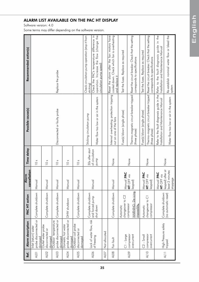
ALARM LIST AvAILABLE ON THE PAC HT DISPLAYSoftware version: 4.0Some terms may differ depending on the software version.Re
f.A
larm
des
crip
tion
PAC
HT
act
ion
Ala
rm
can
cella
tion
Tim
e d
elay
Poss
ible
cau
se(s
)Re
com
men
ded
act
ion
(s)
AL01
Inle
t (re
turn
) wat
er
prob
e di
scon
nect
ed o
r da
mag
edC
ompl
ete
shut
dow
nm
anua
l10
s
Dis
conn
ecte
d or
faul
ty p
robe
Repl
ace
the
prob
e
AL02
Out
let w
ater
pro
be
disc
onne
cted
or
dam
aged
Com
plet
e sh
utdo
wn
man
ual
10 s
AL03
Out
door
tem
pera
ture
pr
obe
disc
onne
cted
or
dam
aged
Com
plet
e sh
utdo
wn
man
ual
10 s
AL04
Dom
estic
hot
wat
er
prob
e di
scon
nect
ed o
r da
mag
edD
HW
shu
tdow
nm
anua
l10
s
AL05
Out
door
coi
l pro
be
disc
onne
cted
or
dam
aged
Com
plet
e sh
utdo
wn
man
ual
10 s
AL06
Lack
of w
ater
flow
, ris
k of
free
zing
Com
plet
e sh
utdo
wn
and
forc
ed p
ump
shut
dow
nm
anua
l30
s af
ter
star
t of
circ
ulat
ion
pum
p
Stic
king
circ
ulat
ion
pum
pC
heck
circ
ulat
ion
pum
p op
erat
ion
(sto
p it
from
st
icki
ng)
Wat
er fl
ow to
o lo
w o
r ai
r in
the
syst
emC
heck
the
pA
C's
tem
pera
ture
diff
eren
ce i
n op
erat
ion.
Inc
reas
e th
e flo
w (
chan
ge t
he
circ
ulat
ion
pum
p sp
eed)
AL07
Not
allo
cate
d
AL08
Fan
faul
tC
ompl
ete
shut
dow
nm
anua
lN
one
Inte
rnal
ove
rhea
ting
prot
ectio
n tri
ppin
g ou
t on
one
of th
e fa
ns
Rese
t th
e al
arm
afte
r th
e fa
n m
otor
s ha
ve
cool
ed d
own.
Che
ck w
hich
fan
is o
verh
eatin
g an
d re
plac
e it
AL09
C1
– La
rge
com
pres
sor
over
curr
ent
Auto
mat
ic
chan
geov
er to
C2
com
pres
sor
WAR
NIN
G: D
e-ic
ing
impo
ssib
le.
man
ual (
PAC
H
T O
FF v
ia
keyp
ad)
Non
e
Fuse
(s) b
low
n (s
ingl
e ph
ase)
Test
the
fuse
s. R
epla
ce a
s re
quire
d
Ther
mo-
mag
netic
circ
uit b
reak
er tr
ippe
d (th
ree
phas
e)Re
set t
he c
ircui
t bre
aker
. Che
ck th
at th
e se
tting
co
rres
pond
s to
spe
cific
atio
ns
AL10
C2
– Sm
all
com
pres
sor
over
curr
ent
Auto
mat
ic
chan
geov
er to
C1
com
pres
sor
man
ual (
PAC
H
T O
FF v
ia
keyp
ad)
Non
e
Fuse
(s) b
low
n (s
ingl
e ph
ase)
Test
the
fuse
s. R
epla
ce a
s re
quire
d
Ther
mo-
mag
netic
circ
uit b
reak
er tr
ippe
d (th
ree
phas
e)Re
set t
he c
ircui
t bre
aker
. Che
ck th
at th
e se
tting
co
rres
pond
s to
spe
cific
atio
ns
AL11
Hig
h pr
essu
re s
afet
y tri
pped
Com
plet
e sh
utdo
wn
(no
auto
mat
ic r
eset
)
man
ual (
PAC
H
T O
FF v
ia
keyp
ad) a
fter
at
leas
t 2 m
inut
es
stop
page
Non
e
Refe
r to
the
faul
t dia
gnos
is g
uide
in th
e In
stal
latio
n an
d m
aint
enan
ce m
anua
lRe
fer
to t
he f
ault
diag
nosi
s gu
ide
in t
he
Inst
alla
tion
and
mai
nten
ance
man
ual
Wat
er fl
ow to
o lo
w o
r ai
r in
the
syst
emRe
-est
ablis
h no
min
al w
ater
flo
w o
r bl
eed
the
syst
em
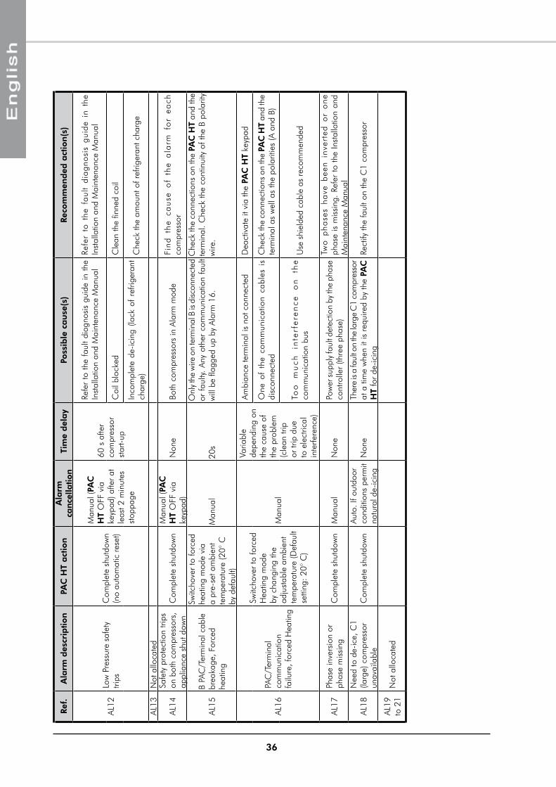
36
Ref.
Ala
rm d
escr
iptio
nPA
C H
T act
ion
Ala
rm
can
cella
tion
Tim
e d
elay
Poss
ible
cau
se(s
)Re
com
men
ded
act
ion
(s)
AL12
Low
pre
ssur
e sa
fety
tri
psC
ompl
ete
shut
dow
n (n
o au
tom
atic
res
et)
man
ual (
PAC
H
T O
FF v
ia
keyp
ad) a
fter
at
leas
t 2 m
inut
es
stop
page
60 s
afte
r
com
pres
sor
star
t-up
Refe
r to
the
faul
t dia
gnos
is g
uide
in th
e In
stal
latio
n an
d m
aint
enan
ce m
anua
lRe
fer
to t
he f
ault
diag
nosi
s gu
ide
in t
he
Inst
alla
tion
and
mai
nten
ance
man
ual
Coi
l blo
cked
Cle
an th
e fin
ned
coil
Inco
mpl
ete
de-ic
ing
(lack
of
refri
gera
nt
char
ge)
Che
ck th
e am
ount
of r
efrig
eran
t cha
rge
AL13
Not
allo
cate
d
AL14
Safe
ty p
rote
ctio
n tri
ps
on b
oth
com
pres
sors
, ap
plia
nce
shut
dow
nC
ompl
ete
shut
dow
nm
anua
l (PA
C
HT
OFF
via
ke
ypad
)N
one
Both
com
pres
sors
in A
larm
mod
eFi
nd
th
e ca
use
of
the
ala
rm f
or
each
co
mpr
esso
r
AL15
B pA
C/T
erm
inal
cab
le
brea
kage
, For
ced
heat
ing
Switc
hove
r to
forc
ed
heat
ing
mod
e vi
a a
pre-
set a
mbi
ent
tem
pera
ture
(20°
C
by d
efau
lt)
man
ual
20s
Onl
y the
wire
on
term
inal
B is
disc
onne
cted
or
fau
lty.
Any
othe
r co
mm
unic
atio
n fa
ult
will
be
flagg
ed u
p by
Ala
rm 1
6.
Che
ck th
e co
nnec
tions
on
the
PAC
HT
and
the
term
inal
. Che
ck th
e co
ntin
uity
of t
he B
pol
arity
w
ire.
AL16
pAC
/Ter
min
al
com
mun
icat
ion
fa
ilure
, for
ced
Hea
ting
Switc
hove
r to
forc
ed
Hea
ting
mod
e by
cha
ngin
g th
e ad
just
able
am
bien
t te
mpe
ratu
re (D
efau
lt se
tting
: 20°
C)
man
ual
Varia
ble
depe
ndin
g on
th
e ca
use
of
the
prob
lem
(c
lean
trip
or
trip
due
to
ele
ctric
al
inte
rfere
nce)
Ambi
ance
term
inal
is n
ot c
onne
cted
Dea
ctiv
ate
it vi
a th
e PA
C H
T ke
ypad
One
of
the
com
mun
icat
ion
cabl
es i
s di
scon
nect
edC
heck
the
conn
ectio
ns o
n th
e PA
C H
T an
d th
e te
rmin
al a
s w
ell a
s th
e po
larit
ies
(A a
nd B
)
Too
m
uch
in
terf
ere
nce
o
n
the
com
mun
icat
ion
bus
Use
shi
elde
d ca
ble
as r
ecom
men
ded
AL17
phas
e in
vers
ion
or
phas
e m
issi
ngC
ompl
ete
shut
dow
nm
anua
lN
one
pow
er su
pply
faul
t det
ectio
n by
the
phas
e co
ntro
ller
(thre
e ph
ase)
Two
pha
ses
have
bee
n in
vert
ed o
r o
ne
phas
e is
mis
sing
. Re
fer
to th
e In
stal
latio
n an
d m
aint
enan
ce m
anua
l
AL18
Nee
d to
de-
ice,
C1
(larg
e) c
ompr
esso
r un
avai
labl
eC
ompl
ete
shut
dow
nAu
to. I
f out
door
co
nditi
ons
perm
it na
tura
l de-
icin
gN
one
Ther
e is
a fa
ult o
n th
e la
rge
C1
com
pres
sor
at a
tim
e w
hen
it is
req
uire
d by
the
PAC
H
T fo
r de
-icin
gRe
ctify
the
faul
t on
the
C1
com
pres
sor
AL19
to
21
Not
allo
cate
d
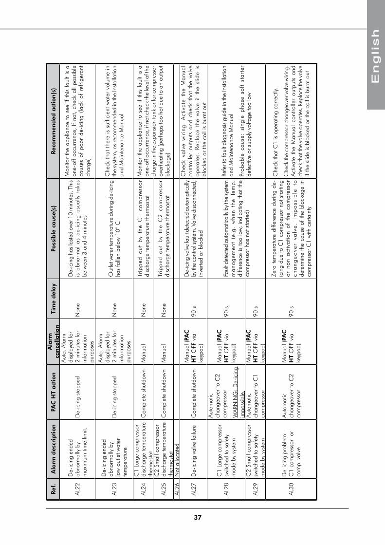
37
Ref.
Ala
rm d
escr
iptio
nPA
C H
T act
ion
Ala
rm
can
cella
tion
Tim
e d
elay
Poss
ible
cau
se(s
)Re
com
men
ded
act
ion
(s)
AL22
De-
icin
g en
ded
abno
rmal
ly b
y m
axim
um ti
me
limit.
De-
icin
g st
oppe
d
Auto
. Ala
rm
disp
laye
d fo
r 2
min
utes
for
info
rmat
ion
purp
oses
Non
eD
e-ic
ing
has l
aste
d ov
er 1
0 m
inut
es. T
his
is a
bnor
mal
as
de-i
cing
usu
ally
tak
es
betw
een
3 an
d 4
min
utes
mon
itor
the
appl
ianc
e to
see
if
this
fau
lt is
a
one-
off
occu
rren
ce,
If no
t, ch
eck
all
poss
ible
ca
uses
of
poor
de-
icin
g (la
ck o
f re
frige
rant
ch
arge
)
AL23
De-
icin
g en
ded
abno
rmal
ly b
y lo
w o
utle
t wat
er
tem
pera
ture
De-
icin
g st
oppe
d
Auto
. Ala
rm
disp
laye
d fo
r 2
min
utes
for
info
rmat
ion
purp
oses
Non
eO
utle
t wat
er te
mpe
ratu
re d
urin
g de
-icin
g ha
s fa
llen
belo
w 1
0° C
Che
ck t
hat
ther
e is
suf
ficie
nt w
ater
vol
ume
in
the
syst
em, a
s re
com
men
ded
in th
e In
stal
latio
n an
d m
aint
enan
ce m
anua
l
AL24
C1
Larg
e co
mpr
esso
r di
scha
rge
tem
pera
ture
th
erm
osta
tC
ompl
ete
shut
dow
nm
anua
lN
one
Trip
ped
out
by
the
C1
co
mpr
esso
r di
scha
rge
tem
pera
ture
ther
mos
tat
mon
itor
the
appl
ianc
e to
see
if
this
fau
lt is
a
one-
off o
ccur
renc
e, if
not
che
ck th
e le
vel o
f the
ch
arge
in th
e ex
pans
ion
tank
or f
or c
ompr
esso
r ov
erhe
atin
g (p
erha
ps to
o ho
t due
to a
n ou
tput
bl
ocka
ge)
AL25
C2
Smal
l com
pres
sor
disc
harg
e te
mpe
ratu
re
ther
mos
tat
Com
plet
e sh
utdo
wn
man
ual
Non
eTr
ippe
d o
ut b
y th
e C
2 c
om
pres
sor
disc
harg
e te
mpe
ratu
re th
erm
osta
t
AL26
Not
allo
cate
d
AL27
De-
icin
g va
lve
failu
reC
ompl
ete
shut
dow
nm
anua
l (PA
C
HT
OFF
via
ke
ypad
)90
sD
e-ic
ing
valv
e fa
ult d
etec
ted
auto
mat
ical
ly
by th
e co
ntro
l sys
tem
. Val
ve d
iscon
nect
ed,
inve
rted
or b
lock
ed
Che
ck v
alve
wir
ing.
Act
ivat
e th
e m
anua
l co
ntro
ller
outp
uts
and
chec
k th
at t
he v
alve
op
erat
es.
Repl
ace
the
valv
e if
the
slid
e is
bl
ocke
d or
the
coil
is b
urnt
out
AL28
C1
Larg
e co
mpr
esso
r sw
itche
d to
saf
ety
mod
e by
sys
tem
Auto
mat
ic
chan
geov
er to
C2
com
pres
sor
WAR
NIN
G: D
e-ic
ing
impo
ssib
le.
man
ual (
PAC
H
T O
FF v
ia
keyp
ad)
90 s
Faul
t det
ecte
d au
tom
atic
ally
by t
he sy
stem
m
anag
emen
t (e
.g.
whe
n th
e Te
mp.
di
ffere
nce
is to
o lo
w, in
dica
ting
that
the
com
pres
sor
has
not s
tarte
d)
Refe
r to
faul
t dia
gnos
is g
uide
in th
e In
stal
latio
n an
d m
aint
enan
ce m
anua
l
prob
able
cau
se:
sing
le p
hase
sof
t st
arte
r de
fect
ive
or s
uppl
y vo
ltage
too
low
AL29
C2
Smal
l com
pres
sor
switc
hed
to s
afet
y m
ode
by s
yste
m
Auto
mat
ic
chan
geov
er to
C1
com
pres
sor
man
ual (
PAC
H
T O
FF v
ia
keyp
ad)
90 s
AL30
De-
icin
g pr
oble
m –
C
1 co
mpr
esso
r o
r co
mp.
val
ve
Auto
mat
ic
chan
geov
er to
C2
com
pres
sor
man
ual (
PAC
H
T O
FF v
ia
keyp
ad)
90 s
Zero
tem
pera
ture
diff
eren
ce d
urin
g de
-ic
ing
due
to C
1 co
mpr
esso
r no
t sta
rting
or
non
act
ivat
ion
of t
he c
ompr
esso
r ch
an
geo
ver
valv
e. I
mp
oss
ible
to
dete
rmin
e th
e ca
use
of th
e bl
ocka
ge in
co
mpr
esso
r C
1 w
ith c
erta
inty
Che
ck th
at C
1 is
ope
ratin
g co
rrec
tly.
Che
ck th
e co
mpr
esso
r cha
ngeo
ver v
alve
wiri
ng.
Act
ivat
e th
e m
anua
l co
ntro
ller
outp
uts
and
chec
k th
at th
e va
lve
oper
ates
. Rep
lace
the
valv
e if
the
slid
e is
blo
cked
or
the
coil
is b
urnt
out
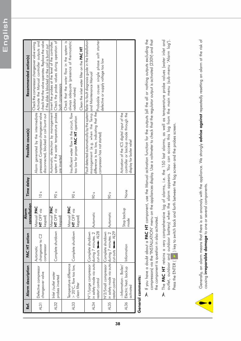
38
Gen
eral c
om
men
ts:
²
If yo
u ha
ve a
dou
bt a
bout
a P
AC
HT
com
pone
nt,
use
the
man
ual
activ
atio
n fu
nctio
n fo
r th
e ou
tput
s (a
ll th
e al
l or
not
hing
out
puts
exc
ludi
ng t
he
com
pres
sors
) via
the
"INST
ALLA
TIO
N" m
enu
on th
e ap
plia
nces
dis
play
. Use
a v
oltm
eter
to c
heck
that
the
regu
lato
r out
put i
s ac
tivat
ed (2
30V)
and
that
th
e co
mpo
nent
is q
uest
ion
in a
lso
activ
ated
.
²
The
PAC
HT
reta
ins
a ve
ry c
ompr
ehen
sive
log
of
alar
ms,
i.e
. th
e 15
0 la
st a
larm
s, a
s w
ell
as t
empe
ratu
re p
robe
val
ues
(wat
er i
nlet
and
ou
tlet,
out
door
and
out
door
bat
tery
) w
hen
the
alar
m a
ppea
rs.
You
can
acce
ss t
his
log
from
the
mai
n m
enu
(sub
-men
u "A
larm
log
").
pres
s th
e EN
TER
( )
key
to s
witc
h ba
ck a
nd fo
rth b
etw
een
the
log
scre
en a
nd th
e pr
obes
scr
een.
Gen
eral
ly, a
n al
arm
mea
ns t
hat
ther
e is
an
anom
aly
with
the
app
lianc
e. W
e st
rong
ly a
dvi
se a
gain
st r
epea
tedl
y re
setti
ng a
n al
arm
at
the
risk
of
caus
ing
irre
para
ble
dam
ag
e to
one
or
seve
ral c
ompo
nent
s.
Ref.
Ala
rm d
escr
iptio
nPA
C H
T act
ion
Ala
rm
can
cella
tion
Tim
e d
elay
Poss
ible
cau
se(s
)Re
com
men
ded
act
ion
(s)
AL31
Def
ectiv
e co
mpr
esso
r ch
ange
over
val
ve
Auto
mat
ic
chan
geov
er to
C2
com
pres
sor
man
ual (
PAC
H
T O
FF v
ia
keyp
ad)
10 s
Ala
rm g
ener
ated
by
the
inte
rmed
iate
pr
esso
stat
. Com
pres
sor c
hang
eove
r val
ve
disc
onne
cted
, blo
cked
or
coil
burn
t out
Che
ck th
e co
mpr
esso
r cha
ngeo
ver v
alve
wiri
ng.
Act
ivat
e th
e m
anua
l co
ntro
ller
outp
uts
and
chec
k th
at th
e va
lve
oper
ates
. Rep
lace
the
valv
e if
the
slid
e is
blo
cked
or
the
coil
is b
urnt
out
AL32
Inle
t /ou
tlet w
ater
pr
obes
inve
rted
Com
plet
e sh
utdo
wn
man
ual (
PAC
H
T O
FF v
ia
keyp
ad)
90 s
Aut
omat
ic d
etec
tion
by m
anag
emen
t sy
stem
if
the
wat
er t
empe
ratu
re p
robe
s ar
e in
verte
d
Inve
rt th
e pr
obes
at t
he le
vel o
f the
con
trolle
r. C
heck
the
pro
be v
alue
s du
ring
oper
atio
n of
bo
th c
ompr
esso
rs
AL33
Tem
pera
ture
diff
eren
ce
> 2
0°C
, flo
w to
o lo
w,
clea
n fil
ter
Com
plet
e sh
utdo
wn
man
ual (
PAC
H
T O
FF v
ia
keyp
ad)
90 s
Insu
ffici
ent w
ater
flow
in th
e ci
rcui
t, flo
w
too
low
for
prop
er P
AC
HT
oper
atio
n
Che
ck t
hat
the
wat
er f
low
in
the
syst
em i
s al
way
s ad
equa
te (
pres
ence
of
ther
mos
tatic
ra
diat
or v
alve
s)
Cle
an th
e in
let w
ater
filte
r on
the
PAC
HT
AL34
N°1
/Lar
ge c
ompr
esso
r in
saf
ety
mod
e vi
a au
to
rest
art c
ontro
l
Com
plet
e sh
utdo
wn
durin
g 7
min
utes
. 2
cut-o
uts
AL2
8Au
tom
atic
90 s
Faul
t det
ecte
d au
tom
atic
ally
by
the
syst
em
ma
nag
emen
t (e
.g.
whe
n th
e Te
mp
. di
ffere
nce
is t
oo l
ow,
indi
catin
g th
at t
he
com
pres
sor
has
not s
tarte
d)
Refe
r to
faul
t dia
gnos
is g
uide
in th
e In
stal
latio
n an
d m
aint
enan
ce m
anua
l
pro
babl
e ca
use:
sin
gle
phas
e so
ft s
tart
er
defe
ctiv
e or
sup
ply
volta
ge to
o lo
w
AL35
N°2
/Sm
all c
ompr
esso
r in
saf
ety
mod
e vi
a au
to
rest
art c
ontro
l
Com
plet
e sh
utdo
wn
durin
g 7
min
utes
. 2
cut-o
uts
AL2
9Au
tom
atic
90 s
AL36
--In
form
atio
n--
Boile
r/El
ectri
c he
at. b
acku
p ac
tivat
edIn
form
atio
nSt
op b
acku
p m
ode
Non
eAc
tivat
ion
of th
e IC
S di
gita
l inp
ut o
f the
co
ntro
ller
or b
acku
p m
ode
thro
ugh
the
disp
lay
for
boile
r re
lief
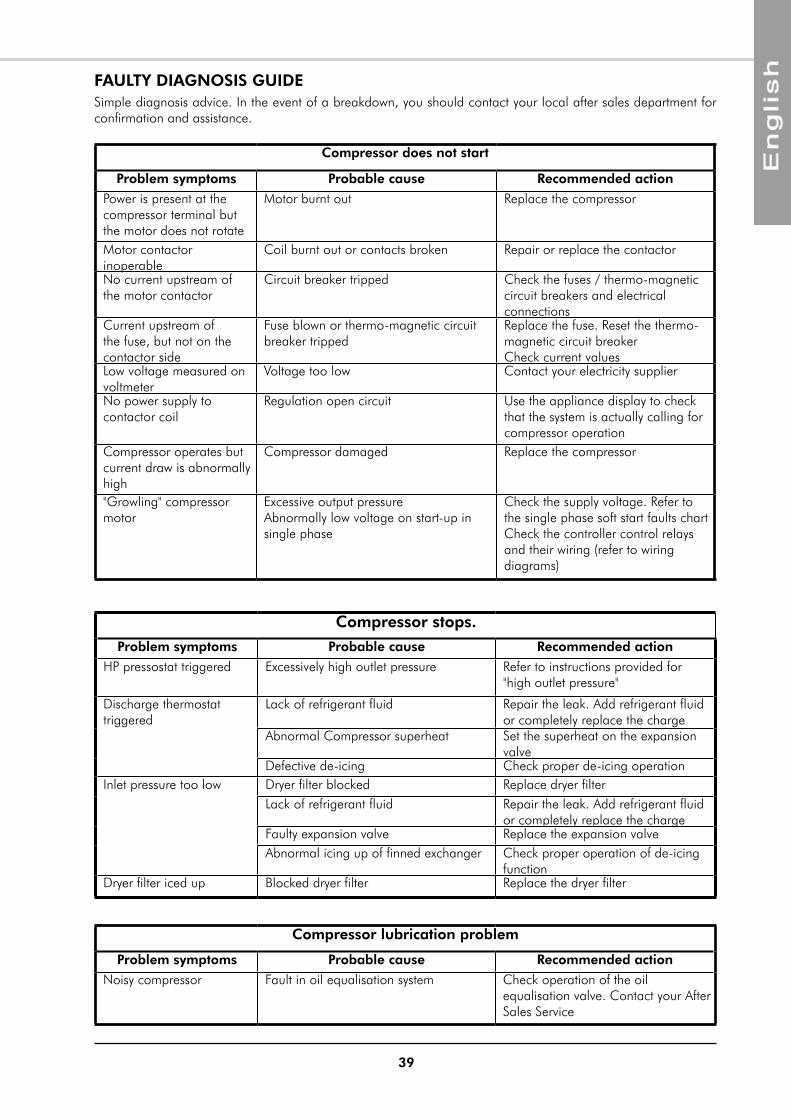
39
FAULTY DIAGNOSIS GUIDESimple diagnosis advice. In the event of a breakdown, you should contact your local after sales department for confirmation and assistance.
Compressor does not start
Problem symptoms Probable cause Recommended action
power is present at the compressor terminal but the motor does not rotate
motor burnt out Replace the compressor
motor contactor inoperable
Coil burnt out or contacts broken Repair or replace the contactor
No current upstream of the motor contactor
Circuit breaker tripped Check the fuses / thermo-magnetic circuit breakers and electrical connections
Current upstream of the fuse, but not on the contactor side
Fuse blown or thermo-magnetic circuit breaker tripped
Replace the fuse. Reset the thermo-magnetic circuit breaker Check current values
Low voltage measured on voltmeter
Voltage too low Contact your electricity supplier
No power supply to contactor coil
Regulation open circuit Use the appliance display to check that the system is actually calling for compressor operation
Compressor operates but current draw is abnormally high
Compressor damaged Replace the compressor
"Growling" compressor motor
Excessive output pressure Abnormally low voltage on start-up in single phase
Check the supply voltage. Refer to the single phase soft start faults chart Check the controller control relays and their wiring (refer to wiring diagrams)
Compressor stops.Problem symptoms Probable cause Recommended action
Hp pressostat triggered Excessively high outlet pressure Refer to instructions provided for "high outlet pressure"
Discharge thermostat triggered
Lack of refrigerant fluid Repair the leak. Add refrigerant fluid or completely replace the charge
Abnormal Compressor superheat Set the superheat on the expansion valve
Defective de-icing Check proper de-icing operationInlet pressure too low Dryer filter blocked Replace dryer filter
Lack of refrigerant fluid Repair the leak. Add refrigerant fluid or completely replace the charge
Faulty expansion valve Replace the expansion valveAbnormal icing up of finned exchanger Check proper operation of de-icing
functionDryer filter iced up Blocked dryer filter Replace the dryer filter
Compressor lubrication problem
Problem symptoms Probable cause Recommended action
Noisy compressor Fault in oil equalisation system Check operation of the oil equalisation valve. Contact your After Sales Service
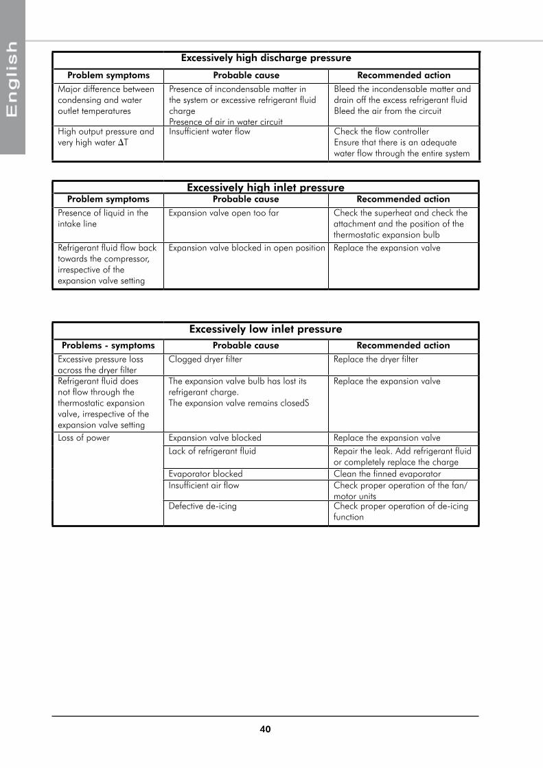
40
Excessively high discharge pressure
Problem symptoms Probable cause Recommended action
major difference between condensing and water outlet temperatures
presence of incondensable matter in the system or excessive refrigerant fluid charge presence of air in water circuit
Bleed the incondensable matter and drain off the excess refrigerant fluid Bleed the air from the circuit
High output pressure and very high water DT
Insufficient water flow Check the flow controller Ensure that there is an adequate water flow through the entire system
Excessively high inlet pressureProblem symptoms Probable cause Recommended action
presence of liquid in the intake line
Expansion valve open too far Check the superheat and check the attachment and the position of the thermostatic expansion bulb
Refrigerant fluid flow back towards the compressor, irrespective of the expansion valve setting
Expansion valve blocked in open position Replace the expansion valve
Excessively low inlet pressureProblems - symptoms Probable cause Recommended action
Excessive pressure loss across the dryer filter
Clogged dryer filter Replace the dryer filter
Refrigerant fluid does not flow through the thermostatic expansion valve, irrespective of the expansion valve setting
The expansion valve bulb has lost its refrigerant charge. The expansion valve remains closedS
Replace the expansion valve
Loss of power Expansion valve blocked Replace the expansion valveLack of refrigerant fluid Repair the leak. Add refrigerant fluid
or completely replace the chargeEvaporator blocked Clean the finned evaporatorInsufficient air flow Check proper operation of the fan/
motor unitsDefective de-icing Check proper operation of de-icing
function

APPENDIX / ANNEXE / ANLAGE / ALLEGATO / ANEXO
APPENDIXANNEXEANLAGE
ALLEGATOANEXO
II
APPENDIX / ANNEXE / ANLAGE / ALLEGATO / ANEXO
ANLAGE
APPENDIX
ANNEXE
ALLEGATO
ANEXO
DIMENSIONS ...........................................................................................................................................IIISCHéMA FRIGORIFIqUE ET HYDRAULIqUE .............................................................................................IvABAqUE DE CALCUL DE DéBIT D'EAU ......................................................................................................vISCHEMAS ELECTRIqUES ........................................................................................................................ vIIPAC HT 12-6 230V +/-10% 50HZ ................................................................................................................................... VIII
PAC HT 14-7 230V +/-10% 50HZ ......................................................................................................................................X
PAC HT 12-6 / 14-7 3N~400V +/-10% 50HZ .................................................................................................................. XII
PAC HT 18-9 3N~400V +/-10% 50HZ ............................................................................................................................ XIVBALLON D'EAU CHAUDE SANITAIRE ........................................................................................................................................ XVICHAUFFAGE ELECTRIqUE ADDITIONNEL ............................................................................................................................... XVI
ABMESSUNGEN .......................................................................................................................................IIIKüHL- UND HYDRAULIKDIAGRAMM ........................................................................................................IvBERECHNUNGSKURvE DER WASSERDURCHFLUSSMENGE ......................................................................vISTROMLAUFPLANS ................................................................................................................................. vIIPAC HT 12-6 230V +/-10% 50HZ ................................................................................................................................... VIII
PAC HT 14-7 230V +/-10% 50HZ ......................................................................................................................................X
PAC HT 12-6 / 14-7 3N~400V +/-10% 50HZ .................................................................................................................. XII
PAC HT 18-9 3N~400V +/-10% 50HZ ............................................................................................................................ XIVBRAUCHWASSERVERSORGUNG ............................................................................................................................................. XVIZUSATZLICHE ELEKTROHEIZUNG ........................................................................................................................................... XVI
DIMENSIONI ............................................................................................................................................IIISCHEMA FRIGORIFERO ED IDRAULICO ....................................................................................................IvABACO DI CALCOLO DELLA PORTATA DELL'ACqUA ................................................................................vISCHEMA ELETRICO ................................................................................................................................ vIIPAC HT 12-6 230V +/-10% 50HZ ................................................................................................................................... VIII
PAC HT 14-7 230V +/-10% 50HZ ......................................................................................................................................X
PAC HT 12-6 / 14-7 3N~400V +/-10% 50HZ .................................................................................................................. XII
PAC HT 18-9 3N~400V +/-10% 50HZ ............................................................................................................................ XIVpALLA DI ACqUA CALDA SANITARIA ....................................................................................................................................... XVIRESISTENZE ELETTRICHE ADDIZIONALE .................................................................................................................................. XVI
DIMENSIONES .........................................................................................................................................IIIESqUEMA FRIGORÍFICO E HIDRÁULICO ..................................................................................................IvÁBACO DE CÁLCULO DE CAUDAL DE AGUA ...........................................................................................vIESqUEMA ELECTRICO ............................................................................................................................ vIIPAC HT 12-6 230V +/-10% 50HZ ................................................................................................................................... VIII
PAC HT 14-7 230V +/-10% 50HZ ......................................................................................................................................X
PAC HT 12-6 / 14-7 3N~400V +/-10% 50HZ .................................................................................................................. XII
PAC HT 18-9 3N~400V +/-10% 50HZ ............................................................................................................................ XIVACUmULADOR DE AGUA CALIENTE SANITARIA ...................................................................................................................... XVICALEFACCION ELECTRTICA ADICIONAL ................................................................................................................................ XVI
DIMENSIONS ...........................................................................................................................................IIIREFRIGERATION AND HYDRAULIC LINKS DIAGRAM ................................................................................IvWATER FLOW CALCULATION GRAPH .......................................................................................................vIWIRING DIAGRAM ................................................................................................................................. vIIPAC HT 12-6 230V +/-10% 50HZ ................................................................................................................................... VIII
PAC HT 14-7 230V +/-10% 50HZ ......................................................................................................................................X
PAC HT 12-6 / 14-7 3N~400V +/-10% 50HZ .................................................................................................................. XII
PAC HT 18-9 3N~400V +/-10% 50HZ ............................................................................................................................ XIVDOmESTIC HOT WATER TANK ................................................................................................................................................ XVIADDITIONAL ELECTRIC HEATER .............................................................................................................................................. XVI
III
APPENDIX / ANNEXE / ANLAGE / ALLEGATO / ANEXODIMENSIONS
DIMENSIONS
ABMESSUNGEN
DIMENSIONI
DIMENSIONES
Amain power supply Alimentation
électriqueStromversorgung Alimentazione
elettricaAlimentación eléctrica
BWater inlet 1" female gas
Entrée eau 1"gaz femelle
Wassereintritt 1" Innengewinde Gas
Ingresso acqua 1" gas femmina
Entrada agua 1" gas hembra
CWater outlet 1" female gas
Sortie eau 1"gaz femelle
Wasseraustritt 1" Innengewinde Gas
Uscita acqua 1" gas femmina
Salida agua 1" gas hembra
E Display Afficheur Display Display DisplayF Circuit breaker Sectionneur Trennschalter Sezionatore Seccionador
GWater pressure gauge
manomètre pression d'eau
manometer Wasserdruck manometro pressione dell’acqua
manómetro presión de agua
H High pressure takeoff prise haute pression Hochdruckanschluss presa alta pressione Toma de alta presión I Low pressure takeoff prise basse pression Niederdruckanschluss presa bassa pressione Toma de baja presión
JRemote control Commande à
distanceFernbetätigung Comando a distanza mando a distancia
KAnti-vibration device Dispositif anti
vibrationsSchwingungsdämpfende Vorrichtungen
Dispositivo antivibrazioni
Dispositivo antivibraciones
1013
08.5
0
I
H
G
F
E
703
141
85C B
J
A
K
349
1150
400.
50
1192.60
1236.60
Iv
APPENDIX / ANNEXE / ANLAGE / ALLEGATO / ANEXO
REFRIGERATION AND HYDRAULIC LINKS DIAGRAM
SCHéMA FRIGORIFIqUE ET HYDRAULIqUE
KüHL- UND HYDRAULIKDIAGRAMM
SCHEMA FRIGORIFERO ED IDRAULICO
ESqUEMA FRIGORÍFICO E HIDRÁULICO
1 Large compressor2 Small compressor3 plate heat exchangers. Counter-current
heating4 Liquid tank5 plate heat exchangers. economiser6 Finned heat exchanger and fans 7 Circulation pump8 Oil separator9 Dehydrator filter 10 Liquid warning light11 Non-return valve12 Automatic bleed13 Flow detectorv1 Four-way valvev2 Four-way valvev3 Injection electrovalvev4 Electrovalvev5 Injection expansion valvev6 Thermostatic expansion valvev7 Safety valve (3.5 bar)P1-A High pressure safety pressostatP2-A High pressure pressostatP3-A Defrost system high pressure control
pressostatP1-B Low pressure safety pressostatP4 Water pressure gaugeCDT1/2 Discharge Thermostat LWT Water temperature probe (outlet)EWT Water temperature probe (inlet)OCT Outdoor coil temperature probeOAT Air temperature probe
1 Gros compresseur2 petit compresseur3 Echangeur à plaques Contre courant
chauffage4 Réservoir liquide5 Echangeur à plaques. économiseur6 Echangeur à ailettes et ventilateurs7 Circulateur8 Séparateur d'huile9 Filtre déshydrateur 10 Voyant liquide11 Clapet anti-retour12 purgeur automatique13 Détecteur de débitv1 Vanne 4 voiesv2 Vanne 4 voiesv3 Electrovanne d'injectionv4 Electrovannev5 Détendeur d'injectionv6 Détendeur thermostatiquev7 Soupape sécurité (3.5 bar)P1-A pressostat sécurité haute pressionP2-A pressostat haute pressionP3-A pressostat contrôle haute pression
dégivrageP1-B pressostat sécurité basse pressionP4 manomètre pression d’eauCDT1/2 Thermostat de refoulementLWT Sonde de température d'eau (sortie)EWT Sonde de température d'eau (entrée)OCT Sonde contrôle de condensationOAT Sonde de température d'air
1 Kompressor Niederdruck2 Kompressor Hochdruck3 plattenwärmeaustauscher. Gegenstrom
Heizung4 Flüssigkeitsbehälter 5 plattenwärmeaustauscher. economiser6 Lamellenwärmetauscher und Ventilatoren7 Umlaufpumpe8 Olabscheider9 Filtertrockner 10 Anzeigelampe Flüssigkeit11 Rückschlagklappe12 Automatischer Ablasshahn13 Wassermelderv1 Vierwegventilv2 Vierwegventilv3 Injektionelektroventilv4 Elektroventilv5 Expansionsventil Injektionv6 Thermostat-Expansionsventilv7 Sicherheitsventil (3.5 Bar)P1-A Hochdruck-SicherheitspressostatP2-A Hochdruck-pressostatP3-A Hochdruckkontrollpressostat AbtauenP1-B Niederdruck - SicherheitspressostatP4 WasserdruckmesserCDT1/2 Druckseitiger ThermostatLWT Wassertemperaturfühler (Austritt)EWT Wassertemperaturfühler (Eintritt)OCT messfühler VerflüssigungskontrolleOAT Lufttemperaturfühler
1 Compressore bassa pressione2 Compressore alta pressione3 Intercambiador térmico de placas
Controcorrente riscaldamento4 Serbatoio liquido5 Intercambiador térmico de placas
economizador6 Scambiatore ad alette e ventilatori7 Circolatore8 Separador de aceite9 Filtro disidratante 10 Indicador luminoso líquido11 Válvula antirretorno12 Valvola di scarico automatica13 Detector del flujov1 Válvula de cuatro viasv2 Válvula de cuatro viasv3 Electroválvula de inyecciónv4 Electroválvulav5 Valvola d’espansione de inyecciónv6 Valvola d’espansione termostaticav7 Valvola di sicurezza (3.5 bar)P1-A pressostato sicurezza alta pressioneP2-A pressostato alta pressioneP3-A pressostato controllo alta pressione
sbrinamentoP1-B pressostato sicurezza bassa pressioneP4 manometro pressione acquaCDT1/2 Termostato di mandataLWT Sonda di temperatura acqua (uscita)EWT Sonda di temperatura acqua (ingresso)OCT Sonda de control de condensaciónOAT Sonda di temperatura aria
1 Compresor baja presión2 Compresor alta presión3 Scambiatori di calore a piastre
Contracorriente calefacción4 Depósito líquido5 Scambiatori di calore a piastre
economizzatore6 Intercambiador de aletas y ventiladores7 Circulador8 Separatore d'olio9 Filtro deshidratador 10 Spia liquido11 Valvola antiritorno12 purgador automático13 Rilevatore del flussov1 Valvola a quattro viev2 Valvola a quattro viev3 Elettrovalvola di iniezioniv4 Elettrovalvolav5 Válvula de expansión di iniezioniv6 Válvula de expansión termostáticav7 Válvula de seguridad (3.5 bares)P1-A presostato de seguridad alta presiónP2-A presostato alta presiónP3-A presostato de control alta presión
descongelaciónP1-B presostato de seguridad baja presiónP4 manómetro de presión de aguaCDT1/2 Termostato de descargaLWT Sonda de temperatura de agua (salida)EWT Sonda de temperatura de agua (entrada)OCT Sonda controllo di condensazioneOAT Sonda de temperatura de aire
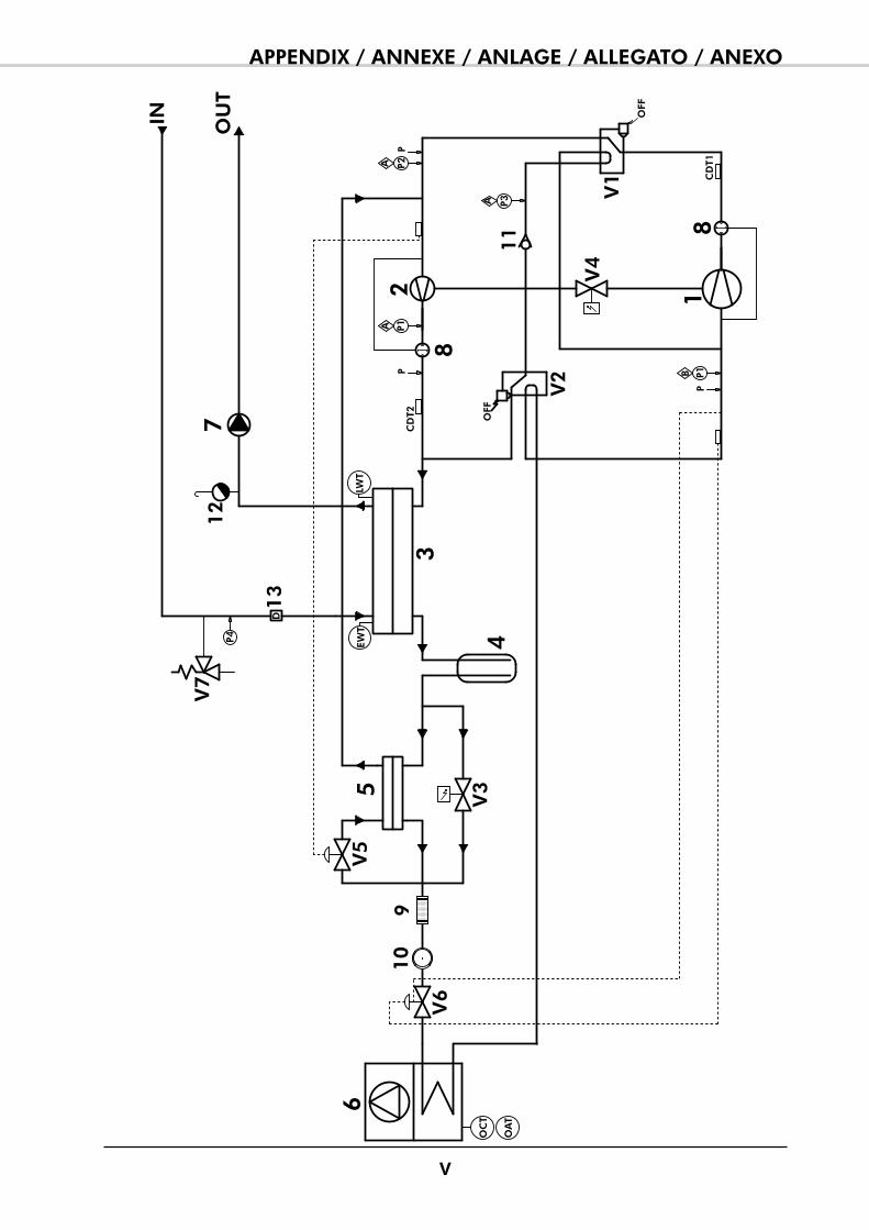
v
APPENDIX / ANNEXE / ANLAGE / ALLEGATO / ANEXO
IN
P1A
P2A
P1B
7
4
1C
DT1
OFF
2C
DT2 OFF
P3A
OU
T
3
56
V1
V2
V3
V4
910
8
8
11
V5
V6
13
D
EWT
P4
V7
12
PP
P
LWT
OC
T
OA
T
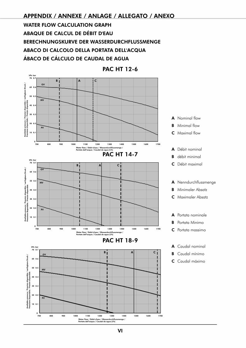
vI
APPENDIX / ANNEXE / ANLAGE / ALLEGATO / ANEXO
WATER FLOW CALCULATION GRAPH
ABAqUE DE CALCUL DE DéBIT D'EAU
BERECHNUNGSKURvE DER WASSERDURCHFLUSSMENGE
ABACO DI CALCOLO DELLA PORTATA DELL'ACqUA
ÁBACO DE CÁLCULO DE CAUDAL DE AGUA
PAC HT 12-6
PAC HT 14-7
PAC HT 18-9
0
0.1
0.2
0.3
0.4
0.5
0.6
0.7
700 800 900 1000 1100 1200 1300 1400 1500 1600 1700
MV
PV
GV
A
Water flow / Débit d'eau / Wasserdurchflussmenge / Portata dell’acqua / Caudal de agua (l/h)
kPa bar
Ava
ilab
le p
ress
ure
/ P
ress
ion
dis
pon
ible
/ v
erfü
gb
are
Dru
ck /
Pr
essi
on
e d
isp
on
ibile
/ P
resi
ón
dis
pon
ible
10
20
30
40
50
60
70
B C
0
0.1
0.2
0.3
0.4
0.5
0.6
0.7
700 800 900 1000 1100 1200 1300 1400 1500 1600 1700
MV
PV
GVA
Water flow / Débit d'eau / Wasserdurchflussmenge / Portata dell’acqua / Caudal de agua (l/h)
kPa bar
Ava
ilab
le p
ress
ure
/ P
ress
ion
dis
pon
ible
/ v
erfü
gb
are
Dru
ck /
Pr
essi
on
e d
isp
on
ibile
/ P
resi
ón
dis
pon
ible
10
20
30
40
50
60
70
B C
A Nominal flow
B minimal flow
C maximal flow
A Débit nominal
B débit minimal
C Débit maximal
A Nenndurchflussmenge
B minimaler Absatz
C maximaler Absatz
A portata nominale
B portata minimo
C portata massimo
A Caudal nominal
B Caudal mínimo
C Caudal máximo
vII
APPENDIX / ANNEXE / ANLAGE / ALLEGATO / ANEXOWIRING DIAGRAM
SCHEMAS ELECTRIqUES
STROMLAUFPLANS
SCHEMA ELETRICO
ESqUEMA ELECTRICO
TAKE CARE!
These wiring diagrams are correct at the time of publication. manufacturing changes can lead to modifications. Always refer to the diagram supplied with the product.
ATTENTION
Ces schémas sont corrects au moment de la publication. Les variantes en fabrication peuvent entraîner des modifications. Reportez-vous toujours au schéma livré avec le produit.
ACHTUNG!
Diese Stromlaufplans sind zum Zeitpunkt der Veröffentlichung gültig. In Herstellung befindliche Varianten können Änderungen mit sich bringen. In jedem Fall den mit dem produkt gelieferten Stromlaufplan hinzuziehen.
ATTENZIONE !
questi schemi sono corretti al momento della pubblicazione. Le varianti apportate nel corso della fabbricazione possono comportare modifiche. Far sempre riferimento allo schema fornito con il prodotto.
ATENCIÓN !
Esto esquemas son correctos en el momento de la publicación. pero las variantes en la fabricación pueden ser motivo de modificaciones. Remítase siempre al esquema entregado con el producto.
PUESTA FUERA DE TNESIÓN OBLIGATORIA ANTES DE CUALqUIER INTERvENCIÓN EN LAS CAJAS ELéCTRICAS!
PRIMA DI OGNI INTERvENTO SULLE CASSETTE ELETTRICHE ESCLUDERE TASSATIvAMENTE L’ALIMENTAZIONE !
vOR JEDEM EINGRIFF AN DEN ANSCHLUßKÄSTEN UNBEDINGT DAS GERÄT STROMLOS SCHALTEN!
MISE HORS TENSION OBLIGATOIRE AvANT TOUTE INTERvENTION DANS LES BOITIERS ELECTRIqUES.
POWER SUPPLY MUST BE SWITCHED OFF BEFORE STARTING TO WORK IN THE ELECTRIC CONTROL BOX!
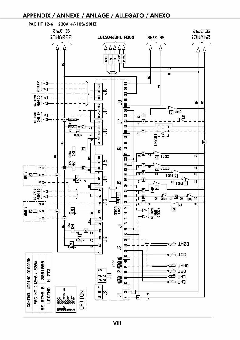
vIII
APPENDIX / ANNEXE / ANLAGE / ALLEGATO / ANEXOPAC HT 12-6 230v +/-10% 50HZ
pC
O1
>
>
<
>>
>
IX
APPENDIX / ANNEXE / ANLAGE / ALLEGATO / ANEXO
<
X
APPENDIX / ANNEXE / ANLAGE / ALLEGATO / ANEXOPAC HT 14-7 230v +/-10% 50HZ
pC
O1
>
>
<
>>
>
XI
APPENDIX / ANNEXE / ANLAGE / ALLEGATO / ANEXO
<
XII
APPENDIX / ANNEXE / ANLAGE / ALLEGATO / ANEXOPAC HT 12-6 / 14-7 3N~400v +/-10% 50HZ
pC
O1
>
>
<
>>
>
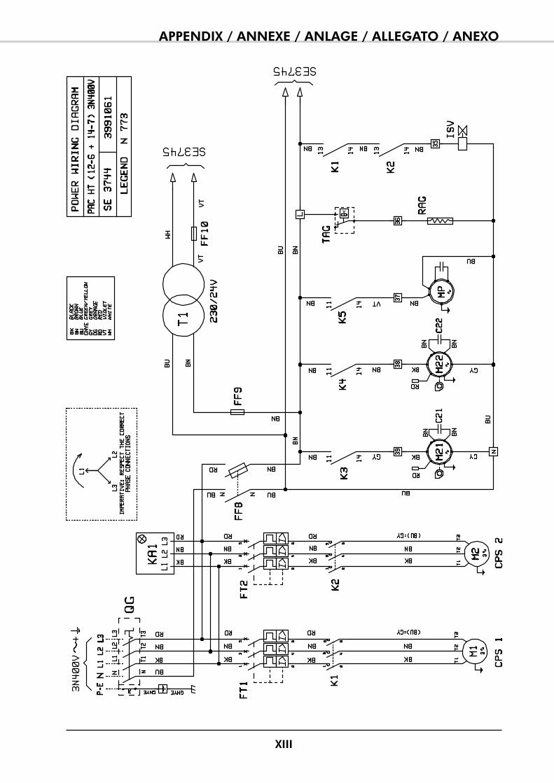
XIII
APPENDIX / ANNEXE / ANLAGE / ALLEGATO / ANEXO
<
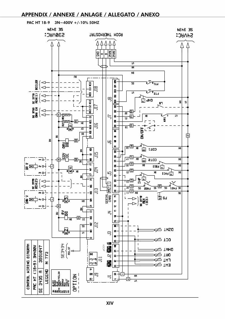
XIv
APPENDIX / ANNEXE / ANLAGE / ALLEGATO / ANEXOPAC HT 18-9 3N~400v +/-10% 50HZ
pC
O1
>
>
<
>>
>
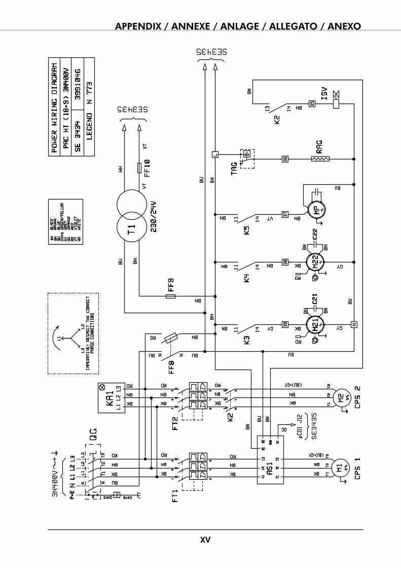
Xv
APPENDIX / ANNEXE / ANLAGE / ALLEGATO / ANEXO
<
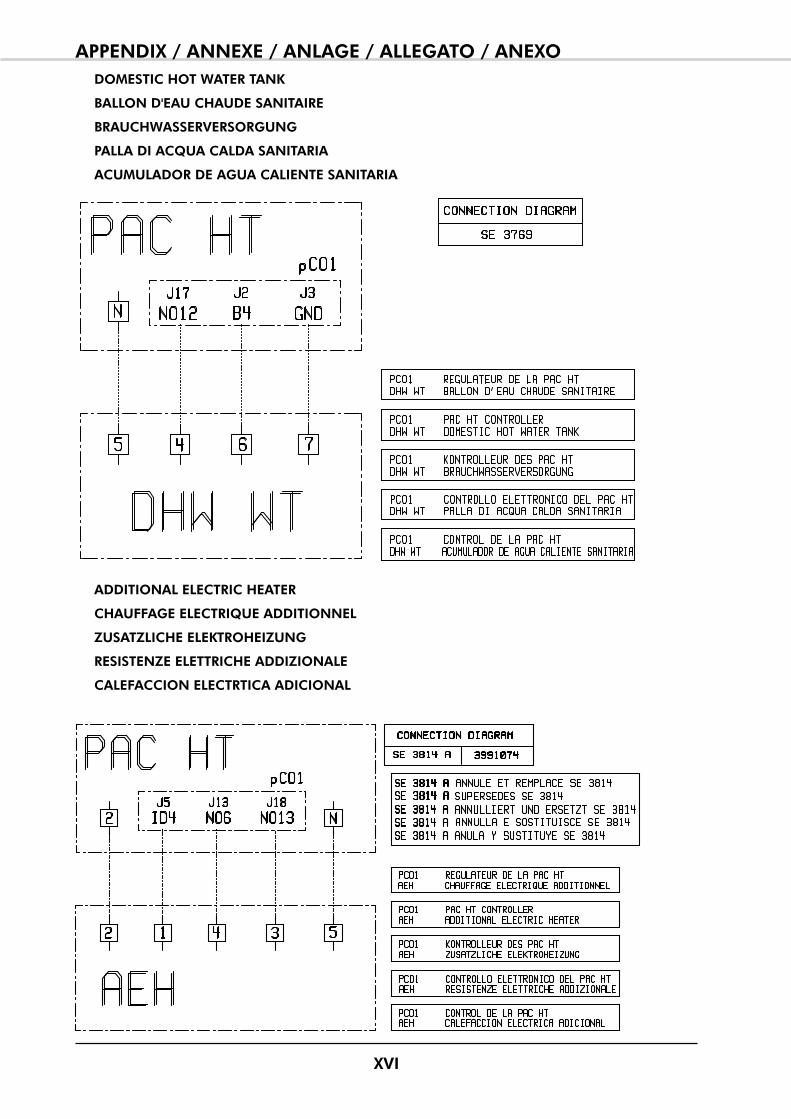
XvI
APPENDIX / ANNEXE / ANLAGE / ALLEGATO / ANEXODOMESTIC HOT WATER TANK
BALLON D'EAU CHAUDE SANITAIRE
BRAUCHWASSERvERSORGUNG
PALLA DI ACqUA CALDA SANITARIA
ACUMULADOR DE AGUA CALIENTE SANITARIA
ADDITIONAL ELECTRIC HEATER
CHAUFFAGE ELECTRIqUE ADDITIONNEL
ZUSATZLICHE ELEKTROHEIZUNG
RESISTENZE ELETTRICHE ADDIZIONALE
CALEFACCION ELECTRTICA ADICIONAL


The meaning of the above logo representing a crossed-out wheeled bin is that this unit must not be disposed of as unsorted municipal waste but should be collected separately as WEEE (Waste Electrical and Electronic Equipment).The presence of hazardous substances in electr ical and e lec t ronic equipment or an improper use of such equipments or of parts thereof as well as the hazards of not separating WEEE from unsorted domestic waste, may affect the environment and human health.As an End User, you are required to place WEEE in a collection separate from that for unsorted domestic waste. please contact a point of sale or installer to find out the collection system available at your local community. You may return your old air conditioning unit for free to the point of sale or the installer when purchasing a new one.As an End User, it is your role to contribute to the reuse, recycling and other forms of recovery of such wastes so as to reduce the disposal of waste. This will help preserve your environment.
Le logo ci-dessus représentant une "poubelle barrée" signifie qu’il ne faut pas se débarrasser de cet appareil comme d’un déchet classique mais que celui-ci doit être collecté séparément en tant que DEEE (Déchet d’Equipement Electrique et Electronique).La présence de subs tances dangereuses dans les équipements électr iques et électroniques, l’utilisation inappropriée de tels équipements ou partie de tels équipements ainsi que le danger représentant la collecte non centralisée de matériels DEEE peuvent être préjudiciables à l’environnement et à la santé publique.En tant qu’utilisateur final, il vous est demandé de collecter les DEEE séparément des déchets ordinaires.Vous êtes priés de prendre contact avec votre revendeur ou votre installateur pour qu’il vous indique le mode de collecte de votre commune. Lors du renouvellement de votre appareil, vous avez la possibilité de rendre votre ancien appareil gratuitement à votre installateur ou votre revendeur qui se chargera d’en assurer la collecte.En tant qu’utilisateur final, il est de votre devoir de participer à la réutilisation, au recyclage, et à toute autre forme de récupération de tels déchets afin d’en diminuer la quantité. Cela contribuera à la préservation de l’environnement.
Die Bedeutung des Logos mit der durchgestrichenen mülltonne besteht darin, dass es sich bei diesem Gerät nicht um Hausmüll (Wertstoffmüll oder Restmüll) handelt.Dieses Gerät ist nach der Elektro- und E lek t ron i kge rä tegese t z ElektroG (WEEE) zu sammeln und zu entsorgen.Durch das Vorhandensein von ge fähr l i chen Subs tanzen in elektrischen oder elektronischen Bauteilen kann die missbräuchliche Verwendung solcher Teile oder das Entsorgen solcher Geräte über den Hausmüll zu nicht unerhebliche Umwelt- und/ oder Gesundheitsschäden führen.Sie als Endkunde sind angehalten, Geräte, welche unter die ElektroG (WEEE) fallen, separat vom Hausmüll zu entsorgen. Bitte informieren Sie den Händler, Installateur oder Ihre Stadt- oder Gemeindeverwaltung, um einen Entsorgungsbetrieb in Ihrer Nähe ausfindig zu machen. Eine möglichkeit besteht darin, das Gerät kostenlos bei Ihrem Händler oder Installateur abzugeben, wenn Sie sich ein neues Gerät kaufen. Als Endkunde beteiligen Sie sich so an der Wiederverwendung, R ü c k g e w i n n u n g o d e r Wiederverwertung von derartigen Rohstoffen. Sie helfen, müll zu vermeiden und leisten so Ihren Beitrag zu einer sauberen Umwelt.
Il significato del logo qui sopra rappresentato indica che i l apparecchio non deve essere rottamato come ri f iuto nella spazzatura indifferenziata, ma deve essere smaltito separatamente in base alle direttive WEEE (Waste Electrical and Electronic Equipment – rifiuti elettrici ed elettronici), in accordo con il decreto legislativo n.151/2005.A causa della presenza di sostanze tossiche nella componentistica e le t t r ica o e le t t ron ica, uno smaltimentodi queste o di parti di esse nei rifiuti non riciclabili, può avere effetti nocivi sull’ambiente e sulla salute umana. Il Cliente è tenuto a separare i prodotti o parte di essi etichettati in base alle normative WEEE dai rifiuti domestici solidi. per ulteriori informazioni si contatti un punto vendita o un installatore per conoscere il punto di raccolta più vicino alla propria città. Il Cliente può smaltire gratuitamente il vecchio apparecchio presso il punto vendita o l’installatore contestualmente all’acquisto di un nuovo apparecchio.qualora i l punto vendi ta o l’installatore non si prendano carico delle incombenze necessarie allo smaltimento del vecchio apparecchio secondo la normativa prevista, potranno essere soggetti ad un’ammenda compresa tra i 150 ed i 400 euro per ogni unità. E’ compito del Cliente provvedere al riutilizzo, al riciclo e ad altre forme di riduzione degli sprechi in modo tale da ridurre la quantità di rifiuti da smaltire. questa normativa viene introdotta a sostegno di politiche ambientali. Il mancato rispetto della legislazione vigente prevede quattro sanzioni pecuniarie comprese tra 25,82 euri e 619.74 euro.
El significado de este logo que representa un cubo de basura con ruedas tachado, es que esta unidad no debe ser desechada como residuo doméstico sin clasificar, sino que deberá ser recogida de forma separada como RAEE (residuos aparatos eléctricos y electrónicos).La presenc ia de sus tanc ias peligrosas en los aparatos eléctricos y electrónicos o un uso impropio de tales aparatos o de partes de los mismos, así como los peligros de no separar RAEE de los residuos domésticos sin clasificar, puede afectar al medio ambiente y a la salud.Como usuario final, se le requiere para que ponga los RAEE en una recogida distinta de los residuos domésticos sin clasificar. por favor, contacte con un punto de venta o instalador para averiguar el sistema de recogida disponible en su comunidad. puede devolver gratis su antigua unidad al punto de venta o instalador cuando compre una unidad.Como usuario final, su papel es contribuir a la reutilización, reciclado y otras formas de recuperación de dichos residuos para reducir la eliminación de basura. Esto ayudará a mantener el medio ambiente.

And that the following paragraphs of the harmonised standards have been applied.Et que les paragraphes suivants les normes harmonisées ont été appliqués.
Und dass die folgenden Paragraphen der vereinheitlichten Normen Angewandt wurden.E che sono stati applicati i seguenti paragraphi delle norme armonnizzate.
Y que se han aplicado los siguientes apartados de las normas armonizadas.
PAC HT 12-6 / PAC HT 14-7 / PAC HT 18-9
MACHINERY DIRECTIvE 2006 / 42 / EECLOW vOLTAGE DIRECTIvE (DBT) 2006 / 95 / EEC
ELECTROMAGNETIC COMPATIBILITY DIRECTIvE 2004 / 108 / EECPRESSURISE EqUIPMENT DIRECTIvE (DESP) 97 / 23 / EEC
SUB-MODULE A CATEGORY I
DIRECTIvE MACHINES 2006 / 42 / C.E.E.DIRECTIvE BASSE TENSION (DBT) 2006 / 95 / C.E.E.
DIRECTIvE COMPATIBILITE ELECTROMAGNETIqUE 2004 / 108 / C.E.EDIRECTIvE DES EqUIPEMENTS SOUS PRESSION (DESP) 97 / 23 /C.E.E.
SOUS-MODULE A CATEGORIE I
RICHTLINIE MASCHINEN 2006 / 42 / EGRICHTLINIE NIERDERSPANNUNG (DBT) 2006 / 95 / EG
RICHTLINIE ELEKTROMAGNETISHE vERTRÄGLICHKEIT 2004 / 108 / EGRICHTLINIE FüR AUSRüSTUNGEN UNTER DRUCK (DESP) 97 / 23 / EG
UNTER MODUL A, KATEGORIE I
DIRETTIvA MACHINE 2006 / 42 / CEEDIRETTIvA BASSA TENSIONE (DBT) 2006 / 95 / CEE
DIRETTIvA COMPATIBILITA ELETTROMAGNATICA 2004 / 108 / CEEDIRETTIvA DEGLI IMPIANTI SOTTO PRESSIONE (DESP) 97 / 23 / CEE
SOTTOMODULO A, CATEGORIA I
DIRECTIvA MAqUIAS 2006 / 42 / CEEDIRECTIvA BAJA TENSION (DBT) 2006 / 95 / CEE
DIRECTIvA COMPATIBILIDAD ELECTROMAGNETICA 2004 / 108 / CEEDIRECTIvA DE LOS EqUIPOS A PRESION (DESP) 97 / 23 / CEE
BAJA MODULO A, CATEGORIA I
Déclaration CE de conformitéNous déclarons sous notre responsabilité que les produits désignés dans la présente notice sont conformes aux dispositions des directives CEE énoncées
ci- après et aux législations nationales les transposant.
EC Compliance declarationUnder our own responsibility, we declare that the product designated in this manual comply with the provisions of the EEC directives listed hereafter
and with the national legislation into which these directives have been transposed.
EG-KonformitätserklärungWir erklarën in eigener verantwortung, das die in der vorliegenden Beschreibung angegebenen Produkte den Bestimungen der nachstehend
erwähnten EG-Richtlinien und den nationalen Gesetzesvorschriffen entsprechen, in denen diese Richtinien umgesetz sind.
Dichiarazione CE di conformitàDichiariamo, assurmendone la responsasabilità, che i prodotti descritti nel presente manuale sono conformi alle disposizioni delle direttive CEE di cui
sott e alle lagislazionni nazionali che li recepiscono
Declaramos, bajo nuestra responsabilidad, que los productos designados en este manual son conformes a las disposiciones de las directivas CEE enunuciadas a continuacion, asi como a las legislaciones nacionales que las contemplan.
Declaración CE de conformidad
EN 378-2:2002 EN 61000-6-3:2007 EN 61000-6-1:2007 EN 61000-3-2:2006 EN 61000-3-3:1995 + A1 2001 + A2 2005 EN 60 335-2-21 EN 60 335-1: 2003+ A1 2005 + A2 2006+ A11 2004 + A12 2006 EN 60 335-2-40:2005 + A11 2005 + A12 2005 + A1 2006
A Tillières sur Avre27570 - FRANCELe: 13/07/2010Sébastien Blardquality managerAIRWELL Industrie France
As part of our ongoing product improvement programme, our products are subject to change without prior notice. Non contractual photos.
Dans un souci d’amélioration constante, nos produits peuvent être modifiés sans préavis. Photos non contractuelles.
In dem Bemühen um ständige Verbesserung können unsere Erzeugnisse ohne vorherige Ankündigung geändert werden. Fotos nicht vertraglich bindend.
A causa della politica di continua miglioria posta in atto dal costruttore, questi prodotti sono soggetti a modifiche senza alcun obbligo di preavviso. Le foto pubblicate non danno luogo ad alcun vincolo contrattuale.
Con objeto de mejorar constantemente, nuestros productos pueden ser modificados sin previo aviso. Fotos no contractuales.
AIRWELL IndustrIe France
Route de Verneuil27570 Tillières-sur-AvreFRANCE& : +33 (0)2 32 60 61 006 : +33 (0)2 32 32 55 13