system x3650 m3 types 4255, 7945, and 7949
TRANSCRIPT

System x3650 M3Types 4255, 7945, and 7949
Problem Determination and Service Guide
���


System x3650 M3Types 4255, 7945, and 7949
Problem Determination and Service Guide
���
NoteNote: Before using this information and the product it supports, read the general information inAppendix B, “Notices,” on page 521; and read the IBM Safety Information and the IBM SystemsEnvironmental Notices and User Guide on the IBM Documentation CD.
Sixteenth Edition (June 2014)
© Copyright IBM Corporation 2014.US Government Users Restricted Rights – Use, duplication or disclosure restricted by GSA ADP Schedule Contractwith IBM Corp.
Contents
Safety . . . . . . . . . . . . . . . viiGuidelines for trained service technicians . . . . ix
Inspecting for unsafe conditions . . . . . . ixGuidelines for servicing electrical equipment . . x
Safety statements . . . . . . . . . . . . xi
Chapter 1. Start here . . . . . . . . . 1Diagnosing a problem . . . . . . . . . . . 1Undocumented problems . . . . . . . . . . 3
Chapter 2. Introduction . . . . . . . . 5Related documentation . . . . . . . . . . . 5Notices and statements in this document . . . . . 6Features and specifications. . . . . . . . . . 7Server controls, LEDs, and power . . . . . . . 11
Front view. . . . . . . . . . . . . . 11Operator information panel . . . . . . . 12Light path diagnostics panel . . . . . . . 13
Rear view . . . . . . . . . . . . . . 14Internal connectors, LEDs, and jumpers . . . . . 16
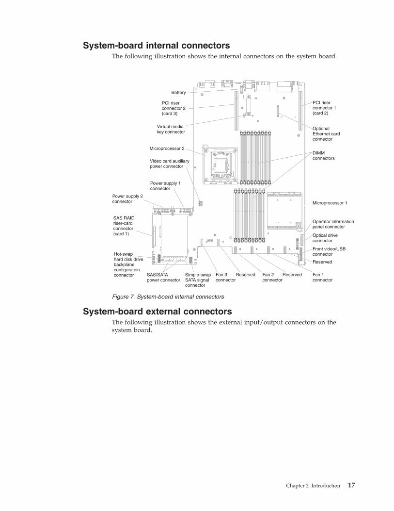
System-board internal connectors . . . . . . 17System-board external connectors . . . . . . 17System-board switches and jumpers . . . . . 18System-board LEDs. . . . . . . . . . . 22
System pulse LEDs . . . . . . . . . . 23System-board optional device connectors . . . 23SAS riser-card connectors and LEDs . . . . . 24PCI riser-card adapter connectors . . . . . . 25PCI riser-card assembly LEDs . . . . . . . 26
Chapter 3. Diagnostics . . . . . . . . 27Diagnostic tools . . . . . . . . . . . . . 27Event logs . . . . . . . . . . . . . . . 28
Viewing event logs from the Setup utility . . . 29Viewing event logs without restarting the server 29
Error messages . . . . . . . . . . . . . 31System event messages log . . . . . . . . 31
Integrated management module errormessages . . . . . . . . . . . . . 31
POST . . . . . . . . . . . . . . . 274POST error codes . . . . . . . . . . 274
Diagnostic programs, messages, and error codes 287Running the diagnostic programs . . . . 287Diagnostic text messages . . . . . . . 288Viewing the test log . . . . . . . . . 288Diagnostic messages . . . . . . . . . 289
Checkout procedure . . . . . . . . . . . 338About the checkout procedure. . . . . . . 338Performing the checkout procedure . . . . . 339
Troubleshooting tables . . . . . . . . . . 340DVD drive problems . . . . . . . . . . 341General problems . . . . . . . . . . . 342Hard disk drive problems . . . . . . . . 342Hypervisor problems . . . . . . . . . . 344Intermittent problems . . . . . . . . . 345
USB keyboard, mouse, or pointing-deviceproblems . . . . . . . . . . . . . . 346Memory problems . . . . . . . . . . . 347Microprocessor problems . . . . . . . . 349Monitor or video problems . . . . . . . . 349Optional-device problems . . . . . . . . 352Power problems . . . . . . . . . . . 353Serial device problems . . . . . . . . . 357ServerGuide problems . . . . . . . . . 358Software problems. . . . . . . . . . . 359Universal Serial Bus (USB) port problems . . . 359Video problems. . . . . . . . . . . . 360
Light path diagnostics . . . . . . . . . . 360Remind button . . . . . . . . . . . . 363Light path diagnostics LEDs . . . . . . . 363
Power-supply LEDs . . . . . . . . . . . 367Tape alert flags . . . . . . . . . . . . . 370Recovering the server firmware . . . . . . . 371Automatic boot failure recovery (ABR) . . . . . 375Nx boot failure . . . . . . . . . . . . . 375Solving power problems. . . . . . . . . . 376Solving Ethernet controller problems . . . . . 377Solving undetermined problems . . . . . . . 378Problem determination tips. . . . . . . . . 379
Chapter 4. Parts listing . . . . . . . 381Replaceable server components . . . . . . . 381Product recovery CDs . . . . . . . . . . 390Power cords . . . . . . . . . . . . . . 391
Chapter 5. Removing and replacingserver components . . . . . . . . . 395Installation guidelines . . . . . . . . . . 395
System reliability guidelines . . . . . . . 397Working inside the server with the power on 397Handling static-sensitive devices . . . . . . 398Returning a device or component . . . . . 398Internal cable routing and connectors . . . . 398
Removing and replacing consumable parts andTier 1 CRUs . . . . . . . . . . . . . . 402
Removing the cover . . . . . . . . . . 402Replacing the cover . . . . . . . . . . 403Removing the microprocessor 2 air baffle . . . 404Replacing the microprocessor 2 air baffle . . . 405Removing the DIMM air baffle . . . . . . 406Replacing the DIMM air baffle . . . . . . 407Removing the fan bracket . . . . . . . . 408Replacing the fan bracket . . . . . . . . 409Removing an IBM virtual media key . . . . 410Replacing an IBM virtual media key. . . . . 411Removing a USB hypervisor memory key . . . 412Replacing a USB hypervisor memory key . . . 413Removing a PCI riser-card assembly. . . . . 414Replacing a PCI riser-card assembly . . . . . 415
© Copyright IBM Corp. 2014 iii
Removing a PCI adapter from a PCI riser-cardassembly . . . . . . . . . . . . . . 417Installing a PCI adapter in a PCI riser-cardassembly . . . . . . . . . . . . . . 418Removing the optional two-port Ethernetadapter . . . . . . . . . . . . . . 420Replacing the optional two-port Ethernetadapter . . . . . . . . . . . . . . 421Storing the full-length-adapter bracket . . . . 424Removing the SAS riser-card and controllerassembly . . . . . . . . . . . . . . 424Replacing the SAS riser-card and controllerassembly . . . . . . . . . . . . . . 426Removing a ServeRAID SAS controller from theSAS riser card . . . . . . . . . . . . 430Replacing a ServeRAID SAS controller on theSAS riser card . . . . . . . . . . . . 431Removing an optional ServeRAID adapteradvanced feature key. . . . . . . . . . 433Replacing an optional ServeRAID adapteradvanced feature key. . . . . . . . . . 434Removing a ServeRAID SAS controller batteryfrom the remote battery tray . . . . . . . 436Replacing a ServeRAID SAS controller batteryon the remote battery tray . . . . . . . . 438Removing a hot-swap hard disk drive . . . . 440Replacing a hot-swap hard disk drive . . . . 440Removing a simple-swap hard disk drive . . . 442Replacing a simple-swap hard disk drive . . . 443Removing an optional CD-RW/DVD drive . . 444Replacing an optional CD-RW/DVD drive . . 445Removing a tape drive . . . . . . . . . 446Replacing a tape drive . . . . . . . . . 447Removing a memory module (DIMM) . . . . 448Installing a memory module . . . . . . . 450
DIMM installation sequence . . . . . . 453Memory mirroring . . . . . . . . . 453Online-spare memory . . . . . . . . 455
Replacing a DIMM . . . . . . . . . . 456Removing a hot-swap fan . . . . . . . . 457Replacing a hot-swap fan . . . . . . . . 458Removing a hot-swap fan . . . . . . . . 459Replacing a hot-swap ac power supply . . . . 460Removing the battery . . . . . . . . . 463Replacing the battery . . . . . . . . . . 465Removing the operator information panelassembly . . . . . . . . . . . . . . 466Replacing the operator information panelassembly . . . . . . . . . . . . . . 467Removing and replacing Tier 2 CRUs . . . . 468
Removing the bezel . . . . . . . . . 468Replacing the bezel . . . . . . . . . 469Removing the SAS hard disk drive backplane 469Replacing the SAS hard disk drive backplane 471Removing the simple-swap hard disk drivebackplate . . . . . . . . . . . . . 472Replacing the simple-swap hard disk drivebackplate . . . . . . . . . . . . . 473
Removing and replacing FRUs . . . . . . 474Removing a microprocessor and heat sink 474Replacing a microprocessor and heat sink 477
Thermal grease . . . . . . . . . . . 482Removing a heat-sink retention module . . 483Replacing a heat-sink retention module. . . 483Removing the system board . . . . . . 484Replacing the system board . . . . . . 486Removing the 240 VA safety cover . . . . 488Replacing the 240 VA safety cover . . . . 489
Chapter 6. Configuration informationand instructions . . . . . . . . . . 491Updating the firmware . . . . . . . . . . 491Configuring the server . . . . . . . . . . 492
Using the Setup utility . . . . . . . . . 493Starting the Setup utility . . . . . . . 494Setup utility menu choices . . . . . . . 494Passwords . . . . . . . . . . . . 497
Using the Boot Selection Menu program . . . 499Starting the backup server firmware . . . . . 499Using the ServerGuide Setup and InstallationCD . . . . . . . . . . . . . . . . 500
ServerGuide features . . . . . . . . . 500Setup and configuration overview . . . . 501Typical operating-system installation . . . 501Installing your operating system withoutusing ServerGuide. . . . . . . . . . 502
Using the integrated management module. . . 502Using the USB memory key for VMwarehypervisor . . . . . . . . . . . . . 503Using the remote presence capability andblue-screen capture . . . . . . . . . . 504
Enabling the remote presence feature . . . 505Obtaining the IP address for the Webinterface access . . . . . . . . . . . 505Logging on to the Web interface . . . . . 506
Enabling the Broadcom Gigabit Ethernet Utilityprogram . . . . . . . . . . . . . . 506Configuring the Gigabit Ethernet controller . . 507Using the LSI Configuration Utility program 507
Starting the LSI Configuration Utilityprogram . . . . . . . . . . . . . 508Formatting a hard disk drive . . . . . . 509Creating a RAID array of hard disk drives 509
IBM Advanced Settings Utility program . . . 510Updating IBM Systems Director . . . . . . 510
Updating the Universal Unique Identifier (UUID) 511Updating the DMI/SMBIOS data . . . . . . . 514
Appendix A. Getting help andtechnical assistance . . . . . . . . 517Before you call . . . . . . . . . . . . . 517Using the documentation . . . . . . . . . 518Getting help and information from the World WideWeb . . . . . . . . . . . . . . . . 518How to send DSA data to IBM . . . . . . . 518Creating a personalized support web page . . . 519Software service and support . . . . . . . . 519Hardware service and support . . . . . . . 519IBM Taiwan product service . . . . . . . . 519
iv System x3650 M3 Types 4255, 7945, and 7949: Problem Determination and Service Guide
Appendix B. Notices . . . . . . . . 521Trademarks . . . . . . . . . . . . . . 522Important notes . . . . . . . . . . . . 522Particulate contamination . . . . . . . . . 523Documentation format . . . . . . . . . . 524Telecommunication regulatory statement . . . . 524Electronic emission notices . . . . . . . . . 525
Federal Communications Commission (FCC)statement. . . . . . . . . . . . . . 525Industry Canada Class A emission compliancestatement. . . . . . . . . . . . . . 525Avis de conformité à la réglementationd'Industrie Canada . . . . . . . . . . 525Australia and New Zealand Class A statement 525European Union EMC Directive conformancestatement. . . . . . . . . . . . . . 526
Germany Class A statement . . . . . . . 526Japan VCCI Class A statement. . . . . . . 527Japan Electronics and Information TechnologyIndustries Association (JEITA) statement . . . 528Korea Communications Commission (KCC)statement. . . . . . . . . . . . . . 528Russia Electromagnetic Interference (EMI) ClassA statement . . . . . . . . . . . . . 528People's Republic of China Class A electronicemission statement . . . . . . . . . . 528Taiwan Class A compliance statement . . . . 529
Index . . . . . . . . . . . . . . . 531
Contents v

vi System x3650 M3 Types 4255, 7945, and 7949: Problem Determination and Service Guide
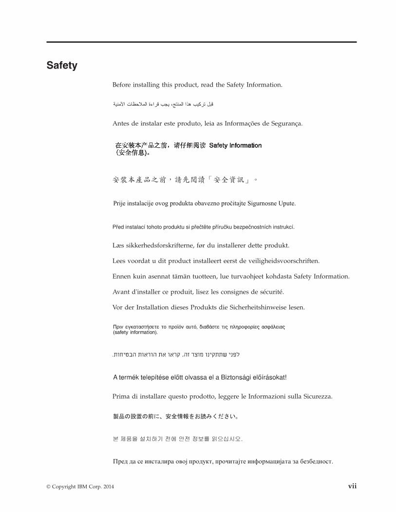
Safety
Before installing this product, read the Safety Information.
Antes de instalar este produto, leia as Informações de Segurança.
Læs sikkerhedsforskrifterne, før du installerer dette produkt.
Lees voordat u dit product installeert eerst de veiligheidsvoorschriften.
Ennen kuin asennat tämän tuotteen, lue turvaohjeet kohdasta Safety Information.
Avant d'installer ce produit, lisez les consignes de sécurité.
Vor der Installation dieses Produkts die Sicherheitshinweise lesen.
Prima di installare questo prodotto, leggere le Informazioni sulla Sicurezza.
© Copyright IBM Corp. 2014 vii
Les sikkerhetsinformasjonen (Safety Information) før du installerer dette produktet.
Antes de instalar este produto, leia as Informações sobre Segurança.
Antes de instalar este producto, lea la información de seguridad.
Läs säkerhetsinformationen innan du installerar den här produkten.
viii System x3650 M3 Types 4255, 7945, and 7949: Problem Determination and Service Guide
Guidelines for trained service techniciansThis section contains information for trained service technicians.
Inspecting for unsafe conditionsUse this information to help you identify potential unsafe conditions in an IBM®
product that you are working on.
Each IBM product, as it was designed and manufactured, has required safety itemsto protect users and service technicians from injury. The information in this sectionaddresses only those items. Use good judgment to identify potential unsafeconditions that might be caused by non-IBM alterations or attachment of non-IBMfeatures or optional devices that are not addressed in this section. If you identifyan unsafe condition, you must determine how serious the hazard is and whetheryou must correct the problem before you work on the product.
Consider the following conditions and the safety hazards that they present:v Electrical hazards, especially primary power. Primary voltage on the frame can
cause serious or fatal electrical shock.v Explosive hazards, such as a damaged CRT face or a bulging capacitor.v Mechanical hazards, such as loose or missing hardware.
To inspect the product for potential unsafe conditions, complete the followingsteps:1. Make sure that the power is off and the power cords are disconnected.2. Make sure that the exterior cover is not damaged, loose, or broken, and observe
any sharp edges.3. Check the power cords:
v Make sure that the third-wire ground connector is in good condition. Use ameter to measure third-wire ground continuity for 0.1 ohm or less betweenthe external ground pin and the frame ground.
v Make sure that the power cords are the correct type.v Make sure that the insulation is not frayed or worn.
4. Remove the cover.5. Check for any obvious non-IBM alterations. Use good judgment as to the safety
of any non-IBM alterations.6. Check inside the system for any obvious unsafe conditions, such as metal
filings, contamination, water or other liquid, or signs of fire or smoke damage.7. Check for worn, frayed, or pinched cables.8. Make sure that the power-supply cover fasteners (screws or rivets) have not
been removed or tampered with.
Safety ix
Guidelines for servicing electrical equipmentObserve these guidelines when you service electrical equipment.v Check the area for electrical hazards such as moist floors, nongrounded power
extension cords, and missing safety grounds.v Use only approved tools and test equipment. Some hand tools have handles that
are covered with a soft material that does not provide insulation from liveelectrical current.
v Regularly inspect and maintain your electrical hand tools for safe operationalcondition. Do not use worn or broken tools or testers.
v Do not touch the reflective surface of a dental mirror to a live electrical circuit.The surface is conductive and can cause personal injury or equipment damage ifit touches a live electrical circuit.
v Some rubber floor mats contain small conductive fibers to decrease electrostaticdischarge. Do not use this type of mat to protect yourself from electrical shock.
v Do not work alone under hazardous conditions or near equipment that hashazardous voltages.
v Locate the emergency power-off (EPO) switch, disconnecting switch, or electricaloutlet so that you can turn off the power quickly in the event of an electricalaccident.
v Disconnect all power before you perform a mechanical inspection, work nearpower supplies, or remove or install main units.
v Before you work on the equipment, disconnect the power cord. If you cannotdisconnect the power cord, have the customer power-off the wall box thatsupplies power to the equipment and lock the wall box in the off position.
v Never assume that power has been disconnected from a circuit. Check it tomake sure that it has been disconnected.
v If you have to work on equipment that has exposed electrical circuits, observethe following precautions:– Make sure that another person who is familiar with the power-off controls is
near you and is available to turn off the power if necessary.– When you work with powered-on electrical equipment, use only one hand.
Keep the other hand in your pocket or behind your back to avoid creating acomplete circuit that could cause an electrical shock.
– When you use a tester, set the controls correctly and use the approved probeleads and accessories for that tester.
– Stand on a suitable rubber mat to insulate you from grounds such as metalfloor strips and equipment frames.
v Use extreme care when you measure high voltages.v To ensure proper grounding of components such as power supplies, pumps,
blowers, fans, and motor generators, do not service these components outside oftheir normal operating locations.
v If an electrical accident occurs, use caution, turn off the power, and send anotherperson to get medical aid.
x System x3650 M3 Types 4255, 7945, and 7949: Problem Determination and Service Guide
Safety statementsThese statements provide the caution and danger information that is used in thisdocumentation.
Important:
Each caution and danger statement in this documentation is labeled with anumber. This number is used to cross reference an English-language caution ordanger statement with translated versions of the caution or danger statement inthe Safety Information document.
For example, if a caution statement is labeled Statement 1, translations for thatcaution statement are in the Safety Information document under Statement 1.
Be sure to read all caution and danger statements in this documentation before youperform the procedures. Read any additional safety information that comes withyour system or optional device before you install the device.
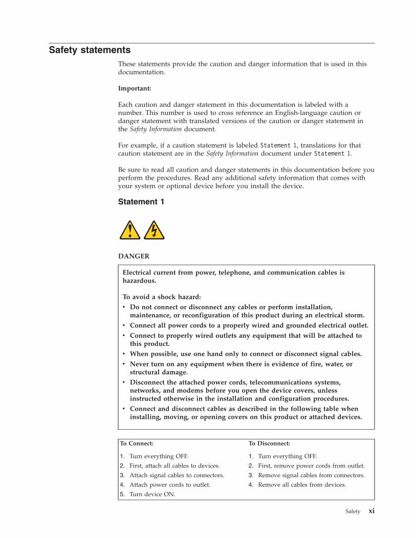
Statement 1
DANGER
Electrical current from power, telephone, and communication cables ishazardous.
To avoid a shock hazard:
v Do not connect or disconnect any cables or perform installation,maintenance, or reconfiguration of this product during an electrical storm.
v Connect all power cords to a properly wired and grounded electrical outlet.
v Connect to properly wired outlets any equipment that will be attached tothis product.
v When possible, use one hand only to connect or disconnect signal cables.
v Never turn on any equipment when there is evidence of fire, water, orstructural damage.
v Disconnect the attached power cords, telecommunications systems,networks, and modems before you open the device covers, unlessinstructed otherwise in the installation and configuration procedures.
v Connect and disconnect cables as described in the following table wheninstalling, moving, or opening covers on this product or attached devices.
To Connect: To Disconnect:
1. Turn everything OFF.
2. First, attach all cables to devices.
3. Attach signal cables to connectors.
4. Attach power cords to outlet.
5. Turn device ON.
1. Turn everything OFF.
2. First, remove power cords from outlet.
3. Remove signal cables from connectors.
4. Remove all cables from devices.
Safety xi
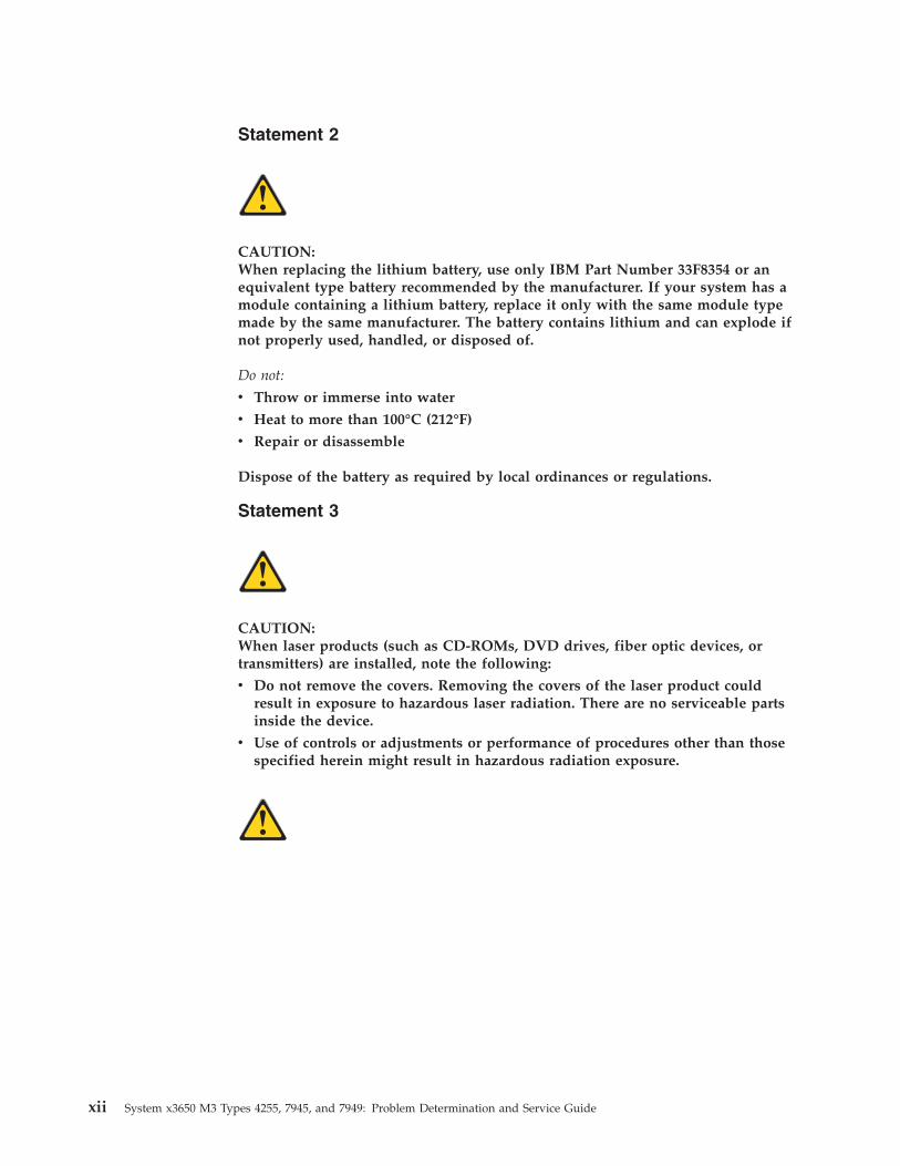
Statement 2
CAUTION:When replacing the lithium battery, use only IBM Part Number 33F8354 or anequivalent type battery recommended by the manufacturer. If your system has amodule containing a lithium battery, replace it only with the same module typemade by the same manufacturer. The battery contains lithium and can explode ifnot properly used, handled, or disposed of.
Do not:
v Throw or immerse into water
v Heat to more than 100°C (212°F)
v Repair or disassemble
Dispose of the battery as required by local ordinances or regulations.
Statement 3
CAUTION:When laser products (such as CD-ROMs, DVD drives, fiber optic devices, ortransmitters) are installed, note the following:
v Do not remove the covers. Removing the covers of the laser product couldresult in exposure to hazardous laser radiation. There are no serviceable partsinside the device.
v Use of controls or adjustments or performance of procedures other than thosespecified herein might result in hazardous radiation exposure.
xii System x3650 M3 Types 4255, 7945, and 7949: Problem Determination and Service Guide
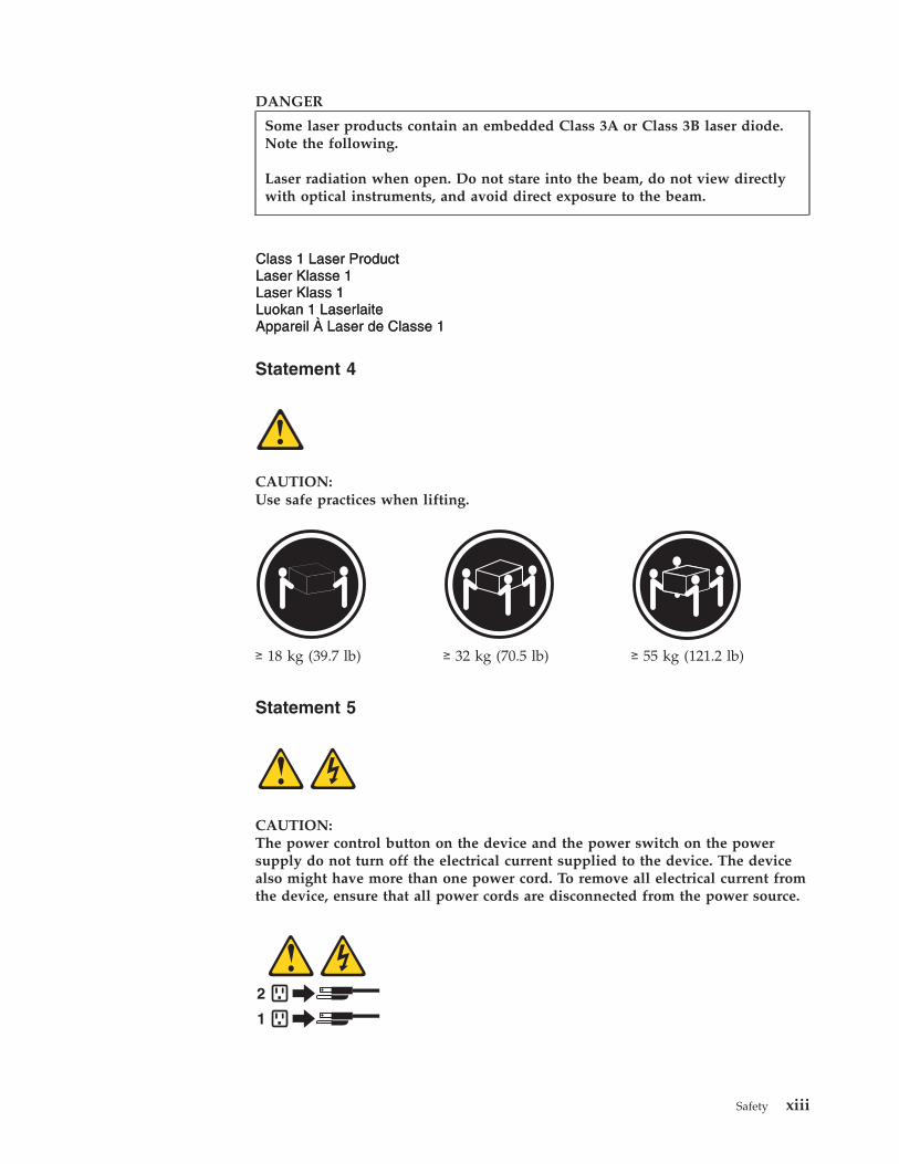
DANGER
Some laser products contain an embedded Class 3A or Class 3B laser diode.Note the following.
Laser radiation when open. Do not stare into the beam, do not view directlywith optical instruments, and avoid direct exposure to the beam.
Statement 4
CAUTION:Use safe practices when lifting.
≥ 18 kg (39.7 lb) ≥ 32 kg (70.5 lb) ≥ 55 kg (121.2 lb)
Statement 5
CAUTION:The power control button on the device and the power switch on the powersupply do not turn off the electrical current supplied to the device. The devicealso might have more than one power cord. To remove all electrical current fromthe device, ensure that all power cords are disconnected from the power source.
1
2
Safety xiii
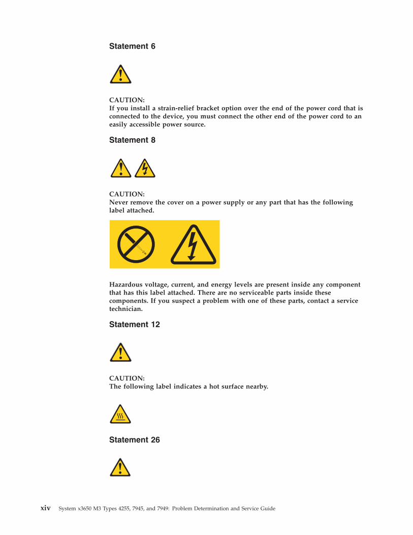
Statement 6
CAUTION:If you install a strain-relief bracket option over the end of the power cord that isconnected to the device, you must connect the other end of the power cord to aneasily accessible power source.
Statement 8
CAUTION:Never remove the cover on a power supply or any part that has the followinglabel attached.
Hazardous voltage, current, and energy levels are present inside any componentthat has this label attached. There are no serviceable parts inside thesecomponents. If you suspect a problem with one of these parts, contact a servicetechnician.
Statement 12
CAUTION:The following label indicates a hot surface nearby.
Statement 26
xiv System x3650 M3 Types 4255, 7945, and 7949: Problem Determination and Service Guide
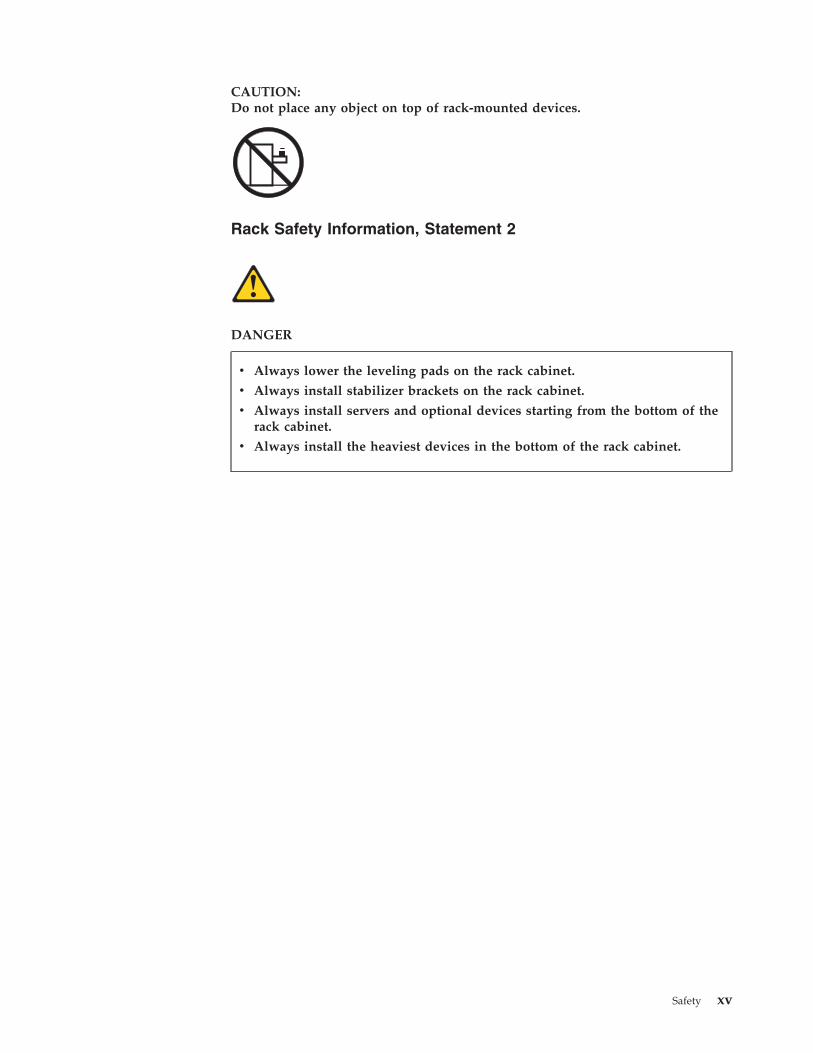
CAUTION:Do not place any object on top of rack-mounted devices.
Rack Safety Information, Statement 2
DANGER
v Always lower the leveling pads on the rack cabinet.
v Always install stabilizer brackets on the rack cabinet.
v Always install servers and optional devices starting from the bottom of therack cabinet.
v Always install the heaviest devices in the bottom of the rack cabinet.
Safety xv

xvi System x3650 M3 Types 4255, 7945, and 7949: Problem Determination and Service Guide
Chapter 1. Start here
You can solve many problems without outside assistance by following thetroubleshooting procedures in this documentation and on the World Wide Web.
This document describes the diagnostic tests that you can perform, troubleshootingprocedures, and explanations of error messages and error codes. Thedocumentation that comes with your operating system and software also containstroubleshooting information.
Diagnosing a problemBefore you contact IBM or an approved warranty service provider, follow theseprocedures in the order in which they are presented to diagnose a problem withyour server.
Procedure1. Return the server to the condition it was in before the problem occurred. If
any hardware, software, or firmware was changed before the problem occurred,if possible, reverse those changes. This might include any of the followingitems:v Hardware componentsv Device drivers and firmwarev System softwarev UEFI firmwarev System input power or network connections
2. View the light path diagnostics LEDs and event logs. The server is designedfor ease of diagnosis of hardware and software problems.v Light path diagnostics LEDs: See “Light path diagnostics” on page 360 for
information about using light path diagnostics LEDs.v Event logs: See “System event messages log” on page 31 for information
about notification events and diagnosis.v Software or operating-system error codes: See the documentation for the
software or operating system for information about a specific error code. Seethe manufacturer's website for documentation.
3. Run IBM Dynamic System Analysis (DSA) and collect system data. RunDynamic System Analysis (DSA) to collect information about the hardware,firmware, software, and operating system. Have this information availablewhen you contact IBM or an approved warranty service provider. Forinstructions for running DSA, see the Dynamic System Analysis Installation andUser's Guide.To download the latest version of DSA code and the Dynamic System AnalysisInstallation and User's Guide, go to http://www.ibm.com/support/entry/portal/docdisplay?lndocid=SERV-DSA.
4. Check for and apply code updates. Fixes or workarounds for many problemsmight be available in updated UEFI firmware, device firmware, or devicedrivers. To display a list of available updates for the server, go tohttp://www.ibm.com/support/fixcentral/.
© Copyright IBM Corp. 2014 1
Attention: Installing the wrong firmware or device-driver update might causethe server to malfunction. Before you install a firmware or device-driverupdate, read any readme and change history files that are provided with thedownloaded update. These files contain important information about theupdate and the procedure for installing the update, including any specialprocedure for updating from an early firmware or device-driver version to thelatest version.
Important: Some cluster solutions require specific code levels or coordinatedcode updates. If the device is part of a cluster solution, verify that the latestlevel of code is supported for the cluster solution before you update the code.a. Install UpdateXpress system updates. You can install code updates that are
packaged as an UpdateXpress System Pack or UpdateXpress CD image. AnUpdateXpress System Pack contains an integration-tested bundle of onlinefirmware and device-driver updates for your server. In addition, you canuse IBM ToolsCenter Bootable Media Creator to create bootable media thatis suitable for applying firmware updates and running preboot diagnostics.For more information about UpdateXpress System Packs, seehttp://www.ibm.com/support/entry/portal/docdisplay?lndocid=SERV-XPRESS and “Updating the firmware” on page 491. For more informationabout the Bootable Media Creator, see http://www.ibm.com/support/entry/portal/docdisplay?lndocid=TOOL-BOMC.Be sure to separately install any listed critical updates that have releasedates that are later than the release date of the UpdateXpress System Packor UpdateXpress image (see step 4b).
b. Install manual system updates.
1) Determine the existing code levels.
In DSA, click Firmware/VPD to view system firmware levels, or clickSoftware to view operating-system levels.
2) Download and install updates of code that is not at the latest level.
To display a list of available updates for the server, go tohttp://www.ibm.com/support/fixcentral/.When you click an update, an information page is displayed, includinga list of the problems that the update fixes. Review this list for yourspecific problem; however, even if your problem is not listed, installingthe update might solve the problem.
5. Check for and correct an incorrect configuration. If the server is incorrectlyconfigured, a system function can fail to work when you enable it; if you makean incorrect change to the server configuration, a system function that has beenenabled can stop working.a. Make sure that all installed hardware and software are supported. See
http://www.ibm.com/systems/info/x86servers/serverproven/compat/us/to verify that the server supports the installed operating system, optionaldevices, and software levels. If any hardware or software component is notsupported, uninstall it to determine whether it is causing the problem. Youmust remove nonsupported hardware before you contact IBM or anapproved warranty service provider for support.
b. Make sure that the server, operating system, and software are installedand configured correctly. Many configuration problems are caused by loosepower or signal cables or incorrectly seated adapters. You might be able tosolve the problem by turning off the server, reconnecting cables, reseatingadapters, and turning the server back on. For information about performingthe checkout procedure, see “About the checkout procedure” on page 338.
2 System x3650 M3 Types 4255, 7945, and 7949: Problem Determination and Service Guide
For information about configuring the server, see Chapter 6, “Configurationinformation and instructions,” on page 491.
6. See controller and management software documentation. If the problem isassociated with a specific function (for example, if a RAID hard disk drive ismarked offline in the RAID array), see the documentation for the associatedcontroller and management or controlling software to verify that the controlleris correctly configured.Problem determination information is available for many devices such as RAIDand network adapters.For problems with operating systems or IBM software or devices, go tohttp://www.ibm.com/supportportal.
7. Check for troubleshooting procedures and RETAIN tips. Troubleshootingprocedures and RETAIN tips document known problems and suggestedsolutions. To search for troubleshooting procedures and RETAIN tips, go tohttp://www.ibm.com/supportportal.
8. Use the troubleshooting tables. See “Troubleshooting tables” on page 340 tofind a solution to a problem that has identifiable symptoms.A single problem might cause multiple symptoms. Follow the troubleshootingprocedure for the most obvious symptom. If that procedure does not diagnosethe problem, use the procedure for another symptom, if possible.If the problem remains, contact IBM or an approved warranty service providerfor assistance with additional problem determination and possible hardwarereplacement. To open an online service request, go to http://www.ibm.com/support/entry/portal/Open_service_request. Be prepared to provideinformation about any error codes and collected data.
Undocumented problemsIf you have completed the diagnostic procedure and the problem remains, theproblem might not have been previously identified by IBM. After you haveverified that all code is at the latest level, all hardware and software configurationsare valid, and no light path diagnostics LEDs or log entries indicate a hardwarecomponent failure, contact IBM or an approved warranty service provider forassistance.
To open an online service request, go to http://www.ibm.com/support/entry/portal/Open_service_request. Be prepared to provide information about any errorcodes and collected data and the problem determination procedures that you haveused.
Chapter 1. Start here 3

4 System x3650 M3 Types 4255, 7945, and 7949: Problem Determination and Service Guide
Chapter 2. Introduction
This Problem Determination and Service Guide contains information to help you solveproblems that might occur in your IBM System x3650 M3 Type 4255, 7945, or 7949server. It describes the diagnostic tools that come with the server, error codes andsuggested actions, and instructions for replacing failing components.
Replaceable components are of four types:v Consumable Parts: Purchase and replacement of consumable parts(components,
such as batteries and printer cartridges, that have depletable life) is yourresponsibility. If IBM acquires or installs a consumable part at your request, youwill be charged for the service.
v Tier 1 customer replaceable unit (CRU): Replacement of Tier 1 CRUs is yourresponsibility. If IBM installs a Tier 1 CRU at your request, you will be chargedfor the installation.
v Tier 2 customer replaceable unit: You may install a Tier 2 CRU yourself orrequest IBM to install it, at no additional charge, under the type of warrantyservice that is designated for your server.
v Field replaceable unit (FRU): FRUs must be installed only by trained servicetechnicians.
For information about the terms of the warranty and getting service and assistance,see the Warranty and Support Information document on the IBM Documentation CD.
Related documentationThis Installation and User’s Guide contains general information about the server,including how to set up the server, how to install supported optional devices, andhow to configure the server.
The following documentation also comes with the server:v Warranty Information
This printed document contains information about the terms of the warranty.v Safety Information
This document is in PDF on the IBM Documentation CD. It contains translatedcaution and danger statements. Each caution and danger statement that appearsin the documentation has a number that you can use to locate the correspondingstatement in your language in the Safety Information document.
v Rack Installation Instructions
This printed document contains instructions for installing the server in a rack.v Problem Determination and Service Guide
This document is in PDF on the IBM Documentation CD. It contains informationto help you solve problems yourself, and it contains information for servicetechnicians.
v Environmental Notices and User Guide
This document is in PDF on the IBM Documentation CD. It contains translatedenvironmental notices.
v IBM License Agreement for Machine Code
© Copyright IBM Corp. 2014 5
This document is in PDF on the IBM Documentation CD. It provides translatedversions of the IBM License Agreement for Machine Code for your product.
v Licenses and Attributions Documents
This document is in PDF. It contains information about the open-source notices.
Depending on the server model, additional documentation might be included onthe IBM Documentation CD.
The System x® and xSeries Tools Center is an online information center thatcontains information about tools for updating, managing, and deploying firmware,device drivers, and operating systems. The System x and xSeries Tools Center is athttp://publib.boulder.ibm.com/infocenter/toolsctr/v1r0/index.jsp.
The server might have features that are not described in the documentation thatcomes with the server. The documentation might be updated occasionally toinclude information about those features, or technical updates might be availableto provide additional information that is not included in the server documentation.These updates are available from the IBM Web site. To check for updateddocumentation and technical updates, complete the following steps.
Note: Changes are made periodically to the IBM Web site. The actual proceduremight vary slightly from what is described in this document.1. Go to http://www.ibm.com/systems/support/.2. Under Product support, click System x.3. Under Popular links, click Publications lookup.4. From the Product family menu, select System x3650 M3 and click Continue.
Notices and statements in this documentThe caution and danger statements in this document are also in the multilingualSafety Information document, which is on the Documentation CD. Each statement isnumbered for reference to the corresponding statement in your language in theSafety Information document.
The following notices and statements are used in this document:v Note: These notices provide important tips, guidance, or advice.v Important: These notices provide information or advice that might help you
avoid inconvenient or problem situations.v Attention: These notices indicate potential damage to programs, devices, or data.
An attention notice is placed just before the instruction or situation in whichdamage might occur.
v Caution: These statements indicate situations that can be potentially hazardousto you. A caution statement is placed just before the description of a potentiallyhazardous procedure step or situation.
v Danger: These statements indicate situations that can be potentially lethal orextremely hazardous to you. A danger statement is placed just before thedescription of a potentially lethal or extremely hazardous procedure step orsituation.
6 System x3650 M3 Types 4255, 7945, and 7949: Problem Determination and Service Guide
Features and specificationsThe following information is a summary of the features and specifications of theserver. Depending on the model, some features might not be available, or somespecifications might not apply.
Racks are marked in vertical increments of 4.45 cm (1.75 inches). Each increment isreferred to as a unit, or “U.” A 1-U-high device is 1.75 inches tall.
Note:
1. Power consumption and heat output vary depending on the number and typeof optional features that are installed and the power-management optionalfeatures that are in use.
2. The sound levels were measured in controlled acoustical environmentsaccording to the procedures specified by the American National StandardsInstitute (ANSI) S12.10 and ISO 7779 and are reported in accordance with ISO9296. Actual sound-pressure levels in a given location might exceed the averagevalues stated because of room reflections and other nearby noise sources. Thedeclared sound-power levels indicate an upper limit, below which a largenumber of computers will operate.
Chapter 2. Introduction 7
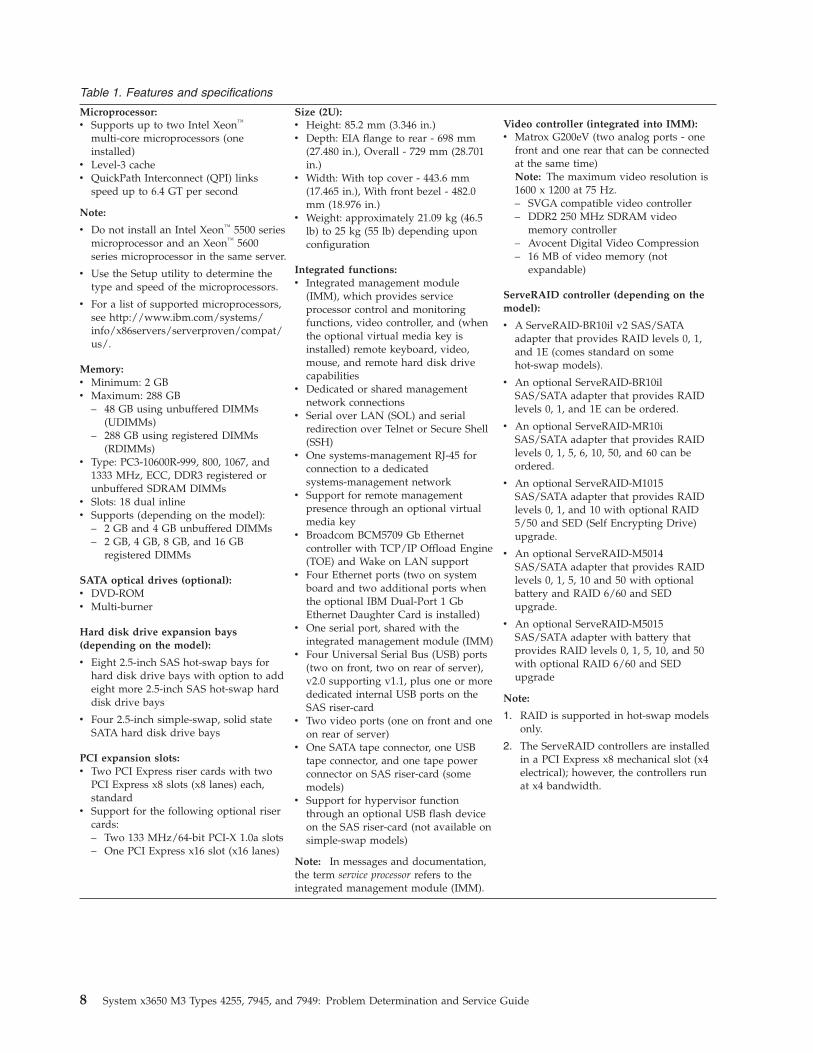
Table 1. Features and specifications
Microprocessor:v Supports up to two Intel Xeon™
multi-core microprocessors (oneinstalled)
v Level-3 cachev QuickPath Interconnect (QPI) links
speed up to 6.4 GT per second
Note:
v Do not install an Intel Xeon™ 5500 seriesmicroprocessor and an Xeon™ 5600series microprocessor in the same server.
v Use the Setup utility to determine thetype and speed of the microprocessors.
v For a list of supported microprocessors,see http://www.ibm.com/systems/info/x86servers/serverproven/compat/us/.
Memory:v Minimum: 2 GBv Maximum: 288 GB
– 48 GB using unbuffered DIMMs(UDIMMs)
– 288 GB using registered DIMMs(RDIMMs)
v Type: PC3-10600R-999, 800, 1067, and1333 MHz, ECC, DDR3 registered orunbuffered SDRAM DIMMs
v Slots: 18 dual inlinev Supports (depending on the model):
– 2 GB and 4 GB unbuffered DIMMs– 2 GB, 4 GB, 8 GB, and 16 GB
registered DIMMs
SATA optical drives (optional):v DVD-ROMv Multi-burner
Hard disk drive expansion bays(depending on the model):
v Eight 2.5-inch SAS hot-swap bays forhard disk drive bays with option to addeight more 2.5-inch SAS hot-swap harddisk drive bays
v Four 2.5-inch simple-swap, solid stateSATA hard disk drive bays
PCI expansion slots:v Two PCI Express riser cards with two
PCI Express x8 slots (x8 lanes) each,standard
v Support for the following optional risercards:– Two 133 MHz/64-bit PCI-X 1.0a slots– One PCI Express x16 slot (x16 lanes)
Size (2U):v Height: 85.2 mm (3.346 in.)v Depth: EIA flange to rear - 698 mm
(27.480 in.), Overall - 729 mm (28.701in.)
v Width: With top cover - 443.6 mm(17.465 in.), With front bezel - 482.0mm (18.976 in.)
v Weight: approximately 21.09 kg (46.5lb) to 25 kg (55 lb) depending uponconfiguration
Integrated functions:v Integrated management module
(IMM), which provides serviceprocessor control and monitoringfunctions, video controller, and (whenthe optional virtual media key isinstalled) remote keyboard, video,mouse, and remote hard disk drivecapabilities
v Dedicated or shared managementnetwork connections
v Serial over LAN (SOL) and serialredirection over Telnet or Secure Shell(SSH)
v One systems-management RJ-45 forconnection to a dedicatedsystems-management network
v Support for remote managementpresence through an optional virtualmedia key
v Broadcom BCM5709 Gb Ethernetcontroller with TCP/IP Offload Engine(TOE) and Wake on LAN support
v Four Ethernet ports (two on systemboard and two additional ports whenthe optional IBM Dual-Port 1 GbEthernet Daughter Card is installed)
v One serial port, shared with theintegrated management module (IMM)
v Four Universal Serial Bus (USB) ports(two on front, two on rear of server),v2.0 supporting v1.1, plus one or morededicated internal USB ports on theSAS riser-card
v Two video ports (one on front and oneon rear of server)
v One SATA tape connector, one USBtape connector, and one tape powerconnector on SAS riser-card (somemodels)
v Support for hypervisor functionthrough an optional USB flash deviceon the SAS riser-card (not available onsimple-swap models)
Note: In messages and documentation,the term service processor refers to theintegrated management module (IMM).
Video controller (integrated into IMM):v Matrox G200eV (two analog ports - one
front and one rear that can be connectedat the same time)Note: The maximum video resolution is1600 x 1200 at 75 Hz.– SVGA compatible video controller– DDR2 250 MHz SDRAM video
memory controller– Avocent Digital Video Compression– 16 MB of video memory (not
expandable)
ServeRAID controller (depending on themodel):
v A ServeRAID-BR10il v2 SAS/SATAadapter that provides RAID levels 0, 1,and 1E (comes standard on somehot-swap models).
v An optional ServeRAID-BR10ilSAS/SATA adapter that provides RAIDlevels 0, 1, and 1E can be ordered.
v An optional ServeRAID-MR10iSAS/SATA adapter that provides RAIDlevels 0, 1, 5, 6, 10, 50, and 60 can beordered.
v An optional ServeRAID-M1015SAS/SATA adapter that provides RAIDlevels 0, 1, and 10 with optional RAID5/50 and SED (Self Encrypting Drive)upgrade.
v An optional ServeRAID-M5014SAS/SATA adapter that provides RAIDlevels 0, 1, 5, 10 and 50 with optionalbattery and RAID 6/60 and SEDupgrade.
v An optional ServeRAID-M5015SAS/SATA adapter with battery thatprovides RAID levels 0, 1, 5, 10, and 50with optional RAID 6/60 and SEDupgrade
Note:
1. RAID is supported in hot-swap modelsonly.
2. The ServeRAID controllers are installedin a PCI Express x8 mechanical slot (x4electrical); however, the controllers runat x4 bandwidth.
8 System x3650 M3 Types 4255, 7945, and 7949: Problem Determination and Service Guide
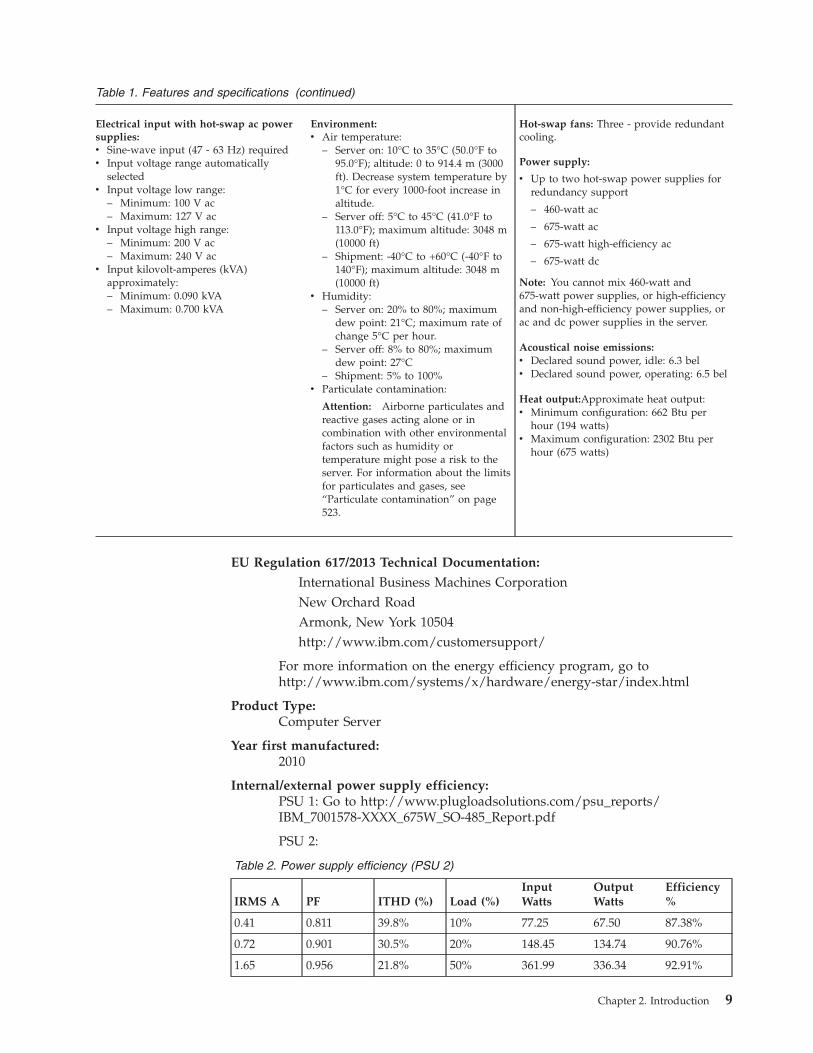
Table 1. Features and specifications (continued)
Electrical input with hot-swap ac powersupplies:v Sine-wave input (47 - 63 Hz) requiredv Input voltage range automatically
selectedv Input voltage low range:
– Minimum: 100 V ac– Maximum: 127 V ac
v Input voltage high range:– Minimum: 200 V ac– Maximum: 240 V ac
v Input kilovolt-amperes (kVA)approximately:– Minimum: 0.090 kVA– Maximum: 0.700 kVA
Environment:v Air temperature:
– Server on: 10°C to 35°C (50.0°F to95.0°F); altitude: 0 to 914.4 m (3000ft). Decrease system temperature by1°C for every 1000-foot increase inaltitude.
– Server off: 5°C to 45°C (41.0°F to113.0°F); maximum altitude: 3048 m(10000 ft)
– Shipment: -40°C to +60°C (-40°F to140°F); maximum altitude: 3048 m(10000 ft)
v Humidity:– Server on: 20% to 80%; maximum
dew point: 21°C; maximum rate ofchange 5°C per hour.
– Server off: 8% to 80%; maximumdew point: 27°C
– Shipment: 5% to 100%v Particulate contamination:
Attention: Airborne particulates andreactive gases acting alone or incombination with other environmentalfactors such as humidity ortemperature might pose a risk to theserver. For information about the limitsfor particulates and gases, see“Particulate contamination” on page523.
Hot-swap fans: Three - provide redundantcooling.
Power supply:
v Up to two hot-swap power supplies forredundancy support
– 460-watt ac
– 675-watt ac
– 675-watt high-efficiency ac
– 675-watt dc
Note: You cannot mix 460-watt and675-watt power supplies, or high-efficiencyand non-high-efficiency power supplies, orac and dc power supplies in the server.
Acoustical noise emissions:v Declared sound power, idle: 6.3 belv Declared sound power, operating: 6.5 bel
Heat output:Approximate heat output:v Minimum configuration: 662 Btu per
hour (194 watts)v Maximum configuration: 2302 Btu per
hour (675 watts)
EU Regulation 617/2013 Technical Documentation:
International Business Machines CorporationNew Orchard RoadArmonk, New York 10504http://www.ibm.com/customersupport/
For more information on the energy efficiency program, go tohttp://www.ibm.com/systems/x/hardware/energy-star/index.html
Product Type:Computer Server
Year first manufactured:2010
Internal/external power supply efficiency:PSU 1: Go to http://www.plugloadsolutions.com/psu_reports/IBM_7001578-XXXX_675W_SO-485_Report.pdf
PSU 2:
Table 2. Power supply efficiency (PSU 2)
IRMS A PF ITHD (%) Load (%)InputWatts
OutputWatts
Efficiency%
0.41 0.811 39.8% 10% 77.25 67.50 87.38%
0.72 0.901 30.5% 20% 148.45 134.74 90.76%
1.65 0.956 21.8% 50% 361.99 336.34 92.91%
Chapter 2. Introduction 9
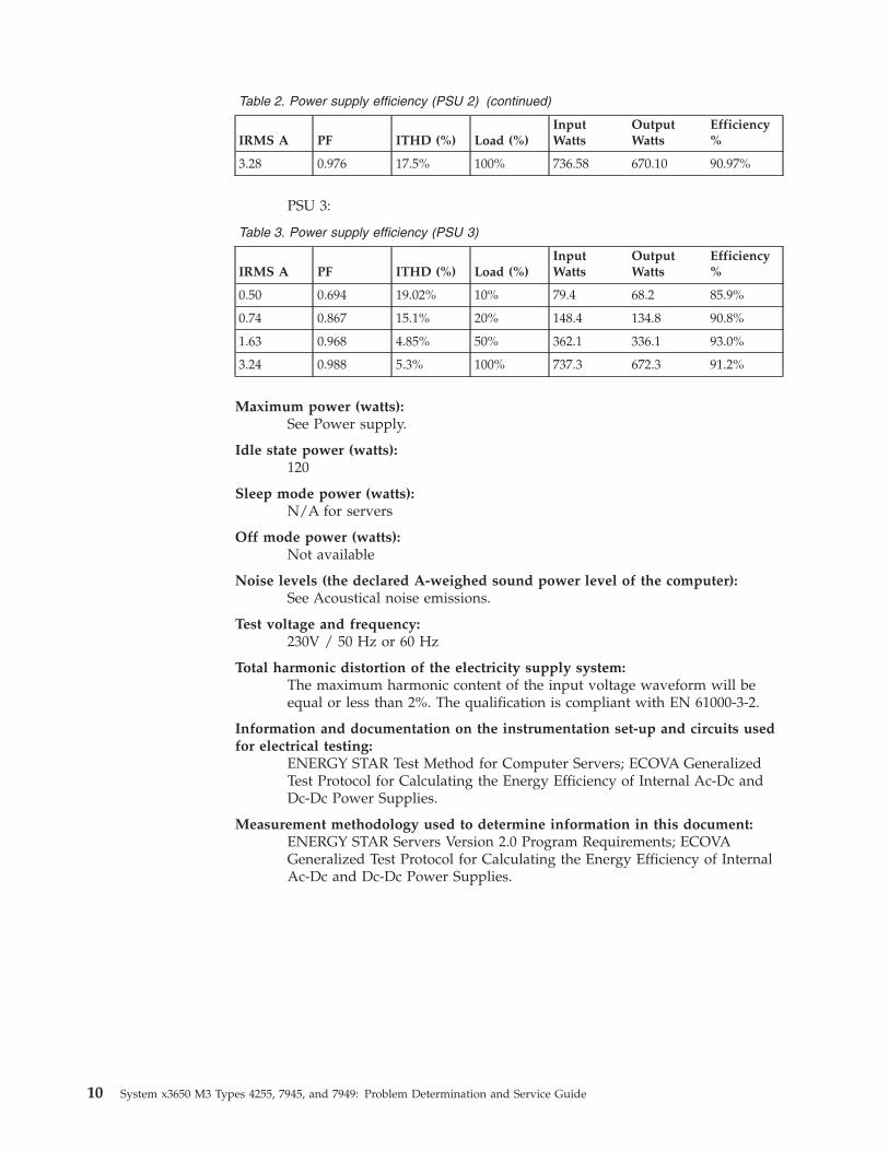
Table 2. Power supply efficiency (PSU 2) (continued)
IRMS A PF ITHD (%) Load (%)InputWatts
OutputWatts
Efficiency%
3.28 0.976 17.5% 100% 736.58 670.10 90.97%
PSU 3:
Table 3. Power supply efficiency (PSU 3)
IRMS A PF ITHD (%) Load (%)InputWatts
OutputWatts
Efficiency%
0.50 0.694 19.02% 10% 79.4 68.2 85.9%
0.74 0.867 15.1% 20% 148.4 134.8 90.8%
1.63 0.968 4.85% 50% 362.1 336.1 93.0%
3.24 0.988 5.3% 100% 737.3 672.3 91.2%
Maximum power (watts):See Power supply.
Idle state power (watts):120
Sleep mode power (watts):N/A for servers
Off mode power (watts):Not available
Noise levels (the declared A-weighed sound power level of the computer):See Acoustical noise emissions.
Test voltage and frequency:230V / 50 Hz or 60 Hz
Total harmonic distortion of the electricity supply system:The maximum harmonic content of the input voltage waveform will beequal or less than 2%. The qualification is compliant with EN 61000-3-2.
Information and documentation on the instrumentation set-up and circuits usedfor electrical testing:
ENERGY STAR Test Method for Computer Servers; ECOVA GeneralizedTest Protocol for Calculating the Energy Efficiency of Internal Ac-Dc andDc-Dc Power Supplies.
Measurement methodology used to determine information in this document:ENERGY STAR Servers Version 2.0 Program Requirements; ECOVAGeneralized Test Protocol for Calculating the Energy Efficiency of InternalAc-Dc and Dc-Dc Power Supplies.
10 System x3650 M3 Types 4255, 7945, and 7949: Problem Determination and Service Guide
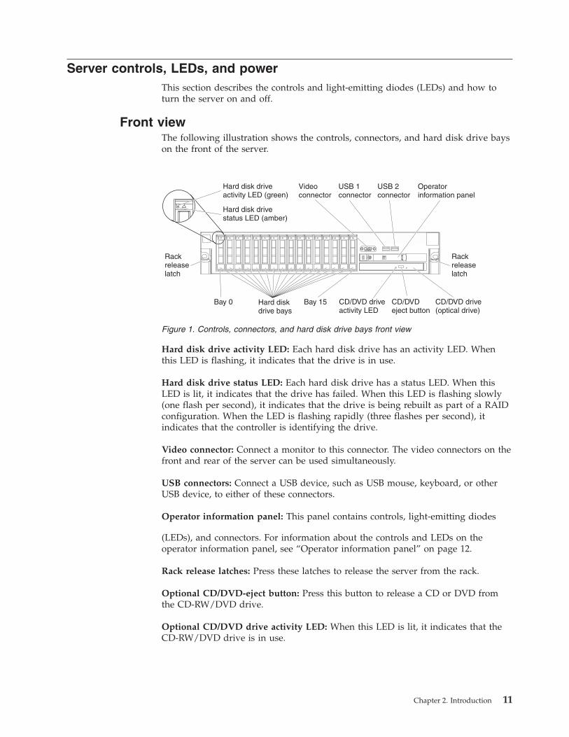
Server controls, LEDs, and powerThis section describes the controls and light-emitting diodes (LEDs) and how toturn the server on and off.
Front viewThe following illustration shows the controls, connectors, and hard disk drive bayson the front of the server.
Hard disk drive activity LED: Each hard disk drive has an activity LED. Whenthis LED is flashing, it indicates that the drive is in use.
Hard disk drive status LED: Each hard disk drive has a status LED. When thisLED is lit, it indicates that the drive has failed. When this LED is flashing slowly(one flash per second), it indicates that the drive is being rebuilt as part of a RAIDconfiguration. When the LED is flashing rapidly (three flashes per second), itindicates that the controller is identifying the drive.
Video connector: Connect a monitor to this connector. The video connectors on thefront and rear of the server can be used simultaneously.
USB connectors: Connect a USB device, such as USB mouse, keyboard, or otherUSB device, to either of these connectors.
Operator information panel: This panel contains controls, light-emitting diodes
(LEDs), and connectors. For information about the controls and LEDs on theoperator information panel, see “Operator information panel” on page 12.
Rack release latches: Press these latches to release the server from the rack.
Optional CD/DVD-eject button: Press this button to release a CD or DVD fromthe CD-RW/DVD drive.
Optional CD/DVD drive activity LED: When this LED is lit, it indicates that theCD-RW/DVD drive is in use.
Hard disk driveactivity LED (green)
Hard disk drivestatus LED (amber)
Hard diskdrive bays
Rackreleaselatch
Videoconnector
USB 1connector
USB 2connector
Operatorinformation panel
CD/DVDeject button
CD/DVD driveactivity LED
Rackreleaselatch
CD/DVD drive(optical drive)
Bay 15Bay 0
Figure 1. Controls, connectors, and hard disk drive bays front view
Chapter 2. Introduction 11
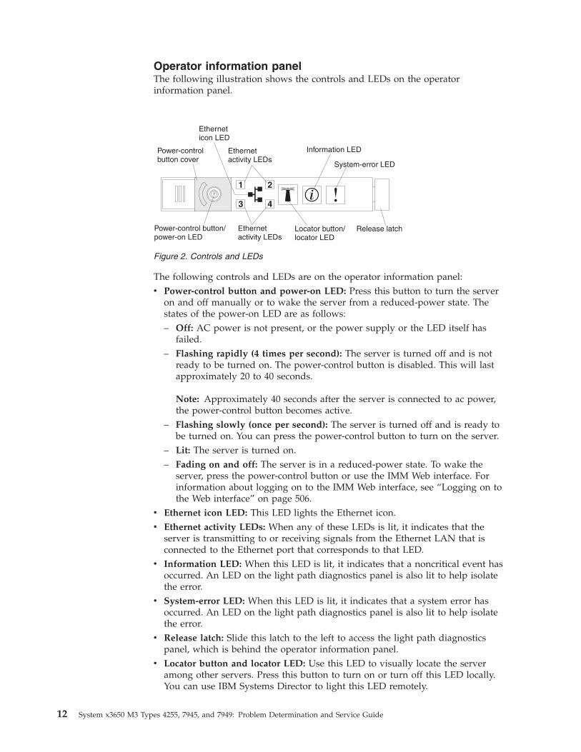
Operator information panelThe following illustration shows the controls and LEDs on the operatorinformation panel.
The following controls and LEDs are on the operator information panel:v Power-control button and power-on LED: Press this button to turn the server
on and off manually or to wake the server from a reduced-power state. Thestates of the power-on LED are as follows:– Off: AC power is not present, or the power supply or the LED itself has
failed.– Flashing rapidly (4 times per second): The server is turned off and is not
ready to be turned on. The power-control button is disabled. This will lastapproximately 20 to 40 seconds.
Note: Approximately 40 seconds after the server is connected to ac power,the power-control button becomes active.
– Flashing slowly (once per second): The server is turned off and is ready tobe turned on. You can press the power-control button to turn on the server.
– Lit: The server is turned on.– Fading on and off: The server is in a reduced-power state. To wake the
server, press the power-control button or use the IMM Web interface. Forinformation about logging on to the IMM Web interface, see “Logging on tothe Web interface” on page 506.
v Ethernet icon LED: This LED lights the Ethernet icon.v Ethernet activity LEDs: When any of these LEDs is lit, it indicates that the
server is transmitting to or receiving signals from the Ethernet LAN that isconnected to the Ethernet port that corresponds to that LED.
v Information LED: When this LED is lit, it indicates that a noncritical event hasoccurred. An LED on the light path diagnostics panel is also lit to help isolatethe error.
v System-error LED: When this LED is lit, it indicates that a system error hasoccurred. An LED on the light path diagnostics panel is also lit to help isolatethe error.
v Release latch: Slide this latch to the left to access the light path diagnosticspanel, which is behind the operator information panel.
v Locator button and locator LED: Use this LED to visually locate the serveramong other servers. Press this button to turn on or turn off this LED locally.You can use IBM Systems Director to light this LED remotely.
Figure 2. Controls and LEDs
12 System x3650 M3 Types 4255, 7945, and 7949: Problem Determination and Service Guide
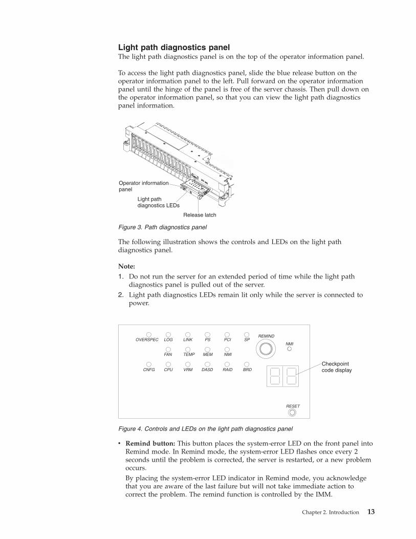
Light path diagnostics panelThe light path diagnostics panel is on the top of the operator information panel.
To access the light path diagnostics panel, slide the blue release button on theoperator information panel to the left. Pull forward on the operator informationpanel until the hinge of the panel is free of the server chassis. Then pull down onthe operator information panel, so that you can view the light path diagnosticspanel information.
The following illustration shows the controls and LEDs on the light pathdiagnostics panel.
Note:
1. Do not run the server for an extended period of time while the light pathdiagnostics panel is pulled out of the server.
2. Light path diagnostics LEDs remain lit only while the server is connected topower.
v Remind button: This button places the system-error LED on the front panel intoRemind mode. In Remind mode, the system-error LED flashes once every 2seconds until the problem is corrected, the server is restarted, or a new problemoccurs.By placing the system-error LED indicator in Remind mode, you acknowledgethat you are aware of the last failure but will not take immediate action tocorrect the problem. The remind function is controlled by the IMM.
Operator informationpanel
Light pathdiagnostics LEDs
Release latch
Figure 3. Path diagnostics panel
Checkpointcode display
Figure 4. Controls and LEDs on the light path diagnostics panel
Chapter 2. Introduction 13
v NMI button: Press this button to force a nonmaskable interrupt to themicroprocessor, if directed to do so by IBM service and support.
v Reset button: Press this button to reset the server and run the power-on self-test(POST). You might have to use a pen or the end of a straightened paper clip topress the button. The reset button is in the lower-right corner of the light pathdiagnostics panel.
For more information about light path diagnostics, see the Problem Determinationand Service Guide on the IBM Documentation CD.
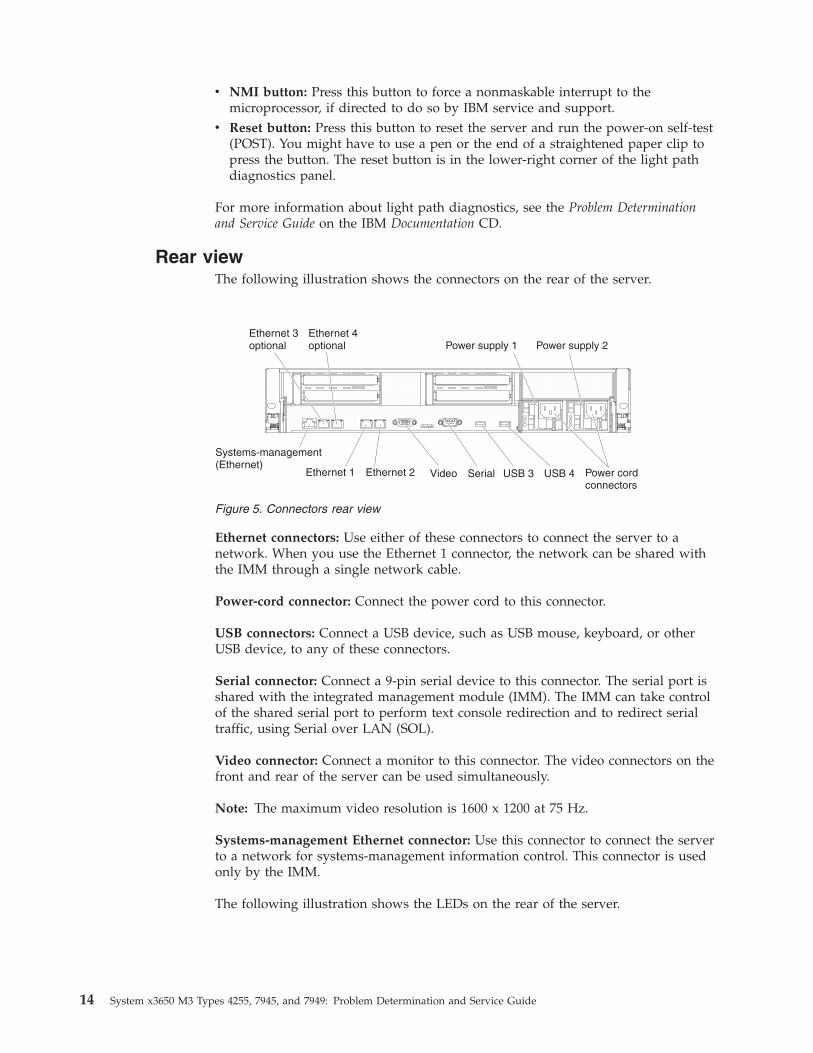
Rear viewThe following illustration shows the connectors on the rear of the server.
Ethernet connectors: Use either of these connectors to connect the server to anetwork. When you use the Ethernet 1 connector, the network can be shared withthe IMM through a single network cable.
Power-cord connector: Connect the power cord to this connector.
USB connectors: Connect a USB device, such as USB mouse, keyboard, or otherUSB device, to any of these connectors.
Serial connector: Connect a 9-pin serial device to this connector. The serial port isshared with the integrated management module (IMM). The IMM can take controlof the shared serial port to perform text console redirection and to redirect serialtraffic, using Serial over LAN (SOL).
Video connector: Connect a monitor to this connector. The video connectors on thefront and rear of the server can be used simultaneously.
Note: The maximum video resolution is 1600 x 1200 at 75 Hz.
Systems-management Ethernet connector: Use this connector to connect the serverto a network for systems-management information control. This connector is usedonly by the IMM.
The following illustration shows the LEDs on the rear of the server.
Figure 5. Connectors rear view
14 System x3650 M3 Types 4255, 7945, and 7949: Problem Determination and Service Guide
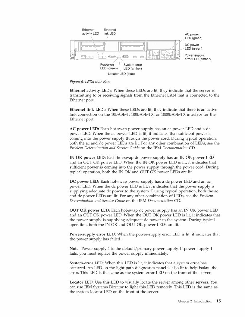
Ethernet activity LEDs: When these LEDs are lit, they indicate that the server istransmitting to or receiving signals from the Ethernet LAN that is connected to theEthernet port.
Ethernet link LEDs: When these LEDs are lit, they indicate that there is an activelink connection on the 10BASE-T, 100BASE-TX, or 1000BASE-TX interface for theEthernet port.
AC power LED: Each hot-swap power supply has an ac power LED and a dcpower LED. When the ac power LED is lit, it indicates that sufficient power iscoming into the power supply through the power cord. During typical operation,both the ac and dc power LEDs are lit. For any other combination of LEDs, see theProblem Determination and Service Guide on the IBM Documentation CD.
IN OK power LED: Each hot-swap dc power supply has an IN OK power LEDand an OUT OK power LED. When the IN OK power LED is lit, it indicates thatsufficient power is coming into the power supply through the power cord. Duringtypical operation, both the IN OK and OUT OK power LEDs are lit.
DC power LED: Each hot-swap power supply has a dc power LED and an acpower LED. When the dc power LED is lit, it indicates that the power supply issupplying adequate dc power to the system. During typical operation, both the acand dc power LEDs are lit. For any other combination of LEDs, see the ProblemDetermination and Service Guide on the IBM Documentation CD.
OUT OK power LED: Each hot-swap dc power supply has an IN OK power LEDand an OUT OK power LED. When the OUT OK power LED is lit, it indicates thatthe power supply is supplying adequate dc power to the system. During typicaloperation, both the IN OK and OUT OK power LEDs are lit.
Power-supply error LED: When the power-supply error LED is lit, it indicates thatthe power supply has failed.
Note: Power supply 1 is the default/primary power supply. If power supply 1fails, you must replace the power supply immediately.
System-error LED: When this LED is lit, it indicates that a system error hasoccurred. An LED on the light path diagnostics panel is also lit to help isolate theerror. This LED is the same as the system-error LED on the front of the server.
Locator LED: Use this LED to visually locate the server among other servers. Youcan use IBM Systems Director to light this LED remotely. This LED is the same asthe system-locator LED on the front of the server.
Ethernetactivity LED
Ethernetlink LED AC power
LED (green)
Power-onLED (green)
Locator LED (blue)
System-errorLED (amber)
DC powerLED (green)
Power-supplyerror LED (amber)
Figure 6. LEDs rear view
Chapter 2. Introduction 15
Power-on LED: Press this button to turn the server on and off manually or towake the server from a reduced-power state. The states of the power-on LED areas follows:v Off: AC power is not present, or the power supply or the LED itself has failed.v Flashing rapidly (4 times per second): The server is turned off and is not ready
to be turned on. The power-control button is disabled. This will lastapproximately 20 to 40 seconds.
Note: Approximately 40 seconds after the server is connected to ac power, thepower-control button becomes active.
v Flashing slowly (once per second): The server is turned off and is ready to beturned on. You can press the power-control button to turn on the server.
v Lit: The server is turned on.v Fading on and off: The server is in a reduced-power state. To wake the server,
press the power-control button or use the IMM Web interface. For informationabout logging on to the IMM Web interface, see “Logging on to the Webinterface” on page 506.
Internal connectors, LEDs, and jumpersThe illustrations in this section show the LEDs, connectors, and jumpers on theinternal boards. The illustrations might differ slightly from your hardware.
16 System x3650 M3 Types 4255, 7945, and 7949: Problem Determination and Service Guide
System-board internal connectorsThe following illustration shows the internal connectors on the system board.
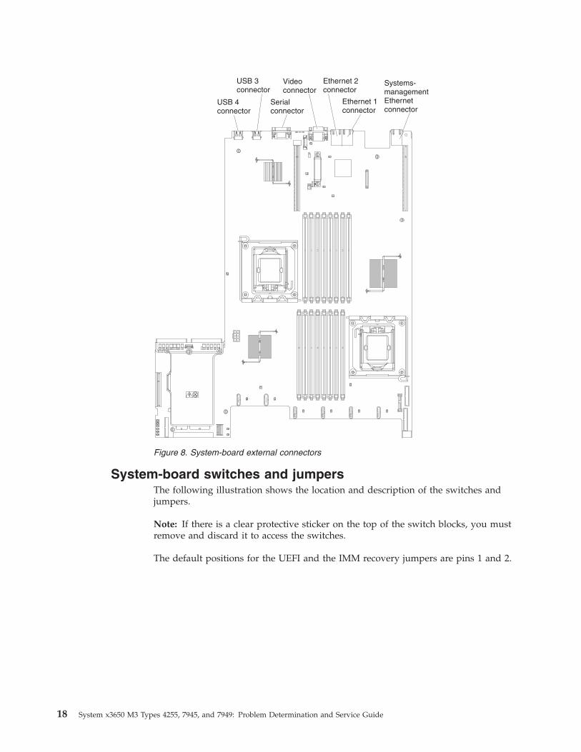
System-board external connectorsThe following illustration shows the external input/output connectors on thesystem board.
Figure 7. System-board internal connectors
Chapter 2. Introduction 17
System-board switches and jumpersThe following illustration shows the location and description of the switches andjumpers.
Note: If there is a clear protective sticker on the top of the switch blocks, you mustremove and discard it to access the switches.
The default positions for the UEFI and the IMM recovery jumpers are pins 1 and 2.
Figure 8. System-board external connectors
18 System x3650 M3 Types 4255, 7945, and 7949: Problem Determination and Service Guide
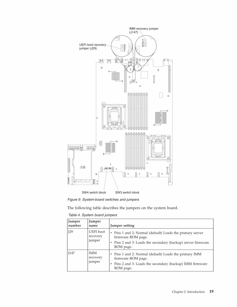
The following table describes the jumpers on the system board.
Table 4. System board jumpers
Jumpernumber
Jumpername Jumper setting
J29 UEFI bootrecoveryjumper
v Pins 1 and 2: Normal (default) Loads the primary serverfirmware ROM page.
v Pins 2 and 3: Loads the secondary (backup) server firmwareROM page.
J147 IMMrecoveryjumper
v Pins 1 and 2: Normal (default) Loads the primary IMMfirmware ROM page.
v Pins 2 and 3: Loads the secondary (backup) IMM firmwareROM page.
SW3 switch blockSW4 switch block
UEFI boot recoveryjumper (J29)
123
123
IMM recovery jumper(J147)
Figure 9. System-board switches and jumpers
Chapter 2. Introduction 19
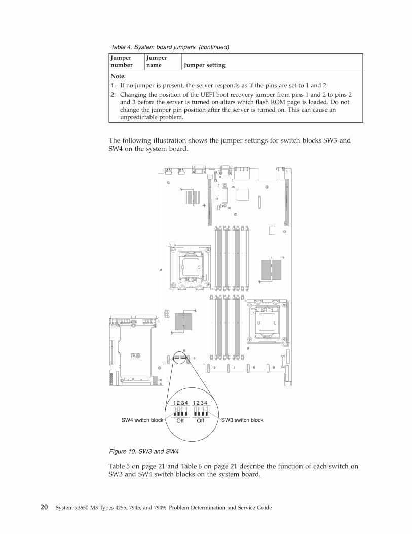
Table 4. System board jumpers (continued)
Jumpernumber
Jumpername Jumper setting
Note:
1. If no jumper is present, the server responds as if the pins are set to 1 and 2.
2. Changing the position of the UEFI boot recovery jumper from pins 1 and 2 to pins 2and 3 before the server is turned on alters which flash ROM page is loaded. Do notchange the jumper pin position after the server is turned on. This can cause anunpredictable problem.
The following illustration shows the jumper settings for switch blocks SW3 andSW4 on the system board.
Table 5 on page 21 and Table 6 on page 21 describe the function of each switch onSW3 and SW4 switch blocks on the system board.
SW3 switch blockSW4 switch block
12 34 12 34
Off Off
Figure 10. SW3 and SW4
20 System x3650 M3 Types 4255, 7945, and 7949: Problem Determination and Service Guide
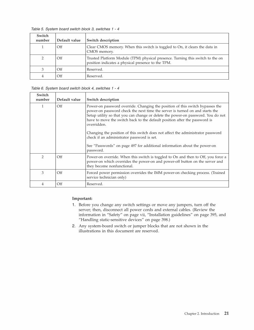
Table 5. System board switch block 3, switches 1 - 4
Switchnumber Default value Switch description
1 Off Clear CMOS memory. When this switch is toggled to On, it clears the data inCMOS memory.
2 Off Trusted Platform Module (TPM) physical presence. Turning this switch to the onposition indicates a physical presence to the TPM.
3 Off Reserved.
4 Off Reserved.
Table 6. System board switch block 4, switches 1 - 4
Switchnumber Default value Switch description
1 Off Power-on password override. Changing the position of this switch bypasses thepower-on password check the next time the server is turned on and starts theSetup utility so that you can change or delete the power-on password. You do nothave to move the switch back to the default position after the password isoverridden.
Changing the position of this switch does not affect the administrator passwordcheck if an administrator password is set.
See “Passwords” on page 497 for additional information about the power-onpassword.
2 Off Power-on override. When this switch is toggled to On and then to Off, you force apower-on which overrides the power-on and power-off button on the server andthey become nonfunctional.
3 Off Forced power permission overrides the IMM power-on checking process. (Trainedservice technician only)
4 Off Reserved.
Important:
1. Before you change any switch settings or move any jumpers, turn off theserver; then, disconnect all power cords and external cables. (Review theinformation in “Safety” on page vii, “Installation guidelines” on page 395, and“Handling static-sensitive devices” on page 398.)
2. Any system-board switch or jumper blocks that are not shown in theillustrations in this document are reserved.
Chapter 2. Introduction 21
System-board LEDsThe following illustration shows the light-emitting diodes (LEDs) on the systemboard.
Note: Error LEDs remain lit only while the server is connected to power.
Figure 11. System-board LEDs
22 System x3650 M3 Types 4255, 7945, and 7949: Problem Determination and Service Guide
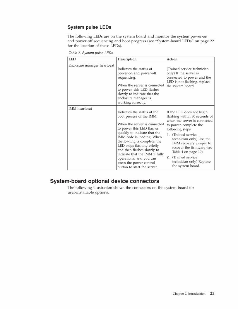
System pulse LEDs
The following LEDs are on the system board and monitor the system power-onand power-off sequencing and boot progress (see “System-board LEDs” on page 22for the location of these LEDs).
Table 7. System-pulse LEDs
LED Description Action
Enclosure manager heartbeatIndicates the status ofpower-on and power-offsequencing.
When the server is connectedto power, this LED flashesslowly to indicate that theenclosure manager isworking correctly.
(Trained service technicianonly) If the server isconnected to power and theLED is not flashing, replacethe system board.
IMM heartbeatIndicates the status of theboot process of the IMM.
When the server is connectedto power this LED flashesquickly to indicate that theIMM code is loading. Whenthe loading is complete, theLED stops flashing brieflyand then flashes slowly toindicate that the IMM if fullyoperational and you canpress the power-controlbutton to start the server.
If the LED does not beginflashing within 30 seconds ofwhen the server is connectedto power, complete thefollowing steps:
1. (Trained servicetechnician only) Use theIMM recovery jumper torecover the firmware (seeTable 4 on page 19).
2. (Trained servicetechnician only) Replacethe system board.
System-board optional device connectorsThe following illustration shows the connectors on the system board foruser-installable options.
Chapter 2. Introduction 23
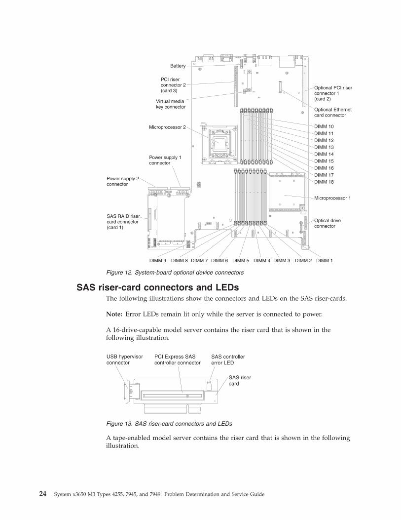
SAS riser-card connectors and LEDsThe following illustrations show the connectors and LEDs on the SAS riser-cards.
Note: Error LEDs remain lit only while the server is connected to power.
A 16-drive-capable model server contains the riser card that is shown in thefollowing illustration.
A tape-enabled model server contains the riser card that is shown in the followingillustration.
Figure 12. System-board optional device connectors
Figure 13. SAS riser-card connectors and LEDs
24 System x3650 M3 Types 4255, 7945, and 7949: Problem Determination and Service Guide
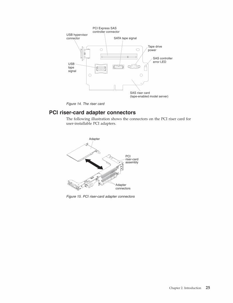
PCI riser-card adapter connectorsThe following illustration shows the connectors on the PCI riser card foruser-installable PCI adapters.
Figure 14. The riser card
PCIriser-cardassembly
Adapter
Adapterconnectors
Figure 15. PCI riser-card adapter connectors
Chapter 2. Introduction 25
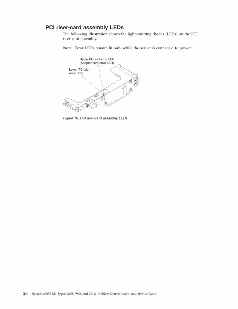
PCI riser-card assembly LEDsThe following illustration shows the light-emitting diodes (LEDs) on the PCIriser-card assembly.
Note: Error LEDs remain lit only while the server is connected to power.
Upper PCI slot error LED(Adaptor card error LED)
Lower PCI sloterror LED
Figure 16. PCI riser-card assembly LEDs
26 System x3650 M3 Types 4255, 7945, and 7949: Problem Determination and Service Guide
Chapter 3. Diagnostics
This chapter describes the diagnostic tools that are available to help you solveproblems that might occur in the server.
If you cannot locate and correct a problem by using the information in this chapter,see Appendix A, “Getting help and technical assistance,” on page 517 for moreinformation.
Diagnostic toolsThe following tools are available to help you diagnose and solve hardware-relatedproblems.v Troubleshooting tables
These tables list problem symptoms and actions to correct the problems. See“Troubleshooting tables” on page 340.
v Light path diagnostics
Use the light path diagnostics to diagnose system errors quickly. See “Light pathdiagnostics” on page 360 for more information.
v Dynamic System Analysis Preboot (DSA) diagnostic programs
The DSA Preboot diagnostic programs provide problem isolation, configurationanalysis, and error log collection. The diagnostic programs are the primarymethod of testing the major components of the server and are stored inintegrated USB memory. The diagnostic programs collect the followinginformation about the server:– System configuration– Network interfaces and settings– Installed hardware– Light path diagnostics status– Service processor status and configuration– Vital product data, firmware, and IBM's implementation of UEFI
configuration– Hard disk drive health– RAID controller configuration– ServeRAID controller and service processor event logs, including the
following information:- System-event logs- Temperature, voltage, and fan speed information- Tape drive presence and read/write test results- Systems management analysis and reporting technology (SMART) data- USB information- Monitor configuration information- PCI slot information
The diagnostic programs create a merged log that includes events from allcollected logs. The information is collected into a file that you can send to IBMservice and support. Additionally, you can view the server information locallythrough a generated text report file. You can also copy the log to removablemedia and view the log from a Web browser. See “Running the diagnosticprograms” on page 287 for more information.
v IBM Electronic Service Agent
© Copyright IBM Corp. 2014 27
IBM Electronic Service Agent is a software tool that monitors the server forhardware error events and automatically submits electronic service requests toIBM service and support. Also, it can collect and transmit system configurationinformation on a scheduled basis so that the information is available to you andyour support representative. It uses minimal system resources, is available freeof charge, and can be downloaded from the Web. For more information and todownload Electronic Service Agent, go to http://www.ibm.com/support/electronic/.
Event logsError codes and messages displayed in POST event log, system-event log,integrated management module (IMM) event log, and DSA event log.v POST event log: This log contains the three most recent error codes and
messages that were generated during POST. You can view the POST event logthrough the Setup utility.
v System-event log: This log contains all BMC, POST, and system managementinterrupt (SMI) events. You can view the system-event log from the Setup utilityand through the Dynamic System Analysis (DSA) program (as the IPMI eventlog).The system-event log is limited in size. When it is full, new entries will notoverwrite existing entries; therefore, you must periodically save and then clearthe system-event log through the Setup utility when the IMM logs an event thatindicates that the log is more than 75% full. When you are troubleshooting, youmight have to save and then clear the system-event log to make the most recentevents available for analysis.Messages are listed on the left side of the screen, and details about the selectedmessage are displayed on the right side of the screen. To move from one entryto the next, use the Up Arrow (↑) and Down Arrow (↓) keys.Some IMM sensors cause assertion events to be logged when their setpoints arereached. When a setpoint condition no longer exists, a corresponding deassertionevent is logged. However, not all events are assertion-type events.
v Integrated management module (IMM) event log: This log contains a filteredsubset of all IMM, POST, and system management interrupt (SMI) events. Youcan view the IMM event log through the IMM Web interface and through theDynamic System Analysis (DSA) program (as the ASM event log).
v DSA log: This log is generated by the Dynamic System Analysis (DSA) program,and it is a chronologically ordered merge of the system-event log (as the IPMIevent log), the IMM event log (as the ASM event log), and the operating-systemevent logs. You can view the DSA log through the DSA program.
28 System x3650 M3 Types 4255, 7945, and 7949: Problem Determination and Service Guide
Viewing event logs from the Setup utilityUse this information to view event logs from the Setup utility.
About this task
To view the POST event log or system-event log, complete the following steps:1. Turn on the server.2. When the prompt <F1> Setup is displayed, press F1. If you have set both a
power-on password and an administrator password, you must type theadministrator password to view the event logs.
3. Select System Event Logs and use one of the following procedures:v To view the POST event log, select POST Event Viewer.v To view the system-event log, select System Event Log.
Viewing event logs without restarting the serverIf the server is not hung, methods are available for you to view one or more eventlogs without having to restart the server.
About this task
If you have installed Portable or Installable Dynamic System Analysis (DSA), youcan use it to view the system-event log (as the IPMI event log), the IMM event log(as the ASM event log), the operating-system event logs, or the merged DAA log.You can also use DSA Preboot to view these logs, although you must restart theserver to use DSA Preboot. To install Portable DSA, Installable DSA, or DSAPreboot or to download a DSA Preboot CD image, go to http://www.ibm.com/support/entry/portal/docdisplay?lndocid=SERV-DSA or complete the followingsteps.
Note: Changes are made periodically to the IBM Web site. The actual proceduremight vary slightly from what is described in this document.
Procedure1. Go to http://www.ibm.com/systems/support/.2. Under Product support, click System x.3. Under Popular links, click Software and device drivers.4. Under Related downloads, click Dynamic System Analysis (DSA) to display
the matrix of downloadable DSA files.
Results
If IPMItool is installed in the server, you can use it to view the system-event log.Most recent versions of the Linux operating system come with a current version ofIPMItool. Complete the following steps to obtain more information about IPMItool.
Note: Changes are made periodically to the IBM Web site. The actual proceduremight vary slightly from what is described in this document.1. Go to http://publib.boulder.ibm.com/infocenter/toolsctr/v1r0/index.jsp.2. In the navigation pane, click IBM System x and BladeCenter Tools Center.3. Expand Tools reference, expand Configuration tools, expand IPMI tools, and
click IPMItool.
Chapter 3. Diagnostics 29
For an overview of IPMI, complete the following steps:1. Go to http://publib.boulder.ibm.com/infocenter/toolsctr/v1r0/index.jsp.2. In the navigation pane, click IBM Systems Information Center.3. Expand Operating systems, expand Linux information, expand Blueprints for
Linux on IBM systems, and click Using Intelligent Platform ManagementInterface (IPMI) on IBM Linux platforms.
You can view the IMM event log through the Event Log link in the integratedmanagement module (IMM) Web interface.
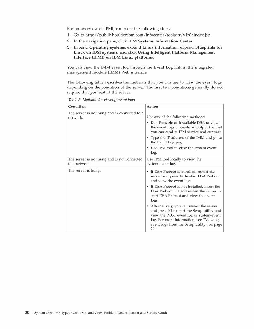
The following table describes the methods that you can use to view the event logs,depending on the condition of the server. The first two conditions generally do notrequire that you restart the server.
Table 8. Methods for viewing event logs
Condition Action
The server is not hung and is connected to anetwork. Use any of the following methods:
v Run Portable or Installable DSA to viewthe event logs or create an output file thatyou can send to IBM service and support.
v Type the IP address of the IMM and go tothe Event Log page.
v Use IPMItool to view the system-eventlog.
The server is not hung and is not connectedto a network.
Use IPMItool locally to view thesystem-event log.
The server is hung. v If DSA Preboot is installed, restart theserver and press F2 to start DSA Prebootand view the event logs.
v If DSA Preboot is not installed, insert theDSA Preboot CD and restart the server tostart DSA Preboot and view the eventlogs.
v Alternatively, you can restart the serverand press F1 to start the Setup utility andview the POST event log or system-eventlog. For more information, see “Viewingevent logs from the Setup utility” on page29.
30 System x3650 M3 Types 4255, 7945, and 7949: Problem Determination and Service Guide
Error messagesThis section provides the list of error codes and messages for UEFI/POST, IMM,and DSA that are generated when a problem is detected.
See “POST error codes” on page 274, “Integrated management module errormessages,” and “Diagnostic messages” on page 289 for more information.
System event messages logThe system event messages log contains messages of three types:
InformationInformation messages do not require action; they record significantsystem-level events, such as when the server is started.
WarningWarning messages do not require immediate action; they indicate possibleproblems, such as when the recommended maximum ambient temperatureis exceeded.
Error Error messages might require action; they indicate system errors, such aswhen a fan is not detected.
Each message contains date and time information, and it indicates the source of themessage (POST or the IMM).
Integrated management module error messages
IMM Events that automatically notify Support:
You can configure the Integrated Management Module II (IMM2) to automaticallynotify Support (also known as call home) if certain types of errors are encountered.If you have configured this function, see the table for a list of events thatautomatically notify Support.
Table 9. Events that automatically notify Support
Event ID Message String
AutomaticallyNotifySupport
80010202-0701xxxx Numeric sensor[NumericSensorElementName] going low(lower critical) has asserted. (Planar 12V)
Yes
80010202-2801xxxx Numeric sensor[NumericSensorElementName] going low(lower critical) has asserted. (CMOSBattery)
Yes
80010902-0701xxxx Numeric sensor[NumericSensorElementName] going high(upper critical) has asserted. (Planar 12V)
Yes
806f0021-2201xxxx Fault in slot[PhysicalConnectorSystemElementName] onsystem [ComputerSystemElementName].(No Op ROM Space)
Yes
Chapter 3. Diagnostics 31
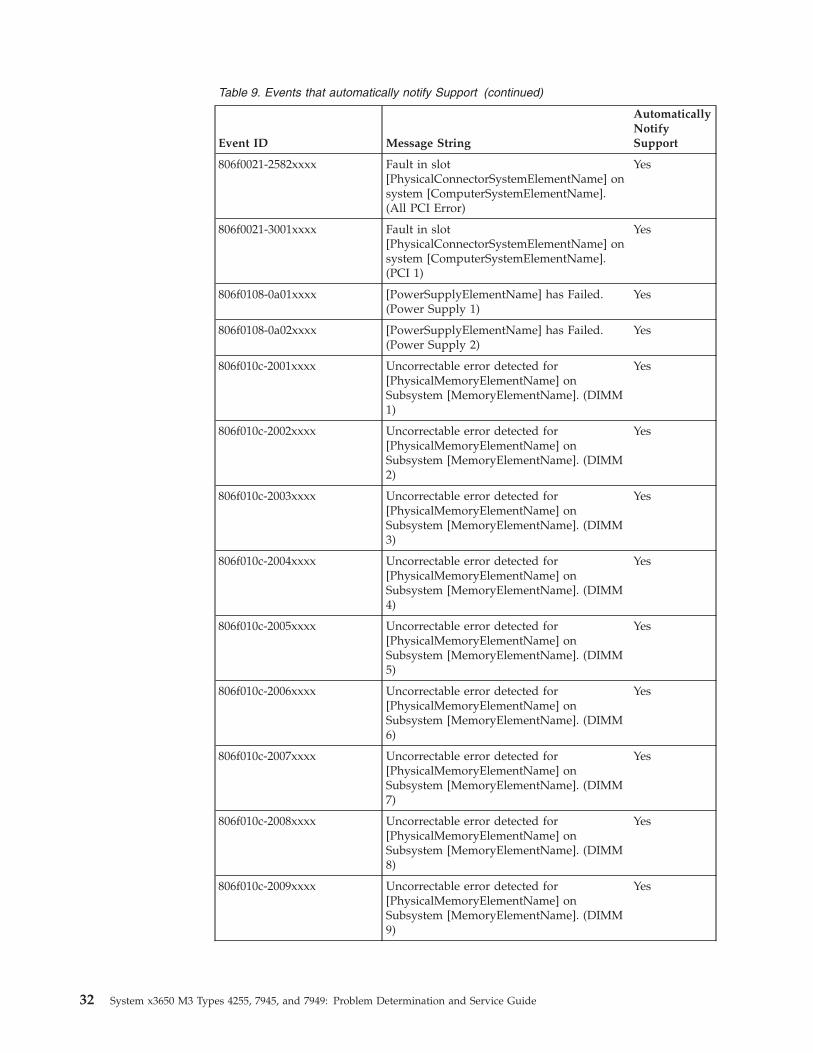
Table 9. Events that automatically notify Support (continued)
Event ID Message String
AutomaticallyNotifySupport
806f0021-2582xxxx Fault in slot[PhysicalConnectorSystemElementName] onsystem [ComputerSystemElementName].(All PCI Error)
Yes
806f0021-3001xxxx Fault in slot[PhysicalConnectorSystemElementName] onsystem [ComputerSystemElementName].(PCI 1)
Yes
806f0108-0a01xxxx [PowerSupplyElementName] has Failed.(Power Supply 1)
Yes
806f0108-0a02xxxx [PowerSupplyElementName] has Failed.(Power Supply 2)
Yes
806f010c-2001xxxx Uncorrectable error detected for[PhysicalMemoryElementName] onSubsystem [MemoryElementName]. (DIMM1)
Yes
806f010c-2002xxxx Uncorrectable error detected for[PhysicalMemoryElementName] onSubsystem [MemoryElementName]. (DIMM2)
Yes
806f010c-2003xxxx Uncorrectable error detected for[PhysicalMemoryElementName] onSubsystem [MemoryElementName]. (DIMM3)
Yes
806f010c-2004xxxx Uncorrectable error detected for[PhysicalMemoryElementName] onSubsystem [MemoryElementName]. (DIMM4)
Yes
806f010c-2005xxxx Uncorrectable error detected for[PhysicalMemoryElementName] onSubsystem [MemoryElementName]. (DIMM5)
Yes
806f010c-2006xxxx Uncorrectable error detected for[PhysicalMemoryElementName] onSubsystem [MemoryElementName]. (DIMM6)
Yes
806f010c-2007xxxx Uncorrectable error detected for[PhysicalMemoryElementName] onSubsystem [MemoryElementName]. (DIMM7)
Yes
806f010c-2008xxxx Uncorrectable error detected for[PhysicalMemoryElementName] onSubsystem [MemoryElementName]. (DIMM8)
Yes
806f010c-2009xxxx Uncorrectable error detected for[PhysicalMemoryElementName] onSubsystem [MemoryElementName]. (DIMM9)
Yes
32 System x3650 M3 Types 4255, 7945, and 7949: Problem Determination and Service Guide
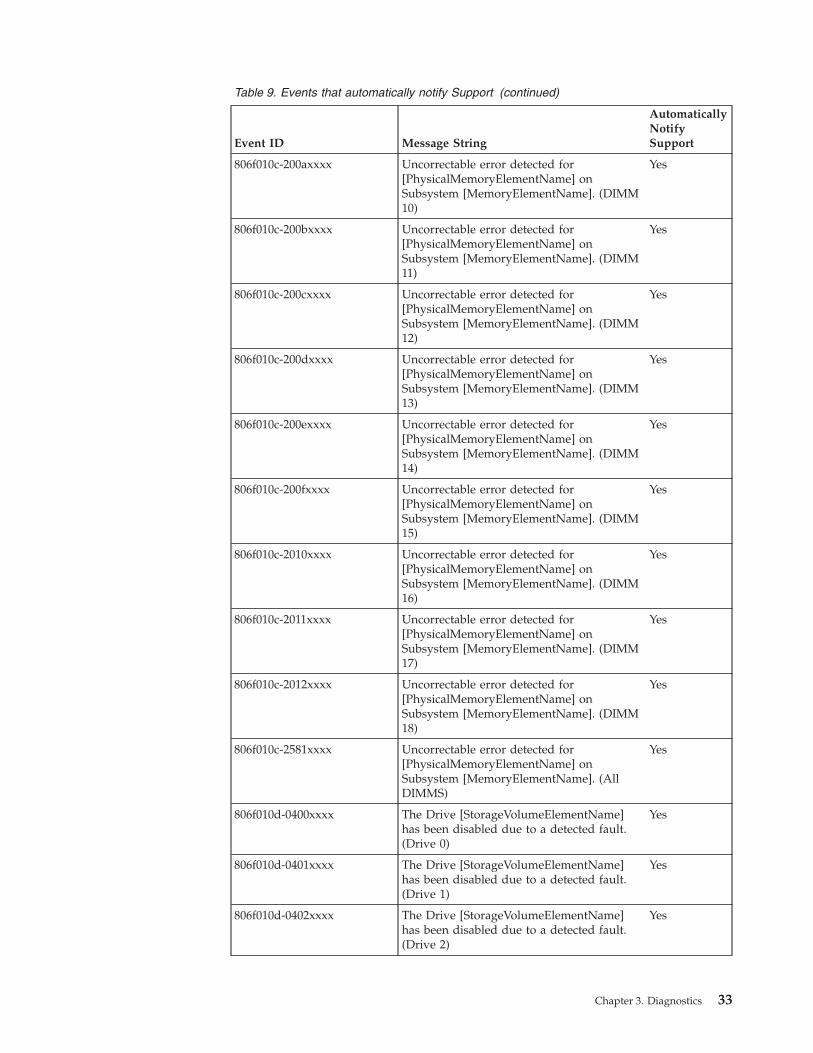
Table 9. Events that automatically notify Support (continued)
Event ID Message String
AutomaticallyNotifySupport
806f010c-200axxxx Uncorrectable error detected for[PhysicalMemoryElementName] onSubsystem [MemoryElementName]. (DIMM10)
Yes
806f010c-200bxxxx Uncorrectable error detected for[PhysicalMemoryElementName] onSubsystem [MemoryElementName]. (DIMM11)
Yes
806f010c-200cxxxx Uncorrectable error detected for[PhysicalMemoryElementName] onSubsystem [MemoryElementName]. (DIMM12)
Yes
806f010c-200dxxxx Uncorrectable error detected for[PhysicalMemoryElementName] onSubsystem [MemoryElementName]. (DIMM13)
Yes
806f010c-200exxxx Uncorrectable error detected for[PhysicalMemoryElementName] onSubsystem [MemoryElementName]. (DIMM14)
Yes
806f010c-200fxxxx Uncorrectable error detected for[PhysicalMemoryElementName] onSubsystem [MemoryElementName]. (DIMM15)
Yes
806f010c-2010xxxx Uncorrectable error detected for[PhysicalMemoryElementName] onSubsystem [MemoryElementName]. (DIMM16)
Yes
806f010c-2011xxxx Uncorrectable error detected for[PhysicalMemoryElementName] onSubsystem [MemoryElementName]. (DIMM17)
Yes
806f010c-2012xxxx Uncorrectable error detected for[PhysicalMemoryElementName] onSubsystem [MemoryElementName]. (DIMM18)
Yes
806f010c-2581xxxx Uncorrectable error detected for[PhysicalMemoryElementName] onSubsystem [MemoryElementName]. (AllDIMMS)
Yes
806f010d-0400xxxx The Drive [StorageVolumeElementName]has been disabled due to a detected fault.(Drive 0)
Yes
806f010d-0401xxxx The Drive [StorageVolumeElementName]has been disabled due to a detected fault.(Drive 1)
Yes
806f010d-0402xxxx The Drive [StorageVolumeElementName]has been disabled due to a detected fault.(Drive 2)
Yes
Chapter 3. Diagnostics 33
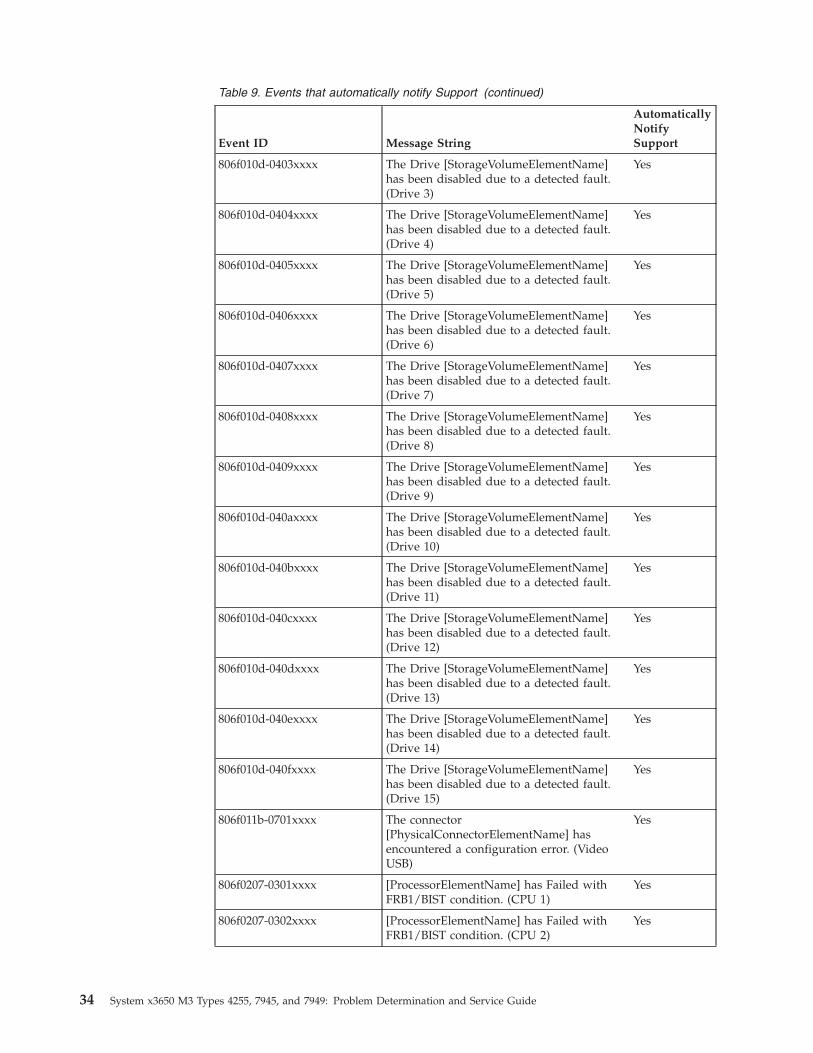
Table 9. Events that automatically notify Support (continued)
Event ID Message String
AutomaticallyNotifySupport
806f010d-0403xxxx The Drive [StorageVolumeElementName]has been disabled due to a detected fault.(Drive 3)
Yes
806f010d-0404xxxx The Drive [StorageVolumeElementName]has been disabled due to a detected fault.(Drive 4)
Yes
806f010d-0405xxxx The Drive [StorageVolumeElementName]has been disabled due to a detected fault.(Drive 5)
Yes
806f010d-0406xxxx The Drive [StorageVolumeElementName]has been disabled due to a detected fault.(Drive 6)
Yes
806f010d-0407xxxx The Drive [StorageVolumeElementName]has been disabled due to a detected fault.(Drive 7)
Yes
806f010d-0408xxxx The Drive [StorageVolumeElementName]has been disabled due to a detected fault.(Drive 8)
Yes
806f010d-0409xxxx The Drive [StorageVolumeElementName]has been disabled due to a detected fault.(Drive 9)
Yes
806f010d-040axxxx The Drive [StorageVolumeElementName]has been disabled due to a detected fault.(Drive 10)
Yes
806f010d-040bxxxx The Drive [StorageVolumeElementName]has been disabled due to a detected fault.(Drive 11)
Yes
806f010d-040cxxxx The Drive [StorageVolumeElementName]has been disabled due to a detected fault.(Drive 12)
Yes
806f010d-040dxxxx The Drive [StorageVolumeElementName]has been disabled due to a detected fault.(Drive 13)
Yes
806f010d-040exxxx The Drive [StorageVolumeElementName]has been disabled due to a detected fault.(Drive 14)
Yes
806f010d-040fxxxx The Drive [StorageVolumeElementName]has been disabled due to a detected fault.(Drive 15)
Yes
806f011b-0701xxxx The connector[PhysicalConnectorElementName] hasencountered a configuration error. (VideoUSB)
Yes
806f0207-0301xxxx [ProcessorElementName] has Failed withFRB1/BIST condition. (CPU 1)
Yes
806f0207-0302xxxx [ProcessorElementName] has Failed withFRB1/BIST condition. (CPU 2)
Yes
34 System x3650 M3 Types 4255, 7945, and 7949: Problem Determination and Service Guide
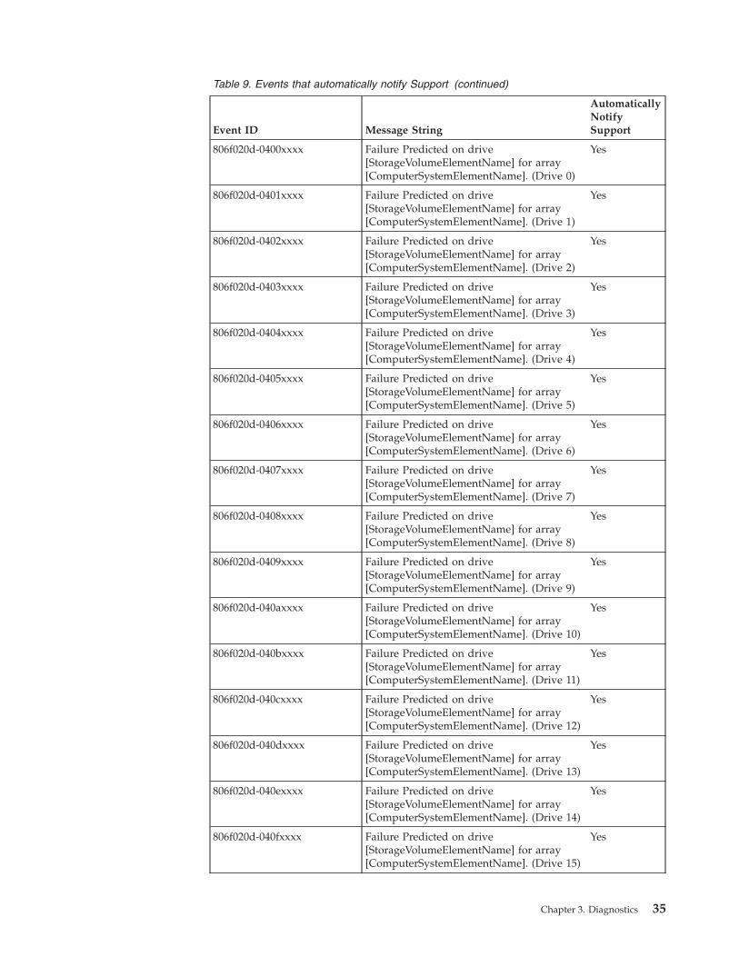
Table 9. Events that automatically notify Support (continued)
Event ID Message String
AutomaticallyNotifySupport
806f020d-0400xxxx Failure Predicted on drive[StorageVolumeElementName] for array[ComputerSystemElementName]. (Drive 0)
Yes
806f020d-0401xxxx Failure Predicted on drive[StorageVolumeElementName] for array[ComputerSystemElementName]. (Drive 1)
Yes
806f020d-0402xxxx Failure Predicted on drive[StorageVolumeElementName] for array[ComputerSystemElementName]. (Drive 2)
Yes
806f020d-0403xxxx Failure Predicted on drive[StorageVolumeElementName] for array[ComputerSystemElementName]. (Drive 3)
Yes
806f020d-0404xxxx Failure Predicted on drive[StorageVolumeElementName] for array[ComputerSystemElementName]. (Drive 4)
Yes
806f020d-0405xxxx Failure Predicted on drive[StorageVolumeElementName] for array[ComputerSystemElementName]. (Drive 5)
Yes
806f020d-0406xxxx Failure Predicted on drive[StorageVolumeElementName] for array[ComputerSystemElementName]. (Drive 6)
Yes
806f020d-0407xxxx Failure Predicted on drive[StorageVolumeElementName] for array[ComputerSystemElementName]. (Drive 7)
Yes
806f020d-0408xxxx Failure Predicted on drive[StorageVolumeElementName] for array[ComputerSystemElementName]. (Drive 8)
Yes
806f020d-0409xxxx Failure Predicted on drive[StorageVolumeElementName] for array[ComputerSystemElementName]. (Drive 9)
Yes
806f020d-040axxxx Failure Predicted on drive[StorageVolumeElementName] for array[ComputerSystemElementName]. (Drive 10)
Yes
806f020d-040bxxxx Failure Predicted on drive[StorageVolumeElementName] for array[ComputerSystemElementName]. (Drive 11)
Yes
806f020d-040cxxxx Failure Predicted on drive[StorageVolumeElementName] for array[ComputerSystemElementName]. (Drive 12)
Yes
806f020d-040dxxxx Failure Predicted on drive[StorageVolumeElementName] for array[ComputerSystemElementName]. (Drive 13)
Yes
806f020d-040exxxx Failure Predicted on drive[StorageVolumeElementName] for array[ComputerSystemElementName]. (Drive 14)
Yes
806f020d-040fxxxx Failure Predicted on drive[StorageVolumeElementName] for array[ComputerSystemElementName]. (Drive 15)
Yes
Chapter 3. Diagnostics 35
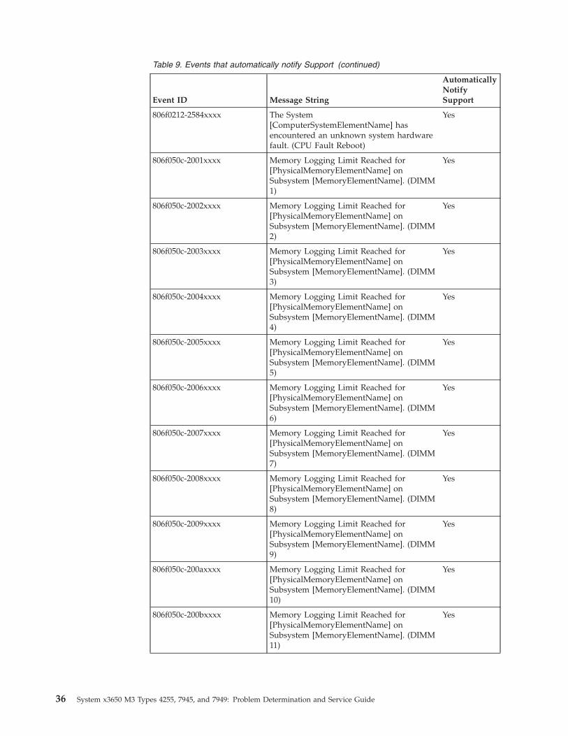
Table 9. Events that automatically notify Support (continued)
Event ID Message String
AutomaticallyNotifySupport
806f0212-2584xxxx The System[ComputerSystemElementName] hasencountered an unknown system hardwarefault. (CPU Fault Reboot)
Yes
806f050c-2001xxxx Memory Logging Limit Reached for[PhysicalMemoryElementName] onSubsystem [MemoryElementName]. (DIMM1)
Yes
806f050c-2002xxxx Memory Logging Limit Reached for[PhysicalMemoryElementName] onSubsystem [MemoryElementName]. (DIMM2)
Yes
806f050c-2003xxxx Memory Logging Limit Reached for[PhysicalMemoryElementName] onSubsystem [MemoryElementName]. (DIMM3)
Yes
806f050c-2004xxxx Memory Logging Limit Reached for[PhysicalMemoryElementName] onSubsystem [MemoryElementName]. (DIMM4)
Yes
806f050c-2005xxxx Memory Logging Limit Reached for[PhysicalMemoryElementName] onSubsystem [MemoryElementName]. (DIMM5)
Yes
806f050c-2006xxxx Memory Logging Limit Reached for[PhysicalMemoryElementName] onSubsystem [MemoryElementName]. (DIMM6)
Yes
806f050c-2007xxxx Memory Logging Limit Reached for[PhysicalMemoryElementName] onSubsystem [MemoryElementName]. (DIMM7)
Yes
806f050c-2008xxxx Memory Logging Limit Reached for[PhysicalMemoryElementName] onSubsystem [MemoryElementName]. (DIMM8)
Yes
806f050c-2009xxxx Memory Logging Limit Reached for[PhysicalMemoryElementName] onSubsystem [MemoryElementName]. (DIMM9)
Yes
806f050c-200axxxx Memory Logging Limit Reached for[PhysicalMemoryElementName] onSubsystem [MemoryElementName]. (DIMM10)
Yes
806f050c-200bxxxx Memory Logging Limit Reached for[PhysicalMemoryElementName] onSubsystem [MemoryElementName]. (DIMM11)
Yes
36 System x3650 M3 Types 4255, 7945, and 7949: Problem Determination and Service Guide
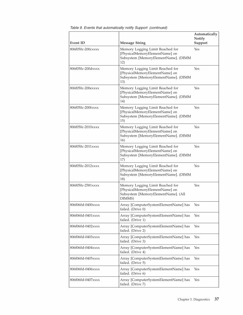
Table 9. Events that automatically notify Support (continued)
Event ID Message String
AutomaticallyNotifySupport
806f050c-200cxxxx Memory Logging Limit Reached for[PhysicalMemoryElementName] onSubsystem [MemoryElementName]. (DIMM12)
Yes
806f050c-200dxxxx Memory Logging Limit Reached for[PhysicalMemoryElementName] onSubsystem [MemoryElementName]. (DIMM13)
Yes
806f050c-200exxxx Memory Logging Limit Reached for[PhysicalMemoryElementName] onSubsystem [MemoryElementName]. (DIMM14)
Yes
806f050c-200fxxxx Memory Logging Limit Reached for[PhysicalMemoryElementName] onSubsystem [MemoryElementName]. (DIMM15)
Yes
806f050c-2010xxxx Memory Logging Limit Reached for[PhysicalMemoryElementName] onSubsystem [MemoryElementName]. (DIMM16)
Yes
806f050c-2011xxxx Memory Logging Limit Reached for[PhysicalMemoryElementName] onSubsystem [MemoryElementName]. (DIMM17)
Yes
806f050c-2012xxxx Memory Logging Limit Reached for[PhysicalMemoryElementName] onSubsystem [MemoryElementName]. (DIMM18)
Yes
806f050c-2581xxxx Memory Logging Limit Reached for[PhysicalMemoryElementName] onSubsystem [MemoryElementName]. (AllDIMMS)
Yes
806f060d-0400xxxx Array [ComputerSystemElementName] hasfailed. (Drive 0)
Yes
806f060d-0401xxxx Array [ComputerSystemElementName] hasfailed. (Drive 1)
Yes
806f060d-0402xxxx Array [ComputerSystemElementName] hasfailed. (Drive 2)
Yes
806f060d-0403xxxx Array [ComputerSystemElementName] hasfailed. (Drive 3)
Yes
806f060d-0404xxxx Array [ComputerSystemElementName] hasfailed. (Drive 4)
Yes
806f060d-0405xxxx Array [ComputerSystemElementName] hasfailed. (Drive 5)
Yes
806f060d-0406xxxx Array [ComputerSystemElementName] hasfailed. (Drive 6)
Yes
806f060d-0407xxxx Array [ComputerSystemElementName] hasfailed. (Drive 7)
Yes
Chapter 3. Diagnostics 37
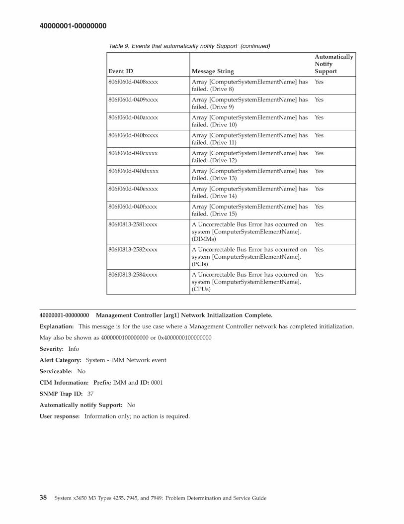
Table 9. Events that automatically notify Support (continued)
Event ID Message String
AutomaticallyNotifySupport
806f060d-0408xxxx Array [ComputerSystemElementName] hasfailed. (Drive 8)
Yes
806f060d-0409xxxx Array [ComputerSystemElementName] hasfailed. (Drive 9)
Yes
806f060d-040axxxx Array [ComputerSystemElementName] hasfailed. (Drive 10)
Yes
806f060d-040bxxxx Array [ComputerSystemElementName] hasfailed. (Drive 11)
Yes
806f060d-040cxxxx Array [ComputerSystemElementName] hasfailed. (Drive 12)
Yes
806f060d-040dxxxx Array [ComputerSystemElementName] hasfailed. (Drive 13)
Yes
806f060d-040exxxx Array [ComputerSystemElementName] hasfailed. (Drive 14)
Yes
806f060d-040fxxxx Array [ComputerSystemElementName] hasfailed. (Drive 15)
Yes
806f0813-2581xxxx A Uncorrectable Bus Error has occurred onsystem [ComputerSystemElementName].(DIMMs)
Yes
806f0813-2582xxxx A Uncorrectable Bus Error has occurred onsystem [ComputerSystemElementName].(PCIs)
Yes
806f0813-2584xxxx A Uncorrectable Bus Error has occurred onsystem [ComputerSystemElementName].(CPUs)
Yes
40000001-00000000 Management Controller [arg1] Network Initialization Complete.
Explanation: This message is for the use case where a Management Controller network has completed initialization.
May also be shown as 4000000100000000 or 0x4000000100000000
Severity: Info
Alert Category: System - IMM Network event
Serviceable: No
CIM Information: Prefix: IMM and ID: 0001
SNMP Trap ID: 37
Automatically notify Support: No
User response: Information only; no action is required.
40000001-00000000
38 System x3650 M3 Types 4255, 7945, and 7949: Problem Determination and Service Guide
40000002-00000000 Certificate Authority [arg1] has detected a [arg2] Certificate Error.
Explanation: This message is for the use case when there is an error with an SSL Server, SSL Client, or SSL TrustedCA Certificate.
May also be shown as 4000000200000000 or 0x4000000200000000
Severity: Error
Alert Category: System - other
Serviceable: No
CIM Information: Prefix: IMM and ID: 0002
SNMP Trap ID: 22
Automatically notify Support: No
User response: Make sure that the certificate that you are importing is correct and properly generated.
40000003-00000000 Ethernet Data Rate modified from [arg1] to [arg2] by user [arg3].
Explanation: This message is for the use case where a client modifies the Ethernet Port data rate.
May also be shown as 4000000300000000 or 0x4000000300000000
Severity: Info
Alert Category: none
Serviceable: No
CIM Information: Prefix: IMM and ID: 0003
SNMP Trap ID:
Automatically notify Support: No
User response: Information only; no action is required.
40000004-00000000 Ethernet Duplex setting modified from [arg1] to [arg2] by user [arg3].
Explanation: This message is for the use case where a client modifies the Ethernet Port duplex setting.
May also be shown as 4000000400000000 or 0x4000000400000000
Severity: Info
Alert Category: none
Serviceable: No
CIM Information: Prefix: IMM and ID: 0004
SNMP Trap ID:
Automatically notify Support: No
User response: Information only; no action is required.
40000002-00000000 • 40000004-00000000
Chapter 3. Diagnostics 39
40000005-00000000 Ethernet MTU setting modified from [arg1] to [arg2] by user [arg3].
Explanation: This message is for the use case where a client modifies the Ethernet Port MTU setting.
May also be shown as 4000000500000000 or 0x4000000500000000
Severity: Info
Alert Category: none
Serviceable: No
CIM Information: Prefix: IMM and ID: 0005
SNMP Trap ID:
Automatically notify Support: No
User response: Information only; no action is required.
40000006-00000000 Ethernet locally administered MAC address modified from [arg1] to [arg2] by user [arg3].
Explanation: This message is for the use case where a client modifies the Ethernet Port MAC address setting.
May also be shown as 4000000600000000 or 0x4000000600000000
Severity: Info
Alert Category: none
Serviceable: No
CIM Information: Prefix: IMM and ID: 0006
SNMP Trap ID:
Automatically notify Support: No
User response: Information only; no action is required.
40000007-00000000 Ethernet interface [arg1] by user [arg2].
Explanation: This message is for the use case where a client enables or disabled the ethernet interface.
May also be shown as 4000000700000000 or 0x4000000700000000
Severity: Info
Alert Category: none
Serviceable: No
CIM Information: Prefix: IMM and ID: 0007
SNMP Trap ID:
Automatically notify Support: No
User response: Information only; no action is required.
40000005-00000000 • 40000007-00000000
40 System x3650 M3 Types 4255, 7945, and 7949: Problem Determination and Service Guide
40000008-00000000 Hostname set to [arg1] by user [arg2].
Explanation: This message is for the use case where a client modifies the Hostname of a Management Controller.
May also be shown as 4000000800000000 or 0x4000000800000000
Severity: Info
Alert Category: System - IMM Network event
Serviceable: No
CIM Information: Prefix: IMM and ID: 0008
SNMP Trap ID: 37
Automatically notify Support: No
User response: Information only; no action is required.
40000009-00000000 IP address of network interface modified from [arg1] to [arg2] by user [arg3].
Explanation: This message is for the use case where a client modifies the IP address of a Management Controller.
May also be shown as 4000000900000000 or 0x4000000900000000
Severity: Info
Alert Category: System - IMM Network event
Serviceable: No
CIM Information: Prefix: IMM and ID: 0009
SNMP Trap ID: 37
Automatically notify Support: No
User response: Information only; no action is required.
4000000a-00000000 IP subnet mask of network interface modified from [arg1] to [arg2] by user [arg3].
Explanation: This message is for the use case where a client modifies the IP subnet mask of a ManagementController.
May also be shown as 4000000a00000000 or 0x4000000a00000000
Severity: Info
Alert Category: none
Serviceable: No
CIM Information: Prefix: IMM and ID: 0010
SNMP Trap ID:
Automatically notify Support: No
User response: Information only; no action is required.
40000008-00000000 • 4000000a-00000000
Chapter 3. Diagnostics 41
4000000b-00000000 IP address of default gateway modified from [arg1] to [arg2] by user [arg3].
Explanation: This message is for the use case where a client modifies the default gateway IP address of aManagement Controller.
May also be shown as 4000000b00000000 or 0x4000000b00000000
Severity: Info
Alert Category: none
Serviceable: No
CIM Information: Prefix: IMM and ID: 0011
SNMP Trap ID:
Automatically notify Support: No
User response: Information only; no action is required.
4000000c-00000000 OS Watchdog response [arg1] by [arg2] .
Explanation: This message is for the use case where an OS Watchdog has been enabled or disabled by a client.
May also be shown as 4000000c00000000 or 0x4000000c00000000
Severity: Info
Alert Category: none
Serviceable: No
CIM Information: Prefix: IMM and ID: 0012
SNMP Trap ID:
Automatically notify Support: No
User response: Information only; no action is required.
4000000d-00000000 DHCP[[arg1]] failure, no IP address assigned.
Explanation: This message is for the use case where a DHCP server fails to assign an IP address to a ManagementController.
May also be shown as 4000000d00000000 or 0x4000000d00000000
Severity: Warning
Alert Category: none
Serviceable: No
CIM Information: Prefix: IMM and ID: 0013
SNMP Trap ID:
Automatically notify Support: No
User response: Complete the following steps until the problem is solved: Make sure that the IMM network cable isconnected. Make sure that there is a DHCP server on the network that can assign an IP address to the IMM.
4000000b-00000000 • 4000000d-00000000
42 System x3650 M3 Types 4255, 7945, and 7949: Problem Determination and Service Guide
4000000e-00000000 Remote Login Successful. Login ID: [arg1] from [arg2] at IP address [arg3].
Explanation: This message is for the use case where a client successfully logs in to a Management Controller.
May also be shown as 4000000e00000000 or 0x4000000e00000000
Severity: Info
Alert Category: System - Remote Login
Serviceable: No
CIM Information: Prefix: IMM and ID: 0014
SNMP Trap ID: 30
Automatically notify Support: No
User response: Information only; no action is required.
4000000f-00000000 Attempting to [arg1] server [arg2] by user [arg3].
Explanation: This message is for the use case where a client is using the Management Controller to perform apower function on the system.
May also be shown as 4000000f00000000 or 0x4000000f00000000
Severity: Info
Alert Category: none
Serviceable: No
CIM Information: Prefix: IMM and ID: 0015
SNMP Trap ID:
Automatically notify Support: No
User response: Information only; no action is required.
40000010-00000000 Security: Userid: [arg1] had [arg2] login failures from WEB client at IP address [arg3].
Explanation: This message is for the use case where a client has failed to log in to a Management Controller from aweb browser.
May also be shown as 4000001000000000 or 0x4000001000000000
Severity: Warning
Alert Category: System - Remote Login
Serviceable: No
CIM Information: Prefix: IMM and ID: 0016
SNMP Trap ID: 30
Automatically notify Support: No
User response: Complete the following steps until the problem is solved: Make sure that the correct login ID andpassword are being used. Have the system administrator reset the login ID or password.
4000000e-00000000 • 40000010-00000000
Chapter 3. Diagnostics 43
40000011-00000000 Security: Login ID: [arg1] had [arg2] login failures from CLI at [arg3]..
Explanation: This message is for the use case where a client has failed to log in to a Management Controller fromthe Legacy CLI.
May also be shown as 4000001100000000 or 0x4000001100000000
Severity: Warning
Alert Category: System - Remote Login
Serviceable: No
CIM Information: Prefix: IMM and ID: 0017
SNMP Trap ID: 30
Automatically notify Support: No
User response: Complete the following steps until the problem is solved: Make sure that the correct login ID andpassword are being used. Have the system administrator reset the login ID or password.
40000012-00000000 Remote access attempt failed. Invalid userid or password received. Userid is [arg1] from WEBbrowser at IP address [arg2].
Explanation: This message is for the use case where a client has failed to log in to a Management Controller from aweb browser.
May also be shown as 4000001200000000 or 0x4000001200000000
Severity: Info
Alert Category: System - Remote Login
Serviceable: No
CIM Information: Prefix: IMM and ID: 0018
SNMP Trap ID: 30
Automatically notify Support: No
User response: Make sure that the correct login ID and password are being used.
40000013-00000000 Remote access attempt failed. Invalid userid or password received. Userid is [arg1] fromTELNET client at IP address [arg2].
Explanation: This message is for the use case where a client has failed to log in to a Management Controller from atelnet session.
May also be shown as 4000001300000000 or 0x4000001300000000
Severity: Info
Alert Category: System - Remote Login
Serviceable: No
CIM Information: Prefix: IMM and ID: 0019
SNMP Trap ID: 30
Automatically notify Support: No
User response: Make sure that the correct login ID and password are being used.
40000011-00000000 • 40000013-00000000
44 System x3650 M3 Types 4255, 7945, and 7949: Problem Determination and Service Guide
40000014-00000000 The [arg1] on system [arg2] cleared by user [arg3].
Explanation: This message is for the use case where a Management Controller Event Log on a system is cleared bya user.
May also be shown as 4000001400000000 or 0x4000001400000000
Severity: Info
Alert Category: none
Serviceable: No
CIM Information: Prefix: IMM and ID: 0020
SNMP Trap ID:
Automatically notify Support: No
User response: Information only; no action is required.
40000015-00000000 Management Controller [arg1] reset was initiated by user [arg2].
Explanation: This message is for the use case where a Management Controller reset is initiated by a user.
May also be shown as 4000001500000000 or 0x4000001500000000
Severity: Info
Alert Category: none
Serviceable: No
CIM Information: Prefix: IMM and ID: 0021
SNMP Trap ID:
Automatically notify Support: No
User response: Information only; no action is required.
40000016-00000000 ENET[[arg1]] DHCP-HSTN=[arg2], DN=[arg3], IP@=[arg4], SN=[arg5], GW@=[arg6],DNS1@=[arg7] .
Explanation: This message is for the use case where a Management Controller IP address and configuration hasbeen assigned by the DHCP server.
May also be shown as 4000001600000000 or 0x4000001600000000
Severity: Info
Alert Category: none
Serviceable: No
CIM Information: Prefix: IMM and ID: 0022
SNMP Trap ID:
Automatically notify Support: No
User response: Information only; no action is required.
40000014-00000000 • 40000016-00000000
Chapter 3. Diagnostics 45
40000017-00000000 ENET[[arg1]] IP-Cfg:HstName=[arg2], IP@=[arg3] ,NetMsk=[arg4], GW@=[arg5] .
Explanation: This message is for the use case where a Management Controller IP address and configuration hasbeen assigned statically using client data.
May also be shown as 4000001700000000 or 0x4000001700000000
Severity: Info
Alert Category: none
Serviceable: No
CIM Information: Prefix: IMM and ID: 0023
SNMP Trap ID:
Automatically notify Support: No
User response: Information only; no action is required.
40000018-00000000 LAN: Ethernet[[arg1]] interface is no longer active.
Explanation: This message is for the use case where a Management Controller ethernet interface is no longer active.
May also be shown as 4000001800000000 or 0x4000001800000000
Severity: Info
Alert Category: none
Serviceable: No
CIM Information: Prefix: IMM and ID: 0024
SNMP Trap ID:
Automatically notify Support: No
User response: Information only; no action is required.
40000019-00000000 LAN: Ethernet[[arg1]] interface is now active.
Explanation: This message is for the use case where a Management Controller ethernet interface is now active.
May also be shown as 4000001900000000 or 0x4000001900000000
Severity: Info
Alert Category: none
Serviceable: No
CIM Information: Prefix: IMM and ID: 0025
SNMP Trap ID:
Automatically notify Support: No
User response: Information only; no action is required.
40000017-00000000 • 40000019-00000000
46 System x3650 M3 Types 4255, 7945, and 7949: Problem Determination and Service Guide
4000001a-00000000 DHCP setting changed to [arg1] by user [arg2].
Explanation: This message is for the use case where a client changes the DHCP setting.
May also be shown as 4000001a00000000 or 0x4000001a00000000
Severity: Info
Alert Category: none
Serviceable: No
CIM Information: Prefix: IMM and ID: 0026
SNMP Trap ID:
Automatically notify Support: No
User response: Information only; no action is required.
4000001b-00000000 Management Controller [arg1]: Configuration restored from a file by user [arg2].
Explanation: This message is for the use case where a client restores a Management Controller configuration from afile.
May also be shown as 4000001b00000000 or 0x4000001b00000000
Severity: Info
Alert Category: none
Serviceable: No
CIM Information: Prefix: IMM and ID: 0027
SNMP Trap ID:
Automatically notify Support: No
User response: Information only; no action is required.
4000001c-00000000 Watchdog [arg1] Screen Capture Occurred .
Explanation: This message is for the use case where an operating system error has occurred and the screen wascaptured.
May also be shown as 4000001c00000000 or 0x4000001c00000000
Severity: Info
Alert Category: System - other
Serviceable: No
CIM Information: Prefix: IMM and ID: 0028
SNMP Trap ID: 22
Automatically notify Support: No
User response: If there was no operating-system error, complete the following steps until the problem is solved:Reconfigure the watchdog timer to a higher value. Make sure that the IMM Ethernet-over-USB interface is enabled.Reinstall the RNDIS or cdc_ether device driver for the operating system. Disable the watchdog. If there was anoperating-system error, check the integrity of the installed operating system.
4000001a-00000000 • 4000001c-00000000
Chapter 3. Diagnostics 47
4000001d-00000000 Watchdog [arg1] Failed to Capture Screen.
Explanation: This message is for the use case where an operating system error has occurred and the screen capturefailed.
May also be shown as 4000001d00000000 or 0x4000001d00000000
Severity: Error
Alert Category: System - other
Serviceable: No
CIM Information: Prefix: IMM and ID: 0029
SNMP Trap ID: 22
Automatically notify Support: No
User response: Complete the following steps until the problem is solved: Reconfigure the watchdog timer to ahigher value. Make sure that the IMM Ethernet over USB interface is enabled.Reinstall the RNDIS or cdc_etherdevice driver for the operating system. Disable the watchdog. Check the integrity of the installed operating system.Update the IMM firmware. Important: Some cluster solutions require specific code levels or coordinated codeupdates. If the device is part of a cluster solution, verify that the latest level of code is supported for the clustersolution before you update the code.
4000001e-00000000 Running the backup Management Controller [arg1] main application.
Explanation: This message is for the use case where a Management Controller has resorted to running the backupmain application.
May also be shown as 4000001e00000000 or 0x4000001e00000000
Severity: Warning
Alert Category: System - other
Serviceable: No
CIM Information: Prefix: IMM and ID: 0030
SNMP Trap ID: 22
Automatically notify Support: No
User response: Update the IMM firmware. Important: Some cluster solutions require specific code levels orcoordinated code updates. If the device is part of a cluster solution, verify that the latest level of code is supportedfor the cluster solution before you update the code.
4000001f-00000000 Please ensure that the Management Controller [arg1] is flashed with the correct firmware. TheManagement Controller is unable to match its firmware to the server.
Explanation: This message is for the use case where a Management Controller firmware version does not match theserver.
May also be shown as 4000001f00000000 or 0x4000001f00000000
Severity: Error
Alert Category: System - other
Serviceable: No
CIM Information: Prefix: IMM and ID: 0031
SNMP Trap ID: 22
Automatically notify Support: No
User response: Update the IMM firmware to a version that the server supports. Important: Some cluster solutionsrequire specific code levels or coordinated code updates. If the device is part of a cluster solution, verify that thelatest level of code is supported for the cluster solution before you update the code.
4000001d-00000000 • 4000001f-00000000
48 System x3650 M3 Types 4255, 7945, and 7949: Problem Determination and Service Guide
40000020-00000000 Management Controller [arg1] Reset was caused by restoring default values.
Explanation: This message is for the use case where a Management Controller has been reset due to a clientrestoring the configuration to default values.
May also be shown as 4000002000000000 or 0x4000002000000000
Severity: Info
Alert Category: none
Serviceable: No
CIM Information: Prefix: IMM and ID: 0032
SNMP Trap ID:
Automatically notify Support: No
User response: Information only; no action is required.
40000021-00000000 Management Controller [arg1] clock has been set from NTP server [arg2].
Explanation: This message is for the use case where a Management Controller clock has been set from the NetworkTime Protocol server.
May also be shown as 4000002100000000 or 0x4000002100000000
Severity: Info
Alert Category: none
Serviceable: No
CIM Information: Prefix: IMM and ID: 0033
SNMP Trap ID:
Automatically notify Support: No
User response: Information only; no action is required.
40000022-00000000 SSL data in the Management Controller [arg1] configuruation data is invalid. Clearingconfiguration data region and disabling SSL.
Explanation: This message is for the use case where a Management Controller has detected invalid SSL data in theconfiguration data and is clearing the configuration data region and disabling the SSL.
May also be shown as 4000002200000000 or 0x4000002200000000
Severity: Error
Alert Category: System - other
Serviceable: No
CIM Information: Prefix: IMM and ID: 0034
SNMP Trap ID: 22
Automatically notify Support: No
User response: Complete the following steps until the problem is solved: Make sure that the certificate that you areimporting is correct. Try to import the certificate again.
40000020-00000000 • 40000022-00000000
Chapter 3. Diagnostics 49
40000023-00000000 Flash of [arg1] from [arg2] succeeded for user [arg3] .
Explanation: This message is for the use case where a client has successfully flashed the firmware component (MCMain Application, MC Boot ROM, BIOS, Diagnostics, System Power Backplane, Remote Expansion Enclosure PowerBackplane, Integrated System Management Processor, or Remote Expansion Enclosure Processor) from the interfaceand IP address ( %d.
May also be shown as 4000002300000000 or 0x4000002300000000
Severity: Info
Alert Category: none
Serviceable: No
CIM Information: Prefix: IMM and ID: 0035
SNMP Trap ID:
Automatically notify Support: No
User response: Information only; no action is required.
40000024-00000000 Flash of [arg1] from [arg2] failed for user [arg3].
Explanation: This message is for the use case where a client has not flashed the firmware component from theinterface and IP address due to a failure.
May also be shown as 4000002400000000 or 0x4000002400000000
Severity: Info
Alert Category: System - other
Serviceable: No
CIM Information: Prefix: IMM and ID: 0036
SNMP Trap ID: 22
Automatically notify Support: No
User response: Information only; no action is required.
40000025-00000000 The [arg1] on system [arg2] is 75% full.
Explanation: This message is for the use case where a Management Controller Event Log on a system is 75% full.
May also be shown as 4000002500000000 or 0x4000002500000000
Severity: Info
Alert Category: System - Event Log 75% full
Serviceable: No
CIM Information: Prefix: IMM and ID: 0037
SNMP Trap ID: 35
Automatically notify Support: No
User response: Information only; no action is required.
40000023-00000000 • 40000025-00000000
50 System x3650 M3 Types 4255, 7945, and 7949: Problem Determination and Service Guide
40000026-00000000 The [arg1] on system [arg2] is 100% full.
Explanation: This message is for the use case where a Management Controller Event Log on a system is 100% full.
May also be shown as 4000002600000000 or 0x4000002600000000
Severity: Info
Alert Category: System - Event Log 75% full
Serviceable: No
CIM Information: Prefix: IMM and ID: 0038
SNMP Trap ID: 35
Automatically notify Support: No
User response: To avoid losing older log entries, save the log as a text file and clear the log.
40000027-00000000 Platform Watchdog Timer expired for [arg1].
Explanation: This message is for the use case when an implementation has detected a Platform Watchdog TimerExpired
May also be shown as 4000002700000000 or 0x4000002700000000
Severity: Error
Alert Category: System - OS Timeout
Serviceable: No
CIM Information: Prefix: IMM and ID: 0039
SNMP Trap ID: 21
Automatically notify Support: No
User response: Complete the following steps until the problem is solved: Reconfigure the watchdog timer to ahigher value. Make sure that the IMM Ethernet-over-USB interface is enabled. Reinstall the RNDIS or cdc_etherdevice driver for the operating system. Disable the watchdog. Check the integrity of the installed operating system.
40000028-00000000 Management Controller Test Alert Generated by [arg1].
Explanation: This message is for the use case where a client has generated a Test Alert.
May also be shown as 4000002800000000 or 0x4000002800000000
Severity: Info
Alert Category: System - other
Serviceable: No
CIM Information: Prefix: IMM and ID: 0040
SNMP Trap ID: 22
Automatically notify Support: No
User response: Information only; no action is required.
40000026-00000000 • 40000028-00000000
Chapter 3. Diagnostics 51
40000029-00000000 Security: Userid: [arg1] had [arg2] login failures from an SSH client at IP address [arg3].
Explanation: This message is for the use case where a client has failed to log in to a Management Controller fromSSH.
May also be shown as 4000002900000000 or 0x4000002900000000
Severity: Info
Alert Category: System - Remote Login
Serviceable: No
CIM Information: Prefix: IMM and ID: 0041
SNMP Trap ID: 30
Automatically notify Support: No
User response: Complete the following steps until the problem is solved: Make sure that the correct login ID andpassword are being used. Have the system administrator reset the login ID or password.
4000002a-00000000 [arg1] firmware mismatch internal to system [arg2]. Please attempt to flash the [arg3]firmware.
Explanation: This message is for the use case where a specific type of firmware mismatch has been detected.
May also be shown as 4000002a00000000 or 0x4000002a00000000
Severity: Error
Alert Category: System - Other
Serviceable: No
CIM Information: Prefix: IMM and ID: 0042
SNMP Trap ID: 22
Automatically notify Support: No
User response: Reflash the IMM firmware to the latest version.
4000002b-00000000 Domain name set to [arg1].
Explanation: Domain name set by user
May also be shown as 4000002b00000000 or 0x4000002b00000000
Severity: Info
Alert Category: none
Serviceable: No
CIM Information: Prefix: IMM and ID: 0043
SNMP Trap ID:
Automatically notify Support: No
User response: Information only; no action is required.
40000029-00000000 • 4000002b-00000000
52 System x3650 M3 Types 4255, 7945, and 7949: Problem Determination and Service Guide
4000002c-00000000 Domain Source changed to [arg1] by user [arg2].
Explanation: Domain source changed by user
May also be shown as 4000002c00000000 or 0x4000002c00000000
Severity: Info
Alert Category: none
Serviceable: No
CIM Information: Prefix: IMM and ID: 0044
SNMP Trap ID:
Automatically notify Support: No
User response: Information only; no action is required.
4000002d-00000000 DDNS setting changed to [arg1] by user [arg2].
Explanation: DDNS setting changed by user
May also be shown as 4000002d00000000 or 0x4000002d00000000
Severity: Info
Alert Category: none
Serviceable: No
CIM Information: Prefix: IMM and ID: 0045
SNMP Trap ID:
Automatically notify Support: No
User response: Information only; no action is required.
4000002e-00000000 DDNS registration successful. The domain name is [arg1].
Explanation: DDNS registation and values
May also be shown as 4000002e00000000 or 0x4000002e00000000
Severity: Info
Alert Category: none
Serviceable: No
CIM Information: Prefix: IMM and ID: 0046
SNMP Trap ID:
Automatically notify Support: No
User response: Information only; no action is required.
4000002c-00000000 • 4000002e-00000000
Chapter 3. Diagnostics 53
4000002f-00000000 IPv6 enabled by user [arg1] .
Explanation: IPv6 protocol is enabled by user
May also be shown as 4000002f00000000 or 0x4000002f00000000
Severity: Info
Alert Category: none
Serviceable: No
CIM Information: Prefix: IMM and ID: 0047
SNMP Trap ID:
Automatically notify Support: No
User response: Information only; no action is required.
40000030-00000000 IPv6 disabled by user [arg1] .
Explanation: IPv6 protocol is disabled by user
May also be shown as 4000003000000000 or 0x4000003000000000
Severity: Info
Alert Category: none
Serviceable: No
CIM Information: Prefix: IMM and ID: 0048
SNMP Trap ID:
Automatically notify Support: No
User response: Information only; no action is required.
40000031-00000000 IPv6 static IP configuration enabled by user [arg1].
Explanation: IPv6 static address assignment method is enabled by user
May also be shown as 4000003100000000 or 0x4000003100000000
Severity: Info
Alert Category: none
Serviceable: No
CIM Information: Prefix: IMM and ID: 0049
SNMP Trap ID:
Automatically notify Support: No
User response: Information only; no action is required.
4000002f-00000000 • 40000031-00000000
54 System x3650 M3 Types 4255, 7945, and 7949: Problem Determination and Service Guide
40000032-00000000 IPv6 DHCP enabled by user [arg1].
Explanation: IPv6 DHCP assignment method is enabled by user
May also be shown as 4000003200000000 or 0x4000003200000000
Severity: Info
Alert Category: none
Serviceable: No
CIM Information: Prefix: IMM and ID: 0050
SNMP Trap ID:
Automatically notify Support: No
User response: Information only; no action is required.
40000033-00000000 IPv6 stateless auto-configuration enabled by user [arg1].
Explanation: IPv6 statless auto-assignment method is enabled by user
May also be shown as 4000003300000000 or 0x4000003300000000
Severity: Info
Alert Category: none
Serviceable: No
CIM Information: Prefix: IMM and ID: 0051
SNMP Trap ID:
Automatically notify Support: No
User response: Information only; no action is required.
40000034-00000000 IPv6 static IP configuration disabled by user [arg1].
Explanation: IPv6 static assignment method is disabled by user
May also be shown as 4000003400000000 or 0x4000003400000000
Severity: Info
Alert Category: none
Serviceable: No
CIM Information: Prefix: IMM and ID: 0052
SNMP Trap ID:
Automatically notify Support: No
User response: Information only; no action is required.
40000032-00000000 • 40000034-00000000
Chapter 3. Diagnostics 55
40000035-00000000 IPv6 DHCP disabled by user [arg1].
Explanation: IPv6 DHCP assignment method is disabled by user
May also be shown as 4000003500000000 or 0x4000003500000000
Severity: Info
Alert Category: none
Serviceable: No
CIM Information: Prefix: IMM and ID: 0053
SNMP Trap ID:
Automatically notify Support: No
User response: Information only; no action is required.
40000036-00000000 IPv6 stateless auto-configuration disabled by user [arg1].
Explanation: IPv6 statless auto-assignment method is disabled by user
May also be shown as 4000003600000000 or 0x4000003600000000
Severity: Info
Alert Category: none
Serviceable: No
CIM Information: Prefix: IMM and ID: 0054
SNMP Trap ID:
Automatically notify Support: No
User response: Information only; no action is required.
40000037-00000000 ENET[[arg1]] IPv6-LinkLocal:HstName=[arg2], IP@=[arg3] ,Pref=[arg4] .
Explanation: IPv6 Link Local address is active
May also be shown as 4000003700000000 or 0x4000003700000000
Severity: Info
Alert Category: none
Serviceable: No
CIM Information: Prefix: IMM and ID: 0055
SNMP Trap ID:
Automatically notify Support: No
User response: Information only; no action is required.
40000035-00000000 • 40000037-00000000
56 System x3650 M3 Types 4255, 7945, and 7949: Problem Determination and Service Guide

40000038-00000000 ENET[[arg1]] IPv6-Static:HstName=[arg2], IP@=[arg3] ,Pref=[arg4], GW@=[arg5] .
Explanation: IPv6 Static address is active
May also be shown as 4000003800000000 or 0x4000003800000000
Severity: Info
Alert Category: none
Serviceable: No
CIM Information: Prefix: IMM and ID: 0056
SNMP Trap ID:
Automatically notify Support: No
User response: Information only; no action is required.
40000039-00000000 ENET[[arg1]] DHCPv6-HSTN=[arg2], DN=[arg3], IP@=[arg4], Pref=[arg5].
Explanation: IPv6 DHCP-assigned address is active
May also be shown as 4000003900000000 or 0x4000003900000000
Severity: Info
Alert Category: none
Serviceable: No
CIM Information: Prefix: IMM and ID: 0057
SNMP Trap ID:
Automatically notify Support: No
User response: Information only; no action is required.
4000003a-00000000 IPv6 static address of network interface modified from [arg1] to [arg2] by user [arg3].
Explanation: This message is for the use case where a client modifies the IPv6 static address of a ManagementController
May also be shown as 4000003a00000000 or 0x4000003a00000000
Severity: Info
Alert Category: none
Serviceable: No
CIM Information: Prefix: IMM and ID: 0058
SNMP Trap ID:
Automatically notify Support: No
User response: Information only; no action is required.
40000038-00000000 • 4000003a-00000000
Chapter 3. Diagnostics 57
4000003b-00000000
Explanation: This message is for the use case where a DHCP6 server fails to assign an IP address to a ManagementController.
May also be shown as 4000003b00000000 or 0x4000003b00000000
Severity: Warning
Alert Category: none
Serviceable: No
CIM Information: Prefix: IMM and ID: 0059
SNMP Trap ID:
Automatically notify Support: No
User response: Complete the following steps until the problem is solved: Make sure that the IMM network cable isconnected. Make sure that there is a DHCPv6 server on the network that can assign an IP address to the IMM.
80010002-2801xxxx Numeric sensor [NumericSensorElementName] going low (lower non-critical) has asserted.(CMOS Battery)
Explanation: This message is for the use case when an implementation has detected a Lower Non-critical sensorgoing low has asserted.
May also be shown as 800100022801xxxx or 0x800100022801xxxx
Severity: Warning
Alert Category: Warning - Voltage
Serviceable: Yes
CIM Information: Prefix: PLAT and ID: 0476
SNMP Trap ID: 13
Automatically notify Support: No
User response: Replace the system battery.
80010202-0701xxxx Numeric sensor [NumericSensorElementName] going low (lower critical) has asserted. (Planar12V)
Explanation: This message is for the use case when an implementation has detected a Lower Critical sensor goinglow has asserted.
May also be shown as 800102020701xxxx or 0x800102020701xxxx
Severity: Error
Alert Category: Critical - Voltage
Serviceable: Yes
CIM Information: Prefix: PLAT and ID: 0480
SNMP Trap ID: 1
Automatically notify Support: Yes
User response: 1. Check power supply n LED. 2. Remove the failing power supply. 3. Follow actions for OVERSPEC LED in Light path diagnostics LEDs. 4. (Trained technician only) Replace the system board. (n = power supplynumber) Planar 3.3V : Planar 5V :
4000003b-00000000 • 80010202-0701xxxx
58 System x3650 M3 Types 4255, 7945, and 7949: Problem Determination and Service Guide
80010202-2801xxxx Numeric sensor [NumericSensorElementName] going low (lower critical) has asserted.(CMOS Battery)
Explanation: This message is for the use case when an implementation has detected a Lower Critical sensor goinglow has asserted.
May also be shown as 800102022801xxxx or 0x800102022801xxxx
Severity: Error
Alert Category: Critical - Voltage
Serviceable: Yes
CIM Information: Prefix: PLAT and ID: 0480
SNMP Trap ID: 1
Automatically notify Support: Yes
User response: 1. Check power supply n LED. 2. Remove the failing power supply. 3. Follow actions for OVERSPEC LED in Light path diagnostics LEDs. 4. (Trained technician only) Replace the system board. (n = power supplynumber)
80010204-1d01xxxx Numeric sensor [NumericSensorElementName] going low (lower critical) has asserted. (Fan1A Tach)
Explanation: This message is for the use case when an implementation has detected a Lower Critical sensor goinglow has asserted.
May also be shown as 800102041d01xxxx or 0x800102041d01xxxx
Severity: Error
Alert Category: Critical - Fan Failure
Serviceable: Yes
CIM Information: Prefix: PLAT and ID: 0480
SNMP Trap ID: 11
Automatically notify Support: No
User response: 1. Reseat the failing fan n, which is indicated by a lit LED near the fan connector on the systemboard. 2. Replace the failing fan. (n = fan number) Fan 1B Tach :
80010204-1d02xxxx Numeric sensor [NumericSensorElementName] going low (lower critical) has asserted. (Fan2A Tach)
Explanation: This message is for the use case when an implementation has detected a Lower Critical sensor goinglow has asserted.
May also be shown as 800102041d02xxxx or 0x800102041d02xxxx
Severity: Error
Alert Category: Critical - Fan Failure
Serviceable: Yes
CIM Information: Prefix: PLAT and ID: 0480
SNMP Trap ID: 11
Automatically notify Support: No
User response: 1. Reseat the failing fan n, which is indicated by a lit LED near the fan connector on the systemboard. 2. Replace the failing fan. (n = fan number) Fan 2B Tach :
80010202-2801xxxx • 80010204-1d02xxxx
Chapter 3. Diagnostics 59
80010204-1d03xxxx Numeric sensor [NumericSensorElementName] going low (lower critical) has asserted. (Fan3A Tach)
Explanation: This message is for the use case when an implementation has detected a Lower Critical sensor goinglow has asserted.
May also be shown as 800102041d03xxxx or 0x800102041d03xxxx
Severity: Error
Alert Category: Critical - Fan Failure
Serviceable: Yes
CIM Information: Prefix: PLAT and ID: 0480
SNMP Trap ID: 11
Automatically notify Support: No
User response: 1. Reseat the failing fan n, which is indicated by a lit LED near the fan connector on the systemboard. 2. Replace the failing fan. (n = fan number) Fan 3B Tach :
80010701-0c01xxxx Numeric sensor [NumericSensorElementName] going high (upper non-critical) has asserted.(Ambient Temp)
Explanation: This message is for the use case when an implementation has detected an Upper Non-critical sensorgoing high has asserted.
May also be shown as 800107010c01xxxx or 0x800107010c01xxxx
Severity: Warning
Alert Category: Warning - Temperature
Serviceable: Yes
CIM Information: Prefix: PLAT and ID: 0490
SNMP Trap ID: 12
Automatically notify Support: No
User response: 1. Reduce the temperature. 2. Check the server airflow. Make sure that nothing is blocking the airfrom coming into or preventing the air from exiting the server.
80010901-0c01xxxx Numeric sensor [NumericSensorElementName] going high (upper critical) has asserted.(Ambient Temp)
Explanation: This message is for the use case when an implementation has detected an Upper Critical sensor goinghigh has asserted.
May also be shown as 800109010c01xxxx or 0x800109010c01xxxx
Severity: Error
Alert Category: Critical - Temperature
Serviceable: Yes
CIM Information: Prefix: PLAT and ID: 0494
SNMP Trap ID: 0
Automatically notify Support: No
User response: 1. Reduce the ambient temperature. 2. Check the server airflow. Make sure that nothing is blockingthe air from coming into or preventing the air from exiting the server.
80010204-1d03xxxx • 80010901-0c01xxxx
60 System x3650 M3 Types 4255, 7945, and 7949: Problem Determination and Service Guide
80010902-0701xxxx Numeric sensor [NumericSensorElementName] going high (upper critical) has asserted.(Planar 12V)
Explanation: This message is for the use case when an implementation has detected an Upper Critical sensor goinghigh has asserted.
May also be shown as 800109020701xxxx or 0x800109020701xxxx
Severity: Error
Alert Category: Critical - Voltage
Serviceable: Yes
CIM Information: Prefix: PLAT and ID: 0494
SNMP Trap ID: 1
Automatically notify Support: Yes
User response: 1. Check power supply n LED. 2. Remove the failing power supply. 3. (Trained technician only)Replace the system board. (n = power supply number) Planar 3.3V : Planar 5V :
80010b01-0c01xxxx Numeric sensor [NumericSensorElementName] going high (upper non-recoverable) hasasserted. (Ambient Temp)
Explanation: This message is for the use case when an implementation has detected an Upper Non-recoverablesensor going high has asserted.
May also be shown as 80010b010c01xxxx or 0x80010b010c01xxxx
Severity: Error
Alert Category: Critical - Temperature
Serviceable: Yes
CIM Information: Prefix: PLAT and ID: 0498
SNMP Trap ID: 0
Automatically notify Support: No
User response: Check the server airflow. Make sure that nothing is blocking the air from coming into or preventingthe air from exiting the server.
80030012-2301xxxx Sensor [SensorElementName] has deasserted. (OS RealTime Mod)
Explanation: This message is for the use case when an implementation has detected a Sensor has deasserted.
May also be shown as 800300122301xxxx or 0x800300122301xxxx
Severity: Info
Alert Category: System - Other
Serviceable: No
CIM Information: Prefix: PLAT and ID: 0509
SNMP Trap ID:
Automatically notify Support: No
User response: No action; information only.
80010902-0701xxxx • 80030012-2301xxxx
Chapter 3. Diagnostics 61

80070201-0301xxxx Sensor [SensorElementName] has transitioned to critical from a less severe state. (CPU 1OverTemp)
Explanation: This message is for the use case when an implementation has detected a Sensor transitioned to criticalfrom less severe.
May also be shown as 800702010301xxxx or 0x800702010301xxxx
Severity: Error
Alert Category: Critical - Temperature
Serviceable: Yes
CIM Information: Prefix: PLAT and ID: 0522
SNMP Trap ID: 0
Automatically notify Support: No
User response: 1. Make sure that the fans are operating, that there are no obstructions to the airflow (front and rearof the server), that the air baffles are in place and correctly installed, and that the server cover is installed andcompletely closed. 2. Check the ambient temperature. You must be operating within the specifications (see Featuresand specifications for more information). 3. Make sure that the heat sink for microprocessor n is installed correctly. 4.(Trained technician only) Replace microprocessor n. (n = microprocessor number)
80070201-0302xxxx Sensor [SensorElementName] has transitioned to critical from a less severe state. (CPU 2OverTemp)
Explanation: This message is for the use case when an implementation has detected a Sensor transitioned to criticalfrom less severe.
May also be shown as 800702010302xxxx or 0x800702010302xxxx
Severity: Error
Alert Category: Critical - Temperature
Serviceable: Yes
CIM Information: Prefix: PLAT and ID: 0522
SNMP Trap ID: 0
Automatically notify Support: No
User response: 1. Make sure that the fans are operating, that there are no obstructions to the airflow (front and rearof the server), that the air baffles are in place and correctly installed, and that the server cover is installed andcompletely closed. 2. Check the ambient temperature. You must be operating within the specifications (see Featuresand specifications for more information). 3. Make sure that the heat sink for microprocessor n is installed correctly. 4.(Trained technician only) Replace microprocessor n. (n = microprocessor number)
80070201-0301xxxx • 80070201-0302xxxx
62 System x3650 M3 Types 4255, 7945, and 7949: Problem Determination and Service Guide

80070201-2001xxxx Sensor [SensorElementName] has transitioned to critical from a less severe state. (DIMM 1Temp)
Explanation: This message is for the use case when an implementation has detected a Sensor transitioned to criticalfrom less severe.
May also be shown as 800702012001xxxx or 0x800702012001xxxx
Severity: Error
Alert Category: Critical - Temperature
Serviceable: Yes
CIM Information: Prefix: PLAT and ID: 0522
SNMP Trap ID: 0
Automatically notify Support: No
User response: 1. Make sure that the fans are operating, that there are no obstructions to the airflow (front and rearof the server), that the air baffles are in place and correctly installed, and that the server cover is installed andcompletely closed. 2. Check the ambient temperature. You must be operating within the specifications (see Featuresand specifications for more information). 3. Make sure that the heat sink for microprocessor n is installed correctly. 4.(Trained technician only) Replace microprocessor n. (n = microprocessor number)
80070201-2002xxxx Sensor [SensorElementName] has transitioned to critical from a less severe state. (DIMM 2Temp)
Explanation: This message is for the use case when an implementation has detected a Sensor transitioned to criticalfrom less severe.
May also be shown as 800702012002xxxx or 0x800702012002xxxx
Severity: Error
Alert Category: Critical - Temperature
Serviceable: Yes
CIM Information: Prefix: PLAT and ID: 0522
SNMP Trap ID: 0
Automatically notify Support: No
User response: 1. Make sure that the fans are operating, that there are no obstructions to the airflow (front and rearof the server), that the air baffles are in place and correctly installed, and that the server cover is installed andcompletely closed. 2. Check the ambient temperature. You must be operating within the specifications (see Featuresand specifications for more information). 3. Make sure that the heat sink for microprocessor n is installed correctly. 4.(Trained technician only) Replace microprocessor n. (n = microprocessor number)
80070201-2001xxxx • 80070201-2002xxxx
Chapter 3. Diagnostics 63

80070201-2003xxxx Sensor [SensorElementName] has transitioned to critical from a less severe state. (DIMM 3Temp)
Explanation: This message is for the use case when an implementation has detected a Sensor transitioned to criticalfrom less severe.
May also be shown as 800702012003xxxx or 0x800702012003xxxx
Severity: Error
Alert Category: Critical - Temperature
Serviceable: Yes
CIM Information: Prefix: PLAT and ID: 0522
SNMP Trap ID: 0
Automatically notify Support: No
User response: 1. Make sure that the fans are operating, that there are no obstructions to the airflow (front and rearof the server), that the air baffles are in place and correctly installed, and that the server cover is installed andcompletely closed. 2. Check the ambient temperature. You must be operating within the specifications (see Featuresand specifications for more information). 3. Make sure that the heat sink for microprocessor n is installed correctly. 4.(Trained technician only) Replace microprocessor n. (n = microprocessor number)
80070201-2004xxxx Sensor [SensorElementName] has transitioned to critical from a less severe state. (DIMM 4Temp)
Explanation: This message is for the use case when an implementation has detected a Sensor transitioned to criticalfrom less severe.
May also be shown as 800702012004xxxx or 0x800702012004xxxx
Severity: Error
Alert Category: Critical - Temperature
Serviceable: Yes
CIM Information: Prefix: PLAT and ID: 0522
SNMP Trap ID: 0
Automatically notify Support: No
User response: 1. Make sure that the fans are operating, that there are no obstructions to the airflow (front and rearof the server), that the air baffles are in place and correctly installed, and that the server cover is installed andcompletely closed. 2. Check the ambient temperature. You must be operating within the specifications (see Featuresand specifications for more information). 3. Make sure that the heat sink for microprocessor n is installed correctly. 4.(Trained technician only) Replace microprocessor n. (n = microprocessor number)
80070201-2003xxxx • 80070201-2004xxxx
64 System x3650 M3 Types 4255, 7945, and 7949: Problem Determination and Service Guide

80070201-2005xxxx Sensor [SensorElementName] has transitioned to critical from a less severe state. (DIMM 5Temp)
Explanation: This message is for the use case when an implementation has detected a Sensor transitioned to criticalfrom less severe.
May also be shown as 800702012005xxxx or 0x800702012005xxxx
Severity: Error
Alert Category: Critical - Temperature
Serviceable: Yes
CIM Information: Prefix: PLAT and ID: 0522
SNMP Trap ID: 0
Automatically notify Support: No
User response: 1. Make sure that the fans are operating, that there are no obstructions to the airflow (front and rearof the server), that the air baffles are in place and correctly installed, and that the server cover is installed andcompletely closed. 2. Check the ambient temperature. You must be operating within the specifications (see Featuresand specifications for more information). 3. Make sure that the heat sink for microprocessor n is installed correctly. 4.(Trained technician only) Replace microprocessor n. (n = microprocessor number)
80070201-2006xxxx Sensor [SensorElementName] has transitioned to critical from a less severe state. (DIMM 6Temp)
Explanation: This message is for the use case when an implementation has detected a Sensor transitioned to criticalfrom less severe.
May also be shown as 800702012006xxxx or 0x800702012006xxxx
Severity: Error
Alert Category: Critical - Temperature
Serviceable: Yes
CIM Information: Prefix: PLAT and ID: 0522
SNMP Trap ID: 0
Automatically notify Support: No
User response: 1. Make sure that the fans are operating, that there are no obstructions to the airflow (front and rearof the server), that the air baffles are in place and correctly installed, and that the server cover is installed andcompletely closed. 2. Check the ambient temperature. You must be operating within the specifications (see Featuresand specifications for more information). 3. Make sure that the heat sink for microprocessor n is installed correctly. 4.(Trained technician only) Replace microprocessor n. (n = microprocessor number)
80070201-2005xxxx • 80070201-2006xxxx
Chapter 3. Diagnostics 65
80070201-2007xxxx Sensor [SensorElementName] has transitioned to critical from a less severe state. (DIMM 7Temp)
Explanation: This message is for the use case when an implementation has detected a Sensor transitioned to criticalfrom less severe.
May also be shown as 800702012007xxxx or 0x800702012007xxxx
Severity: Error
Alert Category: Critical - Temperature
Serviceable: Yes
CIM Information: Prefix: PLAT and ID: 0522
SNMP Trap ID: 0
Automatically notify Support: No
User response: 1. Make sure that the fans are operating, that there are no obstructions to the airflow (front and rearof the server), that the air baffles are in place and correctly installed, and that the server cover is installed andcompletely closed. 2. Check the ambient temperature. You must be operating within the specifications (see Featuresand specifications for more information). 3. Make sure that the heat sink for microprocessor n is installed correctly. 4.(Trained technician only) Replace microprocessor n. (n = microprocessor number)
80070201-2008xxxx Sensor [SensorElementName] has transitioned to critical from a less severe state. (DIMM 8Temp)
Explanation: This message is for the use case when an implementation has detected a Sensor transitioned to criticalfrom less severe.
May also be shown as 800702012008xxxx or 0x800702012008xxxx
Severity: Error
Alert Category: Critical - Temperature
Serviceable: Yes
CIM Information: Prefix: PLAT and ID: 0522
SNMP Trap ID: 0
Automatically notify Support: No
User response: 1. Make sure that the fans are operating, that there are no obstructions to the airflow (front and rearof the server), that the air baffles are in place and correctly installed, and that the server cover is installed andcompletely closed. 2. Check the ambient temperature. You must be operating within the specifications (see Featuresand specifications for more information). 3. Make sure that the heat sink for microprocessor n is installed correctly. 4.(Trained technician only) Replace microprocessor n. (n = microprocessor number)
80070201-2007xxxx • 80070201-2008xxxx
66 System x3650 M3 Types 4255, 7945, and 7949: Problem Determination and Service Guide

80070201-2009xxxx Sensor [SensorElementName] has transitioned to critical from a less severe state. (DIMM 9Temp)
Explanation: This message is for the use case when an implementation has detected a Sensor transitioned to criticalfrom less severe.
May also be shown as 800702012009xxxx or 0x800702012009xxxx
Severity: Error
Alert Category: Critical - Temperature
Serviceable: Yes
CIM Information: Prefix: PLAT and ID: 0522
SNMP Trap ID: 0
Automatically notify Support: No
User response: 1. Make sure that the fans are operating, that there are no obstructions to the airflow (front and rearof the server), that the air baffles are in place and correctly installed, and that the server cover is installed andcompletely closed. 2. Check the ambient temperature. You must be operating within the specifications (see Featuresand specifications for more information). 3. Make sure that the heat sink for microprocessor n is installed correctly. 4.(Trained technician only) Replace microprocessor n. (n = microprocessor number)
80070201-200axxxx Sensor [SensorElementName] has transitioned to critical from a less severe state. (DIMM 10Temp)
Explanation: This message is for the use case when an implementation has detected a Sensor transitioned to criticalfrom less severe.
May also be shown as 80070201200axxxx or 0x80070201200axxxx
Severity: Error
Alert Category: Critical - Temperature
Serviceable: Yes
CIM Information: Prefix: PLAT and ID: 0522
SNMP Trap ID: 0
Automatically notify Support: No
User response: 1. Make sure that the fans are operating, that there are no obstructions to the airflow (front and rearof the server), that the air baffles are in place and correctly installed, and that the server cover is installed andcompletely closed. 2. Check the ambient temperature. You must be operating within the specifications (see Featuresand specifications for more information). 3. Make sure that the heat sink for microprocessor n is installed correctly. 4.(Trained technician only) Replace microprocessor n. (n = microprocessor number)
80070201-2009xxxx • 80070201-200axxxx
Chapter 3. Diagnostics 67

80070201-200bxxxx Sensor [SensorElementName] has transitioned to critical from a less severe state. (DIMM 11Temp)
Explanation: This message is for the use case when an implementation has detected a Sensor transitioned to criticalfrom less severe.
May also be shown as 80070201200bxxxx or 0x80070201200bxxxx
Severity: Error
Alert Category: Critical - Temperature
Serviceable: Yes
CIM Information: Prefix: PLAT and ID: 0522
SNMP Trap ID: 0
Automatically notify Support: No
User response: 1. Make sure that the fans are operating, that there are no obstructions to the airflow (front and rearof the server), that the air baffles are in place and correctly installed, and that the server cover is installed andcompletely closed. 2. Check the ambient temperature. You must be operating within the specifications (see Featuresand specifications for more information). 3. Make sure that the heat sink for microprocessor n is installed correctly. 4.(Trained technician only) Replace microprocessor n. (n = microprocessor number)
80070201-200cxxxx Sensor [SensorElementName] has transitioned to critical from a less severe state. (DIMM 12Temp)
Explanation: This message is for the use case when an implementation has detected a Sensor transitioned to criticalfrom less severe.
May also be shown as 80070201200cxxxx or 0x80070201200cxxxx
Severity: Error
Alert Category: Critical - Temperature
Serviceable: Yes
CIM Information: Prefix: PLAT and ID: 0522
SNMP Trap ID: 0
Automatically notify Support: No
User response: 1. Make sure that the fans are operating, that there are no obstructions to the airflow (front and rearof the server), that the air baffles are in place and correctly installed, and that the server cover is installed andcompletely closed. 2. Check the ambient temperature. You must be operating within the specifications (see Featuresand specifications for more information). 3. Make sure that the heat sink for microprocessor n is installed correctly. 4.(Trained technician only) Replace microprocessor n. (n = microprocessor number)
80070201-200bxxxx • 80070201-200cxxxx
68 System x3650 M3 Types 4255, 7945, and 7949: Problem Determination and Service Guide

80070201-200dxxxx Sensor [SensorElementName] has transitioned to critical from a less severe state. (DIMM 13Temp)
Explanation: This message is for the use case when an implementation has detected a Sensor transitioned to criticalfrom less severe.
May also be shown as 80070201200dxxxx or 0x80070201200dxxxx
Severity: Error
Alert Category: Critical - Temperature
Serviceable: Yes
CIM Information: Prefix: PLAT and ID: 0522
SNMP Trap ID: 0
Automatically notify Support: No
User response: 1. Make sure that the fans are operating, that there are no obstructions to the airflow (front and rearof the server), that the air baffles are in place and correctly installed, and that the server cover is installed andcompletely closed. 2. Check the ambient temperature. You must be operating within the specifications (see Featuresand specifications for more information). 3. Make sure that the heat sink for microprocessor n is installed correctly. 4.(Trained technician only) Replace microprocessor n. (n = microprocessor number)
80070201-200exxxx Sensor [SensorElementName] has transitioned to critical from a less severe state. (DIMM 14Temp)
Explanation: This message is for the use case when an implementation has detected a Sensor transitioned to criticalfrom less severe.
May also be shown as 80070201200exxxx or 0x80070201200exxxx
Severity: Error
Alert Category: Critical - Temperature
Serviceable: Yes
CIM Information: Prefix: PLAT and ID: 0522
SNMP Trap ID: 0
Automatically notify Support: No
User response: 1. Make sure that the fans are operating, that there are no obstructions to the airflow (front and rearof the server), that the air baffles are in place and correctly installed, and that the server cover is installed andcompletely closed. 2. Check the ambient temperature. You must be operating within the specifications (see Featuresand specifications for more information). 3. Make sure that the heat sink for microprocessor n is installed correctly. 4.(Trained technician only) Replace microprocessor n. (n = microprocessor number)
80070201-200dxxxx • 80070201-200exxxx
Chapter 3. Diagnostics 69
80070201-200fxxxx Sensor [SensorElementName] has transitioned to critical from a less severe state. (DIMM 15Temp)
Explanation: This message is for the use case when an implementation has detected a Sensor transitioned to criticalfrom less severe.
May also be shown as 80070201200fxxxx or 0x80070201200fxxxx
Severity: Error
Alert Category: Critical - Temperature
Serviceable: Yes
CIM Information: Prefix: PLAT and ID: 0522
SNMP Trap ID: 0
Automatically notify Support: No
User response: 1. Make sure that the fans are operating, that there are no obstructions to the airflow (front and rearof the server), that the air baffles are in place and correctly installed, and that the server cover is installed andcompletely closed. 2. Check the ambient temperature. You must be operating within the specifications (see Featuresand specifications for more information). 3. Make sure that the heat sink for microprocessor n is installed correctly. 4.(Trained technician only) Replace microprocessor n. (n = microprocessor number)
80070201-2010xxxx Sensor [SensorElementName] has transitioned to critical from a less severe state. (DIMM 16Temp)
Explanation: This message is for the use case when an implementation has detected a Sensor transitioned to criticalfrom less severe.
May also be shown as 800702012010xxxx or 0x800702012010xxxx
Severity: Error
Alert Category: Critical - Temperature
Serviceable: Yes
CIM Information: Prefix: PLAT and ID: 0522
SNMP Trap ID: 0
Automatically notify Support: No
User response: 1. Make sure that the fans are operating, that there are no obstructions to the airflow (front and rearof the server), that the air baffles are in place and correctly installed, and that the server cover is installed andcompletely closed. 2. Check the ambient temperature. You must be operating within the specifications (see Featuresand specifications for more information). 3. Make sure that the heat sink for microprocessor n is installed correctly. 4.(Trained technician only) Replace microprocessor n. (n = microprocessor number)
80070201-200fxxxx • 80070201-2010xxxx
70 System x3650 M3 Types 4255, 7945, and 7949: Problem Determination and Service Guide
80070201-2011xxxx Sensor [SensorElementName] has transitioned to critical from a less severe state. (DIMM 17Temp)
Explanation: This message is for the use case when an implementation has detected a Sensor transitioned to criticalfrom less severe.
May also be shown as 800702012011xxxx or 0x800702012011xxxx
Severity: Error
Alert Category: Critical - Temperature
Serviceable: Yes
CIM Information: Prefix: PLAT and ID: 0522
SNMP Trap ID: 0
Automatically notify Support: No
User response: 1. Make sure that the fans are operating, that there are no obstructions to the airflow (front and rearof the server), that the air baffles are in place and correctly installed, and that the server cover is installed andcompletely closed. 2. Check the ambient temperature. You must be operating within the specifications (see Featuresand specifications for more information). 3. Make sure that the heat sink for microprocessor n is installed correctly. 4.(Trained technician only) Replace microprocessor n. (n = microprocessor number)
80070201-2012xxxx Sensor [SensorElementName] has transitioned to critical from a less severe state. (DIMM 18Temp)
Explanation: This message is for the use case when an implementation has detected a Sensor transitioned to criticalfrom less severe.
May also be shown as 800702012012xxxx or 0x800702012012xxxx
Severity: Error
Alert Category: Critical - Temperature
Serviceable: Yes
CIM Information: Prefix: PLAT and ID: 0522
SNMP Trap ID: 0
Automatically notify Support: No
User response: 1. Make sure that the fans are operating, that there are no obstructions to the airflow (front and rearof the server), that the air baffles are in place and correctly installed, and that the server cover is installed andcompletely closed. 2. Check the ambient temperature. You must be operating within the specifications (see Featuresand specifications for more information). 3. Make sure that the heat sink for microprocessor n is installed correctly. 4.(Trained technician only) Replace microprocessor n. (n = microprocessor number)
80070201-2011xxxx • 80070201-2012xxxx
Chapter 3. Diagnostics 71
80070201-2d01xxxx Sensor [SensorElementName] has transitioned to critical from a less severe state. (IOH TempStatus)
Explanation: This message is for the use case when an implementation has detected a Sensor transitioned to criticalfrom less severe.
May also be shown as 800702012d01xxxx or 0x800702012d01xxxx
Severity: Error
Alert Category: Critical - Temperature
Serviceable: Yes
CIM Information: Prefix: PLAT and ID: 0522
SNMP Trap ID: 0
Automatically notify Support: No
User response: 1. Make sure that the fans are operating, that there are no obstructions to the airflow (front and rearof the server), that the air baffles are in place and correctly installed, and that the server cover is installed andcompletely closed. 2. Check the ambient temperature. You must be operating within the specifications (see Featuresand specifications for more information). 3. Make sure that the heat sink for microprocessor n is installed correctly. 4.(Trained technician only) Replace microprocessor n. (n = microprocessor number)
80070202-0701xxxx Sensor [SensorElementName] has transitioned to critical from a less severe state. (PlanarFault)
Explanation: This message is for the use case when an implementation has detected a Sensor transitioned to criticalfrom less severe.
May also be shown as 800702020701xxxx or 0x800702020701xxxx
Severity: Error
Alert Category: Critical - Voltage
Serviceable: Yes
CIM Information: Prefix: PLAT and ID: 0522
SNMP Trap ID: 1
Automatically notify Support: No
User response: 1. Check the system-event log. 2. Check for an error LED on the system board. 3. Replace any failingdevice. 4. Check for a server firmware update. Important: Some cluster solutions require specific code levels orcoordinated code updates. If the device is part of a cluster solution, verify that the latest level of code is supportedfor the cluster solution before you update the code. 5. (Trained technician only) Replace the system board.
80070201-2d01xxxx • 80070202-0701xxxx
72 System x3650 M3 Types 4255, 7945, and 7949: Problem Determination and Service Guide
80070204-0a01xxxx Sensor [SensorElementName] has transitioned to critical from a less severe state. (PS 1 FanFault)
Explanation: This message is for the use case when an implementation has detected a Sensor transitioned to criticalfrom less severe.
May also be shown as 800702040a01xxxx or 0x800702040a01xxxx
Severity: Error
Alert Category: Critical - Fan Failure
Serviceable: Yes
CIM Information: Prefix: PLAT and ID: 0522
SNMP Trap ID: 11
Automatically notify Support: No
User response: 1. Make sure that there are no obstructions, such as bundled cables, to the airflow from thepower-supply fan. 2. Replace power supply n. (n = power supply number)
80070204-0a02xxxx Sensor [SensorElementName] has transitioned to critical from a less severe state. (PS 2 FanFault)
Explanation: This message is for the use case when an implementation has detected a Sensor transitioned to criticalfrom less severe.
May also be shown as 800702040a02xxxx or 0x800702040a02xxxx
Severity: Error
Alert Category: Critical - Fan Failure
Serviceable: Yes
CIM Information: Prefix: PLAT and ID: 0522
SNMP Trap ID: 11
Automatically notify Support: No
User response: 1. Make sure that there are no obstructions, such as bundled cables, to the airflow from thepower-supply fan. 2. Replace power supply n. (n = power supply number)
80070208-0a01xxxx Sensor [SensorElementName] has transitioned to critical from a less severe state. (PS 1 OPFault)
Explanation: This message is for the use case when an implementation has detected a Sensor transitioned to criticalfrom less severe.
May also be shown as 800702080a01xxxx or 0x800702080a01xxxx
Severity: Error
Alert Category: Critical - Power
Serviceable: Yes
CIM Information: Prefix: PLAT and ID: 0522
SNMP Trap ID: 4
Automatically notify Support: No
User response: 1. Make sure that there are no obstructions, such as bundled cables, to the airflow from thepower-supply fan. 2. Use the IBM Power Configurator utility to determine current system power consumption. Formore information and to download the utility, go to http://www-03.ibm.com/systems/bladecenter/resources/powerconfig.html. 3. Replace power supply n. (n = power supply number) PS 1 Therm Fault :
80070204-0a01xxxx • 80070208-0a01xxxx
Chapter 3. Diagnostics 73
80070208-0a02xxxx Sensor [SensorElementName] has transitioned to critical from a less severe state. (PS 2 OPFault)
Explanation: This message is for the use case when an implementation has detected a Sensor transitioned to criticalfrom less severe.
May also be shown as 800702080a02xxxx or 0x800702080a02xxxx
Severity: Error
Alert Category: Critical - Power
Serviceable: Yes
CIM Information: Prefix: PLAT and ID: 0522
SNMP Trap ID: 4
Automatically notify Support: No
User response: 1. Make sure that there are no obstructions, such as bundled cables, to the airflow from thepower-supply fan. 2. Use the IBM Power Configurator utility to determine current system power consumption. Formore information and to download the utility, go to http://www-03.ibm.com/systems/bladecenter/resources/powerconfig.html. 3. Replace power supply n. (n = power supply number) PS 2 Therm Fault :
8007020f-2582xxxx Sensor [SensorElementName] has transitioned to critical from a less severe state. (No I/OResources)
Explanation: This message is for the use case when an implementation has detected a Sensor transitioned to criticalfrom less severe.
May also be shown as 8007020f2582xxxx or 0x8007020f2582xxxx
Severity: Error
Alert Category: Critical - Other
Serviceable: Yes
CIM Information: Prefix: PLAT and ID: 0522
SNMP Trap ID: 50
Automatically notify Support: No
User response: Complete the following steps for PCI I/O resource error issue resolution: 1. Understand the I/Oresource requirements in a basic system. 2. Identify the I/O resource requirements for desired add-in adapters. Forexamples, PCI-X or PCIe adapters. 3. Disable on-board devices that you can do without and that request I/O. 4. In F1setup, select the System Settings then Device and I/O Ports menu. 5. Remove adapters or disable slots until the I/Oresource is less than 64 KB.
80070208-0a02xxxx • 8007020f-2582xxxx
74 System x3650 M3 Types 4255, 7945, and 7949: Problem Determination and Service Guide
80070219-0701xxxx Sensor [SensorElementName] has transitioned to critical from a less severe state. (Sys BoardFault)
Explanation: This message is for the use case when an implementation has detected a Sensor transitioned to criticalfrom less severe.
May also be shown as 800702190701xxxx or 0x800702190701xxxx
Severity: Error
Alert Category: Critical - Other
Serviceable: Yes
CIM Information: Prefix: PLAT and ID: 0522
SNMP Trap ID: 50
Automatically notify Support: No
User response: 1. Check the system-event log. 2. Check for an error LED on the system board. 3. Replace any failingdevice. 4. Check for a server firmware update. Important: Some cluster solutions require specific code levels orcoordinated code updates. If the device is part of a cluster solution, verify that the latest level of code is supportedfor the cluster solution before you update the code. 5. (Trained technician only) Replace the system board.
80070301-0301xxxx Sensor [SensorElementName] has transitioned to non-recoverable from a less severe state.(CPU 1 OverTemp)
Explanation: This message is for the use case when an implementation has detected a Sensor transitioned tonon-recoverable from less severe.
May also be shown as 800703010301xxxx or 0x800703010301xxxx
Severity: Error
Alert Category: Critical - Temperature
Serviceable: Yes
CIM Information: Prefix: PLAT and ID: 0524
SNMP Trap ID: 0
Automatically notify Support: No
User response: 1. Make sure that the fans are operating, that there are no obstructions to the airflow (front and rearof the server), that the air baffles are in place and correctly installed, and that the server cover is installed andcompletely closed. 2. Check the ambient temperature. You must be operating within the specifications (see Featuresand specifications for more information). 3. Make sure that the heat sink for microprocessor n. 4. (Trained technicianonly) Replace microprocessor n. (n = microprocessor number)
80070219-0701xxxx • 80070301-0301xxxx
Chapter 3. Diagnostics 75
80070301-0302xxxx Sensor [SensorElementName] has transitioned to non-recoverable from a less severe state.(CPU 2 OverTemp)
Explanation: This message is for the use case when an implementation has detected a Sensor transitioned tonon-recoverable from less severe.
May also be shown as 800703010302xxxx or 0x800703010302xxxx
Severity: Error
Alert Category: Critical - Temperature
Serviceable: Yes
CIM Information: Prefix: PLAT and ID: 0524
SNMP Trap ID: 0
Automatically notify Support: No
User response: 1. Make sure that the fans are operating, that there are no obstructions to the airflow (front and rearof the server), that the air baffles are in place and correctly installed, and that the server cover is installed andcompletely closed. 2. Check the ambient temperature. You must be operating within the specifications (see Featuresand specifications for more information). 3. Make sure that the heat sink for microprocessor n. 4. (Trained technicianonly) Replace microprocessor n. (n = microprocessor number)
80070301-2d01xxxx Sensor [SensorElementName] has transitioned to non-recoverable from a less severe state.(IOH Temp Status)
Explanation: This message is for the use case when an implementation has detected a Sensor transitioned tonon-recoverable from less severe.
May also be shown as 800703012d01xxxx or 0x800703012d01xxxx
Severity: Error
Alert Category: Critical - Temperature
Serviceable: Yes
CIM Information: Prefix: PLAT and ID: 0524
SNMP Trap ID: 0
Automatically notify Support: No
User response: 1. Make sure that the fans are operating, that there are no obstructions to the airflow (front and rearof the server), that the air baffles are in place and correctly installed, and that the server cover is installed andcompletely closed. 2. Check the ambient temperature. You must be operating within the specifications (see Featuresand specifications for more information). 3. Make sure that the heat sink for microprocessor n. 4. (Trained technicianonly) Replace microprocessor n. (n = microprocessor number)
80070301-0302xxxx • 80070301-2d01xxxx
76 System x3650 M3 Types 4255, 7945, and 7949: Problem Determination and Service Guide
80070603-0701xxxx Sensor [SensorElementName] has transitioned to non-recoverable. (Pwr Rail A Fault)
Explanation: This message is for the use case when an implementation has detected a Sensor transitioned tonon-recoverable.
May also be shown as 800706030701xxxx or 0x800706030701xxxx
Severity: Error
Alert Category: Critical - Power
Serviceable: Yes
CIM Information: Prefix: PLAT and ID: 0530
SNMP Trap ID: 4
Automatically notify Support: No
User response: 1. See Power problems for more information. 2. Turn off the server and disconnect it from power. 3.(Trained technician only) Replace the system board. 4. (Trained technician only) Replace the failing microprocessor.Pwr Rail B Fault : Pwr Rail C Fault : Pwr Rail D Fault : Pwr Rail E Fault :
80070608-0701xxxx Sensor [SensorElementName] has transitioned to non-recoverable. (VT Fault)
Explanation: This message is for the use case when an implementation has detected a Sensor transitioned tonon-recoverable.
May also be shown as 800706080701xxxx or 0x800706080701xxxx
Severity: Error
Alert Category: Critical - Power
Serviceable: Yes
CIM Information: Prefix: PLAT and ID: 0530
SNMP Trap ID: 4
Automatically notify Support: No
User response: 1. Check power supply n LED. 2. Replace power supply n. (n = power supply number)
80070608-0a01xxxx Sensor [SensorElementName] has transitioned to non-recoverable. (PS 1 VCO Fault)
Explanation: This message is for the use case when an implementation has detected a Sensor transitioned tonon-recoverable.
May also be shown as 800706080a01xxxx or 0x800706080a01xxxx
Severity: Error
Alert Category: Critical - Power
Serviceable: Yes
CIM Information: Prefix: PLAT and ID: 0530
SNMP Trap ID: 4
Automatically notify Support: No
User response: 1. Check power supply n LED. 2. Replace power supply n. (n = power supply number) PS1 12V OCFault : PS1 12V OV Fault : PS1 12V UV Fault :
80070603-0701xxxx • 80070608-0a01xxxx
Chapter 3. Diagnostics 77
80070608-0a02xxxx Sensor [SensorElementName] has transitioned to non-recoverable. (PS 2 VCO Fault)
Explanation: This message is for the use case when an implementation has detected a Sensor transitioned tonon-recoverable.
May also be shown as 800706080a02xxxx or 0x800706080a02xxxx
Severity: Error
Alert Category: Critical - Power
Serviceable: Yes
CIM Information: Prefix: PLAT and ID: 0530
SNMP Trap ID: 4
Automatically notify Support: No
User response: 1. Check power supply n LED. 2. Replace power supply n. (n = power supply number) PS2 12V OCFault : PS2 12V OV Fault : PS2 12V UV Fault :
800b0008-1381xxxx Redundancy [RedundancySetElementName] has been restored. (Power Unit)
Explanation: This message is for the use case when an implementation has detected Redundancy was Restored.
May also be shown as 800b00081381xxxx or 0x800b00081381xxxx
Severity: Info
Alert Category: Warning - Redundant Power Supply
Serviceable: No
CIM Information: Prefix: PLAT and ID: 0561
SNMP Trap ID: 10
Automatically notify Support: No
User response: No action; information only.
800b0108-1381xxxx Redundancy Lost for [RedundancySetElementName] has asserted. (Power Unit)
Explanation: This message is for the use case when Redundancy Lost has asserted.
May also be shown as 800b01081381xxxx or 0x800b01081381xxxx
Severity: Error
Alert Category: Critical - Redundant Power Supply
Serviceable: Yes
CIM Information: Prefix: PLAT and ID: 0802
SNMP Trap ID: 9
Automatically notify Support: No
User response: 1. Check the LEDs for both power supplies. 2. Follow the actions in Power-supply LEDs.
80070608-0a02xxxx • 800b0108-1381xxxx
78 System x3650 M3 Types 4255, 7945, and 7949: Problem Determination and Service Guide
800b010a-1e81xxxx Redundancy Lost for [RedundancySetElementName] has asserted. (Cooling Zone 1)
Explanation: This message is for the use case when Redundancy Lost has asserted.
May also be shown as 800b010a1e81xxxx or 0x800b010a1e81xxxx
Severity: Error
Alert Category: Critical - Fan Failure
Serviceable: Yes
CIM Information: Prefix: PLAT and ID: 0802
SNMP Trap ID: 11
Automatically notify Support: No
User response: 1. Make sure that the connectors on fan n are not damaged. 2. Make sure that the fan n connectorson the system board are not damaged. 3. Make sure that the fans are correctly installed. 4. Reseat the fans. 5. Replacethe fans. (n = fan number)
800b010a-1e82xxxx Redundancy Lost for [RedundancySetElementName] has asserted. (Cooling Zone 2)
Explanation: This message is for the use case when Redundancy Lost has asserted.
May also be shown as 800b010a1e82xxxx or 0x800b010a1e82xxxx
Severity: Error
Alert Category: Critical - Fan Failure
Serviceable: Yes
CIM Information: Prefix: PLAT and ID: 0802
SNMP Trap ID: 11
Automatically notify Support: No
User response: 1. Make sure that the connectors on fan n are not damaged. 2. Make sure that the fan n connectorson the system board are not damaged. 3. Make sure that the fans are correctly installed. 4. Reseat the fans. 5. Replacethe fans. (n = fan number)
800b010a-1e83xxxx Redundancy Lost for [RedundancySetElementName] has asserted. (Cooling Zone 3)
Explanation: This message is for the use case when Redundancy Lost has asserted.
May also be shown as 800b010a1e83xxxx or 0x800b010a1e83xxxx
Severity: Error
Alert Category: Critical - Fan Failure
Serviceable: Yes
CIM Information: Prefix: PLAT and ID: 0802
SNMP Trap ID: 11
Automatically notify Support: No
User response: 1. Make sure that the connectors on fan n are not damaged. 2. Make sure that the fan n connectorson the system board are not damaged. 3. Make sure that the fans are correctly installed. 4. Reseat the fans. 5. Replacethe fans. (n = fan number)
800b010a-1e81xxxx • 800b010a-1e83xxxx
Chapter 3. Diagnostics 79
800b010c-2581xxxx Redundancy Lost for [RedundancySetElementName] has asserted. (Backup Memory)
Explanation: This message is for the use case when Redundancy Lost has asserted.
May also be shown as 800b010c2581xxxx or 0x800b010c2581xxxx
Severity: Error
Alert Category: Critical - Memory
Serviceable: Yes
CIM Information: Prefix: PLAT and ID: 0802
SNMP Trap ID: 41
Automatically notify Support: No
User response: 1. Check the system-event log for DIMM failure events (uncorrectable or PFA) and correct thefailures. 2. Re-enable mirroring in the Setup utility.
800b030c-2581xxxx Non-redundant:Sufficient Resources from Redundancy Degraded or Fully Redundant for[RedundancySetElementName] has asserted. (Backup Memory)
Explanation: This message is for the use case when a Redundancy Set has transitioned from Redundancy Degradedor Fully Redundant to Non-redundant:Sufficient.
May also be shown as 800b030c2581xxxx or 0x800b030c2581xxxx
Severity: Warning
Alert Category: Warning - Memory
Serviceable: Yes
CIM Information: Prefix: PLAT and ID: 0806
SNMP Trap ID: 43
Automatically notify Support: No
User response: 1. Check the system-event log for DIMM failure events (uncorrectable or PFA) and correct thefailures. 2. Re-enable mirroring in the Setup utility.
800b050a-1e81xxxx Non-redundant:Insufficient Resources for [RedundancySetElementName] has asserted.(Cooling Zone 1)
Explanation: This message is for the use case when a Redundancy Set has transitioned to Non-redundant:Insufficient Resources.
May also be shown as 800b050a1e81xxxx or 0x800b050a1e81xxxx
Severity: Error
Alert Category: Critical - Fan Failure
Serviceable: Yes
CIM Information: Prefix: PLAT and ID: 0810
SNMP Trap ID: 11
Automatically notify Support: No
User response: 1. Make sure that the connectors on fan n are not damaged. 2. Make sure that the fan n connectorson the system board are not damaged. 3. Make sure that the fans are correctly installed. 4. Reseat the fans. 5. Replacethe fans. (n = fan number)
800b010c-2581xxxx • 800b050a-1e81xxxx
80 System x3650 M3 Types 4255, 7945, and 7949: Problem Determination and Service Guide
800b050a-1e82xxxx Non-redundant:Insufficient Resources for [RedundancySetElementName] has asserted.(Cooling Zone 2)
Explanation: This message is for the use case when a Redundancy Set has transitioned to Non-redundant:Insufficient Resources.
May also be shown as 800b050a1e82xxxx or 0x800b050a1e82xxxx
Severity: Error
Alert Category: Critical - Fan Failure
Serviceable: Yes
CIM Information: Prefix: PLAT and ID: 0810
SNMP Trap ID: 11
Automatically notify Support: No
User response: 1. Make sure that the connectors on fan n are not damaged. 2. Make sure that the fan n connectorson the system board are not damaged. 3. Make sure that the fans are correctly installed. 4. Reseat the fans. 5. Replacethe fans. (n = fan number)
800b050a-1e83xxxx Non-redundant:Insufficient Resources for [RedundancySetElementName] has asserted.(Cooling Zone 3)
Explanation: This message is for the use case when a Redundancy Set has transitioned to Non-redundant:Insufficient Resources.
May also be shown as 800b050a1e83xxxx or 0x800b050a1e83xxxx
Severity: Error
Alert Category: Critical - Fan Failure
Serviceable: Yes
CIM Information: Prefix: PLAT and ID: 0810
SNMP Trap ID: 11
Automatically notify Support: No
User response: 1. Make sure that the connectors on fan n are not damaged. 2. Make sure that the fan n connectorson the system board are not damaged. 3. Make sure that the fans are correctly installed. 4. Reseat the fans. 5. Replacethe fans. (n = fan number)
800b050c-2581xxxx Non-redundant:Insufficient Resources for [RedundancySetElementName] has asserted.(Backup Memory)
Explanation: This message is for the use case when a Redundancy Set has transitioned to Non-redundant:Insufficient Resources.
May also be shown as 800b050c2581xxxx or 0x800b050c2581xxxx
Severity: Error
Alert Category: Critical - Memory
Serviceable: Yes
CIM Information: Prefix: PLAT and ID: 0810
SNMP Trap ID: 41
Automatically notify Support: No
User response: 1. Check the system-event log for DIMM failure events (uncorrectable or PFA) and correct thefailures. 2. Re-enable mirroring in the Setup utility.
800b050a-1e82xxxx • 800b050c-2581xxxx
Chapter 3. Diagnostics 81
806f0007-0301xxxx [ProcessorElementName] has Failed with IERR. (CPU 1)
Explanation: This message is for the use case when an implementation has detected a Processor Failed - IERRCondition.
May also be shown as 806f00070301xxxx or 0x806f00070301xxxx
Severity: Error
Alert Category: Critical - CPU
Serviceable: Yes
CIM Information: Prefix: PLAT and ID: 0042
SNMP Trap ID: 40
Automatically notify Support: No
User response: 1. Make sure that the latest levels of firmware and device drivers are installed for all adapters andstandard devices, such as Ethernet, SCSI, and SAS. Important: Some cluster solutions require specific code levels orcoordinated code updates. If the device is part of a cluster solution, verify that the latest level of code is supportedfor the cluster solution before you update the code. 2. Update the firmware (UEFI and IMM) to the latest level(Updating the firmware). 3. Run the DSA program. 4. Reseat the adapter. 5. Replace the adapter. 6. (Trainedtechnician only) Replace microprocessor n. 7. (Trained technician only) Replace the system board. (n = microprocessornumber)
806f0007-0302xxxx [ProcessorElementName] has Failed with IERR. (CPU 2)
Explanation: This message is for the use case when an implementation has detected a Processor Failed - IERRCondition.
May also be shown as 806f00070302xxxx or 0x806f00070302xxxx
Severity: Error
Alert Category: Critical - CPU
Serviceable: Yes
CIM Information: Prefix: PLAT and ID: 0042
SNMP Trap ID: 40
Automatically notify Support: No
User response: 1. Make sure that the latest levels of firmware and device drivers are installed for all adapters andstandard devices, such as Ethernet, SCSI, and SAS. Important: Some cluster solutions require specific code levels orcoordinated code updates. If the device is part of a cluster solution, verify that the latest level of code is supportedfor the cluster solution before you update the code. 2. Update the firmware (UEFI and IMM) to the latest level(Updating the firmware). 3. Run the DSA program. 4. Reseat the adapter. 5. Replace the adapter. 6. (Trainedtechnician only) Replace microprocessor n. 7. (Trained technician only) Replace the system board. (n = microprocessornumber)
806f0007-0301xxxx • 806f0007-0302xxxx
82 System x3650 M3 Types 4255, 7945, and 7949: Problem Determination and Service Guide
806f0008-0a01xxxx [PowerSupplyElementName] has been added to container [PhysicalPackageElementName].(Power Supply 1)
Explanation: This message is for the use case when an implementation has detected a Power Supply has beenadded.
May also be shown as 806f00080a01xxxx or 0x806f00080a01xxxx
Severity: Info
Alert Category: System - Other
Serviceable: No
CIM Information: Prefix: PLAT and ID: 0084
SNMP Trap ID:
Automatically notify Support: No
User response: No action; information only.
806f0008-0a02xxxx [PowerSupplyElementName] has been added to container [PhysicalPackageElementName].(Power Supply 2)
Explanation: This message is for the use case when an implementation has detected a Power Supply has beenadded.
May also be shown as 806f00080a02xxxx or 0x806f00080a02xxxx
Severity: Info
Alert Category: System - Other
Serviceable: No
CIM Information: Prefix: PLAT and ID: 0084
SNMP Trap ID:
Automatically notify Support: No
User response: No action; information only.
806f0009-1381xxxx [PowerSupplyElementName] has been turned off. (Host Power)
Explanation: This message is for the use case when an implementation has detected a Power Unit that has beenDisabled.
May also be shown as 806f00091381xxxx or 0x806f00091381xxxx
Severity: Info
Alert Category: System - Power Off
Serviceable: No
CIM Information: Prefix: PLAT and ID: 0106
SNMP Trap ID: 23
Automatically notify Support: No
User response: No action; information only.
806f0008-0a01xxxx • 806f0009-1381xxxx
Chapter 3. Diagnostics 83

806f000d-0400xxxx The Drive [StorageVolumeElementName] has been added. (Drive 0)
Explanation: This message is for the use case when an implementation has detected a Drive has been Added.
May also be shown as 806f000d0400xxxx or 0x806f000d0400xxxx
Severity: Info
Alert Category: Critical - Hard Disk drive
Serviceable: No
CIM Information: Prefix: PLAT and ID: 0162
SNMP Trap ID: 5
Automatically notify Support: No
User response: No action; information only.
806f000d-0401xxxx The Drive [StorageVolumeElementName] has been added. (Drive 1)
Explanation: This message is for the use case when an implementation has detected a Drive has been Added.
May also be shown as 806f000d0401xxxx or 0x806f000d0401xxxx
Severity: Info
Alert Category: Critical - Hard Disk drive
Serviceable: No
CIM Information: Prefix: PLAT and ID: 0162
SNMP Trap ID: 5
Automatically notify Support: No
User response: No action; information only.
806f000d-0402xxxx The Drive [StorageVolumeElementName] has been added. (Drive 2)
Explanation: This message is for the use case when an implementation has detected a Drive has been Added.
May also be shown as 806f000d0402xxxx or 0x806f000d0402xxxx
Severity: Info
Alert Category: Critical - Hard Disk drive
Serviceable: No
CIM Information: Prefix: PLAT and ID: 0162
SNMP Trap ID: 5
Automatically notify Support: No
User response: No action; information only.
806f000d-0400xxxx • 806f000d-0402xxxx
84 System x3650 M3 Types 4255, 7945, and 7949: Problem Determination and Service Guide
806f000d-0403xxxx The Drive [StorageVolumeElementName] has been added. (Drive 3)
Explanation: This message is for the use case when an implementation has detected a Drive has been Added.
May also be shown as 806f000d0403xxxx or 0x806f000d0403xxxx
Severity: Info
Alert Category: Critical - Hard Disk drive
Serviceable: No
CIM Information: Prefix: PLAT and ID: 0162
SNMP Trap ID: 5
Automatically notify Support: No
User response: No action; information only.
806f000d-0404xxxx The Drive [StorageVolumeElementName] has been added. (Drive 4)
Explanation: This message is for the use case when an implementation has detected a Drive has been Added.
May also be shown as 806f000d0404xxxx or 0x806f000d0404xxxx
Severity: Info
Alert Category: Critical - Hard Disk drive
Serviceable: No
CIM Information: Prefix: PLAT and ID: 0162
SNMP Trap ID: 5
Automatically notify Support: No
User response: No action; information only.
806f000d-0405xxxx The Drive [StorageVolumeElementName] has been added. (Drive 5)
Explanation: This message is for the use case when an implementation has detected a Drive has been Added.
May also be shown as 806f000d0405xxxx or 0x806f000d0405xxxx
Severity: Info
Alert Category: Critical - Hard Disk drive
Serviceable: No
CIM Information: Prefix: PLAT and ID: 0162
SNMP Trap ID: 5
Automatically notify Support: No
User response: No action; information only.
806f000d-0403xxxx • 806f000d-0405xxxx
Chapter 3. Diagnostics 85

806f000d-0406xxxx The Drive [StorageVolumeElementName] has been added. (Drive 6)
Explanation: This message is for the use case when an implementation has detected a Drive has been Added.
May also be shown as 806f000d0406xxxx or 0x806f000d0406xxxx
Severity: Info
Alert Category: Critical - Hard Disk drive
Serviceable: No
CIM Information: Prefix: PLAT and ID: 0162
SNMP Trap ID: 5
Automatically notify Support: No
User response: No action; information only.
806f000d-0407xxxx The Drive [StorageVolumeElementName] has been added. (Drive 7)
Explanation: This message is for the use case when an implementation has detected a Drive has been Added.
May also be shown as 806f000d0407xxxx or 0x806f000d0407xxxx
Severity: Info
Alert Category: Critical - Hard Disk drive
Serviceable: No
CIM Information: Prefix: PLAT and ID: 0162
SNMP Trap ID: 5
Automatically notify Support: No
User response: No action; information only.
806f000d-0408xxxx The Drive [StorageVolumeElementName] has been added. (Drive 8)
Explanation: This message is for the use case when an implementation has detected a Drive has been Added.
May also be shown as 806f000d0408xxxx or 0x806f000d0408xxxx
Severity: Info
Alert Category: Critical - Hard Disk drive
Serviceable: No
CIM Information: Prefix: PLAT and ID: 0162
SNMP Trap ID: 5
Automatically notify Support: No
User response: No action; information only.
806f000d-0406xxxx • 806f000d-0408xxxx
86 System x3650 M3 Types 4255, 7945, and 7949: Problem Determination and Service Guide

806f000d-0409xxxx The Drive [StorageVolumeElementName] has been added. (Drive 9)
Explanation: This message is for the use case when an implementation has detected a Drive has been Added.
May also be shown as 806f000d0409xxxx or 0x806f000d0409xxxx
Severity: Info
Alert Category: Critical - Hard Disk drive
Serviceable: No
CIM Information: Prefix: PLAT and ID: 0162
SNMP Trap ID: 5
Automatically notify Support: No
User response: No action; information only.
806f000d-040axxxx The Drive [StorageVolumeElementName] has been added. (Drive 10)
Explanation: This message is for the use case when an implementation has detected a Drive has been Added.
May also be shown as 806f000d040axxxx or 0x806f000d040axxxx
Severity: Info
Alert Category: Critical - Hard Disk drive
Serviceable: No
CIM Information: Prefix: PLAT and ID: 0162
SNMP Trap ID: 5
Automatically notify Support: No
User response: No action; information only.
806f000d-040bxxxx The Drive [StorageVolumeElementName] has been added. (Drive 11)
Explanation: This message is for the use case when an implementation has detected a Drive has been Added.
May also be shown as 806f000d040bxxxx or 0x806f000d040bxxxx
Severity: Info
Alert Category: Critical - Hard Disk drive
Serviceable: No
CIM Information: Prefix: PLAT and ID: 0162
SNMP Trap ID: 5
Automatically notify Support: No
User response: No action; information only.
806f000d-0409xxxx • 806f000d-040bxxxx
Chapter 3. Diagnostics 87
806f000d-040cxxxx The Drive [StorageVolumeElementName] has been added. (Drive 12)
Explanation: This message is for the use case when an implementation has detected a Drive has been Added.
May also be shown as 806f000d040cxxxx or 0x806f000d040cxxxx
Severity: Info
Alert Category: Critical - Hard Disk drive
Serviceable: No
CIM Information: Prefix: PLAT and ID: 0162
SNMP Trap ID: 5
Automatically notify Support: No
User response: No action; information only.
806f000d-040dxxxx The Drive [StorageVolumeElementName] has been added. (Drive 13)
Explanation: This message is for the use case when an implementation has detected a Drive has been Added.
May also be shown as 806f000d040dxxxx or 0x806f000d040dxxxx
Severity: Info
Alert Category: Critical - Hard Disk drive
Serviceable: No
CIM Information: Prefix: PLAT and ID: 0162
SNMP Trap ID: 5
Automatically notify Support: No
User response: No action; information only.
806f000d-040exxxx The Drive [StorageVolumeElementName] has been added. (Drive 14)
Explanation: This message is for the use case when an implementation has detected a Drive has been Added.
May also be shown as 806f000d040exxxx or 0x806f000d040exxxx
Severity: Info
Alert Category: Critical - Hard Disk drive
Serviceable: No
CIM Information: Prefix: PLAT and ID: 0162
SNMP Trap ID: 5
Automatically notify Support: No
User response: No action; information only.
806f000d-040cxxxx • 806f000d-040exxxx
88 System x3650 M3 Types 4255, 7945, and 7949: Problem Determination and Service Guide
806f000d-040fxxxx The Drive [StorageVolumeElementName] has been added. (Drive 15)
Explanation: This message is for the use case when an implementation has detected a Drive has been Added.
May also be shown as 806f000d040fxxxx or 0x806f000d040fxxxx
Severity: Info
Alert Category: Critical - Hard Disk drive
Serviceable: No
CIM Information: Prefix: PLAT and ID: 0162
SNMP Trap ID: 5
Automatically notify Support: No
User response: No action; information only.
806f000f-220101xx The System [ComputerSystemElementName] has detected no memory in the system. (ABRStatus)
Explanation: This message is for the use case when an implementation has detected that memory was detected inthe system.
May also be shown as 806f000f220101xx or 0x806f000f220101xx
Severity: Error
Alert Category: Critical - Memory
Serviceable: Yes
CIM Information: Prefix: PLAT and ID: 0794
SNMP Trap ID: 41
Automatically notify Support: No
User response: 1. Make sure the server meets the minimum configuration to start (see Power-supply LEDs). 2.Recover the server firmware from the backup page: a. Restart the server. b. At the prompt, press F3 to recover thefirmware. 3. Update the server firmware on the primary page. Important: Some cluster solutions require specific codelevels or coordinated code updates. If the device is part of a cluster solution, verify that the latest level of code issupported for the cluster solution before you update the code. 4. Remove components one at a time, restarting theserver each time, to see if the problem goes away. 5. If the problem remains, (Trained technician only) replace thesystem board. Firmware Error :
806f000f-220102xx Subsystem [MemoryElementName] has insufficient memory for operation. (ABR Status)
Explanation: This message is for the use case when an implementation has detected that the usable Memory isinsufficient for operation.
May also be shown as 806f000f220102xx or 0x806f000f220102xx
Severity: Error
Alert Category: Critical - Memory
Serviceable: Yes
CIM Information: Prefix: PLAT and ID: 0132
SNMP Trap ID: 41
Automatically notify Support: No
User response: 1. Make sure the server meets the minimum configuration to start (see Power-supply LEDs). 2.Update the server firmware on the primary page. Important: Some cluster solutions require specific code levels orcoordinated code updates. If the device is part of a cluster solution, verify that the latest level of code is supportedfor the cluster solution before you update the code. 3. (Trained technician only) Replace the system board. FirmwareError :
806f000d-040fxxxx • 806f000f-220102xx
Chapter 3. Diagnostics 89
806f000f-220103xx The System [ComputerSystemElementName] encountered firmware error - unrecoverable bootdevice failure. (ABR Status)
Explanation: This message is for the use case when an implementation has detected that System Firmware ErrorUnrecoverable boot device failure has occurred.
May also be shown as 806f000f220103xx or 0x806f000f220103xx
Severity: Error
Alert Category: Critical - Hard Disk drive
Serviceable: Yes
CIM Information: Prefix: PLAT and ID: 0770
SNMP Trap ID: 5
Automatically notify Support: No
User response: This is a UEFI detected event. The UEFI diagnostic code for this event can be found in the loggedIMM message text. Please refer to the UEFI diagnostic code in the "UEFI diagnostic code" section of the Info Centerfor the appropriate user response. Firmware Error :
806f000f-220104xx The System [ComputerSystemElementName]has encountered a motherboard failure. (ABRStatus)
Explanation: This message is for the use case when an implementation has detected that a fatal motherboard failurein the system.
May also be shown as 806f000f220104xx or 0x806f000f220104xx
Severity: Error
Alert Category: Critical - Other
Serviceable: Yes
CIM Information: Prefix: PLAT and ID: 0795
SNMP Trap ID: 50
Automatically notify Support: No
User response: This is a UEFI detected event. The UEFI diagnostic code for this event can be found in the loggedIMM message text. Please refer to the UEFI diagnostic code in the "UEFI diagnostic code" section of the Info Centerfor the appropriate user response. Firmware Error :
806f000f-220107xx The System [ComputerSystemElementName] encountered firmware error - unrecoverablekeyboard failure. (ABR Status)
Explanation: This message is for the use case when an implementation has detected that System Firmware ErrorUnrecoverable Keyboard failure has occurred.
May also be shown as 806f000f220107xx or 0x806f000f220107xx
Severity: Error
Alert Category: Critical - Other
Serviceable: Yes
CIM Information: Prefix: PLAT and ID: 0764
SNMP Trap ID: 50
Automatically notify Support: No
User response: This is a UEFI detected event. The UEFI diagnostic code for this event can be found in the loggedIMM message text. Please refer to the UEFI diagnostic code in the "UEFI diagnostic code" section of the Info Centerfor the appropriate user response. Firmware Error :
806f000f-220103xx • 806f000f-220107xx
90 System x3650 M3 Types 4255, 7945, and 7949: Problem Determination and Service Guide
806f000f-22010axx The System [ComputerSystemElementName] encountered firmware error - no video devicedetected. (ABR Status)
Explanation: This message is for the use case when an implementation has detected that System Firmware Error Novideo device detected has occurred.
May also be shown as 806f000f22010axx or 0x806f000f22010axx
Severity: Error
Alert Category: Critical - Other
Serviceable: Yes
CIM Information: Prefix: PLAT and ID: 0766
SNMP Trap ID: 50
Automatically notify Support: No
User response: This is a UEFI detected event. The UEFI diagnostic code for this event can be found in the loggedIMM message text. Please refer to the UEFI diagnostic code in the "UEFI diagnostic code" section of the Info Centerfor the appropriate user response. Firmware Error :
806f000f-22010bxx Firmware BIOS (ROM) corruption was detected on system [ComputerSystemElementName]during POST. (ABR Status)
Explanation: Firmware BIOS (ROM) corruption was detected on the system during POST.
May also be shown as 806f000f22010bxx or 0x806f000f22010bxx
Severity: Info
Alert Category: Critical - Other
Serviceable: Yes
CIM Information: Prefix: PLAT and ID: 0850
SNMP Trap ID: 40
Automatically notify Support: No
User response: 1. Make sure the server meets the minimum configuration to start (see Power-supply LEDs). 2.Recover the server firmware from the backup page: a. Restart the server. b. At the prompt, press F3 to recover thefirmware. 3. Update the server firmware to the latest level (see Updating the firmware). Important: Some clustersolutions require specific code levels or coordinated code updates. If the device is part of a cluster solution, verifythat the latest level of code is supported for the cluster solution before you update the code. 4. Remove componentsone at a time, restarting the server each time, to see if the problem goes away. 5. If the problem remains, (trainedservice technician) replace the system board. Firmware Error :
806f000f-22010axx • 806f000f-22010bxx
Chapter 3. Diagnostics 91
806f000f-22010cxx CPU voltage mismatch detected on [ProcessorElementName]. (ABR Status)
Explanation: This message is for the use case when an implementation has detected a CPU voltage mismatch withthe socket voltage.
May also be shown as 806f000f22010cxx or 0x806f000f22010cxx
Severity: Error
Alert Category: Critical - CPU
Serviceable: Yes
CIM Information: Prefix: PLAT and ID: 0050
SNMP Trap ID: 40
Automatically notify Support: No
User response: This is a UEFI detected event. The UEFI diagnostic code for this event can be found in the loggedIMM message text. Please refer to the UEFI diagnostic code in the "UEFI diagnostic code" section of the Info Centerfor the appropriate user response. Firmware Error :
806f000f-2201ffff The System [ComputerSystemElementName] encountered a POST Error. (ABR Status)
Explanation: This message is for the use case when an implementation has detected a Post Error.
May also be shown as 806f000f2201ffff or 0x806f000f2201ffff
Severity: Error
Alert Category: Critical - Other
Serviceable: Yes
CIM Information: Prefix: PLAT and ID: 0184
SNMP Trap ID: 50
Automatically notify Support: No
User response: This is a UEFI detected event. The UEFI diagnostic code for this event can be found in the loggedIMM message text. Please refer to the UEFI diagnostic code in the "UEFI diagnostic code" section of the Info Centerfor the appropriate user response. Firmware Error :
806f0013-1701xxxx A diagnostic interrupt has occurred on system [ComputerSystemElementName]. (NMI State)
Explanation: This message is for the use case when an implementation has detected a Front Panel NMI / DiagnosticInterrupt.
May also be shown as 806f00131701xxxx or 0x806f00131701xxxx
Severity: Error
Alert Category: Critical - Other
Serviceable: Yes
CIM Information: Prefix: PLAT and ID: 0222
SNMP Trap ID: 50
Automatically notify Support: No
User response: If the NMI button has not been pressed, complete the following steps: 1. Make sure that the NMIbutton is not pressed. 2. Replace the operator information panel cable. 3. Replace the operator information panel.
806f000f-22010cxx • 806f0013-1701xxxx
92 System x3650 M3 Types 4255, 7945, and 7949: Problem Determination and Service Guide
806f0021-2201xxxx Fault in slot [PhysicalConnectorSystemElementName] on system[ComputerSystemElementName]. (No Op ROM Space)
Explanation: This message is for the use case when an implementation has detected a Fault in a slot.
May also be shown as 806f00212201xxxx or 0x806f00212201xxxx
Severity: Error
Alert Category: Critical - Other
Serviceable: Yes
CIM Information: Prefix: PLAT and ID: 0330
SNMP Trap ID: 50
Automatically notify Support: Yes
User response: 1. Check the PCI LED. 2. Reseat the affected adapters and riser card. 3. Update the server firmware(UEFI and IMM) and adapter firmware. Important: Some cluster solutions require specific code levels or coordinatedcode updates. If the device is part of a cluster solution, verify that the latest level of code is supported for the clustersolution before you update the code. 4. Remove both adapters. 5. Replace the riser cards. 6. (Trained servicetechnicians only) Replace the system board.
806f0021-2582xxxx Fault in slot [PhysicalConnectorSystemElementName] on system[ComputerSystemElementName]. (All PCI Error)
Explanation: This message is for the use case when an implementation has detected a Fault in a slot.
May also be shown as 806f00212582xxxx or 0x806f00212582xxxx
Severity: Error
Alert Category: Critical - Other
Serviceable: Yes
CIM Information: Prefix: PLAT and ID: 0330
SNMP Trap ID: 50
Automatically notify Support: Yes
User response: 1. Check the PCI LED. 2. Reseat the affected adapters and riser card. 3. Update the server firmware(UEFI and IMM) and adapter firmware. Important: Some cluster solutions require specific code levels or coordinatedcode updates. If the device is part of a cluster solution, verify that the latest level of code is supported for the clustersolution before you update the code. 4. Remove both adapters. 5. Replace the riser cards. 6. (Trained servicetechnicians only) Replace the system board. One of PCI Error :
806f0021-3001xxxx Fault in slot [PhysicalConnectorSystemElementName] on system[ComputerSystemElementName]. (PCI 1)
Explanation: This message is for the use case when an implementation has detected a Fault in a slot.
May also be shown as 806f00213001xxxx or 0x806f00213001xxxx
Severity: Error
Alert Category: Critical - Other
Serviceable: Yes
CIM Information: Prefix: PLAT and ID: 0330
SNMP Trap ID: 50
Automatically notify Support: Yes
User response: 1. Check the PCI LED. 2. Reseat the affected adapters and riser card. 3. Update the server firmware(UEFI and IMM) and adapter firmware. Important: Some cluster solutions require specific code levels or coordinatedcode updates. If the device is part of a cluster solution, verify that the latest level of code is supported for the cluster
806f0021-2201xxxx • 806f0021-3001xxxx
Chapter 3. Diagnostics 93
solution before you update the code. 4. Remove both adapters. 5. Replace the riser cards. 6. (Trained servicetechnicians only) Replace the system board. PCI 2 : PCI 3 : PCI 4 : PCI 5 :
806f0023-2101xxxx Watchdog Timer expired for [WatchdogElementName]. (IPMI Watchdog)
Explanation: This message is for the use case when an implementation has detected a Watchdog Timer Expired.
May also be shown as 806f00232101xxxx or 0x806f00232101xxxx
Severity: Info
Alert Category: System - Other
Serviceable: No
CIM Information: Prefix: PLAT and ID: 0368
SNMP Trap ID:
Automatically notify Support: No
User response: No action; information only.
806f0107-0301xxxx An Over-Temperature Condition has been detected on [ProcessorElementName]. (CPU 1)
Explanation: This message is for the use case when an implementation has detected an Over-Temperature ConditionDetected for Processor.
May also be shown as 806f01070301xxxx or 0x806f01070301xxxx
Severity: Error
Alert Category: Critical - Temperature
Serviceable: Yes
CIM Information: Prefix: PLAT and ID: 0036
SNMP Trap ID: 0
Automatically notify Support: No
User response: 1. Make sure that the fans are operating. There are no obstructions to the airflow (front and rear ofthe server), the air baffles are in place and correctly installed, and the server cover is installed and completely closed.2. Make sure that the heat sink for microprocessor n is installed correctly. 3. (Trained technician only) Replacemicroprocessor n. (n = microprocessor number)
806f0107-0302xxxx An Over-Temperature Condition has been detected on [ProcessorElementName]. (CPU 2)
Explanation: This message is for the use case when an implementation has detected an Over-Temperature ConditionDetected for Processor.
May also be shown as 806f01070302xxxx or 0x806f01070302xxxx
Severity: Error
Alert Category: Critical - Temperature
Serviceable: Yes
CIM Information: Prefix: PLAT and ID: 0036
SNMP Trap ID: 0
Automatically notify Support: No
User response: 1. Make sure that the fans are operating. There are no obstructions to the airflow (front and rear ofthe server), the air baffles are in place and correctly installed, and the server cover is installed and completely closed.2. Make sure that the heat sink for microprocessor n is installed correctly. 3. (Trained technician only) Replacemicroprocessor n. (n = microprocessor number)
806f0023-2101xxxx • 806f0107-0302xxxx
94 System x3650 M3 Types 4255, 7945, and 7949: Problem Determination and Service Guide
806f0108-0a01xxxx [PowerSupplyElementName] has Failed. (Power Supply 1)
Explanation: This message is for the use case when an implementation has detected a Power Supply has failed.
May also be shown as 806f01080a01xxxx or 0x806f01080a01xxxx
Severity: Error
Alert Category: Critical - Power
Serviceable: Yes
CIM Information: Prefix: PLAT and ID: 0086
SNMP Trap ID: 4
Automatically notify Support: Yes
User response: 1. Reseat power supply n. 2. If the power-on LED is not lit and the power-supply error LED is lit,replace power supply n. 3. If both the power-on LED and the power-supply error LED are not lit, see Powerproblems for more information. (n = power supply number)
806f0108-0a02xxxx [PowerSupplyElementName] has Failed. (Power Supply 2)
Explanation: This message is for the use case when an implementation has detected a Power Supply has failed.
May also be shown as 806f01080a02xxxx or 0x806f01080a02xxxx
Severity: Error
Alert Category: Critical - Power
Serviceable: Yes
CIM Information: Prefix: PLAT and ID: 0086
SNMP Trap ID: 4
Automatically notify Support: Yes
User response: 1. Reseat power supply n. 2. If the power-on LED is not lit and the power-supply error LED is lit,replace power supply n. 3. If both the power-on LED and the power-supply error LED are not lit, see Powerproblems for more information. (n = power supply number)
806f0109-1381xxxx [PowerSupplyElementName] has been Power Cycled. (Host Power)
Explanation: This message is for the use case when an implementation has detected a Power Unit that has beenpower cycled.
May also be shown as 806f01091381xxxx or 0x806f01091381xxxx
Severity: Info
Alert Category: System - Other
Serviceable: No
CIM Information: Prefix: PLAT and ID: 0108
SNMP Trap ID:
Automatically notify Support: No
User response: No action; information only.
806f0108-0a01xxxx • 806f0109-1381xxxx
Chapter 3. Diagnostics 95
806f010c-2001xxxx Uncorrectable error detected for [PhysicalMemoryElementName] on Subsystem[MemoryElementName]. (DIMM 1)
Explanation: This message is for the use case when an implementation has detected a Memory uncorrectable error.
May also be shown as 806f010c2001xxxx or 0x806f010c2001xxxx
Severity: Error
Alert Category: Critical - Memory
Serviceable: Yes
CIM Information: Prefix: PLAT and ID: 0138
SNMP Trap ID: 41
Automatically notify Support: Yes
User response: 1. Check the IBM support website for an applicable retain tip or firmware update that applies to thismemory error. 2. Swap the affected DIMMs (as indicated by the error LEDs on the system board or the event logs) toa different memory channel or microprocessor. 3. If the problem follows the DIMM, replace the failing DIMM. 4.(Trained technician only) If the problem occurs on the same DIMM connector, check the DIMM connector. If theconnector contains any foreign material or is damaged, replace the system board. 5. (Trained technician only) Removethe affected microprocessor and check the microprocessor socket pins for any damaged pins. If a damage is found,replace the system board. 6. (Trained technician only) Replace the affected microprocessor. 7. Manually re-enable allaffected DIMMs if the server firmware version is older than UEFI v1.10. If the server firmware version is UEFI v1.10or newer, disconnect and reconnect the server to the power source and restart the server. 8. (Trained Servicetechnician only) Replace the affected microprocessor.
806f010c-2002xxxx Uncorrectable error detected for [PhysicalMemoryElementName] on Subsystem[MemoryElementName]. (DIMM 2)
Explanation: This message is for the use case when an implementation has detected a Memory uncorrectable error.
May also be shown as 806f010c2002xxxx or 0x806f010c2002xxxx
Severity: Error
Alert Category: Critical - Memory
Serviceable: Yes
CIM Information: Prefix: PLAT and ID: 0138
SNMP Trap ID: 41
Automatically notify Support: Yes
User response: 1. Check the IBM support website for an applicable retain tip or firmware update that applies to thismemory error. 2. Swap the affected DIMMs (as indicated by the error LEDs on the system board or the event logs) toa different memory channel or microprocessor. 3. If the problem follows the DIMM, replace the failing DIMM. 4.(Trained technician only) If the problem occurs on the same DIMM connector, check the DIMM connector. If theconnector contains any foreign material or is damaged, replace the system board. 5. (Trained technician only) Removethe affected microprocessor and check the microprocessor socket pins for any damaged pins. If a damage is found,replace the system board. 6. (Trained technician only) Replace the affected microprocessor. 7. Manually re-enable allaffected DIMMs if the server firmware version is older than UEFI v1.10. If the server firmware version is UEFI v1.10or newer, disconnect and reconnect the server to the power source and restart the server. 8. (Trained Servicetechnician only) Replace the affected microprocessor.
806f010c-2001xxxx • 806f010c-2002xxxx
96 System x3650 M3 Types 4255, 7945, and 7949: Problem Determination and Service Guide
806f010c-2003xxxx Uncorrectable error detected for [PhysicalMemoryElementName] on Subsystem[MemoryElementName]. (DIMM 3)
Explanation: This message is for the use case when an implementation has detected a Memory uncorrectable error.
May also be shown as 806f010c2003xxxx or 0x806f010c2003xxxx
Severity: Error
Alert Category: Critical - Memory
Serviceable: Yes
CIM Information: Prefix: PLAT and ID: 0138
SNMP Trap ID: 41
Automatically notify Support: Yes
User response: 1. Check the IBM support website for an applicable retain tip or firmware update that applies to thismemory error. 2. Swap the affected DIMMs (as indicated by the error LEDs on the system board or the event logs) toa different memory channel or microprocessor. 3. If the problem follows the DIMM, replace the failing DIMM. 4.(Trained technician only) If the problem occurs on the same DIMM connector, check the DIMM connector. If theconnector contains any foreign material or is damaged, replace the system board. 5. (Trained technician only) Removethe affected microprocessor and check the microprocessor socket pins for any damaged pins. If a damage is found,replace the system board. 6. (Trained technician only) Replace the affected microprocessor. 7. Manually re-enable allaffected DIMMs if the server firmware version is older than UEFI v1.10. If the server firmware version is UEFI v1.10or newer, disconnect and reconnect the server to the power source and restart the server. 8. (Trained Servicetechnician only) Replace the affected microprocessor.
806f010c-2004xxxx Uncorrectable error detected for [PhysicalMemoryElementName] on Subsystem[MemoryElementName]. (DIMM 4)
Explanation: This message is for the use case when an implementation has detected a Memory uncorrectable error.
May also be shown as 806f010c2004xxxx or 0x806f010c2004xxxx
Severity: Error
Alert Category: Critical - Memory
Serviceable: Yes
CIM Information: Prefix: PLAT and ID: 0138
SNMP Trap ID: 41
Automatically notify Support: Yes
User response: 1. Check the IBM support website for an applicable retain tip or firmware update that applies to thismemory error. 2. Swap the affected DIMMs (as indicated by the error LEDs on the system board or the event logs) toa different memory channel or microprocessor. 3. If the problem follows the DIMM, replace the failing DIMM. 4.(Trained technician only) If the problem occurs on the same DIMM connector, check the DIMM connector. If theconnector contains any foreign material or is damaged, replace the system board. 5. (Trained technician only) Removethe affected microprocessor and check the microprocessor socket pins for any damaged pins. If a damage is found,replace the system board. 6. (Trained technician only) Replace the affected microprocessor. 7. Manually re-enable allaffected DIMMs if the server firmware version is older than UEFI v1.10. If the server firmware version is UEFI v1.10or newer, disconnect and reconnect the server to the power source and restart the server. 8. (Trained Servicetechnician only) Replace the affected microprocessor.
806f010c-2003xxxx • 806f010c-2004xxxx
Chapter 3. Diagnostics 97

806f010c-2005xxxx Uncorrectable error detected for [PhysicalMemoryElementName] on Subsystem[MemoryElementName]. (DIMM 5)
Explanation: This message is for the use case when an implementation has detected a Memory uncorrectable error.
May also be shown as 806f010c2005xxxx or 0x806f010c2005xxxx
Severity: Error
Alert Category: Critical - Memory
Serviceable: Yes
CIM Information: Prefix: PLAT and ID: 0138
SNMP Trap ID: 41
Automatically notify Support: Yes
User response: 1. Check the IBM support website for an applicable retain tip or firmware update that applies to thismemory error. 2. Swap the affected DIMMs (as indicated by the error LEDs on the system board or the event logs) toa different memory channel or microprocessor. 3. If the problem follows the DIMM, replace the failing DIMM. 4.(Trained technician only) If the problem occurs on the same DIMM connector, check the DIMM connector. If theconnector contains any foreign material or is damaged, replace the system board. 5. (Trained technician only) Removethe affected microprocessor and check the microprocessor socket pins for any damaged pins. If a damage is found,replace the system board. 6. (Trained technician only) Replace the affected microprocessor. 7. Manually re-enable allaffected DIMMs if the server firmware version is older than UEFI v1.10. If the server firmware version is UEFI v1.10or newer, disconnect and reconnect the server to the power source and restart the server. 8. (Trained Servicetechnician only) Replace the affected microprocessor.
806f010c-2006xxxx Uncorrectable error detected for [PhysicalMemoryElementName] on Subsystem[MemoryElementName]. (DIMM 6)
Explanation: This message is for the use case when an implementation has detected a Memory uncorrectable error.
May also be shown as 806f010c2006xxxx or 0x806f010c2006xxxx
Severity: Error
Alert Category: Critical - Memory
Serviceable: Yes
CIM Information: Prefix: PLAT and ID: 0138
SNMP Trap ID: 41
Automatically notify Support: Yes
User response: 1. Check the IBM support website for an applicable retain tip or firmware update that applies to thismemory error. 2. Swap the affected DIMMs (as indicated by the error LEDs on the system board or the event logs) toa different memory channel or microprocessor. 3. If the problem follows the DIMM, replace the failing DIMM. 4.(Trained technician only) If the problem occurs on the same DIMM connector, check the DIMM connector. If theconnector contains any foreign material or is damaged, replace the system board. 5. (Trained technician only) Removethe affected microprocessor and check the microprocessor socket pins for any damaged pins. If a damage is found,replace the system board. 6. (Trained technician only) Replace the affected microprocessor. 7. Manually re-enable allaffected DIMMs if the server firmware version is older than UEFI v1.10. If the server firmware version is UEFI v1.10or newer, disconnect and reconnect the server to the power source and restart the server. 8. (Trained Servicetechnician only) Replace the affected microprocessor.
806f010c-2005xxxx • 806f010c-2006xxxx
98 System x3650 M3 Types 4255, 7945, and 7949: Problem Determination and Service Guide

806f010c-2007xxxx Uncorrectable error detected for [PhysicalMemoryElementName] on Subsystem[MemoryElementName]. (DIMM 7)
Explanation: This message is for the use case when an implementation has detected a Memory uncorrectable error.
May also be shown as 806f010c2007xxxx or 0x806f010c2007xxxx
Severity: Error
Alert Category: Critical - Memory
Serviceable: Yes
CIM Information: Prefix: PLAT and ID: 0138
SNMP Trap ID: 41
Automatically notify Support: Yes
User response: 1. Check the IBM support website for an applicable retain tip or firmware update that applies to thismemory error. 2. Swap the affected DIMMs (as indicated by the error LEDs on the system board or the event logs) toa different memory channel or microprocessor. 3. If the problem follows the DIMM, replace the failing DIMM. 4.(Trained technician only) If the problem occurs on the same DIMM connector, check the DIMM connector. If theconnector contains any foreign material or is damaged, replace the system board. 5. (Trained technician only) Removethe affected microprocessor and check the microprocessor socket pins for any damaged pins. If a damage is found,replace the system board. 6. (Trained technician only) Replace the affected microprocessor. 7. Manually re-enable allaffected DIMMs if the server firmware version is older than UEFI v1.10. If the server firmware version is UEFI v1.10or newer, disconnect and reconnect the server to the power source and restart the server. 8. (Trained Servicetechnician only) Replace the affected microprocessor.
806f010c-2008xxxx Uncorrectable error detected for [PhysicalMemoryElementName] on Subsystem[MemoryElementName]. (DIMM 8)
Explanation: This message is for the use case when an implementation has detected a Memory uncorrectable error.
May also be shown as 806f010c2008xxxx or 0x806f010c2008xxxx
Severity: Error
Alert Category: Critical - Memory
Serviceable: Yes
CIM Information: Prefix: PLAT and ID: 0138
SNMP Trap ID: 41
Automatically notify Support: Yes
User response: 1. Check the IBM support website for an applicable retain tip or firmware update that applies to thismemory error. 2. Swap the affected DIMMs (as indicated by the error LEDs on the system board or the event logs) toa different memory channel or microprocessor. 3. If the problem follows the DIMM, replace the failing DIMM. 4.(Trained technician only) If the problem occurs on the same DIMM connector, check the DIMM connector. If theconnector contains any foreign material or is damaged, replace the system board. 5. (Trained technician only) Removethe affected microprocessor and check the microprocessor socket pins for any damaged pins. If a damage is found,replace the system board. 6. (Trained technician only) Replace the affected microprocessor. 7. Manually re-enable allaffected DIMMs if the server firmware version is older than UEFI v1.10. If the server firmware version is UEFI v1.10or newer, disconnect and reconnect the server to the power source and restart the server. 8. (Trained Servicetechnician only) Replace the affected microprocessor.
806f010c-2007xxxx • 806f010c-2008xxxx
Chapter 3. Diagnostics 99

806f010c-2009xxxx Uncorrectable error detected for [PhysicalMemoryElementName] on Subsystem[MemoryElementName]. (DIMM 9)
Explanation: This message is for the use case when an implementation has detected a Memory uncorrectable error.
May also be shown as 806f010c2009xxxx or 0x806f010c2009xxxx
Severity: Error
Alert Category: Critical - Memory
Serviceable: Yes
CIM Information: Prefix: PLAT and ID: 0138
SNMP Trap ID: 41
Automatically notify Support: Yes
User response: 1. Check the IBM support website for an applicable retain tip or firmware update that applies to thismemory error. 2. Swap the affected DIMMs (as indicated by the error LEDs on the system board or the event logs) toa different memory channel or microprocessor. 3. If the problem follows the DIMM, replace the failing DIMM. 4.(Trained technician only) If the problem occurs on the same DIMM connector, check the DIMM connector. If theconnector contains any foreign material or is damaged, replace the system board. 5. (Trained technician only) Removethe affected microprocessor and check the microprocessor socket pins for any damaged pins. If a damage is found,replace the system board. 6. (Trained technician only) Replace the affected microprocessor. 7. Manually re-enable allaffected DIMMs if the server firmware version is older than UEFI v1.10. If the server firmware version is UEFI v1.10or newer, disconnect and reconnect the server to the power source and restart the server. 8. (Trained Servicetechnician only) Replace the affected microprocessor.
806f010c-200axxxx Uncorrectable error detected for [PhysicalMemoryElementName] on Subsystem[MemoryElementName]. (DIMM 10)
Explanation: This message is for the use case when an implementation has detected a Memory uncorrectable error.
May also be shown as 806f010c200axxxx or 0x806f010c200axxxx
Severity: Error
Alert Category: Critical - Memory
Serviceable: Yes
CIM Information: Prefix: PLAT and ID: 0138
SNMP Trap ID: 41
Automatically notify Support: Yes
User response: 1. Check the IBM support website for an applicable retain tip or firmware update that applies to thismemory error. 2. Swap the affected DIMMs (as indicated by the error LEDs on the system board or the event logs) toa different memory channel or microprocessor. 3. If the problem follows the DIMM, replace the failing DIMM. 4.(Trained technician only) If the problem occurs on the same DIMM connector, check the DIMM connector. If theconnector contains any foreign material or is damaged, replace the system board. 5. (Trained technician only) Removethe affected microprocessor and check the microprocessor socket pins for any damaged pins. If a damage is found,replace the system board. 6. (Trained technician only) Replace the affected microprocessor. 7. Manually re-enable allaffected DIMMs if the server firmware version is older than UEFI v1.10. If the server firmware version is UEFI v1.10or newer, disconnect and reconnect the server to the power source and restart the server. 8. (Trained Servicetechnician only) Replace the affected microprocessor.
806f010c-2009xxxx • 806f010c-200axxxx
100 System x3650 M3 Types 4255, 7945, and 7949: Problem Determination and Service Guide

806f010c-200bxxxx Uncorrectable error detected for [PhysicalMemoryElementName] on Subsystem[MemoryElementName]. (DIMM 11)
Explanation: This message is for the use case when an implementation has detected a Memory uncorrectable error.
May also be shown as 806f010c200bxxxx or 0x806f010c200bxxxx
Severity: Error
Alert Category: Critical - Memory
Serviceable: Yes
CIM Information: Prefix: PLAT and ID: 0138
SNMP Trap ID: 41
Automatically notify Support: Yes
User response: 1. Check the IBM support website for an applicable retain tip or firmware update that applies to thismemory error. 2. Swap the affected DIMMs (as indicated by the error LEDs on the system board or the event logs) toa different memory channel or microprocessor. 3. If the problem follows the DIMM, replace the failing DIMM. 4.(Trained technician only) If the problem occurs on the same DIMM connector, check the DIMM connector. If theconnector contains any foreign material or is damaged, replace the system board. 5. (Trained technician only) Removethe affected microprocessor and check the microprocessor socket pins for any damaged pins. If a damage is found,replace the system board. 6. (Trained technician only) Replace the affected microprocessor. 7. Manually re-enable allaffected DIMMs if the server firmware version is older than UEFI v1.10. If the server firmware version is UEFI v1.10or newer, disconnect and reconnect the server to the power source and restart the server. 8. (Trained Servicetechnician only) Replace the affected microprocessor.
806f010c-200cxxxx Uncorrectable error detected for [PhysicalMemoryElementName] on Subsystem[MemoryElementName]. (DIMM 12)
Explanation: This message is for the use case when an implementation has detected a Memory uncorrectable error.
May also be shown as 806f010c200cxxxx or 0x806f010c200cxxxx
Severity: Error
Alert Category: Critical - Memory
Serviceable: Yes
CIM Information: Prefix: PLAT and ID: 0138
SNMP Trap ID: 41
Automatically notify Support: Yes
User response: 1. Check the IBM support website for an applicable retain tip or firmware update that applies to thismemory error. 2. Swap the affected DIMMs (as indicated by the error LEDs on the system board or the event logs) toa different memory channel or microprocessor. 3. If the problem follows the DIMM, replace the failing DIMM. 4.(Trained technician only) If the problem occurs on the same DIMM connector, check the DIMM connector. If theconnector contains any foreign material or is damaged, replace the system board. 5. (Trained technician only) Removethe affected microprocessor and check the microprocessor socket pins for any damaged pins. If a damage is found,replace the system board. 6. (Trained technician only) Replace the affected microprocessor. 7. Manually re-enable allaffected DIMMs if the server firmware version is older than UEFI v1.10. If the server firmware version is UEFI v1.10or newer, disconnect and reconnect the server to the power source and restart the server. 8. (Trained Servicetechnician only) Replace the affected microprocessor.
806f010c-200bxxxx • 806f010c-200cxxxx
Chapter 3. Diagnostics 101

806f010c-200dxxxx Uncorrectable error detected for [PhysicalMemoryElementName] on Subsystem[MemoryElementName]. (DIMM 13)
Explanation: This message is for the use case when an implementation has detected a Memory uncorrectable error.
May also be shown as 806f010c200dxxxx or 0x806f010c200dxxxx
Severity: Error
Alert Category: Critical - Memory
Serviceable: Yes
CIM Information: Prefix: PLAT and ID: 0138
SNMP Trap ID: 41
Automatically notify Support: Yes
User response: 1. Check the IBM support website for an applicable retain tip or firmware update that applies to thismemory error. 2. Swap the affected DIMMs (as indicated by the error LEDs on the system board or the event logs) toa different memory channel or microprocessor. 3. If the problem follows the DIMM, replace the failing DIMM. 4.(Trained technician only) If the problem occurs on the same DIMM connector, check the DIMM connector. If theconnector contains any foreign material or is damaged, replace the system board. 5. (Trained technician only) Removethe affected microprocessor and check the microprocessor socket pins for any damaged pins. If a damage is found,replace the system board. 6. (Trained technician only) Replace the affected microprocessor. 7. Manually re-enable allaffected DIMMs if the server firmware version is older than UEFI v1.10. If the server firmware version is UEFI v1.10or newer, disconnect and reconnect the server to the power source and restart the server. 8. (Trained Servicetechnician only) Replace the affected microprocessor.
806f010c-200exxxx Uncorrectable error detected for [PhysicalMemoryElementName] on Subsystem[MemoryElementName]. (DIMM 14)
Explanation: This message is for the use case when an implementation has detected a Memory uncorrectable error.
May also be shown as 806f010c200exxxx or 0x806f010c200exxxx
Severity: Error
Alert Category: Critical - Memory
Serviceable: Yes
CIM Information: Prefix: PLAT and ID: 0138
SNMP Trap ID: 41
Automatically notify Support: Yes
User response: 1. Check the IBM support website for an applicable retain tip or firmware update that applies to thismemory error. 2. Swap the affected DIMMs (as indicated by the error LEDs on the system board or the event logs) toa different memory channel or microprocessor. 3. If the problem follows the DIMM, replace the failing DIMM. 4.(Trained technician only) If the problem occurs on the same DIMM connector, check the DIMM connector. If theconnector contains any foreign material or is damaged, replace the system board. 5. (Trained technician only) Removethe affected microprocessor and check the microprocessor socket pins for any damaged pins. If a damage is found,replace the system board. 6. (Trained technician only) Replace the affected microprocessor. 7. Manually re-enable allaffected DIMMs if the server firmware version is older than UEFI v1.10. If the server firmware version is UEFI v1.10or newer, disconnect and reconnect the server to the power source and restart the server. 8. (Trained Servicetechnician only) Replace the affected microprocessor.
806f010c-200dxxxx • 806f010c-200exxxx
102 System x3650 M3 Types 4255, 7945, and 7949: Problem Determination and Service Guide

806f010c-200fxxxx Uncorrectable error detected for [PhysicalMemoryElementName] on Subsystem[MemoryElementName]. (DIMM 15)
Explanation: This message is for the use case when an implementation has detected a Memory uncorrectable error.
May also be shown as 806f010c200fxxxx or 0x806f010c200fxxxx
Severity: Error
Alert Category: Critical - Memory
Serviceable: Yes
CIM Information: Prefix: PLAT and ID: 0138
SNMP Trap ID: 41
Automatically notify Support: Yes
User response: 1. Check the IBM support website for an applicable retain tip or firmware update that applies to thismemory error. 2. Swap the affected DIMMs (as indicated by the error LEDs on the system board or the event logs) toa different memory channel or microprocessor. 3. If the problem follows the DIMM, replace the failing DIMM. 4.(Trained technician only) If the problem occurs on the same DIMM connector, check the DIMM connector. If theconnector contains any foreign material or is damaged, replace the system board. 5. (Trained technician only) Removethe affected microprocessor and check the microprocessor socket pins for any damaged pins. If a damage is found,replace the system board. 6. (Trained technician only) Replace the affected microprocessor. 7. Manually re-enable allaffected DIMMs if the server firmware version is older than UEFI v1.10. If the server firmware version is UEFI v1.10or newer, disconnect and reconnect the server to the power source and restart the server. 8. (Trained Servicetechnician only) Replace the affected microprocessor.
806f010c-2010xxxx Uncorrectable error detected for [PhysicalMemoryElementName] on Subsystem[MemoryElementName]. (DIMM 16)
Explanation: This message is for the use case when an implementation has detected a Memory uncorrectable error.
May also be shown as 806f010c2010xxxx or 0x806f010c2010xxxx
Severity: Error
Alert Category: Critical - Memory
Serviceable: Yes
CIM Information: Prefix: PLAT and ID: 0138
SNMP Trap ID: 41
Automatically notify Support: Yes
User response: 1. Check the IBM support website for an applicable retain tip or firmware update that applies to thismemory error. 2. Swap the affected DIMMs (as indicated by the error LEDs on the system board or the event logs) toa different memory channel or microprocessor. 3. If the problem follows the DIMM, replace the failing DIMM. 4.(Trained technician only) If the problem occurs on the same DIMM connector, check the DIMM connector. If theconnector contains any foreign material or is damaged, replace the system board. 5. (Trained technician only) Removethe affected microprocessor and check the microprocessor socket pins for any damaged pins. If a damage is found,replace the system board. 6. (Trained technician only) Replace the affected microprocessor. 7. Manually re-enable allaffected DIMMs if the server firmware version is older than UEFI v1.10. If the server firmware version is UEFI v1.10or newer, disconnect and reconnect the server to the power source and restart the server. 8. (Trained Servicetechnician only) Replace the affected microprocessor.
806f010c-200fxxxx • 806f010c-2010xxxx
Chapter 3. Diagnostics 103

806f010c-2011xxxx Uncorrectable error detected for [PhysicalMemoryElementName] on Subsystem[MemoryElementName]. (DIMM 17)
Explanation: This message is for the use case when an implementation has detected a Memory uncorrectable error.
May also be shown as 806f010c2011xxxx or 0x806f010c2011xxxx
Severity: Error
Alert Category: Critical - Memory
Serviceable: Yes
CIM Information: Prefix: PLAT and ID: 0138
SNMP Trap ID: 41
Automatically notify Support: Yes
User response: 1. Check the IBM support website for an applicable retain tip or firmware update that applies to thismemory error. 2. Swap the affected DIMMs (as indicated by the error LEDs on the system board or the event logs) toa different memory channel or microprocessor. 3. If the problem follows the DIMM, replace the failing DIMM. 4.(Trained technician only) If the problem occurs on the same DIMM connector, check the DIMM connector. If theconnector contains any foreign material or is damaged, replace the system board. 5. (Trained technician only) Removethe affected microprocessor and check the microprocessor socket pins for any damaged pins. If a damage is found,replace the system board. 6. (Trained technician only) Replace the affected microprocessor. 7. Manually re-enable allaffected DIMMs if the server firmware version is older than UEFI v1.10. If the server firmware version is UEFI v1.10or newer, disconnect and reconnect the server to the power source and restart the server. 8. (Trained Servicetechnician only) Replace the affected microprocessor.
806f010c-2012xxxx Uncorrectable error detected for [PhysicalMemoryElementName] on Subsystem[MemoryElementName]. (DIMM 18)
Explanation: This message is for the use case when an implementation has detected a Memory uncorrectable error.
May also be shown as 806f010c2012xxxx or 0x806f010c2012xxxx
Severity: Error
Alert Category: Critical - Memory
Serviceable: Yes
CIM Information: Prefix: PLAT and ID: 0138
SNMP Trap ID: 41
Automatically notify Support: Yes
User response: 1. Check the IBM support website for an applicable retain tip or firmware update that applies to thismemory error. 2. Swap the affected DIMMs (as indicated by the error LEDs on the system board or the event logs) toa different memory channel or microprocessor. 3. If the problem follows the DIMM, replace the failing DIMM. 4.(Trained technician only) If the problem occurs on the same DIMM connector, check the DIMM connector. If theconnector contains any foreign material or is damaged, replace the system board. 5. (Trained technician only) Removethe affected microprocessor and check the microprocessor socket pins for any damaged pins. If a damage is found,replace the system board. 6. (Trained technician only) Replace the affected microprocessor. 7. Manually re-enable allaffected DIMMs if the server firmware version is older than UEFI v1.10. If the server firmware version is UEFI v1.10or newer, disconnect and reconnect the server to the power source and restart the server. 8. (Trained Servicetechnician only) Replace the affected microprocessor.
806f010c-2011xxxx • 806f010c-2012xxxx
104 System x3650 M3 Types 4255, 7945, and 7949: Problem Determination and Service Guide
806f010c-2581xxxx Uncorrectable error detected for [PhysicalMemoryElementName] on Subsystem[MemoryElementName]. (All DIMMS)
Explanation: This message is for the use case when an implementation has detected a Memory uncorrectable error.
May also be shown as 806f010c2581xxxx or 0x806f010c2581xxxx
Severity: Error
Alert Category: Critical - Memory
Serviceable: Yes
CIM Information: Prefix: PLAT and ID: 0138
SNMP Trap ID: 41
Automatically notify Support: Yes
User response: 1. Check the IBM support website for an applicable retain tip or firmware update that applies to thismemory error. 2. Swap the affected DIMMs (as indicated by the error LEDs on the system board or the event logs) toa different memory channel or microprocessor. 3. If the problem follows the DIMM, replace the failing DIMM. 4.(Trained technician only) If the problem occurs on the same DIMM connector, check the DIMM connector. If theconnector contains any foreign material or is damaged, replace the system board. 5. (Trained technician only) Removethe affected microprocessor and check the microprocessor socket pins for any damaged pins. If a damage is found,replace the system board. 6. (Trained technician only) Replace the affected microprocessor. 7. Manually re-enable allaffected DIMMs if the server firmware version is older than UEFI v1.10. If the server firmware version is UEFI v1.10or newer, disconnect and reconnect the server to the power source and restart the server. 8. (Trained Servicetechnician only) Replace the affected microprocessor. One of the DIMMs :
806f010d-0400xxxx The Drive [StorageVolumeElementName] has been disabled due to a detected fault. (Drive 0)
Explanation: This message is for the use case when an implementation has detected a Drive was Disabled due tofault.
May also be shown as 806f010d0400xxxx or 0x806f010d0400xxxx
Severity: Error
Alert Category: Critical - Hard Disk drive
Serviceable: Yes
CIM Information: Prefix: PLAT and ID: 0164
SNMP Trap ID: 5
Automatically notify Support: Yes
User response: 1. Run the hard disk drive diagnostic test on drive n. 2. Reseat the following components: a. Harddisk drive (wait 1 minute or more before reinstalling the drive) b. Cable from the system board to the backplane 3.Replace the following components one at a time, in the order shown, restarting the server each time: a. Hard diskdrive b. Cable from the system board to the backplane c. Hard disk drive backplane (n = hard disk drive number)
806f010c-2581xxxx • 806f010d-0400xxxx
Chapter 3. Diagnostics 105
806f010d-0401xxxx The Drive [StorageVolumeElementName] has been disabled due to a detected fault. (Drive 1)
Explanation: This message is for the use case when an implementation has detected a Drive was Disabled due tofault.
May also be shown as 806f010d0401xxxx or 0x806f010d0401xxxx
Severity: Error
Alert Category: Critical - Hard Disk drive
Serviceable: Yes
CIM Information: Prefix: PLAT and ID: 0164
SNMP Trap ID: 5
Automatically notify Support: Yes
User response: 1. Run the hard disk drive diagnostic test on drive n. 2. Reseat the following components: a. Harddisk drive (wait 1 minute or more before reinstalling the drive) b. Cable from the system board to the backplane 3.Replace the following components one at a time, in the order shown, restarting the server each time: a. Hard diskdrive b. Cable from the system board to the backplane c. Hard disk drive backplane (n = hard disk drive number)
806f010d-0402xxxx The Drive [StorageVolumeElementName] has been disabled due to a detected fault. (Drive 2)
Explanation: This message is for the use case when an implementation has detected a Drive was Disabled due tofault.
May also be shown as 806f010d0402xxxx or 0x806f010d0402xxxx
Severity: Error
Alert Category: Critical - Hard Disk drive
Serviceable: Yes
CIM Information: Prefix: PLAT and ID: 0164
SNMP Trap ID: 5
Automatically notify Support: Yes
User response: 1. Run the hard disk drive diagnostic test on drive n. 2. Reseat the following components: a. Harddisk drive (wait 1 minute or more before reinstalling the drive) b. Cable from the system board to the backplane 3.Replace the following components one at a time, in the order shown, restarting the server each time: a. Hard diskdrive b. Cable from the system board to the backplane c. Hard disk drive backplane (n = hard disk drive number)
806f010d-0403xxxx The Drive [StorageVolumeElementName] has been disabled due to a detected fault. (Drive 3)
Explanation: This message is for the use case when an implementation has detected a Drive was Disabled due tofault.
May also be shown as 806f010d0403xxxx or 0x806f010d0403xxxx
Severity: Error
Alert Category: Critical - Hard Disk drive
Serviceable: Yes
CIM Information: Prefix: PLAT and ID: 0164
SNMP Trap ID: 5
Automatically notify Support: Yes
User response: 1. Run the hard disk drive diagnostic test on drive n. 2. Reseat the following components: a. Harddisk drive (wait 1 minute or more before reinstalling the drive) b. Cable from the system board to the backplane 3.Replace the following components one at a time, in the order shown, restarting the server each time: a. Hard diskdrive b. Cable from the system board to the backplane c. Hard disk drive backplane (n = hard disk drive number)
806f010d-0401xxxx • 806f010d-0403xxxx
106 System x3650 M3 Types 4255, 7945, and 7949: Problem Determination and Service Guide
806f010d-0404xxxx The Drive [StorageVolumeElementName] has been disabled due to a detected fault. (Drive 4)
Explanation: This message is for the use case when an implementation has detected a Drive was Disabled due tofault.
May also be shown as 806f010d0404xxxx or 0x806f010d0404xxxx
Severity: Error
Alert Category: Critical - Hard Disk drive
Serviceable: Yes
CIM Information: Prefix: PLAT and ID: 0164
SNMP Trap ID: 5
Automatically notify Support: Yes
User response: 1. Run the hard disk drive diagnostic test on drive n. 2. Reseat the following components: a. Harddisk drive (wait 1 minute or more before reinstalling the drive) b. Cable from the system board to the backplane 3.Replace the following components one at a time, in the order shown, restarting the server each time: a. Hard diskdrive b. Cable from the system board to the backplane c. Hard disk drive backplane (n = hard disk drive number)
806f010d-0405xxxx The Drive [StorageVolumeElementName] has been disabled due to a detected fault. (Drive 5)
Explanation: This message is for the use case when an implementation has detected a Drive was Disabled due tofault.
May also be shown as 806f010d0405xxxx or 0x806f010d0405xxxx
Severity: Error
Alert Category: Critical - Hard Disk drive
Serviceable: Yes
CIM Information: Prefix: PLAT and ID: 0164
SNMP Trap ID: 5
Automatically notify Support: Yes
User response: 1. Run the hard disk drive diagnostic test on drive n. 2. Reseat the following components: a. Harddisk drive (wait 1 minute or more before reinstalling the drive) b. Cable from the system board to the backplane 3.Replace the following components one at a time, in the order shown, restarting the server each time: a. Hard diskdrive b. Cable from the system board to the backplane c. Hard disk drive backplane (n = hard disk drive number)
806f010d-0406xxxx The Drive [StorageVolumeElementName] has been disabled due to a detected fault. (Drive 6)
Explanation: This message is for the use case when an implementation has detected a Drive was Disabled due tofault.
May also be shown as 806f010d0406xxxx or 0x806f010d0406xxxx
Severity: Error
Alert Category: Critical - Hard Disk drive
Serviceable: Yes
CIM Information: Prefix: PLAT and ID: 0164
SNMP Trap ID: 5
Automatically notify Support: Yes
User response: 1. Run the hard disk drive diagnostic test on drive n. 2. Reseat the following components: a. Harddisk drive (wait 1 minute or more before reinstalling the drive) b. Cable from the system board to the backplane 3.Replace the following components one at a time, in the order shown, restarting the server each time: a. Hard diskdrive b. Cable from the system board to the backplane c. Hard disk drive backplane (n = hard disk drive number)
806f010d-0404xxxx • 806f010d-0406xxxx
Chapter 3. Diagnostics 107

806f010d-0407xxxx The Drive [StorageVolumeElementName] has been disabled due to a detected fault. (Drive 7)
Explanation: This message is for the use case when an implementation has detected a Drive was Disabled due tofault.
May also be shown as 806f010d0407xxxx or 0x806f010d0407xxxx
Severity: Error
Alert Category: Critical - Hard Disk drive
Serviceable: Yes
CIM Information: Prefix: PLAT and ID: 0164
SNMP Trap ID: 5
Automatically notify Support: Yes
User response: 1. Run the hard disk drive diagnostic test on drive n. 2. Reseat the following components: a. Harddisk drive (wait 1 minute or more before reinstalling the drive) b. Cable from the system board to the backplane 3.Replace the following components one at a time, in the order shown, restarting the server each time: a. Hard diskdrive b. Cable from the system board to the backplane c. Hard disk drive backplane (n = hard disk drive number)
806f010d-0408xxxx The Drive [StorageVolumeElementName] has been disabled due to a detected fault. (Drive 8)
Explanation: This message is for the use case when an implementation has detected a Drive was Disabled due tofault.
May also be shown as 806f010d0408xxxx or 0x806f010d0408xxxx
Severity: Error
Alert Category: Critical - Hard Disk drive
Serviceable: Yes
CIM Information: Prefix: PLAT and ID: 0164
SNMP Trap ID: 5
Automatically notify Support: Yes
User response: 1. Run the hard disk drive diagnostic test on drive n. 2. Reseat the following components: a. Harddisk drive (wait 1 minute or more before reinstalling the drive) b. Cable from the system board to the backplane 3.Replace the following components one at a time, in the order shown, restarting the server each time: a. Hard diskdrive b. Cable from the system board to the backplane c. Hard disk drive backplane (n = hard disk drive number)
806f010d-0409xxxx The Drive [StorageVolumeElementName] has been disabled due to a detected fault. (Drive 9)
Explanation: This message is for the use case when an implementation has detected a Drive was Disabled due tofault.
May also be shown as 806f010d0409xxxx or 0x806f010d0409xxxx
Severity: Error
Alert Category: Critical - Hard Disk drive
Serviceable: Yes
CIM Information: Prefix: PLAT and ID: 0164
SNMP Trap ID: 5
Automatically notify Support: Yes
User response: 1. Run the hard disk drive diagnostic test on drive n. 2. Reseat the following components: a. Harddisk drive (wait 1 minute or more before reinstalling the drive) b. Cable from the system board to the backplane 3.Replace the following components one at a time, in the order shown, restarting the server each time: a. Hard diskdrive b. Cable from the system board to the backplane c. Hard disk drive backplane (n = hard disk drive number)
806f010d-0407xxxx • 806f010d-0409xxxx
108 System x3650 M3 Types 4255, 7945, and 7949: Problem Determination and Service Guide
806f010d-040axxxx The Drive [StorageVolumeElementName] has been disabled due to a detected fault. (Drive10)
Explanation: This message is for the use case when an implementation has detected a Drive was Disabled due tofault.
May also be shown as 806f010d040axxxx or 0x806f010d040axxxx
Severity: Error
Alert Category: Critical - Hard Disk drive
Serviceable: Yes
CIM Information: Prefix: PLAT and ID: 0164
SNMP Trap ID: 5
Automatically notify Support: Yes
User response: 1. Run the hard disk drive diagnostic test on drive n. 2. Reseat the following components: a. Harddisk drive (wait 1 minute or more before reinstalling the drive) b. Cable from the system board to the backplane 3.Replace the following components one at a time, in the order shown, restarting the server each time: a. Hard diskdrive b. Cable from the system board to the backplane c. Hard disk drive backplane (n = hard disk drive number)
806f010d-040bxxxx The Drive [StorageVolumeElementName] has been disabled due to a detected fault. (Drive11)
Explanation: This message is for the use case when an implementation has detected a Drive was Disabled due tofault.
May also be shown as 806f010d040bxxxx or 0x806f010d040bxxxx
Severity: Error
Alert Category: Critical - Hard Disk drive
Serviceable: Yes
CIM Information: Prefix: PLAT and ID: 0164
SNMP Trap ID: 5
Automatically notify Support: Yes
User response: 1. Run the hard disk drive diagnostic test on drive n. 2. Reseat the following components: a. Harddisk drive (wait 1 minute or more before reinstalling the drive) b. Cable from the system board to the backplane 3.Replace the following components one at a time, in the order shown, restarting the server each time: a. Hard diskdrive b. Cable from the system board to the backplane c. Hard disk drive backplane (n = hard disk drive number)
806f010d-040cxxxx The Drive [StorageVolumeElementName] has been disabled due to a detected fault. (Drive12)
Explanation: This message is for the use case when an implementation has detected a Drive was Disabled due tofault.
May also be shown as 806f010d040cxxxx or 0x806f010d040cxxxx
Severity: Error
Alert Category: Critical - Hard Disk drive
Serviceable: Yes
CIM Information: Prefix: PLAT and ID: 0164
SNMP Trap ID: 5
Automatically notify Support: Yes
User response: 1. Run the hard disk drive diagnostic test on drive n. 2. Reseat the following components: a. Harddisk drive (wait 1 minute or more before reinstalling the drive) b. Cable from the system board to the backplane 3.
806f010d-040axxxx • 806f010d-040cxxxx
Chapter 3. Diagnostics 109
Replace the following components one at a time, in the order shown, restarting the server each time: a. Hard diskdrive b. Cable from the system board to the backplane c. Hard disk drive backplane (n = hard disk drive number)
806f010d-040dxxxx The Drive [StorageVolumeElementName] has been disabled due to a detected fault. (Drive13)
Explanation: This message is for the use case when an implementation has detected a Drive was Disabled due tofault.
May also be shown as 806f010d040dxxxx or 0x806f010d040dxxxx
Severity: Error
Alert Category: Critical - Hard Disk drive
Serviceable: Yes
CIM Information: Prefix: PLAT and ID: 0164
SNMP Trap ID: 5
Automatically notify Support: Yes
User response: 1. Run the hard disk drive diagnostic test on drive n. 2. Reseat the following components: a. Harddisk drive (wait 1 minute or more before reinstalling the drive) b. Cable from the system board to the backplane 3.Replace the following components one at a time, in the order shown, restarting the server each time: a. Hard diskdrive b. Cable from the system board to the backplane c. Hard disk drive backplane (n = hard disk drive number)
806f010d-040exxxx The Drive [StorageVolumeElementName] has been disabled due to a detected fault. (Drive14)
Explanation: This message is for the use case when an implementation has detected a Drive was Disabled due tofault.
May also be shown as 806f010d040exxxx or 0x806f010d040exxxx
Severity: Error
Alert Category: Critical - Hard Disk drive
Serviceable: Yes
CIM Information: Prefix: PLAT and ID: 0164
SNMP Trap ID: 5
Automatically notify Support: Yes
User response: 1. Run the hard disk drive diagnostic test on drive n. 2. Reseat the following components: a. Harddisk drive (wait 1 minute or more before reinstalling the drive) b. Cable from the system board to the backplane 3.Replace the following components one at a time, in the order shown, restarting the server each time: a. Hard diskdrive b. Cable from the system board to the backplane c. Hard disk drive backplane (n = hard disk drive number)
806f010d-040dxxxx • 806f010d-040exxxx
110 System x3650 M3 Types 4255, 7945, and 7949: Problem Determination and Service Guide
806f010d-040fxxxx The Drive [StorageVolumeElementName] has been disabled due to a detected fault. (Drive 15)
Explanation: This message is for the use case when an implementation has detected a Drive was Disabled due tofault.
May also be shown as 806f010d040fxxxx or 0x806f010d040fxxxx
Severity: Error
Alert Category: Critical - Hard Disk drive
Serviceable: Yes
CIM Information: Prefix: PLAT and ID: 0164
SNMP Trap ID: 5
Automatically notify Support: Yes
User response: 1. Run the hard disk drive diagnostic test on drive n. 2. Reseat the following components: a. Harddisk drive (wait 1 minute or more before reinstalling the drive) b. Cable from the system board to the backplane 3.Replace the following components one at a time, in the order shown, restarting the server each time: a. Hard diskdrive b. Cable from the system board to the backplane c. Hard disk drive backplane (n = hard disk drive number)
806f010f-2201xxxx The System [ComputerSystemElementName] encountered a firmware hang. (Firmware Error)
Explanation: This message is for the use case when an implementation has detected a System Firmware Hang.
May also be shown as 806f010f2201xxxx or 0x806f010f2201xxxx
Severity: Error
Alert Category: System - Boot failure
Serviceable: Yes
CIM Information: Prefix: PLAT and ID: 0186
SNMP Trap ID: 25
Automatically notify Support: No
User response: 1. Make sure the server meets the minimum configuration to start (see Power-supply LEDs). 2.Update the server firmware on the primary page. Important: Some cluster solutions require specific code levels orcoordinated code updates. If the device is part of a cluster solution, verify that the latest level of code is supportedfor the cluster solution before you update the code. 3. (Trained technician only) Replace the system board.
806f011b-0701xxxx The connector [PhysicalConnectorElementName] has encountered a configuration error.(Video USB)
Explanation: This message is for the use case when an implementation has detected an Interconnect ConfigurationError.
May also be shown as 806f011b0701xxxx or 0x806f011b0701xxxx
Severity: Error
Alert Category: Critical - Other
Serviceable: Yes
CIM Information: Prefix: PLAT and ID: 0266
SNMP Trap ID: 50
Automatically notify Support: Yes
User response: 1. Reseat the power paddle cable on the system board. 2. Replace the power paddle cable. 3.(Trained technician only) Replace the system board.
806f010d-040fxxxx • 806f011b-0701xxxx
Chapter 3. Diagnostics 111
806f0123-2101xxxx Reboot of system [ComputerSystemElementName] initiated by [WatchdogElementName].(IPMI Watchdog)
Explanation: This message is for the use case when an implementation has detected a Reboot by a Watchdogoccurred.
May also be shown as 806f01232101xxxx or 0x806f01232101xxxx
Severity: Info
Alert Category: System - Other
Serviceable: No
CIM Information: Prefix: PLAT and ID: 0370
SNMP Trap ID:
Automatically notify Support: No
User response: No action; information only.
806f0125-0b01xxxx [ManagedElementName] detected as absent. (SAS Riser)
Explanation: This message is for the use case when an implementation has detected a Managed Element is Absent.
May also be shown as 806f01250b01xxxx or 0x806f01250b01xxxx
Severity: Info
Alert Category: System - Other
Serviceable: No
CIM Information: Prefix: PLAT and ID: 0392
SNMP Trap ID:
Automatically notify Support: No
User response: No action; information only.
806f0125-0b02xxxx [ManagedElementName] detected as absent. (PCI Riser 1)
Explanation: This message is for the use case when an implementation has detected a Managed Element is Absent.
May also be shown as 806f01250b02xxxx or 0x806f01250b02xxxx
Severity: Info
Alert Category: System - Other
Serviceable: No
CIM Information: Prefix: PLAT and ID: 0392
SNMP Trap ID:
Automatically notify Support: No
User response: No action; information only.
806f0123-2101xxxx • 806f0125-0b02xxxx
112 System x3650 M3 Types 4255, 7945, and 7949: Problem Determination and Service Guide

806f0125-0b03xxxx [ManagedElementName] detected as absent. (PCI Riser 2)
Explanation: This message is for the use case when an implementation has detected a Managed Element is Absent.
May also be shown as 806f01250b03xxxx or 0x806f01250b03xxxx
Severity: Info
Alert Category: System - Other
Serviceable: No
CIM Information: Prefix: PLAT and ID: 0392
SNMP Trap ID:
Automatically notify Support: No
User response: No action; information only.
806f0125-0c01xxxx [ManagedElementName] detected as absent. (Front Panel)
Explanation: This message is for the use case when an implementation has detected a Managed Element is Absent.
May also be shown as 806f01250c01xxxx or 0x806f01250c01xxxx
Severity: Info
Alert Category: System - Other
Serviceable: No
CIM Information: Prefix: PLAT and ID: 0392
SNMP Trap ID:
Automatically notify Support: No
User response: No action; information only.
806f0125-1d01xxxx [ManagedElementName] detected as absent. (Fan 1)
Explanation: This message is for the use case when an implementation has detected a Managed Element is Absent.
May also be shown as 806f01251d01xxxx or 0x806f01251d01xxxx
Severity: Info
Alert Category: System - Other
Serviceable: No
CIM Information: Prefix: PLAT and ID: 0392
SNMP Trap ID:
Automatically notify Support: No
User response: No action; information only.
806f0125-0b03xxxx • 806f0125-1d01xxxx
Chapter 3. Diagnostics 113
806f0125-1d02xxxx [ManagedElementName] detected as absent. (Fan 2)
Explanation: This message is for the use case when an implementation has detected a Managed Element is Absent.
May also be shown as 806f01251d02xxxx or 0x806f01251d02xxxx
Severity: Info
Alert Category: System - Other
Serviceable: No
CIM Information: Prefix: PLAT and ID: 0392
SNMP Trap ID:
Automatically notify Support: No
User response: No action; information only.
806f0125-1d03xxxx [ManagedElementName] detected as absent. (Fan 3)
Explanation: This message is for the use case when an implementation has detected a Managed Element is Absent.
May also be shown as 806f01251d03xxxx or 0x806f01251d03xxxx
Severity: Info
Alert Category: System - Other
Serviceable: No
CIM Information: Prefix: PLAT and ID: 0392
SNMP Trap ID:
Automatically notify Support: No
User response: No action; information only.
806f0207-0301xxxx [ProcessorElementName] has Failed with FRB1/BIST condition. (CPU 1)
Explanation: This message is for the use case when an implementation has detected a Processor Failed - FRB1/BISTcondition.
May also be shown as 806f02070301xxxx or 0x806f02070301xxxx
Severity: Error
Alert Category: Critical - CPU
Serviceable: Yes
CIM Information: Prefix: PLAT and ID: 0044
SNMP Trap ID: 40
Automatically notify Support: Yes
User response: 1. Make sure that the latest levels of firmware and device drivers are installed for all adapters andstandard devices, such as Ethernet, SCSI, and SAS. Important: Some cluster solutions require specific code levels orcoordinated code updates. If the device is part of a cluster solution, verify that the latest level of code is supportedfor the cluster solution before you update the code. 2. Update the firmware (UEFI and IMM) to the latest level(Updating the firmware). 3. Run the DSA program. 4. Reseat the adapter. 5. Replace the adapter. 6. (Trainedtechnician only) Replace microprocessor n. 7. (Trained technician only) Replace the system board. (n = microprocessornumber)
806f0125-1d02xxxx • 806f0207-0301xxxx
114 System x3650 M3 Types 4255, 7945, and 7949: Problem Determination and Service Guide
806f0207-0302xxxx [ProcessorElementName] has Failed with FRB1/BIST condition. (CPU 2)
Explanation: This message is for the use case when an implementation has detected a Processor Failed - FRB1/BISTcondition.
May also be shown as 806f02070302xxxx or 0x806f02070302xxxx
Severity: Error
Alert Category: Critical - CPU
Serviceable: Yes
CIM Information: Prefix: PLAT and ID: 0044
SNMP Trap ID: 40
Automatically notify Support: Yes
User response: 1. Make sure that the latest levels of firmware and device drivers are installed for all adapters andstandard devices, such as Ethernet, SCSI, and SAS. Important: Some cluster solutions require specific code levels orcoordinated code updates. If the device is part of a cluster solution, verify that the latest level of code is supportedfor the cluster solution before you update the code. 2. Update the firmware (UEFI and IMM) to the latest level(Updating the firmware). 3. Run the DSA program. 4. Reseat the adapter. 5. Replace the adapter. 6. (Trainedtechnician only) Replace microprocessor n. 7. (Trained technician only) Replace the system board. (n = microprocessornumber)
806f020d-0400xxxx Failure Predicted on drive [StorageVolumeElementName] for array[ComputerSystemElementName]. (Drive 0)
Explanation: This message is for the use case when an implementation has detected an Array Failure is Predicted.
May also be shown as 806f020d0400xxxx or 0x806f020d0400xxxx
Severity: Warning
Alert Category: System - Predicted Failure
Serviceable: Yes
CIM Information: Prefix: PLAT and ID: 0168
SNMP Trap ID: 27
Automatically notify Support: Yes
User response: 1. Run the hard disk drive diagnostic test on drive n. 2. Reseat the following components: a. Harddisk drive b. Cable from the system board to the backplane. 3. Replace the following components one at a time, inthe order shown, restarting the server each time: a. Hard disk drive. b. Cable from the system board to thebackplane. c. Hard disk drive backplane. (n = hard disk drive number)
806f0207-0302xxxx • 806f020d-0400xxxx
Chapter 3. Diagnostics 115

806f020d-0401xxxx Failure Predicted on drive [StorageVolumeElementName] for array[ComputerSystemElementName]. (Drive 1)
Explanation: This message is for the use case when an implementation has detected an Array Failure is Predicted.
May also be shown as 806f020d0401xxxx or 0x806f020d0401xxxx
Severity: Warning
Alert Category: System - Predicted Failure
Serviceable: Yes
CIM Information: Prefix: PLAT and ID: 0168
SNMP Trap ID: 27
Automatically notify Support: Yes
User response: 1. Run the hard disk drive diagnostic test on drive n. 2. Reseat the following components: a. Harddisk drive b. Cable from the system board to the backplane. 3. Replace the following components one at a time, inthe order shown, restarting the server each time: a. Hard disk drive. b. Cable from the system board to thebackplane. c. Hard disk drive backplane. (n = hard disk drive number)
806f020d-0402xxxx Failure Predicted on drive [StorageVolumeElementName] for array[ComputerSystemElementName]. (Drive 2)
Explanation: This message is for the use case when an implementation has detected an Array Failure is Predicted.
May also be shown as 806f020d0402xxxx or 0x806f020d0402xxxx
Severity: Warning
Alert Category: System - Predicted Failure
Serviceable: Yes
CIM Information: Prefix: PLAT and ID: 0168
SNMP Trap ID: 27
Automatically notify Support: Yes
User response: 1. Run the hard disk drive diagnostic test on drive n. 2. Reseat the following components: a. Harddisk drive b. Cable from the system board to the backplane. 3. Replace the following components one at a time, inthe order shown, restarting the server each time: a. Hard disk drive. b. Cable from the system board to thebackplane. c. Hard disk drive backplane. (n = hard disk drive number)
806f020d-0403xxxx Failure Predicted on drive [StorageVolumeElementName] for array[ComputerSystemElementName]. (Drive 3)
Explanation: This message is for the use case when an implementation has detected an Array Failure is Predicted.
May also be shown as 806f020d0403xxxx or 0x806f020d0403xxxx
Severity: Warning
Alert Category: System - Predicted Failure
Serviceable: Yes
CIM Information: Prefix: PLAT and ID: 0168
SNMP Trap ID: 27
Automatically notify Support: Yes
User response: 1. Run the hard disk drive diagnostic test on drive n. 2. Reseat the following components: a. Harddisk drive b. Cable from the system board to the backplane. 3. Replace the following components one at a time, inthe order shown, restarting the server each time: a. Hard disk drive. b. Cable from the system board to thebackplane. c. Hard disk drive backplane. (n = hard disk drive number)
806f020d-0401xxxx • 806f020d-0403xxxx
116 System x3650 M3 Types 4255, 7945, and 7949: Problem Determination and Service Guide

806f020d-0404xxxx Failure Predicted on drive [StorageVolumeElementName] for array[ComputerSystemElementName]. (Drive 4)
Explanation: This message is for the use case when an implementation has detected an Array Failure is Predicted.
May also be shown as 806f020d0404xxxx or 0x806f020d0404xxxx
Severity: Warning
Alert Category: System - Predicted Failure
Serviceable: Yes
CIM Information: Prefix: PLAT and ID: 0168
SNMP Trap ID: 27
Automatically notify Support: Yes
User response: 1. Run the hard disk drive diagnostic test on drive n. 2. Reseat the following components: a. Harddisk drive b. Cable from the system board to the backplane. 3. Replace the following components one at a time, inthe order shown, restarting the server each time: a. Hard disk drive. b. Cable from the system board to thebackplane. c. Hard disk drive backplane. (n = hard disk drive number)
806f020d-0405xxxx Failure Predicted on drive [StorageVolumeElementName] for array[ComputerSystemElementName]. (Drive 5)
Explanation: This message is for the use case when an implementation has detected an Array Failure is Predicted.
May also be shown as 806f020d0405xxxx or 0x806f020d0405xxxx
Severity: Warning
Alert Category: System - Predicted Failure
Serviceable: Yes
CIM Information: Prefix: PLAT and ID: 0168
SNMP Trap ID: 27
Automatically notify Support: Yes
User response: 1. Run the hard disk drive diagnostic test on drive n. 2. Reseat the following components: a. Harddisk drive b. Cable from the system board to the backplane. 3. Replace the following components one at a time, inthe order shown, restarting the server each time: a. Hard disk drive. b. Cable from the system board to thebackplane. c. Hard disk drive backplane. (n = hard disk drive number)
806f020d-0406xxxx Failure Predicted on drive [StorageVolumeElementName] for array[ComputerSystemElementName]. (Drive 6)
Explanation: This message is for the use case when an implementation has detected an Array Failure is Predicted.
May also be shown as 806f020d0406xxxx or 0x806f020d0406xxxx
Severity: Warning
Alert Category: System - Predicted Failure
Serviceable: Yes
CIM Information: Prefix: PLAT and ID: 0168
SNMP Trap ID: 27
Automatically notify Support: Yes
User response: 1. Run the hard disk drive diagnostic test on drive n. 2. Reseat the following components: a. Harddisk drive b. Cable from the system board to the backplane. 3. Replace the following components one at a time, inthe order shown, restarting the server each time: a. Hard disk drive. b. Cable from the system board to thebackplane. c. Hard disk drive backplane. (n = hard disk drive number)
806f020d-0404xxxx • 806f020d-0406xxxx
Chapter 3. Diagnostics 117
806f020d-0407xxxx Failure Predicted on drive [StorageVolumeElementName] for array[ComputerSystemElementName]. (Drive 7)
Explanation: This message is for the use case when an implementation has detected an Array Failure is Predicted.
May also be shown as 806f020d0407xxxx or 0x806f020d0407xxxx
Severity: Warning
Alert Category: System - Predicted Failure
Serviceable: Yes
CIM Information: Prefix: PLAT and ID: 0168
SNMP Trap ID: 27
Automatically notify Support: Yes
User response: 1. Run the hard disk drive diagnostic test on drive n. 2. Reseat the following components: a. Harddisk drive b. Cable from the system board to the backplane. 3. Replace the following components one at a time, inthe order shown, restarting the server each time: a. Hard disk drive. b. Cable from the system board to thebackplane. c. Hard disk drive backplane. (n = hard disk drive number)
806f020d-0408xxxx Failure Predicted on drive [StorageVolumeElementName] for array[ComputerSystemElementName]. (Drive 8)
Explanation: This message is for the use case when an implementation has detected an Array Failure is Predicted.
May also be shown as 806f020d0408xxxx or 0x806f020d0408xxxx
Severity: Warning
Alert Category: System - Predicted Failure
Serviceable: Yes
CIM Information: Prefix: PLAT and ID: 0168
SNMP Trap ID: 27
Automatically notify Support: Yes
User response: 1. Run the hard disk drive diagnostic test on drive n. 2. Reseat the following components: a. Harddisk drive b. Cable from the system board to the backplane. 3. Replace the following components one at a time, inthe order shown, restarting the server each time: a. Hard disk drive. b. Cable from the system board to thebackplane. c. Hard disk drive backplane. (n = hard disk drive number)
806f020d-0409xxxx Failure Predicted on drive [StorageVolumeElementName] for array[ComputerSystemElementName]. (Drive 9)
Explanation: This message is for the use case when an implementation has detected an Array Failure is Predicted.
May also be shown as 806f020d0409xxxx or 0x806f020d0409xxxx
Severity: Warning
Alert Category: System - Predicted Failure
Serviceable: Yes
CIM Information: Prefix: PLAT and ID: 0168
SNMP Trap ID: 27
Automatically notify Support: Yes
User response: 1. Run the hard disk drive diagnostic test on drive n. 2. Reseat the following components: a. Harddisk drive b. Cable from the system board to the backplane. 3. Replace the following components one at a time, inthe order shown, restarting the server each time: a. Hard disk drive. b. Cable from the system board to thebackplane. c. Hard disk drive backplane. (n = hard disk drive number)
806f020d-0407xxxx • 806f020d-0409xxxx
118 System x3650 M3 Types 4255, 7945, and 7949: Problem Determination and Service Guide
806f020d-040axxxx Failure Predicted on drive [StorageVolumeElementName] for array[ComputerSystemElementName]. (Drive 10)
Explanation: This message is for the use case when an implementation has detected an Array Failure is Predicted.
May also be shown as 806f020d040axxxx or 0x806f020d040axxxx
Severity: Warning
Alert Category: System - Predicted Failure
Serviceable: Yes
CIM Information: Prefix: PLAT and ID: 0168
SNMP Trap ID: 27
Automatically notify Support: Yes
User response: 1. Run the hard disk drive diagnostic test on drive n. 2. Reseat the following components: a. Harddisk drive b. Cable from the system board to the backplane. 3. Replace the following components one at a time, inthe order shown, restarting the server each time: a. Hard disk drive. b. Cable from the system board to thebackplane. c. Hard disk drive backplane. (n = hard disk drive number)
806f020d-040bxxxx Failure Predicted on drive [StorageVolumeElementName] for array[ComputerSystemElementName]. (Drive 11)
Explanation: This message is for the use case when an implementation has detected an Array Failure is Predicted.
May also be shown as 806f020d040bxxxx or 0x806f020d040bxxxx
Severity: Warning
Alert Category: System - Predicted Failure
Serviceable: Yes
CIM Information: Prefix: PLAT and ID: 0168
SNMP Trap ID: 27
Automatically notify Support: Yes
User response: 1. Run the hard disk drive diagnostic test on drive n. 2. Reseat the following components: a. Harddisk drive b. Cable from the system board to the backplane. 3. Replace the following components one at a time, inthe order shown, restarting the server each time: a. Hard disk drive. b. Cable from the system board to thebackplane. c. Hard disk drive backplane. (n = hard disk drive number)
806f020d-040cxxxx Failure Predicted on drive [StorageVolumeElementName] for array[ComputerSystemElementName]. (Drive 12)
Explanation: This message is for the use case when an implementation has detected an Array Failure is Predicted.
May also be shown as 806f020d040cxxxx or 0x806f020d040cxxxx
Severity: Warning
Alert Category: System - Predicted Failure
Serviceable: Yes
CIM Information: Prefix: PLAT and ID: 0168
SNMP Trap ID: 27
Automatically notify Support: Yes
User response: 1. Run the hard disk drive diagnostic test on drive n. 2. Reseat the following components: a. Harddisk drive b. Cable from the system board to the backplane. 3. Replace the following components one at a time, inthe order shown, restarting the server each time: a. Hard disk drive. b. Cable from the system board to thebackplane. c. Hard disk drive backplane. (n = hard disk drive number)
806f020d-040axxxx • 806f020d-040cxxxx
Chapter 3. Diagnostics 119

806f020d-040dxxxx Failure Predicted on drive [StorageVolumeElementName] for array[ComputerSystemElementName]. (Drive 13)
Explanation: This message is for the use case when an implementation has detected an Array Failure is Predicted.
May also be shown as 806f020d040dxxxx or 0x806f020d040dxxxx
Severity: Warning
Alert Category: System - Predicted Failure
Serviceable: Yes
CIM Information: Prefix: PLAT and ID: 0168
SNMP Trap ID: 27
Automatically notify Support: Yes
User response: 1. Run the hard disk drive diagnostic test on drive n. 2. Reseat the following components: a. Harddisk drive b. Cable from the system board to the backplane. 3. Replace the following components one at a time, inthe order shown, restarting the server each time: a. Hard disk drive. b. Cable from the system board to thebackplane. c. Hard disk drive backplane. (n = hard disk drive number)
806f020d-040exxxx Failure Predicted on drive [StorageVolumeElementName] for array[ComputerSystemElementName]. (Drive 14)
Explanation: This message is for the use case when an implementation has detected an Array Failure is Predicted.
May also be shown as 806f020d040exxxx or 0x806f020d040exxxx
Severity: Warning
Alert Category: System - Predicted Failure
Serviceable: Yes
CIM Information: Prefix: PLAT and ID: 0168
SNMP Trap ID: 27
Automatically notify Support: Yes
User response: 1. Run the hard disk drive diagnostic test on drive n. 2. Reseat the following components: a. Harddisk drive b. Cable from the system board to the backplane. 3. Replace the following components one at a time, inthe order shown, restarting the server each time: a. Hard disk drive. b. Cable from the system board to thebackplane. c. Hard disk drive backplane. (n = hard disk drive number)
806f020d-040fxxxx Failure Predicted on drive [StorageVolumeElementName] for array[ComputerSystemElementName]. (Drive 15)
Explanation: This message is for the use case when an implementation has detected an Array Failure is Predicted.
May also be shown as 806f020d040fxxxx or 0x806f020d040fxxxx
Severity: Warning
Alert Category: System - Predicted Failure
Serviceable: Yes
CIM Information: Prefix: PLAT and ID: 0168
SNMP Trap ID: 27
Automatically notify Support: Yes
User response: 1. Run the hard disk drive diagnostic test on drive n. 2. Reseat the following components: a. Harddisk drive b. Cable from the system board to the backplane. 3. Replace the following components one at a time, inthe order shown, restarting the server each time: a. Hard disk drive. b. Cable from the system board to thebackplane. c. Hard disk drive backplane. (n = hard disk drive number)
806f020d-040dxxxx • 806f020d-040fxxxx
120 System x3650 M3 Types 4255, 7945, and 7949: Problem Determination and Service Guide
806f0212-2584xxxx The System [ComputerSystemElementName] has encountered an unknown system hardwarefault. (CPU Fault Reboot)
Explanation: This message is for the use case when an implementation has detected an Unknown System HardwareFailure.
May also be shown as 806f02122584xxxx or 0x806f02122584xxxx
Severity: Error
Alert Category: Critical - Other
Serviceable: Yes
CIM Information: Prefix: PLAT and ID: 0214
SNMP Trap ID: 50
Automatically notify Support: Yes
User response: 1. Make sure that the fans are operating, that there are no obstructions to the airflow (front and rearof the server), that the air baffles are in place and correctly installed, and that the server cover is installed andcompletely closed. 2. Make sure that the heat sink for microprocessor n is installed correctly. 3. (Trained technicianonly) Replace microprocessor n. (n = microprocessor number)
806f0223-2101xxxx Powering off system [ComputerSystemElementName] initiated by [WatchdogElementName].(IPMI Watchdog)
Explanation: This message is for the use case when an implementation has detected a Poweroff by Watchdog hasoccurred.
May also be shown as 806f02232101xxxx or 0x806f02232101xxxx
Severity: Info
Alert Category: System - Other
Serviceable: No
CIM Information: Prefix: PLAT and ID: 0372
SNMP Trap ID:
Automatically notify Support: No
User response: No action; information only.
806f0308-0a01xxxx [PowerSupplyElementName] has lost input. (Power Supply 1)
Explanation: This message is for the use case when an implementation has detected a Power Supply that has inputthat has been lost.
May also be shown as 806f03080a01xxxx or 0x806f03080a01xxxx
Severity: Info
Alert Category: System - Other
Serviceable: No
CIM Information: Prefix: PLAT and ID: 0100
SNMP Trap ID:
Automatically notify Support: No
User response: 1. Reconnect the power cords. 2. Check power supply n LED. 3. See Power-supply LEDs for moreinformation. (n = power supply number)
806f0212-2584xxxx • 806f0308-0a01xxxx
Chapter 3. Diagnostics 121
806f0308-0a02xxxx [PowerSupplyElementName] has lost input. (Power Supply 2)
Explanation: This message is for the use case when an implementation has detected a Power Supply that has inputthat has been lost.
May also be shown as 806f03080a02xxxx or 0x806f03080a02xxxx
Severity: Info
Alert Category: System - Other
Serviceable: No
CIM Information: Prefix: PLAT and ID: 0100
SNMP Trap ID:
Automatically notify Support: No
User response: 1. Reconnect the power cords. 2. Check power supply n LED. 3. See Power-supply LEDs for moreinformation. (n = power supply number)
806f030c-2001xxxx Scrub Failure for [PhysicalMemoryElementName] on Subsystem [MemoryElementName].(DIMM 1)
Explanation: This message is for the use case when an implementation has detected a Memory Scrub failure.
May also be shown as 806f030c2001xxxx or 0x806f030c2001xxxx
Severity: Error
Alert Category: Critical - Memory
Serviceable: Yes
CIM Information: Prefix: PLAT and ID: 0136
SNMP Trap ID: 41
Automatically notify Support: No
User response: Note: Each time you install or remove a DIMM, you must disconnect the server from the powersource; then, wait 10 seconds before restarting the server. 1. Check the IBM support website for an applicable retaintip or firmware update that applies to this memory error. 2. Make sure that the DIMMs are firmly seated and noforeign material is found in the DIMM connector. Then, retry with the same DIMM. 3. If the problem is related to aDIMM, replace the failing DIMM indicated by the error LEDs. 4. If the problem occurs on the same DIMM connector,swap the affected DIMMs (as indicated by the error LEDs on the system board or the event logs) to a differentmemory channel or microprocessor. 5. (Trained technician only) If the problem occurs on the same DIMM connector,check the DIMM connector. If the connector contains any foreign material or is damaged, replace the system board. 6.(Trained service technician only) Remove the affected microprocessor and check the microprocessor socket pins forany damaged pins. If a damage is found, replace the system board. 7. (Trained service technician only) If the problemis related to microprocessor socket pins, replace the system board.
806f0308-0a02xxxx • 806f030c-2001xxxx
122 System x3650 M3 Types 4255, 7945, and 7949: Problem Determination and Service Guide

806f030c-2002xxxx Scrub Failure for [PhysicalMemoryElementName] on Subsystem [MemoryElementName].(DIMM 2)
Explanation: This message is for the use case when an implementation has detected a Memory Scrub failure.
May also be shown as 806f030c2002xxxx or 0x806f030c2002xxxx
Severity: Error
Alert Category: Critical - Memory
Serviceable: Yes
CIM Information: Prefix: PLAT and ID: 0136
SNMP Trap ID: 41
Automatically notify Support: No
User response: Note: Each time you install or remove a DIMM, you must disconnect the server from the powersource; then, wait 10 seconds before restarting the server. 1. Check the IBM support website for an applicable retaintip or firmware update that applies to this memory error. 2. Make sure that the DIMMs are firmly seated and noforeign material is found in the DIMM connector. Then, retry with the same DIMM. 3. If the problem is related to aDIMM, replace the failing DIMM indicated by the error LEDs. 4. If the problem occurs on the same DIMM connector,swap the affected DIMMs (as indicated by the error LEDs on the system board or the event logs) to a differentmemory channel or microprocessor. 5. (Trained technician only) If the problem occurs on the same DIMM connector,check the DIMM connector. If the connector contains any foreign material or is damaged, replace the system board. 6.(Trained service technician only) Remove the affected microprocessor and check the microprocessor socket pins forany damaged pins. If a damage is found, replace the system board. 7. (Trained service technician only) If the problemis related to microprocessor socket pins, replace the system board.
806f030c-2003xxxx Scrub Failure for [PhysicalMemoryElementName] on Subsystem [MemoryElementName].(DIMM 3)
Explanation: This message is for the use case when an implementation has detected a Memory Scrub failure.
May also be shown as 806f030c2003xxxx or 0x806f030c2003xxxx
Severity: Error
Alert Category: Critical - Memory
Serviceable: Yes
CIM Information: Prefix: PLAT and ID: 0136
SNMP Trap ID: 41
Automatically notify Support: No
User response: Note: Each time you install or remove a DIMM, you must disconnect the server from the powersource; then, wait 10 seconds before restarting the server. 1. Check the IBM support website for an applicable retaintip or firmware update that applies to this memory error. 2. Make sure that the DIMMs are firmly seated and noforeign material is found in the DIMM connector. Then, retry with the same DIMM. 3. If the problem is related to aDIMM, replace the failing DIMM indicated by the error LEDs. 4. If the problem occurs on the same DIMM connector,swap the affected DIMMs (as indicated by the error LEDs on the system board or the event logs) to a differentmemory channel or microprocessor. 5. (Trained technician only) If the problem occurs on the same DIMM connector,check the DIMM connector. If the connector contains any foreign material or is damaged, replace the system board. 6.(Trained service technician only) Remove the affected microprocessor and check the microprocessor socket pins forany damaged pins. If a damage is found, replace the system board. 7. (Trained service technician only) If the problemis related to microprocessor socket pins, replace the system board.
806f030c-2002xxxx • 806f030c-2003xxxx
Chapter 3. Diagnostics 123

806f030c-2004xxxx Scrub Failure for [PhysicalMemoryElementName] on Subsystem [MemoryElementName].(DIMM 4)
Explanation: This message is for the use case when an implementation has detected a Memory Scrub failure.
May also be shown as 806f030c2004xxxx or 0x806f030c2004xxxx
Severity: Error
Alert Category: Critical - Memory
Serviceable: Yes
CIM Information: Prefix: PLAT and ID: 0136
SNMP Trap ID: 41
Automatically notify Support: No
User response: Note: Each time you install or remove a DIMM, you must disconnect the server from the powersource; then, wait 10 seconds before restarting the server. 1. Check the IBM support website for an applicable retaintip or firmware update that applies to this memory error. 2. Make sure that the DIMMs are firmly seated and noforeign material is found in the DIMM connector. Then, retry with the same DIMM. 3. If the problem is related to aDIMM, replace the failing DIMM indicated by the error LEDs. 4. If the problem occurs on the same DIMM connector,swap the affected DIMMs (as indicated by the error LEDs on the system board or the event logs) to a differentmemory channel or microprocessor. 5. (Trained technician only) If the problem occurs on the same DIMM connector,check the DIMM connector. If the connector contains any foreign material or is damaged, replace the system board. 6.(Trained service technician only) Remove the affected microprocessor and check the microprocessor socket pins forany damaged pins. If a damage is found, replace the system board. 7. (Trained service technician only) If the problemis related to microprocessor socket pins, replace the system board.
806f030c-2005xxxx Scrub Failure for [PhysicalMemoryElementName] on Subsystem [MemoryElementName].(DIMM 5)
Explanation: This message is for the use case when an implementation has detected a Memory Scrub failure.
May also be shown as 806f030c2005xxxx or 0x806f030c2005xxxx
Severity: Error
Alert Category: Critical - Memory
Serviceable: Yes
CIM Information: Prefix: PLAT and ID: 0136
SNMP Trap ID: 41
Automatically notify Support: No
User response: Note: Each time you install or remove a DIMM, you must disconnect the server from the powersource; then, wait 10 seconds before restarting the server. 1. Check the IBM support website for an applicable retaintip or firmware update that applies to this memory error. 2. Make sure that the DIMMs are firmly seated and noforeign material is found in the DIMM connector. Then, retry with the same DIMM. 3. If the problem is related to aDIMM, replace the failing DIMM indicated by the error LEDs. 4. If the problem occurs on the same DIMM connector,swap the affected DIMMs (as indicated by the error LEDs on the system board or the event logs) to a differentmemory channel or microprocessor. 5. (Trained technician only) If the problem occurs on the same DIMM connector,check the DIMM connector. If the connector contains any foreign material or is damaged, replace the system board. 6.(Trained service technician only) Remove the affected microprocessor and check the microprocessor socket pins forany damaged pins. If a damage is found, replace the system board. 7. (Trained service technician only) If the problemis related to microprocessor socket pins, replace the system board.
806f030c-2004xxxx • 806f030c-2005xxxx
124 System x3650 M3 Types 4255, 7945, and 7949: Problem Determination and Service Guide

806f030c-2006xxxx Scrub Failure for [PhysicalMemoryElementName] on Subsystem [MemoryElementName].(DIMM 6)
Explanation: This message is for the use case when an implementation has detected a Memory Scrub failure.
May also be shown as 806f030c2006xxxx or 0x806f030c2006xxxx
Severity: Error
Alert Category: Critical - Memory
Serviceable: Yes
CIM Information: Prefix: PLAT and ID: 0136
SNMP Trap ID: 41
Automatically notify Support: No
User response: Note: Each time you install or remove a DIMM, you must disconnect the server from the powersource; then, wait 10 seconds before restarting the server. 1. Check the IBM support website for an applicable retaintip or firmware update that applies to this memory error. 2. Make sure that the DIMMs are firmly seated and noforeign material is found in the DIMM connector. Then, retry with the same DIMM. 3. If the problem is related to aDIMM, replace the failing DIMM indicated by the error LEDs. 4. If the problem occurs on the same DIMM connector,swap the affected DIMMs (as indicated by the error LEDs on the system board or the event logs) to a differentmemory channel or microprocessor. 5. (Trained technician only) If the problem occurs on the same DIMM connector,check the DIMM connector. If the connector contains any foreign material or is damaged, replace the system board. 6.(Trained service technician only) Remove the affected microprocessor and check the microprocessor socket pins forany damaged pins. If a damage is found, replace the system board. 7. (Trained service technician only) If the problemis related to microprocessor socket pins, replace the system board.
806f030c-2007xxxx Scrub Failure for [PhysicalMemoryElementName] on Subsystem [MemoryElementName].(DIMM 7)
Explanation: This message is for the use case when an implementation has detected a Memory Scrub failure.
May also be shown as 806f030c2007xxxx or 0x806f030c2007xxxx
Severity: Error
Alert Category: Critical - Memory
Serviceable: Yes
CIM Information: Prefix: PLAT and ID: 0136
SNMP Trap ID: 41
Automatically notify Support: No
User response: Note: Each time you install or remove a DIMM, you must disconnect the server from the powersource; then, wait 10 seconds before restarting the server. 1. Check the IBM support website for an applicable retaintip or firmware update that applies to this memory error. 2. Make sure that the DIMMs are firmly seated and noforeign material is found in the DIMM connector. Then, retry with the same DIMM. 3. If the problem is related to aDIMM, replace the failing DIMM indicated by the error LEDs. 4. If the problem occurs on the same DIMM connector,swap the affected DIMMs (as indicated by the error LEDs on the system board or the event logs) to a differentmemory channel or microprocessor. 5. (Trained technician only) If the problem occurs on the same DIMM connector,check the DIMM connector. If the connector contains any foreign material or is damaged, replace the system board. 6.(Trained service technician only) Remove the affected microprocessor and check the microprocessor socket pins forany damaged pins. If a damage is found, replace the system board. 7. (Trained service technician only) If the problemis related to microprocessor socket pins, replace the system board.
806f030c-2006xxxx • 806f030c-2007xxxx
Chapter 3. Diagnostics 125

806f030c-2008xxxx Scrub Failure for [PhysicalMemoryElementName] on Subsystem [MemoryElementName].(DIMM 8)
Explanation: This message is for the use case when an implementation has detected a Memory Scrub failure.
May also be shown as 806f030c2008xxxx or 0x806f030c2008xxxx
Severity: Error
Alert Category: Critical - Memory
Serviceable: Yes
CIM Information: Prefix: PLAT and ID: 0136
SNMP Trap ID: 41
Automatically notify Support: No
User response: Note: Each time you install or remove a DIMM, you must disconnect the server from the powersource; then, wait 10 seconds before restarting the server. 1. Check the IBM support website for an applicable retaintip or firmware update that applies to this memory error. 2. Make sure that the DIMMs are firmly seated and noforeign material is found in the DIMM connector. Then, retry with the same DIMM. 3. If the problem is related to aDIMM, replace the failing DIMM indicated by the error LEDs. 4. If the problem occurs on the same DIMM connector,swap the affected DIMMs (as indicated by the error LEDs on the system board or the event logs) to a differentmemory channel or microprocessor. 5. (Trained technician only) If the problem occurs on the same DIMM connector,check the DIMM connector. If the connector contains any foreign material or is damaged, replace the system board. 6.(Trained service technician only) Remove the affected microprocessor and check the microprocessor socket pins forany damaged pins. If a damage is found, replace the system board. 7. (Trained service technician only) If the problemis related to microprocessor socket pins, replace the system board.
806f030c-2009xxxx Scrub Failure for [PhysicalMemoryElementName] on Subsystem [MemoryElementName].(DIMM 9)
Explanation: This message is for the use case when an implementation has detected a Memory Scrub failure.
May also be shown as 806f030c2009xxxx or 0x806f030c2009xxxx
Severity: Error
Alert Category: Critical - Memory
Serviceable: Yes
CIM Information: Prefix: PLAT and ID: 0136
SNMP Trap ID: 41
Automatically notify Support: No
User response: Note: Each time you install or remove a DIMM, you must disconnect the server from the powersource; then, wait 10 seconds before restarting the server. 1. Check the IBM support website for an applicable retaintip or firmware update that applies to this memory error. 2. Make sure that the DIMMs are firmly seated and noforeign material is found in the DIMM connector. Then, retry with the same DIMM. 3. If the problem is related to aDIMM, replace the failing DIMM indicated by the error LEDs. 4. If the problem occurs on the same DIMM connector,swap the affected DIMMs (as indicated by the error LEDs on the system board or the event logs) to a differentmemory channel or microprocessor. 5. (Trained technician only) If the problem occurs on the same DIMM connector,check the DIMM connector. If the connector contains any foreign material or is damaged, replace the system board. 6.(Trained service technician only) Remove the affected microprocessor and check the microprocessor socket pins forany damaged pins. If a damage is found, replace the system board. 7. (Trained service technician only) If the problemis related to microprocessor socket pins, replace the system board.
806f030c-2008xxxx • 806f030c-2009xxxx
126 System x3650 M3 Types 4255, 7945, and 7949: Problem Determination and Service Guide
806f030c-200axxxx Scrub Failure for [PhysicalMemoryElementName] on Subsystem [MemoryElementName].(DIMM 10)
Explanation: This message is for the use case when an implementation has detected a Memory Scrub failure.
May also be shown as 806f030c200axxxx or 0x806f030c200axxxx
Severity: Error
Alert Category: Critical - Memory
Serviceable: Yes
CIM Information: Prefix: PLAT and ID: 0136
SNMP Trap ID: 41
Automatically notify Support: No
User response: Note: Each time you install or remove a DIMM, you must disconnect the server from the powersource; then, wait 10 seconds before restarting the server. 1. Check the IBM support website for an applicable retaintip or firmware update that applies to this memory error. 2. Make sure that the DIMMs are firmly seated and noforeign material is found in the DIMM connector. Then, retry with the same DIMM. 3. If the problem is related to aDIMM, replace the failing DIMM indicated by the error LEDs. 4. If the problem occurs on the same DIMM connector,swap the affected DIMMs (as indicated by the error LEDs on the system board or the event logs) to a differentmemory channel or microprocessor. 5. (Trained technician only) If the problem occurs on the same DIMM connector,check the DIMM connector. If the connector contains any foreign material or is damaged, replace the system board. 6.(Trained service technician only) Remove the affected microprocessor and check the microprocessor socket pins forany damaged pins. If a damage is found, replace the system board. 7. (Trained service technician only) If the problemis related to microprocessor socket pins, replace the system board.
806f030c-200bxxxx Scrub Failure for [PhysicalMemoryElementName] on Subsystem [MemoryElementName].(DIMM 11)
Explanation: This message is for the use case when an implementation has detected a Memory Scrub failure.
May also be shown as 806f030c200bxxxx or 0x806f030c200bxxxx
Severity: Error
Alert Category: Critical - Memory
Serviceable: Yes
CIM Information: Prefix: PLAT and ID: 0136
SNMP Trap ID: 41
Automatically notify Support: No
User response: Note: Each time you install or remove a DIMM, you must disconnect the server from the powersource; then, wait 10 seconds before restarting the server. 1. Check the IBM support website for an applicable retaintip or firmware update that applies to this memory error. 2. Make sure that the DIMMs are firmly seated and noforeign material is found in the DIMM connector. Then, retry with the same DIMM. 3. If the problem is related to aDIMM, replace the failing DIMM indicated by the error LEDs. 4. If the problem occurs on the same DIMM connector,swap the affected DIMMs (as indicated by the error LEDs on the system board or the event logs) to a differentmemory channel or microprocessor. 5. (Trained technician only) If the problem occurs on the same DIMM connector,check the DIMM connector. If the connector contains any foreign material or is damaged, replace the system board. 6.(Trained service technician only) Remove the affected microprocessor and check the microprocessor socket pins forany damaged pins. If a damage is found, replace the system board. 7. (Trained service technician only) If the problemis related to microprocessor socket pins, replace the system board.
806f030c-200axxxx • 806f030c-200bxxxx
Chapter 3. Diagnostics 127
806f030c-200cxxxx Scrub Failure for [PhysicalMemoryElementName] on Subsystem [MemoryElementName].(DIMM 12)
Explanation: This message is for the use case when an implementation has detected a Memory Scrub failure.
May also be shown as 806f030c200cxxxx or 0x806f030c200cxxxx
Severity: Error
Alert Category: Critical - Memory
Serviceable: Yes
CIM Information: Prefix: PLAT and ID: 0136
SNMP Trap ID: 41
Automatically notify Support: No
User response: Note: Each time you install or remove a DIMM, you must disconnect the server from the powersource; then, wait 10 seconds before restarting the server. 1. Check the IBM support website for an applicable retaintip or firmware update that applies to this memory error. 2. Make sure that the DIMMs are firmly seated and noforeign material is found in the DIMM connector. Then, retry with the same DIMM. 3. If the problem is related to aDIMM, replace the failing DIMM indicated by the error LEDs. 4. If the problem occurs on the same DIMM connector,swap the affected DIMMs (as indicated by the error LEDs on the system board or the event logs) to a differentmemory channel or microprocessor. 5. (Trained technician only) If the problem occurs on the same DIMM connector,check the DIMM connector. If the connector contains any foreign material or is damaged, replace the system board. 6.(Trained service technician only) Remove the affected microprocessor and check the microprocessor socket pins forany damaged pins. If a damage is found, replace the system board. 7. (Trained service technician only) If the problemis related to microprocessor socket pins, replace the system board.
806f030c-200dxxxx Scrub Failure for [PhysicalMemoryElementName] on Subsystem [MemoryElementName].(DIMM 13)
Explanation: This message is for the use case when an implementation has detected a Memory Scrub failure.
May also be shown as 806f030c200dxxxx or 0x806f030c200dxxxx
Severity: Error
Alert Category: Critical - Memory
Serviceable: Yes
CIM Information: Prefix: PLAT and ID: 0136
SNMP Trap ID: 41
Automatically notify Support: No
User response: Note: Each time you install or remove a DIMM, you must disconnect the server from the powersource; then, wait 10 seconds before restarting the server. 1. Check the IBM support website for an applicable retaintip or firmware update that applies to this memory error. 2. Make sure that the DIMMs are firmly seated and noforeign material is found in the DIMM connector. Then, retry with the same DIMM. 3. If the problem is related to aDIMM, replace the failing DIMM indicated by the error LEDs. 4. If the problem occurs on the same DIMM connector,swap the affected DIMMs (as indicated by the error LEDs on the system board or the event logs) to a differentmemory channel or microprocessor. 5. (Trained technician only) If the problem occurs on the same DIMM connector,check the DIMM connector. If the connector contains any foreign material or is damaged, replace the system board. 6.(Trained service technician only) Remove the affected microprocessor and check the microprocessor socket pins forany damaged pins. If a damage is found, replace the system board. 7. (Trained service technician only) If the problemis related to microprocessor socket pins, replace the system board.
806f030c-200cxxxx • 806f030c-200dxxxx
128 System x3650 M3 Types 4255, 7945, and 7949: Problem Determination and Service Guide

806f030c-200exxxx Scrub Failure for [PhysicalMemoryElementName] on Subsystem [MemoryElementName].(DIMM 14)
Explanation: This message is for the use case when an implementation has detected a Memory Scrub failure.
May also be shown as 806f030c200exxxx or 0x806f030c200exxxx
Severity: Error
Alert Category: Critical - Memory
Serviceable: Yes
CIM Information: Prefix: PLAT and ID: 0136
SNMP Trap ID: 41
Automatically notify Support: No
User response: Note: Each time you install or remove a DIMM, you must disconnect the server from the powersource; then, wait 10 seconds before restarting the server. 1. Check the IBM support website for an applicable retaintip or firmware update that applies to this memory error. 2. Make sure that the DIMMs are firmly seated and noforeign material is found in the DIMM connector. Then, retry with the same DIMM. 3. If the problem is related to aDIMM, replace the failing DIMM indicated by the error LEDs. 4. If the problem occurs on the same DIMM connector,swap the affected DIMMs (as indicated by the error LEDs on the system board or the event logs) to a differentmemory channel or microprocessor. 5. (Trained technician only) If the problem occurs on the same DIMM connector,check the DIMM connector. If the connector contains any foreign material or is damaged, replace the system board. 6.(Trained service technician only) Remove the affected microprocessor and check the microprocessor socket pins forany damaged pins. If a damage is found, replace the system board. 7. (Trained service technician only) If the problemis related to microprocessor socket pins, replace the system board.
806f030c-200fxxxx Scrub Failure for [PhysicalMemoryElementName] on Subsystem [MemoryElementName].(DIMM 15)
Explanation: This message is for the use case when an implementation has detected a Memory Scrub failure.
May also be shown as 806f030c200fxxxx or 0x806f030c200fxxxx
Severity: Error
Alert Category: Critical - Memory
Serviceable: Yes
CIM Information: Prefix: PLAT and ID: 0136
SNMP Trap ID: 41
Automatically notify Support: No
User response: Note: Each time you install or remove a DIMM, you must disconnect the server from the powersource; then, wait 10 seconds before restarting the server. 1. Check the IBM support website for an applicable retaintip or firmware update that applies to this memory error. 2. Make sure that the DIMMs are firmly seated and noforeign material is found in the DIMM connector. Then, retry with the same DIMM. 3. If the problem is related to aDIMM, replace the failing DIMM indicated by the error LEDs. 4. If the problem occurs on the same DIMM connector,swap the affected DIMMs (as indicated by the error LEDs on the system board or the event logs) to a differentmemory channel or microprocessor. 5. (Trained technician only) If the problem occurs on the same DIMM connector,check the DIMM connector. If the connector contains any foreign material or is damaged, replace the system board. 6.(Trained service technician only) Remove the affected microprocessor and check the microprocessor socket pins forany damaged pins. If a damage is found, replace the system board. 7. (Trained service technician only) If the problemis related to microprocessor socket pins, replace the system board.
806f030c-200exxxx • 806f030c-200fxxxx
Chapter 3. Diagnostics 129

806f030c-2010xxxx Scrub Failure for [PhysicalMemoryElementName] on Subsystem [MemoryElementName].(DIMM 16)
Explanation: This message is for the use case when an implementation has detected a Memory Scrub failure.
May also be shown as 806f030c2010xxxx or 0x806f030c2010xxxx
Severity: Error
Alert Category: Critical - Memory
Serviceable: Yes
CIM Information: Prefix: PLAT and ID: 0136
SNMP Trap ID: 41
Automatically notify Support: No
User response: Note: Each time you install or remove a DIMM, you must disconnect the server from the powersource; then, wait 10 seconds before restarting the server. 1. Check the IBM support website for an applicable retaintip or firmware update that applies to this memory error. 2. Make sure that the DIMMs are firmly seated and noforeign material is found in the DIMM connector. Then, retry with the same DIMM. 3. If the problem is related to aDIMM, replace the failing DIMM indicated by the error LEDs. 4. If the problem occurs on the same DIMM connector,swap the affected DIMMs (as indicated by the error LEDs on the system board or the event logs) to a differentmemory channel or microprocessor. 5. (Trained technician only) If the problem occurs on the same DIMM connector,check the DIMM connector. If the connector contains any foreign material or is damaged, replace the system board. 6.(Trained service technician only) Remove the affected microprocessor and check the microprocessor socket pins forany damaged pins. If a damage is found, replace the system board. 7. (Trained service technician only) If the problemis related to microprocessor socket pins, replace the system board.
806f030c-2011xxxx Scrub Failure for [PhysicalMemoryElementName] on Subsystem [MemoryElementName].(DIMM 17)
Explanation: This message is for the use case when an implementation has detected a Memory Scrub failure.
May also be shown as 806f030c2011xxxx or 0x806f030c2011xxxx
Severity: Error
Alert Category: Critical - Memory
Serviceable: Yes
CIM Information: Prefix: PLAT and ID: 0136
SNMP Trap ID: 41
Automatically notify Support: No
User response: Note: Each time you install or remove a DIMM, you must disconnect the server from the powersource; then, wait 10 seconds before restarting the server. 1. Check the IBM support website for an applicable retaintip or firmware update that applies to this memory error. 2. Make sure that the DIMMs are firmly seated and noforeign material is found in the DIMM connector. Then, retry with the same DIMM. 3. If the problem is related to aDIMM, replace the failing DIMM indicated by the error LEDs. 4. If the problem occurs on the same DIMM connector,swap the affected DIMMs (as indicated by the error LEDs on the system board or the event logs) to a differentmemory channel or microprocessor. 5. (Trained technician only) If the problem occurs on the same DIMM connector,check the DIMM connector. If the connector contains any foreign material or is damaged, replace the system board. 6.(Trained service technician only) Remove the affected microprocessor and check the microprocessor socket pins forany damaged pins. If a damage is found, replace the system board. 7. (Trained service technician only) If the problemis related to microprocessor socket pins, replace the system board.
806f030c-2010xxxx • 806f030c-2011xxxx
130 System x3650 M3 Types 4255, 7945, and 7949: Problem Determination and Service Guide
806f030c-2012xxxx Scrub Failure for [PhysicalMemoryElementName] on Subsystem [MemoryElementName].(DIMM 18)
Explanation: This message is for the use case when an implementation has detected a Memory Scrub failure.
May also be shown as 806f030c2012xxxx or 0x806f030c2012xxxx
Severity: Error
Alert Category: Critical - Memory
Serviceable: Yes
CIM Information: Prefix: PLAT and ID: 0136
SNMP Trap ID: 41
Automatically notify Support: No
User response: Note: Each time you install or remove a DIMM, you must disconnect the server from the powersource; then, wait 10 seconds before restarting the server. 1. Check the IBM support website for an applicable retaintip or firmware update that applies to this memory error. 2. Make sure that the DIMMs are firmly seated and noforeign material is found in the DIMM connector. Then, retry with the same DIMM. 3. If the problem is related to aDIMM, replace the failing DIMM indicated by the error LEDs. 4. If the problem occurs on the same DIMM connector,swap the affected DIMMs (as indicated by the error LEDs on the system board or the event logs) to a differentmemory channel or microprocessor. 5. (Trained technician only) If the problem occurs on the same DIMM connector,check the DIMM connector. If the connector contains any foreign material or is damaged, replace the system board. 6.(Trained service technician only) Remove the affected microprocessor and check the microprocessor socket pins forany damaged pins. If a damage is found, replace the system board. 7. (Trained service technician only) If the problemis related to microprocessor socket pins, replace the system board.
806f030c-2581xxxx Scrub Failure for [PhysicalMemoryElementName] on Subsystem [MemoryElementName]. (AllDIMMS)
Explanation: This message is for the use case when an implementation has detected a Memory Scrub failure.
May also be shown as 806f030c2581xxxx or 0x806f030c2581xxxx
Severity: Error
Alert Category: Critical - Memory
Serviceable: Yes
CIM Information: Prefix: PLAT and ID: 0136
SNMP Trap ID: 41
Automatically notify Support: No
User response: Note: Each time you install or remove a DIMM, you must disconnect the server from the powersource; then, wait 10 seconds before restarting the server. 1. Check the IBM support website for an applicable retaintip or firmware update that applies to this memory error. 2. Make sure that the DIMMs are firmly seated and noforeign material is found in the DIMM connector. Then, retry with the same DIMM. 3. If the problem is related to aDIMM, replace the failing DIMM indicated by the error LEDs. 4. If the problem occurs on the same DIMM connector,swap the affected DIMMs (as indicated by the error LEDs on the system board or the event logs) to a differentmemory channel or microprocessor. 5. (Trained technician only) If the problem occurs on the same DIMM connector,check the DIMM connector. If the connector contains any foreign material or is damaged, replace the system board. 6.(Trained service technician only) Remove the affected microprocessor and check the microprocessor socket pins forany damaged pins. If a damage is found, replace the system board. 7. (Trained service technician only) If the problemis related to microprocessor socket pins, replace the system board. One of the DIMMs :
806f030c-2012xxxx • 806f030c-2581xxxx
Chapter 3. Diagnostics 131
806f0313-1701xxxx A software NMI has occurred on system [ComputerSystemElementName]. (NMI State)
Explanation: This message is for the use case when an implementation has detected a Software NMI.
May also be shown as 806f03131701xxxx or 0x806f03131701xxxx
Severity: Error
Alert Category: Critical - Other
Serviceable: Yes
CIM Information: Prefix: PLAT and ID: 0228
SNMP Trap ID: 50
Automatically notify Support: No
User response: 1. Check the device driver. 2. Reinstall the device driver. 3. Update all device drivers to the latestlevel. 4. Update the firmware (UEFI and IMM).
806f0323-2101xxxx Power cycle of system [ComputerSystemElementName] initiated by watchdog[WatchdogElementName]. (IPMI Watchdog)
Explanation: This message is for the use case when an implementation has detected a Power Cycle by Watchdogoccurred.
May also be shown as 806f03232101xxxx or 0x806f03232101xxxx
Severity: Info
Alert Category: System - Other
Serviceable: No
CIM Information: Prefix: PLAT and ID: 0374
SNMP Trap ID:
Automatically notify Support: No
User response: No action; information only.
806f040c-2001xxxx [PhysicalMemoryElementName] Disabled on Subsystem [MemoryElementName]. (DIMM 1)
Explanation: This message is for the use case when an implementation has detected that Memory has beenDisabled.
May also be shown as 806f040c2001xxxx or 0x806f040c2001xxxx
Severity: Info
Alert Category: System - Other
Serviceable: No
CIM Information: Prefix: PLAT and ID: 0131
SNMP Trap ID:
Automatically notify Support: No
User response: 1. Make sure the DIMM is installed correctly. 2. If the DIMM was disabled because of a memoryfault (memory uncorrectable error or memory logging limit reached), follow the suggested actions for that error eventand restart the server. 3. Check the IBM support website for an applicable retain tip or firmware update that appliesto this memory event. If no memory fault is recorded in the logs and no DIMM connector error LED is lit, you canre-enable the DIMM through the Setup utility or the Advanced Settings Utility (ASU).
806f0313-1701xxxx • 806f040c-2001xxxx
132 System x3650 M3 Types 4255, 7945, and 7949: Problem Determination and Service Guide

806f040c-2002xxxx [PhysicalMemoryElementName] Disabled on Subsystem [MemoryElementName]. (DIMM 2)
Explanation: This message is for the use case when an implementation has detected that Memory has beenDisabled.
May also be shown as 806f040c2002xxxx or 0x806f040c2002xxxx
Severity: Info
Alert Category: System - Other
Serviceable: No
CIM Information: Prefix: PLAT and ID: 0131
SNMP Trap ID:
Automatically notify Support: No
User response: 1. Make sure the DIMM is installed correctly. 2. If the DIMM was disabled because of a memoryfault (memory uncorrectable error or memory logging limit reached), follow the suggested actions for that error eventand restart the server. 3. Check the IBM support website for an applicable retain tip or firmware update that appliesto this memory event. If no memory fault is recorded in the logs and no DIMM connector error LED is lit, you canre-enable the DIMM through the Setup utility or the Advanced Settings Utility (ASU).
806f040c-2003xxxx [PhysicalMemoryElementName] Disabled on Subsystem [MemoryElementName]. (DIMM 3)
Explanation: This message is for the use case when an implementation has detected that Memory has beenDisabled.
May also be shown as 806f040c2003xxxx or 0x806f040c2003xxxx
Severity: Info
Alert Category: System - Other
Serviceable: No
CIM Information: Prefix: PLAT and ID: 0131
SNMP Trap ID:
Automatically notify Support: No
User response: 1. Make sure the DIMM is installed correctly. 2. If the DIMM was disabled because of a memoryfault (memory uncorrectable error or memory logging limit reached), follow the suggested actions for that error eventand restart the server. 3. Check the IBM support website for an applicable retain tip or firmware update that appliesto this memory event. If no memory fault is recorded in the logs and no DIMM connector error LED is lit, you canre-enable the DIMM through the Setup utility or the Advanced Settings Utility (ASU).
806f040c-2004xxxx [PhysicalMemoryElementName] Disabled on Subsystem [MemoryElementName]. (DIMM 4)
Explanation: This message is for the use case when an implementation has detected that Memory has beenDisabled.
May also be shown as 806f040c2004xxxx or 0x806f040c2004xxxx
Severity: Info
Alert Category: System - Other
Serviceable: No
CIM Information: Prefix: PLAT and ID: 0131
SNMP Trap ID:
Automatically notify Support: No
User response: 1. Make sure the DIMM is installed correctly. 2. If the DIMM was disabled because of a memoryfault (memory uncorrectable error or memory logging limit reached), follow the suggested actions for that error eventand restart the server. 3. Check the IBM support website for an applicable retain tip or firmware update that applies
806f040c-2002xxxx • 806f040c-2004xxxx
Chapter 3. Diagnostics 133
to this memory event. If no memory fault is recorded in the logs and no DIMM connector error LED is lit, you canre-enable the DIMM through the Setup utility or the Advanced Settings Utility (ASU).
806f040c-2005xxxx [PhysicalMemoryElementName] Disabled on Subsystem [MemoryElementName]. (DIMM 5)
Explanation: This message is for the use case when an implementation has detected that Memory has beenDisabled.
May also be shown as 806f040c2005xxxx or 0x806f040c2005xxxx
Severity: Info
Alert Category: System - Other
Serviceable: No
CIM Information: Prefix: PLAT and ID: 0131
SNMP Trap ID:
Automatically notify Support: No
User response: 1. Make sure the DIMM is installed correctly. 2. If the DIMM was disabled because of a memoryfault (memory uncorrectable error or memory logging limit reached), follow the suggested actions for that error eventand restart the server. 3. Check the IBM support website for an applicable retain tip or firmware update that appliesto this memory event. If no memory fault is recorded in the logs and no DIMM connector error LED is lit, you canre-enable the DIMM through the Setup utility or the Advanced Settings Utility (ASU).
806f040c-2006xxxx [PhysicalMemoryElementName] Disabled on Subsystem [MemoryElementName]. (DIMM 6)
Explanation: This message is for the use case when an implementation has detected that Memory has beenDisabled.
May also be shown as 806f040c2006xxxx or 0x806f040c2006xxxx
Severity: Info
Alert Category: System - Other
Serviceable: No
CIM Information: Prefix: PLAT and ID: 0131
SNMP Trap ID:
Automatically notify Support: No
User response: 1. Make sure the DIMM is installed correctly. 2. If the DIMM was disabled because of a memoryfault (memory uncorrectable error or memory logging limit reached), follow the suggested actions for that error eventand restart the server. 3. Check the IBM support website for an applicable retain tip or firmware update that appliesto this memory event. If no memory fault is recorded in the logs and no DIMM connector error LED is lit, you canre-enable the DIMM through the Setup utility or the Advanced Settings Utility (ASU).
806f040c-2005xxxx • 806f040c-2006xxxx
134 System x3650 M3 Types 4255, 7945, and 7949: Problem Determination and Service Guide

806f040c-2007xxxx [PhysicalMemoryElementName] Disabled on Subsystem [MemoryElementName]. (DIMM 7)
Explanation: This message is for the use case when an implementation has detected that Memory has beenDisabled.
May also be shown as 806f040c2007xxxx or 0x806f040c2007xxxx
Severity: Info
Alert Category: System - Other
Serviceable: No
CIM Information: Prefix: PLAT and ID: 0131
SNMP Trap ID:
Automatically notify Support: No
User response: 1. Make sure the DIMM is installed correctly. 2. If the DIMM was disabled because of a memoryfault (memory uncorrectable error or memory logging limit reached), follow the suggested actions for that error eventand restart the server. 3. Check the IBM support website for an applicable retain tip or firmware update that appliesto this memory event. If no memory fault is recorded in the logs and no DIMM connector error LED is lit, you canre-enable the DIMM through the Setup utility or the Advanced Settings Utility (ASU).
806f040c-2008xxxx [PhysicalMemoryElementName] Disabled on Subsystem [MemoryElementName]. (DIMM 8)
Explanation: This message is for the use case when an implementation has detected that Memory has beenDisabled.
May also be shown as 806f040c2008xxxx or 0x806f040c2008xxxx
Severity: Info
Alert Category: System - Other
Serviceable: No
CIM Information: Prefix: PLAT and ID: 0131
SNMP Trap ID:
Automatically notify Support: No
User response: 1. Make sure the DIMM is installed correctly. 2. If the DIMM was disabled because of a memoryfault (memory uncorrectable error or memory logging limit reached), follow the suggested actions for that error eventand restart the server. 3. Check the IBM support website for an applicable retain tip or firmware update that appliesto this memory event. If no memory fault is recorded in the logs and no DIMM connector error LED is lit, you canre-enable the DIMM through the Setup utility or the Advanced Settings Utility (ASU).
806f040c-2009xxxx [PhysicalMemoryElementName] Disabled on Subsystem [MemoryElementName]. (DIMM 9)
Explanation: This message is for the use case when an implementation has detected that Memory has beenDisabled.
May also be shown as 806f040c2009xxxx or 0x806f040c2009xxxx
Severity: Info
Alert Category: System - Other
Serviceable: No
CIM Information: Prefix: PLAT and ID: 0131
SNMP Trap ID:
Automatically notify Support: No
User response: 1. Make sure the DIMM is installed correctly. 2. If the DIMM was disabled because of a memoryfault (memory uncorrectable error or memory logging limit reached), follow the suggested actions for that error eventand restart the server. 3. Check the IBM support website for an applicable retain tip or firmware update that applies
806f040c-2007xxxx • 806f040c-2009xxxx
Chapter 3. Diagnostics 135

to this memory event. If no memory fault is recorded in the logs and no DIMM connector error LED is lit, you canre-enable the DIMM through the Setup utility or the Advanced Settings Utility (ASU).
806f040c-200axxxx [PhysicalMemoryElementName] Disabled on Subsystem [MemoryElementName]. (DIMM 10)
Explanation: This message is for the use case when an implementation has detected that Memory has beenDisabled.
May also be shown as 806f040c200axxxx or 0x806f040c200axxxx
Severity: Info
Alert Category: System - Other
Serviceable: No
CIM Information: Prefix: PLAT and ID: 0131
SNMP Trap ID:
Automatically notify Support: No
User response: 1. Make sure the DIMM is installed correctly. 2. If the DIMM was disabled because of a memoryfault (memory uncorrectable error or memory logging limit reached), follow the suggested actions for that error eventand restart the server. 3. Check the IBM support website for an applicable retain tip or firmware update that appliesto this memory event. If no memory fault is recorded in the logs and no DIMM connector error LED is lit, you canre-enable the DIMM through the Setup utility or the Advanced Settings Utility (ASU).
806f040c-200bxxxx [PhysicalMemoryElementName] Disabled on Subsystem [MemoryElementName]. (DIMM 11)
Explanation: This message is for the use case when an implementation has detected that Memory has beenDisabled.
May also be shown as 806f040c200bxxxx or 0x806f040c200bxxxx
Severity: Info
Alert Category: System - Other
Serviceable: No
CIM Information: Prefix: PLAT and ID: 0131
SNMP Trap ID:
Automatically notify Support: No
User response: 1. Make sure the DIMM is installed correctly. 2. If the DIMM was disabled because of a memoryfault (memory uncorrectable error or memory logging limit reached), follow the suggested actions for that error eventand restart the server. 3. Check the IBM support website for an applicable retain tip or firmware update that appliesto this memory event. If no memory fault is recorded in the logs and no DIMM connector error LED is lit, you canre-enable the DIMM through the Setup utility or the Advanced Settings Utility (ASU).
806f040c-200axxxx • 806f040c-200bxxxx
136 System x3650 M3 Types 4255, 7945, and 7949: Problem Determination and Service Guide

806f040c-200cxxxx [PhysicalMemoryElementName] Disabled on Subsystem [MemoryElementName]. (DIMM 12)
Explanation: This message is for the use case when an implementation has detected that Memory has beenDisabled.
May also be shown as 806f040c200cxxxx or 0x806f040c200cxxxx
Severity: Info
Alert Category: System - Other
Serviceable: No
CIM Information: Prefix: PLAT and ID: 0131
SNMP Trap ID:
Automatically notify Support: No
User response: 1. Make sure the DIMM is installed correctly. 2. If the DIMM was disabled because of a memoryfault (memory uncorrectable error or memory logging limit reached), follow the suggested actions for that error eventand restart the server. 3. Check the IBM support website for an applicable retain tip or firmware update that appliesto this memory event. If no memory fault is recorded in the logs and no DIMM connector error LED is lit, you canre-enable the DIMM through the Setup utility or the Advanced Settings Utility (ASU).
806f040c-200dxxxx [PhysicalMemoryElementName] Disabled on Subsystem [MemoryElementName]. (DIMM 13)
Explanation: This message is for the use case when an implementation has detected that Memory has beenDisabled.
May also be shown as 806f040c200dxxxx or 0x806f040c200dxxxx
Severity: Info
Alert Category: System - Other
Serviceable: No
CIM Information: Prefix: PLAT and ID: 0131
SNMP Trap ID:
Automatically notify Support: No
User response: 1. Make sure the DIMM is installed correctly. 2. If the DIMM was disabled because of a memoryfault (memory uncorrectable error or memory logging limit reached), follow the suggested actions for that error eventand restart the server. 3. Check the IBM support website for an applicable retain tip or firmware update that appliesto this memory event. If no memory fault is recorded in the logs and no DIMM connector error LED is lit, you canre-enable the DIMM through the Setup utility or the Advanced Settings Utility (ASU).
806f040c-200exxxx [PhysicalMemoryElementName] Disabled on Subsystem [MemoryElementName]. (DIMM 14)
Explanation: This message is for the use case when an implementation has detected that Memory has beenDisabled.
May also be shown as 806f040c200exxxx or 0x806f040c200exxxx
Severity: Info
Alert Category: System - Other
Serviceable: No
CIM Information: Prefix: PLAT and ID: 0131
SNMP Trap ID:
Automatically notify Support: No
User response: 1. Make sure the DIMM is installed correctly. 2. If the DIMM was disabled because of a memoryfault (memory uncorrectable error or memory logging limit reached), follow the suggested actions for that error eventand restart the server. 3. Check the IBM support website for an applicable retain tip or firmware update that applies
806f040c-200cxxxx • 806f040c-200exxxx
Chapter 3. Diagnostics 137
to this memory event. If no memory fault is recorded in the logs and no DIMM connector error LED is lit, you canre-enable the DIMM through the Setup utility or the Advanced Settings Utility (ASU).
806f040c-200fxxxx [PhysicalMemoryElementName] Disabled on Subsystem [MemoryElementName]. (DIMM 15)
Explanation: This message is for the use case when an implementation has detected that Memory has beenDisabled.
May also be shown as 806f040c200fxxxx or 0x806f040c200fxxxx
Severity: Info
Alert Category: System - Other
Serviceable: No
CIM Information: Prefix: PLAT and ID: 0131
SNMP Trap ID:
Automatically notify Support: No
User response: 1. Make sure the DIMM is installed correctly. 2. If the DIMM was disabled because of a memoryfault (memory uncorrectable error or memory logging limit reached), follow the suggested actions for that error eventand restart the server. 3. Check the IBM support website for an applicable retain tip or firmware update that appliesto this memory event. If no memory fault is recorded in the logs and no DIMM connector error LED is lit, you canre-enable the DIMM through the Setup utility or the Advanced Settings Utility (ASU).
806f040c-2010xxxx [PhysicalMemoryElementName] Disabled on Subsystem [MemoryElementName]. (DIMM 16)
Explanation: This message is for the use case when an implementation has detected that Memory has beenDisabled.
May also be shown as 806f040c2010xxxx or 0x806f040c2010xxxx
Severity: Info
Alert Category: System - Other
Serviceable: No
CIM Information: Prefix: PLAT and ID: 0131
SNMP Trap ID:
Automatically notify Support: No
User response: 1. Make sure the DIMM is installed correctly. 2. If the DIMM was disabled because of a memoryfault (memory uncorrectable error or memory logging limit reached), follow the suggested actions for that error eventand restart the server. 3. Check the IBM support website for an applicable retain tip or firmware update that appliesto this memory event. If no memory fault is recorded in the logs and no DIMM connector error LED is lit, you canre-enable the DIMM through the Setup utility or the Advanced Settings Utility (ASU).
806f040c-200fxxxx • 806f040c-2010xxxx
138 System x3650 M3 Types 4255, 7945, and 7949: Problem Determination and Service Guide
806f040c-2011xxxx [PhysicalMemoryElementName] Disabled on Subsystem [MemoryElementName]. (DIMM 17)
Explanation: This message is for the use case when an implementation has detected that Memory has beenDisabled.
May also be shown as 806f040c2011xxxx or 0x806f040c2011xxxx
Severity: Info
Alert Category: System - Other
Serviceable: No
CIM Information: Prefix: PLAT and ID: 0131
SNMP Trap ID:
Automatically notify Support: No
User response: 1. Make sure the DIMM is installed correctly. 2. If the DIMM was disabled because of a memoryfault (memory uncorrectable error or memory logging limit reached), follow the suggested actions for that error eventand restart the server. 3. Check the IBM support website for an applicable retain tip or firmware update that appliesto this memory event. If no memory fault is recorded in the logs and no DIMM connector error LED is lit, you canre-enable the DIMM through the Setup utility or the Advanced Settings Utility (ASU).
806f040c-2012xxxx [PhysicalMemoryElementName] Disabled on Subsystem [MemoryElementName]. (DIMM 18)
Explanation: This message is for the use case when an implementation has detected that Memory has beenDisabled.
May also be shown as 806f040c2012xxxx or 0x806f040c2012xxxx
Severity: Info
Alert Category: System - Other
Serviceable: No
CIM Information: Prefix: PLAT and ID: 0131
SNMP Trap ID:
Automatically notify Support: No
User response: 1. Make sure the DIMM is installed correctly. 2. If the DIMM was disabled because of a memoryfault (memory uncorrectable error or memory logging limit reached), follow the suggested actions for that error eventand restart the server. 3. Check the IBM support website for an applicable retain tip or firmware update that appliesto this memory event. If no memory fault is recorded in the logs and no DIMM connector error LED is lit, you canre-enable the DIMM through the Setup utility or the Advanced Settings Utility (ASU).
806f040c-2581xxxx [PhysicalMemoryElementName] Disabled on Subsystem [MemoryElementName]. (AllDIMMS)
Explanation: This message is for the use case when an implementation has detected that Memory has beenDisabled.
May also be shown as 806f040c2581xxxx or 0x806f040c2581xxxx
Severity: Info
Alert Category: System - Other
Serviceable: No
CIM Information: Prefix: PLAT and ID: 0131
SNMP Trap ID:
Automatically notify Support: No
User response: 1. Make sure the DIMM is installed correctly. 2. If the DIMM was disabled because of a memoryfault (memory uncorrectable error or memory logging limit reached), follow the suggested actions for that error event
806f040c-2011xxxx • 806f040c-2581xxxx
Chapter 3. Diagnostics 139
and restart the server. 3. Check the IBM support website for an applicable retain tip or firmware update that appliesto this memory event. If no memory fault is recorded in the logs and no DIMM connector error LED is lit, you canre-enable the DIMM through the Setup utility or the Advanced Settings Utility (ASU). One of the DIMMs :
806f0413-2582xxxx A PCI PERR has occurred on system [ComputerSystemElementName]. (PCIs)
Explanation: This message is for the use case when an implementation has detected a PCI PERR.
May also be shown as 806f04132582xxxx or 0x806f04132582xxxx
Severity: Error
Alert Category: Critical - Other
Serviceable: Yes
CIM Information: Prefix: PLAT and ID: 0232
SNMP Trap ID: 50
Automatically notify Support: No
User response: 1. Check the PCI LED. 2. Reseat the affected adapters and riser cards. 3. Update the server firmware(UEFI and IMM) and adapter firmware. Important: Some cluster solutions require specific code levels or coordinatedcode updates. If the device is part of a cluster solution, verify that the latest level of code is supported for the clustersolution before you update the code. 4. Remove both adapters. 5. Replace the PCIe adapters. 6. Replace the risercards.
806f0507-0301xxxx [ProcessorElementName] has a Configuration Mismatch. (CPU 1)
Explanation: This message is for the use case when an implementation has detected a Processor ConfigurationMismatch has occurred.
May also be shown as 806f05070301xxxx or 0x806f05070301xxxx
Severity: Error
Alert Category: Critical - CPU
Serviceable: Yes
CIM Information: Prefix: PLAT and ID: 0062
SNMP Trap ID: 40
Automatically notify Support: No
User response: 1. Check the CPU LED. See more information about the CPU LED in Light path diagnostics. 2.Check for a server firmware update. Important: Some cluster solutions require specific code levels or coordinatedcode updates. If the device is part of a cluster solution, verify that the latest level of code is supported for the clustersolution before you update the code. 3. Make sure that the installed microprocessors are compatible with each other.4. (Trained technician only) Reseat microprocessor n. 5. (Trained technician only) Replace microprocessor n. (n =microprocessor number)
806f0413-2582xxxx • 806f0507-0301xxxx
140 System x3650 M3 Types 4255, 7945, and 7949: Problem Determination and Service Guide
806f0507-0302xxxx [ProcessorElementName] has a Configuration Mismatch. (CPU 2)
Explanation: This message is for the use case when an implementation has detected a Processor ConfigurationMismatch has occurred.
May also be shown as 806f05070302xxxx or 0x806f05070302xxxx
Severity: Error
Alert Category: Critical - CPU
Serviceable: Yes
CIM Information: Prefix: PLAT and ID: 0062
SNMP Trap ID: 40
Automatically notify Support: No
User response: 1. Check the CPU LED. See more information about the CPU LED in Light path diagnostics. 2.Check for a server firmware update. Important: Some cluster solutions require specific code levels or coordinatedcode updates. If the device is part of a cluster solution, verify that the latest level of code is supported for the clustersolution before you update the code. 3. Make sure that the installed microprocessors are compatible with each other.4. (Trained technician only) Reseat microprocessor n. 5. (Trained technician only) Replace microprocessor n. (n =microprocessor number)
806f050c-2001xxxx Memory Logging Limit Reached for [PhysicalMemoryElementName] on Subsystem[MemoryElementName]. (DIMM 1)
Explanation: This message is for the use case when an implementation has detected that the Memory Logging Limithas been Reached.
May also be shown as 806f050c2001xxxx or 0x806f050c2001xxxx
Severity: Warning
Alert Category: Warning - Memory
Serviceable: Yes
CIM Information: Prefix: PLAT and ID: 0144
SNMP Trap ID: 43
Automatically notify Support: Yes
User response: 1. Check the IBM support website for an applicable retain tip or firmware update that applies to thismemory error. 2. Swap the affected DIMMs (as indicated by the error LEDs on the system board or the event logs) toa different memory channel or microprocessor. 3. If the error still occurs on the same DIMM, replace the affectedDIMM. 4. (Trained technician only) If the problem occurs on the same DIMM connector, check the DIMM connector.If the connector contains any foreign material or is damaged, replace the system board. 5. (Trained technician only)Remove the affected microprocessor and check the microprocessor socket pins for any damaged pins. If a damage isfound, replace the system board. 6. (Trained technician only) Replace the affected microprocessor.
806f0507-0302xxxx • 806f050c-2001xxxx
Chapter 3. Diagnostics 141
806f050c-2002xxxx Memory Logging Limit Reached for [PhysicalMemoryElementName] on Subsystem[MemoryElementName]. (DIMM 2)
Explanation: This message is for the use case when an implementation has detected that the Memory Logging Limithas been Reached.
May also be shown as 806f050c2002xxxx or 0x806f050c2002xxxx
Severity: Warning
Alert Category: Warning - Memory
Serviceable: Yes
CIM Information: Prefix: PLAT and ID: 0144
SNMP Trap ID: 43
Automatically notify Support: Yes
User response: 1. Check the IBM support website for an applicable retain tip or firmware update that applies to thismemory error. 2. Swap the affected DIMMs (as indicated by the error LEDs on the system board or the event logs) toa different memory channel or microprocessor. 3. If the error still occurs on the same DIMM, replace the affectedDIMM. 4. (Trained technician only) If the problem occurs on the same DIMM connector, check the DIMM connector.If the connector contains any foreign material or is damaged, replace the system board. 5. (Trained technician only)Remove the affected microprocessor and check the microprocessor socket pins for any damaged pins. If a damage isfound, replace the system board. 6. (Trained technician only) Replace the affected microprocessor.
806f050c-2003xxxx Memory Logging Limit Reached for [PhysicalMemoryElementName] on Subsystem[MemoryElementName]. (DIMM 3)
Explanation: This message is for the use case when an implementation has detected that the Memory Logging Limithas been Reached.
May also be shown as 806f050c2003xxxx or 0x806f050c2003xxxx
Severity: Warning
Alert Category: Warning - Memory
Serviceable: Yes
CIM Information: Prefix: PLAT and ID: 0144
SNMP Trap ID: 43
Automatically notify Support: Yes
User response: 1. Check the IBM support website for an applicable retain tip or firmware update that applies to thismemory error. 2. Swap the affected DIMMs (as indicated by the error LEDs on the system board or the event logs) toa different memory channel or microprocessor. 3. If the error still occurs on the same DIMM, replace the affectedDIMM. 4. (Trained technician only) If the problem occurs on the same DIMM connector, check the DIMM connector.If the connector contains any foreign material or is damaged, replace the system board. 5. (Trained technician only)Remove the affected microprocessor and check the microprocessor socket pins for any damaged pins. If a damage isfound, replace the system board. 6. (Trained technician only) Replace the affected microprocessor.
806f050c-2002xxxx • 806f050c-2003xxxx
142 System x3650 M3 Types 4255, 7945, and 7949: Problem Determination and Service Guide

806f050c-2004xxxx Memory Logging Limit Reached for [PhysicalMemoryElementName] on Subsystem[MemoryElementName]. (DIMM 4)
Explanation: This message is for the use case when an implementation has detected that the Memory Logging Limithas been Reached.
May also be shown as 806f050c2004xxxx or 0x806f050c2004xxxx
Severity: Warning
Alert Category: Warning - Memory
Serviceable: Yes
CIM Information: Prefix: PLAT and ID: 0144
SNMP Trap ID: 43
Automatically notify Support: Yes
User response: 1. Check the IBM support website for an applicable retain tip or firmware update that applies to thismemory error. 2. Swap the affected DIMMs (as indicated by the error LEDs on the system board or the event logs) toa different memory channel or microprocessor. 3. If the error still occurs on the same DIMM, replace the affectedDIMM. 4. (Trained technician only) If the problem occurs on the same DIMM connector, check the DIMM connector.If the connector contains any foreign material or is damaged, replace the system board. 5. (Trained technician only)Remove the affected microprocessor and check the microprocessor socket pins for any damaged pins. If a damage isfound, replace the system board. 6. (Trained technician only) Replace the affected microprocessor.
806f050c-2005xxxx Memory Logging Limit Reached for [PhysicalMemoryElementName] on Subsystem[MemoryElementName]. (DIMM 5)
Explanation: This message is for the use case when an implementation has detected that the Memory Logging Limithas been Reached.
May also be shown as 806f050c2005xxxx or 0x806f050c2005xxxx
Severity: Warning
Alert Category: Warning - Memory
Serviceable: Yes
CIM Information: Prefix: PLAT and ID: 0144
SNMP Trap ID: 43
Automatically notify Support: Yes
User response: 1. Check the IBM support website for an applicable retain tip or firmware update that applies to thismemory error. 2. Swap the affected DIMMs (as indicated by the error LEDs on the system board or the event logs) toa different memory channel or microprocessor. 3. If the error still occurs on the same DIMM, replace the affectedDIMM. 4. (Trained technician only) If the problem occurs on the same DIMM connector, check the DIMM connector.If the connector contains any foreign material or is damaged, replace the system board. 5. (Trained technician only)Remove the affected microprocessor and check the microprocessor socket pins for any damaged pins. If a damage isfound, replace the system board. 6. (Trained technician only) Replace the affected microprocessor.
806f050c-2004xxxx • 806f050c-2005xxxx
Chapter 3. Diagnostics 143

806f050c-2006xxxx Memory Logging Limit Reached for [PhysicalMemoryElementName] on Subsystem[MemoryElementName]. (DIMM 6)
Explanation: This message is for the use case when an implementation has detected that the Memory Logging Limithas been Reached.
May also be shown as 806f050c2006xxxx or 0x806f050c2006xxxx
Severity: Warning
Alert Category: Warning - Memory
Serviceable: Yes
CIM Information: Prefix: PLAT and ID: 0144
SNMP Trap ID: 43
Automatically notify Support: Yes
User response: 1. Check the IBM support website for an applicable retain tip or firmware update that applies to thismemory error. 2. Swap the affected DIMMs (as indicated by the error LEDs on the system board or the event logs) toa different memory channel or microprocessor. 3. If the error still occurs on the same DIMM, replace the affectedDIMM. 4. (Trained technician only) If the problem occurs on the same DIMM connector, check the DIMM connector.If the connector contains any foreign material or is damaged, replace the system board. 5. (Trained technician only)Remove the affected microprocessor and check the microprocessor socket pins for any damaged pins. If a damage isfound, replace the system board. 6. (Trained technician only) Replace the affected microprocessor.
806f050c-2007xxxx Memory Logging Limit Reached for [PhysicalMemoryElementName] on Subsystem[MemoryElementName]. (DIMM 7)
Explanation: This message is for the use case when an implementation has detected that the Memory Logging Limithas been Reached.
May also be shown as 806f050c2007xxxx or 0x806f050c2007xxxx
Severity: Warning
Alert Category: Warning - Memory
Serviceable: Yes
CIM Information: Prefix: PLAT and ID: 0144
SNMP Trap ID: 43
Automatically notify Support: Yes
User response: 1. Check the IBM support website for an applicable retain tip or firmware update that applies to thismemory error. 2. Swap the affected DIMMs (as indicated by the error LEDs on the system board or the event logs) toa different memory channel or microprocessor. 3. If the error still occurs on the same DIMM, replace the affectedDIMM. 4. (Trained technician only) If the problem occurs on the same DIMM connector, check the DIMM connector.If the connector contains any foreign material or is damaged, replace the system board. 5. (Trained technician only)Remove the affected microprocessor and check the microprocessor socket pins for any damaged pins. If a damage isfound, replace the system board. 6. (Trained technician only) Replace the affected microprocessor.
806f050c-2006xxxx • 806f050c-2007xxxx
144 System x3650 M3 Types 4255, 7945, and 7949: Problem Determination and Service Guide

806f050c-2008xxxx Memory Logging Limit Reached for [PhysicalMemoryElementName] on Subsystem[MemoryElementName]. (DIMM 8)
Explanation: This message is for the use case when an implementation has detected that the Memory Logging Limithas been Reached.
May also be shown as 806f050c2008xxxx or 0x806f050c2008xxxx
Severity: Warning
Alert Category: Warning - Memory
Serviceable: Yes
CIM Information: Prefix: PLAT and ID: 0144
SNMP Trap ID: 43
Automatically notify Support: Yes
User response: 1. Check the IBM support website for an applicable retain tip or firmware update that applies to thismemory error. 2. Swap the affected DIMMs (as indicated by the error LEDs on the system board or the event logs) toa different memory channel or microprocessor. 3. If the error still occurs on the same DIMM, replace the affectedDIMM. 4. (Trained technician only) If the problem occurs on the same DIMM connector, check the DIMM connector.If the connector contains any foreign material or is damaged, replace the system board. 5. (Trained technician only)Remove the affected microprocessor and check the microprocessor socket pins for any damaged pins. If a damage isfound, replace the system board. 6. (Trained technician only) Replace the affected microprocessor.
806f050c-2009xxxx Memory Logging Limit Reached for [PhysicalMemoryElementName] on Subsystem[MemoryElementName]. (DIMM 9)
Explanation: This message is for the use case when an implementation has detected that the Memory Logging Limithas been Reached.
May also be shown as 806f050c2009xxxx or 0x806f050c2009xxxx
Severity: Warning
Alert Category: Warning - Memory
Serviceable: Yes
CIM Information: Prefix: PLAT and ID: 0144
SNMP Trap ID: 43
Automatically notify Support: Yes
User response: 1. Check the IBM support website for an applicable retain tip or firmware update that applies to thismemory error. 2. Swap the affected DIMMs (as indicated by the error LEDs on the system board or the event logs) toa different memory channel or microprocessor. 3. If the error still occurs on the same DIMM, replace the affectedDIMM. 4. (Trained technician only) If the problem occurs on the same DIMM connector, check the DIMM connector.If the connector contains any foreign material or is damaged, replace the system board. 5. (Trained technician only)Remove the affected microprocessor and check the microprocessor socket pins for any damaged pins. If a damage isfound, replace the system board. 6. (Trained technician only) Replace the affected microprocessor.
806f050c-2008xxxx • 806f050c-2009xxxx
Chapter 3. Diagnostics 145

806f050c-200axxxx Memory Logging Limit Reached for [PhysicalMemoryElementName] on Subsystem[MemoryElementName]. (DIMM 10)
Explanation: This message is for the use case when an implementation has detected that the Memory Logging Limithas been Reached.
May also be shown as 806f050c200axxxx or 0x806f050c200axxxx
Severity: Warning
Alert Category: Warning - Memory
Serviceable: Yes
CIM Information: Prefix: PLAT and ID: 0144
SNMP Trap ID: 43
Automatically notify Support: Yes
User response: 1. Check the IBM support website for an applicable retain tip or firmware update that applies to thismemory error. 2. Swap the affected DIMMs (as indicated by the error LEDs on the system board or the event logs) toa different memory channel or microprocessor. 3. If the error still occurs on the same DIMM, replace the affectedDIMM. 4. (Trained technician only) If the problem occurs on the same DIMM connector, check the DIMM connector.If the connector contains any foreign material or is damaged, replace the system board. 5. (Trained technician only)Remove the affected microprocessor and check the microprocessor socket pins for any damaged pins. If a damage isfound, replace the system board. 6. (Trained technician only) Replace the affected microprocessor.
806f050c-200bxxxx Memory Logging Limit Reached for [PhysicalMemoryElementName] on Subsystem[MemoryElementName]. (DIMM 11)
Explanation: This message is for the use case when an implementation has detected that the Memory Logging Limithas been Reached.
May also be shown as 806f050c200bxxxx or 0x806f050c200bxxxx
Severity: Warning
Alert Category: Warning - Memory
Serviceable: Yes
CIM Information: Prefix: PLAT and ID: 0144
SNMP Trap ID: 43
Automatically notify Support: Yes
User response: 1. Check the IBM support website for an applicable retain tip or firmware update that applies to thismemory error. 2. Swap the affected DIMMs (as indicated by the error LEDs on the system board or the event logs) toa different memory channel or microprocessor. 3. If the error still occurs on the same DIMM, replace the affectedDIMM. 4. (Trained technician only) If the problem occurs on the same DIMM connector, check the DIMM connector.If the connector contains any foreign material or is damaged, replace the system board. 5. (Trained technician only)Remove the affected microprocessor and check the microprocessor socket pins for any damaged pins. If a damage isfound, replace the system board. 6. (Trained technician only) Replace the affected microprocessor.
806f050c-200axxxx • 806f050c-200bxxxx
146 System x3650 M3 Types 4255, 7945, and 7949: Problem Determination and Service Guide
806f050c-200cxxxx Memory Logging Limit Reached for [PhysicalMemoryElementName] on Subsystem[MemoryElementName]. (DIMM 12)
Explanation: This message is for the use case when an implementation has detected that the Memory Logging Limithas been Reached.
May also be shown as 806f050c200cxxxx or 0x806f050c200cxxxx
Severity: Warning
Alert Category: Warning - Memory
Serviceable: Yes
CIM Information: Prefix: PLAT and ID: 0144
SNMP Trap ID: 43
Automatically notify Support: Yes
User response: 1. Check the IBM support website for an applicable retain tip or firmware update that applies to thismemory error. 2. Swap the affected DIMMs (as indicated by the error LEDs on the system board or the event logs) toa different memory channel or microprocessor. 3. If the error still occurs on the same DIMM, replace the affectedDIMM. 4. (Trained technician only) If the problem occurs on the same DIMM connector, check the DIMM connector.If the connector contains any foreign material or is damaged, replace the system board. 5. (Trained technician only)Remove the affected microprocessor and check the microprocessor socket pins for any damaged pins. If a damage isfound, replace the system board. 6. (Trained technician only) Replace the affected microprocessor.
806f050c-200dxxxx Memory Logging Limit Reached for [PhysicalMemoryElementName] on Subsystem[MemoryElementName]. (DIMM 13)
Explanation: This message is for the use case when an implementation has detected that the Memory Logging Limithas been Reached.
May also be shown as 806f050c200dxxxx or 0x806f050c200dxxxx
Severity: Warning
Alert Category: Warning - Memory
Serviceable: Yes
CIM Information: Prefix: PLAT and ID: 0144
SNMP Trap ID: 43
Automatically notify Support: Yes
User response: 1. Check the IBM support website for an applicable retain tip or firmware update that applies to thismemory error. 2. Swap the affected DIMMs (as indicated by the error LEDs on the system board or the event logs) toa different memory channel or microprocessor. 3. If the error still occurs on the same DIMM, replace the affectedDIMM. 4. (Trained technician only) If the problem occurs on the same DIMM connector, check the DIMM connector.If the connector contains any foreign material or is damaged, replace the system board. 5. (Trained technician only)Remove the affected microprocessor and check the microprocessor socket pins for any damaged pins. If a damage isfound, replace the system board. 6. (Trained technician only) Replace the affected microprocessor.
806f050c-200cxxxx • 806f050c-200dxxxx
Chapter 3. Diagnostics 147
806f050c-200exxxx Memory Logging Limit Reached for [PhysicalMemoryElementName] on Subsystem[MemoryElementName]. (DIMM 14)
Explanation: This message is for the use case when an implementation has detected that the Memory Logging Limithas been Reached.
May also be shown as 806f050c200exxxx or 0x806f050c200exxxx
Severity: Warning
Alert Category: Warning - Memory
Serviceable: Yes
CIM Information: Prefix: PLAT and ID: 0144
SNMP Trap ID: 43
Automatically notify Support: Yes
User response: 1. Check the IBM support website for an applicable retain tip or firmware update that applies to thismemory error. 2. Swap the affected DIMMs (as indicated by the error LEDs on the system board or the event logs) toa different memory channel or microprocessor. 3. If the error still occurs on the same DIMM, replace the affectedDIMM. 4. (Trained technician only) If the problem occurs on the same DIMM connector, check the DIMM connector.If the connector contains any foreign material or is damaged, replace the system board. 5. (Trained technician only)Remove the affected microprocessor and check the microprocessor socket pins for any damaged pins. If a damage isfound, replace the system board. 6. (Trained technician only) Replace the affected microprocessor.
806f050c-200fxxxx Memory Logging Limit Reached for [PhysicalMemoryElementName] on Subsystem[MemoryElementName]. (DIMM 15)
Explanation: This message is for the use case when an implementation has detected that the Memory Logging Limithas been Reached.
May also be shown as 806f050c200fxxxx or 0x806f050c200fxxxx
Severity: Warning
Alert Category: Warning - Memory
Serviceable: Yes
CIM Information: Prefix: PLAT and ID: 0144
SNMP Trap ID: 43
Automatically notify Support: Yes
User response: 1. Check the IBM support website for an applicable retain tip or firmware update that applies to thismemory error. 2. Swap the affected DIMMs (as indicated by the error LEDs on the system board or the event logs) toa different memory channel or microprocessor. 3. If the error still occurs on the same DIMM, replace the affectedDIMM. 4. (Trained technician only) If the problem occurs on the same DIMM connector, check the DIMM connector.If the connector contains any foreign material or is damaged, replace the system board. 5. (Trained technician only)Remove the affected microprocessor and check the microprocessor socket pins for any damaged pins. If a damage isfound, replace the system board. 6. (Trained technician only) Replace the affected microprocessor.
806f050c-200exxxx • 806f050c-200fxxxx
148 System x3650 M3 Types 4255, 7945, and 7949: Problem Determination and Service Guide
806f050c-2010xxxx Memory Logging Limit Reached for [PhysicalMemoryElementName] on Subsystem[MemoryElementName]. (DIMM 16)
Explanation: This message is for the use case when an implementation has detected that the Memory Logging Limithas been Reached.
May also be shown as 806f050c2010xxxx or 0x806f050c2010xxxx
Severity: Warning
Alert Category: Warning - Memory
Serviceable: Yes
CIM Information: Prefix: PLAT and ID: 0144
SNMP Trap ID: 43
Automatically notify Support: Yes
User response: 1. Check the IBM support website for an applicable retain tip or firmware update that applies to thismemory error. 2. Swap the affected DIMMs (as indicated by the error LEDs on the system board or the event logs) toa different memory channel or microprocessor. 3. If the error still occurs on the same DIMM, replace the affectedDIMM. 4. (Trained technician only) If the problem occurs on the same DIMM connector, check the DIMM connector.If the connector contains any foreign material or is damaged, replace the system board. 5. (Trained technician only)Remove the affected microprocessor and check the microprocessor socket pins for any damaged pins. If a damage isfound, replace the system board. 6. (Trained technician only) Replace the affected microprocessor.
806f050c-2011xxxx Memory Logging Limit Reached for [PhysicalMemoryElementName] on Subsystem[MemoryElementName]. (DIMM 17)
Explanation: This message is for the use case when an implementation has detected that the Memory Logging Limithas been Reached.
May also be shown as 806f050c2011xxxx or 0x806f050c2011xxxx
Severity: Warning
Alert Category: Warning - Memory
Serviceable: Yes
CIM Information: Prefix: PLAT and ID: 0144
SNMP Trap ID: 43
Automatically notify Support: Yes
User response: 1. Check the IBM support website for an applicable retain tip or firmware update that applies to thismemory error. 2. Swap the affected DIMMs (as indicated by the error LEDs on the system board or the event logs) toa different memory channel or microprocessor. 3. If the error still occurs on the same DIMM, replace the affectedDIMM. 4. (Trained technician only) If the problem occurs on the same DIMM connector, check the DIMM connector.If the connector contains any foreign material or is damaged, replace the system board. 5. (Trained technician only)Remove the affected microprocessor and check the microprocessor socket pins for any damaged pins. If a damage isfound, replace the system board. 6. (Trained technician only) Replace the affected microprocessor.
806f050c-2010xxxx • 806f050c-2011xxxx
Chapter 3. Diagnostics 149
806f050c-2012xxxx Memory Logging Limit Reached for [PhysicalMemoryElementName] on Subsystem[MemoryElementName]. (DIMM 18)
Explanation: This message is for the use case when an implementation has detected that the Memory Logging Limithas been Reached.
May also be shown as 806f050c2012xxxx or 0x806f050c2012xxxx
Severity: Warning
Alert Category: Warning - Memory
Serviceable: Yes
CIM Information: Prefix: PLAT and ID: 0144
SNMP Trap ID: 43
Automatically notify Support: Yes
User response: 1. Check the IBM support website for an applicable retain tip or firmware update that applies to thismemory error. 2. Swap the affected DIMMs (as indicated by the error LEDs on the system board or the event logs) toa different memory channel or microprocessor. 3. If the error still occurs on the same DIMM, replace the affectedDIMM. 4. (Trained technician only) If the problem occurs on the same DIMM connector, check the DIMM connector.If the connector contains any foreign material or is damaged, replace the system board. 5. (Trained technician only)Remove the affected microprocessor and check the microprocessor socket pins for any damaged pins. If a damage isfound, replace the system board. 6. (Trained technician only) Replace the affected microprocessor.
806f050c-2581xxxx Memory Logging Limit Reached for [PhysicalMemoryElementName] on Subsystem[MemoryElementName]. (All DIMMS)
Explanation: This message is for the use case when an implementation has detected that the Memory Logging Limithas been Reached.
May also be shown as 806f050c2581xxxx or 0x806f050c2581xxxx
Severity: Warning
Alert Category: Warning - Memory
Serviceable: Yes
CIM Information: Prefix: PLAT and ID: 0144
SNMP Trap ID: 43
Automatically notify Support: Yes
User response: 1. Check the IBM support website for an applicable retain tip or firmware update that applies to thismemory error. 2. Swap the affected DIMMs (as indicated by the error LEDs on the system board or the event logs) toa different memory channel or microprocessor. 3. If the error still occurs on the same DIMM, replace the affectedDIMM. 4. (Trained technician only) If the problem occurs on the same DIMM connector, check the DIMM connector.If the connector contains any foreign material or is damaged, replace the system board. 5. (Trained technician only)Remove the affected microprocessor and check the microprocessor socket pins for any damaged pins. If a damage isfound, replace the system board. 6. (Trained technician only) Replace the affected microprocessor. One of the DIMMs:
806f050c-2012xxxx • 806f050c-2581xxxx
150 System x3650 M3 Types 4255, 7945, and 7949: Problem Determination and Service Guide

806f050d-0400xxxx Array [ComputerSystemElementName] is in critical condition. (Drive 0)
Explanation: This message is for the use case when an implementation has detected that an Array is Critical.
May also be shown as 806f050d0400xxxx or 0x806f050d0400xxxx
Severity: Error
Alert Category: Critical - Hard Disk drive
Serviceable: Yes
CIM Information: Prefix: PLAT and ID: 0174
SNMP Trap ID: 5
Automatically notify Support: No
User response: 1. Make sure that the RAID adapter firmware and hard disk drive firmware is at the latest level. 2.Make sure that the SAS cable is connected correctly. 3. Replace the SAS cable. 4. Replace the RAID adapter. 5. Replacethe hard disk drive that is indicated by a lit status LED.
806f050d-0401xxxx Array [ComputerSystemElementName] is in critical condition. (Drive 1)
Explanation: This message is for the use case when an implementation has detected that an Array is Critical.
May also be shown as 806f050d0401xxxx or 0x806f050d0401xxxx
Severity: Error
Alert Category: Critical - Hard Disk drive
Serviceable: Yes
CIM Information: Prefix: PLAT and ID: 0174
SNMP Trap ID: 5
Automatically notify Support: No
User response: 1. Make sure that the RAID adapter firmware and hard disk drive firmware is at the latest level. 2.Make sure that the SAS cable is connected correctly. 3. Replace the SAS cable. 4. Replace the RAID adapter. 5. Replacethe hard disk drive that is indicated by a lit status LED.
806f050d-0402xxxx Array [ComputerSystemElementName] is in critical condition. (Drive 2)
Explanation: This message is for the use case when an implementation has detected that an Array is Critical.
May also be shown as 806f050d0402xxxx or 0x806f050d0402xxxx
Severity: Error
Alert Category: Critical - Hard Disk drive
Serviceable: Yes
CIM Information: Prefix: PLAT and ID: 0174
SNMP Trap ID: 5
Automatically notify Support: No
User response: 1. Make sure that the RAID adapter firmware and hard disk drive firmware is at the latest level. 2.Make sure that the SAS cable is connected correctly. 3. Replace the SAS cable. 4. Replace the RAID adapter. 5. Replacethe hard disk drive that is indicated by a lit status LED.
806f050d-0400xxxx • 806f050d-0402xxxx
Chapter 3. Diagnostics 151
806f050d-0403xxxx Array [ComputerSystemElementName] is in critical condition. (Drive 3)
Explanation: This message is for the use case when an implementation has detected that an Array is Critical.
May also be shown as 806f050d0403xxxx or 0x806f050d0403xxxx
Severity: Error
Alert Category: Critical - Hard Disk drive
Serviceable: Yes
CIM Information: Prefix: PLAT and ID: 0174
SNMP Trap ID: 5
Automatically notify Support: No
User response: 1. Make sure that the RAID adapter firmware and hard disk drive firmware is at the latest level. 2.Make sure that the SAS cable is connected correctly. 3. Replace the SAS cable. 4. Replace the RAID adapter. 5. Replacethe hard disk drive that is indicated by a lit status LED.
806f050d-0404xxxx Array [ComputerSystemElementName] is in critical condition. (Drive 4)
Explanation: This message is for the use case when an implementation has detected that an Array is Critical.
May also be shown as 806f050d0404xxxx or 0x806f050d0404xxxx
Severity: Error
Alert Category: Critical - Hard Disk drive
Serviceable: Yes
CIM Information: Prefix: PLAT and ID: 0174
SNMP Trap ID: 5
Automatically notify Support: No
User response: 1. Make sure that the RAID adapter firmware and hard disk drive firmware is at the latest level. 2.Make sure that the SAS cable is connected correctly. 3. Replace the SAS cable. 4. Replace the RAID adapter. 5. Replacethe hard disk drive that is indicated by a lit status LED.
806f050d-0405xxxx Array [ComputerSystemElementName] is in critical condition. (Drive 5)
Explanation: This message is for the use case when an implementation has detected that an Array is Critical.
May also be shown as 806f050d0405xxxx or 0x806f050d0405xxxx
Severity: Error
Alert Category: Critical - Hard Disk drive
Serviceable: Yes
CIM Information: Prefix: PLAT and ID: 0174
SNMP Trap ID: 5
Automatically notify Support: No
User response: 1. Make sure that the RAID adapter firmware and hard disk drive firmware is at the latest level. 2.Make sure that the SAS cable is connected correctly. 3. Replace the SAS cable. 4. Replace the RAID adapter. 5. Replacethe hard disk drive that is indicated by a lit status LED.
806f050d-0403xxxx • 806f050d-0405xxxx
152 System x3650 M3 Types 4255, 7945, and 7949: Problem Determination and Service Guide
806f050d-0406xxxx Array [ComputerSystemElementName] is in critical condition. (Drive 6)
Explanation: This message is for the use case when an implementation has detected that an Array is Critical.
May also be shown as 806f050d0406xxxx or 0x806f050d0406xxxx
Severity: Error
Alert Category: Critical - Hard Disk drive
Serviceable: Yes
CIM Information: Prefix: PLAT and ID: 0174
SNMP Trap ID: 5
Automatically notify Support: No
User response: 1. Make sure that the RAID adapter firmware and hard disk drive firmware is at the latest level. 2.Make sure that the SAS cable is connected correctly. 3. Replace the SAS cable. 4. Replace the RAID adapter. 5. Replacethe hard disk drive that is indicated by a lit status LED.
806f050d-0407xxxx Array [ComputerSystemElementName] is in critical condition. (Drive 7)
Explanation: This message is for the use case when an implementation has detected that an Array is Critical.
May also be shown as 806f050d0407xxxx or 0x806f050d0407xxxx
Severity: Error
Alert Category: Critical - Hard Disk drive
Serviceable: Yes
CIM Information: Prefix: PLAT and ID: 0174
SNMP Trap ID: 5
Automatically notify Support: No
User response: 1. Make sure that the RAID adapter firmware and hard disk drive firmware is at the latest level. 2.Make sure that the SAS cable is connected correctly. 3. Replace the SAS cable. 4. Replace the RAID adapter. 5. Replacethe hard disk drive that is indicated by a lit status LED.
806f050d-0408xxxx Array [ComputerSystemElementName] is in critical condition. (Drive 8)
Explanation: This message is for the use case when an implementation has detected that an Array is Critical.
May also be shown as 806f050d0408xxxx or 0x806f050d0408xxxx
Severity: Error
Alert Category: Critical - Hard Disk drive
Serviceable: Yes
CIM Information: Prefix: PLAT and ID: 0174
SNMP Trap ID: 5
Automatically notify Support: No
User response: 1. Make sure that the RAID adapter firmware and hard disk drive firmware is at the latest level. 2.Make sure that the SAS cable is connected correctly. 3. Replace the SAS cable. 4. Replace the RAID adapter. 5. Replacethe hard disk drive that is indicated by a lit status LED.
806f050d-0406xxxx • 806f050d-0408xxxx
Chapter 3. Diagnostics 153

806f050d-0409xxxx Array [ComputerSystemElementName] is in critical condition. (Drive 9)
Explanation: This message is for the use case when an implementation has detected that an Array is Critical.
May also be shown as 806f050d0409xxxx or 0x806f050d0409xxxx
Severity: Error
Alert Category: Critical - Hard Disk drive
Serviceable: Yes
CIM Information: Prefix: PLAT and ID: 0174
SNMP Trap ID: 5
Automatically notify Support: No
User response: 1. Make sure that the RAID adapter firmware and hard disk drive firmware is at the latest level. 2.Make sure that the SAS cable is connected correctly. 3. Replace the SAS cable. 4. Replace the RAID adapter. 5. Replacethe hard disk drive that is indicated by a lit status LED.
806f050d-040axxxx Array [ComputerSystemElementName] is in critical condition. (Drive 10)
Explanation: This message is for the use case when an implementation has detected that an Array is Critical.
May also be shown as 806f050d040axxxx or 0x806f050d040axxxx
Severity: Error
Alert Category: Critical - Hard Disk drive
Serviceable: Yes
CIM Information: Prefix: PLAT and ID: 0174
SNMP Trap ID: 5
Automatically notify Support: No
User response: 1. Make sure that the RAID adapter firmware and hard disk drive firmware is at the latest level. 2.Make sure that the SAS cable is connected correctly. 3. Replace the SAS cable. 4. Replace the RAID adapter. 5. Replacethe hard disk drive that is indicated by a lit status LED.
806f050d-040bxxxx Array [ComputerSystemElementName] is in critical condition. (Drive 11)
Explanation: This message is for the use case when an implementation has detected that an Array is Critical.
May also be shown as 806f050d040bxxxx or 0x806f050d040bxxxx
Severity: Error
Alert Category: Critical - Hard Disk drive
Serviceable: Yes
CIM Information: Prefix: PLAT and ID: 0174
SNMP Trap ID: 5
Automatically notify Support: No
User response: 1. Make sure that the RAID adapter firmware and hard disk drive firmware is at the latest level. 2.Make sure that the SAS cable is connected correctly. 3. Replace the SAS cable. 4. Replace the RAID adapter. 5. Replacethe hard disk drive that is indicated by a lit status LED.
806f050d-0409xxxx • 806f050d-040bxxxx
154 System x3650 M3 Types 4255, 7945, and 7949: Problem Determination and Service Guide
806f050d-040cxxxx Array [ComputerSystemElementName] is in critical condition. (Drive 12)
Explanation: This message is for the use case when an implementation has detected that an Array is Critical.
May also be shown as 806f050d040cxxxx or 0x806f050d040cxxxx
Severity: Error
Alert Category: Critical - Hard Disk drive
Serviceable: Yes
CIM Information: Prefix: PLAT and ID: 0174
SNMP Trap ID: 5
Automatically notify Support: No
User response: 1. Make sure that the RAID adapter firmware and hard disk drive firmware is at the latest level. 2.Make sure that the SAS cable is connected correctly. 3. Replace the SAS cable. 4. Replace the RAID adapter. 5. Replacethe hard disk drive that is indicated by a lit status LED.
806f050d-040dxxxx Array [ComputerSystemElementName] is in critical condition. (Drive 13)
Explanation: This message is for the use case when an implementation has detected that an Array is Critical.
May also be shown as 806f050d040dxxxx or 0x806f050d040dxxxx
Severity: Error
Alert Category: Critical - Hard Disk drive
Serviceable: Yes
CIM Information: Prefix: PLAT and ID: 0174
SNMP Trap ID: 5
Automatically notify Support: No
User response: 1. Make sure that the RAID adapter firmware and hard disk drive firmware is at the latest level. 2.Make sure that the SAS cable is connected correctly. 3. Replace the SAS cable. 4. Replace the RAID adapter. 5. Replacethe hard disk drive that is indicated by a lit status LED.
806f050d-040exxxx Array [ComputerSystemElementName] is in critical condition. (Drive 14)
Explanation: This message is for the use case when an implementation has detected that an Array is Critical.
May also be shown as 806f050d040exxxx or 0x806f050d040exxxx
Severity: Error
Alert Category: Critical - Hard Disk drive
Serviceable: Yes
CIM Information: Prefix: PLAT and ID: 0174
SNMP Trap ID: 5
Automatically notify Support: No
User response: 1. Make sure that the RAID adapter firmware and hard disk drive firmware is at the latest level. 2.Make sure that the SAS cable is connected correctly. 3. Replace the SAS cable. 4. Replace the RAID adapter. 5. Replacethe hard disk drive that is indicated by a lit status LED.
806f050d-040cxxxx • 806f050d-040exxxx
Chapter 3. Diagnostics 155
806f050d-040fxxxx Array [ComputerSystemElementName] is in critical condition. (Drive 15)
Explanation: This message is for the use case when an implementation has detected that an Array is Critical.
May also be shown as 806f050d040fxxxx or 0x806f050d040fxxxx
Severity: Error
Alert Category: Critical - Hard Disk drive
Serviceable: Yes
CIM Information: Prefix: PLAT and ID: 0174
SNMP Trap ID: 5
Automatically notify Support: No
User response: 1. Make sure that the RAID adapter firmware and hard disk drive firmware is at the latest level. 2.Make sure that the SAS cable is connected correctly. 3. Replace the SAS cable. 4. Replace the RAID adapter. 5. Replacethe hard disk drive that is indicated by a lit status LED.
806f0513-2582xxxx A PCI SERR has occurred on system [ComputerSystemElementName]. (PCIs)
Explanation: This message is for the use case when an implementation has detected a PCI SERR.
May also be shown as 806f05132582xxxx or 0x806f05132582xxxx
Severity: Error
Alert Category: Critical - Other
Serviceable: Yes
CIM Information: Prefix: PLAT and ID: 0234
SNMP Trap ID: 50
Automatically notify Support: No
User response: 1. Check the PCI LED. 2. Reseat the affected adapters and riser card. 3. Update the server firmware(UEFI and IMM) and adapter firmware. Important: Some cluster solutions require specific code levels or coordinatedcode updates. If the device is part of a cluster solution, verify that the latest level of code is supported for the clustersolution before you update the code. 4. Make sure that the adapter is supported. For a list of supported optionaldevices, see http://www.ibm.com/systems/info/x86servers/serverproven/compat/us/. 5. Remove both adapters. 6.Replace the PCIe adapters. 7. Replace the riser cards.
806f052b-2101xxxx Invalid or Unsupported firmware or software was detected on system[ComputerSystemElementName]. (IMM FW Failover)
Explanation: This message is for the use case when an implementation has detected an Invalid/UnsupportedFirmware/Software Version.
May also be shown as 806f052b2101xxxx or 0x806f052b2101xxxx
Severity: Error
Alert Category: Critical - Other
Serviceable: Yes
CIM Information: Prefix: PLAT and ID: 0446
SNMP Trap ID: 50
Automatically notify Support: No
User response: 1. Make sure the server meets the minimum configuration to start (see Power-supply LEDs). 2.Recover the server firmware from the backup page by restarting the server. 3. Update the server firmware to thelatest level (see Updating the firmware). Important: Some cluster solutions require specific code levels or coordinatedcode updates. If the device is part of a cluster solution, verify that the latest level of code is supported for the clustersolution before you update the code. 4. Remove components one at a time, restarting the server each time, to see if
806f050d-040fxxxx • 806f052b-2101xxxx
156 System x3650 M3 Types 4255, 7945, and 7949: Problem Determination and Service Guide
the problem goes away. 5. If the problem remains, (trained service technician) replace the system board.
806f0607-0301xxxx An SM BIOS Uncorrectable CPU complex error for [ProcessorElementName] has asserted.(CPU 1)
Explanation: This message is for the use case when an SM BIOS Uncorrectable CPU complex error has asserted.
May also be shown as 806f06070301xxxx or 0x806f06070301xxxx
Severity: Error
Alert Category: Critical - CPU
Serviceable: Yes
CIM Information: Prefix: PLAT and ID: 0816
SNMP Trap ID: 40
Automatically notify Support: No
User response: 1. Make sure that the installed microprocessors are compatible with each other (see Installing amicroprocessor and heat sink for information about microprocessor requirements). 2. Update the server firmware tothe latest level (see Updating the firmware). 3. (Trained technician only) Replace the incompatible microprocessor.
806f0607-0302xxxx An SM BIOS Uncorrectable CPU complex error for [ProcessorElementName] has asserted.(CPU 2)
Explanation: This message is for the use case when an SM BIOS Uncorrectable CPU complex error has asserted.
May also be shown as 806f06070302xxxx or 0x806f06070302xxxx
Severity: Error
Alert Category: Critical - CPU
Serviceable: Yes
CIM Information: Prefix: PLAT and ID: 0816
SNMP Trap ID: 40
Automatically notify Support: No
User response: 1. Make sure that the installed microprocessors are compatible with each other (see Installing amicroprocessor and heat sink for information about microprocessor requirements). 2. Update the server firmware tothe latest level (see Updating the firmware). 3. (Trained technician only) Replace the incompatible microprocessor.
806f0608-0a01xxxx [PowerSupplyElementName] has a Configuration Mismatch. (Power Supply 1)
Explanation: This message is for the use case when an implementation has detected a Power Supply with aConfiguration Error.
May also be shown as 806f06080a01xxxx or 0x806f06080a01xxxx
Severity: Error
Alert Category: Critical - Power
Serviceable: Yes
CIM Information: Prefix: PLAT and ID: 0104
SNMP Trap ID: 4
Automatically notify Support: No
User response: 1. Make sure that the power supplies installed are with the same rating or wattage. 2. Reinstall thepower supplies with the same rating or wattage.
806f0607-0301xxxx • 806f0608-0a01xxxx
Chapter 3. Diagnostics 157
806f0608-0a02xxxx [PowerSupplyElementName] has a Configuration Mismatch. (Power Supply 2)
Explanation: This message is for the use case when an implementation has detected a Power Supply with aConfiguration Error.
May also be shown as 806f06080a02xxxx or 0x806f06080a02xxxx
Severity: Error
Alert Category: Critical - Power
Serviceable: Yes
CIM Information: Prefix: PLAT and ID: 0104
SNMP Trap ID: 4
Automatically notify Support: No
User response: 1. Make sure that the power supplies installed are with the same rating or wattage. 2. Reinstall thepower supplies with the same rating or wattage.
806f060d-0400xxxx Array [ComputerSystemElementName] has failed. (Drive 0)
Explanation: This message is for the use case when an implementation has detected that an Array Failed.
May also be shown as 806f060d0400xxxx or 0x806f060d0400xxxx
Severity: Error
Alert Category: Critical - Hard Disk drive
Serviceable: Yes
CIM Information: Prefix: PLAT and ID: 0176
SNMP Trap ID: 5
Automatically notify Support: Yes
User response: 1. Make sure that the RAID adapter firmware and hard disk drive firmware is at the latest level. 2.Make sure that the SAS cable is connected correctly. 3. Replace the SAS cable. 4. Replace the RAID adapter. 5. Replacethe hard disk drive that is indicated by a lit status LED.
806f060d-0401xxxx Array [ComputerSystemElementName] has failed. (Drive 1)
Explanation: This message is for the use case when an implementation has detected that an Array Failed.
May also be shown as 806f060d0401xxxx or 0x806f060d0401xxxx
Severity: Error
Alert Category: Critical - Hard Disk drive
Serviceable: Yes
CIM Information: Prefix: PLAT and ID: 0176
SNMP Trap ID: 5
Automatically notify Support: Yes
User response: 1. Make sure that the RAID adapter firmware and hard disk drive firmware is at the latest level. 2.Make sure that the SAS cable is connected correctly. 3. Replace the SAS cable. 4. Replace the RAID adapter. 5. Replacethe hard disk drive that is indicated by a lit status LED.
806f0608-0a02xxxx • 806f060d-0401xxxx
158 System x3650 M3 Types 4255, 7945, and 7949: Problem Determination and Service Guide

806f060d-0402xxxx Array [ComputerSystemElementName] has failed. (Drive 2)
Explanation: This message is for the use case when an implementation has detected that an Array Failed.
May also be shown as 806f060d0402xxxx or 0x806f060d0402xxxx
Severity: Error
Alert Category: Critical - Hard Disk drive
Serviceable: Yes
CIM Information: Prefix: PLAT and ID: 0176
SNMP Trap ID: 5
Automatically notify Support: Yes
User response: 1. Make sure that the RAID adapter firmware and hard disk drive firmware is at the latest level. 2.Make sure that the SAS cable is connected correctly. 3. Replace the SAS cable. 4. Replace the RAID adapter. 5. Replacethe hard disk drive that is indicated by a lit status LED.
806f060d-0403xxxx Array [ComputerSystemElementName] has failed. (Drive 3)
Explanation: This message is for the use case when an implementation has detected that an Array Failed.
May also be shown as 806f060d0403xxxx or 0x806f060d0403xxxx
Severity: Error
Alert Category: Critical - Hard Disk drive
Serviceable: Yes
CIM Information: Prefix: PLAT and ID: 0176
SNMP Trap ID: 5
Automatically notify Support: Yes
User response: 1. Make sure that the RAID adapter firmware and hard disk drive firmware is at the latest level. 2.Make sure that the SAS cable is connected correctly. 3. Replace the SAS cable. 4. Replace the RAID adapter. 5. Replacethe hard disk drive that is indicated by a lit status LED.
806f060d-0404xxxx Array [ComputerSystemElementName] has failed. (Drive 4)
Explanation: This message is for the use case when an implementation has detected that an Array Failed.
May also be shown as 806f060d0404xxxx or 0x806f060d0404xxxx
Severity: Error
Alert Category: Critical - Hard Disk drive
Serviceable: Yes
CIM Information: Prefix: PLAT and ID: 0176
SNMP Trap ID: 5
Automatically notify Support: Yes
User response: 1. Make sure that the RAID adapter firmware and hard disk drive firmware is at the latest level. 2.Make sure that the SAS cable is connected correctly. 3. Replace the SAS cable. 4. Replace the RAID adapter. 5. Replacethe hard disk drive that is indicated by a lit status LED.
806f060d-0402xxxx • 806f060d-0404xxxx
Chapter 3. Diagnostics 159
806f060d-0405xxxx Array [ComputerSystemElementName] has failed. (Drive 5)
Explanation: This message is for the use case when an implementation has detected that an Array Failed.
May also be shown as 806f060d0405xxxx or 0x806f060d0405xxxx
Severity: Error
Alert Category: Critical - Hard Disk drive
Serviceable: Yes
CIM Information: Prefix: PLAT and ID: 0176
SNMP Trap ID: 5
Automatically notify Support: Yes
User response: 1. Make sure that the RAID adapter firmware and hard disk drive firmware is at the latest level. 2.Make sure that the SAS cable is connected correctly. 3. Replace the SAS cable. 4. Replace the RAID adapter. 5. Replacethe hard disk drive that is indicated by a lit status LED.
806f060d-0406xxxx Array [ComputerSystemElementName] has failed. (Drive 6)
Explanation: This message is for the use case when an implementation has detected that an Array Failed.
May also be shown as 806f060d0406xxxx or 0x806f060d0406xxxx
Severity: Error
Alert Category: Critical - Hard Disk drive
Serviceable: Yes
CIM Information: Prefix: PLAT and ID: 0176
SNMP Trap ID: 5
Automatically notify Support: Yes
User response: 1. Make sure that the RAID adapter firmware and hard disk drive firmware is at the latest level. 2.Make sure that the SAS cable is connected correctly. 3. Replace the SAS cable. 4. Replace the RAID adapter. 5. Replacethe hard disk drive that is indicated by a lit status LED.
806f060d-0407xxxx Array [ComputerSystemElementName] has failed. (Drive 7)
Explanation: This message is for the use case when an implementation has detected that an Array Failed.
May also be shown as 806f060d0407xxxx or 0x806f060d0407xxxx
Severity: Error
Alert Category: Critical - Hard Disk drive
Serviceable: Yes
CIM Information: Prefix: PLAT and ID: 0176
SNMP Trap ID: 5
Automatically notify Support: Yes
User response: 1. Make sure that the RAID adapter firmware and hard disk drive firmware is at the latest level. 2.Make sure that the SAS cable is connected correctly. 3. Replace the SAS cable. 4. Replace the RAID adapter. 5. Replacethe hard disk drive that is indicated by a lit status LED.
806f060d-0405xxxx • 806f060d-0407xxxx
160 System x3650 M3 Types 4255, 7945, and 7949: Problem Determination and Service Guide

806f060d-0408xxxx Array [ComputerSystemElementName] has failed. (Drive 8)
Explanation: This message is for the use case when an implementation has detected that an Array Failed.
May also be shown as 806f060d0408xxxx or 0x806f060d0408xxxx
Severity: Error
Alert Category: Critical - Hard Disk drive
Serviceable: Yes
CIM Information: Prefix: PLAT and ID: 0176
SNMP Trap ID: 5
Automatically notify Support: Yes
User response: 1. Make sure that the RAID adapter firmware and hard disk drive firmware is at the latest level. 2.Make sure that the SAS cable is connected correctly. 3. Replace the SAS cable. 4. Replace the RAID adapter. 5. Replacethe hard disk drive that is indicated by a lit status LED.
806f060d-0409xxxx Array [ComputerSystemElementName] has failed. (Drive 9)
Explanation: This message is for the use case when an implementation has detected that an Array Failed.
May also be shown as 806f060d0409xxxx or 0x806f060d0409xxxx
Severity: Error
Alert Category: Critical - Hard Disk drive
Serviceable: Yes
CIM Information: Prefix: PLAT and ID: 0176
SNMP Trap ID: 5
Automatically notify Support: Yes
User response: 1. Make sure that the RAID adapter firmware and hard disk drive firmware is at the latest level. 2.Make sure that the SAS cable is connected correctly. 3. Replace the SAS cable. 4. Replace the RAID adapter. 5. Replacethe hard disk drive that is indicated by a lit status LED.
806f060d-040axxxx Array [ComputerSystemElementName] has failed. (Drive 10)
Explanation: This message is for the use case when an implementation has detected that an Array Failed.
May also be shown as 806f060d040axxxx or 0x806f060d040axxxx
Severity: Error
Alert Category: Critical - Hard Disk drive
Serviceable: Yes
CIM Information: Prefix: PLAT and ID: 0176
SNMP Trap ID: 5
Automatically notify Support: Yes
User response: 1. Make sure that the RAID adapter firmware and hard disk drive firmware is at the latest level. 2.Make sure that the SAS cable is connected correctly. 3. Replace the SAS cable. 4. Replace the RAID adapter. 5. Replacethe hard disk drive that is indicated by a lit status LED.
806f060d-0408xxxx • 806f060d-040axxxx
Chapter 3. Diagnostics 161

806f060d-040bxxxx Array [ComputerSystemElementName] has failed. (Drive 11)
Explanation: This message is for the use case when an implementation has detected that an Array Failed.
May also be shown as 806f060d040bxxxx or 0x806f060d040bxxxx
Severity: Error
Alert Category: Critical - Hard Disk drive
Serviceable: Yes
CIM Information: Prefix: PLAT and ID: 0176
SNMP Trap ID: 5
Automatically notify Support: Yes
User response: 1. Make sure that the RAID adapter firmware and hard disk drive firmware is at the latest level. 2.Make sure that the SAS cable is connected correctly. 3. Replace the SAS cable. 4. Replace the RAID adapter. 5. Replacethe hard disk drive that is indicated by a lit status LED.
806f060d-040cxxxx Array [ComputerSystemElementName] has failed. (Drive 12)
Explanation: This message is for the use case when an implementation has detected that an Array Failed.
May also be shown as 806f060d040cxxxx or 0x806f060d040cxxxx
Severity: Error
Alert Category: Critical - Hard Disk drive
Serviceable: Yes
CIM Information: Prefix: PLAT and ID: 0176
SNMP Trap ID: 5
Automatically notify Support: Yes
User response: 1. Make sure that the RAID adapter firmware and hard disk drive firmware is at the latest level. 2.Make sure that the SAS cable is connected correctly. 3. Replace the SAS cable. 4. Replace the RAID adapter. 5. Replacethe hard disk drive that is indicated by a lit status LED.
806f060d-040dxxxx Array [ComputerSystemElementName] has failed. (Drive 13)
Explanation: This message is for the use case when an implementation has detected that an Array Failed.
May also be shown as 806f060d040dxxxx or 0x806f060d040dxxxx
Severity: Error
Alert Category: Critical - Hard Disk drive
Serviceable: Yes
CIM Information: Prefix: PLAT and ID: 0176
SNMP Trap ID: 5
Automatically notify Support: Yes
User response: 1. Make sure that the RAID adapter firmware and hard disk drive firmware is at the latest level. 2.Make sure that the SAS cable is connected correctly. 3. Replace the SAS cable. 4. Replace the RAID adapter. 5. Replacethe hard disk drive that is indicated by a lit status LED.
806f060d-040bxxxx • 806f060d-040dxxxx
162 System x3650 M3 Types 4255, 7945, and 7949: Problem Determination and Service Guide
806f060d-040exxxx Array [ComputerSystemElementName] has failed. (Drive 14)
Explanation: This message is for the use case when an implementation has detected that an Array Failed.
May also be shown as 806f060d040exxxx or 0x806f060d040exxxx
Severity: Error
Alert Category: Critical - Hard Disk drive
Serviceable: Yes
CIM Information: Prefix: PLAT and ID: 0176
SNMP Trap ID: 5
Automatically notify Support: Yes
User response: 1. Make sure that the RAID adapter firmware and hard disk drive firmware is at the latest level. 2.Make sure that the SAS cable is connected correctly. 3. Replace the SAS cable. 4. Replace the RAID adapter. 5. Replacethe hard disk drive that is indicated by a lit status LED.
806f060d-040fxxxx Array [ComputerSystemElementName] has failed. (Drive 15)
Explanation: This message is for the use case when an implementation has detected that an Array Failed.
May also be shown as 806f060d040fxxxx or 0x806f060d040fxxxx
Severity: Error
Alert Category: Critical - Hard Disk drive
Serviceable: Yes
CIM Information: Prefix: PLAT and ID: 0176
SNMP Trap ID: 5
Automatically notify Support: Yes
User response: 1. Make sure that the RAID adapter firmware and hard disk drive firmware is at the latest level. 2.Make sure that the SAS cable is connected correctly. 3. Replace the SAS cable. 4. Replace the RAID adapter. 5. Replacethe hard disk drive that is indicated by a lit status LED.
806f070c-2001xxxx Configuration Error for [PhysicalMemoryElementName] on Subsystem[MemoryElementName]. (DIMM 1)
Explanation: This message is for the use case when an implementation has detected a Memory DIMM configurationerror has been corrected.
May also be shown as 806f070c2001xxxx or 0x806f070c2001xxxx
Severity: Error
Alert Category: Critical - Memory
Serviceable: Yes
CIM Information: Prefix: PLAT and ID: 0126
SNMP Trap ID: 41
Automatically notify Support: No
User response: Make sure that DIMMs are installed in the correct sequence and have the same size, type, speed,and technology.
806f060d-040exxxx • 806f070c-2001xxxx
Chapter 3. Diagnostics 163

806f070c-2002xxxx Configuration Error for [PhysicalMemoryElementName] on Subsystem[MemoryElementName]. (DIMM 2)
Explanation: This message is for the use case when an implementation has detected a Memory DIMM configurationerror has been corrected.
May also be shown as 806f070c2002xxxx or 0x806f070c2002xxxx
Severity: Error
Alert Category: Critical - Memory
Serviceable: Yes
CIM Information: Prefix: PLAT and ID: 0126
SNMP Trap ID: 41
Automatically notify Support: No
User response: Make sure that DIMMs are installed in the correct sequence and have the same size, type, speed,and technology.
806f070c-2003xxxx Configuration Error for [PhysicalMemoryElementName] on Subsystem[MemoryElementName]. (DIMM 3)
Explanation: This message is for the use case when an implementation has detected a Memory DIMM configurationerror has been corrected.
May also be shown as 806f070c2003xxxx or 0x806f070c2003xxxx
Severity: Error
Alert Category: Critical - Memory
Serviceable: Yes
CIM Information: Prefix: PLAT and ID: 0126
SNMP Trap ID: 41
Automatically notify Support: No
User response: Make sure that DIMMs are installed in the correct sequence and have the same size, type, speed,and technology.
806f070c-2004xxxx Configuration Error for [PhysicalMemoryElementName] on Subsystem[MemoryElementName]. (DIMM 4)
Explanation: This message is for the use case when an implementation has detected a Memory DIMM configurationerror has been corrected.
May also be shown as 806f070c2004xxxx or 0x806f070c2004xxxx
Severity: Error
Alert Category: Critical - Memory
Serviceable: Yes
CIM Information: Prefix: PLAT and ID: 0126
SNMP Trap ID: 41
Automatically notify Support: No
User response: Make sure that DIMMs are installed in the correct sequence and have the same size, type, speed,and technology.
806f070c-2002xxxx • 806f070c-2004xxxx
164 System x3650 M3 Types 4255, 7945, and 7949: Problem Determination and Service Guide

806f070c-2005xxxx Configuration Error for [PhysicalMemoryElementName] on Subsystem[MemoryElementName]. (DIMM 5)
Explanation: This message is for the use case when an implementation has detected a Memory DIMM configurationerror has been corrected.
May also be shown as 806f070c2005xxxx or 0x806f070c2005xxxx
Severity: Error
Alert Category: Critical - Memory
Serviceable: Yes
CIM Information: Prefix: PLAT and ID: 0126
SNMP Trap ID: 41
Automatically notify Support: No
User response: Make sure that DIMMs are installed in the correct sequence and have the same size, type, speed,and technology.
806f070c-2006xxxx Configuration Error for [PhysicalMemoryElementName] on Subsystem[MemoryElementName]. (DIMM 6)
Explanation: This message is for the use case when an implementation has detected a Memory DIMM configurationerror has been corrected.
May also be shown as 806f070c2006xxxx or 0x806f070c2006xxxx
Severity: Error
Alert Category: Critical - Memory
Serviceable: Yes
CIM Information: Prefix: PLAT and ID: 0126
SNMP Trap ID: 41
Automatically notify Support: No
User response: Make sure that DIMMs are installed in the correct sequence and have the same size, type, speed,and technology.
806f070c-2007xxxx Configuration Error for [PhysicalMemoryElementName] on Subsystem[MemoryElementName]. (DIMM 7)
Explanation: This message is for the use case when an implementation has detected a Memory DIMM configurationerror has been corrected.
May also be shown as 806f070c2007xxxx or 0x806f070c2007xxxx
Severity: Error
Alert Category: Critical - Memory
Serviceable: Yes
CIM Information: Prefix: PLAT and ID: 0126
SNMP Trap ID: 41
Automatically notify Support: No
User response: Make sure that DIMMs are installed in the correct sequence and have the same size, type, speed,and technology.
806f070c-2005xxxx • 806f070c-2007xxxx
Chapter 3. Diagnostics 165

806f070c-2008xxxx Configuration Error for [PhysicalMemoryElementName] on Subsystem[MemoryElementName]. (DIMM 8)
Explanation: This message is for the use case when an implementation has detected a Memory DIMM configurationerror has been corrected.
May also be shown as 806f070c2008xxxx or 0x806f070c2008xxxx
Severity: Error
Alert Category: Critical - Memory
Serviceable: Yes
CIM Information: Prefix: PLAT and ID: 0126
SNMP Trap ID: 41
Automatically notify Support: No
User response: Make sure that DIMMs are installed in the correct sequence and have the same size, type, speed,and technology.
806f070c-2009xxxx Configuration Error for [PhysicalMemoryElementName] on Subsystem[MemoryElementName]. (DIMM 9)
Explanation: This message is for the use case when an implementation has detected a Memory DIMM configurationerror has been corrected.
May also be shown as 806f070c2009xxxx or 0x806f070c2009xxxx
Severity: Error
Alert Category: Critical - Memory
Serviceable: Yes
CIM Information: Prefix: PLAT and ID: 0126
SNMP Trap ID: 41
Automatically notify Support: No
User response: Make sure that DIMMs are installed in the correct sequence and have the same size, type, speed,and technology.
806f070c-200axxxx Configuration Error for [PhysicalMemoryElementName] on Subsystem[MemoryElementName]. (DIMM 10)
Explanation: This message is for the use case when an implementation has detected a Memory DIMM configurationerror has been corrected.
May also be shown as 806f070c200axxxx or 0x806f070c200axxxx
Severity: Error
Alert Category: Critical - Memory
Serviceable: Yes
CIM Information: Prefix: PLAT and ID: 0126
SNMP Trap ID: 41
Automatically notify Support: No
User response: Make sure that DIMMs are installed in the correct sequence and have the same size, type, speed,and technology.
806f070c-2008xxxx • 806f070c-200axxxx
166 System x3650 M3 Types 4255, 7945, and 7949: Problem Determination and Service Guide
806f070c-200bxxxx Configuration Error for [PhysicalMemoryElementName] on Subsystem[MemoryElementName]. (DIMM 11)
Explanation: This message is for the use case when an implementation has detected a Memory DIMM configurationerror has been corrected.
May also be shown as 806f070c200bxxxx or 0x806f070c200bxxxx
Severity: Error
Alert Category: Critical - Memory
Serviceable: Yes
CIM Information: Prefix: PLAT and ID: 0126
SNMP Trap ID: 41
Automatically notify Support: No
User response: Make sure that DIMMs are installed in the correct sequence and have the same size, type, speed,and technology.
806f070c-200cxxxx Configuration Error for [PhysicalMemoryElementName] on Subsystem[MemoryElementName]. (DIMM 12)
Explanation: This message is for the use case when an implementation has detected a Memory DIMM configurationerror has been corrected.
May also be shown as 806f070c200cxxxx or 0x806f070c200cxxxx
Severity: Error
Alert Category: Critical - Memory
Serviceable: Yes
CIM Information: Prefix: PLAT and ID: 0126
SNMP Trap ID: 41
Automatically notify Support: No
User response: Make sure that DIMMs are installed in the correct sequence and have the same size, type, speed,and technology.
806f070c-200dxxxx Configuration Error for [PhysicalMemoryElementName] on Subsystem[MemoryElementName]. (DIMM 13)
Explanation: This message is for the use case when an implementation has detected a Memory DIMM configurationerror has been corrected.
May also be shown as 806f070c200dxxxx or 0x806f070c200dxxxx
Severity: Error
Alert Category: Critical - Memory
Serviceable: Yes
CIM Information: Prefix: PLAT and ID: 0126
SNMP Trap ID: 41
Automatically notify Support: No
User response: Make sure that DIMMs are installed in the correct sequence and have the same size, type, speed,and technology.
806f070c-200bxxxx • 806f070c-200dxxxx
Chapter 3. Diagnostics 167
806f070c-200exxxx Configuration Error for [PhysicalMemoryElementName] on Subsystem[MemoryElementName]. (DIMM 14)
Explanation: This message is for the use case when an implementation has detected a Memory DIMM configurationerror has been corrected.
May also be shown as 806f070c200exxxx or 0x806f070c200exxxx
Severity: Error
Alert Category: Critical - Memory
Serviceable: Yes
CIM Information: Prefix: PLAT and ID: 0126
SNMP Trap ID: 41
Automatically notify Support: No
User response: Make sure that DIMMs are installed in the correct sequence and have the same size, type, speed,and technology.
806f070c-200fxxxx Configuration Error for [PhysicalMemoryElementName] on Subsystem[MemoryElementName]. (DIMM 15)
Explanation: This message is for the use case when an implementation has detected a Memory DIMM configurationerror has been corrected.
May also be shown as 806f070c200fxxxx or 0x806f070c200fxxxx
Severity: Error
Alert Category: Critical - Memory
Serviceable: Yes
CIM Information: Prefix: PLAT and ID: 0126
SNMP Trap ID: 41
Automatically notify Support: No
User response: Make sure that DIMMs are installed in the correct sequence and have the same size, type, speed,and technology.
806f070c-2010xxxx Configuration Error for [PhysicalMemoryElementName] on Subsystem[MemoryElementName]. (DIMM 16)
Explanation: This message is for the use case when an implementation has detected a Memory DIMM configurationerror has been corrected.
May also be shown as 806f070c2010xxxx or 0x806f070c2010xxxx
Severity: Error
Alert Category: Critical - Memory
Serviceable: Yes
CIM Information: Prefix: PLAT and ID: 0126
SNMP Trap ID: 41
Automatically notify Support: No
User response: Make sure that DIMMs are installed in the correct sequence and have the same size, type, speed,and technology.
806f070c-200exxxx • 806f070c-2010xxxx
168 System x3650 M3 Types 4255, 7945, and 7949: Problem Determination and Service Guide

806f070c-2011xxxx Configuration Error for [PhysicalMemoryElementName] on Subsystem[MemoryElementName]. (DIMM 17)
Explanation: This message is for the use case when an implementation has detected a Memory DIMM configurationerror has been corrected.
May also be shown as 806f070c2011xxxx or 0x806f070c2011xxxx
Severity: Error
Alert Category: Critical - Memory
Serviceable: Yes
CIM Information: Prefix: PLAT and ID: 0126
SNMP Trap ID: 41
Automatically notify Support: No
User response: Make sure that DIMMs are installed in the correct sequence and have the same size, type, speed,and technology.
806f070c-2012xxxx Configuration Error for [PhysicalMemoryElementName] on Subsystem[MemoryElementName]. (DIMM 18)
Explanation: This message is for the use case when an implementation has detected a Memory DIMM configurationerror has been corrected.
May also be shown as 806f070c2012xxxx or 0x806f070c2012xxxx
Severity: Error
Alert Category: Critical - Memory
Serviceable: Yes
CIM Information: Prefix: PLAT and ID: 0126
SNMP Trap ID: 41
Automatically notify Support: No
User response: Make sure that DIMMs are installed in the correct sequence and have the same size, type, speed,and technology.
806f070c-2581xxxx Configuration Error for [PhysicalMemoryElementName] on Subsystem[MemoryElementName]. (All DIMMS)
Explanation: This message is for the use case when an implementation has detected a Memory DIMM configurationerror has been corrected.
May also be shown as 806f070c2581xxxx or 0x806f070c2581xxxx
Severity: Error
Alert Category: Critical - Memory
Serviceable: Yes
CIM Information: Prefix: PLAT and ID: 0126
SNMP Trap ID: 41
Automatically notify Support: No
User response: Make sure that DIMMs are installed in the correct sequence and have the same size, type, speed,and technology. One of the DIMMs :
806f070c-2011xxxx • 806f070c-2581xxxx
Chapter 3. Diagnostics 169
806f070d-0400xxxx Rebuild in progress for Array in system [ComputerSystemElementName]. (Drive 0)
Explanation: This message is for the use case when an implementation has detected that an Array Rebuild is inProgress.
May also be shown as 806f070d0400xxxx or 0x806f070d0400xxxx
Severity: Info
Alert Category: System - Other
Serviceable: No
CIM Information: Prefix: PLAT and ID: 0178
SNMP Trap ID:
Automatically notify Support: No
User response: No action; information only.
806f070d-0401xxxx Rebuild in progress for Array in system [ComputerSystemElementName]. (Drive 1)
Explanation: This message is for the use case when an implementation has detected that an Array Rebuild is inProgress.
May also be shown as 806f070d0401xxxx or 0x806f070d0401xxxx
Severity: Info
Alert Category: System - Other
Serviceable: No
CIM Information: Prefix: PLAT and ID: 0178
SNMP Trap ID:
Automatically notify Support: No
User response: No action; information only.
806f070d-0402xxxx Rebuild in progress for Array in system [ComputerSystemElementName]. (Drive 2)
Explanation: This message is for the use case when an implementation has detected that an Array Rebuild is inProgress.
May also be shown as 806f070d0402xxxx or 0x806f070d0402xxxx
Severity: Info
Alert Category: System - Other
Serviceable: No
CIM Information: Prefix: PLAT and ID: 0178
SNMP Trap ID:
Automatically notify Support: No
User response: No action; information only.
806f070d-0400xxxx • 806f070d-0402xxxx
170 System x3650 M3 Types 4255, 7945, and 7949: Problem Determination and Service Guide
806f070d-0403xxxx Rebuild in progress for Array in system [ComputerSystemElementName]. (Drive 3)
Explanation: This message is for the use case when an implementation has detected that an Array Rebuild is inProgress.
May also be shown as 806f070d0403xxxx or 0x806f070d0403xxxx
Severity: Info
Alert Category: System - Other
Serviceable: No
CIM Information: Prefix: PLAT and ID: 0178
SNMP Trap ID:
Automatically notify Support: No
User response: No action; information only.
806f070d-0404xxxx Rebuild in progress for Array in system [ComputerSystemElementName]. (Drive 4)
Explanation: This message is for the use case when an implementation has detected that an Array Rebuild is inProgress.
May also be shown as 806f070d0404xxxx or 0x806f070d0404xxxx
Severity: Info
Alert Category: System - Other
Serviceable: No
CIM Information: Prefix: PLAT and ID: 0178
SNMP Trap ID:
Automatically notify Support: No
User response: No action; information only.
806f070d-0405xxxx Rebuild in progress for Array in system [ComputerSystemElementName]. (Drive 5)
Explanation: This message is for the use case when an implementation has detected that an Array Rebuild is inProgress.
May also be shown as 806f070d0405xxxx or 0x806f070d0405xxxx
Severity: Info
Alert Category: System - Other
Serviceable: No
CIM Information: Prefix: PLAT and ID: 0178
SNMP Trap ID:
Automatically notify Support: No
User response: No action; information only.
806f070d-0403xxxx • 806f070d-0405xxxx
Chapter 3. Diagnostics 171

806f070d-0406xxxx Rebuild in progress for Array in system [ComputerSystemElementName]. (Drive 6)
Explanation: This message is for the use case when an implementation has detected that an Array Rebuild is inProgress.
May also be shown as 806f070d0406xxxx or 0x806f070d0406xxxx
Severity: Info
Alert Category: System - Other
Serviceable: No
CIM Information: Prefix: PLAT and ID: 0178
SNMP Trap ID:
Automatically notify Support: No
User response: No action; information only.
806f070d-0407xxxx Rebuild in progress for Array in system [ComputerSystemElementName]. (Drive 7)
Explanation: This message is for the use case when an implementation has detected that an Array Rebuild is inProgress.
May also be shown as 806f070d0407xxxx or 0x806f070d0407xxxx
Severity: Info
Alert Category: System - Other
Serviceable: No
CIM Information: Prefix: PLAT and ID: 0178
SNMP Trap ID:
Automatically notify Support: No
User response: No action; information only.
806f070d-0408xxxx Rebuild in progress for Array in system [ComputerSystemElementName]. (Drive 8)
Explanation: This message is for the use case when an implementation has detected that an Array Rebuild is inProgress.
May also be shown as 806f070d0408xxxx or 0x806f070d0408xxxx
Severity: Info
Alert Category: System - Other
Serviceable: No
CIM Information: Prefix: PLAT and ID: 0178
SNMP Trap ID:
Automatically notify Support: No
User response: No action; information only.
806f070d-0406xxxx • 806f070d-0408xxxx
172 System x3650 M3 Types 4255, 7945, and 7949: Problem Determination and Service Guide

806f070d-0409xxxx Rebuild in progress for Array in system [ComputerSystemElementName]. (Drive 9)
Explanation: This message is for the use case when an implementation has detected that an Array Rebuild is inProgress.
May also be shown as 806f070d0409xxxx or 0x806f070d0409xxxx
Severity: Info
Alert Category: System - Other
Serviceable: No
CIM Information: Prefix: PLAT and ID: 0178
SNMP Trap ID:
Automatically notify Support: No
User response: No action; information only.
806f070d-040axxxx Rebuild in progress for Array in system [ComputerSystemElementName]. (Drive 10)
Explanation: This message is for the use case when an implementation has detected that an Array Rebuild is inProgress.
May also be shown as 806f070d040axxxx or 0x806f070d040axxxx
Severity: Info
Alert Category: System - Other
Serviceable: No
CIM Information: Prefix: PLAT and ID: 0178
SNMP Trap ID:
Automatically notify Support: No
User response: No action; information only.
806f070d-040bxxxx Rebuild in progress for Array in system [ComputerSystemElementName]. (Drive 11)
Explanation: This message is for the use case when an implementation has detected that an Array Rebuild is inProgress.
May also be shown as 806f070d040bxxxx or 0x806f070d040bxxxx
Severity: Info
Alert Category: System - Other
Serviceable: No
CIM Information: Prefix: PLAT and ID: 0178
SNMP Trap ID:
Automatically notify Support: No
User response: No action; information only.
806f070d-0409xxxx • 806f070d-040bxxxx
Chapter 3. Diagnostics 173

806f070d-040cxxxx Rebuild in progress for Array in system [ComputerSystemElementName]. (Drive 12)
Explanation: This message is for the use case when an implementation has detected that an Array Rebuild is inProgress.
May also be shown as 806f070d040cxxxx or 0x806f070d040cxxxx
Severity: Info
Alert Category: System - Other
Serviceable: No
CIM Information: Prefix: PLAT and ID: 0178
SNMP Trap ID:
Automatically notify Support: No
User response: No action; information only.
806f070d-040dxxxx Rebuild in progress for Array in system [ComputerSystemElementName]. (Drive 13)
Explanation: This message is for the use case when an implementation has detected that an Array Rebuild is inProgress.
May also be shown as 806f070d040dxxxx or 0x806f070d040dxxxx
Severity: Info
Alert Category: System - Other
Serviceable: No
CIM Information: Prefix: PLAT and ID: 0178
SNMP Trap ID:
Automatically notify Support: No
User response: No action; information only.
806f070d-040exxxx Rebuild in progress for Array in system [ComputerSystemElementName]. (Drive 14)
Explanation: This message is for the use case when an implementation has detected that an Array Rebuild is inProgress.
May also be shown as 806f070d040exxxx or 0x806f070d040exxxx
Severity: Info
Alert Category: System - Other
Serviceable: No
CIM Information: Prefix: PLAT and ID: 0178
SNMP Trap ID:
Automatically notify Support: No
User response: No action; information only.
806f070d-040cxxxx • 806f070d-040exxxx
174 System x3650 M3 Types 4255, 7945, and 7949: Problem Determination and Service Guide
806f070d-040fxxxx Rebuild in progress for Array in system [ComputerSystemElementName]. (Drive 15)
Explanation: This message is for the use case when an implementation has detected that an Array Rebuild is inProgress.
May also be shown as 806f070d040fxxxx or 0x806f070d040fxxxx
Severity: Info
Alert Category: System - Other
Serviceable: No
CIM Information: Prefix: PLAT and ID: 0178
SNMP Trap ID:
Automatically notify Support: No
User response: No action; information only.
806f0807-0301xxxx [ProcessorElementName] has been Disabled. (CPU 1)
Explanation: This message is for the use case when an implementation has detected a Processor has been Disabled.
May also be shown as 806f08070301xxxx or 0x806f08070301xxxx
Severity: Info
Alert Category: System - Other
Serviceable: No
CIM Information: Prefix: PLAT and ID: 0061
SNMP Trap ID:
Automatically notify Support: No
User response: No action; information only.
806f0807-0302xxxx [ProcessorElementName] has been Disabled. (CPU 2)
Explanation: This message is for the use case when an implementation has detected a Processor has been Disabled.
May also be shown as 806f08070302xxxx or 0x806f08070302xxxx
Severity: Info
Alert Category: System - Other
Serviceable: No
CIM Information: Prefix: PLAT and ID: 0061
SNMP Trap ID:
Automatically notify Support: No
User response: No action; information only.
806f070d-040fxxxx • 806f0807-0302xxxx
Chapter 3. Diagnostics 175
806f0807-2584xxxx [ProcessorElementName] has been Disabled. (All CPUs)
Explanation: This message is for the use case when an implementation has detected a Processor has been Disabled.
May also be shown as 806f08072584xxxx or 0x806f08072584xxxx
Severity: Info
Alert Category: System - Other
Serviceable: No
CIM Information: Prefix: PLAT and ID: 0061
SNMP Trap ID:
Automatically notify Support: No
User response: No action; information only. One of The CPUs :
806f0813-2581xxxx A Uncorrectable Bus Error has occurred on system [ComputerSystemElementName]. (DIMMs)
Explanation: This message is for the use case when an implementation has detected a Bus Uncorrectable Error.
May also be shown as 806f08132581xxxx or 0x806f08132581xxxx
Severity: Error
Alert Category: Critical - Other
Serviceable: Yes
CIM Information: Prefix: PLAT and ID: 0240
SNMP Trap ID: 50
Automatically notify Support: Yes
User response: 1. Check the system-event log. 2. (Trained technician only) Remove the failing microprocessor fromthe system board (see Removing a microprocessor and heat sink). 3. Check for a server firmware update. Important:Some cluster solutions require specific code levels or coordinated code updates. If the device is part of a clustersolution, verify that the latest level of code is supported for the cluster solution before you update the code. 4. Makesure that the two microprocessors are matching. 5. (Trained technician only) Replace the system board.
806f0813-2582xxxx A Uncorrectable Bus Error has occurred on system [ComputerSystemElementName]. (PCIs)
Explanation: This message is for the use case when an implementation has detected a Bus Uncorrectable Error.
May also be shown as 806f08132582xxxx or 0x806f08132582xxxx
Severity: Error
Alert Category: Critical - Other
Serviceable: Yes
CIM Information: Prefix: PLAT and ID: 0240
SNMP Trap ID: 50
Automatically notify Support: Yes
User response: 1. Check the system-event log. 2. (Trained technician only) Remove the failing microprocessor fromthe system board (see Removing a microprocessor and heat sink). 3. Check for a server firmware update. Important:Some cluster solutions require specific code levels or coordinated code updates. If the device is part of a clustersolution, verify that the latest level of code is supported for the cluster solution before you update the code. 4. Makesure that the two microprocessors are matching. 5. (Trained technician only) Replace the system board.
806f0807-2584xxxx • 806f0813-2582xxxx
176 System x3650 M3 Types 4255, 7945, and 7949: Problem Determination and Service Guide
806f0813-2584xxxx A Uncorrectable Bus Error has occurred on system [ComputerSystemElementName]. (CPUs)
Explanation: This message is for the use case when an implementation has detected a Bus Uncorrectable Error.
May also be shown as 806f08132584xxxx or 0x806f08132584xxxx
Severity: Error
Alert Category: Critical - Other
Serviceable: Yes
CIM Information: Prefix: PLAT and ID: 0240
SNMP Trap ID: 50
Automatically notify Support: Yes
User response: 1. Check the system-event log. 2. (Trained technician only) Remove the failing microprocessor fromthe system board (see Removing a microprocessor and heat sink). 3. Check for a server firmware update. Important:Some cluster solutions require specific code levels or coordinated code updates. If the device is part of a clustersolution, verify that the latest level of code is supported for the cluster solution before you update the code. 4. Makesure that the two microprocessors are matching. 5. (Trained technician only) Replace the system board.
806f0823-2101xxxx Watchdog Timer interrupt occurred for [WatchdogElementName]. (IPMI Watchdog)
Explanation: This message is for the use case when an implementation has detected a Watchdog Timer interruptoccurred.
May also be shown as 806f08232101xxxx or 0x806f08232101xxxx
Severity: Info
Alert Category: System - Other
Serviceable: No
CIM Information: Prefix: PLAT and ID: 0376
SNMP Trap ID:
Automatically notify Support: No
User response: No action; information only.
806f0a07-0301xxxx [ProcessorElementName] is operating in a Degraded State. (CPU 1)
Explanation: This message is for the use case when an implementation has detected a Processor is running in theDegraded state.
May also be shown as 806f0a070301xxxx or 0x806f0a070301xxxx
Severity: Warning
Alert Category: Warning - CPU
Serviceable: Yes
CIM Information: Prefix: PLAT and ID: 0038
SNMP Trap ID: 42
Automatically notify Support: No
User response: 1. Make sure that the fans are operating, that there are no obstructions to the airflow (front and rearof the server), that the air baffles are in place and correctly installed, and that the server cover is installed andcompletely closed. 2. Check the ambient temperature. You must be operating within the specifications. 3. Make surethat the heat sink for microprocessor n is installed correctly. 4. (Trained technician only) Replace microprocessor n. (n= microprocessor number)
806f0813-2584xxxx • 806f0a07-0301xxxx
Chapter 3. Diagnostics 177
806f0a07-0302xxxx [ProcessorElementName] is operating in a Degraded State. (CPU 2)
Explanation: This message is for the use case when an implementation has detected a Processor is running in theDegraded state.
May also be shown as 806f0a070302xxxx or 0x806f0a070302xxxx
Severity: Warning
Alert Category: Warning - CPU
Serviceable: Yes
CIM Information: Prefix: PLAT and ID: 0038
SNMP Trap ID: 42
Automatically notify Support: No
User response: 1. Make sure that the fans are operating, that there are no obstructions to the airflow (front and rearof the server), that the air baffles are in place and correctly installed, and that the server cover is installed andcompletely closed. 2. Check the ambient temperature. You must be operating within the specifications. 3. Make surethat the heat sink for microprocessor n is installed correctly. 4. (Trained technician only) Replace microprocessor n. (n= microprocessor number)
81010002-2801xxxx Numeric sensor [NumericSensorElementName] going low (lower non-critical) has deasserted.(CMOS Battery)
Explanation: This message is for the use case when an implementation has detected a Lower Non-critical sensorgoing low has deasserted.
May also be shown as 810100022801xxxx or 0x810100022801xxxx
Severity: Info
Alert Category: Warning - Voltage
Serviceable: No
CIM Information: Prefix: PLAT and ID: 0477
SNMP Trap ID: 13
Automatically notify Support: No
User response: No action; information only.
81010202-0701xxxx Numeric sensor [NumericSensorElementName] going low (lower critical) has deasserted.(Planar 12V)
Explanation: This message is for the use case when an implementation has detected a Lower Critical sensor goinglow has deasserted.
May also be shown as 810102020701xxxx or 0x810102020701xxxx
Severity: Info
Alert Category: Critical - Voltage
Serviceable: No
CIM Information: Prefix: PLAT and ID: 0481
SNMP Trap ID: 1
Automatically notify Support: No
User response: No action; information only. Planar 3.3V : Planar 5V :
806f0a07-0302xxxx • 81010202-0701xxxx
178 System x3650 M3 Types 4255, 7945, and 7949: Problem Determination and Service Guide

81010202-2801xxxx Numeric sensor [NumericSensorElementName] going low (lower critical) has deasserted.(CMOS Battery)
Explanation: This message is for the use case when an implementation has detected a Lower Critical sensor goinglow has deasserted.
May also be shown as 810102022801xxxx or 0x810102022801xxxx
Severity: Info
Alert Category: Critical - Voltage
Serviceable: No
CIM Information: Prefix: PLAT and ID: 0481
SNMP Trap ID: 1
Automatically notify Support: No
User response: No action; information only.
81010204-1d01xxxx Numeric sensor [NumericSensorElementName] going low (lower critical) has deasserted. (Fan1A Tach)
Explanation: This message is for the use case when an implementation has detected a Lower Critical sensor goinglow has deasserted.
May also be shown as 810102041d01xxxx or 0x810102041d01xxxx
Severity: Info
Alert Category: Critical - Fan Failure
Serviceable: No
CIM Information: Prefix: PLAT and ID: 0481
SNMP Trap ID: 11
Automatically notify Support: No
User response: No action; information only. Fan 1B Tach :
81010204-1d02xxxx Numeric sensor [NumericSensorElementName] going low (lower critical) has deasserted. (Fan2A Tach)
Explanation: This message is for the use case when an implementation has detected a Lower Critical sensor goinglow has deasserted.
May also be shown as 810102041d02xxxx or 0x810102041d02xxxx
Severity: Info
Alert Category: Critical - Fan Failure
Serviceable: No
CIM Information: Prefix: PLAT and ID: 0481
SNMP Trap ID: 11
Automatically notify Support: No
User response: No action; information only. Fan 2B Tach :
81010202-2801xxxx • 81010204-1d02xxxx
Chapter 3. Diagnostics 179

81010204-1d03xxxx Numeric sensor [NumericSensorElementName] going low (lower critical) has deasserted. (Fan3A Tach)
Explanation: This message is for the use case when an implementation has detected a Lower Critical sensor goinglow has deasserted.
May also be shown as 810102041d03xxxx or 0x810102041d03xxxx
Severity: Info
Alert Category: Critical - Fan Failure
Serviceable: No
CIM Information: Prefix: PLAT and ID: 0481
SNMP Trap ID: 11
Automatically notify Support: No
User response: No action; information only. Fan 3B Tach :
81010701-0c01xxxx Numeric sensor [NumericSensorElementName] going high (upper non-critical) has deasserted.(Ambient Temp)
Explanation: This message is for the use case when an implementation has detected an Upper Non-critical sensorgoing high has deasserted.
May also be shown as 810107010c01xxxx or 0x810107010c01xxxx
Severity: Info
Alert Category: Warning - Temperature
Serviceable: No
CIM Information: Prefix: PLAT and ID: 0491
SNMP Trap ID: 12
Automatically notify Support: No
User response: No action; information only.
81010901-0c01xxxx Numeric sensor [NumericSensorElementName] going high (upper critical) has deasserted.(Ambient Temp)
Explanation: This message is for the use case when an implementation has detected an Upper Critical sensor goinghigh has deasserted.
May also be shown as 810109010c01xxxx or 0x810109010c01xxxx
Severity: Info
Alert Category: Critical - Temperature
Serviceable: No
CIM Information: Prefix: PLAT and ID: 0495
SNMP Trap ID: 0
Automatically notify Support: No
User response: No action; information only.
81010204-1d03xxxx • 81010901-0c01xxxx
180 System x3650 M3 Types 4255, 7945, and 7949: Problem Determination and Service Guide
81010902-0701xxxx Numeric sensor [NumericSensorElementName] going high (upper critical) has deasserted.(Planar 12V)
Explanation: This message is for the use case when an implementation has detected an Upper Critical sensor goinghigh has deasserted.
May also be shown as 810109020701xxxx or 0x810109020701xxxx
Severity: Info
Alert Category: Critical - Voltage
Serviceable: No
CIM Information: Prefix: PLAT and ID: 0495
SNMP Trap ID: 1
Automatically notify Support: No
User response: No action; information only. Planar 3.3V : Planar 5V :
81010b01-0c01xxxx Numeric sensor [NumericSensorElementName] going high (upper non-recoverable) hasdeasserted. (Ambient Temp)
Explanation: This message is for the use case when an implementation has detected an Upper Non-recoverablesensor going high has deasserted.
May also be shown as 81010b010c01xxxx or 0x81010b010c01xxxx
Severity: Info
Alert Category: Critical - Temperature
Serviceable: No
CIM Information: Prefix: PLAT and ID: 0499
SNMP Trap ID: 0
Automatically notify Support: No
User response: No action; information only.
81030012-2301xxxx Sensor [SensorElementName] has asserted. (OS RealTime Mod)
Explanation: This message is for the use case when an implementation has detected a Sensor has asserted.
May also be shown as 810300122301xxxx or 0x810300122301xxxx
Severity: Info
Alert Category: System - Other
Serviceable: No
CIM Information: Prefix: PLAT and ID: 0508
SNMP Trap ID:
Automatically notify Support: No
User response: No action; information only.
81010902-0701xxxx • 81030012-2301xxxx
Chapter 3. Diagnostics 181
81070201-0301xxxx Sensor [SensorElementName] has transitioned to a less severe state from critical. (CPU 1OverTemp)
Explanation: This message is for the use case when an implementation has detected a Sensor transition to lesssevere from critical.
May also be shown as 810702010301xxxx or 0x810702010301xxxx
Severity: Info
Alert Category: Critical - Temperature
Serviceable: No
CIM Information: Prefix: PLAT and ID: 0523
SNMP Trap ID: 0
Automatically notify Support: No
User response: No action; information only.
81070201-0302xxxx Sensor [SensorElementName] has transitioned to a less severe state from critical. (CPU 2OverTemp)
Explanation: This message is for the use case when an implementation has detected a Sensor transition to lesssevere from critical.
May also be shown as 810702010302xxxx or 0x810702010302xxxx
Severity: Info
Alert Category: Critical - Temperature
Serviceable: No
CIM Information: Prefix: PLAT and ID: 0523
SNMP Trap ID: 0
Automatically notify Support: No
User response: No action; information only.
81070201-2001xxxx Sensor [SensorElementName] has transitioned to a less severe state from critical. (DIMM 1Temp)
Explanation: This message is for the use case when an implementation has detected a Sensor transition to lesssevere from critical.
May also be shown as 810702012001xxxx or 0x810702012001xxxx
Severity: Info
Alert Category: Critical - Temperature
Serviceable: No
CIM Information: Prefix: PLAT and ID: 0523
SNMP Trap ID: 0
Automatically notify Support: No
User response: No action; information only.
81070201-0301xxxx • 81070201-2001xxxx
182 System x3650 M3 Types 4255, 7945, and 7949: Problem Determination and Service Guide
81070201-2002xxxx Sensor [SensorElementName] has transitioned to a less severe state from critical. (DIMM 2Temp)
Explanation: This message is for the use case when an implementation has detected a Sensor transition to lesssevere from critical.
May also be shown as 810702012002xxxx or 0x810702012002xxxx
Severity: Info
Alert Category: Critical - Temperature
Serviceable: No
CIM Information: Prefix: PLAT and ID: 0523
SNMP Trap ID: 0
Automatically notify Support: No
User response: No action; information only.
81070201-2003xxxx Sensor [SensorElementName] has transitioned to a less severe state from critical. (DIMM 3Temp)
Explanation: This message is for the use case when an implementation has detected a Sensor transition to lesssevere from critical.
May also be shown as 810702012003xxxx or 0x810702012003xxxx
Severity: Info
Alert Category: Critical - Temperature
Serviceable: No
CIM Information: Prefix: PLAT and ID: 0523
SNMP Trap ID: 0
Automatically notify Support: No
User response: No action; information only.
81070201-2004xxxx Sensor [SensorElementName] has transitioned to a less severe state from critical. (DIMM 4Temp)
Explanation: This message is for the use case when an implementation has detected a Sensor transition to lesssevere from critical.
May also be shown as 810702012004xxxx or 0x810702012004xxxx
Severity: Info
Alert Category: Critical - Temperature
Serviceable: No
CIM Information: Prefix: PLAT and ID: 0523
SNMP Trap ID: 0
Automatically notify Support: No
User response: No action; information only.
81070201-2002xxxx • 81070201-2004xxxx
Chapter 3. Diagnostics 183

81070201-2005xxxx Sensor [SensorElementName] has transitioned to a less severe state from critical. (DIMM 5Temp)
Explanation: This message is for the use case when an implementation has detected a Sensor transition to lesssevere from critical.
May also be shown as 810702012005xxxx or 0x810702012005xxxx
Severity: Info
Alert Category: Critical - Temperature
Serviceable: No
CIM Information: Prefix: PLAT and ID: 0523
SNMP Trap ID: 0
Automatically notify Support: No
User response: No action; information only.
81070201-2006xxxx Sensor [SensorElementName] has transitioned to a less severe state from critical. (DIMM 6Temp)
Explanation: This message is for the use case when an implementation has detected a Sensor transition to lesssevere from critical.
May also be shown as 810702012006xxxx or 0x810702012006xxxx
Severity: Info
Alert Category: Critical - Temperature
Serviceable: No
CIM Information: Prefix: PLAT and ID: 0523
SNMP Trap ID: 0
Automatically notify Support: No
User response: No action; information only.
81070201-2007xxxx Sensor [SensorElementName] has transitioned to a less severe state from critical. (DIMM 7Temp)
Explanation: This message is for the use case when an implementation has detected a Sensor transition to lesssevere from critical.
May also be shown as 810702012007xxxx or 0x810702012007xxxx
Severity: Info
Alert Category: Critical - Temperature
Serviceable: No
CIM Information: Prefix: PLAT and ID: 0523
SNMP Trap ID: 0
Automatically notify Support: No
User response: No action; information only.
81070201-2005xxxx • 81070201-2007xxxx
184 System x3650 M3 Types 4255, 7945, and 7949: Problem Determination and Service Guide
81070201-2008xxxx Sensor [SensorElementName] has transitioned to a less severe state from critical. (DIMM 8Temp)
Explanation: This message is for the use case when an implementation has detected a Sensor transition to lesssevere from critical.
May also be shown as 810702012008xxxx or 0x810702012008xxxx
Severity: Info
Alert Category: Critical - Temperature
Serviceable: No
CIM Information: Prefix: PLAT and ID: 0523
SNMP Trap ID: 0
Automatically notify Support: No
User response: No action; information only.
81070201-2009xxxx Sensor [SensorElementName] has transitioned to a less severe state from critical. (DIMM 9Temp)
Explanation: This message is for the use case when an implementation has detected a Sensor transition to lesssevere from critical.
May also be shown as 810702012009xxxx or 0x810702012009xxxx
Severity: Info
Alert Category: Critical - Temperature
Serviceable: No
CIM Information: Prefix: PLAT and ID: 0523
SNMP Trap ID: 0
Automatically notify Support: No
User response: No action; information only.
81070201-200axxxx Sensor [SensorElementName] has transitioned to a less severe state from critical. (DIMM 10Temp)
Explanation: This message is for the use case when an implementation has detected a Sensor transition to lesssevere from critical.
May also be shown as 81070201200axxxx or 0x81070201200axxxx
Severity: Info
Alert Category: Critical - Temperature
Serviceable: No
CIM Information: Prefix: PLAT and ID: 0523
SNMP Trap ID: 0
Automatically notify Support: No
User response: No action; information only.
81070201-2008xxxx • 81070201-200axxxx
Chapter 3. Diagnostics 185

81070201-200bxxxx Sensor [SensorElementName] has transitioned to a less severe state from critical. (DIMM 11Temp)
Explanation: This message is for the use case when an implementation has detected a Sensor transition to lesssevere from critical.
May also be shown as 81070201200bxxxx or 0x81070201200bxxxx
Severity: Info
Alert Category: Critical - Temperature
Serviceable: No
CIM Information: Prefix: PLAT and ID: 0523
SNMP Trap ID: 0
Automatically notify Support: No
User response: No action; information only.
81070201-200cxxxx Sensor [SensorElementName] has transitioned to a less severe state from critical. (DIMM 12Temp)
Explanation: This message is for the use case when an implementation has detected a Sensor transition to lesssevere from critical.
May also be shown as 81070201200cxxxx or 0x81070201200cxxxx
Severity: Info
Alert Category: Critical - Temperature
Serviceable: No
CIM Information: Prefix: PLAT and ID: 0523
SNMP Trap ID: 0
Automatically notify Support: No
User response: No action; information only.
81070201-200dxxxx Sensor [SensorElementName] has transitioned to a less severe state from critical. (DIMM 13Temp)
Explanation: This message is for the use case when an implementation has detected a Sensor transition to lesssevere from critical.
May also be shown as 81070201200dxxxx or 0x81070201200dxxxx
Severity: Info
Alert Category: Critical - Temperature
Serviceable: No
CIM Information: Prefix: PLAT and ID: 0523
SNMP Trap ID: 0
Automatically notify Support: No
User response: No action; information only.
81070201-200bxxxx • 81070201-200dxxxx
186 System x3650 M3 Types 4255, 7945, and 7949: Problem Determination and Service Guide

81070201-200exxxx Sensor [SensorElementName] has transitioned to a less severe state from critical. (DIMM 14Temp)
Explanation: This message is for the use case when an implementation has detected a Sensor transition to lesssevere from critical.
May also be shown as 81070201200exxxx or 0x81070201200exxxx
Severity: Info
Alert Category: Critical - Temperature
Serviceable: No
CIM Information: Prefix: PLAT and ID: 0523
SNMP Trap ID: 0
Automatically notify Support: No
User response: No action; information only.
81070201-200fxxxx Sensor [SensorElementName] has transitioned to a less severe state from critical. (DIMM 15Temp)
Explanation: This message is for the use case when an implementation has detected a Sensor transition to lesssevere from critical.
May also be shown as 81070201200fxxxx or 0x81070201200fxxxx
Severity: Info
Alert Category: Critical - Temperature
Serviceable: No
CIM Information: Prefix: PLAT and ID: 0523
SNMP Trap ID: 0
Automatically notify Support: No
User response: No action; information only.
81070201-2010xxxx Sensor [SensorElementName] has transitioned to a less severe state from critical. (DIMM 16Temp)
Explanation: This message is for the use case when an implementation has detected a Sensor transition to lesssevere from critical.
May also be shown as 810702012010xxxx or 0x810702012010xxxx
Severity: Info
Alert Category: Critical - Temperature
Serviceable: No
CIM Information: Prefix: PLAT and ID: 0523
SNMP Trap ID: 0
Automatically notify Support: No
User response: No action; information only.
81070201-200exxxx • 81070201-2010xxxx
Chapter 3. Diagnostics 187

81070201-2011xxxx Sensor [SensorElementName] has transitioned to a less severe state from critical. (DIMM 17Temp)
Explanation: This message is for the use case when an implementation has detected a Sensor transition to lesssevere from critical.
May also be shown as 810702012011xxxx or 0x810702012011xxxx
Severity: Info
Alert Category: Critical - Temperature
Serviceable: No
CIM Information: Prefix: PLAT and ID: 0523
SNMP Trap ID: 0
Automatically notify Support: No
User response: No action; information only.
81070201-2012xxxx Sensor [SensorElementName] has transitioned to a less severe state from critical. (DIMM 18Temp)
Explanation: This message is for the use case when an implementation has detected a Sensor transition to lesssevere from critical.
May also be shown as 810702012012xxxx or 0x810702012012xxxx
Severity: Info
Alert Category: Critical - Temperature
Serviceable: No
CIM Information: Prefix: PLAT and ID: 0523
SNMP Trap ID: 0
Automatically notify Support: No
User response: No action; information only.
81070201-2d01xxxx Sensor [SensorElementName] has transitioned to a less severe state from critical. (IOH TempStatus)
Explanation: This message is for the use case when an implementation has detected a Sensor transition to lesssevere from critical.
May also be shown as 810702012d01xxxx or 0x810702012d01xxxx
Severity: Info
Alert Category: Critical - Temperature
Serviceable: No
CIM Information: Prefix: PLAT and ID: 0523
SNMP Trap ID: 0
Automatically notify Support: No
User response: No action; information only.
81070201-2011xxxx • 81070201-2d01xxxx
188 System x3650 M3 Types 4255, 7945, and 7949: Problem Determination and Service Guide
81070202-0701xxxx Sensor [SensorElementName] has transitioned to a less severe state from critical. (PlanarFault)
Explanation: This message is for the use case when an implementation has detected a Sensor transition to lesssevere from critical.
May also be shown as 810702020701xxxx or 0x810702020701xxxx
Severity: Info
Alert Category: Critical - Voltage
Serviceable: No
CIM Information: Prefix: PLAT and ID: 0523
SNMP Trap ID: 1
Automatically notify Support: No
User response: No action; information only.
81070204-0a01xxxx Sensor [SensorElementName] has transitioned to a less severe state from critical. (PS 1 FanFault)
Explanation: This message is for the use case when an implementation has detected a Sensor transition to lesssevere from critical.
May also be shown as 810702040a01xxxx or 0x810702040a01xxxx
Severity: Info
Alert Category: Critical - Fan Failure
Serviceable: No
CIM Information: Prefix: PLAT and ID: 0523
SNMP Trap ID: 11
Automatically notify Support: No
User response: No action; information only.
81070204-0a02xxxx Sensor [SensorElementName] has transitioned to a less severe state from critical. (PS 2 FanFault)
Explanation: This message is for the use case when an implementation has detected a Sensor transition to lesssevere from critical.
May also be shown as 810702040a02xxxx or 0x810702040a02xxxx
Severity: Info
Alert Category: Critical - Fan Failure
Serviceable: No
CIM Information: Prefix: PLAT and ID: 0523
SNMP Trap ID: 11
Automatically notify Support: No
User response: No action; information only.
81070202-0701xxxx • 81070204-0a02xxxx
Chapter 3. Diagnostics 189

81070208-0a01xxxx Sensor [SensorElementName] has transitioned to a less severe state from critical. (PS 1 OPFault)
Explanation: This message is for the use case when an implementation has detected a Sensor transition to lesssevere from critical.
May also be shown as 810702080a01xxxx or 0x810702080a01xxxx
Severity: Info
Alert Category: Critical - Power
Serviceable: No
CIM Information: Prefix: PLAT and ID: 0523
SNMP Trap ID: 4
Automatically notify Support: No
User response: No action; information only. PS 1 Therm Fault :
81070208-0a02xxxx Sensor [SensorElementName] has transitioned to a less severe state from critical. (PS 2 OPFault)
Explanation: This message is for the use case when an implementation has detected a Sensor transition to lesssevere from critical.
May also be shown as 810702080a02xxxx or 0x810702080a02xxxx
Severity: Info
Alert Category: Critical - Power
Serviceable: No
CIM Information: Prefix: PLAT and ID: 0523
SNMP Trap ID: 4
Automatically notify Support: No
User response: No action; information only. PS 2 Therm Fault :
8107020f-2582xxxx Sensor [SensorElementName] has transitioned to a less severe state from critical. (No I/OResources)
Explanation: This message is for the use case when an implementation has detected a Sensor transition to lesssevere from critical.
May also be shown as 8107020f2582xxxx or 0x8107020f2582xxxx
Severity: Info
Alert Category: Critical - Other
Serviceable: No
CIM Information: Prefix: PLAT and ID: 0523
SNMP Trap ID: 50
Automatically notify Support: No
User response: No action; information only.
81070208-0a01xxxx • 8107020f-2582xxxx
190 System x3650 M3 Types 4255, 7945, and 7949: Problem Determination and Service Guide
81070219-0701xxxx Sensor [SensorElementName] has transitioned to a less severe state from critical. (Sys BoardFault)
Explanation: This message is for the use case when an implementation has detected a Sensor transition to lesssevere from critical.
May also be shown as 810702190701xxxx or 0x810702190701xxxx
Severity: Info
Alert Category: Critical - Other
Serviceable: No
CIM Information: Prefix: PLAT and ID: 0523
SNMP Trap ID: 50
Automatically notify Support: No
User response: No action; information only.
81070301-0301xxxx Sensor [SensorElementName] has deasserted the transition to non-recoverable from a lesssevere state. (CPU 1 OverTemp)
Explanation: This message is for the use case when an implementation has detected that the Sensor transition tonon-recoverable from less severe has deasserted.
May also be shown as 810703010301xxxx or 0x810703010301xxxx
Severity: Info
Alert Category: Critical - Temperature
Serviceable: No
CIM Information: Prefix: PLAT and ID: 0525
SNMP Trap ID: 0
Automatically notify Support: No
User response: No action; information only.
81070301-0302xxxx Sensor [SensorElementName] has deasserted the transition to non-recoverable from a lesssevere state. (CPU 2 OverTemp)
Explanation: This message is for the use case when an implementation has detected that the Sensor transition tonon-recoverable from less severe has deasserted.
May also be shown as 810703010302xxxx or 0x810703010302xxxx
Severity: Info
Alert Category: Critical - Temperature
Serviceable: No
CIM Information: Prefix: PLAT and ID: 0525
SNMP Trap ID: 0
Automatically notify Support: No
User response: No action; information only.
81070219-0701xxxx • 81070301-0302xxxx
Chapter 3. Diagnostics 191
81070301-2d01xxxx Sensor [SensorElementName] has deasserted the transition to non-recoverable from a lesssevere state. (IOH Temp Status)
Explanation: This message is for the use case when an implementation has detected that the Sensor transition tonon-recoverable from less severe has deasserted.
May also be shown as 810703012d01xxxx or 0x810703012d01xxxx
Severity: Info
Alert Category: Critical - Temperature
Serviceable: No
CIM Information: Prefix: PLAT and ID: 0525
SNMP Trap ID: 0
Automatically notify Support: No
User response: No action; information only.
81070603-0701xxxx Sensor [SensorElementName] has deasserted the transition to non-recoverable. (Pwr Rail AFault)
Explanation: This message is for the use case when an implementation has detected that the Sensor transition tonon-recoverable has deasserted.
May also be shown as 810706030701xxxx or 0x810706030701xxxx
Severity: Info
Alert Category: Critical - Power
Serviceable: No
CIM Information: Prefix: PLAT and ID: 0531
SNMP Trap ID: 4
Automatically notify Support: No
User response: No action; information only. Pwr Rail B Fault : Pwr Rail C Fault : Pwr Rail D Fault : Pwr Rail EFault :
81070608-0701xxxx Sensor [SensorElementName] has deasserted the transition to non-recoverable. (VT Fault)
Explanation: This message is for the use case when an implementation has detected that the Sensor transition tonon-recoverable has deasserted.
May also be shown as 810706080701xxxx or 0x810706080701xxxx
Severity: Info
Alert Category: Critical - Power
Serviceable: No
CIM Information: Prefix: PLAT and ID: 0531
SNMP Trap ID: 4
Automatically notify Support: No
User response: No action; information only.
81070301-2d01xxxx • 81070608-0701xxxx
192 System x3650 M3 Types 4255, 7945, and 7949: Problem Determination and Service Guide
81070608-0a01xxxx Sensor [SensorElementName] has deasserted the transition to non-recoverable. (PS 1 VCOFault)
Explanation: This message is for the use case when an implementation has detected that the Sensor transition tonon-recoverable has deasserted.
May also be shown as 810706080a01xxxx or 0x810706080a01xxxx
Severity: Info
Alert Category: Critical - Power
Serviceable: No
CIM Information: Prefix: PLAT and ID: 0531
SNMP Trap ID: 4
Automatically notify Support: No
User response: No action; information only. PS1 12V OC Fault : PS1 12V OV Fault : PS1 12V UV Fault :
81070608-0a02xxxx Sensor [SensorElementName] has deasserted the transition to non-recoverable. (PS 2 VCOFault)
Explanation: This message is for the use case when an implementation has detected that the Sensor transition tonon-recoverable has deasserted.
May also be shown as 810706080a02xxxx or 0x810706080a02xxxx
Severity: Info
Alert Category: Critical - Power
Serviceable: No
CIM Information: Prefix: PLAT and ID: 0531
SNMP Trap ID: 4
Automatically notify Support: No
User response: No action; information only. PS2 12V OC Fault : PS2 12V OV Fault : PS2 12V UV Fault :
810b010a-1e81xxxx Redundancy Lost for [RedundancySetElementName] has deasserted. (Cooling Zone 1)
Explanation: This message is for the use case when Redundacy Lost has deasserted.
May also be shown as 810b010a1e81xxxx or 0x810b010a1e81xxxx
Severity: Info
Alert Category: Critical - Fan Failure
Serviceable: No
CIM Information: Prefix: PLAT and ID: 0803
SNMP Trap ID: 11
Automatically notify Support: No
User response: No action; information only.
81070608-0a01xxxx • 810b010a-1e81xxxx
Chapter 3. Diagnostics 193

810b010a-1e82xxxx Redundancy Lost for [RedundancySetElementName] has deasserted. (Cooling Zone 2)
Explanation: This message is for the use case when Redundacy Lost has deasserted.
May also be shown as 810b010a1e82xxxx or 0x810b010a1e82xxxx
Severity: Info
Alert Category: Critical - Fan Failure
Serviceable: No
CIM Information: Prefix: PLAT and ID: 0803
SNMP Trap ID: 11
Automatically notify Support: No
User response: No action; information only.
810b010a-1e83xxxx Redundancy Lost for [RedundancySetElementName] has deasserted. (Cooling Zone 3)
Explanation: This message is for the use case when Redundacy Lost has deasserted.
May also be shown as 810b010a1e83xxxx or 0x810b010a1e83xxxx
Severity: Info
Alert Category: Critical - Fan Failure
Serviceable: No
CIM Information: Prefix: PLAT and ID: 0803
SNMP Trap ID: 11
Automatically notify Support: No
User response: No action; information only.
810b010c-2581xxxx Redundancy Lost for [RedundancySetElementName] has deasserted. (Backup Memory)
Explanation: This message is for the use case when Redundacy Lost has deasserted.
May also be shown as 810b010c2581xxxx or 0x810b010c2581xxxx
Severity: Info
Alert Category: Critical - Memory
Serviceable: No
CIM Information: Prefix: PLAT and ID: 0803
SNMP Trap ID: 41
Automatically notify Support: No
User response: No action; information only.
810b010a-1e82xxxx • 810b010c-2581xxxx
194 System x3650 M3 Types 4255, 7945, and 7949: Problem Determination and Service Guide
810b030c-2581xxxx Non-redundant:Sufficient Resources from Redundancy Degraded or Fully Redundant for[RedundancySetElementName] has deasserted. (Backup Memory)
Explanation: This message is for the use case when a Redundancy Set has transitioned from Non-redundant:Sufficient Resources.
May also be shown as 810b030c2581xxxx or 0x810b030c2581xxxx
Severity: Info
Alert Category: Warning - Memory
Serviceable: No
CIM Information: Prefix: PLAT and ID: 0807
SNMP Trap ID: 43
Automatically notify Support: No
User response: No action; information only.
810b050a-1e81xxxx Non-redundant:Insufficient Resources for [RedundancySetElementName] has deasserted.(Cooling Zone 1)
Explanation: This message is for the use case when a Redundancy Set has transitioned from Non-redundant:Insufficient Resources.
May also be shown as 810b050a1e81xxxx or 0x810b050a1e81xxxx
Severity: Info
Alert Category: Critical - Fan Failure
Serviceable: No
CIM Information: Prefix: PLAT and ID: 0811
SNMP Trap ID: 11
Automatically notify Support: No
User response: No action; information only.
810b050a-1e82xxxx Non-redundant:Insufficient Resources for [RedundancySetElementName] has deasserted.(Cooling Zone 2)
Explanation: This message is for the use case when a Redundancy Set has transitioned from Non-redundant:Insufficient Resources.
May also be shown as 810b050a1e82xxxx or 0x810b050a1e82xxxx
Severity: Info
Alert Category: Critical - Fan Failure
Serviceable: No
CIM Information: Prefix: PLAT and ID: 0811
SNMP Trap ID: 11
Automatically notify Support: No
User response: No action; information only.
810b030c-2581xxxx • 810b050a-1e82xxxx
Chapter 3. Diagnostics 195
810b050a-1e83xxxx Non-redundant:Insufficient Resources for [RedundancySetElementName] has deasserted.(Cooling Zone 3)
Explanation: This message is for the use case when a Redundancy Set has transitioned from Non-redundant:Insufficient Resources.
May also be shown as 810b050a1e83xxxx or 0x810b050a1e83xxxx
Severity: Info
Alert Category: Critical - Fan Failure
Serviceable: No
CIM Information: Prefix: PLAT and ID: 0811
SNMP Trap ID: 11
Automatically notify Support: No
User response: No action; information only.
810b050c-2581xxxx Non-redundant:Insufficient Resources for [RedundancySetElementName] has deasserted.(Backup Memory)
Explanation: This message is for the use case when a Redundancy Set has transitioned from Non-redundant:Insufficient Resources.
May also be shown as 810b050c2581xxxx or 0x810b050c2581xxxx
Severity: Info
Alert Category: Critical - Memory
Serviceable: No
CIM Information: Prefix: PLAT and ID: 0811
SNMP Trap ID: 41
Automatically notify Support: No
User response: No action; information only.
816f0007-0301xxxx [ProcessorElementName] has Recovered from IERR. (CPU 1)
Explanation: This message is for the use case when an implementation has detected a Processor Recovered - IERRCondition.
May also be shown as 816f00070301xxxx or 0x816f00070301xxxx
Severity: Info
Alert Category: Critical - CPU
Serviceable: No
CIM Information: Prefix: PLAT and ID: 0043
SNMP Trap ID: 40
Automatically notify Support: No
User response: No action; information only.
810b050a-1e83xxxx • 816f0007-0301xxxx
196 System x3650 M3 Types 4255, 7945, and 7949: Problem Determination and Service Guide
816f0007-0302xxxx [ProcessorElementName] has Recovered from IERR. (CPU 2)
Explanation: This message is for the use case when an implementation has detected a Processor Recovered - IERRCondition.
May also be shown as 816f00070302xxxx or 0x816f00070302xxxx
Severity: Info
Alert Category: Critical - CPU
Serviceable: No
CIM Information: Prefix: PLAT and ID: 0043
SNMP Trap ID: 40
Automatically notify Support: No
User response: No action; information only.
816f0008-0a01xxxx [PowerSupplyElementName] has been removed from container[PhysicalPackageElementName]. (Power Supply 1)
Explanation: This message is for the use case when an implementation has detected a Power Supply has beenremoved.
May also be shown as 816f00080a01xxxx or 0x816f00080a01xxxx
Severity: Info
Alert Category: System - Other
Serviceable: No
CIM Information: Prefix: PLAT and ID: 0085
SNMP Trap ID:
Automatically notify Support: No
User response: No action; information only.
816f0008-0a02xxxx [PowerSupplyElementName] has been removed from container[PhysicalPackageElementName]. (Power Supply 2)
Explanation: This message is for the use case when an implementation has detected a Power Supply has beenremoved.
May also be shown as 816f00080a02xxxx or 0x816f00080a02xxxx
Severity: Info
Alert Category: System - Other
Serviceable: No
CIM Information: Prefix: PLAT and ID: 0085
SNMP Trap ID:
Automatically notify Support: No
User response: No action; information only.
816f0007-0302xxxx • 816f0008-0a02xxxx
Chapter 3. Diagnostics 197
816f0009-1381xxxx [PowerSupplyElementName] has been turned on. (Host Power)
Explanation: This message is for the use case when an implementation has detected a Power Unit that has beenEnabled.
May also be shown as 816f00091381xxxx or 0x816f00091381xxxx
Severity: Info
Alert Category: System - Power On
Serviceable: No
CIM Information: Prefix: PLAT and ID: 0107
SNMP Trap ID: 24
Automatically notify Support: No
User response: No action; information only.
816f000d-0400xxxx The Drive [StorageVolumeElementName] has been removed from unit[PhysicalPackageElementName]. (Drive 0)
Explanation: This message is for the use case when an implementation has detected a Drive has been Removed.
May also be shown as 816f000d0400xxxx or 0x816f000d0400xxxx
Severity: Error
Alert Category: Critical - Hard Disk drive
Serviceable: Yes
CIM Information: Prefix: PLAT and ID: 0163
SNMP Trap ID: 5
Automatically notify Support: No
User response: 1. Reseat hard disk drive n.(n = hard disk drive number). Wait 1 minute or more before reinstallingthe drive. 2. Replace the hard disk drive. 3. Make sure that the disk firmware and RAID controller firmware is at thelatest level. 4. Check the SAS cable.
816f000d-0401xxxx The Drive [StorageVolumeElementName] has been removed from unit[PhysicalPackageElementName]. (Drive 1)
Explanation: This message is for the use case when an implementation has detected a Drive has been Removed.
May also be shown as 816f000d0401xxxx or 0x816f000d0401xxxx
Severity: Error
Alert Category: Critical - Hard Disk drive
Serviceable: Yes
CIM Information: Prefix: PLAT and ID: 0163
SNMP Trap ID: 5
Automatically notify Support: No
User response: 1. Reseat hard disk drive n.(n = hard disk drive number). Wait 1 minute or more before reinstallingthe drive. 2. Replace the hard disk drive. 3. Make sure that the disk firmware and RAID controller firmware is at thelatest level. 4. Check the SAS cable.
816f0009-1381xxxx • 816f000d-0401xxxx
198 System x3650 M3 Types 4255, 7945, and 7949: Problem Determination and Service Guide
816f000d-0402xxxx The Drive [StorageVolumeElementName] has been removed from unit[PhysicalPackageElementName]. (Drive 2)
Explanation: This message is for the use case when an implementation has detected a Drive has been Removed.
May also be shown as 816f000d0402xxxx or 0x816f000d0402xxxx
Severity: Error
Alert Category: Critical - Hard Disk drive
Serviceable: Yes
CIM Information: Prefix: PLAT and ID: 0163
SNMP Trap ID: 5
Automatically notify Support: No
User response: 1. Reseat hard disk drive n.(n = hard disk drive number). Wait 1 minute or more before reinstallingthe drive. 2. Replace the hard disk drive. 3. Make sure that the disk firmware and RAID controller firmware is at thelatest level. 4. Check the SAS cable.
816f000d-0403xxxx The Drive [StorageVolumeElementName] has been removed from unit[PhysicalPackageElementName]. (Drive 3)
Explanation: This message is for the use case when an implementation has detected a Drive has been Removed.
May also be shown as 816f000d0403xxxx or 0x816f000d0403xxxx
Severity: Error
Alert Category: Critical - Hard Disk drive
Serviceable: Yes
CIM Information: Prefix: PLAT and ID: 0163
SNMP Trap ID: 5
Automatically notify Support: No
User response: 1. Reseat hard disk drive n.(n = hard disk drive number). Wait 1 minute or more before reinstallingthe drive. 2. Replace the hard disk drive. 3. Make sure that the disk firmware and RAID controller firmware is at thelatest level. 4. Check the SAS cable.
816f000d-0404xxxx The Drive [StorageVolumeElementName] has been removed from unit[PhysicalPackageElementName]. (Drive 4)
Explanation: This message is for the use case when an implementation has detected a Drive has been Removed.
May also be shown as 816f000d0404xxxx or 0x816f000d0404xxxx
Severity: Error
Alert Category: Critical - Hard Disk drive
Serviceable: Yes
CIM Information: Prefix: PLAT and ID: 0163
SNMP Trap ID: 5
Automatically notify Support: No
User response: 1. Reseat hard disk drive n.(n = hard disk drive number). Wait 1 minute or more before reinstallingthe drive. 2. Replace the hard disk drive. 3. Make sure that the disk firmware and RAID controller firmware is at thelatest level. 4. Check the SAS cable.
816f000d-0402xxxx • 816f000d-0404xxxx
Chapter 3. Diagnostics 199
816f000d-0405xxxx The Drive [StorageVolumeElementName] has been removed from unit[PhysicalPackageElementName]. (Drive 5)
Explanation: This message is for the use case when an implementation has detected a Drive has been Removed.
May also be shown as 816f000d0405xxxx or 0x816f000d0405xxxx
Severity: Error
Alert Category: Critical - Hard Disk drive
Serviceable: Yes
CIM Information: Prefix: PLAT and ID: 0163
SNMP Trap ID: 5
Automatically notify Support: No
User response: 1. Reseat hard disk drive n.(n = hard disk drive number). Wait 1 minute or more before reinstallingthe drive. 2. Replace the hard disk drive. 3. Make sure that the disk firmware and RAID controller firmware is at thelatest level. 4. Check the SAS cable.
816f000d-0406xxxx The Drive [StorageVolumeElementName] has been removed from unit[PhysicalPackageElementName]. (Drive 6)
Explanation: This message is for the use case when an implementation has detected a Drive has been Removed.
May also be shown as 816f000d0406xxxx or 0x816f000d0406xxxx
Severity: Error
Alert Category: Critical - Hard Disk drive
Serviceable: Yes
CIM Information: Prefix: PLAT and ID: 0163
SNMP Trap ID: 5
Automatically notify Support: No
User response: 1. Reseat hard disk drive n.(n = hard disk drive number). Wait 1 minute or more before reinstallingthe drive. 2. Replace the hard disk drive. 3. Make sure that the disk firmware and RAID controller firmware is at thelatest level. 4. Check the SAS cable.
816f000d-0407xxxx The Drive [StorageVolumeElementName] has been removed from unit[PhysicalPackageElementName]. (Drive 7)
Explanation: This message is for the use case when an implementation has detected a Drive has been Removed.
May also be shown as 816f000d0407xxxx or 0x816f000d0407xxxx
Severity: Error
Alert Category: Critical - Hard Disk drive
Serviceable: Yes
CIM Information: Prefix: PLAT and ID: 0163
SNMP Trap ID: 5
Automatically notify Support: No
User response: 1. Reseat hard disk drive n.(n = hard disk drive number). Wait 1 minute or more before reinstallingthe drive. 2. Replace the hard disk drive. 3. Make sure that the disk firmware and RAID controller firmware is at thelatest level. 4. Check the SAS cable.
816f000d-0405xxxx • 816f000d-0407xxxx
200 System x3650 M3 Types 4255, 7945, and 7949: Problem Determination and Service Guide

816f000d-0408xxxx The Drive [StorageVolumeElementName] has been removed from unit[PhysicalPackageElementName]. (Drive 8)
Explanation: This message is for the use case when an implementation has detected a Drive has been Removed.
May also be shown as 816f000d0408xxxx or 0x816f000d0408xxxx
Severity: Error
Alert Category: Critical - Hard Disk drive
Serviceable: Yes
CIM Information: Prefix: PLAT and ID: 0163
SNMP Trap ID: 5
Automatically notify Support: No
User response: 1. Reseat hard disk drive n.(n = hard disk drive number). Wait 1 minute or more before reinstallingthe drive. 2. Replace the hard disk drive. 3. Make sure that the disk firmware and RAID controller firmware is at thelatest level. 4. Check the SAS cable.
816f000d-0409xxxx The Drive [StorageVolumeElementName] has been removed from unit[PhysicalPackageElementName]. (Drive 9)
Explanation: This message is for the use case when an implementation has detected a Drive has been Removed.
May also be shown as 816f000d0409xxxx or 0x816f000d0409xxxx
Severity: Error
Alert Category: Critical - Hard Disk drive
Serviceable: Yes
CIM Information: Prefix: PLAT and ID: 0163
SNMP Trap ID: 5
Automatically notify Support: No
User response: 1. Reseat hard disk drive n.(n = hard disk drive number). Wait 1 minute or more before reinstallingthe drive. 2. Replace the hard disk drive. 3. Make sure that the disk firmware and RAID controller firmware is at thelatest level. 4. Check the SAS cable.
816f000d-040axxxx The Drive [StorageVolumeElementName] has been removed from unit[PhysicalPackageElementName]. (Drive 10)
Explanation: This message is for the use case when an implementation has detected a Drive has been Removed.
May also be shown as 816f000d040axxxx or 0x816f000d040axxxx
Severity: Error
Alert Category: Critical - Hard Disk drive
Serviceable: Yes
CIM Information: Prefix: PLAT and ID: 0163
SNMP Trap ID: 5
Automatically notify Support: No
User response: 1. Reseat hard disk drive n.(n = hard disk drive number). Wait 1 minute or more before reinstallingthe drive. 2. Replace the hard disk drive. 3. Make sure that the disk firmware and RAID controller firmware is at thelatest level. 4. Check the SAS cable.
816f000d-0408xxxx • 816f000d-040axxxx
Chapter 3. Diagnostics 201
816f000d-040bxxxx The Drive [StorageVolumeElementName] has been removed from unit[PhysicalPackageElementName]. (Drive 11)
Explanation: This message is for the use case when an implementation has detected a Drive has been Removed.
May also be shown as 816f000d040bxxxx or 0x816f000d040bxxxx
Severity: Error
Alert Category: Critical - Hard Disk drive
Serviceable: Yes
CIM Information: Prefix: PLAT and ID: 0163
SNMP Trap ID: 5
Automatically notify Support: No
User response: 1. Reseat hard disk drive n.(n = hard disk drive number). Wait 1 minute or more before reinstallingthe drive. 2. Replace the hard disk drive. 3. Make sure that the disk firmware and RAID controller firmware is at thelatest level. 4. Check the SAS cable.
816f000d-040cxxxx The Drive [StorageVolumeElementName] has been removed from unit[PhysicalPackageElementName]. (Drive 12)
Explanation: This message is for the use case when an implementation has detected a Drive has been Removed.
May also be shown as 816f000d040cxxxx or 0x816f000d040cxxxx
Severity: Error
Alert Category: Critical - Hard Disk drive
Serviceable: Yes
CIM Information: Prefix: PLAT and ID: 0163
SNMP Trap ID: 5
Automatically notify Support: No
User response: 1. Reseat hard disk drive n.(n = hard disk drive number). Wait 1 minute or more before reinstallingthe drive. 2. Replace the hard disk drive. 3. Make sure that the disk firmware and RAID controller firmware is at thelatest level. 4. Check the SAS cable.
816f000d-040dxxxx The Drive [StorageVolumeElementName] has been removed from unit[PhysicalPackageElementName]. (Drive 13)
Explanation: This message is for the use case when an implementation has detected a Drive has been Removed.
May also be shown as 816f000d040dxxxx or 0x816f000d040dxxxx
Severity: Error
Alert Category: Critical - Hard Disk drive
Serviceable: Yes
CIM Information: Prefix: PLAT and ID: 0163
SNMP Trap ID: 5
Automatically notify Support: No
User response: 1. Reseat hard disk drive n.(n = hard disk drive number). Wait 1 minute or more before reinstallingthe drive. 2. Replace the hard disk drive. 3. Make sure that the disk firmware and RAID controller firmware is at thelatest level. 4. Check the SAS cable.
816f000d-040bxxxx • 816f000d-040dxxxx
202 System x3650 M3 Types 4255, 7945, and 7949: Problem Determination and Service Guide
816f000d-040exxxx The Drive [StorageVolumeElementName] has been removed from unit[PhysicalPackageElementName]. (Drive 14)
Explanation: This message is for the use case when an implementation has detected a Drive has been Removed.
May also be shown as 816f000d040exxxx or 0x816f000d040exxxx
Severity: Error
Alert Category: Critical - Hard Disk drive
Serviceable: Yes
CIM Information: Prefix: PLAT and ID: 0163
SNMP Trap ID: 5
Automatically notify Support: No
User response: 1. Reseat hard disk drive n.(n = hard disk drive number). Wait 1 minute or more before reinstallingthe drive. 2. Replace the hard disk drive. 3. Make sure that the disk firmware and RAID controller firmware is at thelatest level. 4. Check the SAS cable.
816f000d-040fxxxx The Drive [StorageVolumeElementName] has been removed from unit[PhysicalPackageElementName]. (Drive 15)
Explanation: This message is for the use case when an implementation has detected a Drive has been Removed.
May also be shown as 816f000d040fxxxx or 0x816f000d040fxxxx
Severity: Error
Alert Category: Critical - Hard Disk drive
Serviceable: Yes
CIM Information: Prefix: PLAT and ID: 0163
SNMP Trap ID: 5
Automatically notify Support: No
User response: 1. Reseat hard disk drive n.(n = hard disk drive number). Wait 1 minute or more before reinstallingthe drive. 2. Replace the hard disk drive. 3. Make sure that the disk firmware and RAID controller firmware is at thelatest level. 4. Check the SAS cable.
816f000f-2201ffff The System [ComputerSystemElementName] has detected a POST Error deassertion. (ABRStatus)
Explanation: This message is for the use case when an implementation has detected that Post Error has deasserted.
May also be shown as 816f000f2201ffff or 0x816f000f2201ffff
Severity: Info
Alert Category: Critical - Other
Serviceable: No
CIM Information: Prefix: PLAT and ID: 0185
SNMP Trap ID: 50
Automatically notify Support: No
User response: No action; information only. Firmware Error :
816f000d-040exxxx • 816f000f-2201ffff
Chapter 3. Diagnostics 203
816f0013-1701xxxx System [ComputerSystemElementName] has recovered from a diagnostic interrupt. (NMIState)
Explanation: This message is for the use case when an implementation has detected a recovery from a Front PanelNMI / Diagnostic Interrupt
May also be shown as 816f00131701xxxx or 0x816f00131701xxxx
Severity: Info
Alert Category: Critical - Other
Serviceable: No
CIM Information: Prefix: PLAT and ID: 0223
SNMP Trap ID: 50
Automatically notify Support: No
User response: No action; information only.
816f0021-2201xxxx Fault condition removed on slot [PhysicalConnectorElementName] on system[ComputerSystemElementName]. (No Op ROM Space)
Explanation: This message is for the use case when an implementation has detected a Fault condition in a slot hasbeen removed.
May also be shown as 816f00212201xxxx or 0x816f00212201xxxx
Severity: Info
Alert Category: Critical - Other
Serviceable: No
CIM Information: Prefix: PLAT and ID: 0331
SNMP Trap ID: 50
Automatically notify Support: No
User response: No action; information only.
816f0021-2582xxxx Fault condition removed on slot [PhysicalConnectorElementName] on system[ComputerSystemElementName]. (All PCI Error)
Explanation: This message is for the use case when an implementation has detected a Fault condition in a slot hasbeen removed.
May also be shown as 816f00212582xxxx or 0x816f00212582xxxx
Severity: Info
Alert Category: Critical - Other
Serviceable: No
CIM Information: Prefix: PLAT and ID: 0331
SNMP Trap ID: 50
Automatically notify Support: No
User response: No action; information only. One of PCI Error :
816f0013-1701xxxx • 816f0021-2582xxxx
204 System x3650 M3 Types 4255, 7945, and 7949: Problem Determination and Service Guide
816f0021-3001xxxx Fault condition removed on slot [PhysicalConnectorElementName] on system[ComputerSystemElementName]. (PCI 1)
Explanation: This message is for the use case when an implementation has detected a Fault condition in a slot hasbeen removed.
May also be shown as 816f00213001xxxx or 0x816f00213001xxxx
Severity: Info
Alert Category: Critical - Other
Serviceable: No
CIM Information: Prefix: PLAT and ID: 0331
SNMP Trap ID: 50
Automatically notify Support: No
User response: No action; information only. PCI 2 : PCI 3 : PCI 4 : PCI 5 :
816f0107-0301xxxx An Over-Temperature Condition has been removed on [ProcessorElementName]. (CPU 1)
Explanation: This message is for the use case when an implementation has detected a Over-Temperature Conditionhas been Removed for Processor.
May also be shown as 816f01070301xxxx or 0x816f01070301xxxx
Severity: Info
Alert Category: Critical - Temperature
Serviceable: No
CIM Information: Prefix: PLAT and ID: 0037
SNMP Trap ID: 0
Automatically notify Support: No
User response: No action; information only.
816f0107-0302xxxx An Over-Temperature Condition has been removed on [ProcessorElementName]. (CPU 2)
Explanation: This message is for the use case when an implementation has detected a Over-Temperature Conditionhas been Removed for Processor.
May also be shown as 816f01070302xxxx or 0x816f01070302xxxx
Severity: Info
Alert Category: Critical - Temperature
Serviceable: No
CIM Information: Prefix: PLAT and ID: 0037
SNMP Trap ID: 0
Automatically notify Support: No
User response: No action; information only.
816f0021-3001xxxx • 816f0107-0302xxxx
Chapter 3. Diagnostics 205
816f0108-0a01xxxx [PowerSupplyElementName] has returned to OK status. (Power Supply 1)
Explanation: This message is for the use case when an implementation has detected a Power Supply return tonormal operational status.
May also be shown as 816f01080a01xxxx or 0x816f01080a01xxxx
Severity: Info
Alert Category: Critical - Power
Serviceable: No
CIM Information: Prefix: PLAT and ID: 0087
SNMP Trap ID: 4
Automatically notify Support: No
User response: No action; information only.
816f0108-0a02xxxx [PowerSupplyElementName] has returned to OK status. (Power Supply 2)
Explanation: This message is for the use case when an implementation has detected a Power Supply return tonormal operational status.
May also be shown as 816f01080a02xxxx or 0x816f01080a02xxxx
Severity: Info
Alert Category: Critical - Power
Serviceable: No
CIM Information: Prefix: PLAT and ID: 0087
SNMP Trap ID: 4
Automatically notify Support: No
User response: No action; information only.
816f010c-2001xxxx Uncorrectable error recovery detected for [PhysicalMemoryElementName] on Subsystem[MemoryElementName]. (DIMM 1)
Explanation: This message is for the use case when an implementation has detected a Memory uncorrectable errorrecovery.
May also be shown as 816f010c2001xxxx or 0x816f010c2001xxxx
Severity: Info
Alert Category: Critical - Memory
Serviceable: No
CIM Information: Prefix: PLAT and ID: 0139
SNMP Trap ID: 41
Automatically notify Support: No
User response: No action; information only.
816f0108-0a01xxxx • 816f010c-2001xxxx
206 System x3650 M3 Types 4255, 7945, and 7949: Problem Determination and Service Guide

816f010c-2002xxxx Uncorrectable error recovery detected for [PhysicalMemoryElementName] on Subsystem[MemoryElementName]. (DIMM 2)
Explanation: This message is for the use case when an implementation has detected a Memory uncorrectable errorrecovery.
May also be shown as 816f010c2002xxxx or 0x816f010c2002xxxx
Severity: Info
Alert Category: Critical - Memory
Serviceable: No
CIM Information: Prefix: PLAT and ID: 0139
SNMP Trap ID: 41
Automatically notify Support: No
User response: No action; information only.
816f010c-2003xxxx Uncorrectable error recovery detected for [PhysicalMemoryElementName] on Subsystem[MemoryElementName]. (DIMM 3)
Explanation: This message is for the use case when an implementation has detected a Memory uncorrectable errorrecovery.
May also be shown as 816f010c2003xxxx or 0x816f010c2003xxxx
Severity: Info
Alert Category: Critical - Memory
Serviceable: No
CIM Information: Prefix: PLAT and ID: 0139
SNMP Trap ID: 41
Automatically notify Support: No
User response: No action; information only.
816f010c-2004xxxx Uncorrectable error recovery detected for [PhysicalMemoryElementName] on Subsystem[MemoryElementName]. (DIMM 4)
Explanation: This message is for the use case when an implementation has detected a Memory uncorrectable errorrecovery.
May also be shown as 816f010c2004xxxx or 0x816f010c2004xxxx
Severity: Info
Alert Category: Critical - Memory
Serviceable: No
CIM Information: Prefix: PLAT and ID: 0139
SNMP Trap ID: 41
Automatically notify Support: No
User response: No action; information only.
816f010c-2002xxxx • 816f010c-2004xxxx
Chapter 3. Diagnostics 207
816f010c-2005xxxx Uncorrectable error recovery detected for [PhysicalMemoryElementName] on Subsystem[MemoryElementName]. (DIMM 5)
Explanation: This message is for the use case when an implementation has detected a Memory uncorrectable errorrecovery.
May also be shown as 816f010c2005xxxx or 0x816f010c2005xxxx
Severity: Info
Alert Category: Critical - Memory
Serviceable: No
CIM Information: Prefix: PLAT and ID: 0139
SNMP Trap ID: 41
Automatically notify Support: No
User response: No action; information only.
816f010c-2006xxxx Uncorrectable error recovery detected for [PhysicalMemoryElementName] on Subsystem[MemoryElementName]. (DIMM 6)
Explanation: This message is for the use case when an implementation has detected a Memory uncorrectable errorrecovery.
May also be shown as 816f010c2006xxxx or 0x816f010c2006xxxx
Severity: Info
Alert Category: Critical - Memory
Serviceable: No
CIM Information: Prefix: PLAT and ID: 0139
SNMP Trap ID: 41
Automatically notify Support: No
User response: No action; information only.
816f010c-2007xxxx Uncorrectable error recovery detected for [PhysicalMemoryElementName] on Subsystem[MemoryElementName]. (DIMM 7)
Explanation: This message is for the use case when an implementation has detected a Memory uncorrectable errorrecovery.
May also be shown as 816f010c2007xxxx or 0x816f010c2007xxxx
Severity: Info
Alert Category: Critical - Memory
Serviceable: No
CIM Information: Prefix: PLAT and ID: 0139
SNMP Trap ID: 41
Automatically notify Support: No
User response: No action; information only.
816f010c-2005xxxx • 816f010c-2007xxxx
208 System x3650 M3 Types 4255, 7945, and 7949: Problem Determination and Service Guide
816f010c-2008xxxx Uncorrectable error recovery detected for [PhysicalMemoryElementName] on Subsystem[MemoryElementName]. (DIMM 8)
Explanation: This message is for the use case when an implementation has detected a Memory uncorrectable errorrecovery.
May also be shown as 816f010c2008xxxx or 0x816f010c2008xxxx
Severity: Info
Alert Category: Critical - Memory
Serviceable: No
CIM Information: Prefix: PLAT and ID: 0139
SNMP Trap ID: 41
Automatically notify Support: No
User response: No action; information only.
816f010c-2009xxxx Uncorrectable error recovery detected for [PhysicalMemoryElementName] on Subsystem[MemoryElementName]. (DIMM 9)
Explanation: This message is for the use case when an implementation has detected a Memory uncorrectable errorrecovery.
May also be shown as 816f010c2009xxxx or 0x816f010c2009xxxx
Severity: Info
Alert Category: Critical - Memory
Serviceable: No
CIM Information: Prefix: PLAT and ID: 0139
SNMP Trap ID: 41
Automatically notify Support: No
User response: No action; information only.
816f010c-200axxxx Uncorrectable error recovery detected for [PhysicalMemoryElementName] on Subsystem[MemoryElementName]. (DIMM 10)
Explanation: This message is for the use case when an implementation has detected a Memory uncorrectable errorrecovery.
May also be shown as 816f010c200axxxx or 0x816f010c200axxxx
Severity: Info
Alert Category: Critical - Memory
Serviceable: No
CIM Information: Prefix: PLAT and ID: 0139
SNMP Trap ID: 41
Automatically notify Support: No
User response: No action; information only.
816f010c-2008xxxx • 816f010c-200axxxx
Chapter 3. Diagnostics 209

816f010c-200bxxxx Uncorrectable error recovery detected for [PhysicalMemoryElementName] on Subsystem[MemoryElementName]. (DIMM 11)
Explanation: This message is for the use case when an implementation has detected a Memory uncorrectable errorrecovery.
May also be shown as 816f010c200bxxxx or 0x816f010c200bxxxx
Severity: Info
Alert Category: Critical - Memory
Serviceable: No
CIM Information: Prefix: PLAT and ID: 0139
SNMP Trap ID: 41
Automatically notify Support: No
User response: No action; information only.
816f010c-200cxxxx Uncorrectable error recovery detected for [PhysicalMemoryElementName] on Subsystem[MemoryElementName]. (DIMM 12)
Explanation: This message is for the use case when an implementation has detected a Memory uncorrectable errorrecovery.
May also be shown as 816f010c200cxxxx or 0x816f010c200cxxxx
Severity: Info
Alert Category: Critical - Memory
Serviceable: No
CIM Information: Prefix: PLAT and ID: 0139
SNMP Trap ID: 41
Automatically notify Support: No
User response: No action; information only.
816f010c-200dxxxx Uncorrectable error recovery detected for [PhysicalMemoryElementName] on Subsystem[MemoryElementName]. (DIMM 13)
Explanation: This message is for the use case when an implementation has detected a Memory uncorrectable errorrecovery.
May also be shown as 816f010c200dxxxx or 0x816f010c200dxxxx
Severity: Info
Alert Category: Critical - Memory
Serviceable: No
CIM Information: Prefix: PLAT and ID: 0139
SNMP Trap ID: 41
Automatically notify Support: No
User response: No action; information only.
816f010c-200bxxxx • 816f010c-200dxxxx
210 System x3650 M3 Types 4255, 7945, and 7949: Problem Determination and Service Guide

816f010c-200exxxx Uncorrectable error recovery detected for [PhysicalMemoryElementName] on Subsystem[MemoryElementName]. (DIMM 14)
Explanation: This message is for the use case when an implementation has detected a Memory uncorrectable errorrecovery.
May also be shown as 816f010c200exxxx or 0x816f010c200exxxx
Severity: Info
Alert Category: Critical - Memory
Serviceable: No
CIM Information: Prefix: PLAT and ID: 0139
SNMP Trap ID: 41
Automatically notify Support: No
User response: No action; information only.
816f010c-200fxxxx Uncorrectable error recovery detected for [PhysicalMemoryElementName] on Subsystem[MemoryElementName]. (DIMM 15)
Explanation: This message is for the use case when an implementation has detected a Memory uncorrectable errorrecovery.
May also be shown as 816f010c200fxxxx or 0x816f010c200fxxxx
Severity: Info
Alert Category: Critical - Memory
Serviceable: No
CIM Information: Prefix: PLAT and ID: 0139
SNMP Trap ID: 41
Automatically notify Support: No
User response: No action; information only.
816f010c-2010xxxx Uncorrectable error recovery detected for [PhysicalMemoryElementName] on Subsystem[MemoryElementName]. (DIMM 16)
Explanation: This message is for the use case when an implementation has detected a Memory uncorrectable errorrecovery.
May also be shown as 816f010c2010xxxx or 0x816f010c2010xxxx
Severity: Info
Alert Category: Critical - Memory
Serviceable: No
CIM Information: Prefix: PLAT and ID: 0139
SNMP Trap ID: 41
Automatically notify Support: No
User response: No action; information only.
816f010c-200exxxx • 816f010c-2010xxxx
Chapter 3. Diagnostics 211
816f010c-2011xxxx Uncorrectable error recovery detected for [PhysicalMemoryElementName] on Subsystem[MemoryElementName]. (DIMM 17)
Explanation: This message is for the use case when an implementation has detected a Memory uncorrectable errorrecovery.
May also be shown as 816f010c2011xxxx or 0x816f010c2011xxxx
Severity: Info
Alert Category: Critical - Memory
Serviceable: No
CIM Information: Prefix: PLAT and ID: 0139
SNMP Trap ID: 41
Automatically notify Support: No
User response: No action; information only.
816f010c-2012xxxx Uncorrectable error recovery detected for [PhysicalMemoryElementName] on Subsystem[MemoryElementName]. (DIMM 18)
Explanation: This message is for the use case when an implementation has detected a Memory uncorrectable errorrecovery.
May also be shown as 816f010c2012xxxx or 0x816f010c2012xxxx
Severity: Info
Alert Category: Critical - Memory
Serviceable: No
CIM Information: Prefix: PLAT and ID: 0139
SNMP Trap ID: 41
Automatically notify Support: No
User response: No action; information only.
816f010c-2581xxxx Uncorrectable error recovery detected for [PhysicalMemoryElementName] on Subsystem[MemoryElementName]. (All DIMMS)
Explanation: This message is for the use case when an implementation has detected a Memory uncorrectable errorrecovery.
May also be shown as 816f010c2581xxxx or 0x816f010c2581xxxx
Severity: Info
Alert Category: Critical - Memory
Serviceable: No
CIM Information: Prefix: PLAT and ID: 0139
SNMP Trap ID: 41
Automatically notify Support: No
User response: No action; information only. One of the DIMMs :
816f010c-2011xxxx • 816f010c-2581xxxx
212 System x3650 M3 Types 4255, 7945, and 7949: Problem Determination and Service Guide

816f010d-0400xxxx The Drive [StorageVolumeElementName] has been enabled. (Drive 0)
Explanation: This message is for the use case when an implementation has detected a Drive was Enabled.
May also be shown as 816f010d0400xxxx or 0x816f010d0400xxxx
Severity: Info
Alert Category: Critical - Hard Disk drive
Serviceable: No
CIM Information: Prefix: PLAT and ID: 0167
SNMP Trap ID: 5
Automatically notify Support: No
User response: No action; information only.
816f010d-0401xxxx The Drive [StorageVolumeElementName] has been enabled. (Drive 1)
Explanation: This message is for the use case when an implementation has detected a Drive was Enabled.
May also be shown as 816f010d0401xxxx or 0x816f010d0401xxxx
Severity: Info
Alert Category: Critical - Hard Disk drive
Serviceable: No
CIM Information: Prefix: PLAT and ID: 0167
SNMP Trap ID: 5
Automatically notify Support: No
User response: No action; information only.
816f010d-0402xxxx The Drive [StorageVolumeElementName] has been enabled. (Drive 2)
Explanation: This message is for the use case when an implementation has detected a Drive was Enabled.
May also be shown as 816f010d0402xxxx or 0x816f010d0402xxxx
Severity: Info
Alert Category: Critical - Hard Disk drive
Serviceable: No
CIM Information: Prefix: PLAT and ID: 0167
SNMP Trap ID: 5
Automatically notify Support: No
User response: No action; information only.
816f010d-0400xxxx • 816f010d-0402xxxx
Chapter 3. Diagnostics 213

816f010d-0403xxxx The Drive [StorageVolumeElementName] has been enabled. (Drive 3)
Explanation: This message is for the use case when an implementation has detected a Drive was Enabled.
May also be shown as 816f010d0403xxxx or 0x816f010d0403xxxx
Severity: Info
Alert Category: Critical - Hard Disk drive
Serviceable: No
CIM Information: Prefix: PLAT and ID: 0167
SNMP Trap ID: 5
Automatically notify Support: No
User response: No action; information only.
816f010d-0404xxxx The Drive [StorageVolumeElementName] has been enabled. (Drive 4)
Explanation: This message is for the use case when an implementation has detected a Drive was Enabled.
May also be shown as 816f010d0404xxxx or 0x816f010d0404xxxx
Severity: Info
Alert Category: Critical - Hard Disk drive
Serviceable: No
CIM Information: Prefix: PLAT and ID: 0167
SNMP Trap ID: 5
Automatically notify Support: No
User response: No action; information only.
816f010d-0405xxxx The Drive [StorageVolumeElementName] has been enabled. (Drive 5)
Explanation: This message is for the use case when an implementation has detected a Drive was Enabled.
May also be shown as 816f010d0405xxxx or 0x816f010d0405xxxx
Severity: Info
Alert Category: Critical - Hard Disk drive
Serviceable: No
CIM Information: Prefix: PLAT and ID: 0167
SNMP Trap ID: 5
Automatically notify Support: No
User response: No action; information only.
816f010d-0403xxxx • 816f010d-0405xxxx
214 System x3650 M3 Types 4255, 7945, and 7949: Problem Determination and Service Guide
816f010d-0406xxxx The Drive [StorageVolumeElementName] has been enabled. (Drive 6)
Explanation: This message is for the use case when an implementation has detected a Drive was Enabled.
May also be shown as 816f010d0406xxxx or 0x816f010d0406xxxx
Severity: Info
Alert Category: Critical - Hard Disk drive
Serviceable: No
CIM Information: Prefix: PLAT and ID: 0167
SNMP Trap ID: 5
Automatically notify Support: No
User response: No action; information only.
816f010d-0407xxxx The Drive [StorageVolumeElementName] has been enabled. (Drive 7)
Explanation: This message is for the use case when an implementation has detected a Drive was Enabled.
May also be shown as 816f010d0407xxxx or 0x816f010d0407xxxx
Severity: Info
Alert Category: Critical - Hard Disk drive
Serviceable: No
CIM Information: Prefix: PLAT and ID: 0167
SNMP Trap ID: 5
Automatically notify Support: No
User response: No action; information only.
816f010d-0408xxxx The Drive [StorageVolumeElementName] has been enabled. (Drive 8)
Explanation: This message is for the use case when an implementation has detected a Drive was Enabled.
May also be shown as 816f010d0408xxxx or 0x816f010d0408xxxx
Severity: Info
Alert Category: Critical - Hard Disk drive
Serviceable: No
CIM Information: Prefix: PLAT and ID: 0167
SNMP Trap ID: 5
Automatically notify Support: No
User response: No action; information only.
816f010d-0406xxxx • 816f010d-0408xxxx
Chapter 3. Diagnostics 215
816f010d-0409xxxx The Drive [StorageVolumeElementName] has been enabled. (Drive 9)
Explanation: This message is for the use case when an implementation has detected a Drive was Enabled.
May also be shown as 816f010d0409xxxx or 0x816f010d0409xxxx
Severity: Info
Alert Category: Critical - Hard Disk drive
Serviceable: No
CIM Information: Prefix: PLAT and ID: 0167
SNMP Trap ID: 5
Automatically notify Support: No
User response: No action; information only.
816f010d-040axxxx The Drive [StorageVolumeElementName] has been enabled. (Drive 10)
Explanation: This message is for the use case when an implementation has detected a Drive was Enabled.
May also be shown as 816f010d040axxxx or 0x816f010d040axxxx
Severity: Info
Alert Category: Critical - Hard Disk drive
Serviceable: No
CIM Information: Prefix: PLAT and ID: 0167
SNMP Trap ID: 5
Automatically notify Support: No
User response: No action; information only.
816f010d-040bxxxx The Drive [StorageVolumeElementName] has been enabled. (Drive 11)
Explanation: This message is for the use case when an implementation has detected a Drive was Enabled.
May also be shown as 816f010d040bxxxx or 0x816f010d040bxxxx
Severity: Info
Alert Category: Critical - Hard Disk drive
Serviceable: No
CIM Information: Prefix: PLAT and ID: 0167
SNMP Trap ID: 5
Automatically notify Support: No
User response: No action; information only.
816f010d-0409xxxx • 816f010d-040bxxxx
216 System x3650 M3 Types 4255, 7945, and 7949: Problem Determination and Service Guide

816f010d-040cxxxx The Drive [StorageVolumeElementName] has been enabled. (Drive 12)
Explanation: This message is for the use case when an implementation has detected a Drive was Enabled.
May also be shown as 816f010d040cxxxx or 0x816f010d040cxxxx
Severity: Info
Alert Category: Critical - Hard Disk drive
Serviceable: No
CIM Information: Prefix: PLAT and ID: 0167
SNMP Trap ID: 5
Automatically notify Support: No
User response: No action; information only.
816f010d-040dxxxx The Drive [StorageVolumeElementName] has been enabled. (Drive 13)
Explanation: This message is for the use case when an implementation has detected a Drive was Enabled.
May also be shown as 816f010d040dxxxx or 0x816f010d040dxxxx
Severity: Info
Alert Category: Critical - Hard Disk drive
Serviceable: No
CIM Information: Prefix: PLAT and ID: 0167
SNMP Trap ID: 5
Automatically notify Support: No
User response: No action; information only.
816f010d-040exxxx The Drive [StorageVolumeElementName] has been enabled. (Drive 14)
Explanation: This message is for the use case when an implementation has detected a Drive was Enabled.
May also be shown as 816f010d040exxxx or 0x816f010d040exxxx
Severity: Info
Alert Category: Critical - Hard Disk drive
Serviceable: No
CIM Information: Prefix: PLAT and ID: 0167
SNMP Trap ID: 5
Automatically notify Support: No
User response: No action; information only.
816f010d-040cxxxx • 816f010d-040exxxx
Chapter 3. Diagnostics 217
816f010d-040fxxxx The Drive [StorageVolumeElementName] has been enabled. (Drive 15)
Explanation: This message is for the use case when an implementation has detected a Drive was Enabled.
May also be shown as 816f010d040fxxxx or 0x816f010d040fxxxx
Severity: Info
Alert Category: Critical - Hard Disk drive
Serviceable: No
CIM Information: Prefix: PLAT and ID: 0167
SNMP Trap ID: 5
Automatically notify Support: No
User response: No action; information only.
816f010f-2201xxxx The System [ComputerSystemElementName] has recovered from a firmware hang. (FirmwareError)
Explanation: This message is for the use case when an implementation has recovered from a System FirmwareHang.
May also be shown as 816f010f2201xxxx or 0x816f010f2201xxxx
Severity: Info
Alert Category: Critical - Other
Serviceable: No
CIM Information: Prefix: PLAT and ID: 0187
SNMP Trap ID: 50
Automatically notify Support: No
User response: No action; information only.
816f011b-0701xxxx The connector [PhysicalConnectorElementName] configuration error has been repaired.(Video USB)
Explanation: This message is for the use case when an implementation has detected an Interconnect Configurationwas Repaired.
May also be shown as 816f011b0701xxxx or 0x816f011b0701xxxx
Severity: Info
Alert Category: Critical - Other
Serviceable: No
CIM Information: Prefix: PLAT and ID: 0267
SNMP Trap ID: 50
Automatically notify Support: No
User response: No action; information only.
816f010d-040fxxxx • 816f011b-0701xxxx
218 System x3650 M3 Types 4255, 7945, and 7949: Problem Determination and Service Guide
816f0125-0b01xxxx [ManagedElementName] detected as present. (SAS Riser)
Explanation: This message is for the use case when an implementation has detected a Managed Element is nowPresent.
May also be shown as 816f01250b01xxxx or 0x816f01250b01xxxx
Severity: Info
Alert Category: System - Other
Serviceable: No
CIM Information: Prefix: PLAT and ID: 0390
SNMP Trap ID:
Automatically notify Support: No
User response: No action; information only.
816f0125-0b02xxxx [ManagedElementName] detected as present. (PCI Riser 1)
Explanation: This message is for the use case when an implementation has detected a Managed Element is nowPresent.
May also be shown as 816f01250b02xxxx or 0x816f01250b02xxxx
Severity: Info
Alert Category: System - Other
Serviceable: No
CIM Information: Prefix: PLAT and ID: 0390
SNMP Trap ID:
Automatically notify Support: No
User response: No action; information only.
816f0125-0b03xxxx [ManagedElementName] detected as present. (PCI Riser 2)
Explanation: This message is for the use case when an implementation has detected a Managed Element is nowPresent.
May also be shown as 816f01250b03xxxx or 0x816f01250b03xxxx
Severity: Info
Alert Category: System - Other
Serviceable: No
CIM Information: Prefix: PLAT and ID: 0390
SNMP Trap ID:
Automatically notify Support: No
User response: No action; information only.
816f0125-0b01xxxx • 816f0125-0b03xxxx
Chapter 3. Diagnostics 219
816f0125-0c01xxxx [ManagedElementName] detected as present. (Front Panel)
Explanation: This message is for the use case when an implementation has detected a Managed Element is nowPresent.
May also be shown as 816f01250c01xxxx or 0x816f01250c01xxxx
Severity: Info
Alert Category: System - Other
Serviceable: No
CIM Information: Prefix: PLAT and ID: 0390
SNMP Trap ID:
Automatically notify Support: No
User response: No action; information only.
816f0125-1d01xxxx [ManagedElementName] detected as present. (Fan 1)
Explanation: This message is for the use case when an implementation has detected a Managed Element is nowPresent.
May also be shown as 816f01251d01xxxx or 0x816f01251d01xxxx
Severity: Info
Alert Category: System - Other
Serviceable: No
CIM Information: Prefix: PLAT and ID: 0390
SNMP Trap ID:
Automatically notify Support: No
User response: No action; information only.
816f0125-1d02xxxx [ManagedElementName] detected as present. (Fan 2)
Explanation: This message is for the use case when an implementation has detected a Managed Element is nowPresent.
May also be shown as 816f01251d02xxxx or 0x816f01251d02xxxx
Severity: Info
Alert Category: System - Other
Serviceable: No
CIM Information: Prefix: PLAT and ID: 0390
SNMP Trap ID:
Automatically notify Support: No
User response: No action; information only.
816f0125-0c01xxxx • 816f0125-1d02xxxx
220 System x3650 M3 Types 4255, 7945, and 7949: Problem Determination and Service Guide
816f0125-1d03xxxx [ManagedElementName] detected as present. (Fan 3)
Explanation: This message is for the use case when an implementation has detected a Managed Element is nowPresent.
May also be shown as 816f01251d03xxxx or 0x816f01251d03xxxx
Severity: Info
Alert Category: System - Other
Serviceable: No
CIM Information: Prefix: PLAT and ID: 0390
SNMP Trap ID:
Automatically notify Support: No
User response: No action; information only.
816f0207-0301xxxx [ProcessorElementName] has Recovered from FRB1/BIST condition. (CPU 1)
Explanation: This message is for the use case when an implementation has detected a Processor Recovered -FRB1/BIST condition.
May also be shown as 816f02070301xxxx or 0x816f02070301xxxx
Severity: Info
Alert Category: Critical - CPU
Serviceable: No
CIM Information: Prefix: PLAT and ID: 0045
SNMP Trap ID: 40
Automatically notify Support: No
User response: No action; information only.
816f0207-0302xxxx [ProcessorElementName] has Recovered from FRB1/BIST condition. (CPU 2)
Explanation: This message is for the use case when an implementation has detected a Processor Recovered -FRB1/BIST condition.
May also be shown as 816f02070302xxxx or 0x816f02070302xxxx
Severity: Info
Alert Category: Critical - CPU
Serviceable: No
CIM Information: Prefix: PLAT and ID: 0045
SNMP Trap ID: 40
Automatically notify Support: No
User response: No action; information only.
816f0125-1d03xxxx • 816f0207-0302xxxx
Chapter 3. Diagnostics 221
816f020d-0400xxxx Failure no longer Predicted on drive [StorageVolumeElementName] for array[ComputerSystemElementName]. (Drive 0)
Explanation: This message is for the use case when an implementation has detected an Array Failure is no longerPredicted.
May also be shown as 816f020d0400xxxx or 0x816f020d0400xxxx
Severity: Info
Alert Category: System - Predicted Failure
Serviceable: No
CIM Information: Prefix: PLAT and ID: 0169
SNMP Trap ID: 27
Automatically notify Support: No
User response: No action; information only.
816f020d-0401xxxx Failure no longer Predicted on drive [StorageVolumeElementName] for array[ComputerSystemElementName]. (Drive 1)
Explanation: This message is for the use case when an implementation has detected an Array Failure is no longerPredicted.
May also be shown as 816f020d0401xxxx or 0x816f020d0401xxxx
Severity: Info
Alert Category: System - Predicted Failure
Serviceable: No
CIM Information: Prefix: PLAT and ID: 0169
SNMP Trap ID: 27
Automatically notify Support: No
User response: No action; information only.
816f020d-0402xxxx Failure no longer Predicted on drive [StorageVolumeElementName] for array[ComputerSystemElementName]. (Drive 2)
Explanation: This message is for the use case when an implementation has detected an Array Failure is no longerPredicted.
May also be shown as 816f020d0402xxxx or 0x816f020d0402xxxx
Severity: Info
Alert Category: System - Predicted Failure
Serviceable: No
CIM Information: Prefix: PLAT and ID: 0169
SNMP Trap ID: 27
Automatically notify Support: No
User response: No action; information only.
816f020d-0400xxxx • 816f020d-0402xxxx
222 System x3650 M3 Types 4255, 7945, and 7949: Problem Determination and Service Guide

816f020d-0403xxxx Failure no longer Predicted on drive [StorageVolumeElementName] for array[ComputerSystemElementName]. (Drive 3)
Explanation: This message is for the use case when an implementation has detected an Array Failure is no longerPredicted.
May also be shown as 816f020d0403xxxx or 0x816f020d0403xxxx
Severity: Info
Alert Category: System - Predicted Failure
Serviceable: No
CIM Information: Prefix: PLAT and ID: 0169
SNMP Trap ID: 27
Automatically notify Support: No
User response: No action; information only.
816f020d-0404xxxx Failure no longer Predicted on drive [StorageVolumeElementName] for array[ComputerSystemElementName]. (Drive 4)
Explanation: This message is for the use case when an implementation has detected an Array Failure is no longerPredicted.
May also be shown as 816f020d0404xxxx or 0x816f020d0404xxxx
Severity: Info
Alert Category: System - Predicted Failure
Serviceable: No
CIM Information: Prefix: PLAT and ID: 0169
SNMP Trap ID: 27
Automatically notify Support: No
User response: No action; information only.
816f020d-0405xxxx Failure no longer Predicted on drive [StorageVolumeElementName] for array[ComputerSystemElementName]. (Drive 5)
Explanation: This message is for the use case when an implementation has detected an Array Failure is no longerPredicted.
May also be shown as 816f020d0405xxxx or 0x816f020d0405xxxx
Severity: Info
Alert Category: System - Predicted Failure
Serviceable: No
CIM Information: Prefix: PLAT and ID: 0169
SNMP Trap ID: 27
Automatically notify Support: No
User response: No action; information only.
816f020d-0403xxxx • 816f020d-0405xxxx
Chapter 3. Diagnostics 223

816f020d-0406xxxx Failure no longer Predicted on drive [StorageVolumeElementName] for array[ComputerSystemElementName]. (Drive 6)
Explanation: This message is for the use case when an implementation has detected an Array Failure is no longerPredicted.
May also be shown as 816f020d0406xxxx or 0x816f020d0406xxxx
Severity: Info
Alert Category: System - Predicted Failure
Serviceable: No
CIM Information: Prefix: PLAT and ID: 0169
SNMP Trap ID: 27
Automatically notify Support: No
User response: No action; information only.
816f020d-0407xxxx Failure no longer Predicted on drive [StorageVolumeElementName] for array[ComputerSystemElementName]. (Drive 7)
Explanation: This message is for the use case when an implementation has detected an Array Failure is no longerPredicted.
May also be shown as 816f020d0407xxxx or 0x816f020d0407xxxx
Severity: Info
Alert Category: System - Predicted Failure
Serviceable: No
CIM Information: Prefix: PLAT and ID: 0169
SNMP Trap ID: 27
Automatically notify Support: No
User response: No action; information only.
816f020d-0408xxxx Failure no longer Predicted on drive [StorageVolumeElementName] for array[ComputerSystemElementName]. (Drive 8)
Explanation: This message is for the use case when an implementation has detected an Array Failure is no longerPredicted.
May also be shown as 816f020d0408xxxx or 0x816f020d0408xxxx
Severity: Info
Alert Category: System - Predicted Failure
Serviceable: No
CIM Information: Prefix: PLAT and ID: 0169
SNMP Trap ID: 27
Automatically notify Support: No
User response: No action; information only.
816f020d-0406xxxx • 816f020d-0408xxxx
224 System x3650 M3 Types 4255, 7945, and 7949: Problem Determination and Service Guide

816f020d-0409xxxx Failure no longer Predicted on drive [StorageVolumeElementName] for array[ComputerSystemElementName]. (Drive 9)
Explanation: This message is for the use case when an implementation has detected an Array Failure is no longerPredicted.
May also be shown as 816f020d0409xxxx or 0x816f020d0409xxxx
Severity: Info
Alert Category: System - Predicted Failure
Serviceable: No
CIM Information: Prefix: PLAT and ID: 0169
SNMP Trap ID: 27
Automatically notify Support: No
User response: No action; information only.
816f020d-040axxxx Failure no longer Predicted on drive [StorageVolumeElementName] for array[ComputerSystemElementName]. (Drive 10)
Explanation: This message is for the use case when an implementation has detected an Array Failure is no longerPredicted.
May also be shown as 816f020d040axxxx or 0x816f020d040axxxx
Severity: Info
Alert Category: System - Predicted Failure
Serviceable: No
CIM Information: Prefix: PLAT and ID: 0169
SNMP Trap ID: 27
Automatically notify Support: No
User response: No action; information only.
816f020d-040bxxxx Failure no longer Predicted on drive [StorageVolumeElementName] for array[ComputerSystemElementName]. (Drive 11)
Explanation: This message is for the use case when an implementation has detected an Array Failure is no longerPredicted.
May also be shown as 816f020d040bxxxx or 0x816f020d040bxxxx
Severity: Info
Alert Category: System - Predicted Failure
Serviceable: No
CIM Information: Prefix: PLAT and ID: 0169
SNMP Trap ID: 27
Automatically notify Support: No
User response: No action; information only.
816f020d-0409xxxx • 816f020d-040bxxxx
Chapter 3. Diagnostics 225
816f020d-040cxxxx Failure no longer Predicted on drive [StorageVolumeElementName] for array[ComputerSystemElementName]. (Drive 12)
Explanation: This message is for the use case when an implementation has detected an Array Failure is no longerPredicted.
May also be shown as 816f020d040cxxxx or 0x816f020d040cxxxx
Severity: Info
Alert Category: System - Predicted Failure
Serviceable: No
CIM Information: Prefix: PLAT and ID: 0169
SNMP Trap ID: 27
Automatically notify Support: No
User response: No action; information only.
816f020d-040dxxxx Failure no longer Predicted on drive [StorageVolumeElementName] for array[ComputerSystemElementName]. (Drive 13)
Explanation: This message is for the use case when an implementation has detected an Array Failure is no longerPredicted.
May also be shown as 816f020d040dxxxx or 0x816f020d040dxxxx
Severity: Info
Alert Category: System - Predicted Failure
Serviceable: No
CIM Information: Prefix: PLAT and ID: 0169
SNMP Trap ID: 27
Automatically notify Support: No
User response: No action; information only.
816f020d-040exxxx Failure no longer Predicted on drive [StorageVolumeElementName] for array[ComputerSystemElementName]. (Drive 14)
Explanation: This message is for the use case when an implementation has detected an Array Failure is no longerPredicted.
May also be shown as 816f020d040exxxx or 0x816f020d040exxxx
Severity: Info
Alert Category: System - Predicted Failure
Serviceable: No
CIM Information: Prefix: PLAT and ID: 0169
SNMP Trap ID: 27
Automatically notify Support: No
User response: No action; information only.
816f020d-040cxxxx • 816f020d-040exxxx
226 System x3650 M3 Types 4255, 7945, and 7949: Problem Determination and Service Guide
816f020d-040fxxxx Failure no longer Predicted on drive [StorageVolumeElementName] for array[ComputerSystemElementName]. (Drive 15)
Explanation: This message is for the use case when an implementation has detected an Array Failure is no longerPredicted.
May also be shown as 816f020d040fxxxx or 0x816f020d040fxxxx
Severity: Info
Alert Category: System - Predicted Failure
Serviceable: No
CIM Information: Prefix: PLAT and ID: 0169
SNMP Trap ID: 27
Automatically notify Support: No
User response: No action; information only.
816f0212-2584xxxx The System [ComputerSystemElementName] has recovered from an unknown systemhardware fault. (CPU Fault Reboot)
Explanation: This message is for the use case when an implementation has recovered from an Unknown SystemHardware Failure.
May also be shown as 816f02122584xxxx or 0x816f02122584xxxx
Severity: Info
Alert Category: Critical - Other
Serviceable: No
CIM Information: Prefix: PLAT and ID: 0215
SNMP Trap ID: 50
Automatically notify Support: No
User response: No action; information only.
816f0308-0a01xxxx [PowerSupplyElementName] has returned to a Normal Input State. (Power Supply 1)
Explanation: This message is for the use case when an implementation has detected a Power Supply that has inputthat has returned to normal.
May also be shown as 816f03080a01xxxx or 0x816f03080a01xxxx
Severity: Info
Alert Category: System - Other
Serviceable: No
CIM Information: Prefix: PLAT and ID: 0099
SNMP Trap ID:
Automatically notify Support: No
User response: No action; information only.
816f020d-040fxxxx • 816f0308-0a01xxxx
Chapter 3. Diagnostics 227
816f0308-0a02xxxx [PowerSupplyElementName] has returned to a Normal Input State. (Power Supply 2)
Explanation: This message is for the use case when an implementation has detected a Power Supply that has inputthat has returned to normal.
May also be shown as 816f03080a02xxxx or 0x816f03080a02xxxx
Severity: Info
Alert Category: System - Other
Serviceable: No
CIM Information: Prefix: PLAT and ID: 0099
SNMP Trap ID:
Automatically notify Support: No
User response: No action; information only.
816f030c-2001xxxx Scrub Failure for [PhysicalMemoryElementName] on Subsystem [MemoryElementName]hasrecovered. (DIMM 1)
Explanation: This message is for the use case when an implementation has detected a Memory Scrub failurerecovery.
May also be shown as 816f030c2001xxxx or 0x816f030c2001xxxx
Severity: Info
Alert Category: Critical - Memory
Serviceable: No
CIM Information: Prefix: PLAT and ID: 0137
SNMP Trap ID: 41
Automatically notify Support: No
User response: No action; information only.
816f030c-2002xxxx Scrub Failure for [PhysicalMemoryElementName] on Subsystem [MemoryElementName]hasrecovered. (DIMM 2)
Explanation: This message is for the use case when an implementation has detected a Memory Scrub failurerecovery.
May also be shown as 816f030c2002xxxx or 0x816f030c2002xxxx
Severity: Info
Alert Category: Critical - Memory
Serviceable: No
CIM Information: Prefix: PLAT and ID: 0137
SNMP Trap ID: 41
Automatically notify Support: No
User response: No action; information only.
816f0308-0a02xxxx • 816f030c-2002xxxx
228 System x3650 M3 Types 4255, 7945, and 7949: Problem Determination and Service Guide

816f030c-2003xxxx Scrub Failure for [PhysicalMemoryElementName] on Subsystem [MemoryElementName]hasrecovered. (DIMM 3)
Explanation: This message is for the use case when an implementation has detected a Memory Scrub failurerecovery.
May also be shown as 816f030c2003xxxx or 0x816f030c2003xxxx
Severity: Info
Alert Category: Critical - Memory
Serviceable: No
CIM Information: Prefix: PLAT and ID: 0137
SNMP Trap ID: 41
Automatically notify Support: No
User response: No action; information only.
816f030c-2004xxxx Scrub Failure for [PhysicalMemoryElementName] on Subsystem [MemoryElementName]hasrecovered. (DIMM 4)
Explanation: This message is for the use case when an implementation has detected a Memory Scrub failurerecovery.
May also be shown as 816f030c2004xxxx or 0x816f030c2004xxxx
Severity: Info
Alert Category: Critical - Memory
Serviceable: No
CIM Information: Prefix: PLAT and ID: 0137
SNMP Trap ID: 41
Automatically notify Support: No
User response: No action; information only.
816f030c-2005xxxx Scrub Failure for [PhysicalMemoryElementName] on Subsystem [MemoryElementName]hasrecovered. (DIMM 5)
Explanation: This message is for the use case when an implementation has detected a Memory Scrub failurerecovery.
May also be shown as 816f030c2005xxxx or 0x816f030c2005xxxx
Severity: Info
Alert Category: Critical - Memory
Serviceable: No
CIM Information: Prefix: PLAT and ID: 0137
SNMP Trap ID: 41
Automatically notify Support: No
User response: No action; information only.
816f030c-2003xxxx • 816f030c-2005xxxx
Chapter 3. Diagnostics 229

816f030c-2006xxxx Scrub Failure for [PhysicalMemoryElementName] on Subsystem [MemoryElementName]hasrecovered. (DIMM 6)
Explanation: This message is for the use case when an implementation has detected a Memory Scrub failurerecovery.
May also be shown as 816f030c2006xxxx or 0x816f030c2006xxxx
Severity: Info
Alert Category: Critical - Memory
Serviceable: No
CIM Information: Prefix: PLAT and ID: 0137
SNMP Trap ID: 41
Automatically notify Support: No
User response: No action; information only.
816f030c-2007xxxx Scrub Failure for [PhysicalMemoryElementName] on Subsystem [MemoryElementName]hasrecovered. (DIMM 7)
Explanation: This message is for the use case when an implementation has detected a Memory Scrub failurerecovery.
May also be shown as 816f030c2007xxxx or 0x816f030c2007xxxx
Severity: Info
Alert Category: Critical - Memory
Serviceable: No
CIM Information: Prefix: PLAT and ID: 0137
SNMP Trap ID: 41
Automatically notify Support: No
User response: No action; information only.
816f030c-2008xxxx Scrub Failure for [PhysicalMemoryElementName] on Subsystem [MemoryElementName]hasrecovered. (DIMM 8)
Explanation: This message is for the use case when an implementation has detected a Memory Scrub failurerecovery.
May also be shown as 816f030c2008xxxx or 0x816f030c2008xxxx
Severity: Info
Alert Category: Critical - Memory
Serviceable: No
CIM Information: Prefix: PLAT and ID: 0137
SNMP Trap ID: 41
Automatically notify Support: No
User response: No action; information only.
816f030c-2006xxxx • 816f030c-2008xxxx
230 System x3650 M3 Types 4255, 7945, and 7949: Problem Determination and Service Guide

816f030c-2009xxxx Scrub Failure for [PhysicalMemoryElementName] on Subsystem [MemoryElementName]hasrecovered. (DIMM 9)
Explanation: This message is for the use case when an implementation has detected a Memory Scrub failurerecovery.
May also be shown as 816f030c2009xxxx or 0x816f030c2009xxxx
Severity: Info
Alert Category: Critical - Memory
Serviceable: No
CIM Information: Prefix: PLAT and ID: 0137
SNMP Trap ID: 41
Automatically notify Support: No
User response: No action; information only.
816f030c-200axxxx Scrub Failure for [PhysicalMemoryElementName] on Subsystem [MemoryElementName]hasrecovered. (DIMM 10)
Explanation: This message is for the use case when an implementation has detected a Memory Scrub failurerecovery.
May also be shown as 816f030c200axxxx or 0x816f030c200axxxx
Severity: Info
Alert Category: Critical - Memory
Serviceable: No
CIM Information: Prefix: PLAT and ID: 0137
SNMP Trap ID: 41
Automatically notify Support: No
User response: No action; information only.
816f030c-200bxxxx Scrub Failure for [PhysicalMemoryElementName] on Subsystem [MemoryElementName]hasrecovered. (DIMM 11)
Explanation: This message is for the use case when an implementation has detected a Memory Scrub failurerecovery.
May also be shown as 816f030c200bxxxx or 0x816f030c200bxxxx
Severity: Info
Alert Category: Critical - Memory
Serviceable: No
CIM Information: Prefix: PLAT and ID: 0137
SNMP Trap ID: 41
Automatically notify Support: No
User response: No action; information only.
816f030c-2009xxxx • 816f030c-200bxxxx
Chapter 3. Diagnostics 231

816f030c-200cxxxx Scrub Failure for [PhysicalMemoryElementName] on Subsystem [MemoryElementName]hasrecovered. (DIMM 12)
Explanation: This message is for the use case when an implementation has detected a Memory Scrub failurerecovery.
May also be shown as 816f030c200cxxxx or 0x816f030c200cxxxx
Severity: Info
Alert Category: Critical - Memory
Serviceable: No
CIM Information: Prefix: PLAT and ID: 0137
SNMP Trap ID: 41
Automatically notify Support: No
User response: No action; information only.
816f030c-200dxxxx Scrub Failure for [PhysicalMemoryElementName] on Subsystem [MemoryElementName]hasrecovered. (DIMM 13)
Explanation: This message is for the use case when an implementation has detected a Memory Scrub failurerecovery.
May also be shown as 816f030c200dxxxx or 0x816f030c200dxxxx
Severity: Info
Alert Category: Critical - Memory
Serviceable: No
CIM Information: Prefix: PLAT and ID: 0137
SNMP Trap ID: 41
Automatically notify Support: No
User response: No action; information only.
816f030c-200exxxx Scrub Failure for [PhysicalMemoryElementName] on Subsystem [MemoryElementName]hasrecovered. (DIMM 14)
Explanation: This message is for the use case when an implementation has detected a Memory Scrub failurerecovery.
May also be shown as 816f030c200exxxx or 0x816f030c200exxxx
Severity: Info
Alert Category: Critical - Memory
Serviceable: No
CIM Information: Prefix: PLAT and ID: 0137
SNMP Trap ID: 41
Automatically notify Support: No
User response: No action; information only.
816f030c-200cxxxx • 816f030c-200exxxx
232 System x3650 M3 Types 4255, 7945, and 7949: Problem Determination and Service Guide

816f030c-200fxxxx Scrub Failure for [PhysicalMemoryElementName] on Subsystem [MemoryElementName]hasrecovered. (DIMM 15)
Explanation: This message is for the use case when an implementation has detected a Memory Scrub failurerecovery.
May also be shown as 816f030c200fxxxx or 0x816f030c200fxxxx
Severity: Info
Alert Category: Critical - Memory
Serviceable: No
CIM Information: Prefix: PLAT and ID: 0137
SNMP Trap ID: 41
Automatically notify Support: No
User response: No action; information only.
816f030c-2010xxxx Scrub Failure for [PhysicalMemoryElementName] on Subsystem [MemoryElementName]hasrecovered. (DIMM 16)
Explanation: This message is for the use case when an implementation has detected a Memory Scrub failurerecovery.
May also be shown as 816f030c2010xxxx or 0x816f030c2010xxxx
Severity: Info
Alert Category: Critical - Memory
Serviceable: No
CIM Information: Prefix: PLAT and ID: 0137
SNMP Trap ID: 41
Automatically notify Support: No
User response: No action; information only.
816f030c-2011xxxx Scrub Failure for [PhysicalMemoryElementName] on Subsystem [MemoryElementName]hasrecovered. (DIMM 17)
Explanation: This message is for the use case when an implementation has detected a Memory Scrub failurerecovery.
May also be shown as 816f030c2011xxxx or 0x816f030c2011xxxx
Severity: Info
Alert Category: Critical - Memory
Serviceable: No
CIM Information: Prefix: PLAT and ID: 0137
SNMP Trap ID: 41
Automatically notify Support: No
User response: No action; information only.
816f030c-200fxxxx • 816f030c-2011xxxx
Chapter 3. Diagnostics 233
816f030c-2012xxxx Scrub Failure for [PhysicalMemoryElementName] on Subsystem [MemoryElementName]hasrecovered. (DIMM 18)
Explanation: This message is for the use case when an implementation has detected a Memory Scrub failurerecovery.
May also be shown as 816f030c2012xxxx or 0x816f030c2012xxxx
Severity: Info
Alert Category: Critical - Memory
Serviceable: No
CIM Information: Prefix: PLAT and ID: 0137
SNMP Trap ID: 41
Automatically notify Support: No
User response: No action; information only.
816f030c-2581xxxx Scrub Failure for [PhysicalMemoryElementName] on Subsystem [MemoryElementName]hasrecovered. (All DIMMS)
Explanation: This message is for the use case when an implementation has detected a Memory Scrub failurerecovery.
May also be shown as 816f030c2581xxxx or 0x816f030c2581xxxx
Severity: Info
Alert Category: Critical - Memory
Serviceable: No
CIM Information: Prefix: PLAT and ID: 0137
SNMP Trap ID: 41
Automatically notify Support: No
User response: No action; information only. One of the DIMMs :
816f0313-1701xxxx System [ComputerSystemElementName] has recovered from an NMI. (NMI State)
Explanation: This message is for the use case when an implementation has detected a Software NMI has beenRecovered from.
May also be shown as 816f03131701xxxx or 0x816f03131701xxxx
Severity: Info
Alert Category: Critical - Other
Serviceable: No
CIM Information: Prefix: PLAT and ID: 0230
SNMP Trap ID: 50
Automatically notify Support: No
User response: No action; information only.
816f030c-2012xxxx • 816f0313-1701xxxx
234 System x3650 M3 Types 4255, 7945, and 7949: Problem Determination and Service Guide

816f040c-2001xxxx [PhysicalMemoryElementName] Enabled on Subsystem [MemoryElementName]. (DIMM 1)
Explanation: This message is for the use case when an implementation has detected that Memory has been Enabled.
May also be shown as 816f040c2001xxxx or 0x816f040c2001xxxx
Severity: Info
Alert Category: System - Other
Serviceable: No
CIM Information: Prefix: PLAT and ID: 0130
SNMP Trap ID:
Automatically notify Support: No
User response: No action; information only.
816f040c-2002xxxx [PhysicalMemoryElementName] Enabled on Subsystem [MemoryElementName]. (DIMM 2)
Explanation: This message is for the use case when an implementation has detected that Memory has been Enabled.
May also be shown as 816f040c2002xxxx or 0x816f040c2002xxxx
Severity: Info
Alert Category: System - Other
Serviceable: No
CIM Information: Prefix: PLAT and ID: 0130
SNMP Trap ID:
Automatically notify Support: No
User response: No action; information only.
816f040c-2003xxxx [PhysicalMemoryElementName] Enabled on Subsystem [MemoryElementName]. (DIMM 3)
Explanation: This message is for the use case when an implementation has detected that Memory has been Enabled.
May also be shown as 816f040c2003xxxx or 0x816f040c2003xxxx
Severity: Info
Alert Category: System - Other
Serviceable: No
CIM Information: Prefix: PLAT and ID: 0130
SNMP Trap ID:
Automatically notify Support: No
User response: No action; information only.
816f040c-2001xxxx • 816f040c-2003xxxx
Chapter 3. Diagnostics 235
816f040c-2004xxxx [PhysicalMemoryElementName] Enabled on Subsystem [MemoryElementName]. (DIMM 4)
Explanation: This message is for the use case when an implementation has detected that Memory has been Enabled.
May also be shown as 816f040c2004xxxx or 0x816f040c2004xxxx
Severity: Info
Alert Category: System - Other
Serviceable: No
CIM Information: Prefix: PLAT and ID: 0130
SNMP Trap ID:
Automatically notify Support: No
User response: No action; information only.
816f040c-2005xxxx [PhysicalMemoryElementName] Enabled on Subsystem [MemoryElementName]. (DIMM 5)
Explanation: This message is for the use case when an implementation has detected that Memory has been Enabled.
May also be shown as 816f040c2005xxxx or 0x816f040c2005xxxx
Severity: Info
Alert Category: System - Other
Serviceable: No
CIM Information: Prefix: PLAT and ID: 0130
SNMP Trap ID:
Automatically notify Support: No
User response: No action; information only.
816f040c-2006xxxx [PhysicalMemoryElementName] Enabled on Subsystem [MemoryElementName]. (DIMM 6)
Explanation: This message is for the use case when an implementation has detected that Memory has been Enabled.
May also be shown as 816f040c2006xxxx or 0x816f040c2006xxxx
Severity: Info
Alert Category: System - Other
Serviceable: No
CIM Information: Prefix: PLAT and ID: 0130
SNMP Trap ID:
Automatically notify Support: No
User response: No action; information only.
816f040c-2004xxxx • 816f040c-2006xxxx
236 System x3650 M3 Types 4255, 7945, and 7949: Problem Determination and Service Guide

816f040c-2007xxxx [PhysicalMemoryElementName] Enabled on Subsystem [MemoryElementName]. (DIMM 7)
Explanation: This message is for the use case when an implementation has detected that Memory has been Enabled.
May also be shown as 816f040c2007xxxx or 0x816f040c2007xxxx
Severity: Info
Alert Category: System - Other
Serviceable: No
CIM Information: Prefix: PLAT and ID: 0130
SNMP Trap ID:
Automatically notify Support: No
User response: No action; information only.
816f040c-2008xxxx [PhysicalMemoryElementName] Enabled on Subsystem [MemoryElementName]. (DIMM 8)
Explanation: This message is for the use case when an implementation has detected that Memory has been Enabled.
May also be shown as 816f040c2008xxxx or 0x816f040c2008xxxx
Severity: Info
Alert Category: System - Other
Serviceable: No
CIM Information: Prefix: PLAT and ID: 0130
SNMP Trap ID:
Automatically notify Support: No
User response: No action; information only.
816f040c-2009xxxx [PhysicalMemoryElementName] Enabled on Subsystem [MemoryElementName]. (DIMM 9)
Explanation: This message is for the use case when an implementation has detected that Memory has been Enabled.
May also be shown as 816f040c2009xxxx or 0x816f040c2009xxxx
Severity: Info
Alert Category: System - Other
Serviceable: No
CIM Information: Prefix: PLAT and ID: 0130
SNMP Trap ID:
Automatically notify Support: No
User response: No action; information only.
816f040c-2007xxxx • 816f040c-2009xxxx
Chapter 3. Diagnostics 237

816f040c-200axxxx [PhysicalMemoryElementName] Enabled on Subsystem [MemoryElementName]. (DIMM 10)
Explanation: This message is for the use case when an implementation has detected that Memory has been Enabled.
May also be shown as 816f040c200axxxx or 0x816f040c200axxxx
Severity: Info
Alert Category: System - Other
Serviceable: No
CIM Information: Prefix: PLAT and ID: 0130
SNMP Trap ID:
Automatically notify Support: No
User response: No action; information only.
816f040c-200bxxxx [PhysicalMemoryElementName] Enabled on Subsystem [MemoryElementName]. (DIMM 11)
Explanation: This message is for the use case when an implementation has detected that Memory has been Enabled.
May also be shown as 816f040c200bxxxx or 0x816f040c200bxxxx
Severity: Info
Alert Category: System - Other
Serviceable: No
CIM Information: Prefix: PLAT and ID: 0130
SNMP Trap ID:
Automatically notify Support: No
User response: No action; information only.
816f040c-200cxxxx [PhysicalMemoryElementName] Enabled on Subsystem [MemoryElementName]. (DIMM 12)
Explanation: This message is for the use case when an implementation has detected that Memory has been Enabled.
May also be shown as 816f040c200cxxxx or 0x816f040c200cxxxx
Severity: Info
Alert Category: System - Other
Serviceable: No
CIM Information: Prefix: PLAT and ID: 0130
SNMP Trap ID:
Automatically notify Support: No
User response: No action; information only.
816f040c-200axxxx • 816f040c-200cxxxx
238 System x3650 M3 Types 4255, 7945, and 7949: Problem Determination and Service Guide

816f040c-200dxxxx [PhysicalMemoryElementName] Enabled on Subsystem [MemoryElementName]. (DIMM 13)
Explanation: This message is for the use case when an implementation has detected that Memory has been Enabled.
May also be shown as 816f040c200dxxxx or 0x816f040c200dxxxx
Severity: Info
Alert Category: System - Other
Serviceable: No
CIM Information: Prefix: PLAT and ID: 0130
SNMP Trap ID:
Automatically notify Support: No
User response: No action; information only.
816f040c-200exxxx [PhysicalMemoryElementName] Enabled on Subsystem [MemoryElementName]. (DIMM 14)
Explanation: This message is for the use case when an implementation has detected that Memory has been Enabled.
May also be shown as 816f040c200exxxx or 0x816f040c200exxxx
Severity: Info
Alert Category: System - Other
Serviceable: No
CIM Information: Prefix: PLAT and ID: 0130
SNMP Trap ID:
Automatically notify Support: No
User response: No action; information only.
816f040c-200fxxxx [PhysicalMemoryElementName] Enabled on Subsystem [MemoryElementName]. (DIMM 15)
Explanation: This message is for the use case when an implementation has detected that Memory has been Enabled.
May also be shown as 816f040c200fxxxx or 0x816f040c200fxxxx
Severity: Info
Alert Category: System - Other
Serviceable: No
CIM Information: Prefix: PLAT and ID: 0130
SNMP Trap ID:
Automatically notify Support: No
User response: No action; information only.
816f040c-200dxxxx • 816f040c-200fxxxx
Chapter 3. Diagnostics 239

816f040c-2010xxxx [PhysicalMemoryElementName] Enabled on Subsystem [MemoryElementName]. (DIMM 16)
Explanation: This message is for the use case when an implementation has detected that Memory has been Enabled.
May also be shown as 816f040c2010xxxx or 0x816f040c2010xxxx
Severity: Info
Alert Category: System - Other
Serviceable: No
CIM Information: Prefix: PLAT and ID: 0130
SNMP Trap ID:
Automatically notify Support: No
User response: No action; information only.
816f040c-2011xxxx [PhysicalMemoryElementName] Enabled on Subsystem [MemoryElementName]. (DIMM 17)
Explanation: This message is for the use case when an implementation has detected that Memory has been Enabled.
May also be shown as 816f040c2011xxxx or 0x816f040c2011xxxx
Severity: Info
Alert Category: System - Other
Serviceable: No
CIM Information: Prefix: PLAT and ID: 0130
SNMP Trap ID:
Automatically notify Support: No
User response: No action; information only.
816f040c-2012xxxx [PhysicalMemoryElementName] Enabled on Subsystem [MemoryElementName]. (DIMM 18)
Explanation: This message is for the use case when an implementation has detected that Memory has been Enabled.
May also be shown as 816f040c2012xxxx or 0x816f040c2012xxxx
Severity: Info
Alert Category: System - Other
Serviceable: No
CIM Information: Prefix: PLAT and ID: 0130
SNMP Trap ID:
Automatically notify Support: No
User response: No action; information only.
816f040c-2010xxxx • 816f040c-2012xxxx
240 System x3650 M3 Types 4255, 7945, and 7949: Problem Determination and Service Guide
816f040c-2581xxxx [PhysicalMemoryElementName] Enabled on Subsystem [MemoryElementName]. (AllDIMMS)
Explanation: This message is for the use case when an implementation has detected that Memory has been Enabled.
May also be shown as 816f040c2581xxxx or 0x816f040c2581xxxx
Severity: Info
Alert Category: System - Other
Serviceable: No
CIM Information: Prefix: PLAT and ID: 0130
SNMP Trap ID:
Automatically notify Support: No
User response: No action; information only. One of the DIMMs :
816f0413-2582xxxx A PCI PERR recovery has occurred on system [ComputerSystemElementName]. (PCIs)
Explanation: This message is for the use case when an implementation has detected a PCI PERR recovered.
May also be shown as 816f04132582xxxx or 0x816f04132582xxxx
Severity: Info
Alert Category: Critical - Other
Serviceable: No
CIM Information: Prefix: PLAT and ID: 0233
SNMP Trap ID: 50
Automatically notify Support: No
User response: No action; information only.
816f0507-0301xxxx [ProcessorElementName] has Recovered from a Configuration Mismatch. (CPU 1)
Explanation: This message is for the use case when an implementation has Recovered from a ProcessorConfiguration Mismatch.
May also be shown as 816f05070301xxxx or 0x816f05070301xxxx
Severity: Info
Alert Category: Critical - CPU
Serviceable: No
CIM Information: Prefix: PLAT and ID: 0063
SNMP Trap ID: 40
Automatically notify Support: No
User response: No action; information only.
816f040c-2581xxxx • 816f0507-0301xxxx
Chapter 3. Diagnostics 241
816f0507-0302xxxx [ProcessorElementName] has Recovered from a Configuration Mismatch. (CPU 2)
Explanation: This message is for the use case when an implementation has Recovered from a ProcessorConfiguration Mismatch.
May also be shown as 816f05070302xxxx or 0x816f05070302xxxx
Severity: Info
Alert Category: Critical - CPU
Serviceable: No
CIM Information: Prefix: PLAT and ID: 0063
SNMP Trap ID: 40
Automatically notify Support: No
User response: No action; information only.
816f050c-2001xxxx Memory Logging Limit Removed for [PhysicalMemoryElementName] on Subsystem[MemoryElementName]. (DIMM 1)
Explanation: This message is for the use case when an implementation has detected that the Memory Logging Limithas been Removed.
May also be shown as 816f050c2001xxxx or 0x816f050c2001xxxx
Severity: Info
Alert Category: Warning - Memory
Serviceable: No
CIM Information: Prefix: PLAT and ID: 0145
SNMP Trap ID: 43
Automatically notify Support: No
User response: No action; information only.
816f050c-2002xxxx Memory Logging Limit Removed for [PhysicalMemoryElementName] on Subsystem[MemoryElementName]. (DIMM 2)
Explanation: This message is for the use case when an implementation has detected that the Memory Logging Limithas been Removed.
May also be shown as 816f050c2002xxxx or 0x816f050c2002xxxx
Severity: Info
Alert Category: Warning - Memory
Serviceable: No
CIM Information: Prefix: PLAT and ID: 0145
SNMP Trap ID: 43
Automatically notify Support: No
User response: No action; information only.
816f0507-0302xxxx • 816f050c-2002xxxx
242 System x3650 M3 Types 4255, 7945, and 7949: Problem Determination and Service Guide

816f050c-2003xxxx Memory Logging Limit Removed for [PhysicalMemoryElementName] on Subsystem[MemoryElementName]. (DIMM 3)
Explanation: This message is for the use case when an implementation has detected that the Memory Logging Limithas been Removed.
May also be shown as 816f050c2003xxxx or 0x816f050c2003xxxx
Severity: Info
Alert Category: Warning - Memory
Serviceable: No
CIM Information: Prefix: PLAT and ID: 0145
SNMP Trap ID: 43
Automatically notify Support: No
User response: No action; information only.
816f050c-2004xxxx Memory Logging Limit Removed for [PhysicalMemoryElementName] on Subsystem[MemoryElementName]. (DIMM 4)
Explanation: This message is for the use case when an implementation has detected that the Memory Logging Limithas been Removed.
May also be shown as 816f050c2004xxxx or 0x816f050c2004xxxx
Severity: Info
Alert Category: Warning - Memory
Serviceable: No
CIM Information: Prefix: PLAT and ID: 0145
SNMP Trap ID: 43
Automatically notify Support: No
User response: No action; information only.
816f050c-2005xxxx Memory Logging Limit Removed for [PhysicalMemoryElementName] on Subsystem[MemoryElementName]. (DIMM 5)
Explanation: This message is for the use case when an implementation has detected that the Memory Logging Limithas been Removed.
May also be shown as 816f050c2005xxxx or 0x816f050c2005xxxx
Severity: Info
Alert Category: Warning - Memory
Serviceable: No
CIM Information: Prefix: PLAT and ID: 0145
SNMP Trap ID: 43
Automatically notify Support: No
User response: No action; information only.
816f050c-2003xxxx • 816f050c-2005xxxx
Chapter 3. Diagnostics 243

816f050c-2006xxxx Memory Logging Limit Removed for [PhysicalMemoryElementName] on Subsystem[MemoryElementName]. (DIMM 6)
Explanation: This message is for the use case when an implementation has detected that the Memory Logging Limithas been Removed.
May also be shown as 816f050c2006xxxx or 0x816f050c2006xxxx
Severity: Info
Alert Category: Warning - Memory
Serviceable: No
CIM Information: Prefix: PLAT and ID: 0145
SNMP Trap ID: 43
Automatically notify Support: No
User response: No action; information only.
816f050c-2007xxxx Memory Logging Limit Removed for [PhysicalMemoryElementName] on Subsystem[MemoryElementName]. (DIMM 7)
Explanation: This message is for the use case when an implementation has detected that the Memory Logging Limithas been Removed.
May also be shown as 816f050c2007xxxx or 0x816f050c2007xxxx
Severity: Info
Alert Category: Warning - Memory
Serviceable: No
CIM Information: Prefix: PLAT and ID: 0145
SNMP Trap ID: 43
Automatically notify Support: No
User response: No action; information only.
816f050c-2008xxxx Memory Logging Limit Removed for [PhysicalMemoryElementName] on Subsystem[MemoryElementName]. (DIMM 8)
Explanation: This message is for the use case when an implementation has detected that the Memory Logging Limithas been Removed.
May also be shown as 816f050c2008xxxx or 0x816f050c2008xxxx
Severity: Info
Alert Category: Warning - Memory
Serviceable: No
CIM Information: Prefix: PLAT and ID: 0145
SNMP Trap ID: 43
Automatically notify Support: No
User response: No action; information only.
816f050c-2006xxxx • 816f050c-2008xxxx
244 System x3650 M3 Types 4255, 7945, and 7949: Problem Determination and Service Guide

816f050c-2009xxxx Memory Logging Limit Removed for [PhysicalMemoryElementName] on Subsystem[MemoryElementName]. (DIMM 9)
Explanation: This message is for the use case when an implementation has detected that the Memory Logging Limithas been Removed.
May also be shown as 816f050c2009xxxx or 0x816f050c2009xxxx
Severity: Info
Alert Category: Warning - Memory
Serviceable: No
CIM Information: Prefix: PLAT and ID: 0145
SNMP Trap ID: 43
Automatically notify Support: No
User response: No action; information only.
816f050c-200axxxx Memory Logging Limit Removed for [PhysicalMemoryElementName] on Subsystem[MemoryElementName]. (DIMM 10)
Explanation: This message is for the use case when an implementation has detected that the Memory Logging Limithas been Removed.
May also be shown as 816f050c200axxxx or 0x816f050c200axxxx
Severity: Info
Alert Category: Warning - Memory
Serviceable: No
CIM Information: Prefix: PLAT and ID: 0145
SNMP Trap ID: 43
Automatically notify Support: No
User response: No action; information only.
816f050c-200bxxxx Memory Logging Limit Removed for [PhysicalMemoryElementName] on Subsystem[MemoryElementName]. (DIMM 11)
Explanation: This message is for the use case when an implementation has detected that the Memory Logging Limithas been Removed.
May also be shown as 816f050c200bxxxx or 0x816f050c200bxxxx
Severity: Info
Alert Category: Warning - Memory
Serviceable: No
CIM Information: Prefix: PLAT and ID: 0145
SNMP Trap ID: 43
Automatically notify Support: No
User response: No action; information only.
816f050c-2009xxxx • 816f050c-200bxxxx
Chapter 3. Diagnostics 245

816f050c-200cxxxx Memory Logging Limit Removed for [PhysicalMemoryElementName] on Subsystem[MemoryElementName]. (DIMM 12)
Explanation: This message is for the use case when an implementation has detected that the Memory Logging Limithas been Removed.
May also be shown as 816f050c200cxxxx or 0x816f050c200cxxxx
Severity: Info
Alert Category: Warning - Memory
Serviceable: No
CIM Information: Prefix: PLAT and ID: 0145
SNMP Trap ID: 43
Automatically notify Support: No
User response: No action; information only.
816f050c-200dxxxx Memory Logging Limit Removed for [PhysicalMemoryElementName] on Subsystem[MemoryElementName]. (DIMM 13)
Explanation: This message is for the use case when an implementation has detected that the Memory Logging Limithas been Removed.
May also be shown as 816f050c200dxxxx or 0x816f050c200dxxxx
Severity: Info
Alert Category: Warning - Memory
Serviceable: No
CIM Information: Prefix: PLAT and ID: 0145
SNMP Trap ID: 43
Automatically notify Support: No
User response: No action; information only.
816f050c-200exxxx Memory Logging Limit Removed for [PhysicalMemoryElementName] on Subsystem[MemoryElementName]. (DIMM 14)
Explanation: This message is for the use case when an implementation has detected that the Memory Logging Limithas been Removed.
May also be shown as 816f050c200exxxx or 0x816f050c200exxxx
Severity: Info
Alert Category: Warning - Memory
Serviceable: No
CIM Information: Prefix: PLAT and ID: 0145
SNMP Trap ID: 43
Automatically notify Support: No
User response: No action; information only.
816f050c-200cxxxx • 816f050c-200exxxx
246 System x3650 M3 Types 4255, 7945, and 7949: Problem Determination and Service Guide
816f050c-200fxxxx Memory Logging Limit Removed for [PhysicalMemoryElementName] on Subsystem[MemoryElementName]. (DIMM 15)
Explanation: This message is for the use case when an implementation has detected that the Memory Logging Limithas been Removed.
May also be shown as 816f050c200fxxxx or 0x816f050c200fxxxx
Severity: Info
Alert Category: Warning - Memory
Serviceable: No
CIM Information: Prefix: PLAT and ID: 0145
SNMP Trap ID: 43
Automatically notify Support: No
User response: No action; information only.
816f050c-2010xxxx Memory Logging Limit Removed for [PhysicalMemoryElementName] on Subsystem[MemoryElementName]. (DIMM 16)
Explanation: This message is for the use case when an implementation has detected that the Memory Logging Limithas been Removed.
May also be shown as 816f050c2010xxxx or 0x816f050c2010xxxx
Severity: Info
Alert Category: Warning - Memory
Serviceable: No
CIM Information: Prefix: PLAT and ID: 0145
SNMP Trap ID: 43
Automatically notify Support: No
User response: No action; information only.
816f050c-2011xxxx Memory Logging Limit Removed for [PhysicalMemoryElementName] on Subsystem[MemoryElementName]. (DIMM 17)
Explanation: This message is for the use case when an implementation has detected that the Memory Logging Limithas been Removed.
May also be shown as 816f050c2011xxxx or 0x816f050c2011xxxx
Severity: Info
Alert Category: Warning - Memory
Serviceable: No
CIM Information: Prefix: PLAT and ID: 0145
SNMP Trap ID: 43
Automatically notify Support: No
User response: No action; information only.
816f050c-200fxxxx • 816f050c-2011xxxx
Chapter 3. Diagnostics 247
816f050c-2012xxxx Memory Logging Limit Removed for [PhysicalMemoryElementName] on Subsystem[MemoryElementName]. (DIMM 18)
Explanation: This message is for the use case when an implementation has detected that the Memory Logging Limithas been Removed.
May also be shown as 816f050c2012xxxx or 0x816f050c2012xxxx
Severity: Info
Alert Category: Warning - Memory
Serviceable: No
CIM Information: Prefix: PLAT and ID: 0145
SNMP Trap ID: 43
Automatically notify Support: No
User response: No action; information only.
816f050c-2581xxxx Memory Logging Limit Removed for [PhysicalMemoryElementName] on Subsystem[MemoryElementName]. (All DIMMS)
Explanation: This message is for the use case when an implementation has detected that the Memory Logging Limithas been Removed.
May also be shown as 816f050c2581xxxx or 0x816f050c2581xxxx
Severity: Info
Alert Category: Warning - Memory
Serviceable: No
CIM Information: Prefix: PLAT and ID: 0145
SNMP Trap ID: 43
Automatically notify Support: No
User response: No action; information only. One of the DIMMs :
816f050d-0400xxxx Critical Array [ComputerSystemElementName] has deasserted. (Drive 0)
Explanation: This message is for the use case when an implementation has detected that an Critiacal Array hasdeasserted.
May also be shown as 816f050d0400xxxx or 0x816f050d0400xxxx
Severity: Info
Alert Category: Critical - Hard Disk drive
Serviceable: No
CIM Information: Prefix: PLAT and ID: 0175
SNMP Trap ID: 5
Automatically notify Support: No
User response: No action; information only.
816f050c-2012xxxx • 816f050d-0400xxxx
248 System x3650 M3 Types 4255, 7945, and 7949: Problem Determination and Service Guide

816f050d-0401xxxx Critical Array [ComputerSystemElementName] has deasserted. (Drive 1)
Explanation: This message is for the use case when an implementation has detected that an Critiacal Array hasdeasserted.
May also be shown as 816f050d0401xxxx or 0x816f050d0401xxxx
Severity: Info
Alert Category: Critical - Hard Disk drive
Serviceable: No
CIM Information: Prefix: PLAT and ID: 0175
SNMP Trap ID: 5
Automatically notify Support: No
User response: No action; information only.
816f050d-0402xxxx Critical Array [ComputerSystemElementName] has deasserted. (Drive 2)
Explanation: This message is for the use case when an implementation has detected that an Critiacal Array hasdeasserted.
May also be shown as 816f050d0402xxxx or 0x816f050d0402xxxx
Severity: Info
Alert Category: Critical - Hard Disk drive
Serviceable: No
CIM Information: Prefix: PLAT and ID: 0175
SNMP Trap ID: 5
Automatically notify Support: No
User response: No action; information only.
816f050d-0403xxxx Critical Array [ComputerSystemElementName] has deasserted. (Drive 3)
Explanation: This message is for the use case when an implementation has detected that an Critiacal Array hasdeasserted.
May also be shown as 816f050d0403xxxx or 0x816f050d0403xxxx
Severity: Info
Alert Category: Critical - Hard Disk drive
Serviceable: No
CIM Information: Prefix: PLAT and ID: 0175
SNMP Trap ID: 5
Automatically notify Support: No
User response: No action; information only.
816f050d-0401xxxx • 816f050d-0403xxxx
Chapter 3. Diagnostics 249

816f050d-0404xxxx Critical Array [ComputerSystemElementName] has deasserted. (Drive 4)
Explanation: This message is for the use case when an implementation has detected that an Critiacal Array hasdeasserted.
May also be shown as 816f050d0404xxxx or 0x816f050d0404xxxx
Severity: Info
Alert Category: Critical - Hard Disk drive
Serviceable: No
CIM Information: Prefix: PLAT and ID: 0175
SNMP Trap ID: 5
Automatically notify Support: No
User response: No action; information only.
816f050d-0405xxxx Critical Array [ComputerSystemElementName] has deasserted. (Drive 5)
Explanation: This message is for the use case when an implementation has detected that an Critiacal Array hasdeasserted.
May also be shown as 816f050d0405xxxx or 0x816f050d0405xxxx
Severity: Info
Alert Category: Critical - Hard Disk drive
Serviceable: No
CIM Information: Prefix: PLAT and ID: 0175
SNMP Trap ID: 5
Automatically notify Support: No
User response: No action; information only.
816f050d-0406xxxx Critical Array [ComputerSystemElementName] has deasserted. (Drive 6)
Explanation: This message is for the use case when an implementation has detected that an Critiacal Array hasdeasserted.
May also be shown as 816f050d0406xxxx or 0x816f050d0406xxxx
Severity: Info
Alert Category: Critical - Hard Disk drive
Serviceable: No
CIM Information: Prefix: PLAT and ID: 0175
SNMP Trap ID: 5
Automatically notify Support: No
User response: No action; information only.
816f050d-0404xxxx • 816f050d-0406xxxx
250 System x3650 M3 Types 4255, 7945, and 7949: Problem Determination and Service Guide
816f050d-0407xxxx Critical Array [ComputerSystemElementName] has deasserted. (Drive 7)
Explanation: This message is for the use case when an implementation has detected that an Critiacal Array hasdeasserted.
May also be shown as 816f050d0407xxxx or 0x816f050d0407xxxx
Severity: Info
Alert Category: Critical - Hard Disk drive
Serviceable: No
CIM Information: Prefix: PLAT and ID: 0175
SNMP Trap ID: 5
Automatically notify Support: No
User response: No action; information only.
816f050d-0408xxxx Critical Array [ComputerSystemElementName] has deasserted. (Drive 8)
Explanation: This message is for the use case when an implementation has detected that an Critiacal Array hasdeasserted.
May also be shown as 816f050d0408xxxx or 0x816f050d0408xxxx
Severity: Info
Alert Category: Critical - Hard Disk drive
Serviceable: No
CIM Information: Prefix: PLAT and ID: 0175
SNMP Trap ID: 5
Automatically notify Support: No
User response: No action; information only.
816f050d-0409xxxx Critical Array [ComputerSystemElementName] has deasserted. (Drive 9)
Explanation: This message is for the use case when an implementation has detected that an Critiacal Array hasdeasserted.
May also be shown as 816f050d0409xxxx or 0x816f050d0409xxxx
Severity: Info
Alert Category: Critical - Hard Disk drive
Serviceable: No
CIM Information: Prefix: PLAT and ID: 0175
SNMP Trap ID: 5
Automatically notify Support: No
User response: No action; information only.
816f050d-0407xxxx • 816f050d-0409xxxx
Chapter 3. Diagnostics 251

816f050d-040axxxx Critical Array [ComputerSystemElementName] has deasserted. (Drive 10)
Explanation: This message is for the use case when an implementation has detected that an Critiacal Array hasdeasserted.
May also be shown as 816f050d040axxxx or 0x816f050d040axxxx
Severity: Info
Alert Category: Critical - Hard Disk drive
Serviceable: No
CIM Information: Prefix: PLAT and ID: 0175
SNMP Trap ID: 5
Automatically notify Support: No
User response: No action; information only.
816f050d-040bxxxx Critical Array [ComputerSystemElementName] has deasserted. (Drive 11)
Explanation: This message is for the use case when an implementation has detected that an Critiacal Array hasdeasserted.
May also be shown as 816f050d040bxxxx or 0x816f050d040bxxxx
Severity: Info
Alert Category: Critical - Hard Disk drive
Serviceable: No
CIM Information: Prefix: PLAT and ID: 0175
SNMP Trap ID: 5
Automatically notify Support: No
User response: No action; information only.
816f050d-040cxxxx Critical Array [ComputerSystemElementName] has deasserted. (Drive 12)
Explanation: This message is for the use case when an implementation has detected that an Critiacal Array hasdeasserted.
May also be shown as 816f050d040cxxxx or 0x816f050d040cxxxx
Severity: Info
Alert Category: Critical - Hard Disk drive
Serviceable: No
CIM Information: Prefix: PLAT and ID: 0175
SNMP Trap ID: 5
Automatically notify Support: No
User response: No action; information only.
816f050d-040axxxx • 816f050d-040cxxxx
252 System x3650 M3 Types 4255, 7945, and 7949: Problem Determination and Service Guide

816f050d-040dxxxx Critical Array [ComputerSystemElementName] has deasserted. (Drive 13)
Explanation: This message is for the use case when an implementation has detected that an Critiacal Array hasdeasserted.
May also be shown as 816f050d040dxxxx or 0x816f050d040dxxxx
Severity: Info
Alert Category: Critical - Hard Disk drive
Serviceable: No
CIM Information: Prefix: PLAT and ID: 0175
SNMP Trap ID: 5
Automatically notify Support: No
User response: No action; information only.
816f050d-040exxxx Critical Array [ComputerSystemElementName] has deasserted. (Drive 14)
Explanation: This message is for the use case when an implementation has detected that an Critiacal Array hasdeasserted.
May also be shown as 816f050d040exxxx or 0x816f050d040exxxx
Severity: Info
Alert Category: Critical - Hard Disk drive
Serviceable: No
CIM Information: Prefix: PLAT and ID: 0175
SNMP Trap ID: 5
Automatically notify Support: No
User response: No action; information only.
816f050d-040fxxxx Critical Array [ComputerSystemElementName] has deasserted. (Drive 15)
Explanation: This message is for the use case when an implementation has detected that an Critiacal Array hasdeasserted.
May also be shown as 816f050d040fxxxx or 0x816f050d040fxxxx
Severity: Info
Alert Category: Critical - Hard Disk drive
Serviceable: No
CIM Information: Prefix: PLAT and ID: 0175
SNMP Trap ID: 5
Automatically notify Support: No
User response: No action; information only.
816f050d-040dxxxx • 816f050d-040fxxxx
Chapter 3. Diagnostics 253
816f0607-0301xxxx An SM BIOS Uncorrectable CPU complex error for [ProcessorElementName] has deasserted.(CPU 1)
Explanation: This message is for the use case when an SM BIOS Uncorrectable CPU complex error has deasserted.
May also be shown as 816f06070301xxxx or 0x816f06070301xxxx
Severity: Info
Alert Category: Critical - CPU
Serviceable: No
CIM Information: Prefix: PLAT and ID: 0817
SNMP Trap ID: 40
Automatically notify Support: No
User response: No action; information only.
816f0607-0302xxxx An SM BIOS Uncorrectable CPU complex error for [ProcessorElementName] has deasserted.(CPU 2)
Explanation: This message is for the use case when an SM BIOS Uncorrectable CPU complex error has deasserted.
May also be shown as 816f06070302xxxx or 0x816f06070302xxxx
Severity: Info
Alert Category: Critical - CPU
Serviceable: No
CIM Information: Prefix: PLAT and ID: 0817
SNMP Trap ID: 40
Automatically notify Support: No
User response: No action; information only.
816f060d-0400xxxx Array in system [ComputerSystemElementName] has been restored. (Drive 0)
Explanation: This message is for the use case when an implementation has detected that a Failed Array has beenRestored.
May also be shown as 816f060d0400xxxx or 0x816f060d0400xxxx
Severity: Info
Alert Category: Critical - Hard Disk drive
Serviceable: No
CIM Information: Prefix: PLAT and ID: 0177
SNMP Trap ID: 5
Automatically notify Support: No
User response: No action; information only.
816f0607-0301xxxx • 816f060d-0400xxxx
254 System x3650 M3 Types 4255, 7945, and 7949: Problem Determination and Service Guide

816f060d-0401xxxx Array in system [ComputerSystemElementName] has been restored. (Drive 1)
Explanation: This message is for the use case when an implementation has detected that a Failed Array has beenRestored.
May also be shown as 816f060d0401xxxx or 0x816f060d0401xxxx
Severity: Info
Alert Category: Critical - Hard Disk drive
Serviceable: No
CIM Information: Prefix: PLAT and ID: 0177
SNMP Trap ID: 5
Automatically notify Support: No
User response: No action; information only.
816f060d-0402xxxx Array in system [ComputerSystemElementName] has been restored. (Drive 2)
Explanation: This message is for the use case when an implementation has detected that a Failed Array has beenRestored.
May also be shown as 816f060d0402xxxx or 0x816f060d0402xxxx
Severity: Info
Alert Category: Critical - Hard Disk drive
Serviceable: No
CIM Information: Prefix: PLAT and ID: 0177
SNMP Trap ID: 5
Automatically notify Support: No
User response: No action; information only.
816f060d-0403xxxx Array in system [ComputerSystemElementName] has been restored. (Drive 3)
Explanation: This message is for the use case when an implementation has detected that a Failed Array has beenRestored.
May also be shown as 816f060d0403xxxx or 0x816f060d0403xxxx
Severity: Info
Alert Category: Critical - Hard Disk drive
Serviceable: No
CIM Information: Prefix: PLAT and ID: 0177
SNMP Trap ID: 5
Automatically notify Support: No
User response: No action; information only.
816f060d-0401xxxx • 816f060d-0403xxxx
Chapter 3. Diagnostics 255

816f060d-0404xxxx Array in system [ComputerSystemElementName] has been restored. (Drive 4)
Explanation: This message is for the use case when an implementation has detected that a Failed Array has beenRestored.
May also be shown as 816f060d0404xxxx or 0x816f060d0404xxxx
Severity: Info
Alert Category: Critical - Hard Disk drive
Serviceable: No
CIM Information: Prefix: PLAT and ID: 0177
SNMP Trap ID: 5
Automatically notify Support: No
User response: No action; information only.
816f060d-0405xxxx Array in system [ComputerSystemElementName] has been restored. (Drive 5)
Explanation: This message is for the use case when an implementation has detected that a Failed Array has beenRestored.
May also be shown as 816f060d0405xxxx or 0x816f060d0405xxxx
Severity: Info
Alert Category: Critical - Hard Disk drive
Serviceable: No
CIM Information: Prefix: PLAT and ID: 0177
SNMP Trap ID: 5
Automatically notify Support: No
User response: No action; information only.
816f060d-0406xxxx Array in system [ComputerSystemElementName] has been restored. (Drive 6)
Explanation: This message is for the use case when an implementation has detected that a Failed Array has beenRestored.
May also be shown as 816f060d0406xxxx or 0x816f060d0406xxxx
Severity: Info
Alert Category: Critical - Hard Disk drive
Serviceable: No
CIM Information: Prefix: PLAT and ID: 0177
SNMP Trap ID: 5
Automatically notify Support: No
User response: No action; information only.
816f060d-0404xxxx • 816f060d-0406xxxx
256 System x3650 M3 Types 4255, 7945, and 7949: Problem Determination and Service Guide

816f060d-0407xxxx Array in system [ComputerSystemElementName] has been restored. (Drive 7)
Explanation: This message is for the use case when an implementation has detected that a Failed Array has beenRestored.
May also be shown as 816f060d0407xxxx or 0x816f060d0407xxxx
Severity: Info
Alert Category: Critical - Hard Disk drive
Serviceable: No
CIM Information: Prefix: PLAT and ID: 0177
SNMP Trap ID: 5
Automatically notify Support: No
User response: No action; information only.
816f060d-0408xxxx Array in system [ComputerSystemElementName] has been restored. (Drive 8)
Explanation: This message is for the use case when an implementation has detected that a Failed Array has beenRestored.
May also be shown as 816f060d0408xxxx or 0x816f060d0408xxxx
Severity: Info
Alert Category: Critical - Hard Disk drive
Serviceable: No
CIM Information: Prefix: PLAT and ID: 0177
SNMP Trap ID: 5
Automatically notify Support: No
User response: No action; information only.
816f060d-0409xxxx Array in system [ComputerSystemElementName] has been restored. (Drive 9)
Explanation: This message is for the use case when an implementation has detected that a Failed Array has beenRestored.
May also be shown as 816f060d0409xxxx or 0x816f060d0409xxxx
Severity: Info
Alert Category: Critical - Hard Disk drive
Serviceable: No
CIM Information: Prefix: PLAT and ID: 0177
SNMP Trap ID: 5
Automatically notify Support: No
User response: No action; information only.
816f060d-0407xxxx • 816f060d-0409xxxx
Chapter 3. Diagnostics 257
816f060d-040axxxx Array in system [ComputerSystemElementName] has been restored. (Drive 10)
Explanation: This message is for the use case when an implementation has detected that a Failed Array has beenRestored.
May also be shown as 816f060d040axxxx or 0x816f060d040axxxx
Severity: Info
Alert Category: Critical - Hard Disk drive
Serviceable: No
CIM Information: Prefix: PLAT and ID: 0177
SNMP Trap ID: 5
Automatically notify Support: No
User response: No action; information only.
816f060d-040bxxxx Array in system [ComputerSystemElementName] has been restored. (Drive 11)
Explanation: This message is for the use case when an implementation has detected that a Failed Array has beenRestored.
May also be shown as 816f060d040bxxxx or 0x816f060d040bxxxx
Severity: Info
Alert Category: Critical - Hard Disk drive
Serviceable: No
CIM Information: Prefix: PLAT and ID: 0177
SNMP Trap ID: 5
Automatically notify Support: No
User response: No action; information only.
816f060d-040cxxxx Array in system [ComputerSystemElementName] has been restored. (Drive 12)
Explanation: This message is for the use case when an implementation has detected that a Failed Array has beenRestored.
May also be shown as 816f060d040cxxxx or 0x816f060d040cxxxx
Severity: Info
Alert Category: Critical - Hard Disk drive
Serviceable: No
CIM Information: Prefix: PLAT and ID: 0177
SNMP Trap ID: 5
Automatically notify Support: No
User response: No action; information only.
816f060d-040axxxx • 816f060d-040cxxxx
258 System x3650 M3 Types 4255, 7945, and 7949: Problem Determination and Service Guide
816f060d-040dxxxx Array in system [ComputerSystemElementName] has been restored. (Drive 13)
Explanation: This message is for the use case when an implementation has detected that a Failed Array has beenRestored.
May also be shown as 816f060d040dxxxx or 0x816f060d040dxxxx
Severity: Info
Alert Category: Critical - Hard Disk drive
Serviceable: No
CIM Information: Prefix: PLAT and ID: 0177
SNMP Trap ID: 5
Automatically notify Support: No
User response: No action; information only.
816f060d-040exxxx Array in system [ComputerSystemElementName] has been restored. (Drive 14)
Explanation: This message is for the use case when an implementation has detected that a Failed Array has beenRestored.
May also be shown as 816f060d040exxxx or 0x816f060d040exxxx
Severity: Info
Alert Category: Critical - Hard Disk drive
Serviceable: No
CIM Information: Prefix: PLAT and ID: 0177
SNMP Trap ID: 5
Automatically notify Support: No
User response: No action; information only.
816f060d-040fxxxx Array in system [ComputerSystemElementName] has been restored. (Drive 15)
Explanation: This message is for the use case when an implementation has detected that a Failed Array has beenRestored.
May also be shown as 816f060d040fxxxx or 0x816f060d040fxxxx
Severity: Info
Alert Category: Critical - Hard Disk drive
Serviceable: No
CIM Information: Prefix: PLAT and ID: 0177
SNMP Trap ID: 5
Automatically notify Support: No
User response: No action; information only.
816f060d-040dxxxx • 816f060d-040fxxxx
Chapter 3. Diagnostics 259
816f070c-2001xxxx Configuration error for [PhysicalMemoryElementName] on Subsystem[MemoryElementName]has deasserted. (DIMM 1)
Explanation: This message is for the use case when an implementation has detected a Memory DIMM configurationerror has deasserted.
May also be shown as 816f070c2001xxxx or 0x816f070c2001xxxx
Severity: Info
Alert Category: Critical - Memory
Serviceable: No
CIM Information: Prefix: PLAT and ID: 0127
SNMP Trap ID: 41
Automatically notify Support: No
User response: No action; information only.
816f070c-2002xxxx Configuration error for [PhysicalMemoryElementName] on Subsystem[MemoryElementName]has deasserted. (DIMM 2)
Explanation: This message is for the use case when an implementation has detected a Memory DIMM configurationerror has deasserted.
May also be shown as 816f070c2002xxxx or 0x816f070c2002xxxx
Severity: Info
Alert Category: Critical - Memory
Serviceable: No
CIM Information: Prefix: PLAT and ID: 0127
SNMP Trap ID: 41
Automatically notify Support: No
User response: No action; information only.
816f070c-2003xxxx Configuration error for [PhysicalMemoryElementName] on Subsystem[MemoryElementName]has deasserted. (DIMM 3)
Explanation: This message is for the use case when an implementation has detected a Memory DIMM configurationerror has deasserted.
May also be shown as 816f070c2003xxxx or 0x816f070c2003xxxx
Severity: Info
Alert Category: Critical - Memory
Serviceable: No
CIM Information: Prefix: PLAT and ID: 0127
SNMP Trap ID: 41
Automatically notify Support: No
User response: No action; information only.
816f070c-2001xxxx • 816f070c-2003xxxx
260 System x3650 M3 Types 4255, 7945, and 7949: Problem Determination and Service Guide

816f070c-2004xxxx Configuration error for [PhysicalMemoryElementName] on Subsystem[MemoryElementName]has deasserted. (DIMM 4)
Explanation: This message is for the use case when an implementation has detected a Memory DIMM configurationerror has deasserted.
May also be shown as 816f070c2004xxxx or 0x816f070c2004xxxx
Severity: Info
Alert Category: Critical - Memory
Serviceable: No
CIM Information: Prefix: PLAT and ID: 0127
SNMP Trap ID: 41
Automatically notify Support: No
User response: No action; information only.
816f070c-2005xxxx Configuration error for [PhysicalMemoryElementName] on Subsystem[MemoryElementName]has deasserted. (DIMM 5)
Explanation: This message is for the use case when an implementation has detected a Memory DIMM configurationerror has deasserted.
May also be shown as 816f070c2005xxxx or 0x816f070c2005xxxx
Severity: Info
Alert Category: Critical - Memory
Serviceable: No
CIM Information: Prefix: PLAT and ID: 0127
SNMP Trap ID: 41
Automatically notify Support: No
User response: No action; information only.
816f070c-2006xxxx Configuration error for [PhysicalMemoryElementName] on Subsystem[MemoryElementName]has deasserted. (DIMM 6)
Explanation: This message is for the use case when an implementation has detected a Memory DIMM configurationerror has deasserted.
May also be shown as 816f070c2006xxxx or 0x816f070c2006xxxx
Severity: Info
Alert Category: Critical - Memory
Serviceable: No
CIM Information: Prefix: PLAT and ID: 0127
SNMP Trap ID: 41
Automatically notify Support: No
User response: No action; information only.
816f070c-2004xxxx • 816f070c-2006xxxx
Chapter 3. Diagnostics 261

816f070c-2007xxxx Configuration error for [PhysicalMemoryElementName] on Subsystem[MemoryElementName]has deasserted. (DIMM 7)
Explanation: This message is for the use case when an implementation has detected a Memory DIMM configurationerror has deasserted.
May also be shown as 816f070c2007xxxx or 0x816f070c2007xxxx
Severity: Info
Alert Category: Critical - Memory
Serviceable: No
CIM Information: Prefix: PLAT and ID: 0127
SNMP Trap ID: 41
Automatically notify Support: No
User response: No action; information only.
816f070c-2008xxxx Configuration error for [PhysicalMemoryElementName] on Subsystem[MemoryElementName]has deasserted. (DIMM 8)
Explanation: This message is for the use case when an implementation has detected a Memory DIMM configurationerror has deasserted.
May also be shown as 816f070c2008xxxx or 0x816f070c2008xxxx
Severity: Info
Alert Category: Critical - Memory
Serviceable: No
CIM Information: Prefix: PLAT and ID: 0127
SNMP Trap ID: 41
Automatically notify Support: No
User response: No action; information only.
816f070c-2009xxxx Configuration error for [PhysicalMemoryElementName] on Subsystem[MemoryElementName]has deasserted. (DIMM 9)
Explanation: This message is for the use case when an implementation has detected a Memory DIMM configurationerror has deasserted.
May also be shown as 816f070c2009xxxx or 0x816f070c2009xxxx
Severity: Info
Alert Category: Critical - Memory
Serviceable: No
CIM Information: Prefix: PLAT and ID: 0127
SNMP Trap ID: 41
Automatically notify Support: No
User response: No action; information only.
816f070c-2007xxxx • 816f070c-2009xxxx
262 System x3650 M3 Types 4255, 7945, and 7949: Problem Determination and Service Guide

816f070c-200axxxx Configuration error for [PhysicalMemoryElementName] on Subsystem[MemoryElementName]has deasserted. (DIMM 10)
Explanation: This message is for the use case when an implementation has detected a Memory DIMM configurationerror has deasserted.
May also be shown as 816f070c200axxxx or 0x816f070c200axxxx
Severity: Info
Alert Category: Critical - Memory
Serviceable: No
CIM Information: Prefix: PLAT and ID: 0127
SNMP Trap ID: 41
Automatically notify Support: No
User response: No action; information only.
816f070c-200bxxxx Configuration error for [PhysicalMemoryElementName] on Subsystem[MemoryElementName]has deasserted. (DIMM 11)
Explanation: This message is for the use case when an implementation has detected a Memory DIMM configurationerror has deasserted.
May also be shown as 816f070c200bxxxx or 0x816f070c200bxxxx
Severity: Info
Alert Category: Critical - Memory
Serviceable: No
CIM Information: Prefix: PLAT and ID: 0127
SNMP Trap ID: 41
Automatically notify Support: No
User response: No action; information only.
816f070c-200cxxxx Configuration error for [PhysicalMemoryElementName] on Subsystem[MemoryElementName]has deasserted. (DIMM 12)
Explanation: This message is for the use case when an implementation has detected a Memory DIMM configurationerror has deasserted.
May also be shown as 816f070c200cxxxx or 0x816f070c200cxxxx
Severity: Info
Alert Category: Critical - Memory
Serviceable: No
CIM Information: Prefix: PLAT and ID: 0127
SNMP Trap ID: 41
Automatically notify Support: No
User response: No action; information only.
816f070c-200axxxx • 816f070c-200cxxxx
Chapter 3. Diagnostics 263
816f070c-200dxxxx Configuration error for [PhysicalMemoryElementName] on Subsystem[MemoryElementName]has deasserted. (DIMM 13)
Explanation: This message is for the use case when an implementation has detected a Memory DIMM configurationerror has deasserted.
May also be shown as 816f070c200dxxxx or 0x816f070c200dxxxx
Severity: Info
Alert Category: Critical - Memory
Serviceable: No
CIM Information: Prefix: PLAT and ID: 0127
SNMP Trap ID: 41
Automatically notify Support: No
User response: No action; information only.
816f070c-200exxxx Configuration error for [PhysicalMemoryElementName] on Subsystem[MemoryElementName]has deasserted. (DIMM 14)
Explanation: This message is for the use case when an implementation has detected a Memory DIMM configurationerror has deasserted.
May also be shown as 816f070c200exxxx or 0x816f070c200exxxx
Severity: Info
Alert Category: Critical - Memory
Serviceable: No
CIM Information: Prefix: PLAT and ID: 0127
SNMP Trap ID: 41
Automatically notify Support: No
User response: No action; information only.
816f070c-200fxxxx Configuration error for [PhysicalMemoryElementName] on Subsystem[MemoryElementName]has deasserted. (DIMM 15)
Explanation: This message is for the use case when an implementation has detected a Memory DIMM configurationerror has deasserted.
May also be shown as 816f070c200fxxxx or 0x816f070c200fxxxx
Severity: Info
Alert Category: Critical - Memory
Serviceable: No
CIM Information: Prefix: PLAT and ID: 0127
SNMP Trap ID: 41
Automatically notify Support: No
User response: No action; information only.
816f070c-200dxxxx • 816f070c-200fxxxx
264 System x3650 M3 Types 4255, 7945, and 7949: Problem Determination and Service Guide

816f070c-2010xxxx Configuration error for [PhysicalMemoryElementName] on Subsystem[MemoryElementName]has deasserted. (DIMM 16)
Explanation: This message is for the use case when an implementation has detected a Memory DIMM configurationerror has deasserted.
May also be shown as 816f070c2010xxxx or 0x816f070c2010xxxx
Severity: Info
Alert Category: Critical - Memory
Serviceable: No
CIM Information: Prefix: PLAT and ID: 0127
SNMP Trap ID: 41
Automatically notify Support: No
User response: No action; information only.
816f070c-2011xxxx Configuration error for [PhysicalMemoryElementName] on Subsystem[MemoryElementName]has deasserted. (DIMM 17)
Explanation: This message is for the use case when an implementation has detected a Memory DIMM configurationerror has deasserted.
May also be shown as 816f070c2011xxxx or 0x816f070c2011xxxx
Severity: Info
Alert Category: Critical - Memory
Serviceable: No
CIM Information: Prefix: PLAT and ID: 0127
SNMP Trap ID: 41
Automatically notify Support: No
User response: No action; information only.
816f070c-2012xxxx Configuration error for [PhysicalMemoryElementName] on Subsystem[MemoryElementName]has deasserted. (DIMM 18)
Explanation: This message is for the use case when an implementation has detected a Memory DIMM configurationerror has deasserted.
May also be shown as 816f070c2012xxxx or 0x816f070c2012xxxx
Severity: Info
Alert Category: Critical - Memory
Serviceable: No
CIM Information: Prefix: PLAT and ID: 0127
SNMP Trap ID: 41
Automatically notify Support: No
User response: No action; information only.
816f070c-2010xxxx • 816f070c-2012xxxx
Chapter 3. Diagnostics 265
816f070c-2581xxxx Configuration error for [PhysicalMemoryElementName] on Subsystem[MemoryElementName]has deasserted. (All DIMMS)
Explanation: This message is for the use case when an implementation has detected a Memory DIMM configurationerror has deasserted.
May also be shown as 816f070c2581xxxx or 0x816f070c2581xxxx
Severity: Info
Alert Category: Critical - Memory
Serviceable: No
CIM Information: Prefix: PLAT and ID: 0127
SNMP Trap ID: 41
Automatically notify Support: No
User response: No action; information only. One of the DIMMs :
816f070d-0400xxxx Rebuild completed for Array in system [ComputerSystemElementName]. (Drive 0)
Explanation: This message is for the use case when an implementation has detected that an Array Rebuild hasCompleted.
May also be shown as 816f070d0400xxxx or 0x816f070d0400xxxx
Severity: Info
Alert Category: System - Other
Serviceable: No
CIM Information: Prefix: PLAT and ID: 0179
SNMP Trap ID:
Automatically notify Support: No
User response: No action; information only.
816f070d-0401xxxx Rebuild completed for Array in system [ComputerSystemElementName]. (Drive 1)
Explanation: This message is for the use case when an implementation has detected that an Array Rebuild hasCompleted.
May also be shown as 816f070d0401xxxx or 0x816f070d0401xxxx
Severity: Info
Alert Category: System - Other
Serviceable: No
CIM Information: Prefix: PLAT and ID: 0179
SNMP Trap ID:
Automatically notify Support: No
User response: No action; information only.
816f070c-2581xxxx • 816f070d-0401xxxx
266 System x3650 M3 Types 4255, 7945, and 7949: Problem Determination and Service Guide

816f070d-0402xxxx Rebuild completed for Array in system [ComputerSystemElementName]. (Drive 2)
Explanation: This message is for the use case when an implementation has detected that an Array Rebuild hasCompleted.
May also be shown as 816f070d0402xxxx or 0x816f070d0402xxxx
Severity: Info
Alert Category: System - Other
Serviceable: No
CIM Information: Prefix: PLAT and ID: 0179
SNMP Trap ID:
Automatically notify Support: No
User response: No action; information only.
816f070d-0403xxxx Rebuild completed for Array in system [ComputerSystemElementName]. (Drive 3)
Explanation: This message is for the use case when an implementation has detected that an Array Rebuild hasCompleted.
May also be shown as 816f070d0403xxxx or 0x816f070d0403xxxx
Severity: Info
Alert Category: System - Other
Serviceable: No
CIM Information: Prefix: PLAT and ID: 0179
SNMP Trap ID:
Automatically notify Support: No
User response: No action; information only.
816f070d-0404xxxx Rebuild completed for Array in system [ComputerSystemElementName]. (Drive 4)
Explanation: This message is for the use case when an implementation has detected that an Array Rebuild hasCompleted.
May also be shown as 816f070d0404xxxx or 0x816f070d0404xxxx
Severity: Info
Alert Category: System - Other
Serviceable: No
CIM Information: Prefix: PLAT and ID: 0179
SNMP Trap ID:
Automatically notify Support: No
User response: No action; information only.
816f070d-0402xxxx • 816f070d-0404xxxx
Chapter 3. Diagnostics 267

816f070d-0405xxxx Rebuild completed for Array in system [ComputerSystemElementName]. (Drive 5)
Explanation: This message is for the use case when an implementation has detected that an Array Rebuild hasCompleted.
May also be shown as 816f070d0405xxxx or 0x816f070d0405xxxx
Severity: Info
Alert Category: System - Other
Serviceable: No
CIM Information: Prefix: PLAT and ID: 0179
SNMP Trap ID:
Automatically notify Support: No
User response: No action; information only.
816f070d-0406xxxx Rebuild completed for Array in system [ComputerSystemElementName]. (Drive 6)
Explanation: This message is for the use case when an implementation has detected that an Array Rebuild hasCompleted.
May also be shown as 816f070d0406xxxx or 0x816f070d0406xxxx
Severity: Info
Alert Category: System - Other
Serviceable: No
CIM Information: Prefix: PLAT and ID: 0179
SNMP Trap ID:
Automatically notify Support: No
User response: No action; information only.
816f070d-0407xxxx Rebuild completed for Array in system [ComputerSystemElementName]. (Drive 7)
Explanation: This message is for the use case when an implementation has detected that an Array Rebuild hasCompleted.
May also be shown as 816f070d0407xxxx or 0x816f070d0407xxxx
Severity: Info
Alert Category: System - Other
Serviceable: No
CIM Information: Prefix: PLAT and ID: 0179
SNMP Trap ID:
Automatically notify Support: No
User response: No action; information only.
816f070d-0405xxxx • 816f070d-0407xxxx
268 System x3650 M3 Types 4255, 7945, and 7949: Problem Determination and Service Guide

816f070d-0408xxxx Rebuild completed for Array in system [ComputerSystemElementName]. (Drive 8)
Explanation: This message is for the use case when an implementation has detected that an Array Rebuild hasCompleted.
May also be shown as 816f070d0408xxxx or 0x816f070d0408xxxx
Severity: Info
Alert Category: System - Other
Serviceable: No
CIM Information: Prefix: PLAT and ID: 0179
SNMP Trap ID:
Automatically notify Support: No
User response: No action; information only.
816f070d-0409xxxx Rebuild completed for Array in system [ComputerSystemElementName]. (Drive 9)
Explanation: This message is for the use case when an implementation has detected that an Array Rebuild hasCompleted.
May also be shown as 816f070d0409xxxx or 0x816f070d0409xxxx
Severity: Info
Alert Category: System - Other
Serviceable: No
CIM Information: Prefix: PLAT and ID: 0179
SNMP Trap ID:
Automatically notify Support: No
User response: No action; information only.
816f070d-040axxxx Rebuild completed for Array in system [ComputerSystemElementName]. (Drive 10)
Explanation: This message is for the use case when an implementation has detected that an Array Rebuild hasCompleted.
May also be shown as 816f070d040axxxx or 0x816f070d040axxxx
Severity: Info
Alert Category: System - Other
Serviceable: No
CIM Information: Prefix: PLAT and ID: 0179
SNMP Trap ID:
Automatically notify Support: No
User response: No action; information only.
816f070d-0408xxxx • 816f070d-040axxxx
Chapter 3. Diagnostics 269

816f070d-040bxxxx Rebuild completed for Array in system [ComputerSystemElementName]. (Drive 11)
Explanation: This message is for the use case when an implementation has detected that an Array Rebuild hasCompleted.
May also be shown as 816f070d040bxxxx or 0x816f070d040bxxxx
Severity: Info
Alert Category: System - Other
Serviceable: No
CIM Information: Prefix: PLAT and ID: 0179
SNMP Trap ID:
Automatically notify Support: No
User response: No action; information only.
816f070d-040cxxxx Rebuild completed for Array in system [ComputerSystemElementName]. (Drive 12)
Explanation: This message is for the use case when an implementation has detected that an Array Rebuild hasCompleted.
May also be shown as 816f070d040cxxxx or 0x816f070d040cxxxx
Severity: Info
Alert Category: System - Other
Serviceable: No
CIM Information: Prefix: PLAT and ID: 0179
SNMP Trap ID:
Automatically notify Support: No
User response: No action; information only.
816f070d-040dxxxx Rebuild completed for Array in system [ComputerSystemElementName]. (Drive 13)
Explanation: This message is for the use case when an implementation has detected that an Array Rebuild hasCompleted.
May also be shown as 816f070d040dxxxx or 0x816f070d040dxxxx
Severity: Info
Alert Category: System - Other
Serviceable: No
CIM Information: Prefix: PLAT and ID: 0179
SNMP Trap ID:
Automatically notify Support: No
User response: No action; information only.
816f070d-040bxxxx • 816f070d-040dxxxx
270 System x3650 M3 Types 4255, 7945, and 7949: Problem Determination and Service Guide
816f070d-040exxxx Rebuild completed for Array in system [ComputerSystemElementName]. (Drive 14)
Explanation: This message is for the use case when an implementation has detected that an Array Rebuild hasCompleted.
May also be shown as 816f070d040exxxx or 0x816f070d040exxxx
Severity: Info
Alert Category: System - Other
Serviceable: No
CIM Information: Prefix: PLAT and ID: 0179
SNMP Trap ID:
Automatically notify Support: No
User response: No action; information only.
816f070d-040fxxxx Rebuild completed for Array in system [ComputerSystemElementName]. (Drive 15)
Explanation: This message is for the use case when an implementation has detected that an Array Rebuild hasCompleted.
May also be shown as 816f070d040fxxxx or 0x816f070d040fxxxx
Severity: Info
Alert Category: System - Other
Serviceable: No
CIM Information: Prefix: PLAT and ID: 0179
SNMP Trap ID:
Automatically notify Support: No
User response: No action; information only.
816f0807-0301xxxx [ProcessorElementName] has been Enabled. (CPU 1)
Explanation: This message is for the use case when an implementation has detected a Processor has been Enabled.
May also be shown as 816f08070301xxxx or 0x816f08070301xxxx
Severity: Info
Alert Category: System - Other
Serviceable: No
CIM Information: Prefix: PLAT and ID: 0060
SNMP Trap ID:
Automatically notify Support: No
User response: No action; information only.
816f070d-040exxxx • 816f0807-0301xxxx
Chapter 3. Diagnostics 271
816f0807-0302xxxx [ProcessorElementName] has been Enabled. (CPU 2)
Explanation: This message is for the use case when an implementation has detected a Processor has been Enabled.
May also be shown as 816f08070302xxxx or 0x816f08070302xxxx
Severity: Info
Alert Category: System - Other
Serviceable: No
CIM Information: Prefix: PLAT and ID: 0060
SNMP Trap ID:
Automatically notify Support: No
User response: No action; information only.
816f0807-2584xxxx [ProcessorElementName] has been Enabled. (All CPUs)
Explanation: This message is for the use case when an implementation has detected a Processor has been Enabled.
May also be shown as 816f08072584xxxx or 0x816f08072584xxxx
Severity: Info
Alert Category: System - Other
Serviceable: No
CIM Information: Prefix: PLAT and ID: 0060
SNMP Trap ID:
Automatically notify Support: No
User response: No action; information only. One of The CPUs :
816f0813-2581xxxx System [ComputerSystemElementName]has recovered from an Uncorrectable Bus Error.(DIMMs)
Explanation: This message is for the use case when an implementation has detected a that a system has recoveredfrom a Bus Uncorrectable Error.
May also be shown as 816f08132581xxxx or 0x816f08132581xxxx
Severity: Info
Alert Category: Critical - Other
Serviceable: No
CIM Information: Prefix: PLAT and ID: 0241
SNMP Trap ID: 50
Automatically notify Support: No
User response: No action; information only.
816f0807-0302xxxx • 816f0813-2581xxxx
272 System x3650 M3 Types 4255, 7945, and 7949: Problem Determination and Service Guide

816f0813-2582xxxx System [ComputerSystemElementName]has recovered from an Uncorrectable Bus Error. (PCIs)
Explanation: This message is for the use case when an implementation has detected a that a system has recoveredfrom a Bus Uncorrectable Error.
May also be shown as 816f08132582xxxx or 0x816f08132582xxxx
Severity: Info
Alert Category: Critical - Other
Serviceable: No
CIM Information: Prefix: PLAT and ID: 0241
SNMP Trap ID: 50
Automatically notify Support: No
User response: No action; information only.
816f0813-2584xxxx System [ComputerSystemElementName]has recovered from an Uncorrectable Bus Error.(CPUs)
Explanation: This message is for the use case when an implementation has detected a that a system has recoveredfrom a Bus Uncorrectable Error.
May also be shown as 816f08132584xxxx or 0x816f08132584xxxx
Severity: Info
Alert Category: Critical - Other
Serviceable: No
CIM Information: Prefix: PLAT and ID: 0241
SNMP Trap ID: 50
Automatically notify Support: No
User response: No action; information only.
816f0a07-0301xxxx The Processor [ProcessorElementName] is no longer operating in a Degraded State. (CPU 1)
Explanation: This message is for the use case when an implementation has detected a Processor is no longerrunning in the Degraded state.
May also be shown as 816f0a070301xxxx or 0x816f0a070301xxxx
Severity: Info
Alert Category: Warning - CPU
Serviceable: No
CIM Information: Prefix: PLAT and ID: 0039
SNMP Trap ID: 42
Automatically notify Support: No
User response: No action; information only.
816f0813-2582xxxx • 816f0a07-0301xxxx
Chapter 3. Diagnostics 273
816f0a07-0302xxxx The Processor [ProcessorElementName] is no longer operating in a Degraded State. (CPU 2)
Explanation: This message is for the use case when an implementation has detected a Processor is no longerrunning in the Degraded state.
May also be shown as 816f0a070302xxxx or 0x816f0a070302xxxx
Severity: Info
Alert Category: Warning - CPU
Serviceable: No
CIM Information: Prefix: PLAT and ID: 0039
SNMP Trap ID: 42
Automatically notify Support: No
User response: No action; information only.
POSTWhen you turn on the server, it performs a series of tests to check the operation ofthe server components and some optional devices in the server. This series of testsis called the power-on self-test, or POST. This server does not use beep codes forserver status.
If a power-on password is set, you must type the password and press Enter, whenyou are prompted, for POST to run.
POST error codesThe following table describes the POST error codes and suggested actions tocorrect the detected problems. These errors can appear as severe, warning, orinformational.
816f0a07-0302xxxx
274 System x3650 M3 Types 4255, 7945, and 7949: Problem Determination and Service Guide
v Follow the suggested actions in the order in which they are listed in the Action column until the problem issolved.
v See Chapter 4, “Parts listing,” on page 381 to determine which components are customer replaceable units(CRU) and which components are field replaceable units (FRU).
v If an action step is preceded by “(Trained service technician only),” that step must be performed only by atrained service technician.
Error code Description Action
0010002 Microprocessor not supported 1. Reseat the following components one at a time,in the order shown, restarting the server eachtime:
a. (Trained service technician only)Microprocessor 1
b. (Trained service technician only)Microprocessor 2 (if installed)
2. (Trained service technician only) Removemicroprocessor 2 and restart the server.
3. (Trained service technician only) Removemicroprocessor 1 and install microprocessor 2 inthe microprocessor 1 connector. Restart the server.If the error is corrected, microprocessor 1 is badand must be replaced.
4. Replace the following components one at a time,in the order shown, restarting the server eachtime:
a. (Trained service technician only)Microprocessor 1
b. (Trained service technician only)Microprocessor 2
c. (Trained service technician only) System board
0011000 Invalid microprocessor type 1. Update the firmware to the latest level (see“Updating the firmware” on page 491).
2. (Trained service technician only) Remove andreplace the affected microprocessor (error LED islit) with a supported type.
0011002 Microprocessor mismatch 1. Run the Setup utility and view themicroprocessor information to compare theinstalled microprocessor specifications.
2. (Trained service technician only) Remove andreplace one of the microprocessors so that theyboth match.
0011004 Microprocessor failed BIST 1. Update the firmware to the latest level (see“Updating the firmware” on page 491).
2. (Trained service technician only) Reseatmicroprocessor 2.
3. Replace the following components one at a time,in the order shown, restarting the server eachtime:
a. (Trained service technician only)Microprocessor
b. (Trained service technician only) Systemboard
Chapter 3. Diagnostics 275
v Follow the suggested actions in the order in which they are listed in the Action column until the problem issolved.
v See Chapter 4, “Parts listing,” on page 381 to determine which components are customer replaceable units(CRU) and which components are field replaceable units (FRU).
v If an action step is preceded by “(Trained service technician only),” that step must be performed only by atrained service technician.
Error code Description Action
001100A Microcode update failed 1. Update the server firmware to the latest level (see“Updating the firmware” on page 491).
2. (Trained service technician only) Replace themicroprocessor.
0050001 DIMM disabled Note: Each time you install or remove a DIMM, youmust disconnect the server from the power source;then, wait 10 seconds before restarting the server.
1. Make sure the DIMM is installed correctly (see“Installing a memory module” on page 450).
2. If the DIMM was disabled because of a memoryfault, follow the suggested actions for that errorevent and restart the server.
3. Check the IBM support website for an applicableretain tip or firmware update that applies to thismemory event. If no memory fault is recorded inthe logs and no DIMM connector error LED is lit,you can re-enable the DIMM through the Setuputility or the Advanced Settings Utility (ASU).
276 System x3650 M3 Types 4255, 7945, and 7949: Problem Determination and Service Guide
v Follow the suggested actions in the order in which they are listed in the Action column until the problem issolved.
v See Chapter 4, “Parts listing,” on page 381 to determine which components are customer replaceable units(CRU) and which components are field replaceable units (FRU).
v If an action step is preceded by “(Trained service technician only),” that step must be performed only by atrained service technician.
Error code Description Action
0051003 Uncorrectable DIMM error Note: Each time you install or remove a DIMM, youmust disconnect the server from the power source;then, wait 10 seconds before restarting the server.
1. Check the IBM support website for an applicableretain tip or firmware update that applies to thismemory error.
2. Manually re-enable all affected DIMMs if theserver firmware version is older than UEFI v1.10.If the server firmware version is UEFI v1.10 ornewer, disconnect and reconnect the server to thepower source and restart the server.
3. If the problem remains, replace the failing DIMM(see “Removing a memory module (DIMM)” onpage 448 and “Installing a memory module” onpage 450).
4. (Trained service technician only) If the problemoccurs on the same DIMM connector, check theDIMM connector. If the connector contains anyforeign material or is damaged, replace thesystem board (see “Removing the system board”on page 484 and“Replacing the system board” onpage 486).
5. (Trained service technician only) Remove theaffected microprocessor and check themicroprocessor socket pins for any damagedpins. If a damage is found, replace the systemboard (see “Removing the system board” on page484 and“Replacing the system board” on page486).
6. (Trained Service technician only) Replace theaffected microprocessor (see “Removing amicroprocessor and heat sink” on page 474 and“Replacing a microprocessor and heat sink” onpage 477).
0051004 DIMM presence detected read/write failure Note: Each time you install or remove a DIMM, youmust disconnect the server from the power source;then, wait 10 seconds before restarting the server.
1. Update the server firmware to the latest level (see“Updating the firmware” on page 491).
2. Reseat the DIMMs.
3. Install DIMMs in the correct sequence (see“Installing a memory module” on page 450).
4. Replace the failing DIMM.
5. (Trained service technician only) Replace thesystem board.
Chapter 3. Diagnostics 277
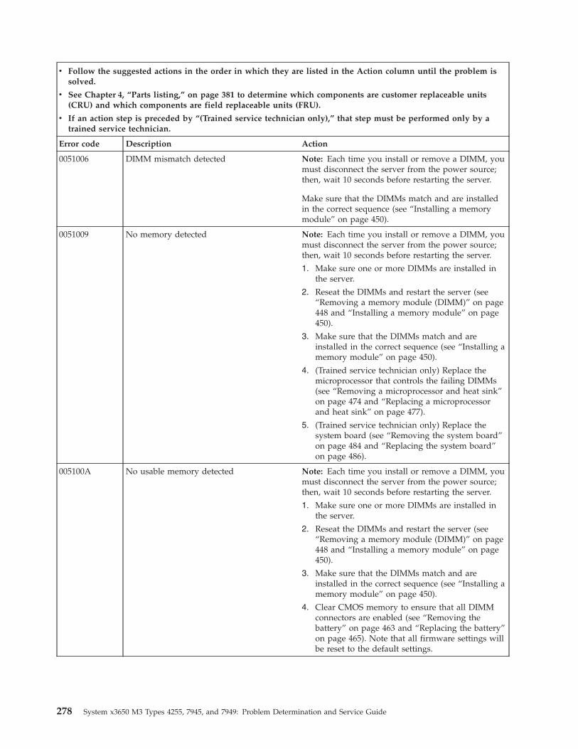
v Follow the suggested actions in the order in which they are listed in the Action column until the problem issolved.
v See Chapter 4, “Parts listing,” on page 381 to determine which components are customer replaceable units(CRU) and which components are field replaceable units (FRU).
v If an action step is preceded by “(Trained service technician only),” that step must be performed only by atrained service technician.
Error code Description Action
0051006 DIMM mismatch detected Note: Each time you install or remove a DIMM, youmust disconnect the server from the power source;then, wait 10 seconds before restarting the server.
Make sure that the DIMMs match and are installedin the correct sequence (see “Installing a memorymodule” on page 450).
0051009 No memory detected Note: Each time you install or remove a DIMM, youmust disconnect the server from the power source;then, wait 10 seconds before restarting the server.
1. Make sure one or more DIMMs are installed inthe server.
2. Reseat the DIMMs and restart the server (see“Removing a memory module (DIMM)” on page448 and “Installing a memory module” on page450).
3. Make sure that the DIMMs match and areinstalled in the correct sequence (see “Installing amemory module” on page 450).
4. (Trained service technician only) Replace themicroprocessor that controls the failing DIMMs(see “Removing a microprocessor and heat sink”on page 474 and “Replacing a microprocessorand heat sink” on page 477).
5. (Trained service technician only) Replace thesystem board (see “Removing the system board”on page 484 and “Replacing the system board”on page 486).
005100A No usable memory detected Note: Each time you install or remove a DIMM, youmust disconnect the server from the power source;then, wait 10 seconds before restarting the server.
1. Make sure one or more DIMMs are installed inthe server.
2. Reseat the DIMMs and restart the server (see“Removing a memory module (DIMM)” on page448 and “Installing a memory module” on page450).
3. Make sure that the DIMMs match and areinstalled in the correct sequence (see “Installing amemory module” on page 450).
4. Clear CMOS memory to ensure that all DIMMconnectors are enabled (see “Removing thebattery” on page 463 and “Replacing the battery”on page 465). Note that all firmware settings willbe reset to the default settings.
278 System x3650 M3 Types 4255, 7945, and 7949: Problem Determination and Service Guide
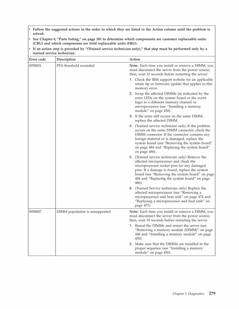
v Follow the suggested actions in the order in which they are listed in the Action column until the problem issolved.
v See Chapter 4, “Parts listing,” on page 381 to determine which components are customer replaceable units(CRU) and which components are field replaceable units (FRU).
v If an action step is preceded by “(Trained service technician only),” that step must be performed only by atrained service technician.
Error code Description Action
0058001 PFA threshold exceeded Note: Each time you install or remove a DIMM, youmust disconnect the server from the power source;then, wait 10 seconds before restarting the server.
1. Check the IBM support website for an applicableretain tip or firmware update that applies to thismemory error.
2. Swap the affected DIMMs (as indicated by theerror LEDs on the system board or the eventlogs) to a different memory channel ormicroprocessor (see “Installing a memorymodule” on page 450).
3. If the error still occurs on the same DIMM,replace the affected DIMM.
4. (Trained service technician only) If the problemoccurs on the same DIMM connector, check theDIMM connector. If the connector contains anyforeign material or is damaged, replace thesystem board (see “Removing the system board”on page 484 and “Replacing the system board”on page 486).
5. (Trained service technician only) Remove theaffected microprocessor and check themicroprocessor socket pins for any damagedpins. If a damage is found, replace the systemboard (see “Removing the system board” on page484 and “Replacing the system board” on page486).
6. (Trained Service technician only) Replace theaffected microprocessor (see “Removing amicroprocessor and heat sink” on page 474 and“Replacing a microprocessor and heat sink” onpage 477).
0058007 DIMM population is unsupported Note: Each time you install or remove a DIMM, youmust disconnect the server from the power source;then, wait 10 seconds before restarting the server.
1. Reseat the DIMMs and restart the server (see“Removing a memory module (DIMM)” on page448 and “Installing a memory module” on page450).
2. Make sure that the DIMMs are installed in theproper sequence (see “Installing a memorymodule” on page 450).
Chapter 3. Diagnostics 279
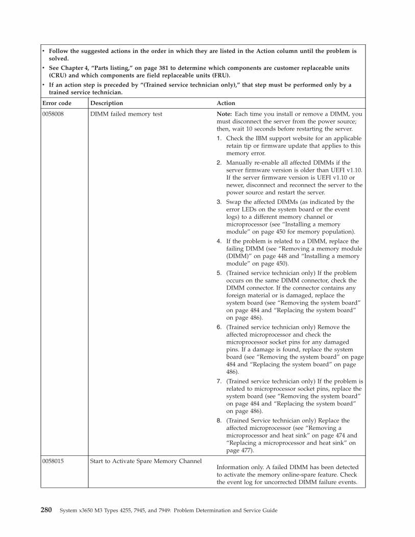
v Follow the suggested actions in the order in which they are listed in the Action column until the problem issolved.
v See Chapter 4, “Parts listing,” on page 381 to determine which components are customer replaceable units(CRU) and which components are field replaceable units (FRU).
v If an action step is preceded by “(Trained service technician only),” that step must be performed only by atrained service technician.
Error code Description Action
0058008 DIMM failed memory test Note: Each time you install or remove a DIMM, youmust disconnect the server from the power source;then, wait 10 seconds before restarting the server.
1. Check the IBM support website for an applicableretain tip or firmware update that applies to thismemory error.
2. Manually re-enable all affected DIMMs if theserver firmware version is older than UEFI v1.10.If the server firmware version is UEFI v1.10 ornewer, disconnect and reconnect the server to thepower source and restart the server.
3. Swap the affected DIMMs (as indicated by theerror LEDs on the system board or the eventlogs) to a different memory channel ormicroprocessor (see “Installing a memorymodule” on page 450 for memory population).
4. If the problem is related to a DIMM, replace thefailing DIMM (see “Removing a memory module(DIMM)” on page 448 and “Installing a memorymodule” on page 450).
5. (Trained service technician only) If the problemoccurs on the same DIMM connector, check theDIMM connector. If the connector contains anyforeign material or is damaged, replace thesystem board (see “Removing the system board”on page 484 and “Replacing the system board”on page 486).
6. (Trained service technician only) Remove theaffected microprocessor and check themicroprocessor socket pins for any damagedpins. If a damage is found, replace the systemboard (see “Removing the system board” on page484 and “Replacing the system board” on page486).
7. (Trained service technician only) If the problem isrelated to microprocessor socket pins, replace thesystem board (see “Removing the system board”on page 484 and “Replacing the system board”on page 486).
8. (Trained Service technician only) Replace theaffected microprocessor (see “Removing amicroprocessor and heat sink” on page 474 and“Replacing a microprocessor and heat sink” onpage 477).
0058015 Start to Activate Spare Memory ChannelInformation only. A failed DIMM has been detectedto activate the memory online-spare feature. Checkthe event log for uncorrected DIMM failure events.
280 System x3650 M3 Types 4255, 7945, and 7949: Problem Determination and Service Guide
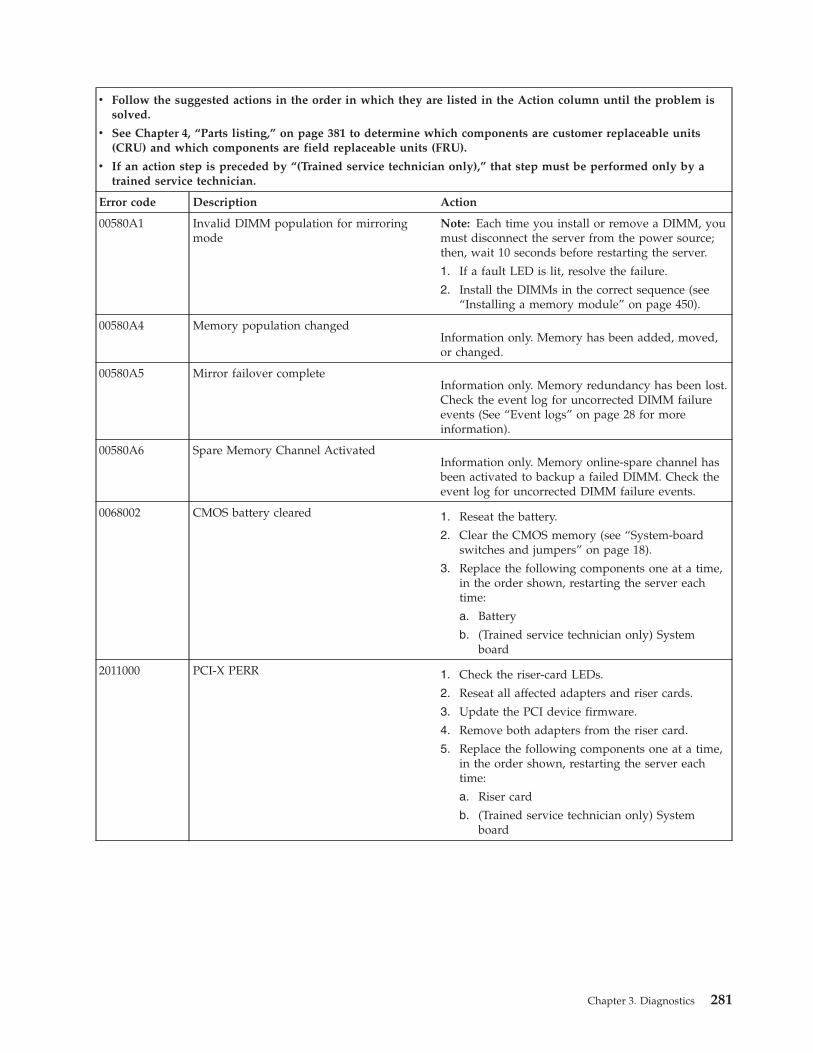
v Follow the suggested actions in the order in which they are listed in the Action column until the problem issolved.
v See Chapter 4, “Parts listing,” on page 381 to determine which components are customer replaceable units(CRU) and which components are field replaceable units (FRU).
v If an action step is preceded by “(Trained service technician only),” that step must be performed only by atrained service technician.
Error code Description Action
00580A1 Invalid DIMM population for mirroringmode
Note: Each time you install or remove a DIMM, youmust disconnect the server from the power source;then, wait 10 seconds before restarting the server.
1. If a fault LED is lit, resolve the failure.
2. Install the DIMMs in the correct sequence (see“Installing a memory module” on page 450).
00580A4 Memory population changedInformation only. Memory has been added, moved,or changed.
00580A5 Mirror failover completeInformation only. Memory redundancy has been lost.Check the event log for uncorrected DIMM failureevents (See “Event logs” on page 28 for moreinformation).
00580A6 Spare Memory Channel ActivatedInformation only. Memory online-spare channel hasbeen activated to backup a failed DIMM. Check theevent log for uncorrected DIMM failure events.
0068002 CMOS battery cleared 1. Reseat the battery.
2. Clear the CMOS memory (see “System-boardswitches and jumpers” on page 18).
3. Replace the following components one at a time,in the order shown, restarting the server eachtime:
a. Battery
b. (Trained service technician only) Systemboard
2011000 PCI-X PERR 1. Check the riser-card LEDs.
2. Reseat all affected adapters and riser cards.
3. Update the PCI device firmware.
4. Remove both adapters from the riser card.
5. Replace the following components one at a time,in the order shown, restarting the server eachtime:
a. Riser card
b. (Trained service technician only) Systemboard
Chapter 3. Diagnostics 281
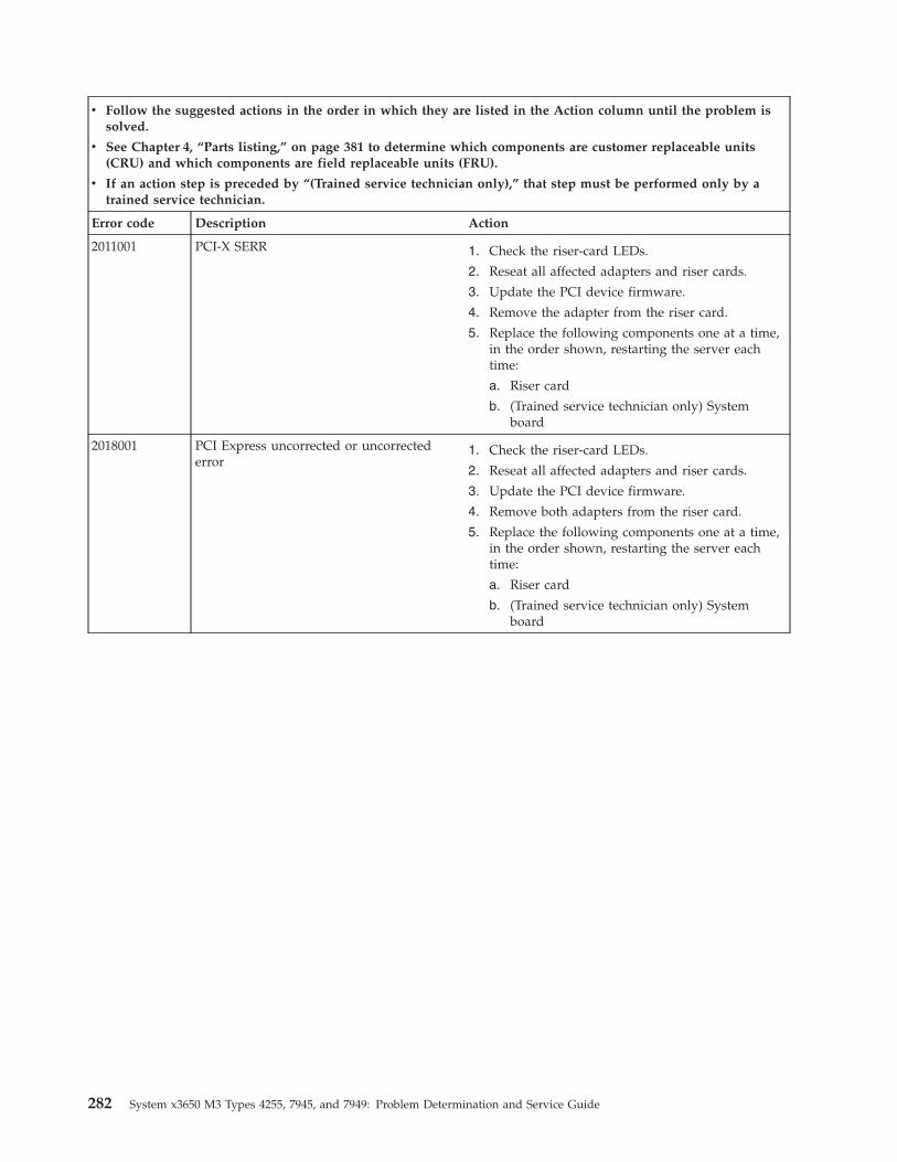
v Follow the suggested actions in the order in which they are listed in the Action column until the problem issolved.
v See Chapter 4, “Parts listing,” on page 381 to determine which components are customer replaceable units(CRU) and which components are field replaceable units (FRU).
v If an action step is preceded by “(Trained service technician only),” that step must be performed only by atrained service technician.
Error code Description Action
2011001 PCI-X SERR 1. Check the riser-card LEDs.
2. Reseat all affected adapters and riser cards.
3. Update the PCI device firmware.
4. Remove the adapter from the riser card.
5. Replace the following components one at a time,in the order shown, restarting the server eachtime:
a. Riser card
b. (Trained service technician only) Systemboard
2018001 PCI Express uncorrected or uncorrectederror
1. Check the riser-card LEDs.
2. Reseat all affected adapters and riser cards.
3. Update the PCI device firmware.
4. Remove both adapters from the riser card.
5. Replace the following components one at a time,in the order shown, restarting the server eachtime:
a. Riser card
b. (Trained service technician only) Systemboard
282 System x3650 M3 Types 4255, 7945, and 7949: Problem Determination and Service Guide
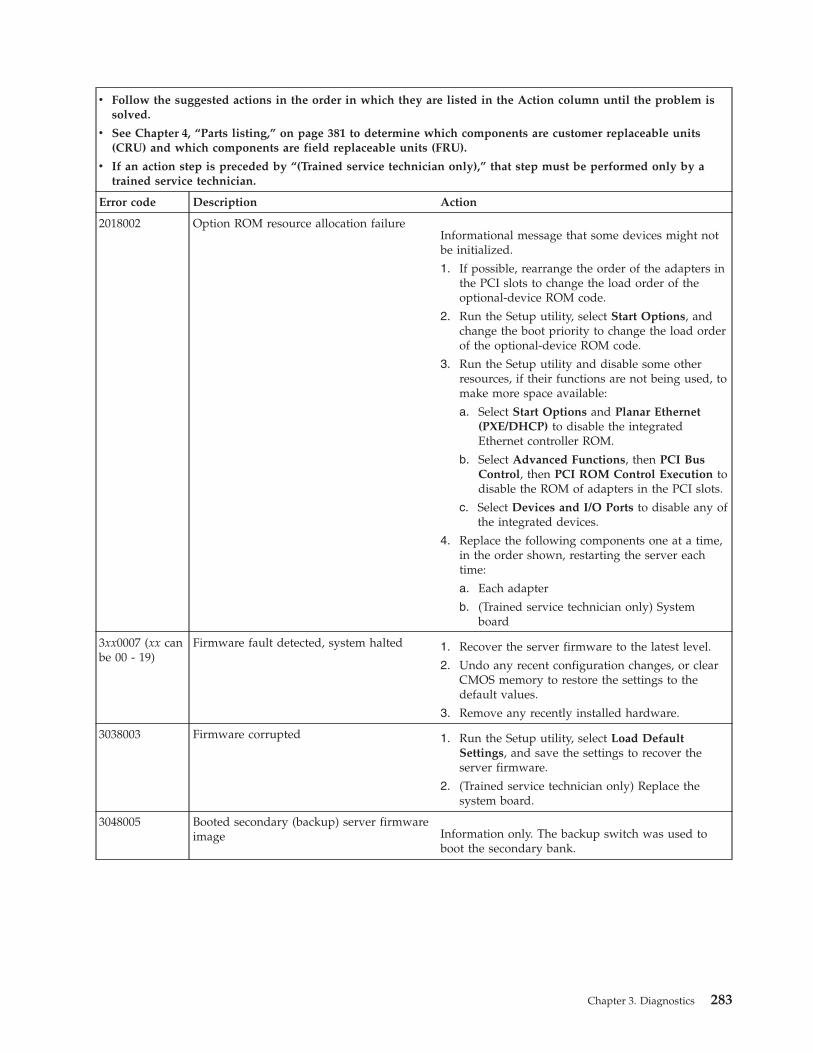
v Follow the suggested actions in the order in which they are listed in the Action column until the problem issolved.
v See Chapter 4, “Parts listing,” on page 381 to determine which components are customer replaceable units(CRU) and which components are field replaceable units (FRU).
v If an action step is preceded by “(Trained service technician only),” that step must be performed only by atrained service technician.
Error code Description Action
2018002 Option ROM resource allocation failureInformational message that some devices might notbe initialized.
1. If possible, rearrange the order of the adapters inthe PCI slots to change the load order of theoptional-device ROM code.
2. Run the Setup utility, select Start Options, andchange the boot priority to change the load orderof the optional-device ROM code.
3. Run the Setup utility and disable some otherresources, if their functions are not being used, tomake more space available:
a. Select Start Options and Planar Ethernet(PXE/DHCP) to disable the integratedEthernet controller ROM.
b. Select Advanced Functions, then PCI BusControl, then PCI ROM Control Execution todisable the ROM of adapters in the PCI slots.
c. Select Devices and I/O Ports to disable any ofthe integrated devices.
4. Replace the following components one at a time,in the order shown, restarting the server eachtime:
a. Each adapter
b. (Trained service technician only) Systemboard
3xx0007 (xx canbe 00 - 19)
Firmware fault detected, system halted 1. Recover the server firmware to the latest level.
2. Undo any recent configuration changes, or clearCMOS memory to restore the settings to thedefault values.
3. Remove any recently installed hardware.
3038003 Firmware corrupted 1. Run the Setup utility, select Load DefaultSettings, and save the settings to recover theserver firmware.
2. (Trained service technician only) Replace thesystem board.
3048005 Booted secondary (backup) server firmwareimage Information only. The backup switch was used to
boot the secondary bank.
Chapter 3. Diagnostics 283
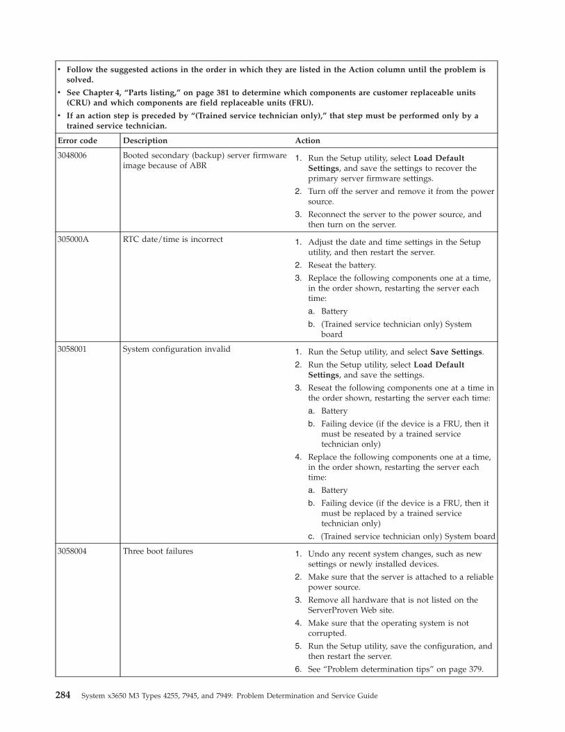
v Follow the suggested actions in the order in which they are listed in the Action column until the problem issolved.
v See Chapter 4, “Parts listing,” on page 381 to determine which components are customer replaceable units(CRU) and which components are field replaceable units (FRU).
v If an action step is preceded by “(Trained service technician only),” that step must be performed only by atrained service technician.
Error code Description Action
3048006 Booted secondary (backup) server firmwareimage because of ABR
1. Run the Setup utility, select Load DefaultSettings, and save the settings to recover theprimary server firmware settings.
2. Turn off the server and remove it from the powersource.
3. Reconnect the server to the power source, andthen turn on the server.
305000A RTC date/time is incorrect 1. Adjust the date and time settings in the Setuputility, and then restart the server.
2. Reseat the battery.
3. Replace the following components one at a time,in the order shown, restarting the server eachtime:
a. Battery
b. (Trained service technician only) Systemboard
3058001 System configuration invalid 1. Run the Setup utility, and select Save Settings.
2. Run the Setup utility, select Load DefaultSettings, and save the settings.
3. Reseat the following components one at a time inthe order shown, restarting the server each time:
a. Battery
b. Failing device (if the device is a FRU, then itmust be reseated by a trained servicetechnician only)
4. Replace the following components one at a time,in the order shown, restarting the server eachtime:
a. Battery
b. Failing device (if the device is a FRU, then itmust be replaced by a trained servicetechnician only)
c. (Trained service technician only) System board
3058004 Three boot failures 1. Undo any recent system changes, such as newsettings or newly installed devices.
2. Make sure that the server is attached to a reliablepower source.
3. Remove all hardware that is not listed on theServerProven Web site.
4. Make sure that the operating system is notcorrupted.
5. Run the Setup utility, save the configuration, andthen restart the server.
6. See “Problem determination tips” on page 379.
284 System x3650 M3 Types 4255, 7945, and 7949: Problem Determination and Service Guide
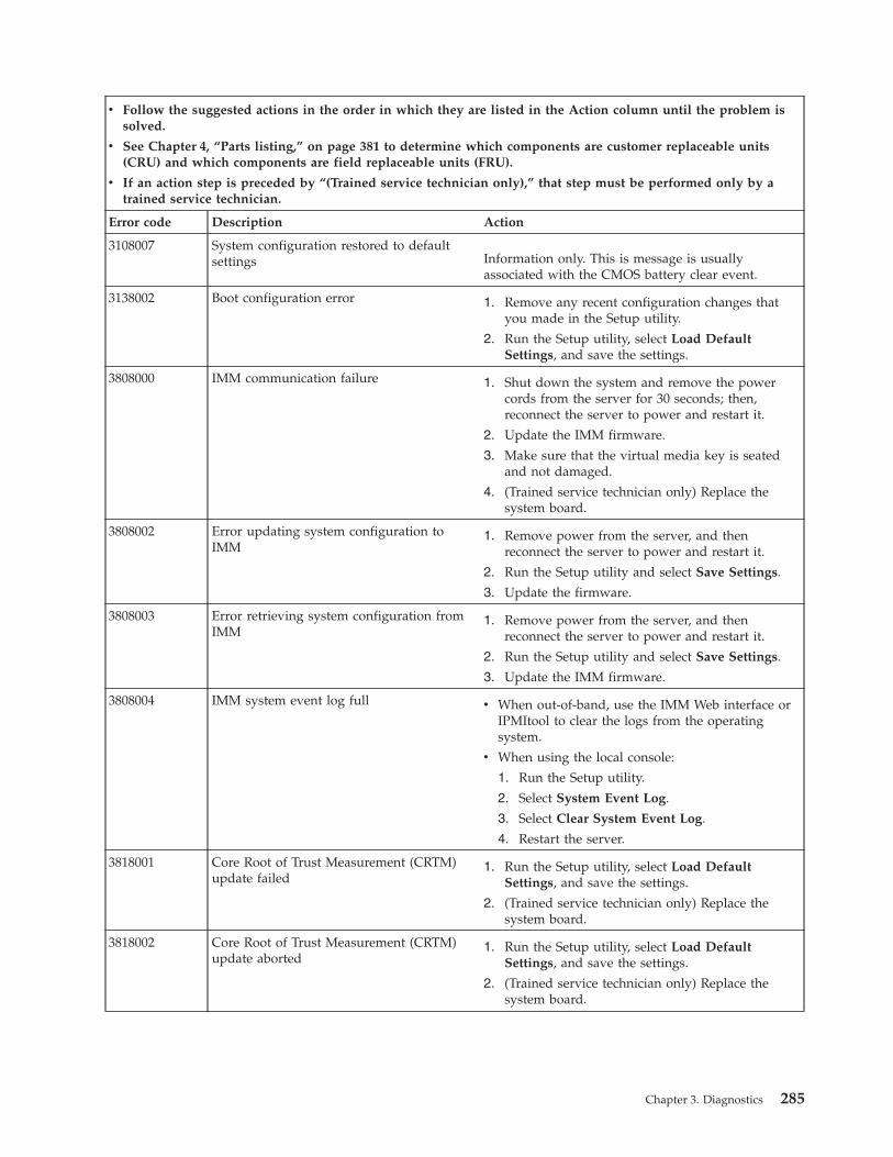
v Follow the suggested actions in the order in which they are listed in the Action column until the problem issolved.
v See Chapter 4, “Parts listing,” on page 381 to determine which components are customer replaceable units(CRU) and which components are field replaceable units (FRU).
v If an action step is preceded by “(Trained service technician only),” that step must be performed only by atrained service technician.
Error code Description Action
3108007 System configuration restored to defaultsettings Information only. This is message is usually
associated with the CMOS battery clear event.
3138002 Boot configuration error 1. Remove any recent configuration changes thatyou made in the Setup utility.
2. Run the Setup utility, select Load DefaultSettings, and save the settings.
3808000 IMM communication failure 1. Shut down the system and remove the powercords from the server for 30 seconds; then,reconnect the server to power and restart it.
2. Update the IMM firmware.
3. Make sure that the virtual media key is seatedand not damaged.
4. (Trained service technician only) Replace thesystem board.
3808002 Error updating system configuration toIMM
1. Remove power from the server, and thenreconnect the server to power and restart it.
2. Run the Setup utility and select Save Settings.
3. Update the firmware.
3808003 Error retrieving system configuration fromIMM
1. Remove power from the server, and thenreconnect the server to power and restart it.
2. Run the Setup utility and select Save Settings.
3. Update the IMM firmware.
3808004 IMM system event log full v When out-of-band, use the IMM Web interface orIPMItool to clear the logs from the operatingsystem.
v When using the local console:
1. Run the Setup utility.
2. Select System Event Log.
3. Select Clear System Event Log.
4. Restart the server.
3818001 Core Root of Trust Measurement (CRTM)update failed
1. Run the Setup utility, select Load DefaultSettings, and save the settings.
2. (Trained service technician only) Replace thesystem board.
3818002 Core Root of Trust Measurement (CRTM)update aborted
1. Run the Setup utility, select Load DefaultSettings, and save the settings.
2. (Trained service technician only) Replace thesystem board.
Chapter 3. Diagnostics 285
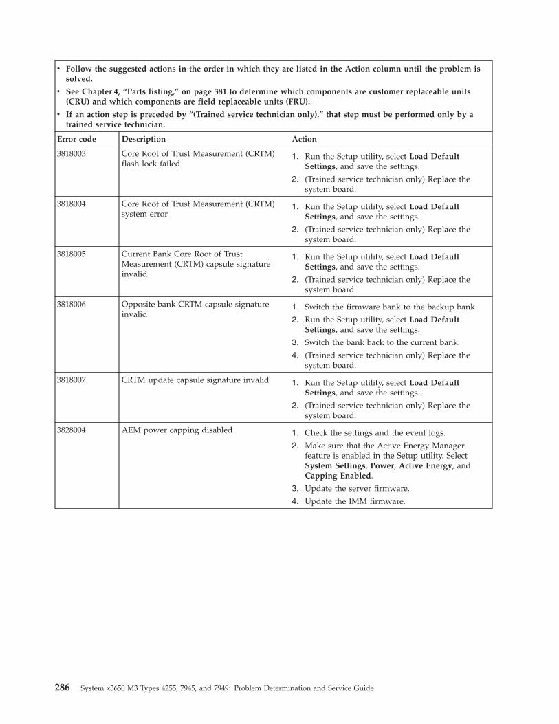
v Follow the suggested actions in the order in which they are listed in the Action column until the problem issolved.
v See Chapter 4, “Parts listing,” on page 381 to determine which components are customer replaceable units(CRU) and which components are field replaceable units (FRU).
v If an action step is preceded by “(Trained service technician only),” that step must be performed only by atrained service technician.
Error code Description Action
3818003 Core Root of Trust Measurement (CRTM)flash lock failed
1. Run the Setup utility, select Load DefaultSettings, and save the settings.
2. (Trained service technician only) Replace thesystem board.
3818004 Core Root of Trust Measurement (CRTM)system error
1. Run the Setup utility, select Load DefaultSettings, and save the settings.
2. (Trained service technician only) Replace thesystem board.
3818005 Current Bank Core Root of TrustMeasurement (CRTM) capsule signatureinvalid
1. Run the Setup utility, select Load DefaultSettings, and save the settings.
2. (Trained service technician only) Replace thesystem board.
3818006 Opposite bank CRTM capsule signatureinvalid
1. Switch the firmware bank to the backup bank.
2. Run the Setup utility, select Load DefaultSettings, and save the settings.
3. Switch the bank back to the current bank.
4. (Trained service technician only) Replace thesystem board.
3818007 CRTM update capsule signature invalid 1. Run the Setup utility, select Load DefaultSettings, and save the settings.
2. (Trained service technician only) Replace thesystem board.
3828004 AEM power capping disabled 1. Check the settings and the event logs.
2. Make sure that the Active Energy Managerfeature is enabled in the Setup utility. SelectSystem Settings, Power, Active Energy, andCapping Enabled.
3. Update the server firmware.
4. Update the IMM firmware.
286 System x3650 M3 Types 4255, 7945, and 7949: Problem Determination and Service Guide
Diagnostic programs, messages, and error codesThe diagnostic programs are the primary method of testing the major componentsof the server.
About this task
As you run the diagnostic programs, text messages are displayed on the screenand are saved in the test log. A diagnostic text message indicates that a problemhas been detected and provides the action you should take as a result of the textmessage.
Make sure that the server has the latest version of the diagnostic programs. Todownload the latest version, complete the following steps.
Note: Changes are made periodically to the IBM Web site. The actual proceduremight vary slightly from what is described in this document.1. Go to http://www.ibm.com/systems/support/.2. Under Product support, click System x.3. Under Popular links, click Software and device drivers.4. Click IBM System x3650 M3 to display the matrix of downloadable files for the
server.
Utilities are available to reset and update the code on the integrated USB flashdevice, if the diagnostic partition becomes damaged and does not start thediagnostic programs. For more information and to download the utilities, go tohttp://www.ibm.com/jct01004c/systems/support/supportsite.wss/docdisplay?lndocid=MIGR-5072294&brandind=5000008.
Running the diagnostic programsAbout this task
To run the diagnostic programs, complete the following steps:
Procedure1. If the server is running, turn off the server and all attached devices.2. Turn on all attached devices; then, turn on the server.3. When the prompt Press F2 for Dynamic System Analysis (DSA) is displayed,
press F2.
Note: The DSA Preboot diagnostic program might appear to be unresponsivefor an unusual length of time when you start the program. This is normaloperation while the program loads. The loading process may take up to 10minutes.
4. Optionally, select Quit to DSA to exit from the stand-alone memory diagnosticprogram.
Note: After you exit from the stand-alone memory diagnostic environment,you must restart the server to access the stand-alone memory diagnosticenvironment again.
5. Type gui to display the graphical user interface, or select cmd to display theDSA interactive menu.
6. Follow the instructions on the screen to select the diagnostic test to run.
Chapter 3. Diagnostics 287
Results
If the diagnostic programs do not detect any hardware errors but the problemremains during normal server operations, a software error might be the cause. Ifyou suspect a software problem, see the information that comes with yoursoftware.
A single problem might cause more than one error message. When this happens,correct the cause of the first error message. The other error messages usually willnot occur the next time you run the diagnostic programs.
Exception: If multiple error codes or light path diagnostics LEDs indicate amicroprocessor error, the error might be in a microprocessor or in a microprocessorsocket. See “Microprocessor problems” on page 349 for information aboutdiagnosing microprocessor problems.
If the server stops during testing and you cannot continue, restart the server andtry running the diagnostic programs again. If the problem remains, replace thecomponent that was being tested when the server stopped.
Diagnostic text messagesDiagnostic text messages are displayed while the tests are running.
A diagnostic text message contains one of the following results:
Passed: The test was completed without any errors.
Failed: The test detected an error.
Aborted: The test could not proceed because of the server configuration.
Additional information concerning test failures is available in the extendeddiagnostic results for each test.
Viewing the test logUse this information to view the test log.
To view the test log when the tests are completed, type the view command in theDSA interactive menu, or select Diagnostic Event Log in the graphical userinterface. To transfer DSA collections to an external USB device, type the copycommand in the DSA interactive menu.
288 System x3650 M3 Types 4255, 7945, and 7949: Problem Determination and Service Guide
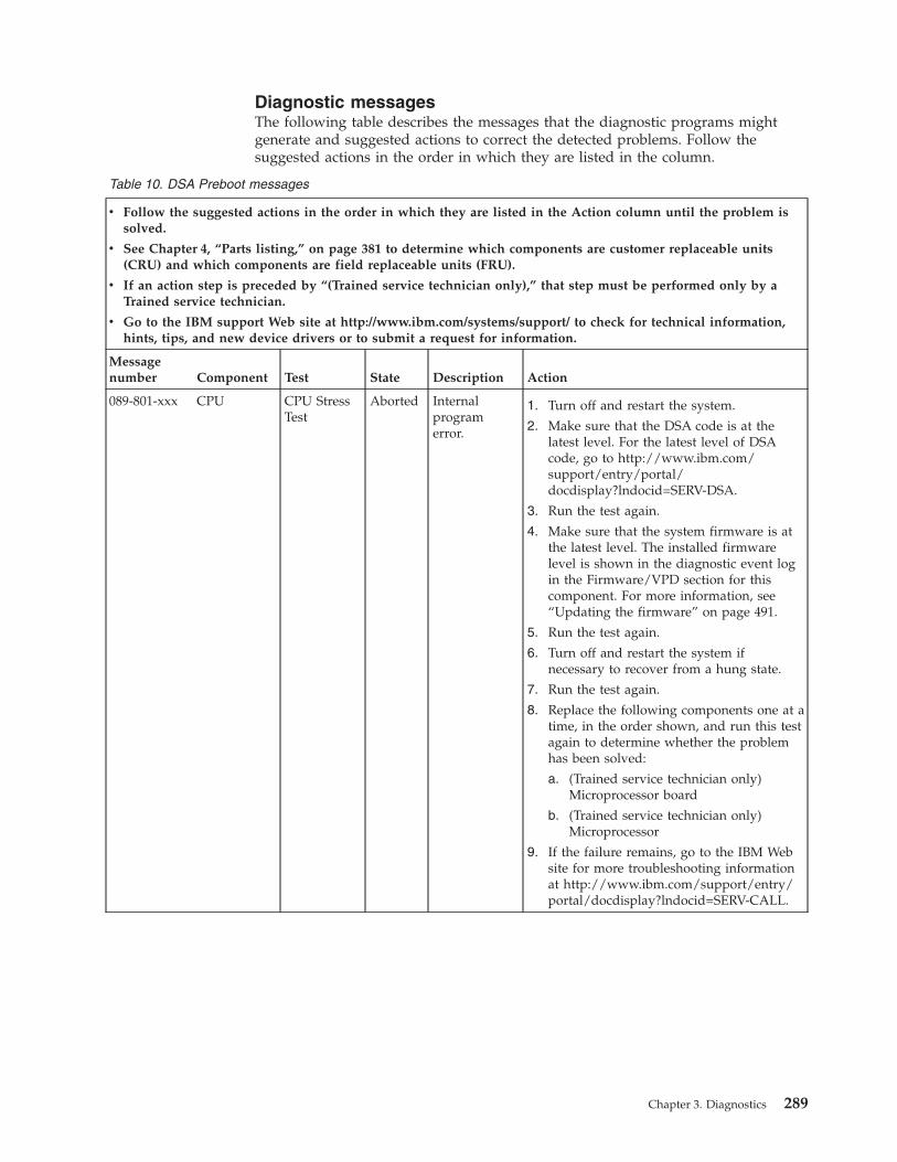
Diagnostic messagesThe following table describes the messages that the diagnostic programs mightgenerate and suggested actions to correct the detected problems. Follow thesuggested actions in the order in which they are listed in the column.
Table 10. DSA Preboot messages
v Follow the suggested actions in the order in which they are listed in the Action column until the problem issolved.
v See Chapter 4, “Parts listing,” on page 381 to determine which components are customer replaceable units(CRU) and which components are field replaceable units (FRU).
v If an action step is preceded by “(Trained service technician only),” that step must be performed only by aTrained service technician.
v Go to the IBM support Web site at http://www.ibm.com/systems/support/ to check for technical information,hints, tips, and new device drivers or to submit a request for information.
Messagenumber Component Test State Description Action
089-801-xxx CPU CPU StressTest
Aborted Internalprogramerror.
1. Turn off and restart the system.
2. Make sure that the DSA code is at thelatest level. For the latest level of DSAcode, go to http://www.ibm.com/support/entry/portal/docdisplay?lndocid=SERV-DSA.
3. Run the test again.
4. Make sure that the system firmware is atthe latest level. The installed firmwarelevel is shown in the diagnostic event login the Firmware/VPD section for thiscomponent. For more information, see“Updating the firmware” on page 491.
5. Run the test again.
6. Turn off and restart the system ifnecessary to recover from a hung state.
7. Run the test again.
8. Replace the following components one at atime, in the order shown, and run this testagain to determine whether the problemhas been solved:
a. (Trained service technician only)Microprocessor board
b. (Trained service technician only)Microprocessor
9. If the failure remains, go to the IBM Website for more troubleshooting informationat http://www.ibm.com/support/entry/portal/docdisplay?lndocid=SERV-CALL.
Chapter 3. Diagnostics 289
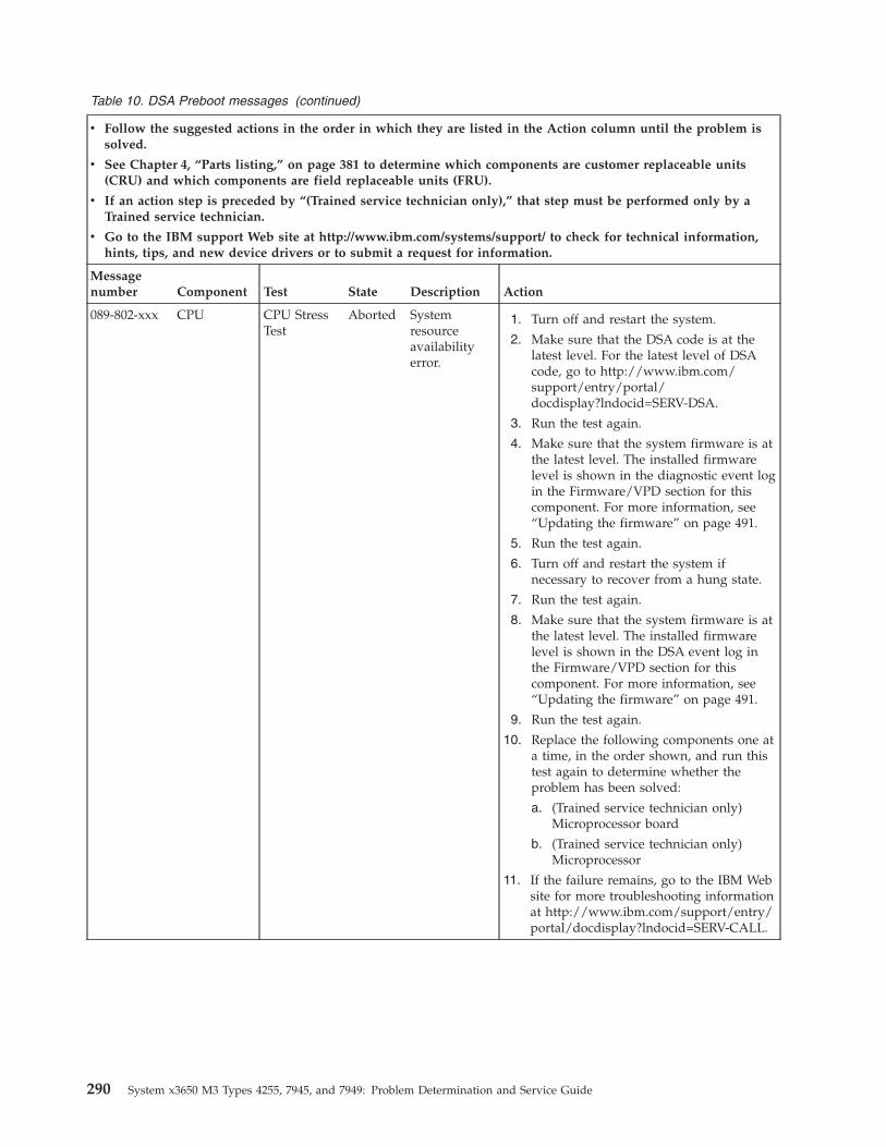
Table 10. DSA Preboot messages (continued)
v Follow the suggested actions in the order in which they are listed in the Action column until the problem issolved.
v See Chapter 4, “Parts listing,” on page 381 to determine which components are customer replaceable units(CRU) and which components are field replaceable units (FRU).
v If an action step is preceded by “(Trained service technician only),” that step must be performed only by aTrained service technician.
v Go to the IBM support Web site at http://www.ibm.com/systems/support/ to check for technical information,hints, tips, and new device drivers or to submit a request for information.
Messagenumber Component Test State Description Action
089-802-xxx CPU CPU StressTest
Aborted Systemresourceavailabilityerror.
1. Turn off and restart the system.
2. Make sure that the DSA code is at thelatest level. For the latest level of DSAcode, go to http://www.ibm.com/support/entry/portal/docdisplay?lndocid=SERV-DSA.
3. Run the test again.
4. Make sure that the system firmware is atthe latest level. The installed firmwarelevel is shown in the diagnostic event login the Firmware/VPD section for thiscomponent. For more information, see“Updating the firmware” on page 491.
5. Run the test again.
6. Turn off and restart the system ifnecessary to recover from a hung state.
7. Run the test again.
8. Make sure that the system firmware is atthe latest level. The installed firmwarelevel is shown in the DSA event log inthe Firmware/VPD section for thiscomponent. For more information, see“Updating the firmware” on page 491.
9. Run the test again.
10. Replace the following components one ata time, in the order shown, and run thistest again to determine whether theproblem has been solved:
a. (Trained service technician only)Microprocessor board
b. (Trained service technician only)Microprocessor
11. If the failure remains, go to the IBM Website for more troubleshooting informationat http://www.ibm.com/support/entry/portal/docdisplay?lndocid=SERV-CALL.
290 System x3650 M3 Types 4255, 7945, and 7949: Problem Determination and Service Guide
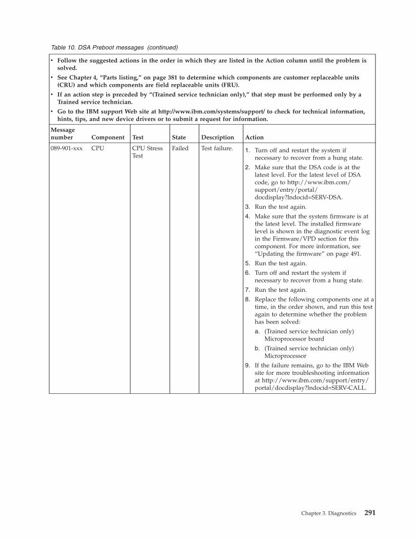
Table 10. DSA Preboot messages (continued)
v Follow the suggested actions in the order in which they are listed in the Action column until the problem issolved.
v See Chapter 4, “Parts listing,” on page 381 to determine which components are customer replaceable units(CRU) and which components are field replaceable units (FRU).
v If an action step is preceded by “(Trained service technician only),” that step must be performed only by aTrained service technician.
v Go to the IBM support Web site at http://www.ibm.com/systems/support/ to check for technical information,hints, tips, and new device drivers or to submit a request for information.
Messagenumber Component Test State Description Action
089-901-xxx CPU CPU StressTest
Failed Test failure. 1. Turn off and restart the system ifnecessary to recover from a hung state.
2. Make sure that the DSA code is at thelatest level. For the latest level of DSAcode, go to http://www.ibm.com/support/entry/portal/docdisplay?lndocid=SERV-DSA.
3. Run the test again.
4. Make sure that the system firmware is atthe latest level. The installed firmwarelevel is shown in the diagnostic event login the Firmware/VPD section for thiscomponent. For more information, see“Updating the firmware” on page 491.
5. Run the test again.
6. Turn off and restart the system ifnecessary to recover from a hung state.
7. Run the test again.
8. Replace the following components one at atime, in the order shown, and run this testagain to determine whether the problemhas been solved:
a. (Trained service technician only)Microprocessor board
b. (Trained service technician only)Microprocessor
9. If the failure remains, go to the IBM Website for more troubleshooting informationat http://www.ibm.com/support/entry/portal/docdisplay?lndocid=SERV-CALL.
Chapter 3. Diagnostics 291

Table 10. DSA Preboot messages (continued)
v Follow the suggested actions in the order in which they are listed in the Action column until the problem issolved.
v See Chapter 4, “Parts listing,” on page 381 to determine which components are customer replaceable units(CRU) and which components are field replaceable units (FRU).
v If an action step is preceded by “(Trained service technician only),” that step must be performed only by aTrained service technician.
v Go to the IBM support Web site at http://www.ibm.com/systems/support/ to check for technical information,hints, tips, and new device drivers or to submit a request for information.
Messagenumber Component Test State Description Action
166-801-xxx IMM IMM I2CTest
Aborted IMM I2C teststopped: theIMM returnedan incorrectresponselength.
1. Turn off the system and disconnect it fromthe power source. You must disconnect thesystem from ac power to reset the IMM.
2. After 45 seconds, reconnect the system tothe power source and turn on the system.
3. Run the test again.
4. Make sure that the DSA code is at thelatest level. For the latest level of DSAcode, go to http://www.ibm.com/support/entry/portal/docdisplay?lndocid=SERV-DSA.
5. Make sure that the IMM firmware is at thelatest level. The installed firmware level isshown in the diagnostic event log in theFirmware/VPD section for thiscomponent. For more information, see“Updating the firmware” on page 491.
6. Run the test again.
7. If the failure remains, go to the IBM Website for more troubleshooting informationat http://www.ibm.com/support/entry/portal/docdisplay?lndocid=SERV-CALL.
292 System x3650 M3 Types 4255, 7945, and 7949: Problem Determination and Service Guide

Table 10. DSA Preboot messages (continued)
v Follow the suggested actions in the order in which they are listed in the Action column until the problem issolved.
v See Chapter 4, “Parts listing,” on page 381 to determine which components are customer replaceable units(CRU) and which components are field replaceable units (FRU).
v If an action step is preceded by “(Trained service technician only),” that step must be performed only by aTrained service technician.
v Go to the IBM support Web site at http://www.ibm.com/systems/support/ to check for technical information,hints, tips, and new device drivers or to submit a request for information.
Messagenumber Component Test State Description Action
166-802-xxx IMM IMM I2CTest
Aborted IMM I2C teststopped: thetest cannot becompleted foran unknownreason.
1. Turn off the system and disconnect it fromthe power source. You must disconnect thesystem from ac power to reset the IMM.
2. After 45 seconds, reconnect the system tothe power source and turn on the system.
3. Run the test again.
4. Make sure that the DSA code is at thelatest level. For the latest level of DSAcode, go to http://www.ibm.com/support/entry/portal/docdisplay?lndocid=SERV-DSA.
5. Make sure that the IMM firmware is at thelatest level. The installed firmware level isshown in the diagnostic event log in theFirmware/VPD section for thiscomponent. For more information, see“Updating the firmware” on page 491.
6. Run the test again.
7. If the failure remains, go to the IBM Website for more troubleshooting informationat http://www.ibm.com/support/entry/portal/docdisplay?lndocid=SERV-CALL.
Chapter 3. Diagnostics 293

Table 10. DSA Preboot messages (continued)
v Follow the suggested actions in the order in which they are listed in the Action column until the problem issolved.
v See Chapter 4, “Parts listing,” on page 381 to determine which components are customer replaceable units(CRU) and which components are field replaceable units (FRU).
v If an action step is preceded by “(Trained service technician only),” that step must be performed only by aTrained service technician.
v Go to the IBM support Web site at http://www.ibm.com/systems/support/ to check for technical information,hints, tips, and new device drivers or to submit a request for information.
Messagenumber Component Test State Description Action
166-803-xxx IMM IMM I2CTest
Aborted IMM I2C teststopped: thenode is busy;try later.
1. Turn off the system and disconnect it fromthe power source. You must disconnect thesystem from ac power to reset the IMM.
2. After 45 seconds, reconnect the system tothe power source and turn on the system.
3. Run the test again.
4. Make sure that the DSA code is at thelatest level. For the latest level of DSAcode, go to http://www.ibm.com/support/entry/portal/docdisplay?lndocid=SERV-DSA.
5. Make sure that the IMM firmware is at thelatest level. The installed firmware level isshown in the diagnostic event log in theFirmware/VPD section for thiscomponent. For more information, see“Updating the firmware” on page 491.
6. Run the test again.
7. If the failure remains, go to the IBM Website for more troubleshooting informationat http://www.ibm.com/support/entry/portal/docdisplay?lndocid=SERV-CALL.
294 System x3650 M3 Types 4255, 7945, and 7949: Problem Determination and Service Guide

Table 10. DSA Preboot messages (continued)
v Follow the suggested actions in the order in which they are listed in the Action column until the problem issolved.
v See Chapter 4, “Parts listing,” on page 381 to determine which components are customer replaceable units(CRU) and which components are field replaceable units (FRU).
v If an action step is preceded by “(Trained service technician only),” that step must be performed only by aTrained service technician.
v Go to the IBM support Web site at http://www.ibm.com/systems/support/ to check for technical information,hints, tips, and new device drivers or to submit a request for information.
Messagenumber Component Test State Description Action
166-804-xxx IMM IMM I2CTest
Aborted IMM I2C teststopped:invalidcommand.
1. Turn off the system and disconnect it fromthe power source. You must disconnect thesystem from ac power to reset the IMM.
2. After 45 seconds, reconnect the system tothe power source and turn on the system.
3. Run the test again.
4. Make sure that the DSA code is at thelatest level. For the latest level of DSAcode, go to http://www.ibm.com/support/entry/portal/docdisplay?lndocid=SERV-DSA.
5. Make sure that the IMM firmware is at thelatest level. The installed firmware level isshown in the diagnostic event log in theFirmware/VPD section for thiscomponent. For more information, see“Updating the firmware” on page 491.
6. Run the test again.
7. If the failure remains, go to the IBM Website for more troubleshooting informationat http://www.ibm.com/support/entry/portal/docdisplay?lndocid=SERV-CALL.
Chapter 3. Diagnostics 295

Table 10. DSA Preboot messages (continued)
v Follow the suggested actions in the order in which they are listed in the Action column until the problem issolved.
v See Chapter 4, “Parts listing,” on page 381 to determine which components are customer replaceable units(CRU) and which components are field replaceable units (FRU).
v If an action step is preceded by “(Trained service technician only),” that step must be performed only by aTrained service technician.
v Go to the IBM support Web site at http://www.ibm.com/systems/support/ to check for technical information,hints, tips, and new device drivers or to submit a request for information.
Messagenumber Component Test State Description Action
166-805-xxx IMM IMM I2CTest
Aborted IMM I2C testaborted:invalidcommand forthe givenLUN.
1. Turn off the system and disconnect it fromthe power source. You must disconnect thesystem from ac power to reset the IMM.
2. After 45 seconds, reconnect the system tothe power source and turn on the system.
3. Run the test again.
4. Make sure that the DSA code is at thelatest level. For the latest level of DSAcode, go to http://www.ibm.com/support/entry/portal/docdisplay?lndocid=SERV-DSA.
5. Make sure that the IMM firmware is at thelatest level. The installed firmware level isshown in the diagnostic event log in theFirmware/VPD section for thiscomponent. For more information, see“Updating the firmware” on page 491.
6. Run the test again.
7. If the failure remains, go to the IBM Website for more troubleshooting informationat http://www.ibm.com/support/entry/portal/docdisplay?lndocid=SERV-CALL.
296 System x3650 M3 Types 4255, 7945, and 7949: Problem Determination and Service Guide

Table 10. DSA Preboot messages (continued)
v Follow the suggested actions in the order in which they are listed in the Action column until the problem issolved.
v See Chapter 4, “Parts listing,” on page 381 to determine which components are customer replaceable units(CRU) and which components are field replaceable units (FRU).
v If an action step is preceded by “(Trained service technician only),” that step must be performed only by aTrained service technician.
v Go to the IBM support Web site at http://www.ibm.com/systems/support/ to check for technical information,hints, tips, and new device drivers or to submit a request for information.
Messagenumber Component Test State Description Action
166-806-xxx IMM IMM I2CTest
Aborted IMM I2C testaborted:timeout whileprocessing thecommand.
1. Turn off the system and disconnect it fromthe power source. You must disconnect thesystem from ac power to reset the IMM.
2. After 45 seconds, reconnect the system tothe power source and turn on the system.
3. Run the test again.
4. Make sure that the DSA code is at thelatest level. For the latest level of DSAcode, go to http://www.ibm.com/support/entry/portal/docdisplay?lndocid=SERV-DSA.
5. Make sure that the IMM firmware is at thelatest level. The installed firmware level isshown in the diagnostic event log in theFirmware/VPD section for thiscomponent. For more information, see“Updating the firmware” on page 491.
6. Run the test again.
7. If the failure remains, go to the IBM Website for more troubleshooting informationat http://www.ibm.com/support/entry/portal/docdisplay?lndocid=SERV-CALL.
Chapter 3. Diagnostics 297

Table 10. DSA Preboot messages (continued)
v Follow the suggested actions in the order in which they are listed in the Action column until the problem issolved.
v See Chapter 4, “Parts listing,” on page 381 to determine which components are customer replaceable units(CRU) and which components are field replaceable units (FRU).
v If an action step is preceded by “(Trained service technician only),” that step must be performed only by aTrained service technician.
v Go to the IBM support Web site at http://www.ibm.com/systems/support/ to check for technical information,hints, tips, and new device drivers or to submit a request for information.
Messagenumber Component Test State Description Action
166-807-xxx IMM IMM I2CTest
Aborted IMM I2C testaborted: outof space.
1. Turn off the system and disconnect it fromthe power source. You must disconnect thesystem from ac power to reset the IMM.
2. After 45 seconds, reconnect the system tothe power source and turn on the system.
3. Run the test again.
4. Make sure that the DSA code is at thelatest level. For the latest level of DSAcode, go to http://www.ibm.com/support/entry/portal/docdisplay?lndocid=SERV-DSA.
5. Make sure that the IMM firmware is at thelatest level. The installed firmware level isshown in the diagnostic event log in theFirmware/VPD section for thiscomponent. For more information, see“Updating the firmware” on page 491.
6. Run the test again.
7. If the failure remains, go to the IBM Website for more troubleshooting informationat http://www.ibm.com/support/entry/portal/docdisplay?lndocid=SERV-CALL.
298 System x3650 M3 Types 4255, 7945, and 7949: Problem Determination and Service Guide

Table 10. DSA Preboot messages (continued)
v Follow the suggested actions in the order in which they are listed in the Action column until the problem issolved.
v See Chapter 4, “Parts listing,” on page 381 to determine which components are customer replaceable units(CRU) and which components are field replaceable units (FRU).
v If an action step is preceded by “(Trained service technician only),” that step must be performed only by aTrained service technician.
v Go to the IBM support Web site at http://www.ibm.com/systems/support/ to check for technical information,hints, tips, and new device drivers or to submit a request for information.
Messagenumber Component Test State Description Action
166-808-xxx IMM IMM I2CTest
Aborted IMM I2C testaborted:reservationcanceled orinvalidreservationID.
1. Turn off the system and disconnect it fromthe power source. You must disconnect thesystem from ac power to reset the IMM.
2. After 45 seconds, reconnect the system tothe power source and turn on the system.
3. Run the test again.
4. Make sure that the DSA code is at thelatest level. For the latest level of DSAcode, go to http://www.ibm.com/support/entry/portal/docdisplay?lndocid=SERV-DSA.
5. Make sure that the IMM firmware is at thelatest level. The installed firmware level isshown in the diagnostic event log in theFirmware/VPD section for thiscomponent. For more information, see“Updating the firmware” on page 491.
6. Run the test again.
7. If the failure remains, go to the IBM Website for more troubleshooting informationat http://www.ibm.com/support/entry/portal/docdisplay?lndocid=SERV-CALL.
Chapter 3. Diagnostics 299

Table 10. DSA Preboot messages (continued)
v Follow the suggested actions in the order in which they are listed in the Action column until the problem issolved.
v See Chapter 4, “Parts listing,” on page 381 to determine which components are customer replaceable units(CRU) and which components are field replaceable units (FRU).
v If an action step is preceded by “(Trained service technician only),” that step must be performed only by aTrained service technician.
v Go to the IBM support Web site at http://www.ibm.com/systems/support/ to check for technical information,hints, tips, and new device drivers or to submit a request for information.
Messagenumber Component Test State Description Action
166-809-xxx IMM IMM I2CTest
Aborted IMM I2C testaborted:request datawastruncated.
1. Turn off the system and disconnect it fromthe power source. You must disconnect thesystem from ac power to reset the IMM.
2. After 45 seconds, reconnect the system tothe power source and turn on the system.
3. Run the test again.
4. Make sure that the DSA code is at thelatest level. For the latest level of DSAcode, go to http://www.ibm.com/support/entry/portal/docdisplay?lndocid=SERV-DSA.
5. Make sure that the IMM firmware is at thelatest level. The installed firmware level isshown in the diagnostic event log in theFirmware/VPD section for thiscomponent. For more information, see“Updating the firmware” on page 491.
6. Run the test again.
7. If the failure remains, go to the IBM Website for more troubleshooting informationat http://www.ibm.com/support/entry/portal/docdisplay?lndocid=SERV-CALL.
300 System x3650 M3 Types 4255, 7945, and 7949: Problem Determination and Service Guide

Table 10. DSA Preboot messages (continued)
v Follow the suggested actions in the order in which they are listed in the Action column until the problem issolved.
v See Chapter 4, “Parts listing,” on page 381 to determine which components are customer replaceable units(CRU) and which components are field replaceable units (FRU).
v If an action step is preceded by “(Trained service technician only),” that step must be performed only by aTrained service technician.
v Go to the IBM support Web site at http://www.ibm.com/systems/support/ to check for technical information,hints, tips, and new device drivers or to submit a request for information.
Messagenumber Component Test State Description Action
166-810-xxx IMM IMM I2CTest
Aborted IMM I2C testaborted:request datalength isinvalid.
1. Turn off the system and disconnect it fromthe power source. You must disconnect thesystem from ac power to reset the IMM.
2. After 45 seconds, reconnect the system tothe power source and turn on the system.
3. Run the test again.
4. Make sure that the DSA code is at thelatest level. For the latest level of DSAcode, go to http://www.ibm.com/support/entry/portal/docdisplay?lndocid=SERV-DSA.
5. Make sure that the IMM firmware is at thelatest level. The installed firmware level isshown in the diagnostic event log in theFirmware/VPD section for thiscomponent. For more information, see“Updating the firmware” on page 491.
6. Run the test again.
7. If the failure remains, go to the IBM Website for more troubleshooting informationat http://www.ibm.com/support/entry/portal/docdisplay?lndocid=SERV-CALL.
Chapter 3. Diagnostics 301

Table 10. DSA Preboot messages (continued)
v Follow the suggested actions in the order in which they are listed in the Action column until the problem issolved.
v See Chapter 4, “Parts listing,” on page 381 to determine which components are customer replaceable units(CRU) and which components are field replaceable units (FRU).
v If an action step is preceded by “(Trained service technician only),” that step must be performed only by aTrained service technician.
v Go to the IBM support Web site at http://www.ibm.com/systems/support/ to check for technical information,hints, tips, and new device drivers or to submit a request for information.
Messagenumber Component Test State Description Action
166-811-xxx IMM IMM I2CTest
Aborted IMM I2C testaborted:request datafield lengthlimit isexceeded.
1. Turn off the system and disconnect it fromthe power source. You must disconnect thesystem from ac power to reset the IMM.
2. After 45 seconds, reconnect the system tothe power source and turn on the system.
3. Run the test again.
4. Make sure that the DSA code is at thelatest level. For the latest level of DSAcode, go to http://www.ibm.com/support/entry/portal/docdisplay?lndocid=SERV-DSA.
5. Make sure that the IMM firmware is at thelatest level. The installed firmware level isshown in the diagnostic event log in theFirmware/VPD section for thiscomponent. For more information, see“Updating the firmware” on page 491.
6. Run the test again.
7. If the failure remains, go to the IBM Website for more troubleshooting informationat http://www.ibm.com/support/entry/portal/docdisplay?lndocid=SERV-CALL.
302 System x3650 M3 Types 4255, 7945, and 7949: Problem Determination and Service Guide
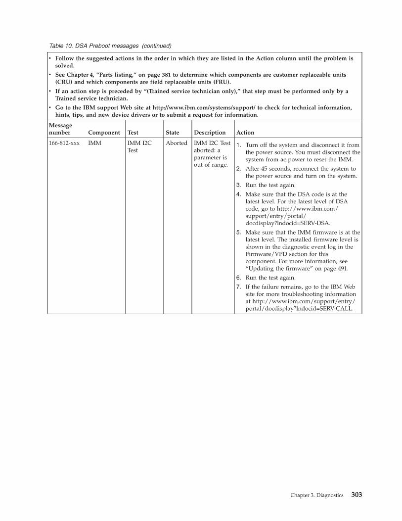
Table 10. DSA Preboot messages (continued)
v Follow the suggested actions in the order in which they are listed in the Action column until the problem issolved.
v See Chapter 4, “Parts listing,” on page 381 to determine which components are customer replaceable units(CRU) and which components are field replaceable units (FRU).
v If an action step is preceded by “(Trained service technician only),” that step must be performed only by aTrained service technician.
v Go to the IBM support Web site at http://www.ibm.com/systems/support/ to check for technical information,hints, tips, and new device drivers or to submit a request for information.
Messagenumber Component Test State Description Action
166-812-xxx IMM IMM I2CTest
Aborted IMM I2C Testaborted: aparameter isout of range.
1. Turn off the system and disconnect it fromthe power source. You must disconnect thesystem from ac power to reset the IMM.
2. After 45 seconds, reconnect the system tothe power source and turn on the system.
3. Run the test again.
4. Make sure that the DSA code is at thelatest level. For the latest level of DSAcode, go to http://www.ibm.com/support/entry/portal/docdisplay?lndocid=SERV-DSA.
5. Make sure that the IMM firmware is at thelatest level. The installed firmware level isshown in the diagnostic event log in theFirmware/VPD section for thiscomponent. For more information, see“Updating the firmware” on page 491.
6. Run the test again.
7. If the failure remains, go to the IBM Website for more troubleshooting informationat http://www.ibm.com/support/entry/portal/docdisplay?lndocid=SERV-CALL.
Chapter 3. Diagnostics 303
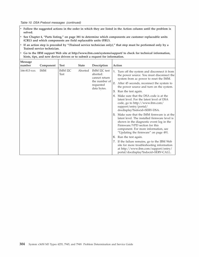
Table 10. DSA Preboot messages (continued)
v Follow the suggested actions in the order in which they are listed in the Action column until the problem issolved.
v See Chapter 4, “Parts listing,” on page 381 to determine which components are customer replaceable units(CRU) and which components are field replaceable units (FRU).
v If an action step is preceded by “(Trained service technician only),” that step must be performed only by aTrained service technician.
v Go to the IBM support Web site at http://www.ibm.com/systems/support/ to check for technical information,hints, tips, and new device drivers or to submit a request for information.
Messagenumber Component Test State Description Action
166-813-xxx IMM IMM I2CTest
Aborted IMM I2C testaborted:cannot returnthe number ofrequesteddata bytes.
1. Turn off the system and disconnect it fromthe power source. You must disconnect thesystem from ac power to reset the IMM.
2. After 45 seconds, reconnect the system tothe power source and turn on the system.
3. Run the test again.
4. Make sure that the DSA code is at thelatest level. For the latest level of DSAcode, go to http://www.ibm.com/support/entry/portal/docdisplay?lndocid=SERV-DSA.
5. Make sure that the IMM firmware is at thelatest level. The installed firmware level isshown in the diagnostic event log in theFirmware/VPD section for thiscomponent. For more information, see“Updating the firmware” on page 491.
6. Run the test again.
7. If the failure remains, go to the IBM Website for more troubleshooting informationat http://www.ibm.com/support/entry/portal/docdisplay?lndocid=SERV-CALL.
304 System x3650 M3 Types 4255, 7945, and 7949: Problem Determination and Service Guide

Table 10. DSA Preboot messages (continued)
v Follow the suggested actions in the order in which they are listed in the Action column until the problem issolved.
v See Chapter 4, “Parts listing,” on page 381 to determine which components are customer replaceable units(CRU) and which components are field replaceable units (FRU).
v If an action step is preceded by “(Trained service technician only),” that step must be performed only by aTrained service technician.
v Go to the IBM support Web site at http://www.ibm.com/systems/support/ to check for technical information,hints, tips, and new device drivers or to submit a request for information.
Messagenumber Component Test State Description Action
166-814-xxx IMM IMM I2CTest
Aborted IMM I2C testaborted:requestedsensor, data,or record isnot present.
1. Turn off the system and disconnect it fromthe power source. You must disconnect thesystem from ac power to reset the IMM.
2. After 45 seconds, reconnect the system tothe power source and turn on the system.
3. Run the test again.
4. Make sure that the DSA code is at thelatest level. For the latest level of DSAcode, go to http://www.ibm.com/support/entry/portal/docdisplay?lndocid=SERV-DSA.
5. Make sure that the IMM firmware is at thelatest level. The installed firmware level isshown in the diagnostic event log in theFirmware/VPD section for thiscomponent. For more information, see“Updating the firmware” on page 491.
6. Run the test again.
7. If the failure remains, go to the IBM Website for more troubleshooting informationat http://www.ibm.com/support/entry/portal/docdisplay?lndocid=SERV-CALL.
Chapter 3. Diagnostics 305

Table 10. DSA Preboot messages (continued)
v Follow the suggested actions in the order in which they are listed in the Action column until the problem issolved.
v See Chapter 4, “Parts listing,” on page 381 to determine which components are customer replaceable units(CRU) and which components are field replaceable units (FRU).
v If an action step is preceded by “(Trained service technician only),” that step must be performed only by aTrained service technician.
v Go to the IBM support Web site at http://www.ibm.com/systems/support/ to check for technical information,hints, tips, and new device drivers or to submit a request for information.
Messagenumber Component Test State Description Action
166-815-xxx IMM IMM I2CTest
Aborted IMM I2C testaborted:invalid datafield in therequest.
1. Turn off the system and disconnect it fromthe power source. You must disconnect thesystem from ac power to reset the IMM.
2. After 45 seconds, reconnect the system tothe power source and turn on the system.
3. Run the test again.
4. Make sure that the DSA code is at thelatest level. For the latest level of DSAcode, go to http://www.ibm.com/support/entry/portal/docdisplay?lndocid=SERV-DSA.
5. Make sure that the IMM firmware is at thelatest level. The installed firmware level isshown in the diagnostic event log in theFirmware/VPD section for thiscomponent. For more information, see“Updating the firmware” on page 491.
6. Run the test again.
7. If the failure remains, go to the IBM Website for more troubleshooting informationat http://www.ibm.com/support/entry/portal/docdisplay?lndocid=SERV-CALL.
306 System x3650 M3 Types 4255, 7945, and 7949: Problem Determination and Service Guide

Table 10. DSA Preboot messages (continued)
v Follow the suggested actions in the order in which they are listed in the Action column until the problem issolved.
v See Chapter 4, “Parts listing,” on page 381 to determine which components are customer replaceable units(CRU) and which components are field replaceable units (FRU).
v If an action step is preceded by “(Trained service technician only),” that step must be performed only by aTrained service technician.
v Go to the IBM support Web site at http://www.ibm.com/systems/support/ to check for technical information,hints, tips, and new device drivers or to submit a request for information.
Messagenumber Component Test State Description Action
166-816-xxx IMM IMM I2CTest
Aborted IMM I2C testaborted: thecommand isillegal for thespecifiedsensor orrecord type.
1. Turn off the system and disconnect it fromthe power source. You must disconnect thesystem from ac power to reset the IMM.
2. After 45 seconds, reconnect the system tothe power source and turn on the system.
3. Run the test again.
4. Make sure that the DSA code is at thelatest level. For the latest level of DSAcode, go to http://www.ibm.com/support/entry/portal/docdisplay?lndocid=SERV-DSA.
5. Make sure that the IMM firmware is at thelatest level. The installed firmware level isshown in the diagnostic event log in theFirmware/VPD section for thiscomponent. For more information, see“Updating the firmware” on page 491.
6. Run the test again.
7. If the failure remains, go to the IBM Website for more troubleshooting informationat http://www.ibm.com/support/entry/portal/docdisplay?lndocid=SERV-CALL.
Chapter 3. Diagnostics 307

Table 10. DSA Preboot messages (continued)
v Follow the suggested actions in the order in which they are listed in the Action column until the problem issolved.
v See Chapter 4, “Parts listing,” on page 381 to determine which components are customer replaceable units(CRU) and which components are field replaceable units (FRU).
v If an action step is preceded by “(Trained service technician only),” that step must be performed only by aTrained service technician.
v Go to the IBM support Web site at http://www.ibm.com/systems/support/ to check for technical information,hints, tips, and new device drivers or to submit a request for information.
Messagenumber Component Test State Description Action
166-817-xxx IMM IMM I2CTest
Aborted IMM I2C testaborted: acommandresponsecould not beprovided.
1. Turn off the system and disconnect it fromthe power source. You must disconnect thesystem from ac power to reset the IMM.
2. After 45 seconds, reconnect the system tothe power source and turn on the system.
3. Run the test again.
4. Make sure that the DSA code is at thelatest level. For the latest level of DSAcode, go to http://www.ibm.com/support/entry/portal/docdisplay?lndocid=SERV-DSA.
5. Make sure that the IMM firmware is at thelatest level. The installed firmware level isshown in the diagnostic event log in theFirmware/VPD section for thiscomponent. For more information, see“Updating the firmware” on page 491.
6. Run the test again.
7. If the failure remains, go to the IBM Website for more troubleshooting informationat http://www.ibm.com/support/entry/portal/docdisplay?lndocid=SERV-CALL.
308 System x3650 M3 Types 4255, 7945, and 7949: Problem Determination and Service Guide

Table 10. DSA Preboot messages (continued)
v Follow the suggested actions in the order in which they are listed in the Action column until the problem issolved.
v See Chapter 4, “Parts listing,” on page 381 to determine which components are customer replaceable units(CRU) and which components are field replaceable units (FRU).
v If an action step is preceded by “(Trained service technician only),” that step must be performed only by aTrained service technician.
v Go to the IBM support Web site at http://www.ibm.com/systems/support/ to check for technical information,hints, tips, and new device drivers or to submit a request for information.
Messagenumber Component Test State Description Action
166-818-xxx IMM IMM I2CTest
Aborted IMM I2C testaborted:cannotexecute aduplicatedrequest.
1. Turn off the system and disconnect it fromthe power source. You must disconnect thesystem from ac power to reset the IMM.
2. After 45 seconds, reconnect the system tothe power source and turn on the system.
3. Run the test again.
4. Make sure that the DSA code is at thelatest level. For the latest level of DSAcode, go to http://www.ibm.com/support/entry/portal/docdisplay?lndocid=SERV-DSA.
5. Make sure that the IMM firmware is at thelatest level. The installed firmware level isshown in the diagnostic event log in theFirmware/VPD section for thiscomponent. For more information, see“Updating the firmware” on page 491.
6. Run the test again.
7. If the failure remains, go to the IBM Website for more troubleshooting informationat http://www.ibm.com/support/entry/portal/docdisplay?lndocid=SERV-CALL.
Chapter 3. Diagnostics 309
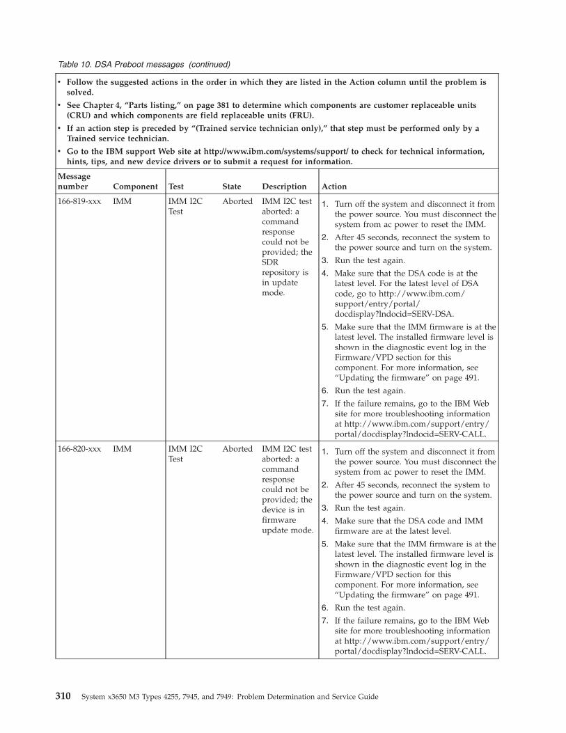
Table 10. DSA Preboot messages (continued)
v Follow the suggested actions in the order in which they are listed in the Action column until the problem issolved.
v See Chapter 4, “Parts listing,” on page 381 to determine which components are customer replaceable units(CRU) and which components are field replaceable units (FRU).
v If an action step is preceded by “(Trained service technician only),” that step must be performed only by aTrained service technician.
v Go to the IBM support Web site at http://www.ibm.com/systems/support/ to check for technical information,hints, tips, and new device drivers or to submit a request for information.
Messagenumber Component Test State Description Action
166-819-xxx IMM IMM I2CTest
Aborted IMM I2C testaborted: acommandresponsecould not beprovided; theSDRrepository isin updatemode.
1. Turn off the system and disconnect it fromthe power source. You must disconnect thesystem from ac power to reset the IMM.
2. After 45 seconds, reconnect the system tothe power source and turn on the system.
3. Run the test again.
4. Make sure that the DSA code is at thelatest level. For the latest level of DSAcode, go to http://www.ibm.com/support/entry/portal/docdisplay?lndocid=SERV-DSA.
5. Make sure that the IMM firmware is at thelatest level. The installed firmware level isshown in the diagnostic event log in theFirmware/VPD section for thiscomponent. For more information, see“Updating the firmware” on page 491.
6. Run the test again.
7. If the failure remains, go to the IBM Website for more troubleshooting informationat http://www.ibm.com/support/entry/portal/docdisplay?lndocid=SERV-CALL.
166-820-xxx IMM IMM I2CTest
Aborted IMM I2C testaborted: acommandresponsecould not beprovided; thedevice is infirmwareupdate mode.
1. Turn off the system and disconnect it fromthe power source. You must disconnect thesystem from ac power to reset the IMM.
2. After 45 seconds, reconnect the system tothe power source and turn on the system.
3. Run the test again.
4. Make sure that the DSA code and IMMfirmware are at the latest level.
5. Make sure that the IMM firmware is at thelatest level. The installed firmware level isshown in the diagnostic event log in theFirmware/VPD section for thiscomponent. For more information, see“Updating the firmware” on page 491.
6. Run the test again.
7. If the failure remains, go to the IBM Website for more troubleshooting informationat http://www.ibm.com/support/entry/portal/docdisplay?lndocid=SERV-CALL.
310 System x3650 M3 Types 4255, 7945, and 7949: Problem Determination and Service Guide

Table 10. DSA Preboot messages (continued)
v Follow the suggested actions in the order in which they are listed in the Action column until the problem issolved.
v See Chapter 4, “Parts listing,” on page 381 to determine which components are customer replaceable units(CRU) and which components are field replaceable units (FRU).
v If an action step is preceded by “(Trained service technician only),” that step must be performed only by aTrained service technician.
v Go to the IBM support Web site at http://www.ibm.com/systems/support/ to check for technical information,hints, tips, and new device drivers or to submit a request for information.
Messagenumber Component Test State Description Action
166-821-xxx IMM IMM I2CTest
Aborted IMM I2C testaborted: acommandresponsecould not beprovided;IMMinitializationis in progress.
1. Turn off the system and disconnect it fromthe power source. You must disconnect thesystem from ac power to reset the IMM.
2. After 45 seconds, reconnect the system tothe power source and turn on the system.
3. Run the test again.
4. Make sure that the DSA code is at thelatest level. For the latest level of DSAcode, go to http://www.ibm.com/support/entry/portal/docdisplay?lndocid=SERV-DSA.
5. Make sure that the IMM firmware is at thelatest level. The installed firmware level isshown in the diagnostic event log in theFirmware/VPD section for thiscomponent. For more information, see“Updating the firmware” on page 491.
6. Run the test again.
7. If the failure remains, go to the IBM Website for more troubleshooting informationat http://www.ibm.com/support/entry/portal/docdisplay?lndocid=SERV-CALL.
Chapter 3. Diagnostics 311

Table 10. DSA Preboot messages (continued)
v Follow the suggested actions in the order in which they are listed in the Action column until the problem issolved.
v See Chapter 4, “Parts listing,” on page 381 to determine which components are customer replaceable units(CRU) and which components are field replaceable units (FRU).
v If an action step is preceded by “(Trained service technician only),” that step must be performed only by aTrained service technician.
v Go to the IBM support Web site at http://www.ibm.com/systems/support/ to check for technical information,hints, tips, and new device drivers or to submit a request for information.
Messagenumber Component Test State Description Action
166-822-xxx IMM IMM I2CTest
Aborted IMM I2C testaborted: thedestination isunavailable.
1. Turn off the system and disconnect it fromthe power source. You must disconnect thesystem from ac power to reset the IMM.
2. After 45 seconds, reconnect the system tothe power source and turn on the system.
3. Run the test again.
4. Make sure that the DSA code is at thelatest level. For the latest level of DSAcode, go to http://www.ibm.com/support/entry/portal/docdisplay?lndocid=SERV-DSA.
5. Make sure that the IMM firmware is at thelatest level. The installed firmware level isshown in the diagnostic event log in theFirmware/VPD section for thiscomponent. For more information, see“Updating the firmware” on page 491.
6. Run the test again.
7. If the failure remains, go to the IBM Website for more troubleshooting informationat http://www.ibm.com/support/entry/portal/docdisplay?lndocid=SERV-CALL.
312 System x3650 M3 Types 4255, 7945, and 7949: Problem Determination and Service Guide

Table 10. DSA Preboot messages (continued)
v Follow the suggested actions in the order in which they are listed in the Action column until the problem issolved.
v See Chapter 4, “Parts listing,” on page 381 to determine which components are customer replaceable units(CRU) and which components are field replaceable units (FRU).
v If an action step is preceded by “(Trained service technician only),” that step must be performed only by aTrained service technician.
v Go to the IBM support Web site at http://www.ibm.com/systems/support/ to check for technical information,hints, tips, and new device drivers or to submit a request for information.
Messagenumber Component Test State Description Action
166-823-xxx IMM IMM I2CTest
Aborted IMM I2C testaborted:cannotexecute thecommand;insufficientprivilegelevel.
1. Turn off the system and disconnect it fromthe power source. You must disconnect thesystem from ac power to reset the IMM.
2. After 45 seconds, reconnect the system tothe power source and turn on the system.
3. Run the test again.
4. Make sure that the DSA code is at thelatest level. For the latest level of DSAcode, go to http://www.ibm.com/support/entry/portal/docdisplay?lndocid=SERV-DSA.
5. Make sure that the IMM firmware is at thelatest level. The installed firmware level isshown in the diagnostic event log in theFirmware/VPD section for thiscomponent. For more information, see“Updating the firmware” on page 491.
6. Run the test again.
7. If the failure remains, go to the IBM Website for more troubleshooting informationat http://www.ibm.com/support/entry/portal/docdisplay?lndocid=SERV-CALL.
Chapter 3. Diagnostics 313
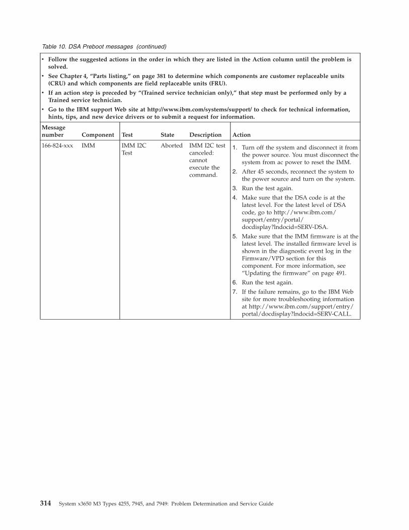
Table 10. DSA Preboot messages (continued)
v Follow the suggested actions in the order in which they are listed in the Action column until the problem issolved.
v See Chapter 4, “Parts listing,” on page 381 to determine which components are customer replaceable units(CRU) and which components are field replaceable units (FRU).
v If an action step is preceded by “(Trained service technician only),” that step must be performed only by aTrained service technician.
v Go to the IBM support Web site at http://www.ibm.com/systems/support/ to check for technical information,hints, tips, and new device drivers or to submit a request for information.
Messagenumber Component Test State Description Action
166-824-xxx IMM IMM I2CTest
Aborted IMM I2C testcanceled:cannotexecute thecommand.
1. Turn off the system and disconnect it fromthe power source. You must disconnect thesystem from ac power to reset the IMM.
2. After 45 seconds, reconnect the system tothe power source and turn on the system.
3. Run the test again.
4. Make sure that the DSA code is at thelatest level. For the latest level of DSAcode, go to http://www.ibm.com/support/entry/portal/docdisplay?lndocid=SERV-DSA.
5. Make sure that the IMM firmware is at thelatest level. The installed firmware level isshown in the diagnostic event log in theFirmware/VPD section for thiscomponent. For more information, see“Updating the firmware” on page 491.
6. Run the test again.
7. If the failure remains, go to the IBM Website for more troubleshooting informationat http://www.ibm.com/support/entry/portal/docdisplay?lndocid=SERV-CALL.
314 System x3650 M3 Types 4255, 7945, and 7949: Problem Determination and Service Guide
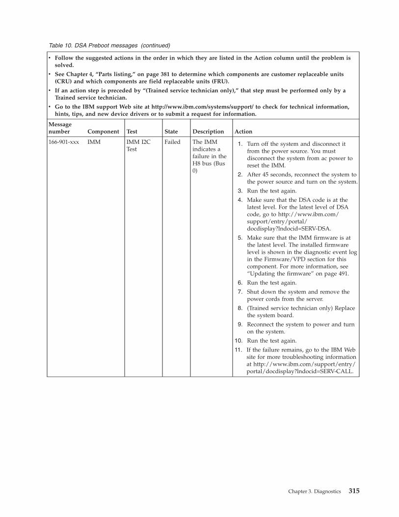
Table 10. DSA Preboot messages (continued)
v Follow the suggested actions in the order in which they are listed in the Action column until the problem issolved.
v See Chapter 4, “Parts listing,” on page 381 to determine which components are customer replaceable units(CRU) and which components are field replaceable units (FRU).
v If an action step is preceded by “(Trained service technician only),” that step must be performed only by aTrained service technician.
v Go to the IBM support Web site at http://www.ibm.com/systems/support/ to check for technical information,hints, tips, and new device drivers or to submit a request for information.
Messagenumber Component Test State Description Action
166-901-xxx IMM IMM I2CTest
Failed The IMMindicates afailure in theH8 bus (Bus0)
1. Turn off the system and disconnect itfrom the power source. You mustdisconnect the system from ac power toreset the IMM.
2. After 45 seconds, reconnect the system tothe power source and turn on the system.
3. Run the test again.
4. Make sure that the DSA code is at thelatest level. For the latest level of DSAcode, go to http://www.ibm.com/support/entry/portal/docdisplay?lndocid=SERV-DSA.
5. Make sure that the IMM firmware is atthe latest level. The installed firmwarelevel is shown in the diagnostic event login the Firmware/VPD section for thiscomponent. For more information, see“Updating the firmware” on page 491.
6. Run the test again.
7. Shut down the system and remove thepower cords from the server.
8. (Trained service technician only) Replacethe system board.
9. Reconnect the system to power and turnon the system.
10. Run the test again.
11. If the failure remains, go to the IBM Website for more troubleshooting informationat http://www.ibm.com/support/entry/portal/docdisplay?lndocid=SERV-CALL.
Chapter 3. Diagnostics 315
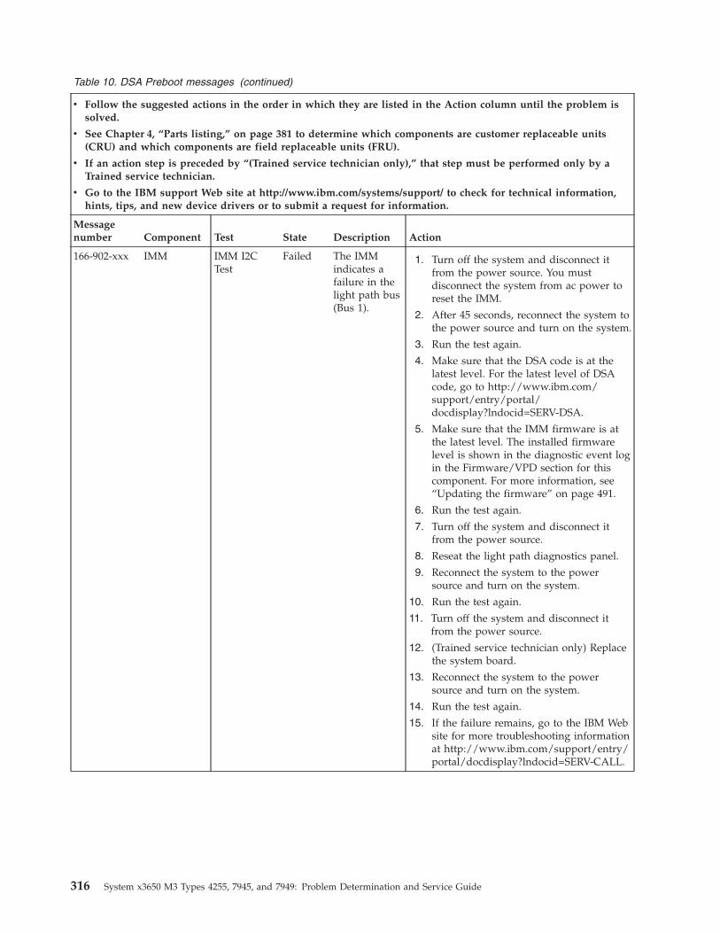
Table 10. DSA Preboot messages (continued)
v Follow the suggested actions in the order in which they are listed in the Action column until the problem issolved.
v See Chapter 4, “Parts listing,” on page 381 to determine which components are customer replaceable units(CRU) and which components are field replaceable units (FRU).
v If an action step is preceded by “(Trained service technician only),” that step must be performed only by aTrained service technician.
v Go to the IBM support Web site at http://www.ibm.com/systems/support/ to check for technical information,hints, tips, and new device drivers or to submit a request for information.
Messagenumber Component Test State Description Action
166-902-xxx IMM IMM I2CTest
Failed The IMMindicates afailure in thelight path bus(Bus 1).
1. Turn off the system and disconnect itfrom the power source. You mustdisconnect the system from ac power toreset the IMM.
2. After 45 seconds, reconnect the system tothe power source and turn on the system.
3. Run the test again.
4. Make sure that the DSA code is at thelatest level. For the latest level of DSAcode, go to http://www.ibm.com/support/entry/portal/docdisplay?lndocid=SERV-DSA.
5. Make sure that the IMM firmware is atthe latest level. The installed firmwarelevel is shown in the diagnostic event login the Firmware/VPD section for thiscomponent. For more information, see“Updating the firmware” on page 491.
6. Run the test again.
7. Turn off the system and disconnect itfrom the power source.
8. Reseat the light path diagnostics panel.
9. Reconnect the system to the powersource and turn on the system.
10. Run the test again.
11. Turn off the system and disconnect itfrom the power source.
12. (Trained service technician only) Replacethe system board.
13. Reconnect the system to the powersource and turn on the system.
14. Run the test again.
15. If the failure remains, go to the IBM Website for more troubleshooting informationat http://www.ibm.com/support/entry/portal/docdisplay?lndocid=SERV-CALL.
316 System x3650 M3 Types 4255, 7945, and 7949: Problem Determination and Service Guide
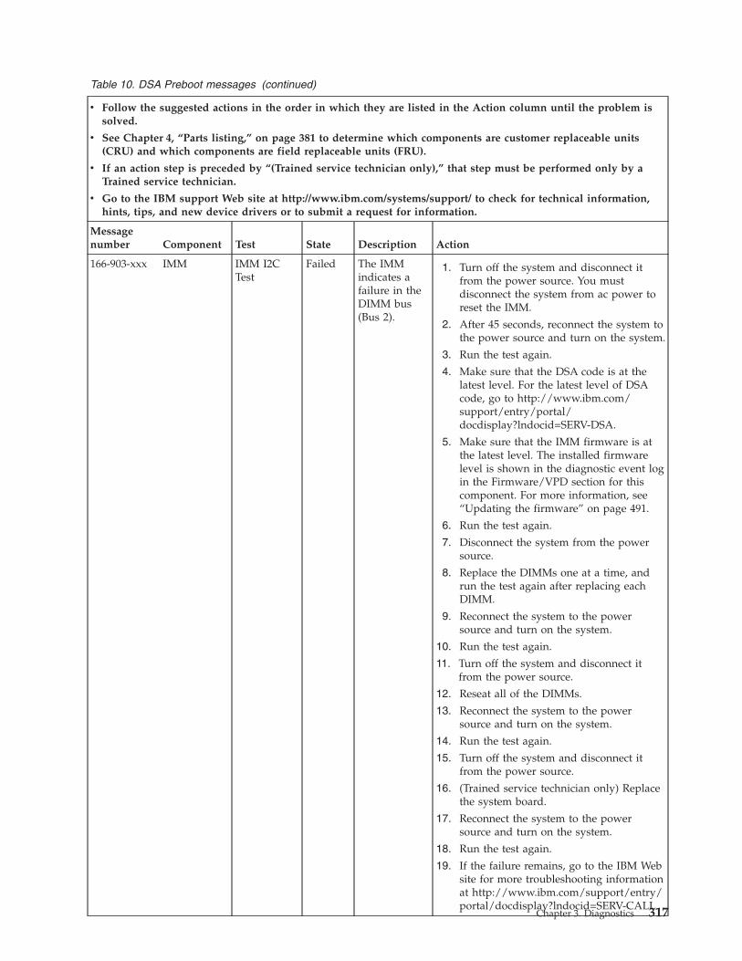
Table 10. DSA Preboot messages (continued)
v Follow the suggested actions in the order in which they are listed in the Action column until the problem issolved.
v See Chapter 4, “Parts listing,” on page 381 to determine which components are customer replaceable units(CRU) and which components are field replaceable units (FRU).
v If an action step is preceded by “(Trained service technician only),” that step must be performed only by aTrained service technician.
v Go to the IBM support Web site at http://www.ibm.com/systems/support/ to check for technical information,hints, tips, and new device drivers or to submit a request for information.
Messagenumber Component Test State Description Action
166-903-xxx IMM IMM I2CTest
Failed The IMMindicates afailure in theDIMM bus(Bus 2).
1. Turn off the system and disconnect itfrom the power source. You mustdisconnect the system from ac power toreset the IMM.
2. After 45 seconds, reconnect the system tothe power source and turn on the system.
3. Run the test again.
4. Make sure that the DSA code is at thelatest level. For the latest level of DSAcode, go to http://www.ibm.com/support/entry/portal/docdisplay?lndocid=SERV-DSA.
5. Make sure that the IMM firmware is atthe latest level. The installed firmwarelevel is shown in the diagnostic event login the Firmware/VPD section for thiscomponent. For more information, see“Updating the firmware” on page 491.
6. Run the test again.
7. Disconnect the system from the powersource.
8. Replace the DIMMs one at a time, andrun the test again after replacing eachDIMM.
9. Reconnect the system to the powersource and turn on the system.
10. Run the test again.
11. Turn off the system and disconnect itfrom the power source.
12. Reseat all of the DIMMs.
13. Reconnect the system to the powersource and turn on the system.
14. Run the test again.
15. Turn off the system and disconnect itfrom the power source.
16. (Trained service technician only) Replacethe system board.
17. Reconnect the system to the powersource and turn on the system.
18. Run the test again.
19. If the failure remains, go to the IBM Website for more troubleshooting informationat http://www.ibm.com/support/entry/portal/docdisplay?lndocid=SERV-CALL.
Chapter 3. Diagnostics 317
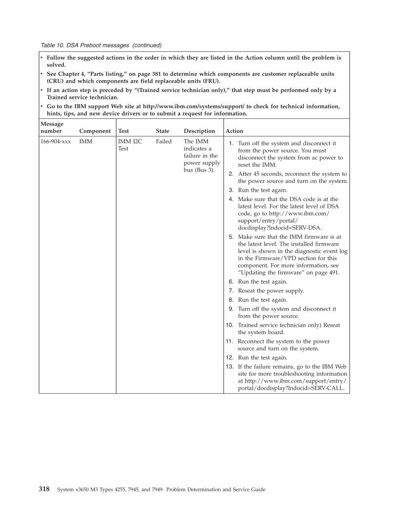
Table 10. DSA Preboot messages (continued)
v Follow the suggested actions in the order in which they are listed in the Action column until the problem issolved.
v See Chapter 4, “Parts listing,” on page 381 to determine which components are customer replaceable units(CRU) and which components are field replaceable units (FRU).
v If an action step is preceded by “(Trained service technician only),” that step must be performed only by aTrained service technician.
v Go to the IBM support Web site at http://www.ibm.com/systems/support/ to check for technical information,hints, tips, and new device drivers or to submit a request for information.
Messagenumber Component Test State Description Action
166-904-xxx IMM IMM I2CTest
Failed The IMMindicates afailure in thepower supplybus (Bus 3).
1. Turn off the system and disconnect itfrom the power source. You mustdisconnect the system from ac power toreset the IMM.
2. After 45 seconds, reconnect the system tothe power source and turn on the system.
3. Run the test again.
4. Make sure that the DSA code is at thelatest level. For the latest level of DSAcode, go to http://www.ibm.com/support/entry/portal/docdisplay?lndocid=SERV-DSA.
5. Make sure that the IMM firmware is atthe latest level. The installed firmwarelevel is shown in the diagnostic event login the Firmware/VPD section for thiscomponent. For more information, see“Updating the firmware” on page 491.
6. Run the test again.
7. Reseat the power supply.
8. Run the test again.
9. Turn off the system and disconnect itfrom the power source.
10. Trained service technician only) Reseatthe system board.
11. Reconnect the system to the powersource and turn on the system.
12. Run the test again.
13. If the failure remains, go to the IBM Website for more troubleshooting informationat http://www.ibm.com/support/entry/portal/docdisplay?lndocid=SERV-CALL.
318 System x3650 M3 Types 4255, 7945, and 7949: Problem Determination and Service Guide
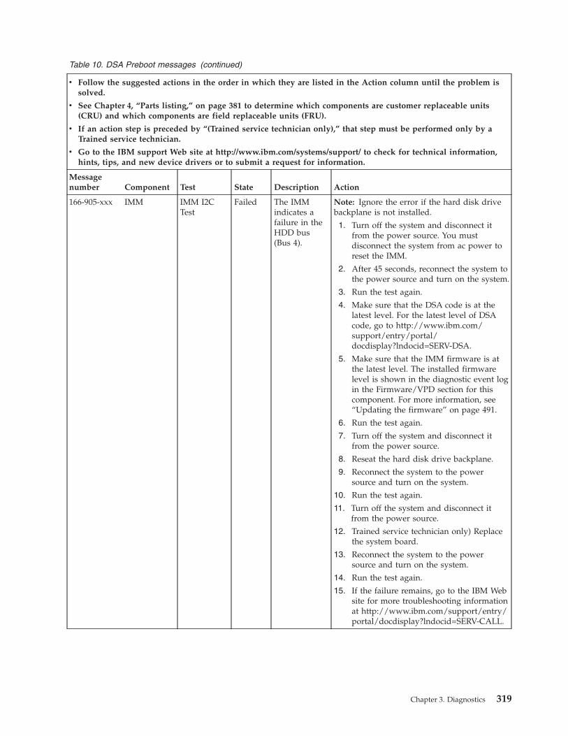
Table 10. DSA Preboot messages (continued)
v Follow the suggested actions in the order in which they are listed in the Action column until the problem issolved.
v See Chapter 4, “Parts listing,” on page 381 to determine which components are customer replaceable units(CRU) and which components are field replaceable units (FRU).
v If an action step is preceded by “(Trained service technician only),” that step must be performed only by aTrained service technician.
v Go to the IBM support Web site at http://www.ibm.com/systems/support/ to check for technical information,hints, tips, and new device drivers or to submit a request for information.
Messagenumber Component Test State Description Action
166-905-xxx IMM IMM I2CTest
Failed The IMMindicates afailure in theHDD bus(Bus 4).
Note: Ignore the error if the hard disk drivebackplane is not installed.
1. Turn off the system and disconnect itfrom the power source. You mustdisconnect the system from ac power toreset the IMM.
2. After 45 seconds, reconnect the system tothe power source and turn on the system.
3. Run the test again.
4. Make sure that the DSA code is at thelatest level. For the latest level of DSAcode, go to http://www.ibm.com/support/entry/portal/docdisplay?lndocid=SERV-DSA.
5. Make sure that the IMM firmware is atthe latest level. The installed firmwarelevel is shown in the diagnostic event login the Firmware/VPD section for thiscomponent. For more information, see“Updating the firmware” on page 491.
6. Run the test again.
7. Turn off the system and disconnect itfrom the power source.
8. Reseat the hard disk drive backplane.
9. Reconnect the system to the powersource and turn on the system.
10. Run the test again.
11. Turn off the system and disconnect itfrom the power source.
12. Trained service technician only) Replacethe system board.
13. Reconnect the system to the powersource and turn on the system.
14. Run the test again.
15. If the failure remains, go to the IBM Website for more troubleshooting informationat http://www.ibm.com/support/entry/portal/docdisplay?lndocid=SERV-CALL.
Chapter 3. Diagnostics 319
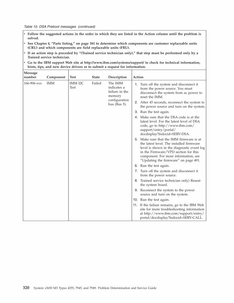
Table 10. DSA Preboot messages (continued)
v Follow the suggested actions in the order in which they are listed in the Action column until the problem issolved.
v See Chapter 4, “Parts listing,” on page 381 to determine which components are customer replaceable units(CRU) and which components are field replaceable units (FRU).
v If an action step is preceded by “(Trained service technician only),” that step must be performed only by aTrained service technician.
v Go to the IBM support Web site at http://www.ibm.com/systems/support/ to check for technical information,hints, tips, and new device drivers or to submit a request for information.
Messagenumber Component Test State Description Action
166-906-xxx IMM IMM I2CTest
Failed The IMMindicates afailure in thememoryconfigurationbus (Bus 5).
1. Turn off the system and disconnect itfrom the power source. You mustdisconnect the system from ac power toreset the IMM.
2. After 45 seconds, reconnect the system tothe power source and turn on the system.
3. Run the test again.
4. Make sure that the DSA code is at thelatest level. For the latest level of DSAcode, go to http://www.ibm.com/support/entry/portal/docdisplay?lndocid=SERV-DSA.
5. Make sure that the IMM firmware is atthe latest level. The installed firmwarelevel is shown in the diagnostic event login the Firmware/VPD section for thiscomponent. For more information, see“Updating the firmware” on page 491.
6. Run the test again.
7. Turn off the system and disconnect itfrom the power source.
8. Trained service technician only) Reseatthe system board.
9. Reconnect the system to the powersource and turn on the system.
10. Run the test again.
11. If the failure remains, go to the IBM Website for more troubleshooting informationat http://www.ibm.com/support/entry/portal/docdisplay?lndocid=SERV-CALL.
320 System x3650 M3 Types 4255, 7945, and 7949: Problem Determination and Service Guide
Table 10. DSA Preboot messages (continued)
v Follow the suggested actions in the order in which they are listed in the Action column until the problem issolved.
v See Chapter 4, “Parts listing,” on page 381 to determine which components are customer replaceable units(CRU) and which components are field replaceable units (FRU).
v If an action step is preceded by “(Trained service technician only),” that step must be performed only by aTrained service technician.
v Go to the IBM support Web site at http://www.ibm.com/systems/support/ to check for technical information,hints, tips, and new device drivers or to submit a request for information.
Messagenumber Component Test State Description Action
201-801-xxx Memory MemoryTest
Aborted Test canceled:the serverfirmwareprogrammedthe memorycontrollerwith aninvalid CBARaddress
1. Turn off and restart the system.
2. Run the test again.
3. Make sure that the server firmware is atthe latest level. The installed firmwarelevel is shown in the diagnostic event login the Firmware/VPD section for thiscomponent. For more information, see“Updating the firmware” on page 491.
4. Run the test again.
5. If the failure remains, go to the IBM Website for more troubleshooting informationat http://www.ibm.com/support/entry/portal/docdisplay?lndocid=SERV-CALL.
201-802-xxx Memory MemoryTest
Aborted Test canceled:the endaddress in theE820 functionis less than 16MB.
1. Turn off and restart the system.
2. Run the test again.
3. Make sure that all DIMMs are enabled inthe Setup utility.
4. Make sure that the server firmware is atthe latest level. The installed firmwarelevel is shown in the diagnostic event login the Firmware/VPD section for thiscomponent. For more information, see“Updating the firmware” on page 491.
5. Run the test again.
6. If the failure remains, go to the IBM Website for more troubleshooting informationat http://www.ibm.com/support/entry/portal/docdisplay?lndocid=SERV-CALL.
201-803-xxx Memory MemoryTest
Aborted Test canceled:could notenable theprocessorcache.
1. Turn off and restart the system.
2. Run the test again.
3. Make sure that the server firmware is atthe latest level. The installed firmwarelevel is shown in the diagnostic event login the Firmware/VPD section for thiscomponent. For more information, see“Updating the firmware” on page 491.
4. Run the test again.
5. If the failure remains, go to the IBM Website for more troubleshooting informationat http://www.ibm.com/support/entry/portal/docdisplay?lndocid=SERV-CALL.
Chapter 3. Diagnostics 321
Table 10. DSA Preboot messages (continued)
v Follow the suggested actions in the order in which they are listed in the Action column until the problem issolved.
v See Chapter 4, “Parts listing,” on page 381 to determine which components are customer replaceable units(CRU) and which components are field replaceable units (FRU).
v If an action step is preceded by “(Trained service technician only),” that step must be performed only by aTrained service technician.
v Go to the IBM support Web site at http://www.ibm.com/systems/support/ to check for technical information,hints, tips, and new device drivers or to submit a request for information.
Messagenumber Component Test State Description Action
201-804-xxx Memory MemoryTest
Aborted Test canceled:the memorycontrollerbuffer requestfailed.
1. Turn off and restart the system.
2. Run the test again.
3. Make sure that the server firmware is atthe latest level. The installed firmwarelevel is shown in the diagnostic event login the Firmware/VPD section for thiscomponent. For more information, see“Updating the firmware” on page 491.
4. Run the test again.
5. If the failure remains, go to the IBM Website for more troubleshooting informationat http://www.ibm.com/support/entry/portal/docdisplay?lndocid=SERV-CALL.
201-805-xxx Memory MemoryTest
Aborted Test canceled:the memorycontrollerdisplay/alterwriteoperation wasnotcompleted.
1. Turn off and restart the system.
2. Run the test again.
3. Make sure that the server firmware is atthe latest level. The installed firmwarelevel is shown in the diagnostic event login the Firmware/VPD section for thiscomponent. For more information, see“Updating the firmware” on page 491.
4. Run the test again.
5. If the failure remains, go to the IBM Website for more troubleshooting informationat http://www.ibm.com/support/entry/portal/docdisplay?lndocid=SERV-CALL.
201-806-xxx Memory MemoryTest
Aborted Test canceled:the memorycontroller fastscruboperation wasnotcompleted.
1. Turn off and restart the system.
2. Run the test again.
3. Make sure that the server firmware is atthe latest level. The installed firmwarelevel is shown in the diagnostic event login the Firmware/VPD section for thiscomponent. For more information, see“Updating the firmware” on page 491.
4. Run the test again.
5. If the failure remains, go to the IBM Website for more troubleshooting informationat http://www.ibm.com/support/entry/portal/docdisplay?lndocid=SERV-CALL.
322 System x3650 M3 Types 4255, 7945, and 7949: Problem Determination and Service Guide
Table 10. DSA Preboot messages (continued)
v Follow the suggested actions in the order in which they are listed in the Action column until the problem issolved.
v See Chapter 4, “Parts listing,” on page 381 to determine which components are customer replaceable units(CRU) and which components are field replaceable units (FRU).
v If an action step is preceded by “(Trained service technician only),” that step must be performed only by aTrained service technician.
v Go to the IBM support Web site at http://www.ibm.com/systems/support/ to check for technical information,hints, tips, and new device drivers or to submit a request for information.
Messagenumber Component Test State Description Action
201-807-xxx Memory MemoryTest
Aborted Test canceled:the memorycontrollerbuffer freerequest failed.
1. Turn off and restart the system.
2. Run the test again.
3. Make sure that the server firmware is atthe latest level. The installed firmwarelevel is shown in the diagnostic event login the Firmware/VPD section for thiscomponent. For more information, see“Updating the firmware” on page 491.
4. Run the test again.
5. If the failure remains, go to the IBM Website for more troubleshooting informationat http://www.ibm.com/support/entry/portal/docdisplay?lndocid=SERV-CALL.
201-808-xxx Memory MemoryTest
Aborted Test canceled:memorycontrollerdisplay/alterbuffer executeerror.
1. Turn off and restart the system.
2. Run the test again.
3. Make sure that the server firmware is atthe latest level. The installed firmwarelevel is shown in the diagnostic event login the Firmware/VPD section for thiscomponent. For more information, see“Updating the firmware” on page 491.
4. Run the test again.
5. If the failure remains, go to the IBM Website for more troubleshooting informationat http://www.ibm.com/support/entry/portal/docdisplay?lndocid=SERV-CALL.
Chapter 3. Diagnostics 323
Table 10. DSA Preboot messages (continued)
v Follow the suggested actions in the order in which they are listed in the Action column until the problem issolved.
v See Chapter 4, “Parts listing,” on page 381 to determine which components are customer replaceable units(CRU) and which components are field replaceable units (FRU).
v If an action step is preceded by “(Trained service technician only),” that step must be performed only by aTrained service technician.
v Go to the IBM support Web site at http://www.ibm.com/systems/support/ to check for technical information,hints, tips, and new device drivers or to submit a request for information.
Messagenumber Component Test State Description Action
201-809-xxx Memory MemoryTest
Aborted Test canceledprogramerror:operationrunning fastscrub.
1. Turn off and restart the system.
2. Run the test again.
3. Make sure that the DSA code is at thelatest level. For the latest level of DSAcode, go to http://www.ibm.com/support/entry/portal/docdisplay?lndocid=SERV-DSA.
4. Make sure that the server firmware is atthe latest level. The installed firmwarelevel is shown in the diagnostic event login the Firmware/VPD section for thiscomponent. For more information, see“Updating the firmware” on page 491.
5. Run the test again.
6. If the failure remains, go to the IBM Website for more troubleshooting informationat http://www.ibm.com/support/entry/portal/docdisplay?lndocid=SERV-CALL.
201-810-xxx Memory MemoryTest
Aborted Test stopped:unknownerror code xxxreceived inCOMMONEXITprocedure.
1. Turn off and restart the system.
2. Run the test again.
3. Make sure that the DSA code is at thelatest level. For the latest level of DSAcode, go to http://www.ibm.com/support/entry/portal/docdisplay?lndocid=SERV-DSA.
4. Make sure that the server firmware is atthe latest level. The installed firmwarelevel is shown in the diagnostic event login the Firmware/VPD section for thiscomponent. For more information, see“Updating the firmware” on page 491.
5. Run the test again.
6. If the failure remains, go to the IBM Website for more troubleshooting informationat http://www.ibm.com/support/entry/portal/docdisplay?lndocid=SERV-CALL.
324 System x3650 M3 Types 4255, 7945, and 7949: Problem Determination and Service Guide
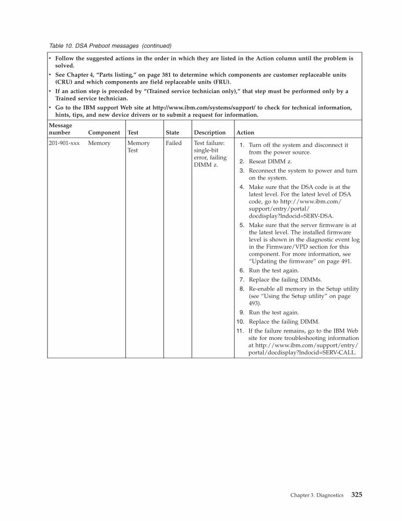
Table 10. DSA Preboot messages (continued)
v Follow the suggested actions in the order in which they are listed in the Action column until the problem issolved.
v See Chapter 4, “Parts listing,” on page 381 to determine which components are customer replaceable units(CRU) and which components are field replaceable units (FRU).
v If an action step is preceded by “(Trained service technician only),” that step must be performed only by aTrained service technician.
v Go to the IBM support Web site at http://www.ibm.com/systems/support/ to check for technical information,hints, tips, and new device drivers or to submit a request for information.
Messagenumber Component Test State Description Action
201-901-xxx Memory MemoryTest
Failed Test failure:single-biterror, failingDIMM z.
1. Turn off the system and disconnect itfrom the power source.
2. Reseat DIMM z.
3. Reconnect the system to power and turnon the system.
4. Make sure that the DSA code is at thelatest level. For the latest level of DSAcode, go to http://www.ibm.com/support/entry/portal/docdisplay?lndocid=SERV-DSA.
5. Make sure that the server firmware is atthe latest level. The installed firmwarelevel is shown in the diagnostic event login the Firmware/VPD section for thiscomponent. For more information, see“Updating the firmware” on page 491.
6. Run the test again.
7. Replace the failing DIMMs.
8. Re-enable all memory in the Setup utility(see “Using the Setup utility” on page493).
9. Run the test again.
10. Replace the failing DIMM.
11. If the failure remains, go to the IBM Website for more troubleshooting informationat http://www.ibm.com/support/entry/portal/docdisplay?lndocid=SERV-CALL.
Chapter 3. Diagnostics 325
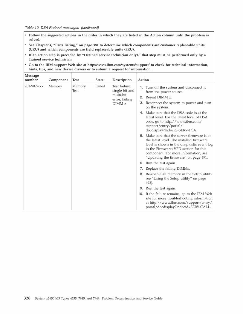
Table 10. DSA Preboot messages (continued)
v Follow the suggested actions in the order in which they are listed in the Action column until the problem issolved.
v See Chapter 4, “Parts listing,” on page 381 to determine which components are customer replaceable units(CRU) and which components are field replaceable units (FRU).
v If an action step is preceded by “(Trained service technician only),” that step must be performed only by aTrained service technician.
v Go to the IBM support Web site at http://www.ibm.com/systems/support/ to check for technical information,hints, tips, and new device drivers or to submit a request for information.
Messagenumber Component Test State Description Action
201-902-xxx Memory MemoryTest
Failed Test failure:single-bit andmulti-biterror, failingDIMM z
1. Turn off the system and disconnect itfrom the power source.
2. Reseat DIMM z.
3. Reconnect the system to power and turnon the system.
4. Make sure that the DSA code is at thelatest level. For the latest level of DSAcode, go to http://www.ibm.com/support/entry/portal/docdisplay?lndocid=SERV-DSA.
5. Make sure that the server firmware is atthe latest level. The installed firmwarelevel is shown in the diagnostic event login the Firmware/VPD section for thiscomponent. For more information, see“Updating the firmware” on page 491.
6. Run the test again.
7. Replace the failing DIMMs.
8. Re-enable all memory in the Setup utilitysee “Using the Setup utility” on page493).
9. Run the test again.
10. If the failure remains, go to the IBM Website for more troubleshooting informationat http://www.ibm.com/support/entry/portal/docdisplay?lndocid=SERV-CALL.
326 System x3650 M3 Types 4255, 7945, and 7949: Problem Determination and Service Guide
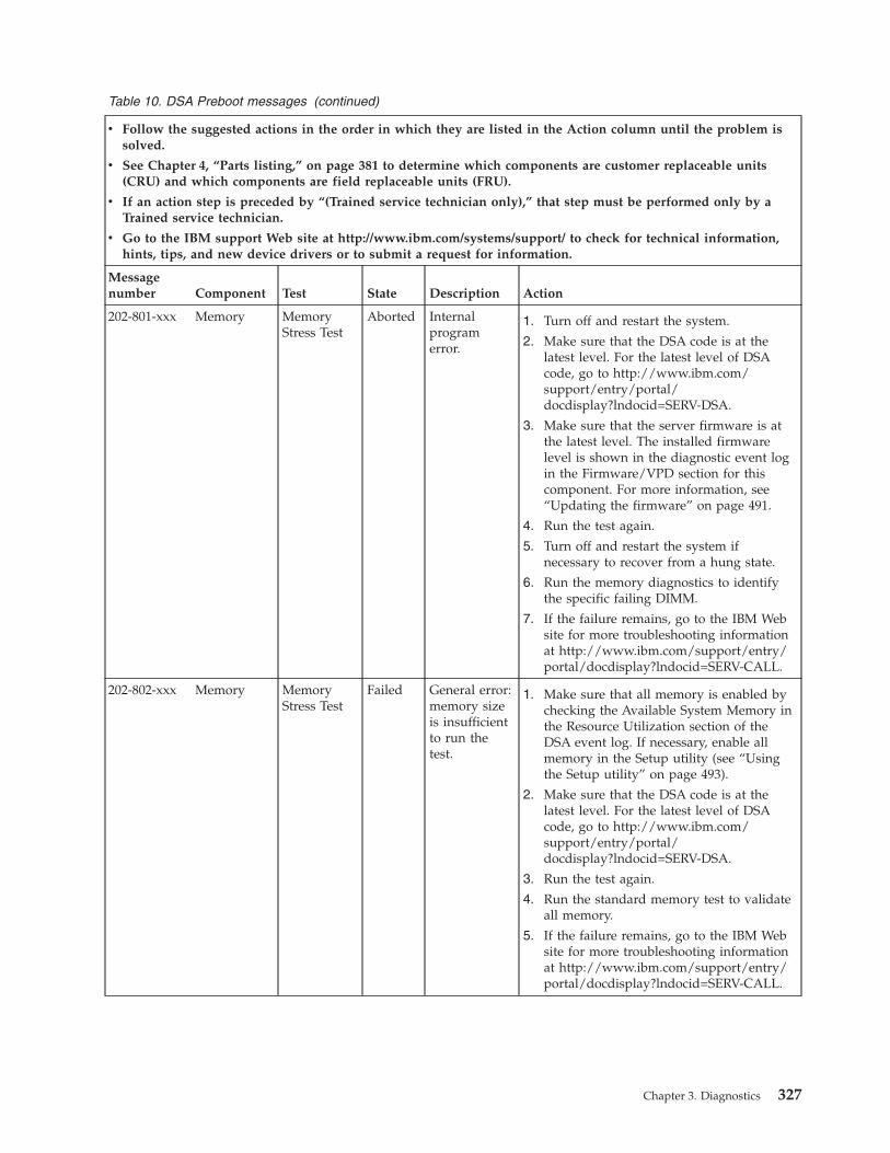
Table 10. DSA Preboot messages (continued)
v Follow the suggested actions in the order in which they are listed in the Action column until the problem issolved.
v See Chapter 4, “Parts listing,” on page 381 to determine which components are customer replaceable units(CRU) and which components are field replaceable units (FRU).
v If an action step is preceded by “(Trained service technician only),” that step must be performed only by aTrained service technician.
v Go to the IBM support Web site at http://www.ibm.com/systems/support/ to check for technical information,hints, tips, and new device drivers or to submit a request for information.
Messagenumber Component Test State Description Action
202-801-xxx Memory MemoryStress Test
Aborted Internalprogramerror.
1. Turn off and restart the system.
2. Make sure that the DSA code is at thelatest level. For the latest level of DSAcode, go to http://www.ibm.com/support/entry/portal/docdisplay?lndocid=SERV-DSA.
3. Make sure that the server firmware is atthe latest level. The installed firmwarelevel is shown in the diagnostic event login the Firmware/VPD section for thiscomponent. For more information, see“Updating the firmware” on page 491.
4. Run the test again.
5. Turn off and restart the system ifnecessary to recover from a hung state.
6. Run the memory diagnostics to identifythe specific failing DIMM.
7. If the failure remains, go to the IBM Website for more troubleshooting informationat http://www.ibm.com/support/entry/portal/docdisplay?lndocid=SERV-CALL.
202-802-xxx Memory MemoryStress Test
Failed General error:memory sizeis insufficientto run thetest.
1. Make sure that all memory is enabled bychecking the Available System Memory inthe Resource Utilization section of theDSA event log. If necessary, enable allmemory in the Setup utility (see “Usingthe Setup utility” on page 493).
2. Make sure that the DSA code is at thelatest level. For the latest level of DSAcode, go to http://www.ibm.com/support/entry/portal/docdisplay?lndocid=SERV-DSA.
3. Run the test again.
4. Run the standard memory test to validateall memory.
5. If the failure remains, go to the IBM Website for more troubleshooting informationat http://www.ibm.com/support/entry/portal/docdisplay?lndocid=SERV-CALL.
Chapter 3. Diagnostics 327
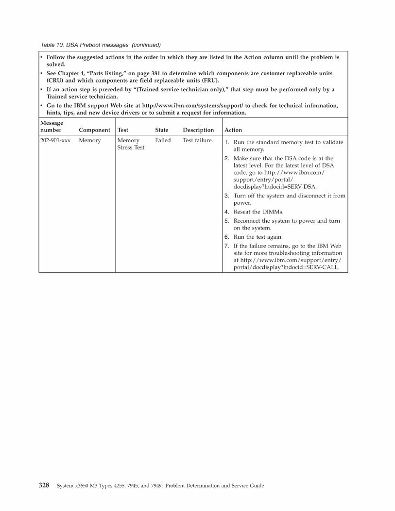
Table 10. DSA Preboot messages (continued)
v Follow the suggested actions in the order in which they are listed in the Action column until the problem issolved.
v See Chapter 4, “Parts listing,” on page 381 to determine which components are customer replaceable units(CRU) and which components are field replaceable units (FRU).
v If an action step is preceded by “(Trained service technician only),” that step must be performed only by aTrained service technician.
v Go to the IBM support Web site at http://www.ibm.com/systems/support/ to check for technical information,hints, tips, and new device drivers or to submit a request for information.
Messagenumber Component Test State Description Action
202-901-xxx Memory MemoryStress Test
Failed Test failure. 1. Run the standard memory test to validateall memory.
2. Make sure that the DSA code is at thelatest level. For the latest level of DSAcode, go to http://www.ibm.com/support/entry/portal/docdisplay?lndocid=SERV-DSA.
3. Turn off the system and disconnect it frompower.
4. Reseat the DIMMs.
5. Reconnect the system to power and turnon the system.
6. Run the test again.
7. If the failure remains, go to the IBM Website for more troubleshooting informationat http://www.ibm.com/support/entry/portal/docdisplay?lndocid=SERV-CALL.
328 System x3650 M3 Types 4255, 7945, and 7949: Problem Determination and Service Guide
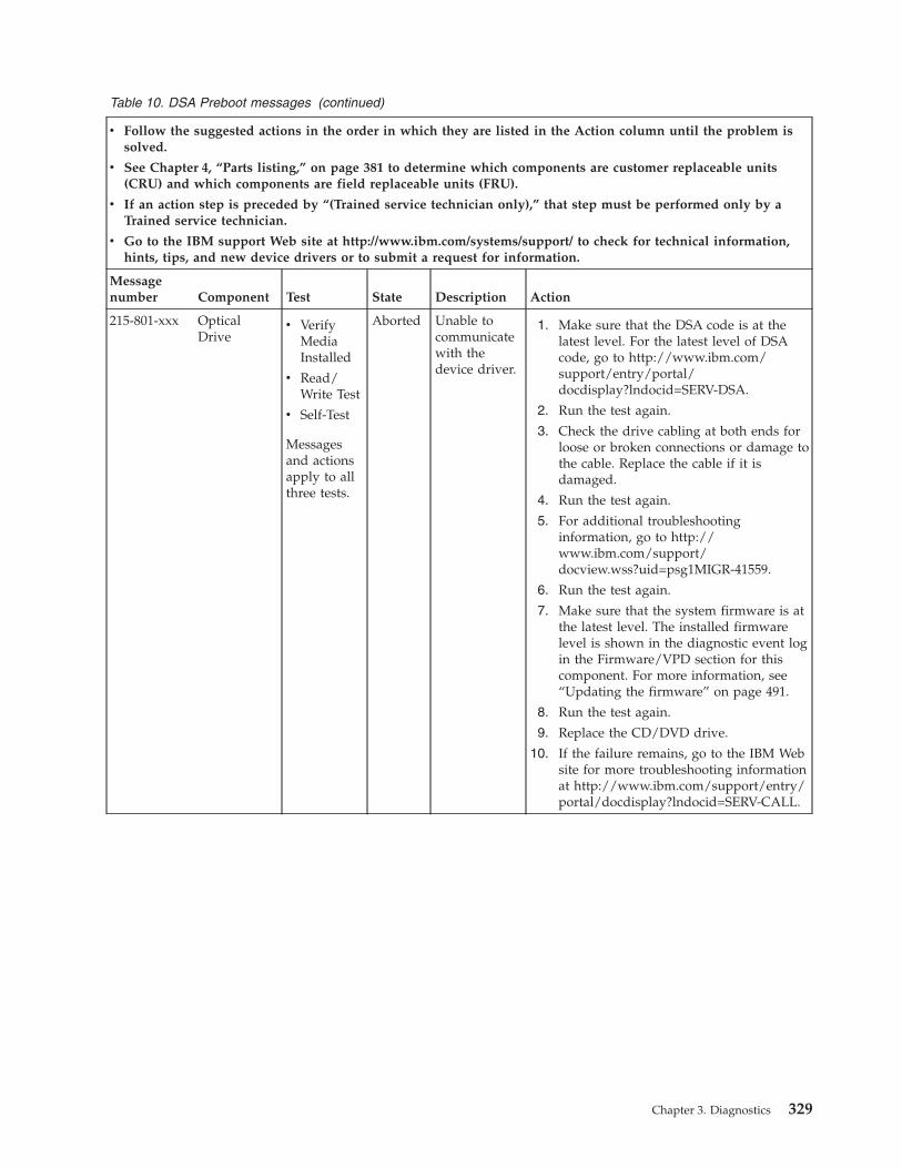
Table 10. DSA Preboot messages (continued)
v Follow the suggested actions in the order in which they are listed in the Action column until the problem issolved.
v See Chapter 4, “Parts listing,” on page 381 to determine which components are customer replaceable units(CRU) and which components are field replaceable units (FRU).
v If an action step is preceded by “(Trained service technician only),” that step must be performed only by aTrained service technician.
v Go to the IBM support Web site at http://www.ibm.com/systems/support/ to check for technical information,hints, tips, and new device drivers or to submit a request for information.
Messagenumber Component Test State Description Action
215-801-xxx OpticalDrive
v VerifyMediaInstalled
v Read/Write Test
v Self-Test
Messagesand actionsapply to allthree tests.
Aborted Unable tocommunicatewith thedevice driver.
1. Make sure that the DSA code is at thelatest level. For the latest level of DSAcode, go to http://www.ibm.com/support/entry/portal/docdisplay?lndocid=SERV-DSA.
2. Run the test again.
3. Check the drive cabling at both ends forloose or broken connections or damage tothe cable. Replace the cable if it isdamaged.
4. Run the test again.
5. For additional troubleshootinginformation, go to http://www.ibm.com/support/docview.wss?uid=psg1MIGR-41559.
6. Run the test again.
7. Make sure that the system firmware is atthe latest level. The installed firmwarelevel is shown in the diagnostic event login the Firmware/VPD section for thiscomponent. For more information, see“Updating the firmware” on page 491.
8. Run the test again.
9. Replace the CD/DVD drive.
10. If the failure remains, go to the IBM Website for more troubleshooting informationat http://www.ibm.com/support/entry/portal/docdisplay?lndocid=SERV-CALL.
Chapter 3. Diagnostics 329
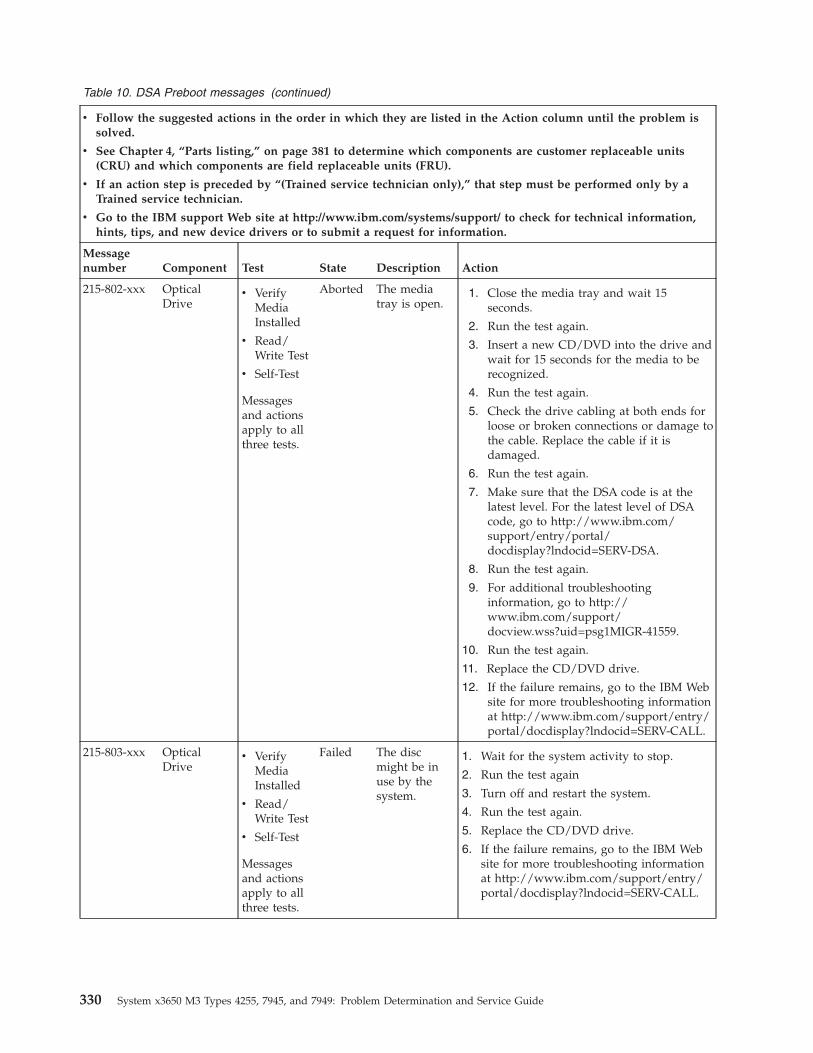
Table 10. DSA Preboot messages (continued)
v Follow the suggested actions in the order in which they are listed in the Action column until the problem issolved.
v See Chapter 4, “Parts listing,” on page 381 to determine which components are customer replaceable units(CRU) and which components are field replaceable units (FRU).
v If an action step is preceded by “(Trained service technician only),” that step must be performed only by aTrained service technician.
v Go to the IBM support Web site at http://www.ibm.com/systems/support/ to check for technical information,hints, tips, and new device drivers or to submit a request for information.
Messagenumber Component Test State Description Action
215-802-xxx OpticalDrive
v VerifyMediaInstalled
v Read/Write Test
v Self-Test
Messagesand actionsapply to allthree tests.
Aborted The mediatray is open.
1. Close the media tray and wait 15seconds.
2. Run the test again.
3. Insert a new CD/DVD into the drive andwait for 15 seconds for the media to berecognized.
4. Run the test again.
5. Check the drive cabling at both ends forloose or broken connections or damage tothe cable. Replace the cable if it isdamaged.
6. Run the test again.
7. Make sure that the DSA code is at thelatest level. For the latest level of DSAcode, go to http://www.ibm.com/support/entry/portal/docdisplay?lndocid=SERV-DSA.
8. Run the test again.
9. For additional troubleshootinginformation, go to http://www.ibm.com/support/docview.wss?uid=psg1MIGR-41559.
10. Run the test again.
11. Replace the CD/DVD drive.
12. If the failure remains, go to the IBM Website for more troubleshooting informationat http://www.ibm.com/support/entry/portal/docdisplay?lndocid=SERV-CALL.
215-803-xxx OpticalDrive
v VerifyMediaInstalled
v Read/Write Test
v Self-Test
Messagesand actionsapply to allthree tests.
Failed The discmight be inuse by thesystem.
1. Wait for the system activity to stop.
2. Run the test again
3. Turn off and restart the system.
4. Run the test again.
5. Replace the CD/DVD drive.
6. If the failure remains, go to the IBM Website for more troubleshooting informationat http://www.ibm.com/support/entry/portal/docdisplay?lndocid=SERV-CALL.
330 System x3650 M3 Types 4255, 7945, and 7949: Problem Determination and Service Guide
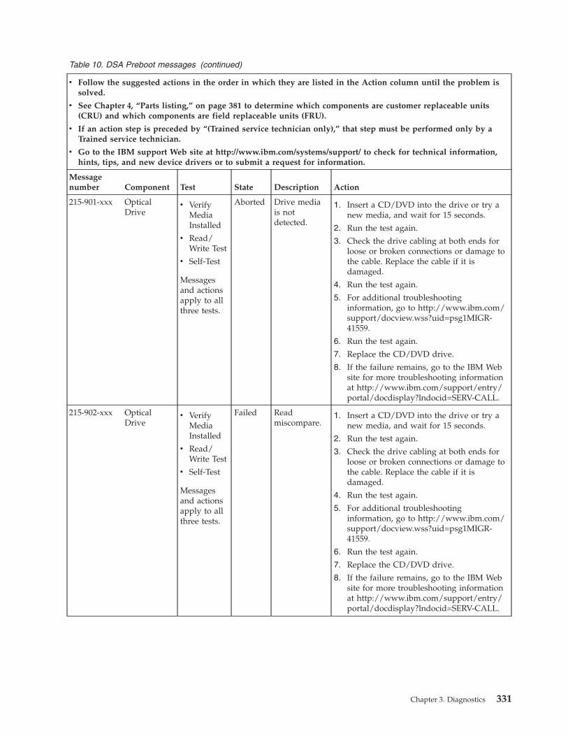
Table 10. DSA Preboot messages (continued)
v Follow the suggested actions in the order in which they are listed in the Action column until the problem issolved.
v See Chapter 4, “Parts listing,” on page 381 to determine which components are customer replaceable units(CRU) and which components are field replaceable units (FRU).
v If an action step is preceded by “(Trained service technician only),” that step must be performed only by aTrained service technician.
v Go to the IBM support Web site at http://www.ibm.com/systems/support/ to check for technical information,hints, tips, and new device drivers or to submit a request for information.
Messagenumber Component Test State Description Action
215-901-xxx OpticalDrive
v VerifyMediaInstalled
v Read/Write Test
v Self-Test
Messagesand actionsapply to allthree tests.
Aborted Drive mediais notdetected.
1. Insert a CD/DVD into the drive or try anew media, and wait for 15 seconds.
2. Run the test again.
3. Check the drive cabling at both ends forloose or broken connections or damage tothe cable. Replace the cable if it isdamaged.
4. Run the test again.
5. For additional troubleshootinginformation, go to http://www.ibm.com/support/docview.wss?uid=psg1MIGR-41559.
6. Run the test again.
7. Replace the CD/DVD drive.
8. If the failure remains, go to the IBM Website for more troubleshooting informationat http://www.ibm.com/support/entry/portal/docdisplay?lndocid=SERV-CALL.
215-902-xxx OpticalDrive
v VerifyMediaInstalled
v Read/Write Test
v Self-Test
Messagesand actionsapply to allthree tests.
Failed Readmiscompare.
1. Insert a CD/DVD into the drive or try anew media, and wait for 15 seconds.
2. Run the test again.
3. Check the drive cabling at both ends forloose or broken connections or damage tothe cable. Replace the cable if it isdamaged.
4. Run the test again.
5. For additional troubleshootinginformation, go to http://www.ibm.com/support/docview.wss?uid=psg1MIGR-41559.
6. Run the test again.
7. Replace the CD/DVD drive.
8. If the failure remains, go to the IBM Website for more troubleshooting informationat http://www.ibm.com/support/entry/portal/docdisplay?lndocid=SERV-CALL.
Chapter 3. Diagnostics 331
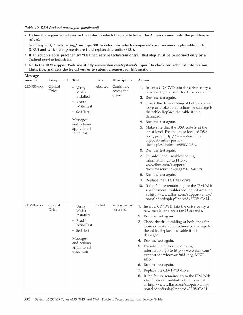
Table 10. DSA Preboot messages (continued)
v Follow the suggested actions in the order in which they are listed in the Action column until the problem issolved.
v See Chapter 4, “Parts listing,” on page 381 to determine which components are customer replaceable units(CRU) and which components are field replaceable units (FRU).
v If an action step is preceded by “(Trained service technician only),” that step must be performed only by aTrained service technician.
v Go to the IBM support Web site at http://www.ibm.com/systems/support/ to check for technical information,hints, tips, and new device drivers or to submit a request for information.
Messagenumber Component Test State Description Action
215-903-xxx OpticalDrive
v VerifyMediaInstalled
v Read/Write Test
v Self-Test
Messagesand actionsapply to allthree tests.
Aborted Could notaccess thedrive.
1. Insert a CD/DVD into the drive or try anew media, and wait for 15 seconds.
2. Run the test again.
3. Check the drive cabling at both ends forloose or broken connections or damage tothe cable. Replace the cable if it isdamaged.
4. Run the test again.
5. Make sure that the DSA code is at thelatest level. For the latest level of DSAcode, go to http://www.ibm.com/support/entry/portal/docdisplay?lndocid=SERV-DSA.
6. Run the test again.
7. For additional troubleshootinginformation, go to http://www.ibm.com/support/docview.wss?uid=psg1MIGR-41559.
8. Run the test again.
9. Replace the CD/DVD drive.
10. If the failure remains, go to the IBM Website for more troubleshooting informationat http://www.ibm.com/support/entry/portal/docdisplay?lndocid=SERV-CALL.
215-904-xxx OpticalDrive
v VerifyMediaInstalled
v Read/Write Test
v Self-Test
Messagesand actionsapply to allthree tests.
Failed A read erroroccurred.
1. Insert a CD/DVD into the drive or try anew media, and wait for 15 seconds.
2. Run the test again.
3. Check the drive cabling at both ends forloose or broken connections or damage tothe cable. Replace the cable if it isdamaged.
4. Run the test again.
5. For additional troubleshootinginformation, go to http://www.ibm.com/support/docview.wss?uid=psg1MIGR-41559.
6. Run the test again.
7. Replace the CD/DVD drive.
8. If the failure remains, go to the IBM Website for more troubleshooting informationat http://www.ibm.com/support/entry/portal/docdisplay?lndocid=SERV-CALL.
332 System x3650 M3 Types 4255, 7945, and 7949: Problem Determination and Service Guide
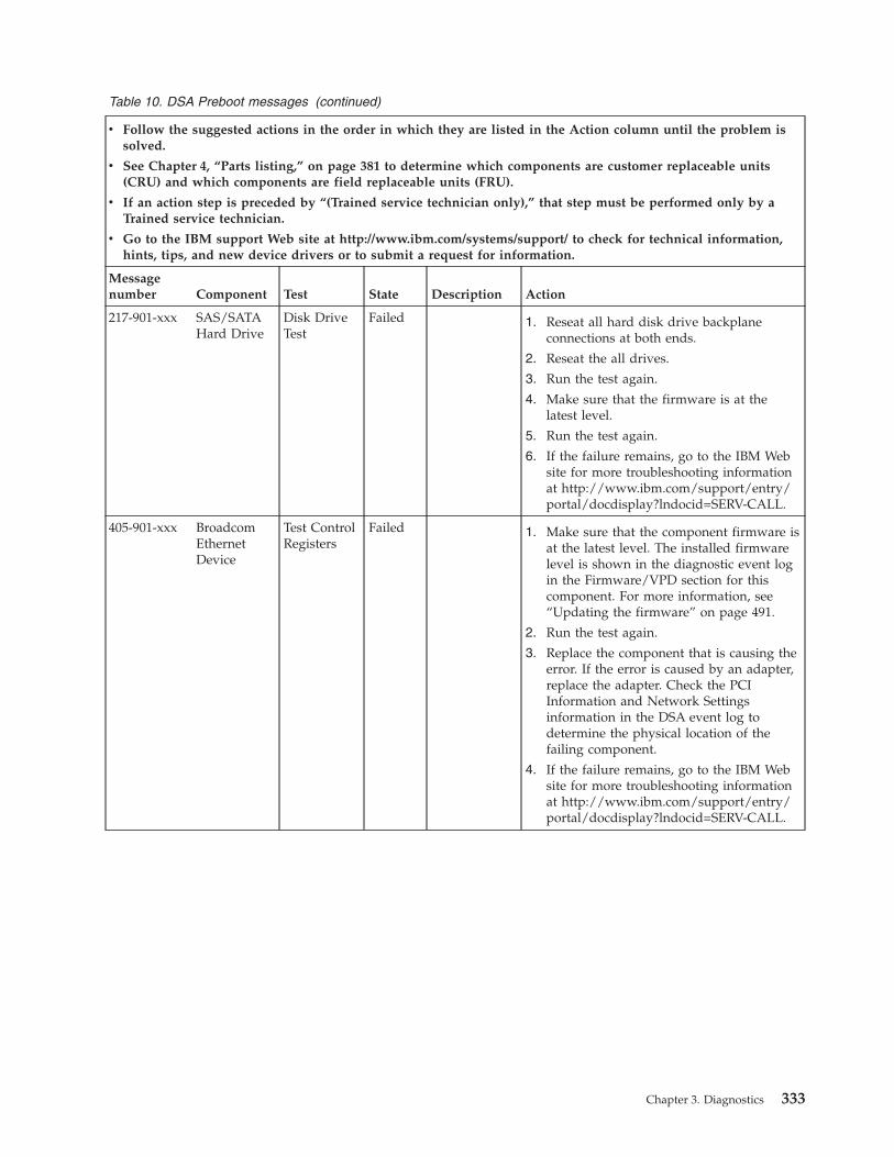
Table 10. DSA Preboot messages (continued)
v Follow the suggested actions in the order in which they are listed in the Action column until the problem issolved.
v See Chapter 4, “Parts listing,” on page 381 to determine which components are customer replaceable units(CRU) and which components are field replaceable units (FRU).
v If an action step is preceded by “(Trained service technician only),” that step must be performed only by aTrained service technician.
v Go to the IBM support Web site at http://www.ibm.com/systems/support/ to check for technical information,hints, tips, and new device drivers or to submit a request for information.
Messagenumber Component Test State Description Action
217-901-xxx SAS/SATAHard Drive
Disk DriveTest
Failed 1. Reseat all hard disk drive backplaneconnections at both ends.
2. Reseat the all drives.
3. Run the test again.
4. Make sure that the firmware is at thelatest level.
5. Run the test again.
6. If the failure remains, go to the IBM Website for more troubleshooting informationat http://www.ibm.com/support/entry/portal/docdisplay?lndocid=SERV-CALL.
405-901-xxx BroadcomEthernetDevice
Test ControlRegisters
Failed 1. Make sure that the component firmware isat the latest level. The installed firmwarelevel is shown in the diagnostic event login the Firmware/VPD section for thiscomponent. For more information, see“Updating the firmware” on page 491.
2. Run the test again.
3. Replace the component that is causing theerror. If the error is caused by an adapter,replace the adapter. Check the PCIInformation and Network Settingsinformation in the DSA event log todetermine the physical location of thefailing component.
4. If the failure remains, go to the IBM Website for more troubleshooting informationat http://www.ibm.com/support/entry/portal/docdisplay?lndocid=SERV-CALL.
Chapter 3. Diagnostics 333
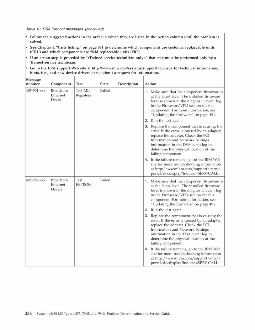
Table 10. DSA Preboot messages (continued)
v Follow the suggested actions in the order in which they are listed in the Action column until the problem issolved.
v See Chapter 4, “Parts listing,” on page 381 to determine which components are customer replaceable units(CRU) and which components are field replaceable units (FRU).
v If an action step is preceded by “(Trained service technician only),” that step must be performed only by aTrained service technician.
v Go to the IBM support Web site at http://www.ibm.com/systems/support/ to check for technical information,hints, tips, and new device drivers or to submit a request for information.
Messagenumber Component Test State Description Action
405-901-xxx BroadcomEthernetDevice
Test MIIRegisters
Failed 1. Make sure that the component firmware isat the latest level. The installed firmwarelevel is shown in the diagnostic event login the Firmware/VPD section for thiscomponent. For more information, see“Updating the firmware” on page 491.
2. Run the test again.
3. Replace the component that is causing theerror. If the error is caused by an adapter,replace the adapter. Check the PCIInformation and Network Settingsinformation in the DSA event log todetermine the physical location of thefailing component.
4. If the failure remains, go to the IBM Website for more troubleshooting informationat http://www.ibm.com/support/entry/portal/docdisplay?lndocid=SERV-CALL.
405-902-xxx BroadcomEthernetDevice
TestEEPROM
Failed 1. Make sure that the component firmware isat the latest level. The installed firmwarelevel is shown in the diagnostic event login the Firmware/VPD section for thiscomponent. For more information, see“Updating the firmware” on page 491.
2. Run the test again.
3. Replace the component that is causing theerror. If the error is caused by an adapter,replace the adapter. Check the PCIInformation and Network Settingsinformation in the DSA event log todetermine the physical location of thefailing component.
4. If the failure remains, go to the IBM Website for more troubleshooting informationat http://www.ibm.com/support/entry/portal/docdisplay?lndocid=SERV-CALL.
334 System x3650 M3 Types 4255, 7945, and 7949: Problem Determination and Service Guide
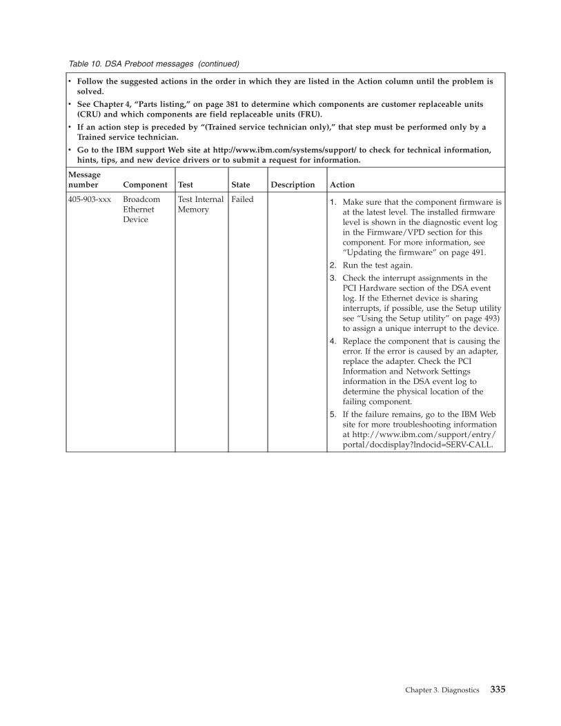
Table 10. DSA Preboot messages (continued)
v Follow the suggested actions in the order in which they are listed in the Action column until the problem issolved.
v See Chapter 4, “Parts listing,” on page 381 to determine which components are customer replaceable units(CRU) and which components are field replaceable units (FRU).
v If an action step is preceded by “(Trained service technician only),” that step must be performed only by aTrained service technician.
v Go to the IBM support Web site at http://www.ibm.com/systems/support/ to check for technical information,hints, tips, and new device drivers or to submit a request for information.
Messagenumber Component Test State Description Action
405-903-xxx BroadcomEthernetDevice
Test InternalMemory
Failed 1. Make sure that the component firmware isat the latest level. The installed firmwarelevel is shown in the diagnostic event login the Firmware/VPD section for thiscomponent. For more information, see“Updating the firmware” on page 491.
2. Run the test again.
3. Check the interrupt assignments in thePCI Hardware section of the DSA eventlog. If the Ethernet device is sharinginterrupts, if possible, use the Setup utilitysee “Using the Setup utility” on page 493)to assign a unique interrupt to the device.
4. Replace the component that is causing theerror. If the error is caused by an adapter,replace the adapter. Check the PCIInformation and Network Settingsinformation in the DSA event log todetermine the physical location of thefailing component.
5. If the failure remains, go to the IBM Website for more troubleshooting informationat http://www.ibm.com/support/entry/portal/docdisplay?lndocid=SERV-CALL.
Chapter 3. Diagnostics 335
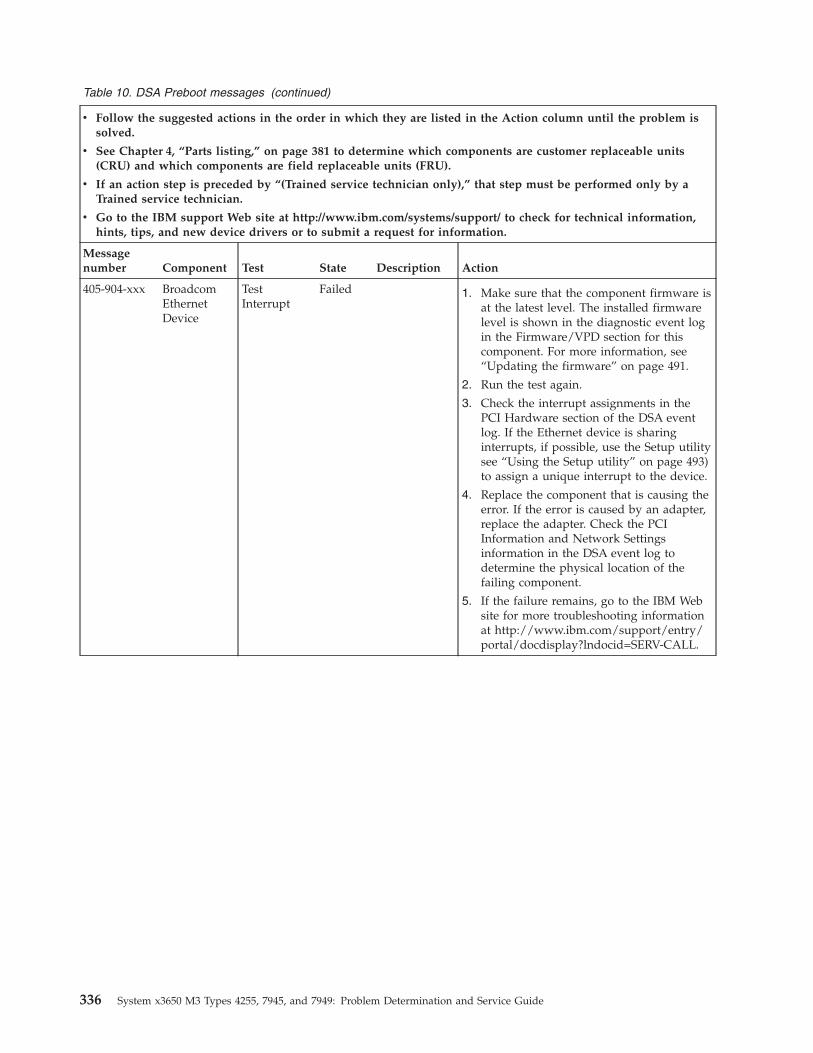
Table 10. DSA Preboot messages (continued)
v Follow the suggested actions in the order in which they are listed in the Action column until the problem issolved.
v See Chapter 4, “Parts listing,” on page 381 to determine which components are customer replaceable units(CRU) and which components are field replaceable units (FRU).
v If an action step is preceded by “(Trained service technician only),” that step must be performed only by aTrained service technician.
v Go to the IBM support Web site at http://www.ibm.com/systems/support/ to check for technical information,hints, tips, and new device drivers or to submit a request for information.
Messagenumber Component Test State Description Action
405-904-xxx BroadcomEthernetDevice
TestInterrupt
Failed 1. Make sure that the component firmware isat the latest level. The installed firmwarelevel is shown in the diagnostic event login the Firmware/VPD section for thiscomponent. For more information, see“Updating the firmware” on page 491.
2. Run the test again.
3. Check the interrupt assignments in thePCI Hardware section of the DSA eventlog. If the Ethernet device is sharinginterrupts, if possible, use the Setup utilitysee “Using the Setup utility” on page 493)to assign a unique interrupt to the device.
4. Replace the component that is causing theerror. If the error is caused by an adapter,replace the adapter. Check the PCIInformation and Network Settingsinformation in the DSA event log todetermine the physical location of thefailing component.
5. If the failure remains, go to the IBM Website for more troubleshooting informationat http://www.ibm.com/support/entry/portal/docdisplay?lndocid=SERV-CALL.
336 System x3650 M3 Types 4255, 7945, and 7949: Problem Determination and Service Guide
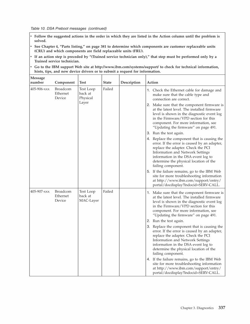
Table 10. DSA Preboot messages (continued)
v Follow the suggested actions in the order in which they are listed in the Action column until the problem issolved.
v See Chapter 4, “Parts listing,” on page 381 to determine which components are customer replaceable units(CRU) and which components are field replaceable units (FRU).
v If an action step is preceded by “(Trained service technician only),” that step must be performed only by aTrained service technician.
v Go to the IBM support Web site at http://www.ibm.com/systems/support/ to check for technical information,hints, tips, and new device drivers or to submit a request for information.
Messagenumber Component Test State Description Action
405-906-xxx BroadcomEthernetDevice
Test Loopback atPhysicalLayer
Failed 1. Check the Ethernet cable for damage andmake sure that the cable type andconnection are correct.
2. Make sure that the component firmware isat the latest level. The installed firmwarelevel is shown in the diagnostic event login the Firmware/VPD section for thiscomponent. For more information, see“Updating the firmware” on page 491.
3. Run the test again.
4. Replace the component that is causing theerror. If the error is caused by an adapter,replace the adapter. Check the PCIInformation and Network Settingsinformation in the DSA event log todetermine the physical location of thefailing component.
5. If the failure remains, go to the IBM Website for more troubleshooting informationat http://www.ibm.com/support/entry/portal/docdisplay?lndocid=SERV-CALL.
405-907-xxx BroadcomEthernetDevice
Test Loopback atMAC-Layer
Failed 1. Make sure that the component firmware isat the latest level. The installed firmwarelevel is shown in the diagnostic event login the Firmware/VPD section for thiscomponent. For more information, see“Updating the firmware” on page 491.
2. Run the test again.
3. Replace the component that is causing theerror. If the error is caused by an adapter,replace the adapter. Check the PCIInformation and Network Settingsinformation in the DSA event log todetermine the physical location of thefailing component.
4. If the failure remains, go to the IBM Website for more troubleshooting informationat http://www.ibm.com/support/entry/portal/docdisplay?lndocid=SERV-CALL.
Chapter 3. Diagnostics 337
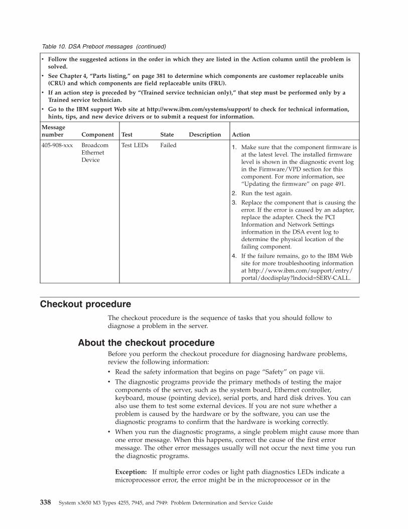
Table 10. DSA Preboot messages (continued)
v Follow the suggested actions in the order in which they are listed in the Action column until the problem issolved.
v See Chapter 4, “Parts listing,” on page 381 to determine which components are customer replaceable units(CRU) and which components are field replaceable units (FRU).
v If an action step is preceded by “(Trained service technician only),” that step must be performed only by aTrained service technician.
v Go to the IBM support Web site at http://www.ibm.com/systems/support/ to check for technical information,hints, tips, and new device drivers or to submit a request for information.
Messagenumber Component Test State Description Action
405-908-xxx BroadcomEthernetDevice
Test LEDs Failed 1. Make sure that the component firmware isat the latest level. The installed firmwarelevel is shown in the diagnostic event login the Firmware/VPD section for thiscomponent. For more information, see“Updating the firmware” on page 491.
2. Run the test again.
3. Replace the component that is causing theerror. If the error is caused by an adapter,replace the adapter. Check the PCIInformation and Network Settingsinformation in the DSA event log todetermine the physical location of thefailing component.
4. If the failure remains, go to the IBM Website for more troubleshooting informationat http://www.ibm.com/support/entry/portal/docdisplay?lndocid=SERV-CALL.
Checkout procedureThe checkout procedure is the sequence of tasks that you should follow todiagnose a problem in the server.
About the checkout procedureBefore you perform the checkout procedure for diagnosing hardware problems,review the following information:v Read the safety information that begins on page “Safety” on page vii.v The diagnostic programs provide the primary methods of testing the major
components of the server, such as the system board, Ethernet controller,keyboard, mouse (pointing device), serial ports, and hard disk drives. You canalso use them to test some external devices. If you are not sure whether aproblem is caused by the hardware or by the software, you can use thediagnostic programs to confirm that the hardware is working correctly.
v When you run the diagnostic programs, a single problem might cause more thanone error message. When this happens, correct the cause of the first errormessage. The other error messages usually will not occur the next time you runthe diagnostic programs.
Exception: If multiple error codes or light path diagnostics LEDs indicate amicroprocessor error, the error might be in the microprocessor or in the
338 System x3650 M3 Types 4255, 7945, and 7949: Problem Determination and Service Guide
microprocessor socket. See “Microprocessor problems” on page 349 forinformation about diagnosing microprocessor problems.
v Before you run the diagnostic programs, you must determine whether the failingserver is part of a shared hard disk drive cluster (two or more servers sharingexternal storage devices). If it is part of a cluster, you can run all diagnosticprograms except the ones that test the storage unit (that is, a hard disk drive inthe storage unit) or the storage adapter that is attached to the storage unit. Thefailing server might be part of a cluster if any of the following conditions is true:– You have identified the failing server as part of a cluster (two or more servers
sharing external storage devices).– One or more external storage units are attached to the failing server and at
least one of the attached storage units is also attached to another server orunidentifiable device.
– One or more servers are located near the failing server.
Important: If the server is part of a shared hard disk drive cluster, run one testat a time. Do not run any suite of tests, such as “quick” or “normal” tests,because this might enable the hard disk drive diagnostic tests.
v If the server is halted and a POST error code is displayed, see “Event logs” onpage 28. If the server is halted and no error message is displayed, see“Troubleshooting tables” on page 340 and “Solving undetermined problems” onpage 378.
v For information about power-supply problems, see “Solving power problems”on page 376.
v For intermittent problems, check the error log; see “Event logs” on page 28 and“Diagnostic programs, messages, and error codes” on page 287.
Performing the checkout procedureUse this information to perform the checkout procedure.
About this task
To perform the checkout procedure, complete the following steps:1. Is the server part of a cluster?
v No: Go to step 2.v Yes: Shut down all failing servers that are related to the cluster. Go to step 2.
2. Complete the following steps:a. Check the power supply LEDs, see “Power-supply LEDs” on page 367.b. Turn off the server and all external devices.c. Check all internal and external devices for compatibility at
http://www.ibm.com/systems/info/x86servers/serverproven/compat/us/.d. Make sure the server is cabled correctly.e. Check all cables and power cords.f. Set all display controls to the middle positions.g. Turn on all external devices.h. Turn on the server. If the server does not start, see “Troubleshooting tables”
on page 340.i. Check the system-error LED on the operator information panel. If it is
flashing, check the light path diagnostics LEDs (see “Light path diagnostics”on page 360).
Chapter 3. Diagnostics 339
j. Check for the following results:v Successful completion of POST (see “POST” on page 274 for more
information).v Successful completion of startup, which is indicated by a readable display
of the operating-system desktop.
Troubleshooting tablesUse the troubleshooting tables to find solutions to problems that have identifiablesymptoms.
About this task
If you cannot find a problem in these tables, see “Running the diagnosticprograms” on page 287 for information about testing the server.
If you have just added new software or a new optional device and the server isnot working, complete the following steps before you use the troubleshootingtables:1. Check the system-error LED on the operator information panel; if it is lit, check
the LEDs on the system board (see “System-board LEDs” on page 22).2. Remove the software or device that you just added.3. Run the diagnostic tests to determine whether the server is running correctly.4. Reinstall the new software or new device.
340 System x3650 M3 Types 4255, 7945, and 7949: Problem Determination and Service Guide
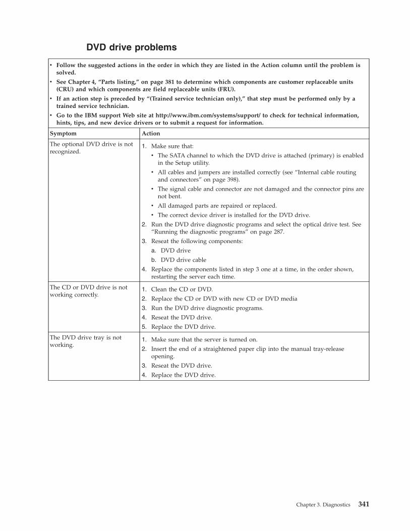
DVD drive problems
v Follow the suggested actions in the order in which they are listed in the Action column until the problem issolved.
v See Chapter 4, “Parts listing,” on page 381 to determine which components are customer replaceable units(CRU) and which components are field replaceable units (FRU).
v If an action step is preceded by “(Trained service technician only),” that step must be performed only by atrained service technician.
v Go to the IBM support Web site at http://www.ibm.com/systems/support/ to check for technical information,hints, tips, and new device drivers or to submit a request for information.
Symptom Action
The optional DVD drive is notrecognized.
1. Make sure that:
v The SATA channel to which the DVD drive is attached (primary) is enabledin the Setup utility.
v All cables and jumpers are installed correctly (see “Internal cable routingand connectors” on page 398).
v The signal cable and connector are not damaged and the connector pins arenot bent.
v All damaged parts are repaired or replaced.
v The correct device driver is installed for the DVD drive.
2. Run the DVD drive diagnostic programs and select the optical drive test. See“Running the diagnostic programs” on page 287.
3. Reseat the following components:
a. DVD drive
b. DVD drive cable
4. Replace the components listed in step 3 one at a time, in the order shown,restarting the server each time.
The CD or DVD drive is notworking correctly.
1. Clean the CD or DVD.
2. Replace the CD or DVD with new CD or DVD media
3. Run the DVD drive diagnostic programs.
4. Reseat the DVD drive.
5. Replace the DVD drive.
The DVD drive tray is notworking.
1. Make sure that the server is turned on.
2. Insert the end of a straightened paper clip into the manual tray-releaseopening.
3. Reseat the DVD drive.
4. Replace the DVD drive.
Chapter 3. Diagnostics 341
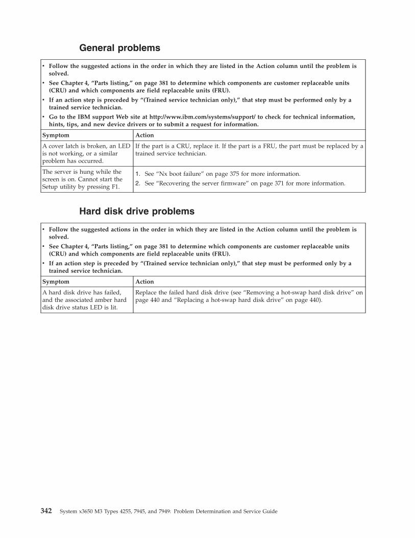
General problems
v Follow the suggested actions in the order in which they are listed in the Action column until the problem issolved.
v See Chapter 4, “Parts listing,” on page 381 to determine which components are customer replaceable units(CRU) and which components are field replaceable units (FRU).
v If an action step is preceded by “(Trained service technician only),” that step must be performed only by atrained service technician.
v Go to the IBM support Web site at http://www.ibm.com/systems/support/ to check for technical information,hints, tips, and new device drivers or to submit a request for information.
Symptom Action
A cover latch is broken, an LEDis not working, or a similarproblem has occurred.
If the part is a CRU, replace it. If the part is a FRU, the part must be replaced by atrained service technician.
The server is hung while thescreen is on. Cannot start theSetup utility by pressing F1.
1. See “Nx boot failure” on page 375 for more information.
2. See “Recovering the server firmware” on page 371 for more information.
Hard disk drive problems
v Follow the suggested actions in the order in which they are listed in the Action column until the problem issolved.
v See Chapter 4, “Parts listing,” on page 381 to determine which components are customer replaceable units(CRU) and which components are field replaceable units (FRU).
v If an action step is preceded by “(Trained service technician only),” that step must be performed only by atrained service technician.
Symptom Action
A hard disk drive has failed,and the associated amber harddisk drive status LED is lit.
Replace the failed hard disk drive (see “Removing a hot-swap hard disk drive” onpage 440 and “Replacing a hot-swap hard disk drive” on page 440).
342 System x3650 M3 Types 4255, 7945, and 7949: Problem Determination and Service Guide
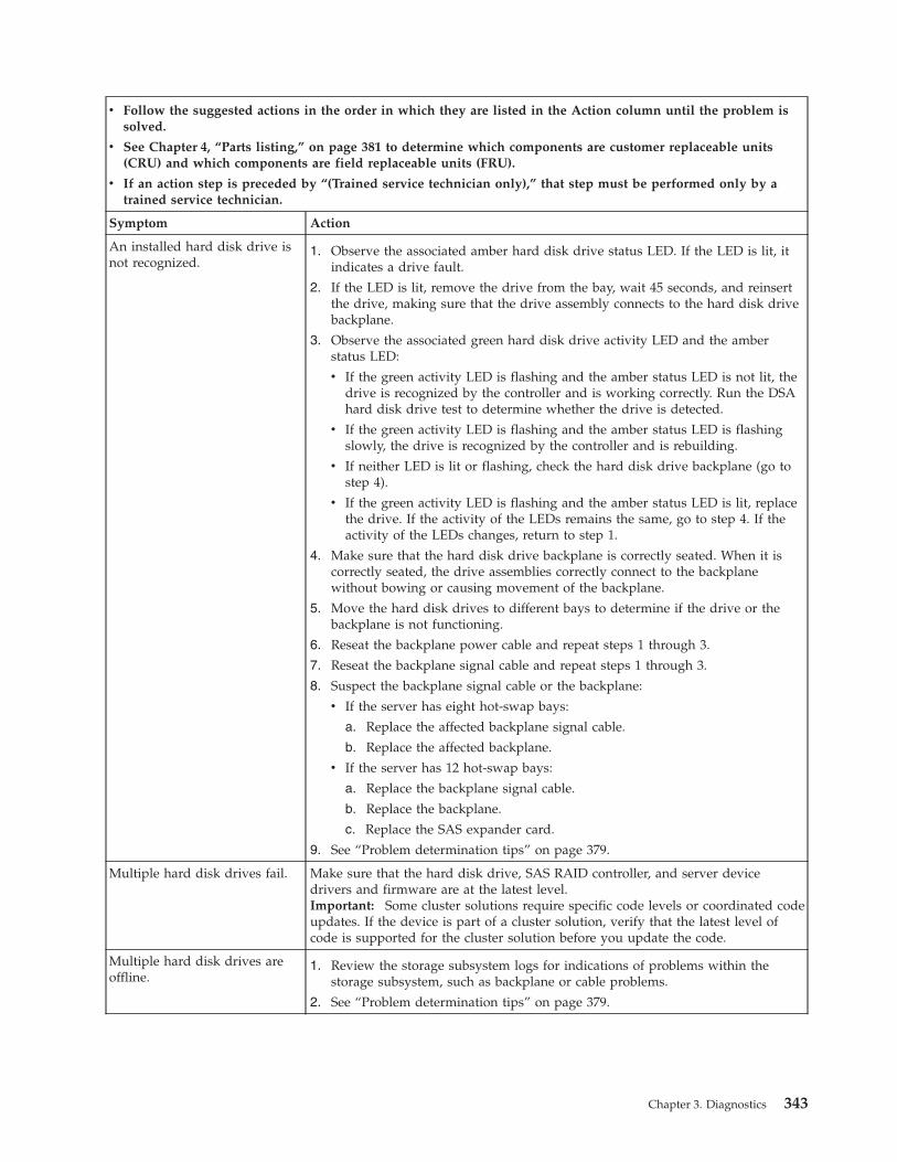
v Follow the suggested actions in the order in which they are listed in the Action column until the problem issolved.
v See Chapter 4, “Parts listing,” on page 381 to determine which components are customer replaceable units(CRU) and which components are field replaceable units (FRU).
v If an action step is preceded by “(Trained service technician only),” that step must be performed only by atrained service technician.
Symptom Action
An installed hard disk drive isnot recognized.
1. Observe the associated amber hard disk drive status LED. If the LED is lit, itindicates a drive fault.
2. If the LED is lit, remove the drive from the bay, wait 45 seconds, and reinsertthe drive, making sure that the drive assembly connects to the hard disk drivebackplane.
3. Observe the associated green hard disk drive activity LED and the amberstatus LED:
v If the green activity LED is flashing and the amber status LED is not lit, thedrive is recognized by the controller and is working correctly. Run the DSAhard disk drive test to determine whether the drive is detected.
v If the green activity LED is flashing and the amber status LED is flashingslowly, the drive is recognized by the controller and is rebuilding.
v If neither LED is lit or flashing, check the hard disk drive backplane (go tostep 4).
v If the green activity LED is flashing and the amber status LED is lit, replacethe drive. If the activity of the LEDs remains the same, go to step 4. If theactivity of the LEDs changes, return to step 1.
4. Make sure that the hard disk drive backplane is correctly seated. When it iscorrectly seated, the drive assemblies correctly connect to the backplanewithout bowing or causing movement of the backplane.
5. Move the hard disk drives to different bays to determine if the drive or thebackplane is not functioning.
6. Reseat the backplane power cable and repeat steps 1 through 3.
7. Reseat the backplane signal cable and repeat steps 1 through 3.
8. Suspect the backplane signal cable or the backplane:
v If the server has eight hot-swap bays:
a. Replace the affected backplane signal cable.
b. Replace the affected backplane.
v If the server has 12 hot-swap bays:
a. Replace the backplane signal cable.
b. Replace the backplane.
c. Replace the SAS expander card.
9. See “Problem determination tips” on page 379.
Multiple hard disk drives fail. Make sure that the hard disk drive, SAS RAID controller, and server devicedrivers and firmware are at the latest level.Important: Some cluster solutions require specific code levels or coordinated codeupdates. If the device is part of a cluster solution, verify that the latest level ofcode is supported for the cluster solution before you update the code.
Multiple hard disk drives areoffline.
1. Review the storage subsystem logs for indications of problems within thestorage subsystem, such as backplane or cable problems.
2. See “Problem determination tips” on page 379.
Chapter 3. Diagnostics 343
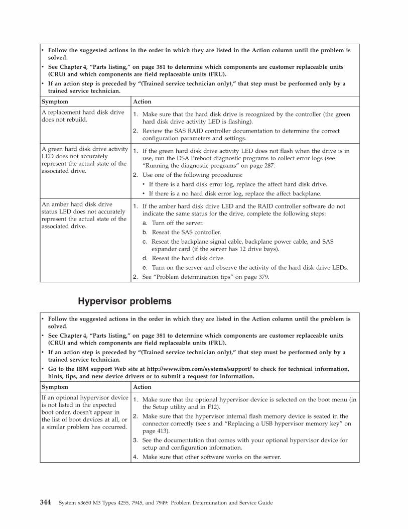
v Follow the suggested actions in the order in which they are listed in the Action column until the problem issolved.
v See Chapter 4, “Parts listing,” on page 381 to determine which components are customer replaceable units(CRU) and which components are field replaceable units (FRU).
v If an action step is preceded by “(Trained service technician only),” that step must be performed only by atrained service technician.
Symptom Action
A replacement hard disk drivedoes not rebuild.
1. Make sure that the hard disk drive is recognized by the controller (the greenhard disk drive activity LED is flashing).
2. Review the SAS RAID controller documentation to determine the correctconfiguration parameters and settings.
A green hard disk drive activityLED does not accuratelyrepresent the actual state of theassociated drive.
1. If the green hard disk drive activity LED does not flash when the drive is inuse, run the DSA Preboot diagnostic programs to collect error logs (see“Running the diagnostic programs” on page 287.
2. Use one of the following procedures:
v If there is a hard disk error log, replace the affect hard disk drive.
v If there is a no hard disk error log, replace the affect backplane.
An amber hard disk drivestatus LED does not accuratelyrepresent the actual state of theassociated drive.
1. If the amber hard disk drive LED and the RAID controller software do notindicate the same status for the drive, complete the following steps:
a. Turn off the server.
b. Reseat the SAS controller.
c. Reseat the backplane signal cable, backplane power cable, and SASexpander card (if the server has 12 drive bays).
d. Reseat the hard disk drive.
e. Turn on the server and observe the activity of the hard disk drive LEDs.
2. See “Problem determination tips” on page 379.
Hypervisor problems
v Follow the suggested actions in the order in which they are listed in the Action column until the problem issolved.
v See Chapter 4, “Parts listing,” on page 381 to determine which components are customer replaceable units(CRU) and which components are field replaceable units (FRU).
v If an action step is preceded by “(Trained service technician only),” that step must be performed only by atrained service technician.
v Go to the IBM support Web site at http://www.ibm.com/systems/support/ to check for technical information,hints, tips, and new device drivers or to submit a request for information.
Symptom Action
If an optional hypervisor deviceis not listed in the expectedboot order, doesn't appear inthe list of boot devices at all, ora similar problem has occurred.
1. Make sure that the optional hypervisor device is selected on the boot menu (inthe Setup utility and in F12).
2. Make sure that the hypervisor internal flash memory device is seated in theconnector correctly (see s and “Replacing a USB hypervisor memory key” onpage 413).
3. See the documentation that comes with your optional hypervisor device forsetup and configuration information.
4. Make sure that other software works on the server.
344 System x3650 M3 Types 4255, 7945, and 7949: Problem Determination and Service Guide
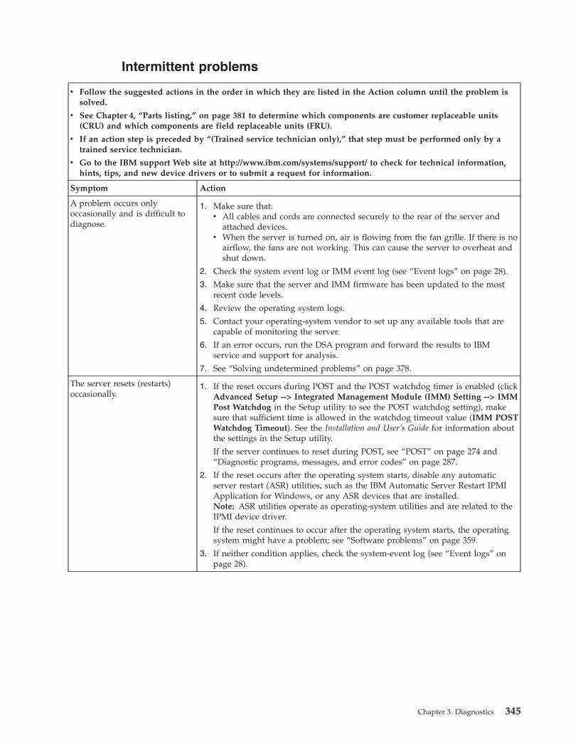
Intermittent problems
v Follow the suggested actions in the order in which they are listed in the Action column until the problem issolved.
v See Chapter 4, “Parts listing,” on page 381 to determine which components are customer replaceable units(CRU) and which components are field replaceable units (FRU).
v If an action step is preceded by “(Trained service technician only),” that step must be performed only by atrained service technician.
v Go to the IBM support Web site at http://www.ibm.com/systems/support/ to check for technical information,hints, tips, and new device drivers or to submit a request for information.
Symptom Action
A problem occurs onlyoccasionally and is difficult todiagnose.
1. Make sure that:v All cables and cords are connected securely to the rear of the server and
attached devices.v When the server is turned on, air is flowing from the fan grille. If there is no
airflow, the fans are not working. This can cause the server to overheat andshut down.
2. Check the system event log or IMM event log (see “Event logs” on page 28).
3. Make sure that the server and IMM firmware has been updated to the mostrecent code levels.
4. Review the operating system logs.
5. Contact your operating-system vendor to set up any available tools that arecapable of monitoring the server.
6. If an error occurs, run the DSA program and forward the results to IBMservice and support for analysis.
7. See “Solving undetermined problems” on page 378.
The server resets (restarts)occasionally.
1. If the reset occurs during POST and the POST watchdog timer is enabled (clickAdvanced Setup --> Integrated Management Module (IMM) Setting --> IMMPost Watchdog in the Setup utility to see the POST watchdog setting), makesure that sufficient time is allowed in the watchdog timeout value (IMM POSTWatchdog Timeout). See the Installation and User’s Guide for information aboutthe settings in the Setup utility.
If the server continues to reset during POST, see “POST” on page 274 and“Diagnostic programs, messages, and error codes” on page 287.
2. If the reset occurs after the operating system starts, disable any automaticserver restart (ASR) utilities, such as the IBM Automatic Server Restart IPMIApplication for Windows, or any ASR devices that are installed.Note: ASR utilities operate as operating-system utilities and are related to theIPMI device driver.
If the reset continues to occur after the operating system starts, the operatingsystem might have a problem; see “Software problems” on page 359.
3. If neither condition applies, check the system-event log (see “Event logs” onpage 28).
Chapter 3. Diagnostics 345
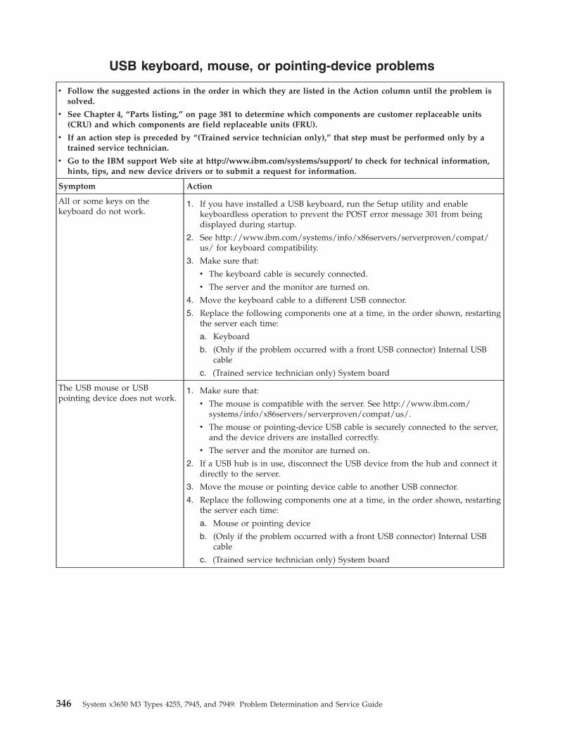
USB keyboard, mouse, or pointing-device problems
v Follow the suggested actions in the order in which they are listed in the Action column until the problem issolved.
v See Chapter 4, “Parts listing,” on page 381 to determine which components are customer replaceable units(CRU) and which components are field replaceable units (FRU).
v If an action step is preceded by “(Trained service technician only),” that step must be performed only by atrained service technician.
v Go to the IBM support Web site at http://www.ibm.com/systems/support/ to check for technical information,hints, tips, and new device drivers or to submit a request for information.
Symptom Action
All or some keys on thekeyboard do not work.
1. If you have installed a USB keyboard, run the Setup utility and enablekeyboardless operation to prevent the POST error message 301 from beingdisplayed during startup.
2. See http://www.ibm.com/systems/info/x86servers/serverproven/compat/us/ for keyboard compatibility.
3. Make sure that:
v The keyboard cable is securely connected.
v The server and the monitor are turned on.
4. Move the keyboard cable to a different USB connector.
5. Replace the following components one at a time, in the order shown, restartingthe server each time:
a. Keyboard
b. (Only if the problem occurred with a front USB connector) Internal USBcable
c. (Trained service technician only) System board
The USB mouse or USBpointing device does not work.
1. Make sure that:
v The mouse is compatible with the server. See http://www.ibm.com/systems/info/x86servers/serverproven/compat/us/.
v The mouse or pointing-device USB cable is securely connected to the server,and the device drivers are installed correctly.
v The server and the monitor are turned on.
2. If a USB hub is in use, disconnect the USB device from the hub and connect itdirectly to the server.
3. Move the mouse or pointing device cable to another USB connector.
4. Replace the following components one at a time, in the order shown, restartingthe server each time:
a. Mouse or pointing device
b. (Only if the problem occurred with a front USB connector) Internal USBcable
c. (Trained service technician only) System board
346 System x3650 M3 Types 4255, 7945, and 7949: Problem Determination and Service Guide
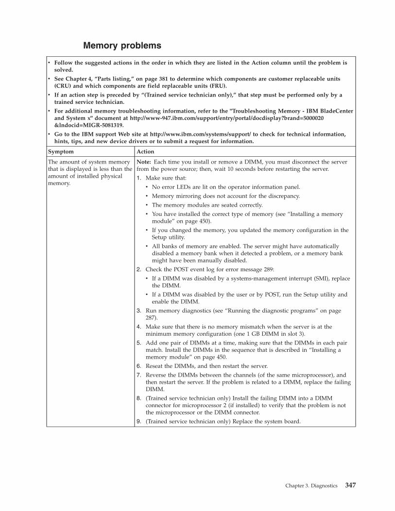
Memory problems
v Follow the suggested actions in the order in which they are listed in the Action column until the problem issolved.
v See Chapter 4, “Parts listing,” on page 381 to determine which components are customer replaceable units(CRU) and which components are field replaceable units (FRU).
v If an action step is preceded by “(Trained service technician only),” that step must be performed only by atrained service technician.
v For additional memory troubleshooting information, refer to the "Troubleshooting Memory - IBM BladeCenterand System x" document at http://www-947.ibm.com/support/entry/portal/docdisplay?brand=5000020&lndocid=MIGR-5081319.
v Go to the IBM support Web site at http://www.ibm.com/systems/support/ to check for technical information,hints, tips, and new device drivers or to submit a request for information.
Symptom Action
The amount of system memorythat is displayed is less than theamount of installed physicalmemory.
Note: Each time you install or remove a DIMM, you must disconnect the serverfrom the power source; then, wait 10 seconds before restarting the server.
1. Make sure that:
v No error LEDs are lit on the operator information panel.
v Memory mirroring does not account for the discrepancy.
v The memory modules are seated correctly.
v You have installed the correct type of memory (see “Installing a memorymodule” on page 450).
v If you changed the memory, you updated the memory configuration in theSetup utility.
v All banks of memory are enabled. The server might have automaticallydisabled a memory bank when it detected a problem, or a memory bankmight have been manually disabled.
2. Check the POST event log for error message 289:
v If a DIMM was disabled by a systems-management interrupt (SMI), replacethe DIMM.
v If a DIMM was disabled by the user or by POST, run the Setup utility andenable the DIMM.
3. Run memory diagnostics (see “Running the diagnostic programs” on page287).
4. Make sure that there is no memory mismatch when the server is at theminimum memory configuration (one 1 GB DIMM in slot 3).
5. Add one pair of DIMMs at a time, making sure that the DIMMs in each pairmatch. Install the DIMMs in the sequence that is described in “Installing amemory module” on page 450.
6. Reseat the DIMMs, and then restart the server.
7. Reverse the DIMMs between the channels (of the same microprocessor), andthen restart the server. If the problem is related to a DIMM, replace the failingDIMM.
8. (Trained service technician only) Install the failing DIMM into a DIMMconnector for microprocessor 2 (if installed) to verify that the problem is notthe microprocessor or the DIMM connector.
9. (Trained service technician only) Replace the system board.
Chapter 3. Diagnostics 347
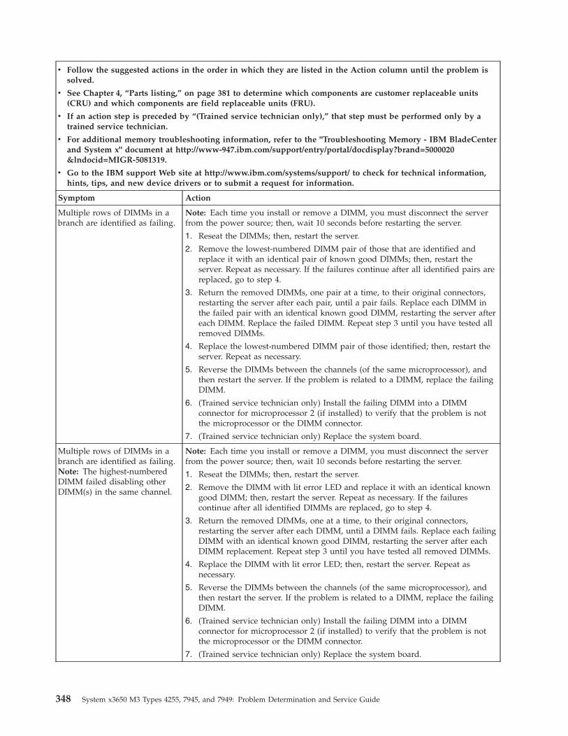
v Follow the suggested actions in the order in which they are listed in the Action column until the problem issolved.
v See Chapter 4, “Parts listing,” on page 381 to determine which components are customer replaceable units(CRU) and which components are field replaceable units (FRU).
v If an action step is preceded by “(Trained service technician only),” that step must be performed only by atrained service technician.
v For additional memory troubleshooting information, refer to the "Troubleshooting Memory - IBM BladeCenterand System x" document at http://www-947.ibm.com/support/entry/portal/docdisplay?brand=5000020&lndocid=MIGR-5081319.
v Go to the IBM support Web site at http://www.ibm.com/systems/support/ to check for technical information,hints, tips, and new device drivers or to submit a request for information.
Symptom Action
Multiple rows of DIMMs in abranch are identified as failing.
Note: Each time you install or remove a DIMM, you must disconnect the serverfrom the power source; then, wait 10 seconds before restarting the server.
1. Reseat the DIMMs; then, restart the server.
2. Remove the lowest-numbered DIMM pair of those that are identified andreplace it with an identical pair of known good DIMMs; then, restart theserver. Repeat as necessary. If the failures continue after all identified pairs arereplaced, go to step 4.
3. Return the removed DIMMs, one pair at a time, to their original connectors,restarting the server after each pair, until a pair fails. Replace each DIMM inthe failed pair with an identical known good DIMM, restarting the server aftereach DIMM. Replace the failed DIMM. Repeat step 3 until you have tested allremoved DIMMs.
4. Replace the lowest-numbered DIMM pair of those identified; then, restart theserver. Repeat as necessary.
5. Reverse the DIMMs between the channels (of the same microprocessor), andthen restart the server. If the problem is related to a DIMM, replace the failingDIMM.
6. (Trained service technician only) Install the failing DIMM into a DIMMconnector for microprocessor 2 (if installed) to verify that the problem is notthe microprocessor or the DIMM connector.
7. (Trained service technician only) Replace the system board.
Multiple rows of DIMMs in abranch are identified as failing.Note: The highest-numberedDIMM failed disabling otherDIMM(s) in the same channel.
Note: Each time you install or remove a DIMM, you must disconnect the serverfrom the power source; then, wait 10 seconds before restarting the server.
1. Reseat the DIMMs; then, restart the server.
2. Remove the DIMM with lit error LED and replace it with an identical knowngood DIMM; then, restart the server. Repeat as necessary. If the failurescontinue after all identified DIMMs are replaced, go to step 4.
3. Return the removed DIMMs, one at a time, to their original connectors,restarting the server after each DIMM, until a DIMM fails. Replace each failingDIMM with an identical known good DIMM, restarting the server after eachDIMM replacement. Repeat step 3 until you have tested all removed DIMMs.
4. Replace the DIMM with lit error LED; then, restart the server. Repeat asnecessary.
5. Reverse the DIMMs between the channels (of the same microprocessor), andthen restart the server. If the problem is related to a DIMM, replace the failingDIMM.
6. (Trained service technician only) Install the failing DIMM into a DIMMconnector for microprocessor 2 (if installed) to verify that the problem is notthe microprocessor or the DIMM connector.
7. (Trained service technician only) Replace the system board.
348 System x3650 M3 Types 4255, 7945, and 7949: Problem Determination and Service Guide
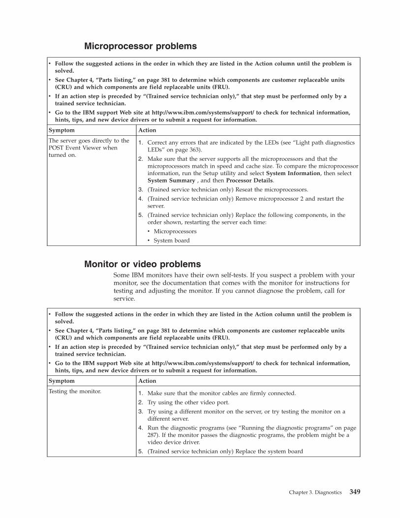
Microprocessor problems
v Follow the suggested actions in the order in which they are listed in the Action column until the problem issolved.
v See Chapter 4, “Parts listing,” on page 381 to determine which components are customer replaceable units(CRU) and which components are field replaceable units (FRU).
v If an action step is preceded by “(Trained service technician only),” that step must be performed only by atrained service technician.
v Go to the IBM support Web site at http://www.ibm.com/systems/support/ to check for technical information,hints, tips, and new device drivers or to submit a request for information.
Symptom Action
The server goes directly to thePOST Event Viewer whenturned on.
1. Correct any errors that are indicated by the LEDs (see “Light path diagnosticsLEDs” on page 363).
2. Make sure that the server supports all the microprocessors and that themicroprocessors match in speed and cache size. To compare the microprocessorinformation, run the Setup utility and select System Information, then selectSystem Summary , and then Processor Details.
3. (Trained service technician only) Reseat the microprocessors.
4. (Trained service technician only) Remove microprocessor 2 and restart theserver.
5. (Trained service technician only) Replace the following components, in theorder shown, restarting the server each time:
v Microprocessors
v System board
Monitor or video problemsSome IBM monitors have their own self-tests. If you suspect a problem with yourmonitor, see the documentation that comes with the monitor for instructions fortesting and adjusting the monitor. If you cannot diagnose the problem, call forservice.
v Follow the suggested actions in the order in which they are listed in the Action column until the problem issolved.
v See Chapter 4, “Parts listing,” on page 381 to determine which components are customer replaceable units(CRU) and which components are field replaceable units (FRU).
v If an action step is preceded by “(Trained service technician only),” that step must be performed only by atrained service technician.
v Go to the IBM support Web site at http://www.ibm.com/systems/support/ to check for technical information,hints, tips, and new device drivers or to submit a request for information.
Symptom Action
Testing the monitor. 1. Make sure that the monitor cables are firmly connected.
2. Try using the other video port.
3. Try using a different monitor on the server, or try testing the monitor on adifferent server.
4. Run the diagnostic programs (see “Running the diagnostic programs” on page287). If the monitor passes the diagnostic programs, the problem might be avideo device driver.
5. (Trained service technician only) Replace the system board
Chapter 3. Diagnostics 349
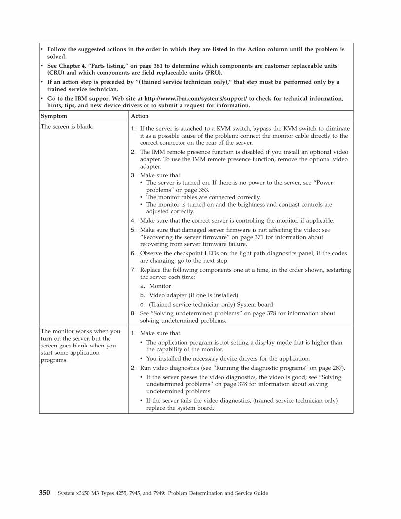
v Follow the suggested actions in the order in which they are listed in the Action column until the problem issolved.
v See Chapter 4, “Parts listing,” on page 381 to determine which components are customer replaceable units(CRU) and which components are field replaceable units (FRU).
v If an action step is preceded by “(Trained service technician only),” that step must be performed only by atrained service technician.
v Go to the IBM support Web site at http://www.ibm.com/systems/support/ to check for technical information,hints, tips, and new device drivers or to submit a request for information.
Symptom Action
The screen is blank. 1. If the server is attached to a KVM switch, bypass the KVM switch to eliminateit as a possible cause of the problem: connect the monitor cable directly to thecorrect connector on the rear of the server.
2. The IMM remote presence function is disabled if you install an optional videoadapter. To use the IMM remote presence function, remove the optional videoadapter.
3. Make sure that:v The server is turned on. If there is no power to the server, see “Power
problems” on page 353.v The monitor cables are connected correctly.v The monitor is turned on and the brightness and contrast controls are
adjusted correctly.
4. Make sure that the correct server is controlling the monitor, if applicable.
5. Make sure that damaged server firmware is not affecting the video; see“Recovering the server firmware” on page 371 for information aboutrecovering from server firmware failure.
6. Observe the checkpoint LEDs on the light path diagnostics panel; if the codesare changing, go to the next step.
7. Replace the following components one at a time, in the order shown, restartingthe server each time:
a. Monitor
b. Video adapter (if one is installed)
c. (Trained service technician only) System board
8. See “Solving undetermined problems” on page 378 for information aboutsolving undetermined problems.
The monitor works when youturn on the server, but thescreen goes blank when youstart some applicationprograms.
1. Make sure that:
v The application program is not setting a display mode that is higher thanthe capability of the monitor.
v You installed the necessary device drivers for the application.
2. Run video diagnostics (see “Running the diagnostic programs” on page 287).
v If the server passes the video diagnostics, the video is good; see “Solvingundetermined problems” on page 378 for information about solvingundetermined problems.
v If the server fails the video diagnostics, (trained service technician only)replace the system board.
350 System x3650 M3 Types 4255, 7945, and 7949: Problem Determination and Service Guide
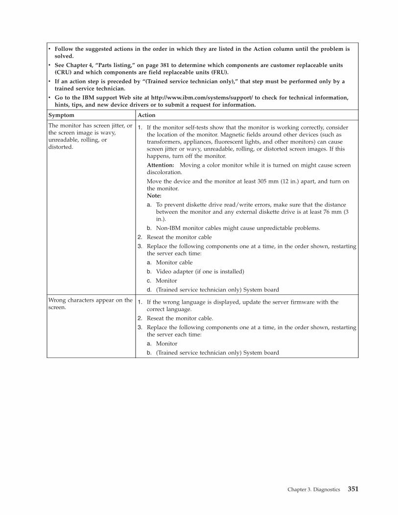
v Follow the suggested actions in the order in which they are listed in the Action column until the problem issolved.
v See Chapter 4, “Parts listing,” on page 381 to determine which components are customer replaceable units(CRU) and which components are field replaceable units (FRU).
v If an action step is preceded by “(Trained service technician only),” that step must be performed only by atrained service technician.
v Go to the IBM support Web site at http://www.ibm.com/systems/support/ to check for technical information,hints, tips, and new device drivers or to submit a request for information.
Symptom Action
The monitor has screen jitter, orthe screen image is wavy,unreadable, rolling, ordistorted.
1. If the monitor self-tests show that the monitor is working correctly, considerthe location of the monitor. Magnetic fields around other devices (such astransformers, appliances, fluorescent lights, and other monitors) can causescreen jitter or wavy, unreadable, rolling, or distorted screen images. If thishappens, turn off the monitor.
Attention: Moving a color monitor while it is turned on might cause screendiscoloration.
Move the device and the monitor at least 305 mm (12 in.) apart, and turn onthe monitor.Note:
a. To prevent diskette drive read/write errors, make sure that the distancebetween the monitor and any external diskette drive is at least 76 mm (3in.).
b. Non-IBM monitor cables might cause unpredictable problems.
2. Reseat the monitor cable
3. Replace the following components one at a time, in the order shown, restartingthe server each time:
a. Monitor cable
b. Video adapter (if one is installed)
c. Monitor
d. (Trained service technician only) System board
Wrong characters appear on thescreen.
1. If the wrong language is displayed, update the server firmware with thecorrect language.
2. Reseat the monitor cable.
3. Replace the following components one at a time, in the order shown, restartingthe server each time:
a. Monitor
b. (Trained service technician only) System board
Chapter 3. Diagnostics 351
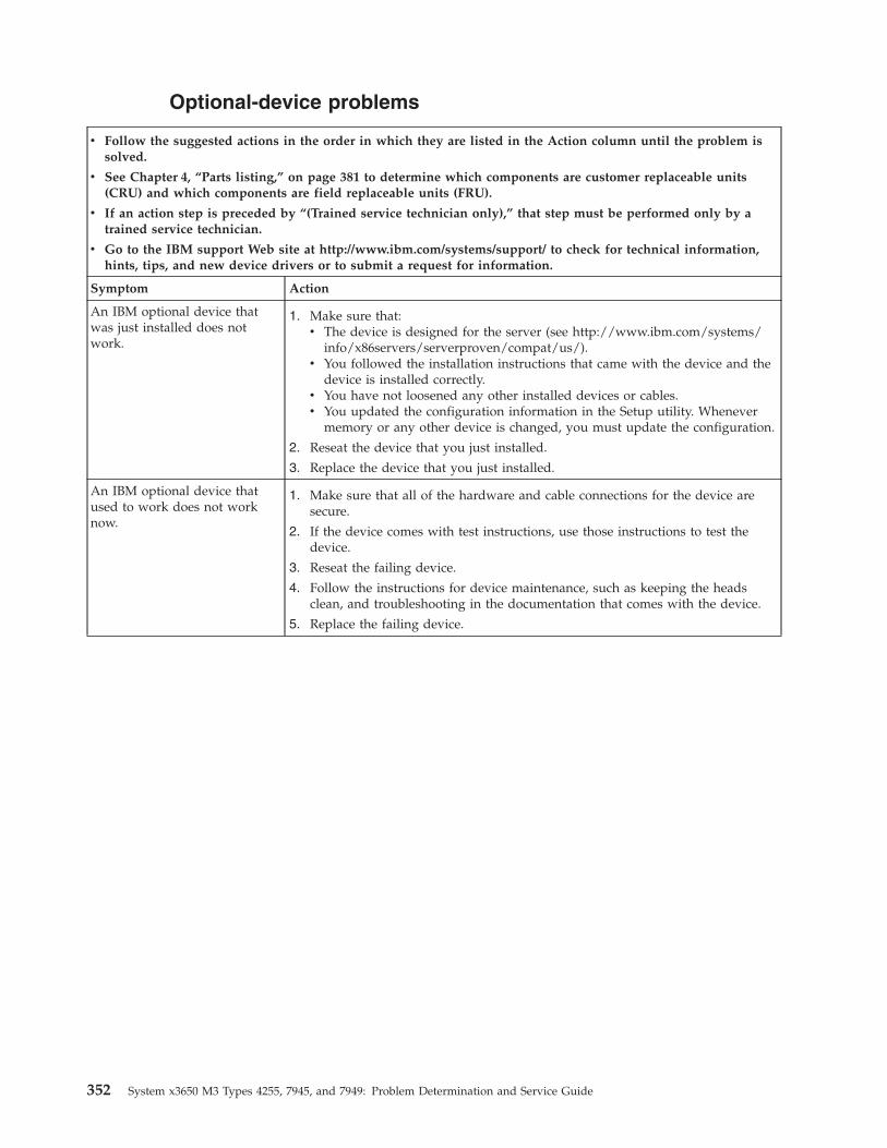
Optional-device problems
v Follow the suggested actions in the order in which they are listed in the Action column until the problem issolved.
v See Chapter 4, “Parts listing,” on page 381 to determine which components are customer replaceable units(CRU) and which components are field replaceable units (FRU).
v If an action step is preceded by “(Trained service technician only),” that step must be performed only by atrained service technician.
v Go to the IBM support Web site at http://www.ibm.com/systems/support/ to check for technical information,hints, tips, and new device drivers or to submit a request for information.
Symptom Action
An IBM optional device thatwas just installed does notwork.
1. Make sure that:v The device is designed for the server (see http://www.ibm.com/systems/
info/x86servers/serverproven/compat/us/).v You followed the installation instructions that came with the device and the
device is installed correctly.v You have not loosened any other installed devices or cables.v You updated the configuration information in the Setup utility. Whenever
memory or any other device is changed, you must update the configuration.
2. Reseat the device that you just installed.
3. Replace the device that you just installed.
An IBM optional device thatused to work does not worknow.
1. Make sure that all of the hardware and cable connections for the device aresecure.
2. If the device comes with test instructions, use those instructions to test thedevice.
3. Reseat the failing device.
4. Follow the instructions for device maintenance, such as keeping the headsclean, and troubleshooting in the documentation that comes with the device.
5. Replace the failing device.
352 System x3650 M3 Types 4255, 7945, and 7949: Problem Determination and Service Guide
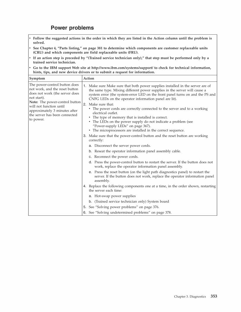
Power problems
v Follow the suggested actions in the order in which they are listed in the Action column until the problem issolved.
v See Chapter 4, “Parts listing,” on page 381 to determine which components are customer replaceable units(CRU) and which components are field replaceable units (FRU).
v If an action step is preceded by “(Trained service technician only),” that step must be performed only by atrained service technician.
v Go to the IBM support Web site at http://www.ibm.com/systems/support/ to check for technical information,hints, tips, and new device drivers or to submit a request for information.
Symptom Action
The power-control button doesnot work, and the reset buttondoes not work (the server doesnot start).Note: The power-control buttonwill not function untilapproximately 3 minutes afterthe server has been connectedto power.
1. Make sure Make sure that both power supplies installed in the server are ofthe same type. Mixing different power supplies in the server will cause asystem error (the system-error LED on the front panel turns on and the PS andCNFG LEDs on the operator information panel are lit).
2. Make sure that:v The power cords are correctly connected to the server and to a working
electrical outlet.v The type of memory that is installed is correct.v The LEDs on the power supply do not indicate a problem (see
“Power-supply LEDs” on page 367).v The microprocessors are installed in the correct sequence.
3. Make sure that the power-control button and the reset button are workingcorrectly:
a. Disconnect the server power cords.
b. Reseat the operator information panel assembly cable.
c. Reconnect the power cords.
d. Press the power-control button to restart the server. If the button does notwork, replace the operator information panel assembly.
e. Press the reset button (on the light path diagnostics panel) to restart theserver. If the button does not work, replace the operator information panelassembly.
4. Replace the following components one at a time, in the order shown, restartingthe server each time:
a. Hot-swap power supplies
b. (Trained service technician only) System board
5. See “Solving power problems” on page 376.
6. See “Solving undetermined problems” on page 378.
Chapter 3. Diagnostics 353
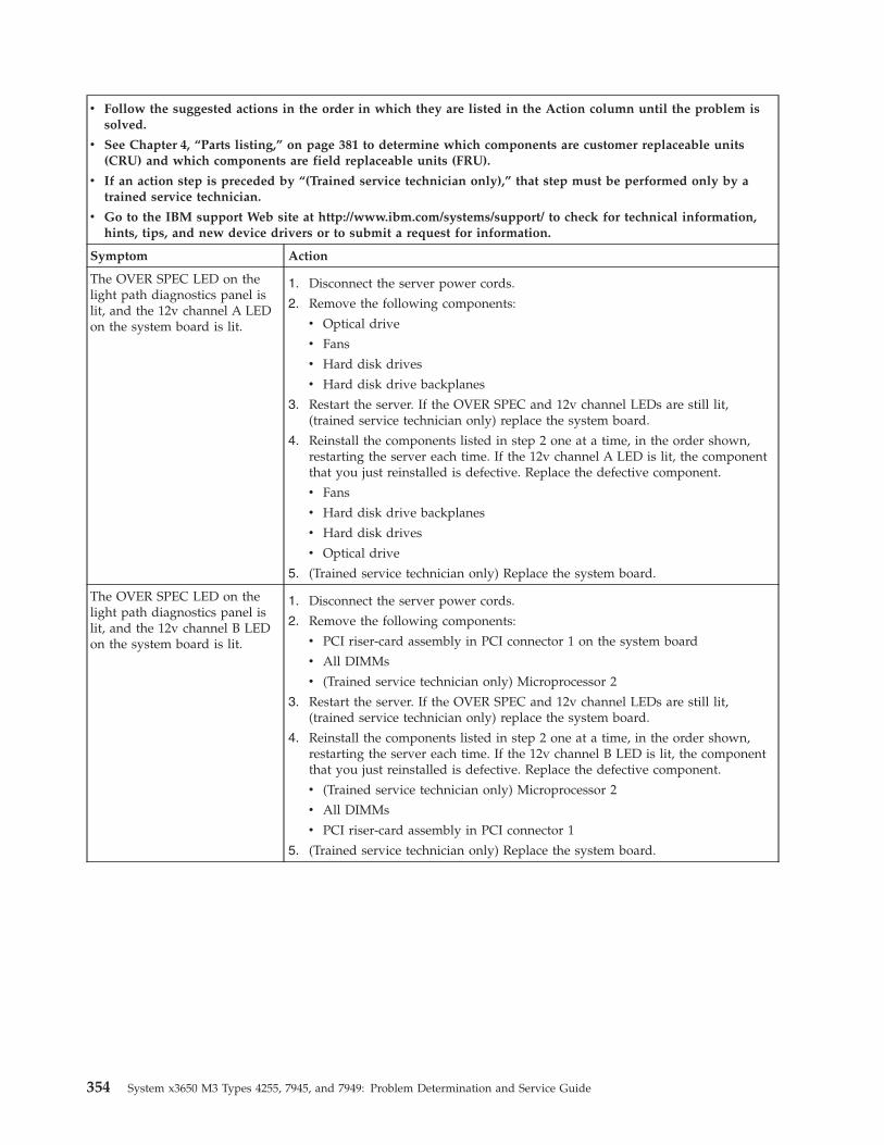
v Follow the suggested actions in the order in which they are listed in the Action column until the problem issolved.
v See Chapter 4, “Parts listing,” on page 381 to determine which components are customer replaceable units(CRU) and which components are field replaceable units (FRU).
v If an action step is preceded by “(Trained service technician only),” that step must be performed only by atrained service technician.
v Go to the IBM support Web site at http://www.ibm.com/systems/support/ to check for technical information,hints, tips, and new device drivers or to submit a request for information.
Symptom Action
The OVER SPEC LED on thelight path diagnostics panel islit, and the 12v channel A LEDon the system board is lit.
1. Disconnect the server power cords.
2. Remove the following components:
v Optical drive
v Fans
v Hard disk drives
v Hard disk drive backplanes
3. Restart the server. If the OVER SPEC and 12v channel LEDs are still lit,(trained service technician only) replace the system board.
4. Reinstall the components listed in step 2 one at a time, in the order shown,restarting the server each time. If the 12v channel A LED is lit, the componentthat you just reinstalled is defective. Replace the defective component.
v Fans
v Hard disk drive backplanes
v Hard disk drives
v Optical drive
5. (Trained service technician only) Replace the system board.
The OVER SPEC LED on thelight path diagnostics panel islit, and the 12v channel B LEDon the system board is lit.
1. Disconnect the server power cords.
2. Remove the following components:
v PCI riser-card assembly in PCI connector 1 on the system board
v All DIMMs
v (Trained service technician only) Microprocessor 2
3. Restart the server. If the OVER SPEC and 12v channel LEDs are still lit,(trained service technician only) replace the system board.
4. Reinstall the components listed in step 2 one at a time, in the order shown,restarting the server each time. If the 12v channel B LED is lit, the componentthat you just reinstalled is defective. Replace the defective component.
v (Trained service technician only) Microprocessor 2
v All DIMMs
v PCI riser-card assembly in PCI connector 1
5. (Trained service technician only) Replace the system board.
354 System x3650 M3 Types 4255, 7945, and 7949: Problem Determination and Service Guide
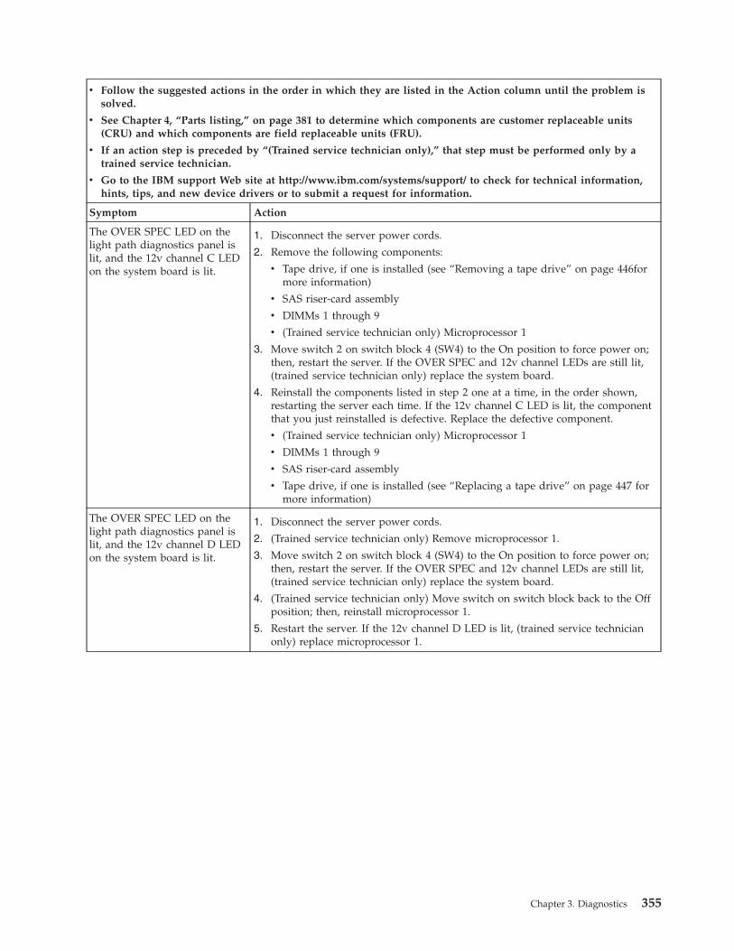
v Follow the suggested actions in the order in which they are listed in the Action column until the problem issolved.
v See Chapter 4, “Parts listing,” on page 381 to determine which components are customer replaceable units(CRU) and which components are field replaceable units (FRU).
v If an action step is preceded by “(Trained service technician only),” that step must be performed only by atrained service technician.
v Go to the IBM support Web site at http://www.ibm.com/systems/support/ to check for technical information,hints, tips, and new device drivers or to submit a request for information.
Symptom Action
The OVER SPEC LED on thelight path diagnostics panel islit, and the 12v channel C LEDon the system board is lit.
1. Disconnect the server power cords.
2. Remove the following components:
v Tape drive, if one is installed (see “Removing a tape drive” on page 446formore information)
v SAS riser-card assembly
v DIMMs 1 through 9
v (Trained service technician only) Microprocessor 1
3. Move switch 2 on switch block 4 (SW4) to the On position to force power on;then, restart the server. If the OVER SPEC and 12v channel LEDs are still lit,(trained service technician only) replace the system board.
4. Reinstall the components listed in step 2 one at a time, in the order shown,restarting the server each time. If the 12v channel C LED is lit, the componentthat you just reinstalled is defective. Replace the defective component.
v (Trained service technician only) Microprocessor 1
v DIMMs 1 through 9
v SAS riser-card assembly
v Tape drive, if one is installed (see “Replacing a tape drive” on page 447 formore information)
The OVER SPEC LED on thelight path diagnostics panel islit, and the 12v channel D LEDon the system board is lit.
1. Disconnect the server power cords.
2. (Trained service technician only) Remove microprocessor 1.
3. Move switch 2 on switch block 4 (SW4) to the On position to force power on;then, restart the server. If the OVER SPEC and 12v channel LEDs are still lit,(trained service technician only) replace the system board.
4. (Trained service technician only) Move switch on switch block back to the Offposition; then, reinstall microprocessor 1.
5. Restart the server. If the 12v channel D LED is lit, (trained service technicianonly) replace microprocessor 1.
Chapter 3. Diagnostics 355
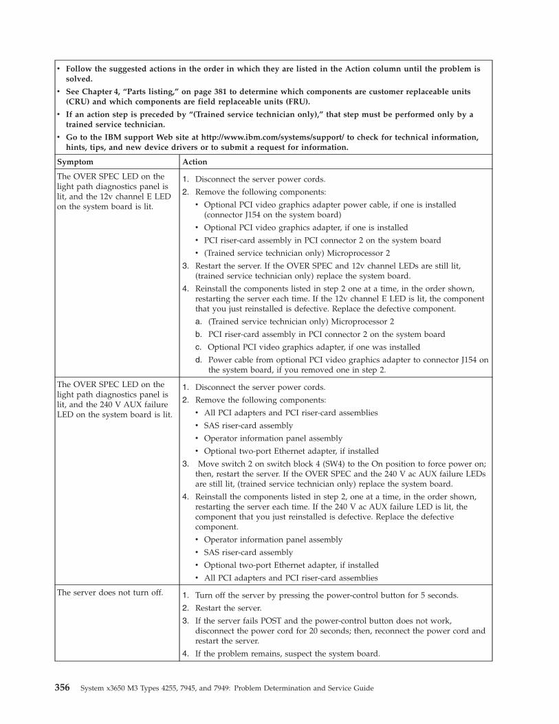
v Follow the suggested actions in the order in which they are listed in the Action column until the problem issolved.
v See Chapter 4, “Parts listing,” on page 381 to determine which components are customer replaceable units(CRU) and which components are field replaceable units (FRU).
v If an action step is preceded by “(Trained service technician only),” that step must be performed only by atrained service technician.
v Go to the IBM support Web site at http://www.ibm.com/systems/support/ to check for technical information,hints, tips, and new device drivers or to submit a request for information.
Symptom Action
The OVER SPEC LED on thelight path diagnostics panel islit, and the 12v channel E LEDon the system board is lit.
1. Disconnect the server power cords.
2. Remove the following components:
v Optional PCI video graphics adapter power cable, if one is installed(connector J154 on the system board)
v Optional PCI video graphics adapter, if one is installed
v PCI riser-card assembly in PCI connector 2 on the system board
v (Trained service technician only) Microprocessor 2
3. Restart the server. If the OVER SPEC and 12v channel LEDs are still lit,(trained service technician only) replace the system board.
4. Reinstall the components listed in step 2 one at a time, in the order shown,restarting the server each time. If the 12v channel E LED is lit, the componentthat you just reinstalled is defective. Replace the defective component.
a. (Trained service technician only) Microprocessor 2
b. PCI riser-card assembly in PCI connector 2 on the system board
c. Optional PCI video graphics adapter, if one was installed
d. Power cable from optional PCI video graphics adapter to connector J154 onthe system board, if you removed one in step 2.
The OVER SPEC LED on thelight path diagnostics panel islit, and the 240 V AUX failureLED on the system board is lit.
1. Disconnect the server power cords.
2. Remove the following components:
v All PCI adapters and PCI riser-card assemblies
v SAS riser-card assembly
v Operator information panel assembly
v Optional two-port Ethernet adapter, if installed
3. Move switch 2 on switch block 4 (SW4) to the On position to force power on;then, restart the server. If the OVER SPEC and the 240 V ac AUX failure LEDsare still lit, (trained service technician only) replace the system board.
4. Reinstall the components listed in step 2, one at a time, in the order shown,restarting the server each time. If the 240 V ac AUX failure LED is lit, thecomponent that you just reinstalled is defective. Replace the defectivecomponent.
v Operator information panel assembly
v SAS riser-card assembly
v Optional two-port Ethernet adapter, if installed
v All PCI adapters and PCI riser-card assemblies
The server does not turn off. 1. Turn off the server by pressing the power-control button for 5 seconds.
2. Restart the server.
3. If the server fails POST and the power-control button does not work,disconnect the power cord for 20 seconds; then, reconnect the power cord andrestart the server.
4. If the problem remains, suspect the system board.
356 System x3650 M3 Types 4255, 7945, and 7949: Problem Determination and Service Guide
v Follow the suggested actions in the order in which they are listed in the Action column until the problem issolved.
v See Chapter 4, “Parts listing,” on page 381 to determine which components are customer replaceable units(CRU) and which components are field replaceable units (FRU).
v If an action step is preceded by “(Trained service technician only),” that step must be performed only by atrained service technician.
v Go to the IBM support Web site at http://www.ibm.com/systems/support/ to check for technical information,hints, tips, and new device drivers or to submit a request for information.
Symptom Action
The server unexpectedly shutsdown, and the LEDs on theoperator information panel arenot lit.
See “Solving undetermined problems” on page 378.
Serial device problems
v Follow the suggested actions in the order in which they are listed in the Action column until the problem issolved.
v See Chapter 4, “Parts listing,” on page 381 to determine which components are customer replaceable units(CRU) and which components are field replaceable units (FRU).
v If an action step is preceded by “(Trained service technician only),” that step must be performed only by atrained service technician.
v Go to the IBM support Web site at http://www.ibm.com/systems/support/ to check for technical information,hints, tips, and new device drivers or to submit a request for information.
Symptom Action
The number of serial ports thatare identified by the operatingsystem is less than the numberof installed serial ports.
1. Make sure that:v Each port is assigned a unique address in the Setup utility and none of the
serial ports is disabled.v The serial-port adapter (if one is present) is seated correctly.
2. Reseat the serial port adapter, if one is present.
3. Replace the serial port adapter, if one is present.
A serial device does not work. 1. Make sure that:v The device is compatible with the server.v The serial port is enabled and is assigned a unique address.v The device is connected to the correct connector (see “Rear view” on page
14).
2. Reseat the following components:
a. Failing serial device
b. Serial cable
3. Replace the following components one at a time, in the order shown, restartingthe server each time:
a. Failing serial device
b. Serial cable
c. (Trained service technician only) System board
Chapter 3. Diagnostics 357
ServerGuide problems
v Follow the suggested actions in the order in which they are listed in the Action column until the problem issolved.
v See Chapter 4, “Parts listing,” on page 381 to determine which components are customer replaceable units(CRU) and which components are field replaceable units (FRU).
v If an action step is preceded by “(Trained service technician only),” that step must be performed only by atrained service technician.
v Go to the IBM support Web site at http://www.ibm.com/systems/support/ to check for technical information,hints, tips, and new device drivers or to submit a request for information.
Symptom Action
The ServerGuide Setup andInstallation CD will not start.
1. Make sure that the server supports the ServerGuide program and has astartable (bootable) CD or DVD drive.
2. If the startup (boot) sequence settings have been changed, make sure that theCD or DVD drive is first in the startup sequence.
3. If more than one CD or DVD drive is installed, make sure that only one driveis set as the primary drive. Start the CD from the primary drive.
The ServeRAID program cannotview all installed drives, or theoperating system cannot beinstalled.
1. Make sure that there are no duplicate IRQ assignments.2. Make sure that the hard disk drive is connected correctly.3. Make sure that the hard disk drive cables are securely connected (see “Internal
cable routing and connectors” on page 398).
The operating-systeminstallation programcontinuously loops.
Make more space available on the hard disk.
The ServerGuide program willnot start the operating-systemCD.
Make sure that the operating-system CD is supported by the ServerGuideprogram. For a list of supported operating-system versions, go tohttp://www.ibm.com/systems/management/serverguide/sub.html, click IBMService and Support Site, click the link for your ServerGuide version, and scrolldown to the list of supported Microsoft Windows operating systems.
The operating system cannot beinstalled; the option is notavailable.
Make sure that the server supports the operating system. If it does, no logicaldrive is defined (RAID servers). Run the ServerGuide program and make sure thatsetup is complete.
358 System x3650 M3 Types 4255, 7945, and 7949: Problem Determination and Service Guide
Software problems
v Follow the suggested actions in the order in which they are listed in the Action column until the problem issolved.
v See Chapter 4, “Parts listing,” on page 381 to determine which components are customer replaceable units(CRU) and which components are field replaceable units (FRU).
v If an action step is preceded by “(Trained service technician only),” that step must be performed only by atrained service technician.
v Go to the IBM support Web site at http://www.ibm.com/systems/support/ to check for technical information,hints, tips, and new device drivers or to submit a request for information.
Symptom Action
You suspect a softwareproblem.
1. To determine whether the problem is caused by the software, make sure that:v The server has the minimum memory that is needed to use the software. For
memory requirements, see the information that comes with the software. Ifyou have just installed an adapter or memory, the server might have amemory-address conflict.
v The software is designed to operate on the server.v Other software works on the server.v The software works on another server.
2. If you received any error messages when using the software, see theinformation that comes with the software for a description of the messages andsuggested solutions to the problem.
3. Contact the software vendor.
Universal Serial Bus (USB) port problems
v Follow the suggested actions in the order in which they are listed in the Action column until the problem issolved.
v See Chapter 4, “Parts listing,” on page 381 to determine which components are customer replaceable units(CRU) and which components are field replaceable units (FRU).
v If an action step is preceded by “(Trained service technician only),” that step must be performed only by atrained service technician.
v Go to the IBM support Web site at http://www.ibm.com/systems/support/ to check for technical information,hints, tips, and new device drivers or to submit a request for information.
Symptom Action
A USB device does not work. 1. Make sure that:v The correct USB device driver is installed.v The operating system supports USB devices.
2. Make sure that the USB configuration options are set correctly in the Setuputility menu (see the Installation and User’s Guide for more information).
3. If you are using a USB hub, disconnect the USB device from the hub andconnect it directly to the server.
4. Move the device cable to a different USB connector.
Chapter 3. Diagnostics 359
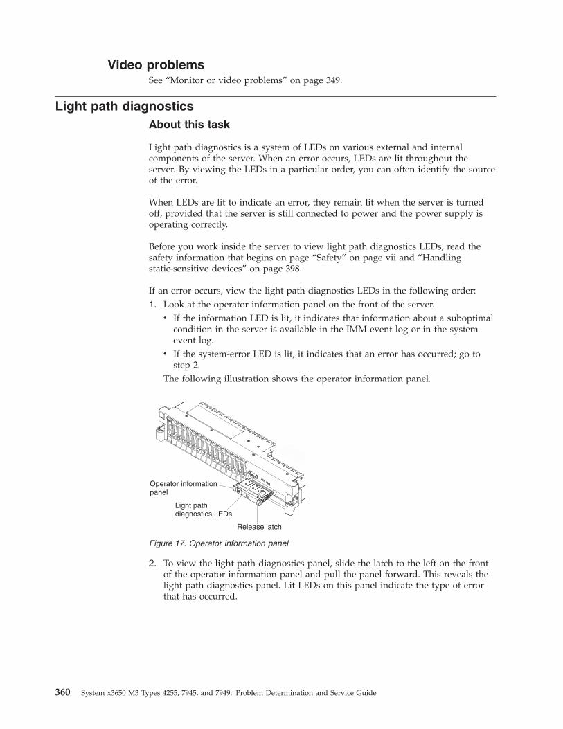
Video problemsSee “Monitor or video problems” on page 349.
Light path diagnosticsAbout this task
Light path diagnostics is a system of LEDs on various external and internalcomponents of the server. When an error occurs, LEDs are lit throughout theserver. By viewing the LEDs in a particular order, you can often identify the sourceof the error.
When LEDs are lit to indicate an error, they remain lit when the server is turnedoff, provided that the server is still connected to power and the power supply isoperating correctly.
Before you work inside the server to view light path diagnostics LEDs, read thesafety information that begins on page “Safety” on page vii and “Handlingstatic-sensitive devices” on page 398.
If an error occurs, view the light path diagnostics LEDs in the following order:1. Look at the operator information panel on the front of the server.
v If the information LED is lit, it indicates that information about a suboptimalcondition in the server is available in the IMM event log or in the systemevent log.
v If the system-error LED is lit, it indicates that an error has occurred; go tostep 2.
The following illustration shows the operator information panel.
2. To view the light path diagnostics panel, slide the latch to the left on the frontof the operator information panel and pull the panel forward. This reveals thelight path diagnostics panel. Lit LEDs on this panel indicate the type of errorthat has occurred.
Operator informationpanel
Light pathdiagnostics LEDs
Release latch
Figure 17. Operator information panel
360 System x3650 M3 Types 4255, 7945, and 7949: Problem Determination and Service Guide
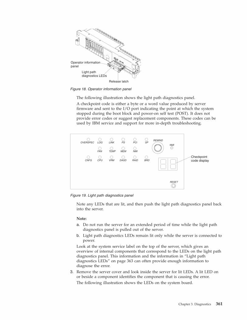
The following illustration shows the light path diagnostics panel.A checkpoint code is either a byte or a word value produced by serverfirmware and sent to the I/O port indicating the point at which the systemstopped during the boot block and power-on self test (POST). It does notprovide error codes or suggest replacement components. These codes can beused by IBM service and support for more in-depth troubleshooting.
Note any LEDs that are lit, and then push the light path diagnostics panel backinto the server.
Note:
a. Do not run the server for an extended period of time while the light pathdiagnostics panel is pulled out of the server.
b. Light path diagnostics LEDs remain lit only while the server is connected topower.
Look at the system service label on the top of the server, which gives anoverview of internal components that correspond to the LEDs on the light pathdiagnostics panel. This information and the information in “Light pathdiagnostics LEDs” on page 363 can often provide enough information todiagnose the error.
3. Remove the server cover and look inside the server for lit LEDs. A lit LED onor beside a component identifies the component that is causing the error.The following illustration shows the LEDs on the system board.
Figure 18. Operator information panel
Checkpointcode display
Figure 19. Light path diagnostics panel
Chapter 3. Diagnostics 361
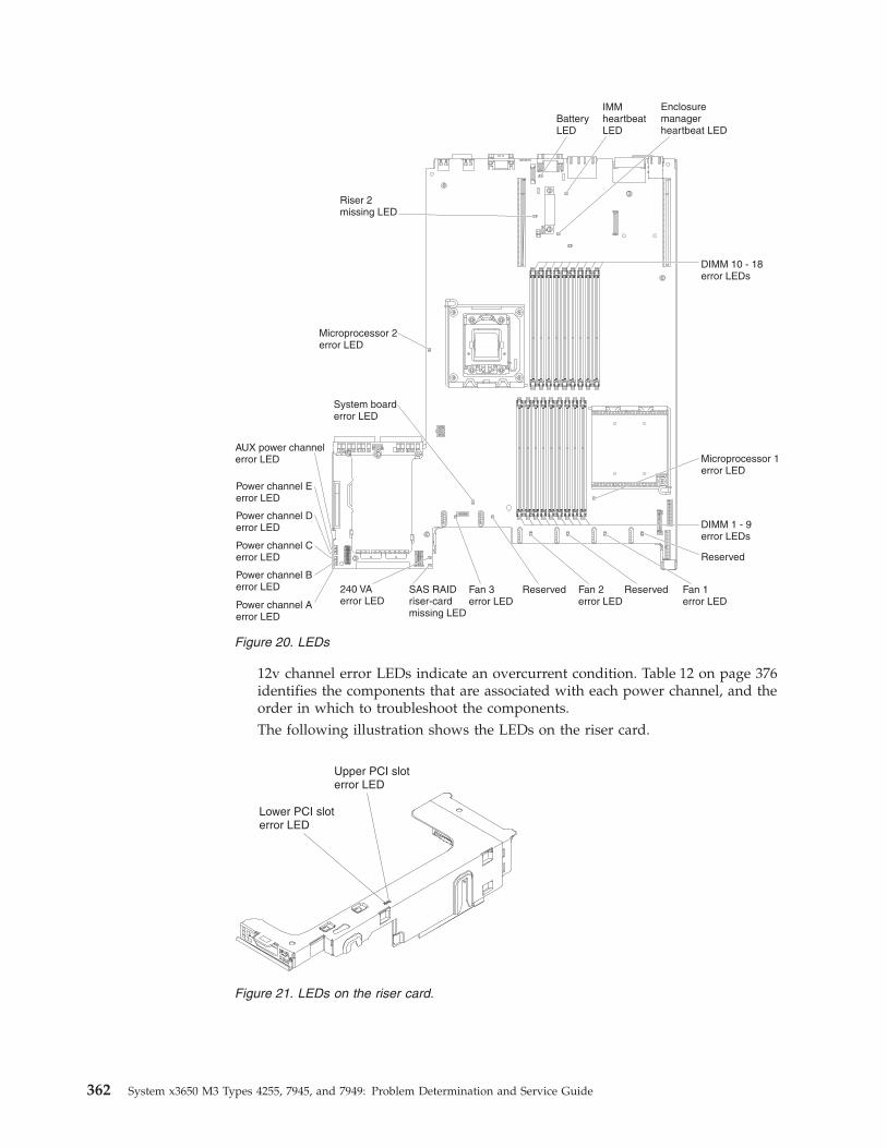
12v channel error LEDs indicate an overcurrent condition. Table 12 on page 376identifies the components that are associated with each power channel, and theorder in which to troubleshoot the components.The following illustration shows the LEDs on the riser card.
Figure 20. LEDs
Figure 21. LEDs on the riser card.
362 System x3650 M3 Types 4255, 7945, and 7949: Problem Determination and Service Guide
Remind buttonYou can use the remind button on the light path diagnostics panel to put thesystem-error LED on the operator information panel into Remind mode.
When you press the remind button, you acknowledge the error but indicate thatyou will not take immediate action. The system-error LED flashes while it is inRemind mode and stays in Remind mode until one of the following conditionsoccurs:v All known errors are corrected.v The server is restarted.v A new error occurs, causing the system-error LED to be lit again.
Light path diagnostics LEDsThe following table describes the LEDs on the light path diagnostics panel andsuggested actions to correct the detected problems.
Note: Check the system-event log and the IMM event log for additionalinformation before you replace a FRU.
LED Problem Action
None, butthesystem-error LEDis lit.
An error has occurred and cannot bediagnosed, or the IMM has failed. Theerror is not represented by a light pathdiagnostics LED.
Use the Setup utility to check the system-event log forinformation about the error.
BRD An error has occurred on the systemboard.
1. Check the LEDs on the system board to identify thecomponent that is causing the error. The BRD LED can belit for the following conditions:v Batteryv Missing PCI riser-card assemblyv Failed voltage regulator
2. Check the system-event log for information about the error.3. Replace any failed or missing replaceable components,
such as the battery (see “Removing the battery” on page463 for more information) or PCI riser-card assembly (see“Removing a PCI riser-card assembly” on page 414 formore information).
4. If a voltage regulator has failed, replace the system board.
Chapter 3. Diagnostics 363
LED Problem Action
CNFG A hardware configuration error hasoccurred. (This LED is used with theMEM and CPU LEDs.)
1. If the CNFG LED and the CPU LED are lit, complete thefollowing steps:
a. Check the microprocessors that were just installed tomake sure that they are compatible with each other (see“Replacing a microprocessor and heat sink” on page477 for additional information about microprocessorrequirements).
b. (Trained service technician only) Replace theincompatible microprocessor.
c. Check the system-error logs for information about theerror. Replace any components that are identified in theerror log.
2. If the CNFG LED and the MEM LED are lit, complete thefollowing steps:
a. Check the system-event log in the Setup utility or IMMerror messages. Follow steps indicated in “POST errorcodes” on page 274 and “Integrated managementmodule error messages” on page 31.
CPUWhen only the CPU LED is lit, amicroprocessor has failed.
When the CPU and CNFG LEDs are lit,an invalid microprocessor configurationhas occurred.
1. Determine whether the CNFG LED is also lit. If the CNFGLED is not lit, a microprocessor has failed.
a. Make sure that the failing microprocessor, which isindicated by a lit LED on the system board, is installedcorrectly. See “Replacing a microprocessor and heatsink” on page 477 for information about installing amicroprocessor.
b. If the failure remains, go to http://www.ibm.com/support/entry/portal/docdisplay?lndocid=SERV-CALLfor additional troubleshooting information.
2. If the CNFG LED is lit, then an invalid microprocessorconfiguration has occurred.
a. Make sure that the microprocessors are compatible witheach other. They must match in speed and cache size.To compare the microprocessor information, run theSetup utility and select System Information, then selectSystem Summary, and then select Processor Details.
b. (Trained service technician only) Replace anincompatible microprocessor.
c. If the failure remains, go to http://www.ibm.com/support/entry/portal/docdisplay?lndocid=SERV-CALLfor additional troubleshooting information.
364 System x3650 M3 Types 4255, 7945, and 7949: Problem Determination and Service Guide
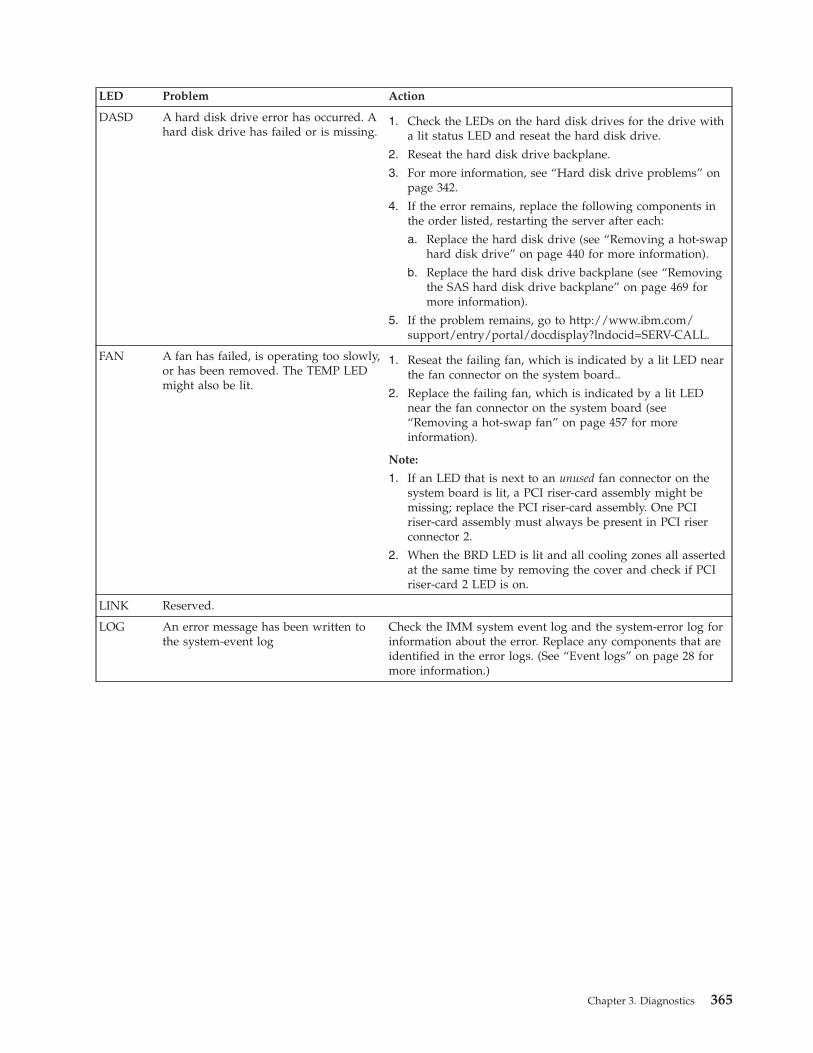
LED Problem Action
DASD A hard disk drive error has occurred. Ahard disk drive has failed or is missing.
1. Check the LEDs on the hard disk drives for the drive witha lit status LED and reseat the hard disk drive.
2. Reseat the hard disk drive backplane.
3. For more information, see “Hard disk drive problems” onpage 342.
4. If the error remains, replace the following components inthe order listed, restarting the server after each:
a. Replace the hard disk drive (see “Removing a hot-swaphard disk drive” on page 440 for more information).
b. Replace the hard disk drive backplane (see “Removingthe SAS hard disk drive backplane” on page 469 formore information).
5. If the problem remains, go to http://www.ibm.com/support/entry/portal/docdisplay?lndocid=SERV-CALL.
FAN A fan has failed, is operating too slowly,or has been removed. The TEMP LEDmight also be lit.
1. Reseat the failing fan, which is indicated by a lit LED nearthe fan connector on the system board..
2. Replace the failing fan, which is indicated by a lit LEDnear the fan connector on the system board (see“Removing a hot-swap fan” on page 457 for moreinformation).
Note:
1. If an LED that is next to an unused fan connector on thesystem board is lit, a PCI riser-card assembly might bemissing; replace the PCI riser-card assembly. One PCIriser-card assembly must always be present in PCI riserconnector 2.
2. When the BRD LED is lit and all cooling zones all assertedat the same time by removing the cover and check if PCIriser-card 2 LED is on.
LINK Reserved.
LOG An error message has been written tothe system-event log
Check the IMM system event log and the system-error log forinformation about the error. Replace any components that areidentified in the error logs. (See “Event logs” on page 28 formore information.)
Chapter 3. Diagnostics 365
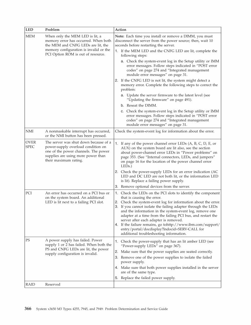
LED Problem Action
MEM When only the MEM LED is lit, amemory error has occurred. When boththe MEM and CNFG LEDs are lit, thememory configuration is invalid or thePCI Option ROM is out of resource.
Note: Each time you install or remove a DIMM, you mustdisconnect the server from the power source; then, wait 10seconds before restarting the server.
1. If the MEM LED and the CNFG LED are lit, complete thefollowing steps:
a. Check the system-event log in the Setup utility or IMMerror messages. Follow steps indicated in “POST errorcodes” on page 274 and “Integrated managementmodule error messages” on page 31.
2. If the CNFG LED is not lit, the system might detect amemory error. Complete the following steps to correct theproblem:
a. Update the server firmware to the latest level (see“Updating the firmware” on page 491).
b. Reseat the DIMM.
c. Check the system-event log in the Setup utility or IMMerror messages. Follow steps indicated in “POST errorcodes” on page 274 and “Integrated managementmodule error messages” on page 31.
NMI A nonmaskable interrupt has occurred,or the NMI button has been pressed.
Check the system-event log for information about the error.
OVERSPEC
The server was shut down because of apower-supply overload condition onone of the power channels. The powersupplies are using more power thantheir maximum rating.
1. If any of the power channel error LEDs (A, B, C, D, E, orAUX) on the system board are lit also, see the sectionabout power-channel error LEDs in “Power problems” onpage 353. (See “Internal connectors, LEDs, and jumpers”on page 16 for the location of the power channel errorLEDs.)
2. Check the power-supply LEDs for an error indication (ACLED and DC LED are not both lit, or the information LEDis lit). Replace a failing power supply.
3. Remove optional devices from the server.
PCI An error has occurred on a PCI bus oron the system board. An additionalLED is lit next to a failing PCI slot.
1. Check the LEDs on the PCI slots to identify the componentthat is causing the error.
2. Check the system-event log for information about the error.3. If you cannot isolate the failing adapter through the LEDs
and the information in the system-event log, remove oneadapter at a time from the failing PCI bus, and restart theserver after each adapter is removed.
4. If the failure remains, go tohttp://www.ibm.com/support/entry/portal/docdisplay?lndocid=SERV-CALL foradditional troubleshooting information.
PS A power supply has failed. Powersupply 1 or 2 has failed. When both thePS and CNFG LEDs are lit, the powersupply configuration is invalid.
1. Check the power-supply that has an lit amber LED (see“Power-supply LEDs” on page 367).
2. Make sure that the power supplies are seated correctly.
3. Remove one of the power supplies to isolate the failedpower supply.
4. Make sure that both power supplies installed in the serverare of the same type.
5. Replace the failed power supply.
RAID Reserved
366 System x3650 M3 Types 4255, 7945, and 7949: Problem Determination and Service Guide
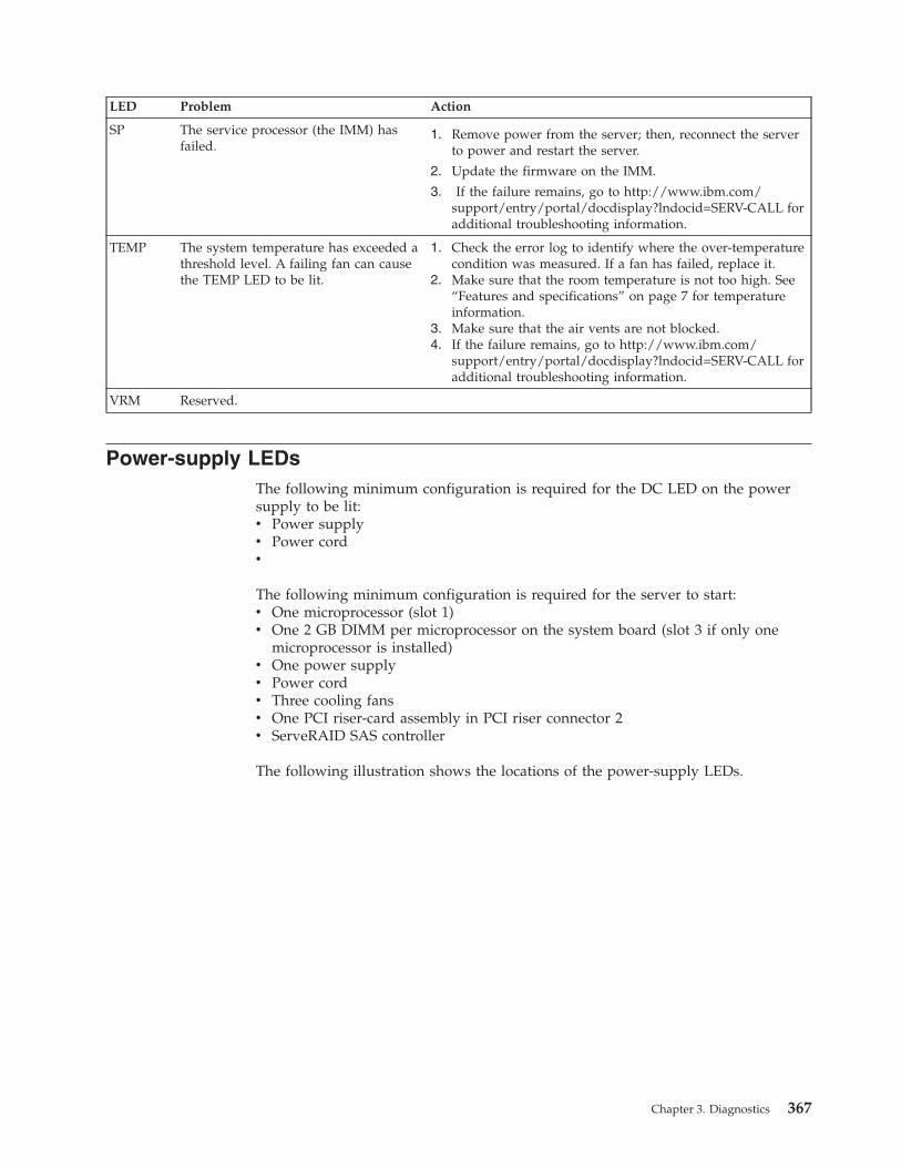
LED Problem Action
SP The service processor (the IMM) hasfailed.
1. Remove power from the server; then, reconnect the serverto power and restart the server.
2. Update the firmware on the IMM.
3. If the failure remains, go to http://www.ibm.com/support/entry/portal/docdisplay?lndocid=SERV-CALL foradditional troubleshooting information.
TEMP The system temperature has exceeded athreshold level. A failing fan can causethe TEMP LED to be lit.
1. Check the error log to identify where the over-temperaturecondition was measured. If a fan has failed, replace it.
2. Make sure that the room temperature is not too high. See“Features and specifications” on page 7 for temperatureinformation.
3. Make sure that the air vents are not blocked.4. If the failure remains, go to http://www.ibm.com/
support/entry/portal/docdisplay?lndocid=SERV-CALL foradditional troubleshooting information.
VRM Reserved.
Power-supply LEDsThe following minimum configuration is required for the DC LED on the powersupply to be lit:v Power supplyv Power cordv
The following minimum configuration is required for the server to start:v One microprocessor (slot 1)v One 2 GB DIMM per microprocessor on the system board (slot 3 if only one
microprocessor is installed)v One power supplyv Power cordv Three cooling fansv One PCI riser-card assembly in PCI riser connector 2v ServeRAID SAS controller
The following illustration shows the locations of the power-supply LEDs.
Chapter 3. Diagnostics 367
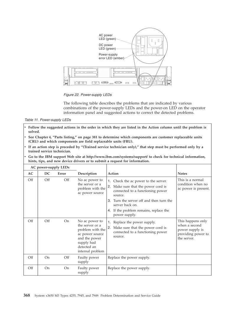
The following table describes the problems that are indicated by variouscombinations of the power-supply LEDs and the power-on LED on the operatorinformation panel and suggested actions to correct the detected problems.
Table 11. Power-supply LEDs
v Follow the suggested actions in the order in which they are listed in the Action column until the problem issolved.
v See Chapter 4, “Parts listing,” on page 381 to determine which components are customer replaceable units(CRU) and which components are field replaceable units (FRU).
v If an action step is preceded by “(Trained service technician only),” that step must be performed only by atrained service technician.
v Go to the IBM support Web site at http://www.ibm.com/systems/support/ to check for technical information,hints, tips, and new device drivers or to submit a request for information.
AC power-supply LEDs
Description Action NotesAC DC Error
Off Off Off No ac power tothe server or aproblem with theac power source
1. Check the ac power to the server.
2. Make sure that the power cord isconnected to a functioning powersource.
3. Turn the server off and then turn theserver back on.
4. If the problem remains, replace thepower supply.
This is a normalcondition when noac power is present.
Off Off On No ac power tothe server or aproblem with theac power sourceand the powersupply haddetected aninternal problem
1. Replace the power supply.
2. Make sure that the power cord isconnected to a functioning powersource.
This happens onlywhen a secondpower supply isproviding power tothe server.
Off On Off Faulty powersupply
Replace the power supply.
Off On On Faulty powersupply
Replace the power supply.
Figure 22. Power-supply LEDs
368 System x3650 M3 Types 4255, 7945, and 7949: Problem Determination and Service Guide
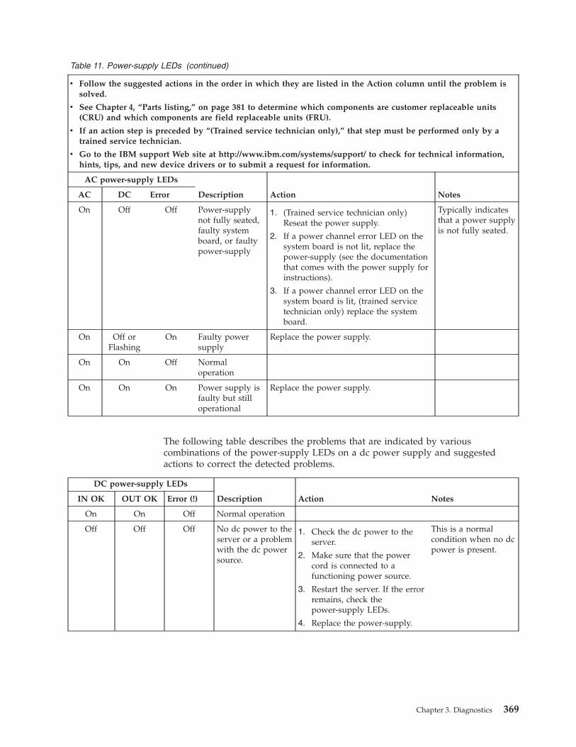
Table 11. Power-supply LEDs (continued)
v Follow the suggested actions in the order in which they are listed in the Action column until the problem issolved.
v See Chapter 4, “Parts listing,” on page 381 to determine which components are customer replaceable units(CRU) and which components are field replaceable units (FRU).
v If an action step is preceded by “(Trained service technician only),” that step must be performed only by atrained service technician.
v Go to the IBM support Web site at http://www.ibm.com/systems/support/ to check for technical information,hints, tips, and new device drivers or to submit a request for information.
AC power-supply LEDs
Description Action NotesAC DC Error
On Off Off Power-supplynot fully seated,faulty systemboard, or faultypower-supply
1. (Trained service technician only)Reseat the power supply.
2. If a power channel error LED on thesystem board is not lit, replace thepower-supply (see the documentationthat comes with the power supply forinstructions).
3. If a power channel error LED on thesystem board is lit, (trained servicetechnician only) replace the systemboard.
Typically indicatesthat a power supplyis not fully seated.
On Off orFlashing
On Faulty powersupply
Replace the power supply.
On On Off Normaloperation
On On On Power supply isfaulty but stilloperational
Replace the power supply.
The following table describes the problems that are indicated by variouscombinations of the power-supply LEDs on a dc power supply and suggestedactions to correct the detected problems.
DC power-supply LEDs
Description Action NotesIN OK OUT OK Error (!)
On On Off Normal operation
Off Off Off No dc power to theserver or a problemwith the dc powersource.
1. Check the dc power to theserver.
2. Make sure that the powercord is connected to afunctioning power source.
3. Restart the server. If the errorremains, check thepower-supply LEDs.
4. Replace the power-supply.
This is a normalcondition when no dcpower is present.
Chapter 3. Diagnostics 369
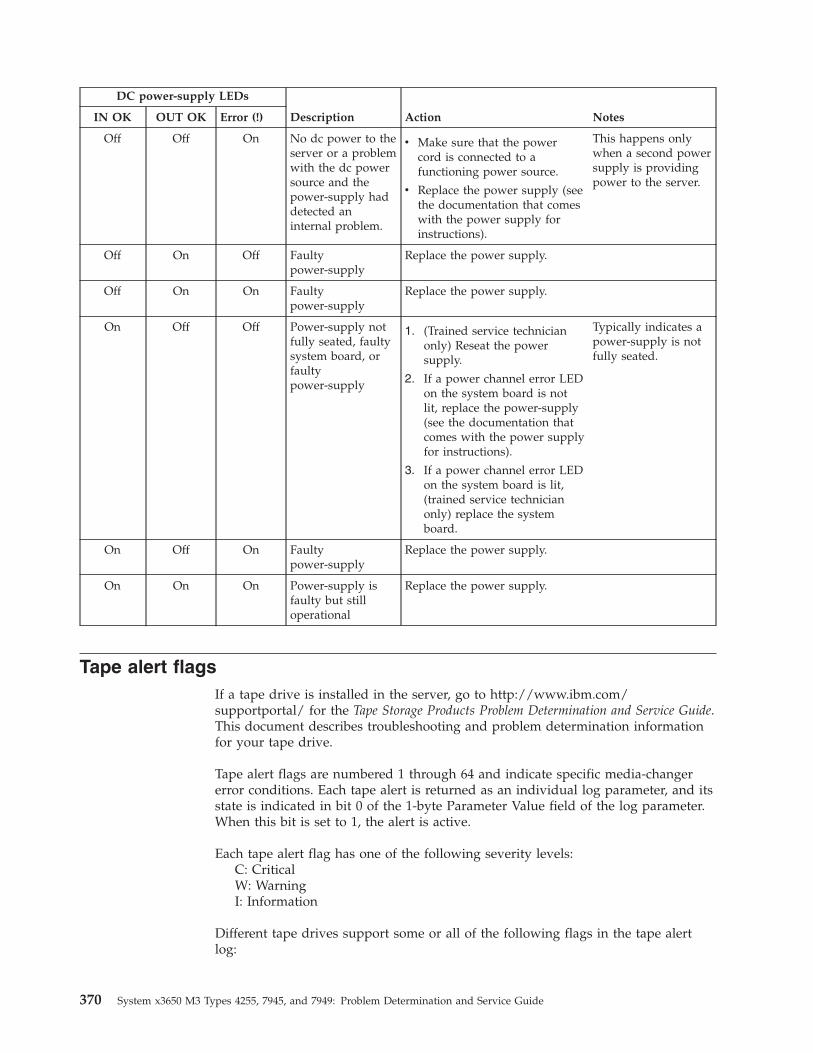
DC power-supply LEDs
Description Action NotesIN OK OUT OK Error (!)
Off Off On No dc power to theserver or a problemwith the dc powersource and thepower-supply haddetected aninternal problem.
v Make sure that the powercord is connected to afunctioning power source.
v Replace the power supply (seethe documentation that comeswith the power supply forinstructions).
This happens onlywhen a second powersupply is providingpower to the server.
Off On Off Faultypower-supply
Replace the power supply.
Off On On Faultypower-supply
Replace the power supply.
On Off Off Power-supply notfully seated, faultysystem board, orfaultypower-supply
1. (Trained service technicianonly) Reseat the powersupply.
2. If a power channel error LEDon the system board is notlit, replace the power-supply(see the documentation thatcomes with the power supplyfor instructions).
3. If a power channel error LEDon the system board is lit,(trained service technicianonly) replace the systemboard.
Typically indicates apower-supply is notfully seated.
On Off On Faultypower-supply
Replace the power supply.
On On On Power-supply isfaulty but stilloperational
Replace the power supply.
Tape alert flagsIf a tape drive is installed in the server, go to http://www.ibm.com/supportportal/ for the Tape Storage Products Problem Determination and Service Guide.This document describes troubleshooting and problem determination informationfor your tape drive.
Tape alert flags are numbered 1 through 64 and indicate specific media-changererror conditions. Each tape alert is returned as an individual log parameter, and itsstate is indicated in bit 0 of the 1-byte Parameter Value field of the log parameter.When this bit is set to 1, the alert is active.
Each tape alert flag has one of the following severity levels:C: CriticalW: WarningI: Information
Different tape drives support some or all of the following flags in the tape alertlog:
370 System x3650 M3 Types 4255, 7945, and 7949: Problem Determination and Service Guide
Flag 2: Library Hardware B (W) This flag is set when an unrecoverablemechanical error occurs.Flag 4: Library Hardware D (C) This flag is set when the tape drive fails thepower-on self-test or a mechanical error occurs that requires a power cycle torecover. This flag is internally cleared when the drive is powered-off.Flag 13: Library Pick Retry (W) This flag is set when a high retry countthreshold is passed during an operation to pick a cartridge from a slot beforethe operation succeeds. This flag is internally cleared when another pickoperation is attempted.Flag 14: Library Place Retry (W) This flag is set when a high retry countthreshold is passed during an operation to place a cartridge back into a slotbefore the operation succeeds. This flag is internally cleared when another placeoperation is attempted.Flag 15: Library Load Retry (W) This flag is set when a high retry countthreshold is passed during an operation to load a cartridge into a drive beforethe operation succeeds. This flag is internally cleared when another loadoperation is attempted. Note that if the load operation fails because of a mediaor drive problem, the drive sets the applicable tape alert flags.Flag 16: Library Door (C) This flag is set when media move operations cannotbe performed because a door is open. This flag is internally cleared when thedoor is closed.Flag 23: Library Scan Retry (W) This flag is set when a high retry countthreshold is passed during an operation to scan the bar code on a cartridgebefore the operation succeeds. This flag is internally cleared when another barcode scanning operation is attempted.
Recovering the server firmwareUse this information to recover the server firmware.
About this task
Important: Some cluster solutions require specific code levels or coordinated codeupdates. If the device is part of a cluster solution, verify that the latest level ofcode is supported for the cluster solution before you update the code.
If the server firmware has become corrupted, such as from a power failure duringan update, you can recover the server firmware in one of two ways:v In-band method: Recover server firmware, using either the boot block jumper
(Automated Boot Recovery) and a server Firmware Update Package ServicePack.
v Out-of-band method: Use the IMM Web Interface to update the firmware, usingthe latest server firmware update package.
Note: You can obtain a server firmware update package from one of the followingsources:v Download the server firmware update from the World Wide Web.v Contact your IBM service representative.
To download the server firmware update package from the World Wide Web,complete the following steps.
Chapter 3. Diagnostics 371
Note: Changes are made periodically to the IBM Web site. The actual proceduremight vary slightly from what is described in this document.1. Go to http://www.ibm.com/systems/support/.2. Under Product support, click System x.3. Under Popular links, click Software and device drivers.4. Click System x3650 M3 to display the matrix of downloadable files for the
server.5. Download the latest server firmware update.
The flash memory of the server consists of a primary bank and a backup bank. It isessential that you maintain the backup bank with a bootable firmware image. If theprimary bank becomes corrupted, you can either manually boot the backup bankwith the boot block jumper, or in the case of image corruption, this will occurautomatically with the Automated Boot Recovery function.
In-band manual recovery method
To recover the server firmware and restore the server operation to the primarybank, complete the following steps:
Procedure1. Turn off the server, and disconnect all power cords and external cables.2. Remove the server cover. See “Removing the cover” on page 402 for more
information.3. Unlock and remove the server cover (see “Removing the cover” on page 402
for more information.4. Locate the UEFI boot recovery jumper block (J29) on the system board.
372 System x3650 M3 Types 4255, 7945, and 7949: Problem Determination and Service Guide
SW3 switch blockSW4 switch block
UEFI boot recoveryjumper (J29)
123
123
IMM recovery jumper(J147)
5. Remove any adapters that impede access to the UEFI boot recovery jumperblock (J29) (see “Removing a PCI adapter from a PCI riser-card assembly” onpage 417).
6. Move the jumper from pins 1 and 2 to pins 2 and 3 to enable the UEFIrecovery mode.
7. Reinstall any adapter that you removed before (see “Installing a PCI adapterin a PCI riser-card assembly” on page 418).
8. Reinstall the server cover (see “Replacing the cover” on page 403).9. Reconnect all power cords and external cables and restart the server. The
power-on self-test (POST) starts.10. Boot the server to an operating system that is supported by the firmware
update package that you downloaded.11. Perform the firmware update by following the instructions that are in the
firmware update package readme file.12. Copy the downloaded firmware update package into a directory.
Chapter 3. Diagnostics 373
13. From a command line, type filename-s, where filename is the name of theexecutable file that you downloaded with the firmware update package.Monitor the firmware update until completion.
14. Turn off the server and disconnect all power cords and external cables, andthen remove the server cover (see “Removing the cover” on page 402
15. Remove any adapters that impede access to the UEFI boot recovery jumperblock (J29) (see “Removing a PCI adapter from a PCI riser-card assembly” onpage 417).
16. Move the UEFI boot block recovery jumper (J29) from pins 2 and 3 back to theprimary position (pins 1 and 2).
17. Reinstall any adapter that you removed before (see “Installing a PCI adapterin a PCI riser-card assembly” on page 418).
18. Reinstall the server cover (see “Replacing the cover” on page 403); then,reconnect all power cords.
19. Restart the server. The power-on self-test (POST) starts. If this does notrecover the primary bank, continue with the following steps.
20. Remove the server cover (see “Removing the cover” on page 402).21. Reset the CMOS by removing the system battery (see “Removing the battery”
on page 463).22. Leave the system battery out of the server for approximately 5 to 15 minutes.23. Reinstall the system battery (see “Replacing the battery” on page 465).24. Reinstall the server cover (see “Replacing the cover” on page 403); then,
reconnect all power cords.25. Restart the server. The power-on self-test (POST) starts.26. If these recovery efforts fail, contact your IBM service representative for
support.
Results
See “System-board switches and jumpers” on page 18 for more information aboutthe switches and jumpers.
In-band automated boot recovery method
Note: Use this method if the BOARD LED on the light path diagnostics panel is litand there is a log entry or Booting Backup Image is displayed on the firmwaresplash screen; otherwise, use the in-band manual recovery method.1. Boot the server to an operating system that is supported by the firmware
update package that you downloaded.2. Perform the firmware update by following the instructions that are in the
firmware update package readme file.3. Restart the server.4. At the firmware splash screen, press F3 when prompted to restore to the
primary bank. The server boots from the primary bank.
Out-of-band method: See the IMM documentation.
374 System x3650 M3 Types 4255, 7945, and 7949: Problem Determination and Service Guide
Automatic boot failure recovery (ABR)While the server is starting, if the integrated management module detects problemswith the server firmware in the primary bank, the server automatically switches tothe backup firmware bank and gives you the opportunity to recover the firmwarein the primary bank.
About this task
For instructions for recovering the UEFI firmware, see “Recovering the serverfirmware” on page 371. After you have recovered the firmware in the primarybank, complete the following steps:
Procedure1. Restart the server.2. When the prompt Press F3 to restore to primary is displayed. Press F3 to
recover the primary bank. Pressing F3 will restart the server.
Nx boot failureConfiguration changes, such as added devices or adapter firmware updates, andfirmware or application code problems can cause the server to fail POST (thepower-on self-test). If this occurs, the server responds in either of the followingways:v The server restarts automatically and attempts POST again.v The server hangs, and you must manually restart the server for the server to
attempt POST again.
After a specified number of consecutive attempts (automatic or manual), the Nxboot failure feature causes the server to revert to the default UEFI configurationand start the Setup utility so that you can make the necessary corrections to theconfiguration and restart the server. If the server is unable to successfully completePOST with the default configuration, there might be a problem with the systemboard.
To specify the number of consecutive restart attempts that will trigger the Nx bootfailure feature, in the Setup utility, click System Settings → Operating Modes →POST Attempts Limit. The available options are 3, 6, 9, and 255 (disable Nx bootfailure).
Chapter 3. Diagnostics 375
Solving power problemsAbout this task
Power problems can be difficult to solve. For example, a short circuit can existanywhere on any of the power distribution buses. Usually, a short circuit willcause the power subsystem to shut down because of an overcurrent condition. Todiagnose a power problem, use the following general procedure:
Procedure1. Turn off the server and disconnect all power cords.2. Check for loose cables in the power subsystem. Also check for short circuits, for
example, if a loose screw is causing a short circuit on a circuit board.3. Check the LEDs on the operator information panel (see “Light path diagnostics
LEDs” on page 363).4. If a power-channel error LED on the system board is lit, complete the following
steps; otherwise, go to step 5. See “System-board LEDs” on page 22 for thelocation of the power-channel error LEDs. Table 12 identifies the componentsthat are associated with each power channel and the order in which totroubleshoot the components.a. Disconnect the cables and power cords to all internal and external devices
(see “Internal cable routing and connectors” on page 398). Leave thepower-supply cords connected.
b. Remove each component that is associated with the LED, one at a time, inthe sequence indicated in Table 12, restarting the server each time, until thecause of the overcurrent condition is identified.Important: Only a trained service technician should remove or replace aFRU, such as a microprocessor or the system board. See Chapter 4, “Partslisting,” on page 381 to determine whether a component is a FRU.
Table 12. Components associated with power-channel error LEDs
Power-channelerror LED Components
A CD or DVD drive (optical drive), fans, hard disk drives, hard disk drivebackplanes
B PCI riser-card assembly in PCI connector 1 on the system board,DIMMs 1 through 16, microprocessor 2
C Tape drive if one is installed, SAS riser card assembly, DIMMs 1through 8, microprocessor 1
D Microprocessor 1, system board
E Optional PCI video graphics adapter power cable if one is installed(connector J154 on the system board), optional PCI video graphicsadapter if one is installed, PCI riser card assembly in PCI connector 2on the system board, microprocessor 2
AUX Power All PCI adapters and PCI riser-card assemblies, SAS riser-cardassembly, operator information panel assembly, optional two-portEthernet card if installed
c. Replace the identified component.5. Remove the adapters and disconnect the cables and power cords to all internal
and external devices until the server is at the minimum configuration that isrequired for the server to start (see “Solving undetermined problems” on page378 for the minimum configuration).
376 System x3650 M3 Types 4255, 7945, and 7949: Problem Determination and Service Guide
6. Reconnect all power cords and turn on the server. If the server startssuccessfully, replace the adapters and devices one at a time until the problem isisolated.
Results
If the server does not start from the minimum configuration, replace thecomponents in the minimum configuration one at a time until the problem isisolated.
Solving Ethernet controller problemsUse this information to solve Ethernet controller problems.
The method that you use to test the Ethernet controller depends on whichoperating system you are using. See the operating-system documentation forinformation about Ethernet controllers, and see the Ethernet controllerdevice-driver readme file.
Try the following procedures:v Make sure that the correct and current device drivers and firmware, which come
with the server, are installed and that they are at the latest level.Important: Some cluster solutions require specific code levels or coordinatedcode updates. If the device is part of a cluster solution, verify that the latest levelof code is supported for the cluster solution before you update the code.
v Make sure that the Ethernet cable is installed correctly.– The cable must be securely attached at all connections. If the cable is attached
but the problem remains, try a different cable.– You must use Category 5 cabling.
v Determine whether the hub supports auto-negotiation. If it does not, tryconfiguring the integrated Ethernet controller manually to match the speed andduplex mode of the hub.
v Check the Ethernet controller LEDs on the rear panel of the server. These LEDsindicate whether there is a problem with the connector, cable, or hub.– The Ethernet link status LED is lit when the Ethernet controller receives a link
pulse from the hub. If the LED is off, there might be a defective connector orcable or a problem with the hub.
– The Ethernet transmit/receive activity LED is lit when the Ethernet controllersends or receives data over the Ethernet network. If the Ethernettransmit/receive activity light is off, make sure that the hub and network areoperating and that the correct device drivers are installed.
v Check the Ethernet activity LED on the rear of the server. The Ethernet activityLED is lit when data is active on the Ethernet network. If the Ethernet activityLED is off, make sure that the hub and network are operating and that thecorrect device drivers are installed.
v Check for operating-system-specific causes of the problem.v Make sure that the device drivers on the client and server are using the same
protocol.
If the Ethernet controller still cannot connect to the network but the hardwareappears to be working, the network administrator must investigate other possiblecauses of the error.
Chapter 3. Diagnostics 377
Solving undetermined problemsAbout this task
If the diagnostic tests did not diagnose the failure or if the server is inoperative,use the information in this section.
If you suspect that a software problem is causing failures (continuous orintermittent), see “Software problems” on page 359.
Damaged data in CMOS memory or damaged server firmware can causeundetermined problems. To reset the CMOS data, use the CMOS switch to clearthe CMOS memory; see “System-board switches and jumpers” on page 18. If yoususpect that the server firmware is damaged, see “Recovering the server firmware”on page 371.
Check the LEDs on all the power supplies (see “Power-supply LEDs” on page 367).If the LEDs indicate that the power supplies are working correctly, complete thefollowing steps:1. Turn off the server.2. Make sure that the server is cabled correctly.3. Remove or disconnect the following devices, one at a time, until you find the
failure. Turn on the server and reconfigure it each time.v Any external devices.v Surge-suppressor device (on the server).v Modem, printer, mouse, and non-IBM devices.v Each adapter.v Hard disk drives.v Memory modules. The minimum configuration requirement is 2 GB DIMM
per installed microprocessor.v Service processor (IMM).The following minimum configuration is required for the server to start:v One microprocessor (slot 1)v One 2 GB DIMM per installed microprocessor (slot 3 if only one
microprocessor is installed)v One power supplyv Power cordv Three cooling fansv One PCI riser-card assembly in PCI riser connector 2v ServeRAID SAS controller
4. Turn on the server. If the problem remains, suspect the system board.
If the problem is solved when you remove an adapter from the server but theproblem recurs when you reinstall the same adapter, suspect the adapter; if theproblem recurs when you replace the adapter with a different one, suspect the risercard.
If you suspect a networking problem and the server passes all the system tests,suspect a network cabling problem that is external to the server.
If the problem remains, see “Troubleshooting tables” on page 340.
378 System x3650 M3 Types 4255, 7945, and 7949: Problem Determination and Service Guide
Problem determination tipsBecause of the variety of hardware and software combinations that you canencounter, use the following information to assist you in problem determination. Ifpossible, have this information available when you request assistance from IBM.v Machine type and modelv Microprocessor and hard disk upgradesv Failure symptom
– Does the server fail the diagnostics tests?– What occurs? When? Where?– Does the failure occur on a single server or on multiple servers?– Is the failure repeatable?– Has this configuration ever worked?– What changes, if any, were made before the configuration failed?– Is this the original reported failure?
v Diagnostics program type and version levelv Hardware configuration (print screen of the system summary)v BIOS code levelv Operating-system type and version level
You can solve some problems by comparing the configuration and software setupsbetween working and nonworking servers. When you compare servers to eachother for diagnostic purposes, consider them identical only if all the followingfactors are exactly the same in all the servers:v Machine type and modelv BIOS levelv Adapters and attachments, in the same locationsv Address jumpers, terminators, and cablingv Software versions and levelsv Diagnostic program type and version levelv Setup utility settingsv Operating-system control-file setup
See Appendix A, “Getting help and technical assistance,” on page 517 forinformation about calling IBM for service.
Chapter 3. Diagnostics 379

380 System x3650 M3 Types 4255, 7945, and 7949: Problem Determination and Service Guide
Chapter 4. Parts listing
The parts listing of System x3650 M3 Types 4255, 7945, and 7949
The following replaceable components are available for all the Series x3650 M3Type 4255, 7945, or 7949 server models, except as specified otherwise in“Replaceable server components.” To check for an updated parts listing on theWeb, complete the following steps.1. Go to http://www.ibm.com/systems/support/.2. Under Product support, click System x.3. Under Popular links, click Parts documents lookup.4. From the Product family menu, select System x3650 M3 and click Go.
Replaceable server componentsReplaceable components are of four types:v Consumable parts: Purchase and replacement of consumable parts (components,
such as batteries and printer cartridges, that have depletable life) is yourresponsibility. If IBM acquires or installs a consumable part at your request, youwill be charged for the service.
v Tier 1 customer replaceable unit (CRU): Replacement of Tier 1 CRUs is yourresponsibility. If IBM installs a Tier 1 CRU at your request, you will be chargedfor the installation.
v Tier 2 customer replaceable unit: You may install a Tier 2 CRU yourself orrequest IBM to install it, at no additional charge, under the type of warrantyservice that is designated for your server.
v Field replaceable unit (FRU): FRUs must be installed only by trained servicetechnicians.
For information about the terms of the warranty and getting service and assistance,see the Warranty Information document on the IBM Documentation CD.
The following illustration shows the major components in the server. Theillustrations in this document might differ slightly from your hardware.
© Copyright IBM Corp. 2014 381
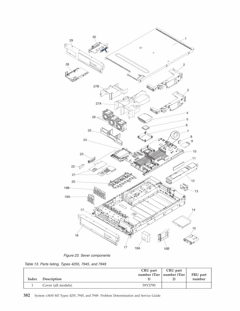
Table 13. Parts listing, Types 4255, 7945, and 7949
Index Description
CRU partnumber (Tier
1)
CRU partnumber (Tier
2)FRU partnumber
1 Cover (all models) 59Y3790
Figure 23. Sever components
382 System x3650 M3 Types 4255, 7945, and 7949: Problem Determination and Service Guide
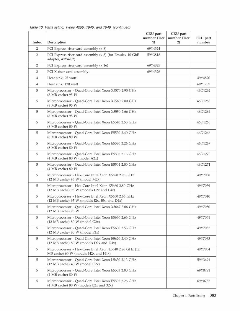
Table 13. Parts listing, Types 4255, 7945, and 7949 (continued)
Index Description
CRU partnumber (Tier
1)
CRU partnumber (Tier
2)FRU partnumber
2 PCI Express riser-card assembly (x 8) 69Y4324
2 PCI Express riser-card assembly (x 8) (for Emulex 10 GbEadapter, 49Y4202)
59Y3818
2 PCI Express riser-card assembly (x 16) 69Y4325
3 PCI-X riser-card assembly 69Y4326
4 Heat sink, 95 watt 49Y4820
4 Heat sink, 130 watt 69Y1207
5 Microprocessor - Quad-Core Intel Xeon X5570 2.93 GHz(8 MB cache) 95 W
46D1262
5 Microprocessor - Quad-Core Intel Xeon X5560 2.80 GHz(8 MB cache) 95 W
46D1263
5 Microprocessor - Quad-Core Intel Xeon X5550 2.66 GHz(8 MB cache) 95 W
46D1264
5 Microprocessor - Quad-Core Intel Xeon E5540 2.53 GHz(8 MB cache) 80 W
46D1265
5 Microprocessor - Quad-Core Intel Xeon E5530 2.40 GHz(8 MB cache) 80 W
46D1266
5 Microprocessor - Quad-Core Intel Xeon E5520 2.26 GHz(8 MB cache) 80 W
46D1267
5 Microprocessor - Quad-Core Intel Xeon E5506 2.13 GHz(4 MB cache) 80 W (model A2x)
46D1270
5 Microprocessor - Quad-Core Intel Xeon E5504 2.00 GHz(4 MB cache) 80 W
46D1271
5 Microprocessor - Hex-Core Intel Xeon X5670 2.93 GHz(12 MB cache) 95 W (model M2x)
49Y7038
5 Microprocessor - Hex-Core Intel Xeon X5660 2.80 GHz(12 MB cache) 95 W (models L2x and L4x)
49Y7039
5 Microprocessor - Hex-Core Intel Xeon X5650 2.66 GHz(12 MB cache) 95 W (models J2x, JSx, and D4x)
49Y7040
5 Microprocessor - Quad-Core Intel Xeon X5667 3.06 GHz(12 MB cache) 95 W
49Y7050
5 Microprocessor - Quad-Core Intel Xeon E5640 2.66 GHz(12 MB cache) 80 W (model G2x)
49Y7051
5 Microprocessor - Quad-Core Intel Xeon E5630 2.53 GHz(12 MB cache) 80 W (model F2x)
49Y7052
5 Microprocessor - Quad-Core Intel Xeon E5620 2.40 GHz(12 MB cache) 80 W (models D2x and D4x)
49Y7053
5 Microprocessor - Hex-Core Intel Xeon L5640 2.26 GHz (12MB cache) 60 W (models H2x and H4x)
49Y7054
5 Microprocessor - Quad-Core Intel Xeon L5630 2.13 GHz(12 MB cache) 40 W (model C2x)
59Y3691
5 Microprocessor - Quad-Core Intel Xeon E5503 2.00 GHz(4 MB cache) 80 W
69Y0781
5 Microprocessor - Quad-Core Intel Xeon E5507 2.26 GHz(4 MB cache) 80 W (models B2x and 32x)
69Y0782
Chapter 4. Parts listing 383
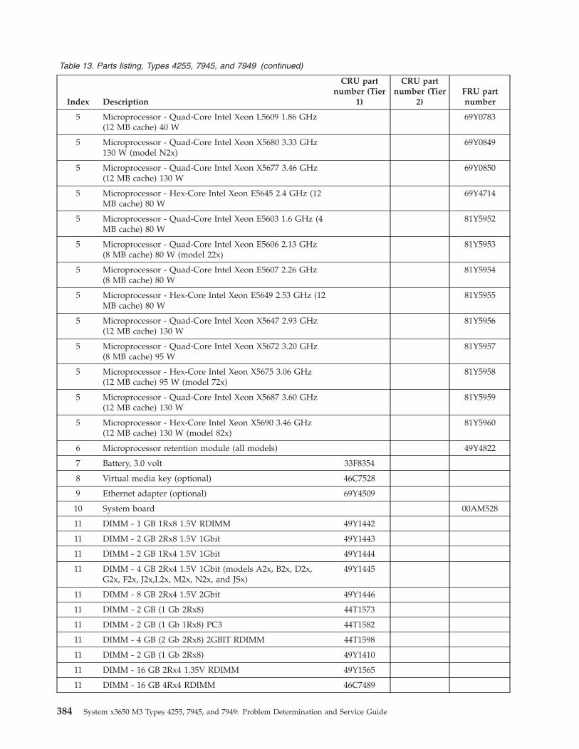
Table 13. Parts listing, Types 4255, 7945, and 7949 (continued)
Index Description
CRU partnumber (Tier
1)
CRU partnumber (Tier
2)FRU partnumber
5 Microprocessor - Quad-Core Intel Xeon L5609 1.86 GHz(12 MB cache) 40 W
69Y0783
5 Microprocessor - Quad-Core Intel Xeon X5680 3.33 GHz130 W (model N2x)
69Y0849
5 Microprocessor - Quad-Core Intel Xeon X5677 3.46 GHz(12 MB cache) 130 W
69Y0850
5 Microprocessor - Hex-Core Intel Xeon E5645 2.4 GHz (12MB cache) 80 W
69Y4714
5 Microprocessor - Quad-Core Intel Xeon E5603 1.6 GHz (4MB cache) 80 W
81Y5952
5 Microprocessor - Quad-Core Intel Xeon E5606 2.13 GHz(8 MB cache) 80 W (model 22x)
81Y5953
5 Microprocessor - Quad-Core Intel Xeon E5607 2.26 GHz(8 MB cache) 80 W
81Y5954
5 Microprocessor - Hex-Core Intel Xeon E5649 2.53 GHz (12MB cache) 80 W
81Y5955
5 Microprocessor - Quad-Core Intel Xeon X5647 2.93 GHz(12 MB cache) 130 W
81Y5956
5 Microprocessor - Quad-Core Intel Xeon X5672 3.20 GHz(8 MB cache) 95 W
81Y5957
5 Microprocessor - Hex-Core Intel Xeon X5675 3.06 GHz(12 MB cache) 95 W (model 72x)
81Y5958
5 Microprocessor - Quad-Core Intel Xeon X5687 3.60 GHz(12 MB cache) 130 W
81Y5959
5 Microprocessor - Hex-Core Intel Xeon X5690 3.46 GHz(12 MB cache) 130 W (model 82x)
81Y5960
6 Microprocessor retention module (all models) 49Y4822
7 Battery, 3.0 volt 33F8354
8 Virtual media key (optional) 46C7528
9 Ethernet adapter (optional) 69Y4509
10 System board 00AM528
11 DIMM - 1 GB 1Rx8 1.5V RDIMM 49Y1442
11 DIMM - 2 GB 2Rx8 1.5V 1Gbit 49Y1443
11 DIMM - 2 GB 1Rx4 1.5V 1Gbit 49Y1444
11 DIMM - 4 GB 2Rx4 1.5V 1Gbit (models A2x, B2x, D2x,G2x, F2x, J2x,L2x, M2x, N2x, and JSx)
49Y1445
11 DIMM - 8 GB 2Rx4 1.5V 2Gbit 49Y1446
11 DIMM - 2 GB (1 Gb 2Rx8) 44T1573
11 DIMM - 2 GB (1 Gb 1Rx8) PC3 44T1582
11 DIMM - 4 GB (2 Gb 2Rx8) 2GBIT RDIMM 44T1598
11 DIMM - 2 GB (1 Gb 2Rx8) 49Y1410
11 DIMM - 16 GB 2Rx4 1.35V RDIMM 49Y1565
11 DIMM - 16 GB 4Rx4 RDIMM 46C7489
384 System x3650 M3 Types 4255, 7945, and 7949: Problem Determination and Service Guide
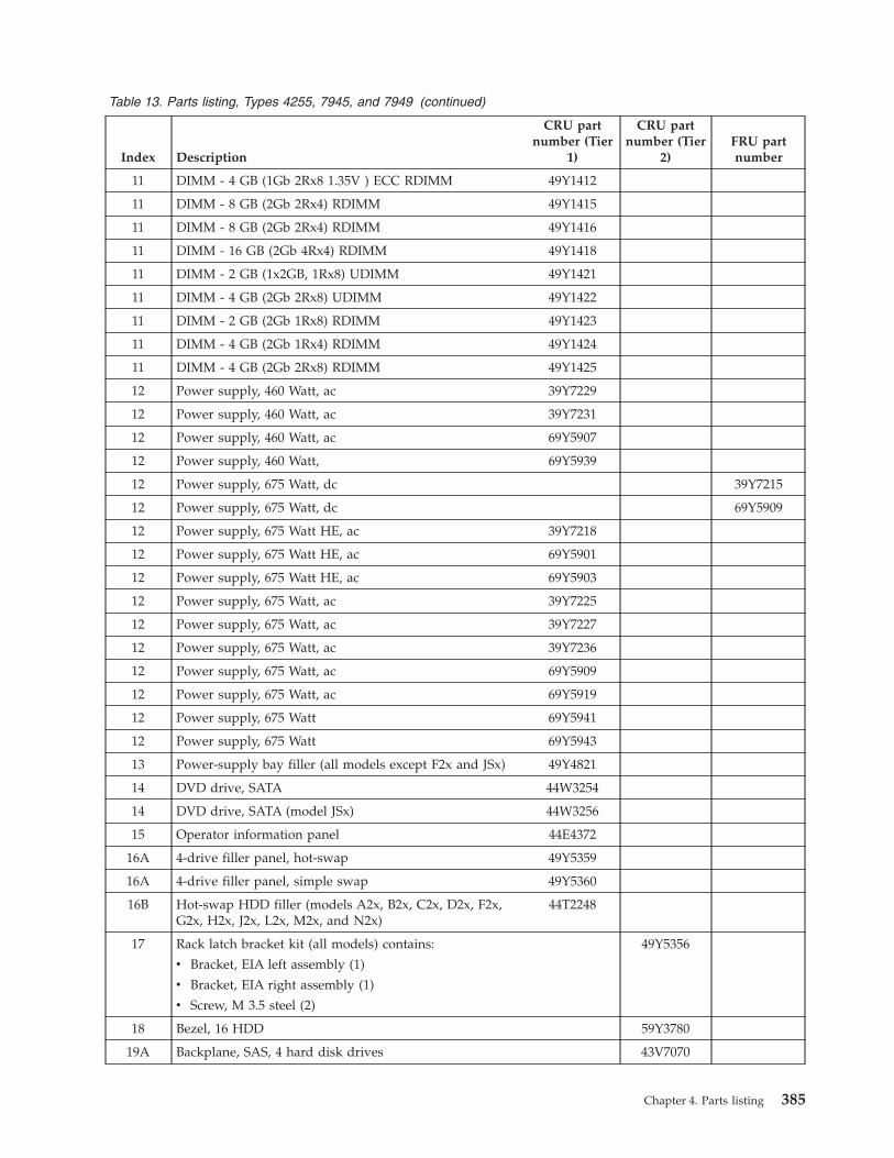
Table 13. Parts listing, Types 4255, 7945, and 7949 (continued)
Index Description
CRU partnumber (Tier
1)
CRU partnumber (Tier
2)FRU partnumber
11 DIMM - 4 GB (1Gb 2Rx8 1.35V ) ECC RDIMM 49Y1412
11 DIMM - 8 GB (2Gb 2Rx4) RDIMM 49Y1415
11 DIMM - 8 GB (2Gb 2Rx4) RDIMM 49Y1416
11 DIMM - 16 GB (2Gb 4Rx4) RDIMM 49Y1418
11 DIMM - 2 GB (1x2GB, 1Rx8) UDIMM 49Y1421
11 DIMM - 4 GB (2Gb 2Rx8) UDIMM 49Y1422
11 DIMM - 2 GB (2Gb 1Rx8) RDIMM 49Y1423
11 DIMM - 4 GB (2Gb 1Rx4) RDIMM 49Y1424
11 DIMM - 4 GB (2Gb 2Rx8) RDIMM 49Y1425
12 Power supply, 460 Watt, ac 39Y7229
12 Power supply, 460 Watt, ac 39Y7231
12 Power supply, 460 Watt, ac 69Y5907
12 Power supply, 460 Watt, 69Y5939
12 Power supply, 675 Watt, dc 39Y7215
12 Power supply, 675 Watt, dc 69Y5909
12 Power supply, 675 Watt HE, ac 39Y7218
12 Power supply, 675 Watt HE, ac 69Y5901
12 Power supply, 675 Watt HE, ac 69Y5903
12 Power supply, 675 Watt, ac 39Y7225
12 Power supply, 675 Watt, ac 39Y7227
12 Power supply, 675 Watt, ac 39Y7236
12 Power supply, 675 Watt, ac 69Y5909
12 Power supply, 675 Watt, ac 69Y5919
12 Power supply, 675 Watt 69Y5941
12 Power supply, 675 Watt 69Y5943
13 Power-supply bay filler (all models except F2x and JSx) 49Y4821
14 DVD drive, SATA 44W3254
14 DVD drive, SATA (model JSx) 44W3256
15 Operator information panel 44E4372
16A 4-drive filler panel, hot-swap 49Y5359
16A 4-drive filler panel, simple swap 49Y5360
16B Hot-swap HDD filler (models A2x, B2x, C2x, D2x, F2x,G2x, H2x, J2x, L2x, M2x, and N2x)
44T2248
17 Rack latch bracket kit (all models) contains:
v Bracket, EIA left assembly (1)
v Bracket, EIA right assembly (1)
v Screw, M 3.5 steel (2)
49Y5356
18 Bezel, 16 HDD 59Y3780
19A Backplane, SAS, 4 hard disk drives 43V7070
Chapter 4. Parts listing 385
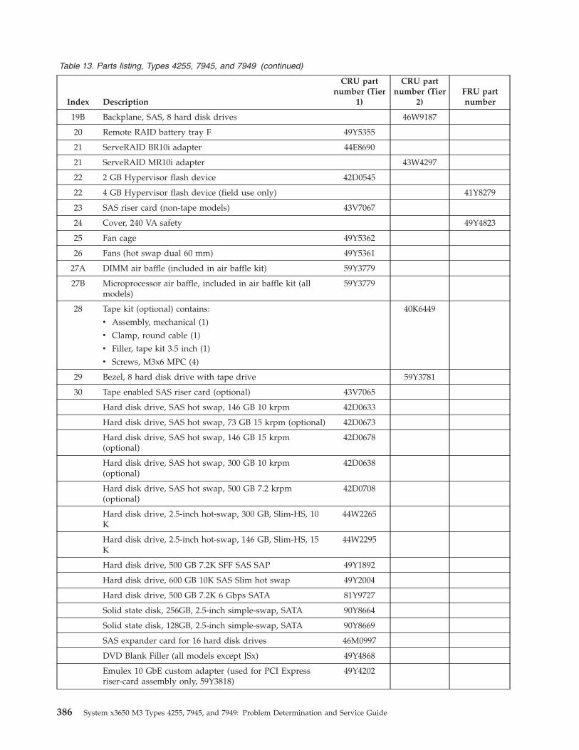
Table 13. Parts listing, Types 4255, 7945, and 7949 (continued)
Index Description
CRU partnumber (Tier
1)
CRU partnumber (Tier
2)FRU partnumber
19B Backplane, SAS, 8 hard disk drives 46W9187
20 Remote RAID battery tray F 49Y5355
21 ServeRAID BR10i adapter 44E8690
21 ServeRAID MR10i adapter 43W4297
22 2 GB Hypervisor flash device 42D0545
22 4 GB Hypervisor flash device (field use only) 41Y8279
23 SAS riser card (non-tape models) 43V7067
24 Cover, 240 VA safety 49Y4823
25 Fan cage 49Y5362
26 Fans (hot swap dual 60 mm) 49Y5361
27A DIMM air baffle (included in air baffle kit) 59Y3779
27B Microprocessor air baffle, included in air baffle kit (allmodels)
59Y3779
28 Tape kit (optional) contains:
v Assembly, mechanical (1)
v Clamp, round cable (1)
v Filler, tape kit 3.5 inch (1)
v Screws, M3x6 MPC (4)
40K6449
29 Bezel, 8 hard disk drive with tape drive 59Y3781
30 Tape enabled SAS riser card (optional) 43V7065
Hard disk drive, SAS hot swap, 146 GB 10 krpm 42D0633
Hard disk drive, SAS hot swap, 73 GB 15 krpm (optional) 42D0673
Hard disk drive, SAS hot swap, 146 GB 15 krpm(optional)
42D0678
Hard disk drive, SAS hot swap, 300 GB 10 krpm(optional)
42D0638
Hard disk drive, SAS hot swap, 500 GB 7.2 krpm(optional)
42D0708
Hard disk drive, 2.5-inch hot-swap, 300 GB, Slim-HS, 10K
44W2265
Hard disk drive, 2.5-inch hot-swap, 146 GB, Slim-HS, 15K
44W2295
Hard disk drive, 500 GB 7.2K SFF SAS SAP 49Y1892
Hard disk drive, 600 GB 10K SAS Slim hot swap 49Y2004
Hard disk drive, 500 GB 7.2K 6 Gbps SATA 81Y9727
Solid state disk, 256GB, 2.5-inch simple-swap, SATA 90Y8664
Solid state disk, 128GB, 2.5-inch simple-swap, SATA 90Y8669
SAS expander card for 16 hard disk drives 46M0997
DVD Blank Filler (all models except JSx) 49Y4868
Emulex 10 GbE custom adapter (used for PCI Expressriser-card assembly only, 59Y3818)
49Y4202
386 System x3650 M3 Types 4255, 7945, and 7949: Problem Determination and Service Guide

Table 13. Parts listing, Types 4255, 7945, and 7949 (continued)
Index Description
CRU partnumber (Tier
1)
CRU partnumber (Tier
2)FRU partnumber
Emulex 10GbE Virtual Fabric Adapter II 49Y7952
NetXtreme II 1000 Express quad port Ethernet adapter 49Y4222
Qlogic 10Gb CNA card assembly 00Y3274
Qlogic 10Gb Dual-Port CN 42C1802
Qlogic 10Gb SFP+SR 42C1816
10Gb SFP+ SR optical transceiver 46C9297
Brocade 10Gb SFP+ SR optical transceiver 42C1819
Brocade 10Gb CNA for IBM System x 42C1822
10Gb SFP+ transceiver module assembly 46C3449
IBM 10 GbE SW SFP+ transceiver 49Y8579
ServeRAID-BR10i SAS/SATA controller 46C9043
ServeRAID-BR10il SAS/SATA controller (model A2x) 49Y4737
ServeRAID M1015 SAS/SATA Controller 46C8933
ServeRAID-M5014 SAS/SATA controller 46C8929
ServeRAID-M5014 SAS/SATA controller (models F2x andG2x)
46M0918
ServeRAID-M5015 SAS/SATA controller 46C8927
ServeRAID-M5015 SAS/SATA controller (models J2x, JSx,L2x, and M2x)
46M0851
ServeRAID-B5015 SAS/SATA controller 46M0970
ServeRAID-M1015 SAS/SATA controller 46C8933
ServeRAID-M1015 SAS/SATA controller (models B2x,C2x, D2x, H2x, and N2x)
46M0861
ServeRAID-MR10i SAS/SATA controller 46C9037
ServeRAID M5000 series advanced feature key 46M0931
ServeRAID M1000 series advanced feature key 46M0864
Carrier daughter card 44E8763
Daughter card mechanic kit, 1 GB 69Y4586
Chapter 4. Parts listing 387
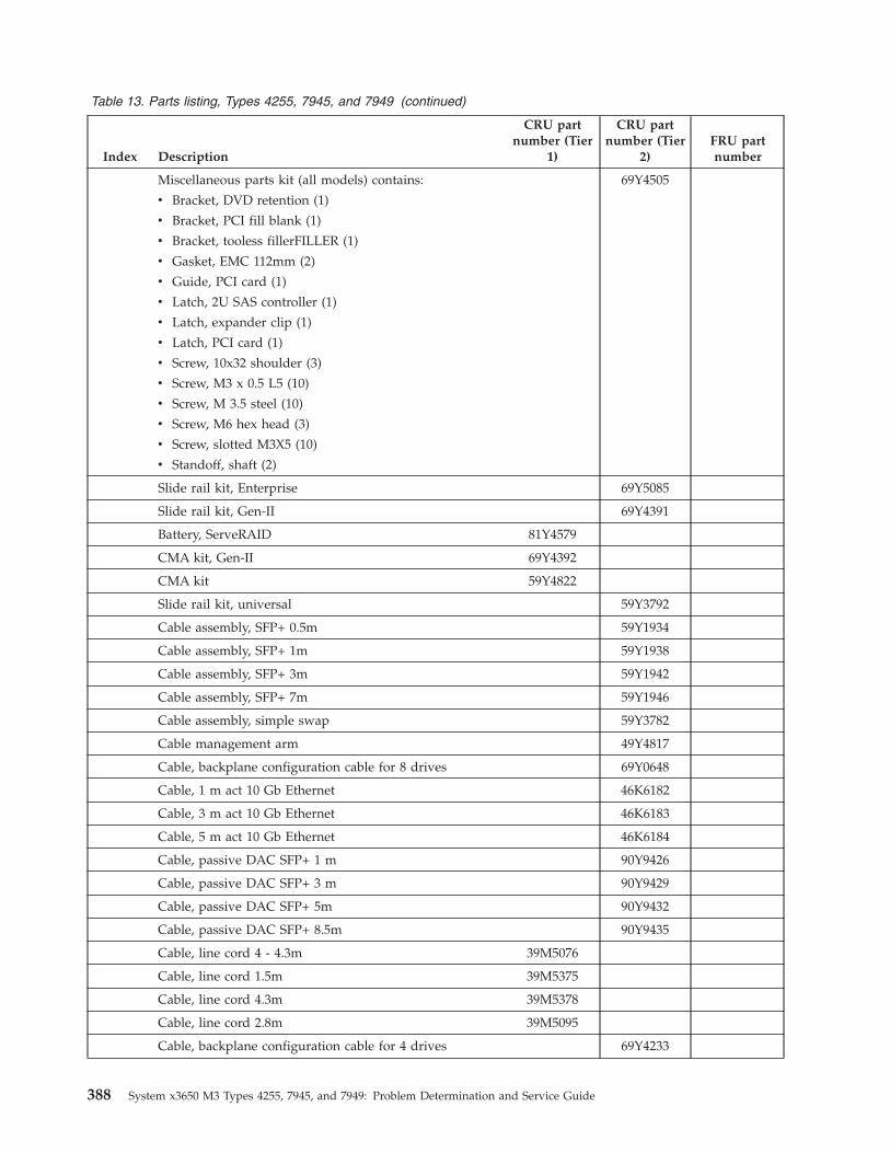
Table 13. Parts listing, Types 4255, 7945, and 7949 (continued)
Index Description
CRU partnumber (Tier
1)
CRU partnumber (Tier
2)FRU partnumber
Miscellaneous parts kit (all models) contains:
v Bracket, DVD retention (1)
v Bracket, PCI fill blank (1)
v Bracket, tooless fillerFILLER (1)
v Gasket, EMC 112mm (2)
v Guide, PCI card (1)
v Latch, 2U SAS controller (1)
v Latch, expander clip (1)
v Latch, PCI card (1)
v Screw, 10x32 shoulder (3)
v Screw, M3 x 0.5 L5 (10)
v Screw, M 3.5 steel (10)
v Screw, M6 hex head (3)
v Screw, slotted M3X5 (10)
v Standoff, shaft (2)
69Y4505
Slide rail kit, Enterprise 69Y5085
Slide rail kit, Gen-II 69Y4391
Battery, ServeRAID 81Y4579
CMA kit, Gen-II 69Y4392
CMA kit 59Y4822
Slide rail kit, universal 59Y3792
Cable assembly, SFP+ 0.5m 59Y1934
Cable assembly, SFP+ 1m 59Y1938
Cable assembly, SFP+ 3m 59Y1942
Cable assembly, SFP+ 7m 59Y1946
Cable assembly, simple swap 59Y3782
Cable management arm 49Y4817
Cable, backplane configuration cable for 8 drives 69Y0648
Cable, 1 m act 10 Gb Ethernet 46K6182
Cable, 3 m act 10 Gb Ethernet 46K6183
Cable, 5 m act 10 Gb Ethernet 46K6184
Cable, passive DAC SFP+ 1 m 90Y9426
Cable, passive DAC SFP+ 3 m 90Y9429
Cable, passive DAC SFP+ 5m 90Y9432
Cable, passive DAC SFP+ 8.5m 90Y9435
Cable, line cord 4 - 4.3m 39M5076
Cable, line cord 1.5m 39M5375
Cable, line cord 4.3m 39M5378
Cable, line cord 2.8m 39M5095
Cable, backplane configuration cable for 4 drives 69Y4233
388 System x3650 M3 Types 4255, 7945, and 7949: Problem Determination and Service Guide
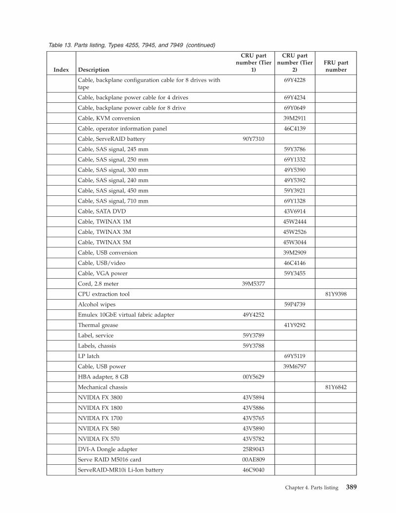
Table 13. Parts listing, Types 4255, 7945, and 7949 (continued)
Index Description
CRU partnumber (Tier
1)
CRU partnumber (Tier
2)FRU partnumber
Cable, backplane configuration cable for 8 drives withtape
69Y4228
Cable, backplane power cable for 4 drives 69Y4234
Cable, backplane power cable for 8 drive 69Y0649
Cable, KVM conversion 39M2911
Cable, operator information panel 46C4139
Cable, ServeRAID battery 90Y7310
Cable, SAS signal, 245 mm 59Y3786
Cable, SAS signal, 250 mm 69Y1332
Cable, SAS signal, 300 mm 49Y5390
Cable, SAS signal, 240 mm 49Y5392
Cable, SAS signal, 450 mm 59Y3921
Cable, SAS signal, 710 mm 69Y1328
Cable, SATA DVD 43V6914
Cable, TWINAX 1M 45W2444
Cable, TWINAX 3M 45W2526
Cable, TWINAX 5M 45W3044
Cable, USB conversion 39M2909
Cable, USB/video 46C4146
Cable, VGA power 59Y3455
Cord, 2.8 meter 39M5377
CPU extraction tool 81Y9398
Alcohol wipes 59P4739
Emulex 10GbE virtual fabric adapter 49Y4252
Thermal grease 41Y9292
Label, service 59Y3789
Labels, chassis 59Y3788
LP latch 69Y5119
Cable, USB power 39M6797
HBA adapter, 8 GB 00Y5629
Mechanical chassis 81Y6842
NVIDIA FX 3800 43V5894
NVIDIA FX 1800 43V5886
NVIDIA FX 1700 43V5765
NVIDIA FX 580 43V5890
NVIDIA FX 570 43V5782
DVI-A Dongle adapter 25R9043
Serve RAID M5016 card 00AE809
ServeRAID-MR10i Li-Ion battery 46C9040
Chapter 4. Parts listing 389
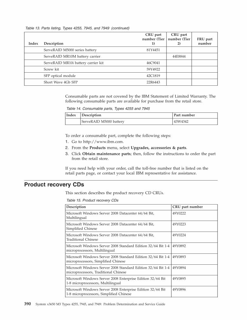
Table 13. Parts listing, Types 4255, 7945, and 7949 (continued)
Index Description
CRU partnumber (Tier
1)
CRU partnumber (Tier
2)FRU partnumber
ServeRAID M5000 series battery 81Y4451
ServeRAID MR10M battery carrier 44E8844
ServeRAID MR10i battery carrier kit 46C9041
Screw kit 59Y4922
SFP optical module 42C1819
Short Wave 4Gb SFP 22R6443
Consumable parts are not covered by the IBM Statement of Limited Warranty. Thefollowing consumable parts are available for purchase from the retail store.
Table 14. Consumable parts, Types 4255 and 7945
Index Description Part number
ServeRAID M5000 battery 43W4342
To order a consumable part, complete the following steps:1. Go to http://www.ibm.com.2. From the Products menu, select Upgrades, accessories & parts.3. Click Obtain maintenance parts; then, follow the instructions to order the part
from the retail store.
If you need help with your order, call the toll-free number that is listed on theretail parts page, or contact your local IBM representative for assistance.
Product recovery CDsThis section describes the product recovery CD CRUs.
Table 15. Product recovery CDs
Description CRU part number
Microsoft Windows Server 2008 Datacenter 64/64 Bit,Multilingual
49Y0222
Microsoft Windows Server 2008 Datacenter 64/64 Bit,Simplified Chinese
49Y0223
Microsoft Windows Server 2008 Datacenter 64/64 Bit,Traditional Chinese
49Y0224
Microsoft Windows Server 2008 Standard Edition 32/64 Bit 1-4microprocessors, Multilingual
49Y0892
Microsoft Windows Server 2008 Standard Edition 32/64 Bit 1-4microprocessors, Simplified Chinese
49Y0893
Microsoft Windows Server 2008 Standard Edition 32/64 Bit 1-4microprocessors, Traditional Chinese
49Y0894
Microsoft Windows Server 2008 Enterprise Edition 32/64 Bit1-8 microprocessors, Multilingual
49Y0895
Microsoft Windows Server 2008 Enterprise Edition 32/64 Bit1-8 microprocessors, Simplified Chinese
49Y0896
390 System x3650 M3 Types 4255, 7945, and 7949: Problem Determination and Service Guide
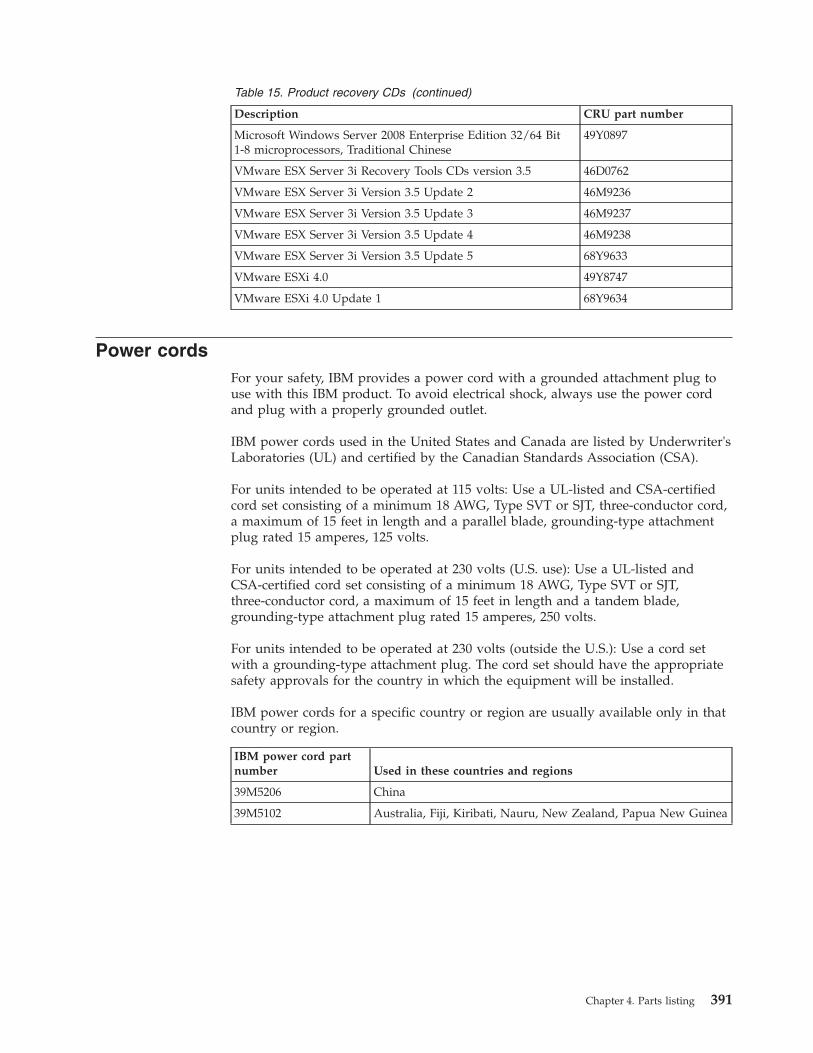
Table 15. Product recovery CDs (continued)
Description CRU part number
Microsoft Windows Server 2008 Enterprise Edition 32/64 Bit1-8 microprocessors, Traditional Chinese
49Y0897
VMware ESX Server 3i Recovery Tools CDs version 3.5 46D0762
VMware ESX Server 3i Version 3.5 Update 2 46M9236
VMware ESX Server 3i Version 3.5 Update 3 46M9237
VMware ESX Server 3i Version 3.5 Update 4 46M9238
VMware ESX Server 3i Version 3.5 Update 5 68Y9633
VMware ESXi 4.0 49Y8747
VMware ESXi 4.0 Update 1 68Y9634
Power cordsFor your safety, IBM provides a power cord with a grounded attachment plug touse with this IBM product. To avoid electrical shock, always use the power cordand plug with a properly grounded outlet.
IBM power cords used in the United States and Canada are listed by Underwriter'sLaboratories (UL) and certified by the Canadian Standards Association (CSA).
For units intended to be operated at 115 volts: Use a UL-listed and CSA-certifiedcord set consisting of a minimum 18 AWG, Type SVT or SJT, three-conductor cord,a maximum of 15 feet in length and a parallel blade, grounding-type attachmentplug rated 15 amperes, 125 volts.
For units intended to be operated at 230 volts (U.S. use): Use a UL-listed andCSA-certified cord set consisting of a minimum 18 AWG, Type SVT or SJT,three-conductor cord, a maximum of 15 feet in length and a tandem blade,grounding-type attachment plug rated 15 amperes, 250 volts.
For units intended to be operated at 230 volts (outside the U.S.): Use a cord setwith a grounding-type attachment plug. The cord set should have the appropriatesafety approvals for the country in which the equipment will be installed.
IBM power cords for a specific country or region are usually available only in thatcountry or region.
IBM power cord partnumber Used in these countries and regions
39M5206 China
39M5102 Australia, Fiji, Kiribati, Nauru, New Zealand, Papua New Guinea
Chapter 4. Parts listing 391
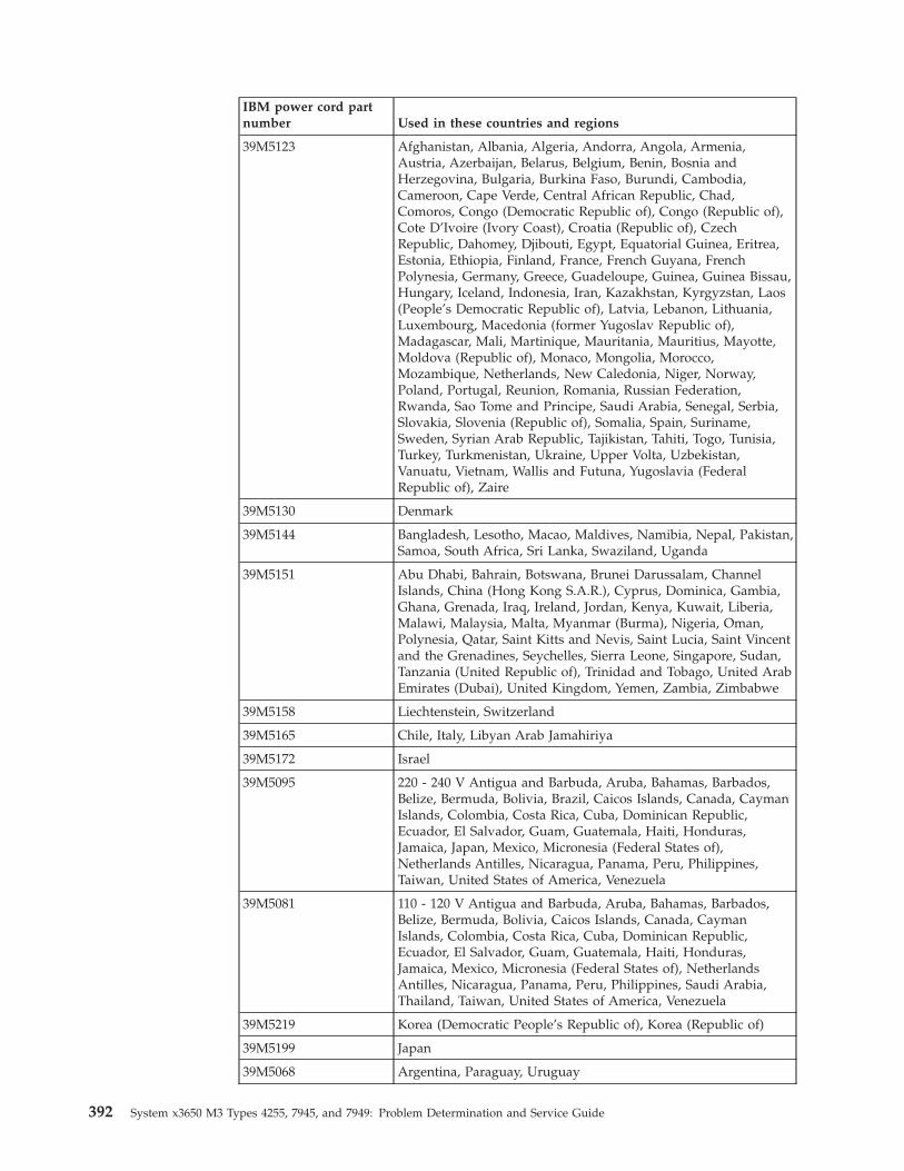
IBM power cord partnumber Used in these countries and regions
39M5123 Afghanistan, Albania, Algeria, Andorra, Angola, Armenia,Austria, Azerbaijan, Belarus, Belgium, Benin, Bosnia andHerzegovina, Bulgaria, Burkina Faso, Burundi, Cambodia,Cameroon, Cape Verde, Central African Republic, Chad,Comoros, Congo (Democratic Republic of), Congo (Republic of),Cote D’Ivoire (Ivory Coast), Croatia (Republic of), CzechRepublic, Dahomey, Djibouti, Egypt, Equatorial Guinea, Eritrea,Estonia, Ethiopia, Finland, France, French Guyana, FrenchPolynesia, Germany, Greece, Guadeloupe, Guinea, Guinea Bissau,Hungary, Iceland, Indonesia, Iran, Kazakhstan, Kyrgyzstan, Laos(People’s Democratic Republic of), Latvia, Lebanon, Lithuania,Luxembourg, Macedonia (former Yugoslav Republic of),Madagascar, Mali, Martinique, Mauritania, Mauritius, Mayotte,Moldova (Republic of), Monaco, Mongolia, Morocco,Mozambique, Netherlands, New Caledonia, Niger, Norway,Poland, Portugal, Reunion, Romania, Russian Federation,Rwanda, Sao Tome and Principe, Saudi Arabia, Senegal, Serbia,Slovakia, Slovenia (Republic of), Somalia, Spain, Suriname,Sweden, Syrian Arab Republic, Tajikistan, Tahiti, Togo, Tunisia,Turkey, Turkmenistan, Ukraine, Upper Volta, Uzbekistan,Vanuatu, Vietnam, Wallis and Futuna, Yugoslavia (FederalRepublic of), Zaire
39M5130 Denmark
39M5144 Bangladesh, Lesotho, Macao, Maldives, Namibia, Nepal, Pakistan,Samoa, South Africa, Sri Lanka, Swaziland, Uganda
39M5151 Abu Dhabi, Bahrain, Botswana, Brunei Darussalam, ChannelIslands, China (Hong Kong S.A.R.), Cyprus, Dominica, Gambia,Ghana, Grenada, Iraq, Ireland, Jordan, Kenya, Kuwait, Liberia,Malawi, Malaysia, Malta, Myanmar (Burma), Nigeria, Oman,Polynesia, Qatar, Saint Kitts and Nevis, Saint Lucia, Saint Vincentand the Grenadines, Seychelles, Sierra Leone, Singapore, Sudan,Tanzania (United Republic of), Trinidad and Tobago, United ArabEmirates (Dubai), United Kingdom, Yemen, Zambia, Zimbabwe
39M5158 Liechtenstein, Switzerland
39M5165 Chile, Italy, Libyan Arab Jamahiriya
39M5172 Israel
39M5095 220 - 240 V Antigua and Barbuda, Aruba, Bahamas, Barbados,Belize, Bermuda, Bolivia, Brazil, Caicos Islands, Canada, CaymanIslands, Colombia, Costa Rica, Cuba, Dominican Republic,Ecuador, El Salvador, Guam, Guatemala, Haiti, Honduras,Jamaica, Japan, Mexico, Micronesia (Federal States of),Netherlands Antilles, Nicaragua, Panama, Peru, Philippines,Taiwan, United States of America, Venezuela
39M5081 110 - 120 V Antigua and Barbuda, Aruba, Bahamas, Barbados,Belize, Bermuda, Bolivia, Caicos Islands, Canada, CaymanIslands, Colombia, Costa Rica, Cuba, Dominican Republic,Ecuador, El Salvador, Guam, Guatemala, Haiti, Honduras,Jamaica, Mexico, Micronesia (Federal States of), NetherlandsAntilles, Nicaragua, Panama, Peru, Philippines, Saudi Arabia,Thailand, Taiwan, United States of America, Venezuela
39M5219 Korea (Democratic People’s Republic of), Korea (Republic of)
39M5199 Japan
39M5068 Argentina, Paraguay, Uruguay
392 System x3650 M3 Types 4255, 7945, and 7949: Problem Determination and Service Guide
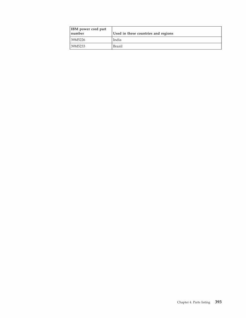
IBM power cord partnumber Used in these countries and regions
39M5226 India
39M5233 Brazil
Chapter 4. Parts listing 393

394 System x3650 M3 Types 4255, 7945, and 7949: Problem Determination and Service Guide
Chapter 5. Removing and replacing server components
Replaceable components are of four types:v Consumable Parts: Purchase and replacement of consumable parts (components,
such as batteries and printer cartridges, that have depletable life) is yourresponsibility. If IBM acquires or installs a consumable part at your request, youwill be charged for the service.
v Tier 1 customer replaceable unit (CRU): Replacement of Tier 1 CRUs is yourresponsibility. If IBM installs a Tier 1 CRU at your request, you will be chargedfor the installation.
v Tier 2 customer replaceable unit: You may install a Tier 2 CRU yourself orrequest IBM to install it, at no additional charge, under the type of warrantyservice that is designated for your server.
v Field replaceable unit (FRU): FRUs must be installed only by trained servicetechnicians.
See Chapter 4, “Parts listing,” on page 381 to determine whether a component is aTier 1 CRU, Tier 2 CRU, or FRU.
For information about the terms of the warranty and getting service and assistance,see the Warranty Information document.
Installation guidelinesUse the installation guidelines to install the System x3650 M3 Types 4255, 7945,and 7949
Attention: Static electricity that is released to internal server components whenthe server is powered-on might cause the system to halt, which might result in theloss of data. To avoid this potential problem, always use an electrostatic-dischargewrist strap or other grounding system when removing or installing a hot-swapdevice.
Before you install optional devices, read the following information:v Read the safety information that begins on page “Safety” on page vii, the
guidelines in “Working inside the server with the power on” on page 397, and“Handling static-sensitive devices” on page 398. This information will help youwork safely.
v When you install your new server, take the opportunity to download and applythe most recent firmware updates. This step will help to ensure that any knownissues are addressed and that your server is ready to function at maximumlevels of performance. To download firmware updates for your server, completethe following steps:1. Go to http://www.ibm.com/systems/support/.2. Under Product support, click System x.3. Under Popular links, click Software and device drivers.4. Click System x3650 M3 to display the matrix of downloadable files for the
server.
© Copyright IBM Corp. 2014 395
For additional information about tools for updating, managing, and deployingfirmware, see the System x and xSeries Tools Center at http://publib.boulder.ibm.com/infocenter/toolsctr/v1r0/index.jsp.
v Before you install optional hardware, make sure that the server is workingcorrectly. Start the server, and make sure that the operating system starts, if anoperating system is installed, or that a 19990305 error code is displayed,indicating that an operating system was not found but the server is otherwiseworking correctly. If the server is not working correctly, see the ProblemDetermination and Service Guide on the IBM System x Documentation CD fordiagnostic information.
v Observe good housekeeping in the area where you are working. Place removedcovers and other parts in a safe place.
v If you must start the server while the cover is removed, make sure that no one isnear the server and that no tools or other objects have been left inside the server.
v Do not attempt to lift an object that you think is too heavy for you. If you haveto lift a heavy object, observe the following precautions:– Make sure that you can stand safely without slipping.– Distribute the weight of the object equally between your feet.– Use a slow lifting force. Never move suddenly or twist when you lift a heavy
object.– To avoid straining the muscles in your back, lift by standing or by pushing
up with your leg muscles.v Make sure that you have an adequate number of properly grounded electrical
outlets for the server, monitor, and other devices.v Back up all important data before you make changes to disk drives.v Have a small flat-blade screwdriver available.v To view the error LEDs on the system board and internal components, leave the
server connected to power.v You do not have to turn off the server to install or replace hot-swap fans,
redundant hot-swap ac power supplies, or hot-plug Universal Serial Bus (USB)devices. However, you must turn off the server before you perform any stepsthat involve removing or installing adapter cables or non-hot-swap optionaldevices or components.
v Blue on a component indicates touch points, where you can grip the componentto remove it from or install it in the server, open or close a latch, and so on.
v Orange on a component or an orange label on or near a component indicatesthat the component can be hot-swapped, which means that if the server andoperating system support hot-swap capability, you can remove or install thecomponent while the server is running. (Orange can also indicate touch pointson hot-swap components.) See the instructions for removing or installing aspecific hot-swap component for any additional procedures that you might haveto perform before you remove or install the component.
v When you are finished working on the server, reinstall all safety shields, guards,labels, and ground wires.
v For a list of supported optional devices for the server, see http://www.ibm.com/systems/info/x86servers/serverproven/compat/us/.
396 System x3650 M3 Types 4255, 7945, and 7949: Problem Determination and Service Guide
System reliability guidelinesThe system reliability guidelines to ensure proper system cooling.
To help ensure proper system cooling and system reliability, make sure that thefollowing requirements are met:v Each of the drive bays has a drive or a filler panel and electromagnetic
compatibility (EMC) shield installed in it.v If the server has redundant power, each of the power-supply bays has a power
supply installed in it.v There is adequate space around the server to allow the server cooling system to
work properly. Leave approximately 50 mm (2.0 in.) of open space around thefront and rear of the server. Do not place objects in front of the fans. For propercooling and airflow, replace the server cover before you turn on the server.Operating the server for extended periods of time (more than 30 minutes) withthe server cover removed might damage server components.
v You have followed the cabling instructions that come with optional adapters.v You have replaced a failed fan within 48 hours.v You have replaced a hot-swap fan within 30 seconds of removal.v You have replaced a hot-swap drive within 2 minutes of removal.v You do not operate the server without the air baffles installed. Operating the
server without the air baffles might cause the microprocessors to overheat.v Microprocessor 2 air baffle and DIMM air baffle are installed.v The light path diagnostics panel is not pulled out of the server.
Working inside the server with the power onGuidelines to work inside the server with the power on.
Attention: Static electricity that is released to internal server components whenthe server is powered-on might cause the server to halt, which might result in theloss of data. To avoid this potential problem, always use an electrostatic-dischargewrist strap or other grounding system when you work inside the server with thepower on.
The server supports hot-plug, hot-add, and hot-swap devices and is designed tooperate safely while it is turned on and the cover is removed. Follow theseguidelines when you work inside a server that is turned on:v Avoid wearing loose-fitting clothing on your forearms. Button long-sleeved
shirts before working inside the server; do not wear cuff links while you areworking inside the server.
v Do not allow your necktie or scarf to hang inside the server.v Remove jewelry, such as bracelets, necklaces, rings, and loose-fitting wrist
watches.v Remove items from your shirt pocket, such as pens and pencils, that might fall
into the server as you lean over it.v Avoid dropping any metallic objects, such as paper clips, hairpins, and screws,
into the server.
Chapter 5. Removing and replacing server components 397
Handling static-sensitive devices
Attention: Static electricity can damage the server and other electronic devices. Toavoid damage, keep static-sensitive devices in their static-protective packages untilyou are ready to install them.
To reduce the possibility of damage from electrostatic discharge, observe thefollowing precautions:v Limit your movement. Movement can cause static electricity to build up around
you.v The use of a grounding system is recommended. For example, wear an
electrostatic-discharge wrist strap, if one is available. Always use anelectrostatic-discharge wrist strap or other grounding system when workinginside the server with the power on.
v Handle the device carefully, holding it by its edges or its frame.v Do not touch solder joints, pins, or exposed circuitry.v Do not leave the device where others can handle and damage it.v While the device is still in its static-protective package, touch it to an unpainted
metal surface on the outside of the server for at least 2 seconds. This drainsstatic electricity from the package and from your body.
v Remove the device from its package and install it directly into the serverwithout setting down the device. If it is necessary to set down the device, put itback into its static-protective package. Do not place the device on the servercover or on a metal surface.
v Take additional care when handling devices during cold weather. Heatingreduces indoor humidity and increases static electricity.
Returning a device or componentIf you are instructed to return a device or component, follow all packaginginstructions, and use any packaging materials for shipping that are supplied toyou.
Internal cable routing and connectorsThe following illustration shows the internal routing and connectors.
The following illustration shows the internal routing and connectors for the twoSAS signal cables.
398 System x3650 M3 Types 4255, 7945, and 7949: Problem Determination and Service Guide
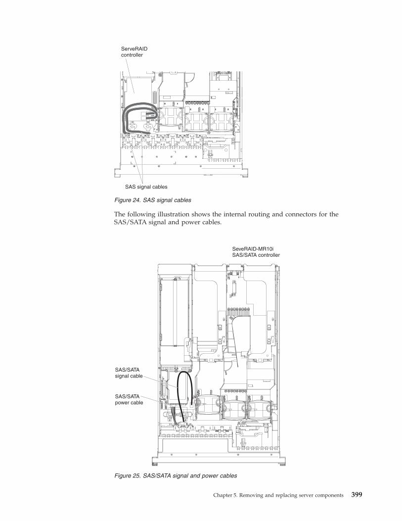
The following illustration shows the internal routing and connectors for theSAS/SATA signal and power cables.
Figure 24. SAS signal cables
Figure 25. SAS/SATA signal and power cables
Chapter 5. Removing and replacing server components 399
The SATA cable is a combination power and signal cable with a shared connectoron both ends. The following illustration shows the internal routing and connectorfor the SATA cable.
Attention: To disconnect the optional optical drive cable, you must first press theconnector release tab, and then disconnect the cable from the connector on thesystem board. Do not disconnect the cable by using excessive force. Failing todisconnect the cable properly may damage the connector on the system board. Anydamage to the connector may require replacing the system board.
The following illustration shows the internal routing and connector for theoperator information panel cable. The following notes describe additionalinformation you must consider when you install or remove the operatorinformation panel cable:v You may remove the optional optical drive cable to obtain more room before
you install or remove the operator information panel cable.v To remove the operator information panel cable, slightly press the cable toward
the chassis; then, pull to remove the cable from the connector on the systemboard. Pulling the cable out of the connector by excessive force might causedamage to the cable or connector.
v To connect the operator information panel cable on the system board, pressevenly on the cable. Pressing on one side of the cable might cause damage to thecable or connector.Attention: Failing to install or remove the cable with care may damage theconnectors on the system board. Any damage to the connectors may requirereplacing the system board.
Figure 26. Disconnecting the optional optical drive cable
400 System x3650 M3 Types 4255, 7945, and 7949: Problem Determination and Service Guide
The following illustration shows the internal routing and connector for theUSB/video cable.
The following illustration shows the internal routing for the configuration cable.
Figure 27. Operator information panel cable
Figure 28. USB cable and video cable
Chapter 5. Removing and replacing server components 401
Removing and replacing consumable parts and Tier 1 CRUsReplacement of consumable parts and Tier 1 CRUs is your responsibility. If IBMinstalls a consumable part or Tier 1 CRU at your request, you will be charged forthe installation.
The illustrations in this document might differ slightly from your hardware.
Removing the coverUse this information to remove the cover.
About this task
To remove the cover, complete the following steps.
Figure 29. configuration cable
Cover-releaselatch
Figure 30. Cover removal
402 System x3650 M3 Types 4255, 7945, and 7949: Problem Determination and Service Guide
Procedure1. Read the safety information that begins on page “Safety” on page vii and
“Installation guidelines” on page 395.2. If you are planning to view the error LEDs that are on the system board and
components, leave the server connected to power and go directly to step 4.3. If you are planning to install or remove a microprocessor, memory module, PCI
adapter, battery, or other non-hot-swap optional device, turn off the server andall attached devices and disconnect all external cables and power cords.
4. Press down on the left and right side latches and slide the server out of therack enclosure until both slide rails lock.
Note: You can reach the cables on the back of the server when the server is inthe locked position.
5. Push the cover-release latch back �1�, then lift it up �2�. Slide the cover back�3�, and then lift off the server. Set the cover aside.Attention: For proper cooling and airflow, replace the cover before you turnon the server. Operating the server for extended periods of time (over 30minutes) with the cover removed might damage server components.
6. If you are instructed to return the cover, follow all packaging instructions, anduse any packaging materials for shipping that are supplied to you.
Replacing the coverAbout this task
To install the cover, complete the following steps.
1. Make sure that all internal cables are correctly routed (see “Internal cablerouting and connectors” on page 398.)
2. Place the cover-release latch in the open (up) position.3. Insert the bottom tabs of the top cover into the matching slots in the server
chassis.4. Press down on the cover-release latch to lock the cover in place.5. Slide the server into the rack.
Figure 31. Cover installation
Chapter 5. Removing and replacing server components 403
Removing the microprocessor 2 air baffleWhen you work with some optional devices, you must first remove themicroprocessor 2 air baffle to access certain components on the system board.
About this task
To remove the microprocessor 2 air baffle, complete the following steps.
Procedure1. Read the safety information that begins on page “Safety” on page vii and
“Installation guidelines” on page 395.2. Turn off the server and peripheral devices and disconnect all power cords and
external cables.3. Remove the cover (see “Removing the cover” on page 402).4. Remove PCI riser-card assembly 2 (see “Removing a PCI riser-card assembly”
on page 414).5. Grasp the top of the air baffle and lift the air baffle out of the server.
Attention: For proper cooling and airflow, replace all air baffles, making sureall cables are out of the way, before you turn on the server. Operating theserver with any air baffle removed might damage server components.
Figure 32. Microprocessor 2 air baffle removal
404 System x3650 M3 Types 4255, 7945, and 7949: Problem Determination and Service Guide
6. If you are instructed to return the microprocessor air baffle, follow allpackaging instructions, and use any packaging materials for shipping that aresupplied to you.
Replacing the microprocessor 2 air baffleUse this information to replace the microprocessor 2 air baffle.
About this task
To install the microprocessor air baffle, complete the following steps.
Procedure1. Align the tab on the left side of the microprocessor 2 air baffle with the slot in
the right side of the power-supply cage.2. Align the pin on the bottom of the microprocessor air baffle with the hole on
the system board retention bracket.3. Lower the microprocessor 2 air baffle into the server, making sure all cables are
out of the way.Attention: For proper cooling and airflow, replace all air baffles before youturn on the server. Operating the server with any air baffle removed mightdamage server components.
4. Install PCI riser-card assembly 2.
Figure 33. Microprocessor 2 air baffle installation
Chapter 5. Removing and replacing server components 405
5. Install the cover (see “Replacing the cover” on page 403).6. Slide the server into the rack.7. Reconnect the external cables; then, reconnect the power cords and turn on the
peripheral devices and the server.
Removing the DIMM air baffleWhen you work with some optional devices, you must first remove the DIMM airbaffle to access certain components or connectors on the system board.
About this task
To remove the DIMM air baffle, complete the following steps.
Procedure1. Read the safety information that begins on page “Safety” on page vii and
“Installation guidelines” on page 395.2. Turn off the server and peripheral devices and disconnect all power cords and
external cables.3. Remove the cover (see “Removing the cover” on page 402).4. If necessary, remove riser-card assembly 1 (see “Removing a PCI riser-card
assembly” on page 414).5. Place your fingers under the front and back of the top of the air baffle; then, lift
the air baffle out of the server.Attention: For proper cooling and airflow, replace all the air baffles beforeyou turn on the server. Operating the server with any air baffle removed mightdamage server components.
DIMM air baffle
PCI riser-cardassembly 1
Figure 34. DIMM air baffle removal
406 System x3650 M3 Types 4255, 7945, and 7949: Problem Determination and Service Guide
Replacing the DIMM air baffleUse this information to replace the DIMM air baffle.
About this task
To install the DIMM air baffle, complete the following steps.
Procedure1. Align the DIMM air baffle with the DIMMs and the back of the fans.2. Lower the air baffle into place, making sure all cables are out of the way.3. Replace PCI riser-card assembly 1, if necessary.4. Install the cover (see “Replacing the cover” on page 403).5. Slide the server into the rack.6. Reconnect the external cables; then, reconnect the power cords and turn on the
peripheral devices and the server.
Results
Attention: For proper cooling and airflow, replace all air baffles before you turnon the server. Operating the server with any air baffle removed might damageserver components.
DIMM air baffle
PCI riser-cardassembly 1
Figure 35. DIMM air baffle installation
Chapter 5. Removing and replacing server components 407
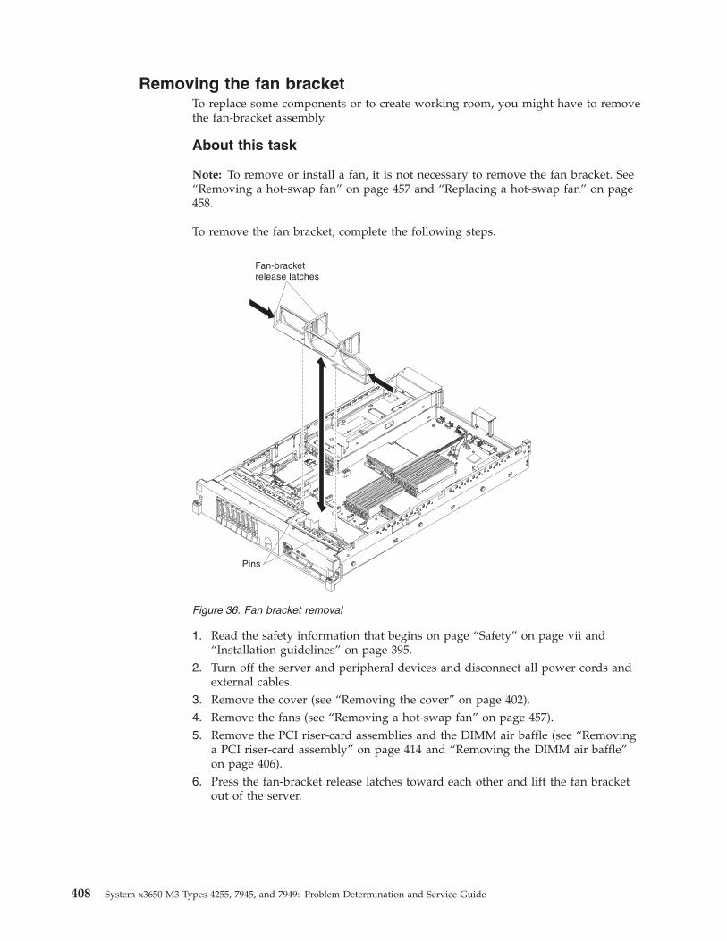
Removing the fan bracketTo replace some components or to create working room, you might have to removethe fan-bracket assembly.
About this task
Note: To remove or install a fan, it is not necessary to remove the fan bracket. See“Removing a hot-swap fan” on page 457 and “Replacing a hot-swap fan” on page458.
To remove the fan bracket, complete the following steps.
1. Read the safety information that begins on page “Safety” on page vii and“Installation guidelines” on page 395.
2. Turn off the server and peripheral devices and disconnect all power cords andexternal cables.
3. Remove the cover (see “Removing the cover” on page 402).4. Remove the fans (see “Removing a hot-swap fan” on page 457).5. Remove the PCI riser-card assemblies and the DIMM air baffle (see “Removing
a PCI riser-card assembly” on page 414 and “Removing the DIMM air baffle”on page 406).
6. Press the fan-bracket release latches toward each other and lift the fan bracketout of the server.
Figure 36. Fan bracket removal
408 System x3650 M3 Types 4255, 7945, and 7949: Problem Determination and Service Guide
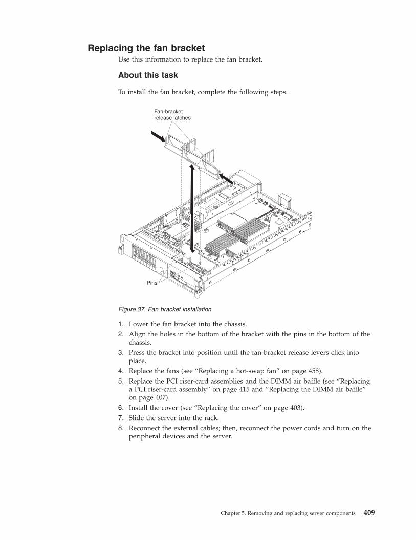
Replacing the fan bracketUse this information to replace the fan bracket.
About this task
To install the fan bracket, complete the following steps.
1. Lower the fan bracket into the chassis.2. Align the holes in the bottom of the bracket with the pins in the bottom of the
chassis.3. Press the bracket into position until the fan-bracket release levers click into
place.4. Replace the fans (see “Replacing a hot-swap fan” on page 458).5. Replace the PCI riser-card assemblies and the DIMM air baffle (see “Replacing
a PCI riser-card assembly” on page 415 and “Replacing the DIMM air baffle”on page 407).
6. Install the cover (see “Replacing the cover” on page 403).7. Slide the server into the rack.8. Reconnect the external cables; then, reconnect the power cords and turn on the
peripheral devices and the server.
Figure 37. Fan bracket installation
Chapter 5. Removing and replacing server components 409
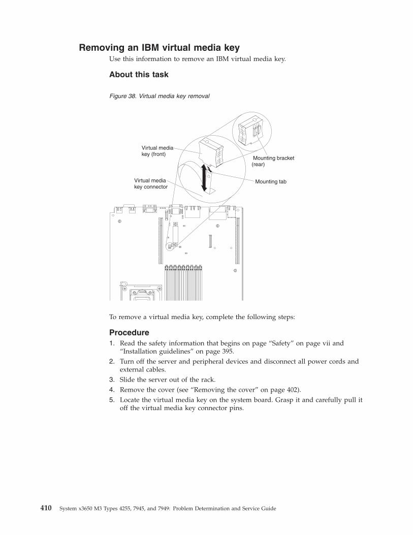
Removing an IBM virtual media keyUse this information to remove an IBM virtual media key.
About this task
To remove a virtual media key, complete the following steps:
Procedure1. Read the safety information that begins on page “Safety” on page vii and
“Installation guidelines” on page 395.2. Turn off the server and peripheral devices and disconnect all power cords and
external cables.3. Slide the server out of the rack.4. Remove the cover (see “Removing the cover” on page 402).5. Locate the virtual media key on the system board. Grasp it and carefully pull it
off the virtual media key connector pins.
Figure 38. Virtual media key removal
410 System x3650 M3 Types 4255, 7945, and 7949: Problem Determination and Service Guide
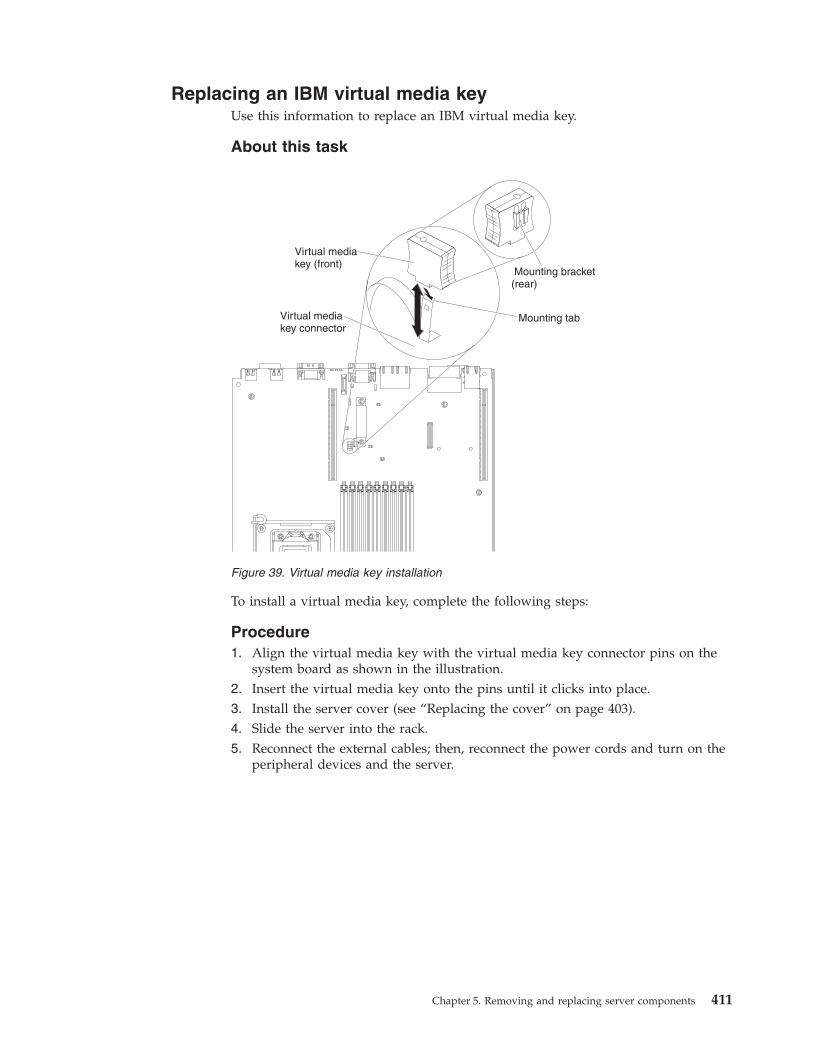
Replacing an IBM virtual media keyUse this information to replace an IBM virtual media key.
About this task
To install a virtual media key, complete the following steps:
Procedure1. Align the virtual media key with the virtual media key connector pins on the
system board as shown in the illustration.2. Insert the virtual media key onto the pins until it clicks into place.3. Install the server cover (see “Replacing the cover” on page 403).4. Slide the server into the rack.5. Reconnect the external cables; then, reconnect the power cords and turn on the
peripheral devices and the server.
Figure 39. Virtual media key installation
Chapter 5. Removing and replacing server components 411
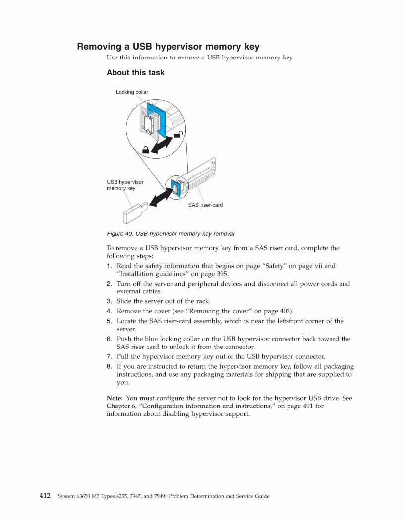
Removing a USB hypervisor memory keyUse this information to remove a USB hypervisor memory key.
About this task
To remove a USB hypervisor memory key from a SAS riser card, complete thefollowing steps:1. Read the safety information that begins on page “Safety” on page vii and
“Installation guidelines” on page 395.2. Turn off the server and peripheral devices and disconnect all power cords and
external cables.3. Slide the server out of the rack.4. Remove the cover (see “Removing the cover” on page 402).5. Locate the SAS riser-card assembly, which is near the left-front corner of the
server.6. Push the blue locking collar on the USB hypervisor connector back toward the
SAS riser card to unlock it from the connector.7. Pull the hypervisor memory key out of the USB hypervisor connector.8. If you are instructed to return the hypervisor memory key, follow all packaging
instructions, and use any packaging materials for shipping that are supplied toyou.
Note: You must configure the server not to look for the hypervisor USB drive. SeeChapter 6, “Configuration information and instructions,” on page 491 forinformation about disabling hypervisor support.
Figure 40. USB hypervisor memory key removal
412 System x3650 M3 Types 4255, 7945, and 7949: Problem Determination and Service Guide
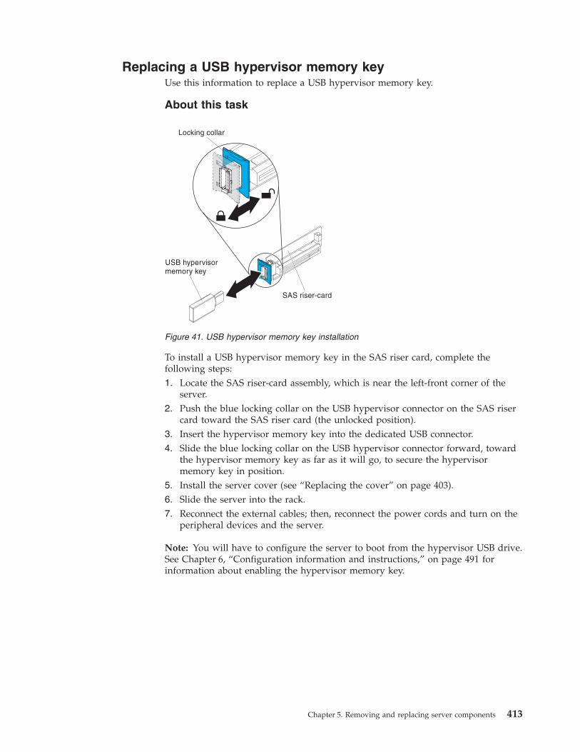
Replacing a USB hypervisor memory keyUse this information to replace a USB hypervisor memory key.
About this task
To install a USB hypervisor memory key in the SAS riser card, complete thefollowing steps:1. Locate the SAS riser-card assembly, which is near the left-front corner of the
server.2. Push the blue locking collar on the USB hypervisor connector on the SAS riser
card toward the SAS riser card (the unlocked position).3. Insert the hypervisor memory key into the dedicated USB connector.4. Slide the blue locking collar on the USB hypervisor connector forward, toward
the hypervisor memory key as far as it will go, to secure the hypervisormemory key in position.
5. Install the server cover (see “Replacing the cover” on page 403).6. Slide the server into the rack.7. Reconnect the external cables; then, reconnect the power cords and turn on the
peripheral devices and the server.
Note: You will have to configure the server to boot from the hypervisor USB drive.See Chapter 6, “Configuration information and instructions,” on page 491 forinformation about enabling the hypervisor memory key.
Figure 41. USB hypervisor memory key installation
Chapter 5. Removing and replacing server components 413
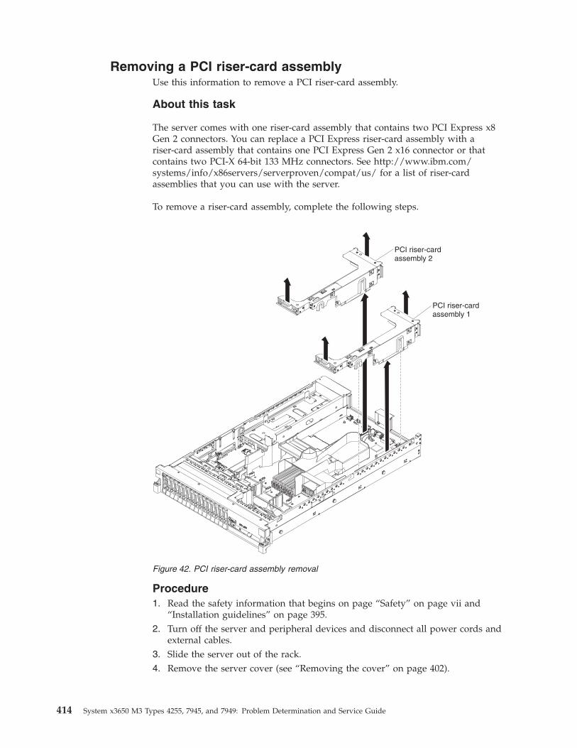
Removing a PCI riser-card assemblyUse this information to remove a PCI riser-card assembly.
About this task
The server comes with one riser-card assembly that contains two PCI Express x8Gen 2 connectors. You can replace a PCI Express riser-card assembly with ariser-card assembly that contains one PCI Express Gen 2 x16 connector or thatcontains two PCI-X 64-bit 133 MHz connectors. See http://www.ibm.com/systems/info/x86servers/serverproven/compat/us/ for a list of riser-cardassemblies that you can use with the server.
To remove a riser-card assembly, complete the following steps.
Procedure1. Read the safety information that begins on page “Safety” on page vii and
“Installation guidelines” on page 395.2. Turn off the server and peripheral devices and disconnect all power cords and
external cables.3. Slide the server out of the rack.4. Remove the server cover (see “Removing the cover” on page 402).
PCI riser-cardassembly 2
PCI riser-cardassembly 1
Figure 42. PCI riser-card assembly removal
414 System x3650 M3 Types 4255, 7945, and 7949: Problem Determination and Service Guide
5. Grasp the riser-card assembly at the front tab and rear edge and lift it toremove it from the server. Place the riser-card assembly on a flat,static-protective surface.
Replacing a PCI riser-card assemblyThe server provides two PCI riser-card slots on the system board. A PCI riserassembly with a bracket is installed in slot 2.
About this task
The following information indicates the riser-card slots:v Standard models of the server come with one PCI Express riser-card assembly
installed. If you want to replace them with PCI-X riser-card assemblies, youmust order the PCI-X riser-card assembly option, which includes the bracket.
v A PCI Express riser-card assembly has a black connector and supports PCIExpress adapters, and a PCI-X riser-card assembly has a white (light in color)connector and supports PCI-X adapters.
v PCI riser slot 1 (the farthest slot from the power supplies). This slot supportsonly low-profile adapters.
v PCI riser slot 2 (the closest slot to the power supplies). You must install a PCIriser-card assembly in slot 2 even if you do not install an adapter.
v Microprocessor 2, aux power, and PCI riser-card assembly 2 share the samepower channel that is limited to 230 W.
To install a riser-card assembly, complete the following steps.
Chapter 5. Removing and replacing server components 415
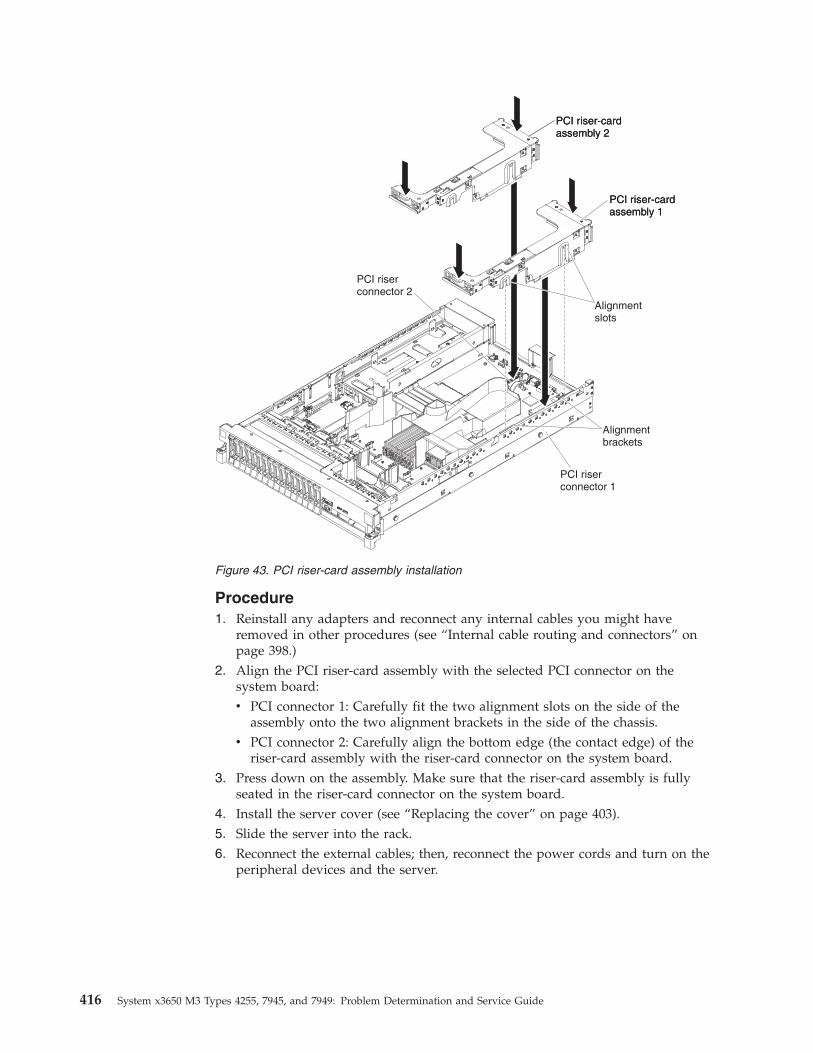
Procedure1. Reinstall any adapters and reconnect any internal cables you might have
removed in other procedures (see “Internal cable routing and connectors” onpage 398.)
2. Align the PCI riser-card assembly with the selected PCI connector on thesystem board:v PCI connector 1: Carefully fit the two alignment slots on the side of the
assembly onto the two alignment brackets in the side of the chassis.v PCI connector 2: Carefully align the bottom edge (the contact edge) of the
riser-card assembly with the riser-card connector on the system board.3. Press down on the assembly. Make sure that the riser-card assembly is fully
seated in the riser-card connector on the system board.4. Install the server cover (see “Replacing the cover” on page 403).5. Slide the server into the rack.6. Reconnect the external cables; then, reconnect the power cords and turn on the
peripheral devices and the server.
PCI riser-cardassembly 2
PCI riser-cardassembly 1
PCI riser-cardassembly 2
PCI riser-cardassembly 1
Alignmentbrackets
Alignmentslots
PCI riserconnector 1
PCI riserconnector 2
Figure 43. PCI riser-card assembly installation
416 System x3650 M3 Types 4255, 7945, and 7949: Problem Determination and Service Guide
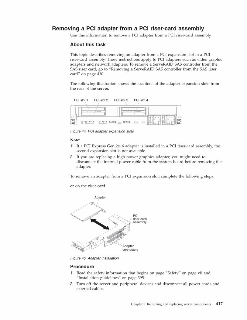
Removing a PCI adapter from a PCI riser-card assemblyUse this information to remove a PCI adapter from a PCI riser-card assembly.
About this task
This topic describes removing an adapter from a PCI expansion slot in a PCIriser-card assembly. These instructions apply to PCI adapters such as video graphicadapters and network adapters. To remove a ServeRAID SAS controller from theSAS riser card, go to “Removing a ServeRAID SAS controller from the SAS risercard” on page 430.
The following illustration shows the locations of the adapter expansion slots fromthe rear of the server.
Note:
1. If a PCI Express Gen 2x16 adapter is installed in a PCI riser-card assembly, thesecond expansion slot is not available.
2. If you are replacing a high power graphics adapter, you might need todisconnect the internal power cable from the system board before removing theadapter.
To remove an adapter from a PCI expansion slot, complete the following steps.
or on the riser card.
Procedure1. Read the safety information that begins on page “Safety” on page vii and
“Installation guidelines” on page 395.2. Turn off the server and peripheral devices and disconnect all power cords and
external cables.
Figure 44. PCI adapter expansion slots
Figure 45. Adapter installation
Chapter 5. Removing and replacing server components 417
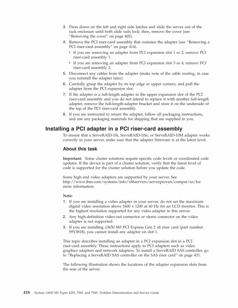
3. Press down on the left and right side latches and slide the server out of therack enclosure until both slide rails lock; then, remove the cover (see“Removing the cover” on page 402).
4. Remove the PCI riser-card assembly that contains the adapter (see “Removing aPCI riser-card assembly” on page 414).v If you are removing an adapter from PCI expansion slot 1 or 2, remove PCI
riser-card assembly 1.v If you are removing an adapter from PCI expansion slot 3 or 4, remove PCI
riser-card assembly 2.5. Disconnect any cables from the adapter (make note of the cable routing, in case
you reinstall the adapter later).6. Carefully grasp the adapter by its top edge or upper corners, and pull the
adapter from the PCI expansion slot.7. If the adapter is a full-length adapter in the upper expansion slot of the PCI
riser-card assembly and you do not intend to replace it with another full-lengthadapter, remove the full-length-adapter bracket and store it on the underside ofthe top of the PCI riser-card assembly.
8. If you are instructed to return the adapter, follow all packaging instructions,and use any packaging materials for shipping that are supplied to you.
Installing a PCI adapter in a PCI riser-card assemblyTo ensure that a ServeRAID-10i, ServeRAID-10is, or ServeRAID-10M adapter workscorrectly in your server, make sure that the adapter firmware is at the latest level.
About this task
Important: Some cluster solutions require specific code levels or coordinated codeupdates. If the device is part of a cluster solution, verify that the latest level ofcode is supported for the cluster solution before you update the code.
Some high end video adapters are supported by your server. Seehttp://www.ibm.com/systems/info/x86servers/serverproven/compat/us/formore information.
Note:
1. If you are installing a video adapter in your server, do not set the maximumdigital video resolution above 1600 x 1200 at 60 Hz for an LCD monitor. This isthe highest resolution supported for any video adapter in this server.
2. Any high-definition video-out connector or stereo connector on the videoadapter is not supported.
3. If you are installing x3650 M3 PCI Express Gen 2 x8 riser card (part number59Y3818), you cannot install any adaptor on slot 1.
This topic describes installing an adapter in a PCI expansion slot in a PCIriser-card assembly. These instructions apply to PCI adapters such as videographics adapters and network adapters. To install a ServeRAID SAS controller, goto “Replacing a ServeRAID SAS controller on the SAS riser card” on page 431.
The following illustration shows the locations of the adapter expansion slots fromthe rear of the server.
418 System x3650 M3 Types 4255, 7945, and 7949: Problem Determination and Service Guide
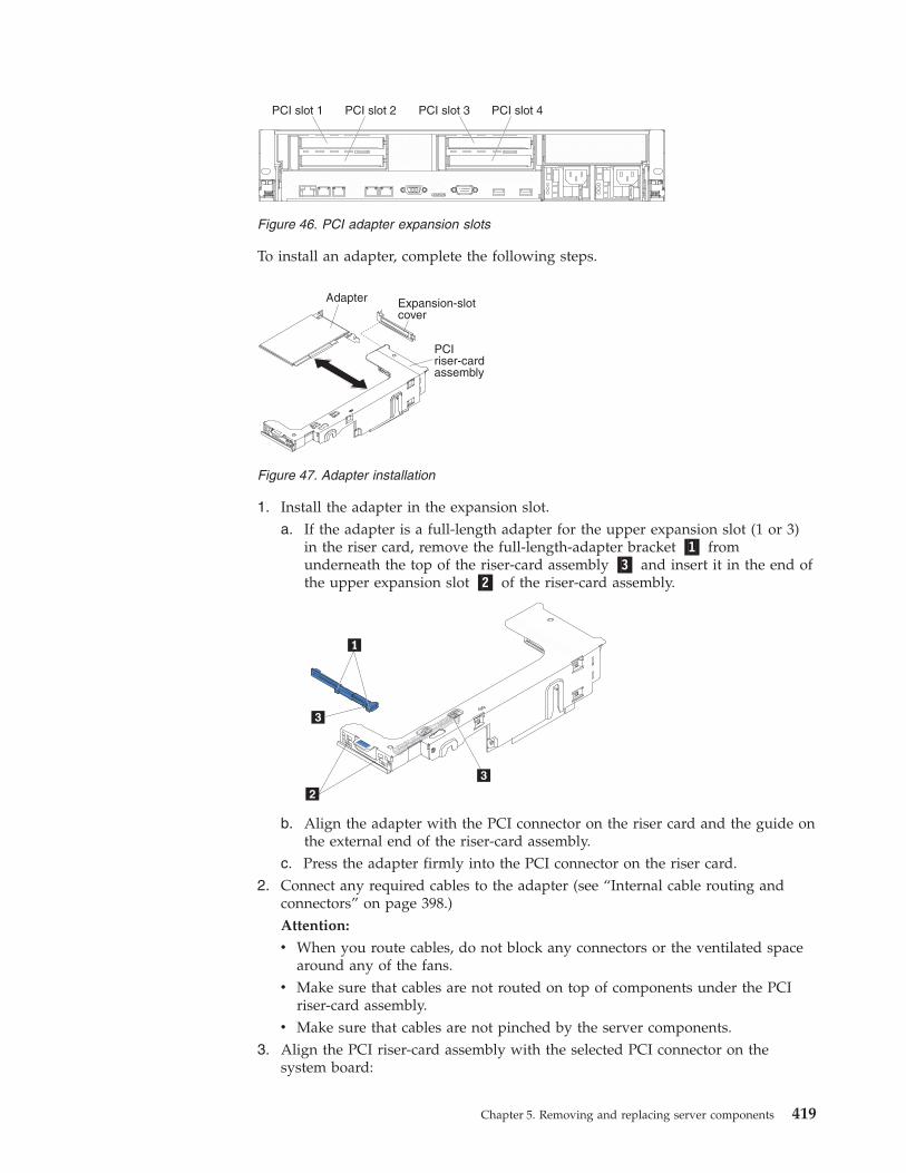
To install an adapter, complete the following steps.
1. Install the adapter in the expansion slot.a. If the adapter is a full-length adapter for the upper expansion slot (1 or 3)
in the riser card, remove the full-length-adapter bracket �1� fromunderneath the top of the riser-card assembly �3� and insert it in the end ofthe upper expansion slot �2� of the riser-card assembly.
b. Align the adapter with the PCI connector on the riser card and the guide onthe external end of the riser-card assembly.
c. Press the adapter firmly into the PCI connector on the riser card.2. Connect any required cables to the adapter (see “Internal cable routing and
connectors” on page 398.)Attention:
v When you route cables, do not block any connectors or the ventilated spacearound any of the fans.
v Make sure that cables are not routed on top of components under the PCIriser-card assembly.
v Make sure that cables are not pinched by the server components.3. Align the PCI riser-card assembly with the selected PCI connector on the
system board:
Figure 46. PCI adapter expansion slots
PCIriser-cardassembly
Expansion-slotcover
Adapter
Figure 47. Adapter installation
Chapter 5. Removing and replacing server components 419
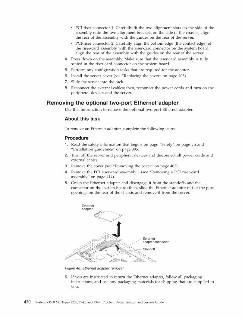
v PCI-riser connector 1: Carefully fit the two alignment slots on the side of theassembly onto the two alignment brackets on the side of the chassis; alignthe rear of the assembly with the guides on the rear of the server.
v PCI-riser connector 2: Carefully align the bottom edge (the contact edge) ofthe riser-card assembly with the riser-card connector on the system board;align the rear of the assembly with the guides on the rear of the server.
4. Press down on the assembly. Make sure that the riser-card assembly is fullyseated in the riser-card connector on the system board.
5. Perform any configuration tasks that are required for the adapter.6. Install the server cover (see “Replacing the cover” on page 403).7. Slide the server into the rack.8. Reconnect the external cables; then, reconnect the power cords and turn on the
peripheral devices and the server.
Removing the optional two-port Ethernet adapterUse this information to remove the optional two-port Ethernet adapter.
About this task
To remove an Ethernet adapter, complete the following steps:
Procedure1. Read the safety information that begins on page “Safety” on page vii and
“Installation guidelines” on page 395.2. Turn off the server and peripheral devices and disconnect all power cords and
external cables.3. Remove the cover (see “Removing the cover” on page 402).4. Remove the PCI riser-card assembly 1 (see “Removing a PCI riser-card
assembly” on page 414).5. Grasp the Ethernet adapter and disengage it from the standoffs and the
connector on the system board; then, slide the Ethernet adapter out of the portopenings on the rear of the chassis and remove it from the server.
6. If you are instructed to return the Ethernet adapter, follow all packaginginstructions, and use any packaging materials for shipping that are supplied toyou.
Figure 48. Ethernet adapter removal
420 System x3650 M3 Types 4255, 7945, and 7949: Problem Determination and Service Guide
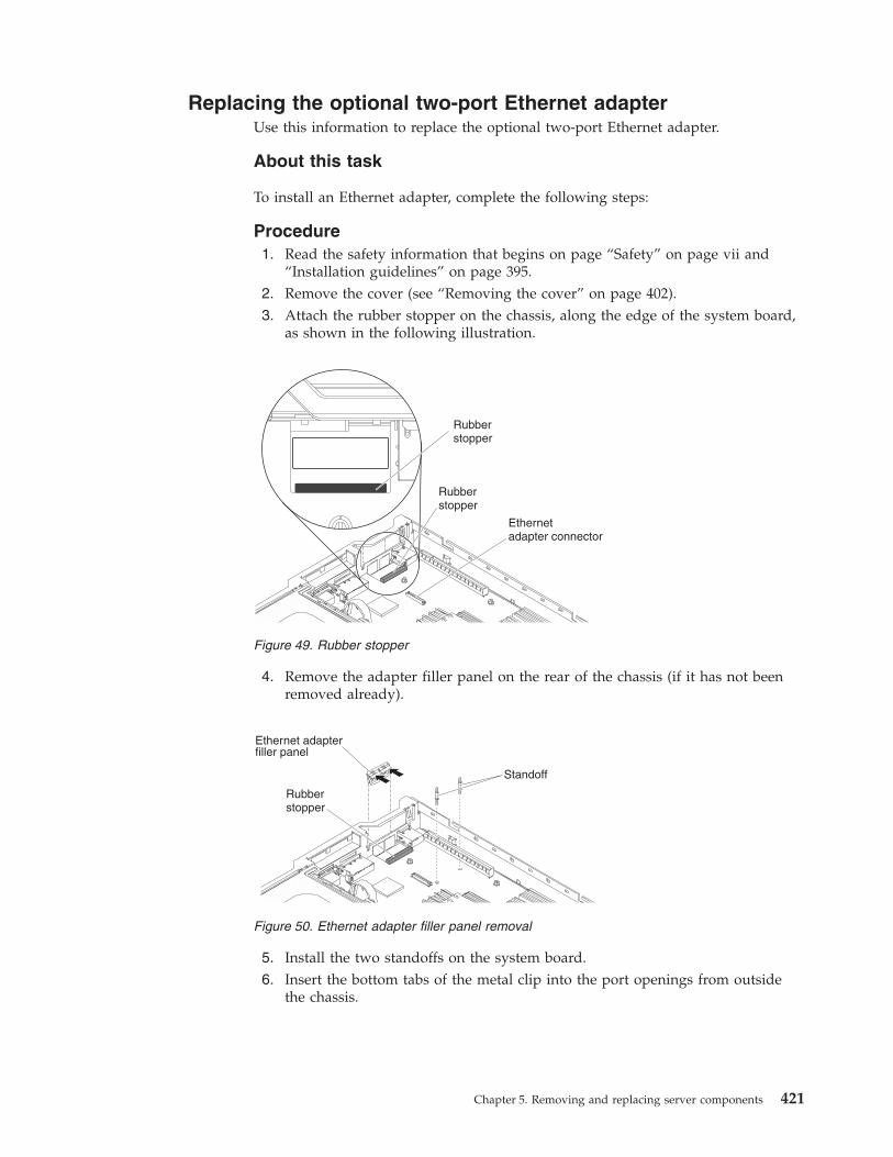
Replacing the optional two-port Ethernet adapterUse this information to replace the optional two-port Ethernet adapter.
About this task
To install an Ethernet adapter, complete the following steps:
Procedure1. Read the safety information that begins on page “Safety” on page vii and
“Installation guidelines” on page 395.2. Remove the cover (see “Removing the cover” on page 402).3. Attach the rubber stopper on the chassis, along the edge of the system board,
as shown in the following illustration.
4. Remove the adapter filler panel on the rear of the chassis (if it has not beenremoved already).
5. Install the two standoffs on the system board.6. Insert the bottom tabs of the metal clip into the port openings from outside
the chassis.
Rubberstopper
Ethernetadapter connector
Rubberstopper
Figure 49. Rubber stopper
Figure 50. Ethernet adapter filler panel removal
Chapter 5. Removing and replacing server components 421
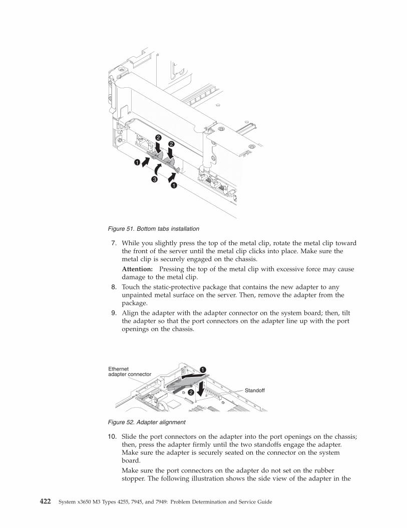
7. While you slightly press the top of the metal clip, rotate the metal clip towardthe front of the server until the metal clip clicks into place. Make sure themetal clip is securely engaged on the chassis.Attention: Pressing the top of the metal clip with excessive force may causedamage to the metal clip.
8. Touch the static-protective package that contains the new adapter to anyunpainted metal surface on the server. Then, remove the adapter from thepackage.
9. Align the adapter with the adapter connector on the system board; then, tiltthe adapter so that the port connectors on the adapter line up with the portopenings on the chassis.
10. Slide the port connectors on the adapter into the port openings on the chassis;then, press the adapter firmly until the two standoffs engage the adapter.Make sure the adapter is securely seated on the connector on the systemboard.Make sure the port connectors on the adapter do not set on the rubberstopper. The following illustration shows the side view of the adapter in the
Figure 51. Bottom tabs installation
Figure 52. Adapter alignment
422 System x3650 M3 Types 4255, 7945, and 7949: Problem Determination and Service Guide
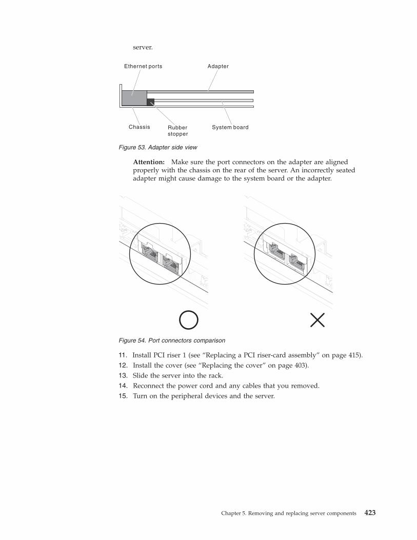
server.
Attention: Make sure the port connectors on the adapter are alignedproperly with the chassis on the rear of the server. An incorrectly seatedadapter might cause damage to the system board or the adapter.
11. Install PCI riser 1 (see “Replacing a PCI riser-card assembly” on page 415).12. Install the cover (see “Replacing the cover” on page 403).13. Slide the server into the rack.14. Reconnect the power cord and any cables that you removed.15. Turn on the peripheral devices and the server.
System boardChassis
Ethernet ports
Rubberstopper
Adapter
Figure 53. Adapter side view
Figure 54. Port connectors comparison
Chapter 5. Removing and replacing server components 423
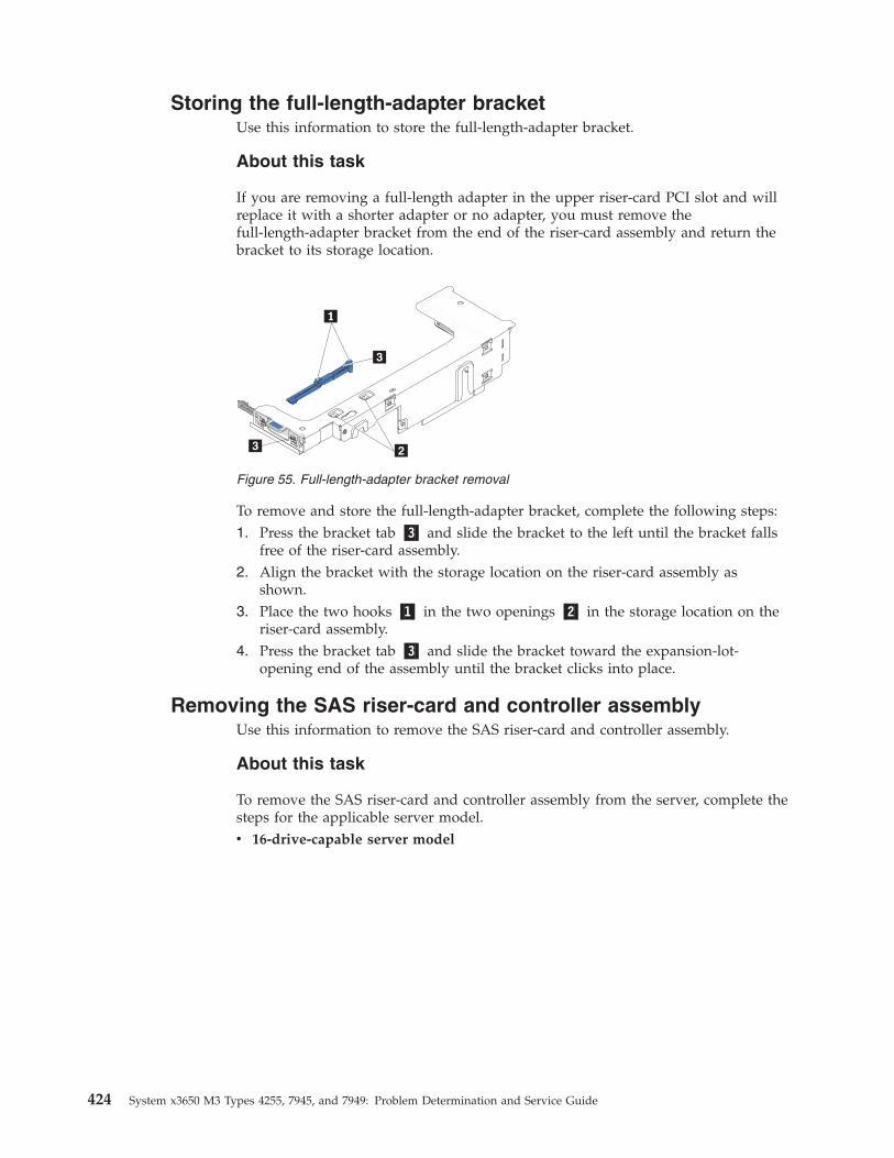
Storing the full-length-adapter bracketUse this information to store the full-length-adapter bracket.
About this task
If you are removing a full-length adapter in the upper riser-card PCI slot and willreplace it with a shorter adapter or no adapter, you must remove thefull-length-adapter bracket from the end of the riser-card assembly and return thebracket to its storage location.
To remove and store the full-length-adapter bracket, complete the following steps:1. Press the bracket tab �3� and slide the bracket to the left until the bracket falls
free of the riser-card assembly.2. Align the bracket with the storage location on the riser-card assembly as
shown.3. Place the two hooks �1� in the two openings �2� in the storage location on the
riser-card assembly.4. Press the bracket tab �3� and slide the bracket toward the expansion-lot-
opening end of the assembly until the bracket clicks into place.
Removing the SAS riser-card and controller assemblyUse this information to remove the SAS riser-card and controller assembly.
About this task
To remove the SAS riser-card and controller assembly from the server, complete thesteps for the applicable server model.v 16-drive-capable server model
Figure 55. Full-length-adapter bracket removal
424 System x3650 M3 Types 4255, 7945, and 7949: Problem Determination and Service Guide
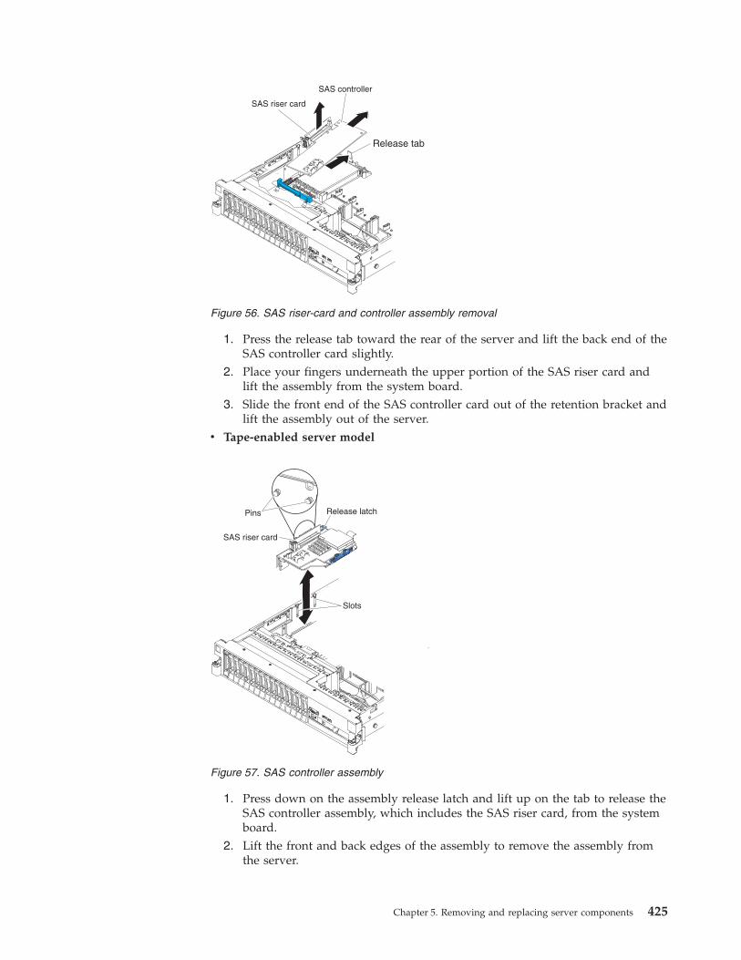
1. Press the release tab toward the rear of the server and lift the back end of theSAS controller card slightly.
2. Place your fingers underneath the upper portion of the SAS riser card andlift the assembly from the system board.
3. Slide the front end of the SAS controller card out of the retention bracket andlift the assembly out of the server.
v Tape-enabled server model
1. Press down on the assembly release latch and lift up on the tab to release theSAS controller assembly, which includes the SAS riser card, from the systemboard.
2. Lift the front and back edges of the assembly to remove the assembly fromthe server.
Figure 56. SAS riser-card and controller assembly removal
Figure 57. SAS controller assembly
Chapter 5. Removing and replacing server components 425
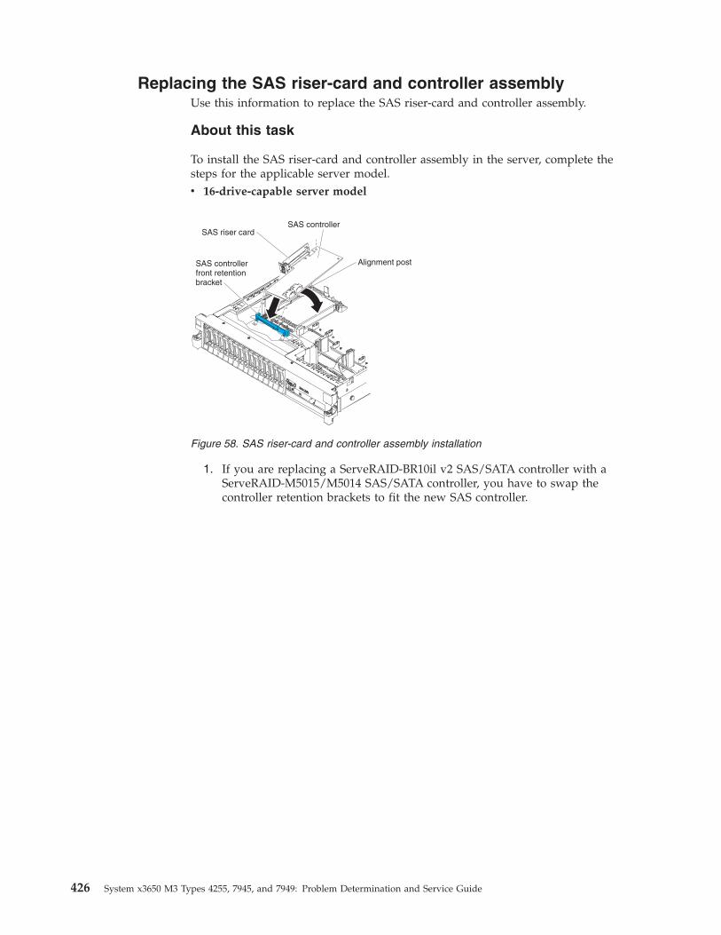
Replacing the SAS riser-card and controller assemblyUse this information to replace the SAS riser-card and controller assembly.
About this task
To install the SAS riser-card and controller assembly in the server, complete thesteps for the applicable server model.v 16-drive-capable server model
1. If you are replacing a ServeRAID-BR10il v2 SAS/SATA controller with aServeRAID-M5015/M5014 SAS/SATA controller, you have to swap thecontroller retention brackets to fit the new SAS controller.
Figure 58. SAS riser-card and controller assembly installation
426 System x3650 M3 Types 4255, 7945, and 7949: Problem Determination and Service Guide
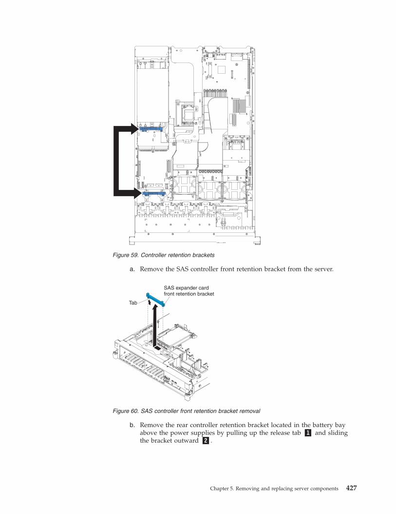
a. Remove the SAS controller front retention bracket from the server.
b. Remove the rear controller retention bracket located in the battery bayabove the power supplies by pulling up the release tab �1� and slidingthe bracket outward �2�.
Figure 59. Controller retention brackets
Figure 60. SAS controller front retention bracket removal
Chapter 5. Removing and replacing server components 427
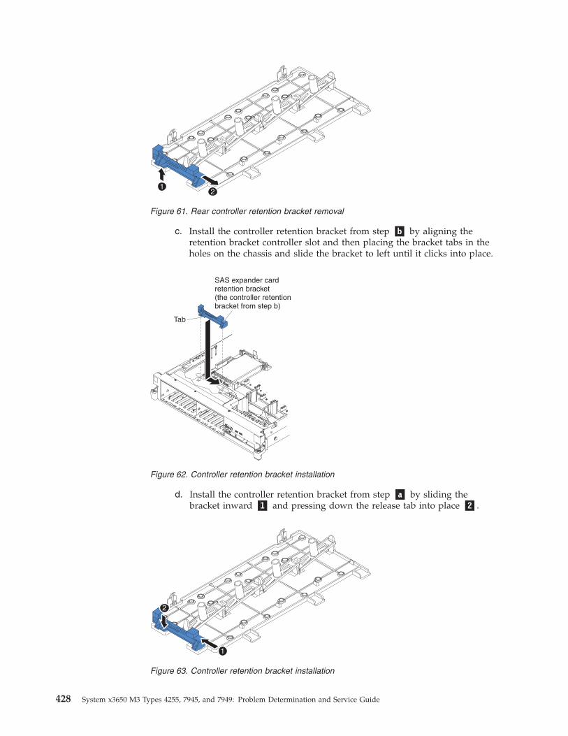
c. Install the controller retention bracket from step �b� by aligning theretention bracket controller slot and then placing the bracket tabs in theholes on the chassis and slide the bracket to left until it clicks into place.
d. Install the controller retention bracket from step �a� by sliding thebracket inward �1� and pressing down the release tab into place �2�.
Figure 61. Rear controller retention bracket removal
Figure 62. Controller retention bracket installation
Figure 63. Controller retention bracket installation
428 System x3650 M3 Types 4255, 7945, and 7949: Problem Determination and Service Guide
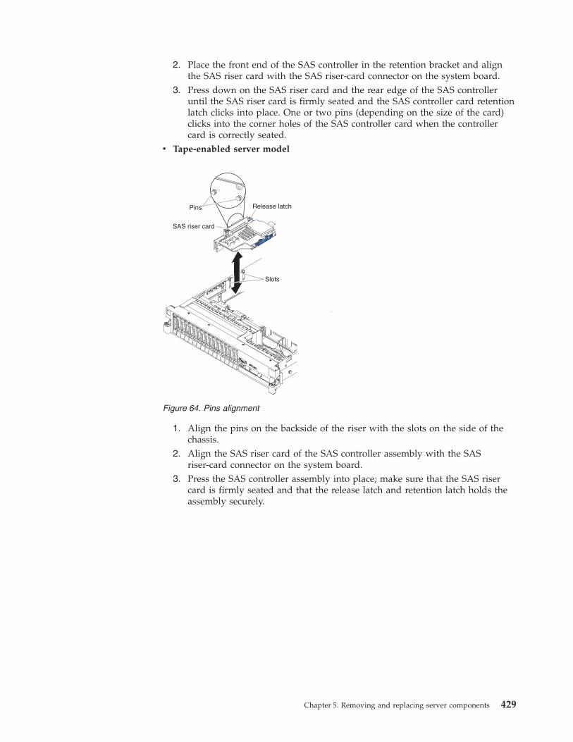
2. Place the front end of the SAS controller in the retention bracket and alignthe SAS riser card with the SAS riser-card connector on the system board.
3. Press down on the SAS riser card and the rear edge of the SAS controlleruntil the SAS riser card is firmly seated and the SAS controller card retentionlatch clicks into place. One or two pins (depending on the size of the card)clicks into the corner holes of the SAS controller card when the controllercard is correctly seated.
v Tape-enabled server model
1. Align the pins on the backside of the riser with the slots on the side of thechassis.
2. Align the SAS riser card of the SAS controller assembly with the SASriser-card connector on the system board.
3. Press the SAS controller assembly into place; make sure that the SAS risercard is firmly seated and that the release latch and retention latch holds theassembly securely.
Figure 64. Pins alignment
Chapter 5. Removing and replacing server components 429
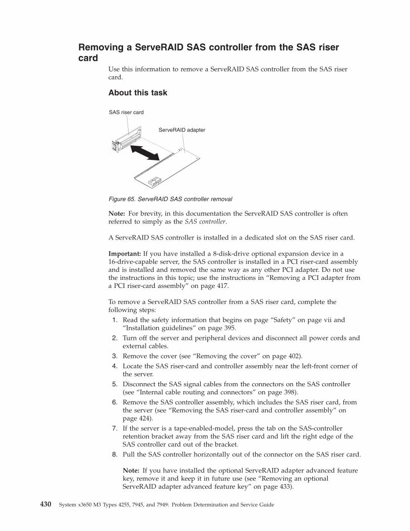
Removing a ServeRAID SAS controller from the SAS risercard
Use this information to remove a ServeRAID SAS controller from the SAS risercard.
About this task
Note: For brevity, in this documentation the ServeRAID SAS controller is oftenreferred to simply as the SAS controller.
A ServeRAID SAS controller is installed in a dedicated slot on the SAS riser card.
Important: If you have installed a 8-disk-drive optional expansion device in a16-drive-capable server, the SAS controller is installed in a PCI riser-card assemblyand is installed and removed the same way as any other PCI adapter. Do not usethe instructions in this topic; use the instructions in “Removing a PCI adapter froma PCI riser-card assembly” on page 417.
To remove a ServeRAID SAS controller from a SAS riser card, complete thefollowing steps:1. Read the safety information that begins on page “Safety” on page vii and
“Installation guidelines” on page 395.2. Turn off the server and peripheral devices and disconnect all power cords and
external cables.3. Remove the cover (see “Removing the cover” on page 402).4. Locate the SAS riser-card and controller assembly near the left-front corner of
the server.5. Disconnect the SAS signal cables from the connectors on the SAS controller
(see “Internal cable routing and connectors” on page 398).6. Remove the SAS controller assembly, which includes the SAS riser card, from
the server (see “Removing the SAS riser-card and controller assembly” onpage 424).
7. If the server is a tape-enabled-model, press the tab on the SAS-controllerretention bracket away from the SAS riser card and lift the right edge of theSAS controller card out of the bracket.
8. Pull the SAS controller horizontally out of the connector on the SAS riser card.
Note: If you have installed the optional ServeRAID adapter advanced featurekey, remove it and keep it in future use (see “Removing an optionalServeRAID adapter advanced feature key” on page 433).
Figure 65. ServeRAID SAS controller removal
430 System x3650 M3 Types 4255, 7945, and 7949: Problem Determination and Service Guide
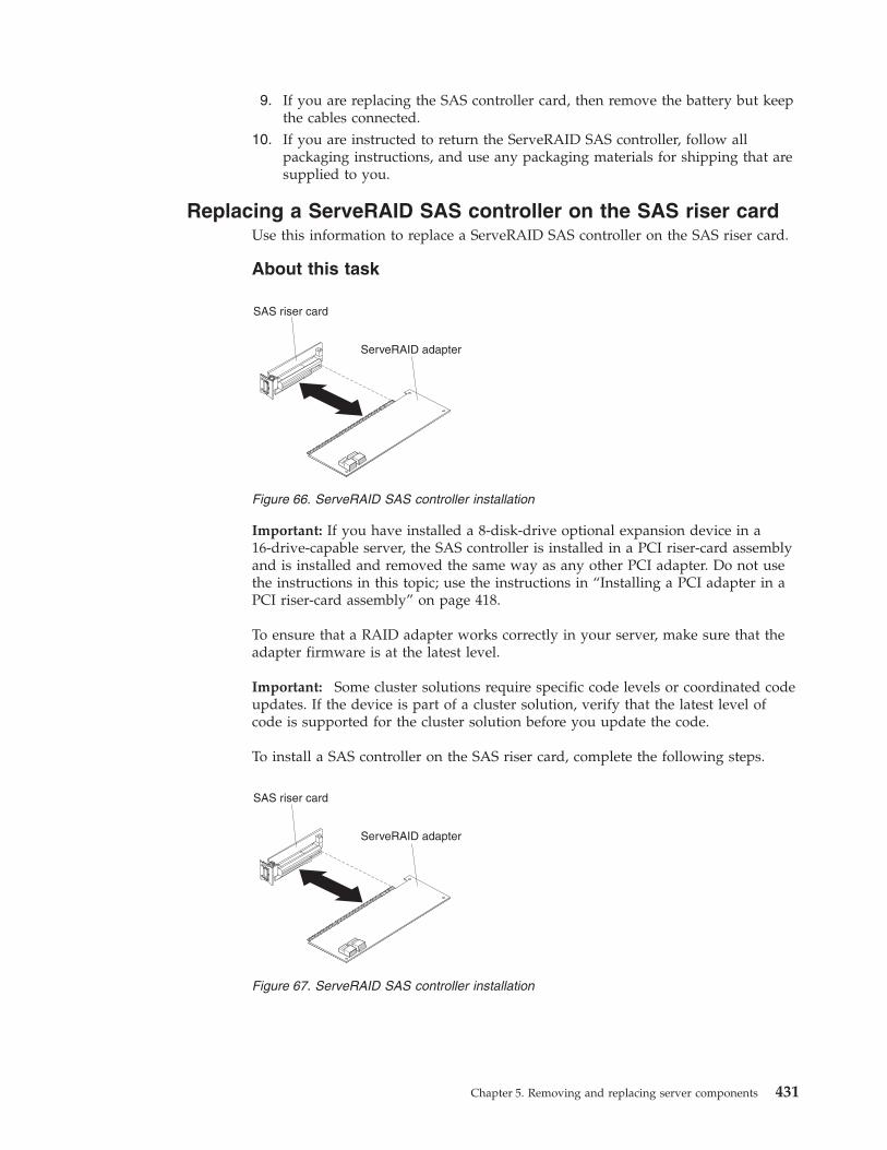
9. If you are replacing the SAS controller card, then remove the battery but keepthe cables connected.
10. If you are instructed to return the ServeRAID SAS controller, follow allpackaging instructions, and use any packaging materials for shipping that aresupplied to you.
Replacing a ServeRAID SAS controller on the SAS riser cardUse this information to replace a ServeRAID SAS controller on the SAS riser card.
About this task
Important: If you have installed a 8-disk-drive optional expansion device in a16-drive-capable server, the SAS controller is installed in a PCI riser-card assemblyand is installed and removed the same way as any other PCI adapter. Do not usethe instructions in this topic; use the instructions in “Installing a PCI adapter in aPCI riser-card assembly” on page 418.
To ensure that a RAID adapter works correctly in your server, make sure that theadapter firmware is at the latest level.
Important: Some cluster solutions require specific code levels or coordinated codeupdates. If the device is part of a cluster solution, verify that the latest level ofcode is supported for the cluster solution before you update the code.
To install a SAS controller on the SAS riser card, complete the following steps.
Figure 66. ServeRAID SAS controller installation
Figure 67. ServeRAID SAS controller installation
Chapter 5. Removing and replacing server components 431
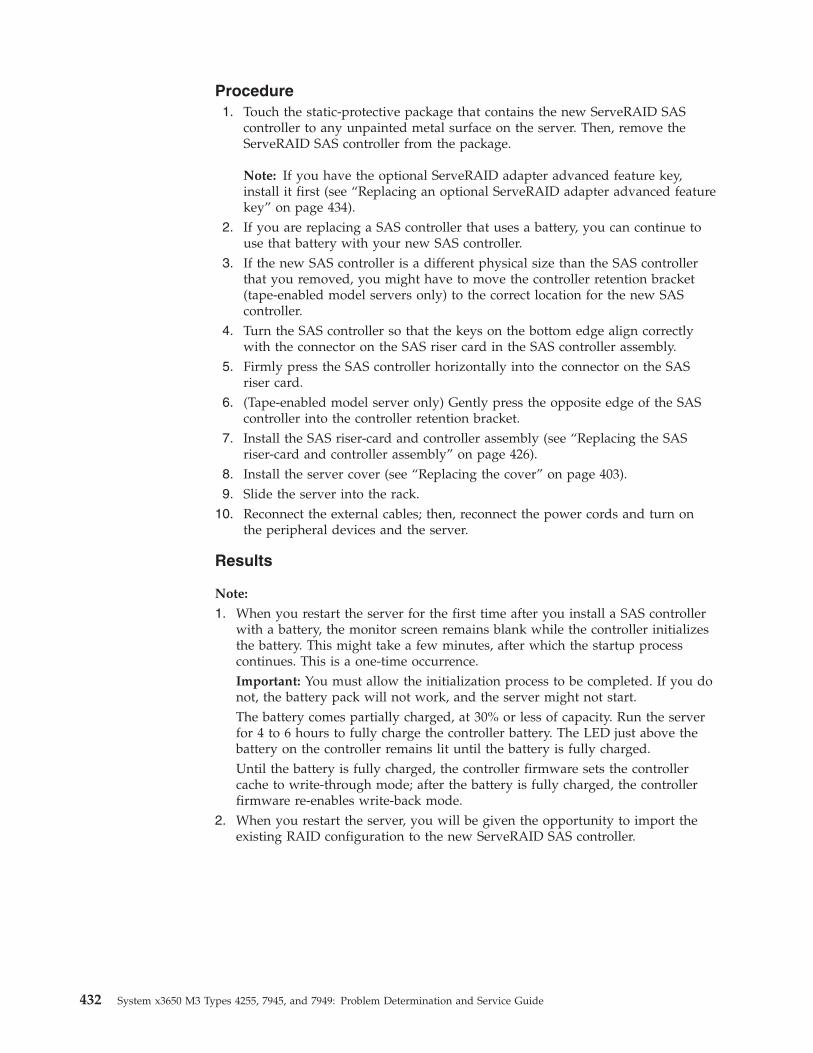
Procedure1. Touch the static-protective package that contains the new ServeRAID SAS
controller to any unpainted metal surface on the server. Then, remove theServeRAID SAS controller from the package.
Note: If you have the optional ServeRAID adapter advanced feature key,install it first (see “Replacing an optional ServeRAID adapter advanced featurekey” on page 434).
2. If you are replacing a SAS controller that uses a battery, you can continue touse that battery with your new SAS controller.
3. If the new SAS controller is a different physical size than the SAS controllerthat you removed, you might have to move the controller retention bracket(tape-enabled model servers only) to the correct location for the new SAScontroller.
4. Turn the SAS controller so that the keys on the bottom edge align correctlywith the connector on the SAS riser card in the SAS controller assembly.
5. Firmly press the SAS controller horizontally into the connector on the SASriser card.
6. (Tape-enabled model server only) Gently press the opposite edge of the SAScontroller into the controller retention bracket.
7. Install the SAS riser-card and controller assembly (see “Replacing the SASriser-card and controller assembly” on page 426).
8. Install the server cover (see “Replacing the cover” on page 403).9. Slide the server into the rack.
10. Reconnect the external cables; then, reconnect the power cords and turn onthe peripheral devices and the server.
Results
Note:
1. When you restart the server for the first time after you install a SAS controllerwith a battery, the monitor screen remains blank while the controller initializesthe battery. This might take a few minutes, after which the startup processcontinues. This is a one-time occurrence.Important: You must allow the initialization process to be completed. If you donot, the battery pack will not work, and the server might not start.The battery comes partially charged, at 30% or less of capacity. Run the serverfor 4 to 6 hours to fully charge the controller battery. The LED just above thebattery on the controller remains lit until the battery is fully charged.Until the battery is fully charged, the controller firmware sets the controllercache to write-through mode; after the battery is fully charged, the controllerfirmware re-enables write-back mode.
2. When you restart the server, you will be given the opportunity to import theexisting RAID configuration to the new ServeRAID SAS controller.
432 System x3650 M3 Types 4255, 7945, and 7949: Problem Determination and Service Guide
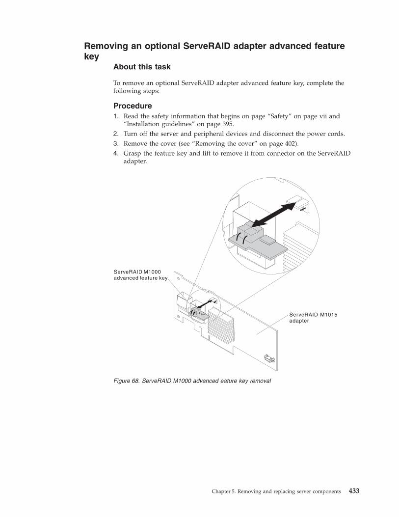
Removing an optional ServeRAID adapter advanced featurekey
About this task
To remove an optional ServeRAID adapter advanced feature key, complete thefollowing steps:
Procedure1. Read the safety information that begins on page “Safety” on page vii and
“Installation guidelines” on page 395.2. Turn off the server and peripheral devices and disconnect the power cords.3. Remove the cover (see “Removing the cover” on page 402).4. Grasp the feature key and lift to remove it from connector on the ServeRAID
adapter.
Figure 68. ServeRAID M1000 advanced eature key removal
Chapter 5. Removing and replacing server components 433
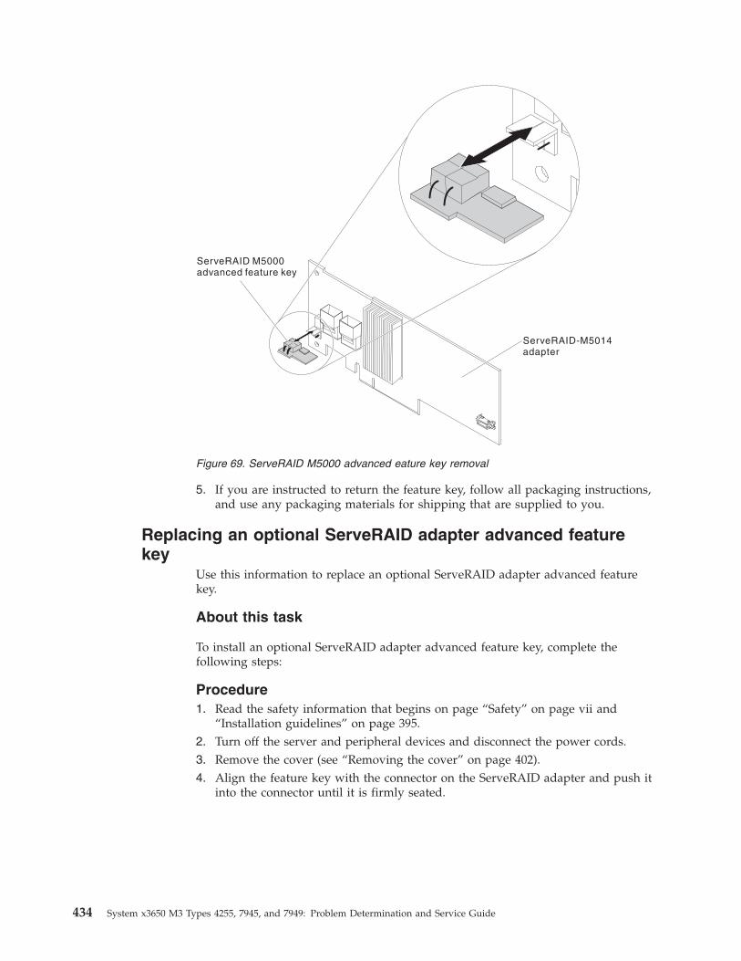
5. If you are instructed to return the feature key, follow all packaging instructions,and use any packaging materials for shipping that are supplied to you.
Replacing an optional ServeRAID adapter advanced featurekey
Use this information to replace an optional ServeRAID adapter advanced featurekey.
About this task
To install an optional ServeRAID adapter advanced feature key, complete thefollowing steps:
Procedure1. Read the safety information that begins on page “Safety” on page vii and
“Installation guidelines” on page 395.2. Turn off the server and peripheral devices and disconnect the power cords.3. Remove the cover (see “Removing the cover” on page 402).4. Align the feature key with the connector on the ServeRAID adapter and push it
into the connector until it is firmly seated.
Figure 69. ServeRAID M5000 advanced eature key removal
434 System x3650 M3 Types 4255, 7945, and 7949: Problem Determination and Service Guide
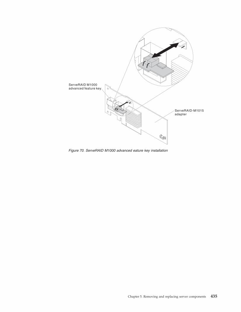
Figure 70. ServeRAID M1000 advanced eature key installation
Chapter 5. Removing and replacing server components 435
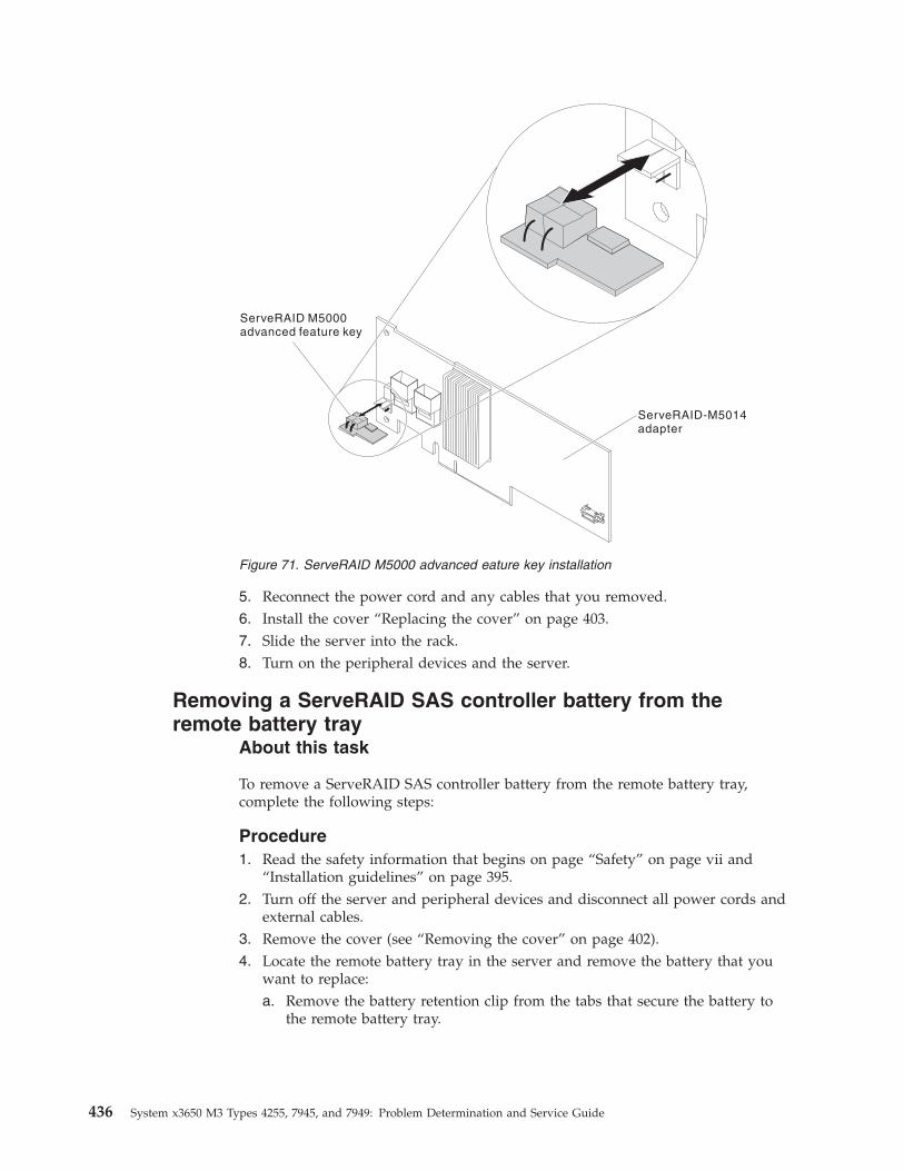
5. Reconnect the power cord and any cables that you removed.6. Install the cover “Replacing the cover” on page 403.7. Slide the server into the rack.8. Turn on the peripheral devices and the server.
Removing a ServeRAID SAS controller battery from theremote battery tray
About this task
To remove a ServeRAID SAS controller battery from the remote battery tray,complete the following steps:
Procedure1. Read the safety information that begins on page “Safety” on page vii and
“Installation guidelines” on page 395.2. Turn off the server and peripheral devices and disconnect all power cords and
external cables.3. Remove the cover (see “Removing the cover” on page 402).4. Locate the remote battery tray in the server and remove the battery that you
want to replace:a. Remove the battery retention clip from the tabs that secure the battery to
the remote battery tray.
Figure 71. ServeRAID M5000 advanced eature key installation
436 System x3650 M3 Types 4255, 7945, and 7949: Problem Determination and Service Guide
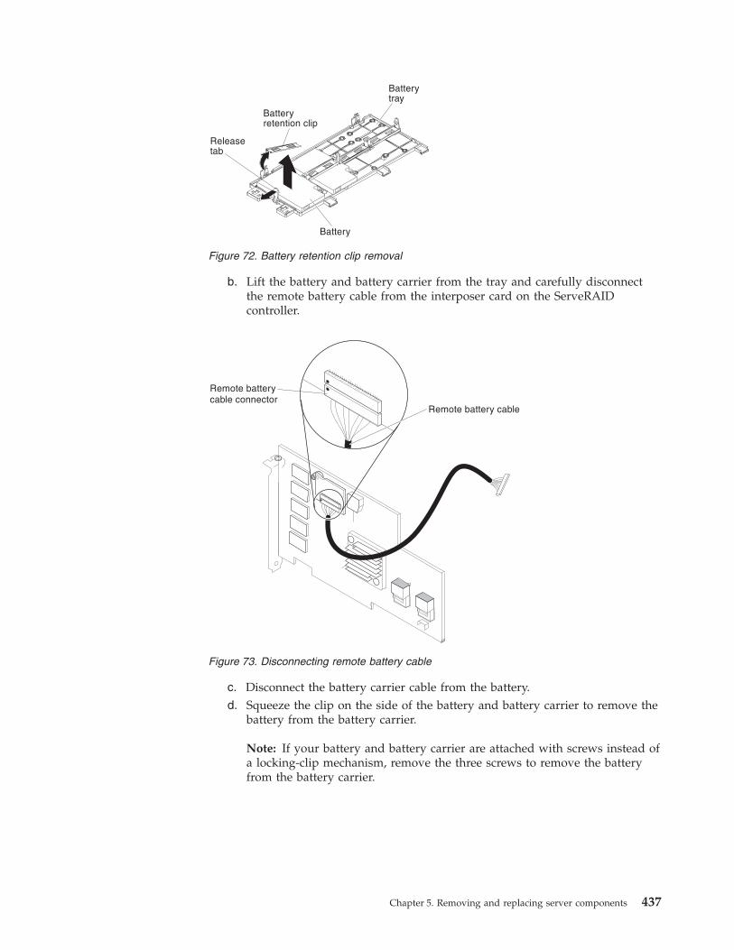
b. Lift the battery and battery carrier from the tray and carefully disconnectthe remote battery cable from the interposer card on the ServeRAIDcontroller.
c. Disconnect the battery carrier cable from the battery.d. Squeeze the clip on the side of the battery and battery carrier to remove the
battery from the battery carrier.
Note: If your battery and battery carrier are attached with screws instead ofa locking-clip mechanism, remove the three screws to remove the batteryfrom the battery carrier.
Figure 72. Battery retention clip removal
Figure 73. Disconnecting remote battery cable
Chapter 5. Removing and replacing server components 437
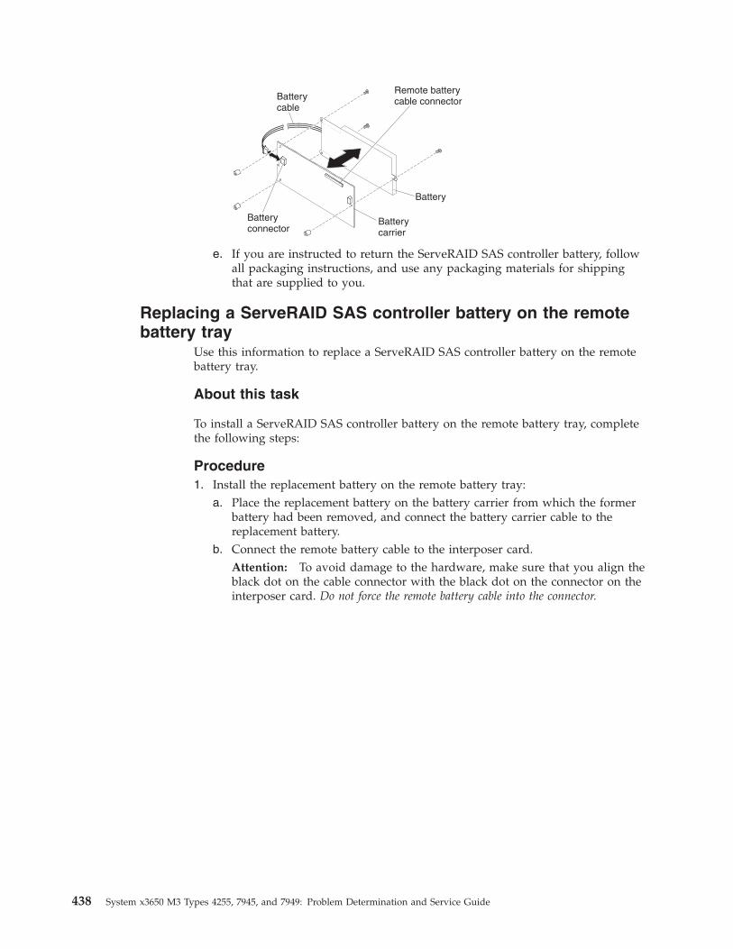
e. If you are instructed to return the ServeRAID SAS controller battery, followall packaging instructions, and use any packaging materials for shippingthat are supplied to you.
Replacing a ServeRAID SAS controller battery on the remotebattery tray
Use this information to replace a ServeRAID SAS controller battery on the remotebattery tray.
About this task
To install a ServeRAID SAS controller battery on the remote battery tray, completethe following steps:
Procedure1. Install the replacement battery on the remote battery tray:
a. Place the replacement battery on the battery carrier from which the formerbattery had been removed, and connect the battery carrier cable to thereplacement battery.
b. Connect the remote battery cable to the interposer card.Attention: To avoid damage to the hardware, make sure that you align theblack dot on the cable connector with the black dot on the connector on theinterposer card. Do not force the remote battery cable into the connector.
438 System x3650 M3 Types 4255, 7945, and 7949: Problem Determination and Service Guide
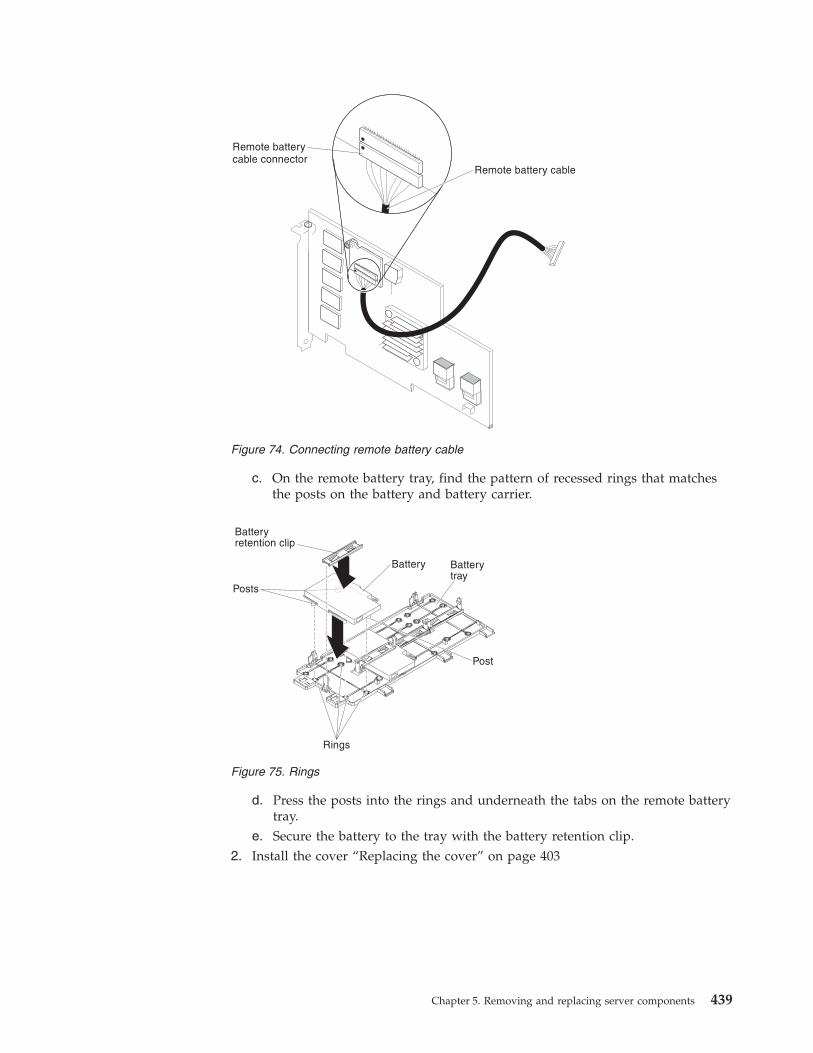
c. On the remote battery tray, find the pattern of recessed rings that matchesthe posts on the battery and battery carrier.
d. Press the posts into the rings and underneath the tabs on the remote batterytray.
e. Secure the battery to the tray with the battery retention clip.2. Install the cover “Replacing the cover” on page 403
Figure 74. Connecting remote battery cable
Figure 75. Rings
Chapter 5. Removing and replacing server components 439
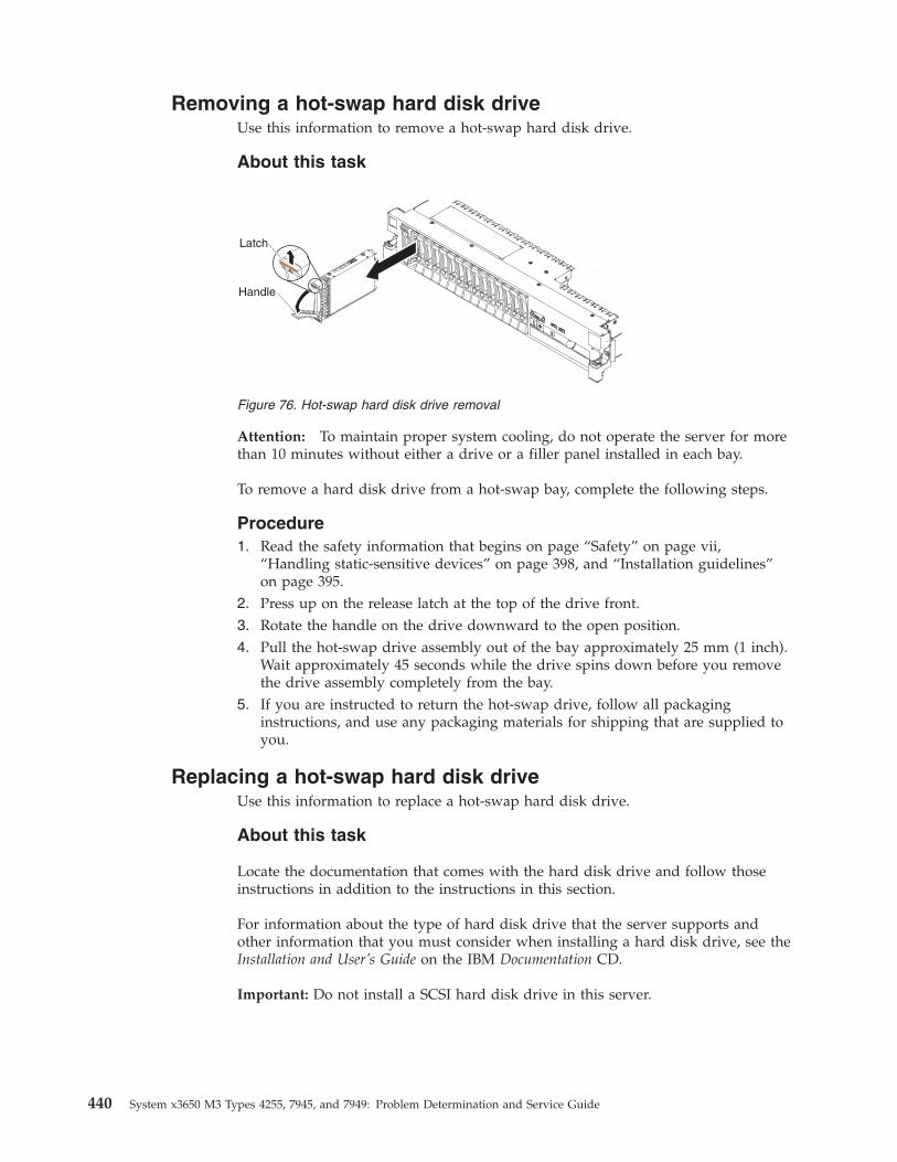
Removing a hot-swap hard disk driveUse this information to remove a hot-swap hard disk drive.
About this task
Attention: To maintain proper system cooling, do not operate the server for morethan 10 minutes without either a drive or a filler panel installed in each bay.
To remove a hard disk drive from a hot-swap bay, complete the following steps.
Procedure1. Read the safety information that begins on page “Safety” on page vii,
“Handling static-sensitive devices” on page 398, and “Installation guidelines”on page 395.
2. Press up on the release latch at the top of the drive front.3. Rotate the handle on the drive downward to the open position.4. Pull the hot-swap drive assembly out of the bay approximately 25 mm (1 inch).
Wait approximately 45 seconds while the drive spins down before you removethe drive assembly completely from the bay.
5. If you are instructed to return the hot-swap drive, follow all packaginginstructions, and use any packaging materials for shipping that are supplied toyou.
Replacing a hot-swap hard disk driveUse this information to replace a hot-swap hard disk drive.
About this task
Locate the documentation that comes with the hard disk drive and follow thoseinstructions in addition to the instructions in this section.
For information about the type of hard disk drive that the server supports andother information that you must consider when installing a hard disk drive, see theInstallation and User’s Guide on the IBM Documentation CD.
Important: Do not install a SCSI hard disk drive in this server.
Latch
Handle
Figure 76. Hot-swap hard disk drive removal
440 System x3650 M3 Types 4255, 7945, and 7949: Problem Determination and Service Guide
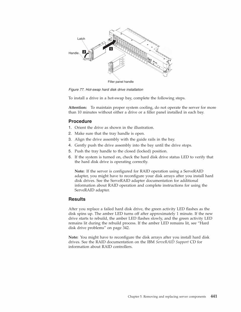
To install a drive in a hot-swap bay, complete the following steps.
Attention: To maintain proper system cooling, do not operate the server for morethan 10 minutes without either a drive or a filler panel installed in each bay.
Procedure1. Orient the drive as shown in the illustration.2. Make sure that the tray handle is open.3. Align the drive assembly with the guide rails in the bay.4. Gently push the drive assembly into the bay until the drive stops.5. Push the tray handle to the closed (locked) position.6. If the system is turned on, check the hard disk drive status LED to verify that
the hard disk drive is operating correctly.
Note: If the server is configured for RAID operation using a ServeRAIDadapter, you might have to reconfigure your disk arrays after you install harddisk drives. See the ServeRAID adapter documentation for additionalinformation about RAID operation and complete instructions for using theServeRAID adapter.
Results
After you replace a failed hard disk drive, the green activity LED flashes as thedisk spins up. The amber LED turns off after approximately 1 minute. If the newdrive starts to rebuild, the amber LED flashes slowly, and the green activity LEDremains lit during the rebuild process. If the amber LED remains lit, see “Harddisk drive problems” on page 342.
Note: You might have to reconfigure the disk arrays after you install hard diskdrives. See the RAID documentation on the IBM ServeRAID Support CD forinformation about RAID controllers.
Latch
Handle
Filler panel handle
Figure 77. Hot-swap hard disk drive installation
Chapter 5. Removing and replacing server components 441
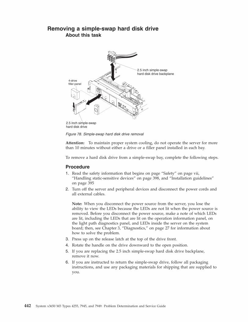
Removing a simple-swap hard disk driveAbout this task
Attention: To maintain proper system cooling, do not operate the server for morethan 10 minutes without either a drive or a filler panel installed in each bay.
To remove a hard disk drive from a simple-swap bay, complete the following steps.
Procedure1. Read the safety information that begins on page “Safety” on page vii,
“Handling static-sensitive devices” on page 398, and “Installation guidelines”on page 395
2. Turn off the server and peripheral devices and disconnect the power cords andall external cables.
Note: When you disconnect the power source from the server, you lose theability to view the LEDs because the LEDs are not lit when the power source isremoved. Before you disconnect the power source, make a note of which LEDsare lit, including the LEDs that are lit on the operation information panel, onthe light path diagnostics panel, and LEDs inside the server on the systemboard; then, see Chapter 3, “Diagnostics,” on page 27 for information abouthow to solve the problem.
3. Press up on the release latch at the top of the drive front.4. Rotate the handle on the drive downward to the open position.5. If you are replacing the 2.5 inch simple-swap hard disk drive backplane,
remove it now.6. If you are instructed to return the simple-swap drive, follow all packaging
instructions, and use any packaging materials for shipping that are supplied toyou.
Figure 78. Simple-swap hard disk drive removal
442 System x3650 M3 Types 4255, 7945, and 7949: Problem Determination and Service Guide
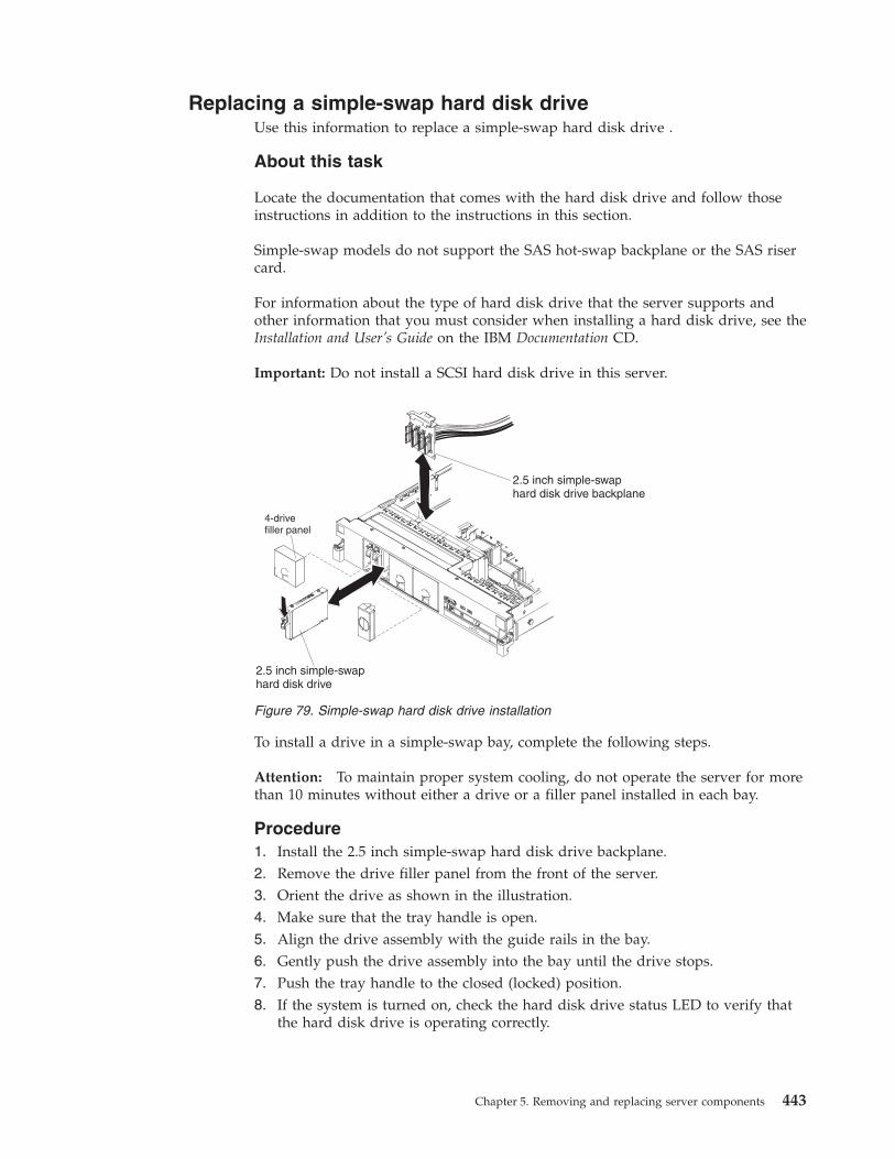
Replacing a simple-swap hard disk driveUse this information to replace a simple-swap hard disk drive .
About this task
Locate the documentation that comes with the hard disk drive and follow thoseinstructions in addition to the instructions in this section.
Simple-swap models do not support the SAS hot-swap backplane or the SAS risercard.
For information about the type of hard disk drive that the server supports andother information that you must consider when installing a hard disk drive, see theInstallation and User’s Guide on the IBM Documentation CD.
Important: Do not install a SCSI hard disk drive in this server.
To install a drive in a simple-swap bay, complete the following steps.
Attention: To maintain proper system cooling, do not operate the server for morethan 10 minutes without either a drive or a filler panel installed in each bay.
Procedure1. Install the 2.5 inch simple-swap hard disk drive backplane.2. Remove the drive filler panel from the front of the server.3. Orient the drive as shown in the illustration.4. Make sure that the tray handle is open.5. Align the drive assembly with the guide rails in the bay.6. Gently push the drive assembly into the bay until the drive stops.7. Push the tray handle to the closed (locked) position.8. If the system is turned on, check the hard disk drive status LED to verify that
the hard disk drive is operating correctly.
Figure 79. Simple-swap hard disk drive installation
Chapter 5. Removing and replacing server components 443
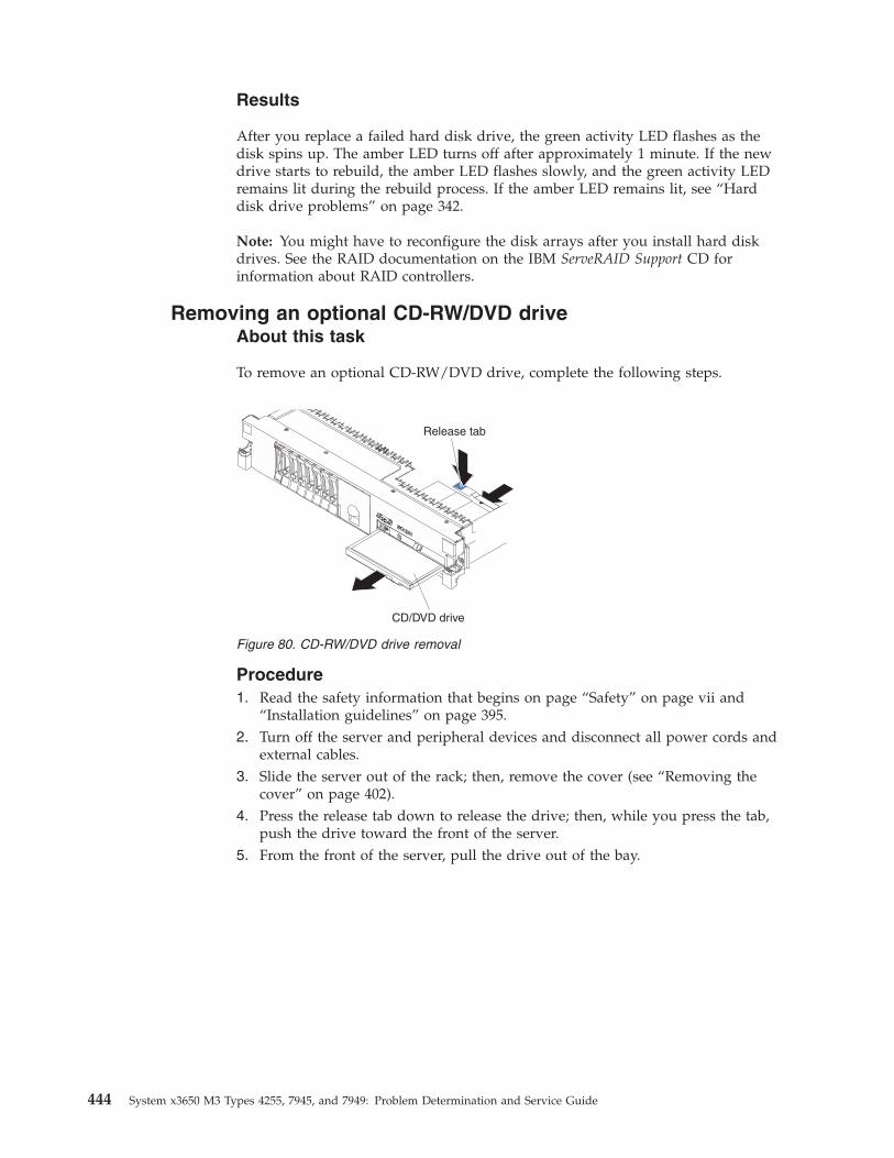
Results
After you replace a failed hard disk drive, the green activity LED flashes as thedisk spins up. The amber LED turns off after approximately 1 minute. If the newdrive starts to rebuild, the amber LED flashes slowly, and the green activity LEDremains lit during the rebuild process. If the amber LED remains lit, see “Harddisk drive problems” on page 342.
Note: You might have to reconfigure the disk arrays after you install hard diskdrives. See the RAID documentation on the IBM ServeRAID Support CD forinformation about RAID controllers.
Removing an optional CD-RW/DVD driveAbout this task
To remove an optional CD-RW/DVD drive, complete the following steps.
Procedure1. Read the safety information that begins on page “Safety” on page vii and
“Installation guidelines” on page 395.2. Turn off the server and peripheral devices and disconnect all power cords and
external cables.3. Slide the server out of the rack; then, remove the cover (see “Removing the
cover” on page 402).4. Press the release tab down to release the drive; then, while you press the tab,
push the drive toward the front of the server.5. From the front of the server, pull the drive out of the bay.
Figure 80. CD-RW/DVD drive removal
444 System x3650 M3 Types 4255, 7945, and 7949: Problem Determination and Service Guide
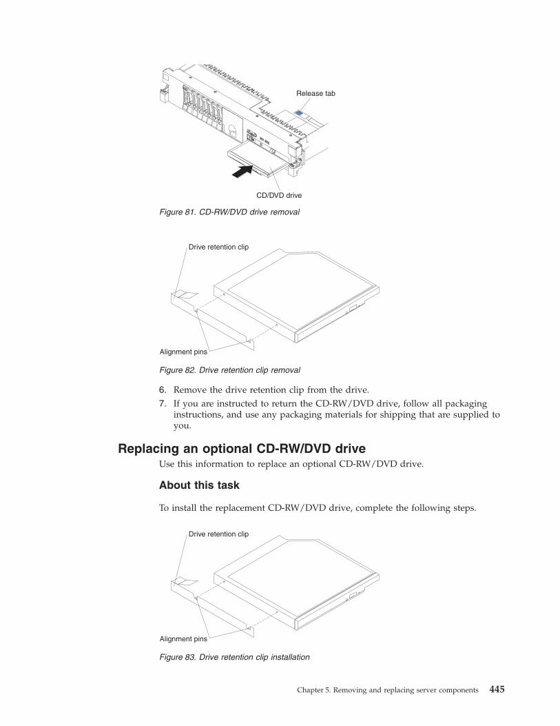
6. Remove the drive retention clip from the drive.7. If you are instructed to return the CD-RW/DVD drive, follow all packaging
instructions, and use any packaging materials for shipping that are supplied toyou.
Replacing an optional CD-RW/DVD driveUse this information to replace an optional CD-RW/DVD drive.
About this task
To install the replacement CD-RW/DVD drive, complete the following steps.
CD/DVD drive
Release tab
Figure 81. CD-RW/DVD drive removal
Alignment pins
Drive retention clip
Figure 82. Drive retention clip removal
Alignment pins
Drive retention clip
Figure 83. Drive retention clip installation
Chapter 5. Removing and replacing server components 445
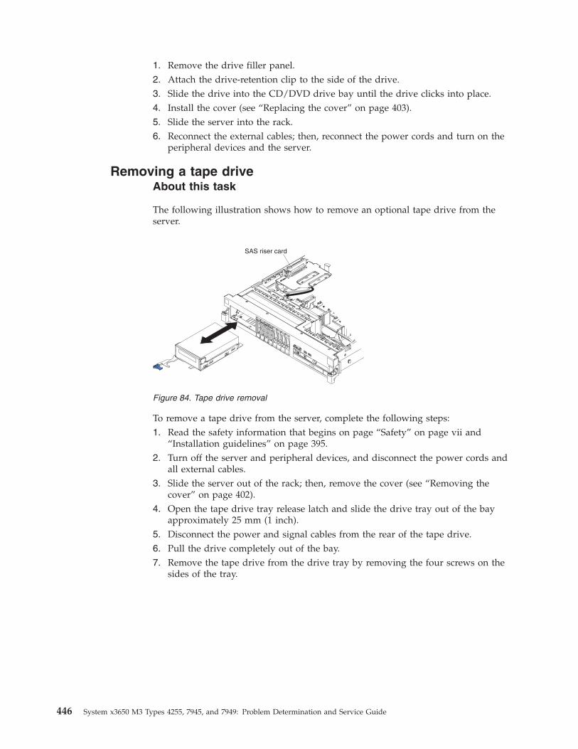
1. Remove the drive filler panel.2. Attach the drive-retention clip to the side of the drive.3. Slide the drive into the CD/DVD drive bay until the drive clicks into place.4. Install the cover (see “Replacing the cover” on page 403).5. Slide the server into the rack.6. Reconnect the external cables; then, reconnect the power cords and turn on the
peripheral devices and the server.
Removing a tape driveAbout this task
The following illustration shows how to remove an optional tape drive from theserver.
To remove a tape drive from the server, complete the following steps:1. Read the safety information that begins on page “Safety” on page vii and
“Installation guidelines” on page 395.2. Turn off the server and peripheral devices, and disconnect the power cords and
all external cables.3. Slide the server out of the rack; then, remove the cover (see “Removing the
cover” on page 402).4. Open the tape drive tray release latch and slide the drive tray out of the bay
approximately 25 mm (1 inch).5. Disconnect the power and signal cables from the rear of the tape drive.6. Pull the drive completely out of the bay.7. Remove the tape drive from the drive tray by removing the four screws on the
sides of the tray.
Figure 84. Tape drive removal
446 System x3650 M3 Types 4255, 7945, and 7949: Problem Determination and Service Guide
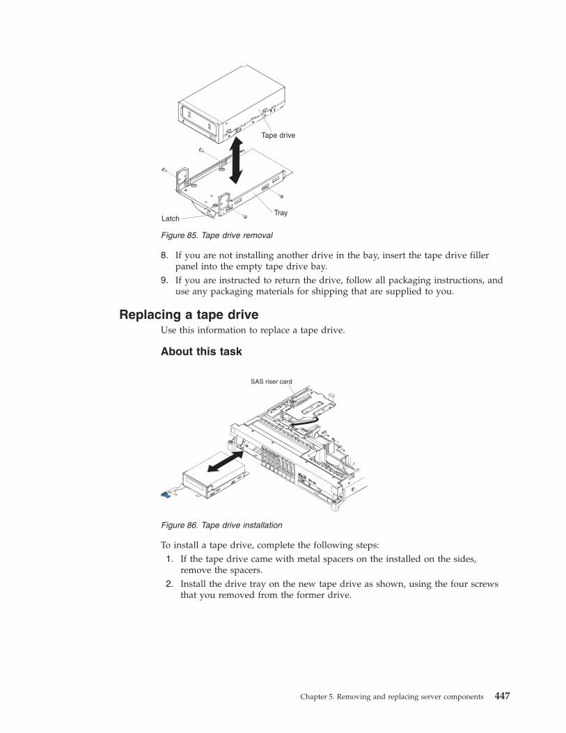
8. If you are not installing another drive in the bay, insert the tape drive fillerpanel into the empty tape drive bay.
9. If you are instructed to return the drive, follow all packaging instructions, anduse any packaging materials for shipping that are supplied to you.
Replacing a tape driveUse this information to replace a tape drive.
About this task
To install a tape drive, complete the following steps:1. If the tape drive came with metal spacers on the installed on the sides,
remove the spacers.2. Install the drive tray on the new tape drive as shown, using the four screws
that you removed from the former drive.
Figure 85. Tape drive removal
Figure 86. Tape drive installation
Chapter 5. Removing and replacing server components 447
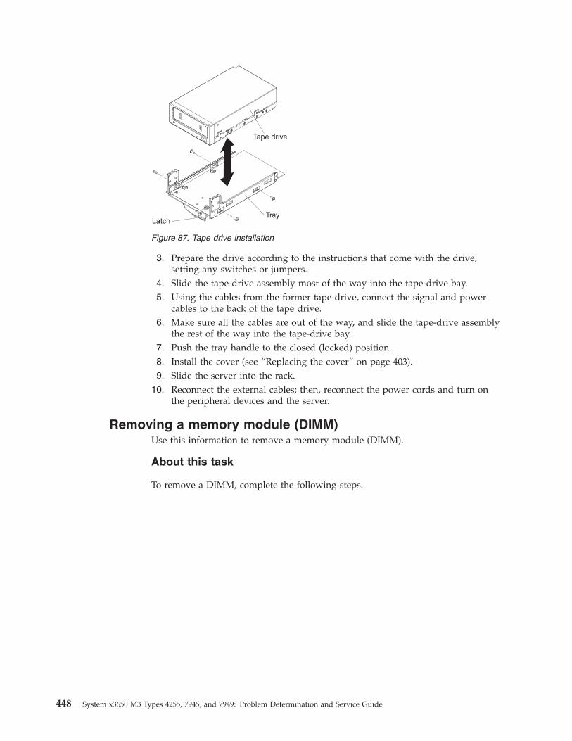
3. Prepare the drive according to the instructions that come with the drive,setting any switches or jumpers.
4. Slide the tape-drive assembly most of the way into the tape-drive bay.5. Using the cables from the former tape drive, connect the signal and power
cables to the back of the tape drive.6. Make sure all the cables are out of the way, and slide the tape-drive assembly
the rest of the way into the tape-drive bay.7. Push the tray handle to the closed (locked) position.8. Install the cover (see “Replacing the cover” on page 403).9. Slide the server into the rack.
10. Reconnect the external cables; then, reconnect the power cords and turn onthe peripheral devices and the server.
Removing a memory module (DIMM)Use this information to remove a memory module (DIMM).
About this task
To remove a DIMM, complete the following steps.
Figure 87. Tape drive installation
448 System x3650 M3 Types 4255, 7945, and 7949: Problem Determination and Service Guide
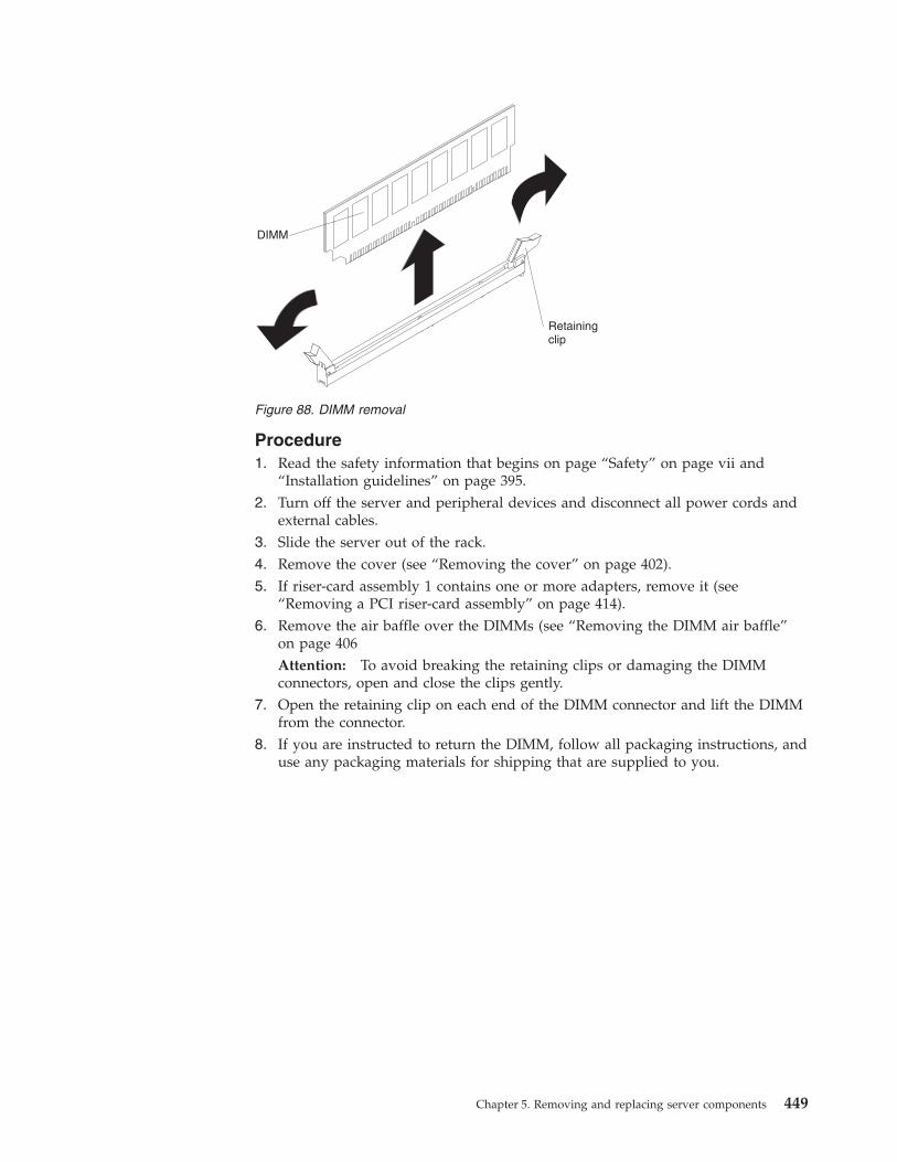
Procedure1. Read the safety information that begins on page “Safety” on page vii and
“Installation guidelines” on page 395.2. Turn off the server and peripheral devices and disconnect all power cords and
external cables.3. Slide the server out of the rack.4. Remove the cover (see “Removing the cover” on page 402).5. If riser-card assembly 1 contains one or more adapters, remove it (see
“Removing a PCI riser-card assembly” on page 414).6. Remove the air baffle over the DIMMs (see “Removing the DIMM air baffle”
on page 406Attention: To avoid breaking the retaining clips or damaging the DIMMconnectors, open and close the clips gently.
7. Open the retaining clip on each end of the DIMM connector and lift the DIMMfrom the connector.
8. If you are instructed to return the DIMM, follow all packaging instructions, anduse any packaging materials for shipping that are supplied to you.
Figure 88. DIMM removal
Chapter 5. Removing and replacing server components 449
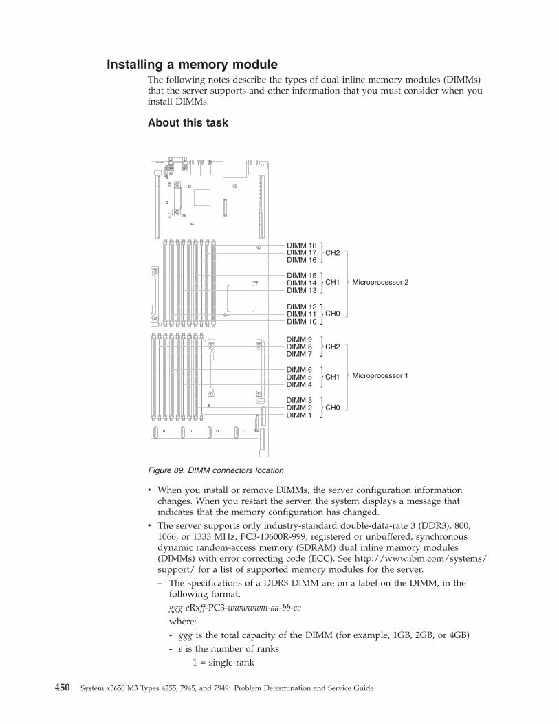
Installing a memory moduleThe following notes describe the types of dual inline memory modules (DIMMs)that the server supports and other information that you must consider when youinstall DIMMs.
About this task
v When you install or remove DIMMs, the server configuration informationchanges. When you restart the server, the system displays a message thatindicates that the memory configuration has changed.
v The server supports only industry-standard double-data-rate 3 (DDR3), 800,1066, or 1333 MHz, PC3-10600R-999, registered or unbuffered, synchronousdynamic random-access memory (SDRAM) dual inline memory modules(DIMMs) with error correcting code (ECC). See http://www.ibm.com/systems/support/ for a list of supported memory modules for the server.– The specifications of a DDR3 DIMM are on a label on the DIMM, in the
following format.ggg eRxff-PC3-wwwwwm-aa-bb-cc
where:- ggg is the total capacity of the DIMM (for example, 1GB, 2GB, or 4GB)- e is the number of ranks
1 = single-rank
Figure 89. DIMM connectors location
450 System x3650 M3 Types 4255, 7945, and 7949: Problem Determination and Service Guide
2 = dual-rank4 = quad-rank
- ff is the device organization (bit width)4 = x4 organization (4 DQ lines per SDRAM)8 = x8 organization16 = x16 organization
- wwwww is the DIMM bandwidth, in MBps6400 = 6.40 GBps (PC3-800 SDRAMs, 8-byte primary data bus)8500 = 8.53 GBps (PC3-1066 SDRAMs, 8-byte primary data bus)10600 = 10.66 GBps (PC3-1333 SDRAMs, 8-byte primary data bus)12800 = 12.80 GBps PC3-1600 SDRAMs, 8-byte primary data bus)
- m is the DIMM typeE = Unbuffered DIMM (UDIMM) with ECC (x72-bit module data bus)R = Registered DIMM (RDIMM)U = Unbuffered DIMM with no ECC (x64-bit primary data bus)
- aa is the CAS latency, in clocks at maximum operating frequency- bb is the JEDEC SPD Revision Encoding and Additions level- cc is the reference design file for the design of the DIMM- d is the revision number of the reference design of the DIMM
v The following rules apply to DDR3 DIMM speed as it relates to the number ofDIMMs in a channel:– When you install 1 DIMM per channel, the memory runs at 1333 MHz– When you install 2 DIMMs per channel, the memory runs at 1066 MHz– When you install 3 DIMMs per channel, the memory runs at 800 MHz– All channels in a server run at the fastest common frequency.– Do not install registered and unbuffered DIMMs in the same server.
v The maximum memory speed is determined by the combination of themicroprocessor, DIMM speed, and the number of DIMMs installed in eachchannel.
v In two-DIMM-per-channel configuration, a server with an Intel Xeon X5600series microprocessor automatically operates with a maximum memory speed ofup to 1333 MHz when one of the following conditions is met:– Two 1.5 V single-rank or dual-rank RDIMMs are installed in the same
channel. In the Setup utility, Memory speed is set to Max performance mode– Two 1.35 V single-rank or dual-ranl RDIMMs are installed in the same
channel. In the Setup utility, Memory speed is set to Max performance andLV-DIMM power is set to Enhance performance mode. The 1.35 V RDIMMswill function at 1.5 V
v The server supports a maximum of 18 single-rank or dual-rank RDIMMs. Theserver supports up to 12 single-rank or dual-rank UDIMMs or quad-rankRDIMMs.
Note: To determine the type of a DIMM, see the label on the DIMM. Theinformation on the label is in the format xxxxx nRxxx PC3-xxxxx-xx-xx-xxx. Thenumeral in the sixth numerical position indicates whether the DIMM issingle-rank (n=1), dual-rank (n=2), or quad-rank (n=4).
Chapter 5. Removing and replacing server components 451
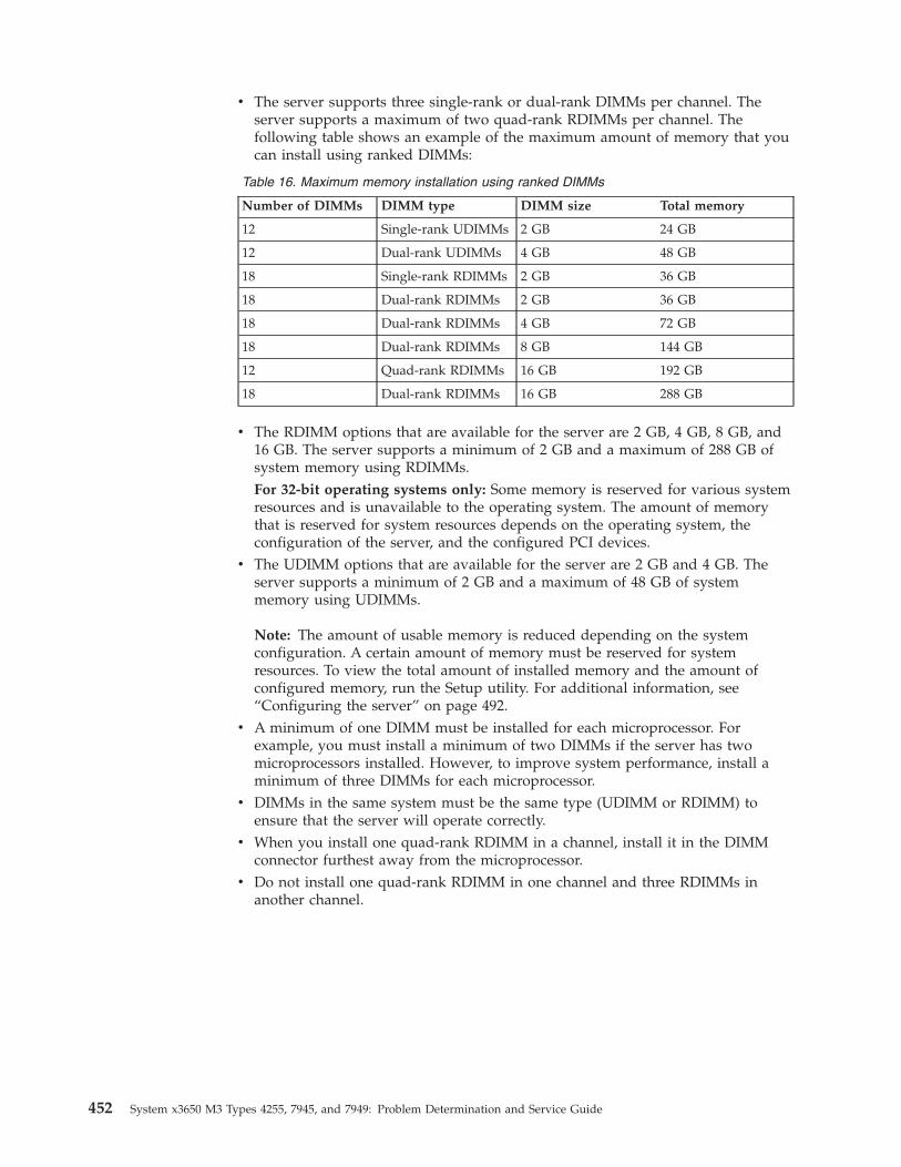
v The server supports three single-rank or dual-rank DIMMs per channel. Theserver supports a maximum of two quad-rank RDIMMs per channel. Thefollowing table shows an example of the maximum amount of memory that youcan install using ranked DIMMs:
Table 16. Maximum memory installation using ranked DIMMs
Number of DIMMs DIMM type DIMM size Total memory
12 Single-rank UDIMMs 2 GB 24 GB
12 Dual-rank UDIMMs 4 GB 48 GB
18 Single-rank RDIMMs 2 GB 36 GB
18 Dual-rank RDIMMs 2 GB 36 GB
18 Dual-rank RDIMMs 4 GB 72 GB
18 Dual-rank RDIMMs 8 GB 144 GB
12 Quad-rank RDIMMs 16 GB 192 GB
18 Dual-rank RDIMMs 16 GB 288 GB
v The RDIMM options that are available for the server are 2 GB, 4 GB, 8 GB, and16 GB. The server supports a minimum of 2 GB and a maximum of 288 GB ofsystem memory using RDIMMs.For 32-bit operating systems only: Some memory is reserved for various systemresources and is unavailable to the operating system. The amount of memorythat is reserved for system resources depends on the operating system, theconfiguration of the server, and the configured PCI devices.
v The UDIMM options that are available for the server are 2 GB and 4 GB. Theserver supports a minimum of 2 GB and a maximum of 48 GB of systemmemory using UDIMMs.
Note: The amount of usable memory is reduced depending on the systemconfiguration. A certain amount of memory must be reserved for systemresources. To view the total amount of installed memory and the amount ofconfigured memory, run the Setup utility. For additional information, see“Configuring the server” on page 492.
v A minimum of one DIMM must be installed for each microprocessor. Forexample, you must install a minimum of two DIMMs if the server has twomicroprocessors installed. However, to improve system performance, install aminimum of three DIMMs for each microprocessor.
v DIMMs in the same system must be the same type (UDIMM or RDIMM) toensure that the server will operate correctly.
v When you install one quad-rank RDIMM in a channel, install it in the DIMMconnector furthest away from the microprocessor.
v Do not install one quad-rank RDIMM in one channel and three RDIMMs inanother channel.
452 System x3650 M3 Types 4255, 7945, and 7949: Problem Determination and Service Guide
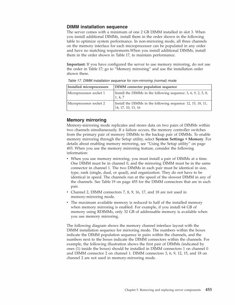
DIMM installation sequenceThe server comes with a minimum of one 2 GB DIMM installed in slot 3. Whenyou install additional DIMMs, install them in the order shown in the followingtable to optimize system performance. In non-mirroring mode, all three channelson the memory interface for each microprocessor can be populated in any orderand have no matching requirements.When you install additional DIMMs, installthem in the order shown in Table 17, to maintain performance.
Important: If you have configured the server to use memory mirroring, do not usethe order in Table 17; go to “Memory mirroring” and use the installation ordershown there.
Table 17. DIMM installation sequence for non-mirroring (normal) mode
Installed microprocessors DIMM connector population sequence
Microprocessor socket 1 Install the DIMMs in the following sequence: 3, 6, 9, 2, 5, 8,1, 4, 7
Microprocessor socket 2 Install the DIMMs in the following sequence: 12, 15, 18, 11,14, 17, 10, 13, 16
Memory mirroringMemory-mirroring mode replicates and stores data on two pairs of DIMMs withintwo channels simultaneously. If a failure occurs, the memory controller switchesfrom the primary pair of memory DIMMs to the backup pair of DIMMs. To enablememory mirroring through the Setup utility, select System Settings → Memory. Fordetails about enabling memory mirroring, see “Using the Setup utility” on page493. When you use the memory mirroring feature, consider the followinginformation:v When you use memory mirroring, you must install a pair of DIMMs at a time.
One DIMM must be in channel 0, and the mirroring DIMM must be in the sameconnector in channel 1. The two DIMMs in each pair must be identical in size,type, rank (single, dual, or quad), and organization. They do not have to beidentical in speed. The channels run at the speed of the slowest DIMM in any ofthe channels. See Table 19 on page 455 for the DIMM connectors that are in eachpair.
v Channel 2, DIMM connectors 7, 8, 9, 16, 17, and 18 are not used inmemory-mirroring mode.
v The maximum available memory is reduced to half of the installed memorywhen memory mirroring is enabled. For example, if you install 64 GB ofmemory using RDIMMs, only 32 GB of addressable memory is available whenyou use memory mirroring.
The following diagram shows the memory channel interface layout with theDIMM installation sequence for mirroring mode. The numbers within the boxesindicate the DIMM population sequence in pairs within the channels, and thenumbers next to the boxes indicate the DIMM connectors within the channels. Forexample, the following illustration shows the first pair of DIMMs (indicated byones (1) inside the boxes) should be installed in DIMM connectors 1 on channel 0and DIMM connector 2 on channel 1. DIMM connectors 3, 6, 9, 12, 15, and 18 onchannel 2 are not used in memory-mirroring mode.
Chapter 5. Removing and replacing server components 453
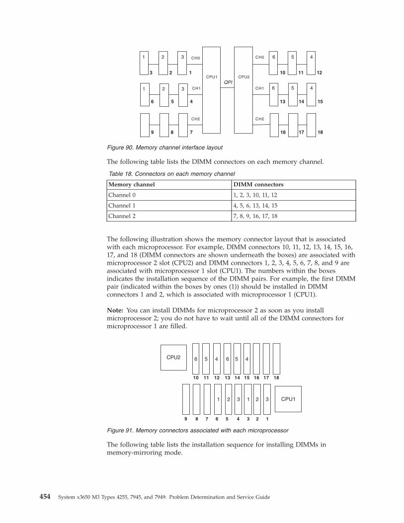
The following table lists the DIMM connectors on each memory channel.
Table 18. Connectors on each memory channel
Memory channel DIMM connectors
Channel 0 1, 2, 3, 10, 11, 12
Channel 1 4, 5, 6, 13, 14, 15
Channel 2 7, 8, 9, 16, 17, 18
The following illustration shows the memory connector layout that is associatedwith each microprocessor. For example, DIMM connectors 10, 11, 12, 13, 14, 15, 16,17, and 18 (DIMM connectors are shown underneath the boxes) are associated withmicroprocessor 2 slot (CPU2) and DIMM connectors 1, 2, 3, 4, 5, 6, 7, 8, and 9 areassociated with microprocessor 1 slot (CPU1). The numbers within the boxesindicates the installation sequence of the DIMM pairs. For example, the first DIMMpair (indicated within the boxes by ones (1)) should be installed in DIMMconnectors 1 and 2, which is associated with microprocessor 1 (CPU1).
Note: You can install DIMMs for microprocessor 2 as soon as you installmicroprocessor 2; you do not have to wait until all of the DIMM connectors formicroprocessor 1 are filled.
The following table lists the installation sequence for installing DIMMs inmemory-mirroring mode.
CH0
CH1
CH2
CPU1
1
1
2
2
3
3
3
6
2 1
5 4
8 7
CH2
CH0
CH1
4
46
1210 11
15
16
1413
QPI
5
5
6
9 1817
CPU2
Figure 90. Memory channel interface layout
CPU1
CPU2
12345678
16151413121110
9
11 22 3 3
4 45 566
17 18
Figure 91. Memory connectors associated with each microprocessor
454 System x3650 M3 Types 4255, 7945, and 7949: Problem Determination and Service Guide
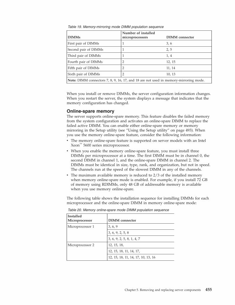
Table 19. Memory-mirroring mode DIMM population sequence
DIMMsNumber of installedmicroprocessors DIMM connector
First pair of DIMMs 1 3, 6
Second pair of DIMMs 1 2, 5
Third pair of DIMMs 1 1, 4
Fourth pair of DIMMs 2 12, 15
Fifth pair of DIMMs 2 11, 14
Sixth pair of DIMMs 2 10, 13
Note: DIMM connectors 7, 8, 9, 16, 17, and 18 are not used in memory-mirroring mode.
When you install or remove DIMMs, the server configuration information changes.When you restart the server, the system displays a message that indicates that thememory configuration has changed.
Online-spare memoryThe server supports online-spare memory. This feature disables the failed memoryfrom the system configuration and activates an online-spare DIMM to replace thefailed active DIMM. You can enable either online-spare memory or memorymirroring in the Setup utility (see “Using the Setup utility” on page 493). Whenyou use the memory online-spare feature, consider the following information:v The memory online-spare feature is supported on server models with an Intel
Xeon™ 5600 series microprocessor.v When you enable the memory online-spare feature, you must install three
DIMMs per microprocessor at a time. The first DIMM must be in channel 0, thesecond DIMM in channel 1, and the online-spare DIMM in channel 2. TheDIMMs must be identical in size, type, rank, and organization, but not in speed.The channels run at the speed of the slowest DIMM in any of the channels.
v The maximum available memory is reduced to 2/3 of the installed memorywhen memory online-spare mode is enabled. For example, if you install 72 GBof memory using RDIMMs, only 48 GB of addressable memory is availablewhen you use memory online-spare.
The following table shows the installation sequence for installing DIMMs for eachmicroprocessor and the online-spare DIMM in memory online-spare mode:
Table 20. Memory online-spare mode DIMM population sequence
InstalledMicroprocessor DIMM connector
Microprocessor 1 3, 6, 9
3, 6, 9, 2, 5, 8
3, 6, 9, 2, 5, 8, 1, 4, 7
Microprocessor 2 12, 15, 18,
12, 15, 18, 11, 14, 17,
12, 15, 18, 11, 14, 17, 10, 13, 16
Chapter 5. Removing and replacing server components 455
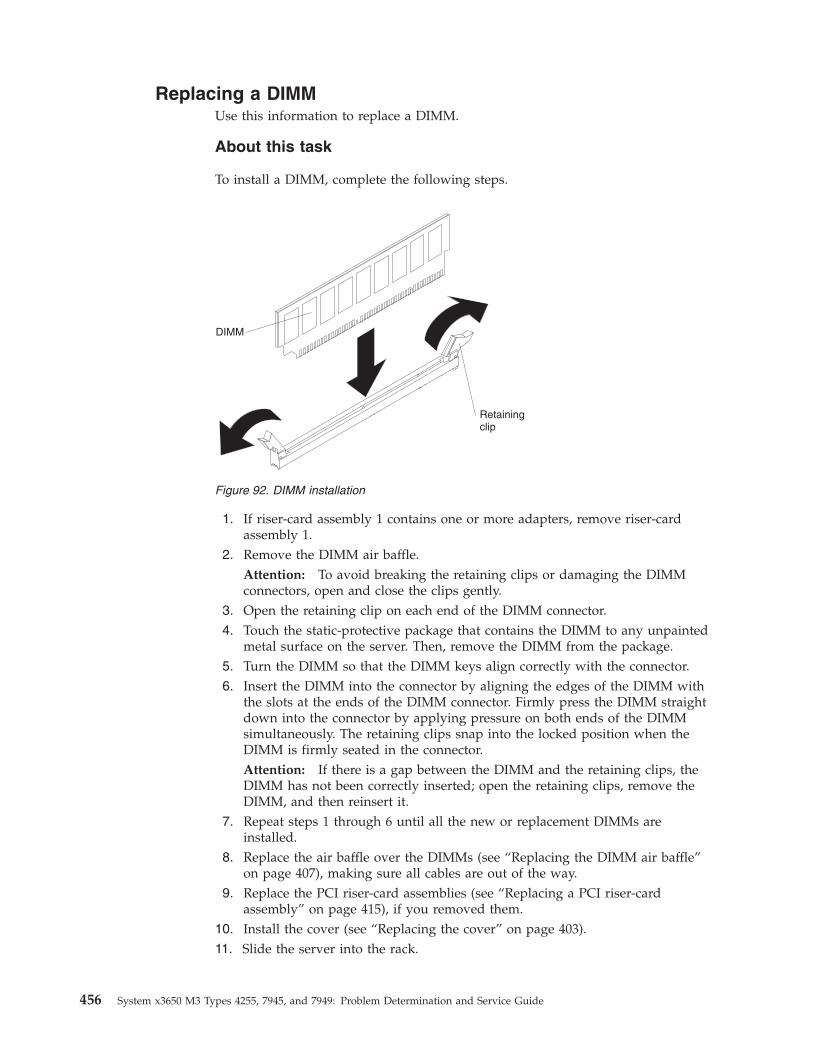
Replacing a DIMMUse this information to replace a DIMM.
About this task
To install a DIMM, complete the following steps.
1. If riser-card assembly 1 contains one or more adapters, remove riser-cardassembly 1.
2. Remove the DIMM air baffle.Attention: To avoid breaking the retaining clips or damaging the DIMMconnectors, open and close the clips gently.
3. Open the retaining clip on each end of the DIMM connector.4. Touch the static-protective package that contains the DIMM to any unpainted
metal surface on the server. Then, remove the DIMM from the package.5. Turn the DIMM so that the DIMM keys align correctly with the connector.6. Insert the DIMM into the connector by aligning the edges of the DIMM with
the slots at the ends of the DIMM connector. Firmly press the DIMM straightdown into the connector by applying pressure on both ends of the DIMMsimultaneously. The retaining clips snap into the locked position when theDIMM is firmly seated in the connector.Attention: If there is a gap between the DIMM and the retaining clips, theDIMM has not been correctly inserted; open the retaining clips, remove theDIMM, and then reinsert it.
7. Repeat steps 1 through 6 until all the new or replacement DIMMs areinstalled.
8. Replace the air baffle over the DIMMs (see “Replacing the DIMM air baffle”on page 407), making sure all cables are out of the way.
9. Replace the PCI riser-card assemblies (see “Replacing a PCI riser-cardassembly” on page 415), if you removed them.
10. Install the cover (see “Replacing the cover” on page 403).11. Slide the server into the rack.
Figure 92. DIMM installation
456 System x3650 M3 Types 4255, 7945, and 7949: Problem Determination and Service Guide
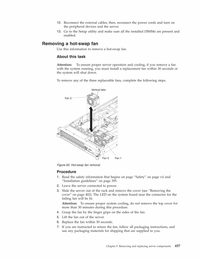
12. Reconnect the external cables; then, reconnect the power cords and turn onthe peripheral devices and the server.
13. Go to the Setup utility and make sure all the installed DIMMs are present andenabled.
Removing a hot-swap fanUse this information to remove a hot-swap fan.
About this task
Attention: To ensure proper server operation and cooling, if you remove a fanwith the system running, you must install a replacement fan within 30 seconds orthe system will shut down.
To remove any of the three replaceable fans, complete the following steps.
Procedure1. Read the safety information that begins on page “Safety” on page vii and
“Installation guidelines” on page 395.2. Leave the server connected to power.3. Slide the server out of the rack and remove the cover (see “Removing the
cover” on page 402). The LED on the system board near the connector for thefailing fan will be lit.Attention: To ensure proper system cooling, do not remove the top cover formore than 30 minutes during this procedure.
4. Grasp the fan by the finger grips on the sides of the fan.5. Lift the fan out of the server.6. Replace the fan within 30 seconds.7. If you are instructed to return the fan, follow all packaging instructions, and
use any packaging materials for shipping that are supplied to you.
Vertical tabs
Fan 3
Fan 2 Fan 1
Figure 93. Hot-swap fan removal
Chapter 5. Removing and replacing server components 457
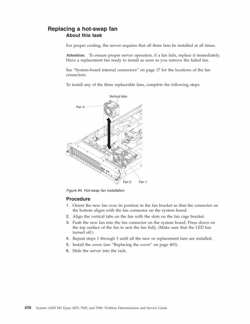
Replacing a hot-swap fanAbout this task
For proper cooling, the server requires that all three fans be installed at all times.
Attention: To ensure proper server operation, if a fan fails, replace it immediately.Have a replacement fan ready to install as soon as you remove the failed fan.
See “System-board internal connectors” on page 17 for the locations of the fanconnectors.
To install any of the three replaceable fans, complete the following steps.
Procedure1. Orient the new fan over its position in the fan bracket so that the connector on
the bottom aligns with the fan connector on the system board.2. Align the vertical tabs on the fan with the slots on the fan cage bracket.3. Push the new fan into the fan connector on the system board. Press down on
the top surface of the fan to seat the fan fully. (Make sure that the LED hasturned off.)
4. Repeat steps 1 through 3 until all the new or replacement fans are installed.5. Install the cover (see “Replacing the cover” on page 403).6. Slide the server into the rack.
Vertical tabs
Fan 3
Fan 2 Fan 1
Figure 94. Hot-swap fan installation
458 System x3650 M3 Types 4255, 7945, and 7949: Problem Determination and Service Guide
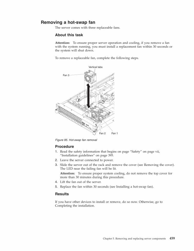
Removing a hot-swap fanThe server comes with three replaceable fans.
About this task
Attention: To ensure proper server operation and cooling, if you remove a fanwith the system running, you must install a replacement fan within 30 seconds orthe system will shut down.
To remove a replaceable fan, complete the following steps.
Procedure1. Read the safety information that begins on page “Safety” on page vii,
“Installation guidelines” on page 395.2. Leave the server connected to power.3. Slide the server out of the rack and remove the cover (see Removing the cover).
The LED near the failing fan will be lit.Attention: To ensure proper system cooling, do not remove the top cover formore than 30 minutes during this procedure.
4. Lift the fan out of the server.5. Replace the fan within 30 seconds (see Installing a hot-swap fan).
Results
If you have other devices to install or remove, do so now. Otherwise, go toCompleting the installation.
Vertical tabs
Fan 3
Fan 2 Fan 1
Figure 95. Hot-swap fan removal
Chapter 5. Removing and replacing server components 459
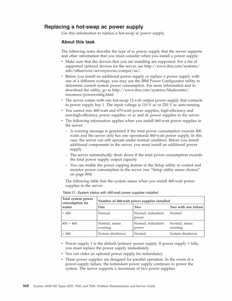
Replacing a hot-swap ac power supplyUse this information to replace a hot-swap ac power supply.
About this task
The following notes describe the type of ac power supply that the server supportsand other information that you must consider when you install a power supply:v Make sure that the devices that you are installing are supported. For a list of
supported optional devices for the server, see http://www.ibm.com/systems/info/x86servers/serverproven/compat/us/.
v Before you install an additional power supply or replace a power supply withone of a different wattage, you may use the IBM Power Configurator utility todetermine current system power consumption. For more information and todownload the utility, go to http://www.ibm.com/systems/bladecenter/resources/powerconfig.html.
v The server comes with one hot-swap 12-volt output power supply that connectsto power supply bay 1. The input voltage is 110 V ac or 220 V ac auto-sensing.
v You cannot mix 460-watt and 675-watt power supplies, high-efficiency andnon-high-efficiency power supplies, or ac and dc power supplies in the server.
v The following information applies when you install 460-watt power supplies inthe server:– A warning message is generated if the total power consumption exceeds 400
watts and the server only has one operational 460-watt power supply. In thiscase, the server can still operate under normal condition. Before you installadditional components in the server, you must install an additional powersupply
– The server automatically shuts down if the total power consumption exceedsthe total power supply output capacity
– You can enable the power capping feature in the Setup utility to control andmonitor power consumption in the server (see “Setup utility menu choices”on page 494)
The following table lists the system status when you install 460-watt powersupplies in the server:
Table 21. System status with 460-watt power supplies installed
Total system powerconsumption (inwatts)
Number of 460-watt power supplies installed
One Two Two with one failure
< 400 Normal Normal, redundantpower
Normal
400 ~ 460 Normal, statuswarning
Normal, redundantpower
Normal, statuswarning
> 460 System shutdown Normal System shutdown
v Power supply 1 is the default/primary power supply. If power supply 1 fails,you must replace the power supply immediately.
v You can order an optional power supply for redundancy.v These power supplies are designed for parallel operation. In the event of a
power-supply failure, the redundant power supply continues to power thesystem. The server supports a maximum of two power supplies.
460 System x3650 M3 Types 4255, 7945, and 7949: Problem Determination and Service Guide
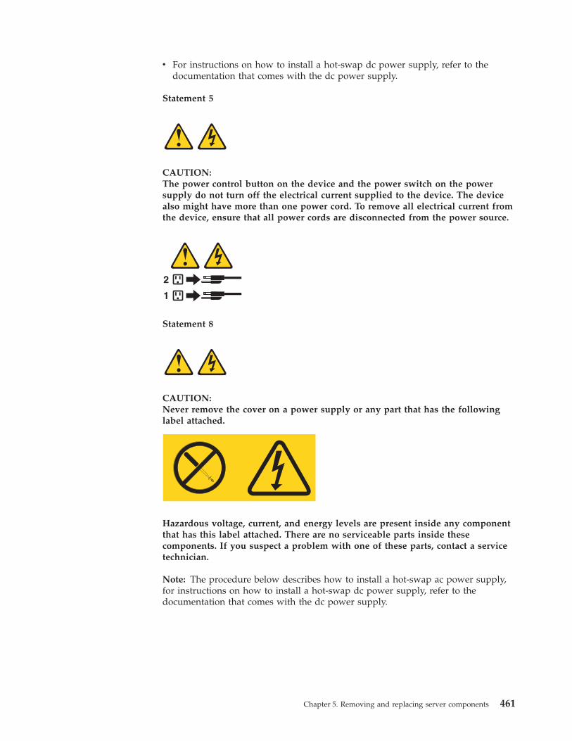
v For instructions on how to install a hot-swap dc power supply, refer to thedocumentation that comes with the dc power supply.
Statement 5
CAUTION:The power control button on the device and the power switch on the powersupply do not turn off the electrical current supplied to the device. The devicealso might have more than one power cord. To remove all electrical current fromthe device, ensure that all power cords are disconnected from the power source.
1
2
Statement 8
CAUTION:Never remove the cover on a power supply or any part that has the followinglabel attached.
Hazardous voltage, current, and energy levels are present inside any componentthat has this label attached. There are no serviceable parts inside thesecomponents. If you suspect a problem with one of these parts, contact a servicetechnician.
Note: The procedure below describes how to install a hot-swap ac power supply,for instructions on how to install a hot-swap dc power supply, refer to thedocumentation that comes with the dc power supply.
Chapter 5. Removing and replacing server components 461
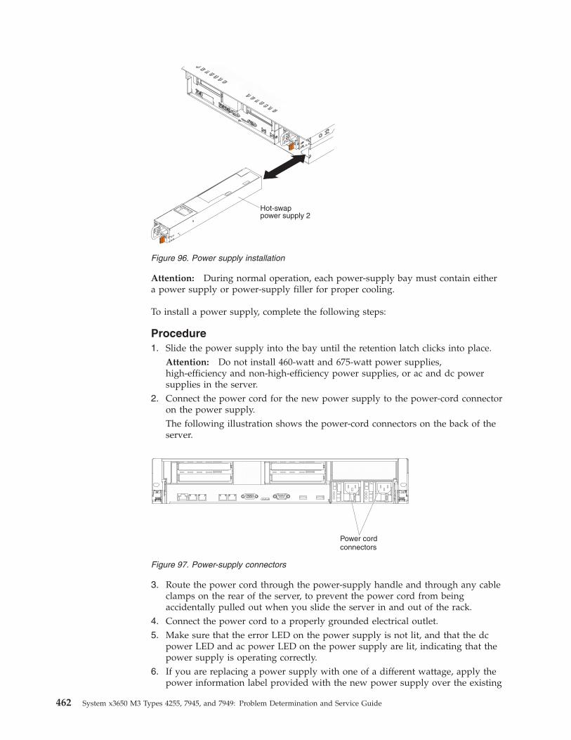
Attention: During normal operation, each power-supply bay must contain eithera power supply or power-supply filler for proper cooling.
To install a power supply, complete the following steps:
Procedure1. Slide the power supply into the bay until the retention latch clicks into place.
Attention: Do not install 460-watt and 675-watt power supplies,high-efficiency and non-high-efficiency power supplies, or ac and dc powersupplies in the server.
2. Connect the power cord for the new power supply to the power-cord connectoron the power supply.The following illustration shows the power-cord connectors on the back of theserver.
3. Route the power cord through the power-supply handle and through any cableclamps on the rear of the server, to prevent the power cord from beingaccidentally pulled out when you slide the server in and out of the rack.
4. Connect the power cord to a properly grounded electrical outlet.5. Make sure that the error LED on the power supply is not lit, and that the dc
power LED and ac power LED on the power supply are lit, indicating that thepower supply is operating correctly.
6. If you are replacing a power supply with one of a different wattage, apply thepower information label provided with the new power supply over the existing
Figure 96. Power supply installation
Figure 97. Power-supply connectors
462 System x3650 M3 Types 4255, 7945, and 7949: Problem Determination and Service Guide
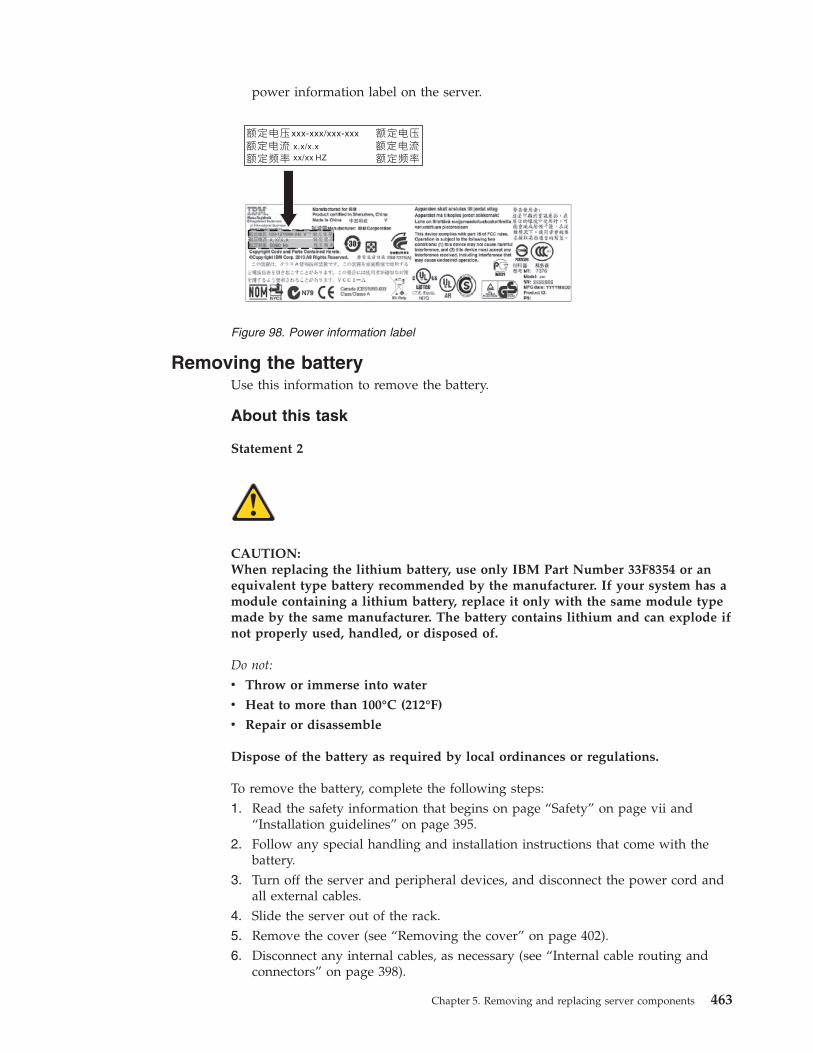
power information label on the server.
Removing the batteryUse this information to remove the battery.
About this task
Statement 2
CAUTION:When replacing the lithium battery, use only IBM Part Number 33F8354 or anequivalent type battery recommended by the manufacturer. If your system has amodule containing a lithium battery, replace it only with the same module typemade by the same manufacturer. The battery contains lithium and can explode ifnot properly used, handled, or disposed of.
Do not:
v Throw or immerse into water
v Heat to more than 100°C (212°F)
v Repair or disassemble
Dispose of the battery as required by local ordinances or regulations.
To remove the battery, complete the following steps:1. Read the safety information that begins on page “Safety” on page vii and
“Installation guidelines” on page 395.2. Follow any special handling and installation instructions that come with the
battery.3. Turn off the server and peripheral devices, and disconnect the power cord and
all external cables.4. Slide the server out of the rack.5. Remove the cover (see “Removing the cover” on page 402).6. Disconnect any internal cables, as necessary (see “Internal cable routing and
connectors” on page 398).
x.x/x.xxx/xx HZ
Figure 98. Power information label
Chapter 5. Removing and replacing server components 463
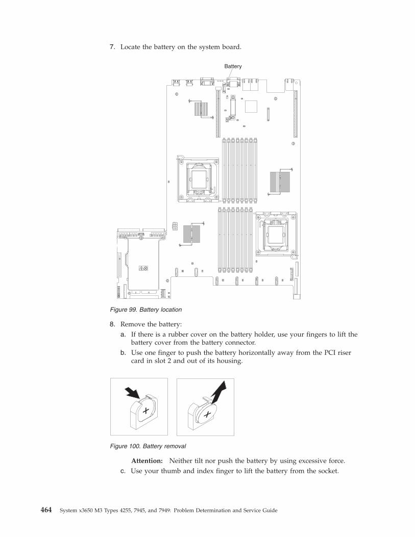
7. Locate the battery on the system board.
8. Remove the battery:a. If there is a rubber cover on the battery holder, use your fingers to lift the
battery cover from the battery connector.b. Use one finger to push the battery horizontally away from the PCI riser
card in slot 2 and out of its housing.
Attention: Neither tilt nor push the battery by using excessive force.c. Use your thumb and index finger to lift the battery from the socket.
Figure 99. Battery location
Figure 100. Battery removal
464 System x3650 M3 Types 4255, 7945, and 7949: Problem Determination and Service Guide
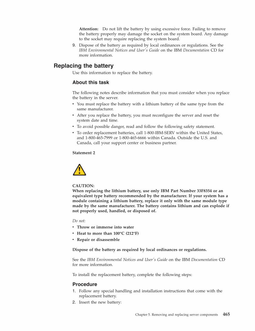
Attention: Do not lift the battery by using excessive force. Failing to removethe battery properly may damage the socket on the system board. Any damageto the socket may require replacing the system board.
9. Dispose of the battery as required by local ordinances or regulations. See theIBM Environmental Notices and User's Guide on the IBM Documentation CD formore information.
Replacing the batteryUse this information to replace the battery.
About this task
The following notes describe information that you must consider when you replacethe battery in the server.v You must replace the battery with a lithium battery of the same type from the
same manufacturer.v After you replace the battery, you must reconfigure the server and reset the
system date and time.v To avoid possible danger, read and follow the following safety statement.v To order replacement batteries, call 1-800-IBM-SERV within the United States,
and 1-800-465-7999 or 1-800-465-6666 within Canada. Outside the U.S. andCanada, call your support center or business partner.
Statement 2
CAUTION:When replacing the lithium battery, use only IBM Part Number 33F8354 or anequivalent type battery recommended by the manufacturer. If your system has amodule containing a lithium battery, replace it only with the same module typemade by the same manufacturer. The battery contains lithium and can explode ifnot properly used, handled, or disposed of.
Do not:
v Throw or immerse into water
v Heat to more than 100°C (212°F)
v Repair or disassemble
Dispose of the battery as required by local ordinances or regulations.
See the IBM Environmental Notices and User's Guide on the IBM Documentation CDfor more information.
To install the replacement battery, complete the following steps:
Procedure1. Follow any special handling and installation instructions that come with the
replacement battery.2. Insert the new battery:
Chapter 5. Removing and replacing server components 465
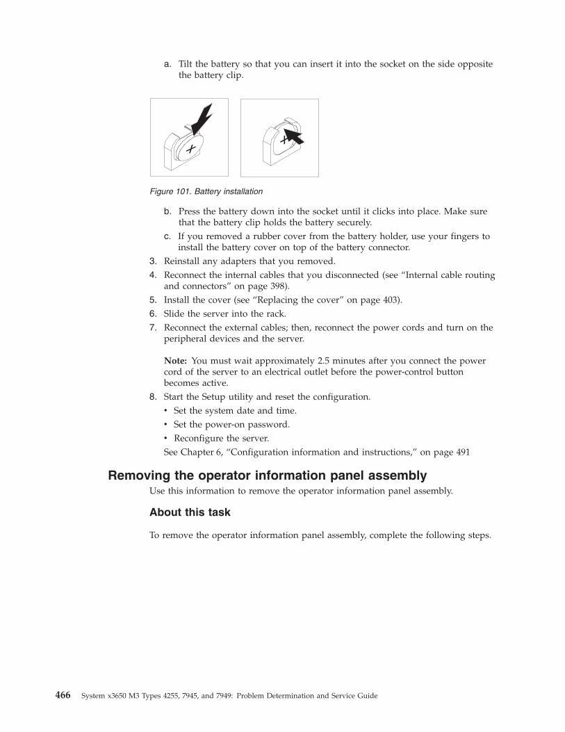
a. Tilt the battery so that you can insert it into the socket on the side oppositethe battery clip.
b. Press the battery down into the socket until it clicks into place. Make surethat the battery clip holds the battery securely.
c. If you removed a rubber cover from the battery holder, use your fingers toinstall the battery cover on top of the battery connector.
3. Reinstall any adapters that you removed.4. Reconnect the internal cables that you disconnected (see “Internal cable routing
and connectors” on page 398).5. Install the cover (see “Replacing the cover” on page 403).6. Slide the server into the rack.7. Reconnect the external cables; then, reconnect the power cords and turn on the
peripheral devices and the server.
Note: You must wait approximately 2.5 minutes after you connect the powercord of the server to an electrical outlet before the power-control buttonbecomes active.
8. Start the Setup utility and reset the configuration.v Set the system date and time.v Set the power-on password.v Reconfigure the server.See Chapter 6, “Configuration information and instructions,” on page 491
Removing the operator information panel assemblyUse this information to remove the operator information panel assembly.
About this task
To remove the operator information panel assembly, complete the following steps.
Figure 101. Battery installation
466 System x3650 M3 Types 4255, 7945, and 7949: Problem Determination and Service Guide
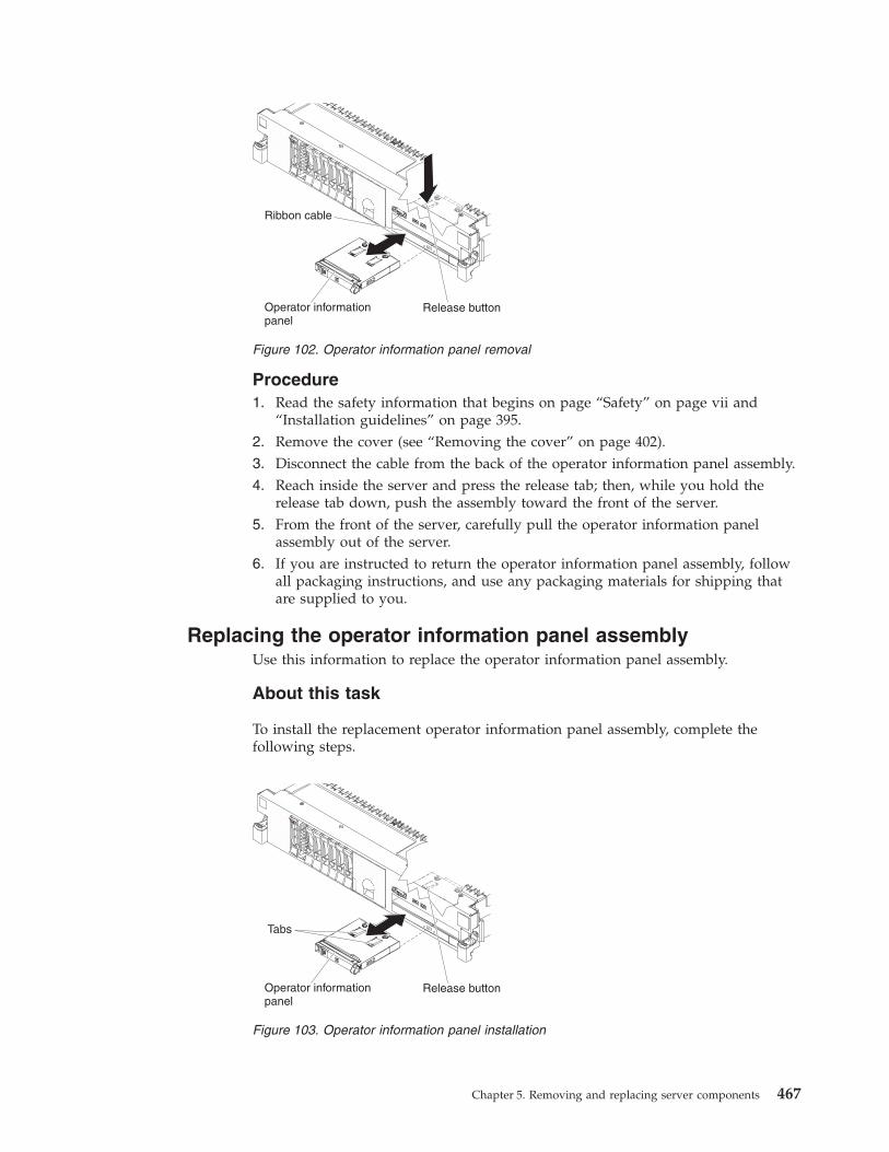
Procedure1. Read the safety information that begins on page “Safety” on page vii and
“Installation guidelines” on page 395.2. Remove the cover (see “Removing the cover” on page 402).3. Disconnect the cable from the back of the operator information panel assembly.4. Reach inside the server and press the release tab; then, while you hold the
release tab down, push the assembly toward the front of the server.5. From the front of the server, carefully pull the operator information panel
assembly out of the server.6. If you are instructed to return the operator information panel assembly, follow
all packaging instructions, and use any packaging materials for shipping thatare supplied to you.
Replacing the operator information panel assemblyUse this information to replace the operator information panel assembly.
About this task
To install the replacement operator information panel assembly, complete thefollowing steps.
Figure 102. Operator information panel removal
Figure 103. Operator information panel installation
Chapter 5. Removing and replacing server components 467
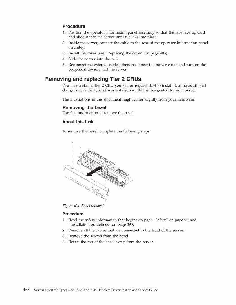
Procedure1. Position the operator information panel assembly so that the tabs face upward
and slide it into the server until it clicks into place.2. Inside the server, connect the cable to the rear of the operator information panel
assembly.3. Install the cover (see “Replacing the cover” on page 403).4. Slide the server into the rack.5. Reconnect the external cables; then, reconnect the power cords and turn on the
peripheral devices and the server.
Removing and replacing Tier 2 CRUsYou may install a Tier 2 CRU yourself or request IBM to install it, at no additionalcharge, under the type of warranty service that is designated for your server.
The illustrations in this document might differ slightly from your hardware.
Removing the bezelUse this information to remove the bezel.
About this task
To remove the bezel, complete the following steps.
Procedure1. Read the safety information that begins on page “Safety” on page vii and
“Installation guidelines” on page 395.2. Remove all the cables that are connected to the front of the server.3. Remove the screws from the bezel.4. Rotate the top of the bezel away from the server.
Figure 104. Bezel removal
468 System x3650 M3 Types 4255, 7945, and 7949: Problem Determination and Service Guide
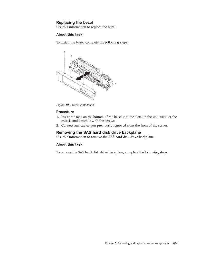
Replacing the bezelUse this information to replace the bezel.
About this task
To install the bezel, complete the following steps.
Procedure1. Insert the tabs on the bottom of the bezel into the slots on the underside of the
chassis and attach it with the screws.2. Connect any cables you previously removed from the front of the server.
Removing the SAS hard disk drive backplaneUse this information to remove the SAS hard disk drive backplane.
About this task
To remove the SAS hard disk drive backplane, complete the following steps.
Figure 105. Bezel installation
Chapter 5. Removing and replacing server components 469
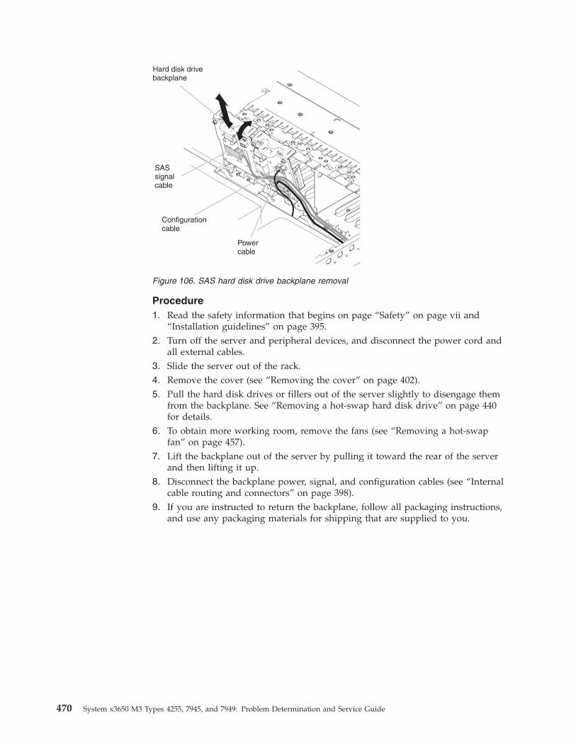
Procedure1. Read the safety information that begins on page “Safety” on page vii and
“Installation guidelines” on page 395.2. Turn off the server and peripheral devices, and disconnect the power cord and
all external cables.3. Slide the server out of the rack.4. Remove the cover (see “Removing the cover” on page 402).5. Pull the hard disk drives or fillers out of the server slightly to disengage them
from the backplane. See “Removing a hot-swap hard disk drive” on page 440for details.
6. To obtain more working room, remove the fans (see “Removing a hot-swapfan” on page 457).
7. Lift the backplane out of the server by pulling it toward the rear of the serverand then lifting it up.
8. Disconnect the backplane power, signal, and configuration cables (see “Internalcable routing and connectors” on page 398).
9. If you are instructed to return the backplane, follow all packaging instructions,and use any packaging materials for shipping that are supplied to you.
Figure 106. SAS hard disk drive backplane removal
470 System x3650 M3 Types 4255, 7945, and 7949: Problem Determination and Service Guide
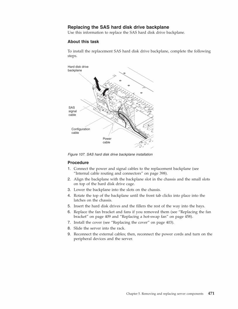
Replacing the SAS hard disk drive backplaneUse this information to replace the SAS hard disk drive backplane.
About this task
To install the replacement SAS hard disk drive backplane, complete the followingsteps.
Procedure1. Connect the power and signal cables to the replacement backplane (see
“Internal cable routing and connectors” on page 398).2. Align the backplane with the backplane slot in the chassis and the small slots
on top of the hard disk drive cage.3. Lower the backplane into the slots on the chassis.4. Rotate the top of the backplane until the front tab clicks into place into the
latches on the chassis.5. Insert the hard disk drives and the fillers the rest of the way into the bays.6. Replace the fan bracket and fans if you removed them (see “Replacing the fan
bracket” on page 409 and “Replacing a hot-swap fan” on page 458).7. Install the cover (see “Replacing the cover” on page 403).8. Slide the server into the rack.9. Reconnect the external cables; then, reconnect the power cords and turn on the
peripheral devices and the server.
Figure 107. SAS hard disk drive backplane installation
Chapter 5. Removing and replacing server components 471
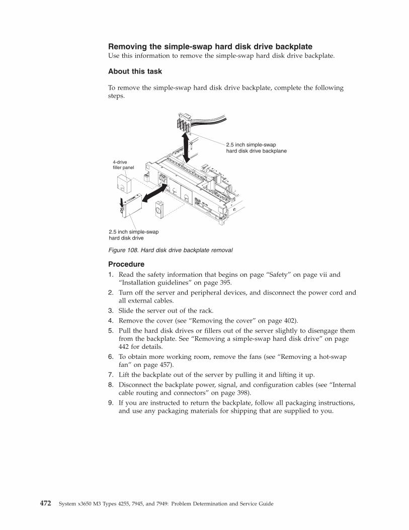
Removing the simple-swap hard disk drive backplateUse this information to remove the simple-swap hard disk drive backplate.
About this task
To remove the simple-swap hard disk drive backplate, complete the followingsteps.
Procedure1. Read the safety information that begins on page “Safety” on page vii and
“Installation guidelines” on page 395.2. Turn off the server and peripheral devices, and disconnect the power cord and
all external cables.3. Slide the server out of the rack.4. Remove the cover (see “Removing the cover” on page 402).5. Pull the hard disk drives or fillers out of the server slightly to disengage them
from the backplate. See “Removing a simple-swap hard disk drive” on page442 for details.
6. To obtain more working room, remove the fans (see “Removing a hot-swapfan” on page 457).
7. Lift the backplate out of the server by pulling it and lifting it up.8. Disconnect the backplate power, signal, and configuration cables (see “Internal
cable routing and connectors” on page 398).9. If you are instructed to return the backplate, follow all packaging instructions,
and use any packaging materials for shipping that are supplied to you.
Figure 108. Hard disk drive backplate removal
472 System x3650 M3 Types 4255, 7945, and 7949: Problem Determination and Service Guide
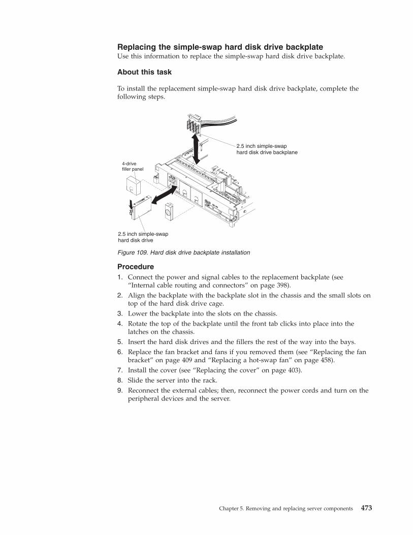
Replacing the simple-swap hard disk drive backplateUse this information to replace the simple-swap hard disk drive backplate.
About this task
To install the replacement simple-swap hard disk drive backplate, complete thefollowing steps.
Procedure1. Connect the power and signal cables to the replacement backplate (see
“Internal cable routing and connectors” on page 398).2. Align the backplate with the backplate slot in the chassis and the small slots on
top of the hard disk drive cage.3. Lower the backplate into the slots on the chassis.4. Rotate the top of the backplate until the front tab clicks into place into the
latches on the chassis.5. Insert the hard disk drives and the fillers the rest of the way into the bays.6. Replace the fan bracket and fans if you removed them (see “Replacing the fan
bracket” on page 409 and “Replacing a hot-swap fan” on page 458).7. Install the cover (see “Replacing the cover” on page 403).8. Slide the server into the rack.9. Reconnect the external cables; then, reconnect the power cords and turn on the
peripheral devices and the server.
Figure 109. Hard disk drive backplate installation
Chapter 5. Removing and replacing server components 473
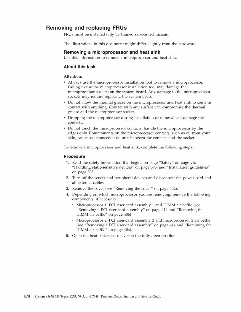
Removing and replacing FRUsFRUs must be installed only by trained service technicians.
The illustrations in this document might differ slightly from the hardware.
Removing a microprocessor and heat sinkUse this information to remove a microprocessor and heat sink.
About this task
Attention:
v Always use the microprocessor installation tool to remove a microprocessor.Failing to use the microprocessor installation tool may damage themicroprocessor sockets on the system board. Any damage to the microprocessorsockets may require replacing the system board.
v Do not allow the thermal grease on the microprocessor and heat sink to come incontact with anything. Contact with any surface can compromise the thermalgrease and the microprocessor socket.
v Dropping the microprocessor during installation or removal can damage thecontacts.
v Do not touch the microprocessor contacts; handle the microprocessor by theedges only. Contaminants on the microprocessor contacts, such as oil from yourskin, can cause connection failures between the contacts and the socket.
To remove a microprocessor and heat sink, complete the following steps:
Procedure1. Read the safety information that begins on page “Safety” on page vii,
“Handling static-sensitive devices” on page 398, and “Installation guidelines”on page 395.
2. Turn off the server and peripheral devices and disconnect the power cord andall external cables.
3. Remove the cover (see “Removing the cover” on page 402).4. Depending on which microprocessor you are removing, remove the following
components, if necessary:v Microprocessor 1: PCI riser-card assembly 1 and DIMM air baffle (see
“Removing a PCI riser-card assembly” on page 414 and “Removing theDIMM air baffle” on page 406)
v Microprocessor 2: PCI riser-card assembly 2 and microprocessor 2 air baffle(see “Removing a PCI riser-card assembly” on page 414 and “Removing theDIMM air baffle” on page 406).
5. Open the heat-sink release lever to the fully open position.
474 System x3650 M3 Types 4255, 7945, and 7949: Problem Determination and Service Guide
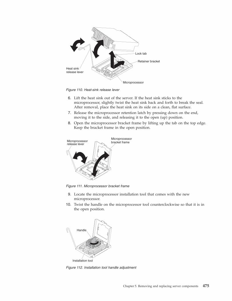
6. Lift the heat sink out of the server. If the heat sink sticks to themicroprocessor, slightly twist the heat sink back and forth to break the seal.After removal, place the heat sink on its side on a clean, flat surface.
7. Release the microprocessor retention latch by pressing down on the end,moving it to the side, and releasing it to the open (up) position.
8. Open the microprocessor bracket frame by lifting up the tab on the top edge.Keep the bracket frame in the open position.
9. Locate the microprocessor installation tool that comes with the newmicroprocessor.
10. Twist the handle on the microprocessor tool counterclockwise so that it is inthe open position.
Figure 110. Heat-sink release lever
Microprocessorbracket frameMicroprocessor
release lever
Figure 111. Microprocessor bracket frame
Installation tool
Handle
Figure 112. Installation tool handle adjustment
Chapter 5. Removing and replacing server components 475
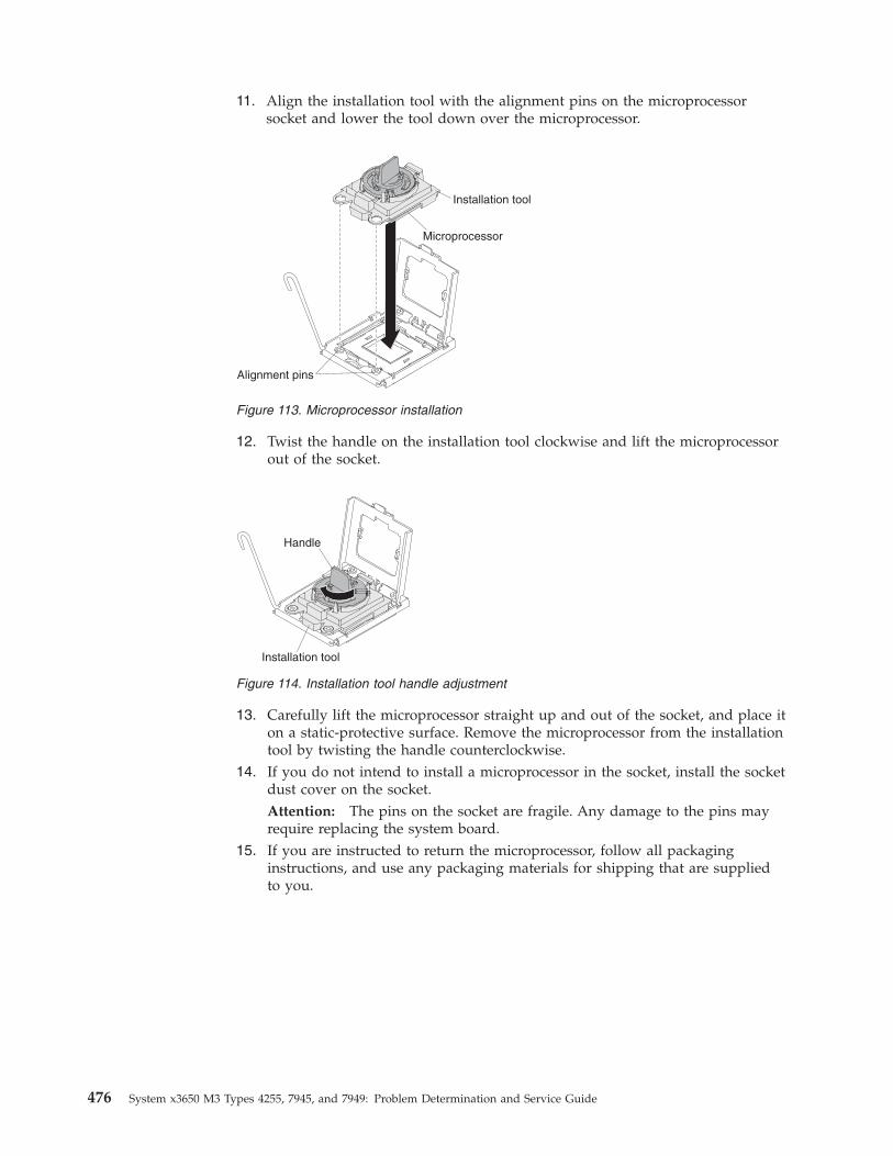
11. Align the installation tool with the alignment pins on the microprocessorsocket and lower the tool down over the microprocessor.
12. Twist the handle on the installation tool clockwise and lift the microprocessorout of the socket.
13. Carefully lift the microprocessor straight up and out of the socket, and place iton a static-protective surface. Remove the microprocessor from the installationtool by twisting the handle counterclockwise.
14. If you do not intend to install a microprocessor in the socket, install the socketdust cover on the socket.Attention: The pins on the socket are fragile. Any damage to the pins mayrequire replacing the system board.
15. If you are instructed to return the microprocessor, follow all packaginginstructions, and use any packaging materials for shipping that are suppliedto you.
Installation tool
Alignment pins
Microprocessor
Figure 113. Microprocessor installation
Installation tool
Handle
Figure 114. Installation tool handle adjustment
476 System x3650 M3 Types 4255, 7945, and 7949: Problem Determination and Service Guide
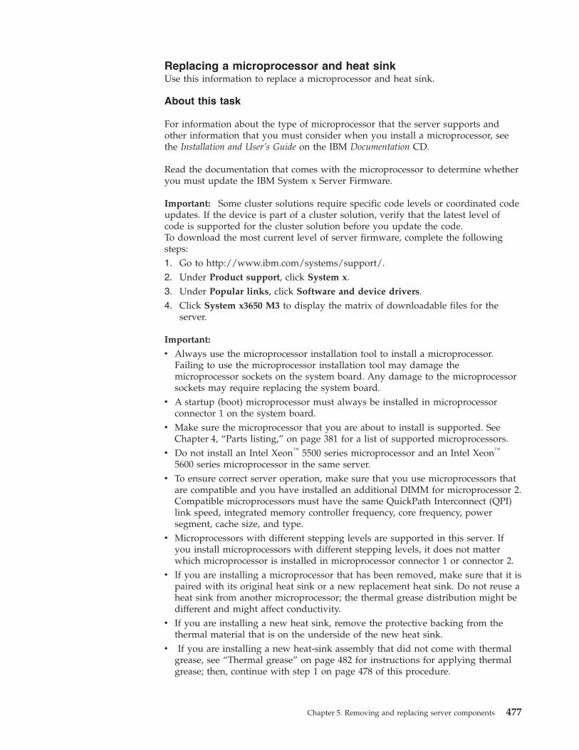
Replacing a microprocessor and heat sinkUse this information to replace a microprocessor and heat sink.
About this task
For information about the type of microprocessor that the server supports andother information that you must consider when you install a microprocessor, seethe Installation and User’s Guide on the IBM Documentation CD.
Read the documentation that comes with the microprocessor to determine whetheryou must update the IBM System x Server Firmware.
Important: Some cluster solutions require specific code levels or coordinated codeupdates. If the device is part of a cluster solution, verify that the latest level ofcode is supported for the cluster solution before you update the code.To download the most current level of server firmware, complete the followingsteps:1. Go to http://www.ibm.com/systems/support/.2. Under Product support, click System x.3. Under Popular links, click Software and device drivers.4. Click System x3650 M3 to display the matrix of downloadable files for the
server.
Important:
v Always use the microprocessor installation tool to install a microprocessor.Failing to use the microprocessor installation tool may damage themicroprocessor sockets on the system board. Any damage to the microprocessorsockets may require replacing the system board.
v A startup (boot) microprocessor must always be installed in microprocessorconnector 1 on the system board.
v Make sure the microprocessor that you are about to install is supported. SeeChapter 4, “Parts listing,” on page 381 for a list of supported microprocessors.
v Do not install an Intel Xeon™ 5500 series microprocessor and an Intel Xeon™
5600 series microprocessor in the same server.v To ensure correct server operation, make sure that you use microprocessors that
are compatible and you have installed an additional DIMM for microprocessor 2.Compatible microprocessors must have the same QuickPath Interconnect (QPI)link speed, integrated memory controller frequency, core frequency, powersegment, cache size, and type.
v Microprocessors with different stepping levels are supported in this server. Ifyou install microprocessors with different stepping levels, it does not matterwhich microprocessor is installed in microprocessor connector 1 or connector 2.
v If you are installing a microprocessor that has been removed, make sure that it ispaired with its original heat sink or a new replacement heat sink. Do not reuse aheat sink from another microprocessor; the thermal grease distribution might bedifferent and might affect conductivity.
v If you are installing a new heat sink, remove the protective backing from thethermal material that is on the underside of the new heat sink.
v If you are installing a new heat-sink assembly that did not come with thermalgrease, see “Thermal grease” on page 482 for instructions for applying thermalgrease; then, continue with step 1 on page 478 of this procedure.
Chapter 5. Removing and replacing server components 477
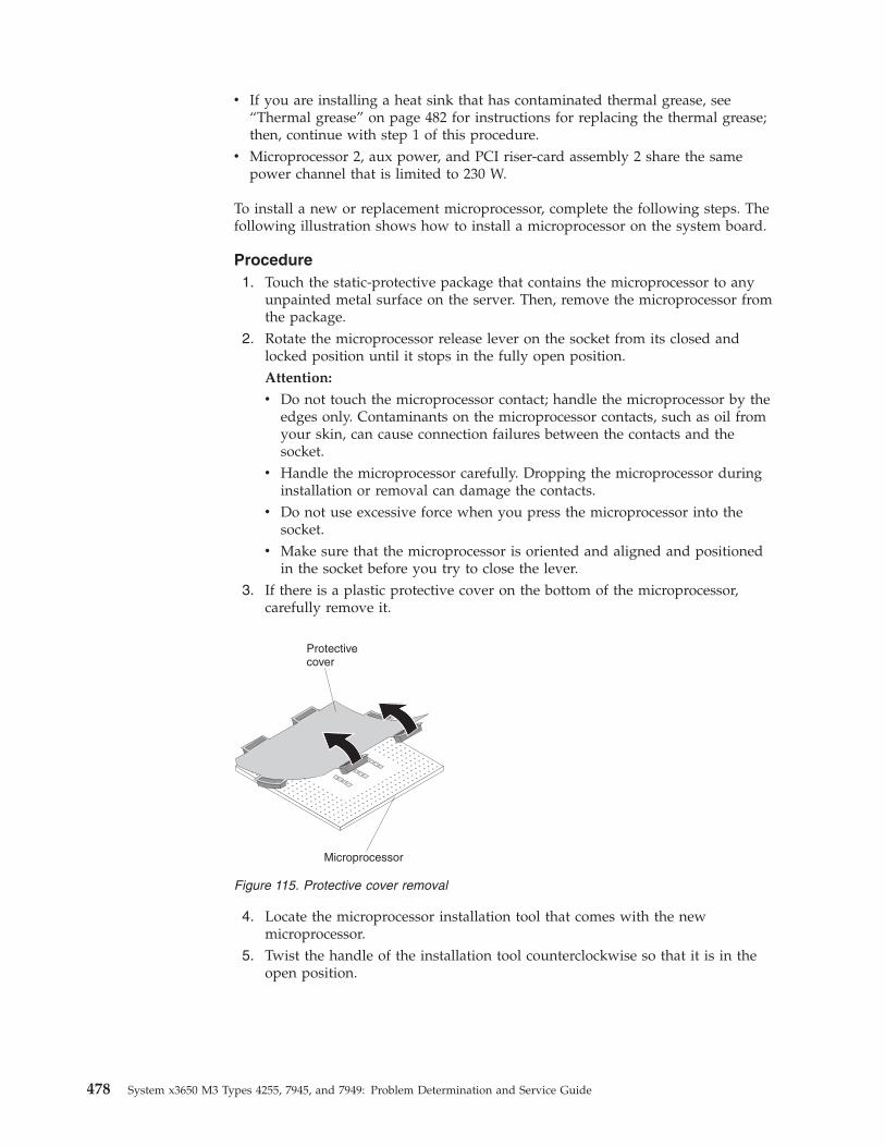
v If you are installing a heat sink that has contaminated thermal grease, see“Thermal grease” on page 482 for instructions for replacing the thermal grease;then, continue with step 1 of this procedure.
v Microprocessor 2, aux power, and PCI riser-card assembly 2 share the samepower channel that is limited to 230 W.
To install a new or replacement microprocessor, complete the following steps. Thefollowing illustration shows how to install a microprocessor on the system board.
Procedure1. Touch the static-protective package that contains the microprocessor to any
unpainted metal surface on the server. Then, remove the microprocessor fromthe package.
2. Rotate the microprocessor release lever on the socket from its closed andlocked position until it stops in the fully open position.Attention:
v Do not touch the microprocessor contact; handle the microprocessor by theedges only. Contaminants on the microprocessor contacts, such as oil fromyour skin, can cause connection failures between the contacts and thesocket.
v Handle the microprocessor carefully. Dropping the microprocessor duringinstallation or removal can damage the contacts.
v Do not use excessive force when you press the microprocessor into thesocket.
v Make sure that the microprocessor is oriented and aligned and positionedin the socket before you try to close the lever.
3. If there is a plastic protective cover on the bottom of the microprocessor,carefully remove it.
4. Locate the microprocessor installation tool that comes with the newmicroprocessor.
5. Twist the handle of the installation tool counterclockwise so that it is in theopen position.
Microprocessor
Protectivecover
Figure 115. Protective cover removal
478 System x3650 M3 Types 4255, 7945, and 7949: Problem Determination and Service Guide
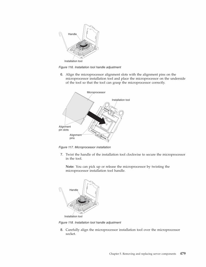
6. Align the microprocessor alignment slots with the alignment pins on themicroprocessor installation tool and place the microprocessor on the undersideof the tool so that the tool can grasp the microprocessor correctly.
7. Twist the handle of the installation tool clockwise to secure the microprocessorin the tool.
Note: You can pick up or release the microprocessor by twisting themicroprocessor installation tool handle.
8. Carefully align the microprocessor installation tool over the microprocessorsocket.
Installation tool
Handle
Figure 116. Installation tool handle adjustment
Alignmentpins
Microprocessor
Alignmentpin slots
Installation tool
Figure 117. Microprocessor installation
Installation tool
Handle
Figure 118. Installation tool handle adjustment
Chapter 5. Removing and replacing server components 479
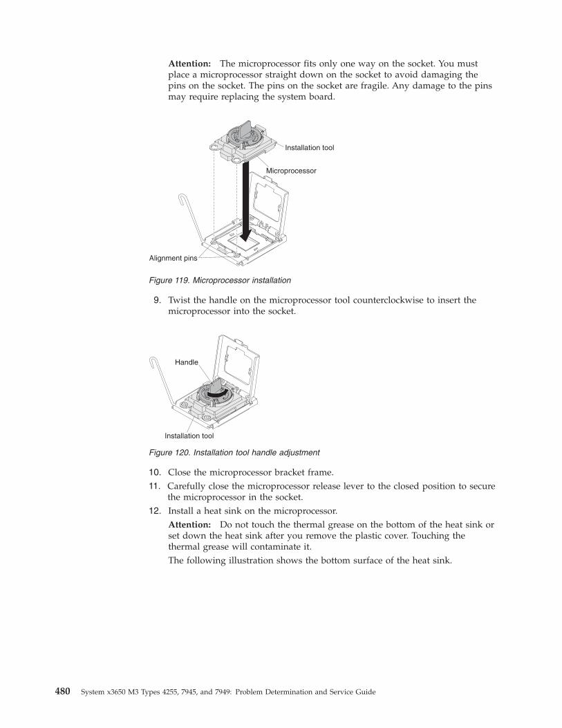
Attention: The microprocessor fits only one way on the socket. You mustplace a microprocessor straight down on the socket to avoid damaging thepins on the socket. The pins on the socket are fragile. Any damage to the pinsmay require replacing the system board.
9. Twist the handle on the microprocessor tool counterclockwise to insert themicroprocessor into the socket.
10. Close the microprocessor bracket frame.11. Carefully close the microprocessor release lever to the closed position to secure
the microprocessor in the socket.12. Install a heat sink on the microprocessor.
Attention: Do not touch the thermal grease on the bottom of the heat sink orset down the heat sink after you remove the plastic cover. Touching thethermal grease will contaminate it.The following illustration shows the bottom surface of the heat sink.
Installation tool
Alignment pins
Microprocessor
Figure 119. Microprocessor installation
Installation tool
Handle
Figure 120. Installation tool handle adjustment
480 System x3650 M3 Types 4255, 7945, and 7949: Problem Determination and Service Guide
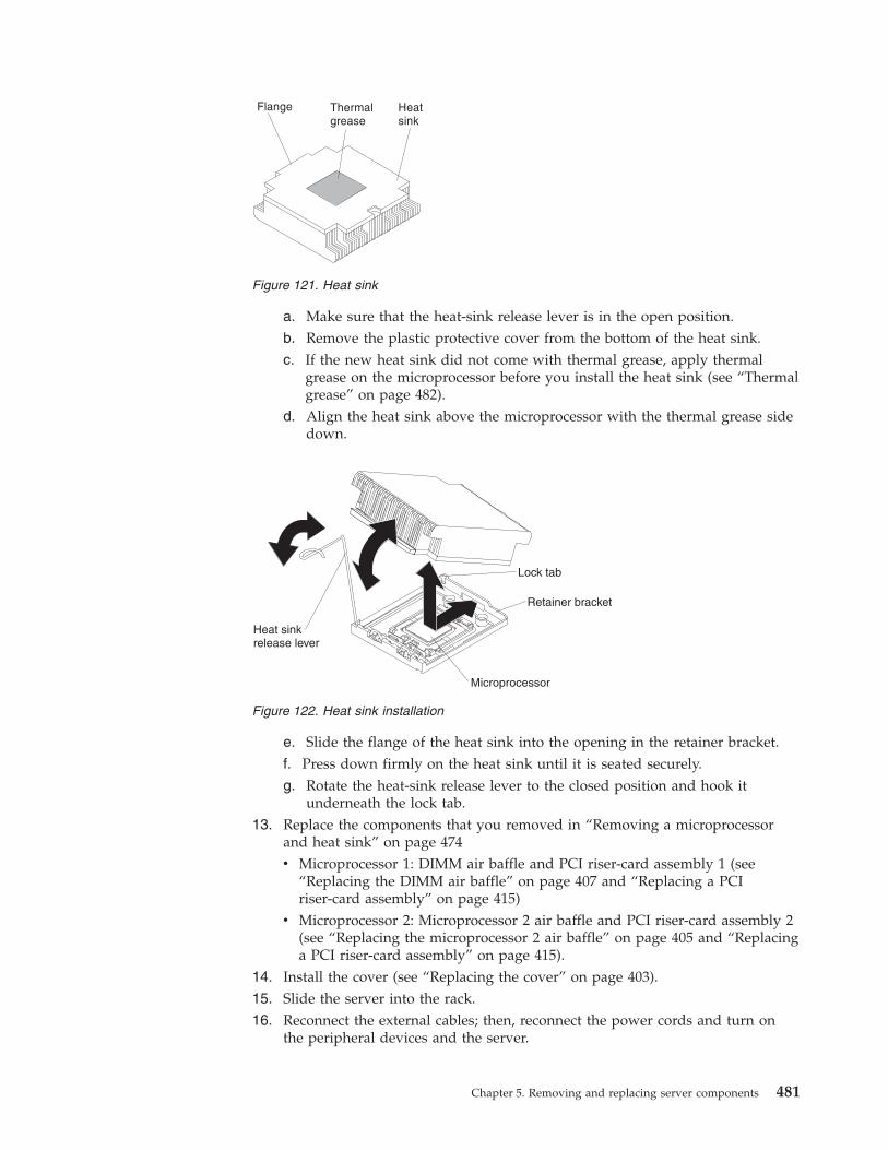
a. Make sure that the heat-sink release lever is in the open position.b. Remove the plastic protective cover from the bottom of the heat sink.c. If the new heat sink did not come with thermal grease, apply thermal
grease on the microprocessor before you install the heat sink (see “Thermalgrease” on page 482).
d. Align the heat sink above the microprocessor with the thermal grease sidedown.
e. Slide the flange of the heat sink into the opening in the retainer bracket.f. Press down firmly on the heat sink until it is seated securely.g. Rotate the heat-sink release lever to the closed position and hook it
underneath the lock tab.13. Replace the components that you removed in “Removing a microprocessor
and heat sink” on page 474v Microprocessor 1: DIMM air baffle and PCI riser-card assembly 1 (see
“Replacing the DIMM air baffle” on page 407 and “Replacing a PCIriser-card assembly” on page 415)
v Microprocessor 2: Microprocessor 2 air baffle and PCI riser-card assembly 2(see “Replacing the microprocessor 2 air baffle” on page 405 and “Replacinga PCI riser-card assembly” on page 415).
14. Install the cover (see “Replacing the cover” on page 403).15. Slide the server into the rack.16. Reconnect the external cables; then, reconnect the power cords and turn on
the peripheral devices and the server.
Figure 121. Heat sink
Figure 122. Heat sink installation
Chapter 5. Removing and replacing server components 481
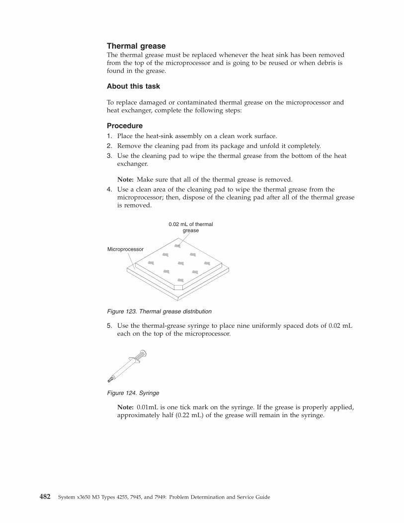
Thermal greaseThe thermal grease must be replaced whenever the heat sink has been removedfrom the top of the microprocessor and is going to be reused or when debris isfound in the grease.
About this task
To replace damaged or contaminated thermal grease on the microprocessor andheat exchanger, complete the following steps:
Procedure1. Place the heat-sink assembly on a clean work surface.2. Remove the cleaning pad from its package and unfold it completely.3. Use the cleaning pad to wipe the thermal grease from the bottom of the heat
exchanger.
Note: Make sure that all of the thermal grease is removed.4. Use a clean area of the cleaning pad to wipe the thermal grease from the
microprocessor; then, dispose of the cleaning pad after all of the thermal greaseis removed.
5. Use the thermal-grease syringe to place nine uniformly spaced dots of 0.02 mLeach on the top of the microprocessor.
Note: 0.01mL is one tick mark on the syringe. If the grease is properly applied,approximately half (0.22 mL) of the grease will remain in the syringe.
Microprocessor
0.02 mL of thermalgrease
Figure 123. Thermal grease distribution
Figure 124. Syringe
482 System x3650 M3 Types 4255, 7945, and 7949: Problem Determination and Service Guide
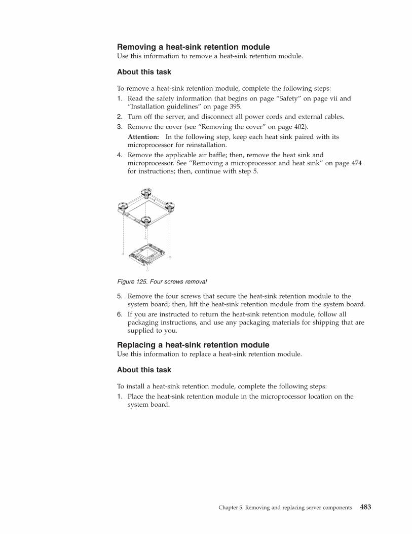
Removing a heat-sink retention moduleUse this information to remove a heat-sink retention module.
About this task
To remove a heat-sink retention module, complete the following steps:1. Read the safety information that begins on page “Safety” on page vii and
“Installation guidelines” on page 395.2. Turn off the server, and disconnect all power cords and external cables.3. Remove the cover (see “Removing the cover” on page 402).
Attention: In the following step, keep each heat sink paired with itsmicroprocessor for reinstallation.
4. Remove the applicable air baffle; then, remove the heat sink andmicroprocessor. See “Removing a microprocessor and heat sink” on page 474for instructions; then, continue with step 5.
5. Remove the four screws that secure the heat-sink retention module to thesystem board; then, lift the heat-sink retention module from the system board.
6. If you are instructed to return the heat-sink retention module, follow allpackaging instructions, and use any packaging materials for shipping that aresupplied to you.
Replacing a heat-sink retention moduleUse this information to replace a heat-sink retention module.
About this task
To install a heat-sink retention module, complete the following steps:1. Place the heat-sink retention module in the microprocessor location on the
system board.
Figure 125. Four screws removal
Chapter 5. Removing and replacing server components 483
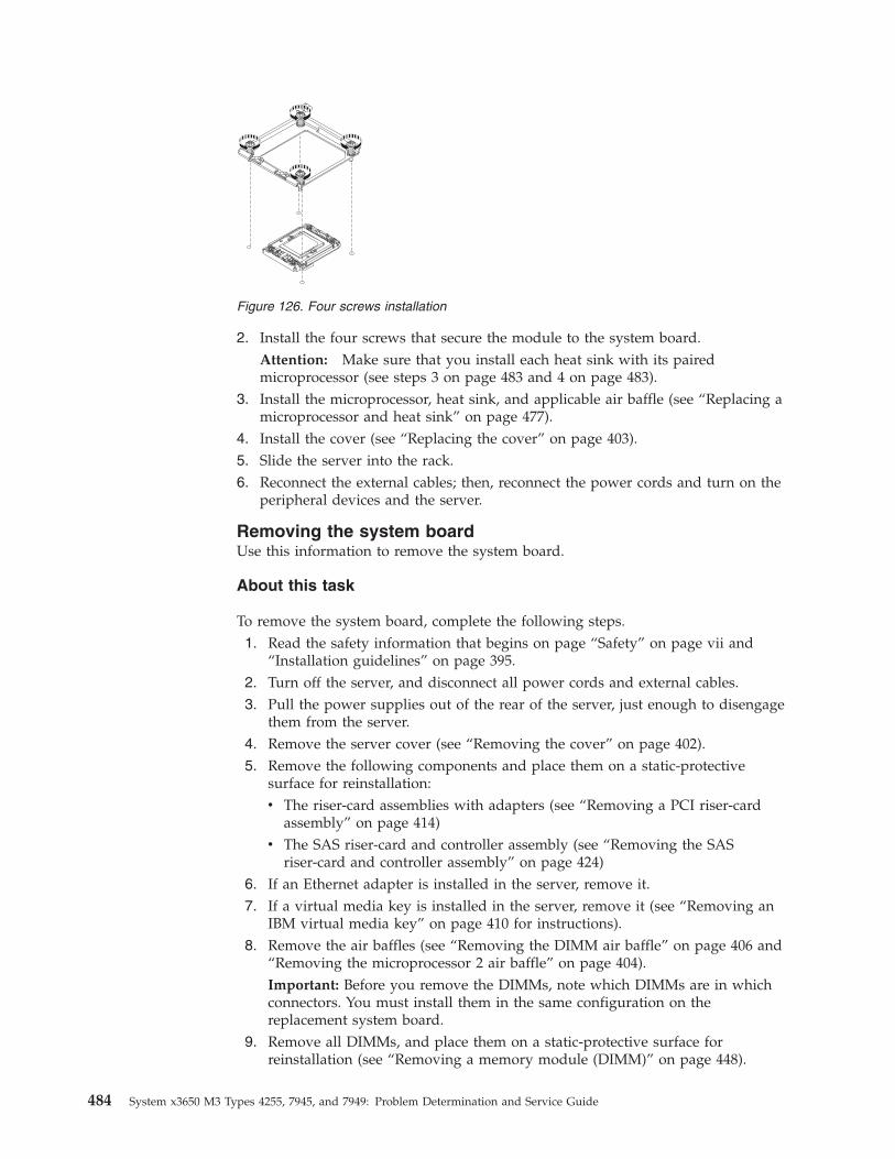
2. Install the four screws that secure the module to the system board.Attention: Make sure that you install each heat sink with its pairedmicroprocessor (see steps 3 on page 483 and 4 on page 483).
3. Install the microprocessor, heat sink, and applicable air baffle (see “Replacing amicroprocessor and heat sink” on page 477).
4. Install the cover (see “Replacing the cover” on page 403).5. Slide the server into the rack.6. Reconnect the external cables; then, reconnect the power cords and turn on the
peripheral devices and the server.
Removing the system boardUse this information to remove the system board.
About this task
To remove the system board, complete the following steps.1. Read the safety information that begins on page “Safety” on page vii and
“Installation guidelines” on page 395.2. Turn off the server, and disconnect all power cords and external cables.3. Pull the power supplies out of the rear of the server, just enough to disengage
them from the server.4. Remove the server cover (see “Removing the cover” on page 402).5. Remove the following components and place them on a static-protective
surface for reinstallation:v The riser-card assemblies with adapters (see “Removing a PCI riser-card
assembly” on page 414)v The SAS riser-card and controller assembly (see “Removing the SAS
riser-card and controller assembly” on page 424)6. If an Ethernet adapter is installed in the server, remove it.7. If a virtual media key is installed in the server, remove it (see “Removing an
IBM virtual media key” on page 410 for instructions).8. Remove the air baffles (see “Removing the DIMM air baffle” on page 406 and
“Removing the microprocessor 2 air baffle” on page 404).Important: Before you remove the DIMMs, note which DIMMs are in whichconnectors. You must install them in the same configuration on thereplacement system board.
9. Remove all DIMMs, and place them on a static-protective surface forreinstallation (see “Removing a memory module (DIMM)” on page 448).
Figure 126. Four screws installation
484 System x3650 M3 Types 4255, 7945, and 7949: Problem Determination and Service Guide
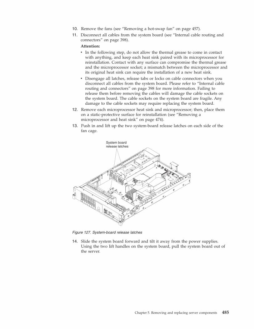
10. Remove the fans (see “Removing a hot-swap fan” on page 457).11. Disconnect all cables from the system board (see “Internal cable routing and
connectors” on page 398).Attention:
v In the following step, do not allow the thermal grease to come in contactwith anything, and keep each heat sink paired with its microprocessor forreinstallation. Contact with any surface can compromise the thermal greaseand the microprocessor socket; a mismatch between the microprocessor andits original heat sink can require the installation of a new heat sink.
v Disengage all latches, release tabs or locks on cable connectors when youdisconnect all cables from the system board. Please refer to “Internal cablerouting and connectors” on page 398 for more information. Failing torelease them before removing the cables will damage the cable sockets onthe system board. The cable sockets on the system board are fragile. Anydamage to the cable sockets may require replacing the system board.
12. Remove each microprocessor heat sink and microprocessor; then, place themon a static-protective surface for reinstallation (see “Removing amicroprocessor and heat sink” on page 474).
13. Push in and lift up the two system-board release latches on each side of thefan cage.
14. Slide the system board forward and tilt it away from the power supplies.Using the two lift handles on the system board, pull the system board out ofthe server.
System boardrelease latches
Figure 127. System-board release latches
Chapter 5. Removing and replacing server components 485
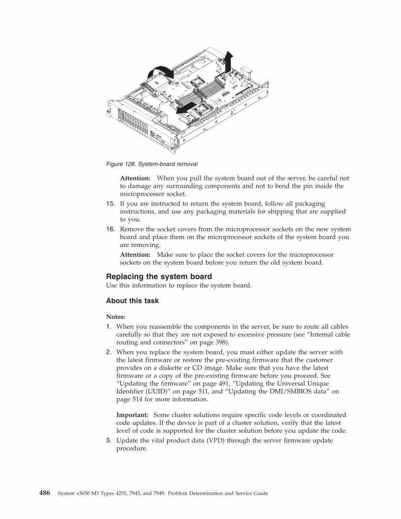
Attention: When you pull the system board out of the server, be careful notto damage any surrounding components and not to bend the pin inside themicroprocessor socket.
15. If you are instructed to return the system board, follow all packaginginstructions, and use any packaging materials for shipping that are suppliedto you.
16. Remove the socket covers from the microprocessor sockets on the new systemboard and place them on the microprocessor sockets of the system board youare removing.Attention: Make sure to place the socket covers for the microprocessorsockets on the system board before you return the old system board.
Replacing the system boardUse this information to replace the system board.
About this task
Notes:
1. When you reassemble the components in the server, be sure to route all cablescarefully so that they are not exposed to excessive pressure (see “Internal cablerouting and connectors” on page 398).
2. When you replace the system board, you must either update the server withthe latest firmware or restore the pre-existing firmware that the customerprovides on a diskette or CD image. Make sure that you have the latestfirmware or a copy of the pre-existing firmware before you proceed. See“Updating the firmware” on page 491, “Updating the Universal UniqueIdentifier (UUID)” on page 511, and “Updating the DMI/SMBIOS data” onpage 514 for more information.
Important: Some cluster solutions require specific code levels or coordinatedcode updates. If the device is part of a cluster solution, verify that the latestlevel of code is supported for the cluster solution before you update the code.
3. Update the vital product data (VPD) through the server firmware updateprocedure.
Figure 128. System-board removal
486 System x3650 M3 Types 4255, 7945, and 7949: Problem Determination and Service Guide
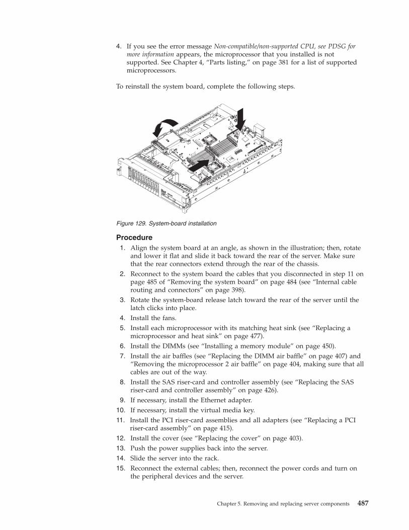
4. If you see the error message Non-compatible/non-supported CPU, see PDSG formore information appears, the microprocessor that you installed is notsupported. See Chapter 4, “Parts listing,” on page 381 for a list of supportedmicroprocessors.
To reinstall the system board, complete the following steps.
Procedure1. Align the system board at an angle, as shown in the illustration; then, rotate
and lower it flat and slide it back toward the rear of the server. Make surethat the rear connectors extend through the rear of the chassis.
2. Reconnect to the system board the cables that you disconnected in step 11 onpage 485 of “Removing the system board” on page 484 (see “Internal cablerouting and connectors” on page 398).
3. Rotate the system-board release latch toward the rear of the server until thelatch clicks into place.
4. Install the fans.5. Install each microprocessor with its matching heat sink (see “Replacing a
microprocessor and heat sink” on page 477).6. Install the DIMMs (see “Installing a memory module” on page 450).7. Install the air baffles (see “Replacing the DIMM air baffle” on page 407) and
“Removing the microprocessor 2 air baffle” on page 404, making sure that allcables are out of the way.
8. Install the SAS riser-card and controller assembly (see “Replacing the SASriser-card and controller assembly” on page 426).
9. If necessary, install the Ethernet adapter.10. If necessary, install the virtual media key.11. Install the PCI riser-card assemblies and all adapters (see “Replacing a PCI
riser-card assembly” on page 415).12. Install the cover (see “Replacing the cover” on page 403).13. Push the power supplies back into the server.14. Slide the server into the rack.15. Reconnect the external cables; then, reconnect the power cords and turn on
the peripheral devices and the server.
Figure 129. System-board installation
Chapter 5. Removing and replacing server components 487
Results
Important: Perform the following updates:v Start the Setup utility and reset the configuration.
– Set the system date and time.– Set the power-on password.– Reconfigure the server.
See “Using the Setup utility” on page 493 for details.v Either update the server with the latest RAID firmware or restore the
pre-existing firmware from a diskette or CD image (see “Updating the firmware”on page 491).
v Update the UUID (see “Updating the Universal Unique Identifier (UUID)” onpage 511).
v Update the DMI/SMBIOS (see “Updating the DMI/SMBIOS data” on page 514).
Important: Some cluster solutions require specific code levels or coordinated codeupdates. If the device is part of a cluster solution, verify that the latest level ofcode is supported for the cluster solution before you update the code.
Removing the 240 VA safety coverUse this information to remove the 240 VA safety cover.
About this task
To remove the 240 VA safety cover, complete the following steps:
Procedure1. Read the safety information that begins on page “Safety” on page vii and
“Installation guidelines” on page 395.2. Turn off the server, and disconnect all power cords and external cables.3. Pull the server out of the rack.4. Remove the server cover (see “Removing the cover” on page 402).5. Remove the SAS riser card assembly (see “Removing the SAS riser-card and
controller assembly” on page 424).
488 System x3650 M3 Types 4255, 7945, and 7949: Problem Determination and Service Guide
6. Remove the screw from the safety cover.7. Disconnect the hard disk drive backplane power cables from the connector in
front of the safety cover.8. Slide the cover forward to disengage it from the system board, and then lift it
out of the server.9. If you are instructed to return the 240 VA safety cover, follow all packaging
instructions, and use any packaging materials for shipping that are supplied toyou.
Replacing the 240 VA safety coverUse this information to replace the 240 VA safety cover.
About this task
To install the 240 VA safety cover, complete the following steps.
Figure 130. 240 VA safety cover removal
Chapter 5. Removing and replacing server components 489
Procedure1. Line up and insert the tabs on the bottom of the safety cover into the slots on
the system board.2. Slide the safety cover toward the back of the server until it is secure.3. Connect the hard disk drive backplane power cables to the connector in front
of the safety cover.4. Install the screw into the safety cover.5. Install the SAS riser-card assembly (see “Replacing the SAS riser-card and
controller assembly” on page 426).6. Install the server cover (see “Replacing the cover” on page 403).7. Slide the server into the rack.8. Reconnect the external cables; then, reconnect the power cords and turn on the
peripheral devices and the server.
Figure 131. 240 VA safety cover installation
490 System x3650 M3 Types 4255, 7945, and 7949: Problem Determination and Service Guide
Chapter 6. Configuration information and instructions
This chapter provides information about updating the firmware and using theconfiguration utilities.
Updating the firmwareUse this information to update the firmware.
Important: Some cluster solutions require specific code levels or coordinated codeupdates. If the device is part of a cluster solution, verify that the latest level ofcode is supported for the cluster solution before you update the code.
The firmware for the server is periodically updated and is available for downloadfrom the Web. To check for the latest level of firmware, such as server firmware,vital product data (VPD) code, device drivers, and service processor firmwarecomplete the following steps.
Note: Changes are made periodically to the IBM Web site. The actual proceduremight vary slightly from what is described in this document.1. Go to http://www.ibm.com/systems/support/.2. Under Product support, click System x.3. Under Popular links, click Software and device drivers.4. Click System x3650 M3 to display the matrix of downloadable files for the
server.
Download the latest firmware for the server; then, install the firmware, using theinstructions that are included with the downloaded files.
When you replace a device in the server, you might have to either update thefirmware that is stored in memory on the device or restore the pre-existingfirmware from a diskette or CD image.v BIOS code is stored in ROM on the system board.v IMM firmware is stored in ROM on the IMM on the system board.v Ethernet firmware is stored in ROM on the Ethernet controller.v ServeRAID firmware is stored in ROM on the ServeRAID adapter.v SATA firmware is stored in ROM on the integrated SATA controller.v SAS/SATA firmware is stored in ROM on the SAS/SATA controller on the
system board.
© Copyright IBM Corp. 2014 491
Configuring the serverThe following configuration programs come with the server:v Setup utility
The Setup utility (formerly called the Configuration/Setup Utility program) ispart of the IBM System x Server Firmware. Use it to change interrupt request(IRQ) settings, change the startup-device sequence, set the date and time, and setpasswords. For information about using this program, see “Using the Setuputility” on page 493.
v Boot Menu program
The Boot Menu program is part of the IBM System x Server Firmware. Use it tooverride the startup sequence that is set in the Setup utility and temporarilyassign a device to be first in the startup sequence.
v IBM ServerGuide Setup and Installation CD
The ServerGuide program provides software-setup tools and installation toolsthat are designed for the server. Use this CD during the installation of the serverto configure basic hardware features, such as an integrated SAS controller withRAID capabilities, and to simplify the installation of your operating system. Forinformation about obtaining and using this CD, see “Using the ServerGuideSetup and Installation CD” on page 500.
v Integrated management module
Use the integrated management module (IMM) for configuration, to update thefirmware and sensor data record/field replaceable unit (SDR/FRU) data, and toremotely manage a network. For information about using the IMM, see “Usingthe integrated management module” on page 502.
v VMware embedded USB hypervisor
The VMware embedded USB hypervisor is available on the server models thatcome with an installed IBM USB Memory Key for VMware hypervisor. The USBmemory key is installed in the USB connector on the SAS riser-card. Hypervisoris virtualization software that enables multiple operating systems to run on ahost computer at the same time. For more information about using theembedded hypervisor, see “Using the USB memory key for VMware hypervisor”on page 503.
v Remote presence capability and blue-screen capture
The remote presence and blue-screen capture feature are integrated into theintegrated management module (IMM). The virtual media key is required toenable these features. When the optional virtual media key is installed in theserver, it activates the remote presence functions. Without the virtual media key,you will not be able to access the network remotely to mount or unmount drivesor images on the client system. However, you will still be able to access the hostgraphical user interface through the Web interface without the virtual media key.You can order an optional IBM Virtual Media Key, if one did not come withyour server. For more information about how to enable the remote presencefunction, see “Using the remote presence capability and blue-screen capture” onpage 504.
v Ethernet controller configuration
For information about configuring the Ethernet controller, see “Configuring theGigabit Ethernet controller” on page 507.
v LSI Configuration Utility program
492 System x3650 M3 Types 4255, 7945, and 7949: Problem Determination and Service Guide
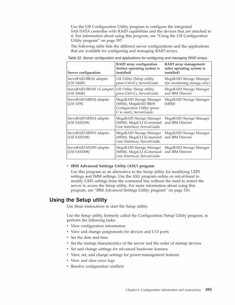
Use the LSI Configuration Utility program to configure the integratedSAS/SATA controller with RAID capabilities and the devices that are attached toit. For information about using this program, see “Using the LSI ConfigurationUtility program” on page 507.The following table lists the different server configurations and the applicationsthat are available for configuring and managing RAID arrays.
Table 22. Server configuration and applications for configuring and managing RAID arrays
Server configuration
RAID array configuration(before operating system isinstalled)
RAID array management(after operating system isinstalled)
ServeRAID-BR10i adapter(LSI 1068E)
LSI Utility (Setup utility,press Ctrl+C), ServerGuide
MegaRAID Storage Manager(for monitoring storage only)
ServeRAID-BR10il v2 adapter(LSI 1064E)
LSI Utility (Setup utility,press Ctrl+C), ServerGuide
MegaRAID Storage Managerand IBM Director
ServeRAID-MR10i adapter(LSI 1078)
MegaRAID Storage Manager(MSM), MegaRAID BIOSConfiguration Utility (pressC to start), ServerGuide
MegaRAID Storage Manager(MSM)
ServeRAID-M5014 adapter(LSI SAS2108)
MegaRAID Storage Manager(MSM), MegaCLI (CommandLine Interface), ServerGuide
MegaRAID Storage Managerand IBM Director
ServeRAID-M5015 adapter(LSI SAS2108)
MegaRAID Storage Manager(MSM), MegaCLI (CommandLine Interface), ServerGuide
MegaRAID Storage Managerand IBM Director
ServeRAID-M1050 adapter(LSI SAS2008)
MegaRAID Storage Manager(MSM), MegaCLI (CommandLine Interface), ServerGuide
MegaRAID Storage Managerand IBM Director
v IBM Advanced Settings Utility (ASU) program
Use this program as an alternative to the Setup utility for modifying UEFIsettings and IMM settings. Use the ASU program online or out-of-band tomodify UEFI settings from the command line without the need to restart theserver to access the Setup utility. For more information about using thisprogram, see “IBM Advanced Settings Utility program” on page 510.
Using the Setup utilityUse these instructions to start the Setup utility.
Use the Setup utility, formerly called the Configuration/Setup Utility program, toperform the following tasks:v View configuration informationv View and change assignments for devices and I/O portsv Set the date and timev Set the startup characteristics of the server and the order of startup devicesv Set and change settings for advanced hardware featuresv View, set, and change settings for power-management featuresv View and clear error logsv Resolve configuration conflicts
Chapter 6. Configuration information and instructions 493
Starting the Setup utility
About this task
To start the Setup utility, complete the following steps:
Procedure1. Turn on the server.
Note: Approximately 3 minutes after the server is connected to ac power, thepower-control button becomes active.
2. When the prompt <F1> Setup is displayed, press F1. If you have set anadministrator password, you must type the administrator password to accessthe full Setup utility menu. If you do not type the administrator password, alimited Setup utility menu is available.
3. Select the settings to view or change.
Setup utility menu choicesThe following choices are on the Setup utility main menu. Depending on theversion of the firmware, some menu choices might differ slightly from thesedescriptions.v System Information
Select this choice to view information about the server. When you make changesthrough other choices in the Setup utility, some of those changes are reflected inthe system information; you cannot change settings directly in the systeminformation.This choice is on the full Setup utility menu only.– System Summary
Select this choice to view configuration information, including the ID, speed,and cache size of the microprocessors, machine type and model of the server,the serial number, the system UUID, and the amount of installed memory.When you make configuration changes through other choices in the Setuputility, the changes are reflected in the system summary; you cannot changesettings directly in the system summary.
– Product Data
Select this choice to view the system-board identifier, the revision level orissue date of the firmware, the integrated management module anddiagnostics code, and the version and date.
v System Settings
Select this choice to view or change the server component settings.– Processors
Select this choice to view or change the processor settings.– Memory
Select this choice to view or change the memory settings. To configurememory mirroring, select System Settings → Memory, and then selectMemory Channel Mode → Mirroring.
– Devices and I/O Ports
Select this choice to view or change assignments for devices andinput/output (I/O) ports. You can configure the serial ports; configure remoteconsole redirection; enable or disable integrated Ethernet controllers, theSAS/SATA controller, SATA optical drive channels, and PCI slots; and video
494 System x3650 M3 Types 4255, 7945, and 7949: Problem Determination and Service Guide
controller. If you disable a device, it cannot be configured, and the operatingsystem will not be able to detect it (this is equivalent to disconnecting thedevice).
– Power
Select this choice to view or change power capping to control consumption,processors, and performance states.
– Operating Modes
Select this choice to view or change the operating profile (for example,performance and power utilization).
– Legacy Support
Select this choice to view or set legacy support.- Force Legacy Video on Boot
Select this choice to force INT video support, if the operating system doesnot support UEFI video output standards.
- Rehook INT
Select this choice to enable or disable devices from taking control of theboot process. The default is Disable.
- Legacy Thunk Support
Select this choice to enable or disable the UEFI to interact with PCI massstorage devices that are not UEFI-compliant.
– Integrated Management Module
Select this choice to view or change the settings for the integratedmanagement module.- POST Watchdog Timer
Select this choice to view or enable the POST watchdog timer.- POST Watchdog Timer Value
Select this choice to view or set the POST loader watchdog timer value.- Reboot System on NMI
Enable or disable restarting the system whenever a nonmaskable interrupt(NMI) occurs. Disabled is the default.
- Commands on USB Interface Preference
Select this choice to enable or disable the Ethernet over USB interface onIMM.
- Network Configuration
Select this choice to view the system management network interface port,the IMM MAC address, the current IMM IP address, and host name; definethe static IMM IP address, subnet mask, and gateway address; specifywhether to use the static IP address or have DHCP assign the IMM IPaddress; save the network changes; and reset the IMM.
- Reset IMM to Defaults
Select this choice to view or reset IMM to the default settings.- Reset IMM
Select this choice to reset IMM.– Adapters and UEFI Drivers
Select this choice to view information about the adapters and drivers in theserver that are compliant with EFI 1.10 and UEFI 2.0.
v Network
Chapter 6. Configuration information and instructions 495
Select this choice to view or configure the network options, such as the iSCSI,PXE, and network devices. There might be additional configuration choices foroptional network devices that are compliant with UEFI 2.1 and later.
v Storage
Select this choice to view or configure the storage devices options. There mightbe additional configuration choices for optional storage devices that arecompliant with UEFI 2.1 and later.
v Video
Select this choice to view or configure the video device options installed in theserver. There might be additional configuration choices for optional videodevices that are compliant with UEFI 2.1 and later.
v Date and Time
Select this choice to set the date and time in the server, in 24-hour format(hour:minute:second).This choice is on the full Setup utility menu only.
v Start Options
Select this choice to view or change the start options, including the startupsequence, keyboard NumLock state, PXE boot option, and PCI device bootpriority. Changes in the startup options take effect when you start the server.The startup sequence specifies the order in which the server checks devices tofind a boot record. The server starts from the first boot record that it finds. If theserver has Wake on LAN hardware and software and the operating systemsupports Wake on LAN functions, you can specify a startup sequence for theWake on LAN functions. For example, you can define a startup sequence thatchecks for a disc in the CD-RW/DVD drive, then checks the hard disk drive,and then checks a network adapter.This choice is on the full Setup utility menu only.
v Boot Manager
Select this choice to view, add, or change the device boot priority, boot from afile, select a one-time boot, or reset the boot order to the default setting.
v System Event Logs
Select this choice to enter the System Event Manager, where you can view theerror messages in the system-event logs. You can use the arrow keys to movebetween pages in the error log.The system-event logs contain all event and error messages that have beengenerated during POST, by the systems-management interface handler, and bythe system service processor. Run the diagnostic programs to get moreinformation about error codes that occur. See the Problem Determination andService Guide on the IBM Documentation CD for instructions for running thediagnostic programs.Important: If the system-error LED on the front of the server is lit but there areno other error indications, clear the system-event log. Also, after you complete arepair or correct an error, clear the system-event log to turn off the system-errorLED on the front of the server.– POST Event Viewer
Select this choice to enter the POST event viewer to view the error messagesin the POST event log.
– System Event Log
Select this choice to view the error messages in the system-event log.– Clear System Event Log
496 System x3650 M3 Types 4255, 7945, and 7949: Problem Determination and Service Guide
Select this choice to clear the system-event log.v User Security
Select this choice to set, change, or clear passwords. See “Passwords” for moreinformation.This choice is on the full and limited Setup utility menu.– Set Power-on Password
Select this choice to set or change a power-on password. For moreinformation, see “Power-on password” on page 498.
– Clear Power-on Password
Select this choice to clear a power-on password. For more information, see“Power-on password” on page 498.
– Set Administrator Password
Select this choice to set or change an administrator password. Anadministrator password is intended to be used by a system administrator; itlimits access to the full Setup utility menu. If an administrator password isset, the full Setup utility menu is available only if you type the administratorpassword at the password prompt. For more information, see “Administratorpassword” on page 499.
– Clear Administrator Password
Select this choice to clear an administrator password. For more information,see “Administrator password” on page 499.
v Save Settings
Select this choice to save the changes that you have made in the settings.v Restore Settings
Select this choice to cancel the changes that you have made in the settings andrestore the previous settings.
v Load Default Settings
Select this choice to cancel the changes that you have made in the settings andrestore the factory settings.
v Exit Setup
Select this choice to exit from the Setup utility. If you have not saved thechanges that you have made in the settings, you are asked whether you want tosave the changes or exit without saving them.
PasswordsFrom the User Security menu choice, you can set, change, and delete a power-onpassword and an administrator password. The User Security choice is on the fullSetup utility menu only.
If you set only a power-on password, you must type the power-on password tocomplete the system startup and to have access to the full Setup utility menu.
An administrator password is intended to be used by a system administrator; itlimits access to the full Setup utility menu. If you set only an administratorpassword, you do not have to type a password to complete the system startup, butyou must type the administrator password to access the Setup utility menu.
If you set a power-on password for a user and an administrator password for asystem administrator, you must type the power-on password to complete thesystem startup. A system administrator who types the administrator password hasaccess to the full Setup utility menu; the system administrator can give the user
Chapter 6. Configuration information and instructions 497
authority to set, change, and delete the power-on password. A user who types thepower-on password has access to only the limited Setup utility menu; the user canset, change, and delete the power-on password, if the system administrator hasgiven the user that authority.
Power-on password:
If a power-on password is set, when you turn on the server, the system startupwill not be completed until you type the power-on password. You can use anycombination of between six and 20 printable ASCII characters for the password.
When a power-on password is set, you can enable the Unattended Start mode, inwhich the keyboard and mouse remain locked but the operating system can start.You can unlock the keyboard and mouse by typing the power-on password.
If you forget the power-on password, you can regain access to the server in any ofthe following ways:v If an administrator password is set, type the administrator password at the
password prompt. Start the Setup utility and reset the power-on password.v Remove the battery from the server and then reinstall it. See the Problem
Determination and Service Guide on the IBM Documentation CD for instructions forremoving the battery.
v Change the position of the power-on password switch (enable switch 1 of thesystem board switch block (SW4) to bypass the power-on password check (see“System-board switches and jumpers” on page 18 for more information).Attention: Before you change any switch settings or move any jumpers, turnoff the server; then, disconnect all power cords and external cables. See thesafety information that begins on page “Safety” on page vii. Do not changesettings or move jumpers on any system-board switch or jumper blocks that arenot shown in this document.The default for all of the switches on switch block (SW4) is Off.While the server is turned off, move switch 1 of the switch block (SW4) to theOn position to enable the power-on password override. You can then start theSetup utility and reset the power-on password. You do not have to return theswitch to the previous position.The power-on password override switch does not affect the administratorpassword.
498 System x3650 M3 Types 4255, 7945, and 7949: Problem Determination and Service Guide
Administrator password:
If an administrator password is set, you must type the administrator password foraccess to the full Setup utility menu. You can use any combination of between sixand 20 printable ASCII characters for the password.
Attention: If you set an administrator password and then forget it, there is noway to change, override, or remove it. You must replace the system board.
Using the Boot Selection Menu programThe Boot Selection Menu is used to temporarily redefine the first startup devicewithout changing boot options or settings in the Setup utility.
About this task
To use the Boot Selection Menu program, complete the following steps:
Procedure1. Turn off the server.2. Restart the server.3. Press F12 (Select Boot Device). If a bootable USB mass storage device is
installed, a submenu item (USB Key/Disk) is displayed.4. Use the Up Arrow and Down Arrow keys to select an item from the Boot
Selection Menu and press Enter.
Results
The next time the server starts, it returns to the startup sequence that is set in theSetup utility.
Starting the backup server firmwareThe system board contains a backup copy area for the server firmware. This is asecondary copy of server firmware that you update only during the process ofupdating server firmware. If the primary copy of the server firmware becomesdamaged, use this backup copy.
About this task
To force the server to start from the backup copy, turn off the server; then, placethe UEFI boot recovery J29 jumper in the backup position (pins 2 and 3).
Use the backup copy of the server firmware until the primary copy is restored.After the primary copy is restored, turn off the server; then, move the UEFI bootrecovery J29 jumper back to the primary position (pins 1 and 2).
Chapter 6. Configuration information and instructions 499
Using the ServerGuide Setup and Installation CDThe ServerGuide Setup and Installation CD contains a setup and installation programthat is designed for your server. The ServerGuide program detects the servermodel and optional hardware devices that are installed and uses that informationduring setup to configure the hardware. The ServerGuide program simplifiesoperating-system installations by providing updated device drivers and, in somecases, installing them automatically.
You can download a free image of the ServerGuide Setup and Installation CD orpurchase the CD from the ServerGuide fulfillment Web site athttp://www.ibm.com/systems/management/serverguide/sub.html. To downloadthe free image, click IBM Service and Support Site.
Note: Changes are made periodically to the IBM Web site. The actual proceduremight vary slightly from what is described in this document.
The ServerGuide program has the following features:v An easy-to-use interfacev Diskette-free setup, and configuration programs that are based on detected
hardwarev ServeRAID Manager program, which configures your ServeRAID adapter or
integrated SCSI controller with RAID capabilitiesv Device drivers that are provided for the server model and detected hardwarev Operating-system partition size and file-system type that are selectable during
setup
ServerGuide featuresFeatures and functions can vary slightly with different versions of the ServerGuideprogram. To learn more about the version that you have, start the ServerGuide Setupand Installation CD and view the online overview. Not all features are supported onall server models.
The ServerGuide program requires a supported IBM server with an enabledstartable (bootable) CD drive. In addition to the ServerGuide Setup and InstallationCD, you must have your operating-system CD to install the operating system.
The ServerGuide program performs the following tasks:v Sets system date and timev Detects the RAID adapter or controller and runs the SAS RAID configuration
program (with LSI chip sets for ServeRAID adapters only)v Checks the microcode (firmware) levels of a ServeRAID adapter and determines
whether a later level is available from the CDv Detects installed optional hardware devices and provides updated device drivers
for most adapters and devicesv Provides diskette-free installation for supported Windows operating systemsv Includes an online readme file with links to tips for hardware and
operating-system installation
500 System x3650 M3 Types 4255, 7945, and 7949: Problem Determination and Service Guide
Setup and configuration overviewWhen you use the ServerGuide Setup and Installation CD, you do not need setupdiskettes. You can use the CD to configure any supported IBM server model. Thesetup program provides a list of tasks that are required to set up your servermodel. On a server with a ServeRAID adapter or integrated SCSI controller withRAID capabilities, you can run the SCSI RAID configuration program to createlogical drives.
Note: Features and functions can vary slightly with different versions of theServerGuide program.
When you start the ServerGuide Setup and Installation CD, the program prompts youto complete the following tasks:v Select your language.v Select your keyboard layout and country.v View the overview to learn about ServerGuide features.v View the readme file to review installation tips for your operating system and
adapter.v Start the operating-system installation. You will need your operating-system CD.
Important: Before you install a legacy operating system (such as VMware) on aserver with an LSI SAS controller, you must first complete the following steps:1. Update the device driver for the LSI SAS controller to the latest level.2. In the Setup utility, set Legacy Only as the first option in the boot sequence in
the Boot Manager menu.3. Using the LSI Configuration Utility program, select a boot drive.
For detailed information and instructions, go to https://www.ibm.com/systems/support/supportsite.wss/docdisplay?lndocid=MIGR-5083225.
Typical operating-system installationThe ServerGuide program can reduce the time it takes to install an operatingsystem. It provides the device drivers that are required for your hardware and forthe operating system that you are installing. This section describes a typicalServerGuide operating-system installation.
Note: Features and functions can vary slightly with different versions of theServerGuide program.1. After you have completed the setup process, the operating-system installation
program starts. (You will need your operating-system CD to complete theinstallation.)
2. The ServerGuide program stores information about the server model, serviceprocessor, hard disk drive controllers, and network adapters. Then, theprogram checks the CD for newer device drivers. This information is storedand then passed to the operating-system installation program.
3. The ServerGuide program presents operating-system partition options that arebased on your operating-system selection and the installed hard disk drives.
4. The ServerGuide program prompts you to insert your operating-system CDand restart the server. At this point, the installation program for the operatingsystem takes control to complete the installation.
Chapter 6. Configuration information and instructions 501
Installing your operating system without using ServerGuideAbout this task
If you have already configured the server hardware and you are not using theServerGuide program to install your operating system, complete the followingsteps to download the latest operating-system installation instructions from theIBM Web site.
Note: Changes are made periodically to the IBM Web site. The actual proceduremight vary slightly from what is described in this document.1. Go to http://www.ibm.com/systems/support/.2. Under Product support, click System x.3. From the menu on the left side of the page, click System x support search.4. From the Task menu, select Install.5. From the Product family menu, select System x3650 M3.6. From the Operating system menu, select your operating system, and then click
Search to display the available installation documents.
Using the integrated management moduleThe integrated management module (IMM) is a second generation of the functionsthat were formerly provided by the baseboard management controller hardware. Itcombines service processor functions, video controller, and (when an optionalvirtual media key is installed) remote presence function in a single chip.
The IMM supports the following basic systems-management features:v Environmental monitor with fan speed control for temperature, voltages, fan
failure, and power supply failure.v Light path diagnostics LEDs to report errors that occur with fans, power
supplies, microprocessor, hard disk drives, and system errors.v DIMM error assistance. The Unified Extensible Firmware Interface (UEFI)
disables a failing DIMM that is detected during POST, and the IMM lights theassociated system-error LED and the failing DIMM error LED.
v System-event log.v ROM-based IMM firmware flash updates.v Auto Boot Failure Recovery.v A virtual media key, which enables full systems-management support (remote
video, remote keyboard/mouse, and remote storage).v When one of the two microprocessors reports an internal error, the server
disables the defective microprocessor and restarts with the one goodmicroprocessor.
v NMI detection and reporting.v Automatic Server Restart (ASR) when POST is not complete or the operating
system hangs and the OS watchdog timer times out. The IMM might beconfigured to watch for the OS watchdog timer and restart the server after atimeout, if the ASR feature is enabled. Otherwise, the IMM allows theadministrator to generate an NMI by pressing an NMI button on the informationpanel for an operating-system memory dump. ASR is supported by IPMI.
v Intelligent Platform Management Interface (IPMI) Specification V2.0 andIntelligent Platform Management Bus (IPMB) support.
v Invalid system configuration (CNFG) LED support.v Serial redirect.
502 System x3650 M3 Types 4255, 7945, and 7949: Problem Determination and Service Guide
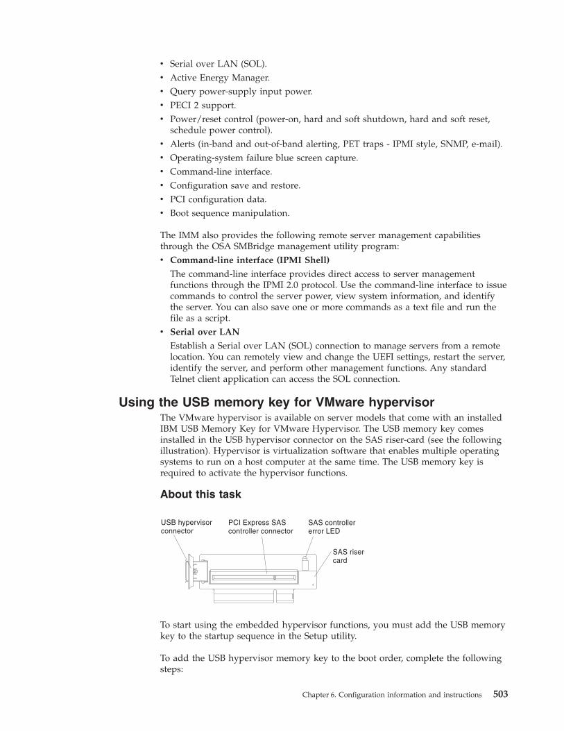
v Serial over LAN (SOL).v Active Energy Manager.v Query power-supply input power.v PECI 2 support.v Power/reset control (power-on, hard and soft shutdown, hard and soft reset,
schedule power control).v Alerts (in-band and out-of-band alerting, PET traps - IPMI style, SNMP, e-mail).v Operating-system failure blue screen capture.v Command-line interface.v Configuration save and restore.v PCI configuration data.v Boot sequence manipulation.
The IMM also provides the following remote server management capabilitiesthrough the OSA SMBridge management utility program:v Command-line interface (IPMI Shell)
The command-line interface provides direct access to server managementfunctions through the IPMI 2.0 protocol. Use the command-line interface to issuecommands to control the server power, view system information, and identifythe server. You can also save one or more commands as a text file and run thefile as a script.
v Serial over LAN
Establish a Serial over LAN (SOL) connection to manage servers from a remotelocation. You can remotely view and change the UEFI settings, restart the server,identify the server, and perform other management functions. Any standardTelnet client application can access the SOL connection.
Using the USB memory key for VMware hypervisorThe VMware hypervisor is available on server models that come with an installedIBM USB Memory Key for VMware Hypervisor. The USB memory key comesinstalled in the USB hypervisor connector on the SAS riser-card (see the followingillustration). Hypervisor is virtualization software that enables multiple operatingsystems to run on a host computer at the same time. The USB memory key isrequired to activate the hypervisor functions.
About this task
To start using the embedded hypervisor functions, you must add the USB memorykey to the startup sequence in the Setup utility.
To add the USB hypervisor memory key to the boot order, complete the followingsteps:
Chapter 6. Configuration information and instructions 503
Procedure1. Turn on the server.
Note: Approximately 3 minutes after the server is connected to ac power, thepower-control button becomes active.
2. When the prompt <F1> Setup is displayed, press F1.3. From the Setup utility main menu, select Boot Manager.4. Select Add Boot Option; then, select Hypervisor. Press Enter, and then press
Esc.5. Select Change Boot Order and then select Commit Changes; then, press Enter.6. Select Save Settings and then select Exit Setup.
Results
If the embedded hypervisor image becomes corrupt, you can use the VMwareRecovery CD that comes with the server to recover the image. To recover the flashdevice image, complete the following steps:1. Turn on the server.
Note: Approximately 3 minutes after the server is connected to ac power, thepower-control button becomes active.
2. Insert the VMware Recovery CD into the CD or DVD drive.3. Follow the instructions on the screen.
For additional information and instructions, see the VMware ESXi Server 3iEmbedded Setup Guide at http://www.vmware.com/pdf/vi3_35/esx_3i_e/r35/vi3_35_25_3i_setup.pdf/.
Using the remote presence capability and blue-screen captureThe remote presence and blue-screen capture features are integrated functions ofthe integrated management module (IMM). When an optional virtual media key isinstalled in the server, it activates full systems-management functions. The virtualmedia key is required to enable the integrated remote presence and blue-screencapture features. Without the virtual media key, you cannot remotely mount orunmount drives or images on the client system. However, you still can access theWeb interface without the key.
After the virtual media key is installed in the server, it is authenticated todetermine whether it is valid. If the key is not valid, you receive a message fromthe Web interface (when you attempt to start the remote presence feature)indicating that the hardware key is required to use the remote presence feature.
The virtual media key has an LED. When this LED is lit and green, it indicates thatthe key is installed and functioning correctly.
The remote presence feature provides the following functions:v Remotely viewing video with graphics resolutions up to 1600 x 1200 at 75 Hz,
regardless of the system statev Remotely accessing the server, using the keyboard and mouse from a remote
client
504 System x3650 M3 Types 4255, 7945, and 7949: Problem Determination and Service Guide
v Mapping the CD or DVD drive, diskette drive, and USB flash drive on a remoteclient, and mapping ISO and diskette image files as virtual drives that areavailable for use by the server
v Uploading a diskette image to the IMM memory and mapping it to the server asa virtual drive
The blue-screen capture feature captures the video display contents before the IMMrestarts the server when the IMM detects an operating-system hang condition. Asystem administrator can use the blue-screen capture to assist in determining thecause of the hang condition.
Enabling the remote presence featureUse this information to enable the remote presence feature.
About this task
To enable the remote presence feature, complete the following steps:
Procedure1. Install the virtual media key into the dedicated slot on the system board (see
“Replacing an IBM virtual media key” on page 411).2. Turn on the server.
Note: Approximately 3 minutes after the server is connected to ac power, thepower-control button becomes active.
Obtaining the IP address for the Web interface accessTo access the Web interface and use the remote presence feature, you need the IPaddress for the IMM. You can obtain the IMM IP address through the Setup utility.
About this task
To locate the IP address, complete the following steps:
Procedure1. Turn on the server.
Note: Approximately 3 minutes after the server is connected to ac power, thepower-control button becomes active.
2. When the prompt <F1> Setup is displayed, press F1. If you have set both apower-on password and an administrator password, you must type theadministrator password to access the full Setup utility menu.
3. From the Setup utility main menu, select System Settings.4. On the next screen, select Integrated Management Module.5. On the next screen, select Network Configuration.6. Find the IP address and write it down.7. Exit from the Setup utility.
Chapter 6. Configuration information and instructions 505

Logging on to the Web interfaceUse this information to log on to the web interface.
About this task
To log on to the Web interface to use the remote presence functions, complete thefollowing steps:
Procedure1. Open a Web browser on a computer that connects to the server and in the
address or URL field, type the IP address or host name of the IMM to whichyou want to connect.
Note:
a. If you are logging in to the IMM for the first time after installation, theIMM defaults to DHCP. If a DHCP host is not available, the IMM uses thedefault static IP address 192.168.70.125.
b. You can obtain the DHCP-assigned IP address or the static IP address fromthe server UEFI or from your network administrator.
The Login page is displayed.2. Type the user name and password. If you are using the IMM for the first time,
you can obtain the user name and password from your system administrator.All login attempts are documented in the event log. A welcome page opens inthe browser.
Note: The IMM is set initially with a user name of USERID and password ofPASSW0RD (passw0rd with a zero, not the letter O). You have read/writeaccess. For enhanced security, change this default password during the initialconfiguration.
3. On the Welcome page, type a timeout value (in minutes) in the field that isprovided. The IMM will log you off the Web interface if your browser isinactive for the number of minutes that you entered for the timeout value.
4. Click Continue to start the session. The browser opens the System Status page,which displays the server status and the server health summary.
Enabling the Broadcom Gigabit Ethernet Utility programThe Broadcom Gigabit Ethernet Utility program is part of the server firmware. Youcan use it to configure the network as a startable device, and you can customizewhere the network startup option appears in the startup sequence. Enable anddisable the Broadcom Gigabit Ethernet Utility program from the Setup utility.
506 System x3650 M3 Types 4255, 7945, and 7949: Problem Determination and Service Guide

Configuring the Gigabit Ethernet controllerThe Ethernet controllers are integrated on the system board. They provide aninterface for connecting to a 10 Mbps, 100 Mbps, or 1 Gbps network and providefull-duplex (FDX) capability, which enables simultaneous transmission andreception of data on the network. If the Ethernet ports in the server supportauto-negotiation, the controllers detect the data-transfer rate (10BASE-T,100BASE-TX, or 1000BASE-T) and duplex mode (full-duplex or half-duplex) of thenetwork and automatically operate at that rate and mode.
About this task
You do not have to set any jumpers or configure the controllers. However, youmust install a device driver to enable the operating system to address thecontrollers. To find updated information about configuring the controllers,complete the following steps.
Note: Changes are made periodically to the IBM Web site. The actual proceduremight vary slightly from what is described in this document.
Procedure1. Go to http://www.ibm.com/systems/support/.2. Under Product support, click System x.3. Under Popular links, click Software and device drivers.4. From the Product family menu, select System x3650 M3 and click Go.
Using the LSI Configuration Utility programUse the LSI Configuration Utility program to configure and manage redundantarray of independent disks (RAID) arrays.
Be sure to use this program as described in this document.v Use the LSI Configuration Utility program to perform the following tasks:
– Perform a low-level format on a hard disk drive– Create an array of hard disk drives with or without a hot-spare drive– Set protocol parameters on hard disk drives
The integrated SAS/SATA controller with RAID capabilities supports RAID arrays.You can use the LSI Configuration Utility program to configure RAID 1 (IM),RAID 1E (IME), and RAID 0 (IS) for a single pair of attached devices. If you installa different type of RAID adapter, follow the instructions in the documentation thatcomes with the adapter to view or change settings for attached devices.
In addition, you can download an LSI command-line configuration program fromhttp://www.ibm.com/systems/support/.
When you are using the LSI Configuration Utility program to configure andmanage arrays, consider the following information:v The integrated SAS/SATA controller with RAID capabilities supports the
following features:– Integrated Mirroring (IM) with hot-spare support (also known as RAID 1)
Use this option to create an integrated array of two disks plus up to twooptional hot spares. All data on the primary disk can be migrated.
Chapter 6. Configuration information and instructions 507
– Integrated Mirroring Enhanced (IME) with hot-spare support (also known asRAID 1E)Use this option to create an integrated mirror enhanced array of three to eightdisks, including up to two optional hot spares. All data on the array diskswill be deleted.
– Integrated Striping (IS) (also known as RAID 0)Use this option to create an integrated striping array of two to eight disks. Alldata on the array disks will be deleted.
v Hard disk drive capacities affect how you create arrays. The drives in an arraycan have different capacities, but the RAID controller treats them as if they allhave the capacity of the smallest hard disk drive.
v If you use an integrated SAS/SATA controller with RAID capabilities toconfigure a RAID 1 (mirrored) array after you have installed the operatingsystem, you will lose access to any data or applications that were previouslystored on the secondary drive of the mirrored pair.
v If you install a different type of RAID controller, see the documentation thatcomes with the controller for information about viewing and changing settingsfor attached devices.
Starting the LSI Configuration Utility programUse this information to start the LSI Configuration Utility program.
About this task
To start the LSI Configuration Utility program, complete the following steps:
Procedure1. Turn on the server.
Note: Approximately 3 minutes after the server is connected to ac power, thepower-control button becomes active.
2. When the prompt <F1> Setup is displayed, press F1. If you have set anadministrator password, you must type the administrator password to accessthe full Setup utility menu. If you do not type the administrator password, alimited Setup utility menu is available.
3. Select System Settings → Adapters and UEFI drivers.4. Select Please refresh this page first and press Enter.5. Select the device driver that is applicable for the SAS controller in the server.
For example, LSI Logic Fusion MPT SAS Driver.6. To perform storage-management tasks, see the SAS controller documentation,
which you can download from the Disk controller and RAID software matrix:a. Go to http://www.ibm.com/systems/support/.b. Under Product support, click System x.c. Under Popular links, click Storage Support Matrix.
Results
When you have finished changing settings, press Esc to exit from the program;select Save to save the settings that you have changed.
508 System x3650 M3 Types 4255, 7945, and 7949: Problem Determination and Service Guide
Formatting a hard disk driveLow-level formatting removes all data from the hard disk. If there is data on thedisk that you want to save, back up the hard disk before you perform thisprocedure.
About this task
Note: Before you format a hard disk, make sure that the disk is not part of amirrored pair.
To format a drive, complete the following steps:1. From the list of adapters, select the controller (channel) for the drive that you
want to format and press Enter.2. Select SAS Topology and press Enter.3. Select Direct Attach Devices and press Enter.4. To highlight the drive that you want to format, use the Up Arrow and Down
Arrow keys. To scroll left and right, use the Left Arrow and Right Arrow keysor the End key. Press Alt+D.
5. To start the low-level formatting operation, select Format and press Enter.
Creating a RAID array of hard disk drivesUse this information to create a RAID array of hard disk drives.
About this task
To create a RAID array of hard disk drives, complete the following steps:1. From the list of adapters, select the controller (channel) for which you want to
create an array.2. Select RAID Properties.3. Select the type of array that you want to create.4. In the RAID Disk column, use the Spacebar or Minus (-) key to select [Yes]
(select) or [No] (deselect) to select or deselect a drive from a RAID disk.5. Continue to select drives, using the Spacebar or Minus (-) key, until you have
selected all the drives for your array.6. Press C to create the disk array.7. Select Save changes then exit this menu to create the array.8. Exit the Setup utility.
Chapter 6. Configuration information and instructions 509
IBM Advanced Settings Utility programThe IBM Advanced Settings Utility (ASU) program is an alternative to the Setuputility for modifying UEFI settings. Use the ASU program online or out-of-band tomodify UEFI settings from the command line without the need to restart the serverto access the Setup utility.
You can also use the ASU program to configure the optional remote presencefeatures or other IMM settings. The remote presence features provide enhancedsystems-management capabilities.
In addition, the ASU program provides limited settings for configuring the IPMIfunction in the IMM through the command-line interface.
Use the command-line interface to issue setup commands. You can save any of thesettings as a file and run the file as a script. The ASU program supports scriptingenvironments through a batch-processing mode.
For more information and to download the ASU program, go tohttp://www.ibm.com/systems/support/.
Updating IBM Systems DirectorIf you plan to use IBM Systems Director to manage the server, you must check forthe latest applicable IBM Systems Director updates and interim fixes.
About this task
Note: Changes are made periodically to the IBM Web site. The actual proceduremight vary slightly from what is described in this document.
To locate and install a newer version of IBM Systems Director, complete thefollowing steps:
Procedure1. Check for the latest version of IBM Systems Director:
a. Go to http://www.ibm.com/systems/management/director/downloads.html.
b. If a newer version of IBM Systems Director than what comes with theserver is shown in the drop-down list, follow the instructions on the Webpage to download the latest version.
2. Install the IBM Systems Director program.
Results
If your management server is connected to the Internet, to locate and installupdates and interim fixes, complete the following steps:1. Make sure that you have run the Discovery and Inventory collection tasks.2. On the Welcome page of the IBM Systems Director Web interface, click View
updates.3. Click Check for updates. The available updates are displayed in a table.4. Select the updates that you want to install, and click Install to start the
installation wizard.
510 System x3650 M3 Types 4255, 7945, and 7949: Problem Determination and Service Guide
If your management server is not connected to the Internet, to locate and installupdates and interim fixes, complete the following steps:1. Make sure that you have run the Discovery and Inventory collection tasks.2. On a system that is connected to the Internet, go to http://www.ibm.com/
support/fixcentral/.3. From the Product family list, select IBM Systems Director.4. From the Product list, select IBM Systems Director.5. From the Installed version list, select the latest version, and click Continue.6. Download the available updates.7. Copy the downloaded files to the management server.8. On the management server, on the Welcome page of the IBM Systems Director
Web interface, click the Manage tab, and click Update Manager.9. Click Import updates and specify the location of the downloaded files that
you copied to the management server.10. Return to the Welcome page of the Web interface, and click View updates.11. Select the updates that you want to install, and click Install to start the
installation wizard.
Updating the Universal Unique Identifier (UUID)The Universal Unique Identifier (UUID) must be updated when the system boardis replaced. Use the Advanced Settings Utility to update the UUID in theUEFI-based server. The ASU is an online tool that supports several operatingsystems. Make sure that you download the version for your operating system. Youcan download the ASU from the IBM Web site.
About this task
To download the ASU and update the UUID, complete the following steps.:
Note: Changes are made periodically to the IBM Web site. The actual proceduremight vary slightly from what is described in this document.
Procedure1. Download the Advanced Settings Utility (ASU):
a. Go to http://www.ibm.com/systems/support/.b. Under Product support, select System x.c. Under Popular links, select Tools and utilities.d. In the left pane, click System x and BladeCenter Tools Center.e. Scroll down and click Tools reference.f. Scroll down and click the plus-sign (+) for Configuration tools to expand the
list; then, select Advanced Settings Utility (ASU).g. In the next window under Related Information, click the Advanced Settings
Utility link and download the ASU version for your operating system.2. ASU sets the UUID in the Integrated Management Module (IMM). Select one of
the following methods to access the Integrated Management Module (IMM) toset the UUID:v Online from the target system (LAN or keyboard console style (KCS) access)v Remote access to the target system (LAN based)
Chapter 6. Configuration information and instructions 511
v Bootable media containing ASU (LAN or KCS, depending upon the bootablemedia)
3. Copy and unpack the ASU package, which also includes other required files, tothe server. Make sure that you unpack the ASU and the required files to thesame directory. In addition to the application executable (asu or asu64), thefollowing files are required:v For Windows based operating systems:
– ibm_rndis_server_os.inf– device.cat
v For Linux based operating systems:– cdc_interface.sh
4. After you install ASU, use the following command syntax to set the UUID:asu set SYSTEM_PROD_DATA.SysInfoUUID <uuid_value> [access_method]
Where:
<uuid_value>Up to 16-byte hexadecimal value assigned by you.
[access_method]The access method that you selected to use from the followingmethods:
v Online authenticated LAN access, type the command:[host <imm_internal_ip>] [user <imm_user_id>][password <imm_password>]
Where:
imm_internal_ipThe IMM internal LAN/USB IP address. The default value is169.254.95.118.
imm_user_idThe IMM account (1 of 12 accounts). The default value is USERID.
imm_passwordThe IMM account password (1 of 12 accounts). The default value isPASSW0RD (with a zero 0 not an O).
Note: If you do not specify any of these parameters, ASU will use thedefault values. When the default values are used and ASU is unable to accessthe IMM using the online authenticated LAN access method, ASU willautomatically use the unauthenticated KCS access method.The following commands are examples of using the userid and passworddefault values and not using the default values:
Example that does not use the userid and password default values:asu set SYSTEM_PROD_DATA.SYsInfoUUID <uuid_value> user <user_id>password <password>
Example that does use the userid and password default values:asu set SYSTEM_PROD_DATA.SysInfoUUID <uuid_value>
v Online KCS access (unauthenticated and user restricted):You do not need to specify a value for access_method when you use thisaccess method.
Example:asu set SYSTEM_PROD_DATA.SysInfoUUID <uuid_value>
512 System x3650 M3 Types 4255, 7945, and 7949: Problem Determination and Service Guide
The KCS access method uses the IPMI/KCS interface. This method requiresthat the IPMI driver be installed. Some operating systems have the IPMIdriver installed by default. ASU provides the corresponding mapping layer.See the Advanced Settings Utility Users Guide for more details. You can accessthe ASU Users Guide from the IBM Web site.
Note: Changes are made periodically to the IBM Web site. The actualprocedure might vary slightly from what is described in this document.a. Go to http://www.ibm.com/systems/support/.b. Under Product support, select System x.c. Under Popular links, select Tools and utilities.d. In the left pane, click System x and BladeCenter Tools Center.e. Scroll down and click Tools reference.f. Scroll down and click the plus-sign (+) for Configuration tools to expand
the list; then, select Advanced Settings Utility (ASU).g. In the next window under Related Information, click the Advanced
Settings Utility link.v Remote LAN access, type the command:
Note: When using the remote LAN access method to access IMM using theLAN from a client, the host and the imm_external_ip address are requiredparameters.host <imm_external_ip> [user <imm_user_id>[[password <imm_password>]
Where:
imm_external_ipThe external IMM LAN IP address. There is no default value. Thisparameter is required.
imm_user_idThe IMM account (1 of 12 accounts). The default value is USERID.
imm_passwordThe IMM account password (1 of 12 accounts). The default value isPASSW0RD (with a zero 0 not an O).
The following commands are examples of using the userid and passworddefault values and not using the default values:
Example that does not use the userid and password default values:asu set SYSTEM_PROD_DATA.SYsInfoUUID <uuid_value> host <imm_ip>user <user_id> password <password>
Example that does use the userid and password default values:asu set SYSTEM_PROD_DATA.SysInfoUUID <uuid_value> host <imm_ip>
v Bootable media:You can also build a bootable media using the applications available throughthe Tools Center Web site at http://publib.boulder.ibm.com/infocenter/toolsctr/v1r0/index.jsp. From the left pane, click IBM System x andBladeCenter Tools Center, then click Tool reference for the available tools.
5. Restart the server.
Chapter 6. Configuration information and instructions 513
Updating the DMI/SMBIOS dataThe Desktop Management Interface (DMI) must be updated when the systemboard is replaced. Use the Advanced Settings Utility to update the DMI in theUEFI-based server. The ASU is an online tool that supports several operatingsystems.
Make sure that you download the version for your operating system. You candownload the ASU from the IBM Web site. To download the ASU and update theDMI, complete the following steps.
Note: Changes are made periodically to the IBM Web site. The actual proceduremight vary slightly from what is described in this document.1. Download the Advanced Settings Utility (ASU):
a. Go to http://www.ibm.com/systems/support/.b. Under Product support, select System x.c. Under Popular links, select Tools and utilities.d. In the left pane, click System x and BladeCenter Tools Center.e. Scroll down and click Tools reference.f. Scroll down and click the plus-sign (+) for Configuration tools to expand the
list; then, select Advanced Settings Utility (ASU).g. In the next window under Related Information, click the Advanced Settings
Utility link and download the ASU version for your operating system.2. ASU sets the DMI in the Integrated Management Module (IMM). Select one of
the following methods to access the Integrated Management Module (IMM) toset the DMI:v Online from the target system (LAN or keyboard console style (KCS) access)v Remote access to the target system (LAN based)v Bootable media containing ASU (LAN or KCS, depending upon the bootable
media)3. Copy and unpack the ASU package, which also includes other required files, to
the server. Make sure that you unpack the ASU and the required files to thesame directory. In addition to the application executable (asu or asu64), thefollowing files are required:v For Windows based operating systems:
– ibm_rndis_server_os.inf– device.cat
v For Linux based operating systems:– cdc_interface.sh
4. After you install ASU, type the following commands to set the DMI:
asu set SYSTEM_PROD_DATA.SysInfoProdName <m/t_model> [access_method]asu set SYSTEM_PROD_DATA.SysInfoProdIdentifier <system model> [access_method]asu set SYSTEM_PROD_DATA.SysInfoSerialNum <s/n> [access_method]asu set SYSTEM_PROD_DATA.SysEncloseAssetTag <asset_tag> [access_method]
Where:
<m/t_model>The server machine type and model number. Type mtm xxxxyy, wherexxxx is the machine type and yyy is the server model number.
514 System x3650 M3 Types 4255, 7945, and 7949: Problem Determination and Service Guide
<system model>The system model. Type system yyyyyyy, where yyyyyyy is the productidentifier such as x3650M3.
<s/n> The serial number on the server. Type sn zzzzzzz, where zzzzzzz is theserial number.
<asset_method>The server asset tag number. Type assetaaaaaaaaaaaaaaaaaaaaaaaaaaaaaaaaa, whereaaaaaaaaaaaaaaaaaaaaaaaaaaaaaaaaa is the asset tag number.
[access_method]The access method that you select to use from the following methods:
v Online authenticated LAN access, type the command:[host <imm_internal_ip>] [user <imm_user_id>][password <imm_password>]
Where:
imm_internal_ipThe IMM internal LAN/USB IP address. The default value is169.254.95.118.
imm_user_idThe IMM account (1 of 12 accounts). The default value is USERID.
imm_passwordThe IMM account password (1 of 12 accounts). The default value isPASSW0RD (with a zero 0 not an O).
Note: If you do not specify any of these parameters, ASU will use thedefault values. When the default values are used and ASU is unable to accessthe IMM using the online authenticated LAN access method, ASU willautomatically use the following unauthenticated KCS access method.The following commands are examples of using the userid and passworddefault values and not using the default values:
Examples that do not use the userid and password default values:asu set SYSTEM_PROD_DATA.SYsInfoProdName <m/t_model> user<imm_user_id> password <imm_password>asu set SYSTEM_PROD_DATA.SYsInfoProdIdentifier <system model> user<imm_user_id> password <imm_password>asu set SYSTEM_PROD_DATA.SYsInfoSerialNum <s/n> user<imm_user_id> password <imm_password>asu set SYSTEM_PROD_DATA.SYsEncloseAssetTag <asset_tag> user<imm_user_id> password <imm_password>
Examples that do use the userid and password default values:asu set SYSTEM_PROD_DATA.SysInfoProdName <m/t_model>asu set SYSTEM_PROD_DATA.SysInfoProdIdentifier <system model>asu set SYSTEM_PROD_DATA.SysInfoSerialNum <s/n>asu set SYSTEM_PROD_DATA.SysEncloseAssetTag <asset_tag>
v Online KCS access (unauthenticated and user restricted):You do not need to specify a value for access_method when you use thisaccess method.The KCS access method uses the IPMI/KCS interface. This method requiresthat the IPMI driver be installed. Some operating systems have the IPMIdriver installed by default. ASU provides the corresponding mapping layer.
Chapter 6. Configuration information and instructions 515
See the Advanced Settings Utility Users Guide at http:://www-947.ibm.com/systems/support/supportsite.wss/docdisplay?brandind=5000008&lndocid=MIGR-55021 for more details.The following commands are examples of using the userid and passworddefault values and not using the default values:
Examples that do not use the userid and password default values:asu set SYSTEM_PROD_DATA.SYsInfoProdName <m/t_model>asu set SYSTEM_PROD_DATA.SYsInfoProdIdentifier <system model>asu set SYSTEM_PROD_DATA.SYsInfoSerialNum <s/n>asu set SYSTEM_PROD_DATA.SYsEncloseAssetTag <asset_tag>
v Remote LAN access, type the command:
Note: When using the remote LAN access method to access IMM using theLAN from a client, the host and the imm_external_ip address are requiredparameters.host <imm_external_ip> [user <imm_user_id>[[password <imm_password>]
Where:
imm_external_ipThe external IMM LAN IP address. There is no default value. Thisparameter is required.
imm_user_idThe IMM account (1 of 12 accounts). The default value is USERID.
imm_passwordThe IMM account password (1 of 12 accounts). The default value isPASSW0RD (with a zero 0 not an O).
The following commands are examples of using the userid and passworddefault values and not using the default values:
Examples that do not use the userid and password default values:asu set SYSTEM_PROD_DATA.SYsInfoProdName <m/t_model> host <imm_ip>user <imm_user_id> password <imm_password>asu set SYSTEM_PROD_DATA.SYsInfoProdIdentifier <system model> host <imm_ip>user <imm_user_id> password <imm_password>asu set SYSTEM_PROD_DATA.SYsInfoSerialNum <s/n> host <imm_ip>user <imm_user_id> password <imm_password>asu set SYSTEM_PROD_DATA.SYsEncloseAssetTag <asset_tag> host <imm_ip>user <imm_user_id> password <imm_password>
Examples that do use the userid and password default values:asu set SYSTEM_PROD_DATA.SysInfoProdName <m/t_model> host <imm_ip>asu set SYSTEM_PROD_DATA.SysInfoProdIdentifier <system model> host <imm_ip>asu set SYSTEM_PROD_DATA.SysInfoSerialNum <s/n> host <imm_ip>asu set SYSTEM_PROD_DATA.SysEncloseAssetTag <asset_tag> host <imm_ip>
v Bootable media:You can also build a bootable media using the applications available throughthe Tools Center Web site at http://publib.boulder.ibm.com/infocenter/toolsctr/v1r0/index.jsp. From the left pane, click IBM System x andBladeCenter Tools Center, then click Tool reference for the available tools.
5. Restart the server.
516 System x3650 M3 Types 4255, 7945, and 7949: Problem Determination and Service Guide
Appendix A. Getting help and technical assistance
If you need help, service, or technical assistance or just want more informationabout IBM products, you will find a wide variety of sources available from IBM toassist you.
Use this information to obtain additional information about IBM and IBMproducts, determine what to do if you experience a problem with your IBM systemor optional device, and determine whom to call for service, if it is necessary.
Before you callBefore you call, make sure that you have taken these steps to try to solve theproblem yourself.
If you believe that you require IBM to perform warranty service on your IBMproduct, the IBM service technicians will be able to assist you more efficiently ifyou prepare before you call.v Check all cables to make sure that they are connected.v Check the power switches to make sure that the system and any optional
devices are turned on.v Check for updated software, firmware, and operating-system device drivers for
your IBM product. The IBM Warranty terms and conditions state that you, theowner of the IBM product, are responsible for maintaining and updating allsoftware and firmware for the product (unless it is covered by an additionalmaintenance contract). Your IBM service technician will request that youupgrade your software and firmware if the problem has a documented solutionwithin a software upgrade.
v If you have installed new hardware or software in your environment, checkhttp://www.ibm.com/systems/info/x86servers/serverproven/compat/us/ tomake sure that the hardware and software is supported by your IBM product.
v Go to http://www.ibm.com/supportportal to check for information to help yousolve the problem.
v Gather the following information to provide to IBM Support. This data will helpIBM Support quickly provide a solution to your problem and ensure that youreceive the level of service for which you might have contracted.– Hardware and Software Maintenance agreement contract numbers, if
applicable– Machine type number (IBM 4-digit machine identifier)– Model number– Serial number– Current system UEFI and firmware levels– Other pertinent information such as error messages and logs
v Go to http://www.ibm.com/support/entry/portal/Open_service_request tosubmit an Electronic Service Request. Submitting an Electronic Service Requestwill start the process of determining a solution to your problem by making thepertinent information available to IBM Support quickly and efficiently. IBMservice technicians can start working on your solution as soon as you havecompleted and submitted an Electronic Service Request.
© Copyright IBM Corp. 2014 517
You can solve many problems without outside assistance by following thetroubleshooting procedures that IBM provides in the online help or in thedocumentation that is provided with your IBM product. The documentation thatcomes with IBM systems also describes the diagnostic tests that you can perform.Most systems, operating systems, and programs come with documentation thatcontains troubleshooting procedures and explanations of error messages and errorcodes. If you suspect a software problem, see the documentation for the operatingsystem or program.
Using the documentationInformation about your IBM system and preinstalled software, if any, or optionaldevice is available in the documentation that comes with the product. Thatdocumentation can include printed documents, online documents, readme files,and help files.
See the troubleshooting information in your system documentation for instructionsfor using the diagnostic programs. The troubleshooting information or thediagnostic programs might tell you that you need additional or updated devicedrivers or other software. IBM maintains pages on the World Wide Web where youcan get the latest technical information and download device drivers and updates.To access these pages, go to http://www.ibm.com/supportportal.
Getting help and information from the World Wide WebUp-to-date information about IBM products and support is available on the WorldWide Web.
On the World Wide Web, up-to-date information about IBM systems, optionaldevices, services, and support is available at http://www.ibm.com/supportportal.IBM System x information is at http://www.ibm.com/systems/x/. IBMBladeCenter information is at http://www.ibm.com/systems/bladecenter. IBMIntelliStation information is at http://www.ibm.com/systems/intellistation.
How to send DSA data to IBMUse the IBM Enhanced Customer Data Repository to send diagnostic data to IBM.
Before you send diagnostic data to IBM, read the terms of use athttp://www.ibm.com/de/support/ecurep/terms.html.
You can use any of the following methods to send diagnostic data to IBM:v Standard upload: http://www.ibm.com/de/support/ecurep/send_http.htmlv Standard upload with the system serial number: http://www.ecurep.ibm.com/
app/upload_hwv Secure upload: http://www.ibm.com/de/support/ecurep/
send_http.html#securev Secure upload with the system serial number: https://www.ecurep.ibm.com/
app/upload_hw
518 System x3650 M3 Types 4255, 7945, and 7949: Problem Determination and Service Guide
Creating a personalized support web pageYou can create a personalized support web page by identifying IBM products thatare of interest to you.
To create a personalized support web page, go to http://www.ibm.com/support/mynotifications. From this personalized page, you can subscribe to weekly emailnotifications about new technical documents, search for information anddownloads, and access various administrative services.
Software service and supportThrough IBM Support Line, you can get telephone assistance, for a fee, with usage,configuration, and software problems with your IBM products.
For more information about Support Line and other IBM services, seehttp://www.ibm.com/services or see http://www.ibm.com/planetwide forsupport telephone numbers. In the U.S. and Canada, call 1-800-IBM-SERV(1-800-426-7378).
Hardware service and supportYou can receive hardware service through your IBM reseller or IBM Services.
To locate a reseller authorized by IBM to provide warranty service, go tohttp://www.ibm.com/partnerworld/ and click Business Partner Locator. For IBMsupport telephone numbers, see http://www.ibm.com/planetwide. In the U.S. andCanada, call 1-800-IBM-SERV (1-800-426-7378).
In the U.S. and Canada, hardware service and support is available 24 hours a day,7 days a week. In the U.K., these services are available Monday through Friday,from 9 a.m. to 6 p.m.
IBM Taiwan product serviceUse this information to contact IBM Taiwan product service.
IBM Taiwan product service contact information:
IBM Taiwan Corporation3F, No 7, Song Ren Rd.Taipei, TaiwanTelephone: 0800-016-888
Appendix A. Getting help and technical assistance 519

520 System x3650 M3 Types 4255, 7945, and 7949: Problem Determination and Service Guide
Appendix B. Notices
This information was developed for products and services offered in the U.S.A.
IBM may not offer the products, services, or features discussed in this document inother countries. Consult your local IBM representative for information on theproducts and services currently available in your area. Any reference to an IBMproduct, program, or service is not intended to state or imply that only that IBMproduct, program, or service may be used. Any functionally equivalent product,program, or service that does not infringe any IBM intellectual property right maybe used instead. However, it is the user's responsibility to evaluate and verify theoperation of any non-IBM product, program, or service.
IBM may have patents or pending patent applications covering subject matterdescribed in this document. The furnishing of this document does not give youany license to these patents. You can send license inquiries, in writing, to:
IBM Director of LicensingIBM CorporationNorth Castle DriveArmonk, NY 10504-1785U.S.A.
INTERNATIONAL BUSINESS MACHINES CORPORATION PROVIDES THISPUBLICATION “AS IS” WITHOUT WARRANTY OF ANY KIND, EITHEREXPRESS OR IMPLIED, INCLUDING, BUT NOT LIMITED TO, THE IMPLIEDWARRANTIES OF NON-INFRINGEMENT, MERCHANTABILITY OR FITNESSFOR A PARTICULAR PURPOSE. Some states do not allow disclaimer of express orimplied warranties in certain transactions, therefore, this statement may not applyto you.
This information could include technical inaccuracies or typographical errors.Changes are periodically made to the information herein; these changes will beincorporated in new editions of the publication. IBM may make improvementsand/or changes in the product(s) and/or the program(s) described in thispublication at any time without notice.
Any references in this information to non-IBM websites are provided forconvenience only and do not in any manner serve as an endorsement of thosewebsites. The materials at those websites are not part of the materials for this IBMproduct, and use of those websites is at your own risk.
IBM may use or distribute any of the information you supply in any way itbelieves appropriate without incurring any obligation to you.
© Copyright IBM Corp. 2014 521
TrademarksIBM, the IBM logo, and ibm.com are trademarks of International BusinessMachines Corp., registered in many jurisdictions worldwide. Other product andservice names might be trademarks of IBM or other companies.
A current list of IBM trademarks is available on the web at http://www.ibm.com/legal/us/en/copytrade.shtml.
Adobe and PostScript are either registered trademarks or trademarks of AdobeSystems Incorporated in the United States and/or other countries.
Cell Broadband Engine is a trademark of Sony Computer Entertainment, Inc., inthe United States, other countries, or both and is used under license therefrom.
Intel, Intel Xeon, Itanium, and Pentium are trademarks or registered trademarks ofIntel Corporation or its subsidiaries in the United States and other countries.
Java and all Java-based trademarks and logos are trademarks or registeredtrademarks of Oracle and/or its affiliates.
Linux is a registered trademark of Linus Torvalds in the United States, othercountries, or both.
Microsoft, Windows, and Windows NT are trademarks of Microsoft Corporation inthe United States, other countries, or both.
UNIX is a registered trademark of The Open Group in the United States and othercountries.
Important notesProcessor speed indicates the internal clock speed of the microprocessor; otherfactors also affect application performance.
CD or DVD drive speed is the variable read rate. Actual speeds vary and are oftenless than the possible maximum.
When referring to processor storage, real and virtual storage, or channel volume,KB stands for 1024 bytes, MB stands for 1,048,576 bytes, and GB stands for1,073,741,824 bytes.
When referring to hard disk drive capacity or communications volume, MB standsfor 1,000,000 bytes, and GB stands for 1,000,000,000 bytes. Total user-accessiblecapacity can vary depending on operating environments.
Maximum internal hard disk drive capacities assume the replacement of anystandard hard disk drives and population of all hard disk drive bays with thelargest currently supported drives that are available from IBM.
Maximum memory might require replacement of the standard memory with anoptional memory module.
Each solid-state memory cell has an intrinsic, finite number of write cycles that thecell can incur. Therefore, a solid-state device has a maximum number of writecycles that it can be subjected to, expressed as total bytes written (TBW). A
522 System x3650 M3 Types 4255, 7945, and 7949: Problem Determination and Service Guide
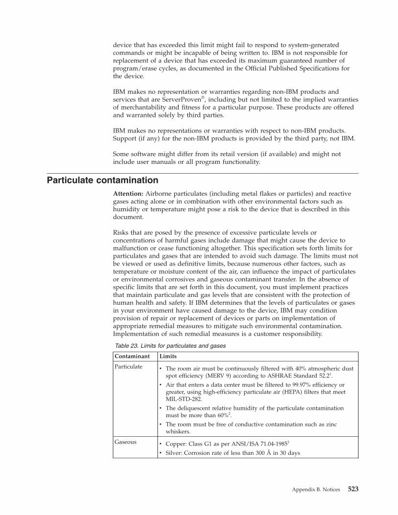
device that has exceeded this limit might fail to respond to system-generatedcommands or might be incapable of being written to. IBM is not responsible forreplacement of a device that has exceeded its maximum guaranteed number ofprogram/erase cycles, as documented in the Official Published Specifications forthe device.
IBM makes no representation or warranties regarding non-IBM products andservices that are ServerProven®, including but not limited to the implied warrantiesof merchantability and fitness for a particular purpose. These products are offeredand warranted solely by third parties.
IBM makes no representations or warranties with respect to non-IBM products.Support (if any) for the non-IBM products is provided by the third party, not IBM.
Some software might differ from its retail version (if available) and might notinclude user manuals or all program functionality.
Particulate contaminationAttention: Airborne particulates (including metal flakes or particles) and reactivegases acting alone or in combination with other environmental factors such ashumidity or temperature might pose a risk to the device that is described in thisdocument.
Risks that are posed by the presence of excessive particulate levels orconcentrations of harmful gases include damage that might cause the device tomalfunction or cease functioning altogether. This specification sets forth limits forparticulates and gases that are intended to avoid such damage. The limits must notbe viewed or used as definitive limits, because numerous other factors, such astemperature or moisture content of the air, can influence the impact of particulatesor environmental corrosives and gaseous contaminant transfer. In the absence ofspecific limits that are set forth in this document, you must implement practicesthat maintain particulate and gas levels that are consistent with the protection ofhuman health and safety. If IBM determines that the levels of particulates or gasesin your environment have caused damage to the device, IBM may conditionprovision of repair or replacement of devices or parts on implementation ofappropriate remedial measures to mitigate such environmental contamination.Implementation of such remedial measures is a customer responsibility.
Table 23. Limits for particulates and gases
Contaminant Limits
Particulate v The room air must be continuously filtered with 40% atmospheric dustspot efficiency (MERV 9) according to ASHRAE Standard 52.21.
v Air that enters a data center must be filtered to 99.97% efficiency orgreater, using high-efficiency particulate air (HEPA) filters that meetMIL-STD-282.
v The deliquescent relative humidity of the particulate contaminationmust be more than 60%2.
v The room must be free of conductive contamination such as zincwhiskers.
Gaseous v Copper: Class G1 as per ANSI/ISA 71.04-19853
v Silver: Corrosion rate of less than 300 Å in 30 days
Appendix B. Notices 523
Table 23. Limits for particulates and gases (continued)
Contaminant Limits
1 ASHRAE 52.2-2008 - Method of Testing General Ventilation Air-Cleaning Devices forRemoval Efficiency by Particle Size. Atlanta: American Society of Heating, Refrigeratingand Air-Conditioning Engineers, Inc.2 The deliquescent relative humidity of particulate contamination is the relativehumidity at which the dust absorbs enough water to become wet and promote ionicconduction.3 ANSI/ISA-71.04-1985. Environmental conditions for process measurement and controlsystems: Airborne contaminants. Instrument Society of America, Research Triangle Park,North Carolina, U.S.A.
Documentation formatThe publications for this product are in Adobe Portable Document Format (PDF)and should be compliant with accessibility standards. If you experience difficultieswhen you use the PDF files and want to request a web-based format or accessiblePDF document for a publication, direct your mail to the following address:
Information DevelopmentIBM Corporation205/A0153039 E. Cornwallis RoadP.O. Box 12195Research Triangle Park, North Carolina 27709-2195U.S.A.
In the request, be sure to include the publication part number and title.
When you send information to IBM, you grant IBM a nonexclusive right to use ordistribute the information in any way it believes appropriate without incurring anyobligation to you.
Telecommunication regulatory statement
This product may not be certified in your country for connection by any meanswhatsoever to interfaces of public telecommunications networks. Furthercertification may be required by law prior to making any such connection. Contactan IBM representative or reseller for any questions.
524 System x3650 M3 Types 4255, 7945, and 7949: Problem Determination and Service Guide

Electronic emission noticesWhen you attach a monitor to the equipment, you must use the designatedmonitor cable and any interference suppression devices that are supplied with themonitor.
Federal Communications Commission (FCC) statementNote: This equipment has been tested and found to comply with the limits for aClass A digital device, pursuant to Part 15 of the FCC Rules. These limits aredesigned to provide reasonable protection against harmful interference when theequipment is operated in a commercial environment. This equipment generates,uses, and can radiate radio frequency energy and, if not installed and used inaccordance with the instruction manual, may cause harmful interference to radiocommunications. Operation of this equipment in a residential area is likely to causeharmful interference, in which case the user will be required to correct theinterference at his own expense.
Properly shielded and grounded cables and connectors must be used in order tomeet FCC emission limits. IBM is not responsible for any radio or televisioninterference caused by using other than recommended cables and connectors or byunauthorized changes or modifications to this equipment. Unauthorized changesor modifications could void the user's authority to operate the equipment.
This device complies with Part 15 of the FCC Rules. Operation is subject to thefollowing two conditions: (1) this device may not cause harmful interference, and(2) this device must accept any interference received, including interference thatmight cause undesired operation.
Industry Canada Class A emission compliance statementThis Class A digital apparatus complies with Canadian ICES-003.
Avis de conformité à la réglementation d'Industrie CanadaCet appareil numérique de la classe A est conforme à la norme NMB-003 duCanada.
Australia and New Zealand Class A statement
Attention: This is a Class A product. In a domestic environment this product maycause radio interference in which case the user may be required to take adequatemeasures.
Appendix B. Notices 525

European Union EMC Directive conformance statementThis product is in conformity with the protection requirements of EU CouncilDirective 2004/108/EC on the approximation of the laws of the Member Statesrelating to electromagnetic compatibility. IBM cannot accept responsibility for anyfailure to satisfy the protection requirements resulting from a nonrecommendedmodification of the product, including the fitting of non-IBM option cards.
Attention: This is an EN 55022 Class A product. In a domestic environment thisproduct may cause radio interference in which case the user may be required totake adequate measures.
Responsible manufacturer:
International Business Machines Corp.New Orchard RoadArmonk, New York 10504914-499-1900
European Community contact:
IBM Deutschland GmbHTechnical Regulations, Department M372IBM-Allee 1, 71139 Ehningen, GermanyTelephone: +49 7032 15 2941Email: [email protected]
Germany Class A statementDeutschsprachiger EU Hinweis: Hinweis für Geräte der Klasse A EU-Richtliniezur Elektromagnetischen Verträglichkeit
Dieses Produkt entspricht den Schutzanforderungen der EU-Richtlinie2004/108/EG zur Angleichung der Rechtsvorschriften über die elektromagnetischeVerträglichkeit in den EU-Mitgliedsstaaten und hält die Grenzwerte der EN 55022Klasse A ein.
Um dieses sicherzustellen, sind die Geräte wie in den Handbüchern beschrieben zuinstallieren und zu betreiben. Des Weiteren dürfen auch nur von der IBMempfohlene Kabel angeschlossen werden. IBM übernimmt keine Verantwortung fürdie Einhaltung der Schutzanforderungen, wenn das Produkt ohne Zustimmung derIBM verändert bzw. wenn Erweiterungskomponenten von Fremdherstellern ohneEmpfehlung der IBM gesteckt/eingebaut werden.
EN 55022 Klasse A Geräte müssen mit folgendem Warnhinweis versehen werden:Warnung: Dieses ist eine Einrichtung der Klasse A. Diese Einrichtung kann imWohnbereich Funk-Störungen verursachen; in diesem Fall kann vom Betreiberverlangt werden, angemessene Maßnahmen zu ergreifen und dafür aufzukommen.
Deutschland: Einhaltung des Gesetzes über dieelektromagnetische Verträglichkeit von Geräten
Dieses Produkt entspricht dem Gesetz über die elektromagnetische Verträglichkeitvon Geräten (EMVG). Dies ist die Umsetzung der EU-Richtlinie 2004/108/EG inder Bundesrepublik Deutschland.
526 System x3650 M3 Types 4255, 7945, and 7949: Problem Determination and Service Guide
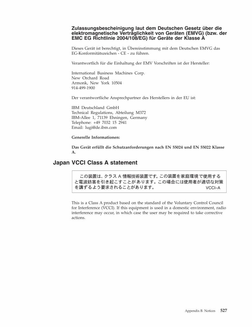
Zulassungsbescheinigung laut dem Deutschen Gesetz über dieelektromagnetische Verträglichkeit von Geräten (EMVG) (bzw. derEMC EG Richtlinie 2004/108/EG) für Geräte der Klasse A
Dieses Gerät ist berechtigt, in Übereinstimmung mit dem Deutschen EMVG dasEG-Konformitätszeichen - CE - zu führen.
Verantwortlich für die Einhaltung der EMV Vorschriften ist der Hersteller:
International Business Machines Corp.New Orchard RoadArmonk, New York 10504914-499-1900
Der verantwortliche Ansprechpartner des Herstellers in der EU ist:
IBM Deutschland GmbHTechnical Regulations, Abteilung M372IBM-Allee 1, 71139 Ehningen, GermanyTelephone: +49 7032 15 2941Email: [email protected]
Generelle Informationen:
Das Gerät erfüllt die Schutzanforderungen nach EN 55024 und EN 55022 KlasseA.
Japan VCCI Class A statement
This is a Class A product based on the standard of the Voluntary Control Councilfor Interference (VCCI). If this equipment is used in a domestic environment, radiointerference may occur, in which case the user may be required to take correctiveactions.
Appendix B. Notices 527
Japan Electronics and Information Technology IndustriesAssociation (JEITA) statement
Japan Electronics and Information Technology Industries Association (JEITA)Confirmed Harmonics Guidelines with Modifications (products greater than 20 Aper phase)
Korea Communications Commission (KCC) statement
This is electromagnetic wave compatibility equipment for business (Type A). Sellersand users need to pay attention to it. This is for any areas other than home.
Russia Electromagnetic Interference (EMI) Class A statement
People's Republic of China Class A electronic emissionstatement
528 System x3650 M3 Types 4255, 7945, and 7949: Problem Determination and Service Guide
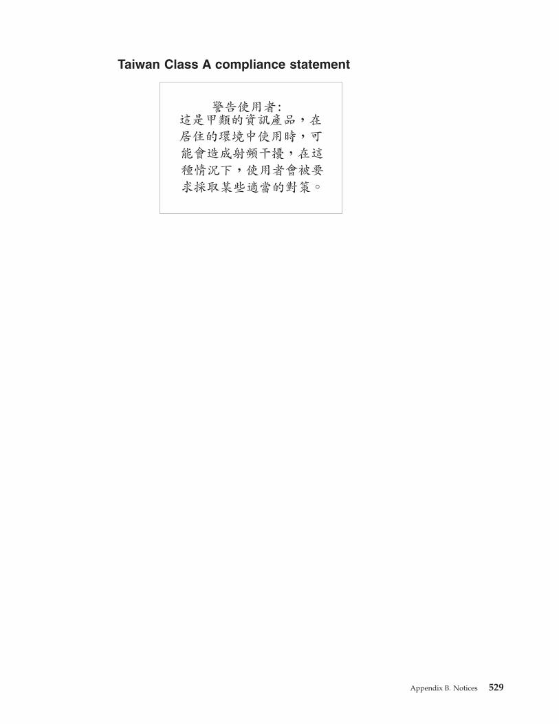
Taiwan Class A compliance statement
Appendix B. Notices 529

530 System x3650 M3 Types 4255, 7945, and 7949: Problem Determination and Service Guide
Index
Numerics240 VA safety cover
installing 489removing 488
AABR, automatic boot failure
recovery 375ac power LED 14accessible documentation 524acoustical noise emissions 7adapter
installing 418removing 417
adapter bracket, storing 424administrator password 494Advanced Settings Utility (ASU)
program, overview 510air baffle
DIMMremoving 406replacing 407
microprocessorremoving 404replacing 405
assertion event, system-event log 28assistance, getting 517attention notices 6Australia Class A statement 525automatic boot failure recovery
(ABR) 375
Bbattery
connector 17replacing 463, 465
before you install a legacy operatingsystem 501
bezelinstalling 469removing 468
blue-screen capture feature,overview 504
boot selection menu program, using 499Broadcom 506Broadcom Gigabit Ethernet Utility
program 506
Ccable
connectors 398routing, internal 398
cable connectors 17cabling
system-board external connectors 18system-board internal connectors 17
Canada Class A electronic emissionstatement 525
caution statements 6CD drive 444CD-RW/DVD drive
installing 445removing 444
CD/DVD driveproblems 341
CD/DVD drive activity LED 11checkout procedure 338
description 338performing 339
China Class A electronic emissionstatement 528
Class A electronic emission notice 525collecting data 1configuration
Nx boot failure 375updating server 492with ServerGuide 501
configuration programsLSI Configuration Utility 492
configuringserver 491
connectorsbattery 17cable 17DIMMs 17external port 18fans 17for options on the system board 24hard disk drive 24internal 17memory 17microprocessor 17PCI 17PCI riser-card adapter 25port 18SAS riser-card 24system board 17tape drive 24
consumable parts 381consumable parts, removing and
replacing 402contamination, particulate and
gaseous 7, 523controller, configuring Ethernet 507controls and LEDs
front view 11on light path diagnostics panel 13operator information panel 12rear view 14
cooling 7cover
installing 403removing 402
creating a personalized support webpage 519
creating, RAID array 509
CRUs, replacingbattery 463CD-RW/DVD drive 445cover 403DIMMs 448memory 448
custom support web page 519customer replaceable units (CRUs) 381
Ddanger statements 6data collection 1dc power supply LED errors 367deassertion event, system-event log 28diagnostic
error codes 289on-board programs, starting 287programs, overview 287test log, viewing 288text message 288tools, overview 27
diagnostic event log 28diagnostic programs, running 287Diagnostics 27diagnostics panel, controls and LEDs 13DIMM installation sequence
for memory mirroring 455DIMMs
installation sequence for memorymirroring 453
installing 456order of installation 453removing 448types supported 450
display problems 349DMI/SMBIOS data, updating 514documentation
format 524using 518
documentation, related 5drive, installing hot-swap 440drive, installing simple-swap 443DSA preboot messages 289DSA, sending data to IBM 518DVD drive 444DVD drive problems 341Dynamic System Analysis (DSA) 287
Eelectrical equipment, servicing xelectrical input 7electronic emission Class A notice 525electrostatic-discharge wrist strap,
using 398embedded hypervisor, using 503enclosure manager heartbeat LED 23environment 7
© Copyright IBM Corp. 2014 531
error codes and messagesdiagnostic 289messages, diagnostic 287POST 274
error messages 31integrated management module 31
error symptomsgeneral 342intermittent 345keyboard, USB 346memory 347microprocessor 349monitor 349mouse, USB 346optional devices 352pointing device, USB 346power 353serial port 357ServerGuide 358software 359USB port 359
errorsdc power supply LEDs 367format, diagnostic code 288power supply LEDs 367
Ethernetadapter, installing 421adapter, removing 420controller, troubleshooting 377systems-management connector 14
Ethernet activity LED 12, 14Ethernet connector 14Ethernet controller, configuring 507Ethernet-link LED 14Ethernet-link status LED 12European Union EMC Directive
conformance statement 526event logs 28event logs, viewing methods 29
Ffan
installing 458removing 457, 459
fan bracketinstalling 409removing 408
FCC Class A notice 525features 7
and specifications 7IMM 502remote presence 504ServerGuide 500
field replaceable units (FRUs) 381firmware
recovering server 371updating 491
firmware updates 499flags, tape alert 370formatting a hard disk drive 509FRUs, removing
and replacing 474FRUs, replacing
heat-sink retention module 483microprocessor 477
FRUs, replacing (continued)operator information panel
assembly 466system board 484
full-length-adapter bracket, storing 424
Ggaseous contamination 7, 523General problems 342Germany Class A statement 526gigabit Ethernet controller,
configuring 507grease, thermal 482guidelines
servicing electrical equipment xtrained service technicians ix
Hhard disk drive
formatting 509installing 440, 443problems 342removing 440, 442
hard disk drive backplane,removing 469
hard disk drive backplate, removing 472hardware service and support telephone
numbers 519heat output 7heat sink
applying thermal grease 477installing 477removing 474
heat-sink retention moduleinstalling 483removing 483
helpfrom the World Wide Web 518from World Wide Web 518sending diagnostic data to IBM 518sources of 517
hot-swapfan 458
removing 459hard disk drive 440power supplies 460power supply, installing 460
humidity 7hypervisor
problems 344hypervisor memory key
using 503Hypervisor problems 344
IIBM Advanced Settings Utility program,
overview 510IBM Systems Director
updating 510IBM Taiwan product service 519IMM
event log 28using 502
IMM heartbeat LED 23important notices 6, 522IN OK LED 367IN OK power LED 14information center 518information LED 12inspecting for unsafe conditions ixinstallation guidelines 395installing
240 VA safety cover 489battery 465bezel 469CD-RW/DVD drive 445cover 403DIMMs 456Ethernet adapter 421fan bracket 409fans 458hard disk drive 440heat sink 477heat-sink retention module 483hot-swap drive 440microprocessor 477operator-information panel 467PCI adapter 418PCI riser card 415SAS hard disk drive backplane 471SAS hard disk drive backplate 473SAS riser-card and controller
assembly 426ServeRAID adapter advanced feature
key 434ServeRAID SAS controller 431ServeRAID SAS controller
battery 438simple-swap drive 443simple-swap hard disk drive 443system board 486tape drive 447USB hypervisor memory key 413virtual media key 411
integrated management module errormessages 31
intermittent problems 345internal cable routing 398Internal connectors 17IP address, obtaining for Web
interface 505
JJapan Class A electronic emission
statement 527Japan Electronics and Information
Technology Industries Associationstatement 528
JEITA statement 528jumpers 17jumpers, description
for system board 18
KKorea Class A electronic emission
statement 528
532 System x3650 M3 Types 4255, 7945, and 7949: Problem Determination and Service Guide
LLED errors
dc power supply 367LEDs 11, 17
ac power 14enclosure manager heartbeat 23Ethernet activity 12, 14Ethernet icon LED 12Ethernet link 14Ethernet-link status 12IMM heartbeat 23IN OK power 14information 12LEDs
Ethernet icon 12light path diagnostics 363locator 12, 14OUT OK power 14power supply 367power-channel error 376power-on 12, 14riser-card assembly 26system board 22system error 12system pulse 23system-error 14
LEDs and controlsfront view 11on light path diagnostics panel 13operator information panel 12rear view 14
legacy operating systemrequirement 501
Licenses and Attributions Documents 5light path diagnostics
description 360LEDs 363panel 360
light path diagnostics panelaccessing 13
Linux license agreement 5locator LED 12, 14logs
event 28system event message 31viewing test 288
LSI Configuration Utilityoverview 507starting 508
Mmemory
two-DIMM-per-channel (2DPC) 450memory mirroring
description 453DIMM population sequence 453, 455
memory moduleremoving 448specifications 7
memory online-sparedescription 455
memory problems 347menu choices in Setup utility 494messages, diagnostic 287
microprocessorapplying thermal grease 477heat sink 477problems 349removing 474replacing 477specifications 7
mirroring mode 453monitor problems 349mouse problems 346
NNew Zealand Class A statement 525NMI button 13notes 6notes, important 522notices 521
electronic emission 525FCC, Class A 525
notices and statements 6Nx boot failure 375
Oobtaining IP address for Web
interface 505online documentation 5online-spare mode 455operating system installation
with ServerGuide 501without ServerGuide 502
operator information panelCD/DVD-eject button 11
operator information panel assembly,replacing 466
optional device connectorson the system board 24
optional device problems 352ordering consumable parts 381OUT OK LED 367OUT OK power LED 14
Pparticulate contamination 7, 523parts listing 381password
administrator 499power-on 498
password, power-onswitch on system board 498
PCIexpansion slots 7
PCI adapterinstalling 418removing 417
PCI riser cardinstalling 415removing 414
People's Republic of China Class Aelectronic emission statement 528
pointing device problems 346port connectors 18POST
description 274
POST (continued)error codes 274event log 28Event Viewer 349
powersupply 7
power cords 391power problems 353, 376power supply
installing 460LED errors 367operating requirements 460ServerProven 460
power-control button 12power-cord connector 14power-on LED
front 12rear 14
power-on passwordsetting 494
power-on password override switch 18problem determination tips 379problem isolation tables 340problems
configurationminimum 378
DVD-ROM drive 341Ethernet controller 377intermittent 345keyboard 346memory 347microprocessor 349minimum configuration 378monitor 349optional devices 352POST 274power 353, 376serial port 357ServerGuide 358software 359undetermined 378USB port 359video 349, 360
product service, IBM Taiwan 519publications 5
RRAID array, creating 509recovering server firmware 371recovery CDs 390recovery, automatic boot failure
(ABR) 375remind button 13, 363remote presence feature
enabling 505using 504
removing240 VA safety cover 488battery 463bezel 468CD-RW/DVD drive 444cover 402DIMM 448DIMM air baffle 406Ethernet adapter 420fan 457
Index 533
removing (continued)fan bracket 408hard disk drive 440, 442heat sink 474heat-sink retention module 483microprocessor 474microprocessor air baffle 404operator information panel
assembly 466PCI adapter 417PCI riser card 414SAS hard disk drive backplane 469SAS hard disk drive backplate 472SAS riser-card and controller
assembly 424server components 395ServeRAID adapter advanced feature
key 433ServeRAID SAS controller 430ServeRAID SAS controller
battery 436system board 484tape drive 446USB hypervisor memory key 412virtual media key 410
removing and replacingFRUs 474
replacement parts 381replacing
battery 465CD-RW/DVD drive 445cover 403DIMM air baffle 407Ethernet adapter 421fan bracket 409hard disk drive 440microprocessor 477microprocessor air baffle 405operator information panel
assembly 467PCI adapter 418PCI riser card 415SAS hard disk drive backplane 471SAS hard disk drive backplate 473server components 395ServeRAID SAS controller 431simple-swap hard disk drive 443tape drive 447USB hypervisor memory key 413virtual media key 411
reset button 13returning components 398riser card
installing 415removing 414
riser-card assemblyLEDs 26location 417
Russia Class A electronic emissionstatement 528
Ssafety viisafety statements vii, xi
SASriser-card and controller assembly,
installing 426riser-card and controller assembly,
removing 424SAS connector, internal 17SAS hard disk drive backplane
installing 471SAS hard disk drive backplate
installing 473sending diagnostic data to IBM 518serial connector 14serial port problems 357server configuration, updating 492Server controls 11Server controls, LEDs, and power 11server firmware, recovering 371server firmware, starting backup 499server replaceable units 381ServeRAID adapter advanced feature key
hypervisor 433installing 434
ServeRAID SAS controllerinstalling 431removing 430
ServeRAID SAS controller batteryinstalling 438removing 436
ServerGuidefeatures 500problems 358using 500using to install operating system 501
service and supportbefore you call 517hardware 519software 519
servicing electrical equipment xsetup and configuration with
ServerGuide 501Setup utility 29
menu choices 494starting 494using 493
simple-swaphard disk drive 442
size 7software problems 359software service and support telephone
numbers 519specifications 7starting
backup server firmware 499LSI Configuration Utility 508Setup utility 494
statements and notices 6static-sensitive devices, handling 398support web page, custom 519switch
functions 18power-on password override 18system board location 18
switch blocksystem board 18
system boardconnectors 17
external port 18
system board (continued)connectors (continued)
internal 17installing 486LEDs 22power-on password switch 498removing 484switch block 18
system board optional devicesconnectors 24
system event message log 31system pulse LEDs 23system reliability guidelines 397system-error LED
front 12rear 14
system-event log 28system-locator LED 12, 14Systems Director, updating 510
TTaiwan Class A electronic emission
statement 529tape alert flags 370tape drive
installing 447removing 446
telecommunication regulatorystatement 524
telephone numbers 519temperature 7test log, viewing 288thermal grease 482thermal material, heat sink 477Tier 1 parts, removing and replacing 402tools, diagnostic 27trademarks 522trained service technicians, guidelines ixtroubleshooting tables 340two-DIMM-per-channel (2DPC)
requirements 450
Uundetermined problems 378undocumented problems 3United States FCC Class A notice 525Universal Serial Bus (USB) problems 359universal unique identifier,
updating 511unsafe conditions, inspecting for ixupdating
DMI/SMBIOS 514firmware 491IBM Systems Director 510server configuration 492universal unique identifier 511
USB connector 11, 14USB hypervisor memory key
installing 413removing 412using 503
usingboot selection menu program 499embedded hypervisor 503
534 System x3650 M3 Types 4255, 7945, and 7949: Problem Determination and Service Guide
using (continued)LSI Configuration Utility 507remote presence feature 504ServerGuide 500Setup utility 493
Vvideo
adapter 418problems 349
video connectorfront 11rear 14
viewing event logs 29Setup utility 29
virtual media keyinstalling 411removing 410
WWeb interface
logging on to 506obtaining IP address 505
web siteServerGuide 500
weight 7
Index 535

536 System x3650 M3 Types 4255, 7945, and 7949: Problem Determination and Service Guide

����
Part Number: 00KC219
Printed in USA
(1P) P/N: 00KC219