fa-m3 programming tool widefield instruction manual
TRANSCRIPT
InstructionManual
Yokogawa Electric Corporation
IM 34M6Q14-01E
FA-M3Programming Tool WideFieldInstruction Manual
IM 34M6Q14-01E1st Edition

<Toc> <Ind> <Rev> i
IM 34M6Q14-01E
Product InformationRange-free Multi-controller FA-M3
• Model Name: SF610-ECW
• Name: FA-M3 Programming Tool WideField
The Document Set No. and Document Model Name are as follows.
If you have any questions or comments about this product, please inform us of the Docu-ment No. You will need either the Document Set No. or the Document Model Name foradditional purchases of this manual.
• Document Set No.: IM34M6Q14-00E *1
• Document Model Name: DOCIM
*1: This document set includes the “FA-M3 Programming Tool WideField InstructionManual” (IM34M6Q14-01E) and the “FA-M3 Programming Tool Instruction Manual-Application” (IM34M6Q14-02E).
1st Edition : July 31,2000-00Media No. IM 34M6Q14-01E (CD) 1st Edition : July 2000 (YK)All Rights Reserved Copyright © 2000, Yokogawa Electric Corporation
ii<Toc> <Ind> <Rev>
IM 34M6Q14-01E
Precautions
� Precautions Concerning This Manual• Please make sure that this manual reaches all users.
• Operation of this product should only be attempted after reading and gaining a thor-ough understanding this manual.
• This manual only provides a detailed description of the functions of the product, anddoes not guarantee that it is suited to the customer’s purposes.
• Transferring or copying all or part of this manual with consent is strictly forbidden.
• The contents of the manual may be changed without notice in the future.
• If you find any mistakes or misprints in this manual, please contact our sales depart-ment or the representative you purchased it at.
� Precautions Concerning Protection, Safety, and Alterations to This Product.• The following symbols are used concerning safety precautions for this product and
this manual.
“Caution” This designates locations where it is necessary to refer to the operationmanual in order to protect human life and machinery when using this product. Further,any safety precautions aimed to prevent death or the danger of bodily injury fromcoming to users through electrocution, etc. are specifically described in this manual.
“Protective Earth Terminal” Be sure to ground the equipment before operation.
“Functional Earth Terminal” Be sure to ground the equipment before operation.
“Alternating Current”
“Direct Current”
The symbols below are only used in the manual.
1st Edition : July 31,2000-00
<Toc> <Ind> <Rev> iii
IM 34M6Q14-01E
WARNING“Warning”
Precautions concerning danger of system trouble that could damage hardware orsoftware are described.
CAUTION“Caution” Precautions concerning operation or functions of the product are described.
TIP
“Tip” Explanations and tips are described.
SEE ALSO
“Reference” Places or pages in the manual are provided for reference.
• Follow all directions in this manual when using this product in order to ensure thesafety and protection of this product or systems controlled by this product. Further-more, we shall not guarantee the safety of this product if it is used in a manner thatdoes not accord with the directions laid out herein as such use may cause the protec-tive features of the product to malfunction.
• In the event that protective or safety circuits are installed in the product or in systemscontrolled by the product, make sure they are installed separately outside the product.
• When replacing parts or expendable supplies, always use replacement items desig-nated by our company.
• Please consult with our customer relations desk in the sales department before usingthis product for systems that involve the safety of human lives and therefore require ahigh level of safety, such as equipment used in connection with nuclear power orradiation, railway equipment, aircraft equipment, medical equipment, etc.
• Any alterations whatsoever to this product are strictly forbidden.
� Exemptions• We do not in any way guarantee this product, except as stipulated in the warranty.
• We shall not shoulder any responsibility for damages that the customer or any thirdparty may suffer through use of this product, or for any indirect damages that thecustomer or any third party may suffer through unforeseeable faults in the product.
� Precautions Concerning Software• We do not in any way guarantee this software, except as stipulated in the warranty.
• Use the software with one designated computer only. Purchase more copies of thesoftware for use with other computers.
• Any copying of the software for purposes other than back-up is strictly forbidden.
• Carefully store all original media included in the software.
• Any reverse engineering of the software, such as reverse compiling or reverse assem-bly, is strictly forbidden.
• Use by any third party of all or part of this software through transfer, exchange, or loanwithout previous approval from us is strictly forbidden.
1st Edition : July 31,2000-00
iv<Toc> <Ind> <Rev>
IM 34M6Q14-01E
� General Precautions Concerning the FA-M3
� Avoid the following locations for installation
• Locations in direct sunlight or that exceed a temperature range of 0 to 50�c.
• Locations where humidity exceeds a range of 10% to 90%, or where rapid tempera-ture changes may cause condensation to form.
• Locations near corrosive or combustible gases.
• Locations subject to strong shaking or shocks.
• Locations where there is the possibility of exposure to excessive levels of radiation.
� Use proper materials when setting up external wiring.
• Use copper wiring rated above 75�c for external wiring.
� Firmly screw in any attachment screws.
• Tighten module screws and terminal screws to avoid malfunction.
• Use appropriate tightening torque for terminal blocks.
• The appropriate torque is 0.8N • m.
� Firmly lock all connecting cables.
• Lock all connectors on connecting cables and re-check them before running electricitythrough them.
� Emergency stop circuits should be on an external relay circuit.
• Arrange the external stop circuit on devices using this product on an external relaycircuit, and be sure to include the run/stop status of this product as well.
� Grounding should be done separately with a type 3 earth.
• Avoid using this product’s earth terminal [FG] with a heavy current earth, using a type3 earth separately.
� Take steps to avoid noise.
• We recommend you avoid assigning AC input/output modules around the CPU mod-ule when assigning input and output.
� Provision of maintenance parts.
• Make sure maintenance parts such as back-up modules, etc. are prepared ahead oftime.
� Discharge static electricity ahead of time.
• Dry locations tend to generate static electricity, so be sure to touch grounded metal toget rid of any static before touching the devices.
1st Edition : July 31,2000-00

<Toc> <Ind> <Rev> v
IM 34M6Q14-01E
� Avoid using thinner for cleaning.
• Clean any stains from the surface of the product by wetting a soft cloth with water or aneutral cleanser, wringing it out thoroughly, and wiping softly.
• Do not use benzene, thinner, or other volatile products or chemicals to wipe theproduct, as this can lead to deformation or discoloration which can cause malfunction.
� Avoid high temperatures and humidity when storing.
• The CPU module contains a battery, so avoid high temperatures and humidity whenstoring.
• Battery life in high temperature conditions decreases rapidly. (A storage temperaturebetween -20�c and +75�c.)
� Attach and remove modules with the power off.
• Attach and remove modules with the power module off. Doing this with the power oncan lead to malfunctions.
� Do not touch parts inside modules.
• With some types of modules, opening the right-side lid allows attachment of ROMpacks and operation of setting switches. When doing this, do not touch any of theother parts on the board, as this can damage parts and lead to malfunctions.
1st Edition : July 31,2000-00
vi<Toc> <Ind> <Rev>
IM 34M6Q14-01E 1st Edition : July 31,2000-00
Preface
� Overview of This ManualThis manual is the operation manual for the Range-free Multi-controller FA-M3 Program-ming Tool. (We will call it WideField here.) It describes how to use WideField to create,run, monitor, and debug ladder programs.For any questions you may have, please contact the store where you purchased theproduct at or the nearest representative from the list on the back of this manual.We also recommend using this manual in combination with the operation manuals for youcomputer or printer, as need be.
� Layout of the ManualThis manual is divided into 2 parts: A and B.
Part A describes the steps in creating programs and actual operation to help users with noexperience using WideField install the software and create simple programs. It also de-scribes object ladder programs.
Part B describes operations such as program creation, sending, and monitoring.
Part A Introductory Manual
� Chapter 1 Overview
Describes a general overview of the functions provided by WideField.
� Chapter 2 Operating Environment
Describes the computer environment that WideField operates in, and the sequence CPUsfor program development with WideField.
� Chapter 3 Installation and Booting
Describes how to install, start, and shut down WideField.
� Chapter 4 Basic Specifications
Describes WideField’s screen layout as well as basic operations.
� Chapter 5 Object Ladders
Gives a general description of object ladder programs that can be created with WideField.
� Chapter 6 Program Development Procedure
Describes object ladder programming with WideField.
<Toc> <Ind> <Rev> vii
IM 34M6Q14-01E 1st Edition : July 31,2000-00
Part B Operation Manual
� Chapter 1 Initial Settings of the WideField Tool
Describes the initial settings upon first use of WideField.
Offline Section
� Chapter 2 Creating Projects
Describes projects, which are the WideField workspace. Also describes how to read old-format executable programs (Ladder Diagram Support Program M3).
� Chapter 3 Program Editing
Describes the operations of creating ladder programs.
� Chapter 4 Assigning Tag Names
Describes how to edit and use tag names attached to devices.
� Chapter 5 Building and Managing Projects
Describes how to define program components to be sent to the CPU, as well as wholeproject search and replacement functions, etc.
� Chapter 6 Printing
Describes how to print program layouts and circuits.
Online Section
� Chapter 7 Outline of Online Function
Describes how to connect to the CPU.
� Chapter 8 Transferring Programs
Describes downloading and uploading programs to and from the CPU.
� Chapter 9 Operating Status Monitors and Settings
Describes how to monitor the CPU’s operating status and functions such as CPU modechange, etc.
� Chapter 10 Program Monitors
Describes how to monitor circuits that are running in the CPU.
� Chapter 11 Device Monitors
Describes how to monitor devices.
viii<Toc> <Ind> <Rev>
IM 34M6Q14-01E 1st Edition : July 31,2000-00
� Chapter 12 Using the Debugging Function
Describes debugging functions such as forced set, reset, data value change, etc.
� Chapter 13 Online Edit
Describes how to change programs online.
� Chapter 14 Protective Functions
Describes the system log display and the user log functions.
� Chapter 15 Managing the ROM
Describes ROM management, such as sending created programs to the ROM pack,deleting information from the ROM pack.
� Chapter 16 I/O Module Setup
Describes network settings using an FA link and diagnostic functions.
Supplementary Functions Section
� Chapter 17 Sampling Trace Tool
Describes the setting when using the FA-M3 sampling trace as well as how to run an actualsampling trace.
� Chapter 18 Device Manager
Describes setup and modification of FA-M3 CPU module devices, how to send thosesettings from the computer to the FA-M3 and how to send FA-M3 device status to thecomputer.
Object Ladder Section
� Chapter 19 Use of Local Devices
Describes how to create programs using local devices as well as how to reuse them.
� Chapter 20 Using Macros
Describes how to create and manage macros.
� Chapter 21 How to Use Group Tag Names
Describes how to define tags that use group tag names as well as programming usinggroup tag names.
Appendix
Appendix 1 Error Messages
Index
<Toc> <Ind> <Rev> ix
IM 34M6Q14-01E 1st Edition : July 31,2000-00
� How to Read This ManualBe sure to read the “Preface” as well as “How to read this manual” before using WideField.
The WideField Part A Manual describes how to set up the application as well as a basicoverview.The WideField Part B Manual describes all the functions provided by the application.
The manuals are written so that you can get an understanding of the specifications of theapplication, with each item written independently so you can refer to any particular whenyou need to know more about a certain function.
We have tried to make the operation and editing functions of the WideField application asclose to the specifications of other generally available Windows software as possible.Accordingly, the manuals do not contain any information on editing screens which are notspecific to WideField.
� Notation
� Notation for Windows Screens and Operation
Quotation marks contain symbols, explanations, and names.
Ex.: “WideField”, “object ladder”, “local device”
Brackets contain menu bar menus, commands, and buttons.
Ex.: Click on [File] - [New] from the menu bar.Use the mouse to click on [File] in the menu bar and click on [New] in the pull downmenu.
� Notation in WideField Figures and Screens
Figures in the text are for a Windows 95 environment.
Some icons and application names may be different in a WindowsNT or Windows 98environment.
Some of the figures in this manual may for reasons of convenience be emphasized, simpli-fied, or abbreviated. Also, some screen images may not be the same as those in thismanual due differences in the operating machine being used.
� Function Keys and Short Cut Keys
WideField menus can be operated with function keys and short cut keys, and not just withthe mouse.
As a rule, this manual describes operation with a mouse, and does not list function keys orshort cut keys that overlap with mouse operation.
x<Toc> <Ind> <Rev>
IM 34M6Q14-01E 1st Edition : July 31,2000-00
� Other Instruction ManualsPlease be sure to refer to the instruction manuals below.
• Please read the FA-M3 Programming Tool Read Me First (IM34M6Q14-11E)
The manual varies depending on the type of sequence CPU module being used.
F3SP28F3SP38 F3SP53
F3SP58
• Sequence CPU Instruction Manual-Functions (for F3SP28, 38, 53, 58) 2nd edition orlater (IM34M6P13-01E)
• Sequence CPU Instruction Manual-Instructions (IM34M6P12-03E) 2nd edition or later
F3SP05F3SP21 F3SP25
F3SP35
• Sequence CPU Instruction Manual-Functions (for F3SP21, 25, 35) (IM34M6P12-02E)2nd edition or later
• Sequence CPU Instruction Manual-Instructions (IM34M6P12-03E)2nd edition or later
Refer to the operation manuals below as needed.
� Advanced Operation of WideField
• FA-M3 Programming Tool Instruction Manual-Application (IM34M6Q14-02E)
� Fiber-optic FA Bus Functions
• Fiber-optic FA Bus Module, Fiber-optic FA Bus Type 2 Module Instruction Manual(IM34M6H45-01E)
� FA Link Functions
• FA Link Module, FA Link H Module, Fiber-optic FA Link H Module Instruction Manual(IM34M6H43-01E)
� Specifications and Layout*1 of the FA-M3, Mounting and Wiring, Testing,Protection and Inspection, also, Module Mounting Restrictions for WholeSystems
*1: See specific manuals for products other than the power module, base module, I/Omodule, cables, and terminal block units.
• Hardware Manual (IM34M6C11-01E) 5th edition or later.

<Toc> <Ind> <Rev> xi
IM 34M6Q14-01E 1st Edition : July 31,2000-00
Copyrights and Trademarks
� CopyrightsOur company reserves all copyrights for all programs and online manuals included in theCD-ROM.The online manuals have PDF security settings on them so that they cannot be modified,although printing is possible.Only print the online manuals for use with this product. When using online manuals thathave been printed out, please make sure that there are no discrepancies with the latestedition. Confirm that the latest edition of the CD-ROM corresponds with the edition num-ber.Copying, transferring, selling, or distributing the online manuals to third parties is forbidden.Further, registering or recording videotapes without consent is also forbidden.
� Trademarks• Microsoft® and Windows® are registered trademarks of the Microsoft Corporation,
USA.
• Ethernet is a proprietary name of the XEROX Corporation, USA.
• All other proper names including proprietary names and company names used in thistext are trademarks or registered trademarks of those companies.

Blank Page
Toc-1<Int> <Ind> <Rev>
IM 34M6Q14-01E
CONTENTSProduct Information.....................................................................................................i
Precautions..................................................................................................................ii
Preface.........................................................................................................................vi
Copyrights and Trademarks.....................................................................................xi
PART-A Introductory ManualA1. Overview ............................................................................................... A1-1
A2. Operating Environment ........................................................................ A2-1
A3. Installation and Booting ....................................................................... A3-1A3.1 Installation ..................................................................................................... A3-1
A3.2 Creating Short-Cut Icons .............................................................................. A3-4
A3.3 Uninstalling ................................................................................................... A3-6
A3.4 Starting and Shut Down................................................................................ A3-9
A3.4.1 Procedure for Starting WideField .................................................... A3-9
A3.4.2 Procedure for Shutting Down WideField ....................................... A3-10
A3.4.3 Procedure for Starting Help ........................................................... A3-11
A4. Basic Specifications ............................................................................. A4-1A4.1 Screen Layout ............................................................................................... A4-1
A4.2 Function List ................................................................................................. A4-5
A4.3 List of Generated Objects ............................................................................. A4-8
A4.3.1 Generated File ................................................................................ A4-8
A4.3.2 Circuit Elements ............................................................................. A4-9
A4.3.3 Folders ........................................................................................... A4-9
A4.4 Shortcut Keys ............................................................................................. A4-10
A4.5 Basic Keys................................................................................................... A4-12
A4.6 Type of Screens .......................................................................................... A4-12
1st Edition : July 31,2000-00
IM 34M6Q14-01E 1st Edition
FA-M3FA-M3 Programming Tool WideFieldInstruction Manual
<Int> <Ind> <Rev>
IM 34M6Q14-01E
Toc-2
1st Edition : July 31,2000-00
A5. Object Ladders ..................................................................................... A5-1A5.1 Architecture of Object Ladders .................................................................... A5-4
A5.1.1 Local Devices ................................................................................. A5-4
A5.1.2 Group Tag Names and Grouping of Tags ........................................ A5-5
A5.1.3 Component Macros ........................................................................ A5-9
A5.1.4 Hyper blocks ................................................................................. A5-10
A5.1.5 Index View .................................................................................... A5-11
A5.1.6 Compatible with Other Applications ............................................... A5-12
A5.1.7 Collective Change of I/O Installation Position ................................ A5-15
A6. Program Development Procedure ....................................................... A6-1A6.1 Creating a New Project ................................................................................. A6-3
A6.2 Creating a Block ............................................................................................ A6-5
A6.3 Program Component Difinition .................................................................... A6-7
A6.4 Local Devices ................................................................................................ A6-9
A6.5 Download .................................................................................................... A6-12
A6.6 Monitor Functions....................................................................................... A6-13
PART-B Operation ManualB1. Initial Setup of the WideField Tool........................................................ B1-1
B1.1 Layout of the Tools, and Locations of Generated Data .............................. B1-1
B1.2 Environment Setup ....................................................................................... B1-2
B1.2.1 Basic Operation of the Setup Environment Dialog ........................... B1-3
B1.2.2 Setup Folders ................................................................................. B1-5
B1.2.3 Setup Communication .................................................................... B1-6
B1.2.4 Setup Circuit Display ...................................................................... B1-8
B1.2.5 Setup Program Check .................................................................. B1-10
B1.2.6 Setup Toolbar ............................................................................... B1-12
PART-B Offline SectionB2. Creating a Project ................................................................................. B2-1
B2.1 What Is a Project? ......................................................................................... B2-1
B2.1.1 Relationship Between Project and CPU .......................................... B2-1
B2.1.2 Configuration of Project .................................................................. B2-2
B2.1.3 Managing Projects Using WideField ............................................... B2-3
B2.1.4 Limitations When Closing Projects .................................................. B2-4
B2.2 Creating a Project ......................................................................................... B2-5
B2.2.1 Creating a New Project ................................................................... B2-5
B2.2.2 Opening Project .............................................................................. B2-7
B2.2.3 Closing Project ............................................................................... B2-9
B2.2.4 Overwriting and Saving Project ..................................................... B2-10
B2.3 Opening Executable Program in CADM3 Format ...................................... B2-11
Toc-3<Int> <Ind> <Rev>
IM 34M6Q14-01E 1st Edition : July 31,2000-00
B3. Editing Program.................................................................................... B3-1B3.1 Cautions for Editing Ladder Diagram .......................................................... B3-1
B3.1.1 Limitations for Editing Ladder Diagram ........................................... B3-1
B3.1.2 Circuits Returning Errors ................................................................. B3-2
B3.1.3 Circuits that cannot be Corrected with Ladder Diagram................... B3-4
B3.2 Operating Block Files ................................................................................... B3-5
B3.2.1 Creating New Project File ............................................................... B3-5
B3.2.2 Opening Existing Block File ............................................................ B3-6
B3.2.3 Saving Block File ............................................................................ B3-7
B3.2 4 Closing Block File ........................................................................... B3-9
B3.2.5 Block’s Local Device and Property Setting .................................... B3-10
B3.2.6 Opening CADM3 Block/Macro ...................................................... B3-12
B3.3 Editing Ladder Diagram.............................................................................. B3-13
B3.3.1 Configuring Window ..................................................................... B3-13
B3.3.2 Basic Operation ............................................................................ B3-17
B3.3.3 Procedure for Entering Commands Using Alphanumeric Keys ...... B3-17
B3.3.4 Entering Basic Instruction ............................................................. B3-18
B3.3.5 Entering Application Instructions ................................................... B3-20
B3.3.6 Entering Timer Instruction ............................................................. B3-24
B3.3.7 Entering Counter Instruction ......................................................... B3-25
B3.3.8 Deleting Ladder Diagram Elements .............................................. B3-25
B3.3.9 Entering Constants (Decimal, Hexadecimal, and Timer Settings),Character Strings, Floating Points, and Block Names ................... B3-26
B3.3.10 Input/Display of Indexed Devices .................................................. B3-28
B3.3.11 Assigning address for Tag Name .................................................. B3-29
B3.3.12 Inserting Connect Lines ................................................................ B3-30
B3.3.13 Entering Continuation Circuit ........................................................ B3-32
B3.3.14 Entering Label .............................................................................. B3-33
B3.3.15 Inserting Empty Lines ................................................................... B3-34
B3.3.16 Selecting Lines ............................................................................. B3-34
B3.3.17 Deleting Lines ............................................................................... B3-35
B3.3.18 Temporarily Deleting Lines/Recovering Temporarily Deleted Lines B3-36
B3.3.19 Copying and Pasting Lines ........................................................... B3-37
B3.3.20 Copying Circuit Image .................................................................. B3-38
B3.3.21 Canceling Operation ..................................................................... B3-38
B3.3.22 Overwrite Mode and Insert Mode .................................................. B3-40
B3.3.23 Inputting and Deleting Circuit Comments ...................................... B3-42
B3.3.24 Entering and Deleting Subcomments ............................................ B3-44
B3.3.25 Entering and Deleting I/O Comments ............................................ B3-45
B3.3.26 Index View .................................................................................... B3-46
B3.3.27 Page Break Function .................................................................... B3-48
<Int> <Ind> <Rev>
IM 34M6Q14-01E
Toc-4
B3.4 Switching Display ....................................................................................... B3-49
B3.4.1 Switching Display for I/O Comments, Tag names and Addresses,and Instruction Numbers ............................................................... B3-49
B3.4.2 Zoom Up/Zoom Down................................................................... B3-50
B3.5 Displaying Conversion and Errors ............................................................ B3-51
B3.6 Find/Replace ............................................................................................... B3-52
B3.6.1 Find Device .................................................................................. B3-52
B3.6.2 Find Instruction ............................................................................. B3-56
B3.6.3 Finding Next Candidate ................................................................ B3-57
B3.6.4 Replace ........................................................................................ B3-57
B3.6.5 Jump ............................................................................................ B3-59
B3.6.6 Displaying Device Usage Status ................................................... B3-60
B4. Assigning Tag Names........................................................................... B4-1B4.1 About Tag Name Definition........................................................................... B4-1
B4.1.1 Common Tag Name Definitions, Block Tag Name Definitionsand Macro Tag Name Definitions .................................................... B4-2
B4.1.2 Cautions for Defining Tag Name Definitions .................................... B4-3
B4.2 Editing Tag Name Definitions ....................................................................... B4-4
B4.2.1 Opening, Closing and Saving Tag Name Definition screen .............. B4-4
B4.2.2 Configuration of Tag Name Definition screen .................................. B4-7
B4.2.3 Defining Tag Names ..................................................................... B4-10
B4.2.4 Switching Tag Name Definition screens ........................................ B4-10
B4.2.5 Searching Tag Name Definition screens ....................................... B4-10
B4.2.6 Copying, Cutting and Pasting Tag Name Definitions ..................... B4-11
B4.2.7 Error Check function ..................................................................... B4-11
B4.2.8 Grouping Tag Names .................................................................... B4-12
B4.2.9 Reading Group Templates ............................................................ B4-13
B4.3 Block/Macro Tag Name Definition Functions ............................................ B4-14
B4.3.1 Use ............................................................................................... B4-14
B4.3.2 Reading devices used in circuit ..................................................... B4-15
B4.3.3 Changing Address ........................................................................ B4-16
B4.4 Defining Group Templates.......................................................................... B4-17
B4.4.1 Creating Group Templates ............................................................ B4-18
B4.4.2 Deleting Group Template Files ...................................................... B4-20
B5. Building and Managing Projects .......................................................... B5-1B5.1 Building Projects .......................................................................................... B5-1
B5.1.1 Configuration Definitions of Executable Programs .......................... B5-1
B5.1.2 Changing CPU Type and Executable Program Properties .............. B5-4
B5.1.3 Setting Configuration ...................................................................... B5-6
B5.1.4 Creating User Log Messages........................................................ B5-30
B5.1.5 Creating Common Tag Name Definitions ...................................... B5-31
1st Edition : July 31,2000-00
Toc-5<Int> <Ind> <Rev>
IM 34M6Q14-01E
B5.2 Managing Project ........................................................................................ B5-35
B5.2.1 Program Check function ............................................................... B5-35
B5.2.2 Find in Project function ................................................................. B5-40
B5.2.3 Find Instruction in Project function ................................................ B5-42
B5.2.4 Replace in Project function ........................................................... B5-44
B5.2.5 Change I/O Installation Position function ....................................... B5-50
B5.2.6 Displaying Device Usage Status ................................................... B5-52
B5.3 Managing Files ............................................................................................ B5-53
B5.3.1 Adding Files .................................................................................. B5-54
B5.3.2 Renaming Files............................................................................. B5-55
B5.3.3 Deleting Files ................................................................................ B5-56
B6. PRINTOUT ............................................................................................. B6-1B6.1 Setting Printer ............................................................................................... B6-2
B6.2 Setting Printing Layout ................................................................................. B6-3
B6.3 Setting Printout Details ................................................................................ B6-6
B6.3.1 Setting Details for Blocks and Instruction Macros ............................ B6-7
B6.3.2 Detailed Configuration Settings....................................................... B6-9
B6.3.3 Setting Cover and Header/Footer ................................................. B6-10
B6.4 Print and Print Preview ............................................................................... B6-12
B6.4.1 Print Screen .................................................................................. B6-12
B6.4.2 Print Project .................................................................................. B6-14
B6.4.3 Procedure for Previewing Printout ................................................. B6-17
B6.5 Printing Layout............................................................................................ B6-18
B6.5.1 Printing Layout for Project Component .......................................... B6-18
B6.5.2 Printing Layout for Circuits ............................................................ B6-19
B6.5.3 Layout for Printing Tag Name Definitions ...................................... B6-20
B6.5.4 Layout for Printing Configuration ................................................... B6-20
B6.5.5 Layout for Printing System Log ..................................................... B6-21
PART-B Online SectionB7. Outline of Online Function ................................................................... B7-1
B7.1 Connecting and Disconnecting ................................................................... B7-1
B7.1.1 Connecting ..................................................................................... B7-1
B7.1.2 Disconnecting ................................................................................. B7-3
B7.2 Online Limitations......................................................................................... B7-4
B7.2.1 Limitations Owing to Run Mode ...................................................... B7-4
B7.2.2 Multi-Window Limitations ................................................................ B7-4
B7.2.3 Limitations Owing to Project ............................................................ B7-4
B7.2.4 Limitations between Other Applications........................................... B7-4
B7.2.5 Limitations on Personal Computers ................................................ B7-4
1st Edition : July 31,2000-00
<Int> <Ind> <Rev>
IM 34M6Q14-01E
Toc-6
B8. Transferring Programs ......................................................................... B8-1B8.1 Downloading Executable Programs ............................................................ B8-1
B8.1.1 Limitations on Downloading ............................................................ B8-1
B8.1.2 Procedure for Downloading ............................................................ B8-1
B8.2 Uploading Executable Programs ................................................................. B8-5
B8.2.1 Limitations on Uploading................................................................. B8-5
B8.2.2 Procedure for Uploading ................................................................. B8-5
B9. Run Mode Settings and Run Status Monitor ....................................... B9-1B9.1 Displaying Action Monitor ............................................................................ B9-2
B9.2 Configuration Display while Running a Program ....................................... B9-3
B9.3 Procedure for Changing Each Mode............................................................ B9-4
B9.3.1 Switching to Run Mode ................................................................... B9-4
B9.3.2 Switching to Stop Mode .................................................................. B9-4
B9.3.3 Switching to Debug Mode ............................................................... B9-4
B9.4 Temporarily Changing Communication Speed ........................................... B9-5
B9.5 Setup Time .................................................................................................... B9-7
B9.6 Clearing Programs ........................................................................................ B9-8
B9.7 Clear Device .................................................................................................. B9-9
B9.8 Reset Start ................................................................................................... B9-10
B9.9 Capturing and Releasing Exclusive Access Control ................................ B9-12
B10. Program Monitor................................................................................. B10-1B10.1 Configuration of Program Monitor Screen ................................................ B10-1
B10.1.1 Relay ON/OFF Display ................................................................. B10-1
B10.1.2 Displaying Application Instructions ................................................ B10-3
B10.2 Activating and Ending Program Monitor ................................................... B10-4
B10.2.1 Procedure for Activating Program Monitor ..................................... B10-4
B10.2.2 Saving the Monitoring Program..................................................... B10-5
B10.2.3 Procedure for Ending Program Monitor ......................................... B10-5
B10.3 Displaying Details of Application Instructions .......................................... B10-6
B10.3.1 Procedure for Displaying Details ................................................... B10-6
B10.3.2 Changing Display Format ............................................................. B10-7
B10.4 Switching Display ....................................................................................... B10-8
B10.4.1 Switching Display of Tag Names and Addresses ........................... B10-8
B10.4.2 Displaying I/O Comments ............................................................. B10-9
B10.4.3 Displaying Instruction Numbers .................................................. B10-10
B10.5 Browsing Tag Names ................................................................................ B10-11
B10.6 Searching with Program Monitor ............................................................. B10-12
B10.6.1 Find Device and Find Instruction functions .................................. B10-12
B10.6.2 Jump Function ............................................................................ B10-12
B10.6.3 Displaying Device Usage Status ................................................. B10-12
1st Edition : July 31,2000-00
Toc-7<Int> <Ind> <Rev>
IM 34M6Q14-01E
B10.7 Suspending and Resuming Program Monitor ......................................... B10-13
B10.7.1 Procedure for Suspending Monitor.............................................. B10-13
B10.7.2 Procedure for Resuming Monitor ................................................ B10-13
B11. Device Monitor .................................................................................... B11-1B11.1 Configuration of Device Monitor Screens ................................................. B11-1
B11.1.1 Configuration of Relay Monitor Screen.......................................... B11-2
B11.1.2 Configuration of Register Monitor Screen ..................................... B11-3
B11.1.3 Configuration of Timer Monitor Screen .......................................... B11-4
B11.1.4 Configuration of Counter Monitor Screen ...................................... B11-5
B11.2 Activating and Ending Device Monitor ...................................................... B11-6
B11.2.1 Procedure for activating Device Monitor ........................................ B11-6
B11.2.2 Procedure for Ending Device Monitor............................................ B11-7
B11.3 Changing Display Format ........................................................................... B11-8
B11.4 Searching Device Monitor ........................................................................ B11-10
B11.5 Suspending Device Monitor ..................................................................... B11-11
B11.5.1 Procedure for Suspending Monitor...............................................B11-11
B11.5.2 Procedure for Resuming Monitor .................................................B11-11
B12. Use of the Debugging Function ......................................................... B12-1B12.1 Forced Set/Reset of the Relay .................................................................... B12-1
B12.1.1 Devices with which Forced Set/Reset is Available ......................... B12-1
B12.1.2 Operation and Expiration of Forced Set/Reset .............................. B12-2
B12.1.3 Procedure for Forced Set/Reset ................................................... B12-2
B12.1.4 Procedure for Canceling Forced Set/Reset ................................... B12-2
B12.1.5 Procedure for Canceling All Forced Set/Reset .............................. B12-2
B12.2 Changing Word/Long Word Data ............................................................... B12-3
B12.2.1 Devices with which Data Change is Available ............................... B12-3
B12.2.2 Operation of Devices that have been Changed ............................. B12-3
B12.2.3 Procedure for Data Change .......................................................... B12-4
B12.3 Changing the Current Value of the Timer/Counter .................................... B12-5
B12.3.1 Devices with which Current Value Change is Available ................. B12-5
B12.3.2 Operation of Devices that have been Changed ............................. B12-5
B12.3.3 Procedure for Changing Current Value ......................................... B12-6
B12.4 Changing the Timer/Counter Set Value ..................................................... B12-7
B12.4.1 Devices with which Current Value Change is Available ................. B12-7
B12.4.2 Operation of Devices that have been Changed ............................. B12-7
B12.4.3 Procedure for Changing Set Value ................................................ B12-7
B12.5 Stop Refreshing .......................................................................................... B12-9
B12.5.1 Procedure for Stopping a Refresh ................................................. B12-9
B12.5.2 Restart Refreshing ........................................................................ B12-9
B12.6 Block Start and Stop ................................................................................. B12-10
B12.6.1 Procedure for Block Launch ........................................................ B12-10
B12.6.2 Procedure for Block Stop ............................................................ B12-10
1st Edition : July 31,2000-00
<Int> <Ind> <Rev>
IM 34M6Q14-01E
Toc-8
B13. Online Edit .......................................................................................... B13-1B13.1 Starting and Quitting Online Edit ............................................................... B13-2
B13.2 Reflecting the Online Edit to the CPU ........................................................ B13-4
B13.3 Reflecting the Online Edit to a File ............................................................. B13-4
B13.4 Precautions concerning the Online Edit .................................................... B13-5
B14. Protective Functions .......................................................................... B14-1B14.1 Alarm Display .............................................................................................. B14-2
B14.1.1 Layout of the Alarm Display Screen .............................................. B14-2
B14.1.2 Displaying the Alarm Display Screen............................................. B14-2
B14.1.3 Canceling the Alarm...................................................................... B14-3
B14.1.4 Error Messages Displayed in the Alarm Monitor ............................ B14-4
B14.2 System Log Display .................................................................................... B14-5
B14.2.1 System Log Display Screen Layout .............................................. B14-5
B14.2.2 Displaying the System Log ........................................................... B14-6
B14.2.3 Saving the System Log File .......................................................... B14-6
B14.2.4 Reading From the System Log File ............................................... B14-7
B14.2.5 Clearing the System Log ............................................................... B14-7
B14.2.6 Log Messages Displayed in the System Log ................................. B14-8
B14.3 User Log Display ......................................................................................... B14-9
B14.3.1 User Log ....................................................................................... B14-9
B14.3.2 User Log Display Screen Layout ................................................. B14-10
B14.3.3 Displaying the User Log Display Screen ..................................... B14-10
B14.3.4 Saving the User Log File ............................................................. B14-11
B14.3.5 Reading From the User Log File ................................................. B14-11
B14.3.6 Clearing the User Log ................................................................. B14-12
B14.4 Comparing Executable Program.............................................................. B14-13
B14.4.1 Contents of the compare ............................................................. B14-13
B14.4.2 Limitation on the Compare Function ........................................... B14-13
B14.4.3 Procedure for Comparing............................................................ B14-14
B15. Operating the ROM ............................................................................. B15-1B15.1 ROM Writer Mode/Canceling ROM Writer Mode ........................................ B15-3
B15.1.1 Switching to ROM writer mode ...................................................... B15-3
B15.1.2 Canceling ROM Writer Mode ........................................................ B15-4
B15.2 ROM Sending (Computer to ROM) ............................................................. B15-5
B15.3 ROM Comparison (Between Computer and ROM) .................................... B15-8
B15.4 ROM Copy ................................................................................................. B15-11
B15.5 ROM Deletion ............................................................................................ B15-13
1st Edition : July 31,2000-00
Toc-9<Int> <Ind> <Rev>
IM 34M6Q14-01E
B16. I/O Module Settings ............................................................................ B16-1B16.1 Station Assignment of the FA Link and the Monitor ................................. B16-1
B16.1.1 Starting the FA Link Tool ............................................................... B16-3
B16.1.2 Setting the FA link station assignment ........................................... B16-4
B16.1.3 Registering to the FA link Module .................................................. B16-7
B16.1.4 Confirmation of the FA Link Module Status .................................... B16-7
B16.1.5 List of FA Link Tool Error Messages ............................................ B16-10
PART-B Supplementary Functions SectionB17. Sampling Trace Tool ........................................................................... B17-1
B17.1 How to Sample ............................................................................................ B17-2
B17.2 Sampling Trace Setup................................................................................. B17-4
B17.2.1 Setup Configuration ...................................................................... B17-4
B17.2.2 Online Setup and Sampling Trace Start ........................................ B17-5
B17.3 Reading Sampling Trace Results ............................................................. B17-11
B17.4 Reading Saved Trace Data ....................................................................... B17-17
B18. Device Management Tool ................................................................... B18-1B18.1 Device Management and Exiting................................................................ B18-2
B18.1.1 Starting the Device Manager ......................................................... B18-2
B18.1.2 Exiting the Device Manager .......................................................... B18-2
B18.2 Uploading Device Data ............................................................................... B18-3
B18.3 Downloading Device Data .......................................................................... B18-6
B18.4 Device Data Edit ........................................................................................ B18-10
B18.4.1 Bringing up the Device Edit Screen/Closing the Device Edit ........ B18-10
B18.4.2 Operation of Special Keys .......................................................... B18-11
B18.4.3 String Display and Floating Point Display .................................... B18-12
B18.4.4 Device Display ............................................................................ B18-13
B18.4.5 Device Data Edit ......................................................................... B18-19
B18.4.6 Comparing Device Data .............................................................. B18-27
PART-B Object Ladder SectionB19. Use of Local Devices .......................................................................... B19-1
B19.1 What are local devices?.............................................................................. B19-1
B19.2 Setup Local Device ..................................................................................... B19-2
B19.2.1 Setup within Each Block ............................................................... B19-3
B19.2.2 Project Setup ................................................................................ B19-4
B19.3 Programming with Local Devices .............................................................. B19-5
B19.4 Reusing Programs Using Local Devices ................................................... B19-6
B19.4.1 Reusing Blocks ............................................................................. B19-7
B19.4.2 Setup Project ................................................................................ B19-7
1st Edition : July 31,2000-00
<Int> <Ind> <Rev>
IM 34M6Q14-01E
Toc-10
B20. Using Macros ...................................................................................... B20-1B20.1 About Macros .............................................................................................. B20-1
B20.1.1 What are Macros? ........................................................................ B20-1
B20.1.2 The Purpose of Macros................................................................. B20-2
B20.1.3 Precautions Regarding Macros ..................................................... B20-3
B20.1.4 Macro-Dedicated Devices and Macro Local Devices .................... B20-4
B20.1.5 Macros that Process Over Several Scans ..................................... B20-5
B20.2 Developing Macros ..................................................................................... B20-7
B20.2.1 Initial Macro Setting ...................................................................... B20-8
B20.2.2 Creating Macros ........................................................................... B20-9
B20.2.3 Using Macros ............................................................................. B20-13
B20.2.4 Transfering Macros ..................................................................... B20-15
B20.2.5 Debugging Macros ..................................................................... B20-16
B20.2.6 Registering Macros ..................................................................... B20-18
B21. How to Use Group Tag Names ........................................................... B21-1B21.1 Defining Group Tag Names ........................................................................ B21-1
B21.2 Programming Using Group Tag Names ..................................................... B21-6
Appendix
Appendix 1.Error Messages ......................................................................App.1-1App. 1.1 Displaying Error Messages with the Online Help .................................. App.1-1
Index.......................................................................................................................Ind-1
Revision Information ............................................................................................ i
1st Edition : July 31,2000-00
TocA-1<Int> <Ind> <Rev>
IM 34M6Q14-01E
CONTENTSA1. Overview ............................................................................................... A1-1
A2. Operating Environment ........................................................................ A2-1
A3. Installation and Booting ....................................................................... A3-1A3.1 Installation ..................................................................................................... A3-1
A3.2 Creating Short-Cut Icons .............................................................................. A3-4
A3.3 Uninstalling ................................................................................................... A3-6
A3.4 Starting and Shut Down................................................................................ A3-9
A3.4.1 Procedure for Starting WideField .................................................... A3-9
A3.4.2 Procedure for Shutting Down WideField ....................................... A3-10
A3.4.3 Procedure for Starting Help ........................................................... A3-11
A4. Basic Specifications ............................................................................. A4-1A4.1 Screen Layout ............................................................................................... A4-1
A4.2 Function List ................................................................................................. A4-5
A4.3 List of Generated Objects ............................................................................. A4-8
A4.3.1 Generated File ................................................................................ A4-8
A4.3.2 Circuit Elements ............................................................................. A4-9
A4.3.3 Folders ........................................................................................... A4-9
A4.4 Shortcut Keys ............................................................................................. A4-10
A4.5 Basic Keys................................................................................................... A4-12
A4.6 Type of Screens .......................................................................................... A4-12
A5. Object Ladders ..................................................................................... A5-1A5.1 Architecture of Object Ladders .................................................................... A5-4
A5.1.1 Local Devices ................................................................................. A5-4
A5.1.2 Group Tag Names and Grouping of Tags ........................................ A5-5
A5.1.3 Component Macros ........................................................................ A5-9
A5.1.4 Hyper blocks ................................................................................. A5-10
A5.1.5 Index View .................................................................................... A5-11
A5.1.6 Compatible with Other Applications ............................................... A5-12
A5.1.7 Collective Change of I/O Installation Position ................................ A5-15
1st Edition : July 31,2000-00
IM 34M6Q14-01E 1st Edition
FA-M3FA-M3 Programming Tool WideField Instruction ManualPART-A Introductory Manual

<Int> <Ind> <Rev>
IM 34M6Q14-01E
TocA-2
1st Edition : July 31,2000-00
A6. Program Development Procedure ....................................................... A6-1A6.1 Creating a New Project ................................................................................. A6-3
A6.2 Creating a Block ............................................................................................ A6-5
A6.3 Program Component Difinition .................................................................... A6-7
A6.4 Local Devices ................................................................................................ A6-9
A6.5 Download .................................................................................................... A6-12
A6.6 Monitor Functions....................................................................................... A6-13
<Toc> <Ind> <A1. Overview> A1-1
IM 34M6Q14-01E
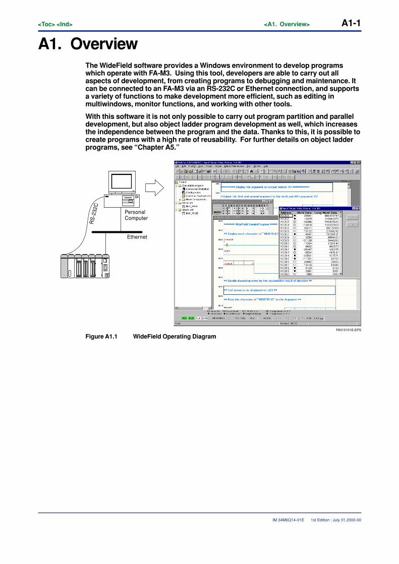
A1. OverviewThe WideField software provides a Windows environment to develop programswhich operate with FA-M3. Using this tool, developers are able to carry out allaspects of development, from creating programs to debugging and maintenance. Itcan be connected to an FA-M3 via an RS-232C or Ethernet connection, and supportsa variety of functions to make development more efficient, such as editing inmultiwindows, monitor functions, and working with other tools.
With this software it is not only possible to carry out program partition and paralleldevelopment, but also object ladder program development as well, which increasesthe independence between the program and the data. Thanks to this, it is possible tocreate programs with a high rate of reusability. For further details on object ladderprograms, see “Chapter A5.”
FA010101E.EPS
PersonalComputer
Ethernet
RS
-232
C
Figure A1.1 WideField Operating Diagram
1st Edition : July 31,2000-00

Blank Page
<Toc> <Ind> <A2. Operating Environment> A2-1
IM 34M6Q14-01E
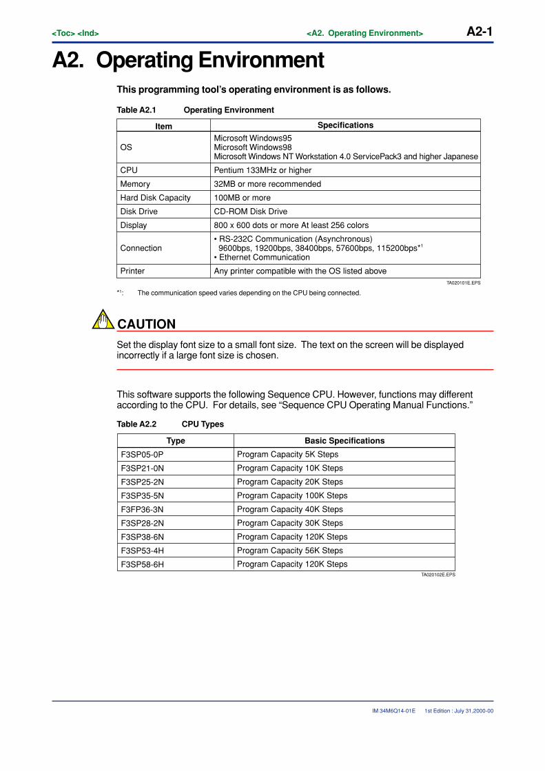
A2. Operating EnvironmentThis programming tool’s operating environment is as follows.
Table A2.1 Operating Environment
TA020101E.EPS
Any printer compatible with the OS listed above
Item Specifications
OSMicrosoft Windows95 Microsoft Windows98 Microsoft Windows NT Workstation 4.0 ServicePack3 and higher Japanese
CPU Pentium 133MHz or higher
Memory 32MB or more recommended
Hard Disk Capacity 100MB or more
Disk Drive CD-ROM Disk Drive
Display 800 x 600 dots or more At least 256 colors
Connection• RS-232C Communication (Asynchronous) 9600bps, 19200bps, 38400bps, 57600bps, 115200bps*1 • Ethernet Communication
Printer
*1: The communication speed varies depending on the CPU being connected.
CAUTION
Set the display font size to a small font size. The text on the screen will be displayedincorrectly if a large font size is chosen.
This software supports the following Sequence CPU. However, functions may differentaccording to the CPU. For details, see “Sequence CPU Operating Manual Functions.”
Table A2.2 CPU Types
TA020102E.EPS
Type Basic Specifications
Program Capacity 5K Steps
Program Capacity 10K Steps
Program Capacity 20K Steps
Program Capacity 100K Steps
Program Capacity 40K Steps
Program Capacity 30K Steps
Program Capacity 120K Steps
Program Capacity 56K Steps
Program Capacity 120K Steps
F3SP05-0P
F3SP21-0N
F3SP25-2N
F3SP35-5N
F3FP36-3N
F3SP28-2N
F3SP38-6N
F3SP53-4H
F3SP58-6H
1st Edition : July 31,2000-00
A2-2<Toc> <Ind> <A2. Operating Environment>
IM 34M6Q14-01E
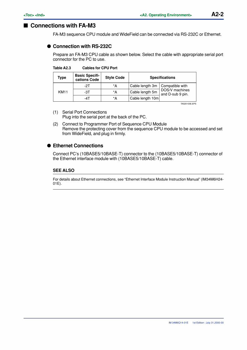
� Connections with FA-M3FA-M3 sequence CPU module and WideField can be connected via RS-232C or Ethernet.
� Connection with RS-232C
Prepare an FA-M3 CPU cable as shown below. Select the cable with appropriate serial portconnector for the PC to use.
Table A2.3 Cables for CPU Port
KM11
-2T
-3T
-4T
*A
*A
*ATA020103E.EPS
Cable length 10m
Type Basic Specifi-cations Code Style Code Specifications
Cable length 3m Compatible with DOS/V machines and D-sub 9 pin.Cable length 5m
(1) Serial Port ConnectionsPlug into the serial port at the back of the PC.
(2) Connect to Programmer Port of Sequence CPU ModuleRemove the protecting cover from the sequence CPU module to be accessed and setfrom WideField, and plug in firmly.
� Ethernet Connections
Connect PC’s (10BASE5/10BASE-T) connector to the (10BASE5/10BASE-T) connector ofthe Ethernet interface module with (10BASE5/10BASE-T) cable.
SEE ALSO
For details about Ethernet connections, see “Ethernet Interface Module Instruction Manual” (IM34M6H24-01E).
1st Edition : July 31,2000-00
<Toc> <Ind> <A3. Installation and Booting> A3-1
IM 34M6Q14-01E
A3. Installation and BootingThis section describes how to install and uninstall this programming tool, creationof short-cut icons, and how to start and shut down the software.
A3.1 InstallationThis section describes how to install this programming tool. Be sure the followingcautions before installing.
CAUTION
• Shut down all other applications before installing.
• If the installation is interrupted, install from the beginning.
• If you are going to overwrite a previously installed version,uninstall it, and then install.
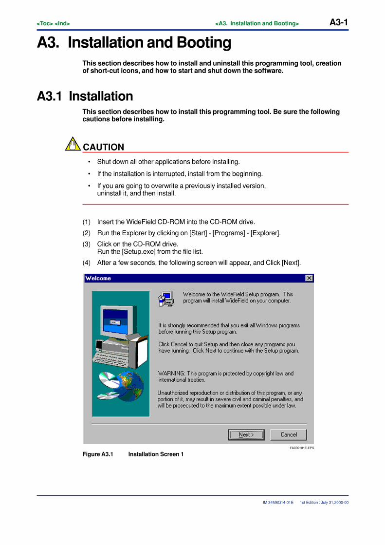
(1) Insert the WideField CD-ROM into the CD-ROM drive.
(2) Run the Explorer by clicking on [Start] - [Programs] - [Explorer].
(3) Click on the CD-ROM drive.Run the [Setup.exe] from the file list.
(4) After a few seconds, the following screen will appear, and Click [Next].
FA030101E.EPS
Figure A3.1 Installation Screen 1
1st Edition : July 31,2000-00
A3-2<Toc> <Ind> <A3. Installation and Booting>
IM 34M6Q14-01E
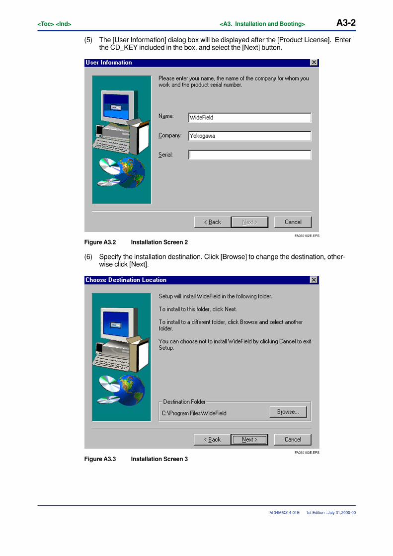
(5) The [User Information] dialog box will be displayed after the [Product License]. Enterthe CD_KEY included in the box, and select the [Next] button.
FA030102E.EPS
Figure A3.2 Installation Screen 2
(6) Specify the installation destination. Click [Browse] to change the destination, other-wise click [Next].
FA030103E.EPS
Figure A3.3 Installation Screen 3
1st Edition : July 31,2000-00
<Toc> <Ind> <A3. Installation and Booting> A3-3
IM 34M6Q14-01E
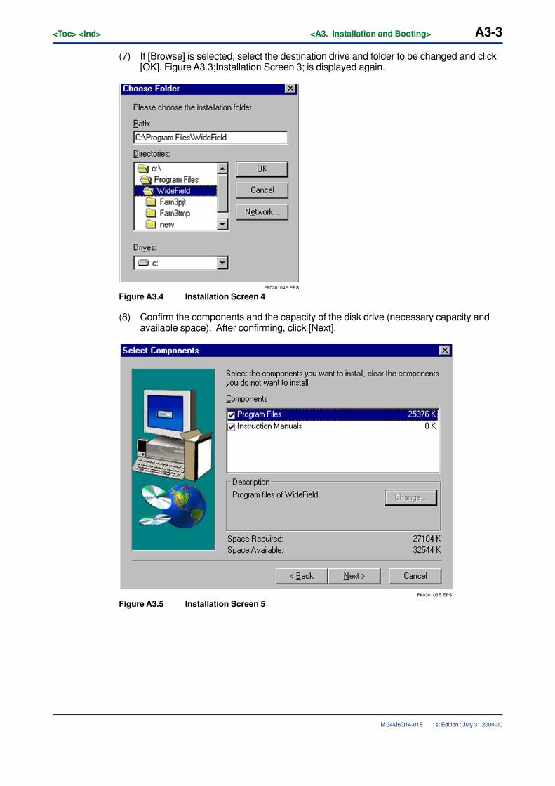
(7) If [Browse] is selected, select the destination drive and folder to be changed and click[OK]. Figure A3.3;Installation Screen 3; is displayed again.
FA030104E.EPS
Figure A3.4 Installation Screen 4
(8) Confirm the components and the capacity of the disk drive (necessary capacity andavailable space). After confirming, click [Next].
FA030105E.EPS
Figure A3.5 Installation Screen 5
1st Edition : July 31,2000-00
A3-4<Toc> <Ind> <A3. Installation and Booting>
IM 34M6Q14-01E
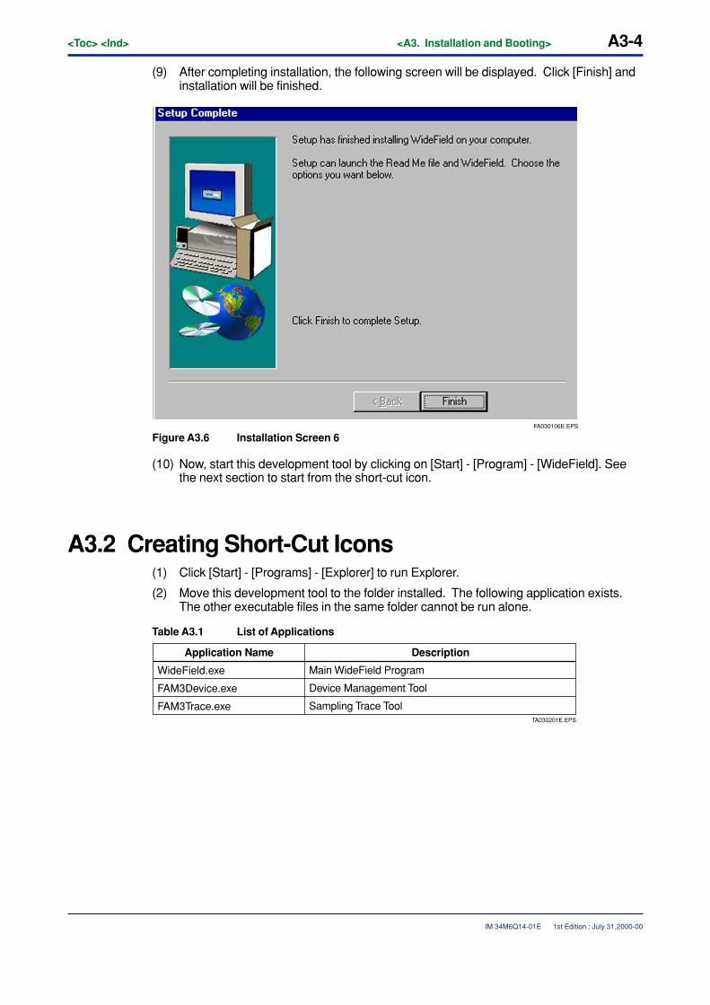
(9) After completing installation, the following screen will be displayed. Click [Finish] andinstallation will be finished.
FA030106E.EPS
Figure A3.6 Installation Screen 6
(10) Now, start this development tool by clicking on [Start] - [Program] - [WideField]. Seethe next section to start from the short-cut icon.
A3.2 Creating Short-Cut Icons(1) Click [Start] - [Programs] - [Explorer] to run Explorer.
(2) Move this development tool to the folder installed. The following application exists.The other executable files in the same folder cannot be run alone.
Table A3.1 List of Applications
WideField.exe
FAM3Device.exe
FAM3Trace.exeTA030201E.EPS
Sampling Trace Tool
Application Name Description
Main WideField Program
Device Management Tool
1st Edition : July 31,2000-00
<Toc> <Ind> <A3. Installation and Booting> A3-5
IM 34M6Q14-01E
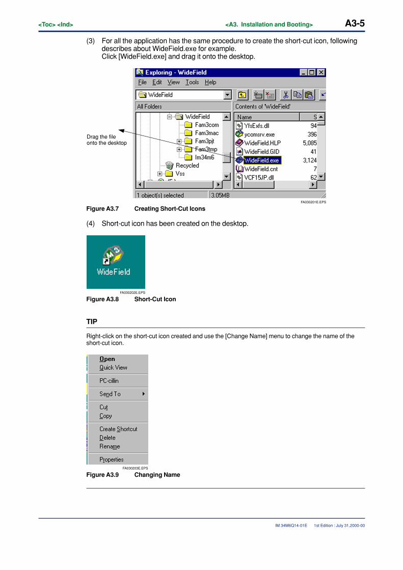
(3) For all the application has the same procedure to create the short-cut icon, followingdescribes about WideField.exe for example.Click [WideField.exe] and drag it onto the desktop.
FA030201E.EPS
Drag the file onto the desktop
Figure A3.7 Creating Short-Cut Icons
(4) Short-cut icon has been created on the desktop.
FA030202E.EPS
Figure A3.8 Short-Cut Icon
TIP
Right-click on the short-cut icon created and use the [Change Name] menu to change the name of theshort-cut icon.
FA030203E.EPS
Figure A3.9 Changing Name
1st Edition : July 31,2000-00
A3-6<Toc> <Ind> <A3. Installation and Booting>
IM 34M6Q14-01E
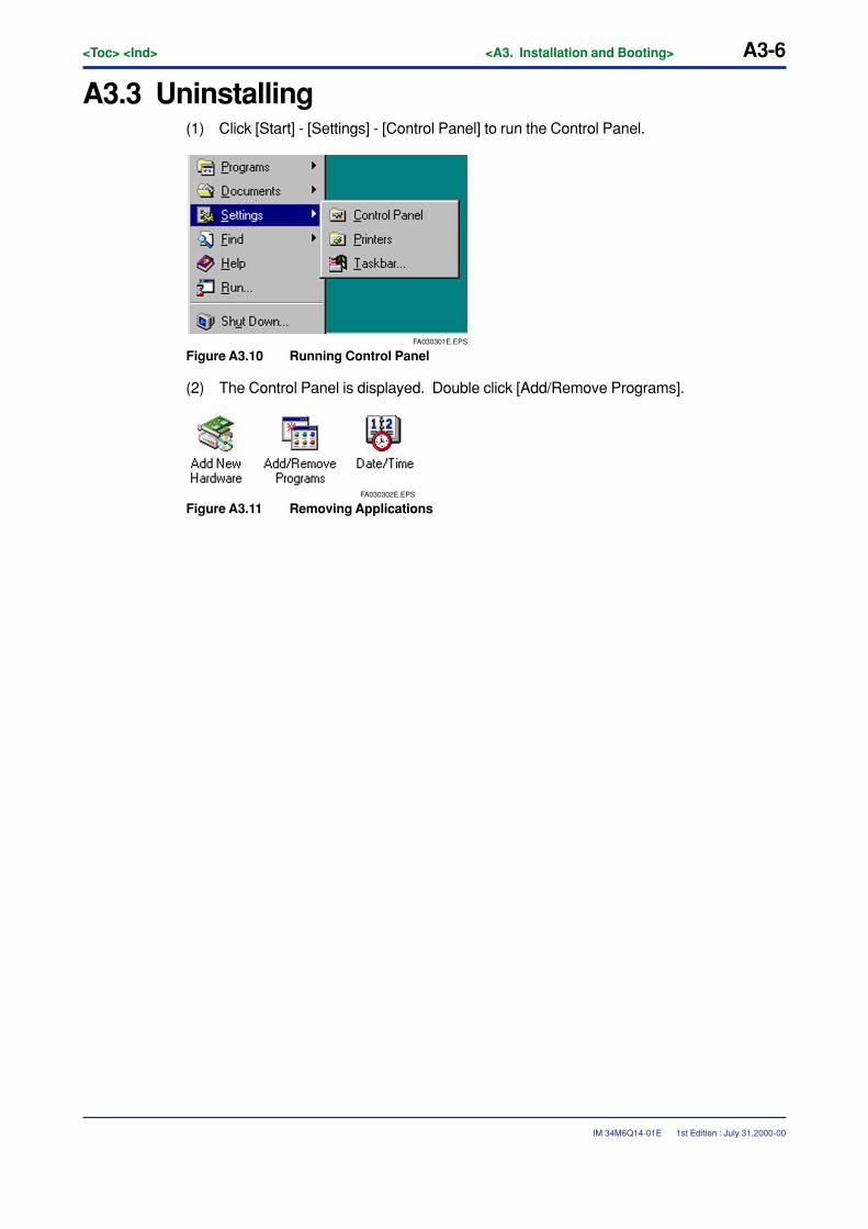
A3.3 Uninstalling(1) Click [Start] - [Settings] - [Control Panel] to run the Control Panel.
FA030301E.EPS
Figure A3.10 Running Control Panel
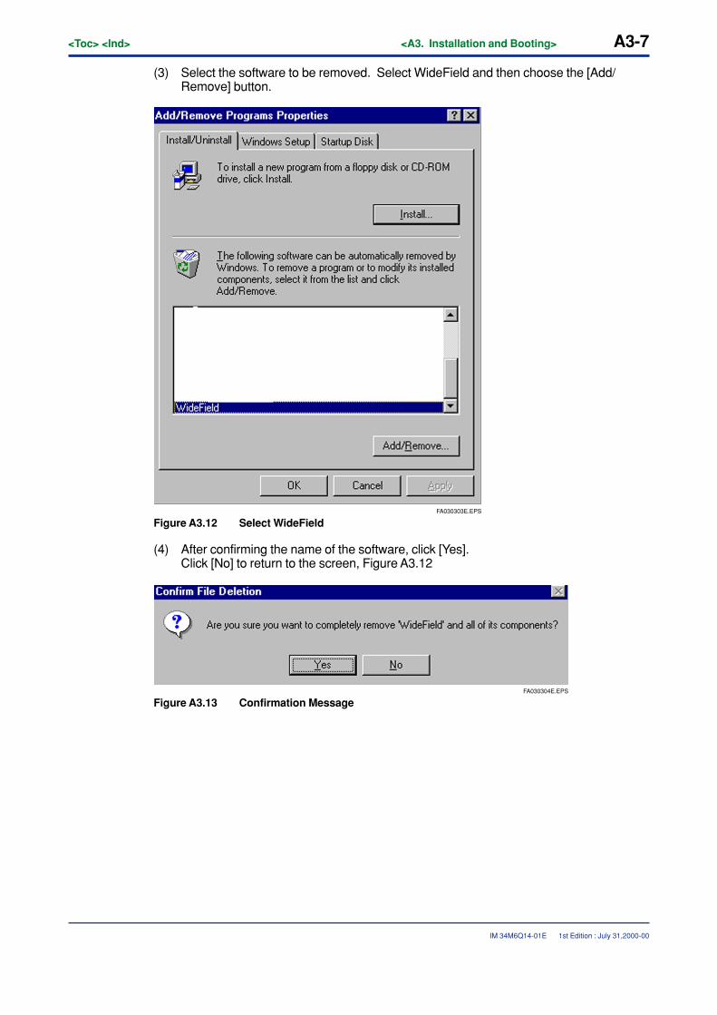
(2) The Control Panel is displayed. Double click [Add/Remove Programs].
FA030302E.EPS
Figure A3.11 Removing Applications
1st Edition : July 31,2000-00
<Toc> <Ind> <A3. Installation and Booting> A3-7
IM 34M6Q14-01E
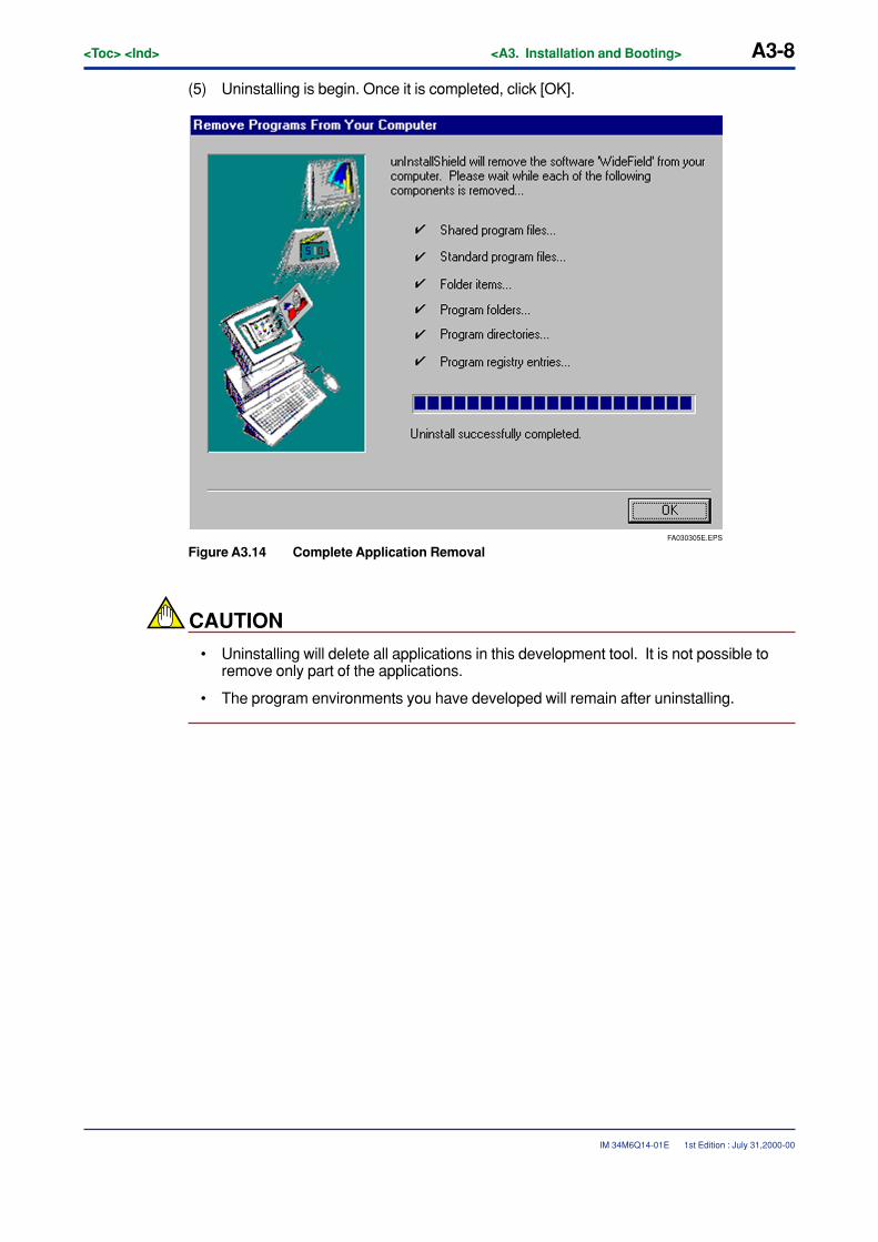
(3) Select the software to be removed. Select WideField and then choose the [Add/Remove] button.
FA030303E.EPS
Figure A3.12 Select WideField
(4) After confirming the name of the software, click [Yes].Click [No] to return to the screen, Figure A3.12
FA030304E.EPS
Figure A3.13 Confirmation Message
1st Edition : July 31,2000-00
A3-8<Toc> <Ind> <A3. Installation and Booting>
IM 34M6Q14-01E
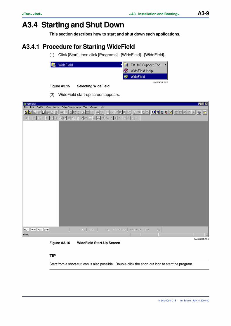
(5) Uninstalling is begin. Once it is completed, click [OK].
FA030305E.EPS
Figure A3.14 Complete Application Removal
CAUTION
• Uninstalling will delete all applications in this development tool. It is not possible toremove only part of the applications.
• The program environments you have developed will remain after uninstalling.
1st Edition : July 31,2000-00
<Toc> <Ind> <A3. Installation and Booting> A3-9
IM 34M6Q14-01E
A3.4 Starting and Shut DownThis section describes how to start and shut down each applications.
A3.4.1 Procedure for Starting WideField(1) Click [Start], then click [Programs] - [WideField] - [WideField].
FA030401E.EPS
Figure A3.15 Selecting WideField
(2) WideField start-up screen appears.
FA030402E.EPS
Figure A3.16 WideField Start-Up Screen
TIP
Start from a short-cut icon is also possible. Double-click the short-cut icon to start the program.
1st Edition : July 31,2000-00
A3-10<Toc> <Ind> <A3. Installation and Booting>
IM 34M6Q14-01E
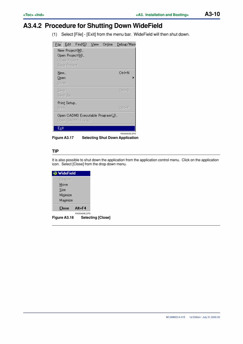
A3.4.2 Procedure for Shutting Down WideField(1) Select [File] - [Exit] from the menu bar. WideField will then shut down.
FA030403E.EPS
Figure A3.17 Selecting Shut Down Application
TIP
It is also possible to shut down the application from the application control menu. Click on the applicationicon. Select [Close] from the drop down menu.
FA030404E.EPS
Figure A3.18 Selecting [Close]
1st Edition : July 31,2000-00
<Toc> <Ind> <A3. Installation and Booting> A3-11
IM 34M6Q14-01E
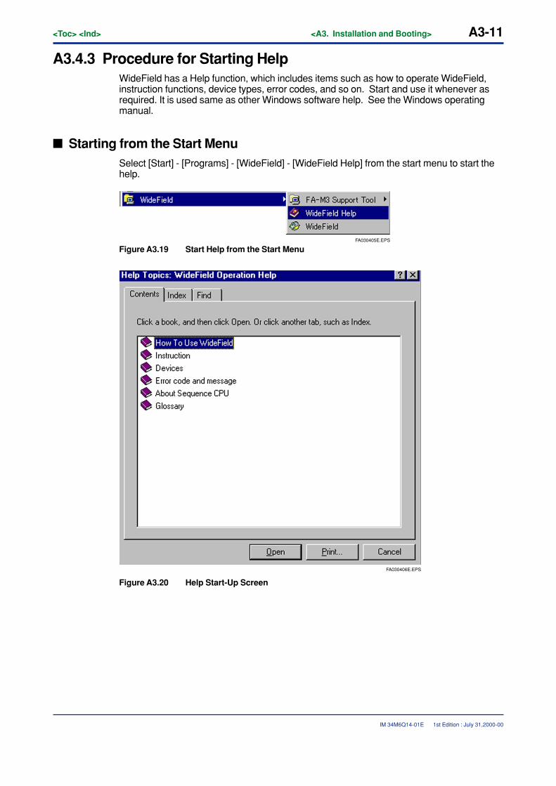
A3.4.3 Procedure for Starting HelpWideField has a Help function, which includes items such as how to operate WideField,instruction functions, device types, error codes, and so on. Start and use it whenever asrequired. It is used same as other Windows software help. See the Windows operatingmanual.
� Starting from the Start MenuSelect [Start] - [Programs] - [WideField] - [WideField Help] from the start menu to start thehelp.
FA030405E.EPS
Figure A3.19 Start Help from the Start Menu
FA030406E.EPS
Figure A3.20 Help Start-Up Screen
1st Edition : July 31,2000-00
A3-12<Toc> <Ind> <A3. Installation and Booting>
IM 34M6Q14-01E
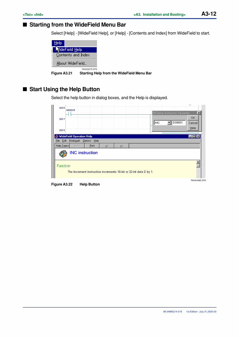
� Starting from the WideField Menu BarSelect [Help] - [WideField Help], or [Help] - [Contents and Index] from WideField to start.
FA030407E.EPS
Figure A3.21 Starting Help from the WideField Menu Bar
� Start Using the Help ButtonSelect the help button in dialog boxes, and the Help is displayed.
FA030408E.EPS
Figure A3.22 Help Button
1st Edition : July 31,2000-00
<Toc> <Ind> <A3. Installation and Booting> A3-13
IM 34M6Q14-01E
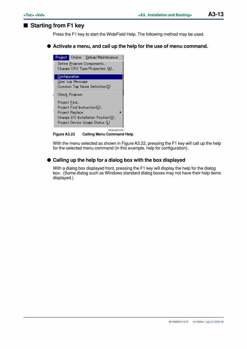
� Starting from F1 keyPress the F1 key to start the WideField Help. The following method may be used.
� Activate a menu, and call up the help for the use of menu command.
FA030409E.EPS
Figure A3.23 Calling Menu Command Help
With the menu selected as shown in Figure A3.22, pressing the F1 key will call up the helpfor the selected menu command (in this example, help for configuration).
� Calling up the help for a dialog box with the box displayed
With a dialog box displayed front, pressing the F1 key will display the help for the dialogbox. (Some dialog such as Windows standard dialog boxes may not have their help itemsdisplayed.)
1st Edition : July 31,2000-00

Blank Page
<Toc> <Ind> <A4. Basic Specifications> A4-1
IM 34M6Q14-01E
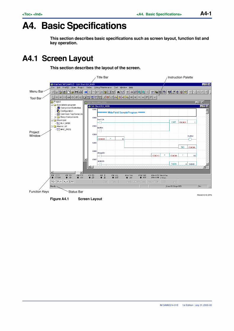
A4. Basic SpecificationsThis section describes basic specifications such as screen layout, function list andkey operation.
A4.1 Screen LayoutThis section describes the layout of the screen.
FA040101E.EPS
Function Keys Status Bar
Project Window
Menu Bar
Tool Bar
Title Bar Instruction Palette
Figure A4.1 Screen Layout
1st Edition : July 31,2000-00
A4-2<Toc> <Ind> <A4. Basic Specifications>
IM 34M6Q14-01E
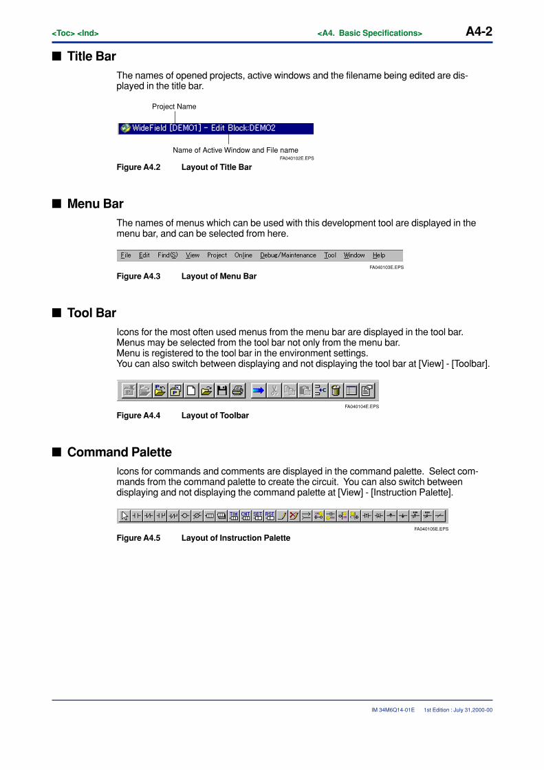
� Title BarThe names of opened projects, active windows and the filename being edited are dis-played in the title bar.
FA040102E.EPS
Project Name
Name of Active Window and File name
Figure A4.2 Layout of Title Bar
� Menu BarThe names of menus which can be used with this development tool are displayed in themenu bar, and can be selected from here.
FA040103E.EPS
Figure A4.3 Layout of Menu Bar
� Tool BarIcons for the most often used menus from the menu bar are displayed in the tool bar.Menus may be selected from the tool bar not only from the menu bar.Menu is registered to the tool bar in the environment settings.You can also switch between displaying and not displaying the tool bar at [View] - [Toolbar].
FA040104E.EPS
Figure A4.4 Layout of Toolbar
� Command PaletteIcons for commands and comments are displayed in the command palette. Select com-mands from the command palette to create the circuit. You can also switch betweendisplaying and not displaying the command palette at [View] - [Instruction Palette].
FA040105E.EPS
Figure A4.5 Layout of Instruction Palette
1st Edition : July 31,2000-00
<Toc> <Ind> <A4. Basic Specifications> A4-3
IM 34M6Q14-01E
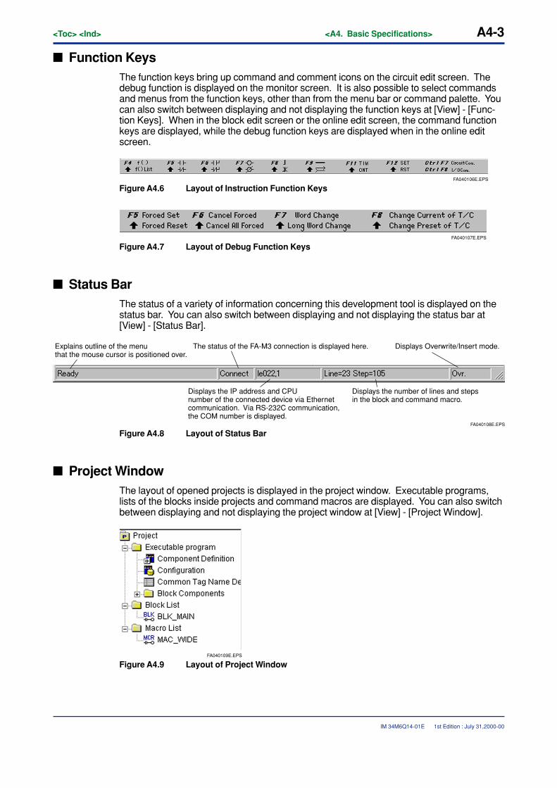
� Function KeysThe function keys bring up command and comment icons on the circuit edit screen. Thedebug function is displayed on the monitor screen. It is also possible to select commandsand menus from the function keys, other than from the menu bar or command palette. Youcan also switch between displaying and not displaying the function keys at [View] - [Func-tion Keys]. When in the block edit screen or the online edit screen, the command functionkeys are displayed, while the debug function keys are displayed when in the online editscreen.
FA040106E.EPS
Figure A4.6 Layout of Instruction Function Keys
FA040107E.EPS
Figure A4.7 Layout of Debug Function Keys
� Status BarThe status of a variety of information concerning this development tool is displayed on thestatus bar. You can also switch between displaying and not displaying the status bar at[View] - [Status Bar].
FA040108E.EPS
The status of the FA-M3 connection is displayed here.Explains outline of the menu that the mouse cursor is positioned over.
Displays Overwrite/Insert mode.
Displays the number of lines and steps in the block and command macro.
Displays the IP address and CPU number of the connected device via Ethernet communication. Via RS-232C communication, the COM number is displayed.
Figure A4.8 Layout of Status Bar
� Project WindowThe layout of opened projects is displayed in the project window. Executable programs,lists of the blocks inside projects and command macros are displayed. You can also switchbetween displaying and not displaying the project window at [View] - [Project Window].
FA040109E.EPS
Figure A4.9 Layout of Project Window
1st Edition : July 31,2000-00
A4-4<Toc> <Ind> <A4. Basic Specifications>
IM 34M6Q14-01E
You can call up the screen directly from the project window.
� Executable Program Layout Definition Screen
Double click on [Layout Definition].
� Configuration Settings Screen
Set the configuration to [Setup] with the executable program layout definition to display[Configuration] in the project window. Double click on [Configuration].
� User Log Message Creation Screen
Set the user log message to [yes] with the executable program layout definition to display“User Log Message” in the project window. Double click on [User Log Message].
� Common Tag Definition Screen
Double click on [Common Tag Name Definition].
� Block Edit Screen
Double click on either block name in the block layout or the block name in the block list.
� Command Macro Edit Screen
Double click on the macro name in the Instruction macro list.
1st Edition : July 31,2000-00
<Toc> <Ind> <A4. Basic Specifications> A4-5
IM 34M6Q14-01E
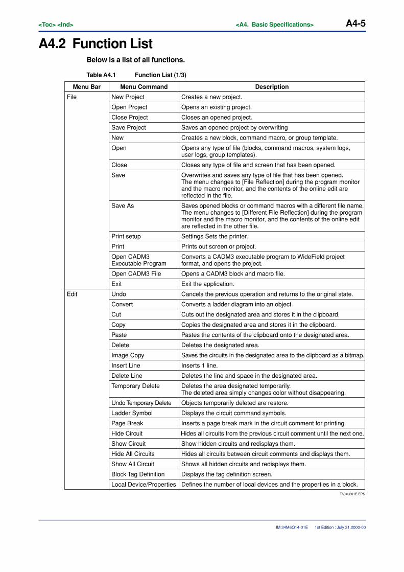
A4.2 Function ListBelow is a list of all functions.
Table A4.1 Function List (1/3)
TA040201E.EPS
Defines the number of local devices and the properties in a block.
Menu Bar Menu Command Description
File New Project Creates a new project.
Open Project Opens an existing project.
Close Project Closes an opened project.
Save Project Saves an opened project by overwriting
New Creates a new block, command macro, or group template.
Open Opens any type of file (blocks, command macros, system logs, user logs, group templates).
Close Closes any type of file and screen that has been opened.
Save Overwrites and saves any type of file that has been opened. The menu changes to [File Reflection] during the program monitor and the macro monitor, and the contents of the online edit are reflected in the file.
Save As Saves opened blocks or command macros with a different file name. The menu changes to [Different File Reflection] during the program monitor and the macro monitor, and the contents of the online edit are reflected in the other file.
Print setup Settings Sets the printer.
Print Prints out screen or project.
Open CADM3 Executable Program
Converts a CADM3 executable program to WideField project format, and opens the project.
Open CADM3 File Opens a CADM3 block and macro file.
Exit Exit the application.
Edit Undo Cancels the previous operation and returns to the original state.
Convert Converts a ladder diagram into an object.
Cut Cuts out the designated area and stores it in the clipboard.
Copy Copies the designated area and stores it in the clipboard.
Paste Pastes the contents of the clipboard onto the designated area.
Delete Deletes the designated area.
Image Copy Saves the circuits in the designated area to the clipboard as a bitmap.
Insert Line Inserts 1 line.
Delete Line Deletes the line and space in the designated area.
Temporary Delete Deletes the area designated temporarily. The deleted area simply changes color without disappearing.
Undo Temporary Delete Objects temporarily deleted are restore.
Ladder Symbol Displays the circuit command symbols.
Page Break Inserts a page break mark in the circuit comment for printing.
Hide Circuit Hides all circuits from the previous circuit comment until the next one.
Show Circuit Show hidden circuits and redisplays them.
Hide All Circuits Hides all circuits between circuit comments and displays them.
Show All Circuit Shows all hidden circuits and redisplays them.
Block Tag Definition Displays the tag definition screen.
Local Device/Properties
1st Edition : July 31,2000-00
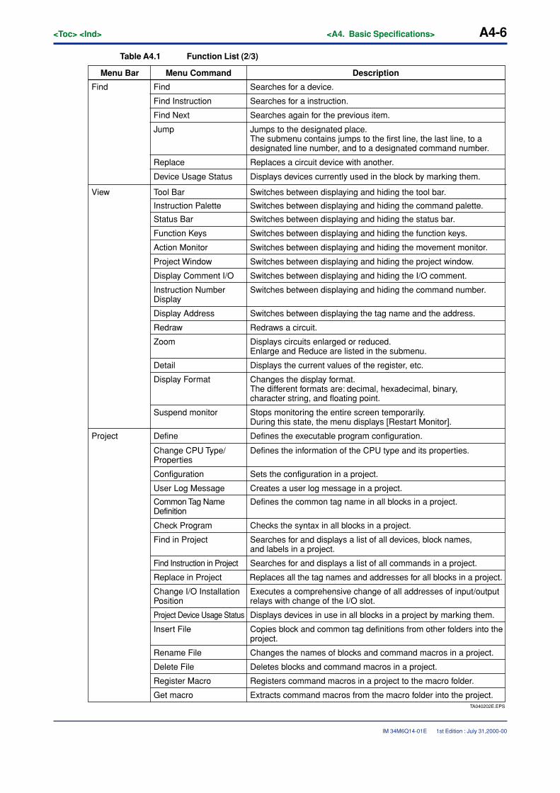
A4-6<Toc> <Ind> <A4. Basic Specifications>
IM 34M6Q14-01E
Table A4.1 Function List (2/3)
TA040202E.EPS
Extracts command macros from the macro folder into the project.
DescriptionMenu Bar Menu Command
Find Find Searches for a device.
Find Instruction Searches for a instruction.
Find Next Searches again for the previous item.
Jump Jumps to the designated place. The submenu contains jumps to the first line, the last line, to a designated line number, and to a designated command number.
Replace Replaces a circuit device with another.
Device Usage Status Displays devices currently used in the block by marking them.
View Tool Bar Switches between displaying and hiding the tool bar.
Instruction Palette Switches between displaying and hiding the command palette.
Status Bar Switches between displaying and hiding the status bar.
Function Keys Switches between displaying and hiding the function keys.
Action Monitor Switches between displaying and hiding the movement monitor.
Project Window Switches between displaying and hiding the project window.
Display Comment I/O Switches between displaying and hiding the I/O comment.
Instruction Number Display
Switches between displaying and hiding the command number.
Display Address Switches between displaying the tag name and the address.
Redraw Redraws a circuit.
Zoom Displays circuits enlarged or reduced. Enlarge and Reduce are listed in the submenu.
Detail Displays the current values of the register, etc.
Display Format Changes the display format. The different formats are: decimal, hexadecimal, binary, character string, and floating point.
Suspend monitor Stops monitoring the entire screen temporarily. During this state, the menu displays [Restart Monitor].
Project Define Defines the executable program configuration.
Change CPU Type/Properties
Defines the information of the CPU type and its properties.
Configuration Sets the configuration in a project.
User Log Message Creates a user log message in a project.
Common Tag Name Definition
Defines the common tag name in all blocks in a project.
Check Program Checks the syntax in all blocks in a project.
Find in Project Searches for and displays a list of all devices, block names, and labels in a project.
Find Instruction in Project Searches for and displays a list of all commands in a project.
Replace in Project Replaces all the tag names and addresses for all blocks in a project.
Change I/O Installation Position
Executes a comprehensive change of all addresses of input/output relays with change of the I/O slot.
Project Device Usage Status Displays devices in use in all blocks in a project by marking them.
Insert File Copies block and common tag definitions from other folders into the project.
Rename File Changes the names of blocks and command macros in a project.
Delete File Deletes blocks and command macros in a project.
Register Macro Registers command macros in a project to the macro folder.
Get macro
1st Edition : July 31,2000-00
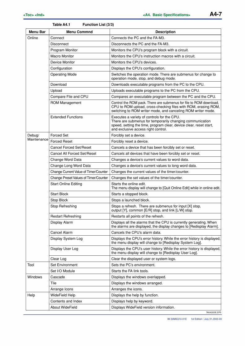
<Toc> <Ind> <A4. Basic Specifications> A4-7
IM 34M6Q14-01E
Table A4.1 Function List (3/3)
TA040203E.EPS
Displays WideField version information.
DescriptionMenu Bar Menu Commnd
Online Connects the PC and the FA-M3.Connect
Disconnect Disconnects the PC and the FA-M3.
Program Monitor Monitors the CPU’s program block with a circuit.
Macro Monitor Monitors the CPU’s instruction macros with a circuit.
Device Monitor Monitors the CPU’s devices.
Configuration Displays the CPU’s configuration.
Operating Mode Switches the operation mode. There are submenus for change to operation mode, stop, and debug mode.
Download Downloads executable programs from the PC to the CPU.
Upload Uploads executable programs to the PC from the CPU.
Compare File and CPU Compares an executable program between the PC and the CPU.
ROM Management Control the ROM pack. There are submenus for file to ROM download, CPU to ROM upload, cross-checking files with ROM, erasing ROM, switching to ROM writer mode, and canceling ROM writer mode.
Extended Functions Executes a variety of controls for the CPU. There are submenus for temporarily changing communication speed, setting the time, program clear, device clear, reset start, and exclusive access right control.
Debug/Maintenance
Forced Set Forcibly set a device.
Forced Reset Forcibly reset a device.
Cancel Forced Set/Reset Cancels a device that has been forcibly set or reset.
Cancel All Forced Set/Reset Cancels all devices that have been forcibly set or reset.
Change Word Data Changes a device’s current values to word data.
Change Long Word Data Changes a device’s current values to long word data.
Change Current Value of Timer/Counter Changes the current values of the timer/counter.
Change Preset Values of Timer/Counter Changes the set values of the timer/counter.
Start Online Editing Starts the online edit. The menu display will change to [Quit Online Edit] while in online edit.
Start Block Starts a stopped block.
Stop Block Stops a launched block.
Stop Refreshing Stops a refresh. There are submenus for input [X] stop, output [Y], common [E/R] stop, and link [L/W] stop.
Restart Refreshing Restarts all points of the refresh.
Display Alarm Displays all the alarms that the CPU is currently generating. When the alarms are displayed, the display changes to [Redisplay Alarm].
Cancel Alarm Cancels the CPU’s alarm data.
Display System Log Displays the CPU’s error history. While the error history is displayed, the menu display will change to [Redisplay System Log].
Display User Log Displays the CPU’s user history. While the error history is displayed, the menu display will change to [Redisplay User Log].
Clear Log Clear the displayed user or system logs.
Tool Set Environment Sets the PC’s environment.
Set I/O Module Starts the FA link tools.
Windows Cascade Displays the windows overlapped.
Tile Displays the windows arranged.
Arrange Icons Arranges the icons.
Help WideField Help Displays the help by function.
Contents and Index Displays help by keyword.
About WideField
1st Edition : July 31,2000-00
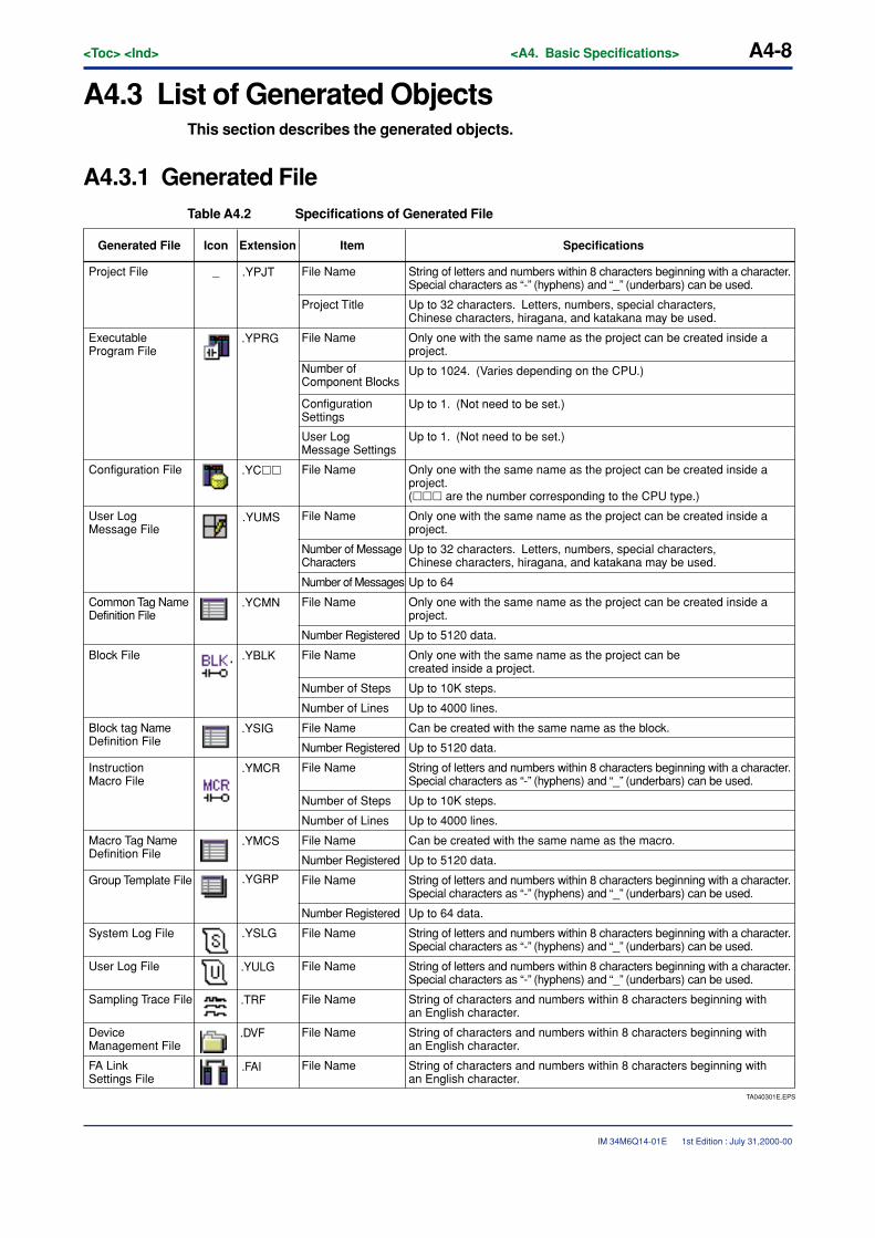
A4-8<Toc> <Ind> <A4. Basic Specifications>
IM 34M6Q14-01E
A4.3 List of Generated ObjectsThis section describes the generated objects.
A4.3.1 Generated FileTable A4.2 Specifications of Generated File
.YPJT
.YPRG
.YC��
.YCMN
.YBLK
.YSIG
.YMCR
.YMCS
.YSLG
.YULG
.DVF
.TRF
.FAI
TA040301E.EPS
.YUMS
.YGRP
_
SpecificationsGenerated File Icon Extension Item
Project File File Name String of letters and numbers within 8 characters beginning with a character. Special characters as “-” (hyphens) and “_” (underbars) can be used.
File Name
File Name
String of letters and numbers within 8 characters beginning with a character. Special characters as “-” (hyphens) and “_” (underbars) can be used.
Project Title Up to 32 characters. Letters, numbers, special characters, Chinese characters, hiragana, and katakana may be used.
Up to 32 characters. Letters, numbers, special characters, Chinese characters, hiragana, and katakana may be used.
Executable Program File
File Name Only one with the same name as the project can be created inside a project.
Only one with the same name as the project can be created inside a project.
Only one with the same name as the project can be created inside a project.
Number of Component Blocks
Up to 1024. (Varies depending on the CPU.)
Configuration Settings
Up to 1. (Not need to be set.)
Up to 1. (Not need to be set.)
User Log Message File
User Log Message Settings
Configuration File File Name
File Name
Only one with the same name as the project can be created inside a project. (��� are the number corresponding to the CPU type.)
Number of MessageCharacters
Number of Messages Up to 64
Common Tag Name Definition File
File Name
Only one with the same name as the project can be created inside a project.
File Name
Number Registered Up to 5120 data.
Block File
Number of Steps Up to 10K steps.
Up to 4000 lines.Number of Lines
File Name String of letters and numbers within 8 characters beginning with a character. Special characters as “-” (hyphens) and “_” (underbars) can be used.
File Name String of letters and numbers within 8 characters beginning with a character. Special characters as “-” (hyphens) and “_” (underbars) can be used.
File Name
File Name
File Name
File Name
String of letters and numbers within 8 characters beginning with a character. Special characters as “-” (hyphens) and “_” (underbars) can be used.
FA Link Settings File
Number of Steps Up to 10K steps.
Up to 4000 lines.Number of Lines
Block tag Name Definition File
File Name Can be created with the same name as the block.
Number Registered Up to 5120 data.
Number Registered Up to 5120 data.
Instruction Macro File
Macro Tag Name Definition File
Can be created with the same name as the macro.
Group Template File
Number Registered Up to 64 data.
System Log File
User Log File
Sampling Trace File String of characters and numbers within 8 characters beginning with an English character.
String of characters and numbers within 8 characters beginning with an English character.
String of characters and numbers within 8 characters beginning with an English character.
Device Management File
1st Edition : July 31,2000-00
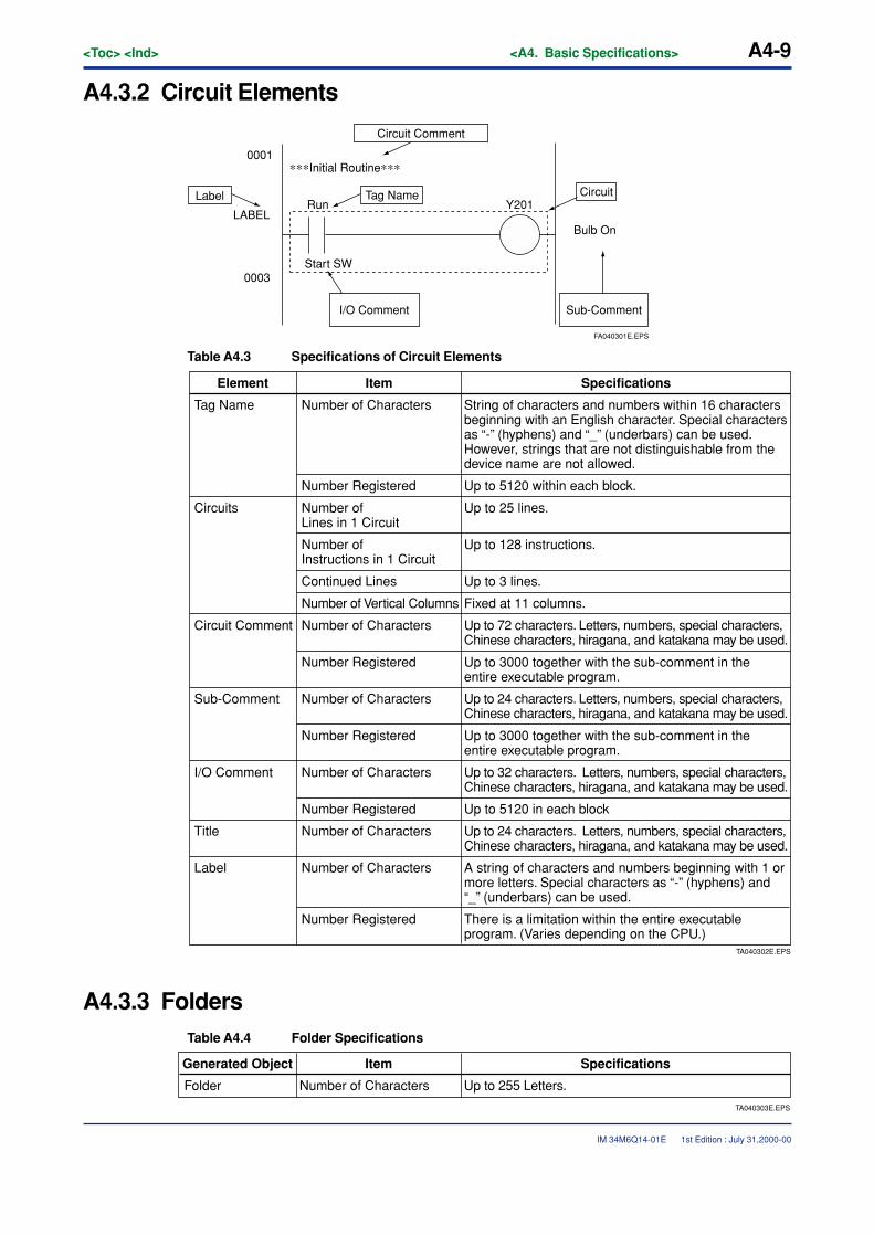
<Toc> <Ind> <A4. Basic Specifications> A4-9
IM 34M6Q14-01E
A4.3.2 Circuit Elements
0001
LABEL
0003
FA040301E.EPS
Circuit Comment
∗∗∗Initial Routine∗∗∗
Start SW
I/O Comment Sub-Comment
CircuitTag NameLabel
Bulb On
Y201Run
Table A4.3 Specifications of Circuit Elements
TA040302E.EPS
Up to 24 characters. Letters, numbers, special characters, Chinese characters, hiragana, and katakana may be used.
Up to 72 characters. Letters, numbers, special characters, Chinese characters, hiragana, and katakana may be used.
SpecificationsElement Item
Tag Name Number of Characters String of characters and numbers within 16 characters beginning with an English character. Special characters as “-” (hyphens) and “_” (underbars) can be used. However, strings that are not distinguishable from the device name are not allowed.
Number Registered
Number of Characters
Number Registered
Number of Characters
Number Registered
Number of Characters
Number Registered
Number of Characters
Number of Characters
Number Registered
Up to 5120 within each block.
Circuits Number of Lines in 1 Circuit
Up to 25 lines.
Number of Instructions in 1 Circuit
Up to 128 instructions.
Continued Lines Up to 3 lines.
Number of Vertical Columns Fixed at 11 columns.
Circuit Comment
Sub-Comment
I/O Comment Up to 32 characters. Letters, numbers, special characters, Chinese characters, hiragana, and katakana may be used.
Up to 5120 in each block
Title Up to 24 characters. Letters, numbers, special characters, Chinese characters, hiragana, and katakana may be used.
Label A string of characters and numbers beginning with 1 or more letters. Special characters as “-” (hyphens) and “_” (underbars) can be used.
There is a limitation within the entire executable program. (Varies depending on the CPU.)
Up to 3000 together with the sub-comment in the entire executable program.
Up to 3000 together with the sub-comment in the entire executable program.
A4.3.3 FoldersTable A4.4 Folder Specifications
TA040303E.EPS
Up to 255 Letters.
SpecificationsGenerated Object Item
Folder Number of Characters
1st Edition : July 31,2000-00
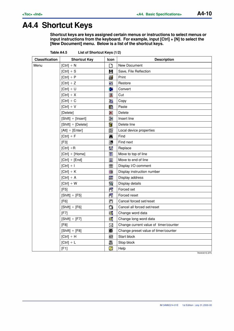
A4-10<Toc> <Ind> <A4. Basic Specifications>
IM 34M6Q14-01E
A4.4 Shortcut KeysShortcut keys are keys assigned certain menus or instructions to select menus orinput instructions from the keyboard. For example, input [Ctrl] + [N] to select the[New Document] menu. Below is a list of the shortcut keys.
Table A4.5 List of Shortcut Keys (1/2)
TA040401E.EPS
Classification Shortcut Key Icon Description
Menu New Document
Save, File Reflection
Restore
Convert
Cut
Copy
Paste
Delete
Insert line
Delete line
Local device properties
Find
Find next
Replace
Move to top of line
Move to end of line
Display I/O comment
Display instruction number
Display address
Display details
Forced set
Forced reset
Cancel forced set/reset
Cancel all forced set/reset
Change word data
Change long word data
Change current value of timer/counter
Change preset value of timer/counter
Start block
Stop block
Help
[Ctrl] � N
[Ctrl] � S
[Ctrl] � P
[Ctrl] � Z
[Ctrl] � U
[Ctrl] � X
[Ctrl] � C
[Ctrl] � V
[Delete]
[Shift] � [Insert]
[Shift] � [Delete]
[Alt] � [Enter]
[Ctrl] � F
[F3]
[Ctrl] �R
[Ctrl] � [Home]
[Ctrl] � [End]
[Ctrl] � I
[Ctrl] � K
[Ctrl] � A
[Ctrl] � W
[F5]
[Shift] � [F5]
[F6]
[Shift] � [F6]
[F7]
[Shift] � [F7]
[F8]
[Shift] � [F8]
[Ctrl] � L
[Ctrl] � H
[F1]
1st Edition : July 31,2000-00
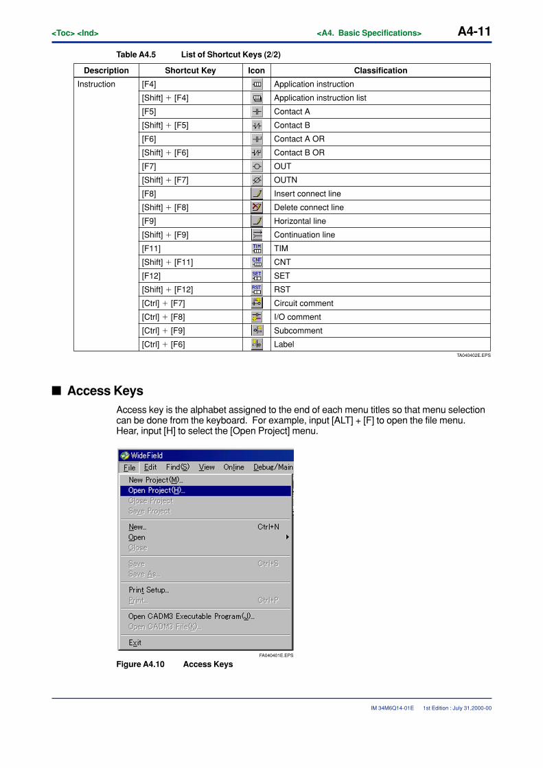
<Toc> <Ind> <A4. Basic Specifications> A4-11
IM 34M6Q14-01E
Table A4.5 List of Shortcut Keys (2/2)
TA040402E.EPS
Label
ClassificationShortcut Key IconDescription
Instruction Application instruction
Application instruction list
Contact A
Contact B
Contact A OR
Contact B OR
OUT
OUTN
Insert connect line
Delete connect line
Horizontal line
Continuation line
TIM
CNT
SET
RST
Circuit comment
I/O comment
Subcomment
[F4]
[Shift] � [F4]
[F5]
[Shift] � [F5]
[F6]
[Shift] � [F6]
[F7]
[Shift] � [F7]
[F8]
[Shift] � [F8]
[F9]
[Shift] � [F9]
[F11]
[Shift] � [F11]
[F12]
[Shift] � [F12]
[Ctrl] � [F7]
[Ctrl] � [F8]
[Ctrl] � [F9]
[Ctrl] � [F6]
� Access KeysAccess key is the alphabet assigned to the end of each menu titles so that menu selectioncan be done from the keyboard. For example, input [ALT] + [F] to open the file menu.Hear, input [H] to select the [Open Project] menu.
FA040401E.EPS
Figure A4.10 Access Keys
1st Edition : July 31,2000-00
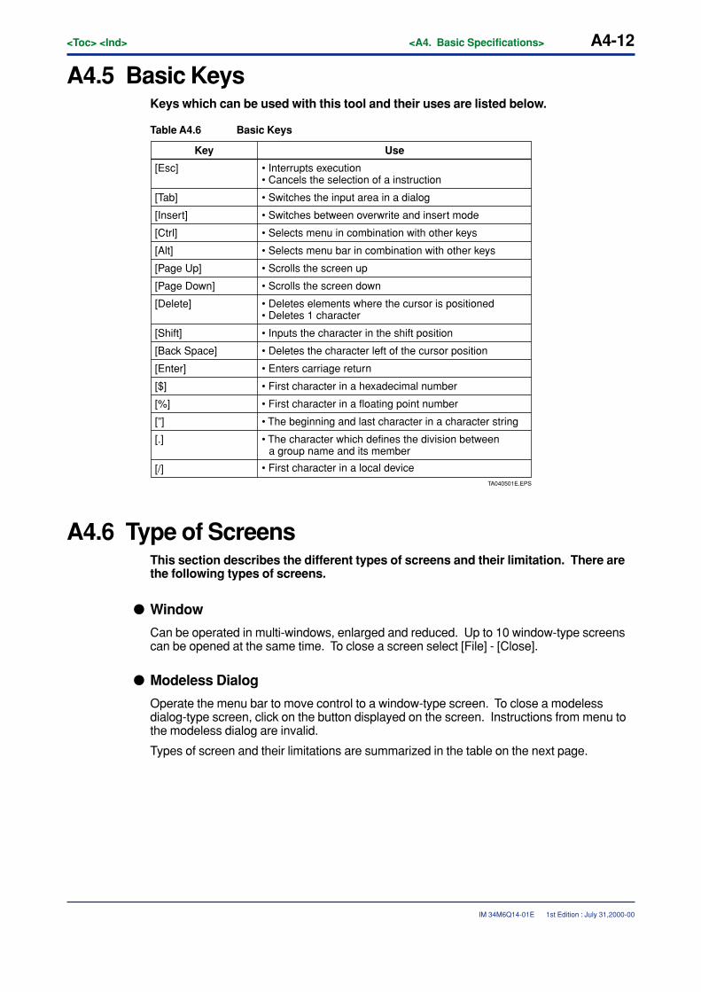
A4-12<Toc> <Ind> <A4. Basic Specifications>
IM 34M6Q14-01E
A4.5 Basic KeysKeys which can be used with this tool and their uses are listed below.
Table A4.6 Basic Keys
TA040501E.EPS
• First character in a local device
Key Use
• Interrupts execution• Cancels the selection of a instruction
• Switches the input area in a dialog
• Switches between overwrite and insert mode
• Selects menu in combination with other keys
• Selects menu bar in combination with other keys
• Scrolls the screen up
• Scrolls the screen down
• Deletes elements where the cursor is positioned• Deletes 1 character
• Inputs the character in the shift position
• Deletes the character left of the cursor position
• Enters carriage return
• First character in a hexadecimal number
• First character in a floating point number
• The beginning and last character in a character string
• The character which defines the division between a group name and its member
[Esc]
[Tab]
[Insert]
[Ctrl]
[Alt]
[Page Up]
[Page Down]
[Delete]
[Shift]
[Back Space]
[Enter]
[$]
[%]
[”]
[.]
[/]
A4.6 Type of ScreensThis section describes the different types of screens and their limitation. There arethe following types of screens.
� Window
Can be operated in multi-windows, enlarged and reduced. Up to 10 window-type screenscan be opened at the same time. To close a screen select [File] - [Close].
� Modeless Dialog
Operate the menu bar to move control to a window-type screen. To close a modelessdialog-type screen, click on the button displayed on the screen. Instructions from menu tothe modeless dialog are invalid.
Types of screen and their limitations are summarized in the table on the next page.
1st Edition : July 31,2000-00
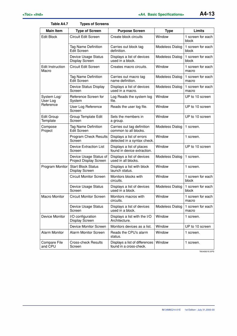
<Toc> <Ind> <A4. Basic Specifications> A4-13
IM 34M6Q14-01E
Table A4.7 Types of Screens
TA040601E.EPS
Displays a list of differences found in a cross-check.
LimitsMain Item Type of Screen Purpose Screen Type
Edit Block Circuit Edit Screen Create block circuits Window 1 screen for each block
1 screen for each block
Tag Name Definition Edit Screen
Carries out block tag definition.
Modeless Dialog
1 screen for each block
Modeless Dialog
1 screen for each macro
Window
1 screen for each macro
Modeless Dialog
1 screen for each macro
Modeless Dialog
UP to 10 screen Window
UP to 10 screen Window
UP to 10 screen Window
Modeless Dialog
Device Usage Status Display Screen
Displays a list of devices used in a block.
Edit Instruction Macro
Circuit Edit Screen Creates macro circuits.
Tag Name Definition Edit Screen
Carries out macro tag name definition.
Device Status Display Screen
Displays a list of devices used in a macro.
System Log/User Log Reference
Reference Screen for System
Log Reads the system log file.
User Log Reference Screen
Reads the user log file.
Edit Group Template
Group Template Edit Screen
Sets the members in a group.
Compose Project
Tag Name Definition Edit Screen
Carries out tag definition common to all blocks.
1 screen.
Window 1 screen.
Window UP to 10 screen
Modeless Dialog 1 screen.
Window 1 screen.
Window 1 screen for each block
Modeless Dialog 1 screen for each block
Window 1 screen for each macro
Modeless Dialog 1 screen for each macro
Window 1 screen.
Window UP to 10 screen
Window 1 screen.
Window 1 screen.
Program Check Results Screen
Displays a list of errors detected in a syntax check.
Device Extraction List Screen
Displays a list of places found in device extraction.
Device Usage Status of Project Display Screen
Displays a list of devices used in all blocks.
Program Monitor Start Block Status Display Screen
Displays a list with block launch status.
Circuit Monitor Screen Monitors blocks with circuits.
Device Usage Status Screen
Displays a list of devices used in a block.
Macro Monitor Circuit Monitor Screen Monitors macros with circuits.
Device Usage Status Screen
Displays a list of devices used in a block.
Device Monitor I/O configuration Display Screen
Displays a list with the I/O Architecture.
Device Monitor Screen Monitors devices as a list.
Alarm Monitor Alarm Monitor Screen Reads the CPU’s alarm status.
Compare File and CPU
Cross-check Results Screen
1st Edition : July 31,2000-00

Blank Page
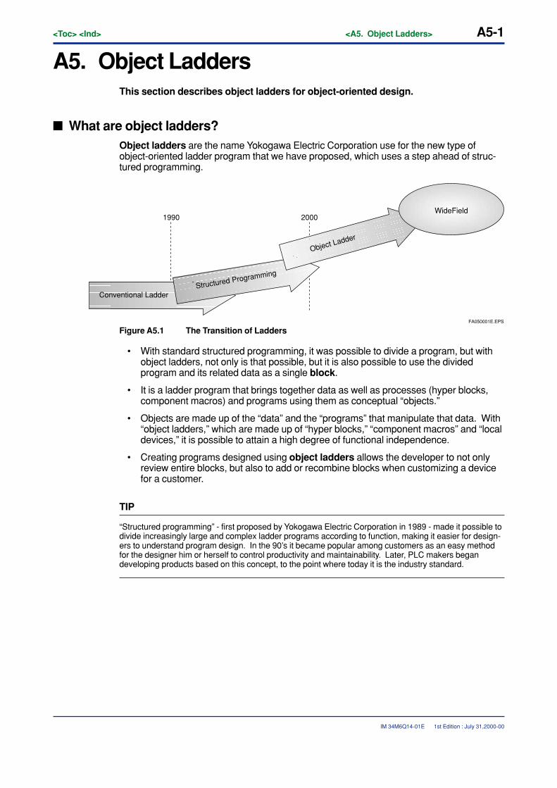
<Toc> <Ind> <A5. Object Ladders> A5-1
IM 34M6Q14-01E
A5. Object LaddersThis section describes object ladders for object-oriented design.
� What are object ladders?Object ladders are the name Yokogawa Electric Corporation use for the new type ofobject-oriented ladder program that we have proposed, which uses a step ahead of struc-tured programming.
Conventional Ladder
1990 2000
Structured Programming
Object Ladder
FA050001E.EPS
WideField
Figure A5.1 The Transition of Ladders
• With standard structured programming, it was possible to divide a program, but withobject ladders, not only is that possible, but it is also possible to use the dividedprogram and its related data as a single block.
• It is a ladder program that brings together data as well as processes (hyper blocks,component macros) and programs using them as conceptual “objects.”
• Objects are made up of the “data” and the “programs” that manipulate that data. With“object ladders,” which are made up of “hyper blocks,” “component macros” and “localdevices,” it is possible to attain a high degree of functional independence.
• Creating programs designed using object ladders allows the developer to not onlyreview entire blocks, but also to add or recombine blocks when customizing a devicefor a customer.
TIP
“Structured programming” - first proposed by Yokogawa Electric Corporation in 1989 - made it possible todivide increasingly large and complex ladder programs according to function, making it easier for design-ers to understand program design. In the 90’s it became popular among customers as an easy methodfor the designer him or herself to control productivity and maintainability. Later, PLC makers begandeveloping products based on this concept, to the point where today it is the industry standard.
1st Edition : July 31,2000-00
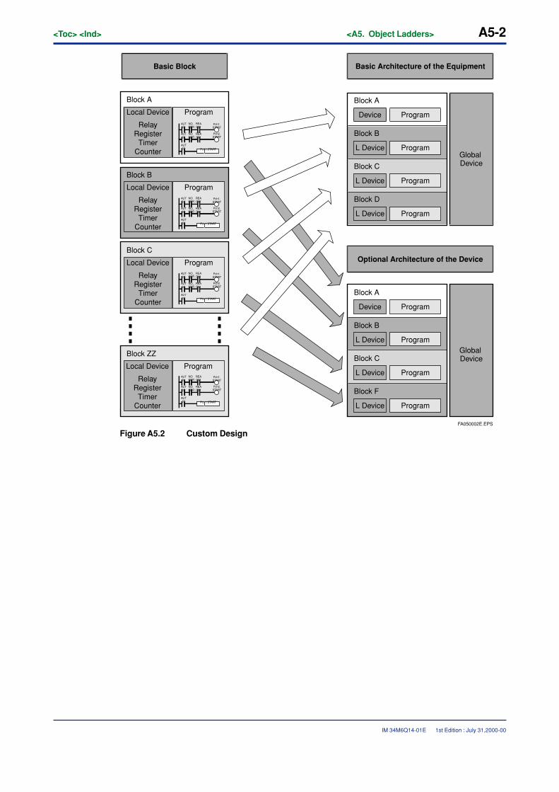
A5-2<Toc> <Ind> <A5. Object Ladders>
IM 34M6Q14-01E
FA050002E.EPS
AUT01
NO_ERR
NO_ERR
AUT02
AUT03
READY1
READY1
Pch1.START
Pch1.START
Pch2.START
AUT01
NO_ERR
NO_ERR
AUT02
AUT03
READY1
READY1
Pch1.START
Pch1.START
Pch2.START
AUT01
NO_ERR
NO_ERR
AUT02
AUT03
READY1
READY1
Pch1.START
Pch1.START
Pch2.START
AUT01
NO_ERR
NO_ERR
AUT02
AUT03
READY1
READY1
Pch1.START
Pch1.START
Pch2.START
Basic Block
Local Device
Block A
Block B
Block C
Block ZZ
Program
RelayRegister
TimerCounter
Local Device Program
RelayRegister
TimerCounter
Local Device Program
RelayRegister
TimerCounter
Local Device Program
RelayRegister
TimerCounter
Basic Architecture of the Equipment
Block A
Device Program
Block B
L Device Program
Block C
L Device Program
Block D
L Device Program
Global Device
Block A
Device Program
Block B
L Device Program
Block C
L Device Program
Block F
L Device Program
Global Device
Optional Architecture of the Device
Figure A5.2 Custom Design
1st Edition : July 31,2000-00
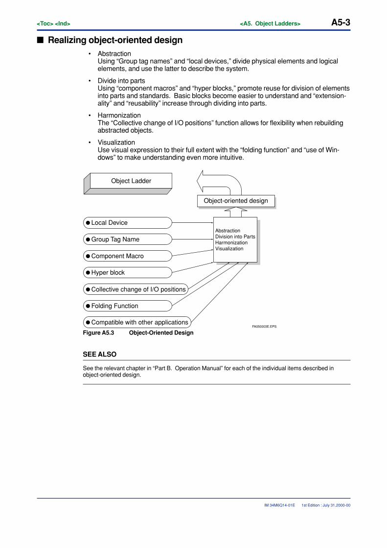
<Toc> <Ind> <A5. Object Ladders> A5-3
IM 34M6Q14-01E
� Realizing object-oriented design• Abstraction
Using “Group tag names” and “local devices,” divide physical elements and logicalelements, and use the latter to describe the system.
• Divide into partsUsing “component macros” and “hyper blocks,” promote reuse for division of elementsinto parts and standards. Basic blocks become easier to understand and “extension-ality” and “reusability” increase through dividing into parts.
• HarmonizationThe “Collective change of I/O positions” function allows for flexibility when rebuildingabstracted objects.
• VisualizationUse visual expression to their full extent with the “folding function” and “use of Win-dows” to make understanding even more intuitive.
Local Device
Group Tag Name
Component Macro
Hyper block
Collective change of I/O positions
Folding Function
Compatible with other applicationsFA050003E.EPS
AbstractionDivision into PartsHarmonizationVisualization
Object Ladder
Object-oriented design
Figure A5.3 Object-Oriented Design
SEE ALSO
See the relevant chapter in “Part B. Operation Manual” for each of the individual items described inobject-oriented design.
1st Edition : July 31,2000-00
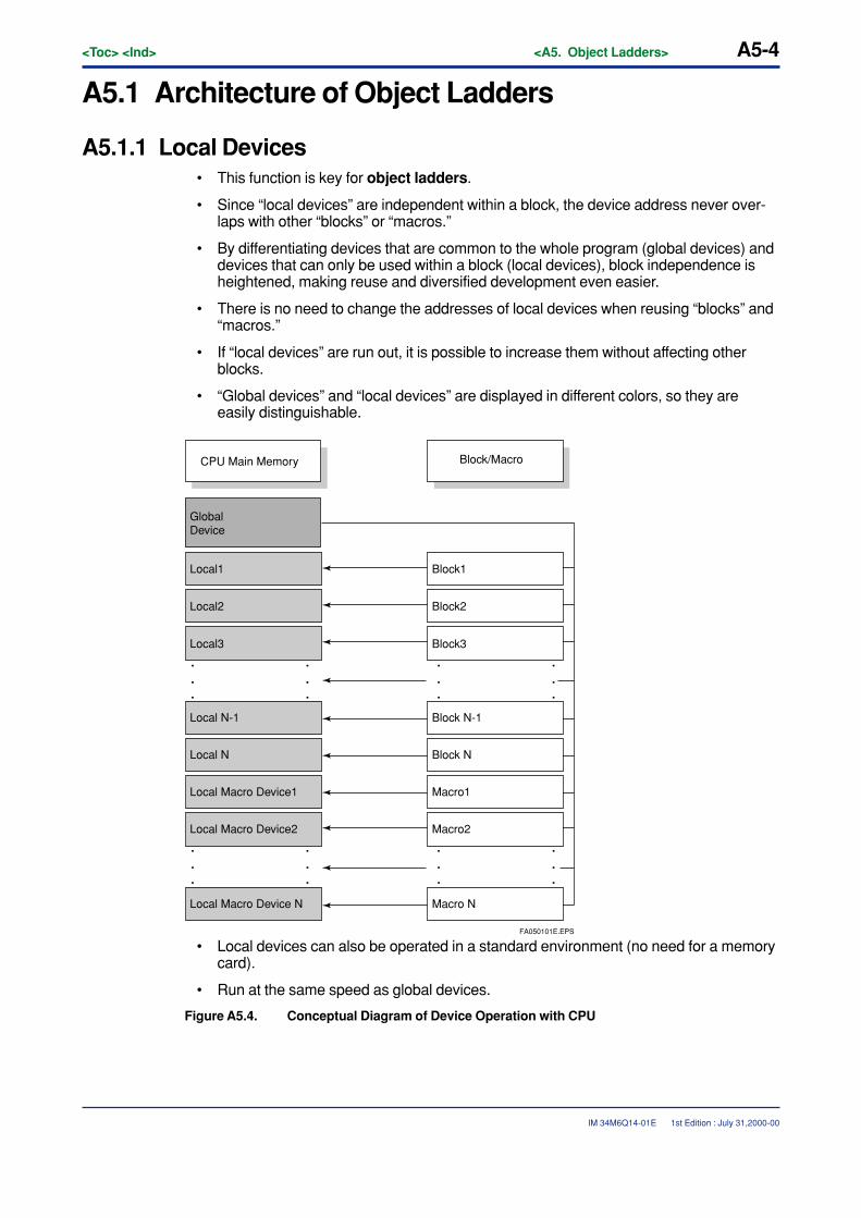
A5-4<Toc> <Ind> <A5. Object Ladders>
IM 34M6Q14-01E
A5.1 Architecture of Object Ladders
A5.1.1 Local Devices• This function is key for object ladders.
• Since “local devices” are independent within a block, the device address never over-laps with other “blocks” or “macros.”
• By differentiating devices that are common to the whole program (global devices) anddevices that can only be used within a block (local devices), block independence isheightened, making reuse and diversified development even easier.
• There is no need to change the addresses of local devices when reusing “blocks” and“macros.”
• If “local devices” are run out, it is possible to increase them without affecting otherblocks.
• “Global devices” and “local devices” are displayed in different colors, so they areeasily distinguishable.
. .
. .
. .
. .
. .
. .
. .
. .
. .
. .
. .
. .
CPU Main Memory Block/Macro
Block1
Block2
Block3
Block N-1
Block N
Macro1
Macro2
Macro N
Global Device
Local1
Local2
Local3
Local N-1
Local N
Local Macro Device1
Local Macro Device2
Local Macro Device N
FA050101E.EPS
• Local devices can also be operated in a standard environment (no need for a memorycard).
• Run at the same speed as global devices.
Figure A5.4. Conceptual Diagram of Device Operation with CPU
1st Edition : July 31,2000-00
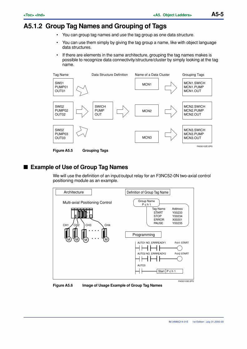
<Toc> <Ind> <A5. Object Ladders> A5-5
IM 34M6Q14-01E
A5.1.2 Group Tag Names and Grouping of Tags• You can group tag names and use the tag group as one data structure.
• You can use them simply by giving the tag group a name, like with object languagedata structures.
• If there are elements in the same architecture, grouping the tag names makes ispossible to recognize data connectivity/structure/cluster by simply looking at the tagname.
SW01PUMP01OUT01
SW02PUMP03OUT03
SW02PUMP02OUT02
SWICHPUMPOUT
MCN1
MCN3
MCN2
MCN1.SWICHMCN1.PUMPMCN1.OUT
MCN3.SWICHMCN3.PUMPMCN3.OUT
MCN2.SWICHMCN2.PUMPMCN2.OUT
Tag Name Data Structure Definition Name of a Data Cluster Grouping Tags
FA050102E.EPS
Figure A5.5 Grouping Tags
� Example of Use of Group Tag NamesWe will use the definition of an input/output relay for an F3NC52-0N two-axial controlpositioning module as an example.
FA050103E.EPS
Architecture
Programming
Definition of Group Tag Name
Group NameP c h 1
Tag Name AddressSTARTSTOPERRORPAUSE
Y00233Y00234X00201Y00235
Start P c h 1
AUTO1 NO_ERRREADY1
AUTO2 NO_ERRREADY2
AUTO3
Pch1 START
Pch2 START
Multi-axial Positioning Control
CH1 CH3 CH4
M MMM
CH2
Figure A5.6 Image of Usage Example of Group Tag Names
1st Edition : July 31,2000-00
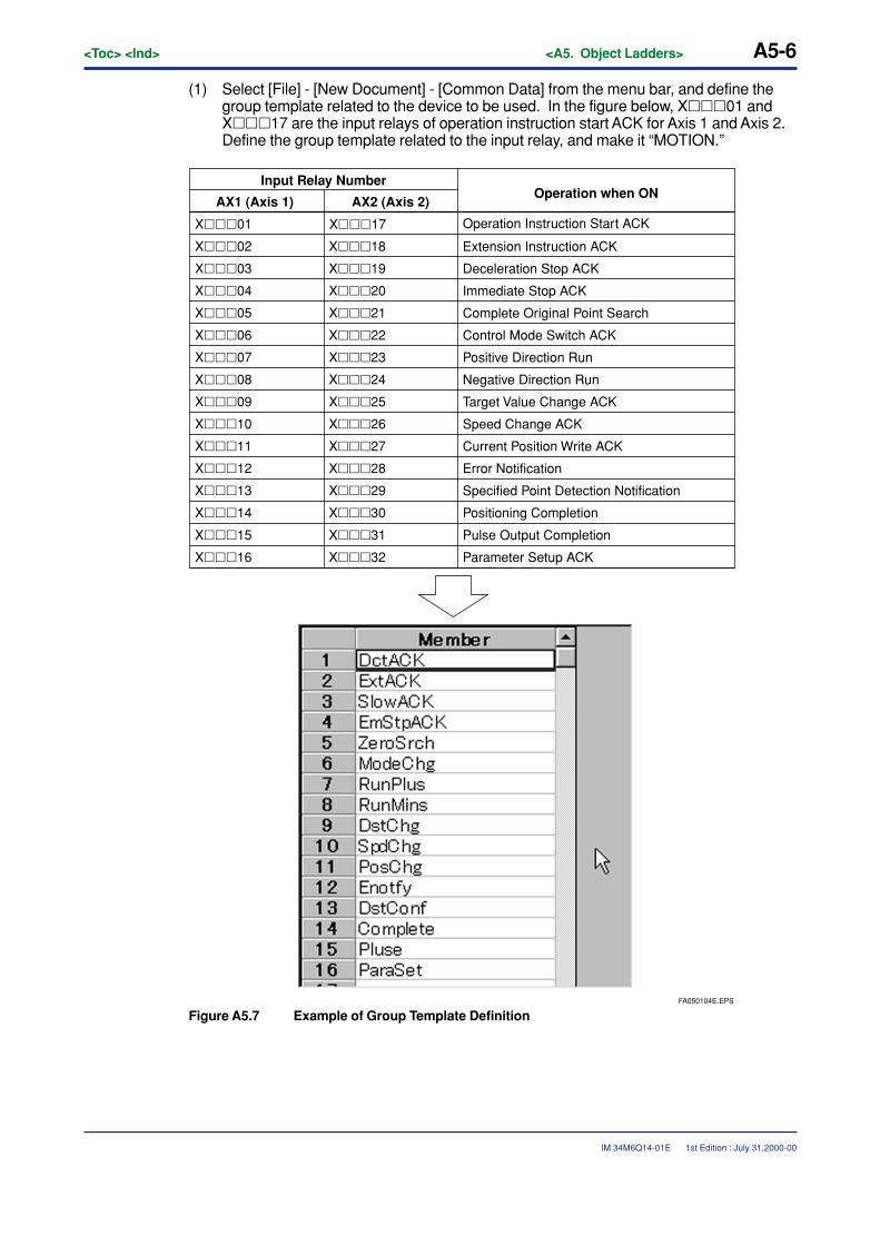
A5-6<Toc> <Ind> <A5. Object Ladders>
IM 34M6Q14-01E
(1) Select [File] - [New Document] - [Common Data] from the menu bar, and define thegroup template related to the device to be used. In the figure below, X���01 andX���17 are the input relays of operation instruction start ACK for Axis 1 and Axis 2.Define the group template related to the input relay, and make it “MOTION.”
FA050104E.EPS
Input Relay Number
AX1 (Axis 1) AX2 (Axis 2)
X���01
X���02
X���03
X���04
X���05
X���06
X���07
X���08
X���09
X���10
X���11
X���12
X���13
X���14
X���18
X���19
X���20
X���21
X���22
X���23
X���24
X���25
X���26
X���27
X���28
X���29
X���30
X���15 X���31
X���16 X���32
Extension Instruction ACK
Operation Instruction Start ACK
Deceleration Stop ACK
Immediate Stop ACK
Complete Original Point Search
Control Mode Switch ACK
Positive Direction Run
Negative Direction Run
Target Value Change ACK
Speed Change ACK
Current Position Write ACK
Error Notification
Specified Point Detection Notification
Positioning Completion
Pulse Output Completion
Parameter Setup ACK
X���17
Operation when ON
Figure A5.7 Example of Group Template Definition
1st Edition : July 31,2000-00
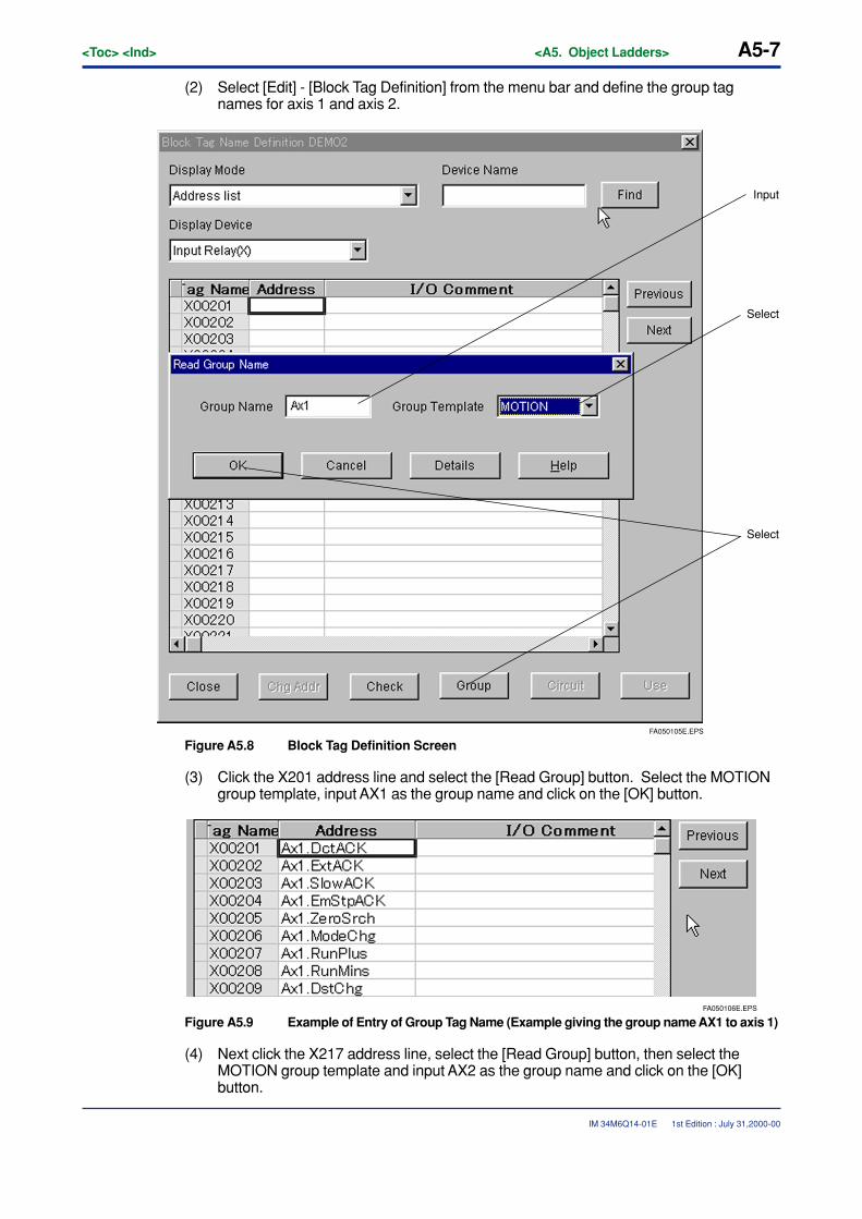
<Toc> <Ind> <A5. Object Ladders> A5-7
IM 34M6Q14-01E 1st Edition : July 31,2000-00
(2) Select [Edit] - [Block Tag Definition] from the menu bar and define the group tagnames for axis 1 and axis 2.
FA050105E.EPS
Input
Select
Select
Figure A5.8 Block Tag Definition Screen
(3) Click the X201 address line and select the [Read Group] button. Select the MOTIONgroup template, input AX1 as the group name and click on the [OK] button.
FA050106E.EPS
Figure A5.9 Example of Entry of Group Tag Name (Example giving the group name AX1 to axis 1)
(4) Next click the X217 address line, select the [Read Group] button, then select theMOTION group template and input AX2 as the group name and click on the [OK]button.
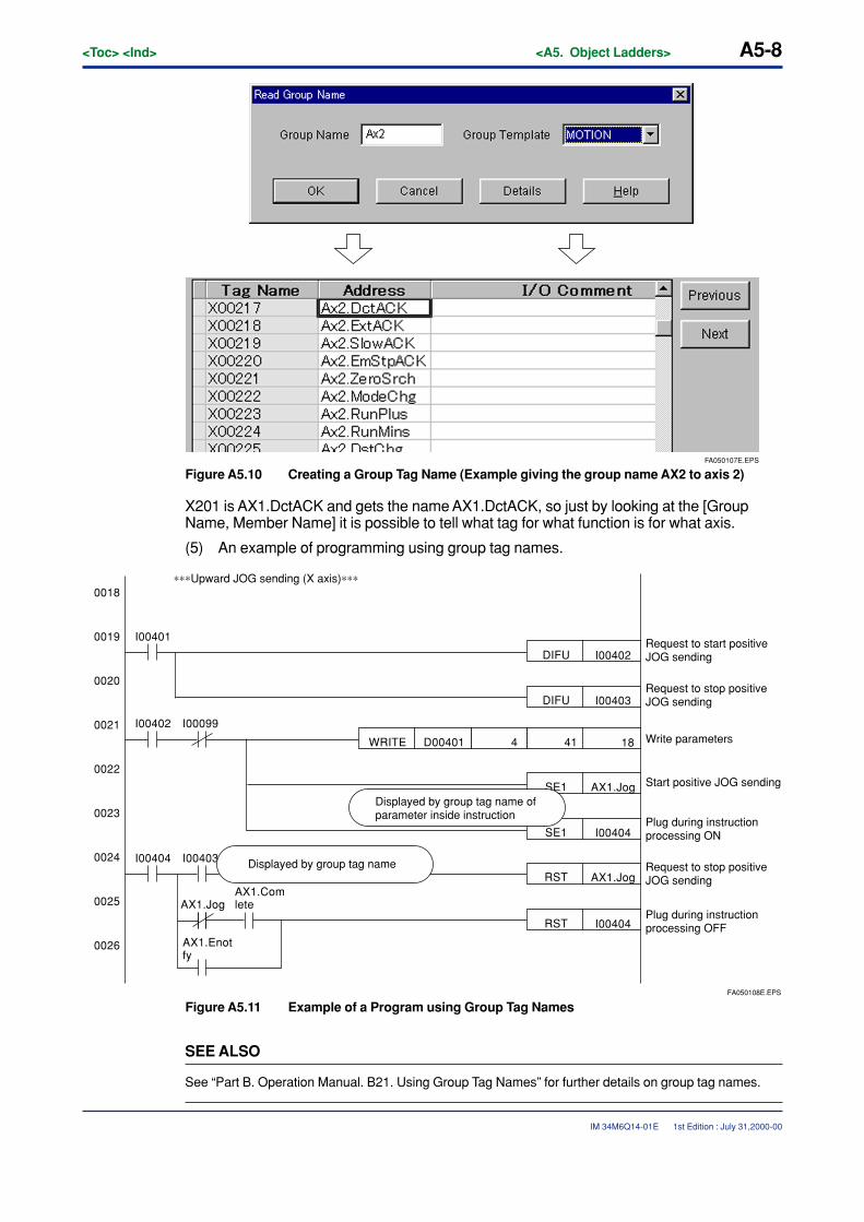
A5-8<Toc> <Ind> <A5. Object Ladders>
IM 34M6Q14-01E 1st Edition : July 31,2000-00
FA050107E.EPS
Figure A5.10 Creating a Group Tag Name (Example giving the group name AX2 to axis 2)
X201 is AX1.DctACK and gets the name AX1.DctACK, so just by looking at the [GroupName, Member Name] it is possible to tell what tag for what function is for what axis.
(5) An example of programming using group tag names.
FA050108E.EPS
I00402DIFU
I00401
I00402 I00099
0018
0019
0020
0021
0022
0023
0024
0025
0026
Request to start positive JOG sending
Request to stop positive JOG sending
Start positive JOG sending
Plug during instruction processing ON
Plug during instruction processing OFF
Write parameters
Request to stop positive JOG sending
I00403DIFU
414D00401WRITE 18
SE1 AX1.Jog
SE1 I00404
RST AX1.Jog
RST I00404
I00404 I00403
AX1.Jog
AX1.Enotfy
AX1.Comlete
Displayed by group tag name of parameter inside instruction
Displayed by group tag name
∗∗∗Upward JOG sending (X axis)∗∗∗
Figure A5.11 Example of a Program using Group Tag Names
SEE ALSO
See “Part B. Operation Manual. B21. Using Group Tag Names” for further details on group tag names.
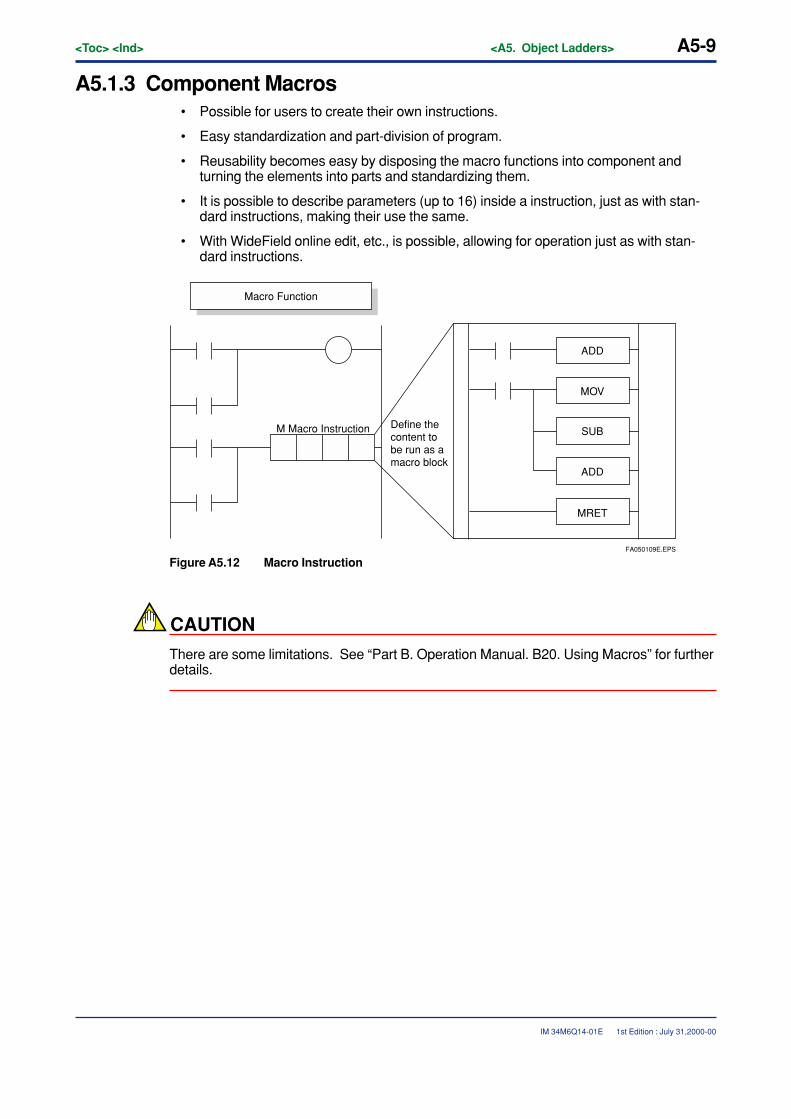
<Toc> <Ind> <A5. Object Ladders> A5-9
IM 34M6Q14-01E
A5.1.3 Component Macros• Possible for users to create their own instructions.
• Easy standardization and part-division of program.
• Reusability becomes easy by disposing the macro functions into component andturning the elements into parts and standardizing them.
• It is possible to describe parameters (up to 16) inside a instruction, just as with stan-dard instructions, making their use the same.
• With WideField online edit, etc., is possible, allowing for operation just as with stan-dard instructions.
M Macro Instruction
ADD
MOV
SUB
ADD
MRET
Macro Function
Define the content to be run as a macro block
FA050109E.EPS
Figure A5.12 Macro Instruction
CAUTION
There are some limitations. See “Part B. Operation Manual. B20. Using Macros” for furtherdetails.
1st Edition : July 31,2000-00
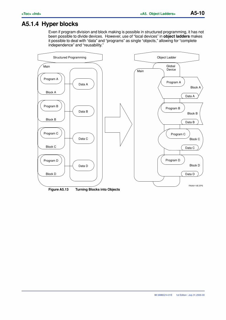
A5-10<Toc> <Ind> <A5. Object Ladders>
IM 34M6Q14-01E 1st Edition : July 31,2000-00
A5.1.4 Hyper blocksEven if program division and block making is possible in structured programming, it has notbeen possible to divide devices. However, use of “local devices” in object ladders makesit possible to deal with “data” and “programs” as single “objects,” allowing for “completeindependence” and “reusability.”
Data A
Data B
Data C
Data D
Program A
Block A
Program D
Block D
Program C
Block C
Program B
Block B
Structured Programming Object Ladder
Program A
Block A
Data A
Program D
Block D
Data D
Program C
Block C
Data C
Program B
Block B
Data B
Global DeviceMain
Main
FA050110E.EPS
Figure A5.13 Turning Blocks into Objects
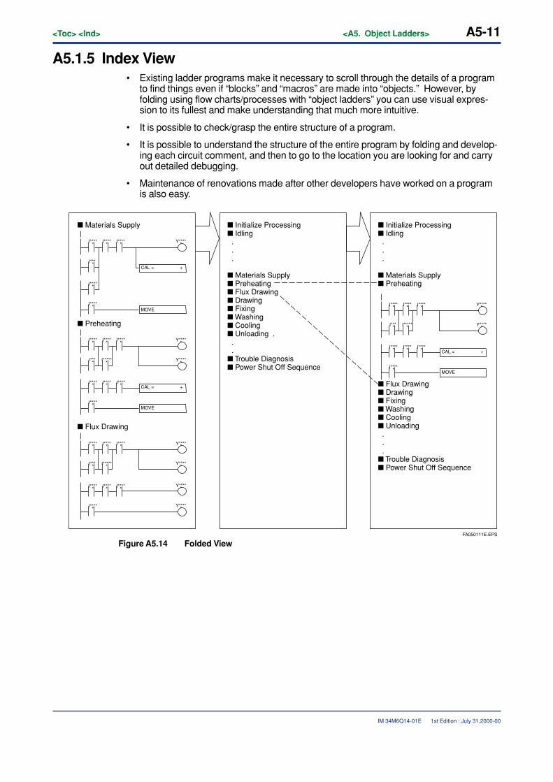
<Toc> <Ind> <A5. Object Ladders> A5-11
IM 34M6Q14-01E 1st Edition : July 31,2000-00
A5.1.5 Index View• Existing ladder programs make it necessary to scroll through the details of a program
to find things even if “blocks” and “macros” are made into “objects.” However, byfolding using flow charts/processes with “object ladders” you can use visual expres-sion to its fullest and make understanding that much more intuitive.
• It is possible to check/grasp the entire structure of a program.
• It is possible to understand the structure of the entire program by folding and develop-ing each circuit comment, and then to go to the location you are looking for and carryout detailed debugging.
• Maintenance of renovations made after other developers have worked on a programis also easy.
CAL = +
MOVE
CAL = +
MOVE
CAL = +
MOVE
� Flux Drawing
� Preheating
� Materials Supply � Initialize Processing� Idling . . .
� Materials Supply� Preheating� Flux Drawing� Drawing� Fixing� Washing� Cooling� Unloading . . .� Trouble Diagnosis� Power Shut Off Sequence
� Initialize Processing� Idling . . .
� Materials Supply� Preheating
� Flux Drawing� Drawing� Fixing� Washing� Cooling� Unloading . . .� Trouble Diagnosis� Power Shut Off Sequence
FA050111E.EPS
Y*****
Y*****
I*****
I*****
I*** *
I*****
I*****
I*****
I*****
I*****
I******
Y*****
Y*****
Y*****
Y*****
I*****
I*****
I*** *
I*****
I*****
I*****
I*****
I*****
I******
Y*****
Y*****
I*****
I*****
I*** *
I*****
I*****
I*****
Y*****
I*****
I*****
I*** *
I*****
I*****
I*****
I*****
I*****
I******
Figure A5.14 Folded View
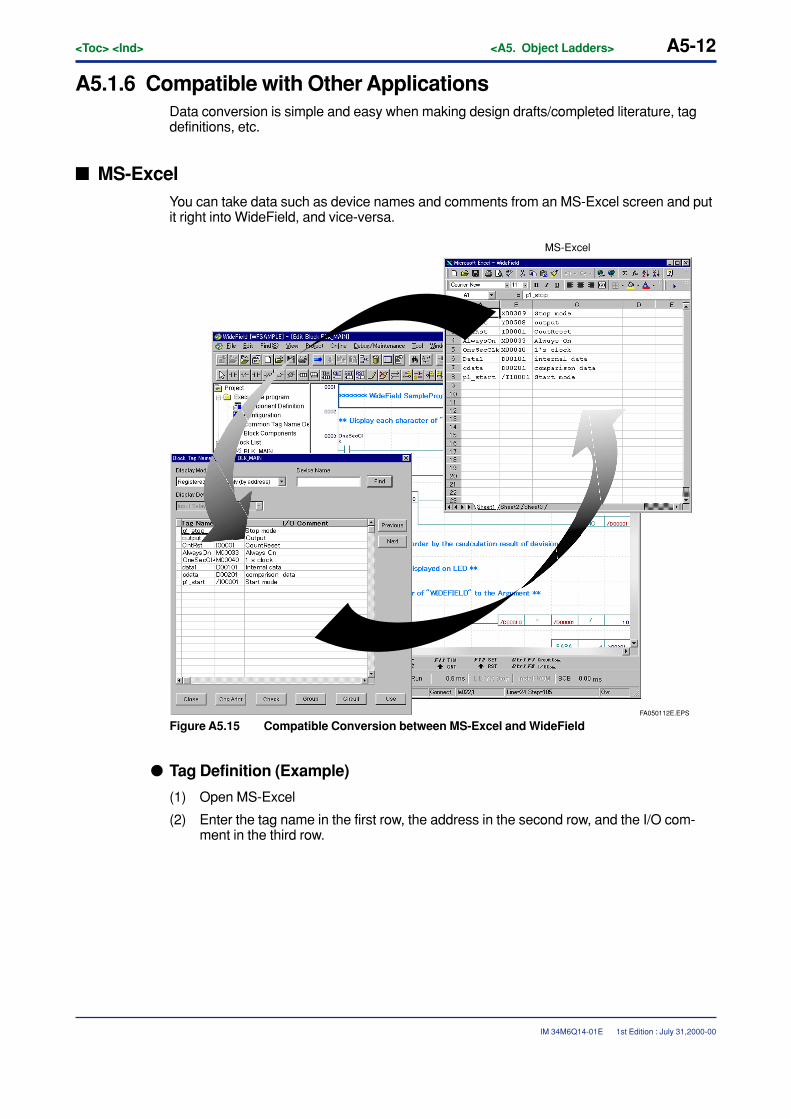
A5-12<Toc> <Ind> <A5. Object Ladders>
IM 34M6Q14-01E
A5.1.6 Compatible with Other ApplicationsData conversion is simple and easy when making design drafts/completed literature, tagdefinitions, etc.
� MS-ExcelYou can take data such as device names and comments from an MS-Excel screen and putit right into WideField, and vice-versa.
FA050112E.EPS
MS-Excel
Figure A5.15 Compatible Conversion between MS-Excel and WideField
� Tag Definition (Example)
(1) Open MS-Excel
(2) Enter the tag name in the first row, the address in the second row, and the I/O com-ment in the third row.
1st Edition : July 31,2000-00
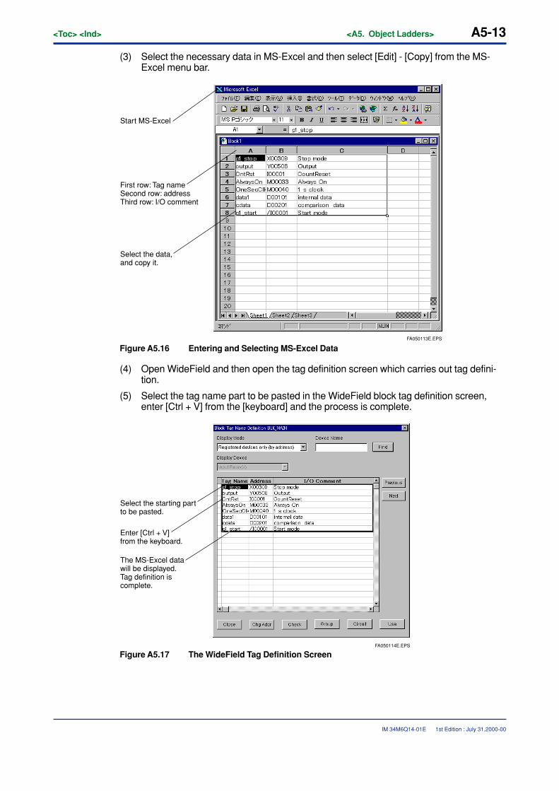
<Toc> <Ind> <A5. Object Ladders> A5-13
IM 34M6Q14-01E
(3) Select the necessary data in MS-Excel and then select [Edit] - [Copy] from the MS-Excel menu bar.
FA050113E.EPS
First row: Tag nameSecond row: addressThird row: I/O comment
Select the data, and copy it.
Start MS-Excel
Figure A5.16 Entering and Selecting MS-Excel Data
(4) Open WideField and then open the tag definition screen which carries out tag defini-tion.
(5) Select the tag name part to be pasted in the WideField block tag definition screen,enter [Ctrl + V] from the [keyboard] and the process is complete.
FA050114E.EPS
Select the starting part to be pasted.
Enter [Ctrl + V] from the keyboard.
The MS-Excel data will be displayed.Tag definition is complete.
Figure A5.17 The WideField Tag Definition Screen
1st Edition : July 31,2000-00
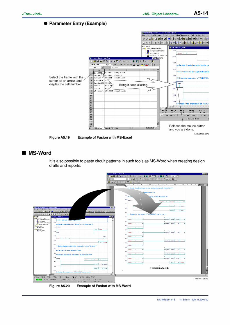
A5-14<Toc> <Ind> <A5. Object Ladders>
IM 34M6Q14-01E
� Parameter Entry (Example)
FA050115E.EPS
Select the frame with the cursor as an arrow, and display the cell number.
Release the mouse button and you are done.
Bring it keep clicking.
Figure A5.19 Example of Fusion with MS-Excel
� MS-WordIt is also possible to paste circuit patterns in such tools as MS-Word when creating designdrafts and reports.
FA050116.EPS
Figure A5.20 Example of Fusion with MS-Word
1st Edition : July 31,2000-00
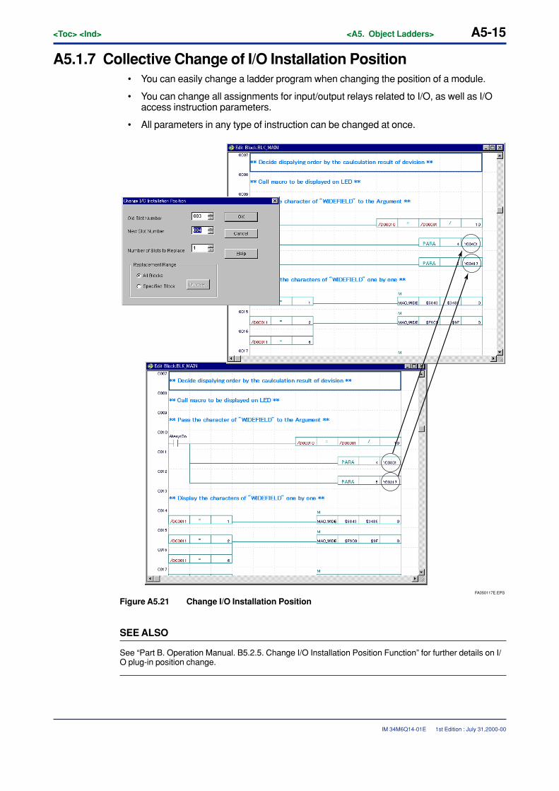
<Toc> <Ind> <A5. Object Ladders> A5-15
IM 34M6Q14-01E 1st Edition : July 31,2000-00
A5.1.7 Collective Change of I/O Installation Position• You can easily change a ladder program when changing the position of a module.
• You can change all assignments for input/output relays related to I/O, as well as I/Oaccess instruction parameters.
• All parameters in any type of instruction can be changed at once.
FA050117E.EPS
Figure A5.21 Change I/O Installation Position
SEE ALSO
See “Part B. Operation Manual. B5.2.5. Change I/O Installation Position Function” for further details on I/O plug-in position change.

Blank Page
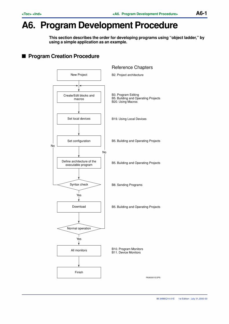
<Toc> <Ind> <A6. Program Development Procedure> A6-1
IM 34M6Q14-01E
A6. Program Development ProcedureThis section describes the order for developing programs using “object ladder,” byusing a simple application as an example.
� Program Creation Procedure
New Project
Finish
All monitors
Normal operation
Syntax check
Download
Define architecture of the executable program
Set configuration
Set local devices
Create/Edit blocks and macros
B10. Program MonitorsB11. Device Monitors
B5. Building and Operating Projects
B2. Project architecture
B3. Program EditingB5. Building and Operating ProjectsB20. Using Macros
B19. Using Local Devices
B5. Building and Operating Projects
B5. Building and Operating Projects
B8. Sending Programs
No
No
Yes
Yes
Reference Chapters
FA060001E.EPS
1st Edition : July 31,2000-00
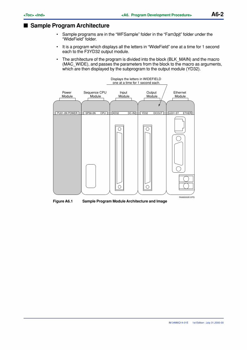
A6-2<Toc> <Ind> <A6. Program Development Procedure>
IM 34M6Q14-01E
� Sample Program Architecture• Sample programs are in the “WFSample” folder in the “Fam3pjt” folder under the
“WideField” folder.
• It is a program which displays all the letters in “WideField” one at a time for 1 secondeach to the F3YD32 output module.
• The architecture of the program is divided into the block (BLK_MAIN) and the macro(MAC_WIDE), and passes the parameters from the block to the macro as arguments,which are then displayed by the subprogram to the output module (YD32).
PU01-0N POWER SP58-0N CPU XD32 DC-IN YD32 DCOUT LE01-ST ETHER
Power Module
Sequence CPU Module
Input Module
Output Module
Ethernet Module
Displays the letters in WIDEFIELD one at a time for 1 second each.
FA060002E.EPS
Figure A6.1 Sample Program Module Architecture and Image
1st Edition : July 31,2000-00
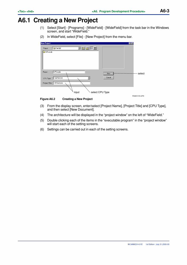
<Toc> <Ind> <A6. Program Development Procedure> A6-3
IM 34M6Q14-01E
A6.1 Creating a New Project(1) Select [Start] - [Programs] - [WideField] - [WideField] from the task bar in the Windows
screen, and start “WideField.”
(2) In WideField, select [File] - [New Project] from the menu bar.
FA060101E.EPS
select
input select CPU Type
Figure A6.2 Creating a New Project
(3) From the display screen, enter/select [Project Name], [Project Title] and [CPU Type],and then select [New Document].
(4) The architecture will be displayed in the “project window” on the left of “WideField.”
(5) Double clicking each of the items in the “executable program” in the “project window”will start each of the setting screens.
(6) Settings can be carried out in each of the setting screens.
1st Edition : July 31,2000-00
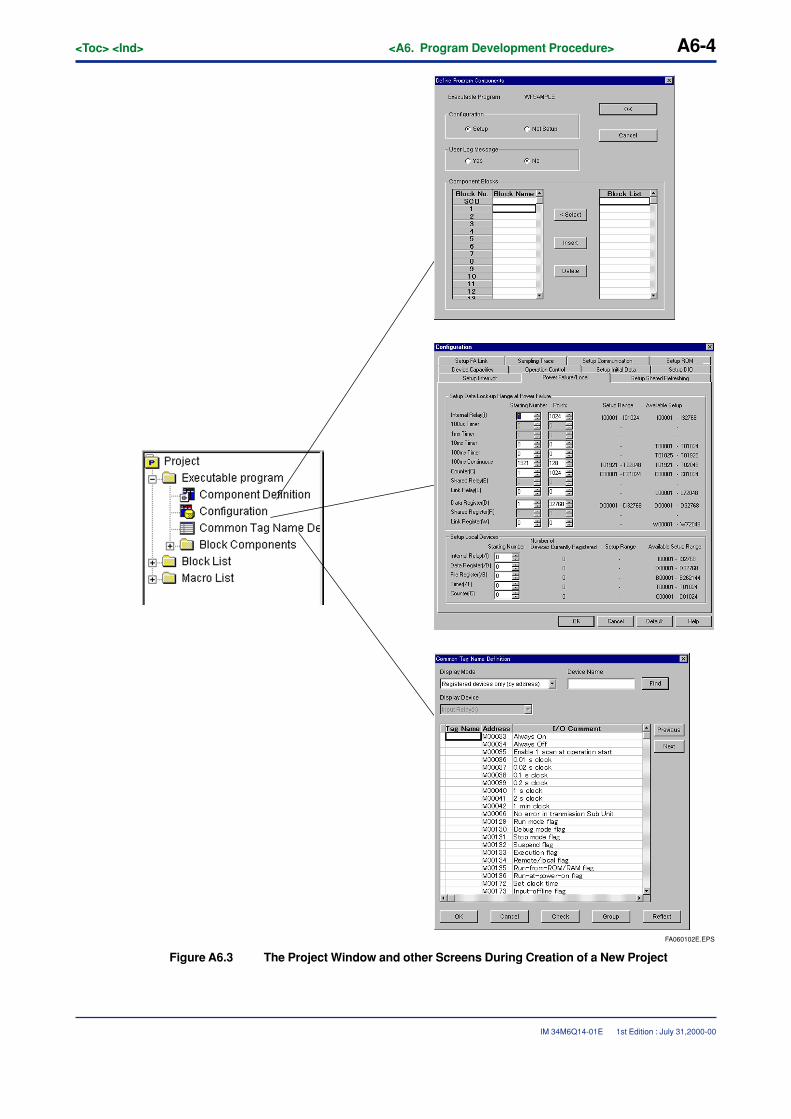
A6-4<Toc> <Ind> <A6. Program Development Procedure>
IM 34M6Q14-01E
FA060102E.EPS
Figure A6.3 The Project Window and other Screens During Creation of a New Project
1st Edition : July 31,2000-00
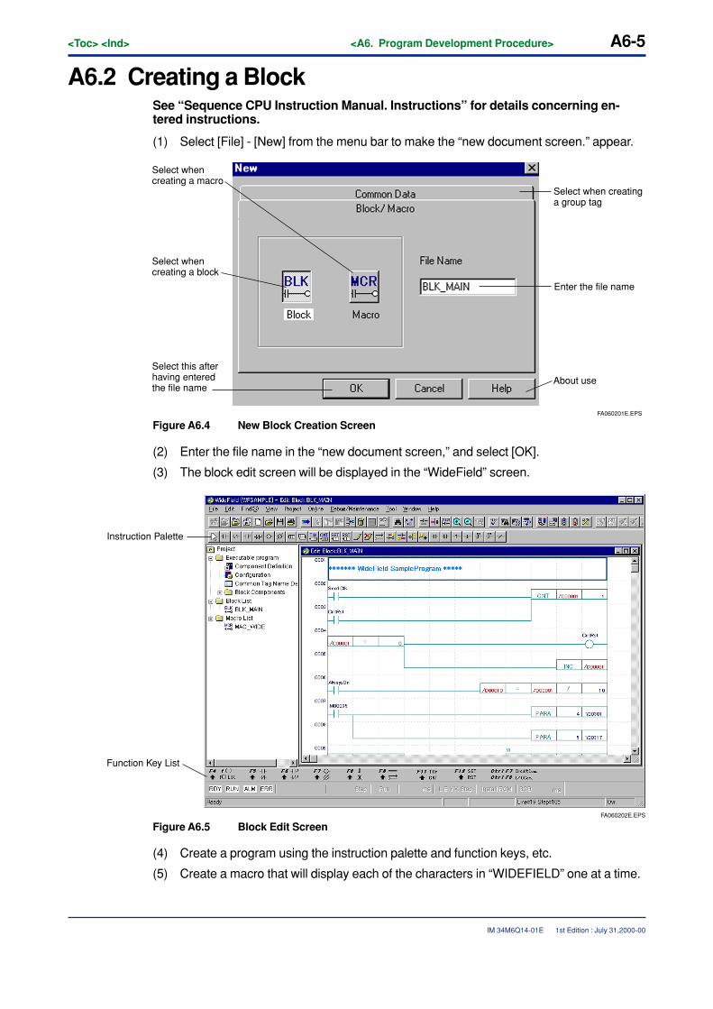
<Toc> <Ind> <A6. Program Development Procedure> A6-5
IM 34M6Q14-01E
A6.2 Creating a BlockSee “Sequence CPU Instruction Manual. Instructions” for details concerning en-tered instructions.
(1) Select [File] - [New] from the menu bar to make the “new document screen.” appear.
FA060201E.EPS
About use
Enter the file name
Select when creating a group tag
Select this after having entered the file name
Select when creating a macro
Select when creating a block
Figure A6.4 New Block Creation Screen
(2) Enter the file name in the “new document screen,” and select [OK].
(3) The block edit screen will be displayed in the “WideField” screen.
FA060202E.EPS
Function Key List
Instruction Palette
Figure A6.5 Block Edit Screen
(4) Create a program using the instruction palette and function keys, etc.
(5) Create a macro that will display each of the characters in “WIDEFIELD” one at a time.
1st Edition : July 31,2000-00
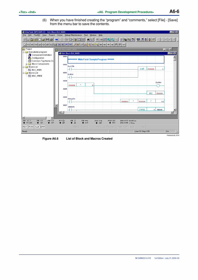
A6-6<Toc> <Ind> <A6. Program Development Procedure>
IM 34M6Q14-01E 1st Edition : July 31,2000-00
(6) When you have finished creating the “program” and “comments,” select [File] - [Save]from the menu bar to save the contents.
FA060203E.EPS
Figure A6.6 List of Block and Macros Created
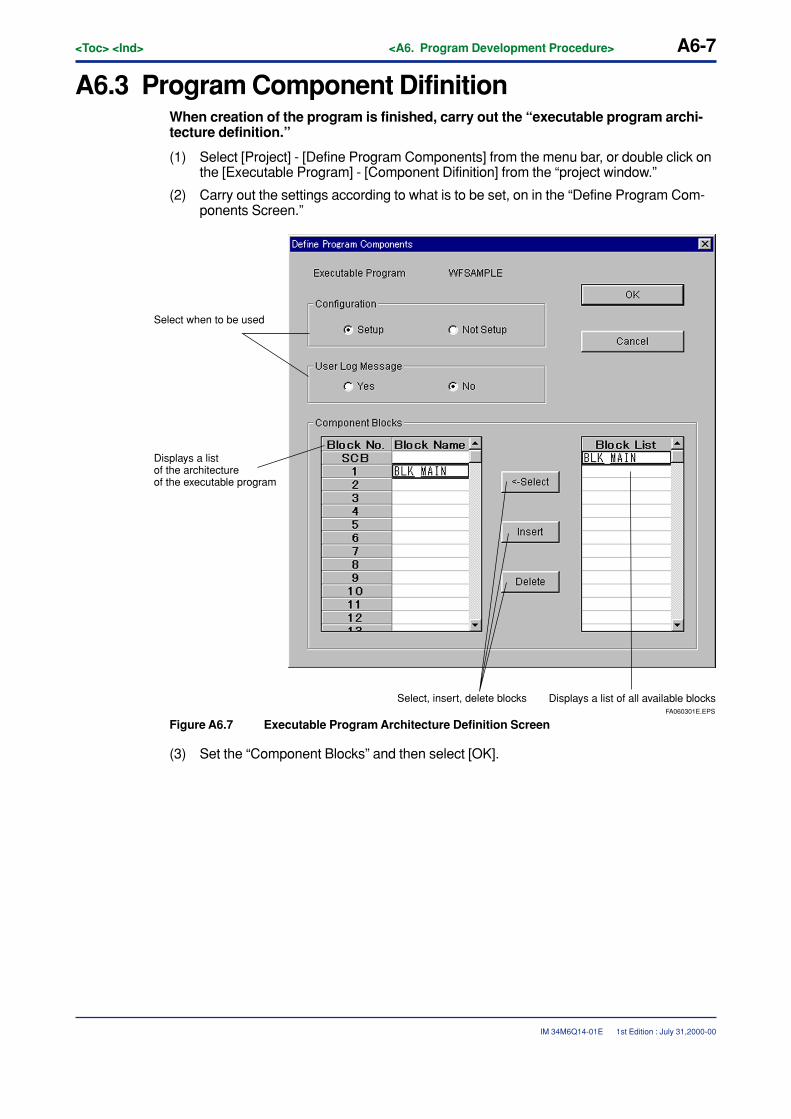
<Toc> <Ind> <A6. Program Development Procedure> A6-7
IM 34M6Q14-01E 1st Edition : July 31,2000-00
A6.3 Program Component DifinitionWhen creation of the program is finished, carry out the “executable program archi-tecture definition.”
(1) Select [Project] - [Define Program Components] from the menu bar, or double click onthe [Executable Program] - [Component Difinition] from the “project window.”
(2) Carry out the settings according to what is to be set, on in the “Define Program Com-ponents Screen.”
FA060301E.EPS
Displays a list of all available blocksSelect, insert, delete blocks
Select when to be used
Displays a list of the architecture of the executable program
Figure A6.7 Executable Program Architecture Definition Screen
(3) Set the “Component Blocks” and then select [OK].
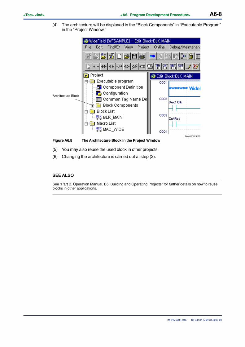
A6-8<Toc> <Ind> <A6. Program Development Procedure>
IM 34M6Q14-01E
(4) The architecture will be displayed in the “Block Components” in “Executable Program”in the “Project Window.”
FA060302E.EPS
Architecture Block
Figure A6.8 The Architecture Block in the Project Window
(5) You may also reuse the used block in other projects.
(6) Changing the architecture is carried out at step (2).
SEE ALSO
See “Part B. Operation Manual. B5. Building and Operating Projects” for further details on how to reuseblocks in other applications.
1st Edition : July 31,2000-00
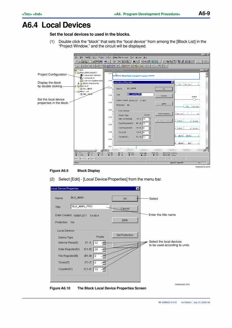
<Toc> <Ind> <A6. Program Development Procedure> A6-9
IM 34M6Q14-01E 1st Edition : July 31,2000-00
A6.4 Local DevicesSet the local devices to used in the blocks.
(1) Double click the “block” that sets the “local device” from among the [Block List] in the“Project Window,” and the circuit will be displayed.
FA060401E.EPS
Project Configuration
Display the block by double clicking
Set the local device properties in the block.
Figure A6.9 Block Display
(2) Select [Edit] - [Local Device/Properties] from the menu bar.
FA060402E.EPS
Select
Enter the title name
Select the local devices to be used according to units.
Figure A6.10 The Block Local Device Properties Screen
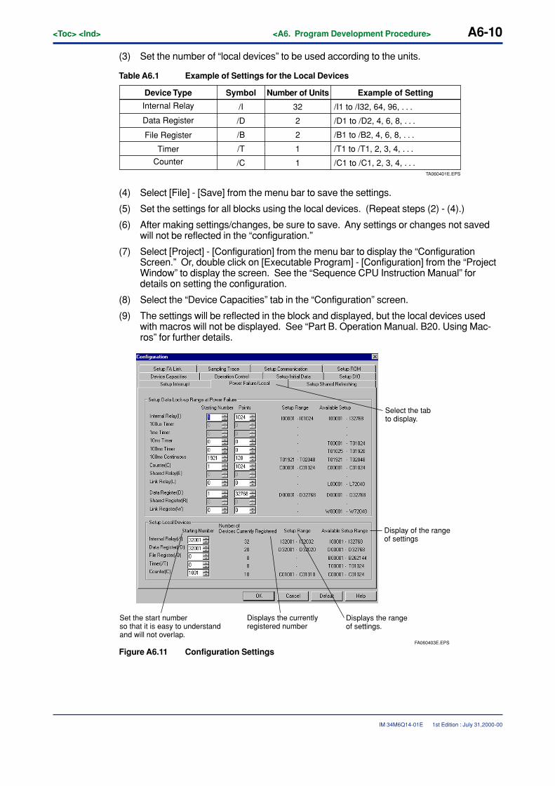
A6-10<Toc> <Ind> <A6. Program Development Procedure>
IM 34M6Q14-01E 1st Edition : July 31,2000-00
(3) Set the number of “local devices” to be used according to the units.
Table A6.1 Example of Settings for the Local Devices
TA060401E.EPS
Counter
Example of SettingDevice Type Symbol Number of Units
Internal Relay
Data Register
File Register
Timer
/I
/D
/B
/T
/C
/I1 to /I32, 64, 96, . . .
/D1 to /D2, 4, 6, 8, . . .
/B1 to /B2, 4, 6, 8, . . .
/T1 to /T1, 2, 3, 4, . . .
/C1 to /C1, 2, 3, 4, . . .
32
2
2
1
1
(4) Select [File] - [Save] from the menu bar to save the settings.
(5) Set the settings for all blocks using the local devices. (Repeat steps (2) - (4).)
(6) After making settings/changes, be sure to save. Any settings or changes not savedwill not be reflected in the “configuration.”
(7) Select [Project] - [Configuration] from the menu bar to display the “ConfigurationScreen.” Or, double click on [Executable Program] - [Configuration] from the “ProjectWindow” to display the screen. See the “Sequence CPU Instruction Manual” fordetails on setting the configuration.
(8) Select the “Device Capacities” tab in the “Configuration” screen.
(9) The settings will be reflected in the block and displayed, but the local devices usedwith macros will not be displayed. See “Part B. Operation Manual. B20. Using Mac-ros” for further details.
FA060403E.EPS
Select the tab to display.
Display of the range of settings
Displays the range of settings.
Displays the currently registered number
Set the start number so that it is easy to understand and will not overlap.
Figure A6.11 Configuration Settings

<Toc> <Ind> <A6. Program Development Procedure> A6-11
IM 34M6Q14-01E 1st Edition : July 31,2000-00
(10) Set the start number so that it is easily distinguishable from the “global devices.”E.g., Data Register (/D) from No. 1001
(11) After selecting “Start Number,” select [OK] from the “Configuration Screen.”
SEE ALSO
See “Part B. Operation Manual. B5. Building and Operating Projects” for further details about the settingitem/content of the “Configuration.”
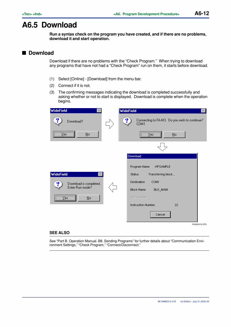
A6-12<Toc> <Ind> <A6. Program Development Procedure>
IM 34M6Q14-01E
A6.5 DownloadRun a syntax check on the program you have created, and if there are no problems,download it and start operation.
� DownloadDownload if there are no problems with the “Check Program.” When trying to downloadany programs that have not had a “Check Program” run on them, it starts before download.
(1) Select [Online] - [Download] from the menu bar.
(2) Connect if it is not.
(3) The confirming messages indicating the download is completed successfully andasking whether or not to start is displayed. Download is complete when the operationbegins.
FA060501E.EPS
SEE ALSO
See “Part B. Operation Manual. B8. Sending Programs” for further details about “Communication Envi-ronment Settings,” “Check Program,” “Connect/Disconnect.”
1st Edition : July 31,2000-00
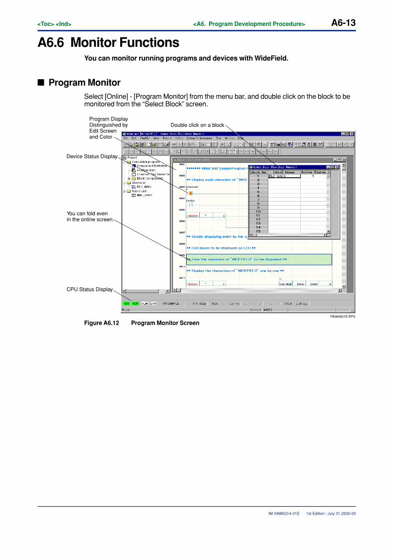
<Toc> <Ind> <A6. Program Development Procedure> A6-13
IM 34M6Q14-01E
A6.6 Monitor FunctionsYou can monitor running programs and devices with WideField.
� Program MonitorSelect [Online] - [Program Monitor] from the menu bar, and double click on the block to bemonitored from the “Select Block” screen.
FA060601E.EPS
Double click on a block
CPU Status Display
Program DisplayDistinguished by Edit Screen and Color
You can fold even in the online screen.
Device Status Display
Figure A6.12 Program Monitor Screen
1st Edition : July 31,2000-00
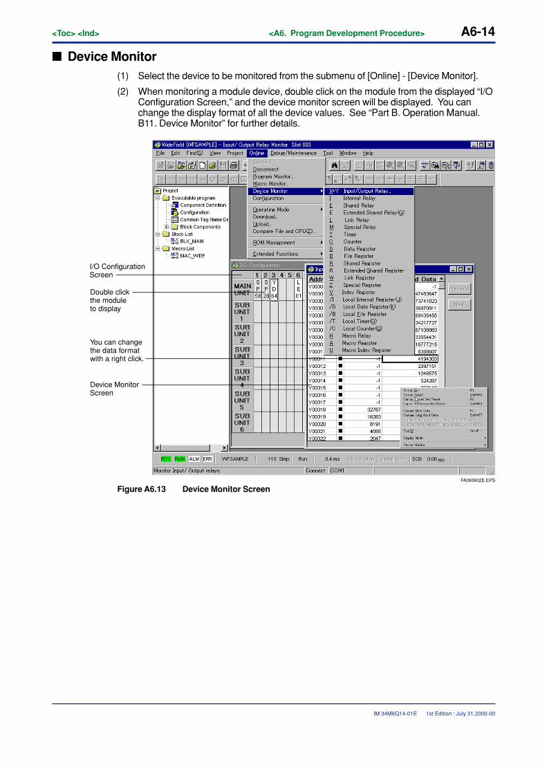
A6-14<Toc> <Ind> <A6. Program Development Procedure>
IM 34M6Q14-01E
� Device Monitor(1) Select the device to be monitored from the submenu of [Online] - [Device Monitor].
(2) When monitoring a module device, double click on the module from the displayed “I/OConfiguration Screen,” and the device monitor screen will be displayed. You canchange the display format of all the device values. See “Part B. Operation Manual.B11. Device Monitor” for further details.
FA060602E.EPS
I/O ConfigurationScreen
Double click the module to display
Device Monitor Screen
You can change the data format with a right click.
Figure A6.13 Device Monitor Screen
1st Edition : July 31,2000-00
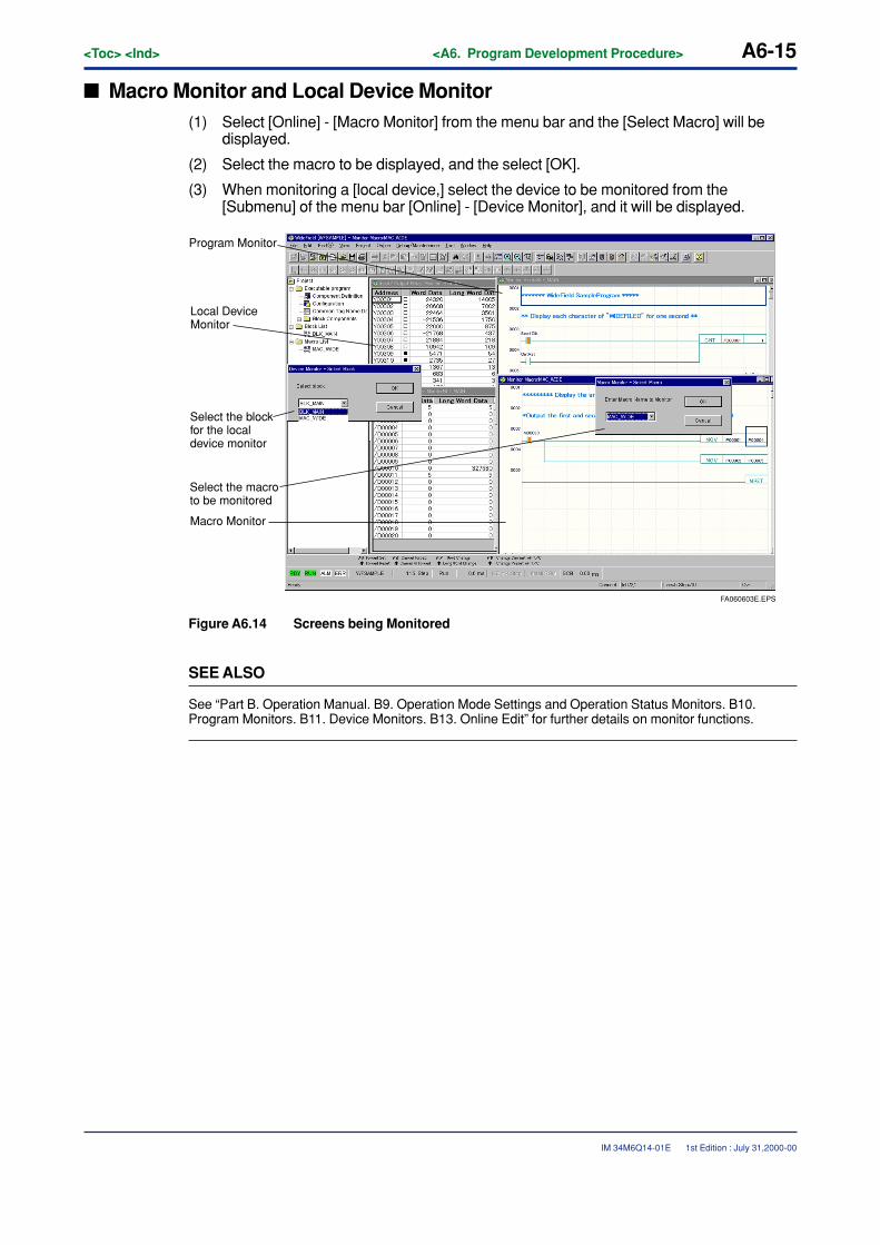
<Toc> <Ind> <A6. Program Development Procedure> A6-15
IM 34M6Q14-01E
� Macro Monitor and Local Device Monitor(1) Select [Online] - [Macro Monitor] from the menu bar and the [Select Macro] will be
displayed.
(2) Select the macro to be displayed, and the select [OK].
(3) When monitoring a [local device,] select the device to be monitored from the[Submenu] of the menu bar [Online] - [Device Monitor], and it will be displayed.
FA060603E.EPS
Program Monitor
Local Device Monitor
Select the block for the local device monitor
Select the macro to be monitored
Macro Monitor
Figure A6.14 Screens being Monitored
SEE ALSO
See “Part B. Operation Manual. B9. Operation Mode Settings and Operation Status Monitors. B10.Program Monitors. B11. Device Monitors. B13. Online Edit” for further details on monitor functions.
1st Edition : July 31,2000-00

Blank Page
TocB-1<Int> <Ind> <Rev>
IM 34M6Q14-01E
CONTENTSB1. Initial Setup of the WideField Tool........................................................ B1-1
B1.1 Layout of the Tools, and Locations of Generated Data .............................. B1-1
B1.2 Environment Setup ....................................................................................... B1-2
B1.2.1 Basic Operation of the Setup Environment Dialog ........................... B1-3
B1.2.2 Setup Folders ................................................................................. B1-5
B1.2.3 Setup Communication .................................................................... B1-6
B1.2.4 Setup Circuit Display ...................................................................... B1-8
B1.2.5 Setup Program Check .................................................................. B1-10
B1.2.6 Setup Toolbar ............................................................................... B1-12
1st Edition : July 31,2000-00
IM 34M6Q14-01E 1st Edition
FA-M3FA-M3 Programming Tool WideField Instruction ManualPART-B Operation Manual

Blank Page
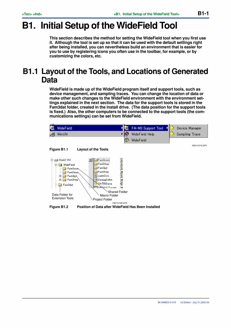
<Toc> <Ind> <B1. Initial Setup of the WideField Tool> B1-1
IM 34M6Q14-01E
B1. Initial Setup of the WideField ToolThis section describes the method for setting the WideField tool when you first useit. Although the tool is set up so that it can be used with the default settings rightafter being installed, you can nevertheless build an environment that is easier foryou to use by registering icons you often use in the toolbar, for example, or bycustomizing the colors, etc.
B1.1 Layout of the Tools, and Locations of GeneratedData
WideField is made up of the WideField program itself and support tools, such asdevice management, and sampling traces. You can change the location of data ormake other such changes to the WideField environment with the environment set-tings explained in the next section. The data for the support tools is stored in theFam3dat folder, created in the install drive. (The data position for the support toolsis fixed.) Also, the other computers to be connected to the support tools (the com-munications settings) can be set from WideField.
FB010101E.EPS
Figure B1.1 Layout of the Tools
FB010102E.EPS
Shared FolderMacro Folder
Project Folder
Data Folder forExtension Tools
Figure B1.2 Position of Data after WideField Has Been Installed
1st Edition : July 31,2000-00
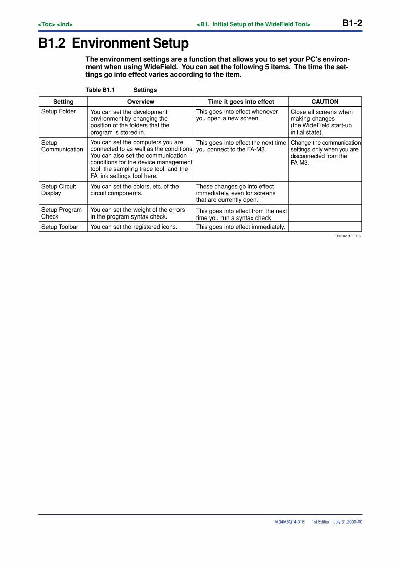
B1-2<Toc> <Ind> <B1. Initial Setup of the WideField Tool>
IM 34M6Q14-01E
B1.2 Environment SetupThe environment settings are a function that allows you to set your PC's environ-ment when using WideField. You can set the following 5 items. The time the set-tings go into effect varies according to the item.
Table B1.1 Settings
TB010201E.EPS
You can set the registered icons.
Setting CAUTIONTime it goes into effectOverview
Setup Folder You can set the development environment by changing the position of the folders that the program is stored in.
This goes into effect whenever you open a new screen.
Close all screens when making changes (the WideField start-up initial state).
Setup Communication
You can set the computers you are connected to as well as the conditions.You can also set the communication conditions for the device management tool, the sampling trace tool, and the FA link settings tool here.
This goes into effect the next time you connect to the FA-M3.
Change the communication settings only when you are disconnected from the FA-M3.
Setup Circuit Display
You can set the colors, etc. of the circuit components.
These changes go into effect immediately, even for screens that are currently open.
Setup Program Check
You can set the weight of the errors in the program syntax check.
This goes into effect from the next time you run a syntax check.
Setup Toolbar This goes into effect immediately.
1st Edition : July 31,2000-00
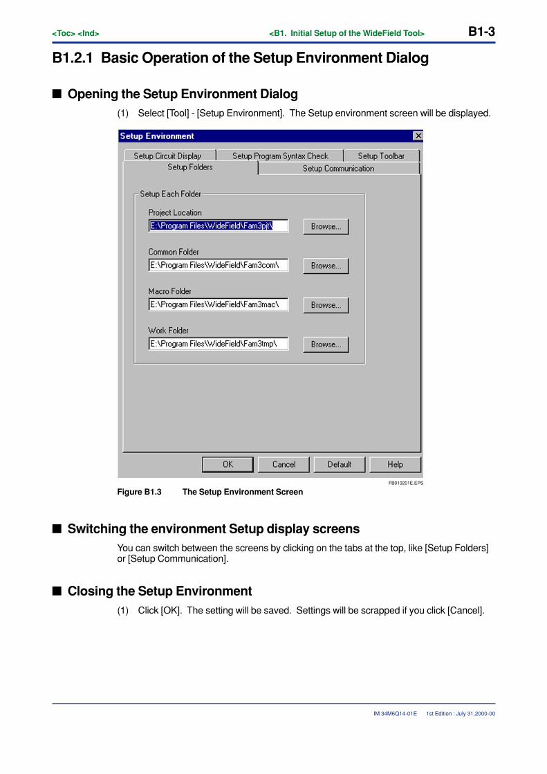
<Toc> <Ind> <B1. Initial Setup of the WideField Tool> B1-3
IM 34M6Q14-01E
B1.2.1 Basic Operation of the Setup Environment Dialog
� Opening the Setup Environment Dialog(1) Select [Tool] - [Setup Environment]. The Setup environment screen will be displayed.
FB010201E.EPS
Figure B1.3 The Setup Environment Screen
� Switching the environment Setup display screensYou can switch between the screens by clicking on the tabs at the top, like [Setup Folders]or [Setup Communication].
� Closing the Setup Environment(1) Click [OK]. The setting will be saved. Settings will be scrapped if you click [Cancel].
1st Edition : July 31,2000-00
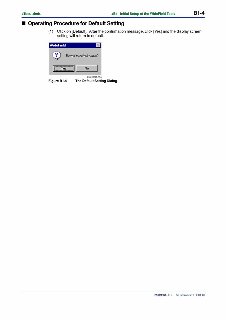
B1-4<Toc> <Ind> <B1. Initial Setup of the WideField Tool>
IM 34M6Q14-01E
� Operating Procedure for Default Setting(1) Click on [Default]. After the confirmation message, click [Yes] and the display screen
setting will return to default.
FB010202E.EPS
Figure B1.4 The Default Setting Dialog
1st Edition : July 31,2000-00
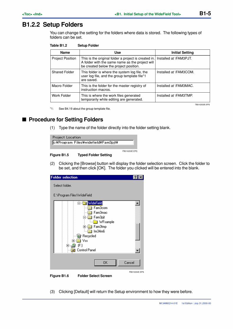
<Toc> <Ind> <B1. Initial Setup of the WideField Tool> B1-5
IM 34M6Q14-01E
B1.2.2 Setup FoldersYou can change the setting for the folders where data is stored. The following types offolders can be set.
Table B1.2 Setup Folder
TB010202E.EPS
Installed at \FAM3TMP.
Name Initial SettingUse
Project Position This is the original folder a project is created in. A folder with the same name as the project will be created below the project position.
Installed at \FAM3PJT.
Shared Folder This folder is where the system log file, the user log file, and the group template file*1 are saved.
Installed at \FAM3COM.
Macro Folder This is the folder for the master registry of instruction macros.
Installed at \FAM3MAC.
Work Folder This is where the work files generated temporarily while editing are generated.
*1: See B4.19 about the group template file.
� Procedure for Setting Folders(1) Type the name of the folder directly into the folder setting blank.
FB010203E.EPS
Figure B1.5 Typed Folder Setting
(2) Clicking the [Browse] button will display the folder selection screen. Click the folder tobe set, and then click [OK]. The folder you clicked will be entered into the blank.
FB010204E.EPS
Figure B1.6 Folder Select Screen
(3) Clicking [Default] will return the Setup environment to how they were before.
1st Edition : July 31,2000-00
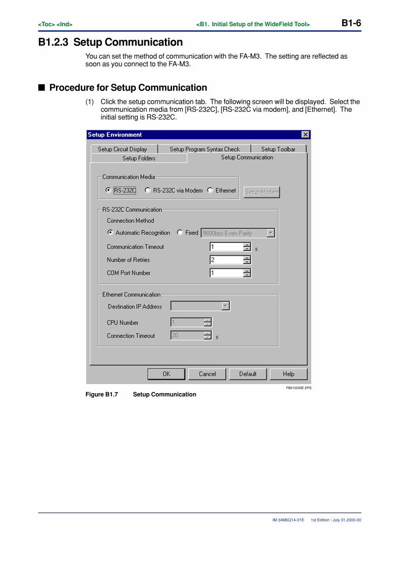
B1-6<Toc> <Ind> <B1. Initial Setup of the WideField Tool>
IM 34M6Q14-01E 1st Edition : July 31,2000-00
B1.2.3 Setup CommunicationYou can set the method of communication with the FA-M3. The setting are reflected assoon as you connect to the FA-M3.
� Procedure for Setup Communication(1) Click the setup communication tab. The following screen will be displayed. Select the
communication media from [RS-232C], [RS-232C via modem], and [Ethernet]. Theinitial setting is RS-232C.
FB010205E.EPS
Figure B1.7 Setup Communication
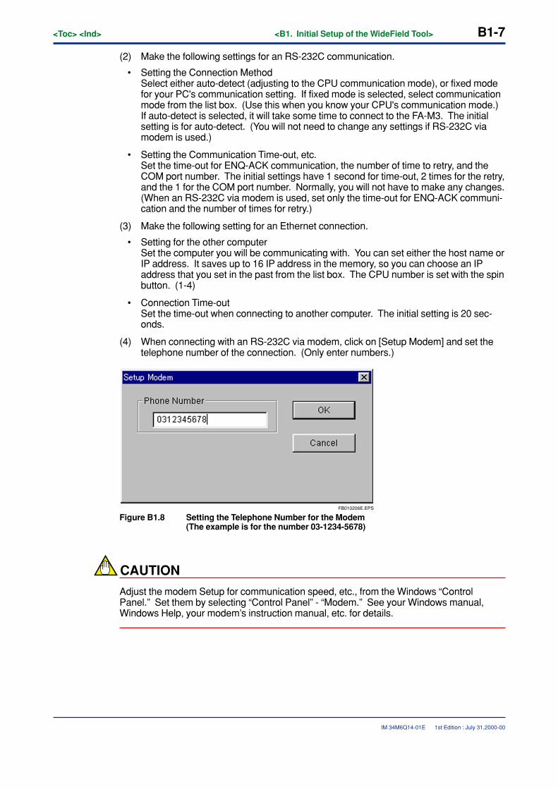
<Toc> <Ind> <B1. Initial Setup of the WideField Tool> B1-7
IM 34M6Q14-01E 1st Edition : July 31,2000-00
(2) Make the following settings for an RS-232C communication.
• Setting the Connection MethodSelect either auto-detect (adjusting to the CPU communication mode), or fixed modefor your PC's communication setting. If fixed mode is selected, select communicationmode from the list box. (Use this when you know your CPU's communication mode.)If auto-detect is selected, it will take some time to connect to the FA-M3. The initialsetting is for auto-detect. (You will not need to change any settings if RS-232C viamodem is used.)
• Setting the Communication Time-out, etc.Set the time-out for ENQ-ACK communication, the number of time to retry, and theCOM port number. The initial settings have 1 second for time-out, 2 times for the retry,and the 1 for the COM port number. Normally, you will not have to make any changes.(When an RS-232C via modem is used, set only the time-out for ENQ-ACK communi-cation and the number of times for retry.)
(3) Make the following setting for an Ethernet connection.
• Setting for the other computerSet the computer you will be communicating with. You can set either the host name orIP address. It saves up to 16 IP address in the memory, so you can choose an IPaddress that you set in the past from the list box. The CPU number is set with the spinbutton. (1-4)
• Connection Time-outSet the time-out when connecting to another computer. The initial setting is 20 sec-onds.
(4) When connecting with an RS-232C via modem, click on [Setup Modem] and set thetelephone number of the connection. (Only enter numbers.)
FB010206E.EPS
Figure B1.8 Setting the Telephone Number for the Modem(The example is for the number 03-1234-5678)
CAUTION
Adjust the modem Setup for communication speed, etc., from the Windows “ControlPanel.” Set them by selecting “Control Panel” - “Modem.” See your Windows manual,Windows Help, your modem’s instruction manual, etc. for details.
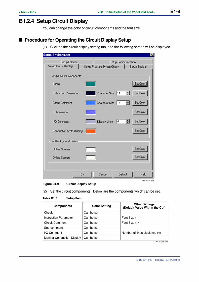
B1-8<Toc> <Ind> <B1. Initial Setup of the WideField Tool>
IM 34M6Q14-01E
B1.2.4 Setup Circuit DisplayYou can change the color of circuit components and the font size.
� Procedure for Operating the Circuit Display Setup(1) Click on the circuit display setting tab, and the following screen will be displayed.
FB010207E.EPS
Figure B1.9 Circuit Display Setup
(2) Set the circuit components. Below are the components which can be set.
Table B1.3 Setup Item
TB010203E.EPS
Monitor Conduction Display
Other Settings(Default Value Within the Cut)Components Color Setting
Circuit Can be set
Can be set
Can be set
Can be set
Can be set
Can be set
Instruction Parameter Font Size (11)
Circuit Comment Font Size (14)
Sub-comment
I/O Comment Number of lines displayed (4)
1st Edition : July 31,2000-00
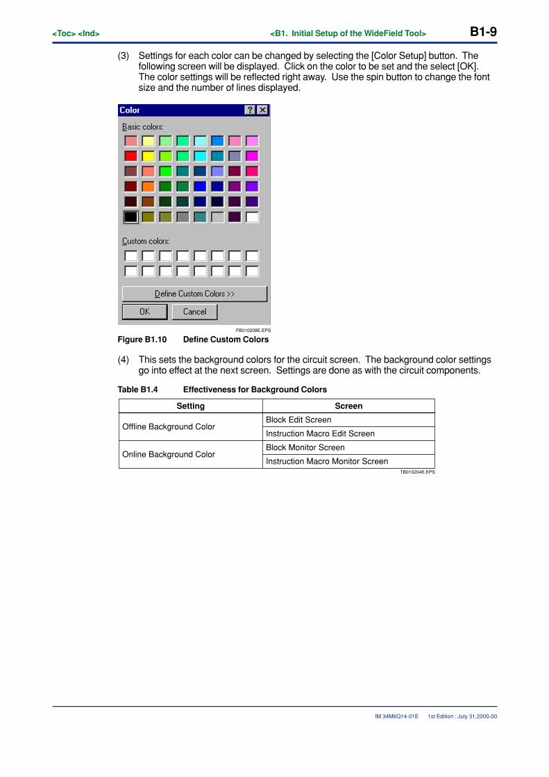
<Toc> <Ind> <B1. Initial Setup of the WideField Tool> B1-9
IM 34M6Q14-01E
(3) Settings for each color can be changed by selecting the [Color Setup] button. Thefollowing screen will be displayed. Click on the color to be set and the select [OK].The color settings will be reflected right away. Use the spin button to change the fontsize and the number of lines displayed.
FB010208E.EPS
Figure B1.10 Define Custom Colors
(4) This sets the background colors for the circuit screen. The background color settingsgo into effect at the next screen. Settings are done as with the circuit components.
Table B1.4 Effectiveness for Background Colors
TB010204E.EPS
Instruction Macro Monitor Screen
Setting Screen
Offline Background ColorBlock Edit Screen
Instruction Macro Edit Screen
Online Background ColorBlock Monitor Screen
1st Edition : July 31,2000-00
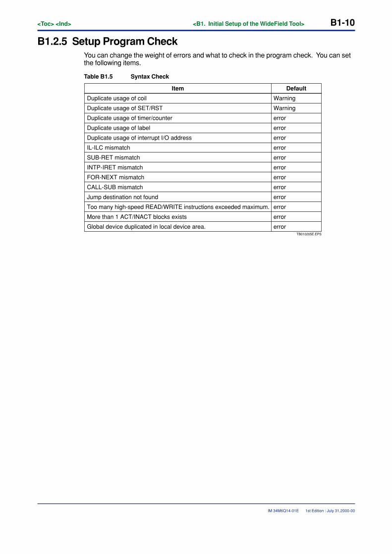
B1-10<Toc> <Ind> <B1. Initial Setup of the WideField Tool>
IM 34M6Q14-01E 1st Edition : July 31,2000-00
B1.2.5 Setup Program CheckYou can change the weight of errors and what to check in the program check. You can setthe following items.
Table B1.5 Syntax Check
TB010205E.EPS
Global device duplicated in local device area.
Item Default
Duplicate usage of coil Warning
WarningDuplicate usage of SET/RST
Duplicate usage of timer/counter error
error
error
error
error
error
error
error
error
error
error
error
Duplicate usage of label
Duplicate usage of interrupt I/O address
IL-ILC mismatch
SUB-RET mismatch
INTP-IRET mismatch
FOR-NEXT mismatch
CALL-SUB mismatch
Jump destination not found
Too many high-speed READ/WRITE instructions exceeded maximum.
More than 1 ACT/INACT blocks exists
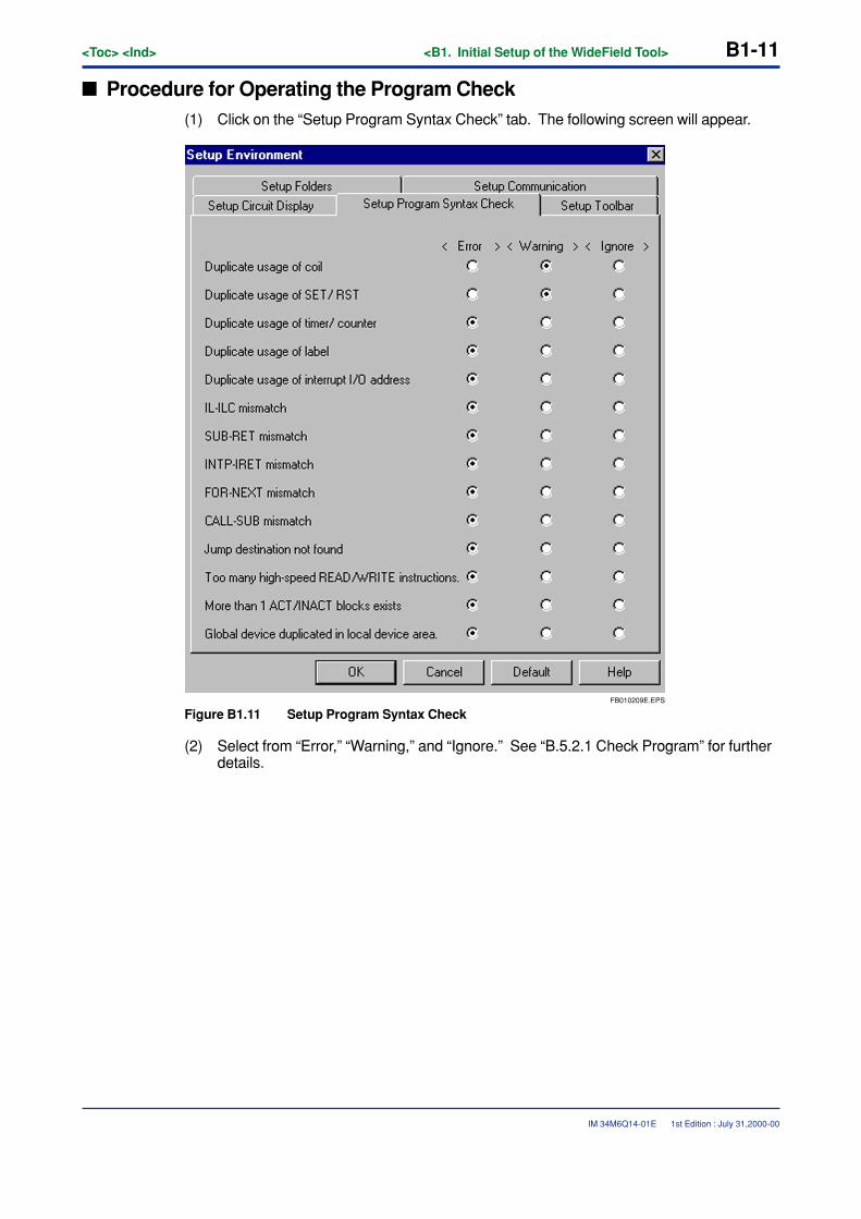
<Toc> <Ind> <B1. Initial Setup of the WideField Tool> B1-11
IM 34M6Q14-01E 1st Edition : July 31,2000-00
� Procedure for Operating the Program Check(1) Click on the “Setup Program Syntax Check” tab. The following screen will appear.
FB010209E.EPS
Figure B1.11 Setup Program Syntax Check
(2) Select from “Error,” “Warning,” and “Ignore.” See “B.5.2.1 Check Program” for furtherdetails.
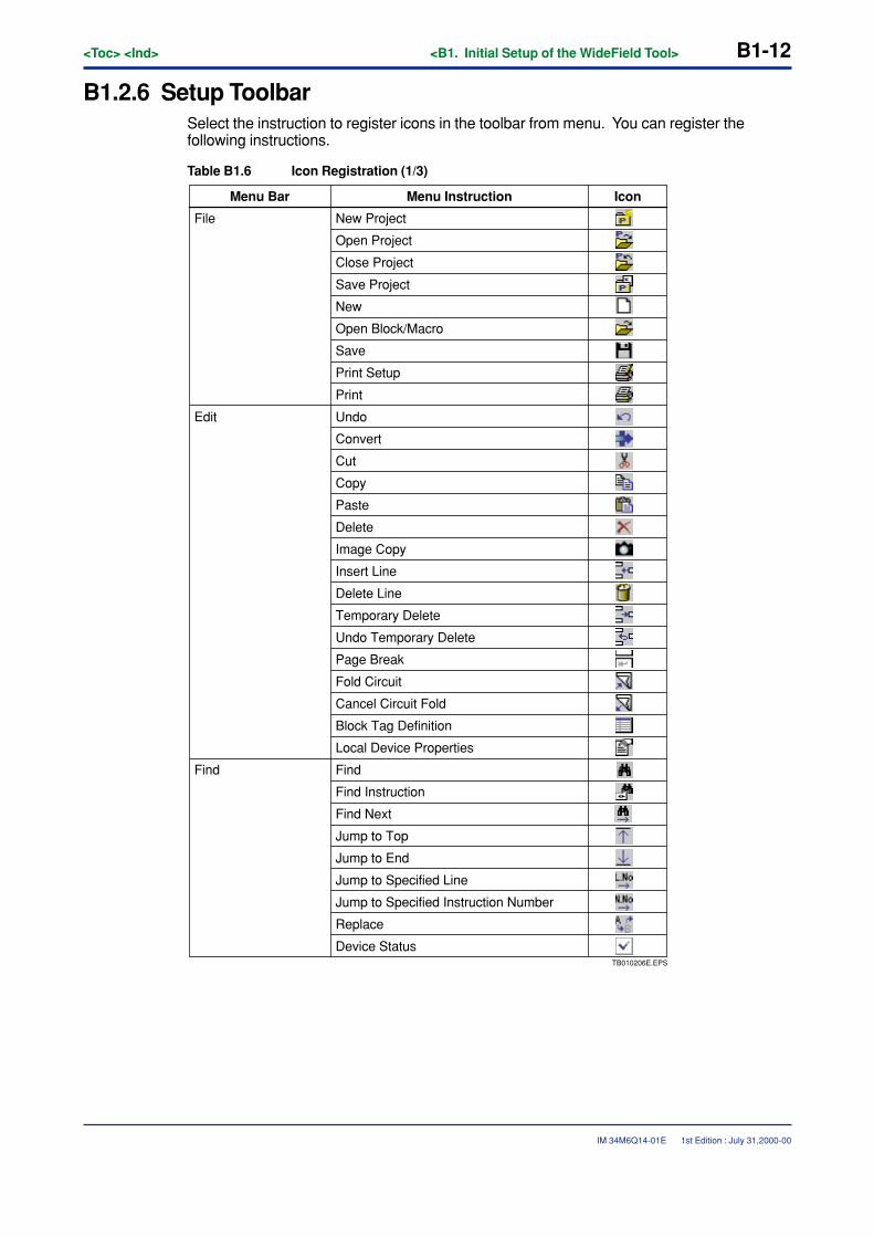
B1-12<Toc> <Ind> <B1. Initial Setup of the WideField Tool>
IM 34M6Q14-01E
B1.2.6 Setup ToolbarSelect the instruction to register icons in the toolbar from menu. You can register thefollowing instructions.
Table B1.6 Icon Registration (1/3)
TB010206E.EPS
Menu Bar IconMenu Instruction
File New Project
Open Project
Close Project
Save Project
New
Open Block/Macro
Save
Print Setup
Edit Undo
Convert
Cut
Copy
Paste
Delete
Image Copy
Insert Line
Delete Line
Temporary Delete
Undo Temporary Delete
Page Break
Fold Circuit
Cancel Circuit Fold
Block Tag Definition
Local Device Properties
FindFind
Find Instruction
Find Next
Jump to Top
Jump to End
Jump to Specified Line
Jump to Specified Instruction Number
Replace
Device Status
1st Edition : July 31,2000-00
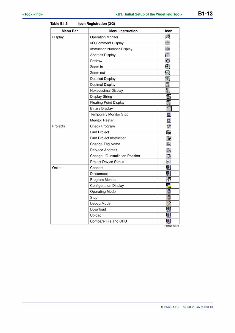
<Toc> <Ind> <B1. Initial Setup of the WideField Tool> B1-13
IM 34M6Q14-01E
Table B1.6 Icon Registration (2/3)
TB010207E.EPS
Display String
Floating Point Display
Binary Display
Temporary Monitor Stop
Monitor Restart
Projects Check Program
Find Project
Find Project Instruction
Change Tag Name
Replace Address
Change I/O Installation Position
Project Device Status
Online Connect
Disconnect
Program Monitor
Configuration Display
Operating Mode
Stop
Debug Mode
Download
Upload
Compare File and CPU
Hexadecimal Display
Menu Bar IconMenu Instruction
Operation MonitorDisplay
I/O Comment Display
Instruction Number Display
Address Display
Zoom in
Redraw
Zoom out
Detailed Display
Decimal Display
1st Edition : July 31,2000-00
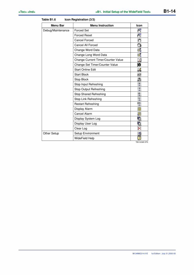
B1-14<Toc> <Ind> <B1. Initial Setup of the WideField Tool>
IM 34M6Q14-01E
Table B1.6 Icon Registration (3/3)
TB010208E.EPS
WideField Help
Debug/Maintenance Forced Set
Forced Reset
Cancel Forced
Cancel All Forced
Change Word Data
Change Long Word Data
Change Current Timer/Counter Value
Change Set Timer/Counter Value
Start Online Edit
Start Block
Stop Block
Stop Input Refreshing
Stop Output Refreshing
Stop Shared Refreshing
Stop Link Refreshing
Restart Refreshing
Display Alarm
Cancel Alarm
Display System Log
Display User Log
Clear Log
Other Setup Setup Environment
Menu Bar IconMenu Instruction
1st Edition : July 31,2000-00
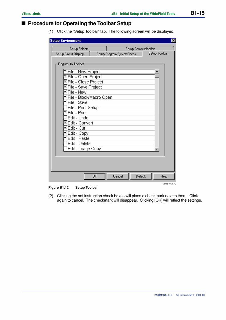
<Toc> <Ind> <B1. Initial Setup of the WideField Tool> B1-15
IM 34M6Q14-01E 1st Edition : July 31,2000-00
� Procedure for Operating the Toolbar Setup(1) Click the “Setup Toolbar” tab. The following screen will be displayed.
FB010210E.EPS
Figure B1.12 Setup Toolbar
(2) Clicking the set instruction check boxes will place a checkmark next to them. Clickagain to cancel. The checkmark will disappear. Clicking [OK] will reflect the settings.

Blank Page
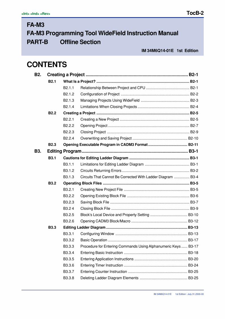
<Int> <Ind> <Rev>
IM 34M6Q14-01E
TocB-2
CONTENTSB2. Creating a Project ................................................................................. B2-1
B2.1 What Is a Project? ......................................................................................... B2-1
B2.1.1 Relationship Between Project and CPU .......................................... B2-1
B2.1.2 Configuration of Project .................................................................. B2-2
B2.1.3 Managing Projects Using WideField ............................................... B2-3
B2.1.4 Limitations When Closing Projects .................................................. B2-4
B2.2 Creating a Project ......................................................................................... B2-5
B2.2.1 Creating a New Project ................................................................... B2-5
B2.2.2 Opening Project .............................................................................. B2-7
B2.2.3 Closing Project ............................................................................... B2-9
B2.2.4 Overwriting and Saving Project ..................................................... B2-10
B2.3 Opening Executable Program in CADM3 Format ...................................... B2-11
B3. Editing Program.................................................................................... B3-1B3.1 Cautions for Editing Ladder Diagram .......................................................... B3-1
B3.1.1 Limitations for Editing Ladder Diagram ........................................... B3-1
B3.1.2 Circuits Returning Errors ................................................................. B3-2
B3.1.3 Circuits That Cannot Be Corrected With Ladder Diagram ............... B3-4
B3.2 Operating Block Files ................................................................................... B3-5
B3.2.1 Creating New Project File ............................................................... B3-5
B3.2.2 Opening Existing Block File ............................................................ B3-6
B3.2.3 Saving Block File ............................................................................ B3-7
B3.2 4 Closing Block File ........................................................................... B3-9
B3.2.5 Block’s Local Device and Property Setting .................................... B3-10
B3.2.6 Opening CADM3 Block/Macro ...................................................... B3-12
B3.3 Editing Ladder Diagram.............................................................................. B3-13
B3.3.1 Configuring Window ..................................................................... B3-13
B3.3.2 Basic Operation ............................................................................ B3-17
B3.3.3 Procedure for Entering Commands Using Alphanumeric Keys ...... B3-17
B3.3.4 Entering Basic Instruction ............................................................. B3-18
B3.3.5 Entering Application Instructions ................................................... B3-20
B3.3.6 Entering Timer Instruction ............................................................. B3-24
B3.3.7 Entering Counter Instruction ......................................................... B3-25
B3.3.8 Deleting Ladder Diagram Elements .............................................. B3-25
1st Edition : July 31,2000-00
IM 34M6Q14-01E 1st Edition
FA-M3FA-M3 Programming Tool WideField Instruction ManualPART-B Offline Section
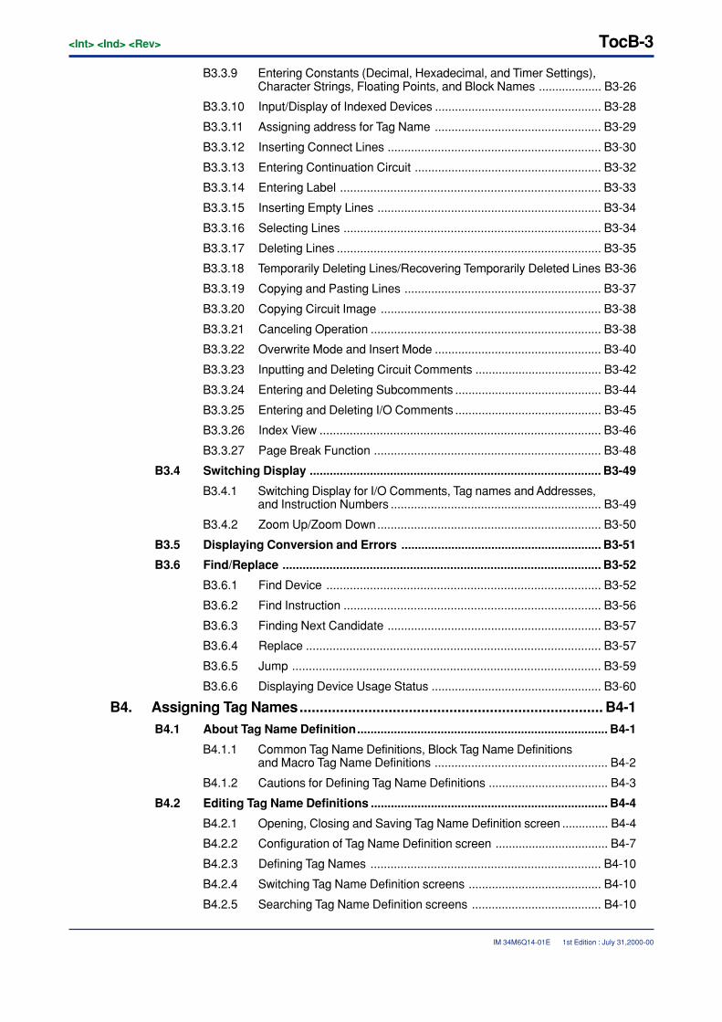
TocB-3<Int> <Ind> <Rev>
IM 34M6Q14-01E 1st Edition : July 31,2000-00
B3.3.9 Entering Constants (Decimal, Hexadecimal, and Timer Settings),Character Strings, Floating Points, and Block Names ................... B3-26
B3.3.10 Input/Display of Indexed Devices .................................................. B3-28
B3.3.11 Assigning address for Tag Name .................................................. B3-29
B3.3.12 Inserting Connect Lines ................................................................ B3-30
B3.3.13 Entering Continuation Circuit ........................................................ B3-32
B3.3.14 Entering Label .............................................................................. B3-33
B3.3.15 Inserting Empty Lines ................................................................... B3-34
B3.3.16 Selecting Lines ............................................................................. B3-34
B3.3.17 Deleting Lines ............................................................................... B3-35
B3.3.18 Temporarily Deleting Lines/Recovering Temporarily Deleted Lines B3-36
B3.3.19 Copying and Pasting Lines ........................................................... B3-37
B3.3.20 Copying Circuit Image .................................................................. B3-38
B3.3.21 Canceling Operation ..................................................................... B3-38
B3.3.22 Overwrite Mode and Insert Mode .................................................. B3-40
B3.3.23 Inputting and Deleting Circuit Comments ...................................... B3-42
B3.3.24 Entering and Deleting Subcomments ............................................ B3-44
B3.3.25 Entering and Deleting I/O Comments ............................................ B3-45
B3.3.26 Index View .................................................................................... B3-46
B3.3.27 Page Break Function .................................................................... B3-48
B3.4 Switching Display ....................................................................................... B3-49
B3.4.1 Switching Display for I/O Comments, Tag names and Addresses,and Instruction Numbers ............................................................... B3-49
B3.4.2 Zoom Up/Zoom Down................................................................... B3-50
B3.5 Displaying Conversion and Errors ............................................................ B3-51
B3.6 Find/Replace ............................................................................................... B3-52
B3.6.1 Find Device .................................................................................. B3-52
B3.6.2 Find Instruction ............................................................................. B3-56
B3.6.3 Finding Next Candidate ................................................................ B3-57
B3.6.4 Replace ........................................................................................ B3-57
B3.6.5 Jump ............................................................................................ B3-59
B3.6.6 Displaying Device Usage Status ................................................... B3-60
B4. Assigning Tag Names........................................................................... B4-1B4.1 About Tag Name Definition........................................................................... B4-1
B4.1.1 Common Tag Name Definitions, Block Tag Name Definitionsand Macro Tag Name Definitions .................................................... B4-2
B4.1.2 Cautions for Defining Tag Name Definitions .................................... B4-3
B4.2 Editing Tag Name Definitions ....................................................................... B4-4
B4.2.1 Opening, Closing and Saving Tag Name Definition screen .............. B4-4
B4.2.2 Configuration of Tag Name Definition screen .................................. B4-7
B4.2.3 Defining Tag Names ..................................................................... B4-10
B4.2.4 Switching Tag Name Definition screens ........................................ B4-10
B4.2.5 Searching Tag Name Definition screens ....................................... B4-10
<Int> <Ind> <Rev>
IM 34M6Q14-01E
TocB-4
1st Edition : July 31,2000-00
B4.2.6 Copying, Cutting and Pasting Tag Name Definitions ..................... B4-11
B4.2.7 Error Check function ..................................................................... B4-11
B4.2.8 Grouping Tag Names .................................................................... B4-12
B4.2.9 Reading Group Templates ............................................................ B4-13
B4.3 Block/Macro Tag Name Definition Functions ............................................ B4-14
B4.3.1 Use ............................................................................................... B4-14
B4.3.2 Reading devices used in circuit ..................................................... B4-15
B4.3.3 Changing Address ........................................................................ B4-16
B4.4 Defining Group Templates.......................................................................... B4-17
B4.4.1 Creating Group Templates ............................................................ B4-18
B4.4.2 Deleting Group Template Files ...................................................... B4-20
B5. Building and Managing Projects .......................................................... B5-1B5.1 Building Projects .......................................................................................... B5-1
B5.1.1 Configuration Definitions of Executable Programs .......................... B5-1
B5.1.2 Changing CPU Type and Executable Program Properties .............. B5-4
B5.1.3 Setting Configuration ...................................................................... B5-6
B5.1.4 Creating User Log Messages........................................................ B5-30
B5.1.5 Creating Common Tag Name Definitions ...................................... B5-31
B5.2 Managing Project ........................................................................................ B5-35
B5.2.1 Program Check function ............................................................... B5-35
B5.2.2 Find in Project function ................................................................. B5-40
B5.2.3 Find Instruction in Project function ................................................ B5-42
B5.2.4 Replace in Project function ........................................................... B5-44
B5.2.5 Change I/O Installation Position Function ..................................... B5-50
B5.2.6 Displaying Device Usage Status ................................................... B5-52
B5.3 Managing Files ............................................................................................ B5-53
B5.3.1 Adding Files .................................................................................. B5-54
B5.3.2 Renaming Files............................................................................. B5-55
B5.3.3 Deleting Files ................................................................................ B5-56
B6. PRINTOUT ............................................................................................. B6-1B6.1 Setting Printer ............................................................................................... B6-2
B6.2 Setting Printing Layout ................................................................................. B6-3
B6.3 Setting Printout Details ................................................................................ B6-6
B6.3.1 Setting Details for Blocks and Instruction Macros ............................ B6-7
B6.3.2 Detailed Configuration Settings ....................................................... B6-9
B6.3.3 Setting Cover and Header/Footer ................................................. B6-10
B6.4 Print and Print Preview ............................................................................... B6-12
B6.4.1 Print Screen .................................................................................. B6-12
B6.4.2 Print Project .................................................................................. B6-14
B6.4.3 Procedure for Previewing Printout ................................................. B6-17
B6.5 Printing Layout............................................................................................ B6-18

TocB-5<Int> <Ind> <Rev>
IM 34M6Q14-01E
B6.5.1 Printing Layout for Project Component .......................................... B6-18
B6.5.2 Printing Layout for Circuits ............................................................ B6-19
B6.5.3 Layout for Printing Tag Name Definitions ...................................... B6-20
B6.5.4 Layout for Printing Configuration ................................................... B6-20
B6.5.5 Layout for Printing System Log ..................................................... B6-21
1st Edition : July 31,2000-00
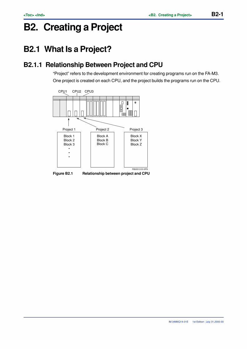
<Toc> <Ind> <B2. Creating a Project> B2-1
IM 34M6Q14-01E
B2. Creating a Project
B2.1 What Is a Project?
B2.1.1 Relationship Between Project and CPU“Project” refers to the development environment for creating programs run on the FA-M3.
One project is created on each CPU, and the project builds the programs run on the CPU.
Block 1Block 2Block 3
•••
Block ABlock BBlock C
Block XBlock YBlock Z
Project 1
CPU1 CPU2 CPU3
Project 2 Project 3
FB020101E.EPS
Figure B2.1 Relationship between project and CPU
1st Edition : July 31,2000-00
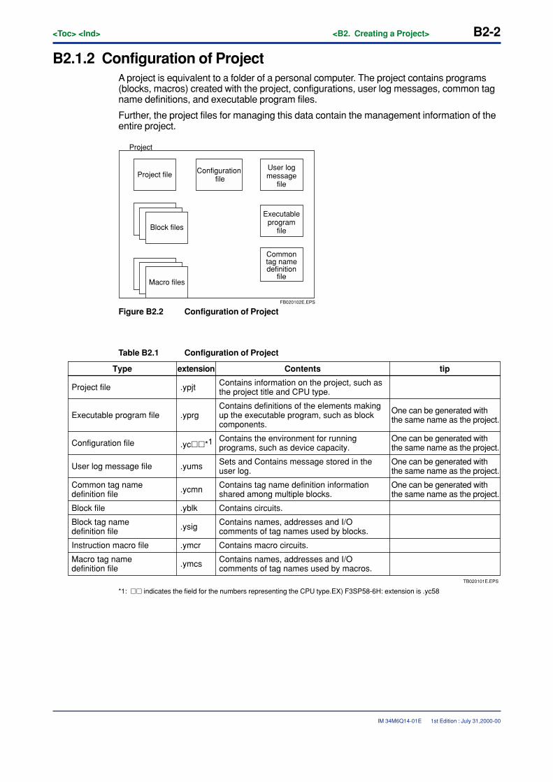
B2-2<Toc> <Ind> <B2. Creating a Project>
IM 34M6Q14-01E
B2.1.2 Configuration of ProjectA project is equivalent to a folder of a personal computer. The project contains programs(blocks, macros) created with the project, configurations, user log messages, common tagname definitions, and executable program files.
Further, the project files for managing this data contain the management information of theentire project.
Macro files
Block files
Project file Configuration file
User logmessage
file
Executableprogram
file
Commontag namedefinition
file
Project
FB020102E.EPS
Figure B2.2 Configuration of Project
Table B2.1 Configuration of Project
TB020101E.EPS
Contains names, addresses and I/O comments of tag names used by macros.
tipType extension Contents
Project file .ypjt Contains information on the project, such as the project title and CPU type.
Executable program file .yprgContains definitions of the elements making up the executable program, such as block components.
One can be generated with the same name as the project.
One can be generated with the same name as the project.
One can be generated with the same name as the project.
One can be generated with the same name as the project.
Configuration file .yc��*1Contains the environment for running programs, such as device capacity.
User log message file .yums Sets and Contains message stored in the user log.
Common tag name definition file .ycmn Contains tag name definition information
shared among multiple blocks.
Block file .yblk Contains circuits.
Block tag name definition file .ysig Contains names, addresses and I/O
comments of tag names used by blocks.
Instruction macro file .ymcr Contains macro circuits.
Macro tag name definition file .ymcs
*1: �� indicates the field for the numbers representing the CPU type.EX) F3SP58-6H: extension is .yc58
1st Edition : July 31,2000-00
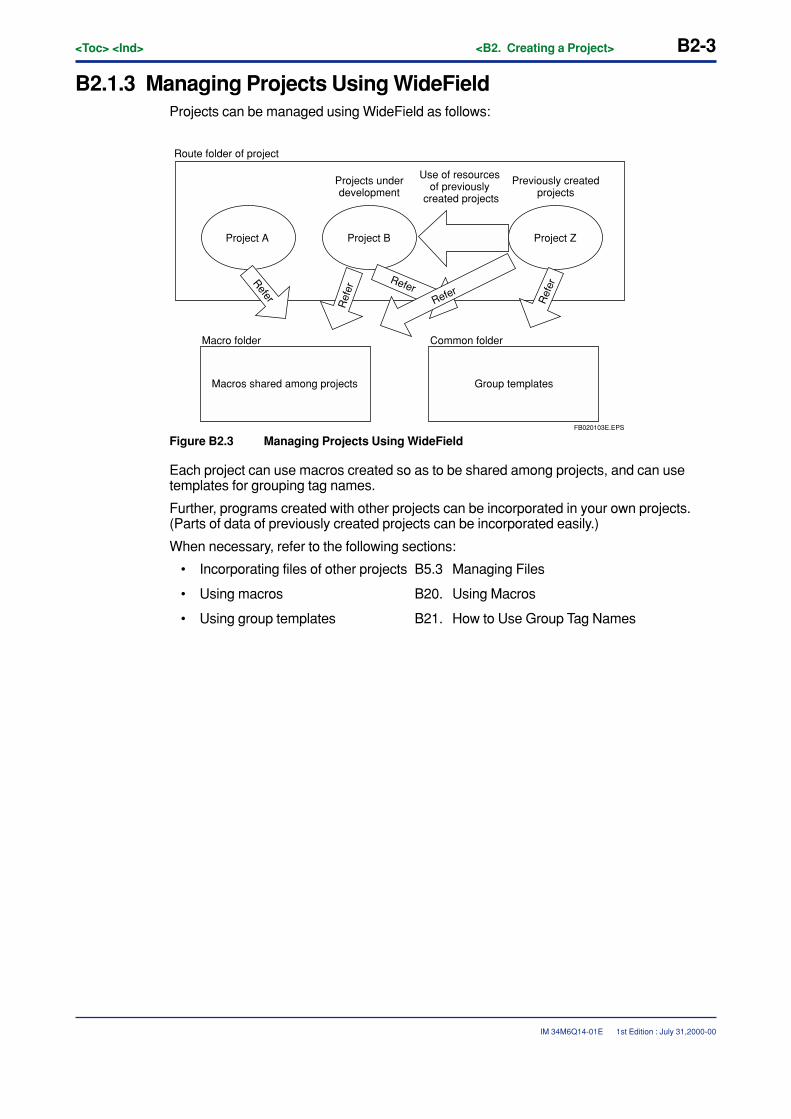
<Toc> <Ind> <B2. Creating a Project> B2-3
IM 34M6Q14-01E
B2.1.3 Managing Projects Using WideFieldProjects can be managed using WideField as follows:
Project A
Route folder of project
Macro folder Common folder
Macros shared among projects
Project B Project Z
Group templates
Projects underdevelopment
Previously createdprojects
Use of resources of previously
created projects
Refer
Ref
er
ReferRefer
Ref
er
FB020103E.EPS
Figure B2.3 Managing Projects Using WideField
Each project can use macros created so as to be shared among projects, and can usetemplates for grouping tag names.
Further, programs created with other projects can be incorporated in your own projects.(Parts of data of previously created projects can be incorporated easily.)
When necessary, refer to the following sections:
• Incorporating files of other projects B5.3 Managing Files
• Using macros B20. Using Macros
• Using group templates B21. How to Use Group Tag Names
1st Edition : July 31,2000-00
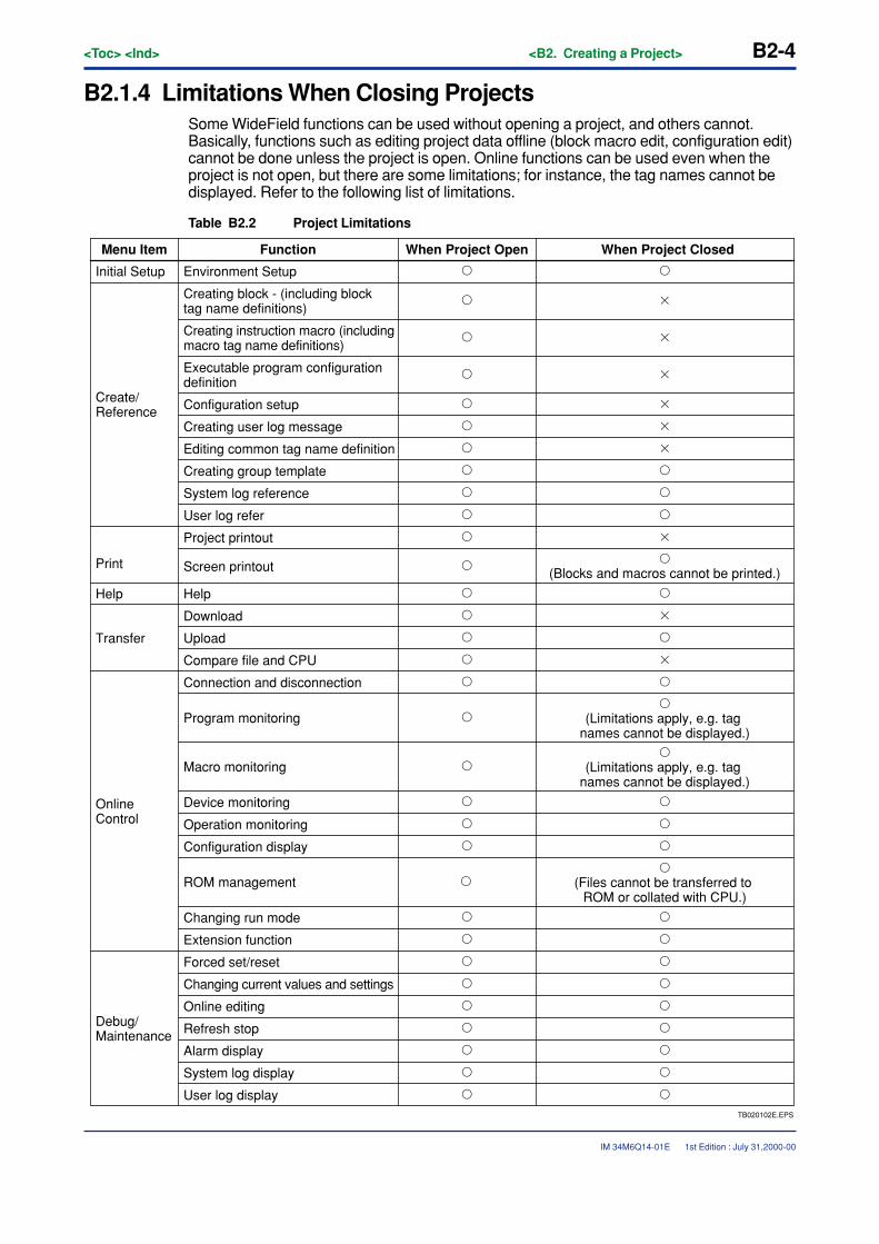
B2-4<Toc> <Ind> <B2. Creating a Project>
IM 34M6Q14-01E
B2.1.4 Limitations When Closing ProjectsSome WideField functions can be used without opening a project, and others cannot.Basically, functions such as editing project data offline (block macro edit, configuration edit)cannot be done unless the project is open. Online functions can be used even when theproject is not open, but there are some limitations; for instance, the tag names cannot bedisplayed. Refer to the following list of limitations.
Table B2.2 Project Limitations
TB020102E.EPS
User log display
When Project ClosedMenu Item Function When Project Open
Initial Setup Environment Setup
Create/Reference
Creating block - (including block tag name definitions)
Creating instruction macro (including macro tag name definitions)
Executable program configuration definition
Configuration setup
Creating user log message
Editing common tag name definition
Creating group template
User log refer
System log reference
Project printout
Screen printout�
(Blocks and macros cannot be printed.)
Help Help
Transfer
Download
Upload
Compare file and CPU
Online Control
Connection and disconnection
Program monitoring�
(Limitations apply, e.g. tag names cannot be displayed.)
�(Limitations apply, e.g. tag
names cannot be displayed.)Macro monitoring
Device monitoring
Operation monitoring
Configuration display
ROM management�
(Files cannot be transferred to ROM or collated with CPU.)
Changing run mode
Extension function
Debug/Maintenance
Forced set/reset
Changing current values and settings
Online editing
Refresh stop
Alarm display
System log display
�
�
�
�
�
�
�
�
�
�
�
�
�
�
�
�
�
�
�
�
�
�
�
�
�
�
�
�
�
�
�
�
�
�
�
�
�
�
�
�
�
�
�
�
�
�
�
�
�
�
�
�
�
�
�
�
�
�
�
�
1st Edition : July 31,2000-00
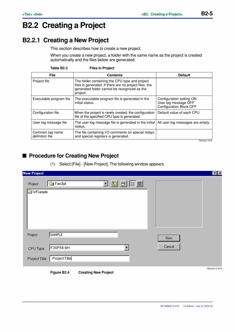
<Toc> <Ind> <B2. Creating a Project> B2-5
IM 34M6Q14-01E
B2.2 Creating a Project
B2.2.1 Creating a New ProjectThis section describes how to create a new project.
When you create a new project, a folder with the same name as the project is createdautomatically and the files below are generated.
Table B2.3 Files in Project
TB020201.EPS
The file containing I/O comments on special relays and special registers is generated.
DefaultFile Contents
Project file The folder containing the CPU type and project files is generated. If there are no project files, the generated folder cannot be recognized as the project.
Executable program file The executable program file is generated in the initial status.
Configuration setting ONUser log message OFFConfiguration Block OFF
Configuration file When the project is newly created, the configuration file of the specified CPU type is generated.
Default value of each CPU
User log message file The user log message file is generated in the initial status.
All user log messages are empty.
Common tag name definition file
� Procedure for Creating New Project(1) Select [File] - [New Project]. The following window appears.
FB020201E.EPS
Figure B2.4 Creating New Project
1st Edition : July 31,2000-00
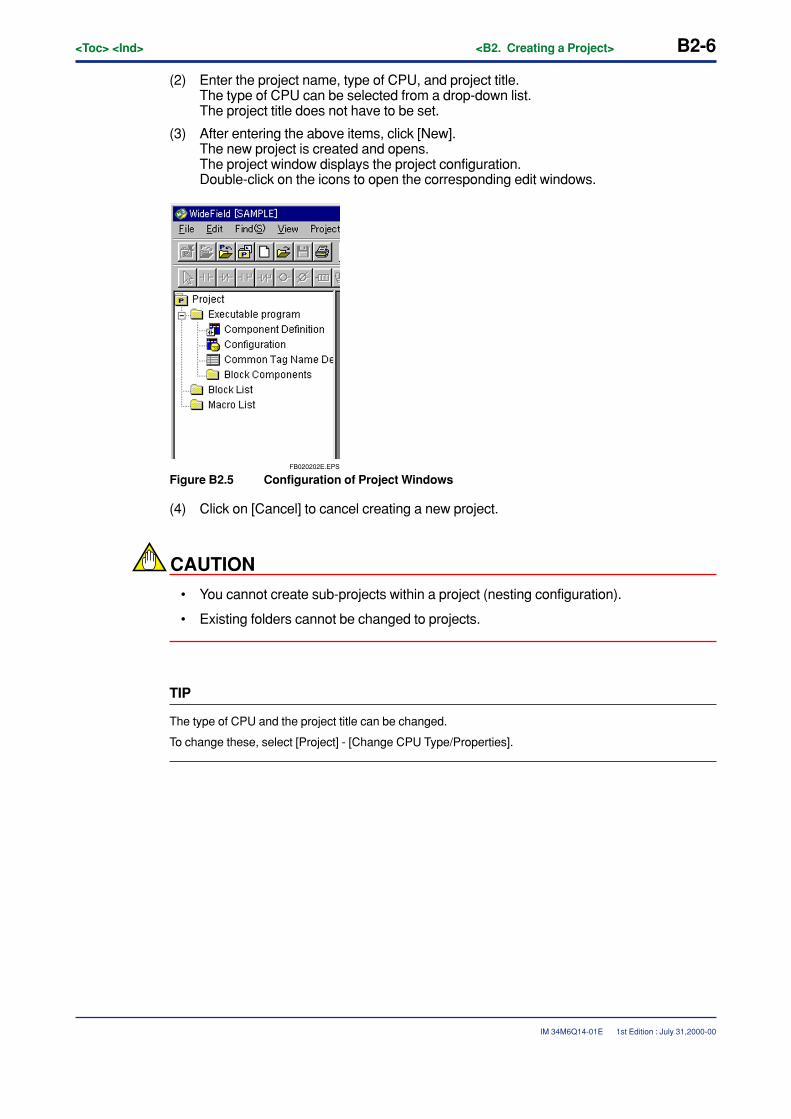
B2-6<Toc> <Ind> <B2. Creating a Project>
IM 34M6Q14-01E 1st Edition : July 31,2000-00
(2) Enter the project name, type of CPU, and project title.The type of CPU can be selected from a drop-down list.The project title does not have to be set.
(3) After entering the above items, click [New].The new project is created and opens.The project window displays the project configuration.Double-click on the icons to open the corresponding edit windows.
FB020202E.EPS
Figure B2.5 Configuration of Project Windows
(4) Click on [Cancel] to cancel creating a new project.
CAUTION
• You cannot create sub-projects within a project (nesting configuration).
• Existing folders cannot be changed to projects.
TIP
The type of CPU and the project title can be changed.
To change these, select [Project] - [Change CPU Type/Properties].
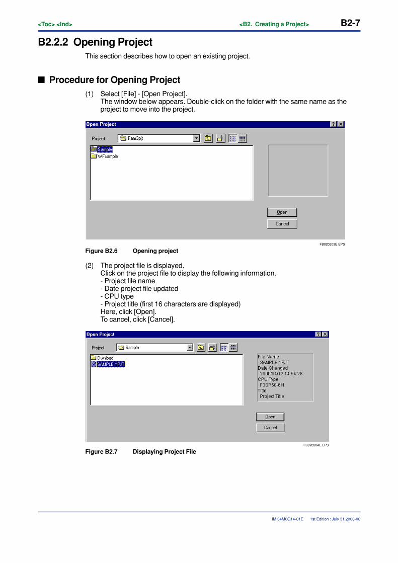
<Toc> <Ind> <B2. Creating a Project> B2-7
IM 34M6Q14-01E 1st Edition : July 31,2000-00
B2.2.2 Opening ProjectThis section describes how to open an existing project.
� Procedure for Opening Project(1) Select [File] - [Open Project].
The window below appears. Double-click on the folder with the same name as theproject to move into the project.
FB020203E.EPS
Figure B2.6 Opening project
(2) The project file is displayed.Click on the project file to display the following information.- Project file name- Date project file updated- CPU type- Project title (first 16 characters are displayed)Here, click [Open].To cancel, click [Cancel].
FB020204E.EPS
Figure B2.7 Displaying Project File
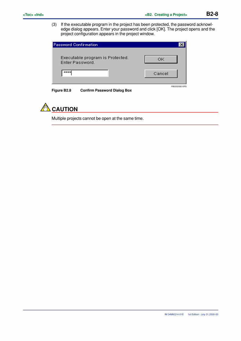
B2-8<Toc> <Ind> <B2. Creating a Project>
IM 34M6Q14-01E
(3) If the executable program in the project has been protected, the password acknowl-edge dialog appears. Enter your password and click [OK]. The project opens and theproject configuration appears in the project window.
FB020205E.EPS
Figure B2.8 Confirm Password Dialog Box
CAUTION
Multiple projects cannot be open at the same time.
1st Edition : July 31,2000-00
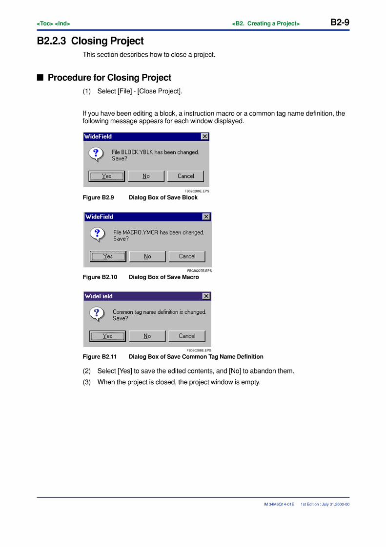
<Toc> <Ind> <B2. Creating a Project> B2-9
IM 34M6Q14-01E
B2.2.3 Closing ProjectThis section describes how to close a project.
� Procedure for Closing Project(1) Select [File] - [Close Project].
If you have been editing a block, a instruction macro or a common tag name definition, thefollowing message appears for each window displayed.
FB020206E.EPS
Figure B2.9 Dialog Box of Save Block
FB020207E.EPS
Figure B2.10 Dialog Box of Save Macro
FB020208E.EPS
Figure B2.11 Dialog Box of Save Common Tag Name Definition
(2) Select [Yes] to save the edited contents, and [No] to abandon them.
(3) When the project is closed, the project window is empty.
1st Edition : July 31,2000-00

B2-10<Toc> <Ind> <B2. Creating a Project>
IM 34M6Q14-01E 1st Edition : July 31,2000-00
B2.2.4 Overwriting and Saving ProjectThis section describes how to overwrite and save a project.
� Procedure for Overwriting and Saving a Project(1) Select [File] - [Save Project].
Any block, instruction macro or common tag name definition being edited will be overwrit-ten and saved.
TIP
You can continue editing after overwriting and saving contents.
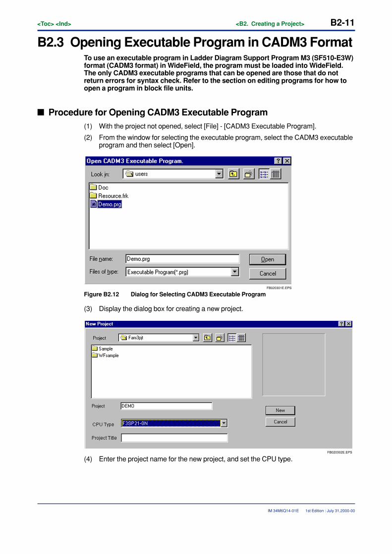
<Toc> <Ind> <B2. Creating a Project> B2-11
IM 34M6Q14-01E 1st Edition : July 31,2000-00
B2.3 Opening Executable Program in CADM3 FormatTo use an executable program in Ladder Diagram Support Program M3 (SF510-E3W)format (CADM3 format) in WideField, the program must be loaded into WideField.The only CADM3 executable programs that can be opened are those that do notreturn errors for syntax check. Refer to the section on editing programs for how toopen a program in block file units.
� Procedure for Opening CADM3 Executable Program(1) With the project not opened, select [File] - [CADM3 Executable Program].
(2) From the window for selecting the executable program, select the CADM3 executableprogram and then select [Open].
FB020301E.EPS
Figure B2.12 Dialog for Selecting CADM3 Executable Program
(3) Display the dialog box for creating a new project.
FB020302E.EPS
(4) Enter the project name for the new project, and set the CPU type.
B2-12<Toc> <Ind> <B2. Creating a Project>
IM 34M6Q14-01E
(5) Select [New], and the CADM3 executable program and its block components and tagname definitions are converted into WideField format.To overwrite an existing project, enter the name of the project file and then select[New].
(6) If conversion ends successfully, the newly created project opens. The results of theconversion are displayed in the window.
CAUTION
• If the CPU type has been changed, the configuration is created with the default valueof the CPU type after the change. Do configuration settings by setting the CPU typeafter it has been changed.
• The CPU type can be changed even after conversion. Use WideField to print out theconfiguration of the previous type, and change the CPU type with [Project] - [ChangeCPU Type/Properties].
• Ladder blocks saved by mnemonic editing cannot be converted. Do this after savingwith the CADM3 ladder diagram edit function.
• The conversion results are saved in text file format in HENKAN.log in the projectfolder.
1st Edition : July 31,2000-00
<Toc> <Ind> <B3. Editing Program> B3-1
IM 34M6Q14-01E
B3. Editing Program
B3.1 Cautions for Editing Ladder Diagram
B3.1.1 Limitations for Editing Ladder DiagramThe following limitations apply to entering circuits and creating blocks. Comply with theselimitations when entering the information.
� Maximum Lines That Can Be Created per Block
Circuits of up to 4,000 lines (including circuit comments) can be created. Circuits in excessof this amount cannot be entered or edited.
� Maximum Steps That Can Be Created per Block
Circuits of up to 10,240 steps can be created. If more steps than the maximum are entered,an error occurs when they are being converted. To create circuits larger than this maxi-mum, divide the block.
� Maximum Lines per Circuit
One circuit can have up to 25 lines. If more lines than the maximum are entered, an erroroccurs at conversion.
� Maximum Instruction per Circuit
One circuit can have up to 128 instructions. If more instructions than the maximum areentered, an error occurs at conversion.
� Maximum Continued Lines per Circuit Comment
One circuit comment can have up to 4 continued lines. If more lines than the maximum areentered, an error occurs at conversion.
� Maximum Lines for Continued Circuit
Continued circuits can have up to 3 lines. If more instructions™ than the maximum areentered, an error occurs at conversion.
1st Edition : July 31,2000-00
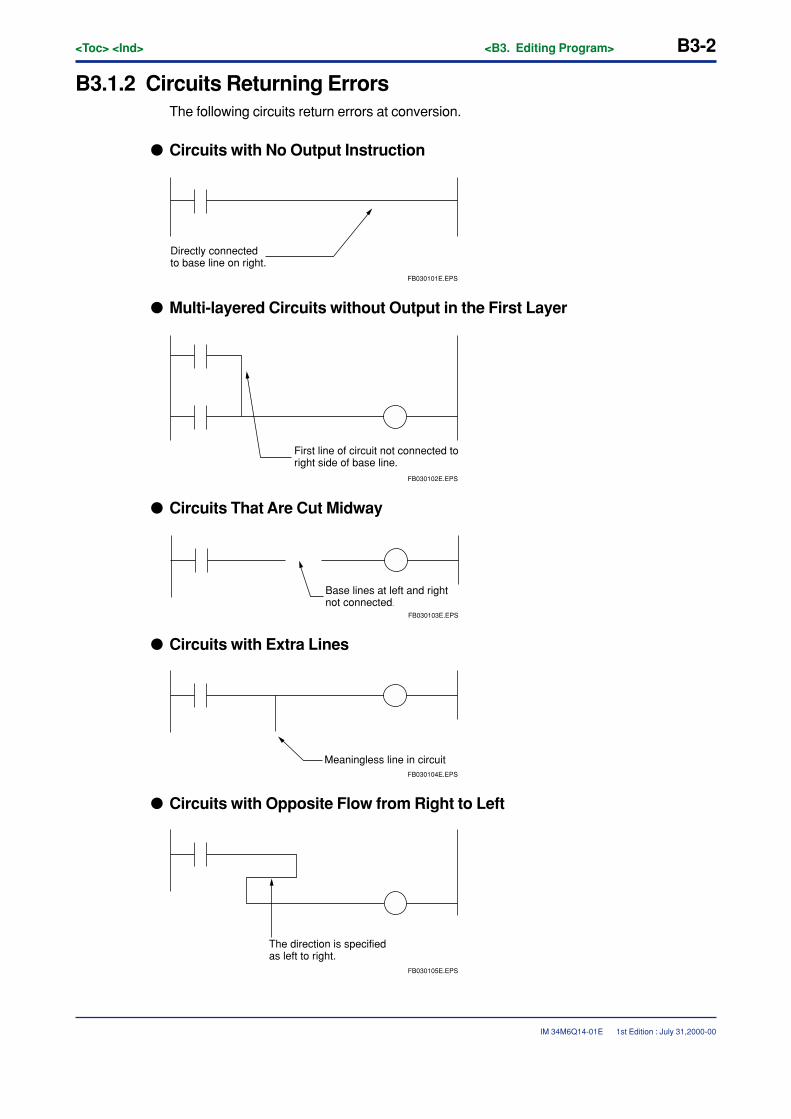
B3-2<Toc> <Ind> <B3. Editing Program>
IM 34M6Q14-01E
B3.1.2 Circuits Returning ErrorsThe following circuits return errors at conversion.
� Circuits with No Output Instruction
Directly connected to base line on right.
FB030101E.EPS
� Multi-layered Circuits without Output in the First Layer
FB030102E.EPS
First line of circuit not connected to right side of base line.
� Circuits That Are Cut Midway
FB030103E.EPS
Base lines at left and right not connected.
� Circuits with Extra Lines
Meaningless line in circuitFB030104E.EPS
� Circuits with Opposite Flow from Right to Left
The direction is specified as left to right.
FB030105E.EPS
1st Edition : July 31,2000-00
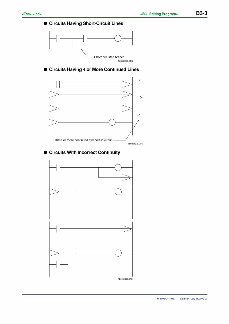
<Toc> <Ind> <B3. Editing Program> B3-3
IM 34M6Q14-01E
� Circuits Having Short-Circuit Lines
Short-circuited branchFB030106E.EPS
� Circuits Having 4 or More Continued Lines
FB030107E.EPS
Three or more continued symbols in circuit
� Circuits With Incorrect Continuity
FB030108E.EPS
1st Edition : July 31,2000-00
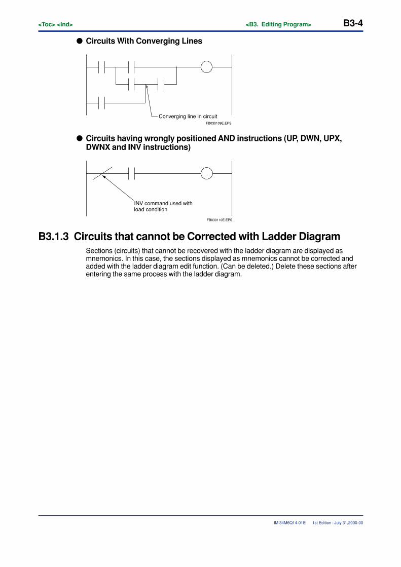
B3-4<Toc> <Ind> <B3. Editing Program>
IM 34M6Q14-01E
� Circuits With Converging Lines
FB030109E.EPS
Converging line in circuit
� Circuits having wrongly positioned AND instructions (UP, DWN, UPX,DWNX and INV instructions)
INV command used with load condition
FB030110E.EPS
B3.1.3 Circuits that cannot be Corrected with Ladder DiagramSections (circuits) that cannot be recovered with the ladder diagram are displayed asmnemonics. In this case, the sections displayed as mnemonics cannot be corrected andadded with the ladder diagram edit function. (Can be deleted.) Delete these sections afterentering the same process with the ladder diagram.
1st Edition : July 31,2000-00
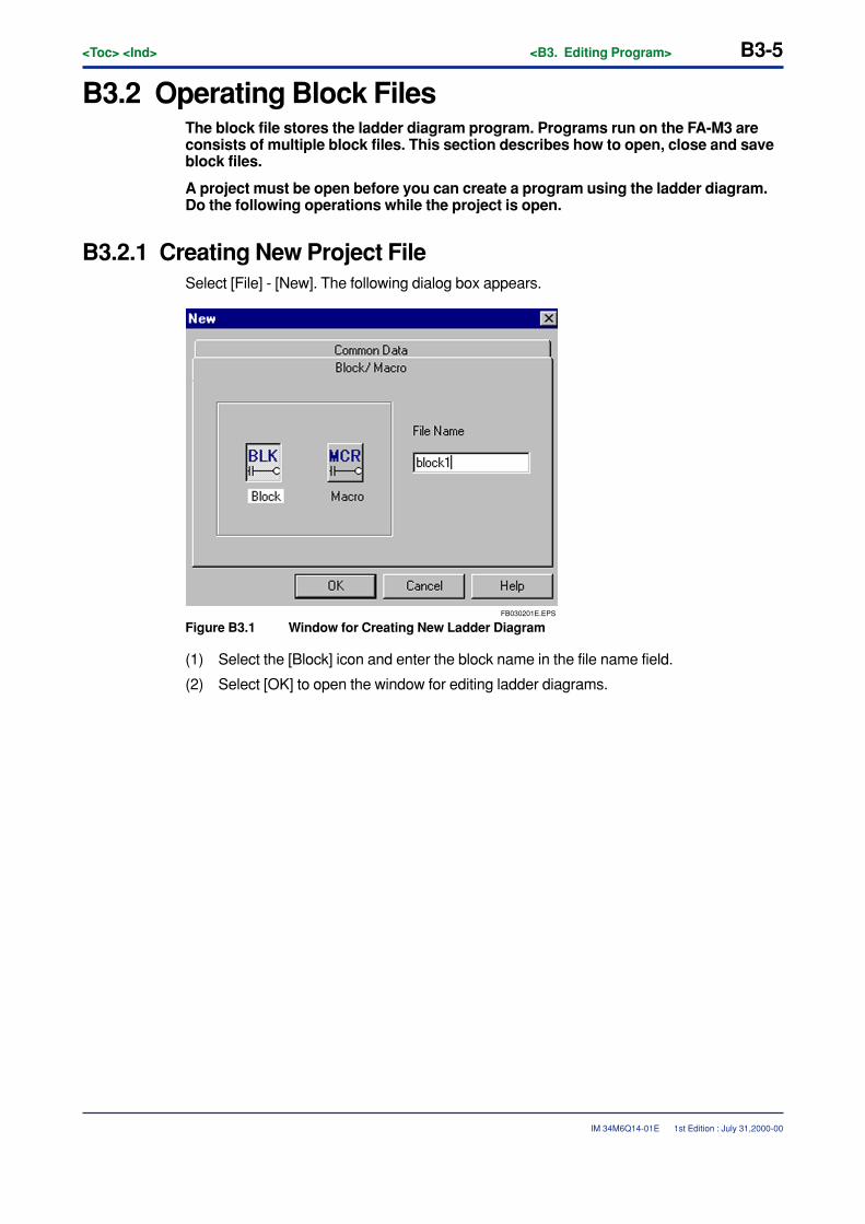
<Toc> <Ind> <B3. Editing Program> B3-5
IM 34M6Q14-01E
B3.2 Operating Block FilesThe block file stores the ladder diagram program. Programs run on the FA-M3 areconsists of multiple block files. This section describes how to open, close and saveblock files.
A project must be open before you can create a program using the ladder diagram.Do the following operations while the project is open.
B3.2.1 Creating New Project FileSelect [File] - [New]. The following dialog box appears.
FB030201E.EPS
Figure B3.1 Window for Creating New Ladder Diagram
(1) Select the [Block] icon and enter the block name in the file name field.
(2) Select [OK] to open the window for editing ladder diagrams.
1st Edition : July 31,2000-00
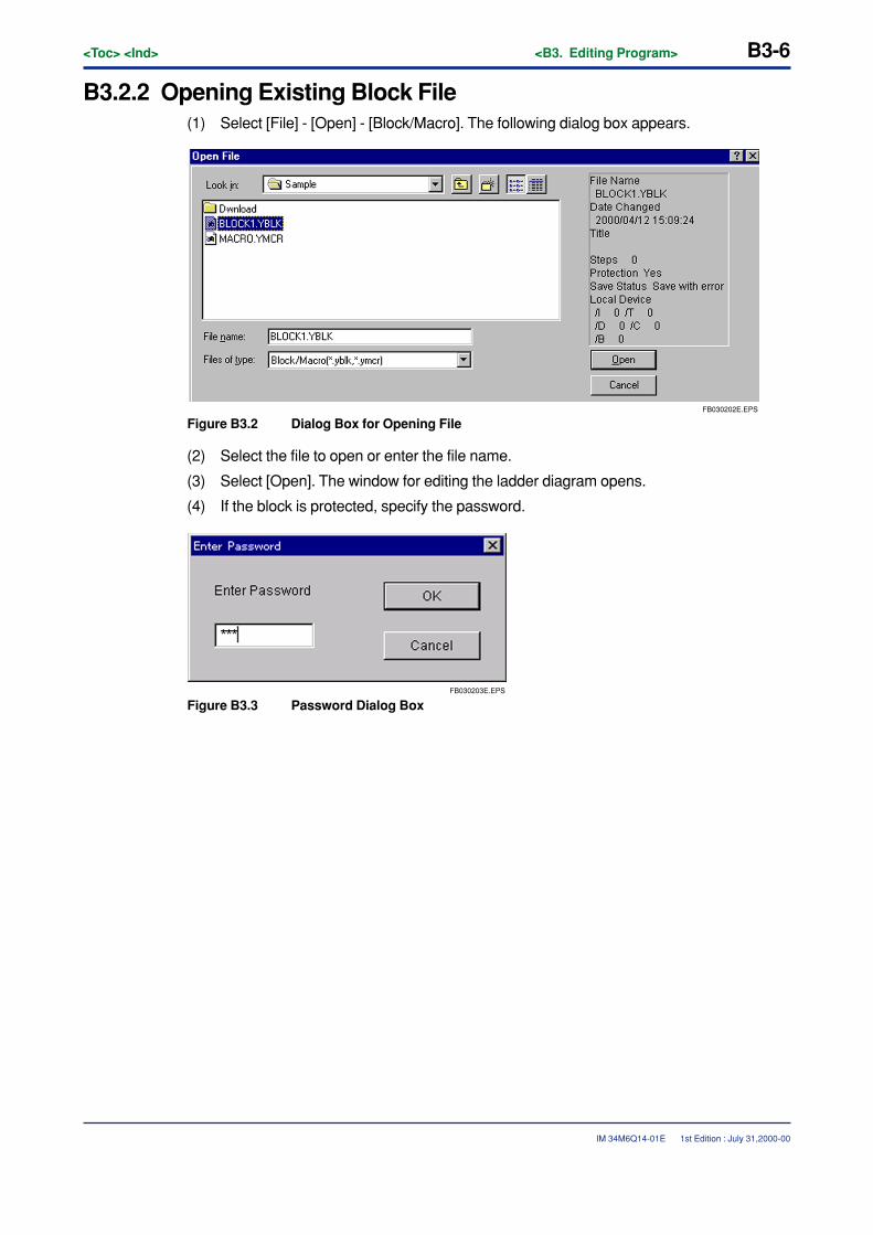
B3-6<Toc> <Ind> <B3. Editing Program>
IM 34M6Q14-01E
B3.2.2 Opening Existing Block File(1) Select [File] - [Open] - [Block/Macro]. The following dialog box appears.
FB030202E.EPS
Figure B3.2 Dialog Box for Opening File
(2) Select the file to open or enter the file name.
(3) Select [Open]. The window for editing the ladder diagram opens.
(4) If the block is protected, specify the password.
FB030203E.EPS
Figure B3.3 Password Dialog Box
1st Edition : July 31,2000-00
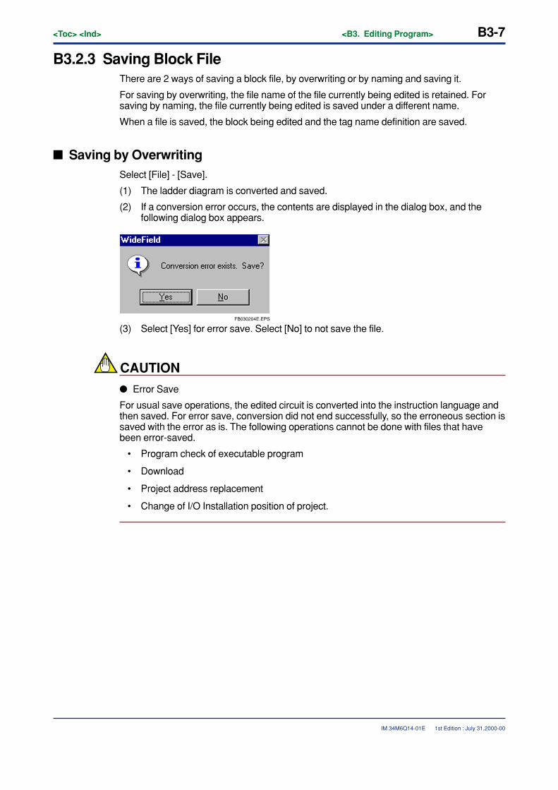
<Toc> <Ind> <B3. Editing Program> B3-7
IM 34M6Q14-01E
B3.2.3 Saving Block FileThere are 2 ways of saving a block file, by overwriting or by naming and saving it.
For saving by overwriting, the file name of the file currently being edited is retained. Forsaving by naming, the file currently being edited is saved under a different name.
When a file is saved, the block being edited and the tag name definition are saved.
� Saving by OverwritingSelect [File] - [Save].
(1) The ladder diagram is converted and saved.
(2) If a conversion error occurs, the contents are displayed in the dialog box, and thefollowing dialog box appears.
FB030204E.EPS
(3) Select [Yes] for error save. Select [No] to not save the file.
CAUTION
� Error Save
For usual save operations, the edited circuit is converted into the instruction language andthen saved. For error save, conversion did not end successfully, so the erroneous section issaved with the error as is. The following operations cannot be done with files that havebeen error-saved.
• Program check of executable program
• Download
• Project address replacement
• Change of I/O Installation position of project.
1st Edition : July 31,2000-00
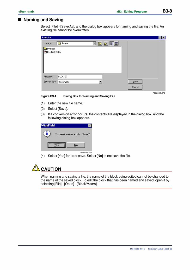
B3-8<Toc> <Ind> <B3. Editing Program>
IM 34M6Q14-01E
� Naming and SavingSelect [File] - [Save As], and the dialog box appears for naming and saving the file. Anexisting file cannot be overwritten.
FB030205E.EPS
Figure B3.4 Dialog Box for Naming and Saving File
(1) Enter the new file name.
(2) Select [Save].
(3) If a conversion error occurs, the contents are displayed in the dialog box, and thefollowing dialog box appears.
FB030206E.EPS
(4) Select [Yes] for error save. Select [No] to not save the file.
CAUTION
When naming and saving a file, the name of the block being edited cannot be changed tothe name of the saved block. To edit the block that has been named and saved, open it byselecting [File] - [Open] - [Block/Macro].
1st Edition : July 31,2000-00

<Toc> <Ind> <B3. Editing Program> B3-9
IM 34M6Q14-01E
B3.2 4 Closing Block FileTo close the edit window, select [File] - [Close]. If the block has been changed, the followingdialog box appears.
FB030207E.EPS
Figure B3.5 Save Dialog Box
When [Yes] is selected, the file is saved and the window closes.
When [No] is selected, the file is not saved and the window closes.
When [Cancel] is selected, the file does not close, but remains displayed.
1st Edition : July 31,2000-00
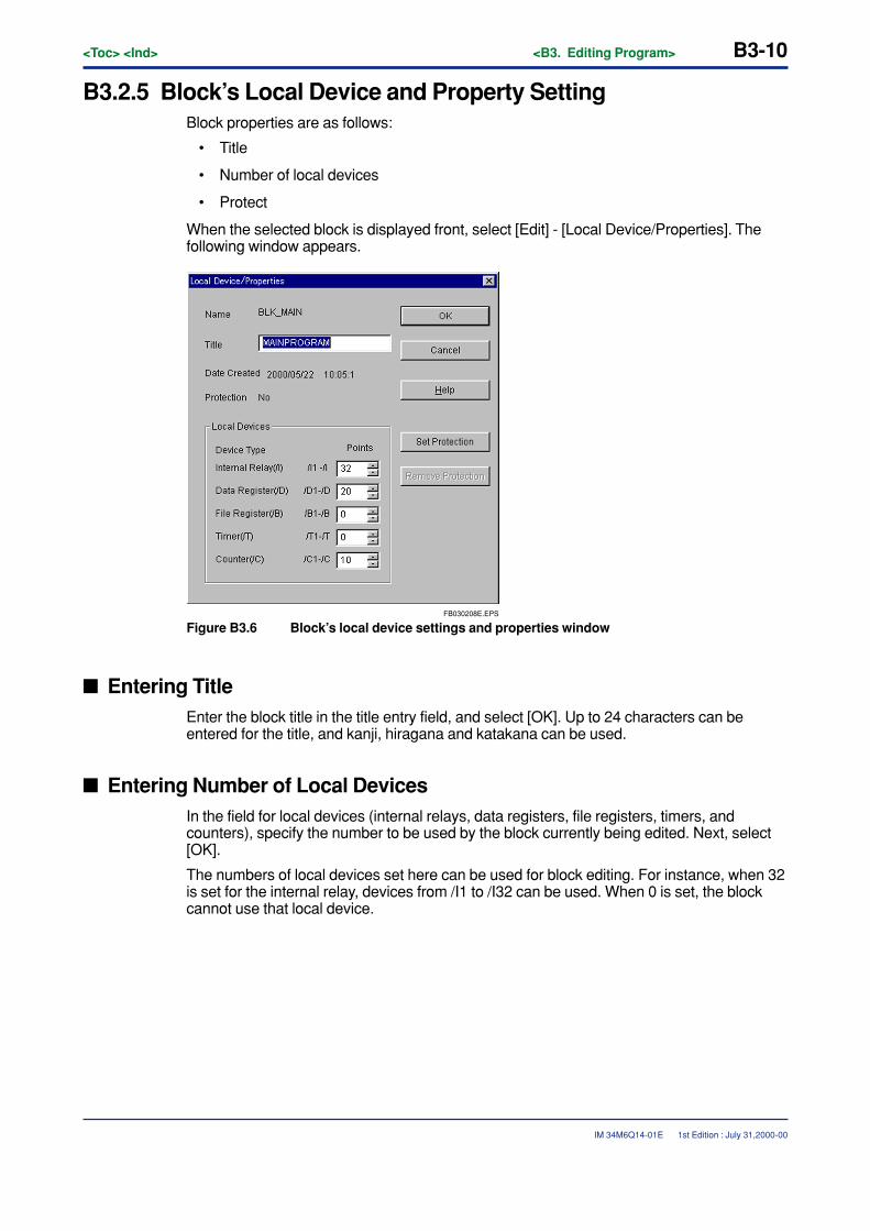
B3-10<Toc> <Ind> <B3. Editing Program>
IM 34M6Q14-01E
B3.2.5 Block’s Local Device and Property SettingBlock properties are as follows:
• Title
• Number of local devices
• Protect
When the selected block is displayed front, select [Edit] - [Local Device/Properties]. Thefollowing window appears.
FB030208E.EPS
Figure B3.6 Block’s local device settings and properties window
� Entering TitleEnter the block title in the title entry field, and select [OK]. Up to 24 characters can beentered for the title, and kanji, hiragana and katakana can be used.
� Entering Number of Local DevicesIn the field for local devices (internal relays, data registers, file registers, timers, andcounters), specify the number to be used by the block currently being edited. Next, select[OK].
The numbers of local devices set here can be used for block editing. For instance, when 32is set for the internal relay, devices from /I1 to /I32 can be used. When 0 is set, the blockcannot use that local device.
1st Edition : July 31,2000-00
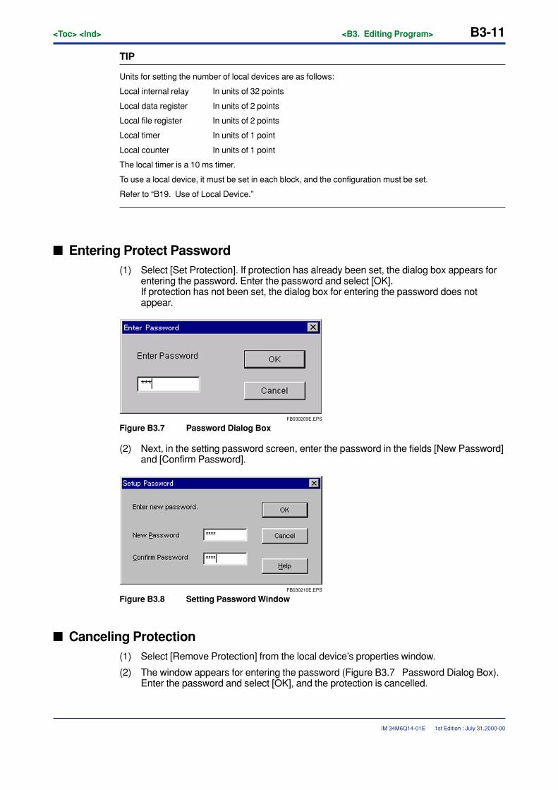
<Toc> <Ind> <B3. Editing Program> B3-11
IM 34M6Q14-01E
TIP
Units for setting the number of local devices are as follows:
Local internal relay In units of 32 points
Local data register In units of 2 points
Local file register In units of 2 points
Local timer In units of 1 point
Local counter In units of 1 point
The local timer is a 10 ms timer.
To use a local device, it must be set in each block, and the configuration must be set.
Refer to “B19. Use of Local Device.”
� Entering Protect Password(1) Select [Set Protection]. If protection has already been set, the dialog box appears for
entering the password. Enter the password and select [OK].If protection has not been set, the dialog box for entering the password does notappear.
FB030209E.EPS
Figure B3.7 Password Dialog Box
(2) Next, in the setting password screen, enter the password in the fields [New Password]and [Confirm Password].
FB030210E.EPS
Figure B3.8 Setting Password Window
� Canceling Protection(1) Select [Remove Protection] from the local device’s properties window.
(2) The window appears for entering the password (Figure B3.7 Password Dialog Box).Enter the password and select [OK], and the protection is cancelled.
1st Edition : July 31,2000-00
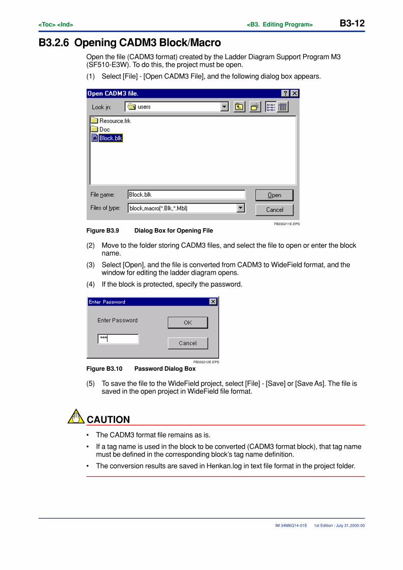
B3-12<Toc> <Ind> <B3. Editing Program>
IM 34M6Q14-01E
B3.2.6 Opening CADM3 Block/MacroOpen the file (CADM3 format) created by the Ladder Diagram Support Program M3(SF510-E3W). To do this, the project must be open.
(1) Select [File] - [Open CADM3 File], and the following dialog box appears.
FB030211E.EPS
Figure B3.9 Dialog Box for Opening File
(2) Move to the folder storing CADM3 files, and select the file to open or enter the blockname.
(3) Select [Open], and the file is converted from CADM3 to WideField format, and thewindow for editing the ladder diagram opens.
(4) If the block is protected, specify the password.
FB030212E.EPS
Figure B3.10 Password Dialog Box
(5) To save the file to the WideField project, select [File] - [Save] or [Save As]. The file issaved in the open project in WideField file format.
CAUTION
• The CADM3 format file remains as is.
• If a tag name is used in the block to be converted (CADM3 format block), that tag namemust be defined in the corresponding block’s tag name definition.
• The conversion results are saved in Henkan.log in text file format in the project folder.
1st Edition : July 31,2000-00
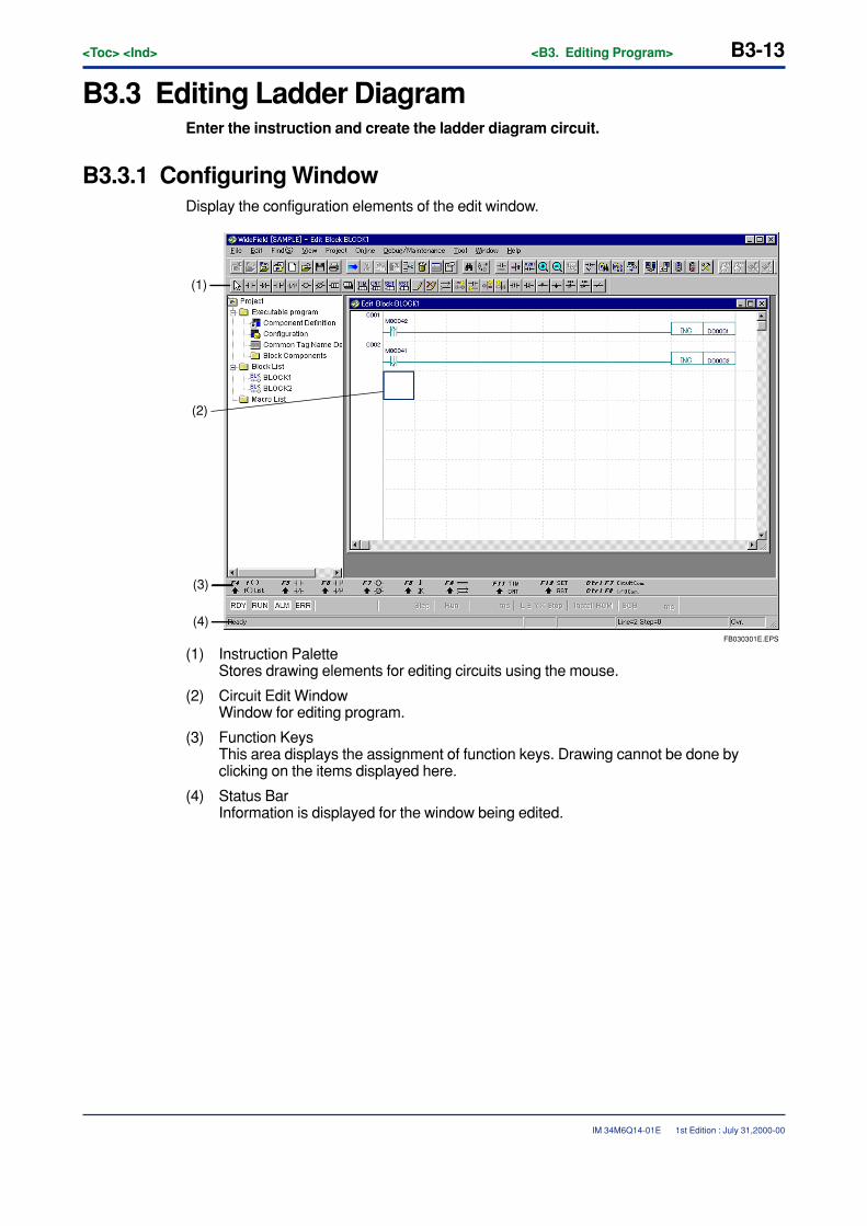
<Toc> <Ind> <B3. Editing Program> B3-13
IM 34M6Q14-01E
B3.3 Editing Ladder DiagramEnter the instruction and create the ladder diagram circuit.
B3.3.1 Configuring WindowDisplay the configuration elements of the edit window.
FB030301E.EPS
(1)
(3)
(4)
(2)
(1) Instruction PaletteStores drawing elements for editing circuits using the mouse.
(2) Circuit Edit WindowWindow for editing program.
(3) Function KeysThis area displays the assignment of function keys. Drawing cannot be done byclicking on the items displayed here.
(4) Status BarInformation is displayed for the window being edited.
1st Edition : July 31,2000-00
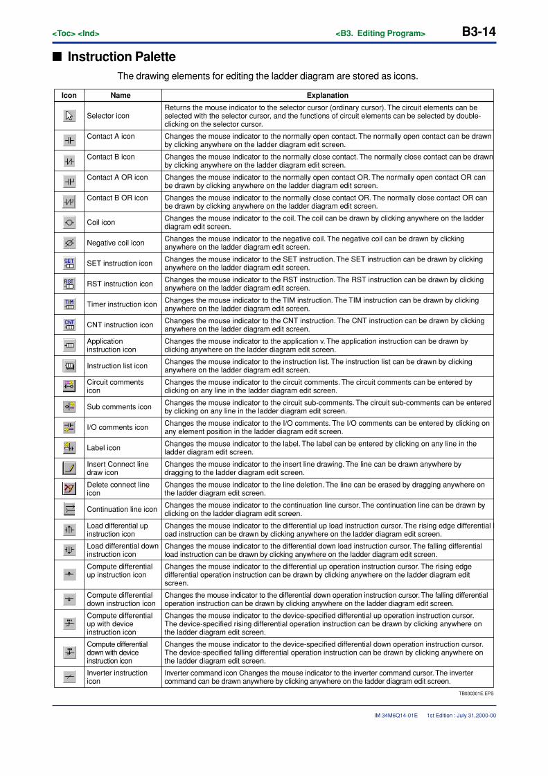
B3-14<Toc> <Ind> <B3. Editing Program>
IM 34M6Q14-01E
� Instruction PaletteThe drawing elements for editing the ladder diagram are stored as icons.
TB030301E.EPS
Inverter instruction icon
ExplanationIcon Name
Selector iconReturns the mouse indicator to the selector cursor (ordinary cursor). The circuit elements can be selected with the selector cursor, and the functions of circuit elements can be selected by double-clicking on the selector cursor.
Contact A icon Changes the mouse indicator to the normally open contact. The normally open contact can be drawn by clicking anywhere on the ladder diagram edit screen.
Contact B icon Changes the mouse indicator to the normally close contact. The normally close contact can be drawn by clicking anywhere on the ladder diagram edit screen.
Contact A OR icon Changes the mouse indicator to the normally open contact OR. The normally open contact OR can be drawn by clicking anywhere on the ladder diagram edit screen.
Contact B OR icon Changes the mouse indicator to the normally close contact OR. The normally close contact OR can be drawn by clicking anywhere on the ladder diagram edit screen.
Coil icon Changes the mouse indicator to the coil. The coil can be drawn by clicking anywhere on the ladder diagram edit screen.
Negative coil icon Changes the mouse indicator to the negative coil. The negative coil can be drawn by clicking anywhere on the ladder diagram edit screen.
SET instruction icon Changes the mouse indicator to the SET instruction. The SET instruction can be drawn by clicking anywhere on the ladder diagram edit screen.
Changes the mouse indicator to the RST instruction. The RST instruction can be drawn by clicking anywhere on the ladder diagram edit screen.RST instruction icon
Timer instruction icon Changes the mouse indicator to the TIM instruction. The TIM instruction can be drawn by clicking anywhere on the ladder diagram edit screen.
CNT instruction icon Changes the mouse indicator to the CNT instruction. The CNT instruction can be drawn by clicking anywhere on the ladder diagram edit screen.
Application instruction icon
Changes the mouse indicator to the application v. The application instruction can be drawn by clicking anywhere on the ladder diagram edit screen.
Instruction list icon Changes the mouse indicator to the instruction list. The instruction list can be drawn by clicking anywhere on the ladder diagram edit screen.
Circuit commentsicon
Changes the mouse indicator to the circuit comments. The circuit comments can be entered by clicking on any line in the ladder diagram edit screen.
Sub comments icon Changes the mouse indicator to the circuit sub-comments. The circuit sub-comments can be entered by clicking on any line in the ladder diagram edit screen.
I/O comments icon Changes the mouse indicator to the I/O comments. The I/O comments can be entered by clicking on any element position in the ladder diagram edit screen.
Label icon Changes the mouse indicator to the label. The label can be entered by clicking on any line in the ladder diagram edit screen.
Insert Connect line draw icon
Changes the mouse indicator to the insert line drawing. The line can be drawn anywhere by dragging to the ladder diagram edit screen.
Delete connect line icon
Changes the mouse indicator to the line deletion. The line can be erased by dragging anywhere on the ladder diagram edit screen.
Continuation line icon Changes the mouse indicator to the continuation line cursor. The continuation line can be drawn by clicking on the ladder diagram edit screen.
Load differential up instruction icon
Changes the mouse indicator to the differential up load instruction cursor. The rising edge differential load instruction can be drawn by clicking anywhere on the ladder diagram edit screen.
Load differential down instruction icon
Changes the mouse indicator to the differential down load instruction cursor. The falling differential load instruction can be drawn by clicking anywhere on the ladder diagram edit screen.
Compute differential up instruction icon
Changes the mouse indicator to the differential up operation instruction cursor. The rising edge differential operation instruction can be drawn by clicking anywhere on the ladder diagram edit screen.
Compute differential down instruction icon
Changes the mouse indicator to the differential down operation instruction cursor. The falling differential operation instruction can be drawn by clicking anywhere on the ladder diagram edit screen.
Changes the mouse indicator to the device-specified differential up operation instruction cursor. The device-specified rising differential operation instruction can be drawn by clicking anywhere on the ladder diagram edit screen.
Compute differential up with device instruction icon
Inverter command icon Changes the mouse indicator to the inverter command cursor. The inverter command can be drawn anywhere by clicking anywhere on the ladder diagram edit screen.
Compute differential down with device instruction icon
Changes the mouse indicator to the device-specified differential down operation instruction cursor. The device-specified falling differential operation instruction can be drawn by clicking anywhere on the ladder diagram edit screen.
1st Edition : July 31,2000-00
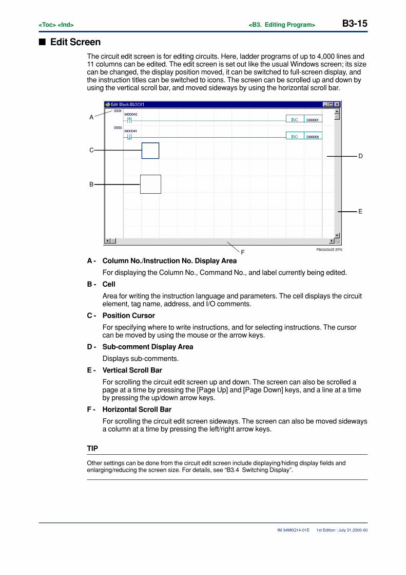
<Toc> <Ind> <B3. Editing Program> B3-15
IM 34M6Q14-01E
� Edit ScreenThe circuit edit screen is for editing circuits. Here, ladder programs of up to 4,000 lines and11 columns can be edited. The edit screen is set out like the usual Windows screen; its sizecan be changed, the display position moved, it can be switched to full-screen display, andthe instruction titles can be switched to icons. The screen can be scrolled up and down byusing the vertical scroll bar, and moved sideways by using the horizontal scroll bar.
FB030302E.EPS
A
F
D
B
C
E
A - Column No./Instruction No. Display Area
For displaying the Column No., Command No., and label currently being edited.
B - Cell
Area for writing the instruction language and parameters. The cell displays the circuitelement, tag name, address, and I/O comments.
C - Position Cursor
For specifying where to write instructions, and for selecting instructions. The cursorcan be moved by using the mouse or the arrow keys.
D - Sub-comment Display Area
Displays sub-comments.
E - Vertical Scroll Bar
For scrolling the circuit edit screen up and down. The screen can also be scrolled apage at a time by pressing the [Page Up] and [Page Down] keys, and a line at a timeby pressing the up/down arrow keys.
F - Horizontal Scroll Bar
For scrolling the circuit edit screen sideways. The screen can also be moved sidewaysa column at a time by pressing the left/right arrow keys.
TIP
Other settings can be done from the circuit edit screen include displaying/hiding display fields andenlarging/reducing the screen size. For details, see “B3.4 Switching Display”.
1st Edition : July 31,2000-00
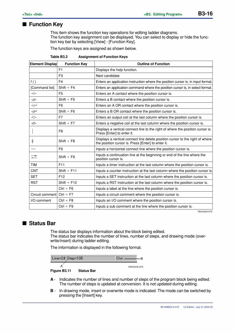
B3-16<Toc> <Ind> <B3. Editing Program>
IM 34M6Q14-01E
� Function KeyThis item shows the function key operations for editing ladder diagrams.The function key assignment can be displayed. You can select to display or hide the func-tion key bar by selecting [View] - [Function Key].
The function keys are assigned as shown below.
Table B3.2 Assignment of Function Keys
TB030302E.EPS
Element Display Function Key Outline of Function
Displays the help function.F1
F3
F4
Shift � F4
F5
Shift � F5
F6
Shift � F6
F7
Shift � F7
F8
F9
Shift � F8
Next candidate
Enters an application instruction where the position cursor is, in input format.
[Command list]
f ( )
Enters an application command where the position cursor is, in select format.
Enters an A contact where the position cursor is.
Enters a B contact where the position cursor is.
Enters an A OR contact where the position cursor is.
Enters a B OR contact where the position cursor is.
Enters an output coil at the last column where the position cursor is.
Enters a negative coil at the last column where the position cursor is.
Displays a vertical connect line to the right of where the position cursor is. Press [Enter] to enter it.
Displays a vertical connect line delete position cursor to the right of where the position cursor is. Press [Enter] to enter it.
Inputs a horizontal connect line where the position cursor is.
Shift � F9
F11
Shift � F11
F12
Shift � F12
Ctrl � F6
Ctrl � F7
Ctrl � F8
Ctrl � F9
Inputs a continuation line at the beginning or end of the line where the position cursor is.
Inputs a timer instruction at the last column where the position cursor is.
Inputs a counter instruction at the last column where the position cursor is.
Inputs a SET instruction at the last column where the position cursor is.
Inputs a RST instruction at the last column where the position cursor is.
Inputs a label at the line where the position cursor is.
Circuit comment
RST
SET
CNT
TIM
Inputs a circuit comment where the position cursor is.
I/O comment Inputs an I/O comment where the position cursor is.
Inputs a sub comment at the line where the position cursor is.
� Status BarThe status bar displays information about the block being edited.The status bar indicates the number of lines, number of steps, and drawing mode (over-write/insert) during ladder editing.
The information is displayed in the following format.
FB030303E.EPS
B
A
Figure B3.11 Status Bar
A - Indicates the number of lines and number of steps of the program block being edited.The number of steps is updated at conversion. It is not updated during editing.
B - In drawing mode, insert or overwrite mode is indicated. The mode can be switched bypressing the [Insert] key.
1st Edition : July 31,2000-00
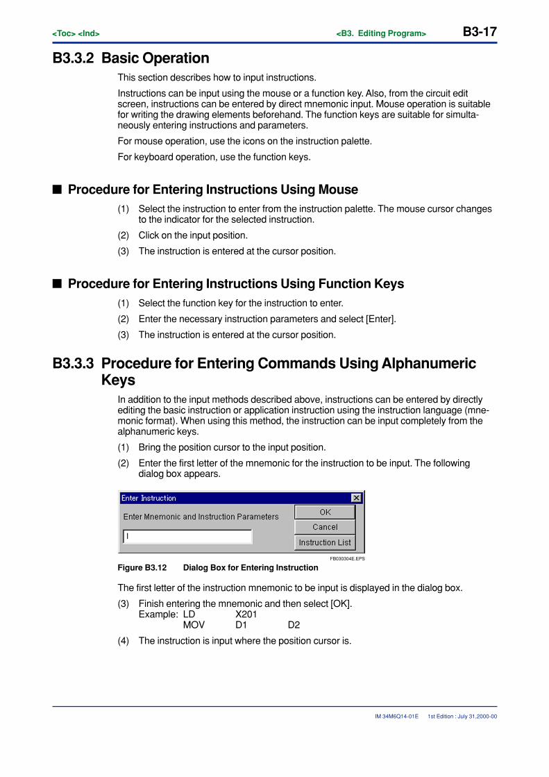
<Toc> <Ind> <B3. Editing Program> B3-17
IM 34M6Q14-01E
B3.3.2 Basic OperationThis section describes how to input instructions.
Instructions can be input using the mouse or a function key. Also, from the circuit editscreen, instructions can be entered by direct mnemonic input. Mouse operation is suitablefor writing the drawing elements beforehand. The function keys are suitable for simulta-neously entering instructions and parameters.
For mouse operation, use the icons on the instruction palette.
For keyboard operation, use the function keys.
� Procedure for Entering Instructions Using Mouse(1) Select the instruction to enter from the instruction palette. The mouse cursor changes
to the indicator for the selected instruction.
(2) Click on the input position.
(3) The instruction is entered at the cursor position.
� Procedure for Entering Instructions Using Function Keys(1) Select the function key for the instruction to enter.
(2) Enter the necessary instruction parameters and select [Enter].
(3) The instruction is entered at the cursor position.
B3.3.3 Procedure for Entering Commands Using AlphanumericKeys
In addition to the input methods described above, instructions can be entered by directlyediting the basic instruction or application instruction using the instruction language (mne-monic format). When using this method, the instruction can be input completely from thealphanumeric keys.
(1) Bring the position cursor to the input position.
(2) Enter the first letter of the mnemonic for the instruction to be input. The followingdialog box appears.
FB030304E.EPS
Figure B3.12 Dialog Box for Entering Instruction
The first letter of the instruction mnemonic to be input is displayed in the dialog box.
(3) Finish entering the mnemonic and then select [OK].Example: LD X201
MOV D1 D2
(4) The instruction is input where the position cursor is.
1st Edition : July 31,2000-00
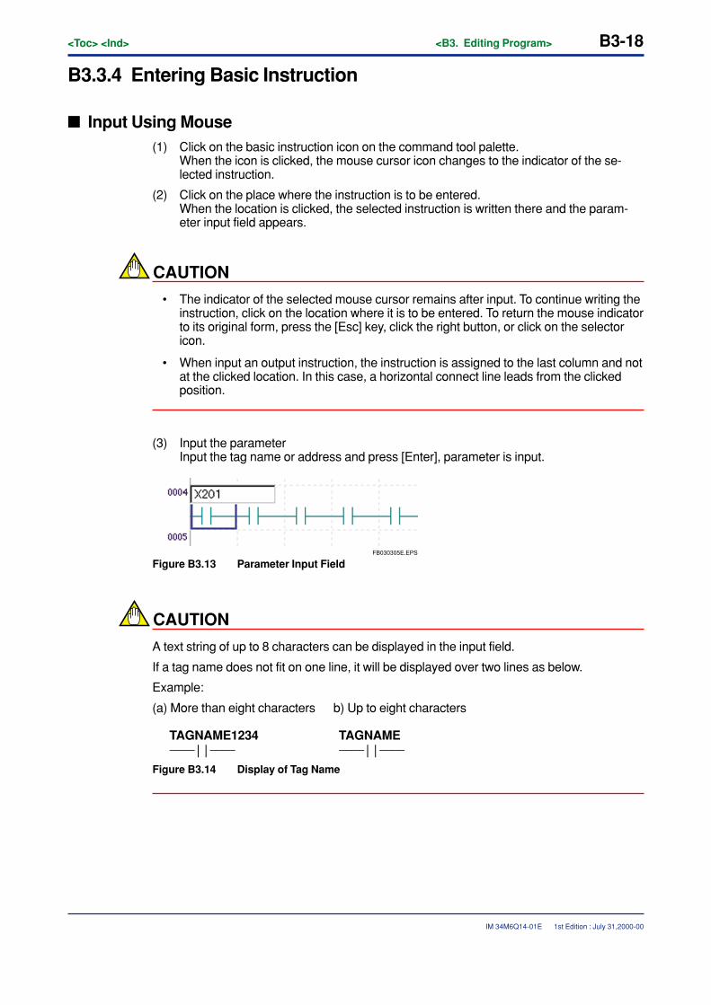
B3-18<Toc> <Ind> <B3. Editing Program>
IM 34M6Q14-01E
B3.3.4 Entering Basic Instruction
� Input Using Mouse(1) Click on the basic instruction icon on the command tool palette.
When the icon is clicked, the mouse cursor icon changes to the indicator of the se-lected instruction.
(2) Click on the place where the instruction is to be entered.When the location is clicked, the selected instruction is written there and the param-eter input field appears.
CAUTION
• The indicator of the selected mouse cursor remains after input. To continue writing theinstruction, click on the location where it is to be entered. To return the mouse indicatorto its original form, press the [Esc] key, click the right button, or click on the selectoricon.
• When input an output instruction, the instruction is assigned to the last column and notat the clicked location. In this case, a horizontal connect line leads from the clickedposition.
(3) Input the parameterInput the tag name or address and press [Enter], parameter is input.
FB030305E.EPS
Figure B3.13 Parameter Input Field
CAUTION
A text string of up to 8 characters can be displayed in the input field.
If a tag name does not fit on one line, it will be displayed over two lines as below.
Example:
(a) More than eight characters b) Up to eight characters
TAGNAME1234 TAGNAME−−−− | | −−−− −−−− | | −−−−
Figure B3.14 Display of Tag Name
1st Edition : July 31,2000-00

<Toc> <Ind> <B3. Editing Program> B3-19
IM 34M6Q14-01E
� Input Using Function Key(1) Bring the position cursor to the input location.
(2) Select the function key for the instruction to be entered. When the function key ispressed the instruction is written at that location, and the input field appears.
(3) Here, input the tag name or device address and press the [Enter] key. The instructionis assigned to the device. Press the [Esc] key to cancel entering the instruction. Oncethe instruction is entered, the position cursor moves to the next column.
1st Edition : July 31,2000-00
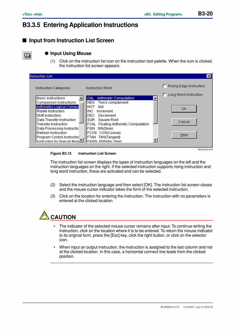
B3-20<Toc> <Ind> <B3. Editing Program>
IM 34M6Q14-01E
B3.3.5 Entering Application Instructions
� Input from Instruction List Screen
� Input Using Mouse
(1) Click on the instruction list icon on the instruction tool palette. When the icon is clicked,the instruction list screen appears.
FB030307E.EPS
Figure B3.15 Instruction List Screen
The instruction list screen displays the types of instruction languages on the left and theinstruction languages on the right. If the selected instruction supports rising instruction andlong word instruction, these are activated and can be selected.
(2) Select the instruction language and then select [OK]. The instruction list screen closesand the mouse cursor indicator takes the form of the selected instruction.
(3) Click on the location for entering the instruction. The instruction with no parameters isentered at the clicked location.
CAUTION
• The indicator of the selected mouse cursor remains after input. To continue writing theinstruction, click on the location where it is to be entered. To return the mouse indicatorto its original form, press the [Esc] key, click the right button, or click on the selectoricon.
• When input an output instruction, the instruction is assigned to the last column and notat the clicked location. In this case, a horizontal connect line leads from the clickedposition.
1st Edition : July 31,2000-00
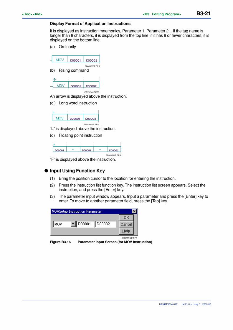
<Toc> <Ind> <B3. Editing Program> B3-21
IM 34M6Q14-01E
Display Format of Application Instructions
It is displayed as instruction mnemonics, Parameter 1, Parameter 2... If the tag name islonger than 8 characters, it is displayed from the top line; if it has 8 or fewer characters, it isdisplayed on the bottom line.
(a) Ordinarily
FB030308E.EPS
(b) Rising command
FB030309E.EPS
An arrow is displayed above the instruction.
(c ) Long word instruction
FB030310E.EPS
“L” is displayed above the instruction.
(d) Floating point instruction
FB030311E.EPS
“F” is displayed above the instruction.
� Input Using Function Key
(1) Bring the position cursor to the location for entering the instruction.
(2) Press the instruction list function key. The instruction list screen appears. Select theinstruction, and press the [Enter] key.
(3) The parameter input window appears. Input a parameter and press the [Enter] key toenter. To move to another parameter field, press the [Tab] key.
FB030312E.EPS
Figure B3.16 Parameter Input Screen (for MOV instruction)
1st Edition : July 31,2000-00
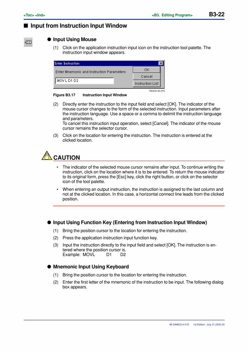
B3-22<Toc> <Ind> <B3. Editing Program>
IM 34M6Q14-01E
� Input from Instruction Input Window
� Input Using Mouse
(1) Click on the application instruction input icon on the instruction tool palette. Theinstruction input window appears.
FB030313E.EPS
Figure B3.17 Instruction Input Window
(2) Directly enter the instruction to the input field and select [OK]. The indicator of themouse cursor changes to the form of the selected instruction. Input parameters afterthe instruction language. Use a space or a comma to delimit the instruction languageand parameters.To cancel this instruction input operation, select [Cancel]. The indicator of the mousecursor remains the selector cursor.
(3) Click on the location for entering the instruction. The instruction is entered at theclicked location.
CAUTION
• The indicator of the selected mouse cursor remains after input. To continue writing theinstruction, click on the location where it is to be entered. To return the mouse indicatorto its original form, press the [Esc] key, click the right button, or click on the selectoricon of the tool palette.
• When entering an output instruction, the instruction is assigned to the last column andnot at the clicked location. In this case, a horizontal connect line leads from the clickedposition.
� Input Using Function Key (Entering from Instruction Input Window)
(1) Bring the position cursor to the location for entering the instruction.
(2) Press the application instruction input function key.
(3) Input the instruction directly to the input field and select [OK]. The instruction is en-tered where the position cursor is.Example: MOVL D1 D2
� Mnemonic Input Using Keyboard
(1) Bring the position cursor to the location for entering the instruction.
(2) Enter the first letter of the mnemonic of the instruction to be input. The following dialogbox appears.
1st Edition : July 31,2000-00
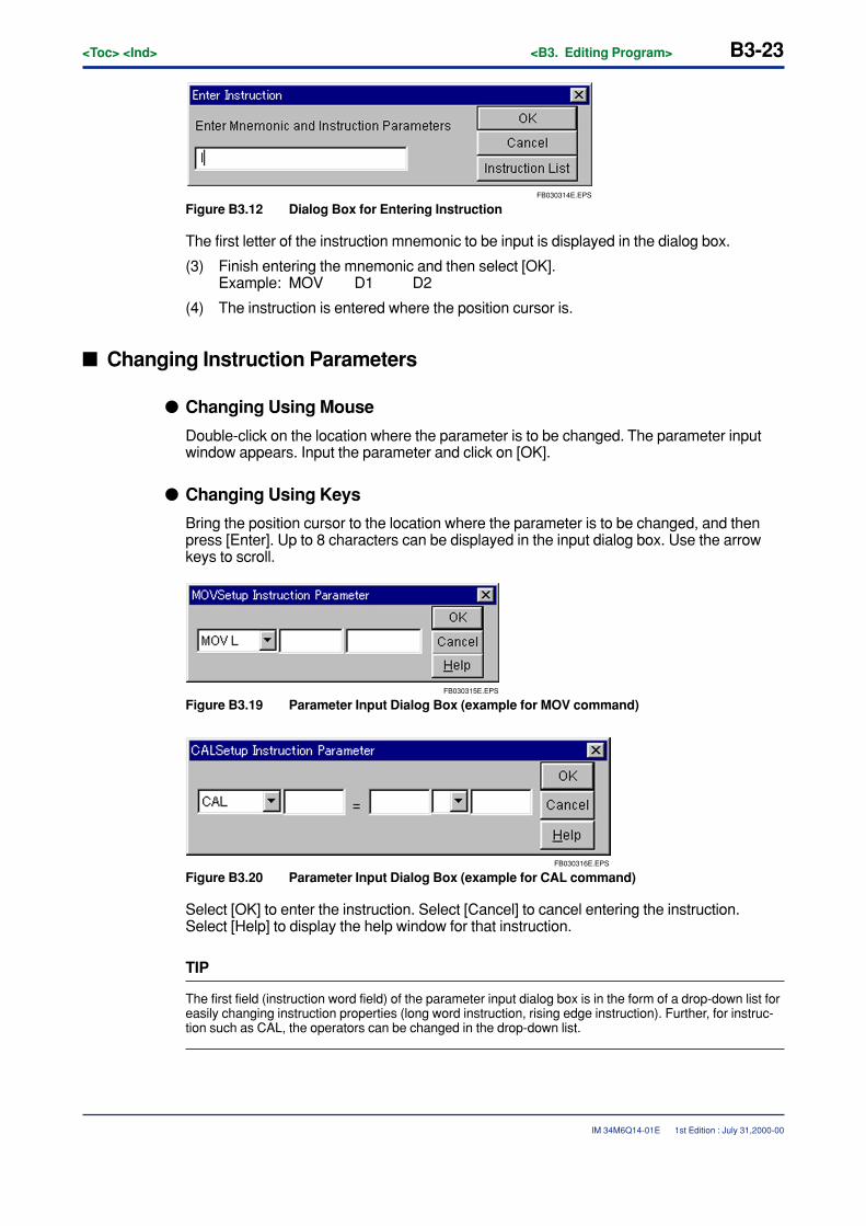
<Toc> <Ind> <B3. Editing Program> B3-23
IM 34M6Q14-01E
FB030314E.EPS
Figure B3.12 Dialog Box for Entering Instruction
The first letter of the instruction mnemonic to be input is displayed in the dialog box.
(3) Finish entering the mnemonic and then select [OK].Example: MOV D1 D2
(4) The instruction is entered where the position cursor is.
� Changing Instruction Parameters
� Changing Using Mouse
Double-click on the location where the parameter is to be changed. The parameter inputwindow appears. Input the parameter and click on [OK].
� Changing Using Keys
Bring the position cursor to the location where the parameter is to be changed, and thenpress [Enter]. Up to 8 characters can be displayed in the input dialog box. Use the arrowkeys to scroll.
FB030315E.EPS
Figure B3.19 Parameter Input Dialog Box (example for MOV command)
FB030316E.EPS
Figure B3.20 Parameter Input Dialog Box (example for CAL command)
Select [OK] to enter the instruction. Select [Cancel] to cancel entering the instruction.Select [Help] to display the help window for that instruction.
TIP
The first field (instruction word field) of the parameter input dialog box is in the form of a drop-down list foreasily changing instruction properties (long word instruction, rising edge instruction). Further, for instruc-tion such as CAL, the operators can be changed in the drop-down list.
1st Edition : July 31,2000-00
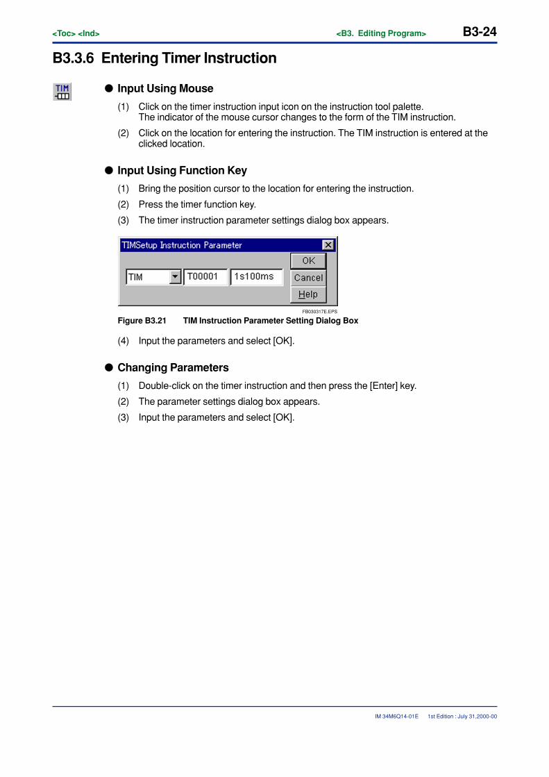
B3-24<Toc> <Ind> <B3. Editing Program>
IM 34M6Q14-01E
B3.3.6 Entering Timer Instruction
� Input Using Mouse
(1) Click on the timer instruction input icon on the instruction tool palette.The indicator of the mouse cursor changes to the form of the TIM instruction.
(2) Click on the location for entering the instruction. The TIM instruction is entered at theclicked location.
� Input Using Function Key
(1) Bring the position cursor to the location for entering the instruction.
(2) Press the timer function key.
(3) The timer instruction parameter settings dialog box appears.
FB030317E.EPS
Figure B3.21 TIM Instruction Parameter Setting Dialog Box
(4) Input the parameters and select [OK].
� Changing Parameters
(1) Double-click on the timer instruction and then press the [Enter] key.
(2) The parameter settings dialog box appears.
(3) Input the parameters and select [OK].
1st Edition : July 31,2000-00
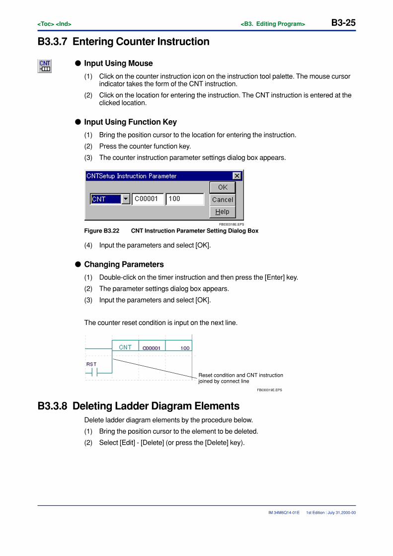
<Toc> <Ind> <B3. Editing Program> B3-25
IM 34M6Q14-01E
B3.3.7 Entering Counter Instruction
� Input Using Mouse
(1) Click on the counter instruction icon on the instruction tool palette. The mouse cursorindicator takes the form of the CNT instruction.
(2) Click on the location for entering the instruction. The CNT instruction is entered at theclicked location.
� Input Using Function Key
(1) Bring the position cursor to the location for entering the instruction.
(2) Press the counter function key.
(3) The counter instruction parameter settings dialog box appears.
FB030318E.EPS
Figure B3.22 CNT Instruction Parameter Setting Dialog Box
(4) Input the parameters and select [OK].
� Changing Parameters
(1) Double-click on the timer instruction and then press the [Enter] key.
(2) The parameter settings dialog box appears.
(3) Input the parameters and select [OK].
The counter reset condition is input on the next line.
FB030319E.EPS
Reset condition and CNT instruction joined by connect line
B3.3.8 Deleting Ladder Diagram ElementsDelete ladder diagram elements by the procedure below.
(1) Bring the position cursor to the element to be deleted.
(2) Select [Edit] - [Delete] (or press the [Delete] key).
1st Edition : July 31,2000-00
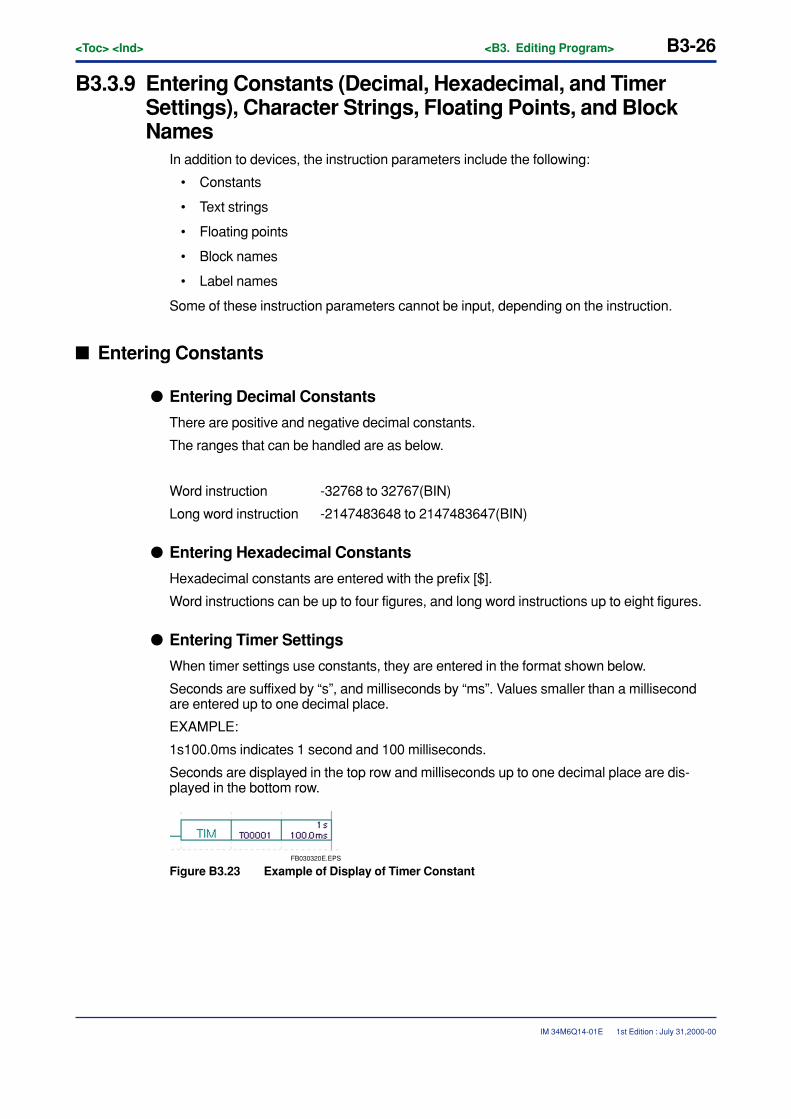
B3-26<Toc> <Ind> <B3. Editing Program>
IM 34M6Q14-01E
B3.3.9 Entering Constants (Decimal, Hexadecimal, and TimerSettings), Character Strings, Floating Points, and BlockNames
In addition to devices, the instruction parameters include the following:
• Constants
• Text strings
• Floating points
• Block names
• Label names
Some of these instruction parameters cannot be input, depending on the instruction.
� Entering Constants
� Entering Decimal Constants
There are positive and negative decimal constants.
The ranges that can be handled are as below.
Word instruction -32768 to 32767(BIN)
Long word instruction -2147483648 to 2147483647(BIN)
� Entering Hexadecimal Constants
Hexadecimal constants are entered with the prefix [$].
Word instructions can be up to four figures, and long word instructions up to eight figures.
� Entering Timer Settings
When timer settings use constants, they are entered in the format shown below.
Seconds are suffixed by “s”, and milliseconds by “ms”. Values smaller than a millisecondare entered up to one decimal place.
EXAMPLE:
1s100.0ms indicates 1 second and 100 milliseconds.
Seconds are displayed in the top row and milliseconds up to one decimal place are dis-played in the bottom row.
FB030320E.EPS
Figure B3.23 Example of Display of Timer Constant
1st Edition : July 31,2000-00

<Toc> <Ind> <B3. Editing Program> B3-27
IM 34M6Q14-01E
� Entering Character StringsWideField handles text strings of kanji, katakana, alphanumeric and symbols. However,some instructions may not be able to handle certain text strings. Text strings are enclosedin inverted commas (“”).
Word instructions up to 2 ASCII characters can be entered. Long word instructions up to 4ASCII characters can be entered.
� Entering Floating PointsThe use of floating points is limited to particular commands. Floating points are enteredwith the prefix “%”. Negative values are entered with “-” after “%”. Floating points can beused with long word commands and floating point instructions.
EXAMPLE:
Display is left-justified, with 8 characters for the argument section and 4 characters for theexponent section.
Display format
%X.XXXXXXEYYY
X.XXXXXX is the argument section, and YYY is the exponent section. The sign is dis-played immediately before X.XXXXXX and YYY.
The range of data that can be entered is approximately as follows:
Negative integers -3.4e37 to -1.5e-38
Positive integers 1.5e-38 to 3.4e37
� Entering Block NamesThe block name is input to a parameter of the ACT/INACT instruction. The entered name isalways displayed in uppercase.
� Entering Label Name in Jump or Sub-routine InstructionThe label name is input to a parameter of the JMP/CALL instruction.
1st Edition : July 31,2000-00
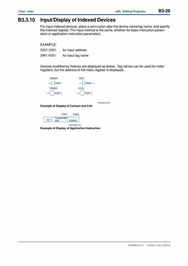
B3-28<Toc> <Ind> <B3. Editing Program>
IM 34M6Q14-01E
B3.3.10 Input/Display of Indexed DevicesFor input indexed devices, place a semi-colon after the device name/tag name, and specifythe indexed register. The input method is the same, whether for basic instruction param-eters or application instruction parameters.
EXAMPLE:
X201;V001 for input address
SW1;V001 for input tag name
Devices modified by indexes are displayed as below. Tag names can be used for indexregisters, but the address of the index register is displayed.
FB030321E.EPS
Example of Display of Contact and Coil
FB030322E.EPS
V001 V002
Example of Display of Application Instruction
1st Edition : July 31,2000-00
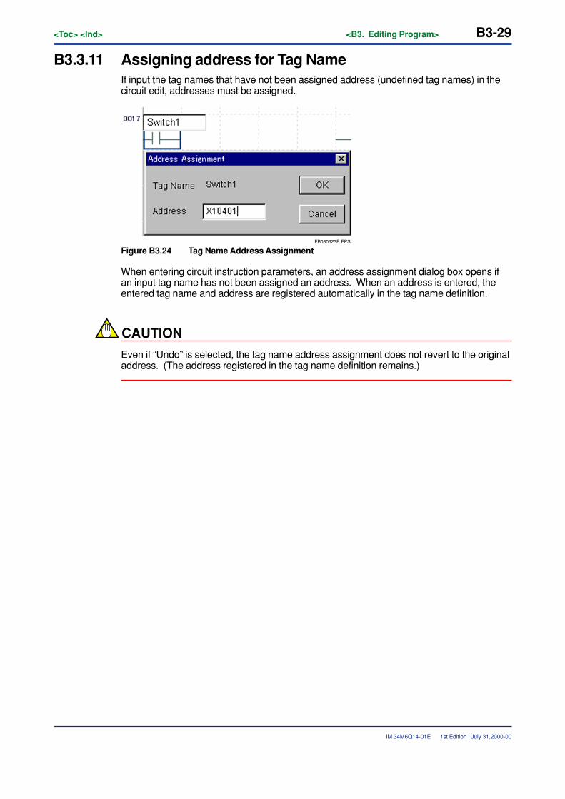
<Toc> <Ind> <B3. Editing Program> B3-29
IM 34M6Q14-01E
B3.3.11 Assigning address for Tag NameIf input the tag names that have not been assigned address (undefined tag names) in thecircuit edit, addresses must be assigned.
FB030323E.EPS
Figure B3.24 Tag Name Address Assignment
When entering circuit instruction parameters, an address assignment dialog box opens ifan input tag name has not been assigned an address. When an address is entered, theentered tag name and address are registered automatically in the tag name definition.
CAUTION
Even if “Undo” is selected, the tag name address assignment does not revert to the originaladdress. (The address registered in the tag name definition remains.)
1st Edition : July 31,2000-00
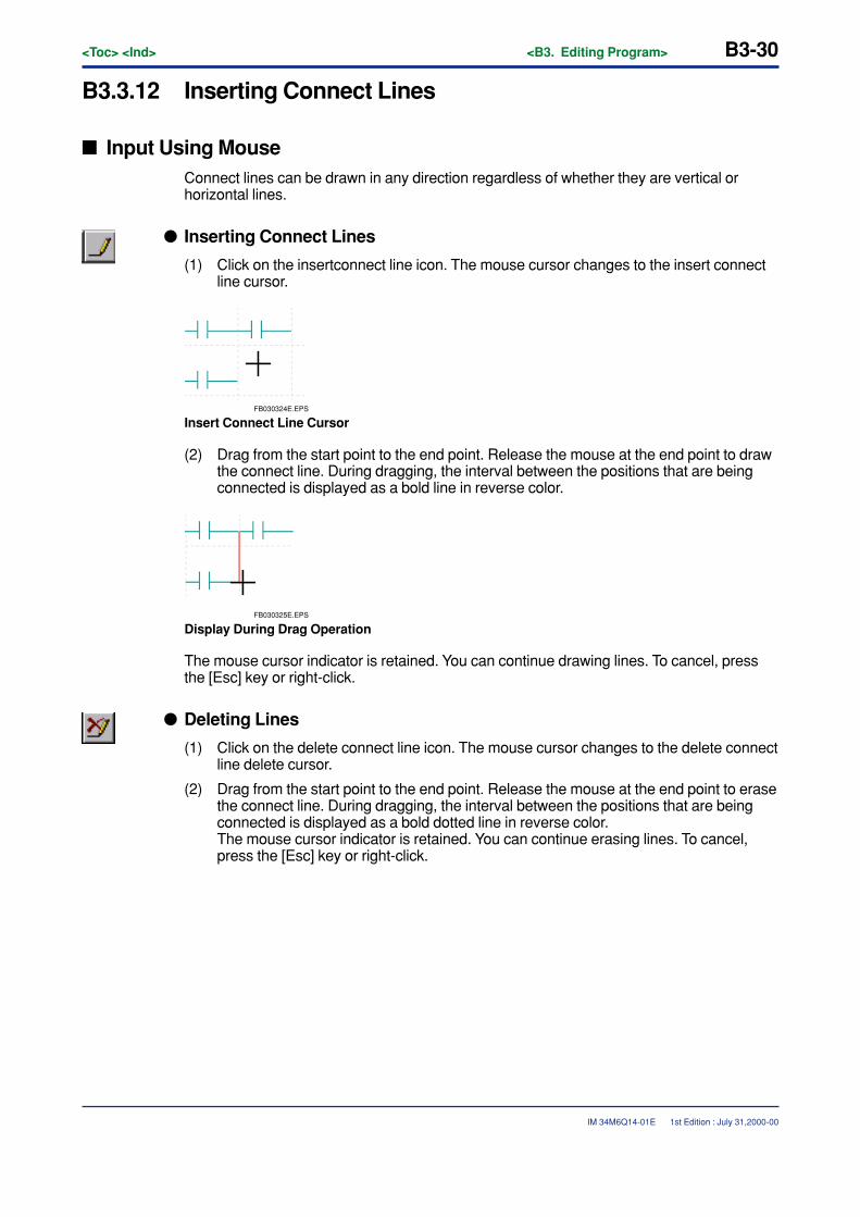
B3-30<Toc> <Ind> <B3. Editing Program>
IM 34M6Q14-01E
B3.3.12 Inserting Connect Lines
� Input Using MouseConnect lines can be drawn in any direction regardless of whether they are vertical orhorizontal lines.
� Inserting Connect Lines
(1) Click on the insertconnect line icon. The mouse cursor changes to the insert connectline cursor.
FB030324E.EPS
Insert Connect Line Cursor
(2) Drag from the start point to the end point. Release the mouse at the end point to drawthe connect line. During dragging, the interval between the positions that are beingconnected is displayed as a bold line in reverse color.
FB030325E.EPS
Display During Drag Operation
The mouse cursor indicator is retained. You can continue drawing lines. To cancel, pressthe [Esc] key or right-click.
� Deleting Lines
(1) Click on the delete connect line icon. The mouse cursor changes to the delete connectline delete cursor.
(2) Drag from the start point to the end point. Release the mouse at the end point to erasethe connect line. During dragging, the interval between the positions that are beingconnected is displayed as a bold dotted line in reverse color.The mouse cursor indicator is retained. You can continue erasing lines. To cancel,press the [Esc] key or right-click.
1st Edition : July 31,2000-00
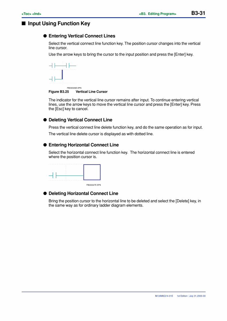
<Toc> <Ind> <B3. Editing Program> B3-31
IM 34M6Q14-01E
� Input Using Function Key
� Entering Vertical Connect Lines
Select the vertical connect line function key. The position cursor changes into the verticalline cursor.
Use the arrow keys to bring the cursor to the input position and press the [Enter] key.
FB030326E.EPS
Figure B3.25 Vertical Line Cursor
The indicator for the vertical line cursor remains after input. To continue entering verticallines, use the arrow keys to move the vertical line cursor and press the [Enter] key. Pressthe [Esc] key to cancel.
� Deleting Vertical Connect Line
Press the vertical connect line delete function key, and do the same operation as for input.
The vertical line delete cursor is displayed as with dotted line.
� Entering Horizontal Connect Line
Select the horizontal connect line function key. The horizontal connect line is enteredwhere the position cursor is.
FB030327E.EPS
� Deleting Horizontal Connect Line
Bring the position cursor to the horizontal line to be deleted and select the [Delete] key, inthe same way as for ordinary ladder diagram elements.
1st Edition : July 31,2000-00
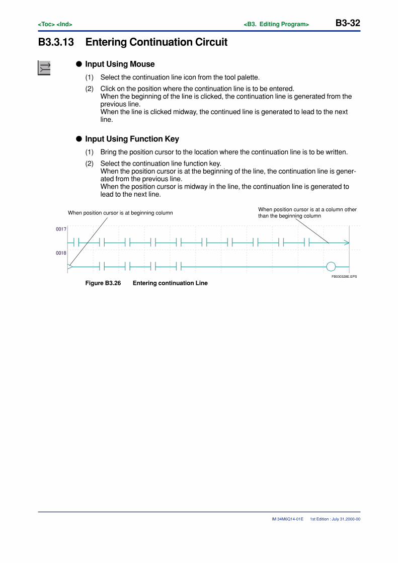
B3-32<Toc> <Ind> <B3. Editing Program>
IM 34M6Q14-01E
B3.3.13 Entering Continuation Circuit
� Input Using Mouse
(1) Select the continuation line icon from the tool palette.
(2) Click on the position where the continuation line is to be entered.When the beginning of the line is clicked, the continuation line is generated from theprevious line.When the line is clicked midway, the continued line is generated to lead to the nextline.
� Input Using Function Key
(1) Bring the position cursor to the location where the continuation line is to be written.
(2) Select the continuation line function key.When the position cursor is at the beginning of the line, the continuation line is gener-ated from the previous line.When the position cursor is midway in the line, the continuation line is generated tolead to the next line.
FB030328E.EPS
When position cursor is at a column other than the beginning columnWhen position cursor is at beginning column
Figure B3.26 Entering continuation Line
1st Edition : July 31,2000-00
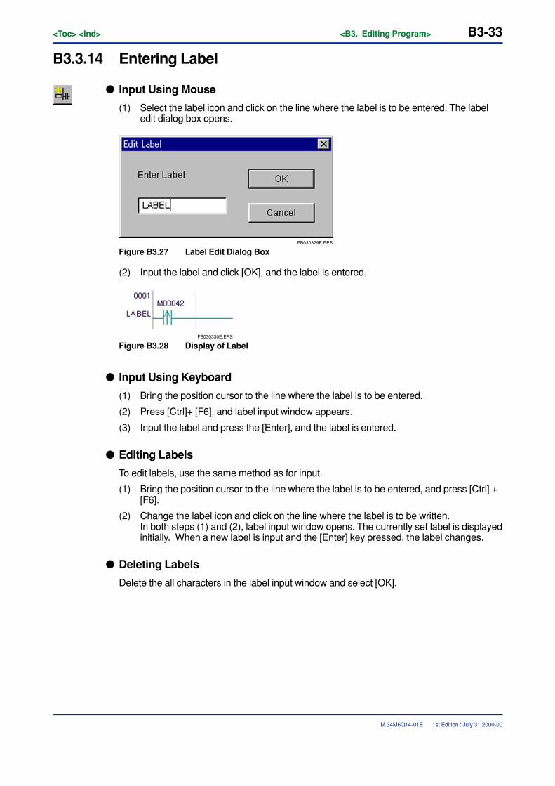
<Toc> <Ind> <B3. Editing Program> B3-33
IM 34M6Q14-01E
B3.3.14 Entering Label
� Input Using Mouse
(1) Select the label icon and click on the line where the label is to be entered. The labeledit dialog box opens.
FB030329E.EPS
Figure B3.27 Label Edit Dialog Box
(2) Input the label and click [OK], and the label is entered.
FB030330E.EPS
Figure B3.28 Display of Label
� Input Using Keyboard
(1) Bring the position cursor to the line where the label is to be entered.
(2) Press [Ctrl]+ [F6], and label input window appears.
(3) Input the label and press the [Enter], and the label is entered.
� Editing Labels
To edit labels, use the same method as for input.
(1) Bring the position cursor to the line where the label is to be entered, and press [Ctrl] +[F6].
(2) Change the label icon and click on the line where the label is to be written.In both steps (1) and (2), label input window opens. The currently set label is displayedinitially. When a new label is input and the [Enter] key pressed, the label changes.
� Deleting Labels
Delete the all characters in the label input window and select [OK].
1st Edition : July 31,2000-00
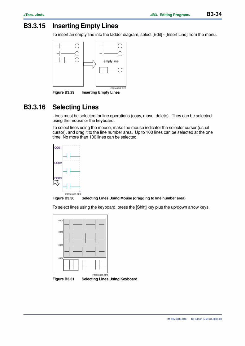
B3-34<Toc> <Ind> <B3. Editing Program>
IM 34M6Q14-01E
B3.3.15 Inserting Empty LinesTo insert an empty line into the ladder diagram, select [Edit] - [Insert Line] from the menu.
FB030331E.EPS
empty line
Figure B3.29 Inserting Empty Lines
B3.3.16 Selecting LinesLines must be selected for line operations (copy, move, delete). They can be selectedusing the mouse or the keyboard.
To select lines using the mouse, make the mouse indicator the selector cursor (usualcursor), and drag it to the line number area. Up to 100 lines can be selected at the onetime. No more than 100 lines can be selected.
FB030332E.EPS
Figure B3.30 Selecting Lines Using Mouse (dragging to line number area)
To select lines using the keyboard, press the [Shift] key plus the up/down arrow keys.
FB030333E.EPS
0001
0002
0003
0004
Figure B3.31 Selecting Lines Using Keyboard
1st Edition : July 31,2000-00
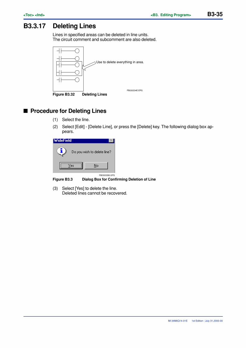
<Toc> <Ind> <B3. Editing Program> B3-35
IM 34M6Q14-01E
B3.3.17 Deleting LinesLines in specified areas can be deleted in line units.The circuit comment and subcomment are also deleted.
FB030334E.EPS
Use to delete everything in area.
Figure B3.32 Deleting Lines
� Procedure for Deleting Lines(1) Select the line.
(2) Select [Edit] - [Delete Line], or press the [Delete] key. The following dialog box ap-pears.
FB030335E.EPS
Figure B3.3 Dialog Box for Confirming Deletion of Line
(3) Select [Yes] to delete the line.Deleted lines cannot be recovered.
1st Edition : July 31,2000-00
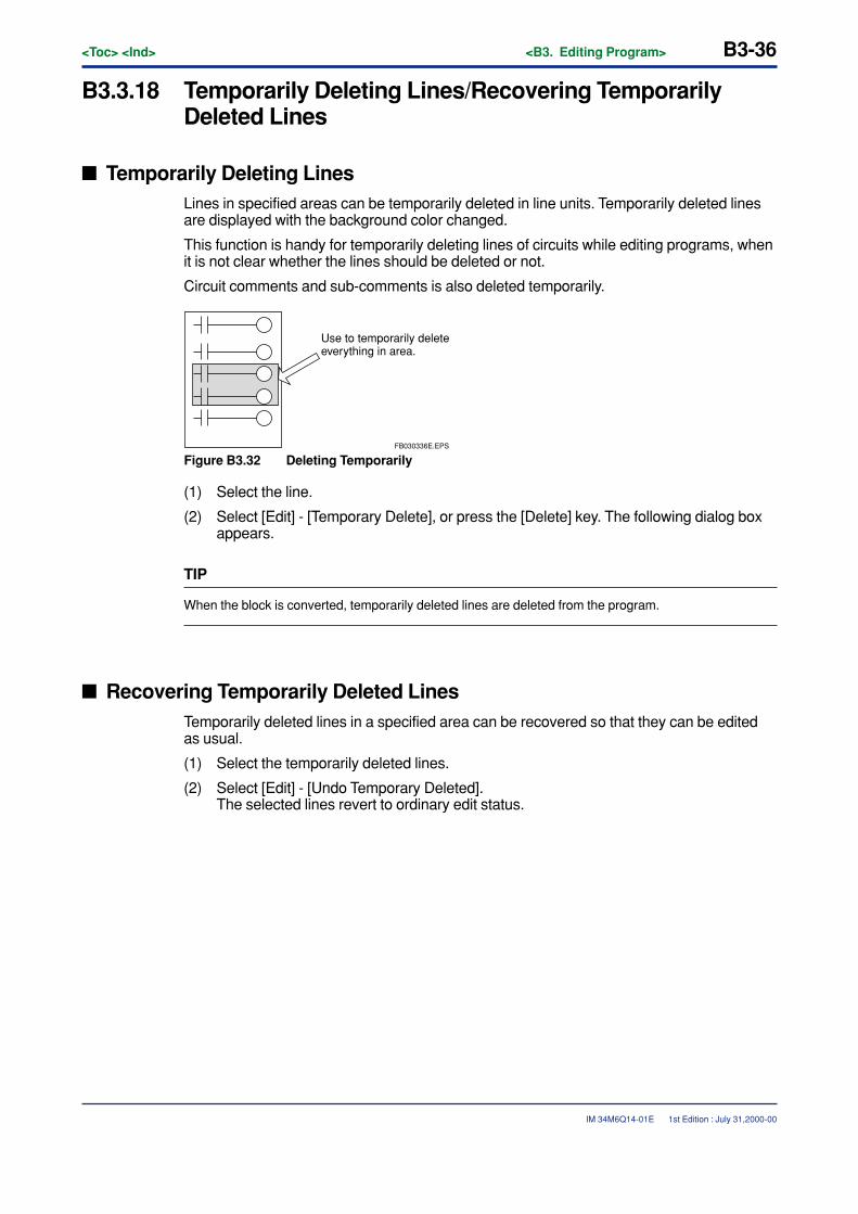
B3-36<Toc> <Ind> <B3. Editing Program>
IM 34M6Q14-01E
B3.3.18 Temporarily Deleting Lines/Recovering TemporarilyDeleted Lines
� Temporarily Deleting LinesLines in specified areas can be temporarily deleted in line units. Temporarily deleted linesare displayed with the background color changed.
This function is handy for temporarily deleting lines of circuits while editing programs, whenit is not clear whether the lines should be deleted or not.
Circuit comments and sub-comments is also deleted temporarily.
Use to temporarily delete everything in area.
FB030336E.EPS
Figure B3.32 Deleting Temporarily
(1) Select the line.
(2) Select [Edit] - [Temporary Delete], or press the [Delete] key. The following dialog boxappears.
TIP
When the block is converted, temporarily deleted lines are deleted from the program.
� Recovering Temporarily Deleted LinesTemporarily deleted lines in a specified area can be recovered so that they can be editedas usual.
(1) Select the temporarily deleted lines.
(2) Select [Edit] - [Undo Temporary Deleted].The selected lines revert to ordinary edit status.
1st Edition : July 31,2000-00
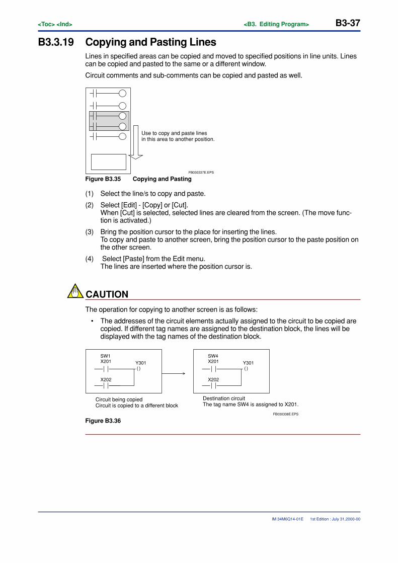
<Toc> <Ind> <B3. Editing Program> B3-37
IM 34M6Q14-01E
B3.3.19 Copying and Pasting LinesLines in specified areas can be copied and moved to specified positions in line units. Linescan be copied and pasted to the same or a different window.
Circuit comments and sub-comments can be copied and pasted as well.
Use to copy and paste lines in this area to another position.
FB030337E.EPS
Figure B3.35 Copying and Pasting
(1) Select the line/s to copy and paste.
(2) Select [Edit] - [Copy] or [Cut].When [Cut] is selected, selected lines are cleared from the screen. (The move func-tion is activated.)
(3) Bring the position cursor to the place for inserting the lines.To copy and paste to another screen, bring the position cursor to the paste position onthe other screen.
(4) Select [Paste] from the Edit menu.The lines are inserted where the position cursor is.
CAUTION
The operation for copying to another screen is as follows:
• The addresses of the circuit elements actually assigned to the circuit to be copied arecopied. If different tag names are assigned to the destination block, the lines will bedisplayed with the tag names of the destination block.
SW1X201
X202
Y301 ( )
Circuit being copiedCircuit is copied to a different block
SW4X201
X202
Y301 ( )
FB030338E.EPS
Destination circuitThe tag name SW4 is assigned to X201.
Figure B3.36
1st Edition : July 31,2000-00
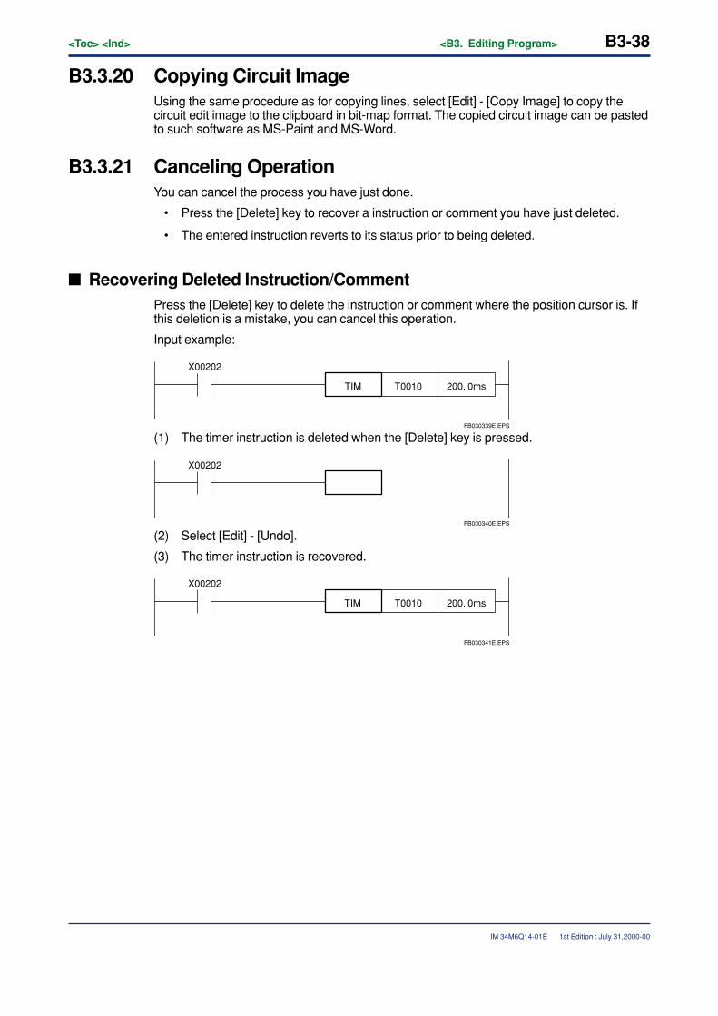
B3-38<Toc> <Ind> <B3. Editing Program>
IM 34M6Q14-01E
B3.3.20 Copying Circuit ImageUsing the same procedure as for copying lines, select [Edit] - [Copy Image] to copy thecircuit edit image to the clipboard in bit-map format. The copied circuit image can be pastedto such software as MS-Paint and MS-Word.
B3.3.21 Canceling OperationYou can cancel the process you have just done.
• Press the [Delete] key to recover a instruction or comment you have just deleted.
• The entered instruction reverts to its status prior to being deleted.
� Recovering Deleted Instruction/CommentPress the [Delete] key to delete the instruction or comment where the position cursor is. Ifthis deletion is a mistake, you can cancel this operation.
Input example:
200. 0msT0010TIM
X00202
FB030339E.EPS
(1) The timer instruction is deleted when the [Delete] key is pressed.
X00202
FB030340E.EPS
(2) Select [Edit] - [Undo].
(3) The timer instruction is recovered.
200. 0msT0010TIM
X00202
FB030341E.EPS
1st Edition : July 31,2000-00
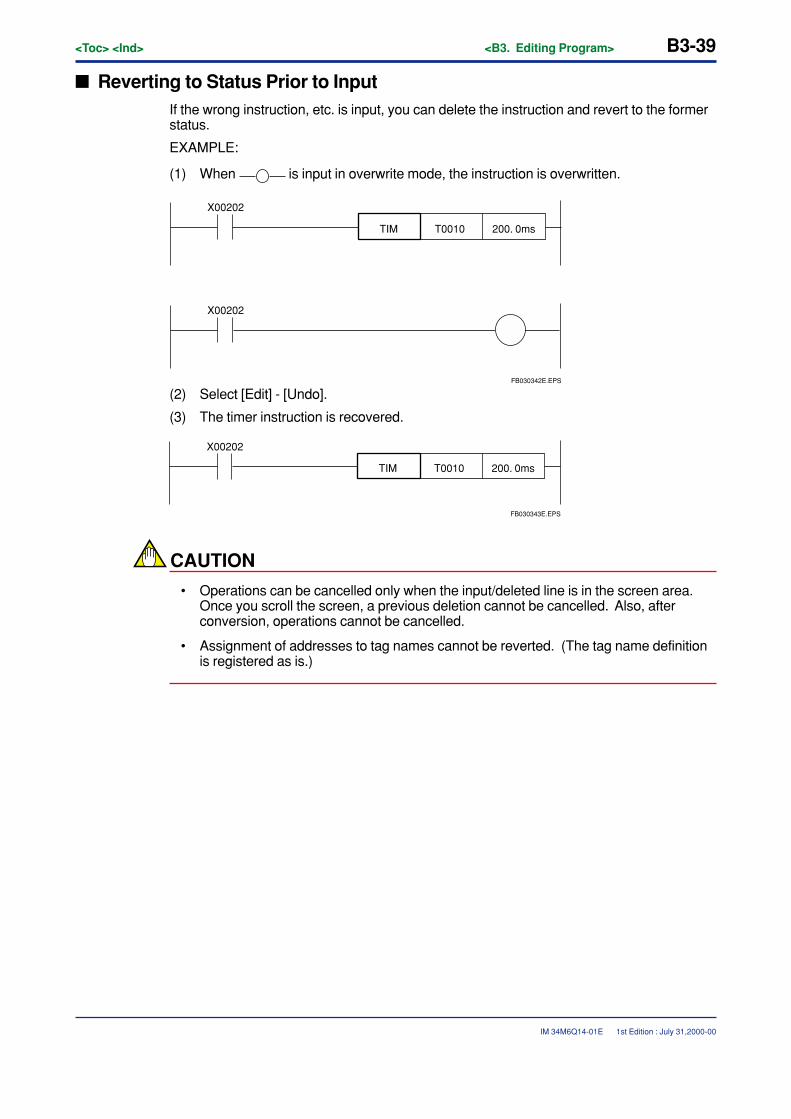
<Toc> <Ind> <B3. Editing Program> B3-39
IM 34M6Q14-01E
� Reverting to Status Prior to InputIf the wrong instruction, etc. is input, you can delete the instruction and revert to the formerstatus.
EXAMPLE:
(1) When is input in overwrite mode, the instruction is overwritten.
200. 0msT0010TIM
X00202
X00202
FB030342E.EPS
(2) Select [Edit] - [Undo].
(3) The timer instruction is recovered.
200. 0msT0010TIM
X00202
FB030343E.EPS
CAUTION
• Operations can be cancelled only when the input/deleted line is in the screen area.Once you scroll the screen, a previous deletion cannot be cancelled. Also, afterconversion, operations cannot be cancelled.
• Assignment of addresses to tag names cannot be reverted. (The tag name definitionis registered as is.)
1st Edition : July 31,2000-00
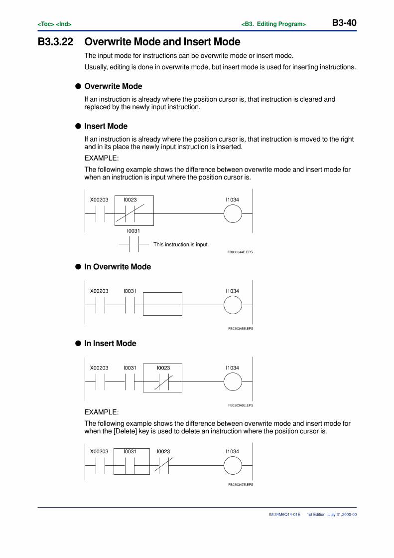
B3-40<Toc> <Ind> <B3. Editing Program>
IM 34M6Q14-01E
B3.3.22 Overwrite Mode and Insert ModeThe input mode for instructions can be overwrite mode or insert mode.
Usually, editing is done in overwrite mode, but insert mode is used for inserting instructions.
� Overwrite Mode
If an instruction is already where the position cursor is, that instruction is cleared andreplaced by the newly input instruction.
� Insert Mode
If an instruction is already where the position cursor is, that instruction is moved to the rightand in its place the newly input instruction is inserted.
EXAMPLE:
The following example shows the difference between overwrite mode and insert mode forwhen an instruction is input where the position cursor is.
X00203
I0031
This instruction is input.
I1034I0023
FB030344E.EPS
� In Overwrite Mode
X00203 I1034I0031
FB030345E.EPS
� In Insert Mode
X00203 I1034I0031 I0023
FB030346E.EPS
EXAMPLE:
The following example shows the difference between overwrite mode and insert mode forwhen the [Delete] key is used to delete an instruction where the position cursor is.
X00203 I1034I0031 I0023
FB030347E.EPS
1st Edition : July 31,2000-00
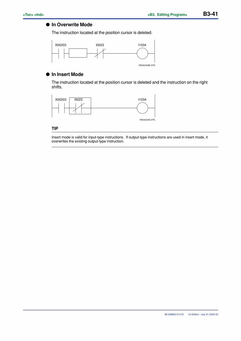
<Toc> <Ind> <B3. Editing Program> B3-41
IM 34M6Q14-01E
� In Overwrite Mode
The instruction located at the position cursor is deleted.
X00203 I1034I0023
FB0303408E.EPS
� In Insert Mode
The instruction located at the position cursor is deleted and the instruction on the rightshifts.
X00203 I1034I0023
FB030349E.EPS
TIP
Insert mode is valid for input-type instructions. If output-type instructions are used in insert mode, itoverwrites the existing output-type instruction.
1st Edition : July 31,2000-00
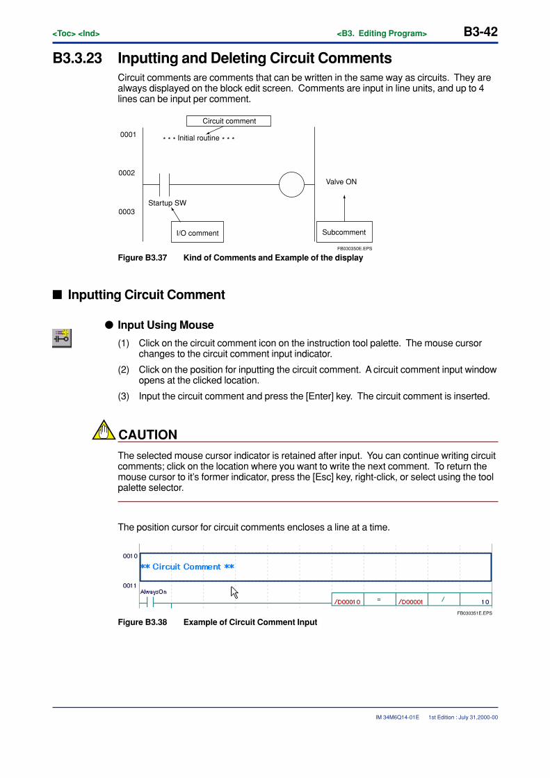
B3-42<Toc> <Ind> <B3. Editing Program>
IM 34M6Q14-01E
B3.3.23 Inputting and Deleting Circuit CommentsCircuit comments are comments that can be written in the same way as circuits. They arealways displayed on the block edit screen. Comments are input in line units, and up to 4lines can be input per comment.
0001
0002
0003
FB030350E.EPS
Circuit comment
Initial routine* * * * * *
Startup SW
I/O comment Subcomment
Valve ON
Figure B3.37 Kind of Comments and Example of the display
� Inputting Circuit Comment
� Input Using Mouse
(1) Click on the circuit comment icon on the instruction tool palette. The mouse cursorchanges to the circuit comment input indicator.
(2) Click on the position for inputting the circuit comment. A circuit comment input windowopens at the clicked location.
(3) Input the circuit comment and press the [Enter] key. The circuit comment is inserted.
CAUTION
The selected mouse cursor indicator is retained after input. You can continue writing circuitcomments; click on the location where you want to write the next comment. To return themouse cursor to it’s former indicator, press the [Esc] key, right-click, or select using the toolpalette selector.
The position cursor for circuit comments encloses a line at a time.
FB030351E.EPS
Figure B3.38 Example of Circuit Comment Input
1st Edition : July 31,2000-00
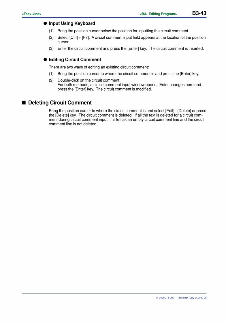
<Toc> <Ind> <B3. Editing Program> B3-43
IM 34M6Q14-01E
� Input Using Keyboard
(1) Bring the position cursor below the position for inputting the circuit comment.
(2) Select [Ctrl] + [F7]. A circuit comment input field appears at the location of the positioncursor.
(3) Enter the circuit comment and press the [Enter] key. The circuit comment is inserted.
� Editing Circuit Comment
There are two ways of editing an existing circuit comment:
(1) Bring the position cursor to where the circuit comment is and press the [Enter] key.
(2) Double-click on the circuit comment.For both methods, a circuit comment input window opens. Enter changes here andpress the [Enter] key. The circuit comment is modified.
� Deleting Circuit CommentBring the position cursor to where the circuit comment is and select [Edit] - [Delete] or pressthe [Delete] key. The circuit comment is deleted. If all the text is deleted for a circuit com-ment during circuit comment input, it is left as an empty circuit comment line and the circuitcomment line is not deleted.
1st Edition : July 31,2000-00
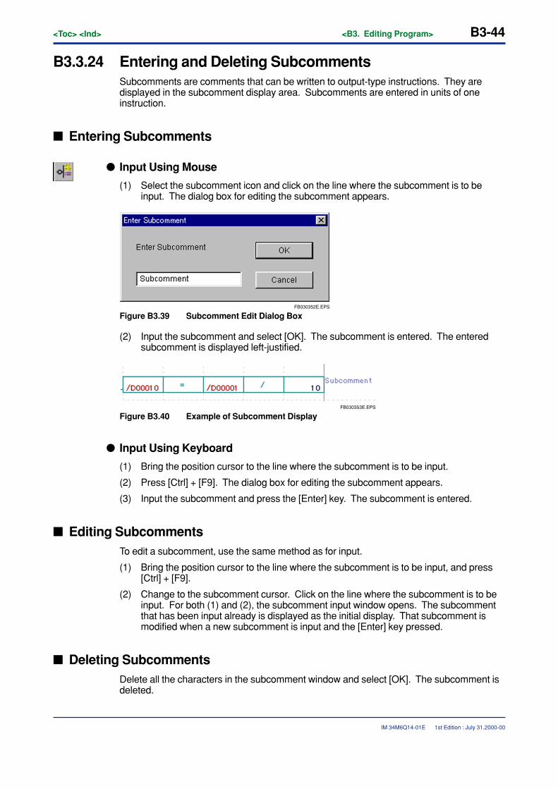
B3-44<Toc> <Ind> <B3. Editing Program>
IM 34M6Q14-01E
B3.3.24 Entering and Deleting SubcommentsSubcomments are comments that can be written to output-type instructions. They aredisplayed in the subcomment display area. Subcomments are entered in units of oneinstruction.
� Entering Subcomments
� Input Using Mouse
(1) Select the subcomment icon and click on the line where the subcomment is to beinput. The dialog box for editing the subcomment appears.
FB030352E.EPS
Figure B3.39 Subcomment Edit Dialog Box
(2) Input the subcomment and select [OK]. The subcomment is entered. The enteredsubcomment is displayed left-justified.
FB030353E.EPS
Figure B3.40 Example of Subcomment Display
� Input Using Keyboard
(1) Bring the position cursor to the line where the subcomment is to be input.
(2) Press [Ctrl] + [F9]. The dialog box for editing the subcomment appears.
(3) Input the subcomment and press the [Enter] key. The subcomment is entered.
� Editing SubcommentsTo edit a subcomment, use the same method as for input.
(1) Bring the position cursor to the line where the subcomment is to be input, and press[Ctrl] + [F9].
(2) Change to the subcomment cursor. Click on the line where the subcomment is to beinput. For both (1) and (2), the subcomment input window opens. The subcommentthat has been input already is displayed as the initial display. That subcomment ismodified when a new subcomment is input and the [Enter] key pressed.
� Deleting SubcommentsDelete all the characters in the subcomment window and select [OK]. The subcomment isdeleted.
1st Edition : July 31,2000-00
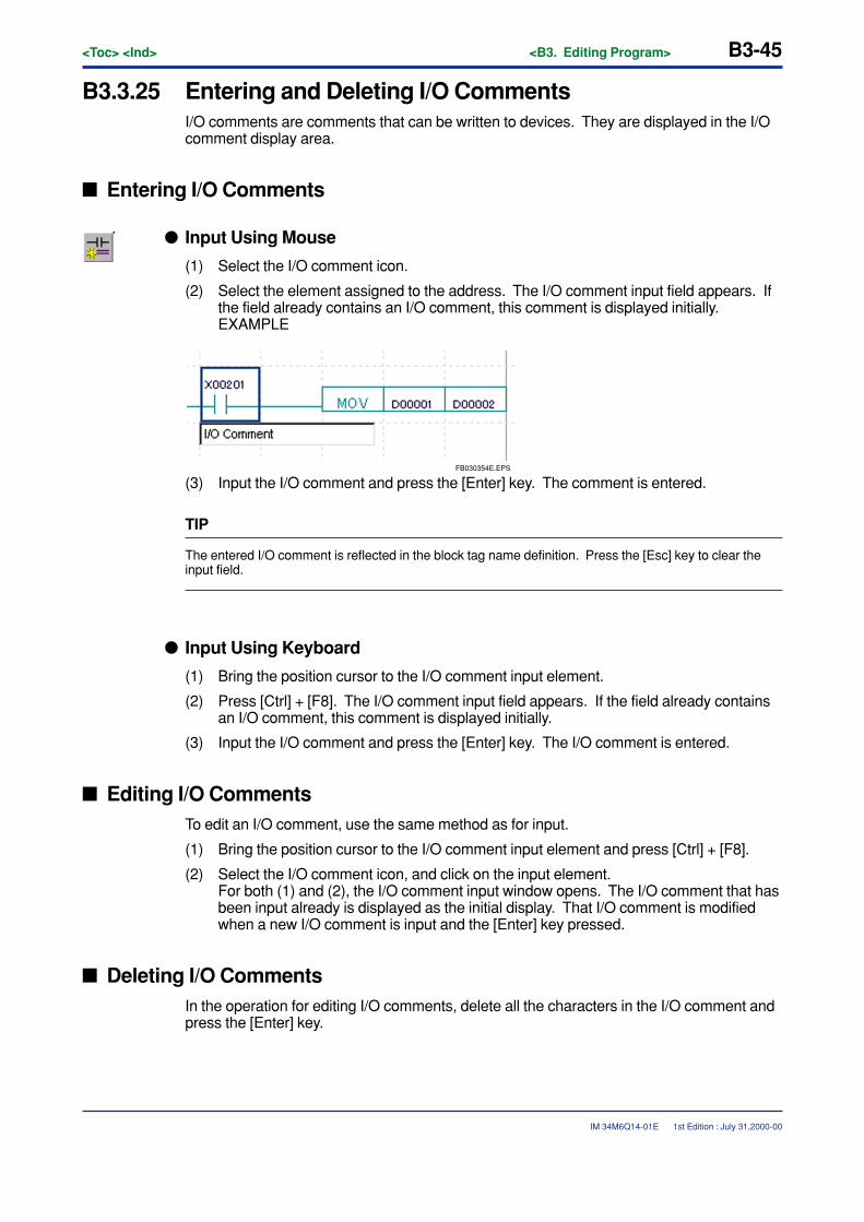
<Toc> <Ind> <B3. Editing Program> B3-45
IM 34M6Q14-01E
B3.3.25 Entering and Deleting I/O CommentsI/O comments are comments that can be written to devices. They are displayed in the I/Ocomment display area.
� Entering I/O Comments
� Input Using Mouse
(1) Select the I/O comment icon.
(2) Select the element assigned to the address. The I/O comment input field appears. Ifthe field already contains an I/O comment, this comment is displayed initially.EXAMPLE
FB030354E.EPS
(3) Input the I/O comment and press the [Enter] key. The comment is entered.
TIP
The entered I/O comment is reflected in the block tag name definition. Press the [Esc] key to clear theinput field.
� Input Using Keyboard
(1) Bring the position cursor to the I/O comment input element.
(2) Press [Ctrl] + [F8]. The I/O comment input field appears. If the field already containsan I/O comment, this comment is displayed initially.
(3) Input the I/O comment and press the [Enter] key. The I/O comment is entered.
� Editing I/O CommentsTo edit an I/O comment, use the same method as for input.
(1) Bring the position cursor to the I/O comment input element and press [Ctrl] + [F8].
(2) Select the I/O comment icon, and click on the input element.For both (1) and (2), the I/O comment input window opens. The I/O comment that hasbeen input already is displayed as the initial display. That I/O comment is modifiedwhen a new I/O comment is input and the [Enter] key pressed.
� Deleting I/O CommentsIn the operation for editing I/O comments, delete all the characters in the I/O comment andpress the [Enter] key.
1st Edition : July 31,2000-00
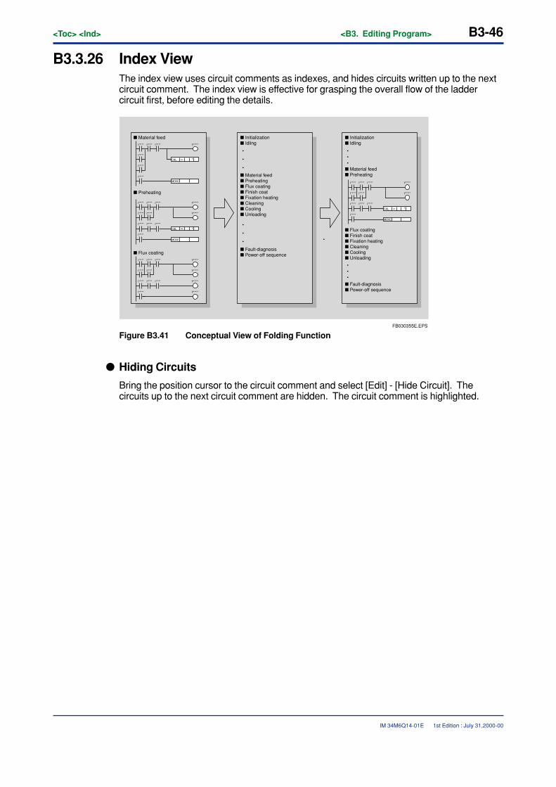
B3-46<Toc> <Ind> <B3. Editing Program>
IM 34M6Q14-01E
B3.3.26 Index ViewThe index view uses circuit comments as indexes, and hides circuits written up to the nextcircuit comment. The index view is effective for grasping the overall flow of the laddercircuit first, before editing the details.
FB030355E.EPS
I*****
I*****
I*****
I*****
Y*****
Y*****
Y*****
Y*****
I*****
I*****
I*****
I*****
I*****
I*****
I*****
I*****
I*****
Y*****
Y*****
I*****
I*****
I*****
I*****
I*****
I*****
I*****
I*****
I***** Y*****I***** I*****
CAL =
MOVE
+
I*****
I*****
I*****
I*****
Y*****
Y*****
I*****
I*****
I*****
I*****
I*****
CAL =
MOVE
+
CAL =
MOVE
+
� Material feed � Initialization� Idling
� Fault-diagnosis� Power-off sequence
� Material feed� Preheating� Flux coating� Finish coat� Fixation heating� Cleaning� Cooling� Unloading
� Preheating
� Flux coating
•
•
•
•
•
•
� Initialization� Idling
� Fault-diagnosis� Power-off sequence
� Material feed� Preheating
•••
•••
� Flux coating� Finish coat� Fixation heating� Cleaning� Cooling� Unloading
Figure B3.41 Conceptual View of Folding Function
� Hiding Circuits
Bring the position cursor to the circuit comment and select [Edit] - [Hide Circuit]. Thecircuits up to the next circuit comment are hidden. The circuit comment is highlighted.
1st Edition : July 31,2000-00
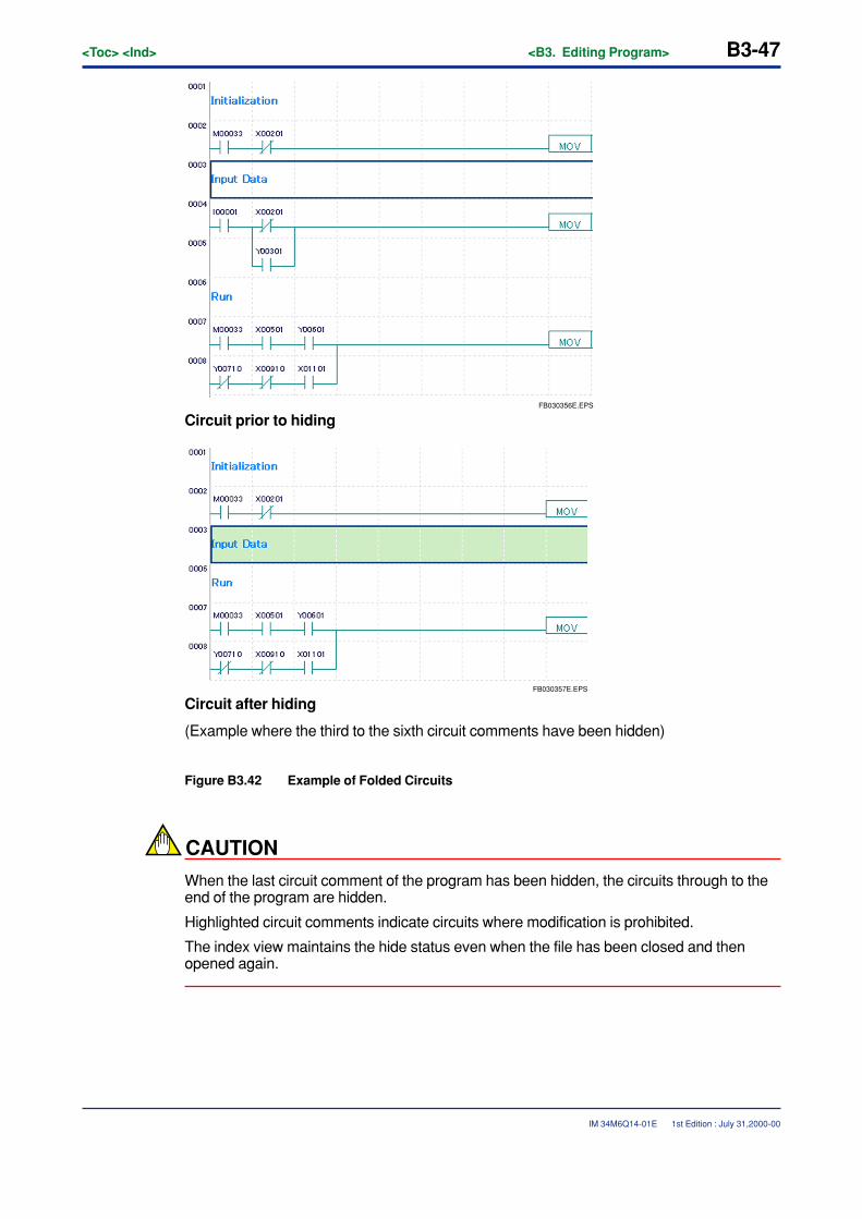
<Toc> <Ind> <B3. Editing Program> B3-47
IM 34M6Q14-01E
FB030356E.EPS
Circuit prior to hiding
FB030357E.EPS
Circuit after hiding
(Example where the third to the sixth circuit comments have been hidden)
Figure B3.42 Example of Folded Circuits
CAUTION
When the last circuit comment of the program has been hidden, the circuits through to theend of the program are hidden.
Highlighted circuit comments indicate circuits where modification is prohibited.
The index view maintains the hide status even when the file has been closed and thenopened again.
1st Edition : July 31,2000-00
B3-48<Toc> <Ind> <B3. Editing Program>
IM 34M6Q14-01E
� Showing Circuit
Bring the position cursor to the hidden circuit comment and select [Edit] - [Show Circuit].The hidden circuit is displayed.
� Hiding All Circuits
Select [Edit] - [Hide All Circuits]. All circuits in the block are hidden. However, this functiondoes not work when the first line of the block has no circuit comment.
� Showing All Circuits
Select [Edit] - [Show All Circuits]. All hidden circuits in the block are unfolded. When allcircuits are shown, the position cursor line is displayed at the top.
B3.3.27 Page Break FunctionWhen “@” is input as the first letter of a circuit comment, this circuit comment is printed atthe top of the page at printout. Input it directly by editing the circuit comment.
To cancel the page break function, delete the @ symbol by editing the circuit comment.
The @ symbol can be input at the beginning of a circuit comment by bringing the positioncursor to the circuit comment and selecting [Edit] - [Page Break].
1st Edition : July 31,2000-00
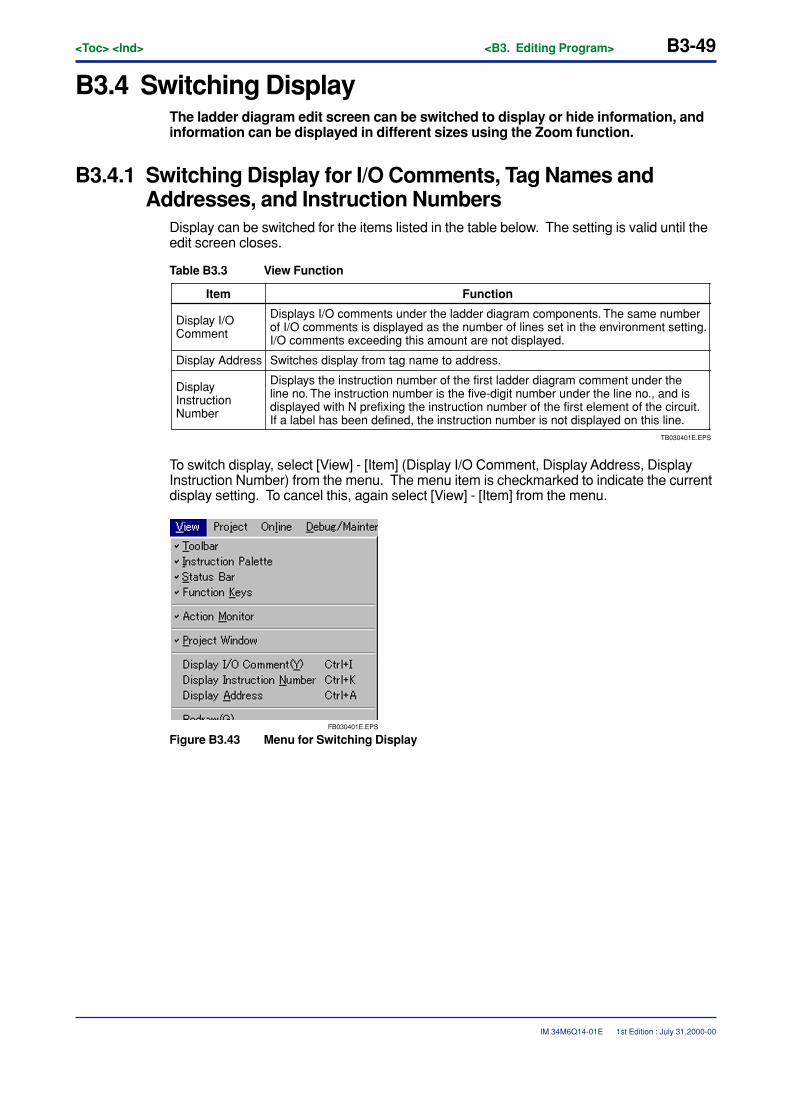
<Toc> <Ind> <B3. Editing Program> B3-49
IM 34M6Q14-01E
B3.4 Switching DisplayThe ladder diagram edit screen can be switched to display or hide information, andinformation can be displayed in different sizes using the Zoom function.
B3.4.1 Switching Display for I/O Comments, Tag Names andAddresses, and Instruction Numbers
Display can be switched for the items listed in the table below. The setting is valid until theedit screen closes.
Table B3.3 View Function
TB030401E.EPS
Displays the instruction number of the first ladder diagram comment under the line no. The instruction number is the five-digit number under the line no., and is displayed with N prefixing the instruction number of the first element of the circuit. If a label has been defined, the instruction number is not displayed on this line.
Item Function
Display I/O Comment
Displays I/O comments under the ladder diagram components. The same number of I/O comments is displayed as the number of lines set in the environment setting. I/O comments exceeding this amount are not displayed.
Display Address Switches display from tag name to address.
Display Instruction Number
To switch display, select [View] - [Item] (Display I/O Comment, Display Address, DisplayInstruction Number) from the menu. The menu item is checkmarked to indicate the currentdisplay setting. To cancel this, again select [View] - [Item] from the menu.
FB030401E.EPS
Figure B3.43 Menu for Switching Display
1st Edition : July 31,2000-00
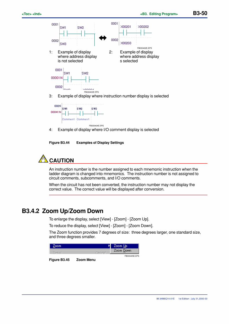
B3-50<Toc> <Ind> <B3. Editing Program>
IM 34M6Q14-01E
FB030402E.EPS
1: Example of display 2: Example of displaywhere address display where address displayis not selected s selected
FB030403E.EPS
3: Example of display where instruction number display is selected
FB030404E.EPS
4: Example of display where I/O comment display is selected
Figure B3.44 Examples of Display Settings
CAUTION
An instruction number is the number assigned to each mnemonic instruction when theladder diagram is changed into mnemonics. The instruction number is not assigned tocircuit comments, subcomments, and I/O comments.
When the circuit has not been converted, the instruction number may not display thecorrect value. The correct value will be displayed after conversion.
B3.4.2 Zoom Up/Zoom DownTo enlarge the display, select [View] - [Zoom] - [Zoom Up].
To reduce the display, select [View] - [Zoom] - [Zoom Down].
The Zoom function provides 7 degrees of size: three degrees larger, one standard size,and three degrees smaller.
FB030405E.EPS
Figure B3.45 Zoom Menu
1st Edition : July 31,2000-00
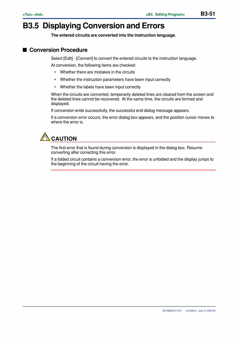
<Toc> <Ind> <B3. Editing Program> B3-51
IM 34M6Q14-01E
B3.5 Displaying Conversion and ErrorsThe entered circuits are converted into the instruction language.
� Conversion ProcedureSelect [Edit] - [Convert] to convert the entered circuits to the instruction language.
At conversion, the following items are checked:
• Whether there are mistakes in the circuits
• Whether the instruction parameters have been input correctly
• Whether the labels have been input correctly
When the circuits are converted, temporarily deleted lines are cleared from the screen andthe deleted lines cannot be recovered. At the same time, the circuits are formed anddisplayed.
If conversion ends successfully, the successful end dialog message appears.
If a conversion error occurs, the error dialog box appears, and the position cursor moves towhere the error is.
CAUTION
The first error that is found during conversion is displayed in the dialog box. Resumeconverting after correcting this error.
If a folded circuit contains a conversion error, the error is unfolded and the display jumps tothe beginning of the circuit having the error.
1st Edition : July 31,2000-00
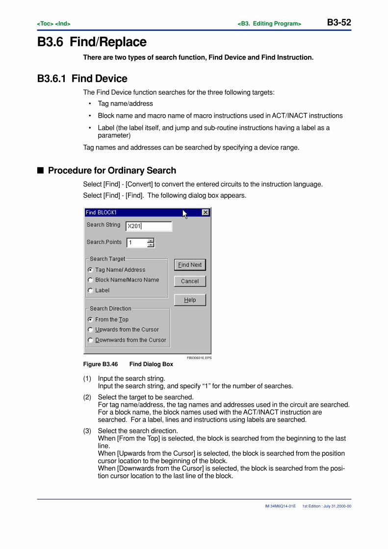
B3-52<Toc> <Ind> <B3. Editing Program>
IM 34M6Q14-01E
B3.6 Find/ReplaceThere are two types of search function, Find Device and Find Instruction.
B3.6.1 Find DeviceThe Find Device function searches for the three following targets:
• Tag name/address
• Block name and macro name of macro instructions used in ACT/INACT instructions
• Label (the label itself, and jump and sub-routine instructions having a label as aparameter)
Tag names and addresses can be searched by specifying a device range.
� Procedure for Ordinary SearchSelect [Find] - [Convert] to convert the entered circuits to the instruction language.
Select [Find] - [Find]. The following dialog box appears.
FB030601E.EPS
Figure B3.46 Find Dialog Box
(1) Input the search string.Input the search string, and specify “1” for the number of searches.
(2) Select the target to be searched.For tag name/address, the tag names and addresses used in the circuit are searched.For a block name, the block names used with the ACT/INACT instruction aresearched. For a label, lines and instructions using labels are searched.
(3) Select the search direction.When [From the Top] is selected, the block is searched from the beginning to the lastline.When [Upwards from the Cursor] is selected, the block is searched from the positioncursor location to the beginning of the block.When [Downwards from the Cursor] is selected, the block is searched from the posi-tion cursor location to the last line of the block.
1st Edition : July 31,2000-00
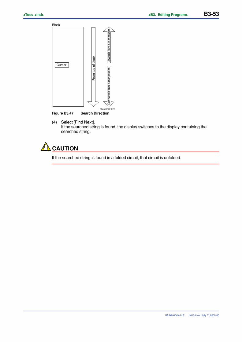
<Toc> <Ind> <B3. Editing Program> B3-53
IM 34M6Q14-01E
Block
From
top
of b
lock
Cursor
Down
ward
s fro
m c
urso
r pos
ition
Upwa
rds
from
cur
sor p
ositio
nFB030602E.EPS
Figure B3.47 Search Direction
(4) Select [Find Next].If the searched string is found, the display switches to the display containing thesearched string.
CAUTION
If the searched string is found in a folded circuit, that circuit is unfolded.
1st Edition : July 31,2000-00
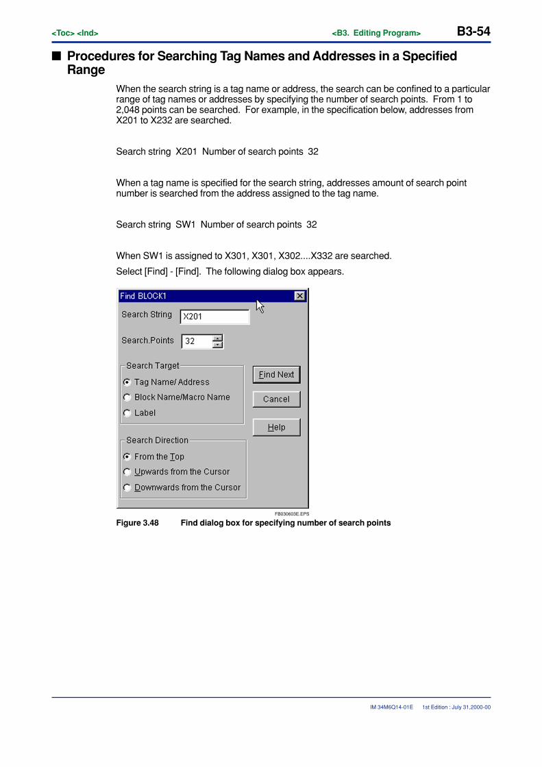
B3-54<Toc> <Ind> <B3. Editing Program>
IM 34M6Q14-01E
� Procedures for Searching Tag Names and Addresses in a SpecifiedRange
When the search string is a tag name or address, the search can be confined to a particularrange of tag names or addresses by specifying the number of search points. From 1 to2,048 points can be searched. For example, in the specification below, addresses fromX201 to X232 are searched.
Search string X201 Number of search points 32
When a tag name is specified for the search string, addresses amount of search pointnumber is searched from the address assigned to the tag name.
Search string SW1 Number of search points 32
When SW1 is assigned to X301, X301, X302....X332 are searched.
Select [Find] - [Find]. The following dialog box appears.
FB030603E.EPS
Figure 3.48 Find dialog box for specifying number of search points
1st Edition : July 31,2000-00

<Toc> <Ind> <B3. Editing Program> B3-55
IM 34M6Q14-01E
(1) Enter the search string.Enter the search string.
(2) Specify the number of search points.Specify the number of points to search in the address specified by the search string.
(3) Select the search target.Select tag name/address.
(4) Select the search direction.When [From the Top] is selected, the block is searched from the beginning to the lastline.When [Upwards from the Cursor] is selected, the block is searched from the positioncursor location to the beginning of the block.When [Downwards from the Cursor] is selected, the block is searched from the posi-tion cursor location to the last line of the block.
(5) Select [Find Next].If the searched string is found, the display switches to the display containing thatstring.
CAUTION
If the searched string is found in a folded circuit, that circuit is unfolded.
1st Edition : July 31,2000-00
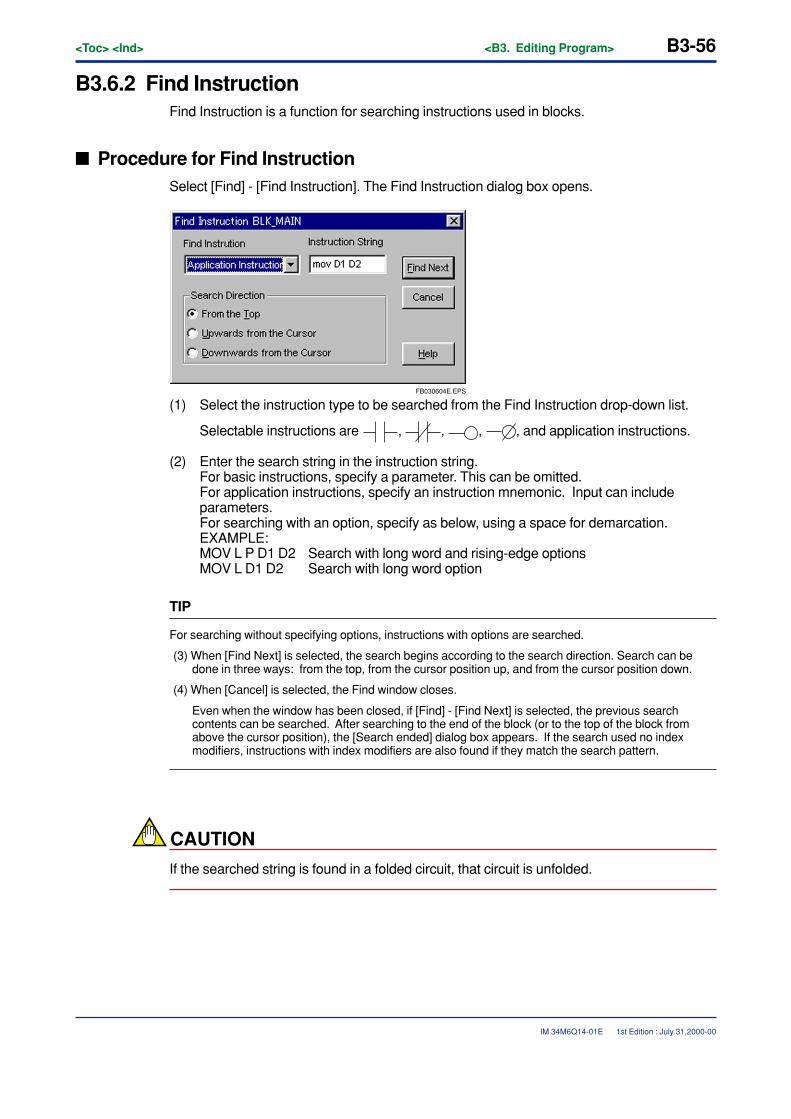
B3-56<Toc> <Ind> <B3. Editing Program>
IM 34M6Q14-01E
B3.6.2 Find InstructionFind Instruction is a function for searching instructions used in blocks.
� Procedure for Find InstructionSelect [Find] - [Find Instruction]. The Find Instruction dialog box opens.
FB030604E.EPS
(1) Select the instruction type to be searched from the Find Instruction drop-down list.
Selectable instructions are , , , , and application instructions.
(2) Enter the search string in the instruction string.For basic instructions, specify a parameter. This can be omitted.For application instructions, specify an instruction mnemonic. Input can includeparameters.For searching with an option, specify as below, using a space for demarcation.EXAMPLE:MOV L P D1 D2 Search with long word and rising-edge optionsMOV L D1 D2 Search with long word option
TIP
For searching without specifying options, instructions with options are searched.
(3) When [Find Next] is selected, the search begins according to the search direction. Search can bedone in three ways: from the top, from the cursor position up, and from the cursor position down.
(4) When [Cancel] is selected, the Find window closes.
Even when the window has been closed, if [Find] - [Find Next] is selected, the previous searchcontents can be searched. After searching to the end of the block (or to the top of the block fromabove the cursor position), the [Search ended] dialog box appears. If the search used no indexmodifiers, instructions with index modifiers are also found if they match the search pattern.
CAUTION
If the searched string is found in a folded circuit, that circuit is unfolded.
1st Edition : July 31,2000-00
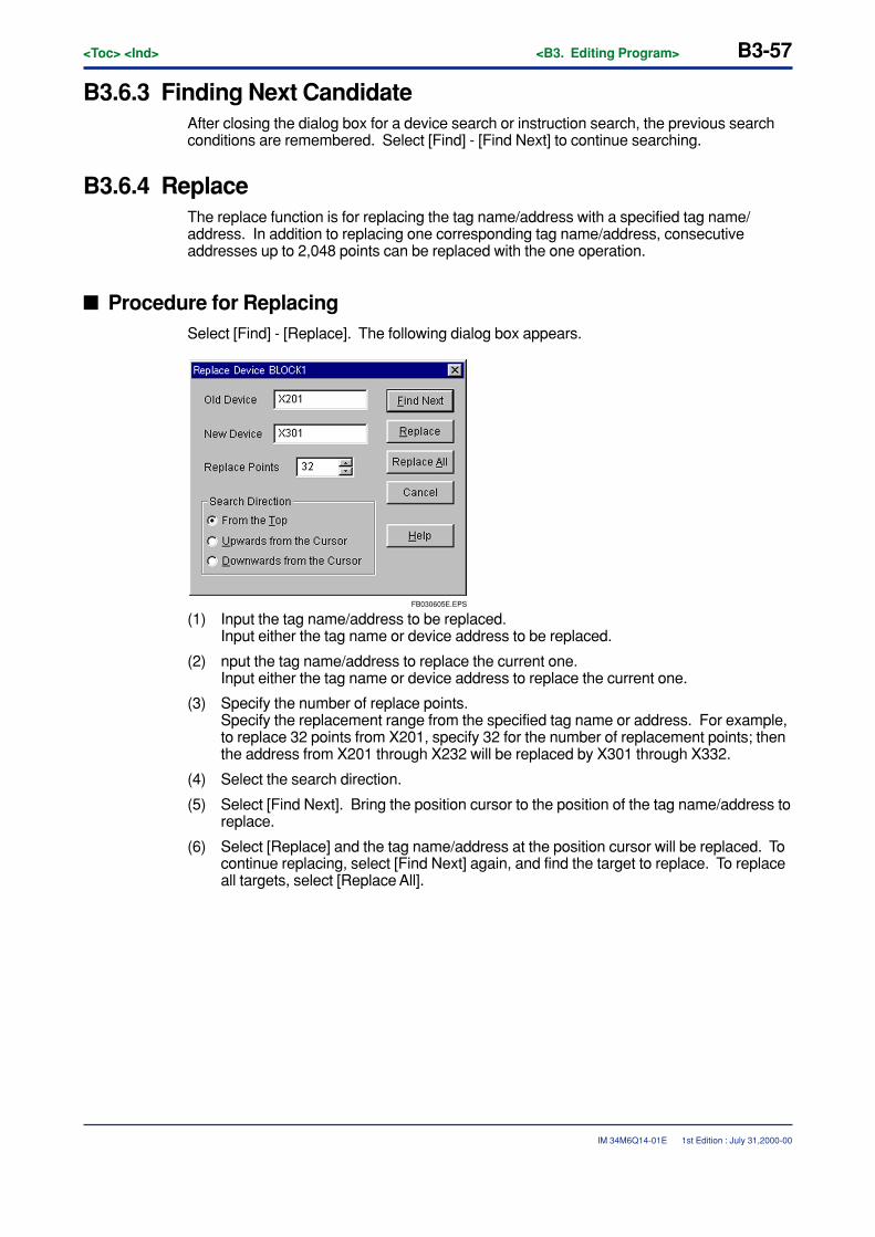
<Toc> <Ind> <B3. Editing Program> B3-57
IM 34M6Q14-01E
B3.6.3 Finding Next CandidateAfter closing the dialog box for a device search or instruction search, the previous searchconditions are remembered. Select [Find] - [Find Next] to continue searching.
B3.6.4 ReplaceThe replace function is for replacing the tag name/address with a specified tag name/address. In addition to replacing one corresponding tag name/address, consecutiveaddresses up to 2,048 points can be replaced with the one operation.
� Procedure for ReplacingSelect [Find] - [Replace]. The following dialog box appears.
FB030605E.EPS
(1) Input the tag name/address to be replaced.Input either the tag name or device address to be replaced.
(2) nput the tag name/address to replace the current one.Input either the tag name or device address to replace the current one.
(3) Specify the number of replace points.Specify the replacement range from the specified tag name or address. For example,to replace 32 points from X201, specify 32 for the number of replacement points; thenthe address from X201 through X232 will be replaced by X301 through X332.
(4) Select the search direction.
(5) Select [Find Next]. Bring the position cursor to the position of the tag name/address toreplace.
(6) Select [Replace] and the tag name/address at the position cursor will be replaced. Tocontinue replacing, select [Find Next] again, and find the target to replace. To replaceall targets, select [Replace All].
1st Edition : July 31,2000-00

B3-58<Toc> <Ind> <B3. Editing Program>
IM 34M6Q14-01E
CAUTION
• When the number of points to be replaced is specified with the tag name, the numberof points is from the address assigned to the replacement tag name. If the address isnot correct after replacement, an error occurs.
• If the replacement tag name is not specified, replacement cannot be done. In thiscase, the error message [Tag address not assigned] appears in the dialog box.
• If the searched string is found in a hidden 0circuit, that circuit is unfolded.
1st Edition : July 31,2000-00
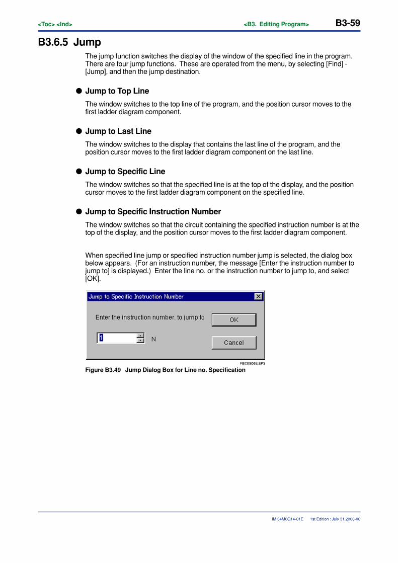
<Toc> <Ind> <B3. Editing Program> B3-59
IM 34M6Q14-01E
B3.6.5 JumpThe jump function switches the display of the window of the specified line in the program.There are four jump functions. These are operated from the menu, by selecting [Find] -[Jump], and then the jump destination.
� Jump to Top Line
The window switches to the top line of the program, and the position cursor moves to thefirst ladder diagram component.
� Jump to Last Line
The window switches to the display that contains the last line of the program, and theposition cursor moves to the first ladder diagram component on the last line.
� Jump to Specific Line
The window switches so that the specified line is at the top of the display, and the positioncursor moves to the first ladder diagram component on the specified line.
� Jump to Specific Instruction Number
The window switches so that the circuit containing the specified instruction number is at thetop of the display, and the position cursor moves to the first ladder diagram component.
When specified line jump or specified instruction number jump is selected, the dialog boxbelow appears. (For an instruction number, the message [Enter the instruction number tojump to] is displayed.) Enter the line no. or the instruction number to jump to, and select[OK].
FB030606E.EPS
Figure B3.49 Jump Dialog Box for Line no. Specification
1st Edition : July 31,2000-00
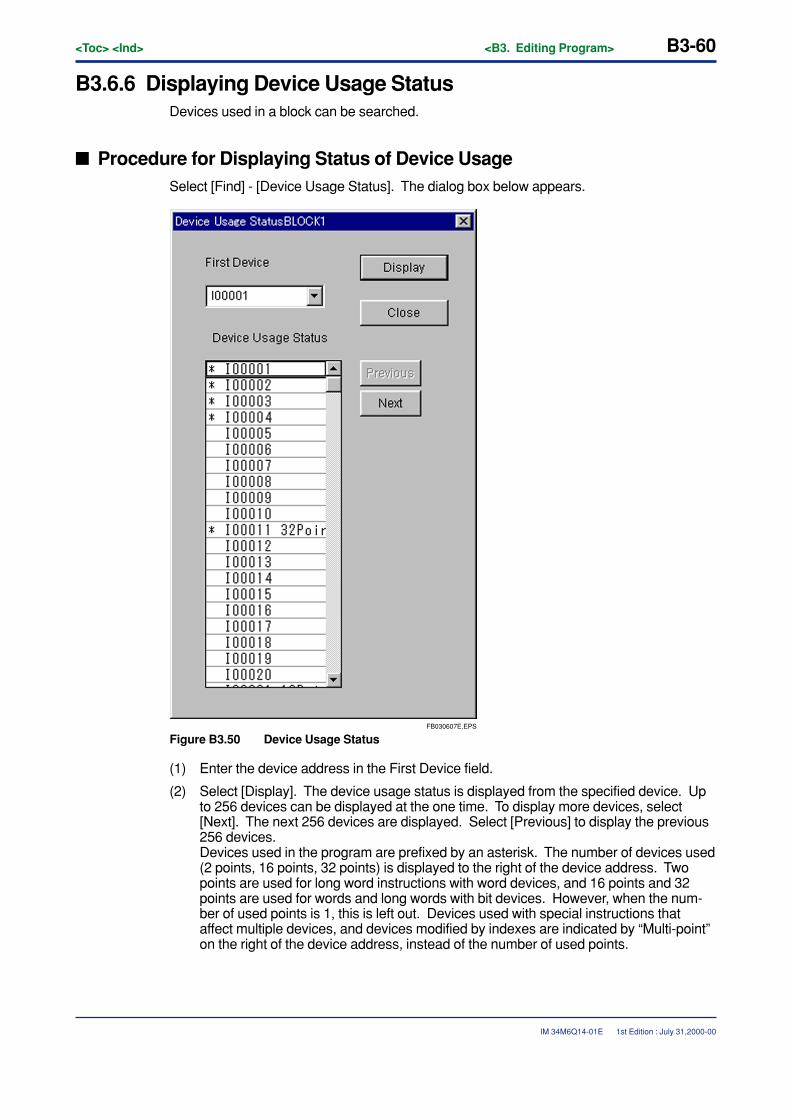
B3-60<Toc> <Ind> <B3. Editing Program>
IM 34M6Q14-01E
B3.6.6 Displaying Device Usage StatusDevices used in a block can be searched.
� Procedure for Displaying Status of Device UsageSelect [Find] - [Device Usage Status]. The dialog box below appears.
FB030607E.EPS
Figure B3.50 Device Usage Status
(1) Enter the device address in the First Device field.
(2) Select [Display]. The device usage status is displayed from the specified device. Upto 256 devices can be displayed at the one time. To display more devices, select[Next]. The next 256 devices are displayed. Select [Previous] to display the previous256 devices.Devices used in the program are prefixed by an asterisk. The number of devices used(2 points, 16 points, 32 points) is displayed to the right of the device address. Twopoints are used for long word instructions with word devices, and 16 points and 32points are used for words and long words with bit devices. However, when the num-ber of used points is 1, this is left out. Devices used with special instructions thataffect multiple devices, and devices modified by indexes are indicated by “Multi-point”on the right of the device address, instead of the number of used points.
1st Edition : July 31,2000-00

<Toc> <Ind> <B3. Editing Program> B3-61
IM 34M6Q14-01E
CAUTION
• Only devices of converted blocks being edited can be displayed.
• The device usage status for the overall project can be looked up by selecting [Project]- [Project Device Usage Status].
1st Edition : July 31,2000-00

Blank Page

<Toc> <Ind> <B4. Assigning Tag Names> B4-1
IM 34M6Q14-01E
B4. Assigning Tag Names
B4.1 About Tag Name DefinitionThis section outlines the tag name definition function.
Tag name definition is a function for attaching tag names and I/O comments toaddresses. Grouped tag names can also be used for tag names.The created program is easier to understand when tag names and I/O comments areattached.
There are 3 types of tag name definition: common tag name definition, where thedefinitions are shared among programs; block tag name definition, where tags usedin blocks are defined; and macro tag name definition, where tags used in instructionmacros are defined.
In the Tag Name Definition screen, data can be copied and pasted between tableswith assigned tag names that have been created with MS-Excel or a similar program.
1st Edition : July 31,2000-00
B4-2<Toc> <Ind> <B4. Assigning Tag Names>
IM 34M6Q14-01E
B4.1.1 Common Tag Name Definitions, Block Tag NameDefinitions and Macro Tag Name Definitions
This section describes the differences among common tag name definitions, block tagname definitions, and macro tag name definitions
� Common Tag Name Definitions
These define the tag names used in common by all blocks making up the executableprogram of the project. After definition, it is reflected in the TAG NAME DEFINITION ofeach project, and is thus usable by each project. The tag name definitions of all devicesexcept local devices and macro devices can be common tag name definitions.
� Block Tag Name Definitions
These define the tag names used in a particular block. Tag names defined in other blockscannot be used. The tag name definitions of all devices except macro devices can beblock tag name definitions.
� Macro Tag Name Definitions
These define the tag names used in a particular instruction macro. Tag names defined inother macros cannot be used. The tag name definitions of all devices can be macro tagname definitions.
1st Edition : July 31,2000-00
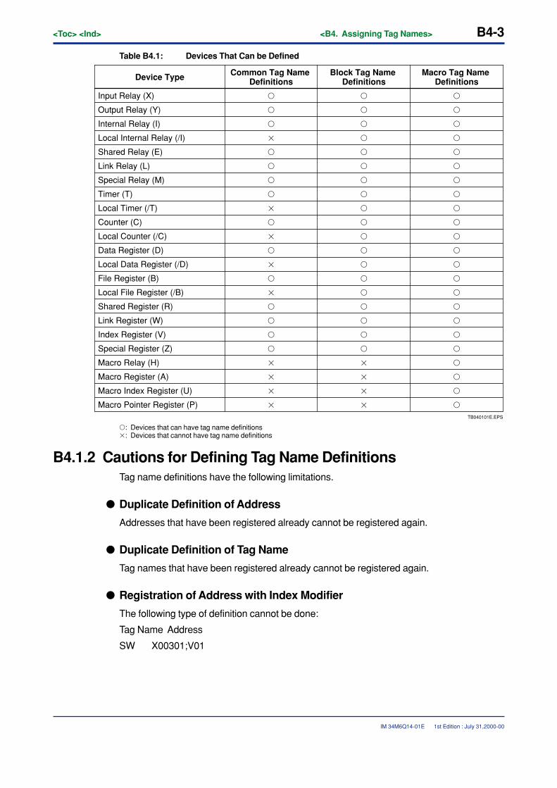
<Toc> <Ind> <B4. Assigning Tag Names> B4-3
IM 34M6Q14-01E
Table B4.1: Devices That Can be Defined
TB040101E.EPS
Macro Pointer Register (P)
Device Type Macro Tag Name Definitions
Block Tag Name Definitions
Common Tag Name Definitions
Input Relay (X)
Output Relay (Y)
Internal Relay (I)
Local Internal Relay (/I)
Shared Relay (E)
Link Relay (L)
Special Relay (M)
Timer (T)
Local Timer (/T)
Counter (C)
Local Counter (/C)
Data Register (D)
Local Data Register (/D)
File Register (B)
Local File Register (/B)
Shared Register (R)
Link Register (W)
Index Register (V)
Special Register (Z)
Macro Relay (H)
Macro Register (A)
Macro Index Register (U)
� � �
� � �
� � �
� � �
� � �
� � �
� � �
� � �
� � �
� � �
� � �
� � �
� � �
� � �
� � �
� � �
� � �
� � �
� � �
� � �
� � �
� � �
� � �
�: Devices that can have tag name definitions�: Devices that cannot have tag name definitions
B4.1.2 Cautions for Defining Tag Name DefinitionsTag name definitions have the following limitations.
� Duplicate Definition of Address
Addresses that have been registered already cannot be registered again.
� Duplicate Definition of Tag Name
Tag names that have been registered already cannot be registered again.
� Registration of Address with Index Modifier
The following type of definition cannot be done:
Tag Name Address
SW X00301;V01
1st Edition : July 31,2000-00
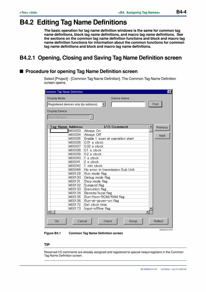
B4-4<Toc> <Ind> <B4. Assigning Tag Names>
IM 34M6Q14-01E
B4.2 Editing Tag Name DefinitionsThe basic operation for tag name definition windows is the same for common tagname definitions, block tag name definitions, and macro tag name definitions. Seethe sections on the common tag name definition functions and block and macro tagname definition functions for information about the common functions for commontag name definitions and block and macro tag name definitions.
B4.2.1 Opening, Closing and Saving Tag Name Definition screen
� Procedure for opening Tag Name Definition screenSelect [Project] - [Common Tag Name Definition]. The Common Tag Name Definitionscreen opens.
FB040201E.EPS
Figure B4.1 Common Tag Name Definition screen
TIP
Reserved I/O comments are already assigned and registered to special relays/registers in the CommonTag Name Definition screen.
1st Edition : July 31,2000-00
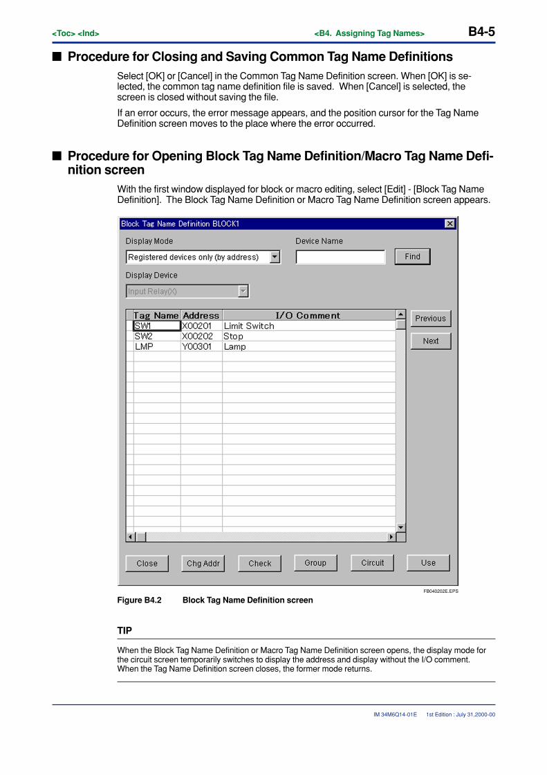
<Toc> <Ind> <B4. Assigning Tag Names> B4-5
IM 34M6Q14-01E
� Procedure for Closing and Saving Common Tag Name DefinitionsSelect [OK] or [Cancel] in the Common Tag Name Definition screen. When [OK] is se-lected, the common tag name definition file is saved. When [Cancel] is selected, thescreen is closed without saving the file.
If an error occurs, the error message appears, and the position cursor for the Tag NameDefinition screen moves to the place where the error occurred.
� Procedure for Opening Block Tag Name Definition/Macro Tag Name Defi-nition screen
With the first window displayed for block or macro editing, select [Edit] - [Block Tag NameDefinition]. The Block Tag Name Definition or Macro Tag Name Definition screen appears.
FB040202E.EPS
Figure B4.2 Block Tag Name Definition screen
TIP
When the Block Tag Name Definition or Macro Tag Name Definition screen opens, the display mode forthe circuit screen temporarily switches to display the address and display without the I/O comment.When the Tag Name Definition screen closes, the former mode returns.
1st Edition : July 31,2000-00

B4-6<Toc> <Ind> <B4. Assigning Tag Names>
IM 34M6Q14-01E
� Procedure for Closing Block Tag Name Definition /Macro Tag Name Defi-nition Screen
Select [Close] in the Block Tag Name Definition or Macro Tag Name Definition screen. If anerror occurs, the error message appears, and the position cursor for the Tag Name Defini-tion screen moves to the place where the error occurred.
� Saving Block Tag Name Definition /Macro Tag Name Definition ScreenWhen the Block Tag Name Definition or Macro Tag Name Definition screen is closed orsaved, it is saved together with the block or macro circuit.
1st Edition : July 31,2000-00
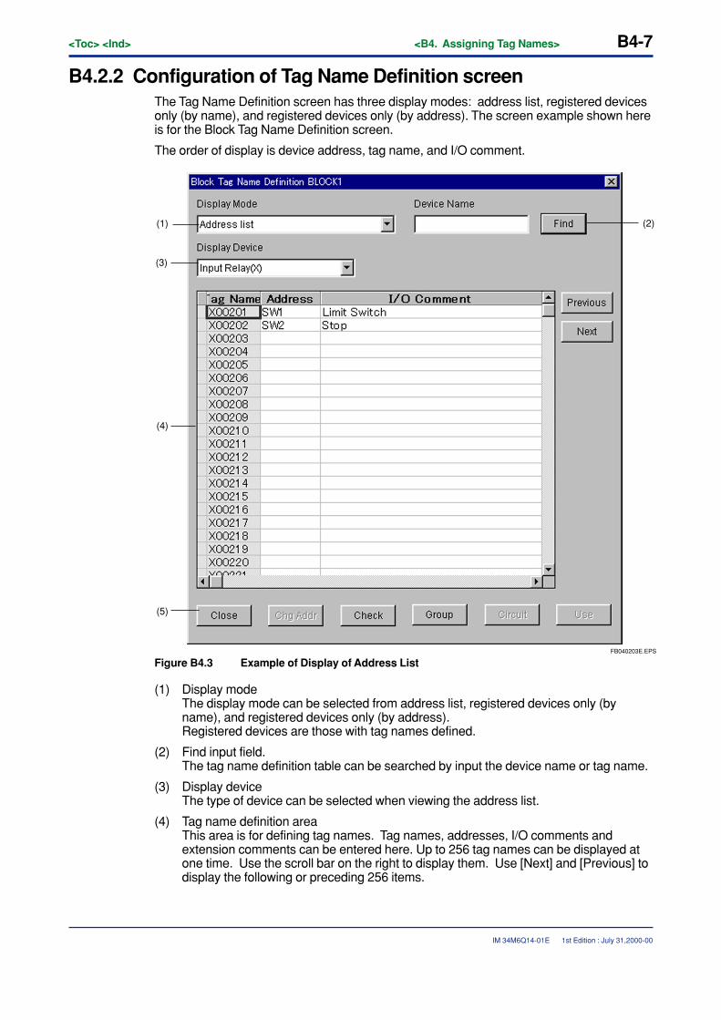
<Toc> <Ind> <B4. Assigning Tag Names> B4-7
IM 34M6Q14-01E
B4.2.2 Configuration of Tag Name Definition screenThe Tag Name Definition screen has three display modes: address list, registered devicesonly (by name), and registered devices only (by address). The screen example shown hereis for the Block Tag Name Definition screen.
The order of display is device address, tag name, and I/O comment.
FB040203E.EPS
(2)(1)
(3)
(4)
(5)
Figure B4.3 Example of Display of Address List
(1) Display modeThe display mode can be selected from address list, registered devices only (byname), and registered devices only (by address).Registered devices are those with tag names defined.
(2) Find input field.The tag name definition table can be searched by input the device name or tag name.
(3) Display deviceThe type of device can be selected when viewing the address list.
(4) Tag name definition areaThis area is for defining tag names. Tag names, addresses, I/O comments andextension comments can be entered here. Up to 256 tag names can be displayed atone time. Use the scroll bar on the right to display them. Use [Next] and [Previous] todisplay the following or preceding 256 items.
1st Edition : July 31,2000-00
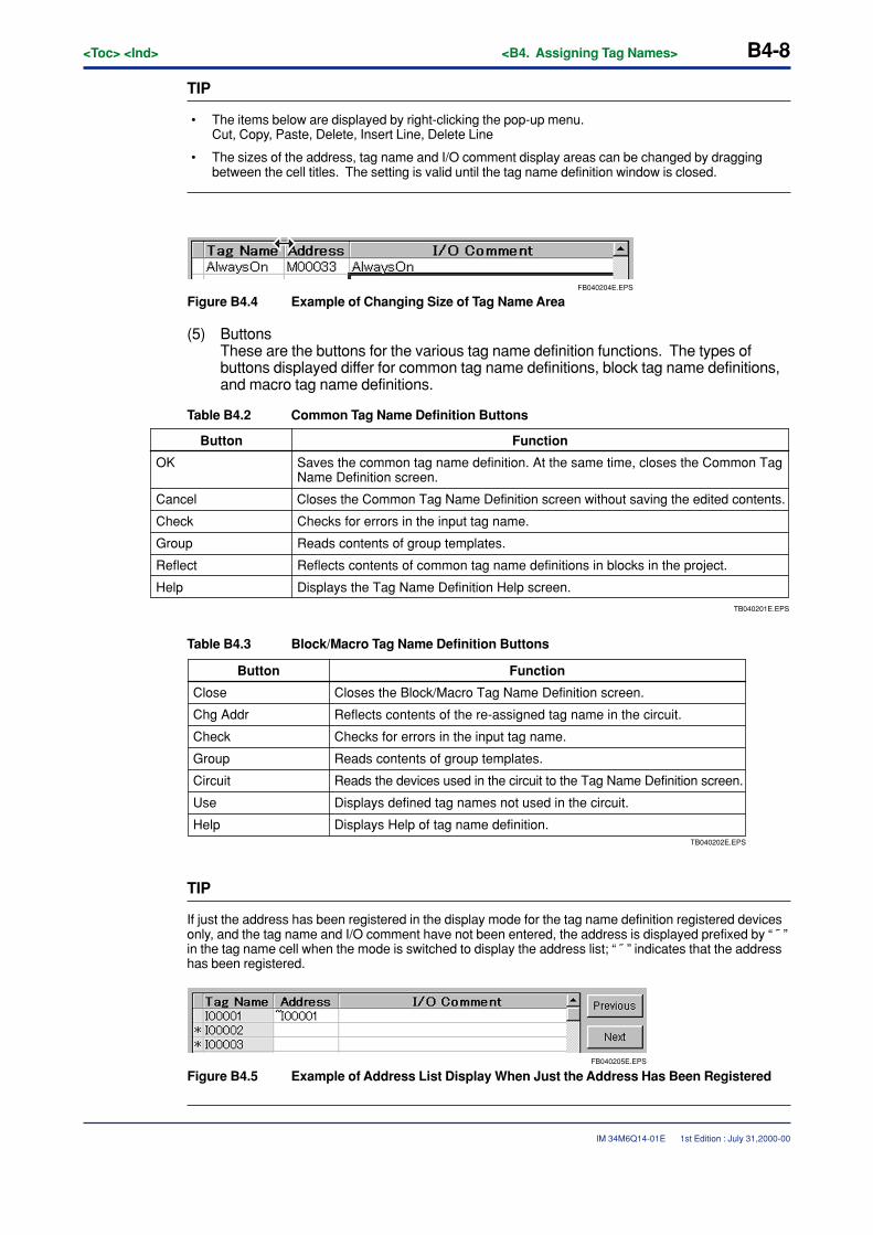
B4-8<Toc> <Ind> <B4. Assigning Tag Names>
IM 34M6Q14-01E
TIP
• The items below are displayed by right-clicking the pop-up menu.Cut, Copy, Paste, Delete, Insert Line, Delete Line
• The sizes of the address, tag name and I/O comment display areas can be changed by draggingbetween the cell titles. The setting is valid until the tag name definition window is closed.
FB040204E.EPS
Figure B4.4 Example of Changing Size of Tag Name Area
(5) ButtonsThese are the buttons for the various tag name definition functions. The types ofbuttons displayed differ for common tag name definitions, block tag name definitions,and macro tag name definitions.
Table B4.2 Common Tag Name Definition Buttons
TB040201E.EPS
Displays the Tag Name Definition Help screen.
Button Function
OK Saves the common tag name definition. At the same time, closes the Common Tag Name Definition screen.
Cancel Closes the Common Tag Name Definition screen without saving the edited contents.
Check Checks for errors in the input tag name.
Group Reads contents of group templates.
Reflect Reflects contents of common tag name definitions in blocks in the project.
Help
Table B4.3 Block/Macro Tag Name Definition Buttons
TB040202E.EPS
Displays Help of tag name definition.
Button Function
Close Closes the Block/Macro Tag Name Definition screen.
Chg Addr Reflects contents of the re-assigned tag name in the circuit.
Check Checks for errors in the input tag name.
Group Reads contents of group templates.
Circuit Reads the devices used in the circuit to the Tag Name Definition screen.
Use Displays defined tag names not used in the circuit.
Help
TIP
If just the address has been registered in the display mode for the tag name definition registered devicesonly, and the tag name and I/O comment have not been entered, the address is displayed prefixed by “ ˜ ”in the tag name cell when the mode is switched to display the address list; “ ˜ ” indicates that the addresshas been registered.
FB040205E.EPS
Figure B4.5 Example of Address List Display When Just the Address Has Been Registered
1st Edition : July 31,2000-00
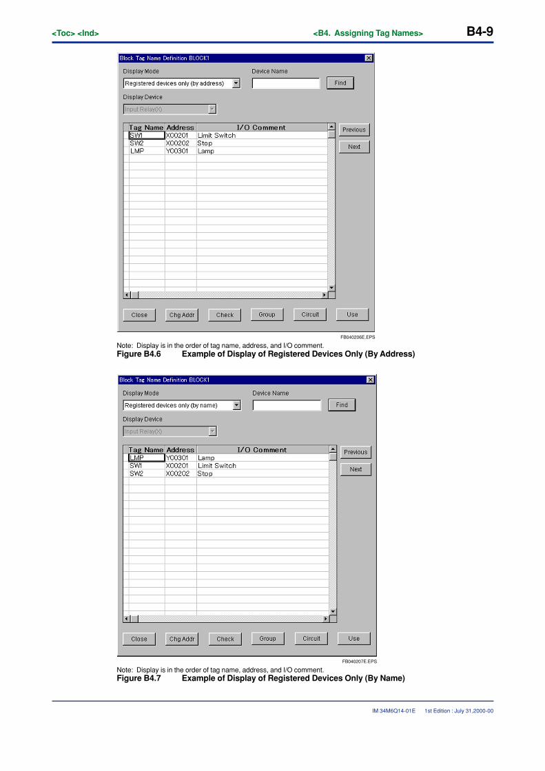
<Toc> <Ind> <B4. Assigning Tag Names> B4-9
IM 34M6Q14-01E
FB040206E.EPS
Note: Display is in the order of tag name, address, and I/O comment.Figure B4.6 Example of Display of Registered Devices Only (By Address)
FB040207E.EPS
Note: Display is in the order of tag name, address, and I/O comment.Figure B4.7 Example of Display of Registered Devices Only (By Name)
1st Edition : July 31,2000-00
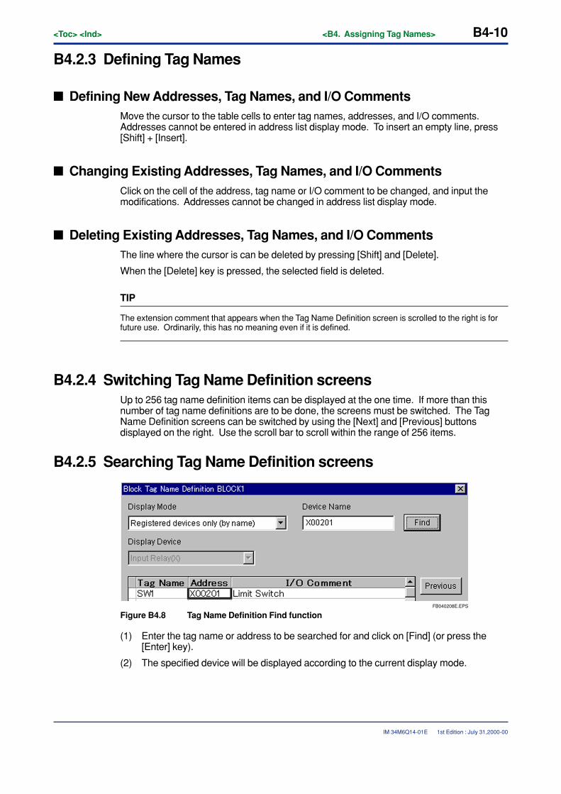
B4-10<Toc> <Ind> <B4. Assigning Tag Names>
IM 34M6Q14-01E
B4.2.3 Defining Tag Names
� Defining New Addresses, Tag Names, and I/O CommentsMove the cursor to the table cells to enter tag names, addresses, and I/O comments.Addresses cannot be entered in address list display mode. To insert an empty line, press[Shift] + [Insert].
� Changing Existing Addresses, Tag Names, and I/O CommentsClick on the cell of the address, tag name or I/O comment to be changed, and input themodifications. Addresses cannot be changed in address list display mode.
� Deleting Existing Addresses, Tag Names, and I/O CommentsThe line where the cursor is can be deleted by pressing [Shift] and [Delete].
When the [Delete] key is pressed, the selected field is deleted.
TIP
The extension comment that appears when the Tag Name Definition screen is scrolled to the right is forfuture use. Ordinarily, this has no meaning even if it is defined.
B4.2.4 Switching Tag Name Definition screensUp to 256 tag name definition items can be displayed at the one time. If more than thisnumber of tag name definitions are to be done, the screens must be switched. The TagName Definition screens can be switched by using the [Next] and [Previous] buttonsdisplayed on the right. Use the scroll bar to scroll within the range of 256 items.
B4.2.5 Searching Tag Name Definition screens
FB040208E.EPS
Figure B4.8 Tag Name Definition Find function
(1) Enter the tag name or address to be searched for and click on [Find] (or press the[Enter] key).
(2) The specified device will be displayed according to the current display mode.
1st Edition : July 31,2000-00
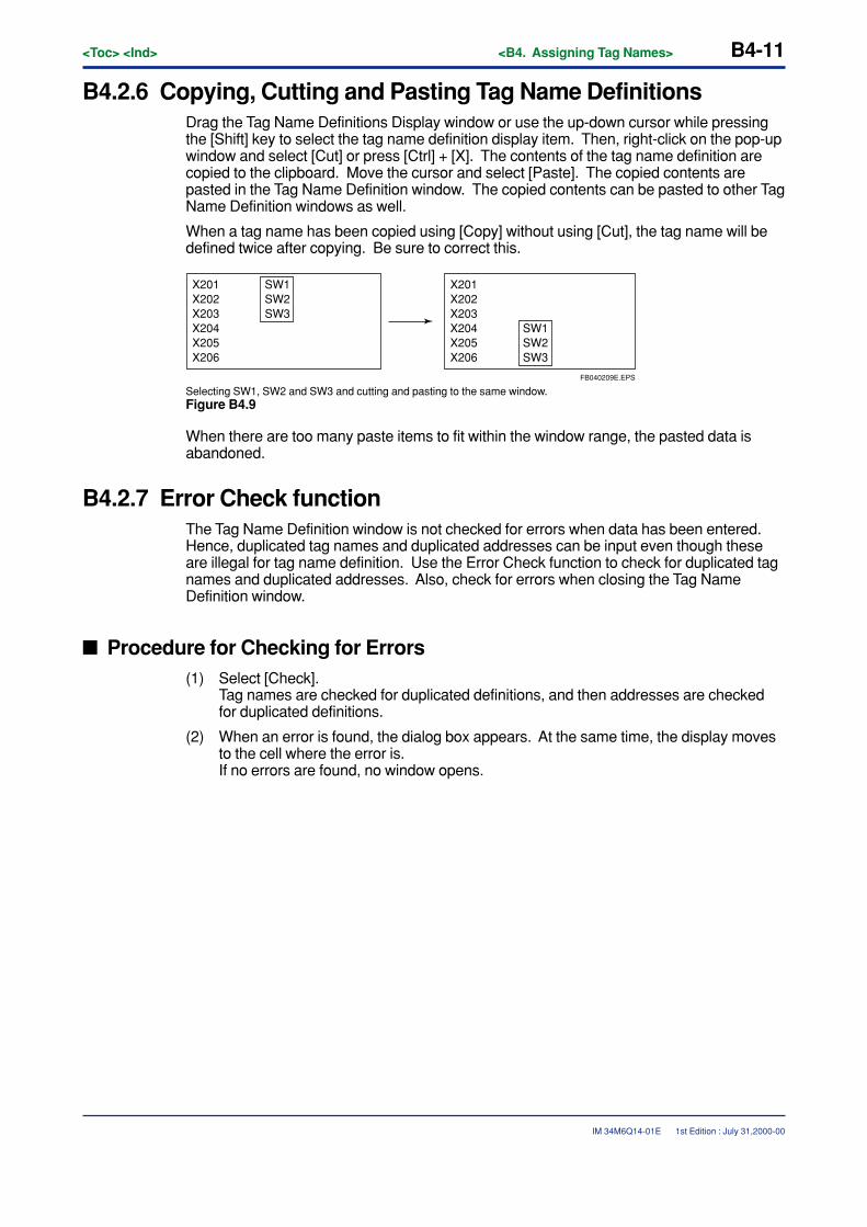
<Toc> <Ind> <B4. Assigning Tag Names> B4-11
IM 34M6Q14-01E
B4.2.6 Copying, Cutting and Pasting Tag Name DefinitionsDrag the Tag Name Definitions Display window or use the up-down cursor while pressingthe [Shift] key to select the tag name definition display item. Then, right-click on the pop-upwindow and select [Cut] or press [Ctrl] + [X]. The contents of the tag name definition arecopied to the clipboard. Move the cursor and select [Paste]. The copied contents arepasted in the Tag Name Definition window. The copied contents can be pasted to other TagName Definition windows as well.
When a tag name has been copied using [Copy] without using [Cut], the tag name will bedefined twice after copying. Be sure to correct this.
X201 SW1 X202 SW2X203 SW3X204X205X206
X201X202X203X204 SW1 X205 SW2X206 SW3
FB040209E.EPS
Selecting SW1, SW2 and SW3 and cutting and pasting to the same window.Figure B4.9
When there are too many paste items to fit within the window range, the pasted data isabandoned.
B4.2.7 Error Check functionThe Tag Name Definition window is not checked for errors when data has been entered.Hence, duplicated tag names and duplicated addresses can be input even though theseare illegal for tag name definition. Use the Error Check function to check for duplicated tagnames and duplicated addresses. Also, check for errors when closing the Tag NameDefinition window.
� Procedure for Checking for Errors(1) Select [Check].
Tag names are checked for duplicated definitions, and then addresses are checkedfor duplicated definitions.
(2) When an error is found, the dialog box appears. At the same time, the display movesto the cell where the error is.If no errors are found, no window opens.
1st Edition : July 31,2000-00
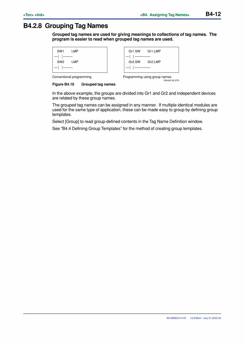
B4-12<Toc> <Ind> <B4. Assigning Tag Names>
IM 34M6Q14-01E
B4.2.8 Grouping Tag NamesGrouped tag names are used for giving meanings to collections of tag names. Theprogram is easier to read when grouped tag names are used.
SW1 LMP
SW2 LMP
Conventional programming Programming using group namesFB040210E.EPS
Gr1.SW Gr1.LMP
Gr2.SW Gr2.LMP
Figure B4.10 Grouped tag names
In the above example, the groups are divided into Gr1 and Gr2 and independent devicesare related by these group names.
The grouped tag names can be assigned in any manner. If multiple identical modules areused for the same type of application, these can be made easy to group by defining grouptemplates.
Select [Group] to read group-defined contents in the Tag Name Definition window.
See “B4.4 Defining Group Templates” for the method of creating group templates.
1st Edition : July 31,2000-00
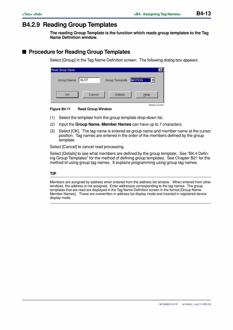
<Toc> <Ind> <B4. Assigning Tag Names> B4-13
IM 34M6Q14-01E
B4.2.9 Reading Group TemplatesThe reading Group Template is the function which reads group templates to the TagName Definition window.
� Procedure for Reading Group TemplatesSelect [Group] in the Tag Name Definition screen. The following dialog box appears.
FB040211E.EPS
Figure B4.11 Read Group Window
(1) Select the template from the group template drop-down list.
(2) Input the Group Name. Member Names can have up to 7 characters.
(3) Select [OK]. The tag name is entered as group name and member name at the cursorposition. Tag names are entered in the order of the members defined by the grouptemplate.
Select [Cancel] to cancel read processing.
Select [Details] to see what members are defined by the group template. See “B4.4 Defin-ing Group Templates” for the method of defining group templates. See Chapter B21 for themethod of using group tag names. It explains programming using group tag names.
TIP
Members are assigned by address when entered from the address list window. When entered from otherwindows, the address is not assigned. Enter addresses corresponding to the tag names. The grouptemplates that are read are displayed in the Tag Name Definition screen in the format [Group Name.Member Names]. These are overwritten in address list display mode and inserted in registered devicedisplay mode.
1st Edition : July 31,2000-00
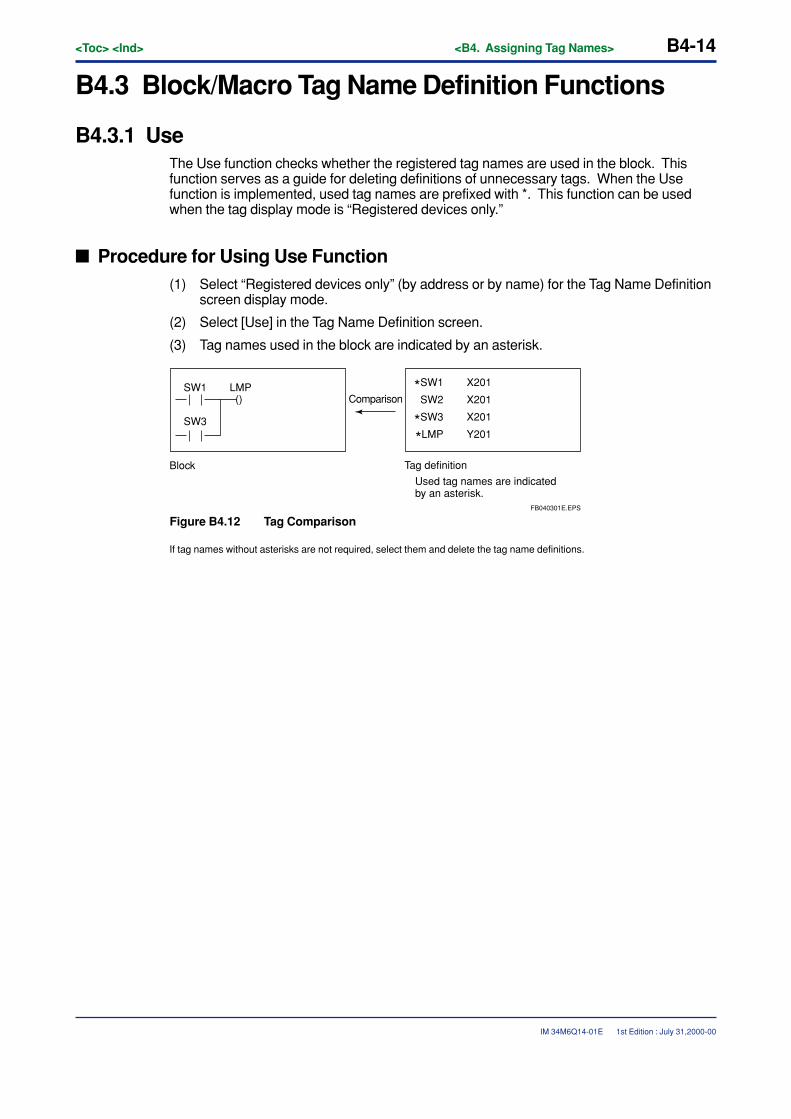
B4-14<Toc> <Ind> <B4. Assigning Tag Names>
IM 34M6Q14-01E
B4.3 Block/Macro Tag Name Definition Functions
B4.3.1 UseThe Use function checks whether the registered tag names are used in the block. Thisfunction serves as a guide for deleting definitions of unnecessary tags. When the Usefunction is implemented, used tag names are prefixed with *. This function can be usedwhen the tag display mode is “Registered devices only.”
� Procedure for Using Use Function(1) Select “Registered devices only” (by address or by name) for the Tag Name Definition
screen display mode.
(2) Select [Use] in the Tag Name Definition screen.
(3) Tag names used in the block are indicated by an asterisk.
*SW1
SW2
*SW3
*LMP
X201
X201
X201
Y201
() Comparison
Block
FB040301E.EPS
Used tag names are indicated by an asterisk.
SW1
SW3
LMP
Tag definition
Figure B4.12 Tag Comparison
If tag names without asterisks are not required, select them and delete the tag name definitions.
1st Edition : July 31,2000-00
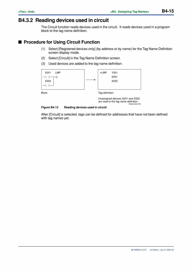
<Toc> <Ind> <B4. Assigning Tag Names> B4-15
IM 34M6Q14-01E
B4.3.2 Reading devices used in circuitThe Circuit function reads devices used in the circuit. It reads devices used in a programblock to the tag name definition.
� Procedure for Using Circuit Function(1) Select [Registered devices only] (by address or by name) for the Tag Name Definition
screen display mode.
(2) Select [Circuit] in the Tag Name Definition screen.
(3) Used devices are added to the tag name definition.
*LMP Y301
X201
X202
X201
X202
()
Block Tag definition
Unassigned devices X201 and X202 are read to the tag name definition.
FB040302E.EPS
LMP
Figure B4.13 Reading devices used in circuit
After [Circuit] is selected, tags can be defined for addresses that have not been definedwith tag names yet.
1st Edition : July 31,2000-00
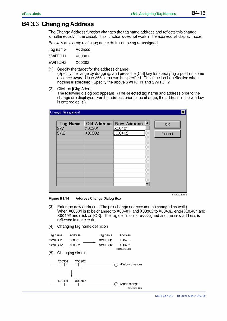
B4-16<Toc> <Ind> <B4. Assigning Tag Names>
IM 34M6Q14-01E
B4.3.3 Changing AddressThe Change Address function changes the tag name address and reflects this changesimultaneously in the circuit. This function does not work in the address list display mode.
Below is an example of a tag name definition being re-assigned.
Tag name Address
SWITCH1 X00301
SWITCH2 X00302
(1) Specify the target for the address change.(Specify the range by dragging, and press the [Ctrl] key for specifying a position somedistance away. Up to 256 items can be specified. This function is ineffective whennothing is specified.) Specify the above SWITCH1 and SWITCH2.
(2) Click on [Chg Addr].The following dialog box appears. (The selected tag name and address prior to thechange are displayed. For the address prior to the change, the address in the windowis entered as is.)
FB040303E.EPS
Figure B4.14 Address Change Dialog Box
(3) Enter the new address. (The pre-change address can be changed as well.)When X00301 is to be changed to X00401, and X00302 to X00402, enter X00401 andX00402 and click on [OK]. The tag definition is re-assigned and the new address isreflected in the circuit.
(4) Changing tag name definition
FB040304E.EPS
Tag name
SWITCH1
SWITCH2
Address
X00301
X00302
Tag name
SWITCH1
SWITCH2
Address
X00401
X00402
(5) Changing circuit
X00301 X00302(Before change)
(After change)X00401 X00402
FB040305E.EPS
1st Edition : July 31,2000-00

<Toc> <Ind> <B4. Assigning Tag Names> B4-17
IM 34M6Q14-01E
B4.4 Defining Group TemplatesGroup tag names consist of [Group Name. Member Names]. The Group TemplateDefinition function defines the members of a group tag name and defines the partexcept the group name. When a group template is created, it is easy to attach grouptag names when defining tag names for groups having the same configuration.
Group templates define only members except group names.
1st Edition : July 31,2000-00
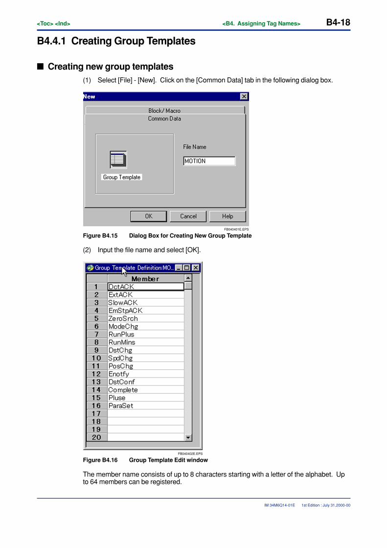
B4-18<Toc> <Ind> <B4. Assigning Tag Names>
IM 34M6Q14-01E
B4.4.1 Creating Group Templates
� Creating new group templates(1) Select [File] - [New]. Click on the [Common Data] tab in the following dialog box.
FB040401E.EPS
Figure B4.15 Dialog Box for Creating New Group Template
(2) Input the file name and select [OK].
FB040402E.EPS
Figure B4.16 Group Template Edit window
The member name consists of up to 8 characters starting with a letter of the alphabet. Upto 64 members can be registered.
1st Edition : July 31,2000-00
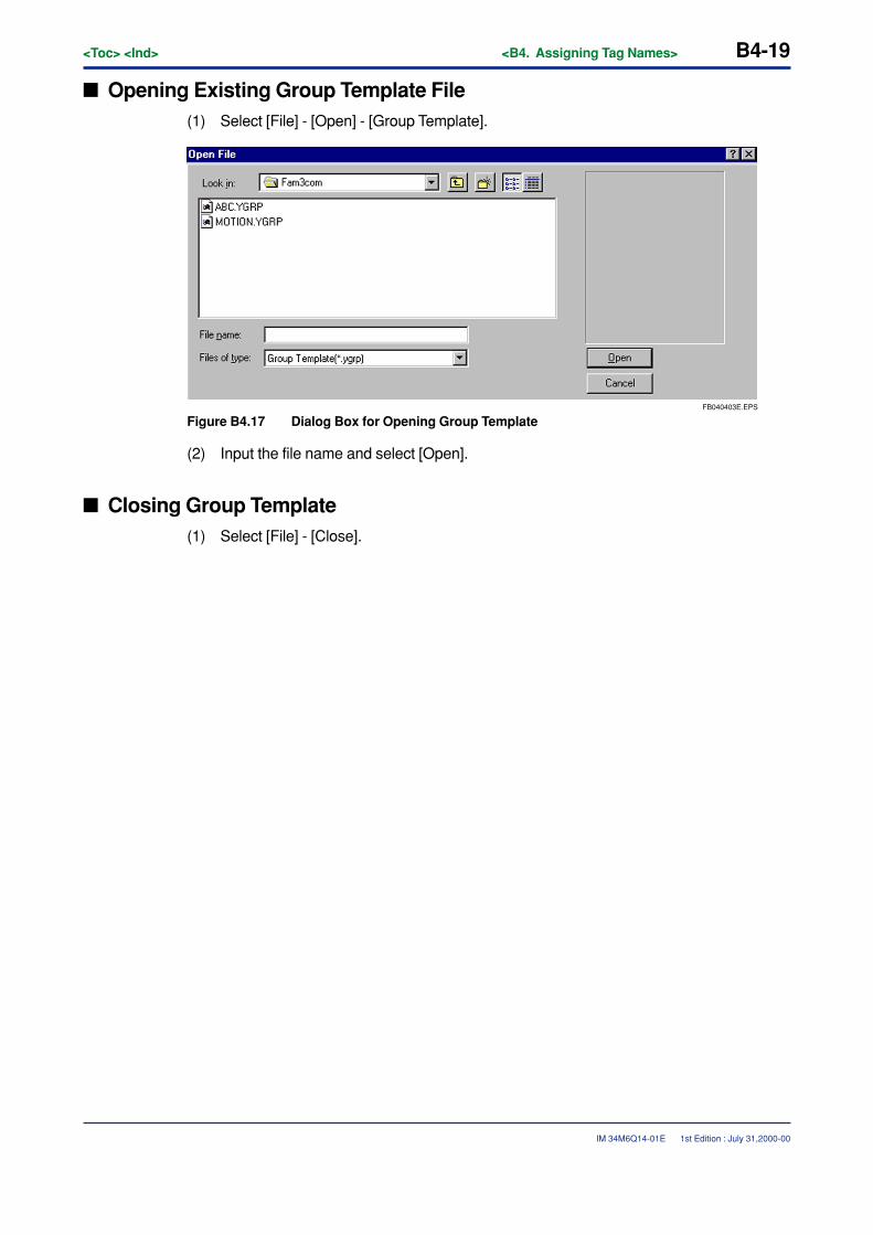
<Toc> <Ind> <B4. Assigning Tag Names> B4-19
IM 34M6Q14-01E
� Opening Existing Group Template File(1) Select [File] - [Open] - [Group Template].
FB040403E.EPS
Figure B4.17 Dialog Box for Opening Group Template
(2) Input the file name and select [Open].
� Closing Group Template(1) Select [File] - [Close].
1st Edition : July 31,2000-00

B4-20<Toc> <Ind> <B4. Assigning Tag Names>
IM 34M6Q14-01E
B4.4.2 Deleting Group Template FilesUse Explorer or a similar program to delete group template files stored in files. Grouptemplate files are stored in the common folder set with the environment settings.
When pin groups of modules having multiple channels are registered as group templates,tags assigned to pins can be standardized.
1st Edition : July 31,2000-00
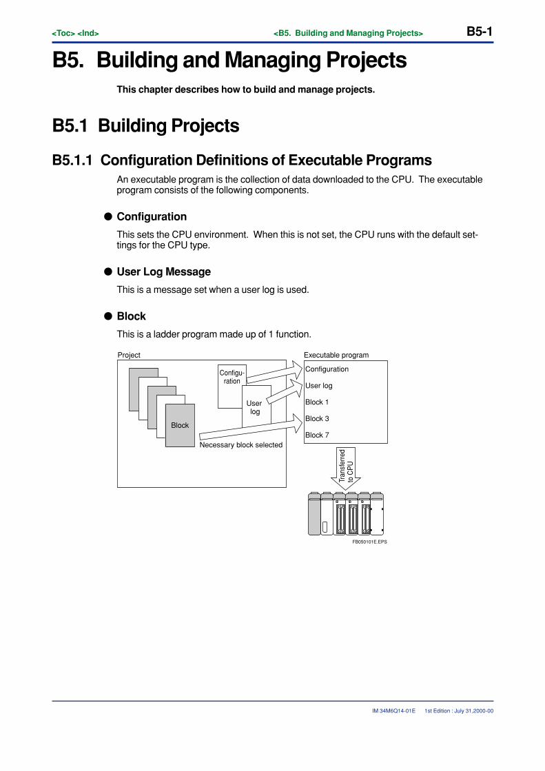
<Toc> <Ind> <B5. Building and Managing Projects> B5-1
IM 34M6Q14-01E
B5. Building and Managing ProjectsThis chapter describes how to build and manage projects.
B5.1 Building Projects
B5.1.1 Configuration Definitions of Executable ProgramsAn executable program is the collection of data downloaded to the CPU. The executableprogram consists of the following components.
� Configuration
This sets the CPU environment. When this is not set, the CPU runs with the default set-tings for the CPU type.
� User Log Message
This is a message set when a user log is used.
� Block
This is a ladder program made up of 1 function.
Project Executable program
Configuration
User log
Block 1
Block 3
Block 7
Configu-ration
User log
Block
Necessary block selected
Tran
sfer
red
to C
PU
FB050101E.EPS
1st Edition : July 31,2000-00
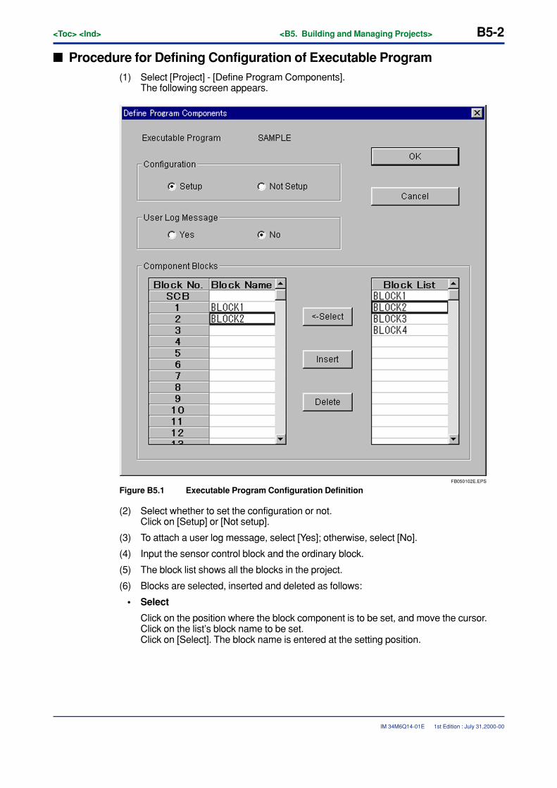
B5-2<Toc> <Ind> <B5. Building and Managing Projects>
IM 34M6Q14-01E
� Procedure for Defining Configuration of Executable Program(1) Select [Project] - [Define Program Components].
The following screen appears.
FB050102E.EPS
Figure B5.1 Executable Program Configuration Definition
(2) Select whether to set the configuration or not.Click on [Setup] or [Not setup].
(3) To attach a user log message, select [Yes]; otherwise, select [No].
(4) Input the sensor control block and the ordinary block.
(5) The block list shows all the blocks in the project.
(6) Blocks are selected, inserted and deleted as follows:
• Select
Click on the position where the block component is to be set, and move the cursor.Click on the list’s block name to be set.Click on [Select]. The block name is entered at the setting position.
1st Edition : July 31,2000-00

<Toc> <Ind> <B5. Building and Managing Projects> B5-3
IM 34M6Q14-01E
• Insert
Click on the position where the block is to be inserted, and move the cursor.Click on [Insert]. An empty line is inserted at that position, and blocks below movedown.
• Delete
Click on the position where the block is to be deleted, and move the cursor.When [Delete] is clicked, the block at that position is deleted and the blocks belowmove up. To keep the empty line, press the [Delete] key instead.
(7) Click on [OK] to update the setting. Click on [Cancel] to abandon the change.
1st Edition : July 31,2000-00
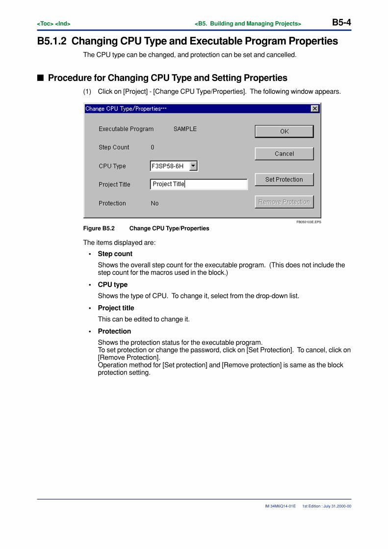
B5-4<Toc> <Ind> <B5. Building and Managing Projects>
IM 34M6Q14-01E
B5.1.2 Changing CPU Type and Executable Program PropertiesThe CPU type can be changed, and protection can be set and cancelled.
� Procedure for Changing CPU Type and Setting Properties(1) Click on [Project] - [Change CPU Type/Properties]. The following window appears.
FB050103E.EPS
Figure B5.2 Change CPU Type/Properties
The items displayed are:
• Step count
Shows the overall step count for the executable program. (This does not include thestep count for the macros used in the block.)
• CPU type
Shows the type of CPU. To change it, select from the drop-down list.
• Project title
This can be edited to change it.
• Protection
Shows the protection status for the executable program.To set protection or change the password, click on [Set Protection]. To cancel, click on[Remove Protection].Operation method for [Set protection] and [Remove protection] is same as the blockprotection setting.
1st Edition : July 31,2000-00
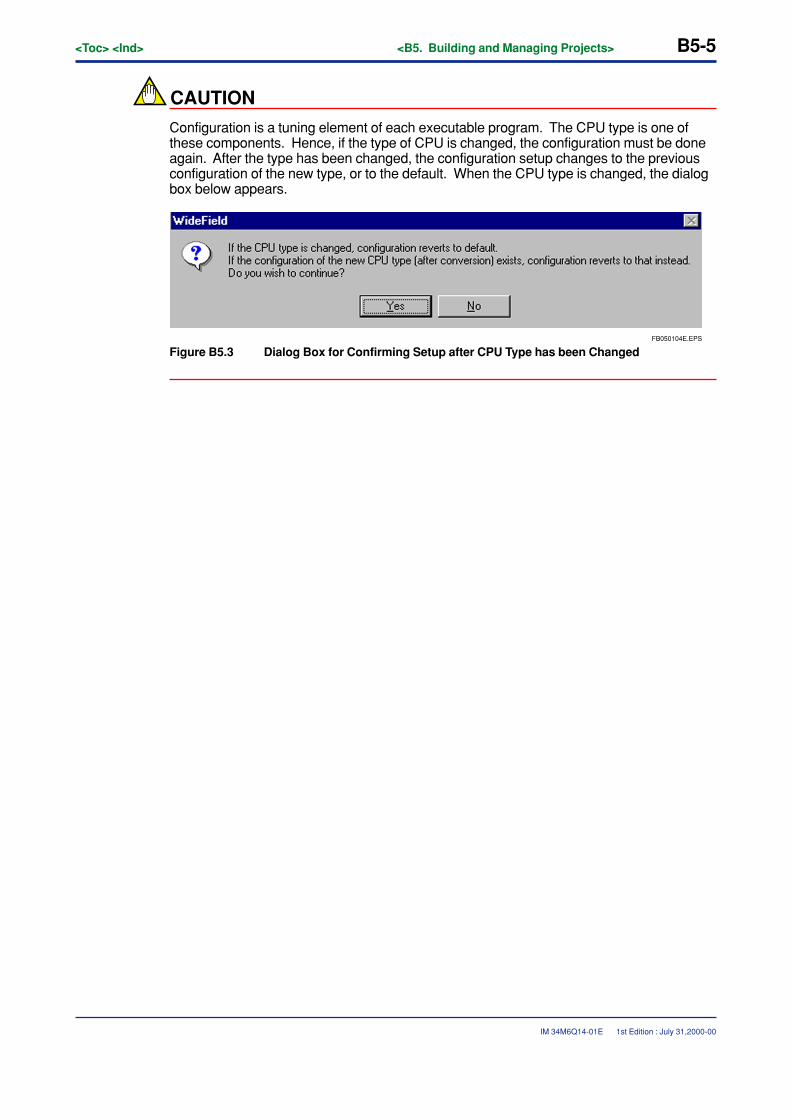
<Toc> <Ind> <B5. Building and Managing Projects> B5-5
IM 34M6Q14-01E
CAUTION
Configuration is a tuning element of each executable program. The CPU type is one ofthese components. Hence, if the type of CPU is changed, the configuration must be doneagain. After the type has been changed, the configuration setup changes to the previousconfiguration of the new type, or to the default. When the CPU type is changed, the dialogbox below appears.
FB050104E.EPS
Figure B5.3 Dialog Box for Confirming Setup after CPU Type has been Changed
1st Edition : July 31,2000-00
B5-6<Toc> <Ind> <B5. Building and Managing Projects>
IM 34M6Q14-01E 1st Edition : July 31,2000-00
B5.1.3 Setting ConfigurationThis section explains how to set the configuration.
The contents of the configuration setup depend on the CPU type. Configuration settingitems are as follows:
• Device Capacities
• Setup Data Lock-up Range at Power Failure/Local Devices
• Operation Control
• Setup Data Register Initial Data
• Setup DIO
• Setup FA Link
• Sampling Trace
• Setup Communication
• Setup ROM
• Setup Interrupt (only available for F3SP28, 38, 53 and 58)
• Setup Shared Refreshing (only available for F3SP28, 38, 53 and 58)
The tables on the following pages set out the setting values for each CPU type.
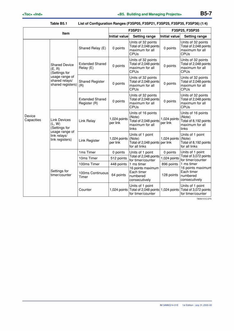
<Toc> <Ind> <B5. Building and Managing Projects> B5-7
IM 34M6Q14-01E 1st Edition : July 31,2000-00
Table B5.1 List of Configuration Ranges (F3SP05, F3SP21, F3SP25, F3SP35, F3SP36) (1/4)
TB050101E.EPS
ItemF3SP21 F3SP25, F3SP35
Initial value Setting range Initial value Setting range
Device Capacities
Shared Device (E, R)(Settings for usage range of shared relays/shared registers)
Units of 32 pointsTotal of 2,048 pointsmaximum for all CPUs
Shared Relay (E) 0 points
Units of 32 pointsTotal of 2,048 pointsmaximum for all CPUs
0 points
Units of 32 pointsTotal of 2,048 pointsmaximum for all CPUs
0 points
Units of 32 pointsTotal of 2,048 pointsmaximum for all CPUs
0 points
Units of 32 pointsTotal of 2,048 pointsmaximum for all CPUs
0 points
Units of 32 pointsTotal of 2,048 pointsmaximum for all CPUs
0 points
Units of 32 pointsTotal of 2,048 pointsmaximum for all CPUs
0 points
Units of 32 pointsTotal of 2,048 pointsmaximum for all CPUs
0 points
Extended Shared Relay (E)
Shared Register (R)
Extended Shared Register (R)
Link Devices (L, W) (Settings for usage range of link relays/link registers)
Link Relay
Units of 16 points (Note) Total of 2,048 points maximum for all links
1,024 points per link
Units of 16 points (Note)Total of 8,192 points maximum for all links
1,024 points per link
Link Register 1,024 points per link
Units of 1 point (Note) Total of 2,048 points for all links
1,024 points per link
Units of 1 point (Note) Total of 8,192 points for all links
Settings for timer/counter
1ms Timer 0 points Units of 1 point Total of 2,048 points for timer/counter1 ms timer 16 points maximum Each timer numbered consecutively
0 points
10ms Timer 512 points 1,024 points
100ms Timer 448 points 896 points
100ms Continuous Timer 64 points 128 points
Units of 1 pointTotal of 3,072 points for timer/counter1 ms timer 16 points maximumEach timer numbered consecutively
Counter 1,024 pointsUnits of 1 point Total of 2,048 points for timer/counter
1,024 pointsUnits of 1 point Total of 3,072 points for timer/counter
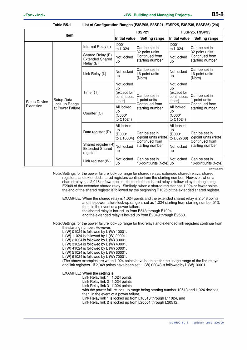
B5-8<Toc> <Ind> <B5. Building and Managing Projects>
IM 34M6Q14-01E
Table B5.1 List of Configuration Ranges (F3SP05, F3SP21, F3SP25, F3SP35, F3SP36) (2/4)
TB050102E.EPS
ItemF3SP21 F3SP25, F3SP35
Initial value Setting range Initial value Setting range
Setup Device Extension
Setup Data Lock-up Range at Power Failure
Can be set in 32-point units Continued from starting number
Internal Relay (I) I0001 to I1024 Can be set in
32-point units Continued from starting number
Not locked up
Not locked up
Not locked up (except for continuous timer)
Can be set in 16-point units (Note)
Can be set in 16-point units (Note)
Can be set in 1-point units Continued from starting number
Can be set in 1-point units Continued from starting number
Shared Relay (E) Extended Shared Relay (E)
Link Relay (L)
Timer (T)
Counter (C)
All locked up (C0001 to C1024)
All locked up (D0001 to D16384)
Not locked up
Data register (D) Can be set in 2-point units (Note) Continued from starting numberShared register (R)
Extended Shared register
Not locked upLink register (W) Can be set in
16-point units (Note)
I0001 to I1024
Not locked up
Not locked up
Not locked up (except for continuous timer)
All locked up (C0001 to C1024)
All locked up (D0001 to D32768)
Not locked up
Can be set in 2-point units (Note) Continued from starting number
Not locked up
Can be set in 16-point units (Note)
Note: Settings for the power failure lock-up range for shared relays, extended shared relays, sharedregisters, and extended shared registers continue from the starting number. However, when ashared relay has 2,048 or fewer points, the end of the shared relay is followed by the beginningE2049 of the extended shared relay. Similarly, when a shared register has 1,024 or fewer points,the end of the shared register is followed by the beginning R1025 of the extended shared register.
EXAMPLE: When the shared relay is 1,024 points and the extended shared relay is 2,048 points,and the power failure lock-up range is set as 1,024 starting from starting number 513,then, in the event of a power failure,the shared relay is locked up from E513 through E1024and the extended relay is locked up from E2049 through E2560.
Note: Settings for the power failure lock-up range for link relays and extended link registers continue fromthe starting number. However:L (W) 01024 is followed by L (W) 10001.L (W) 11024 is followed by L (W) 20001.L (W) 21024 is followed by L (W) 30001.L (W) 31024 is followed by L (W) 40001.L (W) 41024 is followed by L (W) 50001.L (W) 51024 is followed by L (W) 60001.L (W) 61024 is followed by L (W) 70001.(The above examples are when 1,024 points have been set for the usage range of the link relaysand link registers. If 2,048 points have been set, L (W) 02048 is followed by L (W) 10001.
EXAMPLE: When the setting isLink Relay link 1 1,024 pointsLink Relay link 2 1,024 pointsLink Relay link 3 1,024 pointswith the power failure lock-up range being starting number 10513 and 1,024 devices,then, in the event of a power failure,Link Relay link 1 is locked up from L10513 through L11024, andLink Relay link 2 is locked up from L20001 through L20512.
1st Edition : July 31,2000-00
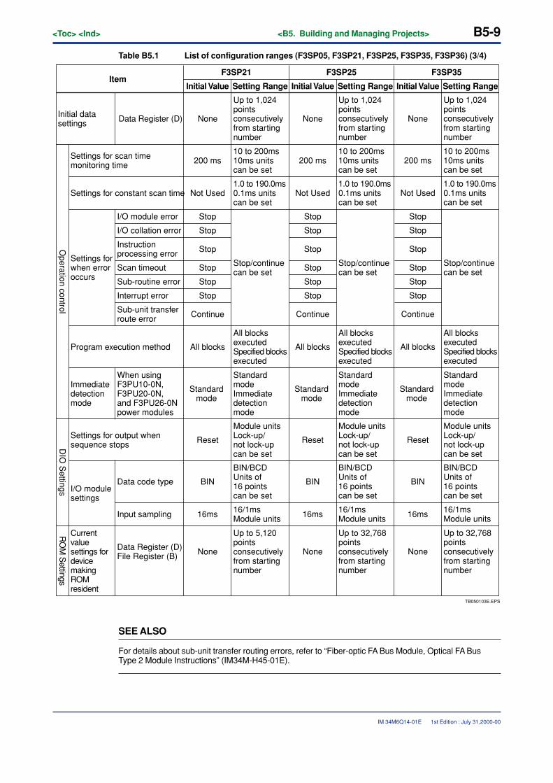
<Toc> <Ind> <B5. Building and Managing Projects> B5-9
IM 34M6Q14-01E
Table B5.1 List of configuration ranges (F3SP05, F3SP21, F3SP25, F3SP35, F3SP36) (3/4)
Setting RangeItem
F3SP21
Initial Value Setting Range
F3SP25
Initial Value Setting Range
F3SP35
Initial Value
Initial data settings Data Register (D) None
Up to 1,024 points consecutively from starting number
Operation control
Settings for scan time monitoring time 200 ms
10 to 200ms 10ms units can be set
Settings for constant scan time Not Used1.0 to 190.0ms0.1ms units can be set
Settings for when error occurs
I/O module error Stop
Stop
Stop
Stop
Stop
Stop
Stop/continue can be set
I/O collation error
Instruction processing error
Scan timeout
Sub-routine error
Interrupt error
Sub-unit transfer route error Continue
Program execution method All blocks
All blocks executed Specified blocks executed
Immediate detection mode
When using F3PU10-0N, F3PU20-0N, and F3PU26-0N power modules
Standard mode
Standard mode Immediate detection mode
DIO
Settings
Settings for output when sequence stops Reset
Module units Lock-up/not lock-up can be set
I/O module settings
Data code type BIN
BIN/BCDUnits of 16 points can be set
Input sampling 16ms 16/1msModule units
RO
M S
ettings
Current value settings for device making ROM resident
Data Register (D)File Register (B) None
Up to 5,120 points consecutively from starting number
None
Up to 1,024 points consecutively from starting number
200 ms10 to 200ms 10ms units can be set
Not Used1.0 to 190.0ms0.1ms units can be set
Stop
Stop
Stop
Stop
Stop
Stop
Stop/continue can be set
Continue
All blocks
All blocks executed Specified blocks executed
Standard mode
Standard mode Immediate detection mode
Reset
Module units Lock-up/not lock-up can be set
BIN
BIN/BCDUnits of 16 points can be set
16ms 16/1msModule units
None
Up to 32,768 points consecutively from starting number
None
Up to 1,024 points consecutively from starting number
200 ms10 to 200ms 10ms units can be set
Not Used1.0 to 190.0ms0.1ms units can be set
Stop
Stop
Stop
Stop
Stop
Stop
Stop/continue can be set
Continue
All blocks
All blocks executed Specified blocks executed
Standard mode
Standard mode Immediate detection mode
Reset
Module units Lock-up/not lock-up can be set
BIN
BIN/BCDUnits of 16 points can be set
16ms 16/1msModule units
None
Up to 32,768 points consecutively from starting number
TB050103E.EPS
SEE ALSO
For details about sub-unit transfer routing errors, refer to “Fiber-optic FA Bus Module, Optical FA BusType 2 Module Instructions” (IM34M-H45-01E).
1st Edition : July 31,2000-00
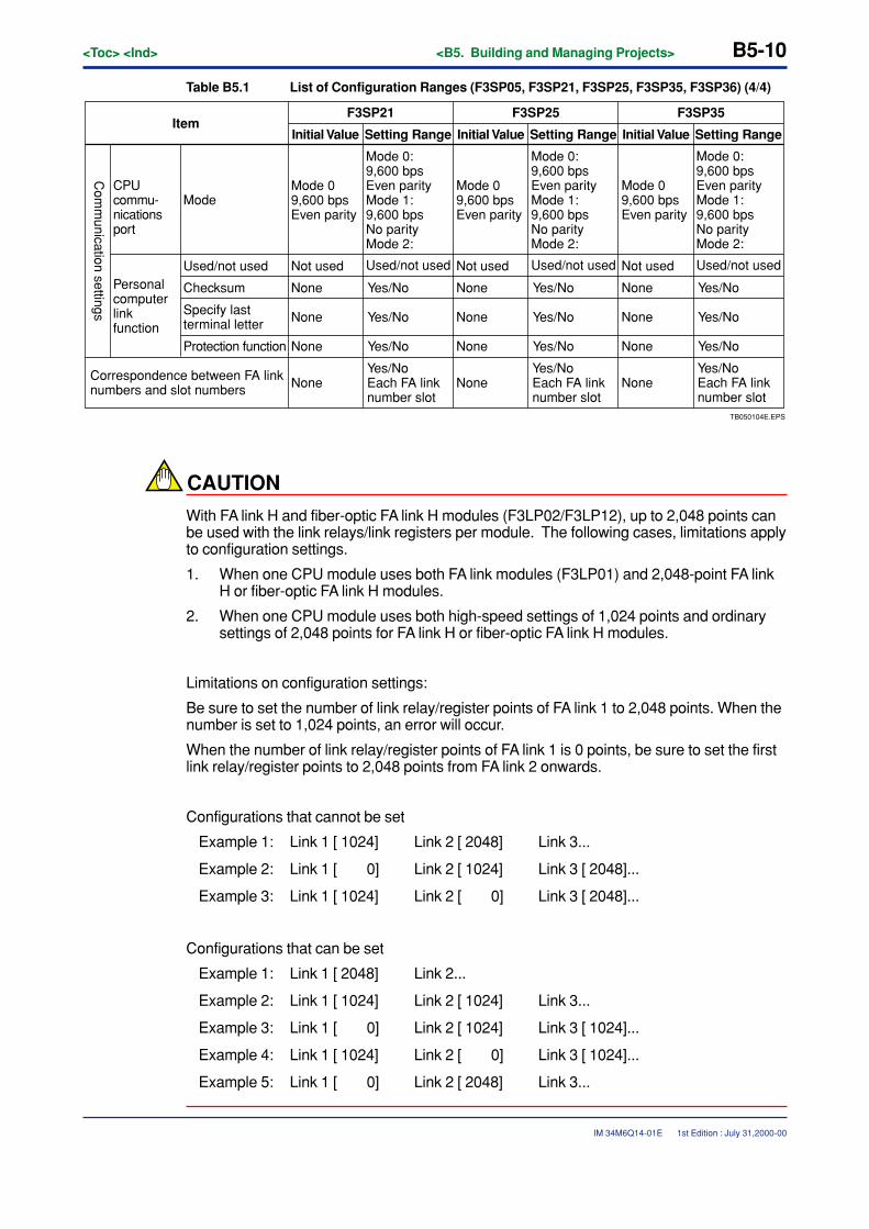
B5-10<Toc> <Ind> <B5. Building and Managing Projects>
IM 34M6Q14-01E
Table B5.1 List of Configuration Ranges (F3SP05, F3SP21, F3SP25, F3SP35, F3SP36) (4/4)
Mode 0 9,600 bpsEven parity
Mode 0:9,600 bpsEven parityMode 1:9,600 bpsNo parityMode 2:
Com
munication settings
Personal computer link function
Used/not used Not used
None
None
None
None
Yes/No
Yes/No
Yes/No
Used/not used
Checksum
Specify last terminal letter
Protection function
Yes/NoEach FA link number slot
Mode 0 9,600 bpsEven parity
Mode 0:9,600 bpsEven parityMode 1:9,600 bpsNo parityMode 2:
Not used
None
None
None
None
Yes/No
Yes/No
Yes/No
Used/not used
Yes/NoEach FA link number slot
Mode 0 9,600 bpsEven parity
Mode 0:9,600 bpsEven parityMode 1:9,600 bpsNo parityMode 2:
Not used
None
None
None
None
Yes/No
Yes/No
Yes/No
Used/not used
Yes/NoEach FA link number slot
CPU commu-nications port
Mode
Correspondence between FA link numbers and slot numbers
TB050104E.EPS
Setting RangeItem
F3SP21
Initial Value Setting Range
F3SP25
Initial Value Setting Range
F3SP35
Initial Value
CAUTION
With FA link H and fiber-optic FA link H modules (F3LP02/F3LP12), up to 2,048 points canbe used with the link relays/link registers per module. The following cases, limitations applyto configuration settings.
1. When one CPU module uses both FA link modules (F3LP01) and 2,048-point FA linkH or fiber-optic FA link H modules.
2. When one CPU module uses both high-speed settings of 1,024 points and ordinarysettings of 2,048 points for FA link H or fiber-optic FA link H modules.
Limitations on configuration settings:
Be sure to set the number of link relay/register points of FA link 1 to 2,048 points. When thenumber is set to 1,024 points, an error will occur.
When the number of link relay/register points of FA link 1 is 0 points, be sure to set the firstlink relay/register points to 2,048 points from FA link 2 onwards.
Configurations that cannot be set
Example 1: Link 1 [ 1024] Link 2 [ 2048] Link 3...
Example 2: Link 1 [ 0] Link 2 [ 1024] Link 3 [ 2048]...
Example 3: Link 1 [ 1024] Link 2 [ 0] Link 3 [ 2048]...
Configurations that can be set
Example 1: Link 1 [ 2048] Link 2...
Example 2: Link 1 [ 1024] Link 2 [ 1024] Link 3...
Example 3: Link 1 [ 0] Link 2 [ 1024] Link 3 [ 1024]...
Example 4: Link 1 [ 1024] Link 2 [ 0] Link 3 [ 1024]...
Example 5: Link 1 [ 0] Link 2 [ 2048] Link 3...
1st Edition : July 31,2000-00
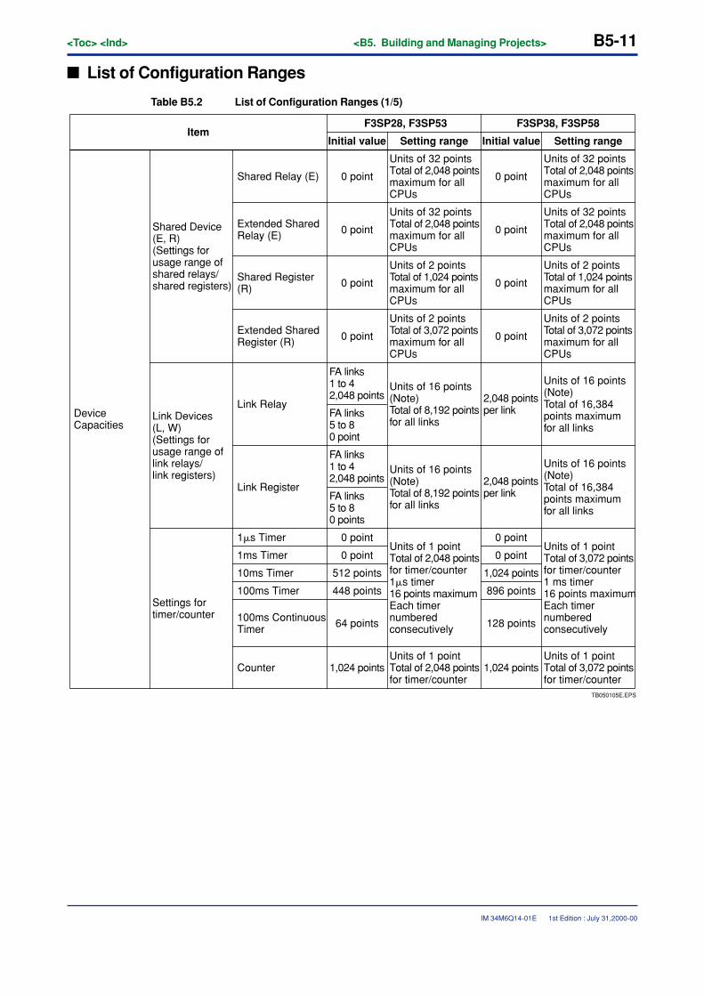
<Toc> <Ind> <B5. Building and Managing Projects> B5-11
IM 34M6Q14-01E
� List of Configuration Ranges
Table B5.2 List of Configuration Ranges (1/5)
TB050105E.EPS
ItemF3SP28, F3SP53 F3SP38, F3SP58
Initial value Setting range Initial value Setting range
Device Capacities
Shared Device (E, R)(Settings for usage range of shared relays/shared registers)
Units of 32 pointsTotal of 2,048 pointsmaximum for all CPUs
Shared Relay (E) 0 point
Units of 32 pointsTotal of 2,048 pointsmaximum for all CPUs
0 point
Units of 32 pointsTotal of 2,048 pointsmaximum for all CPUs
0 point
Units of 32 pointsTotal of 2,048 pointsmaximum for all CPUs
0 point
Units of 2 points Total of 1,024 points maximum for all CPUs
0 point
Units of 2 points Total of 1,024 points maximum for all CPUs
0 point
Units of 2 pointsTotal of 3,072 points maximum for all CPUs
0 point
Units of 2 pointsTotal of 3,072 points maximum for all CPUs
0 point
Extended Shared Relay (E)
Shared Register (R)
Extended Shared Register (R)
Link Devices (L, W) (Settings for usage range of link relays/link registers)
Link Relay
Units of 16 points (Note) Total of 8,192 points for all links
FA links 1 to 42,048 points
FA links 5 to 8 0 point
Units of 16 points (Note)Total of 16,384 points maximum for all links
2,048 points per link
Units of 16 points (Note) Total of 8,192 points for all links
FA links 1 to 42,048 points
FA links 5 to 8 0 points
Units of 16 points (Note)Total of 16,384 points maximum for all links
2,048 points per link Link Register
Settings for timer/counter
1�s Timer 0 point
0 pointUnits of 1 point Total of 2,048 points for timer/counter1�s timer 16 points maximum Each timer numbered consecutively
0 point
1ms Timer 0 point
10ms Timer 512 points 1,024 points
100ms Timer 448 points 896 points
100ms Continuous Timer 64 points 128 points
Units of 1 pointTotal of 3,072 points for timer/counter1 ms timer 16 points maximumEach timer numbered consecutively
Counter 1,024 pointsUnits of 1 point Total of 2,048 points for timer/counter
1,024 pointsUnits of 1 point Total of 3,072 points for timer/counter
1st Edition : July 31,2000-00
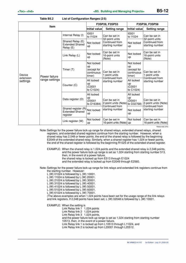
B5-12<Toc> <Ind> <B5. Building and Managing Projects>
IM 34M6Q14-01E
Table B5.2 List of Configuration Ranges (2/5)
TB050106E.EPS
ItemF3SP28, F3SP53 F3SP38, F3SP58
Initial value Setting range Initial value Setting range
Device extension settings
Power failure range settings
Can be set in 32-point units Continued from starting number
Internal Relay (I) I0001 to I1024 Can be set in
32-point units Continued from starting number
Not locked up
Not locked up
Not locked up (except for continuous timer)
Can be set in 16-point units (Note)
Can be set in 16-point units (Note)
Can be set in 1-point units Continued from starting number
Can be set in 1-point units Continued from starting number
Shared Relay (E) Extended Shared Relay (E)
Link Relay (L)
Timer (T)
Counter (C)
All locked up (C0001 to C1024)
All locked up (D0001 to D16384)
Not locked up
Data register (D) Can be set in 2-point units (Note) Continued from starting numberShared register (R)
Extended Shared register
Not locked upLink register (W) Can be set in
16-point units (Note)
I0001 to I1024
Not locked up
Not locked up
Not locked up (except for continuous timer)
All locked up (C0001 to C1024)
All locked up (D0001 to D32768)
Not locked up
Can be set in 2-point units (Note) Continued from starting number
Not locked up
Can be set in 16-point units (Note)
Note: Settings for the power failure lock-up range for shared relays, extended shared relays, sharedregisters, and extended shared registers continue from the starting number. However, when ashared relay has 2,048 or fewer points, the end of the shared relay is followed by the beginningE2049 of the extended shared relay. Similarly, when a shared register has 1,024 or fewer points,the end of the shared register is followed by the beginning R1025 of the extended shared register.
EXAMPLE: When the shared relay is 1,024 points and the extended shared relay is 2,048 points,and the power failure lock-up range is set as 1,024 starting from starting number 513,then, in the event of a power failure,the shared relay is locked up from E513 through E1024and the extended relay is locked up from E2049 through E2560.
Note: Settings for the power failure lock-up range for link relays and extended link registers continue fromthe starting number. However:L (W) 01024 is followed by L (W) 10001.L (W) 11024 is followed by L (W) 20001.L (W) 21024 is followed by L (W) 30001.L (W) 31024 is followed by L (W) 40001.L (W) 41024 is followed by L (W) 50001.L (W) 51024 is followed by L (W) 60001.L (W) 61024 is followed by L (W) 70001.(The above examples are when 1,024 points have been set for the usage range of the link relaysand link registers. If 2,048 points have been set, L (W) 02048 is followed by L (W) 10001.
EXAMPLE: When the setting isLink Relay link 1 1,024 pointsLink Relay link 2 1,024 pointsLink Relay link 3 1,024 points,and the power failure lock-up range is set as 1,024 starting from starting number10513, then, in the event of a power failure,Link Relay link 1 is locked up from L10513 through L11024, andLink Relay link 2 is locked up from L20001 through L20512.
1st Edition : July 31,2000-00
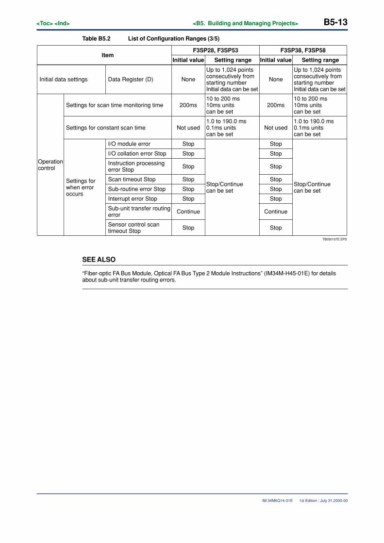
<Toc> <Ind> <B5. Building and Managing Projects> B5-13
IM 34M6Q14-01E
Table B5.2 List of Configuration Ranges (3/5)
TB050107E.EPS
Sensor control scan timeout Stop
Setting rangeItem
F3SP28, F3SP53 F3SP38, F3SP58
Initial value
Initial data settings Data Register (D) None
Up to 1,024 points consecutively from starting number Initial data can be set
Operationcontrol
Settings for scan time monitoring time 200ms10 to 200 ms10ms units can be set
Settings for constant scan time Not used1.0 to 190.0 ms0.1ms units can be set
Settings for when error occurs
I/O module error Stop
Stop
Stop
Stop
Stop
Stop
Continue
Stop
Stop/Continue can be set
Setting rangeInitial value
None
Up to 1,024 points consecutively from starting number Initial data can be set
200ms10 to 200 ms10ms units can be set
Not used1.0 to 190.0 ms0.1ms units can be set
Stop
Stop
Stop
Stop
Stop
Stop
Continue
Stop
Stop/Continue can be set
I/O collation error Stop
Instruction processing error Stop
Scan timeout Stop
Sub-routine error Stop
Interrupt error Stop
Sub-unit transfer routing error
SEE ALSO
“Fiber-optic FA Bus Module, Optical FA Bus Type 2 Module Instructions” (IM34M-H45-01E) for detailsabout sub-unit transfer routing errors.
1st Edition : July 31,2000-00
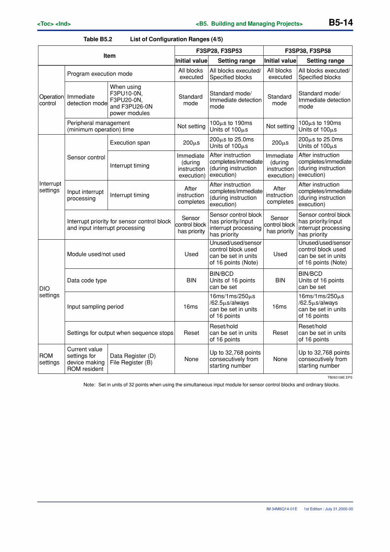
B5-14<Toc> <Ind> <B5. Building and Managing Projects>
IM 34M6Q14-01E
Table B5.2 List of Configuration Ranges (4/5)
TB050108E.EPS
Data Register (D)File Register (B)
Setting rangeItem
F3SP28, F3SP53 F3SP38, F3SP58
Initial value
All blocks executed
All blocks executed/Specified blocks
Operationcontrol
Interrupt settings
DIO settings
Program execution mode
Peripheral management (minimum operation) time Not setting 100�s to 190ms
Units of 100�s
200�s to 25.0msUnits of 100�s
Sensor control
Execution span 200�s
Immediate (during
instruction execution)
After instruction completes
Sensor control block has priority
Used
BIN
16ms
None
Setting rangeInitial value
Interrupt timing
Interrupt timing
Module used/not used
Data code type
Input sampling period
Up to 32,768 points consecutively from starting number
Immediate detection mode
When using F3PU10-0N, F3PU20-0N, and F3PU26-0N power modules
Standard mode
Standard mode/Immediate detection mode
After instruction completes/immediate (during instruction execution)
After instruction completes/immediate (during instruction execution)
Input interrupt processing
Interrupt priority for sensor control block and input interrupt processing
Sensor control block has priority/input interrupt processing has priorityUnused/used/sensor control block used can be set in units of 16 points (Note)
BIN/BCD Units of 16 points can be set
16ms/1ms/250�s/62.5�s/alwayscan be set in units of 16 points
Settings for output when sequence stops ResetReset/hold can be set in units of 16 points
All blocks executed
All blocks executed/Specified blocks
Not setting 100�s to 190msUnits of 100�s
200�s to 25.0msUnits of 100�s200�s
Immediate (during
instruction execution)
After instruction completes
Sensor control block has priority
Used
BIN
16ms
NoneUp to 32,768 points consecutively from starting number
Standard mode
Standard mode/Immediate detection mode
After instruction completes/immediate (during instruction execution)
After instruction completes/immediate (during instruction execution)
Sensor control block has priority/input interrupt processing has priorityUnused/used/sensor control block used can be set in units of 16 points (Note)
BIN/BCD Units of 16 points can be set
16ms/1ms/250�s/62.5�s/alwayscan be set in units of 16 points
ResetReset/hold can be set in units of 16 points
ROM settings
Current value settings for device making ROM resident
Note: Set in units of 32 points when using the simultaneous input module for sensor control blocks and ordinary blocks.
1st Edition : July 31,2000-00
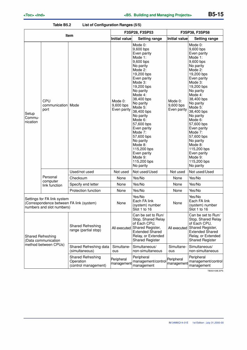
<Toc> <Ind> <B5. Building and Managing Projects> B5-15
IM 34M6Q14-01E
Table B5.2 List of Configuration Ranges (5/5)
TB050109E.EPS
Setting rangeItem
F3SP28, F3SP53 F3SP38, F3SP58
Initial value
Mode 0:9,600 bpsEven parity
Mode 0:9,600 bpsEven parityMode 1:9,600 bpsNo parityMode 2:19,200 bpsEven parityMode 3:19,200 bpsNo parityMode 4:38,400 bpsNo parityMode 5:38,400 bpsNo parityMode 6:57,600 bpsEven parityMode 7:57,600 bpsNo parityMode 8:115,200 bpsEven parityMode 9:115,200 bpsNo parity
Setup Commu-nication
Settings for FA link system(Correspondence between FA link (system) numbers and slot numbers)
Shared Refreshing (Data communication method between CPUs)
CPU communication port
All executed
Setting rangeInitial value
Shared Refreshing range (partial stop)
Personal computer link function
Used/not used
Checksum
Specify end letter
Mode
Not used Not used/Used
None Yes/No
None Yes/No
Protection function None Yes/No
None
Yes/NoEach FA link (system) number Slot 1 to 16
Can be set to Run/Stop, Shared Relay of Each CPU, Shared Register, Extended Shared Relay, or Extended Shared Register
Shared Refreshing data (simultaneous)
Simultane-ous
Simultaneous/non-simultaneous
Shared Refreshing Operation (control management)
Peripheral management
Peripheral management/control management
Mode 0:9,600 bpsEven parity
Mode 0:9,600 bpsEven parityMode 1:9,600 bpsNo parityMode 2:19,200 bpsEven parityMode 3:19,200 bpsNo parityMode 4:38,400 bpsNo parityMode 5:38,400 bpsNo parityMode 6:57,600 bpsEven parityMode 7:57,600 bpsNo parityMode 8:115,200 bpsEven parityMode 9:115,200 bpsNo parity
All executed
Not used Not used/Used
None Yes/No
None Yes/No
None Yes/No
None
Yes/NoEach FA link (system) number Slot 1 to 16
Can be set to Run/Stop, Shared Relay of Each CPU, Shared Register, Extended Shared Relay, or Extended Shared Register
Simultane-ous
Simultaneous/non-simultaneous
Peripheral management
Peripheral management/control management
1st Edition : July 31,2000-00
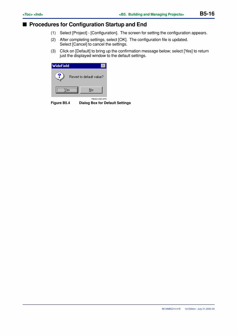
B5-16<Toc> <Ind> <B5. Building and Managing Projects>
IM 34M6Q14-01E
� Procedures for Configuration Startup and End(1) Select [Project] - [Configuration]. The screen for setting the configuration appears.
(2) After completing settings, select [OK]. The configuration file is updated.Select [Cancel] to cancel the settings.
(3) Click on [Default] to bring up the confirmation message below; select [Yes] to returnjust the displayed window to the default settings.
FB050105E.EPS
Figure B5.4 Dialog Box for Default Settings
1st Edition : July 31,2000-00
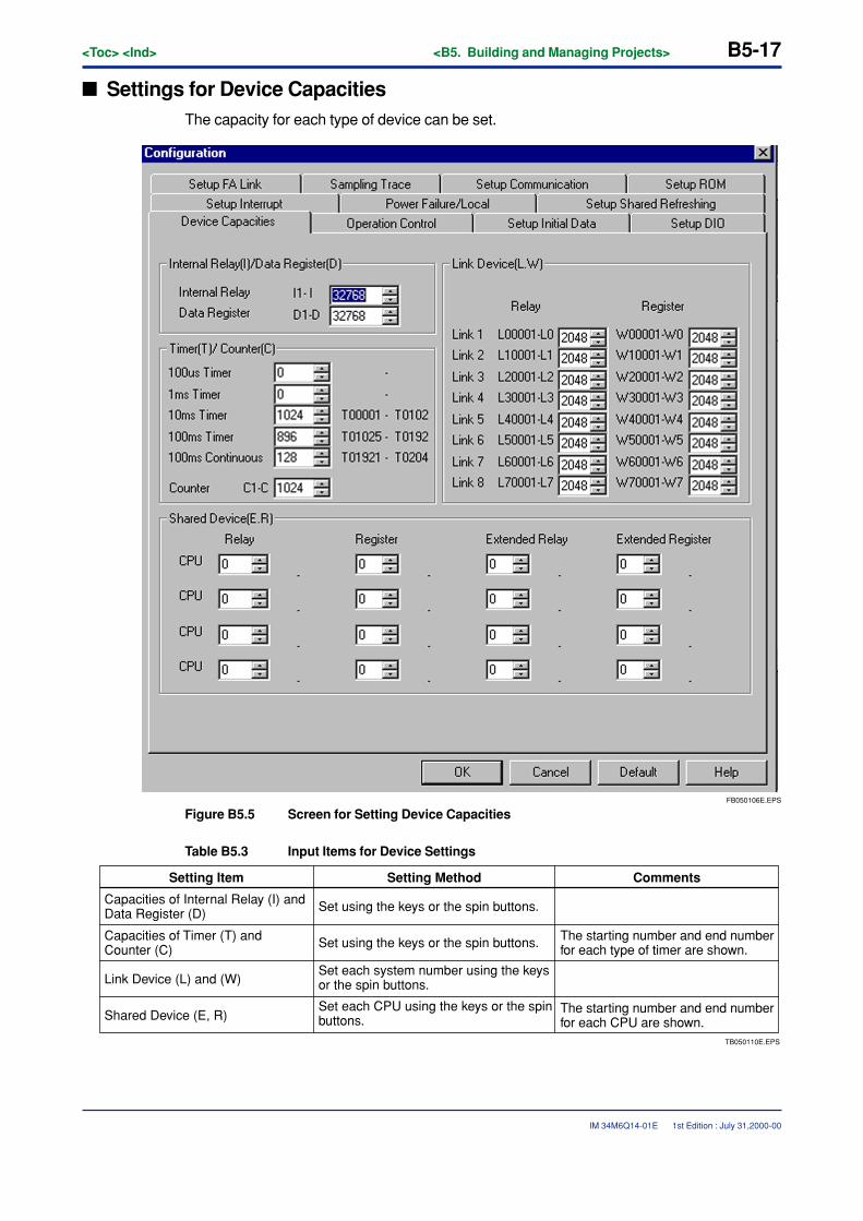
<Toc> <Ind> <B5. Building and Managing Projects> B5-17
IM 34M6Q14-01E
� Settings for Device CapacitiesThe capacity for each type of device can be set.
FB050106E.EPS
Figure B5.5 Screen for Setting Device Capacities
Table B5.3 Input Items for Device Settings
TB050110E.EPS
Set each CPU using the keys or the spin buttons.
CommentsSetting Item Setting Method
Capacities of Internal Relay (I) and Data Register (D) Set using the keys or the spin buttons.
Capacities of Timer (T) and Counter (C) Set using the keys or the spin buttons. The starting number and end number
for each type of timer are shown.
Link Device (L) and (W)Set each system number using the keys or the spin buttons.
Shared Device (E, R) The starting number and end number for each CPU are shown.
1st Edition : July 31,2000-00
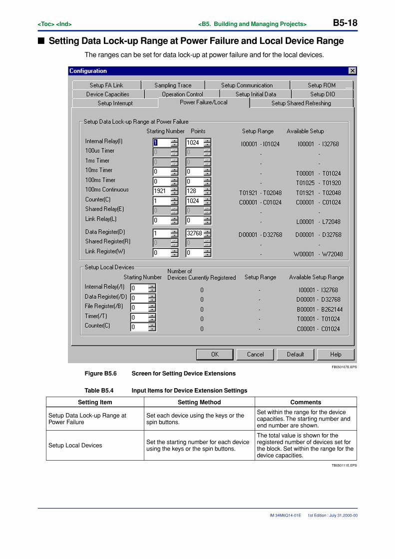
B5-18<Toc> <Ind> <B5. Building and Managing Projects>
IM 34M6Q14-01E
� Setting Data Lock-up Range at Power Failure and Local Device RangeThe ranges can be set for data lock-up at power failure and for the local devices.
FB050107E.EPS
Figure B5.6 Screen for Setting Device Extensions
Table B5.4 Input Items for Device Extension Settings
TB050111E.EPS
CommentsSetting Item Setting Method
Setup Data Lock-up Range at Power Failure
Set each device using the keys or the spin buttons.
Setup Local Devices Set the starting number for each device using the keys or the spin buttons.
The total value is shown for the registered number of devices set for the block. Set within the range for the device capacities.
Set within the range for the device capacities. The starting number and end number are shown.
1st Edition : July 31,2000-00
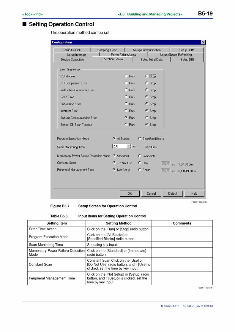
<Toc> <Ind> <B5. Building and Managing Projects> B5-19
IM 34M6Q14-01E
� Setting Operation ControlThe operation method can be set.
FB050108E.EPS
Figure B5.7 Setup Screen for Operation Control
Table B5.5 Input Items for Setting Operation Control
TB050112E.EPS
CommentsSetting Item Setting Method
Error-Time Action Click on the [Run] or [Stop] radio button.
Program Execution Mode Click on the [All Blocks] or [Specified Blocks] radio button.
Scan Monitoring Time Set using key input.
Momentary Power Failure Detection Mode
Click on the [Standard] or [Immediate] radio button.
Constant ScanConstant Scan Click on the [Use] or [Do Not Use] radio button, and if [Use] is clicked, set the time by key input.
Peripheral Management TimeClick on the [Not Setup] or [Setup] radio button, and if [Setup] is clicked, set the time by key input.
1st Edition : July 31,2000-00
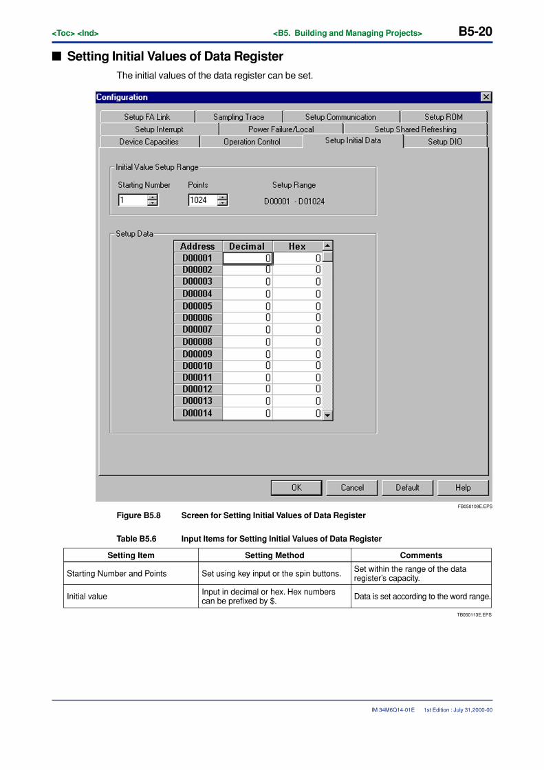
B5-20<Toc> <Ind> <B5. Building and Managing Projects>
IM 34M6Q14-01E
� Setting Initial Values of Data RegisterThe initial values of the data register can be set.
FB050109E.EPS
Figure B5.8 Screen for Setting Initial Values of Data Register
Table B5.6 Input Items for Setting Initial Values of Data Register
TB050113E.EPS
CommentsSetting Item Setting Method
Starting Number and Points Set using key input or the spin buttons.
Initial value Input in decimal or hex. Hex numbers can be prefixed by $. Data is set according to the word range.
Set within the range of the data register’s capacity.
1st Edition : July 31,2000-00
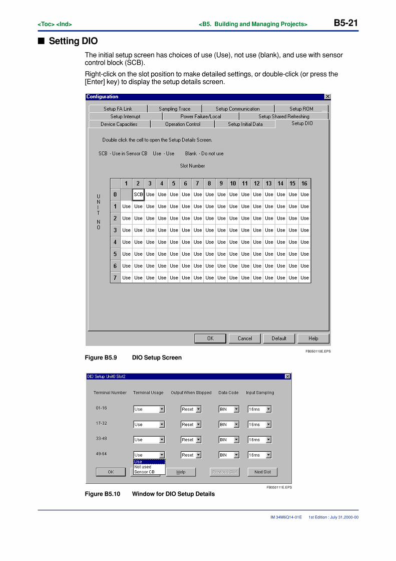
<Toc> <Ind> <B5. Building and Managing Projects> B5-21
IM 34M6Q14-01E
� Setting DIOThe initial setup screen has choices of use (Use), not use (blank), and use with sensorcontrol block (SCB).
Right-click on the slot position to make detailed settings, or double-click (or press the[Enter] key) to display the setup details screen.
FB050110E.EPS
Figure B5.9 DIO Setup Screen
FB050111E.EPS
Figure B5.10 Window for DIO Setup Details
1st Edition : July 31,2000-00
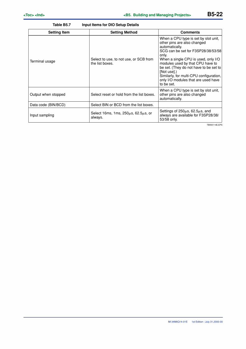
B5-22<Toc> <Ind> <B5. Building and Managing Projects>
IM 34M6Q14-01E
Table B5.7 Input Items for DIO Setup Details
TB050114E.EPS
CommentsSetting Item Setting Method
Terminal usage Select to use, to not use, or SCB from the list boxes.
Output when stopped Select reset or hold from the list boxes.When a CPU type is set by slot unit, other pins are also changed automatically.
Settings of 250�s, 62.5�s, and always are available for F3SP28/38/53/58 only.
Data code (BIN/BCD) Select BIN or BCD from the list boxes.
Input sampling Select 16ms, 1ms, 250�s, 62.5�s, or always.
When a CPU type is set by slot unit, other pins are also changed automatically.SCG can be set for F3SP28/38/53/58 only.When a single CPU is used, only I/O modules used by that CPU have to be set. (They do not have to be set to [Not use].)Similarly, for multi-CPU configuration, only I/O modules that are used have to be set.
1st Edition : July 31,2000-00
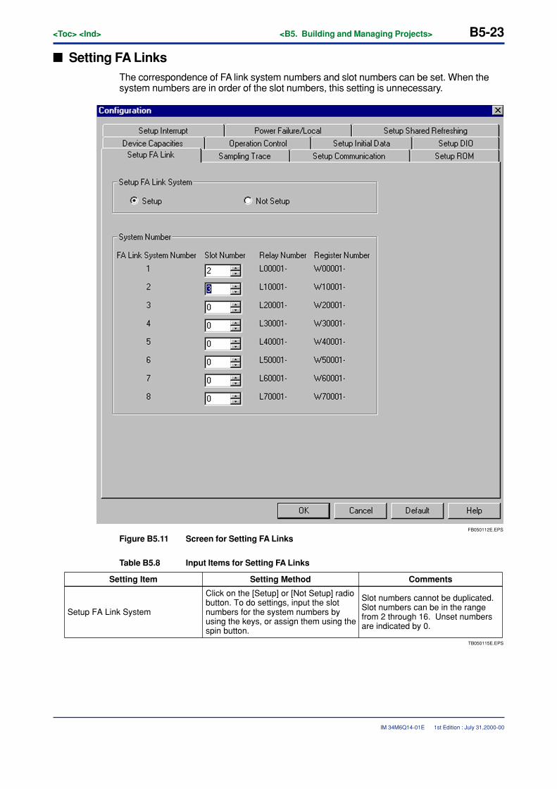
<Toc> <Ind> <B5. Building and Managing Projects> B5-23
IM 34M6Q14-01E
� Setting FA LinksThe correspondence of FA link system numbers and slot numbers can be set. When thesystem numbers are in order of the slot numbers, this setting is unnecessary.
FB050112E.EPS
Figure B5.11 Screen for Setting FA Links
Table B5.8 Input Items for Setting FA Links
TB050115E.EPS
CommentsSetting Item Setting Method
Setup FA Link System
Click on the [Setup] or [Not Setup] radio button. To do settings, input the slot numbers for the system numbers by using the keys, or assign them using the spin button.
Slot numbers cannot be duplicated. Slot numbers can be in the range from 2 through 16. Unset numbers are indicated by 0.
1st Edition : July 31,2000-00
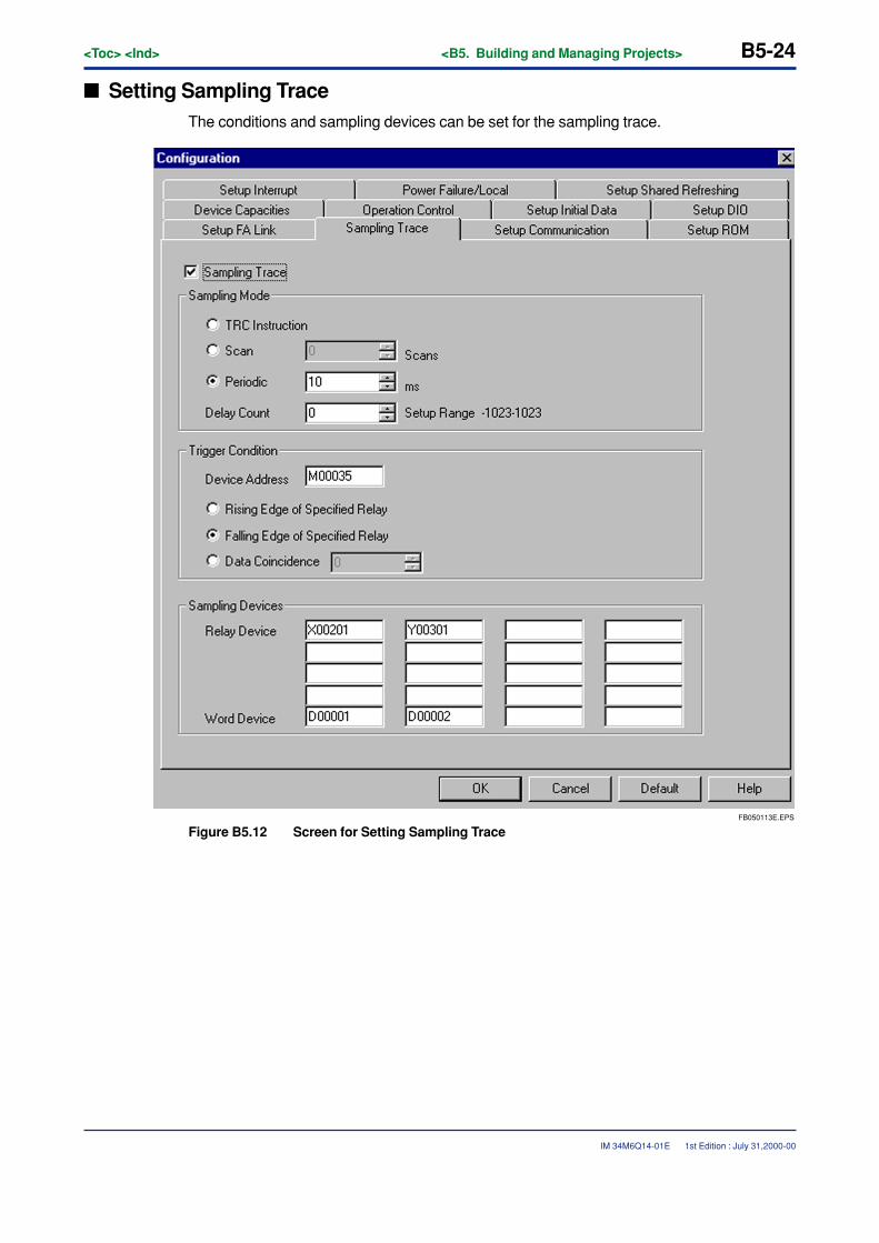
B5-24<Toc> <Ind> <B5. Building and Managing Projects>
IM 34M6Q14-01E
� Setting Sampling TraceThe conditions and sampling devices can be set for the sampling trace.
FB050113E.EPS
Figure B5.12 Screen for Setting Sampling Trace
1st Edition : July 31,2000-00
<Toc> <Ind> <B5. Building and Managing Projects> B5-25
IM 34M6Q14-01E
Table B5.9 Input Items for Setting Sampling Trace
TB050116E.EPS
CommentsSetting Item Setting Method
Sampling Trace Click on the check button to do sampling trace.
Sampling Method
Click on the [TRC Instruction], [Scan] or [Periodic] button. For scan, set the intervals, and for periodic, set the time, using the keys or the spin buttons.
Delay Count Set using the keys or the spin buttons. The delay is from -1023 through 1023.
Trigger Condition
Use the keys to input the trigger address. Then, click on the radio button of [Rising Edge of Specified Relay], [Falling Edge of Specified Relay], or [Data Coincidence]. For data coincidence, input the data using the keys or the spin buttons.
The relay data coincidence is a 16-point value from that address.
Sampling DevicesRelays of up to 16 points and registers of up to 4 points can be input using the keys.
When a relay is input to the register field, it is a 16-point value from that address. When a timer/counter is input to the relay field, the timeout relay is traced, and when input to the register field, the current value is traced.
See Chapter B17 “Sampling Trace”.
1st Edition : July 31,2000-00
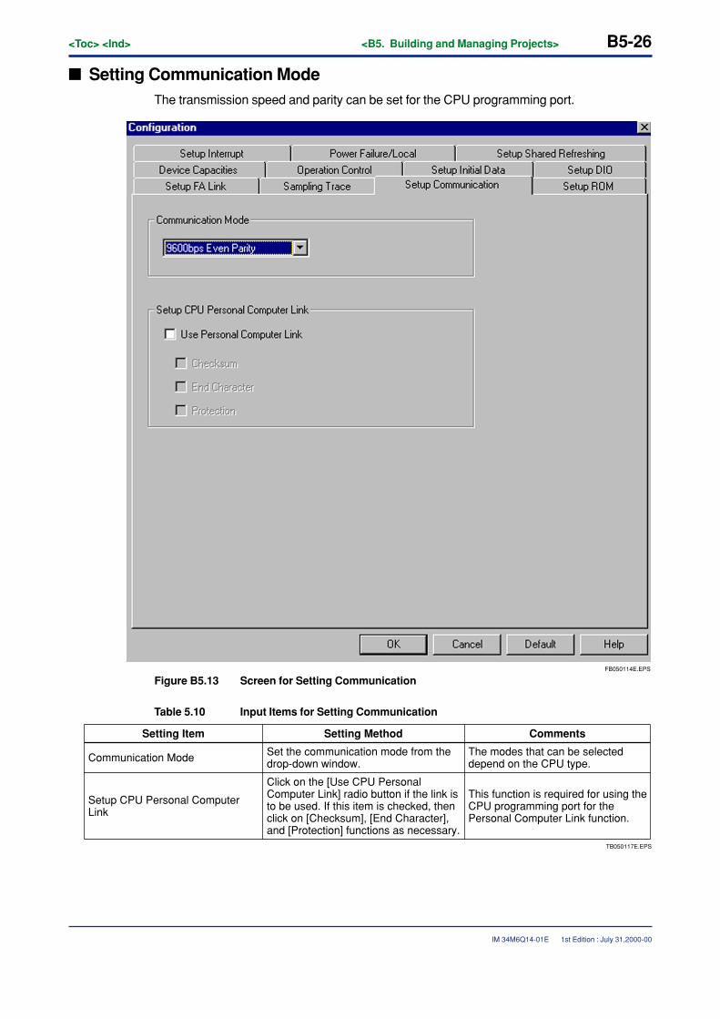
B5-26<Toc> <Ind> <B5. Building and Managing Projects>
IM 34M6Q14-01E
� Setting Communication ModeThe transmission speed and parity can be set for the CPU programming port.
FB050114E.EPS
Figure B5.13 Screen for Setting Communication
Table 5.10 Input Items for Setting Communication
TB050117E.EPS
CommentsSetting Item Setting Method
Communication Mode Set the communication mode from the drop-down window.
Setup CPU Personal Computer Link
Click on the [Use CPU Personal Computer Link] radio button if the link is to be used. If this item is checked, then click on [Checksum], [End Character], and [Protection] functions as necessary.
This function is required for using the CPU programming port for the Personal Computer Link function.
The modes that can be selected depend on the CPU type.
1st Edition : July 31,2000-00
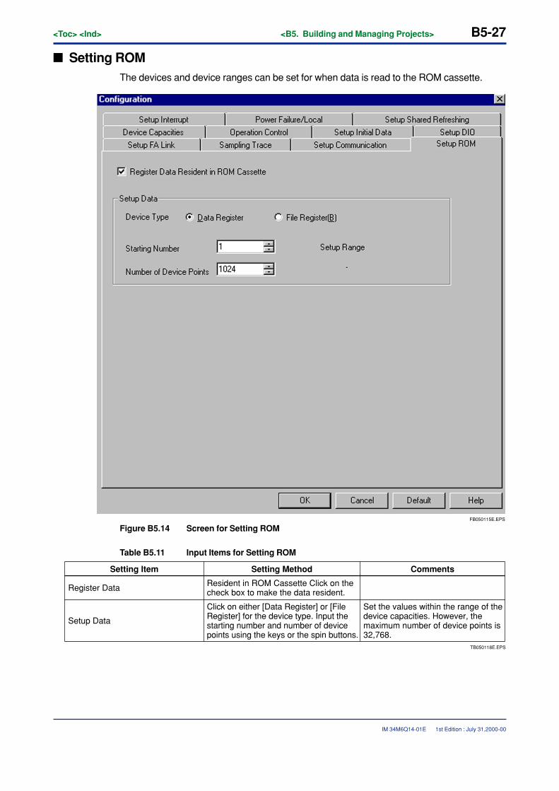
<Toc> <Ind> <B5. Building and Managing Projects> B5-27
IM 34M6Q14-01E
� Setting ROMThe devices and device ranges can be set for when data is read to the ROM cassette.
FB050115E.EPS
Figure B5.14 Screen for Setting ROM
Table B5.11 Input Items for Setting ROM
TB050118E.EPS
CommentsSetting Item Setting Method
Register Data Resident in ROM Cassette Click on the check box to make the data resident.
Setup Data
Click on either [Data Register] or [File Register] for the device type. Input the starting number and number of device points using the keys or the spin buttons.
Set the values within the range of the device capacities. However, the maximum number of device points is 32,768.
1st Edition : July 31,2000-00
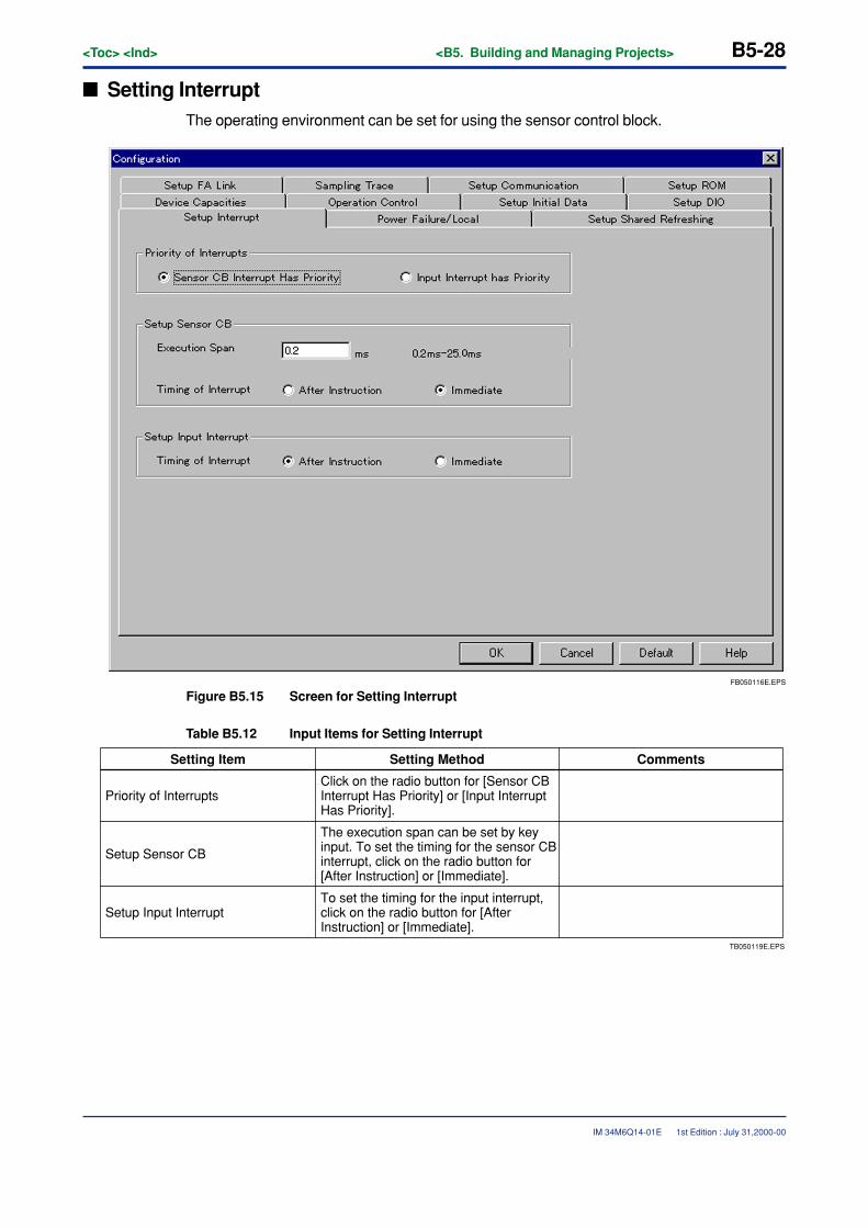
B5-28<Toc> <Ind> <B5. Building and Managing Projects>
IM 34M6Q14-01E 1st Edition : July 31,2000-00
� Setting InterruptThe operating environment can be set for using the sensor control block.
FB050116E.EPS
Figure B5.15 Screen for Setting Interrupt
Table B5.12 Input Items for Setting Interrupt
TB050119E.EPS
CommentsSetting Item Setting Method
Priority of InterruptsClick on the radio button for [Sensor CB Interrupt Has Priority] or [Input Interrupt Has Priority].
Setup Sensor CB
The execution span can be set by key input. To set the timing for the sensor CB interrupt, click on the radio button for [After Instruction] or [Immediate].
Setup Input InterruptTo set the timing for the input interrupt, click on the radio button for [After Instruction] or [Immediate].
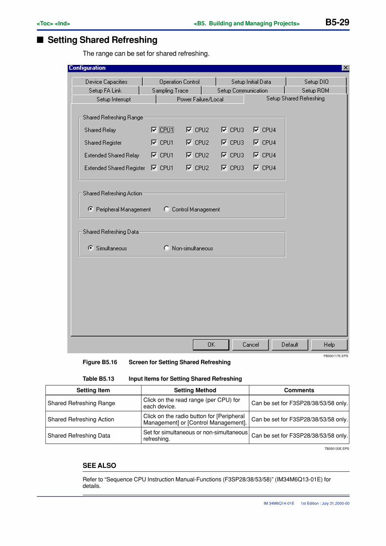
<Toc> <Ind> <B5. Building and Managing Projects> B5-29
IM 34M6Q14-01E 1st Edition : July 31,2000-00
� Setting Shared RefreshingThe range can be set for shared refreshing.
FB050117E.EPS
Figure B5.16 Screen for Setting Shared Refreshing
Table B5.13 Input Items for Setting Shared Refreshing
TB050120E.EPS
CommentsSetting Item Setting Method
Shared Refreshing Range Click on the read range (per CPU) for each device.
Shared Refreshing Data Set for simultaneous or non-simultaneous refreshing. Can be set for F3SP28/38/53/58 only.
Can be set for F3SP28/38/53/58 only.
Shared Refreshing Action Click on the radio button for [Peripheral Management] or [Control Management]. Can be set for F3SP28/38/53/58 only.
SEE ALSO
Refer to “Sequence CPU Instruction Manual-Functions (F3SP28/38/53/58)” (IM34M6Q13-01E) fordetails.
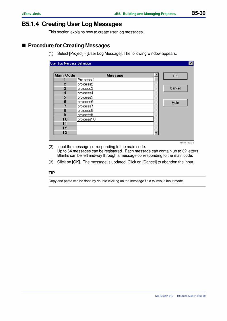
B5-30<Toc> <Ind> <B5. Building and Managing Projects>
IM 34M6Q14-01E
B5.1.4 Creating User Log MessagesThis section explains how to create user log messages.
� Procedure for Creating Messages(1) Select [Project] - [User Log Message]. The following window appears.
FB050118E.EPS
(2) Input the message corresponding to the main code.Up to 64 messages can be registered. Each message can contain up to 32 letters.Blanks can be left midway through a message corresponding to the main code.
(3) Click on [OK]. The message is updated. Click on [Cancel] to abandon the input.
TIP
Copy and paste can be done by double-clicking on the message field to invoke input mode.
1st Edition : July 31,2000-00
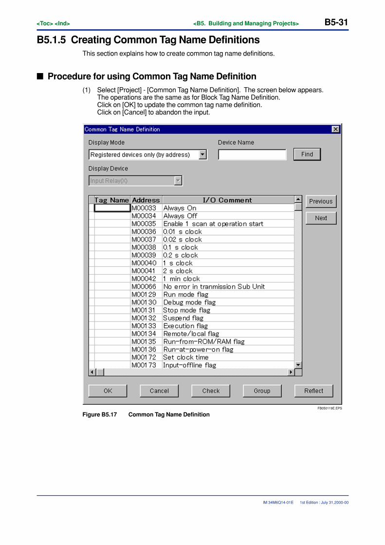
<Toc> <Ind> <B5. Building and Managing Projects> B5-31
IM 34M6Q14-01E
B5.1.5 Creating Common Tag Name DefinitionsThis section explains how to create common tag name definitions.
� Procedure for using Common Tag Name Definition(1) Select [Project] - [Common Tag Name Definition]. The screen below appears.
The operations are the same as for Block Tag Name Definition.Click on [OK] to update the common tag name definition.Click on [Cancel] to abandon the input.
FB050119E.EPS
Figure B5.17 Common Tag Name Definition
1st Edition : July 31,2000-00
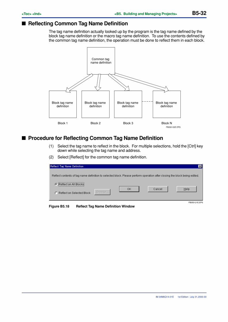
B5-32<Toc> <Ind> <B5. Building and Managing Projects>
IM 34M6Q14-01E
� Reflecting Common Tag Name DefinitionThe tag name definition actually looked up by the program is the tag name defined by theblock tag name definition or the macro tag name definition. To use the contents defined bythe common tag name definition, the operation must be done to reflect them in each block.
Common tag name definition
Block tag name definition
Block tag name definition
Block tag name definition
Block tag name definition
Block 1FB050120E.EPS
Block 2 Block 3 Block N
� Procedure for Reflecting Common Tag Name Definition(1) Select the tag name to reflect in the block. For multiple selections, hold the [Ctrl] key
down while selecting the tag name and address.
(2) Select [Reflect] for the common tag name definition.
FB050121E.EPS
Figure B5.18 Reflect Tag Name Definition Window
1st Edition : July 31,2000-00
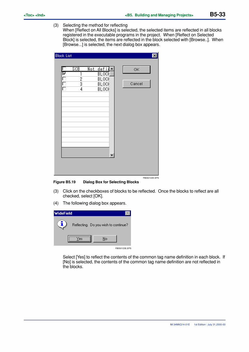
<Toc> <Ind> <B5. Building and Managing Projects> B5-33
IM 34M6Q14-01E
(3) Selecting the method for reflectingWhen [Reflect on All Blocks] is selected, the selected items are reflected in all blocksregistered in the executable programs in the project. When [Reflect on SelectedBlock] is selected, the items are reflected in the block selected with [Browse..]. When[Browse...] is selected, the next dialog box appears.
FB050122E.EPS
Figure B5.19 Dialog Box for Selecting Blocks
(3) Click on the checkboxes of blocks to be reflected. Once the blocks to reflect are allchecked, select [OK].
(4) The following dialog box appears.
FB050123E.EPS
Select [Yes] to reflect the contents of the common tag name definition in each block. If[No] is selected, the contents of the common tag name definition are not reflected inthe blocks.
1st Edition : July 31,2000-00
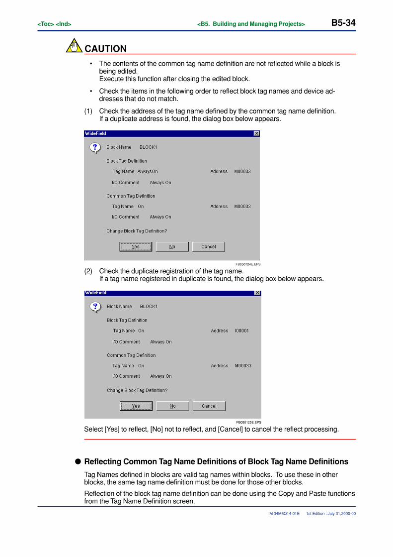
B5-34<Toc> <Ind> <B5. Building and Managing Projects>
IM 34M6Q14-01E
CAUTION
• The contents of the common tag name definition are not reflected while a block isbeing edited.Execute this function after closing the edited block.
• Check the items in the following order to reflect block tag names and device ad-dresses that do not match.
(1) Check the address of the tag name defined by the common tag name definition.If a duplicate address is found, the dialog box below appears.
FB050124E.EPS
(2) Check the duplicate registration of the tag name.If a tag name registered in duplicate is found, the dialog box below appears.
FB050125E.EPS
Select [Yes] to reflect, [No] not to reflect, and [Cancel] to cancel the reflect processing.
� Reflecting Common Tag Name Definitions of Block Tag Name Definitions
Tag Names defined in blocks are valid tag names within blocks. To use these in otherblocks, the same tag name definition must be done for those other blocks.
Reflection of the block tag name definition can be done using the Copy and Paste functionsfrom the Tag Name Definition screen.
1st Edition : July 31,2000-00
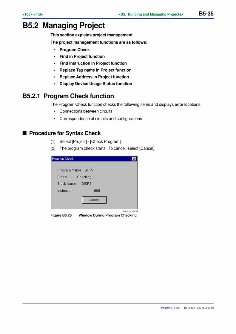
<Toc> <Ind> <B5. Building and Managing Projects> B5-35
IM 34M6Q14-01E
B5.2 Managing ProjectThis section explains project management.
The project management functions are as follows:
• Program Check
• Find in Project function
• Find Instruction in Project function
• Replace Tag name in Project function
• Replace Address in Project function
• Display Device Usage Status function
B5.2.1 Program Check functionThe Program Check function checks the following items and displays error locations.
• Connections between circuits
• Correspondence of circuits and configurations
� Procedure for Syntax Check(1) Select [Project] - [Check Program].
(2) The program check starts. To cancel, select [Cancel].
FB050201E.EPS
Figure B5.20 Window During Program Checking
1st Edition : July 31,2000-00
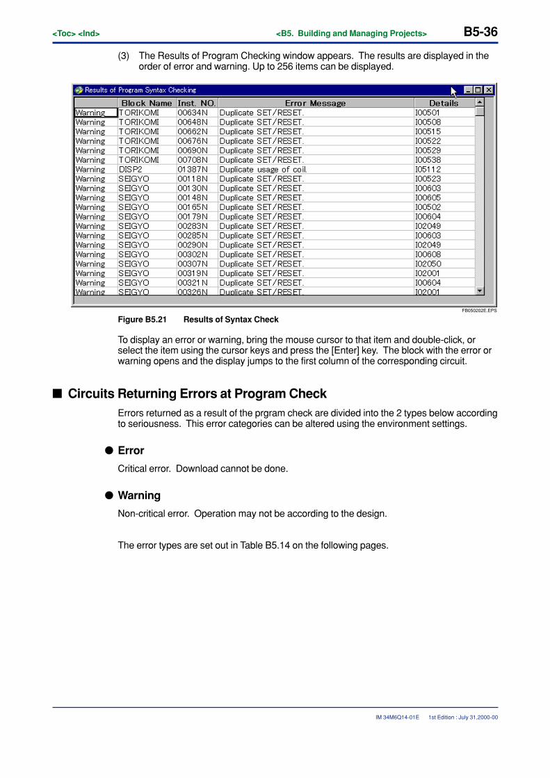
B5-36<Toc> <Ind> <B5. Building and Managing Projects>
IM 34M6Q14-01E
(3) The Results of Program Checking window appears. The results are displayed in theorder of error and warning. Up to 256 items can be displayed.
FB050202E.EPS
Figure B5.21 Results of Syntax Check
To display an error or warning, bring the mouse cursor to that item and double-click, orselect the item using the cursor keys and press the [Enter] key. The block with the error orwarning opens and the display jumps to the first column of the corresponding circuit.
� Circuits Returning Errors at Program CheckErrors returned as a result of the prgram check are divided into the 2 types below accordingto seriousness. This error categories can be altered using the environment settings.
� Error
Critical error. Download cannot be done.
� Warning
Non-critical error. Operation may not be according to the design.
The error types are set out in Table B5.14 on the following pages.
1st Edition : July 31,2000-00
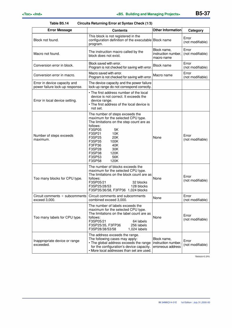
<Toc> <Ind> <B5. Building and Managing Projects> B5-37
IM 34M6Q14-01E
Table B5.14 Circuits Returning Error at Syntax Check (1/3)
TB050201E.EPS
The address exceeds the range. The following cases may apply:• The global address exceeds the range
for the configuration’s device capacity.• More local addresses than set are used.
Error Message CategoryOther InformationContents
Block not found.This block is not registered in the configuration definition of the executable program.
Block name
Block name
Error (not modifiable)
Error (not modifiable)
Error (not modifiable)
Error (not modifiable)
Error (not modifiable)
Macro not found. The instruction macro called by the block does not exist.
Block name, instruction number, macro name
Error (not modifiable)
Block name, instruction number, erroneous address
Conversion error in block. Block saved with error. Program is not checked for saving with error.
Conversion error in macro. Macro saved with error. Program is not checked for saving with error. Macro name
Error in device capacity and power failure lock-up response.
The device capacity and the power failure lock-up range do not correspond correctly.
Error in local device setting.
• The first address number of the local device is not correct. It exceeds the device range.
• The first address of the local device is not set.
Number of steps exceeds maximum.
The number of steps exceeds the maximum for the selected CPU type. The limitations on the step count are as follows: F3SP05 5KF3SP21 10KF3SP25 20KF3SP35 100KF3FP36 40KF3SP28 30KF3SP38 120KF3SP53 56KF3SP58 120K
None
Error (not modifiable)None
Error (not modifiable)None
Error (not modifiable)None
Too many blocks for CPU type.
The number of blocks exceeds the maximum for the selected CPU type. The limitations on the block count are as follows:F3SP05/21 32 blocksF3SP25/28/53 128 blocksF3SP35/36/58, F3FP36 1,024 blocks
Circuit comments � subcomments exceed 3,000.
Circuit comments and subcomments combined exceed 3,000.
Too many labels for CPU type.
The number of labels exceeds the maximum for the selected CPU type. The limitations on the label count are as follows:F3SP05/21 64 labelsF3SP25/35, F3FP36 256 labelsF3SP28/38/53/58 1,024 labels
Inappropriate device or range exceeded.
1st Edition : July 31,2000-00
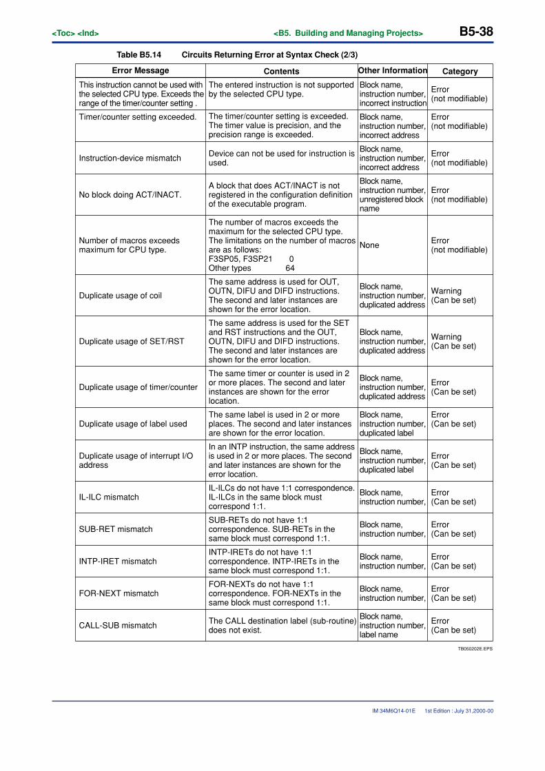
B5-38<Toc> <Ind> <B5. Building and Managing Projects>
IM 34M6Q14-01E
Table B5.14 Circuits Returning Error at Syntax Check (2/3)
TB050202E.EPS
The CALL destination label (sub-routine) does not exist.
Error Message CategoryOther InformationContents
This instruction cannot be used with the selected CPU type. Exceeds the range of the timer/counter setting .
The entered instruction is not supported by the selected CPU type.
Block name, instruction number, incorrect instruction
Block name, instruction number, incorrect address
Error (not modifiable)
Error (not modifiable)
Error (not modifiable)
Error (not modifiable)
Warning (Can be set)
Timer/counter setting exceeded. The timer/counter setting is exceeded. The timer value is precision, and the precision range is exceeded.
Block name, instruction number, incorrect address
Error (Can be set)
Block name, instruction number, label name
Instruction-device mismatch Device can not be used for instruction is used.
No block doing ACT/INACT.A block that does ACT/INACT is not registered in the configuration definition of the executable program.
Block name, instruction number, unregistered block name
Block name, instruction number, duplicated address
Number of macros exceeds maximum for CPU type.
The number of macros exceeds the maximum for the selected CPU type. The limitations on the number of macros are as follows:F3SP05, F3SP21 0Other types 64
Duplicate usage of coil
The same address is used for OUT, OUTN, DIFU and DIFD instructions. The second and later instances are shown for the error location.
Duplicate usage of SET/RST
The same address is used for the SET and RST instructions and the OUT, OUTN, DIFU and DIFD instructions. The second and later instances are shown for the error location.
Block name, instruction number, duplicated address
Error (not modifiable)
Warning (Can be set)
None
Error (Can be set)
Block name, instruction number, duplicated address
Error (Can be set)
Block name, instruction number, duplicated label
Error (Can be set)
Block name, instruction number, duplicated label
Duplicate usage of timer/counter
The same timer or counter is used in 2 or more places. The second and later instances are shown for the error location.
Duplicate usage of label usedThe same label is used in 2 or more places. The second and later instances are shown for the error location.
Duplicate usage of interrupt I/O address
In an INTP instruction, the same address is used in 2 or more places. The second and later instances are shown for the error location.
Error (Can be set)
Block name, instruction number, IL-ILC mismatch
IL-ILCs do not have 1:1 correspondence. IL-ILCs in the same block must correspond 1:1.
Error (Can be set)
Block name, instruction number, SUB-RET mismatch
SUB-RETs do not have 1:1 correspondence. SUB-RETs in the same block must correspond 1:1.
Error (Can be set)
Block name, instruction number, INTP-IRET mismatch
INTP-IRETs do not have 1:1 correspondence. INTP-IRETs in the same block must correspond 1:1.
Error (Can be set)
Block name, instruction number, FOR-NEXT mismatch
FOR-NEXTs do not have 1:1 correspondence. FOR-NEXTs in the same block must correspond 1:1.
CALL-SUB mismatch
1st Edition : July 31,2000-00
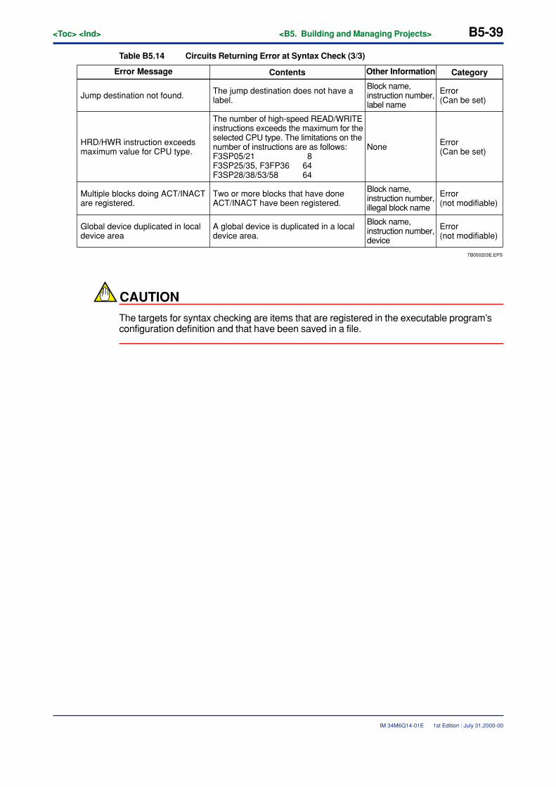
<Toc> <Ind> <B5. Building and Managing Projects> B5-39
IM 34M6Q14-01E
Table B5.14 Circuits Returning Error at Syntax Check (3/3)
TB050203E.EPS
Error Message CategoryOther InformationContents
Jump destination not found. The jump destination does not have a label.
Block name, instruction number, label name
Block name, instruction number, illegal block name
Error (Can be set)
Error (Can be set)
Error (not modifiable)
Error (not modifiable)
HRD/HWR instruction exceeds maximum value for CPU type.
The number of high-speed READ/WRITE instructions exceeds the maximum for the selected CPU type. The limitations on the number of instructions are as follows:F3SP05/21 8F3SP25/35, F3FP36 64F3SP28/38/53/58 64
None
Multiple blocks doing ACT/INACT are registered.
Two or more blocks that have done ACT/INACT have been registered.
Global device duplicated in local device area
A global device is duplicated in a local device area.
Block name, instruction number, device
CAUTION
The targets for syntax checking are items that are registered in the executable program’sconfiguration definition and that have been saved in a file.
1st Edition : July 31,2000-00
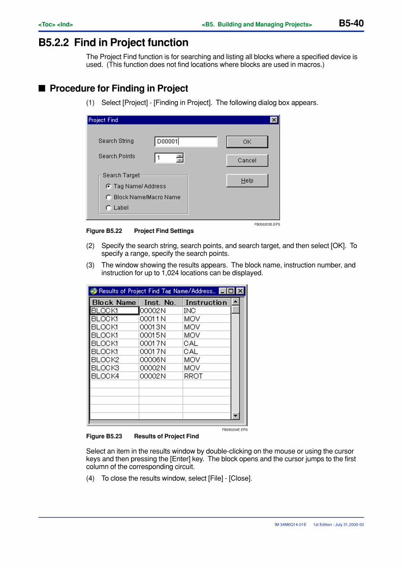
B5-40<Toc> <Ind> <B5. Building and Managing Projects>
IM 34M6Q14-01E
B5.2.2 Find in Project functionThe Project Find function is for searching and listing all blocks where a specified device isused. (This function does not find locations where blocks are used in macros.)
� Procedure for Finding in Project(1) Select [Project] - [Finding in Project]. The following dialog box appears.
FB050203E.EPS
Figure B5.22 Project Find Settings
(2) Specify the search string, search points, and search target, and then select [OK]. Tospecify a range, specify the search points.
(3) The window showing the results appears. The block name, instruction number, andinstruction for up to 1,024 locations can be displayed.
FB050204E.EPS
Figure B5.23 Results of Project Find
Select an item in the results window by double-clicking on the mouse or using the cursorkeys and then pressing the [Enter] key. The block opens and the cursor jumps to the firstcolumn of the corresponding circuit.
(4) To close the results window, select [File] - [Close].
1st Edition : July 31,2000-00

<Toc> <Ind> <B5. Building and Managing Projects> B5-41
IM 34M6Q14-01E
CAUTION
• The target blocks are those registered in the executable program’s configurationdefinition and saved in a file. Also, when blocks have been saved with errors, thecircuits where errors were found are not included as search targets.
• When labels are searched, the parameter section of the label instruction and thelocation of the label are displayed. For the location of the label definition, the instruc-tion number displayed is the first instruction number of the circuit at the location of thelabel definition, and the instruction is displayed as a blank.
1st Edition : July 31,2000-00
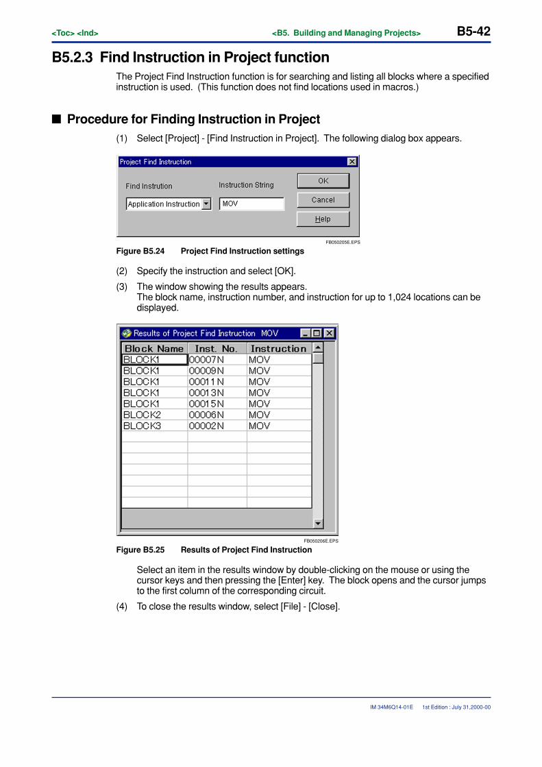
B5-42<Toc> <Ind> <B5. Building and Managing Projects>
IM 34M6Q14-01E
B5.2.3 Find Instruction in Project functionThe Project Find Instruction function is for searching and listing all blocks where a specifiedinstruction is used. (This function does not find locations used in macros.)
� Procedure for Finding Instruction in Project(1) Select [Project] - [Find Instruction in Project]. The following dialog box appears.
FB050205E.EPS
Figure B5.24 Project Find Instruction settings
(2) Specify the instruction and select [OK].
(3) The window showing the results appears.The block name, instruction number, and instruction for up to 1,024 locations can bedisplayed.
FB050206E.EPS
Figure B5.25 Results of Project Find Instruction
Select an item in the results window by double-clicking on the mouse or using thecursor keys and then pressing the [Enter] key. The block opens and the cursor jumpsto the first column of the corresponding circuit.
(4) To close the results window, select [File] - [Close].
1st Edition : July 31,2000-00

<Toc> <Ind> <B5. Building and Managing Projects> B5-43
IM 34M6Q14-01E
CAUTION
The target blocks are those registered in the executable program’s configuration definitionand saved in a file. Also, when blocks have been saved with errors, the circuits whereerrors were found are not included as search targets.
1st Edition : July 31,2000-00

B5-44<Toc> <Ind> <B5. Building and Managing Projects>
IM 34M6Q14-01E
B5.2.4 Replace in Project functionThe Replace in Project function is for replacing the tag name and address registered in theproject’s executable program.
This function is of 2 types, the Replace Address function and the Replace Tag Namefunction.
The Replace Address function replaces addresses and tag name definitions of all blocksregistered in the project’s executable program.
The Replace Tag Name function replaces names of tag names of all blocks registered inthe project’s executable program.
1st Edition : July 31,2000-00
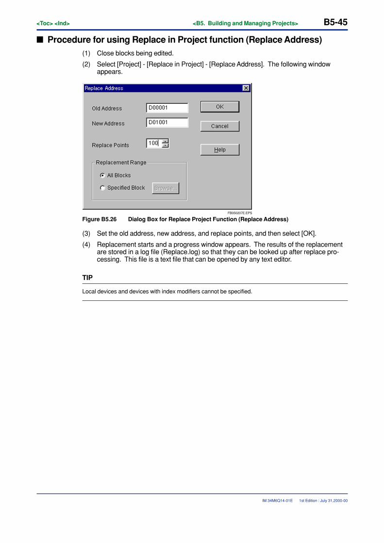
<Toc> <Ind> <B5. Building and Managing Projects> B5-45
IM 34M6Q14-01E
� Procedure for using Replace in Project function (Replace Address)(1) Close blocks being edited.
(2) Select [Project] - [Replace in Project] - [Replace Address]. The following windowappears.
FB050207E.EPS
Figure B5.26 Dialog Box for Replace Project Function (Replace Address)
(3) Set the old address, new address, and replace points, and then select [OK].
(4) Replacement starts and a progress window appears. The results of the replacementare stored in a log file (Replace.log) so that they can be looked up after replace pro-cessing. This file is a text file that can be opened by any text editor.
TIP
Local devices and devices with index modifiers cannot be specified.
1st Edition : July 31,2000-00
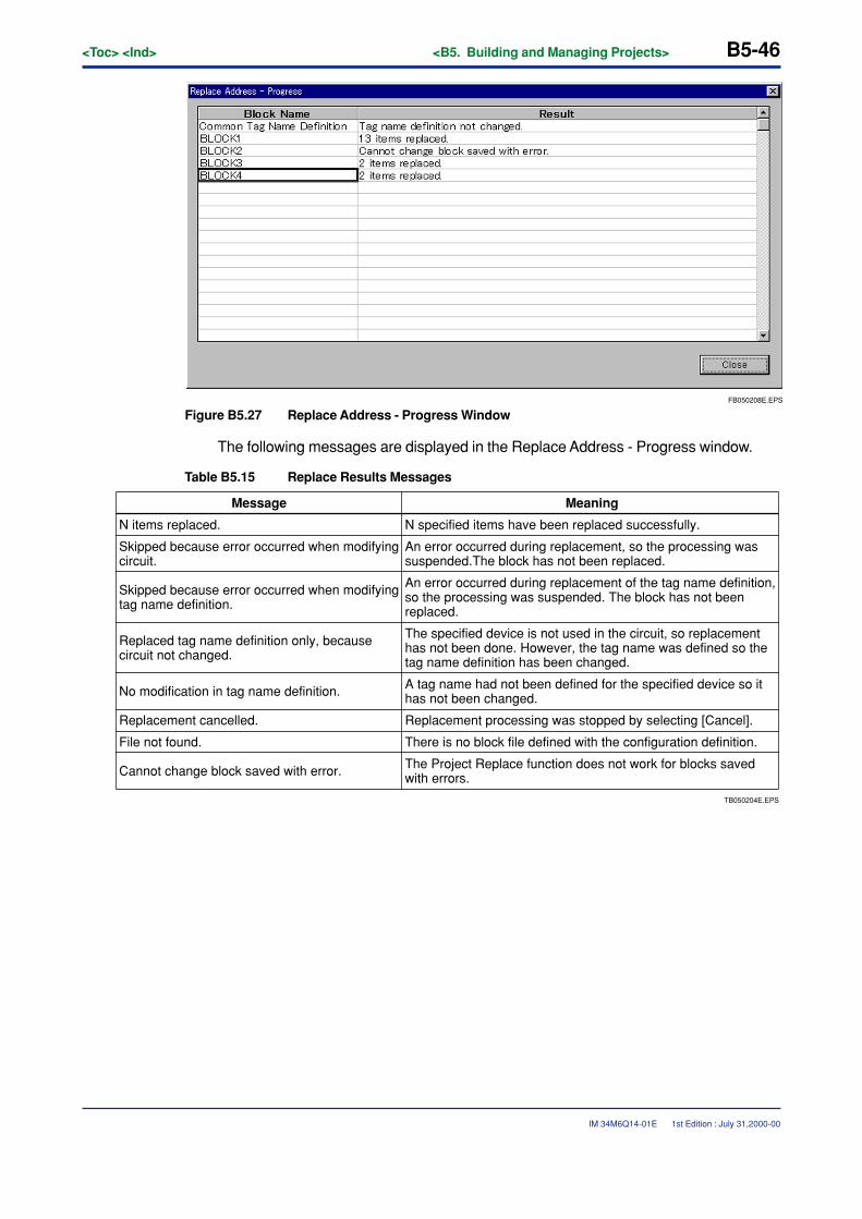
B5-46<Toc> <Ind> <B5. Building and Managing Projects>
IM 34M6Q14-01E
FB050208E.EPS
Figure B5.27 Replace Address - Progress Window
The following messages are displayed in the Replace Address - Progress window.
Table B5.15 Replace Results Messages
TB050204E.EPS
The Project Replace function does not work for blocks saved with errors.
Message Meaning
N items replaced. N specified items have been replaced successfully.
Skipped because error occurred when modifying circuit.
An error occurred during replacement, so the processing was suspended.The block has not been replaced.
Skipped because error occurred when modifying tag name definition.
An error occurred during replacement of the tag name definition, so the processing was suspended. The block has not been replaced.
Replaced tag name definition only, because circuit not changed.
The specified device is not used in the circuit, so replacement has not been done. However, the tag name was defined so the tag name definition has been changed.
No modification in tag name definition. A tag name had not been defined for the specified device so it has not been changed.
Replacement cancelled. Replacement processing was stopped by selecting [Cancel].
File not found. There is no block file defined with the configuration definition.
Cannot change block saved with error.
1st Edition : July 31,2000-00
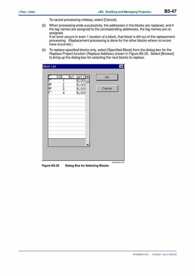
<Toc> <Ind> <B5. Building and Managing Projects> B5-47
IM 34M6Q14-01E
To cancel processing midway, select [Cancel].
(5) When processing ends successfully, the addresses in the blocks are replaced, and ifthe tag names are assigned to the corresponding addresses, the tag names are re-assigned.If an error occurs in even 1 location of a block, that block is left out of the replacementprocessing. (Replacement processing is done for the other blocks where no errorshave occurred.)
(6) To replace specified blocks only, select [Specified Block] from the dialog box for theReplace Project function (Replace Address) shown in Figure B5.26. Select [Browse]to bring up the dialog box for selecting the next blocks to replace.
FB050209E.EPS
Figure B5.28 Dialog Box for Selecting Blocks
1st Edition : July 31,2000-00
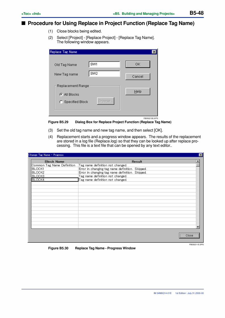
B5-48<Toc> <Ind> <B5. Building and Managing Projects>
IM 34M6Q14-01E
� Procedure for Using Replace in Project Function (Replace Tag Name)(1) Close blocks being edited.
(2) Select [Project] - [Replace Project] - [Replace Tag Name].The following window appears.
FB050210E.EPS
Figure B5.29 Dialog Box for Replace Project Function (Replace Tag Name)
(3) Set the old tag name and new tag name, and then select [OK].
(4) Replacement starts and a progress window appears. The results of the replacementare stored in a log file (Replace.log) so that they can be looked up after replace pro-cessing. This file is a text file that can be opened by any text editor..
FB050211E.EPS
Figure B5.30 Replace Tag Name - Progress Window
1st Edition : July 31,2000-00

<Toc> <Ind> <B5. Building and Managing Projects> B5-49
IM 34M6Q14-01E
Table B5.16 Replace Results Messages
TB050205E.EPS
Message Meaning
N items replaced. N specified tag names have been replaced successfully.
Skipped because error occurred when modifying tag name definition.
An error occurred during replacement, so the processing was suspended. The block has not been replaced.
Replacement cancelled. Replacement processing was stopped by selecting [Cancel].
File not found. There is no block file defined with the configuration definition.
To cancel processing midway, select [Cancel].
(5) When processing ends successfully, the tag names in the blocks are re-assigned.If an error occurs in even 1 location of a block, that block is left out of the replacementprocessing. (Replacement processing is done for the other blocks where no errorshave occurred.)
(6) To replace specified blocks only, select [Specified Block] from the dialog box for theReplace Project function (Replace Tag Name) shown in Figure B5.29. Select[Browse] to select the block.
1st Edition : July 31,2000-00
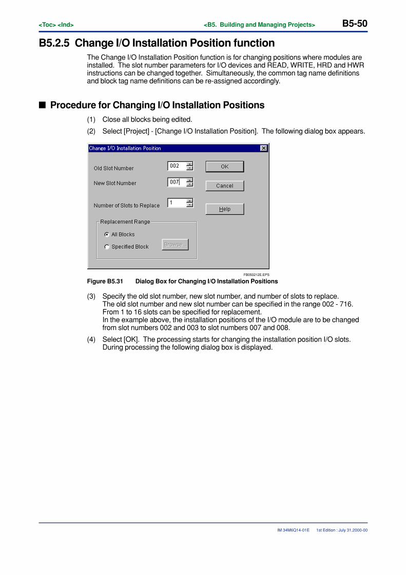
B5-50<Toc> <Ind> <B5. Building and Managing Projects>
IM 34M6Q14-01E
B5.2.5 Change I/O Installation Position functionThe Change I/O Installation Position function is for changing positions where modules areinstalled. The slot number parameters for I/O devices and READ, WRITE, HRD and HWRinstructions can be changed together. Simultaneously, the common tag name definitionsand block tag name definitions can be re-assigned accordingly.
� Procedure for Changing I/O Installation Positions(1) Close all blocks being edited.
(2) Select [Project] - [Change I/O Installation Position]. The following dialog box appears.
FB050212E.EPS
Figure B5.31 Dialog Box for Changing I/O Installation Positions
(3) Specify the old slot number, new slot number, and number of slots to replace.The old slot number and new slot number can be specified in the range 002 - 716.From 1 to 16 slots can be specified for replacement.In the example above, the installation positions of the I/O module are to be changedfrom slot numbers 002 and 003 to slot numbers 007 and 008.
(4) Select [OK]. The processing starts for changing the installation position I/O slots.During processing the following dialog box is displayed.
1st Edition : July 31,2000-00
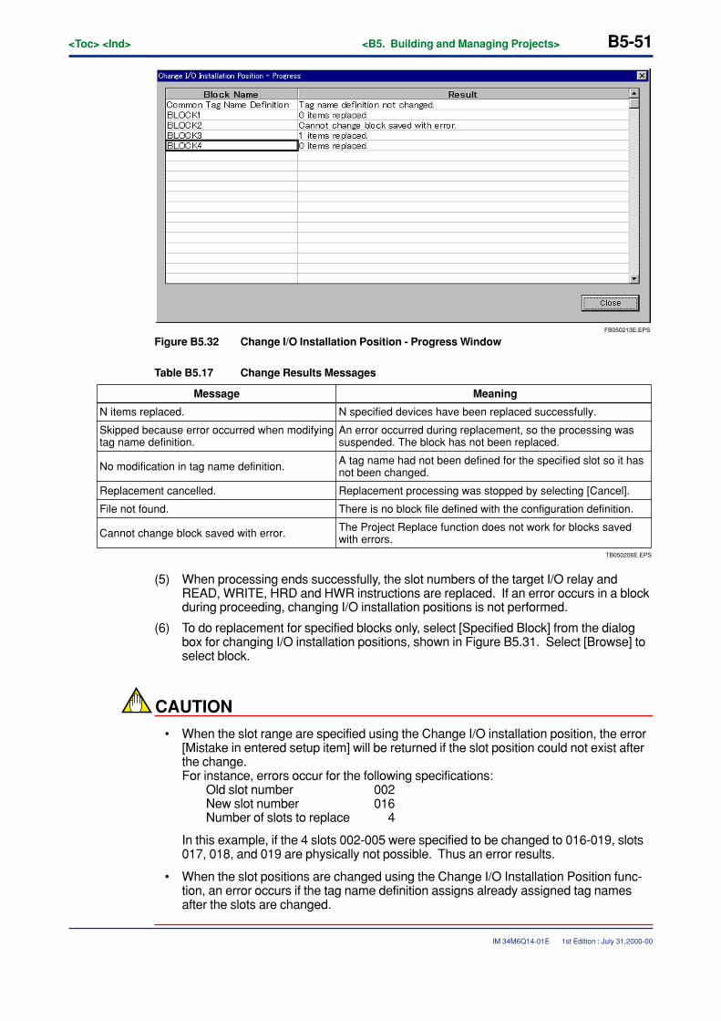
<Toc> <Ind> <B5. Building and Managing Projects> B5-51
IM 34M6Q14-01E
FB050213E.EPS
Figure B5.32 Change I/O Installation Position - Progress Window
Table B5.17 Change Results Messages
TB050206E.EPS
Message Meaning
N items replaced. N specified devices have been replaced successfully.
Skipped because error occurred when modifying tag name definition.
An error occurred during replacement, so the processing was suspended. The block has not been replaced.
No modification in tag name definition. A tag name had not been defined for the specified slot so it has not been changed.
Replacement cancelled. Replacement processing was stopped by selecting [Cancel].
File not found. There is no block file defined with the configuration definition.
Cannot change block saved with error. The Project Replace function does not work for blocks saved with errors.
(5) When processing ends successfully, the slot numbers of the target I/O relay andREAD, WRITE, HRD and HWR instructions are replaced. If an error occurs in a blockduring proceeding, changing I/O installation positions is not performed.
(6) To do replacement for specified blocks only, select [Specified Block] from the dialogbox for changing I/O installation positions, shown in Figure B5.31. Select [Browse] toselect block.
CAUTION
• When the slot range are specified using the Change I/O installation position, the error[Mistake in entered setup item] will be returned if the slot position could not exist afterthe change.For instance, errors occur for the following specifications:
Old slot number 002New slot number 016Number of slots to replace 4
In this example, if the 4 slots 002-005 were specified to be changed to 016-019, slots017, 018, and 019 are physically not possible. Thus an error results.
• When the slot positions are changed using the Change I/O Installation Position func-tion, an error occurs if the tag name definition assigns already assigned tag namesafter the slots are changed.
1st Edition : July 31,2000-00
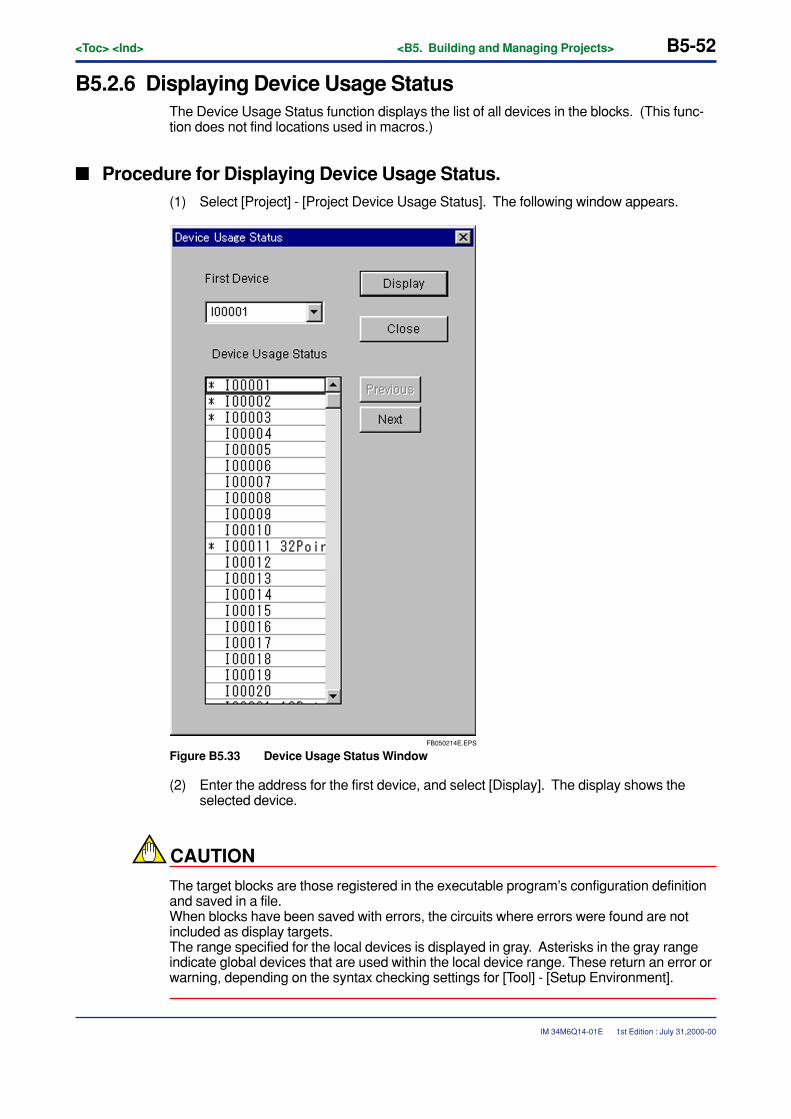
B5-52<Toc> <Ind> <B5. Building and Managing Projects>
IM 34M6Q14-01E
B5.2.6 Displaying Device Usage StatusThe Device Usage Status function displays the list of all devices in the blocks. (This func-tion does not find locations used in macros.)
� Procedure for Displaying Device Usage Status.(1) Select [Project] - [Project Device Usage Status]. The following window appears.
FB050214E.EPS
Figure B5.33 Device Usage Status Window
(2) Enter the address for the first device, and select [Display]. The display shows theselected device.
CAUTION
The target blocks are those registered in the executable program’s configuration definitionand saved in a file.When blocks have been saved with errors, the circuits where errors were found are notincluded as display targets.The range specified for the local devices is displayed in gray. Asterisks in the gray rangeindicate global devices that are used within the local device range. These return an error orwarning, depending on the syntax checking settings for [Tool] - [Setup Environment].
1st Edition : July 31,2000-00
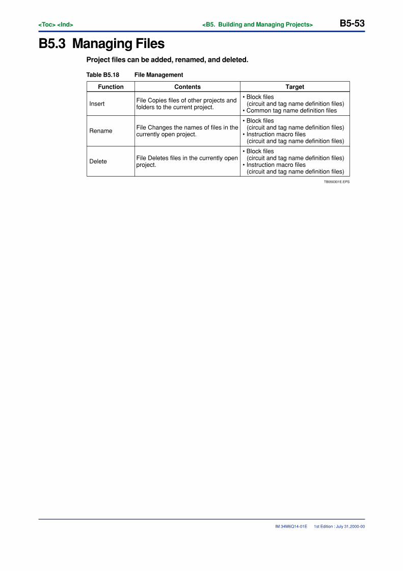
<Toc> <Ind> <B5. Building and Managing Projects> B5-53
IM 34M6Q14-01E
B5.3 Managing FilesProject files can be added, renamed, and deleted.
Table B5.18 File Management
TB050301E.EPS
File Deletes files in the currently open project.
Function TargetContents
• Block files (circuit and tag name definition files)
• Common tag name definition filesInsert File Copies files of other projects and
folders to the current project.
Rename File Changes the names of files in the currently open project.
• Block files (circuit and tag name definition files)
• Instruction macro files (circuit and tag name definition files)
• Block files (circuit and tag name definition files)
• Instruction macro files (circuit and tag name definition files)
Delete
1st Edition : July 31,2000-00
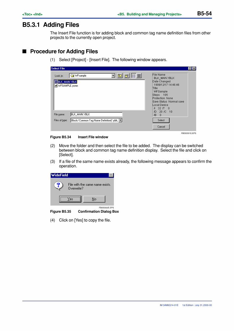
B5-54<Toc> <Ind> <B5. Building and Managing Projects>
IM 34M6Q14-01E
B5.3.1 Adding FilesThe Insert File function is for adding block and common tag name definition files from otherprojects to the currently open project.
� Procedure for Adding Files(1) Select [Project] - [Insert File]. The following window appears.
FB050301E.EPS
Figure B5.34 Insert File window
(2) Move the folder and then select the file to be added. The display can be switchedbetween block and common tag name definition display. Select the file and click on[Select].
(3) If a file of the same name exists already, the following message appears to confirm theoperation.
FB050302E.EPS
Figure B5.35 Confirmation Dialog Box
(4) Click on [Yes] to copy the file.
1st Edition : July 31,2000-00
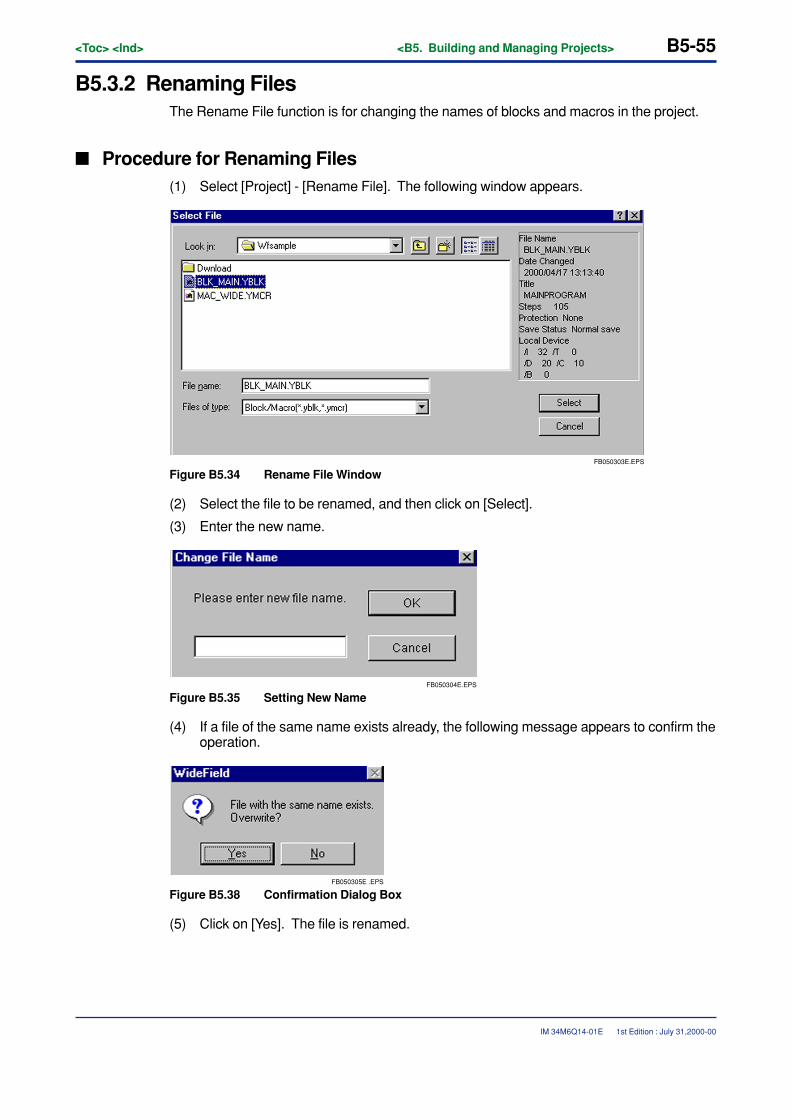
<Toc> <Ind> <B5. Building and Managing Projects> B5-55
IM 34M6Q14-01E
B5.3.2 Renaming FilesThe Rename File function is for changing the names of blocks and macros in the project.
� Procedure for Renaming Files(1) Select [Project] - [Rename File]. The following window appears.
FB050303E.EPS
Figure B5.34 Rename File Window
(2) Select the file to be renamed, and then click on [Select].
(3) Enter the new name.
FB050304E.EPS
Figure B5.35 Setting New Name
(4) If a file of the same name exists already, the following message appears to confirm theoperation.
FB050305E .EPS
Figure B5.38 Confirmation Dialog Box
(5) Click on [Yes]. The file is renamed.
1st Edition : July 31,2000-00
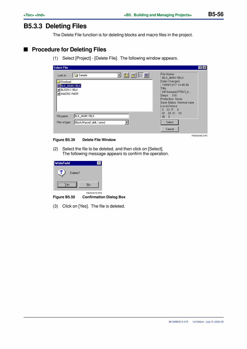
B5-56<Toc> <Ind> <B5. Building and Managing Projects>
IM 34M6Q14-01E
B5.3.3 Deleting FilesThe Delete File function is for deleting blocks and macro files in the project.
� Procedure for Deleting Files(1) Select [Project] - [Delete File]. The following window appears.
FB050306E.EPS
Figure B5.39 Delete File Window
(2) Select the file to be deleted, and then click on [Select].The following message appears to confirm the operation.
FB050307E.EPS
Figure B5.50 Confirmation Dialog Box
(3) Click on [Yes]. The file is deleted.
1st Edition : July 31,2000-00
<Toc> <Ind> <B6. PRINTOUT> B6-1
IM 34M6Q14-01E
B6. PRINTOUTThis chapter describes how to print out the display information of the programscreated with WideField, and how to print out the screens.
The Print function supports printout of screens currently displayed (Print Screen)and projects (Print Project).
� Print Screen
This function prints out the WideField screen displayed in front. The screens that can beprinted are as follows:
• Block and macro edit screens
• System log and user log display screens
• Group template edit screens
• Circuit monitor screens
• Alarm monitor screens
� Print Project
All types of data (for program configuration, blocks, user logs, common tag name defini-tions, and so forth) making up the project can be batch-printed.
Before printing out from WideField, do the printer settings, printing layout settings anddetailed printing settings as required.
� Printer Settings
Set the printer name, paper size, and paper orientation.
� Printing Layout Settings
Set the layout items such as margins.
� Detailed Printing Settings
Set the additional information (such as cross-references and tag name definitions) for whenprinting out circuits, and the cover font, header, and footer items.
1st Edition : July 31,2000-00
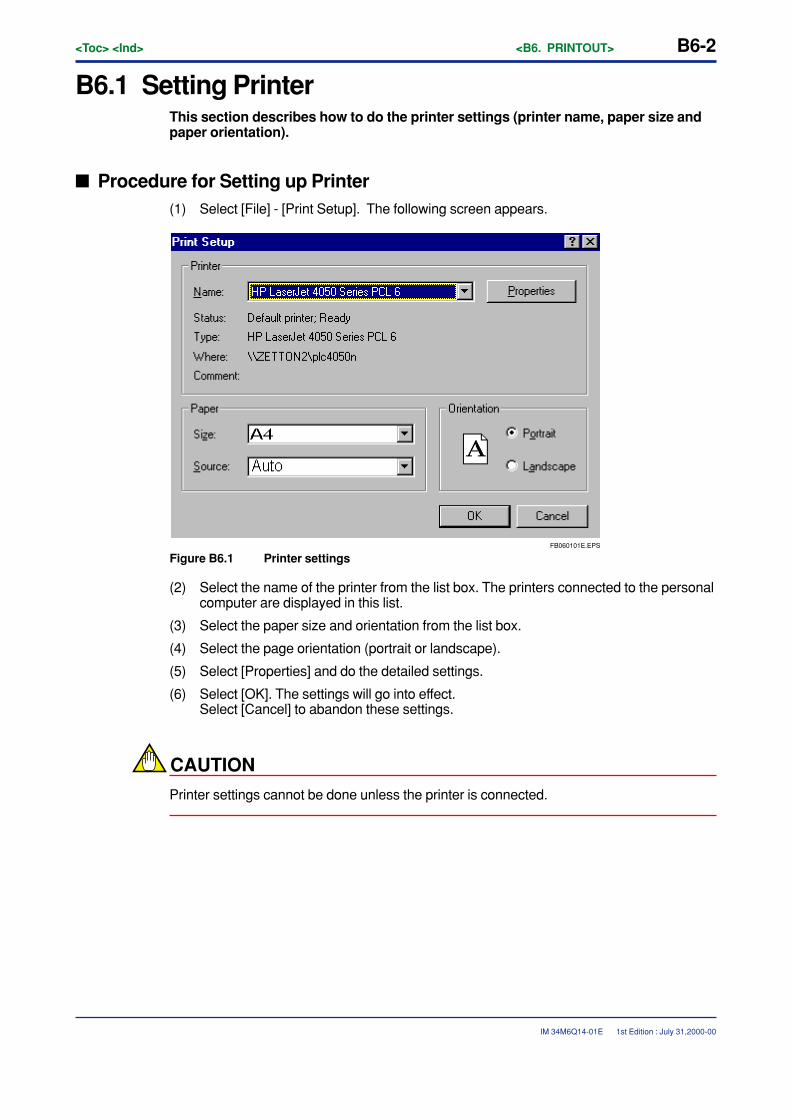
B6-2<Toc> <Ind> <B6. PRINTOUT>
IM 34M6Q14-01E
B6.1 Setting PrinterThis section describes how to do the printer settings (printer name, paper size andpaper orientation).
� Procedure for Setting up Printer(1) Select [File] - [Print Setup]. The following screen appears.
FB060101E.EPS
Figure B6.1 Printer settings
(2) Select the name of the printer from the list box. The printers connected to the personalcomputer are displayed in this list.
(3) Select the paper size and orientation from the list box.
(4) Select the page orientation (portrait or landscape).
(5) Select [Properties] and do the detailed settings.
(6) Select [OK]. The settings will go into effect.Select [Cancel] to abandon these settings.
CAUTION
Printer settings cannot be done unless the printer is connected.
1st Edition : July 31,2000-00
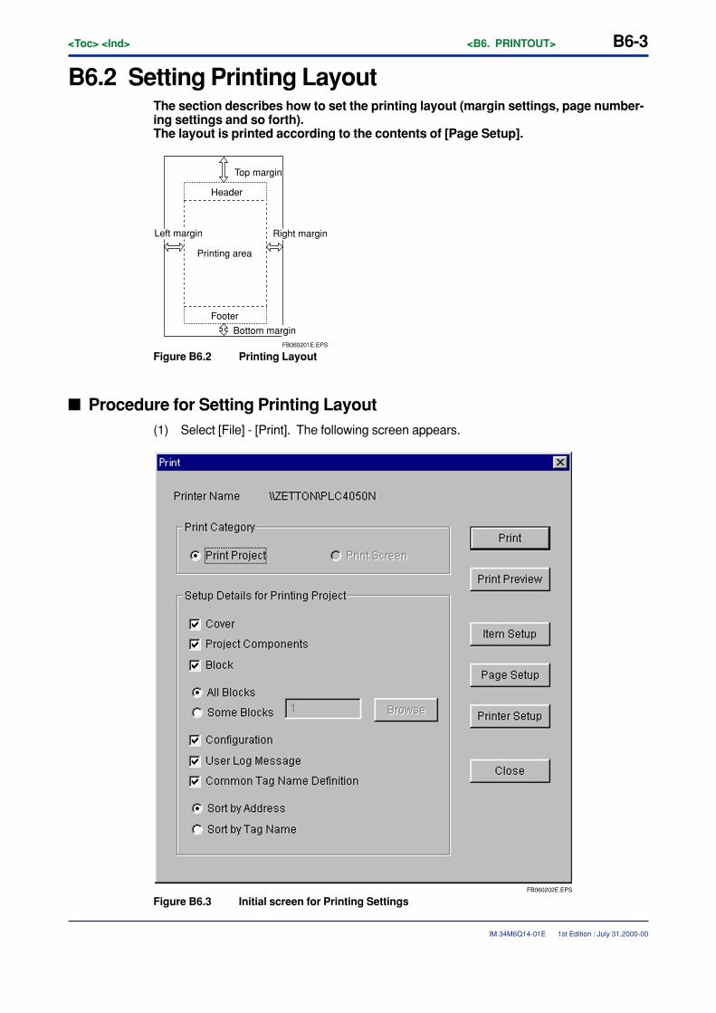
<Toc> <Ind> <B6. PRINTOUT> B6-3
IM 34M6Q14-01E 1st Edition : July 31,2000-00
B6.2 Setting Printing LayoutThe section describes how to set the printing layout (margin settings, page number-ing settings and so forth).The layout is printed according to the contents of [Page Setup].
Top margin
Printing area
Header
Footer
FB060201E.EPS
Left margin Right margin
Bottom margin
Figure B6.2 Printing Layout
� Procedure for Setting Printing Layout(1) Select [File] - [Print]. The following screen appears.
FB060202E.EPS
Figure B6.3 Initial screen for Printing Settings
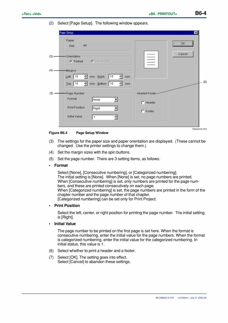
B6-4<Toc> <Ind> <B6. PRINTOUT>
IM 34M6Q14-01E
(2) Select [Page Setup]. The following window appears.
FB060203E.EPS
(6)
(3)
(4)
(5)
Figure B6.4 Page Setup Window
(3) The settings for the paper size and paper orientation are displayed. (These cannot bechanged. Use the printer settings to change them.)
(4) Set the margin sizes with the spin buttons.
(5) Set the page number. There are 3 setting items, as follows:
• Format
Select [None], [Consecutive numbering], or [Categorized numbering].The initial setting is [None]. When [None] is set, no page numbers are printed.When [Consecutive numbering] is set, only numbers are printed for the page num-bers, and these are printed consecutively on each page.When [Categorized numbering] is set, the page numbers are printed in the form of thechapter number and the page number of that chapter.[Categorized numbering] can be set only for Print Project.
• Print Position
Select the left, center, or right position for printing the page number. The initial settingis [Right].
• Initial Value
The page number to be printed on the first page is set here. When the format isconsecutive numbering, enter the initial value for the page numbers. When the formatis categorized numbering, enter the initial value for the categorized numbering. Ininitial status, this value is 1.
(6) Select whether to print a header and a footer.
(7) Select [OK]. The setting goes into effect.Select [Cancel] to abandon these settings.
1st Edition : July 31,2000-00
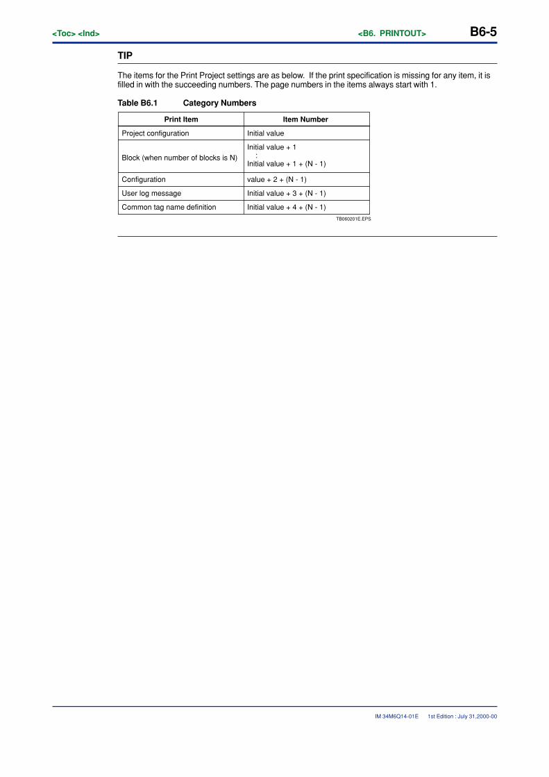
<Toc> <Ind> <B6. PRINTOUT> B6-5
IM 34M6Q14-01E
TIP
The items for the Print Project settings are as below. If the print specification is missing for any item, it isfilled in with the succeeding numbers. The page numbers in the items always start with 1.
Table B6.1 Category Numbers
Project configuration
Block (when number of blocks is N)
Configuration
User log message
Common tag name definition
Item Number
Initial value
Initial value + 1 :Initial value + 1 + (N - 1)
value + 2 + (N - 1)
Initial value + 3 + (N - 1)
Initial value + 4 + (N - 1)
Print Item
TB060201E.EPS
1st Edition : July 31,2000-00
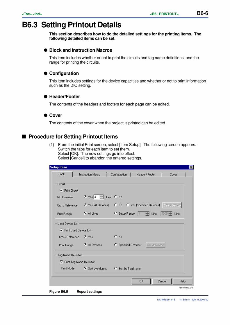
B6-6<Toc> <Ind> <B6. PRINTOUT>
IM 34M6Q14-01E
B6.3 Setting Printout DetailsThis section describes how to do the detailed settings for the printing items. Thefollowing detailed items can be set.
� Block and Instruction Macros
This item includes whether or not to print the circuits and tag name definitions, and therange for printing the circuits.
� Configuration
This item includes settings for the device capacities and whether or not to print informationsuch as the DIO setting.
� Header/Footer
The contents of the headers and footers for each page can be edited.
� Cover
The contents of the cover when the project is printed can be edited.
� Procedure for Setting Printout Items(1) From the initial Print screen, select [Item Setup]. The following screen appears.
Switch the tabs for each item to set them.Select [OK]. The new settings go into effect.Select [Cancel] to abandon the entered settings.
FB060301E.EPS
Figure B6.5 Report settings
1st Edition : July 31,2000-00
<Toc> <Ind> <B6. PRINTOUT> B6-7
IM 34M6Q14-01E
B6.3.1 Setting Details for Blocks and Instruction MacrosDetailed items can be set for the blocks and instruction macros.These items are circuit print settings, settings for printing the list of devices used by thecircuit, and settings for printing tag name definitions.
� Procedure for Setting Details for Blocks and Instruction Macros(1) To set blocks, click on the block tab.
To set instruction macros, click on the instruction macro tab.The window shown in Figure 6.5 appears.
(2) To print a circuit, select [Print Circuit].The detailed settings for circuits are as follows:
• I/O Comment Settings
This item is for selecting whether or not to print the I/O comment under a device. For[Yes], the number of lines to be printed can be set in the range of 1 to 4.Initial status is [Yes] and 4 lines can be printed.
• Cross-reference Settings
The cross-reference function shows the places in the program where the device usedby the circuit is used.The places where it is used are printed out as a list (block name, instruction numberand instruction).Select from [Yes (All Devices)], [No], and [Yes (Specified Devices)] for the cross-reference which is printed under the circuit.When [Yes (Specified Devices)] is selected click on [Setup Devices]. The followingwindow appears for selecting the device type for printing the cross-reference.
1st Edition : July 31,2000-00
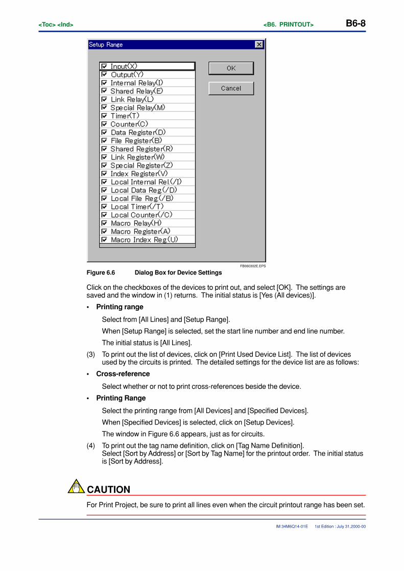
B6-8<Toc> <Ind> <B6. PRINTOUT>
IM 34M6Q14-01E
FB060302E.EPS
Figure 6.6 Dialog Box for Device Settings
Click on the checkboxes of the devices to print out, and select [OK]. The settings aresaved and the window in (1) returns. The initial status is [Yes (All devices)].
• Printing range
Select from [All Lines] and [Setup Range].
When [Setup Range] is selected, set the start line number and end line number.
The initial status is [All Lines].
(3) To print out the list of devices, click on [Print Used Device List]. The list of devicesused by the circuits is printed. The detailed settings for the device list are as follows:
• Cross-reference
Select whether or not to print cross-references beside the device.
• Printing Range
Select the printing range from [All Devices] and [Specified Devices].
When [Specified Devices] is selected, click on [Setup Devices].
The window in Figure 6.6 appears, just as for circuits.
(4) To print out the tag name definition, click on [Tag Name Definition].Select [Sort by Address] or [Sort by Tag Name] for the printout order. The initial statusis [Sort by Address].
CAUTION
For Print Project, be sure to print all lines even when the circuit printout range has been set.
1st Edition : July 31,2000-00
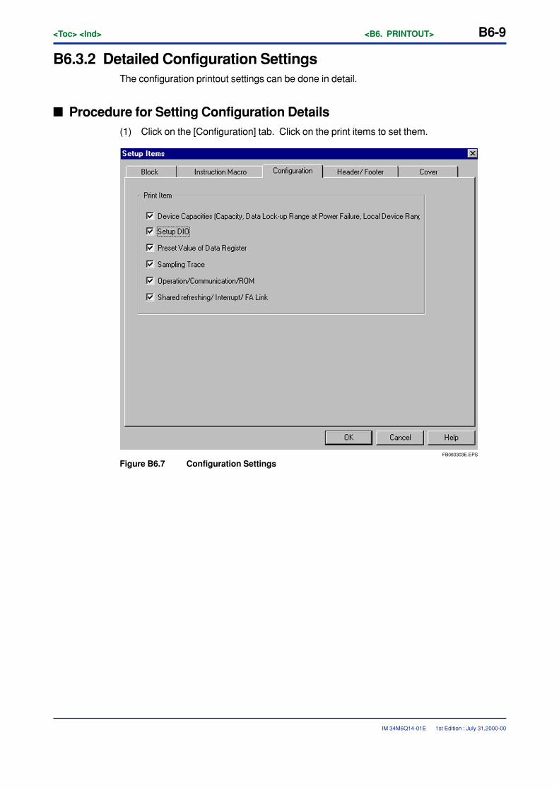
<Toc> <Ind> <B6. PRINTOUT> B6-9
IM 34M6Q14-01E
B6.3.2 Detailed Configuration SettingsThe configuration printout settings can be done in detail.
� Procedure for Setting Configuration Details(1) Click on the [Configuration] tab. Click on the print items to set them.
FB060303E.EPS
Figure B6.7 Configuration Settings
1st Edition : July 31,2000-00
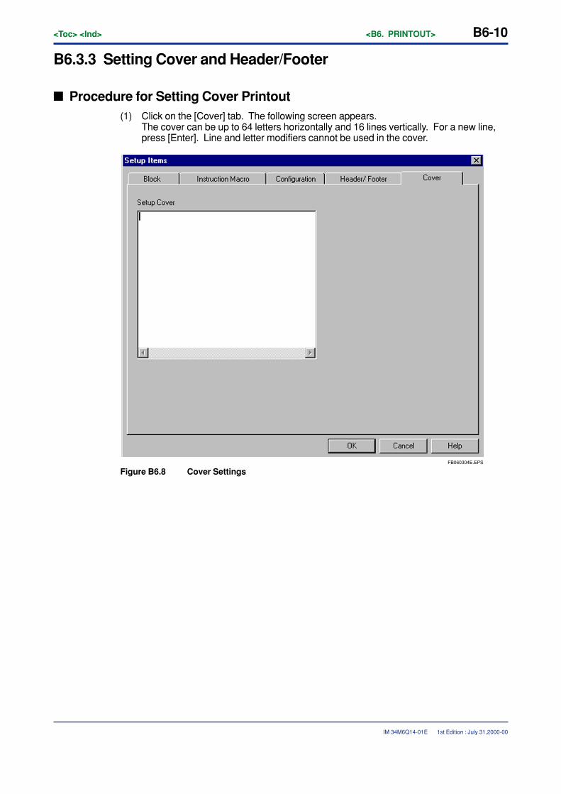
B6-10<Toc> <Ind> <B6. PRINTOUT>
IM 34M6Q14-01E
B6.3.3 Setting Cover and Header/Footer
� Procedure for Setting Cover Printout(1) Click on the [Cover] tab. The following screen appears.
The cover can be up to 64 letters horizontally and 16 lines vertically. For a new line,press [Enter]. Line and letter modifiers cannot be used in the cover.
FB060304E.EPS
Figure B6.8 Cover Settings
1st Edition : July 31,2000-00
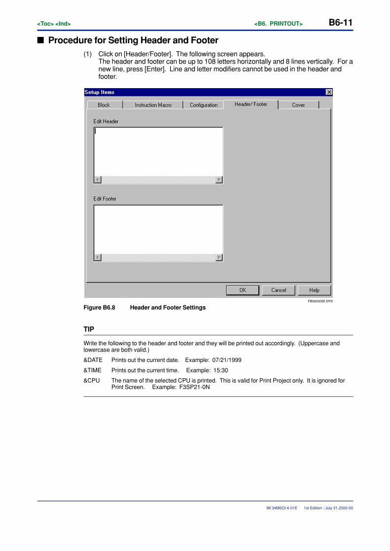
<Toc> <Ind> <B6. PRINTOUT> B6-11
IM 34M6Q14-01E
� Procedure for Setting Header and Footer(1) Click on [Header/Footer]. The following screen appears.
The header and footer can be up to 108 letters horizontally and 8 lines vertically. For anew line, press [Enter]. Line and letter modifiers cannot be used in the header andfooter.
FB060305E.EPS
Figure B6.8 Header and Footer Settings
TIP
Write the following to the header and footer and they will be printed out accordingly. (Uppercase andlowercase are both valid.)
&DATE Prints out the current date. Example: 07/21/1999
&TIME Prints out the current time. Example: 15:30
&CPU The name of the selected CPU is printed. This is valid for Print Project only. It is ignored forPrint Screen. Example: F3SP21-0N
1st Edition : July 31,2000-00
B6-12<Toc> <Ind> <B6. PRINTOUT>
IM 34M6Q14-01E
B6.4 Print and Print PreviewThis section describes the Print and Print Preview functions. The Print functionconsists of the Print Project function and the Print Screen function.
B6.4.1 Print ScreenThe Print Screen function prints out the following screens.
Table B6.2 Print Screen Function
TB060401E.EPS
Prints the circuits and tag name definitions of the monitor screen. Blocks and instruction macros can be printed.
Screen Details
Edit Block screen Prints the circuits and tag name definitions of the block being edited. Items that have been converted are printed.
Edit Macro screen Prints the circuits and tag name definitions of the instruction macro being edited. Items that have been converted are printed.
Display System Log screen Prints the system log being displayed. The log can be read from the file or from the CPU.
Display User Log screen Prints the user log being displayed. The log can be read from the file or from the CPU.
Edit Group Template screen Prints the group template being edited.
Alarm Monitor screen Prints the alarm monitor currently being displayed.
Circuit Monitor screen
1st Edition : July 31,2000-00
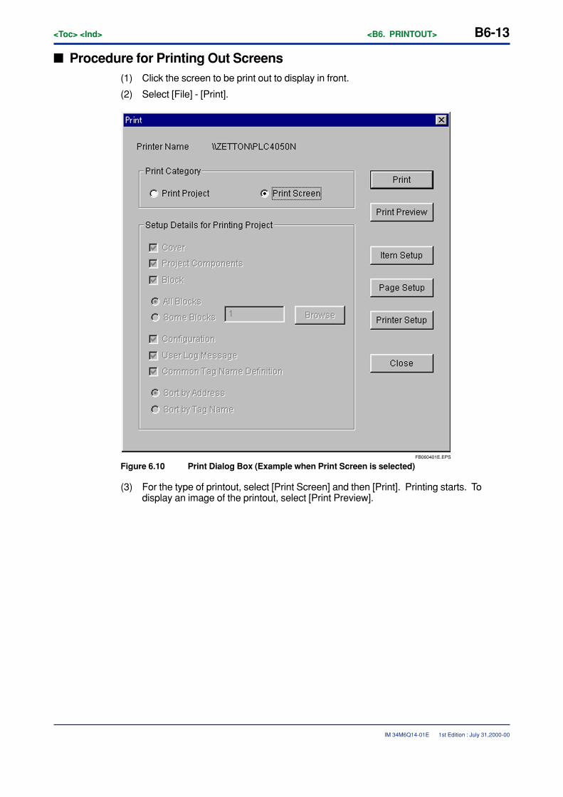
<Toc> <Ind> <B6. PRINTOUT> B6-13
IM 34M6Q14-01E
� Procedure for Printing Out Screens(1) Click the screen to be print out to display in front.
(2) Select [File] - [Print].
FB060401E.EPS
Figure 6.10 Print Dialog Box (Example when Print Screen is selected)
(3) For the type of printout, select [Print Screen] and then [Print]. Printing starts. Todisplay an image of the printout, select [Print Preview].
1st Edition : July 31,2000-00
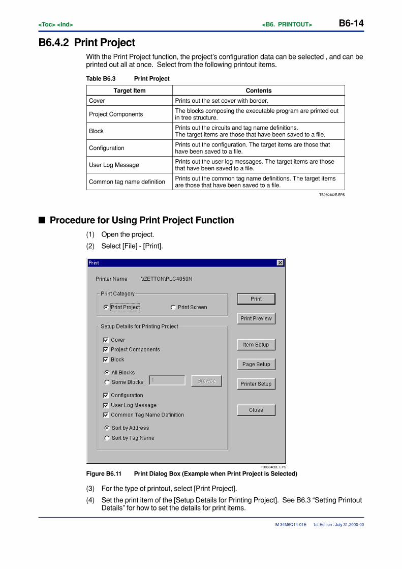
B6-14<Toc> <Ind> <B6. PRINTOUT>
IM 34M6Q14-01E
B6.4.2 Print ProjectWith the Print Project function, the project’s configuration data can be selected , and can beprinted out all at once. Select from the following printout items.
Table B6.3 Print Project
TB060402E.EPS
Prints out the common tag name definitions. The target items are those that have been saved to a file.
Target Item Contents
Cover Prints out the set cover with border.
Project Components The blocks composing the executable program are printed out in tree structure.
Block Prints out the circuits and tag name definitions. The target items are those that have been saved to a file.
Configuration Prints out the configuration. The target items are those that have been saved to a file.
User Log Message Prints out the user log messages. The target items are those that have been saved to a file.
Common tag name definition
� Procedure for Using Print Project Function(1) Open the project.
(2) Select [File] - [Print].
FB060402E.EPS
Figure B6.11 Print Dialog Box (Example when Print Project is Selected)
(3) For the type of printout, select [Print Project].
(4) Set the print item of the [Setup Details for Printing Project]. See B6.3 “Setting PrintoutDetails” for how to set the details for print items.
1st Edition : July 31,2000-00
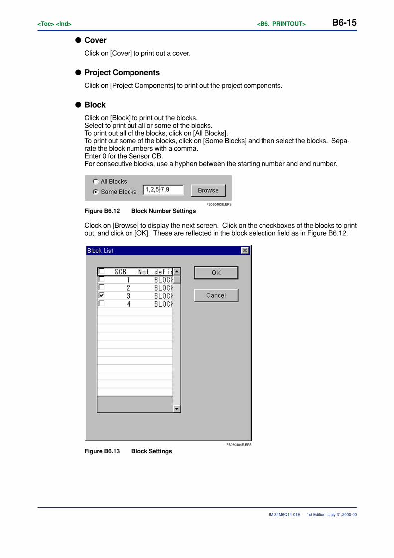
<Toc> <Ind> <B6. PRINTOUT> B6-15
IM 34M6Q14-01E
� Cover
Click on [Cover] to print out a cover.
� Project Components
Click on [Project Components] to print out the project components.
� Block
Click on [Block] to print out the blocks.Select to print out all or some of the blocks.To print out all of the blocks, click on [All Blocks].To print out some of the blocks, click on [Some Blocks] and then select the blocks. Sepa-rate the block numbers with a comma.Enter 0 for the Sensor CB.For consecutive blocks, use a hyphen between the starting number and end number.
FB060403E.EPS
Figure B6.12 Block Number Settings
Clock on [Browse] to display the next screen. Click on the checkboxes of the blocks to printout, and click on [OK]. These are reflected in the block selection field as in Figure B6.12.
FB060404E.EPS
Figure B6.13 Block Settings
1st Edition : July 31,2000-00
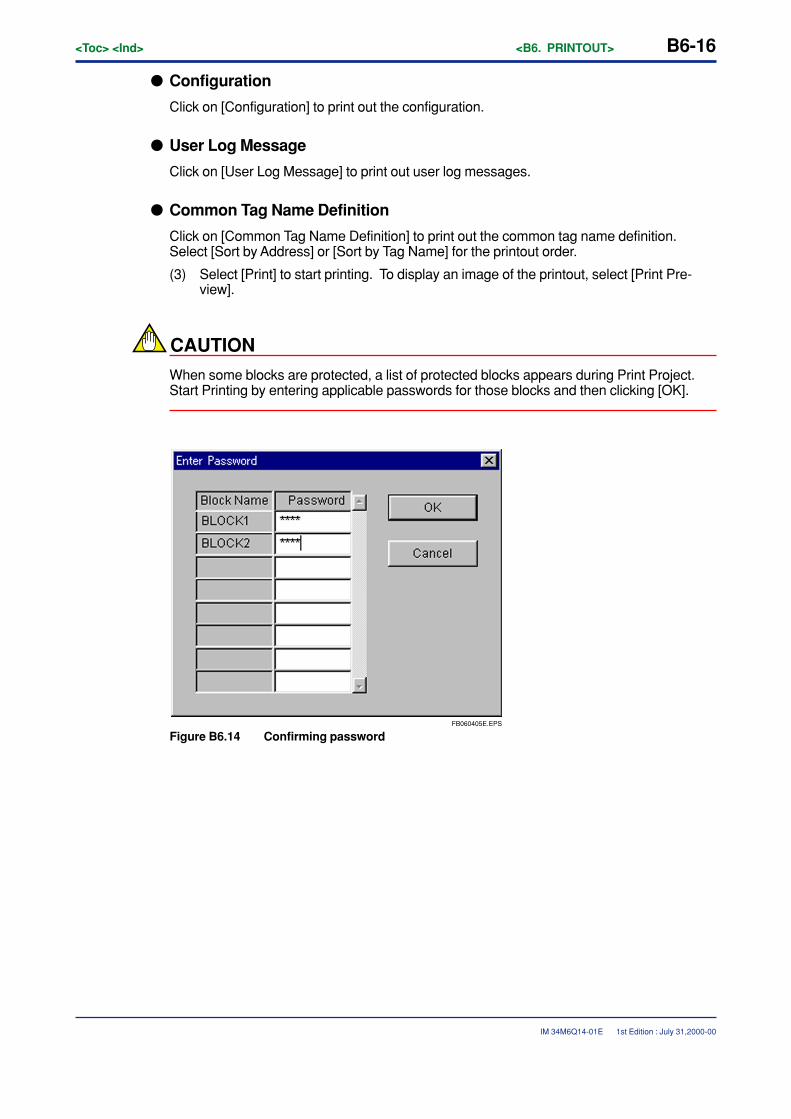
B6-16<Toc> <Ind> <B6. PRINTOUT>
IM 34M6Q14-01E
� Configuration
Click on [Configuration] to print out the configuration.
� User Log Message
Click on [User Log Message] to print out user log messages.
� Common Tag Name Definition
Click on [Common Tag Name Definition] to print out the common tag name definition.Select [Sort by Address] or [Sort by Tag Name] for the printout order.
(3) Select [Print] to start printing. To display an image of the printout, select [Print Pre-view].
CAUTION
When some blocks are protected, a list of protected blocks appears during Print Project.Start Printing by entering applicable passwords for those blocks and then clicking [OK].
FB060405E.EPS
Figure B6.14 Confirming password
1st Edition : July 31,2000-00
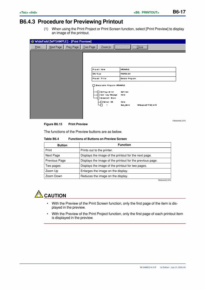
<Toc> <Ind> <B6. PRINTOUT> B6-17
IM 34M6Q14-01E
B6.4.3 Procedure for Previewing Printout(1) When using the Print Project or Print Screen function, select [Print Preview] to display
an image of the printout.
FB060406E.EPS
Figure B6.15 Print Preview
The functions of the Preview buttons are as below.
Table B6.4 Functions of Buttons on Preview Screen
TB060403E.EPS
Zoom Down
Button Function
Print Prints out to the printer.
Next Page Displays the image of the printout for the next page.
Previous Page Displays the image of the printout for the previous page.
Two pages Displays the image of the printout for two pages.
Zoom Up Enlarges the image on the display.
Reduces the image on the display.
CAUTION
• With the Preview of the Print Screen function, only the first page of the item is dis-played in the preview.
• With the Preview of the Print Project function, only the first page of each printout itemis displayed in the preview.
1st Edition : July 31,2000-00
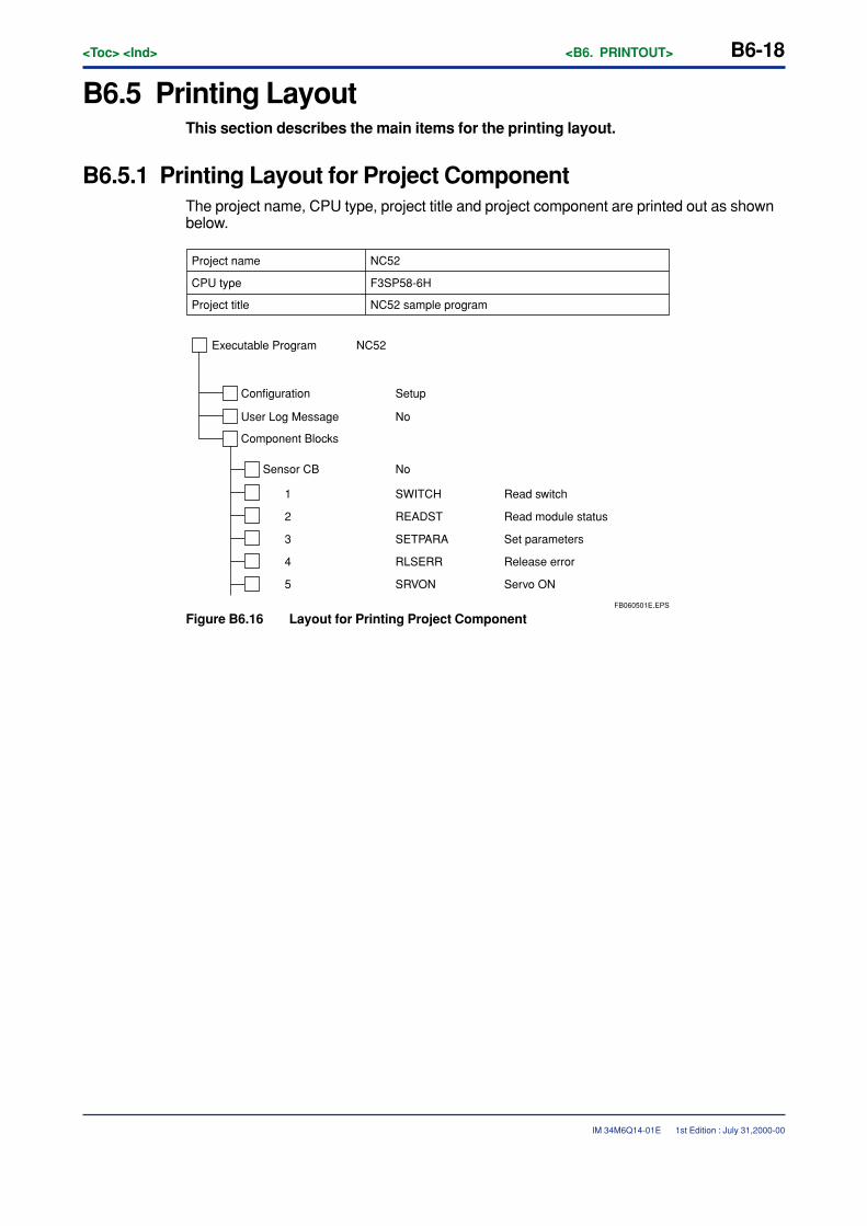
B6-18<Toc> <Ind> <B6. PRINTOUT>
IM 34M6Q14-01E
B6.5 Printing LayoutThis section describes the main items for the printing layout.
B6.5.1 Printing Layout for Project ComponentThe project name, CPU type, project title and project component are printed out as shownbelow.
FB060501E.EPS
Project name
Executable Program NC52
Configuration Setup
User Log Message No
Component Blocks
Sensor CB No
1 SWITCH Read switch
2 READST Read module status
3 SETPARA Set parameters
4 RLSERR Release error
5 SRVON Servo ON
CPU type
Project title
NC52
F3SP58-6H
NC52 sample program
Figure B6.16 Layout for Printing Project Component
1st Edition : July 31,2000-00
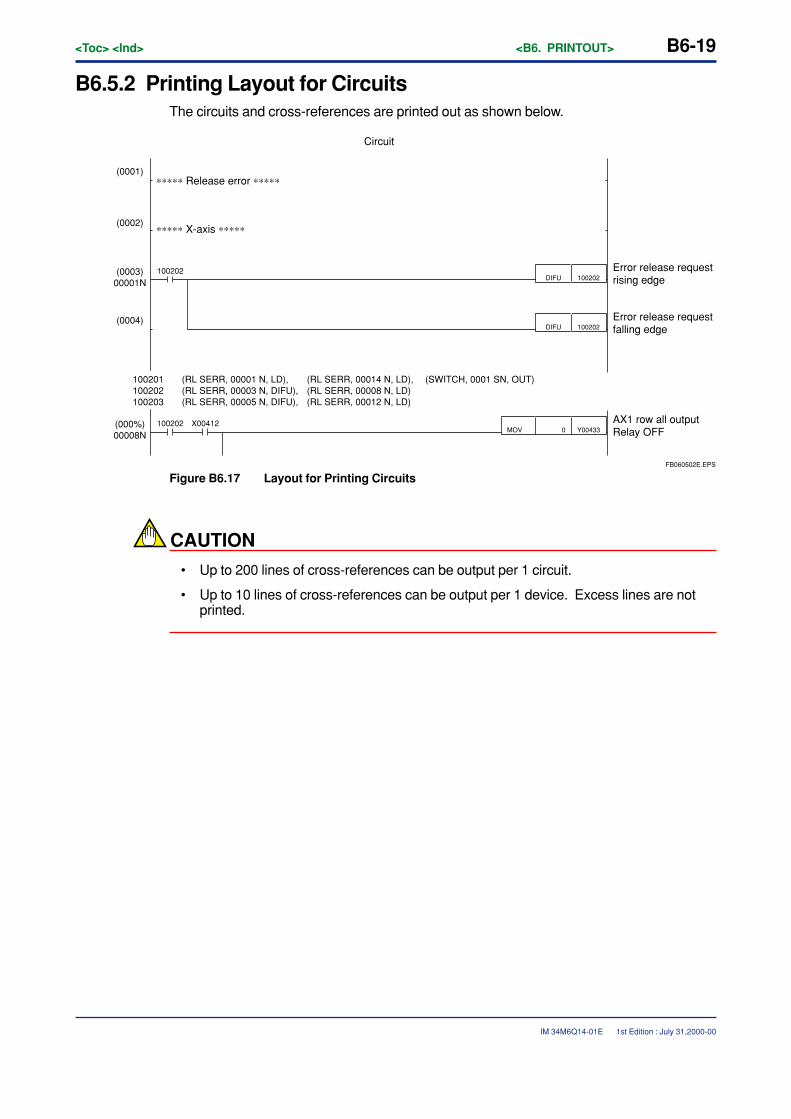
<Toc> <Ind> <B6. PRINTOUT> B6-19
IM 34M6Q14-01E
B6.5.2 Printing Layout for CircuitsThe circuits and cross-references are printed out as shown below.
FB060502E.EPS
DIFU 100202
DIFU 100202
0 Y00433MOV100202
100202
(000%)00008N
(0004)
(0003)00001N
(0002)
(0001)
X00412
100201 (RL SERR, 00001 N, LD), (RL SERR, 00014 N, LD), (SWITCH, 0001 SN, OUT)100202 (RL SERR, 00003 N, DIFU), (RL SERR, 00008 N, LD)100203 (RL SERR, 00005 N, DIFU), (RL SERR, 00012 N, LD)
Error release request rising edge
Error release request falling edge
AX1 row all outputRelay OFF
∗∗∗∗∗ Release error ∗∗∗∗∗
∗∗∗∗∗ X-axis ∗∗∗∗∗
Circuit
Figure B6.17 Layout for Printing Circuits
CAUTION
• Up to 200 lines of cross-references can be output per 1 circuit.
• Up to 10 lines of cross-references can be output per 1 device. Excess lines are notprinted.
1st Edition : July 31,2000-00
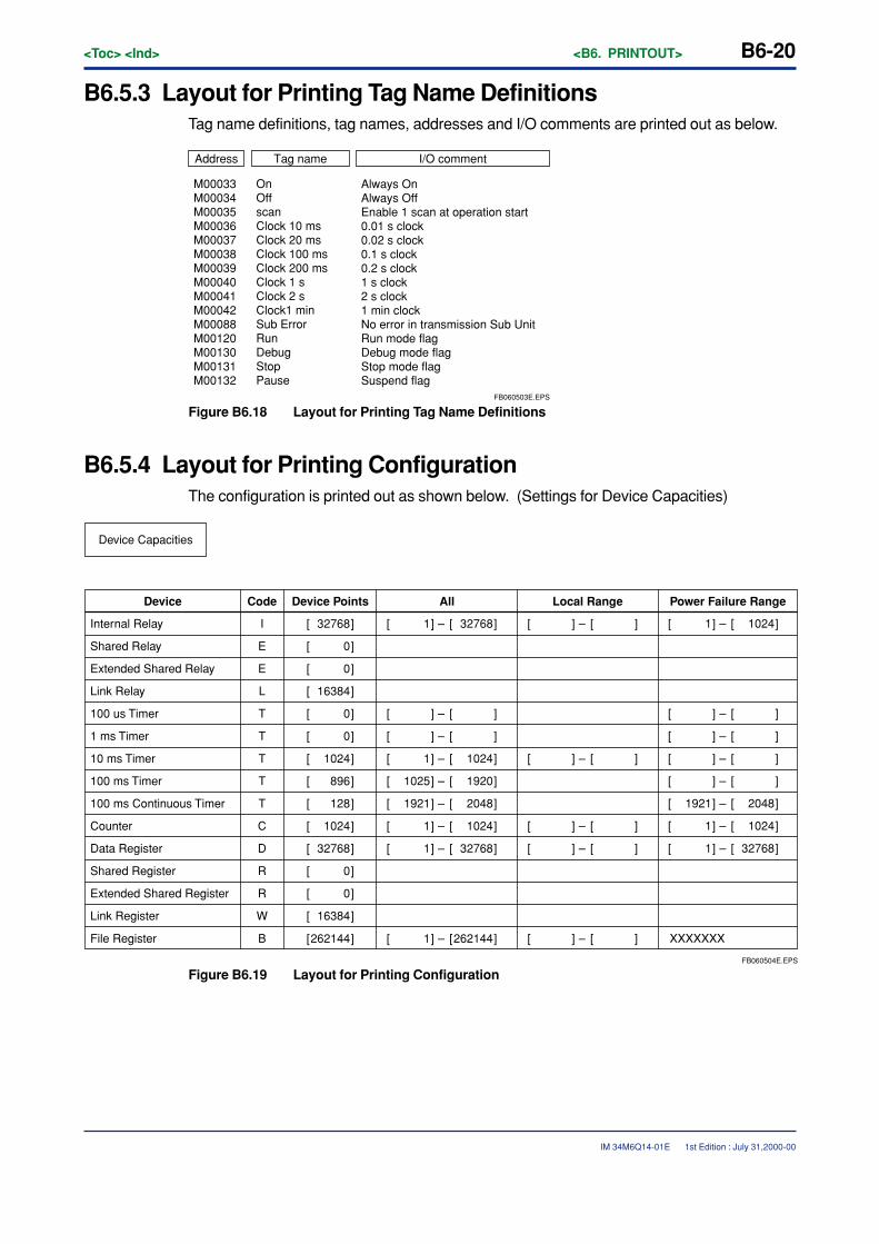
B6-20<Toc> <Ind> <B6. PRINTOUT>
IM 34M6Q14-01E
B6.5.3 Layout for Printing Tag Name DefinitionsTag name definitions, tag names, addresses and I/O comments are printed out as below.
FB060503E.EPS
Always On Always OffEnable 1 scan at operation start0.01 s clock0.02 s clock0.1 s clock0.2 s clock1 s clock2 s clock1 min clockNo error in transmission Sub UnitRun mode flagDebug mode flagStop mode flagSuspend flag
Address Tag name I/O comment
M00033M00034M00035M00036M00037M00038M00039M00040M00041M00042M00088M00120M00130M00131M00132
OnOffscanClock 10 msClock 20 msClock 100 msClock 200 msClock 1 sClock 2 sClock1 minSub ErrorRunDebugStopPause
Figure B6.18 Layout for Printing Tag Name Definitions
B6.5.4 Layout for Printing ConfigurationThe configuration is printed out as shown below. (Settings for Device Capacities)
FB060504E.EPS
Device Capacities
Device
Internal Relay
Shared Relay
Extended Shared Relay
Link Relay
100 us Timer
1 ms Timer
10 ms Timer
100 ms Timer
100 ms Continuous Timer
Counter
Data Register
Shared Register
Extended Shared Register
Link Register
I
E
E
L
T
T
T
T
T
C
D
R
R
W
32768][
][ 0
][ 0
][ 16384
][ 0
][ 0
][ 1024
][ 896
][ 128
][ 1024
][ 32768
][ 0
][ 0
][ 16384
File Register B ][262144
Device Points All Local Range Power Failure RangeCode
1][
][
][
][ 1
][ 1025
][ 1921
][ 1
][ 1
][ 1
32768][
][
][
][ 1024
][ 1920
][ 2048
][ 1024
][ 32768
][262144
–
–
–
–
–
–
–
–
–
][
][
][
][
][
][
][
][
][
][
–
–
–
–
–
1][
][
][
][
][
][ 1921
][ 1
][ 1
XXXXXXX
1024][
][
][
][
][
][ 2048
][ 1024
][ 32768
–
–
–
–
–
–
–
–
Figure B6.19 Layout for Printing Configuration
1st Edition : July 31,2000-00
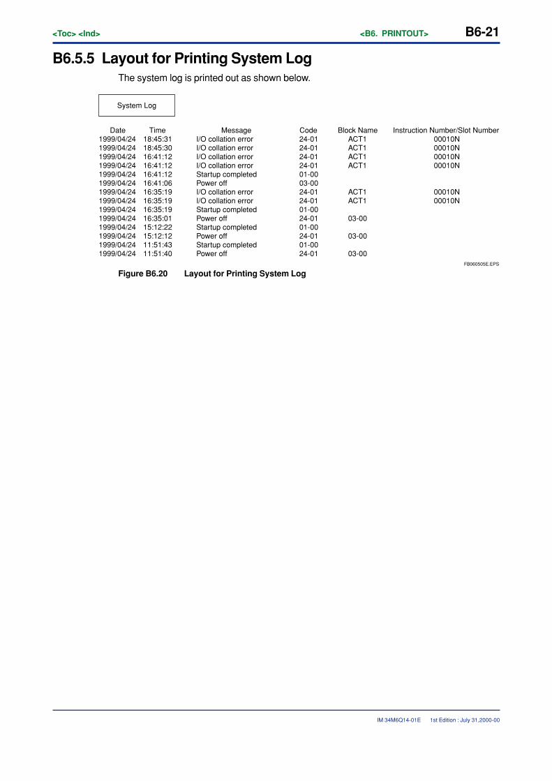
<Toc> <Ind> <B6. PRINTOUT> B6-21
IM 34M6Q14-01E
B6.5.5 Layout for Printing System LogThe system log is printed out as shown below.
FB060505E.EPS
System Log
Date Time Message Code Block Name Instruction Number/Slot Number1999/04/24 18:45:31 I/O collation error 24-01 ACT1 00010N1999/04/24 18:45:30 I/O collation error 24-01 ACT1 00010N1999/04/24 16:41:12 I/O collation error 24-01 ACT1 00010N1999/04/24 16:41:12 I/O collation error 24-01 ACT1 00010N1999/04/24 16:41:12 Startup completed 01-001999/04/24 16:41:06 Power off 03-001999/04/24 16:35:19 I/O collation error 24-01 ACT1 00010N1999/04/24 16:35:19 I/O collation error 24-01 ACT1 00010N1999/04/24 16:35:19 Startup completed 01-001999/04/24 16:35:01 Power off 24-01 03-001999/04/24 15:12:22 Startup completed 01-001999/04/24 15:12:12 Power off 24-01 03-001999/04/24 11:51:43 Startup completed 01-001999/04/24 11:51:40 Power off 24-01 03-00
Figure B6.20 Layout for Printing System Log
1st Edition : July 31,2000-00

Blank Page
<Int> <Ind> <Rev>
IM 34M6Q14-01E
TocB-6
CONTENTSB7. Outline of Online Function ................................................................... B7-1
B7.1 Connecting and Disconnecting ................................................................... B7-1
B7.1.1 Connecting ..................................................................................... B7-1
B7.1.2 Disconnecting ................................................................................. B7-3
B7.2 Online Limitations......................................................................................... B7-4
B7.2.1 Limitations Owing to Run Mode ...................................................... B7-4
B7.2.2 Multi-Window Limitations ................................................................ B7-4
B7.2.3 Limitations Owing to Project ............................................................ B7-4
B7.2.4 Limitations between Other Applications........................................... B7-4
B7.2.5 Limitations on Personal Computers ................................................ B7-4
B8. Transferring Programs ......................................................................... B8-1B8.1 Downloading Executable Programs ............................................................ B8-1
B8.1.1 Limitations on Downloading ............................................................ B8-1
B8.1.2 Procedure for Downloading ............................................................ B8-1
B8.2 Uploading Executable Programs ................................................................. B8-5
B8.2.1 Limitations on Uploading................................................................. B8-5
B8.2.2 Procedure for Uploading ................................................................. B8-5
B9. Run Mode Settings and Run Status Monitor ....................................... B9-1B9.1 Displaying Action Monitor ............................................................................ B9-2
B9.2 Configuration Display while Running a Program ....................................... B9-3
B9.3 Procedure for Changing Each Mode............................................................ B9-4
B9.3.1 Switching to Run Mode ................................................................... B9-4
B9.3.2 Switching to Stop Mode .................................................................. B9-4
B9.3.3 Switching to Debug Mode ............................................................... B9-4
B9.4 Temporarily Changing Communication Speed ........................................... B9-5
B9.5 Setup Time .................................................................................................... B9-7
B9.6 Clearing Programs ........................................................................................ B9-8
B9.7 Clear Device .................................................................................................. B9-9
B9.8 Reset Start ................................................................................................... B9-10
B9.9 Capturing and Releasing Exclusive Access Control ................................ B9-12
B10. Program Monitor................................................................................. B10-1B10.1 Configuration of Program Monitor Screen ................................................ B10-1
B10.1.1 Relay ON/OFF Display ................................................................. B10-1
B10.1.2 Displaying Application Instructions ................................................ B10-3
1st Edition : July 31,2000-00
IM 34M6Q14-01E 1st Edition
FA-M3FA-M3 Programming Tool WideField Instruction ManualPART-B Online Section
TocB-7<Int> <Ind> <Rev>
IM 34M6Q14-01E 1st Edition : July 31,2000-00
B10.2 Activating and Ending Program Monitor ................................................... B10-4
B10.2.1 Procedure for Activating Program Monitor ..................................... B10-4
B10.2.2 Saving the Monitoring Program..................................................... B10-5
B10.2.3 Procedure for Ending Program Monitor ......................................... B10-5
B10.3 Displaying Details of Application Instructions .......................................... B10-6
B10.3.1 Procedure for Displaying Details ................................................... B10-6
B10.3.2 Changing Display Format ............................................................. B10-7
B10.4 Switching Display ....................................................................................... B10-8
B10.4.1 Switching Display of Tag Names and Addresses ........................... B10-8
B10.4.2 Displaying I/O Comments ............................................................. B10-9
B10.4.3 Displaying Instruction Numbers .................................................. B10-10
B10.5 Browsing Tag Names ................................................................................ B10-11
B10.6 Searching with Program Monitor ............................................................. B10-12
B10.6.1 Find Device and Find Instruction functions .................................. B10-12
B10.6.2 Jump Function ............................................................................ B10-12
B10.6.3 Displaying Device Usage Status ................................................. B10-12
B10.7 Suspending and Resuming Program Monitor ......................................... B10-13
B10.7.1 Procedure for Suspending Monitor.............................................. B10-13
B10.7.2 Procedure for Resuming Monitor ................................................ B10-13
B11. Device Monitor .................................................................................... B11-1B11.1 Configuration of Device Monitor Screens ................................................. B11-1
B11.1.1 Configuration of Relay Monitor Screen.......................................... B11-2
B11.1.2 Configuration of Register Monitor Screen ..................................... B11-3
B11.1.3 Configuration of Timer Monitor Screen .......................................... B11-4
B11.1.4 Configuration of Counter Monitor Screen ...................................... B11-5
B11.2 Activating and Ending Device Monitor ...................................................... B11-6
B11.2.1 Procedure for activating Device Monitor ........................................ B11-6
B11.2.2 Procedure for Ending Device Monitor............................................ B11-7
B11.3 Changing Display Format ........................................................................... B11-8
B11.4 Searching Device Monitor ........................................................................ B11-10
B11.5 Suspending Device Monitor ..................................................................... B11-11
B11.5.1 Procedure for Suspending Monitor...............................................B11-11
B11.5.2 Procedure for Resuming Monitor .................................................B11-11
B12. Use of the Debugging Function ......................................................... B12-1B12.1 Forced Set/Reset of the Relay .................................................................... B12-1
B12.1.1 Devices with which Forced Set/Reset is Available ......................... B12-1
B12.1.2 Operation and Expiration of Forced Set/Reset .............................. B12-2
B12.1.3 Procedure for Forced Set/Reset ................................................... B12-2
B12.1.4 Procedure for Canceling Forced Set/Reset ................................... B12-2
B12.1.5 Procedure for Canceling All Forced Set/Reset .............................. B12-2
B12.2 Changing Word/Long Word Data ............................................................... B12-3
B12.2.1 Devices with which Data Change is Available ............................... B12-3
<Int> <Ind> <Rev>
IM 34M6Q14-01E
TocB-8
1st Edition : July 31,2000-00
B12.2.2 Operation of Devices that have been Changed ............................. B12-3
B12.2.3 Procedure for Data Change .......................................................... B12-4
B12.3 Changing the Current Value of the Timer/Counter .................................... B12-5
B12.3.1 Devices with which Current Value Change is Available ................. B12-5
B12.3.2 Operation of Devices that have been Changed ............................. B12-5
B12.3.3 Procedure for Changing Current Value ......................................... B12-6
B12.4 Changing the Timer/Counter Set Value ..................................................... B12-7
B12.4.1 Devices with which Current Value Change is Available ................. B12-7
B12.4.2 Operation of Devices that have been Changed ............................. B12-7
B12.4.3 Procedure for Changing Set Value ................................................ B12-7
B12.5 Stop Refreshing .......................................................................................... B12-9
B12.5.1 Procedure for Stopping a Refresh ................................................. B12-9
B12.5.2 Restart Refreshing ........................................................................ B12-9
B12.6 Block Start and Stop ................................................................................. B12-10
B12.6.1 Procedure for Block Launch ........................................................ B12-10
B12.6.2 Procedure for Block Stop ............................................................ B12-10
B13. Online Edit .......................................................................................... B13-1B13.1 Starting and Quitting Online Edit ............................................................... B13-2
B13.2 Reflecting the Online Edit to the CPU ........................................................ B13-4
B13.3 Reflecting the Online Edit to a File ............................................................. B13-4
B13.4 Precautions concerning the Online Edit .................................................... B13-5
B14. Protective Functions .......................................................................... B14-1B14.1 Alarm Display .............................................................................................. B14-2
B14.1.1 Layout of the Alarm Display Screen .............................................. B14-2
B14.1.2 Displaying the Alarm Display Screen............................................. B14-2
B14.1.3 Canceling the Alarm...................................................................... B14-3
B14.1.4 Error Messages Displayed in the Alarm Monitor ............................ B14-4
B14.2 System Log Display .................................................................................... B14-5
B14.2.1 System Log Display Screen Layout .............................................. B14-5
B14.2.2 Displaying the System Log ........................................................... B14-6
B14.2.3 Saving the System Log File .......................................................... B14-6
B14.2.4 Reading From the System Log File ............................................... B14-7
B14.2.5 Clearing the System Log ............................................................... B14-7
B14.2.6 Log Messages Displayed in the System Log ................................. B14-8
B14.3 User Log Display ......................................................................................... B14-9
B14.3.1 User Log ....................................................................................... B14-9
B14.3.2 User Log Display Screen Layout ................................................. B14-10
B14.3.3 Displaying the User Log Display Screen ..................................... B14-10
B14.3.4 Saving the User Log File ............................................................. B14-11
B14.3.5 Reading From the User Log File ................................................. B14-11
B14.3.6 Clearing the User Log ................................................................. B14-12
TocB-9<Int> <Ind> <Rev>
IM 34M6Q14-01E
B14.4 Comparing Executable Program.............................................................. B14-13
B14.4.1 Contents of the compare ............................................................. B14-13
B14.4.2 Limitation on the Compare Function ........................................... B14-13
B14.4.3 Procedure for Comparing............................................................ B14-14
B15. Operating the ROM ............................................................................. B15-1B15.1 ROM Writer Mode/Canceling ROM Writer Mode ........................................ B15-3
B15.1.1 Switching to ROM writer mode ...................................................... B15-3
B15.1.2 Canceling ROM Writer Mode ........................................................ B15-4
B15.2 ROM Sending (Computer to ROM) ............................................................. B15-5
B15.3 ROM Comparison (Between Computer and ROM) .................................... B15-8
B15.4 ROM Copy ................................................................................................. B15-11
B15.5 ROM Deletion ............................................................................................ B15-13
B16. I/O Module Settings ............................................................................ B16-1B16.1 Station Assignment of the FA Link and the Monitor ................................. B16-1
B16.1.1 Starting the FA Link Tool ............................................................... B16-3
B16.1.2 Setting the FA link station assignment ........................................... B16-4
B16.1.3 Registering to the FA link Module .................................................. B16-7
B16.1.4 Confirmation of the FA Link Module Status .................................... B16-7
B16.1.5 List of FA Link Tool Error Messages ............................................ B16-10
1st Edition : July 31,2000-00
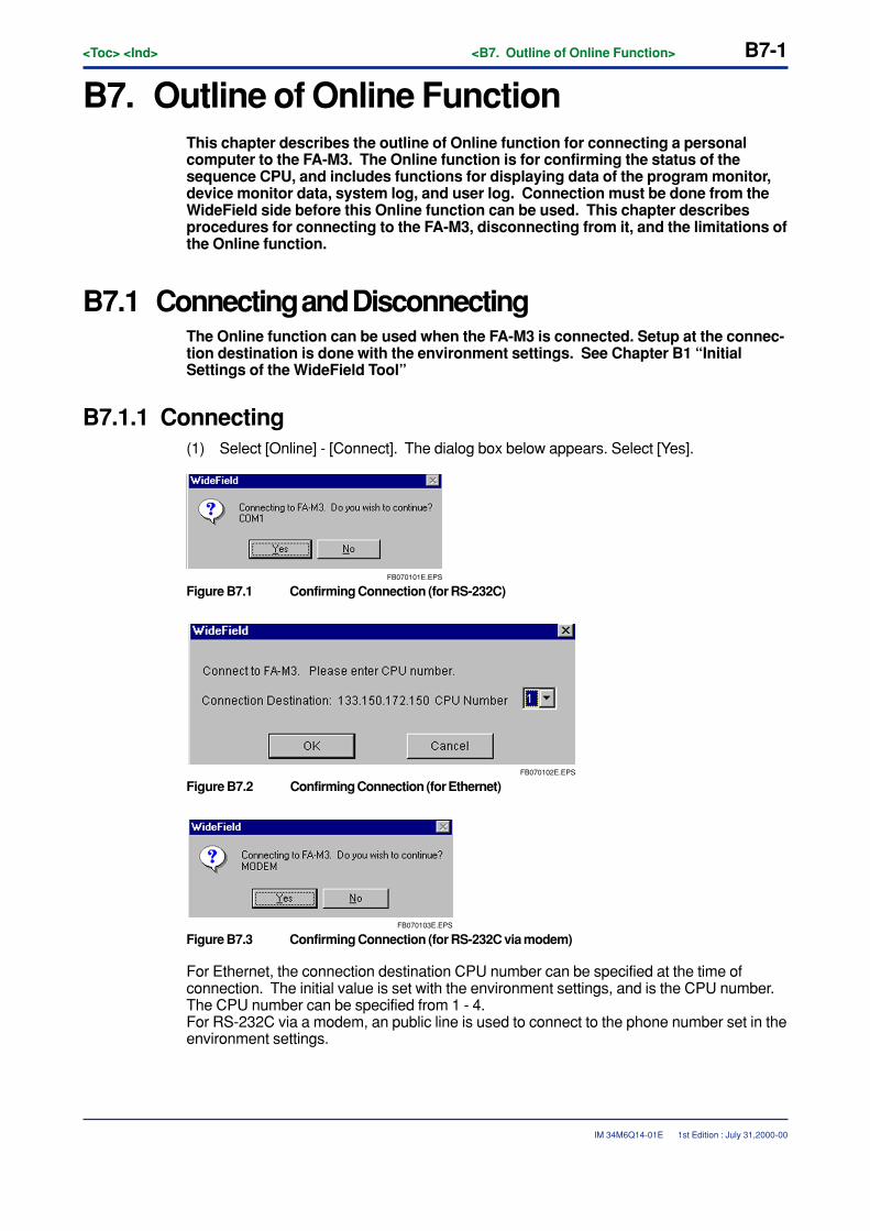
<Toc> <Ind> <B7. Outline of Online Function> B7-1
IM 34M6Q14-01E
B7. Outline of Online FunctionThis chapter describes the outline of Online function for connecting a personalcomputer to the FA-M3. The Online function is for confirming the status of thesequence CPU, and includes functions for displaying data of the program monitor,device monitor data, system log, and user log. Connection must be done from theWideField side before this Online function can be used. This chapter describesprocedures for connecting to the FA-M3, disconnecting from it, and the limitations ofthe Online function.
B7.1 Connecting and DisconnectingThe Online function can be used when the FA-M3 is connected. Setup at the connec-tion destination is done with the environment settings. See Chapter B1 “InitialSettings of the WideField Tool”
B7.1.1 Connecting(1) Select [Online] - [Connect]. The dialog box below appears. Select [Yes].
FB070101E.EPS
Figure B7.1 Confirming Connection (for RS-232C)
FB070102E.EPS
Figure B7.2 Confirming Connection (for Ethernet)
FB070103E.EPS
Figure B7.3 Confirming Connection (for RS-232C via modem)
For Ethernet, the connection destination CPU number can be specified at the time ofconnection. The initial value is set with the environment settings, and is the CPU number.The CPU number can be specified from 1 - 4.For RS-232C via a modem, an public line is used to connect to the phone number set in theenvironment settings.
1st Edition : July 31,2000-00
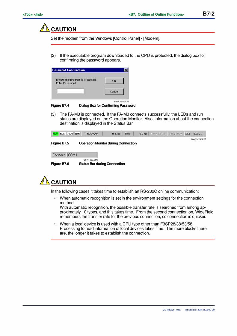
B7-2<Toc> <Ind> <B7. Outline of Online Function>
IM 34M6Q14-01E
CAUTION
Set the modem from the Windows [Control Panel] - [Modem].
(2) If the executable program downloaded to the CPU is protected, the dialog box forconfirming the password appears.
FB070104E.EPS
Figure B7.4 Dialog Box for Confirming Password
(3) The FA-M3 is connected. If the FA-M3 connects successfully, the LEDs and runstatus are displayed on the Operation Monitor. Also, information about the connectiondestination is displayed in the Status Bar.
FB070105E.EPS
Figure B7.5 Operation Monitor during Connection
FB070106E.EPS
Figure B7.6 Status Bar during Connection
CAUTION
In the following cases it takes time to establish an RS-232C online communication:
• When automatic recognition is set in the environment settings for the connectionmethodWith automatic recognition, the possible transfer rate is searched from among ap-proximately 10 types, and this takes time. From the second connection on, WideFieldremembers the transfer rate for the previous connection, so connection is quicker.
• When a local device is used with a CPU type other than F3SP28/38/53/58.Processing to read information of local devices takes time. The more blocks thereare, the longer it takes to establish the connection.
1st Edition : July 31,2000-00
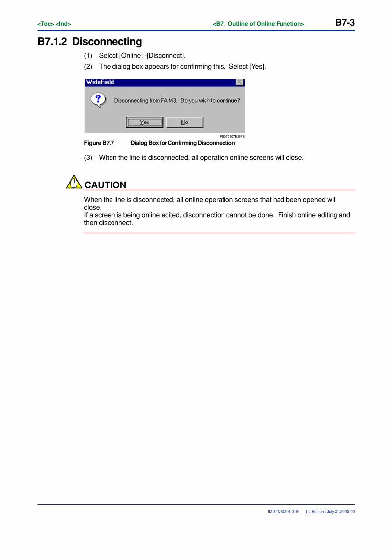
<Toc> <Ind> <B7. Outline of Online Function> B7-3
IM 34M6Q14-01E
B7.1.2 Disconnecting(1) Select [Online] -[Disconnect].
(2) The dialog box appears for confirming this. Select [Yes].
FB070107E.EPS
Figure B7.7 Dialog Box for Confirming Disconnection
(3) When the line is disconnected, all operation online screens will close.
CAUTION
When the line is disconnected, all online operation screens that had been opened willclose.If a screen is being online edited, disconnection cannot be done. Finish online editing andthen disconnect.
1st Edition : July 31,2000-00
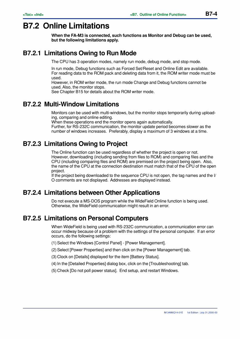
B7-4<Toc> <Ind> <B7. Outline of Online Function>
IM 34M6Q14-01E
B7.2 Online LimitationsWhen the FA-M3 is connected, such functions as Monitor and Debug can be used,but the following limitations apply.
B7.2.1 Limitations Owing to Run ModeThe CPU has 3 operation modes, namely run mode, debug mode, and stop mode.
In run mode, Debug functions such as Forced Set/Reset and Online Edit are available.For reading data to the ROM pack and deleting data from it, the ROM writer mode must beused.However, in ROM writer mode, the run mode Change and Debug functions cannot beused. Also, the monitor stops.See Chapter B15 for details about the ROM writer mode.
B7.2.2 Multi-Window LimitationsMonitors can be used with multi-windows, but the monitor stops temporarily during upload-ing, comparing and online editing.When these operations end the monitor opens again automatically.Further, for RS-232C communication, the monitor update period becomes slower as thenumber of windows increases. Preferably, display a maximum of 3 windows at a time.
B7.2.3 Limitations Owing to ProjectThe Online function can be used regardless of whether the project is open or not.However, downloading (including sending from files to ROM) and comparing files and theCPU (including comparing files and ROM) are premised on the project being open. Also,the name of the CPU at the connection destination must match that of the CPU of the openproject.If the project being downloaded to the sequence CPU is not open, the tag names and the I/O comments are not displayed. Addresses are displayed instead.
B7.2.4 Limitations between Other ApplicationsDo not execute a MS-DOS program while the WideField Online function is being used.Otherwise, the WideField communication might result in an error.
B7.2.5 Limitations on Personal ComputersWhen WideField is being used with RS-232C communication, a communication error canoccur midway because of a problem with the settings of the personal computer. If an erroroccurs, do the following settings:
(1) Select the Windows [Control Panel] - [Power Management].
(2) Select [Power Properties] and then click on the [Power Management] tab.
(3) Clock on [Details] displayed for the item [Battery Status].
(4) In the [Detailed Properties] dialog box, click on the [Troubleshooting] tab.
(5) Check [Do not poll power status]. End setup, and restart Windows.
1st Edition : July 31,2000-00
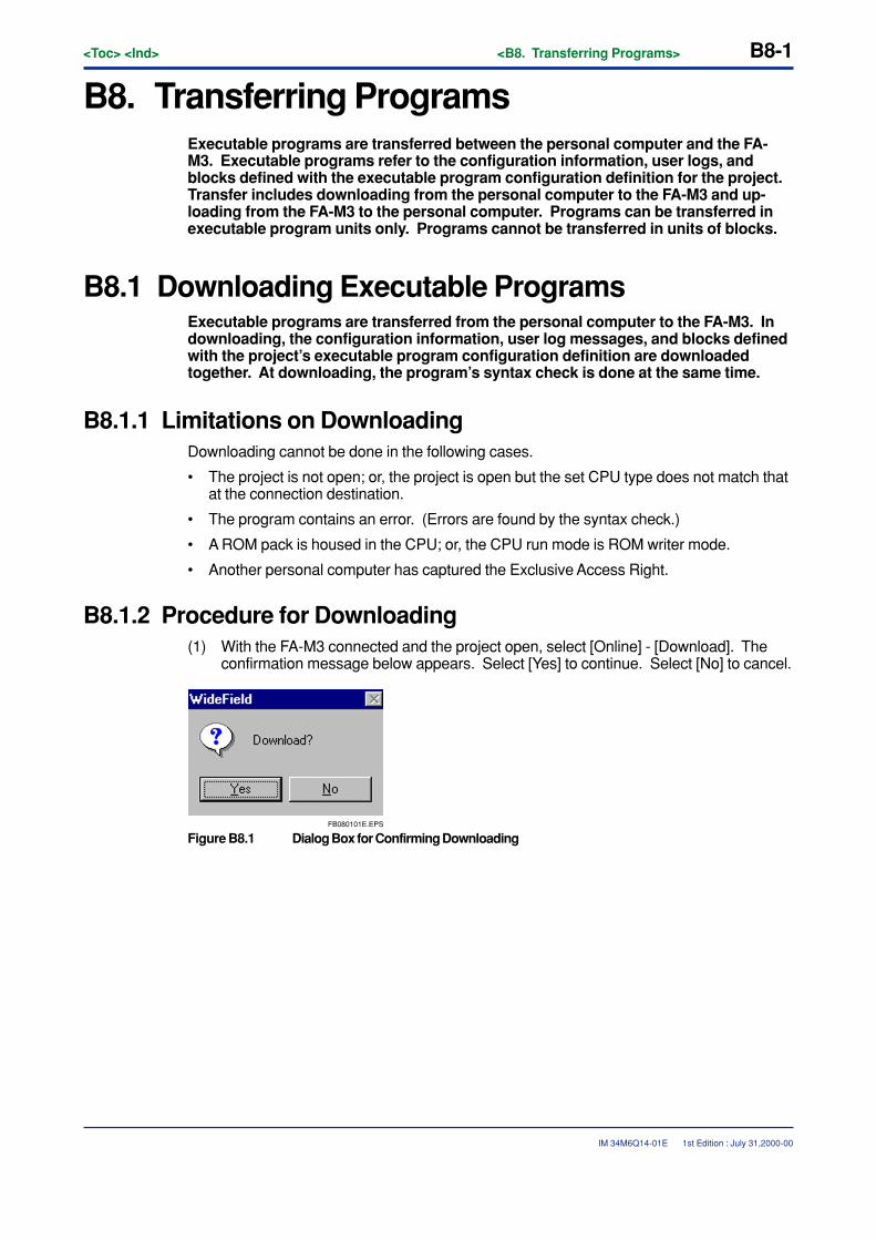
<Toc> <Ind> <B8. Transferring Programs> B8-1
IM 34M6Q14-01E
B8. Transferring ProgramsExecutable programs are transferred between the personal computer and the FA-M3. Executable programs refer to the configuration information, user logs, andblocks defined with the executable program configuration definition for the project.Transfer includes downloading from the personal computer to the FA-M3 and up-loading from the FA-M3 to the personal computer. Programs can be transferred inexecutable program units only. Programs cannot be transferred in units of blocks.
B8.1 Downloading Executable ProgramsExecutable programs are transferred from the personal computer to the FA-M3. Indownloading, the configuration information, user log messages, and blocks definedwith the project’s executable program configuration definition are downloadedtogether. At downloading, the program’s syntax check is done at the same time.
B8.1.1 Limitations on DownloadingDownloading cannot be done in the following cases.
• The project is not open; or, the project is open but the set CPU type does not match thatat the connection destination.
• The program contains an error. (Errors are found by the syntax check.)
• A ROM pack is housed in the CPU; or, the CPU run mode is ROM writer mode.
• Another personal computer has captured the Exclusive Access Right.
B8.1.2 Procedure for Downloading(1) With the FA-M3 connected and the project open, select [Online] - [Download]. The
confirmation message below appears. Select [Yes] to continue. Select [No] to cancel.
FB080101E.EPS
Figure B8.1 Dialog Box for Confirming Downloading
1st Edition : July 31,2000-00
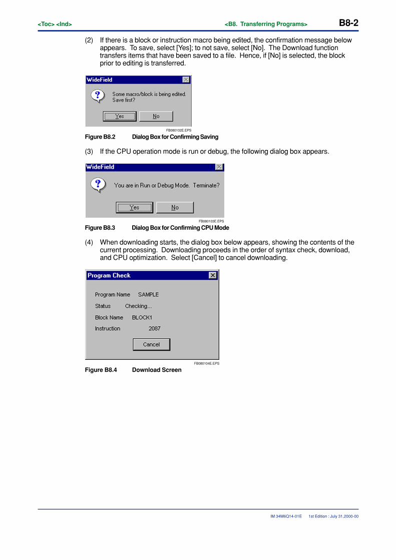
B8-2<Toc> <Ind> <B8. Transferring Programs>
IM 34M6Q14-01E
(2) If there is a block or instruction macro being edited, the confirmation message belowappears. To save, select [Yes]; to not save, select [No]. The Download functiontransfers items that have been saved to a file. Hence, if [No] is selected, the blockprior to editing is transferred.
FB080102E.EPS
Figure B8.2 Dialog Box for Confirming Saving
(3) If the CPU operation mode is run or debug, the following dialog box appears.
FB080103E.EPS
Figure B8.3 Dialog Box for Confirming CPU Mode
(4) When downloading starts, the dialog box below appears, showing the contents of thecurrent processing. Downloading proceeds in the order of syntax check, download,and CPU optimization. Select [Cancel] to cancel downloading.
FB080104E.EPS
Figure B8.4 Download Screen
1st Edition : July 31,2000-00
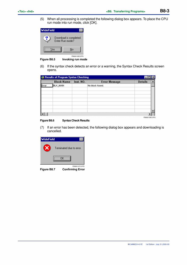
<Toc> <Ind> <B8. Transferring Programs> B8-3
IM 34M6Q14-01E
(5) When all processing is completed the following dialog box appears. To place the CPUrun mode into run mode, click [OK].
FB080105E.EPS
Figure B8.5 Invoking run mode
(6) If the syntax check detects an error or a warning, the Syntax Check Results screenopens.
FB080106E.EPS
Figure B8.6 Syntax Check Results
(7) If an error has been detected, the following dialog box appears and downloading iscancelled.
FB080107E.EPS
Figure B8.7 Confirming Error
1st Edition : July 31,2000-00
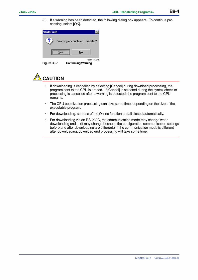
B8-4<Toc> <Ind> <B8. Transferring Programs>
IM 34M6Q14-01E
(8) If a warning has been detected, the following dialog box appears. To continue pro-cessing, select [OK].
FB080108E.EPS
Figure B8.7 Confirming Warning
CAUTION
• If downloading is cancelled by selecting [Cancel] during download processing, theprogram sent to the CPU is erased. If [Cancel] is selected during the syntax check orprocessing is cancelled after a warning is detected, the program sent to the CPUremains.
• The CPU optimization processing can take some time, depending on the size of theexecutable program.
• For downloading, screens of the Online function are all closed automatically.
• For downloading via an RS-232C, the communication mode may change whendownloading ends. (It may change because the configuration communication settingsbefore and after downloading are different.) If the communication mode is differentafter downloading, download end processing will take some time.
1st Edition : July 31,2000-00
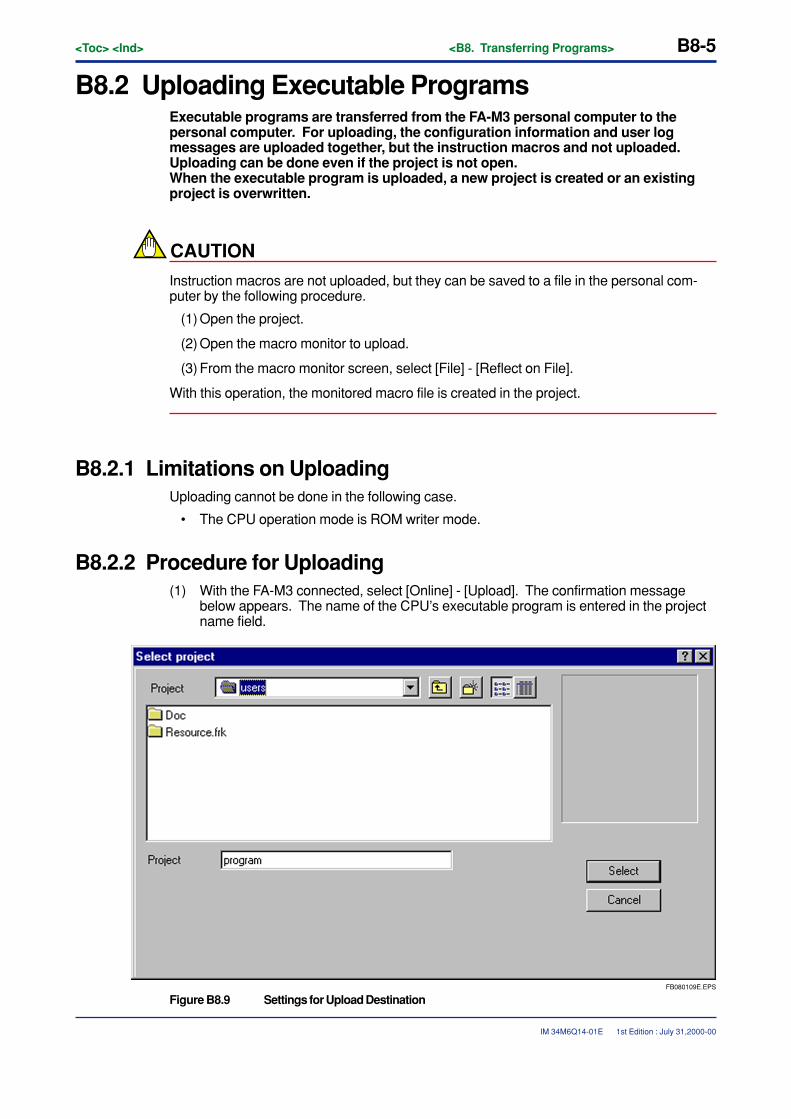
<Toc> <Ind> <B8. Transferring Programs> B8-5
IM 34M6Q14-01E
B8.2 Uploading Executable ProgramsExecutable programs are transferred from the FA-M3 personal computer to thepersonal computer. For uploading, the configuration information and user logmessages are uploaded together, but the instruction macros and not uploaded.Uploading can be done even if the project is not open.When the executable program is uploaded, a new project is created or an existingproject is overwritten.
CAUTION
Instruction macros are not uploaded, but they can be saved to a file in the personal com-puter by the following procedure.
(1) Open the project.
(2) Open the macro monitor to upload.
(3) From the macro monitor screen, select [File] - [Reflect on File].
With this operation, the monitored macro file is created in the project.
B8.2.1 Limitations on UploadingUploading cannot be done in the following case.
• The CPU operation mode is ROM writer mode.
B8.2.2 Procedure for Uploading(1) With the FA-M3 connected, select [Online] - [Upload]. The confirmation message
below appears. The name of the CPU’s executable program is entered in the projectname field.
FB080109E.EPS
Figure B8.9 Settings for Upload Destination
1st Edition : July 31,2000-00
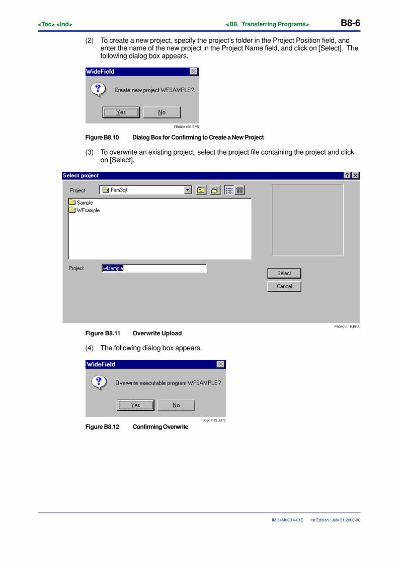
B8-6<Toc> <Ind> <B8. Transferring Programs>
IM 34M6Q14-01E
(2) To create a new project, specify the project’s folder in the Project Position field, andenter the name of the new project in the Project Name field, and click on [Select]. Thefollowing dialog box appears.
FB080110E.EPS
Figure B8.10 Dialog Box for Confirming to Create a New Project
(3) To overwrite an existing project, select the project file containing the project and clickon [Select].
FB080111E.EPS
Figure B8.11 Overwrite Upload
(4) The following dialog box appears.
FB080112E.EPS
Figure B8.12 Confirming Overwrite
1st Edition : July 31,2000-00
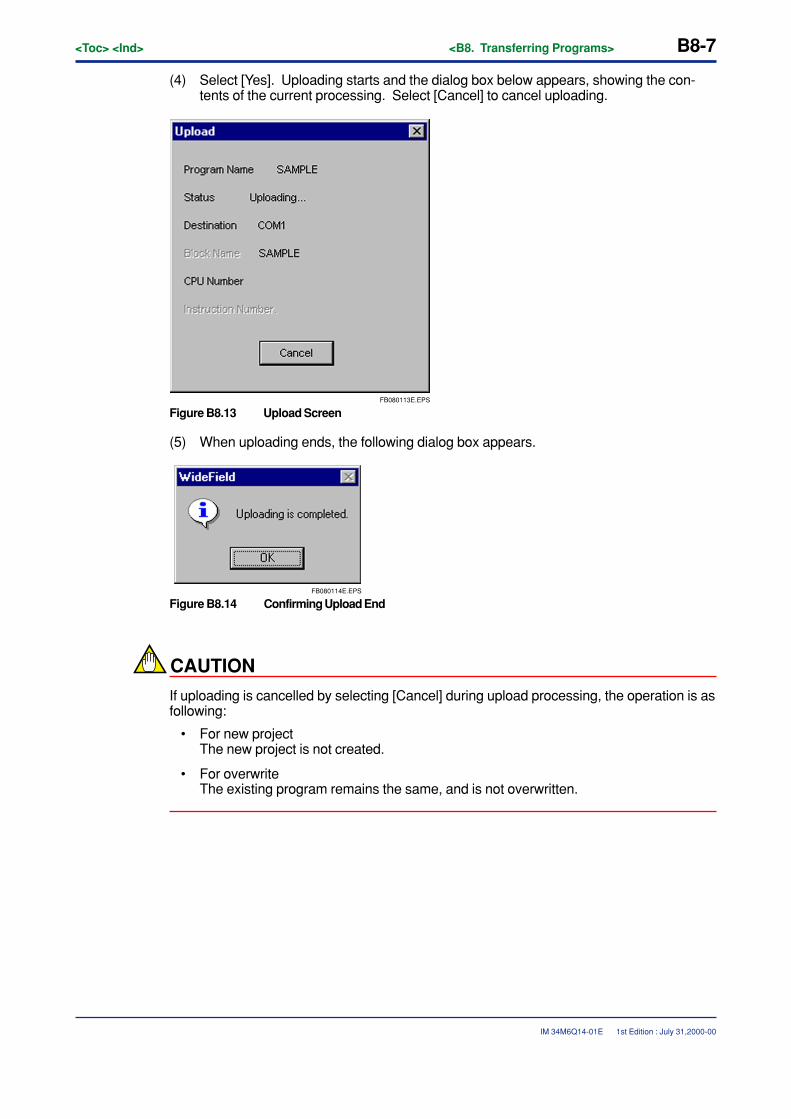
<Toc> <Ind> <B8. Transferring Programs> B8-7
IM 34M6Q14-01E
(4) Select [Yes]. Uploading starts and the dialog box below appears, showing the con-tents of the current processing. Select [Cancel] to cancel uploading.
FB080113E.EPS
Figure B8.13 Upload Screen
(5) When uploading ends, the following dialog box appears.
FB080114E.EPS
Figure B8.14 Confirming Upload End
CAUTION
If uploading is cancelled by selecting [Cancel] during upload processing, the operation is asfollowing:
• For new projectThe new project is not created.
• For overwriteThe existing program remains the same, and is not overwritten.
1st Edition : July 31,2000-00

B8-8<Toc> <Ind> <B8. Transferring Programs>
IM 34M6Q14-01E 1st Edition : July 31,2000-00
CAUTION
When a downloaded project is uploaded to a different project destination, circuit commentsand subcomments are not generated. To generate comments and subcomments, useExplorer to copy the blocks downloaded to the Download folder of the upload destinationproject, and then upload them.To recover tag name definitions (tag name I/O comments), copy the project folder’s tagname definition file (has extension .ysig) to the upload destination after uploading.
FB080115E.EPS
Downloaded Project Aaaa
Copy the Download folder of the upload destination Bbbb tothe file of Aaaa's Download folder. Copy the file of Aaaa'sDownload folder to the Download folder of the uploaddestination Bbbb.
Uploaded Project Bbbb
Figure B8.15 Copying file to Upload Destination So As to Recover Comments

<Toc> <Ind> <B9. Run Mode Settings and Run Status Monitor> B9-1
IM 34M6Q14-01E
B9. Run Mode Settings and Run StatusMonitor
The FA-M3’s CPU operation modes are as below. This chapter describes how tomonitor and set the CPU’s run status.
� Run Mode (RUN LED lights)
This mode is active when the CPU is executing the program. The program run status canbe checked on the CPU Operation Monitor, Program Monitor, and Device Monitor, but theDebug function cannot be used and online editing cannot be done.When the mode is switched from stop mode to run mode, the program starts from the top,just as for booting. Except for the lock-up devices, the devices become 0. If the Debugfunction was being used, it is cancelled.
� Stop Mode (RUN LED off)
This is the mode when the CPU stops executing the program. The Debug function can beused and online editing can be done.
� Debug Mode
This mode is for debugging, and arranging. The manner of executing program is same asRun mode, but the debug function can be used and online editing can be done.
� ROM Writer Mode
This mode is for erasing the ROM pack and writing programs to it. See Chapter B15.“Managing the ROM” for details about how to set the ROM writer mode.
1st Edition : July 31,2000-00
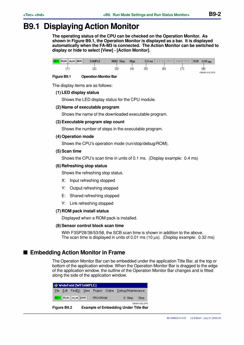
B9-2<Toc> <Ind> <B9. Run Mode Settings and Run Status Monitor>
IM 34M6Q14-01E
B9.1 Displaying Action MonitorThe operating status of the CPU can be checked on the Operation Monitor. Asshown in Figure B9.1, the Operation Monitor is displayed as a bar. It is displayedautomatically when the FA-M3 is connected. The Action Monitor can be switched todisplay or hide to select [View] - [Action Monitor].
FB090101E.EPS
(8)(7)(6)(5)(4)(3)(2)(1)
Figure B9.1 Operation Monitor Bar
The display items are as follows:
(1) LED display status
Shows the LED display status for the CPU module.
(2) Name of executable program
Shows the name of the downloaded executable program.
(3) Executable program step count
Shows the number of steps in the executable program.
(4) Operation mode
Shows the CPU’s operation mode (run/stop/debug/ROM).
(5) Scan time
Shows the CPU’s scan time in units of 0.1 ms. (Display example: 0.4 ms)
(6) Refreshing stop status
Shows the refreshing stop status.
X: Input refreshing stopped
Y: Output refreshing stopped
E: Shared refreshing stopped
Y: Link refreshing stopped
(7) ROM pack install status
Displayed when a ROM pack is installed.
(8) Sensor control block scan time
With F3SP28/38/53/58, the SCB scan time is shown in addition to the above.The scan time is displayed in units of 0.01 ms (10 µs). (Display example: 0.32 ms)
� Embedding Action Monitor in FrameThe Operation Monitor Bar can be embedded under the application Title Bar, at the top orbottom of the application window. When the Operation Monitor Bar is dragged to the edgeof the application window, the outline of the Operation Monitor Bar changes and is fittedalong the side of the application window.
FB090102E.EPS
Figure B9.2 Example of Embedding Under Title Bar
1st Edition : July 31,2000-00
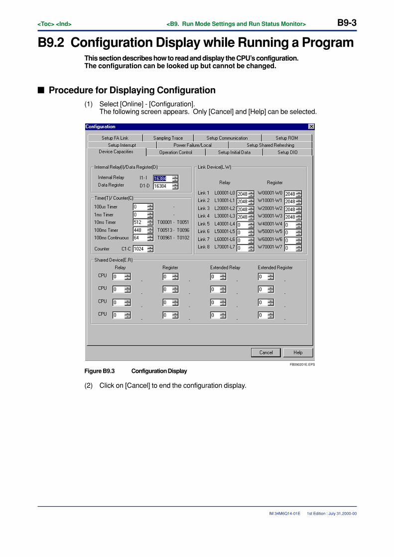
<Toc> <Ind> <B9. Run Mode Settings and Run Status Monitor> B9-3
IM 34M6Q14-01E
B9.2 Configuration Display while Running a ProgramThis section describes how to read and display the CPU’s configuration.The configuration can be looked up but cannot be changed.
� Procedure for Displaying Configuration(1) Select [Online] - [Configuration].
The following screen appears. Only [Cancel] and [Help] can be selected.
FB090201E.EPS
Figure B9.3 Configuration Display
(2) Click on [Cancel] to end the configuration display.
1st Edition : July 31,2000-00
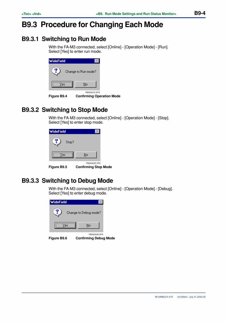
B9-4<Toc> <Ind> <B9. Run Mode Settings and Run Status Monitor>
IM 34M6Q14-01E
B9.3 Procedure for Changing Each Mode
B9.3.1 Switching to Run ModeWith the FA-M3 connected, select [Online] - [Operation Mode] - [Run].Select [Yes] to enter run mode.
FB090301E.EPS
Figure B9.4 Confirming Operation Mode
B9.3.2 Switching to Stop ModeWith the FA-M3 connected, select [Online] - [Operation Mode] - [Stop].Select [Yes] to enter stop mode.
FB090302E.EPS
Figure B9.5 Confirming Stop Mode
B9.3.3 Switching to Debug ModeWith the FA-M3 connected, select [Online] - [Operation Mode] - [Debug].Select [Yes] to enter debug mode.
FB090303E.EPS
Figure B9.6 Confirming Debug Mode
1st Edition : July 31,2000-00
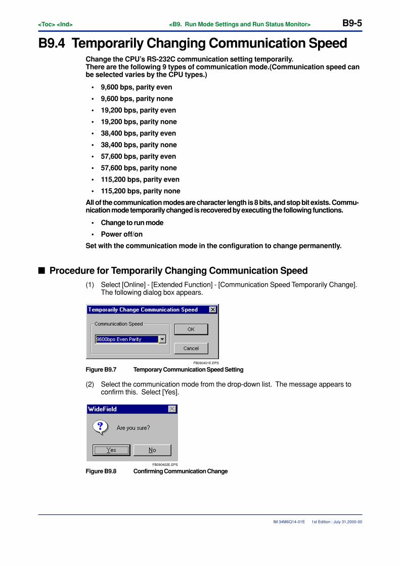
<Toc> <Ind> <B9. Run Mode Settings and Run Status Monitor> B9-5
IM 34M6Q14-01E
B9.4 Temporarily Changing Communication SpeedChange the CPU’s RS-232C communication setting temporarily.There are the following 9 types of communication mode.(Communication speed canbe selected varies by the CPU types.)
• 9,600 bps, parity even
• 9,600 bps, parity none
• 19,200 bps, parity even
• 19,200 bps, parity none
• 38,400 bps, parity even
• 38,400 bps, parity none
• 57,600 bps, parity even
• 57,600 bps, parity none
• 115,200 bps, parity even
• 115,200 bps, parity none
All of the communication modes are character length is 8 bits, and stop bit exists. Commu-nication mode temporarily changed is recovered by executing the following functions.
• Change to run mode
• Power off/on
Set with the communication mode in the configuration to change permanently.
� Procedure for Temporarily Changing Communication Speed(1) Select [Online] - [Extended Function] - [Communication Speed Temporarily Change].
The following dialog box appears.
FB090401E.EPS
Figure B9.7 Temporary Communication Speed Setting
(2) Select the communication mode from the drop-down list. The message appears toconfirm this. Select [Yes].
FB090402E.EPS
Figure B9.8 Confirming Communication Change
1st Edition : July 31,2000-00
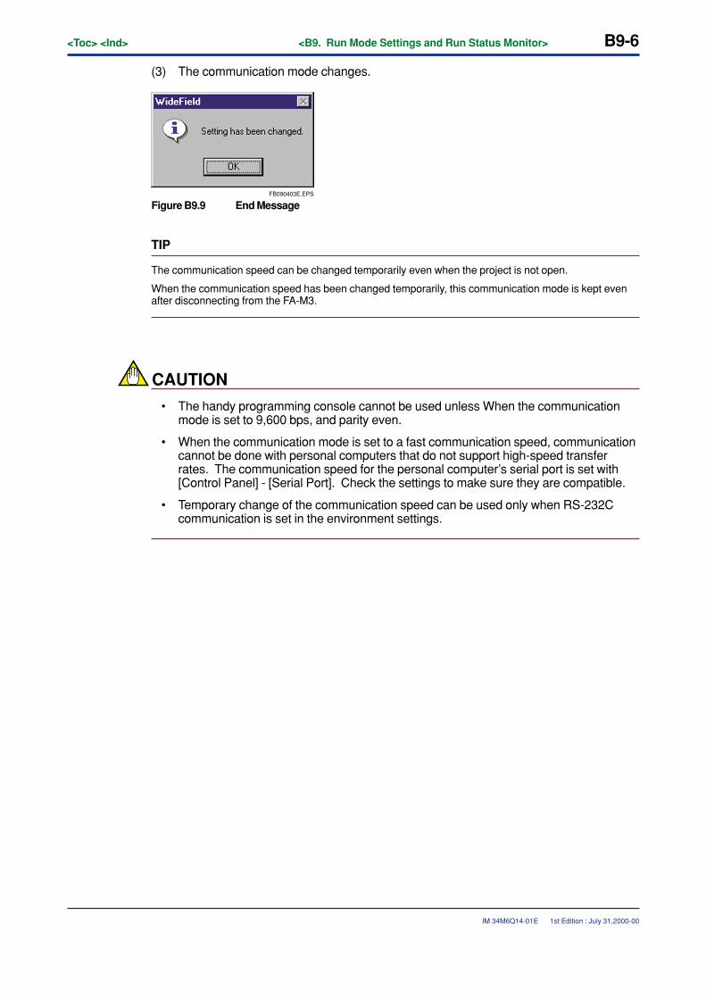
B9-6<Toc> <Ind> <B9. Run Mode Settings and Run Status Monitor>
IM 34M6Q14-01E
(3) The communication mode changes.
FB090403E.EPS
Figure B9.9 End Message
TIP
The communication speed can be changed temporarily even when the project is not open.
When the communication speed has been changed temporarily, this communication mode is kept evenafter disconnecting from the FA-M3.
CAUTION
• The handy programming console cannot be used unless When the communicationmode is set to 9,600 bps, and parity even.
• When the communication mode is set to a fast communication speed, communicationcannot be done with personal computers that do not support high-speed transferrates. The communication speed for the personal computer’s serial port is set with[Control Panel] - [Serial Port]. Check the settings to make sure they are compatible.
• Temporary change of the communication speed can be used only when RS-232Ccommunication is set in the environment settings.
1st Edition : July 31,2000-00
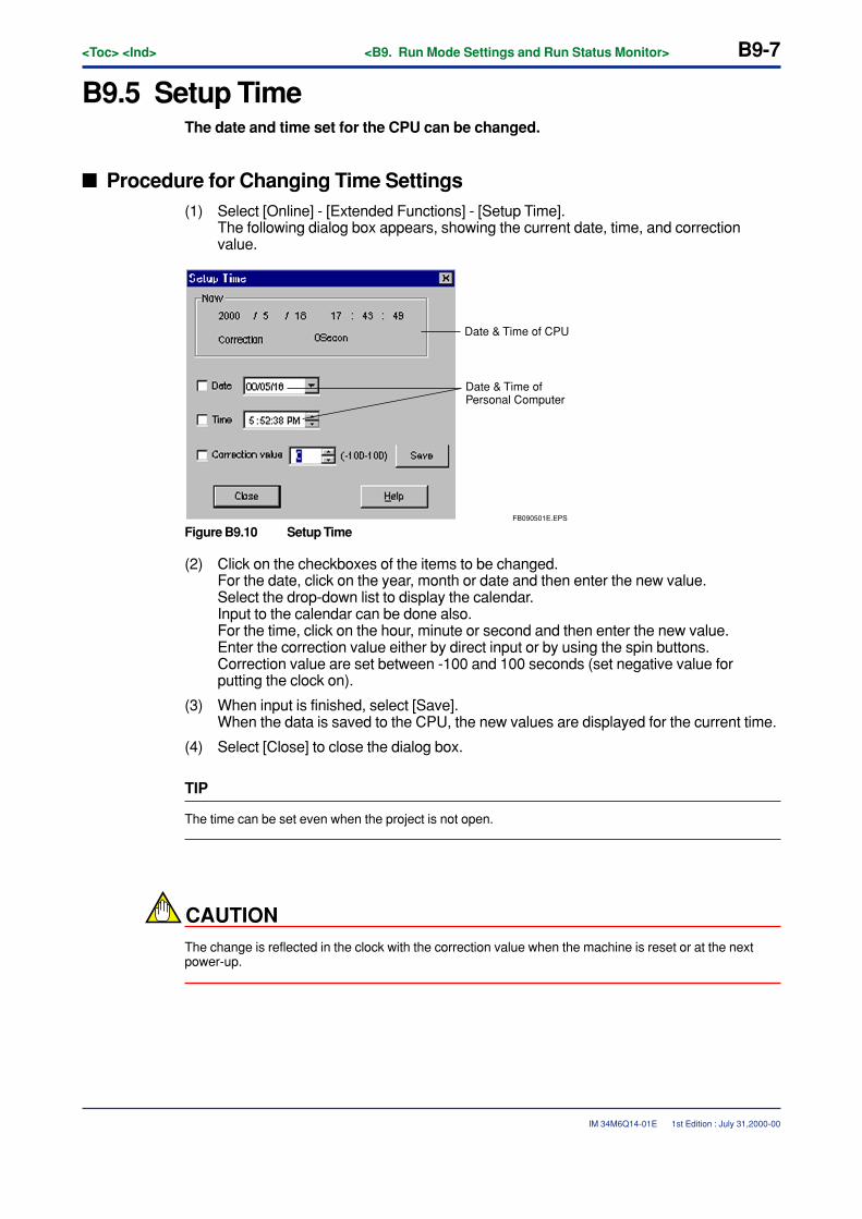
<Toc> <Ind> <B9. Run Mode Settings and Run Status Monitor> B9-7
IM 34M6Q14-01E
B9.5 Setup TimeThe date and time set for the CPU can be changed.
� Procedure for Changing Time Settings(1) Select [Online] - [Extended Functions] - [Setup Time].
The following dialog box appears, showing the current date, time, and correctionvalue.
FB090501E.EPS
Date & Time of CPU
Date & Time of Personal Computer
Figure B9.10 Setup Time
(2) Click on the checkboxes of the items to be changed.For the date, click on the year, month or date and then enter the new value.Select the drop-down list to display the calendar.Input to the calendar can be done also.For the time, click on the hour, minute or second and then enter the new value.Enter the correction value either by direct input or by using the spin buttons.Correction value are set between -100 and 100 seconds (set negative value forputting the clock on).
(3) When input is finished, select [Save].When the data is saved to the CPU, the new values are displayed for the current time.
(4) Select [Close] to close the dialog box.
TIP
The time can be set even when the project is not open.
CAUTIONThe change is reflected in the clock with the correction value when the machine is reset or at the nextpower-up.
1st Edition : July 31,2000-00
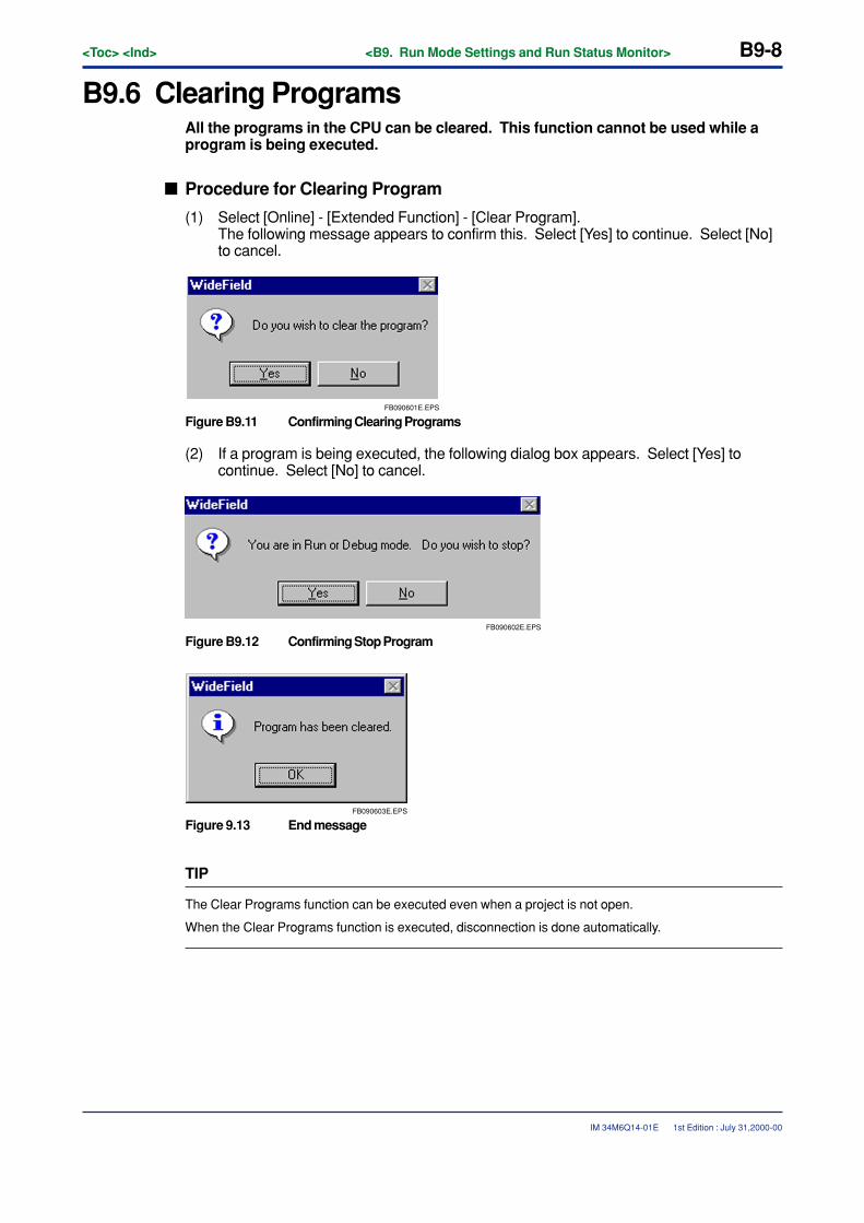
B9-8<Toc> <Ind> <B9. Run Mode Settings and Run Status Monitor>
IM 34M6Q14-01E
B9.6 Clearing ProgramsAll the programs in the CPU can be cleared. This function cannot be used while aprogram is being executed.
� Procedure for Clearing Program
(1) Select [Online] - [Extended Function] - [Clear Program].The following message appears to confirm this. Select [Yes] to continue. Select [No]to cancel.
FB090601E.EPS
Figure B9.11 Confirming Clearing Programs
(2) If a program is being executed, the following dialog box appears. Select [Yes] tocontinue. Select [No] to cancel.
FB090602E.EPS
Figure B9.12 Confirming Stop Program
FB090603E.EPS
Figure 9.13 End message
TIP
The Clear Programs function can be executed even when a project is not open.
When the Clear Programs function is executed, disconnection is done automatically.
1st Edition : July 31,2000-00
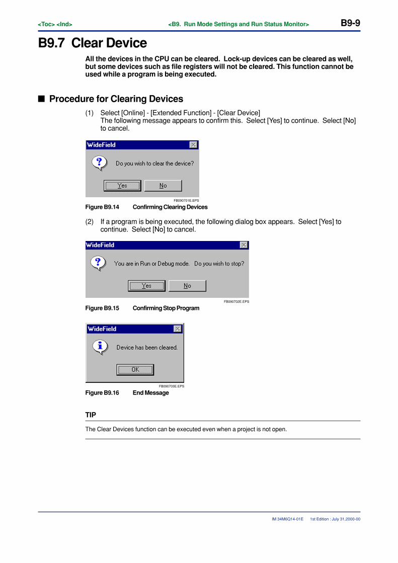
<Toc> <Ind> <B9. Run Mode Settings and Run Status Monitor> B9-9
IM 34M6Q14-01E
B9.7 Clear DeviceAll the devices in the CPU can be cleared. Lock-up devices can be cleared as well,but some devices such as file registers will not be cleared. This function cannot beused while a program is being executed.
� Procedure for Clearing Devices(1) Select [Online] - [Extended Function] - [Clear Device]
The following message appears to confirm this. Select [Yes] to continue. Select [No]to cancel.
FB090701E.EPS
Figure B9.14 Confirming Clearing Devices
(2) If a program is being executed, the following dialog box appears. Select [Yes] tocontinue. Select [No] to cancel.
FB090702E.EPS
Figure B9.15 Confirming Stop Program
FB090703E.EPS
Figure B9.16 End Message
TIP
The Clear Devices function can be executed even when a project is not open.
1st Edition : July 31,2000-00
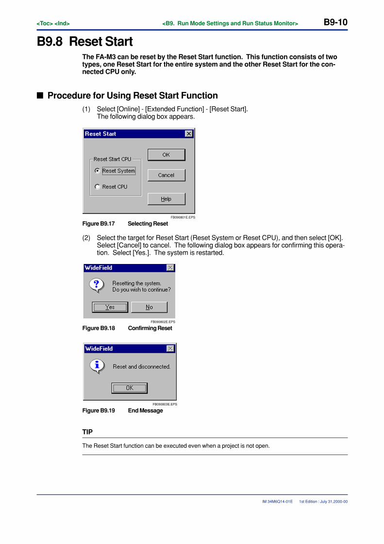
B9-10<Toc> <Ind> <B9. Run Mode Settings and Run Status Monitor>
IM 34M6Q14-01E
B9.8 Reset StartThe FA-M3 can be reset by the Reset Start function. This function consists of twotypes, one Reset Start for the entire system and the other Reset Start for the con-nected CPU only.
� Procedure for Using Reset Start Function(1) Select [Online] - [Extended Function] - [Reset Start].
The following dialog box appears.
FB090801E.EPS
Figure B9.17 Selecting Reset
(2) Select the target for Reset Start (Reset System or Reset CPU), and then select [OK].Select [Cancel] to cancel. The following dialog box appears for confirming this opera-tion. Select [Yes.]. The system is restarted.
FB090802E.EPS
Figure B9.18 Confirming Reset
FB090803E.EPS
Figure B9.19 End Message
TIP
The Reset Start function can be executed even when a project is not open.
1st Edition : July 31,2000-00

<Toc> <Ind> <B9. Run Mode Settings and Run Status Monitor> B9-11
IM 34M6Q14-01E
CAUTION
• When the Reset Start is done, the personal computer is disconnected from the FA-M3.
• System Reset is effective only for the main CPU (CPU mounted in slot 1). If SystemReset is attempted for an add-on CPU, an error occurs and System Reset is notimplemented.
• When Reset Start is done, devices that are not locked up are initialized.
• Reset Start cannot be done during online editing.
• Do not do CPU Reset for a particular CPU when the system is configured of multipleCPUs. Otherwise, an error will occur when CPUs are communicating and when thesame module is being accessed. When the system consists of multiple CPUs, doSystem Reset for the main CPU (CPU mounted in slot 1).
1st Edition : July 31,2000-00
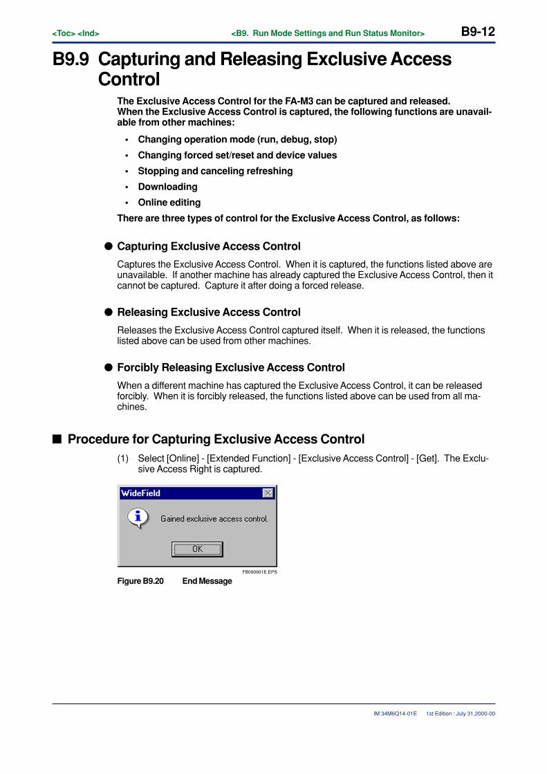
B9-12<Toc> <Ind> <B9. Run Mode Settings and Run Status Monitor>
IM 34M6Q14-01E
B9.9 Capturing and Releasing Exclusive AccessControl
The Exclusive Access Control for the FA-M3 can be captured and released.When the Exclusive Access Control is captured, the following functions are unavail-able from other machines:
• Changing operation mode (run, debug, stop)
• Changing forced set/reset and device values
• Stopping and canceling refreshing
• Downloading
• Online editing
There are three types of control for the Exclusive Access Control, as follows:
� Capturing Exclusive Access Control
Captures the Exclusive Access Control. When it is captured, the functions listed above areunavailable. If another machine has already captured the Exclusive Access Control, then itcannot be captured. Capture it after doing a forced release.
� Releasing Exclusive Access Control
Releases the Exclusive Access Control captured itself. When it is released, the functionslisted above can be used from other machines.
� Forcibly Releasing Exclusive Access Control
When a different machine has captured the Exclusive Access Control, it can be releasedforcibly. When it is forcibly released, the functions listed above can be used from all ma-chines.
� Procedure for Capturing Exclusive Access Control(1) Select [Online] - [Extended Function] - [Exclusive Access Control] - [Get]. The Exclu-
sive Access Right is captured.
FB090901E.EPS
Figure B9.20 End Message
1st Edition : July 31,2000-00
<Toc> <Ind> <B9. Run Mode Settings and Run Status Monitor> B9-13
IM 34M6Q14-01E
� Procedure for Releasing Exclusive Access Control(1) Select [Online] - [Extended Function] - [Exclusive Access Control] - [Release]. The
Exclusive Access Control is released.
FB090902E.EPS
Figure B9.21 End Message
� Procedure for Forcibly Releasing Exclusive Access Control(1) Select [Online] - [Extended Function] - [Exclusive Access Control] - [Forced Release].
The dialog box below appears to confirm the release. Select [Yes]. The ExclusiveAccess Control is forcibly released.
FB090903E.EPS
Figure B9.22 Confirming Forced Release
FB090904E.EPS
Figure B9.23 End message
TIP
The Exclusive Access Control can be captured and released even when a project is not open.
1st Edition : July 31,2000-00

Blank Page
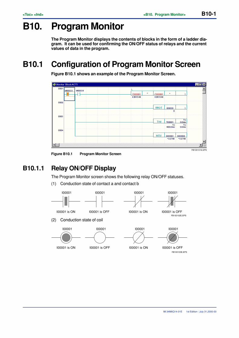
<Toc> <Ind> <B10. Program Monitor> B10-1
IM 34M6Q14-01E
B10. Program MonitorThe Program Monitor displays the contents of blocks in the form of a ladder dia-gram. It can be used for confirming the ON/OFF status of relays and the currentvalues of data in the program.
B10.1 Configuration of Program Monitor ScreenFigure B10.1 shows an example of the Program Monitor Screen.
FB100101E.EPS
Figure B10.1 Program Monitor Screen
B10.1.1 Relay ON/OFF DisplayThe Program Monitor screen shows the following relay ON/OFF statuses.
(1) Conduction state of contact a and contact b
I00001 is ON
I00001
I00001 is OFF
I00001
I00001 is OFF
I00001
I00001 is ON
I00001
FB100102E.EPS
(2) Conduction state of coil
I00001 I00001 I00001 I00001
FB100103E.EPS
I00001 is ON I00001 is OFFI00001 is OFF I00001 is ON
1st Edition : July 31,2000-00
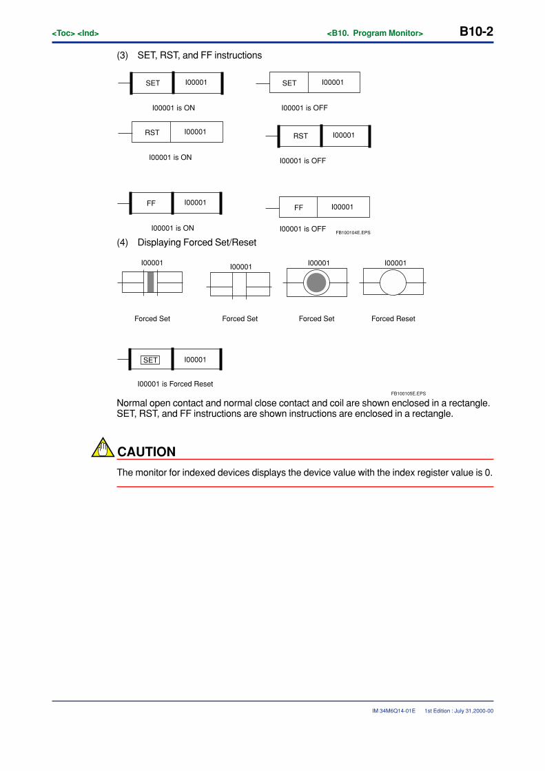
B10-2<Toc> <Ind> <B10. Program Monitor>
IM 34M6Q14-01E
(3) SET, RST, and FF instructions
SET I00001 SET I00001
I00001 is ON
RST I00001
I00001 is OFF
FF I00001
I00001 is ON
I00001 is OFF
RST I00001
I00001 is ON
FF I00001
I00001 is OFFFB100104E.EPS
(4) Displaying Forced Set/Reset
SET I00001
I00001 is Forced Reset
Forced Set Forced Set Forced Set Forced Reset
I00001 I00001 I00001
FB100105E.EPS
I00001
Normal open contact and normal close contact and coil are shown enclosed in a rectangle.SET, RST, and FF instructions are shown instructions are enclosed in a rectangle.
CAUTION
The monitor for indexed devices displays the device value with the index register value is 0.
1st Edition : July 31,2000-00

<Toc> <Ind> <B10. Program Monitor> B10-3
IM 34M6Q14-01E
B10.1.2 Displaying Application InstructionsIf detailed display is selected for the contents of the devices of the application instructionsand the current value of the timer/counter, these are displayed. The usual monitor screenhas the same display as for offline.
CAUTION
The monitor for indexed devices displays the device value with the index register value is 0.
1st Edition : July 31,2000-00
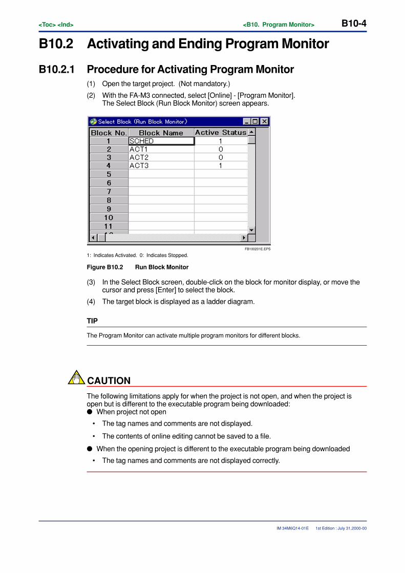
B10-4<Toc> <Ind> <B10. Program Monitor>
IM 34M6Q14-01E
B10.2 Activating and Ending Program Monitor
B10.2.1 Procedure for Activating Program Monitor(1) Open the target project. (Not mandatory.)
(2) With the FA-M3 connected, select [Online] - [Program Monitor].The Select Block (Run Block Monitor) screen appears.
FB100201E.EPS
1: Indicates Activated. 0: Indicates Stopped.
Figure B10.2 Run Block Monitor
(3) In the Select Block screen, double-click on the block for monitor display, or move thecursor and press [Enter] to select the block.
(4) The target block is displayed as a ladder diagram.
TIP
The Program Monitor can activate multiple program monitors for different blocks.
CAUTION
The following limitations apply for when the project is not open, and when the project isopen but is different to the executable program being downloaded:� When project not open
• The tag names and comments are not displayed.
• The contents of online editing cannot be saved to a file.
� When the opening project is different to the executable program being downloaded
• The tag names and comments are not displayed correctly.
1st Edition : July 31,2000-00
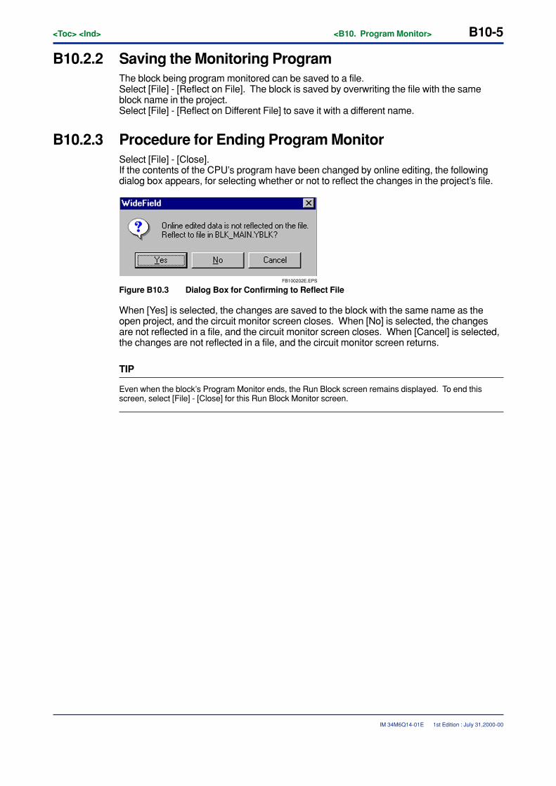
<Toc> <Ind> <B10. Program Monitor> B10-5
IM 34M6Q14-01E
B10.2.2 Saving the Monitoring ProgramThe block being program monitored can be saved to a file.Select [File] - [Reflect on File]. The block is saved by overwriting the file with the sameblock name in the project.Select [File] - [Reflect on Different File] to save it with a different name.
B10.2.3 Procedure for Ending Program MonitorSelect [File] - [Close].If the contents of the CPU’s program have been changed by online editing, the followingdialog box appears, for selecting whether or not to reflect the changes in the project’s file.
FB100202E.EPS
Figure B10.3 Dialog Box for Confirming to Reflect File
When [Yes] is selected, the changes are saved to the block with the same name as theopen project, and the circuit monitor screen closes. When [No] is selected, the changesare not reflected in a file, and the circuit monitor screen closes. When [Cancel] is selected,the changes are not reflected in a file, and the circuit monitor screen returns.
TIP
Even when the block’s Program Monitor ends, the Run Block screen remains displayed. To end thisscreen, select [File] - [Close] for this Run Block Monitor screen.
1st Edition : July 31,2000-00
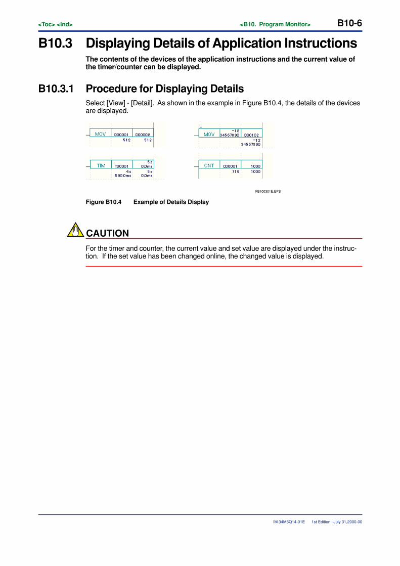
B10-6<Toc> <Ind> <B10. Program Monitor>
IM 34M6Q14-01E
B10.3 Displaying Details of Application InstructionsThe contents of the devices of the application instructions and the current value ofthe timer/counter can be displayed.
B10.3.1 Procedure for Displaying DetailsSelect [View] - [Detail]. As shown in the example in Figure B10.4, the details of the devicesare displayed.
FB100301E.EPS
Figure B10.4 Example of Details Display
CAUTION
For the timer and counter, the current value and set value are displayed under the instruc-tion. If the set value has been changed online, the changed value is displayed.
1st Edition : July 31,2000-00
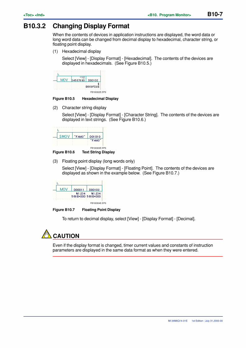
<Toc> <Ind> <B10. Program Monitor> B10-7
IM 34M6Q14-01E
B10.3.2 Changing Display FormatWhen the contents of devices in application instructions are displayed, the word data orlong word data can be changed from decimal display to hexadecimal, character string, orfloating point display.
(1) Hexadecimal display
Select [View] - [Display Format] - [Hexadecimal]. The contents of the devices aredisplayed in hexadecimals. (See Figure B10.5.)
FB100302E.EPS
Figure B10.5 Hexadecimal Display
(2) Character string display
Select [View] - [Display Format] - [Character String]. The contents of the devices aredisplayed in text strings. (See Figure B10.6.)
FB100303E.EPS
Figure B10.6 Text String Display
(3) Floating point display (long words only)
Select [View] - [Display Format] - [Floating Point]. The contents of the devices aredisplayed as shown in the example below. (See Figure B10.7.)
FB100304E.EPS
Figure B10.7 Floating Point Display
To return to decimal display, select [View] - [Display Format] - [Decimal].
CAUTION
Even if the display format is changed, timer current values and constants of instructionparameters are displayed in the same data format as when they were entered.
1st Edition : July 31,2000-00
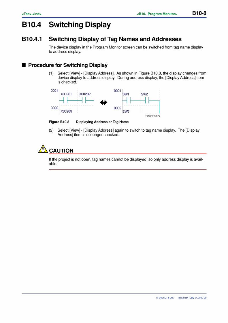
B10-8<Toc> <Ind> <B10. Program Monitor>
IM 34M6Q14-01E
B10.4 Switching Display
B10.4.1 Switching Display of Tag Names and AddressesThe device display in the Program Monitor screen can be switched from tag name displayto address display.
� Procedure for Switching Display(1) Select [View] - [Display Address]. As shown in Figure B10.8, the display changes from
device display to address display. During address display, the [Display Address] itemis checked.
FB100401E.EPS
Figure B10.8 Displaying Address or Tag Name
(2) Select [View] - [Display Address] again to switch to tag name display. The [DisplayAddress] item is no longer checked.
CAUTION
If the project is not open, tag names cannot be displayed, so only address display is avail-able.
1st Edition : July 31,2000-00
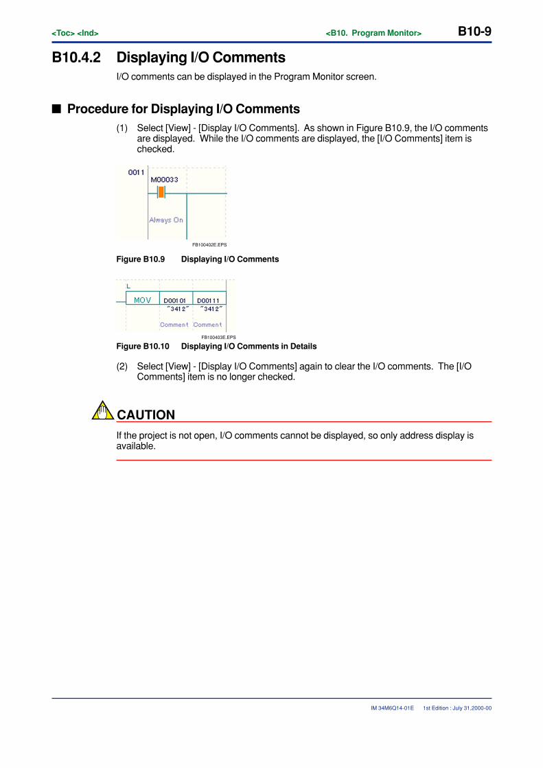
<Toc> <Ind> <B10. Program Monitor> B10-9
IM 34M6Q14-01E
B10.4.2 Displaying I/O CommentsI/O comments can be displayed in the Program Monitor screen.
� Procedure for Displaying I/O Comments(1) Select [View] - [Display I/O Comments]. As shown in Figure B10.9, the I/O comments
are displayed. While the I/O comments are displayed, the [I/O Comments] item ischecked.
FB100402E.EPS
Figure B10.9 Displaying I/O Comments
FB100403E.EPS
Figure B10.10 Displaying I/O Comments in Details
(2) Select [View] - [Display I/O Comments] again to clear the I/O comments. The [I/OComments] item is no longer checked.
CAUTION
If the project is not open, I/O comments cannot be displayed, so only address display isavailable.
1st Edition : July 31,2000-00
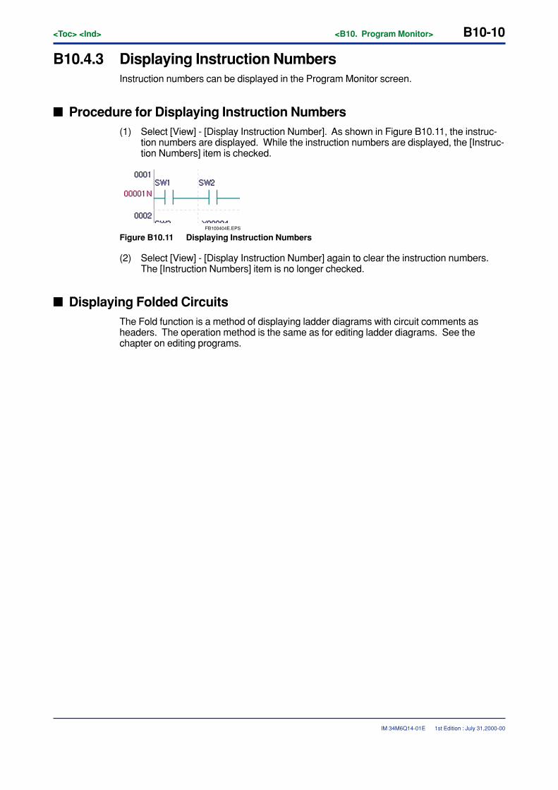
B10-10<Toc> <Ind> <B10. Program Monitor>
IM 34M6Q14-01E
B10.4.3 Displaying Instruction NumbersInstruction numbers can be displayed in the Program Monitor screen.
� Procedure for Displaying Instruction Numbers(1) Select [View] - [Display Instruction Number]. As shown in Figure B10.11, the instruc-
tion numbers are displayed. While the instruction numbers are displayed, the [Instruc-tion Numbers] item is checked.
FB100404E.EPS
Figure B10.11 Displaying Instruction Numbers
(2) Select [View] - [Display Instruction Number] again to clear the instruction numbers.The [Instruction Numbers] item is no longer checked.
� Displaying Folded CircuitsThe Fold function is a method of displaying ladder diagrams with circuit comments asheaders. The operation method is the same as for editing ladder diagrams. See thechapter on editing programs.
1st Edition : July 31,2000-00

<Toc> <Ind> <B10. Program Monitor> B10-11
IM 34M6Q14-01E
B10.5 Browsing Tag NamesSelect [Edit] - [Block Tag Definition] to look up tag name definitions defined byblocks. Tag name definitions cannot be changed online.
1st Edition : July 31,2000-00
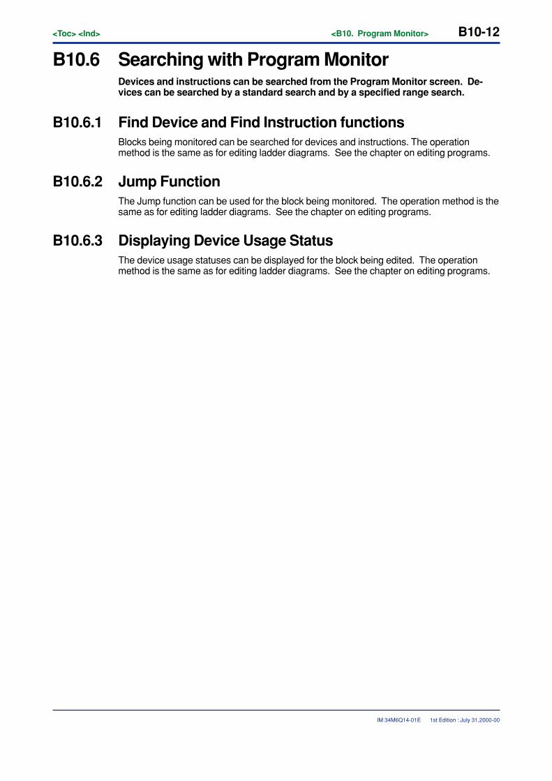
B10-12<Toc> <Ind> <B10. Program Monitor>
IM 34M6Q14-01E
B10.6 Searching with Program MonitorDevices and instructions can be searched from the Program Monitor screen. De-vices can be searched by a standard search and by a specified range search.
B10.6.1 Find Device and Find Instruction functionsBlocks being monitored can be searched for devices and instructions. The operationmethod is the same as for editing ladder diagrams. See the chapter on editing programs.
B10.6.2 Jump FunctionThe Jump function can be used for the block being monitored. The operation method is thesame as for editing ladder diagrams. See the chapter on editing programs.
B10.6.3 Displaying Device Usage StatusThe device usage statuses can be displayed for the block being edited. The operationmethod is the same as for editing ladder diagrams. See the chapter on editing programs.
1st Edition : July 31,2000-00
<Toc> <Ind> <B10. Program Monitor> B10-13
IM 34M6Q14-01E
B10.7 Suspending and Resuming Program MonitorThe Program Monitor can be paused. When it is paused, the device statuses dis-played in the Program Monitor screen are not updated.
B10.7.1 Procedure for Suspending Monitor(1) Select [View] - [Suspend Monitor].
B10.7.2 Procedure for Resuming Monitor(1) Select [Display] - [Resume Monitor].
TIP
This Pause Monitor function affects all Program Monitor and Device Monitor screens.
1st Edition : July 31,2000-00

Blank Page
<Toc> <Ind> <B11. Device Monitor> B11-1
IM 34M6Q14-01E
B11. Device MonitorThe Device Monitor function displays a monitor screen for each type of device thathas been specified. This function is used for confirming the relay ON/OFF statuses,current data values, and the current values and settings for the timer/counter.
B11.1 Configuration of Device Monitor ScreensThe device monitor screens can be roughly divided into four types, for relays, regis-ters, timers and counters.
1st Edition : July 31,2000-00
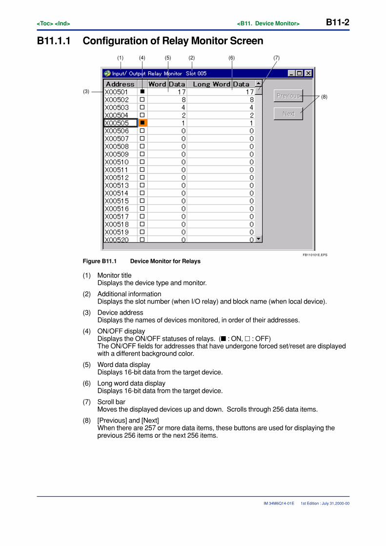
B11-2<Toc> <Ind> <B11. Device Monitor>
IM 34M6Q14-01E
B11.1.1 Configuration of Relay Monitor Screen
FB110101E.EPS
(8)
(7)(6)(2)(5)(4)(1)
(3)
Figure B11.1 Device Monitor for Relays
(1) Monitor titleDisplays the device type and monitor.
(2) Additional informationDisplays the slot number (when I/O relay) and block name (when local device).
(3) Device addressDisplays the names of devices monitored, in order of their addresses.
(4) ON/OFF displayDisplays the ON/OFF statuses of relays. (� : ON, � : OFF)The ON/OFF fields for addresses that have undergone forced set/reset are displayedwith a different background color.
(5) Word data displayDisplays 16-bit data from the target device.
(6) Long word data displayDisplays 16-bit data from the target device.
(7) Scroll barMoves the displayed devices up and down. Scrolls through 256 data items.
(8) [Previous] and [Next]When there are 257 or more data items, these buttons are used for displaying theprevious 256 items or the next 256 items.
1st Edition : July 31,2000-00
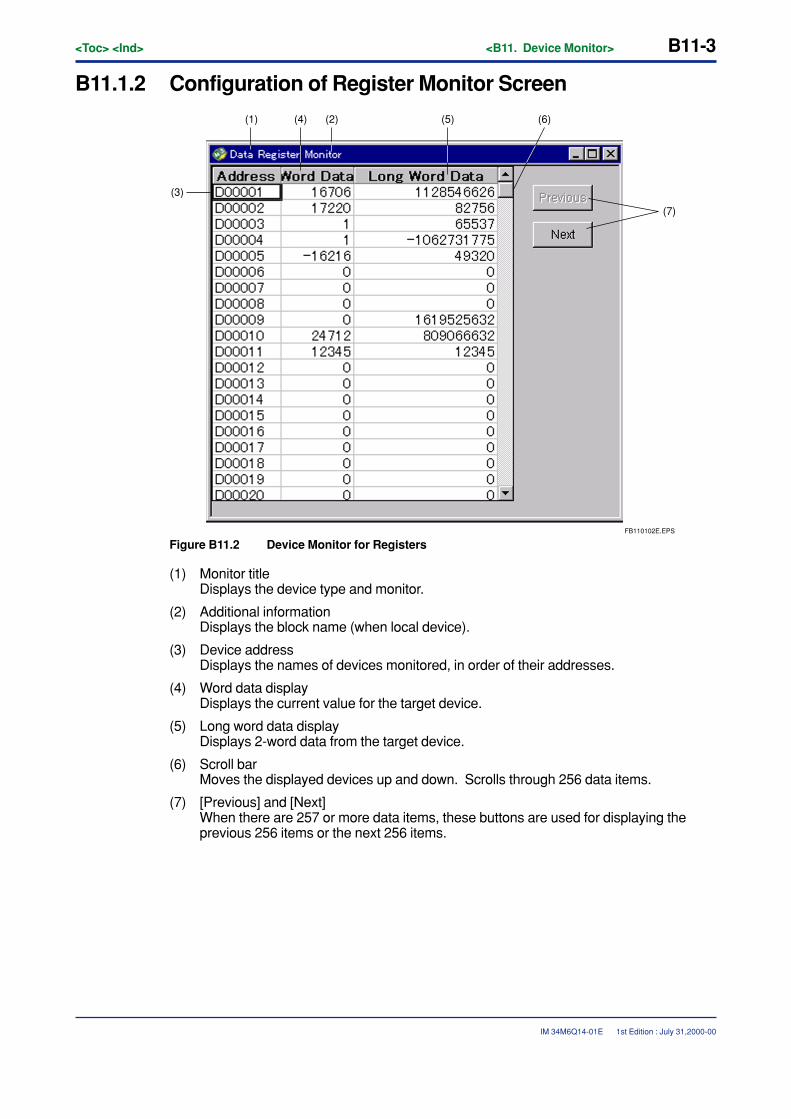
<Toc> <Ind> <B11. Device Monitor> B11-3
IM 34M6Q14-01E
B11.1.2 Configuration of Register Monitor Screen
FB110102E.EPS
(7)
(6)(5)(4) (2)(1)
(3)
Figure B11.2 Device Monitor for Registers
(1) Monitor titleDisplays the device type and monitor.
(2) Additional informationDisplays the block name (when local device).
(3) Device addressDisplays the names of devices monitored, in order of their addresses.
(4) Word data displayDisplays the current value for the target device.
(5) Long word data displayDisplays 2-word data from the target device.
(6) Scroll barMoves the displayed devices up and down. Scrolls through 256 data items.
(7) [Previous] and [Next]When there are 257 or more data items, these buttons are used for displaying theprevious 256 items or the next 256 items.
1st Edition : July 31,2000-00
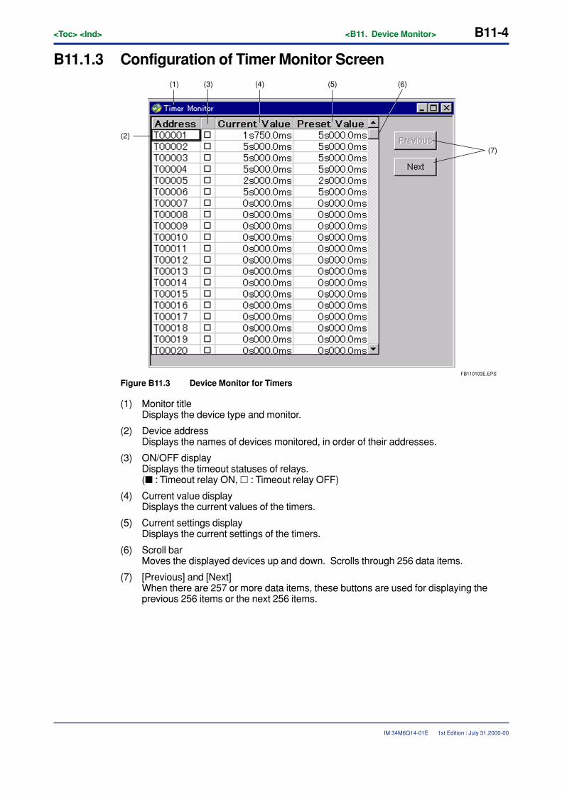
B11-4<Toc> <Ind> <B11. Device Monitor>
IM 34M6Q14-01E
B11.1.3 Configuration of Timer Monitor Screen
FB110103E.EPS
(7)
(6)(5)
(2)
(4)(1) (3)
Figure B11.3 Device Monitor for Timers
(1) Monitor titleDisplays the device type and monitor.
(2) Device addressDisplays the names of devices monitored, in order of their addresses.
(3) ON/OFF displayDisplays the timeout statuses of relays.(� : Timeout relay ON, � : Timeout relay OFF)
(4) Current value displayDisplays the current values of the timers.
(5) Current settings displayDisplays the current settings of the timers.
(6) Scroll barMoves the displayed devices up and down. Scrolls through 256 data items.
(7) [Previous] and [Next]When there are 257 or more data items, these buttons are used for displaying theprevious 256 items or the next 256 items.
1st Edition : July 31,2000-00
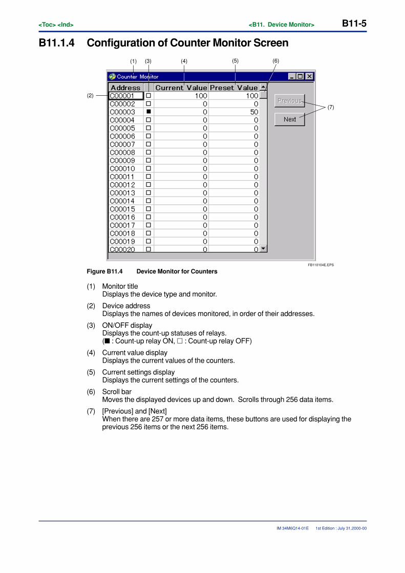
<Toc> <Ind> <B11. Device Monitor> B11-5
IM 34M6Q14-01E
B11.1.4 Configuration of Counter Monitor Screen
FB110104E.EPS
(7)
(5)
(2)
(1) (3) (6)(4)
Figure B11.4 Device Monitor for Counters
(1) Monitor titleDisplays the device type and monitor.
(2) Device addressDisplays the names of devices monitored, in order of their addresses.
(3) ON/OFF displayDisplays the count-up statuses of relays.(� : Count-up relay ON, � : Count-up relay OFF)
(4) Current value displayDisplays the current values of the counters.
(5) Current settings displayDisplays the current settings of the counters.
(6) Scroll barMoves the displayed devices up and down. Scrolls through 256 data items.
(7) [Previous] and [Next]When there are 257 or more data items, these buttons are used for displaying theprevious 256 items or the next 256 items.
1st Edition : July 31,2000-00
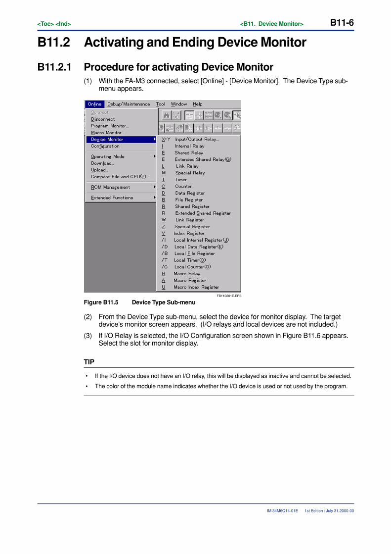
B11-6<Toc> <Ind> <B11. Device Monitor>
IM 34M6Q14-01E 1st Edition : July 31,2000-00
B11.2 Activating and Ending Device Monitor
B11.2.1 Procedure for activating Device Monitor(1) With the FA-M3 connected, select [Online] - [Device Monitor]. The Device Type sub-
menu appears.
FB110201E.EPS
Figure B11.5 Device Type Sub-menu
(2) From the Device Type sub-menu, select the device for monitor display. The targetdevice’s monitor screen appears. (I/O relays and local devices are not included.)
(3) If I/O Relay is selected, the I/O Configuration screen shown in Figure B11.6 appears.Select the slot for monitor display.
TIP
• If the I/O device does not have an I/O relay, this will be displayed as inactive and cannot be selected.
• The color of the module name indicates whether the I/O device is used or not used by the program.
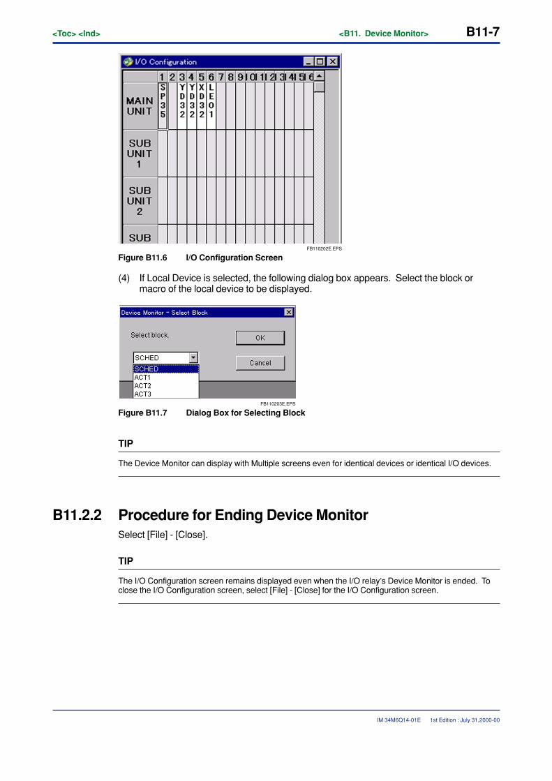
<Toc> <Ind> <B11. Device Monitor> B11-7
IM 34M6Q14-01E 1st Edition : July 31,2000-00
FB110202E.EPS
Figure B11.6 I/O Configuration Screen
(4) If Local Device is selected, the following dialog box appears. Select the block ormacro of the local device to be displayed.
FB110203E.EPS
Figure B11.7 Dialog Box for Selecting Block
TIP
The Device Monitor can display with Multiple screens even for identical devices or identical I/O devices.
B11.2.2 Procedure for Ending Device MonitorSelect [File] - [Close].
TIP
The I/O Configuration screen remains displayed even when the I/O relay’s Device Monitor is ended. Toclose the I/O Configuration screen, select [File] - [Close] for the I/O Configuration screen.
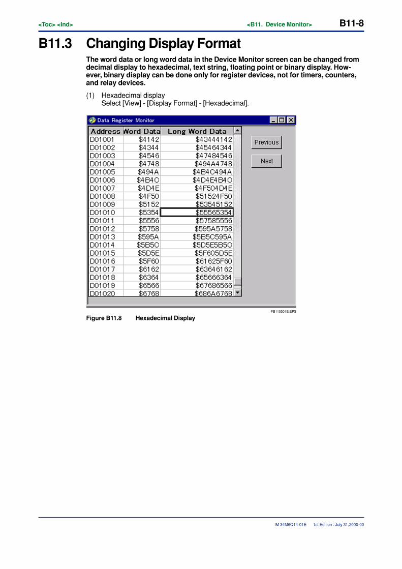
B11-8<Toc> <Ind> <B11. Device Monitor>
IM 34M6Q14-01E
B11.3 Changing Display FormatThe word data or long word data in the Device Monitor screen can be changed fromdecimal display to hexadecimal, text string, floating point or binary display. How-ever, binary display can be done only for register devices, not for timers, counters,and relay devices.
(1) Hexadecimal displaySelect [View] - [Display Format] - [Hexadecimal].
FB110301E.EPS
Figure B11.8 Hexadecimal Display
1st Edition : July 31,2000-00
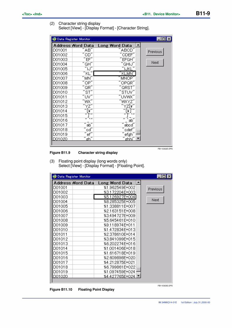
<Toc> <Ind> <B11. Device Monitor> B11-9
IM 34M6Q14-01E
(2) Character string displaySelect [View] - [Display Format] - [Character String].
FB110302E.EPS
Figure B11.9 Character string display
(3) Floating point display (long words only)Select [View] - [Display Format] - [Floating Point].
FB110303E.EPS
Figure B11.10 Floating Point Display
1st Edition : July 31,2000-00
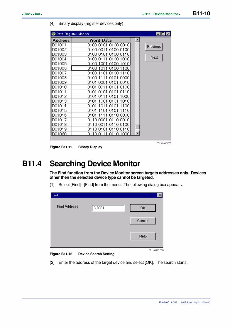
B11-10<Toc> <Ind> <B11. Device Monitor>
IM 34M6Q14-01E 1st Edition : July 31,2000-00
(4) Binary display (register devices only)
FB110304E.EPS
Figure B11.11 Binary Display
B11.4 Searching Device MonitorThe Find function from the Device Monitor screen targets addresses only. Devicesother then the selected device type cannot be targeted.
(1) Select [Find] - [Find] from the menu. The following dialog box appears.
FB110401E.EPS
Figure B11.12 Device Search Setting
(2) Enter the address of the target device and select [OK]. The search starts.
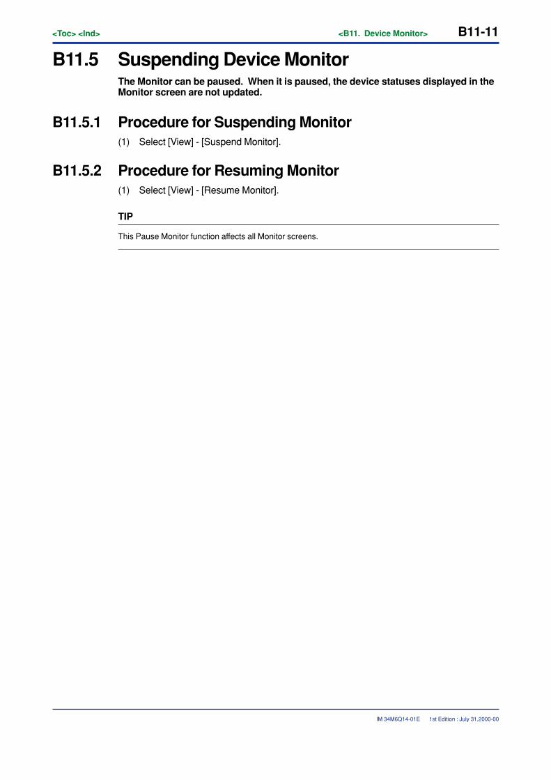
<Toc> <Ind> <B11. Device Monitor> B11-11
IM 34M6Q14-01E 1st Edition : July 31,2000-00
B11.5 Suspending Device MonitorThe Monitor can be paused. When it is paused, the device statuses displayed in theMonitor screen are not updated.
B11.5.1 Procedure for Suspending Monitor(1) Select [View] - [Suspend Monitor].
B11.5.2 Procedure for Resuming Monitor(1) Select [View] - [Resume Monitor].
TIP
This Pause Monitor function affects all Monitor screens.

Blank Page
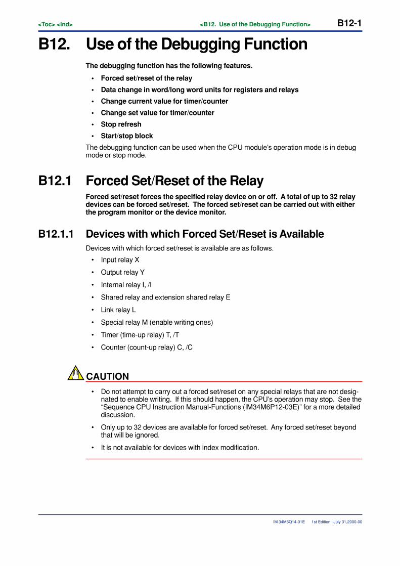
<Toc> <Ind> <B12. Use of the Debugging Function> B12-1
IM 34M6Q14-01E
B12. Use of the Debugging FunctionThe debugging function has the following features.
• Forced set/reset of the relay
• Data change in word/long word units for registers and relays
• Change current value for timer/counter
• Change set value for timer/counter
• Stop refresh
• Start/stop block
The debugging function can be used when the CPU module’s operation mode is in debugmode or stop mode.
B12.1 Forced Set/Reset of the RelayForced set/reset forces the specified relay device on or off. A total of up to 32 relaydevices can be forced set/reset. The forced set/reset can be carried out with eitherthe program monitor or the device monitor.
B12.1.1 Devices with which Forced Set/Reset is AvailableDevices with which forced set/reset is available are as follows.
• Input relay X
• Output relay Y
• Internal relay I, /I
• Shared relay and extension shared relay E
• Link relay L
• Special relay M (enable writing ones)
• Timer (time-up relay) T, /T
• Counter (count-up relay) C, /C
CAUTION
• Do not attempt to carry out a forced set/reset on any special relays that are not desig-nated to enable writing. If this should happen, the CPU’s operation may stop. See the“Sequence CPU Instruction Manual-Functions (IM34M6P12-03E)” for a more detaileddiscussion.
• Only up to 32 devices are available for forced set/reset. Any forced set/reset beyondthat will be ignored.
• It is not available for devices with index modification.
1st Edition : July 31,2000-00
B12-2<Toc> <Ind> <B12. Use of the Debugging Function>
IM 34M6Q14-01E
B12.1.2 Operation and Expiration of Forced Set/Reset• The forced set/reset takes precedence over the program itself. Any relays that are set
to off in the program will be turned on if a forced set/reset is carried out on them.
• The forced set/reset takes precedence over input of input refresh, shared refresh, andlink refresh, so even any externally-connected inputs that are off will be turned on if aforced set/reset is carried out on them.
• Devices that a forced set/reset is carried out on will be protected until one of thefollowing operations is carried out.
• Release forced set/reset.
• Change the CPU’s operation mode to run mode.
• Turn off the CPU’s power.
B12.1.3 Procedure for Forced Set/Reset(1) Select the relay device to undergo the forced set/reset from the program monitor
screen or the device monitor screen.
(2) Select [Debug/Maintenance] - [Forced Set] (or [Forced Reset]) from the menu.
(3) The selected relay device will go on (or off).
B12.1.4 Procedure for Canceling Forced Set/Reset(1) Select the relay device to have the forced set/reset undone from the program monitor
screen or the device monitor screen.
(2) Select [Debug/Maintenance] - [Cancel Forced Set] from the menu.
(3) The selected relay device will have the forced set/reset released.
B12.1.5 Procedure for Canceling All Forced Set/ResetAll devices with a forced set/reset carried out on them will have it undone.
(1) Select [Debug/Maintenance] - [Cancel All Forced].
(2) All devices with a forced set/reset carried out on them will have it release.
1st Edition : July 31,2000-00
<Toc> <Ind> <B12. Use of the Debugging Function> B12-3
IM 34M6Q14-01E
B12.2 Changing Word/Long Word DataThis changes data in either word units or in long word units for the register andrelays. There is no limitation on the number of devices that can be changed. Datachange can be done either from the program monitor or the device monitor.
B12.2.1 Devices with which Data Change is AvailableAll devices can have their current value changed except for those listed below.
• Timer and counter
• Special relays or special registers which are not designated to enable write.
CAUTION
• The current value cannot be changed for special relays and special registers whichare not designated to enable writing. If this should happen, the CPU’s operation maystop. See the “Sequence CPU Manual-Functions Section” for a more detailed discus-sion.
• It is not available for devices with index modification.
B12.2.2 Operation of Devices that have been Changed• Program execution takes precedence over changes in data. If there is a write to a
device by the program, the written value will take precedence over any changes thatare carried out.
• Input refresh, shared refresh, and link refresh take precedence over changes in data,so if there are any externally-connected inputs, the input value will be re-read.
1st Edition : July 31,2000-00
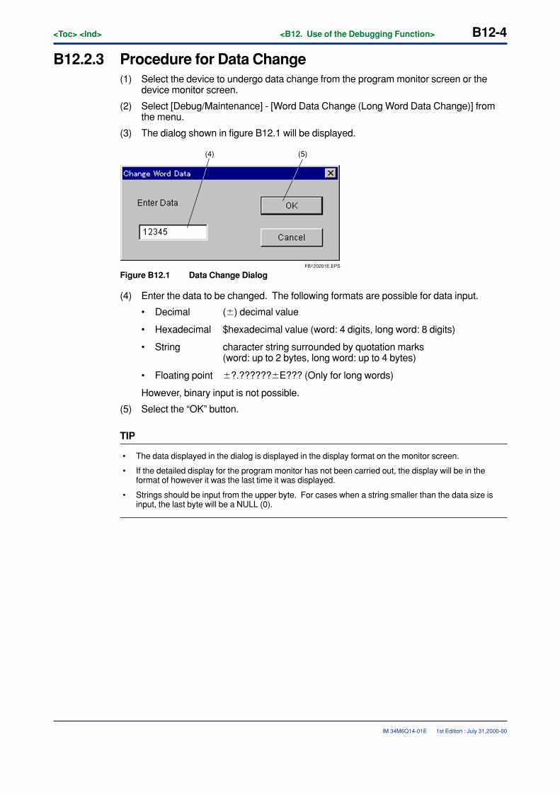
B12-4<Toc> <Ind> <B12. Use of the Debugging Function>
IM 34M6Q14-01E
B12.2.3 Procedure for Data Change(1) Select the device to undergo data change from the program monitor screen or the
device monitor screen.
(2) Select [Debug/Maintenance] - [Word Data Change (Long Word Data Change)] fromthe menu.
(3) The dialog shown in figure B12.1 will be displayed.
FB120201E.EPS
(5)(4)
Figure B12.1 Data Change Dialog
(4) Enter the data to be changed. The following formats are possible for data input.
• Decimal (�) decimal value
• Hexadecimal $hexadecimal value (word: 4 digits, long word: 8 digits)
• String character string surrounded by quotation marks(word: up to 2 bytes, long word: up to 4 bytes)
• Floating point �?.??????�E??? (Only for long words)
However, binary input is not possible.
(5) Select the “OK” button.
TIP
• The data displayed in the dialog is displayed in the display format on the monitor screen.
• If the detailed display for the program monitor has not been carried out, the display will be in theformat of however it was the last time it was displayed.
• Strings should be input from the upper byte. For cases when a string smaller than the data size isinput, the last byte will be a NULL (0).
1st Edition : July 31,2000-00
<Toc> <Ind> <B12. Use of the Debugging Function> B12-5
IM 34M6Q14-01E
B12.3 Changing the Current Value of the Timer/CounterThis changes the current value of the timer and counter. There are no restrictionson the number of devices that may be changed. Current value change can be doneeither from the program monitor or the device monitor.
B12.3.1 Devices with which Current Value Change is Available• The timer and the counter.
B12.3.2 Operation of Devices that have been Changed• The timer/counter will continue operation with the changed value as the current value.
• If the program writes data to the timer/counter, then execution of the program will takeprecedence. If there is a write to a device by the program, the written value will takeprecedence over any changes that are carried out.
1st Edition : July 31,2000-00
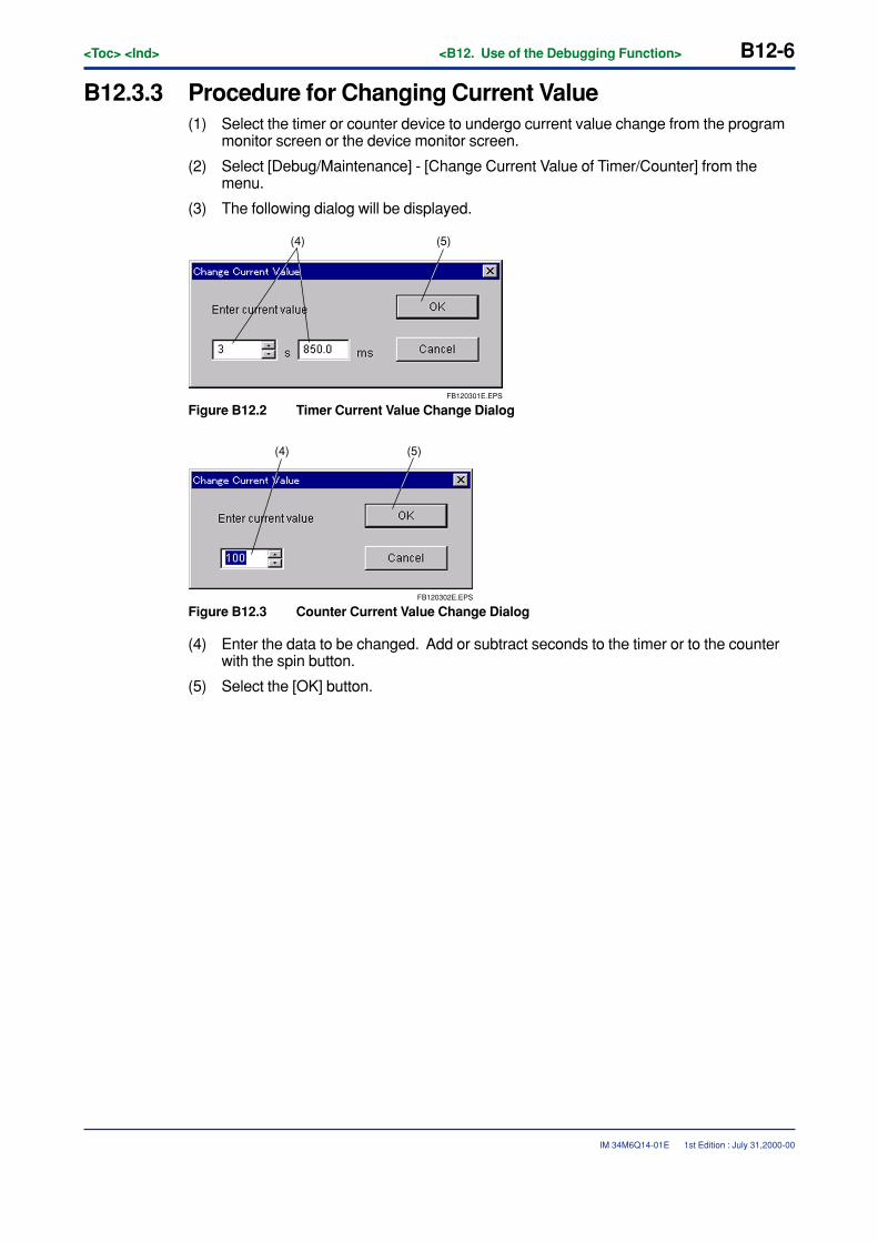
B12-6<Toc> <Ind> <B12. Use of the Debugging Function>
IM 34M6Q14-01E 1st Edition : July 31,2000-00
B12.3.3 Procedure for Changing Current Value(1) Select the timer or counter device to undergo current value change from the program
monitor screen or the device monitor screen.
(2) Select [Debug/Maintenance] - [Change Current Value of Timer/Counter] from themenu.
(3) The following dialog will be displayed.
FB120301E.EPS
(5)(4)
Figure B12.2 Timer Current Value Change Dialog
FB120302E.EPS
(5)(4)
Figure B12.3 Counter Current Value Change Dialog
(4) Enter the data to be changed. Add or subtract seconds to the timer or to the counterwith the spin button.
(5) Select the [OK] button.
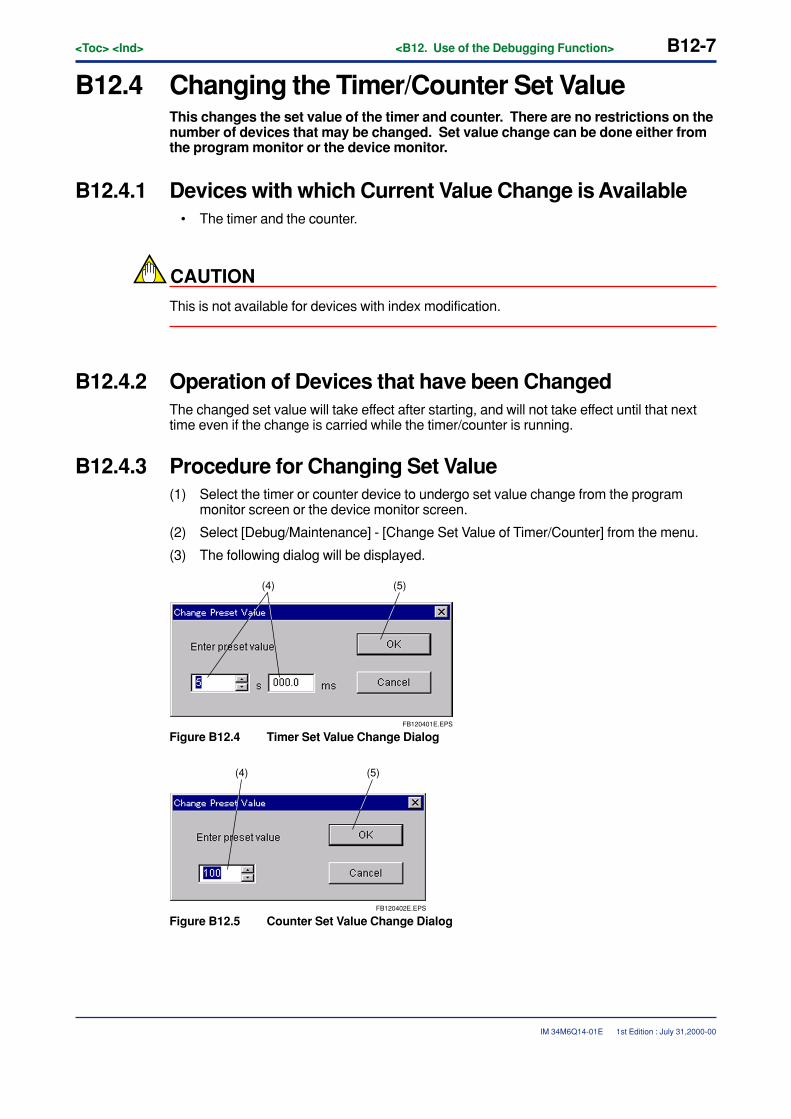
<Toc> <Ind> <B12. Use of the Debugging Function> B12-7
IM 34M6Q14-01E 1st Edition : July 31,2000-00
B12.4 Changing the Timer/Counter Set ValueThis changes the set value of the timer and counter. There are no restrictions on thenumber of devices that may be changed. Set value change can be done either fromthe program monitor or the device monitor.
B12.4.1 Devices with which Current Value Change is Available• The timer and the counter.
CAUTION
This is not available for devices with index modification.
B12.4.2 Operation of Devices that have been ChangedThe changed set value will take effect after starting, and will not take effect until that nexttime even if the change is carried while the timer/counter is running.
B12.4.3 Procedure for Changing Set Value(1) Select the timer or counter device to undergo set value change from the program
monitor screen or the device monitor screen.
(2) Select [Debug/Maintenance] - [Change Set Value of Timer/Counter] from the menu.
(3) The following dialog will be displayed.
FB120401E.EPS
(5)(4)
Figure B12.4 Timer Set Value Change Dialog
FB120402E.EPS
(5)(4)
Figure B12.5 Counter Set Value Change Dialog

B12-8<Toc> <Ind> <B12. Use of the Debugging Function>
IM 34M6Q14-01E 1st Edition : July 31,2000-00
(4) Enter the data to be changed. Add or subtract seconds to the timer or to the counterwith the spin button.
(5) Select the [OK] button.
CAUTION
The changes to the set value will not be reflected to the file even if file reflection is carriedout. In order implemented the reflection, do the timer/counter set value change with theonline edit.
<Toc> <Ind> <B12. Use of the Debugging Function> B12-9
IM 34M6Q14-01E 1st Edition : July 31,2000-00
B12.5 Stop RefreshingThis stops and undoes a variety of refreshes.
The following refresh stops are available.
• Stop Input RefreshThis stops the refresh of the input relay [X]
• Stop Output RefreshThis stops the refresh of the output relay [Y]
• Stop Shared RefreshThis stops the refresh of the shared relay and the extension shared relay [E], as wellas the refresh of the shared register and the extension shared register [R].
• Stop Link RefreshThis stops the refresh of the link relay L and the link register [W].
B12.5.1 Procedure for Stopping a Refresh(1) Select [Debug/Maintenance] - [Stop Refreshing].
(2) If the operation monitor is displayed, the devices which are in the middle of a refreshstop will be displayed.
B12.5.2 Restart RefreshingThis restarts a stopped refreshing.
(1) Select [Debug/Maintenance] - [Restart Refreshing].All stopped refreshing will be restarted.
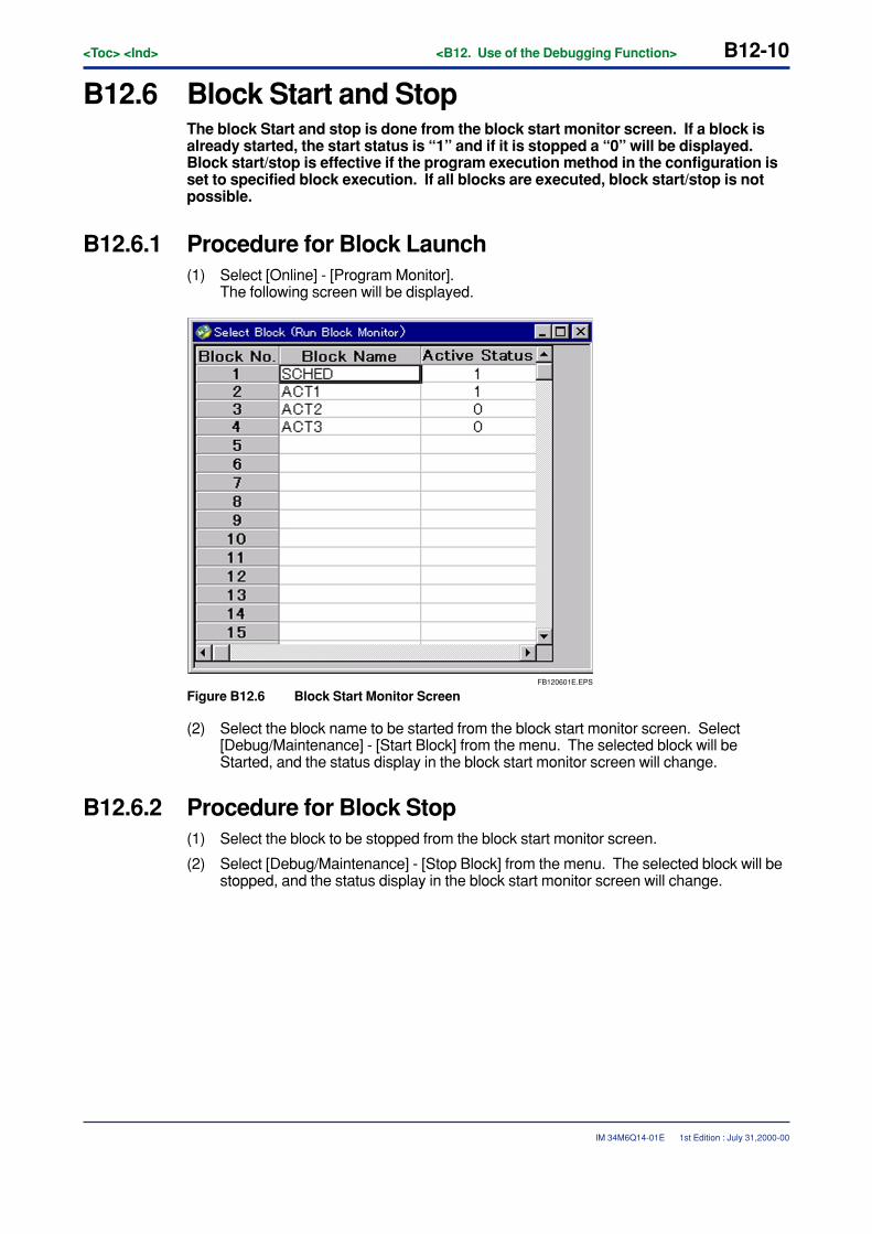
B12-10<Toc> <Ind> <B12. Use of the Debugging Function>
IM 34M6Q14-01E 1st Edition : July 31,2000-00
B12.6 Block Start and StopThe block Start and stop is done from the block start monitor screen. If a block isalready started, the start status is “1” and if it is stopped a “0” will be displayed.Block start/stop is effective if the program execution method in the configuration isset to specified block execution. If all blocks are executed, block start/stop is notpossible.
B12.6.1 Procedure for Block Launch(1) Select [Online] - [Program Monitor].
The following screen will be displayed.
FB120601E.EPS
Figure B12.6 Block Start Monitor Screen
(2) Select the block name to be started from the block start monitor screen. Select[Debug/Maintenance] - [Start Block] from the menu. The selected block will beStarted, and the status display in the block start monitor screen will change.
B12.6.2 Procedure for Block Stop(1) Select the block to be stopped from the block start monitor screen.
(2) Select [Debug/Maintenance] - [Stop Block] from the menu. The selected block will bestopped, and the status display in the block start monitor screen will change.
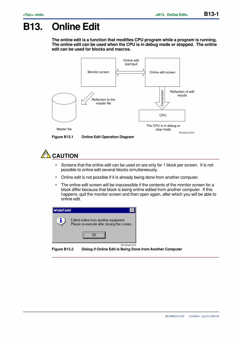
<Toc> <Ind> <B13. Online Edit> B13-1
IM 34M6Q14-01E
B13. Online EditThe online edit is a function that modifies CPU program while a program is running.The online edit can be used when the CPU is in debug mode or stopped. The onlineedit can be used for blocks and macros.
Monitor screen
Reflection to the master file
Reflection of edit results
The CPU is in debug or stop modeMaster file
Online edit screen
Online edit start/quit
Con
vers
ion
CPU
FB130001E.EPS
Figure B13.1 Online Edit Operation Diagram
CAUTION
• Screens that the online edit can be used on are only for 1 block per screen. It is notpossible to online edit several blocks simultaneously.
• Online edit is not possible if it is already being done from another computer.
• The online edit screen will be inaccessible if the contents of the monitor screen for ablock differ because that block is being online edited from another computer. If thishappens, quit the monitor screen and then open again, after which you will be able toonline edit.
FB130002E.EPS
Figure B13.2 Dialog if Online Edit is Being Done from Another Computer
1st Edition : July 31,2000-00
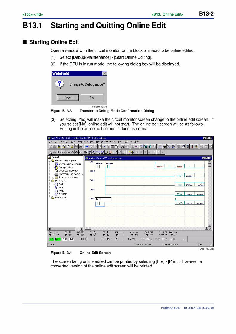
B13-2<Toc> <Ind> <B13. Online Edit>
IM 34M6Q14-01E
B13.1 Starting and Quitting Online Edit
� Starting Online EditOpen a window with the circuit monitor for the block or macro to be online edited.
(1) Select [Debug/Maintenance] - [Start Online Editing].
(2) If the CPU is in run mode, the following dialog box will be displayed.
FB130101E.EPS
Figure B13.3 Transfer to Debug Mode Confirmation Dialog
(3) Selecting [Yes] will make the circuit monitor screen change to the online edit screen. Ifyou select [No], online edit will not start. The online edit screen will be as follows.Editing in the online edit screen is done as normal.
FB130102E.EPS
Figure B13.4 Online Edit Screen
The screen being online edited can be printed by selecting [File] - [Print]. However, aconverted version of the online edit screen will be printed.
1st Edition : July 31,2000-00
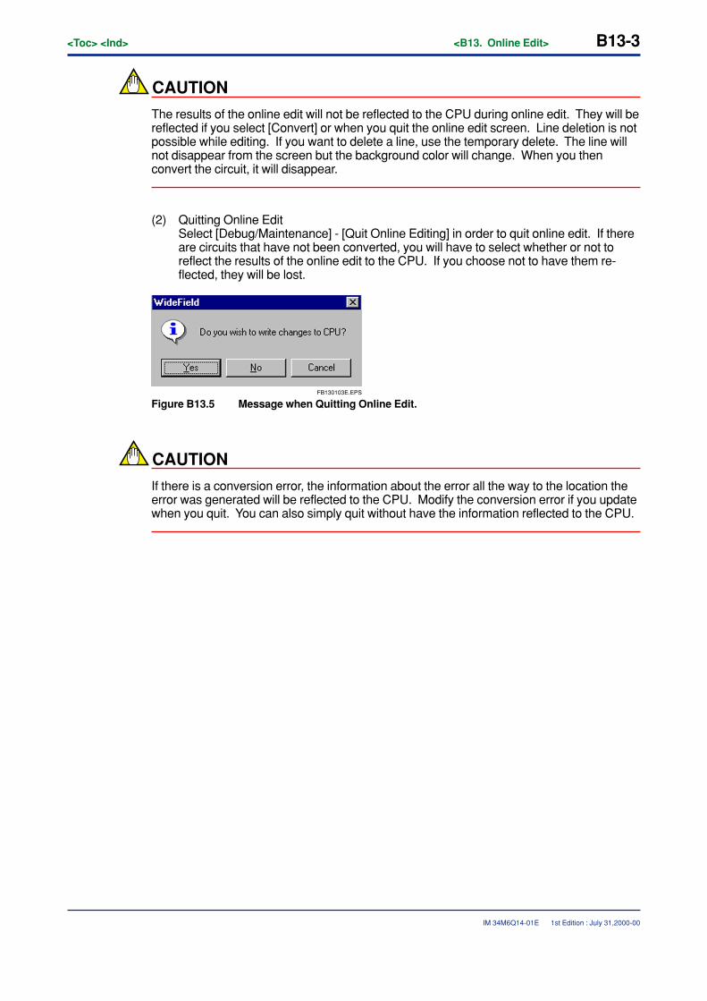
<Toc> <Ind> <B13. Online Edit> B13-3
IM 34M6Q14-01E
CAUTION
The results of the online edit will not be reflected to the CPU during online edit. They will bereflected if you select [Convert] or when you quit the online edit screen. Line deletion is notpossible while editing. If you want to delete a line, use the temporary delete. The line willnot disappear from the screen but the background color will change. When you thenconvert the circuit, it will disappear.
(2) Quitting Online EditSelect [Debug/Maintenance] - [Quit Online Editing] in order to quit online edit. If thereare circuits that have not been converted, you will have to select whether or not toreflect the results of the online edit to the CPU. If you choose not to have them re-flected, they will be lost.
FB130103E.EPS
Figure B13.5 Message when Quitting Online Edit.
CAUTION
If there is a conversion error, the information about the error all the way to the location theerror was generated will be reflected to the CPU. Modify the conversion error if you updatewhen you quit. You can also simply quit without have the information reflected to the CPU.
1st Edition : July 31,2000-00
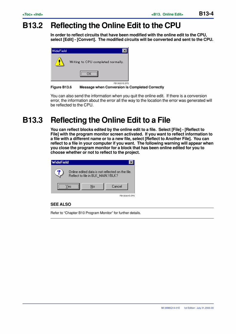
B13-4<Toc> <Ind> <B13. Online Edit>
IM 34M6Q14-01E
B13.2 Reflecting the Online Edit to the CPUIn order to reflect circuits that have been modified with the online edit to the CPU,select [Edit] - [Convert]. The modified circuits will be converted and sent to the CPU.
FB130201E.EPS
Figure B13.6 Message when Conversion is Completed Correctly
You can also send the information when you quit the online edit. If there is a conversionerror, the information about the error all the way to the location the error was generated willbe reflected to the CPU.
B13.3 Reflecting the Online Edit to a FileYou can reflect blocks edited by the online edit to a file. Select [File] - [Reflect toFile] with the program monitor screen activated. If you want to reflect information toa file with a different name or to a new file, select [Reflect to Another File]. You canreflect to a file in your computer if you want. The following warning will appear whenyou close the program monitor for a block that has been online edited for you tochoose whether or not to reflect to the project.
FB130301E.EPS
SEE ALSO
Refer to “Chapter B10 Program Monitor” for further details.
1st Edition : July 31,2000-00
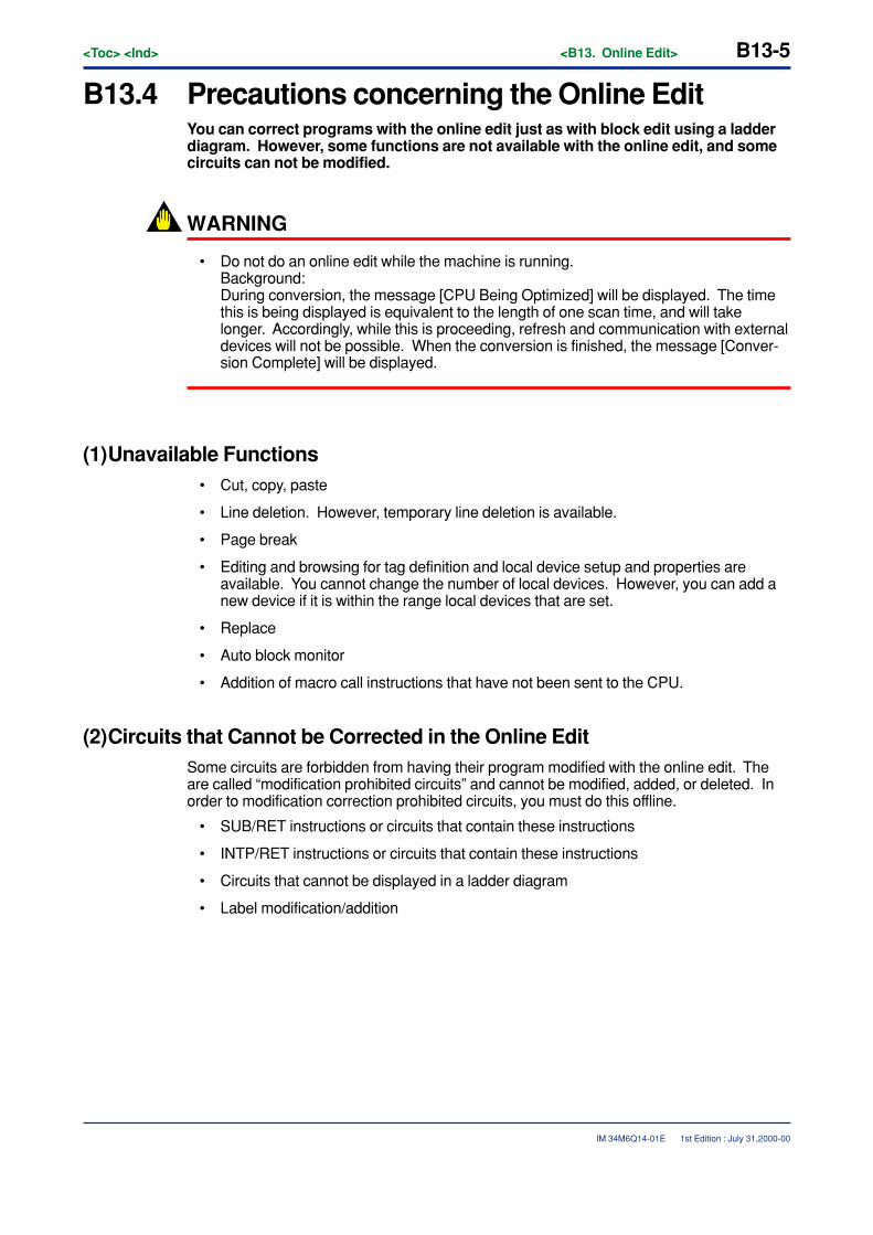
<Toc> <Ind> <B13. Online Edit> B13-5
IM 34M6Q14-01E
B13.4 Precautions concerning the Online EditYou can correct programs with the online edit just as with block edit using a ladderdiagram. However, some functions are not available with the online edit, and somecircuits can not be modified.
WARNING
• Do not do an online edit while the machine is running.Background:During conversion, the message [CPU Being Optimized] will be displayed. The timethis is being displayed is equivalent to the length of one scan time, and will takelonger. Accordingly, while this is proceeding, refresh and communication with externaldevices will not be possible. When the conversion is finished, the message [Conver-sion Complete] will be displayed.
(1)Unavailable Functions• Cut, copy, paste
• Line deletion. However, temporary line deletion is available.
• Page break
• Editing and browsing for tag definition and local device setup and properties areavailable. You cannot change the number of local devices. However, you can add anew device if it is within the range local devices that are set.
• Replace
• Auto block monitor
• Addition of macro call instructions that have not been sent to the CPU.
(2)Circuits that Cannot be Corrected in the Online EditSome circuits are forbidden from having their program modified with the online edit. Theare called “modification prohibited circuits” and cannot be modified, added, or deleted. Inorder to modification correction prohibited circuits, you must do this offline.
• SUB/RET instructions or circuits that contain these instructions
• INTP/RET instructions or circuits that contain these instructions
• Circuits that cannot be displayed in a ladder diagram
• Label modification/addition
1st Edition : July 31,2000-00
B13-6<Toc> <Ind> <B13. Online Edit>
IM 34M6Q14-01E 1st Edition : July 31,2000-00
� Modification Prohibited Comments
The following comments cannot be either modified or added.
• Modification or addition of circuit comment (deletion is possible)
• Modification or addition of sub-comment (deletion is possible)
• I/O comments cannot be modified, added, or deleted.
TIP
• To delete label and sub-comments, open the label or sub-comment edit dialog box and delete thecharacter string.
• Erase circuit comments temporarily using the temporary delete for lines. You will not be able toselect the normal delete and line delete. Once you convert the circuit, the comment will be deleted.
CAUTION
� Prohibitions during Online Edit - 1
Do not under any circumstances unplug cables, etc. during online edit. If for somereason communication becomes impossible, restore by following these steps.
(1) Close the WideField online edit screen by selecting [Debug/Maintenance] - [CloseOnline Edit]. If there are changes, select [No], and close without reflecting to the CPU.
(2) Select [Online] - [Disconnect] to disconnect from the FA-M3.
(3) Turn the FA-M3 power off and then back on.
(4) Select [Online] - [Connect] and reconnect to the FA-M3.
(5) Select [Online] - [Download] to download the program.
(6) Select [Debug/Maintenance] - [Start Online Editing] and re-enter the corrections.
� Prohibitions during Online Edit - 2
Quit the online edit only after having deleted the circuits between circuit comments, orif there are over 5 continuous circuit comments, after having reduced them to 4. Ifthere are 5 or more circuit comments in a row in the online edit results, a conversionerror will be generated, and written to the CPU. However, this will not affect theoperation of the CPU. The CPU will ignore this conversion error.
<Toc> <Ind> <B14. Protective Functions> B14-1
IM 34M6Q14-01E
B14. Protective FunctionsThese are functions to monitor the FA-M3’s operation status and trouble. The fol-lowing functions are available.
� Alarm display
This displays any error and alarm status being currently generated.
� System log display
The FA-M3 stores events such as errors and power on along with time information. Theinformation is displayed, saved to file, and printed.
� User log display
By executing a user log instruction, the history of errors, etc. in the user system can bestored to the CPU. The information is displayed, saved to file, and printed.
� Compare
This compares the executable program in a project with the executable program down-loaded to the CPU.
1st Edition : July 31,2000-00
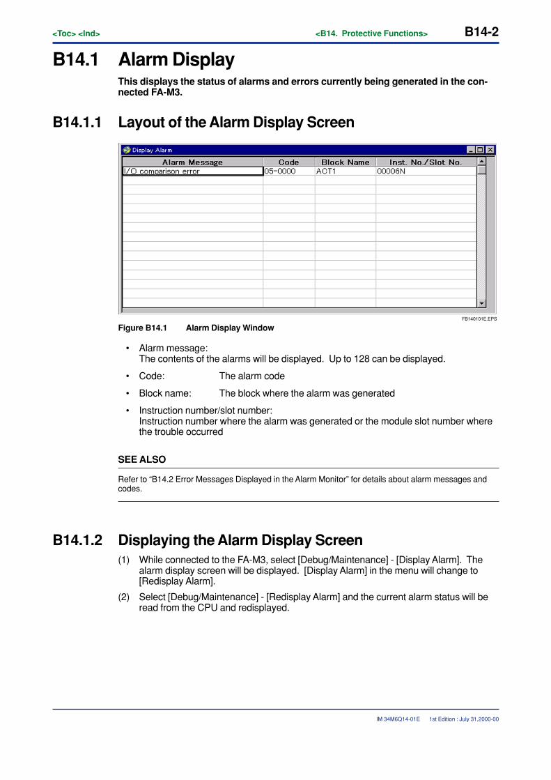
B14-2<Toc> <Ind> <B14. Protective Functions>
IM 34M6Q14-01E
B14.1 Alarm DisplayThis displays the status of alarms and errors currently being generated in the con-nected FA-M3.
B14.1.1 Layout of the Alarm Display Screen
FB140101E.EPS
Figure B14.1 Alarm Display Window
• Alarm message:The contents of the alarms will be displayed. Up to 128 can be displayed.
• Code: The alarm code
• Block name: The block where the alarm was generated
• Instruction number/slot number:Instruction number where the alarm was generated or the module slot number wherethe trouble occurred
SEE ALSO
Refer to “B14.2 Error Messages Displayed in the Alarm Monitor” for details about alarm messages andcodes.
B14.1.2 Displaying the Alarm Display Screen(1) While connected to the FA-M3, select [Debug/Maintenance] - [Display Alarm]. The
alarm display screen will be displayed. [Display Alarm] in the menu will change to[Redisplay Alarm].
(2) Select [Debug/Maintenance] - [Redisplay Alarm] and the current alarm status will beread from the CPU and redisplayed.
1st Edition : July 31,2000-00

<Toc> <Ind> <B14. Protective Functions> B14-3
IM 34M6Q14-01E
B14.1.3 Canceling the AlarmThis cancels the alarm status (slight malfunction cancel). Alarms that were generated inthe past and are not now being generated will be cancelled.
(1) Select [Debug/Maintenance] - [Cancel Alarm].
SEE ALSO
Refer to “Chapter B6 Printout” for further details about printing out the alarm status.
1st Edition : July 31,2000-00
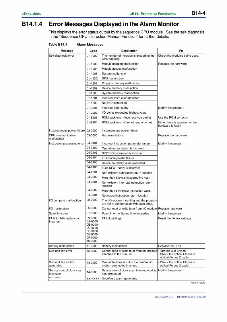
B14-4<Toc> <Ind> <B14. Protective Functions>
IM 34M6Q14-01E
B14.1.4 Error Messages Displayed in the Alarm MonitorThis displays the error status output by the sequence CPU module. See the self-diagnosisin the “Sequence CPU Instruction Manual-Function” for further details.
Table B14.1 Alarm Messages
Sub-unit line switch generated
01-1002
01-1003
01-1004
01-1005
01-11XX
01-1201
01-1202
01-1203
01-1701
01-1702
01-2001
01-2002
01-8203
01-8204
02-0000
04-2101
03-0000
04-2102
04-2103
04-2104
04-2105
04-2106
04-2201
04-2202
04-2301
04-2302
04-2501
05-0000
06-0000
07-0000
09-00000A-00000B-00000C-00000D-00000E-00000F-000010-0000
11-0000
12-0000
13-0000
14-0000
XX-XXXXTB140101E.EPS
Undefined alarm generated
Message FixDescriptionCode
Self-diagnosis error The number of modules is exceeding the CPU capacity.
Check the modules being used.
Module mapping malfunction Replace the hardware.
Module access malfunction
System malfunction
SPU malfunction
Program memory malfunction
Device memory malfunction
System memory malfunction
Incorrect instruction detected
No END instruction
Incorrect label parity
I/O points exceeding highest value
ROM pack error (Incorrect type parity) Use the ROM correctly.
Modify the program.
ROM pack error (Cannot read or write) Either there is a protect or the hardware is faulty.
Instantaneous power failure Instantaneous power failure
CPU communication malfunction
Hardware failure Replace the hardware.
Instruction processing error Incorrect instruction parameter range Modify the program
Operation calculation is incorrect
BIN/BCD conversion is incorrect
FIFO table pointer failure
Device boundary value exceeded
FOR-NEXT parity is incorrect
Non-existent subroutine return location
More than 8 levels in subroutine nest
Non-existent interrupt instruction return location
More than 8 interrupt instruction waits
No macro instruction return location
I/O compare malfunction The I/O module mounting and the program are not in conformation with each other.
I/O malfunction Cannot read or write to or from I/O module Replace hardware.
Scan time over Scan time monitoring time exceeded Modify the program
FA link (1-8) malfunction Incorrect
FA link settings Reset the FA link settings
Battery malfunction Battery malfunction Replace the CPU.
Sub-unit line error Cannot read or write to or from the module attached to the sub-unit
• Turn the sub-unit on. • Check the optical FA bus or
optical FA bus 2 cable.
One of the lines is cut in the remote I/O system connected in a loop
• Check the optical FA bus or optical FA bus 2 cable.
Sensor control block scan time over
***********
Sensor control block scan time monitoring time exceeded
Modify the program.
1st Edition : July 31,2000-00
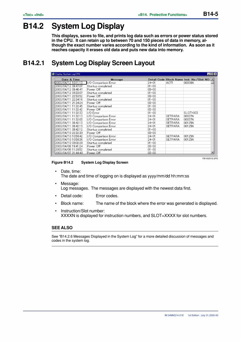
<Toc> <Ind> <B14. Protective Functions> B14-5
IM 34M6Q14-01E
B14.2 System Log DisplayThis displays, saves to file, and prints log data such as errors or power status storedin the CPU. It can retain up to between 70 and 150 pieces of data in memory, al-though the exact number varies according to the kind of information. As soon as itreaches capacity it erases old data and puts new data into memory.
B14.2.1 System Log Display Screen Layout
FB140201E.EPS
Figure B14.2 System Log Display Screen
• Date, time:The date and time of logging on is displayed as yyyy/mm/dd hh:mm:ss
• Message:Log messages. The messages are displayed with the newest data first.
• Detail code: Error codes.
• Block name: The name of the block where the error was generated is displayed.
• Instruction/Slot number:XXXXN is displayed for instruction numbers, and SLOT=XXXX for slot numbers.
SEE ALSO
See “B14.2.6 Messages Displayed in the System Log” for a more detailed discussion of messages andcodes in the system log.
1st Edition : July 31,2000-00
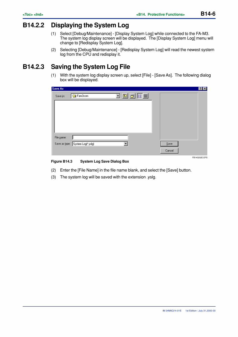
B14-6<Toc> <Ind> <B14. Protective Functions>
IM 34M6Q14-01E 1st Edition : July 31,2000-00
B14.2.2 Displaying the System Log(1) Select [Debug/Maintenance] - [Display System Log] while connected to the FA-M3.
The system log display screen will be displayed. The [Display System Log] menu willchange to [Redisplay System Log].
(2) Selecting [Debug/Maintenance] - [Redisplay System Log] will read the newest systemlog from the CPU and redisplay it.
B14.2.3 Saving the System Log File(1) With the system log display screen up, select [File] - [Save As]. The following dialog
box will be displayed.
FB140202E.EPS
Figure B14.3 System Log Save Dialog Box
(2) Enter the [File Name] in the file name blank, and select the [Save] button.
(3) The system log will be saved with the extension .yslg.
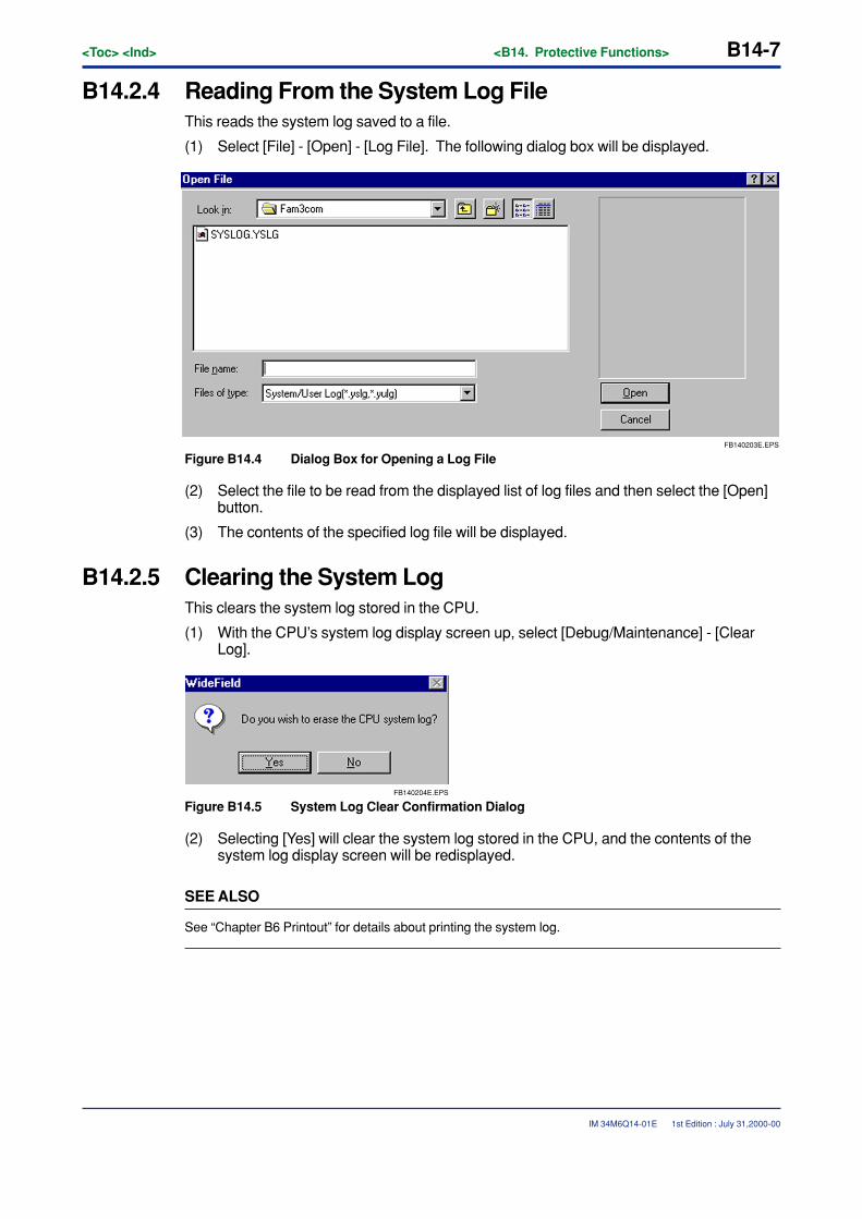
<Toc> <Ind> <B14. Protective Functions> B14-7
IM 34M6Q14-01E 1st Edition : July 31,2000-00
B14.2.4 Reading From the System Log FileThis reads the system log saved to a file.
(1) Select [File] - [Open] - [Log File]. The following dialog box will be displayed.
FB140203E.EPS
Figure B14.4 Dialog Box for Opening a Log File
(2) Select the file to be read from the displayed list of log files and then select the [Open]button.
(3) The contents of the specified log file will be displayed.
B14.2.5 Clearing the System LogThis clears the system log stored in the CPU.
(1) With the CPU’s system log display screen up, select [Debug/Maintenance] - [ClearLog].
FB140204E.EPS
Figure B14.5 System Log Clear Confirmation Dialog
(2) Selecting [Yes] will clear the system log stored in the CPU, and the contents of thesystem log display screen will be redisplayed.
SEE ALSO
See “Chapter B6 Printout” for details about printing the system log.
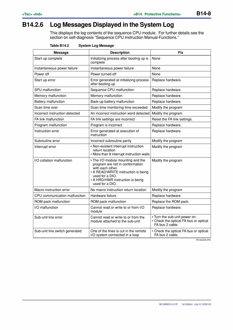
B14-8<Toc> <Ind> <B14. Protective Functions>
IM 34M6Q14-01E
B14.2.6 Log Messages Displayed in the System LogThis displays the log contents of the sequence CPU module. For further details see thesection on self-diagnosis “Sequence CPU Instruction Manual-Functions.”
Table B14.2 System Log Message
Modify the program
Modify the program
Modify the program
Modify the program
TB140202E.EPS
• Check the optical FA bus or optical FA bus 2 cable.
Message FixDescription
Start up complete Initializing process after booting up is complete
None
None
None
Instantaneous power failure Instantaneous power failure
Power off Power turned off
Start up error Error generated at initializing process after booting up
Replace hardware.
Replace hardware.
Replace hardware.
Replace hardware.
Replace hardware.
Replace hardware.
SPU malfunction Sequence CPU malfunction
Memory malfunction Memory malfunction
Battery malfunction Back-up battery malfunction
Scan time over Scan time monitoring time exceeded Modify the program
Replace hardware.
Replace hardware.
Modify the programIncorrect instruction detected An incorrect instruction word detected
FA link malfunction FA link settings are incorrect Reset the FA link settings.
Program malfunction Program is incorrect
Instruction error Error generated at execution of instruction
Incorrect subroutine paritySubroutine error
Interrupt error • Non-existent interrupt instruction return location
• More than 8 interrupt instruction waits
I/O collation malfunction • The I/O module mounting and the program are not in conformation with each other.
• A READ/WRITE instruction is being used for a DIO.
• A HRD/HWR instruction is being used for a DIO.
Macro instruction error No macro instruction return location
CPU communication malfunction Hardware failure
ROM pack malfunction ROM pack malfunction Replace the ROM pack.
I/O malfunction Cannot read or write to or from I/O module
Sub-unit line error Cannot read or write to or from the module attached to the sub-unit
• Turn the sub-unit power on.• Check the optical FA bus or optical
FA bus 2 cable.
Sub-unit line switch generated One of the lines is cut in the remote I/O system connected in a loop
1st Edition : July 31,2000-00
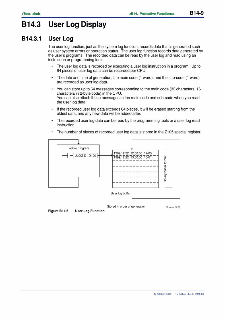
<Toc> <Ind> <B14. Protective Functions> B14-9
IM 34M6Q14-01E
B14.3 User Log Display
B14.3.1 User LogThe user log function, just as the system log function, records data that is generated suchas user system errors or operation status. The user log function records data generated bythe user’s programs. The recorded data can be read by the user log and read using aninstruction or programming tools.
• The user log data is recorded by executing a user log instruction in a program. Up to64 pieces of user log data can be recorded per CPU.
• The date and time of generation, the main code (1 word), and the sub-code (1 word)are recorded as user log data.
• You can store up to 64 messages corresponding to the main code (32 characters, 16characters in 2-byte code) in the CPU.You can also attach these messages to the main code and sub-code when you readthe user log data.
• If the recorded user log data exceeds 64 pieces, it will be erased starting from theoldest data, and any new data will be added after.
• The recorded user log data can be read by the programming tools or a user log readinstruction.
• The number of pieces of recorded user log data is stored in the Z105 special register.
ULOG D1 D100
Ladder program
1999/12/22 12:00:00 12-051999/12/22 13:00:00 16-01
Rot
ary
buffe
r fo
rmat
User log buffer
Stored in order of generation FB140301E.EPS
Figure B14.6 User Log Function
1st Edition : July 31,2000-00
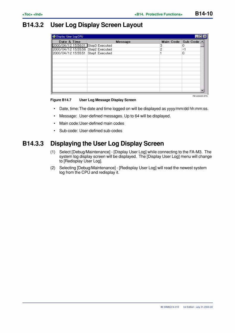
B14-10<Toc> <Ind> <B14. Protective Functions>
IM 34M6Q14-01E 1st Edition : July 31,2000-00
B14.3.2 User Log Display Screen Layout
FB140302E.EPS
Figure B14.7 User Log Message Display Screen
• Date, time:The date and time logged on will be displayed as yyyy/mm/dd hh:mm:ss.
• Message: User-defined messages. Up to 64 will be displayed.
• Main code:User-defined main codes
• Sub-code: User-defined sub-codes
B14.3.3 Displaying the User Log Display Screen(1) Select [Debug/Maintenance] - [Display User Log] while connecting to the FA-M3. The
system log display screen will be displayed. The [Display User Log] menu will changeto [Redisplay User Log].
(2) Selecting [Debug/Maintenance] - [Redisplay User Log] will read the newest systemlog from the CPU and redisplay it.
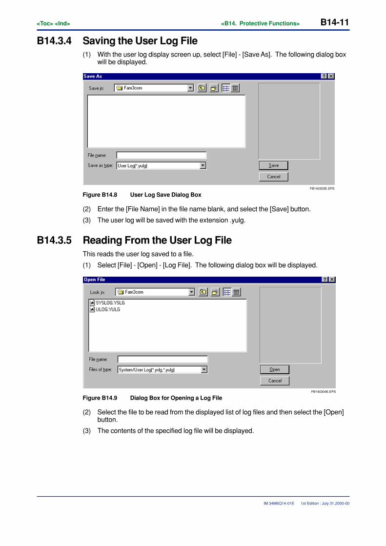
<Toc> <Ind> <B14. Protective Functions> B14-11
IM 34M6Q14-01E 1st Edition : July 31,2000-00
B14.3.4 Saving the User Log File(1) With the user log display screen up, select [File] - [Save As]. The following dialog box
will be displayed.
FB140303E.EPS
Figure B14.8 User Log Save Dialog Box
(2) Enter the [File Name] in the file name blank, and select the [Save] button.
(3) The user log will be saved with the extension .yulg.
B14.3.5 Reading From the User Log FileThis reads the user log saved to a file.
(1) Select [File] - [Open] - [Log File]. The following dialog box will be displayed.
FB140304E.EPS
Figure B14.9 Dialog Box for Opening a Log File
(2) Select the file to be read from the displayed list of log files and then select the [Open]button.
(3) The contents of the specified log file will be displayed.
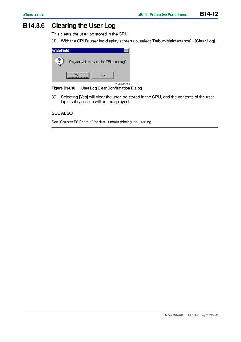
B14-12<Toc> <Ind> <B14. Protective Functions>
IM 34M6Q14-01E
B14.3.6 Clearing the User LogThis clears the user log stored in the CPU.
(1) With the CPU’s user log display screen up, select [Debug/Maintenance] - [Clear Log].
FB140305E.EPS
Figure B14.10 User Log Clear Confirmation Dialog
(2) Selecting [Yes] will clear the user log stored in the CPU, and the contents of the userlog display screen will be redisplayed.
SEE ALSO
See “Chapter B6 Printout” for details about printing the user log.
1st Edition : July 31,2000-00
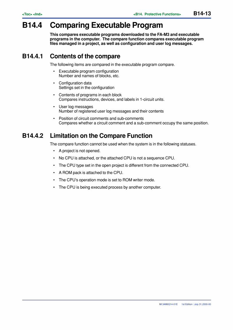
<Toc> <Ind> <B14. Protective Functions> B14-13
IM 34M6Q14-01E
B14.4 Comparing Executable ProgramThis compares executable programs downloaded to the FA-M3 and executableprograms in the computer. The compare function compares executable programfiles managed in a project, as well as configuration and user log messages.
B14.4.1 Contents of the compareThe following items are compared in the executable program compare.
• Executable program configurationNumber and names of blocks, etc.
• Configuration dataSettings set in the configuration
• Contents of programs in each blockCompares instructions, devices, and labels in 1-circuit units.
• User log messagesNumber of registered user log messages and their contents
• Position of circuit comments and sub-commentsCompares whether a circuit comment and a sub-comment occupy the same position.
B14.4.2 Limitation on the Compare FunctionThe compare function cannot be used when the system is in the following statuses.
• A project is not opened.
• No CPU is attached, or the attached CPU is not a sequence CPU.
• The CPU type set in the open project is different from the connected CPU.
• A ROM pack is attached to the CPU.
• The CPU’s operation mode is set to ROM writer mode.
• The CPU is being executed process by another computer.
1st Edition : July 31,2000-00
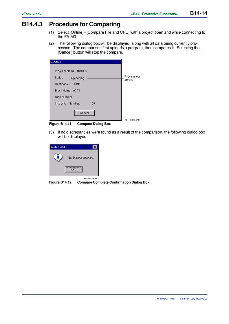
B14-14<Toc> <Ind> <B14. Protective Functions>
IM 34M6Q14-01E
B14.4.3 Procedure for Comparing(1) Select [Online] - [Compare File and CPU] with a project open and while connecting to
the FA-M3.
(2) The following dialog box will be displayed, along with all data being currently pro-cessed. The comparison first uploads a program, then compares it. Selecting the[Cancel] button will stop the compare.
FB140401E.EPS
Processing status
Figure B14.11 Compare Dialog Box
(3) If no discrepancies were found as a result of the comparison, the following dialog boxwill be displayed.
FB140402E.EPS
Figure B14.12 Compare Complete Confirmation Dialog Box
1st Edition : July 31,2000-00
<Toc> <Ind> <B14. Protective Functions> B14-15
IM 34M6Q14-01E
(4) If a discrepancy was found as a result of the comparison, the following compareresults list screen will be displayed.
FB140403E.EPS
Figure B14.13 Comparison Results Window
Errors and warnings are classified as follows.
� Errors
• Executable program configuration different.The executable program configuration are different.
• Configuration different.The configurations are different.
• Instruction or address mismatchThe contents of a block (instructions, devices, labels) are different.
� Warnings
• User log message different.The contents of the user log messages are different.
• Different number of user log messages.The number of registered user log messages is different.
• Sub-comment present/absent.There are more/fewer sub-comments.
• Circuit comment present/absent.There are more/fewer circuit comments.
1st Edition : July 31,2000-00

B14-16<Toc> <Ind> <B14. Protective Functions>
IM 34M6Q14-01E
CAUTION
• The comparison results display the top instruction number in a circuit (or project) witha mismatch. Only one result per circuit is displayed.
• Program comparison is done in circuit units. Accordingly, if a circuit (not includingcircuit comments) is inserted, all the circuits after that will mismatch.
• The contents of comments are not compared when comparing sub-comments andcircuit comments.
• Up to 256 mismatches will be displayed.
• If the executable program configuration is different, the contents of the block will notbe compared.
1st Edition : July 31,2000-00
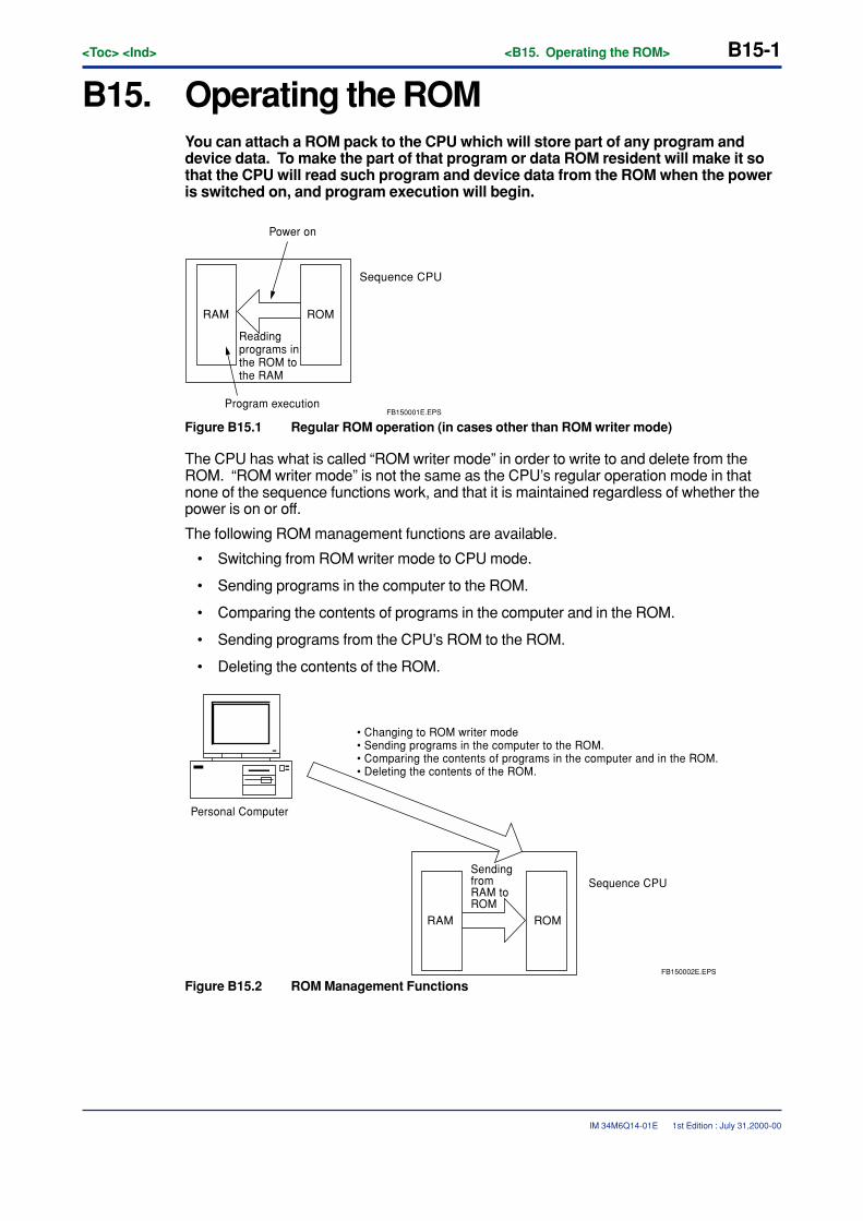
<Toc> <Ind> <B15. Operating the ROM> B15-1
IM 34M6Q14-01E
B15. Operating the ROMYou can attach a ROM pack to the CPU which will store part of any program anddevice data. To make the part of that program or data ROM resident will make it sothat the CPU will read such program and device data from the ROM when the poweris switched on, and program execution will begin.
RAM ROM
Reading programs in the ROM to the RAM
Power on
Program executionFB150001E.EPS
Sequence CPU
Figure B15.1 Regular ROM operation (in cases other than ROM writer mode)
The CPU has what is called “ROM writer mode” in order to write to and delete from theROM. “ROM writer mode” is not the same as the CPU’s regular operation mode in thatnone of the sequence functions work, and that it is maintained regardless of whether thepower is on or off.
The following ROM management functions are available.
• Switching from ROM writer mode to CPU mode.
• Sending programs in the computer to the ROM.
• Comparing the contents of programs in the computer and in the ROM.
• Sending programs from the CPU’s ROM to the ROM.
• Deleting the contents of the ROM.
RAM ROM
Sending from RAM to ROM
Sequence CPU
• Changing to ROM writer mode• Sending programs in the computer to the ROM.• Comparing the contents of programs in the computer and in the ROM.• Deleting the contents of the ROM.
FB150002E.EPS
Personal Computer
Figure B15.2 ROM Management Functions
1st Edition : July 31,2000-00

B15-2<Toc> <Ind> <B15. Operating the ROM>
IM 34M6Q14-01E
The ROM management functions are unavailable in the following situations.
� Not ROM writer mode
The CPU is not in ROM writer mode. Switch to ROM writer mode.
� Exclusive access acquired
A different terminal has acquired exclusive access. Use the forced liberation on the exclu-sive access.
1st Edition : July 31,2000-00
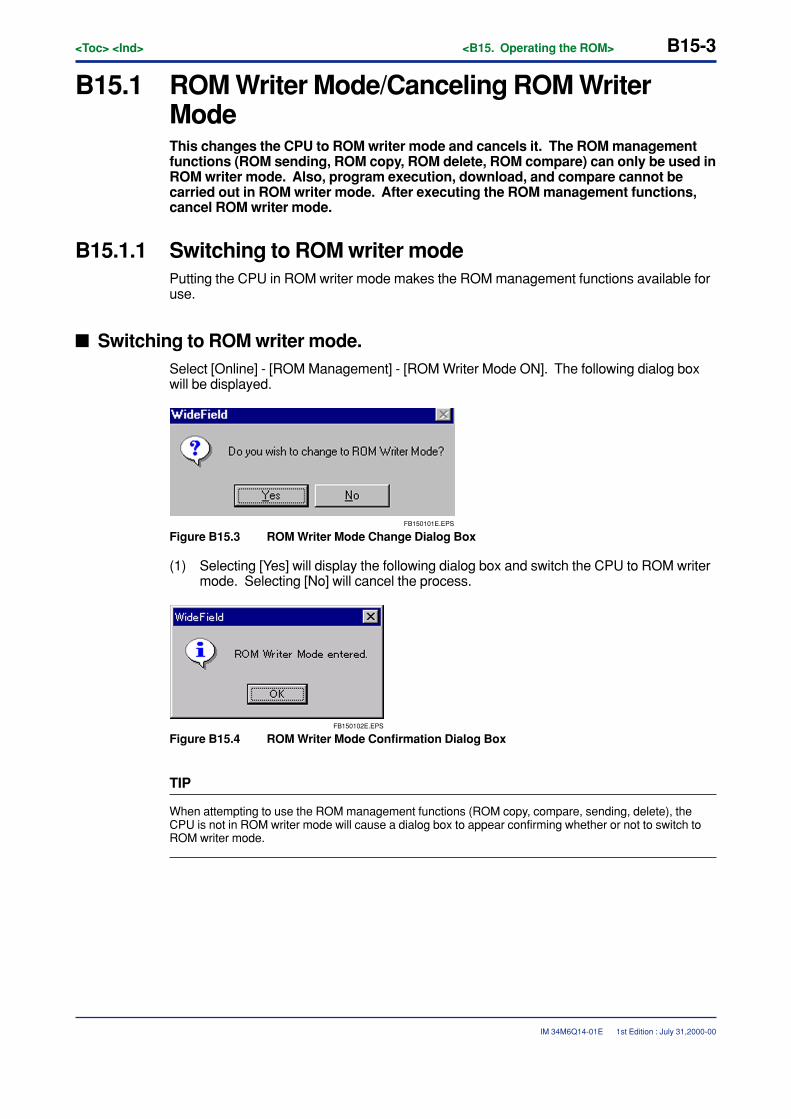
<Toc> <Ind> <B15. Operating the ROM> B15-3
IM 34M6Q14-01E
B15.1 ROM Writer Mode/Canceling ROM WriterModeThis changes the CPU to ROM writer mode and cancels it. The ROM managementfunctions (ROM sending, ROM copy, ROM delete, ROM compare) can only be used inROM writer mode. Also, program execution, download, and compare cannot becarried out in ROM writer mode. After executing the ROM management functions,cancel ROM writer mode.
B15.1.1 Switching to ROM writer modePutting the CPU in ROM writer mode makes the ROM management functions available foruse.
� Switching to ROM writer mode.Select [Online] - [ROM Management] - [ROM Writer Mode ON]. The following dialog boxwill be displayed.
FB150101E.EPS
Figure B15.3 ROM Writer Mode Change Dialog Box
(1) Selecting [Yes] will display the following dialog box and switch the CPU to ROM writermode. Selecting [No] will cancel the process.
FB150102E.EPS
Figure B15.4 ROM Writer Mode Confirmation Dialog Box
TIP
When attempting to use the ROM management functions (ROM copy, compare, sending, delete), theCPU is not in ROM writer mode will cause a dialog box to appear confirming whether or not to switch toROM writer mode.
1st Edition : July 31,2000-00
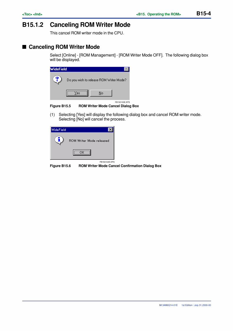
B15-4<Toc> <Ind> <B15. Operating the ROM>
IM 34M6Q14-01E
B15.1.2 Canceling ROM Writer ModeThis cancel ROM writer mode in the CPU.
� Canceling ROM Writer ModeSelect [Online] - [ROM Management] - [ROM Writer Mode OFF]. The following dialog boxwill be displayed.
FB150103E.EPS
Figure B15.5 ROM Writer Mode Cancel Dialog Box
(1) Selecting [Yes] will display the following dialog box and cancel ROM writer mode.Selecting [No] will cancel the process.
FB150104E.EPS
Figure B15.6 ROM Writer Mode Cancel Confirmation Dialog Box
1st Edition : July 31,2000-00
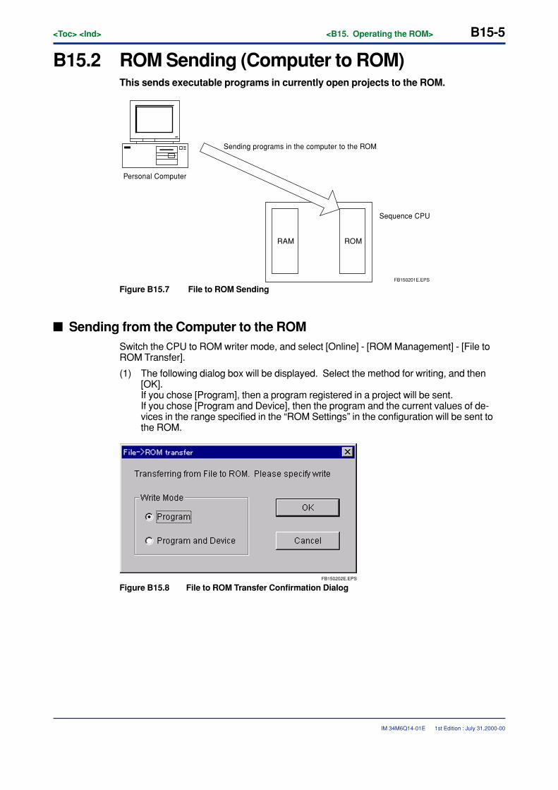
<Toc> <Ind> <B15. Operating the ROM> B15-5
IM 34M6Q14-01E
B15.2 ROM Sending (Computer to ROM)This sends executable programs in currently open projects to the ROM.
RAM ROM
Sequence CPU
Sending programs in the computer to the ROM
FB150201E.EPS
Personal Computer
Figure B15.7 File to ROM Sending
� Sending from the Computer to the ROMSwitch the CPU to ROM writer mode, and select [Online] - [ROM Management] - [File toROM Transfer].
(1) The following dialog box will be displayed. Select the method for writing, and then[OK].If you chose [Program], then a program registered in a project will be sent.If you chose [Program and Device], then the program and the current values of de-vices in the range specified in the “ROM Settings” in the configuration will be sent tothe ROM.
FB150202E.EPS
Figure B15.8 File to ROM Transfer Confirmation Dialog
1st Edition : July 31,2000-00
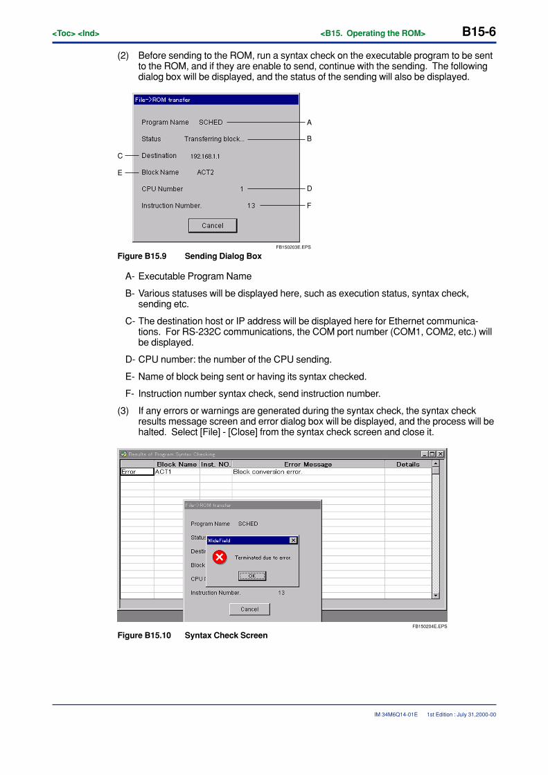
B15-6<Toc> <Ind> <B15. Operating the ROM>
IM 34M6Q14-01E 1st Edition : July 31,2000-00
(2) Before sending to the ROM, run a syntax check on the executable program to be sentto the ROM, and if they are enable to send, continue with the sending. The followingdialog box will be displayed, and the status of the sending will also be displayed.
FB150203E.EPS
A
B
C
D
F
E
Figure B15.9 Sending Dialog Box
A- Executable Program Name
B- Various statuses will be displayed here, such as execution status, syntax check,sending etc.
C- The destination host or IP address will be displayed here for Ethernet communica-tions. For RS-232C communications, the COM port number (COM1, COM2, etc.) willbe displayed.
D- CPU number: the number of the CPU sending.
E- Name of block being sent or having its syntax checked.
F- Instruction number syntax check, send instruction number.
(3) If any errors or warnings are generated during the syntax check, the syntax checkresults message screen and error dialog box will be displayed, and the process will behalted. Select [File] - [Close] from the syntax check screen and close it.
FB150204E.EPS
Figure B15.10 Syntax Check Screen
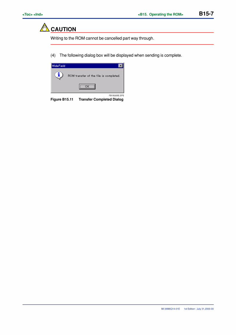
<Toc> <Ind> <B15. Operating the ROM> B15-7
IM 34M6Q14-01E 1st Edition : July 31,2000-00
CAUTION
Writing to the ROM cannot be cancelled part way through.
(4) The following dialog box will be displayed when sending is complete.
FB150205E.EPS
Figure B15.11 Transfer Completed Dialog
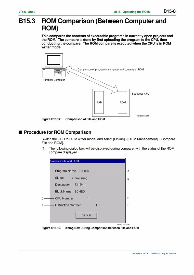
B15-8<Toc> <Ind> <B15. Operating the ROM>
IM 34M6Q14-01E
B15.3 ROM Comparison (Between Computer andROM)This compares the contents of executable programs in currently open projects andthe ROM. The compare is done by first uploading the program to the CPU, thenconducting the compare. The ROM compare is executed when the CPU is in ROMwriter mode.
RAM ROM
Sequence CPU
Comparison of program in computer and contents of ROM
FB150206E.EPS
Personal Computer
Figure B15.12 Comparison of File and ROM
� Procedure for ROM ComparisonSwitch the CPU to ROM writer mode, and select [Online] - [ROM Management] - [CompareFile and ROM].
(1) The following dialog box will be displayed during compare, with the status of the ROMcompare displayed.
FB150207E.EPS
A
B
C D
FE
Figure B15.13 Dialog Box During Comparison between File and ROM
1st Edition : July 31,2000-00
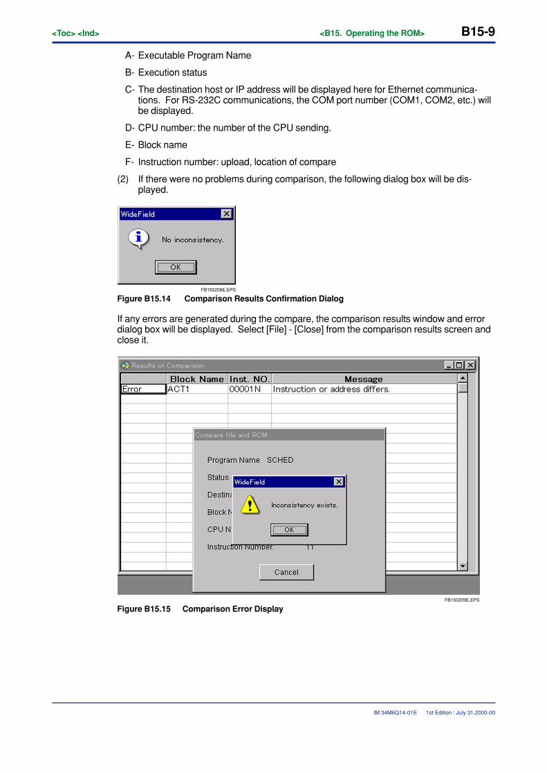
<Toc> <Ind> <B15. Operating the ROM> B15-9
IM 34M6Q14-01E
A- Executable Program Name
B- Execution status
C- The destination host or IP address will be displayed here for Ethernet communica-tions. For RS-232C communications, the COM port number (COM1, COM2, etc.) willbe displayed.
D- CPU number: the number of the CPU sending.
E- Block name
F- Instruction number: upload, location of compare
(2) If there were no problems during comparison, the following dialog box will be dis-played.
FB150208E.EPS
Figure B15.14 Comparison Results Confirmation Dialog
If any errors are generated during the compare, the comparison results window and errordialog box will be displayed. Select [File] - [Close] from the comparison results screen andclose it.
FB150209E.EPS
Figure B15.15 Comparison Error Display
1st Edition : July 31,2000-00
B15-10<Toc> <Ind> <B15. Operating the ROM>
IM 34M6Q14-01E 1st Edition : July 31,2000-00
Errors and warnings are classified as follows.
� Errors
(1) Executable program configuration different.• The executable program configurations are different.
(2) Configuration different.• The configurations are different.
(3) Instruction or address mismatch• The contents of a block (instructions, devices, labels) are different.
� Warnings
(1) User log message different.• The contents of the user log messages are different.
(2) Different number of user log messages.• The number of registered user log messages is different.
(3) Sub-comment present/absent.• There are more/fewer sub-comments.
(4) Circuit comment present/absent.• There are more/fewer circuit comments.
CAUTION
• The comparison results display the top instruction number in a circuit with a mismatch.
• If a circuit (not including circuit comments) is inserted, all the circuits after that willmismatch.
• The contents of comments are not compared when comparing sub-comments andcircuit comments. (Only the presence or absence of comments will be compared.)
• Up to 256 mismatches will be displayed.
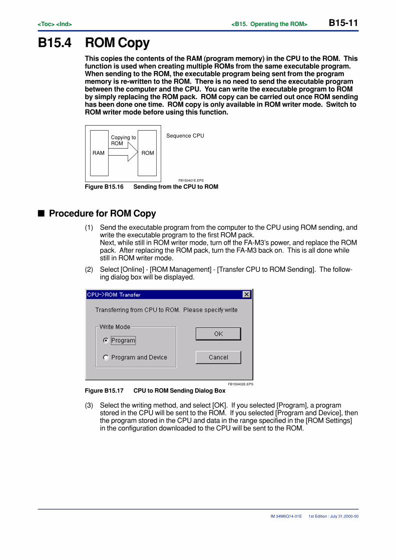
<Toc> <Ind> <B15. Operating the ROM> B15-11
IM 34M6Q14-01E 1st Edition : July 31,2000-00
B15.4 ROM CopyThis copies the contents of the RAM (program memory) in the CPU to the ROM. Thisfunction is used when creating multiple ROMs from the same executable program.When sending to the ROM, the executable program being sent from the programmemory is re-written to the ROM. There is no need to send the executable programbetween the computer and the CPU. You can write the executable program to ROMby simply replacing the ROM pack. ROM copy can be carried out once ROM sendinghas been done one time. ROM copy is only available in ROM writer mode. Switch toROM writer mode before using this function.
RAM ROM
Copying to ROM
FB150401E.EPS
Sequence CPU
Figure B15.16 Sending from the CPU to ROM
� Procedure for ROM Copy(1) Send the executable program from the computer to the CPU using ROM sending, and
write the executable program to the first ROM pack.Next, while still in ROM writer mode, turn off the FA-M3’s power, and replace the ROMpack. After replacing the ROM pack, turn the FA-M3 back on. This is all done whilestill in ROM writer mode.
(2) Select [Online] - [ROM Management] - [Transfer CPU to ROM Sending]. The follow-ing dialog box will be displayed.
FB150402E.EPS
Figure B15.17 CPU to ROM Sending Dialog Box
(3) Select the writing method, and select [OK]. If you selected [Program], a programstored in the CPU will be sent to the ROM. If you selected [Program and Device], thenthe program stored in the CPU and data in the range specified in the [ROM Settings]in the configuration downloaded to the CPU will be sent to the ROM.
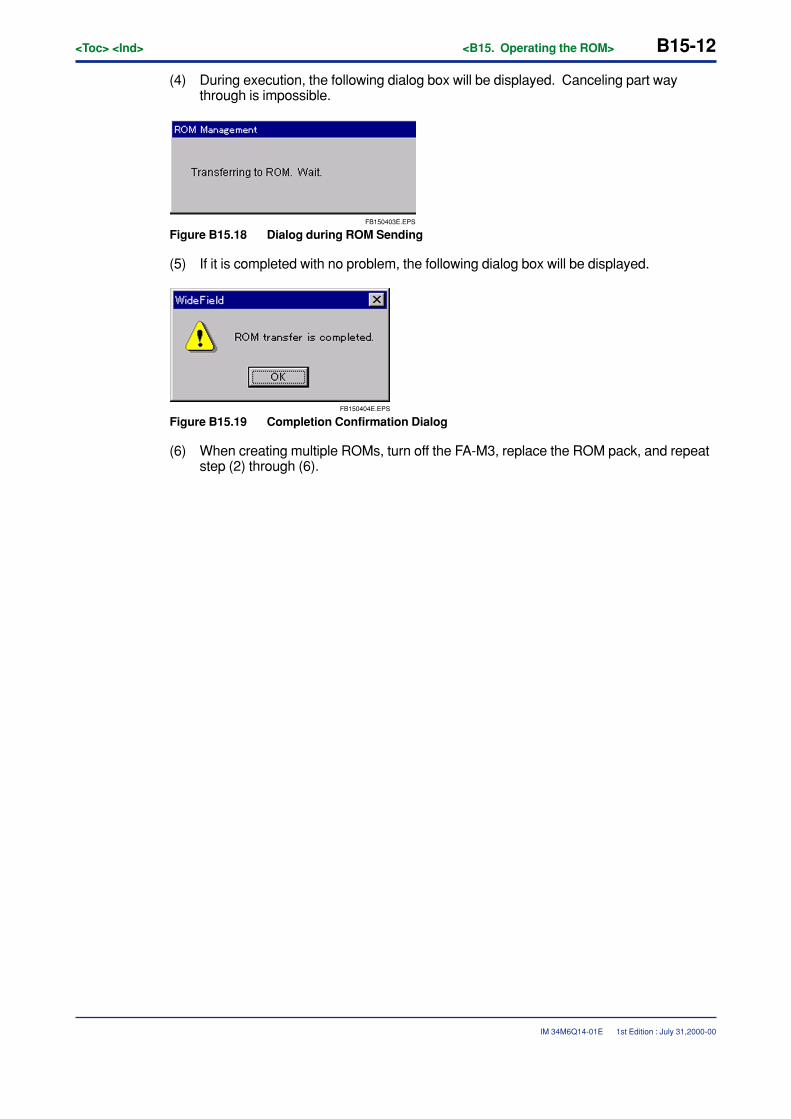
B15-12<Toc> <Ind> <B15. Operating the ROM>
IM 34M6Q14-01E
(4) During execution, the following dialog box will be displayed. Canceling part waythrough is impossible.
FB150403E.EPS
Figure B15.18 Dialog during ROM Sending
(5) If it is completed with no problem, the following dialog box will be displayed.
FB150404E.EPS
Figure B15.19 Completion Confirmation Dialog
(6) When creating multiple ROMs, turn off the FA-M3, replace the ROM pack, and repeatstep (2) through (6).
1st Edition : July 31,2000-00
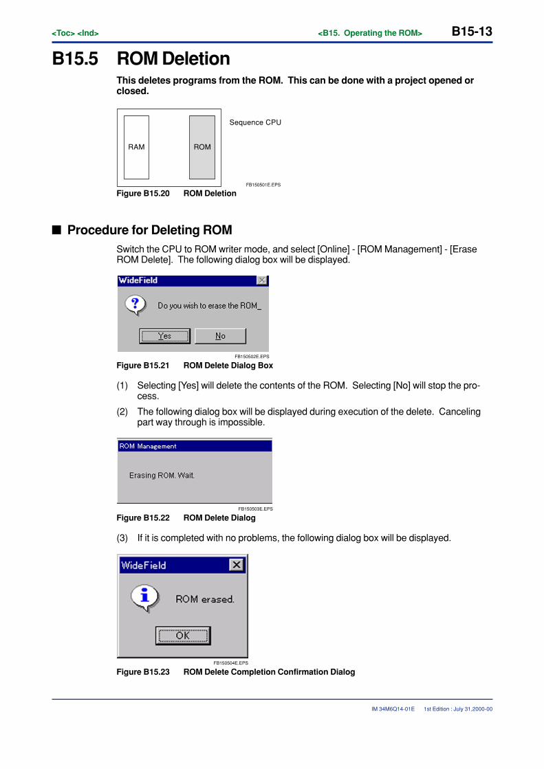
<Toc> <Ind> <B15. Operating the ROM> B15-13
IM 34M6Q14-01E
B15.5 ROM DeletionThis deletes programs from the ROM. This can be done with a project opened orclosed.
RAM ROM
FB150501E.EPS
Sequence CPU
Figure B15.20 ROM Deletion
� Procedure for Deleting ROMSwitch the CPU to ROM writer mode, and select [Online] - [ROM Management] - [EraseROM Delete]. The following dialog box will be displayed.
FB150502E.EPS
Figure B15.21 ROM Delete Dialog Box
(1) Selecting [Yes] will delete the contents of the ROM. Selecting [No] will stop the pro-cess.
(2) The following dialog box will be displayed during execution of the delete. Cancelingpart way through is impossible.
FB150503E.EPS
Figure B15.22 ROM Delete Dialog
(3) If it is completed with no problems, the following dialog box will be displayed.
FB150504E.EPS
Figure B15.23 ROM Delete Completion Confirmation Dialog
1st Edition : July 31,2000-00

Blank Page
<Toc> <Ind> <B16. I/O Module Settings> B16-1
IM 34M6Q14-01E
B16. I/O Module SettingsThis chapter describes how to set the high-level functions in the I/O module.
B16.1 Station Assignment of the FA Link and theMonitorThis section describes the settings FA link functions using the FA link module, theFA link H module, or the optical FA link H module, as well as how to monitor the FAlink module’s status.
CAUTION
In this manual, FA link will be used to refer to the FA link, the FA link H, and the fiber-opticFA link H in general, unless otherwise specified. For a more detailed discussion of thefunctions on the FA link, the FA link H, and the fiber-optic FA link H modules, see “FA link,the FA link H, and the fiber-optic FA link H module Instruction Manual” (IM34M6H43-01E).
The FA link functions include station assignment of FA link and FA link module status read.
� Local assignment of FA link
• Assigns link relays
• Assigns link registers
� FA link module status
• Confirms the status of one’s own station location.
• Confirms the status of another station’s location.
Both of these are done with the “FA Link Tool.”
1st Edition : July 31,2000-00
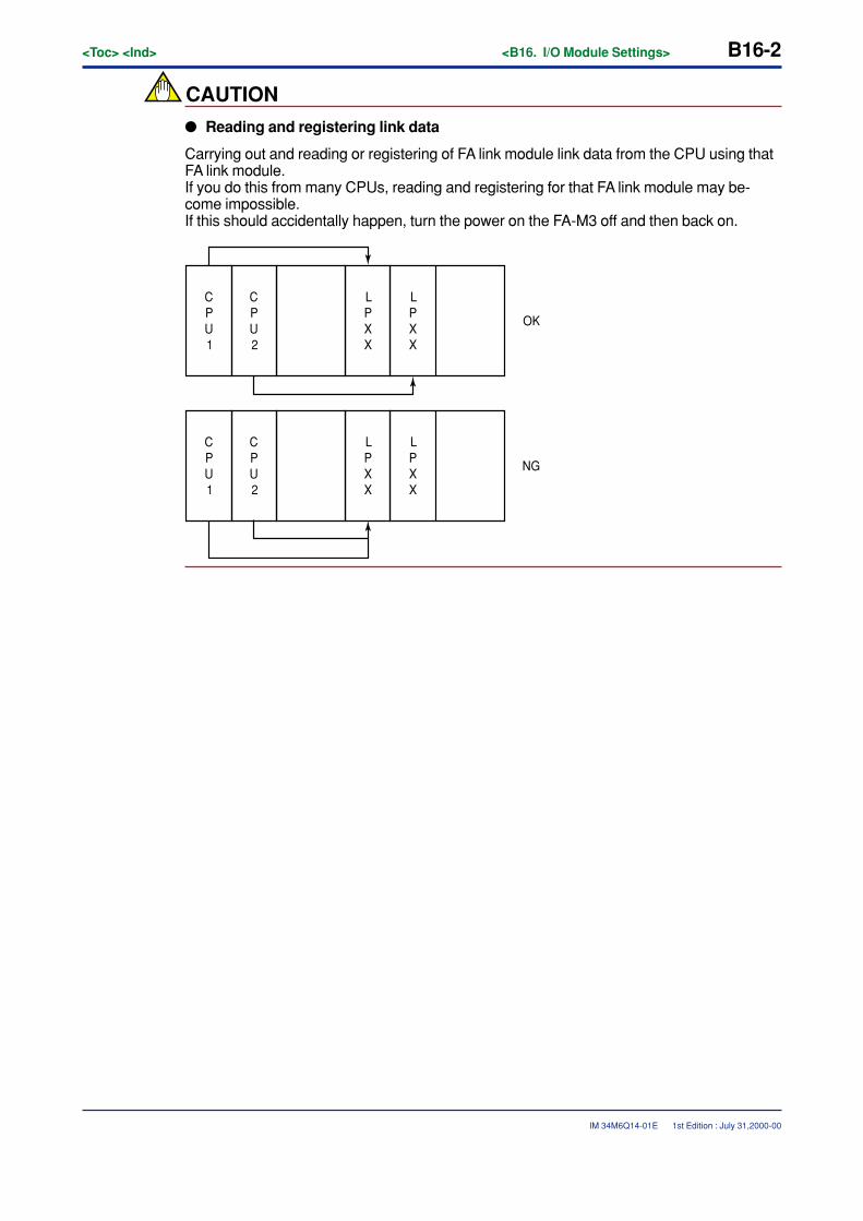
B16-2<Toc> <Ind> <B16. I/O Module Settings>
IM 34M6Q14-01E
CAUTION
� Reading and registering link data
Carrying out and reading or registering of FA link module link data from the CPU using thatFA link module.If you do this from many CPUs, reading and registering for that FA link module may be-come impossible.If this should accidentally happen, turn the power on the FA-M3 off and then back on.
CPU1
CPU2
LPXX
LPXX
CPU1
CPU2
LPXX
LPXX
OK
NG
1st Edition : July 31,2000-00
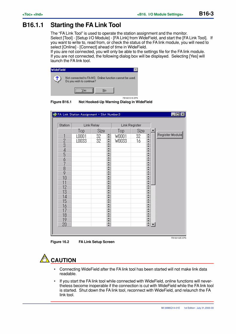
<Toc> <Ind> <B16. I/O Module Settings> B16-3
IM 34M6Q14-01E
B16.1.1 Starting the FA Link ToolThe “FA Link Tool” is used to operate the station assignment and the monitor.Select [Tool] - [Setup I/O Module] - [FA Link] from WideField, and start the [FA Link Tool]. Ifyou want to write to, read from, or check the status of the FA link module, you will need toselect [Online] - [Connect] ahead of time in WideField.If you are not connected, you will only be able to the settings file for the FA link module.If you are not connected, the following dialog box will be displayed. Selecting [Yes] willlaunch the FA link tool.
FB160101E.EPS
Figure B16.1 Not Hooked-Up Warning Dialog in WideField
FB160102E.EPS
Figure 16.2 FA Link Setup Screen
CAUTION
• Connecting WideField after the FA link tool has been started will not make link datareadable.
• If you start the FA link tool while connected with WideField, online functions will never-theless become inoperable if the connection is cut with WideField while the FA link toolis started. Shut down the FA link tool, reconnect with WideField, and relaunch the FAlink tool.
1st Edition : July 31,2000-00
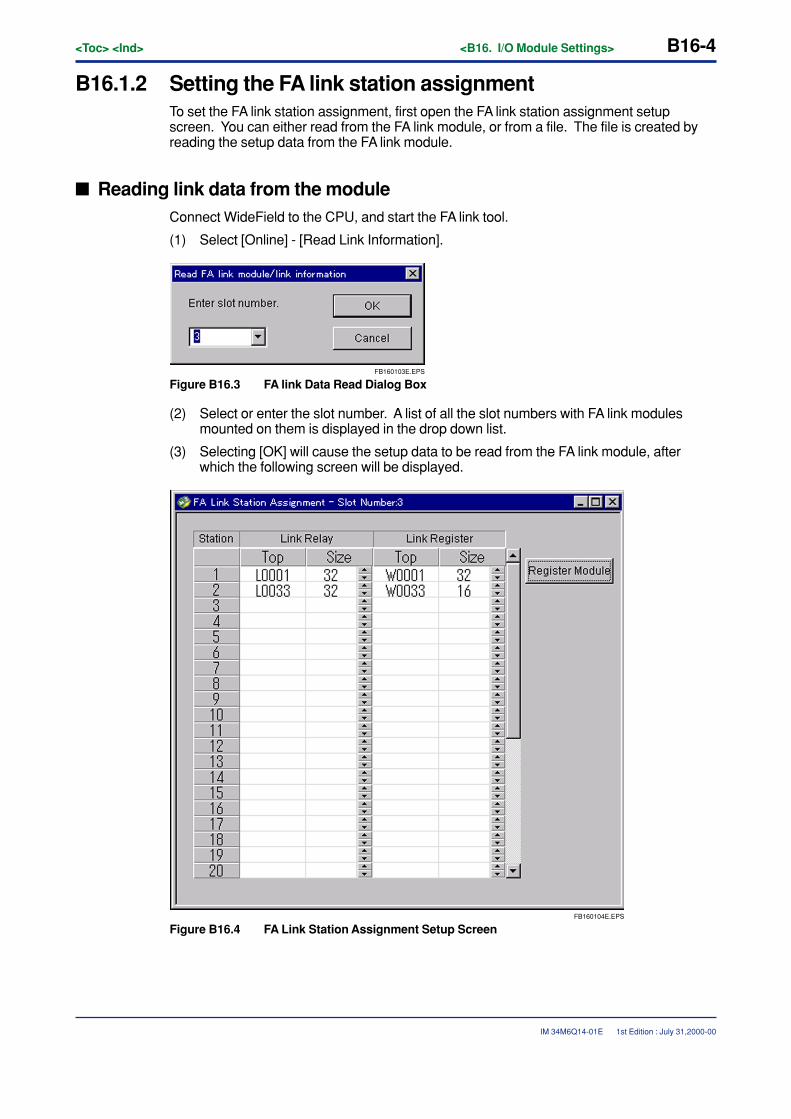
B16-4<Toc> <Ind> <B16. I/O Module Settings>
IM 34M6Q14-01E
B16.1.2 Setting the FA link station assignmentTo set the FA link station assignment, first open the FA link station assignment setupscreen. You can either read from the FA link module, or from a file. The file is created byreading the setup data from the FA link module.
� Reading link data from the moduleConnect WideField to the CPU, and start the FA link tool.
(1) Select [Online] - [Read Link Information].
FB160103E.EPS
Figure B16.3 FA link Data Read Dialog Box
(2) Select or enter the slot number. A list of all the slot numbers with FA link modulesmounted on them is displayed in the drop down list.
(3) Selecting [OK] will cause the setup data to be read from the FA link module, afterwhich the following screen will be displayed.
FB160104E.EPS
Figure B16.4 FA Link Station Assignment Setup Screen
1st Edition : July 31,2000-00
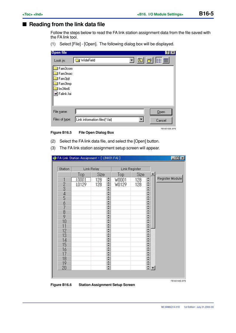
<Toc> <Ind> <B16. I/O Module Settings> B16-5
IM 34M6Q14-01E
� Reading from the link data fileFollow the steps below to read the FA link station assignment data from the file saved withthe FA link tool.
(1) Select [File] - [Open]. The following dialog box will be displayed.
FB160105E.EPS
Figure B16.5 File Open Dialog Box
(2) Select the FA link data file, and select the [Open] button.
(3) The FA link station assignment setup screen will appear.
FB160106E.EPS
Figure B16.6 Station Assignment Setup Screen
1st Edition : July 31,2000-00
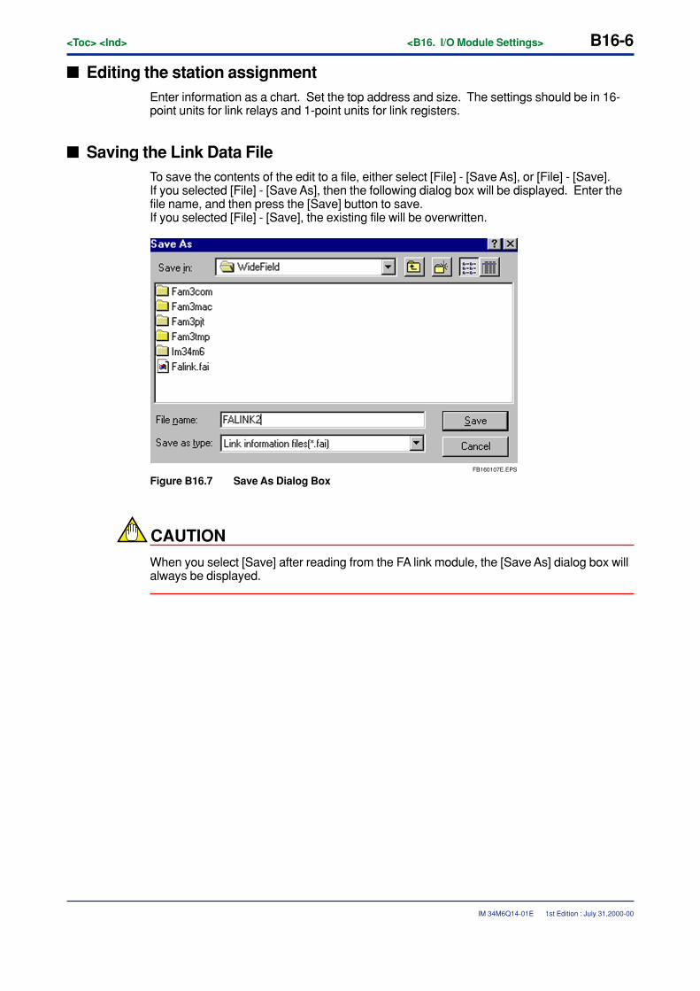
B16-6<Toc> <Ind> <B16. I/O Module Settings>
IM 34M6Q14-01E
� Editing the station assignmentEnter information as a chart. Set the top address and size. The settings should be in 16-point units for link relays and 1-point units for link registers.
� Saving the Link Data FileTo save the contents of the edit to a file, either select [File] - [Save As], or [File] - [Save].If you selected [File] - [Save As], then the following dialog box will be displayed. Enter thefile name, and then press the [Save] button to save.If you selected [File] - [Save], the existing file will be overwritten.
FB160107E.EPS
Figure B16.7 Save As Dialog Box
CAUTION
When you select [Save] after reading from the FA link module, the [Save As] dialog box willalways be displayed.
1st Edition : July 31,2000-00
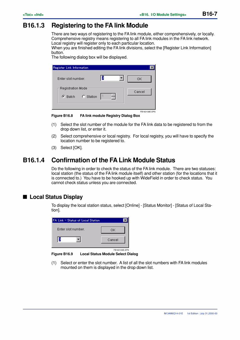
<Toc> <Ind> <B16. I/O Module Settings> B16-7
IM 34M6Q14-01E
B16.1.3 Registering to the FA link ModuleThere are two ways of registering to the FA link module, either comprehensively, or locally.Comprehensive registry means registering to all FA link modules in the FA link network.Local registry will register only to each particular location.When you are finished editing the FA link divisions, select the [Register Link Information]button.The following dialog box will be displayed.
FB160108E.EPS
Figure B16.8 FA link module Registry Dialog Box
(1) Select the slot number of the module for the FA link data to be registered to from thedrop down list, or enter it.
(2) Select comprehensive or local registry. For local registry, you will have to specify thelocation number to be registered to.
(3) Select [OK].
B16.1.4 Confirmation of the FA Link Module StatusDo the following in order to check the status of the FA link module. There are two statuses:local station (the status of the FA link module itself) and other station (for the locations that itis connected to.) You have to be hooked up with WideField in order to check status. Youcannot check status unless you are connected.
� Local Status DisplayTo display the local station status, select [Online] - [Status Monitor] - [Status of Local Sta-tion].
FB160109E.EPS
Figure B16.9 Local Status Module Select Dialog
(1) Select or enter the slot number. A list of all the slot numbers with FA link modulesmounted on them is displayed in the drop down list.
1st Edition : July 31,2000-00
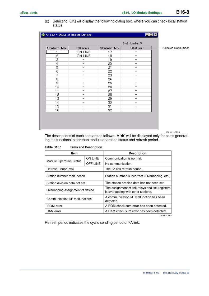
B16-8<Toc> <Ind> <B16. I/O Module Settings>
IM 34M6Q14-01E
(2) Selecting [OK] will display the following dialog box, where you can check local stationstatus.
FB160110E.EPS
Selected slot number
The descriptions of each item are as follows. A “�” will be displayed only for items generat-ing malfunctions, other than module operation status and refresh period.
Table B16.1 Items and Description
TB160101.EPS
Item
ON LINE
OFF LINEModule Operation Status
Description
Communication is normal.
No communication.
Refresh Period(ms) The FA link refresh period.
Station number malfunction Station number is incorrect. (Overlapping, etc.)
Station division data not set The station division data has not been set.
Overlapping assignment of deviceThe assignment of link relays and link registersis overlapping with other stations.
Communication I/F malfunctions A communication I/F malfunction has been detected.
ROM error A ROM check sum error has been detected.
RAM error A RAM check sum error has been detected.
Refresh period indicates the cyclic sending period of FA link.
1st Edition : July 31,2000-00

<Toc> <Ind> <B16. I/O Module Settings> B16-9
IM 34M6Q14-01E
� Other Station Status DisplayThis displays the FA link module status of a different station on the network (32 stations)that includes the specified FA link module.To display other station status, select [Online] - [Status Monitor] - [Status of Remote Sta-tions].
FB160111E.EPS
Figure B16.10 Other Station Status Module Select Dialog
(1) Select or enter the slot number. A list of all the slot numbers with FA link modulesmounted on them is displayed in the drop down list.
(2) Selecting [OK] will display the following dialog box, where you can check other stationstatus.
FB160112E.EPS
Selected slot number
Figure B16.11 Other Station Status Screen
The descriptions of the different statuses are as follows.
Table B16.2 Statuses and Descriptions
TB160102.EPS
Status Descriptions
ON LINE Communication is normal.
SEQ STOPThe sequence program has either malfunctioned or stopped, or is not operating.
CPU NOT READY CPU is not operating normally.
-Not set. Communication is not taking place normally, due to a disconnection or setup error, etc.
1st Edition : July 31,2000-00
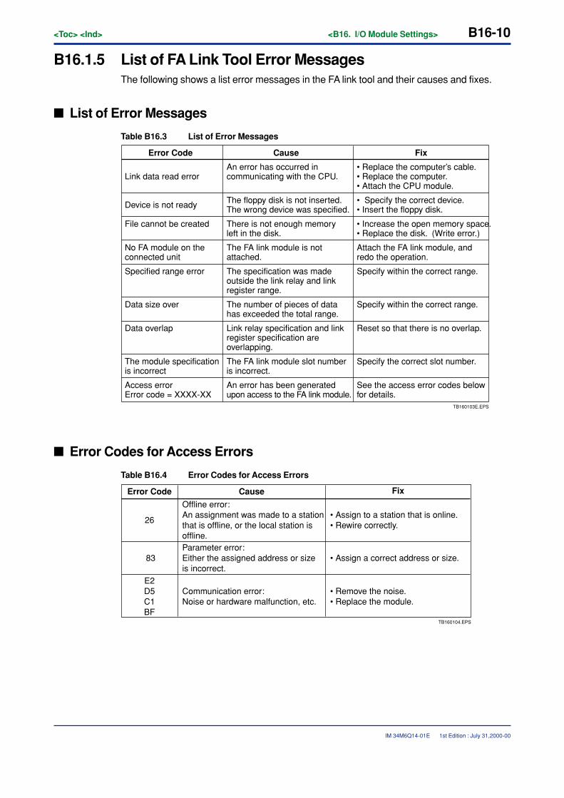
B16-10<Toc> <Ind> <B16. I/O Module Settings>
IM 34M6Q14-01E
B16.1.5 List of FA Link Tool Error MessagesThe following shows a list error messages in the FA link tool and their causes and fixes.
� List of Error Messages
Table B16.3 List of Error Messages
TB160103E.EPS
Error Code FixCause
Link data read errorAn error has occurred in communicating with the CPU.
The floppy disk is not inserted.The wrong device was specified.
• Replace the computer’s cable.• Replace the computer.• Attach the CPU module.
Device is not ready • Specify the correct device.• Insert the floppy disk.
File cannot be created There is not enough memory left in the disk.
• Increase the open memory space.• Replace the disk. (Write error.)
No FA module on the connected unit
The FA link module is not attached.
Attach the FA link module, and redo the operation.
Specified range error The specification was made outside the link relay and link register range.
Specify within the correct range.
Data size over The number of pieces of data has exceeded the total range.
Specify within the correct range.
Data overlap Link relay specification and link register specification are overlapping.
Reset so that there is no overlap.
The module specification is incorrect
The FA link module slot number is incorrect.
Specify the correct slot number.
Access errorError code = XXXX-XX
An error has been generated upon access to the FA link module.
See the access error codes below for details.
� Error Codes for Access Errors
Table B16.4 Error Codes for Access Errors
TB160104.EPS
Error Code
26
83
E2D5C1BF
Cause
Offline error: An assignment was made to a station that is offline, or the local station is offline. Parameter error: Either the assigned address or size is incorrect.
Communication error: Noise or hardware malfunction, etc.
Fix
• Assign to a station that is online.• Rewire correctly.
• Assign a correct address or size.
• Remove the noise.• Replace the module.
1st Edition : July 31,2000-00
<Int> <Ind> <Rev>
IM 34M6Q14-01E
TocB-10
CONTENTSB17. Sampling Trace Tool ........................................................................... B17-1
B17.1 How to Sample ............................................................................................ B17-2
B17.2 Sampling Trace Setup................................................................................. B17-4
B17.2.1 Setup Configuration ...................................................................... B17-4
B17.2.2 Online Setup and Sampling Trace Start ........................................ B17-5
B17.3 Reading Sampling Trace Results ............................................................. B17-11
B17.4 Reading Saved Trace Data ....................................................................... B17-17
B18. Device Management Tool ................................................................... B18-1B18.1 Device Management and Exiting................................................................ B18-2
B18.1.1 Starting the Device Manager ......................................................... B18-2
B18.1.2 Exiting the Device Manager .......................................................... B18-2
B18.2 Uploading Device Data ............................................................................... B18-3
B18.3 Downloading Device Data .......................................................................... B18-6
B18.4 Device Data Edit ........................................................................................ B18-10
B18.4.1 Bringing up the Device Edit Screen/Closing the Device Edit ........ B18-10
B18.4.2 Operation of Special Keys .......................................................... B18-11
B18.4.3 String Display and Floating Point Display .................................... B18-12
B18.4.4 Device Display ............................................................................ B18-13
B18.4.5 Device Data Edit ......................................................................... B18-19
B18.4.6 Comparing Device Data .............................................................. B18-27
1st Edition : July 31,2000-00
IM 34M6Q14-01E 1st Edition
FA-M3FA-M3 Programming Tool WideField Instruction ManualPART-B Supplementary Functions Section

Blank Page
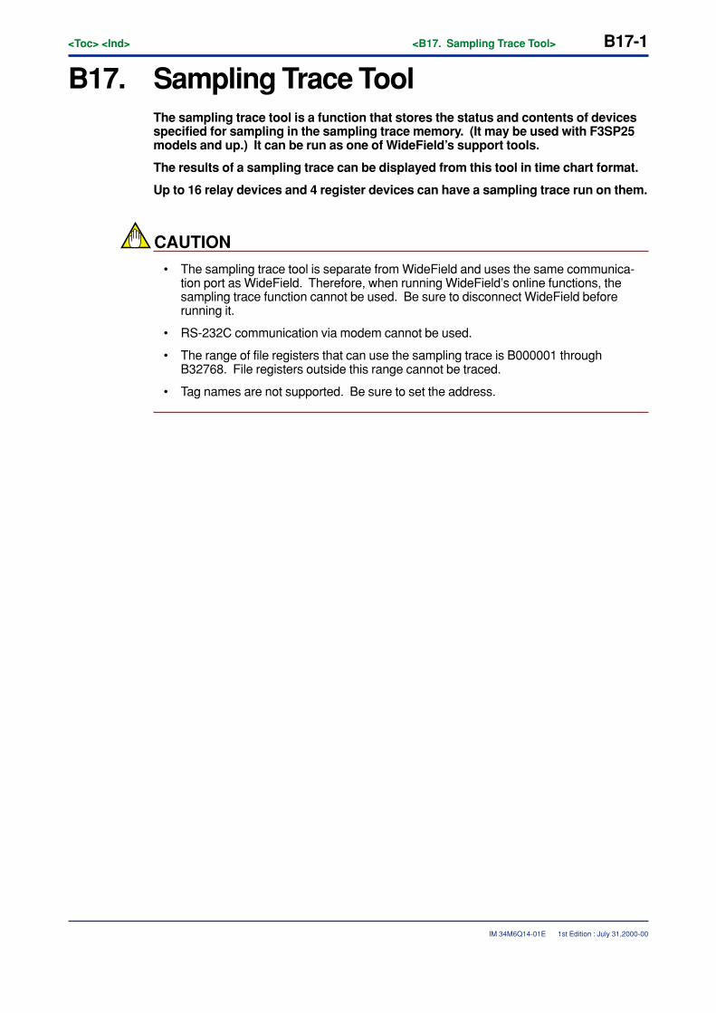
<Toc> <Ind> <B17. Sampling Trace Tool> B17-1
IM 34M6Q14-01E
B17. Sampling Trace ToolThe sampling trace tool is a function that stores the status and contents of devicesspecified for sampling in the sampling trace memory. (It may be used with F3SP25models and up.) It can be run as one of WideField’s support tools.
The results of a sampling trace can be displayed from this tool in time chart format.
Up to 16 relay devices and 4 register devices can have a sampling trace run on them.
CAUTION
• The sampling trace tool is separate from WideField and uses the same communica-tion port as WideField. Therefore, when running WideField’s online functions, thesampling trace function cannot be used. Be sure to disconnect WideField beforerunning it.
• RS-232C communication via modem cannot be used.
• The range of file registers that can use the sampling trace is B000001 throughB32768. File registers outside this range cannot be traced.
• Tag names are not supported. Be sure to set the address.
1st Edition : July 31,2000-00
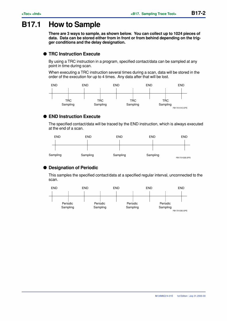
B17-2<Toc> <Ind> <B17. Sampling Trace Tool>
IM 34M6Q14-01E
B17.1 How to SampleThere are 3 ways to sample, as shown below. You can collect up to 1024 pieces ofdata. Data can be stored either from in front or from behind depending on the trig-ger conditions and the delay designation.
� TRC Instruction Execute
By using a TRC instruction in a program, specified contact/data can be sampled at anypoint in time during scan.
When executing a TRC instruction several times during a scan, data will be stored in theorder of the execution for up to 4 times. Any data after that will be lost.
ENDEND END END END
TRCSampling
TRCSampling
TRCSampling
TRCSampling
FB170101E.EPS
� END Instruction Execute
The specified contact/data will be traced by the END instruction, which is always executedat the end of a scan.
ENDEND END END END
Sampling Sampling Sampling SamplingFB170102E.EPS
� Designation of Periodic
This samples the specified contact/data at a specified regular interval, unconnected to thescan.
ENDEND END END END
Periodic Periodic Periodic PeriodicSampling Sampling Sampling Sampling
FB170103E.EPS
1st Edition : July 31,2000-00
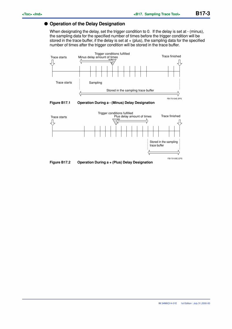
<Toc> <Ind> <B17. Sampling Trace Tool> B17-3
IM 34M6Q14-01E
� Operation of the Delay Designation
When designating the delay, set the trigger condition to 0. If the delay is set at - (minus),the sampling data for the specified number of times before the trigger condition will bestored in the trace buffer, if the delay is set at + (plus), the sampling data for the specifiednumber of times after the trigger condition will be stored in the trace buffer.
Minus delay amount of timesTrace starts
Trace starts
Trigger conditions fulfilledTrace finished
Sampling
Stored in the sampling trace buffer
FB170104E.EPS
Figure B17.1 Operation During a - (Minus) Delay Designation
Plus delay amount of timesTrace startsTrigger conditions fulfilled
Trace finished
Stored in the sampling trace buffer
FB170105E.EPS
Figure B17.2 Operation During a + (Plus) Delay Designation
1st Edition : July 31,2000-00
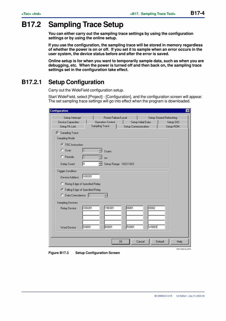
B17-4<Toc> <Ind> <B17. Sampling Trace Tool>
IM 34M6Q14-01E
B17.2 Sampling Trace SetupYou can either carry out the sampling trace settings by using the configurationsettings or by using the online setup.
If you use the configuration, the sampling trace will be stored in memory regardlessof whether the power is on or off. If you set it to sample when an error occurs in theuser system, the device status before and after the error is saved.
Online setup is for when you want to temporarily sample data, such as when you aredebugging, etc. When the power is turned off and then back on, the sampling tracesettings set in the configuration take effect.
B17.2.1 Setup ConfigurationCarry out the WideField configuration setup.
Start WideField, select [Project] - [Configuration], and the configuration screen will appear.The set sampling trace settings will go into effect when the program is downloaded.
FB170201E.EPS
Figure B17.3 Setup Configuration Screen
1st Edition : July 31,2000-00
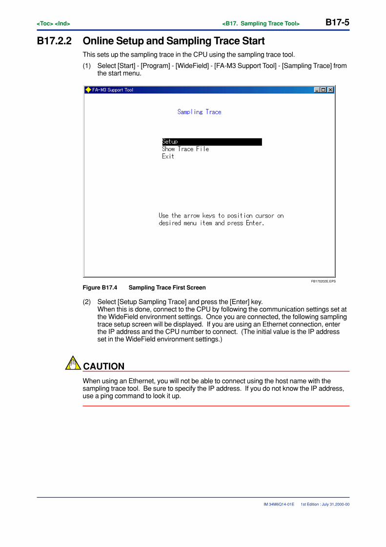
<Toc> <Ind> <B17. Sampling Trace Tool> B17-5
IM 34M6Q14-01E
B17.2.2 Online Setup and Sampling Trace StartThis sets up the sampling trace in the CPU using the sampling trace tool.
(1) Select [Start] - [Program] - [WideField] - [FA-M3 Support Tool] - [Sampling Trace] fromthe start menu.
FB170202E.EPS
Figure B17.4 Sampling Trace First Screen
(2) Select [Setup Sampling Trace] and press the [Enter] key.When this is done, connect to the CPU by following the communication settings set atthe WideField environment settings. Once you are connected, the following samplingtrace setup screen will be displayed. If you are using an Ethernet connection, enterthe IP address and the CPU number to connect. (The initial value is the IP addressset in the WideField environment settings.)
CAUTION
When using an Ethernet, you will not be able to connect using the host name with thesampling trace tool. Be sure to specify the IP address. If you do not know the IP address,use a ping command to look it up.
1st Edition : July 31,2000-00
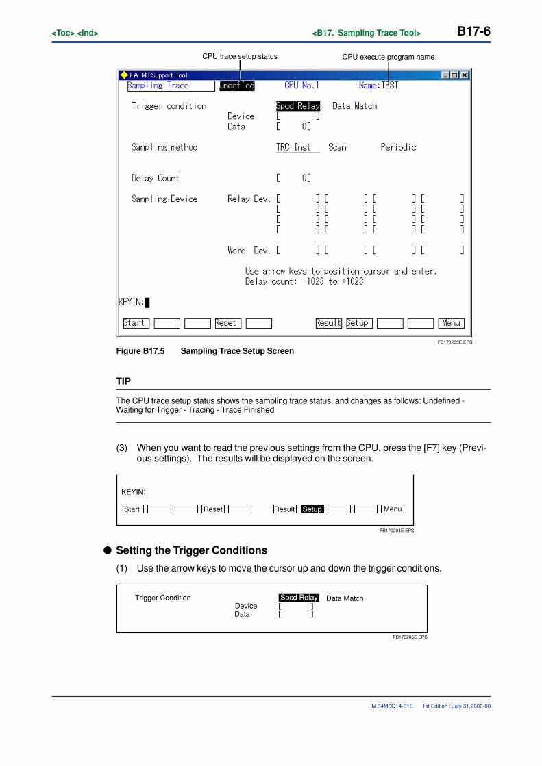
B17-6<Toc> <Ind> <B17. Sampling Trace Tool>
IM 34M6Q14-01E 1st Edition : July 31,2000-00
FB170203E.EPS
CPU trace setup status CPU execute program name
Figure B17.5 Sampling Trace Setup Screen
TIP
The CPU trace setup status shows the sampling trace status, and changes as follows: Undefined -Waiting for Trigger - Tracing - Trace Finished
(3) When you want to read the previous settings from the CPU, press the [F7] key (Previ-ous settings). The results will be displayed on the screen.
Start Reset Result Setup Menu
KEYIN
FB170204E.EPS
:
� Setting the Trigger Conditions
(1) Use the arrow keys to move the cursor up and down the trigger conditions.
FB170205E.EPS
Trigger ConditionDeviceData
Spcd Relay Data Match[ ][ ]
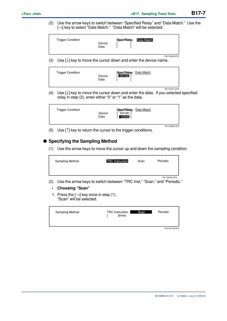
<Toc> <Ind> <B17. Sampling Trace Tool> B17-7
IM 34M6Q14-01E 1st Edition : July 31,2000-00
(2) Use the arrow keys to switch between “Specified Relay” and “Data Match.” Use the[→] key to select “Data Match.” “Data Match” will be selected.
FB170206E.EPS
Trigger ConditionDeviceData
Spcd Relay Data Match[ ][ ]
Spcd Relay
(3) Use [↓] key to move the cursor down and enter the device name.
FB170207E.EPS
Trigger ConditionDeviceData
Spcd Relay
[ ][ ]Spcd Relay Data Match
D0100
(4) Use [↓] key to move the cursor down and enter the data. If you selected specifiedrelay in step (2), enter either “0” or “1” as the data.
FB170208E.EPS
Trigger ConditionDeviceData
Spcd Relay
[ ][ ]Spcd Relay Data Match
-12345D0100
(5) Use [↑] key to return the cursor to the trigger conditions.
� Specifying the Sampling Method
(1) Use the arrow keys to move the cursor up and down the sampling condition.
FB170209E.EPS
TRC InstructionSampling Method Scan Periodic
(2) Use the arrow keys to switch between “TRC Inst,” “Scan,” and “Periodic.”
• Choosing “Scan”
1. Press the [→] key once in step (1).“Scan” will be selected.
FB170210E.EPS
Sampling Method Scan PeriodicTRC Instruction[ ]times
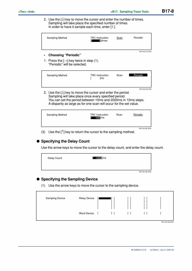
B17-8<Toc> <Ind> <B17. Sampling Trace Tool>
IM 34M6Q14-01E
2. Use the [↓] key to move the cursor and enter the number of times.Sampling will take place the specified number of times.In order to have it sample each time, enter [1.]
FB170211E.EPS
Sampling Method Scan PeriodicTRC Instruction[ ]times1
• Choosing “Periodic”
1. Press the [→] key twice in step (1).“Periodic” will be selected.
FB170212E.EPS
Sampling Method Scan PeriodicTRC Instruction[ ]ms
2. Use the [↓] key to move the cursor and enter the period.Sampling will take place once every specified period.You can set the period between 10ms and 2000ms in 10ms steps.A disparity as large as for one scan will occur for the set value.
FB170213E.EPS
Sampling Method Scan PeriodicTRC Instruction[ ]ms100
(3) Use the [↑] key to return the cursor to the sampling method.
� Specifying the Delay Count
Use the arrow keys to move the cursor to the delay count, and enter the delay count.
Delay Count
FB170214E.EPS
[ ]ms-1000
� Specifying the Sampling Device
(1) Use the arrow keys to move the cursor to the sampling device.
Relay Device
Word Device
Sampling Device
FB170215E.EPS
[ ] [ ] [ ] [ ][ ][ ]
[ ][ ]
[ ]
[ ] [ ][ ] [ ] [ ][ ] [ ] [ ]
[ ] [ ] [ ]
1st Edition : July 31,2000-00
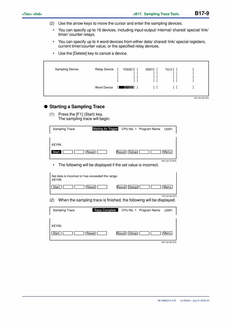
<Toc> <Ind> <B17. Sampling Trace Tool> B17-9
IM 34M6Q14-01E
(2) Use the arrow keys to move the cursor and enter the sampling devices.
• You can specify up to 16 devices, including input-output/ internal/ shared/ special/ link/timer/ counter relays.
• You can specify up to 4 word devices from either data/ shared/ link/ special registers,current timer/counter value, or the specified relay devices.
• Use the [Delete] key to cancel a device.
Relay Device
Word Device
Sampling Device
FB170216E.EPS
[ ] [ ] [ ] [ ][ ][ ]
[ ][ ]
[ ]
[ ] [ ][ ] [ ] [ ][ ] [ ] [ ]
[ ] [ ] [ ]
Y00301
D1000
I0001 T012
� Starting a Sampling Trace
(1) Press the [F1] (Start) key.The sampling trace will begin.
Start Setup
KEYIN:
Program NameCPU-No. 1Sampling Trace
FB170217E.EPS
Waiting for Trigger USR1
Reset Result Menu
• The following will be displayed if the set value is incorrect.
Reset
Set data is incorrect or has exceeded the range.
SetupStart Result Menu
KEYIN:
FB170218E.EPS
(2) When the sampling trace is finished, the following will be displayed.
Start Setup
KEYIN:
Program NameCPU-No. 1Sampling Trace
FB170219E.EPS
USR1
Reset Result Menu
Trace Complete
1st Edition : July 31,2000-00
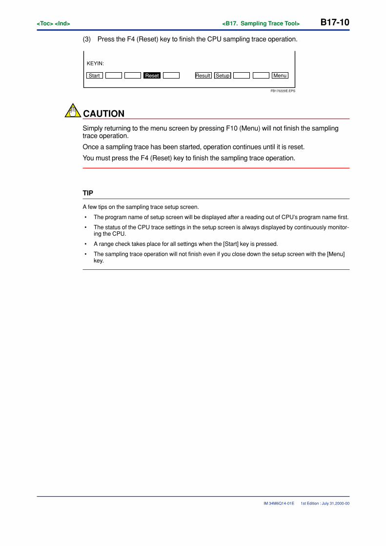
B17-10<Toc> <Ind> <B17. Sampling Trace Tool>
IM 34M6Q14-01E 1st Edition : July 31,2000-00
(3) Press the F4 (Reset) key to finish the CPU sampling trace operation.
SetupResetStart Result Menu
KEYIN:
FB170220E.EPS
CAUTION
Simply returning to the menu screen by pressing F10 (Menu) will not finish the samplingtrace operation.
Once a sampling trace has been started, operation continues until it is reset.
You must press the F4 (Reset) key to finish the sampling trace operation.
TIP
A few tips on the sampling trace setup screen.
• The program name of setup screen will be displayed after a reading out of CPU’s program name first.
• The status of the CPU trace settings in the setup screen is always displayed by continuously monitor-ing the CPU.
• A range check takes place for all settings when the [Start] key is pressed.
• The sampling trace operation will not finish even if you close down the setup screen with the [Menu]key.
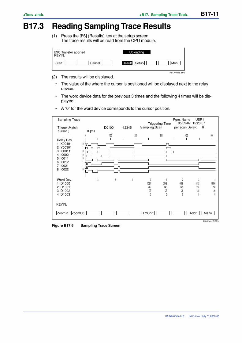
<Toc> <Ind> <B17. Sampling Trace Tool> B17-11
IM 34M6Q14-01E 1st Edition : July 31,2000-00
B17.3 Reading Sampling Trace Results(1) Press the [F6] (Results) key at the setup screen.
The trace results will be read from the CPU module.
ESC:Transfer aborted Uploading
Result Setup
KEYIN:
FB170401E.EPS
Start Cancel Menu
(2) The results will be displayed.
• The value of the where the cursor is positioned will be displayed next to the relaydevice.
• The word device data for the previous 3 times and the following 4 times will be dis-played.
• A “0” for the word device corresponds to the cursor position.
ZoomIn ZoomOt TmChrt MenuAddr
KEYIN:
Sampling Trace Pgm. Name USR1
Relay Dev.1. X004012. Y003013. I000114. I00025. I00116. I00127. I00218. I0022
0 100 200 300 400 500
Trigger:Match Sampling:ScanTriggering Time
per scan Delay: 0
Word Dev.1. D10002. D10013. D10024. D1003
416384
250290
38192250280
24696245280
12048245270
01024245270
-1
01000110
-2-3
FB170402E.EPS
D0100 -12345cursor [ 0 ]ms
95/09/07 15:23:07
Figure B17.6 Sampling Trace Screen
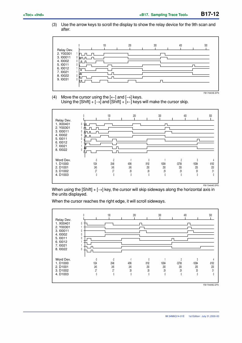
B17-12<Toc> <Ind> <B17. Sampling Trace Tool>
IM 34M6Q14-01E
(3) Use the arrow keys to scroll the display to show the relay device for the 9th scan andafter.
Relay Dev.2. Y003013. I000114. I00025. I00116. I00127. I00218. I00229. I0031
0 100 200 300 400 500
FB170403E.EPS
10001100
(4) Move the cursor using the [←] and [→] keys.Using the [Shift] + [→] and [Shift] + [←] keys will make the cursor skip.
FB170404E.EPS
Relay Dev.1. X004012. Y003013. I000114. I00025. I00116. I00127. I00218. I0022
0 100 200 300 400 500
Word Dev.1. D10002. D10013. D10024. D1003
4-8192
23031
0
3-16384
25530
0
2-32768
25029
0
116384
25029
0
08192
25028
0
-14096
24528
0
01000110
-22048
24527
0
-31024
24527
0
When using the [Shift] + [→] key, the cursor will skip sideways along the horizontal axis inthe units displayed.
When the cursor reaches the right edge, it will scroll sideways.
FB170405E.EPS
Relay Dev.1. X004012. Y003013. I000114. I00025. I00116. I00127. I00218. I0022
0 100 200 300 400 500
Word Dev.1. D10002. D10013. D10024. D1003
4-8192
23031
0
3-16384
25530
0
2-32768
25029
0
116384
25029
0
08192
25028
0
-14096
24528
0
01000110
-22048
24527
0
-31024
24527
0
1st Edition : July 31,2000-00
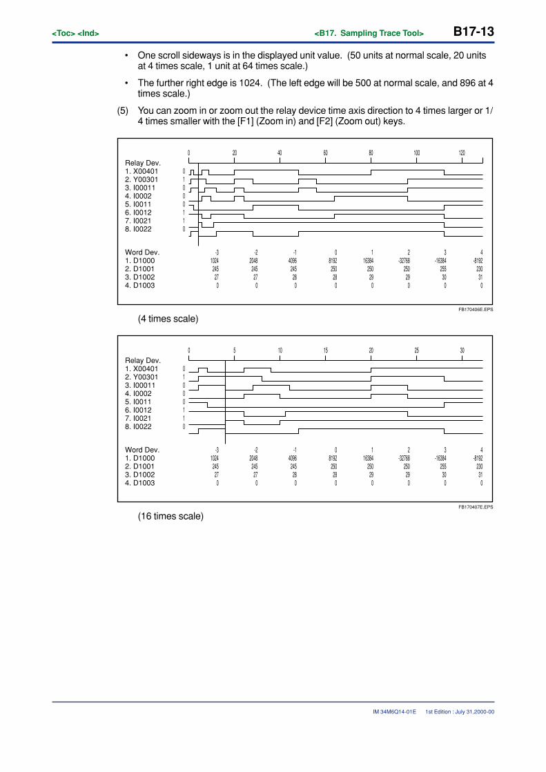
<Toc> <Ind> <B17. Sampling Trace Tool> B17-13
IM 34M6Q14-01E
• One scroll sideways is in the displayed unit value. (50 units at normal scale, 20 unitsat 4 times scale, 1 unit at 64 times scale.)
• The further right edge is 1024. (The left edge will be 500 at normal scale, and 896 at 4times scale.)
(5) You can zoom in or zoom out the relay device time axis direction to 4 times larger or 1/4 times smaller with the [F1] (Zoom in) and [F2] (Zoom out) keys.
FB170406E.EPS
Relay Dev.1. X004012. Y003013. I000114. I00025. I00116. I00127. I00218. I0022
10020 40 8060 1200
Word Dev.1. D10002. D10013. D10024. D1003
4-8192
230310
3-16384
255300
2-32768
250290
116384
250290
08192250280
-14096245280
01000110
-22048245270
-31024245270
(4 times scale)
0 5 10 15 20 25 30
FB170407E.EPS
Relay Dev.1. X004012. Y003013. I000114. I00025. I00116. I00127. I00218. I0022
Word Dev.1. D10002. D10013. D10024. D1003
4-8192
230310
3-16384
255300
2-32768
250290
116384
250290
08192250280
-14096245280
01000110
-22048245270
-31024245270
(16 times scale)
1st Edition : July 31,2000-00
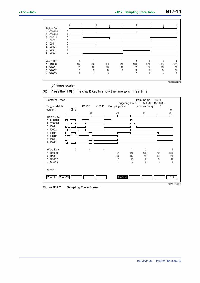
B17-14<Toc> <Ind> <B17. Sampling Trace Tool>
IM 34M6Q14-01E
0 1 2 3 4 5 6 7 8
FB170408E.EPS
Relay Dev.1. X004012. Y003013. I000114. I00025. I00116. I00127. I00218. I0022
Word Dev.1. D10002. D10013. D10024. D1003
4-8192
23031
0
3-16384
25530
0
2-32768
25029
0
116384
25029
0
08192
25028
0
-14096
24528
0
01000110
-22048
24527
0
-31024
24527
0
(64 times scale)
(6) Press the [F6] (Time chart) key to show the time axis in real time.
ZoomIn ZoomOt TmChrt Exit
KEYIN:
Sampling TraceTriggering Time
USR195/09/07 15:23:08
Relay Dev.1. X004012. Y003013. I00114. I00025. I00116. I00127. I00218. I0022
0
Trigger:Matchcursor [ 0]ms
D0100 -12345 Sampling:Scan per scan Delay: 0
Word Dev.1. D10002. D10013. D10024. D1003
416384
25029
0
38192
25028
0
24696
24528
0
12048
24527
0
01024
24527
0
-1-2-3
200 400 600 800
FB170409E.EPS
[ms]
Pgm. Name
Figure B17.7 Sampling Trace Screen
1st Edition : July 31,2000-00
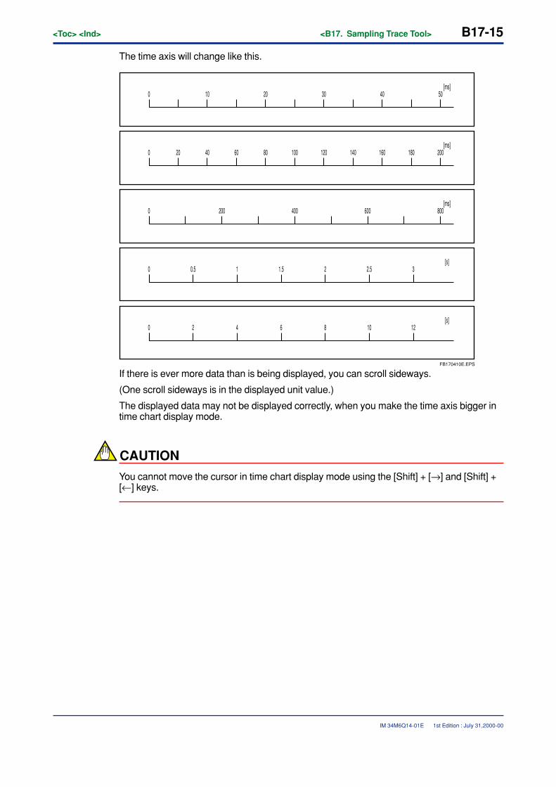
<Toc> <Ind> <B17. Sampling Trace Tool> B17-15
IM 34M6Q14-01E
The time axis will change like this.
0 10 20 30 40 50[ms]
0 40 80 100 160 180[ms]
6020 120 140 200
0 200 400 600 800[ms]
0 0.5 1 3[s]
1.5 2 2.5
0 2 4 12[s]
6 8 10
FB170410E.EPS
If there is ever more data than is being displayed, you can scroll sideways.
(One scroll sideways is in the displayed unit value.)
The displayed data may not be displayed correctly, when you make the time axis bigger intime chart display mode.
CAUTION
You cannot move the cursor in time chart display mode using the [Shift] + [→] and [Shift] +[←] keys.
1st Edition : July 31,2000-00
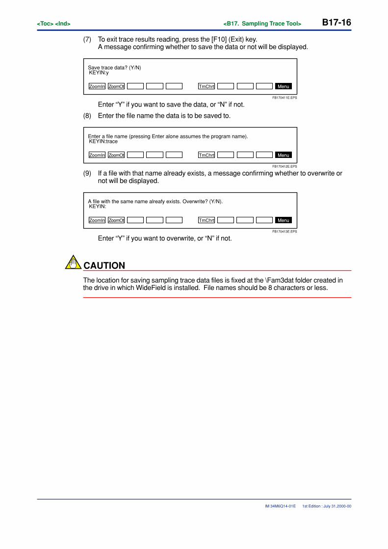
B17-16<Toc> <Ind> <B17. Sampling Trace Tool>
IM 34M6Q14-01E
(7) To exit trace results reading, press the [F10] (Exit) key.A message confirming whether to save the data or not will be displayed.
ZoomIn ZoomOt TmChrt
KEYIN:ySave trace data? (Y/N)
Menu
FB170411E.EPS
Enter “Y” if you want to save the data, or “N” if not.
(8) Enter the file name the data is to be saved to.
ZoomIn ZoomOt TmChrt
KEYIN:traceEnter a file name (pressing Enter alone assumes the program name).
Menu
FB170412E.EPS
(9) If a file with that name already exists, a message confirming whether to overwrite ornot will be displayed.
ZoomIn ZoomOt TmChrt
KEYIN:A file with the same name alreafy exists. Overwrite? (Y/N).
Menu
FB170413E.EPS
Enter “Y” if you want to overwrite, or “N” if not.
CAUTION
The location for saving sampling trace data files is fixed at the \Fam3dat folder created inthe drive in which WideField is installed. File names should be 8 characters or less.
1st Edition : July 31,2000-00
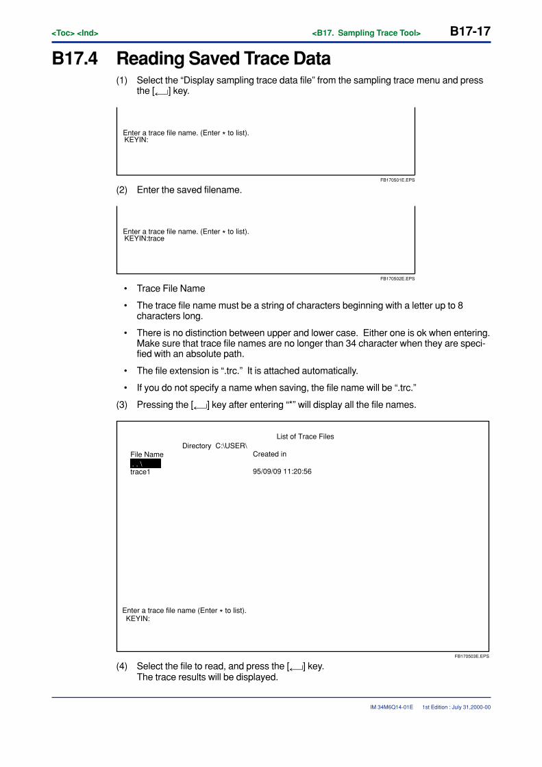
<Toc> <Ind> <B17. Sampling Trace Tool> B17-17
IM 34M6Q14-01E
B17.4 Reading Saved Trace Data(1) Select the “Display sampling trace data file” from the sampling trace menu and press
the [ ] key.
KEYIN:Enter a trace file name. (Enter * to list).
FB170501E.EPS
(2) Enter the saved filename.
KEYIN:traceEnter a trace file name. (Enter * to list).
FB170502E.EPS
• Trace File Name
• The trace file name must be a string of characters beginning with a letter up to 8characters long.
• There is no distinction between upper and lower case. Either one is ok when entering.Make sure that trace file names are no longer than 34 character when they are speci-fied with an absolute path.
• The file extension is “.trc.” It is attached automatically.
• If you do not specify a name when saving, the file name will be “.trc.”
(3) Pressing the [ ] key after entering “*” will display all the file names.
KEYIN:
File Name
trace1
Directory C:\USER\
Enter a trace file name (Enter * to list).
Created in
95/09/09 11:20:56
List of Trace Files
. . \
FB170503E.EPS
(4) Select the file to read, and press the [ ] key.The trace results will be displayed.
1st Edition : July 31,2000-00

B17-18<Toc> <Ind> <B17. Sampling Trace Tool>
IM 34M6Q14-01E
(5) You may repeat this process as many times as needed.
SEE ALSO
See step (2) and after in “B17.3 Reading Sampling Trace Results” for further details on how to read thetrace results.
(6) Press the [F10] (Exit) key.You will exit from the trace file display.
1st Edition : July 31,2000-00
<Toc> <Ind> <B18. Device Management Tool> B18-1
IM 34M6Q14-01E
B18. Device Management ToolThe device manager uploads the CPU’s device data and saves it to a file. You canuse this file to edit device data, download, and compare. You can also set the rangeof devices to upload and download.
The devices saved are as follows:
• Internal relay (I)
• Shared relay / Extension shared relay (E)
• Link relay (L)
• Timer relay / current value(T)
• Counter relay / current value(C)
• Data register (D)
• Shared register / Extension shared register (R)
• Link register (W)
• Index register (V)
• File register (B) However, this is limited to between B000001 and B32768
Devices that cannot be saved are as follows:
• Input/output relay (X, Y)
• Timer/Counter Set Value
CAUTION
• The device management tool is separate from WideField and uses the same commu-nication port as WideField. Therefore, when running WideField’s online functions, thedevice manager cannot be used. Be sure to disconnect WideField before running it.
• RS-232C communication via modem cannot be used.
• The range of file registers that can be handled by the device manager is B000001through B32768. File registers outside this range cannot be traced.
• Tag names are not supported.
• No new device data can be created. Edit files that have been uploaded.
1st Edition : July 31,2000-00
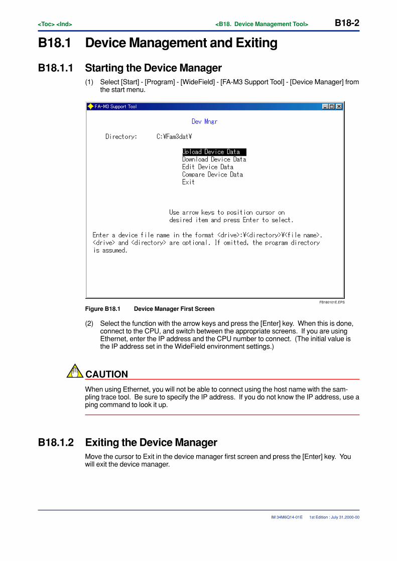
B18-2<Toc> <Ind> <B18. Device Management Tool>
IM 34M6Q14-01E
B18.1 Device Management and Exiting
B18.1.1 Starting the Device Manager(1) Select [Start] - [Program] - [WideField] - [FA-M3 Support Tool] - [Device Manager] from
the start menu.
FB180101E.EPS
Figure B18.1 Device Manager First Screen
(2) Select the function with the arrow keys and press the [Enter] key. When this is done,connect to the CPU, and switch between the appropriate screens. If you are usingEthernet, enter the IP address and the CPU number to connect. (The initial value isthe IP address set in the WideField environment settings.)
CAUTION
When using Ethernet, you will not be able to connect using the host name with the sam-pling trace tool. Be sure to specify the IP address. If you do not know the IP address, use aping command to look it up.
B18.1.2 Exiting the Device ManagerMove the cursor to Exit in the device manager first screen and press the [Enter] key. Youwill exit the device manager.
1st Edition : July 31,2000-00
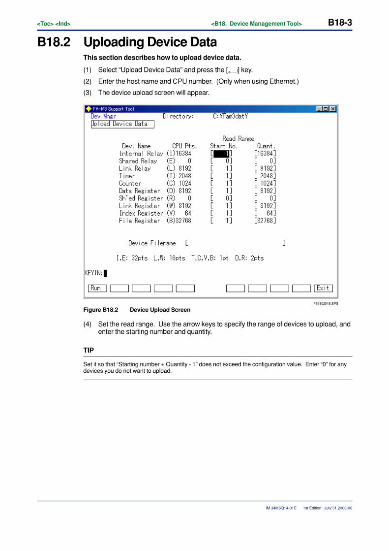
<Toc> <Ind> <B18. Device Management Tool> B18-3
IM 34M6Q14-01E
B18.2 Uploading Device DataThis section describes how to upload device data.
(1) Select “Upload Device Data” and press the [ ] key.
(2) Enter the host name and CPU number. (Only when using Ethernet.)
(3) The device upload screen will appear.
FB180201E.EPS
Figure B18.2 Device Upload Screen
(4) Set the read range. Use the arrow keys to specify the range of devices to upload, andenter the starting number and quantity.
TIP
Set it so that “Starting number + Quantity - 1” does not exceed the configuration value. Enter “0” for anydevices you do not want to upload.
1st Edition : July 31,2000-00
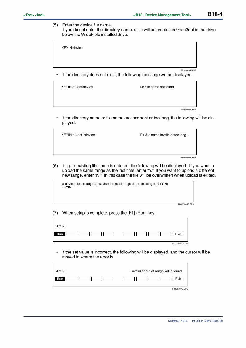
B18-4<Toc> <Ind> <B18. Device Management Tool>
IM 34M6Q14-01E
(5) Enter the device file name.If you do not enter the directory name, a file will be created in \Fam3dat in the drivebelow the WideField installed drive.
FB180202E.EPS
KEYIN:device
• If the directory does not exist, the following message will be displayed.
FB180203E.EPS
KEYIN:a:\test\device Dir./file name not found.
• If the directory name or file name are incorrect or too long, the following will be dis-played.
FB180204E.EPS
KEYIN:a:\test1\device Dir./file name invalid or too long.
(6) If a pre-existing file name is entered, the following will be displayed. If you want toupload the same range as the last time, enter “Y.” If you want to upload a differentnew range, enter “N.” In this case the file will be overwritten when upload is exited.
KEYIN:A device file already exists. Use the read range of the existing file? (Y/N)
FB180205E.EPS
(7) When setup is complete, press the [F1] (Run) key.
Exit
KEYIN:
FB180206E.EPS
Run
• If the set value is incorrect, the following will be displayed, and the cursor will bemoved to where the error is.
KEYIN: Invalid or out-of-range value found.
FB180207E.EPS
Run Exit
1st Edition : July 31,2000-00
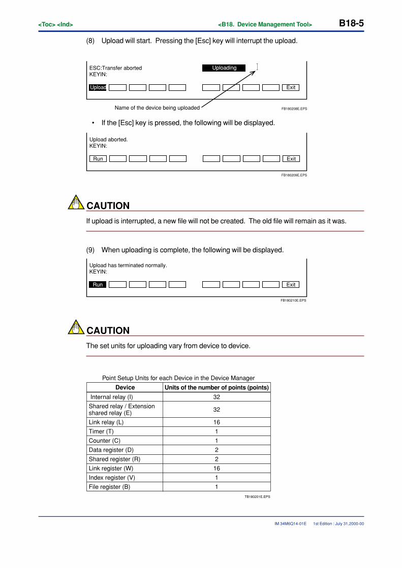
<Toc> <Ind> <B18. Device Management Tool> B18-5
IM 34M6Q14-01E
(8) Upload will start. Pressing the [Esc] key will interrupt the upload.
ESC:Transfer aborted
Name of the device being uploaded
KEYIN:
Exit
Uploading
Upload
FB180208E.EPS
• If the [Esc] key is pressed, the following will be displayed.
Run Exit
KEYIN:Upload aborted.
FB180209E.EPS
CAUTION
If upload is interrupted, a new file will not be created. The old file will remain as it was.
(9) When uploading is complete, the following will be displayed.
Upload has terminated normally.
Run
KEYIN:
Exit
FB180210E.EPS
CAUTION
The set units for uploading vary from device to device.
TB180201E.EPS
Device
Internal relay (I)
Shared relay / Extension shared relay (E)
Link relay (L)
Timer (T)
Counter (C)
Data register (D)
Shared register (R)
Link register (W)
Index register (V)
File register (B)
Units of the number of points (points)
32
32
16
1
1
2
2
16
1
1
Point Setup Units for each Device in the Device Manager
1st Edition : July 31,2000-00
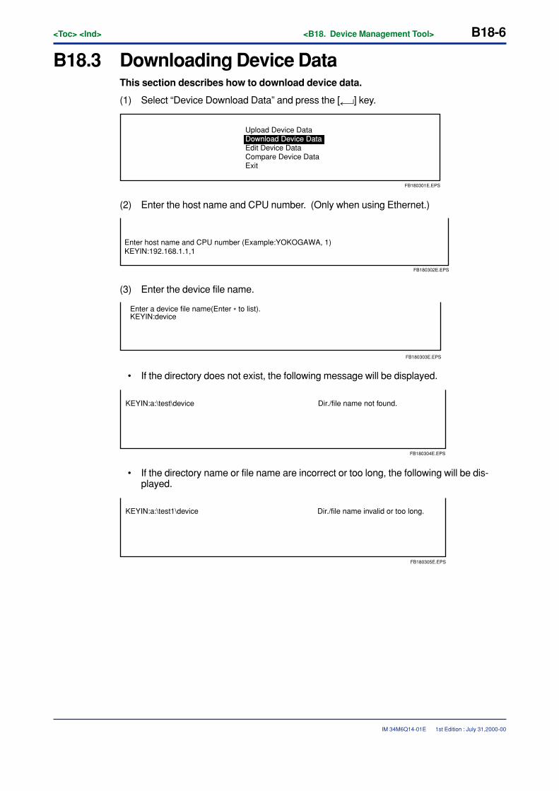
B18-6<Toc> <Ind> <B18. Device Management Tool>
IM 34M6Q14-01E
B18.3 Downloading Device DataThis section describes how to download device data.
(1) Select “Device Download Data” and press the [ ] key.
Upload Device DataDownload Device DataEdit Device Data Compare Device DataExit
FB180301E.EPS
(2) Enter the host name and CPU number. (Only when using Ethernet.)
Enter host name and CPU number (Example:YOKOGAWA, 1)KEYIN:192.168.1.1,1
FB180302E.EPS
(3) Enter the device file name.
KEYIN:deviceEnter a device file name(Enter * to list).
FB180303E.EPS
• If the directory does not exist, the following message will be displayed.
KEYIN:a:\test\device Dir./file name not found.
FB180304E.EPS
• If the directory name or file name are incorrect or too long, the following will be dis-played.
KEYIN:a:\test1\device Dir./file name invalid or too long.
FB180305E.EPS
1st Edition : July 31,2000-00
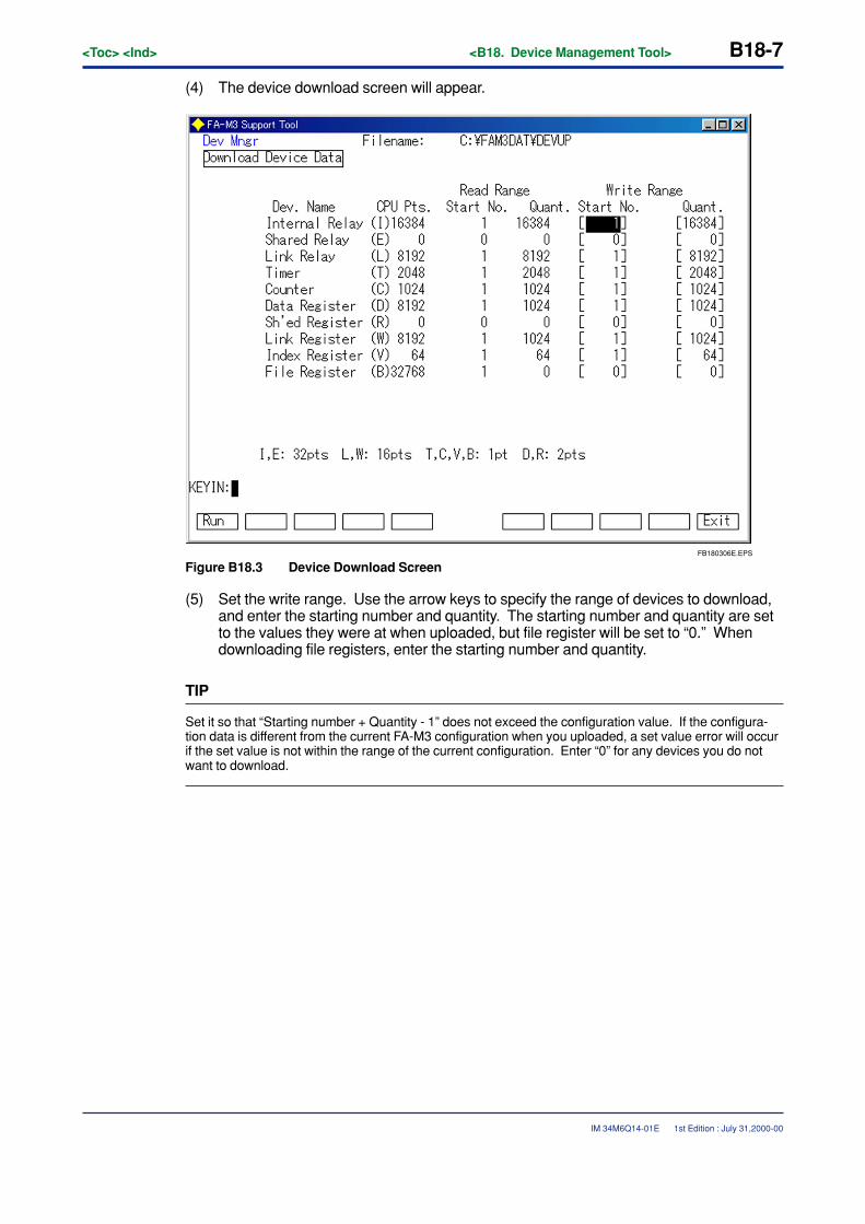
<Toc> <Ind> <B18. Device Management Tool> B18-7
IM 34M6Q14-01E
(4) The device download screen will appear.
FB180306E.EPS
Figure B18.3 Device Download Screen
(5) Set the write range. Use the arrow keys to specify the range of devices to download,and enter the starting number and quantity. The starting number and quantity are setto the values they were at when uploaded, but file register will be set to “0.” Whendownloading file registers, enter the starting number and quantity.
TIP
Set it so that “Starting number + Quantity - 1” does not exceed the configuration value. If the configura-tion data is different from the current FA-M3 configuration when you uploaded, a set value error will occurif the set value is not within the range of the current configuration. Enter “0” for any devices you do notwant to download.
1st Edition : July 31,2000-00
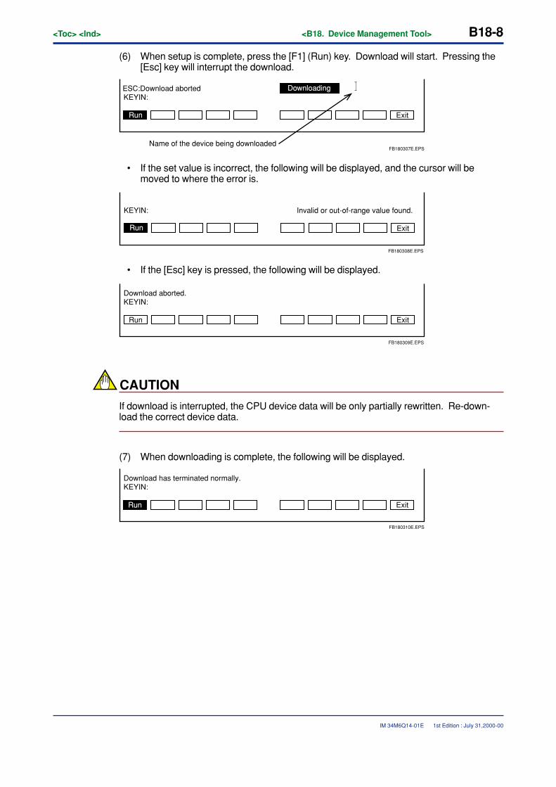
B18-8<Toc> <Ind> <B18. Device Management Tool>
IM 34M6Q14-01E
(6) When setup is complete, press the [F1] (Run) key. Download will start. Pressing the[Esc] key will interrupt the download.
ESC:Download aborted
Name of the device being downloaded
KEYIN:
Exit
FB180307E.EPS
Downloading
Run
• If the set value is incorrect, the following will be displayed, and the cursor will bemoved to where the error is.
Exit
KEYIN: Invalid or out-of-range value found.
FB180308E.EPS
Run
• If the [Esc] key is pressed, the following will be displayed.
Run Exit
KEYIN:Download aborted.
FB180309E.EPS
CAUTION
If download is interrupted, the CPU device data will be only partially rewritten. Re-down-load the correct device data.
(7) When downloading is complete, the following will be displayed.
KEYIN:Download has terminated normally.
ExitRun
FB180310E.EPS
1st Edition : July 31,2000-00
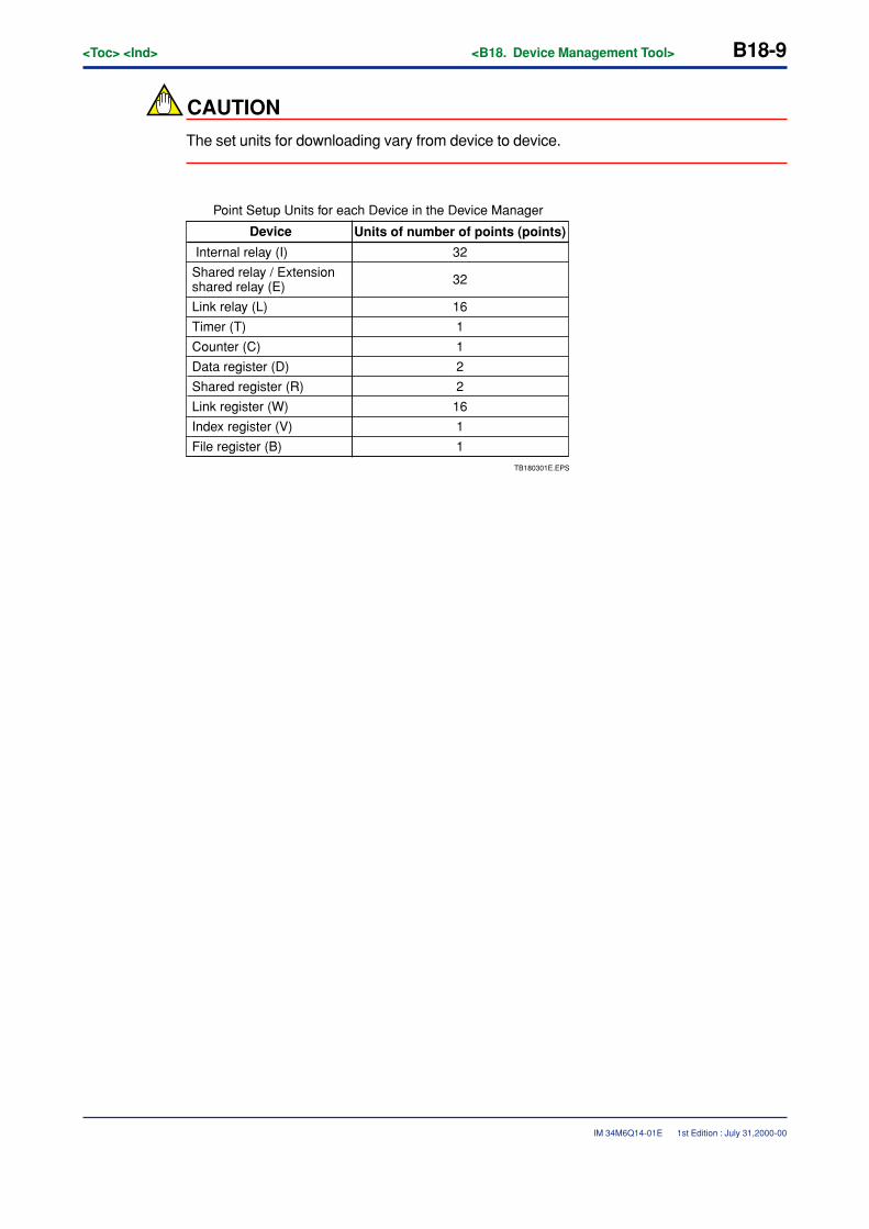
<Toc> <Ind> <B18. Device Management Tool> B18-9
IM 34M6Q14-01E
CAUTION
The set units for downloading vary from device to device.
TB180301E.EPS
Device
Internal relay (I)
Shared relay / Extension shared relay (E)
Link relay (L)
Timer (T)
Counter (C)
Data register (D)
Shared register (R)
Link register (W)
Index register (V)
File register (B)
Units of number of points (points)
32
32
16
1
1
2
2
16
1
1
Point Setup Units for each Device in the Device Manager
1st Edition : July 31,2000-00
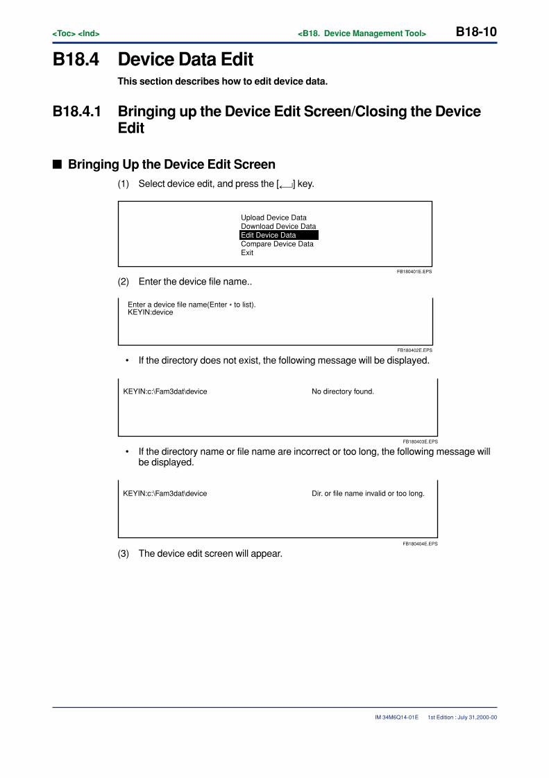
B18-10<Toc> <Ind> <B18. Device Management Tool>
IM 34M6Q14-01E
B18.4 Device Data EditThis section describes how to edit device data.
B18.4.1 Bringing up the Device Edit Screen/Closing the DeviceEdit
� Bringing Up the Device Edit Screen(1) Select device edit, and press the [ ] key.
Upload Device DataDownload Device DataEdit Device Data Compare Device DataExit
FB180401E.EPS
(2) Enter the device file name..
KEYIN:deviceEnter a device file name(Enter * to list).
FB180402E.EPS
• If the directory does not exist, the following message will be displayed.
KEYIN:c:\Fam3dat\device No directory found.
FB180403E.EPS
• If the directory name or file name are incorrect or too long, the following message willbe displayed.
KEYIN:c:\Fam3dat\device Dir. or file name invalid or too long.
FB180404E.EPS
(3) The device edit screen will appear.
1st Edition : July 31,2000-00
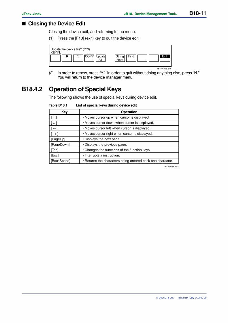
<Toc> <Ind> <B18. Device Management Tool> B18-11
IM 34M6Q14-01E
� Closing the Device EditClosing the device edit, and returning to the menu.
(1) Press the [F10] (exit) key to quit the device edit.
� � COPY UpdateFloatString Find Exit
All
KEYIN:Update the device file? (Y/N)
FB180405E.EPS
(2) In order to renew, press “Y.” In order to quit without doing anything else, press “N.”You will return to the device manager menu.
B18.4.2 Operation of Special KeysThe following shows the use of special keys during device edit.
Table B18.1 List of special keys during device edit
Key Operation
• Moves cursor up when cursor is displayed.
• Moves cursor down when cursor is displayed.
• Moves cursor left when cursor is displayed.
• Moves cursor right when cursor is displayed.
• Displays the next page.
• Displays the previous page.
• Changes the functions of the function keys.
• Interrupts a instruction.
• Returns the characters being entered back one character.
[ ↑ ][ ↓ ]
[ ← ]
[ → ]
[PageUp]
[PageDown]
[Tab]
[Esc]
[BackSpace]
TB180401E.EPS
1st Edition : July 31,2000-00
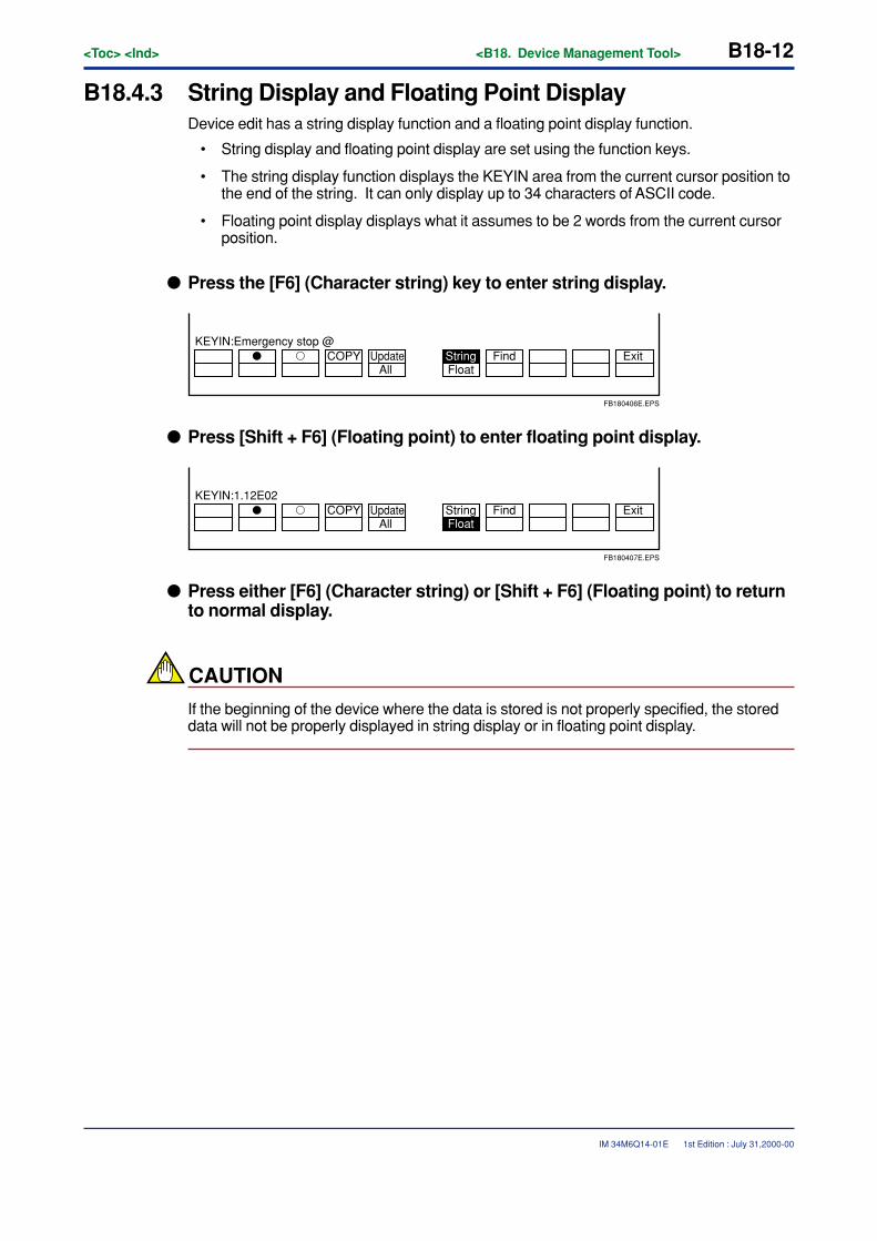
B18-12<Toc> <Ind> <B18. Device Management Tool>
IM 34M6Q14-01E
B18.4.3 String Display and Floating Point DisplayDevice edit has a string display function and a floating point display function.
• String display and floating point display are set using the function keys.
• The string display function displays the KEYIN area from the current cursor position tothe end of the string. It can only display up to 34 characters of ASCII code.
• Floating point display displays what it assumes to be 2 words from the current cursorposition.
� Press the [F6] (Character string) key to enter string display.
� � COPY UpdateFloatString Find Exit
All
KEYIN:Emergency stop @
FB180406E.EPS
� Press [Shift + F6] (Floating point) to enter floating point display.
� � COPY UpdateFloatString Find Exit
All
KEYIN:1.12E02
FB180407E.EPS
� Press either [F6] (Character string) or [Shift + F6] (Floating point) to returnto normal display.
CAUTION
If the beginning of the device where the data is stored is not properly specified, the storeddata will not be properly displayed in string display or in floating point display.
1st Edition : July 31,2000-00
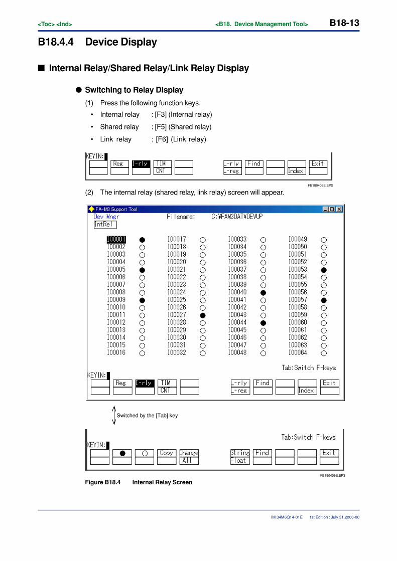
<Toc> <Ind> <B18. Device Management Tool> B18-13
IM 34M6Q14-01E
B18.4.4 Device Display
� Internal Relay/Shared Relay/Link Relay Display
� Switching to Relay Display
(1) Press the following function keys.
• Internal relay : [F3] (Internal relay)
• Shared relay : [F5] (Shared relay)
• Link relay : [F6] (Link relay)
FB180408E.EPS
(2) The internal relay (shared relay, link relay) screen will appear.
Switched by the [Tab] key
FB180409E.EPS
Figure B18.4 Internal Relay Screen
1st Edition : July 31,2000-00
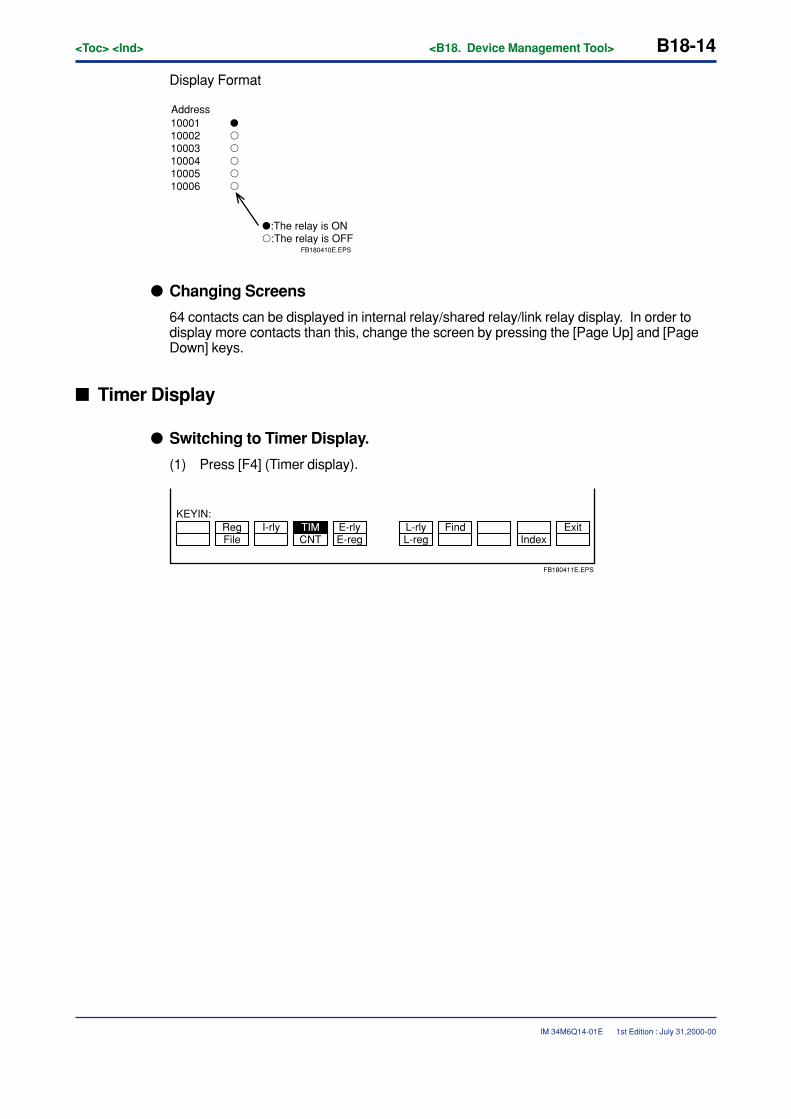
B18-14<Toc> <Ind> <B18. Device Management Tool>
IM 34M6Q14-01E
Display Format
Address
�:The relay is ON�:The relay is OFF
FB180410E.EPS
100011000210003100041000510006
��
�
�
�
�
� Changing Screens
64 contacts can be displayed in internal relay/shared relay/link relay display. In order todisplay more contacts than this, change the screen by pressing the [Page Up] and [PageDown] keys.
� Timer Display
� Switching to Timer Display.
(1) Press [F4] (Timer display).
FileReg
CNT L-regL-rly Find
IndexExitI-rly E-rly
E-regTIM
KEYIN:
FB180411E.EPS
1st Edition : July 31,2000-00
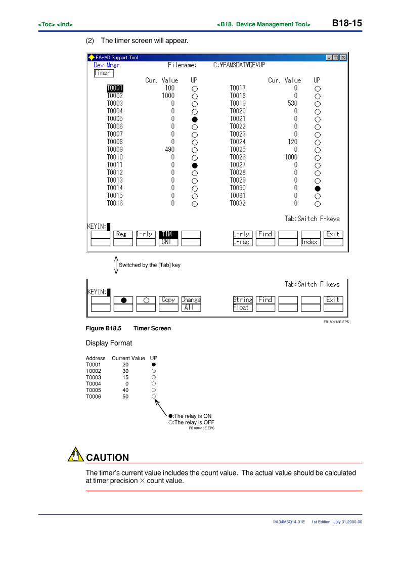
<Toc> <Ind> <B18. Device Management Tool> B18-15
IM 34M6Q14-01E
(2) The timer screen will appear.
Switched by the [Tab] key
FB180412E.EPS
Figure B18.5 Timer Screen
Display Format
�:The relay is ON�:The relay is OFF
FB180413E.EPS
AddressT0001T0002T0003T0004T0005T0006
Current Value2030150
4050
UP��
�
�
�
�
CAUTION
The timer’s current value includes the count value. The actual value should be calculatedat timer precision � count value.
1st Edition : July 31,2000-00
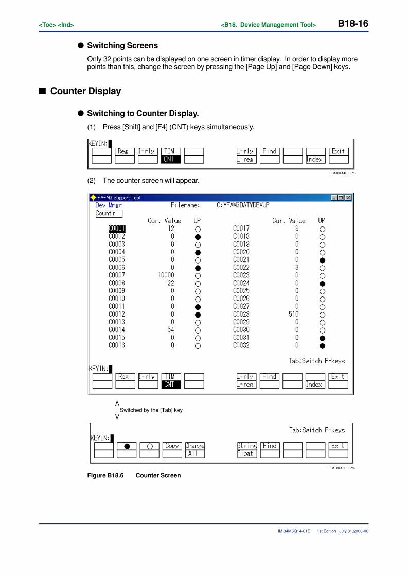
B18-16<Toc> <Ind> <B18. Device Management Tool>
IM 34M6Q14-01E
� Switching Screens
Only 32 points can be displayed on one screen in timer display. In order to display morepoints than this, change the screen by pressing the [Page Up] and [Page Down] keys.
� Counter Display
� Switching to Counter Display.
(1) Press [Shift] and [F4] (CNT) keys simultaneously.
FB180414E.EPS
(2) The counter screen will appear.
Switched by the [Tab] key
FB180415E.EPS
Figure B18.6 Counter Screen
1st Edition : July 31,2000-00
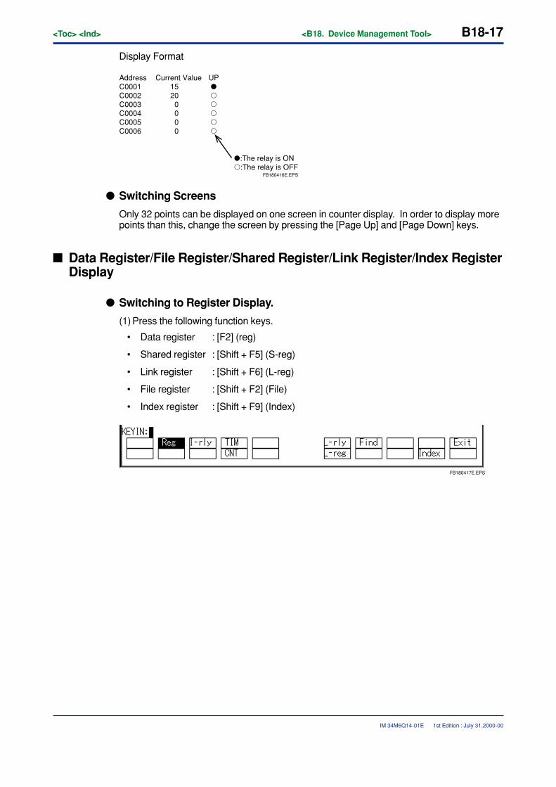
<Toc> <Ind> <B18. Device Management Tool> B18-17
IM 34M6Q14-01E
Display Format
�:The relay is ON�:The relay is OFF
FB180416E.EPS
AddressC0001C0002C0003C0004C0005C0006
Current Value15200000
UP��
�
�
�
�
� Switching Screens
Only 32 points can be displayed on one screen in counter display. In order to display morepoints than this, change the screen by pressing the [Page Up] and [Page Down] keys.
� Data Register/File Register/Shared Register/Link Register/Index RegisterDisplay
� Switching to Register Display.
(1) Press the following function keys.
• Data register : [F2] (reg)
• Shared register : [Shift + F5] (S-reg)
• Link register : [Shift + F6] (L-reg)
• File register : [Shift + F2] (File)
• Index register : [Shift + F9] (Index)
FB180417E.EPS
1st Edition : July 31,2000-00
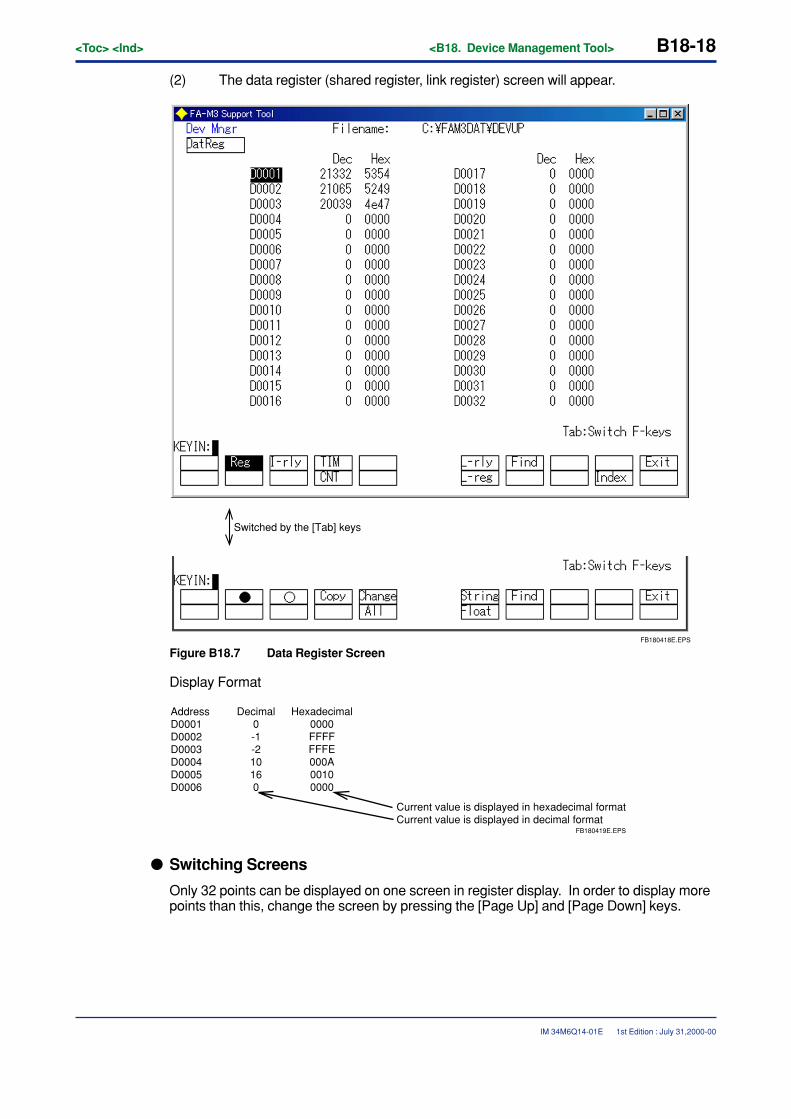
B18-18<Toc> <Ind> <B18. Device Management Tool>
IM 34M6Q14-01E
(2) The data register (shared register, link register) screen will appear.
Switched by the [Tab] keys
FB180418E.EPS
Figure B18.7 Data Register Screen
Display Format
Current value is displayed in hexadecimal formatCurrent value is displayed in decimal format
FB180419E.EPS
AddressD0001D0002D0003D0004D0005D0006
Decimal0-1-210160
Hexadecimal0000FFFFFFFE000A00100000
� Switching Screens
Only 32 points can be displayed on one screen in register display. In order to display morepoints than this, change the screen by pressing the [Page Up] and [Page Down] keys.
1st Edition : July 31,2000-00
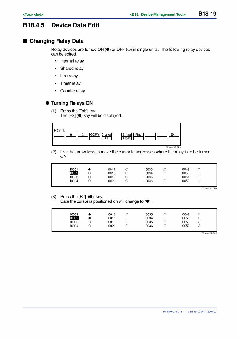
<Toc> <Ind> <B18. Device Management Tool> B18-19
IM 34M6Q14-01E
B18.4.5 Device Data Edit
� Changing Relay DataRelay devices are turned ON (�) or OFF (�) in single units. The following relay devicescan be edited.
• Internal relay
• Shared relay
• Link relay
• Timer relay
• Counter relay
� Turning Relays ON
(1) Press the [Tab] key.The [F2] (�) key will be displayed.
� � COPY Change
FloatString Find Exit
All
KEYIN:
FB180420E.EPS
(2) Use the arrow keys to move the cursor to addresses where the relay is to be turnedON.
FB180421E.EPS
I0001I0002I0003I0004
I0017I0018I0019I0020
I0033I0034I0035I0036
��
�
�
�
�
�
�
�
�
�
�
�
�
�
�
I0049I0050I0051I0052
(3) Press the [F2] (�) key.Data the cursor is positioned on will change to “�” .
FB180422E.EPS
I0001I0002I0003I0004
I0017I0018I0019I0020
I0033I0034I0035I0036
���
�
�
�
�
�
�
�
�
�
�
�
�
�
I0049I0050I0051I0052
1st Edition : July 31,2000-00
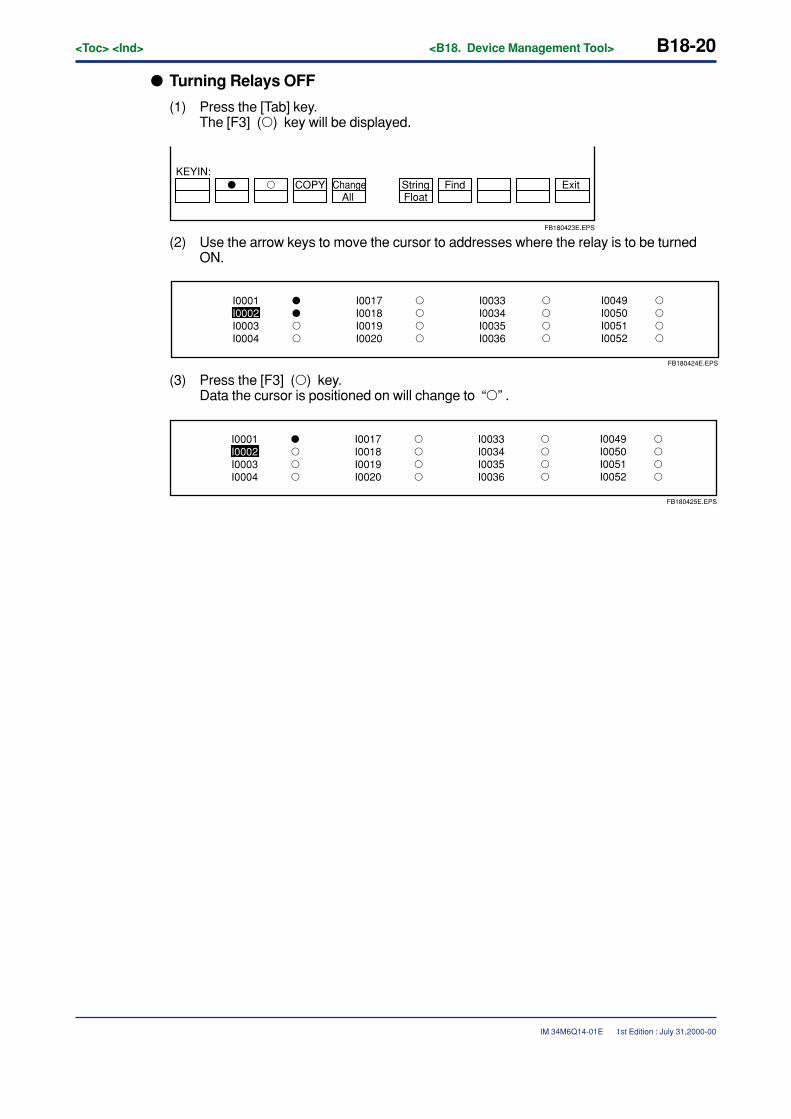
B18-20<Toc> <Ind> <B18. Device Management Tool>
IM 34M6Q14-01E
� Turning Relays OFF
(1) Press the [Tab] key.The [F3] (�) key will be displayed.
� � COPY ChangeFloatString Find Exit
All
KEYIN:
FB180423E.EPS
(2) Use the arrow keys to move the cursor to addresses where the relay is to be turnedON.
FB180424E.EPS
I0001I0002I0003I0004
I0017I0018I0019I0020
I0033I0034I0035I0036
���
�
�
�
�
�
�
�
�
�
�
�
�
�
I0049I0050I0051I0052
(3) Press the [F3] (�) key.Data the cursor is positioned on will change to “�” .
FB180425E.EPS
I0001I0002I0003I0004
I0017I0018I0019I0020
I0033I0034I0035I0036
��
�
�
�
�
�
�
�
�
�
�
�
�
�
�
I0049I0050I0051I0052
1st Edition : July 31,2000-00
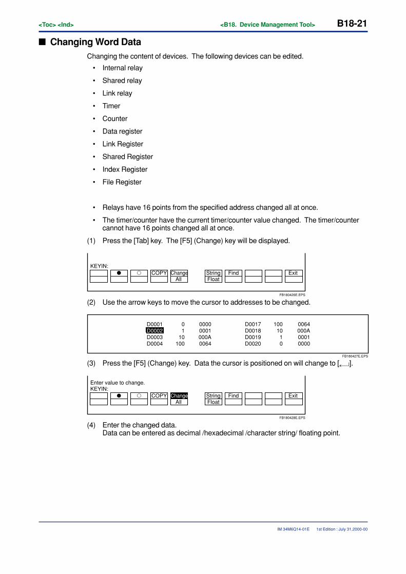
<Toc> <Ind> <B18. Device Management Tool> B18-21
IM 34M6Q14-01E
� Changing Word DataChanging the content of devices. The following devices can be edited.
• Internal relay
• Shared relay
• Link relay
• Timer
• Counter
• Data register
• Link Register
• Shared Register
• Index Register
• File Register
• Relays have 16 points from the specified address changed all at once.
• The timer/counter have the current timer/counter value changed. The timer/countercannot have 16 points changed all at once.
(1) Press the [Tab] key. The [F5] (Change) key will be displayed.
� � COPY ChangeFloatString Find Exit
All
KEYIN:
FB180426E.EPS
(2) Use the arrow keys to move the cursor to addresses to be changed.
FB180427E.EPS
D0001D0002D0003D0004
01
10100
D0017D0018D0019D0020
10010
10
00000001000A0064
0064000A00010000
(3) Press the [F5] (Change) key. Data the cursor is positioned on will change to [ ].
� � COPY ChangeFloatString Find Exit
All
KEYIN:Enter value to change.
FB180428E.EPS
(4) Enter the changed data.Data can be entered as decimal /hexadecimal /character string/ floating point.
1st Edition : July 31,2000-00
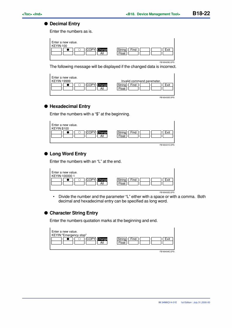
B18-22<Toc> <Ind> <B18. Device Management Tool>
IM 34M6Q14-01E
� Decimal Entry
Enter the numbers as is.
� � COPY ChangeFloatString Find Exit
All
KEYIN:100Enter a new value.
FB180429E.EPS
The following message will be displayed if the changed data is incorrect.
� � COPY ChangeFloatString Find Exit
All
KEYIN:19999 Invalid command parameter.Enter a new value.
FB180430E.EPS
� Hexadecimal Entry
Enter the numbers with a “$” at the beginning.
� � COPY ChangeFloatString Find Exit
All
KEYIN:$100Enter a new value.
FB180431E.EPS
� Long Word Entry
Enter the numbers with an “L” at the end.
� � COPY ChangeFloatString Find Exit
All
KEYIN:100000 1Enter a new value.
FB180432E.EPS
• Divide the number and the parameter “L” either with a space or with a comma. Bothdecimal and hexadecimal entry can be specified as long word.
� Character String Entry
Enter the numbers quotation marks at the beginning and end.
� � COPY ChangeFloatString Find Exit
All
KEYIN:"Emergency stop"Enter a new value.
FB180434E.EPS
1st Edition : July 31,2000-00

<Toc> <Ind> <B18. Device Management Tool> B18-23
IM 34M6Q14-01E
� Floating Point Entry
Enter the numbers with an “F” at the end.
� � COPY ChangeFloatString Find Exit
All
KEYIN:0.111 fEnter a new value.
FB180435E.EPS
Any of the following operations will quit the change instruction.
• Entering the change value.
• Pressing the [Esc] key.
• Press [Shift + F5] (Change).
• Executing any instruction other than a search.
1st Edition : July 31,2000-00
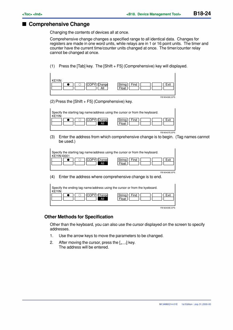
B18-24<Toc> <Ind> <B18. Device Management Tool>
IM 34M6Q14-01E
� Comprehensive ChangeChanging the contents of devices all at once.
Comprehensive change changes a specified range to all identical data. Changes forregisters are made in one word units, while relays are in 1 or 16 point units. The timer andcounter have the current time/counter units changed at once. The timer/counter relaycannot be changed at once.
(1) Press the [Tab] key. The [Shift + F5] (Comprehensive) key will displayed.
� � COPY ChangeFloatString Find Exit
All
KEYIN:
FB180436E.EPS
(2) Press the [Shift + F5] (Comprehensive) key.
� � COPY ChangeFloatString Find Exit
All
KEYIN:Specify the starting tag name/address using the cursor or from the keyboard.
FB180437E.EPS
(3) Enter the address from which comprehensive change is to begin. (Tag names cannotbe used.)
� � COPY ChangeFloatString Find Exit
All
KEYIN:l0001Specify the starting tag name/address using the cursor or from the keyboard.
FB180438E.EPS
(4) Enter the address where comprehensive change is to end.
� � COPY ChangeFloatString Find Exit
All
KEYIN:Specify the ending tag name/address using the cursor or from the kyeboard.
FB180439E.EPS
Other Methods for Specification
Other than the keyboard, you can also use the cursor displayed on the screen to specifyaddresses.
1. Use the arrow keys to move the parameters to be changed.
2. After moving the cursor, press the [ ] key.The address will be entered.
1st Edition : July 31,2000-00
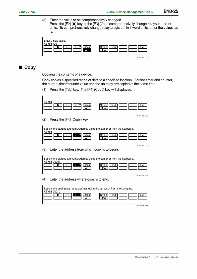
<Toc> <Ind> <B18. Device Management Tool> B18-25
IM 34M6Q14-01E
(5) Enter the value to be comprehensively changed.Press the [F2] (�) key or the [F3] (�) to comprehensively change relays in 1 pointunits. To comprehensively change relays/registers in 1 word units, enter the values asis.
� � COPY ChangeFloatString Find Exit
All
KEYIN:100Enter a new value.
FB180440E.EPS
� CopyCopying the contents of a device.
Copy copies a specified range of data to a specified location. For the timer and counter,the current timer/counter value and the up relay are copied at the same time.
(1) Press the [Tab] key. The [F4] (Copy) key will displayed.
� � COPY ChangeFloatString Find Exit
All
KEYIN:
FB180441E.EPS
(2) Press the [F4] (Copy) key.
� � COPY ChangeFloatString Find Exit
All
KEYIN:Specify the starting tag name/address using the cursor or from the keyboard.
FB180442E.EPS
(3) Enter the address from which copy is to begin.
� � COPY ChangeFloatString Find Exit
All
KEYIN:D0001Specify the starting tag name/address using the cursor or from the keyboard.
FB180443E.EPS
(4) Enter the address where copy is to end.
� � COPY ChangeFloatString Find Exit
All
KEYIN:D0010Specify the ending tag name/address using the cursor or from the keyboard.
FB180444E.EPS
1st Edition : July 31,2000-00

B18-26<Toc> <Ind> <B18. Device Management Tool>
IM 34M6Q14-01E
Other Methods for Specification
Other than the keyboard, you can also use the cursor displayed on the screen to specifyaddresses.
1. Use the arrow keys to move the parameters to be changed.
2. After moving the cursor, press the [ ] key.The address will be entered.
(5) Enter the address at the position to be inserted.
� � COPY ChangeFloatString Find Exit
All
KEYIN:D0010Specify the insertion position with the cursor or from the keyboard.
FB180445E.EPS
1st Edition : July 31,2000-00
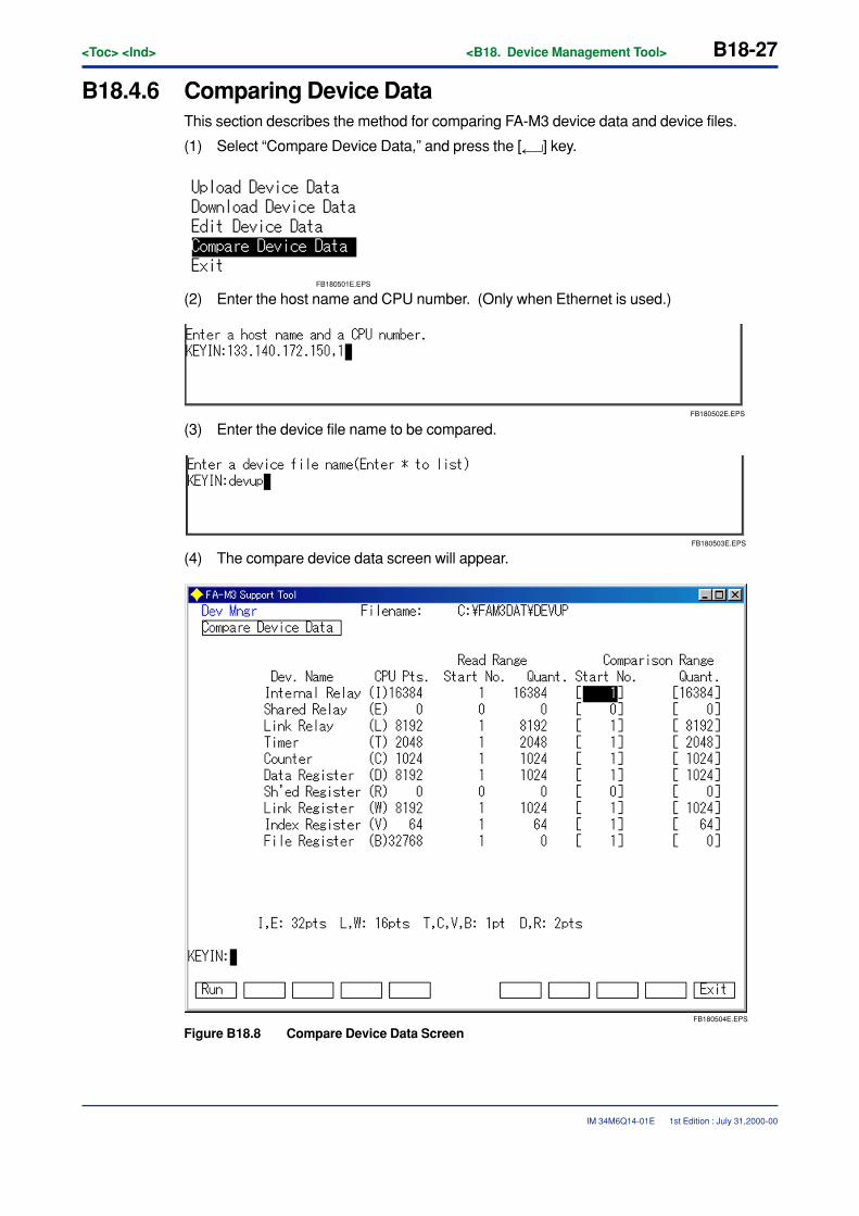
<Toc> <Ind> <B18. Device Management Tool> B18-27
IM 34M6Q14-01E
B18.4.6 Comparing Device DataThis section describes the method for comparing FA-M3 device data and device files.
(1) Select “Compare Device Data,” and press the [ ] key.
FB180501E.EPS
(2) Enter the host name and CPU number. (Only when Ethernet is used.)
FB180502E.EPS
(3) Enter the device file name to be compared.
FB180503E.EPS
(4) The compare device data screen will appear.
FB180504E.EPS
Figure B18.8 Compare Device Data Screen
1st Edition : July 31,2000-00
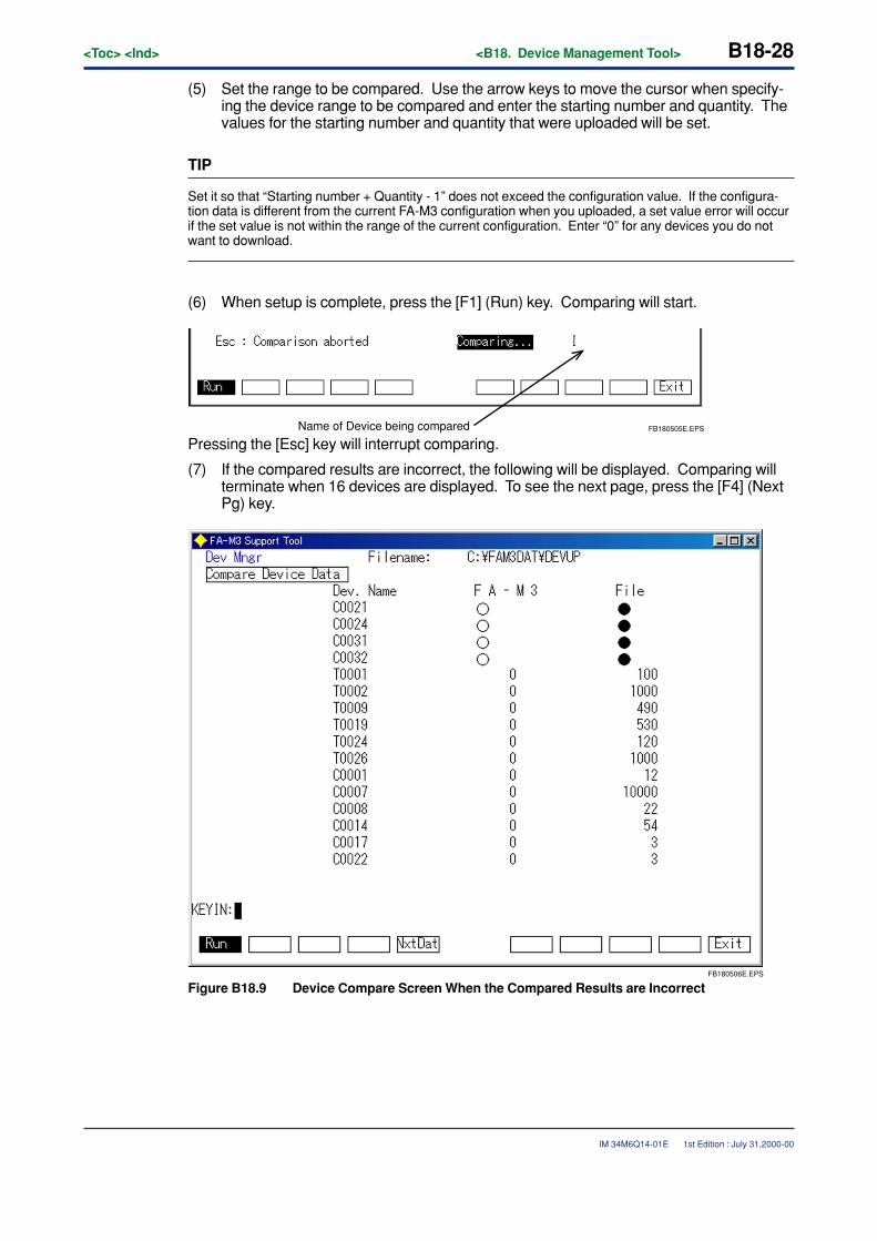
B18-28<Toc> <Ind> <B18. Device Management Tool>
IM 34M6Q14-01E
(5) Set the range to be compared. Use the arrow keys to move the cursor when specify-ing the device range to be compared and enter the starting number and quantity. Thevalues for the starting number and quantity that were uploaded will be set.
TIP
Set it so that “Starting number + Quantity - 1” does not exceed the configuration value. If the configura-tion data is different from the current FA-M3 configuration when you uploaded, a set value error will occurif the set value is not within the range of the current configuration. Enter “0” for any devices you do notwant to download.
(6) When setup is complete, press the [F1] (Run) key. Comparing will start.
FB180505E.EPSName of Device being compared
Pressing the [Esc] key will interrupt comparing.
(7) If the compared results are incorrect, the following will be displayed. Comparing willterminate when 16 devices are displayed. To see the next page, press the [F4] (NextPg) key.
FB180506E.EPS
Figure B18.9 Device Compare Screen When the Compared Results are Incorrect
1st Edition : July 31,2000-00
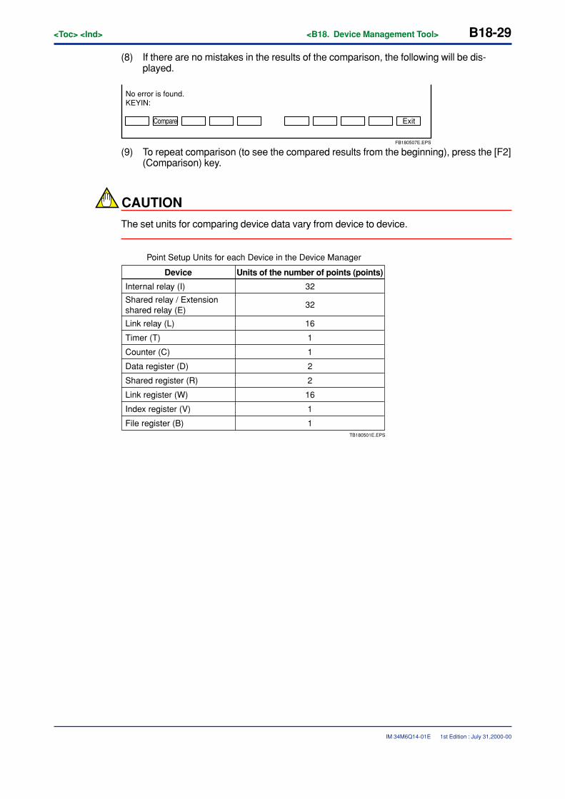
<Toc> <Ind> <B18. Device Management Tool> B18-29
IM 34M6Q14-01E
Point Setup Units for each Device in the Device Manager
32
32
16
1
1
2
2
16
1
1TB180501E.EPS
Device Units of the number of points (points)
Internal relay (I)
Shared relay / Extension shared relay (E)
Link relay (L)
Timer (T)
Data register (D)
Link register (W)
Index register (V)
File register (B)
Counter (C)
Shared register (R)
(8) If there are no mistakes in the results of the comparison, the following will be dis-played.
Compare
No error is found.KEYIN:
Exit
FB180507E.EPS
(9) To repeat comparison (to see the compared results from the beginning), press the [F2](Comparison) key.
CAUTION
The set units for comparing device data vary from device to device.
1st Edition : July 31,2000-00

Blank Page
TocB-11<Int> <Ind> <Rev>
IM 34M6Q14-01E
CONTENTSB19. Use of Local Devices .......................................................................... B19-1
B19.1 What are local devices?.............................................................................. B19-1
B19.2 Setup Local Device ..................................................................................... B19-2
B19.2.1 Setup within Each Block ............................................................... B19-3
B19.2.2 Project Setup ................................................................................ B19-4
B19.3 Programming with Local Devices .............................................................. B19-5
B19.4 Reusing Programs Using Local Devices ................................................... B19-6
B19.4.1 Reusing Blocks ............................................................................. B19-7
B19.4.2 Setup Project ................................................................................ B19-7
B20. Using Macros ...................................................................................... B20-1B20.1 About Macros .............................................................................................. B20-1
B20.1.1 What are Macros? ........................................................................ B20-1
B20.1.2 The Purpose of Macros................................................................. B20-2
B20.1.3 Precautions Regarding Macros ..................................................... B20-3
B20.1.4 Macro-Dedicated Devices and Macro Local Devices .................... B20-4
B20.1.5 Macros that Process Over Several Scans ..................................... B20-5
B20.2 Developing Macros ..................................................................................... B20-7
B20.2.1 Initial Macro Setting ...................................................................... B20-8
B20.2.2 Creating Macros ........................................................................... B20-9
B20.2.3 Using Macros ............................................................................. B20-13
B20.2.4 Transfering Macros ..................................................................... B20-15
B20.2.5 Debugging Macros ..................................................................... B20-16
B20.2.6 Registering Macros ..................................................................... B20-18
B21. How to Use Group Tag Names ........................................................... B21-1B21.1 Defining Group Tag Names ........................................................................ B21-1
B21.2 Programming Using Group Tag Names ..................................................... B21-6
1st Edition : July 31,2000-00
IM 34M6Q14-01E 1st Edition
FA-M3FA-M3 Programming Tool WideField Instruction ManualPART-B Object Ladder Section

Blank Page
<Toc> <Ind> <B19. Use of Local Devices> B19-1
IM 34M6Q14-01E
B19. Use of Local Devices
B19.1 What are local devices?Local devices are independent devices inside blocks. Unlike normal devices, thesecan only be used inside blocks. Using a local device allows the developer to createhighly independent ladder programs without having to think about their allocationwithin the entire program. The devices listed below can be used as local devices. (Apart of a normal device is assigned to a local device.)
• Internal relay (I)
• Data register (D)
• File register (B)
• Timer (T) (However, the timer’s precision is 10ms)
• Counter (C)
Local devices use a different notation for addresses than normal devices. Local devicesare recognized by a “/” (slash) added before them.Notation Examples
/I00001 Local Internal Relay
/D0001 Local Data Register
/B00001 Local File Register
/T00001 Local Timer
/C00001 Local Counter
Addresses for local devices are taken as continuing numbers with 1 as a starting numberand only for the quantity set up in each block. For example, if 32 internal relays are usedas local devices, then devices /I00001 to /I00032 can be used.
Local devices provide the following merits:
• You do not have to think about allocation of devices throughout the whole program.If any local device is not used, you will have to change the allocation of a device forthat block if you want to change all device allocations, but if local devices are used,you will not have to worry about device allocation for the rest of the program.
• Blocks can easily be reused in other projects.Devices which are described as local devices do not need to be corrected when theyare used in other projects.
1st Edition : July 31,2000-00
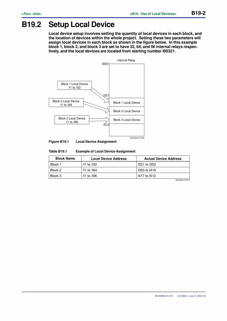
B19-2<Toc> <Ind> <B19. Use of Local Devices>
IM 34M6Q14-01E
B19.2 Setup Local DeviceLocal device setup involves setting the quantity of local devices in each block, andthe location of devices within the whole project. Setting these two parameters willassign local devices in each block as shown in the figure below. In this exampleblock 1, block 2, and block 3 are set to have 32, 64, and 96 internal relays respec-tively, and the local devices are located from starting number I00321.
Block 3 Local Device/I1 to /I96
Block 1 Local Device
Block 2 Local Device
Block 3 Local Device
I321
I513
I0001Internal Relay
FB190201E.EPS
Block 1 Local Device/I1 to /I32
Block 2 Local Device/I1 to /I64
Figure B19.1 Local Device Assignment
Table B19.1 Example of Local Device Assignment
Block Name Local Device Address Actual Device Address
Block 1 /I1 to /I32 I321 to I352
Block 2 /I1 to /I64 I353 to I416
Block 3 /I1 to /I96 I417 to I512TB190201E.EPS
1st Edition : July 31,2000-00
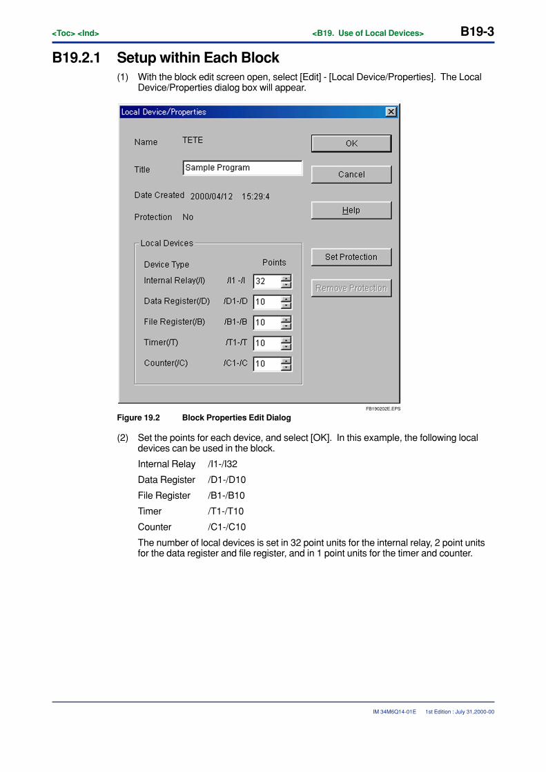
<Toc> <Ind> <B19. Use of Local Devices> B19-3
IM 34M6Q14-01E
B19.2.1 Setup within Each Block(1) With the block edit screen open, select [Edit] - [Local Device/Properties]. The Local
Device/Properties dialog box will appear.
FB190202E.EPS
Figure 19.2 Block Properties Edit Dialog
(2) Set the points for each device, and select [OK]. In this example, the following localdevices can be used in the block.
Internal Relay /I1-/I32
Data Register /D1-/D10
File Register /B1-/B10
Timer /T1-/T10
Counter /C1-/C10
The number of local devices is set in 32 point units for the internal relay, 2 point unitsfor the data register and file register, and in 1 point units for the timer and counter.
1st Edition : July 31,2000-00
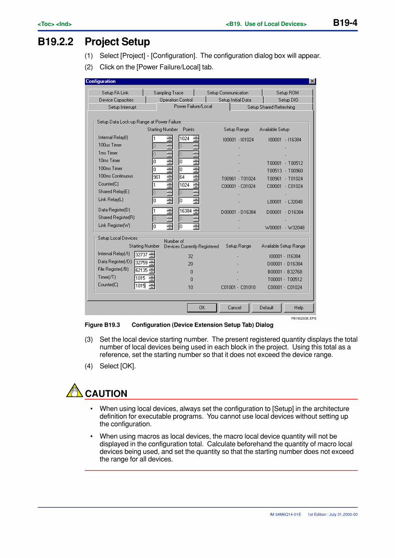
B19-4<Toc> <Ind> <B19. Use of Local Devices>
IM 34M6Q14-01E
B19.2.2 Project Setup(1) Select [Project] - [Configuration]. The configuration dialog box will appear.
(2) Click on the [Power Failure/Local] tab.
FB190203E.EPS
Figure B19.3 Configuration (Device Extension Setup Tab) Dialog
(3) Set the local device starting number. The present registered quantity displays the totalnumber of local devices being used in each block in the project. Using this total as areference, set the starting number so that it does not exceed the device range.
(4) Select [OK].
CAUTION
• When using local devices, always set the configuration to [Setup] in the architecturedefinition for executable programs. You cannot use local devices without setting upthe configuration.
• When using macros as local devices, the macro local device quantity will not bedisplayed in the configuration total. Calculate beforehand the quantity of macro localdevices being used, and set the quantity so that the starting number does not exceedthe range for all devices.
1st Edition : July 31,2000-00
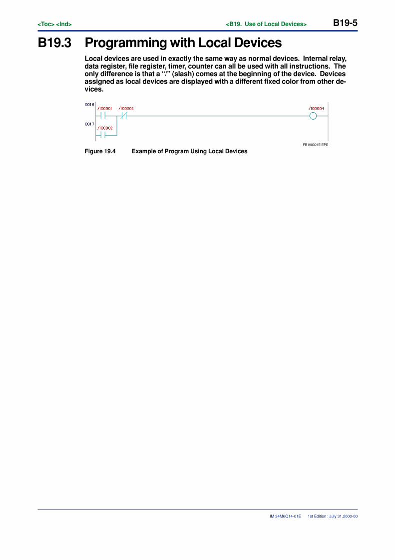
<Toc> <Ind> <B19. Use of Local Devices> B19-5
IM 34M6Q14-01E
B19.3 Programming with Local DevicesLocal devices are used in exactly the same way as normal devices. Internal relay,data register, file register, timer, counter can all be used with all instructions. Theonly difference is that a “/” (slash) comes at the beginning of the device. Devicesassigned as local devices are displayed with a different fixed color from other de-vices.
FB190301E.EPS
Figure 19.4 Example of Program Using Local Devices
1st Edition : July 31,2000-00
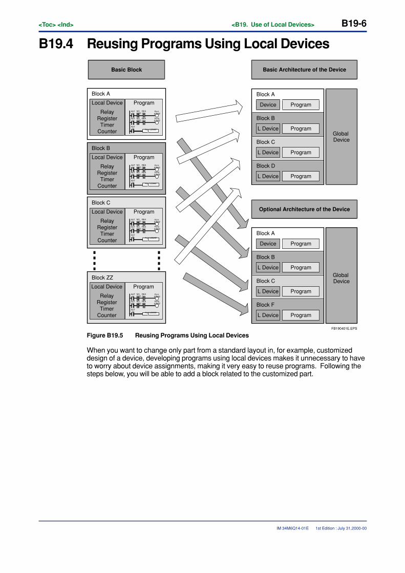
B19-6<Toc> <Ind> <B19. Use of Local Devices>
IM 34M6Q14-01E 1st Edition : July 31,2000-00
B19.4 Reusing Programs Using Local Devices
FB190401E.EPS
AUT01
NO_ERR
NO_ERR
AUT02
AUT03
READY1
READY1
Pch1.START
Pch1.START
Pch2.START
AUT01
NO_ERR
NO_ERR
AUT02
AUT03
READY1
READY1
Pch1.START
Pch1.START
Pch2.START
AUT01
NO_ERR
NO_ERR
AUT02
AUT03
READY1
READY1
Pch1.START
Pch1.START
Pch2.START
AUT01
NO_ERR
NO_ERR
AUT02
AUT03
READY1
READY1
Pch1.START
Pch1.START
Pch2.START
Basic Block
Local Device
Block A
Block B
Block C
Block ZZ
Program
RelayRegister
TimerCounter
Local Device Program
RelayRegister
TimerCounter
Local Device Program
RelayRegister
TimerCounter
Local Device Program
RelayRegister
TimerCounter
Basic Architecture of the Device
Block A
Device Program
Block B
L Device Program
Block C
L Device Program
Block D
L Device Program
Global Device
Block A
Device Program
Block B
L Device Program
Block C
L Device Program
Block F
L Device Program
Global Device
Optional Architecture of the Device
Figure B19.5 Reusing Programs Using Local Devices
When you want to change only part from a standard layout in, for example, customizeddesign of a device, developing programs using local devices makes it unnecessary to haveto worry about device assignments, making it very easy to reuse programs. Following thesteps below, you will be able to add a block related to the customized part.
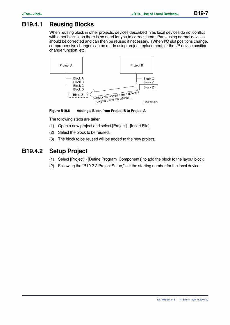
<Toc> <Ind> <B19. Use of Local Devices> B19-7
IM 34M6Q14-01E 1st Edition : July 31,2000-00
B19.4.1 Reusing BlocksWhen reusing block in other projects, devices described in as local devices do not conflictwith other blocks, so there is no need for you to correct them. Parts using normal devicesshould be corrected and can then be reused if necessary. (When I/O slot positions change,comprehensive changes can be made using project replacement, or the I/P device positionchange function, etc.
Project A
Block ABlock BBlock CBlock D
Project B
Block Z
Block XBlock Y
Block Z
Block file added from a different
project using file addition.FB190402E.EPS
Figure B19.6 Adding a Block from Project B to Project A
The following steps are taken.
(1) Open a new project and select [Project] - [Insert File].
(2) Select the block to be reused.
(3) The block to be reused will be added to the new project.
B19.4.2 Setup Project(1) Select [Project] - [Define Program Components] to add the block to the layout block.
(2) Following the “B19.2.2 Project Setup,” set the starting number for the local device.

Blank Page

<Toc> <Ind> <B20. Using Macros> B20-1
IM 34M6Q14-01E
B20. Using Macros
B20.1 About MacrosThis section describes the thinking behind macros and their purpose.
B20.1.1 What are Macros?Macros are a series of processes defined as one instruction. Macros can be named, whichmeans that they can be used just like other pre-existing instructions by naming themaccording to their function.
1st Edition : July 31,2000-00
B20-2<Toc> <Ind> <B20. Using Macros>
IM 34M6Q14-01E
B20.1.2 The Purpose of MacrosUsing Macros has the following advantages.
� Program Visibility Increases
Program visibility decreases as the size of a program grows. As a results, debugging andmaintenance work become more difficult. By using macros, program visibility increasesand debugging and maintenance become easier.
� The Number of Program Steps Is Reduced
Writing program repeating the same process over and over increases the number ofprogram steps. Bringing all those steps together into a macro reduces the number of stepsto one.
� Macros Promote Modules in Programming
Past assets are easier to use. Parts which are made into macros have already undergonetesting, so the amount of time used for debugging is reduced. Also, macros can be createdindependently, so many developers can work together at once.
� Expertise Is Accumulated
What is difficult to create with pre-existing instructions is accumulated as original know-howin the shape of macros. Also, by protecting macros, secrecy is maintained.
� Easier to Use than Subroutines
The following points are easier to use when compared to subroutines.
• The actual macro can be used as a black boxWith subroutines, the content of devices used internally is changed. Accordingly,caution is necessary to avoid using that device externally. With macros, devices usedinternally need not be worried about.
• Transference of parameters with macros is possibleWith subroutines, you have to decide interfaces ahead of time of what devices are tobe used as input and what devices are to be used as output. With macros, changescan be made anytime for the devices and number of parameters in such interfaces.
• You do not have to put the actual macro into a programSubroutines must be part of programs, while with macros, the actual macro does nothave to. It is linked automatically and sent to the CPU.
1st Edition : July 31,2000-00
<Toc> <Ind> <B20. Using Macros> B20-3
IM 34M6Q14-01E
B20.1.3 Precautions Regarding MacrosThe following restrictions apply to macros. Follow these restrictions when using macros.
� Usable CPU’s
Some CPU’s cannot be used with macros.
� Number of Macros that Can Be Used
Up to 64 macros can be used in one executable program. However, the same macro canbe used any number of times.
� Number of Macros that Can Be Stored at Once
Only one macro can be created in one file. However, there is no limit on the number offiles. Make one file for each macro.
� The Number of Parameters Delivered between Macro Calling Instructionsand the Macro Itself
Up to 16 parameters can be passed between a macro calling instruction and the macroitself.
� Available Devices
The macro itself can be used with the following devices, apart from normal devices andlocal devices.
• Pointer Register (P)
• Macro Relay (H)
• Macro Register (A)
• Macro Index Register (U)
Due to the characteristics of macros, we only recommend using the actual macro itself withP, H, A, and U. The pointer register is the register which stores the parameters passed tothe macro itself. The macro relay, macro register, and macro index register are equivalentto the internal relay, data register, and index register which can be used in the actualmacro.
� Tag Name Statements
Tag name statements in the actual macro can be made for normal devices, local devices,and macro devices (P, H, A, U).
� Use of Local Devices in Macros
Do not call a macro when using a local device in that macro. (Save the macro under adifferent name, and then call it as a different macro.)
1st Edition : July 31,2000-00
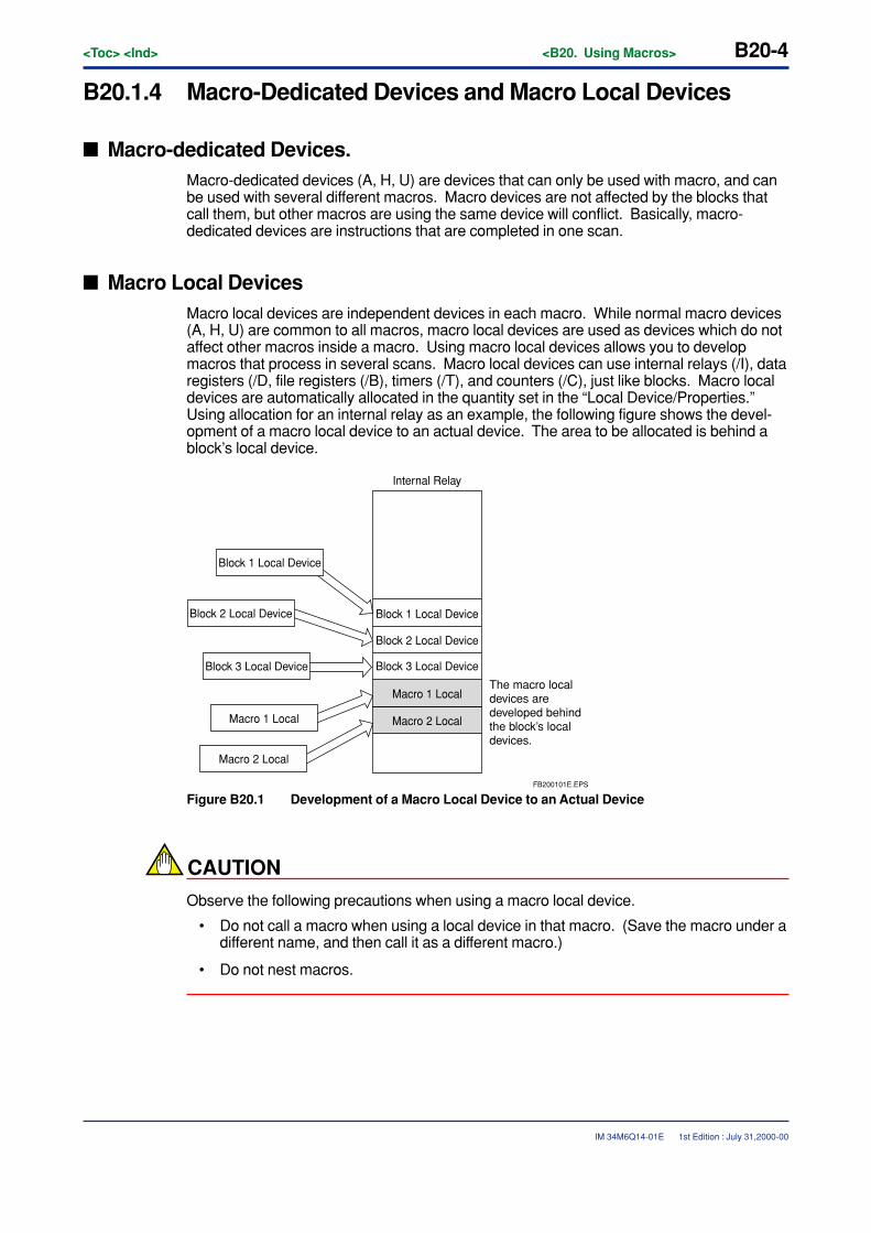
B20-4<Toc> <Ind> <B20. Using Macros>
IM 34M6Q14-01E
B20.1.4 Macro-Dedicated Devices and Macro Local Devices
� Macro-dedicated Devices.Macro-dedicated devices (A, H, U) are devices that can only be used with macro, and canbe used with several different macros. Macro devices are not affected by the blocks thatcall them, but other macros are using the same device will conflict. Basically, macro-dedicated devices are instructions that are completed in one scan.
� Macro Local DevicesMacro local devices are independent devices in each macro. While normal macro devices(A, H, U) are common to all macros, macro local devices are used as devices which do notaffect other macros inside a macro. Using macro local devices allows you to developmacros that process in several scans. Macro local devices can use internal relays (/I), dataregisters (/D, file registers (/B), timers (/T), and counters (/C), just like blocks. Macro localdevices are automatically allocated in the quantity set in the “Local Device/Properties.”Using allocation for an internal relay as an example, the following figure shows the devel-opment of a macro local device to an actual device. The area to be allocated is behind ablock’s local device.
Block 3 Local Device
Macro 1 Local
Macro 2 Local
Block 1 Local Device
Block 2 Local Device
Block 3 Local Device
Macro 1 Local
Macro 2 Local
Internal Relay
FB200101E.EPS
The macro local devices are developed behind the block’s local devices.
Block 1 Local Device
Block 2 Local Device
Figure B20.1 Development of a Macro Local Device to an Actual Device
CAUTION
Observe the following precautions when using a macro local device.
• Do not call a macro when using a local device in that macro. (Save the macro under adifferent name, and then call it as a different macro.)
• Do not nest macros.
1st Edition : July 31,2000-00
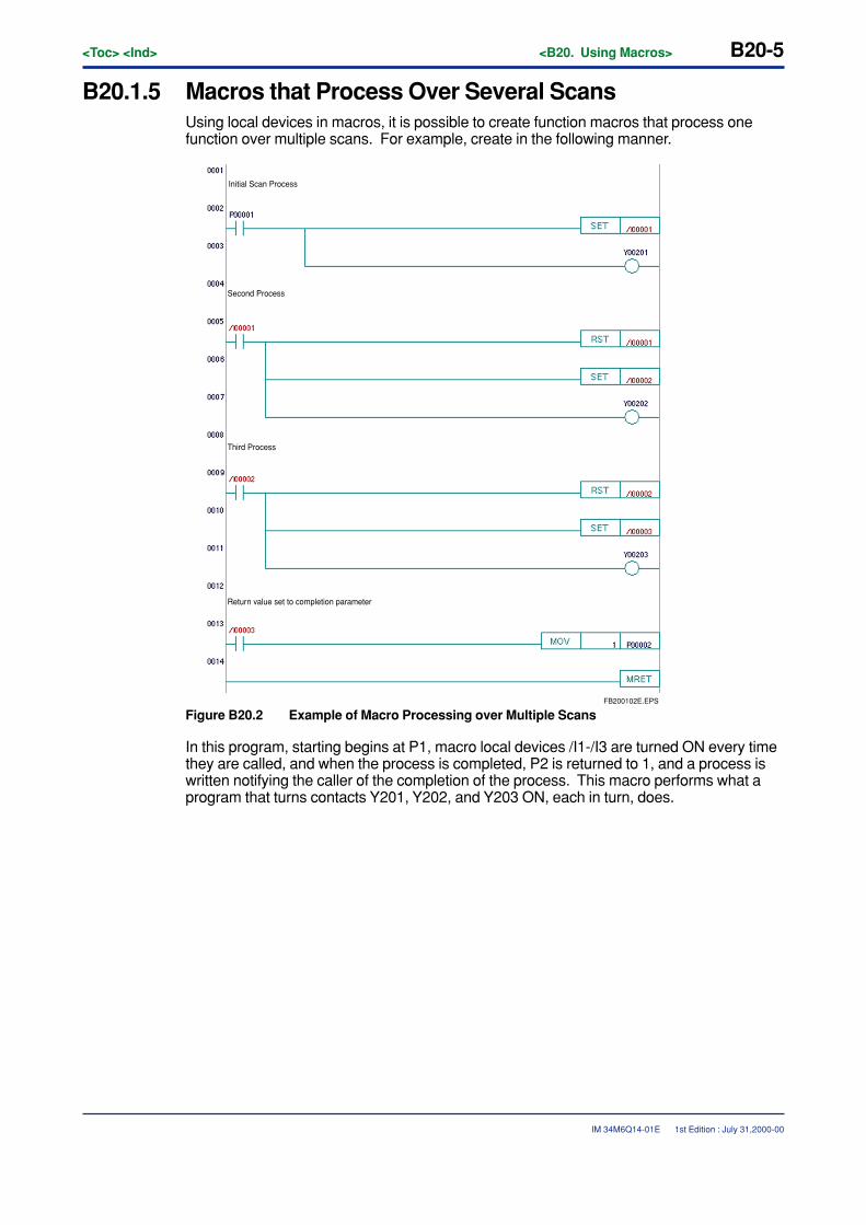
<Toc> <Ind> <B20. Using Macros> B20-5
IM 34M6Q14-01E
B20.1.5 Macros that Process Over Several ScansUsing local devices in macros, it is possible to create function macros that process onefunction over multiple scans. For example, create in the following manner.
FB200102E.EPS
Return value set to completion parameter
Initial Scan Process
Second Process
Third Process
Figure B20.2 Example of Macro Processing over Multiple Scans
In this program, starting begins at P1, macro local devices /I1-/I3 are turned ON every timethey are called, and when the process is completed, P2 is returned to 1, and a process iswritten notifying the caller of the completion of the process. This macro performs what aprogram that turns contacts Y201, Y202, and Y203 ON, each in turn, does.
1st Edition : July 31,2000-00
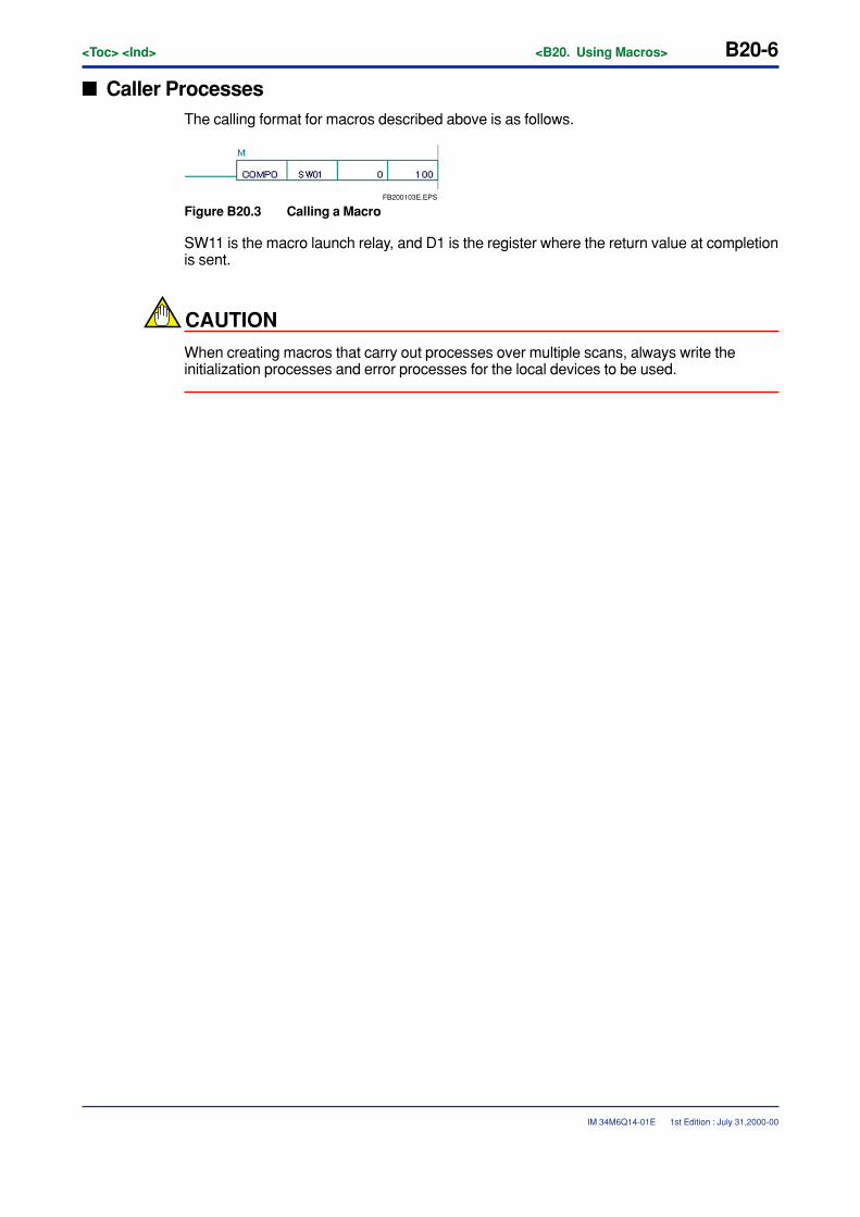
B20-6<Toc> <Ind> <B20. Using Macros>
IM 34M6Q14-01E 1st Edition : July 31,2000-00
� Caller ProcessesThe calling format for macros described above is as follows.
FB200103E.EPS
Figure B20.3 Calling a Macro
SW11 is the macro launch relay, and D1 is the register where the return value at completionis sent.
CAUTION
When creating macros that carry out processes over multiple scans, always write theinitialization processes and error processes for the local devices to be used.
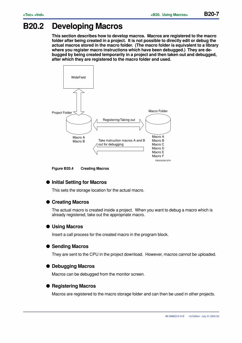
<Toc> <Ind> <B20. Using Macros> B20-7
IM 34M6Q14-01E 1st Edition : July 31,2000-00
B20.2 Developing MacrosThis section describes how to develop macros. Macros are registered to the macrofolder after being created in a project. It is not possible to directly edit or debug theactual macros stored in the macro folder. (The macro folder is equivalent to a librarywhere you register macro instructions which have been debugged.) They are de-bugged by being created temporarily in a project and then taken out and debugged,after which they are registered to the macro folder and used.
Project Folder
Registering/Taking out
Macro Folder
Macro AMacro B
Macro AMacro BMacro CMacro DMacro EMacro F
WideField
Take instruction macros A and B out for debugging
FB200200E.EPS
Figure B20.4 Creating Macros
� Initial Setting for Macros
This sets the storage location for the actual macro.
� Creating Macros
The actual macro is created inside a project. When you want to debug a macro which isalready registered, take out the appropriate macro.
� Using Macros
Insert a call process for the created macro in the program block.
� Sending Macros
They are sent to the CPU in the project download. However, macros cannot be uploaded.
� Debugging Macros
Macros can be debugged from the monitor screen.
� Registering Macros
Macros are registered to the macro storage folder and can then be used in other projects.
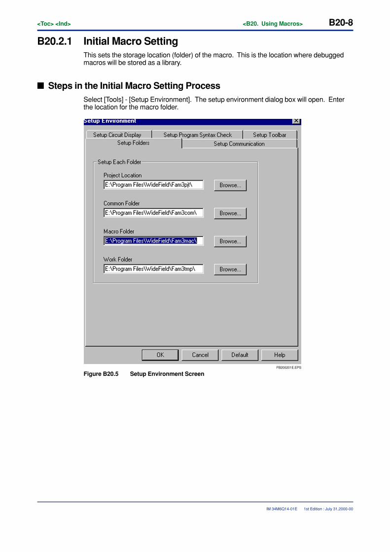
B20-8<Toc> <Ind> <B20. Using Macros>
IM 34M6Q14-01E
B20.2.1 Initial Macro SettingThis sets the storage location (folder) of the macro. This is the location where debuggedmacros will be stored as a library.
� Steps in the Initial Macro Setting ProcessSelect [Tools] - [Setup Environment]. The setup environment dialog box will open. Enterthe location for the macro folder.
FB200201E.EPS
Figure B20.5 Setup Environment Screen
1st Edition : July 31,2000-00
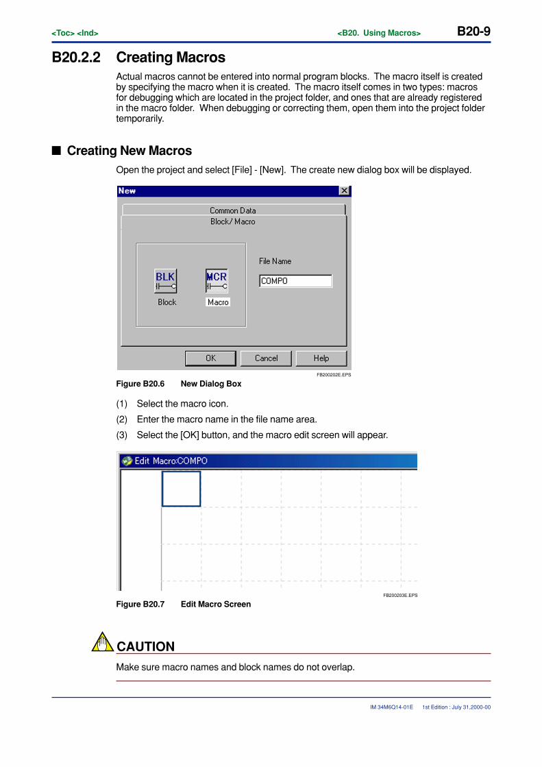
<Toc> <Ind> <B20. Using Macros> B20-9
IM 34M6Q14-01E
B20.2.2 Creating MacrosActual macros cannot be entered into normal program blocks. The macro itself is createdby specifying the macro when it is created. The macro itself comes in two types: macrosfor debugging which are located in the project folder, and ones that are already registeredin the macro folder. When debugging or correcting them, open them into the project foldertemporarily.
� Creating New MacrosOpen the project and select [File] - [New]. The create new dialog box will be displayed.
FB200202E.EPS
Figure B20.6 New Dialog Box
(1) Select the macro icon.
(2) Enter the macro name in the file name area.
(3) Select the [OK] button, and the macro edit screen will appear.
FB200203E.EPS
Figure B20.7 Edit Macro Screen
CAUTION
Make sure macro names and block names do not overlap.
1st Edition : July 31,2000-00
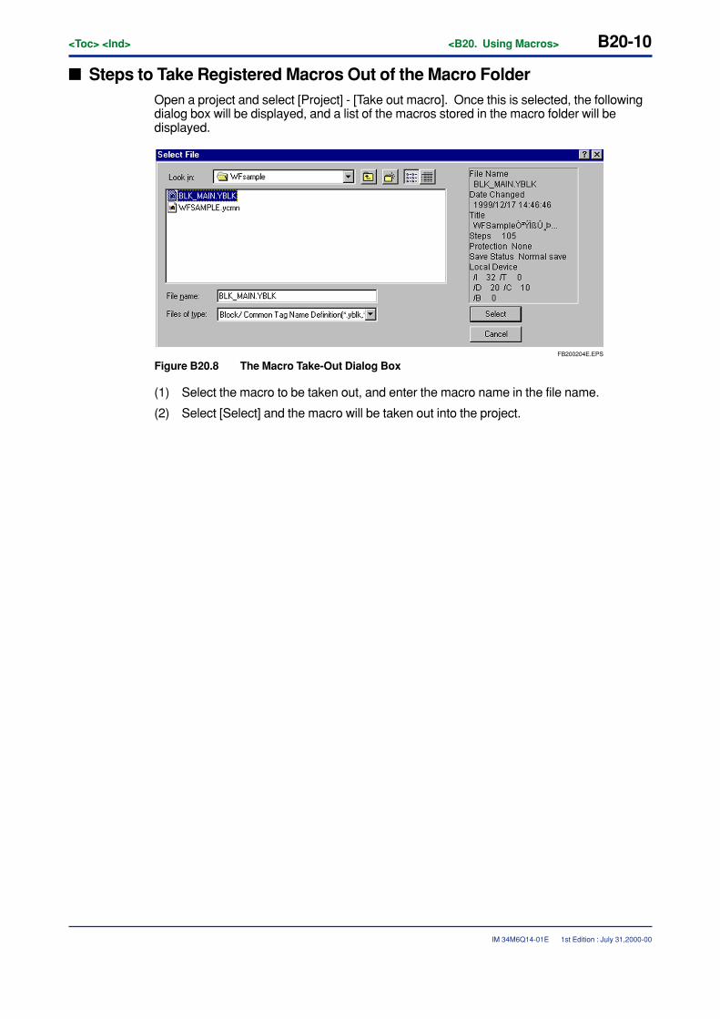
B20-10<Toc> <Ind> <B20. Using Macros>
IM 34M6Q14-01E 1st Edition : July 31,2000-00
� Steps to Take Registered Macros Out of the Macro FolderOpen a project and select [Project] - [Take out macro]. Once this is selected, the followingdialog box will be displayed, and a list of the macros stored in the macro folder will bedisplayed.
FB200204E.EPS
Figure B20.8 The Macro Take-Out Dialog Box
(1) Select the macro to be taken out, and enter the macro name in the file name.
(2) Select [Select] and the macro will be taken out into the project.
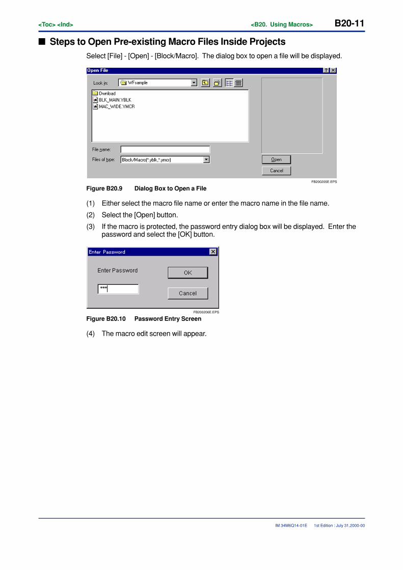
<Toc> <Ind> <B20. Using Macros> B20-11
IM 34M6Q14-01E 1st Edition : July 31,2000-00
� Steps to Open Pre-existing Macro Files Inside ProjectsSelect [File] - [Open] - [Block/Macro]. The dialog box to open a file will be displayed.
FB200205E.EPS
Figure B20.9 Dialog Box to Open a File
(1) Either select the macro file name or enter the macro name in the file name.
(2) Select the [Open] button.
(3) If the macro is protected, the password entry dialog box will be displayed. Enter thepassword and select the [OK] button.
FB200206E.EPS
Figure B20.10 Password Entry Screen
(4) The macro edit screen will appear.
B20-12<Toc> <Ind> <B20. Using Macros>
IM 34M6Q14-01E
� Macro EditMacro edit comes equipped with the same functions as the normal ladder diagram editfunction. Also, all steps are carried out as with normal ladder diagram edit and tag defini-tion with the ladder diagram edit. However, with the macro edit, you can use devicesspecific to macros (macro relay, macro register, macro index register, macro pointer regis-ter).
CAUTION
Always enter the macro return instruction (MRET) at the end of a macro.
� Setting Local Devices and Editing Properties in MacrosSetting local devices and editing properties in macros are both done just like blocks byselecting [Edit] - [Local Device/Properties] from the menu.
1st Edition : July 31,2000-00
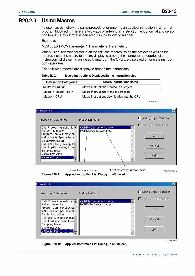
<Toc> <Ind> <B20. Using Macros> B20-13
IM 34M6Q14-01E
B20.2.3 Using MacrosTo use macros, follow the same procedure for entering an applied instruction in a normalprogram block edit. There are two ways of entering an instruction: entry format and selec-tion format. Entry format is carried out in the following manner.
Example:
MCALL EXTMOV Parameter 1 Parameter 2 Parameter 3
When using selection format in offline edit, the macros inside the project as well as themacros inside the macro folder are displayed among the instruction categories of theinstruction list dialog. In online edit, macros in the CPU are displayed among the instruc-tion categories.
The following macros are displayed among the instructions.
Table B20.1 Macro Instructions Displayed in the Instruction List.
Instruction Categories Macro instructions listed
Macro in Project Macro instructions created in a project
Macro in Macro Folder Macro instructions in the macro folder
Macro in CPU Macro instructions downloaded into the CPU
TB200201E.EPS
FB200207E.EPSInstruction macro name Title of created instruction macro
Figure B20.11 Applied Instruction List Dialog (in offline edit)
FB200208E.EPS
Figure B20.12 Applied Instruction List Dialog (in online edit)
1st Edition : July 31,2000-00

B20-14<Toc> <Ind> <B20. Using Macros>
IM 34M6Q14-01E
Parameters 1, 2, and 3 are set on the side of the caller. Optional devices can be used.With the actual macros, parameters 1, 2, and 3 correspond to macro pointer registers P1,P2, and P3. Up to 16 parameters can be passed to the actual macro, but for passing morethan 3 parameters, use a PARA instruction before the MCALL instruction.
Example
PARA 4 D00001
In this example, D1 is made the fourth parameter of the instruction macro.
1st Edition : July 31,2000-00
<Toc> <Ind> <B20. Using Macros> B20-15
IM 34M6Q14-01E
B20.2.4 Transfering MacrosSending macros is done by downloading. When sending executable programs macrosused in those executable programs are sent along automatically. If macros of the samename exist in both the project folder and the macro folder, the macros in the project folderwill be sent. However, the actual macros cannot be uploaded. (See B.20.2.5) If you areusing a macro in an executable program, other than the normal errors, the following errorsmay also appear during syntax checks or downloading executable programs.
� Error: No Macro
The actual macro does not exist either in the project or in the macro folder.
� Error: Number of Steps Exceeds the Highest Range for Type Selected
When using a macro, the steps in the macro itself are calculated in to the total number ofsteps in a block.
� Error: No MRET Instruction
An MRET instruction is always necessary at the end of a macro.
� Error: Number of Macros Exceeds the Highest Range for Type Selected
The type of macro that can be used is set for each CPU.
� Error: Global Device Being Used in the Local Device Range
When using local devices in a macro, a macro local device is added behind the set range ina block. You will have to use global devices taking the macro local devices into consider-ation.
� Error: Incorrect Setting for Local Device Range
When using local devices in a macro, you will have to set a starting number for the localdevice that is in the range that includes the number of macro local devices.
CAUTION
You must register macros when creating an executable program. Macros are automaticallylinked the executable program and sent to the CPU.
1st Edition : July 31,2000-00
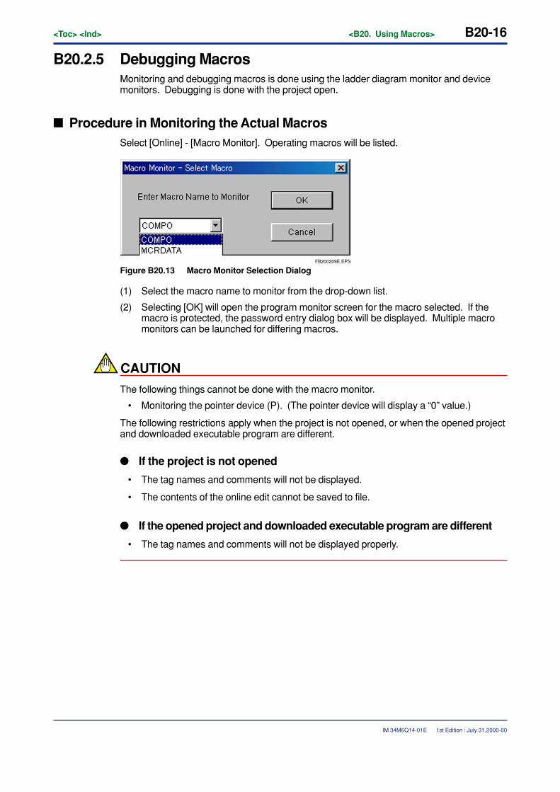
B20-16<Toc> <Ind> <B20. Using Macros>
IM 34M6Q14-01E
B20.2.5 Debugging MacrosMonitoring and debugging macros is done using the ladder diagram monitor and devicemonitors. Debugging is done with the project open.
� Procedure in Monitoring the Actual MacrosSelect [Online] - [Macro Monitor]. Operating macros will be listed.
FB200209E.EPS
Figure B20.13 Macro Monitor Selection Dialog
(1) Select the macro name to monitor from the drop-down list.
(2) Selecting [OK] will open the program monitor screen for the macro selected. If themacro is protected, the password entry dialog box will be displayed. Multiple macromonitors can be launched for differing macros.
CAUTION
The following things cannot be done with the macro monitor.
• Monitoring the pointer device (P). (The pointer device will display a “0” value.)
The following restrictions apply when the project is not opened, or when the opened projectand downloaded executable program are different.
� If the project is not opened
• The tag names and comments will not be displayed.
• The contents of the online edit cannot be saved to file.
� If the opened project and downloaded executable program are different
• The tag names and comments will not be displayed properly.
1st Edition : July 31,2000-00
<Toc> <Ind> <B20. Using Macros> B20-17
IM 34M6Q14-01E
� Quitting the macro monitorSelect [File] - [Exit].
� Online Editing the Actual MacroSelect [Debug/Maintenance] - [Online Editing] from the macro monitor screen. Online editcan be performed just as with normal blocks. However, with macros, there are certaincircuits that cannot be corrected. Make any corrections for uncorrectable circuits with theoffline edit.
CAUTION
MRET and circuits including MRET cannot be corrected.
� Uploading Actual MacrosNormally, actual macros cannot be sent with the upload menu. If you want to reflect thecontent of the online edit into your computer, select [File] - [Reflect to File] from the macromonitor screen. It will be saved to the project folder. Corrected macros will be registered tothe macro folder.
� Monitoring Macro-Dedicated DevicesSelect [Online] - [Device Monitor], specify macro relay, macro register, and macro indexregister and start them. The monitor screen for the specified devices will open.
CAUTION
It is not possible to monitor the pointer device (P).
1st Edition : July 31,2000-00
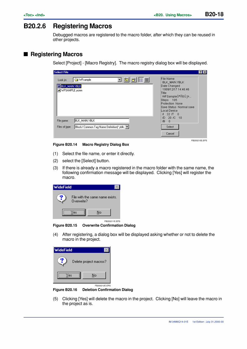
B20-18<Toc> <Ind> <B20. Using Macros>
IM 34M6Q14-01E
B20.2.6 Registering MacrosDebugged macros are registered to the macro folder, after which they can be reused inother projects.
� Registering MacrosSelect [Project] - [Macro Registry]. The macro registry dialog box will be displayed.
FB200210E.EPS
Figure B20.14 Macro Registry Dialog Box
(1) Select the file name, or enter it directly.
(2) select the [Select] button.
(3) If there is already a macro registered in the macro folder with the same name, thefollowing confirmation message will be displayed. Clicking [Yes] will register themacro.
FB200211E.EPS
Figure B20.15 Overwrite Confirmation Dialog
(4) After registering, a dialog box will be displayed asking whether or not to delete themacro in the project.
FB200212E.EPS
Figure B20.16 Deletion Confirmation Dialog
(5) Clicking [Yes] will delete the macro in the project. Clicking [No] will leave the macro inthe project as is.
1st Edition : July 31,2000-00
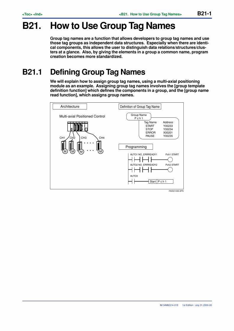
<Toc> <Ind> <B21. How to Use Group Tag Names> B21-1
IM 34M6Q14-01E
B21. How to Use Group Tag NamesGroup tag names are a function that allows developers to group tag names and usethose tag groups as independent data structures. Especially when there are identi-cal components, this allows the user to distinguish data relations/structures/clus-ters at a glance. Also, by giving the elements in a group a common name, programcreation becomes more standardized.
B21.1 Defining Group Tag NamesWe will explain how to assign group tag names, using a multi-axial positioningmodule as an example. Assigning group tag names involves the [group templatedefinition function] which defines the components in a group, and the [group nameread function], which assigns group names.
FA050103E.EPS
Architecture
Programming
Definition of Group Tag Name
Group NameP c h 1
Tag Name AddressSTARTSTOPERRORPAUSE
Y00233Y00234X00201Y00235
Start P c h 1
AUTO1 NO_ERRREADY1
AUTO2 NO_ERRREADY2
AUTO3
Pch1 START
Pch2 START
Multi-axial Positioned Control
CH1 CH3 CH4
M MMM
CH2
1st Edition : July 31,2000-00
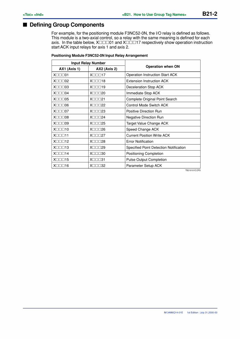
B21-2<Toc> <Ind> <B21. How to Use Group Tag Names>
IM 34M6Q14-01E
� Defining Group ComponentsFor example, for the positioning module F3NC52-0N, the I/O relay is defined as follows.This module is a two-axial control, so a relay with the same meaning is defined for eachaxis. In the table below, X���01 and X���17 respectively show operation instructionstart ACK input relays for axis 1 and axis 2.
Positioning Module F3NC52-0N Input Relay Arrangement
Input Relay Number
AX1 (Axis 1) AX2 (Axis 2)
X���01
X���02
X���03
X���04
X���05
X���06
X���07
X���08
X���09
X���10
X���11
X���12
X���13
X���14
X���18
X���19
X���20
X���21
X���22
X���23
X���24
X���25
X���26
X���27
X���28
X���29
X���30
X���15 X���31
X���16 X���32
Extension Instruction ACK
Operation Instruction Start ACK
Deceleration Stop ACK
Immediate Stop ACK
Complete Original Point Search
Control Mode Switch ACK
Positive Direction Run
Negative Direction Run
Target Value Change ACK
Speed Change ACK
Current Position Write ACK
Error Notification
Specified Point Detection Notification
Positioning Completion
Pulse Output Completion
Parameter Setup ACK
X���17
Operation when ON
TB210101E.EPS
1st Edition : July 31,2000-00
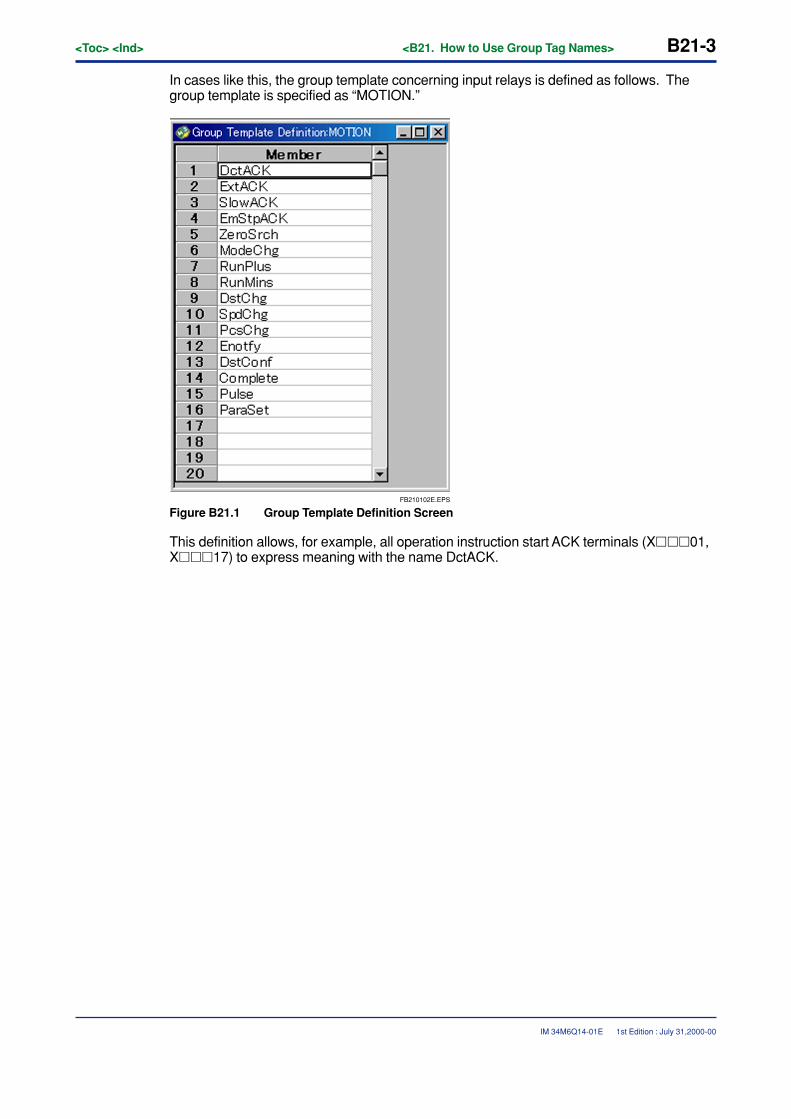
<Toc> <Ind> <B21. How to Use Group Tag Names> B21-3
IM 34M6Q14-01E
In cases like this, the group template concerning input relays is defined as follows. Thegroup template is specified as “MOTION.”
FB210102E.EPS
Figure B21.1 Group Template Definition Screen
This definition allows, for example, all operation instruction start ACK terminals (X���01,X���17) to express meaning with the name DctACK.
1st Edition : July 31,2000-00
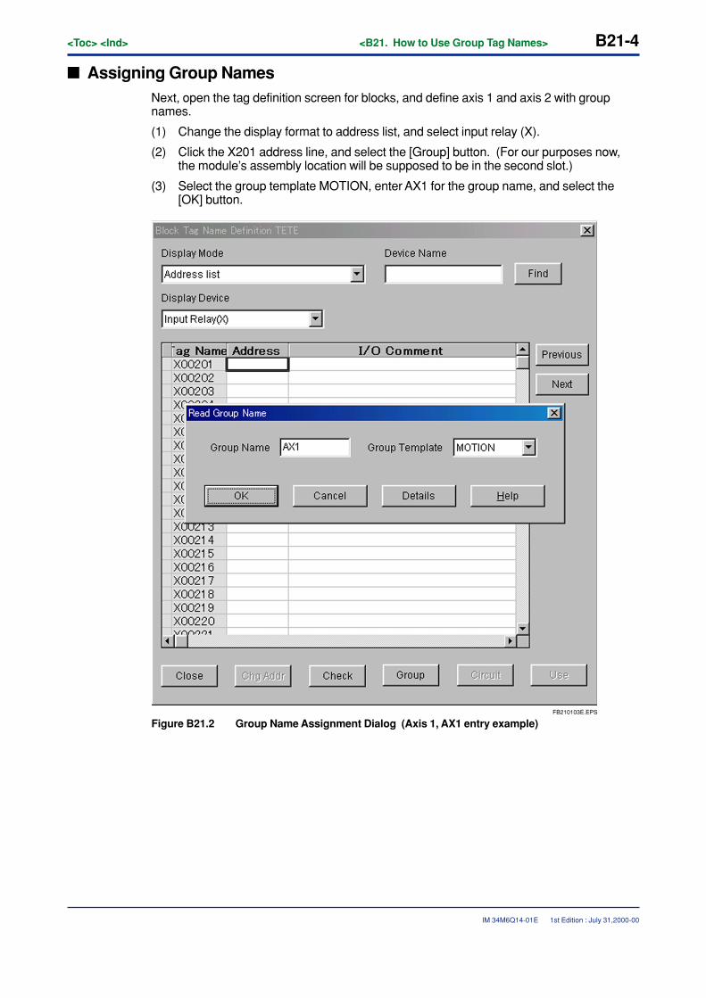
B21-4<Toc> <Ind> <B21. How to Use Group Tag Names>
IM 34M6Q14-01E 1st Edition : July 31,2000-00
� Assigning Group NamesNext, open the tag definition screen for blocks, and define axis 1 and axis 2 with groupnames.
(1) Change the display format to address list, and select input relay (X).
(2) Click the X201 address line, and select the [Group] button. (For our purposes now,the module’s assembly location will be supposed to be in the second slot.)
(3) Select the group template MOTION, enter AX1 for the group name, and select the[OK] button.
FB210103E.EPS
Figure B21.2 Group Name Assignment Dialog (Axis 1, AX1 entry example)
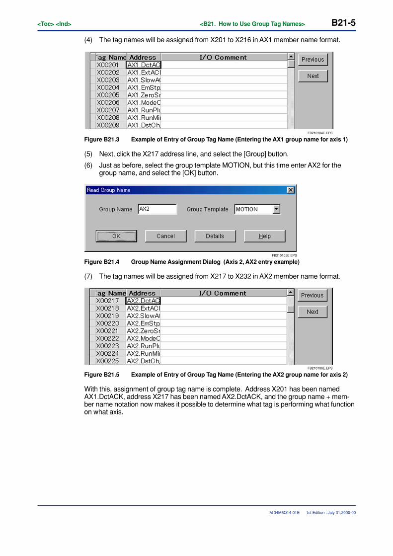
<Toc> <Ind> <B21. How to Use Group Tag Names> B21-5
IM 34M6Q14-01E 1st Edition : July 31,2000-00
(4) The tag names will be assigned from X201 to X216 in AX1 member name format.
FB210104E.EPS
Figure B21.3 Example of Entry of Group Tag Name (Entering the AX1 group name for axis 1)
(5) Next, click the X217 address line, and select the [Group] button.
(6) Just as before, select the group template MOTION, but this time enter AX2 for thegroup name, and select the [OK] button.
FB210105E.EPS
Figure B21.4 Group Name Assignment Dialog (Axis 2, AX2 entry example)
(7) The tag names will be assigned from X217 to X232 in AX2 member name format.
FB210106E.EPS
Figure B21.5 Example of Entry of Group Tag Name (Entering the AX2 group name for axis 2)
With this, assignment of group tag name is complete. Address X201 has been namedAX1.DctACK, address X217 has been named AX2.DctACK, and the group name + mem-ber name notation now makes it possible to determine what tag is performing what functionon what axis.
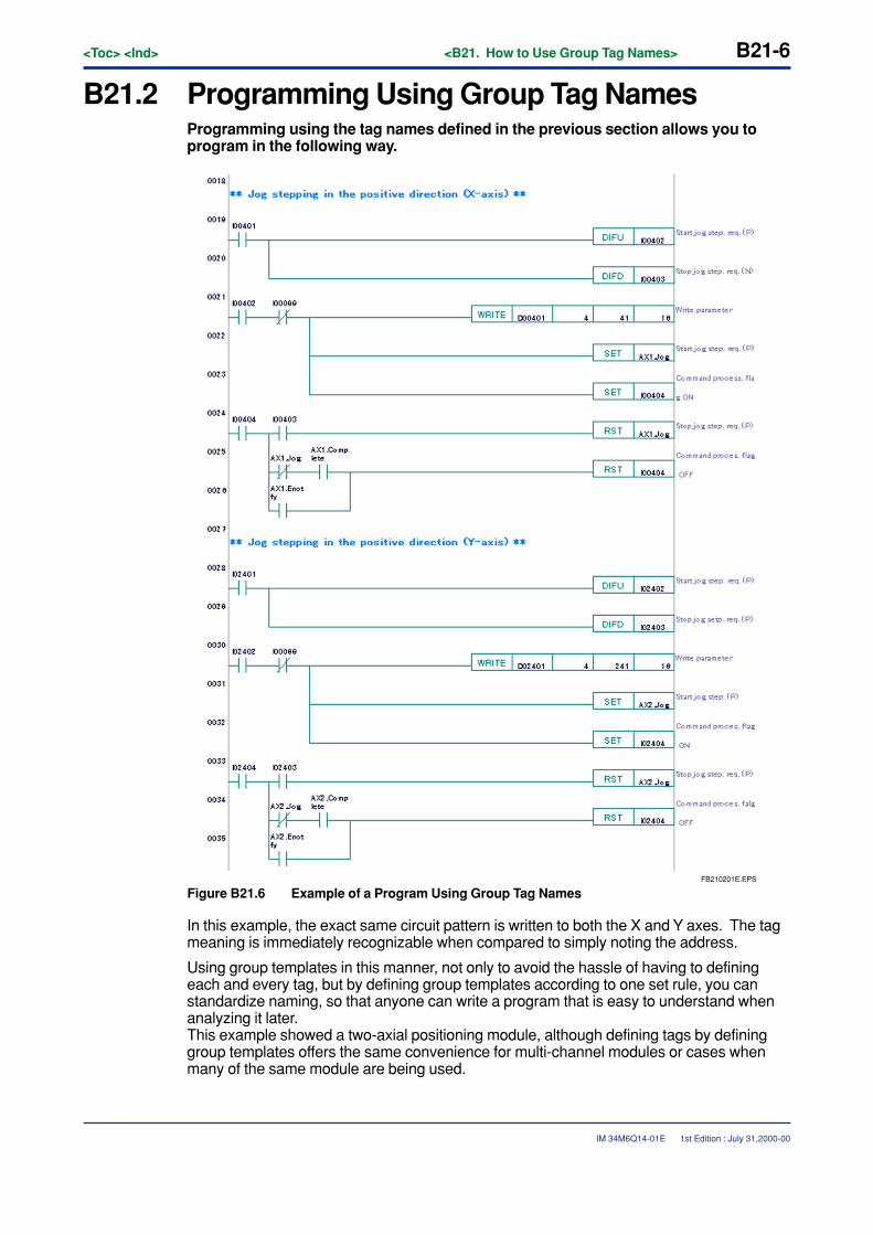
B21-6<Toc> <Ind> <B21. How to Use Group Tag Names>
IM 34M6Q14-01E 1st Edition : July 31,2000-00
B21.2 Programming Using Group Tag NamesProgramming using the tag names defined in the previous section allows you toprogram in the following way.
FB210201E.EPS
Figure B21.6 Example of a Program Using Group Tag Names
In this example, the exact same circuit pattern is written to both the X and Y axes. The tagmeaning is immediately recognizable when compared to simply noting the address.
Using group templates in this manner, not only to avoid the hassle of having to definingeach and every tag, but by defining group templates according to one set rule, you canstandardize naming, so that anyone can write a program that is easy to understand whenanalyzing it later.This example showed a two-axial positioning module, although defining tags by defininggroup templates offers the same convenience for multi-channel modules or cases whenmany of the same module are being used.

TocApp-1<Int> <Ind> <Rev>
IM 34M6Q14-01E
CONTENTSAppendix 1.Error Messages ......................................................................App.1-1
App. 1.1 Displaying Error Messages with the Online Help .................................. App.1-1
1st Edition : July 31,2000-00
IM 34M6Q14-01E 1st Edition
FA-M3FA-M3 Programming Tool WideField Instruction ManualAppendix

Blank Page
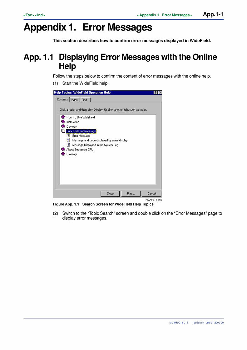
<Toc> <Ind> <Appendix 1. Error Messages> App.1-1
IM 34M6Q14-01E
Appendix 1. Error MessagesThis section describes how to confirm error messages displayed in WideField.
App. 1.1 Displaying Error Messages with the OnlineHelp
Follow the steps below to confirm the content of error messages with the online help.
(1) Start the WideField help.
FBAP0101E.EPS
Figure App. 1.1 Search Screen for WideField Help Topics
(2) Switch to the “Topic Search” screen and double click on the “Error Messages” page todisplay error messages.
1st Edition : July 31,2000-00
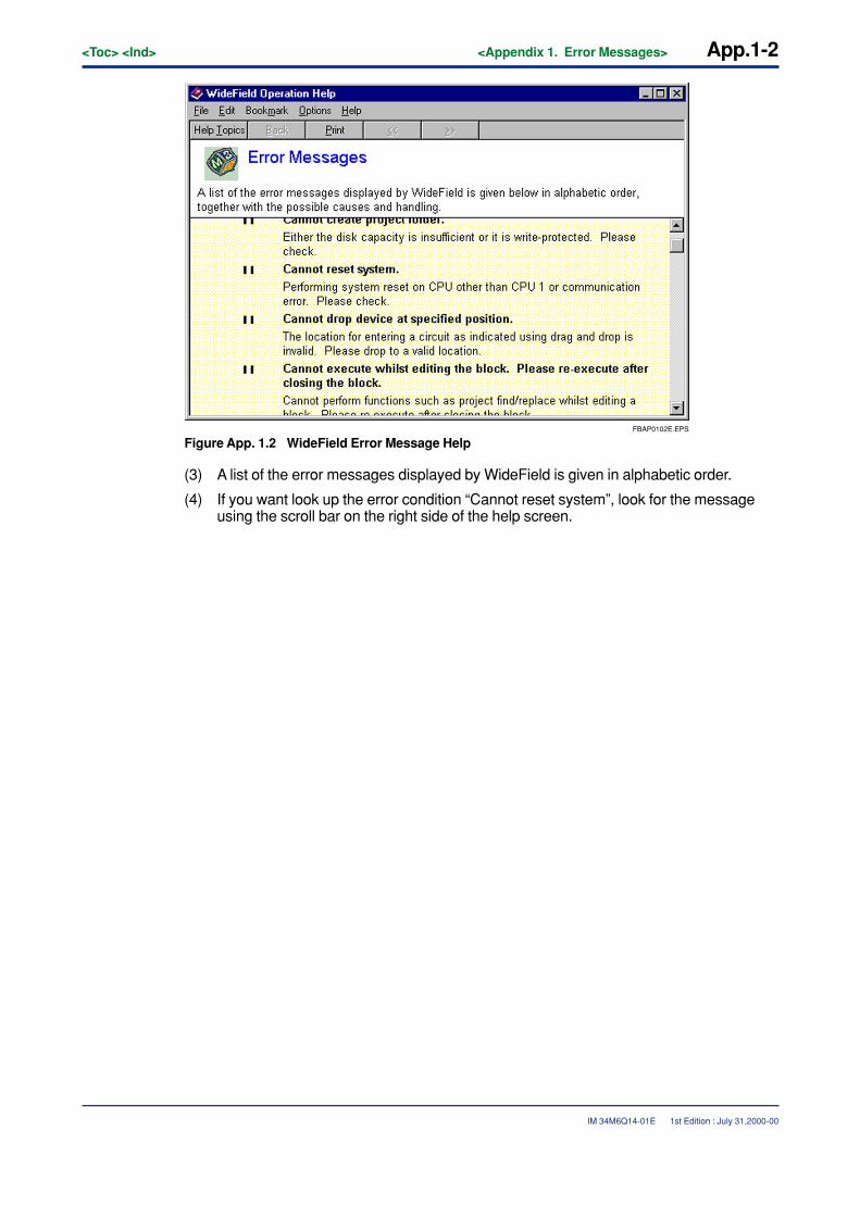
App.1-2<Toc> <Ind> <Appendix 1. Error Messages>
IM 34M6Q14-01E
FBAP0102E.EPS
Figure App. 1.2 WideField Error Message Help
(3) A list of the error messages displayed by WideField is given in alphabetic order.
(4) If you want look up the error condition “Cannot reset system”, look for the messageusing the scroll bar on the right side of the help screen.
1st Edition : July 31,2000-00

i<Int> <Toc> <Ind>
IM 34M6Q14-01E
Revision Information� Title : FA-M3 Programming Tool WideField Instruction Manual
� Manual No. : IM 34M6Q14-01E
July 2000/1st EditionNewly published.
Written by Product Marketing Department, IT Controller Division.Yokogawa Electric Corporation
Published by Yokogawa Electric Corporation2-9-32 Nakacho, Musashino-shi, Tokyo 180-8750, JAPAN
Printed by Yokogawa Graphic Arts Co., Ltd.
1st Edition : July 31,2000-00

Blank Page