subsonic and intersonic dynamic crack growth in unidirectional composites
TRANSCRIPT

SUBSONIC AND INTERSONIC DYNAMIC CRACK GROWTH IN UNIDIRECTIONAL COMPOSITES
Ares J. Rosakis1, Demirkan Coker1 and Yonggang Y. Huang2
1 Graduate Aeronautical Laboratories, California Institute of Technology
Pasadena, CA, USA 91125 2 Department of Mechanical and Industrial Engineering
University of Illinois at Urbana-Champaign, Urbana, IL, USA 61801 SUMMARY: Some recent experimental observations of highly dynamic crack growth events in thick unidirectional graphite fiber-reinforced epoxy matrix composite plates are presented. The composite plates were symmetrically (mode-I) and asymmetrically (mode-II) loaded in a one-point bend configuration with an edge pre-notch machined in the fiber direction. The lateral shearing interferometric technique of coherent gradient sensing (CGS) was used in conjunction with high-speed photography. Symmetric, mode-I cracks initiated at 1300 m/s and subsequently accelerated up to the Rayleigh wave speed but never exceeded it. For asymmetric, Mode-II types of loading, the results reveal highly unstable and intersonic, shear-dominated crack growth along the fibers. The intersonic cracks propagated with unprecedented speeds reaching 7400 m/s, more than three times the shear wave speed of the composite, and featured a shock wave structure typical of disturbances travelling with speeds higher than one of the characteristic wave speeds in the solid. KEYWORDS: dynamic fracture, crack propagation, intersonic, unidirectional composite, shear crack growth, mode-II crack growth
INTRODUCTION
Dynamic crack growth along weak planes is a significant mode of failure in composites and other layered materials. In the past years bimaterial fracture specimens, fabricated by the bonding of a stiff material to a compliant material (featuring a mismatch in wave speeds), have been used to demonstrate the importance of highly transient and dynamic crack growth in heterogeneous solids. It was observed that interfacial crack tip speeds rapidly approached and exceeded the shear wave speed of the more compliant material [1-5]. Thus they reached intersonic speeds with respect to the more compliant material in which intersonic crack tip speed is defined as the speed in the open interval between the shear wave speed and the longitudinal wave speed. For crack tip speeds above the shear wave speed a ray emanating from the crack tip representing a line of strong discontinuity (shear shock wave) was observed experimentally and also predicted theoretically [2]. These high crack tip speeds were obtained under loading conditions that promoted locally shear dominated deformations at the crack tip which were further enhanced by the stress wave mismatch due to the bimaterial nature of the solid [6]. In homogeneous materials and in the absence of a weak prescribed crack growth path, Mode-II crack propagation is not possible because the crack naturally kinks and propagates in a

2
2
direction that causes a local Mode-I stress state around the crack tip. This is not necessarily true in solids that may be homogeneous regarding their properties but may involve preferable crack paths in the form of weak planes of lower toughness. Unidirectional composites may indeed fit this description if viewed from the "macroscopic" point of view of a homogenized anisotropic theory. Although from the microscopic viewpoint, unidirectional composite materials are locally inhomogeneous and are related to bimaterials, in the sense that they also involve a preferred crack growth direction, and are also composed of a stiffer material (the fiber) bonded together with a more compliant material (the matrix), from a macroscopic point of view such solids can be viewed as homogeneous anisotropic materials as far as their elastic properties are concerned. However, they are still inhomogeneous regarding their fracture toughness properties. Indeed, from both the macroscopic or microscopic view points the common characteristic between unidirectional composites and bimaterials which also seem to be the most relevant is the existence of a weak straight line crack path which may accommodate growing cracks of both modes and not the existence of the two phases. Because of the above observations and because of our previous discovery of intersonic crack growth in bimaterials, unidirectional composites seem to be natural candidates for studying maximum allowable crack tip speeds of cracks of both modes in a system that is macroscopically at least homogeneous. While the theory excludes intersonic growth of mode-I cracks, it has not excluded the possibility of intersonic mode-II dominated crack growth in isotropic or anisotropic homogeneous elastic solids in the case of a self similar crack growing in the direction of the plane of the crack [7]. Several researchers [7-11] calculated the critical speed at which intersonic crack growth is stable in isotropic materials to be √2 cs. For stable intersonic crack growth this is the only speed at which the energy release rate is finite. Analysis of the intersonic crack growth in anisotropic materials was developed by Piva and Hasan [12], Huang et al. [8] and Broberg [13]. They predicted that, just as in isotropic materials, intersonic shear crack growth is possible at a specific critical speed, vc, above the shear wave speed. However, in the case of anisotropic materials, this speed is the product of a complex function of the material properties and the shear wave speed. To our knowledge, very few experimental studies of dynamic crack propagation in fiber-reinforced composites have been performed. Liu et al. [14], investigated quasi-static fracture of polymer composites using the optical technique of CGS. Khanna and Shukla [15] extended the theoretical results of Piva and Viola [16] to in-plane stress and used it to analyze the results of strain gages and to thus determine mode-I stress intensity factors for cracks propagating in unidirectional glass-epoxy composite laminates at constant speed. Lambros and Rosakis [17], using CGS shearing interferometry technique in conjunction with high speed photography, looked at the initiation and growth in thick unidirectional graphite-epoxy composite plates under symmetric 1-pt impact loading. They observed crack tip speeds for mode-I loading which approached 900 m/s or 0.58cR, where cR is the speed of the Rayleigh waves travelling in the direction of the fibers. In another investigation, Lambros and Rosakis [18] also studied the dynamic delamination propagation in real time of a cross-plied laminate subjected to out-of-plane impact. In this paper we present experimental results of dynamic crack propagation in unidirectional graphite-epoxy composite plates under mode-I and mode-II loading. The optical technique of CGS was used in conjunction with high-speed camera to obtain interferograms during crack growth. Crack tip speeds are then computed from the interferograms and the limiting crack tip speeds are determined for both the mode-I and the mode-II cases.
3
3
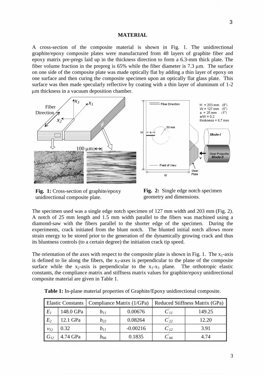
MATERIAL A cross-section of the composite material is shown in Fig. 1. The unidirectional graphite/epoxy composite plates were manufactured from 48 layers of graphite fiber and epoxy matrix pre-pregs laid up in the thickness direction to form a 6.3-mm thick plate. The fiber volume fraction in the prepreg is 65% while the fiber diameter is 7.3 µm. The surface on one side of the composite plate was made optically flat by adding a thin layer of epoxy on one surface and then curing the composite specimen upon an optically flat glass plate. This surface was then made specularly reflective by coating with a thin layer of aluminum of 1-2 µm thickness in a vacuum deposition chamber.
The specimen used was a single edge notch specimen of 127 mm width and 203 mm (Fig. 2). A notch of 25 mm length and 1.5 mm width parallel to the fibers was machined using a diamond-saw with the fibers parallel to the shorter edge of the specimen. During the experiments, crack initiated from the blunt notch. The blunted initial notch allows more strain energy to be stored prior to the generation of the dynamically growing crack and thus its bluntness controls (to a certain degree) the initiation crack tip speed. The orientation of the axes with respect to the composite plate is shown in Fig. 1. The x1-axis is defined to lie along the fibers, the x3-axes is perpendicular to the plane of the composite surface while the x2-axis is perpendicular to the x1-x3 plane. The orthotropic elastic constants, the compliance matrix and stiffness matrix values for graphite/epoxy unidirectional composite material are given in Table 1.
Table 1: In-plane material properties of Graphite/Epoxy unidirectional composite.
Elastic Constants Compliance Matrix (1/GPa) Reduced Stiffness Matrix (GPa) E1 148.0 GPa b11 0.00676 C'
11 149.25 E2 12.1 GPa b22 0.08264 C'
22 12.20 ν12 0.32 b11 -0.00216 C'
12 3.91 G12 4.74 GPa b66 0.1835 C'
66 4.74
Fig. 2: Single edge notch specimen geometry and dimensions.
100 µm
x1
x2
x3 Fiber Direction
Fig. 1: Cross-section of graphite/epoxy unidirectional composite plate.
4
4
The longitudinal and shear wave speeds in terms of reduced stiffness matrix (plane stress) in the direction of the major axes are given by: 2/1
11|| )/( ρccl ′= , 2/1
22 )/( ρccl ′=⊥ , and 2/1
66 )/( ρccs ′= , in which ||lc denotes the dilatational wave speed parallel to the fibers while
⊥lc denotes the dilatational wave speed perpendicular to the fibers. The density is 1478
kg/m3. The shear wave speed as well as the longitudinal wave speeds parallel and perpendicular to the fibers are shown in Table 2.
Table 2: Characteristic plane-stress wave speeds.
Wave Speeds 5 MHz Ultrasonic transducer SPHB
cl� ρ'
11C= 10000 ± 400 9900 ± 200
cl⊥ ρ'
22C= 2860 ± 50 2800 ± 100
cs ρ'66C= 1790 ± 50 Not measured
EXPERIMENTAL TECHNIQUE
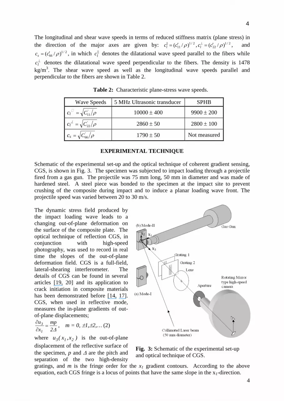
Schematic of the experimental set-up and the optical technique of coherent gradient sensing, CGS, is shown in Fig. 3. The specimen was subjected to impact loading through a projectile fired from a gas gun. The projectile was 75 mm long, 50 mm in diameter and was made of hardened steel. A steel piece was bonded to the specimen at the impact site to prevent crushing of the composite during impact and to induce a planar loading wave front. The projectile speed was varied between 20 to 30 m/s. The dynamic stress field produced by the impact loading wave leads to a changing out-of-plane deformation on the surface of the composite plate. The optical technique of reflection CGS, in conjunction with high-speed photography, was used to record in real time the slopes of the out-of-plane deformation field. CGS is a full-field, lateral-shearing interferometer. The details of CGS can be found in several articles [19, 20] and its application to crack initiation in composite materials has been demonstrated before [14, 17]. CGS, when used in reflective mode, measures the in-plane gradients of out-of-plane displacements;
∆2mp
xu
1
3 =∂∂ , m = 0, ±1,±2,… (2)
where )x,x(u 213 is the out-of-plane displacement of the reflective surface of the specimen, p and ∆ are the pitch and separation of the two high-density gratings, and m is the fringe order for the x1 gradient contours. According to the above equation, each CGS fringe is a locus of points that have the same slope in the x1-direction.
Fig. 3: Schematic of the experimental set-up and optical technique of CGS.
x3
x2 x1
5
5
The experimental set-up used a coherent, monochromatic, collimated laser beam of 50 mm diameter which was incident on the specimen and was reflected off the optically flat surface. Subsequently the reflected beam acquired an optical path difference due to the non-uniform specimen surface deformation near the crack tip after impact. The resulting beam passed through two high-density line diffraction gratings G1 and G2 which sheared the reflected beam and recombined it with itself to form an interferogram. The interference pattern was finally captured by a rotating mirror type high-speed camera (Cordin model 330A). The camera is capable of recording 80 frames at framing rates up to 2 million frames per second.
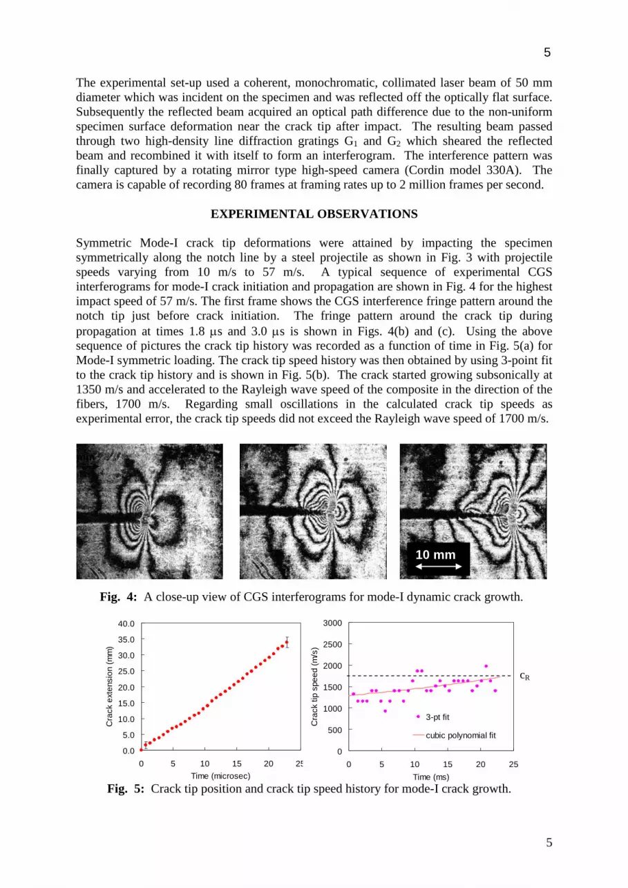
EXPERIMENTAL OBSERVATIONS Symmetric Mode-I crack tip deformations were attained by impacting the specimen symmetrically along the notch line by a steel projectile as shown in Fig. 3 with projectile speeds varying from 10 m/s to 57 m/s. A typical sequence of experimental CGS interferograms for mode-I crack initiation and propagation are shown in Fig. 4 for the highest impact speed of 57 m/s. The first frame shows the CGS interference fringe pattern around the notch tip just before crack initiation. The fringe pattern around the crack tip during propagation at times 1.8 µs and 3.0 µs is shown in Figs. 4(b) and (c). Using the above sequence of pictures the crack tip history was recorded as a function of time in Fig. 5(a) for Mode-I symmetric loading. The crack tip speed history was then obtained by using 3-point fit to the crack tip history and is shown in Fig. 5(b). The crack started growing subsonically at 1350 m/s and accelerated to the Rayleigh wave speed of the composite in the direction of the fibers, 1700 m/s. Regarding small oscillations in the calculated crack tip speeds as experimental error, the crack tip speeds did not exceed the Rayleigh wave speed of 1700 m/s.
10 mm
Fig. 4: A close-up view of CGS interferograms for mode-I dynamic crack growth.
0.0
5.0
10.0
15.0
20.0
25.0
30.0
35.0
40.0
0 5 10 15 20 25Time (microsec)
Cra
ck e
xten
sion
(mm
)
0
500
1000
1500
2000
2500
3000
0 5 10 15 20 25Time (ms)
Cra
ck ti
p sp
eed
(m/s
)
3-pt fit
cubic polynomial fit
Fig. 5: Crack tip position and crack tip speed history for mode-I crack growth.
cR
6
6
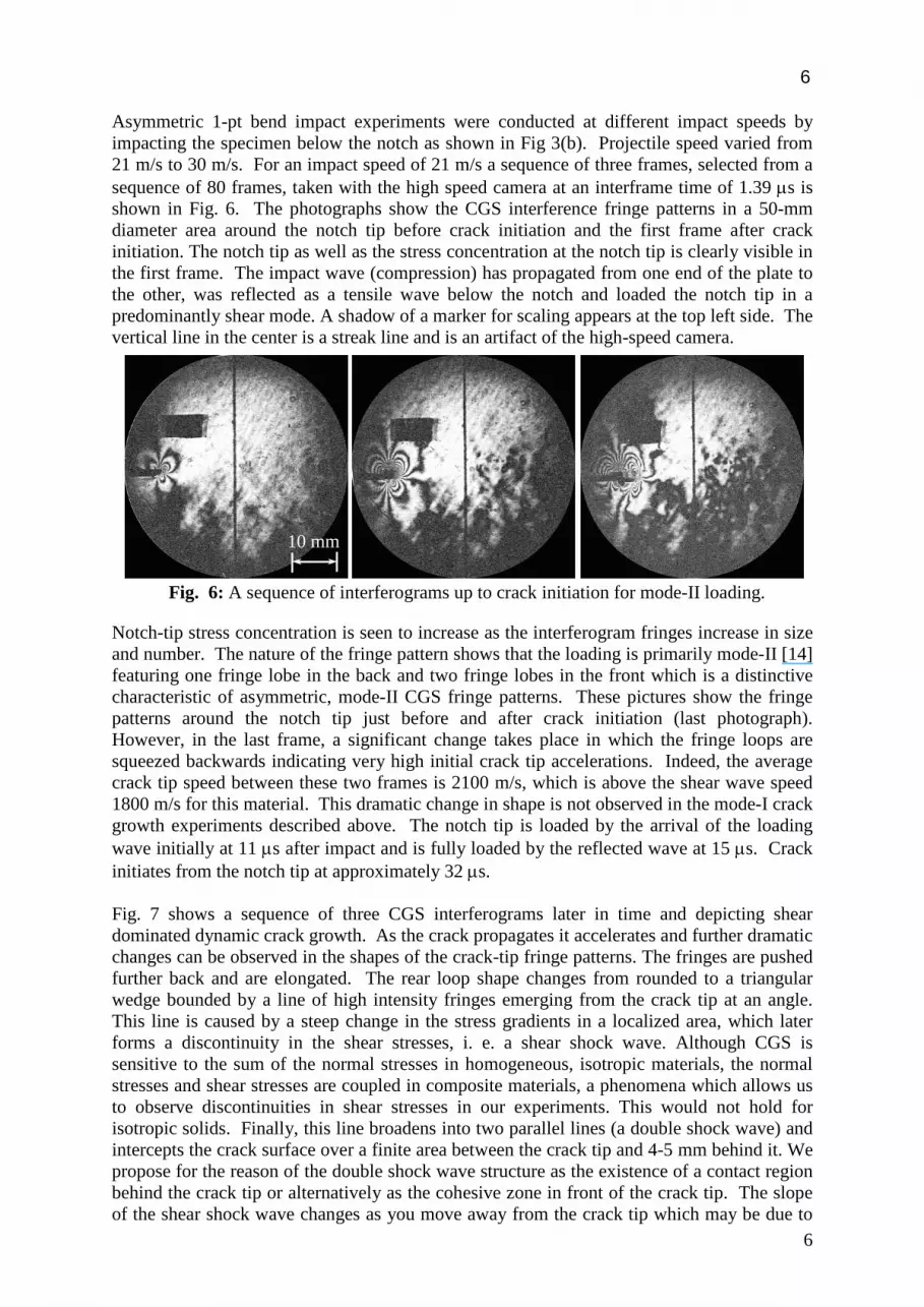
Asymmetric 1-pt bend impact experiments were conducted at different impact speeds by impacting the specimen below the notch as shown in Fig 3(b). Projectile speed varied from 21 m/s to 30 m/s. For an impact speed of 21 m/s a sequence of three frames, selected from a sequence of 80 frames, taken with the high speed camera at an interframe time of 1.39 µs is shown in Fig. 6. The photographs show the CGS interference fringe patterns in a 50-mm diameter area around the notch tip before crack initiation and the first frame after crack initiation. The notch tip as well as the stress concentration at the notch tip is clearly visible in the first frame. The impact wave (compression) has propagated from one end of the plate to the other, was reflected as a tensile wave below the notch and loaded the notch tip in a predominantly shear mode. A shadow of a marker for scaling appears at the top left side. The vertical line in the center is a streak line and is an artifact of the high-speed camera.
Notch-tip stress concentration is seen to increase as the interferogram fringes increase in size and number. The nature of the fringe pattern shows that the loading is primarily mode-II [14] featuring one fringe lobe in the back and two fringe lobes in the front which is a distinctive characteristic of asymmetric, mode-II CGS fringe patterns. These pictures show the fringe patterns around the notch tip just before and after crack initiation (last photograph). However, in the last frame, a significant change takes place in which the fringe loops are squeezed backwards indicating very high initial crack tip accelerations. Indeed, the average crack tip speed between these two frames is 2100 m/s, which is above the shear wave speed 1800 m/s for this material. This dramatic change in shape is not observed in the mode-I crack growth experiments described above. The notch tip is loaded by the arrival of the loading wave initially at 11 µs after impact and is fully loaded by the reflected wave at 15 µs. Crack initiates from the notch tip at approximately 32 µs. Fig. 7 shows a sequence of three CGS interferograms later in time and depicting shear dominated dynamic crack growth. As the crack propagates it accelerates and further dramatic changes can be observed in the shapes of the crack-tip fringe patterns. The fringes are pushed further back and are elongated. The rear loop shape changes from rounded to a triangular wedge bounded by a line of high intensity fringes emerging from the crack tip at an angle. This line is caused by a steep change in the stress gradients in a localized area, which later forms a discontinuity in the shear stresses, i. e. a shear shock wave. Although CGS is sensitive to the sum of the normal stresses in homogeneous, isotropic materials, the normal stresses and shear stresses are coupled in composite materials, a phenomena which allows us to observe discontinuities in shear stresses in our experiments. This would not hold for isotropic solids. Finally, this line broadens into two parallel lines (a double shock wave) and intercepts the crack surface over a finite area between the crack tip and 4-5 mm behind it. We propose for the reason of the double shock wave structure as the existence of a contact region behind the crack tip or alternatively as the cohesive zone in front of the crack tip. The slope of the shear shock wave changes as you move away from the crack tip which may be due to
Fig. 6: A sequence of interferograms up to crack initiation for mode-II loading.
10 mm
7
7
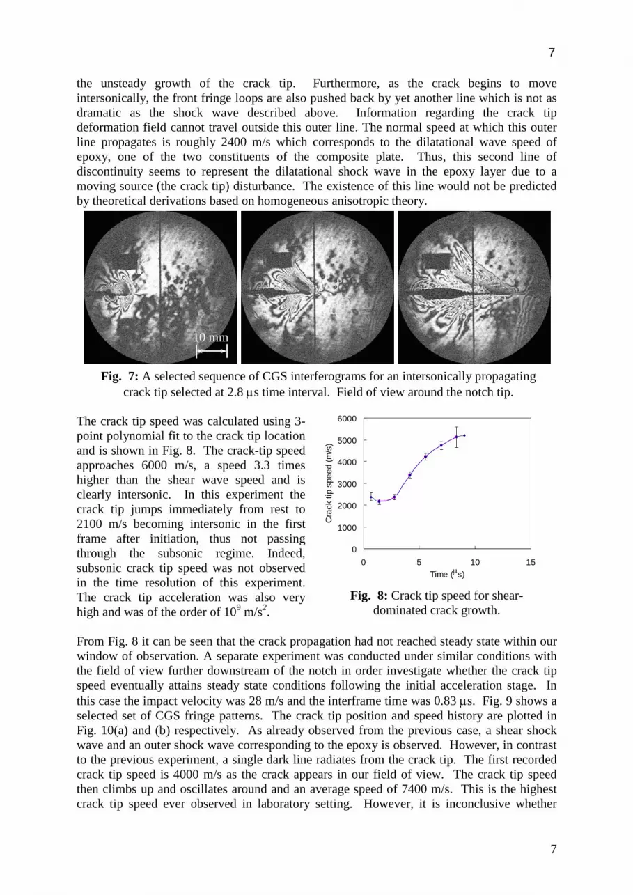
the unsteady growth of the crack tip. Furthermore, as the crack begins to move intersonically, the front fringe loops are also pushed back by yet another line which is not as dramatic as the shock wave described above. Information regarding the crack tip deformation field cannot travel outside this outer line. The normal speed at which this outer line propagates is roughly 2400 m/s which corresponds to the dilatational wave speed of epoxy, one of the two constituents of the composite plate. Thus, this second line of discontinuity seems to represent the dilatational shock wave in the epoxy layer due to a moving source (the crack tip) disturbance. The existence of this line would not be predicted by theoretical derivations based on homogeneous anisotropic theory.
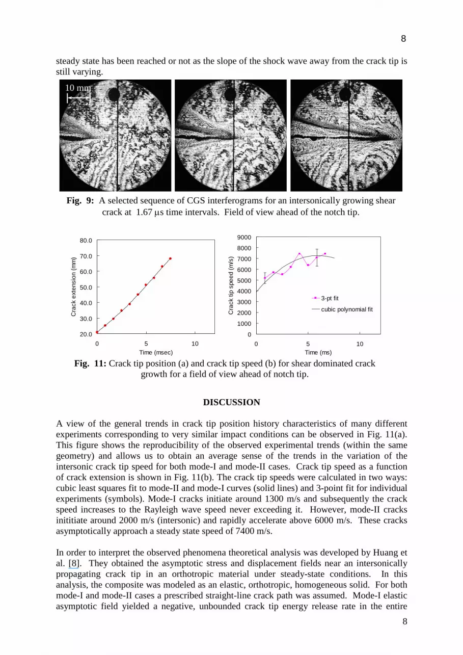
The crack tip speed was calculated using 3-point polynomial fit to the crack tip location and is shown in Fig. 8. The crack-tip speed approaches 6000 m/s, a speed 3.3 times higher than the shear wave speed and is clearly intersonic. In this experiment the crack tip jumps immediately from rest to 2100 m/s becoming intersonic in the first frame after initiation, thus not passing through the subsonic regime. Indeed, subsonic crack tip speed was not observed in the time resolution of this experiment. The crack tip acceleration was also very high and was of the order of 109 m/s2. From Fig. 8 it can be seen that the crack propagation had not reached steady state within our window of observation. A separate experiment was conducted under similar conditions with the field of view further downstream of the notch in order investigate whether the crack tip speed eventually attains steady state conditions following the initial acceleration stage. In this case the impact velocity was 28 m/s and the interframe time was 0.83 µs. Fig. 9 shows a selected set of CGS fringe patterns. The crack tip position and speed history are plotted in Fig. 10(a) and (b) respectively. As already observed from the previous case, a shear shock wave and an outer shock wave corresponding to the epoxy is observed. However, in contrast to the previous experiment, a single dark line radiates from the crack tip. The first recorded crack tip speed is 4000 m/s as the crack appears in our field of view. The crack tip speed then climbs up and oscillates around and an average speed of 7400 m/s. This is the highest crack tip speed ever observed in laboratory setting. However, it is inconclusive whether
0
1000
2000
3000
4000
5000
6000
0 5 10 15Time (µs)
Cra
ck ti
p sp
eed
(m/s
)
Fig. 8: Crack tip speed for shear-dominated crack growth.
Fig. 7: A selected sequence of CGS interferograms for an intersonically propagating crack tip selected at 2.8 µs time interval. Field of view around the notch tip.
10 mm
8
8
steady state has been reached or not as the slope of the shock wave away from the crack tip is still varying.
DISCUSSION
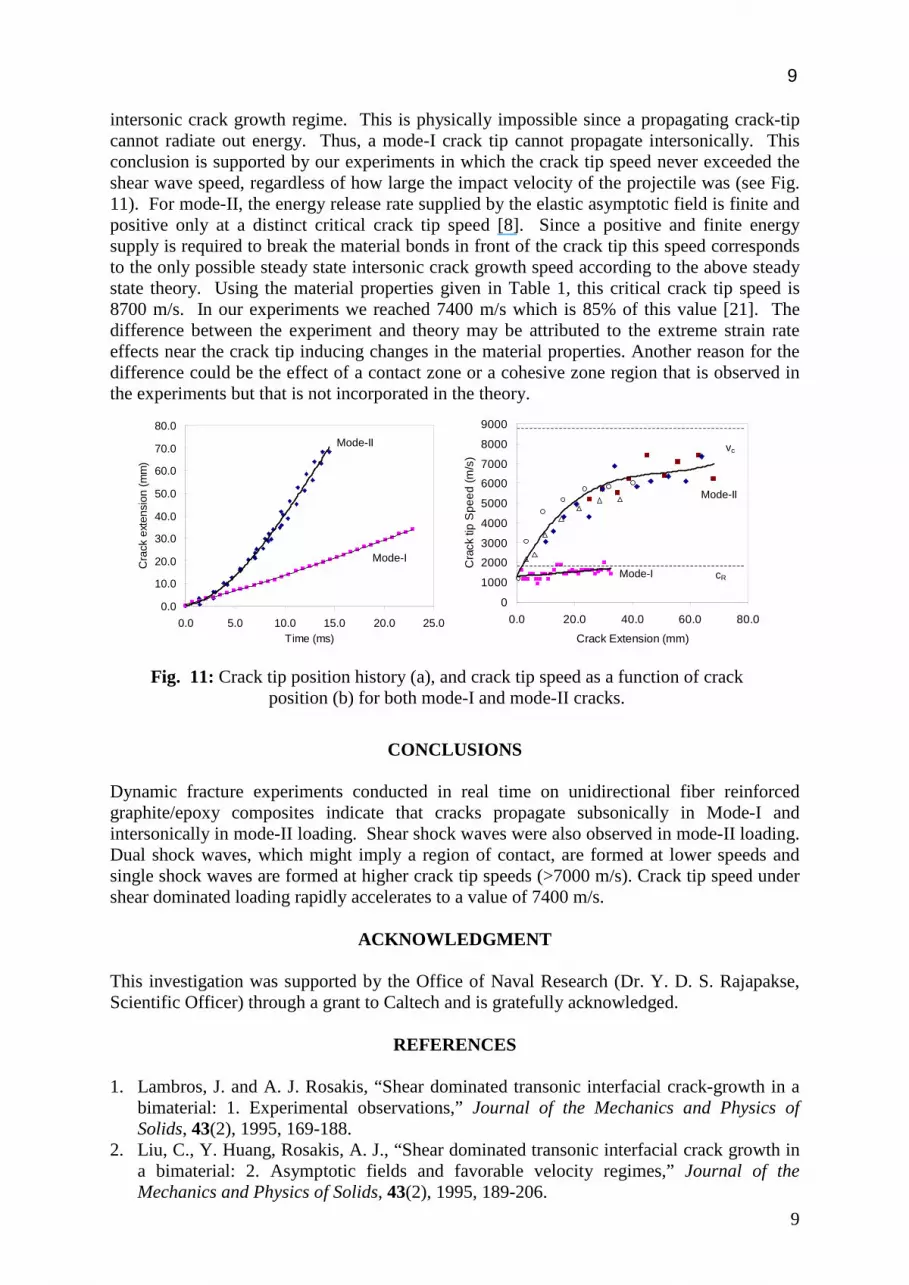
A view of the general trends in crack tip position history characteristics of many different experiments corresponding to very similar impact conditions can be observed in Fig. 11(a). This figure shows the reproducibility of the observed experimental trends (within the same geometry) and allows us to obtain an average sense of the trends in the variation of the intersonic crack tip speed for both mode-I and mode-II cases. Crack tip speed as a function of crack extension is shown in Fig. 11(b). The crack tip speeds were calculated in two ways: cubic least squares fit to mode-II and mode-I curves (solid lines) and 3-point fit for individual experiments (symbols). Mode-I cracks initiate around 1300 m/s and subsequently the crack speed increases to the Rayleigh wave speed never exceeding it. However, mode-II cracks inititiate around 2000 m/s (intersonic) and rapidly accelerate above 6000 m/s. These cracks asymptotically approach a steady state speed of 7400 m/s. In order to interpret the observed phenomena theoretical analysis was developed by Huang et al. [8]. They obtained the asymptotic stress and displacement fields near an intersonically propagating crack tip in an orthotropic material under steady-state conditions. In this analysis, the composite was modeled as an elastic, orthotropic, homogeneous solid. For both mode-I and mode-II cases a prescribed straight-line crack path was assumed. Mode-I elastic asymptotic field yielded a negative, unbounded crack tip energy release rate in the entire
Fig. 9: A selected sequence of CGS interferograms for an intersonically growing shear crack at 1.67 µs time intervals. Field of view ahead of the notch tip.
20.0
30.0
40.0
50.0
60.0
70.0
80.0
0 5 10Time (msec)
Cra
ck e
xten
sion
(mm
)
0
1000
2000
3000
4000
5000
6000
7000
8000
9000
0 5 10Time (ms)
Cra
ck ti
p sp
eed
(m/s
)
3-pt fit
cubic polynomial fit
Fig. 11: Crack tip position (a) and crack tip speed (b) for shear dominated crack growth for a field of view ahead of notch tip.
10 mm
9
9
intersonic crack growth regime. This is physically impossible since a propagating crack-tip cannot radiate out energy. Thus, a mode-I crack tip cannot propagate intersonically. This conclusion is supported by our experiments in which the crack tip speed never exceeded the shear wave speed, regardless of how large the impact velocity of the projectile was (see Fig. 11). For mode-II, the energy release rate supplied by the elastic asymptotic field is finite and positive only at a distinct critical crack tip speed [8]. Since a positive and finite energy supply is required to break the material bonds in front of the crack tip this speed corresponds to the only possible steady state intersonic crack growth speed according to the above steady state theory. Using the material properties given in Table 1, this critical crack tip speed is 8700 m/s. In our experiments we reached 7400 m/s which is 85% of this value [21]. The difference between the experiment and theory may be attributed to the extreme strain rate effects near the crack tip inducing changes in the material properties. Another reason for the difference could be the effect of a contact zone or a cohesive zone region that is observed in the experiments but that is not incorporated in the theory.
CONCLUSIONS
Dynamic fracture experiments conducted in real time on unidirectional fiber reinforced graphite/epoxy composites indicate that cracks propagate subsonically in Mode-I and intersonically in mode-II loading. Shear shock waves were also observed in mode-II loading. Dual shock waves, which might imply a region of contact, are formed at lower speeds and single shock waves are formed at higher crack tip speeds (>7000 m/s). Crack tip speed under shear dominated loading rapidly accelerates to a value of 7400 m/s.
ACKNOWLEDGMENT This investigation was supported by the Office of Naval Research (Dr. Y. D. S. Rajapakse, Scientific Officer) through a grant to Caltech and is gratefully acknowledged.
REFERENCES 1. Lambros, J. and A. J. Rosakis, “Shear dominated transonic interfacial crack-growth in a
bimaterial: 1. Experimental observations,” Journal of the Mechanics and Physics of Solids, 43(2), 1995, 169-188.
2. Liu, C., Y. Huang, Rosakis, A. J., “Shear dominated transonic interfacial crack growth in a bimaterial: 2. Asymptotic fields and favorable velocity regimes,” Journal of the Mechanics and Physics of Solids, 43(2), 1995, 189-206.
0.0
10.0
20.0
30.0
40.0
50.0
60.0
70.0
80.0
0.0 5.0 10.0 15.0 20.0 25.0Time (ms)
Cra
ck e
xten
sion
(mm
)
Mode-II
Mode-I
0
1000
2000
3000
4000
5000
6000
7000
8000
9000
0.0 20.0 40.0 60.0 80.0
Crack Extension (mm)
Cra
ck ti
p S
peed
(m/s
)
vc
cRMode-I
Mode-II
Fig. 11: Crack tip position history (a), and crack tip speed as a function of crack position (b) for both mode-I and mode-II cracks.

10
10
3. Singh, R. P., J. Lambros, Shukla, A. and Rosakis, A. J., “Investigation of the mechanics of intersonic crack propagation along a bimaterial interface using coherent gradient sensing and photoelasticity,” Proceedings of the Royal Society of London Series A, 453(1967), 1997, 2649-2667.
4. Singh, R. P. and Shukla, A., “Subsonic and intersonic crack growth along a bimaterial surface,” Journal of Applied Mechanics 63, 1996, 919-924.
5. Rosakis, A. J., Samudrala, O., Singh, R. P. and Shukla, A., “Intersonic crack propagation in bimaterial systems.” Journal of the Mechanics and Physics of Solids, 46(10), 1998, 1789-1813.
6. Lambros, J. and Rosakis, A. J., “Development of a dynamic decohesion criterion for subsonic fracture of the interface between two dissimilar materials,” Proceedings of the Royal Society of London Series A, 451(1943), 1995, 711-736.
7. Broberg, K. B., “The Near-Tip Field at High Crack Velocities.” International Journal of Fracture, 39, 1989, 1-13.
8. Huang, Y., Wang, W., Liu, C. and Rosakis, A. J., “Analysis of intersonic crack growth in unidirectional fiber-reinforced composites,” to be published in Journal of the Mechanics and Physics of Solids, 1999.
9. Burridge, R., “Admissible speeds for plane-strain self-similar shear cracks with friction but lacking cohesion,” Geophysical Journal of the Royal Astronomical Society, 35, 1973, 439-455.
10. Freund, L. B., “The Mechanics of Dynamic Shear Crack Propagation,” J. of Geophysical Research, 84(B5), 1979, 2199-2209.
11. Georgiadis, H. G., “On the stress singularity in steady-state transonic shear crack propagation,” International Journal of Fracture, 30, 1986, 175-180.
12. Piva, A. and Hasan, W., “Effect of orthotropy on the intersonic shear crack propagation,” Journal of Applied Mechanics, 63, 1996, 933-938.
13. Broberg, K. B., “Intersonic crack propagation in an orthotropic material,” International Journal of Fracture, to be published, 1999.
14. Liu, C., Rosakis, A. J., Ellis, R. W. and Stout, M. G., “A study of the fracture behavior of unidirectional fiber-reinforced composites using coherent gradient sensing (CGS) interferometry,” International Journal of Fracture, 90, 1998, 355-382.
15. Khanna, S. K. and Shukla, A., “Development of stress-field equations and determination of Stress intensity factor during dynamic fracture of orthotropic composite materials,” Engineering Fracture Mechanics 47(3), 1994, 345-359.
16. Piva, A. and Viola, E., “Crack-propagation in an orthotropic medium,” Engineering Fracture Mechanics, 29(5), 1988, 535-548.
17. Lambros, J. and Rosakis, A. J., “Dynamic crack initiation and growth in thick unidirectional graphite/epoxy plates,” Composites Science and Technology, 57(1), 1997, 55-65.
18. Lambros, J. and Rosakis, A. J., “An experimental study of dynamic delamination of thick fiber reinforced polymeric matrix composites,” Experimental Mechanics, 37(3), 1997, 360-366.
19. Tippur, H. V., Krishnaswamy, S. and Rosakis, A. J., “A coherent gradient sensor for crack tip deformation measurements: analysis and experimental results,” International Journal of Fracture, 48, 1991, 193-204.
20. Rosakis, A. J., "Two optical techniques sensitive to the gradients of optical path difference: The method of caustics and the coherent gradient sensor (CGS)," Experimental Techniques in Fracture, J. S. Epstein, Ed., New York, VCH, 1993, 327-425.
21. Coker, D. and Rosakis, A. J., "Experimental Observations of Intersonic Crack Growth in Asymmetrically Loaded Unidirectional Composite Plates," SM Report No. 98-16, Pasadena, California Institute of Technology, 1998.