submersible pumps afp 0831 to 2046 - stuart group
TRANSCRIPT

SUBMERSIBLE PUMPS AFP 0831 to 2046
For wastewater and for sewage and sludge con-taining solid or fibrous particles and storm water
Hydraulic design with ContraBlock ® System or Vortex impellers
Jacket cooling system as an option
Automatic seal and temperature monitoring at all times
High operational reliability even under continuous operating conditions
Available in transportable execution
High performance and output
In standard or Ex-versions
www.abspumps.com
DIN/EN 12050-1
Robust, reliable sewage pumps from 1.3 to 22 kW for pumping wastewater and sewage from buildings and sites in private, commer-cial, industrial and communal areas. Available with ContraBlock ® or Vortex impellers
Applications ABS centrifugal pumps of the AFP series have been designed for economical and reliable pumping of sewage from private, com-mercial, communal and industrial sources.They are suitable for clear and wastewater, and for sewage and sludge containing solid and fibrous material as well as for gaseous liquids. Used in conjunction with the ABS automatic coupling system the below ground level wet installation is a particularly economical solution. It avoids the necessity to enter sump to remove pump. The pumps are also suitable for portable applications as well as for horizontal or vertical dry installation.These pumps are available both in standard and in explosion-proof versions in accordance with international standards e.g. EExd II BT4 and FM.
Maximum ambient temperature +40° C, information on applica-tions at other temperatures available on request.
Construction The water-tight fully flood-proof motor and pump section form a compact and robust unit. Motor Three-phase squirrel-cage motor 400 V3-, 50 Hz, 2-pole (2900 min -1 ), 4-pole (1450 min -1 ) and 6-pole (980 min -1 ), pro-tection type IP 68, stator insulation class F, for 155° C, direct starting up to 3 kW, from 4 kW is star-delta or direct starting possible. Motors with other operating voltages and frequencies are available. Rotor shaft is supported in lubricated for life maintenance-free ball-bear-ings. Shaft sealing between motor and hydraulic section by means of high quality sealing unit using a silicon carbide mechanical seal, independ-ent of direction of rotation and resistant to temperature shock. Seal monitoring: DI-System* DI-system with a sensor in the oil chamber and motor chamber to give a timely indication that an inspection is due and leakage at the shaft seal has occurred. Temperature monitoring* TCS-Thermo-Control-System with thermal sensors in the stator to give a warning and switch off the pump should overheating of the motor occur and switches on automatically after cooling down. Motor cooling As standard supplied without cooling jacket for free circulation cooling. Optional with open jacket cooling system (M-motors only), Closed cooling system on ‘ME’ models. Hydraulics ContraBlock ® System consisting of spiral bottom plate with waved shearing cutting edge, and open ABS channel type impeller, prevents blockage of the impeller where large quantities of solid or fibrous matters are present. Vortex impeller Vortex impeller for pumping of materials which tend to “rope”. Discharge outlet Discharge outlet with DIN-flange: DN 80, 100, 150 and 200.* Standard on M-motors, optional on S-motors
Materials Motor housing __________________________ Cast Iron GG-25Rotor shaft __________________ Stainless steel 1.4021 (AISI 420)Volute ___________________________________ Cast Iron GG-25Impeller CB ______________________________ Cast Iron GG-25Impeller Vortex ___________________________ Cast Iron GG-25Fasteners in contact with medium _ Stainless steel 1.4401 (AISI 316)
Options Rotor shafts _________________ Stainless steel 1.4401 (AISI 316)Impellers ___________________ Stainless steel 1.4460 (AISI 329) Certain models (classified as SX) are also available entirely in stainless steel for chemical and corrosive applications. Surface hardened impeller and bot-tom plate versions available for special applications-contact ABS for details
SUBMERSIBLE PUMPS AFP 0831 to 2046
Technical Data
2
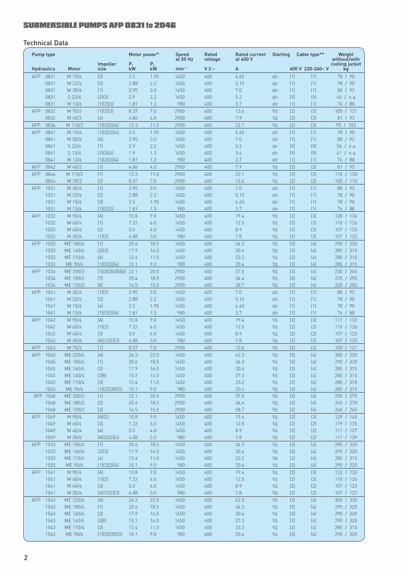
Pump type Motor power* Speed Rated Rated current Starting Cable type** Weight at 50 Hz voltage at 400 V without/with Impeller P 1 P 2 cooling jacket Hydraulics Motor size kW kW min-1 V 3 ~ A 400 V 220-240~ V kg
AFP 0831 M 15/4 (3) 2.5 1.95 1450 400 4.65 dir. (1) (1) 78 / 90 0831 M 22/4 (2) 2.88 2.2 1450 400 5.15 dir. (1) (1) 78 / 90 0831 M 30/4 (1) 3.95 3.0 1450 400 7.0 dir. (1) (1) 80 / 92 0831 S 22/4 (2)(3) 2.9 2.2 1450 400 5.2 dir. (5) (5) 45 / n.a. 0831 M 13/6 (1)(2)(3) 1.81 1.3 980 400 3.7 dir (1) (1) 76 / 88
AFP 0832 M 70/2 (1)(2)(3) 8.37 7.0 2900 400 13.6 Y∆ (2) (2) 105 / 121 0832 M 40/2 (4) 4.86 4.0 2900 400 7.9 Y∆ (2) (2) 81 / 93
AFP 0834 M 110/2 (1)(2)(3)(4) 13.3 11.0 2900 400 22.1 Y∆ (2) (3) 95 / 103AFP 0841 M 15/4 (1)(2)(3)(4) 2.5 1.95 1450 400 4.65 dir. (1) (1) 78 / 90 0841 M 30/4 (A) 3.95 3.0 1450 400 7.0 dir. (1) (1) 80 / 92 0841 S 22/4 (1) 2.9 2.2 1450 400 5.2 dir (5) (5) 56 / n.a. 0841 S 13/4 (2)(3)(4) 1.9 1.3 1450 400 3.6 dir. (5) (5) 41 / n.a. 0841 M 13/6 (1)(2)(3)(4) 1.81 1.3 980 400 3.7 dir (1) (1) 76 / 88
AFP 0842 M 40/2 (1) 4.86 4.0 2900 400 7.9 Y∆ (2) (2) 81 / 93AFP 0844 M 110/2 (1) 13.3 11.0 2900 400 22.1 Y∆ (2) (3) 110 / 120 0844 M 70/2 (2) 8.37 7.0 2900 400 13.6 Y∆ (2) (2) 100 / 110
AFP 1031 M 30/4 (1) 3.95 3.0 1450 400 7.0 dir. (1) (1) 80 / 92 1031 M 22/4 (2) 2.88 2.2 1450 400 5.15 dir. (1) (1) 78 / 90 1031 M 15/4 (3) 2.5 1.95 1450 400 4.65 dir. (1) (1) 78 / 90 1031 M 13/6 (1)(2)(3) 1.81 1.3 980 400 3.7 dir. (1) (1) 76 / 88
AFP 1032 M 90/4 (A) 10.8 9.0 1450 400 19.4 Y∆ (2) (3) 120 / 136 1032 M 60/4 (1) 7.22 6.0 1450 400 12.5 Y∆ (2) (2) 110 / 126 1032 M 40/4 (2) 5.0 4.0 1450 400 8.9 Y∆ (2) (2) 107 / 123 1032 M 30/6 (1)(2) 4.08 3.0 980 400 7.8 Y∆ (2) (2) 107 / 123
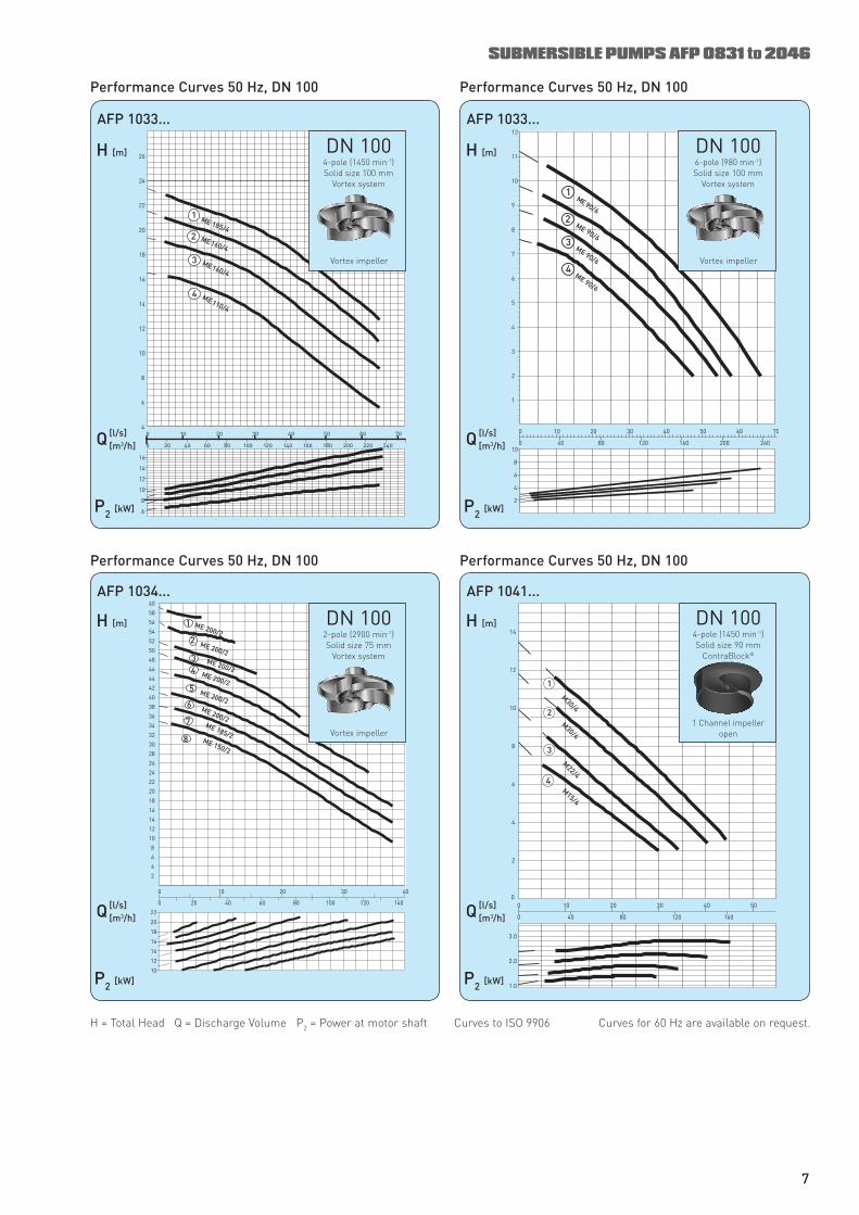
AFP 1033 ME 185/4 (1) 20.6 18.5 1450 400 34.3 Y∆ (3) (4) 290 / 320 1033 ME 160/4 (2)(3) 17.9 16.0 1450 400 30.4 Y∆ (3) (4) 285 / 315 1033 ME 110/4 (4) 12.4 11.0 1450 400 23.2 Y∆ (2) (4) 280 / 310 1033 ME 90/6 (1)(2)(3)(4) 10.1 9.0 980 400 20.4 Y∆ (3) (4) 285 / 315
AFP 1034 ME 200/2 (1)(2)(3)(4)(5)(6) 22.1 20.0 2900 400 37.0 Y∆ (3) (4) 230 / 260 1034 ME 185/2 (7) 20.4 18.5 2900 400 34.4 Y∆ (3) (4) 225 / 255 1034 ME 150/2 (8) 16.5 15.0 2900 400 28.7 Y∆ (3) (4) 220 / 250
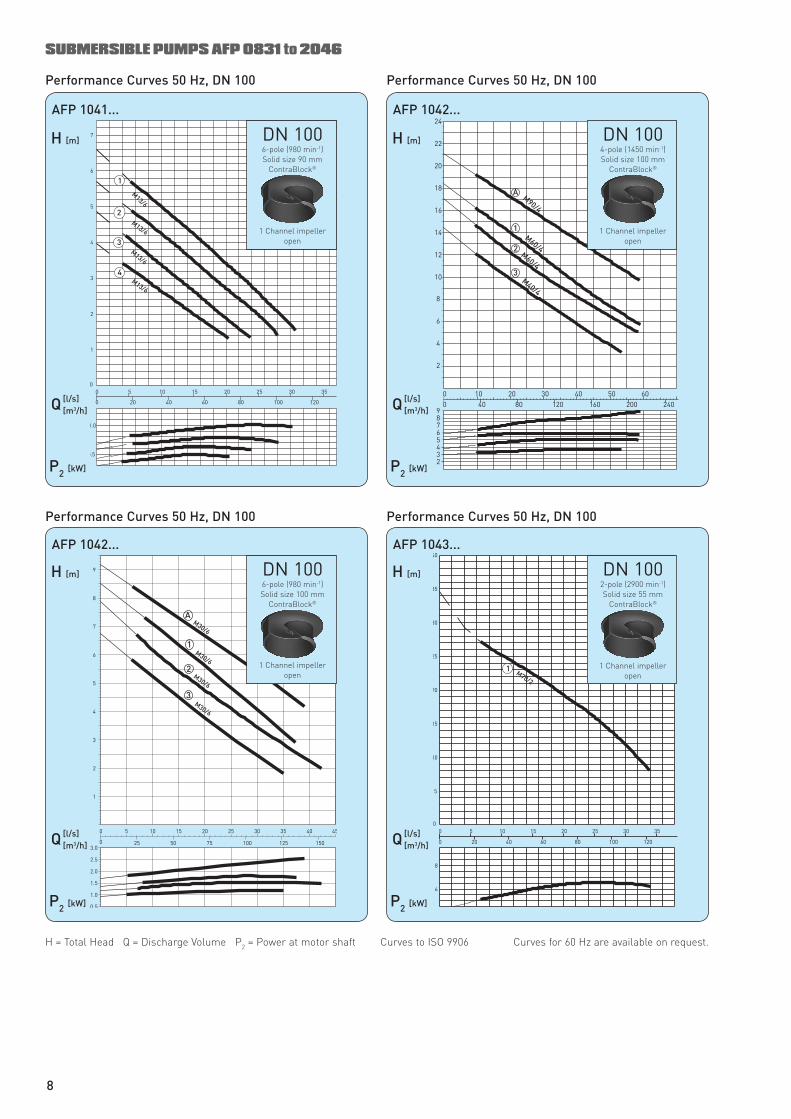
AFP 1041 M 30/4 (1)(2) 3.95 3.0 1450 400 7.0 dir. (1) (1) 80 / 92 1041 M 22/4 (3) 2.88 2.2 1450 400 5.15 dir. (1) (1) 78 / 90 1041 M 15/4 (4) 2.5 1.95 1450 400 4.65 dir. (1) (1) 78 / 90 1041 M 13/6 (1)(2)(3)(4) 1.81 1.3 980 400 3.7 dir. (1) (1) 76 / 88
AFP 1042 M 90/4 (A) 10.8 9.0 1450 400 19.4 Y∆ (2) (3) 117 / 133 1042 M 60/4 (1)(2) 7.22 6.0 1450 400 12.5 Y∆ (2) (2) 110 / 126 1042 M 40/4 (3) 5.0 4.0 1450 400 8.9 Y∆ (2) (2) 107 / 123 1042 M 30/6 (A)(1)(2)(3) 4.08 3.0 980 400 7.8 Y∆ (2) (2) 107 / 123
AFP 1043 M 70/2 (1) 8.37 7.0 2900 400 13.6 Y∆ (2) (2) 105 / 121AFP 1045 ME 220/4 (A) 24.3 22.0 1450 400 42.3 Y∆ (3) (4) 300 / 320 1045 ME 185/4 (1) 20.6 18.5 1450 400 34.3 Y∆ (3) (4) 290 / 320 1045 ME 160/4 (2) 17.9 16.0 1450 400 30.4 Y∆ (3) (4) 285 / 315 1045 ME 140/4 (2B) 15.7 14.0 1450 400 27.3 Y∆ (3) (4) 285 / 315 1045 ME 110/4 (3) 12.4 11.0 1450 400 23.2 Y∆ (2) (4) 280 / 315 1045 ME 90/6 (1)(2)(2B)(3) 10.1 9.0 980 400 20.4 Y∆ (3) (4) 285 / 315 AFP 1048 ME 200/2 (1) 22.1 20.0 2900 400 37.0 Y∆ (3) (4) 250 / 275 1048 ME 185/2 (2) 20.4 18.5 2900 400 34.4 Y∆ (3) (4) 245 / 270 1048 ME 150/2 (3) 16.5 15.0 2900 400 28.7 Y∆ (3) (4) 240 / 265
AFP 1049 M 90/4 (A)(2) 10.8 9.0 1450 400 19.4 Y∆ (2) (3) 129 / 145 1049 M 60/4 (3) 7.22 6.0 1450 400 12.5 Y∆ (2) (2) 119 / 135 1049 M 40/4 (4) 5.0 4.0 1450 400 8.9 Y∆ (2) (2) 111 / 127 1049 M 30/6 (A)(2)(3)(4) 4.08 3.0 980 400 7.8 Y∆ (2) (2) 117 / 139
AFP 1533 ME 185/4 (1) 20.6 18.5 1450 400 34.3 Y∆ (3) (4) 295 / 325 1533 ME 160/4 (2)(3) 17.9 16.0 1450 400 30.4 Y∆ (3) (4) 290 / 320 1533 ME 110/4 (4) 12.4 11.0 1450 400 23.2 Y∆ (2) (4) 285 / 315 1533 ME 90/6 (1)(2)(3)(4) 10.1 9.0 980 400 20.4 Y∆ (3) (4) 290 / 320
AFP 1541 M 90/4 (A) 10.8 9.0 1450 400 19.4 Y∆ (2) (3) 122 / 133 1541 M 60/4 (1)(2) 7.22 6.0 1450 400 12.5 Y∆ (2) (2) 110 / 126 1541 M 40/4 (3) 5.0 4.0 1450 400 8.9 Y∆ (2) (2) 107 / 123 1541 M 30/6 (A)(1)(2)(3) 4.08 3.0 980 400 7.8 Y∆ (2) (2) 107 / 123
AFP 1543 ME 220/4 (A) 24.3 22.0 1450 400 42.3 Y∆ (3) (4) 300 / 330 1543 ME 185/4 (1) 20.6 18.5 1450 400 34.3 Y∆ (3) (4) 295 / 325 1543 ME 160/4 (2) 17.9 16.0 1450 400 30.4 Y∆ (3) (4) 290 / 320 1543 ME 140/4 (2B) 15.7 14.0 1450 400 27.3 Y∆ (3) (4) 290 / 320 1543 ME 110/4 (3) 12.4 11.0 1450 400 23.2 Y∆ (2) (4) 285 / 315 1543 ME 90/6 (1)(2)(2B)(3) 10.1 9.0 980 400 20.4 Y∆ (3) (4) 290 / 320
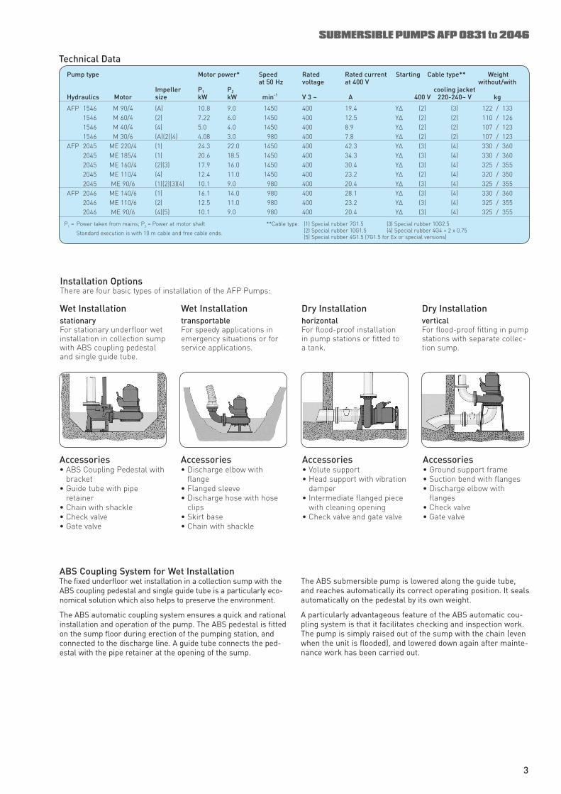
Pump type Motor power* Speed Rated Rated current Starting Cable type** Weight at 50 Hz voltage at 400 V without/with Impeller P 1 P 2 cooling jacket Hydraulics Motor size kW kW min -1 V 3 ~ A 400 V 220-240~ V kg
AFP 1546 M 90/4 (A) 10.8 9.0 1450 400 19.4 Y∆ (2) (3) 122 / 133 1546 M 60/4 (2) 7.22 6.0 1450 400 12.5 Y∆ (2) (2) 110 / 126 1546 M 40/4 (4) 5.0 4.0 1450 400 8.9 Y∆ (2) (2) 107 / 123 1546 M 30/6 (A)(2)(4) 4.08 3.0 980 400 7.8 Y∆ (2) (2) 107 / 123 AFP 2045 ME 220/4 (1) 24.3 22.0 1450 400 42.3 Y∆ (3) (4) 330 / 360 2045 ME 185/4 (1) 20.6 18.5 1450 400 34.3 Y∆ (3) (4) 330 / 360 2045 ME 160/4 (2)(3) 17.9 16.0 1450 400 30.4 Y∆ (3) (4) 325 / 355 2045 ME 110/4 (4) 12.4 11.0 1450 400 23.2 Y∆ (2) (4) 320 / 350 2045 ME 90/6 (1)(2)(3)(4) 10.1 9.0 980 400 20.4 Y∆ (3) (4) 325 / 355 AFP 2046 ME 140/6 (1) 16.1 14.0 980 400 28.1 Y∆ (3) (4) 330 / 360 2046 ME 110/6 (2) 12.5 11.0 980 400 23.2 Y∆ (3) (4) 325 / 355 2046 ME 90/6 (4)(5) 10.1 9.0 980 400 20.4 Y∆ (3) (4) 325 / 355
ABS Coupling System for Wet Installation The fixed underfloor wet installation in a collection sump with the ABS coupling pedestal and single guide tube is a particularly eco-nomical solution which also helps to preserve the environment.
The ABS automatic coupling system ensures a quick and rational installation and operation of the pump. The ABS pedestal is fitted on the sump floor during erection of the pumping station, and connected to the discharge line. A guide tube connects the ped-estal with the pipe retainer at the opening of the sump.
Installation Options There are four basic types of installation of the AFP Pumps:
Wet Installation stationary For stationary underfloor wet installation in collection sump with ABS coupling pedestal and single guide tube.
Wet Installation transportable For speedy applications in emergency situations or for service applications.
Dry Installation horizontal For flood-proof installation in pump stations or fitted to a tank.
Dry Installation vertical For flood-proof fitting in pump stations with separate collec-tion sump.
Accessories • ABS Coupling Pedestal with
bracket• Guide tube with pipe
retainer• Chain with shackle• Check valve• Gate valve
Accessories • Discharge elbow with
flange• Flanged sleeve• Discharge hose with hose
clips• Skirt base• Chain with shackle
Accessories • Volute support• Head support with vibration
damper• Intermediate flanged piece
with cleaning opening• Check valve and gate valve
Accessories • Ground support frame• Suction bend with flanges • Discharge elbow with
flanges• Check valve• Gate valve
P 1 = Power taken from mains; P 2 = Power at motor shaft
Standard execution is with 10 m cable and free cable ends.
**Cable type: (1) Special rubber 7G1.5 (3) Special rubber 10G2.5 (2) Special rubber 10G1.5 (4) Special rubber 4G4 + 2 x 0.75 (5) Special rubber 4G1.5 (7G1.5 for Ex or special versions)
Technical Data
SUBMERSIBLE PUMPS AFP 0831 to 2046
The ABS submersible pump is lowered along the guide tube, and reaches automatically its correct operating position. It seals automatically on the pedestal by its own weight.
A particularly advantageous feature of the ABS automatic cou-pling system is that it facilitates checking and inspection work. The pump is simply raised out of the sump with the chain (even when the unit is flooded), and lowered down again after mainte-nance work has been carried out.
3
AFP 0831...
� �����
�
�
�
����������������
��
�
���
���
���
���
���
������ �� �� ��
�
�
�
�
�
�����������
������
������
������
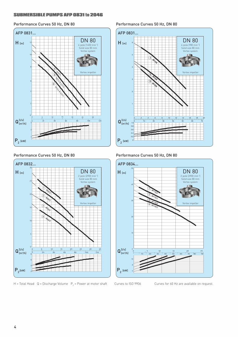
DN 80 6-pole (980 min -1 ) Solid size 80 mm
Vortex system
Vortex impeller
AFP 0834...
DN 80 2-pole (2900 min -1 ) Solid size 80 mm
Vortex system
Vortex impeller
Performance Curves 50 Hz, DN 80
AFP 0832...
SUBMERSIBLE PUMPS AFP 0831 to 2046
Performance Curves 50 Hz, DN 80
DN 804-pole (1480 min-1)Solid size 80 mm
Vortex system
Vortex impeller
Performance Curves 50 Hz, DN 80
Performance Curves 50 Hz, DN 80
AFP 0831...
H [m]
Q [l/s] [m 3 /h]
P 2 [kW]
DN 80 4-pole (1450 min -1 ) Solid size 80 mm
Vortex system
Vortex impeller
H = Total Head Q = Discharge Volume P 2 = Power at motor shaft Curves to ISO 9906 Curves for 60 Hz are available on request.
4
DN 80 2-pole (2900 min -1 ) Solid size 80 mm
Vortex system
Vortex impeller
H [m]
Q [l/s] [m 3 /h]
P 2 [kW]
H [m]
Q [l/s] [m 3 /h]
P 2 [kW]
H [m]
Q [l/s] [m 3 /h]
P 2 [kW]
DN 80 6-pole (980 min -1 ) Solid size 80 mm
ContraBlock ®
1 Channel impeller open
SUBMERSIBLE PUMPS AFP 0831 to 2046
Performance Curves 50 Hz, DN 80
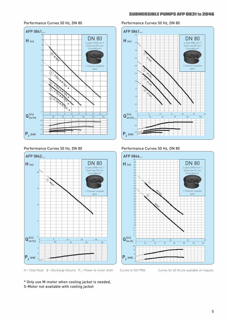
AFP 0841...
Performance Curves 50 Hz, DN 80
AFP 0841...
Performance Curves 50 Hz, DN 80
AFP 0842...
Performance Curves 50 Hz, DN 80
AFP 0844...
DN 80 4-pole (1450 min -1 ) Solid size 80 mm
ContraBlock ®
1 Channel impeller open
DN 80 2-pole (2900 min -1 ) Solid size 45 mm
ContraBlock ®
1 Channel impeller open
DN 80 2-pole (2900 min -1 ) Solid size 50 mm
ContraBlock ®
1 Channel impeller open
H = Total Head Q = Discharge Volume P 2 = Power at motor shaft Curves to ISO 9906 Curves for 60 Hz are available on request.
5
* Only use M-motor when cooling jacket is needed, S-Motor not available with cooling jacket
*
*
*
*
H [m]
Q [l/s] [m 3 /h]
P 2 [kW]
H [m]
Q [l/s] [m 3 /h]
P 2 [kW]
H [m]
Q [l/s] [m 3 /h]
P 2 [kW]
H [m]
Q [l/s] [m 3 /h]
P 2 [kW]

DN 100 4-pole (1450 min -1 ) Solid size 100 mm
Vortex system
Vortex impeller
DN 100 6-pole (980 min -1 ) Solid size 100 mm
Vortex system
Vortex impeller
DN 100 6-pole (980 min -1 ) Solid size 100 mm
Vortex system
Vortex impeller
DN 100 4-pole (1450 min -1 ) Solid size 100 mm
Vortex system
Vortex impeller
SUBMERSIBLE PUMPS AFP 0831 to 2046
Performance Curves 50 Hz, DN 100 Performance Curves 50 Hz, DN 100
AFP 1031...
Performance Curves 50 Hz, DN 100
AFP 1032...
Performance Curves 50 Hz, DN 100
AFP 1032...
H [m]
Q [l/s] [m 3 /h]
P 2 [kW]
H [m]
Q [l/s] [m 3 /h]
P
2 [kW]
H [m]
Q [l/s] [m 3 /h]
P 2 [kW]
H [m]
Q [l/s] [m 3 /h]
P 2 [kW]
AFP 1031...
H = Total Head Q = Discharge Volume P 2 = Power at motor shaft Curves to ISO 9906 Curves for 60 Hz are available on request.
6
SUBMERSIBLE PUMPS AFP 0831 to 2046
Performance Curves 50 Hz, DN 100
H [m]
Q [l/s] [m 3 /h]
AFP 1033...
P 2 [kW]
Performance Curves 50 Hz, DN 100
H [m]
Q [l/s] [m 3 /h]
AFP 1033...
P 2 [kW]
Performance Curves 50 Hz, DN 100
H [m]
Q [l/s] [m 3 /h]
AFP 1034...
P 2 [kW]
Performance Curves 50 Hz, DN 100
H [m]
Q [l/s] [m 3 /h]
AFP 1041...
P 2 [kW]
DN 100 4-pole (1450 min -1 ) Solid size 100 mm
Vortex system
Vortex impeller
DN 100 6-pole (980 min -1 ) Solid size 100 mm
Vortex system
Vortex impeller
DN 100 2-pole (2900 min -1 ) Solid size 75 mm
Vortex system
Vortex impeller
DN 1004-pole (1450 min-1) Solid size 90 mm
ContraBlock®
1 Channel impeller open
H = Total Head Q = Discharge Volume P 2 = Power at motor shaft Curves to ISO 9906 Curves for 60 Hz are available on request.
7
H [m]
Q [l/s] [m 3 /h]
AFP 1041...
P 2 [kW]
SUBMERSIBLE PUMPS AFP 0831 to 2046
Performance Curves 50 Hz, DN 100
H [m]
Q [l/s] [m 3 /h]
AFP 1042...
P 2 [kW]
Performance Curves 50 Hz, DN 100
DN 100 4-pole (1450 min -1 ) Solid size 100 mm
ContraBlock ®
1 Channel impeller open
DN 100 6-pole (980 min -1 ) Solid size 90 mm
ContraBlock ®
1 Channel impeller open
H [m]
Q [l/s]
[m 3 /h]
AFP 1042...
P 2 [kW]
Performance Curves 50 Hz, DN 100
H [m]
Q [l/s] [m 3 /h]
AFP 1043...
P 2 [kW]
Performance Curves 50 Hz, DN 100
DN 100 2-pole (2900 min -1 ) Solid size 55 mm
ContraBlock ®
1 Channel impeller open
DN 100 6-pole (980 min -1 ) Solid size 100 mm
ContraBlock ®
1 Channel impeller open
H = Total Head Q = Discharge Volume P 2 = Power at motor shaft Curves to ISO 9906 Curves for 60 Hz are available on request.
8
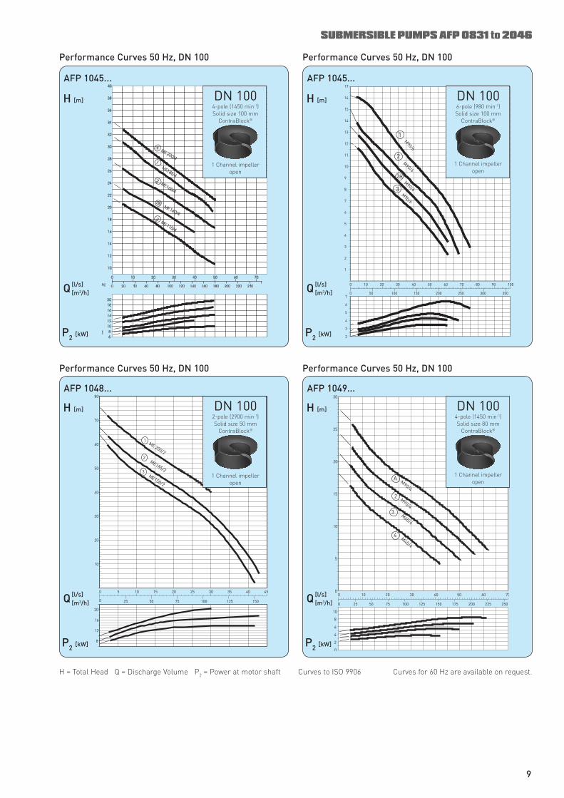
SUBMERSIBLE PUMPS AFP 0831 to 2046
H [m]
Q [l/s] [m 3 /h]
AFP 1045...
P 2 [kW]
Performance Curves 50 Hz, DN 100
H [m]
Q [l/s] [m 3 /h]
AFP 1045...
P 2 [kW]
Performance Curves 50 Hz, DN 100
DN 1006-pole (980 min-1)Solid size 100 mm
ContraBlock®
1 Channel impelleropen
DN 100 4-pole (1450 min -1 ) Solid size 100 mm
ContraBlock ®
1 Channel impeller open
H [m]
Q [l/s] [m 3 /h]
AFP 1048...
P 2 [kW]
Performance Curves 50 Hz, DN 100
H [m]
Q [l/s] [m 3 /h]
AFP 1049...
P 2 [kW]
Performance Curves 50 Hz, DN 100
DN 100 4-pole (1450 min -1 ) Solid size 80 mm
ContraBlock ®
1 Channel impeller open
DN 100 2-pole (2900 min -1 ) Solid size 50 mm
ContraBlock ®
1 Channel impeller open
DN 100 6-pole (980 min -1 ) Solid size 100 mm
ContraBlock ®
1 Channel impeller open
H = Total Head Q = Discharge Volume P 2 = Power at motor shaft Curves to ISO 9906 Curves for 60 Hz are available on request.
9
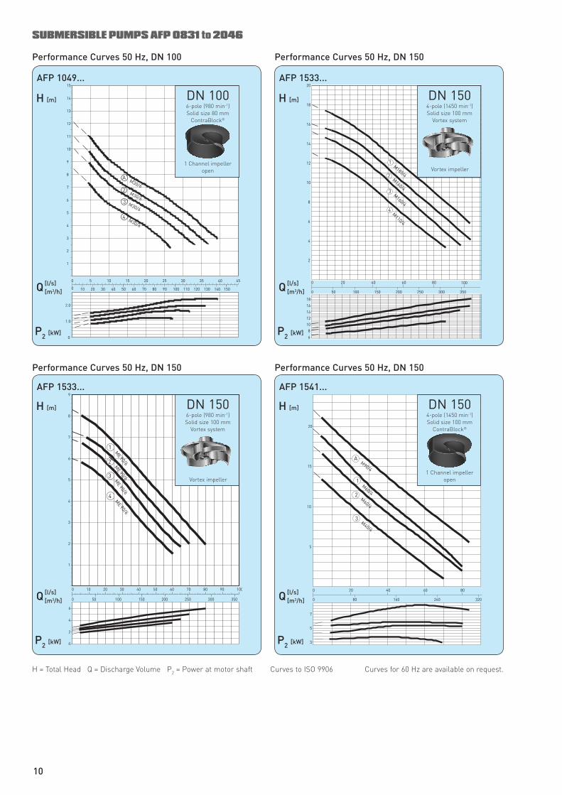
H [m]
Q [l/s] [m 3 /h]
AFP 1049...
P 2 [kW]
SUBMERSIBLE PUMPS AFP 0831 to 2046
Performance Curves 50 Hz, DN 100
H [m]
Q [l/s] [m 3 /h]
AFP 1533...
P 2 [kW]
Performance Curves 50 Hz, DN 150
DN 100 6-pole (980 min -1 ) Solid size 80 mm
ContraBlock ®
1 Channel impeller open
H [m]
Q [l/s] [m 3 /h]
AFP 1533...
P 2 [kW]
Performance Curves 50 Hz, DN 150
H [m]
Q [l/s] [m 3 /h]
AFP 1541...
P 2 [kW]
Performance Curves 50 Hz, DN 150
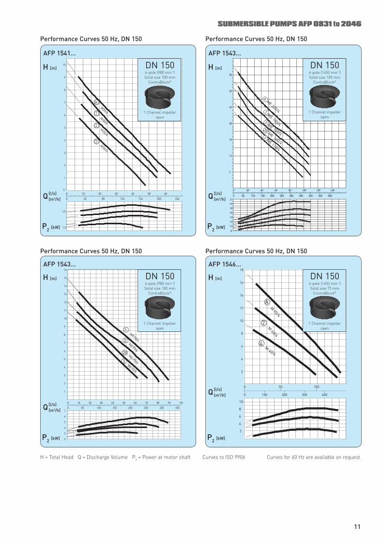
DN 150 4-pole (1450 min -1 ) Solid size 100 mm
ContraBlock ®
1 Channel impeller open
DN 150 4-pole (1450 min -1 ) Solid size 100 mm
Vortex system
Vortex impeller
DN 150 6-pole (980 min -1 ) Solid size 100 mm
Vortex system
Vortex impeller
H = Total Head Q = Discharge Volume P 2 = Power at motor shaft Curves to ISO 9906 Curves for 60 Hz are available on request.
10
SUBMERSIBLE PUMPS AFP 0831 to 2046
H [m]
Q [l/s] [m 3 /h]
AFP 1541...
P 2 [kW]
Performance Curves 50 Hz, DN 150
H [m]
Q [l/s] [m 3 /h]
AFP 1543...
P 2 [kW]
Performance Curves 50 Hz, DN 150
DN 150 4-pole (1450 min -1 ) Solid size 100 mm
ContraBlock ®
1 Channel impeller open
DN 150 6-pole (980 min -1 ) Solid size 100 mm
ContraBlock ®
1 Channel impeller open
H [m]
Q [l/s] [m 3 /h]
AFP 1543...
P 2 [kW]
Performance Curves 50 Hz, DN 150
H [m]
Q [l/s] [m 3 /h]
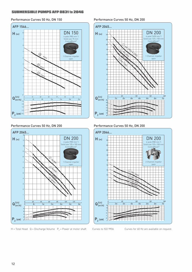
AFP 1546...
P 2 [kW]
Performance Curves 50 Hz, DN 150
DN 150 6-pole (980 min -1 ) Solid size 100 mm
ContraBlock ®
1 Channel impeller open
DN 150 4-pole (1450 min -1 ) Solid size 75 mm
ContraBlock ®
1 Channel impeller open
H = Total Head Q = Discharge Volume P 2 = Power at motor shaft Curves to ISO 9906 Curves for 60 Hz are available on request.
11
E
SUBMERSIBLE PUMPS AFP 0831 to 2046
Performance Curves 50 Hz, DN 150
H [m]
Q [l/s] [m 3 /h]
AFP 2045...
P 2 [kW]
Performance Curves 50 Hz, DN 200
DN 150 6-pole (980 min -1 ) Solid size 75 mm
ContraBlock ®
1 Channel impeller open
H [m]
Q [l/s] [m 3 /h]
AFP 2045...
P 2 [kW]
Performance Curves 50 Hz, DN 200
H [m]
Q [l/s] [m 3 /h]
AFP 2046...
P 2 [kW]
Performance Curves 50 Hz, DN 200
DN 200 6-pole (980 min -1 )
Solid size 125 x 100 mm ContraBlock ®
2 Channel impeller open
DN 200 4-pole (1450 min -1 )
Solid size 125 x 100 mm ContraBlock ®
1 Channel impeller open
DN 200 6-pole (980 min -1 )
Solid size 125 x 100 mm ContraBlock ®
1 Channel impeller open
H = Total Head Q = Discharge Volume P 2 = Power at motor shaft Curves to ISO 9906 Curves for 60 Hz are available on request.
H [m]
Q [l/s] [m 3 /h]
AFP 1546...
P 2 [kW]
12

SUBMERSIBLE PUMPS AFP 0831 to 2046
13
Installation Dimensions with Pedestal and Cooling Jacket (example)
Minimum Sump openingone pump two pumps
* For hexagon head wood screw 10 x 70 DIN 571 and dowel size 12.
Round Sump opening
AFP 0831-1043AFP 1541
AFP 1033-2046
Dimensions for Dry Installation
Horizontal Installation
Vertical Installation Transportable version AFP
Centre of discharge line
Flanges DIN 2633, PN 16All dimensions in mm
All dimensions in mm
* not applicable for Vortex hydraulics
Lowest switch off point for auto-matic control
PLowest switch off point for auto-matic control
SUBMERSIBLE PUMPS AFP 0831 to 2046
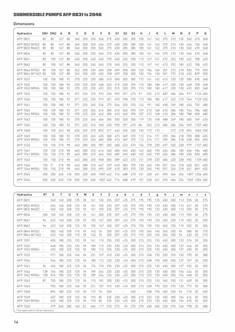
Dimensions
Hydraulics DN1 DN2 A B C D E F G G1 G2 G3 H J K L M N 0 P Q
AFP 0831 80 80 167 88 340 200 250 560 275 450 285 385 100 161 162 375 210 130 560 670 348
AFP 0832 M70/2 80 80 167 88 340 200 250 626 275 450 285 385 100 161 162 375 210 130 626 736 348 AFP 0832 M40/2 80 80 167 88 340 200 250 560 275 450 285 385 100 161 162 375 210 130 560 670 348
AFP 0834 80 80 167 88 340 200 250 560 275 450 285 385 100 161 162 375 210 130 560 670 348
AFP 0841 80 100 167 88 340 200 240 540 270 540 325 330 115 167 141 472 252 180 622 708 425
AFP 0842 80 100 167 88 340 200 240 540 270 540 325 330 115 167 141 472 252 180 622 708 425
AFP 0844 M70/2 80 100 167 88 342 200 230 605 258 409 258 300 102 154 140 351 272 218 583 779 550 AFP 0844 M110/2 80 100 167 88 342 200 230 655 258 409 258 300 102 154 140 351 272 218 633 829 550
AFP 1031 100 100 180 92 370 225 250 580 310 500 305 385 115 161 162 415 220 130 580 690 348
AFP 1032 100 100 180 92 370 225 250 648 323 515 320 395 115 180 180 417 220 130 648 758 348 AFP 1032 M90/4 100 100 180 92 370 225 250 692 323 515 320 395 115 180 180 417 220 130 692 802 348
AFP 1033 100 150 180 92 371 225 315 973 330 592 391 475 91 252 212 487 286 204 971 1125 682
AFP 1034 100 100 180 92 371 225 250 919 301 493 398 370 113 180 180 417 322 210 944 1129 520
AFP 1041 100 100 180 92 371 225 265 534 275 546 320 370 124 191 160 498 269 180 626 702 480
AFP 1042 100 100 180 92 371 225 265 616 285 610 345 390 107 212 168 610 286 180 744 784 480 AFP 1042 M90/4 100 100 180 92 370 225 265 662 285 610 345 390 107 212 168 610 286 180 788 828 480
AFP 1043 100 100 180 92 370 225 240 606 285 550 330 305 119 125 108 488 269 180 683 769 425
AFP 1045 100 150 180 92 371 225 315 960 330 590 391 475 86 252 212 486 286 204 949 1107 682
AFP 1048 100 100 243 98 425 249 270 892 311 443 334 320 150 172 172 - 272 218 894 1065 550
AFP 1049 100 100 180 92 370 225 265 635 308 473 369 370 112 214 171 390 286 218 590 808 605 AFP 1049 M90/4 100 100 180 92 370 225 265 683 308 473 369 370 112 214 171 390 286 218 638 856 605
AFP 1533 150 150 210 98 463 280 335 981 383 600 423 470 136 278 220 497 320 228 979 1157 682
AFP 1541 150 150 210 98 465 280 310 616 340 685 345 400 162 240 190 626 286 180 606 784 480 AFP 1541 M90/4 150 150 210 98 465 280 310 666 340 685 345 400 162 240 190 626 286 180 650 828 480
AFP 1543 150 150 210 98 463 280 335 968 383 589 423 470 131 278 220 486 320 228 950 1139 682
AFP 1546 150 5” 210 98 463 280 310 647 339 610 383 370 130 240 190 551 324 218 603 821 605 AFP 1546 M90/4 150 150 210 98 463 280 310 695 339 610 383 370 130 240 190 551 324 218 651 869 605
AFP 2045 200 200 245 135 550 320 400 1007 442 716 488 470 151 328 241 595 366 254 1007 1204 682
AFP 2046 200 200 245 135 550 320 400 1007 442 716 488 470 151 328 241 595 366 254 1007 1204 682
Hydraulics R* S T U V W X Y Z a b c d f g h j m n r s
AFP 0831 - 560 160 200 125 18 161 100 235 207 +25 275 195 190 125 450 300 113 555 30 275
AFP 0832 M70/2 - 626 160 200 125 18 161 100 235 207 +25 275 195 190 125 450 300 113 621 30 275 AFP 0832 M40/2 - 560 160 200 125 18 161 100 235 207 +25 275 195 190 125 450 300 113 555 30 275
AFP 0834 200 760 160 200 125 18 161 300 235 207 +25 275 195 190 125 450 300 113 555 30 275
AFP 0841 94 622 160 200 125 18 155 167 200 207 +25 275 195 190 125 365 250 115 552 30 305
AFP 0842 94 622 160 200 125 18 155 167 200 207 +25 275 195 190 125 365 250 115 552 30 305
AFP 0844 M70/2 - 583 160 200 110 18 143 76 200 207 +25 275 195 265 165 365 250 96 580 30 275 AFP 0844 M110/2 - 633 160 200 110 18 143 76 200 207 +25 275 195 265 165 365 250 96 630 30 275
AFP 1031 - 605 180 225 125 18 161 110 235 230 +25 300 215 225 135 450 300 123 576 30 305
AFP 1032 - 648 180 225 125 18 180 112 235 230 +25 300 215 225 135 450 300 137 646 30 305 AFP 1032 M90/4 - 692 180 225 125 18 180 112 235 230 +25 300 215 225 135 450 300 137 690 30 305
AFP 1033 - 971 180 225 160 18 231 107 310 230 +25 300 215 338 195 520 370 130 790 30 380
AFP 1034 - 944 180 225 125 18 180 112 235 230 +25 300 215 338 195 450 300 137 767 30 305
AFP 1041 94 626 180 225 125 18 176 193 235 230 +25 300 215 225 135 450 300 137 552 30 305
AFP 1042 138 766 180 225 125 18 189 244 235 230 +25 300 215 225 135 450 300 154 624 30 305 AFP 1042 M90/4 138 816 180 225 125 18 189 244 235 230 +25 300 215 225 135 450 300 154 668 30 305
AFP 1043 87 705 180 225 125 18 115 181 200 230 +25 300 215 225 135 365 250 131 609 30 305
AFP 1045 - 953 180 225 160 18 231 107 310 230 +25 300 215 338 195 520 370 130 772 30 380
AFP 1048 - 894 180 225 125 18 172 76 200 - - 260 - 338 195 365 250 96 710 30 305
AFP 1049 - 607 180 225 125 18 193 85 235 230 +25 300 215 225 135 450 300 154 616 30 305 AFP 1049 M90/4 - 655 180 225 125 18 193 85 235 230 +25 300 215 225 135 450 300 154 655 30 305
AFP 1533 - 979 240 285 160 23 246 117 310 272 -18 270 270 430 260 520 370 140 798 30 380
14
* Not applicable to Vortex hydraulics
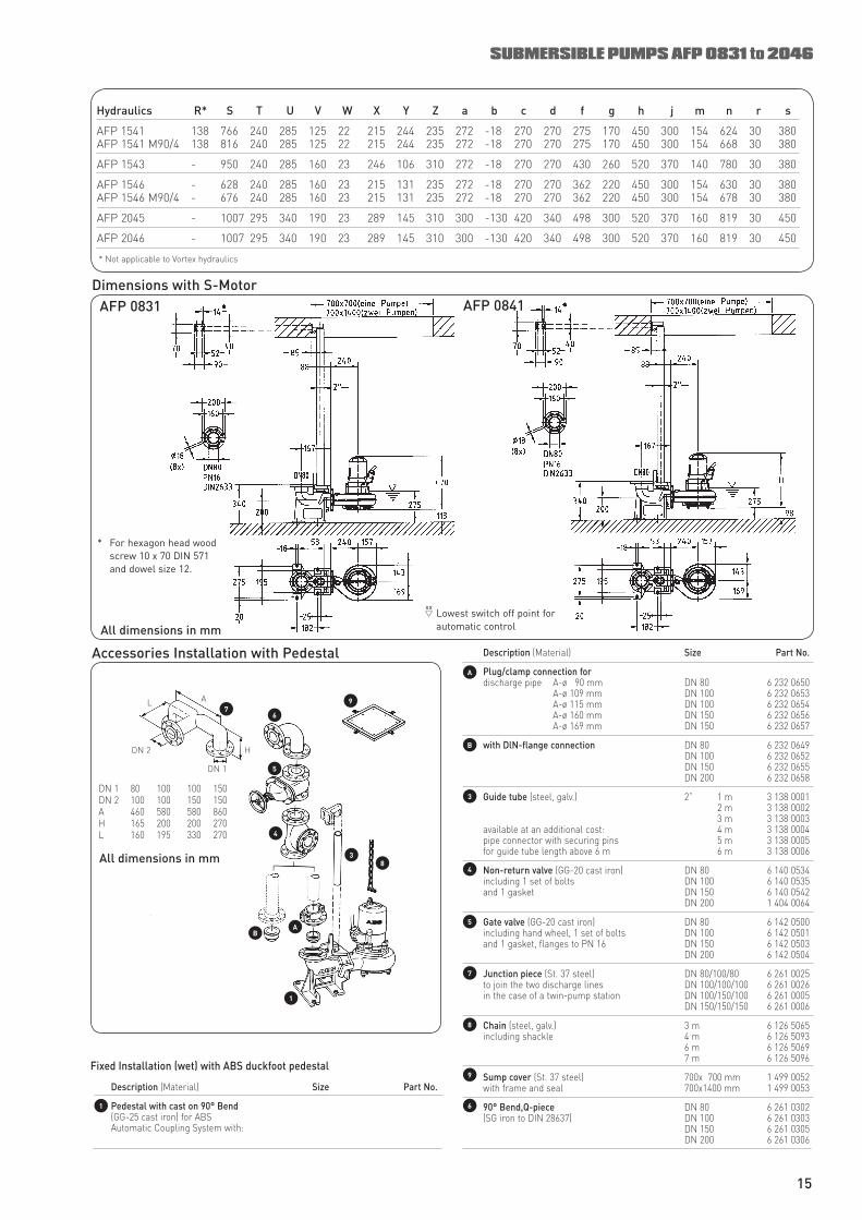
Hydraulics R* S T U V W X Y Z a b c d f g h j m n r s
AFP 1541 138 766 240 285 125 22 215 244 235 272 -18 270 270 275 170 450 300 154 624 30 380 AFP 1541 M90/4 138 816 240 285 125 22 215 244 235 272 -18 270 270 275 170 450 300 154 668 30 380
AFP 1543 - 950 240 285 160 23 246 106 310 272 -18 270 270 430 260 520 370 140 780 30 380
AFP 1546 - 628 240 285 160 23 215 131 235 272 -18 270 270 362 220 450 300 154 630 30 380 AFP 1546 M90/4 - 676 240 285 160 23 215 131 235 272 -18 270 270 362 220 450 300 154 678 30 380
AFP 2045 - 1007 295 340 190 23 289 145 310 300 -130 420 340 498 300 520 370 160 819 30 450
AFP 2046 - 1007 295 340 190 23 289 145 310 300 -130 420 340 498 300 520 370 160 819 30 450
Description (Material) Size Part No.
Plug/clamp connection for discharge pipe A-ø 90 mm DN 80 6 232 0650 A-ø 109 mm DN 100 6 232 0653 A-ø 115 mm DN 100 6 232 0654 A-ø 160 mm DN 150 6 232 0656 A-ø 169 mm DN 150 6 232 0657
with DlN-flange connection DN 80 6 232 0649 DN 100 6 232 0652 DN 150 6 232 0655 DN 200 6 232 0658
Guide tube (steel, galv.) 2” 1 m 3 138 0001 2 m 3 138 0002 3 m 3 138 0003 available at an additional cost: 4 m 3 138 0004 pipe connector with securing pins 5 m 3 138 0005 for guide tube length above 6 m 6 m 3 138 0006
Non-return valve (GG-20 cast iron) DN 80 6 140 0534 including 1 set of bolts DN 100 6 140 0535 and 1 gasket DN 150 6 140 0542 DN 200 1 404 0064
Gate valve (GG-20 cast iron) DN 80 6 142 0500 including hand wheel, 1 set of bolts DN 100 6 142 0501 and 1 gasket, flanges to PN 16 DN 150 6 142 0503 DN 200 6 142 0504
Junction piece (St. 37 steel) DN 80/100/80 6 261 0025 to join the two discharge lines DN 100/100/100 6 261 0026 in the case of a twin-pump station DN 100/150/100 6 261 0005 DN 150/150/150 6 261 0006
Chain (steel, galv.) 3 m 6 126 5065 including shackle 4 m 6 126 5093 6 m 6 126 5069 7 m 6 126 5096
Sump cover (St. 37 steel) 700x 700 mm 1 499 0052 with frame and seal 700x1400 mm 1 499 0053
90° Bend,Q-piece DN 80 6 261 0302 (SG iron to DIN 28637) DN 100 6 261 0303 DN 150 6 261 0305 DN 200 6 261 0306
6
9
B
8
5
4
3
AL
DN 2 H
DN 1
A
4
3
79
6
B
8
5
Fixed Installation (wet) with ABS duckfoot pedestal
Description (Material) Size Part No.
Pedestal with cast on 90° Bend (GG-25 cast iron) for ABS Automatic Coupling System with:
A
1
SUBMERSIBLE PUMPS AFP 0831 to 2046
Accessories Installation with Pedestal
1
* Not applicable to Vortex hydraulics
Dimensions with S-Motor
All dimensions in mm
AFP 0831 AFP 0841
Lowest switch off point for automatic control
xx
15
DN 1 80 100 100 150DN 2 100 100 150 150A 460 580 580 860H 165 200 200 270L 160 195 330 270
7
All dimensions in mm
* For hexagon head wood screw 10 x 70 DIN 571 and dowel size 12.
Description (Material) Size Part No.
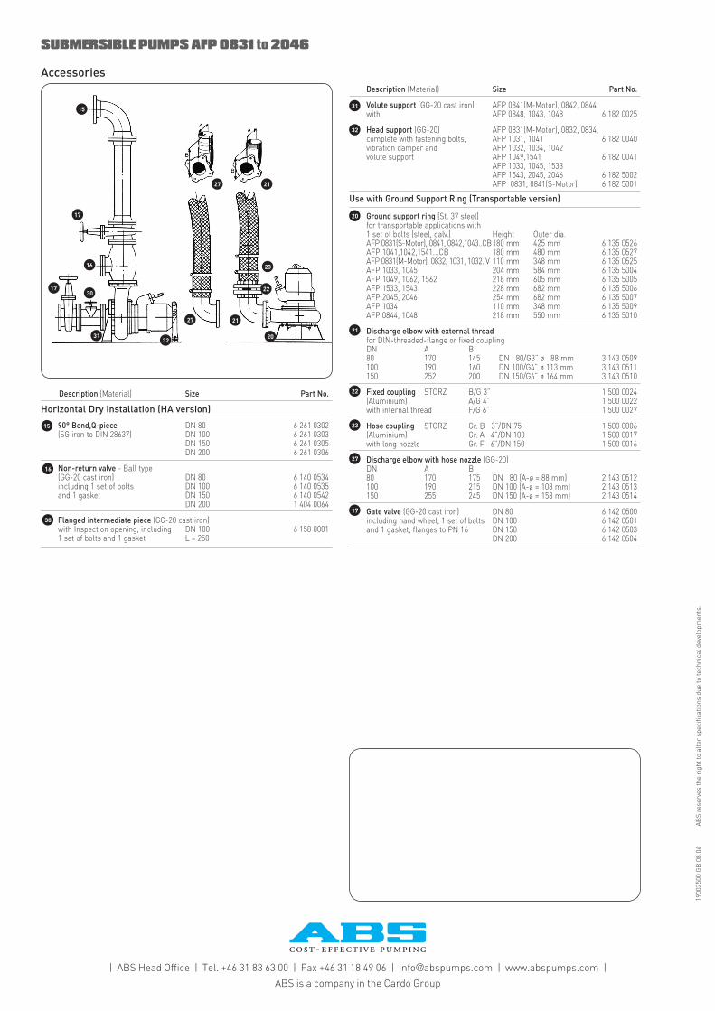
Horizontal Dry Installation (HA version)
90° Bend,Q-piece DN 80 6 261 0302 (SG iron to DIN 28637) DN 100 6 261 0303 DN 150 6 261 0305 DN 200 6 261 0306
Non-return valve - Ball type (GG-20 cast iron) DN 80 6 140 0534 including 1 set of bolts DN 100 6 140 0535 and 1 gasket DN 150 6 140 0542 DN 200 1 404 0064
Flanged intermediate piece (GG-20 cast iron) with Inspection opening, including DN 100 6 158 0001 1 set of bolts and 1 gasket L = 250
Description (Material) Size Part No.
Volute support (GG-20 cast iron) AFP 0841(M-Motor), 0842, 0844 with AFP 0848, 1043, 1048 6 182 0025
Head support (GG-20) AFP 0831(M-Motor), 0832, 0834, complete with fastening bolts, AFP 1031, 1041 6 182 0040 vibration damper and AFP 1032, 1034, 1042 volute support AFP 1049,1541 6 182 0041 AFP 1033, 1045, 1533 AFP 1543, 2045, 2046 6 182 5002 AFP 0831, 0841(S-Motor) 6 182 5001
Use with Ground Support Ring (Transportable version)
Ground support ring (St. 37 steel) for transportable applications with 1 set of bolts (steel, galv.) Height Outer dia. AFP 0831(S-Motor), 0841, 0842,1043..CB 180 mm 425 mm 6 135 0526 AFP 1041,1042,1541...CB 180 mm 480 mm 6 135 0527 AFP 0831(M-Motor), 0832, 1031, 1032..V 110 mm 348 mm 6 135 0525 AFP 1033, 1045 204 mm 584 mm 6 135 5004 AFP 1049, 1062, 1562 218 mm 605 mm 6 135 5005 AFP 1533, 1543 228 mm 682 mm 6 135 5006 AFP 2045, 2046 254 mm 682 mm 6 135 5007 AFP 1034 110 mm 348 mm 6 135 5009 AFP 0844, 1048 218 mm 550 mm 6 135 5010
Discharge elbow with external thread for DlN-threaded-flange or fixed coupling DN A B 80 170 145 DN 80/G3” ø 88 mm 3 143 0509 100 190 160 DN 100/G4” ø 113 mm 3 143 0511 150 252 200 DN 150/G6” ø 164 mm 3 143 0510
Fixed coupling STORZ B/G 3” 1 500 0024 (Aluminium) A/G 4” 1 500 0022 with internal thread F/G 6” 1 500 0027
Hose coupling STORZ Gr. B 3”/DN 75 1 500 0006 (Aluminium) Gr. A 4”/DN 100 1 500 0017 with long nozzle Gr. F 6”/DN 150 1 500 0016
Discharge elbow with hose nozzle (GG-20) DN A B 80 170 175 DN 80 (A-ø = 88 mm) 2 143 0512 100 190 215 DN 100 (A-ø = 108 mm) 2 143 0513 150 255 245 DN 150 (A-ø = 158 mm) 2 143 0514
Gate valve (GG-20 cast iron) DN 80 6 142 0500 including hand wheel, 1 set of bolts DN 100 6 142 0501 and 1 gasket, flanges to PN 16 DN 150 6 142 0503 DN 200 6 142 0504
32
16
27
23
22
31
21
20
15
1900
2500
GB
08.
04
ABS
rese
rves
the
righ
t to
alte
r sp
ecifi
catio
ns d
ue to
tech
nica
l dev
elop
men
ts.
| ABS Head Office | Tel. +46 31 83 63 00 | Fax +46 31 18 49 06 | info @ abspumps.com | www.abspumps.com |
ABS is a company in the Cardo Group
SUBMERSIBLE PUMPS AFP 0831 to 2046
Accessories
27
23
22
21
2032
31
21
30
27
16
17
17
15
30
17