subdural porous and notched mini-grid electrodes for wireless intracranial electroencephalographic...
TRANSCRIPT
© 2014 Salam et al. This work is published by Dove Medical Press Limited, and licensed under Creative Commons Attribution – Non Commercial (unported, v3.0) License. The full terms of the License are available at http://creativecommons.org/licenses/by-nc/3.0/. Non-commercial uses of the work are permitted without any further
permission from Dove Medical Press Limited, provided the work is properly attributed. Permissions beyond the scope of the License are administered by Dove Medical Press Limited. Information on how to request permission may be found at: http://www.dovepress.com/permissions.php
Journal of Multidisciplinary Healthcare 2014:7 573–586
Journal of Multidisciplinary Healthcare Dovepress
submit your manuscript | www.dovepress.com
Dovepress 573
O r i g i n a l r e s e a r c H
open access to scientific and medical research
Open access Full Text article
http://dx.doi.org/10.2147/JMDH.S64269
subdural porous and notched mini-grid electrodes for wireless intracranial electroencephalographic recordings
Muhammad Tariqus salam1
sébastien gélinas1
sébastien Desgent2
sandra Duss2
Félix Bernier Turmel1,3
lionel carmant2
Mohamad sawan1
Dang Khoa nguyen3
1Polystim neurotechnologies laboratory, Polytechnique Montréal, Qc, canada; 2research center, sainte-Justine University Hospital center (cHU sainte-Justine), Université de Montréal, Qc, canada; 3neurology service, Department of Medicine, notre-Dame Hospital, centre Hospitalier de l’Université de Montréal (cHUM), Qc, canada
correspondence: Muhammad Tariqus salam Polystim neurotechnologies laboratory, Polytechnique Montréal, 2900 Boulevard edouard-Montpetit, Qc, H3T 1J4, canada email [email protected]
Background: Intracranial electroencephalography (EEG) studies are widely used in the
presurgical evaluation of drug-refractory patients with partial epilepsy. Because chronic
implantation of intracranial electrodes carries a risk of infection, hemorrhage, and edema, it
is best to limit the number of electrodes used without compromising the ability to localize the
epileptogenic zone (EZ). There is always a risk that an intracranial study may fail to identify
the EZ because of suboptimal coverage. We present a new subdural electrode design that will
allow better sampling of suspected areas of epileptogenicity with lower risk to patients.
Method: Impedance of the proposed electrodes was characterized in vitro using electrochemical
impedance spectroscopy. The appearance of the novel electrodes on magnetic resonance imaging
(MRI) was tested by placing the electrodes into a gel solution (0.9% NaCl with 14 g gelatin). In
vivo neural recordings were performed in male Sprague Dawley rats. Performance comparisons
were made using microelectrode recordings from rat cortex and subdural/depth recordings
from epileptic patients. Histological examinations of rat brain after 3-week icEEG intracerebral
electroencephalography (icEEG) recordings were performed.
Results: The in vitro results showed minimum impedances for optimum choice of pure gold
materials for electrode contacts and wire. Different attributes of the new electrodes were identified
on MRI. The results of in vivo recordings demonstrated signal stability, 50% noise reduction,
and up to 6 dB signal-to-noise ratio (SNR) improvement as compared to commercial electrodes.
The wireless icEEG recording system demonstrated on average a 2% normalized root-mean-
square (RMS) deviation. Following the long-term icEEG recording, brain histological results
showed no abnormal tissue reaction in the underlying cortex.
Conclusion: The proposed subdural electrode system features attributes that could potentially
translate into better icEEG recordings and allow sampling of large of areas of epileptogenicity
at lower risk to patients. Further validation for use in humans is required.
Keywords: epilepsy, seizure, monitoring, surgery, electrodes
IntroductionEpilepsy is a chronic neurological disorder characterized by abnormal electrographic
discharges in the brain that cause seizures and a range of behavioral manifestations.
Presently, many patients with epilepsy are antiepileptic drug resistant or have systemic
side-effects due to the antiepileptic drugs. These patients with refractory focal epi-
lepsy may benefit from epilepsy surgery. However, a successful surgical treatment is
dependent upon adequate localization of the epileptogenic zone (EZ).1 Non-invasive
localization techniques such as scalp electroencephalography (EEG), positron emis-
sion tomography (PET), magnetic resonance imaging (MRI), ictal single-photon
emission computed tomography (SPECT), magnetoencephalography (MEG), and

Journal of Multidisciplinary Healthcare 2014:7submit your manuscript | www.dovepress.com
Dovepress
Dovepress
574
salam et al
EEG-functional MRI (EEG-fMRI) can help in the identi-
fication of the EZ, which sometimes allows some patients
to go directly on to resective surgery.1,2 When non-invasive
techniques fail to adequately localize the EZ, an invasive
EEG study is generally required. These invasive EEG studies
involve implanting intracerebral electrodes to allow direct
recording from the brain. A variety of intra cranial electrodes
are available for such invasive studies: subdural strip or grid,
depth, epidural, and foramen ovale electrodes;3–6 these differ
in method of insertion, accuracy, risks, and limitations.7,8 The
choice of electrodes depends on the areas to be sampled.
Figure 1A and C show the traditional method of performing
an invasive EEG study.
Intracranial electrodes are more sensitive to brain
activities than extracranial electrodes because they are
closer to the EZ. Whereas extracranial electrodes record
Traditional subduralgrid electrode
New subdural gridelectrode
40 mm
80 mm
RF link
40 m
m
80 m
m
Traditional procedure
Amplifier
A B
C D
Skin
Device
Skull
Electrodes
New procedure
Figure 1 schematic representation of intracerebral eeg recording systems and electrodes.Notes: (A) The traditional procedure using currently available commercial electrodes, (B) the new procedure using the proposed novel subdural electrodes, (C) the traditional subdural grid electrode and (D) the new subdural grid electrode.

Journal of Multidisciplinary Healthcare 2014:7 submit your manuscript | www.dovepress.com
Dovepress
Dovepress
575
Mini-grid electrodes for wireless eeg
signals generated from a large cortical surface, intracranial
electrodes record the synchronous firing of many neurons
throughout a few millimeters of cortex across the diameter of
an electrode contact. However, using intracranial electrodes
has some disadvantages, including a small risk of infection,
edema, and hemorrhage.1,8 Thus, it is best to limit the num-
ber of electrodes implanted to delineate the EZ for safety
purposes.9,10 Restrictions on the number of electrodes may,
however, cause insufficient coverage to allow identification
of the EZ. Erroneous identification of the EZ translates into
a poor epilepsy surgery outcome.
Intracerebral electrodes have been in use since the 1950s,
but few improvements have been made except for the devel-
opment of the shank microelectrode array and the micro
electrocorticography grid electrode to record high-frequency
oscillations, which are primarily used for research purposes.11–14
Because of the small electrode-tissue interface compared to
the area of EZ, these microelectrodes have different electrical
characteristics than subdural electrodes. Commercial compa-
nies (eg, Ad-Tech Medical Instrument Corporation, Racine,
WI, USA or PMT Corporation, Chanhassen, MN, USA) use
common manufacturing methods for developing intracerebral
subdural electrodes (diameter 4-5 mm). These commer-
cial electrodes have silicone rubber (polydimethylsiloxane
[PDMS]) as insulation and substrate material, platinum or
stainless steel as electrode material, and stainless steel for
wiring.14 Gold (Au) has been used in subdural electrodes,15 but
no significant improvements in intracerebral electroencepha-
lography (icEEG) recording have been reported.
The motivation for the work presented here was that currently
used electrodes have several limitations. Mechanical resistance of
electrode-wire generates noise that degrades the icEEG record-
ing.15 Chemical reactions at the electrode- tissue interface produce
ions that are toxic to tissues.16 Moreover, many materials (eg,
stainless steel, tungsten, and titanium) need corrosion protection
(ie, passive film),16 but this protection often dissolves because of
faradic reaction in the passive film.17 Other unresolved problems
include wiring material, poor connection at the electrode-wire
interface, and visualization of implanted electrodes on post-
implantation scans or MRIs. Finally, current intracerebral EEG
recordings use many wired connections that limit the patient’s
freedom of movement and increase the risk of brain infections.
The icEEG recording is characterized by low-amplitude
signals (microvolt range) and low-frequency bandwidth.
The available instruments have relatively poor noise per-
formance for low-spectral neural signal amplification.
Moreover, other low-spectral noises generated from
electrodes and the electrode-tissue interface combine with
instrument noise to modulate the neural signal and degrade
the signal-to-noise ratio (SNR). We have previously demon-
strated several front-end preamplifiers for noise reduction.18,19
However, optimum SNR values can also be obtained by
improving intracranial electrode contacts.20
We propose a novel subdural electrode-based recording
system (Figure 1B) featuring attributes that could potentially
facilitate larger sampling areas with lower morbidity: mini-
grids (Figure 1D) connected as needed, a single exit cable,
wireless transmission, grid notches and holes, edge markers
and a numbering system, low-impedance electrode contacts
and wiring, and a wireless recording system.
Proposed novel intracranial recording systemThe proposed subdural mini-grid and/or strip electrodes
are meant to be implanted independently over suspected
areas of epileptogenicity through a craniotomy (Figure 2).
One or two main grid electrode(s) hold(s) all the electrodes
and connect(s) to the implantable wireless icEEG recorder
(Figure 1B). After the implantation of intracranial electrodes,
the patient can undergo an MRI study to verify the position-
ing of implanted electrodes and then long-term video-EEG
recording for localization of the EZ. The shapes and attri-
butes of the new subdural electrodes and recording system
are described below.
smaller gridsThe subdural mini-grid electrode is a 4×4 matrix (height, 40
mm; width, 40 mm; thickness, 0.6 mm). The dimensions of
grid electrodes are smaller than the conventional grid to fit
curved regions of the brain.
HolesCommercial subdural grid electrodes may cause brain
swelling.21 To minimize the risk of brain swelling, each mini-
grid has six holes to allow circulation of cerebrospinal fluid.
notchesThe mini-grid electrode is designed to fit on the human
brain cortical surface. Each mini-grid has four notches for
better flexibility to allow a better fit with the curved cortical
surface.
MarkersEdge and numbering markers are included in the
grid electrodes to facilitate their identification on the
post-implantation MRI. All materials used in the electrodes are

Journal of Multidisciplinary Healthcare 2014:7submit your manuscript | www.dovepress.com
Dovepress
Dovepress
576
salam et al
MRI compatible and take into account the magnetic resonance
(MR)- susceptibility artifacts generated by metal contacts.
connectorsThe mini-grids are connected to one another using custom-
made contactors that enhance electrical and mechanical
connections. The connectors provide internal routing of elec-
trical wiring. Shorter wires reduce resistance in the electrical
paths. Moreover, the connectors provide stronger mechanical
strength and the mini-grids do not move and overlap. This
mini-grid electrode system may better adapt to the anatomy
and different curvatures of various brain regions.
One exit cableAll the electrical paths are internally routed; thus, all the
cables are merged in one exit cable coated with Teflon that
connects to the implantable device for wireless icEEG record-
ing or to the skin for wired recording. A single exit cable or
wireless transmission should reduce the risk of infections.
electrode and wiring materialsThe quality of icEEG recordings is dependent on the choice
of electrode material. We have previously shown that
pure platinum (Pt) or pure Au electrodes provided higher
conductivity than commercial electrodes.22 Therefore,
contacts of the mini-grid electrodes are made of pure Pt or
Au, and wire connections between the electrodes (thickness,
0.05 mm) and amplifiers are made using the same materials
used for electrodes but with 0.1 mm diameter wires.
electrode-wire junction manipulationElectrode impedance can potentially be further improved
by manipulating the electrode-wire junction. Two types of
junctions are used for in vitro impedance analysis experiments:
an electrode-wire touch junction and manipulation of an
electrode-wire junction using conductive silver epoxy (SE).
Wireless recording systemThe wireless recording system contains a preamplifier
and a wireless data transceiver. The preamplifier has tun-
able gain with an input-referred root-mean-square (RMS)
noise of ∼1 µV and an accurate analog to digital converter
with 24-bit resolution. The wireless chip has an serial
peripheral interface interface and a media access control
layer module. The low-power wireless system uses a custom
frequency-shift keying transceiver (402–405 MHz) for icEEG
recording transmission. The Medical Implant Communica-
tion Service transceiver offers high throughput up to 800 kbps
and automatic error handling and flow control with bit-error
rate below (10–10).
Length unit in mm
Length unitin mm
Grid # 2 Grid # 1Move/slide Move/slide
Numbering marker
Electrode
Edge marker
B
A C
D
Exit cable
Subtract
WireHole
Notch
Electrode
Numbering marker
Edge marker
40
32
40
Ø 6
Ø 4
10
0.5
0.05 0.05
Connector
Figure 2 illustration of the proposed novel subdural mini-grid electrodes.Notes: (A) new attributes and dimensions, (B) cross-section of the mini-grid, (C) placement, and (D) connection of the grid electrodes.Abbreviation: PDMs, polydimethylsiloxane.

Journal of Multidisciplinary Healthcare 2014:7 submit your manuscript | www.dovepress.com
Dovepress
Dovepress
577
Mini-grid electrodes for wireless eeg
Methods and materialsFabrication of mini-grid electrodesFigure 3 illustrates the subdural mini-grid electrode fabrica-
tion process. This process has three steps: mold construction,
electrode-wire junction manipulation, and assembly and
packaging.
Mold designThe molds were designed using computer aided
three-dimensional interactive application (CATIA) software
(Waltham, MA, United States) and fabricated using high-
speed precision 3-axis computer numerical controlled (CNC)
vertical machining (Huron speed machine). The design and
dimensions of the molds are shown in Figure 4A and B.
electrode-wire connectionsTwo types of electrode-wire connections were used to reduce
impedance and improve icEEG recording performance:
electrode-wire touch connections and electrode-SE-wire
connections.
assembly and packagingElectrodes and wires were assembled on the mold (Figure 4C)
and PDMS was poured (Figure 4D). After 20 minutes of
heating at 1,100°C (Figure 4E), subdural electrode arrays
were encapsulated with a thin PDMS substrate and released
from the mold (Figure 4F and G).
electron-probe microanalysisCompositional analyses of the electrode contacts were
performed using a scanning electron microscope (SEM)
and an electron-probe microanalysis with energy dispersive
spectrometry quantitative technique (Oxford Instrumentation
Company, Abingdon, Oxfordshire,United Kingdom).
electrical impedance spectroscopyImpedances of the proposed electrodes were electrically
characterized in vitro using electrochemical impedance spec-
troscopy (impedance analyzer, HIOKI 3522 LCR) in standard
physiological saline solution (0.9% NaCl). Conductivity of
the solution (Rs) was measured using a conductivity meter
(Cole-Parmer, model 1481–40; Montreal, Quebec, Canada ).
The impedances of the new electrodes and commercial elec-
trodes were measured as bipolar configurations. Figure 7A
shows the experimental setup. The corresponding equivalent
circuit is shown in Figure 7B.
ZT
= Rw1
+ (Cp1
|| Rp1
) + Rs + R
w2 + (C
p2 || R
p2). (1)
The total equivalent impedance is where Rw1,2
is the
wire resistance, Cp1,2
is the double layer capacitance, Rp1,2
the charge transfer resistance, and Rs the resistance of the
solution. Thus, the impedance of an electrode (Zi) is the
combination of Rw1/2
, Cp1/2
and Rp1/2
.
iceeg recording performance of proposed subdural contacts compared to commercially available subdural contactsThese studies were conducted at the CHUM–Notre-Dame
Hospital and CHU-Ste-Justine Hospital. All procedures
for the use and care of animals for these experiments
complied with the policy and guidelines of the Canadian
Council for Animal Care (CCAC). Experimental protocols
were approved by the Comité Institutionnel des Bonnes
Pratiques Animales en Recherche (CIBPAR) at the CHU
Sainte-Justine Research Center, Université de Montréal.
The recordings obtained with the proposed subdural
contacts were compared with recordings made in human
epileptics with commercial electrodes as part of their
usual clinical care at the CHUM-Notre-Dame Hospital.
Use of these recordings was approved by the CHUM eth-
ics committee.
animals and surgical electrode implantation procedureTwo groups of male Sprague Dawley rats (P80, ∼450–580 g)
underwent craniotomies under general anesthesia (ie, induction:
4% isoflurane in 0.1 l/min (liter per minute) of O2 and 0.05
mg/kg buprenorphine, maintenance: 2% isoflurane in 0.5 l/
min (liter per minute) of O2 as shown in Figure 5A. Twenty
minutes before surgery, the animals were pretreated with
atropine 0.1% (subcutaneously, to minimize airway secre-
tions), lactated Ringer’s solution US Pharmacopeia (USP)
Cool at room temperature Pac
kagi
ngA
ssem
ble
Mol
dfa
bric
atio
n
Assemble the electrodes and pour PDMS in mold
Heating: 90°C for 40 minutes
Prepare electrodes and wire connection
Fabricate the moulding design in CNC machine
Design electrodes moulding in CATIA software
Figure 3 Flow chart of the subdural mini-grid electrode fabrication process.Abbreviations: caTia, computer aided three-dimensional interactive application; cnc, computer numerical controlled; PDMs, polydimethylsiloxane.

Journal of Multidisciplinary Healthcare 2014:7submit your manuscript | www.dovepress.com
Dovepress
Dovepress
578
salam et al
(2 mL subcutaneously, for hydration and electrolytes),
and lidocaine 2.5% (subcutaneously, for local anesthesia).
Next, a small slit (1 cm) was made in the skin overlying the
head to expose the skull.
Three holes were drilled on the skull to place two
anchor screws and one reference screw (1.25 mm
in diameter) on top of the cerebellum as shown in Figure 5B.
Craniotomy windows were drilled out starting at 1 mm cau-
dal to the bregma coronal suture on the skull and the dura
was carefully opened using a 30 G × 1/2 in syringe needle
tip. The electrode implants were placed directly on top of the
cortex using a stereotaxic micro-manipulator apparatus with
Bottom part
Top part
Top partElectrode
PDMS
A B C
D E F
G
Wire
Wire
Bottom part
Bottom part
Top part
Marker
80
6
5
10
60
80
20
2423 Depth =0.8
58
48.5
38.5
28.5
22
20 10
Ø 4
Ø 6
Figure 4 Fabrication process.Notes: Design of mini-grid electrodes mold structures of top (A) and bottom (B) parts using caTia software and assembling and packaging process, assembling of electrodes and markers (C), pouring of silicone on the mold (D), attachment of both parts (E) and cross section of assembly (F), and cross section of fabricated mini-grid electrodes (G).Abbreviations: caTia, computer aided three-dimensional interactive application; PDMs, polydimethylsiloxane.
Figure 5 surgical electrode implantation procedure in rats.Notes: (A) animal attached to stereotaxic instrument, (B) craniotomy windows, (C and D) electrode implantation in group 1 rats, and (E and F) implantation and coverage with dental cement on group 2 rats.
Journal of Multidisciplinary Healthcare 2014:7 submit your manuscript | www.dovepress.com
Dovepress
Dovepress
579
Mini-grid electrodes for wireless eeg
steady forceps arms (Stoelting Co., Wood Dale, IL, USA)
and was left there for 2 minutes while the brain was hydrated.
A piece of gelfoam (,1 mm thick), covering the craniotomy
window space, was placed on top of the implant to keep the
site moist, stabilize the electrode, minimize vibrations, and
protect the brain from the extrinsic milieu. The surgical site
surface, remaining skull, anchors, cannula sides, and refer-
ence screws were covered/sealed with dental cement leav-
ing only the tip of the injection site (cannula silicon entry),
recording sites, and reference outputs visible (Plastics One,
Inc., Roanoke, VA, USA).
After the implantation, animals received postoperative
care for 3 consecutive days (enrofloxacin 10 mg/kg, subcu-
taneously, and buprenorphine 0.05 mg/kg, subcutaneously).
After a 10 day postoperative recovery period, the freely-
moving animals were placed in a Plexiglas cylinder cage sur-
rounded by a Faraday tent to undergo video-EEG recording.
EEG and animal behavior were recorded simultaneously
with a Stellate Harmonie System (Stellate Systems v 6.2e;
Montreal, QC, Canada) linked to a 32-channel Lamont
amplifying unit and an infrared video camera positioned
1.5 m in front of the cages. Three separate observers blinded
to the treatment groups reviewed the video-EEGs to detect
spontaneous recurrent seizures and clinically associated
behaviors.
iceeg recordings and performance evaluationRecording performance of the proposed subdural contacts
was first tested in two different rat experimental groups
and compared with icEEG recordings from human patient
groups using commercial electrodes. Recording quality was
evaluated by the SNR of the icEEG recording and the SNR
was measured using Equation 2.
SNR dB
i N
i i N
ini
N
n ni
N
i
( ) log
( ) /
( ( ) ( ) )/, ,
=
+
=
==
∑
∑20 10
2
1
12
22
11
V
V VNN
∑ (2)
where i=1, 2, 3, … N, Vin
is icEEG recording, Vn,1
is noise1
and Vn,2
is noise2
(noise1
is primarily instrumentation or
flicker noise and noise2 is higher frequency thermal noises;
the details and graphical illustration are presented in the
Results section). SNR of icEEG recording improves with
signal strength in the icEEG frequency band while reducing
noise1 and noise
2.
group 1: basal activity recordings for 3 weeks with one subdural electrode contact on each side of the rat brainThe rats in Group 1 underwent two rectangular cranioto-
mies (4×6 mm) on top of both hemispheres (Figure 5C).
The proposed subdural pure Au contact was positioned over
the left hemisphere and the pure Pt electrode contact over the
other through craniotomy windows (Figure 5D). Basal icEEG
activities and animal behaviors were monitored 12 hours per
day (6 hours during the day, from 12 pm to 6 pm, and 6 hours
at night, from 12 am to 6 am). Here, only basal activity was
recorded to better evaluate SNR in recordings and electrode-
tissue reaction.
group 2: induction of cortical seizures in vivo in rats using 4-aminopyridineFor seizure induction and detection experiments, rats from
Group 2 were implanted with a subdural contact with
a PDMS coated micro-cannula (1.5 mm diameter and
10 mm length) by drilling a wider rectangular craniotomy
(4×9 mm) only on the right side of the skull (Figure 5E
and F; zoom inset of Figure 6). To induce focal seizures
of different durations in these rats, animals were injected
with 4-aminopyridine ([4-AP]; a selective blocker of the
Kv1 family of voltage-activated K+ channels) at doses of
30, 100, and 200 nmol (all diluted in 2 µL of sterile 0.9%
saline and sonicated for two minutes to obtain a uniform
suspension and adequate dilution of the drug). The injection
was performed using a 10 µL reservoir of 4-AP solution
in a Hamilton syringe (26 G) that was positioned using
a stereotaxic apparatus and injected through the PDMS
micro-cannula orifice into the adjacent region of the anterior
part of the subdural electrode. The syringe needle orifice
was stereotaxically positioned at 11 mm downward from
the top of the cannula for intracortical (∼0.5–1 mm below
the pial surface of the sensorimotor cortex) 4-AP solution
injection (2 µL, over 10 minutes at 0.2 µL/min). As for
Group 1, 12 hours of basal activities were recorded but
only over 24 hours. The next day, the rats were anesthe-
tized with isoflurane and injected with 4-AP before being
put back into a recording chamber to recover while being
monitored for 40 minutes for seizures. These experiments
were done to prove better SNR in seizure activity recordings
and evaluate seizure signal recording performance using
the proposed electrodes as compared with commercially
available subdural electrodes.

Journal of Multidisciplinary Healthcare 2014:7submit your manuscript | www.dovepress.com
Dovepress
Dovepress
580
salam et al
group 3: comparative studies with human patientsFor comparative studies, we obtained recordings from two
human patients (24- and 36-year-old men) with intractable
partial epilepsy who had undergone previous icEEG invasive
studies for epilepsy surgeries. The signal analyzed in patient
one came from a commercially available subdural electrode
(Ad-Tech Medical Instruments) positioned over the right
frontotemporal region; and in patient two came from the
electrode contact positioned over the left orbitofrontal region.
The icEEG signal was recorded for 2 to 3 weeks. SNR in the
recordings was compared with icEEG recordings performed
in rats using the proposed electrodes.
Mri visualization of subdural mini-gridsMRI appearance of the new electrodes was tested by placing
them in a gel solution (0.9% NaCl with 14 g gelatin) and
scanning them using a 1.5 T Phillips MRI scanner.
Validation of wireless transmission of iceeg recordingsThe icEEG was recorded in vivo from rats’ cortex using
Stellate Inc.’s video-EEG wired recording system and the
wireless recording device was tested in vitro using the wired
recordings by evaluating the distortion between the original
wired and the wirelessly re-recorded EEG. Figure 6 shows
the functional block diagrams of both recording systems.
Moreover, this wireless device recorded 32 channels at 2 kHz
sampling with 24-bit resolution. The front-end of this sys-
tem has a tunable gain (1 to 12) and an on-chip delta-sigma
analog-to-digital converter.
Histological analysisAfter long-term icEEG recordings using our proposed
pure Pt or Au electrode contacts, histological examina-
tions were carried out in the rats. The animals were first
perfused through the heart using phosphate-buffered saline
Connector
Numbering systemNotchHoles
ElectrodeExit cable
Au
Pt
0 2 4 6 8 10 12
Change intensity to intensity (keV)
X-r
ay in
ten
sity
14 16
PtMα =9.4424 keV
PtLα =2.0485 keV
AuMα =9.7135 keV
AuLα =2.1205 keV
18 20
Edge maker
4 cm
5.5 cm
A BE
G
FC D
Figure 7 Fabrication of the mini-grid-electrodes.Notes: (A and B) fabricated mold, (C and D) fabricated au (C) and Pt (D) grid electrodes, (E and F) microanalysis of Au and Pt electrodes. X-ray fluorescence spectra recorded from au (E) and Pt (F) electrode, and (G) wireless iceeg recording device.Abbreviation: iceeg, intracerebral electroencephalography.
ADC
ADC
Tim
em
ultiplexing
Am
plifier
MAC
RF link400 MHzMICSTX/RX
2.45 GHzwakeupRX
Amplifier
TI ADS1298
PDMS
Recording site
Wire
Electrode
Gel
Dental cement
Reference
4-AP
Fluidicchannel
Figure 6 Method of iceeg recording using wired connections and the wireless system.Note: Zoom inset illustrates implantation procedure and 4-aP drug injection into the brain for seizure induction.Abbreviations: iceeg, intracerebral electroencephalography; 4-aP, 4-aminopyridine; PDMs, polydimethylsiloxane; Mics, Medical implant communication service; Mac, media access control; rX, receiver; TX, transmitter; aDc, analog to digital converter.

Journal of Multidisciplinary Healthcare 2014:7 submit your manuscript | www.dovepress.com
Dovepress
Dovepress
581
Mini-grid electrodes for wireless eeg
and 4% paraformaldehyde. The brains were then blocked
stereotaxically within the skull, removed, post-fixed for
2 hours at 4°C in a 4% paraformaldehyde phosphate-buffered
saline solution (PBS) and cryoprotected in graded sucrose
in 0.1 M phosphate buffer (pH 7.4) for 48 hours and frozen
until processed. The blocks were cut in a series of 50 µm
thick sections in the coronal plane; sections were stained
with a cresyl violet for Nissl substance and histological
examinations were performed.
ResultsFigure 7A and B shows the fabricated molds for the new
subdural electrodes. Two types of subdural grid electrodes
were fabricated, one with pure Au contacts (Figure 7C)
and the other with pure Pt contacts (Figure 7D). These
electrodes were scanned using SEM imaging and their
material composition was analyzed using an energy
dispersive spectrometry quantitative technique. The
SEM images and compositional analyses of the electrode
contacts showed 99.90% purity for both electrodes.20
Figure 7G shows a photograph of the 4×5.5 cm wireless
icEEG recording device. Details of experimental results
are described to follow.
impedance measurementsThe in vivo icEEG recording at 200 Hz sampling frequency
is generally located in the low-frequency bandwidth (3 to
40 Hz). Flicker noise is predominant in lower frequencies
(,3 Hz) and higher frequency noise is primarily located
at .40 Hz because of the sampling frequency limitations
and thermal noise.19 Therefore, recorded signals were
divided into three main frequency bands (ie, noise1, icEEG,
and noise2 as shown in Figure 8D). Figure 8D–F show com-
parative studies on impedance magnitude of commercial
10−2 10−1
Commercial SDEPt-PtAu-Au
10−2 10−2 10−1 100 101 102 103 104 10510−1 100100 101101
102 Noise1
Rw2
Rp1
Rp2
Rw1Cp1
Cp2
Noise2
lcEEG
104
103
105
106
107
Saline solution
Electrode 2
Electrode 1Rs
Rs
Dc offset
Flicker noise
icEEG
0 5 10 15 20 55 60 65
Au-AuCommercial SDEPt-SE-SSPt-PtPt-SE-Pt
Thermal noise
60 Hz noise
Au-SE-PtAu-SE-Au
Au-Pt
102 103 104 105 101 102 103 104 105
Imp
edan
ce |Z
| (Ω
)
(Hz)Frequency (Hz)
Frequency (Hz)
(Hz)
A
D E F
B C
Figure 8 impedance spectroscopy in vitro.Notes: (A) Bipolar impedance analysis configuration, (B) equivalent electrical circuit of electrolyte-electrode interface, (C) frequency analysis of iceeg recording with other noises, and (D–F) measured impedance sweep of different electrodes, where Pt-Pt is Pt-electrode-Pt-wire, au-au is au-electrode-au-wire, Pt-se-ss is Pt-electrode- silver epoxy (se)-stainless steel (ss)-wire, Pt-se-Pt is Pt-electrode- se-Pt-wire, au-Pt is au-electrode-Pt-wire, au-se-Pt is au-electrode-se-Pt-wire, and au-se-au is au-electrode-se-au-wire. Abbreviation: iceeg, intracerebral electroencephalography.
0 1 2 3Time (seconds)
Am
plit
ud
e (µ
V)
4 5 0−50
−1000
100
−1000
100
−1000
100A
B
C
D
−40
−30
−20
−10
0
10
20
30
10 20
SNRC =−5.53 dB
SNRP =1.55 dB
SNRA =8.76 dB
Noise2 reduction
Noise1 reductionCommercial SDE
Proposed Pt SDE
Proposed Au SDE
30 40Frequency (Hz)
Po
wer
/fre
qu
ency
(d
B/H
z)
50 60 70 80 9090 100100
Figure 9 in vivo iceeg recordings.Notes: in vivo iceeg recordings using: (A) commercial subdural electrodes; (B) proposed Pt subdural electrodes; (C) proposed au electrodes; and (D) average power spectral density of the iceeg recordings (A–C).Abbreviation: iceeg, intracerebral electroencephalography.
Journal of Multidisciplinary Healthcare 2014:7submit your manuscript | www.dovepress.com
Dovepress
Dovepress
582
salam et al
subdural electrodes (Ad-Tech Medical Instruments) and
the proposed subdural electrodes. Figure 8D shows the
significantly lower impedance of the proposed pure Au
and pure Pt electrodes as compared to the commercial
electrodes. Moreover, Figure 8E shows that the imped-
ance of Pt electrodes is reduced by attaching wire with
SE. However, the Au-electrode-silver-epoxy-Au-wire
increases impedance compared to Au-electrode-Au-wire
(Figure 8F).
iceeg recording performanceBasal activity recordingsFigure 9 shows five-second samples of in vivo icEEG
recordings using commercial subdural electrodes and the
proposed Pt and Au electrode contacts. The icEEG record-
ing using commercial subdural electrodes (Figure 9A) had
severe low- and high-spectral noise because of higher elec-
trode impedance. The recordings using the proposed pure
Pt and pure Au electrode contacts (Figure 9B and C) had
lower noises while recording neural activities efficiently.
Moreover, the higher conductivity of the proposed elec-
trodes makes it possible to translate more neural activities
into icEEG recordings. Power spectral densities (PSD) of
Figure 9A and C demonstrate recording efficacy in the 3 to
40 Hz bandwidth while suppressing the noises in lower and
higher frequencies. Figure 9D illustrates that PSD of the
recording using commercial subdural electrodes had the
highest noise effect on the lower and higher frequency bands,
whereas recordings using the proposed pure Pt and pure Au
electrode contacts had the lowest noise effect.
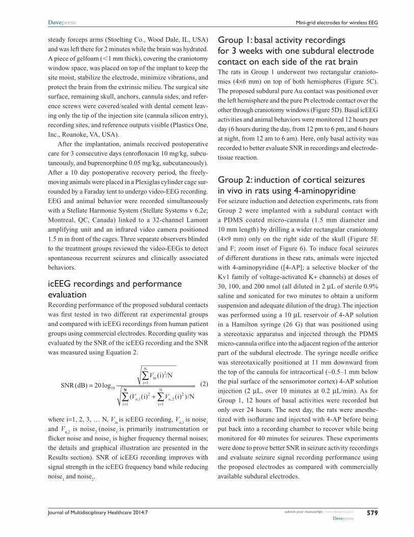
4-aP drug administration and seizure activity recordingAfter the 4-AP injection, the rats were attached to
the video-EEG recording system and various seizure
signals were recorded for ∼40 minutes (Figure 10).
The epileptiform activity induced was characterized
by an initial hypersynchronous brain wave activity fol-
lowed by trains of poly-spikes, with low-amplitude and
low-frequency spike-wave complexes that increased
after the first few minutes. The corresponding convul-
sive behaviors (eg, myoclonus and tonico-clonic) were
ranked with a modified Racine’s scale of 0 to 5 (Table 1)
in Figure 10.23
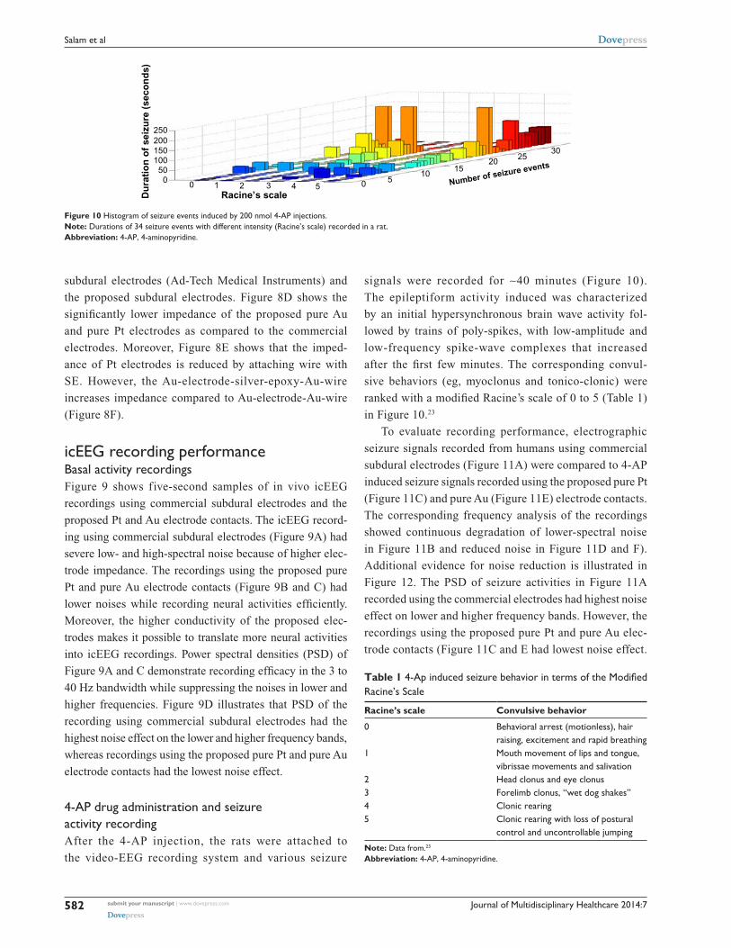
To evaluate recording performance, electrographic
seizure signals recorded from humans using commercial
subdural electrodes (Figure 11A) were compared to 4-AP
induced seizure signals recorded using the proposed pure Pt
(Figure 11C) and pure Au (Figure 11E) electrode contacts.
The corresponding frequency analysis of the recordings
showed continuous degradation of lower-spectral noise
in Figure 11B and reduced noise in Figure 11D and F).
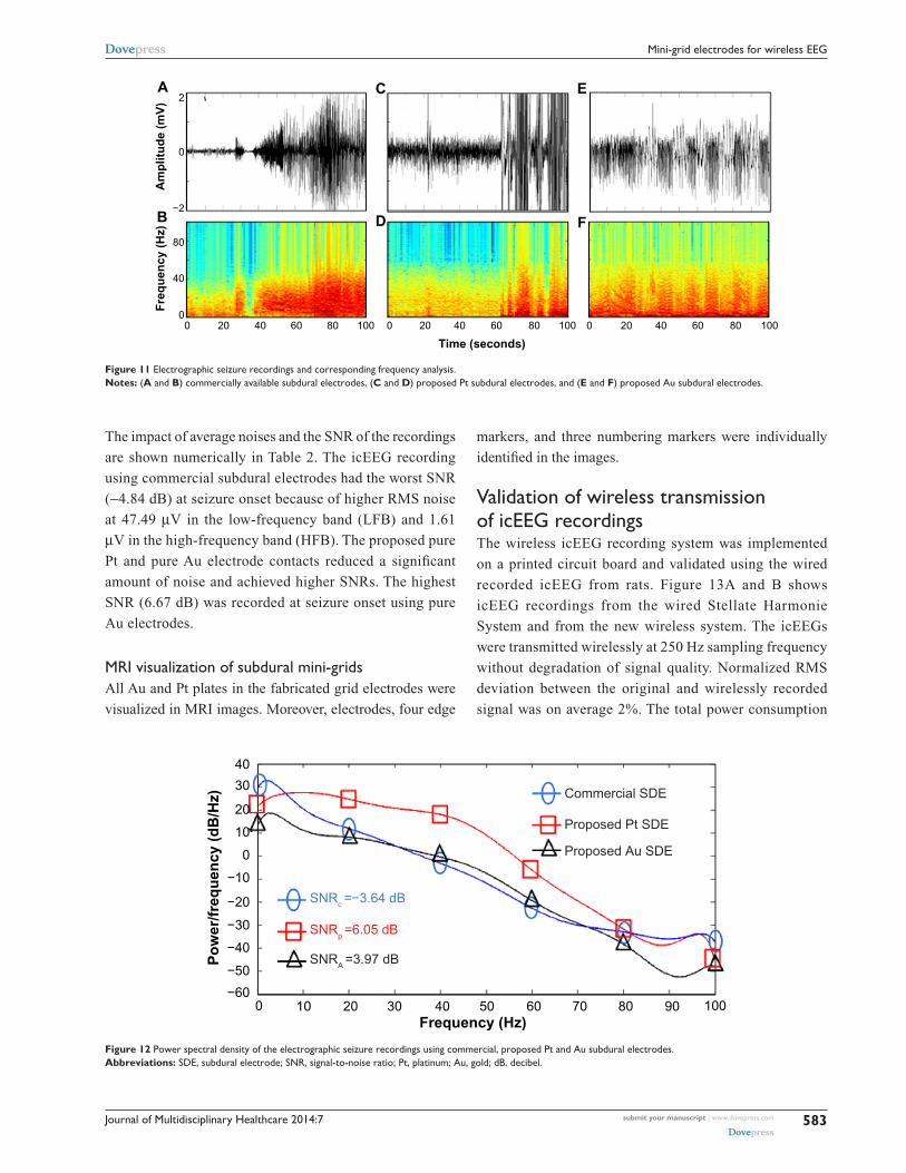
Additional evidence for noise reduction is illustrated in
Figure 12. The PSD of seizure activities in Figure 11A
recorded using the commercial electrodes had highest noise
effect on lower and higher frequency bands. However, the
recordings using the proposed pure Pt and pure Au elec-
trode contacts (Figure 11C and E had lowest noise effect.
0050
100150200250
1 2 3Racine’s scaleD
ura
tio
n o
f se
izu
re (
seco
nd
s)
4 5 0 510
1520
Number of seizure events25
30
Figure 10 Histogram of seizure events induced by 200 nmol 4-aP injections.Note: Durations of 34 seizure events with different intensity (racine’s scale) recorded in a rat.Abbreviation: 4-aP, 4-aminopyridine.
Table 1 4-Ap induced seizure behavior in terms of the Modified racine’s scale
Racine’s scale Convulsive behavior
0 Behavioral arrest (motionless), hair raising, excitement and rapid breathing
1 Mouth movement of lips and tongue, vibrissae movements and salivation
2 Head clonus and eye clonus3 Forelimb clonus, “wet dog shakes”4 clonic rearing5 clonic rearing with loss of postural
control and uncontrollable jumping
Note: Data from.23
Abbreviation: 4-aP, 4-aminopyridine.
Journal of Multidisciplinary Healthcare 2014:7 submit your manuscript | www.dovepress.com
Dovepress
Dovepress
583
Mini-grid electrodes for wireless eeg
The impact of average noises and the SNR of the recordings
are shown numerically in Table 2. The icEEG recording
using commercial subdural electrodes had the worst SNR
(−4.84 dB) at seizure onset because of higher RMS noise
at 47.49 µV in the low-frequency band (LFB) and 1.61
µV in the high-frequency band (HFB). The proposed pure
Pt and pure Au electrode contacts reduced a significant
amount of noise and achieved higher SNRs. The highest
SNR (6.67 dB) was recorded at seizure onset using pure
Au electrodes.
Mri visualization of subdural mini-gridsAll Au and Pt plates in the fabricated grid electrodes were
visualized in MRI images. Moreover, electrodes, four edge
markers, and three numbering markers were individually
identified in the images.
Validation of wireless transmission of iceeg recordingsThe wireless icEEG recording system was implemented
on a printed circuit board and validated using the wired
recorded icEEG from rats. Figure 13A and B shows
icEEG recordings from the wired Stellate Harmonie
System and from the new wireless system. The icEEGs
were transmitted wirelessly at 250 Hz sampling frequency
without degradation of signal quality. Normalized RMS
deviation between the original and wirelessly recorded
signal was on average 2%. The total power consumption
00
40
80
−2
0
2A
B
C
D
E
F
20 40 60 80 100 0 20 40
Time (seconds)
Fre
qu
ency
(H
z)A
mp
litu
de
(mV
)
60 80 100 0 20 40 60 80 100
Figure 11 electrographic seizure recordings and corresponding frequency analysis.Notes: (A and B) commercially available subdural electrodes, (C and D) proposed Pt subdural electrodes, and (E and F) proposed au subdural electrodes.
40
20
30
10
0
−10
−20
−30
Po
wer
/fre
qu
ency
(d
B/H
z)
−40
SNRc =−3.64 dB
SNRp =6.05 dB
SNRA =3.97 dB
Commercial SDE
Proposed Pt SDE
Proposed Au SDE
−50
−600 10 20 30 40 50
Frequency (Hz)60 70 80 90 100
Figure 12 Power spectral density of the electrographic seizure recordings using commercial, proposed Pt and au subdural electrodes.Abbreviations: sDe, subdural electrode; snr, signal-to-noise ratio; Pt, platinum; au, gold; dB, decibel.

Journal of Multidisciplinary Healthcare 2014:7submit your manuscript | www.dovepress.com
Dovepress
Dovepress
584
salam et al
of the wireless recording system was 15 mW. Heat
dissipation resulting in a 10°C temperature increase
is deemed safe for the cortex tissue. This corresponds
to 15 to 80 mW/cm2 power density,24 depending on the
heat conductivity of the device encapsulation materials.
The power density of the device presented herein was
0.57 mW/cm2.
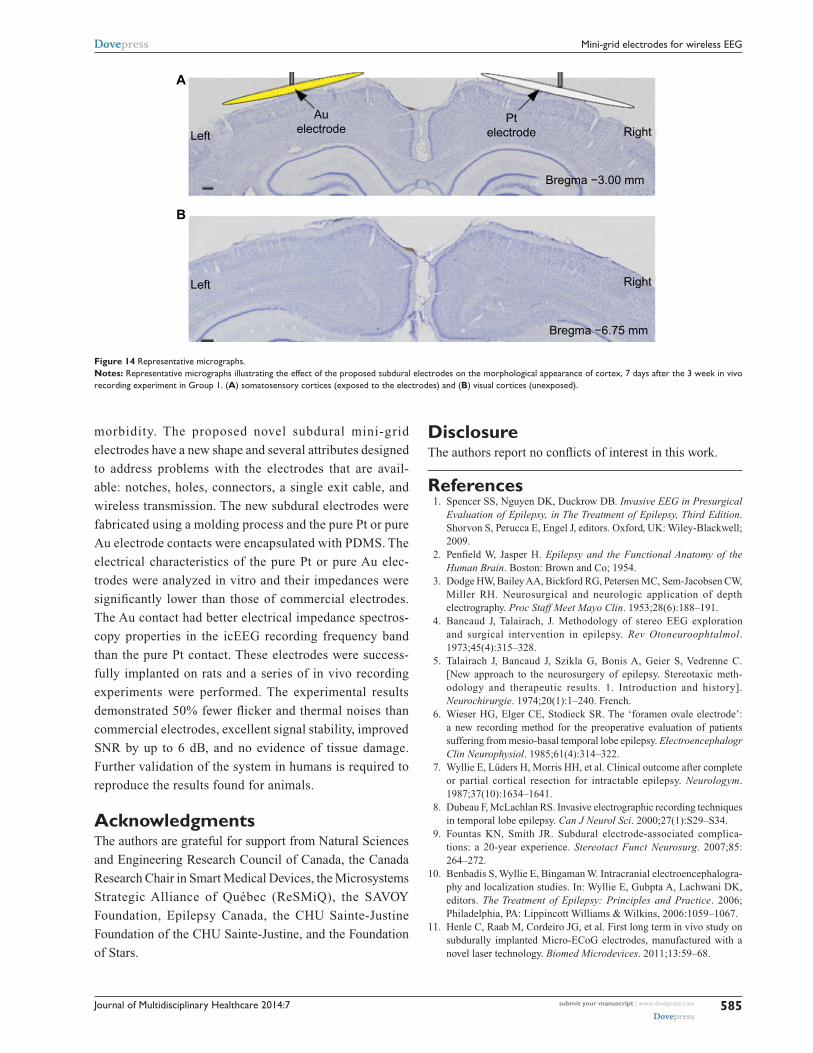
Post iceeg brain histologyHistology showed Nissl substance and labeled cells on the
cerebral cortex. The cytoarchitecture of the somatosen-
sory cortices was similar between both brain hemispheres
underneath the pure Pt (right) and pure Au (left) subdural
electrode contacts in Group 1 rats (Figure 14). The exposed
regions were compared to other sensory regions (not
exposed to electrode contacts) such as the visual cortex.
Clear cytoarchitectonic borders were detected between
the primary and secondary sensory cortices. Neocortical
laminar organization and cellular densities (eg, neurons
and glial cells) did not appear to be altered by the implants.
The rest of the tissues exposed to the electrodes were found
to be normal.25
DiscussionInvasive studies involve implanting intracerebral electrodes
to allow direct EEG recordings from brain and subsequently
provide precise localization of the EZ, which is key to a suc-
cessful epilepsy surgical treatment. Although various kinds
of subdural and depth electrodes are reported in the litera-
ture,11–13 and some of them are commercially available,14 the
proposed mini-grid electrode and wireless recording system
described in this paper have capabilities and characteristics
that make them particularly appropriate for local field poten-
tial and high-frequency oscillation recordings in animals
and humans. A practical grid electrode must satisfy certain
technical (eg, lower impedance and higher SNR) and physi-
ological (eg, biocompatibility, MRI compatible) criteria. The
proposed grid electrodes demonstrated approximately 80-fold
lower impendence and 6 dB higher SNR than the commercial
electrodes evaluated. Moreover, we used electrode contact and
subtract materials, which are widely used in human intrac-
erebral recordings and approved by the US Food and Drug
Administration (FDA) for human implantation. In addition,
these materials are MRI compatible and visible in the MRI
imaging for the post-electrode implantation reconstruction.
After the implantation and recording using the mini-grid
electrode, no abnormalities in the brain tissue were observed.
In addition, the wireless recording system has some impor-
tant features (eg, high resolution, 24-bit analog-to-digital
conversion, 2 kHz sampling rate) that allows recording small
amplitude (1–5 µV) high-frequency oscillations (,500 Hz),
whereas the icEEG recordings digitized with lower bit
precision may result in complete loss of the low-amplitude
high-frequency oscillation.
ConclusionWe present early work on a new intracerebral recording
system to improve localization of the EZ with lower
Table 2 comparative study of average iceeg recordings in vivo
Basal Electrographic seizure
Day Night Seizure onset Seizure
RMS noise (μV)
SNR (dB)
RMS noise (μV)
SNR (dB)
RMS noise (μV)
SNR (dB)
RMS noise (μV)
SNR (dB)
LFB HFB LFB HFB LFB HFB LFB HFB
commercial sDe 47.49 1.618 −4.84 54.25 7.07 −3.06 60.23 3.38 −2.92 47.44 5.12 5.35Proposed Pt electrodes
39.81 6.53 0.22 35.18 9.91 0.16 32.58 14.38 3.12 57.20 12.73 2.37
Proposed au electrodes
22.12 4.23 1.85 21.46 4.44 3.69 55.91 15.81 6.67 75.75 15.78 3.74
Abbreviations: iceeg, intracerebral electroencephalography; rMs, root-mean-square; lFB, low-frequency band; HFB, high-frequency band; snr, signal-to- noise ratio.
AicEEG recorded using wired setup
icEEG recorded using wireless system
0
0
0
Vw
(mV
)V
in (m
V) 1
1
−1
−1
4 8 12Time (seconds)
16 20
B
Figure 13 iceeg recordings.Notes: (A) stellate Harmonie system (wired setup) and (B) wireless system.Abbreviation: iceeg, intracerebral electroencephalography.
Journal of Multidisciplinary Healthcare 2014:7 submit your manuscript | www.dovepress.com
Dovepress
Dovepress
585
Mini-grid electrodes for wireless eeg
morbidity. The proposed novel subdural mini-grid
electrodes have a new shape and several attributes designed
to address problems with the electrodes that are avail-
able: notches, holes, connectors, a single exit cable, and
wireless transmission. The new subdural electrodes were
fabricated using a molding process and the pure Pt or pure
Au electrode contacts were encapsulated with PDMS. The
electrical characteristics of the pure Pt or pure Au elec-
trodes were analyzed in vitro and their impedances were
significantly lower than those of commercial electrodes.
The Au contact had better electrical impedance spectros-
copy properties in the icEEG recording frequency band
than the pure Pt contact. These electrodes were success-
fully implanted on rats and a series of in vivo recording
experiments were performed. The experimental results
demonstrated 50% fewer flicker and thermal noises than
commercial electrodes, excellent signal stability, improved
SNR by up to 6 dB, and no evidence of tissue damage.
Further validation of the system in humans is required to
reproduce the results found for animals.
AcknowledgmentsThe authors are grateful for support from Natural Sciences
and Engineering Research Council of Canada, the Canada
Research Chair in Smart Medical Devices, the Microsystems
Strategic Alliance of Québec (ReSMiQ), the SAVOY
Foundation, Epilepsy Canada, the CHU Sainte-Justine
Foundation of the CHU Sainte-Justine, and the Foundation
of Stars.
DisclosureThe authors report no conflicts of interest in this work.
References 1. Spencer SS, Nguyen DK, Duckrow DB. Invasive EEG in Presurgical
Evaluation of Epilepsy, in The Treatment of Epilepsy, Third Edition. Shorvon S, Perucca E, Engel J, editors. Oxford, UK: Wiley-Blackwell; 2009.
2. Penfield W, Jasper H. Epilepsy and the Functional Anatomy of the Human Brain. Boston: Brown and Co; 1954.
3. Dodge HW, Bailey AA, Bickford RG, Petersen MC, Sem-Jacobsen CW, Miller RH. Neurosurgical and neurologic application of depth electrography. Proc Staff Meet Mayo Clin. 1953;28(6):188–191.
4. Bancaud J, Talairach, J. Methodology of stereo EEG exploration and surgical intervention in epilepsy. Rev Otoneuroophtalmol. 1973;45(4):315–328.
5. Talairach J, Bancaud J, Szikla G, Bonis A, Geier S, Vedrenne C. [New approach to the neurosurgery of epilepsy. Stereotaxic meth-odology and therapeutic results. 1. Introduction and history]. Neurochirurgie. 1974;20(1):1–240. French.
6. Wieser HG, Elger CE, Stodieck SR. The ‘foramen ovale electrode’: a new recording method for the preoperative evaluation of patients suffering from mesio-basal temporal lobe epilepsy. Electroencephalogr Clin Neurophysiol. 1985;61(4):314–322.
7. Wyllie E, Lüders H, Morris HH, et al. Clinical outcome after complete or partial cortical resection for intractable epilepsy. Neurologym. 1987;37(10):1634–1641.
8. Dubeau F, McLachlan RS. Invasive electrographic recording techniques in temporal lobe epilepsy. Can J Neurol Sci. 2000;27(1):S29–S34.
9. Fountas KN, Smith JR. Subdural electrode-associated complica-tions: a 20-year experience. Stereotact Funct Neurosurg. 2007;85: 264–272.
10. Benbadis S, Wyllie E, Bingaman W. Intracranial electroencephalogra-phy and localization studies. In: Wyllie E, Gubpta A, Lachwani DK, editors. The Treatment of Epilepsy: Principles and Practice. 2006; Philadelphia, PA: Lippincott Williams & Wilkins, 2006:1059–1067.
11. Henle C, Raab M, Cordeiro JG, et al. First long term in vivo study on subdurally implanted Micro-ECoG electrodes, manufactured with a novel laser technology. Biomed Microdevices. 2011;13:59–68.
A
Left
Left
Right
Bregma −3.00 mm
Bregma −6.75 mm
Right
Auelectrode
Ptelectrode
B
Figure 14 representative micrographs.Notes: representative micrographs illustrating the effect of the proposed subdural electrodes on the morphological appearance of cortex, 7 days after the 3 week in vivo recording experiment in group 1. (A) somatosensory cortices (exposed to the electrodes) and (B) visual cortices (unexposed).

Journal of Multidisciplinary Healthcare
Publish your work in this journal
Submit your manuscript here: http://www.dovepress.com/journal-of-multidisciplinary-healthcare-journal
The Journal of Multidisciplinary Healthcare is an international, peer-reviewed open-access journal that aims to represent and publish research in healthcare areas delivered by practitioners of different disciplines. This includes studies and reviews conducted by multidisciplinary teams as well as research which evaluates the results or conduct of such teams or
healthcare processes in general. The journal covers a wide range of areas and welcomes submission from practitioners at all levels, from all over the world. The manuscript management system is completely online and includes a very quick and fair peer-review system. Visit http://www.dove-press.com/testimonials.php to read real quotes from published authors.
Journal of Multidisciplinary Healthcare 2014:7submit your manuscript | www.dovepress.com
Dovepress
Dovepress
Dovepress
586
salam et al
12. Guo L, Guvanasen GS, Liu X, Tuthill C, Nichols TR, DeWeerth P. A PDMS-Based Integrated Stretchable Microelectrode Array (isMEA) for Neural and Muscular Surface Interfacing. IEEE Trans Biomed Circuits Syst. 2013;7(1):1–10.
13. Ceyssens F, Kuyck K, Velde G, et al. Resorbable scaffold based chronic neural electrode arrays. Biomed Microdevices. 2014;15(3):481–493.
14. Schendel AA, Thongpang S, Brodnick SK, et al. A cranial window imag-ing method for monitoring vascular growth around chronically implanted micro-ECoG devices. J Neurosci Methods. 2013;218(1):121–130.
15. Ren TL, Yan B, Lin JH, et al. A MEMS-Based Flexible Elec-trode Array Using Composite Substrate. IEEE EDSSC. 2010; pp. 1–6. Available from: http://ieeexplore.ieee.org/xpl/articleDetails.jsp?arnumber=5713778. Accessed August 13, 2014.
16. Merrill DR, Bikson M, Jefferys JGR. Electrical stimulation of excitable tissue: design of efficacious and safe protocols. J Neurosci Methods. 2005;141:171–198.
17. Norlin A, Pan J, Leygraf C. Investigation of interfacial capacitance of Pt, Ti and TiN coated electrodes by electrochemical impedance spec-troscopy. Biomol Eng. 2002;19:67–71.
18. Salam MT, Sawan M, Nguyen DK, Hamoui AA. Epileptic low-voltage fast-activity seizure-onset detector. IEEE BIOCAS. 2009:169–172.
19. Salam MT, Nguyen DK, Sawan M. A Multichannel Intracerebral EEG Monitoring System For Epilepsy Presurgical Evaluation. IEEE CCECE. 2011:169–172.
20. Sawan M, Salam MT, Le Lan J, et al. Wireless recording systems: from non- invasive EEG-NIRS to invasive EEG devices. IEEE Trans Biomed Circuits Syst. 2013;7:2.
21. Lee WS, Lee JK, Lee SA, Kang JK, Ko TS. Complications and results of subdural grid electrode implantation in epilepsy surgery. Surg Neurol. 2000;54(5):346–351.
22. Salam MT, Desgent S, Duss S, Carmant L, Nguyen DK, Sawan M. New subdural electrode contacts for intracerebral electroencephalographic recordings: comparative studies on neural signal recording in vivo. IEEE BIOCAS. 2011:241–244.
23. Racine RJ. Modification of seizure activity by electrical stimulation. II. Motor seizure. Electroencephalogr Clin Neurophysiol. 1972;32: 281–294.
24. Kim S, Tathireddy P, Normann RA, Solzbacher F. Thermal impact of an active 3-D microelectrode array implanted in the brain. IEEE Trans Neural Syst Rehabil Eng. 2007;15(4):493–501.
25. Paxinos G, Watson C. The Rat Brain in Stereotaxis Coordinates. 6th ed. Amsterdam; Boston: Academic Press/Elsevier; 2007.