study the performance of the bell crank lever - ijraset
TRANSCRIPT

6 III March 2018
http://doi.org/10.22214/ijraset.2018.3340
International Journal for Research in Applied Science & Engineering Technology (IJRASET) ISSN: 2321-9653; IC Value: 45.98; SJ Impact Factor: 6.887
Volume 6 Issue III, March 2018- Available at www.ijraset.com
2160 ©IJRASET (UGC Approved Journal): All Rights are Reserved
Study the Performance of the Bell Crank Lever Apparatus
Dr. Ali Hasan1
1Assistant Professor, Department of Mechanical Engineering, Faculty of Engineering & Technology, Jamia Millia Islamia, New Delhi-110025, India,
Abstract: In this paper author determines the clockwise and counter clockwise moments acting on a beam experimentally. If both the values of the moments (clockwise and counter clockwise) are not equal and opposite then the error is determined and author predict the various sources of error in verifying the law of moments. The aim of the paper is to study the performance of the Bell Crank Lever Apparatus used to verify the law of moments. The work is advantageous for Graduate/ post graduate and inventors who are willing to work in the field of mechanical design. Keywords: Couple of Force, Bell crank lever, Load
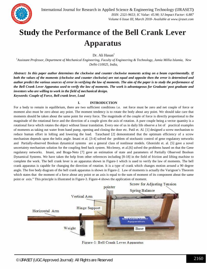
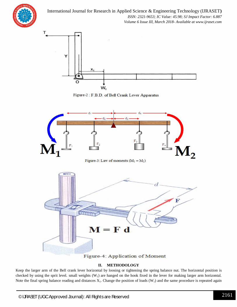
I. INTRODUCTION For a body to remain in equilibrium, there are two sufficient conditions i.e. net force must be zero and net couple of force or moment also must be zero about any point. The moment tendency is to rotate the body about any point. We should take care that moments should be taken about the same point for every force. The magnitude of the couple of force is directly proportional to the magnitude of the rotational force and the direction of a couple gives the axis of rotation. A pure couple being a vector quantity is a rotational force which rotates the object without linear translation. Every one of us in daily life observe a lot of practical examples of moments as taking out water from hand pump, opening and closing the door etc. Patil et. Al. [1] designed a screw mechanism to reduce human effort in lofting and lowering the load. Tarachand [2] demonstrated that the optimum efficiency of a screw mechanism depends upon the helix angle. Imani et al. [3-4] solved the problem of stochastic control of gene regulatory networks and Partially-observed Boolean dynamical systems are a general class of nonlinear models. Ghoreishi et. al. [5] gave a novel uncertainty mechanism solution for the coupling feed back system. Mcclenny, et al.[6] solved the problems based on that the Gene regulatory networks. Imani, and Braga-Neto [7] gave an estimation of state and parameters of Partially Observed Boolean Dynamical Systems. We have taken the help from other references including [8-18] in the field of friction and lifting machine to complete the work. The bell crank lever is an apparatus shown in Figure-1 which is used to verify the law of moments. The bell crank apparatus is capable for changing the direction of rotation. It is a type of crank which changes motion around a 90 degree angle. The free body diagram of the bell crank apparatus is shown in Figure-2. Law of moments is actually the Varignon’s Theorem which states that the moment of a force about any point or an axis is equal to the sum of moment of its component about the same point or axis.” This principle is illustrated in Figure-3. Figure-4 shows the application of moment.
International Journal for Research in Applied Science & Engineering Technology (IJRASET) ISSN: 2321-9653; IC Value: 45.98; SJ Impact Factor: 6.887
Volume 6 Issue III, March 2018- Available at www.ijraset.com
2161 ©IJRASET (UGC Approved Journal): All Rights are Reserved
II. METHODOLOGY Keep the larger arm of the Bell crank lever horizontal by loosing or tightening the spring balance nut. The horizontal position is checked by using the sprit level. small weights (W1) are hanged on the hook fixed in the lever for making larger arm horizontal. Note the final spring balance reading and distances X1. Change the position of loads (W1) and the same procedure is repeated again
International Journal for Research in Applied Science & Engineering Technology (IJRASET) ISSN: 2321-9653; IC Value: 45.98; SJ Impact Factor: 6.887
Volume 6 Issue III, March 2018- Available at www.ijraset.com
2162 ©IJRASET (UGC Approved Journal): All Rights are Reserved
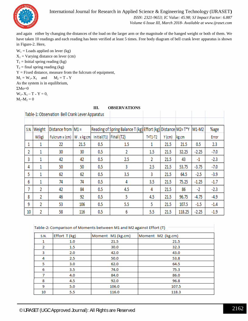
and again either by changing the distances of the load on the larger arm or the magnitude of the hanged weight or both of them. We have taken 10 readings and each reading has been verified at least 5 times. Free body diagram of bell crank lever apparatus is shown in Figure-2. Here, W1 = Loads applied on lever (kg) X1 = Varying distance on lever (cm) T1 = Initial spring reading (kg) T2 = final spring reading (kg) Y = Fixed distance, measure from the fulcrum of equipment, M1 = W1* X1 and M2 = T * Y
As the system is in equilibrium, ΣMo=0 W1* X1 – T * Y = 0, M1-M2 = 0
III. OBSERVATIONS
International Journal for Research in Applied Science & Engineering Technology (IJRASET) ISSN: 2321-9653; IC Value: 45.98; SJ Impact Factor: 6.887
Volume 6 Issue III, March 2018- Available at www.ijraset.com
2163 ©IJRASET (UGC Approved Journal): All Rights are Reserved
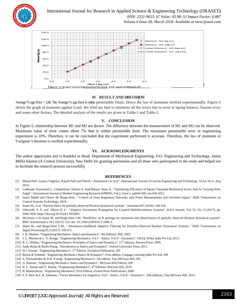
IV. RESULT AND DISCUSSION Average % age Error = 3.46. The Average % age Error is within permissible limits. Hence the law of moments verified experimentally. Figure-5 shows the graph of moments against Load. We tried our best to minimize all the errors due to error in spring balance, human error and some other factors. The detailed analysis of the results are given in Table-1 and Table-2.
V. CONCLUSION In Figure-5, relationship between M1 and M2 are shown. The difference between the measurement of M1 and M2 can be observed. Maximum value of error comes about 7% that is within permissible limit. The maximum permissible error in engineering experiment is 10%. Therefore, it can be concluded that the experiment performed is accurate. Therefore, the law of moments or Varignon’s theorem is verified experimentally.
VI. ACKNOWLEDGMENTS The author appreciates and is thankful to Head, Department of Mechanical Engineering, F/O- Engineering and Technology, Jamia Millia Islamia (A Central University), New Delhi for granting permission and all those who participated in the study and helped me to facilitate the research process successfully.
REFERENCES
[1] Manoj Patil, Gaurav Udgirkar, Rajesh Patil and Nilesh, “Automated Car Jack”, International Journal of Current Engineering and Technology ,Vol.4, No.4, Aug 2014.
[2] Lokhande Tarachand G., Chatpalliwar Ashwin S. And Bhoyar Amar A., “Optimizing Efficiency of Square Threaded Mechanical Screw Jack by Varying Helix Angle”, International Journal of Modern Engineering Research (IJMER), Vol.2, Issue.1, pp504-508, Jan-Feb 2012.
[3] Imani Mahdi and Ulisses M. Braga-Neto, " Control of Gene Regulatory Networks with Noisy Measurements and Uncertain Inputs," IEEE Transactions on Control Systems Technology, 2018.
[4] Imani M., et al. “Particle filters for partially-observed Boolean dynamical systems”. Automatica87 (2018): 238-250. [5] Ghoreishi S. F. and Allaire D. L. "Adaptive Uncertainty Propagation for Coupled Multidisciplinary Systems", AIAA Journal, Vol. 55, No. 11 (2017), pp.
3940-3950. https://doi.org/10.2514/1.J055893 [6] Mcclenny L.D, Imani M. and Braga-Neto UM, “BoolFilter: an R package for estimation and identification of partially observed Boolean dynamical systems”
BMC bioinformatics 18.1 (2017): 519. doi: 10.1186/s12859-017-1886-3. [7] Imani M., and Braga-Neto U.M., " Maximum-Likelihood Adaptive Filtering for Partially-Observed Boolean Dynamical Systems ," IEEE Transactions on
Signal Processing 65.2 (2017): 359-371. [8] I. H. Shames, “Engineering Mechanics: Statics and dynamics”, 4th Editions, PHI, 2002. [9] J. L. Meriam & L. G. Kraige, “Engineering Mechanics, Vol I – Statics, Vol II – Dynamics”, 7th Ed, Wiley India Pvt Ltd, 2013. [10] R. C. Hibbler, “Engineering Mechanics: Principles of Statics and Dynamics”, 11th editions, Pearson Press, 2009. [11] Andy Ruina & Rudra Pratap, “Introduction to Statics and Dynamics”, Oxford University Press, 2011. [12] H.J. Sawant, “Engineering Mechanics”, 2nd Edition, Technical Publication, 201 [13] Boresi & Schmidt, “Engineering Mechanics-Statics & Dynamics”, First edition, Cengage Learning India Pvt Ltd, 200 [14] S. Thimoshenko & D.H. Young, “Engineering Mechanics”, 5th edition, Tata McGraw Hill, 201 [15] A. Nelason ,“Engineering Mechanics: Statics and Dynamics”, McGraw-Hill Edition, 200 [16] K. L. Kumar and V. Kumar, “Engineering Mechanics”, 4th Editions, McGraw Hill, 2010 [17] B. Bhattacharya, “Engineering Mechanics”,First Edition, Oxford Press Publications, 2008 [18] F. P. Beer & E. R. Johnston, “Vector Mechanics for Engineers, Vol I - Statics, Vol II – Dynamics”, 10th Editions, Tata McGraw Hill, 2013.