sid: 22 mid: 128 fmi: 2, 3 & 8 crank speed sensor
TRANSCRIPT
www.TruckFaultCodes.com
Copyright 2017
VOLVO
SID: 22
MID: 128
FMI: 2, 3 & 8
CRANK SPEED SENSOR
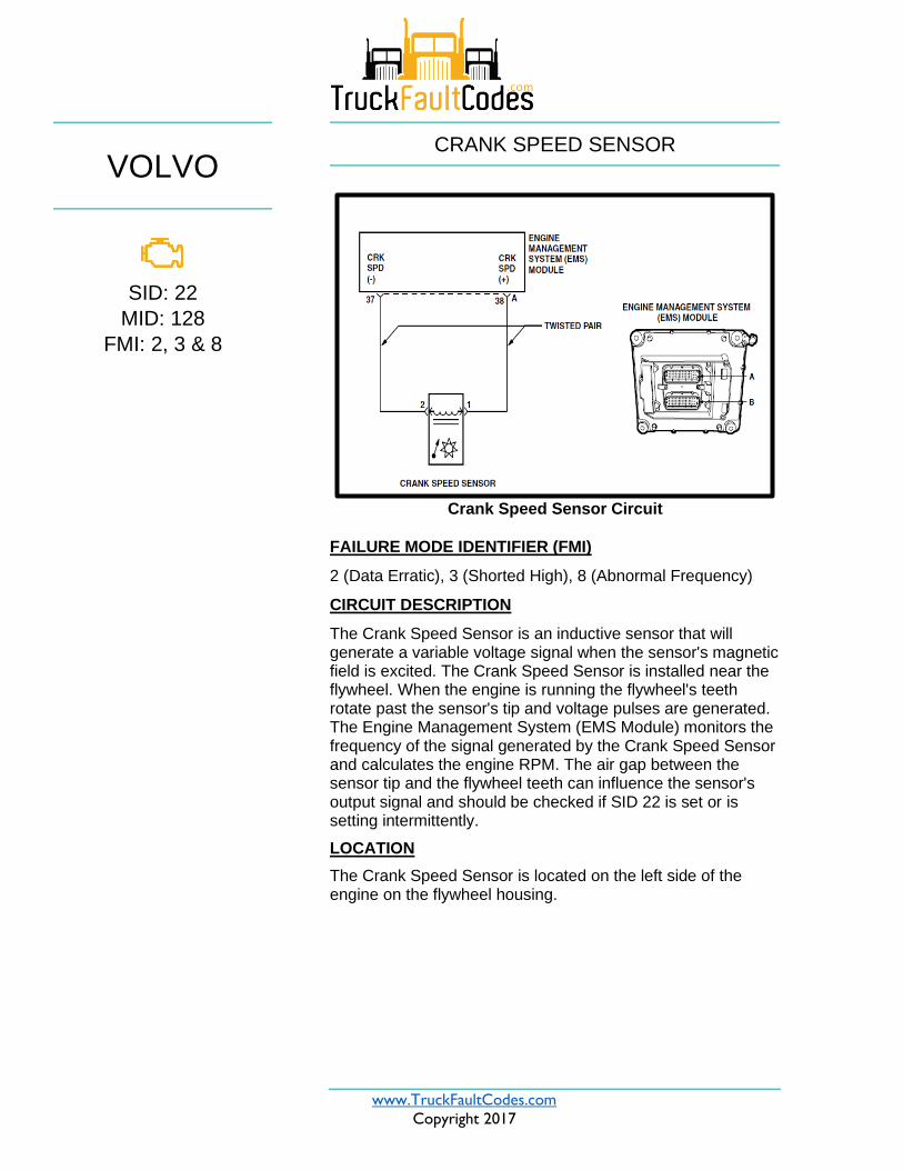
Crank Speed Sensor Circuit
FAILURE MODE IDENTIFIER (FMI)
2 (Data Erratic), 3 (Shorted High), 8 (Abnormal Frequency)
CIRCUIT DESCRIPTION
The Crank Speed Sensor is an inductive sensor that will generate a variable voltage signal when the sensor's magnetic field is excited. The Crank Speed Sensor is installed near the flywheel. When the engine is running the flywheel's teeth rotate past the sensor's tip and voltage pulses are generated. The Engine Management System (EMS Module) monitors the frequency of the signal generated by the Crank Speed Sensor and calculates the engine RPM. The air gap between the sensor tip and the flywheel teeth can influence the sensor's output signal and should be checked if SID 22 is set or is setting intermittently.
LOCATION
The Crank Speed Sensor is located on the left side of the engine on the flywheel housing.

www.TruckFaultCodes.com
Copyright 2017
2
CODE SETTING CONDITIONS
If the Engine Management System (EMS) Module calculates a significant difference between the Crank Speed Sensor input signal and the CAM Speed Sensor input signal, the EMS Module will turn on the Electronic Malfunction Lamp (EML) and SID 22 will set. If the engine speed signals agree, the fault will become inactive. The engine and tachometer will continue to operate when SID 22 is set because the EMS Module will use the CAM Speed Sensor signal to calculate engine speed.
NOTE: Electrical problems can cause this fault to be
generated, and electrical diagnostics are provided in this
section. Mechanical problems can also cause temporary or
permanent speed signal errors. After all electrical possibilities
have been ruled out, check mechanical conditions that could
cause vibration or signal errors. Such conditions include but
are not limited to:
− Faulty Engine Vibration Damper
− Contaminated sensor tips
− Missing or chipped gear teeth
− Improperly installed Flywheel Ring Gear
− Incorrect Flywheel
− Contaminated Flywheel Ring Gear
− Improperly adjusted sensor
− Excessive Driveshaft backlash
− Improperly balanced engine components.
NOTE: FMI 3 will only be seen as active with the engine OFF.
In all cases the SID 22 FMI will change to 2 when the engine
is started.
www.TruckFaultCodes.com
Copyright 2017
3
TROUBLESHOOTING STEPS
Test 1 – Checking for SID 22.
1. Verify that SID 22 is set.
Is SID 22 set?
Yes – If SID 22 is set, go to “Test 2 — Checking for
an Open or Short in the Sensor”.
No – If SID 22 is not set, wiggle the harness and
connectors to try to set the code.
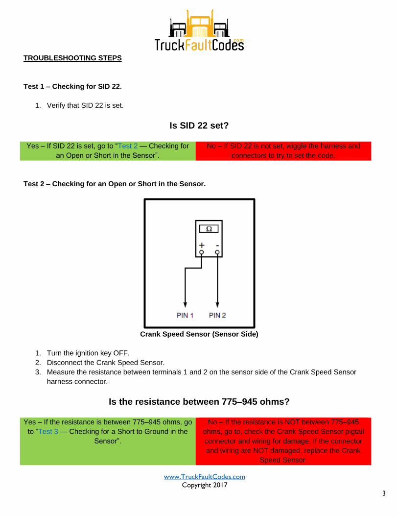
Test 2 – Checking for an Open or Short in the Sensor.
Crank Speed Sensor (Sensor Side)
1. Turn the ignition key OFF.
2. Disconnect the Crank Speed Sensor.
3. Measure the resistance between terminals 1 and 2 on the sensor side of the Crank Speed Sensor
harness connector.
Is the resistance between 775–945 ohms?
Yes – If the resistance is between 775–945 ohms, go
to “Test 3 — Checking for a Short to Ground in the
Sensor”.
No – If the resistance is NOT between 775–945
ohms, go to, check the Crank Speed Sensor pigtail
connector and wiring for damage. If the connector
and wiring are NOT damaged, replace the Crank
Speed Sensor.
www.TruckFaultCodes.com
Copyright 2017
4
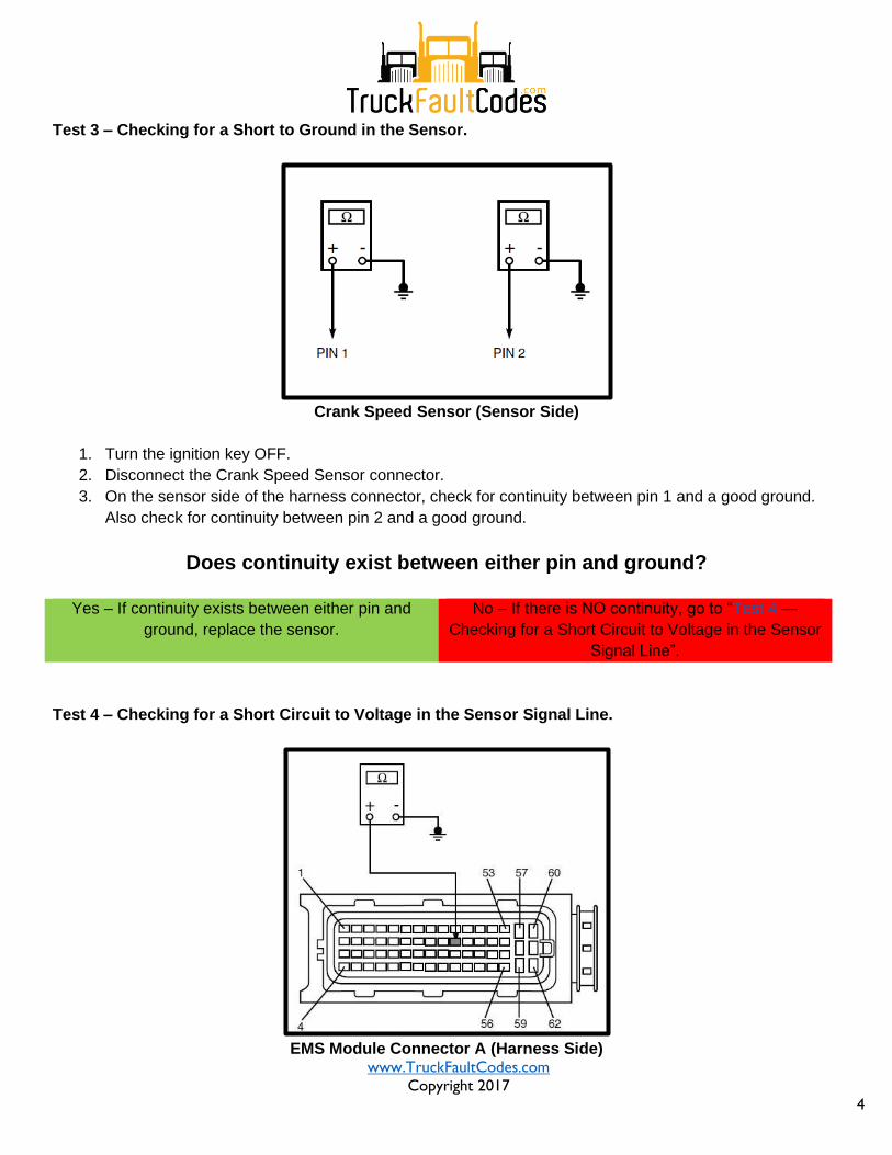
Test 3 – Checking for a Short to Ground in the Sensor.
Crank Speed Sensor (Sensor Side)
1. Turn the ignition key OFF.
2. Disconnect the Crank Speed Sensor connector.
3. On the sensor side of the harness connector, check for continuity between pin 1 and a good ground.
Also check for continuity between pin 2 and a good ground.
Does continuity exist between either pin and ground?
Yes – If continuity exists between either pin and
ground, replace the sensor.
No – If there is NO continuity, go to “Test 4 —
Checking for a Short Circuit to Voltage in the Sensor
Signal Line”.
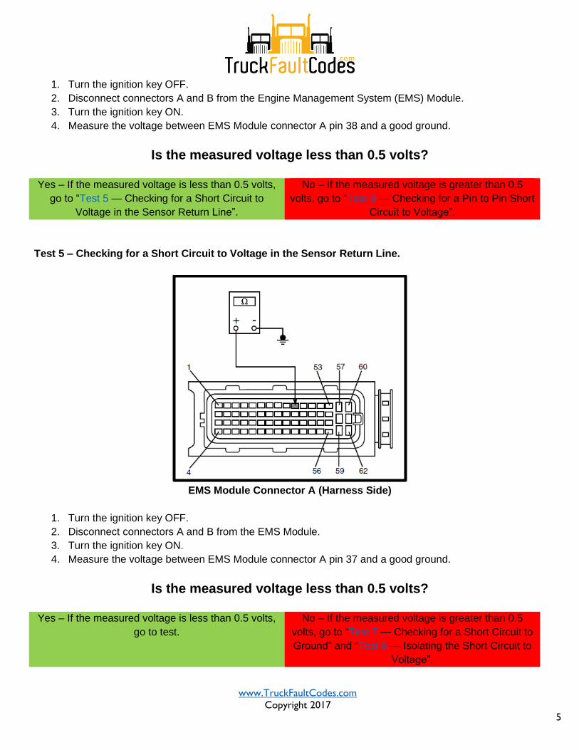
Test 4 – Checking for a Short Circuit to Voltage in the Sensor Signal Line.
EMS Module Connector A (Harness Side)
www.TruckFaultCodes.com
Copyright 2017
5
1. Turn the ignition key OFF.
2. Disconnect connectors A and B from the Engine Management System (EMS) Module.
3. Turn the ignition key ON.
4. Measure the voltage between EMS Module connector A pin 38 and a good ground.
Is the measured voltage less than 0.5 volts?
Yes – If the measured voltage is less than 0.5 volts,
go to “Test 5 — Checking for a Short Circuit to
Voltage in the Sensor Return Line”.
No – If the measured voltage is greater than 0.5
volts, go to “Test 6 — Checking for a Pin to Pin Short
Circuit to Voltage”.
Test 5 – Checking for a Short Circuit to Voltage in the Sensor Return Line.
EMS Module Connector A (Harness Side)
1. Turn the ignition key OFF.
2. Disconnect connectors A and B from the EMS Module.
3. Turn the ignition key ON.
4. Measure the voltage between EMS Module connector A pin 37 and a good ground.
Is the measured voltage less than 0.5 volts?
Yes – If the measured voltage is less than 0.5 volts,
go to test.
No – If the measured voltage is greater than 0.5
volts, go to “Test 7 — Checking for a Short Circuit to
Ground” and “Test 8 — Isolating the Short Circuit to
Voltage”.
www.TruckFaultCodes.com
Copyright 2017
6
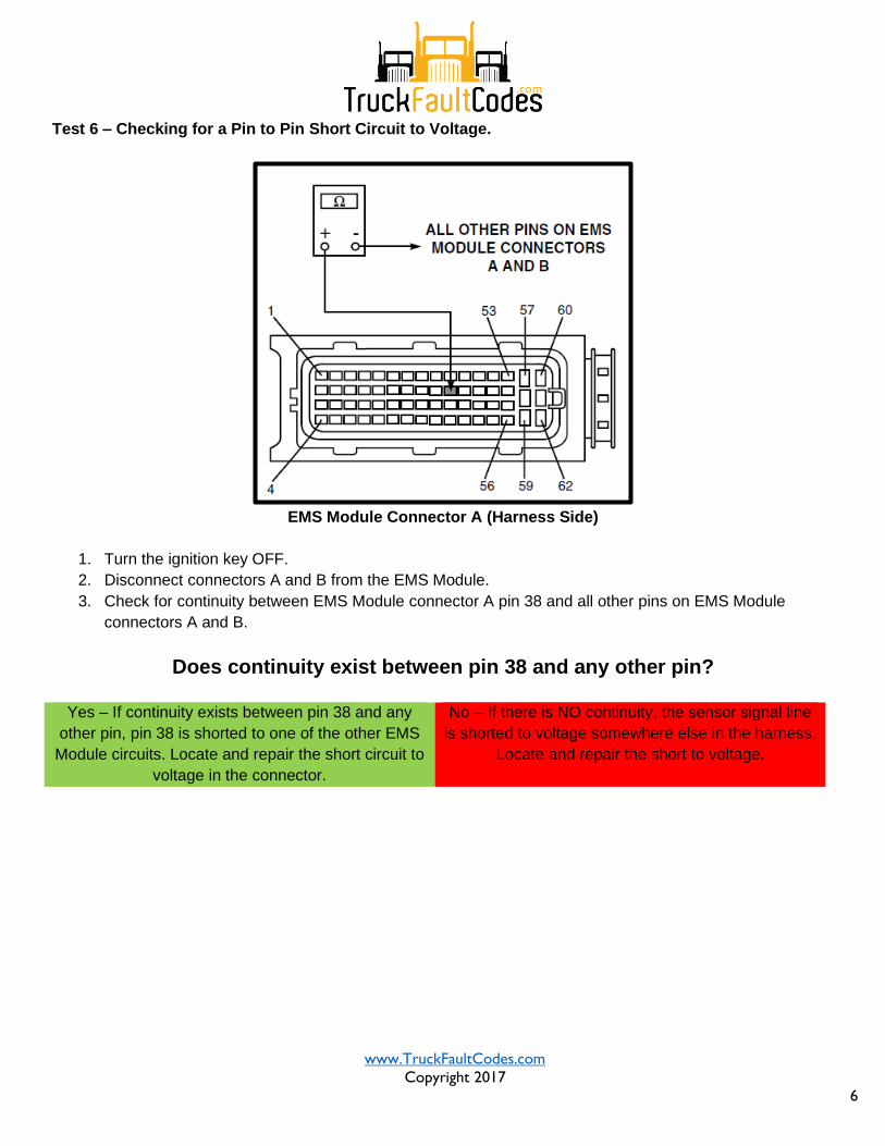
Test 6 – Checking for a Pin to Pin Short Circuit to Voltage.
EMS Module Connector A (Harness Side)
1. Turn the ignition key OFF.
2. Disconnect connectors A and B from the EMS Module.
3. Check for continuity between EMS Module connector A pin 38 and all other pins on EMS Module
connectors A and B.
Does continuity exist between pin 38 and any other pin?
Yes – If continuity exists between pin 38 and any
other pin, pin 38 is shorted to one of the other EMS
Module circuits. Locate and repair the short circuit to
voltage in the connector.
No – If there is NO continuity, the sensor signal line
is shorted to voltage somewhere else in the harness.
Locate and repair the short to voltage.
www.TruckFaultCodes.com
Copyright 2017
7
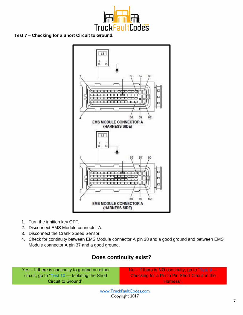
Test 7 – Checking for a Short Circuit to Ground.
1. Turn the ignition key OFF.
2. Disconnect EMS Module connector A.
3. Disconnect the Crank Speed Sensor.
4. Check for continuity between EMS Module connector A pin 38 and a good ground and between EMS
Module connector A pin 37 and a good ground.
Does continuity exist?
Yes – If there is continuity to ground on either
circuit, go to “Test 10 — Isolating the Short
Circuit to Ground”.
No – If there is NO continuity, go to “Test 9 —
Checking for a Pin to Pin Short Circuit in the
Harness”.
www.TruckFaultCodes.com
Copyright 2017
8
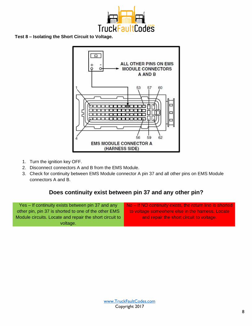
Test 8 – Isolating the Short Circuit to Voltage.
1. Turn the ignition key OFF.
2. Disconnect connectors A and B from the EMS Module.
3. Check for continuity between EMS Module connector A pin 37 and all other pins on EMS Module
connectors A and B.
Does continuity exist between pin 37 and any other pin?
Yes – If continuity exists between pin 37 and any
other pin, pin 37 is shorted to one of the other EMS
Module circuits. Locate and repair the short circuit to
voltage.
No – If NO continuity exists, the return line is shorted
to voltage somewhere else in the harness. Locate
and repair the short circuit to voltage.
www.TruckFaultCodes.com
Copyright 2017
9
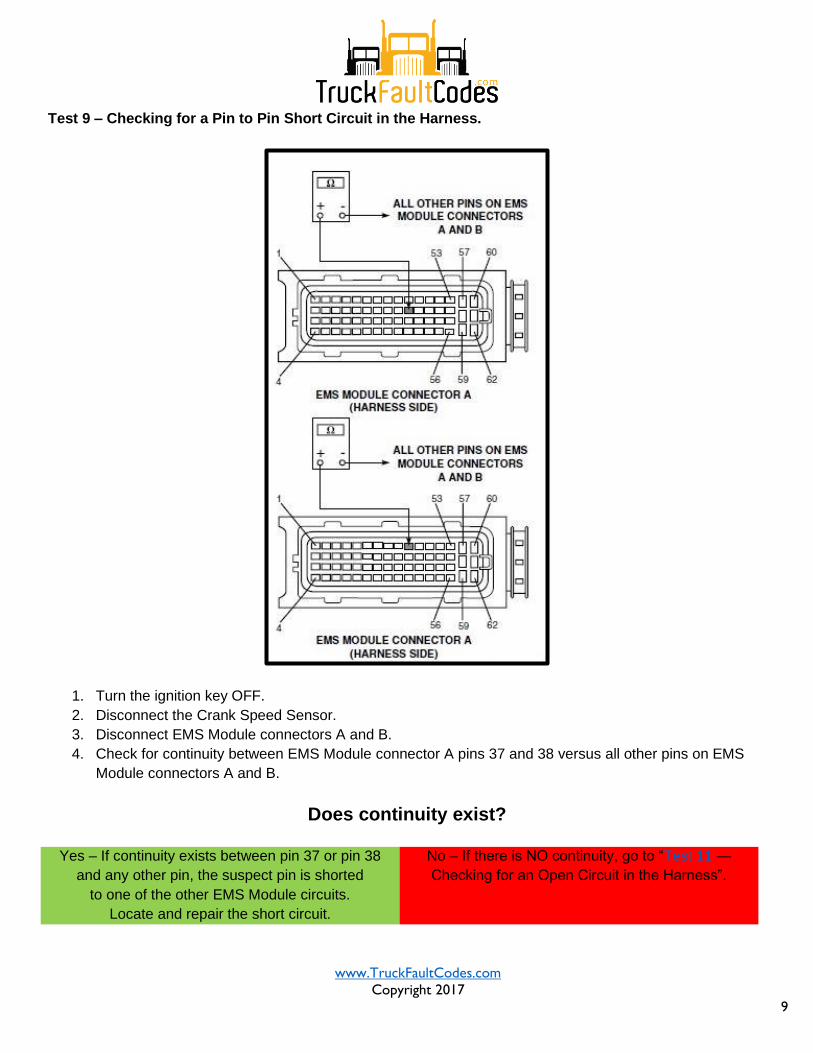
Test 9 – Checking for a Pin to Pin Short Circuit in the Harness.
1. Turn the ignition key OFF.
2. Disconnect the Crank Speed Sensor.
3. Disconnect EMS Module connectors A and B.
4. Check for continuity between EMS Module connector A pins 37 and 38 versus all other pins on EMS
Module connectors A and B.
Does continuity exist?
Yes – If continuity exists between pin 37 or pin 38
and any other pin, the suspect pin is shorted
to one of the other EMS Module circuits.
Locate and repair the short circuit.
No – If there is NO continuity, go to “Test 11 —
Checking for an Open Circuit in the Harness”.
www.TruckFaultCodes.com
Copyright 2017
10
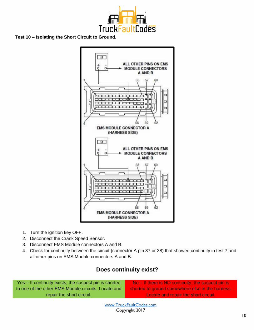
Test 10 – Isolating the Short Circuit to Ground.
1. Turn the ignition key OFF.
2. Disconnect the Crank Speed Sensor.
3. Disconnect EMS Module connectors A and B.
4. Check for continuity between the circuit (connector A pin 37 or 38) that showed continuity in test 7 and
all other pins on EMS Module connectors A and B.
Does continuity exist?
Yes – If continuity exists, the suspect pin is shorted
to one of the other EMS Module circuits. Locate and
repair the short circuit.
No – If there is NO continuity, the suspect pin is
shorted to ground somewhere else in the harness.
Locate and repair the short circuit.
www.TruckFaultCodes.com
Copyright 2017
11
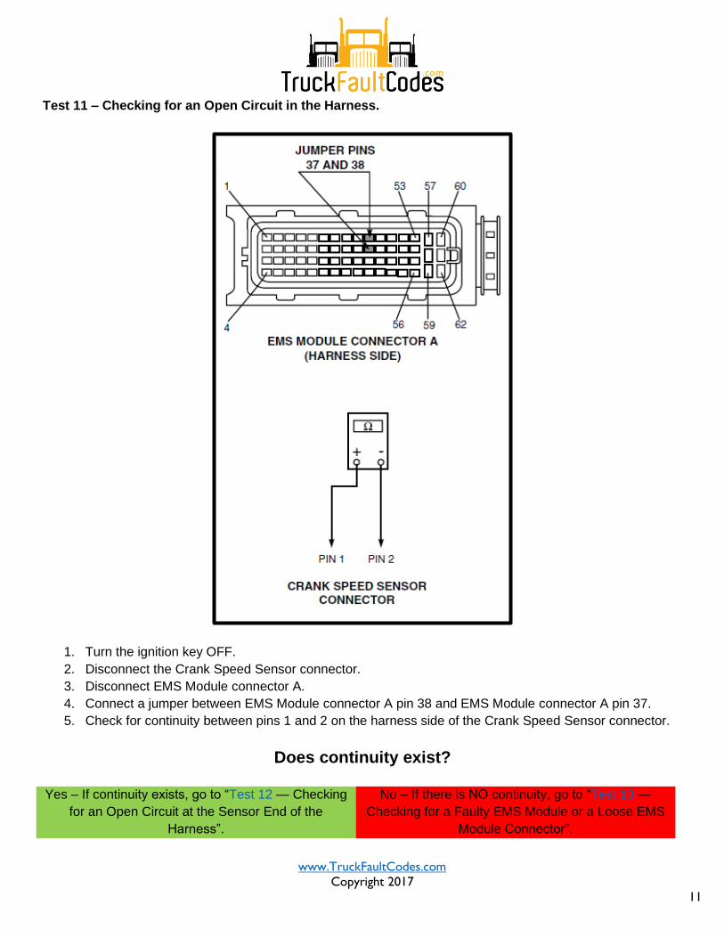
Test 11 – Checking for an Open Circuit in the Harness.
1. Turn the ignition key OFF.
2. Disconnect the Crank Speed Sensor connector.
3. Disconnect EMS Module connector A.
4. Connect a jumper between EMS Module connector A pin 38 and EMS Module connector A pin 37.
5. Check for continuity between pins 1 and 2 on the harness side of the Crank Speed Sensor connector.
Does continuity exist?
Yes – If continuity exists, go to “Test 12 — Checking
for an Open Circuit at the Sensor End of the
Harness”.
No – If there is NO continuity, go to “Test 13 —
Checking for a Faulty EMS Module or a Loose EMS
Module Connector”.
www.TruckFaultCodes.com
Copyright 2017
12
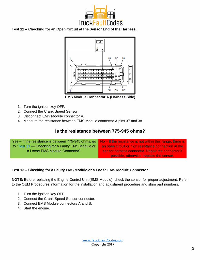
Test 12 – Checking for an Open Circuit at the Sensor End of the Harness.
EMS Module Connector A (Harness Side)
1. Turn the ignition key OFF.
2. Connect the Crank Speed Sensor.
3. Disconnect EMS Module connector A.
4. Measure the resistance between EMS Module connector A pins 37 and 38.
Is the resistance between 775-945 ohms?
Yes – If the resistance is between 775-945 ohms, go
to “Test 13 — Checking for a Faulty EMS Module or
a Loose EMS Module Connector”.
No – If the resistance is not within this range, there is
an open circuit or high resistance connection at the
sensor harness connector. Repair the connector if
possible, otherwise, replace the sensor.
Test 13 – Checking for a Faulty EMS Module or a Loose EMS Module Connector.
NOTE: Before replacing the Engine Control Unit (EMS Module), check the sensor for proper adjustment. Refer
to the OEM Procedures information for the installation and adjustment procedure and shim part numbers.
1. Turn the ignition key OFF.
2. Connect the Crank Speed Sensor connector.
3. Connect EMS Module connectors A and B.
4. Start the engine.

www.TruckFaultCodes.com
Copyright 2017
13
Is SID 22 still active?
Yes – If SID 22 is still active, check the Engine
Management System (EMS Module) and connectors
for dirt, loose or broken pins, or repairable damage.
If no problems are evident, or they are not
repairable, replace the EMS Module and retest the
system.
No – If SID 22 is NOT active, the diagnostic
procedures have corrected the problem. Check all
connectors to ensure proper connections.