storage battery maintenance and principles
TRANSCRIPT

Storage Battery Maintenance and Principles Course No: E08-004
Credit: 8 PDH
A. Bhatia
Continuing Education and Development, Inc.22 Stonewall CourtWoodcliff Lake, NJ 07677
P: (877) [email protected]
FACILITIES INSTRUCTIONS,STANDARDS, AND TECHNIQUES
VOLUME 3-6
STORAGE BATTERYMAINTENANCE AND PRINCIPLES
Internet version of This Manual Created June, 1998
HYDROELECTRIC RESEARCH AND TECHNICAL SERVICES GROUP
The Appearance of the Internet Version of This Manual May Differ from the Original but the Content does not
UNITED STATES DEPARTMENT OF THE INTERIORBUREAU OF RECLAMATION
DENVER, COLORADO
TABLE OF CONTENTSSection Page
Flooded, wet cell, lead-acid battery maintenance schedule (last updated 12/31/97) . . . . . . . . . . . . . . . . 11 Condensed instructions: lead-acid batteries (last updated 12/31/97) . . . . . . . . . . . . . . . . . . . . . . . . . 2
1.1 Purpose . . . . . . . . . . . . . . . . . . . . . . . . . . . . . . . . . . . . . . . . . . . . . . . . . . . . . . . . . . . . . . 21.2 Battery charging and specific gravity temperature correction . . . . . . . . . . . . . . . . . . . . 21.3 Voltage readings . . . . . . . . . . . . . . . . . . . . . . . . . . . . . . . . . . . . . . . . . . . . . . . . . . . . . . . 41.4 Specific gravity readings . . . . . . . . . . . . . . . . . . . . . . . . . . . . . . . . . . . . . . . . . . . . . . . . . 51.5 Temperature readings . . . . . . . . . . . . . . . . . . . . . . . . . . . . . . . . . . . . . . . . . . . . . . . . . . . 61.6 Connection resistance readings . . . . . . . . . . . . . . . . . . . . . . . . . . . . . . . . . . . . . . . . . . . 61.7 Visual inspections . . . . . . . . . . . . . . . . . . . . . . . . . . . . . . . . . . . . . . . . . . . . . . . . . . . . . . 81.8 Battery care . . . . . . . . . . . . . . . . . . . . . . . . . . . . . . . . . . . . . . . . . . . . . . . . . . . . . . . . . . . 81.9 Chargers . . . . . . . . . . . . . . . . . . . . . . . . . . . . . . . . . . . . . . . . . . . . . . . . . . . . . . . . . . . . . 81.10 Records . . . . . . . . . . . . . . . . . . . . . . . . . . . . . . . . . . . . . . . . . . . . . . . . . . . . . . . . . . . . . . . . . 91.11 Battery troubles summarized . . . . . . . . . . . . . . . . . . . . . . . . . . . . . . . . . . . . . . . . . . . . . . . 101.12 Recommended actions . . . . . . . . . . . . . . . . . . . . . . . . . . . . . . . . . . . . . . . . . . . . . . . . . . . . 111.13 Cell replacement . . . . . . . . . . . . . . . . . . . . . . . . . . . . . . . . . . . . . . . . . . . . . . . . . . . . . . . . . 12
2 Lead-acid battery principles (last updated 12/31/97) . . . . . . . . . . . . . . . . . . . . . . . . . . . . . . . . . . . . . 122.1 Purpose . . . . . . . . . . . . . . . . . . . . . . . . . . . . . . . . . . . . . . . . . . . . . . . . . . . . . . . . . . . . . 122.2 Full charge . . . . . . . . . . . . . . . . . . . . . . . . . . . . . . . . . . . . . . . . . . . . . . . . . . . . . . . . . . 122.3 Appearance of normal cells . . . . . . . . . . . . . . . . . . . . . . . . . . . . . . . . . . . . . . . . . . . . . . 122.4 Chemical changes . . . . . . . . . . . . . . . . . . . . . . . . . . . . . . . . . . . . . . . . . . . . . . . . . . . . . 132.5 Internal self-discharge and effect of impurities on floating voltage . . . . . . . . . . . . . . . 132.6 Temperature characteristics . . . . . . . . . . . . . . . . . . . . . . . . . . . . . . . . . . . . . . . . . . . . . 142.7 Proper amount of charge . . . . . . . . . . . . . . . . . . . . . . . . . . . . . . . . . . . . . . . . . . . . . . . 142.8 High-rate overcharging . . . . . . . . . . . . . . . . . . . . . . . . . . . . . . . . . . . . . . . . . . . . . . . . . 152.9 Low-rate overcharging . . . . . . . . . . . . . . . . . . . . . . . . . . . . . . . . . . . . . . . . . . . . . . . . . 152.10 Undercharging . . . . . . . . . . . . . . . . . . . . . . . . . . . . . . . . . . . . . . . . . . . . . . . . . . . . . . . . . . 152.11 Over discharge . . . . . . . . . . . . . . . . . . . . . . . . . . . . . . . . . . . . . . . . . . . . . . . . . . . . . . . . . . 162.12 Sedimentation . . . . . . . . . . . . . . . . . . . . . . . . . . . . . . . . . . . . . . . . . . . . . . . . . . . . . . . . . . . 162.13 Replacement water . . . . . . . . . . . . . . . . . . . . . . . . . . . . . . . . . . . . . . . . . . . . . . . . . . . . . . . 162.14 Water replacement rate for lead-antimony cells . . . . . . . . . . . . . . . . . . . . . . . . . . . . . . . . . 162.15 Water replacement rate for lead-calcium cells . . . . . . . . . . . . . . . . . . . . . . . . . . . . . . . . . . 172.16 Water replacement for lead-selenium cells . . . . . . . . . . . . . . . . . . . . . . . . . . . . . . . . . . . . . 172.17 Adjusting specific gravity . . . . . . . . . . . . . . . . . . . . . . . . . . . . . . . . . . . . . . . . . . . . . . . . . . . 172.18 Hydrometer readings . . . . . . . . . . . . . . . . . . . . . . . . . . . . . . . . . . . . . . . . . . . . . . . . . . . . . . 172.19 Constant voltage charging . . . . . . . . . . . . . . . . . . . . . . . . . . . . . . . . . . . . . . . . . . . . . . . . . . 182.20 Battery life for different types and services . . . . . . . . . . . . . . . . . . . . . . . . . . . . . . . . . . . . . 182.21 Cleanliness . . . . . . . . . . . . . . . . . . . . . . . . . . . . . . . . . . . . . . . . . . . . . . . . . . . . . . . . . . . . . 182.22 Internal shorts . . . . . . . . . . . . . . . . . . . . . . . . . . . . . . . . . . . . . . . . . . . . . . . . . . . . . . . . . . . 182.23 Normal sulfate and over sulfation . . . . . . . . . . . . . . . . . . . . . . . . . . . . . . . . . . . . . . . . . . . . 192.24 Elimination of over sulfation . . . . . . . . . . . . . . . . . . . . . . . . . . . . . . . . . . . . . . . . . . . . . . . . 192.25 Water treatment for over sulfation . . . . . . . . . . . . . . . . . . . . . . . . . . . . . . . . . . . . . . . . . . . 20
3 Battery testing (last updated 12/31/97) . . . . . . . . . . . . . . . . . . . . . . . . . . . . . . . . . . . . . . . . . . . . . . . 213.1 Acceptance testing . . . . . . . . . . . . . . . . . . . . . . . . . . . . . . . . . . . . . . . . . . . . . . . . . . . . 213.2 Capacity tests to determine replacement . . . . . . . . . . . . . . . . . . . . . . . . . . . . . . . . . . . 21
4 Optional instructions lead-calcium batteries (last updated 12/31/97) . . . . . . . . . . . . . . . . . . . . . . . . 224.1 Float charge . . . . . . . . . . . . . . . . . . . . . . . . . . . . . . . . . . . . . . . . . . . . . . . . . . . . . . . . . 224.2 Initial charge . . . . . . . . . . . . . . . . . . . . . . . . . . . . . . . . . . . . . . . . . . . . . . . . . . . . . . . . . 22
i
TABLE OF CONTENTSCCCONTINUED
Section Page
4.3 Voltage readings . . . . . . . . . . . . . . . . . . . . . . . . . . . . . . . . . . . . . . . . . . . . . . . . . . . . . . 224.4 Specific gravity readings . . . . . . . . . . . . . . . . . . . . . . . . . . . . . . . . . . . . . . . . . . . . . . . . 234.5 Heavy discharge . . . . . . . . . . . . . . . . . . . . . . . . . . . . . . . . . . . . . . . . . . . . . . . . . . . . . . 234.6 Water replacement . . . . . . . . . . . . . . . . . . . . . . . . . . . . . . . . . . . . . . . . . . . . . . . . . . . . 23
Valve regulated lead-acid battery (gel cell) maintenance schedule (last updated12/31/97) . . . . . . . . . . . . . . . . . . . . . . . . . . . . . . . . . . . . . . . . . . . . . . . . . . . . . . . . . . . . . . . . . . . . . 24
5 Condensed instructions—valve regulated lead-acid batteries (gel cells) (last updated12/31/97) . . . . . . . . . . . . . . . . . . . . . . . . . . . . . . . . . . . . . . . . . . . . . . . . . . . . . . . . . . . . . . . . . . . . . 255.1 General . . . . . . . . . . . . . . . . . . . . . . . . . . . . . . . . . . . . . . . . . . . . . . . . . . . . . . . . . . . . . 255.2 Float charge . . . . . . . . . . . . . . . . . . . . . . . . . . . . . . . . . . . . . . . . . . . . . . . . . . . . . . . . . 255.3 Equalizing charge . . . . . . . . . . . . . . . . . . . . . . . . . . . . . . . . . . . . . . . . . . . . . . . . . . . . . 265.4 Charger . . . . . . . . . . . . . . . . . . . . . . . . . . . . . . . . . . . . . . . . . . . . . . . . . . . . . . . . . . . . . 265.5 Battery maintenance . . . . . . . . . . . . . . . . . . . . . . . . . . . . . . . . . . . . . . . . . . . . . . . . . . . 265.6 Visual inspections . . . . . . . . . . . . . . . . . . . . . . . . . . . . . . . . . . . . . . . . . . . . . . . . . . . . . . . . 265.7 Voltage readings . . . . . . . . . . . . . . . . . . . . . . . . . . . . . . . . . . . . . . . . . . . . . . . . . . . . . . 275.8 Temperature readings . . . . . . . . . . . . . . . . . . . . . . . . . . . . . . . . . . . . . . . . . . . . . . . . . . 275.9 Connection resistance . . . . . . . . . . . . . . . . . . . . . . . . . . . . . . . . . . . . . . . . . . . . . . . . . 285.10 Internal resistance . . . . . . . . . . . . . . . . . . . . . . . . . . . . . . . . . . . . . . . . . . . . . . . . . . . . . . . 285.11 Testing . . . . . . . . . . . . . . . . . . . . . . . . . . . . . . . . . . . . . . . . . . . . . . . . . . . . . . . . . . . . . . . . . 29
Vented nickel cadmium battery maintenance schedule (last updated 12/31/97) . . . . . . . . . . . . . . . . . . 31
6 Vented nickel cadmium battery principles (last updated 12/31/97) . . . . . . . . . . . . . . . . . . . . . . . . . . 326.1 General . . . . . . . . . . . . . . . . . . . . . . . . . . . . . . . . . . . . . . . . . . . . . . . . . . . . . . . . . . . . . 326.2 Description . . . . . . . . . . . . . . . . . . . . . . . . . . . . . . . . . . . . . . . . . . . . . . . . . . . . . . . . . . 326.3 Chemical reactions . . . . . . . . . . . . . . . . . . . . . . . . . . . . . . . . . . . . . . . . . . . . . . . . . . . . 326.4 Upon installation . . . . . . . . . . . . . . . . . . . . . . . . . . . . . . . . . . . . . . . . . . . . . . . . . . . . . 336.5 Charging . . . . . . . . . . . . . . . . . . . . . . . . . . . . . . . . . . . . . . . . . . . . . . . . . . . . . . . . . . . . 336.6 Voltage readings . . . . . . . . . . . . . . . . . . . . . . . . . . . . . . . . . . . . . . . . . . . . . . . . . . . . . . 346.7 Temperature readings . . . . . . . . . . . . . . . . . . . . . . . . . . . . . . . . . . . . . . . . . . . . . . . . . . 356.8 Visual inspections . . . . . . . . . . . . . . . . . . . . . . . . . . . . . . . . . . . . . . . . . . . . . . . . . . . . . 356.9 Battery discharge testing . . . . . . . . . . . . . . . . . . . . . . . . . . . . . . . . . . . . . . . . . . . . . . . . 356.10 Electrolyte . . . . . . . . . . . . . . . . . . . . . . . . . . . . . . . . . . . . . . . . . . . . . . . . . . . . . . . . . . . . . . 366.11 Electrolyte level . . . . . . . . . . . . . . . . . . . . . . . . . . . . . . . . . . . . . . . . . . . . . . . . . . . . . . . . . . 376.12 Specific gravity readings . . . . . . . . . . . . . . . . . . . . . . . . . . . . . . . . . . . . . . . . . . . . . . . . . . . 376.13 Electrolyte renewal . . . . . . . . . . . . . . . . . . . . . . . . . . . . . . . . . . . . . . . . . . . . . . . . . . . . . . . 386.14 General care . . . . . . . . . . . . . . . . . . . . . . . . . . . . . . . . . . . . . . . . . . . . . . . . . . . . . . . . . . . . 396.15 Battery records . . . . . . . . . . . . . . . . . . . . . . . . . . . . . . . . . . . . . . . . . . . . . . . . . . . . . . . . . . 396.16 Wall card records . . . . . . . . . . . . . . . . . . . . . . . . . . . . . . . . . . . . . . . . . . . . . . . . . . . . . . . . 39
7 Batteries for microwave and VHF radio equipment (last updated 12/31/97) . . . . . . . . . . . . . . . . . . . 397.1 Lead-acid batteries . . . . . . . . . . . . . . . . . . . . . . . . . . . . . . . . . . . . . . . . . . . . . . . . . . . . 397.2 Nickel-cadmium batteries . . . . . . . . . . . . . . . . . . . . . . . . . . . . . . . . . . . . . . . . . . . . . . . 40
8 Battery safety (last updated 12/31/97) . . . . . . . . . . . . . . . . . . . . . . . . . . . . . . . . . . . . . . . . . . . . . . . . 408.1 Explosive hazard . . . . . . . . . . . . . . . . . . . . . . . . . . . . . . . . . . . . . . . . . . . . . . . . . . . . . . 408.2 Electrolyte hazard . . . . . . . . . . . . . . . . . . . . . . . . . . . . . . . . . . . . . . . . . . . . . . . . . . . . . 41
ii
8.3 Flame arresters purpose and cleaning . . . . . . . . . . . . . . . . . . . . . . . . . . . . . . . . . . . . . 41
Section Page
8.4 Ventilation . . . . . . . . . . . . . . . . . . . . . . . . . . . . . . . . . . . . . . . . . . . . . . . . . . . . . . . . . . 418.5 Battery rooms . . . . . . . . . . . . . . . . . . . . . . . . . . . . . . . . . . . . . . . . . . . . . . . . . . . . . . . . 448.6 Safety meetings . . . . . . . . . . . . . . . . . . . . . . . . . . . . . . . . . . . . . . . . . . . . . . . . . . . . . . . 44
9 Battery charging equipment (last updated 12/31/97) . . . . . . . . . . . . . . . . . . . . . . . . . . . . . . . . . . . . . 459.1 Motor-generator sets . . . . . . . . . . . . . . . . . . . . . . . . . . . . . . . . . . . . . . . . . . . . . . . . . . . 459.2 Static rectifier chargers . . . . . . . . . . . . . . . . . . . . . . . . . . . . . . . . . . . . . . . . . . . . . . . . 48
10 Replacement storage battery sizing (last updated 12/31/97) . . . . . . . . . . . . . . . . . . . . . . . . . . . . . . 49
11 Standards (last updated 12/31/97) . . . . . . . . . . . . . . . . . . . . . . . . . . . . . . . . . . . . . . . . . . . . . . . . . . 49
TABLES
Table
1 Flooded, wet cell, lead-acid battery maintenance schedule . . . . . . . . . . . . . . . . . . . . . . . . . . . . . 1 2 Common voltage ranges . . . . . . . . . . . . . . . . . . . . . . . . . . . . . . . . . . . . . . . . . . . . . . . . . . . . . . . 22 3 Valve regulated lead-acid battery maintenance schedule . . . . . . . . . . . . . . . . . . . . . . . . . . . . . 24 4 Vented nickel cadmium battery maintenance schedule . . . . . . . . . . . . . . . . . . . . . . . . . . . . . . 31
FIGURES
Figure
1 Water consumption for lead-acid battery sizes and types . . . . . . . . . . . . . . . . . . . . . . . . . . . . . 65 2 Placement of meter probes for connection resistance measurements . . . . . . . . . . . . . . . . . . . . . 7 3 Percent capacity of batteries with pasted and plante´ type plates for various
discharge rates . . . . . . . . . . . . . . . . . . . . . . . . . . . . . . . . . . . . . . . . . . . . . . . . . . . . . . . . . . . . . . 67 4 Effect of concentration of electrolyte on cell capacity . . . . . . . . . . . . . . . . . . . . . . . . . . . . . . . . 69 5 Final voltage at various rates after charge is fully completed . . . . . . . . . . . . . . . . . . . . . . . . . . 71 6 Percent local action in 1.280 electrolyte versus specific gravity of electrolyte . . . . . . . . . . . . . . 73 7 Approximate variation of local action in lead-acid storage cells with changes in
specific gravity of electrolyte and changes in temperature . . . . . . . . . . . . . . . . . . . . . . . . . . . . 73 8 Approximate variation of capacity with temperature in lead-acid chloride-
accumulatortype storage cells . . . . . . . . . . . . . . . . . . . . . . . . . . . . . . . . . . . . . . . . . . . . . . . . . . . . . . . . . . . . 75
9 Typical recharge curves at constant voltages following 100-percent discharges . . . . . . . . . . . . 77 10 Voltage probe placement for nickel-cadmium cells with different type connectors . . . . . . . . . 79
iii
TABLE OF CONTENTSCCCONTINUED
REPORT FORMS
Form Page
POM-133A Flooded lead-acid battery maintenance report (last updated 12/31/97) . . . . . . . . . . . . 51POM-133B Valve regulated lead-acid battery maintenance report (last updated
12/31/97) . . . . . . . . . . . . . . . . . . . . . . . . . . . . . . . . . . . . . . . . . . . . . . . . . . . . . . . . . . . 53POM-133C Nickel-cadmium battery maintenance report (last updated 12/31/97) . . . . . . . . . . . . . 55POM-134A Flooded lead acid batter connection resistance annual report
(last updated 12/31/97) . . . . . . . . . . . . . . . . . . . . . . . . . . . . . . . . . . . . . . . . . . . . . . . . 57POM-134B Valve regulated lead-acid battery connection and internal resistance
annual report (last updated 12/31/97) . . . . . . . . . . . . . . . . . . . . . . . . . . . . . . . . . . . . . 59POM-157 Lead-acid storage battery data (last updated 12/31/97) . . . . . . . . . . . . . . . . . . . . . 61POM-159 Nickel cadmium storage battery data (last updated 12/31/97) . . . . . . . . . . . . . . . . 63
iv
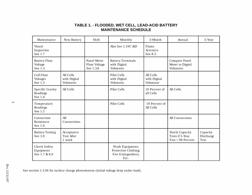
TABLE 1. - FLOODED, WET CELL, LEAD-ACID BATTERYMAINTENANCE SCHEDULE
1
Rev.12/31/97
Maintenance New Battery Shift Monthly 3-Month Annual 5-Year
Visual Also See 1.10C &D Flame Inspection Arresters See 1.7 See 8.3
Battery Float Panel Meter Battery Terminals Compare Panel Voltage Float Voltage with Digital Meter to Digital See 1.3 See 1.3A Voltmeter Voltmeter
Cell Float All Cells Pilot Cells All Cells Voltages with Digital with Digital with Digital See 1.3 Voltmeter Voltmeter Voltmeter
Specific Gravity All Cells Pilot Cells 10 Percent of All Cells Readings all Cells See 1.4
Temperature Pilot Cells 10 Percent of Readings All Cells See 1.5
Connection All All Connections Resistance Connections See 1.6
Battery Testing Acceptance Yearly Capacity Capacity See 3.0 Test After Tests if 5-Year Discharge
1 week Test <90 Percent Test
Check Safety Wash Equipment; Equipment Protective Clothing; See 1.7 & 8.0 Fire Extinguishers,
Etc.
See section 1.11H for surface charge phenomenon (initial voltage drop under load).
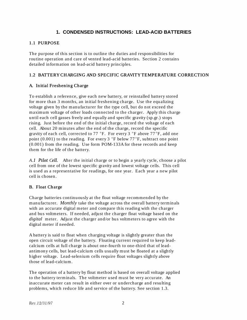
1. CONDENSED INSTRUCTIONS: LEAD-ACID BATTERIES
E1.1 PURPOS11. PURPOSE
The purpose of this section is to outline the duties and responsibilities for routine operation and care of vented lead-acid batteries. Section 2 contains detailed information on lead-acid battery principles.
1.21.2 BATTERY CHARGING AND SPECIFIC GRAVITY TEMPERATURE CORRECTIONBATTERY CHARGING AND SPECIFIC GRAVITY TEMPERATURE CORRECTION
A.A. Initial Freshening ChargeInitial Freshening Charge
To establish a reference, give each new battery, or reinstalled battery stored for more than 3 months, an initial freshening charge. Use the equalizing voltage given by the manufacturer for the type cell, but do not exceed the maximum voltage of other loads connected to the charger. Apply this charge until each cell gasses freely and equally and specific gravity (sp.gr.) stops rising. Just before the end of the initial charge, record the voltage of each cell. About 20 minutes after the end of the charge, record the specific gravity of each cell, corrected to 77 EF. For every 3 EF above 77EF, add one point (0.001) to the reading. For every 3 EF below 77EF, subtract one point (0.001) from the reading. Use form POM-133A for these records and keep them for the life of the battery.
—ell.CPilot.1AA.1 Pilot Cell.—After the initial charge or to begin a yearly cycle, choose a pilot cell from one of the lowest specific gravity and lowest voltage cells. This cell is used as a representative for readings, for one year. Each year a new pilot cell is chosen.
eB. Float Charg.B Float Charge
Charge batteries continuously at the float voltage recommended by the manufacturer. Monthlyy take the voltage across the overall battery terminals with an accurate digital meter and compare this reading with the charger and bus voltmeters. If needed, adjust the charger float voltage based on the digital meter. Adjust the charger and/or bus voltmeters to agree with the digital meter if needed.
A battery is said to float when charging voltage is slightly greater than the open circuit voltage of the battery. Floating current required to keep lead-calcium cells at full charge is about one-fourth to one-third that of lead-antimony cells, but lead-calcium cells usually must be floated at a slightly higher voltage. Lead-selenium cells require float voltages slightly above those of lead-calcium.
The operation of a battery by float method is based on overall voltage applied to the battery terminals. The voltmeter used must be very accurate. An inaccurate meter can result in either over or undercharge and resulting problems, which reduce life and service of the battery. See section 1.3.
Rev.12/31/97 2
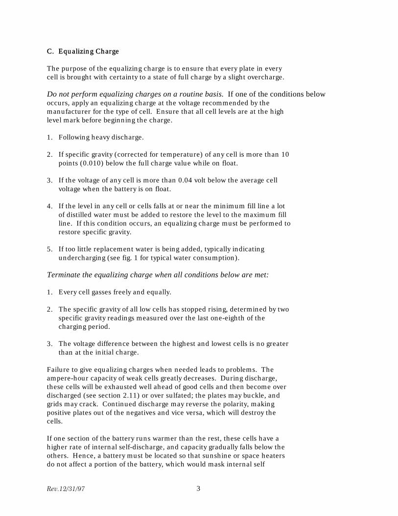
C.C. Equalizing ChargeEqualizing Charge
The purpose of the equalizing charge is to ensure that every plate in every cell is brought with certainty to a state of full charge by a slight overcharge.
Do not perform equalizing charges on a routine basis. If one of the conditions below occurs, apply an equalizing charge at the voltage recommended by the manufacturer for the type of cell. Ensure that all cell levels are at the high level mark before beginning the charge.
1. Following heavy discharge.
2. If specific gravity (corrected for temperature) of any cell is more than 10 points (0.010) below the full charge value while on float.
3. If the voltage of any cell is more than 0.04 volt below the average cell voltage when the battery is on float.
4. If the level in any cell or cells falls at or near the minimum fill line a lot of distilled water must be added to restore the level to the maximum fill line. If this condition occurs, an equalizing charge must be performed to restore specific gravity.
5. If too little replacement water is being added, typically indicating undercharging (see fig. 1 for typical water consumption).
Terminate the equalizing charge when all conditions below are met:
1. Every cell gasses freely and equally.
2. The specific gravity of all low cells has stopped rising, determined by two specific gravity readings measured over the last one-eighth of the charging period.
3. The voltage difference between the highest and lowest cells is no greater than at the initial charge.
Failure to give equalizing charges when needed leads to problems. The ampere-hour capacity of weak cells greatly decreases. During discharge, these cells will be exhausted well ahead of good cells and then become over discharged (see section 2.11) or over sulfated; the plates may buckle, and grids may crack. Continued discharge may reverse the polarity, making positive plates out of the negatives and vice versa, which will destroy the cells.
If one section of the battery runs warmer than the rest, these cells have a higher rate of internal self-discharge, and capacity gradually falls below the others. Hence, a battery must be located so that sunshine or space heaters do not affect a portion of the battery, which would mask internal self
Rev.12/31/97 3

discharge temperature increases.
Rev.12/31/97 4
D.D. Unattended StationsUnattended Stations
The equalizing charge may be terminated automatically by a timer. Use the manufacturer’s recommended charge time for the cell type. Set the timer to switch off the equalizing charge and to reconnect the float charge. In the event that the manufacturer does not provide a recommended charge time, 3 days (72 hours) may be used as the charge time.
A "check charge" for batteries at unattended locations may be used to determine if equalization is necessary. With a "check charge,” the battery is placed on charge at the equalizing rate. After allowing 15 or 20 minutes for the rate to stabilize, the voltages of individual cells are measured. If the highest and lowest cell voltages (while on charge at the equalizing rate) differ by no more than 0.04 volt, the battery does not require equalizing. The battery should be equalized if the voltage differences exceed 0.04 volt. Use a digital meter accurate to 0.01 volt. The test described above is effective in determining equality of cell charge. However, the test cannot be substituted for a hydrometer in determining state of charge. All cells must be within 5°F, the reason is described in paragraph 2.6, and the temperature must not be below 55 °F.
1.31.3. VOLTAGE READINGSVOLTAGE READINGS
Voltage readings should be taken in accordance with the following instructions. NNote: Accurate voltmeters are critical for extending battery life. Provide a digital voltmeter accurate to 0.01 volt reserved only for station battery duty and calibrate it or send it out for calibration at least once a year. This voltmeter must be treated with extra care; do not use a shop meter or electrician’s general-use meter for battery voltages.
A.A. Each Shift (Attended Stations) or DuringEach Shift (Attended Stations) or During Routine Inspections (Unattended Stations)Routine Inspections (Unattended Stations)
Check the voltmeter on the control panel to determine if the battery is being charged at the proper voltage. Adjust the battery charging voltage if necessary.
B.B. When Taps Are ChangedWhen Taps Are Changed
Check the voltage on the control panel when taps are changed on power or station-service transformers. Adjust the battery charging voltage if necessary.
C.C. During Equalizing ChargeDuring Equalizing Charge
Just before terminating the equalizing charge, measure the voltages of the highest voltage cell and the lowest voltage cell of the battery to the nearest 0.01 volt with an accurate digital voltmeter. The equalizing charge should be continued if the voltage difference between the two cells is more than that recorded for the initial charge.
Rev.12/31/97 5
D.D. MonthlyMonthly
With the charger in service, check the overall float voltage across the battery terminals with an accurate digital meter and record on form POM-133A.
E.E. MonthlyMonthly
Check the pilot cell float voltage with an accurate digital voltmeter and record on form POM-133A.
F.F. QuarterlyQuarterly
Check the float voltage on all individual cells to the nearest 0.01 volt with an accurate digital voltmeter. Take these readings as rapidly as possible and record them on form POM-133A. At the end of the yearly cycle, use these readings to determine the pilot cells for the next year.
1.41.4 SPECIFIC GRAVITY READINGSSPECIFIC GRAVITY READINGS
Specific gravity readings of vented lead-acid batteries must be taken in accordance with the following instructions. Note: All specific gravity readings must be corrected to 77EF before recording (see 2.18). Do not attempt to take any specific gravity reading after adding water to a cell. The electrolyte takes several hours to mix after water is added.
A.A. MonthlyMonthly
Take the specific gravity reading of the pilot cell and record it on form POM133A.
B.B. QuarterlyQuarterly
Take specific gravity readings of 10 percent of the total number of cells and record them on form POM-133A. Rotate these cells so that readings are taken on different cells each quarter.
C.C. AnnuallyAnnually
Take specific gravity readings of every cell and record them on form POM133A.
D.D. After Equalizing ChargeAfter Equalizing Charge
About 15 minutes after heavy gassing stops, take the specific gravity readings of every cell and record them on form POM-133A. If two cells with the lowest specific gravity (checked over the last one-eighth of the charging period) have not stopped rising, continue the equalizing charge.
Rev.12/31/97 6
1.51.5 TEMPERATURE READINGSTEMPERATURE READINGS
All cells of a battery should be at the same ambient temperature. Heat sources such as sunlight, portable heaters, etc. must be blocked so they do not raise the temperature of individual cells. Record the room ambient temperature before cell temperatures are taken.
Note: An accurate infrared (IR) camera may be used for temperatures; however, the camera calibration must be checked at least once each year. If possible, take the annual temperature readings of the cells just after camera calibration. If the temperature spread of the cells exceeds 5 °F (i.e., upper rows are warmer) the room ventilation may be inadequate.
A.A. MonthlyMonthly
Record the pilot cell temperatures on form POM-133A.
B.B. QuarterlyQuarterly
Record temperature readings of 10 percent of all the cells; rotate the subject cells each quarter.
C.C. AnnuallyAnnually
If an accurate IR camera is available, take the temperature of the battery connections during a load or discharge test, i.e., while current is flowing. If one or more of the connections are loose or dirty, their temperatures will be higher than the other connections.
1.61.6 CONNECTION RESISTANCE READINGSCONNECTION RESISTANCE READINGS
A.A. After InstallationAfter Installation
Using an accurate micro-ohm meter, record the resistance of each connection on form POM-134A. The readings should be on the order of a few micro-ohms (less than 100). Record the readings as a baseline on form POM-134A. For additional information see IEEE 450-1995—Maintenance, Testing , and Replacement of Vented Lead-acid Batteries, Annex D and F. See below for detailed instructions.
B.B. AnnuallyAnnually
Repeat resistance checks of the connections checked in step A above and compare values. If any connection resistance has increased more than 20 percent, clean, apply no-ox grease, retorque the connections, and retest. Fill out both “as found” and “as left” columns on form POM-134A.
Rev.12/31/97 7
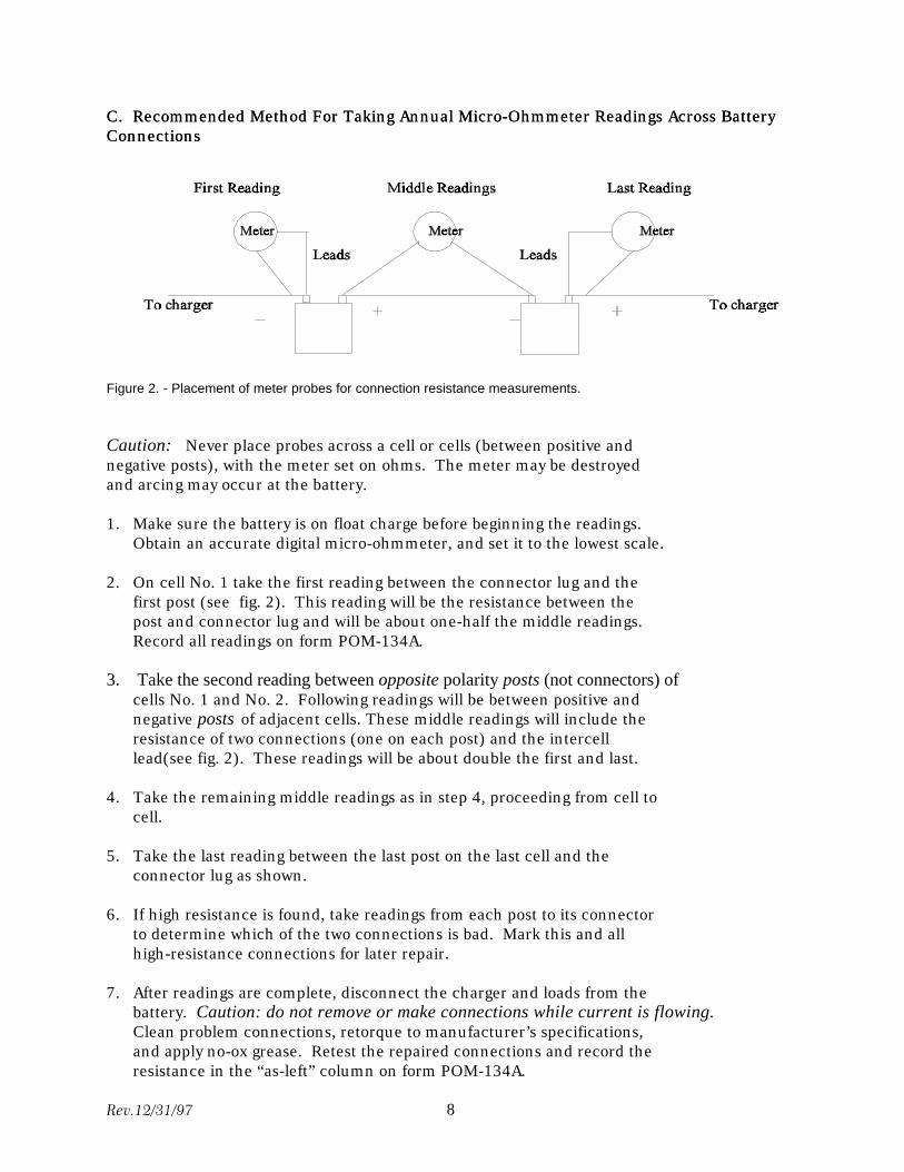
C.C. Recommended Method For Taking Annual Micro-Ohmmeter Readings Across BatteryRecommended Method For Taking Annual Micro-Ohmmeter Readings Across BatteryConnectionsConnections
Figure 2. - Placement of meter probes for connection resistance measurements.
Caution: Never place probes across a cell or cells (between positive and negative posts), with the meter set on ohms. The meter may be destroyed and arcing may occur at the battery.
1. Make sure the battery is on float charge before beginning the readings. Obtain an accurate digital micro-ohmmeter, and set it to the lowest scale.
2. On cell No. 1 take the first reading between the connector lug and the first post (see fig. 2). This reading will be the resistance between the post and connector lug and will be about one-half the middle readings. Record all readings on form POM-134A.
3. Take the second reading between opposite polarity posts (not connectors) of cells No. 1 and No. 2. Following readings will be between positive andnegative posts of adjacent cells. These middle readings will include theresistance of two connections (one on each post) and the intercelllead(see fig. 2). These readings will be about double the first and last.
4. Take the remaining middle readings as in step 4, proceeding from cell to cell.
5. Take the last reading between the last post on the last cell and the connector lug as shown.
6. If high resistance is found, take readings from each post to its connector to determine which of the two connections is bad. Mark this and all high-resistance connections for later repair.
7. After readings are complete, disconnect the charger and loads from the battery. Caution: do not remove or make connections while current is flowing. Clean problem connections, retorque to manufacturer’s specifications, and apply no-ox grease. Retest the repaired connections and record the resistance in the “as-left” column on form POM-134A.
Rev.12/31/97 8
1.71.7 VISUAL INSPECTIONSVISUAL INSPECTIONS
Visual inspections are made to assess the general condition of the battery, battery room, and safety equipment. See below and section 1.10 and record on form 133-A.
A.A. MonthlyMonthly
Check for general cleanliness of the battery, mounting rack, and battery room. Check for electrolyte leaks and cracks in cells, and take corrective action if any are found. Check for corrosion at terminals, connectors, racks, and cabinets. Check the ambient temperature and make sure ventilation devices (fans and vents) are operable. Check all the electrolyte levels and correct if necessary.
Check for availability and condition of all safety equipment, gloves, aprons, face shields, etc. (see section 8). Check for a full gallon of labeled neutralizing solution, and operability of eyewash station or portable eyewash equipment. Check for operation and cleanliness of body wash station. Check for a class C fire extinguisher and check that it has been inspected and tested according to schedule. Check for availability of insulated tools and utensils so short circuits can be avoided. Check the hydrometer for cleanliness and cracking of rubber parts.
1.81.8 BATTERY CAREBATTERY CARE
A.A. Adjustment of Specific GravityAdjustment of Specific Gravity
Do not add or remove acid in any cell except when following instructions in paragraph 2.17.
B.B. TemperatureTemperature
Never intentionally allow electrolyte temperature to exceed 100 EF.
C.C. CleanlinessCleanliness
Keep the battery room or cabinet clean and well ventilated. Keep cells, especially the tops, clean, dry, and free of electrolyte and corrosion residue.
D.D. Spilled ElectrolyteSpilled Electrolyte
At each battery room or cabinet, provide a labeled gallon jar of solution consisting of 1 pound baking soda to 1 gallon of water. Neutralize spilled electrolyte with soda solution, rinse with water, and wipe dry. Do not allow any solution to enter the cells. Keep vent plugs tight and gas vents open. Any missing or worn vent plug gaskets should be replaced.
1.91.9 CHARGERSCHARGERS
Rev.12/31/97 9
Chargers serve two important functions. The main function is to provide dc station power and to keep the battery charged. The second function is to be able to replace the battery if the need arises. Two main types available are silicon-controlled rectifier (SCR) and ferro-resonant. The two types differ greatly. SCR chargers consist of a transformer with an SCR bridge and filtering. All control and protection in these chargers is electronic. These chargers are usually the cheapest type because the manufacturer can buy SCRs and electronics “off the shelf.” Ferro-resonant chargers uses a transformer specifically designed for each application. When extreme conditions occur, these transformers saturate and limit, by design, the maximum current and voltage. Additional electronics are not needed. This feature makes the chargers more durable and dependable in a power plant environment. The ferro-resonant type charger is therefore recommended.
Chargers normally are bought and operated in pairs to share the load. Both chargers operating, with all safety features activated on both, will less likely have a double failure than if one is operating and one is in stand-by mode. In an emergency, a charger on standby trying to power up and assume the duties of a failed charger may exceed its current or voltage limits before safety circuits are enabled. The result may be two failed chargers. The best way to avoid this problem is to operate both chargers in parallel at all times, each supplying half the load.
The size of the chargers is very important to the life and service of the battery. The chargers must have enough capacity to easily gas the battery under charging conditions. Chargers with too little capacity reduce battery life. A smaller charger, though cheaper initially, can be the most expensive on a long term basis.
A.A. Every ShiftEvery Shift
Check the panel voltmeter to see if the correct float voltage is being used for charging.
B.B. QuarterlyQuarterly
Check each charger by turning off one, then the other, and see if each charger will carry the total load.
C.C. AnnuallyAnnually
Check the accuracy of the charger panel voltmeter with the digital meter.
1.101.10 RECORDSRECORDS
Post a battery data card form POM-157 in a conspicuous location near the battery, and keep accumulated forms in a permanent file.
Loss of capacity over time is shown by a gradual change in specific gravity of
Rev.12/31/97 10
the cells. Keeping accurate records in the battery room is important. Comparison can be made easily between current and earlier readings. A copy of forms POM-133A and POM-134A are included in the forms section and are available from Reclamation’s Technical Service Center in Denver. Four POM-133A quarterly reports and one POM-134A connection resistance report are required for a 60-cell battery each year. Special care is necessary to protect data sheets. Keep current records on clip boards or in a log book near the battery and transfer them to a permanent file at the end of the year.
Rev.12/31/97 11
1.111.11 BATTERY TROUBLES SUMMARIZEDBATTERY TROUBLES SUMMARIZED
A.A. Lack of GassingLack of Gassing
Lack of gassing while on charge may indicate an internal short between plates, i.e., the cell discharges internally as fast as it is being charged.
B.B. Specific Gravity or VoltageSpecific Gravity or Voltage
Specific gravity or voltage of a cell lower than other cells is an indication of excessive internal losses and may result from consistent undercharging.
C.C. ColorColor
Color or appearance of plates or sediment different from other cells is addressed below:
1. Patches of white lead sulfate on either the positive or negative plates: caused by standing idle or undercharging for extended periods.
2. Antimony deposit dark-slate patches on negative plates (usually near the terminal): caused by charging at too high a rate or an aged cell nearing the end of its service life.
3. Top layer of sediment white: caused by undercharging.
4. Lumpy brown sediment: caused by overcharging.
5. All white sediment no visible layers: caused by overcharging after prolonged low float voltage.
6. Large flaking on the interplate collector bar: caused by being on float charge for extended periods at insufficient float voltage without equalizing charging being performed.
D.D. Plate ProblemsPlate Problems
If any checks below are excessive, capacity tests must be run to determine if individual cells or the entire battery should be replaced. See section 3.
1. Cracks on the edges of the positive plate grids.
2. Light-colored sulfating spots on edges of plates below cracks mentioned in check No. 1 above.
3. Excessive sediment in the bottom of the case.
4. “Mossing” or “treeing” on the tops of negative plates.
Rev.12/31/97 12
E.E. WaterWater
1. Cell uses excessive water (check fig. 1 for typical water consumption): caused by excess charging rates, high operating temperatures, or leaking cell.
2. Cell requires very little water: caused by insufficient charging.
FF. Buckling of PlatesBuckling of Plates
Buckling of positive plates indicates excessive sulfation caused by undercharging or excessive temperature. See sections 2.10, 2.22, and 2.23.
GG. Failure to Supply Rated Ampere-Hour LoadsFailure to Supply Rated Ampere-Hour Loads
Failure to supply rated ampere hours indicates discharged condition, excessive sulfation, or loss of active material from positive plates. Cells may be worn out or active material may be gone from positive plates. See section 3 for testing.
H.H. Surface Charge PhenomenonSurface Charge Phenomenon
When a battery has been on float charge for a long time and is put under load with the chargers off, the voltage will drop rapidly. This drop is caused by plugging of some of the pores on the surface of the plates, which partially blocks the transfer of ions. The voltage may drop below the low-voltage alarm and trip settings. After this initial drop, the voltage will usually increase to a level above the low-voltage alarm and trip settings. The battery will then operate normally until its capacity is exhausted.
If the battery is exercised (partially discharged) on a routine basis, the voltage dip can be reduced or eliminated. Turning off both chargers and allowing the battery to take the load for at least 15 minutes exercises the battery. The first few times this procedure is performed, disconnect the low voltage trip relay to prevent an inadvertent trip. The first time the battery is exercised, the procedure should be performed several times in succession until the voltage drop stays above the alarm setting. Always give the chargers time to reduce charging current to float value before turning off the chargers again for the next cycle.
Each battery has its own characteristics, and the frequency of exercising should be adjusted so that the voltage drop does not cause the low voltage alarm. Start at a monthly cycle and experiment with increasing the time between exercises. The proper time between exercises exists when the voltage drop is just above the alarm relay setting.
1.121.12 RECOMMENDED ACTIONSRECOMMENDED ACTIONS
If any cells seem to be in trouble, the whole battery should be given an
Rev.12/31/97 13
equalizing charge, and then specific gravity readings should be taken on all cells. If all cells gas evenly and specific gravity of every cell is normal, all the battery needed was the charge. Otherwise, all low gravities should be recorded, and an extra thorough charge, as described in section 1.2C should be given. The temperature of all cells should be compared by thermometer or IR camera with the rest of the cells. Sulfated cells will run hot enough to cause damage if not corrected. Any cells that still will not gas with the extra charging should be investigated for impurities and inspected for internal short circuits. See section 3 for testing.
Additional information may be obtained from IEEE Standard 450-1995—Maintenance, Testing, and Replacement of Vented Lead-Acid Batteries. If this standard does not help solve a problem, record the voltage of each cell and the specific gravity of 10 percent of all the cells. Also, record the electrolyte temperature and the ambient temperature, then contact the battery manufacturer for assistance.
1.131.13 CELL REPLACEMENTCELL REPLACEMENT
A faulty cell may be replaced by one in good condition of the same make, type, rating, and approximate age. A new cell should not be installed in series with older cells except as a last resort. A battery may be operated without several cells by proper adjustment of float and equalizing voltages, provided discharge capacity requirements can be met.
2. LEAD-ACID BATTERY PRINCIPLES
2.12.1 PURPOSEPURPOSE
This section describes the principles of lead-acid battery care and how to determine if the care is adequate and correct. The most important part of battery care is a proper charging program. Keeping and comparing accurate records of physical conditions and measured data assists in determining whether the charging program is correct. Correct charging is critical for long battery life and reliability of service.
The following discussion describes cell conditions with both proper and improper operation and maintenance. These principles do not take precedence over the manufacturer's instructions, but provide explanations and details.
2.22.2 FULL CHARGEFULL CHARGE
Knowing when a cell is fully charged is important. A cell is fully charged when, charging at the equalizing rate, the cell is gassing, specific gravity has stopped rising, and specific gravity remains constant for two successive readings. Hydrometer readings must be corrected for any changes in cell temperature that have occurred between readings. These two readings should be taken during the last one-eighth of the charging period.
Rev.12/31/97 14
2.32.3 APPEARANCE OF NORMAL CELLSAPPEARANCE OF NORMAL CELLS
Edges of positive plates do not give much information. Edges of negative plates should be uniformly gray; they should be examined with a nonmetallic flashlight for sparkling from lead sulfate crystals. Correct float charging will cause no lead sulfate crystals. See section 1.10 for more information on cell appearance.
Rev.12/31/97 15
No visible change occurs when the cell is discharged a normal amount. If the charging program is correct, sediment accumulates very slowly and should never be white or lumpy. The charging program may require changes to produce a very scanty, fine, dark-brown sediment. The electrolyte should be at the marked level, midway between top of the case and top of the plates.
2.42.4 CHEMICAL CHANGESCHEMICAL CHANGES
A fully charged cell has brown lead peroxide on positive plates and gray sponge lead on negative plates.
On discharge, electric current converts active materials of positive and negative plates to normal lead sulfate and uses up sulfuric acid to manufacture lead sulfate. This process leaves the acid weak at the end of the discharge. Lead sulfate is white in color but cannot be seen on plates unless the cell is over-discharged, which produces over sulfation. This condition makes the plates first lighter in color and finally mottled white in patches or white all over.
Charging the cell reverses this process, converting lead sulfate in the plates to lead peroxide and sponge lead and producing sulfuric acid, which restores the specific gravity to normal. Chemical reactions in a storage cell are:
Battery Discharged Battery Charged
(+ plate) (- plate) (solutio (+ plate) (- plate) (solution) n
PbSO4 PbSO4 2H2O PbO2 + Pb 2H2 SO4
+ + +
(lead sulfate) (lead sulfate) (water) (lead peroxide) (lead) (sulfuric acid)
As the charge nears completion little lead sulfate remains to convert to lead. The charging current begins to separate water into oxygen and hydrogen, which bubbles to the top of the electrolyte and forms a mixture of very explosive gases.
Quantity of ampere-hours available from a cell decreases with an increasing rate of discharge. Available ampere-hours are much less at rapid rates of discharge (see fig. 3). The ampere hours also decrease for cells with weaker specific gravity (see fig. 4).
2.52.5 INTERNAL SELF-DISCHARGE AND EFFECT OF IMPURITIES ON FLOATINGINTERNAL SELF-DISCHARGE AND EFFECT OF IMPURITIES ON FLOATINGVOLTAGEVOLTAGE
Lead-calcium and lead-selenium cells have the advantage of low internal losses, which remain constant for the life of the cell. Lead-selenium cells
Rev.12/31/97 16
contain little antimony and do not have antimony migration like lead-antimony cells.
Fully charged lead-antimony cells discharge internally by an action between active material and the grid. Impurities may hasten this action and may result in visible or invisible changes on the plates depending on the types of impurities present. No metals should be put into the electrolyte at any time, except a cadmium test electrode. Impurities may prevent a proper floating voltage from keeping up the charge and may prevent an equalizing charge from equalizing voltage, so a higher floating voltage may be required.
The rate of self-discharge is decreased by using a lower specific gravity. The rate increases as the cell temperature rises, as may be seen on the curves of figures 5 and 6. The charge will not be lost if a small charging current, just equal to the self-discharge rate, is given to the cell. This charge is known as a trickle charge and is usually made a little larger than necessary so as to gradually restore losses caused by small loads connected to the battery.
Self-discharge increases with age to perhaps five times the initial rate. This process is believed to be caused by the antimony being deposited on the negative plate in a form that behaves as an impurity. Many batteries use calcium instead of antimony as the alloying material, which reduces the internal discharge as indicated on figure 7.
2.62.6 TEMPERATURE CHARACTERISTICSTEMPERATURE CHARACTERISTICS
Operating temperature greatly affects performance of storage cells. Capacity is greatly reduced when cold, as shown by figure 8. The self-discharge rate is increased at warm temperatures, as shown by figure 7. The temperature at which the electrolyte will freeze and burst cells is lowered as specific gravity rises. Little danger of freezing exists if the battery is kept well charged.
If charging current is kept constant, charging voltage will rise to a final value and is one indication that full charge has been reached. This final voltage increases greatly as the cell gets colder, as shown by figure 5. For this reason, do not try to terminate an equalizing charge by a relay that operates at a constant voltage. This procedure would only work correctly for one temperature. Relays are available where operating voltage varies with temperature. This charge control must be subject to the same ambient temperature as the battery.
If charging voltage is held constant, final charging current increases with temperature, as also shown in figure 5. This condition is needed to offset the increasing internal self-discharge current. The constant voltage charge method automatically keeps the current at the value the battery needs for replacing both the self discharge and load discharges.
2.72.7 PROPER AMOUNT OF CHARGEPROPER AMOUNT OF CHARGE
Rev.12/31/97 17
If cells of either lead-antimony or lead-calcium are undercharged, service will be poor and battery life short. If overcharged , service with either cell type will be good, but excessive overcharging will shorten life. Proper charging, means slight overcharging to cause the least possible sedimentation and a minimum of heavy gassing. This condition requires very little makeup water. No perceptible sedimentation or buckling of plates occurs during charge at high or low rates if cells are not allowed to gas vigorously. Sedimentation starts with gassing and is proportional to the total amount of gas liberated. Lead-selenium cells do not have the grid growth or the lead-antimony cell problems. Typical curves of recharge times after 100-percent discharge at the 8-hour rate are shown in figure 9.
2.82.8 HIGH-RATE OVERCHARGINGHIGH-RATE OVERCHARGING
After a battery is fully charged, continuation of charging current at a high rate damages positive plates. Violent gassing takes place, bubbles form in the interior of the active material, and the resulting pressure forces bubbles through the porous active material. The active material restrains the bubbles sufficiently so that many particles of plate material are broken out. These particles rise with the bubbles and result in a muddy red or brown color of the electrolyte. Some of this fine sediment settles on negative plates where it short circuits. The sediment is converted to gray sponge lead and results in a growth of moss-like sediment deposited on top edges of the negative plates. This deposit indicates that high-rate overcharging previously occurred. The battery will overheat on sustained heavy charge rates. The temperature of the cells should never intentionally be allowed to exceed 100 °F.
2.92.9 LOW-RATE OVERCHARGINGLOW-RATE OVERCHARGING
At lower rates of overcharge, bubbling is reduced and sediment falls to the bottom of the cell. Overcharging at a very slow rate disturbs electrolyte so little that fine brown sediment falls in a vertical line, forming tiny ridges on top of the sediment. Ridged sediment is a good indication that the recent overcharging was not at high rates. Obviously, overcharging should be kept at a minimum, and ridges should be small.
2.102.10 UNDERCHARGINGUNDERCHARGING
If the battery gets too little charging, unconverted sulfate remains on the plates too long and hardens. The longer plates stay in less-than-full-charge condition, the harder the sulfate becomes and the more difficult it is to reconvert. When new, the sulfate is easily converted back to soft active materials by a normal charge, but a long overcharge is required to remove it after becoming hard. Sulfate accumulates unnoticed, a little on each charge, if charging is not enough to eliminate all the sulfate. This residue build-up continues until a substantial portion of ampere-hour capacity is lost. The remedy is to increase charging to give a slight overcharge. This procedure must be put into practice while the battery is new and followed
Rev.12/31/97 18
for the life of the battery (see also paragraph 1.2C—Equalizing Charge). Prolonged undercharging also leads to large flaking on the interplate collector bar.
Sulfate build-up caused by undercharging is the most common cause of buckling plates and cracked grids. Sulfate takes up more room than the original material and strains the plates out of shape. The pressure of expanding active material can break separators and cause short circuits.
A badly sulfated cell should be treated as described in section 2.24. If charged at too low a rate, the hardened sulfate is thrown out of plates and settles in white ridges on the cell bottom. At higher rates, the gassing distributes the sediment evenly without ridges. An over sulfated cell has high internal resistance and requires extra voltage across the cell, which also causes them to develop higher temperatures on charge. Buckled or cracked plates cannot be repaired by removal of sulfate but may be used as long as they retain satisfactory ampere-hour capacity. See section 3 for capacity testing.
2.112.11 OVER DISCHARGEOVER DISCHARGE
The plates suffer greatly when over discharged. Voltage per cell should not be allowed to drop below 1.75 volts. Specific gravity should not be allowed to decrease below the limit given by the manufacturer, which is different for various types and sizes of cells. As normal discharge proceeds, active materials are converted to normal lead sulfate, which requires only slightly more space than active materials. Over discharge forms more lead sulfate in the pores of the active material than they are able to hold. This process may expand and bend or buckle plates or crack grids. In some instances, sufficient pressure is created to crack or puncture separators.
2.122.12 SEDIMENTATIONSEDIMENTATION
The history of each cell is shown by the sedimentation because successive layers are laid down in colored strata.. These layers can be seen edgewise against the inside of the case. Layers of fine, dark gray show periods of excessive charging (current too high or charge too long). Lumpy gray layers indicate times the battery was over discharged. These layers are generally covered by a layer of white sulfate from the following charge. A considerable amount of sediment and slivers will be found initially in Gould processed plate batteries. This condition is a normal result of the forming process. Some additional sediment and slivers will be dislodged in shipment and will accumulate at the bottom of the case of these batteries during the first few equalizing charges. With this exception, a perfectly charged battery should have nothing but fine brown sediment, free from lumps and as scanty as possible. If some experimenting is done with the charging program, slight undercharging may result in a white sulfate layer. This layer indicates that the charging should be slightly increased.
Rev.12/31/97 19
2.132.13 REPLACEMENT WATERREPLACEMENT WATER
As batteries are charged, a small quantity of water in the electrolyte is broken down into hydrogen and oxygen by the charging current. The gases are dissipated through openings in vent plugs. As this process takes place, electrolyte level gradually lowers until distilled water must be added. Commercially available "demineralized" water has been found by test to be equal or superior to commercial or "in plant" distilled water. References throughout this bulletin to "distilled water" do not preclude the use of "demineralized water.” Do not add water in excess of the maximum level mark. Never store distilled water in a metallic container. Use glass, plastic, or rubber containers.
Water consumption of batteries is indicated on figure 1. Take an average of the amount of water added over several months and compare with the amounts given on figure 1.
2.142.14 WATER REPLACEMENT RATE FORWATER REPLACEMENT RATE FOR LEAD-ANTIMONY CELLSLEAD-ANTIMONY CELLS
Lead-antimony cells begin their lives with low water consumption, which increases as much as five times toward the end of their lives (see fig. 1). Capped cells evaporate very little water, and loss is caused by gassing and is proportional to the amount of charge the battery receives. Heavy gassing requires frequent additions of distilled water. The water should be added just before or at the beginning of a charge so that gassing will ensure thorough mixing before specific gravity readings are taken. Proper charging minimizes distilled water replacement by limiting the amount of gas generated to a small quantity. This method is much easier than overcharging and having to refill cells frequently. It also extends the life of the battery.
2.152.15 WATER REPLACEMENT RATE FORWATER REPLACEMENT RATE FOR LEAD-CALCIUM CELLSLEAD-CALCIUM CELLS
Frequent additions of distilled water in small amounts are not desirable. Water additions two or three times a year will probably be sufficient at most installations. The electrolyte in all cells should be maintained within 1/4 inch below the high level mark. Calcium cells, because of greater purity of their components, require only about one tenth the water needed by equivalent size antimony cells. This low requirement remains constant during the entire battery life. See figure 1 for water consumption rate.
2.162.16 WATER REPLACEMENT FOR LEAD-SELENIUM CELLSWATER REPLACEMENT FOR LEAD-SELENIUM CELLS
Water replacement should only be necessary every 12 to 18 months if the battery is not subjected to many discharges. If several discharges are experienced, water replacement should be performed as with the lead-calcium cells in paragraph 2.15 above. Water consumption is low throughout the life of these cells.
Rev.12/31/97 20
2.172.17 ADJUSTING SPECIFIC GRAVITYADJUSTING SPECIFIC GRAVITY
Specific gravity should nevernever be adjusted until the gravity is definitely established to be wrong. Before adjusting for low gravity, make sure that the gravity cannot be raised by equalizing (see 1.2 C). Continue the charge until the specific gravity shows no rise, and then charge for 3 more hours. Hydrometer readings must be taken as indicated in 2.18 below. Never make a gravity adjustment on a cell that does not gas on charge. Remove some electrolyte from the cell and replace it with pure, 1.300-gravity sulfuric acid, which consists of 30-percent concentrated acid and 70-percent distilled water by volume. Recharge until all cells gas for an hour. Repeat the procedure if the gravity is still not normal. To lower the gravity, replace some of the electrolyte with distilled water.
2.182.18 HYDROMETER READINGSHYDROMETER READINGS
Provide two hydrometers of high accuracy and sensitivity and check them against each other frequently. The hydrometers should be replaced every 2 to 3 years. The hydrometer must be held vertically for accurate specific gravity readings. Do not take readings after adding water (or acid) until the electrolyte has had time to mix thoroughly (not less than 1 hour when gassing or 2 days if not gassing for antimony cells, and several weeks for calcium cells in floating service). Use a long nozzle syringe and take samples several inches down to minimize errors. Bubbles in the electrolyte cause errors, and readings should not be taken sooner than 15 minutes after gassing has stopped.
Specific gravity of electrolyte must be corrected for temperature. Subtract one point (0.001) from the specific gravity reading for each 3 EF the temperature is below 77 °F, and add one point (0.001) for each 3 EF the temperature is above 77 °F. The recommended specific gravity spread between all cells is 0.010.
2.192.19 CONSTANT VOLTAGE CHARGINGCONSTANT VOLTAGE CHARGING
Constant voltage charging is the preferred method because of extended service life. If charging equipment is suitable for a continuously floating charge at a constant voltage, the proper floating voltage should be chosen from the manufacturer’s data. If the voltage is given for a single cell, multiply this voltage by the number of cells in the battery.
2.202.20 BATTERY LIFE FOR DIFFERENTBATTERY LIFE FOR DIFFERENT TYPES AND SERVICESTYPES AND SERVICES
The life of various types of cells can vary markedly. Valve regulated lead-acid cells have the shortest life. Formed plates of the Plante or Manchex type on light duty and floating charge have a longer life, usually 14 to 18 years. Pasted plate Plante cells may be expected to last in excess of 25 years on float charge. Formed plate cells, if cycle charged, usually last only about 9 years. Lead-calcium cells on constant float charge typically last 12 to 15
Rev.12/31/97 21
years. Lead-selenium cells have a longer life expectation than lead-calcium or lead-antimony. A battery is considered worn out when it fails to deliver 80 percent of its original capacity.
2.212.21 CLEANLINESSCLEANLINESS
Battery connections must be clean, bright, and free of corrosion for the battery to perform. Corrosion that is not cleaned off terminals periodically will spread into areas between posts and connectors. This condition will develop into a high resistance connection and cause heating and wasted capacity. The battery and surrounding parts should be kept clean, dry, and free of acid. Sulfuric acid absorbs moisture, and spilled electrolyte will not dry up. If electrolyte is spilled or sprayed out of the cells on charge, neutralize with a solution of baking soda (1 pound of soda to 1 gallon of water), then rinse with distilled water and dry with a soft cloth. A labeled jar of soda solution at least one gallon, must be kept in the battery room. Care should be taken to prevent the solution from getting into the cells. Make sure vent plugs are open, flame arresters and dust caps are in place, and all components are in good condition.
2.222.22 INTERNAL SHORTSINTERNAL SHORTS
A short circuit through a separator may be caused by:
1. Insufficient charging causes material in the plates to become mostly lead sulfate. The lead sulfate expands and, if the grid does not crack to relieve the strain, the plate will become distorted. This condition is commonly known as buckling. The buckling is most pronounced at the four corners of the positive plates, where shorts are most likely to occur.
2. Impurities in the solution caused by using contaminated water or dirty utensils.
3. Excessive overcharging causes the grid specific gravity to be partially converted to lead peroxide, which reduces mechanical strength and allows positive and negative plate contact.
A short in a cell can be detected by falling specific gravity and falling cell voltage. In some cases, an orange discoloration occurs at the point of the short. If a short is long standing, disintegration of the positive plate will occur at the point of contact with the negative because of the conversion of positive plate material to negative.
2.232.23 NORMAL SULFATE AND OVER SULFATIONNORMAL SULFATE AND OVER SULFATION
During discharge of a battery, "normal" sulfate is formed, which is required to produce current. If charging is neglected, the sulfate fills the pores of the plates and makes the active material dense and hard. This condition is referred to as "over sulfated."
Rev.12/31/97 22
Normal lead sulfate formed on discharge is in a form that a charge will easily reconvert. When a battery is "over sulfated," plates are less porous than normal and absorb a charge with difficulty. With this condition, an ordinary charge will not reconvert all the sulfate to sulfuric acid and specific gravity remains below normal. Active material of "over sulfated" negative plates is light in color and either hard and dense or granular and gritty and easily disintegrated. The negative plates require the prolonged charge necessary to restore an "over sulfated" battery. An individual cell may become "over sulfated" by external grounding, by an internal short, or by drying out because of failure to add water. Over sulfation may also be caused by prolonged low float charging.
2.242.24 ELIMINATION OF OVER SULFATIONELIMINATION OF OVER SULFATION
A battery or cell that is "over sulfated" should be charged fully in the regular way until specific gravity stops rising. Then one of the weakest cells should be discharged through a load resistor at the normal 8-hour discharge rate to a final voltage of 1.75 volts. The battery is not over sulfated if the representative cell gives normal capacity, that is, about 100 percent rated capacity for a fairly new battery or down to 80 percent of initial rated capacity for a battery nearing the end of its expected life.
If the above capacity is not obtained, possible over sulfation should be treated as follows:
1. In cases where one or more individual cells have become "over sulfated" and the rest of the battery is in good condition, these cells should be treated separately after removing them from the circuit.
2. Recharge the removed cells at half the 8-hour discharge rate. Record hydrometer readings and temperature at regular intervals (3 to 5 hours) during the charge to determine if rising specific gravity has peaked. Maintain constant electrolyte level by adding water after each reading. Do not add water before taking readings.
3. Continue the charge, recording the readings until no further specific gravity rise has occurred in any cell for 10 hours. If the temperature reaches 100 °F, reduce the current or temporarily interrupt the charge so as not to exceed this temperature. When the specific gravity has reached maximum, terminate the charge and record the hydrometer reading of each cell.
4. The cells must be replaced if they again fail the capacity check in 2.24.
Rev.12/31/97 23
2.252.25 WATER TREATMENT FOR OVER SULFATIONWATER TREATMENT FOR OVER SULFATION
In cases of emergency such as plant power loss or loss of both chargers, a long discharge to the point of over-discharge may make the battery difficult to recover. Over sulfation may have occurred such that prolonged charging set forth in section 2.24 may not recover the battery.
The water treatment should only be attempted in an emergency as a lastlastresort after prolonged charges will not restore the specific gravity.
The principle is to reduce the specific gravity in steps by removing a portion of the electrolyte and replacing it with distilled water, then charging the battery after each step. As the specific gravity is reduced and the charge is applied, the sulfate is dissolved from the plates by lower specific gravity electrolyte at each step. The electrolyte becomes more and more like pure water, making it easier for the sulfate to transfer off the plates into the electrolyte. Once the sulphates have been dissolved and removed, the process is reversed to bring the electrolyte back to normal specific gravity.
The steps are as follows:
1. Reduce the specific gravity to about 1.050 to 1.100 by removing some of the electrolyte and replacing it with distilled water.
2. Charge the battery at the equalizing rate until the specific gravity of the pilot cell stops rising for two consecutive readings. However, do not charge longer than 48 hours before the next step.
3. Again reduce the specific gravity as in step 1 above and repeat the charge in step 2.
4. Repeat the above steps until the maximum specific gravity obtained at the end of a charge is less than 1.150.
5. Reverse the above process by removing some of the weakened electrolyte and replacing it with 1.300 specific gravity acid. The amount to be replaced is about the same as that in step 1 above. Do not try to speed up the process by replacing more of electrolyte than that removed in steps 1 through 4.
6. Charge the battery as in step 2 above, checking the specific gravity of 10 percent of the cells.
7. Repeat steps 5 and 6, increasing the specific gravity until it is just below normal operating value. Record the specific gravity of all the cells on the last step.
8. Place the battery back under normal float charge and service.
Rev.12/31/97 24

9. After 1 month under normal service, the battery should be given a capacity test to see if the battery must be replaced (see section 3.2).
Rev.12/31/97 25
3. BATTERY TESTING
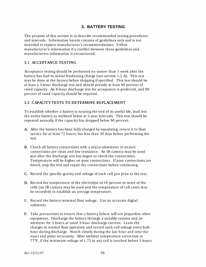
The purpose of this section is to describe recommended testing procedures and intervals. Information herein consists of guidelines only and is not intended to replace manufacturer’s recommendations. Follow manufacturer’s information if a conflict between these guidelines and manufacturers information is encountered.
3.13.1 ACCEPTANCE TESTINGACCEPTANCE TESTING
Acceptance testing should be performed no sooner than 1 week after the battery has had its initial freshening charge (see section 1.2 A). This test may be done at the factory before shipping if specified. This test should be at least a 3-hour discharge test and should provide at least 90 percent of rated capacity. An 8-hour discharge test for acceptance is preferred, and 90 percent of rated capacity should be required.
3.23.2 CAPACITY TESTS TO DETERMINE REPLACEMENTCAPACITY TESTS TO DETERMINE REPLACEMENT
To establish whether a battery is nearing the end of its useful life, load test the entire battery as outlined below at 5-year intervals. This test should be repeated annually if the capacity has dropped below 90 percent.
A.A. After the battery has been fully charged by equalizing, return it to float service for at least 72 hours, but less than 30 days before performing the test.
B.B. Check all battery connections with a micro-ohmmeter to ensure connections are clean and low resistance. An IR camera may be used just after the discharge test has begun to check the connections. Temperature will be higher on poor connections. If poor connections are found, stop the test and repair the connections before continuing.
C.C. Record the specific gravity and voltage of each cell just prior to the test.
D.D. Record the temperature of the electrolyte of 10 percent or more of the cells (an IR camera may be used and the temperature of cell cases may be recorded) to establish an average temperature.
E. Record the battery terminal float voltage. Use an accurate digital voltmeter.
F.F. Take precautions to ensure that a battery failure will not jeopardize other equipment. Discharge the battery through a suitable resistor and an ammeter for 3 hours at rated 3-hour discharge current. Leave the charger in normal float operation and record each cell voltage every half-hour during discharge. Watch closely during the last hour and time the exact end point accurately. After ambient temperature correction to 77°F, if the minimum voltage of 1.75 in any cell is reached before 3 hours
Rev.12/31/97 26

has elapsed, the test should be stopped and the ampere-hours discharge should be computed. Capacity can be determined by referring to figure 3. Testing should be done each year if the capacity is less than 90 percent of the original rating. The entire battery should be replaced as soon as possible after capacity drops below 80 percent of original. The battery cannot be relied upon in an emergency if it has deteriorated below 80-percent capacity.
Rev.12/31/97 27
4. OPTIONAL INSTRUCTIONS LEAD-CALCIUM BATTERIES
4.14.1 FLOAT CHARGEFLOAT CHARGE
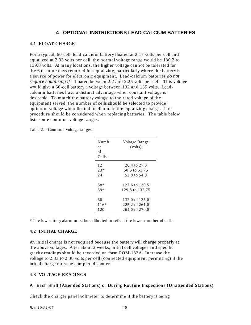
For a typical, 60-cell, lead-calcium battery floated at 2.17 volts per cell and equalized at 2.33 volts per cell, the normal voltage range would be 130.2 to 139.8 volts. At many locations, the higher voltage cannot be tolerated for the 6 or more days required for equalizing, particularly where the battery is a source of power for electronic equipment. Lead-calcium batteries do not require equalizing if floated between 2.2 and 2.25 volts per cell. This voltage would give a 60-cell battery a voltage between 132 and 135 volts. Lead-calcium batteries have a distinct advantage when constant voltage is desirable. To match the battery voltage to the rated voltage of the equipment served, the number of cells should be selected to provide optimum voltage when floated to eliminate the equalizing charge. This procedure should be considered when replacing batteries. The table below lists some common voltage ranges.
Table 2. - Common voltage ranges.
Numb Voltage Range er (volts) of Cells
12 26.4 to 27.0 23* 50.6 to 51.75 24 52.8 to 54.0
58* 127.6 to 130.5 59* 129.8 to 132.75
60 132.0 to 135.0 116* 225.2 to 261.0 120 264.0 to 270.0
* The low battery alarm must be calibrated to reflect the lower number of cells.
4.24.2 INITIAL CHARGEINITIAL CHARGE
An initial charge is not required because the battery will charge properly at the above voltages. After about 2 weeks, initial cell voltages and specific gravity readings should be recorded on form POM-133A. Increase the voltage to 2.33 to 2.38 volts per cell (connected equipment permitting) if the initial charge must be completed sooner.
4.34.3 VOLTAGE READINGSVOLTAGE READINGS
A.A. Each Shift (Attended Stations) or During Routine Inspections (Unattended Stations)Each Shift (Attended Stations) or During Routine Inspections (Unattended Stations)
Check the charger panel voltmeter to determine if the battery is being
Rev.12/31/97 28

floated at the proper voltage. Adjust the battery charging voltage when necessary, and check when the power or station-service transformer taps are changed.
Rev.12/31/97 29
B.B. MonthlyMonthly
Check voltage across the battery terminals with an accurate digital voltmeter and adjust the panel voltmeter if necessary. Record pilot cell voltages to the nearest 0.01 volt, measured with an accurate digital voltmeter, on form POM-133A. Battery is functioning normally if all cells are above 2.14 volts.
C.C. QuarterlyQuarterly
Check voltages across all individual cells and record them on POM-133A.
4.44.4 SPECIFIC GRAVITY READINGSSPECIFIC GRAVITY READINGS
A.A. Monthly (Attended Stations) or During Routine Inspections(Unattended Stations)Monthly (Attended Stations) or During Routine Inspections(Unattended Stations)
Read the specific gravity of the pilot cell. For accurate readings, hold the hydrometer vertically and use a long nozzle syringe about one-third down from the top. Record the pilot cell specific gravity, corrected for temperature, on form POM-133A.
B.B. QuarterlyQuarterly
Read the specific gravity of 10 percent all cells and record, corrected for temperature, on form POM-133A.
C.C. AnnuallyAnnually
Read the specific gravity of 100 percent of the cells, corrected for temperature, and record on form POM-133A.
4.54.5 HEAVY DISCHARGEHEAVY DISCHARGE
The battery should be recharged as quickly as possible following a heavy discharge. This recharge can be done by raising the charging voltage to the maximum allowed by other circuit components but not greater than the range of 2.33 to 2.38 volts per cell. The battery should be returned to normal voltage after the capacity been restored.
4.64.6 WATER REPLACEMENTWATER REPLACEMENT
Add water only when the water level approaches the low level mark or prior to an equalizing charge. This step should be needed every 2 or 3 years with a proper charging program.
Rev.12/31/97 30
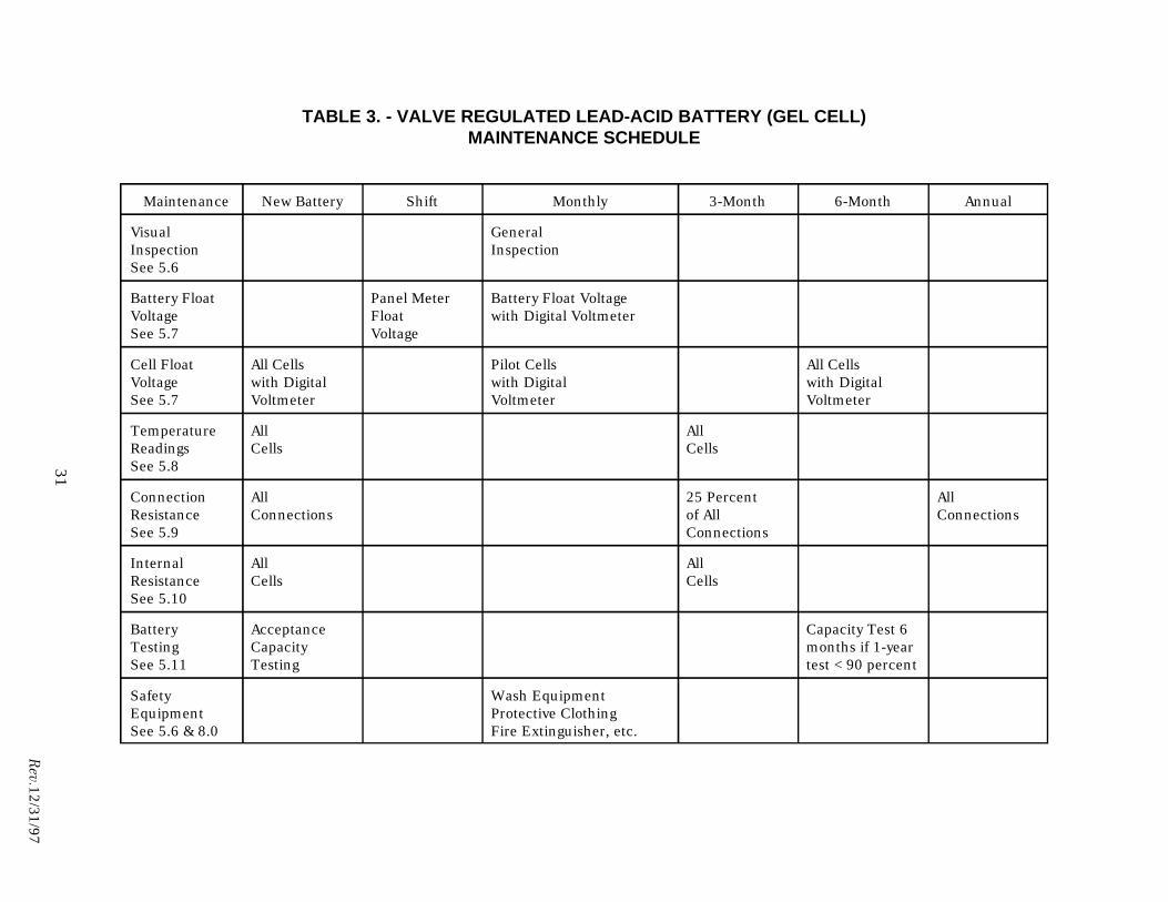
TABLE 3. - VALVE REGULATED LEAD-ACID BATTERY (GEL CELL)MAINTENANCE SCHEDULE
31
Rev.12/31/97
Maintenance New Battery Shift Monthly 3-Month 6-Month Annual
Visual General Inspection Inspection See 5.6
Battery Float Panel Meter Battery Float Voltage Voltage Float with Digital Voltmeter See 5.7 Voltage
Cell Float All Cells Pilot Cells All Cells Voltage with Digital with Digital with Digital See 5.7 Voltmeter Voltmeter Voltmeter
Temperature All All Readings Cells Cells See 5.8
Connection All 25 Percent All Resistance Connections of All Connections See 5.9 Connections
Internal All All Resistance Cells Cells See 5.10
Battery Acceptance Capacity Test 6 Testing Capacity months if 1-year See 5.11 Testing test <90 percent
Safety Wash Equipment Equipment Protective Clothing See 5.6 & 8.0 Fire Extinguisher, etc.
5. CONDENSED INSTRUCTIONSCCVALVE REGULATED LEAD-ACID BATTERIES (GEL CELLS)
5.15.1 GENERALGENERAL
Valve regulated lead-acid batteries (VRLA) are usually manufactured in multi-cell blocks, (called modules) rather than single cells. The cases are often made of ABS plastic material and do not permit visual inspection of plates or electrolyte levels. They are called starved electrolyte or absorbed electrolyte cells and operate under a positive pressure. The hydrogen and oxygen are not expelled but recombined. Cells are sealed and require no water addition or specific gravity readings. These cells are typically lead calcium pasted-plate type cells with the electrolyte retained in gel or fiberglass mats.
These batteries are normally used for emergency lighting, telecommunications, and other uninterrupted power supply (UPS) service. They are best applied where long slow discharges are needed. Heavy short discharges required for breaker operations are not recommended for this type battery. The life has been found to be only 18 months to 10 years in actual service.
These cells are not flooded and do not effectively dissipate heat. This characteristic can lead to thermal runaway if ambient and battery temperatures are not carefully controlled (see 5.2 below). Cases have occurred in which the battery has burst into flame. Maintaining the cells as close as possible to 77 EF is imperative. Ambient temperature should be maintained as close as possible to 72 EF. Air circulation must be sufficient to eliminate any ambient temperature differences. The maximum cell temperature spread (hottest to coldest cell) should not exceed 5 EF, and the hottest cell should not be more than 5EF above ambient. Colder temperatures reduce capacity, and higher temperatures greatly reduce service life. About 50 percent of the service life will be lost for every 15 EF above 77EF. Do not allow sunlight or other heat sources to raise the temperature of individual cells. These cells are not recommended for station service because of these characteristicscharacteristics.
VRLA modules/cells are typically shipped fully charged and do not require initial charge.
5.25.2 FLOAT CHARGEFLOAT CHARGE
VRLA cells are typically floated at 2.25 to 2.30 volts depending on the manufacturer. Correct battery float voltage is critical for valve-regulated cells. The float voltage must be within the manufacturer’s recommended limits compensated for temperature. See the manufacturer’s literature for temperature compensation of float voltages.
When VRLA cells are operated on float at normal full charge, no net
Rev.12/31/97 32
chemical reaction occurs and almost all the overcharge energy results in heat generation. If the environment is such that the heat produced can be dissipated, no thermal runaway problem occurs. If the rate of heat generated exceeds the dissipated rate, the battery temperature rises and more current is required to maintain the float voltage. The additional current results in more heat generation, which raises the battery temperature further, and the cycle is repeated. Thermal runaway and destruction of the battery result. Elevated ambient temperature (above 72°F) or cell and/or charger malfunction will aggravate this condition. Ventilation and temperature control is critical for VRLA cells, and the battery should reach thermal equilibrium at no more than 5°F above ambient for the hottest cell.
As cells approach full charge, battery voltage rises to approach the charger output voltage, and charging current decreases. The battery is fully charged when the charging current has not changed more than 10 percent for more than 3 hours. If the charging voltage has been set higher than float voltage to reduce the charging time, reduce the charging voltage to normal float value after the charging current has stabilized. Caution: Never exceed the maximum charging voltage recommended by the manufacturer.
5.35.3 EQUALIZING CHARGEEQUALIZING CHARGE
Equalizing charge is not normally performed on VRLA cells. An equalizing charge may be necessary if a low float voltage is indicated or if a fast recharge is needed. The battery manufacturer should be consulted before proceeding if an equalizing charge is needed. The exact voltages and charge times indicated by the manufacturer must be followed carefully.
5.45.4 CHARGERCHARGER
A VRLA cell charger must have at least two capabilities: (1) extra electrical filtering to protect the cells from AC ripple, which may lead to thermal runaway, and (2) temperature compensation to prevent thermal run-away. Do not try to charge these cells with a charger designed for a flooded lead-acid cells.
5.55.5 BATTERY MAINTENANCEBATTERY MAINTENANCE
The regimen described below is strongly recommended to maximize performance and life expectancy. See manufacturer’s data and IEEE 1188-1996—Recommended Practice for Maintenance, Testing, and Replacement of Valve-Regulated Lead-Acid (VRLA) Batteries for Stationary Application for further information.
5.65.6 VISUAL INSPECTIONSVISUAL INSPECTIONS
Visual inspections are made to assess the general condition of the battery, mounting rack and battery room, and safety equipment.
Rev.12/31/97 33
A.A. MonthlyMonthly
Check for general cleanliness of the battery, mounting rack, and battery room. Check for electrolyte leaks and cover integrity, and take corrective action if needed. Check for corrosion at terminals, connectors, racks, and cabinets. Check the ambient temperature and make sure all ventilation equipment (fans, vents, etc.) is operable.
Check for availability and condition of all safety equipment, gloves, aprons, face shields, etc. Check for a full gallon of labeled neutralizing solution. Check for cleanliness and operability of eyewash station or portable eyewash equipment and body wash station (see section 8.2). Check for a class C fire extinguisher and ensure that it has been inspected and tested according to schedule. Carbon dioxide (CO2) fire extinguishers are not recommended because of the cooling effect they will have on the battery. Check for availability of insulated tools and utensils so short circuits can be avoided.
5.75.7 VOLTAGE READINGSVOLTAGE READINGS
An accurate digital voltmeter is critical for extended life of the battery (see section 1.3). At a constant float voltage, the charging current will increase as the temperature of the electrolyte increases. Therefore, cells of higher temperature will indicate a lower cell voltage. See figure 10 for proper meter probe placement. Place the probes across the posts of the cell so as not to include the voltage drops across the intercell connections.
A.A. Initial VoltageInitial Voltage
Readings of all cells should be taken and recorded about 24 hours after placing the battery in float. Select the cell/module with the lowest float voltage as the pilot cell for future readings. Use form POM-133B for all voltage readings.
B.B. Each ShiftEach Shift
Check the voltmeter on the charger and adjust the float voltage if necessary.
C.C. When Taps Are ChangedWhen Taps Are Changed
When taps are changed on the power or station service transformers, check the float voltage on the charger panel and adjust if necessary.
D.D. MonthlyMonthly
Check and record the voltage of the pilot cell with an accurate digital voltmeter.
E.E. MonthlyMonthly
Rev.12/31/97 34
Check and record the float voltage across the whole battery with an accurate digital voltmeter. Compare this reading to the panel voltmeter and adjust the panel meter to agree with the digital meter if necessary.
F.F. Every Six MonthsEvery Six Months
Check and record the voltage of each individual cell with an accurate digital voltmeter.
5.85.8 TEMPERATURE READINGSTEMPERATURE READINGS
A.A. After InstallationAfter Installation
After 24 hours on float and the temperatures have stabilized, record temperatures of each individual cell on form POM-133B. Use an accurate surface thermometer and take the readings on the negative posts. Accurate readings are critical for extended life and performance. Check the thermometer for accuracy at least once per year. Take all temperature readings only on float. Do not try to take post temperatures while the battery is discharging. The resistance of the connections causes errors in temperature readings. An accurate IR camera may also be used for temperature readings.
B.B. QuarterlyQuarterly
Take temperature readings of each individual cell and record them on form POM-133B. Compare readings with the initial and all prior temperatures for trending purposes. The highest temperature cell will typically also have the lowest voltage.
5.95.9 CONNECTION RESISTANCECONNECTION RESISTANCE
See section 1.6C for detailed instructions.
A.A. After InstallationAfter Installation
Record resistance of each connection between the cell post and the interconnection strap on form POM-134B. Contact the manufacturer for expected readings for specific cells. See figure 2 in section 1.6C or figure 10 at the back of this FIST for resistance probe placement. Clean, retorque, and re-coat with no-oxide grease any connection with a resistance 20 percent or more above the manufacturer’s recommended value. Use these values as a baseline. Caution: Never put meter leads across a cell with the function switch on ohms. This procedure will place a voltage across the meter instead of a resistance.
B.B. QuarterlyQuarterly
Record the resistance of 25 percent of the connections as in step A above
Rev.12/31/97 35
and compare them with the previous readings. Rotate the measured connections each quarter. Repair those that have increased 20 percent in resistance.
C.C. AnnuallyAnnually
Record the resistance of all the connections as in step A above and compare them with the previous readings. Repair those that have increased 20 percent in resistance.
D.D. During DischargeDuring Discharge
Connection integrity may be checked with an accurate IR camera. Temperature of the higher resistance connections will be noticeably higher and should be repaired.
5.105.10 INTERNAL RESISTANCEINTERNAL RESISTANCE
Internal resistance is a good indication of the state of charge and substitutes for specific gravity readings taken on flooded, lead-acid type cells. Measuring the internal resistance of a module monitors the two main failure modes—grid corrosion and dryout. The manufacturer’s literature will list the normal expected values. This test should not be done until after the connection resistances of the cells are checked and repaired as in 5.9 above. Elevated connection resistance will appear as internal resistance and make cells appear faulty. Internal resistance can be checked as follows:
1. While the battery is fully charged and operating on float, check and record voltage and current for the cell being tested.
2. Apply a normal load across the cell. 3. Again check and record the voltage and current. 4. The internal resistance can then be calculated by dividing the change in
voltage by the change in current.
Commercial test sets are available to measure internal resistance, which saves time and effort. Consider purchasing a test set if maintaining more than one VRLA battery.
A.A. Upon InstallationUpon Installation
After the battery has reached equilibrium (1 to 3 days) on float, perform the internal resistance check on each cell/module and record the results on form POM-134B as a baseline for future comparisons.
B.B. QuarterlyQuarterly
Perform the internal resistance check on each cell and compare the results with the initial records. Changes in the internal resistance of 20 percent or greater should be considered significant. Contact the battery manufacturer
Rev.12/31/97 36
and follow their recommendations.
5.115.11 TESTINGTESTING
A.A. Upon InstallationUpon Installation
Acceptance capacity testing should be performed within 1 week after the battery has reached equilibrium in charge and temperature. Operating temperature of the battery will greatly affect the available capacity, and manufacturer’s data must be consulted for correction factors. Maintain accurate records of tests, including all equipment used and test results. These records can be used as baseline for later comparisons.
1. Conduct the test only after a connection resistance test has been performed as in 5.9 above.
2. Install an accurate ammeter, voltmeter, and temperature instrumentation, and provide an accurate stopwatch or other means to indicate elapsed time. Minimum test time should be at least 1 hour. More time is recommended for critical applications and test accuracy.
3. Provide a variable load resistance so that constant current can be maintained equal to the rating of the battery for the selected test time.
4. Disconnect the charger.
5. Read and record individual cell/module voltages and the battery terminal voltage. The readings should be taken after applying the load at the beginning of the test. Repeat the readings at specified intervals and plan the test time long enough in advance to provide a minimum of five sets of readings. Caution: Take individual cell voltage readings between respective terminals of like polarity ( positive to positive) so the voltage drop of the intercell connectors will be included. See figure 10 for probe placement.
6. If an individual cell/module is approaching reversal of its polarity (zero volts) or a module voltage is 2 volts or more lower than the others, but the overall terminal voltage has not reached its test limit, bypass the cell/module and continue the test. Perform the bypass connection away from the cell/module to avoid arcing. A new minimum voltage based on the remaining cells should be established for the remainder of the test (1.75 times the number of remaining cells).
Consult the manufacturer and prepare to bypass cells in advance. The possibility of weak cells is high, especially as the battery ages.
7. Maintain the discharge rate until the battery terminal voltage decreases to a value equal to the manufacturer’s specified minimum voltage per cell (usually 1.75 volts) times the number of cells.
Rev.12/31/97 37
8. Battery capacity can then be calculated by dividing the actual time to reach specified terminal voltage by the rated time to specified terminal voltage and multiplying by 100.
Percent Capacity = actual time
x 100 rated time
B.B. AnnuallyAnnually
Perform a discharge capacity test with the same set-up and equipment as in step A above.
C.C. Every Six MonthsEvery Six Months
Perform a discharge capacity test as in step A above, after the battery falls below 90 percent of its original design capacity on the annual test. Replace the battery as soon as possible after it falls below 80 percent of its original design capacity rating.
D.D. Continuity TestsContinuity Tests
Continuity tests are performed on a non-routine basis, whenever the integrity of the battery is suspect. A VRLA cell typically fails open, and continuity through the cell is lost. This condition is not readily apparent. A quick check is to turn off both chargers and see if the battery will accept the load of the connected equipment. Another method is to place a test load across the battery and see if it will accept load. If cells/modules are connected in parallel, the load must be placed across individual cells/modules to detect an open circuit. Contact the manufacturer if further information is needed.
Rev.12/31/97 38
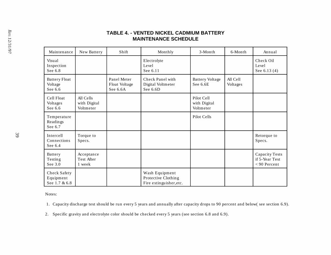
39
Rev.12/31/97
TABLE 4. - VENTED NICKEL CADMIUM BATTERYMAINTENANCE SCHEDULE
Maintenance New Battery Shift Monthly 3-Month 6-Month Annual
Visual Electrolyte Check Oil Inspection Level Level See 6.8 See 6.11 See 6.13 (4)
Battery Float Panel Meter Check Panel with Battery Voltage All Cell Voltage Float Voltage Digital Voltmeter See 6.6E Voltages See 6.6 See 6.6A See 6.6D
Cell Float All Cells Pilot Cell Voltages with Digital with Digital See 6.6 Voltmeter Voltmeter
Temperature Pilot Cells Readings See 6.7
Intercell Torque to Retorque to Connections Specs. Specs. See 6.4
Battery Acceptance Capacity Tests Testing Test After if 5-Year Test See 3.0 1 week <90 Percent
Check Safety Wash Equipment Equipment Protective Clothing See 1.7 & 6.8 Fire extinguisher,etc.
Notes:
1. Capacity discharge test should be run every 5 years and annually after capacity drops to 90 percent and below( see section 6.9).
2. Specific gravity and electrolyte color should be checked every 5 years (see section 6.8 and 6.9).
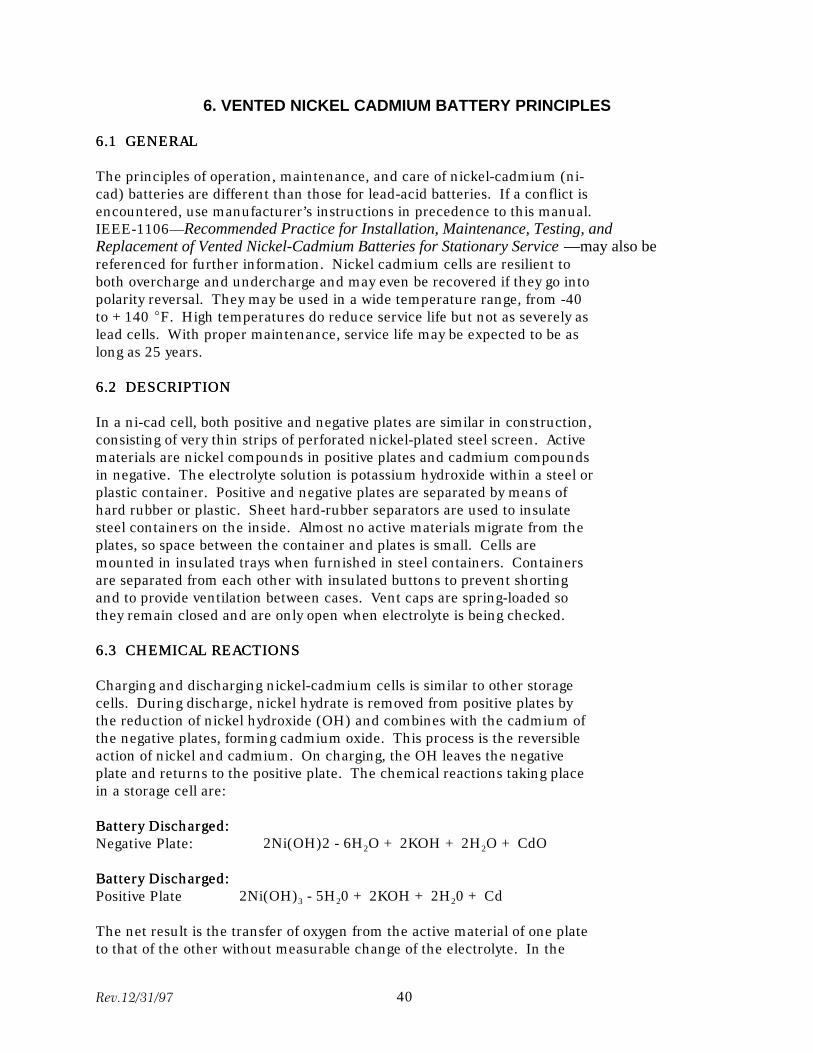
6. VENTED NICKEL CADMIUM BATTERY PRINCIPLES
6.16.1 GENERALGENERAL
The principles of operation, maintenance, and care of nickel-cadmium (nicad) batteries are different than those for lead-acid batteries. If a conflict is encountered, use manufacturer’s instructions in precedence to this manual. IEEE-1106—Recommended Practice for Installation, Maintenance, Testing, and Replacement of Vented Nickel-Cadmium Batteries for Stationary Service —may also be referenced for further information. Nickel cadmium cells are resilient to both overcharge and undercharge and may even be recovered if they go into polarity reversal. They may be used in a wide temperature range, from -40 to +140 EF. High temperatures do reduce service life but not as severely as lead cells. With proper maintenance, service life may be expected to be as long as 25 years.
6.26.2 DESCRIPTIONDESCRIPTION
In a ni-cad cell, both positive and negative plates are similar in construction, consisting of very thin strips of perforated nickel-plated steel screen. Active materials are nickel compounds in positive plates and cadmium compounds in negative. The electrolyte solution is potassium hydroxide within a steel or plastic container. Positive and negative plates are separated by means of hard rubber or plastic. Sheet hard-rubber separators are used to insulate steel containers on the inside. Almost no active materials migrate from the plates, so space between the container and plates is small. Cells are mounted in insulated trays when furnished in steel containers. Containers are separated from each other with insulated buttons to prevent shorting and to provide ventilation between cases. Vent caps are spring-loaded so they remain closed and are only open when electrolyte is being checked.
6.36.3 CHEMICAL REACTIONSCHEMICAL REACTIONS
Charging and discharging nickel-cadmium cells is similar to other storage cells. During discharge, nickel hydrate is removed from positive plates by the reduction of nickel hydroxide (OH) and combines with the cadmium of the negative plates, forming cadmium oxide. This process is the reversible action of nickel and cadmium. On charging, the OH leaves the negative plate and returns to the positive plate. The chemical reactions taking place in a storage cell are:
Battery Discharged:Battery Discharged:Negative Plate: 2Ni(OH)2 - 6H2O + 2KOH + 2H2O + CdO
Battery Discharged:Battery Discharged:Positive Plate 2Ni(OH)3 - 5H20 + 2KOH + 2H20 + Cd
The net result is the transfer of oxygen from the active material of one plate to that of the other without measurable change of the electrolyte. In the
Rev.12/31/97 40
electro-chemical reaction within the battery, the electrolyte acts as a carrier for ions and does not change in concentration. Specific gravity remains the same, and does not indicate the state of battery charge.
6.46.4 UPON INSTALLATIONUPON INSTALLATION
Make sure all connections are torqued according to the manufacturer’s specifications. Coat the connections with no-oxide grease.
A.A. AnnuallyAnnually
Retorque all connections to the manufacturer’s specifications.
6.56.5 CHARGINGCHARGING
The density of electrolyte in ni-cad cells does not change appreciably with charge so specific gravity does not indicate state of charge. This state can be estimated when the battery is on float. To hold battery voltage at 1.40 volts per cell, a fully charged battery requires about 1 milliampere (excluding load current) per ampere-hour of capacity. A fully charged 100-ampere-hour battery draws a charging current (0.001 x 100 = 0.1 amp). The battery is not fully charged if charging current is higher.
A more accurate state-of-charge determination may be made as follows. With the battery on float charge, record the ampere output of the charger and the battery terminal voltage. Record the time the above readings were taken. Then place the charger into the high-rate charge or equalize charge position. Record both charger ampere output and battery terminal voltage again. Continue the high-rate charge until the voltage reaches the high-rate maximum voltage for the system. The state of charge may then be determined as follows:
1. The battery is fully charged if the high-rate charge voltage is reached in less than 1 minute and the current output of the charger drops to near the float current measured above.
2. The battery is in need of a charge if the high-rate charge voltage is not reached in 1 minute or less.
3. The battery is in need of a charge if the charging current is greater than the float current after 1 minute or more on high rate. Continue the high-rate equalizing charge until the current is nearly the same as the measured float current. Record the charge on form POM-133C.
A.A. Initial Freshening ChargeInitial Freshening Charge
An initial freshening charge should be given to compensate for self discharge losses during shipment and storage. If the cells have been shipped filled and charged, placing the battery on float will probably be sufficient. If the cells were shipped discharged, they must be charged according to the manufacturer’s instructions as to voltage level and time. Inspect all cells for
Rev.12/31/97 41
the proper electrolyte level and oil level before charging.
B.B. Float ChargeFloat Charge
Float voltage is normally maintained at 1.40 to 1.42 volts per cell to avoid gassing. Gassing begins at about 1.47 volts, and charging at this level should be avoided because water consumption becomes excessive. Excessive voltage variations between cells may be caused by excessively low float voltage, which causes the battery to become partially discharged. If so, the charger voltage setting should be increased slightly to within the above limits. The charger voltmeter should be checked against an accurate digital voltmeter at least once a year (see 1.2B).
C.C. Equalizing ChargeEqualizing Charge
An equalizing charge should not be given unless the battery has been discharged to less than 90-percent capacity. Smaller discharges are handled by float charging. A fully discharged ni-cad battery in good condition can be fully recharged in 4 to 10 hours. When an equalizing charge is necessary, 1.52 volts per cell may be used (1.40 volts on a 92-cell bank) if the chargercan provide the current. As the battery charges, current decreases and voltage stabilizes at the pre-set charger voltage. The charge should be continued until charging current has leveled off for two consecutive readings, 30 minutes apart. During an equalizing charge, carefully monitor electrolyte temperature; lower charging voltage immediately if 115EF is reached.
6.66.6 VOLTAGE READINGSVOLTAGE READINGS
Voltage readings must be taken by an accurate digital voltmeter (see section 1.3).
A.A. Each ShiftEach Shift
Check the voltmeter on the control panel to determine if the battery is being charged at the proper voltage. Adjust the voltage if necessary.
B.B. When Taps Are ChangedWhen Taps Are Changed
When taps are changed on power or station-service transformers, check the voltage on the control panel and adjust the charging voltage if necessary.
C.C. During Initial ChargeDuring Initial Charge
Just before terminating the initial or equalizing charge, measure and record the voltage of each cell with an accurate digital voltmeter. Choose a pilot cell from one with the lowest voltage for readings in the coming year. Change this cell each year.
Rev.12/31/97 42
D.D. MonthlyMonthly
Check the accuracy of the panel voltmeter against the digital voltmeter by measuring the battery terminal voltage. Adjust the panel voltmeter if necessary.
E.E. QuarterlyQuarterly
Read the pilot cell voltage and the overall battery terminal voltage while on float. Read the voltages with the digital voltmeter and record them on form POM-133C.
Rev.12/31/97 43
F.F. Every Six MonthsEvery Six Months
Record the voltages of every cell taken with the digital voltmeter on form POM-133C. Take the voltages while on float and compare with previous readings.
6.76.7 TEMPERATURE READINGSTEMPERATURE READINGS
A.A. QuarterlyQuarterly
Check and record the electrolyte temperature of the pilot cell. Use only an alcohol thermometer reserved only for this battery. Mercury thermometers may break and cause sparking or an explosion. Never insert a thermometer or any tool ever used for other batteries into a ni-cad cell.
6.86.8 VISUAL INSPECTIONSVISUAL INSPECTIONS
Visual inspections are made to assess the general condition of the battery, battery room, and safety equipment.
A.A. MonthlyMonthly
Check for general cleanliness of the battery, mounting rack, and battery room. Check for electrolyte leaks and cracks in cells and take corrective action if found. Check for corrosion at terminals, connectors, racks, and cabinets. Check the ambient temperature and make sure ventilation devices (fans and vents) are operable. Check the charger for current and voltage output.
Check for availability and condition of all safety equipment, gloves, face shields, aprons, etc. Check for a full gallon of labeled neutralizing solution (20 ounces of boric acid per gallon of distilled water) and operability of body wash/eyewash station or portable eyewash equipment. Check for availability of insulated tools so short circuits can be avoided (see section 8).
6.96.9 BATTERY DISCHARGE TESTINGBATTERY DISCHARGE TESTING
A.A. Acceptance TestingAcceptance Testing
Acceptance testing may be done at the factory prior to shipping or at the service location after the battery comes to equilibrium in charge and temperature. The discharge rate should be constant at the full rated current for the duration of the test. See the manufacturer’s literature for this information. Most manufacturers recommend a test duration of 3 to 8 hours for this test.
Note: Temperature affects battery capacity. Take electrolyte temperatures of individual cells and average them prior to the test. The test discharge current is equal to the rated discharge current divided by the temperature
Rev.12/31/97 44
correction factor for electrolyte temperature. Contact the manufacturer or consult the instruction manual for correct data for the specific battery to be tested.
1. Set up the instrumentation to measure time, test current, and the required voltages.
2. Disconnect the charger, connect the test load, and maintain the constant current discharge for the duration of the test. Begin timing the test when the discharge current begins.
3. Read and record individual cell voltages and the battery terminal voltage as soon as possible after the discharge begins. Repeat the readings at the required intervals and just before completion of the test with the rated discharge load connected. At least three sets of readings should be taken at rated discharge current flow. More readings are preferred. Individual cell voltages should be taken between like polarity posts of adjacent cells to include the voltage drops of intercell connections.
4. Maintain the discharge and record the elapsed time at the point when terminal voltage decreases to the manufacturer’s specified minimum volts per cell, usually 1.00 volt times the number of cells. If one or more cells approach polarity reversal before the specified test time, continue the test for the originally planned test time. Ni-cad cells are not damaged as a result of polarity reversal, so bypassing weak cells is unnecessary. Contact the manufacturer if the battery fails the test, that is, if the specified terminal voltage (1.00 volt per cell) is reached prior to the specified test time.
5. Battery capacity can then be calculated by dividing the actual time to reach specified terminal voltage by the rated time to specified terminal voltage and multiplying by 100.
actual timePercent Capacity = x 100
rated time
B.B. Five-Year Capacity Discharge TestFive-Year Capacity Discharge Test
Perform this test every 5 years as in step A above. A battery capacity of 90 percent or less than rated capacity indicates that the battery is reaching the end of its service life. A battery that falls to 90-percent capacity must be tested annually as in step C below.
C.C. Annual Capacity Discharge TestAnnual Capacity Discharge Test
Perform capacity discharge tests annually after the capacity falls to 90 percent as revealed in the 5-year test in step B above. Replace the battery as soon as possible after the capacity falls to 75 percent.
Rev.12/31/97 45
6.106.10 ELECTROLYTEELECTROLYTE
The electrolyte solution in nickel-cadmium batteries consists of purified caustic potash (KOH potassium hydroxide) and other salts in distilled water. Liquid electrolyte should be stored in a clean, glass, or porcelain container. The electrolyte will readily absorb carbon dioxide from air to form potassium carbonate. This process will temporarily lower battery capacity. Electrolyte must therefore be stored in airtight containers. The specific gravity of electrolyte does not change with state of charge but remains almost constant on charge and discharge. The average specific gravity of a normal cell will be about 1.190 at 72 EF;; however, in servicing a battery, always refer to the manufacturer's recommended specific gravity range. The specific gravity range for ni-cad cells has limits. Below 1.200, the resistivity begins to increase rapidly, making cells sluggish, and the lowest electrolyte density is usually set at 1.170. High concentrations are damaging because of the increased solubility of the iron electrodes, especially at higher temperatures. Concentrations much higher than 1.170 also result in increased resistivity. The proper density of the electrolyte is a compromise held within narrow limits.
The freezing point of electrolyte with a specific gravity of 1.190 is about -10 °F, at which the solution forms a slush but will not freeze solid. If the battery will encounter temperatures colder than -10 EF, specific gravity is usually raised to 1.230 for protection to -40 EF. Always consult the manufacturer before attempting to change the specific gravity of electrolyte.
6.116.11 ELECTROLYTE LEVELELECTROLYTE LEVEL
Cells lose water through natural evaporation and when gassing on equalizing charge. Always keep the plates covered with electrolyte. Serious damage will occur if the plate tops are exposed to air.
A.A. MonthlyMonthly
Check the electrolyte level in every cell during the visual inspection. The level can be observed by looking closely at the cell. Cell cases are typically translucent, and the electrolyte level can be seen through the cell case. When electrolyte level is low, add distilled water to the proper height but do not overfill. If cells are overfilled, the electrolyte may be forced out of vents on charge. This condition can cause electrolysis between the cells, corrosion of the cell containers, and grounds in the electrical circuit. The maximummaximum level of the electrolyte is halfwayhalfway between the tops of the plates and the inside of the cell covers.
To retard natural evaporation, pure mineral oil should be floated on the electrolyte in each cell. All cells should be checked annually for adequate oil depth, (about 1/4 inch). See manufacturer's instructions for the recommended oil type and depth.
Rev.12/31/97 46
6.126.12 SPECIFIC GRAVITY READINGSSPECIFIC GRAVITY READINGS
Specific gravity readings are only needed every 5 years to determine if the electrolyte needs to be replaced (see 6.9 above). When taking a hydrometer reading, squeeze the bulb before inserting, insert the nozzle to the top of the plates, then release the bulb. This procedure will avoid introducing air bubbles and prevent floating oil from being drawn into the barrel. The sample should always be returned to the cell from which it was taken. Wash out the hydrometer thoroughly with distilled water. Electrolyte remaining in the hydrometer absorbs carbon dioxide from the air, forms a coating, and causes false readings. Specific gravity changes with temperature, and if the electrolyte temperature is different from 77 EF, add 0.001 to the reading for every 4 EF above 77 EF. Subtract 0.001 for every 4 EF below 77 EF.
Do not take specific gravity readings when gas bubbles are visible in the electrolyte. False readings will result unless the bubbles are allowed to dissipate. Specific gravity readings cannot be taken on cells just after adding water; the readings should be delayed until mixing has occurred.
Do not try to maintain a single supply of distilled water for serving both nicad and lead-acid batteries. Water will become contaminated with traces of sulfuric acid from the filler bulb by the transfer between lead-acid cells and the water container. A separate supply of distilled or approved mineral water, used only for nickel-cadmium batteries, is necessary. Provide a separate hydrometer that is used exclusively for testing nickel-cadmium cells.
6.136.13 ELECTROLYTE RENEWALELECTROLYTE RENEWAL
Traces of potassium hydroxide are lost with the gas while the battery is on charge, resulting in gradual lowering of specific gravity over the years. Performance deteriorates as the battery ages, and cannot be restored by normal charges. When this condition occurs, check the electrolyte color by inserting a clear glass draw tube to the top of the plates. Place a thumb over the top end and partially withdraw the tube; do not totally remove the tube. This procedure avoids spills on the tops of the cells. After observing the color, release the electrolyte back into the same cell. Clear electrolyte is in good condition. Electrolyte that has absorbed small quantities of carbon dioxide from the air will appear cloudy. Impurities accidentally introduced in cells during manufacture or by addition of contaminated water may also color the electrolyte. Electrolyte that becomes colored or cloudy is contaminated with impurities and should be changed.
Electrolyte renewal may also become necessary because of overcharging and overflow of electrolyte, causing cell specific gravity to fall below manufacturer's specified minimums. A rapid reduction in the life of the battery will follow with continued operation. The electrolyte should be changed when the specific gravity falls below 1.170 (see 6.8 above).
Rev.12/31/97 47
Renewal electrolyte, which is purified potassium hydroxide plus additives, is available from the battery manufacturer in dry form. The dry renewal electrolyte is mixed with distilled water in accordance with manufacturer's instructions and allowed to cool for 24 hours. Do not substitute commercial grade potassium hydroxide. After the renewal electrolyte solution of proper specific gravity has been prepared and cooled, the change of electrolyte is made in steps as follows:
1. Discharge the battery to a voltage of 0.8 volt per cell or lower.
2. Pour the electrolyte out of the cells and rinse cells with clear distilled water.
3. Fill the cells with renewal electrolyte to the proper level. Leave about 1/4 inch of space for mineral oil (see step 4 below).
4. To retard evaporation and contamination by CO2, add pure mineral oil to cells as instructed by the manufacturer (about 1/4 inch) and mentioned in step 6.7 above. Do not overfill cells above the high level mark. Add oil as needed until about 1/4-inch deep.
5. Charge the battery at the equalizing charge rate until fully charged. 6.146.14 GENERAL CAREGENERAL CARE
A salt formation called potassium carbonate may form on the top of the cells. This formation is non-corrosive and does not damage the battery but should be removed. Excessive salt formation indicates that charging may be excessive. Top hardware should be coated with no-ox grease after cleaning to keep the carbonate salts in a soft condition for easy removal. Any excess grease should be removed with a clean, soft cloth.
Cells and trays must be kept clean and dry at all times. Moisture and dirt on top of and between cells permits stray intercell currents, resulting in corrosion through electrolysis. For this reason, water or electrolyte spilled on the cells or the trays must be wiped off all surfaces. Never place or drop metal objects, such as nuts, bolts, or tools, on or between the cells. These objects may cause heavy short circuits and damage containers and cells.
Small traces of sulfuric acid will ruin a nickel-cadmium battery by corroding the steel plates and cell containers. To prevent contamination, never use any tools, such as hydrometers, funnels, rubber hoses, battery fillers, etc., that have ever been used for serving lead-acid batteries.
Keep all vent caps closed. To prevent air from entering the cells, raise the caps only for checking the electrolyte, never for charging.. Always check and service only one cell at a time.
Never allow sparking near any storage battery or remove connections with current flowing. Keep all connections tight and in good repair.
Rev.12/31/97 48
Never approach any storage battery with an open flame. The gas given off by all storage batteries on charge is an explosive mixture of hydrogen and oxygen..
6.156.15 BATTERY RECORDSBATTERY RECORDS
A manufacturer's warranty provided with each battery extends from the date of purchase. Battery records are kept to show the care provided during the service period as well as to facilitate routine battery maintenance. Monthly report form POM-133C should be filled out each month for each battery and filed for future reference.
6.166.16 WALL CARD RECORDSWALL CARD RECORDS
To facilitate proper battery operation, maintenance, and care, post a battery data card (POM-159) in a conspicuous place near the battery to provide the attendant with service information and data.
7. BATTERIES FOR MICROWAVE AND VHF RADIO EQUIPMENT
7.17.1 LEAD-ACID BATTERIESLEAD-ACID BATTERIES
See section 1 for detailed information.
A.A. Engine-Generator Starting BatteriesEngine-Generator Starting Batteries
Keep the engine-generator starting batteries clean and installed in the trays provided. The cell tops should be wiped with a solution of 1 pound of bicarbonate of soda to 1 gallon of water two or three times a year.
Keep the electrical connections tight and free of corrosion. A coating of no-oxide anti-corrosive grease on terminals will usually prevent corrosion. Dry sand should be kept in trays on which batteries are placed.
Adjust the charge rate to keep batteries fully charged. Open-cell voltage should be maintained at the manufacturer’s recommended level. Open circuit voltage on a 12-volt battery should be approximately 12.9 to 13.2 volts d.c., based on the manufacturer’s data. Care should be taken not to overcharge the battery in order to avoid the excessive use of water. Use only distilled water
When replacing starting batteries, use batteries of equal or greater capacity than originally installed. The battery should be of sufficient capacity to hold starting voltage after 30 seconds cranking (10.5 volts d.c. or higher on 12volt systems).
If the difference in specific gravity between the highest and lowest cell is 0.050 (50 points) or more, the battery is nearing the end of its useful life
Rev.12/31/97 49
and should be replaced. However, if the highest cell reads less than 1.190, the results are questionable. Recharge the battery and make the test again.
B.B. Load BatteriesLoad Batteries
Refer to section 1 of this bulletin for instructions on the maintenance and care of lead-acid load batteries.
7.27.2 NICKEL-CADMIUM BATTERIESNICKEL-CADMIUM BATTERIES
See section 6 for detailed discussion of nickel-cadmium batteries.
8. BATTERY SAFETY
8.18.1 EXPLOSIVE HAZARDEXPLOSIVE HAZARD
All storage batteries give off a highly explosive mixture of hydrogen and oxygen when gassing. Therefore, never permit sparks, open flame, or lightedTherefore, never permit sparks, open flame, or lightedcigarettes near a storage battery.cigarettes near a storage battery. Post "No Smoking" signs where they are clearly visible to anyone entering the battery room area. A nonmetallic flashlight is desirable for battery inspection. Use only alcohol thermometers when taking electrolyte temperatures. Keep all battery connections tight to avoid sparking. Never lay any metallic object on top of a battery. A class C 10pound fire extinguisher should be mounted just inside the battery room door. Carbon dioxide (CO2) is not recommended because of the potential for thermal shock to the batteries.
8.28.2 ELECTROLYTE HAZARDELECTROLYTE HAZARD
When handling electrolyte, wear face shields (face shields should not have metal reinforcing rims, which could cause a battery short if dropped), rubber aprons, and rubber gloves; avoid splashes. The electrolyte is injurious to skin and clothing and must therefore always be handled carefully. The eyes in particular should be guarded. If acid is splashed into the eyes or anywhere on the skin, flood with water for at least 15 minutes and get medical attention. Do not use bicarbonate of soda on the skin, which may aggravate the burn. For neutralization of acid electrolyte spilled on the floor or rack, a bicarbonate of soda solution—1 pound per gallon of water—is recommended.
For neutralization of ni-cad battery electrolyte (potassium hydroxide), keep a concentrated solution of 20 ounces of boric acid powder per gallon of water available for neutralizing spills on skin or clothing. Use plain water to wash up spills of potassium hydroxide on the cells or racks. Care must be taken to prevent the solution from getting into the cells.
A combination eye-wash, face, and body spray unit must be located within 25 feet of each battery room or battery system. These units can be permanently mounted and connected to the facility's potable water system
Rev.12/31/97 50
or can be of a portable pressurized type.
8.38.3 FLAME ARRESTERS PURPOSE AND CLEANINGFLAME ARRESTERS PURPOSE AND CLEANING
Article 480-9 of the National Electric Code requires each vented battery cell to be equipped with a flame arrester designed to prevent destruction of the cell attributable to an ignition of gases outside the cell.
The diffuser material of flame arresters can become partially clogged from electrolyte spray if cells are overfilled with water or have been excessively overcharged. Flame arresters should therefore be inspected annually, and all arresters having clogged pores should be replaced or cleaned as follows:
1. Immerse the flame arrester several times in fresh water in a plastic bucket.
2. Eject the water after each immersion by vigorous shaking or an air blast.
3. Dump and refill the bucket with clean water for every 15 flame arresters that are cleaned.
4. Do not use any cleaning or neutralizing agents in the water because any dry residue may clog the pores of the diffuser materials.
8.48.4 VENTILATIONVENTILATION
A determination must be made for each battery area as to whether sufficient ventilation is being provided to ensure adequate diffusion of hydrogen gas during maximum gas generating conditions. Such determination can be made from the following data:
Rev.12/31/97 51
1. When the battery is fully charged, each charging ampere supplied to the cell produces about 0.016 cubic feet of hydrogen per hour from each cell. This rate of production applies at sea level, when the ambient temperature is about 77 EF, and when the electrolyte is "gassing or bubbling."
2. Number of battery cells and maximum charging rate (not float rate) can be obtained from specifications or field inspection.
3. Hydrogen gas lower explosive limit is 4 percent by volume. Good practice dictates a safety factor of 5, which reduces the critical concentration to 0.8 percent by volume. This large safety factor is to allow for hydrogen production variations with changes in temperature, battery room elevation, and barometric pressure and also allows for deterioration in ventilation systems.
4. Examples of calculations for determining adequate battery room ventilation appear below:
Example 1Example 1
A fully-charged, 60-cell, lead-acid battery, located in a room having a volume of 60 cubic meters, is being charged at 50 amperes. The ventilation system is designed to provide three air changes each hour. Determine the rate of hydrogen production, the critical volume of the battery room, and the adequacy of the air exchanges required for ventilation.
Hydrogen (H2) production in cubic meters per hour is:
(50 amps)(60 cells)(0.000453 m3 H2/cell/hour) = 1.359 m3 H2/hour
Critical volume, with safety factor based on 0.8 percent by volume is:
(0.008)(60 m3) = 0.48 m3 H2
Hours to produce critical level of 0.8 percent hydrogen (0.48 cubic meters) in the 60-cubic-meter battery room is:
0.48 ÷1.359 = 0.35 hour (21 minutes)
The ventilation system must move 60 cubic meters (the room volume), with the 0.48 cubic meters of hydrogen contained within, before the 0.35 hour (21 minutes) elapses.
Three air changes each hour provide one air change in 20 minutes, which is quicker than the 21 minutes required. Critical hydrogen concentration will not be reached with continuous operation of the ventilation system.
Example 2Example 2
Rev.12/31/97 52
Same condition as previously mentioned except that the battery is located in a general control room area of 15 by 7 by 5 meters with one air change per hour:
Hydrogen production rate per hour:
(50 amps)(60 cells)(0.000453) = 1.353 m3 H2/hour
Critical volume based on 0.8 percent:
(0.008)(15 m)(7 m)(5 m) = 4.20 m3 H2
Hours to produce critical level of 4.20 cubic meters of hydrogen:
4.20 ÷ 1.353 = 3.10 hours, or 3 hours and 6 minutes
Because one air change occurs per hour, the critical concentration would not be reached with continuous operation of the ventilation system and with adequate air movement over the battery to ensure diffusion of generated gases.
Example 3Example 3
Same condition as example 2. Determine fan size for room with no naturalcirculation.
Hydrogen production in cubic meters per hour:
(0.000453 m3/hour)(50 amps)(60 cells) = 1.35 m3/hour
Because fans are rated in cubic feet per minute, cubic meters per hour mustbe converted to cubic feet per minute:
(1.35 m3/hour)(35.31 ft3/m3) = 47.67 ft3/hour H2 production
Divide by 60 minutes per hour to change 47.67 cubic feet per hour into cubic feet per minute.
47.67 ÷ 60 = 0.794 ft3/min H2 production
A safety factor of 5 (0.8 percent by volume) is required. With 0.794 cubic foot per minute hydrogen production, the hydrogen must never reach 0.8 percent of the total volume of the room. Total volume of the room is (15 m)(7 m)(5 m) = 525 m3.
(525 m3)(35.32 ft3/m3) = 18,538 ft3 total volume of the room
0.8 percent of 18,538 ft3 = 148.3 ft3
Rev.12/31/97 53
So the fan must clear the room before the hydrogen generation can produce 148.3 cubic feet of hydrogen. This production is 0.794 cubic foot per minute, so:
148.3 ft3 ÷ 0.794 ft3/min = 186.7 min to clear the room before H2 volume is produced
The total room volume is 18,538 ft3, so:
18,538 ÷ 186.7 = 99.29-ft3/min fan capacity
Fans are rated in hundreds of cubic feet per minute, so at least a 100-cubic-foot-per-minute fan is needed.
Another way to calculate this fan size would be that the fan must move 0.8 percent of the total volume of the room each minute. So divide the hydrogen production rate by 0.8 percent to give the total fan capacity.
0.794 ft 3 /min ÷ 0.008 = 99.25 ft 3 /min
8.58.5 BATTERY ROOMSBATTERY ROOMS
Battery rooms in future and remodeled facilities are to be designed, constructed, and maintained in accordance with section 14—Storage Batteries—of the National Electrical Safety Code. Battery systems now located in control buildings or powerplants need not be placed in a separate room. However, when not located in a separate room, barriers or some type of mechanical protection must be provided to prevent inadvertent personnel or equipment contact and resultant damage. Periodic air flow measurements and explosion meter (total combustible gas) readings are recommended in the general battery areas to ensure adequate air movement to diffuse generation of hydrogen gas.
“No Smoking,” “No Sparks,” or “No Open Flame” signs should be posted on the outside of the door.
Seismic protection should be provided in areas with high seismic activity.
Metal battery racks shall be grounded.
Concrete floors shall be painted with acid-resistive paint (alkaline resistive) for ni-cad batteries.
Electrical receptacles and light switches should be located outside of battery areas.
A 10-pound class C fire extinguisher should be located just inside the battery room door. The fire extinguisher should not be a CO2 type to prevent thermal shock to the battery.
Rev.12/31/97 54
Egress from the battery room must be kept clear at all times.
8.68.6 SAFETY MEETINGSSAFETY MEETINGS
Field maintenance and operation personnel shall be informed of design criteria and operational requirements of ventilation system performance. Such information will be posted on battery room doors or in close proximity to battery systems. Discussions of these rules and regulations shall be the subject of at least one toolbox meeting semi-annually. Operation of the fire extinguisher and how to read the inspection tag must be covered.
Rev.12/31/97 55
9. BATTERY CHARGING EQUIPMENT
9.19.1 MOTOR-GENERATOR SETSMOTOR-GENERATOR SETS
Diverter-pole motor-generator sets used for battery charging,, if properly installed and maintained, will give long and satisfactory service. Shunt generators with voltage regulating equipment are used as battery chargers in some older installations.
Operation of the diverter-pole generator is similar to that of a shunt-wound generator, except the field rheostat is set to maintain floating voltage. The diverter-pole generator will maintain voltage within close limits and will automatically adapt to fixed or fluctuating loads within its capacity and will charge the battery at the proper rate.
A.A. CommutationCommutation
Common problems with motor-generator sets involve the commutation system, and frequent checking of commutators is desirable. After several months of operation, a commutator should develop a smooth, burnished surface, free from grooves, burns, or pit marks, and should be kept in this condition. Never use oil or any other lubricant on the commutator.
Once each month, remove brushes from the holders and wipe off the commutator, brushes, and brush holders with a clean, dry cloth. If oil or grease are found on these parts, clean thoroughly with a cloth dripped in an approved solvent. Follow with a cloth saturated with hydrogen peroxide and thoroughly wipe dry with a clean cloth. The lower brushes have a natural tendency to collect dirt and must be cleaned each month. If grooves develop in the commutator, brushes should be lifted from holders, and the faces of the brushes should be carefully inspected for embedded specks of copper. These particles of copper or other hard spots should be carefully removed with a knife point.
The grooves between commutator bars should be cleaned regularly. Remove copper or carbon dust or other foreign matter. A thin, flat piece of wood or fiber is recommended for this purpose.
Mica should always be located about 1/32 inch below the surface of the commutator bars. When undercutting the mica becomes necessary, a knife or broken hacksaw blade on which the "set" of the teeth has been ground off is effective in scraping the mica to the required depth. Do not undercut the mica more than 1/32 inch. Be sure that slots are left clean and that no small flakes of mica project above the surface of the commutator, particularly on the sides of the bars.
All sharp corners on the edges of the commutator bars should be rounded off to prevent cutting or scraping the brushes.
Rev.12/31/97 56
Commutation is best when the commutator is perfectly smooth and "seasoned" to a chocolate brown color. The commutators should not be stoned or ground except when necessary to remove grooves or scoring, and they should not be turned down in a lathe except when allowed to become badly out of round or after commutators have been dismantled and rebuilt. Excessive cutting or grinding should be avoided. Cut barely enough to accomplish the required result.
When stoning, use the finest grit that will serve the purpose and finish by polishing with a canvas pad and rouge. Mica between bars must be undercut after turning and after repeated stoning to keep within the 1/32-inch depth mentioned above.
New brushes must be carefully fitted to the commutator to ensure good contact. Place a strip of 00 sandpaper between the commutator and the brushes with the sanded side against the brushes and draw the sandpaper back and forth until the brushes are hollowed to fit the commutator. Increase the spring tension to its highest point to speed this preliminary fitting, but the tension must be restored to its original position for the final fitting. The correct operating pressure is about 2-1/2 pounds per square inch of brush surface area.
For the final fitting of the brushes, pull the sandpaper in one direction only. When the brush holders are of the reaction (Baylis) type, the sandpaper must be pulled against the direction of rotation. When the brush holders are of the radial type, the sandpaper must be pulled in the direction of rotation.
Before starting the motor-generator after sanding the new brushes, be sure to wipe all sand and carbon dust from the brushes, brush holders, and commutator. See that each brush makes firm contact with the commutator and is free in its holder. Clean and tighten all connections in the field circuit. Clean the rheostat contact points and contact arm, and see that they make firm contact.
B.B. Positioning Brushes of Diverter-Pole GeneratorsPositioning Brushes of Diverter-Pole Generators
For best commutation, brushes should be set so that the armature coils short circuited by the brushes are under the influence of the diverter-pole flux.
Moving brushes in the direction of rotation may improve commutation but may reduce compounding action of the diverter poles. Increased strength of the diverter poles is then necessary to produce the same compounding action. Increased strength of the diverter poles increases the flux change in the poles and results in greater curvature of the voltage curve. Best results are obtained when this curvature is at a minimum.
Brushes should be set as far back (against direction of rotation) as perfect
Rev.12/31/97 57
commutation at full load will permit. Then the strength of the diverter-pole winding should be adjusted to produce the flattest possible curve without showing a rising voltage characteristic. Each point on the voltage curve should be slightly lower as load is added. If the voltage rises at any point, operation with a battery will be unstable.
The strength of the diverter-pole coils is adjustable by means of an adjustable shunt connected in parallel with the diverter-pole circuit. This shunt consists of resistance wire wound on an insulating tube and is usually mounted inside one of the arms of the commutator end bearing bracket. Clamp-type sliders provide means for adjusting the resistance of this circuit.
If commutation is not perfect, as evidenced by burning of the commutator bars, shift brushes slightly in the direction of rotation. Moving the brushes too far will make the generator slow to recover voltage following an overload. Under this condition, the battery will regain voltage faster than the generator, which will result in a momentary discharge from the battery through the generator. This condition will cause any reverse-current device between the generator and the battery to trip open. When no reverse-current device is used, this same condition may cause surging of current back and forth between the battery and the generator
C.C. Checking Voltage RegulationChecking Voltage Regulation
When checking generator voltage regulation, always start the generator without load and with the field rheostat resistance all cut in. Raise the voltage slowly to the floating value, using care not to go beyond this value. If this value is exceeded, shut down the generator, allow it to come to a complete stop, and then start over. This procedure is important to eliminate the effect of hysteresis.
Use a variable-resistance and increase the load in successive steps to a point where the generator voltage drops sharply, recording the generator volts and amperes on each step. Be sure that each successive step increases the load to eliminate the effect of hysteresis. The generator should always be run long enough to produce a perfect and full seating of the brushes on the commutator before taking final check test readings.
The final voltage curve should show a drop as the first small increments of load are added in order to prevent a swing to discharge on light loads. The load should then level off to a very gradual drop over the major portion of the curve to ensure stability until cutoff point is reached, then the load should drop abruptly to protect the generator against overloads beyond its safe capacity.
D.D. Motor-Generator Bearing MaintenanceMotor-Generator Bearing Maintenance
Rev.12/31/97 58
Once every 6 months, remove bearing covers; clean out old grease; flush the bearings and bearing chamber with kerosene; and repack the bearing loosely with clean, neutral mineral grease, filling about one-fourth full. Do not neglect the complete flushing of the bearing chamber and replacement of the grease every 6 months; otherwise, the grease will pack and harden, and the balls will drag and slide rather than roll on the races, resulting in overheating and scoring. Do not use grease containing vegetable or animal oils or graphite; vegetable and animal oils develop acids that are highly destructive to the finely polished surfaces of the balls and raceways. The rolling action of the balls will pack graphite into the surface of the raceways and close the necessary clearance between balls and races. The grease container should always be kept tightly sealed because dust and grit will quickly destroy any ball bearing. Also be sure that tools used to remove grease from the container are perfectly clean. Follow the above instructions carefully. More ball bearings are destroyed by the use of dirty or too much grease than from any other cause.
The motor-generator should be shut down when adding oil because the oil level is always slightly lower when the machine is running, which can cause danger of overfilling and subsequent waste of oil and fouling of the windings. Proper oil level is about 1/16 inch below the top of the overflow fitting on the side of the bearing. The following schedule is recommended:
Once each week Check the oil level and add oil if necessary. Inspect oil rings to see that they are rotating with the shaft and carrying oil to the journal.
Once every month Drain the bearing chamber completely. Flush with a clean, light oil, and refill within 1/16 inch of the top of the overflow fitting using a high grade, medium machine oil.
9.29.2 STATIC RECTIFIER CHARGERSSTATIC RECTIFIER CHARGERS
Static rectifier chargers are generally provided with automatic voltage-regulation features. Maintenance personnel must always refer to manufacturer's instructions and service manuals for correct operation, maintenance, and care procedures. This charger consists of a saturable reactor, a transformer, a silicon rectifier controlled by a sensing device, a magnetic amplifier, and a reference voltage.
Battery chargers of this type exhibit a constant voltage output characteristic under changing load conditions and a-c supply fluctuations. This charger, when operating within its current rating, will maintain the float voltage or the equalizing voltage within 1 percent. The charger will do this with a-c supply voltage fluctuations of ±10 percent.
The magnetic amplifier charger is capable of regulating the voltage down to zero load, but only when the battery is connected to the charger output. Chargers may be equipped with copper oxide rectifiers, selenium rectifiers, or silicon rectifiers.
Rev.12/31/97 59
A.A. Trouble-Shooting Static Rectifier ChargersTrouble-Shooting Static Rectifier Chargers
A common problem is low output voltage in chargers that have copper oxide rectifiers in the control circuits. Copper oxide rectifiers (and to a lesser degree selenium rectifiers) have a tendency to deteriorate after long use, causing a reduction in output voltage. When this condition occurs, rectifiers should be replaced with silicon rectifiers, which have a slow aging rate.
Oscillations in output voltage can occur in some types of battery chargers during light or no-load conditions because of resonance between the battery and the charger. These oscillations can be damped out by connecting a small load resistor (about 100 watts) across the output of the charger.
Always refer to the manufacturer's service manual for detailed instructions regarding operation, maintenance, and care.
Rev.12/31/97 60
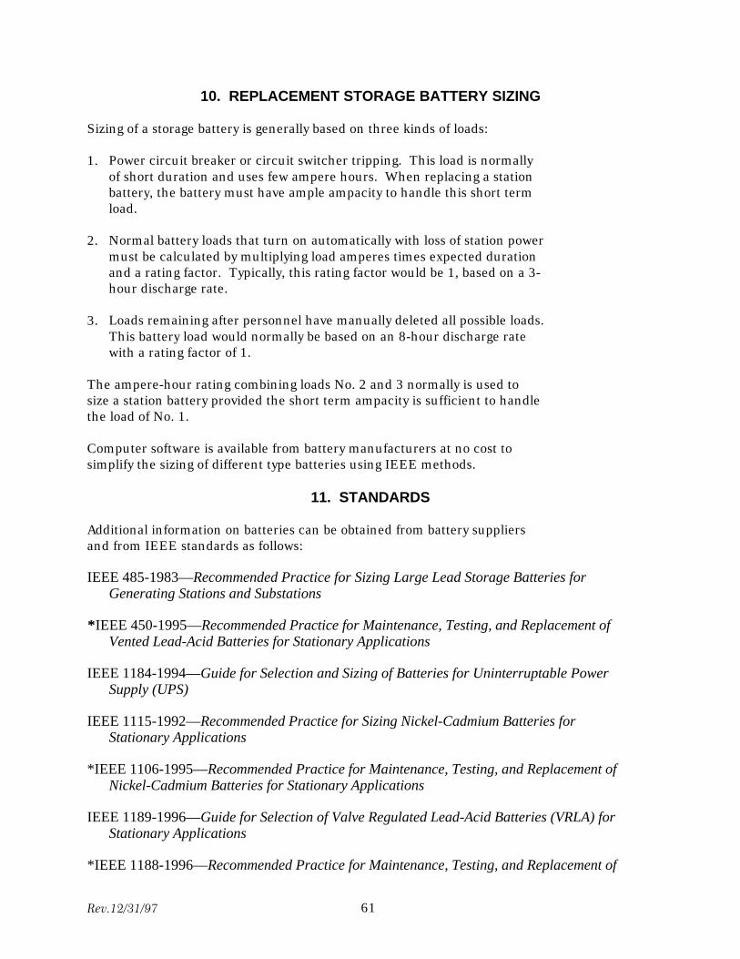
10. REPLACEMENT STORAGE BATTERY SIZING
Sizing of a storage battery is generally based on three kinds of loads:
1. Power circuit breaker or circuit switcher tripping. This load is normally of short duration and uses few ampere hours. When replacing a station battery, the battery must have ample ampacity to handle this short term load.
2. Normal battery loads that turn on automatically with loss of station power must be calculated by multiplying load amperes times expected duration and a rating factor. Typically, this rating factor would be 1, based on a 3hour discharge rate.
3. Loads remaining after personnel have manually deleted all possible loads. This battery load would normally be based on an 8-hour discharge rate with a rating factor of 1.
The ampere-hour rating combining loads No. 2 and 3 normally is used to size a station battery provided the short term ampacity is sufficient to handle the load of No. 1.
Computer software is available from battery manufacturers at no cost to simplify the sizing of different type batteries using IEEE methods.
11. STANDARDS
Additional information on batteries can be obtained from battery suppliers and from IEEE standards as follows:
IEEE 485-1983—Recommended Practice for Sizing Large Lead Storage Batteries for Generating Stations and Substations
**IEEE 450-1995—Recommended Practice for Maintenance, Testing, and Replacement of Vented Lead-Acid Batteries for Stationary Applications
IEEE 1184-1994—Guide for Selection and Sizing of Batteries for Uninterruptable Power Supply (UPS)
IEEE 1115-1992—Recommended Practice for Sizing Nickel-Cadmium Batteries for Stationary Applications
*IEEE 1106-1995—Recommended Practice for Maintenance, Testing, and Replacement of Nickel-Cadmium Batteries for Stationary Applications
IEEE 1189-1996—Guide for Selection of Valve Regulated Lead-Acid Batteries (VRLA) for Stationary Applications
*IEEE 1188-1996—Recommended Practice for Maintenance, Testing, and Replacement of
Rev.12/31/97 61

Valve Regulated Lead-Acid (VRLA) Batteries for Stationary Applications
* These IEEE Standards are referenced extensively in this FIST.
Rev.12/31/97 62
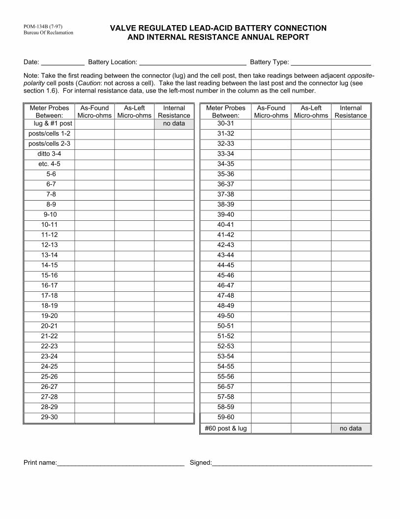
POM-134B (7-97) Bureau Of Reclamation
VALVE REGULATED LEAD-ACID BATTERY CONNECTION AND INTERNAL RESISTANCE ANNUAL REPORT
Date: Battery Location: Battery Type: ______________________ Note: Take the first reading between the connector (lug) and the cell post, then take readings between adjacent opposite-polarity cell posts (Caution: not across a cell). Take the last reading between the last post and the connector lug (see section 1.6). For internal resistance data, use the left-most number in the column as the cell number.
Meter Probes Between:
As-Found Micro-ohms
As-Left Micro-ohms
Internal Resistance
Meter Probes Between:
As-Found Micro-ohms
As-Left Micro-ohms
Internal Resistance
lug & #1 post no data 30-31 posts/cells 1-2 31-32 posts/cells 2-3 32-33
ditto 3-4 33-34 etc. 4-5 34-35
5-6 35-36 6-7 36-37 7-8 37-38 8-9 38-39 9-10 39-40 10-11 40-41 11-12 41-42 12-13 42-43 13-14 43-44 14-15 44-45 15-16 45-46 16-17 46-47 17-18 47-48 18-19 48-49 19-20 49-50 20-21 50-51 21-22 51-52 22-23 52-53 23-24 53-54 24-25 54-55 25-26 55-56 26-27 56-57 27-28 57-58 28-29 58-59 29-30 59-60
#60 post & lug no data
Print name:___________________________________ Signed:____________________________________________
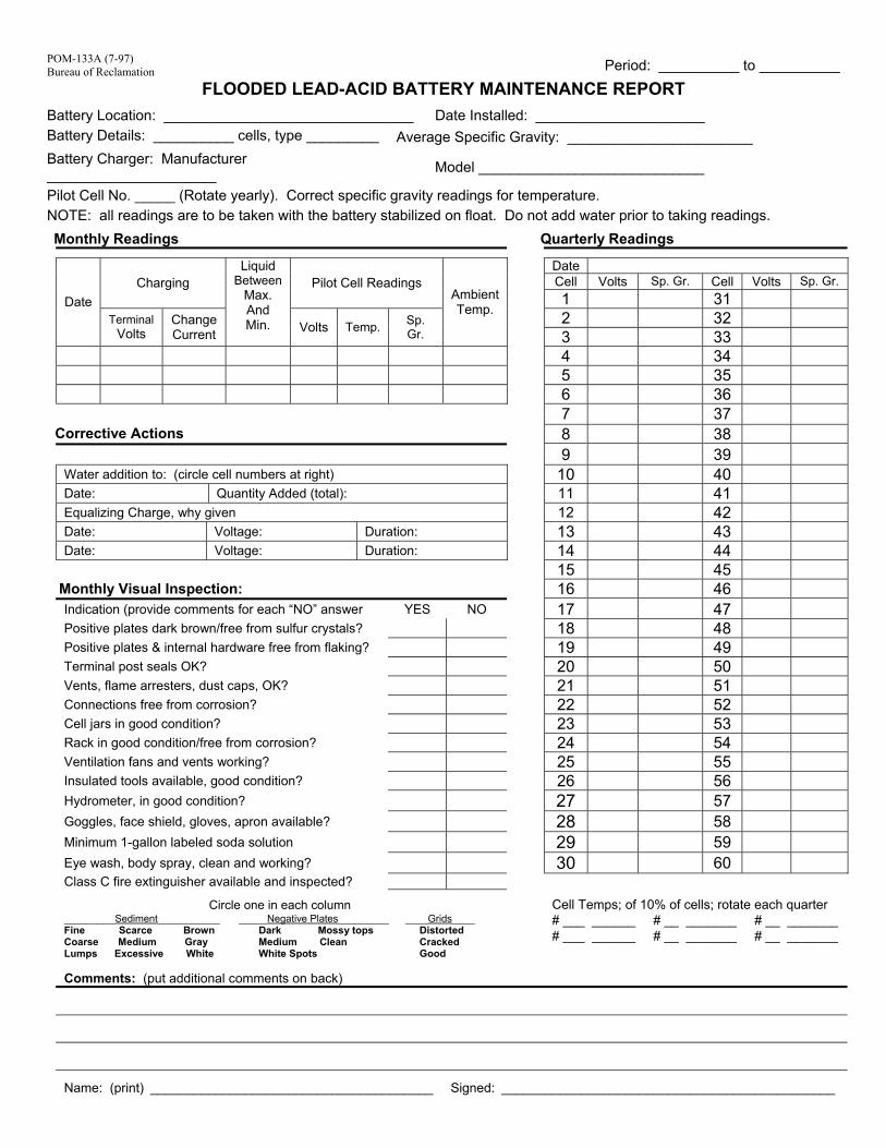
POM-133A (7-97) Bureau of Reclamation Period: __________ to __________
FLOODED LEAD-ACID BATTERY MAINTENANCE REPORT
Battery Location: _______________________________
Date Installed: _____________________
Battery Details: __________ cells, type _________
Average Specific Gravity: _______________________
Battery Charger: Manufacturer _____________________
Model ____________________________
Pilot Cell No. _____ (Rotate yearly). Correct specific gravity readings for temperature.
NOTE: all readings are to be taken with the battery stabilized on float. Do not add water prior to taking readings.
Monthly Readings Quarterly Readings
Date Cell Volts Sp. Gr. Cell Volts Sp. Gr. Charging Pilot Cell Readings 1 31 2 32
Date Terminal
Volts Change Current
Liquid Between
Max. And Min. Volts Temp. Sp.
Gr.
Ambient Temp.
3 33 4 34
5 35
6 36
7 37 Corrective Actions 8 38 9 39 Water addition to: (circle cell numbers at right) 10 40
Date: Quantity Added (total): 11 41
Equalizing Charge, why given 12 42
Date: Voltage: Duration: 13 43
Date: Voltage: Duration: 14 44
15 45
Monthly Visual Inspection: 16 46
Indication (provide comments for each “NO” answer YES NO 17 47
Positive plates dark brown/free from sulfur crystals? 18 48
Positive plates & internal hardware free from flaking? 19 49
Terminal post seals OK? 20 50
Vents, flame arresters, dust caps, OK? 21 51
Connections free from corrosion? 22 52
Cell jars in good condition? 23 53
Rack in good condition/free from corrosion? 24 54
Ventilation fans and vents working? 25 55
Insulated tools available, good condition? 26 56
Hydrometer, in good condition? 27 57
Goggles, face shield, gloves, apron available? 28 58
Minimum 1-gallon labeled soda solution 29 59
Eye wash, body spray, clean and working? 30 60 Class C fire extinguisher available and inspected?
Circle one in each column
Cell Temps; of 10% of cells; rotate each quarter # ___ ______ # __ _______ # __ _______ # ___ ______ # __ _______ # __ _______
_________Sediment___________ Fine Scarce Brown Coarse Medium Gray Lumps Excessive White
_____Negative Plates_________ Dark Mossy tops Medium Clean White Spots
____Grids____ Distorted Cracked Good
Comments: (put additional comments on back)
Name: (print) _______________________________________ Signed: ______________________________________________
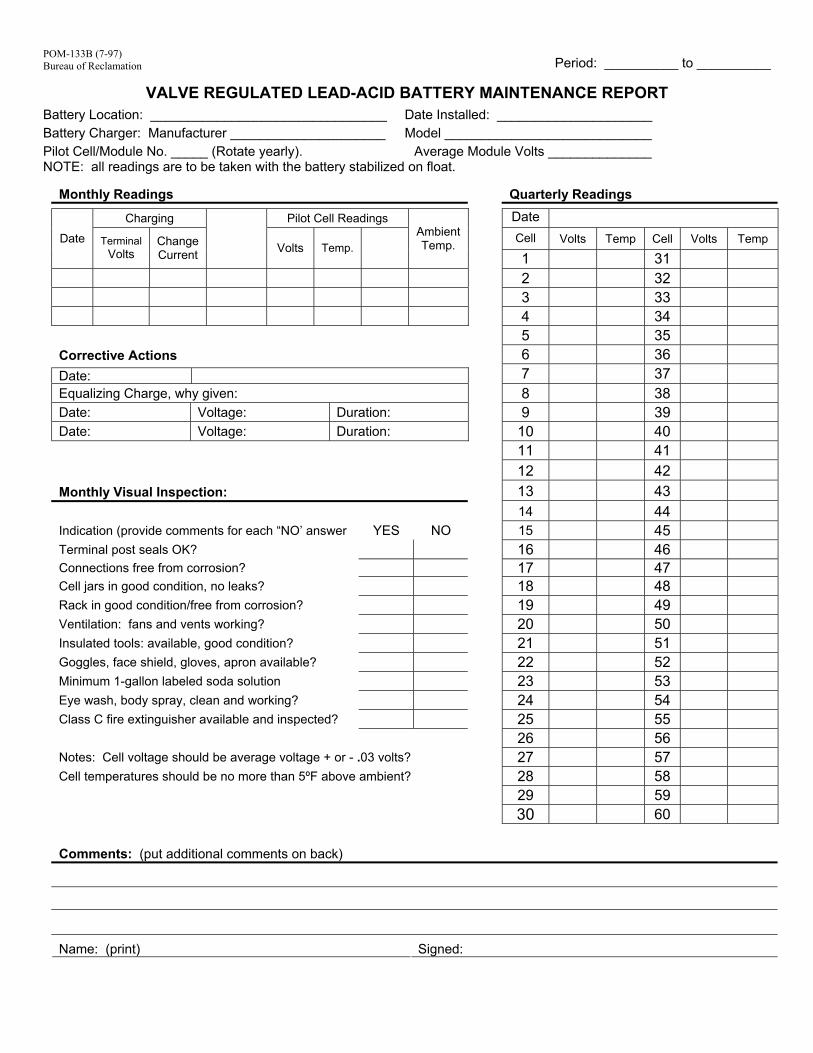
POM-133B (7-97) Bureau of Reclamation
Period: __________ to __________
VALVE REGULATED LEAD-ACID BATTERY MAINTENANCE REPORT Battery Location: ________________________________
Date Installed: _____________________
Battery Charger: Manufacturer _____________________
Model ____________________________
Pilot Cell/Module No. _____ (Rotate yearly). Average Module Volts ______________ NOTE: all readings are to be taken with the battery stabilized on float.
Monthly Readings Quarterly Readings
Charging Pilot Cell Readings Date
Cell
Volts Temp Cell Volts Temp Date Terminal Volts
Change Current
Volts Temp. Ambient Temp.
1 31 2 32 3 33 4 34
5 35
Corrective Actions 6 36
Date: 7 37
Equalizing Charge, why given: 8 38
Date: Voltage: Duration: 9 39
Date: Voltage: Duration: 10 40
11 41
12 42
Monthly Visual Inspection: 13 43
14 44
Indication (provide comments for each “NO’ answer YES NO 15 45
Terminal post seals OK? 16 46
Connections free from corrosion? 17 47
Cell jars in good condition, no leaks? 18 48
Rack in good condition/free from corrosion? 19 49
Ventilation: fans and vents working? 20 50
Insulated tools: available, good condition? 21 51
Goggles, face shield, gloves, apron available? 22 52
Minimum 1-gallon labeled soda solution 23 53
Eye wash, body spray, clean and working? 24 54
Class C fire extinguisher available and inspected? 25 55
26 56
Notes: Cell voltage should be average voltage + or - .03 volts? 27 57
Cell temperatures should be no more than 5ºF above ambient? 28 58
29 59
30 60
Comments: (put additional comments on back)
Name: (print) Signed:
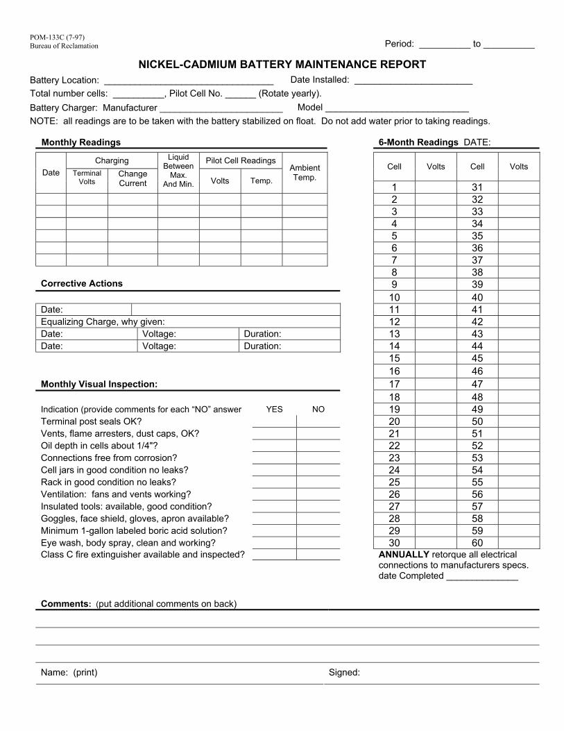
POM-133C (7-97) Bureau of Reclamation
Period: __________ to __________
NICKEL-CADMIUM BATTERY MAINTENANCE REPORT Battery Location: _________________________________
Date Installed: _______________________
Total number cells: __________, Pilot Cell No. ______ (Rotate yearly).
Battery Charger: Manufacturer ________________________
Model ____________________________
NOTE: all readings are to be taken with the battery stabilized on float. Do not add water prior to taking readings.
Monthly Readings 6-Month Readings DATE:
Charging
Pilot Cell Readings Cell Volts Cell Volts
Date Terminal Volts
Change Current
Liquid Between
Max. And Min. Volts Temp.
Ambient Temp.
1 31
2 32 3 33
4 34
Corrective Actions
Date: Equalizing Charge, why given: Date: Voltage: Duration: Date: Voltage: Duration:
Monthly Visual Inspection:
Indication (provide comments for each “NO” answer YES NO Terminal post seals OK? Vents, flame arresters, dust caps, OK? Oil depth in cells about 1/4"? Connections free from corrosion? Cell jars in good condition no leaks? Rack in good condition no leaks? Ventilation: fans and vents working? Insulated tools: available, good condition? Goggles, face shield, gloves, apron available? Minimum 1-gallon labeled boric acid solution? Eye wash, body spray, clean and working? Class C fire extinguisher available and inspected?
Comments: (put additional comments on back)
Name: (print)
Signed:
5 35
6 36
7 37
8 38
9 39
10 40
11 41
12 42
13 43
14 44
15 45
16 46
17 47
18 48
19 49
20 50
21 51
22 52
23 53
24 54
25 55
26 56
27 57
28 58
29 59
30 60 ANNUALLY retorque all electrical connections to manufacturers specs. date Completed ______________
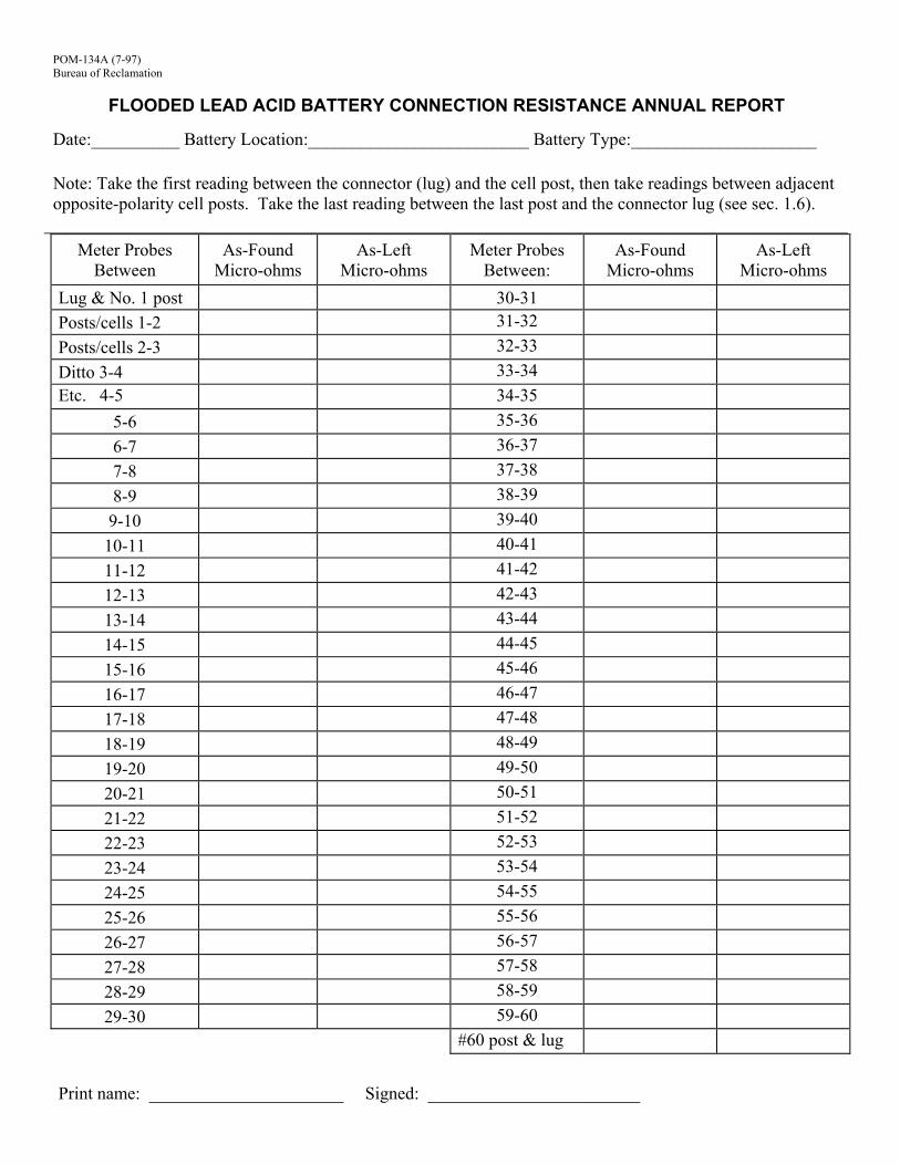
POM-134A (7-97) Bureau of Reclamation
FLOODED LEAD ACID BATTERY CONNECTION RESISTANCE ANNUAL REPORT
Date:__________ Battery Location:_________________________ Battery Type:_____________________ Note: Take the first reading between the connector (lug) and the cell post, then take readings between adjacent opposite-polarity cell posts. Take the last reading between the last post and the connector lug (see sec. 1.6).
Meter Probes Between
As-Found Micro-ohms
As-Left Micro-ohms
Meter Probes Between:
As-Found Micro-ohms
As-Left Micro-ohms
Lug & No. 1 post 30-31 Posts/cells 1-2 31-32 Posts/cells 2-3 32-33 Ditto 3-4 33-34 Etc. 4-5 34-35
5-6 35-36 6-7 36-37 7-8 37-38 8-9 38-39 9-10 39-40 10-11 40-41 11-12 41-42 12-13 42-43 13-14 43-44 14-15 44-45 15-16 45-46 16-17 46-47 17-18 47-48 18-19 48-49 19-20 49-50 20-21 50-51 21-22 51-52 22-23 52-53 23-24 53-54 24-25 54-55 25-26 55-56 26-27 56-57 27-28 57-58 28-29 58-59 29-30 59-60
#60 post & lug
Print name: ______________________ Signed: ________________________
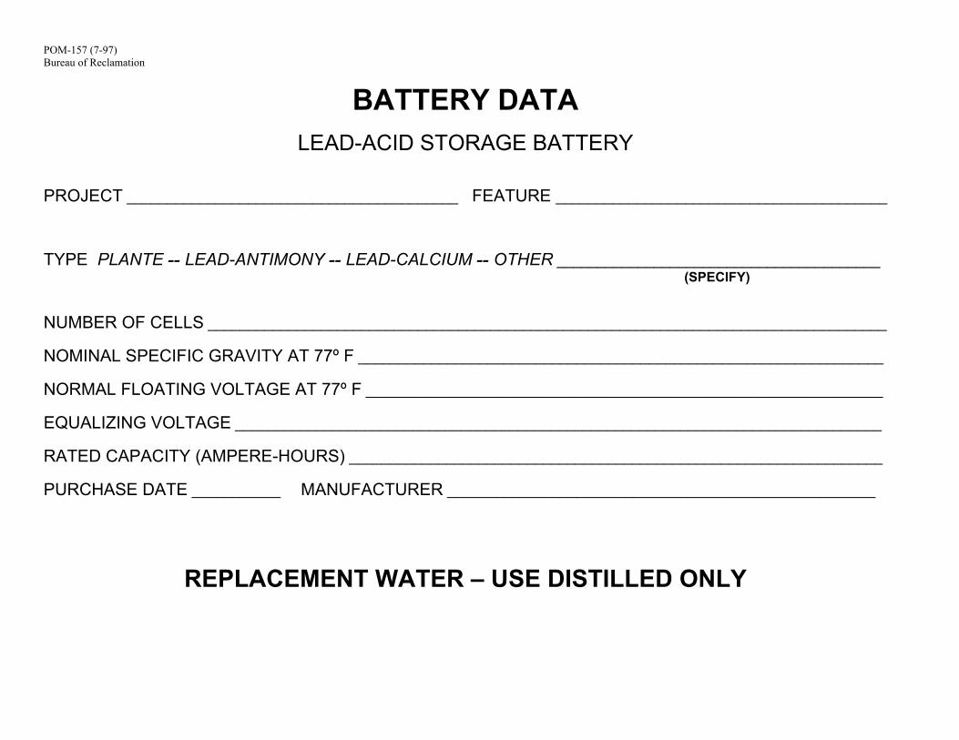
POM-157 (7-97) Bureau of Reclamation
BATTERY DATA
LEAD-ACID STORAGE BATTERY
PROJECT _________________________________________ FEATURE _________________________________________
TYPE PLANTE -- LEAD-ANTIMONY -- LEAD-CALCIUM -- OTHER ________________________________________ (SPECIFY)
NUMBER OF CELLS ____________________________________________________________________________________ NOMINAL SPECIFIC GRAVITY AT 77º F _________________________________________________________________ NORMAL FLOATING VOLTAGE AT 77º F ________________________________________________________________ EQUALIZING VOLTAGE ________________________________________________________________________________ RATED CAPACITY (AMPERE-HOURS) __________________________________________________________________ PURCHASE DATE ___________
MANUFACTURER _____________________________________________________
REPLACEMENT WATER – USE DISTILLED ONLY
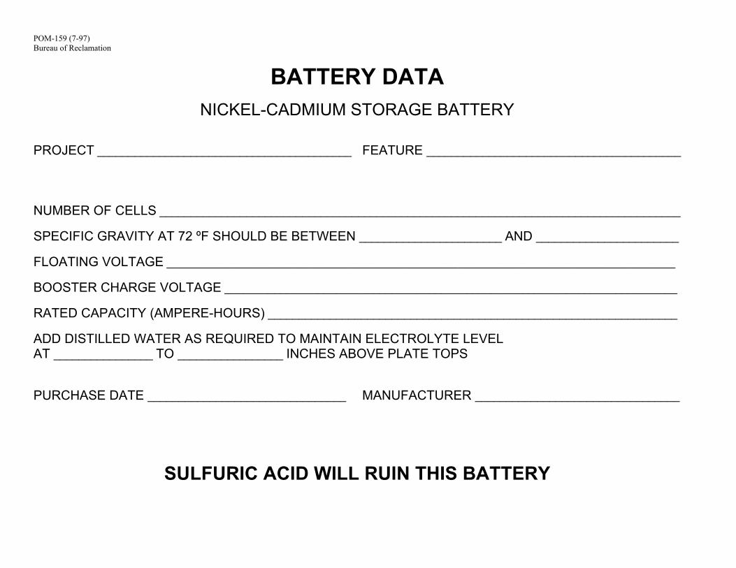
POM-159 (7-97) Bureau of Reclamation
BATTERY DATA
NICKEL-CADMIUM STORAGE BATTERY
PROJECT _________________________________________ FEATURE _________________________________________
NUMBER OF CELLS ____________________________________________________________________________________ SPECIFIC GRAVITY AT 72 ºF SHOULD BE BETWEEN _______________________ AND _______________________ FLOATING VOLTAGE __________________________________________________________________________________ BOOSTER CHARGE VOLTAGE _________________________________________________________________________ RATED CAPACITY (AMPERE-HOURS) __________________________________________________________________ ADD DISTILLED WATER AS REQUIRED TO MAINTAIN ELECTROLYTE LEVEL AT ________________ TO _________________ INCHES ABOVE PLATE TOPS PURCHASE DATE ________________________________
MANUFACTURER _________________________________
SULFURIC ACID WILL RUIN THIS BATTERY
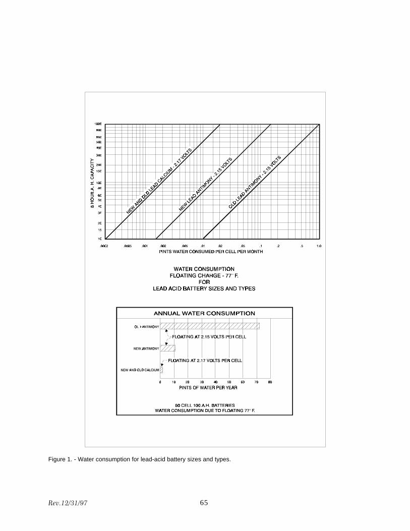
Figure 1. - Water consumption for lead-acid battery sizes and types.
Rev.12/31/97 65
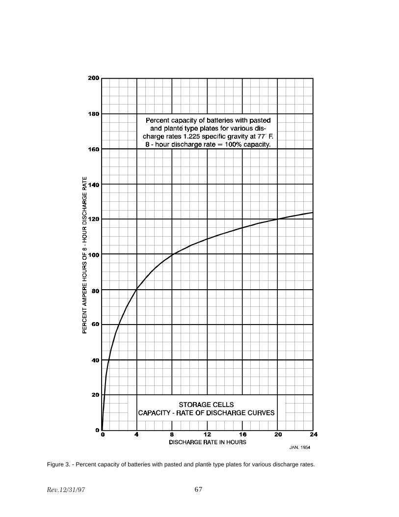
Figure 3. - Percent capacity of batteries with pasted and plante type plates for various discharge rates.´
Rev.12/31/97 67
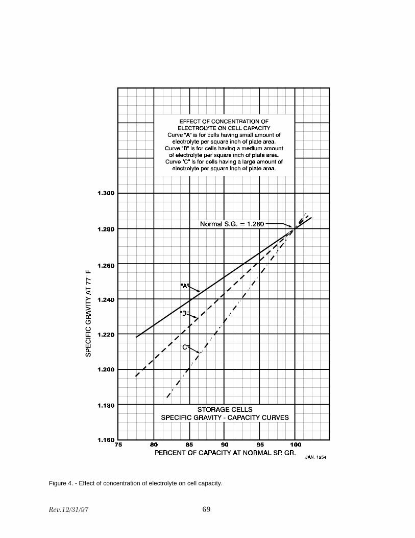
Figure 4. - Effect of concentration of electrolyte on cell capacity.
Rev.12/31/97 69
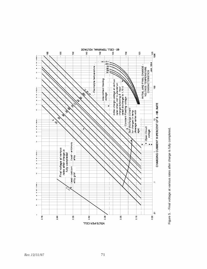
Rev.12/31/97 71
Fig
ure
5. -
Fin
al v
olta
ge a
t var
ious
rat
es a
fter
char
ge is
ful
ly c
ompl
eted
.
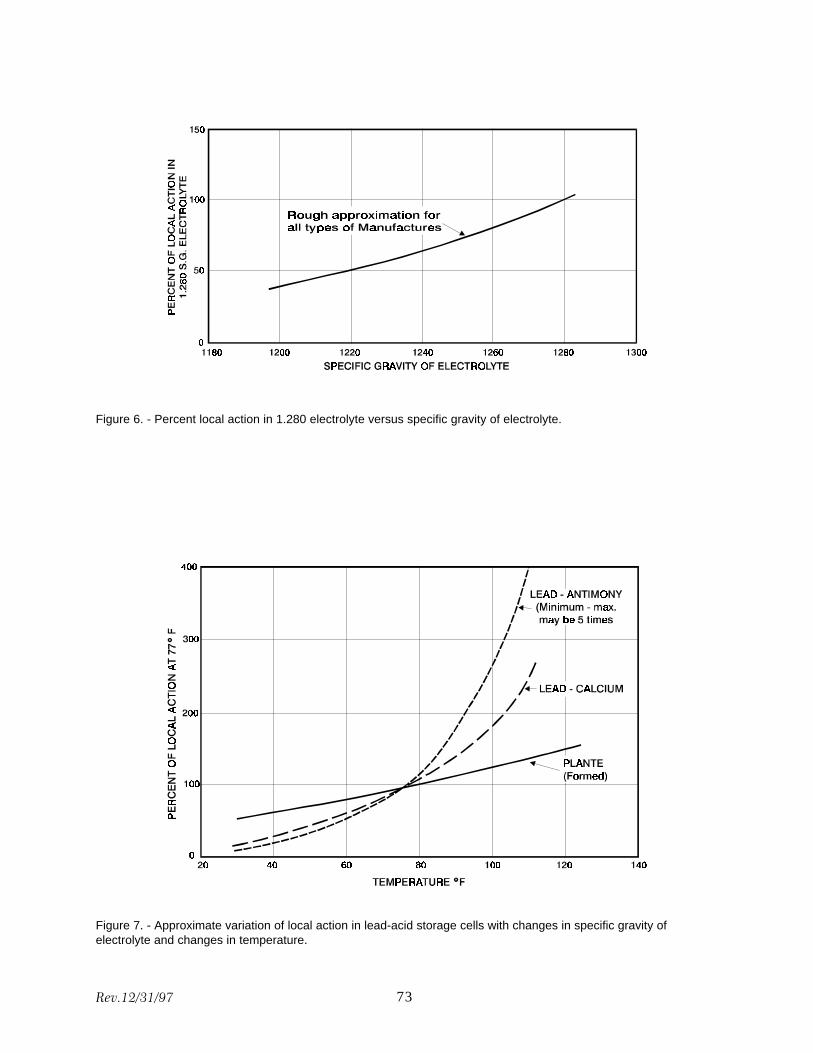
Figure 6. - Percent local action in 1.280 electrolyte versus specific gravity of electrolyte.
Figure 7. - Approximate variation of local action in lead-acid storage cells with changes in specific gravity of electrolyte and changes in temperature.
Rev.12/31/97 73
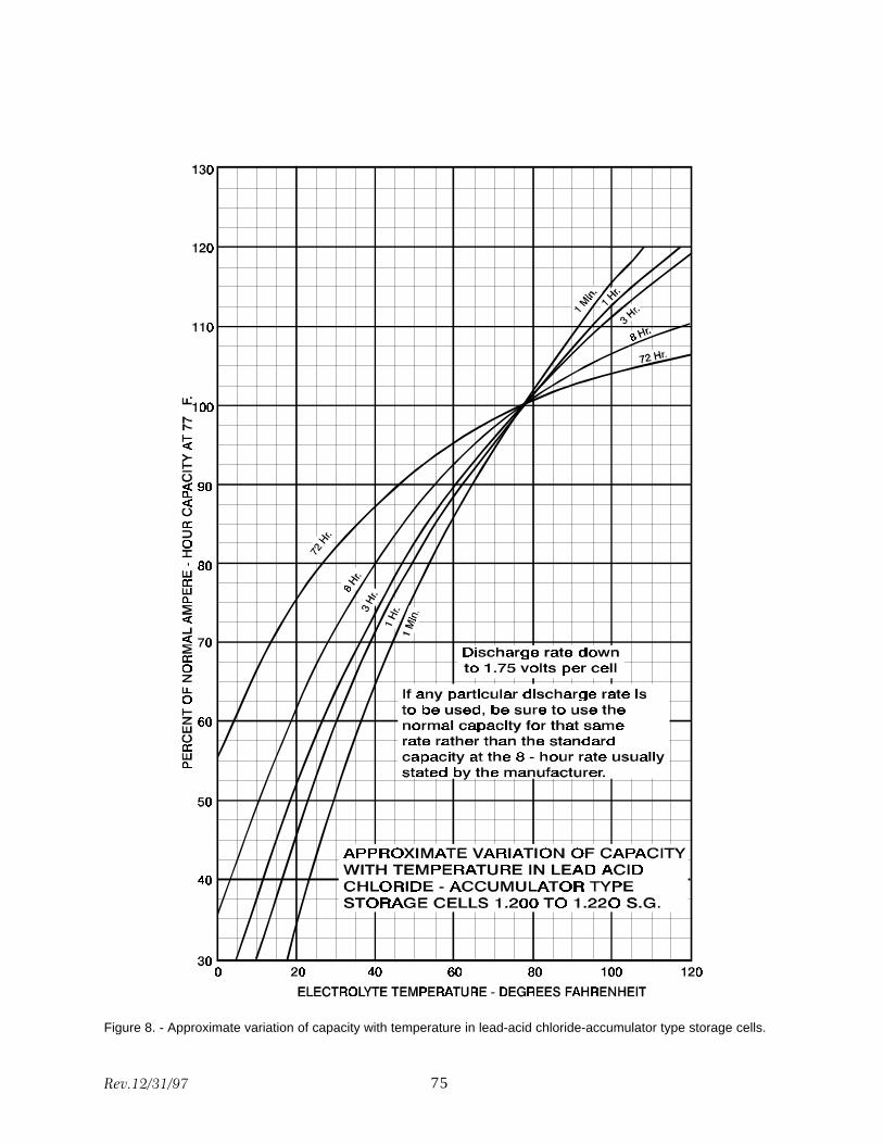
Figure 8. - Approximate variation of capacity with temperature in lead-acid chloride-accumulator type storage cells.
Rev.12/31/97 75
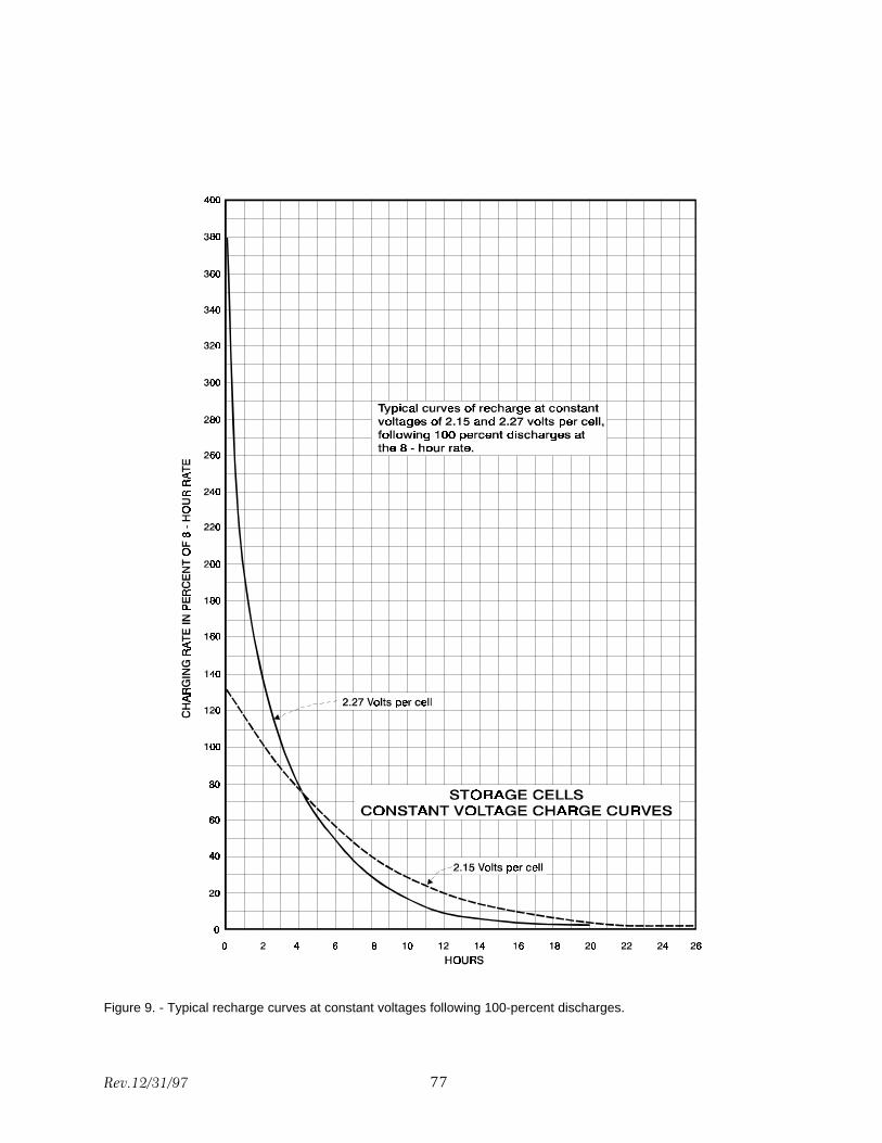
Figure 9. - Typical recharge curves at constant voltages following 100-percent discharges.
Rev.12/31/97 77
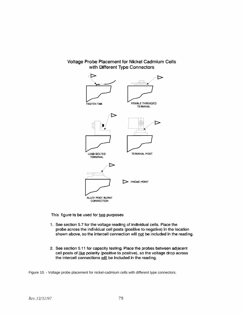
Figure 10. - Voltage probe placement for nickel-cadmium cells with different type connectors.
Rev.12/31/97 79
MISSION STATEMENTS
The mission of the Department of the Interior is to protect and provide access to our Nation's natural and cultural heritage and honor our trust responsibilities to tribes.
The mission of the Bureau of Reclamation is to manage, develop, and protect water and related resources in an environmentally and economically sound manner in the interest of the American public.