lead storage battery
TRANSCRIPT
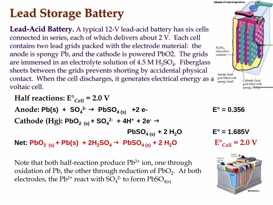
Lead Storage BatteryLead-Acid Battery. A typical 12-V lead-acid battery has six cells connected in series, each of which delivers about 2 V. Each cell contains two lead grids packed with the electrode material: the anode is spongy Pb, and the cathode is powered PbO2. The grids are immersed in an electrolyte solution of 4.5 M H2SO4. Fiberglass sheets between the grids prevents shorting by accidental physical contact. When the cell discharges, it generates electrical energy as a voltaic cell.
Half reactions: E°Cell = 2.0 VAnode: Pb(s) + SO4
2- PbSO4 (s) +2 e- E° = 0.356Cathode (Hg): PbO2 (s) + SO4
2- + 4H+ + 2e-
PbSO4 (s) + 2 H2O E° = 1.685VNet: PbO2 (s) + Pb(s) + 2H2SO4 PbSO4 (s) + 2 H2O E°Cell = 2.0 V
Note that both half-reaction produce Pb2+ ion, one through oxidation of Pb, the other through reduction of PbO2. At both electrodes, the Pb2+ react with SO4
2- to form PbSO4(s)

Physical and Chemical Properties of Lead and Lead Oxides (PbO2)
Typically, a charged positive electrode contains both α-PbO2 (orthorhombic) and β-PbO2 (tetragonal). The equilibrium potential of the α-PbO2 is more positive than that of β -PbO2 by 0.01 V. The form also has a larger, more compact crystal morphology which is less active electrochemically and slightly lower in capacity per unit weight; it does, however, promote longer cycle life. Neither of the two forms is fully stoichiometric. Their composition can be represented by PbOx, with x varying between 1.85 and 2.05.
What happens as all the amps get used up?
• The electrolyte turns to water and the lead and sponge lead plates turn to Lead sulfate and the acid will no longer strip electrons from the positive plates and add them to the negative plates
• The battery will go DEAD.
Note: Add distilled (or de-mineralized) water to the low electrolyte battery. Adding tap water will encourage electrolysis. This will speed up the loss of that water when charging and discharging. It will also encourage corrosion on the battery cables
Major Advantages and Disadvantages of Lead-Acid Batteries

Deep Cycle batteries
Recreational Vehicles and marines are intended to operate smaller electrical loads (lights, 12 volt accessories, trolling motors etc.) for long periods of time without being recharged.
They are called Deep Cycle batteries as they can withstand many cycles of long slow discharging followed by long slow charging.
Rapid discharging (like the hundreds of amps pulled by a starter motor) will ruin a Deep Cycle battery. It will overheat the plates.
Cells are always made with an outside-negative design (e.g., n positive plates, (n+1) negative plates).
Starting Batteries
The function of the battery is to start the engine
Then the generator will run all electrical loads.
Some Recreational Vehicles use both a starting battery and a deep cycle battery.
The deep cycle battery is not hooked to the starter motor. If you allow a starting battery to slowly go dead it will “SULFATE”
This happens when lead sulfate (formed when a battery discharges) crystallizes on the surface of the lead plates.
This will not allow the battery to fully recharge.
Sometimes a sulfated battery will not recharge at all.

ChargingProper recharging is important to obtain optimum life from any lead-acid battery under any
conditions of use. Some of the rules for proper charging are given below and apply to all types of lead-acid batteries.
1. The charge current at the start of recharge can be any value that does not produce an average cell voltage in the battery string greater than the gassing voltage (about 2.4 V per cell).
2. During the recharge and until 100% of the previous discharge capacity has been returned, the current should be controlled to maintain a voltage lower than the gassing voltage. To minimize charge time, this voltage can be just below the gassing voltage.
3. When 100% of the discharged capacity has been returned under this voltage control, the charge rate will have normally decayed to the charge ‘‘finishing’’ rate. The charge should be finished at a constant current no higher than this rate, normally 5 A per 100 Ah of rated capacity (referred to as the 20-h rate).
A number of methods for charging lead-acid batteries have evolved to meet these conditions. These charging methods are commonly known as:
1. Constant-current, one-current rate, 2. Constant-current, multiple decreasing-current steps3. Modified constant current, 4. Constant potential5. Modified constant potential with constant initial current6. Modified constant potential with a constant finish rate7. Modified constant potential with a constant start and finish rate8. Taper charge (a variation of the modified constant-potential method, using less sophisticated
controls to reduce equipment cost)9. Pulse charging10. Trickle charging (continuous constant-current charge at a low (about C/100) rate)11. Float charging (low-rate constant-potential charge)12. Rapid charging

Overcharging
Results in:• warped or broken plates• damaged separators• severe shedding of the active materials pasted
to the plates and •excessive loss of water, which cause plates to
dry out.
Self-Discharge
The rate of self-discharge depends on several factors. Lead and lead dioxide are thermodynamically unstable in sulfuric acid solutions, and on open circuit, they react with the electrolyte. Oxygen is evolved at the positive electrode and hydrogen at the negative, at a rate dependent on temperature and acid concentration (the gassing rate increases with increasing acid concentration) as follows:
For most positives, the formation of PbSO4 by self-discharge is slow, typically much lessthan 0.5%/day at 25C. (Some positives which have been made with nonantimonial gridscan fail by a different mechanism on open circuit, namely, the development of a grid-active material barrier layer.) The self-discharge of the negative is generally more rapid, especially if the cell is contaminated with various catalytic metallic ions. Antimony lost from the positive grids by corrosion can diffuse to the negative, where it is deposited, resulting in a ‘‘local action’’ discharge cell which converts some lead active material to PbSO4. New batteries with lead-antimony grids lose about 1% of charge per day at 25C, but the charge loss increases by a factor of 2 to 5 as the battery ages. Batteries with nonantimonial lead grids lose less than 0.5% of charge per day regardless of age. Self-discharge can be minimized by storing batteries at temperatures between 5 and 15C.

CONSTRUCTIONAL FEATURES
Weight analysis of typical lead-acid batteries. (a) SLI battery. (b) Tubular industrial battery. (c) Flat-plate traction battery.

Capacity Rating System
The Society of Automotive Engineers (SAE) has established two ratings for domestic made batteries:1- Reserve Capacity (RC): is the time required (in
minutes) for a fully charged battery at 80°F under a constant 25 amp draw to reach a voltage of 10.5 volts.
2- Cold Cranking Amps (CCA): measures the discharge lead (in amps) that a battery can supply for 30 seconds at 0°F (-17°C), while maintaining a voltage of 1.2 volts per cell (7.2 volts per battery or higher).

Ventilation Requirements
The oxygen and hydrogen gases released during the gassing phase of a typical flooded lead-acid battery recharge can be dangerous if allowed to exceed 0.8 % (by volume) or 20 percent of the lower explosive range. Concentrations of hydrogen between 4 % and 74% are considered explosive (40,000 ppm and 740,000 ppm).
•All lead acid power batteries give off gases when recharging and also for a period after the charge is completed.•A Concentration of hydrogen in excess of 4% (by volume). It is suggested that the concentration be controlled to a maximum of 2% (by volume).•A typical lead acid motive power cell will, evolve approximately 0.016 cubic feet of hydrogen gas over A.h. overcharge. Since this gas is given off at the maximum rate at the end of the charging period, the following calculation assumes a charging current of 5% of the 6 hour A.h. capacity (C6) during this over charge period. (This charging current is excessive but has been used to take account of the worst case.)Gas given off per hour per cell = 0.16 x .05 = .0008 C6 cu ft. / cell / hr.

Hydrometer
The chart below gives state of charge vs. specific gravity of the electrolyte.
State of Charge Specific Gravity
100% Charged 1.265
75% Charged 1.239
50% Charged 1.200
25% Charged 1.170
Fully Discharged 1.110
These readings are correct at 75°F

Jump Starting
• Be sure to turn off accessories.• Connect the red cable to the positive terminal on the good battery
while the engine is running.• Connect the other end of the red cable to the positive terminal on the
dead battery.• Then connect one end of the black cable to the negative terminal on
the good battery.• Connect the other end of the negative cable to a known good ground
in the vehicle with the dead battery.• After starting the vehicle with the discharged battery, allow the
engine to return to idle speed.• Remove the negative jumper cable starting with the end that is
connected to the vehicle ground• Remove the positive cable.

Frozen BatteriesDO NOT ATTEMPT TO JUMP START OR CHARGE A FROZEN
BATTERYA charging battery forms Hydrogen gas that will be trapped by the ice and can cause the battery to explode. A frozen battery is ruined due to the ice breaking up the sponge lead plates. Once thawed out it will soon fail.
Replace frozen batteries.
A frozen battery will have a bulged out case that will not reform.
An overcharged battery can also cause the case to bulge or distort.
If the case looks distorted test the battery and the charging system .

Nickel-Cadmium BatteryBattery for the Technological AgeRechargeable, lightweight “ni-cad” are used for variety of cordless appliances. Main advantage is that the oxidizing and reducing agent can be regenerated easily when recharged. These produce constant potential.Half reactions: E°Cell = 1.4 V
Anode: Cd(s) + 2OH-(aq) Cd(OH)2 (s) + 2e-
Cathode: 2Ni(OH) (s) + 2H2O(l) + 2e- Ni(OH)2 (s) + 2 OH-(aq)
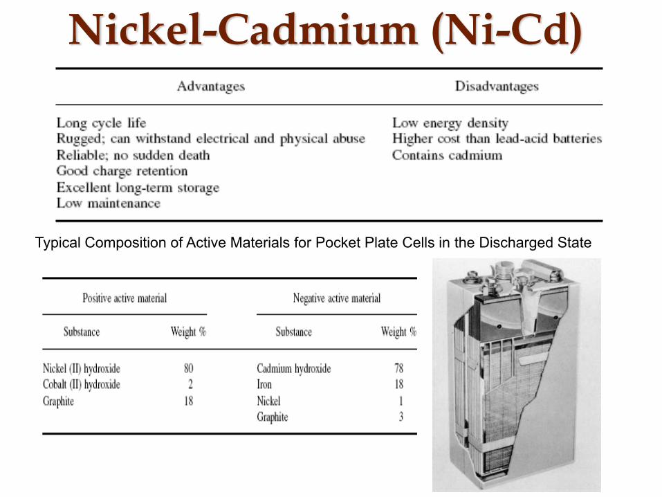
Nickel-Cadmium (Ni-Cd)
Typical Composition of Active Materials for Pocket Plate Cells in the Discharged State
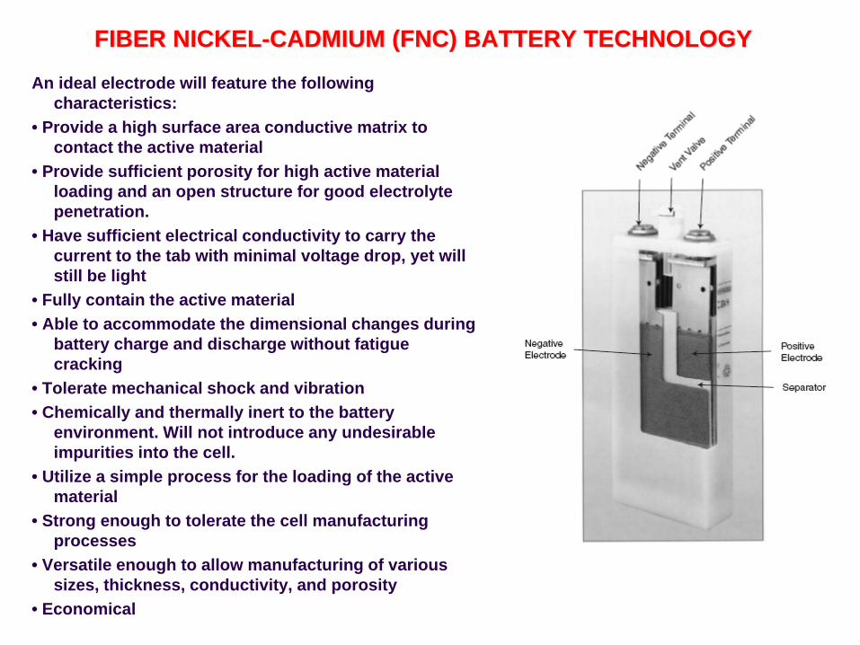
FIBER NICKEL-CADMIUM (FNC) BATTERY TECHNOLOGY
An ideal electrode will feature the following characteristics:
• Provide a high surface area conductive matrix to contact the active material
• Provide sufficient porosity for high active material loading and an open structure for good electrolyte penetration.
• Have sufficient electrical conductivity to carry the current to the tab with minimal voltage drop, yet will still be light
• Fully contain the active material• Able to accommodate the dimensional changes during
battery charge and discharge without fatigue cracking
• Tolerate mechanical shock and vibration• Chemically and thermally inert to the battery
environment. Will not introduce any undesirable impurities into the cell.
• Utilize a simple process for the loading of the active material
• Strong enough to tolerate the cell manufacturing processes
• Versatile enough to allow manufacturing of various sizes, thickness, conductivity, and porosity
• Economical
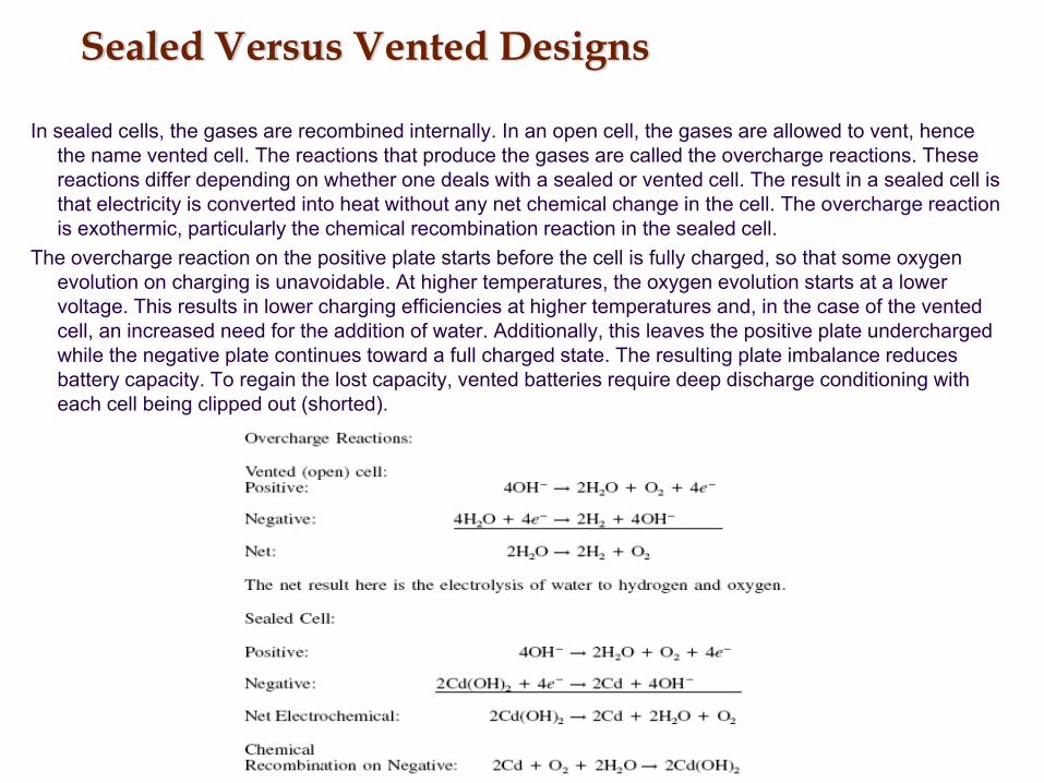
Sealed Versus Vented Designs
In sealed cells, the gases are recombined internally. In an open cell, the gases are allowed to vent, hence the name vented cell. The reactions that produce the gases are called the overcharge reactions. These reactions differ depending on whether one deals with a sealed or vented cell. The result in a sealed cell is that electricity is converted into heat without any net chemical change in the cell. The overcharge reaction is exothermic, particularly the chemical recombination reaction in the sealed cell.
The overcharge reaction on the positive plate starts before the cell is fully charged, so that some oxygen evolution on charging is unavoidable. At higher temperatures, the oxygen evolution starts at a lower voltage. This results in lower charging efficiencies at higher temperatures and, in the case of the vented cell, an increased need for the addition of water. Additionally, this leaves the positive plate undercharged while the negative plate continues toward a full charged state. The resulting plate imbalance reduces battery capacity. To regain the lost capacity, vented batteries require deep discharge conditioning with each cell being clipped out (shorted).

NiCd Memory EffectA reversible effect which may result in a gradual reduction of both power and capacity with cycling. This effect, sometimes referred to as ‘‘memory effect,’’ ‘‘fading,’’ or ‘‘voltage depression,’’ results from charging following repetitive shallow discharges where some portion of the active materials in the cell is not used or discharged, such as in a typical engine-start use. This effect is noticed when the previously undischarged material is eventually discharged. The terminal voltage during the latter part of that full discharge may be lower by approximately 120 mV (hence, ‘‘voltage depression’’). The total capacity is not reduced, however, if the discharge is continued to the lower voltages, as, for example, to the ‘‘knee’’ of the curve.

Nickel Metal Hydride Batteries
A key component of the sealed nickel-metal hydride cell is the hydrogen storage metal alloy. The composition of the alloy is formulated to obtain a material that is stable over a large number of charge-discharge cycles. Other important properties of the alloy include:
1. Good hydrogen storage to achieve a high-energy density and battery capacity2. Thermodynamic properties suitable for reversible absorption/desorption3. Low hydrogen equilibrium pressure4. High electrochemical reactivity5. Favorable kinetic properties for high-rate performance6. High oxidation resistance7. Stability, with repeated charge/ discharge cycles, in alkaline electrolyte
Chemistry(-)LaNi5, TiMn2,ZrMn2(+) nickel hydroxidePotassium hydroxide aqueous electrolyte
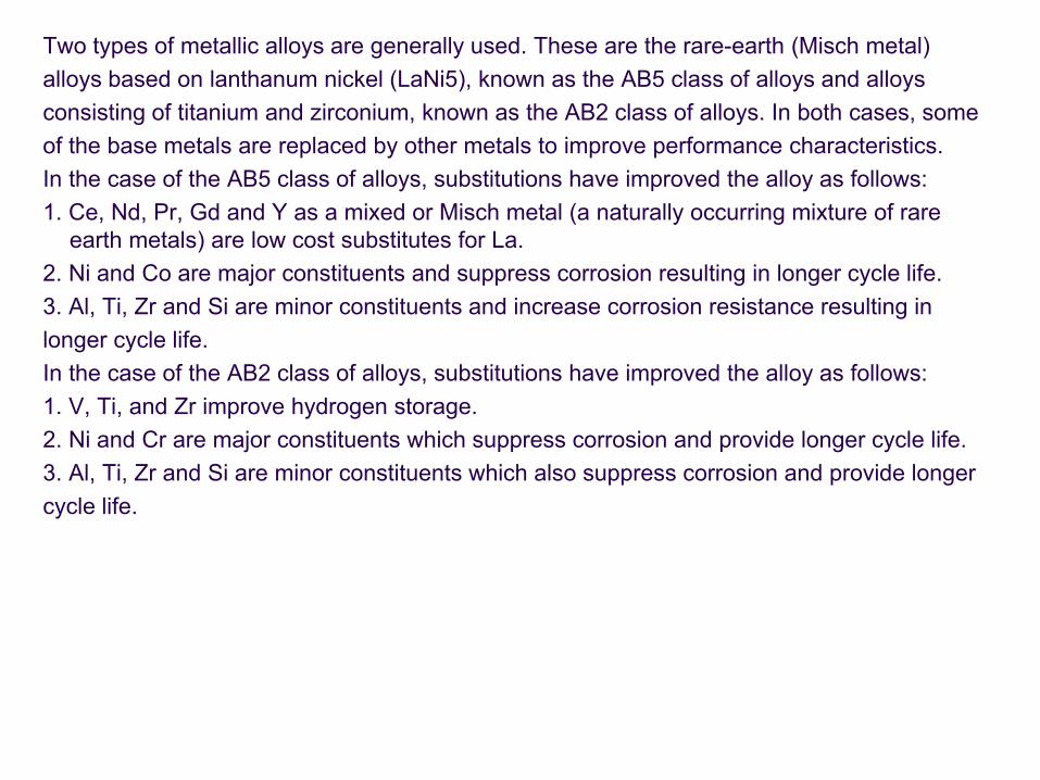
Two types of metallic alloys are generally used. These are the rare-earth (Misch metal)alloys based on lanthanum nickel (LaNi5), known as the AB5 class of alloys and alloysconsisting of titanium and zirconium, known as the AB2 class of alloys. In both cases, someof the base metals are replaced by other metals to improve performance characteristics.In the case of the AB5 class of alloys, substitutions have improved the alloy as follows:1. Ce, Nd, Pr, Gd and Y as a mixed or Misch metal (a naturally occurring mixture of rare
earth metals) are low cost substitutes for La.2. Ni and Co are major constituents and suppress corrosion resulting in longer cycle life.3. Al, Ti, Zr and Si are minor constituents and increase corrosion resistance resulting inlonger cycle life.In the case of the AB2 class of alloys, substitutions have improved the alloy as follows:1. V, Ti, and Zr improve hydrogen storage.2. Ni and Cr are major constituents which suppress corrosion and provide longer cycle life.3. Al, Ti, Zr and Si are minor constituents which also suppress corrosion and provide longercycle life.
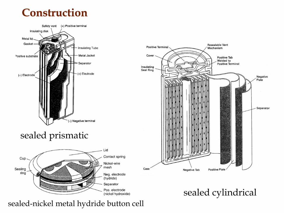
Construction
sealed cylindricalsealed-nickel metal hydride button cell
sealed prismatic
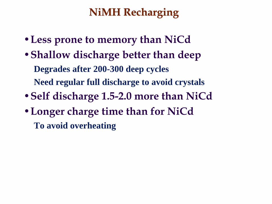
NiMH Recharging
•Less prone to memory than NiCd•Shallow discharge better than deep
Degrades after 200-300 deep cyclesNeed regular full discharge to avoid crystals
•Self discharge 1.5-2.0 more than NiCd•Longer charge time than for NiCd
To avoid overheating

NiMH Memory Effect

Lithium-Batteries• Chemistry
Graphite (-), cobalt or manganese (+) and a nonaqueous electrolyte• Features:
+ 40% more capacity than NiCd, + Flat discharge (like NiCd)+ Self-discharge 50% less than NiCd, - Expensive, + 3.6 V+ Slow-loss of charge (5% per month), + Best energy to weight ratio+ No memory effect, + Popular for portable electronics (cell phones, IPod)
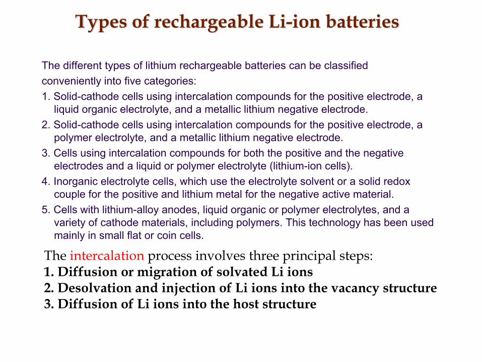
Types of rechargeable Li-ion batteries
The different types of lithium rechargeable batteries can be classifiedconveniently into five categories:1. Solid-cathode cells using intercalation compounds for the positive electrode, a
liquid organic electrolyte, and a metallic lithium negative electrode.2. Solid-cathode cells using intercalation compounds for the positive electrode, a
polymer electrolyte, and a metallic lithium negative electrode.3. Cells using intercalation compounds for both the positive and the negative
electrodes and a liquid or polymer electrolyte (lithium-ion cells).4. Inorganic electrolyte cells, which use the electrolyte solvent or a solid redox
couple for the positive and lithium metal for the negative active material.5. Cells with lithium-alloy anodes, liquid organic or polymer electrolytes, and a
variety of cathode materials, including polymers. This technology has been used mainly in small flat or coin cells.
The intercalation process involves three principal steps:1. Diffusion or migration of solvated Li ions2. Desolvation and injection of Li ions into the vacancy structure3. Diffusion of Li ions into the host structure
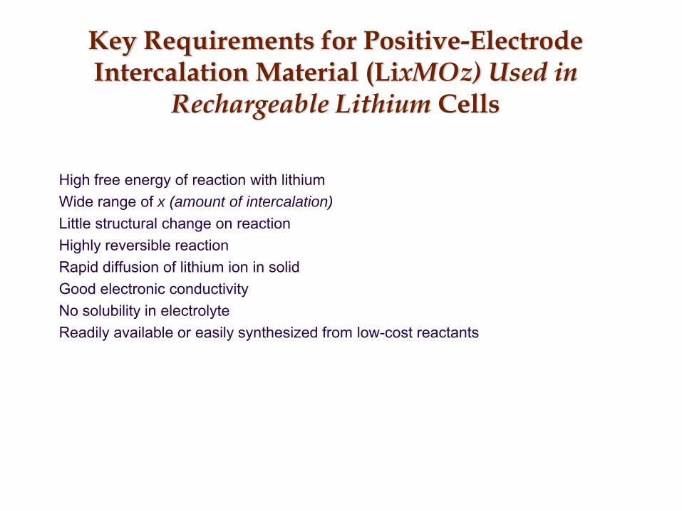
Key Requirements for Positive-ElectrodeIntercalation Material (LixMOz) Used in
Rechargeable Lithium Cells
High free energy of reaction with lithiumWide range of x (amount of intercalation)Little structural change on reactionHighly reversible reactionRapid diffusion of lithium ion in solidGood electronic conductivityNo solubility in electrolyteReadily available or easily synthesized from low-cost reactants
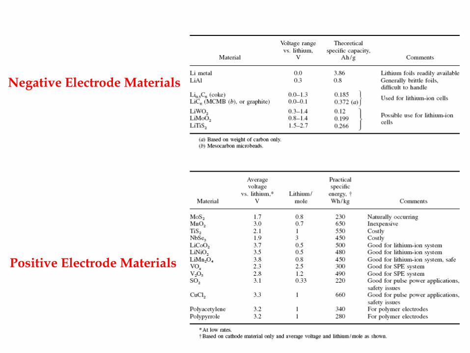
Negative Electrode Materials
Positive Electrode Materials

ElectrolytesThe choice of electrolyte for rechargeable lithium batteries is also critical. The electrolyteshould have the following characteristics:1. Good ionic conductivity (103 S/cm from 40 to 90C) to minimize internal resistance.2. Lithium ion transference number approaching unity (to limit concentration polarization)3. Wide electrochemical voltage window (0 to 5 V)4. Thermal stability (up to 70C)5. Compatibility with other cell components
Aprotic Organic Electrolyte: Aprotic liquid organic electrolyte solvents, such as dioxolane,propylene carbonate, ethylene carbonate, diethyl carbonate and ethylmethyl carbonate are the most common electrolyte solvents because of their low reactivity with lithium.
Polymer Electrolytes: An alternative to the liquid electrolytes is a solid polymer electrolyte(SPE) formed by incorporating lithium salts into polymer matrices and casting into thin films. These can be used as both the electrolyte and separator.
Solid-State Electrolytes: True all solid-state ionic electrolytes such as lithium phosphorusoxynitride (LiPON) provide adequate conductivity for use in thin film solid-state batteries.
Inorganic Electrolytes: The SO2-based inorganic electrolytes are another alternative foruse in rechargeable lithium batteries. These electrolytes are attractive because they offer thehighest ionic conductivity of any electrolyte used in rechargeable lithium batteries.
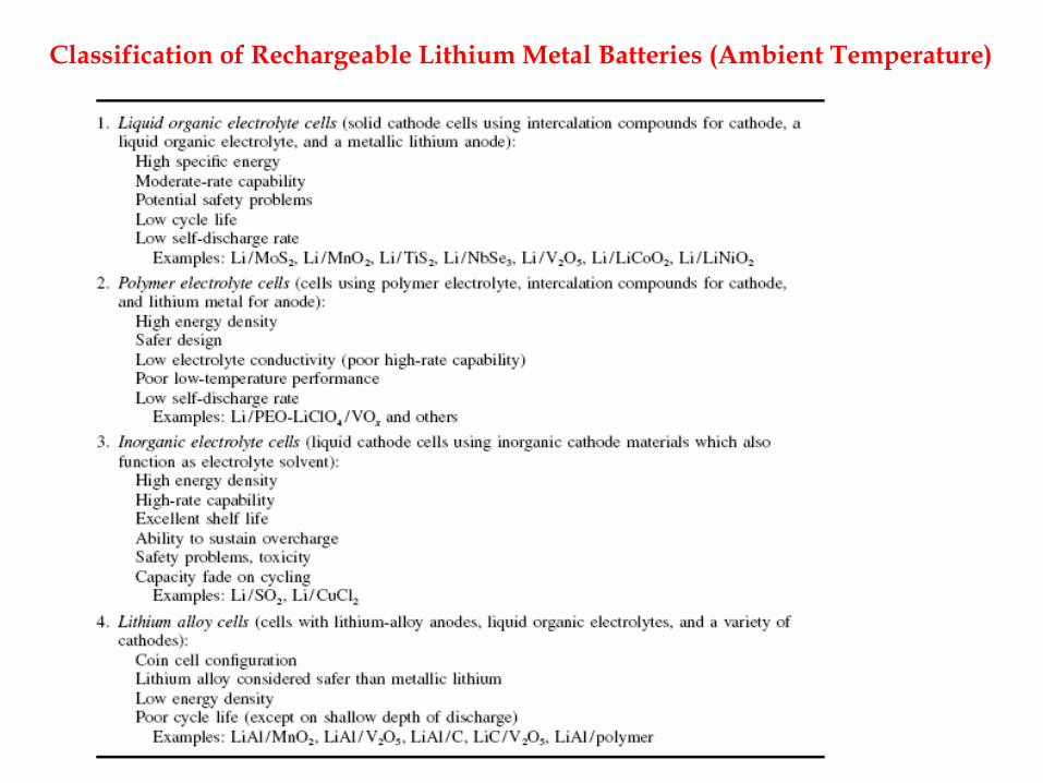
Classification of Rechargeable Lithium Metal Batteries (Ambient Temperature)
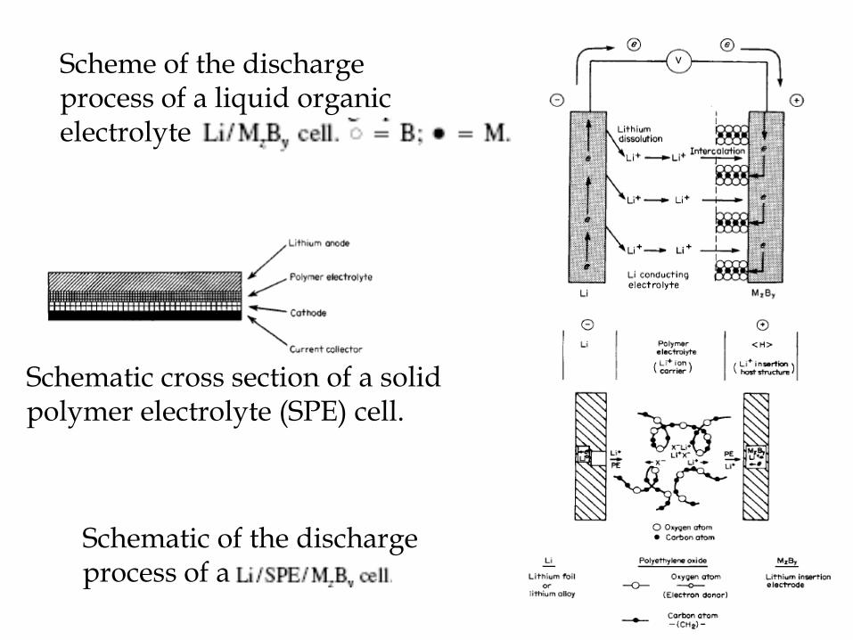
Scheme of the discharge process of a liquid organic electrolyte
Schematic of the discharge process of a
Schematic cross section of a solid polymer electrolyte (SPE) cell.

Chemistry of Rechargeable Lithium Systems
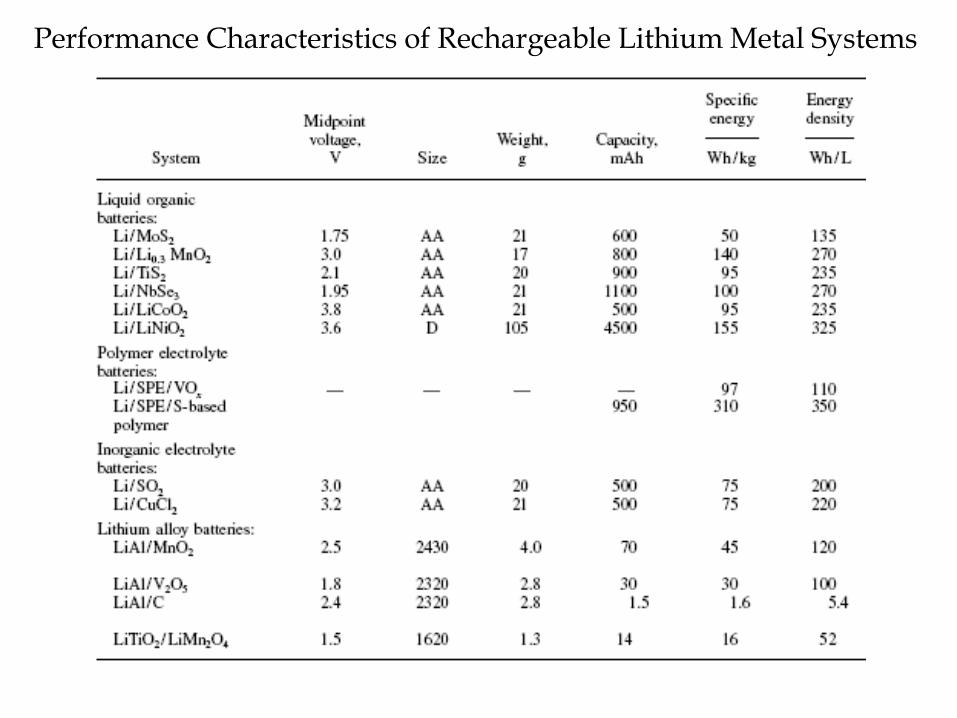
Performance Characteristics of Rechargeable Lithium Metal Systems

Schematic of the electrochemical process in a Li-ion cell
Requirements for Li-ion Positive ElectrodeMaterials:-High free energy of reaction with lithium-Can incorporate large quantities of lithium-Reversibly incorporates lithium without
structural change-High lithium ion diffusivity
-Good electronic conductivity-Insoluble in the electrolyte
-Prepared from inexpensive reagents-Low cost synthesis
Negative Electrode Materials

Salts and Solvents Used in Electrolytes for Li-ion Cells
Salts
Solvents

Requirements for Li-ion separators include:• High machine direction strength to permit
automated winding• Does not yield or shrink in width• Resistant to puncture by electrode materials• Effective pore size less than 1 µm• Easily wetted by electrolyte• Compatible and stable in contact with electrolyte
and electrode materials
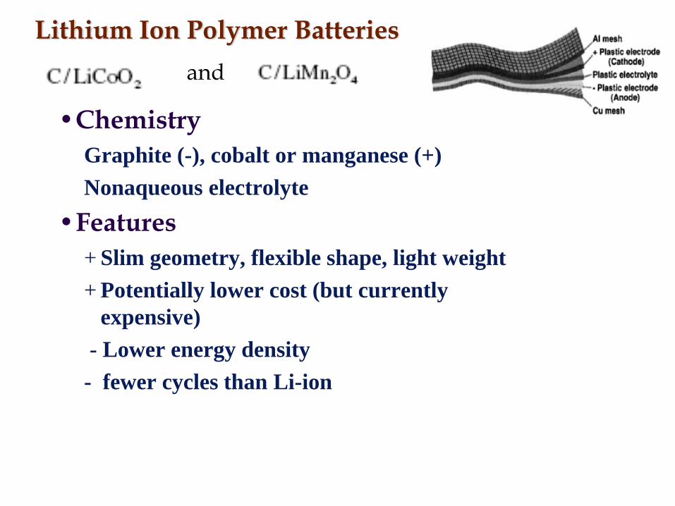
Lithium Ion Polymer Batteries
•ChemistryGraphite (-), cobalt or manganese (+)Nonaqueous electrolyte
•Features+ Slim geometry, flexible shape, light weight+ Potentially lower cost (but currently
expensive)- Lower energy density- fewer cycles than Li-ion
and

Battery Capacity
Type Capacity (mAh)
Density (Wh/kg)
Alkaline AA 2850 124Rechargeable 1600 80
NiCd AA 750 41
NiMH AA 1100 51
Lithium ion 1200 100
Lead acid 2000 30

Discharge Rates
Type Voltage Peak Drain
Optimal Drain
Alkaline 1.5 0.5C < 0.2CNiCd 1.25 20C 1C
Nickel metal 1.25 5C < 0.5C
Lead acid 2 5C 0.2C
Lithium ion 3.6 2C < 1C

Recharging
Type Cycles (to 80%)
Charge time
Dischargper month
e Cost per kWh
Alkaline 50 (50%) 3-10h 0.3% $95.00
NiCd 1500 1h 20% $7.50NiMH 300-500 2-4h 30% $18.50
Li-ion 500-1000 2-4h 10% $24.00
Polymer 300-500 2-4h 10%
Lead acid 200-2000 8-16h 5% $8.50