gutor battery management system - schneider electric
TRANSCRIPT

Gutor Battery Management System
G.BMS
User Guide
04/2021 Version 1
https://www.gutor.com

Legal InformationThe Schneider Electric brand and any trademarks of Schneider Electric SE and itssubsidiaries referred to in this guide are the property of Schneider Electric SE or itssubsidiaries. All other brands may be trademarks of their respective owners.
This guide and its content are protected under applicable copyright laws andfurnished for informational use only. No part of this guide may be reproduced ortransmitted in any form or by any means (electronic, mechanical, photocopying,recording, or otherwise), for any purpose, without the prior written permission ofSchneider Electric.
Schneider Electric does not grant any right or license for commercial use of the guideor its content, except for a non-exclusive and personal license to consult it on an "asis" basis. Schneider Electric products and equipment should be installed, operated,serviced, and maintained only by qualified personnel.
As standards, specifications, and designs change from time to time, informationcontained in this guide may be subject to change without notice.
To the extent permitted by applicable law, no responsibility or liability is assumed bySchneider Electric and its subsidiaries for any errors or omissions in the informationalcontent of this material or consequences arising out of or resulting from the use of theinformation contained herein.

G.BMS
Table of Contents
Safety Information.......................................................................................5G.BMS Safety Precautions..........................................................................6
Battery Regulations...............................................................................8Standards and Certificates ....................................................................9
G.BMS Solution Overview.......................................................................10Port, LED and Button Overview ................................................................. 11
Module Ports, LEDs and Buttons.......................................................... 11Webmanager Ports, LEDs and Buttons.................................................12
Installation of the G.BMS Solution..........................................................14Prepare the Batteries ................................................................................14Install Battery Measuring Cables................................................................15
Attach BC5xx Measuring Cable for 4–16 V Batteries..............................15Attach BC4Bxx Measuring Cable for 1.2–2 V Batteries with 2Poles .................................................................................................16Attach BC4Bxx Measuring Cable for 1.2–2 V Batteries with 4 or MorePoles .................................................................................................17Examples of Measuring Cable Installations ...........................................18
Install G.BMS Modules..............................................................................18Place the G.BMS Modules...................................................................18Attach the G.BMS Modules..................................................................21Attach Bus Cables between Modules ...................................................22
Install the Webmanager and any Splitting Boxes.........................................26Examples of Webmanager and Splitting Box Installations ......................27
Install the Current Sensor..........................................................................28Install Additional Options...........................................................................28
Install Bus Interface (GX_R_AUX)........................................................28Install Stand-Alone Temperature and Humidity Sensor...........................28Install Sensormanager and Additional Sensors .....................................28
Configure the Webmanager ....................................................................30Initial Local Connection to the Webmanager ...............................................30Webmanager Interface Overview...............................................................31Check Battery Setup Settings ....................................................................31Configure Modules from the Programmer ...................................................32
Set Initial Module Address ...................................................................32Find a Module with a Specific Address..................................................33Program a Single Module ....................................................................33
Add Sensors and Devices .........................................................................34Configure and Change Settings from the Web Interface...............................35
Language Settings..............................................................................35Date and Time Settings .......................................................................35Alarm Thresholds................................................................................35Network Settings ................................................................................36Configuration Backup..........................................................................36Firmware Update ................................................................................37
Communication .........................................................................................38EcoStruxure and Digital Integration............................................................38Modbus Read Registers (Function Calls 03/04) ..........................................38
0000509775_01_en 3

G.BMS
General Modbus Registers ..................................................................38Battery String Modbus Registers ..........................................................39Module Modbus Registers ...................................................................40GXR_AUX Alarm Modbus Registers.....................................................42GXR_AUX Output Modbus Registers ...................................................43
SNMP OID List .........................................................................................43Settings OIDs .....................................................................................43Objects OIDs......................................................................................45Alarm OIDs ........................................................................................47Traps OIDs.........................................................................................49GX_R_AUX OIDs ...............................................................................49
Alarm Flag Descriptions ............................................................................50
Troubleshooting ........................................................................................53
Technical Data...........................................................................................54Module Technical Data and Parts...............................................................54Control Cabinets Technical Data and Parts .................................................55Webmanager Technical Data and Parts......................................................56Splitting Box Technical Data and Parts .......................................................56Current Sensor Technical Data and Parts ...................................................57BACS Measuring Cables Technical Data and Parts .....................................57
BC4B Measuring Cables .....................................................................57BC4B Measuring Cables .....................................................................58BC5 Measuring Cables .......................................................................59BC5 Measuring Cables .......................................................................59
BACS Bus Communication Cable Technical Data and Parts ........................60Additional Options Technical Data and Parts...............................................61Sensormanager and Additional Sensors Technical Data and Parts ...............63
Contact Us .................................................................................................66
4 0000509775_01_en
Safety Information G.BMS
Safety InformationRead these instructions carefully and look at the equipment to become familiarwith it before trying to install, operate, service or maintain it. The following safetymessages may appear throughout this manual or on the equipment to warn ofpotential hazards or to call attention to information that clarifies or simplifies aprocedure.
IMPORTANT: Save the safety information for future reference.
The addition of this symbol to a “Danger” or “Warning” safetymessage indicates that an electrical hazard exists which will result inpersonal injury if the instructions are not followed.
This is the safety alert symbol. It is used to alert you to potentialpersonal injury hazards. Obey all safety messages with this symbolto avoid possible injury or death.
DANGERDANGER indicates a hazardous situation which, if not avoided, will result indeath or serious injury.
Failure to follow these instructions will result in death or serious injury.
WARNINGWARNING indicates a hazardous situation which, if not avoided, could result indeath or serious injury.
Failure to follow these instructions can result in death, serious injury, orequipment damage.
CAUTIONCAUTION indicates a hazardous situation which, if not avoided, could result inminor or moderate injury.
Failure to follow these instructions can result in injury or equipmentdamage.
NOTICENOTICE is used to address practices not related to physical injury.
Failure to follow these instructions can result in equipment damage.
Please NoteElectrical equipment should only be installed, operated, serviced, and maintainedby qualified personnel. No responsibility is assumed by Schneider Electric for anyconsequences arising out of the use of this material.
A qualified person is one who has skills and knowledge related to the construction,installation, and operation of electrical equipment and has received safety trainingto recognize and avoid the hazards involved.
0000509775_01_en 5
G.BMS Safety Information
G.BMS Safety Precautions
DANGERHAZARD OF ELECTRIC SHOCK, EXPLOSION, OR ARC FLASH• All safety information in this document must be read, understood and
followed.• Only qualified personnel are allowed to install, operate and perform
maintenance on the G.BMS solution and the batteries.• Batteries and connected measuring cables are always live.• Always disconnect the G.BMS module from the measuring cables before
touching or replacing any other cables.• Always use appropriate personal protective equipment (PPE).• Follow safe electrical work practices. See NFPA 70E or CSA Z462.Failure to follow these instructions will result in death or serious injury.
DANGERHAZARD OF ELECTRIC SHOCK, EXPLOSION, OR ARC FLASH
When working on batteries always use:• Eye protection• Protective rubber gloves• Protective rubber apron• Protective rubber boots• Insulated toolsWhen working on batteries:• Always disconnect the charging source• Always remove from earth if inadvertently earthed• Always remove watches, rings, or other metal objects• Never place tools or metal objects on top of batteriesFailure to follow these instructions will result in death or serious injury.
DANGERHAZARD OF ELECTRIC SHOCK, EXPLOSION, OR ARC FLASH
Always verify the polarity before connecting the measurement cables betweenthe battery and the G.BMS module.
Failure to follow these instructions will result in death or serious injury.
DANGERHAZARD OF ELECTRIC SHOCK, EXPLOSION, OR ARC FLASH
Never place G.BMS modules on damaged batteries or batteries with too highinternal resistances.
Always observe the battery temperature for 12 hours after discharge forpotential thermal runaway or battery damage.
Failure to follow these instructions will result in death or serious injury.
6 0000509775_01_en
Safety Information G.BMS
DANGERHAZARD OF ELECTRIC SHOCK, EXPLOSION, OR ARC FLASH• Never open or alter G.BMS modules.• Never attach any objects to the battery or the G.BMS module apart from the
connecting cables.Failure to follow these instructions will result in death or serious injury.
DANGERHAZARD OF ELECTRIC SHOCK, EXPLOSION, OR ARC FLASH• Never open, alter or damage batteries. This can release toxic electrolytes
that are harmful to the skin and eyes.• Never smoke, handle open flames or create sparks near the batteries.• Never dispose of batteries in a fire as they can explode.Failure to follow these instructions will result in death or serious injury.
WARNINGINCOMPLETE INSTALLATION PROCESS
A service technician should monitor the G.BMS modules and the initial chargeduring the installation. Excessive heat created by the G.BMS modules mayindicate a damaged battery or incorrectly mounted cables. Do not leave theinstallation site before the installation of the G.BMS solution is complete and thebattery has charged for 60 minutes. After that and only if the G.BMS solutionshows stable voltages and normal internal resistance values is the G.BMSsolution ready to be monitored remotely.
Failure to follow these instructions can result in death, serious injury, orequipment damage.
WARNINGINCORRECT INSTALLATION ENVIRONMENT
Do not install G.BMS modules in an area that:• Is wet or dusty.• Is unprotected from water or high humidity.• Has a constantly high concentration of salted or oxidizing gases.• Is close to sources of extreme heat, open flames, or sparks, or have a high
variation in temperature.• Is prone to physical vibrations.• Has a high gas concentration or flammable materials.Failure to follow these instructions can result in death, serious injury, orequipment damage.
WARNINGTOO LATE ALARM ORWARNING SIGNAL
Ensure that the alarm thresholds are set for time to react to the alarm or warningsignal.
It is recommended that alarm signals are attend to within at least two hours.
Failure to follow these instructions can result in death, serious injury, orequipment damage.
0000509775_01_en 7
G.BMS Safety Information
CAUTIONINACCURATE MEASUREMENTS
Never use G.BMS modules or bus cables of different versions in the same G.BMS solution.
Failure to follow these instructions can result in injury or equipmentdamage.
CAUTIONMAGNETIC EMISSION
Never place any materials or equipment sensitive to magnetic emissions nearthe webmanager. For example, monitors, disk drives, memory chips ormagnetic tapes.
Failure to follow these instructions can result in injury or equipmentdamage.
CAUTIONHAZARDOUS SUBSTANCE• Battery electrolyte solutions are highly corrosive.• Battery electrolyte are harmful to both eyes and skin.Failure to follow these instructions can result in injury or equipmentdamage.
Battery Regulations
For battery installation always follow local and national regulations that apply inyour local area. For example:
• ZVEI publication "Instructions for the Safe Handling of Electrolyte for Lead-acid Accumulators."
• ZVEI publication "Safety Data Sheet on Accumulator Acid (Diluted SulfuricAcid)."
• VDE 0510 Part 2: 2001-12, in accordance with EN 50272-2:2001: "SafetyRequirements for Secondary Batteries and Battery Installations - Part 2:Stationary Batteries".
• IEEE Standard 450-2002: "Recommended Practice for Maintenance, Testingand Replacement of Vented Lead Acid Batteries for Stationary Application."
• IEEE Standard 1188-2005: “Recommended Practice for Maintenance,Testing and Replacement of Valve Regulated Lead Acid Batteries forStationary Application."
• IEEE Standard 1375-1998: "Guide for Protection of Stationary BatterySystems
For further information refer to the original equipment manufacturer (OEM) of thebatteries for instructions on installation, maintenance, and operation of thebatteries.
8 0000509775_01_en
Safety Information G.BMS
Standards and Certificates
Directives and Regulations
2014/30/EU Electromagnetic compatibility - directive
2011/65/EU and (EU) 2015/863 Restriction of the use of certain hazardoussubstances (RoHS)
2012/19/EU Waste electrical and electronic equipment (WEEE)
2006/66/EG Waste Batteries and accumulators and repealing directive
CE Conformity
EN 55024:2010Information technology equipment - Immunity characteristics - Limits and methodsof measurement
EN 55022:2003Information technology equipment - Radio disturbance characteristics - Limits andmethods of measurement
EN 55032:2015Electromagnetic compatibility of multimedia equipment - Emission - Limits andmethods of measurement
EN 61000-4-3:2006+A1:2008+A2:2010Electromagnetic compatibility (EMC) Part 4: Environment Section 3: Radiated,radio-frequency, electromagnetic field immunity test. Limits and methods ofmeasurement
IEC 61010-1General safety requirements for the following types of electrical equipment andtheir accessories, wherever they are intended to be used. A) Electrical test andmeasurement equipment B) Electrical industrial process-control equipment C)Electrical laboratory equipment
EN IEC 63000:2018Technical documentation for the assessment of electrical and electronic productswith respect to the restriction of hazardous substances; European version
EN 62368-1:2014 + AC:2015Information Technology Equipment – Safety
UL/CSA Certification
NOTE: Currently only certain devices are UL/CSA certified, for details refer tothe section Technical Data, page 54.
UL Std. No. 60950-1 2nd EditionInformation Technology Equipment – Safety – Part 1: General Requirements (Incl.AM 1:2011 and AM 2:2014)
CAN/CSA-C22.2 No. 60950-1-07Incl. Amendment 1 (2011) and Amendment 2 (2014) - Information TechnologyEquipment – Safety – Part 1: General Requirements
0000509775_01_en 9
G.BMS G.BMS Solution Overview
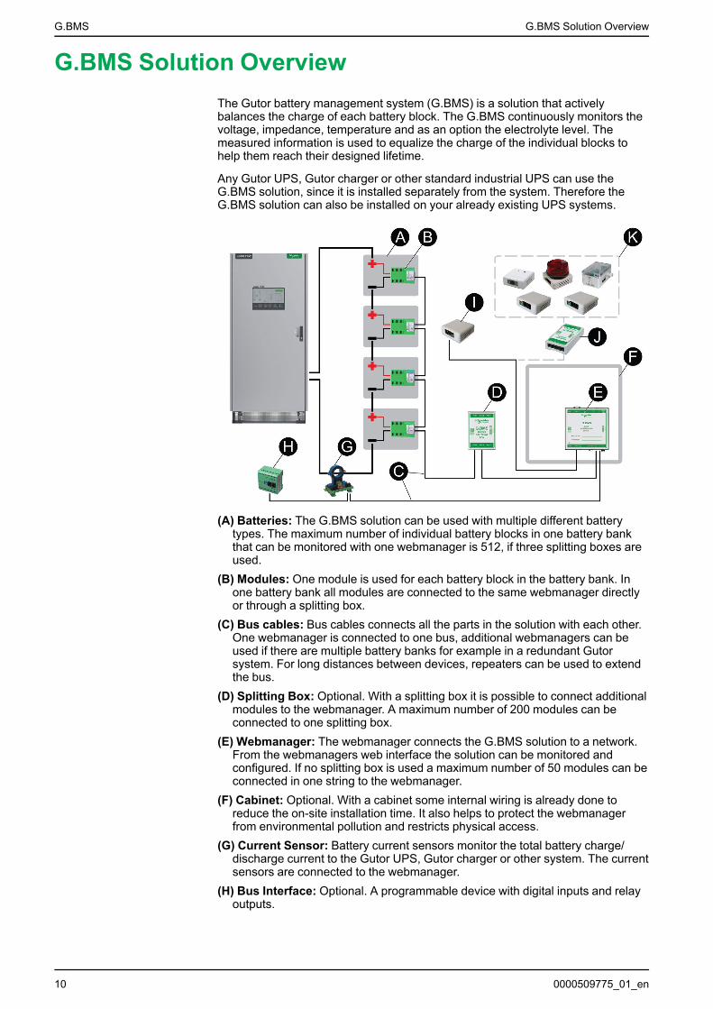
G.BMS Solution OverviewThe Gutor battery management system (G.BMS) is a solution that activelybalances the charge of each battery block. The G.BMS continuously monitors thevoltage, impedance, temperature and as an option the electrolyte level. Themeasured information is used to equalize the charge of the individual blocks tohelp them reach their designed lifetime.
Any Gutor UPS, Gutor charger or other standard industrial UPS can use theG.BMS solution, since it is installed separately from the system. Therefore theG.BMS solution can also be installed on your already existing UPS systems.
(A) Batteries: The G.BMS solution can be used with multiple different batterytypes. The maximum number of individual battery blocks in one battery bankthat can be monitored with one webmanager is 512, if three splitting boxes areused.
(B) Modules: One module is used for each battery block in the battery bank. Inone battery bank all modules are connected to the same webmanager directlyor through a splitting box.
(C) Bus cables: Bus cables connects all the parts in the solution with each other.One webmanager is connected to one bus, additional webmanagers can beused if there are multiple battery banks for example in a redundant Gutorsystem. For long distances between devices, repeaters can be used to extendthe bus.
(D) Splitting Box: Optional. With a splitting box it is possible to connect additionalmodules to the webmanager. A maximum number of 200 modules can beconnected to one splitting box.
(E) Webmanager: The webmanager connects the G.BMS solution to a network.From the webmanagers web interface the solution can be monitored andconfigured. If no splitting box is used a maximum number of 50 modules can beconnected in one string to the webmanager.
(F) Cabinet: Optional. With a cabinet some internal wiring is already done toreduce the on-site installation time. It also helps to protect the webmanagerfrom environmental pollution and restricts physical access.
(G) Current Sensor: Battery current sensors monitor the total battery charge/discharge current to the Gutor UPS, Gutor charger or other system. The currentsensors are connected to the webmanager.
(H) Bus Interface: Optional. A programmable device with digital inputs and relayoutputs.
10 0000509775_01_en
G.BMS Solution Overview G.BMS
(I) Stand-Alone Temperature and Humidity Sensor: Optional. A stand-alonetemperature and humidity sensor that can be connected directly to thewebmanager.
(J) Sensormanager: Optional. Incase other sensors than the stand-alonetemperature and humidity sensor are need, a sensormanager can be used.
(K) Additional sensors: Optional. Various additional sensors can be connectedto the sensormanager to monitor or send signals to the webmanager.
Port, LED and Button OverviewOverview, details and specifications of the ports, LEDs and buttons on the maindevices in the Gutor battery management system.
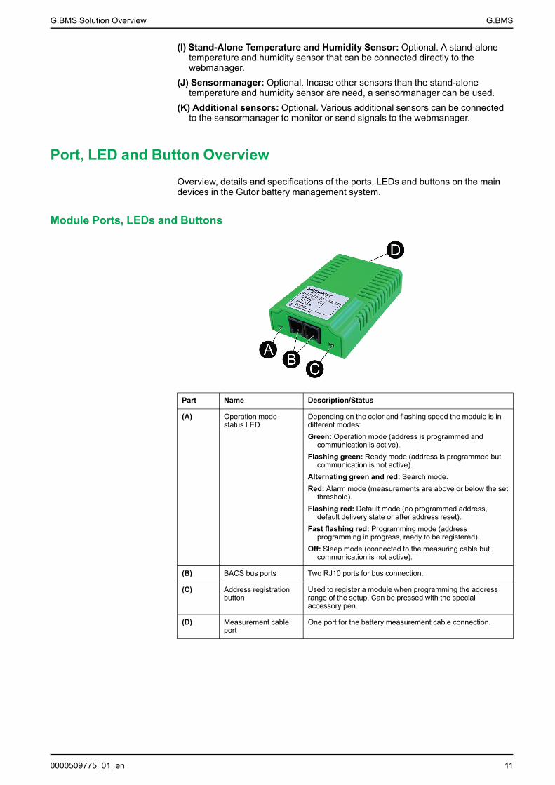
Module Ports, LEDs and Buttons
Part Name Description/Status
(A) Operation modestatus LED
Depending on the color and flashing speed the module is indifferent modes:Green: Operation mode (address is programmed and
communication is active).Flashing green: Ready mode (address is programmed but
communication is not active).Alternating green and red: Search mode.Red: Alarm mode (measurements are above or below the set
threshold).Flashing red: Default mode (no programmed address,
default delivery state or after address reset).Fast flashing red: Programming mode (address
programming in progress, ready to be registered).Off: Sleep mode (connected to the measuring cable but
communication is not active).
(B) BACS bus ports Two RJ10 ports for bus connection.
(C) Address registrationbutton
Used to register a module when programming the addressrange of the setup. Can be pressed with the specialaccessory pen.
(D) Measurement cableport
One port for the battery measurement cable connection.
0000509775_01_en 11
G.BMS G.BMS Solution Overview
Webmanager Ports, LEDs and Buttons
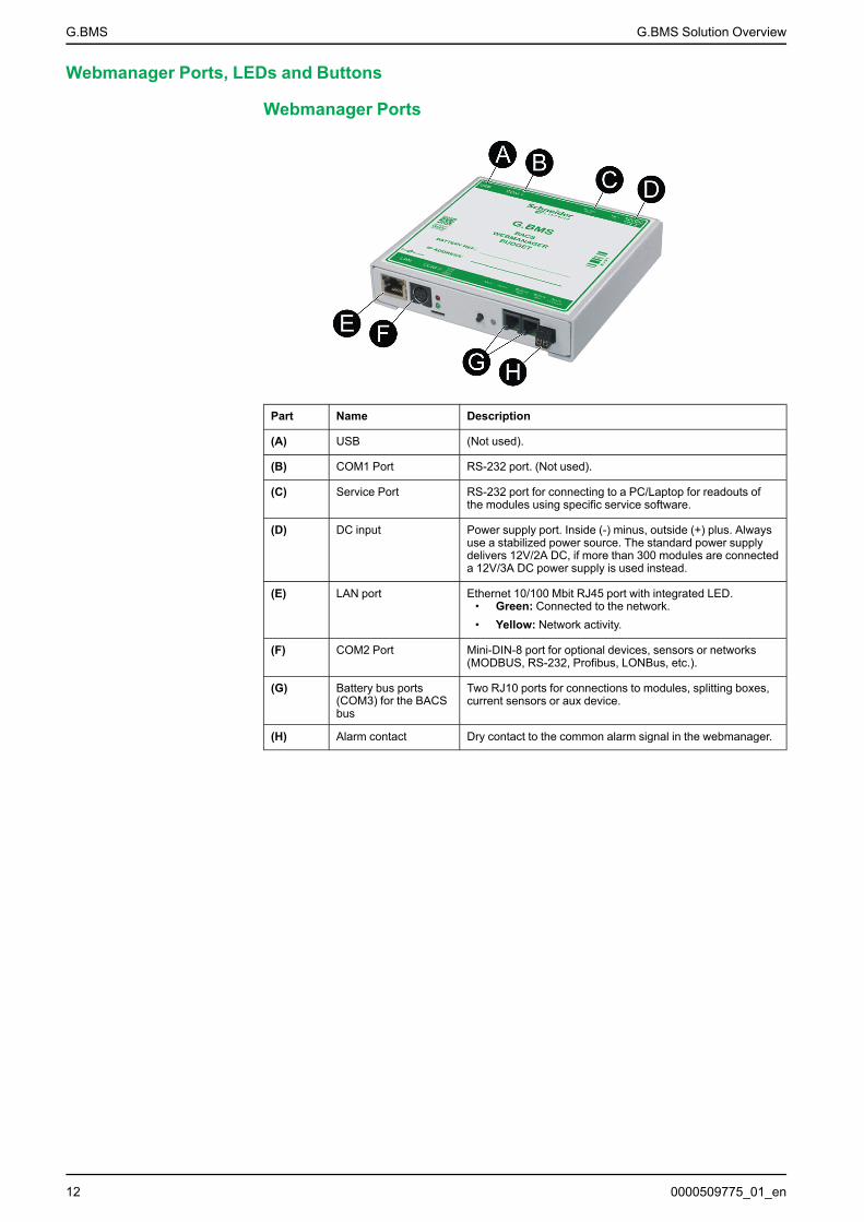
Webmanager Ports
Part Name Description
(A) USB (Not used).
(B) COM1 Port RS-232 port. (Not used).
(C) Service Port RS-232 port for connecting to a PC/Laptop for readouts ofthe modules using specific service software.
(D) DC input Power supply port. Inside (-) minus, outside (+) plus. Alwaysuse a stabilized power source. The standard power supplydelivers 12V/2A DC, if more than 300 modules are connecteda 12V/3A DC power supply is used instead.
(E) LAN port Ethernet 10/100 Mbit RJ45 port with integrated LED.• Green: Connected to the network.• Yellow: Network activity.
(F) COM2 Port Mini-DIN-8 port for optional devices, sensors or networks(MODBUS, RS-232, Profibus, LONBus, etc.).
(G) Battery bus ports(COM3) for the BACSbus
Two RJ10 ports for connections to modules, splitting boxes,current sensors or aux device.
(H) Alarm contact Dry contact to the common alarm signal in the webmanager.
12 0000509775_01_en
G.BMS Solution Overview G.BMS
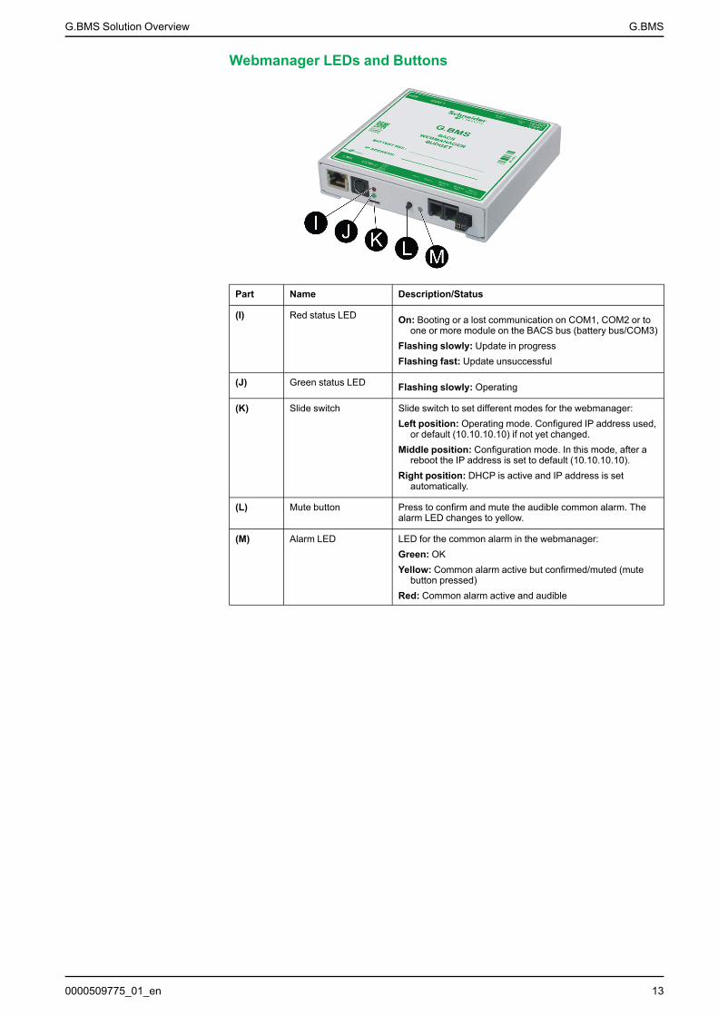
Webmanager LEDs and Buttons
Part Name Description/Status
(I) Red status LED On: Booting or a lost communication on COM1, COM2 or toone or more module on the BACS bus (battery bus/COM3)
Flashing slowly: Update in progressFlashing fast: Update unsuccessful
(J) Green status LED Flashing slowly: Operating
(K) Slide switch Slide switch to set different modes for the webmanager:Left position: Operating mode. Configured IP address used,
or default (10.10.10.10) if not yet changed.Middle position: Configuration mode. In this mode, after a
reboot the IP address is set to default (10.10.10.10).Right position: DHCP is active and IP address is set
automatically.
(L) Mute button Press to confirm and mute the audible common alarm. Thealarm LED changes to yellow.
(M) Alarm LED LED for the common alarm in the webmanager:Green: OKYellow: Common alarm active but confirmed/muted (mute
button pressed)Red: Common alarm active and audible
0000509775_01_en 13

G.BMS Installation of the G.BMS Solution
Installation of the G.BMS SolutionThe installation covers preparation of the batteries, installation of the devices andconnections between the devices. See the sections:
• Prepare the Batteries, page 14• Install Battery Measuring Cables, page 15• Install G.BMS Modules, page 18• Install the Webmanager and any Splitting Boxes, page 26• Install the Current Sensor, page 28• Install Additional Options, page 28
Prepare the BatteriesBefore you attach the G.BMS module fastening strips the battery surface must beclean and dry. To clean the battery surface:
1. Check what cleaning product is recommended by the battery manufacturer.NOTE: If you are unsure or there are no recommendations available useonly soapy water.
2. Clean the surface of the batteries with the recommended cleaning product.3. Dry the surface of the batteries with an antistatic fabric.
14 0000509775_01_en

Installation of the G.BMS Solution G.BMS
Install Battery Measuring Cables
CAUTIONINACCURATE MEASUREMENTS
Make sure to tighten the pole screws with the correct torque value for yourbattery.
Failure to follow these instructions can result in injury or equipmentdamage.
NOTICEAlways connect the measuring cable to the right pole, the red cable to thepositive pole and the black cable to the negative pole. If the cable connection isreversed the integrated fuse can be damaged.
Failure to follow these instructions can result in equipment damage.
Follow the procedure to connect the measuring cable for your battery type usingthe right cable:
• Attach BC5xx Measuring Cable for 4–16 V Batteries, page 15• Attach BC4Bxx Measuring Cable for 1.2–2 V Batteries with 2 Poles, page 16• Attach BC4Bxx Measuring Cable for 1.2–2 V Batteries with 4 or More Poles,
page 17NOTE: Please refer to the battery manufacturers connection guidelines forresistance/impedance measurements.
4 V – 16 V Batteries 1.2 V - 2 V Batterieswith 2 poles
1.2 V - 2 V Batterieswith 4 poles or more
BC5xx measuring cable BC4Bxx measuring cable
Attach BC5xx Measuring Cable for 4–16 V Batteries
(A) Pole screw(B) Safety washer(C) Washer(D) Measuring cable(E) Battery connector(F) Battery pole
IMPORTANT: Attach the cable as close as possible to the battery poles, butabove the battery connectors.
ABCD
EF
0000509775_01_en 15
G.BMS Installation of the G.BMS Solution
To attach the BC5xx measuring cable to the battery:
1. Connect the red cable to the positive battery pole.
2. Connect the black cable to the negative battery pole.
3. Tighten the pole bolts with the torque value recommended by the batterymanufacturer.
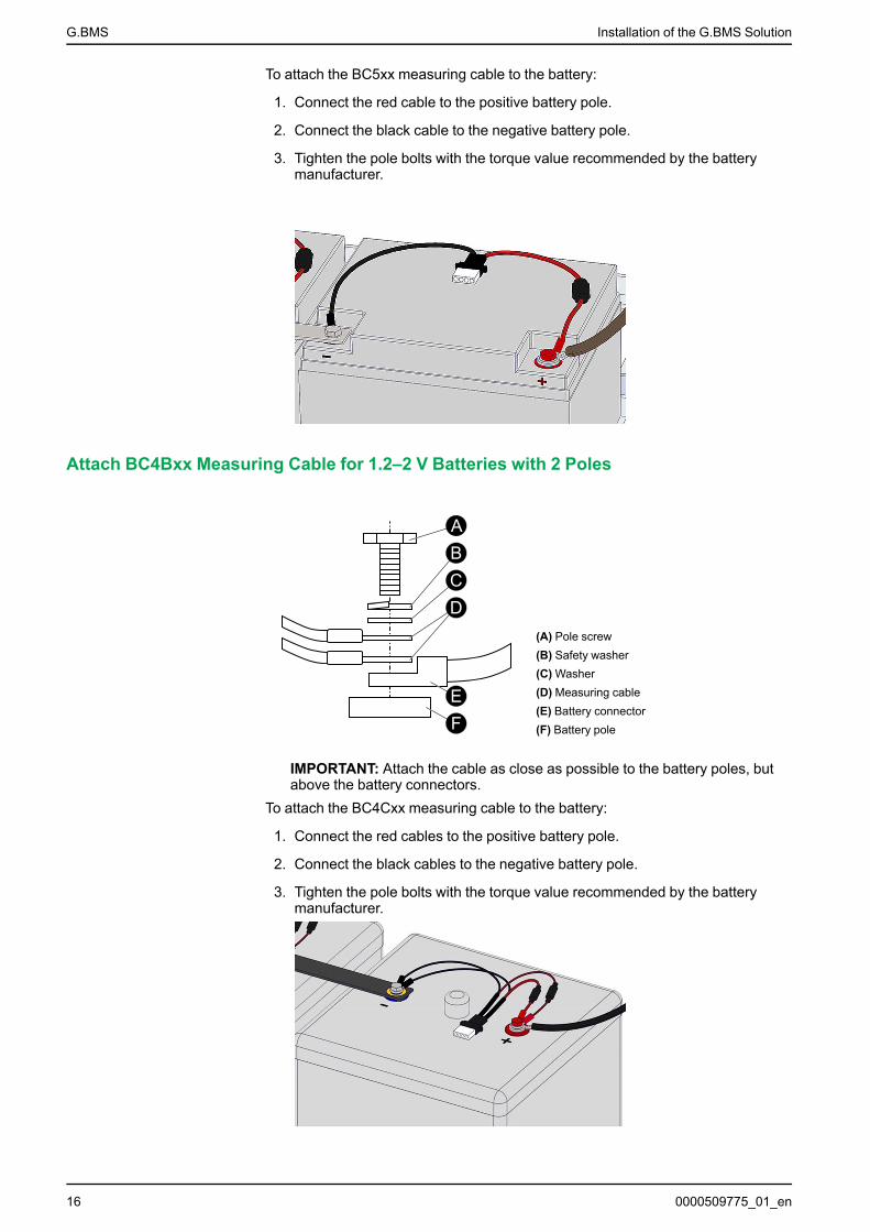
Attach BC4Bxx Measuring Cable for 1.2–2 V Batteries with 2 Poles
(A) Pole screw(B) Safety washer(C) Washer(D) Measuring cable(E) Battery connector(F) Battery pole
IMPORTANT: Attach the cable as close as possible to the battery poles, butabove the battery connectors.
To attach the BC4Cxx measuring cable to the battery:
1. Connect the red cables to the positive battery pole.
2. Connect the black cables to the negative battery pole.
3. Tighten the pole bolts with the torque value recommended by the batterymanufacturer.
ABCD
EF
16 0000509775_01_en
Installation of the G.BMS Solution G.BMS
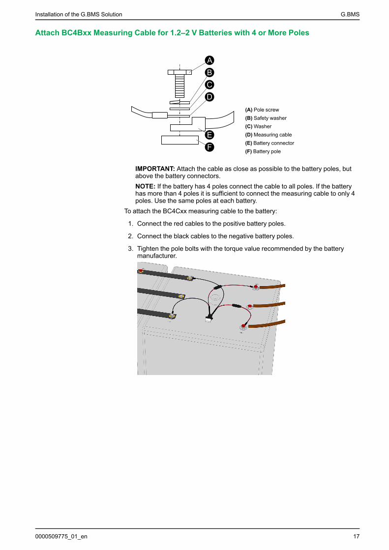
Attach BC4Bxx Measuring Cable for 1.2–2 V Batteries with 4 or More Poles
(A) Pole screw(B) Safety washer(C) Washer(D) Measuring cable(E) Battery connector(F) Battery pole
IMPORTANT: Attach the cable as close as possible to the battery poles, butabove the battery connectors.NOTE: If the battery has 4 poles connect the cable to all poles. If the batteryhas more than 4 poles it is sufficient to connect the measuring cable to only 4poles. Use the same poles at each battery.
To attach the BC4Cxx measuring cable to the battery:
1. Connect the red cables to the positive battery poles.
2. Connect the black cables to the negative battery poles.
3. Tighten the pole bolts with the torque value recommended by the batterymanufacturer.
ABCD
EF
0000509775_01_en 17

G.BMS Installation of the G.BMS Solution
Examples of Measuring Cable Installations
Install G.BMS ModulesThere are two types of G.BMS modules:
• G.BMS module with integratedtemperature (standard)
• G.BMS module with externaltemperature sensor (option)
To install the modules see the sections:• Place the G.BMS Modules, page 18• Attach the G.BMS Modules, page 21• Attach Bus Cables between Modules, page 22
Place the G.BMS Modules
Read all the relevant positioning information before you attach any modules.• General Placement Information, page 19• Additional Placement Information for Batteries with Vents, page 20• Additional Placement Information for G.BMS Modules with External
Temperature Sensors, page 20
18 0000509775_01_en
Installation of the G.BMS Solution G.BMS
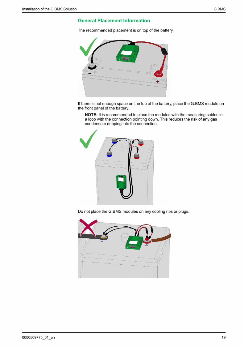
General Placement Information
The recommended placement is on top of the battery.
If there is not enough space on the top of the battery, place the G.BMS module onthe front panel of the battery.
NOTE: It is recommended to place the modules with the measuring cables ina loop with the connection pointing down. This reduces the risk of any gascondensate dripping into the connection.
Do not place the G.BMS modules on any cooling ribs or plugs.
0000509775_01_en 19

G.BMS Installation of the G.BMS Solution
Additional Placement Information for Batteries with Vents
If placed on top of batteries with vents: Make sure the distance (A) betweenthe vent and the module is at least 10 cm (4 inches).
Additional Placement Information for G.BMS Modules withExternal Temperature Sensors
For G.BMS modules with external temperature sensors: Make sure that thetemperature sensor is placed at the same position on each battery.
NOTE: The cable for the temperature sensor is 23 cm (9 inches) or 90 cm (35inches) long.
20 0000509775_01_en
Installation of the G.BMS Solution G.BMS
Attach the G.BMS Modules
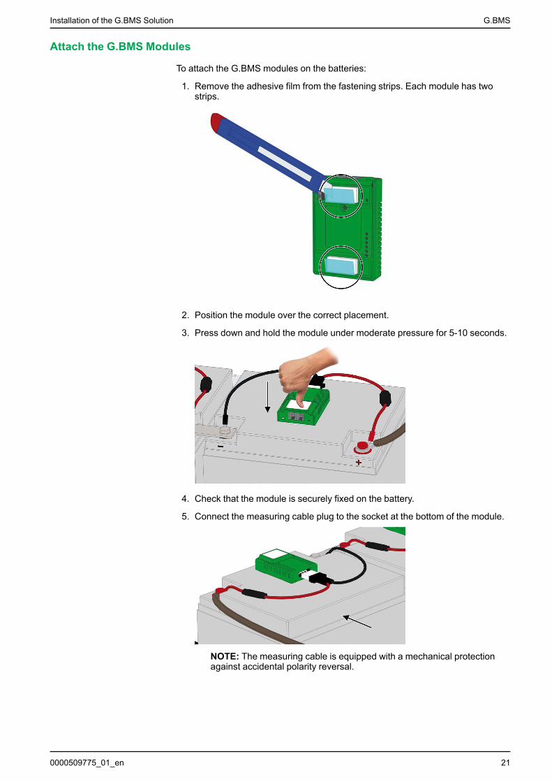
To attach the G.BMS modules on the batteries:
1. Remove the adhesive film from the fastening strips. Each module has twostrips.
2. Position the module over the correct placement.
3. Press down and hold the module under moderate pressure for 5-10 seconds.
4. Check that the module is securely fixed on the battery.
5. Connect the measuring cable plug to the socket at the bottom of the module.
NOTE: The measuring cable is equipped with a mechanical protectionagainst accidental polarity reversal.
0000509775_01_en 21
G.BMS Installation of the G.BMS Solution
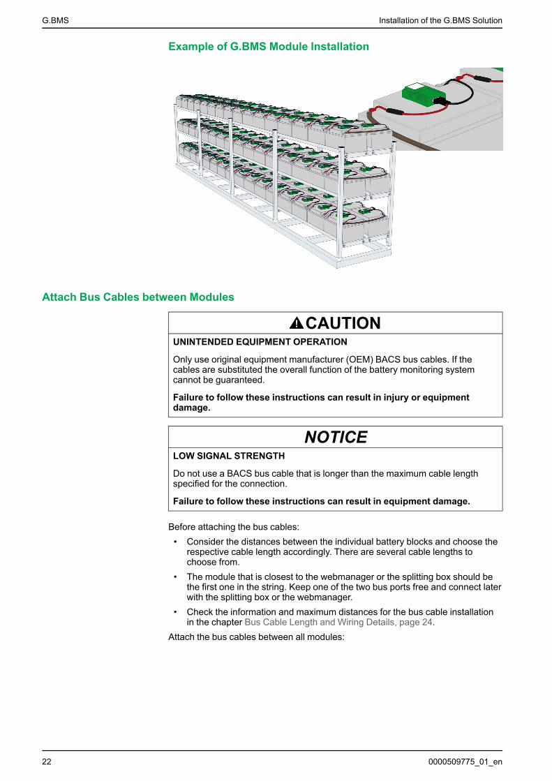
Example of G.BMS Module Installation
Attach Bus Cables between Modules
CAUTIONUNINTENDED EQUIPMENT OPERATION
Only use original equipment manufacturer (OEM) BACS bus cables. If thecables are substituted the overall function of the battery monitoring systemcannot be guaranteed.
Failure to follow these instructions can result in injury or equipmentdamage.
NOTICELOW SIGNAL STRENGTH
Do not use a BACS bus cable that is longer than the maximum cable lengthspecified for the connection.
Failure to follow these instructions can result in equipment damage.
Before attaching the bus cables:• Consider the distances between the individual battery blocks and choose the
respective cable length accordingly. There are several cable lengths tochoose from.
• The module that is closest to the webmanager or the splitting box should bethe first one in the string. Keep one of the two bus ports free and connect laterwith the splitting box or the webmanager.
• Check the information and maximum distances for the bus cable installationin the chapter Bus Cable Length and Wiring Details, page 24.
Attach the bus cables between all modules:
22 0000509775_01_en
Installation of the G.BMS Solution G.BMS
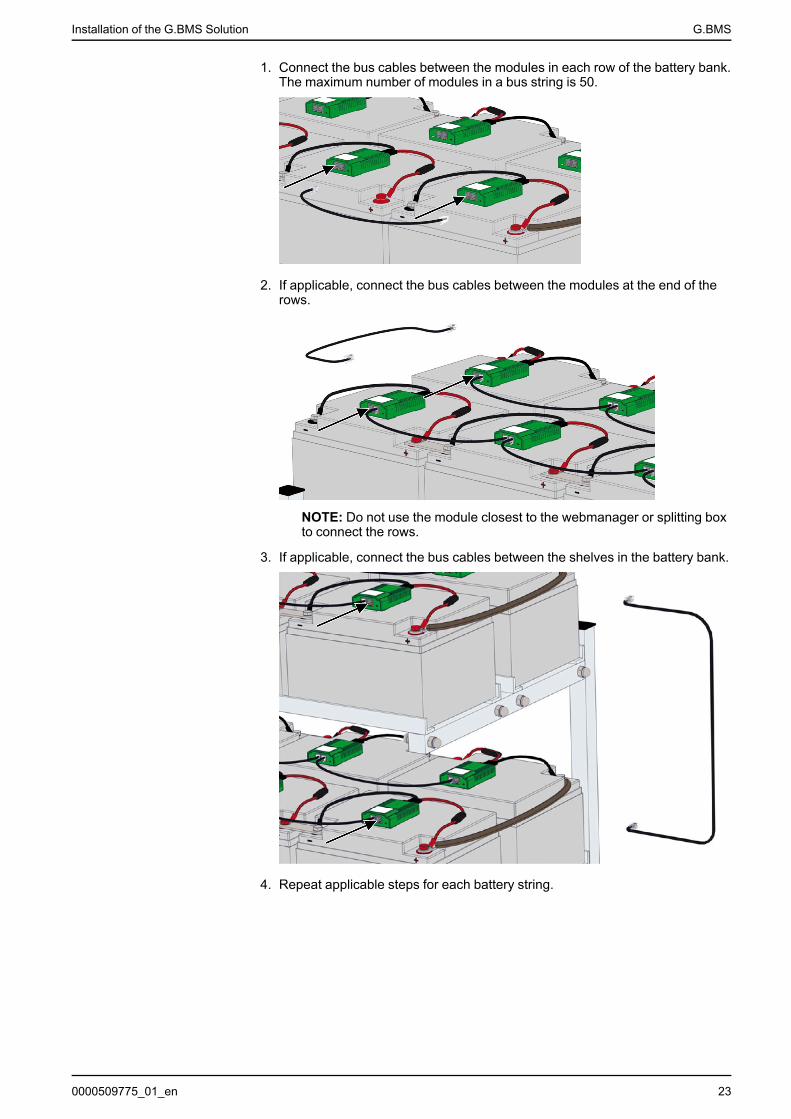
1. Connect the bus cables between the modules in each row of the battery bank.The maximum number of modules in a bus string is 50.
2. If applicable, connect the bus cables between the modules at the end of therows.
NOTE: Do not use the module closest to the webmanager or splitting boxto connect the rows.
3. If applicable, connect the bus cables between the shelves in the battery bank.
4. Repeat applicable steps for each battery string.
0000509775_01_en 23
G.BMS Installation of the G.BMS Solution
Bus Cable Length and Wiring Details
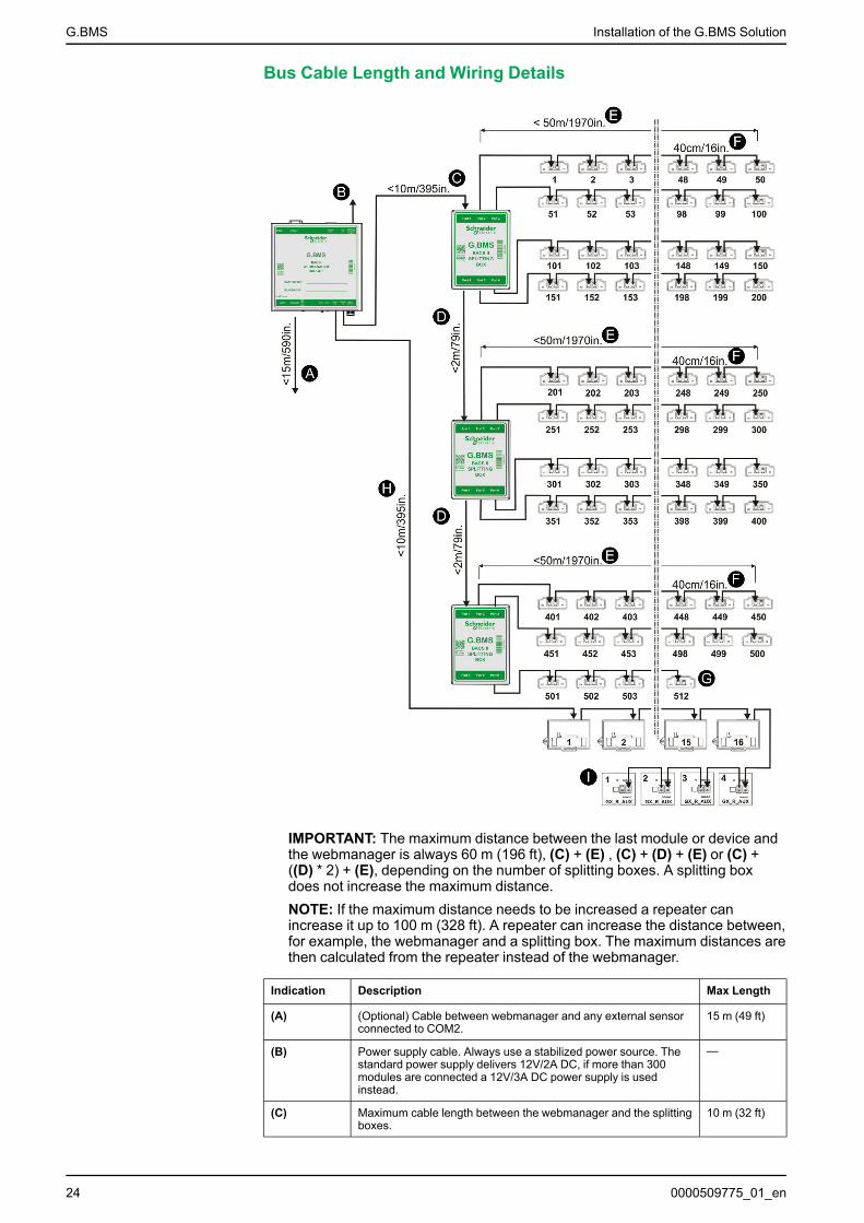
IMPORTANT: The maximum distance between the last module or device andthe webmanager is always 60 m (196 ft), (C) + (E) , (C) + (D) + (E) or (C) +((D) * 2) + (E), depending on the number of splitting boxes. A splitting boxdoes not increase the maximum distance.NOTE: If the maximum distance needs to be increased a repeater canincrease it up to 100 m (328 ft). A repeater can increase the distance between,for example, the webmanager and a splitting box. The maximum distances arethen calculated from the repeater instead of the webmanager.
Indication Description Max Length
(A) (Optional) Cable between webmanager and any external sensorconnected to COM2.
15 m (49 ft)
(B) Power supply cable. Always use a stabilized power source. Thestandard power supply delivers 12V/2A DC, if more than 300modules are connected a 12V/3A DC power supply is usedinstead.
—
(C) Maximum cable length between the webmanager and the splittingboxes.
10 m (32 ft)
24 0000509775_01_en
Installation of the G.BMS Solution G.BMS
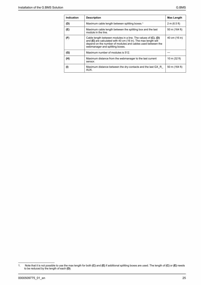
Indication Description Max Length
(D) Maximum cable length between splitting boxes.1 2 m (6.5 ft)
(E) Maximum cable length between the splitting box and the lastmodule in the line.
50 m (164 ft)
(F) Cable length between modules in a line. The values of (C), (D)and (E) are calculated with 40 cm (16 in). The max length willdepend on the number of modules and cables used between thewebmanager and splitting boxes.
40 cm (16 in)
(G) Maximum number of modules is 512. —
(H) Maximum distance from the webmanager to the last currentsensor.
10 m (32 ft)
(I) Maximum distance between the dry-contacts and the last GX_R_AUX.
50 m (164 ft)
0000509775_01_en 25
1. Note that it is not possible to use the max length for both (C) and (E) if additional splitting boxes are used. The length of (C) or (E) needsto be reduced by the length of each (D).

G.BMS Installation of the G.BMS Solution
Install the Webmanager and any Splitting BoxesBefore attaching the bus cables:
• Consider what bus cable lengths to use, the cables are available in multiplelengths to avoid unnecessary cable length.
• Check the information and maximum distances for the bus cable installationin the chapter Bus Cable Length and Wiring Details, page 24.
• If a repeater is needed because the maximum distance is exceeded, installthe repeater less than 100 m (328 ft) from the webmanager. The maximumdistances are then calculated from the repeater instead of the webmanager.
1. Mount the webmanager or the control cabinet with the webmanager inside.
2. If applicable, mount the splitting box(es).
3. Only for solutions without splitting box(es):
a. Attach the bus cable (A) from the closest module to the webmanager.
b. Attach the power supply cable (C) to the webmanager.
IMPORTANT: Always use a secure power source as the power supply tothe webmanager.
4. Only for solutions with splitting box(es):
a. Attach the bus cable(s) (A) from the closest module(s) to the splitting box(es).
b. If applicable, attach the bus cables (A) between any additional splittingboxes.
c. Attach the bus cable (B) from the closest splitting box to thewebmanager.
d. Attach the power supply cable (C) to the webmanager.
NOTE: Always use a secure power source as the power supply to thewebmanager.
C
A
C
B
A
26 0000509775_01_en
Installation of the G.BMS Solution G.BMS
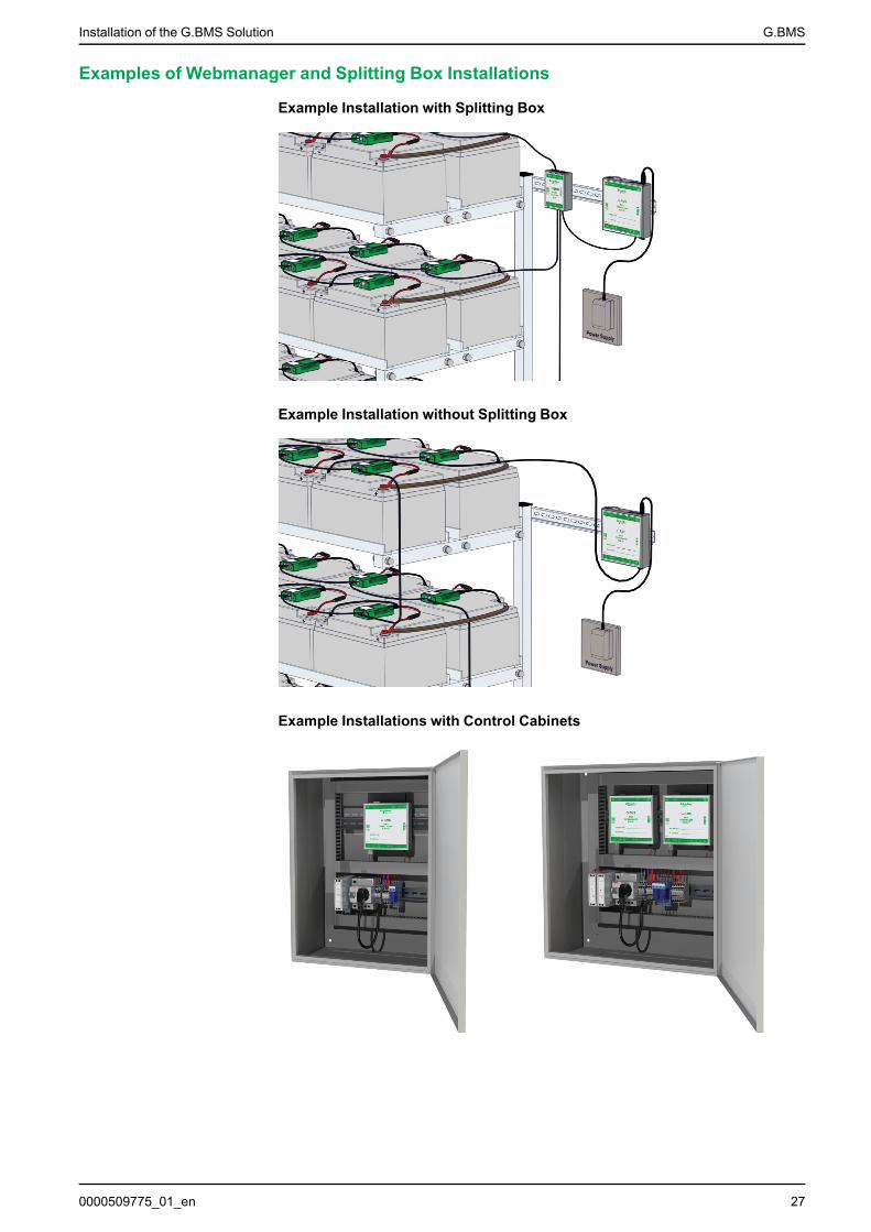
Examples of Webmanager and Splitting Box Installations
Example Installation with Splitting Box
Example Installation without Splitting Box
Example Installations with Control Cabinets
0000509775_01_en 27
G.BMS Installation of the G.BMS Solution
Install the Current SensorThe current sensor should be installed at a point with the full battery current that isgoing to a Gutor system, unit in a redundant Gutor system or other system. Thecurrent sensor housing can be attached to a DIN rail 35 x 7.5 mm (TS35 rail).
If multiple current sensors are used, configure a unique address with the DIPswitches on each current sensor connected to the same webmanager.
It is recommended to connect the current sensor to a battery bus (COM3) port onthe webmanager with a BACS bus cable.
NOTE: The maximum bus cable length between the current sensor and thewebmanager is 10 m (32 ft). For more information see Bus Cable Length andWiring Details, page 24.
If a sensormanager is used, it is also possible to connect the current sensor to thesensormanager with RJ12 cables.
Install Additional OptionsDepending on the sensor or device different fastening options exists, for exampleDIN rail 35 x 7.5 mm (TS35 rail), wall mounted or adhesive. For more informationsee the respective section in Technical Data, page 54.
Install Bus Interface (GX_R_AUX)
The GX_R_AUX is connected to the BACS bus with a BACS bus cable. It can beconnected at various locations of the BACS bus that uses the COM3 port on thewebmanager, for example, to a current sensor, a splitting box, repeater or amodule.
If multiple GX_R_AUX devices are used, configure a unique address with the DIPswitches on each GX_R_AUX device connected to the same webmanager.
NOTE: The maximum bus cable length depends where it is connected. Formore information see Bus Cable Length and Wiring Details, page 24.
Install Stand-Alone Temperature and Humidity Sensor
A stand-alone temperature and humidity sensor needs to be connected directly tothe COM2 port on the webmanager with the included mini-DIN-8/DB-9 cable. Themaximum cable length for connections to COM2 is 15 m (49 ft).
NOTE: There is only one COM2 port so it is only possible to connect onestand-alone temperature and humidity sensor to a webmanager.
Install Sensormanager and Additional Sensors
If more sensors are needed, a sensormanager can be used instead of the stand-alone temperature and humidity sensor.
Connect Sensormanager
The sensormanager needs to be connected directly to the COM2 port on thewebmanager with the included mini-DIN-8/DB-9 cable. The maximum cable lengthfor connections to COM2 is 15 m (49 ft).
NOTE: There is only one COM2 port, so it is only possible to connect onesensormanager to a webmanager.
28 0000509775_01_en
Installation of the G.BMS Solution G.BMS
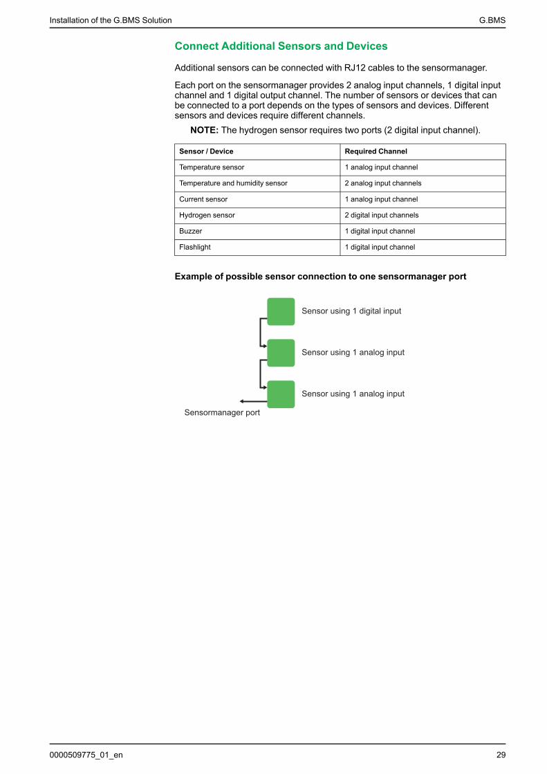
Connect Additional Sensors and Devices
Additional sensors can be connected with RJ12 cables to the sensormanager.
Each port on the sensormanager provides 2 analog input channels, 1 digital inputchannel and 1 digital output channel. The number of sensors or devices that canbe connected to a port depends on the types of sensors and devices. Differentsensors and devices require different channels.
NOTE: The hydrogen sensor requires two ports (2 digital input channel).
Sensor / Device Required Channel
Temperature sensor 1 analog input channel
Temperature and humidity sensor 2 analog input channels
Current sensor 1 analog input channel
Hydrogen sensor 2 digital input channels
Buzzer 1 digital input channel
Flashlight 1 digital input channel
Example of possible sensor connection to one sensormanager port
Sensor using 1 digital input
Sensor using 1 analog input
Sensor using 1 analog input
Sensormanager port
0000509775_01_en 29
G.BMS Configure the Webmanager
Configure the WebmanagerThe webmanager needs to be configured for the specific battery setup. Thewebmanager interface is accessed locally or remotely through a connectednetwork. From the webmanager interface the modules must be programed with aunique address for each module on the bus.
Initial Local Connection to the WebmanagerFirst login with default IP address:
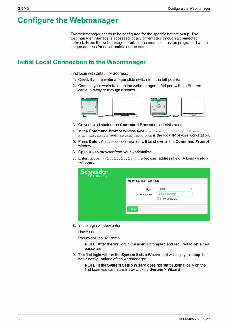
1. Check that the webmanager slide switch is in the left position.2. Connect your workstation to the webmanagers LAN port with an Ethernet
cable, directly or through a switch.
3. On your workstation run Command Prompt as administrator.4. In the Command Prompt window type route add 10.10.10.10 xxx.
xxx.xxx.xxx, where xxx.xxx.xxx.xxx is the local IP of your workstation.5. Press Enter. A success confirmation will be shown in the Command Prompt
window.6. Open a web browser from your workstation.7. Enter https://10.10.10.10 in the browser address field. A login window
will open.
8. In the login window enter:User: adminPassword: cs141-snmp
NOTE: After the first log in the user is prompted and required to set a newpassword.
9. The first login will run the System Setup Wizard that will help you setup thebasic configurations of the webmanager.
NOTE: If the System Setup Wizard does not start automatically on thefirst login you can launch it by clicking System > Wizard
30 0000509775_01_en
Configure the Webmanager G.BMS
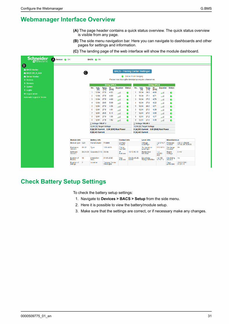
Webmanager Interface Overview(A) The page header contains a quick status overview. The quick status overview
is visible from any page.(B) The side menu navigation bar. Here you can navigate to dashboards and other
pages for settings and information.(C) The landing page of the web interface will show the module dashboard.
Check Battery Setup SettingsTo check the battery setup settings:
1. Navigate to Devices > BACS > Setup from the side menu.2. Here it is possible to view the battery/module setup.3. Make sure that the settings are correct, or if necessary make any changes.
0000509775_01_en 31
G.BMS Configure the Webmanager
Configure Modules from the Programmer
NOTICETo program the modules the slider on the programmer page needs to be toggledto On. This activates programmer mode and stops the bus polling. After themodule addresses have been programmed toggle the slider to Off to deactivateprogrammer mode and go to operation mode.
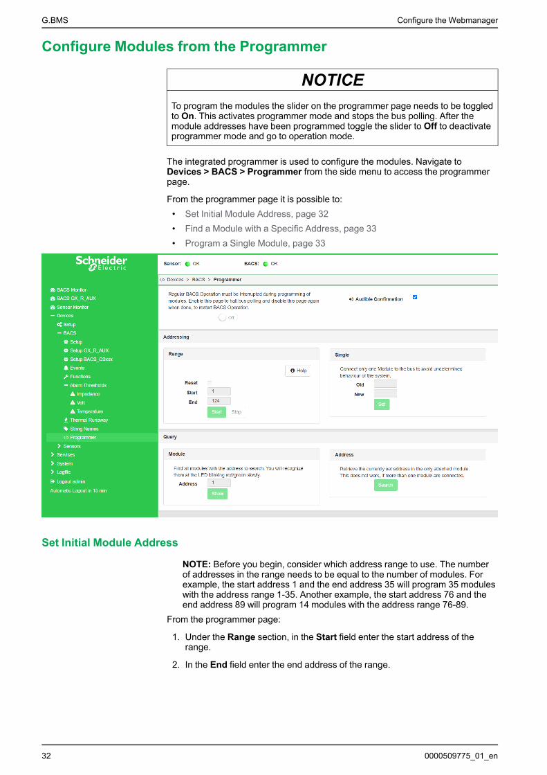
The integrated programmer is used to configure the modules. Navigate toDevices > BACS > Programmer from the side menu to access the programmerpage.
From the programmer page it is possible to:• Set Initial Module Address, page 32• Find a Module with a Specific Address, page 33• Program a Single Module, page 33
Set Initial Module Address
NOTE: Before you begin, consider which address range to use. The numberof addresses in the range needs to be equal to the number of modules. Forexample, the start address 1 and the end address 35 will program 35 moduleswith the address range 1-35. Another example, the start address 76 and theend address 89 will program 14 modules with the address range 76-89.
From the programmer page:
1. Under the Range section, in the Start field enter the start address of therange.
2. In the End field enter the end address of the range.
32 0000509775_01_en
Configure the Webmanager G.BMS
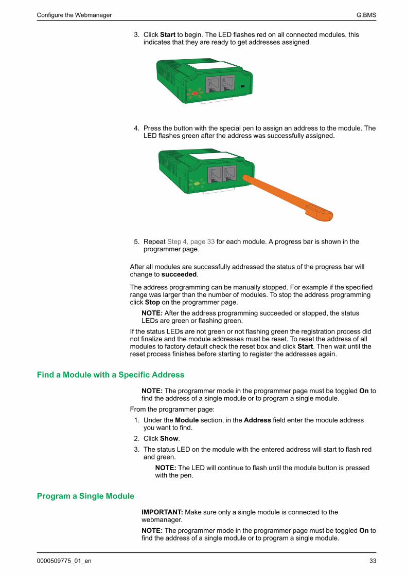
3. Click Start to begin. The LED flashes red on all connected modules, thisindicates that they are ready to get addresses assigned.
4. Press the button with the special pen to assign an address to the module. TheLED flashes green after the address was successfully assigned.
5. Repeat Step 4, page 33 for each module. A progress bar is shown in theprogrammer page.
After all modules are successfully addressed the status of the progress bar willchange to succeeded.
The address programming can be manually stopped. For example if the specifiedrange was larger than the number of modules. To stop the address programmingclick Stop on the programmer page.
NOTE: After the address programming succeeded or stopped, the statusLEDs are green or flashing green.
If the status LEDs are not green or not flashing green the registration process didnot finalize and the module addresses must be reset. To reset the address of allmodules to factory default check the reset box and click Start. Then wait until thereset process finishes before starting to register the addresses again.
Find a Module with a Specific Address
NOTE: The programmer mode in the programmer page must be toggled On tofind the address of a single module or to program a single module.
From the programmer page:1. Under the Module section, in the Address field enter the module address
you want to find.2. Click Show.3. The status LED on the module with the entered address will start to flash red
and green.NOTE: The LED will continue to flash until the module button is pressedwith the pen.
Program a Single Module
IMPORTANT: Make sure only a single module is connected to thewebmanager.NOTE: The programmer mode in the programmer page must be toggled On tofind the address of a single module or to program a single module.
0000509775_01_en 33
G.BMS Configure the Webmanager
Check the Currently Programed Address of a Single Module
From the programmer page:1. Under the Address section click Search2. A progress bar will appear and after a short while the address of the single
connected module will be shown.
Change the Currently Programed Address of a Single Module
From the programmer page:1. Under the Single section, in the Old field enter the current module address.2. In the New field enter the new target address for the module.3. Click Set to confirm the new address for the module.
Add Sensors and DevicesAny sensor or other device used in the G.BMS needs to be added before it can beconfigured from the web interface.
To add a sensor or device:1. Check that the sensor or device is correctly connected to the webmanager,
either to COM2 or via the BACS bus to a battery bus (COM3) port. Thisdepends on the type of sensor or device and the cable needed.
2. If multiple current sensors or GX_R_AUX devices are connected to the samewebmanager check that they have unique addresses configured with the DIPswitches.
3. Navigate to Devices > Setup.4. Under COM2 or COM3 use the drop-down menu(s) to select the connected
sensor or device.5. Click Apply to add the sensor or device.6. A new setup menu or submenu under Devices is added for that sensor or
device. From this new menu the sensor or device can be configured asneeded.
34 0000509775_01_en
Configure the Webmanager G.BMS
Configure and Change Settings from the Web InterfaceThe initial startup defined some basic settings in the System Setup Wizard. It ispossible to change these settings and to change additional settings from the webinterface.
Language Settings
To change the language viewed in the web interface:1. Navigate to System > General from the side menu.2. Under the Region section it is possible to change the displayed language and
temperature format.3. Click Apply to confirm the change.
NOTE: A new login might be required for the update to take effect.
Date and Time Settings
To change the date and time setting:1. Navigate to System > Date & Time from the side menu.2. Here it is possible to synchronize to specific time servers, change time zone
or set a system time manually.3. Click Apply to confirm any changes.
NOTE: A new login might be required for the update to take effect.
Alarm Thresholds
CAUTIONINCORRECTALARM SETTINGS
Do not change the alarm or warning thresholds unless the battery setupchanges. The alarm thresholds are set during the design and configuration foreach specific battery setup.
Failure to follow these instructions can result in injury or equipmentdamage.
To change the alarm threshold values:1. Navigate to Devices > BACS > Alarm Thresholds from the side menu.2. Here it is possible to change the different alarm thresholds and other settings
for each type of alarm/warning:• Impedance• Voltage
NOTE: It is possible to set a delay for the voltage alarm.• Temperature
3. Click Apply to confirm any changes.NOTE: A new login might be required for the update to take effect.
0000509775_01_en 35
G.BMS Configure the Webmanager
Network Settings
IMPORTANT: Make sure that the network settings confirm to your cybersecurity policy.
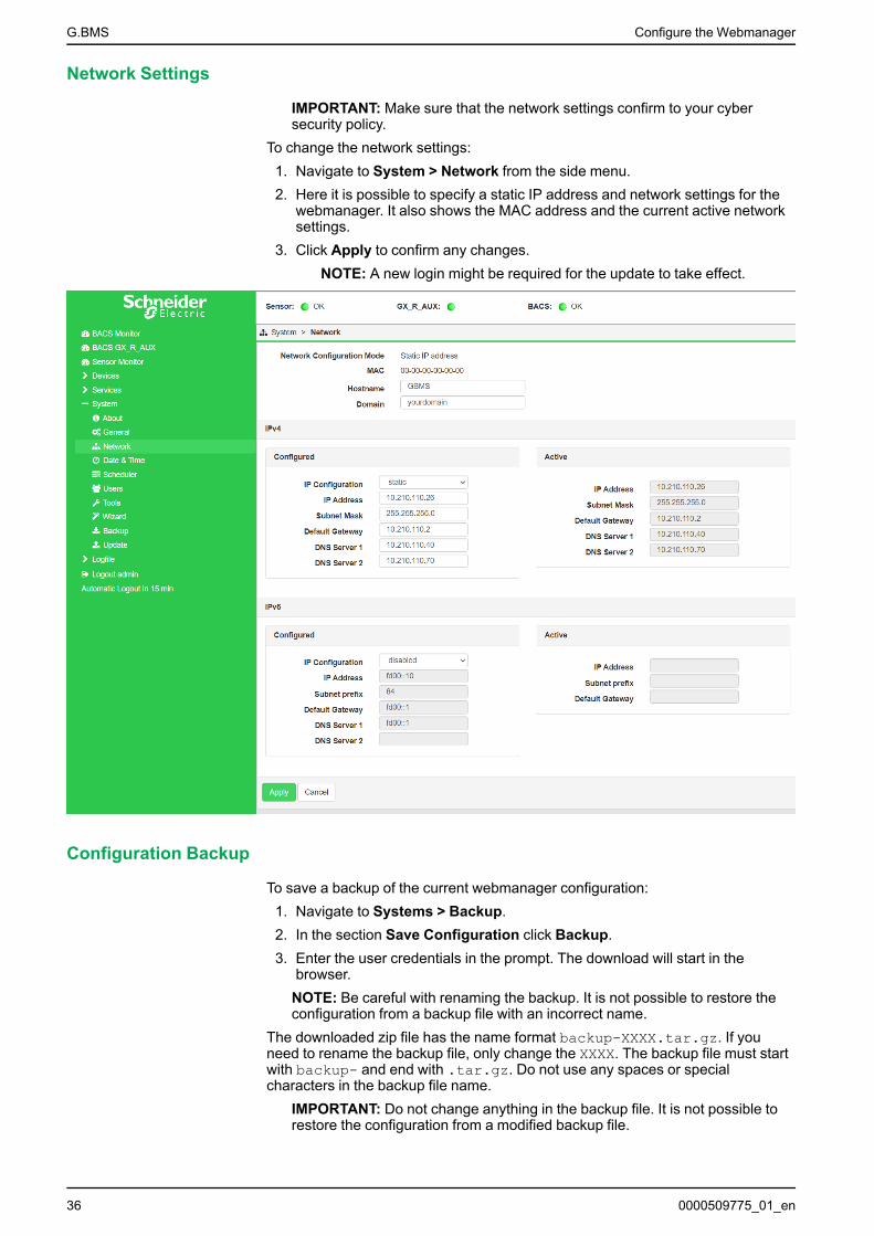
To change the network settings:1. Navigate to System > Network from the side menu.2. Here it is possible to specify a static IP address and network settings for the
webmanager. It also shows the MAC address and the current active networksettings.
3. Click Apply to confirm any changes.NOTE: A new login might be required for the update to take effect.
Configuration Backup
To save a backup of the current webmanager configuration:1. Navigate to Systems > Backup.2. In the section Save Configuration click Backup.3. Enter the user credentials in the prompt. The download will start in the
browser.NOTE: Be careful with renaming the backup. It is not possible to restore theconfiguration from a backup file with an incorrect name.
The downloaded zip file has the name format backup-XXXX.tar.gz. If youneed to rename the backup file, only change the XXXX. The backup file must startwith backup- and end with .tar.gz. Do not use any spaces or specialcharacters in the backup file name.
IMPORTANT: Do not change anything in the backup file. It is not possible torestore the configuration from a modified backup file.
36 0000509775_01_en
Configure the Webmanager G.BMS
To load a backup in the connected webmanager:1. Navigate to Systems > Backup.2. In the section Configuration file drag the backup file to the box, or click to
select the backup file.3. Do not check the box for Restore network settings if you want to keep the
current IP settings. Only check if you want to use the IP settings from thebackup file.
4. Click Restore to start the restoration process of the configuration backup.5. You will automatically be logged out. Enter the user credentials again to log
in.6. Check that the configuration was restored correctly.
Firmware Update
It is recommended to use the latest firmware update available for thewebmanager. To update the firmware:
1. Download the latest firmware from the product webpage.2. Log in to the web interface.3. Navigate to System > Update.4. Drag the firmware file to the box or click to select the firmware file. It is not
necessary to unpack the file.NOTE: Make sure that none of the boxes for Reset to factory settings orReset network to factory settings are checked. If they are checked, theconfigurations will be lost and cannot be retrieved unless a backup of thesettings was made.
5. Click Start.6. The update manager will start and guide you through the update.7. When prompted, restart the webmanager.8. After the restart navigate to System > About to verify that the firmware
update was successful.
0000509775_01_en 37
G.BMS Communication
CommunicationFrom the webmanager it is possible to receive different events and alarms viaModbus and SNMP.
To change the Modbus or SNMP settings:1. Make sure the network settings are correctly configured for your network, see
Network Settings, page 36.2. Navigate to Services > Modbus or Services > SNMPAgent from the side
menu.3. Make necessary settings and changes for your network setup.
IMPORTANT: Make sure that the Modbus or SNMP settings confirm toyour cyber security policy.
4. Click Apply to confirm any changes.For the mapping lists see:
• Modbus Read Registers (Function Calls 03/04), page 38• SNMP OID List, page 43
EcoStruxure and Digital IntegrationThe webmanagers Modbus or SNMP settings can be configured for integrationwith EcoStruxure Grid (Modbus), EcoStruxure Power (Modbus), EcoStruxure IT(SNMP), AVEVA or other third-party solutions. For the setup refer to thedocumentation for the respective solution.
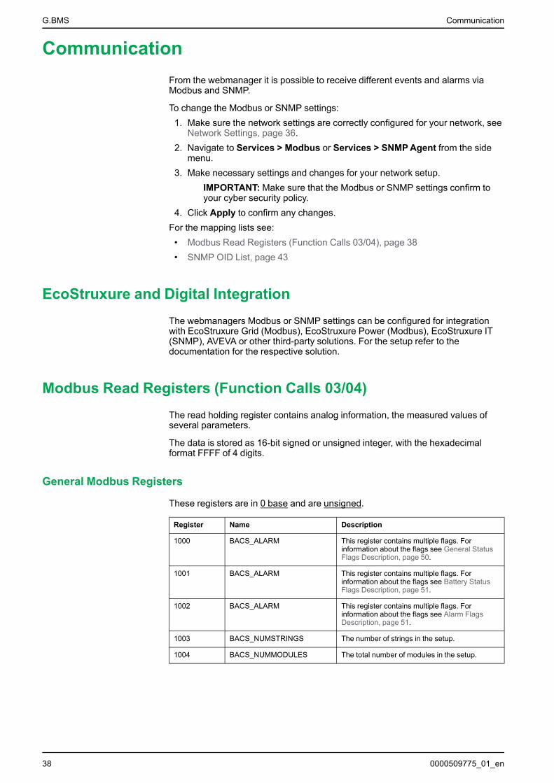
Modbus Read Registers (Function Calls 03/04)The read holding register contains analog information, the measured values ofseveral parameters.
The data is stored as 16-bit signed or unsigned integer, with the hexadecimalformat FFFF of 4 digits.
General Modbus Registers
These registers are in 0 base and are unsigned.
Register Name Description
1000 BACS_ALARM This register contains multiple flags. Forinformation about the flags see General StatusFlags Description, page 50.
1001 BACS_ALARM This register contains multiple flags. Forinformation about the flags see Battery StatusFlags Description, page 51.
1002 BACS_ALARM This register contains multiple flags. Forinformation about the flags see Alarm FlagsDescription, page 51.
1003 BACS_NUMSTRINGS The number of strings in the setup.
1004 BACS_NUMMODULES The total number of modules in the setup.
38 0000509775_01_en
Communication G.BMS
Battery String Modbus Registers
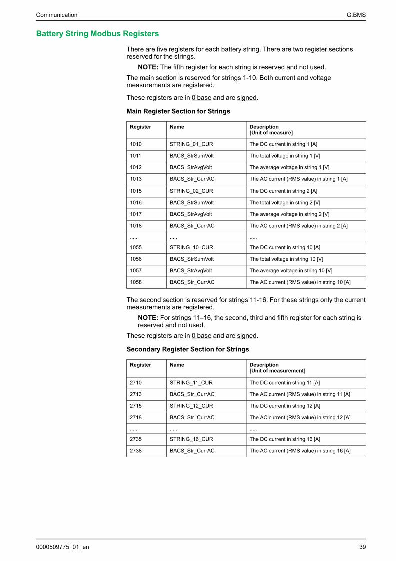
There are five registers for each battery string. There are two register sectionsreserved for the strings.
NOTE: The fifth register for each string is reserved and not used.The main section is reserved for strings 1-10. Both current and voltagemeasurements are registered.
These registers are in 0 base and are signed.
Main Register Section for Strings
Register Name Description[Unit of measure]
1010 STRING_01_CUR The DC current in string 1 [A]
1011 BACS_StrSumVolt The total voltage in string 1 [V]
1012 BACS_StrAvgVolt The average voltage in string 1 [V]
1013 BACS_Str_CurrAC The AC current (RMS value) in string 1 [A]
1015 STRING_02_CUR The DC current in string 2 [A]
1016 BACS_StrSumVolt The total voltage in string 2 [V]
1017 BACS_StrAvgVolt The average voltage in string 2 [V]
1018 BACS_Str_CurrAC The AC current (RMS value) in string 2 [A]
..... ..... .....
1055 STRING_10_CUR The DC current in string 10 [A]
1056 BACS_StrSumVolt The total voltage in string 10 [V]
1057 BACS_StrAvgVolt The average voltage in string 10 [V]
1058 BACS_Str_CurrAC The AC current (RMS value) in string 10 [A]
The second section is reserved for strings 11-16. For these strings only the currentmeasurements are registered.
NOTE: For strings 11–16, the second, third and fifth register for each string isreserved and not used.
These registers are in 0 base and are signed.
Secondary Register Section for Strings
Register Name Description[Unit of measurement]
2710 STRING_11_CUR The DC current in string 11 [A]
2713 BACS_Str_CurrAC The AC current (RMS value) in string 11 [A]
2715 STRING_12_CUR The DC current in string 12 [A]
2718 BACS_Str_CurrAC The AC current (RMS value) in string 12 [A]
..... ..... .....
2735 STRING_16_CUR The DC current in string 16 [A]
2738 BACS_Str_CurrAC The AC current (RMS value) in string 16 [A]
0000509775_01_en 39
G.BMS Communication
Module Modbus Registers
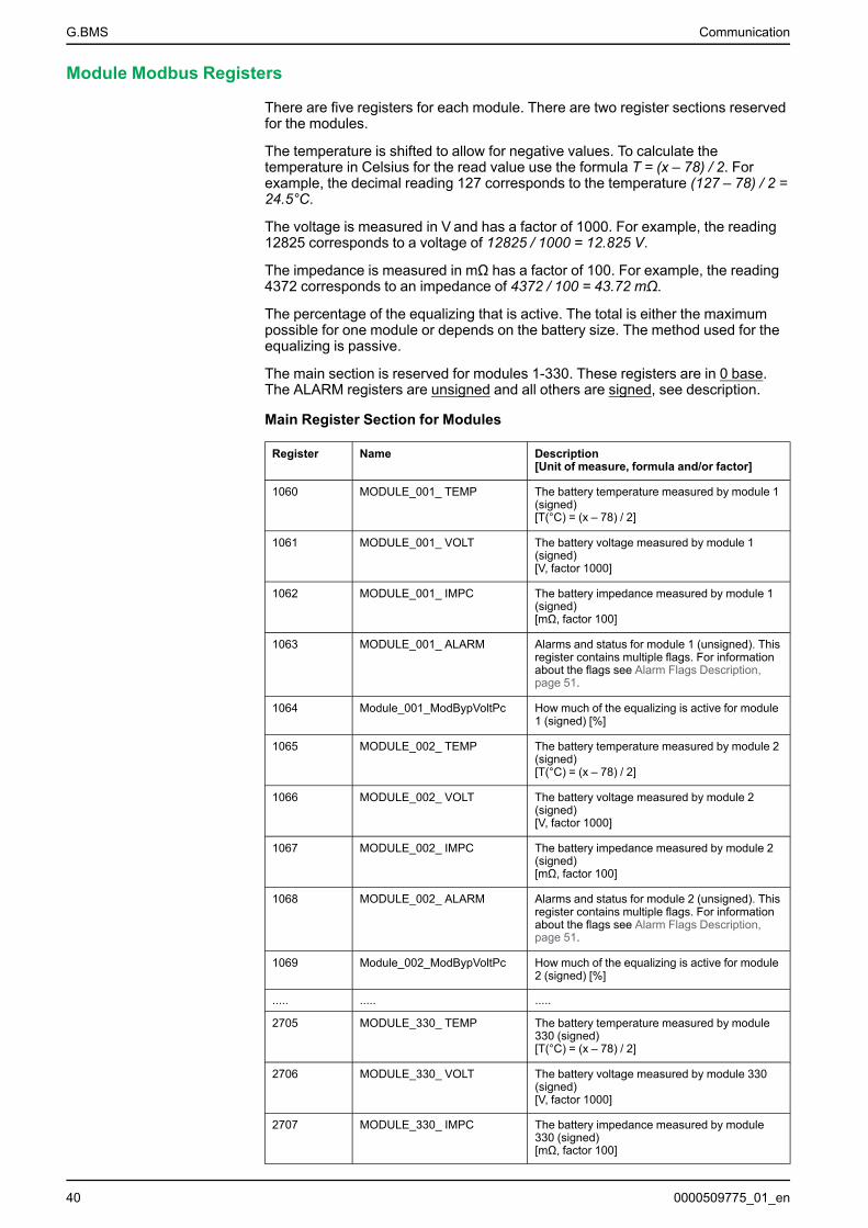
There are five registers for each module. There are two register sections reservedfor the modules.
The temperature is shifted to allow for negative values. To calculate thetemperature in Celsius for the read value use the formula T = (x – 78) / 2. Forexample, the decimal reading 127 corresponds to the temperature (127 – 78) / 2 =24.5°C.
The voltage is measured in V and has a factor of 1000. For example, the reading12825 corresponds to a voltage of 12825 / 1000 = 12.825 V.
The impedance is measured in mΩ has a factor of 100. For example, the reading4372 corresponds to an impedance of 4372 / 100 = 43.72 mΩ.
The percentage of the equalizing that is active. The total is either the maximumpossible for one module or depends on the battery size. The method used for theequalizing is passive.
The main section is reserved for modules 1-330. These registers are in 0 base.The ALARM registers are unsigned and all others are signed, see description.
Main Register Section for Modules
Register Name Description[Unit of measure, formula and/or factor]
1060 MODULE_001_ TEMP The battery temperature measured by module 1(signed)[T(°C) = (x – 78) / 2]
1061 MODULE_001_ VOLT The battery voltage measured by module 1(signed)[V, factor 1000]
1062 MODULE_001_ IMPC The battery impedance measured by module 1(signed)[mΩ, factor 100]
1063 MODULE_001_ ALARM Alarms and status for module 1 (unsigned). Thisregister contains multiple flags. For informationabout the flags see Alarm Flags Description,page 51.
1064 Module_001_ModBypVoltPc How much of the equalizing is active for module1 (signed) [%]
1065 MODULE_002_ TEMP The battery temperature measured by module 2(signed)[T(°C) = (x – 78) / 2]
1066 MODULE_002_ VOLT The battery voltage measured by module 2(signed)[V, factor 1000]
1067 MODULE_002_ IMPC The battery impedance measured by module 2(signed)[mΩ, factor 100]
1068 MODULE_002_ ALARM Alarms and status for module 2 (unsigned). Thisregister contains multiple flags. For informationabout the flags see Alarm Flags Description,page 51.
1069 Module_002_ModBypVoltPc How much of the equalizing is active for module2 (signed) [%]
..... ..... .....
2705 MODULE_330_ TEMP The battery temperature measured by module330 (signed)[T(°C) = (x – 78) / 2]
2706 MODULE_330_ VOLT The battery voltage measured by module 330(signed)[V, factor 1000]
2707 MODULE_330_ IMPC The battery impedance measured by module330 (signed)[mΩ, factor 100]
40 0000509775_01_en

Communication G.BMS
Main Register Section for Modules (Continued)
Register Name Description[Unit of measure, formula and/or factor]
2708 MODULE_330_ ALARM Alarms and status for module 330 (unsigned).This register contains multiple flags. Forinformation about the flags see Alarm FlagsDescription, page 51.
2709 Module_330_ModBypVoltPc How much of the equalizing is active for module330 (signed) [%]
The second section is reserved for modules 331-520.
These registers are in 0 base. The ALARM registers are unsigned and all othersare signed, see description.
Secondary Register Section for Modules
Register Name Description[Unit of measurement, formula and/or factor]
2740 MODULE_331_ TEMP The battery temperature measured by module331 (signed)[T(°C) = (x – 78) / 2]
2741 MODULE_331_ VOLT The battery voltage measured by module 331(signed)[V, factor 1000]
2742 MODULE_331_ IMPC The battery impedance measured by module331 (signed)[mΩ, factor 100]
2743 MODULE_331_ ALARM Alarms and status for module 331 (unsigned).This register contains multiple flags. Forinformation about the flags see Alarm FlagsDescription, page 51.
2744 Module_331_ModBypVoltPc How much of the equalizing is active for module331 (signed) [%]
2745 MODULE_332_ TEMP The battery temperature measured by module332 (signed)[T(°C) = (x – 78) / 2]
2746 MODULE_332_ VOLT The battery voltage measured by module 332(signed)[V, factor 1000]
2747 MODULE_332_ IMPC The battery impedance measured by module332 (signed)[mΩ, factor 100]
2748 MODULE_332_ ALARM Alarms and status for module 332 (unsigned).This register contains multiple flags. Forinformation about the flags see Alarm FlagsDescription, page 51.
2749 Module_332_ModBypVoltPc How much of the equalizing is active for module332 (signed) [%]
..... ..... .....
3645 MODULE_520_ TEMP The battery temperature measured by module520 (signed)[T(°C) = (x – 78) / 2]
3646 MODULE_520_ VOLT The battery voltage measured by module 520(signed)[V, factor 1000]
3647 MODULE_520_ IMPC The battery impedance measured by module520 (signed)[mΩ, factor 100]
0000509775_01_en 41
G.BMS Communication
Secondary Register Section for Modules (Continued)
Register Name Description[Unit of measurement, formula and/or factor]
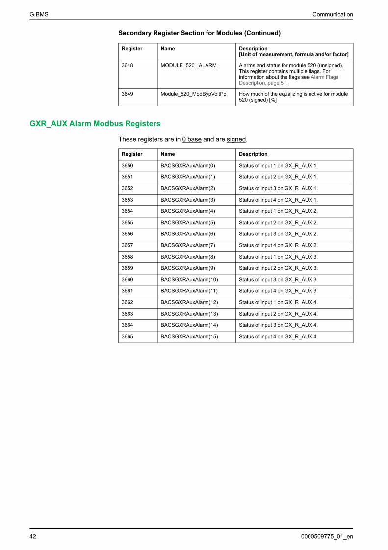
3648 MODULE_520_ ALARM Alarms and status for module 520 (unsigned).This register contains multiple flags. Forinformation about the flags see Alarm FlagsDescription, page 51.
3649 Module_520_ModBypVoltPc How much of the equalizing is active for module520 (signed) [%]
GXR_AUX Alarm Modbus Registers
These registers are in 0 base and are signed.
Register Name Description
3650 BACSGXRAuxAlarm(0) Status of input 1 on GX_R_AUX 1.
3651 BACSGXRAuxAlarm(1) Status of input 2 on GX_R_AUX 1.
3652 BACSGXRAuxAlarm(2) Status of input 3 on GX_R_AUX 1.
3653 BACSGXRAuxAlarm(3) Status of input 4 on GX_R_AUX 1.
3654 BACSGXRAuxAlarm(4) Status of input 1 on GX_R_AUX 2.
3655 BACSGXRAuxAlarm(5) Status of input 2 on GX_R_AUX 2.
3656 BACSGXRAuxAlarm(6) Status of input 3 on GX_R_AUX 2.
3657 BACSGXRAuxAlarm(7) Status of input 4 on GX_R_AUX 2.
3658 BACSGXRAuxAlarm(8) Status of input 1 on GX_R_AUX 3.
3659 BACSGXRAuxAlarm(9) Status of input 2 on GX_R_AUX 3.
3660 BACSGXRAuxAlarm(10) Status of input 3 on GX_R_AUX 3.
3661 BACSGXRAuxAlarm(11) Status of input 4 on GX_R_AUX 3.
3662 BACSGXRAuxAlarm(12) Status of input 1 on GX_R_AUX 4.
3663 BACSGXRAuxAlarm(13) Status of input 2 on GX_R_AUX 4.
3664 BACSGXRAuxAlarm(14) Status of input 3 on GX_R_AUX 4.
3665 BACSGXRAuxAlarm(15) Status of input 4 on GX_R_AUX 4.
42 0000509775_01_en
Communication G.BMS
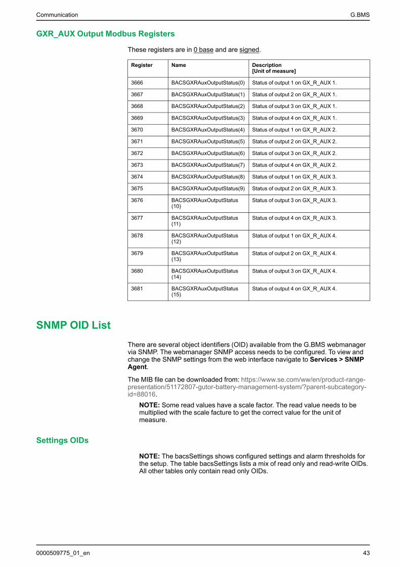
GXR_AUX Output Modbus Registers
These registers are in 0 base and are signed.
Register Name Description[Unit of measure]
3666 BACSGXRAuxOutputStatus(0) Status of output 1 on GX_R_AUX 1.
3667 BACSGXRAuxOutputStatus(1) Status of output 2 on GX_R_AUX 1.
3668 BACSGXRAuxOutputStatus(2) Status of output 3 on GX_R_AUX 1.
3669 BACSGXRAuxOutputStatus(3) Status of output 4 on GX_R_AUX 1.
3670 BACSGXRAuxOutputStatus(4) Status of output 1 on GX_R_AUX 2.
3671 BACSGXRAuxOutputStatus(5) Status of output 2 on GX_R_AUX 2.
3672 BACSGXRAuxOutputStatus(6) Status of output 3 on GX_R_AUX 2.
3673 BACSGXRAuxOutputStatus(7) Status of output 4 on GX_R_AUX 2.
3674 BACSGXRAuxOutputStatus(8) Status of output 1 on GX_R_AUX 3.
3675 BACSGXRAuxOutputStatus(9) Status of output 2 on GX_R_AUX 3.
3676 BACSGXRAuxOutputStatus(10)
Status of output 3 on GX_R_AUX 3.
3677 BACSGXRAuxOutputStatus(11)
Status of output 4 on GX_R_AUX 3.
3678 BACSGXRAuxOutputStatus(12)
Status of output 1 on GX_R_AUX 4.
3679 BACSGXRAuxOutputStatus(13)
Status of output 2 on GX_R_AUX 4.
3680 BACSGXRAuxOutputStatus(14)
Status of output 3 on GX_R_AUX 4.
3681 BACSGXRAuxOutputStatus(15)
Status of output 4 on GX_R_AUX 4.
SNMP OID ListThere are several object identifiers (OID) available from the G.BMS webmanagervia SNMP. The webmanager SNMP access needs to be configured. To view andchange the SNMP settings from the web interface navigate to Services > SNMPAgent.
The MIB file can be downloaded from: https://www.se.com/ww/en/product-range-presentation/51172807-gutor-battery-management-system/?parent-subcategory-id=88016.
NOTE: Some read values have a scale factor. The read value needs to bemultiplied with the scale facture to get the correct value for the unit ofmeasure.
Settings OIDs
NOTE: The bacsSettings shows configured settings and alarm thresholds forthe setup. The table bacsSettings lists a mix of read only and read-write OIDs.All other tables only contain read only OIDs.
0000509775_01_en 43
G.BMS Communication
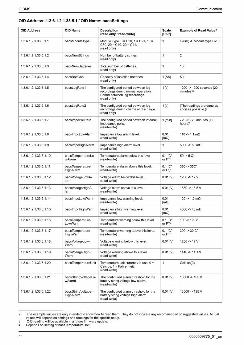
OID Address: 1.3.6.1.2.1.33.5.1 / OID Name: bacsSettings
OID Address OID Name Description(read only / read-write)
Scale[Unit]
Example of Read Value2
1.3.6.1.2.1.33.5.1.1 bacsModuleType Module Type. 0 = C20, 1 = C21, 10 =C30, 20 = C40, 20 = C41.(read only)
1 c20(0) -> Module type C20
1.3.6.1.2.1.33.5.1.2 bacsNumStrings Number of battery strings.(read only)
1 2
1.3.6.1.2.1.33.5.1.3 bacsNumBatteries Total number of batteries.(read only)
1 18
1.3.6.1.2.1.33.5.1.4 bacsBattCap Capacity of installed batteries.(read only)
1 [Ah] 50
1.3.6.1.2.1.33.5.1.5 bacsLogRate1 The configured period between logrecordings during normal operation.Period between log recordings.(read only)
1 [s] 1200 -> 1200 seconds (20minutes)3
1.3.6.1.2.1.33.5.1.6 bacsLogRate2 The configured period between logrecordings during charge or discharge.(read only)
1 [s] (The readings are done assoon as possible.)3
1.3.6.1.2.1.33.5.1.7 bacsImpcPollRate The configured period between internalimpedance polls.(read-write)
1 [min] 720 -> 720 minutes (12hours)3
1.3.6.1.2.1.33.5.1.8 bacsImpcLowAlarm Impedance low alarm level.(read-write)
0.01[mΩ]
110 -> 1.1 mΩ
1.3.6.1.2.1.33.5.1.9 bacsImpcHighAlarm Impedance high alarm level.(read-write)
1 5000 -> 50 mΩ
1.3.6.1.2.1.33.5.1.10 bacsTemperatureLo-wAlarm
Temperature alarm below this level.(read-write)
0.1 [C°or F°]4
50 -> 5 C°
1.3.6.1.2.1.33.5.1.11 bacsTemperature-HighAlarm
Temperature alarm above this level.(read-write)
0.1 [C°or F°]4
350 -> 35C°
1.3.6.1.2.1.33.5.1.12 bacsVoltageLowA-larm
Voltage alarm below this level.(read-write)
0.01 [V] 1200 -> 12 V
1.3.6.1.2.1.33.5.1.13 bacsVoltageHighA-larm
Voltage alarm above this level.(read-write)
0.01 [V] 1550 -> 15.5 V
1.3.6.1.2.1.33.5.1.14 bacsImpcLowWarn Impedance low warning level.(read-write)
0.01[mΩ]
120 -> 1.2 mΩ
1.3.6.1.2.1.33.5.1.15 bacsImpcHighWarn Impedance high warning level.(read-write)
0.01[mΩ]
4000 -> 40 mΩ
1.3.6.1.2.1.33.5.1.16 bacsTemperature-LowWarn
Temperature warning below this level.(read-write)
0.1 [C°or F°]4
100 -> 10 C°
1.3.6.1.2.1.33.5.1.17 bacsTemperature-HighWarn
Temperature warning above this level.(read-write)
0.1 [C°or F°]4
300 -> 30 C°
1.3.6.1.2.1.33.5.1.18 bacsVoltageLow-Warn
Voltage warning below this level.(read-write)
0.01 [V] 1200 -> 12 V
1.3.6.1.2.1.33.5.1.19 bacsVoltageHigh-Warn
Voltage warning above this level.(read-write)
0.01 [V] 1410 -> 14.1 V
1.3.6.1.2.1.33.5.1.20 bacsTemperatureUnit Temperature unit currently in use. 0 =Celsius, 1 = Fahrenheit.(read-write)
1 Celsius(0)
1.3.6.1.2.1.33.5.1.21 bacsStringVoltageLo-wAlarm
The configured alarm threshold for thebattery string voltage low alarm.(read-write)
0.01 [V] 10500 -> 105 V
1.3.6.1.2.1.33.5.1.22 bacsStringVoltage-HighAlarm
The configured alarm threshold for thebattery string voltage high alarm.(read-write)
0.01 [V] 13500 -> 135 V
44 0000509775_01_en
2. The example values are only intended to show how to read them. They do not indicate any recommended or suggested values. Actualvalues will depend on settings and readings for the specific setup.
3. OID reading will be available in a future firmware update.4. Depends on setting of bacsTemperatureUnit.
Communication G.BMS
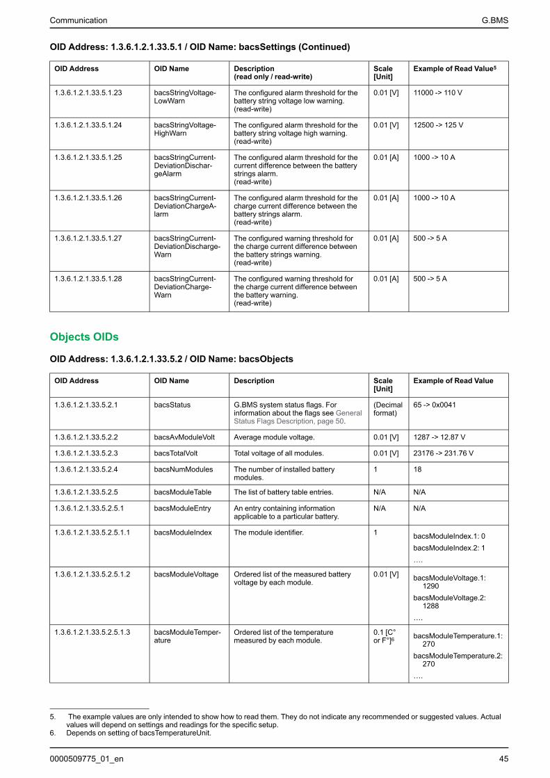
OID Address: 1.3.6.1.2.1.33.5.1 / OID Name: bacsSettings (Continued)
OID Address OID Name Description(read only / read-write)
Scale[Unit]
Example of Read Value5
1.3.6.1.2.1.33.5.1.23 bacsStringVoltage-LowWarn
The configured alarm threshold for thebattery string voltage low warning.(read-write)
0.01 [V] 11000 -> 110 V
1.3.6.1.2.1.33.5.1.24 bacsStringVoltage-HighWarn
The configured alarm threshold for thebattery string voltage high warning.(read-write)
0.01 [V] 12500 -> 125 V
1.3.6.1.2.1.33.5.1.25 bacsStringCurrent-DeviationDischar-geAlarm
The configured alarm threshold for thecurrent difference between the batterystrings alarm.(read-write)
0.01 [A] 1000 -> 10 A
1.3.6.1.2.1.33.5.1.26 bacsStringCurrent-DeviationChargeA-larm
The configured alarm threshold for thecharge current difference between thebattery strings alarm.(read-write)
0.01 [A] 1000 -> 10 A
1.3.6.1.2.1.33.5.1.27 bacsStringCurrent-DeviationDischarge-Warn
The configured warning threshold forthe charge current difference betweenthe battery strings warning.(read-write)
0.01 [A] 500 -> 5 A
1.3.6.1.2.1.33.5.1.28 bacsStringCurrent-DeviationCharge-Warn
The configured warning threshold forthe charge current difference betweenthe battery warning.(read-write)
0.01 [A] 500 -> 5 A
Objects OIDs
OID Address: 1.3.6.1.2.1.33.5.2 / OID Name: bacsObjects
OID Address OID Name Description Scale[Unit]
Example of Read Value
1.3.6.1.2.1.33.5.2.1 bacsStatus G.BMS system status flags. Forinformation about the flags see GeneralStatus Flags Description, page 50.
(Decimalformat)
65 -> 0x0041
1.3.6.1.2.1.33.5.2.2 bacsAvModuleVolt Average module voltage. 0.01 [V] 1287 -> 12.87 V
1.3.6.1.2.1.33.5.2.3 bacsTotalVolt Total voltage of all modules. 0.01 [V] 23176 -> 231.76 V
1.3.6.1.2.1.33.5.2.4 bacsNumModules The number of installed batterymodules.
1 18
1.3.6.1.2.1.33.5.2.5 bacsModuleTable The list of battery table entries. N/A N/A
1.3.6.1.2.1.33.5.2.5.1 bacsModuleEntry An entry containing informationapplicable to a particular battery.
N/A N/A
1.3.6.1.2.1.33.5.2.5.1.1 bacsModuleIndex The module identifier. 1 bacsModuleIndex.1: 0bacsModuleIndex.2: 1….
1.3.6.1.2.1.33.5.2.5.1.2 bacsModuleVoltage Ordered list of the measured batteryvoltage by each module.
0.01 [V] bacsModuleVoltage.1:1290
bacsModuleVoltage.2:1288
….
1.3.6.1.2.1.33.5.2.5.1.3 bacsModuleTemper-ature
Ordered list of the temperaturemeasured by each module.
0.1 [C°or F°]6 bacsModuleTemperature.1:
270bacsModuleTemperature.2:
270….
0000509775_01_en 45
5. The example values are only intended to show how to read them. They do not indicate any recommended or suggested values. Actualvalues will depend on settings and readings for the specific setup.
6. Depends on setting of bacsTemperatureUnit.
G.BMS Communication
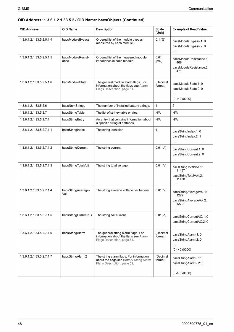
OID Address: 1.3.6.1.2.1.33.5.2 / OID Name: bacsObjects (Continued)
OID Address OID Name Description Scale[Unit]
Example of Read Value
1.3.6.1.2.1.33.5.2.5.1.4 bacsModuleBypass Ordered list of the module bypassmeasured by each module.
0.1 [%] bacsModuleBypass.1: 0bacsModuleBypass.2: 0….
1.3.6.1.2.1.33.5.2.5.1.5 bacsModuleResist-ance
Ordered list of the measured moduleimpedance in each module.
0.01[mΩ] bacsModuleResistance.1:
468bacsModuleResistance.2:
471….
1.3.6.1.2.1.33.5.2.5.1.6 bacsModuleState The general module alarm flags. Forinformation about the flags see AlarmFlags Description, page 51.
(Decimalformat) bacsModuleState.1: 0
bacsModuleState.2: 0….(0 -> 0x0000)
1.3.6.1.2.1.33.5.2.6 bacsNumStrings The number of installed battery strings. 1 2
1.3.6.1.2.1.33.5.2.7 bacsStringTable The list of stringy table entries. N/A N/A
1.3.6.1.2.1.33.5.2.7.1 bacsStringEntry An entry that contains information abouta specific string of batteries.
N/A N/A
1.3.6.1.2.1.33.5.2.7.1.1 bacsStringIndex The string identifier. 1 bacsStringIndex.1: 0bacsStringIndex.2: 1….
1.3.6.1.2.1.33.5.2.7.1.2 bacsStringCurrent The string current. 0.01 [A] bacsStringCurrent.1: 0bacsStringCurrent.2: 0….
1.3.6.1.2.1.33.5.2.7.1.3 bacsStringTotalVolt The string total voltage. 0.01 [V] bacsStringTotalVolt.1:11497
bacsStringTotalVolt.2:11438
….
1.3.6.1.2.1.33.5.2.7.1.4 bacsStringAverage-Vol
The string average voltage per battery. 0.01 [V] bacsStringAverageVol.1:1277
bacsStringAverageVol.2:1270
….
1.3.6.1.2.1.33.5.2.7.1.5 bacsStringCurrentAC The string AC current. 0.01 [A] bacsStringCurrentAC.1: 0bacsStringCurrentAC.2: 0….
1.3.6.1.2.1.33.5.2.7.1.6 bacsStringAlarm The general string alarm flags. Forinformation about the flags see AlarmFlags Description, page 51.
(Decimalformat) bacsStringAlarm.1: 0
bacsStringAlarm.2: 0….(0 -> 0x0000)
1.3.6.1.2.1.33.5.2.7.1.7 bacsStringAlarm2 The string alarm flags. For informationabout the flags see Battery String AlarmFlags Description, page 52.
(Decimalformat) bacsStringAlarm2.1: 0
bacsStringAlarm2.2: 0….(0 -> 0x0000)
46 0000509775_01_en
Communication G.BMS
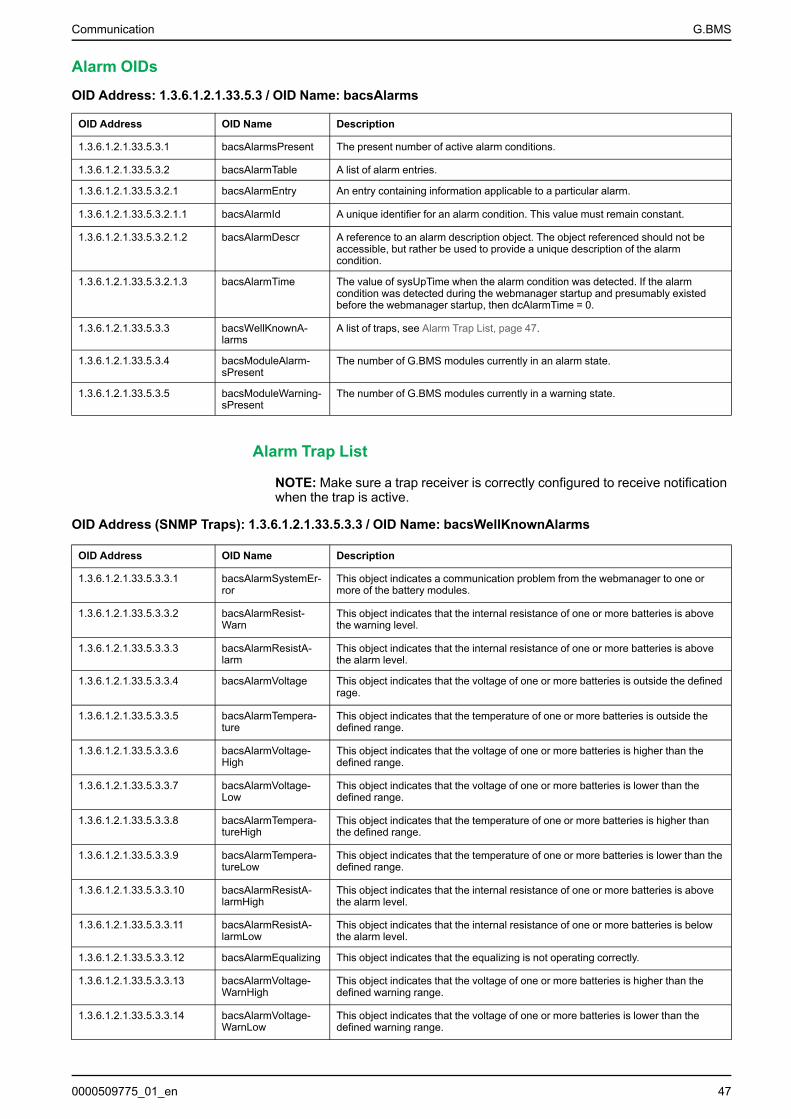
Alarm OIDs
OID Address: 1.3.6.1.2.1.33.5.3 / OID Name: bacsAlarms
OID Address OID Name Description
1.3.6.1.2.1.33.5.3.1 bacsAlarmsPresent The present number of active alarm conditions.
1.3.6.1.2.1.33.5.3.2 bacsAlarmTable A list of alarm entries.
1.3.6.1.2.1.33.5.3.2.1 bacsAlarmEntry An entry containing information applicable to a particular alarm.
1.3.6.1.2.1.33.5.3.2.1.1 bacsAlarmId A unique identifier for an alarm condition. This value must remain constant.
1.3.6.1.2.1.33.5.3.2.1.2 bacsAlarmDescr A reference to an alarm description object. The object referenced should not beaccessible, but rather be used to provide a unique description of the alarmcondition.
1.3.6.1.2.1.33.5.3.2.1.3 bacsAlarmTime The value of sysUpTime when the alarm condition was detected. If the alarmcondition was detected during the webmanager startup and presumably existedbefore the webmanager startup, then dcAlarmTime = 0.
1.3.6.1.2.1.33.5.3.3 bacsWellKnownA-larms
A list of traps, see Alarm Trap List, page 47.
1.3.6.1.2.1.33.5.3.4 bacsModuleAlarm-sPresent
The number of G.BMS modules currently in an alarm state.
1.3.6.1.2.1.33.5.3.5 bacsModuleWarning-sPresent
The number of G.BMS modules currently in a warning state.
Alarm Trap List
NOTE: Make sure a trap receiver is correctly configured to receive notificationwhen the trap is active.
OID Address (SNMP Traps): 1.3.6.1.2.1.33.5.3.3 / OID Name: bacsWellKnownAlarms
OID Address OID Name Description
1.3.6.1.2.1.33.5.3.3.1 bacsAlarmSystemEr-ror
This object indicates a communication problem from the webmanager to one ormore of the battery modules.
1.3.6.1.2.1.33.5.3.3.2 bacsAlarmResist-Warn
This object indicates that the internal resistance of one or more batteries is abovethe warning level.
1.3.6.1.2.1.33.5.3.3.3 bacsAlarmResistA-larm
This object indicates that the internal resistance of one or more batteries is abovethe alarm level.
1.3.6.1.2.1.33.5.3.3.4 bacsAlarmVoltage This object indicates that the voltage of one or more batteries is outside the definedrage.
1.3.6.1.2.1.33.5.3.3.5 bacsAlarmTempera-ture
This object indicates that the temperature of one or more batteries is outside thedefined range.
1.3.6.1.2.1.33.5.3.3.6 bacsAlarmVoltage-High
This object indicates that the voltage of one or more batteries is higher than thedefined range.
1.3.6.1.2.1.33.5.3.3.7 bacsAlarmVoltage-Low
This object indicates that the voltage of one or more batteries is lower than thedefined range.
1.3.6.1.2.1.33.5.3.3.8 bacsAlarmTempera-tureHigh
This object indicates that the temperature of one or more batteries is higher thanthe defined range.
1.3.6.1.2.1.33.5.3.3.9 bacsAlarmTempera-tureLow
This object indicates that the temperature of one or more batteries is lower than thedefined range.
1.3.6.1.2.1.33.5.3.3.10 bacsAlarmResistA-larmHigh
This object indicates that the internal resistance of one or more batteries is abovethe alarm level.
1.3.6.1.2.1.33.5.3.3.11 bacsAlarmResistA-larmLow
This object indicates that the internal resistance of one or more batteries is belowthe alarm level.
1.3.6.1.2.1.33.5.3.3.12 bacsAlarmEqualizing This object indicates that the equalizing is not operating correctly.
1.3.6.1.2.1.33.5.3.3.13 bacsAlarmVoltage-WarnHigh
This object indicates that the voltage of one or more batteries is higher than thedefined warning range.
1.3.6.1.2.1.33.5.3.3.14 bacsAlarmVoltage-WarnLow
This object indicates that the voltage of one or more batteries is lower than thedefined warning range.
0000509775_01_en 47

G.BMS Communication
OID Address (SNMP Traps): 1.3.6.1.2.1.33.5.3.3 / OID Name: bacsWellKnownAlarms (Continued)
OID Address OID Name Description
1.3.6.1.2.1.33.5.3.3.15 bacsAlarmTempera-tureWarnHigh
This object indicates that the temperature of one or more batteries is higher thanthe defined warning range.
1.3.6.1.2.1.33.5.3.3.16 bacsAlarmTempera-tureWarnLow
This object indicates that the temperature of one or more batteries is lower than thedefined warning range.
1.3.6.1.2.1.33.5.3.3.17 bacsAlarmResist-WarnHigh
This object indicates that the internal resistance of one or more batteries is higherthan the defined warning range.
1.3.6.1.2.1.33.5.3.3.18 bacsAlarmResist-WarnLow
This object indicates that the internal resistance of one or more batteries is lowerthan the defined warning range.
1.3.6.1.2.1.33.5.3.3.19 bacsAlarmInitializing The webmanager is initializing.
1.3.6.1.2.1.33.5.3.3.20 bacsAlarmCommuni-cationLost
BACS bus communication is lost.
1.3.6.1.2.1.33.5.3.3.21 bacsAlarmBattery-BreakerOpen
Battery breaker is open.
1.3.6.1.2.1.33.5.3.3.22 bacsAlarmThermal-Runaway
Thermal runaway detected.
1.3.6.1.2.1.33.5.3.3.23 bacsAlarmSensor-CommunicationLost
Sensor communication is lost.
1.3.6.1.2.1.33.5.3.3.24 bacsAlarmDischarg-ing
Batteries are being discharged.
1.3.6.1.2.1.33.5.3.3.25 bacsAlarmDischar-gingStopped
Batteries are no longer being discharged.
1.3.6.1.2.1.33.5.3.3.26 bacsAlarmMaxVolta-geDiff
The voltage difference is too high.
1.3.6.1.2.1.33.5.3.3.27 bacsAlarmString-VoltHigh
The battery string voltage is above the configured alarm threshold.
1.3.6.1.2.1.33.5.3.3.28 bacsAlarmStringVolt-Low
The battery string voltage is below the configured alarm threshold.
1.3.6.1.2.1.33.5.3.3.29 bacsAlarmString-VoltHighWarn
The battery string voltage is above the configured warning threshold.
1.3.6.1.2.1.33.5.3.3.30 bacsAlarmStringVolt-LowWarn
The battery string voltage is below the configured warning threshold.
1.3.6.1.2.1.33.5.3.3.31 bacsAlarmStringCur-rentHigh
The battery string current is above the configured alarm threshold.
1.3.6.1.2.1.33.5.3.3.32 bacsAlarmStringCur-rentLow
The battery string current is below the configured alarm threshold.
1.3.6.1.2.1.33.5.3.3.33 bacsAlarmStringCur-rentHighWarn
The battery string current is above the configured warning threshold.
1.3.6.1.2.1.33.5.3.3.34 bacsAlarmStringCur-rentLowWarn
The battery string current is below the configured warning threshold.
1.3.6.1.2.1.33.5.3.3.35 bacsAlarmStringE-qualizingDisabled
The battery string equalizing is disabled.
1.3.6.1.2.1.33.5.3.3.36 bacsAlarmString-CurrDeviationCharge
The charge current difference between the battery strings is above the configuredalarm threshold.
1.3.6.1.2.1.33.5.3.3.37 bacsAlarmString-CurrDeviationDi-scharge
The discharge current difference between the battery strings is above theconfigured alarm threshold.
1.3.6.1.2.1.33.5.3.3.38 bacsAlarmString-CurrDeviationChar-geWarn
The charge current difference between the battery strings is above the configuredwarning threshold.
1.3.6.1.2.1.33.5.3.3.39 bacsAlarmString-CurrDeviationDi-schargeWarn
The discharge current difference between the battery strings is above theconfigured warning threshold.
48 0000509775_01_en
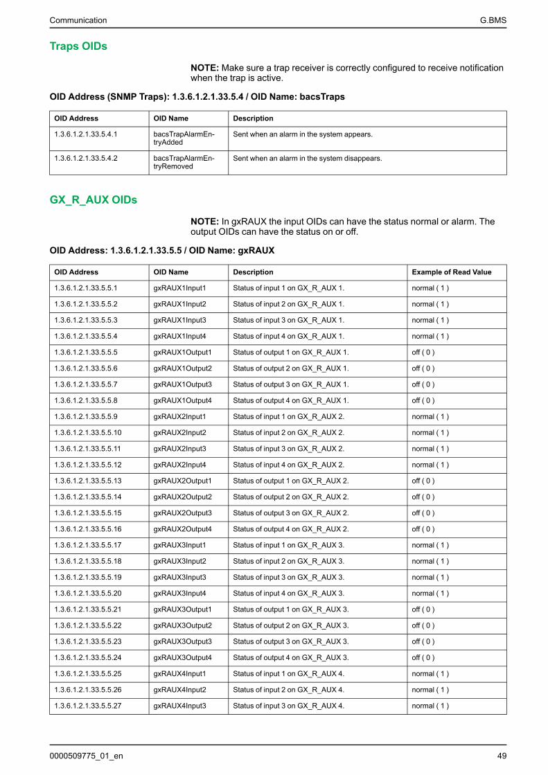
Communication G.BMS
Traps OIDs
NOTE: Make sure a trap receiver is correctly configured to receive notificationwhen the trap is active.
OID Address (SNMP Traps): 1.3.6.1.2.1.33.5.4 / OID Name: bacsTraps
OID Address OID Name Description
1.3.6.1.2.1.33.5.4.1 bacsTrapAlarmEn-tryAdded
Sent when an alarm in the system appears.
1.3.6.1.2.1.33.5.4.2 bacsTrapAlarmEn-tryRemoved
Sent when an alarm in the system disappears.
GX_R_AUX OIDs
NOTE: In gxRAUX the input OIDs can have the status normal or alarm. Theoutput OIDs can have the status on or off.
OID Address: 1.3.6.1.2.1.33.5.5 / OID Name: gxRAUX
OID Address OID Name Description Example of Read Value
1.3.6.1.2.1.33.5.5.1 gxRAUX1Input1 Status of input 1 on GX_R_AUX 1. normal ( 1 )
1.3.6.1.2.1.33.5.5.2 gxRAUX1Input2 Status of input 2 on GX_R_AUX 1. normal ( 1 )
1.3.6.1.2.1.33.5.5.3 gxRAUX1Input3 Status of input 3 on GX_R_AUX 1. normal ( 1 )
1.3.6.1.2.1.33.5.5.4 gxRAUX1Input4 Status of input 4 on GX_R_AUX 1. normal ( 1 )
1.3.6.1.2.1.33.5.5.5 gxRAUX1Output1 Status of output 1 on GX_R_AUX 1. off ( 0 )
1.3.6.1.2.1.33.5.5.6 gxRAUX1Output2 Status of output 2 on GX_R_AUX 1. off ( 0 )
1.3.6.1.2.1.33.5.5.7 gxRAUX1Output3 Status of output 3 on GX_R_AUX 1. off ( 0 )
1.3.6.1.2.1.33.5.5.8 gxRAUX1Output4 Status of output 4 on GX_R_AUX 1. off ( 0 )
1.3.6.1.2.1.33.5.5.9 gxRAUX2Input1 Status of input 1 on GX_R_AUX 2. normal ( 1 )
1.3.6.1.2.1.33.5.5.10 gxRAUX2Input2 Status of input 2 on GX_R_AUX 2. normal ( 1 )
1.3.6.1.2.1.33.5.5.11 gxRAUX2Input3 Status of input 3 on GX_R_AUX 2. normal ( 1 )
1.3.6.1.2.1.33.5.5.12 gxRAUX2Input4 Status of input 4 on GX_R_AUX 2. normal ( 1 )
1.3.6.1.2.1.33.5.5.13 gxRAUX2Output1 Status of output 1 on GX_R_AUX 2. off ( 0 )
1.3.6.1.2.1.33.5.5.14 gxRAUX2Output2 Status of output 2 on GX_R_AUX 2. off ( 0 )
1.3.6.1.2.1.33.5.5.15 gxRAUX2Output3 Status of output 3 on GX_R_AUX 2. off ( 0 )
1.3.6.1.2.1.33.5.5.16 gxRAUX2Output4 Status of output 4 on GX_R_AUX 2. off ( 0 )
1.3.6.1.2.1.33.5.5.17 gxRAUX3Input1 Status of input 1 on GX_R_AUX 3. normal ( 1 )
1.3.6.1.2.1.33.5.5.18 gxRAUX3Input2 Status of input 2 on GX_R_AUX 3. normal ( 1 )
1.3.6.1.2.1.33.5.5.19 gxRAUX3Input3 Status of input 3 on GX_R_AUX 3. normal ( 1 )
1.3.6.1.2.1.33.5.5.20 gxRAUX3Input4 Status of input 4 on GX_R_AUX 3. normal ( 1 )
1.3.6.1.2.1.33.5.5.21 gxRAUX3Output1 Status of output 1 on GX_R_AUX 3. off ( 0 )
1.3.6.1.2.1.33.5.5.22 gxRAUX3Output2 Status of output 2 on GX_R_AUX 3. off ( 0 )
1.3.6.1.2.1.33.5.5.23 gxRAUX3Output3 Status of output 3 on GX_R_AUX 3. off ( 0 )
1.3.6.1.2.1.33.5.5.24 gxRAUX3Output4 Status of output 4 on GX_R_AUX 3. off ( 0 )
1.3.6.1.2.1.33.5.5.25 gxRAUX4Input1 Status of input 1 on GX_R_AUX 4. normal ( 1 )
1.3.6.1.2.1.33.5.5.26 gxRAUX4Input2 Status of input 2 on GX_R_AUX 4. normal ( 1 )
1.3.6.1.2.1.33.5.5.27 gxRAUX4Input3 Status of input 3 on GX_R_AUX 4. normal ( 1 )
0000509775_01_en 49
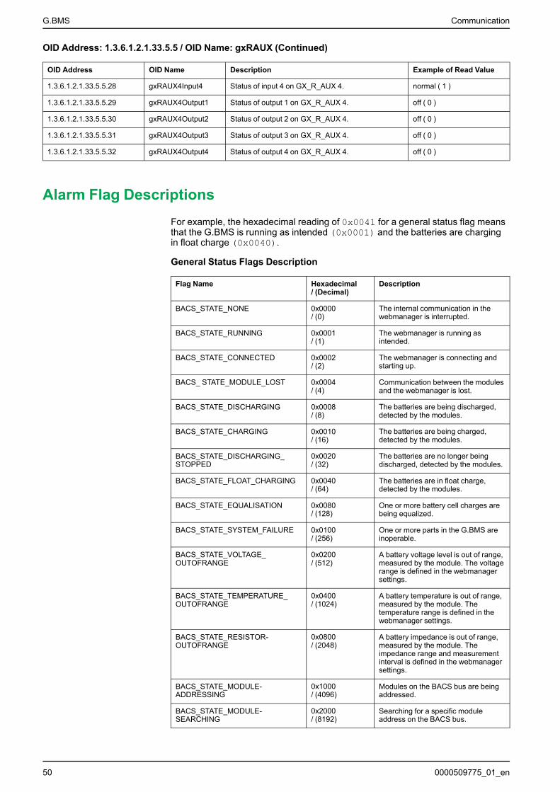
G.BMS Communication
OID Address: 1.3.6.1.2.1.33.5.5 / OID Name: gxRAUX (Continued)
OID Address OID Name Description Example of Read Value
1.3.6.1.2.1.33.5.5.28 gxRAUX4Input4 Status of input 4 on GX_R_AUX 4. normal ( 1 )
1.3.6.1.2.1.33.5.5.29 gxRAUX4Output1 Status of output 1 on GX_R_AUX 4. off ( 0 )
1.3.6.1.2.1.33.5.5.30 gxRAUX4Output2 Status of output 2 on GX_R_AUX 4. off ( 0 )
1.3.6.1.2.1.33.5.5.31 gxRAUX4Output3 Status of output 3 on GX_R_AUX 4. off ( 0 )
1.3.6.1.2.1.33.5.5.32 gxRAUX4Output4 Status of output 4 on GX_R_AUX 4. off ( 0 )
Alarm Flag DescriptionsFor example, the hexadecimal reading of 0x0041 for a general status flag meansthat the G.BMS is running as intended (0x0001) and the batteries are chargingin float charge (0x0040).
General Status Flags Description
Flag Name Hexadecimal/ (Decimal)
Description
BACS_STATE_NONE 0x0000/ (0)
The internal communication in thewebmanager is interrupted.
BACS_STATE_RUNNING 0x0001/ (1)
The webmanager is running asintended.
BACS_STATE_CONNECTED 0x0002/ (2)
The webmanager is connecting andstarting up.
BACS_ STATE_MODULE_LOST 0x0004/ (4)
Communication between the modulesand the webmanager is lost.
BACS_STATE_DISCHARGING 0x0008/ (8)
The batteries are being discharged,detected by the modules.
BACS_STATE_CHARGING 0x0010/ (16)
The batteries are being charged,detected by the modules.
BACS_STATE_DISCHARGING_STOPPED
0x0020/ (32)
The batteries are no longer beingdischarged, detected by the modules.
BACS_STATE_FLOAT_CHARGING 0x0040/ (64)
The batteries are in float charge,detected by the modules.
BACS_STATE_EQUALISATION 0x0080/ (128)
One or more battery cell charges arebeing equalized.
BACS_STATE_SYSTEM_FAILURE 0x0100/ (256)
One or more parts in the G.BMS areinoperable.
BACS_STATE_VOLTAGE_OUTOFRANGE
0x0200/ (512)
A battery voltage level is out of range,measured by the module. The voltagerange is defined in the webmanagersettings.
BACS_STATE_TEMPERATURE_OUTOFRANGE
0x0400/ (1024)
A battery temperature is out of range,measured by the module. Thetemperature range is defined in thewebmanager settings.
BACS_STATE_RESISTOR-OUTOFRANGE
0x0800/ (2048)
A battery impedance is out of range,measured by the module. Theimpedance range and measurementinterval is defined in the webmanagersettings.
BACS_STATE_MODULE-ADDRESSING
0x1000/ (4096)
Modules on the BACS bus are beingaddressed.
BACS_STATE_MODULE-SEARCHING
0x2000/ (8192)
Searching for a specific moduleaddress on the BACS bus.
50 0000509775_01_en
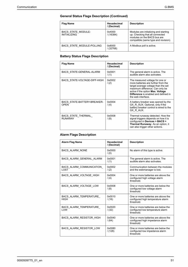
Communication G.BMS
General Status Flags Description (Continued)
Flag Name Hexadecimal/ (Decimal)
Description
BACS_STATE_MODULE-INITIALIZING
0x4000/ (16384)
Modules are initializing and startingup. Checking that all connectedmodules on the BACS bus arecompatible (same type and revision).
BACS_STATE_MODULE-POLLING 0x8000/ (32768)
A Modbus poll is active.
Battery Status Flags Description
Flag Name Hexadecimal/ (Decimal)
Description
BACS_STATE-GENERAL-ALARM 0x0001/ (1)
The general alarm is active. Theaudible alarm also activates.
BACS_STATE-VOLTAGE-DIFF-HIGH 0x0002/ (2)
The measured voltage for one ormore batteries are further from thetarget average voltage than the setmaximum difference. Can only beactive if the option Max. VoltageDifference is enabled and defined inthe web interface.
BACS_STATE-BATTERY-BREAKER-OPEN
0x0004/ (4)
A battery breaker was opened by theGX_R_AUX. Optional, only if thebattery breaker control is wired to theGX_R_AUX.
BACS_STATE_THERMAL_RUNAWAY
0x0008/ (8)
Thermal runaway detected. How thesignal triggers depends on how it isconfigured in Devices > BACS >Thermal Runaway. As an option, itcan also trigger other actions.
Alarm Flags Description
Alarm Flag Name Hexadecimal/ (Decimal)
Description
BACS_ALARM_NONE 0x0000/ (0)
No alarm of this type is active.
BACS_ALARM_GENERAL_ALARM 0x0001/ (1)
The general alarm is active. Theaudible alarm also activates.
BACS_ALARM_COMMUNICATION_LOST
0x0002/ (2)
Communication between the modulesand the webmanager is lost.
BACS_ALARM_VOLTAGE_HIGH 0x0004/ (4)
One or more batteries are above theconfigured high voltage alarmthreshold.
BACS_ALARM_VOLTAGE_LOW 0x0008/ (8)
One or more batteries are below theconfigured low voltage alarmthreshold.
BACS_ALARM_TEMPERATURE_HIGH
0x0010/ (16)
One or more batteries are above theconfigured high temperature alarmthreshold.
BACS_ALARM_TEMPERATURE_LOW
0x0020/ (32)
One or more batteries are below theconfigured low temperature alarmthreshold.
BACS_ALARM_RESISTOR_HIGH 0x0040/ (64)
One or more batteries are above theconfigured high impedance alarmthreshold.
BACS_ALARM_RESISTOR_LOW 0x0080/ (128)
One or more batteries are below theconfigured low impedance alarmthreshold.
0000509775_01_en 51
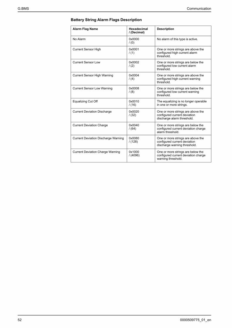
G.BMS Communication
Battery String Alarm Flags Description
Alarm Flag Name Hexadecimal/ (Decimal)
Description
No Alarm 0x0000/ (0)
No alarm of this type is active.
Current Sensor High 0x0001/ (1)
One or more strings are above theconfigured high current alarmthreshold.
Current Sensor Low 0x0002/ (2)
One or more strings are below theconfigured low current alarmthreshold.
Current Sensor High Warning 0x0004/ (4)
One or more strings are above theconfigured high current warningthreshold.
Current Sensor Low Warning 0x0008/ (8)
One or more strings are below theconfigured low current warningthreshold.
Equalizing Cut Off 0x0010/ (16)
The equalizing is no longer operablein one or more strings.
Current Deviation Discharge 0x0020/ (32)
One or more strings are above theconfigured current deviationdischarge alarm threshold.
Current Deviation Charge 0x0040/ (64)
One or more strings are below theconfigured current deviation chargealarm threshold.
Current Deviation Discharge Warning 0x0080/ (128)
One or more strings are above theconfigured current deviationdischarge warning threshold.
Current Deviation Charge Warning 0x1000/ (4096)
One or more strings are below theconfigured current deviation chargewarning threshold.
52 0000509775_01_en

Troubleshooting G.BMS
Troubleshooting
Problem Check
Webmanager power supply LED(s) not illuminated Check the status and connection of the power supply.
Check that a correct power supply is used, for more details see Webmanager Ports, page 12.
No local connection to thewebmanager Check the slide switch position. If the slide switch is in the left position the default set IP address will be
used. If the IP address was changed, you can set the IP address to the hard coded address(10.10.10.10) if you set the slide switch in the center position and restart the webmanager. For moredetails see Webmanager LEDs and Buttons, page 13 and Initial Local Connection to theWebmanager, page 30.
No or weak BACS buscommunication Check the connections between the webmanager and modules, and any splitting boxes, repeaters,
converters, sensors or other devices.Check that the maximum bus cable lengths are not exceeded, for details see Bus Cable Length and
Wiring Details, page 24.Check that the modules and cables are compatible (correct type and revision). For additional support
please contact your local Gutor Service Center.
No or incorrect measurementfrom modules Check that the measurement cables are correctly placed on the battery poles and tightened according
to the original equipment manufacturer (OEM) for the batteries. For more details see Install BatteryMeasuring Cables, page 15.
Check the module placement and if applicable the placement of the external temperature sensor. Formore details see Place the G.BMS Modules, page 18.
Check if the fuse on the measuring cable might be damaged, try to connect the module to anothermeasuring cable to check if the modules is functioning correctly.
No Modbus or SNMPcommunication from thewebmanager
Check the IP address settings from the webmanager web interface.Check that the Modbus or SNMP settings are correctly configured in the webmanager web interface.
Incorrect values displayed in thewebmanager web interface. Delete the web browser cache. Previously stored data in the cache can cause incorrect information to
be displayed. This can especially occur if connections are made to multiple webmanagers from thesame web browser.
0000509775_01_en 53

G.BMS Technical Data
Technical DataTechnical information and specifications about the devices and parts. Also listspart numbers, name and details for each part.
• Module Technical Data and Parts, page 54• Control Cabinets Technical Data and Parts, page 55• Webmanager Technical Data and Parts, page 56• Splitting Box Technical Data and Parts, page 56• Current Sensor Technical Data and Parts, page 57• BACS Measuring Cables Technical Data and Parts, page 57• BACS Bus Communication Cable Technical Data and Parts, page 60• Additional Options Technical Data and Parts, page 61• Sensormanager and Additional Sensors Technical Data and Parts, page 63
Module Technical Data and PartsDimension (W x L x H) 56 x 79 x 22 mm (2.2 x 3.1 x 0.87 in)
Protection rating IP 42
Operating condition Between 0°C – 60°C (32°F – 140°F) with a maximum humidity of90% (not condensing)
Current consumptionfrom battery
Normal operation:• C20, C23, C30: 15–20 mA• C40, C41: 35–40 mA
“Sleep Mode”: < 1mA
Measuring accuracy • Internal resistance C2x, C30: < 5%• Internal resistance C4x: < 10%• Voltage: < 0.5%• Temperature: < 15%
Measuring resolution • Internal resistance: 0.5 mΩ• Voltage: 0.1 V• Temperature: 0.1°
Battery types Lead, NiCad, NiMH or lithium batteries
Fastening Velcro if mounted on the battery, or if using an external batterysensor it can be mounted on a DIN rails with an additional clip, seeDIN Clip for Modules with External Temperature Sensors Add-on,page 55.
Certifications UL, CSA and CE
Module Parts
Part Number Part Name BACSType
Voltagerange
Resist-ancerange
Equaliza-tionpower
BatterySize
950-6500 BMS MODULE 2V 7-5000AH 1.25-3.2V C40 1.25–3.2 V 0.02–6 mΩ 0.9A (at2.27 V)
2 V DC,7–9000Ah
950-6501 BMS MODULE 4VDC 7-900AH 2.4-5.0V C41 2.4–5.0 V 0.5–30 mΩ 0.3 A 4 V DC,7–900Ah
950-6502 BMS MODULE 6VDC 7-900AH 4.8-8.0V C30 4.8–8.0 V 0.5–60 mΩ 0.3 A 6 V DC,7–900Ah
950-6503 BMS MODULE 12VDC 7-600AH 9.7-17V C20 9.7–17 V 0.5–60 mΩ 0.15 A 12 V DC,7–600Ah
950-6504 BMS MODULE 16VDC 7-600AH 9.7-21V C23 9.7–21 V 0.5–60 mΩ 0.12 A 16 V DC,7–600Ah
54 0000509775_01_en

Technical Data G.BMS
Add-ons for Modules
These parts can be added to a module. The module will then have these partsalready installed on the module.
External Temperature Sensor Add-on
Part Number Part Name Description CableLength
950-6514 BACS EXTERNAL TEMPERATURE SENSOR23CM
For any BACS module type. Sensor is attached ontop of the battery.
23 cm(0.75 ft)
950-6515 BACS EXTERNAL TEMPERATURE SENSOR90CM
For any BACS module type. Sensor is attached ontop of the battery.
90 cm(2.95 ft)
950-6516 BACS EXT. TEMP. SENSOR 23CM WITHFASTON
For any BACS module type. Sensor is attached withFaston at a battery terminal.
23 cm(0.75 ft)
950-6517 BACS EXT. TEMP. SENSOR 90CM WITHFASTON
For any BACS module type. Sensor is attached withFaston at a battery terminal.
90 cm(2.95 ft)
DIN Clip for Modules with External Temperature Sensors Add-on
Part Number Part Name Description
950-6540 BMS BACS MOUNT CLIP INCL.INSTALLATION
A module with an external temperature sensor can be mounted on aDIN rail 35 x 7.5 mm (TS35 rail) with this additional clip.
Control Cabinets Technical Data and PartsFront panel indications The front panel have two LEDs for each webmanager inside:
Power (green): The power supply to the webmanager is ok ifilluminated.
Alarm (red): An alarm is active if illuminated.
Cabinet protection rating IP 56
Operating condition Between 0°C – 60°C (32°F – 140°F) with a maximum humidity of90% (not condensing)
Power consumption 30 W depending on the number of webmanagers
Certification Depends on part number see respective parts table ControlCabinets Parts (UL, CSA and CE Certified), page 55 or ControlCabinets Parts (CE Certified), page 55.
Control Cabinets Parts (UL, CSA and CE Certified)
Part Number Part Name Webman-agersIncluded
Width Height Depth Weight
950-6528 BMS CONTROL CABINET 1406X508X223MM UL
1 406 mm(16 in)
508 mm(20 in)
223 mm(9 in)
17 Kg(37.5 lb)
950-6529 BMS CONTROL CABINET 2406X508X223MM UL
2 406 mm(16 in)
508 mm(20 in)
223 mm(9 in)
21 Kg(46.3 lb)
Control Cabinets Parts (CE Certified)
Part Number Part Name Webman-agersIncluded
Width Height Depth Weight
950-6518 BMS CONTROL CABINET 1400X500X210MM
1 400 mm(15.7 in)
500 mm(19.7 in)
210 mm(8.27 in)
17 Kg(37.5 lb)
950-6519 BMS CONTROL CABINET 2500X500X210MM
2 500 mm(19.7 in)
500 mm(19.7 in)
210 mm(8.27 in)
21 Kg(46.3 lb)
0000509775_01_en 55
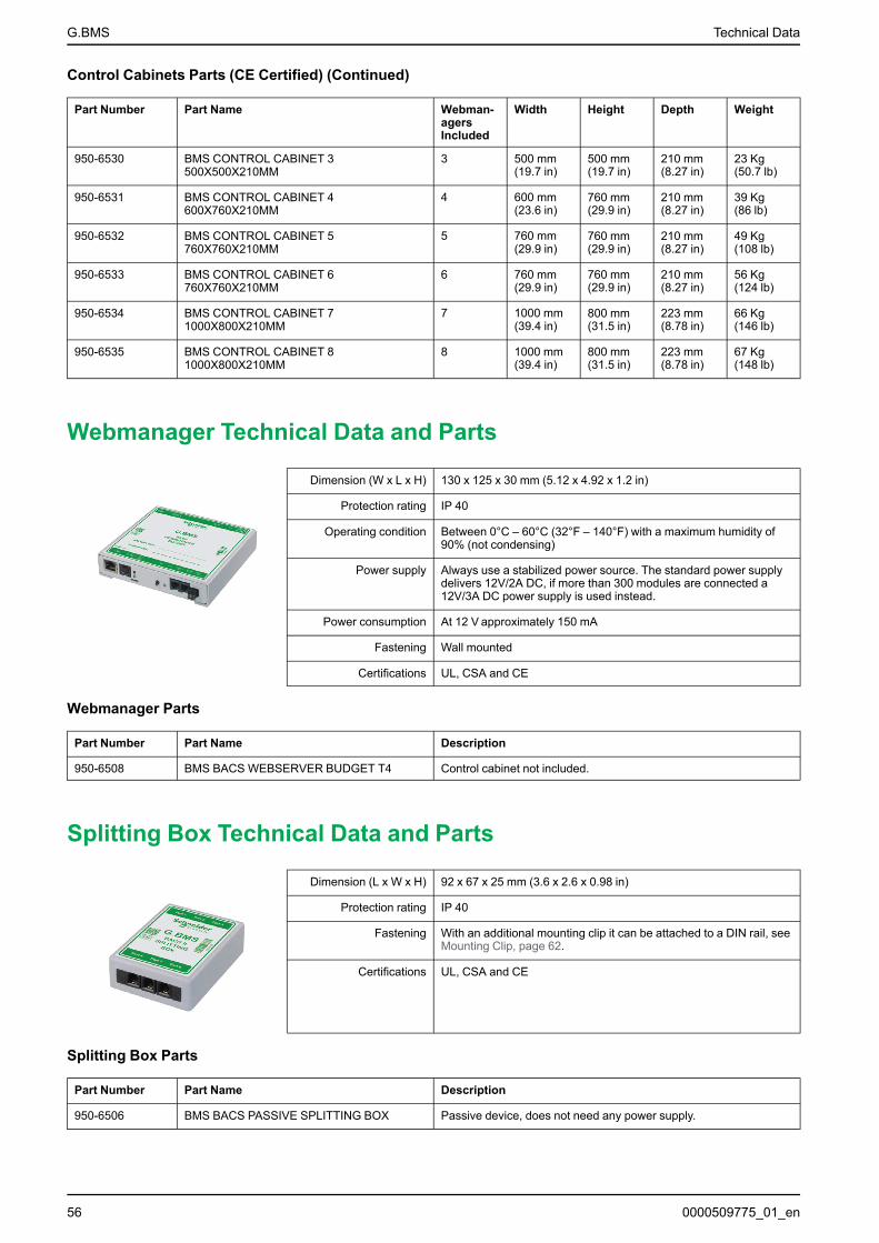
G.BMS Technical Data
Control Cabinets Parts (CE Certified) (Continued)
Part Number Part Name Webman-agersIncluded
Width Height Depth Weight
950-6530 BMS CONTROL CABINET 3500X500X210MM
3 500 mm(19.7 in)
500 mm(19.7 in)
210 mm(8.27 in)
23 Kg(50.7 lb)
950-6531 BMS CONTROL CABINET 4600X760X210MM
4 600 mm(23.6 in)
760 mm(29.9 in)
210 mm(8.27 in)
39 Kg(86 lb)
950-6532 BMS CONTROL CABINET 5760X760X210MM
5 760 mm(29.9 in)
760 mm(29.9 in)
210 mm(8.27 in)
49 Kg(108 lb)
950-6533 BMS CONTROL CABINET 6760X760X210MM
6 760 mm(29.9 in)
760 mm(29.9 in)
210 mm(8.27 in)
56 Kg(124 lb)
950-6534 BMS CONTROL CABINET 71000X800X210MM
7 1000 mm(39.4 in)
800 mm(31.5 in)
223 mm(8.78 in)
66 Kg(146 lb)
950-6535 BMS CONTROL CABINET 81000X800X210MM
8 1000 mm(39.4 in)
800 mm(31.5 in)
223 mm(8.78 in)
67 Kg(148 lb)
Webmanager Technical Data and Parts
Dimension (W x L x H) 130 x 125 x 30 mm (5.12 x 4.92 x 1.2 in)
Protection rating IP 40
Operating condition Between 0°C – 60°C (32°F – 140°F) with a maximum humidity of90% (not condensing)
Power supply Always use a stabilized power source. The standard power supplydelivers 12V/2A DC, if more than 300 modules are connected a12V/3A DC power supply is used instead.
Power consumption At 12 V approximately 150 mA
Fastening Wall mounted
Certifications UL, CSA and CE
Webmanager Parts
Part Number Part Name Description
950-6508 BMS BACS WEBSERVER BUDGET T4 Control cabinet not included.
Splitting Box Technical Data and Parts
Dimension (L x W x H) 92 x 67 x 25 mm (3.6 x 2.6 x 0.98 in)
Protection rating IP 40
Fastening With an additional mounting clip it can be attached to a DIN rail, seeMounting Clip, page 62.
Certifications UL, CSA and CE
Splitting Box Parts
Part Number Part Name Description
950-6506 BMS BACS PASSIVE SPLITTING BOX Passive device, does not need any power supply.
56 0000509775_01_en

Technical Data G.BMS
Current Sensor Technical Data and PartsPorts 2 RJ10 ports for the BACS bus, and 2 RJ12 ports for an alternative
connection to the sensormanager. Only one set of the ports shouldbe used.
AC (Ripple) voltagemeasurements Range: 0.1 - 5 V RMS (string)
Resolution: 0.1 VAccuracy: 10%Max Freq: 200 Hz (no attenuation)
Dimension (L x W x H) 110 x 82 x 125 mm (4.33 x 3.22 x 4.92 in)
Fastening The housing can be attached to a DIN rail 35 x 7.5 mm (TS35 rail)
Certifications CE
Current Sensor Parts
Part Number Part Name Inner Diameter Description
950-6509 BACS DC CURRENT SENSOR 50ADC D_21MM
21 mm (0.827 in) For measuring charging/dischargingcurrents of ± 50 A. Includes a 3 m (9.8ft) BACS bus cable.
950-6510 BACS DC CURRENT SENSOR 200ADC D_40MM
40 mm (1.57 in) For measuring charging/dischargingcurrents of ± 200 A. Includes a 3 m (9.8ft) BACS bus cable.
950-6511 BACS DC CURRENT SENSOR 400ADC D_40MM
40 mm (1.57 in) For measuring charging/dischargingcurrents of ± 400 A. Includes a 3 m (9.8ft) BACS bus cable.
950-6512 BACS DC CURRENT SENSOR 1000ADC D_40MM
40 mm (1.57 in) For measuring charging/dischargingcurrents of ± 1000 A. Includes a 3 m(9.8 ft) BACS bus cable.
950-6513 BACS DC CURRENT SENSOR 2000ADC D_40MM
40 mm (1.57 in) For measuring charging/dischargingcurrents of ± 2000 A. Includes a 3 m(9.8 ft) BACS bus cable.
BACS Measuring Cables Technical Data and PartsDepending on the module type there are different measuring cables available:
• For C40 modules:◦ UL, CSA and CE certified: BC4B Measuring Cables, page 57◦ CE certified: BC4B Measuring Cables, page 58
• For C20, C23, C30, C41 modules:◦ UL, CSA and CE certified: BC5 Measuring Cables, page 59◦ CE certified: BC5 Measuring Cables, page 59
BC4B Measuring Cables
For module type C40 on 1.2 V - 2 V batteries
Cable cross section 2 x 1.50 mm2 (16 AWG)
Nominal voltage (U0 / U) 300 V / 500 V
Fuses 1000 V / 10 A and 1000 V / 1 A
Temperature range -25°C – 70°C (-13°F – 158°F)
Certifications UL, CSA and CE
0000509775_01_en 57
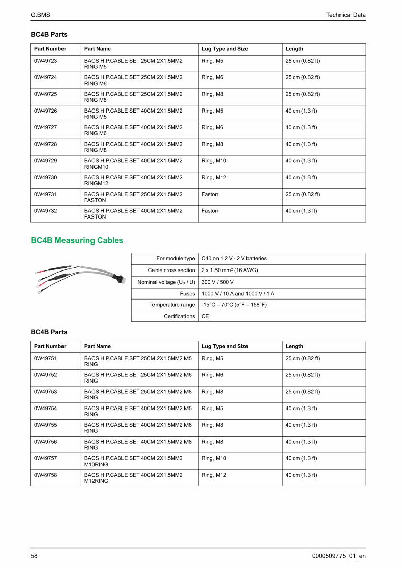
G.BMS Technical Data
BC4B Parts
Part Number Part Name Lug Type and Size Length
0W49723 BACS H.P.CABLE SET 25CM 2X1.5MM2RING M5
Ring, M5 25 cm (0.82 ft)
0W49724 BACS H.P.CABLE SET 25CM 2X1.5MM2RING M6
Ring, M6 25 cm (0.82 ft)
0W49725 BACS H.P.CABLE SET 25CM 2X1.5MM2RING M8
Ring, M8 25 cm (0.82 ft)
0W49726 BACS H.P.CABLE SET 40CM 2X1.5MM2RING M5
Ring, M5 40 cm (1.3 ft)
0W49727 BACS H.P.CABLE SET 40CM 2X1.5MM2RING M6
Ring, M6 40 cm (1.3 ft)
0W49728 BACS H.P.CABLE SET 40CM 2X1.5MM2RING M8
Ring, M8 40 cm (1.3 ft)
0W49729 BACS H.P.CABLE SET 40CM 2X1.5MM2RINGM10
Ring, M10 40 cm (1.3 ft)
0W49730 BACS H.P.CABLE SET 40CM 2X1.5MM2RINGM12
Ring, M12 40 cm (1.3 ft)
0W49731 BACS H.P.CABLE SET 25CM 2X1.5MM2FASTON
Faston 25 cm (0.82 ft)
0W49732 BACS H.P.CABLE SET 40CM 2X1.5MM2FASTON
Faston 40 cm (1.3 ft)
BC4B Measuring Cables
For module type C40 on 1.2 V - 2 V batteries
Cable cross section 2 x 1.50 mm2 (16 AWG)
Nominal voltage (U0 / U) 300 V / 500 V
Fuses 1000 V / 10 A and 1000 V / 1 A
Temperature range -15°C – 70°C (5°F – 158°F)
Certifications CE
BC4B Parts
Part Number Part Name Lug Type and Size Length
0W49751 BACS H.P.CABLE SET 25CM 2X1.5MM2 M5RING
Ring, M5 25 cm (0.82 ft)
0W49752 BACS H.P.CABLE SET 25CM 2X1.5MM2 M6RING
Ring, M6 25 cm (0.82 ft)
0W49753 BACS H.P.CABLE SET 25CM 2X1.5MM2 M8RING
Ring, M8 25 cm (0.82 ft)
0W49754 BACS H.P.CABLE SET 40CM 2X1.5MM2 M5RING
Ring, M5 40 cm (1.3 ft)
0W49755 BACS H.P.CABLE SET 40CM 2X1.5MM2 M6RING
Ring, M8 40 cm (1.3 ft)
0W49756 BACS H.P.CABLE SET 40CM 2X1.5MM2 M8RING
Ring, M8 40 cm (1.3 ft)
0W49757 BACS H.P.CABLE SET 40CM 2X1.5MM2M10RING
Ring, M10 40 cm (1.3 ft)
0W49758 BACS H.P.CABLE SET 40CM 2X1.5MM2M12RING
Ring, M12 40 cm (1.3 ft)
58 0000509775_01_en

Technical Data G.BMS
BC5 Measuring Cables
For module type C20, C23, C30, C41 on 4 V - 16 V batteries
Cable cross section 2 x 0.75 mm2 (20 AWG)
Nominal voltage (U0 / U) 300 V / 500 V
Fuses 1000 V / 10 A and 1000 V / 1 A
Temperature range -25°C – 70°C (-13°F – 158°F)
Certifications UL, CSA and CE
BC5 Parts
Part Number Part Name Lug Type and Size Length
0W49740 BACS M.CABLE SET 15CM 2X0.75MM2 M5RING
Ring, M5 15 cm (0.49 ft)
0W49741 BACS M.CABLE SET 15CM 2X0.75MM2 M6RING
Ring, M6 15 cm (0.49 ft)
0W49742 BACS M.CABLE SET 15CM 2X0.75MM2 M8RING
Ring, M8 15 cm (0.49 ft)
0W49743 BACS M.CABLE SET 25CM 2X0.75MM2 M5RING
Ring, M5 25 cm (0.82 ft)
0W49744 BACS M.CABLE SET 25CM 2X0.75MM2 M6RING
Ring, M6 25 cm (0.82 ft)
0W49745 BACS M.CABLE SET 25CM 2X0.75MM2 M8RING
Ring, M8 25 cm (0.82 ft)
0W49746 BACS M.CABLE SET 40CM 2X0.75MM2 M5RING
Ring, M5 40 cm (1.3 ft)
0W49747 BACS M.CABLE SET 40CM 2X0.75MM2 M6RING
Ring, M6 40 cm (1.3 ft)
0W49748 BACS M.CABLE SET 40CM 2X0.75MM2 M8RING
Ring, M8 40 cm (1.3 ft)
0W49749 BACS M.CABLE SET 40CM 2X0.75MM2 M10RING
Ring, M10 40 cm (1.3 ft)
0W49750 BACS M.CABLE SET 40CM 2X0.75MM2 M12RING
Ring, M12 40 cm (1.3 ft)
0W49721 BACS M.CABLE SET 25CM 2X0.75MM2FASTON
Faston 25 cm (0.82 ft)
0W49722 BACS M.CABLE SET 25CM 2X0.75MM22XFASTON
2 Faston 25 cm (0.82 ft)
BC5 Measuring Cables
For module type C20, C23, C30, C41 on 4 V - 16 V batteries
Cable cross section 2 x 0.75 mm2 (20 AWG)
Nominal voltage (U0 / U) 300 V / 500 V
Fuses 1000 V / 10 A and 1000 V / 1 A
Temperature range -15°C – 70°C (5°F – 158°F)
Certifications CE
BC5 Parts
Part Number Part Name Lug Type and Size Length
0W49710 BACS M.CABLE SET 15CM 2X0.75MM2RING M5
Ring, M5 15 cm (0.49 ft)
0W49711 BACS M.CABLE SET 15CM 2X0.75MM2RING M6
Ring, M6 15 cm (0.49 ft)
0000509775_01_en 59
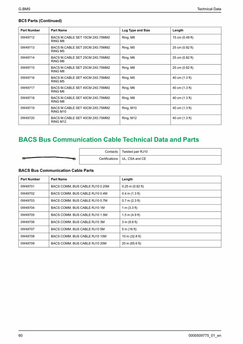
G.BMS Technical Data
BC5 Parts (Continued)
Part Number Part Name Lug Type and Size Length
0W49712 BACS M.CABLE SET 15CM 2X0.75MM2RING M8
Ring, M8 15 cm (0.49 ft)
0W49713 BACS M.CABLE SET 25CM 2X0.75MM2RING M5
Ring, M5 25 cm (0.82 ft)
0W49714 BACS M.CABLE SET 25CM 2X0.75MM2RING M6
Ring, M6 25 cm (0.82 ft)
0W49715 BACS M.CABLE SET 25CM 2X0.75MM2RING M8
Ring, M8 25 cm (0.82 ft)
0W49716 BACS M.CABLE SET 40CM 2X0.75MM2RING M5
Ring, M5 40 cm (1.3 ft)
0W49717 BACS M.CABLE SET 40CM 2X0.75MM2RING M6
Ring, M6 40 cm (1.3 ft)
0W49718 BACS M.CABLE SET 40CM 2X0.75MM2RING M8
Ring, M8 40 cm (1.3 ft)
0W49719 BACS M.CABLE SET 40CM 2X0.75MM2RING M10
Ring, M10 40 cm (1.3 ft)
0W49720 BACS M.CABLE SET 40CM 2X0.75MM2RING M12
Ring, M12 40 cm (1.3 ft)
BACS Bus Communication Cable Technical Data and PartsContacts Twisted pair RJ10
Certifications UL, CSA and CE
BACS Bus Communication Cable Parts
Part Number Part Name Length
0W49701 BACS COMM. BUS CABLE RJ10 0.25M 0.25 m (0.82 ft)
0W49702 BACS COMM. BUS CABLE RJ10 0.4M 0.4 m (1.3 ft)
0W49703 BACS COMM. BUS CABLE RJ10 0.7M 0.7 m (2.3 ft)
0W49704 BACS COMM. BUS CABLE RJ10 1M 1 m (3.3 ft)
0W49705 BACS COMM. BUS CABLE RJ10 1.5M 1.5 m (4.9 ft)
0W49706 BACS COMM. BUS CABLE RJ10 3M 3 m (9.8 ft)
0W49707 BACS COMM. BUS CABLE RJ10 5M 5 m (16 ft)
0W49708 BACS COMM. BUS CABLE RJ10 10M 10 m (32.8 ft)
0W49709 BACS COMM. BUS CABLE RJ10 20M 20 m (65.6 ft)
60 0000509775_01_en
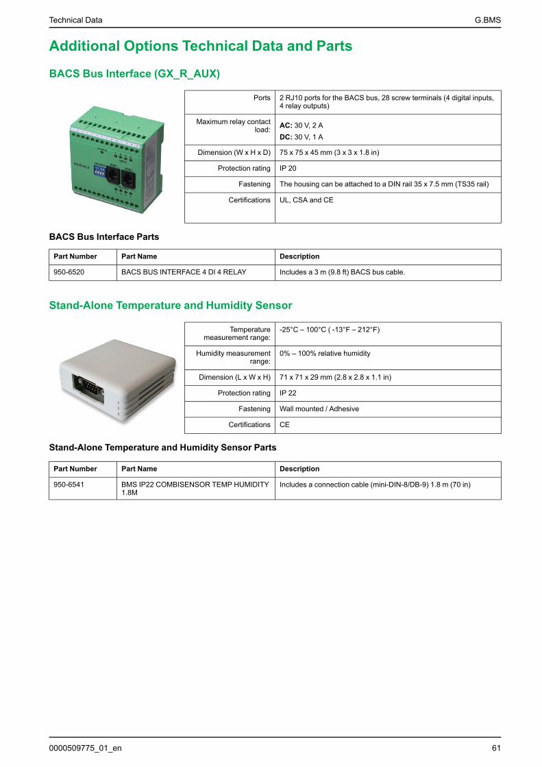
Technical Data G.BMS
Additional Options Technical Data and Parts
BACS Bus Interface (GX_R_AUX)
Ports 2 RJ10 ports for the BACS bus, 28 screw terminals (4 digital inputs,4 relay outputs)
Maximum relay contactload: AC: 30 V, 2 A
DC: 30 V, 1 A
Dimension (W x H x D) 75 x 75 x 45 mm (3 x 3 x 1.8 in)
Protection rating IP 20
Fastening The housing can be attached to a DIN rail 35 x 7.5 mm (TS35 rail)
Certifications UL, CSA and CE
BACS Bus Interface Parts
Part Number Part Name Description
950-6520 BACS BUS INTERFACE 4 DI 4 RELAY Includes a 3 m (9.8 ft) BACS bus cable.
Stand-Alone Temperature and Humidity Sensor
Temperaturemeasurement range:
-25°C – 100°C ( -13°F – 212°F)
Humidity measurementrange:
0% – 100% relative humidity
Dimension (L x W x H) 71 x 71 x 29 mm (2.8 x 2.8 x 1.1 in)
Protection rating IP 22
Fastening Wall mounted / Adhesive
Certifications CE
Stand-Alone Temperature and Humidity Sensor Parts
Part Number Part Name Description
950-6541 BMS IP22 COMBISENSOR TEMP HUMIDITY1.8M
Includes a connection cable (mini-DIN-8/DB-9) 1.8 m (70 in)
0000509775_01_en 61
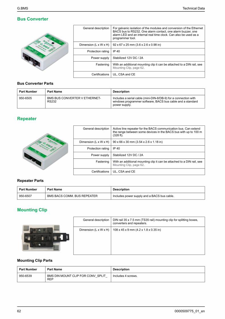
G.BMS Technical Data
Bus Converter
General description For galvanic isolation of the modules and conversion of the EthernetBACS bus to RS232. One alarm contact, one alarm buzzer, onealarm LED and an internal real time clock. Can also be used as aprogrammer tool.
Dimension (L x W x H) 92 x 67 x 25 mm (3.6 x 2.6 x 0.98 in)
Protection rating IP 40
Power supply Stabilized 12V DC / 2A
Fastening With an additional mounting clip it can be attached to a DIN rail, seeMounting Clip, page 62.
Certifications UL, CSA and CE
Bus Converter Parts
Part Number Part Name Description
950-6505 BMS BUS CONVERTER V ETHERNET-RS232
Includes a serial cable (mini-DIN-8/DB-9) for a connection withwindows programmer software, BACS bus cable and a standardpower supply.
Repeater
General description Active line repeater for the BACS communication bus. Can extendthe range between some devices in the BACS bus with up to 100 m(328 ft).
Dimension (L x W x H) 90 x 66 x 30 mm (3.54 x 2.6 x 1.18 in)
Protection rating IP 40
Power supply Stabilized 12V DC / 2A
Fastening With an additional mounting clip it can be attached to a DIN rail, seeMounting Clip, page 62.
Certifications UL, CSA and CE
Repeater Parts
Part Number Part Name Description
950-6507 BMS BACS COMM. BUS REPEATER Includes power supply and a BACS bus cable.
Mounting Clip
General description DIN rail 35 x 7.5 mm (TS35 rail) mounting clip for splitting boxes,converters and repeaters.
Dimension (L x W x H) 108 x 45 x 9 mm (4.2 x 1.8 x 0.35 in)
Mounting Clip Parts
Part Number Part Name Description
950-6539 BMS DIN MOUNT CLIP FOR CONV_SPLIT_REP
Includes 4 screws.
62 0000509775_01_en
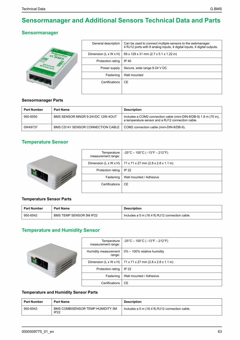
Technical Data G.BMS
Sensormanager and Additional Sensors Technical Data and Parts
Sensormanager
General description Can be used to connect multiple sensors to the webmanager.4 RJ12 ports with 8 analog inputs, 4 digital inputs, 4 digital outputs.
Dimension (L x W x H) 69 x 129 x 31 mm (2.7 x 5.1 x 1.22 in)
Protection rating IP 40
Power supply Secure, wide range 9-24 V DC
Fastening Wall mounted
Certifications CE
Sensormanager Parts
Part Number Part Name Description
950-6550 BMS SENSOR MNGR 9-24VDC 12IN 4OUT Includes a COM2 connection cable (mini-DIN-8/DB-9) 1.8 m (70 in),a temperature sensor and a RJ12 connection cable.
0W49737 BMS CS141 SENSOR CONNECTION CABLE COM2 connection cable (mini-DIN-8/DB-9).
Temperature Sensor
Temperaturemeasurement range:
-25°C – 100°C ( -13°F – 212°F)
Dimension (L x W x H) 71 x 71 x 27 mm (2.8 x 2.8 x 1.1 in)
Protection rating IP 22
Fastening Wall mounted / Adhesive
Certifications CE
Temperature Sensor Parts
Part Number Part Name Description
950-6542 BMS TEMP SENSOR 5M IP22 Includes a 5 m (16.4 ft) RJ12 connection cable.
Temperature and Humidity Sensor
Temperaturemeasurement range:
-25°C – 100°C ( -13°F – 212°F)
Humidity measurementrange:
0% – 100% relative humidity
Dimension (L x W x H) 71 x 71 x 27 mm (2.8 x 2.8 x 1.1 in)
Protection rating IP 22
Fastening Wall mounted / Adhesive
Certifications CE
Temperature and Humidity Sensor Parts
Part Number Part Name Description
950-6543 BMS COMBISENSOR TEMP HUMIDITY 5MIP22
Includes a 5 m (16.4 ft) RJ12 connection cable.
0000509775_01_en 63

G.BMS Technical Data
Hydrogen Sensor
Alarm thresholds 20% and 40% lower explosive limit (LEL)
Dimension (L x W x H) 120 x 80 x 60 mm (4.7 x 3.1 x 2.4 in)
Protection rating IP20 (optionally: IP52/Ex-i/ATEX approved)
Fastening Wall mounted / Adhesive
Certifications CE
Hydrogen Sensor Parts
Part Number Part Name Description
950-6538 BMS HYDROGEN SENSOR Includes power supply and a RJ12 connection cable 6.5 m (21 ft)
Alarm Buzzer
Sound level 60dB
Dimension (L x W x H) 71 x 71 x 29 mm (2.8 x 2.8 x 1.1 in)
Protection rating IP 22
Fastening Wall mounted / Adhesive
Certifications CE
Alarm Buzzer Parts
Part Number Part Name Description
950-6536 BMS ALARM BUZZER W. NC_NO RELAYIP22
Includes a 5 m (16.4 ft) RJ12 connection cable.
Flashlight
Dimension (L x W x H) 70 x 70 x 67 mm (2.8 x 2.8 x 2.4 in)
Protection rating IP 22
Fastening Wall mounted / Adhesive
Certifications CE
Flashlight Parts
Part Number Part Name Description
950-6537 BMS FLASHLIGHT STROBE IP22 Includes a 5 m (16.4 ft) RJ12 connection cable.
64 0000509775_01_en

Technical Data G.BMS
RJ12 Sensormanager Communication Cables
Contacts RJ12
Certifications CE
RJ12 Sensormanager Communication Cable Parts
Part Number Part Name Length
0W49760 BMS SENSOR MNGR CONN CABLE 0.4M 0.4 m (1.3 ft)
0W49761 BMS SENSOR MNGR CONN CABLE 1M 1 m (3.3 ft)
0W49762 BMS SENSOR MNGR CONN CABLE 5M 5 m (16 ft)
0W49763 BMS SENSOR MNGR CONN CABLE 10M 10 m (33 ft)
0W49764 BMS SENSOR MNGR CONN CABLE 15M 15 m (49 ft)
0000509775_01_en 65

G.BMS Contact Us
Contact UsGlobal service organizationSchneider Electric recognizes the importance of a global service network tosupport our globally operating customers. We provide you with a worldwideservice network, an inventory of readily available spare parts and trained servicepartners.
For more details regarding our service offers or other inquiries please contact yourlocal Gutor Service Center as listed below or visit https://www.se.com/ww/en/brands/gutor/gutor-service-centers.jsp.
Headquarters:Gutor Electronic LLC, Hardstrasse 72 – 74, 5430 Wettingen, SwitzerlandP +41 (0)56 437 34 34 | F +41 (0)56 437 34 [email protected]
Asia Pacific:Gutor Electronic Asia Pacific Sdn.BhdNo.19, Jalan Juruukur U1/19, Seksyen U1, Hicom Glenmarie Industrial Park,40150 Shah Alam, Selangor, MalaysiaP +(6) 03 5569 0331 | F +(6) 03 5569 [email protected]
Americas:Gutor Electronic LLC10900 Equity Drive, Houston, Texas 77041, United StatesP +888-994-8867 | F +281-588-2199(Afterhour Hotline +1-888-GUTOR-CS, or 1-888-488-6727)[email protected]
Middle East:Gutor Electronic LLCBeside SEHA/Emirates ID and Daman OfficeUnit 13 Ground Floor, Musaffah M4, Plot 12, PO Box 29580, Musaffah, AbuDhabi, United Arab EmiratesP +97126193166 | F [email protected]
Saudi Arabia:Gutor Electronic LLCDhahran (King Abdulla Road), Dhahran Center, 6th Flr - Office # 603, AL-Khobar31952, P.O. Box 3789, Saudi ArabiaP +966 (0)3 864 9667 | F +966 (0)3 864 [email protected]
China:Gutor Electronic LLC12/F, Changfeng Building, No.89.East Yun Ling Road, Putuo District, Shanghai200062, P.R. ChinaP +86 (0)21 6065 7145| F +86 (0)21 6076 [email protected]
66 0000509775_01_en


Gutor Electronic LLCHardstrasse 72–745430 WettingenSwitzerland
+41 (0) 56 437 34 34
https://www.se.com/ww/en/brands/gutor/gutor-service-centers.jsp
As standards, specifications, and design change from time to time,please ask for confirmation of the information given in this publication.
© 2021 – 2021 Schneider Electric. All rights reserved.
0000509775_01_en