stepping motor controls - stÖgra antriebstechnik gmbh
TRANSCRIPT
stepping motor controls
power amplifier boards
position controls
equipment
All rights reserved
Without written approval we don’t allow any reprint and partial copying.
We reserve the right to make engineering changes, refinements and impro-
vements to all products described herein.
Mechanical and electrical ratings and dimensions are, therefore, subject to
change without notice.
No liability whatsoever is accepted.
STÖGRA Antriebstechnik GmbHMachtlfinger Straße 24
D-81379 München
Tel: +49 89 15 90 40 00
Fax: +49 89 15 90 40 09
E-Mail: [email protected]
Internet:http://www.stoegra.de
Edition: Juli 2015
driving
motion control
positioning
general product overview 4
stepping motor controls – general explanations 5
stepping motor power amplifier boards in eurocard format series SEstandard series SE...V3 and SE...E50 V3
microstepping series SE P05...V2
69
stepper motor power amplifier in compact housing series WSEmains ready 230VAC and 115VAC – series WSE ...230AC V01
20 to 80VDC and 4A per phases – series WSE 04.80 V01
20 to 80VDC and 8A per phases – series WSE 08.80 V01
101414
power supplies series NT 16board holder KH-SE_01 17
front panels for power amplifier boards series SEE 17panel mount/19 inch-systems series ELK/ELR 18
position controls series SERS modes of operation
overview functions
programming via RS232 and RS485
SERS Programmer 2
SERS with Closed Loop control
encoder input
SERS with Profibus-DP
SERS with PROFIdrive
SERS with CANopen
seperate 24V logic supply
SERS block diagram
specifications, versions, ordering key
242628293031323333343536
position controls in compact housing series WSERS mains ready 230VAC and 115VAC – series WSERS...230 AC V01
20 to 80VDC and 4A per phases – series WSE 04.80 V01
20 to 80VDC and 8A per phases – series WSE 08.80 V01
connections
dimensions, ordering key, specifications, equipment
3737373839
equipment SERS/WSERS 39
STÖGRA ANTRIEBSTECHNIK GMBH www.stoegra.de stepping motor controls catalogue 2015
Index 3
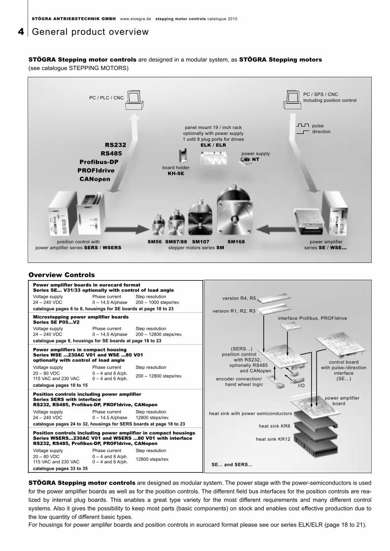
STÖGRA Stepping motor controls are designed in a modular system, as STÖGRA Stepping motors(see catalogue STEPPING MOTORS)
board holder
KH-SE
power supply
NT
panel mount 19 / inch rack
optionally with power supply
1 until 8 plug ports for drives
ELK / ELR
PC / PLC / CNCPC / SPS / CNC
including position control
position control with
power amplifier series SERS / WSERS power amplifier
series SE / WSE...SM56 SM87/88 SM107 SM168
stepper motors series SM
RS232 RS485 Profibus-DPPROFIdrive CANopen
pulse
direction
interface Profibus, PROFIdrive
control board
with pulse-/direction
interface
(SE...)encoder connection/
hand wheel logic
(SERS...)
position control
with RS232,
optionally RS485
and CANopen
power amplifier
board
heat sink with power semiconductors
heat sink KR6
heat sink KR12
version R4, R5
version R1, R2, R3
I/O
SE... and SERS...
Overview Controls
STÖGRA Stepping motor controls are designed as modular system. The power stage with the power-semiconductors is used
for the power amplifier boards as well as for the position controls. The different field bus interfaces for the position controls are rea-
lized by internal plug boards. This enables a great type variety for the most different requirements and many different control
systems. Also it gives the possibility to keep most parts (basic components) on stock and enables cost effective production due to
the low quantity of different basic types.For housings for power amplifer boards and position controls in eurocard format please see our series ELK/ELR (page 18 to 21).
Power amplifier boards in eurocard formatSeries SE... V31/33 optionally with control of load angleVoltage supply Phase current Step resolution24 – 240 VDC 0 – 14,5 A/phase 200 – 1000 steps/rev.
catalogue pages 6 to 8, housings for SE boards at page 18 to 23
Microstepping power amplifier boardsSeries SE P05...V2Voltage supply Phase current Step resolution24 – 240 VDC 0 – 14,5 A/phase 200 – 12800 steps/rev.
catalogue page 9, housings for SE boards at page 18 to 23
Power amplifiers in compact housingSeries WSE ...230AC V01 and WSE ...80 V01optionally with control of load angleVoltage supply Phase current Step resolution20 – 80 VDC115 VAC and 230 VAC
0 – 4 and 8 A/ph.0 – 4 and 6 A/ph.
200 – 12800 steps/rev.
catalogue pages 10 to 15
Position controls including power amplifierSeries SERS with interface RS232, RS485, Profibus-DP, PROFIdrive, CANopenVoltage supply Phase current Step resolution24 – 240 VDC 0 – 14,5 A/phase 12800 steps/rev.
catalogue pages 24 to 32, housings for SERS boards at page 18 to 23
Position controls including power amplifier in compact housingsSeries WSERS...230AC V01 and WSERS ...80 V01 with interfaceRS232, RS485, Profibus-DP, PROFIdrive, CANopenVoltage supply Phase current Step resolution20 – 80 VDC115 VAC and 230 VAC
0 – 4 and 8 A/ph.0 – 4 and 6 A/ph.
12800 steps/rev.
catalogue pages 33 to 35
STÖGRA ANTRIEBSTECHNIK GMBH www.stoegra.de stepping motor controls catalogue 2015
4 General product overview
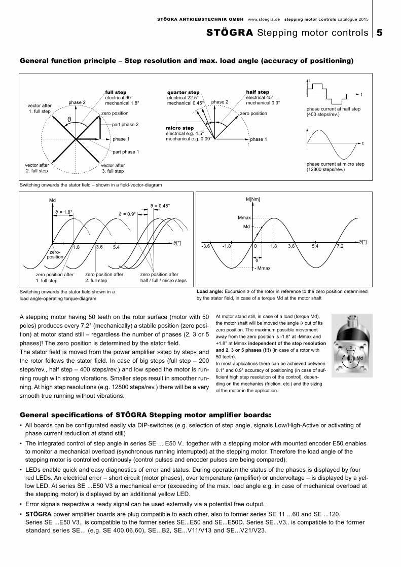
Md
ϑ
At motor stand still, in case of a load (torque Md),
the motor shaft will be moved the angle ϑ out of its
zero position. The maximum possible movement
away from the zero position is -1.8° at -Mmax and
+1.8° at Mmax independent of the step resolution
and 2, 3 or 5 phases (!!!) (in case of a rotor with
50 teeth).
In most applications there can be achieved between
0.1° and 0.9° accuracy of positioning (in case of suf-
ficient high step resolution of the control), depen-
ding on the mechanics (friction, etc.) and the sizing
of the motor in the application.
General specifications of STÖGRA Stepping motor amplifier boards:• All boards can be configurated easily via DIP-switches (e.g. selection of step angle, signals Low/High-Active or activating of
phase current reduction at stand still)
• The integrated control of step angle in series SE ... E50 V.. together with a stepping motor with mounted encoder E50 enables to monitor a mechanical overload (synchronous running interrupted) at the stepping motor. Therefore the load angle of thestepping motor is controlled continously (control pulses and encoder pulses are being compared).
• LEDs enable quick and easy diagnostics of error and status. During operation the status of the phases is displayed by four red LEDs. An electrical error – short circuit (motor phases), over temperature (amplifier) or undervoltage – is displayed by a yel-low LED. At series SE ...E50 V3 a mechanical error (exceeding of the max. load angle e.g. in case of mechanical overload atthe stepping motor) is displayed by an additional yellow LED.
• Error signals respective a ready signal can be used externally via a potential free output.
• STÖGRA power amplifier boards are plug compatible to each other, also to former series SE 11 ...60 and SE ...120. Series SE ...E50 V3.. is compatible to the former series SE...E50 and SE...E50D. Series SE...V3.. is compatible to the former standard series SE... (e.g. SE 400.06.60), SE...B2, SE...V11/V13 and SE...V21/V23.
General function principle – Step resolution and max. load angle (accuracy of positioning)
vector after
1. full step
vector after
2. full stepvector after
3. full step
part phase 1
part phase 2
phase 1
zero position
full stepelectrical 90°mechanical 1.8°phase 2
quarter stepelectrical 22.5°mechanical 0.45°
micro stepelectrical e.g. 4.5°mechanical e.g. 0.09°
half stepelectrical 45°mechanical 0.9°phase 2
phase 1
zero positionphase current at half step(400 steps/rev.)
phase current at micro step(12800 steps/rev.)
ϑ
t
t
Ι
Ι
Md
ϑ = 1,8° ϑ = 0.9°
ϑ = 0.45°
ϑ [°]
zero-position
zero position after
1. full step
zero position after
2. full step
zero position after
half / full / micro steps
1.8 3.6 5.4
M[Nm]
Mmax
Md
Mmax
ϑ
ϑ [°]-3.6 -1.8 0 1.8 3.6 5.4 7.2
Switching onwards the stator field shown in a
load angle-operating torque-diagram
Load angle: Excursion ϑ of the rotor in reference to the zero position determined
by the stator field, in case of a torque Md at the motor shaft
A stepping motor having 50 teeth on the rotor surface (motor with 50
poles) produces every 7,2° (mechanically) a stabile position (zero posi-
tion) at motor stand still – regardless the number of phases (2, 3 or 5
phases)! The zero position is determined by the stator field.
The stator field is moved from the power amplifier »step by step« and
the rotor follows the stator field. In case of big steps (full step – 200
steps/rev., half step – 400 steps/rev.) and low speed the motor is run-
ning rough with strong vibrations. Smaller steps result in smoother run-
ning. At high step resolutions (e.g. 12800 steps/rev.) there will be a very
smooth true running without vibrations.
Switching onwards the stator field – shown in a field-vector-diagram
STÖGRA ANTRIEBSTECHNIK GMBH www.stoegra.de stepping motor controls catalogue 2015
STÖGRA Stepping motor controls 5
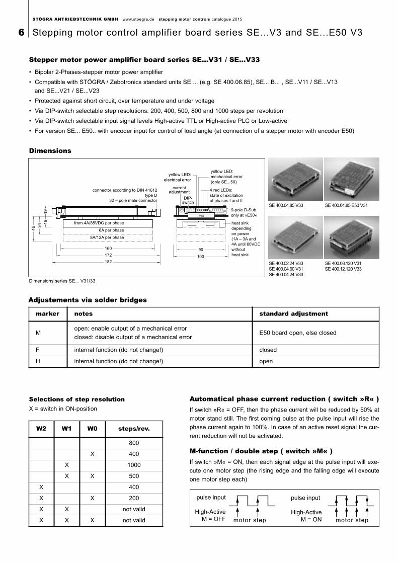
Stepper motor power amplifier board series SE...V31 / SE...V33
• Bipolar 2-Phases-stepper motor power amplifier
• Compatible with STÖGRA / Zebotronics standard units SE ... (e.g. SE 400.06.85), SE... B... , SE...V11 / SE...V13
and SE...V21 / SE...V23
• Protected against short circuit, over temperature and under voltage
• Via DIP-switch selectable step resolutions: 200, 400, 500, 800 and 1000 steps per revolution
• Via DIP-switch selectable input signal levels High-active TTL or High-active PLC or Low-active
• For version SE... E50.. with encoder input for control of load angle (at connection of a stepper motor with encoder E50)
connector according to DIN 41612
type D
32 – pole male connector
from 4A/85VDC per phase
6A per phase
8A/12A per phase
160
172
182
46 3
4 19
19
90
100
heat sink
depending
on power
(1A – 3A and
4A until 60VDC
without
heat sink
9-pole D-Sub
only at »E50«
yellow LED:
electrical error
4 red LEDs:
state of excitation
of phases I and II
yellow LED:
mechanical error
(only SE...50)
DIP-switch
0 12
34
5
6789
AB
C
D
1 2 3 4 5 6 7
APEMs ON
type
currentadjustment
Dimensions series SE... V31/33
SE 400.04.85 V33 SE 400.04.85.E50 V31
SE 400.02.24 V33SE 400.04.60 V31SE 400.04.24 V33
SE 400.08.120 V31 SE 400.12.120 V33
Dimensions
Adjustements via solder bridges
Automatical phase current reduction ( switch »R« )If switch »R« = OFF, then the phase current will be reduced by 50% at
motor stand still. The first coming pulse at the pulse input will rise the
phase current again to 100%. In case of an active reset signal the cur-
rent reduction will not be activated.
Selections of step resolutionX = switch in ON-position
M-function / double step ( switch »M« )If switch »M« = ON, then each signal edge at the pulse input will exe-
cute one motor step (the rising edge and the falling edge will execute
one motor step each)
pulse input
High-Active
M = OFF
pulse input
High-Active
M = ONmotor step motor step
marker notes standard adjustment
Mopen: enable output of a mechanical error
closed: disable output of a mechanical errorE50 board open, else closed
F internal function (do not change!) closed
H internal function (do not change!) open
W2 W1 W0 steps/rev.
800
X 400
X 1000
X X 500
X 400
X X 200
X X not valid
X X X not valid
STÖGRA ANTRIEBSTECHNIK GMBH www.stoegra.de stepping motor controls catalogue 2015
6 Stepping motor control amplifier board series SE...V3 and SE...E50 V3
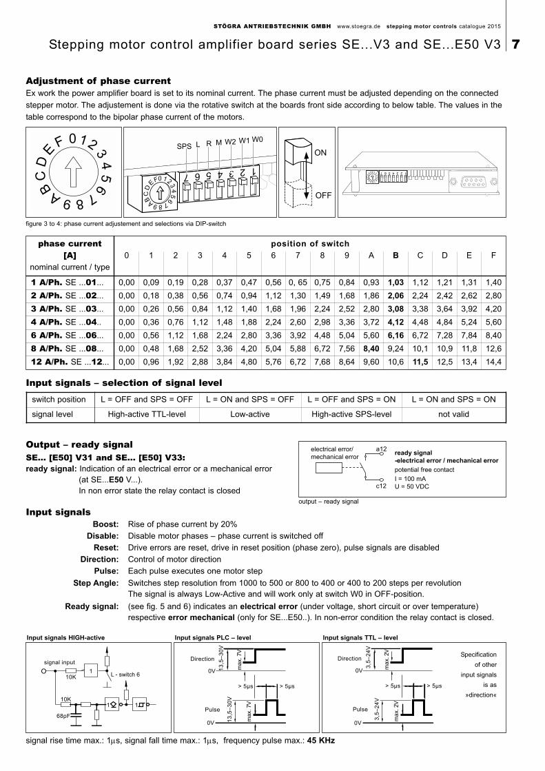
Boost: Rise of phase current by 20%
Disable: Disable motor phases – phase current is switched off
Reset: Drive errors are reset, drive in reset position (phase zero), pulse signals are disabled
Direction: Control of motor direction
Pulse: Each pulse executes one motor step
Step Angle: Switches step resolution from 1000 to 500 or 800 to 400 or 400 to 200 steps per revolutionThe signal is always Low-Active and will work only at switch W0 in OFF-position.
Ready signal: (see fig. 5 and 6) indicates an electrical error (under voltage, short circuit or over temperature) respective error mechanical (only for SE...E50..). In non-error condition the relay contact is closed.
Adjustment of phase currentEx work the power amplifier board is set to its nominal current. The phase current must be adjusted depending on the connected
stepper motor. The adjustement is done via the rotative switch at the boards front side according to below table. The values in the
table correspond to the bipolar phase current of the motors.
Input signals – selection of signal level
Output – ready signalSE... [E50] V31 and SE... [E50] V33:ready signal: Indication of an electrical error or a mechanical error
(at SE...E50 V...). In non error state the relay contact is closed
signal input
68pF
10K
10K
1 1
1L - switch 6
Direction
13
,5–
30
V
max. 7V
13
,5–
30
V
max. 7V
> 5µs > 5µs
Pulse
0V
Direction
3,5
–2
4V
max. 2V
3,5
–2
4V
max. 2V
> 5µs > 5µs
Pulse
0V
signal rise time max.: 1µs, signal fall time max.: 1µs, frequency pulse max.: 45 KHz
Specification
of other
input signals
is as
»direction«
Input signals HIGH-active Input signals PLC – level Input signals TTL – level
electrical error/
mechanical error
a12
c12
ready signal
-electrical error / mechanical error
potential free contact
I = 100 mA
U = 50 VDC
output – ready signal
figure 3 to 4: phase current adjustement and selections via DIP-switch
SPS L R M W2 W1 W00 12
34
56
789A
BC
DE
FON
OFF
phase current position of switch
[A] 0 1 2 3 4 5 6 7 8 9 A B C D E F
nominal current / type
1 A/Ph. SE ...01... 0,00 0,09 0,19 0,28 0,37 0,47 0,56 0, 65 0,75 0,84 0,93 1,03 1,12 1,21 1,31 1,40
2 A/Ph. SE ...02... 0,00 0,18 0,38 0,56 0,74 0,94 1,12 1,30 1,49 1,68 1,86 2,06 2,24 2,42 2,62 2,80
3 A/Ph. SE ...03... 0,00 0,26 0,56 0,84 1,12 1,40 1,68 1,96 2,24 2,52 2,80 3,08 3,38 3,64 3,92 4,20
4 A/Ph. SE ...04.. 0,00 0,36 0,76 1,12 1,48 1,88 2,24 2,60 2,98 3,36 3,72 4,12 4,48 4,84 5,24 5,60
6 A/Ph. SE ...06... 0,00 0,56 1,12 1,68 2,24 2,80 3,36 3,92 4,48 5,04 5,60 6,16 6,72 7,28 7,84 8,40
8 A/Ph. SE ...08... 0,00 0,48 1,68 2,52 3,36 4,20 5,04 5,88 6,72 7,56 8,40 9,24 10,1 10,9 11,8 12,6
12 A/Ph. SE ...12... 0,00 0,96 1,92 2,88 3,84 4,80 5,76 6,72 7,68 8,64 9,60 10,6 11,5 12,5 13,4 14,4
switch position L = OFF and SPS = OFF L = ON and SPS = OFF L = OFF and SPS = ON L = ON and SPS = ON
signal level High-active TTL-level Low-active High-active SPS-level not valid
Input signals
STÖGRA ANTRIEBSTECHNIK GMBH www.stoegra.de stepping motor controls catalogue 2015
Stepping motor control amplifier board series SE...V3 and SE...E50 V3 7
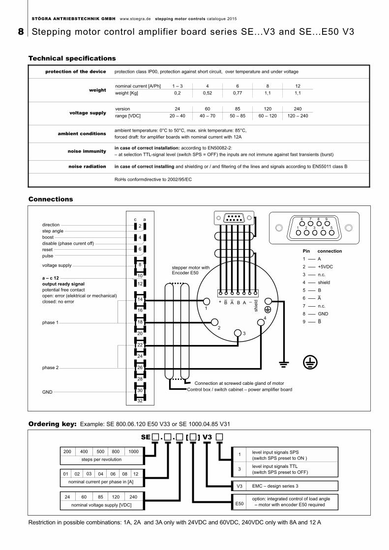
direction
step angle
boost
disable (phase curent off)
reset
pulse
voltage supply
phase 1
phase 2
a – c 12
output ready signal
potential free contact
open: error (elektrical or mechanical)
closed: no error
GND
c a
2
4
6
8
10
12
14
16
20
18
22
24
26
28
30
32
stepper motor withEncoder E50
Connection at screwed cable gland of motor
Control box / switch cabinet – power amplifier board
1
2
3
4
+ B_
BA A__
shie
ld
6
1
7 8 9
2 3 4 5
Pin connection
1 A
2 +5VDC
3 n.c.
4 shield
5 B
6 A_
7 n.c.
8 GND
9 B_
Connections
Technical specifications
200 400 500 800 1000
steps per revolution
nominal current per phase in [A]
01 02 04 06 08 12
nominal voltage supply [VDC]
24 60 85 120 240
1
3
V3
E50
level input signals SPS
(switch SPS preset to ON )
level input signals TTL
(switch SPS preset to OFF)
EMC – design series 3
option: integrated control of load angle
– motor with encoder E50 required
SE . . [ ] V3
03
Ordering key: Example: SE 800.06.120 E50 V33 or SE 1000.04.85 V31
Restriction in possible combinations: 1A, 2A and 3A only with 24VDC and 60VDC, 240VDC only with 8A and 12 A
protection of the device protection class IP00, protection against short circuit, over temperature and under voltage
weightnominal current [A/Ph] 1 – 3 4 6 8 12
weight [Kg] 0,2 0,52 0,77 1,1 1,1
voltage supplyversion 24 60 85 120 240
range [VDC] 20 – 40 40 – 70 50 – 85 60 – 120 120 – 240
ambient conditionsambient temperature: 0°C to 50°C, max. sink temperature: 85°C,
forced draft: for amplifier boards with nominal current with 12A
noise immunityin case of correct installation: according to EN50082-2:
– at selection TTL-signal level (switch SPS = OFF) the inputs are not immune against fast transients (burst)
noise radiation in case of correct installing and shielding or / and filtering of the lines and signals according to EN55011 class B
RoHs conformdirective to 2002/95/EC
STÖGRA ANTRIEBSTECHNIK GMBH www.stoegra.de stepping motor controls catalogue 2015
8 Stepping motor control amplifier board series SE...V3 and SE...E50 V3
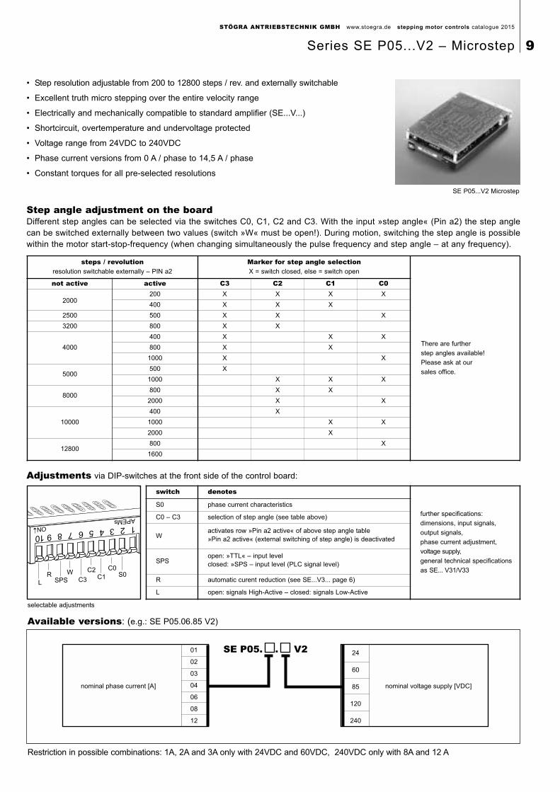
• Step resolution adjustable from 200 to 12800 steps / rev. and externally switchable
• Excellent truth micro stepping over the entire velocity range
• Electrically and mechanically compatible to standard amplifier (SE...V...)
• Shortcircuit, overtemperature and undervoltage protected
• Voltage range from 24VDC to 240VDC
• Phase current versions from 0 A / phase to 14,5 A / phase
• Constant torques for all pre-selected resolutions
SE P05...V2 Microstep
Adjustments via DIP-switches at the front side of the control board:
selectable adjustments
Step angle adjustment on the board Different step angles can be selected via the switches C0, C1, C2 and C3. With the input »step angle« (Pin a2) the step anglecan be switched externally between two values (switch »W« must be open!). During motion, switching the step angle is possiblewithin the motor start-stop-frequency (when changing simultaneously the pulse frequency and step angle – at any frequency).
nominal phase current [A]
01
02
03
04
06
08
12
nominal voltage supply [VDC]
24
60
85
120
240
SE P05. . V2
Available versions: (e.g.: SE P05.06.85 V2)
Restriction in possible combinations: 1A, 2A and 3A only with 24VDC and 60VDC, 240VDC only with 8A and 12 A
C0
C1C2
S0WC3SPS
R
L
steps / revolutionresolution switchable externally – PIN a2
Marker for step angle selectionX = switch closed, else = switch open
There are further
step angles available!
Please ask at our
sales office.
not active active C3 C2 C1 C0
2000200 X X X X
400 X X X
2500 500 X X X
3200 800 X X
4000
400 X X X
800 X X
1000 X X
5000500 X
1000 X X X
8000800 X X
2000 X X
10000
400 X
1000 X X
2000 X
12800800 X
1600
switch denotes
further specifications:
dimensions, input signals,
output signals,
phase current adjustment,
voltage supply,
general technical specifications
as SE... V31/V33
S0 phase current characteristics
C0 – C3 selection of step angle (see table above)
Wactivates row »Pin a2 active« of above step angle table»Pin a2 active« (external switching of step angle) is deactivated
SPSopen: »TTL« – input levelclosed: »SPS – input level (PLC signal level)
R automatic curent reduction (see SE...V3... page 6)
L open: signals High-Active – closed: signals Low-Active
STÖGRA ANTRIEBSTECHNIK GMBH www.stoegra.de stepping motor controls catalogue 2015
Series SE P05...V2 – Microstep 9
50Hz
325VDC
micro step logic
pulse
direction
WSE 04.230AC V01 / WSE 06.230AC V01mains
230VAC
2-phases
stepper motor
EMC-filter
capacitors
encoder-logic
optionally with control of load angle
reset, boost,
disable,
step angle
H-bridges
13
5 m
m
12
5 m
m
63 mm
A10
5 m
m
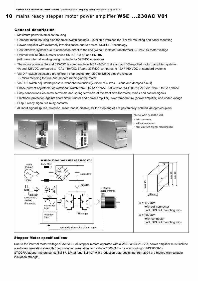
General description• Maximum power in smallest housing
• Compact metal housing also for small switch cabinets – available versions for DIN rail mounting and panel mounting
• Power amplifier with extremely low dissipation due to newest MOSFET-technology
• Cost effective system due to connection direct to the line (without isolated transformer) → 325VDC motor voltage
• Optimal with STÖGRA motor series SM 87, SM 88 and SM 107
(with new internal winding design suitable for 325VDC operation)
• The motor power at 2A and 325VDC is comparable with 8A / 80VDC at standard DC-supplied motor / amplifier systems,
4A and 325VDC compares to 12A / 110VDC, 6A and 325VDC compares to 12A / 160 VDC at standard systems
• Via DIP-switch selectable are different step angles from 200 to 12800 steps/revolution
→ micro stepping for true and smooth running of the motor
• Via DIP-switch adjustable phase current characterisics (2 different curves – sinus and damped sinus)
• Phase current adjustable via rotational switch from 0 to 4A / phase – at version WSE 06.230AC V01 from 0 to 6A / phase
• Easy connections via screw terminals and spring terminals at the front side for motor, mains and control signals
• Electronic protection against short circuit (motor and power amplifier), over temperature (power amplifier) and under voltage
• Output ready signal via relay contacts
• All input signals (pulse, direction, reset, boost, disable, switch step angle) are galvanically isolated via opto-couplers
Photos WSE 04.230AC V01:
• with connector,
• without connector,
• rear view with hut rail mounting clip
A = 177 mm without connector (incl. DIN rail mounting clip)
A = 207 mm with connector (incl. DIN rail mounting clip)
Stepper Motor specifications
Due to the internal motor voltage of 325VDC, all stepper motors operated with a WSE xx.230AC V01 power amplifier must include
a sufficient insulation strength (motor winding insultation test voltage 2000VAC – 1s – according to VDE0530-1).
STÖGRA stepper motors series SM 87, SM 88 and SM 107 with production date beginning from 2004 are motors with suitable
insulation strength.
STÖGRA ANTRIEBSTECHNIK GMBH www.stoegra.de stepping motor controls catalogue 2015
10 mains ready stepper motor power amplifier WSE ...230AC V01
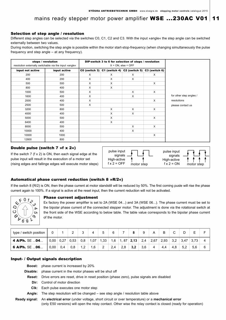
Automatical phase current reduction (switch 8 »R/2«)If the switch 8 (R/2) is ON, then the phase current at motor standstill will be reduced by 50%. The first coming pusle will rise the phase
current again to 100%. If a signal is active at the reset input, then the current reduction will not be activated.
Phase current adjustmentEx factory the power amplifier is set to 2A (WSE 04...) and 3A (WSE 06...). The phase current must be set to
the bipolar phase current of the connected stepper motor. The adjustment is done via the rotational switch at
the front side of the WSE according to below table. The table value corresponds to the bipolar phase current
of the motor.
Input- / Output signals description
Double pulse (switch 7 »f x 2«)If the switch 7 (f x 2) is ON, then each signal edge at the
pulse input will result in the execution of a motor set
(rising edges and fallinge edges will execute motor steps)
0 12
34
56
789A
BC
DE
F
pulse input
signals
High-active
f x 2 = OFF
pulse input
signals
High-active
f x 2 = ONmotor step motor step
Selection of step angle / resolution Different step angles can be selected via the switches C0, C1, C2 and C3. With the input »angle« the step angle can be switchedexternally between two values.During motion, switching the step angle is possible within the motor start-stop-frequency (when changing simultaneously the pulsefrequency and step angle – at any frequency).
steps / revolutionresolution externally switchable via the input »angle«
DIP-switch 3 to 6 for selection of steps / revolutionX = ON, else = OFF
for other step angles /
resolutions
please contact us
input not active input active C0 (switch 3) C1 (switch 4) C2 (switch 5) C3 (switch 6)200 200 X X X X
400 200 X X X
500 500 X X X
800 400 X X
1000 500 X X X
1600 400 X X
2000 400 X X
2500 500 X
3200 800 X X X
4000 400 X X
5000 500 X X
6400 400 X
8000 500 X X
10000 400 X
10000 1000 X
12800 800
type / switch position 0 1 2 3 4 5 6 7 8 9 A B C D E F
4 A/Ph. SE ...04... 0,00 0,27 0,53 0,8 1,07 1,33 1,6 1, 87 2,13 2,4 2,67 2,93 3,2 3,47 3,73 4
6 A/Ph. SE ...06... 0,00 0,4 0,8 1,2 1,6 2 2,4 2,8 3,2 3,6 4 4,4 4,8 5,2 5,6 6
Boost: phase current is increased by 20%
Disable: phase current in the motor phases will be shut off
Reset: Drive errors are reset, drive in reset position (phase zero), pulse signals are disabled
Dir: Control of motor direction
Clk: Each pulse executes one motor step
Angle: The step resolution will be changed – see step angle / resolution table above
Ready signal: An electrical error (under voltage, short circuit or over temperature) or a mechanical error(only E50 versions) will open the relay contact. Other wise the relay contact is closed (ready for operation)
STÖGRA ANTRIEBSTECHNIK GMBH www.stoegra.de stepping motor controls catalogue 2015
mains ready stepper motor power amplifier WSE ...230AC V01 11
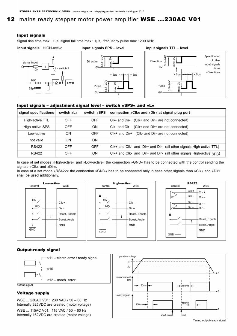
Input signals – adjustment signal level – switch »SPS« and »L«
Input signalsSignal rise time max.: 1µs, signal fall time max.: 1µs, frequency pulse max.: 200 KHz
Output-ready signal
signal input
68pF
10K
10K
1 1
1L - switch 9
Direction
13
,5–
30
V
ma
x. 7V
13
,5–
30
V
ma
x. 7V
> 5µs > 5µs
Pulse
0V
Direction
3,5
–2
4V
ma
x. 2V
3,5
–2
4V
ma
x. 2V
> 5µs > 5µs
Pulse
0V
Specification
of other
input signals
is as
»Direction«
input signals HIGH-active input signals SPS – level input signals TTL – level
Voltage supply
10
11 – electr. error / ready signal
12 – mech. error
output signal 150ms
100ms
150ms
100ms
short circuit reset
motor current
ON
ready signal
operation voltage
UM
t
t
t
UB
Timing output-ready signal
WSE ... 230AC V01: 230 VAC / 50 – 60 HzInternally 325VDC are created (motor voltage)
WSE ... 115AC V01: 115 VAC / 50 – 60 HzInternally 162VDC are created (motor voltage)
In case of set modes »High-active« and »Low-active« the connection »GND« has to be connected with the control sending thesignals »Clk« and »Dir«.In case of a set mode »RS422« the connection »GND« has to be connected only in case other signals than »Clk« and »Dir«shall be used additionally.
control WSE
Clk +
Dir +
Reset, Enable
Boost, Angle
GND
GND
Clk
Dir
Low-active
…
control WSE
Clk –
Dir –
Reset, Enable
Boost, Angle
GND
GND
Clk
Dir
High-active
…
control WSE
Reset, Enable
Boost, Angle
GND
GND
RS422
Clk +
Clk –
Dir +
Dir –
Clk +
Clk –
Dir +
Dir –
…
signal specifications switch »L« switch »SPS connection »Clk« and »Dir« at signal plug port
High-active TTL OFF OFF Clk- and Dir- (Clk+ and Dir+ are not connected)
High-active SPS OFF ON Clk- and Dir- (Clk+ and Dir+ are not connected)
Low-active ON OFF Clk+ and Dir+ (Clk- and Dir- are not connected)
not valid ON ON
RS422 OFF OFF Clk+ and Clk- and Dir+ and Dir- (all other signals High-active TTL)
RS422 OFF ON Clk+ and Clk- and Dir+ and Dir- (all other signals High-active SPS)
STÖGRA ANTRIEBSTECHNIK GMBH www.stoegra.de stepping motor controls catalogue 2015
12 mains ready stepper motor power amplifier WSE ...230AC V01
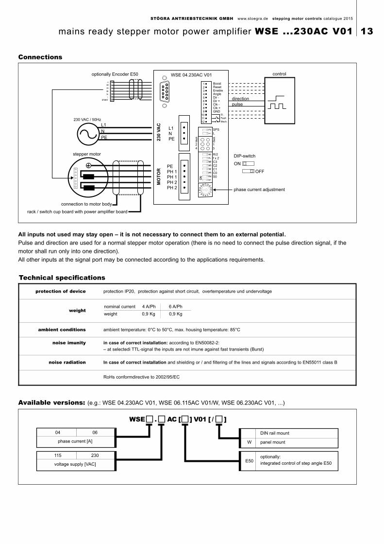
Connections
Available versions: (e.g.: WSE 04.230AC V01, WSE 06.115AC V01/W, WSE 06.230AC V01, ...)
All inputs not used may stay open – it is not necessary to connect them to an external potential.
Pulse and direction are used for a normal stepper motor operation (there is no need to connect the pulse direction signal, if the
motor shall run only into one direction).
All other inputs at the signal port may be connected according to the applications requirements.
Technical specifications
protection of device protection IP20, protection against short circuit, overtemperature und undervoltage
weightnominal current 4 A/Ph 6 A/Ph
weight 0,9 Kg 0,9 Kg
ambient conditions ambient temperature: 0°C to 50°C, max. housing temperature: 85°C
noise imunity in case of correct installation: according to EN50082-2:
– at selectedi TTL-signal the inputs are not imune against fast transients (Burst)
noise radiation In case of correct installation and shielding or / and filtering of the lines and signals according to EN55011 class B
RoHs conformdirective to 2002/95/EC
115 230
voltage supply [VAC]
WSE . AC [ ] V01 [ / ]
04 06
phase current [A]
DIN rail mount
panel mountW
optionally:
integrated control of step angle E50E50
BoostResetEnableAngleDir -Dir +Clk -Clk +GND
El..
Fault
Mech.
PE
PH 1
PH 1
PH 2
PH 2
L1
N
PE
WSE 04.230AC V01
MO
TO
R2
30
VA
C
230 VAC / 50Hz
L1
N
PE
stepper motor
control
DIP-switch
OFF
ON
phase current adjustment
direction
pulse
1
2
3
4
5
6
7
8
9
10
11
12
connection to motor body
rack / switch cup board with power amplifier board
optionally Encoder E50
+B
_B
AA
__
shield
81
2
Ele
ctr.
1
3
2
4
R/2f x 2C3C2C1C0S0
SPSL
Mec
h.
STÖGRA ANTRIEBSTECHNIK GMBH www.stoegra.de stepping motor controls catalogue 2015
mains ready stepper motor power amplifier WSE ...230AC V01 13
B
A105
mm
135 m
m
125 m
m
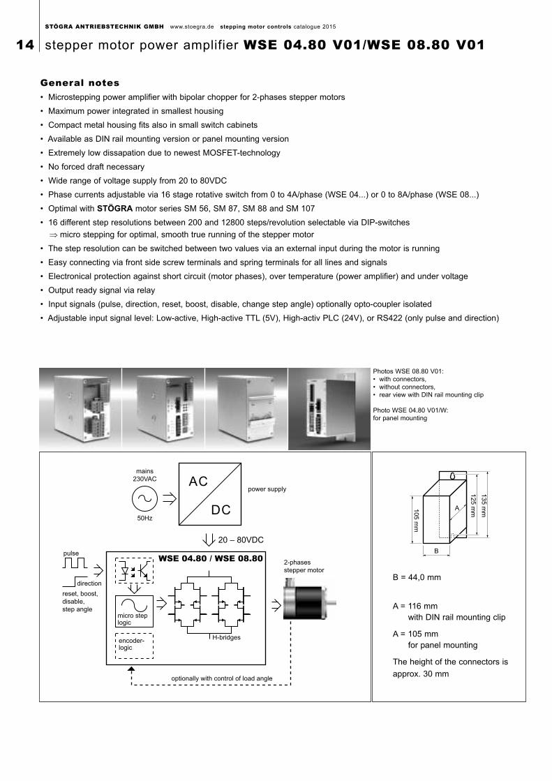
Photos WSE 08.80 V01:• with connectors,• without connectors,• rear view with DIN rail mounting clip
Photo WSE 04.80 V01/W: for panel mounting
B = 44,0 mm
A = 116 mm with DIN rail mounting clip
A = 105 mm for panel mounting
The height of the connectors is
approx. 30 mm
General notes• Microstepping power amplifier with bipolar chopper for 2-phases stepper motors
• Maximum power integrated in smallest housing
• Compact metal housing fits also in small switch cabinets
• Available as DIN rail mounting version or panel mounting version
• Extremely low dissapation due to newest MOSFET-technology
• No forced draft necessary
• Wide range of voltage supply from 20 to 80VDC
• Phase currents adjustable via 16 stage rotative switch from 0 to 4A/phase (WSE 04...) or 0 to 8A/phase (WSE 08...)
• Optimal with STÖGRA motor series SM 56, SM 87, SM 88 and SM 107
• 16 different step resolutions between 200 and 12800 steps/revolution selectable via DIP-switches
⇒ micro stepping for optimal, smooth true running of the stepper motor
• The step resolution can be switched between two values via an external input during the motor is running
• Easy connecting via front side screw terminals and spring terminals for all lines and signals
• Electronical protection against short circuit (motor phases), over temperature (power amplifier) and under voltage
• Output ready signal via relay
• Input signals (pulse, direction, reset, boost, disable, change step angle) optionally opto-coupler isolated
• Adjustable input signal level: Low-active, High-active TTL (5V), High-activ PLC (24V), or RS422 (only pulse and direction)
micro steplogic
pulse
direction
WSE 04.80 / WSE 08.802-phases
stepper motor
encoder-logic
optionally with control of load angle
reset, boost,
disable,
step angle
H-bridges
50Hz
20 – 80VDC
mains
230VAC
power supplyAC
DC
STÖGRA ANTRIEBSTECHNIK GMBH www.stoegra.de stepping motor controls catalogue 2015
14 stepper motor power amplifier WSE 04.80 V01/WSE 08.80 V01
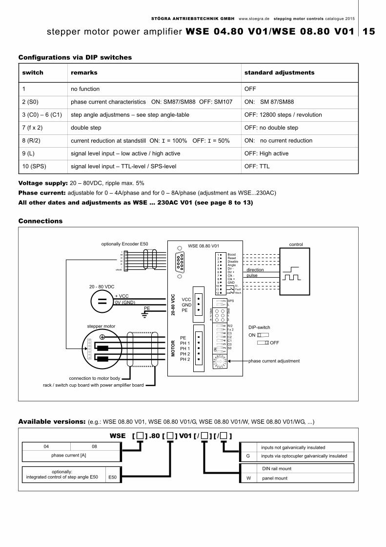
Configurations via DIP switches
Available versions: (e.g.: WSE 08.80 V01, WSE 08.80 V01/G, WSE 08.80 V01/W, WSE 08.80 V01/WG, ...)
Voltage supply: 20 – 80VDC, ripple max. 5%
Phase current: adjustable for 0 – 4A/phase and for 0 – 8A/phase (adjustment as WSE...230AC)
All other dates and adjustments as WSE ... 230AC V01 (see page 8 to 13)
Connections
DIN rail mount
WSE [ ] .80 [ ] V01 [ / ] [ / ]
panel mountE50
inputs not galvanically insulated
inputs via optocupler galvanically insulatedG
W
optionally:integrated control of step angle E50
04 08
phase current [A]
switch remarks standard adjustments
1 no function OFF
2 (S0) phase current characteristics ON: SM87/SM88 OFF: SM107 ON: SM 87/SM88
3 (C0) – 6 (C1) step angle adjustmens – see step angle-table OFF: 12800 steps / revolution
7 (f x 2) double step OFF: no double step
8 (R/2) current reduction at standstill ON: I = 100% OFF: I = 50% ON: no current reduction
9 (L) signal level input – low active / high active OFF: High active
10 (SPS) signal level input – TTL-level / SPS-level OFF: TTL
BoostResetDisableAngleDir -Dir +Clk -Clk +GND
El..
Fault
Mech.
PE
PH 1
PH 1
PH 2
PH 2
VCC
GND
PE
WSE 08.80 V01
MO
TO
R2
0-8
0 V
DC
20 - 80 VDC
+ VCC
0V (GND)
stepper motor
control
DIP-switch
OFF
ON
phase current adjustment
direction
pulse
1
2
3
4
5
6
7
8
9
10
11
12
=PE
connection to motor body
rack / switch cup board with power amplifier board
optionally Encoder E50
+B
_B
AA
__
shield
81
2
Ele
ctr.
1
3
2
4
R/2f x 2C3C2C1C0S0
SPSL
Mec
h.
STÖGRA ANTRIEBSTECHNIK GMBH www.stoegra.de stepping motor controls catalogue 2015
stepper motor power amplifier WSE 04.80 V01/WSE 08.80 V01 15
3
20 ca.
95
300
150
235
400
3
20 c
a.
95
designation field
designation field
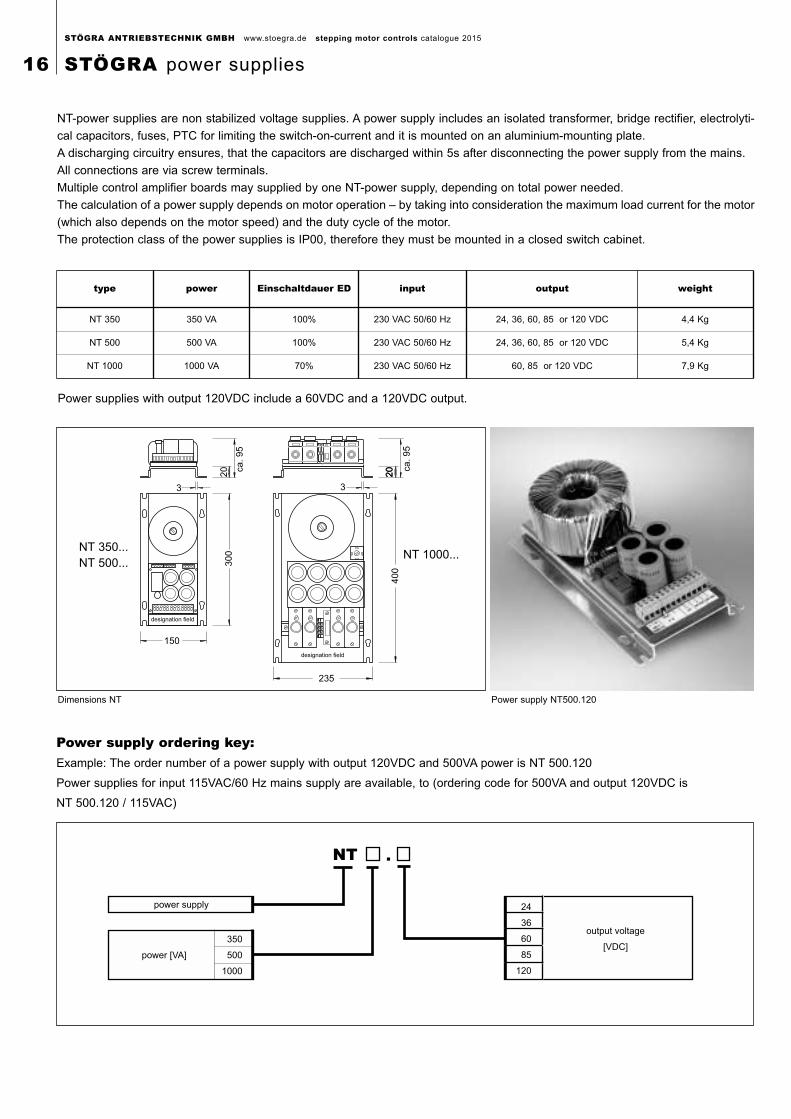
Power supply ordering key:Example: The order number of a power supply with output 120VDC and 500VA power is NT 500.120
Power supplies for input 115VAC/60 Hz mains supply are available, to (ordering code for 500VA and output 120VDC is
NT 500.120 / 115VAC)
power supply
power [VA]
350
500
1000
24
36
60
85
120
output voltage
[VDC]
NT
NT 1000...
NT-power supplies are non stabilized voltage supplies. A power supply includes an isolated transformer, bridge rectifier, electrolyti-
cal capacitors, fuses, PTC for limiting the switch-on-current and it is mounted on an aluminium-mounting plate.
A discharging circuitry ensures, that the capacitors are discharged within 5s after disconnecting the power supply from the mains.
All connections are via screw terminals.
Multiple control amplifier boards may supplied by one NT-power supply, depending on total power needed.
The calculation of a power supply depends on motor operation – by taking into consideration the maximum load current for the motor
(which also depends on the motor speed) and the duty cycle of the motor.
The protection class of the power supplies is IP00, therefore they must be mounted in a closed switch cabinet.
NT 350...NT 500...
Power supplies with output 120VDC include a 60VDC and a 120VDC output.
Dimensions NT Power supply NT500.120
type power Einschaltdauer ED input output weight
NT 350 350 VA 100% 230 VAC 50/60 Hz 24, 36, 60, 85 or 120 VDC 4,4 Kg
NT 500 500 VA 100% 230 VAC 50/60 Hz 24, 36, 60, 85 or 120 VDC 5,4 Kg
NT 1000 1000 VA 70% 230 VAC 50/60 Hz 60, 85 or 120 VDC 7,9 Kg
STÖGRA ANTRIEBSTECHNIK GMBH www.stoegra.de stepping motor controls catalogue 2015
16 STÖGRA power supplies
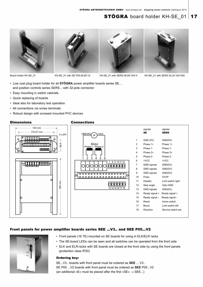
• Low cost plug board holder for all STÖGRA power amplifier boards series SE...
and position controls series SERS... with 32-pole connector
• Easy mounting in switch cabinets
• Quick replacing of boards
• Ideal also for laboratory test operation
• All connections via screw terminals
• Robust design with screwed mounted PVC devices
1 2 3 4 5 6
7 8 9 10 11 12
13 14 15 16 17 18
=GND (0V) +VCC
signals signals
SE SERS
1 GND (0V) GND(0V)
2 Phase 1+ Phase 1+
3 Phase 1- Phase 1-
4 Phase 2+ Phase 2+
5 Phase 2- Phase 2-
6 +VCC +VCC
7 GND signals GND(0V)
8 GND signals GND(0V)
9 GND signals GND(0V)
10 Pulse STOP
11 Disable Limit switch right
12 Step angle Opto GND
13 GND signals GND(0V)
14 Ready signal + Ready signal +
15 Ready signal - Ready signal -
16 Reset Home switch
17 Boost Limit switch left
18 Direction Service switch ext.
Phase 1 Phase 2Motor
185 m
m
135 mm
116,47 mm
38,5
4 x 4
ConnectionsDimensions
Board holder KH-SE_01 KH-SE_01 with SERS 06.85 V04 H KH-SE_01 with SERS 02.24 V04 E50KH-SE_01 with SE P05.06.85 V2
• Front panels (16 TE) mounted on SE boards for using in ELK/ELR racks
• The SE-board LEDs can be seen and all switches can be operated from the front side
• ELK and ELR-racks with SE boards are closed at the front side by using the front panels
(protection class IP20)
Ordering key:SE...V3.. boards with front panel must be ordered as SEE ... V3..
SE P05 ...V2 boards with front panel must be ordered as SEE P05...V2
(an additional »E« must be placed after the first »SE« → SEE...)
Front panels for power amplifier boards series SEE ...V3.. and SEE P05...V2
STÖGRA ANTRIEBSTECHNIK GMBH www.stoegra.de stepping motor controls catalogue 2015
STÖGRA board holder KH-SE_01 17
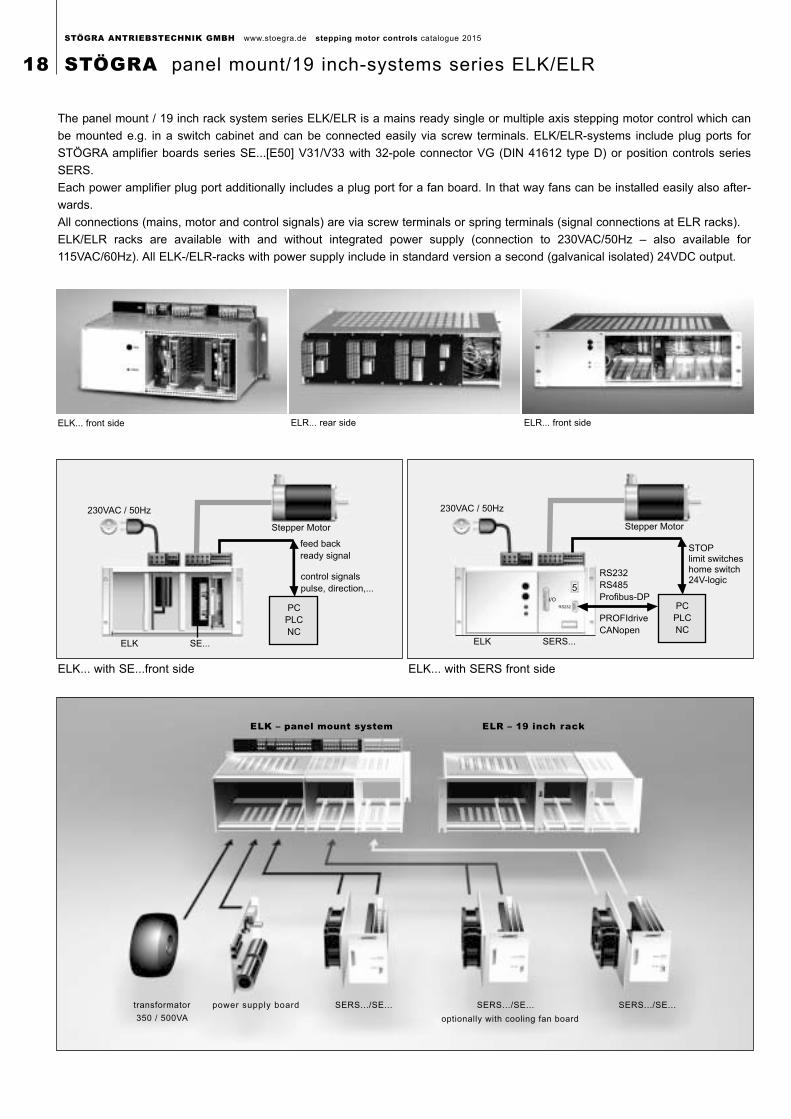
transformator
350 / 500VA
power supply board SERS.../SE... SERS.../SE... SERS.../SE...
optionally with cooling fan board
ELK – panel mount system ELR – 19 inch rack
The panel mount / 19 inch rack system series ELK/ELR is a mains ready single or multiple axis stepping motor control which can
be mounted e.g. in a switch cabinet and can be connected easily via screw terminals. ELK/ELR-systems include plug ports for
STÖGRA amplifier boards series SE...[E50] V31/V33 with 32-pole connector VG (DIN 41612 type D) or position controls series
SERS.
Each power amplifier plug port additionally includes a plug port for a fan board. In that way fans can be installed easily also after-
wards.
All connections (mains, motor and control signals) are via screw terminals or spring terminals (signal connections at ELR racks).
ELK/ELR racks are available with and without integrated power supply (connection to 230VAC/50Hz – also available for
115VAC/60Hz). All ELK-/ELR-racks with power supply include in standard version a second (galvanical isolated) 24VDC output.
230VAC / 50Hz
ELK SE...
Stepper Motor
feed back
ready signal
control signals
pulse, direction,...
PC
PLC
NC
ELK... front side
ELK... with SE...front side
230VAC / 50Hz
ELK SERS...
Stepper Motor
STOPlimit switcheshome switch24V-logic
PC
PLC
NC
RS232
5I/O
RS232
RS485
Profibus-DP
PROFIdrive
CANopen
ELK... with SERS front side
ELR... front sideELR... rear side
STÖGRA ANTRIEBSTECHNIK GMBH www.stoegra.de stepping motor controls catalogue 2015
18 STÖGRA panel mount/19 inch-systems series ELK/ELR
RS232RS232
I/OI/O
55
Profibus
I/O
5
Profibus
I/O
5
Profibus
I/O
5
Profibus
I/O
5
Profibus
I/O
5
Profibus
I/O
5
Profibus
I/O
5
Profibus
I/O
5
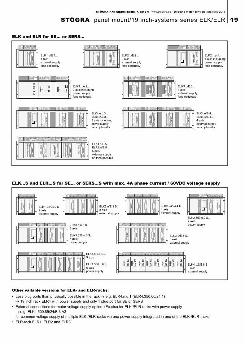
Other vailable versions for ELK- and ELR-racks:• Less plug ports than physically possible in the rack → e.g. ELR4.n.u.1 (ELR4.350.60/24.1)
→ 19 inch rack ELR4 with power supply and only 1 plug port for SE or SERS
• External connections for motor voltage supply option »E« also for ELK-/ELR-racks with power supply → e.g. ELK4.500.85/24/E.3 A3for common voltage supply of multiple ELK-/ELR-racks via one power supply integrated in one of the ELK-/ELR-racks
• ELR-rack ELR1, ELR2 and ELR3
ELK...S and ELR...S for SE... or SERS...S with max. 4A phase current / 60VDC voltage supply
ELK and ELR for SE... or SERS...
ELK1.u/E.1...1 axisexternal supplyfans optionally
ELK2.u/E.2...2 axisexternal supplyfans optionally
ELK2.n.u.1...1 axis includungpower supplyfans optionally
ELK3.n.u.2...2 axis includungpower supplyfans optionally
ELK3.u/E.3...3 axisexternal supplyfans optionally
ELK4.n.u.3...ELR4.n.u.3...3 axis includungpower supplyfans optionally
ELK4.u/E.4...ELR4.u/E.4...4 axisexternal supplyfans optionally
ELK4.n/E.5...ELR4.n/E.5...5 axisexternal supplyno fans possible
ELK1.24/24.2 S2 axisexternal supply
ELK2.u/E.3 S...3 axisexternal supply
ELK2.24/24.4 S4 axisexternal supply
ELK3.n.u.3 S...3 axis
ELK3.350.u.4 S...4 axispower supply
ELK3.u/E.5 S...5 axisexternal supply
ELK4.n.u.5 S...5 axis
ELK4.350.u.6 S...6 axispower supply
ELK4.u.5/E.8 S8 axisexternal supply
ELK2.350.u.2 S...2 axispower supply
STÖGRA ANTRIEBSTECHNIK GMBH www.stoegra.de stepping motor controls catalogue 2015
STÖGRA panel mount/19 inch-systems series ELK/ELR 19
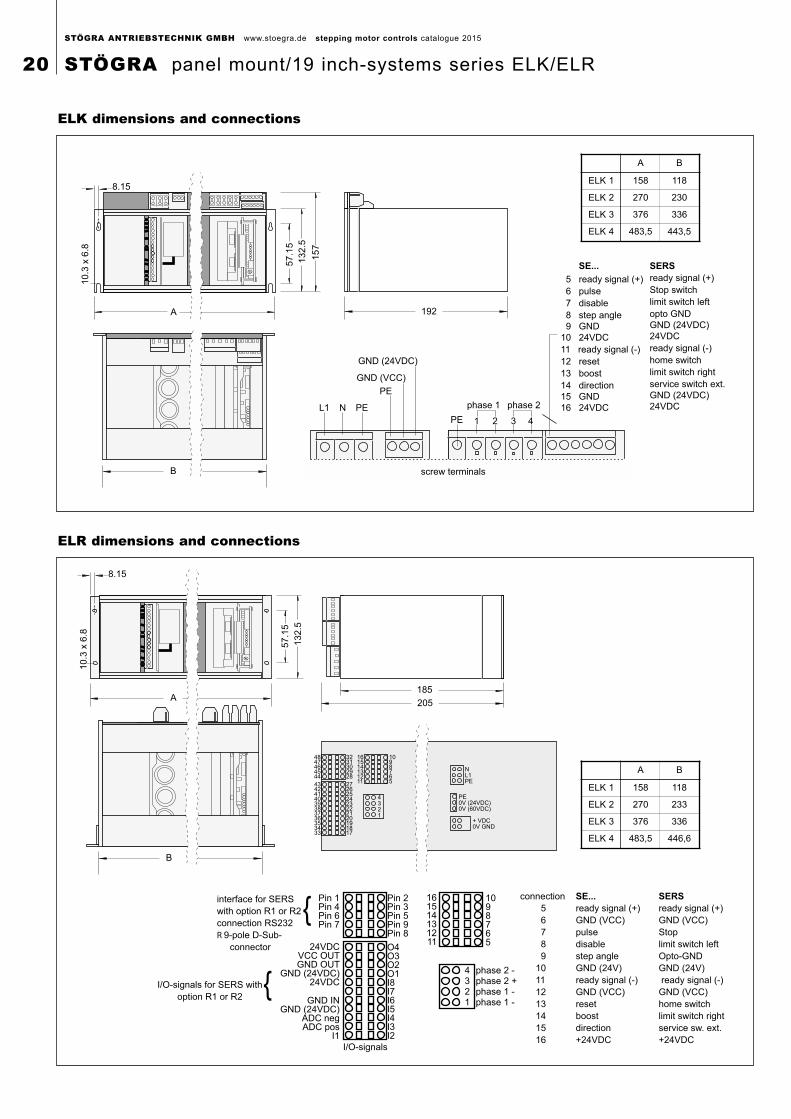
A
8.15
10
.3 x
6.8
57
.15
13
2.5
15
7192
B
L1 N PE
PE
GND (24VDC)
GND (VCC)
PE 1 2 3 4
phase 1 phase 2
screw terminals
SE...
5 ready signal (+)
6 pulse
7 disable
8 step angle
9 GND
10 24VDC
11 ready signal (-)
12 reset
13 boost
14 direction
15 GND
16 24VDC
SERS
ready signal (+)
Stop switch
limit switch left
opto GND
GND (24VDC)
24VDC
ready signal (-)
home switch
limit switch right
service switch ext.
GND (24VDC)
24VDC
B
A
8.15
10.3
x 6
.8
57.1
5
132.5
185
205
4847464544
4342414039383736353433
3231302928
161514131211
1098765
4321
2726252423222120191817
NL1PE
PE0V (24VDC)0V (60VDC)
+ VDC0V GND
interface for SERS
with option R1 or R2
connection RS232
R 9-pole D-Sub-
connector
I/O-signals for SERS with
option R1 or R2
Pin 1Pin 4Pin 6Pin 7
24VDCVCC OUTGND OUT
GND (24VDC)24VDC
GND INGND (24VDC)
ADC negADC pos
I1
I/O-signals
Pin 2Pin 3Pin 5Pin 9Pin 8
O4O3O2O1I8I7I6I5I4I3I2
161514131211
1098765
4321
phase 2 -phase 2 +phase 1 -phase 1 -
connection SE...
5 ready signal (+)
6 GND (VCC)
7 pulse
8 disable
9 step angle
10 GND (24V)
11 ready signal (-)
12 GND (VCC)
13 reset
14 boost
15 direction
16 +24VDC
SERS
ready signal (+)
GND (VCC)
Stop
limit switch left
Opto-GND
GND (24V)
ready signal (-)
GND (VCC)
home switch
limit switch right
service sw. ext.
+24VDC
ELR dimensions and connections
ELK dimensions and connections
A B
ELK 1 158 118
ELK 2 270 230
ELK 3 376 336
ELK 4 483,5 443,5
A B
ELK 1 158 118
ELK 2 270 233
ELK 3 376 336
ELK 4 483,5 446,6
STÖGRA ANTRIEBSTECHNIK GMBH www.stoegra.de stepping motor controls catalogue 2015
20 STÖGRA panel mount/19 inch-systems series ELK/ELR
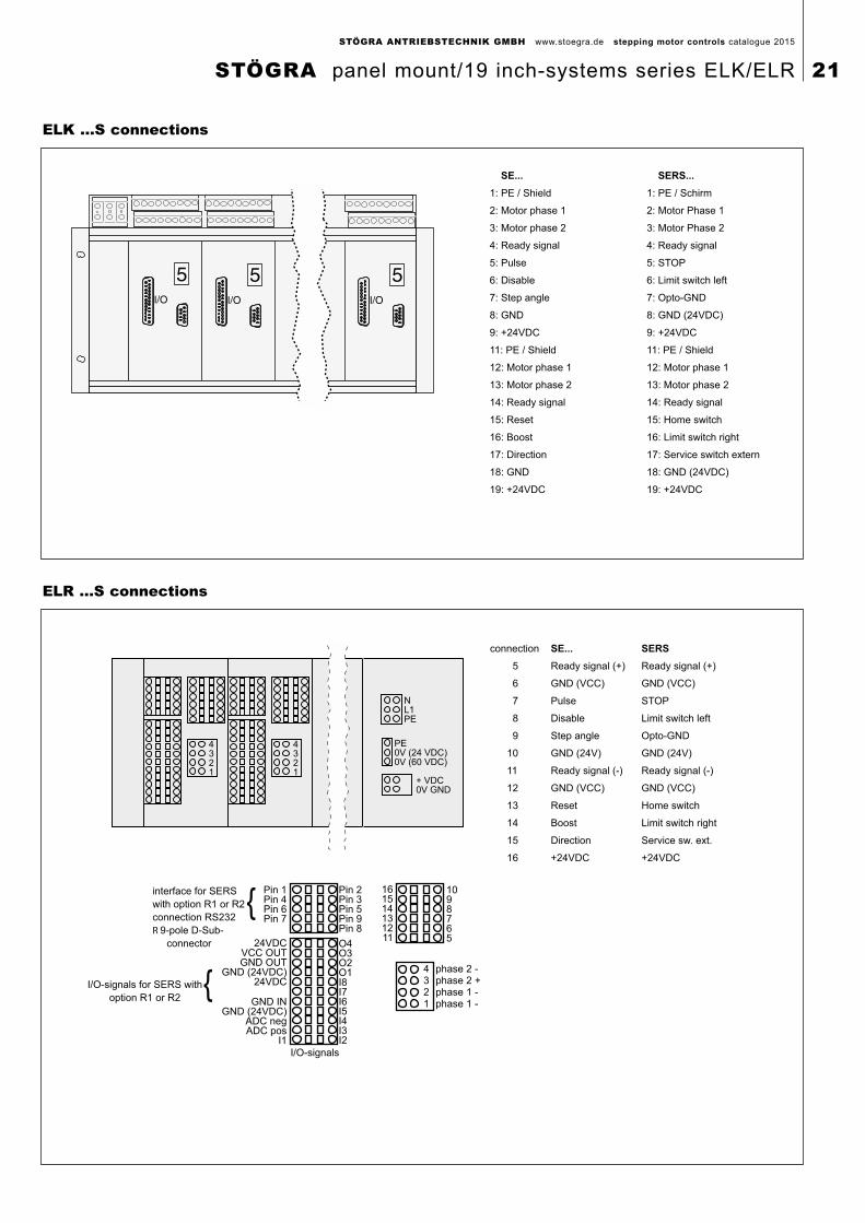
SE... SERS...
1: PE / Shield 1: PE / Schirm
2: Motor phase 1 2: Motor Phase 1
3: Motor phase 2 3: Motor Phase 2
4: Ready signal 4: Ready signal
5: Pulse 5: STOP
6: Disable 6: Limit switch left
7: Step angle 7: Opto-GND
8: GND 8: GND (24VDC)
9: +24VDC 9: +24VDC
11: PE / Shield 11: PE / Shield
12: Motor phase 1 12: Motor phase 1
13: Motor phase 2 13: Motor phase 2
14: Ready signal 14: Ready signal
15: Reset 15: Home switch
16: Boost 16: Limit switch right
17: Direction 17: Service switch extern
18: GND 18: GND (24VDC)
19: +24VDC 19: +24VDC
ELK ...S connections
interface for SERS
with option R1 or R2
connection RS232
R 9-pole D-Sub-
connector
I/O-signals for SERS with
option R1 or R2
Pin 1Pin 4Pin 6Pin 7
24VDCVCC OUTGND OUT
GND (24VDC)24VDC
GND INGND (24VDC)
ADC negADC pos
I1
I/O-signals
Pin 2Pin 3Pin 5Pin 9Pin 8
O4O3O2O1I8I7I6I5I4I3I2
161514131211
1098765
4321
phase 2 -phase 2 +phase 1 -phase 1 -
connection SE...
5 Ready signal (+)
6 GND (VCC)
7 Pulse
8 Disable
9 Step angle
10 GND (24V)
11 Ready signal (-)
12 GND (VCC)
13 Reset
14 Boost
15 Direction
16 +24VDC
SERS
Ready signal (+)
GND (VCC)
STOP
Limit switch left
Opto-GND
GND (24V)
Ready signal (-)
GND (VCC)
Home switch
Limit switch right
Service sw. ext.
+24VDC
NL1PE
PE0V (24 VDC)0V (60 VDC)
+ VDC0V GND
4321
4321
ELR ...S connections
STÖGRA ANTRIEBSTECHNIK GMBH www.stoegra.de stepping motor controls catalogue 2015
STÖGRA panel mount/19 inch-systems series ELK/ELR 21
PC
ELK4.350.85/24.3
RS2321:1 cable
SERS SERS SERS
PC
RS2321:1 cablel
ELK.350.85/24.3 2
ELK4.350.85/24.3
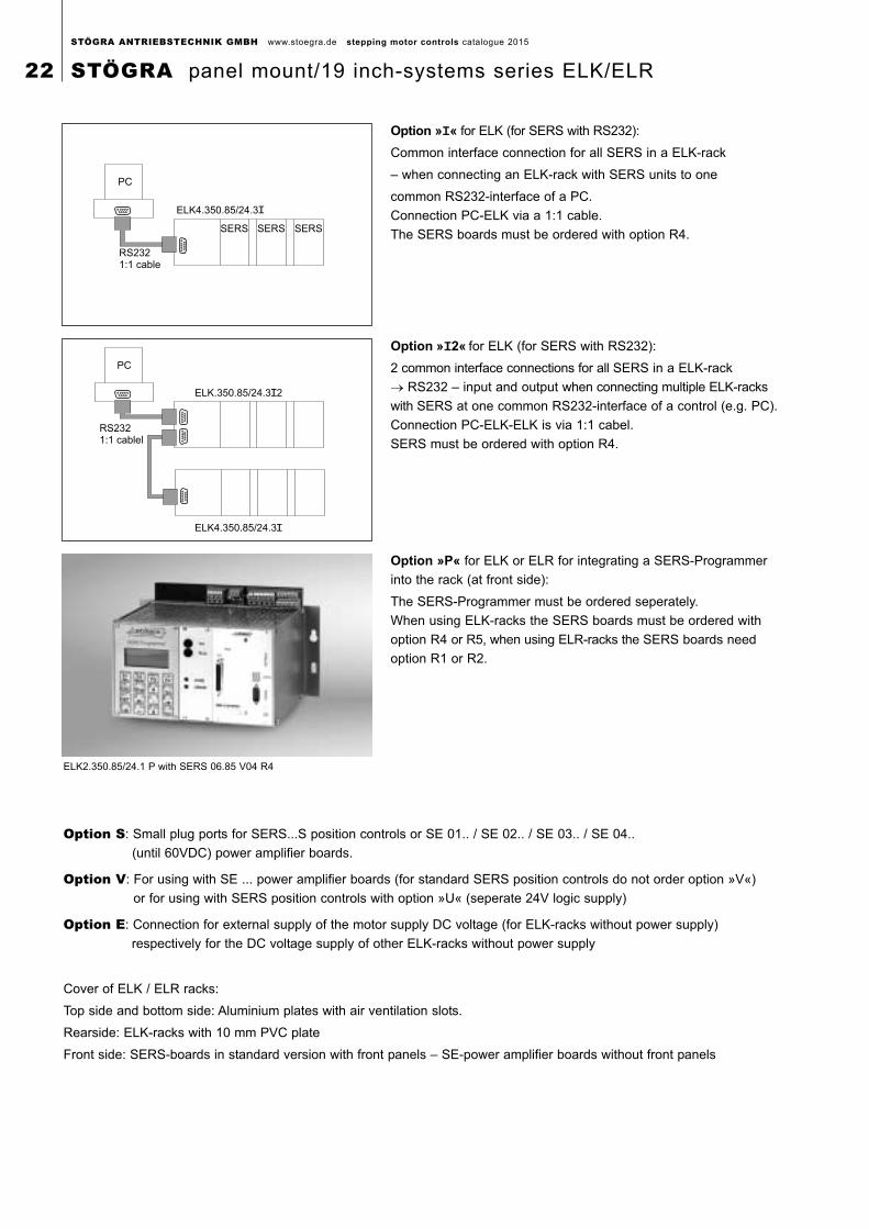
Option S: Small plug ports for SERS...S position controls or SE 01.. / SE 02.. / SE 03.. / SE 04..
(until 60VDC) power amplifier boards.
Option V: For using with SE ... power amplifier boards (for standard SERS position controls do not order option »V«)
or for using with SERS position controls with option »U« (seperate 24V logic supply)
Option E: Connection for external supply of the motor supply DC voltage (for ELK-racks without power supply)
respectively for the DC voltage supply of other ELK-racks without power supply
Cover of ELK / ELR racks:
Top side and bottom side: Aluminium plates with air ventilation slots.
Rearside: ELK-racks with 10 mm PVC plate
Front side: SERS-boards in standard version with front panels – SE-power amplifier boards without front panels
Option »II« for ELK (for SERS with RS232):
Common interface connection for all SERS in a ELK-rack
– when connecting an ELK-rack with SERS units to one
common RS232-interface of a PC.
Connection PC-ELK via a 1:1 cable.
The SERS boards must be ordered with option R4.
Option »II2« for ELK (for SERS with RS232):
2 common interface connections for all SERS in a ELK-rack
→ RS232 – input and output when connecting multiple ELK-racks
with SERS at one common RS232-interface of a control (e.g. PC).
Connection PC-ELK-ELK is via 1:1 cabel.
SERS must be ordered with option R4.
Option »P« for ELK or ELR for integrating a SERS-Programmer
into the rack (at front side):
The SERS-Programmer must be ordered seperately.
When using ELK-racks the SERS boards must be ordered with
option R4 or R5, when using ELR-racks the SERS boards need
option R1 or R2.
ELK2.350.85/24.1 P with SERS 06.85 V04 R4
STÖGRA ANTRIEBSTECHNIK GMBH www.stoegra.de stepping motor controls catalogue 2015
22 STÖGRA panel mount/19 inch-systems series ELK/ELR
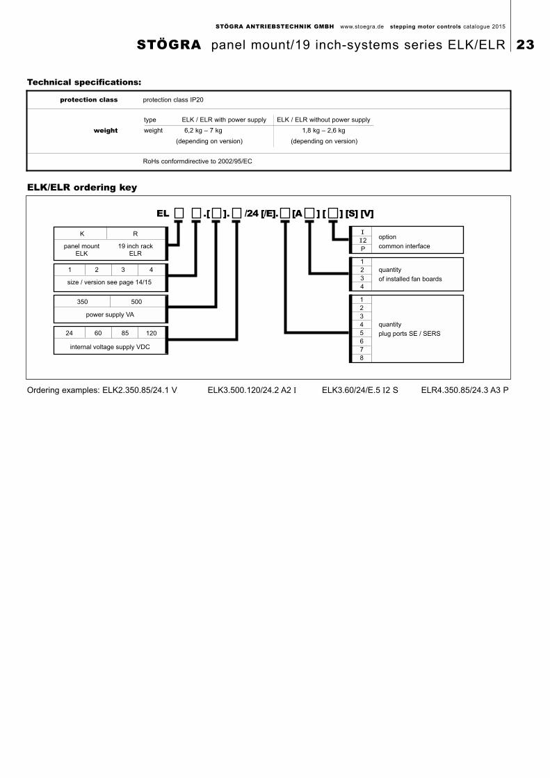
panel mountELK
19 inch rackELR
K R
1 2 3 4
size / version see page 14/15
350 500
power supply VA
internal voltage supply VDC
24 60 85 120
option
common interface
quantity
of installed fan boards
quantity
plug ports SE / SERS
1
2
3
4
5
6
7
8
1
2
3
4
2
P
EL .[ ]. /24 [/E]. [A ] [ ] [S] [V]
Ordering examples: ELK2.350.85/24.1 V ELK3.500.120/24.2 A2 Ι ELK3.60/24/E.5 Ι2 S ELR4.350.85/24.3 A3 P
ELK/ELR ordering key
Technical specifications:
protection class protection class IP20
weighttype ELK / ELR with power supply ELK / ELR without power supply
weight 6,2 kg – 7 kg 1,8 kg – 2,6 kg
(depending on version) (depending on version)
RoHs conformdirective to 2002/95/EC
STÖGRA ANTRIEBSTECHNIK GMBH www.stoegra.de stepping motor controls catalogue 2015
STÖGRA panel mount/19 inch-systems series ELK/ELR 23
Sensors /limit switch /
I/O
SM 1
WSERS 1
WSERS 2
SM 2
230VAC /
50Hz
Profibus-DPPROFIdrive
CANopenRS485RS232
SM 1
ELK/ELR
PC/NC
230VAC / 50Hz
Sensors/limit switch
RS232
SM 2
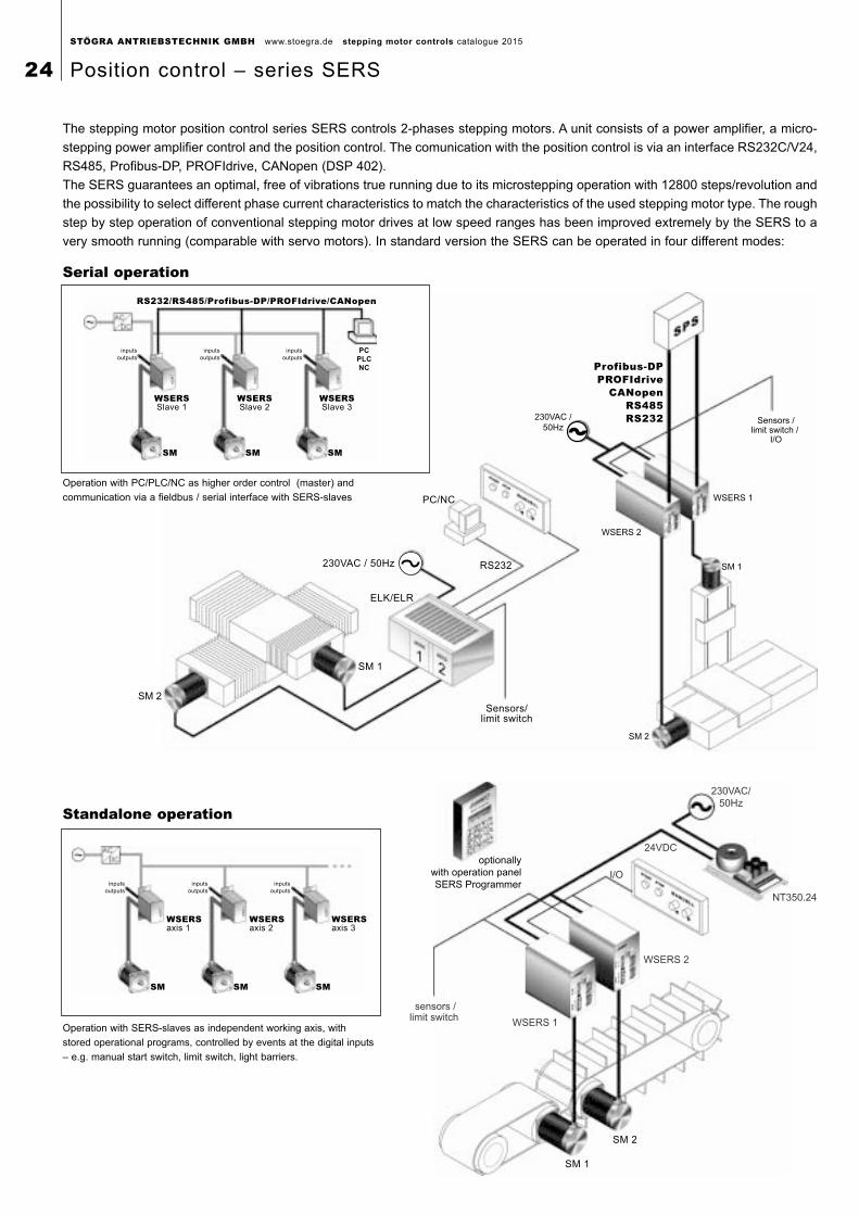
The stepping motor position control series SERS controls 2-phases stepping motors. A unit consists of a power amplifier, a micro-
stepping power amplifier control and the position control. The comunication with the position control is via an interface RS232C/V24,
RS485, Profibus-DP, PROFIdrive, CANopen (DSP 402).
The SERS guarantees an optimal, free of vibrations true running due to its microstepping operation with 12800 steps/revolution and
the possibility to select different phase current characteristics to match the characteristics of the used stepping motor type. The rough
step by step operation of conventional stepping motor drives at low speed ranges has been improved extremely by the SERS to a
very smooth running (comparable with servo motors). In standard version the SERS can be operated in four different modes:
SM 1
SM 2
sensors /limit switch
I/O
NT350.24
WSERS 2
230VAC/
50Hz
24VDC
WSERS 1
optionally
with operation panel
SERS Programmerinputs
outputs
SM
inputs
outputs
SM
inputs
outputs
SM
WSERSaxis 1
WSERSaxis 2
WSERSaxis 3
Operation with SERS-slaves as independent working axis, with
stored operational programs, controlled by events at the digital inputs
– e.g. manual start switch, limit switch, light barriers.
Operation with PC/PLC/NC as higher order control (master) and
communication via a fieldbus / serial interface with SERS-slaves
inputs
outputs
SM
inputs
outputs
SM
inputs
outputs
SM
PC
PLC
NC
WSERSSlave 1
WSERSSlave 2
WSERSSlave 3
RS232/RS485/Profibus-DP/PROFIdrive/CANopen
Serial operation
Standalone operation
STÖGRA ANTRIEBSTECHNIK GMBH www.stoegra.de stepping motor controls catalogue 2015
24 Position control – series SERS
SM 1
sensors/limit switch/
I/O
ELK/ELR
230VAC/50Hz
max. 6 adress lines+ 1 start per axis
1: X 10, Y 35, Z 22: X 120, Y 0, Z 45
max. 64 different
positions per axis
SM 2
SM 3
77
7
SM 2
SM 1
sensors/limit switch
ELK/ELR
230VAC/50Hz
NT...
85VDC
I/O
SM 4
SM 3
SM 5
inputs
outputs
SM
inputs
outputs
SM
inputs
outputs
SM
SERSSlave3
SERSSlave1
SERSSlave2
PLC
NC
1 start
6 address lines
1 start
6 address lines1 start
6 address lines
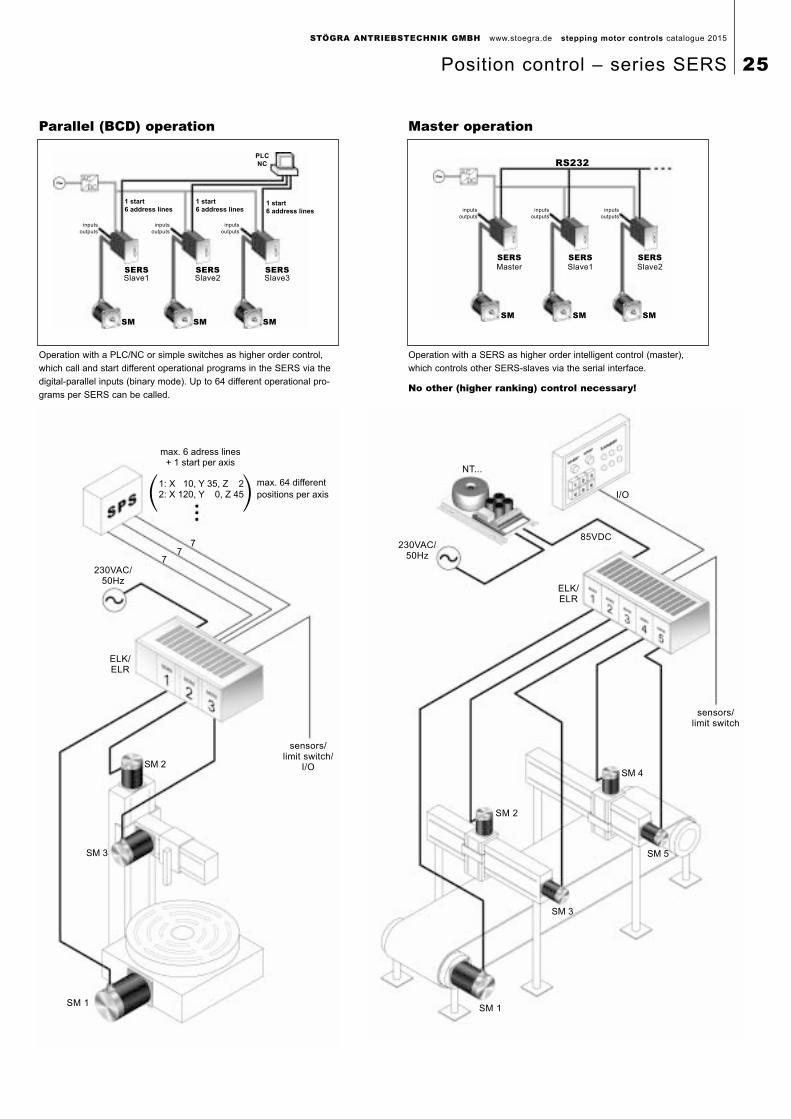
Operation with a PLC/NC or simple switches as higher order control,
which call and start different operational programs in the SERS via the
digital-parallel inputs (binary mode). Up to 64 different operational pro-
grams per SERS can be called.
Operation with a SERS as higher order intelligent control (master),
which controls other SERS-slaves via the serial interface.
No other (higher ranking) control necessary!
inputs
outputs
SM
inputs
outputs
SM
inputs
outputs
SM
SERSSlave2
SERSMaster
SERSSlave1
RS232
Parallel (BCD) operation Master operation
STÖGRA ANTRIEBSTECHNIK GMBH www.stoegra.de stepping motor controls catalogue 2015
Position control – series SERS 25
Overview functions and specifications:
Power amplifer:• excellent truth running because of microstepping operation at 12800 steps/revolution and four different phase current
characteristics, which can be selected for matching different stepping motor types
• phase current from 0 to 14,5A/phase, depending on version, programmable via interface
• power supply depending on version 24 until 240 VDC
• protection against short circuit, over temperature and under voltage, additional pre-warning of temperature and under voltage
Inputs and outputs:• 8 digital inputs, configurable low-/high-active (pull up or pull down input resistors),
TTL (5V) or PLC (24V) – signal level
• 2 limit switch inputs and 1 home switch input and 1 STOP switch input
– optoisolated for 24VDC signal level
• 4 digital outputs, each max. 500 mA / 24VDC
– optoisolated for external 24VDC supply and protected against short circuit
• 1 potential free output – relay max. 100mA / 24VDC – usable e.g. as ready signal
• 1 analogue input – 8 Bit, 0 to 5VDC
• Optional I/O – extension: additional 8 digital inputs and 12 outputs
(each max. 100mA / 24VDC)
Optionally step angle control / connection of hand wheel / electrical gearing function• control of motor step angle, together with a two channel encoder (signals A, A, B, B) mounted on the motor
– 5VDC or 24VDC encoders
• closed position loop – lost steps (because of mechanical overload at motor) can be corrected
– encoder controls real motor position
• connection of a hand wheel (with 2-channel encoder signals), via the optionally encoder evaluation logic,
or via two digital standard inputs
Interface:• RS232C/V24 (standard-PC COM-interface), with or without hardware handshake (selectable by software), RS485,
Profibus-DP/V0, PROFIdrive or CANopen
• via DIP-switch adjustable baudrate from 2400 to 115200 Baud (RS232 and RS485) and drive adress from 0 to 127
Profibus with baud rate until 12 MBaud (GSD-file is provided),
CANopen with baud rate until 1 MBaud (EDS file provided)
Structural shape and connections:• euro card format (100x160), front panel and 32 pole connector (DIN 41612) for mounting into 3 HE 19 inch systems
e.g. ELK-/ELR-systems – see pages 17 until 23)
• motor leads, power supply, connections for limit and home switches via 32 pole connector,
or via screw / spring terminals in case of using ELK / ELR – panel mount / rack – systems.
• digital inputs and outputs via 25-pole D-Sub female connector
or optionally via additional 32 pole connector (DIN 41612)
– in case of using an ELR rack system and the SERS with additional 32 pole connector,
the I/Os can be connected via spring terminals
• interface via 9-pole D-Sub connector or optionally via 32 pole connector (DIN 41612)
– when using ELR racks via spring terminals
STÖGRA ANTRIEBSTECHNIK GMBH www.stoegra.de stepping motor controls catalogue 2015
26 Position control – series SERS
Positioniersteuerung:
• communication by sending and receiving ASCII characters via the interface (for RS232 and RS485)
• simple and easy understandable syntax for all standard commands and parameters (see table on next page)
• programming of operational programms similar to BASIC
• 3 different kinds of scaling selectable for all position, speed and acceleration dates
(incremental e.g. 5000 steps, rotational e.g. 1000 rpm and linear e.g 20 mm/min)
• Parametrisierung von Getriebefaktoren und Vorschubkonstante (z.B. Spindelsteigung) für translatorische Werteangaben
• Velocities from 0,12 until 10000 rpm
(stepping motor usable until approx. 3000 rpm, depending on motor and supply)
• acceleration from 2 until 15600 U/s2 and linear, exponential or sinus acceleration characteristics
• 2 KByte E2Prom-memory (depending on program up to 300 lines, optionally 8 KByte for up to 1200 lines)
for storing an operational program in standalone mode, master-slave mode, parallel (BCD) mode
• backlash function for using e.g. gear boxes, chains, or spindles with backlash
• print mark control (automatical set or reset of outputs after reaching a certain position)
• travel distance after stop signal (after a stop command / signal the motor continues moving for a defined distance)
• arithmetical operations: +, -, * , /, AND, OR, EXCL-OR, NOT, NEG – usable with alle SERS parameters
1 acumulator for calculating and 12 free usable registers (R0 - R11)
• all SERS parameters can be programmed and changed anytime, also within an operational program
• Program jumps (GOTO) and subroutine calls (GOSUB)
• conditional jumps and commands (IF-commands) by query of inputs, markers, drives status and parameters,
programmable with IF ... THEN ... ELSE structures
• wait function »WAIT...«, with user defined wait condition (e.g. wait for a signal at digital inputs)
• programmable delay function, with units in 10ms
• timer function (parallel to an operational program)
• counters (e.g. for realising program loops)
• manual driving functions (jog)
(without set target position, started via inputs or commands, with variable speed - can be changed during motor movement)
• extensive diagnostics – all errors and warnings can be inquired any time via the interface
• selection of language for the communication with the SERS e.g. error messages and parameter designations)
– German and English
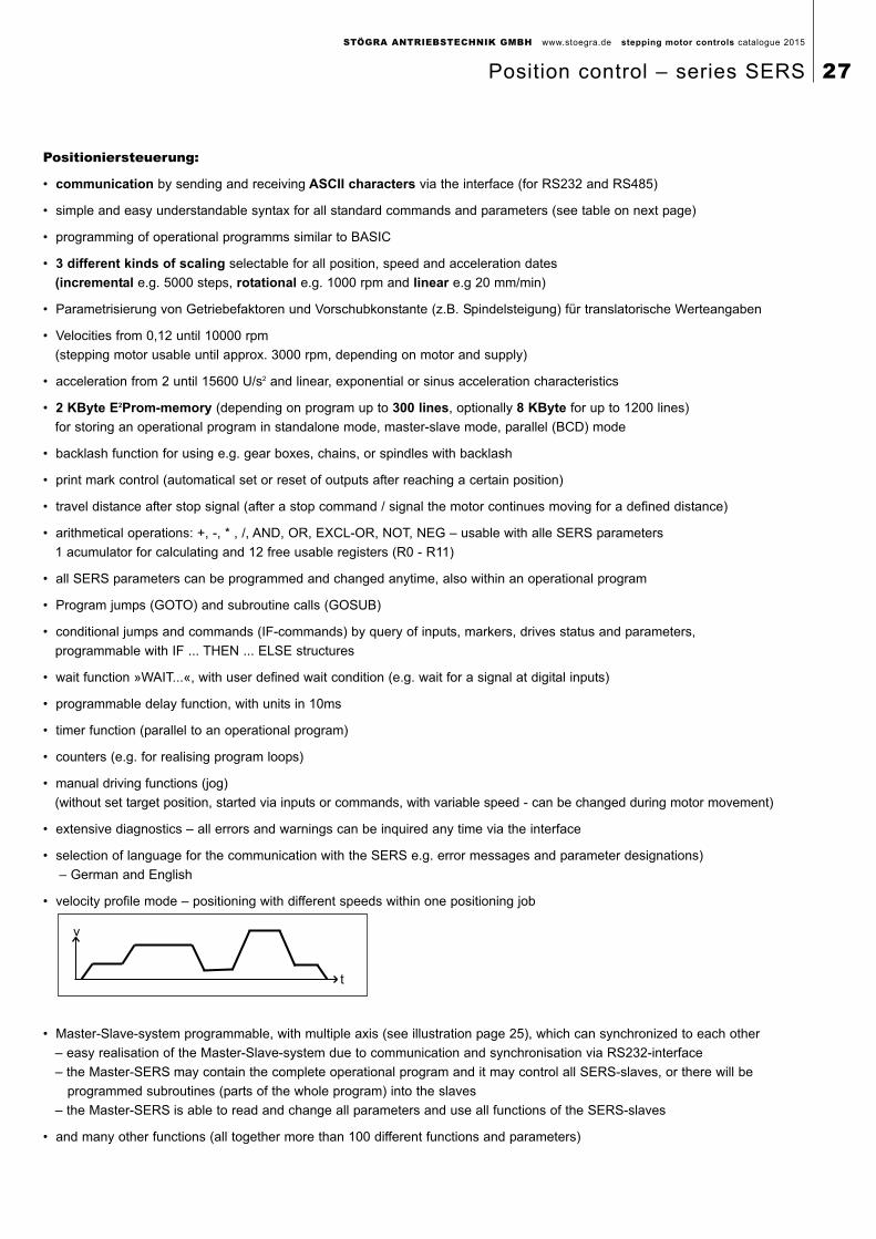
• velocity profile mode – positioning with different speeds within one positioning job
• Master-Slave-system programmable, with multiple axis (see illustration page 25), which can synchronized to each other
– easy realisation of the Master-Slave-system due to communication and synchronisation via RS232-interface
– the Master-SERS may contain the complete operational program and it may control all SERS-slaves, or there will be
programmed subroutines (parts of the whole program) into the slaves
– the Master-SERS is able to read and change all parameters and use all functions of the SERS-slaves
• and many other functions (all together more than 100 different functions and parameters)
t
v
STÖGRA ANTRIEBSTECHNIK GMBH www.stoegra.de stepping motor controls catalogue 2015
Position control – series SERS 27
STÖGRA ANTRIEBSTECHNIK GMBH www.stoegra.de stepping motor controls catalogue 2015
28 Position control – series SERS
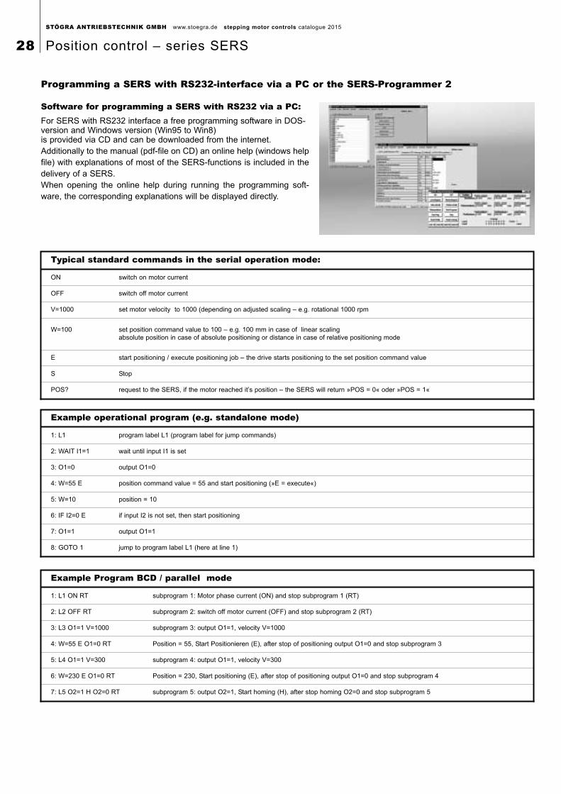
Software for programming a SERS with RS232 via a PC:For SERS with RS232 interface a free programming software in DOS-version and Windows version (Win95 to Win8) is provided via CD and can be downloaded from the internet.Additionally to the manual (pdf-file on CD) an online help (windows helpfile) with explanations of most of the SERS-functions is included in thedelivery of a SERS.When opening the online help during running the programming soft-ware, the corresponding explanations will be displayed directly.
Programming a SERS with RS232-interface via a PC or the SERS-Programmer 2
Typical standard commands in the serial operation mode:
ON switch on motor current
OFF switch off motor current
V=1000 set motor velocity to 1000 (depending on adjusted scaling – e.g. rotational 1000 rpm
W=100 set position command value to 100 – e.g. 100 mm in case of linear scalingabsolute position in case of absolute positioning or distance in case of relative positioning mode
E start positioning / execute positioning job – the drive starts positioning to the set position command value
S Stop
POS? request to the SERS, if the motor reached it’s position – the SERS will return »POS = 0« oder »POS = 1«
Example operational program (e.g. standalone mode)
1: L1 program label L1 (program label for jump commands)
2: WAIT I1=1 wait until input I1 is set
3: O1=0 output O1=0
4: W=55 E position command value = 55 and start positioning (»E = execute«)
5: W=10 position = 10
6: IF I2=0 E if input I2 is not set, then start positioning
7: O1=1 output O1=1
8: GOTO 1 jump to program label L1 (here at line 1)
Example Program BCD / parallel mode
1: L1 ON RT subprogram 1: Motor phase current (ON) and stop subprogram 1 (RT)
2: L2 OFF RT subprogram 2: switch off motor current (OFF) and stop subprogram 2 (RT)
3: L3 O1=1 V=1000 subprogram 3: output O1=1, velocity V=1000
4: W=55 E O1=0 RT Position = 55, Start Positionieren (E), after stop of positioning output O1=0 and stop subprogram 3
5: L4 O1=1 V=300 subprogram 4: output O1=1, velocity V=300
6: W=230 E O1=0 RT Position = 230, Start positioning (E), after stop of positioning output O1=0 and stop subprogram 4
7: L5 O2=1 H O2=0 RT subprogram 5: output O2=1, Start homing (H), after stop homing O2=0 and stop subprogram 5
STÖGRA ANTRIEBSTECHNIK GMBH www.stoegra.de stepping motor controls catalogue 2015
Position control – series SERS 29
SERS-Programmer 2:• low priced programming device, in case no PC can be used
• easy to use control panel, e.g. for using in a produktion facility, for modifying parameters or program lines
Special features of the SERS-Programmer 2:• the keypad with integrated 16x4 character display is suitable especially for dirty environments
(frontside IP65 protection degree)
• colored marking of the threefold configuration of the keypad keys
Standard mode:pre-defined standard menu with following possibilities:
• setup parameters in the SERS-control
• setup / modify operation programs in the SERS-control
• possibility of locking or releasing certain parameters and program lines via a password
• free definable text in the display for single value asignements, in an operational program
• start / stop manual drive functions (jog) and homing, via keys at the SERS-Programmer 2
• start / stop of SERS-operational programs
• start / stop of a Master-/Slave-system with one SERS as Master and further SERS as Slaves
• display of digital Inputs and Outputs (e.g. for verifying the SERS-I/Os during setup / installation of a machine)
• terminal function for communications with SERS-controls
• available as housed version (hand device), or for installing in 19’’ systems (e.g. STÖGRA ELK-racks),
respectively for integration in any kind of control / operator panels
Extended programming mode:• free programmable customer specific operator menus (ready menu examples exist),
for realising simple menus with single level (see example below), or also menus with multiple levels
• free assignment of SERS-Programmer 2 keys to customer specific programmable functions
• operational program can be stored completely in the SERS-Programmer 2
• Master-Slave-system with SERS-Programmer as Master and all SERS drives as Slaves
Simple example for extended programming mode:Via a SERS-Programmer 2 the machine operator shall modify just the travel distance, and he shall
start and stop the operational program.
The menu, which can be accessed by the operator, shall be as simple as possible.
In the adjacent example, with key F1 the travel distance can be modified. With F3 the operational
program (hidden in the background) can be started, and via the key »STOP« (unique key which
is labelled with »stop«) the program respectively the motor movement can be stopped.
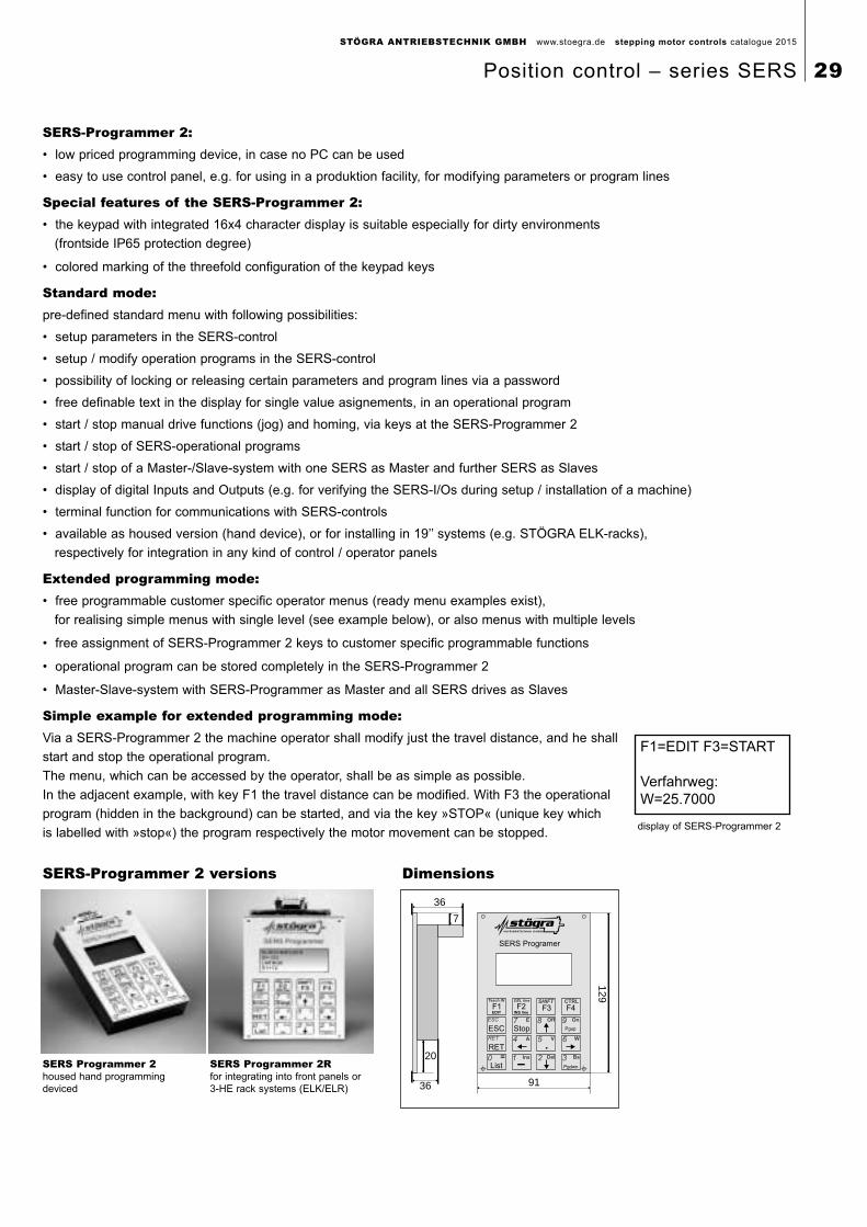
SERS Programmer 2housed hand programmingdeviced
SERS Programmer 2Rfor integrating into front panels or3-HE rack systems (ELK/ELR)
SERS-Programmer 2 versions Dimensions
91
7
36
20
36
129
SERS Programer
Teach IN DEL line SHIFT
ESC
RET
7 8
5
2 3
6
9
4
10
CTRL
OnOffE
A V W
BsDelIns=
ESC Stop
Pgdwn
Pgup
INS lineEDIT
F2 F3
.
F4F1
RET
List
F1=EDIT F3=START
Verfahrweg:W=25.7000
display of SERS-Programmer 2
STÖGRA ANTRIEBSTECHNIK GMBH www.stoegra.de stepping motor controls catalogue 2015
30 Position control – series SERS
Option Closed Loop ControlThe SERS/WSERS is available optionally with Closed Loop control. The stepper motor must be a STÖGRA type with adjusted
H500 encoder (motor option »C500« e.g. SM 87.2.18M6 C500). The SERS/WSERS must be ordered with option »E50/C« (e.g.
WSERS 04.80 V01 E50/C).
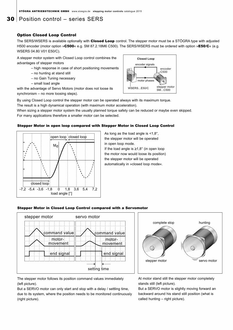
A stepper motor system with Closed Loop control combines the
advantages of stepper motors
– high response in case of short positioning movements
– no hunting at stand still
– no Gain Tuning necessary
– small load angle
with the advantage of Servo Motors (motor does not loose its
synchronism – no more loosing steps).
By using Closed Loop control the stepper motor can be operated always with its maximum torque.
The result is a high dynamical operation (with maximum motor acceleration).
When sizing a stepper motor system the usually planned torque safety can be reduced or maybe even skipped.
For many applications therefore a smaller motor can be selected.
motor- movement
command value
end signal
setting time
command value
end signal
motor- movement
stepper motor servo motor
complete stop hunting
stepper motor servo motor
As long as the load angle is <1,8°,
the stepper motor will be operated
in open loop mode.
If the load angle is ≥≥1,8° (in open loop
the motor now would loose its position)
the stepper motor will be operated
automatically in »closed loop mode«.
At motor stand still the stepper motor completely
stands still (left picture).
But a SERVO motor is slightly moving forward an
backward around his stand still position (what is
called hunting – right picture).
The stepper motor follows its position command values immediately
(left picture).
But a SERVO motor can only start and stop with a delay / settling time,
due to its system, where the position needs to be monitored continuously
(right picture).
-7,2 -5,4 -3,6 0-1,8 1,8 3,6 5,4 7,2
load angle [°]
closed loop
closed loopopen loop
Md
Stepper Motor in open loop compared with Stepper Motor in Closed Loop Control
Stepper Motor in Closed Loop Control compared with a Servomotor
Closed Loop
WSERS...E50/C
encoderC500
stepper motorSM...C500
motor phases
encoder signals
STÖGRA ANTRIEBSTECHNIK GMBH www.stoegra.de stepping motor controls catalogue 2015
Position control – series SERS 31
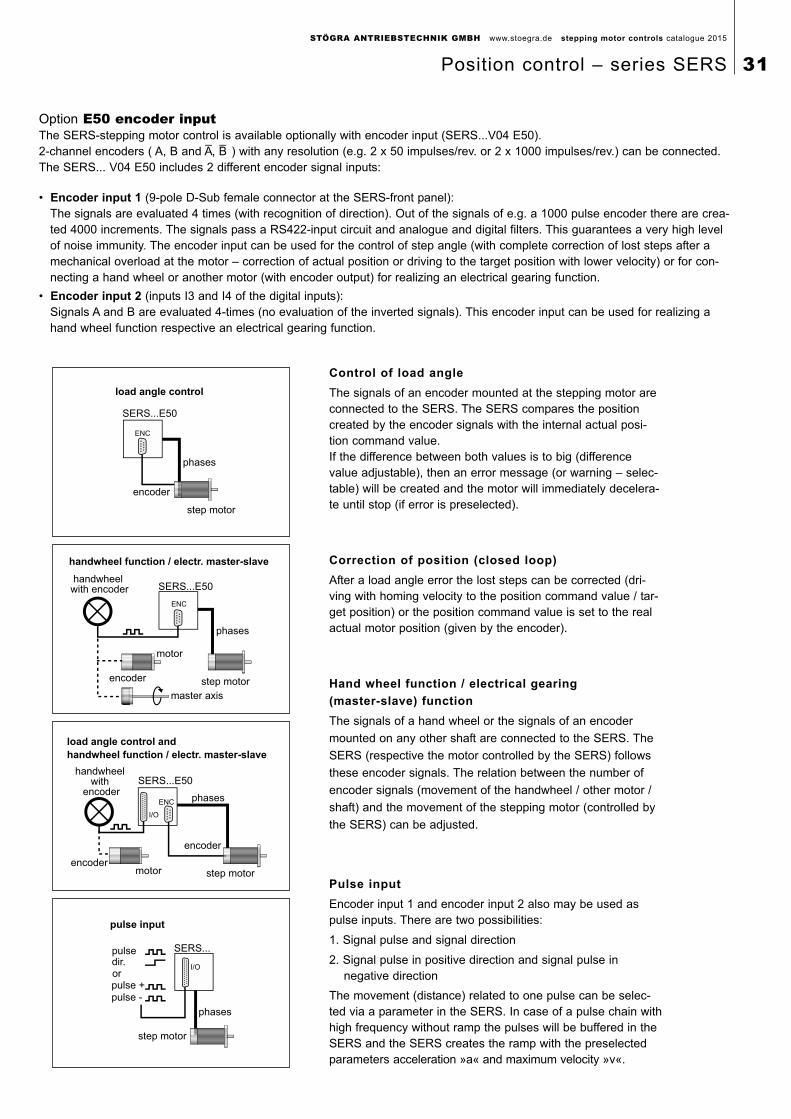
Option E50 encoder inputThe SERS-stepping motor control is available optionally with encoder input (SERS...V04 E50). 2-channel encoders ( A, B and A
_, B
_ ) with any resolution (e.g. 2 x 50 impulses/rev. or 2 x 1000 impulses/rev.) can be connected.
The SERS... V04 E50 includes 2 different encoder signal inputs:
Control of load angle
The signals of an encoder mounted at the stepping motor are connected to the SERS. The SERS compares the positioncreated by the encoder signals with the internal actual posi-tion command value.If the difference between both values is to big (differencevalue adjustable), then an error message (or warning – selec-table) will be created and the motor will immediately decelera-te until stop (if error is preselected).
Correction of position (closed loop)
After a load angle error the lost steps can be corrected (dri- ving with homing velocity to the position command value / tar-get position) or the position command value is set to the realactual motor position (given by the encoder).
Hand wheel function / electrical gearing
(master-slave) function
The signals of a hand wheel or the signals of an encoder
mounted on any other shaft are connected to the SERS. The
SERS (respective the motor controlled by the SERS) follows
these encoder signals. The relation between the number of
encoder signals (movement of the handwheel / other motor /
shaft) and the movement of the stepping motor (controlled by
the SERS) can be adjusted.
Pulse input
Encoder input 1 and encoder input 2 also may be used as pulse inputs. There are two possibilities:
1. Signal pulse and signal direction
2. Signal pulse in positive direction and signal pulse in negative direction
The movement (distance) related to one pulse can be selec-ted via a parameter in the SERS. In case of a pulse chain withhigh frequency without ramp the pulses will be buffered in theSERS and the SERS creates the ramp with the preselectedparameters acceleration »a« and maximum velocity »v«.
handwheel function / electr. master-slave
handwheel with encoder
encoder
motor
step motor
phases
SERS...E50
ENC
master axis
load angle control and
handwheel function / electr. master-slave
handwheel with
encoder
encoder
encodermotor step motor
phases
SERS...E50
I/O
ENC
pulse input
step motor
phases
pulse +
pulse -
or
pulsedir.
SERS...
I/O
• Encoder input 1 (9-pole D-Sub female connector at the SERS-front panel):The signals are evaluated 4 times (with recognition of direction). Out of the signals of e.g. a 1000 pulse encoder there are crea-ted 4000 increments. The signals pass a RS422-input circuit and analogue and digital filters. This guarantees a very high levelof noise immunity. The encoder input can be used for the control of step angle (with complete correction of lost steps after amechanical overload at the motor – correction of actual position or driving to the target position with lower velocity) or for con-necting a hand wheel or another motor (with encoder output) for realizing an electrical gearing function.
• Encoder input 2 (inputs I3 and I4 of the digital inputs):Signals A and B are evaluated 4-times (no evaluation of the inverted signals). This encoder input can be used for realizing ahand wheel function respective an electrical gearing function.
load angle control
encoder
step motor
phases
SERS...E50
ENC
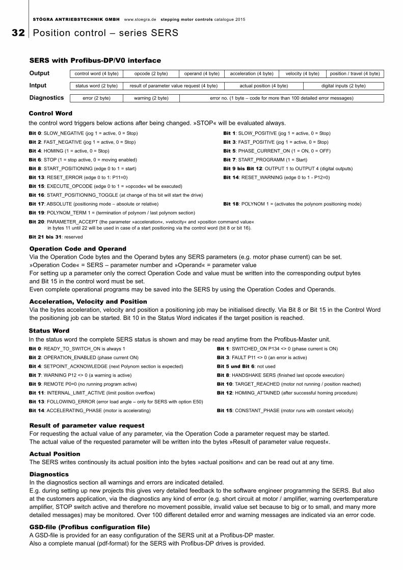
SERS with Profibus-DP/V0 interface
control word (4 byte) opcode (2 byte) operand (4 byte) acceleration (4 byte) velocity (4 byte) position / travel (4 byte)
status word (2 byte) result of parameter value request (4 byte) actual position (4 byte) digital inputs (2 byte)
error (2 byte) warning (2 byte) error no. (1 byte – code for more than 100 detailed error messages)
Output
Intput
Diagnostics
Control Wordthe control word triggers below actions after being changed. »STOP« will be evaluated always.
Bit 0: SLOW_NEGATIVE (jog 1 = active, 0 = Stop) Bit 1: SLOW_POSITIVE (jog 1 = active, 0 = Stop)
Bit 2: FAST_NEGATIVE (jog 1 = active, 0 = Stop) Bit 3: FAST_POSITIVE (jog 1 = active, 0 = Stop)
Bit 4: HOMING (1 = active, 0 = Stop) Bit 5: PHASE_CURRENT_ON (1 = ON, 0 = OFF)
Bit 6: STOP (1 = stop active, 0 = moving enabled) Bit 7: START_PROGRAMM (1 = Start)
Bit 8: START_POSITIONING (edge 0 to 1 = start) Bit 9 bis Bit 12: OUTPUT 1 to OUTPUT 4 (digital outputs)
Bit 13: RESET_ERROR (edge 0 to 1: P11=0) Bit 14: RESET_WARNING (edge 0 to 1 - P12=0)
Bit 15: EXECUTE_OPCODE (edge 0 to 1 = »opcode« wil be executed)
Bit 16: START_POSITIONING_TOGGLE (at change of this bit will start the drive)
Bit 17: ABSOLUTE (positioning mode – absolute or relative) Bit 18: POLYNOM 1 = (activates the polynom positioning mode)
Bit 19: POLYNOM_TERM 1 = (termination of polynom / last polynom section)
Bit 20: PARAMETER_ACCEPT (the parameter »acceleration«, »velocity« and »position command value« in bytes 11 until 22 will be used in case of a start positioning via the control word (bit 8 or bit 16).
Bit 21 bis 31: reserved
Status WordIn the status word the complete SERS status is shown and may be read anytime from the Profibus-Master unit.
Bit 0: READY_TO_SWITCH_ON is always 1 Bit 1: SWITCHED_ON P134 <> 0 (phase current is ON)
Bit 2: OPERATION_ENABLED (phase current ON) Bit 3: FAULT P11 <> 0 (an error is active)
Bit 4: SETPOINT_ACKNOWLEDGE (next Polynom section is expected) Bit 5 und Bit 6: not used
Bit 7: WARNING P12 <> 0 (a warning is active) Bit 8: HANDSHAKE SERS (finished last opcode execution)
Bit 9: REMOTE P0=0 (no running program active) Bit 10: TARGET_REACHED (motor not running / position reached)
Bit 11: INTERNAL_LIMIT_ACTIVE (limit position overflow) Bit 12: HOMING_ATTAINED (after successful homing procedure)
Bit 13: FOLLOWING_ERROR (error load angle – only for SERS with option E50)
Bit 14: ACCELERATING_PHASE (motor is accelerating) Bit 15: CONSTANT_PHASE (motor runs with constant velocity)
Operation Code and OperandVia the Operation Code bytes and the Operand bytes any SERS parameters (e.g. motor phase current) can be set.»Operation Code« = SERS – parameter number and »Operand« = parameter valueFor setting up a parameter only the correct Operation Code and value must be written into the corresponding output bytes and Bit 15 in the control word must be set.Even complete operational programs may be saved into the SERS by using the Operation Codes and Operands.
Acceleration, Velocity and PositionVia the bytes acceleration, velocity and position a positioning job may be initialised directly. Via Bit 8 or Bit 15 in the Control Word the positioning job can be started. Bit 10 in the Status Word indicates if the target position is reached.
Result of parameter value requestFor requesting the actual value of any parameter, via the Operation Code a parameter request may be started. The actual value of the requested parameter will be written into the bytes »Result of parameter value request«.
Actual PositionThe SERS writes continously its actual position into the bytes »actual position« and can be read out at any time.
DiagnosticsIn the diagnostics section all warnings and errors are indicated detailed. E.g. during setting up new projects this gives very detailed feedback to the software engineer programming the SERS. But also at the customers application, via the diagnostics any kind of error (e.g. short circuit at motor / amplifier, warning overtemperatureamplifier, STOP switch active and therefore no movement possible, invalid value set because to big or to small, and many moredetailed messages) may be monitored. Over 100 different detailed error and warning messages are indicated via an error code.
GSD-file (Profibus configuration file)A GSD-file is provided for an easy configuration of the SERS unit at a Profibus-DP master.Also a complete manual (pdf-format) for the SERS with Profibus-DP drives is provided.
STÖGRA ANTRIEBSTECHNIK GMBH www.stoegra.de stepping motor controls catalogue 2015
32 Position control – series SERS

SERS with Profibus-DP/V1 interface and PROFIdrive protocol V3.1:The SERS with PROFIdrive interface follows the specifications of the PROFIdrive profile drive technology Version 3.1.Profibus-DP/V1 (sometimes also called Profibus-DP/V2 in case of PROFIdrive) is implemented in the SERS.The SERS drive is an application class 4 drive, where the PROFIdrive master calculates and cyclically transmitts speed setpointvalues and the SERS returns actual position values and status word (closed position loop control realized via the Profibus).A clock synchronism ensures high timing precision and exact synchronising of all connected drive axis.This enables position interpolation with high precision and speed of mutliple drive axis via the Profibus.All SERS units with PROFIdrive also support the Profibus-DP/V0 mode (described at page 28).Specifications of the SERS with PROFIdrive
• operation with any PROFIdrive-Master (e.g. Siemens Simotion control)
• implemented operating mode: speed control mode (application class 4)
• supported cycle times: 2ms and 4ms (for other cycle times please contact STÖGRA technical support)
• status word and control word according to PROFIdrive profile 3.1
A Profibus (PROFIdrive) configuration file (GSD-file) is provided.
SERS with CANopen interface:SERS units with CANopen interface include following specifications:
• standard parameter of the »CANopen Device Profile for Drives and Motion Control« of Index 0x6000 are according to »CiA confirming to Draft Standard Proposal DSP-402«
• general (e.g. communication) parameters with index numbers until 0x1000 are implemented according to »CiA Draft Standard 301« (Application Layer and Communication Profile) from »CAN in Automation e. V.«
• 11 Bit identifier used
• implemented positioning modes (“modes_of_operation" (6060) ): 1 »Profile Position Mode« and 6 »Homing Mode«
• galvanically isolated CANopen interface with selectable Baudrates up to 1Mbaud
• all functions of the standard SERS with RS232 interface are implemented (see description page 22 to 27)
• EDS-file provided including reference to all manufacturer specific SERS parameter
• manual (pdf-format) provided
PROFIdrive Master
with
technology functions
t
v
SERS 1 SERS 2 SERS x
Profibus-DP / PROFIdrive protocol
speedsetpoint
postionfeedback
clock clock clock
speedsetpoint
postionfeedback
speedsetpoint
postionfeedback
A motion profile for multiple axis (e.g. an interpolation in a 3D system with X-Y-Z axis) is given to a PROFIdrive master.
A closed position control loop via the Profibus is realised by cyclically transmitting speed setpoint values to the drives and recei-ving actual position values from the drives (controlled by a clock synchronism with time stamp).
For achieving the wanted position at the different axis the position feedback values are used for calulating the speed setpointvalues for the next cycle.
This dynamical interpolation system also enables changing the profile at any time online, respectively generating the profile conti-nously (when starting the first movement, the following movements – positions and speed – are calculated online depending onany actual new events).
STÖGRA ANTRIEBSTECHNIK GMBH www.stoegra.de stepping motor controls catalogue 2015
Position control – series SERS 33
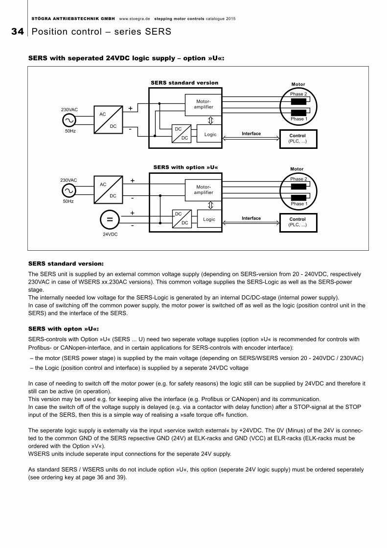
STÖGRA ANTRIEBSTECHNIK GMBH www.stoegra.de stepping motor controls catalogue 2015
34 Position control – series SERS
SERS with seperated 24VDC logic supply – option »U«:
SERS standard version
Motor-
amplifier
Logic
DC
DC
Phase 1
Phase 2
Interface Control
(PLC, ...)
AC
DC
230VAC
50Hz -
SERS with option »U«
Logic
DC
DC
Phase 1
Phase 2
AC
DC50Hz
-
-
230VAC
24VDC
Control
(PLC, ...)
Motor
Motor
Motor-
amplifier
Interface
SERS standard version:
The SERS unit is supplied by an external common voltage supply (depending on SERS-version from 20 - 240VDC, respectively 230VAC in case of WSERS xx.230AC versions). This common voltage supplies the SERS-Logic as well as the SERS-powerstage. The internally needed low voltage for the SERS-Logic is generated by an internal DC/DC-stage (internal power supply). In case of switching off the common power supply, the motor power is switched off as well as the logic (position control unit in theSERS) and the interface of the SERS.
SERS with opton »U«:
SERS-controls with Option »U« (SERS ... U) need two seperate voltage supplies (option »U« is recommended for controls with
Profibus- or CANopen-interface, and in certain applications for SERS-controls with encoder interface):
– the motor (SERS power stage) is supplied by the main voltage (depending on SERS/WSERS version 20 - 240VDC / 230VAC)
– the Logic (position control and interface) is supplied by a seperate 24VDC voltage
In case of needing to switch off the motor power (e.g. for safety reasons) the logic still can be supplied by 24VDC and therefore itstill can be active (in operation).This version may be used e.g. for keeping alive the interface (e.g. Profibus or CANopen) and its communication.In case the switch off of the voltage supply is delayed (e.g. via a contactor with delay function) after a STOP-signal at the STOPinput of the SERS, then this is a simple way of realising a »safe torque off« function.
The seperate logic supply is externally via the input »service switch external« by +24VDC. The 0V (Minus) of the 24V is connec-ted to the common GND of the SERS repsective GND (24V) at ELK-racks and GND (VCC) at ELR-racks (ELK-racks must beordered with the Option »V«).WSERS units include seperate input connections for the seperate 24V supply.
As standard SERS / WSERS units do not include option »U«, this option (seperate 24V logic supply) must be ordered seperately(see ordering key at page 36 and 39).
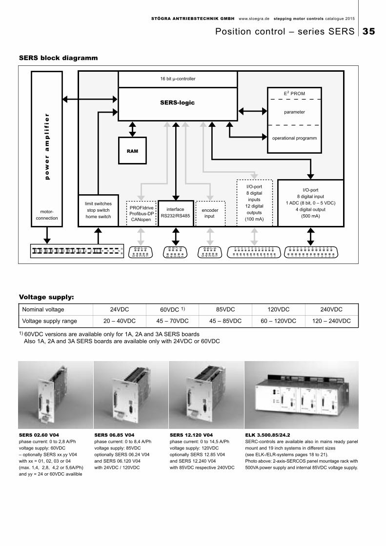
STÖGRA ANTRIEBSTECHNIK GMBH www.stoegra.de stepping motor controls catalogue 2015
Position control – series SERS 35
E2 PROM
parameter
operational programm
I/O-port
8 digital input
1 ADC (8 bit, 0 – 5 VDC)
4 digital output
(500 mA)
encoder
input
I/O-port
8 digital
inputs
12 digital
outputs
(100 mA)
interface
RS232/RS485
limit switches
stop switch
home switchmotor-
connection
po
we
r a
mp
lifi
er
RAM
246810
12
14
16
18
20
22
24
26
28
30
32
c a
5 4 3 2 1
9 8 7 6
5 4 3 2 1
9 8 7 6
1 2 3 4 5 6 7 8 9
10
11
12
13
14
15
16
17
18
19
20
21
22
23
24
25
1 2 3 4 5 6 7 8 9
10
11
12
13
14
15
16
17
18
19
20
21
22
23
24
25
16 bit µ-controller
SERS-logic
5 4 3 2 1
9 8 7 6
PROFIdrive
Profibus-DP
CANopen
SERS block diagramm
Voltage supply:
Nominal voltage 24VDC 60VDC 1) 85VDC 120VDC 240VDC
Voltage supply range 20 – 40VDC 45 – 70VDC 45 – 85VDC 60 – 120VDC 120 – 240VDC
1) 60VDC versions are available only for 1A, 2A and 3A SERS boardsAlso 1A, 2A and 3A SERS boards are available only with 24VDC or 60VDC
ELK 3.500.85/24.2SERC-controls are available also in mains ready panel
mount and 19 inch systems in different sizes
(see ELK-/ELR-systems pages 18 to 21).
Photo above: 2-axis-SERCOS panel mountage rack with
500VA power supply and internal 85VDC voltage supply.
SERS 02.60 V04phase current: 0 to 2,8 A/Ph
voltage supply: 60VDC
– optionally SERS xx.yy V04
with xx = 01, 02, 03 or 04
(max. 1,4, 2,8, 4,2 or 5,6A/Ph)
and yy = 24 or 60VDC availible
SERS 06.85 V04phase current: 0 to 8,4 A/Ph
voltage supply: 85VDC
optionally SERS 06.24 V04
and SERS 06.120 V04
with 24VDC / 120VDC
SERS 12.120 V04phase current: 0 to 14,5 A/Ph
voltage supply: 120VDC
optionally SERS 12.85 V04
and SERS 12.240 V04
with 85VDC respective 240VDC
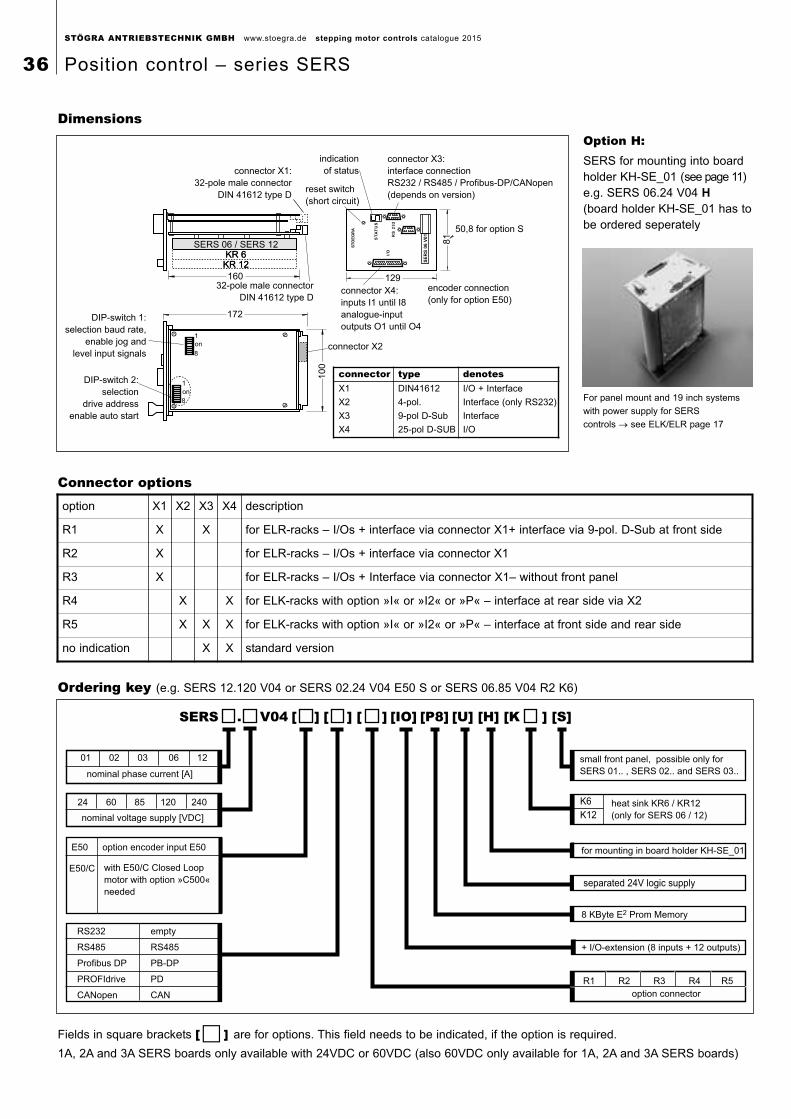
01 02 03 06 12
24 60 85 120 240
nominal phase current [A]
nominal voltage supply [VDC]
option encoder input E50
empty
RS485
PB-DP
PD
CAN
RS232
RS485
Profibus DP
PROFIdrive
CANopen
separated 24V logic supply
K6
K12
heat sink KR6 / KR12
(only for SERS 06 / 12)
for mounting in board holder KH-SE_01
+ I/O-extension (8 inputs + 12 outputs)
option connector
R1 R2 R3 R4 R5
SERS . V04 [ ] ] [ ] [IO] [P8] [U] [H] [K ] [S]
8 KByte E2 Prom Memory
small front panel, possible only for
SERS 01.. , SERS 02.. and SERS 03..
[
E50
with E50/C Closed Loop
motor with option »C500«
needed
E50/C
DIP-switch 1:
selection baud rate,
enable jog and
level input signals
DIP-switch 2:
selection
drive address
enable auto start
connector X1:
32-pole male connector
DIN 41612 type D
32-pole male connector
DIN 41612 type Dconnector X4:
inputs I1 until I8
analogue-input
outputs O1 until O4
connector X2
connector X3:
interface connection
RS232 / RS485 / Profibus-DP/CANopen
(depends on version)
indication
of status
reset switch
(short circuit)
50,8 for option S
encoder connection
(only for option E50)
160
SERS 06 / SERS 12KR 6KR 12
172
129
81
10
0
SERS 06 / SERS 12KR 6KR 12
ST
OE
GR
A
ST
AT
US
RS
23
2
I/O
SE
RS
06 V
01
on
on
1
8
1
8
DimensionsOption H:SERS for mounting into boardholder KH-SE_01 (see page 11)e.g. SERS 06.24 V04 H(board holder KH-SE_01 has tobe ordered seperately
Ordering key (e.g. SERS 12.120 V04 or SERS 02.24 V04 E50 S or SERS 06.85 V04 R2 K6)
Connector options
For panel mount and 19 inch systems
with power supply for SERS
controls → see ELK/ELR page 17
connector type denotesX1 DIN41612 I/O + Interface
X2 4-pol. Interface (only RS232)
X3 9-pol D-Sub Interface
X4 25-pol D-SUB I/O
option X1 X2 X3 X4 description
R1 X X for ELR-racks – I/Os + interface via connector X1+ interface via 9-pol. D-Sub at front side
R2 X for ELR-racks – I/Os + interface via connector X1
R3 X for ELR-racks – I/Os + Interface via connector X1– without front panel
R4 X X for ELK-racks with option »I« or »I2« or »P« – interface at rear side via X2
R5 X X X for ELK-racks with option »I« or »I2« or »P« – interface at front side and rear side
no indication X X standard version
Fields in square brackets [� ] are for options. This field needs to be indicated, if the option is required.
1A, 2A and 3A SERS boards only available with 24VDC or 60VDC (also 60VDC only available for 1A, 2A and 3A SERS boards)
STÖGRA ANTRIEBSTECHNIK GMBH www.stoegra.de stepping motor controls catalogue 2015
36 Position control – series SERS
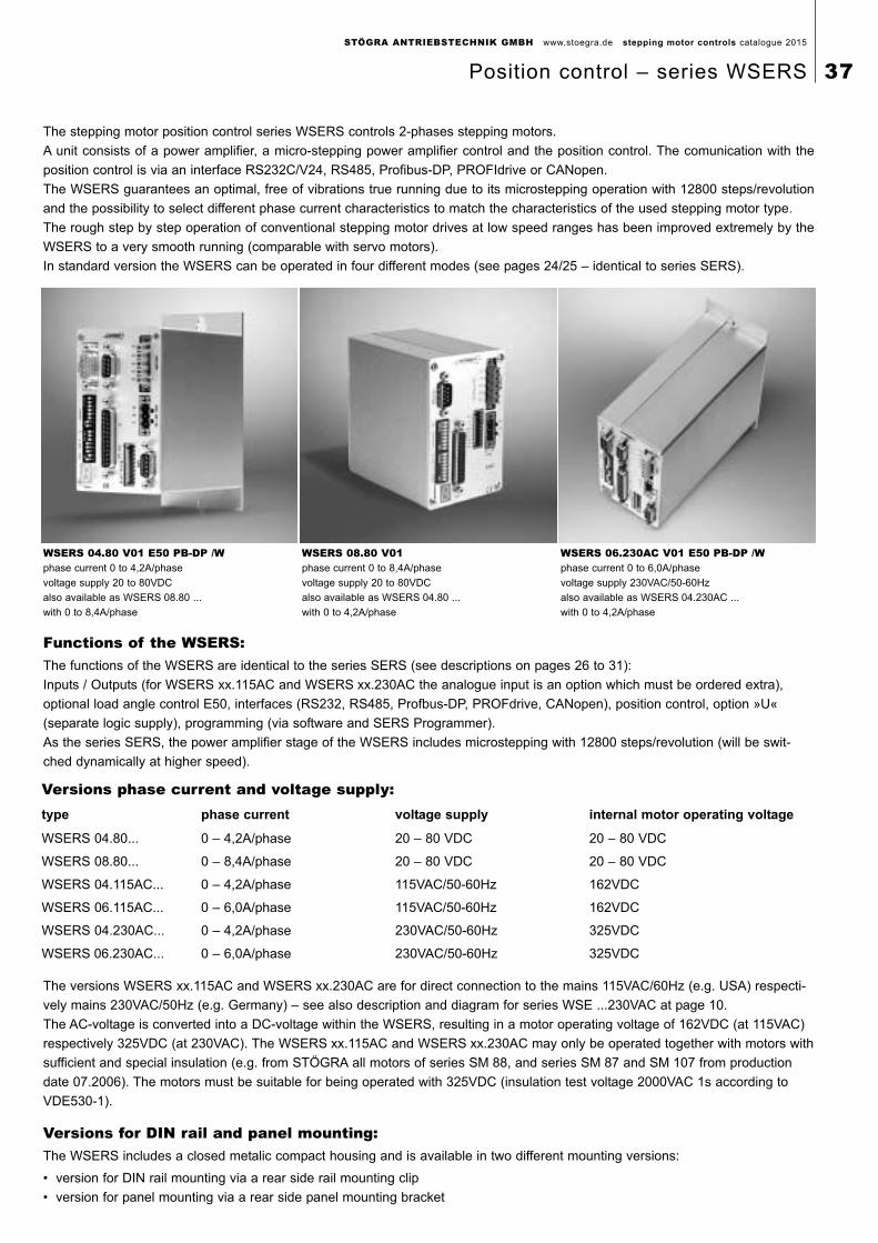
WSERS 04.80 V01 E50 PB-DP /Wphase current 0 to 4,2A/phase
voltage supply 20 to 80VDC
also available as WSERS 08.80 ...
with 0 to 8,4A/phase
WSERS 08.80 V01phase current 0 to 8,4A/phase
voltage supply 20 to 80VDC
also available as WSERS 04.80 ...
with 0 to 4,2A/phase
WSERS 06.230AC V01 E50 PB-DP /Wphase current 0 to 6,0A/phase
voltage supply 230VAC/50-60Hz
also available as WSERS 04.230AC ...
with 0 to 4,2A/phase
The stepping motor position control series WSERS controls 2-phases stepping motors.
A unit consists of a power amplifier, a micro-stepping power amplifier control and the position control. The comunication with the
position control is via an interface RS232C/V24, RS485, Profibus-DP, PROFIdrive or CANopen.
The WSERS guarantees an optimal, free of vibrations true running due to its microstepping operation with 12800 steps/revolution
and the possibility to select different phase current characteristics to match the characteristics of the used stepping motor type.
The rough step by step operation of conventional stepping motor drives at low speed ranges has been improved extremely by the
WSERS to a very smooth running (comparable with servo motors).
In standard version the WSERS can be operated in four different modes (see pages 24/25 – identical to series SERS).
Functions of the WSERS:The functions of the WSERS are identical to the series SERS (see descriptions on pages 26 to 31):
Inputs / Outputs (for WSERS xx.115AC and WSERS xx.230AC the analogue input is an option which must be ordered extra),
optional load angle control E50, interfaces (RS232, RS485, Profbus-DP, PROFdrive, CANopen), position control, option »U«
(separate logic supply), programming (via software and SERS Programmer).
As the series SERS, the power amplifier stage of the WSERS includes microstepping with 12800 steps/revolution (will be swit-
ched dynamically at higher speed).
Versions phase current and voltage supply:type phase current voltage supply internal motor operating voltage
WSERS 04.80... 0 – 4,2A/phase 20 – 80 VDC 20 – 80 VDC
WSERS 08.80... 0 – 8,4A/phase 20 – 80 VDC 20 – 80 VDC
WSERS 04.115AC... 0 – 4,2A/phase 115VAC/50-60Hz 162VDC
WSERS 06.115AC... 0 – 6,0A/phase 115VAC/50-60Hz 162VDC
WSERS 04.230AC... 0 – 4,2A/phase 230VAC/50-60Hz 325VDC
WSERS 06.230AC... 0 – 6,0A/phase 230VAC/50-60Hz 325VDC
The versions WSERS xx.115AC and WSERS xx.230AC are for direct connection to the mains 115VAC/60Hz (e.g. USA) respecti-
vely mains 230VAC/50Hz (e.g. Germany) – see also description and diagram for series WSE ...230VAC at page 10.
The AC-voltage is converted into a DC-voltage within the WSERS, resulting in a motor operating voltage of 162VDC (at 115VAC)
respectively 325VDC (at 230VAC). The WSERS xx.115AC and WSERS xx.230AC may only be operated together with motors with
sufficient and special insulation (e.g. from STÖGRA all motors of series SM 88, and series SM 87 and SM 107 from production
date 07.2006). The motors must be suitable for being operated with 325VDC (insulation test voltage 2000VAC 1s according to
VDE530-1).
Versions for DIN rail and panel mounting:The WSERS includes a closed metalic compact housing and is available in two different mounting versions:
• version for DIN rail mounting via a rear side rail mounting clip
• version for panel mounting via a rear side panel mounting bracket
STÖGRA ANTRIEBSTECHNIK GMBH www.stoegra.de stepping motor controls catalogue 2015
Position control – series WSERS 37
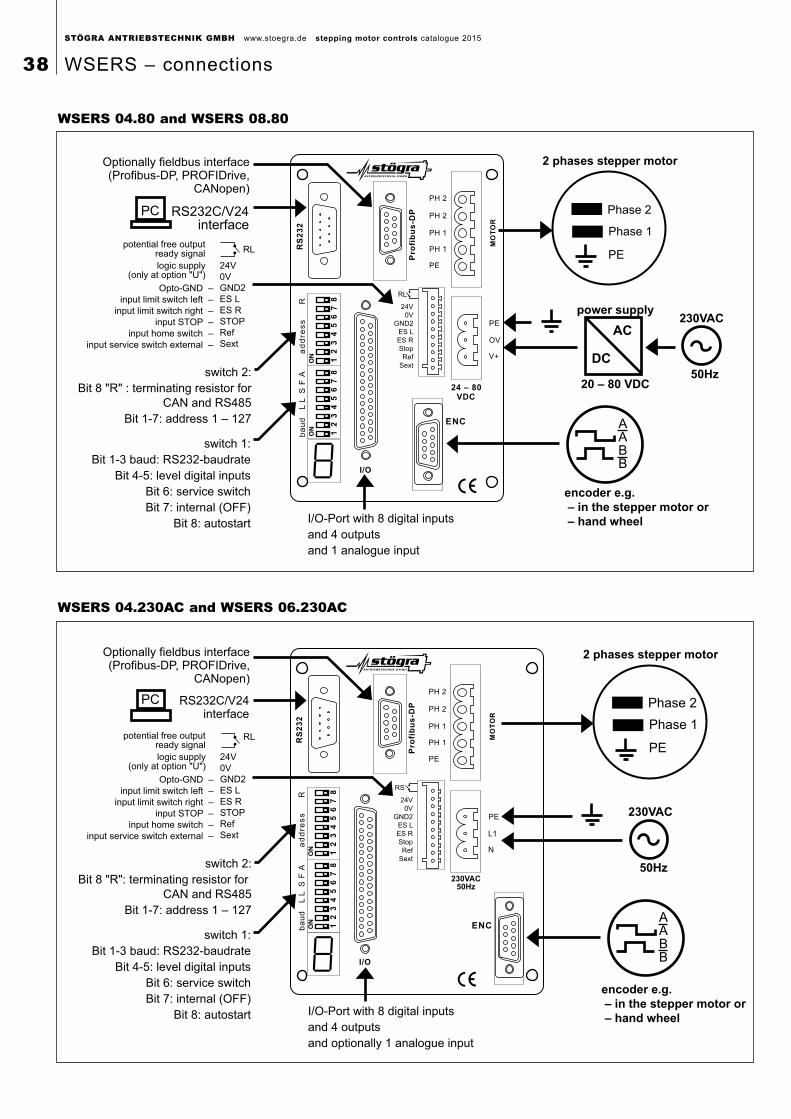
STÖGRA ANTRIEBSTECHNIK GMBH www.stoegra.de stepping motor controls catalogue 2015
38 WSERS – connections
Pro
fib
us
-DP
RS
23
2a
dd
res
sb
au
dL
AS
FL
R
I/O
RL
24V
0V
GND2
ES L
ES R
Stop
Ref
Sext
2 phases stepper motor
Phase 2
Phase 1
PE
AABB
encoder e.g.
– in the stepper motor or
– hand wheel
power supply
20 – 80 VDC
AC
DC
230VAC
50Hz
ON
12
34
56
78
ON
12
34
56
78
RL
logic supply(only at option "U")
24V
0V
GND2
ES L
ES R
STOP
Ref
Sext
potential free outputready signal
Opto-GND –
input limit switch left –
input limit switch right –
input STOP –
input home switch –
input service switch external –
RS232C/V24interface
Optionally fieldbus interface(Profibus-DP, PROFIDrive,
CANopen)
PC
switch 2:
Bit 8 "R" : terminating resistor for
CAN and RS485
Bit 1-7: address 1 – 127
switch 1:
Bit 1-3 baud: RS232-baudrate
Bit 4-5: level digital inputs
Bit 6: service switch
Bit 7: internal (OFF)
Bit 8: autostart I/O-Port with 8 digital inputs
and 4 outputs
and 1 analogue input
WSERS 04.80 and WSERS 08.80
WSERS 04.230AC and WSERS 06.230AC
RS
23
2a
dd
res
sb
au
dL
AS
Pro
fib
us
-DP
FL
R
I/O
RS
24V
0V
GND2
ES L
ES R
Stop
Ref
Sext
2 phases stepper motor
Phase 2
Phase 1
PE
AABB
encoder e.g.
– in the stepper motor or
– hand wheel
230VAC
50Hz
L1
N
230VAC50Hz
ON
12
34
56
78
ON
12
34
56
78
RL
logic supply(only at option "U")
24V
0V
GND2
ES L
ES R
STOP
Ref
Sext
potential free outputready signal
Opto-GND –
input limit switch left –
input limit switch right –
input STOP –
input home switch –
input service switch external –
RS232C/V24interface
Optionally fieldbus interface(Profibus-DP, PROFIDrive,
CANopen)
PC
switch 2:
Bit 8 "R": terminating resistor for
CAN and RS485
Bit 1-7: address 1 – 127
switch 1:
Bit 1-3 baud: RS232-baudrate
Bit 4-5: level digital inputs
Bit 6: service switch
Bit 7: internal (OFF)
Bit 8: autostart I/O-Port with 8 digital inputs
and 4 outputs
and optionally 1 analogue input
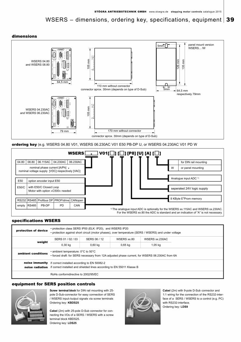
STÖGRA ANTRIEBSTECHNIK GMBH www.stoegra.de stepping motor controls catalogue 2015
WSERS – dimensions, ordering key, specifications, equipment 39
specifications WSERS
equipment for SERS position controlsScrew terminal block for DIN rail mounting with 25-
pole D-Sub-connector for easy connection of SERS
/ WSERS input-/output signals via screw terminals
Ordering key: KBDS25
Cabel (2m) with 25-pole D-Sub connector for con-
necting the I/Os of a SERS / WSERS with a screw
terminal block KBDS25.
Ordering key: LDS25
Cabel (2m) with 9-pole D-Sub connector and
1:1 wiring for the connection of the RS232-inter-
face of a SERS / WSERS to a control (e.g. PC)
with RS232-interface.
Ordering key: LDS9
protection of device• protection class SERS IP00 (ELK: IP20), and WSERS IP20
• protection against short circuit (motor phases), over temperature (SERS / WSERS) and under voltage
weightSERS 01 / 02 / 03 SERS 06 / 12 WSERS xx.80 WSERS xx.230AC
0,30 kg 0,60 kg 0,65 kg 1,05 kg
ambient conditions• ambient temperature: 0°C to 50°C
• forced draft: for SERS necessary from 12A adjusted phase current, for WSERS 06.230AC from 6A
noise immunitynoise radiation
if correct installed according to EN 50082-2
if correct installed and shielded lines according to EN 55011 Klasse B
RoHs conformdirective to 2002/95/EC
seperated 24V logic supply
W or panel mounting
WSERS V01[ ] [ ] [P8] [U] [A] [ ]
8 KByte E2Prom memory
for DIN rail mounting04.80 08.80 06.115AC 04.230AC 06.230AC
.
nominal phase current [A/Ph] .nominal voltage supply [VDC] respectively [VAC]
RS232 RS485 Profibus DP PROFIdrive CANopen
empty RS485 PB-DP PD CAN
Analogue input ADC 1)
1) The analogue input ADC is optionally for the WSERS xx.115AC and WSERS xx.230AC.
For the WSERS xx.80 the ADC is standard and an indication of ”A” is not necessary.
option encoder input E50E50
with E50/C Closed Loop
Motor with option »C500« needed
E50/C
ordering key (e.g. WSERS 04.80 V01, WSERS 06.230AC V01 E50 PB-DP U, or WSERS 04.230AC V01 PD W
64,5 mm
110 mm without connector
connector aprox. 30mm (depends on type of D-Sub)1
05
mm
Pro
fib
us
-DP
RS
23
2a
dd
res
sb
au
dL
AS
FL
R
I/O
RS
24V
0V
GND2
ES L
ES R
Stop
Ref
Sext
WSERS 04.80
and WSERS 08.80
79 mm 170 mm without connector
connector aprox. 30mm (depends on type of D-Sub)
10
5 m
m
Pro
fib
us
-DP
RS
23
2a
dd
res
sb
au
dL
AS
FL
R
I/O
RS
24V
0V
GND2
ES L
ES R
Stop
Ref
Sext
WSERS 04.230AC
and WSERS 06.230AC
230VAC/
50Hz
L1
N
13
5 m
m
panel mount version
WSERS... /W
64,5 mm
respectively 79mm
5mm
5mm
12
6 m
m
dimensions
STÖGRA ANTRIEBSTECHNIK GMBH
Machtlfinger Strasse 24
D-81379 München
Tel ++49-89-15 90 40 00
Fax ++49-89-15 90 40 09
E-Mail [email protected]
Internet http: //www.stoegra .de
presented by:
Lindau
A96 A94
A995A95
A8
A8
A9
Autobahnausfahrt
M-Kreuzhof
Drygalski
Allee
Machtlfinger Strasse
München
Zentrum
Mittlerer Ring
Mittlerer Ring
Boschetsrieder Strasse
Isar
Fürstenrieder Strasse
Salzburg
Passau
NürnbergStuttgard
Salzburg/
Kufstein
Garmisch-
Partenkirchen