stepping into augmented reality
TRANSCRIPT

Stepping into Augmented Reality
1a Eman R. Elbasiouny, 1b T. Medhat, 2 Amany Sarhan, 2c Tarek E. Eltobely 1 Computer and Control Department, Faculty of Engineering,
Kafrelsheikh University, 33516, Kafrelsheikh, Egypt, a E-mail: [email protected]
b E-mail: [email protected] 2 Computer and Control Department, Faculty of Engineering,
Tanta University, 31521, Tanta, Egypt, c E-mail: [email protected]
Abstract
This paper surveys AR (Augmented Reality) technology from various perspectives and it contains all the researcher needs to know when he starts searching in that topic. We present the ideal characteristics which realize an ultimate AR system. Basic components of AR system containing output components (vision, audition, touch, smell and taste), input components (video camera, tracking, registration and interaction interfaces) and software (the most commonly used toolkits) are highlighted in a great detail. Applications involving medicine, learning, manufacturing, annotation and robot path planning are also discussed. Finally, registration problem which is the greatest impediment faces most of AR applications is showed with some previous solutions. Keywords: Components of AR, Applications of AR, Registration Problem and Previous Solutions. 1. Introduction AR is a technology in which a user‘s view of the real world is enhanced or augmented with additional information generated by a computer, such as computer graphics, text, sound and other modalities. It seeks to integrate the computer models or computer-generated information with the live behavior environment captured with a movable video camera, as shown in Fig. 1. Using AR technology, users may therefore interact with a mixed virtual and real world in a natural way. Azuma [1] has defined three characteristics that are integral to an augmented reality interface. Firstly, it combines the real and the virtual. Secondly, it is interactive in real time. Third, it is registered in three dimensions.
Fig. 1. A user can watch both real and virtual worlds by overlaying virtual objects onto images. Users see a mixed world [2].
The term 'virtual reality' (VR) was defined as ―a computer generated, interactive, three-dimensional environment in which a person is immersed‖ as mentioned in [3]. Augmented reality is similar to virtual reality in the sense that both make use of computer generated virtual data. On the other hand, augmented reality differs from virtual reality in that it does not try to block the surrounding real environment from user. Instead its purpose is to enrich the perceived reality with additional visual information. In other words, we can say that VR totally immerses the user in a virtual world and AR partially immerses the user in the virtual world while maintaining his sense of presence in the real world.

AR has a comparative advantage over VR as the existing environment provides the background for the augmented entities, and the user needs only to create the virtual objects that will be integrated into that background [4]. This can significantly reduce the effort and time required for creating, rendering, and updating the computer-generated graphical content of the scene. However, the fact that in an AR scene virtual and real objects are both present at the same time introduces the critical challenge of precise virtual object alignment such that they are perceived as authentic by the user‘s mind. Therefore, there are always some distracting features, such as the time-lag between user actions and systems reactions, misplaced or disoriented virtual objects due to tracking errors, and abnormalities in the object-interactions, which tend to diminish the immersiveness of the system. The real-time requirements of augmented reality are even stricter than those of typical virtual reality applications. As shown in [3], Milgram introduced a taxonomy that relates augmented reality to virtual reality as different degrees of reality-virtuality continuum. Reality-virtuality continuum is shown in Fig. 2. In the left end of the reality-virtuality continuum is the real environment. A completely immersive virtual environment is in the other end. Augmented reality is near the real environment end, as it consists of some synthetic elements that overlap the actual real environment. The inverse case where real world content contributes to synthetic surroundings would be called augmented virtuality. Milgram also considered augmented reality and augmented virtuality as different levels of the broader concept of mixed reality, even though the term augmented reality has become quite popular in literature.
Fig. 2. Simplified representation of Milgram‘s Reality-Virtuality continuum [5].
In the following, we present the ultimate performance goals for obtaining an ideal AR system (section 2), basic components that are required to implement a typical AR application (section 3), the most common AR applications (section 4) and registration problems that face most of AR applications and some previous solutions (section 5). 2. Performance Goals Linking the physical and digital worlds is a long standing goal of AR. But the ultimate goal is to create a system such that the user can not tell the difference between the real world and the virtual augmentation of it and it would appear that he is working in a single real environment. Current and future applications help to shape the requirements specification for an interactive augmented reality system. Some applications will not demand an ―ultimate‖ augmented reality system. An augmented reality system with a high degree of verisimilitude and utility will possess the following ideal characteristics: Perfect augmented scene in the static case
To realize an ideal static registration, the following characteristics must be considered: - When a virtual object has been placed at a location in the real scene it should appear in
the position expected by the user and remained at that same position in 3D space when viewed from different viewpoints unless an object has interacted with it [6].

- Visual occlusions between virtual and real objects must occur correctly. This is not only for virtual objects occluding real ones, but also for the more difficult case of real objects occluding virtual ones. Focus can be a problem for different AR visualization approaches [1]. A comprehensible visualization for AR scene is presented by Denis Kalkofen et. al. in [7] which used focus and context (F+C) visualization technique.
- The brightness of real and virtual objects should be appropriately matched [1]. - Correct lighting is an essential part of generating virtual objects with convincing shading.
It is therefore important to properly model the lighting of a real environment and project it onto the virtual objects. It is equally important and difficult to modify the shading of real objects within the video stream with virtual light sources [8].
Perfect augmented scene in the dynamic case The system design should minimize the dynamic errors – which are caused by the graphical augmentation being out of synchronization with the real-world scene – within the requirements for real-time performance. When the user interacts with a virtual object it should move with the same dynamic behavior that an equivalent real object would exhibit. This includes correctly rebounding from collisions between virtual objects or between virtual and real objects [6]. Unconstrained motion within the workspace Some AR applications support a user who will walk around a large environment. In such case the system should allow the user to move without constraints or limitations. If the AR system becomes portable, many more applications that have not been tried will become available. For example, the ability to annotate the surrounding environment could be useful to soldiers, hikers, or tourists in an unfamiliar new location [1].
Perfect registration of visual and haptic scenes This can be phrased as WYSIWYF or ―What you see is what you feel.‖ The user should feel the surface of a virtual object at the same time and in the same place that the augmented view shows the contact [6]. Minimal prior calibration or run-time setup is required To determine the location of the viewer many augmented reality systems require calibration of the video camera viewing the scene and performing extensive setup such as measurement of the locations of fiducials, or complicated procedures for placing objects into the scene. This calibration process is tedious to perform and will often limit the operation [6].
3. Components of AR System
3.1 Output Components
Output components are responsible for the presentation of the virtual environment and its phenomena – which are perceived by the five senses – to the user. Therefore, it is preferred to use a particular output device for each of the human senses. 3.1.1 Vision Human vision provides the most of information passed to our brain and captures most of our attention [9]. So a basic design decision in building an AR system is how to accomplish the visual combining of real and virtual. AR is not necessarily limited to a certain type of display technology. There are more forms of visual displays available to choose from. 3.1.1.1 See-through HMD In contrast to the closed-view Head-Mounted Display (HMD) – which is used in VR applications – "see-through" designation comes from the need for the user to be able see the real world view [10]. The HMD must be tracked because this allows for computing system to register the virtual information in

its correct position in the physical world [11]. HMD devices are mainly divided into two categories: optical see-through and video see-through. Optical see-through HMDs work by placing optical combiners in front of the user's eyes. These combiners are partially transparent, so that the user can look directly through them to see the real world. The combiners are also partially reflective, so that the user sees virtual images bounced off the combiners from head-mounted monitors. The optical combiners either reduce the amount of light that the user sees from the real world or might be set to reflect all light of a certain wavelength and none at any other wavelengths. Fig. 3 shows an optical see-through HMD and its conceptual diagram.
Fig. 3. Optical see-through HMD and its conceptual diagram [1].
In contrast, video see-through HMDs work by combining a closed-view HMD with one or two head-mounted video cameras. The video cameras provide the user's view of the real world. Video from these cameras is combined with the graphic images created by the scene generator, blending the real and virtual. The result is sent to the monitors in front of the user's eyes in the closed-view HMD. Video composition can be done by either chroma-keying technique or depth-information technique [1]. Fig. 4 shows a video see-through HMD and its conceptual diagram.
Fig. 4. Video see-through HMD [6] and its conceptual diagram [1].
The advantages and disadvantages of each type are discussed in greater detail by Azuma [1]. 3.1.1.2 Monitor-based Display The simplest augmented reality system is the so called ―Window on the World‖ system (WoW) [3]. In this case [1], one or two video cameras view the environment. The video of the real world and the graphic images generated by a scene generator are combined, just as in the video see-through HMD case, and displayed in a monitor in front of the user. The user does not wear the display device. Optionally, the images may be displayed in stereo on the monitor, which then requires the user to wear a pair of stereo glasses. The user has little feeling of being immersed in the environment created by the display. Fig. 5 shows a monitor-based display and its conceptual diagram.
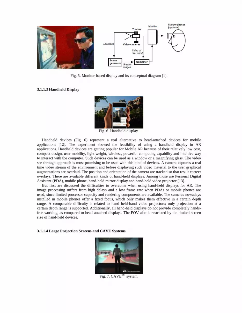
Fig. 5. Monitor-based display and its conceptual diagram [1].
3.1.1.3 Handheld Display
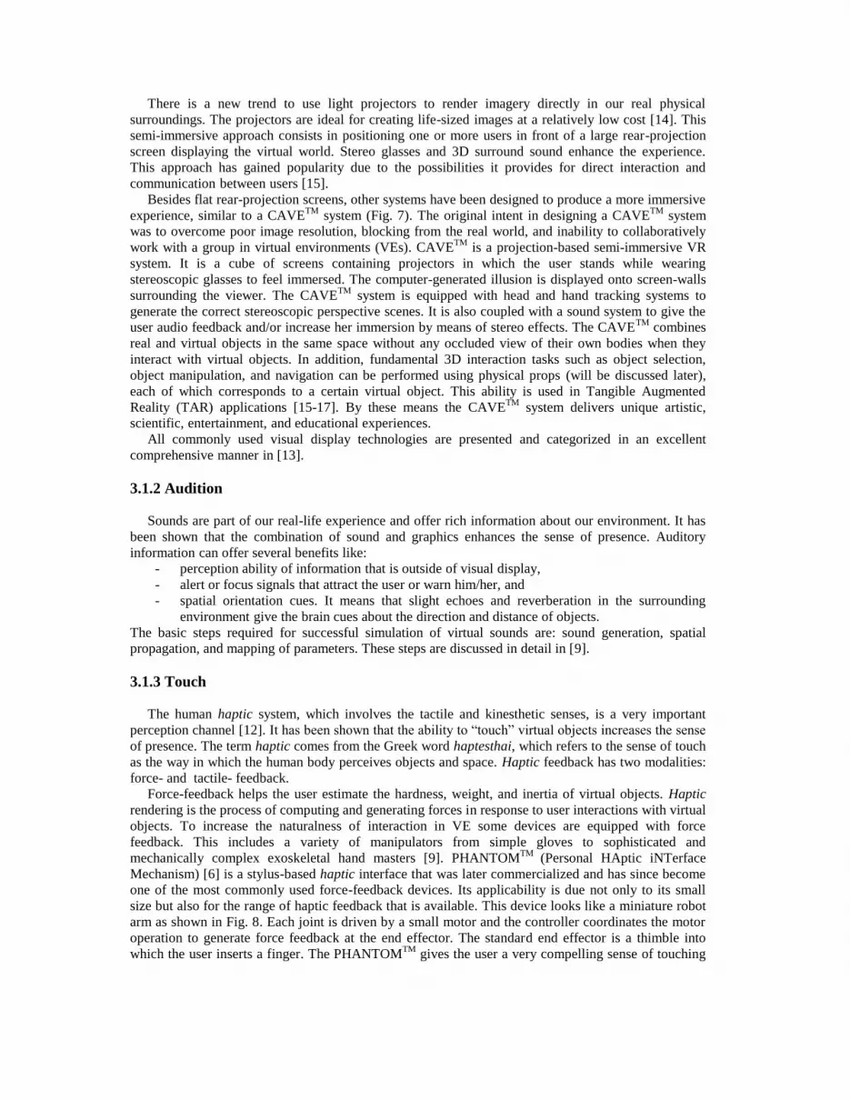
Fig. 6. Handheld display.
Handheld devices (Fig. 6) represent a real alternative to head-attached devices for mobile applications [12]. The experiment showed the feasibility of using a handheld display in AR applications. Handheld devices are getting popular for Mobile AR because of their relatively low cost, compact design, user mobility, light weight, wireless, powerful computing capability and intuitive way to interact with the computer. Such devices can be used as a window or a magnifying glass. The video see-through approach is most promising to be used with this kind of devices. A camera captures a real time video stream of the environment and before displaying such video material to the user graphical augmentations are overlaid. The position and orientation of the camera are tracked so that result correct overlays. There are available different kinds of hand-held displays. Among those are Personal Digital Assistant (PDA), mobile phone, hand-held mirror display and hand-held video projector [13]. But first are discussed the difficulties to overcome when using hand-held displays for AR. The image processing suffers from high delays and a low frame rate when PDAs or mobile phones are used, since limited processor capacity and rendering components are available. The cameras nowadays installed in mobile phones offer a fixed focus, which only makes them effective in a certain depth range. A comparable difficulty is related to hand held-hand video projectors; only projection at a certain depth range is supported. Additionally, all hand-held displays do not provide completely hands-free working, as compared to head-attached displays. The FOV also is restricted by the limited screen size of hand-held devices. 3.1.1.4 Large Projection Screens and CAVE Systems
Fig. 7. CAVETM system.
There is a new trend to use light projectors to render imagery directly in our real physical surroundings. The projectors are ideal for creating life-sized images at a relatively low cost [14]. This semi-immersive approach consists in positioning one or more users in front of a large rear-projection screen displaying the virtual world. Stereo glasses and 3D surround sound enhance the experience. This approach has gained popularity due to the possibilities it provides for direct interaction and communication between users [15]. Besides flat rear-projection screens, other systems have been designed to produce a more immersive experience, similar to a CAVETM system (Fig. 7). The original intent in designing a CAVETM system was to overcome poor image resolution, blocking from the real world, and inability to collaboratively work with a group in virtual environments (VEs). CAVETM is a projection-based semi-immersive VR system. It is a cube of screens containing projectors in which the user stands while wearing stereoscopic glasses to feel immersed. The computer-generated illusion is displayed onto screen-walls surrounding the viewer. The CAVETM system is equipped with head and hand tracking systems to generate the correct stereoscopic perspective scenes. It is also coupled with a sound system to give the user audio feedback and/or increase her immersion by means of stereo effects. The CAVETM combines real and virtual objects in the same space without any occluded view of their own bodies when they interact with virtual objects. In addition, fundamental 3D interaction tasks such as object selection, object manipulation, and navigation can be performed using physical props (will be discussed later), each of which corresponds to a certain virtual object. This ability is used in Tangible Augmented Reality (TAR) applications [15-17]. By these means the CAVETM system delivers unique artistic, scientific, entertainment, and educational experiences. All commonly used visual display technologies are presented and categorized in an excellent comprehensive manner in [13]. 3.1.2 Audition Sounds are part of our real-life experience and offer rich information about our environment. It has been shown that the combination of sound and graphics enhances the sense of presence. Auditory information can offer several benefits like:
- perception ability of information that is outside of visual display, - alert or focus signals that attract the user or warn him/her, and - spatial orientation cues. It means that slight echoes and reverberation in the surrounding
environment give the brain cues about the direction and distance of objects. The basic steps required for successful simulation of virtual sounds are: sound generation, spatial propagation, and mapping of parameters. These steps are discussed in detail in [9]. 3.1.3 Touch The human haptic system, which involves the tactile and kinesthetic senses, is a very important perception channel [12]. It has been shown that the ability to ―touch‖ virtual objects increases the sense of presence. The term haptic comes from the Greek word haptesthai, which refers to the sense of touch as the way in which the human body perceives objects and space. Haptic feedback has two modalities: force- and tactile- feedback. Force-feedback helps the user estimate the hardness, weight, and inertia of virtual objects. Haptic rendering is the process of computing and generating forces in response to user interactions with virtual objects. To increase the naturalness of interaction in VE some devices are equipped with force feedback. This includes a variety of manipulators from simple gloves to sophisticated and mechanically complex exoskeletal hand masters [9]. PHANTOMTM (Personal HAptic iNTerface Mechanism) [6] is a stylus-based haptic interface that was later commercialized and has since become one of the most commonly used force-feedback devices. Its applicability is due not only to its small size but also for the range of haptic feedback that is available. This device looks like a miniature robot arm as shown in Fig. 8. Each joint is driven by a small motor and the controller coordinates the motor operation to generate force feedback at the end effector. The standard end effector is a thimble into which the user inserts a finger. The PHANTOMTM gives the user a very compelling sense of touching

these virtual objects. Mass can be assigned to the objects so if the user places his finger under an object and lifts, the weight of the object is felt resting on the finger.
Fig. 8. PHANTOMTM haptic interface [6].
Tactile feedback provides a feel of the object‘s surface contact geometry, smoothness, temperature, etc [9]. Tactile feedback is much more subtle than force-feedback and therefore more difficult to generate artificially. Tactile displays can be classified into three types of stimulation: electrotactile, thermal, and mechanical. They are mentioned in detail in [12]. Some devices, like Immersion‘s CyberTouchTM (Fig. 9a) and CyberGraspTM (Fig. 9b), can also provide vibrotactile and force-feedback, respectively.
(a) CyberTouchTM (b) CyberGraspTM
Fig. 9. Data gloves for touch and force-feedback [12]. 3.1.4 Smell It is commonly accepted that smells influence how we act and feel. The sense of smell can stimulate the memorization of concepts or experiences. Smell interfaces are also called olfactory displays [12]. Olfactory displays have been mainly used to provide alerts and notifications. In general, an olfactory display consists of a palette of odorants, a flow-delivery system, and a control algorithm that determines the mixing ratios, concentration, and timing of the stimulus. For example, a system has a spice rack with sensors attached to each spice jar was linked to a set of spray guns at a remote location. Whenever a jar was removed from the rack, the corresponding essential oil was released at the remote location, conveying some kind of sense of presence. It was reported that some scent combinations were rather unpleasant. This is an important issue to consider. Mixing smells is much more complex than mixing colors.

3.1.5 Taste The sense of taste is the result of a complex interaction between multiple sensory mechanisms: whenever food is placed in the mouth, different types of sensory fiber that monitor several food attributes such as texture, temperature, and odor are activated [12]. Humans can distinguish five major taste classes: sweet, sour, bitter, salty, and umami, a savory flavor exemplified by the amino acid glutamate. The sense of taste has never been directly addressed in VR or AR systems. This is still an unexplored research area. Very few examples of what we call ―taste interfaces‖ could be found in the scientific literature. The ―food simulator‖ developed by Iwata et. al. [18] is an example of an interaction device that addresses the sense of taste. 3.2 Input Components Input components are responsible for interaction and determine the way a user communicates with the virtual objects. Ideally all these devices together, should make user‘s environment control as intuitive and natural as possible. Basic input requirements are mentioned below. 3.2.1 Live Input: video camera The first required interface that must be implemented exists between the computing system and external environment. There must be a method of obtaining continuous visual images of the user‘s environment, which is ultimately integrated with the virtual images to produce the final, augmented view. The two most critical factors in the selection of a video camera were the resolution of the video images, and the speed with which the images are transmitted to the video compositor engine, so that they can be augmented and displayed to the user in real-time [4]. In order to get proper position and orientation data regarding real objects, we must consider the camera properties [15], because proper position and orientation are calculated based on the image frame grabbed by the camera. Camera model
Most video cameras used in AR systems are of a perspective or pinhole type. Otherwise, the user would see the augmented view as the same size regardless of distance. The transformation from 3D world coordinates to camera pixel coordinates is performed, and all 3D images within the view frame are projected to the 2D plane, with characteristics of the perspective projection as follows: 1. As Fig. 10 shows, the view volume is typically shaped like a frustum or truncated
pyramid, the viewing frustum consisting of six planes. The frustum's apex is at the eye, and thus the camera, too, has this eye position.
2. Two planes of the frustum are set up perpendicular to the axis. We call these two planes the near and the far plane. Thus, the camera can recognize objects between two planes. 3. The view angle is set by opening the frustum. The distance between the image plane and the apex of the frustum is referred to as the focal length. 4. All points inside the view volume are projected onto the image plane. For example, there is some point P = [X, Y, Z] inside the frustum, and we can think of the image plane as a 2D image onto which P is projected. If the focal length is marked as f, then we can have an equation, denoted by x = f (X/ Z) y = f (Y/ Z) to establish a point P' = [x, y] on the 2D projection plane.

Fig. 10. 3D View Volume. Camera calibration
To represent virtual objects properly in the real scene, AR systems should calibrate the camera with intrinsic and extrinsic parameters. User would certainly get very disoriented if virtual objects would be floating in front of real objects but yet they would feel to be further away. Faulty camera parameters also undermine chances for successful occlusion detection [3]. Camera calibration involves the numerical calculation of both types of parameters for each camera.
1. Intrinsic parameters The intrinsic parameters are about how the camera will convert objects within the camera's field of view into an image, and they are independent on position and orientation. The intrinsic parameters are related to the internal geometry of the camera: for example, the focal length, the center position in the pixel image, and the pixel size of the resolution. 2. Extrinsic parameters The extrinsic parameters are related to the external properties of the camera, such as camera position and camera orientation in space. These parameters uniquely identify the transformation between the unknown camera coordinate system and the known world coordinate system. Using these extrinsic parameters, we can define a transformation matrix, which consists of a 3x3 rotation matrix and a 3D translation vector.
Dennis [13] presented a more detailed explanation of camera calibration. If the AR system doesn't require camera calibration, it is considered a great advantage of that system [6].
Robert examined three camera hardware options and showed the findings of his examination in detail in [19]. The three hardware options are:
a) Unibrain Fire-i IEEE 1396 camera Unibrain‘s Fire-i camera (Fig. 11) is a CCD (Charge Coupled Device) sensor based firewire digital camera which is marketed for home and office use. The camera delivers sharp and clear images, and very fast frame rates, allowing to capture VGA resolution video (640x480 pixels) at the rate of 30 frames per second. The video stream is provided to the computer at 400 Mbps through the IEEE 1394a port. This camera captures scenes from the landscape within a 42o horizontal and a 32o vertical view angle [4]. This type is used in [4], [13], [19] and [20].
Fig. 11. Unibrain Fire-I camera.

b) Logitech QuickCam Pro 4000 USB2 camera
The Logitech QuickCam Pro 4000 (pictured Fig. 12) was used as an alternative video source during the development of the prototype. This CCD sensor based webcam class camera captures at the maximum resolution of 640 x 480 pixels (VGA) with 30 fps framerate. The interface used is USB2.0, power is provided to the camera from the computer‘s USB port. Logitech performed well, but the Unibrain Fire-I camera‘s output in the same lighting conditions was (in authors subjective opinion) visually sharper, with less motion blurring, which can be possibly attributed to faster transfer rates of the FireWire interface, or to better responsiveness of the Fire-I‘s CCD sensor.
Fig. 12. Logitech QuickCam Pro 4000 camera.
c) Belkin USB2.0 Digitizer + Miniature Analog CMOS camera
Another hardware alternative that was briefly considered was a combination of an analog CMOS camera mounted on the HMD and a video digitizer. Potential advantages of such configuration are the ability to use smaller sized analog cameras and more flexibility with prototyping, since any number of analog cameras providing NTSC video signal may be evaluated without any modification of the other system components (camera drivers etc). Miniaturized analog surveillance cameras can be used, which can be potentially easier to integrate with the HMD or helmet. This configuration was found to be slightly inferior to the Fire-I and QuickCam options in terms of video capture speed and image quality and contrast (inferior contrast can be possibly attributed to the camera‘s CMOS sensor quality).
In [13], the authors used IR (Infrared) camera to detect the invisible markers and determine the position and orientation of the markers. 3.2.2 Tracking Every AR application has to detect and calculate the position and orientation of the user's head (or the camera) relative to the entities in the real world scene continuously. Additionally other parts of body may be tracked e.g., hands – to allow interaction, chest or legs. Three-dimensional objects have six degrees of freedom (DOF): position coordinates (x, y and z offsets) and orientation (yaw, pitch and roll angles for example). Tracking is significantly more difficult in AR than in VR because greater precision is required and the latency can not be tolerated. In AR, without accurate tracking the virtual objects will not be drawn in the correct location and the correct time, ruining the illusion that they coexist with the real objects. The most important properties of 6DOF trackers [9], to be considered for choosing the right device for the given application are: Update rate – defines how many measurements per second (measured in Hz) are made.
Higher update rate values support smoother tracking of movements, but require more processing. The tracking rate must be not less than 10 frames per second to ensure accurate augmented scene. Latency – the amount of time (usually measured in ms) between the user‘s real (physical) action and the beginning of transmission of the report that represents this action. Lower values contribute to better performance.

Accuracy – the measure of error in the reported position and orientation. Defined generally in absolute values (e.g., in mm for position, or in degrees for orientation). Smaller values mean better accuracy. Range – working volume, within which the tracker can measure position and orientation with its specified accuracy and resolution, and the angular coverage of the tracker.
Beside these properties, some other aspects cannot be forgotten like the ease of use, size and weight etc. of the device. These characteristics will be further used to determine the quality and usefulness of different kinds of trackers. In general, tracking methods can be divided into two types: sensor-based and vision-based. 3.2.2.1 Sensor-based Tracking Sensor-based methods use not only the cameras, but also special sensors to determine the relationships between the viewer (or the camera), the display and the real world [21].
Magnetic tracker A magnetic tracker is a position measurement device that uses a magnetic field produced by a stationary transmitter to determine the real-time position of a moving receiver element. It consists of: a static part (emitter, sometimes called a source), a number of movable parts (receivers, sometimes called sensors), and a control station unit [9]. The assembly of emitter and receiver is very similar: they both consist of three mutually perpendicular antennae. As the antennae of the emitter are provided with current, they generate magnetic fields that are picked up by the antennae of the receiver. The receiver sends its measurements to the control unit that calculates position and orientation of the given sensor. There are two kinds of magnetic trackers that use either alternating current (AC) or direct current (DC) to generate magnetic fields as the communication medium [22]. Magnetic tracking devices are not feasible for all AR applications because of [8]: (a) inaccuracy measurement, (b) their limited range (3–5m), (c) interference with ferromagnetic objects of the environment, (d) their lack of portability, and (e) requires more initial calibration.
Acoustic (ultrasonic) tracker An ultrasonic tracker is a position measurement device that uses an ultrasonic signal produced by a stationary transmitter to determine the real-time position of a moving receiver element. Ultrasonic trackers have three components, a transmitter, a receiver, and an electronic unit, similar to their magnetic counterparts. The difference is that the transmitter is a set of three ultrasonic speakers and the receiver is a set of three microphones. Due to their simplicity, ultrasonic trackers represent a cheaper alternative to the magnetic ones [22]. It is not commonly used in AR applications because of [9]: (a) inaccuracy, (b) suffer from acoustic interference – noise or echoes may lead to inaccurate measurements, (c) low update rates, and (d) line-of-sight restriction. Mechanical tracker A mechanical tracker consists of a serial or parallel kinematic structure composed of links interconnected using sensorized joints. The dimensions of each link segment are known a priori and used by the direct kinematics computational models stored in the computer. This model allows the determination of the position and orientation of one end of the mechanical tracker relative to the other, based on the real-time reading of the tracker joint sensors. By attaching one end of the tracker to the desk or floor and the other to an object, the computer can track the object's 3D position relative to the fixed end of the arm [22]. It is not commonly used because of [9]: (a) not full freedom of movements due to the mechanical linkage, and (b) small working volume (about one cubic meter).

Inertial tracker Inertial tracker is a self-contained sensor that measures the rate of change in an object orientation. It may also measure the rate of change of an object translation velocity [22]. Inertial sensors have no range limitations, no line-of sight requirements, and no risk of interference from any magnetic or acoustic interference sources. They can be sampled as fast as desired, and provide relatively high-bandwidth motion measurement with negligible latency. Even tiny low-cost MEMS inertial sensors measure motion with very low noise resulting in jitter-free tracking which looks very smooth to the eye. Unfortunately, any slight inertial sensor bias or noise, when integrated over time, will cause the orientation and position outputs to gradually drift. Thus, inertial sensors must be at least occasionally corrected by other sensors in a hybrid or aided-inertial tracking configuration [23]. Optical tracker An optical tracker is a noncontact position measurement device that uses optical sensing to determine the real-time position/orientation of an object [22]. Similar to ultrasonic trackers, optical trackers work through triangulation, require direct line-of-sight, and are immune to metal interference. Optical trackers, however, offer significant advantages over their ultrasonic counterparts. Their update rates are much higher and their latency is smaller than those of ultrasonic because light (whether visible or infrared) travels much faster than sound. They are also capable of (much) larger work envelopers. If the tracker sensing component (charge-coupled device [CCD] camera, photodiode or other photo sensor) is fixed and some light beacons are placed on the user the tracker is said to be outside-looking-in. By contrast, an inside-looking-out has the camera(s) attached to the tracked object or user. The two paradigms are explained in more detail in [22]. From another perspective, Optical trackers can be classified based on type of markers into: passive and active systems [12]. Passive optical systems [24] use markers coated with a retroreflective material to reflect light back that is generated near the cameras lens. The camera‘s sensitivity can be adjusted, taking advantage of most cameras‘ narrow range of sensitivity to light so that only the bright markers will be sampled, ignoring skin and fabric. In active optical systems [25], rather than reflecting light back that is generated externally, the markers themselves are powered to emit their own light. The optical trackers can be integrated with other tracking types, such as magnetic [26] and inertial [23] trackers. S. De Amici et. al. [27] presented a wii remote-based infrared-optical tracking system. The optical tracking systems have some drawbacks [9], such as: (a) line-of-sight restriction, (b) ambient light and infrared radiation may influence the performance, (c) expensive and very often complicated construction, (d) difficulties to track more than one object in one volume. 3.2.1.2 Vision-based Tracking Sensor-based methods do lack in either accuracy, robustness, range, drift or noise sensitivity [24]. Furthermore, there are practical limitations on the use of sensors, such as a user‘s limited area of movement and perturbation caused by the environment [2]. Computer vision has the potential to yield noninvasive, accurate, and low cost solutions [12] without the need of any additional sensors. The relationship between the camera position, the real world and the virtual computer-generated objects is computed directly from the image sequences [21]. Different methods with variable degrees of accuracy and robustness can be applied. Marker-based tracking Camera tracking systems based on placing fiducial markers in the scene have been highly successful. Markers are constructed so that they are easily detected in each image frame and given some a priori information about the shapes or positions of the markers, the relative pose of the camera can be easily determined [28]. This assumes that one or more fiducials are visible at all times. Otherwise, the registration cannot be done. A drawback of this method is that it is not always possible to place fiducials. In fact, AR end users do not like them because it is not always possible to modify the environment before running the application [12].
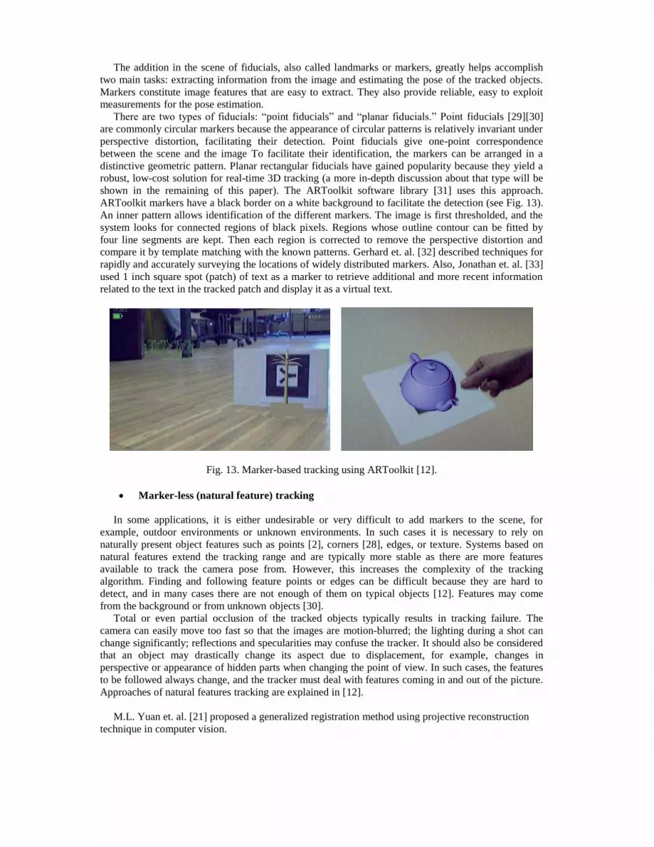
The addition in the scene of fiducials, also called landmarks or markers, greatly helps accomplish two main tasks: extracting information from the image and estimating the pose of the tracked objects. Markers constitute image features that are easy to extract. They also provide reliable, easy to exploit measurements for the pose estimation. There are two types of fiducials: ―point fiducials‖ and ―planar fiducials.‖ Point fiducials [29][30] are commonly circular markers because the appearance of circular patterns is relatively invariant under perspective distortion, facilitating their detection. Point fiducials give one-point correspondence between the scene and the image To facilitate their identification, the markers can be arranged in a distinctive geometric pattern. Planar rectangular fiducials have gained popularity because they yield a robust, low-cost solution for real-time 3D tracking (a more in-depth discussion about that type will be shown in the remaining of this paper). The ARToolkit software library [31] uses this approach. ARToolkit markers have a black border on a white background to facilitate the detection (see Fig. 13). An inner pattern allows identification of the different markers. The image is first thresholded, and the system looks for connected regions of black pixels. Regions whose outline contour can be fitted by four line segments are kept. Then each region is corrected to remove the perspective distortion and compare it by template matching with the known patterns. Gerhard et. al. [32] described techniques for rapidly and accurately surveying the locations of widely distributed markers. Also, Jonathan et. al. [33] used 1 inch square spot (patch) of text as a marker to retrieve additional and more recent information related to the text in the tracked patch and display it as a virtual text.
Fig. 13. Marker-based tracking using ARToolkit [12]. Marker-less (natural feature) tracking In some applications, it is either undesirable or very difficult to add markers to the scene, for example, outdoor environments or unknown environments. In such cases it is necessary to rely on naturally present object features such as points [2], corners [28], edges, or texture. Systems based on natural features extend the tracking range and are typically more stable as there are more features available to track the camera pose from. However, this increases the complexity of the tracking algorithm. Finding and following feature points or edges can be difficult because they are hard to detect, and in many cases there are not enough of them on typical objects [12]. Features may come from the background or from unknown objects [30]. Total or even partial occlusion of the tracked objects typically results in tracking failure. The camera can easily move too fast so that the images are motion-blurred; the lighting during a shot can change significantly; reflections and specularities may confuse the tracker. It should also be considered that an object may drastically change its aspect due to displacement, for example, changes in perspective or appearance of hidden parts when changing the point of view. In such cases, the features to be followed always change, and the tracker must deal with features coming in and out of the picture. Approaches of natural features tracking are explained in [12]. M.L. Yuan et. al. [21] proposed a generalized registration method using projective reconstruction technique in computer vision.

We can decide which tracker we will use depending on not only the nature and requirements of the application, but also the environment in which it will be performed. For indoor applications, since the dimensions of the environment are predefined (e.g. a laboratory room), physical restrictions on user‘s movements and location can be conveniently determined by the AR system. In addition, an indoor environment can be deemed ‗‗prepared‘‘ by placing sensors, optical markers, or location tracking cameras at important locations. Unlike indoor environments, a user operating outdoors has an unlimited number of possible locations and orientations [4]. Tracking in unprepared environments is difficult for three reasons [34]. First, if the user operates outdoors and traverses long distances, the resources available to the system may be limited due to mobility constraints (size, weight, and power). Second, lighting conditions, weather, and temperature are all factors to consider in unprepared environments. Third and most importantly, the system designer cannot control the environment. It may not be possible to modify the environment, such as placing special fiducial markers at known locations in the environment. If we survey tracking technologies for how well they operate in unprepared environments, we find that no single technology will offer the required performance. The global positioning system (GPS) can measure the position of any point on the earth from which enough satellites can be seen. Ordinary GPS measurements have typical errors around 30 m; differential GPS systems can reduce the typical error to around 3 m. Carrier phase systems can achieve errors measured in the centimeters under certain conditions. However, GPS does not directly measure orientation and does not work when the user cannot see enough of the sky (indoors, near buildings, in canyons, etc). Amir H. Behzada et. al. [4] presented design takes advantage of the GPS and 3DOF head orientation data in order to describe a user‘s real time location and heading. 3.2.3 Registration Registration is the process of rendering virtual objects onto the user‘s view based on the values calculated from the tracking process. Visually the real-time constraint is manifested in the user viewing an augmented image in which the virtual parts are rendered without any visible jumps. To appear without any jumps, a standard rule of thumb is that the graphics system must be able to render the virtual scene at least 10 times per second. Although tracking technology is a primary concern to the registration issue in AR, data latency can also bring about unexpected registration problems [15]. The sources of registration errors will be discussed in section 5. Registration approaches are named depending on the name of the tracking approaches used. So we can say that registration methods are: sensor-based registration and vision-based registration. 3.2.4 Interaction While great advances have been made in AR display technologies and tracking techniques, few systems provide tools that let the user interact with and modify AR content. AR technology typically includes input devices that enable users to control and interact with the synthetic world. Input devices can be as simple as keyboards or as complex as tracking systems that are used to determine the location and orientation of real objects in the environment [35]. In fact, writing this part was a difficult mission because there was no clear and specific categorization of the recent input devices. There were three different classifications presented in [36], [37] and [9]. Hiroshi et. al. [36] classified input interfaces for wearable computers into contact and non-contact devices. Their classification was limited only to wearable computers. Sriram and Wijnand [37] presented an excellent classification of spatial object manipulation techniques. This classification considered 3D spatial contact devices only and didn't consider 2D input devices or non-contact spatial techniques. Also, Tomasz and Michael [9], who classified input devices into 3D and desktop input devices didn't mention non-contact spatial devices. Furthermore, the three papers are very old. So the recent technologies were not considered in them. As a result, we will present a new classification which integrates between the previous classifications and consider the most recent interaction technologies. We have classified interaction interfaces mainly into 2D (or non-spatial) and 3D (or spatial) interfaces.

3.2.4.1 2D (non-spatial) Interfaces Some AR systems are equipped only with standard 2D input devices. They do not support so intuitive control of three-dimensional virtual objects and decrease the immersion feeling, but are handy, simple in use and relatively cheap [9]. Pointing devices such as a mouse, trackball, pen, stylus, joystick, touchpad or touchscreen, and text-based devices such as a keyboard are commonly used for human-computer interaction. The Twiddler2.1 [38] is an example of 2D input devices. It is a pocket-sized mouse pointer plus a full-function keyboard in a single unit that fits neatly in either right or left hand. All recently mentioned devices support 2DOF and are manually operated (not hands-free). Some other 2D input devices such as SpaceBall and CyberMan [9], which represent an extension of typical two-dimensional mouse support 6DOF input. The drawback of 2D input devices is that they lack the flexibility due to spatial constraints from the environments. For example, in a large-scale collaborative product design AR platform, each user is allowed to interact with the virtual product prototype. It is obviously unrealistic to furnish each user a mouse and a keyboard to interact with the virtual prototype in the large-scale AR environment [39]. 3.2.4.2 3D (spatial) Interfaces AR environments provide a whole new way of viewing and manipulating 3D data. Current technology moves the images out of desktop monitors and into the space immediately surrounding the user [20]. The users can literally put their hands on the virtual objects. AR environments offer the opportunity to interact with data in ways unavailable using traditional computing or physical tools. We are interested in developing an alternative, natural interface that more closely models the way we interact with the real world. The user should be able to reach out, grab, point and move 3D objects just as we do with real objects. Indeed, our aim to provide an overview of the latest developments in 3D input for spatial interaction, based on a number of relevant characteristics [37], on which we depend to differ between different techniques. Naturalness
Augmented Reality interaction techniques need to be as intuitive as possible to be accepted by end users. When done well, the interaction shouldn‘t feel like a human-computer interaction anymore, but rather like a human product or human-task interaction. The focus should be on interacting through a computer instead of interacting with a computer. R. O'Hagan et. al. [20] explained the basic requirements to achieve a natural AR system. Those requirements are briefly: (a) interaction response should be fast, (b) interaction should be precise and (c) cognitive load on the user should be minimized.
Range of spatial interaction [20]
The space that surrounds the user can be meaningfully segmented into several ranges, based on principles of human perception and action. Based on the volume of the interaction space the devices can be classified as:
- Tablet-size interaction devices: Tablet-size devices have a limited manipulating space, which supports detailed movements. Typically these devices have an interaction space equivalent to that of finger and wrist movements. Most of the interaction tools developed belong to this category.
- Tabletop-size interaction devices: Tabletop-size devices have a larger interaction space, roughly within arm‘s reach.
- Room-size interaction devices: These interaction devices can have an entire room as the interaction space. The user can either use the space as an ambient context or actively interact with it through various tracking devices and computer vision technologies.

Effective interaction styles can include speech or gesture. Examples of such systems are smart rooms or the CAVE.
Degrees of freedom(DOFs) [20]
To be able to manipulate 3D objects, one generally needs 6 DOF. As a general rule, the degrees of freedom of the task should match the degrees of freedom of the interaction device. Based on the number of degrees of freedom incorporated, interaction devices can be classified as:
- 1DOF: for example a slider or dial used to control one parameter, such as volume. - 2 DOF: a standard mouse has 2 DOF and enables tasks such as selecting or drawing in
2D space. - More than 2 DOF but less than 6 DOF: for 3D interaction more than 2 DOF is required.
Several modifications to the mouse were made to incorporate greater degrees of freedom. These devices are usually meant for specific applications that do not require 6 DOF.
- 6 DOF: these input devices, such as the flying mice, and can easily provide the basic 3D motions like translation and rotation.
- More than 6 DOF: most of the devices in the previous categories are meant for single-handed use. But real world observations reveal that we prefer to perform operations with both our hands. Driven by this motivation many two-handed interaction devices are being introduced. These devices can provide up to 12 DOF. Several devices have been developed which provide varying DOF between 6 and 12. Motion tracking devices for animation purposes (e.g. body suits) can have an even larger number of DOFs (i.e.100+).
Type of action
There are several kinds of elementary actions. They can be reduced to the following: - Selection/Grabbing: Selection is the task of specifying an object or objects for some
purpose including selection of items for application control (e.g. selecting menu items [36][40][41][42]). The action of grabbing secures a firm interaction with surrounding objects for comfortable manipulation.
- Positioning: Displacing objects by movements from one position to another, whilst retaining the object's shape and size.
- Deforming: This action enables modification of the shape and size of the objects (e.g. Digital Foam [43] which is used as a new input device which is designed to support natural sculpting operations similar to those used when sculpting clay).
In [20], they mentioned that manipulations include selection, manipulation (translation, rotation and resizing) of objects and changing the viewpoint of the scene (e.g. zooming in and out).
In the following we present an overview of the most commonly used 3D input devices clarifying their relation to each of the classification scheme items we have presented. The proposed devices can be divided into two types; contact and non-contact devices.
3.2.4.2.1 Contact Interfaces This type of 3D input interfaces requires users to wear or hold sensors or special devices. As yet, there is no such clear winner for 3D interfaces, and there may never be. Indeed, most of them can be characterized by a trend of divergence to special-purpose, application specific interfaces and devices. Difficulties in establishing a standard 3D input device are mentioned in [37]. 3D Mice and Bats
3D mice and Bats are 6 DOF input devices which can be used for positioning and selecting actions. 3D mouse is basic and simple user interaction tool which is in general a joystick-like 6DOF device that can be moved in space by hand. It is equipped with a tracker sensor to determine its position/orientation and a few buttons that may trigger some actions [9]. The Bat can be used as
a relative positioning device, i.e. a button on the Bat acts as a clutch allowing or disallowing movement, enabling users to employ a "ratcheting" technique to perform large translations or rotations [37]. The range of interaction is limited to tablet-size manipulations.
Phantom We have mentioned this device before in this paper as an output device which is used as force-feedback device. Here we present it as 6 DOF input device. The mechanical motors and pulleys detect the position of a stylus. The Phantom is being used in many 3D CAD/CAM and medical applications. Different types of Phantom can support different interaction ranges, from tablet-size to tabletop-size. The basic atomic operations that are best supported by the Phantom are selecting and positioning [37].
Laser Pointer Pro The Laser Pointer Pro replaces the cursor as an interaction device. A beam is cast from the user's pointer in a straight line. The fi rst object to be intersected by the ray is selected for further manipulation. This has the advantage that it allows "action at a distance" (AAAD). The user does not need to be close to the object in order to manipulate it. The Laser Pointer could be used for any range of interaction, though it would be well suited for room-size interactions. The basic atomic operations that can be performed are selecting/grabbing and positioning operations. The device has only two degrees of freedom for positioning, while it has 3 DOF for selecting.
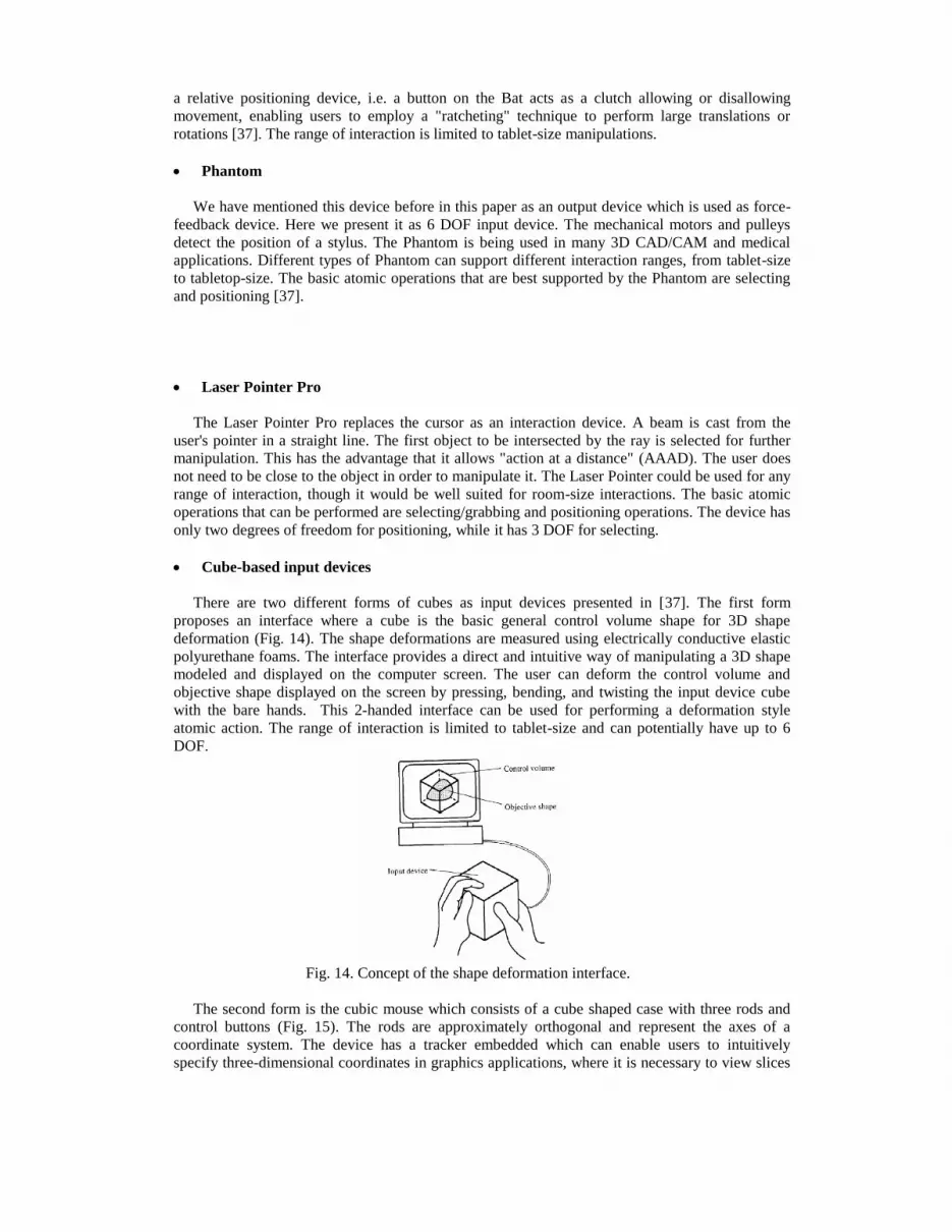
Cube-based input devices There are two different forms of cubes as input devices presented in [37]. The first form proposes an interface where a cube is the basic general control volume shape for 3D shape deformation (Fig. 14). The shape deformations are measured using electrically conductive elastic polyurethane foams. The interface provides a direct and intuitive way of manipulating a 3D shape modeled and displayed on the computer screen. The user can deform the control volume and objective shape displayed on the screen by pressing, bending, and twisting the input device cube with the bare hands. This 2-handed interface can be used for performing a deformation style atomic action. The range of interaction is limited to tablet-size and can potentially have up to 6 DOF.
Fig. 14. Concept of the shape deformation interface.
The second form is the cubic mouse which consists of a cube shaped case with three rods and control buttons (Fig. 15). The rods are approximately orthogonal and represent the axes of a coordinate system. The device has a tracker embedded which can enable users to intuitively specify three-dimensional coordinates in graphics applications, where it is necessary to view slices

of volumetric data. This two-handed interaction device has 6 DOF. The interaction space is limited to tablet and tabletop-size. The atomic operation that can be performed is positioning.
Fig. 15. The Cubic Mouse.
Another usage of cubes is proposed in [40] which presented two demonstrations. The first one demonstrates two-dimensional (2D) widget manipulations within a 3D virtual world, used amongst others for performing control tasks. The second one shows 3D navigation and manipulation in volumetric data. These input devices are tagged with infrared reflecting markers, and tracked by means of well-calibrated infrared stereo cameras (optical tracking). As shown in Fig. 16, the sensing technology allows the user to manipulate 3D virtual objects by means of optically-tracked input devices such as a thimble or pen for point selections, a planar device to position and orient (cutting) planes, a ruler to measure distances, and a cube to position and rotate 3D models.
Fig. 16. The user manipulates two interaction devices (pen and cube) in order to
control the corresponding virtual objects. Data gloves
Our hands are the main interface to touch and manipulate our external environment. One of the first interaction devices created to take advantage of hand gestures was the data glove which allows us to keep the hands free from holding input devices. Various sensor technologies are used to capture physical data such as bending of fingers. Often a motion tracker is attached to capture the global position/rotation data of the glove. These movements are then interpreted by the software that accompanies the glove. Fakespace labs produced the PINCH® gloves [44] as a reliable and low-cost method of recognizing natural gestures. Recognizable gestures have natural meaning to the user: a pinching gesture can be used to grab a virtual object, and a finger snap between the middle finger and thumb can be used to initiate an action. The PINCH system uses cloth gloves with electrical sensors in each fingertip. Contact between any two or more digits completes a conductive path, and a complex variety of actions based on these simple "pinch" gestures can be programmed into applications. Fakespace provides additional products and services for virtual environment technology including hardware integration, software tools and peripherals. Doug et. al. [42] presented an analysis of PINCH® gloves (Fig. 17).

Fig. 17. User wearing PINCH® Gloves.
Bruce and Wayne [41] extended the original Tinmith-Hand to produce a new Tinmith-Hand. The original Tinmith-Hand provides user interaction for graphical object manipulation through the 3D tracking of the user‘s head and two electronic pinch gloves. Those gloves are used to provide a menuing system by sending signals to the computer indicating which fingers are currently pressed into either the palm or the thumb, and when the appropriate finger is pressed, the menu node is selected as shown in Fig. 18.
Fig. 18. Root menu node layout, with corresponding finger mappings.
To track the location of the gloves, small fiducial markers are placed on the thumbs, and a camera mounted on the HMD feeds live video into the laptop. The ARtoolkit software library is used to process the image to recover a 3D transformation matrix relative to the camera, allowing us to calculate the position of the user‘s hands in world coordinates ( the same two authors discussed in [45] the problem of making ARToolKit generate world coordinates, and the solutions to meet the requirements for their tracking system ). The new Tinmith-Hand developed a set of augmented reality information presentation techniques based on the previously presented logistics scenario. The three selection techniques are two-handed framing, line of sight and laser beam. Finally, a new glove based text entry mechanism was discussed. The interaction space of data gloves is limited to tablet and tabletop-size. Also, they can be used as a part of a wearable computer system in outdoor environments. They are able to perform most of the atomic actions. Data gloves have several drawbacks [46] in terms of casual use as they are very expensive, hinder the naturalness of hand motion, and require complex calibration and setup procedures to be able to obtain precise measurements.
There are some other 3D spatial contact devices such as JDCAD, Rockin' Mouse, 3-Draw, Frog, Passive Interface Props, Image plane interaction techniques in 3D immersive environments, Chameleon and Personal Interaction Panel which are described in detail in [37].
3.2.4.2.2 Non-contact Interfaces An input device should be natural and convenient for a user to transmit information to a computer. Users may feel troublesome and restricted to wear contact devices when using and carrying these devices with themselves. On contrast, non-contact devices don't require users to wear or hold special

device for input interface. So, they are more intuitive and natural. Non-contact devices may be based upon either image recognition or speech recognition techniques. Image recognition
Vision-based gesture recognition provides a natural interface to virtual environments that combines the advantage of glove-based devices with the unobtrusive nature of vision-based tracking. Users can use props, marker-based gloves or even their bare hands to manipulate virtual objects without being connected to the system in any way.
a) Props
The Tangible User Interface (TUI) is a more effective and intuitive vision-based interface in virtual environments than were earlier interfaces. It enables users to manipulate computer-generated 3D shapes by handling physical objects (props). Similarly, AR systems enable users to interact with virtual objects in the real world, and we call it, "Tangible Augmented Reality (TAR)", which refers to TUI's incorporation in AR. In other words, TAR is an approach that combines TUI input methods with AR display and output. Physical objects (props) are used as input devices instead of any tethered electromagnetic trackers. A unique pattern marker is attached to the prop, which is easily and simply tracked by ARToolKit. The use of the props would not only support natural and intuitive interaction with a 3D virtual world, but it would also help the user's hands move more freely due to the absence of wires or cables. props, are very light-weighted and simple shapes, like cards (Fig. 19), so that users can grab and hold them as much as they want. fundamental 3D interaction tasks, such as selecting, translating, rotating, and scaling virtual objects, as well as user navigation can be performed by using props. Design principles of props and their interaction space are explained in detail in [15].
Fig. 19. Control props.
Gun and Gerard used props as a TAR interaction tool in their series of works that present the
immersive authoring application [15][16][17][47-50]. Fig. 20 shows an example of their work.
The interaction space of props is limited to tablet and tabletop-size and they are used for more than 6 DOF interactions. There is an important design principle must be taken into account because it may affect and limit using props. It is that the hands that are manipulating the input devices may block the line-of-sight of cameras, which can result in a (temporary) loss of the tracking of one or more interaction elements [40].

Fig. 20. Pick & drop interaction for moving and
destroying virtual objects.
b) Marker-based gloves
Volkert et. al. [51] presented the FingARtips project which is concerned with near objects that can be manipulated by natural gestures such as grabbing, pressing, dragging and releasing virtual objects in an urban planning interface
using natural hand gestures. The application does not take any input other than from a single gloved hand. The glove has 2 cm square markers mounted on the tips of the thumb and the index finger, and on the hand itself. These markers are used by the ARToolKit to find the user‘s viewpoint in the world coordinate frame. They used a simplified model of the hand to interpolate the position of the index finger and the thumb from three markers. Our goal is to provide a simple model of the hand that can be used for correct occlusion. Grabbing, dragging and releasing gestures are used for manipulating virtual buildings (Fig. 21).
Fig. 21. The simplified model of the hand.
The interaction space of marker-based gloves is limited to tablet and tabletop-size and they are used for more than 6 DOF interactions. The limitation in using that interaction technique is that the user is restricted to certain gestures which reduces the intuitiveness requirement. c) Free hands
There has been a great emphasis lately in Human-Computer Interaction (HCI) research to create easier to use interfaces by directly employing natural communication and manipulation skills of humans. The direct sensing approach requires capturing and interpreting the motion of head, eye gaze, face, hand, arms or even the whole body. Among different body parts, the hand is the most effective, general-purpose interaction tool due to its dexterous functionality in communication and manipulation. the hand serves as an efficient, high DOF (more than 20 DOF) control device. Gestures can be static (the user assumes a certain pose or configuration) or dynamic (with prestroke, stroke, and poststroke phases). Some gestures also have both static and dynamic elements, as in sign languages [52]. The hand must be tracked within the

work volume to give positioning information to the interface, and gestures must be recognized to present the meaning behind the movements to the interface.
There are two main approaches in hand pose estimation. The first one consists of ‗‗partial pose estimation‘‘ methods that can be viewed as extensions of appearance-based systems by which 3D motion information is limited to rough estimates of fingertip positions, finger orientations and/or palm frame obtained using appearance-specific features that affect the generality of the approach. These systems rely on appearance-specific 2D image analysis to enable simple, low DOF tasks such as pointing or navigation. Fig. 22 shows a block-diagram of a generic partial hand pose estimation system. The system shown is explained in a great detail in [46]. The second approach is the full DOF hand pose estimation that targets all the kinematic parameters (i.e., joint angles, hand position or orientation) of the skeleton of the hand, leading to a full reconstruction of hand motion.
Fig. 22. Block diagram of a generic gesture-based interaction system.
In the study presented in [46], they reviewed a general problem, which aims to recover the
full kinematic structure of the hand by bridging the gap between computer vision based (CV-based) and glove-based sensing which is a very challenging, high dimensional problem. In [20], they developed a robust and reliable real-time tracking and recognition system by making a combination of feature-based and model-based approaches. Fig. 23 shows examples of the gestures to be used.
Fig. 23. Examples of gestures to be used.

In [36], the authors proposed ―Hand-Menu System‖, in which the menu appears on the
fingertips of a hand and the user can select a certain item from the menu by touching a certain fingertip with the index finger of the other hand. In [39], they proposed and developed an effective hand tracking based on detecting the skin color.
The design of hand pose estimation systems encounters some difficulties such as high-dimensional problem, self-occlusions, processing speed uncontrolled environments and rapid hand motion which are explained in [46].
Speech recognition
Speech is a familiar, convenient, and spontaneous part of the capabilities people bring to the situation of interacting with machines [53]. When conducting HMI speech may offer advantages over keyboard skills or manual input, which are difficult without practice and training. Speech input presents considerable opportunities to harness reality based interactions; however, there is often still a requirement to learn task grammar and develop suitable mental models that account for how a machine might respond to spoken inputs. Speech offers the potential to liberate users and allow a greater degree of freedom to interact within VEs as traditional input devices are often unsuited to simultaneous 3D navigation and control. Speech allows hands free operation and could be particularly useful for navigation through easily accessible menus and short cut commands. Furthermore, multiuser recognition systems support speech input in collaborative VEs allowing many users to interact with each other and the VE at the same time. In [54], they developed a 3D authoring tool which takes advantage of multimodal interfaces such as gestures and speech. The main benefit of using a multimodal based augmented reality system is the provision of a more transparent, flexible, efficient and expressive means of human computer interaction. In [55], the authors presented an AR interactive drama, in which players are situated in a married couple‘s apartment, and interact primarily through conversation with the characters and manipulation of objects in the space. In [56], they proposed an industrial scenario— that is, opening communication through augmented reality—could empower the industrial maintenance industry with immeasurable freedom and efficiency. According to that scenario, when the technicians enter a specific component‘s vicinity, the speech-enabled AR framework could then automatically engage them in a context-specific speech dialog concerning the corresponding factory component. The current state of the art in speech recognition is still limited (recognition error rates, throughput of the user-computer communications) and introduces additional challenges (increased cognitive load), as reported in [19]. A voice activated system is likely to create conflicts with voice communications between responders, especially when the system‘s user is trying to look up information while communicating with another team member.
There are also some other new interfaces such as, Radio Frequency Identification (RFID) interface technology [57][19] which is used to directly integrate physical objects with virtual objects and to systematically support the tangible query of the relation between physical objects and virtual ones, which can provide more intuitive tangibility and a new way of virtual object manipulation.
3.3 Software The development of software to support AR environments is much more challenging compared to other environments such as traditional 2D desktops. In 2D environments, there has been a lot of existing research and implementations have converged on a generally agreed best practice. In contrast, 3D environments such as AR and VR suffer from many different types of applications, differing opinion on the best user interfaces to deploy, and nonstandardised and changing hardware [58]. Also, system components should be able to exchange data with soft real-time performance to couple several processing modules in a hybrid architecture [59]. The development of higher level software toolkits is not possible until there are a stable set of low level toolkits to support them. For AR environments to become mainstream and easy to develop for (similar to the ubiquitous 2D desktop), high level toolkits
with a rich feature set are required. Computer vision algorithms are the basis of the most commonly used planar marker toolkits. ARToolkit [31]
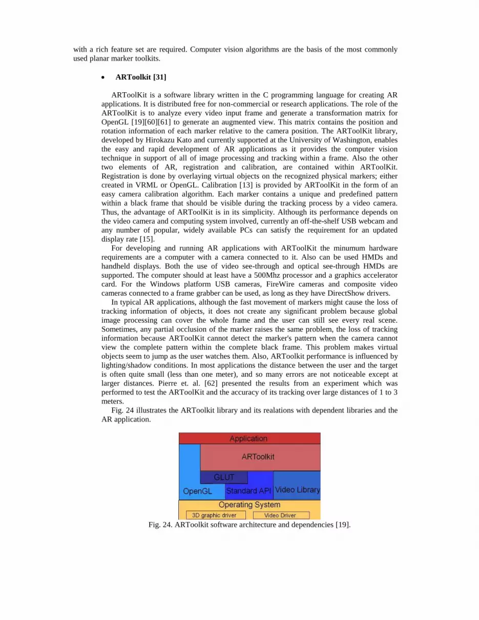
ARToolKit is a software library written in the C programming language for creating AR applications. It is distributed free for non-commercial or research applications. The role of the ARToolKit is to analyze every video input frame and generate a transformation matrix for OpenGL [19][60][61] to generate an augmented view. This matrix contains the position and rotation information of each marker relative to the camera position. The ARToolKit library, developed by Hirokazu Kato and currently supported at the University of Washington, enables the easy and rapid development of AR applications as it provides the computer vision technique in support of all of image processing and tracking within a frame. Also the other two elements of AR, registration and calibration, are contained within ARToolKit. Registration is done by overlaying virtual objects on the recognized physical markers; either created in VRML or OpenGL. Calibration [13] is provided by ARToolKit in the form of an easy camera calibration algorithm. Each marker contains a unique and predefined pattern within a black frame that should be visible during the tracking process by a video camera. Thus, the advantage of ARToolKit is in its simplicity. Although its performance depends on the video camera and computing system involved, currently an off-the-shelf USB webcam and any number of popular, widely available PCs can satisfy the requirement for an updated display rate [15]. For developing and running AR applications with ARToolKit the minumum hardware requirements are a computer with a camera connected to it. Also can be used HMDs and handheld displays. Both the use of video see-through and optical see-through HMDs are supported. The computer should at least have a 500Mhz processor and a graphics accelerator card. For the Windows platform USB cameras, FireWire cameras and composite video cameras connected to a frame grabber can be used, as long as they have DirectShow drivers. In typical AR applications, although the fast movement of markers might cause the loss of tracking information of objects, it does not create any significant problem because global image processing can cover the whole frame and the user can still see every real scene. Sometimes, any partial occlusion of the marker raises the same problem, the loss of tracking information because ARToolKit cannot detect the marker's pattern when the camera cannot view the complete pattern within the complete black frame. This problem makes virtual objects seem to jump as the user watches them. Also, ARToolkit performance is influenced by lighting/shadow conditions. In most applications the distance between the user and the target is often quite small (less than one meter), and so many errors are not noticeable except at larger distances. Pierre et. al. [62] presented the results from an experiment which was performed to test the ARToolKit and the accuracy of its tracking over large distances of 1 to 3 meters. Fig. 24 illustrates the ARToolkit library and its realations with dependent libraries and the AR application.
Fig. 24. ARToolkit software architecture and dependencies [19].

For being able to recognize the markers several steps are executed. First the live video image is turned into a binary image based upon a preset lighting treshold value. The resulting image is searched for squares regions. For every found square the pattern inside it is matched against pattern templates. If a match occurs a marker has been found. The next step is to calculate the position of the real camera relative to the physical marker. These real world coordinates are used to set the position of the virtual camera coordinates. This assures that the virtual objects drawn are precisely overlaid. Figures 25 through 27 show the three steps involved in overlaying virtual objects.
Fig. 25 Live video [13]. Fig. 26. Binary image [13]. Fig. 27. Virtual
object overlaid on live video
[13]. ARTag [63]
ARTag was inspired by ARToolkit, but came out later in Nov 2004 taking advantage of the increased computing processing power available. ARTag is a library originally designed to be used in conjunction with ARToolkit; however the core functionality provided by this library is useable in standalone mode. Further revisions also included a full SDK allowing for rapid development of applications without using ARToolkit [19]. ARTag uses more complex image processing and digital symbol processing to achieve a higher reliability and immunity to lighting. ARTag's planar marker recognition is based on digital coding theory, allowing for error correction. Unlike ARToolkit, where after determining the boundary box for a particular marker the contents are sampled and compared to bitmap templates by using convolution, ARTag after unwarping and sampling on a 6x6 grid treats the contents as codewords, calculating checksums and applying forward error correction. Another important difference is that ARTag finds quadrilaterals by linking edge pixels. ARTag's occlusion handling is possible due to error correcting properties of the code utilized in the encoding of the marker IDs in the patterns (also true for ARToolkitPlus, but not tested) as well as the particulars of the quadrilateral detection employed in ARTag (the border can be partially occluded, unlike in ARToolkit). The advantage of this approach over ARToolkit's is illustrated on Fig. 28.
a) ARToolkit, before b) ARToolkit, occluded border, c) ARTag, successful detection occlusion. failed detection despite partial occlusion of border and several bits of the pattern.
Fig. 28. Effects of marker occlusion [19]. ARToolkitPlus [64]
ARToolKitPlus is a reworking of ARToolKit's vision code extending it with id-based marker
functionality inspired by ARTag. Unlike ARTag, ARToolkitPlus is freely available as an open-source. Since this library was developed for a project involving handheld devices, many

speed optimizations were introduced for devices with less processing power. The code was also repackaged, allowing for greater use flexibility but also breaking compatibility with the original library. ARToolKitPlus is not meant as a complete rapid prototyping solution, as all camera capture and geometry rendering functionality have been stripped from it [19]. This version of ARToolKit is only targeted to experienced C++ programmers. It does not read camera images or render geometry of any kind (especially no VRML) nor is it an out-of-the box solution. In contrast to the original ARToolKit, this library is not meant for starters in developing AR software. No binary executables are provided and no help in setting up your IDE is given.
In [65], the author presented an improvement of ARTag and ARToolkitPlus. ARStudio
ARStudio is a technology demo of a planar marker system, rather than a complete
development solution. The ARStudio demo incorporates image and video file overlaying, loading of VRML object (VRML animations are supported ). It is interesting to note, that unlike in ARToolkit and ARTag, the marker detection is based on corner detection, and each marker can be considered as a local constellation of corner-based features. Such approach allows for detection even in the presence of partial occlusions. Apparently, the work on the ARStudio has been discontinued since September 2002.
A greatly detailed comparison between the four recently mentioned toolkits is presented in [19]. NYARToolkit [66]
NyARToolKit is a complete port of ARToolkit that was written exclusively in Java. This
makes it slower in execution than the original, but completely architecture independent. Like the original, NyARToolKit is a library of functions visual interpretation and integration of VR data into physical environments, including real-time camera vision functionality, 3D rendering of virtual objects, and integrating both into the output stream.
The odd name is due to a degree of self-promotion. It was created by a Japanese man known as Nyatla in 2008, so the Ny got added to the toolkit name.
Despite being native to Java, the toolkit works with C# and the Android operating system elegantly. Numerous other ports based off of it, account for other languages and set-ups.
The company that commercialized ARToolkit, ARToolworks, Inc, still owns the commercial license for NyArToolkit, despite their having nothing to do with its development. NyArToolkit is, perhaps for this reason, distributed open-source as a non-commercial product.
FLARToolkit [67]
FLARToolKit stands for FLash-based Augmented Reality Toolkit, and is a port of the Java-based port of ARToolkit, NyARToolKit bringing augmented reality to the web browser.
Created by Japanese developers in late 2008, at time of writing, the port is available. The toolkit is compatible with Flash version 10, using Action Script 3, where it executes natively. However, as with all flash coding, it executes exceedingly slowly as compared to Java or C. This limits the capabilities of derivative animations to handle AR data to realistically just a single camera and a handful of 3D models per scene.
Like the toolkits it is derived from, FLAR makes use of Magic Symbol technology to position its augmented reality creations in the video stream.
SLARToolkit [68]
SLARToolkit is a flexible Augmented Reality library for Silverlight with the aim to make real time Augmented Reality applications with Silverlight (Fig. 29) as easy and fast as possible. It can be used with the Webcam API that was introduced in Silverlight 4 or with any

other CaptureSource or a WriteableBitmap. SLARTookit is based on the established NyARToolkit and ARToolkit. SLARToolkit uses a dual license model and could be used for open or closed source applications under certain conditions.
Fig. 29. Examples of SLARToolkit applications [68].
There are application-specific AR platforms presented in several previous works, such as those are presented in [4], [19], [58], [59], [69] and [70]. 4. Applications Augmented reality is designed to blur the line between the reality the user is experiencing and the virtual content provided by technology to enhance a user's interaction with the real world. Researchers working with augmented reality systems have proposed them as solutions in many domains. This section highlights some of the proposed applications for augmented reality. 4.1 Medical Doctors could use Augmented Reality as a visualization and training aid for surgery [1]. AR might also be helpful for general medical visualization tasks in the surgical room. Surgeons can detect some features with the naked eye that they cannot see in MRI or CT scans, and vice-versa. AR would give surgeons access to both types of data simultaneously. This might also guide precision tasks, such as displaying where to drill a hole into the skull for brain surgery or where to perform a needle biopsy of a tiny tumor. The information from the non-invasive sensors would be directly displayed on the patient, showing exactly where to perform the operation (Fig. 30). AR might also be useful for training purposes. Virtual instructions could remind a novice surgeon of the required steps, without the need to look away from a patient to consult a manual. Virtual objects could also identify organs and specify locations to avoid disturbing. In [13], the authors distinguished four types of applications for AR in the medical area; image guided surgery, surgery planning, surgical training and psychiatry. In [35], they presented medical education applications enabling the visualization of internal human knee joint anatomy on a real human knee. Michael presented in his thesis [71] a registration, tracking, and visualization system for image-guided surgery.
Fig. 30. Augmenting the internal organs during surgery [69].

4.2 Virtual Learning
AR has been proposed as a technological breakthrough that holds the power to facilitate learning. The research and application of AR technology in education have enriched the form of teaching and learning in current educational strategy [72]. Virtual learning environment (VLE), not only provides rich teaching patterns and teaching contents, but also helps to improve learners‘ ability of analyzing problems and exploring new concepts. Based on AR techniques, learning action may be processed as following scenery: History students can learn about ancient Greece by walking its streets, visiting its buildings, and interacting with its people. Biology students can learn about anatomy and physiology through adventures inside the human body. The range of worlds that people can explore and experience is unlimited, ranging from factual to fantasy, set in the past, present, or future. One of the most important purposes of an educational environment is to promote social interaction among users located in the same physical space. In collaborative Augmented Reality [73] multiple users may access a shared space populated by virtual objects, while remaining grounded in the real world (Fig. 31). This technique is particularly powerful for educational purposes when users are collocated and can use natural means of communication (speech, gestures etc.), but can also be mixed successfully with immersive VR or remote collaboration.
Fig. 31. Collaborative work of students within the
Augmented Reality application Construct3D. In this example the students inscribe a sphere in a cone.
The MagicBook is a Mixed Reality interface that uses a real book to seamlessly transport users between Reality and Virtuality [74]. A vision-based tracking method is used to overlay virtual models on real book pages, creating an Augmented Reality (AR) scene. People can turn the pages of these books, look at the pictures, and read the text without any additional technology (Fig. 32a). However, if they look at the book through an AR display they see 3D virtual models appearing out of the pages (Fig. 32b). The models appear attached to the real page so users can see the AR scene from any perspective simply by moving themselves or the book. The models can be of any size and are also animated, so the AR view is an enhanced version of a traditional 3D ‗‗pop-up‘‘ book. Users can change the virtual models simply by turning the book pages and when they see a scene they particularly like, they can fly into the page and experience it as an immersive virtual environment (Fig. 32c). In the VR view they are free to move about the scene at will and interact with the characters in the story. Thus, users can experience the full Reality-Virtuality continuum. The interface also supports multi-scale collaboration, allowing multiple users to experience the same virtual environment either from an egocentric or an exocentric perspective.

Fig. 32. Using the MagicBook to move between Reality and Virtual Reality.
Neven et. al. [75] presented and explained the Augmented Reality Student Card (ARSC) as an application of AR in the field of education. ARSC used single static markers combined in one card for assigning different objects, while leaving the choice to the computer application. 4.3 Manufacturing, Maintenance, and Repair Another category of Augmented Reality applications is the assembly, maintenance, and repair of complex machinery [1]. Instructions might be easier to understand if they were available, not as manuals with text and pictures, but rather as 3-D drawings superimposed upon the actual equipment, showing step-by-step the tasks that need to be done and how to do them. These superimposed 3-D drawings can be animated, making the directions even more explicit. Fig. 33 shows the user's view, where installation details appear in the technician‘s field of view. In [76], the authors described the architecture of a system which uses the technologies of AR and VR to support the planning process of complex manufacturing systems. In [77], they described the development of an AR-based equipment Operations and Maintenance (O&M) fieldwork support application to improve efficiency at the site and the experimental evaluation of the application.
Fig. 33. AR-scene: installation details are shown via special glasses in the user‘s field of view [76].
4.4 Annotation and Visualization AR could be used to annotate objects and environments with public or private information [1]. Applications using public information assume the availability of public databases to draw upon. For example, a hand-held display could provide information about the contents of library shelves as the user walks around the library. Fig. 34 shows this, where the user points at the exhaust manifold on an engine model and the label "exhaust manifold" appears.

Fig. 34. Engine model part labels appear as user points at them.
4.5 Robot Path Planning Teleoperation of a robot is often a difficult problem, especially when the robot is far away, with long delays in the communication link. Under this circumstance, instead of controlling the robot directly, it may be preferable to instead control a virtual version of the robot [1]. The user plans and specifies the robot's actions by manipulating the local virtual version, in real time. The results are directly displayed on the real world. Once the plan is tested and determined, then user tells the real robot to execute the specified plan. This avoids pilot-induced oscillations caused by the lengthy delays. The virtual versions can also predict the effects of manipulating the environment, thus serving as a planning and previewing tool to aid the user in performing the desired task. Fig. 35 shows how a virtual outline can represent a future location of a robot arm.
Fig. 35. Virtual lines show a planned motion of a robot arm.
J.W.S. Chong et. al. [78] used an AR environment for facilitating intuitive robot programming, and presented a novel methodology for planning collision-free paths for an n-DOF manipulator in a 3D AR environment. AR technology can also be used in many other applications, such as entertainment, military aircraft [1][6], engineering design, consumer applications [6] and architecture [79]. 5. Registration Problem and Previous Solutions 5.1 Registration Problem One of the most basic problems currently limiting Augmented Reality applications is the registration problem. The objects in the real and virtual worlds must be properly aligned with respect to each other, or the illusion that the two worlds coexist will be compromised [1]. This is a mostly important and complicated matter for three reasons [13]:

a) The human visual system is very sensitive to small misregistrations, even if they are in the order of few pixels.
b) For AR applications tighter requirements are put upon on error tolerances that are allowed.
c) One also has to cope with system delay; the time interval that lies in between tracking and the actual superimposing of the corresponding images.
The accuracy of registration of virtual objects is determined by the alignment errors that result. The possible alignment errors can be classified in two categories:
• Static errors, which are defined as the misalignment the user can perceive when he is immobile. • Dynamic errors, which are defined as the misalignment the user can perceive when he moves. Static errors
Static errors are the ones that cause registration errors even when the user's viewpoint and the objects in the environment remain completely still. Although static errors have less impact they can not be ignored (Fig. 36). There are various sources of error [1] that can be pointed out. For static errors the most important are optical distortion, errors in the tracking system, mechanical misalignments and incorrect viewing parameters. Now will be shortly discussed the four sources of error responsible for causing static errors. Also are mentioned ways to decrease their effect.
Fig. 36. Misregistration caused by static errors [13].
a) Optical distortion is an inevitable property which is exhibited by most camera and lens
systems. Also cameras for recording a real scene and the optics used in display devices are influenced by this. Because distortions are usually a function of the radial distance away from the optical axis, wide field-of-view displays can be especially vulnerable to this error. But also non-linearity may exist in these distortions. The virtual overlay images are distorted under influence of this, and this causes static registration errors when they are mapped on top of the undistorted view of the real world.
Optical distortions are usually systematic errors, so they can be mapped and Compensated by using two methods: - Compensation by additional optics can be a difficult design problem, and it will add weight, which is not desirable in HMD. - Digital compensation adds a portion to the system delay because it is a computational expensive method.
b) Errors in the tracking system is the most serious type. These distortions are not easy to measure and eliminate, because that requires another "3-D ruler" that is more accurate than the tracker being tested. All of the before described ways of tracking provide an accuracy which is not adequate enough. Ongoing developments in the area of tracking methods need to increase the ability to track more accurately.
c) Mechanical misalignments occurs because various component parts may change their relative positions as the user moves around. For example, the combiners, optics, and monitors in an optical see-through HMD may not be at the expected distances or

orientations with respect to each other. Mechanical misalignments can cause subtle changes in the position and orientation of the projected virtual images that are difficult to compensate. While some alignment errors can be calibrated, for many others it may be more effective to "build it right" initially.
d) Incorrect viewing parameters specify how to convert the reported head or camera locations into viewing matrices used by the scene generator to draw the graphic images. Incorrect viewing parameters cause systematic static errors. Take the example of a head tracker located above a user's eyes. If the vertical translation offsets between the tracker and the eyes are too small, all the virtual objects will appear lower than they should. There exist several methods for adjusting this type of error. The viewing parameters can be estimated by making minor manual adjustments according to a non-systematic fashion. This does not give satisfying results because it requires a skilled user and it is applicable only if the environment and the viewpoint remain static. Another approach is to directly measure the viewing parameters by using a variety of measuring tools and sensors. Up until now, this has not lead to great success in establishing correct viewing parameters. View-based tasks are another approach to calibration. These ask the user to perform various tasks that set up geometric constraints. By performing several tasks, enough information is gathered to determine the viewing parameters. It heavenly depends on the user accurately performing the specified task and the quality of the used tracker. For video-based systems, a camera's viewing parameters are computed by taking several pictures of an object of fixed and sometimes unknown geometry. These pictures must be taken from different locations. Matching points in the 2-D images with corresponding 3-D points on the object sets up mathematical constraints. With enough pictures, these constraints determine the viewing parameters and the 3-D location of the calibration object. Alternately, they can serve to drive an optimization routine that will search for the best set of viewing parameters that fits the collected data.
Dynamic errors
Dynamic errors are the ones that have no effect until either the viewpoint or the objects begin to move. They occur because of system delays or lags. The end-to-end system delay is defined as the time difference between the moment that the tracking system measures the position and orientation of the viewpoint to the moment when the generated images corresponding to that position and orientation appear in the displays. These delays are related to the fact that each and every component in an AR system requires a certain amount of time for carrying out its function. Several methods to reduce the impact of dynamic registration errors have been tried; reducing system lag, reducing apparent lag, matching temporal streams and predicting future locations. These are shortly explained now. a) Reduce system lag: The most direct approach is simply to reduce, or ideally eliminate, the
system delays. Unfortunately, modern scene generators are usually built for throughput, not minimal latency. It is sometimes possible to reconfigure the software to sacrifice throughput to minimize latency. It is also not expected that eliminating system delays will ever be the case. Then, at least can be tried to minimize them to the smallest amount possible. This is to be accomplished by the ever ongoing technological development.
b) Reduce apparent lag: Reducing the apparent lag can be done using image deflection and image warping techniques. Image deflection is a technique that incorporates more recent orientation measurements into the late stages of the rendering cycle. This results in the virtual images being displayed with less registration error. Image warping works on translation. After the scene generator renders the image based upon the head tracker reading, small adjustments in orientation and translation could be done after rendering by warping the image. These techniques assume knowledge of the depth at every pixel, and the warp must be done much more quickly than rerendering the entire image.
c) Match temporal streams: It allows the temporal streams of the real and virtual images to be matched. Additional delay is added to the video from the real world to match the scene

generator delays in generating the virtual images. This additional delay to the video stream will probably not remain constant, since the scene generator delay will vary with the complexity of the rendered scene. Therefore, the system must dynamically synchronize the two streams.
d) Predict: Predicting future locations is the last method that could be used to reduce dynamic errors. The predicted locations, instead of the measured locations, are used as reference for the virtual images that are overlaid. For short system delays this is shown to reduce registration errors by an order of magnitude. The prediction is required to be done in real time. More work is needed to develop better performance prediction and models that more closely match actual head motion.
5.2 Previous solutions Primarily, the focus in AR research is upon tracking the motion of objects within the environment that are considered rigid. We have mentioned different sensor-based tracking systems and their drawbacks in section 3.2.2.1. We have listed the drawbacks of each of them if they were used individually. Some previous works used hybrid trackers which fuse two or more tracking methods to cover weaknesses of individual ones. Thomas and Axel [26] used a magnetic tracking system to give an estimate of position and orientation which then can be refined in real time by optical tracking. The system was more precise than a magnetic tracker and both faster, and more reliable than an optical tracker. Eric et. al. [23] implemented algorithms for differential inertial tracking between helmet-mounted and aircraft-mounted inertial sensors, and novel optical drift correction techniques. They fused low-rate inside-out and outside-in optical measurements with high-rate inertial data. The inertial sensor can be integrated with vision-based tracking system to achieve better real-time tracking as proposed in [59]. Also, in [80] the authors presented a hybrid tracking method that had combined the accuracy of vision-based tracking with the robustness of magnetic tracking. The use of predictive filtering improves tracking performance. The most commonly used predictive filter is the Kalman filter [81][8][28]. J. Chen and A. Pinz [81] fused vision-based tracking with a commercially available inertial sensor by Kalman filtering. In [8] Dieter et. al. utilized fully automated landmark-based camera calibration to initialize the motion estimation and employ extended Kalman filter techniques to track landmarks and to dynamically estimate the camera location. In [28], although they didn‘t use Kalman filter explicitly, they use a recursive form of temporal regularization technique that is similar in spirit to the Kalman filter. It was used to minimize deviations between two precaptured reference images and current frame as a function of the camera motion parameters to obtain an estimate of the current camera pose relative to the reference images. Another filter also be used is particle filter. It was proposed in [82] as they combined it with CamShift using multiple cues. Jaco et. al. [83] presented a novel approach to visual tracking called the harmony filter. It is based on the Harmony Search algorithm, a derivative free meta heuristic optimization algorithm inspired by the way musicians improvise new harmonies. The harmony filter models the target as a color histogram and searches for the best estimated target location using the Bhattacharyya coefficient as a fitness metric. Experimental results showed the harmony filter to be faster and more accurate than both the particle filter and the unscented Kalman filter. Another method is tracking multiple planes instead of one. Using multiple planes is better than using a single plane because the user can move around a wide space by switching the planes based on the user‘s point of view and thus he will guarantee that always some of the planes will appear in the scene. Moreover, using multiple planes simultaneously stabilizes tracking and improves its accuracy by integrating between matrices resulted from tracking different planes. Yuko and Hideo [2] proposed method did not require a priori knowledge about the geometrical relationships among the multiple planes because the geometrical relationship is automatically estimated by ‗‗Projective Space‖. In [32], they described techniques for rapidly and accurately surveying the locations of widely distributed markers in order to extend tracking range and simultaneously build a model of the environment. But unlike the method presented in [2], the system in [32] requires premeasurements of the working area by dividing it into measurable distances. Jose and Rajeev [29] also used a set of markers or fiducials for object tracking and recognition. In this paper they presented a system of marker coding that, together with an efficient image processing technique, provides a practical method for tracking the marked objects in real-time. The technique was based on clustering of candidate regions in space using a

minimum spanning tree. J. Yang et. al. [84] proposed a tracking scheme for tracking multiple workers on construction sites using video cameras. The authors developed a tracking algorithm based upon machine learning methods. The algorithm requires several sample templates of the tracking target and learns a general model that can be applied to other targets with similar geometry. Occlusion detection is an active area of study in AR in general because occlusion errors easily ruin the feeling of presence the user might experience. W. Dangelmaier et. al. [76] mentioned two approaches to avoid this problem. The first one is that the virtual object is laid semi-transparently over the real image. However, the correct spatial overall impression of the scene disappears here, which eventually leads to confusion of the user. The second approach is to either develop a 3D-model of the reality preliminarily and then use this as an alpha-channel by the image generation of the virtual objects or identify the occlusion optically. In [7], the authors demonstrated how Focus and Context (F+C) visualizations are used to affect the user‘s perception of hidden or nearby objects by presenting contextual information in the area of augmentation. A robust method of handling ambiguous targets (partial occlusion, split region or mixed state of the partial occlusion and the split region) for visual object tracking is presented in [85]. The object model is a combination of bounding box features and expected object region. Some AR applications would become feasible if accurate tracking was possible in unprepared environments, where users are not allowed to modify the real environment, such as in outdoor applications. Accurate tracking in such situations is difficult. Ronald Azuma et. al. [34] summarized two 3DOF results: a real-time system with a compass inertial hybrid, and a non-real-time system fusing optical and inertial inputs. A novel feature-based approach for camera tracking [86] was proposed intending to facilitate tracking in on-line, time-critical applications. At its core lies a feature- based 3D plane tracking technique, which permits the estimation of the homographies induced by a virtual 3D plane between successive image pairs. That approach is causal, is tolerant to erroneous and missing feature matches, does not require modifications of the environment and has computational requirements that permit a near real-time implementation. Amir H. Behzadan et. al. [4] presented a reusable, general-purpose, mobile AR framework developed to address the critical and repetitive challenges specific to visualization in outdoor AR. Their design took advantage of the GPS and 3DOF head orientation data in order to describe a user‘s real time location and heading. 6. Conclusion AR is an old idea that is right now on the verge of success. There were several iterations to improve the performance of AR applications, but they are still not at the prospective level which is explained in detail in section 2. They have been lacking either in computing power, user tracking accuracy, robustness or ease of use and comfortableness, which all are necessary to produce a satisfying AR experience. This article presented a comprehensive review of AR technology. Although we have highlighted that technology from different perspectives, we have concentrated on the AR system components. We have classified them mainly into input components, output components and software that links between input and output components. We have tried to cover all current input and output components and have proposed the main features of each of them from an analytical and comprehensive perspective. Furthermore, we have presented the current toolkits which are used for building AR systems and showed which of them are available as open source. Therefore, this paper is not only a good starting point for any researcher but also a good reference for any casual user seeking to build an AR system. There is no certain input, output component or toolkit can be considered as the best one, but each AR application has a special nature and specific requirements that fit it. Recently, AR technology started to be applied in our daily life applications. They are now used in several applications, such as medicine, manufacturing, entertainment, military training, engineering design, consumer design, robotics and telerobotics, annotation and learning. Some applications consider the registration accuracy as a critical demand, such as medicine and surgery applications and some other applications don‘t influenced by the accuracy of registration, such as entertainment or consumer design applications. At the end of the paper, we have pointed to the most problem that faces a lot of AR researchers. This problem is the registration problem which is usually caused by the weaknesses in the tracking systems. We have listed the causes which led to that problem in both static and dynamic cases. Finally, we have showed some of what the researchers presented before to solve
that problem. The approaches which have been highlighted were hybrid tracking systems, predictive filtering, tracking multiple objects, occlusion detection and tracking objects in unprepared environments. 7. References [1] R. Azuma, "A Survey Of Augmented Reality", Teleoperators and Virtual Environments, Vol. 6,
No. 4, pp. 355-385, August 1997.
[2] Yuko Uematsu, Hideo Saito, " Multiple planes based registration using 3D Projective Space for
Augmented Reality", Image and Vision Computing, Vol. 27, No. 10, pp. 1484-1496, September
2009.
[3] Mikko Sairio, "Augmented Reality", Helsinki University of Technology, 2000,
http://www.tml.tkk.fi/Studies/Tik-111.590/2001s/papers/mikko_sairio.pdf [Last Visit: Oct. 13,
2011].
[4] Amir H. Behzadan, Brian W. Timm, Vineet R. Kamat, " General-purpose modular hardware and
software framework for mobile outdoor augmented reality applications in engineering",
Advanced Engineering Informatics, Vol. 22, No. 1, pp. 90-105, January 2008.
[5] http://www.scribd.com/doc/60239635/Augmnt-Theory-Practice [Last Visit: Oct. 12, 2011].
[6] James R Vallino, "Interactive Augmented Reality", PHD thesis, University of Rochester,
Rochester, New York, 1998.
[7] Denis Kalkofen, Erick Mendez, and Dieter Schmalstieg, "Comprehensible Visualization for
Augmented Reality", IEEE TRANSACTIONS ON VISUALIZATION AND COMPUTER GRAPHICS,
Vol. 15, No. 2, pp. 193-204, March/April 2009.
[8] Dieter Koller, Gudrun Klinker, Eric Rose, David Breen, Ross Whitaker, and Mihran Tuceryan,
"Real-time Vision-Based Camera Tracking for Augmented Reality Applications", In Proceedings
of the Symposium on Virtual Reality Software and Technology (VRST-97), Lausanne,
Switzerland, pp. 87–94, September 15–17, 1997.
[9] Tomasz Mazuryk and Michael Gervautz, "Virtual Reality History, Applications, Technology and
Future", Institute of Computer Graphics Vienna University of Technology, Austria.
[10] "Augmented reality page", [Online]. Available: http://www.se.rit.edu/~jrv/research/ar/ [Last
Visit: Dec. 10, 2010].
[11] "Augmented reality", [Online]. Available: http://en.wikipedia.org/wiki/Augmented_reality [Last
Visit: Oct. 12, 2011].
[12] Mario A. Gutiérrez A, Frédéric Vexo, Daniel Thalmann, "Stepping into Virtual Reality", Springer,
2008.
[13] Dennis Joele, "Development of an Augmented Reality system using ARToolKit and user invisible
markers", Delft University of technology, Valencia, May 26th 2005.
[14] Ramesh Raskar, Kok-Lim Low, "Interacting with Spatially Augmented Reality", AFRIGRAPH '01
Proceedings of the 1st international conference on Computer graphics, virtual reality and
visualization, ACM, New York, USA, 2001.
[15] JI-SUN KIM, " Tangible User Interface for CAVETM based on Augmented Reality Technique",
MSc Thesis, Faculty of the Virginia Polytechnic Institute and State University, Blacksburg,
Virginia, December 2005.
[16] Gun A. Lee, Claudia Nelles, Mark Billinghurst, and Gerard Jounghyun Kim, "Component-based
Approach on Immersive Authoring of Tangible Augmented Reality Applications", Virtual Reality
Laboratory, Dept. of CSE, POSTECH HIT Lab NZ, University of Canterbury, ISMAR 2004.
[17] Gun A. Lee, Gerard J. Kim, " Immersive authoring of Tangible Augmented Reality content: A
user study", Journal of Visual Languages & Computing, Vol. 20, No. 2, pp. 61-79, April 2009.
[18] H. Iwata, H. Yano, T. Uemura, T. Moriya: "Food Simulator: A Haptic Interface for Biting", in
VR’04: Pro eedings of the IEEE Virtual Reality 2004 VR’04 IEEE Computer Society,
Washington, DC, USA) pp. 51–7, 2004.
[19] Robert Andrzej Bogucki, "Augmented Reality Device for First Response Scenarios", MSc Thesis,
MS, Gdansk University of Technology, Poland, Dec. 2006.

[20] R. G. O'Hagan, A. Zelinsky, S. Rougeaux, "Visual gesture interfaces for virtual environments",
Interacting with Computers, Vol. 14, No. 3, pp. 231-250, April 2002.
[21] M.L. Yuana, S.K. Ongb, A.Y.C. Nee, "A generalized registration method for augmented reality
systems", Computers & Graphics, Vol. 29, No. 6, pp.980–997, December 2005.
[22] Burdea and Coiffet, " Virtual Reality Technology", 2nd ed., Wiley, 2003.
[23] Eric Foxlin, Yury Altshuler, Leonid Naimark and Mike Harrington, "FlightTracker: A Novel
Optical/Inertial Tracker for Cockpit Enhanced Vision", IEEE/ACM International Symposium on
Mixed and Augmented Reality, Washington, D.C, ISMAR, Nov. 2-5, 2004.
[24] Klaus Dorfmüller, " Robust tracking for augmented reality using retro reflective markers",
Computers & Graphics, Vol. 23, No. 6, pp. 795-800, December 1999.
[25] Ronald Azuma, Gary Bishop, "Improving Static and Dynamic Registration in an Optical See-
through HMD", SIGGRAPH '94 Proceedings of the 21st annual conference on Computer
graphics and interactive techniques, ACM New York, USA, 1994.
[26] Thomas Auer, Axel Pinz, "The integration of optical and magnetic tracking for multi-user
augmented reality", Computers & Graphics, Vol. 23, No. 6, pp. 805-808, December 1999.
[27] S. De Amici, A. Sanna, F. Lamberti, B. Pralio, "A Wii remote-based infrared-optical tracking
system", Entertainment Computing, Vol. 1, No.s 3-4, pp. 119-124, December 2010.
[28] Ke Xu, Kar Wee Chia, Adrian David Cheok, "Real-time camera tracking for marker-less and
unprepared augmented reality environments", Image and Vision Computing, Vol. 26, No. 5, pp.
673-689, 1 May 2008.
[29] Jose Molineros and Rajeev Sharma, "Real-Time Tracking of Multiple Objects Using Fiducials for
Augmented Reality", Real-Time Imaging, Vol. 7, No. 6, pp. 495-506, December 2001.
[30] William A. Hoff, Khoi Nguyen, "Computer vision-based registration techniques for augmented
reality", Proceedings of Intelligent Robots and Computer Vision XV, SPIE Vol. 2904, Boston,
MA, pp. 538-548, Nov 18-22, 1996.
[31] "ARToolKit", [Online]. Available: http://www.hitl.washington.edu/artoolkit/ [Last Visit: Dec.
10, 2010].
[32] Gerhard Schall, Joseph Newman and Dieter Schmalstieg, "Rapid and Accurate Deployment of
Fiducial Markers for Augmented Reality", 10th
Computer Vistion Winter Workshop, Feb. 2005.
[33] Jonathan J. Hull, Berna Erol, Jamey Graham, Qifa Ke, Hidenobu Kishi, Jorge Moraleda, Daniel G.
Van Olst, "Paper-Based Augmented Reality", 17th International Conference on Artificial Reality
and Telexistence, 2007.
[34] Ronald Azuma, Jong Weon Lee, Bolan Jiang, Jun Park, Suya You, Ulrich Neumann, "Tracking in
unprepared environments for augmented reality systems", Computers & Graphics, Vol. 23,
No. 6, pp. 787-793, December 1999.
[35] Yann Argotti, Larry Davis, Valerie Outters, Jannick P. Rolland, "Dynamic superimposition of
synthetic objects on rigid and simple-deformable real objects", Computers & Graphics, Vol. 26,
No. 6, pp. 919-930, December 2002.
[36] Hiroshi Sasaki, Tomohiro Kuroda, Yoshitsugu Manabe, and Kunihiro Chihara, "Augmented
Reality Based Input Interface for Wearable Computers", VW 2000, LNAI 1834, pp. 294-302,
2000.
[37] Sriram Subramanian and Wijnand IJsselsteijn, "Survey and Classification of Spatial Object
Manipulation Techniques", in Proceedings of OzCHI, pp 330-337, 2000.
[38] "Handykey Corporation. T iddler™," Online]. Available: http://www.handykey.com/ [Last
Visit: Dec. 10, 2010].
[39] Miaolong Yuan, Farzam Farbiz, Corey Mason Manders and Tang Ka Yin, "Robust Hand
Tracking Using a Simple Color Classification Technique", The International Journal of Virtual
Reality, Vol. 8, No. 2, pp. 7-12, 2009.
[40] Jean-Bernard Martens, Wen Qi, Dima Aliakseyeu, Arjan Kok, Robert van Liere, "Experiencing
3D Interactions in Virtual Reality and Augmented Reality", EUSAI '04 Proceedings of the 2nd
European Union symposium on Ambient intelligence, ACM New York, USA, 2004.
[41] B. H. Thomas, W. Piekarski, "Glove Based User Interaction Techniques for Augmented Reality
in an Outdoor Environment", Virtual Reality, Vol. 6, pp. 167-180, 2002.

[42] Doug A. Bowman, Chadwick A. Wingrave, Joshua M. Campbell, and Vinh Q. Ly, "Using Pinch
Glo es™ for oth Natural and A stra t Intera tion Te hniques in Virtual Environments",
Proceedings of the HCI International Conference, pp. 629-633, 2001.
[43] Ross T. Smith, Bruce H. Thomas, Wayne Piekarski, "Tech Note: Digital Foam", 3DUI '08
Proceedings of the 2008 IEEE Symposium on 3D User Interfaces, IEEE Computer Society
Washington, DC, USA, 2008.
[44] "FakeSpace Labs, Pinch Gloves", [Online]. Available: http://www.fakespacelabs.com/products/
pinch.html [Last Visit: Dec.10, 2010].
[45] Wayne Piekarski and Bruce H. Thomas, "Using ARToolKit for 3D Hand Position Tracking in
Mobile Outdoor Environments", In ART02, International Augmented Reality Toolkit Workshop –
Darmstadt, Germany – Copyright © 2002 IEEE, September 29, 2002.
[46] Ali Erol, George Bebis, Mircea Nicolescu, Richard D. Boyle, Xander Twombly, "Vision-based
hand pose estimation: A review", Computer Vision and Image Understanding, Vol. 108, No.s 1-
2, pp. 52-73, October-November 2007.
[47] G.A. Lee, M. Billinghurst, G.J. Kim, "Occlusion based interaction methods for Tangible
Augmented Reality Environments", in: Proceedings of ACM SIGGRAPH International
Conference on Virtual- Reality Continuum and its Applications in Industry, 2004.
[48] Gun A. Lee, Gerard J. Kim, "Immersive authoring of Tangible Augmented Reality content: A
user study," Journal of Visual Languages and Computing, Vol. 20, No.2, April, 2009.
[49] Gun A. Lee, Claudia Nelles, Mark Billinghurst, Gerard Jounghyun Kim, "Immersive Authoring
of Tangible Augmented Reality Applications", IEEE and ACM International Symposium on Mixed
and Augmented Reality 2004 (ISMAR 2004), Arlington, USA, 2-5 Nov 2004.
[50] Gun A. Lee, "Immersive Authoring of Virtual Worlds", PhD. Thesis, the faculty of Pohang
University of Science and Technology, Oct., 2008.
[51] Volkert Buchmann, Stephen Violich, Mark Billinghurst, Andy Cockburn, "FingARtips – Gesture
Based Direct Manipulation in Augmented Reality", Proceedings of Graphite '04: International
Conference on Computer Graphics and Interactive Techniques, Singapore, pp. 212-221, Jun
2004.
[52] Sushmita Mitra and Tinku Acharya, "Gesture Recognition: A Survey", IEEE Transactions on
Systems, Man, And Cybernetics—Part C: Applications And Reviews, Vol. 37, No. 3, pp. 311-324,
MAY 2007.
[53] Alex W. Stedmon, Harshada Patel, Sarah C. Sharples, John R. Wilson, "Developing speech input
for virtual reality applications: A reality based interaction approach", International Journal of
Human-Computer Studies, Vol. 69, No.s 1-2, pp. 3-8, January-February 2011.
[54] Miguel Sales Dias, Rafael Bastos, João Fernandes, João Tavares, and Pedro Santos, "Using Hand
Gesture and Speech in a Multimodal Augmented Reality Environment", GW 2007, LNAI 5085,
pp. 175–180, 2009.
[55] Steven Dow, Manish Mehta, Blair MacIntyre and Michael Mateas, "AR Façade: An Augmented
Reality Interactve Drama", ACE 06 Proceedings of the 2006 ACM SIGCHI international
conference on Advances in computer entertainment technology, 2006.
[56] Stuart Goose, Sandra Sudarsky, Xiang Zhang, and Nassir Navab, "Speech-Enabled Augmented
Reality Supporting Mobile Industrial Maintenance", Published by the IEEE CS and IEEE
Communications Society, JANUARY–MARCH 2003.
[57] Jae Yeol Lee, Dong Woo Seo, Gue Won Rhee, "Tangible authoring of 3D virtual scenes in
dynamic augmented reality environment", Computers in Industry, Vol. 62, No. 1, pp. 107-119,
January 2011.
[58] Wayne Piekarski and Bruce H. Thomas, "Developing Interactive Augmented Reality Modelling
Applications", in STARS2003: INTERNATIONAL WORKSHOP ON SOFTWARE TECHNOLOGY FOR
AUGMENTED REALITY SYSTEMS, Tokyo-Japan, Copyright (c) 2003 IEEE, Oct. 7 2003.
[59] H. Siegl, M. Hanheide, S. Wrede, A. Pinz, "An augmented reality human–computer interface for
object localization in a cognitive vision system", Image and Vision Computing, Vol. 25, No.
12, pp. 1895-1903, 3 December 2007.
[60] "OpenGl library", [Online]. Available: http://www.opengl.org [Last Visit: Dec.10, 2010].
[61] Luc Van Gool, "Markerless 3D Augmented Reality", Semester Thesis, Swiss Federal Institute of
Technology Zurich, Oct. 2002 - Feb. 2003.
[62] Pierre Malbezin, Wayne Piekarski and Bruce H. Thomas, "Measuring ARToolKit Accuracy in
Long Distance Tracking Experiments", in ART02, 1st
International Augmented Reality Toolkit
Workshop, Darmstadt, Germany, Copyright (C) 2002 IEEE, Sep. 29 2002.
[63] "ARTAG", [Online]. Available: http://www.artag.net/ [Last Visit: Dec. 10, 2010].
[64] "ARToolkitPlus", [Online]. Available:
http://studierstube.icg.tugraz.ac.at/handheld_ar/artoolkitplus.php [Last Visit: Dec. 10, 2010].
[65] Edwin Olson, "AprilTag: A robust and flexible multi-purpose fiducial system", University of
Michigan APRIL Laboratory, May 2010.
[66] "NyARToolkit", [Online]. Available:
http://www.virtualworldlets.net/Resources/Hosted/Resource.php?Name=NyARToolKit
[Last Visit: Dec. 10, 2010].
[67] "FLARToolkit", [Online]. Available:
http://www.virtualworldlets.net/Resources/Hosted/Resource.php?Name=FLARToolKit
[Last Visit: Dec. 10, 2010].
[68] "SLARToolkit", [Online]. Available: http://slartoolkit.codeplex.com/ [Last Visit: Dec. 10,
2010].
[69] Daniel Diggins, "ARLib: A C++ Augmented Reality Software Development Kit", MSc Thesis,
Bournemouth University, Sep. 2005.
[70] Wayne Piekarski and Bruce H. Thomas, "An Object-Oriented Software Architecture for 3D
Mixed Reality Applications", in ISMAR2003: International Symposium on Mixed and
Augmented Reality, Copyright (c) 2003 IEEE, Oct. 7-10 2003.
[71] Michael Emmanuel Leventon, "A Registration, Tracking, and Visualization System for
Image_Guided Surgery", MSc Thesis, Massachusetts Institute of Technology, May 9, 1997.
[72] Zhigeng Pan, Adrian David Cheok, Hongwei Yang, Jiejie Zhu, Jiaoying Shi, "Virtual reality and
mixed reality for virtual learning environments", Computers & Graphics, Vol. 30, No. 1, pp.
20-28, February 2006.
[73] Hannes Kaufmann, "Collaborative Augmented Reality in Education", Position paper for keynote
speech at Imagina 2003 conference, Imagina03 Proceedings CDRom, Feb. 3rd, 2003.
[74] Mark Billinghurst, Hirokazu Kato, IvanPoupyrev, "The MagicBook: a transitional AR
interface", Computers & Graphics, Vol. 25, No. 5, pp. 745-753, October 2001.
[75] Neven A.M. El Sayed, Hala H. Zayed, Mohamed.I. Sharawy, "ARSC: Augmented Reality
Student Card", Computers & Education, Vol. 56, No. 4, pp. 1045-1061, 2011.
[76] Wilhelm Dangelmaier, Matthias Fischer, Jürgen Gausemeier, Michael Grafe, Carsten
Matysczok, Bengt Mueck, "Virtual and augmented reality support for discrete manufacturing
system simulation", Computers in Industry, Vol. 56, No. 4, pp. 371-383, May 2005.
[77] Sanghoon Lee, Ömer Akin, "Augmented reality-based computational fieldwork support for
equipment operations and maintenance", Automation in Construction, Vol.20, No. 4, pp.338-
352, July 2011.
[78] J.W.S. Chong, S.K. Ong, A.Y.C. Nee, K. Youcef-Youmi, "Robot programming using augmented
reality: An interactive method for planning collision-free paths", Robotics and Computer-
Integrated Manufacturing, Vol. 25, No. 3, pp. 689-701, June 2009.
[79] Do Hyoung Shin, Phillip S. Dunston, "Technology development needs for advancing Augmented
Reality-based inspection", Automation in Construction, Vol. 19, No. 2, pp. 169-182, March
2010.
[80] Andrei State, Gentaro Hirota, David T. Chen, William F. Garrett, Mark A. Livingston, "Superior
Augmented Reality Registration by Integrating landmark tracking and magnetic tracking",
Proceeding SIGGRAPH '96 Proceedings of the 23rd annual conference on Computer graphics
and interactive techniques, New York, USA, 1996.
[81] J. Chen, A. Pinz, "Simultaneous tracking and modeling by fusion of inertial and vision sensors",
CAPTECH 04 (Zermat), pp. 26–31, 2004.
[82] Minghao Yin, Jin Zhang, Hongguang Sun, Wenxiang Gu, "Multi-cue-based CamShift guided

particle filter tracking", Expert Systems with Applications, Vol. 38, No. 5, pp. 6313-6318, May
2011.
[83] Jaco Fourie, Steven Mills, Richard Green, "Harmony filter: A robust visual tracking system using
the improved harmony search algorithm", Image and Vision Computing, Vol. 28, No. 12, pp.
1702-1716, December 2010.
[84] J. Yang, O. Arif, P.A. Vela, J. Teizer, Zhongke Shi, "Tracking multiple workers on construction
sites using video cameras", Advanced Engineering Informatics, Vol. 24, No. 4, pp. 428-434,
November 2010.
[85] Kairoek Choeychuen, PinitKumhom, KosinChamnongthai, "Robust ambiguous target handling
for visual object tracking", AEU - International Journal of Electronics and Communications, Vol.
64, No. 10, pp. 960-970, October 2010.
[86] Manolis I.A. Lourakis, Antonis A. Argyros, "Efficient, causal camera tracking in unprepared
environments", Computer Vision and Image Understanding, Vol. 99, No. 2, pp. 259-290, August
2005.