state of colorado - ford construction
TRANSCRIPT
STATE OF COLORADODEPARTMENT OF TRANSPORTATION
Office of the Chief EngineerProperty Management Section2829 W. Howard Place, 4th FloorDenver, CO 80204
WOLCOTT 8-BAY VEHICLE STORAGE FACILITY
SAP #23334
SPECIFICATIONS
August 21, 2020
STRUCTURAL CIVIL
8.21.2020
PR
OF
E
SS
ION AL ENG
INE
ER
PE 0046750
CO
LO
RADO REGIS
T
ER
ED
TEVE
SN YA
TLC
MI EHA
OLR
Digitally signed by Steven Michael TaylorReason: I have reviewed this documentDate: 2020.08.24 10:00:08-06'00'
Digitally signed by James D. BishopDate: 2020.08.21
12:53:59-06'00'
MECHANICAL/PLUMBING
ELECTRICAL
ARCHITECTURAL
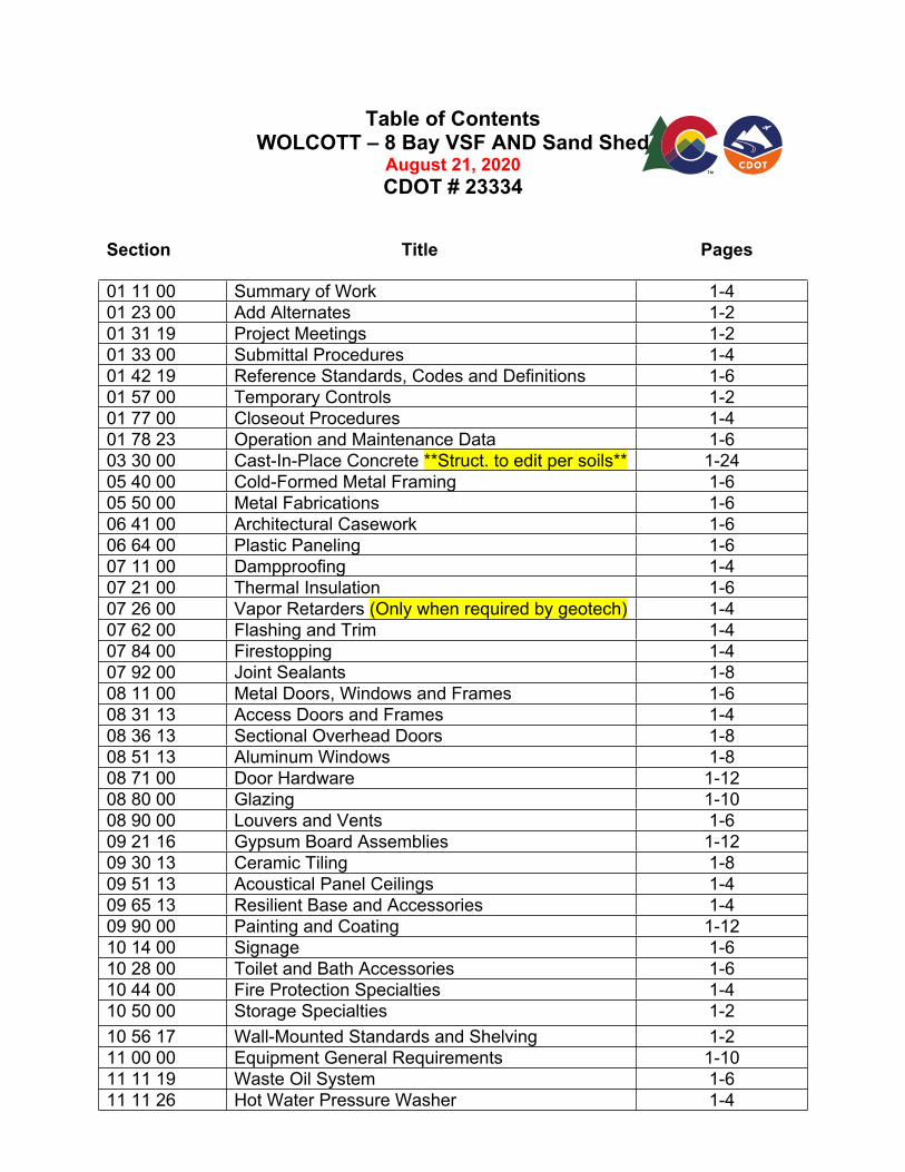
Table of Contents WOLCOTT – 8 Bay VSF AND Sand Shed
August 21, 2020
CDOT # 23334
Section Title Pages
01 11 00 Summary of Work 1-4
01 23 00 Add Alternates 1-2
01 31 19 Project Meetings 1-2
01 33 00 Submittal Procedures 1-4
01 42 19 Reference Standards, Codes and Definitions 1-6
01 57 00 Temporary Controls 1-2
01 77 00 Closeout Procedures 1-4
01 78 23 Operation and Maintenance Data 1-6
03 30 00 Cast-In-Place Concrete **Struct. to edit per soils** 1-24
05 40 00 Cold-Formed Metal Framing 1-6
05 50 00 Metal Fabrications 1-6
06 41 00 Architectural Casework 1-6
06 64 00 Plastic Paneling 1-6
07 11 00 Dampproofing 1-4
07 21 00 Thermal Insulation 1-6
07 26 00 Vapor Retarders (Only when required by geotech) 1-4
07 62 00 Flashing and Trim 1-4
07 84 00 Firestopping 1-4
07 92 00 Joint Sealants 1-8
08 11 00 Metal Doors, Windows and Frames 1-6
08 31 13 Access Doors and Frames 1-4
08 36 13 Sectional Overhead Doors 1-8
08 51 13 Aluminum Windows 1-8
08 71 00 Door Hardware 1-12
08 80 00 Glazing 1-10
08 90 00 Louvers and Vents 1-6
09 21 16 Gypsum Board Assemblies 1-12
09 30 13 Ceramic Tiling 1-8
09 51 13 Acoustical Panel Ceilings 1-4
09 65 13 Resilient Base and Accessories 1-4
09 90 00 Painting and Coating 1-12
10 14 00 Signage 1-6
10 28 00 Toilet and Bath Accessories 1-6
10 44 00 Fire Protection Specialties 1-4
10 50 00 Storage Specialties 1-2
10 56 17 Wall-Mounted Standards and Shelving 1-2
11 00 00 Equipment General Requirements 1-10
11 11 19 Waste Oil System 1-6
11 11 26 Hot Water Pressure Washer 1-4
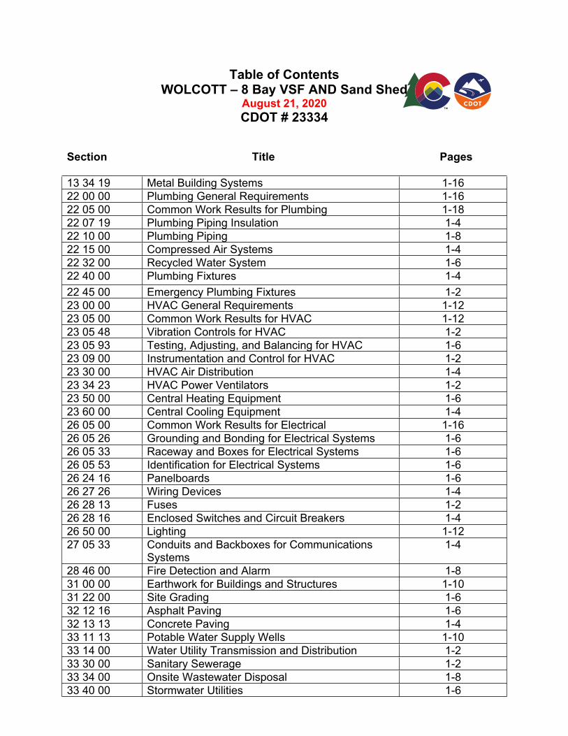
Table of Contents WOLCOTT – 8 Bay VSF AND Sand Shed
August 21, 2020
CDOT # 23334
Section Title Pages
13 34 19 Metal Building Systems 1-16
22 00 00 Plumbing General Requirements 1-16
22 05 00 Common Work Results for Plumbing 1-18
22 07 19 Plumbing Piping Insulation 1-4
22 10 00 Plumbing Piping 1-8
22 15 00 Compressed Air Systems 1-4
22 32 00 Recycled Water System 1-6
22 40 00 Plumbing Fixtures 1-4
22 45 00 Emergency Plumbing Fixtures 1-2
23 00 00 HVAC General Requirements 1-12
23 05 00 Common Work Results for HVAC 1-12
23 05 48 Vibration Controls for HVAC 1-2
23 05 93 Testing, Adjusting, and Balancing for HVAC 1-6
23 09 00 Instrumentation and Control for HVAC 1-2
23 30 00 HVAC Air Distribution 1-4
23 34 23 HVAC Power Ventilators 1-2
23 50 00 Central Heating Equipment 1-6
23 60 00 Central Cooling Equipment 1-4
26 05 00 Common Work Results for Electrical 1-16
26 05 26 Grounding and Bonding for Electrical Systems 1-6
26 05 33 Raceway and Boxes for Electrical Systems 1-6
26 05 53 Identification for Electrical Systems 1-6
26 24 16 Panelboards 1-6
26 27 26 Wiring Devices 1-4
26 28 13 Fuses 1-2
26 28 16 Enclosed Switches and Circuit Breakers 1-4
26 50 00 Lighting 1-12
27 05 33 Conduits and Backboxes for Communications Systems
1-4
28 46 00 Fire Detection and Alarm 1-8
31 00 00 Earthwork for Buildings and Structures 1-10
31 22 00 Site Grading 1-6
32 12 16 Asphalt Paving 1-6
32 13 13 Concrete Paving 1-4
33 11 13 Potable Water Supply Wells 1-10
33 14 00 Water Utility Transmission and Distribution 1-2
33 30 00 Sanitary Sewerage 1-2
33 34 00 Onsite Wastewater Disposal 1-8
33 40 00 Stormwater Utilities 1-6
Table of Contents WOLCOTT – 8 Bay VSF AND Sand Shed
August 21, 2020
CDOT # 23334
Section Title Pages
Additional Project Information:
Date: December 6, 2019
Geotechnical Report Investigation, Wolcott 8-Bay Vehicle Storage Facility, Admin Bay, and Sand Shed 26773 US Highway 6 Wolcott, Colorado
Project # 23334, Kleinfelder Project # 20170834.020
By: Kleinfelder
Project Scope of Work 1-6
Building Envelope Comcheck 1-14
WOLCOTT 8 BAY VSF AND SAND SHED SUMMARY OF WORK
SAP PROJECT # 23334 01 11 00 - 1
SECTION 01 11 00SUMMARY OF WORK
PART 1 - GENERAL
1.1 RELATED DOCUMENTS
A. Provisions of The General Conditions of the Contract (Design/Bid/Build) and Division 1 General Requirements and applicable provisions elsewhere in the contract documents apply to this Section.
1.2 PROJECT INFORMATION
A. The Project Information and Contacts are:
1. Project Title: WOLCOTT 8 BAY VSF AND SAND SHEDCDOT Project Number #XXXXX
2. Project Location: Colorado Department of Transportation26773 US HIGHWAY 6WOLCOTT, CO 81632
3. Owner: (Denver) Colorado Department of TransportationProperty Management2829 W. Howard Pl.Denver, CO 80204
4. CDOT Representative: KARM WAHAB2829 W. Howard Pl. Denver, CO 80204(P) 720-648-0141; (F) 303-512-5550e-mail: [email protected]
5. Geotechnical Engineer: KLEINFELDER1801 CALIFORNIA STREET, SUITE 1100DENVER, COLORADO 80202(P) 303-237-6601; (F) 303-237-6602Email: [email protected]
6. Architect: D2C ARCHITECTSERIC COMBS
1580 LINCOLN STREET, SUITE 1110DENVER, COLORADO(P) 303-952-4802 e-mail: [email protected]
7. Civil Engineer BASELINE ENGINEERINGNOAH NEMMERS
112 N RUBEY DRIV, SUITE 210GOLDEN, COLORADO 80403(P) 303-940-9966; (F) 303-940-9959e-mail: NOAH2BASELINECORP.COM
8. Structural Engineer: RICHARD WEINGARDT CONSULTANTS INCTOM FAST
2121 SOUTH ONEIDA STREET, SUITE 530DENVER, COLORADO 80224(P) 303-671-7033; (F) 303-671-7379
WOLCOTT 8 BAY VSF AND SAND SHED SUMMARY OF WORK
SAP PROJECT # 23334 01 11 00 - 2
TFAST@WEINGARDT,COM
9. Mechanical, Electrical, BRIDGERS & PAXTONPlumbing Engineer: STEVEN TAYLOR
1365 GARDEN OF THE GODS ROAD, SUITE 260COLORADO SPRINGS(P) 719-630-3350 [email protected]
B. The Work consists of the Architectural, Civil, Structural, Mechanical, Plumbing, and Electrical work as shown on the Drawings, specified in the Specifications and as otherwise amended by Addendum prior to bidding. Bidding General Contractors to verify tie-ins to Gas, Electrical, Water and Communications prior to submitting bids.
1. Work includes all labor, material, equipment, means and methods to perform the construction of all infrastructure, site work and buildings as shown on the Drawings.
C. Geotechnical Report: Reference Geotechnical Engineering Study, Project No. 13-2-193 Dated October 18, 2013 by Kumar & Associates, Inc.
D. Submittal Log is provided as part of the Project Documents. Submittals are due from the Contractor to the CDOT Representative on the specific dates indicated. This log delineates due dates based on the Notice to Proceed date of the project. Failure to meet these deadlines will have an effect on Contractor’s overall rating as part of the Contract Management System requirements.
1.3 CONTRACTOR USE OF PREMISES
A. General: The Contractor shall have limited use of the premises during the construction period. The existing maintenance facility on site needs to continue to function during construction. Coordinate with owner before disrupting utilities to occupied structures.
B. Limit use of premises to areas indicated or directed. Do not disturb portions of the area and site beyond the areas indicated or directed.
C. Allow for Owner occupancy and use.
D. Keep driveways and entrances clear. Unless directed, do not use these areas for parking or material storage. Schedule deliveries to minimize on-site storage of materials and equipment.
E. Work currently underway at the Site: The Contractor shall be made aware if construction work is planned or is currently underway at the site.
F. Full Owner Occupancy: The Owner will occupy and use the site during construction. Cooperate with the Owner to minimize conflicts and facilitate Owner usage. Do not interfere with the Owner's operations.
G. Owner Provided Utilities: The Owner shall make available the following utilities for use by the Contractor during construction.
1. Existing electrical; coordinate with electrical company.
H. Contractor Provided Utilities: The Contractor shall provide for the following temporary service utilities during construction:
WOLCOTT 8 BAY VSF AND SAND SHED SUMMARY OF WORK
SAP PROJECT # 23334 01 11 00 - 3
1. Telephone2. Toilets 3. Water4. Electrical Power5. Septic Permit
I. On-Site Storage: On-Site storage will need to be arranged with CDOT at pre-construction meeting.
J. Contractor Provided Permits and Fees: The Contractor shall provide for all permits and fees which may include, but not be limited to:
1. State Electrical and State Plumbing permits2. Traffic Permits3. Use Fees4. Fire Department Review by local jurisdiction, including fire alarm design review and
permit if required.5. Colorado Department of Public Health and Environment Permits required for
construction.
K. Contractor to provide fencing around construction area to secure job site and staging, at contractor’s risk.
L. Owner pays the following fees:
1. State contracted code review, inspection fees2. Tap fees3. Electrical service upgrade fees4. Fire Line Connection fees, if needed
PART 2 - PRODUCTS (Not Applicable)
PART 3 - EXECUTION (Not Applicable)
END OF SECTION
WOLCOTT 8 BAY VSF AND SAND SHED SUMMARY OF WORK
SAP PROJECT # 23334 01 11 00 - 4
THIS PAGE INTENTIONALLY LEFT BLANK
WOLCOTT 8 BAY VSF AND SAND SHED ADD ALTERNATES SAP PROJECT # 23334 01 23 00 - 1
SECTION 01 23 00 ADD ALTERNATES
PART 1 - GENERAL
1.1 GENERAL
A. Provisions of The General Conditions of the Contract (Design/Bid/Build) and Division 1 General Requirements and applicable provisions elsewhere in the contract documents apply to this Section.
1.2 DEFINITIONS
A. Alternate: An amount proposed by bidders and stated on the Bid Form for certain work defined in the bidding requirements that may be added to or deducted from the base bid amount if Owner decides to accept a corresponding change either in the amount of construction to be completed or in the products, materials, equipment, systems, or installation methods described in the Contract Documents.
1. Alternates described in this Section are part of the Work only if enumerated in the Agreement.
2. The cost or credit for each alternate is the net addition to or deduction from the Contract Sum to incorporate alternate into the Work. No other adjustments are made to the Contract Sum.
1.3 PROCEDURES
A. Coordination: Revise or adjust affected adjacent work as necessary to completely integrate work of the alternate into Project.
B. Execute accepted alternates under the same conditions as other work of the Contract.
C. Schedule: A schedule of alternates is included at the end of the Section. Specification Sections referenced in schedule contain requirements for materials necessary to achieve the work described under each alternate.
PART 2 - PRODUCTS (Not used)
PART 3 - EXECUTION
3.1 SCHEDULE OF ALTERNATES
A. Add. Alternate No. 1: TITLE OF ALTERNATE
1. Base Bid: Embedded Steel Pipe Bollards. Embedded steel pipe bollards shall be 10 inch nominal diameter as indicated in spec section 055000 metal fabrication sub section 2.4.
WOLCOTT 8 BAY VSF AND SAND SHED ADD ALTERNATES SAP PROJECT # 23334 01 23 00 - 2
2. Add. Alternate: 6 inch bollard, concrete filled, install to a depth as needed for a 6” bollard, standard metal pain on bollard in lieu of Tnemec paint.
END OF SECTION
WOLCOTT 8 BAY VSF AND SAND SHED PROJECT MEETINGS
SAP PROJECT # 23334 01 31 19 - 1
SECTION 01 31 19PROJECT MEETINGS
PART 1 - GENERAL
1.1 RELATED DOCUMENTS
A. Provisions of The General Conditions of the Contract (Design/Bid/Build) and Division 1 General Requirements and applicable provisions elsewhere in the contract documents apply to this Section.
1.2 SUMMARY
A. This Section specifies administrative and procedural requirements for project meetings, including, but not limited to, the following:1. Preconstruction Conference2. Construction Progress meetings3. Project Closeout (Punch List) meeting4. Project Final Inspection
1.3 CONSTRUCTION MEETINGS
A. Preconstruction Conference: Contractor shall attend a preconstruction conference, to be held at the site of the Work, before starting construction to review responsibilities, personnel assignments, and any other pertinent construction related issues. The time of the preconstruction conference is to be determined by the CDOT Representative. CDOT Representative will provide notification to the Contractor.1. Attendees: Authorized representatives of the CDOT, Engineer, Engineer's Sub-
Consultants (as needed); the Contractor; subcontractors; and other concerned parties shall attend. Participants shall be familiar with the Project and authorized to conclude matters relating to the Work.
2. Agenda: Discuss items that could affect progress, including, but not limited to the following:a. Tentative construction scheduleb. Critical work sequencingc. Conformance with CDOT procedures (CDOT Standard Specifications for Road and
Bridge Construction, Current Edition)d. Submittalse. Development of Coordination Drawingsf. Use of the premisesg. Anticipated interval of subsequent construction progress meetingsh. Location of existing easements and requirements regarding work on, near, or under
existing easements
B. Environmental Preconstruction Conference: Prior to construction or any earthwork being performed, an on-site Environmental Preconstruction Conference shall be held. The time of the environmental preconstruction conference is to be determined by the CDOT Representative. This conference can be held concurrently with the preconstruction conference. 1. The conference shall be attended by:
a. The CDOT Representativeb. The CDOT Region Water Pollution Control Manager (RWPCM)
WOLCOTT 8 BAY VSF AND SAND SHED PROJECT MEETINGS
SAP PROJECT # 23334 01 31 19 - 2
c. The CDOT Personnel (e.g. CDOT Landscape Architect) who prepared or reviewed the Stormwater Management Plan (SWMP)
d. The Contractor’s Superintendente. The Contractor’s SWMP Administratorf. Supervisors or Foremen of subcontractors working on the project
2. Agenda: At this conference, the attendees shall discuss the SWMP, the Colorado Department of Public Safety Stormwater Construction Permit (CDPS – SCP), sensitive habitats on site, wetlands, other vegetation to be protected, individual’s responsibilities, required inspections and the enforcement mechanisms for not meeting the requirements of this specification.
C. Construction Progress Meetings: Attend construction progress meetings at the Project Site at regular intervals as scheduled by the CDOT Representative. It is anticipated that a Construction Progress Meeting shall take place during each site observation visit that will be conducted by the CDOT Representative; contractor will notify pertinent sub-contractors. 1. Attendees: The CDOT Representatives, the Contractor, subcontractors; and other
concerned parties shall attend. All parties concerned with current progress or involved in planning, coordination, or future activities shall be represented. Participants shall be authorized to conclude matters relating to the Work.
2. Agenda: Review minutes of the previous construction progress meetings. Review items of significance that could affect progress. Include topics for discussion appropriate to Project status.
1.4 CLOSEOUT MEETINGS
A. Project Closeout (Punch List) Meeting: Attend project closeout (punch list) meeting, to be conducted at the Project Site, after issuance of notification to the CDOT Representative of substantial completion. The timing of the project closeout (punch list) meeting shall be determined by the CDOT Representative. The CDOT Representative will provide notification to the Contractor. The Contractor shall be made aware that a Project Closeout (Punch List) Meeting shall not be scheduled by the CDOT Representative unless, in the opinion of the CDOT Representative, the total number of minor items that are anticipated to be included on the punch list shall be ten (10) or less and include no major structural, inspection or other major issues.1. Attendees: The CDOT Representative, Architect, Engineer and their Sub-Consultants
(as needed), CDOT State Buildings Delegee, the Contractor, subcontractors; Owner’s code consultant and other concerned parties shall attend. All parties concerned with project closeout events. Participants shall be authorized to perform project closeout tasks.
2. Agenda: Project Closeout (Punch List) Meeting is to be conducted by the CDOT Representative. Review project closeout procedures, perform Punch List walk-through of the work for the purpose of demonstrating to the Owner, Architect, Engineer, and Engineer’s Sub-Consultants (as needed) and code compliance consultant that the work has been performed and completed within the guidelines set forth in the Contract Documents.
3. Record Documents: During the project closeout meeting, the Contractor shall make arrangements to transfer the record documents to the CDOT Representative.
4. Building Permit(s): During the project closeout meeting, the Contractor shall show evidence to the CDOT Representative that all necessary building permits have been signed off by the governing code authority on the Project’s Building Inspection Report Yellow Card (State Buildings Form SBP-BIR).
5. Contract Closeout Final Punch List is written by CDOT Representative and communicated to Contractor on State Buildings Form SBP 06 – Rev. 9/2006.
B. Project Final Inspection Meeting: Project Final Inspection written by CDOT State Buildings
WOLCOTT 8 BAY VSF AND SAND SHED PROJECT MEETINGS
SAP PROJECT # 23334 01 31 19 - 3
Delegee and communicated to Contractor.1. Attendees: The CDOT Representative, Architect, Engineer, Sub-Consultants (as
needed), CDOT State Buildings Delegee, the Contractor, subcontractors; Owner’s code consultant and other concerned parties shall attend. All parties concerned with project closeout events. Participants shall be authorized to perform remaining punch list items.
2. Agenda: Final Inspection Meeting is to be conducted by the CDOT Representative. Review project closeout procedures, perform final walk-through of the work for the purpose of demonstrating to the Owner, Architect, Engineer, and Engineer’s Sub-Consultants (as needed) and code compliance consultant that the punch list items has been performed and completed within the guidelines set forth in the Contract Documents.
3. Contract Closeout Final Punch List is written by Owner and communicated to Contractor on State Buildings Form SBP 06 – Rev. 9/2006.
PART 2 - PRODUCTS (Not Applicable)
PART 3 - EXECUTION (Not Applicable)
END OF SECTION

WOLCOTT 8 BAY VSF AND SAND SHED PROJECT MEETINGS
SAP PROJECT # 23334 01 31 19 - 4
THIS PAGE INTENTIONALLY LEFT BLANK
WOLCOTT 8 BAY VSF AND SAND SHED SUBMITTAL PROCEDURES
SAP PROJECT # 23334 01 33 00 - 1
SECTION 01 33 00SUBMITTAL PROCEDURES
PART 1 - GENERAL
1.1 RELATED DOCUMENTS
A. Provisions of The General Conditions of the Contract (Design/Bid/Build) and Division 1 General Requirements and applicable provisions elsewhere in the contract documents apply to this Section.
1.2 SUMMARY
A. This Section specifies requirements for handling submittals.
1.3 GENERAL PROCEDURES
A. Coordinate submittal preparation with performance of construction activities, and with purchasing or fabrication, delivery, other submittals and related activities. Transmit per the due dates listed per activity on the Submittal Log provided by CDOT Representative.
B. Coordinate transmittal of different submittals for related elements so processing will not be delayed by the need to review concurrently for coordination. Submit four (4) copies of paper submittals and/or an electronic copy, a minimum of one (1) stamped copy and/or an electronic copy will be returned to contractor. Electronic submittals are acceptable for all submittals except in the case where engineer-stamped drawings are required or color selection or material selection is required. The CDOT Representative reserves the right to withhold action on a submittal requiring coordination until all related submittals are received.
C. Processing: Contractor shall allow ten working days beyond the date at which the submittal arrives for initial review. Allow more time if processing must be delayed for coordination with other submittals. The CDOT Representative will advise the Contractor when a submittal must be delayed for coordination.
1. No extension of time will be authorized because of failure to transmit submittals sufficiently in advance of the Work to permit processing.
D. Substitutions: Contractor may submit “like” products for review/acceptance. Contractor must provide specific documentation evidencing that proposed product meets complete specification. CDOT Representative may reject substitution. Any substitutions must comply with agreed-upon Submittal Log Date.
E. Submittal Preparation: Place a label or title block on each submittal for identification. Include the following minimum information on the label:
1. CDOT Project Name and Project Number2. Date (of transmittal to CDOT Representative)3. Name, address, and telephone number of Contractor4. Indication of review by Contractor, date, and result of review. Submittals without
Contractor review stamp will not be accepted and will be returned without review.5. Specification Section and Submittal Schedule number, the products included in the
WOLCOTT 8 BAY VSF AND SAND SHED SUBMITTAL PROCEDURES
SAP PROJECT # 23334 01 33 00 - 2
Submittal relating to Submittal clearly referenced on the submittal package.6. Subsequent resubmittals require a suffix to the Submittal Section number identifying the
resubmittal as such.7. Meet agreed-upon Submittal Schedule
F. Submittal Transmittal: Package submittals appropriately for transmittal and handling. Transmit with a transmittal form identifying the name of the Submittal and product, the Specification Section, and the Submittal Schedule number.
G. Project-Specific Submittal Log: Owner will provide a project-specific Submittal Log to Contractor at the Project Pre-Construction Meeting. Submittals are due from Contractor to CDOT Representative on the specific dates indicated. At Pre-construction meeting, CDOT Representative will provide contractor proposed schedule of submittal due dates for review. Contractor must propose any date changes within seven (7) days of pre-construction meeting. The Submittal Log delineates due dates based on the Notice to Proceed date of the project. Failure to meet these submittal deadlines will have an effect on the Contractor’s overall rating as part of the State’s Contract Management System requirements.
H. Contractor's Construction Schedule: The Contractor shall submit a written/electronic detailed construction schedule within 21 calendar days of receiving the Notice to Proceed from the CDOT Representative. Provide for separation of major construction activities. Provide starting and completion dates for major construction activities.
I. Weekly Construction Reports: Contractor shall prepare a weekly construction report recording information concerning events at the site. Report shall be sent electronically every Friday by 8:00 a.m. recapping the current week’s activities and projecting the next week’s activities, for each work day. Weekly progress photos should be included with this report. Submit one copy to the CDOT Representative, electronic files are preferred. Reports shall include the following information:
1. Substantial completions.2. General weather conditions, if applicable.3. Accidents, stoppages, delays, shortages, losses. (Note: any accidents or delays/losses
need to be communicated verbally to Owner at the time of incident.)4. Change Order Bulletins, Change Order Proposals, Change Orders, Emergency Change
Orders, or Field Orders received and/or implemented. Written report does not substitute for verbal telephone communication by Contractor to CDOT Representative on any pertinent issue.
J. Manufacturer's Operations and Maintenance Manuals/Instructions: See Section 01 78 23 Operations and Maintenance Data for more detailed information.
K. Shop Drawings: Submit new information, drawn to accurate scale. Indicate deviations from Contract Documents. Do not reproduce Contract Documents or copy standard information as the basis of Shop Drawings. Include the following information:
1. Dimensions, elevations, heights, etc.2. Identification of products and materials included.3. Notation of dimensions established by field measurement.
L. Coordination Drawings: General Contractor is required to prepare Coordination Drawings incorporating approved product and system submittal information to include: Floor plans, reflected ceiling plans and/or building sections and details as appropriate, drawn to scale and dimensioned, and coordinating penetrations, mounting, clearances, embeds for the following, as identified by Systems:
WOLCOTT 8 BAY VSF AND SAND SHED SUBMITTAL PROCEDURES
SAP PROJECT # 23334 01 33 00 - 3
1. System 1: Piping penetrations through approved foundation system and slab; piping below slab including invert elevations and slop of piping, slope of floor, incorporating drain and grate elevations.
2. System 2: Metal building structure and framing, concrete curbs, foundations, and column bases; Steel stair system, insulation system meeting the requirements of IECC 2015; Track mounting clearance and attachment for overhead door system including concrete curbs and column bases and adjacency to metal building structure and framing.
3. System 3: Lighting and fans, and clerestory glazing to ensure required clearance at overhead door openings; Ceiling-mounted items including lighting fixtures, ceiling fans, diffusers, grilles, speakers, sprinklers (if required), radiant heat system, exhaust and ventilation system, access panels, vents, compressed air piping.
4. General Contractor shall provide the anticipated delivery dates of Coordination Drawings Systems to be reviewed, and verify the content of the Coordination Drawings package or packages.
5. General Contractor shall advise the CDOT Representative of conflicts in the system engineering and coordination within five (5) days after discovery of the conflict.
6. General Contractor shall identify the subcontractor responsible for producing the Coordination Drawings within the first 30 days of the project, including the anticipated schedule for completion of each System.
7. Coordination drawings that have been produced in a standard CADD or Revit drawing format will be provided to the CDOT Representative, Architect and Engineer as PDF files.
8. CDOT Representative, Architect and Engineers will provide comments within five (5) days of receipt of Coordination Drawing package.
9. Coordination Drawing System packages are each a one-time submittal, reviewed by the CDOT Representative, Architect and Engineers for compliance with design intent.
M. Submittal: Submit electronic drawings or correctable, translucent, reproducible print(s) and one copy made from the translucent, reproducible print(s) for review if the submittal is in the form of a drawing. Submit one electronic or four identical copies for review if the submittal is in the form of cut sheets, written data, etc. Submit one sample or color chip for review if the submittal is a color selection or product sample. The reproducible print(s) (if submittal is in the form of a drawing) or one copy (if the submittal is in the form of cut sheets, written data, etc.) will be returned to the Contractor marked with action taken and corrections or modifications required after review by Architect, Owner, Engineers and Code Reviewer. The Contractor shall make all necessary copies of the returned reproducible print or copy for distribution to Sub-Contractors or affected parties. Submittals must have the stamp and signature of the Contractor, indicating the General Contractor has reviewed the Submittal prior to submission to the Architect, Owner, Engineer, and Code Reviewer. Submittals not reviewed by General Contractor will be returned un-reviewed by the CDOT Representative.
N. Do not fabricate or install any items from Shop Drawings without a final stamp from the CDOT Representative, Architect or Engineer which indicates action to be taken (if any) by the Contractor.
O. Product Data: Collect Product Data into a single submittal for each element or system. Mark each copy to show applicable choices and options. Where Product Data includes information on several products, some of which are not required, mark copies to indicate the applicable information. Include, as applicable, the following information:
1. Manufacturer's printed recommendations.2. Compliance with recognized testing agency standards and with the requirements of the
Specifications.3. Application of testing agency labels and seals.4. Submittal: Submit four identical copies or an electronic copy of product data. One copy
WOLCOTT 8 BAY VSF AND SAND SHED SUBMITTAL PROCEDURES
SAP PROJECT # 23334 01 33 00 - 4
will be returned to the Contractor marked with action taken and corrections or modifications required after review by Architect, Owner, Engineers and Code Reviewer. The Contractor shall make all necessary copies of the returned submittal for distribution to Sub-Contractors or affected parties.
P. Submittal Action: CDOT Representative, Architect, or Engineers will review each submittal, mark to indicate action taken, and return. Compliance with specified characteristics is the Contractor's responsibility.
Q. Action Stamp: The CDOT Representative, Architect, or Engineer will stamp each submittal with an action stamp or transmittal. The stamp or transmittal will be marked to indicate action to be taken.
PART 2 - PRODUCTS (Not Applicable)
PART 3 - EXECUTION (Not Applicable)
END OF SECTION
WOLCOTT 8 BAY VSF AND SAND SHED REFERENCE STANDARDS,SAP PROJECT # 23334 CODES AND DEFINITIONS
01 42 19 - 1
SECTION 01 42 19REFERENCE STANDARDS, CODES AND DEFINITIONS
PART 1 - GENERAL
1.1 RELATED DOCUMENTS
A. Related Documents: Provisions of The General Conditions of the Contract (Design/Bid/Build) and Division 1 General Requirements and applicable provisions elsewhere in the contract documents apply to this Section.
1.2 DEFINITIONS
A. Indicated refers to graphic representations, notes, or schedules on the Drawings, paragraphs or Schedules in the Specifications, and similar requirements in the Contract Documents. Terms such as shown, noted, scheduled, and specified are used to help the reader locate the reference. Location is not limited.
B. Directed, requested, authorized, selected, approved, required, and permitted mean directed by the CDOT Representative, requested by the CDOT Representative, and similar phrases.
C. Reviewed, when used in conjunction with the CDOT Representative's action on submittals, applications, and requests, is limited to the CDOT Representative’s duties and responsibilities as stated in the Conditions of the Contract.
D. Regulations include laws, ordinances, statutes, and lawful orders issued by authorities having jurisdiction, as well as rules, conventions, and agreements within the construction industry that control performance of the Work.
E. Furnish means supply and deliver to the Project Site, ready for unloading, unpacking, assembly, installation, and similar operations.
F. Install describes operations at the Project Site including unloading, unpacking, assembly, erecting, placing, anchoring, applying, working to dimension, finishing, curing, protecting, cleaning, and similar operations.
G. Provide means to furnish and install, complete and ready for the intended use.
H. Installer is the Contractor or another entity engaged by the Contractor, either as an employee, subcontractor, or contractor of lower tier, to perform a particular construction activity, including installation, erection, application, and similar operations. Installers are required to be experienced in the operations they are engaged to perform.
I. The term experienced, when used with the term Installer, means having a minimum of 5 previous projects similar in size and scope to this Project, being familiar with the special requirements indicated, and having complied with requirements of the authorities having jurisdiction.
J. Project Site is the space available for performing construction activities, either exclusively or in conjunction, with others performing work as part of the Project.
WOLCOTT 8 BAY VSF AND SAND SHED REFERENCE STANDARDS,SAP PROJECT # 23334 CODES AND DEFINITIONS
01 42 19 - 2
K. Testing Agency is an independent entity, or Geotechnical Company of Record, engaged to perform specific inspections or tests, either at the Project Site or elsewhere, or to report on and, if required, to interpret results of those inspections or tests.
L. Specifications are organized into Divisions and Sections based on the Construction Specifications Institute's 2004 format.
M. Abbreviated Language: Language used in Specifications is abbreviated. Implied words and meanings shall be interpreted as appropriate. Singular words shall be interpreted as plural and plural words interpreted as singular where applicable as the context of the Contract Documents indicates.
N. Imperative and streamlined language is used. Requirements expressed in the imperative mood are to be performed by the Contractor. At certain locations in the Text, subjective language is used for clarity to describe responsibilities that must be fulfilled indirectly by the Contractor, or by others when so noted.
1. The words "shall be" are implied where a colon (:) is used within a sentence or phrase.
O. Abbreviations and Names: Where acronyms or abbreviations are used in the Specifications or other Contract Documents, they mean the recognized name of the trade association, standards-generating organization, authorities having jurisdiction, or other entity applicable to the context of the text provision. Refer to the "Encyclopedia of Associations," published by Gale Research Co., available in most libraries.
P. Permits, Licenses, and Certificates: For the Owner's records, submit copies of permits, licenses, certifications, inspection reports, releases, jurisdictional settlements, notices, receipts for fee payments (including taxes), judgments, correspondence, records, and similar documents, established in conjunction with compliance with standards and regulations bearing upon performance of the Work.
1.3 CODES, ORDINANCES, PERMITS AND FEES
A. Execute work per underwriters, public utility, local, state codes, ordinances, and regulations applicable. Contact city water and sewer agencies for verification of all requirements, permits, state fees and inspections prior to submitting bid. Obtain and pay for state plumbing and state electrical required permits, inspections, utility service connections, meters and certificates. Systems development fees and similar charges are not to be included in the bid, as they will be paid directly to the utility agency by the Owner upon notification. Notify CDOT Representative of items not meeting said requirements.
B. This Contractor shall include in the work, all labor, materials, services, apparatus and drawings, in order to comply with all applicable laws, ordinances, rules and regulations, whether or not shown on drawings and /or specified.
C. All materials furnished and all work installed shall comply with the National Fire Codes of the National Fire Protection Association, with the requirements of local utility companies, and with the requirements of all governmental departments having jurisdiction. In the event of a conflict, applicable codes and ordinances shall take precedence over this specification or contract drawings.
D. All material and equipment for the electrical portion of the mechanical systems shall bear the approval label of, or shall be listed by the Underwriter's Laboratories, Incorporated, and shall be installed in compliance with the National Electric Code.
WOLCOTT 8 BAY VSF AND SAND SHED REFERENCE STANDARDS,SAP PROJECT # 23334 CODES AND DEFINITIONS
01 42 19 - 3
E. Comply with the latest edition and/or the adopted edition of the following codes and standards as a minimum Approved State Building Codes:
The following approved building codes and standards have been adopted by State Buildings Programs (SBP) and other state authorities. These minimum requirements are to be applied to all construction at state agencies and institutions of higher education owned facilities including capital construction and controlled maintenance construction projects:
The 2018 edition of the International Building Code (IBC)(As adopted by the Colorado State Buildings Program as follows: Chapter 1 as amended, Chapters 2-35 and Appendices C and I)
The 2018 edition of the International Existing Building Code (IEBC)(As adopted by the Colorado State Buildings Program as follows: Chapters 2-16, Appendices A-C and Resource A)
The 2018 edition of the International Mechanical Code (IMC)(As adopted by the Colorado State Buildings Program as follows: Chapters 2-15 and Appendix A)
The 2018 edition of the International Energy Conservation Code (IECC)(As adopted by the Colorado State Buildings Program)Commercial Energy Efficiency to comply with the requirements of ANSI/ASHRAE/IESNA Standard 90.1 – 2016 in accordance with Section C401.2.1 of the 2018 IECC.
The 2017 edition of the National Electrical Code (NEC)(National Fire Protection Association Standard 70) (As adopted by the Colorado State Electrical Board)
The 2018 edition of the International Plumbing Code (IPC)(As adopted by the Colorado Examining Board of Plumbers)
The 2018 edition of the International Fuel Gas Code (IFGC)(As adopted by the Colorado Examining Board of Plumbers)
The National Fire Protection Association Standards (NFPA)(as adopted by the Department of Public Safety/Division of Fire Prevention and Control)
The 2018 edition of the International Fire Code (IFC)(The 2015 edition continues to be adopted by the Department of Public Safety/Division of Fire Prevention and Control (DFPC). Projects requiring DFPC review should be designed with the most restrictive requirements)
The 2015 edition of the ASME Boiler and Pressure Vessel Code(As adopted by the Department of Labor and Employment/Boiler Inspection Section)
The 2017 edition of the National Boiler Inspection Code (NBIC)(As adopted by the Department of Labor and Employment/Boiler Inspection Section)
The 2015 edition of the Controls and Safety Devices for Automatically Fired Boilers CSD-1(As adopted by the Department of Labor and Employment/Boiler Inspection Section)
The 2015 edition of the Boiler and Combustion Systems Hazards Code, NFPA 85(As adopted by the Department of Labor and Employment/Boiler Inspection Section)
WOLCOTT 8 BAY VSF AND SAND SHED REFERENCE STANDARDS,SAP PROJECT # 23334 CODES AND DEFINITIONS
01 42 19 - 4
The 2013 edition of ASME A17.1 Safety Code for Elevators and Escalators(As adopted by the Department of Labor and Employment/Conveyance Section)
The 2005 edition of ASME A17.3 Safety Code for Existing Elevators and Escalators(As adopted by the Department of Labor and Employment/Conveyance Section)
The 2011 edition of ASME A18.1 Safety Standard for Platform Lifts and Stairway Chairlifts(As adopted by the Department of Labor and Employment/Conveyance Section)
The current edition of the Rules and Regulations Governing the Sanitation of Food Service Establishments(As adopted by the Department of Public Health and Environment/Colorado State Board of Health)
The 2017 edition of ICC/ANSI A117.1, Accessible and Usable Buildings and Facilities(As adopted by the Colorado General Assembly as follows: CRS 9-5-101, as amended, for accessible housing)
Sheet Metal and Conditioning Contractors National Assoc. Standards (SMACNA)
American Water Works Association (A.W.W.A.)
Local Utility Company Requirements
Local Governing Fire Department Requirements
National Electrical Manufacturers Association (N.E.M.A.)
Air Movement and Control Association (A.M.C.A.)
American Concrete Institute (A.C.I.)
Note: Additional codes, standards and appendices may be adopted by the state agencies and institutions in addition to the minimum codes and standards herein adopted by State Buildings Programs.
1. The 2018 edition of the IBC became effective on July 1, 2019. Consult the state electrical and plumbing boards and the state boiler inspector and conveyance administrator and the Division of Fire Prevention and Control for adoption of current editions and amendments to their codes.
2. Projects should be designed and plans and specifications should be reviewed based upon the approved codes at the time of A/E contract execution. If an agency prefers to design to a different code such as a newer edition of a code that State Buildings Programs has not yet adopted, the agency must contact SBP for approval and then amend the A/E contract with a revised Exhibit C, Approved State Building Codes. Please note that the state plumbing and electrical boards enforce the editions of their codes that are in effect at the time of permitting not design.
3. The state’s code review agents, or the State Buildings Programs approved agency building official, shall review all documents for compliance with the codes stipulated herein. Note: The Department of Public Health and Environment, Division of Consumer Protection will review drawings for food service related projects.
WOLCOTT 8 BAY VSF AND SAND SHED REFERENCE STANDARDS,SAP PROJECT # 23334 CODES AND DEFINITIONS
01 42 19 - 5
4. This policy does not prohibit the application of various life safety codes as established by each agency for specific building types and funding requirements. NFPA 101 and other standards notwithstanding, approved codes will supersede where their minimum requirements are the most restrictive in specific situations. If a conflict arises, contact State Buildings Programs for resolution.
5. It is anticipated that compliance with the federal Americans with Disabilities Act Accessibility Guidelines for Buildings and Facilities (ADAAG) and Colorado Revised Statutes Section 9-5-101 will be met by compliance with the 2018 International Building Code and ICC/ANSI A117.1. However, each project may have unique aspects that may require individual attention to these legislated mandates.
6. The 2018 edition of the International Building Code (IBC) is to be applied to factory-built nonresidential structures as established by the Division of Housing within the Department of Local Affairs.
F. Appendices
Appendices are provided to supplement the basic provisions of the codes. Approved IBC Appendices are as follows:
1. MandatoryIBC Appendix Chapter C - Agricultural BuildingsIBC Appendix Chapter I - Patio Covers
2. OptionalAny non-mandatory appendix published in the International Building Code may be utilized at the discretion of the agency. Use of an appendix shall be indicated in the project code approach.
G. Amendments
1. International Building Code, Chapter 1 as amended
H. Referenced Standards
1. The IBC, IMC, IECC, IPC and IFGC standards shall be utilized to provide specific, or prescriptive, requirements on how to achieve the requirements established in the code. These standards may be unique to the code or may be derived from other established industry standards. Recognized standards may also be used to show compliance with the standard of duty established by the code.
PART 2 - PRODUCTS (Not Applicable)
PART 3 - EXECUTION (Not Applicable)
END OF SECTION
WOLCOTT 8 BAY VSF AND SAND SHED TEMPORARY CONTROLS
SAP PROJECT # 23334 01 57 00 - 1
SECTION 01 57 00TEMPORARY CONTROLS
PART 1 – GENERAL
1.1 RELATED DOCUMENTS
A. Provisions of The General Conditions of the Contract (Design/Bid/Build) and Division 1 General Requirements and applicable provisions elsewhere in the contract documents apply to this Section. The “Standard Specifications” when referenced hereinafter shall mean the Colorado Department of Transportation, Standard Specifications for Road and Bridge Construction, current edition.
1.2 SUMMARY
A. This Section includes the following:
1. Water Control 2. Dust Control 3. Erosion and Sediment Control
B. Related Sections include the following:
1. Section 01 11 00: Summary of Work 2. Section 01 42 19: Reference Standards, Codes and Definitions
C. References:
1. Stormwater Management Plan (SWMP) shall be provided by the Owner.2. CDOT Standard Specification for Road and Bridge Construction, current edition.
1.3 PERFORMANCE REQUIREMENTS
A. Best Management Practices in compliance with the “Standard Specifications” Section 208 Erosion Control and the SWMP, specific to the project.
B. Water Control
1. Grade site to drain. Maintain excavations free of water. Provide, operate and maintain pumping equipment.
2. Protect site from puddling, ponding, or running water. Provide water barriers as required to protect site from soil erosion.
C. Dust Control
1. Execute the Work by methods to minimize raising dust from construction operations.2. Provide positive means to prevent air-borne dust from dispersing into atmosphere.
D. Erosion and Sediment Control
1. Plan and execute construction by methods to control surface drainage from cuts and fills, from borrow and waste disposal areas. Prevent erosion and sedimentation.
2. Minimize amount of bare soil exposed at one time.
WOLCOTT 8 BAY VSF AND SAND SHED TEMPORARY CONTROLS
SAP PROJECT # 23334 01 57 00 - 2
3. Provide temporary measures such as berms, dikes, and drains, to prevent water flow.4. Construct fill and waste areas by selective placement to avoid erosive surface silts or
clays.
E. Failure to Perform Erosion Control
1. Failure to implement the Stormwater Management Plan may result in penalties including liquidated damages for failure to meet the Permit requirements. Enforcement shall be in accordance with Subsection 208.09 of the Standard Specifications.
PART 2 - PRODUCTS
A. Materials shall be in accordance with Subsection 208.02 of the Standard Specification.
PART 3 - EXECUTION
Not used.
END OF SECTION
WOLCOTT 8 BAY VSF AND SAND SHED CLOSEOUT PROCEDURES
SAP PROJECT # 23334 01 77 00 - 1
SECTION 01 77 00CLOSEOUT PROCEDURES
PART 1 - GENERAL
1.1 RELATED DOCUMENTS
A. Provisions of The General Conditions of the Contract (Design/Bid/Build) and Division 1 General Requirements and applicable provisions elsewhere in the contract documents apply to this Section.
1.2 COMPLETION AND ACCEPTANCE OF THE WORK
A. The Contractor shall communicate to CDOT Representative that project is substantially complete. CDOT Representative will schedule a Project Closeout (Punch List) Meeting. The project shall be considered complete when, in the CDOT Representative’s opinion, a list of incomplete work does not exceed ten (10) minor items of the Work. Should the CDOT Representative determine that the work is not complete, the CDOT Representative will immediately notify the Contractor, in writing, stating reasons why the project is not considered complete. Project is not considered complete if there are major issues outstanding or incomplete or failed inspections. Should the CDOT Representative determine that the work is complete, after the walk through; the CDOT Representative will prepare and issue a punch list of deficiencies that need to be corrected before final acceptance. After Contractor brings the project into a state of completion, a Final Inspection Meeting shall be set up by the CDOT Representative. The Contractor is made aware that all additional costs associated with re-inspection shall be paid from monies otherwise earned by the Contractor. These costs shall include the CDOT Representative’s labor (time) and all associated costs of travel to the project site to attend the follow-up Project Closeout (Punch List) Meeting.
1.3 RECORD DRAWINGS
A. Maintain a clean, undamaged set of Contract Drawings. Mark-up these drawings to show the actual installation. Give particular attention to concealed elements that would be difficult to measure and record at a later date. The Record Drawings shall be kept current and shall be marked-up as necessary during the course of executing the Work. If requested by the CDOT Representative, the Contractor shall show evidence that the Record Drawings are current as a precedent to approval of Contractor Payment Applications.
1.4 RECORD SPECIFICATIONS, FINAL AS-BUILT PLANS AND SURVEY
A. Maintain one copy of the Project Contract, including addenda. Mark to show variations in actual Work performed in comparison with the Specifications and modifications. The Record Specifications shall be kept current and shall be marked-up as necessary during the course of executing the Work. Give particular attention to substitutions, selection of options and similar information on elements that are concealed or cannot be readily discerned later by direct observation. If requested by the CDOT Representative, the Contractor shall show evidence that the Record Specifications are current as a precedent to approval of Contractor Payment Applications.
B. Provide an as-built survey completed by a certified surveyor indicating final location of all underground utilities as well as the as-built construction of all permanent Storm Water Management structures.
WOLCOTT 8 BAY VSF AND SAND SHED CLOSEOUT PROCEDURES
SAP PROJECT # 23334 01 77 00 - 2
C. Upon completion of Project, one (1) paper copy, and two (2) electronic PDF versions on a USB storage drive, of final, accurate as-built drawings and survey shall be delivered to the CDOT Representative. This complete submittal shall include all drawings, including architectural, structural, civil, mechanical, electrical, plumbing and fire.
1.5 SYSTEM COMMISSIONING
A. Prior to Project Closeout, HVAC testing, adjusting and balancing and lighting system functional testing must be completed in accordance with the IECC Section C408 and shown to be compliant with drawings and specifications. Contractor shall submit reports to owner and code reviewer at the Project Closeout meeting.
1. HVAC testing shall be provided by the contractor at the Contractor’s cost in accordance with Section 23 05 93 Testing, Adjusting and Balancing.
2. Lighting System Function Testing shall be completed at CDOT’s cost by the Electrical Engineer for the project in accordance with IECC Section C408. Contractor to notify owner when project is ready for inspection. If inspection is failed, re-inspection is at Contractor’s cost.
1.6 OPERATIONS AND MAINTENANCE (O & M) MANUAL
A. Refer to Section 01 78 23, Operations & Maintenance Data, for further information on O & M specifics.
1.7 START-UP, OPERATING AND MAINTENANCE TRAINING AND INSTRUCTION
A. Unless directed otherwise in Divisions 11, 13, 22, 23 or 26, the Contractor shall arrange for training and instruction of the Owner's personnel in proper start-up, operation and maintenance procedures for all devices and equipment installed in this contract. All training and instruction is intended to be completed in one session, however, at the mutual consent of the Contractor and Owner, more than one session may take place. Schedule training with CDOT Representative, most likely to take place on the day of the Substantial Completion Walk Through. The total length of the training and instruction session(s) shall not exceed 8 hours unless mutually agreed upon by the Owner and the Contractor. Training and instruction in excess of 8 hours shall not be compensated by the Owner. Training and Instruction shall include, but not be limited to, the following topics:
1. Start-up procedures2. Operating instructions3. Shut-down procedures4. Review of Operating and Maintenance manuals
1.8 FINAL CLEANING
A. Complete the following before providing notification that the work is complete:
1. Remove labels that are not permanent labels.2. Clean exposed hard-surfaced finishes to a dust-free condition, free of stains, films and
similar foreign substances.3. Clean the site of rubbish, litter and other foreign substances. See Special Conditions.
B. Compliance: Comply with regulations of authorities having jurisdiction and safety standards
WOLCOTT 8 BAY VSF AND SAND SHED CLOSEOUT PROCEDURES
SAP PROJECT # 23334 01 77 00 - 3
for cleaning. Remove waste materials from the site and dispose of in a lawful manner.
PART 2 - PART 2 - PRODUCTS (Not Applicable)
PART 3 - PART 3 - EXECUTION (Not Applicable)
END OF SECTION

WOLCOTT 8 BAY VSF AND SAND SHED CLOSEOUT PROCEDURES
SAP PROJECT # 23334 01 77 00 - 4
THIS PAGE INTENTIONALLY LEFT BLANK
WOLCOTT 8 BAY VSF AND SAND SHED OPERATION AND MAINTENANCE DATA
SAP PROJECT # 23334 01 78 23 - 1
SECTION 01 78 23OPERATIONS AND MAINTENANCE DATA
PART 1 - GENERAL
1.1 RELATED DOCUMENTS
A. Provisions of The General Conditions of the Contract (Design/Bid/Build) and Division 1 General Requirements and applicable provisions elsewhere in the contract documents apply to this Section.
1.2 SUMMARY
A. This Section includes administrative and procedural requirements for preparing operation and maintenance manuals, including the following:
1. Operation manuals for systems and equipment2. Maintenance manuals for the care and maintenance of systems and equipment
B. Related Sections include the following:
1. Section 01 33 00: "Submittal Procedures" for submitting copies of operation and maintenance manuals.
2. Section 01 77 00: “Closeout Procedures” for timing of Operation and Maintenance Training for Owner.
1.3 DEFINITIONS
A. System: An organized collection of parts, equipment, or subsystems united by regular interaction.
B. Subsystem: A portion of a system with characteristics similar to a system.
1.4 SUBMITTALS
A. Preliminary Submittal: Submit one (1) copy of Operations and Maintenance manual in final form a minimum of two (2) weeks prior to the Project Closeout (Punch List) Meeting. CDOT Representative will return one (1) copy with comments within 10 days of receipt.
1. Correct or modify manual to comply with CDOT Representative’s comments. Submit two (2) hard copies of corrected manual and two (2) electronic PDF copies on a USB storage drive within 10 days of receipt of Owner or Architect’s comments.
1.5 COORDINATION
A. Where operation and maintenance documentation includes information on installations by more than one factory-authorized service representative, assemble and coordinate information furnished by representatives and prepare manuals.
WOLCOTT 8 BAY VSF AND SAND SHED OPERATION AND MAINTENANCE DATA
SAP PROJECT # 23334 01 78 23 - 2
PART 2 - PRODUCTS
2.1 MANUALS, GENERAL
A. Organization: Unless otherwise indicated, organize the information required in the manual into a separate section for each system and subsystem, and a separate section for each piece of equipment not part of a system. Each manual shall contain the following materials, in the order listed:
1. Title page2. Table of contents3. Manual contents
B. Title Page: Include the following information:
1. Subject matter included in manual2. Name, address, and telephone number of Contractor
C. Table of Contents: List each product included in the manual.
1. If operation or maintenance documentation requires more than one volume to accommodate data, include comprehensive table of contents for all volumes in each volume of the set.
2. Include Specification Section Number for each product in table of contents3. Include the final copy of the Submittal Log
D. Manual Contents: Organize into sets of manageable size. Arrange contents by specification section number and then alphabetically by system, subsystem, and equipment. If possible, assemble instructions for subsystems, equipment, and components of one system into a single binder.
1. Binders: Heavy-duty, 3-ring, vinyl-covered, loose-leaf binders, in thickness necessary to accommodate contents, (3 inch wide maximum) sized to hold 8-1/2-by-11-inch paper; with clear plastic sleeve on spine to hold label describing contents.a. Identify binder(s) on spine, with printed title "OPERATION AND MAINTENANCE
MANUAL," Project title or name, and subject matter of contents. Indicate volume number for multiple-volume sets.
2. Dividers: Heavy-paper dividers with plastic-covered tabs for each section. Mark each tab to indicate contents. Include typed list of products and major components of equipment included in the section on each divider.
3. Supplementary Text: Prepared on 8-1/2-by-11-inch white bond paper.4. Drawings: Attach reinforced, punched binder tabs on drawings and bind with text.
a. If oversize drawings are necessary, fold drawings to same size as text pages and use as foldouts.
5. Electronic Copy: Provide a USB storage drive that contains electronic PDFs of all information contained within the Operation and Maintenance Manual. Information to be organized into folders that match the divider section in the hard copy manual.
2.2 OPERATION MANUALS
A. The Contractor shall refer to Divisions 11, 13, 22, 23 and 26 specifications concerning the O & M manuals for devices germane to Divisions 11, 13, 22, 23 and 26. Unless otherwise
WOLCOTT 8 BAY VSF AND SAND SHED OPERATION AND MAINTENANCE DATA
SAP PROJECT # 23334 01 78 23 - 3
indicated, organize O & M manuals into 3-ring binders.
1. Copies of Warranties2. Index referencing Specification section number3. Clear identification of specific product(s) or equipment used4. Identification of equipment or products identified in the project manual that may not be
typical5. Parts list(s)6. Start-up procedures7. Operating Instructions8. Wiring Diagrams9. Piped system diagrams10. Maintenance instructions11. Manufacturer and/or Representative including:
a. Name of Firm, Address, Telephone Number, Facsimile Number, Contact Name and e-mail address
12. List of Contractors, Sub-Contractorsa. Name of Firm, Address, Telephone Number, Facsimile Number, Contact Name and
e-mail address
B. Preliminary Submittal: Submit one (1) copy of each manual in final form prior to the Project Closeout (Punch List) Meeting. CDOT Representative will return copy with comments within 10 days of receipt.
1. Correct or modify manual to comply with CDOT Representative’s comments. Submit two (2) hard copies of corrected manual and two (2) electronic PDF copies on a USB storage drive within 10 days of receipt of CDOT Representative’s comments.
C. Manuals shall be prepared from the following materials:
1. Loose leaf, punched paper2. Dividers with holes reinforced with plastic cloth3. Page size, 8-1/2 inches by 11 inches4. Foldout diagrams and illustrations5. Reproducible by dry-copy xerography method6. Oil-, moisture- and wear-resistant plastic covers
D. General Requirements for Manuals:
1. Manufacturer's operating manuals giving complete instructions relative to assembly, installation operation, adjustment, lubrication, maintenance, cleaning and carrying complete parts list shall be furnished by the Contractor for every item of machinery and equipment furnished by the Contractor.
2. Manuals furnished may be manufacturer's standard publications in regard to size and binding provided they comply with specified requirements relative to quantity and quality of information and data.
3. Manuals shall be bound in hard or flexible covers. Illustrations shall be clear, and printed matter, including dimensions and lettering on drawings, shall be easily legible. If reduced drawings are incorporated into manuals, original lines and letters shall be darkened as necessary to retain their legibility after reduction. Larger drawings may be folded into manuals to page size.
E. Format Manuals as follows:
1. Title page: Include the name and function of the equipment, manufacturer's identification
WOLCOTT 8 BAY VSF AND SAND SHED OPERATION AND MAINTENANCE DATA
SAP PROJECT # 23334 01 78 23 - 4
number, and the project Specifications number and title.2. Table of contents, in numerical order listing each section and subsection title of the O&M
Manual with reference to the page on which each starts and a list of included diagrams and drawings.
3. Index, in alphabetical order.4. Frontispiece: Recognition illustration of the equipment described in the O&M Manual.5. Manufacturer's literature describing each piece of equipment or product, including major
assemblies and subassemblies, and giving manufacturer's model number and drawing number.
6. Operation instructions including step-by-step preparation for starting, safe operation, shutdown and draining, cleaning and emergency requirements.
7. Control diagrams, as-installed by the manufacturer.8. Sequence of operation by the control manufacturer.9. Wiring diagrams, as-installed and color codes, of electrical motor controllers, connections
and interlock connections.10. Diagrammatic location, function and tag numbers of each valve.11. Maintenance instructions: Include step-by-step procedures for inspection, operation
checks, cleaning, lubrication, adjustments, repair, overhaul, disassembly, and reassembly of the equipment for proper safe operation of the equipment. Include list of special tools which are required for maintenance with the maintenance information.
12. Possible breakdowns and repairs.13. Manufacturer's parts list of functional components, control diagrams and wiring diagrams,
giving manufacturer's model number and manufacturer's part number.14. "Long-Lead-Time" spare parts list for spare parts not readily available on the local open
market or for which it is anticipated ordering and delivery time will exceed 10 days.15. List of nearest local suppliers of all equipment parts.16. Lubrication schedule indicating type and frequency of lubrication.17. Manufacturer's warranty and guarantee data.18. Spare parts data as follows:
a. Complete list of parts and supplies, with current unit prices and sources of supply.b. List of parts and supplies that are either normally furnished at no extra cost with
purchase of equipment, or specified herein to be furnished as part of Contract.c. List of additional items recommended by manufacturer to assure efficient operation
for period of 120 days.19. Appendix: Include safety precautions, a glossary, and, if available at time of submittal,
copies of test reports, and other relevant material not specified to be submitted.20. Delete information on material or equipment not used in the work from the O&M Manual.
F. Operating Diagrams:
1. Piping system, electrical wiring diagrams, fuel oil, lubricating oil, water capacity diagrams, and other diagrams, necessary for operation of machinery and equipment shall be furnished and installed where designated by the Engineer.
2. No single diagram shall show more than one system, or parts thereof.3. Diagrams shall be reproduced by photographic process to a size not to exceed 18 inches
by 24 inches and shall be complete and legible in all respects. Systems shall be subdivided into portions which are operable from location where diagrams are installed, and to provide intelligible information within specified size. They shall be made on white paper and vacuum-sealed in transparent plastic material impervious to moisture and oil, and resistant to abrasion. Other formats which are equal in clarity, sharpness, durability and permanence will be considered.
WOLCOTT 8 BAY VSF AND SAND SHED OPERATION AND MAINTENANCE DATA
SAP PROJECT # 23334 01 78 23 - 5
2.3 MAINTENANCE MANUALS
A. Content: For each system, or piece of equipment not part of a system, include source information, manufacturers' maintenance documentation, maintenance procedures, maintenance and service schedules, spare parts list and source information, maintenance service contracts, and warranty information, as described below.
B. Source Information: List each system, or piece of equipment included in the manual, identified by product name and arranged to match manual's table of contents. For each product, list name, address, and telephone number of Installer or supplier and maintenance service agent.
C. Manufacturers' Maintenance Documentation: Manufacturers' maintenance documentation including the following information for each component part or piece of equipment:
1. Standard printed maintenance instructions, with specific product(s) or equipment identified.
2. Drawings, diagrams, and instructions required for maintenance
D. Maintenance Procedures: Include the following information and items that detail essential maintenance procedures:
1. Troubleshooting guide
E. Maintenance and Service Schedules: Include service and lubrication requirements, list of required lubricants for equipment, and separate schedules for preventive and routine maintenance and service.
F. Maintenance Service Contracts: Include copies of maintenance agreements with name and telephone number of service agent.
G. Warranties: Include copies of warranties and lists of circumstances and conditions that would affect validity of warranties.
1. Include procedures to follow and required notifications for warranty claims.a. Facsimile Number, Contact Name and e-mail address
PART 3 - EXECUTION
3.1 MANUAL PREPARATION
A. Operation and Maintenance Manuals: Assemble a complete set of operation and maintenance data indicating operation and maintenance of each system, subsystem, and piece of equipment not part of a system.
1. Manufacturers' Data: Where manuals contain manufacturers' standard printed data, include only sheets pertinent to product or component installed. Mark each sheet to identify each product or component incorporated into the Work.
END OF SECTION
WOLCOTT 8 BAY VSF AND SAND SHED OPERATION AND MAINTENANCE DATA
SAP PROJECT # 23334 01 78 23 - 6
THIS PAGE INTENTIONALLY LEFT BLANK
WOLCOTT 8 BAY VSF AND SAND SHED CAST-IN-PLACE CONCRETE
SAP PROJECT # 23334 03 30 00 - 1
SECTION 03 30 00CAST-IN-PLACE CONCRETE
PART 1 - GENERAL
1.1 RELATED DOCUMENTS
A. Provisions of The General Conditions of the Contract (Design/Bid/Build) and Division 1 General Requirements and applicable provisions elsewhere in the contract documents apply to this Section.
B. Related Sections:
1. Section 05 50 00: Metal Fabrications2. Section 07 11 00: Dampproofing3. Section 07 21 00: Thermal Insulation4. Section 07 92 00: Joint Sealants5. Section 09 90 00: Painting and Coating6. Section 13 34 19: Metal Building Systems7. Section 31 22 00: Site Grading8. Section 32 12 16: Asphalt Paving9. Section 32 13 13: Concrete Paving10. Section 32 31 00: Fences and Gates11. Section 32 31 32: Composite Fences and Gates
1.2 SUMMARY
A. This Section specifies cast-in place concrete, including formwork, reinforcing, mix design, admixtures, placement procedures, testing, miscellaneous items, and finishes for all reinforced concrete items shown by the structural engineer.
B. Drain pans and other miscellaneous civil improvement works are not addressed by this Section.
C. Cast-in-place concrete includes the following:
1. Foundation (footings, grade beams, curbs, and pedestals, and the like)2. Slabs-on-grade3. Waste oil storage tank base, other equipment bases4. Form Materials5. Reinforcing6. Concrete Materials7. Related materials to include:
a. Absorptive Coverb. Moisture-Retaining Coverc. Liquid Membrane-Forming Curing Compoundd. Cleaner / Strippere. Sealerf. Evaporation Controlg. Bonding Agenth. Preformed Expansion Joint Filler
WOLCOTT 8 BAY VSF AND SAND SHED CAST-IN-PLACE CONCRETE
SAP PROJECT # 23334 03 30 00 - 2
i. Joint Sealantj. Slab Construction Joint Formsk. Slab Control Joint Formsl. Embedded (in concrete) Steel Pipe Bollards
1.3 SUBMITTALS
A. Product data for proprietary materials and items, including all admixtures, patching compounds, joint systems, absorptive cover, moisture-retaining cover, liquid membrane-forming curing compound, sealer, evaporation control compound, bonding agent, cleaner/stripper, preformed expansion joint filler strips, joint sealant, and others as requested by the Structural Engineer.
B. Submit certifications that curing compound (if used) is compatible with finishes.
C. Shop drawings for reinforcement detailing fabrication, bending, and placing concrete reinforcement. Comply with ACI 315 “Manual of Standard Practice for Detailing Reinforced Concrete Structures,” ACI 318, and ACI Detailing Manual SP 66 showing bar schedules, stirrup spacing, bent bar diagrams, and arrangement of concrete reinforcement. Include special reinforcing required for openings through concrete structures, within slabs on grade at wall corners, pilaster projections, sumps, trenches, and doorways, and location of any construction joints not shown. Include all accessories specified and required to support reinforcement at positions shown on the structural drawings.
D. Laboratory test reports for concrete materials and mix design test. Provide record of one laboratory lab trial batch for each concrete mix. The laboratory trial batch shall have a compressive strength of at least 110% of the required design strength. Results of the trial shall not be older than 6 months unless approved by the Engineer.
E. Submit results of concrete slump, air content, and compressive strength tests during construction per ACI 301.
F. Material certificates in lieu of material laboratory test reports when permitted by the Structural Engineer. Material certificates shall be signed by manufacturer and Contractor, certifying that each material item complies with or exceeds specified requirements including cement content, w/c ratio, entrained air content, design slump and unit weight. Provide certification from admixture manufacturers that chlorides have not been used in mixes.
G. Refer to Project-Specific “Submittal Log” presented by Owner at Pre-Bid Meeting.
1.4 QUALITY ASSURANCE
A. Codes and Standards: Comply with provisions of the following codes, specifications, and standards (latest edition and/or version), except where more stringent requirements are shown or specified elsewhere:
1. ACI 117, “Specifications for Tolerances for Concrete Construction and Materials and Commentary.”
2. ACI 211.1, “Standard Practice for Selecting Proportions for Normal, Heavyweight and Mass Concrete.”
3. ACI 211.2, “Standard Practice for Selecting Proportions for Structural Lightweight Concrete.”
4. ACI 211.5R, “Guide for Submittal of Concrete Proportions.”
WOLCOTT 8 BAY VSF AND SAND SHED CAST-IN-PLACE CONCRETE
SAP PROJECT # 23334 03 30 00 - 3
5. American Concrete Institute (ACI) 301, "Specifications for Structural Concrete for Buildings."
6. ACI 301, “Specifications for Structural Concrete.”7. ACI 302.1R, “Guide for Concrete Floor and Slab Construction.”8. American Concrete Institute (ACI) 301, "Specifications for Structural Concrete for
Buildings."9. ACI 304R, “Guide for Measuring, Mixing, Transporting, and Placing Concrete.”10. ACI 305R, “Hot Weather Concreting.”11. ACI 306R, “Cold Weather Concreting.”12. ACI 308R, “Guide to Curing Concrete.”13. ACI 309, “Recommended Practice for Consolidation of Concrete.”14. ACI 315, “Details and Detailing of Concrete Reinforcement.”15. ACI 318, "Building Code Requirements for Reinforced Concrete."16. ACI 347, “Guide to Formwork for Concrete.”17. ANSI/ASTM A82, “Cold Drawn Steel Wire for Concrete Reinforcement.”18. ANSI/ASTM A185, “Welded Steel Wire Fabric for Concrete Reinforcement.”19. ASTM A615, “Deformed and Plain Billet-Steel for Concrete Reinforcement.”20. ASTM C33, “Concrete Aggregates.”21. ASTM C94, “Ready-Mixed Concrete.’22. ASTM C150, “Portland Cement.”23. ASTM C260, “Air Entraining Admixtures for Concrete.”24. ASTM C309, “Liquid Membrane-Forming Compounds for Curing Concrete.”25. ASTM C494, “Water Reducing Admixtures for Concrete.”26. ASTM C595, “Blended Hydraulic Cements”27. ASTM C618, “Fly Ash Mineral Admixture for Concrete.”28. ASTM C1157, “Performance Specification for Hydraulic Cement” 29. ASTM C1602, “Mixing Water Used in the Production of Hydraulic Cement Concrete”30. Concrete Reinforcing Steel Institute (CRSI) "Manual of Standard Practice."
B. Concrete Testing Service: The Contractor shall retain geotech of record to perform material evaluation tests of the concrete work. Work and materials that are defective shall be repaired or replaced and re-tested at the Contractor’s expense. Testing shall comply with special inspection requirements of IBC Ch. 17 and as noted in the Special Inspection Plan on the structural drawings.
C. Materials and installed work shall require testing during progress of Work. Retesting of rejected materials for installed Work, shall be done at no cost to the Owner.
1.5 MATERIALS DELIVERY, STORAGE, AND HANDLING
A. General: Materials handling and batching shall conform to applicable provisions of ASTM C94.
B. Reinforcing: Unload and store reinforcing bars so they will be kept free of mud and damage.
C. Grout, Curing, Bond Breaking, Adhesive, and other products: Deliver in original sealed containers. Store in strict compliance with manufacturer’s recommendations.
PART 2 - PRODUCTS
2.1 FORM MATERIALS
WOLCOTT 8 BAY VSF AND SAND SHED CAST-IN-PLACE CONCRETE
SAP PROJECT # 23334 03 30 00 - 4
A. Contractor shall be responsible for design, strength, and safety of formwork. Formwork shall be designed to withstand vibrator action. Design, strength, spans, details, etc. of forms shall be the Contractor’s responsibility, and shall be in full conformance with the form manufacturer’s recommendations.
B. Forms for Exposed Finish Concrete: Plywood, metal, metal-framed plywood faced, or other acceptable panel-type materials complying with PS 1, A-C or B-B High Density Overlaid Concrete Form, Class I to provide continuous, straight, smooth, exposed surfaces. Furnish in largest practical sizes to minimize number of joints and to conform to joint system shown on drawings. Provide form material with sufficient thickness to withstand pressure of newly placed concrete without bow of deflection.
C. Forms for Unexposed Finish Concrete: Plywood, lumber, metal, or another acceptable material. Provide lumber dressed on at least two edges and one side for tight fit.
D. Form Release Agent: Provide commercial formulation form release agent with a maximum of 210 g/L volatile organic compounds (VOCs) that will not stain, or adversely affect concrete surfaces and will not impair subsequent treatments of concrete surfaces.
1. Available Products: Subject to compliance with requirements, products that may be incorporated in the Work include, but are not limited to, the following:
a. Formshield WB or Formshield Pure, The Euclid Chemical Company 1-800-321-7628www.euclidchemical.com
b. Clean Strip Form Release (J-1EF), Dayton Superior 1 877-416-3439 www.daytonsuperior.com
c. Duogard ® II, W.R. Meadows, Inc. 1-800-342-5976www.wrmeadows.com
E. Inspection must occur prior to placing concrete. Forms must be inspected for cleanliness, accuracy of alignment, and reinforcing steel clearances.
F. Form Ties: Factory-fabricated, adjustable-length, removable or snap-off metal form ties designed to prevent form deflection and to prevent spalling of concrete upon removal. Provide units that will leave no metal closer than 1-1/2 inches to the plane of the exposed concrete surface.
1. Provide ties that, when removed, will leave holes not larger than 1 inch in diameter in the concrete surface.
2.2 REINFORCING MATERIALS
A. Reinforcing Bars: ASTM A615, Grade 60, deformed.
B. Welded Steel Wire Fabric: ANSI/ASTM A185 plain type; in flat sheets only; uncoated finish unless noted as hot dip galvanized on the structural drawings.
C. Steel Tie Wire: ASTM A 82, plain, cold-drawn steel, minimum 16 gage annealed type.
D. Supports for Reinforcement: Bolsters, chairs, spacers, and other devices for spacing, supporting, and fastening reinforcing bars and welded wire fabric in place. Use wire bar-type supports complying with CRSI specifications.
WOLCOTT 8 BAY VSF AND SAND SHED CAST-IN-PLACE CONCRETE
SAP PROJECT # 23334 03 30 00 - 5
1. For slabs-on-grade, use supports with sand plates or horizontal runners where base material may not suitably or adequately support chair legs.
2. For exposed-to-view concrete surfaces where legs of supports are in contact with forms, provide supports with legs that are protected by plastic (CRSI, Class 1) or stainless steel (CRSI, Class 2).
3. Wood, brick or other unacceptable material is not permitted.
2.3 CONCRETE MATERIALS
A. General: Refer also to “TABLE 03 30 00 – 1” at the end of this Specification Section.
B. Hydraulic Cement:
1. ASTM C 150, Type I/II or V, ASTM C595 Type IP or ASTM C1157 Type GU, MS or HS unless otherwise noted on drawings
2. Use one brand of cement throughout the Project, unless otherwise noted on drawings.3. Refer to Table 03 30 00-1 at the end of this specification section for more information
about the different “uses” of concrete.4. Cement shall have no more than 0.40 percent expansion at 14 days when tested
according to ASTM C 452.
C. Fly Ash: ASTM C 618, Type F. Fly ash shall not exceed 30% of total cementitious material by weight.
D. Normal-Weight Aggregates: ASTM C 33. Provide aggregates from a single source throughout the Project.
1. For exposed exterior surfaces, Coarse aggregates shall meet the requirements for Class 4S.
2. Fine Aggregate: Natural sand, manufactured sand or a combination thereof.3. Coarse Aggregate: Gravel or crushed stone.4. Maximum size of coarse aggregate shall be as follows:
For footings……………….. 1 inchFor walls……………………3/4 inch
5. Any aggregate source used shall be screened for alkali-silica reactivity (ASR) using ASTM C1260. Aggregates with an expansion greater than 0.10% shall not be used or mitigative measures shall be used. a. Mitigative measures shall be tested using ASTM C1567 on each aggregate source to
determine the minimum amount of mitigation. ASTM C1567 testing shall be run using the mix design cement and fly ash. The mitigative measure shall have an expansion less than 0.10%.
E. Ready-Mix Concrete:
1. Materials: Materials, including cement, aggregates, water, and admixtures, shall meet the requirements of ASTM C94, subject to the additional requirements of this section.
2. Quality of Concrete: Concrete shall be furnished under Alternative No. 3, ASTM C 94, whereby the manufacturer assumes full responsibility for the selection of the proportions for the concrete mixture, with the minimum allowable cement content specified. Submit statement of composition as specified in Part 1 of this section.
3. Cement Content: As required to meet minimum strengths as indicated on the structural drawings.
WOLCOTT 8 BAY VSF AND SAND SHED CAST-IN-PLACE CONCRETE
SAP PROJECT # 23334 03 30 00 - 6
4. Air Content: See Table 03 30 00-15. Slump: See Table 03 30 00-16. Maximum water-cement ratio: See Table 03 30 00-17. Manufacture and Delivery:
a. Measurement of materials, batching, mixing, transporting, and delivery shall be as specified in ASTM C 94.
b. Hauling Time: Discharge all concrete transmitted in a truck mixer, agitator, or other transportation device no later than 1-1/2 hours.
c. Temperature of Concrete: The temperature of the concrete prior to placement shall be less than 90 degrees Fahrenheit.
d. Extra Water:(i Deliver concrete to site in exact quantities required by design mix.(ii Additional water is not permitted to be added to mix after leaving batch plant
without prior approval of the structural engineer. If additional water is to be added, sets of 3 test cylinders shall be created for every truck where water has been added, taken at the point of placement. Additional water quantity shall be indicated on truck ticket and signed by person responsible.
(iii Where extra water is added to concrete it shall be mixed thoroughly for 50 revolutions of drum before depositing.
(iv Water may be added to the site only once for each batch.(v An additional slump and air content test shall be performed following the addition
of any water.e. Redosage with High Range Water Reducing Mixture (Superplasticizer); May be
done with prior acceptance of Engineer regarding dosage and time periods.
F. Water: Shall meet the requirements of ASTM C1602.
G. Admixtures: Assure that admixtures used contain zero percent calcium chloride, or admixtures containing more than 0.05 percent chloride ions or thiocyanates.
H. Air-Entraining Admixture: ASTM C 260/AASHTO M154. The Contractor is responsible for assuring that the admixture is compatible with all other admixtures, if used, as well as related materials.
1. Available Products: Subject to compliance with requirements, products that may be incorporated in the Work are listed of CDOT’s Approved Products List located at: http://apps.coloradodot.info/apl/AplSearch.cfm
I. Water-Reducing Admixture: ASTM C 494, Type A/ AASHTO M194 Type A. This admixture may be used at the Contractor’s option. The Contractor is responsible for assuring that the admixture is compatible with all other admixtures, if used, as well as related materials.
1. Available Products: Subject to compliance with requirements, products that may be incorporated in the Work are listed of CDOT’s Approved Products List located at: http://apps.coloradodot.info/apl/AplSearch.cfm
J. Accelerating Admixture: ASTM C 494, Type C/ AASHTO M194 Type C. This admixture may be used at the Contractor’s option. The Contractor is responsible for assuring that the admixture is compatible with all other admixtures, if used, as well as related materials.
1. Available Products: Subject to compliance with requirements, products that may be incorporated in the Work are listed of CDOT’s Approved Products List located at: http://apps.coloradodot.info/apl/AplSearch.cfm
WOLCOTT 8 BAY VSF AND SAND SHED CAST-IN-PLACE CONCRETE
SAP PROJECT # 23334 03 30 00 - 7
K. Water-Reducing and Retarding Admixture: ASTM C 494, Type D/ AASHTO M194 Type D. This admixture may be used at the Contractor’s option. The Contractor is responsible for assuring that the admixture is compatible with all other admixtures, if used, as well as related materials.1. Available Products: Subject to compliance with requirements, products that may be
incorporated in the are listed of CDOT’s Approved Products List located at: http://apps.coloradodot.info/apl/AplSearch.cfm
L. Water-Reducing and Accelerating Admixture: ASTM C 494, Type E/ AASHTO M194 Type E. This admixture may be used at the Contractor’s option. The Contractor is responsible for assuring that the admixture is compatible with all other admixtures, if used, as well as related materials.
1. Available Products: Subject to compliance with requirements, products that may be incorporated in the Work are listed of CDOT’s Approved Products List located at: http://apps.coloradodot.info/apl/AplSearch.cfm
M. Water-Reducing, High Range Admixture: ASTM C 494, Type F/ AASHTO M194 Type F. This admixture may be used at the Contractor’s option. The Contractor is responsible for assuring that the admixture is compatible with all other admixtures, if used, as well as related materials.
1. Available Products: Subject to compliance with requirements, products that may be incorporated in the Work are listed of CDOT’s Approved Products List located at: http://apps.coloradodot.info/apl/AplSearch.cfm
N. Water-Reducing, High Range, and Retarding Admixture: ASTM C 494, Type G/ AASHTO M194 Type G. This admixture may be used at the Contractor’s option. The Contractor is responsible for assuring that the admixture is compatible with all other admixtures, if used, as well as related materials.
1. Available Products: Subject to compliance with requirements, products that may be incorporated in the Work are listed of CDOT’s Approved Products List located at: http://apps.coloradodot.info/apl/AplSearch.cfm
O. Use of admixtures will not relax cold weather placement requirements.
2.4 RELATED MATERIALS
A. Absorptive Cover: Burlap cloth made from jute or kenaf, weighing approximately 9 oz. per sq. yd., complying with AASHTO M 182, Class 2. Burlap shall be free of sizing or any substance that is harmful to concrete.
B. Moisture-Retaining Cover: One of the following, complying with ASTM C 171.
1. Waterproof Paper.2. Polyethylene Film, clear.3. White-Burlap-Polyethylene Sheet.
C. Liquid Membrane-Forming Curing Compound: Liquid-type membrane-forming curing compound complying with ASTM C 309, Type I, Class B. The liquid membrane-forming curing compound shall be dissipating type, with red or white pigmented fugitive dye. Confirm effect of color on finished surface coloration with architect prior to ordering materials or application of curing compound to architecturally exposed concrete surfaces including slabs.
WOLCOTT 8 BAY VSF AND SAND SHED CAST-IN-PLACE CONCRETE
SAP PROJECT # 23334 03 30 00 - 8
1. Available Products: Subject to compliance with requirements, products that may be incorporated in the Work are listed of CDOT’s Approved Products List located at: http://apps.coloradodot.info/apl/AplSearch.cfm
D. Cleaner / Stripper: Biodegradable citrus-based solvent that will not etch concrete.
1. Available Products: Subject to compliance with requirements, products that may be incorporated in the Work include, but are not limited to, the following:a. Euco Clean & Strip, Euclid Chemical Co. 1-800-628-9900
www.euclidchemical.comb. Citrus Peel (J-48)™, Dayton Superior Corporation 1-866-329-8724
www.daytonsuperiorchemical.comc. Green Bean Clean, Dayton Superior 1-877-416-3439 www.daytonsuperior.com
E. Interior Concrete Sealer (SC-1): Liquid-type non-yellowing sealer compound designed to provide protection from oil and gasoline. To be used on all horizontal interior concrete including concrete floors and concrete stair treads
1. Approved Product:a. Dayton Superior Tuf Seal J35S Satin Sealer
1-877-416-3439 www.daytonsuperior.com
F. Exterior Concrete Sealer (SC-2): VOC compliant, liquid-type water repellent sealer compound. For use on all exposed exterior concrete
1. Available Products: Subject to compliance with requirements, products that may be incorporated in the Work include, but are not limited to, the following:a. A-Tech Concrete Sealer, Applied Technologies, 1-877-APPLYIT 1-877-277-5948
www.appliedtechnologies.com b. Barricade WB 244, Euclid Chemical Co. 1-800-628-9900
www.euclidchemical.comc. Weather Worker WB(J-29WB) Dayton Superior 1-877-416-3439
www.daytonsuperior.com
G. Evaporation Control: Monomolecular film-forming compound applied to exposed concrete slab surfaces for temporary protection from rapid moisture loss. It is the responsibility of the Contractor to assure compatibility between evaporation control product and curing compound. After application of a monomolecular film-forming compound, the concrete surface shall not be re-worked.
1. Available Products: Subject to compliance with requirements, products that may be incorporated in the Work include, but are not limited to, the following:a. EucoBar, Euclid Chemical Co. 1-800-321-7628
www.euclidchemical.comb. Sure Film (J-74)™, Dayton Superior 1-877-416-3439 www.daytonsuperior.com
H. Bonding Agent: Polyvinyl acetate or acrylic base.
1. Available Products: Subject to compliance with requirements, products that may be incorporated in the Work include, but are not limited to, the following:a. Polyvinyl Acetate (Interior Only):
(i Euco Weld, Euclid Chemical Co. 1-800-321-7628www.euclidchemical.com
WOLCOTT 8 BAY VSF AND SAND SHED CAST-IN-PLACE CONCRETE
SAP PROJECT # 23334 03 30 00 - 9
(ii Superior Concrete Bonder (J-41)™, Dayton Superior 10877-416-3439 www.daytonsuperior.com
b. Acrylic or Styrene Butadiene:(i SBR Latex, Euclid Chemical Co. 1-800-321-7628
www.euclidchemical.com(ii Day-Chem Ad Bond J-40, Dayton Superior 1-877-416-3439
www.daytonsuperior.com
I. Preformed Expansion Joint Filler. Preformed rigid sugarcane fiber board product containing durable asphalt conforming to ASTM D 1751.
1. Available Products: Subject to compliance with requirements, products that may be incorporated in the Work include, but are not limited to, the following:a. Conflex ®, A Knight Company 1-800-375-0289
www.aknightcompany.com
J. Joint Sealant: Sealant over the top of the preformed expansion joint filler strip, and within the sawn shrinkage control joints in the slab on grade. Sealant shall be a one-component, high-performance, gun-grade, urethane sealant for sealing and protecting moving joints of all types and suitable for exterior joints and possessing chemical resistance to: gasoline, mineral spirits, lubricating oil, and diesel fuel. Sealant shall conform to ASTM C 920, Type S, Grade NS, Class 25.
1. Available Products: Subject to compliance with requirements, products that may be incorporated in the Work are listed of CDOT’s Approved Products List located at: http://apps.coloradodot.info/apl/AplSearch.cfm
2. Color: Manufacturer’s standard, gray (or as directed by the Architect).3. Refer to Section 07 92 00 Joint Sealants
K. Slab Construction Joint Forms: Galvanized steel with continuous tongue and groove.
1. Subject to compliance with requirements, provide one of the following:a. Keyed Kold, Burke Co.b. Super Screed, Vulcan Metal Products
L. Slab Control Joint Forms: Molded plastic material for insertion into slab surface during finishing. Configuration shall provide joint depth of not less than 1/4th of the slab thickness.
1. Subject to compliance with requirements, provide one of the following:a. Zipcap, Greenstreak Plastic Products Co.b. Crack Inducer, Progress Unlimited, Inc.c. Kold-Seal Zipper STRIP, Vinylex Corp.
2.5 ANCHORING SYSTEMS
A. Anchor bolts: ASTM F1554 Gr. 36 or Gr. 55 nonheaded type, with threaded ends, double nut and 2 inch x 2 inch x 3/16 inch plate washer at embedded end unless otherwise indicated on structural drawings.
B. Hilti HIT HY 200A (bolt anchoring) and 200R (reinforcing anchoring) Injection Adhesive Anchor by Hilti Fastening Systems, P.O. Box 21148, Tulsa, OK 74121, Ph (800) 879-8000 or approved equal.
WOLCOTT 8 BAY VSF AND SAND SHED CAST-IN-PLACE CONCRETE
SAP PROJECT # 23334 03 30 00 - 10
C. Hilti Kwik Bolt III by Hilti Fastening Systems or approved equal unless specifically noted in drawings. Use as indicated on the drawings only.
D. Hilti X-U powder actuated fasteners by Hilti Fastening Systems or approved equal, or as indicated on structural drawings
2.6 PATCHING GROUT
A. Portland cement, water, and fine sand passing a No. 30 mesh sieve.
B. Sikagrout 212 or Sikadur 32 Hi-Mod as manufactured by Sika Corporation, or approved equal.
2.7 NONSHRINK GROUT
A. Premixed compound consisting of non-metallic aggregate, cement, water reducing and plasticizing agents meeting the requirements of ASTM C1107; capable of developing a minimum compressive strength of 6,000 psi in 28 days.
1. Subject to compliance with requirements, use one of the following:a. “Masterflow 713" - Master Buildersb. “Five Star Grout” - U.S. Grout Corp.c. “Propak” – Protexd. 1107 Advantage Grout – Dayton Superior 1-877-416-3439
www.daytonsuperior.com
2.8 SLEEVES
A. Floor Sleeves: PVC or hot dipped galvanized schedule 40 pipe sleeves, two pipe sizes larger than carrier pipe, unless otherwise noted on the Drawings.
2.9 OTHER EMBEDDED ITEMS
A. Items encased in concrete shall not be painted. Structural steel items embedded into concrete shall be painted with finish paint coating minimum 2 inch embedment into concrete, the remainder shall not be painted. Where accessible, paint bollards 6 inch embedment.
2.10 PROPORTIONING AND DESIGNING MIXES
A. Prepare design mixes for each type and strength of concrete by laboratory trial batch.
1. Limit use of fly ash in proportions not greater than 30 percent by weight of total amount of cementitious materials.
B. Submit design mixes to the CDOT representative for distribution to contracted Structural Engineer for proposed mix for each use of concrete at least 10 days prior to start of Work. Do not begin concrete production until proposed mix designs have been reviewed and accepted by the Structural Engineer, per submittal process.
WOLCOTT 8 BAY VSF AND SAND SHED CAST-IN-PLACE CONCRETE
SAP PROJECT # 23334 03 30 00 - 11
C. Design mixes to provide normal weight concrete with the properties as shown in TABLE 03 30 00 - 1 which is located at the end of this specification section. Note that there are different “uses” which require different mixes, cement types, strengths, etc.
D. Adjustment to Concrete Mixes: Mix design adjustments may be requested by Contractor when characteristics of materials, job conditions, weather, test results, or other circumstances warrant, as accepted in writing by the Structural Engineer prior to placement. Laboratory test data for revised mix design and strength results must be submitted to and accepted by the Structural Engineer before using in Work.
2.11 ADMIXTURES
A. The use of water-reducing admixture or high-range water-reducing admixture (superplasticizer) in concrete for placement and workability is acceptable and done at the Contractor’s option.
B. The use of accelerating admixture in concrete slabs placed at ambient temperatures below 50 deg F (10 deg C) is acceptable.
C. Use admixtures for water reduction, set acceleration, or retarding in strict compliance with manufacturer's directions.
2.12 CONCRETE MIXING
A. Ready-Mixed Concrete: Comply with requirements of ASTM C 94.
B. Batch Tickets: All concrete delivered to the Project shall be accompanied with batch tickets that bear the Mix Identification Number that matches the mixes that were reviewed and approved by the Structural Engineer. If concrete is delivered to the site without accompanying batch tickets that bear the Mix Identification Number, the Contractor is notified that the material may be rejected.
PART 3 - EXECUTION
3.1 GENERAL
A. Coordinate the installation of joint materials, anchor rods, trench drains, sleeves, block-outs, drains and other related materials with placement of forms and reinforcing steel.
3.2 FORMS
A. General: Design, erect, support, brace, and maintain formwork to support vertical, lateral, static, and dynamic loads that might be applied until concrete structure can support such loads. Construct formwork so concrete members and structures are of correct size, shape, alignment, elevation, and position. Maintain formwork construction tolerances and surface irregularities complying with the following ACI 347 limits:
1. Provide Class A tolerances for concrete surfaces exposed to view. Refer to Architectural drawings for control joint and tie hole patterns, as indicated.
2. Provide Class C tolerances for other concrete surfaces.
WOLCOTT 8 BAY VSF AND SAND SHED CAST-IN-PLACE CONCRETE
SAP PROJECT # 23334 03 30 00 - 12
B. Forms:
1. Sufficiently tight to prevent loss of mortar.2. Seal wood with coating material to minimize absorption of moisture from the concrete.3. Coat textured forms with release agent and others where required. Application shall be
prior to reinforcement placement.4. Coat steel forms with a non-staining, rust preventive form oil or otherwise protect against
rusting. Rust-stained steel formwork is not acceptable.
C. Fabricate forms for easy removal without hammering or prying against concrete surfaces. Provide crush plates or wrecking plates where stripping may damage cast concrete surfaces. Provide top forms for inclined surfaces where slope is too steep to place concrete with bottom forms only. Kerf wood inserts for forming keyways, recesses, and the like for easy removal.
D. Securely brace temporary openings and set tightly to forms to prevent losing concrete mortar. Locate temporary openings in forms at inconspicuous locations.
E. Chamfer exposed corners and edges 3/4 inch, both interior and exterior of structure, except where other construction contacts the concrete, using wood, metal, PVC, or rubber chamfer strips fabricated to produce uniform smooth lines and tight edge joints, as indicated on Structural or Architectural drawings.
F. Provisions for Other Trades: Provide openings in concrete formwork to accommodate work of other trades. Determine size and location of openings, recesses, sleeves, and chases from trades providing such items. Accurately place and securely support items built into forms.
G. Cleaning and Tightening: Thoroughly clean forms and adjacent surfaces to receive concrete. Remove chips, wood, sawdust, dirt, or other debris just before placing concrete. Retighten forms and bracing before placing concrete, as required, to prevent mortar leaks and maintain proper alignment.
H. Where tolerances are not stated elsewhere in these specifications or drawings for any individual structure or feature, permissible deviations from established lines, grades, and dimensions are listed below:
1. Variation From the Plumb:a. In the lines and surfaces of columns, walls, and in arises: In 10 feet, 1/4-inch; in any
story or 20 feet maximum, 3/8-inch; in 40 feet or more, 3/4-inch.b. For exposed corners, control-joints and other conspicuous lines: In any bay or 20
feet maximum 1/4-inch; in 40 feet or more, 1/2-inch.2. Variation From the Level or From the Grades Shown:
a. In Top of Walls: In 10 feet, 1/4-inch; in any bay or 20 feet maximum, 3/8-inch; in 40 feet or more, 3/4-inch.
b. For exposed horizontal grooves and other conspicuous lines: In any bay or 20 feet maximum, 1/4-inch; in 40 feet or more, 1/2-inch.
3. Variation of the linear building lines from established position in plan and related position of walls and partitions: In any bay or 20 feet maximum, 1/4-inch; in 40 feet or more, 1/2-inch.
4. Variation in the sizes and locations of sleeves, floor openings and wall openings: 1/4-inch.
5. Variation of cross-sectional dimensions in the thickness of slabs and walls: Minus, 1/4-inch; plus, 1/2-inch.
6. Variation from established lines and grades in sidewalks, plazas, outdoor concrete slabs,
WOLCOTT 8 BAY VSF AND SAND SHED CAST-IN-PLACE CONCRETE
SAP PROJECT # 23334 03 30 00 - 13
curb and gutter sections: in 10 feet, 1/4-inch; in 1 foot, 1/8-inch.
3.3 PLACING REINFORCEMENT
A. Design: The reinforcement design shown on drawings shows only the necessary information for detailing the reinforcement and preparing placing and bending details.
B. Bending: In accordance with CRSI Manual of Standard Practice, Chapter 7.
C. Placement: Place reinforcement accurately as shown on the drawings. Adequately secure reinforcement in position by concrete or metal chairs and spacers, in accordance with CRSI Manual of Standard Practice. Provide concrete clear cover as shown, where not indicated provide cover in accordance with CRSI. In walls, use bolsters or chairs between form and reinforcement to prevent lateral displacement of reinforcement and to ensure proper concrete cover. In slabs on grade and slabs over metal deck, provide chairs for reinforcing and welded wire fabric reinforcing to meet cover requirements; bars lying on the bottom or “pulled up” during concrete placement and finishing is not permitted.
D. Placing bars in fresh concrete as the Work progresses (“stabbing”), and adjusting bars during the placement of concrete is not permitted.
E. Splices:
1. Bar laps shall be in contact and securely tied, unless otherwise noted.2. Locate splices of reinforcement as shown on the drawings. 3. In beams, grade beams, and suspended structural slabs, all top bars shall be spliced at
midspan and all bottom bars shall be spliced at supports.4. Install welded wire fabric in as long lengths as practicable. Lap adjoining pieces at least
one full mesh and lace splices with wire. Offset end laps in adjacent widths to prevent continuous laps in either direction.
F. Reinforcement shall be continuous around corners.
G. Bars shall not be field bent unless otherwise approved by the Engineer. Bars shall not be bent or straightened in a manner that will damage the bars. The use of heat to bend or straighten bars is not permitted.
H. Tack welding of reinforcing bars is not permitted.
I. Inspection: After reinforcement has been placed, it shall be inspected prior to placing the concrete.
J. Condition of Surfaces: At time concrete is placed, all metal reinforcement shall be free from rust, scale, frost, oil, dirt, or other coatings that would destroy or reduce the bond, unless otherwise noted on the drawings.
3.4 JOINTS
A. Construction Joints: Locate and install construction joints in the slabs-on-grade so they do not impair strength or appearance of the item, as acceptable to the Structural Engineer. It is the responsibility of the Contractor to locate all construction joints as necessary.
1. Continue all reinforcing steel across construction joints.
WOLCOTT 8 BAY VSF AND SAND SHED CAST-IN-PLACE CONCRETE
SAP PROJECT # 23334 03 30 00 - 14
B. Provide keyways at least 1-1/2 inches deep in construction joints in slabs-on-grade. Bulkheads designed and accepted for this purpose may be used for slabs.
C. Place construction joints perpendicular to main reinforcement. Construction joints are allowed only in the slabs-on-grade. Construction joints are not allowed in the pad footings, pedestals, or perimeter frost cut-off grade beam. Construction joints in the slabs-on-grade are not required and are used only at the contractor’s option. Construction joints in the slabs-on-grade can be built as shown and detailed or the Contractor may propose an alternate construction joint for review and acceptance by the Structural Engineer. Slab on grade construction joints shall align with control joint pattern such that exposed construction joints do not exist in the completed condition.
D. Use bonding agent on existing concrete surfaces that will be joined with fresh concrete.
E. Isolation Joints in Slabs-on-Grade: Construct isolation joints in slabs-on-grade at points of contact between slabs-on-grade and vertical surfaces, such as column pedestals, grade beams, pre-engineered column, and other locations, as indicated.
F. Control Joints (Shrinkage Joints) in Slabs-on-Grade: Construct control joints in slabs-on-grade to form panels of patterns as shown on Structural Drawings. Saw cuts shall be 3/16 inch wide by 1/4 slab thickness as indicated
1. Control joints in slabs shall be formed by saw cuts as soon as possible after slab finishing as may be safely done without dislodging aggregate.
2. Unless shown and dimensioned otherwise, provide shrinkage joints not exceeding 10 feet in either direction and located to conform to bay spacing wherever possible (at column center lines, half bays, third bays).
3. Reduce control joint depth as required to avoid cutting or damaging reinforcing steel, ½” deep minimum.
4. All control joints shall be sealed. Refer to Section 07 92 00 “Joint Sealants” for further information on sealing of joints.
3.5 INSTALLING EMBEDDED ITEMS
A. General: Set and build into formwork anchorage devices and other embedded items required for other work that is attached to or supported by cast-in-place concrete. Use setting drawings, diagrams, instructions, and directions provided by suppliers of items to be attached. The Contractor is made aware that the anchor rods for the pre-engineered metal building are not provided by the pre-engineered metal building manufacturer. These anchor rods are extremely important embedded items and require close attention to location, spacing, and arrangement to assure proper connection to the pre-engineered metal building structure. Anchor to prevent floatation and displacement. Use of plywood or sheet metal setting templates is required for main building column anchor bolts.
B. Give all trades whose work is related to the concrete ample notice and opportunity to introduce embedded items before concrete is placed.
C. Position embedded items accurately and support them against displacement. Fill voids in sleeves, and inserts, and anchor slots temporarily with readily removable material to prevent the entry of concrete.
WOLCOTT 8 BAY VSF AND SAND SHED CAST-IN-PLACE CONCRETE
SAP PROJECT # 23334 03 30 00 - 15
D. Forms for Slabs: Set edge forms, bulkheads, and intermediate screed strips for slabs to achieve required elevations and contours in finished surfaces. Provide and secure units to support screed strips using strike-off templates or compacting-type screeds.
E. Embedded steel pipe bollards shall be painted prior to casting in concrete, with 6 inches of the embedded portion of the steel pipe to be painted. The embedded steel pipe bollard shall be plumb and secured prior to casting. Assure that the steel pipe bollard has a 42 inch projection prior to embedding. The concrete bollard foundation shall be installed to permit removal and replacement of both bollard and concrete without damaging adjacent concrete slabs and foundations. The inner portion of the embedded steel pipe bollard is allowed to be filled either during the embedment or at a later time. The top of the inner fill portion shall be mounded 1 inch so as to allow drainage. Upon completion of the embedding and filling of the steel pipe bollard, the exposed steel portion and the mounded top concrete shall be touch up painted as specified in Section 09 90 00 – Painting and Coating.
3.6 INSTALLING PREFORMED EXPANSION JOINT FILLER STRIPS
A. General: Preformed expansion filler strips shall be free from dirt or other substances which would impair its bond to concrete. No damaged pieces of preformed expansion joint filler materials shall be installed.
B. Preparations: Unless otherwise specified or shown on the drawings, preformed expansion joint filler strips shall be placed perpendicular to the finished surface of the concrete. Preformed expansion joint filler strips shall be placed so that their edges are below the finished concrete surface so as to provide a recess for the subsequent sealant, 1/2 inch deep minimum, 1 inch deep maximum.
C. Seals and Caps: Hydrostatic seals or joint caps may be installed and subsequently removed so as to allow placement of the sealant.
3.7 INSTALLING POLYURETHANE JOINT SEALANT
A. General: Apply materials in accordance with manufacturer's recommendations; take care to produce beads of proper width and depth, tool as recommended by manufacturer, and immediately remove surplus sealant.
B. Apply materials only within manufacturer's specified application life period. Discard sealant after application life is expired or if prescribed application period has elapsed.
3.8 PREPARING FORM SURFACES
A. General: Coat contact surfaces of forms with an approved, non-residual, low-VOC, form-release agent before placing reinforcement. Do not allow form release agent to come in contact with the reinforcement.
B. Do not allow excess form-coating material to accumulate in forms or come into contact with in-place concrete surfaces against which fresh concrete will be placed. Apply according to manufacturer's instructions.
3.9 CONCRETE PLACEMENT
WOLCOTT 8 BAY VSF AND SAND SHED CAST-IN-PLACE CONCRETE
SAP PROJECT # 23334 03 30 00 - 16
A. Preparation Before Placing:
1. Remove hardened concrete and foreign materials from inner surfaces of conveying equipment.
2. Inspection: Before placing concrete, inspect and complete formwork installation, reinforcing steel, and items to be embedded or cast in. Notify other trades to permit installation of their work. Placement of concrete where reinforcing is required shall not occur until the reinforcing has been inspected and approved by the Engineer.
3. Remove ice and excess water and sprinkle semiporous subgrades sufficiently to eliminate suction.
4. Do no place concrete on frozen ground.5. Do not place concrete during rain, sleet, or snow unless protection is provided.
B. General: Comply with ACI 304, “Guide for Measuring, Mixing, Transporting, and Placing Concrete,” and as specified.
C. Deposit concrete continuously or in layers of such thickness that no new concrete will be placed on concrete that has hardened sufficiently to cause seams or planes of weakness. If a section cannot be placed continuously, provide construction joints as specified. Deposit concrete to avoid segregation at its final location.
D. Placing Concrete in Forms: Place concrete in final position to avoid segregation due to rehandling or flowing. Spread concrete in horizontal layers and do not drop more than 5 feet without using drop chutes. Place concrete at such a rate that the concrete remains plastic and flows readily into spaces between bars. Do not deposit concrete that has partially hardened or become contaminated by foreign material. Deposit concrete in forms in horizontal layers between 6 inches and 20 inches high and in a manner to avoid inclined construction joints. Where placement consists of several layers, place each layer while preceding layer is still plastic to avoid cold joints. Remove temporary form spreaders when concrete reaches them.
E. Consolidating:
1. Use high frequency vibrators in the placement of concrete forms. When concrete is being placed on hardened concrete or in bottom of forms, exercise care to ensure complete consolidation. After the initial lift, vibrator shall penetrate through and into top of previous lift of concrete.
2. Internal vibrators shall have a minimum frequency of 8,000 rpm. Over-vibrating and use of vibrators to transport concrete within forms shall not be allowed. Insert and withdraw vibrators at many points, from 18 to 30 inches apart, for 5 to 15-second duration. Keep a spare vibrator on the project site during all concrete placing operations.
3. Once concreting is started, it shall be carried on as a continuous operation until the placing of the panel or section is completed, preventing fresh concrete from being deposited on concrete that has hardened sufficiently to cause formation of seams and planes of weakness within the section.
4. Remove splashes or accumulations of hardened or partially hardened concrete or mortar on forms or reinforcement above general level of the concrete already in place before the work proceeds.
5. Maintain reinforcement in proper position during concrete placement operations.6. Bring slab surfaces to correct level with straightedge and strikeoff. Use bull floats or
darbies to smooth surfaces free of lumps or hollows. Do not disturb slab surfaces prior to beginning finishing operations.
F. Placing Concrete Slabs: Deposit and consolidate concrete slabs in a continuous operation, within limits of construction joints, until completing placement of a panel or section.
WOLCOTT 8 BAY VSF AND SAND SHED CAST-IN-PLACE CONCRETE
SAP PROJECT # 23334 03 30 00 - 17
1. Consolidate concrete during placement operations so that concrete is thoroughly worked around reinforcement, other embedded items and into corners.
2. Bring slab surfaces to correct level with a straightedge and strike off. Use bull floats or darbies to smooth surface free of humps or hollows. Do not disturb slab surfaces prior to beginning finishing operations.
3. Maintain reinforcing in proper position on chairs during concrete placement.
G. Cold Weather Placement:
1. When for three successive days prior to concrete placement the average daily outdoor temperature drops below 40 deg F or when the average outdoor temperature is expected to drop below 40 deg F on the day of concrete placement, preparation, protection and curing of concrete shall comply with ACI 306.R.
2. Minimum temperature of concrete upon delivery shall conform to ACI 301 Table 7.6.1.1. Concrete temperature at time of placement shall conform to minimum values of ACI 306.R Table 1.4.1, and shall not exceed minimum values by more than 20 degrees F.
3. Subject to acceptance of Engineer an accelerating admixture may be used. Admixtures shall meet requirements of Part 2. Calcium Chloride and other chloride-type accelerating admixtures will not be allowed.
4. Comply with concrete protection temperature requirements of ACI 306.R. Record concrete temperatures during specified protection period at intervals not to exceed 16 hours and no less than twice during any 24 hour period.
5. Submittal of detailed procedures, means, and methods, for production, transportation, placement, protection, curing, and temperature monitoring of concrete during cold weather is required.
6. Do not use frozen materials or materials containing ice or snow. Do not place concrete on frozen subgrade or on subgrade containing frozen materials.
H. Hot Weather Placement:
1. When depositing concrete in hot weather, follow recommendations of ACI 305R.2. Temperature of concrete at time of placement shall not exceed 85 deg F.3. When air temperatures on day of placement are expected to exceed 90 deg F, mix
ingredients shall be cooled before mixing. Flake ice or well-crushed ice of a size that will melt completely during mixing may be substituted for all or part of mix water.
4. Retarding admixture may be used subject to acceptance of Engineer. Admixtures shall meet requirements of Part 2.
5. Protect to prevent rapid drying. Start finishing and curing as soon as possible. Cover reinforcing steel with water-soaked burlap if it becomes too hot, so that steel temperature will not exceed the ambient air temperature immediately before embedding in concrete.
6. Fog spray forms, reinforcing steel, and subgrade just before placing concrete. Keep subgrade moisture uniform without puddles or dry areas.
I. Protection: Protect newly finished slabs from rain damage. Protect finished slabs from mortar leakage from pouring of concrete above. Cover masonry walls, glazing, and other finish materials with polyethylene or otherwise protect from damage due to pouring of concrete.
3.10 FINISHING FORMED SURFACES
A. Rough-Formed Finish: Provide a rough-formed finish on formed concrete surfaces not exposed to view in the finished Work or concealed by other construction. This is the concrete surface having texture imparted by form-facing material used, with all tie holes and defective
WOLCOTT 8 BAY VSF AND SAND SHED CAST-IN-PLACE CONCRETE
SAP PROJECT # 23334 03 30 00 - 18
areas repaired and patched, and fins and other projections exceeding 1/4 inch in height rubbed down or chipped off.
B. Smooth-Formed Finish: Provide a smooth-formed finish on formed concrete surfaces exposed to view or to be covered with a coating material applied directly to concrete. This is an as-cast concrete surface obtained with selected form-facing material, arranged in an orderly and symmetrical manner with a minimum of seams. Repair and patch defective areas with fins and other projections completely removed and smoothed.
C. Related Unformed Surfaces: At tops of walls, horizontal offsets, and similar unformed surfaces adjacent to formed surfaces, strike-off smooth and finish with a texture matching adjacent formed surfaces. Continue final surface treatment of formed surfaces uniformly across adjacent unformed surfaces unless otherwise indicated.
D. Protect concrete from damage until completion of concrete sealing.
3.11 SLAB FINISHES
A. Screeding: After concrete has been thoroughly consolidated, screed slabs to the desired elevation and contours by means of accurately placed edge forms and intermediate screed strips.
B. Jointing: Locate and construct control joints as shown.
C. Float Finish: Apply float finish to all slab surfaces.
1. After screeding, consolidating, and leveling concrete slabs, do not work surface until ready for floating. Begin floating, using float blades or float shoes only, when surface water has disappeared, or when concrete has stiffened sufficiently to permit operation of power-driven floats, or both. Consolidate surface with power-driven floats or by hand-floating if area is small or inaccessible to power units. Finish surfaces to tolerances of F(F) 18 (floor flatness) and F(L) 15 (floor levelness) measured according to ASTM E 1155. Cut down high spots and fill low spots. Slope surfaces to drains, a minimum of ¼ inch per foot unless otherwise noted. Immediately after leveling, re-float surface to a uniform, smooth, granular texture.
D. Trowel Finish: Apply a trowel finish to all slab surfaces.
1. After floating, begin first trowel-finish operation using a power-driven trowel. Begin final troweling when surface produces a ringing sound as trowel is moved over surface. Consolidate concrete surface by final hand-troweling operation, free of trowel marks, uniform in texture and appearance, and finish surfaces to tolerances of F(F) 20 (floor flatness) and F(L) 17 (floor levelness) measured according to ASTM E 1155. Grind smooth any surface defects that would telegraph through applied floor covering system.
E. Non-slip Broom Finish: Apply a non-slip broom finish only to the exterior concrete aprons, stoops, and the waste oil tank slab.
1. Immediately after float finishing, slightly roughen concrete surface by brooming with fiber-bristle broom perpendicular to main traffic route. Do not apply broom finish until such operations are assured of not dislodging aggregate.
3.12 CONCRETE CURING AND PROTECTION
WOLCOTT 8 BAY VSF AND SAND SHED CAST-IN-PLACE CONCRETE
SAP PROJECT # 23334 03 30 00 - 19
A. General: Protect freshly placed concrete from premature drying and excessive cold or hot temperatures. In hot, dry, and windy weather protect concrete from rapid moisture loss before and during finishing operations with an evaporation-control material. Apply according to manufacturer's instructions.
B. Curing Formed Surfaces: Cure formed concrete surfaces with forms in place for the full curing period of 7 days minimum. If forms are removed prior to full curing period, continue curing after forms are removed by any of three curing methods:1. Method that maintains the presence of mixing water in the concrete during the early
hardening period. These include ponding, spraying, fogging, and saturated wet coverings.
2. Method that prevents loss of mixing water from the concrete by sealing the surface. These include impervious paper, plastic sheets, or applying membrane-forming curing compounds.
3. Method that accelerates strength gain by supplying heat and additional moisture to the concrete. This is accomplished with heating the concrete, heating the forms, or heating pads.
C. Curing Unformed Surfaces: Start initial curing as soon as free water has disappeared from concrete surface and after placing and finishing. Cure unformed surfaces, including slabs, aprons, stoops, and toppings by any of the following three curing methods:
1. Moisture curing:a. Keep concrete surface continuously wet by covering with water.b. Use continuous water-fog spray.c. Cover concrete surface with specified absorptive cover, thoroughly saturate cover
with water, and keep continuously wet. Place absorptive cover to provide coverage of concrete surfaces and edges, with a 4-inch lap over adjacent absorptive covers.
d. Maintain moisture curing method for not less than 7 days.2. Moisture-retaining cover curing:
a. Cover concrete surfaces with moisture-retaining cover, placed in widest practical width with sides and ends lapped at least 3 inches and sealed by waterproof tape or adhesive. Immediately repair any holes or tears during curing period using cover material and waterproof tape.
b. Maintain moisture-retaining cover curing method for not less than 3 days.3. Liquid membrane-forming curing compound: Use membrane curing compound that will
not adversely affect surfaces to be covered with finish materials applied directly to the concrete. Furthermore, use membrane curing compound that will not adversely affect any sealer compound to be applied at a later date. The Contractor is made aware of the fact that the interior concrete floor slab-on-grade in the Vehicle Storage Bays will be coated with a sealer after the slab has cured. As such, there is a high probability that a liquid membrane-forming curing compound will be required to be removed, either mechanically or chemically, so that the sealer can be successfully applied. If the Contractor chooses to cure the unformed slab surface with a liquid membrane-forming curing compound, then the Contractor must consider this potential for additional work in order to prepare the slab for sealing. The liquid membrane-forming curing compounds that have been specified are dissipating type products. If the dissipation has not fully taken place, then the remaining product on the surface of the slab must be removed through the use of a cleaner/stripper product. The Contractor is reminded that there are three acceptable methods to providing for curing of unformed surfaces. Apply curing compound as soon as final finishing operations are complete (within 2 hours and after surface water sheen has disappeared). Apply uniformly according to manufacturer's directions. Recoat areas subjected to heavy rainfall within 3 hours after initial application.
WOLCOTT 8 BAY VSF AND SAND SHED CAST-IN-PLACE CONCRETE
SAP PROJECT # 23334 03 30 00 - 20
D. Protection:
1. In cold weather, maintain the moisture conditions but also, by heating or covering, maintain temperature of the concrete between 50 degrees F and 70 degrees F for entire curing period.
2. In hot weather, take immediate steps to protect newly finished concrete from the drying effects of wind and sun, and maintain temperature of the air surrounding the concrete uniform within 5 degrees F in any one hour or 50 degrees F in any 24-hour period.During curing period, protect concrete from mechanical damage, loading, shock, and vibration.
E. Cleaning and/or Stripping Unformed Surfaces: If the dissipating liquid membrane-forming curing compound has not fully dissipated by the time the sealer is to be applied, then the remaining portions shall be removed through the use of a cleaner / stripper product. Surface shall be prepared in accordance with manufacturer’s directions. Application may be with sprayers, automatic floor scrubbers, or other conventional methods. Apply cleaner / stripper in accordance with manufacturer’s written recommendations. Thoroughly clean surface in advance of applying sealer. Cleaner / stripper need only be applied to slab-on-grade surfaces that are intended to be sealed.
F. Sealer:
1. Vehicle Storage Facility (SC-1): Apply sealer to all exposed interior concrete slab-on-grade surfaces. Floors shall be cleaned prior to application of the sealer if concrete has had a liquid membrane-forming curing compound previously applied. Apply sealer in accordance with manufacturer’s written recommendations.
2. Exterior Concrete (SC-2): Apply sealer to exposed concrete on building exterior at vertical walls, foundations, and at concrete apron. Concrete shall be cleaned prior to application of the sealer if concrete has had a liquid membrane-forming curing compound previously added. Apply sealer in accordance with manufacturer’s written recommendations.
3.13 REMOVING FORMS
A. General: Formwork not supporting weight of concrete, such as sides of beams, walls, columns, and similar parts of the work, may be removed after cumulatively curing at not less than 50 deg F (10 deg C) for 24 hours after placing concrete, provided concrete is sufficiently hard to not be damaged by form-removal operations, and provided curing and protection operations are maintained. All supporting forms shall remain in place for a minimum of 14 days and until concrete has obtained design minimum compressive strength at 28 days. Do not remove supporting forms or shoring until members have acquired sufficient strength to support their weight and imposed loads safely.
3.14 REUSING FORMS
A. Clean and repair surfaces of forms to be reused in the Work. Split, frayed, delaminated, or otherwise damaged form-facing material will not be acceptable for exposed surfaces. Apply new form-coating compound as specified for new formwork.
B. When forms are extended for successive concrete placement, thoroughly clean surfaces, remove fins and laitance, and tighten forms to close joints. Align and secure joint to avoid offsets. Do not use patched forms for exposed concrete surfaces.
WOLCOTT 8 BAY VSF AND SAND SHED CAST-IN-PLACE CONCRETE
SAP PROJECT # 23334 03 30 00 - 21
3.15 CONCRETE SURFACE REPAIRS
A. Patching Defective Areas: Repair and patch defective areas with cement mortar immediately after removing forms.
B. Mix dry-pack mortar, consisting of one part portland cement to 2-1/2 parts fine aggregate passing a No. 16 mesh sieve, using only enough water as required for handling and placing. Mix the patching grout in advance and allow to stand with frequent manipulation with a trowel, without adding water, until it has reached the stiffest consistency that will permit placing.
1. Cut out honeycombs, rock pockets, voids over 1/4 inch in any dimension, and holes left by tie rods and bolts down to solid concrete but in no case to a depth less than 1 inch. Make edges of cuts perpendicular to the concrete surface. Thoroughly clean, dampen with water, and brush-coat the area to be patched with bonding agent. When the bonding agent begins to lose the water sheen, apply the premixed patching grout. The grout shall be thoroughly consolidated into place and struck off to leave the patch slightly higher than the surrounding surface. To permit initial shrinkage, leave the patch undisturbed for at least 1 hour before finishing it. Keep the patched area damp for 7 days. Do not use metal tools in finishing a patch in a formed wall that will be exposed.
C. Repairing Formed Surfaces: Remove and replace concrete having defective surfaces if defects cannot be repaired to satisfaction of the Structural Engineer. Surface defects include color and texture irregularities, cracks, spalls, air bubbles, honeycomb, rock pockets, fins and other projections on the surface, and stains and other discolorations that cannot be removed by cleaning. Flush out form tie holes and fill with dry-pack mortar.
1. Repair concealed formed surfaces, where possible, containing defects that affect the concrete's durability. If defects cannot be repaired, remove and replace the concrete.
D. Repairing Unformed Surfaces: Test unformed surfaces, such as monolithic slabs, for smoothness and verify surface tolerances specified for each surface and finish. Correct low and high areas as specified. Test unformed surfaces sloped to drain for trueness of slope and smoothness by using a template having the required slope.
1. Repair finished unformed surfaces containing defects that affect the concrete's durability. Surface defects include crazing and cracks in excess of 0.01 inch wide or that penetrate to the reinforcement or completely through non-reinforced sections regardless of width, spalling, popouts, honeycombs, rock pockets, and other objectionable conditions.
2. Correct high areas in unformed surfaces by grinding after concrete has cured.3. Correct low areas in unformed surfaces during or immediately after completing surface
finishing operations by cutting out low areas and replacing with patching mortar. Finish repaired areas to blend into adjacent concrete.
4. Repair defective areas, except random cracks and single holes not exceeding 1 inch in diameter, by cutting out and replacing with fresh concrete. Remove defective areas with clean, square cuts and expose reinforcing steel with at least 3/4-inch clearance all around. Dampen concrete surfaces in contact with patching concrete and apply bonding agent. Mix patching concrete of same materials to provide concrete of same type or class as original concrete. Place, compact, and finish so as to blend in with the adjacent finished concrete. Cure in same manner as adjacent concrete.
E. Repair isolated random cracks and single holes 1 inch or less in diameter by dry-pack method. Groove top of cracks and cut out holes to sound concrete and clean of dust, dirt, and loose particles. Dampen cleaned concrete surfaces and apply bonding compound. Place dry-pack before bonding agent has dried. Compact dry-pack mixture in place and
WOLCOTT 8 BAY VSF AND SAND SHED CAST-IN-PLACE CONCRETE
SAP PROJECT # 23334 03 30 00 - 22
finish to match adjacent concrete. Keep patched area continuously moist for at least 72 hours.
F. Perform structural repairs with prior written approval of the Structural Engineer for method and procedure.
G. Repair methods not specified above may be used, subject to prior written acceptance of the Structural Engineer.
3.16 QUALITY CONTROL TESTING DURING CONSTRUCTION
A. General: The Contractor shall retain geotech of record to perform tests and to submit test reports for the concrete work. This includes Special Inspections as noted on the structural drawings and as may be additionally required by code. Work and materials that are defective shall be repaired or replaced and re-tested at the Contractor’s expense.
B. Sampling and testing for quality control during concrete placement shall include the following:
1. Sampling Fresh Concrete: ASTM C 172, except modified for slump to comply with ASTM C 94.a. Slump: ASTM C 143; one test at point of placement for each day's pour exceeding 5
cu. yd. plus additional tests for each 50 cu. yd. more than the first 50 cu. yd. of each type of concrete. If slumps differ by more than 2 inches, the mixer or agitator shall not be used until condition causing this variation is corrected. The equipment for these tests shall be furnished by Contractor’s certified independent testing laboratory technician.
b. Air Content: ASTM C 231, pressure method for normal weight concrete; one test at point of placement for each day's pour exceeding 5 cu. yd. plus additional sets for each 50 cu. yd. more than the first 50 cu. yd. of each type of air-entrained concrete.
c. Concrete Temperature: ASTM C 1064; one test hourly when air temperature is 40 deg F (4 deg C) and below, when 80 deg F (27 deg C) and above, and one test for each set of compressive-strength specimens.
d. Compression Test Specimen: ASTM C 31; one set of seven standard cylinders for each compressive-strength test, unless otherwise directed. Mold and store cylinders for laboratory-cured test specimens. The Contractor shall make available a storage area to securely keep and store freshly made compression test specimens at the site until they are hardened and ready for transportation to the laboratory. The testing agency is responsible for providing a suitable container into which the compression test specimens will be placed.
e. Compressive-Strength Tests: ASTM C 39; one set for each day's pour exceeding 5 cu. yd. plus additional sets for each 50 cu. yd. more than the first 50 cu. yd. of each concrete class placed in any one day; two specimens tested at 7 days, three specimens tested at 28 days, and two specimens retained in reserve for later testing if required. If the Contractor wishes to demonstrate that the strength of any portion of the work has attained a specific strength earlier than that which would be demonstrated under the normal testing regimen, the Contractor is allowed to make extra compression test specimens.
2. Strength level of concrete will be considered satisfactory if averages of sets of three consecutive strength test results equal or exceed specified compressive strength and no individual strength test result falls below specified compressive strength by more than 500 psi.
C. Test results will be reported in writing to the Owner, Architect, Engineer and concrete supplier within 24 hours after tests. Reports of compressive strength tests shall contain the Project
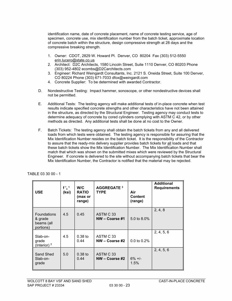
WOLCOTT 8 BAY VSF AND SAND SHED CAST-IN-PLACE CONCRETE
SAP PROJECT # 23334 03 30 00 - 23
identification name, date of concrete placement, name of concrete testing service, age of specimen, concrete use, mix identification number from the batch ticket, approximate location of concrete batch within the structure, design compressive strength at 28 days and the compressive breaking strength.
1. Owner: CDOT, 2829 W. Howard Pl. Denver, CO 80204 Fax (303) 512-5550 [email protected]
2. Architect: D2C Architects, 1580 Lincoln Street, Suite 1110 Denver, CO 80203 Phone (303) 952-4802 [email protected]
3. Engineer: Richard Weingardt Consultants, Inc. 2121 S. Oneida Street, Suite 100 Denver, CO 80224 Phone (303) 671-7033 [email protected]
4. Concrete Supplier: To be determined with awarded Contractor.
D. Nondestructive Testing: Impact hammer, sonoscope, or other nondestructive devices shall not be permitted.
E. Additional Tests: The testing agency will make additional tests of in-place concrete when test results indicate specified concrete strengths and other characteristics have not been attained in the structure, as directed by the Structural Engineer. Testing agency may conduct tests to determine adequacy of concrete by cored cylinders complying with ASTM C 42, or by other methods as directed. Any additional tests shall be done at no cost to the Owner.
F. Batch Tickets: The testing agency shall obtain the batch tickets from any and all delivered loads from which tests were obtained. The testing agency is responsible for assuring that the Mix Identification Number resides on the batch ticket. It is the responsibility of the Contractor to assure that the ready-mix delivery supplier provides batch tickets for all loads and that these batch tickets show the Mix Identification Number. The Mix Identification Number shall match that which was shown on the submitted mixes which were reviewed by the Structural Engineer. If concrete is delivered to the site without accompanying batch tickets that bear the Mix Identification Number, the Contractor is notified that the material may be rejected.
TABLE 03 30 00 - 1
USEf 'c
1
(ksi)W/C RATIO(max or range)
AGGREGATE 3
TYPE Air Content(range)
Additional Requirements
Foundations & grade beams (all portions)
4.5 0.45 ASTM C 33NW – Coarse #1 5.0 to 8.0%
2, 4, 8
Slab-on-grade (Interior) 7
4.5 0.38 to 0.44
ASTM C 33NW – Coarse #2 0.0 to 0.2%
2, 4, 5, 6
Sand Shed Slab-on-grade
5.0 0.38 to 0.44
ASTM C 33NW – Coarse #2 6% +/-
1.5%
2, 4, 5, 6
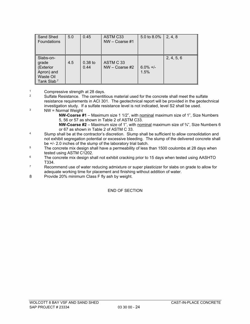
WOLCOTT 8 BAY VSF AND SAND SHED CAST-IN-PLACE CONCRETE
SAP PROJECT # 23334 03 30 00 - 24
Sand Shed Foundations
5.0 0.45 ASTM C33NW – Coarse #1
5.0 to 8.0% 2, 4, 8
Slabs-on-grade (Exterior Apron) andWaste Oil Tank Slab 7
4.5 0.38 to 0.44
ASTM C 33NW – Coarse #2 6.0% +/-
1.5%
2, 4, 5, 6
1 Compressive strength at 28 days.2 Sulfate Resistance. The cementitious material used for the concrete shall meet the sulfate
resistance requirements in ACI 301. The geotechnical report will be provided in the geotechnical investigation study. If a sulfate resistance level is not indicated, level S2 shall be used.
3 NW = Normal WeightNW-Coarse #1 – Maximum size 1 1/2”, with nominal maximum size of 1”, Size Numbers 5, 56 or 57 as shown in Table 2 of ASTM C33.NW-Coarse #2 – Maximum size of 1”, with nominal maximum size of ¾”, Size Numbers 6 or 67 as shown in Table 2 of ASTM C 33.
4 Slump shall be at the contractor’s discretion. Slump shall be sufficient to allow consolidation and not exhibit segregation potential or excessive bleeding. The slump of the delivered concrete shall be +/- 2.0 inches of the slump of the laboratory trial batch.
5 The concrete mix design shall have a permeability of less than 1500 coulombs at 28 days when tested using ASTM C1202.
6 The concrete mix design shall not exhibit cracking prior to 15 days when tested using AASHTO T334.
7 Recommend use of water reducing admixture or super plasticizer for slabs on grade to allow for adequate working time for placement and finishing without addition of water.
8 Provide 20% minimum Class F fly ash by weight.
END OF SECTION
WOLCOTT 8 BAY VSF AND SAND SHED CAST-IN-PLACE CONCRETE
SAP PROJECT # 23334 03 30 00 - 25
THIS PAGE INTENTIONALLY LEFT BLANK
WOLCOTT 8 BAY VSF AND SAND SHED COLD-FORMED METAL FRAMING
SAP PROJECT # 23334 05 40 00 - 1
SECTION 05 40 00COLD-FORMED METAL FRAMING
PART 1 - GENERAL
1.1 RELATED DOCUMENTS
A. Provisions of The General Conditions of the Contract (Design/Bid/Build) and Division 1 General Requirements and applicable provisions elsewhere in the contract Documents apply to this Section
1.2 SUMMARY
A. This Section includes the following:
1. Interior non-load-bearing wall framing not provided by the metal building manufacturer, including studs, tracks, headers over window and door openings, cripples, jack studs and bridging/straps.
2. Steel studs for load bearing walls not provided by the metal building manufacturer. Provide blocking as required for plumbing fixtures and attachment to Metal Building where required.
B. Related Sections:
1. Section 07 21 00: Thermal Insulation2. Section 09 21 16: Gypsum Board Assemblies
1.3 PERFORMANCE REQUIREMENTS
A. Structural Performance: Provide cold-formed metal framing capable of withstanding design loads indicated on the Drawings in which deflections do not exceed the following:
1. Interior Non-Load-Bearing Wall Framing: Horizontal deflection of 1/180th of the wall height when subjected to a uniformly applied lateral load of 5 psf for the entire wall height. Where walls are adjacent to vehicle bays with overhead doors, the wall framing shall achieve this criteria with a uniformly applied lateral load of 15 psf.
B. Design framing systems to provide for movement of framing members without damage or overstressing, sheathing failure, connection failure, undue strain on fasteners and anchors, or other detrimental effects when subject to a maximum ambient temperature change of 120 degrees F.
1.4 SUBMITTALS
A. Product Data: Manufacturer’s technical literature covering all products to be installed as part of the Work, including manufacturer’s certification of product compliance with codes and standards. Products to be installed as part of the Work include, but are not limited to:
1. Primary elements such as joists, headers, and studs.2. Secondary elements such as tracks, side clips, web stiffeners, flat straps, U-channel
bridging, and fasteners.
WOLCOTT 8 BAY VSF AND SAND SHED COLD-FORMED METAL FRAMING
SAP PROJECT # 23334 05 40 00 - 2
B. Refer to Project-Specific “Submittal Log” provided by Owner at Pre-Bid Meeting.
C. Mill certificates signed by steel sheet producer or test reports from a qualified independent testing agency indicating steel sheet complies with requirements.
D. Welding Certificates: Copies of certificates for welding procedures and personnel.
E. Product Test Reports: From a qualified testing agency indicating that each of the following complies with requirements, based on comprehensive testing of current products.
1. Expansion anchors2. Power-actuated anchors3. Mechanical fasteners4. Vertical deflection clips5. Miscellaneous structural clips and accessories
F. Research/Evaluation Reports: Evidence of cold-formed metal framing’s compliance with building code in effect for Project, from a model code organization acceptable to authorities having jurisdiction.
1.5 QUALITY ASSURANCE
A. The cold-formed structural metal framing and its installation shall meet the following standards:
1. American Iron and Steel Institute (AISI) “Specification for the Design of Cold-Formed Steel Structural Members" latest edition.
2. ASTM C955 Standard Specification for Load Bearing (Transverse and Axial) Steel Studs, Runners (Tracks), and Bracing or Bridging for Screw Applications of Gypsum Board and Metal Plaster Bases.
3. ASTM C1007 Standard Specification for Installation of Load Bearing (Transverse and Axial) Steel Studs and Related Accessories.
B. Welding: AWS D1.1, "Structural Welding Code--Steel," and AWS D1.3, "Structural Welding Code-Sheet Steel."
C. Installer Qualifications: An experienced installer who has completed cold-formed metal framing similar in material, design, and extent to that indicated for this Project and whose work has resulted in construction with a record of successful in-service performance.
1.6 DELIVERY, STORAGE & HANDLING
A. Upon delivery, the structural framing materials shall be protected from the elements by storing them in a sheltered area or using protective covers.
PART 2 - PRODUCTS
2.1 MANUFACTURERS
A. Available Manufacturers: Subject to compliance with requirements, manufacturers offering products that may be incorporated into the Work include, but are not limited to, the following:
WOLCOTT 8 BAY VSF AND SAND SHED COLD-FORMED METAL FRAMING
SAP PROJECT # 23334 05 40 00 - 3
1. Clark Dietrich Building Systems. 1-800-543-7140 www.clarkdietrich.com2. Marino-Ware 1-800-627-4661 www.marinoware.com3. Custom Stud, Inc. (952) 985-7000 www.customstud.com4. The Steel Network, Inc. 1-888-474-48766 http://www.steelnetwork.com/
2.2 MATERIALS
A. The cold-formed structural metal framing shall be manufactured from structural quality steel having minimum yield strength of 33 ksi for all design thicknesses, or optional 50 ksi for 16 GA (0.054 inch) and heavier members and have minimum protective coating equal to G-60 galvanized finish. The steel shall conform to one of the following ASTM Standards: ASTM A 653, A 875, A 792, or A 463.
B. Structural framing members shall conform to ASTM C955, and shall have engineering properties calculated in conformance with the AISI “Specifications For The Design of Cold-Formed Steel Structural Members” and have minimum properties as published by the manufacturer to include; Ix (in 4), Sx (in 3), Area (in 2), Rx (in), and Resisting Moment (in.-lb.).
C. All structural framing accessories shall be formed from structural quality steel with minimum yield strength of 33 ksi and have minimum protective coating equal to G-60 galvanized finish.
D. Steel Track: Manufacturer’s standard U-shaped steel track, of web depths indicated, unpunched, with unstiffened flanges, and as follows:1. Minimum Base-Metal Thickness: Matching steel studs, unless otherwise indicated.
E. Power Actuated Fasteners: Fastener system of type suitable for application indicated, fabricated from corrosion-resistant materials, with capability to sustain, without failure, a load equal to 4 times design load, as determined by testing per ASTM E 1190.
F. Mechanical Fasteners: Corrosion-resistant-coated, self-drilling steel screws.
2.3 FRAMING ACCESSORIES
A. Fabricate steel-framing accessories of the same material and finish used for framing members, with a minimum yield strength of 33,000 psi, unless otherwise noted.
B. Provide accessories of manufacturer’s standard thickness and configuration, unless otherwise indicated, as follows:
1. Supplementary framing2. Bracing, bridging, and solid blocking3. Web stiffeners4. End clips5. Foundation clips6. Gusset plates7. Stud kickers, knee braces, and girts8. Hole reinforcing plates9. Backer plates
2.4 ANCHORS, CLIPS, AND FASTENERS
A. Steel Shapes and Clips: ASTM A36/A 36M, zinc coated by hot-dip process according to
WOLCOTT 8 BAY VSF AND SAND SHED COLD-FORMED METAL FRAMING
SAP PROJECT # 23334 05 40 00 - 4
ASTM A123.
B. Power-Actuated Anchors: Fastener system of type suitable for application indicated, fabricated from corrosion-resistant materials, with capability to sustain, without failure, a load equal to 5 times design load, as determined by testing per ASTM E 1190 conducted by a qualified independent testing agency.
C. Mechanical Fasteners: Corrosion-resistant-coated, self-drilling, self-threading steel drill screws.
1. Head Type: Low-profile head beneath sheathing, manufacturer’s standard elsewhere.
D. Welding Electrodes: Comply with AWS standards.
2.5 MISCELLANEOUS MATERIALS
A. Galvanizing Repair Paint: SSPC-Paint 20
B. Cement Grout: Portland cement, ASTM C 150, Type I; and clean, natural sand, ASTM C 404. Mix at ratio of 1-part cement to 2-1/2 parts sand, by volume, with minimum water required for placement and hydration.
C. Nonmetallic, Nonshrink Grout: Premixed, nonmetallic, noncorrosive, non-staining grout containing selected silica sands, portland cement, shrinkage-compensating agents, and plasticizing and water-reducing agents, complying with ASTM C 1107, with fluid consistency and 30-minute working time.
D. Thermal Insulation: ASTM C 665, Type I, unfaced mineral-fiber blankets produced by combining glass or slag fibers with thermosetting resins.
E. Sealer Gaskets: Closed cell neoprene foam.
2.6 FABRICATION
A. Fabricate cold-formed metal framing and accessories plumb, square, and true to line, and with connections securely fastened, according to manufacturer’s written recommendations and requirements in this Section.
1. Fabricate framing assemblies using jigs or templates.2. Cut framing members by sawing or shearing; do not torch cut.3. Fasten cold-formed metal framing members by welding. Wire tying of framing members
is not permitted. Comply with AWS D1.3 requirements and procedures for welding, appearance and quality of welds, and methods used in correcting welding work.
4. Fasten cold-formed metal framing members by welding or screw fastening, as standard with fabricator. Wire tying of framing members is not permitted.a. Comply with AWS D1.3 requirements and procedures for welding, appearance and
quality of welds, and methods used in correcting welding work.b. Locate mechanical fasteners and install according to Shop Drawings, with screw
penetrating joined members by not less than three exposed screw threads.5. Fasten other materials to cold-formed metal framing by welding, bolting, or screw
fastening, according to Shop Drawings.
B. Reinforce, stiffen, and brace framing assemblies to withstand handling, delivery, and erection stresses. Lift fabricated assemblies to prevent damage or permanent distortion.
WOLCOTT 8 BAY VSF AND SAND SHED COLD-FORMED METAL FRAMING
SAP PROJECT # 23334 05 40 00 - 5
C. Fabrication Tolerances: Fabricate assemblies level, plumb, and true to line to a maximum allowable tolerance variation of 1/8 inch in 10 feet and as follows:
1. Spacing: Space individual framing members no more than plus or minus 1/8 inch from manufacturer’s designed recommendations. Cumulative error shall not exceed minimum fastening requirements of sheathing or other finishing materials.
2. Squareness: Fabricate each cold-formed metal framing assembly to a maximum out-of-square tolerance of 1/8 inch.
PART 3 - EXECUTION
3.1 INSPECTION
A. Prior to installation of cold-formed structural metal framing, inspect work of other trades. Verify that all such work is complete and accurate to the point where the installation of the cold-formed structural metal framing may properly commence in strict accordance with the shop drawings. Report any discrepancies to the Architect/Structural Engineer. Do not proceed with installation of cold-formed structural metal framing until discrepancy has been resolved.
3.2 FASTENING
A. Cold-formed structural metal framing shall be properly spaced, plumbed, leveled, squared, fit properly against abutting members and held securely in place until permanently fastened. Wire tying of cold-formed structural metal framing is not permitted.
B. Fastening of cold-formed structural metal framing shall be accomplished by self-drilling steel screws, power actuated fasteners, welding, or a combination of methods as indicated on the structural or architectural drawings. The type, size, and spacing of the fasteners shall be as determined by the manufacturer’s structural calculations which are to be reviewed by the Structural Engineer.
C. Cold-formed structural metal framing members shall have the coating repaired, at the welds, by painting with a zinc rich primer.
D. Splices in cold-formed structural metal framing studs and joists are not permitted unless otherwise noted on the drawings.
3.3 WALL FRAMING
A. Cold-formed structural metal framing members shall be stick built in the field. The wall framing members shall be sized, spaced and erected in accordance with the Drawings and reviewed manufacturer’s shop drawings
B. The wall framing member shall have ends squarely cut by shearing or sawing, be installed plumb, square, true to line and securely fastened per the manufacturer’s connection details shown on the shop drawings.
C. Fabrication, handling, and erection of wall framing members shall be done in a manner to prevent any damage or distortion of the framing.
WOLCOTT 8 BAY VSF AND SAND SHED COLD-FORMED METAL FRAMING
SAP PROJECT # 23334 05 40 00 - 6
D. Cold-formed tracks, when set to adjacent structures, shall have web contact with a uniform and level bearing surface and be securely anchored with fasteners, sized and spaced per the manufacturer’s shop drawings.
E. Bracing of wall framing resisting wind (transverse) loading only, (non-axially loaded), can be accomplished by the attachment of wall sheathing to both sides of the studs.
F. Bracing of axially loaded wall framing shall be accomplished by either cold rolled U-channel, run horizontally through the stud punchouts and attached at each stud, or by minimum 2-inch wide steel straps run horizontally on both sides of the studs, and attached at each stud. Vertical spacing of bracing is limited to a maximum of 4 ft. – 0 in. throughout the height of the wall, or as per the manufacturer’s recommendations.
G. Structural “C” members are not permitted to have splices or cutouts in the flanges.
H. Framing of wall openings shall include jack studs, cripples, headers and jamb studs as indicated on the drawings, or if not indicated specifically, per typical framing practices. Install deep leg track headers over wall openings wider than stud spacing. Locate headers above openings as indicated. Fabricate headers of compound shapes required to transfer load to supporting studs, complete with clip-angle connectors, web stiffeners, or gusset plates as required.
I. For wall framing assemblies that will form voids which will not be accessible to the insulation sub-contractor (if utilized), then the framing sub-contractor shall be responsible for filling these voids with suitable insulation as shown on the Drawings prior to final assembly.
J. Slip connections, allowing for movement of the structure without imposing loads to the wall framing, shall be per the drawings. If not shown specifically on the drawings, provide minimum 2-inch deep leg slip track at top of wall, or deflection clip with vertically slotted holes at top of non-bearing partition wall connections.
K. Erection Tolerances: Install wall framing level, plumb, and true to line to a maximum allowable tolerance variation of 1/8 inch in 10 feet.
3.4 FIELD QUALITY CONTROL
A. Remove and replace Work that does not comply with specified requirements.
B. Contractor is required to notify Owner’s inspection/observation agent in a timely manner in order that they may conduct field inspection/observation visits that they deem necessary.
C. Periodic site observation visits will be made by the Architect/Structural Engineer during the course of the Work.
END OF SECTION
WOLCOTT 8 BAY VSF AND SAND SHED METAL FABRICATIONS
SAP PROJECT # 23334 05 50 00 - 1
SECTION 05 50 00METAL FABRICATIONS
PART 1 - GENERAL
1.1 RELATED DOCUMENTS
A. Provisions of The General Conditions of the Contract (Design/Bid/Build) and Division 1 General Requirements and applicable provisions elsewhere in the contract documents apply to this Section.
B. Related Sections:
1. Section 03 30 00: Cast-in-Place Concrete2. Section 05 51 00: Metal Stairs3. Section 09 90 00: Painting and Coating
1.2 SUMMARY
A. Section Includes:
1. Steel pipe and tube railings attached to walls adjacent to metal stairs.2. Steel concrete-filled bollards3. Steel bollards anchored to VSF and Wash Bay floors
1.3 ACTION SUBMITTALS
A. Product Data: For Steel Pipe Bollards
1. Installation Instructions for 4 inch pipe bollards including proposed base plate.
1.4 QUALITY ASSURANCE
A. NAAMM Railing Standard: Comply with "Type 2 Voluntary Joint Finish Standards" in NAAMM AMP 521-01, "Pipe Railing Systems Manual Including Round Tube" for class of Railing and Guard designated, unless more stringent requirements are indicated.1. Commercial class
B. Field Measurements: Field verify vertical and horizontal dimensions of spaces where guards and rails are to be installed.
WOLCOTT 8 BAY VSF AND SAND SHED METAL FABRICATIONS
SAP PROJECT # 23334 05 50 00 - 2
PART 2 - PRODUCTS
2.1 METALS
A. Metal Surfaces, General: Provide materials with smooth, flat surfaces unless otherwise indicated. For components exposed to view in the completed Work, provide materials without seam marks, roller marks, rolled trade names, or blemishes.
2.2 MISCELLANEOUS MATERIALS
A. Cast-Metal Units: Cast iron, with an integral abrasive, as-cast finish.
1. Manufacturers: Subject to compliance with requirements, provide products by one of the following:a. American Safety Tread Co., Inc.b. Balco Inc.c. Barry Pattern & Foundry Co., Inc.d. Granite State Casting Co.e. Safe-T-Metal Company, Inc.f. Wooster Products Inc.g. Or Other Approved Equal
2.3 FABRICATION, GENERAL
A. Provide complete bollard assemblies, including brackets, bearing plates, and other components necessary to support and anchor guard and rail and bollards on supporting structure.
1. Join components by welding unless otherwise indicated.2. Use connections that maintain structural value of joined pieces.3. Comply with applicable provisions of specified building code, ADAAG and ANSI A117.1
as applicable for guards and handrails.4. Comply with applicable provisions of specified building code for exterior guards and
handrails.
B. Cut, drill, and punch metals cleanly and accurately. Remove burrs and ease edges. Remove sharp or rough areas on exposed surfaces.
2.4 BOLLARDS
A. Embedded Steel Pipe Bollards. Embedded steel pipe bollards shall be 10 inch nominal diameter, ASTM A53, Type E, Grade B Electric-Resistance Welded or ASTM A53, Type S, Grade B Seamless members, By = 35 KSI minimum. Bollards shall be shop primed using the system primer for high performance coating for bollards. Extend finish paint 6 inches into embedded concrete. The finish paint that is embedded into the concrete can be the urethane enamel paint specified for exterior ferrous metals in Section 09 90 00 – Painting and Coating. Finish paint that is not embedded into the concrete shall be the high performance coating system specified for bollards.
B. Bolted Steel Pipe Bollards: Bollards protecting plumbing and equipment inside the VSF shall be 4 inch nominal diameter ASTM A53, Type E, Grade B Electric-Resistance Welded or ASTM A53, Type S, Grade B Seamless members. Bollards shall have integral base plate for bolting into concrete floor. Bolts to be ½ inch anchor bolts, typical. Bollards shall be shop primed with

WOLCOTT 8 BAY VSF AND SAND SHED METAL FABRICATIONS
SAP PROJECT # 23334 05 50 00 - 3
an industry standard rust-inhibiting primer and have manufacturer’s standard powder-coat finish, color safety yellow. Provide bollard with welded on cap, or provide schedule 40 PVC cap, painted to match.
2.5 FINISHES
A. Comply with NAAMM's "Metal Finishes Manual for Architectural and Metal Products" for recommendations for applying and designating finishes.
B. Low-Emitting Materials: Paints and coatings shall comply with the testing and product requirements of the California Department of Health Services' "Standard Practice for the Testing of Volatile Organic Emissions from Various Sources Using Small-Scale Environmental Chambers."
C. Universal Shop Primer: Fast-curing, lead- and chromate-free, universal modified-alkyd primer complying with MPI#79 and compatible with topcoat.
D. Preparation for Shop Priming: Prepare uncoated ferrous-metal surfaces to comply with SSPC-SP 3, "Power Tool Cleaning.”
E. Apply shop primer to uncoated surfaces of metal stair components. Comply with SSPC-PA 1, "Paint Application Specification No. 1: Shop, Field, and Maintenance Painting of Steel," for shop painting.
PART 3 - EXECUTION
3.1 EXAMINATION
A. Do not begin installation until substrates and adjacent construction have been properly constructed. Verify framing enclosures, weld plates, blocking and size and location of carriers, sleeves, or pockets.
B. If unsatisfactory conditions are encountered, notify CDOT Representative in writing. Do not proceed until unsatisfactory conditions have been corrected.
C. Notify Manufacturer of any detail, design or tolerance deviations as noted or drawn on stair shop drawing.
3.2 INSTALLATION
A. Install 10 inch steel bollards by details shown in structural drawings. Prior to pouring of concrete, Contractor to have CDOT Representative inspect all bollard locations at overhead doors. Bollards that do not meet the specified dimensional tolerances indicated in the drawings will be required to be removed and re-installed.
C. Install 4 inch bolt-down pipe bollards to weld plates on 4 inch sleeves bolted into concrete. Confirm final location of bollards with equipment locations.
D. Fit exposed connections accurately together to form hairline joints. Weld connections that are not to be left as exposed joints. Do not weld, cut, or abrade surfaces of exterior units that have been hot-dip galvanized after fabrication.
WOLCOTT 8 BAY VSF AND SAND SHED METAL FABRICATIONS
SAP PROJECT # 23334 05 50 00 - 4
3.3 ADJUSTING AND CLEANING
A. Touchup Painting: Immediately after erection, clean field welds, bolted connections, and abraded areas of shop paint, and paint exposed areas with same material as used for shop painting to comply with SSPC-PA 1 for touching up shop-painted surfaces.
B. Galvanized Surfaces: Clean field welds, bolted connections, and abraded areas and repair galvanizing to comply with ASTM A 780.
END OF SECTION
WOLCOTT 8 BAY VSF AND SAND SHED ARCHITECTURAL CASEWORKSAP PROJECT # 23334
06 41 00 - 1
SECTION 06 41 00 ARCHITECTURAL CASEWORK
PART 1 - GENERAL
1.1 RELATED DOCUMENTS
A. Provisions of The General Conditions of the Contract (Design/Bid/Build) and Division 1 General Requirements and applicable provisions elsewhere in the contract documents apply to this Section.
B. Related Sections
1. Section 10 56 17: Wall-Mounted Standards and Shelving
1.2 WORK INCLUDED
A. Provide all labor, material and equipment required for the furnishing and installation of custom casework (plastic laminate) panels and shelving as indicated in the construction documents.
1.3 DEFINITIONS
A. Custom Casework: Custom fabricated casework as indicated on drawings.
1.4 QUALITY ASSURANCE
A. Qualifications
1. Fabricator and Installer: Company specializing in the fabrication and installation of custom casework with a minimum five years satisfactory experience.
2. Submit documentation of experience.3. Warranty: A Warranty shall be required for a period of one year for all components
of work. Warranty to commence on “Substantial Completion” issued by State.
1.5 REFERENCES
A. Applicable Publications: The publications listed below form a part of the Specification to the extent referenced.
1. Architectural Woodwork Institute (AWI) "Quality Standards" revised 2003.
B. National Woodwork Manufacturer's Association (NWMA).
1.6 SUBMITTALS
A. Submit shop drawings, product data, and samples under provisions of Section 01 33 00.
WOLCOTT 8 BAY VSF AND SAND SHED ARCHITECTURAL CASEWORKSAP PROJECT # 23334
06 41 00 - 2
B. Shop Drawings:
1. Submit Shop Drawings showing:a. Location of each itemb. Dimensioned plans and elevationsc. Mounting height in relation to finish floor elevationd. Large scale detailse. Attachment devicesf. Countertop details shall include proposed jointing arrangements,
expanded details to all specific locations2. Submit Shop Drawings for all millwork items required.3. Key Shop Drawings to drawing and section number as shown on the Architectural
Drawings.
B. Samples:
1. When plastic laminate is indicated on the drawings, furnish two (2) 2 inch x 3 inch samples of each color.
C. Refer to Project-Specific “Submittal Log” provided by Owner at Pre-Bid Meeting.
1.7 QUALITY ASSURANCE
A. Quality Standards: For the following types of architectural wood work, comply with the indicated standards as applicable:
2. Architectural Cabinets: AWI Section 400, Custom Grade. a. Flush overlay style
3. Work Area Work Surface: AWI Section 400, Custom Grade4. Plastic Laminate Window Sills: AWI Standards for Paneling and Trim, Custom
Grade.
B. Provide two (2) copies of recommended finish maintenance instructions.
1.8 DELIVERY, STORAGE AND HANDLING
A. Protect countertop materials during transit, delivery, storage and handling to prevent damage, soiling and deterioration.
B. Do not deliver casework, until painting, wet work, grinding and similar operations which could damage, soil or deteriorate woodwork have been completed in installation areas.
C. If, due to unforeseen circumstances, casework must be stored in other than installation areas, store only in areas meeting requirements specified for installation areas.
PART 2 - PRODUCTS
2.1 MANUFACTURERS
A. As indicated for various products hereunder.
WOLCOTT 8 BAY VSF AND SAND SHED ARCHITECTURAL CASEWORKSAP PROJECT # 23334
06 41 00 - 3
2.2 MATERIALS
A. Particle Board:
1. Medium density (forty-five (45) lbs./cu.ft.) minimum wood chip and phenolic resin binders, compressed board, ¾ inch thickness unless otherwise indicated.
B. Hardboard:
1. PS 58, Class 1 (tempered), smooth one side or both sides where indicated, ¼ inch thickness unless as otherwise indicated.
C. Plastic Laminate:
1. Provide plastic laminate for all cabinet work and window sill laminate by Formica Corporation, Nevamar or Wilson Art. Re: Finish schedule for laminate types.
2. Countertop Vertical Edge: Provide continuous plastic laminate with demi full bull nose 1 1/2 inch width.
3. Finishes:a. Plastic laminate for horizontal surfaces: Type 2, 0.050 inch thick, General-
Purpose Type (high pressure) solid color.b. Plastic laminate for external vertical surfaces: Type 4, 0.028 inch thick,
General-Purpose Type (high pressure).c. Plastic laminate for concealed panel backing: 0.020 inch thick, Backer-
Type (High Pressure).d. White Melamine for inside cabinet faces and shelves.e. Colors shall be as indicated on finish schedule.f. Black melamine for exposed shelves at desks and storage areas
2.3 MISCELLANEOUS ACCESSORIES
A. Nails:
1. Face nailing not permitted.2. Do not use nails for gluing pressure.3. Nails may be used only for temporary, concealed anchorage.
B. Adhesives:
1. Adhesive for plastic laminate shall conform to AWI 100-S-5, Resorcinol-Formaldehyde Resins, CS-35, Type 1; mechanically pressed under heat.
2. All adhesives required for field application of plastic laminate shall conform to AWI 100-S-5, Contact Cement, CS-35, Type II, non-flammable.
2.4 MOISTURE CONTENT
A. At the time lumber and other materials are delivered and when installed in the work, their moisture content shall be 19 percent maximum for treated and untreated lumber 2 inches or less in thickness.
2.5 CUSTOM CASEWORK (PLASTIC LAMINATE)
WOLCOTT 8 BAY VSF AND SAND SHED ARCHITECTURAL CASEWORKSAP PROJECT # 23334
06 41 00 - 4
A. Custom Mill Built Casework: AWI Sections 400, 400B, 1600, and 1600A, B & C “Custom” grade, flush overlay construction.
B. Plastic Laminate Window Sill: AWI Section 300, “Custom“ Grade single piece construction with half bullnose edge.
2.6 CABINET HARDWARE
A. ¾ inch Doors: concealed hinge – Blum ‘COMPACT’ or equal.
B. Adjustable Shelf Standards: Knape and Vogt No. 255 with No. 256 or 32mm hole system.
C. Shelving: 3/4 inch thick melamine face particle board with applied PVC front edge.
D. Door and Drawer Pulls: Base: Hafele 4 inch Wire Pull, satin chrome finish, part no. 116.39.464; Optional: Berenson 4” wire pull, satin chrome part #6130-2sc-p1. Provide attic stock of (2) additional pulls.
E. Drawer Slides:1. Typical Drawer Slide: Blum Drawer Runner No. BS230E for side mounting.
F. Door and Drawer Silencers: BHMA A156.16, L03011
G. Grommets: Standard 2 inch black plastic grommet
2.7 SHELVING
A. Exposed shelving made from the following materials, 3/4 inch thick.1. Melamine faces particle board with applied PVC front edge
B. Provide adjustable shelf brackets in accordance with Section 10 56 17.
PART 3 - EXECUTION
3.1 INSPECTION
A. Prior to starting work, examine and determine conditions of preceding work for suitability and adequacy of performance to insure compliance with quality of workmanship of this Section.
B. Notify Contractor, Owner and Architect in writing if any surfaces are not in a suitable condition to receive this work.
3.2 PREPARATION
A. Verify all dimensions in the field and take particular care to align with all joints and recesses, where required, with the building module lines.
WOLCOTT 8 BAY VSF AND SAND SHED ARCHITECTURAL CASEWORKSAP PROJECT # 23334
06 41 00 - 5
B. Coordinate the work with that of other trades affected by installation of wood ground, nailers and blocking to avoid delay in job progress.
C. Treat all blocking and grounds in accordance with AWPA. Brush coat surfaces that have been cut after treatment. Air season all lumber for not less than 30 days before covering with finishing materials.
3.3 FABRICATION
A. Workmanship shall equal in all respect to the standards of custom quality furniture work as described by AWI. Perform all work by qualified and fully competent workmen.
B. Fabricate and finish all millwork work at the shop and assemble in single and complete units, insofar as the dimensions thereof will permit shipment to and installation at the building. Construct large pieces requiring sectional construction so their several parts are accurately fitted and aligned with each other, using fasteners that will be concealed in the finished work.
C. Provide ample screws, glue and bolt blocks, tongues, grooves and splines, dowels, mortises and tenons, screws bolts, clip angles, braces, anchors, or suitable means rigid and permanently secured in proper position to each related section.
D. Allow sufficient additional material to permit:
1. Accurate scribing to walls, floors, and related work.2. Provide for shrinkage that may develop after installation.
E. Provide all single and sectional units with adequate cleating, blocking, crating and other forms of protection as required to preclude damages thereto during shipping and handling.
F. Assemble framing and blocking members with concealed bolted and screwed connections, and secure to the structural backings with cinch, expansion screws, or toggle bolts, as required, so spaced and installed as to insure ample strength and rigidity.
G. Accurately construct all members plumb, square, level and permanently secured in precise position as indicated. Construct moldings true to detail, cleanly cut and sharp.
H. All screws shall be driven snugly into lead holes. No screws shall be hammer driven. Any member with a split or crack of any description caused by fastener application or other cause shall be replaced. If dowels are used only spirally grooved non-compressed dowels shall be used.
I. Return plastic laminate to exposed ends of casework.
3.4 CASEWORK INSTALLATION
A. Custom grade per AWI standards.
B. Assemble all units on job without face nails or screws. Accurately set all trim plumb, square, level and permanently secured in precise position as indicated.
WOLCOTT 8 BAY VSF AND SAND SHED ARCHITECTURAL CASEWORKSAP PROJECT # 23334
06 41 00 - 6
C. Exercise extreme care to avoid damaging finished surfaces during the handling and erecting of all members. All damaged surfaces or blemishes arising from such operation, or other causes, shall be replaced.
3.6 CLEANING
A. Remove soil, stains, paint, prints and adhered matter from exposed parts of hardware and wood surfaces. Remove foreign matter that could affect operation of hardware.
B. Clean adjacent surfaces for soiling incurred during installation of hardware. Repair or replace defective materials.
C. Repair or replace damage to adjacent surfaces caused by installation of casework.
END OF SECTION
WOLCOTT 8 BAY VSF AND SAND SHED PLASTIC PANELINGSAP PROJECT # 23334 06 64 00 - 1
SECTION 06 64 00PLASTIC PANELING
PART 1 - GENERAL
1.1 RELATED DOCUMENTS
A. Provisions of The General Conditions of the Contract (Design/Bid/Build) and Division 1 General Requirements and applicable provisions elsewhere in the contract documents apply to this Section.
B. Related Sections:
1. Section 07 21 00: Thermal Insulation2. Section 09 90 00: Painting and Coating3. Section 11 11 26: Hot Water Pressure Washer4. Section 13 34 19: Metal Building Systems5. Section 23 30 00: HVAC Air Distribution
1.2 SUMMARY
A. Section includes composite glass-fiber reinforced plastic (FRP) wall paneling and trim accessories.
1.3 SUBMITTALS
A. Product Data: For each type of product indicated.
B. Samples: furnish two (2) 12 inch x 12 inch samples of each color in the specified profile for each FRP type unless providng the basis of design indicated in this section.
C. Details: Fully detail to graphically show all panel dimensions and vertical and horizontal termination and transitions. Key to floor plan
1.4 QUALITY ASSURANCE
A. Surface-Burning Characteristics: As determined by testing identical products according to ASTM E 84 by a qualified testing agency. Identify products with appropriate markings of applicable testing agency.
1. Flame-Spread Index: 200 or less.2. Smoke-Developed Index: 450 or less.
1.5 DELIVERY, STORAGE, AND HANDLING
A. Store material(s) in accordance with manufacturer’s instructions, with seals and labels intact and legible.
B. Store butyl tape in accordance with manufacturer’s instructions, maintaining temperatures above freezing at all times prior to installation.
WOLCOTT 8 BAY VSF AND SAND SHED PLASTIC PANELINGSAP PROJECT # 23334 06 64 00 - 2
PART 2 - PRODUCTS
2.1 FRP1 – FIBERGLASS REINFORCED PANELS
A. General: Gelcoat-finished, composite glass-fiber reinforced plastic panels, field adhered and cut FRP to moisture resistant plywood complying with ASTM D 5319.
1. Manufacturers: Subject to compliance with requirements, available manufacturers offering products that may be incorporated into the Work include, but are not limited to, the following:a. Crane Composites, Inc., (formerly Kemlite Company Inc.)b. Creative Panel Solutionsc. Nudo Products, Inc.
2. Basis-of-Design Product: Subject to compliance with requirements, provide Nudo Products, Inc NuFiber panels mounted to .625 inch plywood backing or equal.
3. Substrate: Field adhere and cut to moisture resistant Plywood4. Nominal Thickness: Not less than 0.675 inch5. Surface Finish: Smooth texture6. Fire Rating: Class C: non-structural7. Width: 4 foot-0 inches 8. Length: Longest available length avoiding horizontal joints, 8 foot-0 inches high.9. Color: White
2.2 FRP2 – CORRUGATED FIBERGLASS REINFORCED PANELS – WASH BAY
A. Fiberglass reinforced panels: Provide in the Wash Bay as indicated on the drawings.
1. Manufacturers: Subject to compliance with requirements, available manufacturers offering products that may be incorporated into the Work include, but are not limited to, the following:a. Resolite, A United Dominion Company.b. Crane Composites, Inc. (formerly Kemlite Co.).
2. Basis-of-Design Product: Subject to compliance with requirements, provide Resolite, CR-Acryloy 1030 or equal.
3. Profile 4 3/16 inch by 9/16 inch corrugation or approved equal.4. Comply with ASTM D-38415. Installation assembly shall include all necessary accessories for the proper installation of
the panels.6. Butyl Tape.7. Adhesive shall be a high strength mastic recommended by manufacturer.8. Provide all trim as necessary for a complete installation, and positive drainage to the
interior of the wash bay.9. Provide flashed head trim at all sills and door heads and closure strips where
recommended by manufacturer.10. Panels to be maximum length possible, one horizontal joint permitted on ceiling.11. Color: White
Note: Ceiling panels shall be installed with a maximum of three (3) horizontal joints.
WOLCOTT 8 BAY VSF AND SAND SHED PLASTIC PANELINGSAP PROJECT # 23334 06 64 00 - 3
2.3 ACCESSORIES
A. FRP1 Accessories: Manufacturer's accessories designed and specifically sized to secure, retain and cover edges of composite panels. Provide division bars, inside corners, outside corners, caps and fasteners as needed to secure and conceal all exposed edges. All edges of Composite panels to be covered with manufactures standard trim set in full bed of sealant. Accessories to be utilized that provide complete seal of all edges and concealing all non vinyl fasteners.
1. Color: Match FRP panels2. Edge to Edge Trim: 2 inch inch “T” bar (V-45), set in receiver for Two-Piece Division bar
(V-55)3. Edge to alternate material: Manufacturer’s standard vinyl trim with minimum one inch
face overlapping FRP panel.4. Inside Corner: Manufacturer’s standard vinyl trim with minimum of one inch face
overlapping each surface.5. Outside Corner: Manufacturer’s standard vinyl trim with minimum of one inch face
overlapping in each direction.6. Mechanical Edge Fasteners: Manufacturer’s recommended stainless steel self tapping
and countersunk screws.7. Mechanical Field Fasteners: Manufacturer’s standard stainless steel self tapping rivet or
screw with exposed vinyl head.8. Strapping: Provide 4 inch 20 gauge metal straps for bracing between girts at pre-
engineered metal building applications.
B. FRP2 Accessories: Manufacturer's standard one-piece extrusions designed and specifically sized to retain and cover edges of panels. Provide division bars, inside corners, outside corners, and caps as needed to conceal all exposed edges. Provide material specifically manufactured for panels being installed.
1. Color: Match panels.2. Inside Corners: Manufacturer’s standard inside 90 degree corner flashing, designed to to
shed moisture to inside of space and away from the interstitial space of the wall.3. Outside Corner: Manufacturer’s standard outside 90 degree corner flashing, designed to
shed moisture to inside of space and away from the interstitial space of the wall.4. Wall to Ceiling Trim: Manufacturer’s standard Transition (headwall) flashing installed to
shed moisture to inside of space and away from the interstitial space of the wall.5. Butyl Tape to seal side and end laps of panels and at fastener locations.6. Adhesive: As recommended by plastic paneling manufacturer.7. Mechanical Fasteners: Manufacturer’s standard stainless steel non-corroding self
tapping fasteners with neoprene backed washers of size required by panel profile. Where required for side lap or at slip locations use manufacturers standard stainless steel SB-2 side lap fastener by Resolite or equal.
8. Accessories and detailing at Metal Building System structural columns, base plates, and bracing.
9. Strapping: Provide 4 inch 20 gauge metal straps for bracing between purlins at pre-engineered metal building applications.
C. Sealant: Single-component, mildew-resistant, neutral-curing silicone sealant recommended by plastic paneling manufacturer and complying with requirements in Section 07 92 00 - Joint Sealants.
WOLCOTT 8 BAY VSF AND SAND SHED PLASTIC PANELINGSAP PROJECT # 23334 06 64 00 - 4
PART 3 - EXECUTION
3.1 PREPARATION
A. Clean substrates of substances that could impair bond of adhesive, including oil, grease, dirt, and dust.
B. Condition panels by unpacking and placing in installation space before installation according to manufacturer's written recommendations.
C. Lay out paneling before installing. Locate panel joints to provide equal panels at ends of walls not less than half the width of full panels.
3.2 INSTALLATION
A. Install plastic paneling according to manufacturer's written instructions, with manufacturer’s standard mounting rivets, hardware and trim. Provide a full bed of sealant at all overlapping vertical wall joints. Place a full bed of sealant at the overlapping horizontal joints in the wash bay ceiling. Panel overlaps to meet manufacturer’s recommendations.
B. FRP1 –FRP Paneling
1. FRP panels to be field cut and adhered to moisture resistant 5/8” plywood. At pre-engineered metal building applications, mount directly to engineered buildings wind girt system and vertical metal stud sub framing coordinated to occur at vertical joint of FRP composite panels and a maximum vertical dimension of 4 foot-0 inches. Horizontal sub framing to be provided as required limiting vertical span of panels to maximum 4 foot-0 inches o.c. At conventional metal framing systems mount directly to metal studs.
2. Install panels in a bed of adhesive at horizontal and vertical framing. In addition, mechanically anchor panels to metal stud sub framing at every 4 feet. Predrill and use grommet type washer for anchors.
3. Panels to be installed without horizontal joints unless vertical application extends beyondthe available length of composite panel.
4. Mechanical edge fasteners to be countersunk and concealed by manufacturer’s vinyl trim. 5. At metal buildings, install vertical metal straps behind frp panels for bracing every 2 feet
on center between metal girts.6. Mechanical field fasteners permitted as recommended by panel manufacturer for span of
rating of FRP composite panel. When required field fasteners to be manufacturer’s standard through fastener with vinyl head.
7. Install trim accessories with adhesive and full bed of sealant. All exposed plywood edges to have manufacturer’s trim and full bed of sealant.
8. Fill grooves in trim accessories with sealant before installing panels and bed inside corner trim in a bead of sealant.
9. Maintain uniform space between panels and wall fixtures. Fill space with sealant.10. Remove excess sealant and smears as paneling is installed. Clean with solvent
recommended by sealant manufacturer and then wipe with clean dry cloths until no residue remains.
C. FRP2 – Corrugated Fiberglass Reinforced Panels – Wash Bay Ceiling
1. Install FRP1 panels with stainless steel mechanical fasteners (with neoprene washer) placed as recommended by the panel manufacturer.
WOLCOTT 8 BAY VSF AND SAND SHED PLASTIC PANELINGSAP PROJECT # 23334 06 64 00 - 5
2. Place a full bed of sealant at all overlapping horizontal joints in the Wash Bay ceiling shingled to shed water to the interior of the bay and not weep behind panels. Panel overlaps to meet manufacturer’s recommendations.
3. Material shall be supported at the edges and at terminations of panels adjacent to pre-engineered metal building structural framing; no cantilever installation permitted. Minimum mounting surface shall be 1 ¼ inch.
4. Install vertical metal straps behind FRP panels for bracing every 4 feet on center between metal purlins.
5. All materials to be installed in compliance with manufacturer’s recommendations and design details provided.
6. Install butyl tape to seal the side and end laps in opaque panels. Install butyl tape to girts, framing at 24 inches o.c., bracing and behind all fastener locations to prevent water ingress.
D. Trim Installation: 1. Start in the corner. Mark plumb line 48 1/8 inches from corner.2. Apply adhesive directly to entire back of composite wall panel using correct trowel with
100% adhesive coverage using crosshatch pattern. Apply adhesive to within 1/2 inch of all edges of panel.
3. Slide panel into molding and withdraw 1/8 inch for moldings to provide appropriate gap. Align with plumb line.
4. Begin in top corner nearest molding with laminate roller, rolling down and out toward the edge without molding.
5. Continue rolling down and out working across panel away from previously installed panel or initial molding. Remove all trapped air.
6. Install one-piece division bar and caps or next molding by sliding onto panel.7. Repeat process, working in one direction around room. Immediately remove all adhesive
residue. To remove, clean with nonabrasive cotton cloth and warm water. If necessary, use a mild nonabrasive detergent. For cleanup with solvent based adhesives, use mineral spirits or acetone to remove residue
END OF SECTION

WOLCOTT 8 BAY VSF AND SAND SHED PLASTIC PANELINGSAP PROJECT # 23334 06 64 00 - 6
THIS PAGE INTENTIONALLY LEFT BLANK
WOLCOTT 8 BAY VSF AND SAND SHED DAMPPROOFING
SAP PROJECT # 23334 07 11 00 - 1
SECTION 07 11 00DAMPPROOFING
PART 1 - GENERAL
1.1 RELATED DOCUMENTS
A. Provisions of The General Conditions of the Contract (Design/Bid/Build) and Division 1 General Requirements and applicable provisions elsewhere in the contract documents apply to this Section.
B. Related Sections: 1. Section 03 30 00: Cast-in-Place Concrete
1.2 SUMMARY
A. This Section includes the following:1. Application of dampproofing coating to the exterior face of the concrete foundation.
1.3 SUBMITTALS
A. Product data for each type of product specified, including data substantiating that materials comply with requirements for each dampproofing material specified. Include recommended method of application, recommended primer, and number of coats, coverage or thickness.
B. Refer to Project-Specific “Submittal Log” provided by Owner at Pre-Bid Meeting.
1.4 QUALITY ASSURANCE
A. Installer Qualifications: Engage an experienced Installer who has completed dampproofing similar in material, design, and extent to that indicated for this Project.
1.5 DELIVERY, STORAGE, AND HANDLING
A. Deliver materials to Project site as specified by manufacturer labeled with manufacturer’s name, product brand name and type, date of manufacture, shelf life, and directions for storing and mixing with other components.
B. Store materials as specified by the vapor barrier/dampproofing manufacturer in a clean, dry, protected location and within the temperature range required by vapor barrier/dampproofing manufacturer. Protect stored materials from direct sunlight.
C. Remove and replace material that cannot be applied within its stated shelf life.
1.6 PROJECT CONDITIONS
A. Substrate: Proceed with dampproofing only after substrate construction and penetrating work have been completed.
WOLCOTT 8 BAY VSF AND SAND SHED DAMPPROOFING
SAP PROJECT # 23334 07 11 00 - 2
B. Protect all adjacent areas not to be applied to. Where necessary, apply masking to prevent staining of surfaces to remain exposed wherever membrane abuts to other finish surfaces.
C. Perform work only when existing and forecasted weather conditions are within manufacturer’s recommendations for the material and application method used.
D. Ambient temperature shall be within manufacturer’s specifications.
E. All plumbing, electrical, mechanical and structural items to be under or passing through the vapor barrier/dampproofing membrane shall be positively secured in their proper positions and appropriately protected prior to membrane application.
F. Vapor barrier/dampproofing membrane shall be installed before placement of reinforcing steel. When not possible, all exposed reinforcing steel shall be masked by General Contractor prior to membrane application.
PART 2 - PRODUCTS
2.1 MANUFACTURERS
A. Available Manufacturers: Subject to compliance with requirements, manufacturers offering products that may be incorporated in the Work include, but are not limited to, the following:
1. EPRO Waterproofing SystemsP.O. Box 347Derby, KS 67037800-882-1896 www.eproserv.com
2. W.R. Meadows, Inc. P.O. Box 338Hampshire, IL 60140800-342-5976 www.wrmeadows.com
3. Karnak800-526-4236 www.karnakcorp.com
4. Tremco Barrier Solutionswww.termcobarriersolutions.com
2.2 DAMPPROOFING
A. Spray-Applied, solvent dampproofing should be asbestos-free, non-fibered asphalt compound that meets U.S. EPA Architectural Coatings Rule requirements for VOC content.
1. Basis of Design: SealMastic Spray-Mastic by W.R. Meadowsa. ASTM D 4479, Type I
B. Spray-Applied water-based dampproofing should be asbestos-free, non-fibered polymer modified asphalt emulsion.
1. Basis of Design: EcoDamp polymerized moisture protection membrane by EPRO Waterproofing Systems
C. Brush applied solvent dampproofing should be an asbestos-free, fibered, asphalt compound
WOLCOTT 8 BAY VSF AND SAND SHED DAMPPROOFING
SAP PROJECT # 23334 07 11 00 - 3
that meets the U.S. EPA Architectural Coatings Rule requirements for VOC content.
1. Basis of Design: SealMastic Semi-Mastic by W.R. Meadowsa. ASTM D 4479, Type I
D. Trowel applied solvent dampproofing should be a heavy bodied, asbestos-free, fibered, asphalt compound that meets the U.S. EPA Architectural Coatings Rule requirements for VOC content.
1. Basis of Design: SealMastic Trowel-Mastic W.R. Meadowsa. ASTM D 4586, Type I
E. Fluid-Applied, Elastomeric Coal-Tar Free Waterproofing, High Solids, VOC-Compliant, Modified Polyurethane Waterproofing membrane.
1. Basis of Design: TREMProof 201/60 Tremco Sealants, Roller (R) Gradea. ASTM C 836
PART 3 - EXECUTION
3.1 PREPARATION
A. Clean concrete substrate of all scale, loose concrete, dust, rust, dirt, oil, grease and other foreign matter. Use a wire brush. Before product application, fill voids, cracks and holes in concrete with cement mortar and allow patch to dry.
3.2 INSTALLATION, GENERAL
A. Comply with manufacturer's recommendations except where more stringent requirements are indicated and where Project conditions require extra precautions to ensure satisfactory performance of work.
B. Application: Apply dampproofing to the following surfaces.1. Exterior, below-grade surfaces of concrete foundation grade beams in contact with earth
or other backfill.2. Backside of block or concrete retaining walls.
C. Apply vertical dampproofing down grade beams from finished-grade line to bottom of grade beam. Do not extend onto surfaces exposed to view when the Project is completed.
D. Apply dampproofing in accordance with manufacturer instructions.
E. Apply dampproofing to properly prepared surface in a continuous, unbroken film, free of pinholes, filling and spreading around all joints, slots and grooves and penetrating into all crevices, chases, reveals, soffits and corners.
F. The manufacturer’s technical representative shall visit the site during installation and before backfilling and submit to the Contractor, CDOT and the Architect within two (2) days a written report stating what was observed and if the work was being done per the manufacturer’s requirements.
WOLCOTT 8 BAY VSF AND SAND SHED DAMPPROOFING
SAP PROJECT # 23334 07 11 00 - 4
3.3 BACKFILLING
A. Backfilling should be done within 24 to 48 hours after application or as required by product. No longer than seven days maximum should elapse. Be careful not to damage or rupture the film or displace coating or membranes.
3.4 PRECAUTIONS
A. Handle as a combustible product. Read and follow application information and precautions.
END OF SECTION

WOLCOTT 8 BAY VSF AND SAND SHED DAMPPROOFING
SAP PROJECT # 23334 07 11 00 - 5
WOLCOTT 8 BAY VSF AND SAND SHED THERMAL INSULATION
SAP PROJECT # 23334 07 21 00 - 1
SECTION 07 21 00THERMAL INSULATION
PART 1 - GENERAL
1.1 RELATED DOCUMENTS
A. Provisions of The General Conditions of the Contract (Design/Bid/Build) and Division 1 General Requirements and applicable provisions elsewhere in the contract documents apply to this Section.
1.2 SUMMARY
A. This Section includes the following:
1. Foundation wall insulation (supporting backfill)2. Concealed building insulation3. Sound-attenuating insulation
B. Related Sections
1. Section 03 30 00 – Cast-In-Place Concrete2. Section 04 22 00 – Concrete Unit Masonry3. Section 05 40 00 – Cold-Formed Metal Framing4. Section 06 64 00 – Plastic Paneling5. Section 07 11 00 – Dampproofing6. Section 08 11 00 – Metal Doors, Windows and Frames7. Section 09 21 16 – Gypsum Board Assemblies8. Section 11 11 26 – Hot Water Pressure Washer9. Section 13 34 19 – Metal Building Systems
C. Thermal and Moisture Protection
1. Minimum R-values for Insulation and air filtration must comply with the building envelope requirements for metal buildings set forth in the Building Envelope Comcheck and the drawing details and in accordance with ANSI/ASHRAE/IES Standard 90.1 (2010 / 2013) “Energy Standard for Buildings.
2. Provide vapor retarder at inside face of all walls and roof.3. Provide air barrier at exterior envelope. Air barrier shall be caulked and sealed at all
edges and may consist of interior metal panel, plastic panel or gypsum board.
1.3 SUBMITTALS
A. Product Data for each type of insulation product used.
B. Product Data for Roof and Wall Insulation Assemblies or Systems
C. U-factor Compliance Report for Compliance with Wall and Roof Insulation Requirements
E. Product test reports from and based on tests performed by a qualified independent testing agency evidencing compliance of insulation products with specified requirements including those for thermal resistance, fire-test-response characteristics, water-vapor transmission,
WOLCOTT 8 BAY VSF AND SAND SHED THERMAL INSULATION
SAP PROJECT # 23334 07 21 00 - 2
water absorption, and other properties, based on comprehensive testing of current products. Refer to Project-Specific “Submittal Log” provided by Owner at Pre-Bid Meeting.
1.4 QUALITY ASSURANCE
A. Fire-Test-Response Characteristics: Provide insulation and related materials with the fire-test-response characteristics indicated on Drawings or specified elsewhere in this Section as determined by testing identical products per test method indicated below by UL or another testing and inspecting agency acceptable to authorities having jurisdiction. Identify materials with appropriate markings of applicable testing and inspecting agency.
1. Surface-Burning Characteristics: ASTM E 84.2. Fire-Resistance Ratings: ASTM E 119.3. Combustion Characteristics: ASTM E 136.
1.5 DELIVERY, STORAGE, AND HANDLING
A. Protect insulation materials from physical damage and from deterioration by moisture, soiling, and other sources. Store inside and in a dry location. Comply with manufacturer's written instructions for handling, storing, and protecting during installation.
B. Protect plastic insulation as follows:
1. Do not expose to sunlight, except to extent necessary for period of installation and concealment.
2. Protect against ignition at all times. Do not deliver plastic insulating materials to Project site before installation time.
3. Complete installation and concealment of plastic materials as rapidly as possible in each area of construction.
PART 2 - PRODUCTS
2.1 MANUFACTURERS
A. Available Manufacturers: Subject to compliance with requirements, manufacturers offering insulation products that may be incorporated in the work include, but are not limited to, the following:
1. Extruded-Polystyrene Board (XPS) Insulation: a. DiversiFoam Products www.diversifoam.com 1-763-477-5854b. Dow Chemical Co. www.dow.com 1-866-583-2583c. Owens Corning www.owenscorning.com 1-800-438-7465d. UC Industries, Inc.; OwensCorning www.owenscorning.com 1-800-438-7465
2. Glass-Fiber Insulation:a. Guardian Building Products www.guardianbp.com 1-800-569-4262b. Owens-Corning Fiberglas Corporation www.owenscorning.com 1-800-438-7465c. CertainTeed Corporation www.certainteed.com 1-800-233-8990d. Knauf Fiber Glass GmbH www.knaufusa.com 1-317-398-4434e. Johns Manville www.jm.com 1.800.654.3103
3. Mineral-Wool Blanket Insulation:
WOLCOTT 8 BAY VSF AND SAND SHED THERMAL INSULATION
SAP PROJECT # 23334 07 21 00 - 3
a. Fibrex Insulations Inc.b. Owens Corningc. Roxul Inc.d. Thermafiber
4. Vapor Retardera. Raven Industriesb. Reef Industriesc. Or Approved Equal
2.2 INSULATING MATERIALS
A. General: Provide insulating materials that comply with requirements and with referenced standards.
1. Preformed Units: Sizes to fit applications indicated; selected from manufacturer's standard thicknesses, widths, and lengths.
B. Extruded-Polystyrene Board Insulation: Rigid, cellular polystyrene thermal insulation formed from polystyrene base resin by an extrusion process using hydrochlorofluorocarbons as blowing agent to comply with ASTM C 578 for type and with other requirements indicated below:
1. Type IV, 1.60-lb/cu. ft. (26-kg/cu. m) minimum density, unless otherwise indicated. Surface-Burning Characteristics: Maximum flame-spread and smoke-developed indices of 75 and 450, respectively
C. Un-faced Glass-Fiber Blanket Insulation: To be used with vapor retarder: Thermal insulation combining fibers to comply with ASTM C 665, Type I; with maximum flame-spread and smoke developed indexes of 25 and 50, respectively, per ASTM E 84; passing ASTM E 136 for combustion characteristics. For exterior metal building applications, use fiber insulation specifically designed for metal building application.
D. Unfaced, Mineral-Wool Blanket Insulation: ASTM C 665, Type I (blankets without membrane facing); consisting of fibers; with maximum flame-spread and smoke-developed indexes of 25 and 50, respectively, per ASTM E 84; passing ASTM E 136 for combustion characteristics.
2.3 AUXILIARY INSULATING MATERIALS
A. Adhesive for Bonding Insulation: Product with demonstrated capability to bond insulation securely to substrates indicated without damaging insulation and substrates.
B. Protection Board: Pre-molded, semi rigid asphalt/fiber composition board, 1/4 inch (6 mm) thick, formed under heat and pressure, standard sizes.
2.4 VAPOR RETARDERS
A. Reinforced-Polyethylene Vapor Retarders: Two outer layers of polyethylene film laminated to an inner reinforcing layer consisting of either nylon cord or polyester scrim and weighing not less than 25 lb/1000 sq. ft. (12 kg/100 sq. m), with maximum permeance rating of 0.0507 perm (2.9 ng/Pa x s x sq. m).
B. Products: Subject to compliance with requirements, provide one of the following:
WOLCOTT 8 BAY VSF AND SAND SHED THERMAL INSULATION
SAP PROJECT # 23334 07 21 00 - 4
1. Raven Industries Inc.; DURA-SKRIM 6WW.2. Reef Industries, Inc.; Griffolyn T-65.
2.5 INSULATION ACCESSORIES
A. Insulation-Retaining Washers: Self-locking washers formed from 0.016-inch- (0.41-mm-) thick galvanized steel sheet, with beveled edge for increased stiffness, sized as required to hold insulation securely in place, but not less than 1-1/2 inches (38 mm) square or in diameter.
1. Where spindles will be exposed to human contact after installation, protect ends with capped self-locking washers incorporating a spring steel insert to ensure permanent retention of cap.
B. Anchor Adhesive: Product with demonstrated capability to bond insulation anchors securely to substrates indicated without damaging insulation, fasteners, and substrates.
C. Products: Subject to compliance with requirements, provide one of the following:
1. Adhesively Attached, Spindle-Type Anchors:a. TACTOO Insul-Hangers; AGM Industries, Inc.b. Spindle Type Gemco Hangers; Gemco.
D. Insulation Hangers;
1. Spindle Hanger: Gemco
2. Hanger for supporting insulation between girts: Insul-Hold
3. Insulation-Retaining Washers:a. RC150; AGM Industries, Inc.b. Dome-Cap; Gemcoc. R-150; Gemco
4. Anchor Adhesives:a. TACTOO Adhesive; AGM Industries, Inc.b. Tuff Bond Hanger Adhesive; Gemco
PART 3 - EXECUTION
3.1 EXAMINATION
A. Examine substrates and conditions, with Installer present, for compliance with requirements of Sections in which substrates and related work are specified and to determine if other conditions affecting performance of insulation are satisfactory. Do not proceed with installation until unsatisfactory conditions have been corrected.
3.2 PREPARATION
A. Clean substrates of substances harmful to insulations or vapor retarders, including removing projections capable of puncturing vapor retarders or that interfere with insulation attachment.
WOLCOTT 8 BAY VSF AND SAND SHED THERMAL INSULATION
SAP PROJECT # 23334 07 21 00 - 5
B. Close off openings in cavities receiving poured-in-place insulation to prevent escape of insulation. Provide bronze or stainless-steel screens (inside) where openings must be maintained for drainage or ventilation.
3.3 INSTALLATION, GENERAL
A. Comply with insulation manufacturer's written instructions applicable to products and application indicated.
B. Install insulation that is undamaged, dry, unsoiled, and has not been exposed at any time to ice and snow.
C. Extend insulation in thickness indicated to envelop entire area to be insulated. Cut and fit tightly around obstructions and fill voids with insulation. Remove projections that interfere with placement.
D. Apply single layer of insulation to meet required R-value as indicated in drawings, unless multiple layers are otherwise shown or required to meet the required R-value.
3.4 INSTALLATION OF BELOW-GRADE INSULATION
A. On vertical surfaces, set units using manufacturer’s recommended adhesive applied according to manufacturer's written instructions.
B. Protect below-grade insulation on vertical surfaces from damage during backfilling by applying protection board. Set in adhesive according to written instructions of insulation manufacturer.
1. If not otherwise indicated extend insulation a minimum of 36 inches below exterior grade line.
3.5 INSTALLATION OF GENERAL BUILDING INSULATION
A. Glass-Fiber or Mineral-Wool Blanket Insulation: Install in cavities formed by framing members according to the following requirements:1. Use insulation widths and lengths that fill the cavities formed by framing members. If
more than one length is required to fill the cavities, provide lengths that will produce a snug fit between ends.
2. Place insulation in cavities formed by framing members to produce a friction fit between edges of insulation and adjoining framing members.
3. Maintain 3-inch (76-mm) clearance of insulation around recessed lighting fixtures not rated for or protected from contact with insulation.
4. Install eave ventilation troughs between roof framing members in insulated attic spaces at vented eaves.
5. For metal-framed wall cavities where cavity heights exceed 96 inches (2438 mm), support unfaced blankets mechanically and support faced blankets by taping flanges of insulation to flanges of metal studs.
6. With faced blankets having stapling flanges, lap blanket flange over flange of adjacent blanket to maintain continuity of vapor retarder once finish material is installed over it.
B. Glass Fiber Metal Building Blanket Insulation: Install in accordance with ASHRAE 90.1 standards, and as described in the details, building Com Check and Section 13 34 19-Metal
WOLCOTT 8 BAY VSF AND SAND SHED THERMAL INSULATION
SAP PROJECT # 23334 07 21 00 - 6
Building Systems.
1. At walls install the insulation such that it is compressed between the metal wall panel and the metal structure as a single layer installation.
2. At roofs install a two layer system where the first layer of insulation is draped over the purlins and then compressed when the metal roof panels are attached. Install the second layer parallel to the purlins and use fall protection as required by code and the metal building manufacturer.
C. Install mineral-fiber blankets in cavities formed by framing members according to the following requirements:
1. Use blanket widths and lengths that fill cavities formed by framing members. Where more than one length is required to fill cavity, provide lengths that will produce a snug fit between ends.
2. Place blankets in cavities formed by framing members to produce a friction fit between edges of insulation and adjoining framing members.
3.6 INSTALLATION OF VAPOR RETARDERS
A. Place vapor retarders on side of construction indicated on Drawings. Extend vapor retarders to extremities of areas to protect from vapor transmission. Secure vapor retarders in place with adhesives or other anchorage system as indicated. Extend vapor retarders to cover miscellaneous voids in insulated substrates, including those filled with loose-fiber insulation.
B. Seal vertical joints in vapor retarders over framing by lapping no fewer than two studs.1. Fasten vapor retarders to framing at top, end, and bottom edges; at perimeter of wall
openings; and at lap joints. Space fasteners 16 inches (406 mm) o.c.2. Before installing vapor retarders, apply urethane sealant to flanges of metal framing
including runner tracks, metal studs, and framing around door and window openings. Seal overlapping joints in vapor retarders with vapor-retarder tape according to vapor-retarder manufacturer's written instructions. Seal butt joints with vapor-retarder tape. Locate all joints over framing members or other solid substrates.
3. Firmly attach vapor retarders to metal framing and solid substrates with vapor-retarder fasteners as recommended by vapor-retarder manufacturer.
C. Seal joints caused by pipes, conduits, electrical boxes, and similar items penetrating vapor retarders with vapor-retarder tape to create an airtight seal between penetrating objects and vapor retarders.
D. Repair tears or punctures in vapor retarders immediately before concealment by other work. Cover with vapor-retarder tape or another layer of vapor retarders.
3.7 PROTECTION
A. General: Protect installed insulation and vapor retarders from damage due to harmful weather exposures, physical abuse, and other causes. Provide temporary coverings or enclosures where insulation is subject to abuse and cannot be concealed and protected by permanent construction immediately after installation.
END OF SECTION

WOLCOTT 8 BAY VSF AND SAND SHED THERMAL INSULATION
SAP PROJECT # 23334 07 21 00 - 7
WOLCOTT 8 BAY VSF AND SAND SHED VAPOR RETARDERS
SAP PROJECT # 23334 07 26 00 - 1
SECTION 07 26 00VAPOR RETARDERS
PART 1- GENERAL
1.1 RELATED DOCUMENTS
A. Provisions of The General Conditions of the Contract (Design/Bid/Build) and Division 1 General Requirements and applicable provisions elsewhere in the contract documents apply to this Section.
1.2 SECTION INCLUDES
A. Reinforced vapor retarders under concrete slab on grade
B. Tape to seal joints and repair vapor retarder
C. Pipe boots for sealing penetrations
1.3 RELATED SECTIONS
A. Section 03 30 00: Cast-In-Place Concrete
1.4 REFERENCES
A. ASTM International (ASTM):
1. ASTM D 882 - Tensile Properties of Thin Plastic Sheeting. 2. ASTM D 1709 - Impact Resistance of Plastic Film by the Free-Falling Dart
Method. 3. ASTM D 2582 - Puncture-Propagation Tear Resistance of Plastic Film and
Thin Sheeting. 4. ASTM D 3776 - Mass Per Unit Area (Weight) of Woven Fabric. 5. ASTM D 4833 - Index Puncture Resistance of Geotextiles, Geomembranes,
and Related Products. 6. ASTM E 84 - Surface Burning Characteristics of Building Materials. 7. ASTM E 96 - Standard Test Methods for Water Vapor Transmission of
Materials. 8. ASTM E 1643 - Installation of Water Vapor Retarders Used in Contact with
Earth or Granular Fill Under Concrete Slabs. 9. ASTM E 1745 - Standard Specification for Plastic Water Vapor Retarders
Used in Contact with Soil or Granular Fill under Concrete Slabs.
1.5 SUBMITTALS
A. Submit under provisions of Section 01 33 00.
B. Manufacturer's data sheets on each product to be used, including:
1. Preparation instructions and recommendations.
WOLCOTT 8 BAY VSF AND SAND SHED VAPOR RETARDERS
SAP PROJECT # 23334 07 26 00 - 2
2. Storage and handling requirements and recommendations.3. Installation methods.
C. Samples: Submit manufacturer's samples of reinforced vapor retarders.
1.6 QUALITY ASSURANCE
A. Pre-installation Meeting: Convene a pre-installation meeting two weeks before start of installation of reinforced vapor retarders. Require attendance of parties directly affecting work of this section, including Contractor, CDOT Representative, and installer. Review installation, protection, and coordination with other work.
1.7 DELIVERY, STORAGE, AND HANDLING
A. Delivery: Deliver materials to site in manufacturer's original, unopened containers and packaging, with labels clearly identifying product name and manufacturer.
B. Storage:
1. Store products in manufacturer's unopened packaging until ready for installation.
2. Store materials in a clean, dry area in accordance with manufacturer's instructions.
C. Handling: Protect materials during handling and installation to prevent damage.
PART 2- PRODUCTS
2.1 UNDERSLAB REINFORCED VAPOR RETARDERS
A. Products: Subject to compliance with requirements, provide one of the following:
1. Reinforced-Polyethylene or Polyolefin Resin Vapor Retarders:a. Raven Industries Engineered Films Vapor Block 10 mil minimumb. Stego Industries Stego Wrap Vapor Barrier 15 mil minimumc. W. R. Meadows Perminator, 10 mil minimum,
B. Reinforced- Polyethylene or Polyolefin Resin Vapor Retarders: 10 mil minimum thickness with permeance rating of less than 0.01 perm (2.9 ng/Pa x s x sq. m).
2.2 ACCESSORIES
A. General: Ensure accessories are from same manufacturer as reinforced vapor retarders.
B. Mastic Tape:
1. Description: Black, double-sided, asphaltic, pressure-sensitive, mastic tape. 2. Weight: 3.75 pounds per 100 feet (1.7 kg per 30 m). 3. Thickness: 35 mils (0.9 mm). 4. 3 Inch Seam Shear: 35 pounds (156N).
WOLCOTT 8 BAY VSF AND SAND SHED VAPOR RETARDERS
SAP PROJECT # 23334 07 26 00 - 3
C. Self-Adhesive Repair Tape:
1. Description: Reinforced white backing with Gray Adhesive. 2. Weight: 3.0 lbs for 4 inch x 50 foot roll. 3. Thickness: 26 mils (0.65 mm).4. 3 inch Seam Shear: 30 lbs (134 N)
D. Pipe Boots: pipe boots, factory-fabricated.
PART 3- EXECUTION
3.1 EXAMINATION
A. Examine surfaces and areas to receive reinforced vapor retarders. Notify Architect in writing of defects of work and other unsatisfactory site conditions that would cause defective installation of vapor retarders. Do not begin installation until unacceptable conditions have been corrected.
B. Verify site dimensions.
C. Commencement of work will imply acceptance of substrate.
3.2 INSTALLATION OF VAPOR RETARDERS
A. General: Extend vapor retarder to extremities of areas to be protected from vapor transmission. Secure in place with adhesives or other anchorage system as indicated.
B. Seal vertical joints in vapor retarders over framing by lapping not less than 2 wall studs. Fasten vapor retarders to framing at top, end, and bottom edges; at perimeter of wall openings; and at lap joints. Space fasteners 16 inches (406 mm) o.c.
C. Seal overlapping joints in vapor retarders with adhesives or vapor-retarder tape according to vapor retarder manufacturer's instructions. Seal butt joints and fastener penetrations with vapor-retarder tape.
D. Seal joints caused by pipes, conduits, electrical boxes, and similar items penetrating vapor retarders with vapor-retarder tape to create an airtight seal between penetrating objects and vapor retarder.
E. Repair any tears or punctures in vapor retarders immediately before concealment by other work. Cover with vapor-retarder tape or another layer of vapor retarder.
3.1 PROTECTION
A. Protect reinforced vapor retarders from damage during installation of reinforcing steel and utilities and during placement of granular materials or concrete slab.
B. Immediately repair damaged vapor retarder in accordance with manufacturer's instructions.
END OF SECTION

WOLCOTT 8 BAY VSF AND SAND SHED VAPOR RETARDERS
SAP PROJECT # 23334 07 26 00 - 4
WOLCOTT 8 BAY VSF AND SAND SHED VAPOR RETARDERS
SAP PROJECT # 23334 07 26 00 - 5
THIS PAGE INTENTIONALLY LEFT BLANK
WOLCOTT 8 BAY VSF AND SAND SHED FLASHING AND TRIM
SAP PROJECT # 23334 07 62 00 - 1
SECTION 07 62 00FLASHING AND TRIM
PART 1 - GENERAL
1.1 RELATED DOCUMENTS
A. Provisions of The General Conditions of the Contract (Design/Bid/Build) and Division 1 General Requirements and applicable provisions elsewhere in the contract documents apply to this Section.
B. Related Sections include the following:
1. Section 04 22 00: Concrete Unit Masonry2. Section 06 64 00: Plastic Paneling3. Section 07 92 00: Joint Sealants4. Section 08 11 00: Metal Doors, Windows and Frames5. Section 08 36 13: Sectional Overhead Doors6. Section 08 51 13: Aluminum Windows7. Section 13 34 19: Metal Building Systems
1.2 SUMMARY
A. Section Includes:
1. Brake metal flashing and trim
1.3 ACTION SUBMITTALS
A. Product Data: For each location.
B. Shop Drawings: Include sections, fabrication details and connections to supporting structure and other adjoining work.
1. Submit Shop Drawings showing flashing and trim, and attachment devices:a. Flashing at Concrete Unit Masonryb. Flashing at bottom of Plastic Panelingc. Flashing at Aluminum window systemsd. Flashing at head of Overhead Doorse. Flashing at Canopyf. Other locations as identified on project documents.g. Attachment devices
C. Samples : Submit 8 inch square samples of specified sheet materials to be exposed as finished surfaces. Submit 12 inch-long, completely finished units of specified factory-fabricated products.
D. Product Schedule: For Plastic Paneling, Overhead Door head, window systems, and metal wall panel at concrete curb.
WOLCOTT 8 BAY VSF AND SAND SHED FLASHING AND TRIM
SAP PROJECT # 23334 07 62 00 - 2
1.4 REFERENCES
A. ASTM A653/A653M – Standard Specification for Steel Sheet, Zinc-coated (Galvanized) or Zinc- Iron Alloy-Coated (Galvannealed) by the Hot-Dip Process.
B. SMACNA – Architectural Sheet Metal manual.
1.5 CLOSEOUT SUBMITTALS
A. Maintenance data.
PART 2 - PRODUCTS
2.1 PRODUCTS
A. Sheet Metal Flashing and Trim
1. Aluminum Sheet: Commercial quality, ASTM B209, 6063-T5 alloy, mill finish, shop precoated, 0.032 inch thick (minimum) except as otherwise indicated.
2. Galvanized Steel: ASTM A653, Grade A, G90 zinc coating; 24-gauge core steel.
B. Finish
1. Aluminum flashing and trim shall be mill finish or as otherwise called out on the contract drawings.
C. Reglets and Counter-flashings:
1. Shall be prefabricated, 24-gauge with factory mitered corners.a. Provide continuous foam backer rod and sealant where shown.
D. Miscellaneous Materials and Accessories:
1. Solder: Provide approved sheet metal compatible lead free solder with resin flux.2. Fasteners: Stainless Steel or other non-corrosive metal as recommended by sheet
manufacturer. Match finish of exposed heads with material being fastened.3. Bituminous Coating: FS TT-C-494 or SSPC-Paint 12, solvent type bituminous mastic,
nominally free of sulfur, compounded for 15-mil dry film thickness per coat.4. Metal Accessories: Provide sheet metal clips, straps, anchoring devices and similar
accessory units as required for installation of work, matching or compatible with material being installed and adjacent systems, non-corrosive, size and gauge required for performance.
5. Roofing Cement: ASTM D4586 with no asbestos.6. Master Sealant: For slipping joints in flashings shall be polyisobutylene and be
nonhardening, non-migrating, non-skinning, and non-drying.7. Back paint concealed metal surfaces with protective backing paint to a minimum dry film
thickness of 15-mil.
2.2 FABRICATION
A. Shop-fabricate work to greatest extent possible and to comply with details shown and with applicable requirements of SMACNA Architectural Sheet Metal Manual.
WOLCOTT 8 BAY VSF AND SAND SHED FLASHING AND TRIM
SAP PROJECT # 23334 07 62 00 - 3
B. Form the work to fit substrates. Comply with material manufacturer instructions and recommendations for forming material.
C. Form exposed sheet metal work without excessive oil-canning, buckling and tool marks, true to line and levels indicated with exposed edges folded back to form hems.
D. Fabricate non-moving seams in sheet metal with flat-lock seams.
1. For metal other than aluminum, on seamed tin edges form seams and solder.2. After soldering, remove flux and wash joints clean.
E. When movable expansion type joints indicated on plans or required for proper performance of work, form metal to provide for proper installation of elastomeric sealant, in compliance with SMACNA standards.
PART 3 - EXECUTION
3.1 INSTALLATION
A. Except as otherwise indicated, comply with manufacturer's installation instructions and recommendations and with SMACNA Architectural Sheet Metal Manual.
B. Anchor units of work securely in place by methods indicated, providing for thermal expansion of metal units; conceal fasteners and set units true to line and level as indicated.
C. Install work with laps, joints and seams that will be permanently watertight and weatherproof. Drip edge flashing shall be provided with concealed splice plates for joints 10 feet, o.c.
D. Bed flanges of work in a thick coat of bituminous roofing cement where required for waterproofing performance.
E. Provide for separation of metal from non-compatible metal or corrosive substrates by coating concealed surfaces at locations of contract, with bituminous coating to other permanent separation as recommended by manufacturer/fabricator.
F. Install reglets to receive counter-flashing in manner and by methods recommended by manufacturer.
G. Install counter-flashing in reglets by snap-in seal arrangement.
H. Install elastic flashing in accordance with manufacturers’ recommendations. Where required, provide for movement at joints by forming loops or bellows in width of flashing. Locate cover or filler strips at joints to facilitate complete drainage of water from flashing. Seam adjacent flashing sheets with adhesive, seal and anchor edges in accordance with manufacturer's recommendations.
3.2 PROTECTION
A. Provide for surveillance and protection of flashings and sheet metal work during construction to ensure ensure the work will be without damage or deterioration, other than natural weathering at time of substantial completion.
3.3 CLEANING
WOLCOTT 8 BAY VSF AND SAND SHED FLASHING AND TRIM
SAP PROJECT # 23334 07 62 00 - 4
A. Clean exposed metal surfaces, removing substances that might cause corrosion or metal or deterioration of finishes.
END OF SECTION
WOLCOTT 8 BAY VSF AND SAND SHED FIRESTOPPING
SAP PROJECT # 23334 07 84 00- 1
SECTION 07 84 00FIRESTOPPING
PART 1 – GENERAL
1.1 RELATED DOCUMENTS
A. Provisions of The General Conditions of the Contract (Design/Bid/Build) and Division 1 General Requirements and applicable provisions elsewhere in the contract documents apply to this Section.
B. Related Sections:
1. Section 03 30 00: Cast-in-Place Concrete2. Section 07 21 00: Thermal Insulation3. Section 07 92 00: Joint Sealants4. Section 09 90 00: Painting and Coating
1.2 SUMMARY
A. This Section includes sealants for the following applications, including those specified by reference to this Section:
B. This Section includes penetrations in fire-resistance-rated walls:
1. Penetrations in the following vertical surfaces :a. Penetrations in three (3) hour rated wall.b. Terminations of three (3) hour rated wallc. Joints in three (3) hour rated wall
1.3 PERFORMANCE REQUIREMENTS
A. Penetration firestopping.
1. Basis of design: Conduit or Pipe Penetrations, UL W-J-1010, as described on project drawings.
2. Basis of design: Joint System, WW-D-1011, as described on project drawings3. Engineering Judgment Firestop Detail: Hilti Firestop Systems, wall/roof CMU wall termination4. Other systems as may be identified in project documents5. Or Approved Equal
1.4 SUBMITTALS
A. Product Data: For each penetration firestopping system. Include location and design designation of qualified testing and inspecting agency.
B. Where Project conditions require modification to a qualified testing and inspecting agency’s illustration for a particular penetration firestopping condition, submit illustration, with modifications marked, approved by penetration firestopping manufacturer’s fire-protection engineer as an engineering judgment or equivalent fire-resistance-rated assembly.
C. Qualification Data: For Qualified Installer
D. Refer to Project-Specific “Submittal Log” provided by Owner at Pre-Bid Meeting.
1.5 QUALITY ASSURANCE
WOLCOTT 8 BAY VSF AND SAND SHED FIRESTOPPING
SAP PROJECT # 23334 07 84 00- 2
A. Installer Certificates: From Installer indicating penetration firestopping has been installed in compliance with requirements and manufacturer’s written recommendations.
B. Installer Qualifications: A firm experienced in installing penetration firestopping similar in material, design, and extent to that indicated for this Project.
C. Product Test Reports: Based on evaluation of comprehensive tests performed by a qualified testing agency, for penetration firestopping.
D. Source Limitations: Obtain each type of joint sealant through one source from a single manufacturer.
1.6 DELIVERY, STORAGE, AND HANDLING
A. Deliver materials to Project site in original unopened containers or bundles with labels indicating manufacturer, product name and designation.
B. Store and handle materials in compliance with manufacturer's written instructions to prevent their deterioration or damage due to moisture, high or low temperatures, contaminants, or other causes.
PART 2 – PRODUCTS
2.1 MATERIALS, GENERAL
A. Compatibility: Provide system materials that are compatible with penetration substrates under conditions of service and application, as demonstrated by manufacturer based on testing and field experience.
2.2 MANUFACTURERS
A. Subject to compliance with the requirements, provide products by one of the following.
1. 3M Company – CP 25WB+ caulk or FB-3000 WT sealant2. Hilti Construction Chemicals, Divison of Hilti – CP501s Elatomeric Firestop Sealant or CFS-S
SIL GG Sealant3. Hilti Construction Chemicals – CFS-SP WB Firestop Joint Spray4. Approved equal, complying with ratings identified by UL System No. W-J-10105. Approved equal, complying with ratings identified by UL System No. WW-D-10116. Approved equal, complying with ratings identified by Hilti Engineering Judgment
PART 3 – EXECUTION
3.1 EXAMINATION
A. Examine joints indicated to receive penetration firestopping, with Installer present, for compliance with requirements for penetration configuration, installation tolerances, and other conditions affecting system performance.
B. Proceed with installation only after unsatisfactory conditions have been corrected.
WOLCOTT 8 BAY VSF AND SAND SHED FIRESTOPPING
SAP PROJECT # 23334 07 84 00- 3
3.2 PROJECT CONDITIONS
A. Environmental Limitations: Do not proceed with installation of firestopping systems under the following conditions:
1. When ambient and substrate temperature conditions are outside limits permitted by penetration firestopping manufacturer.
2. When joint substrates are wet.3. Install and cure penetration firestopping per manufacturer’s written instruction using natural
means of ventilations or, where this is inadequate, forced-air circulation.
3.3 PREPARATION
A. Clean out joints immediately before installing penetration firestopping to comply with sealant written instructions and the following requirements:
1. Remove from surfaces of opening substrates and from penetrating items foreign materials that could interfere with adhesion of penetration firestopping.
2. Clean opening substrates and penetrating items to produce clean, sound surfaces capable of developing optimum bond with penetration firestopping. Remove loose particles remaining from cleaning operation.
B. Priming: Prime substrates where recommended in writing by manufacturer using that manufacturer’s recommended products and methods. Confine primers to areas of bond; do not allow spillage and migration onto exposed surfaces.
C. Masking Tape: Use masking tape to prevent penetration firestopping from contacting adjoining surfaces that will remain exposed on completion of the Work and that would otherwise be permanently stained or damaged by such contact or by cleaning methods used to remove stains. Remove tape as soon as possible without disturbing firestopping seal with substrates.
D. General: Install penetration firestopping to comply with manufacturer’s written installation instruction and published drawings for products and applications indicated.
E. Install forming materials and other accessories of types required to support fill materials during their application and in the position needed to produce cross-sectional shapes and depths required to achieve fire ratings indicated.
1. After installing fill materials and allowing them to fully cure, remove combustible forming materials and other accessories not indicated as permanent components of firestopping.
F. Install fill materials for firestopping by proven techniques to produce the following results:
1. Fill voids and cavities formed by openings, forming materials, accessories, and penetrating items as required to achieve fire-resistance ratings indicated.
2. Apply materials so they contact and adhere to substrates formed by openings and penetrating items.
3. For fill materials that will remain exposed after completing the Work, finish to product smooth uniform surfaces that are flush with adjoining finishes
3.4 COORDINATION
A. Coordinate construction of openings and penetrating items to ensure that penetration firestopping is installed according to specified requirements.
B. Coordinate sizing of sleeves, openings, core-drilled holes, or cut openings to accommodate penetration firestopping.
WOLCOTT 8 BAY VSF AND SAND SHED FIRESTOPPING
SAP PROJECT # 23334 07 84 00- 4
C. Notify Owner’s testing agency at least seven days in advance of penetration firestopping installations.
3.5 CLEANING AND PROTECTION
A. Clean off excess fill materials adjacent to openings as the Work progresses by methods and with cleaning materials that are approved in writing by penetration firestopping manufacturer and that do not damage materials in which openings occur.
B. Provide final protection and maintain conditions during and after installation that ensure that penetration firestopping is without damage or deterioration at time of Substantial Completion. If, despite such protection, damage or deterioration occurs, immediately cut out and remove damaged or deteriorated penetration firestopping and install new materials to product systems complying with specified requirements.
3.6 FIELD QUALITY CONTROL
A. Owner will engage a qualified testing agency to perform tests and inspections.
B. Where deficiencies are found or penetration firestopping is damaged or removed because of testing, repair or replace penetration firestopping to comply with requirements.
C. Proceed with enclosing penetration firestopping with other construction only after inspection reports are issued and installations comply with requirements.
END OF SECTION
WOLCOTT 8 BAY VSF AND SAND SHED JOINT SEALANTS
SAP PROJECT # 23334 07 92 00 - 1
SECTION 07 92 00JOINT SEALANTS
PART 1 - GENERAL
1.1 RELATED DOCUMENTS
A. Provisions of The General Conditions of the Contract (Design/Bid/Build) and Division 1 General Requirements and applicable provisions elsewhere in the contract documents apply to this Section.
B. Related Sections:
1. Section 03 30 00: Cast-in-Place Concrete2. Section 06 64 00: Plastic Paneling3. Section 08 10 00: Metal Doors, Windows and Frames4. Section 08 51 13: Aluminum Windows5. Section 08 80 00: Glazing for glazing sealants6. Section 09 21 16: Gypsum Board Assemblies
1.2 SUMMARY
A. This Section includes sealants for the following applications, including those specified by reference to this Section.
B. This Section includes sealants for the following applications:
1. Exterior joints in the following vertical surfaces and nontraffic horizontal surfaces:a. Joints between different materials and around frames of doors and windows.b. Joints around frames of doors and windows between frame and metal buildingc. Other joints as indicated.
2. Interior joints in the following vertical surfaces and horizontal nontraffic surfaces:a. Control and expansion joints on exposed interior surfaces of exterior walls.b. Perimeter joints of exterior openings.c. Tile control and expansion joints.d. Joints between interior wall surfaces and frames of interior doors and windows.e. Joints between plumbing fixtures and adjoining walls, floors, and counters.f. Other joints as indicated.
3. Perimeter Draft Stopping System at Mezzanine Floor
1.3 PERFORMANCE REQUIREMENTS
A. Provide elastomeric joint sealants that establish and maintain watertight and airtight continuous joint seals without staining or deteriorating joint substrates.
1.4 SUBMITTALS
A. Product Data: For each joint-sealant product indicated.
WOLCOTT 8 BAY VSF AND SAND SHED JOINT SEALANTS
SAP PROJECT # 23334 07 92 00 - 2
B. Samples for Initial Selection: Manufacturer's color charts consisting of strips of cured sealants showing the full range of colors available for each product exposed to view.
C. Product Certificates: Signed by manufacturers of joint sealants certifying that products furnished comply with requirements and are suitable for the use indicated.
D. Refer to Project-Specific “Submittal Log” provided by Owner at Pre-Bid Meeting.
1.5 QUALITY ASSURANCE
A. Installer Qualifications: An experienced installer who has specialized in installing joint sealants similar in material, design, and extent to those indicated for this Project and whose work has resulted in joint-sealant installations with a record of successful in-service performance.
B. Source Limitations: Obtain each type of joint sealant through one source from a single manufacturer.
1.6 DELIVERY, STORAGE, AND HANDLING
A. Deliver materials to Project site in original unopened containers or bundles with labels indicating manufacturer, product name and designation, color, expiration date, pot life, curing time, and mixing instructions for multicomponent materials.
B. Store and handle materials in compliance with manufacturer's written instructions to prevent their deterioration or damage due to moisture, high or low temperatures, contaminants, or other causes.
1.7 PROJECT CONDITIONS
A. Environmental Limitations: Do not proceed with installation of joint sealants under the following conditions:
1. When ambient and substrate temperature conditions are outside limits permitted by joint sealant manufacturer. When ambient and substrate temperature conditions are outside limits permitted by joint sealant manufacturer or are below 40 deg F (4.4 deg C).
2. When joint substrates are wet.
B. Joint-Width Conditions: Do not proceed with installation of joint sealants where joint widths are less than or greater than those allowed by joint sealant manufacturer for applications indicated.
C. Joint-Substrate Conditions: Do not proceed with installation of joint sealants until contaminants capable of interfering with adhesion are removed from joint substrates.
PART 2 - PRODUCTS
2.1 MATERIALS, GENERAL
WOLCOTT 8 BAY VSF AND SAND SHED JOINT SEALANTS
SAP PROJECT # 23334 07 92 00 - 3
A. Compatibility: Provide joint sealants, backings, and other related materials that are compatible with one another and with joint substrates under conditions of service and application, as demonstrated by sealant manufacturer based on testing and field experience.
B. Colors of Exposed Joint Sealants: As selected by CDOT Architect from manufacturer's full range for this characteristic.
2.2 ELASTOMERIC JOINT SEALANTS
A. Elastomeric Sealant Standard: Comply with ASTM C 920 and other requirements indicated for each liquid-applied chemically curing sealant in the Elastomeric Joint-Sealant Schedule at the end of Part 3, including those referencing ASTM C 920 classifications for type, grade, class, and uses.
2.3 JOINT-SEALANT BACKING
A. General: Provide sealant backings of material and type that are nonstaining; are compatible with joint substrates, sealants, primers, and other joint fillers; and are approved for applications indicated by sealant manufacturer based on field experience and laboratory testing.
B. Bond-Breaker Tape: Polyethylene tape or other plastic tape recommended by sealant manufacturer for preventing sealant from adhering to rigid, inflexible joint-filler materials or joint surfaces at back of joint where such adhesion would result in sealant failure. Provide self-adhesive tape where applicable
C. Backer rod to be closed-cell type.
2.4 MISCELLANEOUS MATERIALS
A. Primer: Material recommended by joint sealant manufacturer where required for adhesion of sealant to joint substrates indicated, as determined from preconstruction joint-sealant-substrate tests and field tests.
B. Cleaners for Nonporous Surfaces: Chemical cleaners acceptable to manufacturers of sealants and sealant backing materials, free of oily residues or other substances capable of staining or harming joint substrates and adjacent nonporous surfaces in any way, and formulated to promote optimum adhesion of sealants with joint substrates.
C. Masking Tape: Nonstaining, nonabsorbent material compatible with joint sealants and surfaces adjacent to joints.
2.5 PERIMETER DRAFT STOPPING JOINT SYSTEM
A. General: Provide perimeter joint protection system at mezzanine floor for draft stopping in accordance with manufacturers installation instructions
B. Provide product and accessories in accordance with the following approved system or approved equal1. Hilti Firestop System No. CEJ 421 P Perimeter Fire Barrier System Application 3
Perimeter Joint Protectiona. Hilti CP 672 Firestop Joint Spray
WOLCOTT 8 BAY VSF AND SAND SHED JOINT SEALANTS
SAP PROJECT # 23334 07 92 00 - 4
PART 3 - EXECUTION
3.1 EXAMINATION
A. Examine joints indicated to receive joint sealants, with Installer present, for compliance with requirements for joint configuration, installation tolerances, and other conditions affecting joint-sealant performance.
B. Proceed with installation only after unsatisfactory conditions have been corrected.
3.2 PREPARATION
A. Surface Cleaning of Joints: Clean out joints immediately before installing joint sealants to comply with joint sealant manufacturer's written instructions and the following requirements:
1. Remove all foreign material from joint substrates that could interfere with adhesion of joint sealant, including dust, paints (except for permanent, protective coatings tested and approved for sealant adhesion and compatibility by sealant manufacturer), old joint sealants, oil, grease, waterproofing, water repellents, water, surface dirt, and frost.
2. Clean porous joint substrate surfaces by brushing, grinding, blast cleaning, mechanical abrading, or a combination of these methods to produce a clean, sound substrate capable of developing optimum bond with joint sealants. Remove loose particles remaining from above cleaning operations by vacuuming or blowing out joints with oil-free compressed air. Porous joint surfaces include the following:a. Unglazed surfaces of ceramic tile.
3. Clean nonporous surfaces with chemical cleaners or other means that do not stain, harm substrates, or leave residues capable of interfering with adhesion of joint sealants.a. Metalb. Glassc. Porcelain enameld. Glazed surfaces of ceramic tile
B. Joint Priming: Prime joint substrates where recommended in writing by joint sealant manufacturer, based on preconstruction joint-sealant-substrate tests or prior experience. Apply primer to comply with joint sealant manufacturer's written instructions. Confine primers to areas of joint-sealant bond; do not allow spillage or migration onto adjoining surfaces.
C. Masking Tape: Use masking tape where required to prevent contact of sealant with adjoining surfaces that otherwise would be permanently stained or damaged by such contact or by cleaning methods required to remove sealant smears. Remove tape immediately after tooling without disturbing joint seal.
3.3 INSTALLATION OF JOINT SEALANTS
A. General: Comply with joint sealant manufacturer's written installation instructions for products and applications indicated, unless more stringent requirements apply.
B. Sealant Installation Standard: Comply with recommendations of ASTM C 1193 for use of joint sealants as applicable to materials, applications, and conditions indicated.
WOLCOTT 8 BAY VSF AND SAND SHED JOINT SEALANTS
SAP PROJECT # 23334 07 92 00 - 5
C. Install sealant backings of type indicated to support sealants during application and at position required to produce cross-sectional shapes and depths of installed sealants relative to joint widths that allow optimum sealant movement capability.
1. Do not leave gaps between ends of sealant backings.2. Do not stretch, twist, puncture, or tear sealant backings.3. Remove absorbent sealant backings that have become wet before sealant application
and replace them with dry materials.
D. Install bond-breaker tape behind sealants where sealant backings are not used between sealants and back of joints.
E. Install sealants by proven techniques to comply with the following and at the same time backings are installed:
1. Place sealants so they directly contact and fully wet joint substrates.2. Completely fill recesses provided for each joint configuration.3. Produce uniform, cross-sectional shapes and depths relative to joint widths that allow
optimum sealant movement capability.
F. Tooling of Nonsag Sealants: Immediately after sealant application and before skinning or curing begins, tool sealants according to requirements specified below to form smooth, uniform beads of configuration indicated; to eliminate air pockets; and to ensure contact and adhesion of sealant with sides of joint.
1. Remove excess sealants from surfaces adjacent to joint.2. Use tooling agents that are approved in writing by sealant manufacturer and that do not
discolor sealants or adjacent surfaces.3. Provide concave joint configuration per Figure 5A in ASTM C 1193, unless otherwise
indicated.
3.4 INSTALLATION OF PERIMETER DRAFTSTOPPING JOINT SYSTEM
A. Perimeter Joint Protection: The perimeter joint shall not exceed 9 inches nominal between the interior face of the exterior wall surface and the vertical face of the concrete floor assembly. The perimeter joint treatment shall incorporate the following:1. Packing material:
a. Use a minimum 4 inch thick, 4 pcf density, mineral wool batt insulation. Install the top surface of the packing material flush with the top surface of the concrete floor assembly. Compress the lengths of packing material together at least 1/2 inch at splices (butt joints).
b. Install pieces of packing material between the vertical framing members. Cut and install the packing material with the fivers running horizontally to the slab edge. Cut the pieces at least 1/4 inch longer than the distance between the vertical framing members. Allow no voices between vertical surfaces and packing material.
2. Reinforcing Angle: Required for packing material support. Mount a minimum 20 gauge 1 1/2 inch x 1 1/2 inch galvanized steel angle to the vertical framing members using #6 x 1.25 inch bugle head screws.
3. Fill Void Material: Spray applied liquid over exposed surface of the packing material. Apply a minimum wet spray film thickness of 1/8 inch and overlap the minimum ½ inch onto the adjacent wall assembly and concrete floor assembly. When the spraying process is stopped and the applied liquid cures to an elastomeric film before application
WOLCOTT 8 BAY VSF AND SAND SHED JOINT SEALANTS
SAP PROJECT # 23334 07 92 00 - 6
process is restarted, then overlap the edge of the cured material at least 1/8 inch with the spray
3.5 CLEANING
A. Clean off excess sealants or sealant smears adjacent to joints as the Work progresses by methods and with cleaning materials approved in writing by manufacturers of joint sealants and of products in which joints occur.
3.6 PROTECTION
A. Protect joint sealants during and after curing period from contact with contaminating substances and from damage resulting from construction operations or other causes so sealants are without deterioration or damage at time of Substantial Completion. If, despite such protection, damage or deterioration occurs, cut out and remove damaged or deteriorated joint sealants immediately so installations with repaired areas are indistinguishable from the original work.
3.7 ELASTOMERIC JOINT-SEALANT SCHEDULE
A. One-Part Nonacid-Curing Silicone Sealant: At all exterior joints, provide products complying with the following:
1. Products: a. Dow Corning 790; Dow Corningb. Silpruf SCS 2000; GE Siliconesc. 890 FTS; Pecora Corporationd. Spectrem 2; Tremcoe. SikaSil WS 605-S; Sika Corporation
2. Type and Grade: S (single component) and NS (nonsag)3. Class: 504. Use Related to Exposure: NT (nontraffic).
B. Mildew-Resistant Silicone Sealant: At interior joints exposed to water, kitchen, toilets, showers, etc., provide products formulated with fungicide that are intended for sealing and other nonporous substrates that are subject to in-service exposures of high humidity and temperature extremes, and that comply with the following:
1. Products: a. Dow Corning 786 Mildew Resistant; Dow Corningb. Sanitary SCS 1702; GE Siliconesc. 898NST Silicone Sanitary Sealant; Pecora Corporationd. PSI-611; Polymeric Systems, Inc.e. Proglaze White; Tremco
2. Type and Grade: S (single component) and NS (nonsag)3. Class: 254. Use Related to Exposure: NT (nontraffic)
C. Multicomponent Nonsag Urethane Sealant: At interior joints not otherwise indicated, provide products complying with the following:
1. Products:
WOLCOTT 8 BAY VSF AND SAND SHED JOINT SEALANTS
SAP PROJECT # 23334 07 92 00 - 7
a. Chem-Calk 505; Bostik Inc.b. Dymerik 24 OFC; Tremcoc. Dynatrol II; Pecora Corporationd. PSI-275; Polymeric Systems, Inc.e. Sonolaastic NP2; BASF Constructionf. Sikaflex 2C NS; Sika Corporation
2. Type and Grade: M (multicomponent) and NS (nonsag)3. Class: 254. Use Related to Exposure: NT (nontraffic)
D. Multicomponent Pourable Urethane Sealant: At interior and exterior horizontal joints, provide products complying with the following:
1. Products: Provide one of the following a. Chem-Calk 550; Bostik Inc.b. Vulkem 245; Mameco Internationalc. Pourthane; W.R. Meadows, Inc.d. NR-200 Urexpan; Pecora Corporatione. Sikaflex - 2c SL; Sika Corporationf. SL 2; BASF Constructiong. Vulkem 445; Tremco
2. Type and Grade: M (multicomponent) and P (pourable)3. Class: 254. Use Related to Exposure: T (traffic)
END OF SECTION
WOLCOTT 8 BAY VSF AND SAND SHED JOINT SEALANTS
SAP PROJECT # 23334 07 92 00 - 8
THIS PAGE INTENTIONALLY LEFT BLANK
WOLCOTT 8 BAY VSF AND SAND SHED METAL DOORS, WINDOWS AND FRAMES
SAP PROJECT # 23334 08 11 00 - 1
SECTION 08 11 00METAL DOORS, WINDOWS AND FRAMES
PART 1 - GENERAL
1.1 RELATED DOCUMENTS
A. Provisions of The General Conditions of the Contract (Design/Bid/Build) and Division 1 General Requirements and applicable provisions elsewhere in the contract documents apply to this Section.
1.2 SUMMARY
A. This Section includes the following:
1. Steel doors2. Steel door frames3. Hollow metal doors4. Hollow metal frames5. Hollow metal windows6. Hollow metal borrowed lights7. Other hollow metal items
B. Related Sections include the following:
1. Section 07 92 00: Joint Sealants2. Section 08 31 13: Access Doors and Frames3. Section 08 71 00: Door Hardware4. Section 08 80 00: Glazing5. Section 09 21 16: Gypsum Board Assemblies6. Section 09 90 00: Painting and Coating7. Section 13 34 19: Metal Building Systems
1.3 SYSTEM DESCRIPTION
A. Design Requirements: Exterior hollow metal frames shall be designed by a professional engineer registered in the State of Colorado, to resist a wind load of 27.5 psf with a maximum deflection not to exceed L/180. Provide internal reinforcing as required to meet these requirements. Design calculations shall be submitted to the CDOT Architect on request.
1.4 SUBMITTALS
A. Product Data: For each type of door and frame indicated, include door designation, type, level and model, material description, core description, construction details, label compliance, sound and fire-resistance ratings, and finishes.
B. Shop Drawings: Show the following:
1. Elevations of each door design2. Details of doors including vertical and horizontal edge details3. Frame details for each frame type including dimensioned profiles
WOLCOTT 8 BAY VSF AND SAND SHED METAL DOORS, WINDOWS AND FRAMES
SAP PROJECT # 23334 08 11 00 - 2
4. Details and locations of reinforcement and preparations for hardware5. Details of each different wall opening condition6. Details of anchorages, accessories, joints, and connections7. Coordination of glazing frames and stops with glass and glazing requirements
C. Door Schedule: Use same reference designations indicated on Drawings in preparing schedule for doors and frames.
D. Refer to Project-Specific “Submittal Log” provided by Owner at Pre-Bid Meeting.
1.5 QUALITY ASSURANCE
A. Steel Door and Frame Standard: Comply with ANSI A 250.8, unless more stringent requirements are indicated.
1.6 DELIVERY, STORAGE, AND HANDLING
A. Deliver doors and frames cardboard-wrapped or crated to provide protection during transit and job storage. Provide additional protection to prevent damage to finish of factory-finished doors and frames.
B. Inspect doors and frames on delivery for damage, and notify shipper and supplier if damage is found. Minor damages may be repaired provided refinished items match new work and are acceptable to CDOT Architect. Remove and replace damaged items that cannot be repaired as directed.
C. Store doors and frames at building site under cover. Place units on minimum 4-inch- (100-mm-) high wood blocking. Avoid using nonvented plastic or canvas shelters that could create a humidity chamber. If door packaging becomes wet, remove cartons immediately. Provide minimum 1/4-inch (6-mm) spaces between stacked doors to permit air circulation.
PART 2 - PRODUCTS
2.1 MANUFACTURERS
A. Manufacturers: Subject to compliance with requirements, provide products by one of the following:
1. Steel Doors and Frames:a. Curries Manufacturingb. Elco Metal Productsc. Gateway Metal Productsd. McKinney Door and Hardwaree. North Central Supplyf. Southwestern Hollow Metalsg. State Door, Inc.h. SteelCrafti. Transit Mix Doors Shopj. Or approved equal
2.2 MATERIALS
WOLCOTT 8 BAY VSF AND SAND SHED METAL DOORS, WINDOWS AND FRAMES
SAP PROJECT # 23334 08 11 00 - 3
A. Hot-Rolled Steel Sheets: ASTM A 569/A 569M, Commercial Steel (CS), Type B; free of scale, pitting, or surface defects; pickled and oiled.
B. Cold-Rolled Steel Sheets: ASTM A 366/A 366M, Commercial Steel (CS), or ASTM A 620/A 620M, Drawing Steel (DS), Type B; stretcher-leveled standard of flatness.
C. Metallic-Coated Steel Sheets: ASTM A 653/A 653M, Commercial Steel (CS), Type B, with an A40 (ZF120) zinc-iron-alloy (galvannealed) coating; stretcher-leveled standard of flatness.
D. Electrolytic Zinc-Coated Steel Sheet: ASTM A 591/A 591M, Commercial Steel (CS), Class B coating; mill phosphatized; suitable for unexposed applications; stretcher-leveled standard of flatness where used for face sheets.
2.3 DOORS
A. General: Provide doors of sizes, thicknesses, and designs indicated.
B. Interior Doors: Provide doors complying with requirements indicated below by referencing ANSI 250.8 for level and model and ANSI A250.4 for physical-endurance level:
1. Level 2 and Physical Performance Level C, (Standard Duty), Model 1 (Full Flush)2. Door closers as specified3. Lever lock sets4. Kick plates as specified5. Paint doors and frames as scheduled6. Sound insulated7. Other hardware as specified
C. Exterior Doors: Provide doors complying with requirements indicated below by referencing ANSI A250.8 for level and model and ANSI A250.4 for physical-endurance level.
1. Level 2 and Physical Performance Level B (Heavy Duty), Model 1 (Full Flush), with 16 gauge galvanized steel faces.
2. Door closers3. Paint doors and frames as scheduled4. Kick plate5. Card access lock on the outside of exterior door6. Weather stripping7. Aluminum threshold and sweep8. Thermal-rated assembly: Provide u-factor of .091 or less9. Other hardware as specified
D. Vision Lite Systems: Manufacturer's standard kits consisting of glass lite moldings to accommodate glass thickness and size of vision lite indicated. Size of lite shall not interfere with door hardware and/or exit devices.
E. Interior Windows: Refer to glazing section for glazing requirements.
2.4 FRAMES
A. General: Provide steel frames for doors, transoms, sidelights, borrowed lights, windows and other openings that comply with ANSI A250.8 and with details indicated for type and profile. Conceal fastenings, unless otherwise indicated.
WOLCOTT 8 BAY VSF AND SAND SHED METAL DOORS, WINDOWS AND FRAMES
SAP PROJECT # 23334 08 11 00 - 4
B. Frames of 18 gauge thick steel sheet for interior doors and window frames.
C. Frames of 16 gauge thick galvanized steel sheet for exterior doors.
D. Door Silencers: Except on weather-stripped frames, fabricate stops to receive three silencers on strike jambs of single-door frames and two silencers on heads of double-door frames.
E. Supports and Anchors: Fabricated from not less than 16 gauge thick, electrolytic zinc-coated or metallic-coated steel sheet.
F. Inserts, Bolts, and Fasteners: Manufacturer's standard units. Where zinc-coated items are to be built into exterior walls, comply with ASTM A 153/A 153M, Class C or D as applicable.
2.5 FABRICATION
A. General: Fabricate steel door and frame units to comply with ANSI A250.8 and to be rigid, neat in appearance, and free from defects including warp and buckle. Where practical, fit and assemble units in manufacturer's plant. Clearly identify work that cannot be permanently factory assembled before shipment, to assure proper assembly at Project site.
B. Door Construction: For locations as indicated, fabricate doors, panels, and frames from cold-rolled steel sheet. Close top and bottom edges of doors flush as an integral part of door construction or by addition of 16 gauge metallic-coated steel channels with channel webs placed even with top and bottom edges.
C. Interior Door Faces: Fabricate exposed faces of doors and panels, including stiles and rails of non-flush units, from the following material:
1. Cold-rolled steel sheet, minimum 18 gauge for interior doors2. Galvannealed steel sheet, minimum 16 gauge for exterior doors
D. Core Construction: Manufacturer's standard core construction that produces a door complying with SDI Standards.
E. Tolerances: Comply with SDI 117, "Manufacturing Tolerances for Standard Steel Doors and Frames”.
F. Fabricate concealed stiffeners, reinforcement, edge channels, louvers, and moldings from either cold- or hot-rolled steel sheet.
G. Thermal-Rated (Insulating) Assemblies: At exterior locations and elsewhere as shown or scheduled, provide doors fabricated as thermal-insulating door and frame assemblies and tested according to ASTM C 236 or ASTM C 976 on fully operable door assemblies.
H. Hardware Preparation: Prepare doors and frames to receive mortised and concealed hardware according to final door hardware schedule and templates provided by hardware supplier. Comply with applicable requirements in ANSI A250.6 and ANSI A115 Series specifications for door and frame preparation for hardware.
I. Frame Construction: Fabricate frame with mitered or coped and continuously welded corners to shape required to accommodate specified door and adjacent wall construction.
J. Reinforce doors and frames to receive surface-applied hardware. Drilling and tapping for surface-applied hardware may be done at Project site.
WOLCOTT 8 BAY VSF AND SAND SHED METAL DOORS, WINDOWS AND FRAMES
SAP PROJECT # 23334 08 11 00 - 5
K. Locate hardware as indicated on Shop Drawings or, if not indicated, according to ANSI A250.8.
L. Glazing Stops: Manufacturer's standard, formed from 20 gauge thick steel sheet.
1. Provide non-removable stops on outside of exterior doors and on secure side of interior doors for glass, louvers, and other panels in doors.
2. Provide screw-applied, removable, glazing stops on inside of glass, louvers, and other panels in doors.
2.6 FINISHES
A. Prime Finish: Manufacturer's standard, factory-applied coat of rust-inhibiting primer complying with ANSI A250.10 for acceptance criteria.
PART 3 - EXECUTION
3.1 INSTALLATION
A. General: Install pre-hung steel doors, frames, and accessories manufactured specifically for metal buildings (no knock down frames permitted) according to Shop Drawings, manufacturer's data, and as specified
B. Placing Frames: Comply with provisions in SDI 105, unless otherwise indicated. Set frames accurately in position, plumbed, aligned, and braced securely until permanent anchors are set. After wall construction is completed, remove temporary braces and spreaders, leaving surfaces smooth and undamaged.1. Provide at least three wall anchors per jamb; install adjacent to hinge location on hinge
jamb and at corresponding heights on strike jamb. Attach wall anchors to studs with screws.
2. Install fire-rated frames according to NFPA 80.3. Provide at least two anchors per side on interior window frames
C. Door Installation: Comply with ANSI A250.8. Fit hollow-metal doors accurately in frames, within clearances specified in ANSI A250.8. Shim as necessary to comply with SDI 122 and ANSI/DHI A115.1G.
D. Window installations: Comply with industry standards for commercial window installation.
3.2 ADJUSTING AND CLEANING
A. Prime-Coat Touchup: Immediately after installation, sand smooth any rusted or damaged areas of prime coat and apply touch up of compatible air-drying primer.
B. Protection Removal: Immediately before final inspection, remove protective wrappings from doors and frames.
END OF SECTION

WOLCOTT 8 BAY VSF AND SAND SHED METAL DOORS, WINDOWS AND FRAMES
SAP PROJECT # 23334 08 11 00 - 6
THIS PAGE INTENTIONALLY LEFT BLANK
WOLCOTT 8 BAY VSF AND SAND SHED ACCESS DOORS AND FRAMES
SAP PROJECT # 23334 08 31 13 - 1
SECTION 08 31 13ACCESS DOORS AND FRAMES
PART 1 - GENERAL
1.1 RELATED DOCUMENTS
A. Provisions of The General Conditions of the Contract (Design/Bid/Build) and Division 1 General Requirements and applicable provisions elsewhere in the contract documents apply to this section.
1.2 SUMMARY
A. The extent, location, type and size of each access door required shall be determined by the individual trade contractor, i.e.: mechanical, electrical, fire protection, etc.
B. Related Sections: The following Sections contain requirements that relate to this Section:
1. Section 07 92 00: “Joint Sealants”2. Section 08 11 00: “Metal Doors, Windows and Frames”3. Section 09 21 16: "Gypsum Board Assemblies" for gypsum board walls and ceilings.4. Section 09 30 13: "Ceramic Tiling" for ceramic tile walls.5. Section 09 51 13: "Acoustical Panel Ceilings" for access tile in suspended or furred
acoustical tile ceilings.6. Section 23 05 00: “Common Work Results for HVAC”
1.3 SUBMITTALS
A. Product data for each type of access door assembly specified, including details of construction relative to materials, individual components, profiles, finishes, and fire-protection ratings (if required).
1. Include complete schedule, including types, general locations, sizes, wall and ceiling construction details, latching or locking provisions, and other data pertinent to installation.
B. Refer to Project-Specific “Submittal Log” provided by Owner at Pre-Bid Meeting.
1.4 QUALITY ASSURANCE
A. Single-Source Responsibility: Obtain access doors for entire Project from one source and by a single manufacturer.
B. Fire-Rated Door Assemblies: Units that comply with NFPA 80, are identical to door and frame assemblies tested for fire-test-response characteristics per test method as indicated below, and are labeled and listed by UL, Warnock Hersey, or another testing and inspecting agency acceptable to authorities having jurisdiction.
C. Size Variations: Obtain Architect’s acceptance of manufacturer's standard size units, which may vary slightly from sizes indicated.
WOLCOTT 8 BAY VSF AND SAND SHED ACCESS DOORS AND FRAMES
SAP PROJECT # 23334 08 31 13 - 2
PART 2 - PRODUCTS
2.1 MANUFACTURERS
A. Manufacturers: Subject to compliance with requirements, provide products by one of the following:
1. Acudor Products Inc.2. Bar-Co, Inc. Div., Alfab, Inc.3. J.L. Industries4. Karp Associates, Inc.5. Larsen's Manufacturing Co.6. Meadowcraft, Inc.7. Milcor, Inc.8. Nystrom, Inc.9. Smith (Jay R.) Mfg Co.10. Zurn Industries Inc; Hydromechanics Div.
2.2 MATERIALS
A. Steel Sheet: ASTM A 366 commercial-quality, cold-rolled steel sheet with baked-on, rust-inhibitive primer.
2.3 ACCESS DOORS
A. Non-Insulated, Access Doors: Self-latching units consisting of frame, trim, door, and hardware, complying with the following requirements:
1. Frame with Exposed Trim: 16 gauge sheet steel with 1 inch trim flange overlapping surfaces surrounding door frame.
2. Door: 14 gauge sheet, welded pan type, flush panel door.3. Hinges: Concealed Continuous spring hinges4. Latches: Flush Screwdriver cam latch with key operated cylinder. 5. Fire-Protection Rating for walls and ceilings: As applicable.6. Factory applied rust inhibitive prime coat paint finish.
B. Gasketed Construction: Where indicated as "Sealed", furnish manufacturer's gasketed-type door, with built-in protected cushion-type neoprene gasket, intended for reduction of noise, air and moisture penetration.
C. Drained Construction: Where indicated as "Drained", or where drainage pipe connection is shown, furnish manufacturer's gutter-type or watertight-type unit, complete with drainage slots or ports at floor surface, and with encompassing gutter with one, or more drain pipe connections.
D. Double-Leaf Construction: Where opening width exceeds 3 feet, furnish manufacturer's standard double-leaf unit construction.
E. Removable Access Plates
2.4 FABRICATION
WOLCOTT 8 BAY VSF AND SAND SHED ACCESS DOORS AND FRAMES
SAP PROJECT # 23334 08 31 13 - 3
A. General: Manufacture each access door assembly as an integral unit ready for installation.
B. Steel Access Doors and Frames: Continuous welded construction. Grind welds smooth and flush with adjacent surfaces. Furnish attachment devices and fasteners of type required to secure access panels to types of supports indicated.
1. Exposed Flange: Nominal 1 inch wide around perimeter of frame.2. For gypsum board assemblies or gypsum veneer plaster, furnish frames with edge trim
for gypsum board or gypsum base.3. For installation in masonry construction, furnish frames with adjustable metal masonry
anchors.
C. Locking Devices: Furnish number required to hold door in flush, smooth plane when closed.
1. Cylinder lock, furnish 2 keys per lock and key all locks alike.
PART 3 - EXECUTION
3.1 INSTALLATION
A. Comply with manufacturer's instructions for installing access doors.
B. Set frames accurately in position and attach securely to supports with plane of face panels aligned with adjacent finished surfaces.
C. Install concealed-frame access doors flush with adjacent finish surfaces.
3.2 ADJUST AND CLEAN
A. Adjust hardware and panels after installation for proper operation.
B. Remove and replace panels or frames that are warped, bowed, or otherwise damaged.
END OF SECTION

WOLCOTT 8 BAY VSF AND SAND SHED ACCESS DOORS AND FRAMES
SAP PROJECT # 23334 08 31 13 - 4
THIS PAGE INTENTIONALLY LEFT BLANK
WOLCOTT 8 BAY VSF AND SAND SHED SECTIONAL OVERHEAD DOORS
SAP PROJECT # 23334 08 36 13 - 1
SECTION 08 36 13 SECTIONAL OVERHEAD DOORS
PART 1 - GENERAL
1.1 RELATED DOCUMENTS
A. Provisions of The General Conditions of the Contract (Design/Bid/Build) and Division 1 General Requirements and applicable provisions elsewhere in the contract documents apply to this Section.
1.2 SUMMARY
A. This Section includes the following types of sectional overhead doors:
1. Doors with steel-framed steel panels2. Tracks and hardware for overhead doors3. Remote-controlled automatic door operators
B. Related Sections include the following:
1. Section 08 80 00: “Glazing”2. Section 13 34 19: “Metal Building Systems”3. Section 26 05 00: "Common Work Results for Electrical" for electrical service and
connections for powered operators, and accessories.
1.3 PERFORMANCE REQUIREMENTS
A. Structural Performance: Provide sectional overhead doors capable of withstanding the effects of gravity loads and the following loads and stresses without evidencing permanent deformation of door components:
1. Wind Load: Uniform pressure (velocity pressure) of 20 lbf/sq. ft., or as otherwise applicable to the site location, acting inward and outward.
B. Operation-Cycle Requirements: Design sectional overhead door components and operator to operate for not less than 50,000 cycles.
1.4 SUBMITTALS
A. Product Data: For each type and size of sectional overhead door and accessory. Include details of construction relative to materials, dimensions of individual components, profiles, and finishes. Provide roughing-in diagrams, operating instructions, and maintenance information. Include the following:
1. Setting drawings, templates, and installation instructions for built-in or embedded anchor devices.
2. Summary of forces and loads on walls and jambs.3. Motors: Show nameplate data and speed ratings; characteristics; mounting
arrangements; size and location of winding termination lugs, conduit entry, and grounding
WOLCOTT 8 BAY VSF AND SAND SHED SECTIONAL OVERHEAD DOORS
SAP PROJECT # 23334 08 36 13 - 2
lug; and coatings. Demonstrate compliance with all items in Section 2.6 of this Specification.
B. Shop Drawings: For special components and installations not dimensioned or detailed in manufacturer's data sheets.
1. Wiring Diagrams: Detail wiring for power, signal, and control systems. Differentiate between manufacturer-installed and field-installed wiring and between components provided by door manufacturer and those provided by others.
C. Samples for Initial Selection: Manufacturer's color charts showing the full range of colors available for units with factory-applied finishes.
D. Refer to Project-Specific “Submittal Log” provided by Owner at Pre-Bid Meeting.
1.5 QUALITY ASSURANCE
A. Installer Qualifications: Engage an experienced installer who is an authorized representative of the sectional overhead door manufacturer for both installation and maintenance of units required for this Project.
B. Source Limitations: Obtain sectional overhead doors through one source from a single manufacturer.
1. Obtain operators and controls from the sectional overhead door manufacturer.
C. Listing and Labeling: Provide electrically operated fixtures specified in this Section that are listed and labeled.
1. The Terms "Listed" and "Labeled": As defined in NFPA 70, Article 100.2. Listing and Labeling Agency Qualifications: A "Nationally Recognized Testing
Laboratory" as defined in OSHA Regulation 1910.7.
PART 2 - PRODUCTS
2.1 MANUFACTURERS
A. Available Manufacturers: Subject to compliance with requirements, manufacturers offering products that may be incorporated into the Work include, but are not limited to, the following:
1. Raynor Garage Doors2. CHI Overhead Door3. Clopay Building Products Co.4. Overhead Door Corporation5. Haas Door Co.6. Wayne-Dalton Corp.7. Windsor Door; a United Dominion Company8. American Garage Door Supply (stainless steel hardware)
2.2 STEEL SECTIONS
WOLCOTT 8 BAY VSF AND SAND SHED SECTIONAL OVERHEAD DOORS
SAP PROJECT # 23334 08 36 13 - 3
A. Construct door sections from galvanized, structural-quality carbon-steel sheets complying with ASTM A 653, commercial quality, with minimum yield strength of 33,000 psi and a minimum G60 zinc coating.
1. Steel Sheet Thickness: Exterior face shall be 25 gauge minimum, hot dipped galvanized steel, shop painted. Interior face shall be 28 gauge minimum, hot dipped galvanized steel, shop painted. Interior and exterior faces panels shall be either: grooved, ribbed, or textured (embossed).
B. Fabricate door panels from a single sheet to provide sections 24 inches high and a minimum of 2 inches deep, with a minimum R-Value of R-17. Roll horizontal meeting edges to a continuous, interlocking, keyed, rabbeted, shiplap, or tongue-in-groove weather tight seal, with a reinforcing flange return. Exception: Insulation in doors is NOT required on Sand Shed Overhead Doors. Color: White
C. Enclose open section with not less than 14 gauge galvanized end stiles welded in place. Provide not less than 16 gauge galvanized intermediate stiles, cut to door section profile, spaced at not more than 48 inches o.c, and welded in place.
D. Reinforce bottom section with a continuous channel or angle complying with bottom section profile and allowing installation of astragal.
E. Reinforce sections with continuous horizontal and diagonal reinforcement, as required to stiffen door and for wind loading. Provide galvanized steel bars, struts, trusses or strip steel, formed to depth and bolted or welded in place.
F. Provide reinforcement for hardware attachment.
G. Insulation: Insulate inner core of steel sections with manufacturer's standard rigid cellular bonded and adhered polystyrene or foamed-in-place polyurethane thermal insulation, with maximum flame-spread and smoke-developed indices of 75 and 450, respectively, according to ASTM E 84; or with fiberglass thermal insulation. Secure insulation to door section. Enclose insulation completely, with no exposed insulation material evident. EXCEPTION: Insulation NOT required on Sand Shed Overhead Doors.
H. Fabricate sections so finished door assembly is rigid and aligned, with tight hairline joints, and free of warp, twist, and deformation.
I. Finish galvanized steel door sections as follows:
1. General: Comply with NAAMM's "Metal Finishes Manual for Architectural and Metal Products" for recommendations for applying and designating finishes.
2. Surface Preparation: Clean galvanized surfaces with nonpetroleum solvent so surfaces are free of oil and surface contaminants.
3. Pretreat zinc-coated steel, after cleaning, with a conversion coating of type suited to organic coating applied over it.
4. Apply manufacturer's standard primer and powder-coat or baked enamel applied finish coats to interior and exterior door faces after forming, according to coating manufacturer's written instructions for application, thermosetting, and minimum dry film thickness.a. Color and Gloss: As selected by Architect from manufacturer's full range of colors
and glosses.
2.3 TRACKS, SUPPORTS, AND ACCESSORIES
WOLCOTT 8 BAY VSF AND SAND SHED SECTIONAL OVERHEAD DOORS
SAP PROJECT # 23334 08 36 13 - 4
A. Tracks: Provide 14 gauge galvanized steel track system for vehicle storage areas, and 12-gauge 304L stainless steel track system for Wash Bay, providing the required clearances shown. Provide complete track assembly including brackets, bracing, and reinforcement for rigid support of ball-bearing roller guides for required door type and size. Slot vertical sections of track at 2 inches (50 mm) o.c. for door-drop safety device. Slope tracks at proper angle from vertical or otherwise design to ensure tight closure at jambs when door unit is closed. Weld or bolt to track supports.
B. Track Reinforcement and Supports: Provide galvanized steel track reinforcement and support members for vehicle storage areas, complying with ASTM A 36 and ASTM A 123. Use stainless steel supports in the wash bay, Secure, reinforce, and support tracks as required for door size and weight to provide strength and rigidity without sag, sway, and vibration during opening and closing of doors.
C. Support and attach tracks to opening jambs with continuous angle welded to tracks and attached to wall. Support horizontal (ceiling) tracks with continuous angle welded to track and supported by laterally braced attachments to overhead structural members at curve and end of tracks.
D. Weatherseals: Provide replaceable, adjustable, continuous, compressible weather-stripping gaskets of flexible vinyl, rubber, or neoprene fitted to bottom and at top of overhead door.
1. Provide motor-operated doors with combination bottom weatherseal and sensor edge.2. In addition, provide continuous flexible seals at door jambs for a weathertight installation.
E. Windows: Provide windows of type and size indicated on drawings and in Section 08 80 00 Glazing. Size of glazing to be dictated by manufacturer’s standard door panel. Set glazing in vinyl, rubber, or neoprene glazing channel for metal-framed doors. Provide removable stops of same material as door section frames. Wash Bay windows to be polycarbonate glazing in accordance with Section 08 80 00.
2.4 HARDWARE
A. General: Provide heavy-duty, corrosion-resistant hardware, with hot-dip galvanized, stainless-steel, or other corrosion-resistant fasteners, to suit door type.
1. Wash Bay: Provide only stainless steel hardware and fasteners of the same gauge and performance specified herein.
B. Hinges: Provide 14 gauge heavy-duty galvanized steel hinges, at each end stile and at each intermediate stile. Attach hinges to door sections through stiles and rails with bolts and lock nuts or lock washers and nuts. Use rivets or self-tapping fasteners where access to nuts is not possible. Provide double-end stiles and hinges.
1. Wash Bay: Provide only stainless steel hinges of the same gauge and performance specified herein.
C. Rollers: Provide heavy-duty rollers, with steel ball bearings in case-hardened steel races, mounted with varying projections to suit slope of track. Roller shaft should be minimum 7 1/2 inches in length. Extend roller shaft through both hinges of the specified double hinges. Provide 3-inch diameter case hardened steel roller tires for 3-inch track or 2-inch diameter roller tires for 2-inch track, depending on door size.
1. Wash Bay: Stainless steel hardware and roller shaft with double sealed bearings required. Rollers in the Wash Bay shall have high density polyethylene tires.
WOLCOTT 8 BAY VSF AND SAND SHED SECTIONAL OVERHEAD DOORS
SAP PROJECT # 23334 08 36 13 - 5
2.5 COUNTERBALANCING MECHANISM
A. Torsion Spring: Use manufacturer recommended springs rated 50,000 cycles or greater, for the size, weight and configuration of door. Use 302 stainless steel wire for springs in wash bays. Combine operation with a spring bumper in each horizontal track to cushion door at end of opening operation.
B. Bracket: Provide anchor support bracket, as required to connect stationary end of spring to the wall, to level shaft and prevent sag.
1. Wash Bay: Provide only stainless steel brackets of the same gauge and performance specified herein.
C. Provide a spring bumper at each horizontal track to cushion door at end of opening operation.
2.6 ELECTRIC DOOR OPERATORS
A. General: Provide electric door operator assembly minimum ¾ horse power complete with electric motor and factory-prewired motor controls, starter, gear-reduction unit, solenoid operated brake, clutch, remote-control stations, control devices, integral gearing for locking door, and accessories required for proper operation. Provide two (2) remote openers per door and a waterproof wall-mounted control panel for all bays.
1. Usage Classification: Heavy Duty, 25 or more cycles per hour and more than 90 cycles per day
2. Safety: Listed according to UL325 by a qualified testing agency for commercial or industrial use.
3. All electrical equipment in the Wash Bay to water resistant and applicable for wet area use, NEMA 4X, minimum.
B. Emergency Manual Operation: Provide manual chain hoist for emergency manual operation. Chain to be accessible at floor level.
C. Comply with NFPA 70.
D. Disconnect Device: Provide hand-operated disconnect or mechanism for automatically engaging sprocket-chain operator and releasing brake for emergency manual operation while disconnecting motor, without affecting timing of limit switch. Mount disconnect and operator so they are accessible from floor level. Include interlock device to automatically prevent motor from operating when emergency operator is engaged.
E. Design operator so motor may be removed without disturbing limit-switch adjustment and without affecting emergency auxiliary operator.
F. Provide control equipment complying with NEMA ICS 1, NEMA ICS 2, and NEMA ICS 6, with NFPA 70 Class 2 control circuit, maximum 24-V, ac or dc.
G. Door-Operator Type: Provide unit consisting of electric motor and the following:
1. Jackshaft Type, side mounted, operator for commercial doors with quick disconnect-release for manual operation.
2. Electric Motors: Provide high-starting torque, reversible, continuous-duty, Class A insulated, electric motors, with overload protection, sized to start, accelerate, and
WOLCOTT 8 BAY VSF AND SAND SHED SECTIONAL OVERHEAD DOORS
SAP PROJECT # 23334 08 36 13 - 6
operate door in either direction, from any position, at not less than 8 inches per second and not more than 12 inches per second, without exceeding nameplate ratings or considering service factor. Motor Exposure: Exterior, dusty, wet or humid environment; provide NEMA 4 minimum in wash bay.
H. Door Controls: Provide momentary-contact, 3-button control station with push-button controls labeled "Open," "Close," and "Stop."
1. Provide interior side-mounted units, full-guarded, surface-mounted, heavy-duty type, with general-purpose NEMA ICS 6, Type 4X (weatherproof) enclosure at all bays.
I. Obstruction Detection Device: Provide each motorized door with a primary and secondary entrapment protection device in accordance with UL 325 for a Vehicular Class III Door operator. External entrapment protection consisting of an indicated automatic safety sensor capable of protecting full width of door opening. Activation of device immediately stops and reverses downward door travel.
1. Photoelectric Sensor: Manufacturer’s standard system designed to detect an obstruction in door opening without contact between door and obstructiona. Self-Monitoring Type: Designed to interface with door operator control circuit to
detect damage to or disconnection of sensing device. When self-monitoring feature is activated, door closes only with sustained pressure on close button.
b. Wash Bays: Wash bay doors to have photoelectric sensors approved for wet environments. Vitector NEMA 4/4X Optoeye or equivalent product.
2. Electric Sensor Edge: Automatic safety sensor edge, located within astragal or weather stripping mounted to bottom bar. Contact with sensor immediately stops and reverses downward door travel. Connect to control circuit using manufacturer's standard take-up reel.a. Provide electrically actuated automatic bottom bar.
(1 Self-Monitoring Type: Provide self-monitoring, 4-wire configured device designed to interface with door-operator control circuit to detect damage to or disconnection of sensor edge.
J. Limit Switches: Provide adjustable switches, interlocked with motor controls and set to automatically stop door at fully opened and fully closed positions.
K. Radio Control: Provide radio control system consisting of the following:
1. 3-channel universal coaxial receiver to open, close, and stop door, 1 per operator2. Multifunction remote control3. Remote antenna mounting kit
PART 3 - EXECUTION
3.1 EXAMINATION
A. Examine wall and overhead areas, including opening framing and blocking, with Installer present, for compliance with requirements for installation tolerances, clearances, and other conditions affecting performance of Work of this Section.
1. Proceed with installation only after unsatisfactory conditions have been corrected.
3.2 INSTALLATION
WOLCOTT 8 BAY VSF AND SAND SHED SECTIONAL OVERHEAD DOORS
SAP PROJECT # 23334 08 36 13 - 7
A. General: Install door, track, and operating equipment complete with necessary hardware, jamb and head mold strips, anchors, inserts, hangers, and equipment supports according to Shop Drawings, manufacturer's written instructions, and as specified.
B. Fasten vertical track assembly to framing at not less than 24 inches o.c. Hang horizontal track from structural overhead framing with angle or channel hangers welded and bolt fastened in place. Provide sway bracing, diagonal bracing, and reinforcement as required for rigid installation of track and door-operating equipment.
C. Maintain integrity of building insulation system. Provide photo documentation to CDOT Representative during installation of operator and other wall mounted equipment that building insulation system has not been compromised.
3.3 ADJUSTING
A. Lubricate bearings and sliding parts; adjust doors to operate easily, free from warp, twist, or distortion and fitting weathertight for entire perimeter.
B. Adjust belt-driven motors as follows:
1. Use adjustable motor-mounting bases for belt-driven motors.2. Align pulleys and install belts.3. Tension belt according to manufacturer's written instructions.
3.4 DEMONSTRATION
A. Startup Services: Engage a factory-authorized service representative to perform startup services and to train Owner's maintenance personnel as specified below:
1. Test and adjust controls and safeties. Replace damaged and malfunctioning controls and equipment.
2. Train Owner's maintenance personnel on procedures and schedules related to startup and shutdown, troubleshooting, servicing, and preventive maintenance.
3. Review data in the maintenance manuals. Refer to Division 1 Section "Closeout Procedures."
4. Review data in the maintenance manuals. Refer to Division 1 Section "Operation and Maintenance Data."
5. Schedule training with Owner with at least 7 days' advance notice.
END OF SECTION

WOLCOTT 8 BAY VSF AND SAND SHED SECTIONAL OVERHEAD DOORS
SAP PROJECT # 23334 08 36 13 - 8
THIS PAGE INTENTIONALLY LEFT BLANK
WOLCOTT 8 BAY VSF AND SAND SHED ALUMINUM WINDOWS
SAP PROJECT # 23334 08 51 13 - 1
SECTION 08 51 13ALUMINUM WINDOWS
PART 1 - GENERAL
1.1 RELATED DOCUMENTS
A. Provisions of The General Conditions of the Contract (Design/Bid/Build) and Division 1 General Requirements and applicable provisions elsewhere in the contract documents apply to this Section.
B. Related Sections
1. Section 07 92 00: Joint Sealants2. Section 08 80 00: Glazing3. Section 13 34 19: Metal Building Systems
1.2 SUMMARY
A. This Section includes Commercial Grade exterior, horizontal sliding aluminum windows and fixed aluminum windows in mulled units, double glazed with insulating glass, designed for metal buildings, of the performance class indicated.
1.3 PERFORMANCE REQUIREMENTS
A. General: Provide aluminum windows engineered, fabricated, and installed to withstand normal thermal movement, wind loading, and impact loading without failure, as demonstrated by testing manufacturer's standard window assemblies representing types, grades, classes, and sizes required for Project according to test methods indicated. Thermal performance of windows is to comply with the requirements of ANSI/ASHRAE/IES Standard 90.1-2013 and the Building Envelope Comcheck that is part of the Contract Documents.
B. Performance Requirements: Testing shall demonstrate compliance with requirements indicated in AAMA 101 for air infiltration, water penetration, and structural performance for type, grade, and performance class of window units required. Where required design pressure exceeds the minimum for the specified window grade, comply with requirements of AAMA 101, Section 3, "Optional Performance Classes," for higher than minimum performance class.1. Air-Infiltration Rate for Operating Units: Not more than 0.37 cfm/ft. of operable sash joint
for an inward test pressure of 6.24 lbf/sq. ft. Water Penetration: No water penetration as defined in the test method at an inward test pressure of 20 percent of the design pressure.
2. Uniform Load Deflection: No deflection in excess of 1/175 of any member's span during the imposed load, for a positive (inward) and negative (outward) test pressure of 60 lbf/sq. ft.
3. Structural Performance: No failure or permanent deflection in excess of 0.4 percent of any member's span after removing the imposed load, for a positive (inward) and negative (outward) test pressure of 30 lbf/sq. ft.
4. Condensation Resistance: Provide units tested for thermal performance according to AAMA 1503.1 showing a condensation resistance factor (CRF) of 45.
WOLCOTT 8 BAY VSF AND SAND SHED ALUMINUM WINDOWS
SAP PROJECT # 23334 08 51 13 - 2
5. Thermal Transmittance Test (Conductive U-Factor): Conductive thermal transmittance (U-Factor) shall not be more than 0.62 BTU/hr X sq.ft. X deg F when glazed with 0.47 center of glass U-Factor.
1.4 SUBMITTALS
A. Product Data for each type of window specified, including the following:
1. Construction details and fabrication methods2. Profiles and dimensions of individual components3. Data on hardware, accessories, and finishes
B. Shop Drawings showing fabrication and installation of each type of window required including information not fully detailed in manufacturer's standard Product Data and the following:
1. Layout and installation details, including anchors2. Elevations at 1/4 inch = 1 foot scale and typical window unit elevations at 3/4 inch = 1
foot scale3. Full-size section details of typical composite members, including reinforcement and
stiffeners4. Location of weep holes5. Panning details6. Hardware, including operators7. Glazing details
C. Test reports from a qualified independent testing agency indicating that each type, grade, and size of window unit complies with performance requirements indicated based on comprehensive testing of current window units within the last 5 years. Test results based on use of down-sized test units will not be accepted.
D. Test Report of Air-Infiltration Testing performed by qualified Testing Agency in accordance with Section 3 of this Specification
E. Refer to Project-Specific “Submittal Log” provided by Owner at Pre-Bid Meeting.
1.5 QUALITY ASSURANCE
A. Installer Qualifications: Engage an experienced Installer who has completed installation of aluminum windows similar in material, design, and extent to those required for this Project and with a record of successful in-service performance.
B. Single-Source Responsibility: Obtain aluminum windows from one source and by a single manufacturer.
1.6 PROJECT CONDITIONS
A. Field Measurements: Check window openings by field measurements before fabrication and show recorded measurements on Shop Drawings. Coordinate fabrication schedule with construction progress to avoid delaying the Work.
1. Where field measurements cannot be made without delaying the Work, guarantee opening dimensions and proceed with fabricating aluminum windows without field
WOLCOTT 8 BAY VSF AND SAND SHED ALUMINUM WINDOWS
SAP PROJECT # 23334 08 51 13 - 3
measurements. Coordinate wall construction to ensure that actual opening dimensions correspond to guaranteed dimensions.
PART 2 - PRODUCTS
2.1 MANUFACTURERS
A. Available Manufacturers: Subject to compliance with requirements, manufacturers offering products that may be incorporated in the Work include, but are not limited to, the following:
a. Horizontal-Sliding Windows:a. Dominion Building Productsb. EFCO Corporationc. Kawneerd. Manko
b. Fixed Windows:a. Dominion Building Productsb. EFCO Corporationc. Kawneerd. Manko
2.2 MATERIALS
A. Aluminum Extrusions: Provide alloy and temper recommended by manufacturer for strength, corrosion resistance, and application of required finish, but not less than 22,000-psi ultimate tensile strength and not less than 0.062 inch thick at any location for main frame and sash members.
B. Fasteners: Provide aluminum, nonmagnetic stainless steel, epoxy adhesive, or other materials warranted by manufacturer to be noncorrosive and compatible with aluminum window members, trim, hardware, anchors, and other components of window units.
1. Reinforcement: Where fasteners screw anchor into aluminum less than 0.125 inch thick, reinforce interior with aluminum or nonmagnetic stainless steel to receive screw threads or provide standard, noncorrosive, pressed-in, splined grommet nuts.
2. Exposed Fasteners: Except where unavoidable for application of hardware, do not use exposed fasteners. For application of hardware, use fasteners that match finish of member or hardware being fastened, as appropriate.
C. Anchors, Clips, and Window Accessories: Fabricate anchors, clips, and window accessories of aluminum, nonmagnetic stainless steel, or hot-dip zinc-coated steel or iron complying with requirements of ASTMs B 633; provide sufficient strength to withstand design pressure indicated.
D. Compression-Type Glazing Strips and Weatherstripping: Unless otherwise indicated, and at manufacturer's option, provide compressible stripping for glazing and weatherstripping such as molded EPDM or neoprene gaskets complying with ASTM D 2000 Designation 2BC415 to 3BC620, or molded PVC gaskets complying with ASTM D 2287, or molded expanded EPDM or neoprene gaskets complying with ASTM C 509, Grade 4.
E. Sliding-Type Weatherstripping: Provide woven-pile weatherstripping of wool, polypropylene, or nylon pile and resin-impregnated backing fabric. Comply with AAMA 701.2.
WOLCOTT 8 BAY VSF AND SAND SHED ALUMINUM WINDOWS
SAP PROJECT # 23334 08 51 13 - 4
1. Provide stripping with integral centerline barrier fin of semirigid plastic sheet of polypropylene.
F. Sealant: For sealants required within fabricated window units, provide type recommended by manufacturer for joint size and movement. Sealant shall remain permanently elastic, nonshrinking, and nonmigrating. Comply with Division 7 Section 07 92 00 "Joint Sealants" of these Specifications for selection and installation of sealants.
G. Wire-Fabric Insect Screen: 18-by-18, 18-by-16, or 18-by-14 mesh of 0.011-inch- diameter, coated aluminum wire, complying with FS RR-W-365, Type VII.
2.3 HARDWARE
A. General: Provide manufacturer's standard hardware fabricated from aluminum, stainless steel, or other corrosion-resistant material compatible with aluminum and of sufficient strength to perform the function for which it is intended.
2.4 ACCESSORIES
A. General: Provide manufacturer's standard accessories that comply with indicated standards.
B. Insect Screens: Provide insect screens for each operable exterior sash or ventilator. Locate screens on inside or outside of window sash or ventilator, depending on window type. Design windows and hardware to accommodate screens in a tight-fitting, removable arrangement, with a minimum of exposed fasteners and latches.
1. Wickets: Provide sliding or hinged-type wickets, framed and trimmed for a tight fit and durability during handling. Screen Frames: Fabricate frames of aluminum members of 0.020-mil- minimum wall thickness, with mitered or coped joints and concealed mechanical fasteners. Finish to match window units.
2. Provide removable PVC spline-anchor concealing edge of screen frame.
C. Weatherstripping: Provide sliding-type weatherstripping where sash rails slide horizontally or vertically along unit frame. Provide compression-type weatherstripping at perimeter of each operating sash where sliding type is inappropriate.
1. Provide weatherstripping locked into extruded grooves in sash.
2.5 HORIZONTAL-SLIDING WINDOWS
A. Window Grade and Class: Comply with requirements of AAMA Grade and Performance Class HS-CW50. Window units shall successfully pass operating force test performance requirements specified in AAMA 101. 1. Basis of Design: Manko 3 1/2 inch 2135xpt Ultra Thermal Slider
B. NFRC Rating for Window Thermal Performance: Provide window with NFRC rating for whole window thermal transmittance not to exceed 0.54
C. Operating Force: Where operable windows are provided in an accessible room or space, at least one shall comply with the following requirements. Where operable windows are required to provide natural ventilation or an emergency escape, that window shall comply with the following requirements.
WOLCOTT 8 BAY VSF AND SAND SHED ALUMINUM WINDOWS
SAP PROJECT # 23334 08 51 13 - 5
1. Operating force for opening and closing operable windows: 8.5 pounds max for horizontal sliding windows.
D. Hardware: Provide the following operating hardware:
1. Sweep Latch2. Pull
2.6 FIXED WINDOWS
A. Window Grade and Class: Comply with requirements of AAMA Grade and Performance Class FW-AW100. Window units shall successfully pass operating force test performance requirements specified in AAMA 101.1. Basis of Design: Manko 3 1/2 inch 3135xpt Ultra Thermal Fixed
B. NFRC Rating for Window Thermal Performance: Provide window with NFRC rating for whole window thermal transmittance not to exceed 0.54
C. Clerestory Window units shall be mulled units selected to withstand local wind load requirements.
2.7 FABRICATION
A. General: Fabricate aluminum window units to comply with indicated standards. Include a complete system for assembly of components and anchorage of window units.
1. Provide units that are reglazable without dismantling sash or ventilator framing.2. Prepare window sash or ventilators for glazing, except where preglazing at the factory is
indicated.
B. Thermally Improved Construction: Fabricate window units with an integral, concealed, low-conductance, thermal barrier, located between exterior materials and window members exposed on interior, in a manner that eliminates direct metal-to-metal contact.
1. Provide thermal-break construction that has been in use for not less than 3 years, has been tested to demonstrate resistance to thermal conductance and condensation, and has been tested to show adequate strength and security of glass retention.
2. Provide hardware with low conductivity or nonmetallic material for hardware bridging thermal breaks at frame or vent sash.
3. Weep Holes: Provide weep holes and internal passages to conduct infiltrating water to exterior.
4. Provide water-shed members above side-hinged ventilators and similar lines of natural water penetration.
5. Subframes: Provide subframes with anchors for window units as shown, of profile and dimensions indicated but not less than 0.062-inch- thick extruded aluminum. Miter or cope corners, and weld and dress smooth with concealed mechanical joint fasteners. Finish to match window units.
6. Mullions: Provide mullions and cover plates as shown, matching window units, complete with anchors for support to structure and installation of window units. Allow for erection tolerances and provide for movement of window units due to thermal expansion and building deflections, as indicated.
7. Glazing Stops: Provide screw-applied or snap-on glazing stops, coordinated with glass selection and glazing system indicated. Finish to match window units.
WOLCOTT 8 BAY VSF AND SAND SHED ALUMINUM WINDOWS
SAP PROJECT # 23334 08 51 13 - 6
C. Preglazed Fabrication: Preglaze window units at the factory where possible and practical for applications indicated. Comply with glass and glazing requirements of Division 8 Section "Glazing" of these Specifications and AAMA 101.
2.8 FINISHES
A. Comply with NAAMM "Metal Finishes Manual" for recommendations relative to applying and designating finishes.
B. Class II, Clear Anodic Finish: AA-M12C22A31 (Mechanical Finish: nonspecular as fabricated; Chemical Finish: etched, medium matte; Anodic Coating: Architectural Class II, clear coating 0.010 mm or thicker) complying with AAMA 607.1.
PART 3 - EXECUTION
3.1 INSPECTION
A. Inspect openings before installation. Verify that rough or masonry opening is correct and sill plate is level.
3.2 INSTALLATION
A. Comply with manufacturer's specifications and recommendations for installing window units, hardware, operators, and other components of the Work.
B. Set window units plumb, level, and true to line, without warp or rack of frames or sash. Provide proper support and anchor securely in place.
1. Separate aluminum and other corrodible surfaces from sources of corrosion or electrolytic action at points of contact with other materials by complying with requirements specified under "Dissimilar Materials" Paragraph in appendix to AAMA 101.
C. Set sill members and other members in a bed of sealant or with joint fillers or gaskets, as shown on Shop Drawings, to provide weathertight construction. Refer to Division 7 Section 07 92 00 "Joint Sealants" for compounds, fillers, and gaskets to be installed concurrently with window units. Coordinate installation with wall flashings and other components of the Work.
1. Sealants, joint fillers, and gaskets to be installed after installation of window units are specified in another Division 7 Section 07 92 00.
2. Provide sealant at head, sill, and jambs at both the interior and exterior walls.
3.3 FIELD QUALITY CONTROL
A. Testing Agency: Contractor will engage a qualified testing agency to perform tests and inspections. Testing Agency is required to be an AAMA Accredited Laboratory.
B. Testing Services: Testing and inspecting of installed windows shall take place as follows:1. Testing Methodology: Testing of windows for air infiltration and water resistance shall be
performed according to AAMA 502.2. Air-Infiltration Testing:
WOLCOTT 8 BAY VSF AND SAND SHED ALUMINUM WINDOWS
SAP PROJECT # 23334 08 51 13 - 7
a. Test Pressure: That required to determine compliance with AMA/WDMA/CSA 101/I.S.2/A440 performance class indicated.
b. Allowable Air-Leakage Rate: 1.5 times the applicable AAMA/WDMA/CSA 101/I.S.2/A440 rate for product type and performance class rounded down to one decimal place.
3. Water-Resistance Testing:a. Test Pressure: Two-thirds times test pressure required to determine compliance with
AAMA/ WDMA/CSA 101/I.S.2/A440 performance grade indicated.b. Allowable Water Infiltration: No water penetration through or around assembly.
4. Testing Extent: Three windows of each type as selected by Owner Representative and inspecting agency. Windows shall be tested after perimeter sealants have cured.
5. Test Reports: Prepared according to AAMA 502.
C. Noncomplying windows shall be fixed, removed, or replaced and retested as specified above.
D. Additional testing and inspecting, at Contractor’s expense, will be performed to determine compliance of additional work with specified requirements.
E. Prepare test and inspection reports.
3.4 ADJUSTING
A. Adjust operating sash and hardware to provide a tight fit at contact points and at weatherstripping for smooth operation and a weathertight closure.
3.5 CLEANING
A. Clean aluminum surfaces promptly after installing windows. Exercise care to avoid damage to protective coatings and finishes. Remove excess glazing and sealant compounds, dirt, and other substances. Lubricate hardware and other moving parts.
B. Clean glass of preglazed units promptly after installing windows. Comply with requirements of Division 8 Section "Glazing" for cleaning and maintenance.
3.6 PROTECTION
A. Provide final protection and maintain conditions, in a manner acceptable to aluminum window manufacturer, that ensure window units are without damage or deterioration at the time of Substantial Completion.
END OF SECTION
WOLCOTT 8 BAY VSF AND SAND SHED ALUMINUM WINDOWS
SAP PROJECT # 23334 08 51 13 - 8
THIS PAGE INTENTIONALLY LEFT BLANK
WOLCOTT 8 BAY VSF AND SAND SHED DOOR HARDWARESAP PROJECT # 23334 08 71 00 - 1
SECTION 08 71 00DOOR HARDWARE
PART 1 - GENERAL
1.1 RELATED DOCUMENTS
A. Provisions of The General Conditions of the Contract (Design/Bid/Build) and Division 1 General Requirements and applicable provisions elsewhere in the contract documents apply to this Section.
1.2 SUMMARY
A. This Section includes the following:
1. Commercial door hardware for the following:a. Swinging doors
2. Card Reader system for Doors
B. Related Sections include the following:
1. Section 08 11 00: Metal Doors, Windows and Frames2. Section 08 80 00: Glazing3. Section 13 34 19: Metal Building Systems
1.3 SUBMITTALS
A. Product Data: Include installation details, material descriptions, dimensions of individual components and profiles, and finishes.
B. Certification for Card Reader Vendor: Provide authorized dealer certificate and certified training certificate of card reader vendor and installer for system. Vendor must be pre-approved by manufacturer to install the Velocity system.
C. Door Hardware Schedule: Prepared by or under the supervision of the supplier’s Architectural Hardware Consultant, detailing fabrication and assembly of door hardware, as well as procedures and diagrams. Coordinate the final Door Hardware Schedule with doors, frames, and related work to ensure proper size, thickness, hand, function, and finish of door hardware.
1. Format: Comply with scheduling sequence and vertical format in DHI's "Sequence and Format for the Hardware Schedule."
2. Organization: Organize the Door Hardware Schedule into door hardware sets indicating complete designations of every item required for each door or opening.a. Organize door hardware sets in same order as in the Door Hardware Schedule at the
end of Part 3.3. Content: Include the following information:
a. Type, style, function, size, label, hand, and finish of each door hardware itemb. Manufacturer of each itemc. Fastenings and other pertinent informationd. Location of each door hardware set, cross-referenced to Drawings, both on floor
plans and in door and frame schedule
WOLCOTT 8 BAY VSF AND SAND SHED DOOR HARDWARESAP PROJECT # 23334 08 71 00 - 2
e. Explanation of abbreviations, symbols, and codes contained in schedulef. Mounting locations for door hardwareg. Door and frame sizes and materials
4. Submittal Sequence: Submit the final Door Hardware Schedule at earliest possible date, particularly where approval of the Door Hardware Schedule must precede fabrication of other work that is critical in the Project construction schedule. Include Product Data, Samples, Shop Drawings of other work affected by door hardware, and other information essential to the coordinated review of the Door Hardware Schedule.
D. Keying Schedule: Prepared by or under the supervision of supplier’s Architectural Hardware Consultant, detailing Owner's final keying instructions for locks. Include schematic keying diagram and index each key set to unique door designations.
E. Maintenance Data: For each type of door hardware.
F. Refer to Project-Specific “Submittal Log” provided by Owner at Pre-Bid Meeting.
1.4 QUALITY ASSURANCE
A. Installer Qualifications: An experienced installer who has completed door hardware similar in material, design, and extent to that indicated for this Project and whose work has resulted in construction with a record of successful in-service performance.
B. Supplier Qualifications: Door hardware supplier with warehousing facilities in Project's vicinity and who is or employs a qualified Architectural Hardware Consultant, available during the course of the Work to consult with Contractor, Architect, and Owner about door hardware and keying.
1. Scheduling Responsibility: Preparation of door hardware and keying schedules.
C. Architectural Hardware Consultant Qualifications: A person who is currently certified by the Door and Hardware Institute as an Architectural Hardware Consultant and who is experienced in providing consulting services for door hardware installations that are comparable in material, design, and extent to that indicated for this Project.
D. Source Limitations for Door Hardware: Obtain each type and variety of door hardware from a single manufacturer, unless otherwise indicated.
E. Source Limitations for Card Reader System:1. Vendors for the Velocity Card Reader system must be an approved vendor authorized by
the manufacturer2. Vendor must be trained and certified by the manufacturer in the Velocity 3.5 equipment
installation
F. Regulatory Requirements: Comply with provisions of the following:
1. Where indicated to comply with accessibility requirements, comply with Americans with Disabilities Act (ADA), "Accessibility Guidelines for Buildings and Facilities (ADAAG)", ICC A117.1 and NFPA 101.
G. Keying Conference: Conduct conference at Project site to comply with requirements in Division 1 Section 01 31 19 "Project Meetings." Incorporate keying conference decisions into final keying schedule after reviewing door hardware keying system including, but not limited to, the following:
WOLCOTT 8 BAY VSF AND SAND SHED DOOR HARDWARESAP PROJECT # 23334 08 71 00 - 3
1. Function of building, flow of traffic, purpose of each area, degree of security required, and plans for future expansion
2. Preliminary key system schematic diagram3. Requirements for key control system4. Address for delivery of keys
1.5 DELIVERY, STORAGE, AND HANDLING
A. Inventory door hardware on receipt and provide secure lock-up for door hardware delivered to Project site.
B. Tag each item or package separately with identification related to the final Door Hardware Schedule, and include basic installation instructions with each item or package.
C. Deliver keys to Owner either in person or by registered mail or overnight package service.
1.6 COORDINATION
A. Templates: Obtain and distribute to the parties involved templates for doors, frames, and other work specified to be factory prepared for installing door hardware. Check Shop Drawings of other work to confirm that adequate provisions are made for locating and installing door hardware to comply with indicated requirements.
PART 2 - PRODUCTS
2.1 SCHEDULED DOOR HARDWARE
A. General: Provide door hardware for each door to comply with requirements in this Section.
B. Designations: Requirements for design, grade, function, finish, size, and other distinctive qualities of each type of door hardware are indicated in the Door Hardware Schedule at the end of Part 3.
2.2 HINGES AND PIVOTS
A. Manufacturers: Subject to compliance with requirements, provide products by one of the following:
1. Hinges a. Ives (IVE)b. McKinney c. Stanley
B. Standards: Comply with the following:
1. Butts and Hinges: ANSI/BHMA A156.1.2. Template Hinge Dimensions: ANSI/BHMA A156.7.
C. Quantity: As scheduled.
D. Size: Provide the following, unless otherwise indicated, with hinge widths sized for door
WOLCOTT 8 BAY VSF AND SAND SHED DOOR HARDWARESAP PROJECT # 23334 08 71 00 - 4
thickness and clearances required:
E. Template Requirements: Except for hinges and pivots to be installed entirely (both leaves) into wood doors and frames, provide only template-produced units.
F. Hinge Weight: Unless otherwise indicated, provide the following:
1. Entrance Doors: Heavy-weight ball bearing hinges.2. Doors with Closers: Ball-bearing hinges.3. Interior Doors: Ball-bearing hinges.
G. Hinge Base Metal: Unless otherwise indicated, provide the following:
1. Stainless steel, with stainless-steel pin.2. Non-removable Pins: Provide set screw in hinge barrel that, when tightened into a
groove in hinge pin, prevents removal of pin while door is closed; for the following applications:a. Out-swinging doors with locksets.
3. Corners: Square.
H. Fasteners: Comply with the following:
1. Machine Screws: For metal doors and frames. Install into drilled and tapped holes.2. Stainless Steel Screws: At doors in wash bay provide all stainless steel fasteners and
screws at metal door and frames.
2.3 LOCKS AND LATCHES
A. Manufacturers: Subject to compliance with requirements, provide products by one of the following:
1. Card Reader Lock (at Sand Shed)a. Alarm Lock Trilogy PDL3000 Card Reader Lock (with interior lever handle) – no
substitutions (ALA). 2. Mechanical Locks and Latches:
a. Best Lock Corporation (BLC)b. Sargent Manufacturing; An ASSA ABLOY Group Company (SGT)c. Schlage Lock Company; an Ingersoll-Rand Company
B. Backset: 2-3/4 inches (70 mm), unless otherwise indicated.
C. Card Reader Lock Accessories: (At Sand Shed)
1. At each exterior card reader lock provide a Key Pad Cover sized to match lock.a. Manufacturer: Safety Technology International
(1 Product: STI-6516 Mini Bopper Stopper with Spring Loaded Hinge - Clear
2.4 CYLINDERS AND KEYING
A. Manufacturers: Subject to compliance with requirements, provide products by one of the following:
1. Cylinders: Same manufacturer as for locks and latches.
WOLCOTT 8 BAY VSF AND SAND SHED DOOR HARDWARESAP PROJECT # 23334 08 71 00 - 5
B. Standards: Comply with the following:
1. Cylinders: ANSI/BHMA A156.5.
C. Cylinders: Manufacturer's standard tumbler type, constructed from brass or bronze, stainless steel, or nickel silver, and complying with the following:
1. Number of Pins: Six2. Bored-Lock Type: Cylinders with tailpieces to suit locks
D. Construction Keying: Comply with the following:
1. Construction Master Keys: Provide cylinders with feature that permits voiding of construction keys without cylinder removal. Provide 10 construction master keys.
E. Keying System: Unless otherwise indicated, provide a factory-registered keying system complying with the following requirements:
1. Grand Master Key System: Cylinders are operated by a change key, a master key, and a grand master key.
F. Keys: Provide nickel-silver keys complying with the following:
1. Quantity: In addition to one extra blank key for each lock, provide the following:a. Cylinder Change Keys: Fiveb. Master Keys: Fivec. Grand Master Keys: Five
2.5 CLOSERS
A. Manufacturers: Subject to compliance with requirements, provide products by one of the following:
1. Surface-Mounted Closers:a. LCN Closers; and Ingersoll-Rand Company (LCN)b. Norton Door Controls; Div. of Yale Security Inc.; An ASSA ABLOY Group Company
(NDC)c. Sargent Manufacturing Company; An ASSA ABLOY Group Company (SGT)
B. Standards: Comply with the following:
1. Closers:a. ANSI/BHMA A156.4.b. ICC A117.1, section 404.2.8 – Closers of interior hinged doors to be adjusted to meet
maximum opening force of 5.0 pounds (22.2 N).
C. Size of Units: Unless otherwise indicated, comply with manufacturer's written recommendations for size of door closers depending on size of door, exposure to weather, and anticipated frequency of use. Provide non-sized closers, adjustable to meet field conditions and requirements for opening force.
2.6 PROTECTIVE TRIM UNITS
A. Manufacturers: Subject to compliance with requirements, provide products by one of the
WOLCOTT 8 BAY VSF AND SAND SHED DOOR HARDWARESAP PROJECT # 23334 08 71 00 - 6
following:
1. Metal Protective Trim Units:a. Hager Companies (HA)b. Ives; an Ingersoll-Rand Company (IVE)c. Rockwood Manufacturing; An ASSA ABLOY Group Company (RO)d. Trimco (TR)
B. Standard: Comply with ANSI/BHMA A156.6.
C. Materials: Fabricate protection plates from the following:
1. Stainless Steel: 0.050 inch thick; beveled top and 2 sides.
D. Fasteners: Provide manufacturer's standard exposed fasteners for door trim units consisting of either machine or self-tapping screws.
E. Furnish protection plates sized 2 inches less than door width by height specified in Door Hardware Schedule.
2.7 STOPS AND HOLDERS
A. Manufacturers: Subject to compliance with requirements, provide products by one of the following:
a. Ives; an Ingersoll-Rand Company (IVE)b. Rockwood Manufacturing; An ASSA ABLOY Group Company (RO)c. Trimco (TR)
B. Standards: Comply with the following:
1. Stops and Bumpers: ANSI/BHMA A156.16
C. Wall Stops: For doors, unless wall or other type stops are scheduled or indicated.
1. Where wall stops are not appropriate, provide overhead holders.
D. Silencers for Metal Door Frames: BHMA Grade 1; neoprene or rubber, minimum diameter 1/2 inch (13 mm); fabricated for drilled-in application to frame.
2.8 DOOR GASKETING
A. Available Manufacturers: Subject to compliance with requirements, manufacturers offering products that may be incorporated into the Work include, but are not limited to, the following:
B. Manufacturers: Subject to compliance with requirements, provide products by one of the following:
1. Door Gasketing:a. National Guard Products, Inc. (NG)b. Pemko Manufacturing Co., Inc. (PK)c. Zero International (ZI)
C. Standard: Comply with ANSI/BHMA A156.22.
WOLCOTT 8 BAY VSF AND SAND SHED DOOR HARDWARESAP PROJECT # 23334 08 71 00 - 7
D. General: Provide continuous weather-strip gasketing on exterior doors and provide smoke, light, or sound gasketing on interior doors where indicated or scheduled. Provide noncorrosive fasteners for exterior applications and elsewhere as indicated.
1. Perimeter Gasketing: Apply to head and jamb, forming seal between door and frame.2. Meeting Stile Gasketing: Fasten to meeting stiles, forming seal when doors are closed.
E. Air Leakage: Not to exceed 0.50 cfm per foot (0.000774 cu. m/s per m) of crack length for gasketing other than for smoke control, as tested according to ASTM E 283.
F. Gasketing Materials: Comply with ASTM D 2000 and AAMA 701/702.
2.9 THRESHOLDS
A. Manufacturers: Subject to compliance with requirements, provide products by one of the following:
1. National Guard Products, Inc. (NG)2. Pemko Manufacturing Co., Inc. (PEM)3. Zero International (ZI)
B. Standard: Comply with ANSI/BHMA A156.21.
2.10 KICK PLATES
A. Manufacturers: Subject to compliance with requirements, provide products by one of the following:
1. Ives; an Ingersoll-Rand Company (IVE)2. Rockwood Manufacturing; An ASSA ABLOY Group Company (RO)3. McKinney4. Stanley
B. Standard: Comply with NFPA 80.
C. Materials: Fabricate protection plates from the following:
1. Stainless steel: .050 inch thick.
D. Fasteners: Provide manufacturer’s standard exposed sheet metal screws.
E. Size: Provide protection pates of sizes that follow:
1. Height: 12 inches2. Width: 2 inches less than door width
2.11 CARD READER
A. Manufacturer: Hirsch Products by Identiv, Inc. No substitutions1. Mx Controller – Fully Supervised 2, 4 and 8 door models. Refer to drawings and door
hardware schedule for total number of card readersa. Building with 2 or fewer card readers, provide the Hirsch Model MX-2 Controller – 2
WOLCOTT 8 BAY VSF AND SAND SHED DOOR HARDWARESAP PROJECT # 23334 08 71 00 - 8
door controllerb. Building with 2-4 card readers, provide the Hisrch Model MX-4 Controller – 4 door
controllerc. Building with 4-8 card readers, provide the Hirsch Moxdel MX-8 controller – 8 door
controller2. Provide Dual Frequency Card Readers for both Prox and Smart Cards (Reader, uTrust
TS Migration, Pigtail, Wall Mount, Wiegand, HF: MIFARE Classic, MIFARE DESFire EV1, PLAID [ISO/IEC 25185], ISO15693 UID, ISO14443A UID; LF: HID Prox, Indala, Casi, Rusco, AWID, Farpointe, And Others) a. Identiv 8110ABP0000 – standard size b. Identiv 8010APB0000 – narrow size *narrow size if required for building conditions
B. Approved Installers: Installers must be certified by Identiv to install the Hirsch System. Current installers in Colorado include:1. Beacon Communications, 3211 S Zuni St Englewood, CO 80110 303-750-6500 Contact:
Mike Young2. Key-Rite Security; 5570 E Yale Ave, Denver, CO 80222 303-759-5013
2.12 FABRICATION
A. Manufacturer's Nameplate: Do not provide manufacturers' products that have manufacturer's name or trade name displayed in a visible location (omit removable nameplates) except in conjunction with required fire-rated labels and as otherwise approved by Architect.
1. Manufacturer's identification will be permitted on rim of lock cylinders only.
B. Base Metals: Produce door hardware units of base metal, fabricated by forming method indicated, using manufacturer's standard metal alloy, composition, temper, and hardness. Furnish metals of a quality equal to or greater than that of specified door hardware units and ANSI/BHMA A156.18 for finishes. Do not furnish manufacturer's standard materials or forming methods if different from specified standard.
C. Fasteners: Provide door hardware manufactured to comply with published templates generally prepared for machine, wood, and sheet metal screws. Provide screws according to commercially recognized industry standards for application intended. Provide Phillips flat-head screws with finished heads to match surface of door hardware, unless otherwise indicated.
1. Concealed Fasteners: For door hardware units that are exposed when door is closed, except for units already specified with concealed fasteners. Do not use through bolts for installation where bolt head or nut on opposite face is exposed unless it is the only means of securely attaching the door hardware. Where through bolts are used on hollow door and frame construction, provide sleeves for each through bolt.
2. Steel Machine or Wood Screws: For the following fire-rated applications:a. Mortise hinges to doorsb. Strike plates to framesc. Closers to doors and frames
3. Steel Through Bolts: For the following fire-rated applications, unless door blocking is provided:a. Surface hinges to doors.b. Closers to doors and frames.
4. Spacers or Sex Bolts: For through bolting of hollow metal doors.5. At wash bay doors provide stainless steel screws at doors and frames.
2.13 FINISHES
WOLCOTT 8 BAY VSF AND SAND SHED DOOR HARDWARESAP PROJECT # 23334 08 71 00 - 9
A. Standard: Comply with ANSI/BHMA A156.18.
B. Protect mechanical finishes on exposed surfaces from damage by applying a strippable, temporary protective covering before shipping.
C. Appearance of Finished Work: Variations in appearance of abutting or adjacent pieces are acceptable if they are within one-half of the range of approved Samples. Noticeable variations in the same piece are not acceptable. Variations in appearance of other components are acceptable if they are within the range of approved Samples and are assembled or installed to minimize contrast.
D. BHMA Designations: Comply with base material and finish requirements indicated by the following:
1. BHMA 630: Satin stainless steel, over stainless-steel base metal.
PART 3 - EXECUTION
3.1 EXAMINATION
A. Examine doors and frames, with Installer present, for compliance with requirements for installation tolerances, labeled fire door assembly construction, wall and floor construction, and other conditions affecting performance.
B. Proceed with installation only after unsatisfactory conditions have been corrected.
3.2 PREPARATION
A. Steel Doors and Frames: Comply with DHI A115 series.
1. Surface-Applied Door Hardware: Drill and tap doors and frames according to SDI 107.
3.3 INSTALLATION
A. Mounting Heights: Mount door hardware units at heights indicated in following applicable publications, unless specifically indicated or required to comply with governing regulations:
1. Standard Steel Doors and Frames: DHI's "Recommended Locations for Architectural Hardware for Standard Steel Doors and Frames."
B. Install each door hardware item to comply with manufacturer's written instructions. Where cutting and fitting are required to install door hardware onto or into surfaces that are later to be painted or finished in another way, coordinate removal, storage, and reinstallation of surface protective trim units with finishing work specified in Division 9 Sections. Do not install surface-mounted items until finishes have been completed on substrates involved.
1. Set units level, plumb, and true to line and location. Adjust and reinforce attachment substrates as necessary for proper installation and operation.
2. Drill and countersink units that are not factory prepared for anchorage fasteners. Space fasteners and anchors according to industry standards.
WOLCOTT 8 BAY VSF AND SAND SHED DOOR HARDWARESAP PROJECT # 23334 08 71 00 - 10
C. Thresholds: Set thresholds for exterior, VSF bay, wash bay and acoustical doors in full bed of sealant complying with requirements specified in Division 7 Section 07 92 00 "Joint Sealants."
3.4 CARD READER INSTALLATION
A. Provide and install appropriate size Hirsch door controller with lock power supply at each Location identified on the drawings and door hardware schedule. Provide and install proximity card reader, electric strike, rex motion and door contact on the appropriate number of doors corresponding to the door controller size. Provide and install cabling from each door to controls.
B. Cabling, Testing and Connections1. Providing final connections to the main control equipment for the above referenced
systems.2. Locate panel adjacent to IT phone board and demark cabinet. Refer to Section 27 05 33
Communication Devices for cabling scope. Coordinate Ethernet network cabling to Hirsch panel with CDOT cabling vendor. Provide conduit for wiring as well as 120-volt connection for power to the panel.
3. Installation vendor shall provide final testing and inspection for the above referenced systems.
4. Vendor shall coordinate with the CDOT’s OIT for IP addresses and final connections. Vendor shall provide services for programming of new panels and readers into the existing Velocity software.
5. MX controller setup will not include any form of encryption.
3.5 ADJUSTING
A. Initial Adjustment: Adjust and check each operating item of door hardware and each door to ensure proper operation or function of every unit. Replace units that cannot be adjusted to operate as intended. Adjust door control devices to compensate for final operation of heating and ventilating equipment and to comply with referenced accessibility requirements.
1. Door Closers: Adjust sweep period so that, from an open position of 70 degrees, the door will take at least 3 seconds to move to a point 3 inches from the latch, measured to the leading edge of the door.
3.6 CLEANING AND PROTECTION
A. Clean adjacent surfaces soiled by door hardware installation.
B. Clean operating items as necessary to restore proper function and finish.
C. Provide final protection and maintain conditions that ensure door hardware is without damage or deterioration at time of Substantial Completion.
3.7 DOOR HARDWARE SCHEDULE
Manufacturer: Approved Substitution: (ALA) Alarm Lock no substitutions(STI) Safety Technology International no substitutions(IVE) Ives McKinney, Stanley(LCN) LCN Sargent
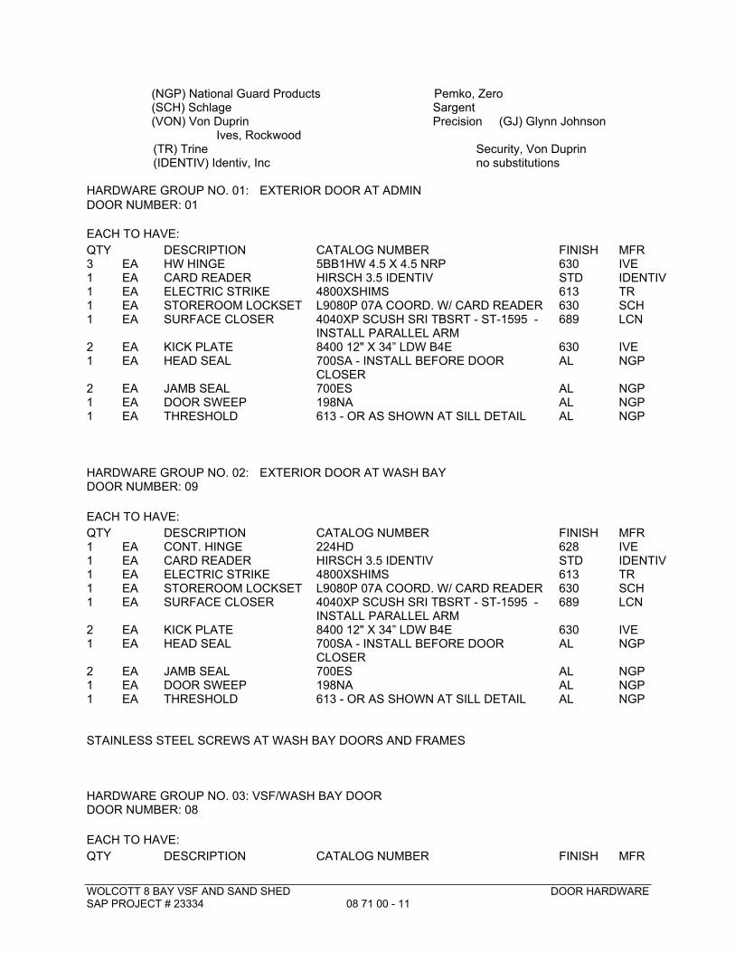
WOLCOTT 8 BAY VSF AND SAND SHED DOOR HARDWARESAP PROJECT # 23334 08 71 00 - 11
(NGP) National Guard Products Pemko, Zero (SCH) Schlage Sargent (VON) Von Duprin Precision (GJ) Glynn Johnson
Ives, Rockwood (TR) Trine Security, Von Duprin (IDENTIV) Identiv, Inc no substitutions
HARDWARE GROUP NO. 01: EXTERIOR DOOR AT ADMIN
DOOR NUMBER: 01
EACH TO HAVE:
QTY DESCRIPTION CATALOG NUMBER FINISH MFR3 EA HW HINGE 5BB1HW 4.5 X 4.5 NRP 630 IVE1 EA CARD READER HIRSCH 3.5 IDENTIV STD IDENTIV1 EA ELECTRIC STRIKE 4800XSHIMS 613 TR1 EA STOREROOM LOCKSET L9080P 07A COORD. W/ CARD READER 630 SCH1 EA SURFACE CLOSER 4040XP SCUSH SRI TBSRT - ST-1595 -
INSTALL PARALLEL ARM689 LCN
2 EA KICK PLATE 8400 12" X 34” LDW B4E 630 IVE1 EA HEAD SEAL 700SA - INSTALL BEFORE DOOR
CLOSERAL NGP
2 EA JAMB SEAL 700ES AL NGP1 EA DOOR SWEEP 198NA AL NGP1 EA THRESHOLD 613 - OR AS SHOWN AT SILL DETAIL AL NGP
HARDWARE GROUP NO. 02: EXTERIOR DOOR AT WASH BAYDOOR NUMBER: 09
EACH TO HAVE:
QTY DESCRIPTION CATALOG NUMBER FINISH MFR1 EA CONT. HINGE 224HD 628 IVE1 EA CARD READER HIRSCH 3.5 IDENTIV STD IDENTIV1 EA ELECTRIC STRIKE 4800XSHIMS 613 TR1 EA STOREROOM LOCKSET L9080P 07A COORD. W/ CARD READER 630 SCH1 EA SURFACE CLOSER 4040XP SCUSH SRI TBSRT - ST-1595 -
INSTALL PARALLEL ARM689 LCN
2 EA KICK PLATE 8400 12" X 34” LDW B4E 630 IVE1 EA HEAD SEAL 700SA - INSTALL BEFORE DOOR
CLOSERAL NGP
2 EA JAMB SEAL 700ES AL NGP1 EA DOOR SWEEP 198NA AL NGP1 EA THRESHOLD 613 - OR AS SHOWN AT SILL DETAIL AL NGP
STAINLESS STEEL SCREWS AT WASH BAY DOORS AND FRAMES
HARDWARE GROUP NO. 03: VSF/WASH BAY DOORDOOR NUMBER: 08
EACH TO HAVE:
QTY DESCRIPTION CATALOG NUMBER FINISH MFR
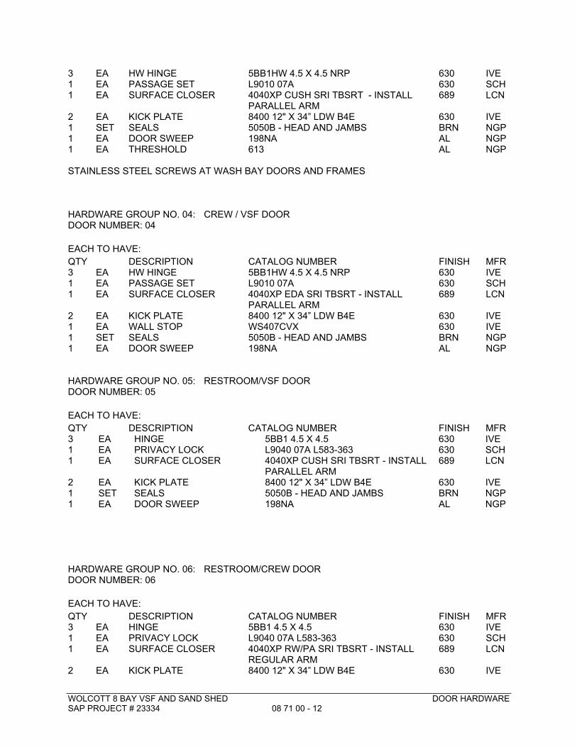
WOLCOTT 8 BAY VSF AND SAND SHED DOOR HARDWARESAP PROJECT # 23334 08 71 00 - 12
3 EA HW HINGE 5BB1HW 4.5 X 4.5 NRP 630 IVE1 EA PASSAGE SET L9010 07A 630 SCH1 EA SURFACE CLOSER 4040XP CUSH SRI TBSRT - INSTALL
PARALLEL ARM689 LCN
2 EA KICK PLATE 8400 12" X 34” LDW B4E 630 IVE1 SET SEALS 5050B - HEAD AND JAMBS BRN NGP11
EAEA
DOOR SWEEPTHRESHOLD
198NA613
ALAL
NGPNGP
STAINLESS STEEL SCREWS AT WASH BAY DOORS AND FRAMES
HARDWARE GROUP NO. 04: CREW / VSF DOORDOOR NUMBER: 04
EACH TO HAVE:
QTY DESCRIPTION CATALOG NUMBER FINISH MFR3 EA HW HINGE 5BB1HW 4.5 X 4.5 NRP 630 IVE1 EA PASSAGE SET L9010 07A 630 SCH1 EA SURFACE CLOSER 4040XP EDA SRI TBSRT - INSTALL
PARALLEL ARM689 LCN
2 EA KICK PLATE 8400 12" X 34” LDW B4E 630 IVE1 EA WALL STOP WS407CVX 630 IVE1 SET SEALS 5050B - HEAD AND JAMBS BRN NGP1 EA DOOR SWEEP 198NA AL NGP
HARDWARE GROUP NO. 05: RESTROOM/VSF DOORDOOR NUMBER: 05
EACH TO HAVE:
QTY DESCRIPTION CATALOG NUMBER FINISH MFR3 EA HINGE 5BB1 4.5 X 4.5 630 IVE1 EA PRIVACY LOCK L9040 07A L583-363 630 SCH1 EA SURFACE CLOSER 4040XP CUSH SRI TBSRT - INSTALL
PARALLEL ARM689 LCN
2 EA KICK PLATE 8400 12" X 34” LDW B4E 630 IVE1 SET SEALS 5050B - HEAD AND JAMBS BRN NGP1 EA DOOR SWEEP 198NA AL NGP
HARDWARE GROUP NO. 06: RESTROOM/CREW DOORDOOR NUMBER: 06
EACH TO HAVE:
QTY DESCRIPTION CATALOG NUMBER FINISH MFR3 EA HINGE 5BB1 4.5 X 4.5 630 IVE1 EA PRIVACY LOCK L9040 07A L583-363 630 SCH1 EA SURFACE CLOSER 4040XP RW/PA SRI TBSRT - INSTALL
REGULAR ARM689 LCN
2 EA KICK PLATE 8400 12" X 34” LDW B4E 630 IVE
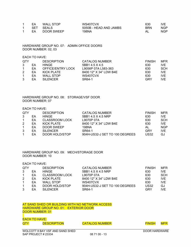
WOLCOTT 8 BAY VSF AND SAND SHED DOOR HARDWARESAP PROJECT # 23334 08 71 00 - 13
1 EA WALL STOP WS407CVX 630 IVE1 SET SEALS 5050B - HEAD AND JAMBS BRN NGP1 EA DOOR SWEEP 198NA AL NGP
HARDWARE GROUP NO. 07: ADMIN OFFICE DOORSDOOR NUMBER: 02, 03
EACH TO HAVE:
QTY DESCRIPTION CATALOG NUMBER FINISH MFR3 EA HINGE 5BB1 4.5 X 4.5 630 IVE1 EA OFFICE/ENTRY LOCK L9056P 07A L583-363 630 SCH2 EA KICK PLATE 8400 12" X 34” LDW B4E 630 IVE1 EA WALL STOP WS407CVX 630 IVE3 EA SILENCER SR64-1 GRY IVE
HARDWARE GROUP NO. 08: STORAGE/VSF DOORDOOR NUMBER: 07
EACH TO HAVE:
QTY DESCRIPTION CATALOG NUMBER FINISH MFR3 EA HINGE 5BB1 4.5 X 4.5 NRP 630 IVE1 EA CLASSROOM LOCK L9070P 07A 630 SCH2 EA KICK PLATE 8400 12" X 34” LDW B4E 630 IVE1 EA DOOR SWEEP 198NA AL NGP3 EA SILENCER SR64-1 GRY IVE1 EA DOOR HOLD/STOP 904H-US32-J SET TO 100 DEGREES US32 GJ
HARDWARE GROUP NO. 09: MECH/STORAGE DOORDOOR NUMBER: 10
EACH TO HAVE:
QTY DESCRIPTION CATALOG NUMBER FINISH MFR3 EA HINGE 5BB1 4.5 X 4.5 NRP 630 IVE1 EA CLASSROOM LOCK L9070P 07A 630 SCH2 EA KICK PLATE 8400 12" X 34” LDW B4E 630 IVE1 EA WALL STOP WS407CVX 630 IVE1 EA DOOR HOLD/STOP 904H-US32-J SET TO 100 DEGREES US32 GJ3 EA SILENCER SR64-1 GRY IVE
AT SAND SHED OR BUILDING WITH NO NETWORK ACCESSHARDWARE GROUP NO. 01: EXTERIOR DOOR
DOOR NUMBER: 01
EACH TO HAVE:
QTY DESCRIPTION CATALOG NUMBER FINISH MFR
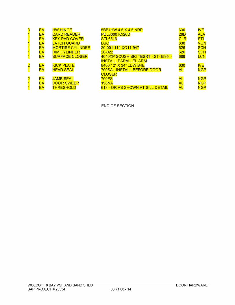
WOLCOTT 8 BAY VSF AND SAND SHED DOOR HARDWARESAP PROJECT # 23334 08 71 00 - 14
3 EA HW HINGE 5BB1HW 4.5 X 4.5 NRP 630 IVE1 EA CARD READER PDL3000 IC/26D 26D ALA1 EA KEY PAD COVER STI-6516 CLR STI1 EA LATCH GUARD LGO 630 VON1 EA MORTISE CYLINDER 20-001 114 XQ11-947 626 SCH1 EA RIM CYLINDER 20-022 626 SCH1 EA SURFACE CLOSER 4040XP SCUSH SRI TBSRT - ST-1595 -
INSTALL PARALLEL ARM689 LCN
2 EA KICK PLATE 8400 12" X 34” LDW B4E 630 IVE1 EA HEAD SEAL 700SA - INSTALL BEFORE DOOR
CLOSERAL NGP
2 EA JAMB SEAL 700ES AL NGP1 EA DOOR SWEEP 198NA AL NGP1 EA THRESHOLD 613 - OR AS SHOWN AT SILL DETAIL AL NGP
END OF SECTION
WOLCOTT 8 BAY VSF AND SAND SHED GLAZING
SAP PROJECT # 23334 08 80 00 - 1
SECTION 08 80 00GLAZING
PART 1 - GENERAL
1.1 RELATED DOCUMENTS
A. Provisions of The General Conditions of the Contract (Design/Bid/Build) and Division 1 General Requirements and applicable provisions elsewhere in the contract documents apply to this Section.
1.2 SUMMARY
A. This Section includes glazing for the following products and applications, including those specified in other Sections where glazing requirements are specified by reference to this Section:
1. Windows2. Man Doors3. Overhead Doors
B. Related Sections include the following:
1. Section 07 92 00: Joint Sealants2. Section 08 11 00: Metal Doors, Windows, and Frames3. Section 08 36 13: Sectional Overhead Doors4. Section 08 51 13: Aluminum Windows5. Section 08 71 00: Door Hardware6. Section 13 34 19: Metal Building Systems
1.3 DEFINITIONS
A. Manufacturer: A firm that produces primary glass or fabricated glass as defined in referenced glazing publications.
B. Deterioration of Insulating Glass: Failure of the hermetic seal under normal use that is attributed to the manufacturing process and not to causes other than glass breakage and practices for maintaining and cleaning insulating glass contrary to manufacturer's written instructions. Evidence of failure is the obstruction of vision by dust, moisture, or film on interior surfaces of glass.
1.4 PERFORMANCE REQUIREMENTS
A. General: Provide glazing systems capable of withstanding normal thermal movement and wind and impact loads (where applicable) without failure, including loss or glass breakage attributable to the following: defective manufacture, fabrication, and installation; failure of sealants or gaskets to remain watertight and airtight; deterioration of glazing materials; or other system or material defects.
WOLCOTT 8 BAY VSF AND SAND SHED GLAZING
SAP PROJECT # 23334 08 80 00 - 2
B. Provide glazing that complies with the ASHRAE 90.1 (2013) Energy Standard requirements for fenestration and as indicated in the glazing schedule.
C. Glass Design: Glass thicknesses indicated are minimums and are for detailing only. Confirm glass thicknesses by analyzing Project loads and in-service conditions. Provide glass lites for various size openings in nominal thicknesses indicated, but not less than thicknesses and in strengths (annealed or heat treated) required to meet or exceed the site location requirements.
D. Thermal Movements: Provide glazing that allows for thermal movements resulting from the following maximum change (range) in ambient and surface temperatures acting on glass framing members and glazing components. Base engineering calculation on surface temperatures of materials due to both solar heat gain and nighttime-sky heat loss.
1. Temperature Change (Range): 120 deg F, ambient; 180 deg F, material surfaces.
1.5 SUBMITTALS
A. Product Data: For each glass product and glazing material indicated.
B. Glazing Schedule: Use same designations indicated on Drawings for glazed openings in preparing a schedule listing glass types and thicknesses for each size opening and location.
C. Product Certificates: Signed by manufacturers of glass and glazing products certifying that products furnished comply with requirements.
D. Samples: For each type of insulated glazing system specified, provide a 12 inch square sample.
E. Refer to Project-Specific “Submittal Log” provided by Owner at Pre-Bid Meeting.
1.6 QUALITY ASSURANCE
A. Installer Qualifications: An experienced installer who has completed glazing similar in material, design, and extent to that indicated for Project and whose work has resulted in construction with a record of successful in-service performance.
B. Source Limitations for Glass: Obtain each type of glass from the same primary-glass manufacturer.
C. Source Limitations for Glazing Accessories: Obtain glazing accessories from one source for each product and installation method indicated.
D. Glazing Publications: Comply with published recommendations of glass product manufacturers and organizations below, unless more stringent requirements are indicated. Refer to these publications for glazing terms not otherwise defined in this Section or in referenced standards.
1. GANA Publications: GANA'S "Glazing Manual" and "Laminated Glass Design Guide."2. AAMA Publications: AAMA GDSG-1, "Glass Design for Sloped Glazing," and
AAMA TIR-A7, "Sloped Glazing Guidelines."3. SIGMA Publications: SIGMA TM-3000, "Vertical Glazing Guidelines," and SIGMA
TB-3001, "Sloped Glazing Guidelines."
WOLCOTT 8 BAY VSF AND SAND SHED GLAZING
SAP PROJECT # 23334 08 80 00 - 3
E. Insulating-Glass Certification Program: Permanently marked either on spacers or on at least one component lite of units with appropriate certification label of the following inspecting and testing agency:
1. Insulating Glass Certification Council2. Associated Laboratories, Inc.3. National Accreditation and Management Institute
1.7 DELIVERY, STORAGE, AND HANDLING
A. Protect glazing materials according to manufacturer's written instructions and as needed to prevent damage to glass and glazing materials from condensation, temperature changes, direct exposure to sun, or other causes.
B. For insulating-glass units that will be exposed to substantial altitude changes, comply with insulating-glass manufacturer's written recommendations for venting and sealing to avoid hermetic seal ruptures.
1.8 PROJECT CONDITIONS
A. Environmental Limitations: Do not proceed with glazing when ambient and substrate temperature conditions are outside limits permitted by glazing material manufacturers and when glazing channel substrates are wet from rain, frost, condensation, or other causes.
1. Do not install liquid glazing sealants when ambient and substrate temperature conditions are outside limits permitted by glazing sealant manufacturer or below 40 deg F (4.4 deg C).
PART 2 - PRODUCTS
2.1 PRODUCTS AND MANUFACTURERS
A. Available Products: Subject to compliance with requirements, products that may be incorporated into the Work include, but are not limited to, the products indicated in the Glass Schedule at the end of Part 3.
B. Products: Subject to compliance with requirements, provide one of the products indicated in the Glass Schedule at the end of Part 3.
2.2 PRIMARY FLOAT GLASS
A. Float Glass: ASTM C 1036, Type I (transparent glass, flat), Quality q3 (glazing select); class as indicated in the Glass Schedule at the end of Part 3.
2.3 INSULATING GLASS
A. Insulating-Glass Units: Preassembled units consisting of sealed lites of glass separated by a dehydrated interspace, and complying with ASTM E 774 for Class CBA units and with requirements specified in this Article and in the Insulating-Glass Schedule at the end of Part 3.
WOLCOTT 8 BAY VSF AND SAND SHED GLAZING
SAP PROJECT # 23334 08 80 00 - 4
1. Provide Kind HS (heat-strengthened) float glass in place of annealed glass where needed to resist thermal stresses induced by differential shading of individual glass lites and to comply with glass design requirements specified in "Performance Requirements" Article. Provide Kind FT (fully tempered) where safety glass is indicated.
B. Overall Unit Thickness and Thickness of Each Lite: Dimensions indicated in the Insulating-Glass Schedule at the end of Part 3 are nominal and the overall thicknesses of units are measured perpendicularly from outer surfaces of glass lites at unit's edge.
C. Sealing System: Dual seal, with primary and secondary sealants as follows:
1. Manufacturer's standard sealants2. Polyisobutylene and polysulfide3. Polyisobutylene and silicone4. Polyisobutylene and hot-melt butyl5. Polyisobutylene and polyurethane
D. Spacer Specifications: Manufacturer's standard spacer material and construction complying with the following requirements:
1. Aluminum with mill or clear-anodized finish.
2.4 ELASTOMERIC GLAZING SEALANTS
A. General: Provide products of type indicated, complying with the following requirements:
1. Compatibility: Select glazing sealants that are compatible with one another and with other materials they will contact, including glass products, seals of insulating-glass units, and glazing channel substrates, under conditions of service and application, as demonstrated by sealant manufacturer based on testing and field experience.
2. Suitability: Comply with sealant and glass manufacturers' written instructions for selecting glazing sealants suitable for applications indicated and for conditions existing at time of installation.
3. Colors of Exposed Glazing Sealants: As indicated by manufacturer's designations.
B. Elastomeric Glazing Sealant Standard: Comply with ASTM C 920 for type, grade, class, and uses.
1. Additional Movement Capability: Where additional movement capability is required, provide products with the capability, when tested for adhesion and cohesion under maximum cyclic movement per ASTM C 719, to withstand the specified percentage change in the joint width existing at time of installation and remain in compliance with other requirements in ASTM C 920 for uses indicated.
C. Glazing Sealant for Fire-Resistive Glazing Products: Identical to product used in test assembly to obtain fire-protection rating.
2.5 GLAZING TAPES
A. Back-Bedding Mastic Glazing Tape: Preformed, butyl-based elastomeric tape with a solids content of 100 percent; nonstaining and nonmigrating in contact with nonporous surfaces; with or without spacer rod as recommended in writing by tape and glass manufacturers for
WOLCOTT 8 BAY VSF AND SAND SHED GLAZING
SAP PROJECT # 23334 08 80 00 - 5
application indicated; packaged on rolls with a release paper backing; and complying with ASTM C 1281 and AAMA 800 for products indicated below:
1. AAMA 804.3 tape, where indicated.
2.6 MISCELLANEOUS GLAZING MATERIALS
A. General: Provide products of material, size, and shape complying with referenced glazing standard, requirements of manufacturers of glass and other glazing materials for application indicated, and with a proven record of compatibility with surfaces contacted in installation.
B. Cleaners, Primers, and Sealers: Types recommended by sealant or gasket manufacturer.
C. Setting Blocks: Elastomeric material with a Shore A durometer hardness of 85, plus or minus 5.
D. Spacers: Elastomeric blocks or continuous extrusions with a Shore A durometer hardness required by glass manufacturer to maintain glass lites in place for installation indicated.
E. Edge Blocks: Elastomeric material of hardness needed to limit glass lateral movement (side walking).
F. Cylindrical Glazing Sealant Backing: ASTM C 1330, Type O (open-cell material), of size and density to control glazing sealant depth and otherwise produce optimum glazing sealant performance.
G. Perimeter Insulation for Fire-Resistive Glazing: Identical to product used in test assembly to obtain fire-resistance rating.
2.7 FABRICATION OF GLASS AND OTHER GLAZING PRODUCTS
A. Fabricate glass and other glazing products in sizes required to glaze openings indicated for Project, with edge and face clearances, edge and surface conditions, and bite complying with written instructions of product manufacturer and referenced glazing standard, to comply with system performance requirements.
B. Clean-cut or flat-grind vertical edges of butt-glazed monolithic lites in a manner that produces square edges with slight kerfs at junctions with indoor and outdoor faces.
C. Grind smooth and polish exposed glass edges.
PART 3 - EXECUTION
3.1 EXAMINATION
A. Examine framing glazing, with Installer present, for compliance with the following:
1. Manufacturing and installation tolerances, including those for size, squareness, and offsets at corners.
2. Presence and functioning of weep system.3. Minimum required face or edge clearances.4. Effective sealing between joints of glass-framing members.
WOLCOTT 8 BAY VSF AND SAND SHED GLAZING
SAP PROJECT # 23334 08 80 00 - 6
B. Proceed with installation only after unsatisfactory conditions have been corrected.
3.2 PREPARATION
A. Clean glazing channels and other framing members receiving glass immediately before glazing. Remove coatings not firmly bonded to substrates.
3.3 GLAZING, GENERAL
A. Comply with combined written instructions of manufacturers of glass, sealants, gaskets, and other glazing materials, unless more stringent requirements are indicated, including those in referenced glazing publications.
B. Glazing channel dimensions, as indicated on Drawings, provide necessary bite on glass, minimum edge and face clearances, and adequate sealant thicknesses, with reasonable tolerances. Adjust as required by Project conditions during installation.
C. Protect glass edges from damage during handling and installation. Remove damaged glass from Project site and legally dispose of off Project site. Damaged glass is glass with edge damage or other imperfections that, when installed, could weaken glass and impair performance and appearance.
D. Apply primers to joint surfaces where required for adhesion of sealants, as determined by preconstruction sealant-substrate testing.
E. Install setting blocks in sill rabbets, sized and located to comply with referenced glazing publications, unless otherwise required by glass manufacturer. Set blocks in thin course of compatible sealant suitable for heel bead.
F. Do not exceed edge pressures stipulated by glass manufacturers for installing glass lites.
G. Provide spacers for glass lites where the length plus width is larger than 50 inches as follows:
1. Locate spacers directly opposite each other on both inside and outside faces of glass. Install correct size and spacing to preserve required face clearances, unless gaskets and glazing tapes are used that have demonstrated ability to maintain required face clearances and to comply with system performance requirements.
2. Provide 1/8-inch minimum bite of spacers on glass and use thickness equal to sealant width. With glazing tape, use thickness slightly less than final compressed thickness of tape.
H. Provide edge blocking where indicated or needed to prevent glass lites from moving sideways in glazing channel, as recommended in writing by glass manufacturer and according to requirements in referenced glazing publications.
I. Set glass lites in each series with uniform pattern, draw, bow, and similar characteristics.
J. Where wedge-shaped gaskets are driven into one side of channel to pressurize sealant or gasket on opposite side, provide adequate anchorage so gasket cannot walk out when installation is subjected to movement.
WOLCOTT 8 BAY VSF AND SAND SHED GLAZING
SAP PROJECT # 23334 08 80 00 - 7
K. Square cut wedge-shaped gaskets at corners and install gaskets in a manner recommended by gasket manufacturer to prevent corners from pulling away; seal corner joints and butt joints with sealant recommended by gasket manufacturer.
3.4 TAPE GLAZING
A. Position tapes on fixed stops so that, when compressed by glass, their exposed edges are flush with or protrude slightly above sightline of stops.
B. Install tapes continuously, but not necessarily in one continuous length. Do not stretch tapes to make them fit opening.
C. Where framing joints are vertical, cover these joints by applying tapes to heads and sills first and then to jambs. Where framing joints are horizontal, cover these joints by applying tapes to jambs and then to heads and sills.
D. Place joints in tapes at corners of opening with adjoining lengths butted together, not lapped. Seal joints in tapes with compatible sealant approved by tape manufacturer.
E. Do not remove release paper from tape until just before each glazing unit is installed.
F. Apply heel bead of elastomeric sealant.
G. Center glass lites in openings on setting blocks and press firmly against tape by inserting dense compression gaskets formed and installed to lock in place against faces of removable stops. Start gasket applications at corners and work toward centers of openings.
H. Apply cap bead of elastomeric sealant over exposed edge of tape.
3.5 SEALANT GLAZING (WET)
A. Install continuous spacers, or spacers combined with cylindrical sealant backing, between glass lites and glazing stops to maintain glass face clearances and to prevent sealant from extruding into glass channel and blocking weep systems until sealants cure. Secure spacers or spacers and backings in place and in position to control depth of installed sealant relative to edge clearance for optimum sealant performance.
B. Force sealants into glazing channels to eliminate voids and to ensure complete wetting or bond of sealant to glass and channel surfaces.
C. Tool exposed surfaces of sealants to provide a substantial wash away from glass.
3.6 PROTECTION AND CLEANING
A. Protect exterior glass from damage immediately after installation by attaching crossed streamers to framing held away from glass. Do not apply markers to glass surface. Remove nonpermanent labels, and clean surfaces.
B. Protect glass from contact with contaminating substances resulting from construction operations, including weld splatter. If, despite such protection, contaminating substances do come into contact with glass, remove them immediately as recommended by glass manufacturer.
WOLCOTT 8 BAY VSF AND SAND SHED GLAZING
SAP PROJECT # 23334 08 80 00 - 8
C. Examine glass surfaces adjacent to or below exterior concrete and other masonry surfaces at frequent intervals during construction, but not less than once a month, for build-up of dirt, scum, alkaline deposits, or stains; remove as recommended by glass manufacturer.
D. Remove and replace glass that is broken, chipped, cracked, abraded, or damaged in any way, including natural causes, accidents, and vandalism, during construction period.
E. Wash glass on both exposed surfaces in each area of Project not more than four days before date scheduled for inspections that establish date of Substantial Completion. Wash glass as recommended by glass manufacturer.
3.7 GLASS SCHEDULE
A. Where glass is designated on the Drawings, provide the following:
1. GL-1: Uncoated Clear Insulating Safety Glass: Where glass of this designation is indicated, primarily for exterior doors, provide uncoated insulating-glass units complying with the following: a. Overall Unit Thickness: 3/4 inchb. Thickness of each Glass Lite: 1/4 inchc. Class 1, Clear, Fully Tempered Glassd. Interspace Content: Aire. Tinting: Nonef. Exterior applications to be insulated with a maximum U-Factor of 0.80
2. GL-2: Uncoated Clear Safety Glass: Where glass of this designation is indicated, primarily for interior windows and doors, provide uncoated tempered glass units complying with the following: a. Class 1, Kind FT (Fully Tempered), clear float glass.b. Overall thickness: 1/4 inch.c. Tinting: None
3. GL-3: Insulated Double Strength Glazing: Where glass of this designation is indicated, primarily for regular VSF garage doors, provide uncoated insulating-glass units complying with the following: a. Clear Float Glass: 1/8 inch insulated DSB, complying with ASTM C 1036, Type I,
Class 1, Quality q3.b. Overall thickness: 1/2 inch double pane.c. Tinting: Noned. Minimum U-Factor: 0.31e. Coordinate Glazing size with overhead door manufacturer standard window size.
4. GL-4: Polycarbonate Glazing: Where glass of this designation is indicated, primarily wash bay garage doors, provide 2 sheets of 1/8 inch thick polycarbonate with 1/4 inch air space for a total of 1/2 inch thick glazing system. Use Makrolon GP or equal. Provide clear (not frosted) panels with polished surfaces, and light transmission of 74%. Provide a minimum U-Factor of 0.31. Coordinate glazing size with overhead door manufacturer standard window size.
5. GL-5: Low-E Coated Clear Insulating Glass: Where glass of this designation is indicated, primarily for exterior clerestory windows, provide insulating glass units complying with the following:
a. Overall Unit Thickness: 1 inchb. Thickness of each Glass Lite: 1/4 inch
WOLCOTT 8 BAY VSF AND SAND SHED GLAZING
SAP PROJECT # 23334 08 80 00 - 9
c. Outdoor Lite: Clear, Fully Tempered Glass with Low E Coating. Basis of Design Solarban 70xl by PPG
d. Interspace Content: Aire. Indoor Lite: Clear Float Glass. f. Performance Values
(1 Visible Light Transmission: 60%-70%(2 U-Value Winter: Maximum of 0.28(3 SHGC: Maximum of 0.27(4 Shading Coefficient: Maximum of 0.81(5 Outdoor Visible Light Reflectance: 10%-20%
g. Outdoor Appearance: Clear, low-reflective glass product
6. GL-6: Tinted Insulating Low-E Glass: Where glass of this designation is indicated, primarily for exterior administration windows, provide tinted insulating glass unity complying with the following:a. Overall Unit Thickness: 1 inchb. Thickness of each Glass Lite: 1/4 inchc. Outdoor Lite: Tinted, Fully Tempered Glass with Low E Coating
(1 Basis of Design Color: SolarGray by PPG or equal. (2 Basis of Design Coating: Solarban 70XL(3 Submit manufacturer’s standard colors for architect selection.
d. Interspace Content: Aire. Indoor Lite: Clear Fully tempered float glass. f. Performance Values
(1 Visible Light Transmission: 30% - 40%(2 U-Value Winter: Maximum of .28(3 SHGC: Maximum of .20 (4 Outdoor Visible Light Reflectance: 5% - 10%
g. Outdoor Appearance: Tinted, Low-E low-reflective glass product
7. GL-7: Polycarbonate Glazing: Where glass of this designation is indicated, primarily for exterior sand shed windows, provide 1 sheet of 1/8 inch thick polycarbonate in a hollow metal frame. Use Makrolon GP or equal. Provide clear (not frosted) panels with polished surfaces, and light transmission of 74%.
END OF SECTION
WOLCOTT 8 BAY VSF AND SAND SHED GLAZING
SAP PROJECT # 23334 08 80 00 - 10
THIS PAGE INTENTIONALLY LEFT BLANK
WOLCOTT 8 BAY VSF AND SAND SHED LOUVERS AND VENTSSAP PROJECT # 23334 08 90 00 - 1
SECTION 08 90 00LOUVERS AND VENTS
PART 1 - GENERAL
1.1 RELATED DOCUMENTS
A. Provisions of The General Conditions of the Contract (Design/Bid/Build) and Division 1 General Requirements and applicable provisions elsewhere in the contract documents apply to this Section.
B. Provide all items, articles, materials, operations, or methods listed, mentioned, or scheduled on drawings and/or herein specified, including all labor, materials, equipment, and incidentals necessary and required for their completion.
1.2 SUMMARY
A. Section Includes:
1. Fixed, extruded-aluminum louvers.
1.3 DEFINITIONS
A. Louver Terminology: Definitions of terms for metal louvers contained in AMCA 501 apply to this Section unless otherwise defined in this Section or in referenced standards.
B. Drainable-Blade Louver: Louver with blades having gutters that collect water and drain it to channels in jambs and mullions, which carry it to bottom of unit and away from opening.
1.4 PERFORMANCE REQUIREMENTS
A. Structural Performance: Louvers shall withstand the effects of gravity loads and the following loads and stresses within limits and under conditions indicated without permanent deformation of louver components, noise or metal fatigue caused by louver blade rattle or flutter, or permanent damage to fasteners and anchors. Wind pressures shall be considered to act normal to the face of the building.
1. Wind Loads: Determine loads based on a uniform pressure of 20 lbf/sq. ft., acting inward or outward.
B. Louver Performance Ratings: Provide louvers complying with requirements specified, as demonstrated by testing manufacturer's stock units identical to those provided, except for length and width according to AMCA 500-L.
1.5 ACTION SUBMITTALS
A. Product Data: For each type of product indicated.
WOLCOTT 8 BAY VSF AND SAND SHED LOUVERS AND VENTSSAP PROJECT # 23334 08 90 00 - 2
1. For louvers specified to bear AMCA seal, include printed catalog pages showing specified models with appropriate AMCA Certified Ratings Seals.
B. Samples for Initial Selection: Submit manufacturer’s standard color line for units with factory-applied color finishes.
1.6 QUALITY ASSURANCE
A. SMACNA Standard: Comply with recommendations in SMACNA's "Architectural Sheet Metal Manual" for fabrication, construction details, and installation procedures.
1.7 PROJECT CONDITIONS
A. Field Measurements: Verify actual dimensions of openings by field measurements before fabrication.
PART 2 - PRODUCTS
2.1 MATERIALS
A. Aluminum Extrusions: ASTM B 221, Alloy 6063-T5, T-52, or T6.
B. Aluminum Sheet: ASTM B 209, Alloy 3003 or 5005 with temper as required for forming, or as otherwise recommended by metal producer for required finish.
C. Aluminum Castings: ASTM B 26/B 26M, Alloy 319.
D. Fasteners: Use types and sizes to suit unit installation conditions.
1. Use tamper-resistant screws for exposed fasteners unless otherwise indicated.2. For fastening aluminum, use aluminum or 300 series stainless-steel fasteners.3. For color-finished louvers, use fasteners with heads that match color of louvers.
E. Postinstalled Fasteners for Concrete and Masonry: Torque-controlled expansion anchors, made from stainless-steel components, with capability to sustain, without failure, a load equal to 4 times the loads imposed, for concrete, or 6 times the load imposed, for masonry, as determined by testing per ASTM E 488, conducted by a qualified independent testing agency.
2.2 FABRICATION, GENERAL
A. Assemble louvers in factory to minimize field splicing and assembly. Disassemble units as necessary for shipping and handling limitations. Clearly mark units for reassembly and coordinated installation.
B. Fabricate frames, including integral sills, to fit in openings of sizes indicated, with allowances made for fabrication and installation tolerances, adjoining material tolerances, and perimeter sealant joints.
1. Frame Type: Channel unless otherwise indicated.
WOLCOTT 8 BAY VSF AND SAND SHED LOUVERS AND VENTSSAP PROJECT # 23334 08 90 00 - 3
C. Include supports, anchorages, and accessories required for complete assembly.
D. Provide vertical mullions of type and at spacings indicated, but not more than recommended by manufacturer, or 72 inches o.c., whichever is less.
1. Fully Recessed Mullions: Where indicated, provide mullions fully recessed behind louver blades. Where length of louver exceeds fabrication and handling limitations, fabricate with close-fitting blade splices designed to permit expansion and contraction.
E. Provide subsills made of same material as louvers and extended sills for recessed louvers.
F. Join frame members to each other and to fixed louver blades with fillet welds concealed from view unless otherwise indicated or size of louver assembly makes bolted connections between frame members necessary.
2.3 FIXED, EXTRUDED-ALUMINUM LOUVERS
A. Horizontal Drainable Blade Louver:
1. Manufacturers: Subject to compliance with requirements, provide products by one of the following:
a. Air Balance Inc.; a Mestek company.b. American Warming and Ventilating, Inc.; a Mestek company.c. Arrow United Industries; a division of Mestek, Inc.d. Construction Specialties, Inc.e. Greenheck Fan Corporation.f. Ruskin Company; Tomkins PLC.
2. Louver Depth: 4 inches3. AMCA Seal: Mark units with AMCA Certified Ratings Seal.
2.4 LOUVER SCREENS
A. General: Provide screen at each exterior louver.
1. Screen Location: Interior face.2. Screening Type: Bird screening.
B. Secure screen frames to louver frames with machine screws with heads finished to match louver, spaced a maximum of 6 inches from each corner and at 12 inches o.c.
C. Louver Screen Frames: Fabricate with mitered corners to louver sizes indicated.
1. Metal: Same kind and form of metal as indicated for louver to which screens are attached.
2. Finish: Same finish as louver frames to which louver screens are attached
2.5 FINISHES, GENERAL
A. Comply with NAAMM's "Metal Finishes Manual for Architectural and Metal Products" for recommendations for applying and designating finishes.
WOLCOTT 8 BAY VSF AND SAND SHED LOUVERS AND VENTSSAP PROJECT # 23334 08 90 00 - 4
2.6 ALUMINUM FINISHES
A. Finish louvers in factory after assembly.
B. High-Performance Organic Finish: Two-coat fluoropolymer finish complying with AAMA 2604 and containing not less than 50 percent PVDF resin by weight in color coat. Prepare, pretreat, and apply coating to exposed metal surfaces to comply with coating and resin manufacturers' written instructions.
C. Color and Gloss: As selected by Architect from manufacturer's standard range.
PART 3 - EXECUTION
3.1 EXAMINATION
A. Examine substrates and openings, with Installer present, for compliance with requirements for installation tolerances and other conditions affecting performance.
B. Proceed with installation only after unsatisfactory conditions have been corrected.
3.2 PREPARATION
A. Coordinate setting drawings, diagrams, templates, instructions, and directions for installation of anchorages that are to be embedded in concrete or masonry construction. Coordinate delivery of such items to Project site.
3.3 INSTALLATION
A. Locate and place louvers and vents level, plumb, and at indicated alignment with adjacent work.
B. Use concealed anchorages where possible. Provide brass or lead washers fitted to screws where required to protect metal surfaces and to make a weathertight connection.
C. Form closely fitted joints with exposed connections accurately located and secured.
D. Provide perimeter reveals and openings of uniform width for sealants and joint fillers, as indicated.
E. Repair finishes damaged by cutting, welding, soldering, and grinding. Restore finishes so no evidence remains of corrective work. Return items that cannot be refinished in the field to the factory, make required alterations, and refinish entire unit or provide new units.
F. Install concealed gaskets, flashings, joint fillers, and insulation as louver installation progresses, where weathertight louver joints are required. Comply with Division 07 Section "Joint Sealants" for sealants applied during louver installation.
3.4 ADJUSTING AND CLEANING
A. Test operation of adjustable louvers and adjust as needed to produce fully functioning units that comply with requirements.
WOLCOTT 8 BAY VSF AND SAND SHED LOUVERS AND VENTSSAP PROJECT # 23334 08 90 00 - 5
B. Clean exposed surfaces of louvers and vents that are not protected by temporary covering, to remove fingerprints and soil during construction period. Do not let soil accumulate during construction period.
C. Before final inspection, clean exposed surfaces with water and a mild soap or detergent not harmful to finishes. Thoroughly rinse surfaces and dry.
D. Restore louvers and vents damaged during installation and construction so no evidence remains of corrective work. If results of restoration are unsuccessful, as determined by Architect, remove damaged units and replace with new units.
1. Touch up minor abrasions in finishes with air-dried coating that matches color and gloss of, and is compatible with, factory-applied finish coating.
END OF SECTION

WOLCOTT 8 BAY VSF AND SAND SHED LOUVERS AND VENTSSAP PROJECT # 23334 08 90 00 - 6
THIS PAGE INTENTIONALLY LEFT BLANK
WOLCOTT 8 BAY VSF AND SAND SHED GYPSUM BOARD ASSEMBLIES
SAP PROJECT # 23334 09 21 16 - 1
SECTION 09 21 16GYPSUM BOARD ASSEMBLIES
PART 1 - GENERAL
1.1 RELATED DOCUMENTS
A. Provisions of The General Conditions of the Contract (Design/Bid/Build) and Division 1 General Requirements and applicable provisions elsewhere in the contract documents apply to this Section.
1.2 SUMMARY
A. This Section includes the following:
1. Interior gypsum wallboard2. Cementitious Tile Backer Board3. Non-load-bearing steel framing
B. Related Sections include the following:
1. Section 05 40 00: Cold-Formed Metal Framing2. Section 06 64 00: Plastic Paneling3. Section 07 21 00: Thermal Insulation4. Section 07 26 00: Vapor Retarders5. Section 07 92 00: Joint Sealants6. Section 08 11 00: Metal Doors, Windows and Frames7. Section 08 31 13: Access Doors and Frames8. Section 09 30 13: Ceramic Tiling9. Section 09 51 13: Acoustical Panel Ceilings 10. Section 09 90 00: Painting and Coating11. Section 10 28 00: Toilet and Bath Accessories12. Section 13 34 19: Metal Building Systems
1.3 DEFINITIONS
A. Gypsum Board Terminology: Refer to ASTM C 11 for definitions of terms for gypsum board assemblies not defined in this Section or in other referenced standards.
1.4 SUBMITTALS
A. Product Data: For each type of product indicated.
B. Refer to Project-Specific “Submittal Log” provided by Owner at Pre-Bid Meeting.
1.5 QUALITY ASSURANCE
A. Fire-Test-Response Characteristics: For gypsum board assemblies with fire-resistance ratings, provide materials and construction identical to those tested in assembly indicated according to ASTM E 119 by an independent testing and inspecting agency acceptable to
WOLCOTT 8 BAY VSF AND SAND SHED GYPSUM BOARD ASSEMBLIES
SAP PROJECT # 23334 09 21 16 - 2
authorities having jurisdiction.
B. Certified Asbestos Free: All gypsum board and joint compounds used in project shall be certified asbestos free.
1.6 DELIVERY, STORAGE, AND HANDLING
A. Deliver materials in original packages, containers, or bundles bearing brand name and identification of manufacturer or supplier.
B. Store materials inside under cover and keep them dry and protected against damage from weather, direct sunlight, surface contamination, corrosion, construction traffic, and other causes. Stack gypsum panels flat to prevent sagging.
1.7 PROJECT CONDITIONS
A. Environmental Limitations: Comply with ASTM C 840 requirements or gypsum board manufacturer's written recommendations, whichever are more stringent.
PART 2 - PRODUCTS
2.1 MANUFACTURERS
A. Available Manufacturers: Subject to compliance with requirements, manufacturers offering products that may be incorporated into the Work include, but are not limited to, the following:
B. Manufacturers: Subject to compliance with requirements, provide products by one of the following:
1. Steel Framing and Furring:a. Clark-Dietrich Steel Framing Systemsb. Consolidated Systems, Inc.c. Dale Industries, Inc. - Dale/Incord. MarinoWare; Division of Ware Ind.e. National Gypsum Companyf. Scafco Corporationg. Unimast, Inc.
2. Gypsum Board and Related Products:a. American Gypsum Co.b. G-P Gypsum Corp.c. National Gypsum Companyd. United States Gypsum Co.
3. Cementitious/Fiberglass Tile Backer Board:a. Custom Building Productsb. Domtar Gypsumc. FinPan, Inc.d. United States Gypsum Co.e. Georgia Pacific
WOLCOTT 8 BAY VSF AND SAND SHED GYPSUM BOARD ASSEMBLIES
SAP PROJECT # 23334 09 21 16 - 3
2.2 STEEL SUSPENDED CEILING AND SOFFIT FRAMING
A. Components, General: Comply with ASTM C 754 for conditions indicated.
B. Tie Wire: ASTM A 641/A 641M, Class 1 zinc coating, soft temper, 0.0625-inch- diameter wire, or double strand of 0.0475-inch- diameter wire.
C. Hangers: As follows:
1. Wire Hangers: ASTM A 641/A 641M, Class 1 zinc coating, soft temper, 0.162-inch diameter.
2. Rod Hangers: ASTM A 510, mild carbon steel.3. Flat Hangers: Commercial-steel sheet, ASTM A 653/A 653M, G40, hot-dip galvanized
zinc coating.
D. Carrying Channels: Cold-rolled, commercial-steel sheet with a base metal thickness of 0.0538 inch, a minimum 1/2-inch- wide flange, with ASTM A 653/A 653M, G40, hot-dip galvanized zinc coating.
E. Furring Channels (Furring Members): Commercial-steel sheet with ASTM A 653/A 653M, G40, hot-dip galvanized zinc coating. Hat-Shaped, Rigid Furring Channels: ASTM C 645, 7/8 inch deep.
1. Resilient Furring Channels: 1/2-inch-deep members designed to reduce sound transmission.
F. Grid Suspension System for Interior Ceilings: ASTM C 645, direct-hung system composed of main beams and cross-furring members that interlock.
1. Products: Subject to compliance with requirements, provide one of the following:a. Armstrong World Industries, Inc.b. Chicago Metallic Corporationc. USG Interiors, Inc.
2.3 STEEL PARTITION AND SOFFIT FRAMING
A. Steel Studs and Runners: ASTM C 645.
1. Minimum Base Metal Thickness: 0.035, / 20 gauge EQ with 50 ksi strength.2. Depth: 3-5/8 inches unless otherwise indicated on the Drawings.3. Depth: 2 1/2 inches at perimeter insulated walls and high, insulated curb in administrative
area
B. King Studs at Doors: ASTM C 645
1. Minimum Base Metal Thickness: 0.053 / 16 gauge EQ2. Depth: 3-5/8 inches unless otherwise indicated on the Drawings.
C. Deep-Leg Deflection Track: ASTM C 645 top runner with 3 5/8 inch deep flanges for 2 inch minimum vertical slip movement
D. Flat Strap and Backing Plate: Steel sheet for blocking and bracing in length and width indicated.
1. Minimum Base Metal Thickness: 0.035 inch / 20 gauge EQ
WOLCOTT 8 BAY VSF AND SAND SHED GYPSUM BOARD ASSEMBLIES
SAP PROJECT # 23334 09 21 16 - 4
2. Minimum Width: 4 inches
E. Cold-Rolled Channel Bridging: 0.0538-inch bare steel thickness, with minimum 1/2-inch-wide flange.
1. Depth: 1-1/2 inches.2. Clip Angle: 1-1/2 by 1-1/2 inch, 0.068-inch- thick, galvanized steel.
F. Hat-Shaped, Rigid Furring Channels: ASTM C 645.
1. Minimum Base Metal Thickness: 0.035 inch / 20 gauge EQ.2. Depth: 7/8 inch.
G. Resilient Furring Channels: 1/2-inch- deep, steel sheet members designed to reduce sound transmission.
H. Cold-Rolled Furring Channels: 0.0538-inch bare steel thickness, with minimum 1/2-inch- wide flange.
1. Depth: 3/4 inch.2. Furring Brackets: Adjustable, corrugated-edge type of steel sheet with minimum bare
steel thickness of 0.0312 inch.3. Tie Wire: ASTM A 641/A 641M, Class 1 zinc coating, soft temper, 0.0625-inch- diameter
wire, or double strand of 0.0475-inch- diameter wire.
I. Z-Shaped Furring: With slotted or non-slotted web, face flange of 1-1/4 inches, wall attachment flange of 7/8 inch, minimum bare metal thickness of 0.0179 inch, and depth required to fit insulation thickness indicated.
J. Fasteners for Metal Framing: Of type, material, size, corrosion resistance, holding power, and other properties required to fasten steel members to substrates.
2.4 INTERIOR GYPSUM WALLBOARD
A. Panel Size: Provide in maximum lengths and widths available that will minimize joints in each area and correspond with support system indicated.
B. Gypsum Wallboard: ASTM C 1396/C 1396/M.
1. 5/8 inch thick, Type X2. See Section 06 64 00 Plastic Paneling for detail on interior plywood wainscot.
2.5 TILE BACKER BOARD
A. Panel Size: Provide in maximum lengths and widths available that will minimize joints in each area and correspond with support system indicated.
B. Tile Backer Board: ANSI A118.9 and ASTMC1288 or 1325 with manufacturer’s standard edges.1. Thickness: 5/8 inch, unless otherwise indicated2. Width: Manufacturer’s Standard width, but not less than 32 inches
C. Products: Subject to compliance with requirements, provide one of the following products:1. Wonderboard Multi-board: Custom Building Product
WOLCOTT 8 BAY VSF AND SAND SHED GYPSUM BOARD ASSEMBLIES
SAP PROJECT # 23334 09 21 16 - 5
2. DomCrete Cementitious Tile-Backer Board: Domtar Gypsum3. Util-A-Crete Concrete Backer Board: FinPan, Inc. 4. Durock Cement Board: United States Gypsum5. DensShield Tile Backer; Georgia Pacific
2.6 TRIM ACCESSORIES
A. Interior Trim: ASTM C 1047.
1. Material: Galvanized or aluminum-coated steel sheet.2. Shapes:
a. Cornerbead: Use at all outside corners.b. LC-Bead (J-Bead): Use at exposed panel edges and where gypsum board panels
abut other materials.c. Expansion (Control) Joint: Where indicated or at 20 feet o.c. max in continuous
gypsum wall board, vertical application, evenly distributed.
2.7 JOINT TREATMENT MATERIALS
A. General: Comply with ASTM C 475.
B. Joint Tape:
1. Interior Gypsum Wallboard: Paper2. Tile Backing Panels: As recommended by panel manufacturer
C. Joint Compound for Interior Gypsum Wallboard: For each coat use formulation that is compatible with other compounds applied on previous or for successive coats.
2.8 AUXILIARY MATERIALS
A. General: Provide auxiliary materials that comply with referenced installation standards and manufacturer's written recommendations.
B. Laminating Adhesive: Adhesive or joint compound recommended for directly adhering gypsum panels to continuous substrate.
C. Fastening Adhesive:
1. Steel: Adhesive recommended for attaching panels to steel framing.
D. Steel Drill Screws: ASTM C 1002, unless otherwise indicated.
1. Use screws complying with ASTM C 954 for fastening panels to steel members from 0.033 to 0.112 inch thick.
E. Isolation Strip at Exterior Walls:
1. Asphalt-Saturated Organic Felt: ASTM D 226, Type I (No. 15 asphalt felt), non-perforated.
2. Foam Gasket: Adhesive-backed, closed-cell vinyl foam strips that allow fastener penetration without foam displacement, 1/8 inch (3.2 mm) thick, in width to suit steel stud size.
WOLCOTT 8 BAY VSF AND SAND SHED GYPSUM BOARD ASSEMBLIES
SAP PROJECT # 23334 09 21 16 - 6
2.9 SURFACE FINISHES
A. Sand joints and screw holes to provide smooth finish.
1. Texture: Spatter knock-down.
PART 3 - EXECUTION
3.1 EXAMINATION
A. Examine areas and substrates, with Installer present, and including welded hollow-metal frames, cast-in anchors, and structural framing, for compliance with requirements and other conditions affecting performance. Proceed with installation only after unsatisfactory conditions have been corrected.
3.2 PREPARATION
A. Suspended Ceilings: Coordinate installation of ceiling suspension systems with installation of overhead structure to ensure that inserts and other provisions for anchorages to building structure have been installed to receive ceiling hangers at spacing required to support ceilings and that hangers will develop their full strength.
1. Furnish concrete inserts and other devises indicated to other trades for installation in advance of time needed for coordination and construction.
3.3 INSTALLING STEEL FRAMING, GENERAL
A. Installation Standards: ASTM C 754, and ASTM C 840 requirements that apply to framing installation.
B. Install supplementary framing, blocking, and bracing at terminations in gypsum board assemblies to support fixtures, equipment services, heavy trim, grab bars, toilet accessories, furnishings, or similar construction. Comply with details indicated and with gypsum board manufacturer's written recommendations or, if none available, with United States Gypsum's "Gypsum Construction Handbook."
C. Isolate steel framing from building structure at locations indicated to prevent transfer of loading imposed by structural movement.
1. Isolate ceiling assemblies where they abut or are penetrated by building structure.2. Isolate partition framing and wall furring where it abuts structure, except at floor. Install
slip-type joints at head of assemblies that avoid axial loading of assembly and laterally support assembly.
a. Use deep-leg deflection track where indicated.
D. Do not bridge building control and expansion joints with steel framing or furring members. Frame both sides of joints independently.
WOLCOTT 8 BAY VSF AND SAND SHED GYPSUM BOARD ASSEMBLIES
SAP PROJECT # 23334 09 21 16 - 7
3.4 INSTALLING STEEL SUSPENDED CEILING AND SOFFIT FRAMING
A. Suspend ceiling hangers from building structure as follows:
1. Install hangers plumb and free from contact with insulation or other objects within ceiling plenum that are not part of supporting structural or ceiling suspension system. Splay hangers only where required to miss obstructions and offset resulting horizontal forces by bracing, counters playing, or other equally effective means.
2. Where width of ducts and other construction within ceiling plenum produces hanger spacing that interfere with the location of hangers required to support standard suspension system members, install supplemental suspension members and hangers in form of trapezes or equivalent devices. Size supplemental suspension members and hangers to support ceiling loads within performance limits established by referenced standards.
3. Secure wire hangers by looping and wire-tying, either directly to structures or to inserts, eye screws, or other devices and fasteners that are secure and appropriate for substrate, and in a manner that will not cause them to deteriorate or otherwise fail.
4. Secure hangers to structure, including intermediate framing members, by attaching to inserts, eye screws, or other devices and fasteners that are secure and appropriate for structure and hanger, and in a manner that will not cause hangers to deteriorate or otherwise fail.
5. Do not support ceilings directly from permanent metal forms. Furnish cast-in-place hanger inserts that extend through forms.
6. Do not attach hangers to steel deck tabs.7. Do not attach hangers to steel roof deck. Attach hangers to structural members.8. Do not connect or suspend steel framing from ducts, pipes, or conduit.
B. Installation Tolerances: Install steel framing components for suspended ceilings so members for panel attachment are level to within 1/8 inch in 12 feet measured lengthwise on each member and transversely between parallel members.
C. Sway-brace suspended steel framing with hangers used for support.
D. Grid Suspension System: Attach perimeter wall track or angle where grid suspension system meets vertical surfaces. Mechanically join main beam and cross-furring members to each other and butt-cut to fit into wall track.
3.5 INSTALLING STEEL PARTITION AND SOFFIT FRAMING
A. Install tracks (runners) at floors, ceilings, and structural walls and columns where gypsum board assemblies abut other construction.
1. Where studs are installed directly against exterior walls, install foam-gasket isolation strip between studs and wall.
B. Installation Tolerance: Install each steel framing and furring member so fastening surfaces vary not more than 1/8 inch from the plane formed by the faces of adjacent framing.
C. Extend partition framing 4 inches above highest adjacent ceiling. Brace top of framed wall every 6 feet in two directions to structural supports or substrates above suspended ceilings. Continue framing over frames for doors and openings and frame around ducts penetrating partitions above ceiling to provide support for gypsum board.
D. Install steel studs and furring at the following spacing:
WOLCOTT 8 BAY VSF AND SAND SHED GYPSUM BOARD ASSEMBLIES
SAP PROJECT # 23334 09 21 16 - 8
1. Single-Layer Construction: 16 inches on center, unless otherwise indicated.2. Multilayer Construction: 16 inches on center, unless otherwise indicated.3. At Column Cladding in administrative, 12 inches on center, maximum, or three studs per
clad face, minimum.
E. Install steel studs so flanges point in the same direction and leading edge or end of each panel can be attached to open (unsupported) edges of stud flanges first.
F. Frame door openings to comply with GA-600 and with gypsum board manufacturer's applicable written recommendations, unless otherwise indicated. Screw vertical studs at jambs to jamb anchor clips on door frames; install runner track section (for cripple studs) at head and secure to jamb studs.
1. Install two studs at each jamb, unless otherwise indicated.2. Install cripple studs at head adjacent to each jamb stud, with a minimum 1/2-inch
clearance from jamb stud to allow for installation of control joint.3. Extend jamb studs through suspended ceilings and attach to underside of floor or roof
structure above.
G. Frame openings other than door openings the same as required for door openings, unless otherwise indicated. Install framing below sills of openings to match framing required above door heads.
H. Polyethylene Vapor Retarder: Install to comply with requirements specified in Section 07 21 00 "Thermal Insulation”.
3.6 APPLYING AND FINISHING PANELS, GENERAL
A. Gypsum Board Application and Finishing Standards: ASTM C 840 and GA-216.
B. Install sound attenuation blankets before installing gypsum panels, unless blankets are readily installed after panels have been installed on one side.
C. Install ceiling board panels across framing to minimize the number of abutting end joints and to avoid abutting end joints in the central area of each ceiling. Stagger abutting end joints of adjacent panels not less than one framing member.
D. Install gypsum panels with face side out. Butt panels together for a light contact at edges and ends with not more than 1/16 inch of open space between panels. Do not force into place.
E. Locate edge and end joints over supports, except in ceiling applications where intermediate supports or gypsum board back-blocking is provided behind end joints. Do not place tapered edges against cut edges or ends. Stagger vertical joints on opposite sides of partitions. Do not make joints other than control joints at corners of framed openings.
F. Attach gypsum panels to steel studs so leading edge or end of each panel is attached to open (unsupported) edges of stud flanges first.
G. Attach gypsum panels to framing provided at openings and cutouts.
H. Do not attach gypsum panels across the flat grain of wide-dimension lumber, including floor joists and headers. Float gypsum panels over these members using resilient channels, or provide control joints to counteract wood shrinkage.
I. Form control and expansion joints with space between edges of adjoining gypsum panels.
WOLCOTT 8 BAY VSF AND SAND SHED GYPSUM BOARD ASSEMBLIES
SAP PROJECT # 23334 09 21 16 - 9
J. Cover both faces of steel stud partition framing with gypsum panels in concealed spaces (above ceilings, etc.), except in chases braced internally.
1. Unless concealed application is indicated or required for sound, fire, air, or smoke ratings, coverage may be accomplished with scraps of not less than 8 sq. ft. (0.7 sq. m) in area.
2. Fit gypsum panels around ducts, pipes, and conduits.3. Where partitions intersect open concrete coffers, concrete joists, and other structural
members projecting below underside of floor/roof slabs and decks, cut gypsum panels to fit profile formed by coffers, joists, and other structural members; allow 1/4- to 3/8-inch- (6.4- to 9.5-mm-) wide joints to install sealant.
K. Isolate perimeter of non-load-bearing gypsum board partitions at structural abutments and perpendicular walls of dissimilar materials. Provide 1/4 inch wide spaces at these locations, and trim edges with J-bead edge trim where edges of gypsum panels are exposed. Seal joints between edges and abutting structural surfaces and perpendicular walls with acoustical sealant.
L. Sound Insulated Partitions: Seal construction at perimeters, behind control and expansion joints, and at openings and penetrations with a continuous bead of acoustical sealant. Install acoustical sealant at both faces of partitions at perimeters and through penetrations. Comply with ASTM C 919 and manufacturer's written recommendations for locating edge trim and closing off sound-flanking paths around or through gypsum board assemblies, including sealing partitions above acoustical ceilings. Provide minimum 3 inches, un-faced batt insulation, minimum R-11, for inside wall cavity.
M. Space fasteners in gypsum panels according to referenced gypsum board application and finishing standard and manufacturer's written recommendations.
1. Space screws a maximum of 12 inches o.c. for vertical applications.
N. Space fasteners in panels that are tile substrates a maximum of 8 inches o.c.
3.7 PANEL APPLICATION METHODS
A. Single-Layer Application:
1. On restroom ceilings, apply gypsum panels before wall/partition board application to the greatest extent possible and at right angles to framing, unless otherwise indicated.
2. On partitions/walls, apply gypsum panels horizontally, perpendicular to framing, unless otherwise indicated or required by fire-resistance-rated assembly, and minimize end joints.a. Stagger abutting end joints not less than one framing member in alternate courses of
board. At stairwells and other high walls or where framing is more suitable, install panels horizontally, unless otherwise indicated or required by fire-resistance-rated assembly. Panels may not be installed in both horizontal and vertical directions on the same wall.
B. Multilayer Application on Ceilings: Apply gypsum board indicated for base layers before applying base layers on walls/partitions; apply face layers in same sequence. Apply base layers at right angles to framing members and offset face-layer joints 1 framing member, 16 inches minimum, from parallel base-layer joints, unless otherwise indicated or required by fire-resistance-rated assembly.
WOLCOTT 8 BAY VSF AND SAND SHED GYPSUM BOARD ASSEMBLIES
SAP PROJECT # 23334 09 21 16 - 10
C. Multilayer Application on Partitions/Walls: Apply gypsum board indicated for base layers and face layers vertically (parallel to framing) with joints of base layers located over stud or furring member and face-layer joints offset at least one stud or furring member with base-layer joints, unless otherwise indicated or required by fire-resistance-rated assembly. Stagger joints on opposite sides of partitions.
D. Z-Furring Members: Apply base layer vertically (parallel to framing) and face layer either vertically (parallel to framing) or horizontally (perpendicular to framing) with vertical joints offset at least one furring member. Locate edge joints of base layer over furring members.
E. Single-Layer Fastening Methods: Apply gypsum panels to supports with steel drill screws.
F. Multilayer Fastening Methods: Fasten base layers and face layers separately to supports with screws.
G. Tile Backing Panels:
1. Cement Tile Backing Board: Install at showers, tubs, sinks, behind tile and where indicated. Install with 1/4-inch gap where panels abut other construction or penetrations.
3.8 INSTALLING TRIM ACCESSORIES
A. General: For trim with back flanges intended for fasteners, attach to framing with same fasteners used for panels. Otherwise, attach trim according to manufacturer's written instructions.
B. Control Joints: Install control joints according to ASTM C 840 and in specific locations approved by Architect for visual effect.
3.9 FINISHING GYPSUM BOARD ASSEMBLIES
A. General: Treat gypsum board joints, interior angles, edge trim, control joints, penetrations, fastener heads, surface defects, and elsewhere as required to prepare gypsum board surfaces for decoration. Promptly remove residual joint compound from adjacent surfaces. Refer to room finish legend on plans for gypsum board finish level.
B. Prefill open joints, rounded or beveled edges, and damaged surface areas.
C. Apply joint tape over gypsum board joints, except those with trim having flanges not intended for tape.
D. Gypsum Board Finish Levels: Finish panels to levels indicated below, according to ASTM C 840, for locations indicated:
1. Embed tape at joints in ceiling plenum areas, concealed areas, and where indicated, unless a higher level of finish is required for fire-resistance-rated assemblies and sound-rated assemblies.
2. Embed tape and apply separate first and fill coats of joint compound to tape, fasteners, and trim flanges.
3.10 FIELD QUALITY CONTROL
WOLCOTT 8 BAY VSF AND SAND SHED GYPSUM BOARD ASSEMBLIES
SAP PROJECT # 23334 09 21 16 - 11
A. Above-Ceiling Observation: Architect will conduct an above-ceiling observation before installing gypsum board ceilings and report deficiencies in the Work observed. Do not proceed with installation of gypsum board to ceiling support framing until deficiencies have been corrected.
1. Notify Architect seven days in advance of date and time when Project, or part of Project, will be ready for above-ceiling observation.
2. Before notifying Architect, complete the following in areas to receive gypsum board ceilings:
a. Installation of 80 percent of lighting fixtures, powered for operationb. Installation, insulation, and leak and pressure testing of water piping systemsc. Installation of air-duct systemsd. Installation of air devicese. Installation of mechanical system control-air tubingf. Installation of ceiling support framing
END OF SECTION
WOLCOTT 8 BAY VSF AND SAND SHED GYPSUM BOARD ASSEMBLIES
SAP PROJECT # 23334 09 21 16 - 12
THIS PAGE INTENTIONALLY LEFT BLANK
WOLCOTT 8 BAY VSF AND SAND SHED CERAMIC TILINGSAP PROJECT # 23334 09 30 13 - 1
SECTION 09 30 13CERAMIC TILING
PART 1 - GENERAL
1.1 RELATED DOCUMENTS
A. Provisions of The General Conditions of the Contract (Design/Bid/Build) and Division 1 General Requirements and applicable provisions elsewhere in the contract documents apply to this Section.
1.2 SUMMARY
A. This Section includes the following:
1. 4-1/4 x 8-1/2 inch scheduled glazed wall tile
B. Related Sections include the following:
1. Section 09 21 16: "Gypsum Board Assemblies" for water resistant cement backer board installed in gypsum wallboard assemblies.
2. Section 07 92 00: “Joint Sealants”3. Section 08 31 13: “Access Doors and Frames”4. Section 13 34 19: “Metal Building Systems”
1.3 SUBMITTALS
A. Product Data: For each type of tile, mortar, grout, sealant and other products specified.
A. Tile Samples: Furnish two (2) actual tiles or sections of tiles showing the color, texture and pattern for each scheduled tile type and color indicated unless providing basis of design per finish schedule on the drawings. Include samples of accessories involving color selection.
B. Grout Samples: Furnish two (2) sections of grout showing the color for each scheduled grout type and color indicated unless providing basis of design per finish schedule on the drawings.
C. Product Certificates: Signed by manufacturers certifying that the products furnished comply with requirements.
D. Refer to Project-Specific “Submittal Log” provided by Owner at Pre-Bid Meeting.
1.4 QUALITY ASSURANCE
A. Installer Qualifications: Engage an experienced installer who has completed tile installations similar in material, design, and extent to that indicated for this Project and with a record of successful in-service performance.
B. Source Limitations for Tile: Obtain each color, grade, finish, type, composition, and variety of tile from one source with resources to provide products from the same production run for each contiguous area of consistent quality in appearance and physical properties without delaying the Work.
WOLCOTT 8 BAY VSF AND SAND SHED CERAMIC TILINGSAP PROJECT # 23334 09 30 13 - 2
C. Source Limitations for Setting and Grouting Materials: Obtain ingredients of a uniform quality for each mortar, adhesive, and grout component from a single manufacturer and each aggregate from one source or producer.
1.5 DELIVERY, STORAGE, AND HANDLING
A. Deliver and store packaged materials in original containers with seals unbroken and labels intact until time of use. Comply with requirement of ANSI A137.1 for labeling sealed tile packages.
B. Prevent damage or contamination to materials by water, freezing, foreign matter, and other causes.
C. Handle tile with temporary protective coating on exposed surfaces to prevent coated surfaces from contacting backs or edges of other units. If coating does contact bonding surfaces of tile, remove coating from bonding surfaces before setting tile.
1.6 PROJECT CONDITIONS
A. Environmental Limitations: Do not install tile until construction in spaces is completed and ambient temperature and humidity conditions are being maintained to comply with referenced standards and manufacturer's written instructions.
1.7 EXTRA MATERIALS
A. Deliver extra materials to Owner. Furnish extra materials described below that match products installed, are packaged with protective covering for storage, and are identified with labels describing contents.
1. Tile and Trim Units: Furnish quantity of full-size units equal to 3 percent of amount installed, for each type, composition, color, pattern, and size indicated.
PART 2 - PRODUCTS
2.1 MANUFACTURERS
A. Products: Subject to compliance with requirements, provide products indicated in the ceramic tile installation schedules at the end of this Section.
B. Available Manufacturers: Subject to compliance with requirements, manufacturers offering products that may be incorporated into the Work include, but are not limited to, the following:
1. Tile Products:a. American Olean Tile Companyb. Dal-Tile Corporationc. Florida Tile Industries, Inc.d. Mannington Ceramic Tilee. Monarch Tile, Inc.f. Summitville Tiles, Inc.g. United States Ceramic Tile Company
WOLCOTT 8 BAY VSF AND SAND SHED CERAMIC TILINGSAP PROJECT # 23334 09 30 13 - 3
2. Tile-Setting and -Grouting Materials:a. American Olean Tile Companyb. Bostikc. Dal-Tile Corporationd. DAP, Inc.e. Laticrete International, Inc.f. Mapei Corporationg. Summitville Tiles, Inc.
2.2 PRODUCTS, GENERAL
A. ANSI Ceramic Tile Standard: Provide tile that complies with ANSI A137.1, "Specifications for Ceramic Tile," for types, compositions, and other characteristics indicated.
1. Provide tile complying with Standard Grade requirements, unless otherwise indicated.2. For facial dimensions of tile, comply with requirements relating to tile sizes specified in
Part 1 "Definitions" Article.
B. ANSI Standards for Tile Installation Materials: Provide materials complying with ANSI standards referenced in "Setting Materials" and "Grouting Materials" articles.
C. Colors, Textures, and Patterns: Where manufacturer's standard products are indicated for tile, grout, and other products requiring selection of colors, surface textures, patterns, and other appearance characteristics, provide specific products or materials complying with the following requirements:
1. Provide CDOT Representative selections from manufacturer's typical full range of colors, textures, and patterns for products of type indicated.
2. Provide tile trim and accessories that match color and finish of adjoining flat tile.
D. Factory Blending: For tile exhibiting color variations within the ranges selected during Sample submittals, blend tile in the factory and package so tile units taken from one package show the same range in colors as those taken from other packages and match approved Samples.
E. Mounting: Where factory-mounted tile is required, provide back- or edge-mounted tile assemblies as standard with manufacturer, unless another mounting method is indicated.
1. Where tile is indicated for installation in swimming pools, on exteriors, or in wet areas, do not use back- or edge-mounted tile assemblies unless tile manufacturer specifies in writing that this type of mounting is suitable for these kinds of installations and has a record of successful in-service performance.
2.3 TILE PRODUCTS
A. Glazed Wall Tile: Provide flat tile complying with the following requirements:
1. Module Size: 4-1/4 by 8-1/2 inches.2. Thickness: 5/16 inch.3. Face: Plain with modified square edges or cushion edges.4. Mounting: Factory back-mounted.
B. Basis of Design: Daltile Color Wheel Collection Glazed Ceramic Wall Tile
WOLCOTT 8 BAY VSF AND SAND SHED CERAMIC TILINGSAP PROJECT # 23334 09 30 13 - 4
C. Trim Units: Provide tile trim units (bullnose, cove) to match characteristics of adjoining flat tile and to comply with the following requirements:
1. Size: As indicated, coordinated with sizes and coursing of adjoining flat tile where applicable.
2. Shapes: As follows, selected from manufacturer's standard shapes:a. Base for Thin-Set Mortar Installations: 4 1/4 inch high cove baseb. Wainscot Cap for Thin-Set Mortar Installations: Surface bullnose.c. External Corners for Thin-Set Mortar Installations: Surface bullnose.d. Internal Corners: Field-butted square corners, except with coved base and cap angle
pieces designed to member with stretcher shapes.
2.4 SETTING MATERIALS
A. Latex-Portland Cement Mortar: ANSI A118.4, composed as follows:
1. Mixture of Dry-Mortar Mix and Latex Additive: Mixture of prepackaged dry-mortar mix and liquid-latex additive complying with the following requirements:a. Latex Additive: Acrylic resin.b. For wall applications, provide no sagging, latex-Portland cement mortar complying
with ANSI A118.4 for mortar of this type defined in Section F-2.1.2.
2.5 GROUTING MATERIALS
A. Latex-Portland Cement Grout: ANSI A118.6 for materials described in Section H-2.4, composed as follows:
1. Mixture of Dry-Grout Mix and Latex Additive: Mixture of factory-prepared, dry-grout mix and latex additive complying with the following requirements:a. Unsanded Dry-Grout Mix (for walls): Dry-set grout complying with ANSI A118.6 for
materials described in Section H-2.3, for joints 1/8 inch and narrower.b. Sanded Dry-Grout Mix (for floor): Commercial Portland cement grout complying with
ANSI A118.6 for materials described in Section H-2.1, for joints 1/8 inch and wider.c. Latex Additive: Acrylic resin.
2.6 ELASTOMERIC SEALANTS
A. General: Provide manufacturer's standard chemically curing, elastomeric sealants of base polymer and characteristics indicated that comply with applicable requirements of Division 7 Section 07 92 00 "Joint Sealants."
B. Colors: Provide colors of exposed sealants to match colors of grout in tile adjoining sealed joints, unless otherwise indicated.
2.7 TILE BACKER BOARDS
A. Provide cementitious backer units or fiberglass mat-faced tile backer boards complying with ANSI A118.9, of thickness and width indicated below, and in maximum lengths available to minimize end-to-end butt joints. Refer to Section 09 21 16 “Gypsum Board Assemblies” for detailed requirements.
WOLCOTT 8 BAY VSF AND SAND SHED CERAMIC TILINGSAP PROJECT # 23334 09 30 13 - 5
2.8 MISCELLANEOUS MATERIALS
A. Trowelable Underlayments and Patching Compounds: Latex-modified, portland-cement-based formulation provided or approved by manufacturer of tile-setting materials for installations indicated.
B. Metal Edge Strips: White-zinc-alloy terrazzo strips, 1/8 inch (3.2 mm) wide at top edge with integral provision for anchorage to mortar bed or substrate, unless otherwise indicated.Tile Cleaner: A neutral cleaner capable of removing soil and residue without harming tile and grout surfaces, specifically approved for materials and installations indicated by tile and grout manufacturers.
2.9 MIXING MORTARS AND GROUT
A. Mix mortars and grouts to comply with referenced standards and mortar and grout manufacturers' written instructions.
B. Add materials, water, and additives in accurate proportions.
C. Obtain and use type of mixing equipment, mixer speeds, mixing containers, mixing time, and other procedures to produce mortars and grouts of uniform quality with optimum performance characteristics for installations indicated.
PART 3 - EXECUTION
3.1 EXAMINATION
A. Examine substrates, areas, and conditions where tile will be installed, with Installer present, for compliance with requirements for installation tolerances and other conditions affecting performance of installed tile.
1. Verify that substrates for setting tile are firm; dry; clean; free from oil, waxy films, and curing compounds; and within flatness tolerances required by referenced ANSI A108 series of tile installation standards for installations indicated.
2. Verify that installation of grounds, anchors, recessed frames, electrical and mechanical units of work, and similar items located in or behind tile has been completed before installing tile.
3. Verify that joints and cracks in tile substrates are coordinated with tile joint locations; if not coordinated, adjust latter in consultation with the CDOT Representative.
B. Do not proceed with installation until unsatisfactory conditions have been corrected.
3.2 PREPARATION
A. Remove coatings, including curing compounds, and other substances that contain soap, wax, oil, or silicone and are incompatible with tile-setting materials by using a terrazzo or concrete grinder, a drum sander, or a polishing machine equipped with a heavy-duty wire brush.
B. Provide concrete substrates for tile floors installed with dry-set or latex-portland cement mortars that comply with flatness tolerances specified in referenced ANSI A108 series of tile installation standards for installations indicated.
WOLCOTT 8 BAY VSF AND SAND SHED CERAMIC TILINGSAP PROJECT # 23334 09 30 13 - 6
1. Use trowelable leveling and patching compounds per tile-setting material manufacturer's written instructions to fill cracks, holes, and depressions.
2. Remove protrusions, bumps, and ridges by sanding or grinding.
C. Blending: For tile exhibiting color variations within the ranges selected during Sample submittals, verify that tile has been blended in the factory and packaged so tile units taken from one package show the same range in colors as those taken from other packages and match approved Samples. If not factory blended, either return to manufacturer or blend tiles at Project site before installing.
D. Field-Applied Temporary Protective Coating: Where indicated under tile type or needed to prevent adhesion or staining of exposed tile surfaces by grout, protect exposed surfaces of tile against adherence of mortar and grout by precoating them with a continuous film of temporary protective coating indicated below, taking care not to coat unexposed tile surfaces:
1. Petroleum paraffin wax, applied hot.2. Grout release.3. Petroleum paraffin wax or grout release.
3.3 INSTALLATION, GENERAL
A. ANSI Tile Installation Standards: Comply with parts of ANSI A108 series of tile installation standards in "Specifications for Installation of Ceramic Tile" that apply to types of setting and grouting materials and to methods indicated in ceramic tile installation schedules.
B. TCA Installation Guidelines: TCA's "Handbook for Ceramic Tile Installation." Comply with TCA installation methods indicated in ceramic tile installation schedules.
C. Extend tile work into recesses and under or behind equipment and fixtures to form a complete covering without interruptions, unless otherwise indicated. Terminate work neatly at obstructions, edges, and corners without disrupting pattern or joint alignments.
D. Accurately form intersections and returns. Perform cutting and drilling of tile without marring visible surfaces. Carefully grind cut edges of tile abutting trim, finish, or built-in items for straight aligned joints. Fit tile closely to electrical outlets, piping, fixtures, and other penetrations so plates, collars, or covers overlap tile.
E. Jointing Pattern: Lay tile in grid pattern, unless otherwise indicated. Align joints when adjoining tiles on floor, base, walls, and trim are the same size. Lay out tile work and center tile fields in both directions in each space or on each wall area. Adjust to minimize tile cutting. Provide uniform joint widths, unless otherwise indicated.
1. For tile mounted in sheets, make joints between tile sheets the same width as joints within tile sheets so joints between sheets are not apparent in finished work.
F. Lay out tile wainscots to next full tile beyond dimensions indicated.
G. Expansion Joints: Locate expansion joints and other sealant-filled joints, including control, contraction, and isolation joints, where indicated during installation of setting materials, mortar beds, and tile. Do not saw-cut joints after installing tiles.
1. Locate joints in tile surfaces directly above joints in concrete substrates.2. Prepare joints and apply sealants to comply with requirements of Division 7 Section "Joint
Sealants."
WOLCOTT 8 BAY VSF AND SAND SHED CERAMIC TILINGSAP PROJECT # 23334 09 30 13 - 7
H. Grout tile to comply with the requirements of the following tile installation standards:
1. For ceramic tile grouts (sand-portland cement, dry-set, commercial portland cement, and latex-portland cement grouts), comply with ANSI A108.10.
2. For chemical-resistant epoxy grouts, comply with ANSI A108.6.3. For chemical-resistant furan grouts, comply with ANSI A108.8.
I. At showers, tubs, and where indicated, install cementitious backer units and treat joints to comply with ANSI A108.11 and manufacturer's written instructions for type of application indicated.
3.4 WATERPROOFING INSTALLATION
A. Install waterproofing to comply with waterproofing manufacturer's written instructions to produce a waterproof membrane of uniform thickness bonded securely to substrate.
B. Do not install tile over waterproofing until waterproofing has cured and been tested to determine that it is watertight.
3.5 WALL TILE INSTALLATION
A. Install types of tile designated for wall installations to comply with requirements in the Ceramic Tile Wall Installation Schedule, including those referencing TCA installation methods and ANSI setting-bed standards.
B. Joint Widths: Install tile on walls with the following joint widths:
1. Wall Tile: 1/8 inch. (minimum 1/16 inch)
C. Back Buttering: For installations indicated, obtain 100 percent mortar coverage by complying with applicable special requirements for back buttering of tile in referenced ANSI A108 series of tile installation standards
3.6 CLEANING, PROTECTING and SEALING TILE
A. Cleaning: On completion of placement and grouting, clean all ceramic tile surfaces so they are free of foreign matter.
1. Remove latex-portland cement grout residue from tile as soon as possible.2. Unglazed tile may be cleaned with acid solutions only when permitted by tile and grout
manufacturer's written instructions, but no sooner than 10 days after installation. Protect metal surfaces, cast iron, and vitreous plumbing fixtures from effects of acid cleaning. Flush surface with clean water before and after cleaning.
B. Finished Tile Work: Leave finished installation clean and free of cracked, chipped, broken, unbonded, and otherwise defective tile work.
C. Provide final protection (sealing) and maintain conditions, in a manner acceptable to manufacturer and Installer that ensures tile is without damage or deterioration at the time of Substantial Completion.
1. When recommended by tile manufacturer, apply a protective coat of sealer (Miracle Sealants 511 Impregnator. (Company info: Miracle Sealants Company (800) 350-1901)
WOLCOTT 8 BAY VSF AND SAND SHED CERAMIC TILINGSAP PROJECT # 23334 09 30 13 - 8
to completed tile walls and floors. Protect installed tile work with kraft paper or other heavy covering during construction period to prevent staining, damage, and wear.
2. Prohibit foot and wheel traffic from tiled floors for at least 7 days after grouting is completed.
D. Before final inspection, remove protective coverings and rinse neutral cleaner from tile surfaces.
END OF SECTION
WOLCOTT 8 BAY VSF AND SAND SHED ACOUSTICAL PANEL CEILINGSSAP PROJECT # 23334 09 51 13 - 1
SECTION 09 51 13ACOUSTICAL PANEL CEILINGS
PART 1 - GENERAL
1.1 RELATED DOCUMENTS
A. Provisions of The General Conditions of the Contract (Design/Bid/Build) and Division 1 General Requirements and applicable provisions elsewhere in the contract documents apply to this section
B. Related Sections
1. Section 09 21 16: Gypsum Board Assemblies2. Section 26 50 00: Lighting
1.2 SUMMARY
A. This Section includes acoustical panels and exposed suspension systems for acoustical tile ceilings.
1.3 SUBMITTALS
A. Product Data: For each type of product indicated.
B. Samples: For each exposed finish unless providing basis of design.
C. Product test reports
D. Research/evaluation reports
E. Maintenance data
1.4 QUALITY ASSURANCE
A. Acoustical Testing Agency Qualifications: An independent testing laboratory or an NVLAP-accredited laboratory.
B. Fire-Test-Response Characteristics:
1. Fire-Resistance Characteristics: Where indicated, provide acoustical panel ceilings identical to those of assemblies tested for fire resistance per ASTM E 119 by UL or another testing and inspecting agency acceptable to authorities having jurisdiction.a. Identify materials with appropriate markings of applicable testing and inspecting
agency.2. Surface-Burning Characteristics: Acoustical panels complying with ASTM E 1264 for
Class A materials, when tested per ASTM E 84.a. Smoke-Developed Index: 450 or less.
WOLCOTT 8 BAY VSF AND SAND SHED ACOUSTICAL PANEL CEILINGSSAP PROJECT # 23334 09 51 13 - 2
1.5 EXTRA MATERIALS
A. Furnish extra materials described below that match products installed and that are packaged with protective covering for storage and identified with labels describing contents.
1. Acoustical Ceiling Panels: Full-size panels equal to 5 percent of quantity installed.2. Suspension System Components: Quantity of each exposed component equal to 5
percent of quantity installed.
PART 2 - PRODUCTS
2.1 ACOUSTICAL PANEL CEILINGS, GENERAL
A. Acoustical Panel Standard: Comply with ASTM E 1264.
1. Recycled Content: Provide acoustical panels with recycled content such that postconsumer recycled content plus one-half of preconsumer recycled content constitutes a minimum of 25 percent by weight.
B. Metal Suspension System Standard: Comply with ASTM C 635.
1. Recycled Content: Provide products made from steel sheet with average recycled content such that postconsumer recycled content plus one-half of preconsumer recycled content is not less than 25 percent.
C. Attachment Devices: Size for five times the design load indicated in ASTM C 635, Table 1, "Direct Hung," unless otherwise indicated. Comply with seismic design requirements.
D. Wire Hangers, Braces, and Ties: Zinc-coated carbon-steel wire; ASTM A 641/A 641M, Class 1 zinc coating, soft temper.
1. Size: Select wire diameter so its stress at 3 times hanger design load (ASTM C 635, Table 1, "Direct Hung") will be less than yield stress of wire, but provide not less than 0.106-inch- (2.69-mm-) diameter wire.
E. Seismic perimeter stabilizer bars, seismic struts, and seismic clips.
F. Metal Edge Moldings and Trim: Type and profile indicated or, if not indicated, manufacturer's standard moldings for edges and penetrations that comply with seismic design requirements; formed from sheet metal of same material, finish, and color as that used for exposed flanges of suspension system runners.
2.2 ACOUSTICAL PANELS FOR ACOUSTICAL PANEL CEILING – ACT-1
A. Basis-of-Design Product: Subject to compliance with requirements, provide Armstrong World Industies, Inc.; Cortega 703 24 inch by 48 inch or a comparable product by one of the following:
1. Armstrong World Industries, Inc.2. BPB USA 3. Chicago Metallic Corporation4. Ecophon CertainTeed, Inc.5. Tectum Inc.
WOLCOTT 8 BAY VSF AND SAND SHED ACOUSTICAL PANEL CEILINGSSAP PROJECT # 23334 09 51 13 - 3
6. USG Interiors, Inc.
B. Classification: Provide panels complying with ASTM E 1264 for type and form as follows:
1. Type and Form: Type III, mineral base with painted finish; Form 2, water felted
C. Color: White.
D. LR: Not less than .82
E. NRC: Not less than .55, Type E-400 mounting per ASTM E 795.
F. CAC: Not less than 40.
G. Edge/Joint Detail: Angled Tegular; for 15/16 grid
H. Thickness: 3/4 inch (19 mm)
I. Modular Size: 24x48 inch
2.3 METAL SUSPENSION SYSTEM FOR ACOUSTICAL PANEL CEILING ACT-1
A. Basis-of-Design Product: Subject to compliance with requirements, provide Armstrong World Industries, Inc product compatible with selected ACT ceiling panel or a comparable product by one of the following:
1. Armstrong World Industries, Inc.2. BPB USA 3. Chicago Metallic Corporation4. Ecophon CertainTeed, Inc.5. USG Interiors, Inc.
B. Double-Web Steel Suspension System: Main and cross runners roll formed from cold-rolled steel sheet, prepainted, electrolytically zinc coated, or hot-dip galvanized according to ASTM A 653/A 653M, not less than G30 (Z90) coating designation, with prefinished 15/16-inch- (24-mm-) wide metal caps on flanges and 7/8 inch x 7/8 inch wall angle.
1. Structural Classification: Intermediate-duty system.2. End Condition of Cross Runners: Override (stepped) type.3. Cap Material: Steel or aluminum cold-rolled sheet.4. Cap Finish: Painted white.
PART 3 - EXECUTION
3.1 INSTALLATION
A. Comply with ASTM C 636 and seismic design requirements indicated, per manufacturer's written instructions and CISCA's "Ceiling Systems Handbook."
B. Measure each ceiling area and establish layout of acoustical panels to balance border widths at opposite edges of each ceiling. Avoid using less-than-half-width panels at borders.
WOLCOTT 8 BAY VSF AND SAND SHED ACOUSTICAL PANEL CEILINGSSAP PROJECT # 23334 09 51 13 - 4
C. Suspend ceiling hangers from building's structural members, plumb and free from contact with insulation or other objects within ceiling plenum. Splay hangers only where required and, if permitted with fire-resistance-rated ceilings, to miss obstructions; offset resulting horizontal forces by bracing, counter-splaying, or other equally effective means. Where width of ducts and other construction within ceiling plenum produces hanger spacings that interfere with location of hangers, use trapezes or equivalent devices. When steel framing does not permit installation of hanger wires at spacing required, install carrying channels or other supplemental support for attachment of hanger wires.
1. Do not support ceilings directly from permanent metal forms or floor deck; anchor into concrete slabs.
2. Do not attach hangers to steel deck tabs or to steel roof deck.
D. Install edge moldings and trim of type indicated at perimeter of acoustical ceiling area and where necessary to conceal edges of acoustical panels. Screw attach moldings to substrate at intervals not more than 16 inches (400 mm) o.c. and not more than 3 inches (75 mm) from ends, leveling with ceiling suspension system to a tolerance of 1/8 inch in 12 feet (3.2 mm in 3.6 m). Miter corners accurately and connect securely.
E. Install suspension system runners so they are square and securely interlocked with one another. Remove and replace dented, bent, or kinked members.
F. Install acoustical panels with undamaged edges and fit accurately into suspension system runners and edge moldings. Scribe and cut panels at borders and penetrations to provide a neat, precise fit.
END OF SECTION
WOLCOTT 8 BAY VSF AND SAND SHED RESILIENT BASE AND ACCESSORIESSAP PROJECT # 23334 09 65 13 - 1
SECTION 09 65 13RESILIENT BASE AND ACCESSORIES
PART 1 - GENERAL
1.1 RELATED DOCUMENTS
A. Provisions of The General Conditions of the Contract (Design/Bid/Build) and Division 1 General Requirements and applicable provisions elsewhere in the contract documents apply to this Section.
1.2 SUMMARY
A. This Section includes the following:
1. Resilient wall base and accessories
1.3 SUBMITTALS
A. Product Data: For each type of product specified.
B. Samples for Initial Selection: When submitting a different product than the basis of design, provide Manufacturer's color charts consisting of units or sections of units showing the full range of colors and patterns available for each type of product indicated.
D. Samples for Verification: Provide two (2) product samples of selected color and style. Refer to Project-Specific “Submittal Log” provided by Owner at Pre-Bid Meeting.
1.4 QUALITY ASSURANCE
A. Installer Qualifications: Engage an experienced installer to perform work of this Section who has specialized in installing resilient products similar to those required for this Project and with a record of successful in-service performance.
B. Source Limitations: Obtain each type, color, and pattern of product specified from one source with resources to provide products of consistent quality in appearance and physical properties without delaying the Work.
C. Fire-Test-Response Characteristics: Provide products with the following fire-test-response characteristics as determined by testing identical products per test method indicated below by a testing and inspecting agency acceptable to authorities having jurisdiction.
1. Critical Radiant Flux: 0.45 W/sq. cm or greater when tested per ASTM E 648.2. Smoke Density: Maximum specific optical density of 450 or less when tested per
ASTM E 662.
1.5 DELIVERY, STORAGE, AND HANDLING
A. Deliver products to Project site in manufacturer's original, unopened cartons and containers, each bearing names of product and manufacturer, Project identification, and shipping and handling instructions.
WOLCOTT 8 BAY VSF AND SAND SHED RESILIENT BASE AND ACCESSORIESSAP PROJECT # 23334 09 65 13 - 2
B. Store products in dry spaces protected from the weather, with ambient temperatures maintained between 50 and 90 deg F.
C. Move products into spaces where they will be installed at least 48 hours before installation, unless longer conditioning period is recommended in writing by manufacturer.
1.6 PROJECT CONDITIONS
A. Maintain a temperature of not less than 70 deg F nor more than 95 deg F in spaces to receive products for at least 48 hours before installation, during installation, and for at least 48 hours after installation, unless manufacturer's written recommendations specify longer time periods. After post-installation period, maintain a temperature of not less than 55 deg F nor more than 95 deg F.
B. Install accessories after other finishing operations, including painting, have been completed.
C. Do not install base over concrete slabs until slabs have cured and are sufficiently dry to bond with adhesive, as determined by flooring manufacturer's recommended bond and moisture test.
1.7 EXTRA MATERIALS
A. Furnish extra materials described below that match products installed, are packaged with protective covering for storage, and are identified with labels describing contents.
1. Furnish not less than 10 linear feet for each 500 linear feet or fraction thereof, of each type, color, pattern, and size of resilient accessory installed.
2. Deliver extra materials to Owner.
PART 2 - PRODUCTS
2.1 MANUFACTURERS
A. Products: Subject to compliance with requirements, provide one of the products indicated for each designation.
2.2 RESILIENT ACCESSORIES
A. Rubber Wall Base:
B. Basis of Design: Roppe Pinnacle 4 inch Rubber Wall Base – Standard Toe
1. Style B- Cove2. Alternate Manufacturers: Armstrong and Johnsonite3. Product to comply with ASTM F1861 Type TP-Rubber Thermoplastic and with
requirements specified in the Finish Schedule.
2.3 INSTALLATION ACCESSORIES
WOLCOTT 8 BAY VSF AND SAND SHED RESILIENT BASE AND ACCESSORIESSAP PROJECT # 23334 09 65 13 - 3
A. Pre-molded outside and inside corners
B. Adhesives: Water-resistant type recommended by manufacturer to suit resilient products and substrate conditions indicated.
PART 3 - EXECUTION
3.1 EXAMINATION
A. Examine substrates, areas, and conditions where installation of resilient products will occur, with Installer present, for compliance with manufacturer's requirements. Verify that substrates and conditions are satisfactory for resilient product installation and comply with requirements specified.
B. Do not proceed with installation until unsatisfactory conditions have been corrected.
3.2 PREPARATION
A. General: Comply with resilient product manufacturer's written installation instructions for preparing substrates indicated to receive resilient products.
B. Use trowelable leveling and patching compounds, according to manufacturer's written instructions, to fill cracks, holes, and depressions in substrates.
C. Broom and vacuum clean substrates to be covered immediately before product installation. After cleaning, examine substrates for moisture, alkaline salts, carbonation, or dust. Do not proceed with installation until unsatisfactory conditions have been corrected.
3.3 RESILIENT ACCESSORY INSTALLATION
A. General: Install resilient accessories according to manufacturer's written installation instructions.
B. Apply resilient wall base to walls, columns, pilasters, casework and cabinets in toe spaces, and other permanent fixtures in rooms and areas where base is required.
1. Install wall base in lengths as long as practicable without gaps at seams and with tops of adjacent pieces aligned.
2. Tightly adhere wall base to substrate throughout length of each piece, with base in continuous contact with horizontal and vertical substrates.
3. Do not stretch base during installation.4. On irregular substrates, fill voids along top edge of resilient wall base with manufacturer's
recommended adhesive filler material.5. Install pre-molded outside and inside corners before installing straight pieces or score or
miter continuous base to maintain continuous contact on inside and outside corners.
C. Place resilient accessories so they are butted to adjacent materials and bond to substrates with adhesive. Install reducer strips at edges of flooring that would otherwise be exposed.
3.4 CLEANING AND PROTECTING
A. Perform the following operations immediately after installing resilient products:
WOLCOTT 8 BAY VSF AND SAND SHED RESILIENT BASE AND ACCESSORIESSAP PROJECT # 23334 09 65 13 - 4
1. Remove adhesive and other surface blemishes using cleaner recommended by resilient product manufacturers.
2. Sweep or vacuum floor thoroughly.
END OF SECTION
WOLCOTT 8 BAY VSF AND SAND SHED PAINTING AND COATING
SAP PROJECT # 23334 09 90 00 - 1
SECTION 09 90 00PAINTING AND COATING
PART 1 - GENERAL
1.1 RELATED DOCUMENTS
A. Provisions of The General Conditions of the Contract (Design/Bid/Build) and Division 1 General Requirements and applicable provisions elsewhere in the contract documents apply to this Section.
B. Related Sections
1. Section 03 30 00: Cast-in-Place Concrete2. Section 04 22 00: Concrete Unit Masonry3. Section 05 51 00: Metal Stairs4. Section 06 64 00: Plastic Paneling5. Section 08 11 00: Metal Doors, Windows and Frames6. Section 11 11 19: Waste Oil System7. Section 13 34 19: Metal Building System8. Division 22, 23, and 26: Painting of Plumbing, Mechanical and Electrical work is specified
in Divisions 22, 23 and 26, respectively
1.2 SUMMARY
A. This Section includes surface preparation and field painting of the following, colors as scheduled:
1. Exposed exterior items and surfaces2. Exposed interior items and surfaces3. Surface preparation, priming, and finish coats specified in this Section are in addition to
shop priming and surface treatment specified in other Sections.4. Steel Bollards5. Hollow Metal Door and Frames6. Metal Building structure in Wash Bay 7. Metal Building Structure in VSF8. CMU walls, interior and exterior9. Paint at Stair nosings10. Exposed Steel trim
B. Paint: As Specified or Architect approved equal. One coat primer on all surfaces and 2 finish coats.
1. Paint exposed surfaces, except where the paint schedules indicate that a surface or material is not to be painted or is to remain natural. If the paint schedules do not specifically mention an item or a surface, paint the item or surface the same as similar adjacent materials or surfaces whether or not schedules indicate colors. If the schedules do not indicate color or finish, Architect will select from standard colors and finishes available.
a. Painting includes field painting of exposed bare and covered pipes and ducts (including color coding), hangers, exposed steel and iron work, primed steel structure, concrete building curb, and primed metal surfaces of mechanical and electrical equipment.
WOLCOTT 8 BAY VSF AND SAND SHED PAINTING AND COATING
SAP PROJECT # 23334 09 90 00 - 2
C. Do not paint prefinished items, concealed surfaces, finished metal surfaces, operating parts, and labels.
1. Prefinished items include the following factory-finished components:a. Pre-engineered metal building wall panels and trim (Fluoropolymer Finish)b. Finished mechanical and electrical equipmentc. Light fixturesd. Louvers and Vents (Flouropolymer Finish)
2. Concealed surfaces include walls or ceilings in the following generally inaccessible spaces:a. Foundation spacesb. Furred areasc. Ceiling plenums
3. Finished metal surfaces include the following:a. Anodized aluminumb. Stainless steelc. Chromium plated. Coppere. Bronze and brassf. Galvanized Metal
4. Operating parts include moving parts of operating equipment and the following:a. Valve and damper operatorsb. Linkagesc. Sensing devicesd. Motor and fan shafts
5. Labels: Do not paint over Underwriters Laboratories (UL), Factory Mutual (FM), or other code-required labels or equipment name, identification, performance rating, or nomenclature plates.
1.3 SUBMITTALS
A. Product Data: For each paint system specified. Include block fillers and primers.
1. Material List: Provide an inclusive list of required coating materials. Indicate each material and cross-reference specific coating, finish system, and application. Identify each material by manufacturer's catalog number and general classification.
2. Manufacturer's Information: Provide manufacturer's technical information, including label analysis and instructions for handling, storing, and applying each coating material proposed for use.
3. Certification by the manufacturer that products supplied comply with local regulations controlling use of volatile organic compounds (VOCs).
B. Samples for Initial Selection: Submit 4 samples of each color and each type of finish – coat material indicated.
C. Prior to execution, provide 24 inch by 24 inch Mockups of specified CMU for Interior Masonry Paint system application for review by Owner to verify fill and finish of paint system for approval.
D. Refer to Project-Specific “Submittal Log” provided by Owner at Pre-Construction Meeting.
WOLCOTT 8 BAY VSF AND SAND SHED PAINTING AND COATING
SAP PROJECT # 23334 09 90 00 - 3
1.4 QUALITY ASSURANCE
A. Applicator Qualifications: Engage an experienced applicator who has completed painting system applications similar in material and extent to that indicated for this Project with a record of successful in-service performance.
B. Source Limitations: Obtain block fillers, primers, and undercoat materials for each coating system from the same manufacturer as the finish coats.
1.5 DELIVERY, STORAGE, AND HANDLING
A. Deliver materials to the Project Site in manufacturer's original, unopened packages and containers bearing manufacturer's name and label, and the following information:
1. Product name or title of material2. Product description (generic classification or binder type)3. Manufacturer's stock number and date of manufacture4. Contents by volume, for pigment and vehicle constituents5. Thinning instructions6. Application instructions7. Color name and number8. VOC content
B. Store materials not in use in tightly covered containers in a well-ventilated area at a minimum ambient temperature of 45 deg F. Maintain containers used in storage in a clean condition, free of foreign materials and residue.
1. Protect from freezing. Keep storage area neat and orderly. Remove oily rags and waste daily. Take necessary measures to ensure that workers and work areas are protected from fire and health hazards resulting from handling, mixing, and application.
2. Store and dispose of solvent-based materials, and materials used with solvent-based materials, in accordance with requirements of local authorities having jurisdiction.
1.6 PROJECT CONDITIONS
A. Maintain environmental conditions (temperature, humidity, and ventilation) within limits recommended by manufacturer for optimum results. Do not install products under environmental conditions outside manufacturer's absolute limits.
B. Do not apply paint in snow, rain, fog, or mist; or when the relative humidity exceeds 85 percent; or at temperatures less than 5 deg F above the dew point; or to damp or wet surfaces.
1. Painting may continue during inclement weather if surfaces and areas to be painted are enclosed and heated within temperature limits specified by manufacturer during application and drying periods.
1.7 EXTRA MATERIALS
WOLCOTT 8 BAY VSF AND SAND SHED PAINTING AND COATING
SAP PROJECT # 23334 09 90 00 - 4
A. Furnish extra paint materials from the same production run as the materials applied in the quantities described below. Package paint materials in unopened, factory-sealed containers for storage and identify with labels describing contents. Deliver extra materials to the Owner.
PART 2 - PRODUCTS
2.1 MANUFACTURERS
A. Available Products: Subject to compliance with requirements, products that may be incorporated into the Work include, but are not limited to, products listed in the paint schedules.
B. Manufacturer’s Names: The following manufacturers are referred to in the paint schedules by use of shortened versions of their names, which are shown in parentheses:
1. Benjamin Moore & Co. (Moore).2. Comex Industrial Paint, a division of Kwal-Howell Paints (Comex)3. Deidrich Technologies, Inc. (Diedrich)4. Diamond Vogel (DV)5. Devoe Coatings from Akzo Nobel. (Devoe).6. Glidden Professional and Devoe Coatings from Akzo Nobel (Glidden)7. Kwal Paint, a division of Sherwin Williams8. PPG Industries, Inc. (PPG).9. Pratt & Lambert, Inc. (P & L).10. Sherwin-Williams Co. (S-W).
C. Acceptable Manufacturer for High Performance Coatings for Metal Bollards:
1. Tnemec Company, Inc.
2.2 PAINT MATERIALS, GENERAL
A. Material Compatibility: Provide block fillers, primers, undercoats, and finish-coat materials that are compatible with one another and the substrates indicated under conditions of service and application, as demonstrated by manufacturer based on testing and field experience.
B. Material Quality: Provide manufacturer's best-quality paint material of the various coating types specified. Paint-material containers not displaying manufacturer's product identification will not be acceptable.
1. Proprietary Names: Use of manufacturer's proprietary product names to designate colors or materials is not intended to imply that products named are required to be used to the exclusion of equivalent products of other manufacturers. Furnish manufacturer's material data and certificates of performance for proposed substitutions.
C. Colors: Provide color selections as scheduled. If not scheduled, provide full range of Manufacturer’s Standard Color Samples to Architect for selection.
2.3 MIXING AND TINTING
A. Except where specifically noted in this section, all paint shall be ready-mixed and pre-tinted. Agitate all paint prior to and during application to ensure uniform color, gloss, and consistency.
WOLCOTT 8 BAY VSF AND SAND SHED PAINTING AND COATING
SAP PROJECT # 23334 09 90 00 - 5
B. Thinner addition shall not exceed manufacturer's printed recommendations. Do not use kerosene or other organic solvents to thin water-based paints.
C. Where paint is to be sprayed, thin according to manufacturer's current guidelines.
2.4 EXTERIOR PAINT SCHEDULE
A. Ferrous Metal: Provide the following finish system over exterior ferrous metal. Primer is not required on shop-primed items, however confirm the primer on shop primed items is compatible with the finish coat specified.
1. Urethane High Performance Coating: Provide 2 finish coats over a rust-inhibitive primer.
a. Primer: Quick-drying, rust-inhibitive, alkyd-based or epoxy-metal primer, as recommended by the manufacturer for this substrate, applied at spreading rate to achieve a total dry film thickness of not less than 1.5 mils (0.038 mm) or as recommended by the manufacturer. Acceptable products include:(1 Moore: Super Spec HP Alkyd Metal Primer P06(2 DV: DVP Pinnacle Protective Coatings CoteAll Multi-Purpose Alkyd Primer(3 Devoe: Devran 203 Waterborne Epoxy Primer(4 PPG: 95-245 Series Pitt-Guard Rapid Coat DTR Polyamide Epoxy Mastic
Coating(5 S-W: Kem Bond HS Primer B50N23
b. Finish Coats: Two coats of urethane high performance exterior enamel applied at spreading rate to achieve a total dry film thickness of not less than 3.4 mils (0.086 mm) or as recommended by the manufacturer. Acceptable products include:(1 Moore: Super Spec HP Urethane Alkyd Gloss Enamel P22.(2 DV: DVP Pinnacle Protective Coatings CoteAll Multi-Purpose Alkyd Enamel(3 Devoe: Devthane 379 Acrylic Urethane Gloss(4 PPG: 95-8800 Series Pitthane High Build Semi-Gloss Urethane Enamel(5 S-W: Pro Industrial Urethane Alkyd Enamel B54-150 Series
B. Bollards - High Performance Coating: Provide the following system, no substitutions:
1. Prime Coat: Tnemec Series 135-33 GRChembuild Primer, 4.0 dry film mills medium2. Base Coat: Tnemec 73 Endura-Shield, 4.0 dry film3. Finish Coat: Tnemec Series 1070 Fluoronar, 2.0-3.0 dry film mils
2.5 INTERIOR PAINT SCHEDULE
A. Gypsum Board: Provide the following finish systems over interior gypsum board surfaces:
1. Semigloss, 100 % Acrylic Latex: 2 finish coats over a primer.
a. Primer: Latex-based, interior primer applied at spreading rate recommended by the manufacturer to achieve a total dry film thickness of not less than 1.2 mils (0.031 mm). Acceptable products include:(1 Moore: Ultra Spec 500 Interior Latex Primer N534(2 DV: DVP Health-Kote Interior Zero VOC Primer(3 Glidden: Lifemaster No VOC Interior Primer 9116-1200.(4 PPG: Speedhide Zero Interior Zero VOC Primer 6-4900.(5 P & L: ProHide Green Interior Latex Primer Z9160/F9160(6 S-W: ProMar 200 Zero VOC Latex Primer B28W2600.
WOLCOTT 8 BAY VSF AND SAND SHED PAINTING AND COATING
SAP PROJECT # 23334 09 90 00 - 6
b. First and Second Coats: Low Odor, Low VOC 100% Acrylic Interior Latex Semi-Gloss applied at spreading rate recommended by the manufacturer to achieve a total dry film thickness of not less than 2.6 mils (0.066 mm). Acceptable products include:(1 Moore: Ultra Spec 500 Interior Semi-Gloss N539(2 DV: DVP Zero Plus Zero VOC Interior Latex Semi Gloss(3 Glidden: Ultra-Hide No VOC Interior Semi-Gloss Paint 1415-XXXX(4 PPG: Speedhide Zero Interior Zero VOC Latex Semi-Gloss 6-4510.(5 P & L: ProHide Green Interior Semi-Gloss Latex Z9300/F9300 Series(6 S-W: ProMar 200 Latex Zero VOC Semi-Gloss B31-2600 Series.
B. Ferrous Metal: Provide the following finish systems over ferrous metal (except at wash bay). Ferrous metal items to be painted include but are not limited to hollow metal doors, metal door frames, exposed structural steel, steel stairs, and steel railings:
1. Semigloss, Latex Finish: Two finish coats over an alkyd based primer.
a. Primer: Quick-drying, rust-inhibitive, alkyd-based or latex-metal primer, as recommended by the manufacturer for this substrate, applied at spreading rate recommended by the manufacturer to achieve a total dry film thickness of not less than 1.5 mils (0.038 mm) or as recommended by the manufacturer. Acceptable products include:(1 Moore: Super Spec HP Alkyd Metal Primer P06(2 DV: DVP Pinnacle Protective Coatings Vers-Acryl 200 Acyrlic Maintenance
Primer/Finish(3 Devoe: 4160 Devguard Alkyd Primer(4 PPG: 6-208 Speedhide Int/Ext Rust Inhibitive Steel Primer.(5 P & L: Interior/Exterior Metal Waterborne Primer P2305.(6 S-W: Pro Industrial Pro-Cryl Universal Primer, B66N310
b. Finish Coat: Low Odor, Quick Drying, Rust Inhibitive Waterborne Acrylic or Alkyd Semi-Gloss applied at spreading rate recommended by the manufacturer to achieve a total dry film thickness of not less than 2.5 mils (0.036 mm) or as recommended by the manufacturer. Acceptable products include:(1 Moore: Super Spec HP DTM Acrylic Semi-Gloss P29.(2 DV: DVP Pinnacle Protective Coatings Finium DTM-AT Semi Gloss(3 Devoe: 4216 Devflex Acrylic Enamel Semi-Gloss (4 PPG: 90-1210 Pitt-Tech Int/Ext Semi-Gloss DTM Industrial Enamel(5 P & L: Acrylic Waterborne DTM Enamel – Semi-Gloss Z6700 Series (6 S-W: Pro Industrial Zero VOC Acrylic B66-650 Series
C. Ferrous Metal-Dry Fall: Provide the following finish systems over ferrous metal at ceiling/roof. Metal items to be painted include, exposed structural steel joist and roof deck at VSFand Motor Pool.1. Semigloss, Acrylic Finish: Two finish coats over an alkyd based primer.
a. Primer: Quick-drying, rust-inhibitive, alkyd-based or latex-metal primer, as recommended by the manufacturer for this substrate, applied at spreading rate recommended by the manufacturer to achieve a total dry film thickness of not less than 1.5 mils (0.038 mm) or as recommended by the manufacturer. Acceptable products include:(1 Moore: Super Spec Sweep-Up Primer(2 DV: DVP Pinnacle Protective Coatings Vers-Acryl 200 Acyrlic Maintenance
Primer/Finish(3 Devoe: Devflex 4020PF Direct-to-Metal Primer(4 PPG: Universal HP Acrylic Primer(5 P & L: Interior/Exterior Metal Waterborne Primer P2305.
WOLCOTT 8 BAY VSF AND SAND SHED PAINTING AND COATING
SAP PROJECT # 23334 09 90 00 - 7
(6 S-W: Pro Industrial Pro-Cryl Universal Primer, B66N310 or DTM Acrylic Primer/Finish
b. Finish Coat: Low Odor, Quick Drying, Rust Inhibitive Waterborne Acrylic or Alkyd semi-Gloss applied at spreading rate recommended by the manufacturer to achieve a total dry film thickness of not less than 2.5 mils (0.036 mm) or as recommended by the manufacturer. Acceptable products include:(1 Moore: Super Spec Sweep-Up Semi-gloss 156(2 DV: DVP Pinnacle Protective Coatings, Luminance 303 Dry Mist Semi-gloss(3 Devoe: (Glidden: WB Dry Fall SG WH 1486-1200)(4 PPG: 6-714XI Speedhide Dry-fog Semi-gloss(5 P & L: Z5910 Semi-gloss white(6 S-W: Pro Ind WB Acrylic Dryf
D. High Performance Coating for Metal in Wet Areas: Interior structural steel, steel framing, steel doors and frames at Wash Bay
1. Gloss, Epoxy: 2 finish coats over a primer
a. Primer: Primer applied at a spreading rate recommended by the manufacturer to achieve a total dry film thickness recommended by the manufacturer. Structural Steel primer or finish and other metal primer or finish must be verified for compatibility with system primer prior to application. Acceptable products include:(1 Devoe: Devran 203 Waterborne Epoxy Primer(2 DV: DVP Pinnacle Protective Coatings Mult-E-Prime 500 Hi-Build Epoxy(3 S-W: Factory Primed with Paintable Primer (factory primer must be verified)(4 PPG: Amercoat 68HS
b. First Coat: Applied at a spreading rate recommended by the manufacturer to achieve a total dry film thickness recommended by the manufacturer. Acceptable products include:(1 Devoe: Devran 224 Epoxy(2 DV: DVP Pinnacle Protective Coatings Mult-E-Poxy 180 Epoxy Mastic(3 S-W: S-W Macropoxy® 646-100 Fast Cure Epoxy, B58-600 Series (4 PPG: Amerlock 2 Epoxy
c. Second Coat: Applied at a spreading rate recommended by the manufacturer to achieve a total dry film thickness recommended by the manufacturer. Acceptable products include:(1 Devoe: Devran 224 Epoxy(2 DV: DVP Pinnacle Protective Coatings Mult-E-Poxy 180 Epoxy Mastic(3 S-W: S-W Macropoxy® 646-100 Fast Cure Epoxy, B58-600 Series
(5-10 mils dry per coat) (4 PPG: Amerlock 2 Epoxy
E. High Performance Coating for Interior Concrete Masonry Units and at Concrete Stair Nosing: Acceptable products include:
1. High Gloss, Epoxy: 2 finish coats over primer
a. Primer: Applied at a spreading rate recommended by the manufacturer to achieve a total dry film thickness recommended by the manufacturer. (1 DV: DVP Pinnacle Protective Coating Vers-E-Poxy 100 Waterborne Epoxy Block
Filler(2 Devoe: Devran 203 Waterborne Epoxy Primer (3 S-W: Kem Cati-Coat HS Epoxy Filler/Sealer, B42W400 Series (10-20 mils DFT)(4 PPG: Amercoat 114A Epoxy Filler
WOLCOTT 8 BAY VSF AND SAND SHED PAINTING AND COATING
SAP PROJECT # 23334 09 90 00 - 8
b. First Coat: Applied at a spreading rate recommended by the manufacturer to achieve a total dry film thickness recommended by the manufacturer. (1 DV: DVP Pinnacle Protective Coatings Mult-E-Poxy 180 Epoxy Mastic(2 Devoe: Devran 224 Epoxy(3 S-W: S-W Macropoxy 646 Fast Cure Epoxy, B58W610 Series(4 PPG: Amerlock 2 Epoxy
c. Finish Coat: Applied at a spreading rate recommended by the manufacturer to achieve a total dry film thickness recommended by the manufacturer(1 DV: DVP Pinnacle Protective Coatings Mult-E-Poxy 180 Epoxy Mastic(2 Devoe: Devran 224 Epoxy(3 S-W: S-W Macropoxy 646 Fast Cure Epoxy, B58W610 Series(4 PPG: Amerlock 2 Epoxy
F. “NO SAND ABOVE/BEYOND THIS LINE” safety stripe and letters at Sand Shed – High Performance Coating:
1. Prime Coat: Tnemec Series 130 Envirofill Primer2. Finish Coat: Tnemec Series 1026 Enduratone, 4.0 dry film
Color: Safety Yellow
PART 3 - EXECUTION
3.1 EXAMINATION
A. Examine substrates, areas, and conditions, with the Applicator present, under which painting will be performed for compliance with paint application requirements.
1. Do not begin to apply paint until unsatisfactory conditions have been corrected and surfaces receiving paint are thoroughly dry.
2. Start of painting will be construed as the Applicator's acceptance of surfaces and conditions within a particular area.
B. Coordination of Work: Review other Sections in which primers are provided to ensure compatibility of the total system for various substrates. On request, furnish information on characteristics of finish materials to ensure use of compatible primers.
1. Notify the CDOT Representative about anticipated problems using the materials specified over substrates primed by others.
3.2 PREPARATION
A. General: Remove hardware and hardware accessories, plates, machined surfaces, lighting fixtures, and similar items already installed that are not to be painted. If removal is impractical or impossible because of the size or weight of the item, provide surface-applied protection before surface preparation and painting.
1. After completing painting operations in each space or area, reinstall items removed using workers skilled in the trades involved.
B. Cleaning: Before applying paint or other surface treatments, clean the substrates of substances that could impair the bond of the various coatings. Remove oil and grease before cleaning.
WOLCOTT 8 BAY VSF AND SAND SHED PAINTING AND COATING
SAP PROJECT # 23334 09 90 00 - 9
1. Schedule cleaning and painting so dust and other contaminants from the cleaning process will not fall on wet, newly painted surfaces.
C. Surface Preparation: Clean and prepare surfaces to be painted according to manufacturer's written instructions for each particular substrate condition and as specified.
1. Verify compatibility of primer or coating with paint system. Provide barrier coats over incompatible primers or remove and reprime.
2. Cementitious Materials: Prepare concrete, concrete masonry block, cement plaster, and mineral-fiber-reinforced cement panel surfaces to be painted. Remove efflorescence, chalk, dust, dirt, grease, oils, and release agents. Roughen as required to remove glaze. If hardeners or sealers have been used to improve curing, use mechanical methods of surface preparation.
a. Use abrasive blast-cleaning methods if recommended by paint manufacturer.b. Determine alkalinity and moisture content of surfaces by performing appropriate
tests. If surfaces are sufficiently alkaline to cause the finish paint to blister and burn, correct this condition before application. Do not paint surfaces where moisture content exceeds that permitted in manufacturer's written instructions.
c. Clean surfaces to be painted to manufacturer’s specifications for surface preparation.
3. Ferrous Metals: Clean ungalvanized ferrous-metal surfaces that have not been shop coated; remove oil, grease, dirt, loose mill scale, and other foreign substances. Use solvent or mechanical cleaning methods that comply with the Steel Structures Painting Council's (SSPC) recommendations.
a. Blast steel surfaces clean as recommended by paint system manufacturer and according to requirements of SSPC-SP 10.
b. Treat bare and sandblasted or pickled clean metal with a metal treatment wash coat before priming.
c. Touch up bare areas and shop-applied prime coats that have been damaged. Wire-brush, clean with solvents recommended by paint manufacturer, and touch up with the same primer as the shop coat.
4. Zinc Coated Metal (Galvanized Surfaces): Solvent clean with mineral spirits or other acceptable solvent in accordance with SSPC-SP1 to remove all residue oil, grease or other contamination. Prime as specified.
D. Materials Preparation: Mix and prepare paint materials according to manufacturer's written
instructions.
1. Maintain containers used in mixing and applying paint in a clean condition, free of foreign materials and residue.
2. Stir material before application to produce a mixture of uniform density. Stir as required during application. Do not stir surface film into material. If necessary, remove surface film and strain material before using.
3. Use only thinners approved by paint manufacturer and only within recommended limits.
E. Tinting: Tint each undercoat a lighter shade to simplify identification of each coat when multiple coats of the same material are applied. Tint undercoats to match the color of the finish coat, but provide sufficient differences in shade of undercoats to distinguish each separate coat.
WOLCOTT 8 BAY VSF AND SAND SHED PAINTING AND COATING
SAP PROJECT # 23334 09 90 00 - 10
3.3 APPLICATION
A. General: Apply paint according to manufacturer's written instructions. Use applicators and techniques best suited for substrate and type of material being applied.
1. Paint colors, surface treatments, and finishes are indicated in the schedules.2. Do not paint over dirt, rust, scale, grease, moisture, scuffed surfaces, or conditions
detrimental to formation of a durable paint film.3. Provide finish coats that are compatible with primers used.4. The term "exposed surfaces" includes areas visible when permanent or built-in fixtures,
convector covers, covers for finned-tube radiation, grilles, and similar components are in place. Extend coatings in these areas, as required, to maintain the system integrity and provide desired protection.
5. Paint surfaces behind movable equipment and furniture the same as similar exposed surfaces. Before the final installation of equipment, paint surfaces behind permanently fixed equipment or furniture with prime coat only.
6. Paint back sides of access panels and removable or hinged covers to match exposed surfaces.
7. Finish exterior doors on tops, bottoms, and side edges the same as exterior faces.8. Finish interior of unfinished casework to match exterior.9. At the request of CDOT or Architect, provide field test of any high performance coating
system.
B. Scheduling Painting: Apply first coat to surfaces that have been cleaned, pretreated, or otherwise prepared for painting as soon as practicable after preparation and before subsequent surface deterioration.
1. The number of coats and the film thickness required are the same regardless of application method. Do not apply succeeding coats until the previous coat has cured as recommended by the manufacturer. If sanding is required to produce a smooth, even surface according to manufacturer's written instructions, sand between applications.
2. Omit primer on metal surfaces that have been shop primed and touchup painted.3. If undercoats, stains, or other conditions show through final coat of paint, apply additional
coats until paint film is of uniform finish, color, and appearance. Give special attention to ensure edges, corners, crevices, welds, and exposed fasteners receive a dry film thickness equivalent to that of flat surfaces.
4. Allow sufficient time between successive coats to permit proper drying. Do not recoat surfaces until paint has dried to where it feels firm, does not deform or feel sticky under moderate thumb pressure, and where application of another coat of paint does not cause the undercoat to lift or lose adhesion.
C. Application Procedures: Apply paints and coatings by brush, roller, spray, or other applicators according to manufacturer's written instructions.
1. Brushes: Use brushes best suited for the type of material applied. Use brush of appropriate size for the surface or item being painted.
2. Rollers: Use rollers of carpet, velvet back, or high-pile sheep's wool as recommended by the manufacturer for the material and texture required.
3. Spray Equipment: Use airless spray equipment with orifice size as recommended by the manufacturer for the material and texture required.
D. Minimum Coating Thickness: Apply paint materials no thinner than manufacturer's recommended spreading rate. Provide the total dry film thickness of the entire system as recommended by the manufacturer.
WOLCOTT 8 BAY VSF AND SAND SHED PAINTING AND COATING
SAP PROJECT # 23334 09 90 00 - 11
E. Mechanical and Electrical Work: Painting of mechanical and electrical work is limited to items exposed in equipment rooms and in occupied spaces.
F. Mechanical items to be painted include, but are not limited to, the following:
1. Exposed piping, pipe hangers, and supports.2. Ductwork.
G. Prime Coats: Before applying finish coats, apply a prime coat of material, as recommended by the manufacturer, to material that is required to be painted or finished and that has not been prime coated by others. Recoat primed and sealed surfaces where evidence of suction spots or unsealed areas in first coat appears, to ensure a finish coat with no burn through or other defects due to insufficient sealing.
H. Pigmented (Opaque) Finishes: Completely cover surfaces as necessary to provide a smooth, opaque surface of uniform finish, color, appearance, and coverage. Cloudiness, spotting, holidays, laps, brush marks, runs, sags, ropiness, or other surface imperfections will not be acceptable.
I. Completed Work: Match approved samples for color, texture, and coverage. Remove, refinish, or repaint work not complying with requirements.
3.4 CLEANING
A. Cleanup: At the end of each workday, remove empty cans, rags, rubbish, and other discarded paint materials from the site.
1. After completing painting, clean glass and paint-spattered surfaces. Remove spattered paint by washing and scraping. Be careful not to scratch or damage adjacent finished surfaces.
B. Extra Stock
1. Extra Paint: At the completion of painting, deliver to the Owner any excess paint of each paint color and type used along with the color number or formula for each type.
3.5 PROTECTION
A. Protect work of other trades, whether being painted or not, against damage by painting. Correct damage by cleaning, repairing or replacing, and repainting, as approved by Architect.
B. Provide "Wet Paint" signs to protect newly painted finishes. Remove temporary protective wrappings provided by others to protect their work after completing painting operations.
1. At completion of construction activities of other trades, touch up and restore damaged or defaced painted surfaces. Comply with procedures specified in PDCA P1.
.
END OF SECTION

WOLCOTT 8 BAY VSF AND SAND SHED PAINTING AND COATING
SAP PROJECT # 23334 09 90 00 - 12
THIS PAGE INTENTIONALLY LEFT BLANK
WOLCOTT 8 BAY VSF AND SAND SHED SIGNAGE
SAP PROJECT # 23334 10 14 00 - 1
SECTION 10 14 00SIGNAGE
PART 1 - GENERAL
1.1 RELATED DOCUMENTS
A. Provisions of The General Conditions of the Contract (Design/Bid/Build) and Division 1 General Requirements and applicable provisions elsewhere in the contract documents apply to this Section.
B. Related Sections:
1. Section 23 05 00: Common Work Results for HVAC2. Section 26 05 00: Common Work Results for Electrical3. Section 26 50 00: Lighting
1.2 SUMMARY
A. This Section includes the following types of signs:
1. Restroom Signage2. Exit Signage3. Fire Extinguisher Identification Signage4. Dimensional letters and numbers5. Handicapped Parking Signs6. Occupancy Signage
1.3 SUBMITTALS
A. Product data for each type of sign specified, including details of construction relative to materials, dimensions of individual components, profiles, and finishes.
B. Panel Signs: Material and color sample chips from manufacturer’s full line for submitted products.
C. ADA signage: Color chart identifying approved color combinations.
D. Shop drawings showing fabrication and erection of signs. Include plans, elevations, and large-scale sections of typical members and other components. Show anchors, grounds, layout, reinforcement, accessories, and installation details.
1. Provide message list for each sign required, including large-scale details of wording and lettering layout.
2. For signs supported by or anchored to permanent construction, provide setting drawings, templates, and directions for installation of anchor bolts and other anchors to be installed as a unit of Work in other Sections.
E. Refer to Project-Specific “Submittal Log” provided by Owner at Pre-Bid Meeting.
1.4 QUALITY ASSURANCE
WOLCOTT 8 BAY VSF AND SAND SHED SIGNAGE
SAP PROJECT # 23334 10 14 00 - 2
A. Sign Fabricator Qualifications: Firm experienced in producing signs similar to those indicated for this Project, with a record of successful in-service performance, and sufficient production capacity to produce sign units required without causing delay in the Work.
B. Single-Source Responsibility: For each separate sign type required, obtain signs from one source of a single manufacturer.
C. ADA Accessibility Guidelines, Latest Edition
PART 2 - PRODUCTS
2.1 MANUFACTURERS
A. Available Manufacturers: Subject to compliance with requirements, manufacturers offering products that may be incorporated in the Work include, but are not limited to, the following:
1. Manufacturers of Panel Signs:
a. Alleniteb. Andco Industries Corp.c. ASI Sign Systems, Inc.d. Best Manufacturing Companye. Compliance Signsf. Kroy Sign Systemsg. Romarkh. Seton Identification Productsi. Spanjer Brothers, Inc.j. Vomar Products, Inc.
2. Manufacturers of Dimensional Letters:
a. Andco Industries Corp.b. A.R.K. Ramos Manufacturing Company, Inc.c. ASI Sign Systems, Inc.d. Geminie. Metal Artsf. Metallic Arts, Inc.g. The Southwell Companyh. Spanjer Brothers, Inc.i. Vomar Products, Inc.
2.2 MATERIALS
A. Cast Acrylic Sheet: Provide cast (not extruded or continuous cast) methyl methacrylate monomer plastic sheet, in sizes and thicknesses indicated, with a minimum flexural strength of 16,000 psi when tested according to ASTM D 790, with a minimum allowable continuous service temperature of 176 deg F (80 deg C), and of the following general types:
1. Opaque Sheet: Where sheet material is indicated as "opaque," provide colored opaque acrylic sheet in colors and finishes as selected from the manufacturer's standards.
B. Plastic Laminate: Provide high-pressure plastic laminate engraving stock with face and core plies in contrasting colors, in finishes and color combinations indicated or, if not indicated, as selected from the manufacturer's standards.
WOLCOTT 8 BAY VSF AND SAND SHED SIGNAGE
SAP PROJECT # 23334 10 14 00 - 3
C. Fasteners: Use concealed fasteners fabricated from metals that are not corrosive to the sign material and mounting surface.
D. Anchors and Inserts: Use nonferrous metal or hot-dipped galvanized anchors and inserts for exterior installations and elsewhere as required for corrosion resistance. Use toothed steel or lead expansion bolt devices for drilled-in-place anchors. Furnish inserts, as required, to be set into concrete or masonry work.
2.3 SIGNAGE
A. Unframed Panel Signs: Fabricate signs of plastic laminate, vinyl or acrylic sheets, with edges mechanically and smoothly finished to conform with the following requirements:
1. Edge Condition: Square cut.
2. Edge Color for Plastic Laminate: Edge color same as copy.
3. Corner Condition: Corners rounded to radius indicated.
B. Graphic Content and Style: Provide sign copy that complies with the requirements indicated for size, style, spacing, content, position, material, finishes, and colors of letters, numbers, and other graphic devices.
C. Engraved Copy –for signs not required to be ADA Compliant: Machine-engrave letters, numbers, symbols, and other graphic devices into sign panel on the face indicated to produce precisely formed copy, incised to uniform depth. Use high-speed cutters mechanically linked to master templates in a pantographic system or equivalent process capable of producing characters of the style indicated with sharply formed edges.
1. Engraved Plastic Laminate: Engrave through the exposed face ply of the plastic laminate sheet to expose the contrasting core ply.
2. Engraved Opaque Acrylic Sheet: Fill engraved copy with enamel.
D. Interior Identification signs shall be as follows:
1. Unisex Restroom:a. Provide one 9 inch x 6 inch ADA compliant identification sign at each Unisex
restroom b. Basis of Design: ComplianceSigns.com RRE-120 or approved equal.c. Sign Material: Acrylic d. Color: White Lettering on Blue
2. Men’s and Women’s Restroom (where applicable, edit for project)a. Provide one 9 inch x 6 inch ADA compliant identification sign at each restroom b. Basis of Design: ComplianceSigns.com RRE-130_150_PairedSet_WhiteonBlue or
approved equal.c. Sign Material: Acrylic d. Color: White Lettering on Blue
3. Exit Sign: a. Provide one sign stating EXIT in raised characters and Braille at each accessible exit
doorb. Basis of Design: ComplianceSigns.com RRE-655 6 inch x 4 inch or approved equalc. Sign Material: Acrylic
WOLCOTT 8 BAY VSF AND SAND SHED SIGNAGE
SAP PROJECT # 23334 10 14 00 - 4
d. Color: White Lettering on Blue
4. Accessible Exit Directional Sign:a. At any exits that are not an accessible exit provide an accessible exit directional sign
in raised characters and braille indicating the closest accessible exitb. Basis of Design: Compliancesigns.com ADA Acessible Braille Sign RRE-14757c. Color: White Lettering on Blue
5. Occupancy Signa. At Second Floor provide one sign stating “Maximum Occupancy Not to Exceed 5
Persons”b. Basis of Design: Compliancesigns.com NHE-15663c. Color: Black Letters on White Fieldd. Size: 14 inches x 10 inches
6. Fire Extinguisher Identification Signa. Provide an identification sign immediately above where the portable fire extinguisher
shall be mounted, to read “FIRE EXTINGUISHER” within an arrow. b. Basis of Design: Compliancesigns.com NHE-7470tric. Mounting Option: 3D Triangle Projection Mountd. Material: Plastice. Color: White Letters on Red Fieldf. Size: 4 inches wide x 18 inches high, minimum
7. Other Identification Graphics: Provide signs with written name, raised braille lettering, graphic symbol, and contrasting color that is compliant with ADA requirements
E. Exterior Identification Signs shall be as follows:
1. Parking Signs (Accessible Parking Space):a. Size: 12 inch X 18 inch Accessible Handicap Parking Sign mounted on post at
Accessible parking spaces or on building when space is adjacent to building. Mounted a minimum of 60 inches above pavement.
b. Van Accessible Space Sign: Compliancedesigns.com PKE-16771 or approved equalc. Standard Accessible Space Sign: Compliance Design PKE-20875 or approved equald. CDOT M&S Standards S-614-1 and S-614-2
e. Sign Material: Aluminum metal sheet.f. Color: White with Green and Blue Lettering
2.4 DIMENSIONAL LETTERS AND NUMBERS – BUILDING ADDRESS
A. Building Address Signage: Fabricate letters and numbers to required sizes and styles, using metals and thicknesses indicated. Form exposed faces and sides of characters to produce surfaces free from warp and distortion. Include internal bracing for stability and attachment of mounting accessories.
1. Provide exterior signage to indicate street address number of building, assuming a maximum of five numbers.
2. Aluminum Sheet: Not less than 0.090 inch thick. Fabricate by the heliarc welding process Into ½ inch thick letter and number
3. Letter Height: 6 inches4. Letter Style: Helvetica5. Color: Numbers to be silver or a contrasting color to the building as approved by the Fire
Marshal. The background plate shall match the color of the building. Numbers shall contrast the background.
6. Mounting Location to be determined by Fire Marshal by contractor prior to installation
WOLCOTT 8 BAY VSF AND SAND SHED SIGNAGE
SAP PROJECT # 23334 10 14 00 - 5
PART 3 - EXECUTION
3.1 INSTALLATION
A. General: Locate sign units and accessories where indicated, using mounting methods of the type described and in compliance with the manufacturer's instructions.
1. Install signs level, plumb, and at the height indicated, with sign surfaces free from distortion or other defects in appearance.
B. Wall-Mounted Panel Signs: Attach panel signs to wall surfaces using the methods indicated below:
1. Vinyl-Tape Mounting: Use double-sided foam tape to mount signs to smooth, nonporous surfaces. Do not use this method for vinyl-covered or rough surfaces.
C. Dimensional Letters and Numbers: Mount letters and numbers using standard fastening methods recommended by the manufacturer for letter form, type of mounting, wall construction, and condition of exposure indicated.
1. Projected Mounting: Mount letters projection from the wall surface using a bracket-type of mounting to the exterior surface of the building.
D. Handicapped Accessible Signage:
1. Sign Mounting Height: Braille shall be 48 inches minimum and 60 inches maximum above floor, measured to the baseline of braille cells.
2. When a sign containing braille or raised characters is provided at a door, the sign shall be alongside the door at the latch side. Where the sign is provided at double doors where both leaves are active, the sign shall be to the right of the right hand door. If there is a window at the latch side of the door, provide a back plate for the sign and mount at the window.
3.2 CLEANING AND PROTECTION
A. After installation, clean soiled sign surfaces according to the manufacturer's instructions. Protect units from damage until acceptance by the Owner.
END OF SECTION

WOLCOTT 8 BAY VSF AND SAND SHED SIGNAGE
SAP PROJECT # 23334 10 14 00 - 6
THIS PAGE INTENTIONALLY LEFT BLANK
WOLCOTT 8 BAY VSF AND SAND SHED TOILET AND BATH ACCESSORIES
SAP PROJECT # 23334 10 28 00 - 1
SECTION 10 28 00TOILET AND BATH ACCESSORIES
PART 1 - GENERAL
1.1 RELATED DOCUMENTS
A. Provisions of The General Conditions of the Contract (Design/Bid/Build) and Division 1 General Requirements and applicable provisions elsewhere in the contract documents apply to this Section.
B. Related Sections
1. Section 22 40 00: Plumbing Fixtures
1.2 SUMMARY
A. This Section includes the following:
1. Toilet and bath accessories.
1.3 SUBMITTALS
A. Product Data: Include construction details, material descriptions and thicknesses, dimensions, profiles, fastening and mounting methods, specified options, and finishes for each type of accessory specified.
B. Setting Drawings: For cutouts required in other work; include templates, substrate preparation instructions, and directions for preparing cutouts and installing anchoring devices.
C. Product Schedule: Indicating types, quantities, sizes, and installation locations by room of each accessory required. Use designations indicated in the Toilet and Bath Accessory Schedule and room designations indicated on Drawings in product schedule.
D. Refer to Project-Specific “Submittal Log” provided by Owner at Pre-Bid Meeting.
1.4 QUALITY ASSURANCE
A. Source Limitations: Provide products of same manufacturer for each type of accessory unit and for units exposed to view in same areas, unless otherwise approved by Architect or Owner.
1.5 COORDINATION
A. Coordinate accessory locations with other work to prevent interference with clearances required for access by disabled persons, proper installation, adjustment, operation, cleaning, and servicing of accessories.
B. Deliver inserts and anchoring devices set into concrete or masonry as required to prevent delaying the Work.
WOLCOTT 8 BAY VSF AND SAND SHED TOILET AND BATH ACCESSORIES
SAP PROJECT # 23334 10 28 00 - 2
1.6 WARRANTY
A. Manufacturer's Mirror Warranty: Written warranty, executed by mirror manufacturer agreeing to replace mirrors that develop visible silver spoilage defects within minimum warranty period indicated.
1. Minimum Warranty Period: 5 years from date of Substantial Completion.
PART 2 - PRODUCTS
2.1 MANUFACTURERS
A. Available Manufacturers: Subject to compliance with requirements, manufacturers offering accessories that may be incorporated into the Work include, but are not limited to, the following:
B. Manufacturers: Subject to compliance with requirements, provide accessories by one of the following:
1. Toilet and Bath Accessories:
a. American Specialties, Inc. (ASI)b. Bobrick Washroom Equipment, Inc.c. Bradley Corporation.d. McKinney/Parker Washroom Accessories Corp.e. Tork and SCA Brand.
C. Products: Subject to compliance with requirements, provide one of the products indicated for each designation in the Toilet and Bath Accessory Schedule at the end of Part 3.
2.2 MATERIALS
A. Stainless Steel: ASTM A 666, Type 304, with No. 4 finish (satin), in 0.0312-inch minimum nominal thickness, unless otherwise indicated.
B. Brass: ASTM B 19, leaded and unleaded flat products; ASTM B 16, rods, shapes, forgings, and flat products with finished edges; ASTM B 30, castings.
C. Sheet Steel: ASTM A 366/A 366M, cold rolled, commercial quality, 0.0359-inch minimum nominal thickness; surface preparation and metal pretreatment as required for applied finish.
D. Galvanized Steel Sheet: ASTM A 653/A 653M, G60.
E. Chromium Plating: ASTM B 456, Service Condition Number SC 2 (moderate service), nickel plus chromium electrodeposited on base metal.
F. Baked-Enamel Finish: Factory-applied, gloss-white, baked-acrylic-enamel coating.
G. Mirror Glass: ASTM C 1036, Type I, Class 1, Quality q2, nominal 6.0 mm thick, with silvering, electroplated copper coating, and protective organic coating complying with FS DD-M-411.
WOLCOTT 8 BAY VSF AND SAND SHED TOILET AND BATH ACCESSORIES
SAP PROJECT # 23334 10 28 00 - 3
H. Galvanized Steel Mounting Devices: ASTM A 153/A 153M, hot-dip galvanized after fabrication.
I. Fasteners: Screws, bolts, and other devices of same material as accessory unit, tamper and theft resistant when exposed, and of galvanized steel when concealed.
2.3 FABRICATION
A. General: Names or labels are not permitted on exposed faces of accessories. On interior surface not exposed to view or on back surface of each accessory, provide printed, waterproof label or stamped nameplate indicating manufacturer's name and product model number.
B. Surface-Mounted Toilet Accessories: Unless otherwise indicated, fabricate units with tight seams and joints, and exposed edges rolled. Hang doors and access panels with continuous stainless-steel hinge. Provide concealed anchorage where possible.
C. Recessed Toilet Accessories: Unless otherwise indicated, fabricate units of all-welded construction, without mitered corners. Hang doors and access panels with full-length, stainless-steel hinge. Provide anchorage that is fully concealed when unit is closed.
D. Framed Glass-Mirror Units: Fabricate frames for glass-mirror units to accommodate glass edge protection material. Provide mirror backing and support system that permits rigid, tamper-resistant glass installation and prevents moisture accumulation.
1. Provide galvanized steel backing sheet, not less than 0.034 inch and full mirror size, with non-absorptive filler material. Corrugated cardboard is not an acceptable filler material.
E. Mirror-Unit Hangers: Provide mirror-unit mounting system that permits rigid, tamper- and theft-resistant installation, as follows:
1. One-piece, galvanized steel, wall-hanger device with spring-action locking mechanism to hold mirror unit in position with no exposed screws or bolts.
2. Heavy-duty wall brackets of galvanized steel, equipped with concealed locking devices requiring a special tool to remove.
F. Keys: Provide universal keys for internal access to accessories for servicing and re-supplying. Provide minimum of six keys to Owner's representative.
PART 3 - EXECUTION
3.1 INSTALLATION
A. Install accessories according to manufacturers' written instructions, using fasteners appropriate to substrate indicated and recommended by unit manufacturer. Install units level, plumb, and firmly anchored in locations and at heights indicated.
B. Secure mirrors to walls in concealed, tamper-resistant manner with special hangers, toggle bolts, or screws. Set units level, plumb, and square at locations indicated, according to manufacturer's written instructions for substrate indicated.
C. Install grab bars to withstand a downward load of at least 250 lbf (1112 N), when tested according to method in ASTM F 446.
WOLCOTT 8 BAY VSF AND SAND SHED TOILET AND BATH ACCESSORIES
SAP PROJECT # 23334 10 28 00 - 4
D. Provide grab bars per ICC/ANSI A117.1-2009 requirements.
3.2 ADJUSTING AND CLEANING
A. Adjust accessories for unencumbered, smooth operation and verify that mechanisms function properly. Replace damaged or defective items.
B. Remove temporary labels and protective coatings.
C. Clean and polish exposed surfaces according to manufacturer's written recommendations.
3.3 TOILET AND BATH ACCESSORIESProvide the following accessories where indicated on the drawings.
A. Paper Towel Dispenser (PTD): Provide metal/plastic paper towel dispenser, one per Toilet Room and one at janitor sink, and one at kitchen sink complying with the following:
1. Surface-Mounted Type: Sized for Tork H1 Roll Towel without using special adapters; with hinged front equipped with tumbler lockset; battery powered and with refill indicators window on front.
2. Mounting Height: Mount dispenser such that access to the paper towels is between 44 inches – 48 inches AFF and mount outside of required ADA clear floor space of plumbing fixtures
3. Model: Tork Matic Hand Towel Roll Dispenser – with Intuition Sensor, Product 5511282
B. Toilet Tissue Dispenser (TD): Provide toilet tissue dispenser, one per water closet, complying with the following:
1. Type: Roll-in-reserve dispenser with hinged front secured with tumbler lockset, Double-roll dispenser
2. Mounting: Surface mounted with concealed anchorage. 3. Mounting Height: Install top of unit 2 inches below bottom of grab bar and per ANSI
requirements for height and distance from water closet.4. Material: Stainless steel5. Model: ASI No. 0030 or approved equal
C. Soap Dispenser (SD): Provide soap dispenser, one per lavatory hand sink at VSF, at janitor sink, and at kitchen sink, complying with the following:
1. Liquid Soap Dispenser, Vertical-Tank Type: Surface-mounted type, minimum 40-oz. capacity tank with stainless-steel piston, springs, and internal parts designed to dispense soap in measured quantity by pump action; and stainless-steel cover with unbreakable window-type refill indicator.
2. Mounting Height: Mount over or adjacent to sink such that the soap valve or push button is 8 inches above sink or 42 inches AFF.
3. Model: ASI NO. 0347 or approved equal.
D. Grab Bars: Provide stainless-steel grab bars, two horizontal and one vertical per water closet, complying with the following:
1. Stainless-Steel Nominal Thickness: Minimum 0.05 inch2. Mounting: Concealed with manufacturer's standard flanges and anchors. 3. Mounting height: Mount horizontal grab bars 33 inch minimum or 36 inch maximum AFF
and vertical bar at 40 inches AFF (bottom of bar) and with centerline of bar 40 inches from rear wall and as required per ANSI /A-117-2003 Chapter 6
WOLCOTT 8 BAY VSF AND SAND SHED TOILET AND BATH ACCESSORIES
SAP PROJECT # 23334 10 28 00 - 5
4. Gripping Surfaces: Manufacturer's standard slip-resistant texture (not peened)5. Outside Diameter: 1-1/2 inches6. Size and Location: Provide as indicated on drawings 7. Model: ASI No. 3200 series
E. Mirror Unit: Provide mirror unit, one per lavatory, complying with the following:
1. Stainless Steel, Framed Mirror: Fabricate frame from minimum nominal 0.05 inch thick stainless steel angles, with square corners mitered, welded, and ground smooth. Size: 18 inch x 36 inch
2. Mounting Height: Mount mirror a minimum of such that the bottom of the reflective surface of the mirror is no more than 40 inches AFF and the frame is a minimum of 3 inches above the sink.
3. Model: ASI No. 0600 or approved equal
F. Sanitary Trash Container: Provide one per women’s restroom stall (WHEN APPLICABLE)1. Surface mounted, stainless steel unit2. Basis of Design: ASI No 20852 or approved equal
G. Toilet partitions, overhead braced, complying with the following: WHEN APPLICABLE)1. Door, Panel, and Pilaster Construction, General: Form edges with interlock to provide
watertight fit without crown molding. Braze corners and finish smooth.2. Provide exposed surfaces free of pitting, visible seams and fabrication marks, stains,
telegraphing of core material, or other imperfections.3. Core Material: Manufacturer's standard sound-deadening, water resistant honeycomb in
thickness required to provide finished thickness for doors, panels and pilasters. 4. Door Construction: 1 inch (25 mm) thick, constructed from 0.0313 inch/22 ga (0.794 mm)
galvannealed steel.5. Provide each door with internal 0.0625 inch/16 ga (1.59 mm) and 0.0781 inch/14 ga (1.98
mm) welded reinforcements at top and bottom hinge locations, with factory installed concealed true gravity cam hinges.
6. Panel Construction: 1 inch (25 mm) thick, constructed from 0.0313 inch/22 ga (0.794 mm) galvannealed steel.
7. Grab-Bar Reinforcement: Provide concealed internal reinforcement for grab bars mounted on units.
8. Pilaster Construction: 1 1/4 inch (32 mm) thick, constructed from 0.0375 inch/20 gauge (0.953 mm) galvannealed steel.
9. Provide pilaster with internally welded bracket suitable to accept minimum 3 inch (76 mm) long, 5/16 inch (7.9 mm) stainless steel hex bolt for leveling.
10. Headrail: Extruded anodized aluminum headrail with anti-grip profile. Provide fasteners for attachment to pilaster and stainless steel brackets to secure to wall.
11. Shoes: 4 inches (102 mm) high minimum, Type 304 stainless steel with No. 4 satin brushed finish. Secured to the floor with tamper-resistant screws.
12. Provide manufacturer's standard corrosion-resistant supports, leveling mechanism, and anchors at pilasters to suit floor conditions. Provide shoes at pilasters to conceal supports and leveling mechanism.
13. Urinal-Screen Construction: Matching toilet compartment panel construction.14. Hardware, Standard Duty: Manufacturer's standard chrome-plated zamac castings,
including corrosion-resistant, tamper-resistant fasteners:a. Hinges: Self-closing wrap-around gravity-type adjustable to hold doors open at any
angle up to 90 degrees, with emergency access by lifting door.b. Latch and Keeper: Surface-mounted slide latch with wrap-around rubber-faced
combination door strike and keeper, with provision for emergency access, meeting requirements for accessibility at accessible compartments.
c. Coat Hook: Combination hook and rubber-tipped stop, sized to prevent door from hitting compartment-mounted accessories. Provide wall bumper where door abuts wall. Provide formed L-shaped hook without stop at outswing doors.
WOLCOTT 8 BAY VSF AND SAND SHED TOILET AND BATH ACCESSORIES
SAP PROJECT # 23334 10 28 00 - 6
d. Door Pull: Standard unit on outside of inswing doors. Provide pulls on both sides of outswing doors.
15. Manufacturer's standard powder coat finish, color as selected by Architect from manufacturer's full range.
16. Basis of Design Product: Bradley Mills Partitions, Sentinel, Series 400, or approved equal.
17. Other approved manufacturers include: Global Industrial and Manning Materials Inc.
END OF SECTION

WOLCOTT 8 BAY VSF AND SAND SHED TOILET AND BATH ACCESSORIES
SAP PROJECT # 23334 10 28 00 - 7
THIS PAGE INTENTIONALLY LEFT BLANK
WOLCOTT 8 BAY VSF AND SAND SHED FIRE PROTECTION SPECIALITIES
SAP PROJECT # 23334 10 44 00 - 1
SECTION 10 44 00FIRE PROTECTION SPECIALTIES
PART 1 - GENERAL
1.1 RELATED DOCUMENTS
A. Provisions of The General Conditions of the Contract (Design/Bid/Build) and Division 1 General Requirements and applicable provisions elsewhere in the contract documents apply to this Section. Note: Fire Alarm System is part of Section 16721.
B. Related Sections
1. Section 28 46 00: Fire Detection and Alarm
1.2 SUMMARY
A. This Section includes the following:
1. Portable fire extinguishers2. Identification3. Knox Box4. Knox Key Switch
1.3 SUBMITTALS
A. Product Data: Include construction details, material descriptions, dimensions of individual components and profiles, and finishes (including color) for fire-protection specialties.
1. Fire Extinguishers: Include rating and classification2. Brackets: Include wall brackets3. Knox Box4. Knox Key Switch
B. Refer to Project-Specific “Submittal Log” provided by Owner at Pre-Bid Meeting.
1.4 QUALITY ASSURANCE
A. Model number indicated is to establish a minimum standard of quality only.
B. Source Limitations: Obtain fire extinguishers through one source from a single manufacturer.
C. ANSI/UL Compliance: Comply with ANSI/UL 299 and 711.
PART 2 - PRODUCTS
2.1 PORTABLE FIRE EXTINGUISHER
A. Acceptable Manufacturers:
WOLCOTT 8 BAY VSF AND SAND SHED FIRE PROTECTION SPECIALITIES
SAP PROJECT # 23334 10 44 00 - 2
1. Products of the following manufacturers are specified herein as the standard of quality for the portable fire extinguishers:
a. Badger Fire Protection944 Glenwood Station LaneCharlottesville, VA 22901Telephone: (800) 446-3857www.badgerfire.com
b. Pyro-ChemOne Stanton StreetMarionette, WI 84143Telephone: (800) 526-1079www.pyrochem.com
c. Ansul/Tyco Fire Protection ProductsOne Stanton StreetMarinette, WI 54143-2542Telephone: (715) 735-7411www.ansul.com
B. Features:
1. Extinguisher Type: Dry chemical2. Shell Type: Steel3. Hose Length: 26.6 in.4. Capacity: 10 lb.5. Discharge Time: no more than 19 sec.6. Flow Rate: minimum 0.59 lb./sec.7. Effective Range: 16 ft or greater8. Charged Weight: 17 lbs.9. UL Rating: 60-B:C / 40-B:C
C. Dimensions:
1. Height: 16.1 inches2. Width: 8.3 inches3. Depth: 5.3 inches
D. Models:
1. Badger Fire Protection Model B10BC2. Pyro-Chem PC10BC-13. Ansul/Tyco Sentry Model C10S
E. Accessories:
1. Mounting Bracket: Manufacturer's standard steel, multipurpose bracket designed to secure extinguisher.
2. Identification/Backing Panel: Provide an identification panel immediately above where the portable fire extinguisher shall be mounted. Refer to Section 10425 Signs for more detailed information. The panel shall be securely fastened to the wall on which it is attached.
2.2 KNOX BOX AND KEY SWITCH
WOLCOTT 8 BAY VSF AND SAND SHED FIRE PROTECTION SPECIALITIES
SAP PROJECT # 23334 10 44 00 - 3
A. Acceptable Product for Knox Box: 3200 Series Knox-Box, with a lift-off door, 5 inches high by 4 inches wide by 3 ¾ inches deep, color: aluminum with Knox-Coat proprietary coring system; mount on building by main entrance.
B. Acceptable Product for Knox Key Switch: Knox Key Switch 3500 Series Model 3502. Provide key switch at the electric gate operator to provide emergency override access at gate. Include lock cover for weather resistant operation. Mount on gooseneck pedestal next to gate keypad.
PART 3 - EXECUTION
3.1 EXAMINATION
A. Examine walls and partitions for suitable anchoring of identification/backing panel and subsequent portable fire extinguisher unit.
B. Examine fire extinguishers for proper charging and tagging.
1. Remove and replace damaged, defective, or undercharged units.2. Proceed with installation only after unsatisfactory conditions, if any, have been corrected.
3.2 INSTALLATION
A. Comply with manufacturer's written instructions for installing portable fire extinguisher device.
B. Install in locations and at mounting heights indicated or, if not indicated, at heights acceptable to authorities having jurisdiction.
1. Fasten painted, plywood identification/backing panel to wall, square and level.2. Fasten mounting bracket(s) to plywood identification/backing panel.3. Fasten portable fire extinguisher device to mounting bracket(s).
3.3 PROTECTION
A. Provide final protection and maintain conditions that ensure that knox box and portable fire extinguisher devices are without damage or deterioration at the time of Substantial Completion.
END OF SECTION
WOLCOTT 8 BAY VSF AND SAND SHED FIRE PROTECTION SPECIALITIES
SAP PROJECT # 23334 10 44 00 - 4
THIS PAGE INTENTIONALLY LEFT BLANK
WOLCOTT 8 BAY VSF AND SAND SHED STORAGE SPECIALTIES
SAP PROJECT # 23334 10 50 00 - 1
SECTION 10 50 00STORAGE SPECIALTIES
PART 1 - GENERAL
1.1 RELATED DOCUMENTS
A. Provisions of The General Conditions of the Contract (Design/Bid/Build) and Division 1 General Requirements and applicable provisions elsewhere in the contract documents apply to this Section.
1.2 DESCRIPTION
A. The work specified in this Section consists of furnishing and installing flammable materials storage cabinet(s) at the location(s) indicated on the Contract Drawings.
1.3 QUALITY ASSURANCE
A. Model number indicated is to establish a minimum standard of quality only.
B. Provide flammable materials storage equipment in manufacturer's standard painted yellow color finish.
C. Units with damaged or missing parts or components will be rejected.
1.4 SUBMITTALS
A. Submit the following for approval in accordance with the Equipment General Requirements with the following additional requirements specified for each:1. Product Data:
a. Submit manufacturer's product descriptive literature for flammable materials storage cabinets. Literature shall also include; overall dimensions, shelving descriptions, weight, color, and installation instructions and bracing and anchoring details.
B. Refer to Project-Specific “Submittal Log” provided by Owner at Pre-Bid Meeting.
1.5 PRODUCT DELIVERY, STORAGE AND HANDLING
A. Ship all equipment and accessories securely wrapped, crated or packaged and labeled for safe handling to avoid damage.
B. Store in a dry area safe from damage.
1.6 WARRANTY
A. Following completion, the manufacturer shall provide a one (1) year warranty starting at Substantial Completion, covering all parts, materials, and labor. All warranty work shall be performed by a local manufacturer's representative at the installation location. Any shipping and delivery costs associated with the warranty of this equipment will be the responsibility of the Manufacturer.
WOLCOTT 8 BAY VSF AND SAND SHED STORAGE SPECIALTIES
SAP PROJECT # 23334 10 50 00 - 2
PART 2 - PRODUCTS
2.1 FLAMMABLE MATERIALS STORAGE CABINETS
A. Acceptable Manufacturers:
1. Eagle Manufacturing Co.2400 Charles StreetWellsburg, WV 26070Telephone: (800) 323-0082www.eagle-mfg.com
2. Jamco Products, Inc.One Jamco CourtSouth Beloit, IL 61080Telephone: (800) 748-8080www.jamcoproducts.com
B. Flammable Material Cabinet shall be Model No. 1947 Safety Cabinet or approved equal with the minimum requirements as listed below.
C. Construction Features:
1. “FLAMMABLE - KEEP FIRE AWAY" in red letters on a minimum of one door.2. Two ribbed, galvanized steel shelves adjustable in ½ inch increments. Shelves shall
have a capacity of 350 lbs. per shelf.3. All-welded, double wall construction with 1-1/2 inch insulation air-space between walls.4. Both vents, with 2 inch threaded fittings, have fire baffle and cap.5. Ground wire connection to deter static build-up.6. Zinc-plated leveling legs.7. 2-inch raised, leakproof door sill8. Three-point latching system with key lock, manual closing.
D. Dimensions and Capacities:
1. Size: 43 inches wide x 18 inches deep x 65 inches high2. Shelf Depth 14.75 inches3. Capacity: 45 gallons4. Approximate shipping weight: 360 lbs. fully assembled
PART 3 - EXECUTION
3.1 INSTALLATION
A. Install units in a rigid assembly with each member plumb and in true alignment. Execute component assembling in accordance with the directions and recommendations of the product manufacturers and local codes.
B. Place unit at location shown on the drawings.
C. Repair all surfaces where the finish has been marred or scratched during installation with paint approved by the manufacturer to the satisfaction of the Owner or Architect.
END OF SECTION
WOLCOTT 8 BAY VSF AND SAND SHED WALL-MOUNTED STANDARDS SAP PROJECT # 23334 10 56 17 - 1 AND SHELVING
SECTION 10 56 17WALL-MOUNTED STANDARDS AND SHELVING
PART 1 - GENERAL
1.1 RELATED DOCUMENTS
A. Provisions of The General Conditions of the Contract (Design/Bid/Build) and Division 1 General Requirements and applicable provisions elsewhere in the contract documents apply to this Section.
B. Related Sections
1. Section 06 41 00: Architectural Casework
1.2 SUMMARY
A. This Section includes: Wall mounted, heavy duty, welded metal brackets for supporting shelves.
1.3 SUBMITTALS
A. Product Data for support brackets.
B. Shop drawings indicating dimensions and installation details.
C. Installation instructions.
1.4 QUALITY ASSURANCE
A. Model number indicated is to establish a minimum standard of quality only.
B. Source Limitations: Obtain brackets through one source from a single manufacturer.
PART 2 - PRODUCTS
2.1 Shelf Support
A. Acceptable Manufacturers:
1. Products of the following manufacturer are specified herein as the standard of quality for shelf supports:a. FastCap, LLC
3725 Irongate RoadBellingham, WA 98226888-443-3748www.fastcap.com
b. Federal Brace52 Ervin St.Belmont NC 28012
WOLCOTT 8 BAY VSF AND SAND SHED WALL-MOUNTED STANDARDS SAP PROJECT # 23334 10 56 17 - 2 AND SHELVING
877-353-8899www.federalbrace.com
c. Rangine Corporation330 Reservoir StNeedham, MA 02494800-826-6006www.rakks.com
d. Or approved equal
B. Features:
1. Prefinished or primed metal. Primed metal shall be painted in accordance with Section 09 90 00.
2. Minimum 250 lb load capacity per bracket.3. Pre-drilled.4. Allow for adjustable shelving.
C. Dimensions: Refer to drawings for specific requirements and depths of shelves throughout the building.
1. Height: 8 - 24 inches2. Depth: 12 - 30 inches3. Width: 1/2 - 2 inches
PART 3 - EXECUTION
3.1 EXAMINATION
A. Examine walls and partitions for suitable anchoring into blocking or partition structure.
B. Examine brackets for defect.
3.2 INSTALLATION
A. Comply with manufacturer's written instructions for installing and anchorage sufficient to support maximum load rating.
B. Install in locations and at mounting heights indicated in drawings at maximum interval allowable to achieve 25 psf loading for shelves.
1. Fasten bracket to wall, square and level.2. Fasten shelving to brackets.3. Paint if primed.
3.3 PROTECTION
A. Provide final protection and maintain conditions that ensure that brackets and shelves are without damage or deterioration at the time of Substantial Completion.
END OF SECTION
WOLCOTT 8 BAY VSF AND SAND SHED EQUIPMENT GENERAL REQUIREMENTS
SAP PROJECT # 23334 11 00 00 - 1
SECTION 11 00 00EQUIPMENT GENERAL REQUIREMENTS
PART 1 - GENERAL
1.1 RELATED DOCUMENTS
A. Provisions of The General Conditions of the Contract (Design/Bid/Build) and Division 1 General Requirements and applicable provisions elsewhere in the contract documents apply to this Section.
B. Related Work Specified Elsewhere: The following items of work are specified in other Sections of the Specifications. Each supplier and installer shall familiarize himself with these items as they apply to his work, and he shall cooperate with other trades to facilitate the execution of the work.
1. Concrete - Division 32. Structural Steel - Division 53. Plumbing – Division 224. Mechanical - Division 235. Electrical - Division 266. Earthwork - Division 31
1.2 SUMMARY
A. Section Includes:
1. The requirements of this Section shall apply to all other Sections of Division 11 and related sections of Divisions 22 and 23.
2. Furnish and install where shown on the Contract Drawings all equipment, as specified, complete and ready for safe operation. Each item shall be specifically designed for the intended function. Provide necessary accessories, items of equipment, mechanical, electrical and structural items, whether specified or not in order to provide properly installed and functional equipment.
3. Equipment shall be suitable for installation in the space allocated on Contract Drawings and operation on the available building utilities. Any modification or redesign to the building structure or utilities because of an alternate equipment selection by the Contractor shall be provided by the Contractor at no additional cost to the Colorado Department of Transportation (CDOT) and shall be as approved by the Engineer.
4. In all cases where a device or part of the equipment is referred to in the singular number, it is intended that such reference shall apply to as many such devices as are required to complete the installation.
1.3 REFERENCES
A. Verify that all references are correct and are the latest edition.
B. Work shall conform to Federal, State and local governing rules and regulations and ordinances, including OSHA and NFPA requirements, and shall pass inspection by the authorities having jurisdiction.
1. Work shall conform to referenced codes in Section 01 42 19.
WOLCOTT 8 BAY VSF AND SAND SHED EQUIPMENT GENERAL REQUIREMENTS
SAP PROJECT # 23334 11 00 00 - 2
C. Furnish all materials and labor above and beyond those required by these specifications in order to meet these requirements and to obtain approvals of inspections and tests.
1.4 SUBMITTALS
A. Submit the following in accordance with the requirements of Section 01 33 00 Submittal Procedures and as specified in the various Sections of Equipment Specifications.
1. Shop drawings2. Product data3. Samples4. Installation Instructions5. Operations and maintenance manuals
B. Sequence of Approval:
1. Tentative approval of Equipment: Before submittal of shop drawings, submit to the Engineer for approval, drawings, specifications and lists of equipment to be incorporated in the work. This list shall include catalog numbers, cuts, and such other descriptive data as may be required to assure compliance with these specifications. No consideration will be given to partial lists submitted from time to time. Approval of equipment will be tentative subject to submission of complete shop drawings indicating compliance with the Contract Documents.
2. Final Approval of Equipment: After receiving tentative approval of the equipment lists submit shop drawings, product data and installation instructions for final approval.
C. Shop Drawings: Shop drawings shall consist of the following as applicable:
1. Layout drawings showing equipment layout, elevations, conduit runs, utility layout and hook-ups, and all required dimensions
2. Fabrication drawings, including bill of materials3. Detail drawings4. Foundation and structural support drawings including anchor bolt plan and elevation.5. Utility connection plan6. Electrical control diagram7. Electrical wiring diagram8. Electrical equipment layout, with all motors, limit switches, solenoid valves, disconnects,
control panels, etc. located and labeled9. Piping systems including pipe routing, sizing, valving, lubricators, regulators, pumps,
nozzles etc. fully noted and scheduled
D. Product Data: Manufacturer's literature including catalog cuts, pamphlets, descriptive literature, equipment specifications, performance and test data, and brochures which adequately describe the piece of equipment or product. Chemical product data must include Material Safety Data Sheet from manufacturer.
1. Equipment Data2. Preventive Maintenance Schedule3. Recommended Spare Parts
E. Installation Instructions: Manufacturer's recommended installation instructions and manufacturer's installation drawings.
1.5 QUALITY ASSURANCE
WOLCOTT 8 BAY VSF AND SAND SHED EQUIPMENT GENERAL REQUIREMENTS
SAP PROJECT # 23334 11 00 00 - 3
A. General:
1. All articles, materials, fittings, equipment and machinery incorporated in the work shall be new and unused, of recent manufacturer, free from defects and imperfections, and shall, as far as practicable, be manufacturer's standard make and shall be of first grade commercial quality, from reputable manufacturers, suitable for the purpose intended and subject to approval of the Engineer.
2. When two or more items of equipment are required, they shall be products of a single manufacturer.
3. All work shall be performed in a neat and workmanlike manner by workers skilled in their respective trades, and all materials and equipment shall be installed as recommended by the manufacturers and in accordance with specified codes and standards.
4. Touch-up or repaint to match original finishes, all factory finished or painted equipment and materials which are scratched or marred during shipment or installation.
5. For purposes of designating type and quality of works under Divisions 11, 22 and 23 the Contract Drawings and Specifications are based on products by manufacturers listed in Part 2 - Products of each individual Section.
B. Permits and Tests: The Contractor shall obtain all necessary construction and/or operating permits from the State and other authorities having jurisdiction, make application and file all drawings required for such permits, and pay for all permits. Arrange for inspections and tests required by governing authorities and by CDOT, and pay all costs connected therewith. Obtain and file with the CDOT Representative written evidence that all the above requirements have been met. All permits will be in place (acknowledged in writing) and all testing will be complete prior to substantial completion.
C. Certificates:
1. Furnish an affidavit certifying that all materials and workmanship comply with the applicable code requirements.
2. Before final acceptance, furnish all required certificates of the authorities having jurisdiction.
D. Certificates of Compliance. Upon delivery of the equipment, submit certificates of compliance. Each certificate shall be signed by an authorized representative of the manufacturer stating that the equipment and its installation complies in all respects with the Contract requirements.
E. Warranty: All equipment shall be warranted in accordance with the following provisions:
1. The Contractor warrants that the work performed, and all materials and equipment furnished hereunder by Contractor or his subcontractors or suppliers will be free from defects in design, material, workmanship and operation for a period of one year from the date of substantial completion except for special warranties as may be specified in the individual sections.
2. The Contractor shall remedy any such defect at his own expense.3. The Contractor shall furnish written warranties, prior to final acceptance of the equipment
item, required by the respective sections of the Specifications for time stipulated therein. These warranties shall be in writing, on the Contractor's or supplier's letterhead and shall be included in the operations and maintenance manual(s) as specified in 1.04 of this section.
4. Major equipment components, (as required by the respective sections of the specifications) specifically those manufactured by other than the primary equipment supplier, shall be covered by their own respective warranties, which shall not be less than the suppliers standard warranty. These warranties shall also be included in the operations and maintenance manual(s).
5. Nothing in these requirements, conditions or specifications including CDOT’s right to a
WOLCOTT 8 BAY VSF AND SAND SHED EQUIPMENT GENERAL REQUIREMENTS
SAP PROJECT # 23334 11 00 00 - 4
complete inspection shall constitute a disclaimer to or limit, negate, exclude or modify in any way any warranty created hereunder.
1.6 TRAINING PROGRAM
A. General Requirements: The Contractor is responsible for training as outlined in this section.
1. Maintenance management classes are to take place prior to substantial completion of the facility.
2. Mechanics training will commence only after installation of machine is complete at the facility.
3. Training shall be conducted at the new facility.4. Hours for training are to be between 7:00 a.m. and 5:00 p.m. unless specifically permitted
otherwise.
B. The Contractor is responsible for ensuring that the instructors teaching these training courses are not only familiar with technical information, but able to utilize proper methods of instruction, training aids, audiovisuals, etc. to ensure effective presentations.
C. The Contractor is responsible for providing all training aids, audiovisual equipment and visual aids for the conduct of these courses.
D. All training materials are to become the property of the CDOT at the conclusion of training.
E. Submission and Approval of Training Plans:
1. The Contractor is to meet with CDOT no later than three weeks prior to the start of formal training, at that time, Contractor will submit lesson plans and an outline of his training program, as well as to demonstrate any training aids involved. Handouts are also to be presented for approval and provided later in a ratio of one per student. Each location shall receive a complete set of prints and schematics.
2. The Contractor will describe his plans for meeting the specification training requirements. CDOT will approve and then coordinate and schedule all training involved with CDOT.
F. The Contractor will outline specific objectives for each of the courses that he is required to present.
1. The course should include sessions in safety, machine operation, a comprehensive seminar on learning basic skills/knowledge of each operation. The course should include both classroom and practical exercise sessions and is to provide the maintenance staff with the basic knowledge necessary to utilize all training materials. The Contractor will provide a detailed schedule outlining the length and content of each of these sessions in accordance with the guidelines established.
2. The training program shall include familiarization with safe equipment operation and performance and detailed instruction in operation, maintenance and test procedures. The minimum level of training shall be provided for each personnel category as follows:
a. Engineering and Management - 1 hour; b. Operating and Maintenance Personnel - 3 hours (based on following minimum
training times by Equipment Specification Number);
Specification Section Description Training Hours
Section 11 11 19 Waste Oil System 1/2Section 11 11 26 Pressure Washer 1/2Section 22 15 00 Compressed Air Systems 2
WOLCOTT 8 BAY VSF AND SAND SHED EQUIPMENT GENERAL REQUIREMENTS
SAP PROJECT # 23334 11 00 00 - 5
1.7 GENERAL DESIGN AND FABRICATION REQUIREMENTS
A. Equipment shall be designed, fabricated, installed and adjusted to secure the best commercially available results with respect to smooth, quiet, convenient and efficient operation, durability, economy of maintenance and operation, and the highest standards of safety.
B. It is not the intent of these Specifications to detail the design and fabrication of the various parts of the equipment, but is expected that the type, material, design, workmanship and fabrication of each and every part shall be fully adequate for the service required, durable, properly coordinated with all other parts, in accordance with the best commercial standards and of the highest commercial efficiency. The components of electric circuits shall be of ample and proper size, design and material to avoid injurious heating and arcing, and all other objectionable effects which may reduce the efficiency of operation and economy of maintenance and upkeep below the best commercially available results. Minimum requirements are given herein for the certain parts of equipment. Equivalent requirements approved by the Engineer shall apply to such parts as are of special design, construction or material and to which the specified requirements are not directly applicable. These minimum requirements as a whole shall also be considered as establishing proportionate general minimum standards for all parts of the equipment.
C. The Engineer may permit variations from the requirements of these Specifications to permit the use of the manufacturer' standard equipment, provided that in his opinion such standard equipment is in every way adequate for the intended use and meets the full intent of these Specifications. All such variations proposed by the Contractor shall be called to the attention of the Engineer in writing and shall be made only if approved in writing.
D. Certain design limitations and tests are herein specified as a partial check on the adequacy of design, fabrication, and materials. These requirements do not cover all features necessary to insure satisfactory and approved operation of the equipment. Conformity with these requirements shall, in no way, supersede the general requirements as to satisfactory and efficient operation of the equipment.
1.8 NOISE AND VIBRATION ISOLATION
A. Noise and vibration isolation pads shall be provided where required and shall be approved type equipped with necessary bearing plates and bolts. They shall be specifically designed for the weights, speeds and vibration characteristics of the equipment supported. The pads shall provide proper distribution of weight to avoid distortion of the bed plates.
B. Bolts and other fastenings in connection with these pads shall also be effectively isolated.
1.9 SHOP PAINTING
A. Equipment shall be given one shop prime coat of approved rust-inhibitive paint containing at least 50 percent rust-inhibitive pigments and manufacture's standard finish coat system. Shop drawings shall indicate brand and type of paint.
1.10 ELECTRICAL REQUIREMENTS
A. Power supply for equipment shall be 208 volts, 3-phase, 60 hertz unless otherwise specified.
B. Provide transformers for equipment as required to step down the specified supply voltage to
WOLCOTT 8 BAY VSF AND SAND SHED EQUIPMENT GENERAL REQUIREMENTS
SAP PROJECT # 23334 11 00 00 - 6
provide lower voltage for controls and accessories and to provide voltage compatible with equipment as required.
C. Wiring shall be provided for complete installation of all equipment and accessories and shall be adequate for proper operation of equipment. Provide a disconnect switch for each equipment item requiring electric power; disconnect switch shall meet requirements of the respective equipment item manufacturer and Division 26. Permanently label each disconnect switch to identify corresponding equipment item; labeling method shall be subject to approval of the Engineer. Electrical Trade will bring power wiring to line side of disconnect switch. Contractor/supplier shall make connection to secondary side of disconnect switch and provide all wiring and conduit form this point, including wiring to controllers and starters. Provide 480 volt equipment with electric fusible disconnecting means, sized and fused as required for each equipment item. All disconnect switches shall be fused with 200,000 amp limiter fuses. Provide 120 volt equipment with electric thermal overload disconnect means sized as required for each equipment item. Wire and cable for light, power and signal circuits shall conform to those specified in the National Electrical Code. In no case shall maximum current carried exceed that specified by National Electrical Code for type of conductor used. Provide conduit where required; all wiring and conduit shall be in accordance with the requirements of Division 26. Verify power supply with Division 26.
D. Motors:
1. Motors shall be high efficiency motors each bearing the UL label and constructed to standard of NEMA, IEEE, ANSI, and AFBMA.
2. Motors shall be suitable for operation on the electrical service indicated.3. Horsepower ratings and sizes shall be selected at 40C ambient temperature for open
motors, with a service factor for totally enclosed or drip-proof motors. Provide motors with epoxy encapsulated insulation for severe usage in a corrosive atmosphere.
4. Motors rated one horsepower or greater shall have a full-load power factor of 85 percent or higher. Motors rated 25 horsepower and over shall be designed for reduced voltage starting.
E. Drives:
1. Guards shall be provided for each coupling and belt drive in conformance with applicable codes.
2. Belt drives shall have adjustable motor drive pulleys, and pulleys shall be replaced by the Contractor if required to properly operate the equipment.
3. Provide sliding motor bases where adjustable motor drive pulleys are provided.
1.11 GASKETS AND FASTENERS
A. Provide new gaskets wherever gasketed mating equipment items or pipe connections have been dismantled. Gaskets shall be in accordance with manufacturer's recommendations.
B. Replace all assembly bolts, studs, nuts and fasteners of any kind which are bent, flattened, corroded, or have their threads, heads or slots damaged.
C. Furnish all bolts, studs, nuts and other fasteners for make-up of all connections to equipment and replace any of these items damaged in storage, shipment or moving.
1.12 EQUIPMENT
A. Equipment, machinery and materials shall be as specified in the various Sections of Divisions 11, 22, 23 and 26.
WOLCOTT 8 BAY VSF AND SAND SHED EQUIPMENT GENERAL REQUIREMENTS
SAP PROJECT # 23334 11 00 00 - 7
B. Equipment shall be factory-finished with manufacturer's standard primer and finish coats of paint.
C. Starters, controllers, disconnect switches and start-stop stations shall be provided for all equipment. Correct sizing of starters and disconnect switches shall be the joint responsibility of the Contractor and the equipment or apparatus manufacturer.
1. Electrical enclosures to be NEMA 12 for indoor units and NEMA 4 for outdoor units and units in the Wash Bay unless otherwise noted on the Contract Drawings.
2. Starters shall be complete with two sets of auxiliary contacts; one set normally open; one set normally closed.
3. For motors 2 HP and above, provide magnetic starters. For motors 25 HP or greater, provide auto-transformer type reduced voltage starters.
D. Control devices necessary for proper operation shall be provided and shall be located to permit efficient operation of the equipment, and where possible shall be grouped in a factory-fabricated NEMA approved control panel.
E. Switches, lights and control functions shall be identified with legend plates. The plates shall be constructed of polyvinylchloride material of laminated multiple constructions, and rout engraved with appropriate legends. The size of letters, colors and legend shall be submitted for approval. The legend plates shall be mounted on the equipment in an approved manner. No decals will be accepted.
F. All piping, valves, fittings, conduits and wiring required for the equipment installation shall be in accordance with the applicable portions of Divisions 22, 23 and 26, except where specified by the Equipment Specification.
1.13 INSTALLATION REQUIREMENTS
A. Furnish common and skilled labor, tools, rigging equipment, scaffolding, shims, dowels, and other materials necessary to make complete installation of equipment specified and indicated in the Contract Documents.
B. Receive, unload, check and store equipment in suitable facilities. All equipment should be kept clean, dry, and free from damage and be marked and tagged with equipment item numbers.
C. Examine equipment for concealed damage and report any damage.
D. Be responsible for safety and protection from loss or damage of equipment received until work is complete.
E. Pay demurrage charges and claims for damage resulting from unloading operations.
F. Reassemble equipment items which were dismantled for shipment or moving. Assemble items which are delivered knocked down, or disassembled.
G. Coordinate the installation of equipment with other trades.
H. Protect equipment during storage and prior to start-up, which shall include covering of openings, protection against rust and other damage. Equipment may be stored outdoors only with approval of the Engineer.
I. Furnish and install grout, shim material and miscellaneous steel necessary for brackets,
WOLCOTT 8 BAY VSF AND SAND SHED EQUIPMENT GENERAL REQUIREMENTS
SAP PROJECT # 23334 11 00 00 - 8
anchors, or support required in installation of equipment.
J. Accomplish field machining that might be required to fit equipment together or to install equipment.
K. Lubricate apparatus before start-up.
L. Field check for clearance and interferences before fabrication or installation and relocate material and equipment furnished as required to eliminate interferences.
M. Storage tanks for all fluids are to be filled with appropriate fluids by CDOT.
N. Details listed in these specifications are given for a better understanding of the work required by the Contractor, and do not place a limitation on the amount of work to be done nor do they relieve the Contractor of additional work that may be required for a complete installation.
O. Perform mechanical and electrical work required to install the equipment in accordance with the requirements of the jurisdictional authorities and the current applicable codes and standards of practice employed by these trades.
1.14 HOLES, OPENINGS AND INSERTS
A. Provide holes and openings in floors, walls, ceilings and roofs as required.
B. Core drill holes in existing work using dustless method. Grout in holes in concrete walls, floor and roof slabs after installation of equipment, and leave them in a completely neat and sealed condition.
C. Install concrete inserts and flashings as required.
1.15 SETTING AND ALIGNING EQUIPMENT
A. Equipment shall be set and aligned in accordance with manufacturer's recommendations, approved shop drawings and applicable standards of trade practice.
B. Equipment shall be set true and level. Demonstrate adequate leveling of installed equipment.
C. Retighten bolted connections after installation.
1.16 CLEANING AND PROTECTION
A. Clean fabricated assemblies and equipment items thoroughly before and after operating and testing.
B. Protect equipment from damage, deterioration, paint or coating spills or spots, corrosion, or harm from any source.
C. Immediately following completion of equipment installation, comply with manufacturers recommended procedures for Extended Equipment Lay-Up. This requirement shall only be waived upon written permission by the Engineer.
1.17 CONCRETE FOUNDATIONS
WOLCOTT 8 BAY VSF AND SAND SHED EQUIPMENT GENERAL REQUIREMENTS
SAP PROJECT # 23334 11 00 00 - 9
A. Provide concrete foundations for equipment as indicated on the Contract Drawings or as specified herein.
B. Concrete and reinforcement shall conform to Division 3.
C. Provide anchor bolts as required for equipment to be mounted.
D. Provide grouting as necessary to stabilize equipment bases to concrete foundations.
1.18 EQUIPMENT TEST AND CHECK-OUT
A. Before Substantial Completion, the Contractor-furnished equipment shall be tested in the presence of the Engineer to this satisfaction and demonstrated to be correctly connected and installed. Submit a testing schedule to the Engineer for approval prior to the start of the equipment test and check-out.
B. Testing and check-out procedures of the manufacturer shall be carried out completely.
C. Equipment tests shall not only be performed to demonstrate that the equipment has been properly installed and connected and operates properly but also to demonstrate that the equipment performs the work for which it is intended.
D. Tested equipment found to be defective or inoperable to any extent shall be reported to the Engineer immediately.
E. Any operating difficulty or defective item shall be repaired or replaced and put into proper operation by the Contractor immediately, at no additional expense to CDOT.
F. Protect equipment and surrounding areas from damage resulting from testing operations. Clean-up spills or leakage from testing.
G. The Contractor shall bear all expenses of all tests, including the furnishing of all necessary instruments, lubricants, hydraulic fluid, supplies, data recorders, and operation personnel. Provide and bear all expenses for fuel/power required to operate the equipment during the tests.
1.19 MOTORS AND DRIVES
A. Motors and drives shall be checked carefully for correct rotation and alignment before placing equipment into operation.
B. Couplings shall be disconnected and realigned before placing into service or testing.
C. Belt drives shall be adjusted and worn belts replaced in sets. Speed adjustment shall be subject to approval of the Engineer.
1.20 OBSERVATIONS
A. Architect or Engineer will conduct periodic site observation visits during the course of construction.
B. Provide for inspections by all others having jurisdiction over the Work.
WOLCOTT 8 BAY VSF AND SAND SHED EQUIPMENT GENERAL REQUIREMENTS
SAP PROJECT # 23334 11 00 00 - 10
1.21 FIELD PAINTING
A. Field painting equipment, including touch-up painting, if any, is included under this Section of Specifications. Normally, equipment shall be factory-finished as previously specified.
B. Where factory finishes are provided on equipment and no additional field painting is specified, all marred or damaged surfaces shall be touched up or refinished so as to leave a smooth, uniform finish at the time of final inspection.
1.22 START-UP AND INSTRUCTIONS
A. Unless otherwise specified in other Sections of these Specifications, all lubricants, cleaning compounds, and similar operating materials will be furnished by the Contractor during instruction of CDOT personnel.
B. After all equipment and system shave been installed, connected and tested, proceed with the simultaneous start-up and initial operation of the entire facility as well as the instruction of CDOT personnel in the safe operation and maintenance of equipment. The Contractor shall provide sufficient personnel to adequately complement personnel made available by CDOT.
C. During this period, provide qualified representatives of equipment manufacturers of instruction of the CDOT's personnel in safe operation and maintenance of the equipment.
D. Comply with requirements of Article 1.5 herein.
PART 2 - PRODUCTS
A. The following Specification Sections and products will be covered by the requirements of this Section.
Section 11 11 19 Waste Oil SystemSection 11 11 26 Hot Water Pressure WasherSection 22 15 00 Compressed Air System
PART 3 - EXECUTION: Not Required.
END OF SECTION
WOLCOTT 8 BAY VSF AND SAND SHED WASTE OIL SYSTEMSAP PROJECT # 23334 11 11 19 - 1
SECTION 11 11 19WASTE OIL SYSTEM
PART 1 - GENERAL
1.1 RELATED DOCUMENTS
A. Provisions of The General Conditions of the Contract (Design/Bid/Build) and Division 1 General Requirements and applicable provisions elsewhere in the contract documents apply to this Section.
B. Related Sections
1. Section 22 00 00: Plumbing General Requirements2. Section 22 07 19: Plumbing Piping Insulation3. Section 22 10 00: Plumbing Piping
1.2 DESCRIPTION
A. This Section specifies the Waste Oil System and is defined to include, but not necessarily be limited to:
1. Furnishing, and installing a complete system at the location(s) indicated on the Contract Drawings
2. Interfacing with the other work specified in these Contract Documents3. Acceptance testing4. Training of the Owner’s personnel5. Maintenance of the system during the warranty period
1.3 QUALITY ASSURANCE
A. Interior Waste Oil System1. Samson 379701, 1352, OA1 model numbers are used to establish a minimum
standard of quality. Substitutions must be approved by owner prior to bid.
B. Exterior Waste Oil Tank1. Containment Solutions ‘Lube Cube’ is used to establish a minimum standard of
quality. Substitutions must be approved by owner prior to bid.2. Code Compliance: The Exterior Waste Oil Tank and associated venting and piping
must comply with the following Code Requirements and Standards for a Class IIIB Liquid:a. NFPA 30 Above Ground Tank Installation Chapter 4 Tank Storageb. Current Adoption of the International Fire Code Chapter 57 Storage of
Flammable and Combustible Liquids c. UL 142 Standard for Steel Aboveground Tanks for Flammable and Combustible
Liquidsd. API Standards 650 Welded Steel Tanks for Oil Storage
1.4 SUBMITTALS
A. Submit shop drawings, catalog cuts and all manufacturer’s data covering all equipment
WOLCOTT 8 BAY VSF AND SAND SHED WASTE OIL SYSTEMSAP PROJECT # 23334 11 11 19 - 2
covered in this section. If submitting catalog cuts, the contractor is responsible to assure that the models specified or submitted are highlighted or underlined. No generic information will be accepted.
B. Product Submission and Shop Drawings: Fabrication drawings of Waste Oil Drain Bench to be submitted to the Architect or Owner prior to fabrication.
1.5 JOB CONDITIONS
A. The Contractor’s equipment and proposed materials shall be at least of the same level of quality as that indicated and specified.
B. Work includes furnishing and installation of shut-off valves, check valves, flexible hydraulic hose, distribution piping and fittings, above ground waste oil storage tank and all other work and material to provide an approved working installation as shown in the Contract Drawings and as specified.
C. Unless otherwise specified, any materials described, shown, reasonably implied, or obviously a part of the system and necessary to its complete finish and perfect operation shall be furnished and installed, without extra charge. The drawings and specifications are intended to supplement each other, and any item set forth in either shall be recognized as the same as if fully set forth in both.
D. The contractor shall be responsible for coordinating all of the materials and equipment to provide a complete fully waste oil system. Information provided on the Contract Drawings and specifications are requirements to be used as guidelines to assist the Contractor.
E. The various component parts shall function together as a workable waste oil system, complete with everything necessary for its operation and with all equipment properly adjusted and in working order.
F. Contractor shall provide complete maintenance and operation manuals for all of the equipment under this section.
1.6 WARRANTY
A. Following completion, the manufacturer shall provide Owner with a one (1) year warranty minimum starting at project acceptance, covering all parts, materials, and labor. Where equipment comes with longer warranty period, such as the pumps and tank, the longer period shall be valid. All warranty work shall be performed by a local manufacturer's representative at the project location, who has capabilities of responding to all problems within 24 hours. Any shipping and delivery costs associated with the warranty of this equipment will be the responsibility of the Manufacturer.
PART 2 - PRODUCTS
2.1 INTERIOR WASTE OIL COLLECTION AND EVACUATION SYSTEM
A. Acceptable Manufacturer of interior waste oil collection and evacuation system.
1. Products of the following manufacturer are specified herein as the standard of quality for the interior waste oil collection and evacuation system products:
WOLCOTT 8 BAY VSF AND SAND SHED WASTE OIL SYSTEMSAP PROJECT # 23334 11 11 19 - 3
a. Samson CorporationTelephone: 1-800-311-1047e-mail: [email protected]
b. Local DistributorRemco Equipment2210 Bott Ave.Colorado Springs, CO 80904Attn: Mike MerrionP (719) 632-4621
e-mail: [email protected]
B. Description of the interior waste oil collection and evacuation system.
1. The interior waste oil collection and evacuation system shall include the following:
a. Low profile, portable (rolling) waste oil collection basin, 1352, for use beneath vehicles.
b. Air operated diaphragm waste oil evacuation pump, Model # 2835 (non-standard pump).
c. Automatic Air Shut-off System, OA1.
C. Features of the interior waste oil collection and evacuation system. (Samson Kit W01) includes all of the three pieces below:
1. Samson Model 1352, low-profile, portable (rolling) waste oil collection basin.
a. 28 gallon used oil capacityb. 9 inches highc. Built-in baffles and splash deflectorsd. Heavy duty 14 gauge constructione. Draining filtersf. 6 inch diameter heavy-duty wheelsg. ¾ inch drain valveh. Push/pull handle
2. Samson Model 379 701, Waste Fluid Evacuation System, air-operated diaphragm pump:
a. 1 inch diameterb. Wall mountedc.10 ft. of suction hose with a mounting bracketd. 5 ft. outlet connectione. 2 ft. air inlet hose
3. Samson Model OA-1, automatic air shut-off system:
a. Non-electricb. Float level style sensor alarmc. Automatic shut-off valve with alarm whistled. Contractor is made aware that the automatic air shut-off system’s float must be properly sized to fit with the waste oil storage tank specified elsewhere
D. Interior waste oil collection and evacuation system to be supplied with all necessary air connection hoses, quick couplers, nipples, valves, etc. for a complete and functioning system. Lines and Hoses that are exposed to the exterior will be insulated to 20 deg F and clad with protective rigid cladding. Lines and hoses to include the following:
WOLCOTT 8 BAY VSF AND SAND SHED WASTE OIL SYSTEMSAP PROJECT # 23334 11 11 19 - 4
1. Evacuation system piping powered by air compressor to include:a. 1/2 inch tubing with fittingb. 1 inch shut off valvec. 1 inch check valve
2.2 EXTERIOR WASTE OIL TANK
A. Acceptable Manufacturer:
1. Products of the following manufacturer are specified herein as the standard of quality for the aboveground storage tanks.
a. Containment SolutionsModel: Lube Cube with Secondary Containment5150 Jefferson Chemical Rd.Conroe, TX 77301Phone: (936) 756-7731www.containmentsolutions.com
B. Construction Features - Provide 500 gallon above-ground waste fluid tank with secondary containment with the following attributes:
1. Provide steel tank with secondary containment vault having corrosion protection coating suitable for above ground installation.
2. Tank to comply with NFPA 30 requirements for a Class IIIB liquid and requirements of Local Fire Authority Having Jurisdiction
3. Storage tank and secondary containment tank to be designed, constructed and listed in accordance with UL 142. The listing shall meet requirements for atmospheric tanks of the NFPA Sections 30, 30A, 31
4. Tank to be constructed of UL 142 specified steel thickness with continuous welds. Primary tank to be constructed of ASTM A-569 or A-36 carbon steel as required for compatibility of oil being stored
5. Primary and secondary containment tanks shall be pressure tested in the factory to UL 142 specifications (3 psi)
6. Secondary containment tanks shall be equipped with five (5) NPT openings in the single wall, two(2) NPT openings in the secondary containment for monitoring the interstitial space and an emergency vent. The emergency vent shall be sized per NFPA and UL 142 requirements. All openings will be from the top.
7. The tanks shall be equipped with a minimum two (2) lifting lugs.8. Tanks shall be provided with a threaded PVC plug in fittings (water tight)9. Tanks shall be provided with a minimum of two (2) support feet)10. Secondary containment shall provide a minimum of 110% of primary storage.11. The secondary containment tank shall be equipped with a 2 inch monitoring port
and a 4, 6, 8 or 10 inch emergency vent port as required by ULa. The exterior surface of the secondary tank shall be cleansed of foreign material and
coated with a corrosion resistant industrial paint (epoxy) as recommended by the manufacturer. Color to be selected by architect from standard Color selections by manufacturer
12. Mount on steel saddle supports for earthquake tie down. Supports to comply with NFPA 30 Chapter 4. Secure supports to tank pad.
13. Waste oil line shall be plumbed directly from waste oil pump to tank.14. Appropriate signage/labeling marking all doors, devices, shut/cut off devices and
safety equipment.
C. Provide exterior piping from Exterior Oil Tank to interior waste oil collection basin. Exterior piping to have pipe insulation and UV metal jacketing in accordance with Section 22 07 19.
WOLCOTT 8 BAY VSF AND SAND SHED WASTE OIL SYSTEMSAP PROJECT # 23334 11 11 19 - 5
PART 3 - EXECUTION
3.1 INSTALLATION
A. Install equipment in strict accordance with manufacturer’s installation instructions at locations indicated in drawings.
B. The Contractor will provide all air line connections with required air filters, regulators and valves.
C. Installation of above ground tank to comply with NFPA 30 and current adopted edition of the International Fire Code Chapter 57 for a Class IIIB Liquid and requirement of Local Authority Having Jurisdiction
D. Above ground tank to be located five (5) feet minimum away from building.
E. Install piping from waste oil tank to waste oil pump at interior. All penetrations through wall to be sealed with appropriate steel band, escutcheon and joint sealant.
3.2 FIELD QUALITY CONTROL
A. Provide the services of qualified manufacturer's representatives to perform the following:
1. Supervise preparatory work performed by other trades.2. Supervise installation.3. Prior to substantial completion of the facility, supervise testing, by the Contractor, to
ensure proper operation of the equipment.4. Instruct Owner’s personnel in the proper safe operation and maintenance of the
equipment.5. Perform all scheduled and unscheduled maintenance during warranty period;
provide all labor and materials.
END OF SECTION

WOLCOTT 8 BAY VSF AND SAND SHED WASTE OIL SYSTEMSAP PROJECT # 23334 11 11 19 - 6
THIS PAGE INTENTIONALLY LEFT BLANK
WOLCOTT 8 BAY VSF AND SAND SHED HOT WATER PRESSURE WASHER
SAP PROJECT # 23334 11 11 26 - 1
SECTION 11 11 26HOT WATER PRESSURE WASHER
PART 1 - GENERAL:
1.1 Provisions of The General Conditions of the Contract (Design/Bid/Build) and Division 1 General Requirements and applicable provisions elsewhere in the contract documents apply to this Section.
1.2 DESCRIPTION
A. This Section specifies furnishing of one (1) hot-water pressure washing device. See Project-Specific Scope of Work as to whether a portable or stationary pressure washer is required.
B. Related Sections
1. Section 07 21 00: Thermal Insulation2. Section 13 34 19: Metal Building Systems3. Section 22 00 00: Plumbing General Requirements
1.3 SUBMITTALS
A. Submit manufacturer's product literature for review including model number and all options to and accessories to be provided.
1.4 PRODUCT DELIVERY, STORAGE, AND HANDLING:
A. Ship all equipment and accessories securely wrapped, crated, or packaged and labeled for safe handling to avoid damage. Store in a dry area safe from damage.
1.5 WARRANTY
A. One year warranty covering all parts, materials, and labor. All warranty work shall be performed by a local manufacturer's representative who has capabilities of responding to all problems within 24 hours.
PART 2 - PRODUCTS:
2.1 HOT-WATER PRESSURE WASHER
A. Acceptable Manufacturers:
1. Manufacturer Qualifications: All manufacturers shall have local representative who has capabilities of responding to all problems within 24 hours.
2. Products of the following manufacturer is specified herein as the standard of quality for the Pressure Washer:
a. The Hotsy Corporation
WOLCOTT 8 BAY VSF AND SAND SHED HOT WATER PRESSURE WASHER
SAP PROJECT # 23334 11 11 26 - 2
1-800-525-1976Local Supplier: Royce Industries, Inc. 303-239-8083
b. Landa Cleaning Systems 1-800-526-3248 Ext. 2Local Supplier: H2O Power Equipment, 303-287-7561
c. Or CDOT approved equal
B. Stationary Pressure Washer Features:
1. Construction: Durable, heavy-gauge sheet-metal chassis with high-gloss, powder coat finish.
2. Water Pump Volume: 3.7 to 3.9 GPM 3. Water Pump Pressure: 3000 PSI4. Pump Drive: 7.5 HP, 230 V, 60 Hz, 3 PH electric motor (3 phase where service is
available)5. Water Heater: Natural-gas, 340,000 BTU/hr., minimum UL-listed burner6. Heating Coil: Schedule 80, ASTM A53 close coiling pipe; hydrostatic pressure tested;
vertically fired. Heating coil shall be sheathed in a full-length sheet-metal wrap. Equipped with an independently welded heat-retention baffle plate.
7. Stack Size: 8 in. diameter, minimum8. Controls: Adjustable temperature control; self-cleaning, safety pressure-relief valve;
heavy-duty rocker type ON/OFF pump motor and water-heater switches; upstream detergent injector.
9. Wand Assembly: Trigger-gun control with cool grip, quick-coupled to heavy-duty, chrome-plated wand with insulated grip.
10. Nozzle: Adjustable, spray-angle nozzle with 0 o to 80 o spray patterns.11. Hose: 3/8 in. ID, 50 ft. wire braided with swivel fitting at both ends; 3,000 PSI working
pressure; burst pressure at least 4 times working pressure; oil and chemical resistant.12. Power Cord: No power cord; Direct Wire washer with an emergency disconnect.13. Options: Hose reel, five (5) additional nozzles.14. Damper: If project is in Climate Zones 6 or 7 provide automatic damper in exhaust flue
that remains open during operation and closes at shutdown. 15. For side wall venting, Provide power ventilator for exhaust.16. Provide backflow preventer as required by plumbing code.
C. Hot-Water Pressure Washer Basis of Design. Model based on available power supply:
1. Hotsy Model:a. 208V/1 phase: Hotsy 1451N if natural gas is used; b. 208V/3 phase: Hotsy 1452N if natural gas is used; Hotsy 1452P if propane is usedc. 230V/1 phase: Hotsy 1453N if natural gas is used; Hotsy 1453P if propane is usedd. 230V/3 phase: Hotsy 1454N if natural gas is used; Hotsy 1454P if propane is used
2. Landa: VHG4-30024
D. Ceiling Mount Wash Boom1. Basis of Design Mosmatic Ceiling Mount DKP Boom (Part No 66.099)2. Full 360 degree rotation3. 19 foot length, with pedestal 4. Provide wash hose of sufficient length to run from pressure washer to boom and from
boom to wand holder
E. Wand Holder1. Basis of Design: Floor Mount, Mosmatic 29.097 with weep connection
F. Concentrated Liquid Detergent:1. Hotsy Part No. 52623 Envirogard – 5 gallon
WOLCOTT 8 BAY VSF AND SAND SHED HOT WATER PRESSURE WASHER
SAP PROJECT # 23334 11 11 26 - 3
PART 3 - EXECUTION:
3.1 INSTALLATION
A. Pressure wash operations will be drained to a trench drain located in the center of the building and directed to a new oil/water separator prior to being discharged to the sanitary sewer or holding tank. Contractor shall install the pressure wash system provided under this contract in accordance with manufacturer’s installation requirements for the hot pressure washer.
B. Pressure washer will be connected to the recycled water system that is part of a separate CDOT contract. Coordinate with CDOT Representative for connection to this water system.
C. Mount ceiling mount boom to center beam, at center of wash bay.
3.2 FIELD QUALITY CONTROL
A. Contractor shall provide the services of a qualified manufacturer’s representative to perform the following:
1. Perform field testing of the pressure washer in the presence of CDOT personnel.2. Contractor shall be responsible in instructing CDOT personnel in the proper operation
and maintenance of the pressure washer.
END OF SECTION

WOLCOTT 8 BAY VSF AND SAND SHED HOT WATER PRESSURE WASHER
SAP PROJECT # 23334 11 11 26 - 4
THIS PAGE INTENTIONALLY LEFT BLANK
WOLCOTT 8 BAY VSF AND SAND SHED METAL BUILDING SYSTEMS
SAP PROJECT # 23334 13 34 19 - 1
SECTION 13 34 19METAL BUILDING SYSTEMS
PART 1 - GENERAL
1.1 RELATED DOCUMENTS
A. Provisions of The General Conditions of the Contract (Design/Bid/Build) and Division 1 General Requirements and applicable provisions elsewhere in the contract documents apply to this Section.
B. Related Sections:
1. Division 31: Foundation Preparation and Earthwork2. Section 03 30 00: Cast-in-Place Concrete: Concrete floor, foundations, installation of
anchor bolts, control joints and reinforcing3. Section 05 40 00: Cold Formed Metal Framing including flashing4. Section 05 51 00: Metal Stairs5. Section 06 64 00: Plastic Paneling6. Section 07 21 00: Thermal Insulation: Building Insulation and Vapor Barrier7. Section 07 92 00: Joint Sealants8. Section 08 11 00: Metal Doors, Windows and Frames9. Section 08 36 13: Sectional Overhead Doors10. Section 08 51 13: Aluminum Windows11. Section 08 71 00: Door Hardware12. Section 09 21 16: Gypsum Board Assemblies13. Section 09 90 00: Painting and Coating including painting of metal building components
1.2 SUMMARY
A. This Section includes a single-story, single-span, rigid-frame-type metal building system of the nominal length, width, eave height, and roof pitch indicated. Furnish all necessary structural steel design, materials, labor and equipment for the complete installation of the pre-engineered metal building system.
1. Manufacturer's standard building components and accessories may be used, provided components, accessories, and complete structure conform to design indicated and specified requirements. It is required that the Contractor and Manufacturer follow the building layouts and details shown on the drawings, including all disciplines. Modification to the design drawing information will not be allowed without prior authorization and approval by CDOT and the A/E, and will result in the contractor being responsible for any A/E re-design work or drawing modification
2. CDOT contracted engineer designs a non-manufacturer-specific foundation in accordance with site-specific geotechnical report recommendations. CDOT provides this generic design at the pre-bid meeting. Contractor to select a building manufacturer from CDOT-approved list on page 13122-7, 2.1A. If contractor desires to propose a manufacturer that is not on this list, contractor must submit a full submittal to CDOT before the question deadline of Addendum # 2 (date as detailed in Addendum # 1 and announced at the pre-bid meeting.) CDOT retains the right to deny specific manufacturers based on past performance, including inability to provide product in a timely manner.
B. Work includes but is not limited to the following:
WOLCOTT 8 BAY VSF AND SAND SHED METAL BUILDING SYSTEMS
SAP PROJECT # 23334 13 34 19 - 2
1. Structural design documents, structural calculations.2. Structure with rigid main frames, purlins, X-bracing, girts and other required framing
members.3. Structural support for hangers provided by others as required to support structure
mounted equipment as shown on the drawings, including but not limited to overhead doors, racks for HVAC equipment, ductwork, light fixtures, vent stack bracing, etc.
4. Prefinished metal roof and wall panels.5. End flashing, doors, windows, frames, overhead doors, and miscellaneous trim and
flashing.6. Pre-engineered metal structures insulation7. Building sealants8. Building Canopies at man doors9. Snow Guards10. Gutters and downspouts
1.3 SYSTEM PERFORMANCE REQUIREMENTS
A. General: Engineer, design, fabricate and erect the metal building system to withstand loads from self weight and dead loads, live, wind, seismic, gravity, structural movement including movement thermally induced, and to resist in-service use conditions that the building will experience, including exposure to the weather, without failure.
1. Design each member to withstand stresses resulting from combinations of loads that produce the maximum allowable stresses in that member as prescribed in MBMA's "Design Practices Manual."
B. Design Loads: Basic design loads are to be in conformance with the 2018 International Building Code (IBC) as well as the Local Building Department, and as indicated on the Structural drawings. The structural engineering design of the pre-engineered metal building superstructure is provided by the manufacturer of the pre-engineered metal building system. The manufacturer’s structural engineering design shall be provided, as a deferred submittal, to the building code review officials. Unless prescribed otherwise, the structural engineering design of the pre-engineered metal building system shall be based on the following loads:
1. Dead Loads:
a. Self Weight of the pre-engineered metal building members to include all primary framing, secondary framing, roof sheathing, wall sheathing, bracing, connections, and fasteners.
b. Collateral loads to include additional dead loads over and above the weight of the metal building system such as electrical systems, ceiling systems and mechanical systems. Collateral load to be a minimum of 4.0 psf.
2. Snow Loads: As indicated on the Structural drawings. The flat roof snow load shall not be reduced due to slope of the roof. The drawings prepared by the pre-engineered metal building manufacturer shall clearly show the minimum flat roof snow load, Pf ,on their drawings. Designs shall include snow load provisions required by 2018 IBC such as unbalanced snow loads, snow drift due to windward and leeward direction, sliding snow load, and roof eave snow loading.
3. Roof Live Loads: The roof is considered a pitched roof per IBC Section 1607.11.2.1. The minimum roof live load, Lr , is not considered to be in excess of the minimum flat roof snow load. Therefore, the minimum roof live load will not govern the design of the pre-engineered metal building. However, the roof live load is established at 20 psf per IBC Table 1607.1. “Ordinary flat, pitched, and curved roofs”. The drawings prepared by the pre-engineered metal building manufacturer shall clearly show the minimum roof live
WOLCOTT 8 BAY VSF AND SAND SHED METAL BUILDING SYSTEMS
SAP PROJECT # 23334 13 34 19 - 3
load, Lr ,on their drawings.
4. Wind Loads: Wind design shall adhere to Section 1609 of the 2018 IBC and ASCE/SEI 7-16 with parameters set forth by the local building officials and as indicated on the Structural drawings. The contractor is made aware that the Colorado Department of Transportation (Owner) may dictate parameters which may result in a higher wind pressure than that which is attained by following the prescribed code at the local site or parameters dictated by building officials at the local site. The drawings prepared by the pre-engineered metal building manufacturer shall clearly show the pertinent Wind Design Data per IBC Section 1603.1.4. Data for each of the parameters listed below are contained on the structural drawings and shall be maintained unless otherwise noted. Parameters pertaining to the Wind Loads are as shown on the structural engineering and architectural drawings.
5. Earthquake Loads: Earthquake (Seismic) design shall adhere to Section 1613 of the 2015 IBC and all applicable portions of ASCE/SEI 7-10 excluding Chapter 14 and Appendix 11A, as well as any parameters set forth by the local building officials and parameters set forth in any accompanying geotechnical investigation report, as applicable. The drawings prepared by the pre-engineered metal building manufacturer shall clearly show the pertinent Earthquake Design Data per IBC Section 1603.1.5. Parameters pertaining to the Earthquake (Seismic) Loads are as shown on the structural engineering drawings.
6. Special Loads. Special loads that are applicable to the design of the pre-engineered metal building structure, or portions thereof are as indicated on the structural engineering drawings. If these loads are described only, with no load values given, then it is assumed to be the general contractor’s responsibility to obtain the loads for the special items indicated and provide those special loads to the pre-engineered metal building manufacturer. Special loads include, but are not limited to the following:
a. Roll-up door devices, components, parts.b. Overhead door devices, components, parts.c. Ridge ventilation equipment.d. Suspended HVAC equipment (not intended to be for ductwork, conveyance systems,
etc.)e. Bracing for exhaust ventilation piping on roof
7. Load Combinations for primary and secondary structural members: In accordance with governing code.
C. Structural Design Practice – Deflections. Calculations for deflections shall be done using only the bare frame method. Reductions based on engineering judgment using the assumed composite stiffness of the building envelope shall not be allowed. Drift shall follow AISC’s “Serviceability Design Considerations for Low-Rise Buildings.” The use of composite stiffness for deflection calculations for the stiffness are included with the design for the specific project.
D. Structural Framing and Roof and Siding Panels: Design primary and secondary structural members and exterior covering materials for applicable loads and combinations of loads in accordance with the Metal Building Manufacturers Association's (MBMA) "Design Practices Manual."
1. Structural Steel: Comply with the American Institute of Steel Construction's (AISC) "Specifications for the Design, Fabrication and Erection of Structural Steel for Buildings" for design requirements and allowable stresses.
2. Light Gauge Steel: Comply with the American Iron and Steel Institute's (AISI) "Specification for the Design of Cold Formed Steel Structural Members" and "Design of
WOLCOTT 8 BAY VSF AND SAND SHED METAL BUILDING SYSTEMS
SAP PROJECT # 23334 13 34 19 - 4
Light Gauge Steel Diaphragms" for design requirements and allowable stresses.3. Welded Connections: Comply with the American Welding Society's (AWS) "Standard
Code for Arc and Gas Welding in Building Construction" for welding procedures.
E. Building Accessories: Provide metal building system accessories that comply with the following criteria:
1. Doors, Windows and Overhead Doors shall comply with Division 8 Specification Sections.
1.4 SUBMITTALS
A. General: Submit the following in accordance with Conditions of the Contract and any Division 1 Specification Sections.
1. Shop drawings for metal building’s structural primary and secondary framing members, roofing and siding panels, bracing, and any other metal building system components that are necessary to provide a fully functional, structurally integral system. Submit a total of four (4) stamped and signed sets of the manufacturer shop drawings to the CDOT Representative to forward the structural engineer of record for review and to the code officials as a deferred submittal. Furnish also one electronic (PDF) set of shop drawings to the CDOT Representative.
2. Building Accessory Components: Provide details of metal building accessory components to clearly indicate methods of installation including the following:
a. Lateral load resisting elements: Provide details of lateral load resisting elements (“X” bracing and/or Portal Frames), including location as shown to be verified.
b. Overhead Doors and Man Doors: Provide elevations and details of each type of door and frame, including anchors and reinforcement; show location and installation requirements for finish hardware. Include attachment details for overhead door machinery and coordinate with locations of portal frames around doors.
c. Building Canopies: Provide elevations and details of the canopies in compliance with the drawings, showing size and slope. Include anchors, reinforcement, attachment and flashing details. Canopy must match profiles shown on architectural drawings.
d. Operable Aluminum Windows: Provide elevations and details of each type of window and frame, including anchors. reinforcement and flashing
e. Clerestory Windows: Provide elevations and details of each type of window and frame, including anchors, reinforcement and flashing
f. Sheet Metal Accessories: Provide layouts and details of ventilators, louvers, gutters, downspouts, flashings, and other sheet metal accessories showing profiles, methods of joining, and anchorages.
g. Joint Sealants: Joint sealants, flexible closure strips and sealing tape.h. Insulation system details: Details and Insulation system related to building system
framing shall meet the insulation requirements identified in Section 07 21 00, the Building Envelope Comcheck, the drawings and in compliance with IECC by means of ANSI/ASHRAE/IES Standard 90.1 – 2010.
i. Thermal Blocking: Location of required thermal blocking for the roof as related to insulation requirements identified in Section 07 21 00, the Building Envelope Comcheck, the drawings, and in compliance with ANSI/ASHRAE/IES Standard 90.1 – 2010.
j. Rust Inhibitor/Primer: Technical product and application method system data for rust inhibitor/primer of structural steel members. Identify location of Rust Inhibitor/Primer
k. Prefinish: Technical product and application method system data for prefinished of structural steel members. Identify location of Prefinish.
WOLCOTT 8 BAY VSF AND SAND SHED METAL BUILDING SYSTEMS
SAP PROJECT # 23334 13 34 19 - 5
3. Structural calculations, prepared, signed and stamped by a Colorado Registered Professional Engineer, verifying that the structural framing and covering panels meet indicated loading requirements and codes of authorities having jurisdiction. Submit a total of two (2) sets of manufacturer specific calculations to the CDOT Representative to forward to the structural engineer of record for review and to the code officials as a deferred submittal. Furnish also one electronic (PDF) set of structural calculations to the CDOT Representative.
4. CDOT will provide the submitted manufacturer’s drawings and calculations to the contracted engineer and code reviewer.
5. CDOT-contracted engineer (as part of initial engineering costs) will provide anchor rod sizes and foundation modifications to meet the selected building manufacturer’s anchoring requirements.
6. Any engineer-required foundation modifications are to be provided by the contractor at no additional cost to CDOT.
7. Any significant departures from CDOT’s contracted engineer’s original foundation design are prohibited without prior notification to CDOT and CDOT’s concurrence. Any job delays and or associated costs from such delays caused by failed or incomplete submittals are borne by the contractor.
B. Refer to Project-Specific “Submittal Log” provided by Owner at Pre-Bid Meeting.
C. Production Data: Submit manufacturer's product information specifications, and installation instructions for all building components, accessories, and flashing. Include certification verifying that metal roofing system has been tested and approved by Underwriter's Laboratory as Class 90.
D. Submit certification verifying that pre-engineered metal roofing system has been tested and approved by Underwriter's Laboratory as Class 90.
E. Dealer Certification: Submit certification thirty (30) days after Notice to Proceed that the pre-engineered metal building or metal roof system supplier is a manufacturer's authorized dealer of the system to be furnished. Certification shall state date on which authorization was granted.
F. Installer Certification: Submit certificate thirty (30) days after Notice to Apparent Low Bidder that the pre-engineered metal building or roof system installer has been regularly engaged in the installation of pre-engineered metal buildings of the same or equal construction to the system specified.
G. Samples: Submit samples, two (2) each of the following. Samples will be used as basis for evaluating quality of finished roof and wall systems.
1. For color selection: 2 inch by 4 inch sample of all standard colors for selection of roofing, and siding panel colors, with required finished for color selection.
2. Fasteners for application of roofing and siding panels.3. Flashing and closures.
H. Manufacturer's Certification: Submit written Certification by the signed manufacturer date stating that the pre-engineering metal roof system manufacturer will provide warranties specified herein. Submit required warranties. Submit required certifications.
1.5 QUALITY ASSURANCE
WOLCOTT 8 BAY VSF AND SAND SHED METAL BUILDING SYSTEMS
SAP PROJECT # 23334 13 34 19 - 6
A. Installer Qualifications: Engage an experienced Installer to erect the metal building system who has experience in the erection and installation of types of metal buildings systems similar to that required for this project and who is certified in writing by the metal building system manufacturer as qualified for erection of the manufacturer's products.
B. Manufacturer's Qualifications: Provide metal building systems manufactured by a firm experienced in manufacturing metal buildings systems that are similar to those indicated for this project and have a record of successful in-service performance. The metal building system supplier shall be a member in good standing of the Metal Building Manufacturers Association (MBMA). The supplier shall be accredited by the International Code Council Inspection Program for Manufacturers of Metal Building Systems (AC472).
C. Single-Source Responsibility: Obtain the metal building system components, including structural framing, wall and roof covering, and typical pre-engineered metal building accessory components, from a single manufacturer.
D. Code Standards. Meet requirements and recommendations of applicable portions of standards listed, latest edition.
1. AISC Steel Construction Manual2. AISI Cold-Formed Steel Design Manual3. AWS D1.1 Structural Welding Code4. FS TT-P Federal Specification for Primer Coats. 664C5. MBMA Metal Building Systems Code of Standard Practice6. ASTM American Society for Testing and Materials
E. Conduct a pre-installation conference attended by representatives of the contractor, installer, manufacturer, other work-related contractors and Owner’s representative.
F. The manufacturer’s technical representative shall visit the site at least twice during installation and submit within seven (7) days a written report stating what was observed and if the work was being done per the manufacturer’s requirements. The erector cannot be the manufacturer’s technical representative.
G. The Building System Manufacturer shall submit a written certification prepared and signed by a professional Engineer, registered to practice in the State of Colorado verifying that the metal building system design, metal roof system, and wall system design (including panels, clips, and support system components) meet indicated loading requirements and codes of authorities having jurisdictions. The certification must reference specific dead loads, live loads, snow loads, wind loads/speeds, tributary area load reductions (if applicable), concentrated loads, collateral loads, seismic loads, end use categories, governing code bodies including year, and load applications as specified for the project on the structural drawings.
H. Material testing: In addition to mill certifications of structural steel, the manufacturer shall provide, upon request, evidence of compliance with specifications through testing independent of the manufacturer's suppliers. This quality assurance testing to include structural bolts, nuts, screw fasteners, mastics and metal coatings (primers, metallic coated products and painted coil products).
I. The contract documents define design intent and performance requirements. Details show general profiles. The Contractor is responsible for the final design.
1.6 DELIVERY, STORAGE, AND HANDLING
WOLCOTT 8 BAY VSF AND SAND SHED METAL BUILDING SYSTEMS
SAP PROJECT # 23334 13 34 19 - 7
A. Deliver prefabricated components, sheets, panels, and other manufactured items so they will not be damaged or deformed.
B. Handling: Exercise care in unloading, storing, and erecting wall and roof covering panels to prevent bending, warping, twisting, and surface damage.
C. Stack materials on platforms or pallets, covered with tarpaulins or other suitable weather tight ventilated covering. Store metal wall and roof panels so that water accumulations will drain freely. Do not store panels in contact with other materials that might cause staining, denting or other surface damage.
1.7 WARRANTY
A. Provide manufacturer’s Tier 2 written weather-tightness warranty for a minimum of twenty (20) years against leaks in the roof system arising out of or caused by ordinary wear and tear under normal weather and atmospheric conditions. Warranty shall be signed by both the pre-engineered metal building system manufacturer and the pre-engineered metal building system contractor.
B. Provide manufacturer’s standard written warranty for twenty (20) years against perforation of metal roof and wall panels due to corrosion under normal weather and atmospheric conditions. Warranty shall be signed by pre-engineered metal building manufacturer. Warranty shall duplicate terms of the manufacturer.
C. Roofing and Siding Panel Finish Warranty: Provide manufacturer’s standard written warranty for 25 years for roofing and siding panel finish, covering failure of the factory-applied exterior finish on metal wall and roof panels within the warranty period. This warranty shall be in addition to and not a limitation of other rights the Owner may have against the Contractor under the Contract Documents.
1. Painted Wall Panels
a. Will not chalk more than a #8 during years 1-25 when measured per ASTM D4214.b. Will not change color more that 5 Hunter Units during years 1-25 per ASTM D2244.c. Will not noticeably peel, blister, chip, crack of check in finish for a period of 25 years.
2. Painted Roof Panels.
a. Will not chalk more than a #8 during years 1-25 when measured per ASTM D4214.b. Will not change color more that 5 Hunter Units during years 1-25 per ASTM D2244.c. Will not noticeably peel, blister, chip, crack of check in finish for a period of 25 years.
1.8 EXTRA MATERIALS
A. Maintenance Stock: Furnish at least 5 percent excess over required amount of nuts, bolts, screws, washers, panels and other required fasteners. Pack in cartons labeled to identify the contents and store on the site where directed by Owner's representative.
PART 2 - PRODUCTS
2.1 MANUFACTURERS
A. Available Manufacturers: Subject to compliance with requirements, manufacturers offering
WOLCOTT 8 BAY VSF AND SAND SHED METAL BUILDING SYSTEMS
SAP PROJECT # 23334 13 34 19 - 8
metal building systems that may be incorporated in the work include but are not limited to the following:
1. Alliance Steel Buildings2. Behlen Building Systems3. Braemar Building Systems4. Butler Manufacturing Co.5. Ceco6. Chief Metal Buildings Co.7. Varco-Pruden Buildings
Refer to drawings for pre-approved table of acceptable wall and roof profiles by approved manufacturers. Any deviations from this table must be approved by CDOT prior to the Addendum #2 Question deadline, as described at the Pre-Bid Meeting and in Addendum #1.
2.2 GENERAL
A. Design the structural system as shown on the drawings. The building structure consists of single rigid frame columns and roof beams, with a shed roof. Rigid main frames shall be considered "hinged" or "pinned" at the base.
B. Actual building length shall be structural line to structural line and shall be the same as nominal.
C. Actual building width shall be structural line to structural line and shall be the nominal building width.
D. Building clear height shall be measured from finished slab to bottom of rigid frame haunch at lowest point. Refer to the drawings for actual height. No variation allowed.
E. The roof shall have a slope as shown on the drawings.
F. All components and parts of the structural system shall be as indicated on the drawings and/or specifications. All components and parts shall be clearly marked and erection drawings shall be supplied for identification and assembly of the parts.
G. Field modification of parts shall be in accordance with the best standard procedures and shall be the responsibility of the building erector.
H. Foundations: Metal building manufacturer to provide all reactions for the proper design of foundations. Design and provide anchor rods diameter and layout per ASTM F1554 Fr. 36, 3/4 inch minimum diameter.
I. Deliver anchor bolts together with setting drawings in accordance with the project schedule to assure placement of anchor bolts during cast in place concrete operations.
2.3 MATERIALS
A. Hot-Rolled Structural Steel Shapes: Comply with ASTM A 36 or A 529.
B. Steel Tubing or Pipe: Comply with ASTM A 500, Grade B, ASTM A 501, or ASTM A 53.
C. Steel Members Fabricated from Plate or Bar Stock: Provide 42,000 psi minimum yield strength. Comply with ASTM A 529, ASTM A 570, or ASTM A 572.
WOLCOTT 8 BAY VSF AND SAND SHED METAL BUILDING SYSTEMS
SAP PROJECT # 23334 13 34 19 - 9
D. Steel Members Fabricated by Cold Forming: Comply with ASTM A 607, Grade 50.
E. Cold-Rolled Carbon Steel Sheet: Comply with requirements of ASTM A 366, ASTM A 568, or A1011.
F. Hot-Rolled Carbon Steel Sheet: Comply with requirements of ASTM A 568 or ASTM A 569.
G. Structural Quality Aluminum Zinc-Coated (Galvanized) Steel Sheet: Comply with ASTM A 446 with G90 coating complying with ASTM A 525. Grade to suit manufacturer's standards.
H. Commercial Quality Aluminum Zinc-Coated (Galvanized) Steel Sheet: Comply with ASTM A 526 with G60 coating complying with ASTM A 525.
I. Bolts for Structural Framing: Comply with ASTM A 307 or ASTM A 325 as necessary for design loads and connection details.
J. Thermal Insulation, Thermal Blocking and Vapor Retarders: Refer to Section 07 21 00 – Thermal Insulation for requirements.
K. Paint and Coating Materials: Comply with performance requirements of the federal specifications indicated. Unless specifically indicated otherwise, compliance with compositional requirements of federal specifications indicated is not required.
1. Shop Primer for Ferrous Metal: Fast-curing, lead-free, universal primer, selected by the manufacturer for resistance to normal atmospheric corrosion, compatibility with finish paint systems, and capability to provide a sound foundation for field-applied topcoats despite prolonged exposure. Comply with FS TT-P-645 or FS TT-P-36.
2. Shop Primer for Ferrous Metal: Fast-curing, lead-free, abrasion- resistant, rust-inhibitive primer selected by the manufacturer for compatibility with substrates with types of alkyd finish paint systems indicated and for capability to provide a sound foundation for field-applied topcoats despite prolonged exposure. Comply with FS TT-P-86, Types I, II, or III.
3. Shop Primer for Galvanized Metal Surfaces: Zinc dust-zinc oxide primer selected by the manufacturer for compatibility with substrate. Comply with FS TT-P-641.
2.4 STRUCTURAL FRAMING
A. Rigid Frames: Provide factory-welded, shop-painted, "I-beam"-shape frames consisting of tapered or parallel flange beams and columns. Design all structural mill sections or welded-up plate sections in accordance with the ANSI/AISC 360-05 “Specification for Structural Steel Buildings”, current edition. Furnish frames with attachment plates, bearing plates, and splice members factory welded in place. Factory drill for field-bolted assembly.
1. At Sand Shed Buildings, rigid frames shall be made from structural quality Aluminum Zinc-Coated (Galvanized) steel sheet.
2. At Vehicle Storage Facilities, all rigid frames shall be carbon steel sheet.3. Columns and roof beams shall be fabricated complete with holes in webs and flanges for
the attachment of secondary structural members and bracing except for field work as noted on manufacturer’s erection drawings.
4. All bolts for field assembly of frame members shall be high strength bolts, ASTM A325.5. Provide length of span and spacing of frames indicated.6. Coordinate frame dimensions and anchorage locations with Structural and Architectural
drawings. Column base shall not extend closer than 1 inch to edge of pilasters, walls, or foundation projections.
7. Columns shall be located so, when combined with other buildings and systems, as not to reduce required dimensions for accessible means of egress or other building components
WOLCOTT 8 BAY VSF AND SAND SHED METAL BUILDING SYSTEMS
SAP PROJECT # 23334 13 34 19 - 10
identified as required to be accessible.
B. Primary Endwall Framing: Endwalls are not considered to be expandable. Provide the following primary endwall framing members fabricated for field-bolted assembly:
1. Endwall Columns: Manufacturer's standard shop-painted, "I"-shape or "C" sections. Design all welded-up sections in accordance with the ANSI/AISC 360-05 “Specification for Structural Steel Buildings,” current edition. Design all cold-formed steel structural members in accordance with the AISI “Specifications for the Design of Cold-Formed Steel Structural Members,” current edition.
2. At Sand Shed Buildings, endwall framing shall be made from structural quality Aluminum Zinc-Coated (Galvanized) steel sheet.
3. At Vehicle Storage Facilities, endwall framing shall be made from carbon steel sheet.4. Endwall Beams: Manufacturer's standard shop-painted "C"-shape roll-formed sections.5. Endwall frames shall consist of endwall corner posts, endwall roof beams and endwall
posts as required by design criteria.a. All splice plates and base clips shall be shop fabricated complete with bolt connection
holes. All base plates, cap plates, compression splice plates and stiffener plates shall be factory welded into place and have the connection holes shop fabricated.
b. Beams and posts shall be shop fabricated complete with holes for the attachment of secondary structural members except for field work as noted on manufacturer's erection drawings.
6. Intermediate frames shall be substituted for end-wall roof beams when specified.a. Necessary endwall posts and holes for connection to the intermediate frame used in
the endwall shall be shop fabricated.7. Coordinate end wall structure dimensions and anchorage locations with Structural and
Architectural drawings. Column base shall not extend closer than 1 inch to edge of pilasters, walls, or foundation projections.
C. Secondary Framing: Provide the following secondary framing members:
1. Roof Purlins, Sidewall and Endwall Girts at Sand Sheds: "C"-or "Z"-shaped sections, aluminum zinc-coated (Galvanized) or Galvalume steel with minimum 55 ksi yield strength, grade 55. Purlin spacers shall be fabricated from cold-formed galvanized steel sections.
2. Roof Purlins, Sidewall and Endwall Girts at Vehicle Storage Facilities: "C"-or "Z"-shaped sections, shop-painted, cold-formed steel with minimum 55 ksi yield strength steel, grade 55. Purlin spacers shall be fabricated from cold-formed galvanized steel sections. At all walls, a minimum of one additional horizontal wall girt shall be placed between the top of the foundation and the typical first horizontal wall girt at elevation 8 foot – 6 inches above Finished Floor to allow for attachment of interior wall finish panel. This girt shall be placed at the bottom edge of the windows. This additional wall girt shall provide additional lateral strength to resist drifting of snow against the wall.
3. Inset girts shall be utilized at all exterior walls for Sand Sheds as shown on structural drawings.
4. By-pass girts shall be utilized at all exterior walls for Vehicle Storage Facilities as shown on structural drawings.
5. Eave Struts: Unequal flange "C"-shaped sections formed to provide adequate backup for both wall and roof panels. Fabricate from shop-painted roll-formed steel.
6. Flange and Sag Bracing: Angles fabricated from shop-painted roll-formed steel.7. Base or Sill Angles: Fabricate from cold-formed galvanized steel sections.8. Secondary endwall structural members, except columns and beams, shall be the
manufacturer's standard sections fabricated from cold-formed galvanized steel.9. Incidental support members: Provide headers between purlins and/or girts, or additional
members as required to provide attachment support for roof or wall structure mounted equipment or support systems provided by others to support wall or roof structure mounted equipment as generally shown on the drawings.
WOLCOTT 8 BAY VSF AND SAND SHED METAL BUILDING SYSTEMS
SAP PROJECT # 23334 13 34 19 - 11
D. Wind Bracing: Provide portal frames at front walls and end wall and adjustable wind bracing at rear wall using round, threaded steel rods: comply with ASTM A 36 or ASTM A 572, Grade D. Locate wind bracing only where indicated. In no case shall diaphragm action be considered to be the lateral load resisting system, both for the roof and the walls. Portal frames shall be located so, when combined with other buildings and systems, as not to reduce required dimensions for accessible means of egress, overhead door framing, or other building components identified as required to be accessible.
E. Bolts at Sand Sheds: Provide zinc-plated or cadmium-plated bolts.
F. Bolts at Vehicle Storage Facilities: Provide shop-painted bolts except when structural framing components are in direct contact with roofing and siding panels. Provide zinc-plated or cadmium-plated bolts when structural framing components are in direct contact with roofing and siding panels.
G. Welding: Welding procedure and operator qualifications and welding quality standards shall be in accordance with the American Welding Society structural welding code. Inspection other than visual inspection as defined by AWS paragraph 8.15.1, shall be identified and negotiated prior to bidding.
H. Shop Painting: Clean surfaces to be primed of loose mill scale, rust, dirt, oil, grease, and other matter precluding paint bond. Follow procedures of SSPC-SP2 or SSPC-SP3 for power-tool cleaning, SSPC-SP7 for brush-off blast cleaning, or SSPC-SP1 for solvent cleaning.
1. Prime structural steel primary and secondary framing members with the manufacturer's standard rust-inhibitive primer.
2. Prime galvanized members, after phosphoric acid pretreatment, with manufacturer's standard zinc dust-zinc oxide primer.
2.5 ROOFING, SIDING, AND LINER PANELS
A. Lap-Seam Wall Panels: All metal buildings to have lap-seam wall panels. Fabricate from sheets to an approved profile from 26-gauge (.0179-inch), structural quality, Grade C, aluminum-zinc coated steel (per ASTM A792) or Galvalume sheets.
B. Roof Panels:
1. Sand Sheds: Open metal buildings (not enclosed, not insulated, and not lined such as the Sand Sheds) to have lap-seam roof panels. a. Fabricate lap-seam roof panels from sheets to an approved profile from 24-gauge
(.0239-inch), structural quality, Grade C, aluminum-zinc coated steel (per ASTM A792) or Galvalume sheets designed for direct mechanical attachment of panels to roof purlins using exposed fasteners and sealants.
2. Vehicle Storage Facilities: Enclosed metal buildings (insulated, and lined such as the Vehicle Storage Building) to have standing seam roof panels. a. Fabricate standing seam roof panels from 24-gauge (.0239-inch), structural quality,
Grade C, aluminum-zinc coated steel (per ASTM A792) or Galvalume sheets to an approved profile with a trapezoidal seam nest suitable for machine seaming or snap-lock installation. (Refer to Sheet A1.0 for pre-approved table of acceptable wall/roof panel profiles.)
C. Fasteners: Self-tapping screws, bolts, nuts, self-locking rivets, self-locking bolts, end-welded studs, and other suitable fasteners designed to withstand design loads.
WOLCOTT 8 BAY VSF AND SAND SHED METAL BUILDING SYSTEMS
SAP PROJECT # 23334 13 34 19 - 12
1. Show fastener locations on erection drawings and shall be furnished by the pre-engineered metal building manufacturer.
2. Provide metal-backed neoprene washers under heads of fasteners bearing on weather side of panels.
3. Locate and space fastenings in true vertical and horizontal alignment. Use proper tools to obtain controlled uniform compression for positive seal without rupture of neoprene washer.
4. Provide fasteners with heads matching color of roofing or siding sheets by means of plastic caps or factory-applied coating.
5. Provide sufficient fasteners adjacent to windows and doors to create a flat panel with no bowing at edge of siding.
D. Trim, flashing and caps: aluminum-zinc coated steel (per ASTM A792) or Galvalume sheets, 26 gauge minimum, matching the exterior color of the roof and wall panel.1. Pipe and Equipment Penetrations: Provide flashing with flange following profile of roof
panel and cone to 8 inches above the roof surface and strapped and sealed to pipe and/or equipment.
2. Windows and Doors. Provide continuous flashing at all window and door penetrations3. All flashings, ridges, trims closures and similar items shall be supplied by the
manufacturer of the roof and wall panels.4. All neoprene closures shall match exactly the panel rib profile.5. Provide flashing at roof canopies.
E. Soffit Panels: aluminum-zinc coated steel (per ASTM A792) or Galvalume sheets, 24 gauge material, matching the exterior color of the roof. Profile of soffit panels shall match the profile of the wall panel. Soffit panels shall attach to framing members using concealed fasteners.
F. Gutters / Downspouts (Climate Zone 5)
1. Gutters: Formed from 0.022-inch nominal-thickness, metallic-coated steel sheet or aluminum-zinc alloy-coated steel sheet pre-painted with coil coating; finished to match roof fascia and rake trim. Match profile of gable trim, complete with end pieces, outlet tubes, and other special pieces as required. Fabricate in minimum 96-inch- long sections, sized according to SMACNA's "Architectural Sheet Metal Manual."a. Gutter Supports: Fabricated from same material and finish as gutters.b. Strainers: Bronze, copper, or aluminum wire ball type at outlets.
2. Downspouts: Formed from 0.022-inch nominal-thickness, zinc-coated (galvanized) steel sheet or aluminum-zinc alloy-coated steel sheet prepainted with coil coating; finished to match metal wall panels. Fabricate in minimum 10-foot- long sections, complete with formed elbows and offsets.
3. Splash Blocks: Provide pre-cast concrete splash blocks, minimum of 30 inches long at all downspouts.
G. Snow Guards (Climate Zone 6 and 7)1. Snow Guards: Provide clamp on snow guards with bar that matches roof color with a
non-penetrating attachment system. Clamping system shall be approved for specific roof manufacturer and panel type. Submit delegated design submittal showing spacing and sizing for specific roof size and applicable snow loads.a. Basis of Design:
(1 S-5! Snow Guard ColorGard with S-5-U clamp attachment. 25 Year limited warranty
H. Accessories: Provide the following sheet metal accessories factory-formed of the same material in the same finish as roof and wall panels:
1. Flashings2. Closers
WOLCOTT 8 BAY VSF AND SAND SHED METAL BUILDING SYSTEMS
SAP PROJECT # 23334 13 34 19 - 13
3. Fillers4. Metal expansion joints5. Fascias6. Bracing for roof vent penetrations7. Roof canopies
I. Fluoropolymer Finish: Provide at all exterior roof, wall and soffit panels and all exterior trim. Provide shop-applied fluoropolymer finish to aluminum-zinc coated or Galvalume steel roofing and siding panels and related trim and accessory elements.
1. Clean aluminum zinc coated steel with an alkaline compound, then treat with a zinc phosphate conversion coating and seal with a chromic acid rinse.
2. Apply a 2-coat fluoropolymer coating system to pretreated steel. Coating shall consist of a specially formulated inhibitive primer applied to a dry film thickness of 0.15 mil to 0.25 mil and a fluorocarbon color coat containing not less than 70 percent polyvinylidene fluoride resin by weight applied to a dry film thickness of 0.80 mils to 1.3 mils.
a. Color: To be selected by the Architect or Owner from the manufacturer's standard colors and installed as scheduled.
J. Flexible Closure Strips: Closed-cell, expanded cellular rubber, self-extinguishing flexible closure strips. Cut or premold to match configuration of roofing and siding sheets. Provide closure strips where indicated or necessary to ensure weather tight construction.
K. Sealing Tape: Pressure-sensitive 100 percent solids gray polyisobutylene compound sealing tape with release paper backing. Provide permanently elastic, nonsag, nontoxic, nonstaining tape 3 inches wide and 1/8 inch thick.
L. Joint Sealant: One-part elastomeric polyurethane, polysulfide, or silicone rubber sealant as recommended by the building manufacturer.
M. Liner Panels: Enclosed metal buildings (insulated, and lined such as the Vehicle Storage Building) shall have a liner panel placed on the inside of the building at all walls and underside of the roof up to the peak except where other materials are called out in the drawings (no liner panels where FRP panels are used at wash bay and VSF). Fabricate liner panels from sheets to an approved profile from a 29 gauge minimum, Grade C, aluminum-zinc coated steel (per ASTM A792) or Galvalume A750 sheets designed for direct mechanical attachment of liner panels to roof purlins and wall girts using exposed fasteners. The finish of the liner panels shall be a manufacturer's standard silicon polyester paint finish, white.
N. Thermal Blocks: Provide R3.5 thermal blocks of expanded polystyrene at roof purlins. The thickness of the thermal block shall be compatible with clip height and insulation thickness.
O. Refer to Architectural drawings for thermal break, thermal isolation, and insulation details and requirements.
2.6 MAN DOORS AND WINDOWS
A. Provide all necessary framing, anchors, and appurtenances as needed to accept man doors and windows.
2.7 OVERHEAD SECTIONAL DOORS
A. Provide all necessary framing, anchors, and appurtenances as needed to accept overhead
WOLCOTT 8 BAY VSF AND SAND SHED METAL BUILDING SYSTEMS
SAP PROJECT # 23334 13 34 19 - 14
sectional doors.
2.8 SHEET METAL ACCESSORIES
A. General: Provide coated steel sheet metal accessories with coated steel roofing and siding panels.
B. Provide all trim pieces necessary to achieve a finished appearance. Gable trim and eave trim shall have a roll formed face to maintain uniformity.
C. Provide trim at all corners of the building and for all sides of framed openings. Provide trim for base of building if required.
D. Wall Louvers: Provide all necessary framing, anchors, and appurtenances as need to accept wall louvers.
2.9 FABRICATION
A. General: Design prefabricated components and necessary field connections required for erection to permit easy assembly.
1. Clearly and legibly mark each piece and part of the assembly to correspond with previously prepared erection drawings, diagrams, and instruction manuals.
B. Structural Framing: Shop-fabricate framing components to indicated size and section with base plates, bearing plates, and other plates required for erection, welded in place. Provide holes for anchoring or connections shop-drilled or punched to template dimensions.
1. Shop Connections: Provide bolted, or welded shop connections.2. Field Connections: Provide bolted field connections.
PART 3 - EXECUTION
3.1 PRIOR INSPECTION OF THE STRUCTURE
A. Before beginning installation, examine all parts of the structure affecting the installation of the work. Should any conditions be found which will prevent the proper execution of the work, do not proceed with installation work until such conditions are corrected or adjusted.
3.2 ERECTION
A. Deliver all material in the order it shall be erected, secure all materials prior to the end of each shift.
B. Framing: Erect building in accordance with the MBMA Code of Standard Practice. Do not modify primary or secondary structural members without authorization from the building manufacturer. Erect framing true to line, level, plumb, rigid, and secure. Install members plumb and level within a tolerance of 1 in 500. Level base plates to a true even plane with full bearing to supporting structures, set with single-nutted anchor bolts. Install and tighten all bolts by the turn-of-nut method as set forth by AISC. The use of a nonshrinking grout to obtain uniform bearing and to maintain a level base line elevation is at the Contractor’s option.
WOLCOTT 8 BAY VSF AND SAND SHED METAL BUILDING SYSTEMS
SAP PROJECT # 23334 13 34 19 - 15
C. Purlins and Girts: Provide rake or gable purlins with tight-fitting closure channels and fascias. Locate and space wall girts to suit door arrangements and heights. Secure purlins and girts to structural framing and hold rigidly to a straight line by sag rods.
D. Bracing: Provide diagonal rod bracing in roof and sidewalls as necessary in the bays indicated.
E. Framed Openings: Provide shapes of proper design and size to reinforce around all openings and to carry loads and vibrations imposed, including equipment furnished under mechanical and electrical work. Securely attach to building structural frame.
3.3 ROOFING AND SIDING
A. General: Arrange and nest sidelap joints so prevailing winds blow over, not into, lapped joints. Lap ribbed or fluted sheets one full rib corrugation. Apply panels and associated items for neat and weather tight enclosure. Avoid "panel creep" or application not true to line. Protect factory finishes from damage.
1. Field cutting of exterior panels by torch is not permitted.2. Provide weather seal under ridge cap. Flash and seal roof panels at eave and rake with
rubber, neoprene, or other closures to exclude weather.
B. Roof Sheets: Provide sealant tape at lapped joints of ribbed or fluted roof sheets and between roof sheets and protruding equipment, vents, and accessories.
1. Apply a continuous ribbon of sealant tape to clean, dry surface of the weather side of fastenings on end laps, and on side laps of corrugated nesting-type, ribbed, or fluted panels and elsewhere as needed to make roof sheets weatherproof to driving rains.
C. Standing-Seam or Snap-Lock Roof Panel System: Fasten roof panels to purlins with concealed clip in accordance with the manufacturer's instructions.
1. Install clips at each support with self-drilling fasteners.2. At end laps of panels, install tape caulk between panels.3. Install factory-caulked cleats at standing-seam joints. Machine-seam or snap-lock cleats
to the panels to provide a weather tight joint.4. Wall Sheets: Apply elastomeric sealant continuously between metal base channel (sill
angle) and concrete and elsewhere as necessary for waterproofing. Handle and apply sealant and backup in accordance with the sealant manufacturer's recommendations.
5. Align bottom of wall panels and fasten panels with blind rivets, bolts, or self-tapping screws. Fasten flashings and trim around openings and similar elements with self-tapping screws. Fasten window and door frames with machine screws or bolts. When building height requires two rows of panels at gable ends, align lap of gable panels over wall panels at eave height.
6. Install screw fasteners with power tools having controlled torque adjusted to compress neoprene washer tightly without damage to washer, screw threads, or panels. Install screws in predrilled holes.
7. Provide sealant and weatherproof escutcheons that completely cover opening for pipe and conduit penetrating exterior walls.
D. Sheet Metal Accessories: Install gutters, downspouts, ventilators, louvers, and other sheet metal accessories in accordance with manufacturer's recommendations for positive anchorage to building and weather tight mounting. Adjust operating mechanism for precise operation.
WOLCOTT 8 BAY VSF AND SAND SHED METAL BUILDING SYSTEMS
SAP PROJECT # 23334 13 34 19 - 16
E. Hollow Metal Doors and Frames, Hollow Metal Window Frames, and Aluminum Windows: Install doors and frames, window frames, and windows straight, plumb, and level. Securely anchor frames to building structure. Set units with 1/8-inch maximum clearance between door and frame at jambs and head and 3/4-inch maximum between door and floor. Adjust hardware for proper operation.
F. Overhead Sectional Doors: Set doors and operating equipment complete with necessary hardware, jamb and head mold stops, anchors, inserts, hangers, and equipment supports in accordance with manufacturer's instructions. Adjust moving hardware for proper operation.
G. Thermal Insulation: Install insulation concurrently with installation of roof and wall panels in accordance with manufacturer's directions. Install blankets straight and true in one-piece lengths.
1. Insulation to be installed in accordance with the Building Envelope Comcheck, the drawings and in compliance with ANSI/ASHRAE/IES Standard 90.1 – 2010.
2. Roof insulation: Provide two layers of roof insulation. The first layer of insulation is to be draped over the purlins and then compressed when the metal roof panels are attached. A minimum R3.5 thermal spacer block between the purlins and the metal roof panels is required. The second layer of insulation shall be installed parallel to the purlins. Provide a continuous vapor barrier installed on the inside face of the metal structure.
3. Wall Insulation: Provide one layer of wall insulation compressed between the metal wall panel and the metal structure. Provide a continuous vapor barrier installed on the inside face of the metal structure.
H. Cleaning and Touch-Up:
1. Clean, repair and touch up all structural steel, structural steel connections and all areas damaged subsequent to shop painting prior to field finishing primary and secondary members. Do not install wall, roof or ceiling panels until completion of field finishing primary and secondary members scheduled to be field finished.
2. Touch up field-cut edges of roofing and siding with manufacturer's coating compatible with sheet finish.
3. Touch up damaged or stained areas of roofing, siding, and accessories with the manufacturer's coating in accordance with manufacturer's current published instructions.
END OF SECTION