start-up, operation, and maintenance instructions - aires
TRANSCRIPT
Manufacturer reserves the right to discontinue, or change at any time, specifications or designs without notice and without incurring obligations.Catalog No. 04-53190066-01 Printed in U.S.A. Form 19XR-CLT-16SS Pg 1 1-2020 Replaces: 19XR-CLT-15SS
Start-Up, Operation, and Maintenance Instructions
CONTENTSPage
SAFETY CONSIDERATIONS . . . . . . . . . . . . . . . . . . . 2INTRODUCTION . . . . . . . . . . . . . . . . . . . . . . . . . . . . . . 3ABBREVIATIONS AND EXPLANATIONS . . . . . . . . . 4CHILLER FAMILIARIZATION (FIG. 1-5) . . . . . . . . . . . 4Chiller Information Nameplate . . . . . . . . . . . . . . . . . . 4System Components . . . . . . . . . . . . . . . . . . . . . . . . . 4Cooler . . . . . . . . . . . . . . . . . . . . . . . . . . . . . . . . . . . . . . 4Condenser . . . . . . . . . . . . . . . . . . . . . . . . . . . . . . . . . . 4Motor-Compressor . . . . . . . . . . . . . . . . . . . . . . . . . . . 4Control Panel . . . . . . . . . . . . . . . . . . . . . . . . . . . . . . . . 4Power Panel (19XR2-E) . . . . . . . . . . . . . . . . . . . . . . . . 5Power Panel (19XR6/7) . . . . . . . . . . . . . . . . . . . . . . . . 5Economizer (if available) . . . . . . . . . . . . . . . . . . . . . . 5Free-Standing/Factory-Mounted Starter or VFD . . . 5Storage Vessel (Optional) . . . . . . . . . . . . . . . . . . . . . 5REFRIGERATION CYCLE . . . . . . . . . . . . . . . . . . . . . 11MOTOR AND OIL COOLING CYCLE . . . . . . . . . . . . 12VFD Cooling Cycle . . . . . . . . . . . . . . . . . . . . . . . . . . 12LUBRICATION CYCLE . . . . . . . . . . . . . . . . . . . . . . . 13Summary . . . . . . . . . . . . . . . . . . . . . . . . . . . . . . . . . . 13Details . . . . . . . . . . . . . . . . . . . . . . . . . . . . . . . . . . . . 13Bearings . . . . . . . . . . . . . . . . . . . . . . . . . . . . . . . . . . . 13Oil Reclaim System . . . . . . . . . . . . . . . . . . . . . . . . . . 13STARTING EQUIPMENT . . . . . . . . . . . . . . . . . . . . . . 16Unit-Mounted VFDs . . . . . . . . . . . . . . . . . . . . . . . . . . 16Parts Identification and Location . . . . . . . . . . . . . . 16Unit-Mounted Starters . . . . . . . . . . . . . . . . . . . . . . . 21Solid-State Starter . . . . . . . . . . . . . . . . . . . . . . . . . . . 21Wye-Delta Starter . . . . . . . . . . . . . . . . . . . . . . . . . . . 21Free-Standing Starters/VFDs . . . . . . . . . . . . . . . . . . 21CONTROLS . . . . . . . . . . . . . . . . . . . . . . . . . . . . . . . . 21Definitions . . . . . . . . . . . . . . . . . . . . . . . . . . . . . . . . . 21General . . . . . . . . . . . . . . . . . . . . . . . . . . . . . . . . . . . . 21PIC 6 System Components . . . . . . . . . . . . . . . . . . . 21START-UP/SHUTDOWN/
RECYCLE SEQUENCE . . . . . . . . . . . . . . . . . . . . . 22Local Start/Stop Control . . . . . . . . . . . . . . . . . . . . . . 22Lubrication Control . . . . . . . . . . . . . . . . . . . . . . . . . . 24Shutdown . . . . . . . . . . . . . . . . . . . . . . . . . . . . . . . . . . 24BEFORE INITIAL START-UP . . . . . . . . . . . . . . . . . . 24Job Data Required . . . . . . . . . . . . . . . . . . . . . . . . . . 24Equipment Required . . . . . . . . . . . . . . . . . . . . . . . . . 24Remove Shipping Packaging . . . . . . . . . . . . . . . . . . 24Open Oil Circuit Valves . . . . . . . . . . . . . . . . . . . . . . 24
Tighten All Gasketed Joints . . . . . . . . . . . . . . . . . . .25Check Chiller Tightness . . . . . . . . . . . . . . . . . . . . . .25Refrigerant Tracer . . . . . . . . . . . . . . . . . . . . . . . . . . .27Leak Test Chiller . . . . . . . . . . . . . . . . . . . . . . . . . . . .27Standing Vacuum Test . . . . . . . . . . . . . . . . . . . . . . .27Chiller Dehydration . . . . . . . . . . . . . . . . . . . . . . . . . .29Inspect Water Piping . . . . . . . . . . . . . . . . . . . . . . . . .29Check Relief Valves . . . . . . . . . . . . . . . . . . . . . . . . . .29Check the Optional Pumpout Compressor Water
Piping . . . . . . . . . . . . . . . . . . . . . . . . . . . . . . . . . . .29Identify and Check Starter/VFD . . . . . . . . . . . . . . . .29Mechanical Starter . . . . . . . . . . . . . . . . . . . . . . . . . . .30Benshaw RediStart MX3™ Solid-State Starter . . . .30VFD Starter . . . . . . . . . . . . . . . . . . . . . . . . . . . . . . . . .30Verify Condition of Installation . . . . . . . . . . . . . . . . .30Inspect Wiring . . . . . . . . . . . . . . . . . . . . . . . . . . . . . .30Carrier Comfort Network (CCN) and
Local Equipment Network (LEN) Interface . . . . .31Check Starter . . . . . . . . . . . . . . . . . . . . . . . . . . . . . . .31Oil Charge . . . . . . . . . . . . . . . . . . . . . . . . . . . . . . . . . .32Power Up Controls and Check Oil Heater . . . . . . . .32Software Configuration . . . . . . . . . . . . . . . . . . . . . . .32Input the Design Set Points . . . . . . . . . . . . . . . . . . .32Input the Local Occupied Schedule . . . . . . . . . . . . .32Input Service Configurations . . . . . . . . . . . . . . . . . .33Field Set Up and Verification . . . . . . . . . . . . . . . . . .35Perform a Controls Test (Quick Test/
Quick Calibration) . . . . . . . . . . . . . . . . . . . . . . . . .37Check Optional Pumpout System Controls and
Compressor . . . . . . . . . . . . . . . . . . . . . . . . . . . . . .38Charge Refrigerant into Chiller . . . . . . . . . . . . . . . . .38INITIAL START-UP . . . . . . . . . . . . . . . . . . . . . . . . . . .40Preparation . . . . . . . . . . . . . . . . . . . . . . . . . . . . . . . . .40Check Motor Rotation . . . . . . . . . . . . . . . . . . . . . . . .40Check Oil Pressure and Compressor Stop . . . . . . .40To Prevent Accidental Start-Up . . . . . . . . . . . . . . . .40Check Chiller Operating Condition . . . . . . . . . . . . .40Instruct the Customer Operator . . . . . . . . . . . . . . . .40OPERATING INSTRUCTIONS . . . . . . . . . . . . . . . . . .41Operator Duties . . . . . . . . . . . . . . . . . . . . . . . . . . . . .41Prepare the Chiller for Start-Up . . . . . . . . . . . . . . . .41To Start the Chiller . . . . . . . . . . . . . . . . . . . . . . . . . . .41Check the Running System . . . . . . . . . . . . . . . . . . .41To Stop the Chiller . . . . . . . . . . . . . . . . . . . . . . . . . . .41After Limited Shutdown . . . . . . . . . . . . . . . . . . . . . .41Preparation for Extended Shutdown . . . . . . . . . . . .42After Extended Shutdown . . . . . . . . . . . . . . . . . . . . .42
AquaEdge® 19XRSingle Stage and Two-Stage Semi-Hermetic CentrifugalLiquid Chillers with PIC 6 Controls and R-134a/R-513A
50/60 Hz
2
Cold Weather Operation . . . . . . . . . . . . . . . . . . . . . . 42Manual Guide Vane Operation . . . . . . . . . . . . . . . . . 42Refrigeration Log . . . . . . . . . . . . . . . . . . . . . . . . . . . . 42PUMPOUT AND REFRIGERANT
TRANSFER PROCEDURES . . . . . . . . . . . . . . . . . 42Preparation . . . . . . . . . . . . . . . . . . . . . . . . . . . . . . . . . 42Operating the Optional Pumpout Unit (Fig. 44) . . . 44GENERAL MAINTENANCE . . . . . . . . . . . . . . . . . . . . 47Refrigerant Properties . . . . . . . . . . . . . . . . . . . . . . . . 47Adding Refrigerant . . . . . . . . . . . . . . . . . . . . . . . . . . 47Adjusting the Refrigerant Charge . . . . . . . . . . . . . . 47Refrigerant Leak Testing . . . . . . . . . . . . . . . . . . . . . 47Leak Rate . . . . . . . . . . . . . . . . . . . . . . . . . . . . . . . . . . 47Test After Service, Repair, or Major Leak . . . . . . . . 47Repair the Leak, Retest, and Apply
Standing Vacuum Test . . . . . . . . . . . . . . . . . . . . . 47Checking Guide Vanes . . . . . . . . . . . . . . . . . . . . . . . 47Trim Refrigerant Charge . . . . . . . . . . . . . . . . . . . . . . 47WEEKLY MAINTENANCE . . . . . . . . . . . . . . . . . . . . . 50Check the Lubrication System . . . . . . . . . . . . . . . . . 50SCHEDULED MAINTENANCE . . . . . . . . . . . . . . . . . . 50Service Ontime . . . . . . . . . . . . . . . . . . . . . . . . . . . . . 50Inspect the Control Panel . . . . . . . . . . . . . . . . . . . . . 50Changing Oil Filter . . . . . . . . . . . . . . . . . . . . . . . . . . 50Oil Specification . . . . . . . . . . . . . . . . . . . . . . . . . . . . 50Oil Changes . . . . . . . . . . . . . . . . . . . . . . . . . . . . . . . . 50Refrigerant Filter . . . . . . . . . . . . . . . . . . . . . . . . . . . . 51VFD Refrigerant Strainer (if equipped) . . . . . . . . . . 51Oil Reclaim Filter . . . . . . . . . . . . . . . . . . . . . . . . . . . . 51Inspect Refrigerant Float System . . . . . . . . . . . . . . 51Inspect Relief Valves and Piping . . . . . . . . . . . . . . . 52Compressor Bearing and Gear Maintenance . . . . . 52Inspect the Heat Exchanger Tubes and
Flow Devices . . . . . . . . . . . . . . . . . . . . . . . . . . . . . 52Water Leaks . . . . . . . . . . . . . . . . . . . . . . . . . . . . . . . . 52Water Treatment . . . . . . . . . . . . . . . . . . . . . . . . . . . . 52Inspect the Starting Equipment or VFD . . . . . . . . . . 53Recalibrate Pressure Transducers . . . . . . . . . . . . . 53Optional Pumpout System Maintenance . . . . . . . . . 53Ordering Replacement Chiller Parts . . . . . . . . . . . . 53TROUBLESHOOTING GUIDE . . . . . . . . . . . . . . . . . . 54Overview . . . . . . . . . . . . . . . . . . . . . . . . . . . . . . . . . . . 54Checking Display Messages . . . . . . . . . . . . . . . . . . 54Checking Temperature Sensors . . . . . . . . . . . . . . . 54Checking Pressure Transducers . . . . . . . . . . . . . . . 58High Altitude Locations . . . . . . . . . . . . . . . . . . . . . . 58Quick Test . . . . . . . . . . . . . . . . . . . . . . . . . . . . . . . . . 58Pumpdown/Lockout . . . . . . . . . . . . . . . . . . . . . . . . . 58Physical Data . . . . . . . . . . . . . . . . . . . . . . . . . . . . . . . 58APPENDIX A — PIC 6 SCREEN AND TABLE
STRUCTURE . . . . . . . . . . . . . . . . . . . . . . . . . . . . 114APPENDIX B — CCN COMMUNICATION WIRING
FOR MULTIPLE CHILLERS (TYPICAL) . . . . . . . 116APPENDIX C — MAINTENANCE SUMMARY
AND LOG SHEETS . . . . . . . . . . . . . . . . . . . . . . . 117INDEX . . . . . . . . . . . . . . . . . . . . . . . . . . . . . . . . . . . . 120INITIAL START-UP CHECKLIST
FOR 19XR SEMI-HERMETIC TWO-STAGE CENTRIFUGAL LIQUID CHILLER . . . . . . . . . . . CL-1
SAFETY CONSIDERATIONSCentrifugal liquid chillers are designed to provide safe and reli-able service when operated within design specifications. Whenoperating this equipment, use good judgment and safety pre-cautions to avoid damage to equipment and property or injuryto personnel.Be sure you understand and follow the procedures and safetyprecautions contained in the chiller instructions as well asthose listed in this guide.
DANGER
Failure to follow these procedures will result in severe per-sonal injury or death.DO NOT VENT refrigerant relief valves within a building.Outlet from rupture disc or relief valve must be vented out-doors in accordance with the latest edition of ANSI/ASHRAE 15 (American National Standards Institute/American Society of Heating, Refrigerating, and Air-Conditioning Engineers). The accumulation of refrigerantin an enclosed space can displace oxygen and causeasphyxiation.PROVIDE adequate ventilation in accordance with ANSI/ASHRAE 15, especially for enclosed and low overheadspaces. Inhalation of high concentrations of vapor is harm-ful and may cause heart irregularities, unconsciousness, ordeath. Misuse can be fatal. Vapor is heavier than air and re-duces the amount of oxygen available for breathing. Prod-uct causes eye and skin irritation. Decomposition productsare hazardous.DO NOT USE OXYGEN to purge lines or to pressurize achiller for any purpose. Oxygen gas reacts violently withoil, grease, and other common substances.NEVER EXCEED specified test pressures; VERIFY the al-lowable test pressure by checking the instruction literatureand the design pressures on the equipment nameplate.DO NOT USE air for leak testing. Use only refrigerant ordry nitrogen.DO NOT VALVE OFF any safety device.BE SURE that all pressure relief devices are properly in-stalled and functioning before operating any chiller.RISK OF INJURY OR DEATH by electrocution. Highvoltage is present on motor leads even though the motor isnot running when a solid-state or wye-delta mechanicalstarter is used. Open the power supply disconnect beforetouching motor leads or terminals.
3
INTRODUCTION
Prior to initial start-up of the 19XR unit, those involved in thestart-up, operation, and maintenance should be thoroughly fa-miliar with these instructions and other necessary job data.Procedures in this manual are arranged in the sequence re-quired for proper chiller start-up and operation. This book alsooutlines the control system for those involved in the start-up,operation, and maintenance of the unit before performing start-up procedures. It is intended to be used in combination with the19XR Controls Operation and Troubleshooting manual that de-scribes PIC 6 controls in detail.
WARNINGFailure to follow these procedures may result in personalinjury or death.DO NOT USE TORCH to remove any component. Systemcontains oil and refrigerant under pressure. To remove a component, wear protective gloves and gog-gles and proceed as follows:1. Shut off electrical power to unit.2. Recover refrigerant to relieve all pressure from system
using both high-pressure and low pressure ports.3. Traces of vapor should be displaced with nitrogen and
the work area should be well ventilated. Refrigerant incontact with an open flame produces toxic gases.
4. Cut component connection tubing with tubing cutterand remove component from unit. Use a pan to catchany oil that may come out of the lines and as a gage forhow much oil to add to the system.
5. Carefully unsweat remaining tubing stubs when neces-sary. Oil can ignite when exposed to torch flame.
DO NOT USE eyebolts or eyebolt holes to rig chiller sec-tions or the entire assembly.DO NOT work on high-voltage equipment unless you are aqualified electrician.DO NOT WORK ON electrical components, includingcontrol panels, switches, starters, or oil heater until you aresure ALL POWER IS OFF and no residual voltage can leakfrom capacitors or solid-state components.LOCK OPEN AND TAG electrical circuits during servic-ing. IF WORK IS INTERRUPTED, confirm that all cir-cuits are de-energized before resuming work.AVOID SPILLING liquid refrigerant on skin or getting itinto the eyes. USE SAFETY GOGGLES. Wash any spillsfrom the skin with soap and water. If liquid refrigerant en-ters the eyes, IMMEDIATELY FLUSH EYES with waterand consult a physician.NEVER APPLY an open flame or live steam to a refriger-ant cylinder. Dangerous overpressure can result. When it isnecessary to heat refrigerant, use only warm (110°F [43°C])water.DO NOT REUSE disposable (nonreturnable) cylinders orattempt to refill them. It is DANGEROUS AND ILLE-GAL. When cylinder is emptied, evacuate remaining gaspressure, loosen the collar. and unscrew and discard thevalve stem. DO NOT INCINERATE.CHECK THE REFRIGERANT TYPE before adding re-frigerant to the chiller. The introduction of the wrong re-frigerant can cause damage or malfunction to this chiller.Operation of this equipment with refrigerants other thanthose cited herein should comply with ANSI/ASHRAE 15(latest edition). Contact Carrier for further information onuse of this chiller with other refrigerants.DO NOT ATTEMPT TO REMOVE fittings, covers, etc.,while chiller is under pressure or while chiller is running.Be sure pressure is at 0 psig (0 kPa) before breaking any re-frigerant connection.CAREFULLY INSPECT all relief valves, rupture discs,and other relief devices AT LEAST ONCE A YEAR. Ifchiller operates in a corrosive atmosphere, inspect the de-vices at more frequent intervals.DO NOT ATTEMPT TO REPAIR OR RECONDITIONany relief device when corrosion or build-up of foreign ma-terial (rust, dirt, scale, etc.) is found within the valve bodyor mechanism. Replace the device.DO NOT install relief devices in series or backwards.
WARNINGUSE CARE when working near or in line with a com-pressed spring. Sudden release of the spring can cause itand objects in its path to act as projectiles.
CAUTION
Failure to follow these procedures may result in personalinjury or damage to equipment.DO NOT STEP on refrigerant lines. Broken lines can whipabout and release refrigerant, causing personal injury.DO NOT climb over a chiller. Use platform, catwalk, orstaging. Follow safe practices when using ladders.USE MECHANICAL EQUIPMENT (crane, hoist, etc.) tolift or move inspection covers or other heavy components.Even if components are light, use mechanical equipmentwhen there is a risk of slipping or losing your balance.BE AWARE that certain automatic start arrangements CANENGAGE THE STARTER, TOWER FAN, OR PUMPS.Open the disconnect ahead of the starter, tower fans, orpumps.
CAUTION
USE only repair or replacement parts that meet the code re-quirements of the original equipment.DO NOT VENT OR DRAIN waterboxes containing indus-trial brines, liquid, gases, or semisolids without the permis-sion of your process control group.DO NOT LOOSEN waterbox cover bolts until the water-box has been completely drained.DO NOT LOOSEN a packing gland nut before checkingthat the nut has a positive thread engagement.PERIODICALLY INSPECT all valves, fittings, and pipingfor corrosion, rust, leaks, or damage.PROVIDE A DRAIN connection in the vent line near eachpressure relief device to prevent a build-up of condensate orrain water.DO NOT re-use compressor oil or any oil that has been ex-posed to the atmosphere. Dispose of oil per local codes andregulations. DO NOT leave refrigerant system open to air any longerthan the actual time required to service the equipment. Sealcircuits being serviced and charge with dry nitrogen to pre-vent oil contamination when timely repairs cannot becompleted.
4
ABBREVIATIONS AND EXPLANATIONSFrequently used abbreviations in this manual include:
Factory-installed additional components are referred to as op-tions in this manual; factory-supplied but field-installed addi-tional components are referred to as accessories.
CHILLER FAMILIARIZATION (Fig. 1-5)
Chiller Information NameplateThe information nameplate is located on the right side of thechiller control panel.
System ComponentsThe components include cooler and condenser heat exchangersin separate vessels, motor-compressor, lubrication package,control panel/HMI, power panel, economizer, and motor starteror VFD.
CoolerThis vessel (also known as the evaporator) is located under-neath the compressor. The cooler is maintained at lower tem-perature/pressure so evaporating refrigerant can remove heatfrom water flowing through its internal tubes.
CondenserThe condenser operates at a higher temperature/pressure thanthe cooler and has water flowing through its internal tubes inorder to remove heat from the refrigerant.
Motor-CompressorThis component maintains system temperature and pressuredifferences and moves the heat- carrying refrigerant from thecooler to the condenser. The 19XR compressor frames 2, 3, 4,and 5 are single-stage compressors with one impeller. Frame C,E, 6, and 7 are two-stage compressors with two impellers.
Control PanelThe control panel includes the Carrier PIC 6 HMI touchscreen. Itallows user interface for controlling the chiller. It regulates thechiller’s capacity as required to maintain proper leaving chilledwater temperature. The control panel:• registers cooler, condenser, and lubricating system pressures• shows chiller operating condition and alarm shutdown
conditions• records the total chiller operating hours• sequences chiller start, stop, and recycle under micropro-
cessor control• displays status of motor starter• provides access to other CCN (Carrier Comfort Network®)
devices and energy management systems• supports languages that may be preinstalled at factory, in-
cluding English, Chinese, Korean, Italian, Japanese,French, and German.
CAUTION
UNIT DAMAGE HAZARDThis unit uses a microprocessor-based electronic controlsystem. Do not use jumpers or other tools to short out com-ponents or to bypass or otherwise depart from recommend-ed procedures. Any short-to-ground of the control board oraccompanying wiring may destroy the electronic modulesor electrical components.
CAUTIONDo NOT punch holes or drill into the top surface of thestarter enclosure for field wiring. Knockouts are providedfor field wiring connections.
CAUTIONPROVIDE MACHINE PROTECTION. Store machine andstarter indoors, protected from construction dirt and mois-ture and if required follow Carrier Long Term Storageguidelines. Inspect under shipping tarps, bags, or crates tobe sure water has not collected during transit. Keep protec-tive shipping covers in place until machine is ready forinstallation.
CAUTIONBe aware of electrostatic discharge (static electricity) whenhandling or making contact with circuit boards or moduleconnections. Always touch a chassis (grounded) part to dis-sipate body electrostatic charge before working inside con-trol center.Use extreme care when handling tools near boards andwhen connecting or disconnecting terminal plugs. Circuitboards can easily be damaged. Always hold boards by theedges and avoid touching components and connections.This equipment uses, and can radiate, radio frequency ener-gy. If not installed and used in accordance with the instruc-tion manual, it may cause interference to radio communica-tions. The PIC 6 control boards have been tested and foundto comply with the limits for a Class A computing devicepursuant to International Standard in North America EN61000-2/3 which are designed to provide reasonable pro-tection against such interference when operated in a com-mercial environment. Operation of this equipment in a resi-dential area is likely to cause interference, in which case theuser, at his own expense, will be required to take whatevermeasures may be required to correct the interference.Always store and transport replacement or defective boardsin anti-static shipping bag.
CAUTIONWHEN FLUSHING THE WATER SYSTEMS isolate thechiller from the water circuits to prevent damage to the heatexchanger tubes.
CCN — Carrier Comfort Network®
ECDW — Entering Condenser WaterECW — Entering Chilled WaterEMS — Energy Management SystemHGBP — Hot Gas BypassHMI — Human Machine InterfaceI/O — Input/OutputISM — Integrated Starter ModuleLCDW — Leaving Condenser WaterLCW — Leaving Chilled WaterLED — Light-Emitting DiodeOLTA — Overload Trip AmpsPIC 6 — Product Integrated Controls 6RLA — Rated Load AmpsSCR — Silicon Controlled RectifierTXV — Thermostatic Expansion ValveVFD — Variable Frequency Drive
5
Power Panel (19XR2-E)The power panel contains oil heater and oil pump contactors,as well as the envelope control/HGBP relay if specified. Thepower panel also contains transformers T1/T2 for 24 VAC con-trol power, as well as the low voltage starter interlock and com-munication terminals.
Power Panel (19XR6/7)The control panel contains both power components for heaters, oilpump and electrical actuators as well as low voltage control com-ponents. They are separated by a barrier.
Economizer (if available)This chamber reduces the refrigerant pressure to an intermedi-ate level between the cooler and condenser vessels. In theeconomizer, vapor is separated from liquid, the separated vaporflows to the second stage of the compressor, and the liquidflows into the cooler. The energy removed from the vaporizedrefrigerant in the economizer allows the liquid refrigerant in
the cooler to absorb more heat when it evaporates and benefitsthe overall cooling efficiency cycle.
Free-Standing/Factory-Mounted Starter or VFDThe starter or VFD allows for the proper start and disconnectof electrical energy for the compressor-motor, oil pump, oilheater, and control panel.
Storage Vessel (Optional)There are 2 sizes of storage vessels available. The vessels havedouble relief valves, a magnetically-coupled dial-type refriger-ant level gage, a 1 in. FPT drain valve, and a 1/2-in. male flarevapor connection for the pumpout unit.NOTE: If a storage vessel is not used at the jobsite, factory in-stalled isolation valves on the chiller may be used to isolate thechiller charge in either the cooler or condenser. An optionalpumpout system is used to transfer refrigerant from vessel tovessel.
6
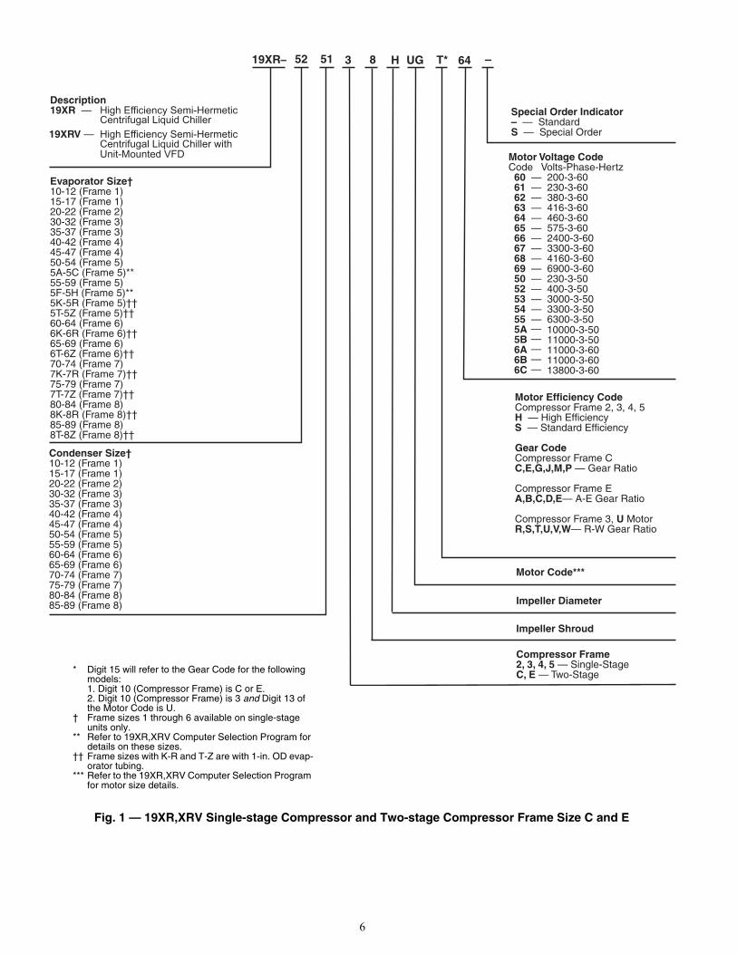
Fig. 1 — 19XR,XRV Single-stage Compressor and Two-stage Compressor Frame Size C and E
8 H
Evaporator Size†10-12 (Frame 1)15-17 (Frame 1)20-22 (Frame 2)30-32 (Frame 3)35-37 (Frame 3)40-42 (Frame 4)45-47 (Frame 4)50-54 (Frame 5)5A-5C (Frame 5)**55-59 (Frame 5)5F-5H (Frame 5)**5K-5R (Frame 5)††5T-5Z (Frame 5)††60-64 (Frame 6)6K-6R (Frame 6)††65-69 (Frame 6)6T-6Z (Frame 6)†† 70-74 (Frame 7)7K-7R (Frame 7)††75-79 (Frame 7)7T-7Z (Frame 7)††80-84 (Frame 8)8K-8R (Frame 8)††85-89 (Frame 8)8T-8Z (Frame 8)††
Condenser Size†10-12 (Frame 1)15-17 (Frame 1)20-22 (Frame 2)30-32 (Frame 3)35-37 (Frame 3)40-42 (Frame 4)45-47 (Frame 4)50-54 (Frame 5)55-59 (Frame 5)60-64 (Frame 6)65-69 (Frame 6)70-74 (Frame 7)75-79 (Frame 7)80-84 (Frame 8)85-89 (Frame 8)
Compressor Frame2, 3, 4, 5 — Single-StageC, E — Two-Stage
Motor Code***
Motor Voltage CodeCode Volts-Phase-Hertz 60 — 200-3-60 61 — 230-3-60 62 — 380-3-60 63 — 416-3-60 64 — 460-3-60 65 — 575-3-60 66 — 2400-3-60 67 — 3300-3-60 68 — 4160-3-60 69 — 6900-3-60 50 — 230-3-50 52 — 400-3-50 53 — 3000-3-50 54 — 3300-3-50 55 — 6300-3-50 5A 5B 6A 6B 6C
—————
10000-3-5011000-3-5011000-3-6011000-3-6013800-3-60
Special Order Indicator– — StandardS — Special Order
Description19XR — High Efficiency Semi-Hermetic
Centrifugal Liquid Chiller19XRV — High Efficiency Semi-Hermetic
Centrifugal Liquid Chiller withUnit-Mounted VFD
Impeller Diameter
UG T* 6419XR– 52 51 3
Impeller Shroud
Motor Efficiency CodeCompressor Frame 2, 3, 4, 5H — High EfficiencyS — Standard Efficiency
Gear CodeCompressor Frame CC,E,G,J,M,P — Gear Ratio
Compressor Frame EA,B,C,D,E— A-E Gear Ratio
Compressor Frame 3, U MotorR,S,T,U,V,W— R-W Gear Ratio
* Digit 15 will refer to the Gear Code for the following models:1. Digit 10 (Compressor Frame) is C or E.2. Digit 10 (Compressor Frame) is 3 and Digit 13 of the Motor Code is U.
† Frame sizes 1 through 6 available on single-stage units only.
** Refer to 19XR,XRV Computer Selection Program for details on these sizes.
†† Frame sizes with K-R and T-Z are with 1-in. OD evap-orator tubing.
*** Refer to the 19XR,XRV Computer Selection Program for motor size details.
7
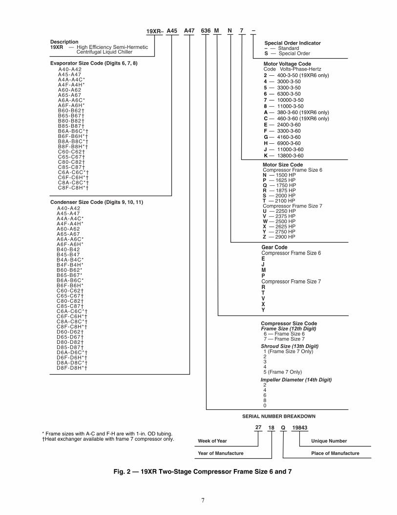
Fig. 2 — 19XR Two-Stage Compressor Frame Size 6 and 7
636
Motor Size CodeCompressor Frame Size 6N — 1500 HPP — 1625 HPQ — 1750 HPR — 1875 HPS — 2000 HPT — 2100 HPCompressor Frame Size 7U — 2250 HPV — 2375 HPW — 2500 HPX — 2625 HPY — 2750 HPZ — 2900 HP
Motor Voltage CodeCode Volts-Phase-Hertz
Special Order Indicator– — StandardS — Special Order
M N 7
Gear CodeCompressor Frame Size 6EJMPCompressor Frame Size 7RTVXY
Centrifugal Liquid Chiller
Description19XR — High Efficiency Semi-Hermetic
19XR– A45 A47
Evaporator Size Code (Digits 6, 7, 8) A40-A42 A45-A47 A4A-A4C* A4F-A4H* A60-A62 A65-A67 A6A-A6C* A6F-A6H* B60-B62† B65-B67† B80-B82† B85-B87† B6A-B6C*† B6F-B6H*† B8A-B8C*† B8F-B8H*† C60-C62† C65-C67† C80-C82† C85-C87† C6A-C6C*† C6F-C6H*† C8A-C8C*† C8F-C8H*†
Condenser Size Code (Digits 9, 10, 11) A40-A42 A45-A47 A4A-A4C* A4F-A4H* A60-A62 A65-A67 A6A-A6C* A6F-A6H* B40-B42 B45-B47 B4A-B4C* B4F-B4H* B60-B62* B65-B67* B6A-B6C* B6F-B6H* C60-C62† C65-C67† C80-C82† C85-C87† C6A-C6C*† C6F-C6H*† C8A-C8C*† C8F-C8H*† D60-D62† D65-D67† D80-D82† D85-D87† D6A-D6C*† D6F-D6H*† D8A-D8C*† D8F-D8H*†
Compressor Size Code Frame Size (12th Digit) 6 — Frame Size 6 7 — Frame Size 7Shroud Size (13th Digit) 1 (Frame Size 7 Only) 2 3 4 5 (Frame 7 Only)
Impeller Diameter (14th Digit) 2 4 6 8 0
2 — 400-3-50 (19XR6 only)4 — 3000-3-505 — 3300-3-506 — 6300-3-507 — 10000-3-508 — 11000-3-50A — 380-3-60 (19XR6 only) C — 460-3-60 (19XR6 only)E — 2400-3-60F — 3300-3-60G — 4160-3-60H — 6900-3-60J — 11000-3-60K — 13800-3-60
* Frame sizes with A-C and F-H are with 1-in. OD tubing.†Heat exchanger available with frame 7 compressor only. Unique Number
27 Q18 19843
Place of Manufacture
Week of Year
Year of Manufacture
SERIAL NUMBER BREAKDOWN
8
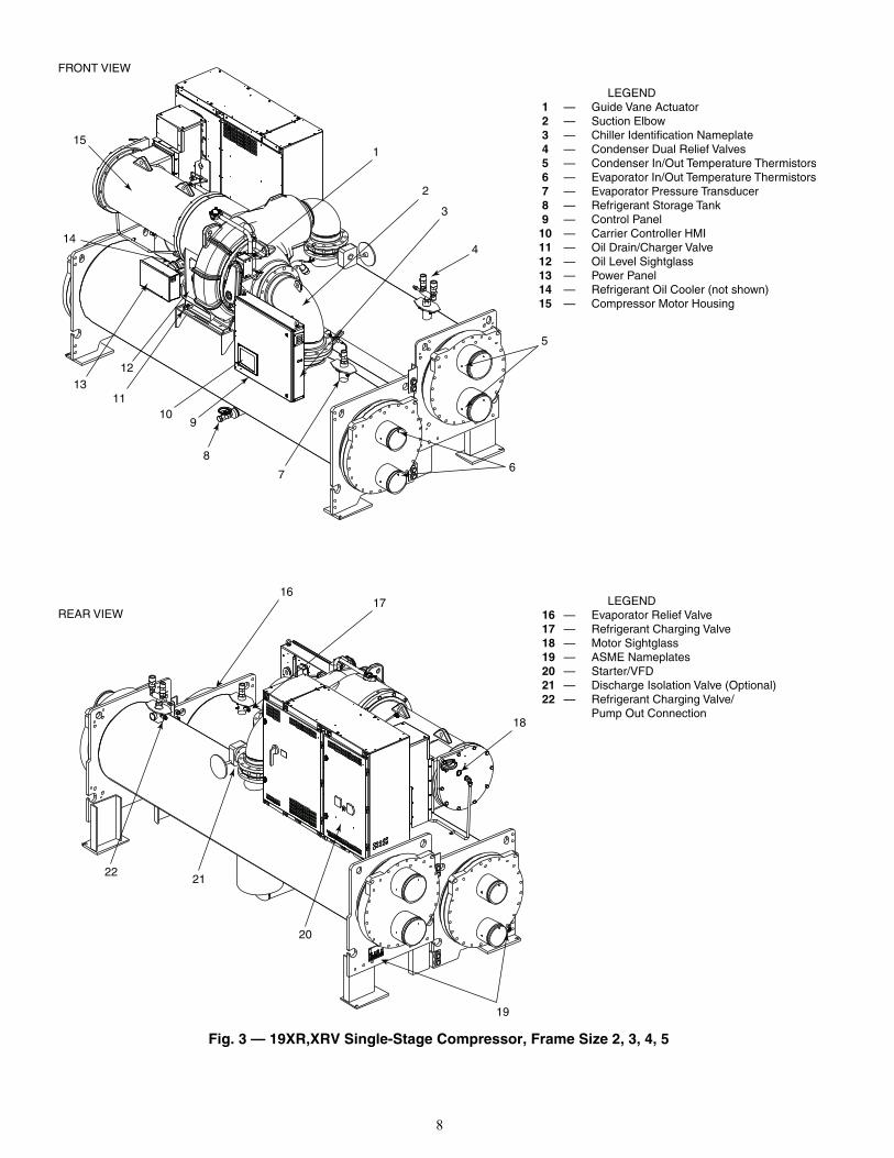
Fig. 3 — 19XR,XRV Single-Stage Compressor, Frame Size 2, 3, 4, 5
LEGEND 1 — Guide Vane Actuator 2 — Suction Elbow 3 — Chiller Identification Nameplate 4 — Condenser Dual Relief Valves 5 — Condenser In/Out Temperature Thermistors 6 — Evaporator In/Out Temperature Thermistors 7 — Evaporator Pressure Transducer 8 — Refrigerant Storage Tank 9 — Control Panel10 — Carrier Controller HMI11 — Oil Drain/Charger Valve12 — Oil Level Sightglass13 — Power Panel14 — Refrigerant Oil Cooler (not shown)15 — Compressor Motor Housing
LEGEND 16 — Evaporator Relief Valve 17 — Refrigerant Charging Valve 18 — Motor Sightglass 19 — ASME Nameplates 20 — Starter/VFD 21 — Discharge Isolation Valve (Optional) 22 — Refrigerant Charging Valve/ Pump Out Connection
FRONT VIEW
REAR VIEW
1
2
4
3
5
67
8
910
12
1113
14
15
1617
18
19
20
2122
9
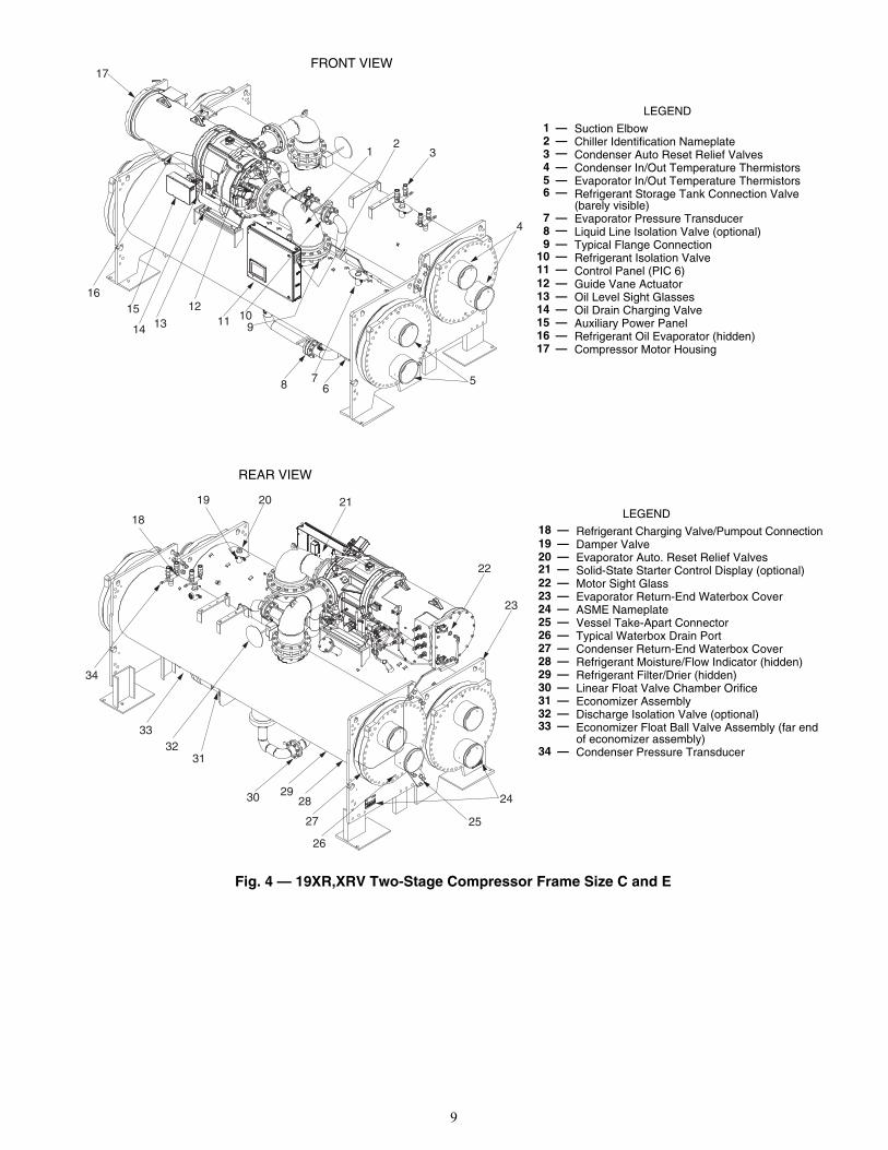
Fig. 4 — 19XR,XRV Two-Stage Compressor Frame Size C and E
23
4
56
78
91011
12
1314
1516
1
17
LEGEND1 — Suction Elbow2 — Chiller Identification Nameplate3 — Condenser Auto Reset Relief Valves4 — Condenser In/Out Temperature Thermistors5 — Evaporator In/Out Temperature Thermistors6 — Refrigerant Storage Tank Connection Valve
(barely visible)7 — Evaporator Pressure Transducer8 — Liquid Line Isolation Valve (optional)9 — Typical Flange Connection
10 — Refrigerant Isolation Valve11 — Control Panel (PIC 6)12 — Guide Vane Actuator13 — Oil Level Sight Glasses14 — Oil Drain Charging Valve15 — Auxiliary Power Panel16 — Refrigerant Oil Evaporator (hidden)17 — Compressor Motor Housing
LEGEND18 — Refrigerant Charging Valve/Pumpout Connection19 — Damper Valve20 — Evaporator Auto. Reset Relief Valves21 — Solid-State Starter Control Display (optional)22 — Motor Sight Glass23 — Evaporator Return-End Waterbox Cover24 — ASME Nameplate25 — Vessel Take-Apart Connector26 — Typical Waterbox Drain Port27 — Condenser Return-End Waterbox Cover28 — Refrigerant Moisture/Flow Indicator (hidden)29 — Refrigerant Filter/Drier (hidden)30 — Linear Float Valve Chamber Orifice31 — Economizer Assembly32 — Discharge Isolation Valve (optional)33 — Economizer Float Ball Valve Assembly (far end
of economizer assembly)34 — Condenser Pressure Transducer
REAR VIEW
FRONT VIEW
19 20 21
22
23
24
26
27
282930
3132
33
34
18
25
10
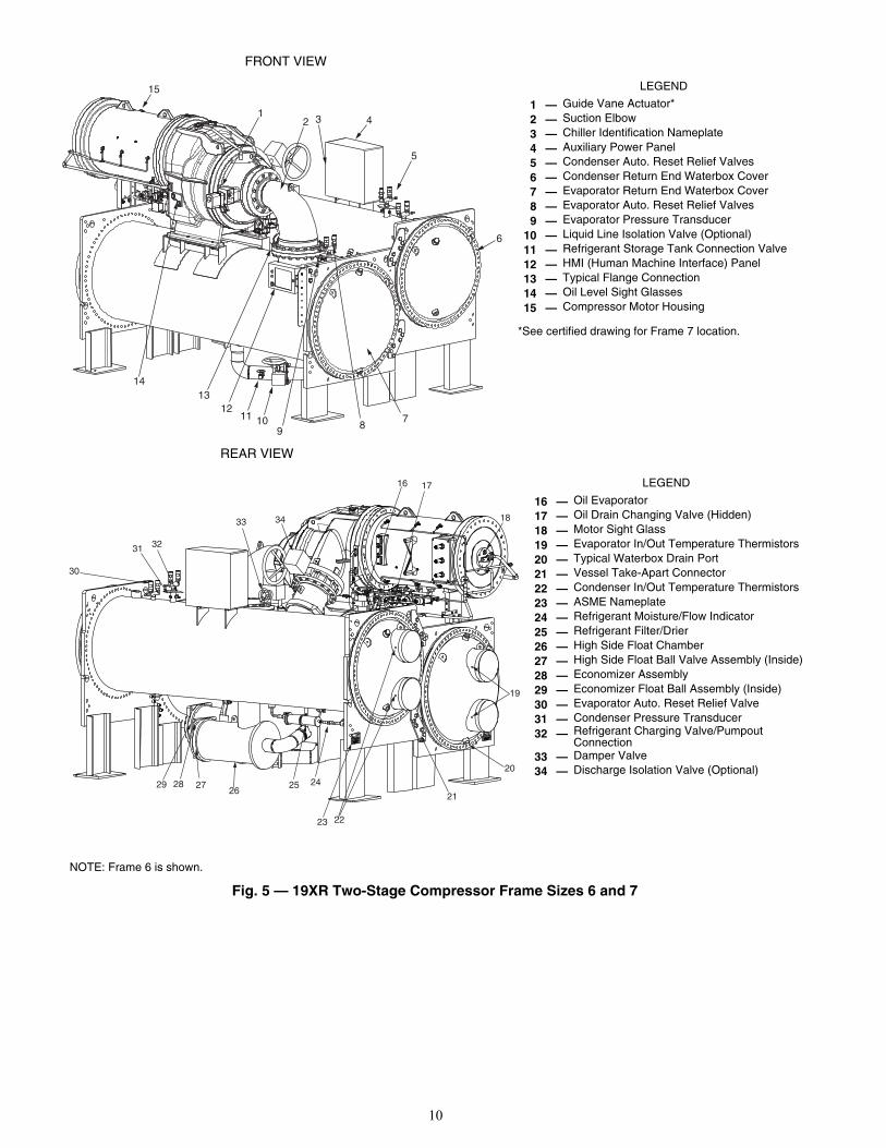
Fig. 5 — 19XR Two-Stage Compressor Frame Sizes 6 and 7
15
12 3 4
5
6
78
91011
1213
14
16 17
18
19
20
21
2223
242526
272829
30
31 32
33 34
REAR VIEW
FRONT VIEW
LEGEND
*See certified drawing for Frame 7 location.
1 — Guide Vane Actuator*2 — Suction Elbow3 — Chiller Identification Nameplate4 — Auxiliary Power Panel5 — Condenser Auto. Reset Relief Valves6 — Condenser Return End Waterbox Cover7 — Evaporator Return End Waterbox Cover8 — Evaporator Auto. Reset Relief Valves9 — Evaporator Pressure Transducer
10 — Liquid Line Isolation Valve (Optional)11 — Refrigerant Storage Tank Connection Valve12 — HMI (Human Machine Interface) Panel13 — Typical Flange Connection14 — Oil Level Sight Glasses15 — Compressor Motor Housing
LEGEND
16 — Oil Evaporator17 — Oil Drain Changing Valve (Hidden)18 — Motor Sight Glass19 — Evaporator In/Out Temperature Thermistors20 — Typical Waterbox Drain Port21 — Vessel Take-Apart Connector22 — Condenser In/Out Temperature Thermistors23 — ASME Nameplate24 — Refrigerant Moisture/Flow Indicator25 — Refrigerant Filter/Drier26 — High Side Float Chamber27 — High Side Float Ball Valve Assembly (Inside)28 — Economizer Assembly29 — Economizer Float Ball Assembly (Inside)30 — Evaporator Auto. Reset Relief Valve31 — Condenser Pressure Transducer32 — Refrigerant Charging Valve/Pumpout
Connection33 — Damper Valve34 — Discharge Isolation Valve (Optional)
NOTE: Frame 6 is shown.
11
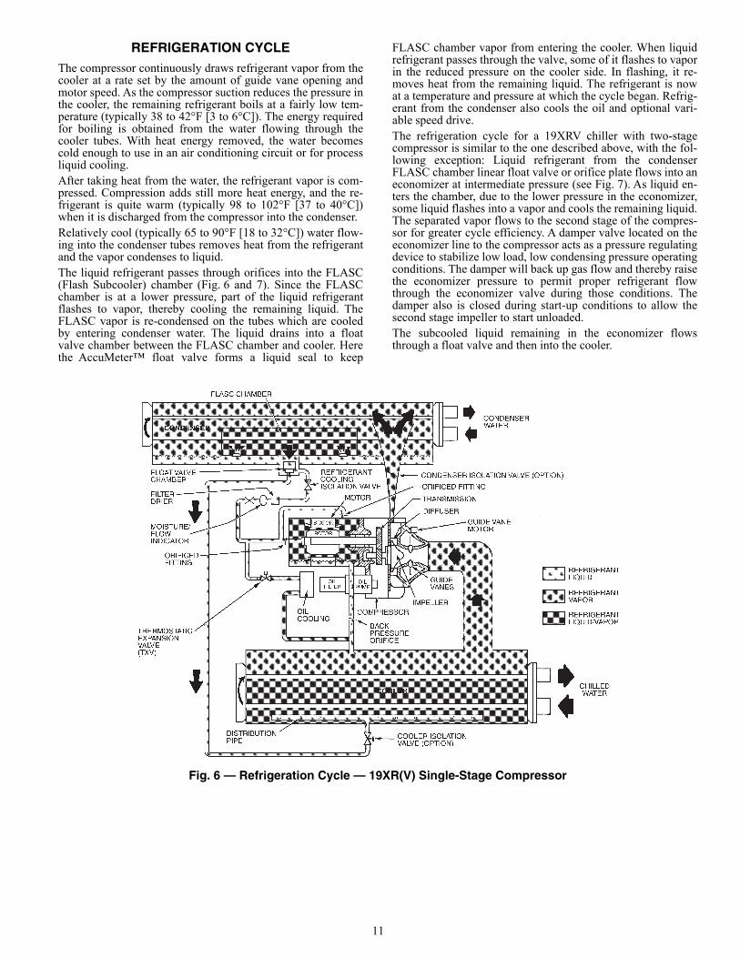
REFRIGERATION CYCLEThe compressor continuously draws refrigerant vapor from thecooler at a rate set by the amount of guide vane opening andmotor speed. As the compressor suction reduces the pressure inthe cooler, the remaining refrigerant boils at a fairly low tem-perature (typically 38 to 42°F [3 to 6°C]). The energy requiredfor boiling is obtained from the water flowing through thecooler tubes. With heat energy removed, the water becomescold enough to use in an air conditioning circuit or for processliquid cooling.After taking heat from the water, the refrigerant vapor is com-pressed. Compression adds still more heat energy, and the re-frigerant is quite warm (typically 98 to 102°F [37 to 40°C])when it is discharged from the compressor into the condenser.Relatively cool (typically 65 to 90°F [18 to 32°C]) water flow-ing into the condenser tubes removes heat from the refrigerantand the vapor condenses to liquid.The liquid refrigerant passes through orifices into the FLASC(Flash Subcooler) chamber (Fig. 6 and 7). Since the FLASCchamber is at a lower pressure, part of the liquid refrigerantflashes to vapor, thereby cooling the remaining liquid. TheFLASC vapor is re-condensed on the tubes which are cooledby entering condenser water. The liquid drains into a floatvalve chamber between the FLASC chamber and cooler. Herethe AccuMeter™ float valve forms a liquid seal to keep
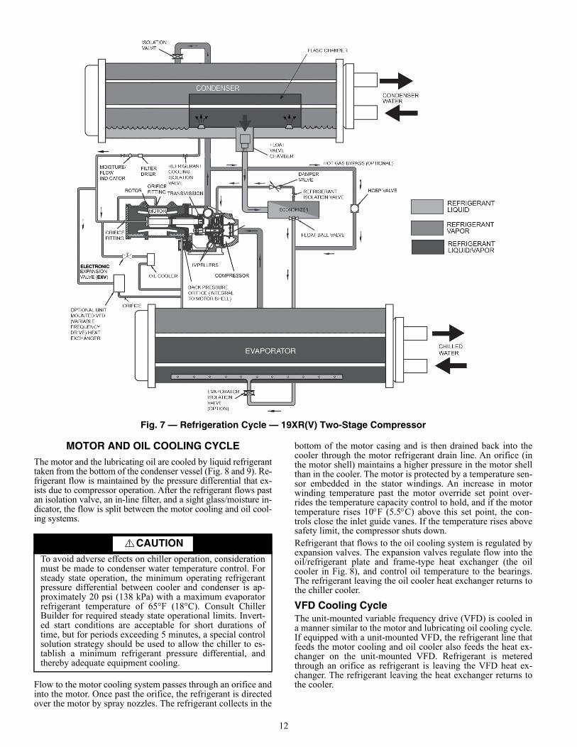
FLASC chamber vapor from entering the cooler. When liquidrefrigerant passes through the valve, some of it flashes to vaporin the reduced pressure on the cooler side. In flashing, it re-moves heat from the remaining liquid. The refrigerant is nowat a temperature and pressure at which the cycle began. Refrig-erant from the condenser also cools the oil and optional vari-able speed drive.The refrigeration cycle for a 19XRV chiller with two-stagecompressor is similar to the one described above, with the fol-lowing exception: Liquid refrigerant from the condenserFLASC chamber linear float valve or orifice plate flows into aneconomizer at intermediate pressure (see Fig. 7). As liquid en-ters the chamber, due to the lower pressure in the economizer,some liquid flashes into a vapor and cools the remaining liquid.The separated vapor flows to the second stage of the compres-sor for greater cycle efficiency. A damper valve located on theeconomizer line to the compressor acts as a pressure regulatingdevice to stabilize low load, low condensing pressure operatingconditions. The damper will back up gas flow and thereby raisethe economizer pressure to permit proper refrigerant flowthrough the economizer valve during those conditions. Thedamper also is closed during start-up conditions to allow thesecond stage impeller to start unloaded.The subcooled liquid remaining in the economizer flowsthrough a float valve and then into the cooler.
Fig. 6 — Refrigeration Cycle — 19XR(V) Single-Stage Compressor
a19-1550tf
12
Fig. 7 — Refrigeration Cycle — 19XR(V) Two-Stage Compressor
MOTOR AND OIL COOLING CYCLE
The motor and the lubricating oil are cooled by liquid refrigeranttaken from the bottom of the condenser vessel (Fig. 8 and 9). Re-frigerant flow is maintained by the pressure differential that ex-ists due to compressor operation. After the refrigerant flows pastan isolation valve, an in-line filter, and a sight glass/moisture in-dicator, the flow is split between the motor cooling and oil cool-ing systems.
Flow to the motor cooling system passes through an orifice andinto the motor. Once past the orifice, the refrigerant is directedover the motor by spray nozzles. The refrigerant collects in the
bottom of the motor casing and is then drained back into thecooler through the motor refrigerant drain line. An orifice (inthe motor shell) maintains a higher pressure in the motor shellthan in the cooler. The motor is protected by a temperature sen-sor embedded in the stator windings. An increase in motorwinding temperature past the motor override set point over-rides the temperature capacity control to hold, and if the motortemperature rises 10F (5.5C) above this set point, the con-trols close the inlet guide vanes. If the temperature rises abovesafety limit, the compressor shuts down.Refrigerant that flows to the oil cooling system is regulated byexpansion valves. The expansion valves regulate flow into theoil/refrigerant plate and frame-type heat exchanger (the oilcooler in Fig. 8), and control oil temperature to the bearings.The refrigerant leaving the oil cooler heat exchanger returns tothe chiller cooler.
VFD Cooling CycleThe unit-mounted variable frequency drive (VFD) is cooled ina manner similar to the motor and lubricating oil cooling cycle.If equipped with a unit-mounted VFD, the refrigerant line thatfeeds the motor cooling and oil cooler also feeds the heat ex-changer on the unit-mounted VFD. Refrigerant is meteredthrough an orifice as refrigerant is leaving the VFD heat ex-changer. The refrigerant leaving the heat exchanger returns tothe cooler.
CAUTIONTo avoid adverse effects on chiller operation, considerationmust be made to condenser water temperature control. Forsteady state operation, the minimum operating refrigerantpressure differential between cooler and condenser is ap-proximately 20 psi (138 kPa) with a maximum evaporatorrefrigerant temperature of 65°F (18°C). Consult ChillerBuilder for required steady state operational limits. Invert-ed start conditions are acceptable for short durations oftime, but for periods exceeding 5 minutes, a special controlsolution strategy should be used to allow the chiller to es-tablish a minimum refrigerant pressure differential, andthereby adequate equipment cooling.
13
LUBRICATION CYCLE
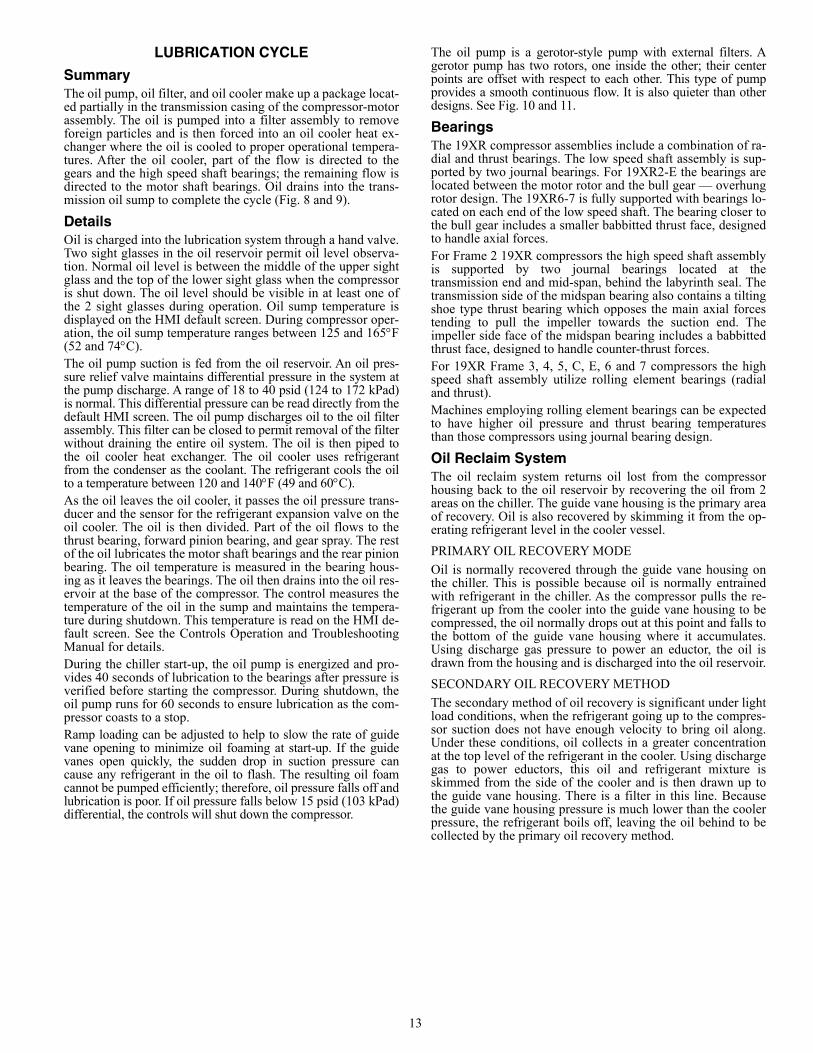
SummaryThe oil pump, oil filter, and oil cooler make up a package locat-ed partially in the transmission casing of the compressor-motorassembly. The oil is pumped into a filter assembly to removeforeign particles and is then forced into an oil cooler heat ex-changer where the oil is cooled to proper operational tempera-tures. After the oil cooler, part of the flow is directed to thegears and the high speed shaft bearings; the remaining flow isdirected to the motor shaft bearings. Oil drains into the trans-mission oil sump to complete the cycle (Fig. 8 and 9).
DetailsOil is charged into the lubrication system through a hand valve.Two sight glasses in the oil reservoir permit oil level observa-tion. Normal oil level is between the middle of the upper sightglass and the top of the lower sight glass when the compressoris shut down. The oil level should be visible in at least one ofthe 2 sight glasses during operation. Oil sump temperature isdisplayed on the HMI default screen. During compressor oper-ation, the oil sump temperature ranges between 125 and 165F(52 and 74C).The oil pump suction is fed from the oil reservoir. An oil pres-sure relief valve maintains differential pressure in the system atthe pump discharge. A range of 18 to 40 psid (124 to 172 kPad)is normal. This differential pressure can be read directly from thedefault HMI screen. The oil pump discharges oil to the oil filterassembly. This filter can be closed to permit removal of the filterwithout draining the entire oil system. The oil is then piped tothe oil cooler heat exchanger. The oil cooler uses refrigerantfrom the condenser as the coolant. The refrigerant cools the oilto a temperature between 120 and 140F (49 and 60C).As the oil leaves the oil cooler, it passes the oil pressure trans-ducer and the sensor for the refrigerant expansion valve on theoil cooler. The oil is then divided. Part of the oil flows to thethrust bearing, forward pinion bearing, and gear spray. The restof the oil lubricates the motor shaft bearings and the rear pinionbearing. The oil temperature is measured in the bearing hous-ing as it leaves the bearings. The oil then drains into the oil res-ervoir at the base of the compressor. The control measures thetemperature of the oil in the sump and maintains the tempera-ture during shutdown. This temperature is read on the HMI de-fault screen. See the Controls Operation and TroubleshootingManual for details.During the chiller start-up, the oil pump is energized and pro-vides 40 seconds of lubrication to the bearings after pressure isverified before starting the compressor. During shutdown, theoil pump runs for 60 seconds to ensure lubrication as the com-pressor coasts to a stop. Ramp loading can be adjusted to help to slow the rate of guidevane opening to minimize oil foaming at start-up. If the guidevanes open quickly, the sudden drop in suction pressure cancause any refrigerant in the oil to flash. The resulting oil foamcannot be pumped efficiently; therefore, oil pressure falls off andlubrication is poor. If oil pressure falls below 15 psid (103 kPad)differential, the controls will shut down the compressor.
The oil pump is a gerotor-style pump with external filters. Agerotor pump has two rotors, one inside the other; their centerpoints are offset with respect to each other. This type of pumpprovides a smooth continuous flow. It is also quieter than otherdesigns. See Fig. 10 and 11.
BearingsThe 19XR compressor assemblies include a combination of ra-dial and thrust bearings. The low speed shaft assembly is sup-ported by two journal bearings. For 19XR2-E the bearings arelocated between the motor rotor and the bull gear — overhungrotor design. The 19XR6-7 is fully supported with bearings lo-cated on each end of the low speed shaft. The bearing closer tothe bull gear includes a smaller babbitted thrust face, designedto handle axial forces.For Frame 2 19XR compressors the high speed shaft assemblyis supported by two journal bearings located at thetransmission end and mid-span, behind the labyrinth seal. Thetransmission side of the midspan bearing also contains a tiltingshoe type thrust bearing which opposes the main axial forcestending to pull the impeller towards the suction end. Theimpeller side face of the midspan bearing includes a babbittedthrust face, designed to handle counter-thrust forces.For 19XR Frame 3, 4, 5, C, E, 6 and 7 compressors the highspeed shaft assembly utilize rolling element bearings (radialand thrust). Machines employing rolling element bearings can be expectedto have higher oil pressure and thrust bearing temperaturesthan those compressors using journal bearing design.
Oil Reclaim SystemThe oil reclaim system returns oil lost from the compressorhousing back to the oil reservoir by recovering the oil from 2areas on the chiller. The guide vane housing is the primary areaof recovery. Oil is also recovered by skimming it from the op-erating refrigerant level in the cooler vessel.
PRIMARY OIL RECOVERY MODE
Oil is normally recovered through the guide vane housing onthe chiller. This is possible because oil is normally entrainedwith refrigerant in the chiller. As the compressor pulls the re-frigerant up from the cooler into the guide vane housing to becompressed, the oil normally drops out at this point and falls tothe bottom of the guide vane housing where it accumulates.Using discharge gas pressure to power an eductor, the oil isdrawn from the housing and is discharged into the oil reservoir.
SECONDARY OIL RECOVERY METHOD
The secondary method of oil recovery is significant under lightload conditions, when the refrigerant going up to the compres-sor suction does not have enough velocity to bring oil along.Under these conditions, oil collects in a greater concentrationat the top level of the refrigerant in the cooler. Using dischargegas to power eductors, this oil and refrigerant mixture isskimmed from the side of the cooler and is then drawn up tothe guide vane housing. There is a filter in this line. Becausethe guide vane housing pressure is much lower than the coolerpressure, the refrigerant boils off, leaving the oil behind to becollected by the primary oil recovery method.

14
Fig. 8 — 19XR2-E Compressor Lubrication System
Fig. 9 — 19XR6-7 Compressor Lubrication System
OIL PUMPAND MOTOR
OILHEATER
OIL PRESSREGULATOR
OIL COOLER
ISOLATIONVALVESPRESSURE
TRANSDUCER
TXV BULB
MOTORCOOLING LINE
REAR HIGHSPD BRG
OIL FILTERFLOW
EDUCTORS
SIGHT GLASS
STRAINERS
FILTER
SIGHTGLASS
OIL SKIMMERLINE
COOLER
LABYRINTHGAS LINE
OIL SUPPLY TOFORWARD HIGHSPEED BEARING
FWD MOTORBEARINGREAR MOTOR
BEARING
OIL LINE
VENT LINE
1
2
3
4
5
6
7
8
9
10
LEGEND1 — Motor Stator 6 — Oil Heater2 — Impellers 7 — Oil Pump3 — Variable Inlet Guide Vanes 8 — Oil Filters4 — Transmission 9 — Motor Rotor5 — High Speed Shaft Bearings 10 — Motor Shaft Bearings
15
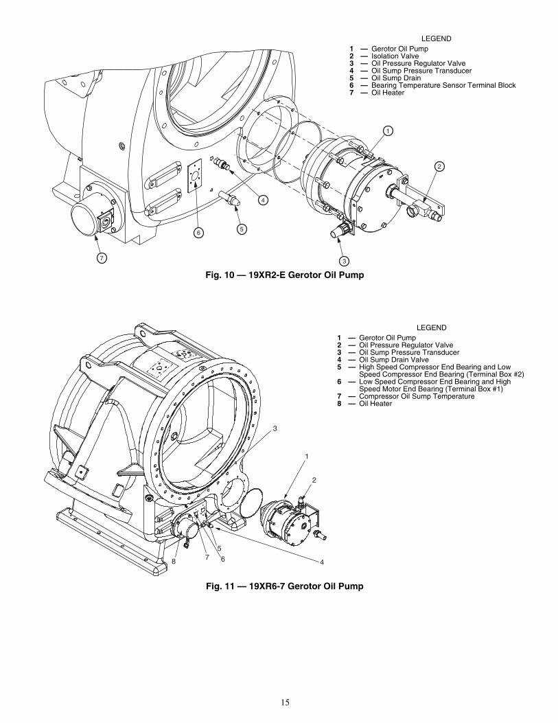
Fig. 10 — 19XR2-E Gerotor Oil Pump
Fig. 11 — 19XR6-7 Gerotor Oil Pump
2
1
3
5
7
6
4
LEGEND1 — Gerotor Oil Pump2 — Isolation Valve3 — Oil Pressure Regulator Valve4 — Oil Sump Pressure Transducer5 — Oil Sump Drain6 — Bearing Temperature Sensor Terminal Block7 — Oil Heater
1
2
3
4
5
678
a19-2116LEGEND
1 — Gerotor Oil Pump2 — Oil Pressure Regulator Valve3 — Oil Sump Pressure Transducer4 — Oil Sump Drain Valve5 — High Speed Compressor End Bearing and Low
Speed Compressor End Bearing (Terminal Box #2)6 — Low Speed Compressor End Bearing and High
Speed Motor End Bearing (Terminal Box #1)7 — Compressor Oil Sump Temperature8 — Oil Heater
16
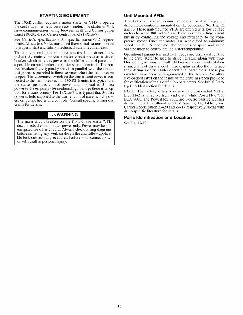
STARTING EQUIPMENTThe 19XR chiller requires a motor starter or VFD to operatethe centrifugal hermetic compressor motor. The starter or VFDhave communication wiring between itself and Carrier powerpanel (19XR2-E) or Carrier control panel (19XR6-7).See Carrier’s specifications for specific starter/VFD require-ments. All starters/VFDs must meet these specifications in orderto properly start and satisfy mechanical safety requirements.There may be multiple circuit breakers inside the starter. Theseinclude the main compressor motor circuit breaker, a circuitbreaker which provides power to the chiller control panel, anda possible circuit breaker for starter specific controls. The con-trol breaker(s) are typically wired in parallel with the first sothat power is provided to those services when the main breakeris open. The disconnect switch on the starter front cover is con-nected to the main breaker. For 19XR2-E units it is typical thatthe starter provides control power and if specified 3-phasepower to the oil pump (for medium/high voltage there is an op-tion for a transformer). For 19XR6-7 it is typical that 3-phasepower is field supplied to the Carrier control panel which pow-ers oil-pump, heater and controls. Consult specific wiring dia-grams for details.
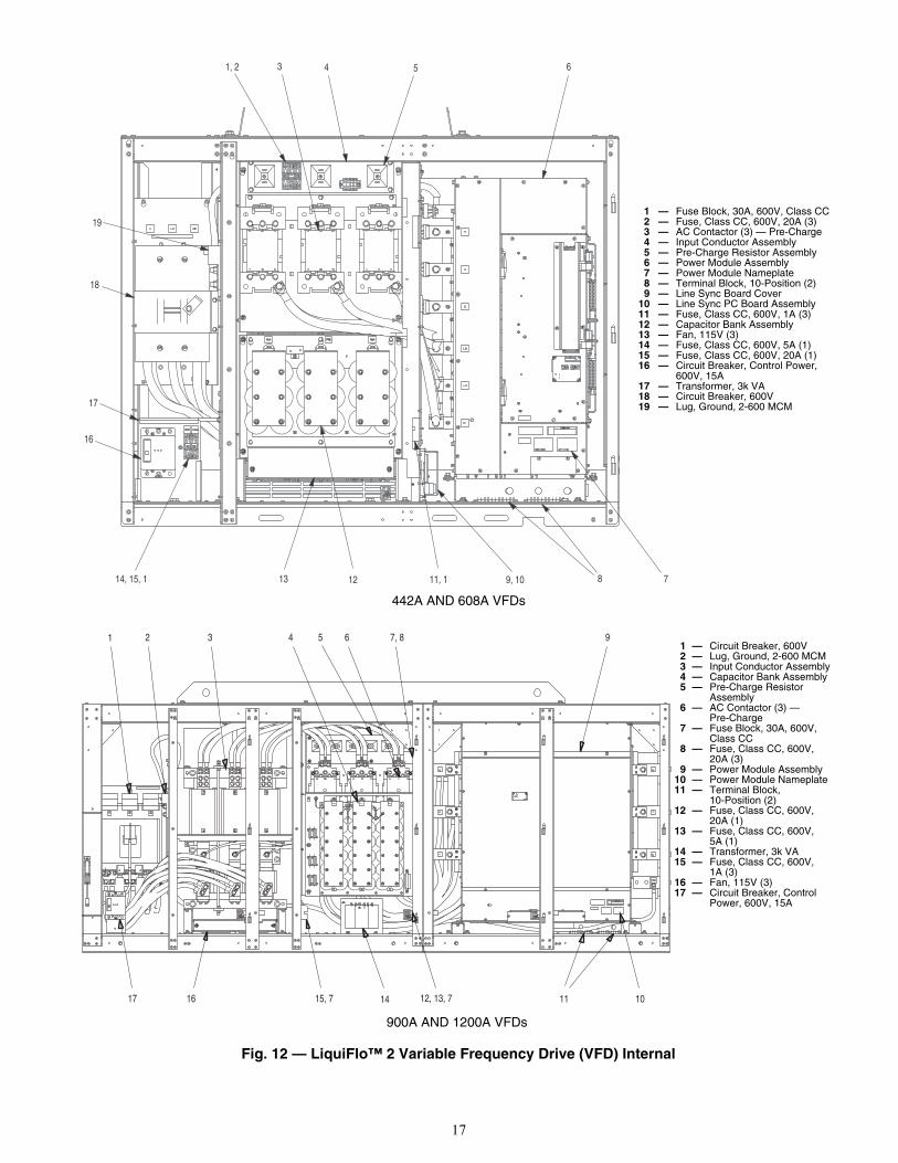
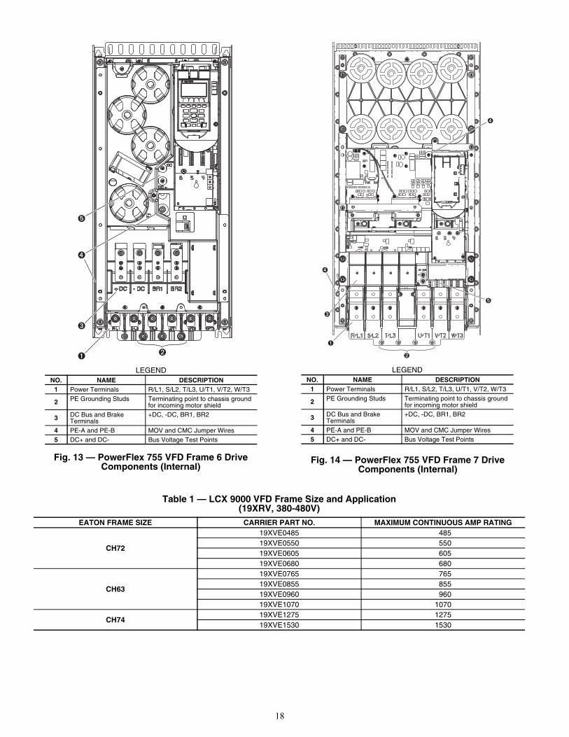
Unit-Mounted VFDsThe 19XR2-E starter options include a variable frequencydrive motor controller mounted on the condenser. See Fig. 12and 13. These unit-mounted VFDs are offered with low voltagemotors between 380 and 575 vac. It reduces the starting currentinrush by controlling the voltage and frequency to the com-pressor motor. Once the motor has accelerated to minimumspeed, the PIC 6 modulates the compressor speed and guidevane position to control chilled water temperature. Operational parameters and fault codes are displayed relativeto the drive. Refer to specific drive literature along with trou-bleshooting sections (consult VFD nameplate on inside of doorif uncertain of drive model). The display is also the interfacefor entering specific chiller operational parameters. These pa-rameters have been preprogrammed at the factory. An adhe-sive-backed label on the inside of the drive has been providedfor verification of the specific job parameters. See Initial Start-Up Checklist section for details.NOTE: The factory offers a variety of unit-mounted VFDs.LiquiFlo2 is an active front end drive while PowerFlex 755,LCX 9000, and PowerFlex 700L are 6-pulse passive rectifierdrives. PF700L is offered in 575V. See Fig. 14, Table 1, andCarrier Specification Z-420 and Z-417 respectively, along withdrive-specific literature for details.
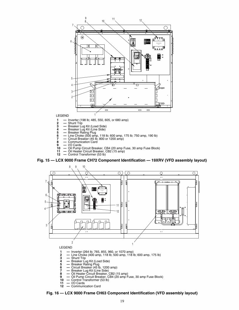
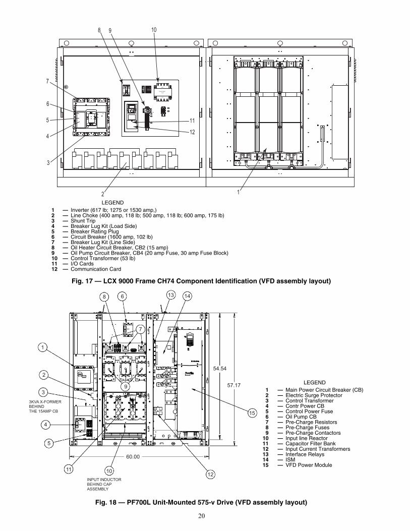
Parts Identification and LocationSee Fig. 15-18.
WARNINGThe main circuit breaker on the front of the starter/VFDdisconnects the main motor power only. Power may be stillenergized for other circuits. Always check wiring diagramsbefore initiating any work on the chiller and follow applica-ble lock-out/tag-out procedures. Failure to disconnect pow-er will result in personal injury.
17
Fig. 12 — LiquiFlo™ 2 Variable Frequency Drive (VFD) Internal
4
12
53 6
8 711, 1
17
13
16
18
19
1, 2
14, 15, 1 9, 10
3 4 5 6 9
11 1012, 13, 715, 7
7, 8
141617
1 2
442A AND 608A VFDs
900A AND 1200A VFDs
a19-1726
a19-1727
1 — Fuse Block, 30A, 600V, Class CC2 — Fuse, Class CC, 600V, 20A (3)3 — AC Contactor (3) — Pre-Charge4 — Input Conductor Assembly5 — Pre-Charge Resistor Assembly6 — Power Module Assembly7 — Power Module Nameplate8 — Terminal Block, 10-Position (2)9 — Line Sync Board Cover
10 — Line Sync PC Board Assembly11 — Fuse, Class CC, 600V, 1A (3)12 — Capacitor Bank Assembly13 — Fan, 115V (3)14 — Fuse, Class CC, 600V, 5A (1)15 — Fuse, Class CC, 600V, 20A (1)16 — Circuit Breaker, Control Power,
600V, 15A17 — Transformer, 3k VA18 — Circuit Breaker, 600V19 — Lug, Ground, 2-600 MCM
1 — Circuit Breaker, 600V2 — Lug, Ground, 2-600 MCM3 — Input Conductor Assembly4 — Capacitor Bank Assembly5 — Pre-Charge Resistor
Assembly6 — AC Contactor (3) —
Pre-Charge7 — Fuse Block, 30A, 600V,
Class CC8 — Fuse, Class CC, 600V,
20A (3)9 — Power Module Assembly
10 — Power Module Nameplate11 — Terminal Block,
10-Position (2)12 — Fuse, Class CC, 600V,
20A (1)13 — Fuse, Class CC, 600V,
5A (1)14 — Transformer, 3k VA15 — Fuse, Class CC, 600V,
1A (3)16 — Fan, 115V (3)17 — Circuit Breaker, Control
Power, 600V, 15A
18
Fig. 13 — PowerFlex 755 VFD Frame 6 Drive Components (Internal)
Fig. 14 — PowerFlex 755 VFD Frame 7 Drive Components (Internal)
Table 1 — LCX 9000 VFD Frame Size and Application(19XRV, 380-480V)
LEGENDNO. NAME DESCRIPTION
1 Power Terminals R/L1, S/L2, T/L3, U/T1, V/T2, W/T3
2 PE Grounding Studs Terminating point to chassis ground for incoming motor shield
3 DC Bus and Brake Terminals
+DC, -DC, BR1, BR2
4 PE-A and PE-B MOV and CMC Jumper Wires5 DC+ and DC- Bus Voltage Test Points
LEGENDNO. NAME DESCRIPTION
1 Power Terminals R/L1, S/L2, T/L3, U/T1, V/T2, W/T3
2 PE Grounding Studs Terminating point to chassis ground for incoming motor shield
3 DC Bus and Brake Terminals
+DC, -DC, BR1, BR2
4 PE-A and PE-B MOV and CMC Jumper Wires5 DC+ and DC- Bus Voltage Test Points
EATON FRAME SIZE CARRIER PART NO. MAXIMUM CONTINUOUS AMP RATING
CH72
19XVE0485 48519XVE0550 55019XVE0605 60519XVE0680 680
CH63
19XVE0765 76519XVE0855 85519XVE0960 96019XVE1070 1070
CH7419XVE1275 127519XVE1530 1530
19
Fig. 15 — LCX 9000 Frame CH72 Component Identification — 19XRV (VFD assembly layout)
Fig. 16 — LCX 9000 Frame CH63 Component Identification (VFD assembly layout)
a19-1933
LEGEND1 — Inverter (198 lb; 485, 550, 605, or 680 amp)2 — Shunt Trip3 — Breaker Lug Kit (Load Side)4 — Breaker Lug Kit (Line Side)5 — Breaker Rating Plug6 — Line Choke (500 amp, 118 lb; 600 amp, 175 lb; 750 amp, 190 lb)7 — Circuit Breaker (45 lb; 800 or 1200 amp)8 — Communication Card9 — I/O Cards10 — Oil Pump Circuit Breaker, CB4 (20 amp Fuse, 30 amp Fuse Block)11 — Oil Heater Circuit Breaker, CB2 (15 amp)12 — Control Transformer (53 lb)
1
5
4
3
7
2
6
22232425
21
26
181920
17TB116
15
6789
5
10
234
1
272829
TB2
TB3
GLL2LL1
G
TB6
OS2OS1
OS3
TB7
120V
460V
-
3KVATRANSFORMER
F1 X2F2X1
H4 H2 H1H3
Cutler-Hammer
bypass
ready run
+
-
HOA
STARTfault
STOP
enter
12119108
a19-1934
LEGEND1 — Inverter (264 lb; 765, 855, 960, or 1070 amp)2 — Line Choke (400 amp, 118 lb; 500 amp, 118 lb; 600 amp, 175 lb)3 — Shunt Trip4 — Breaker Lug Kit (Load Side)5 — Breaker Rating Plug6 — Circuit Breaker (45 lb, 1200 amp)7 — Breaker Lug Kit (Line Side)8 — Oil Heater Circuit Breaker, CB2 (15 amp)9 — Oil Pump Circuit Breaker, CB4 (20 amp Fuse, 30 amp Fuse Block)10 — Control Transformer (53 lb)11 — I/O Cards12 — Communication Card
1098
11
12
12
7
3
6
5
4
22232425
21
26
181920
17TB116
15
6789
5
10
234
1
272829
TB2
TB3
GLL2LL1
G
TB6
OS2OS1
OS3
TB7
120V
460V
-
3KVATRANSFORMER
F1 X2F2X1
H4 H2 H1H3
Cutler-Hammer
bypass
ready run
+
-
HOA
STARTfault
STOP
enter
20
Fig. 17 — LCX 9000 Frame CH74 Component Identification (VFD assembly layout)
Fig. 18 — PF700L Unit-Mounted 575-v Drive (VFD assembly layout)
a19-1935
LEGEND1 — Inverter (617 lb; 1275 or 1530 amp,)2 — Line Choke (400 amp, 118 lb; 500 amp, 118 lb; 600 amp, 175 lb)3 — Shunt Trip4 — Breaker Lug Kit (Load Side)5 — Breaker Rating Plug6 — Circuit Breaker (1600 amp, 102 lb)7 — Breaker Lug Kit (Line Side)8 — Oil Heater Circuit Breaker, CB2 (15 amp)9 — Oil Pump Circuit Breaker, CB4 (20 amp Fuse, 30 amp Fuse Block)10 — Control Transformer (53 lb)11 — I/O Cards12 — Communication Card
1098
11
12
2
3
4
5
6
7
1
22232425
21
26
181920
17TB116
15
6789
5
10
234
1
272829
TB2
TB3
GLL2LL1
G
TB6
OS2OS1
OS3
TB7
120V
460V
-
3KVATRANSFORMER
F1 X2F2X1
H4 H2 H1H3
Cutler-Hammer
bypass
ready run
+
-
HOA
STARTfault
STOP
enter
57.17
54.54
60.00
INPUT INDUCTORBEHIND CAPASSEMBLY
12
15
141368
7
9
1
2
3
4
5
11 10
3KVA X-FORMERBEHINDTHE 15AMP CB
LEGEND 1 — Main Power Circuit Breaker (CB) 2 — Electric Surge Protector 3 — Control Transformer 4 — Contr Power CB 5 — Control Power Fuse 6 — Oil Pump CB 7 — Pre-Charge Resistors 8 — Pre-Charge Fuses 9 — Pre-Charge Contactors10 — Input line Reactor11 — Capacitor Filter Bank12 — Input Current Transformers13 — Interface Relays14 — ISM15 — VFD Power Module
21
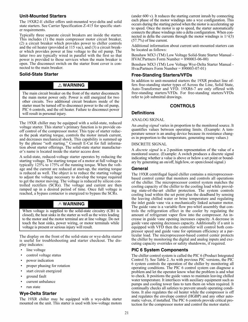
Unit-Mounted StartersThe 19XR2-E chiller offers unit-mounted wye-delta and solidstate starters. See Carrier Specification Z-415 for specific start-er requirements.Typically three separate circuit breakers are inside the starter.This includes (1) the main compressor motor circuit breaker,(2) a circuit breaker which provides power to chiller controlsand the oil heater (provided at 115 vac), and (3) a circuit break-er which provides power at line voltage to the oil pump. Thelatter two are typically wired in parallel with the first so thatpower is provided to those services when the main breaker isopen. The disconnect switch on the starter front cover is con-nected to the main breaker.
Solid-State Starter
The 19XR chiller may be equipped with a solid-state, reducedvoltage starter. This starter’s primary function is to provide on-off control of the compressor motor. This type of starter reduc-es the peak starting torque, controls the motor inrush current,and decreases mechanical shock. This capability is summed upby the phrase “soft starting.” Consult E-Cat for full informa-tion about starter offerings. The solid-state starter manufactur-er’s name is located inside the starter access door.A solid-state, reduced-voltage starter operates by reducing thestarting voltage. The starting torque of a motor at full voltage istypically 125% to 175% of the running torque. When the volt-age and the current are reduced at start-up, the starting torqueis reduced as well. The object is to reduce the starting voltageto adjust the voltage necessary to develop the torque requiredto get the motor moving. The voltage is reduced by silicon con-trolled rectifiers (SCRs). The voltage and current are thenramped up in a desired period of time. Once full voltage isreached, a bypass contactor is energized to bypass the SCRs.
The display on the front of the solid-state or wye-delta starteris useful for troubleshooting and starter checkout. The dis-play indicates:• line voltage• control voltage status• power indication• proper phasing for rotation• start circuit energized• ground fault• current unbalance• run state
Wye-Delta StarterThe 19XR chiller may be equipped with a wye-delta startermounted on the unit. This starter is used with low-voltage motors
(under 600 v). It reduces the starting current inrush by connectingeach phase of the motor windings into a wye configuration. Thisoccurs during the starting period when the motor is accelerating upto speed. Once the motor is up to speed, the starter automaticallyconnects the phase windings into a delta configuration. When con-nected in delta the currents through the motor windings is 1/√(3)(57.7%) of line current.Additional information about current unit-mounted starters canbe located as follows:Benshaw MX3 (TM) Low Voltage Solid-State Starter Manual -HVACPartners Form Number = 890003-06-00)Benshaw MX3 (TM) Low Voltage Wye-Delta Starter Manual -HvacPartners Form Number = 890003-07-01)
Free-Standing Starters/VFDs In addition to unit-mounted starters the 19XR product line of-fers free-standing starter types of Across the Line, Solid State,Auto-Transformer and VFD. 19XR6-7 are only offered withfree-standing starters/VFDs. For free-standing starters/VFDsrefer to job submittal drawings.
CONTROLS
DefinitionsANALOG SIGNAL
An analog signal varies in proportion to the monitored source. Itquantifies values between operating limits. (Example: A tem-perature sensor is an analog device because its resistance chang-es in proportion to the temperature, generating many values.)
DISCRETE SIGNAL
A discrete signal is a 2-position representation of the value of amonitored source. (Example: A switch produces a discrete signalindicating whether a value is above or below a set point or bound-ary by generating an on/off, high/low, or open/closed signal.)
GeneralThe 19XR centrifugal liquid chiller contains a microprocessor-based control center that monitors and controls all operationsof the chiller. The microprocessor control system matches thecooling capacity of the chiller to the cooling load while provid-ing state-of-the-art chiller protection. The system controlscooling load within the set point plus the deadband by sensingthe leaving chilled water or brine temperature and regulatingthe inlet guide vane via a mechanically linked actuator motor.The guide vane is a variable flow pre-whirl assembly that con-trols the refrigeration effect in the cooler by regulating theamount of refrigerant vapor flow into the compressor. An in-crease in guide vane opening increases capacity. A decrease inguide vane opening decreases capacity. Additionally if a unit isequipped with VFD then the controller will control both com-pressor speed and guide vane for optimum efficiency at a par-ticular load. The microprocessor-based control center protectsthe chiller by monitoring the digital and analog inputs and exe-cuting capacity overrides or safety shutdowns, if required.
PIC 6 System ComponentsThe chiller control system is called the PIC 6 (Product IntegratedControl 5). See Table 2. As with previous PIC versions, the PIC6 system controls the operation of the chiller by monitoring alloperating conditions. The PIC 6 control system can diagnose aproblem and let the operator know what the problem is and whatto check. It positions the guide vanes to maintain leaving chilledwater temperature. It interfaces with auxiliary equipment such aspumps and cooling tower fans to turn them on when required. Itcontinually checks all safeties to prevent unsafe operating condi-tions. It also regulates the oil heater while the compressor is offand regulates the envelope control (HGBP) and any other auto-matic valves, if installed. The PIC 6 controls provide critical pro-tection for the compressor motor and control the motor starter.
WARNING
The main circuit breaker on the front of the starter disconnectsthe main motor power only. Power is still energized for twoother circuits. Two additional circuit breakers inside of thestarter must be turned off to disconnect power to the oil pump,PIC 6 controls, and the oil heater. Failure to disconnect powerwill result in personal injury.
WARNING
When voltage is supplied to the solid-state circuitry (CB1 isclosed), the heat sinks in the starter as well as the wires leadingto the motor and the motor terminal are at line voltage. Do nottouch the heat sinks, power wiring, or motor terminals whilevoltage is present or serious injury will result.
22
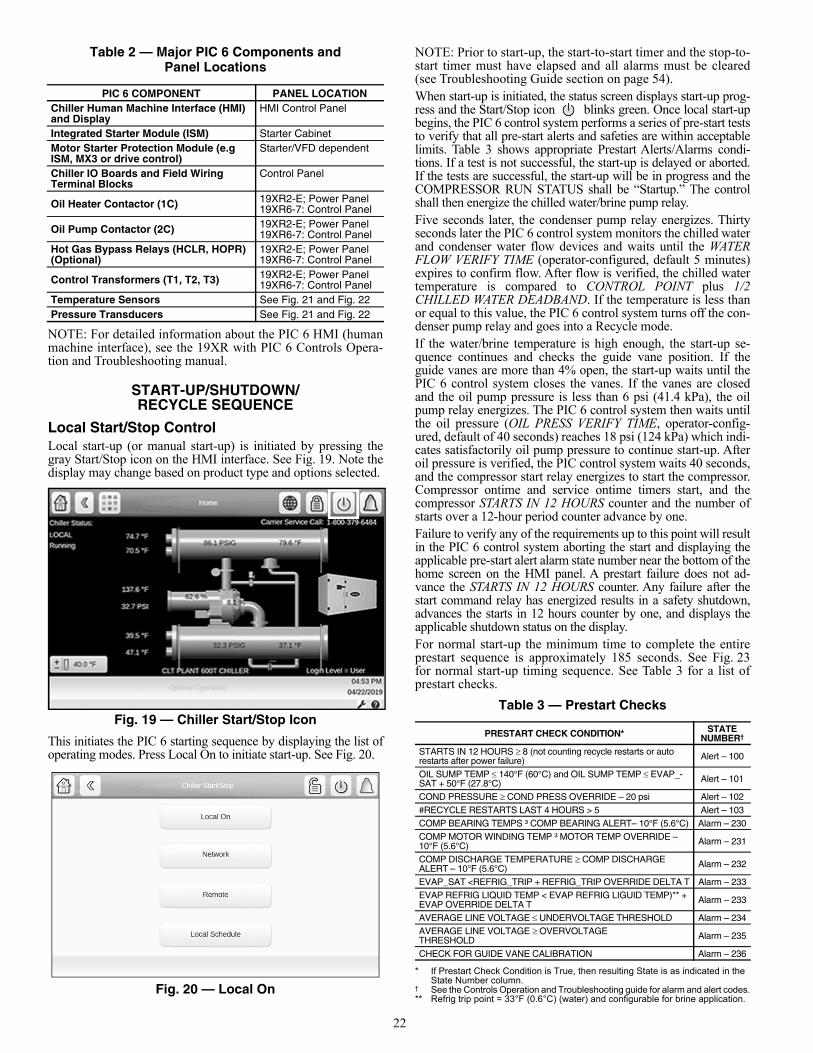
Table 2 — Major PIC 6 Components andPanel Locations
NOTE: For detailed information about the PIC 6 HMI (humanmachine interface), see the 19XR with PIC 6 Controls Opera-tion and Troubleshooting manual.
START-UP/SHUTDOWN/RECYCLE SEQUENCE
Local Start/Stop ControlLocal start-up (or manual start-up) is initiated by pressing thegray Start/Stop icon on the HMI interface. See Fig. 19. Note thedisplay may change based on product type and options selected.
Fig. 19 — Chiller Start/Stop Icon
This initiates the PIC 6 starting sequence by displaying the list ofoperating modes. Press Local On to initiate start-up. See Fig. 20.
Fig. 20 — Local On
NOTE: Prior to start-up, the start-to-start timer and the stop-to-start timer must have elapsed and all alarms must be cleared(see Troubleshooting Guide section on page 54).When start-up is initiated, the status screen displays start-up prog-ress and the Start/Stop icon blinks green. Once local start-upbegins, the PIC 6 control system performs a series of pre-start teststo verify that all pre-start alerts and safeties are within acceptablelimits. Table 3 shows appropriate Prestart Alerts/Alarms condi-tions. If a test is not successful, the start-up is delayed or aborted.If the tests are successful, the start-up will be in progress and theCOMPRESSOR RUN STATUS shall be “Startup.” The controlshall then energize the chilled water/brine pump relay.Five seconds later, the condenser pump relay energizes. Thirtyseconds later the PIC 6 control system monitors the chilled waterand condenser water flow devices and waits until the WATERFLOW VERIFY TIME (operator-configured, default 5 minutes)expires to confirm flow. After flow is verified, the chilled watertemperature is compared to CONTROL POINT plus 1/2CHILLED WATER DEADBAND. If the temperature is less thanor equal to this value, the PIC 6 control system turns off the con-denser pump relay and goes into a Recycle mode.If the water/brine temperature is high enough, the start-up se-quence continues and checks the guide vane position. If theguide vanes are more than 4% open, the start-up waits until thePIC 6 control system closes the vanes. If the vanes are closedand the oil pump pressure is less than 6 psi (41.4 kPa), the oilpump relay energizes. The PIC 6 control system then waits untilthe oil pressure (OIL PRESS VERIFY TIME, operator-config-ured, default of 40 seconds) reaches 18 psi (124 kPa) which indi-cates satisfactorily oil pump pressure to continue start-up. Afteroil pressure is verified, the PIC control system waits 40 seconds,and the compressor start relay energizes to start the compressor.Compressor ontime and service ontime timers start, and thecompressor STARTS IN 12 HOURS counter and the number ofstarts over a 12-hour period counter advance by one.Failure to verify any of the requirements up to this point will resultin the PIC 6 control system aborting the start and displaying theapplicable pre-start alert alarm state number near the bottom of thehome screen on the HMI panel. A prestart failure does not ad-vance the STARTS IN 12 HOURS counter. Any failure after thestart command relay has energized results in a safety shutdown,advances the starts in 12 hours counter by one, and displays theapplicable shutdown status on the display.For normal start-up the minimum time to complete the entireprestart sequence is approximately 185 seconds. See Fig. 23for normal start-up timing sequence. See Table 3 for a list ofprestart checks.
Table 3 — Prestart Checks
* If Prestart Check Condition is True, then resulting State is as indicated in the State Number column.
† See the Controls Operation and Troubleshooting guide for alarm and alert codes.** Refrig trip point = 33°F (0.6°C) (water) and configurable for brine application.
PIC 6 COMPONENT PANEL LOCATIONChiller Human Machine Interface (HMI) and Display
HMI Control Panel
Integrated Starter Module (ISM) Starter CabinetMotor Starter Protection Module (e.g ISM, MX3 or drive control)
Starter/VFD dependent
Chiller IO Boards and Field Wiring Terminal Blocks
Control Panel
Oil Heater Contactor (1C) 19XR2-E; Power Panel19XR6-7: Control Panel
Oil Pump Contactor (2C) 19XR2-E; Power Panel19XR6-7: Control Panel
Hot Gas Bypass Relays (HCLR, HOPR) (Optional)
19XR2-E; Power Panel19XR6-7: Control Panel
Control Transformers (T1, T2, T3) 19XR2-E; Power Panel19XR6-7: Control Panel
Temperature Sensors See Fig. 21 and Fig. 22Pressure Transducers See Fig. 21 and Fig. 22
PRESTART CHECK CONDITION* STATE NUMBER†
STARTS IN 12 HOURS 8 (not counting recycle restarts or auto restarts after power failure) Alert – 100
OIL SUMP TEMP 140°F (60°C) and OIL SUMP TEMP EVAP_-SAT + 50°F (27.8°C) Alert – 101
COND PRESSURE COND PRESS OVERRIDE – 20 psi Alert – 102#RECYCLE RESTARTS LAST 4 HOURS > 5 Alert – 103COMP BEARING TEMPS ³ COMP BEARING ALERT– 10°F (5.6°C) Alarm – 230COMP MOTOR WINDING TEMP ³ MOTOR TEMP OVERRIDE – 10°F (5.6°C) Alarm – 231
COMP DISCHARGE TEMPERATURE COMP DISCHARGE ALERT– 10°F (5.6°C) Alarm – 232
EVAP_SAT <REFRIG_TRIP + REFRIG_TRIP OVERRIDE DELTA T Alarm – 233EVAP REFRIG LIQUID TEMP < EVAP REFRIG LIGUID TEMP)** + EVAP OVERRIDE DELTA T Alarm – 233
AVERAGE LINE VOLTAGE UNDERVOLTAGE THRESHOLD Alarm – 234AVERAGE LINE VOLTAGE OVERVOLTAGE THRESHOLD Alarm – 235
CHECK FOR GUIDE VANE CALIBRATION Alarm – 236
23
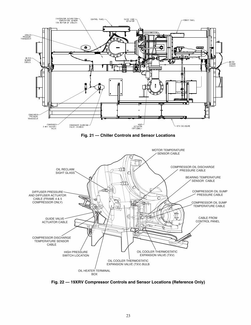
Fig. 21 — Chiller Controls and Sensor Locations
Fig. 22 — 19XRV Compressor Controls and Sensor Locations (Reference Only)
OIL COOLER THERMOSTATICEXPANSION VALVE (TXV)
OIL COOLER THERMOSTATICEXPANSION VALVE (TXV) BULB
OIL HEATER TERMINALBOX
HIGH PRESSURESWITCH LOCATION
COMPRESSOR DISCHARGETEMPERATURE SENSOR
CABLE
GUIDE VALVEACTUATOR CABLE
DIFFUSER PRESSUREAND DIFFUSER ACTUATOR
CABLE (FRAME 4 & 5COMPRESSOR ONLY)
OIL RECLAIMSIGHT GLASS
CABLE FROMCONTROL PANEL
COMPRESSOR OIL SUMPTEMPERATURE CABLE
COMPRESSOR OIL SUMPPRESSURE CABLE
BEARING TEMPERATURESENSOR CABLE
COMPRESSOR OIL DISCHARGEPRESSURE CABLE
MOTOR TEMPERATURESENSOR CABLE
a19-1606
24
Lubrication ControlAs part of the pre-start checks executed by the controls, the oilsump temperature is compared to the evaporator saturated re-frigerant temperature. If the oil temperature is less than 140F(60C) and less than evaporator saturated refrigerant tempera-ture plus 50F (27.8C), the start-up will be delayed until eitherof these conditions is no longer true. Once this temperature isconfirmed, the start-up continues. The oil heater relay is energized whenever the chiller compressoris off and the oil sump temperature is less than 140F (60C) orthe oil sump temperature is less than the evaporator saturated re-frigerant temperature plus 53F (29.4C). The oil heater is turnedoff when either of the following conditions is true:• Oil sump temperature is more than 152F (66.7C) • Oil sump temperature is more than 144F (62.2C) and
more than the evaporator saturated refrigerant temperatureplus 55F (30.6C)
The oil heater is always off when the compressor is running.The oil pump is also energized for 30 seconds after each 30minutes of oil heat relay being energized in order to stir the oilfor more evenly distributed heating. For 19XR6/7 the oil pumpstir frequency has options.
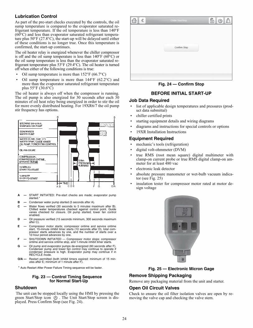
Fig. 23 — Control Timing Sequence for Normal Start-Up
Shutdown The unit can be stopped locally using the HMI by pressing thegreen Start/Stop icon . The Unit Start/Stop screen is dis-played. Press Confirm Stop (see Fig. 24).
Fig. 24 — Confirm Stop
BEFORE INITIAL START-UP
Job Data Required• list of applicable design temperatures and pressures (prod-
uct data submittal)• chiller certified prints• starting equipment details and wiring diagrams• diagrams and instructions for special controls or options• 19XR Installation Instructions
Equipment Required• mechanic’s tools (refrigeration)• digital volt-ohmmeter (DVM)• true RMS (root mean square) digital multimeter with
clamp-on current probe or true RMS digital clamp-on am-meter for at least 480 vac
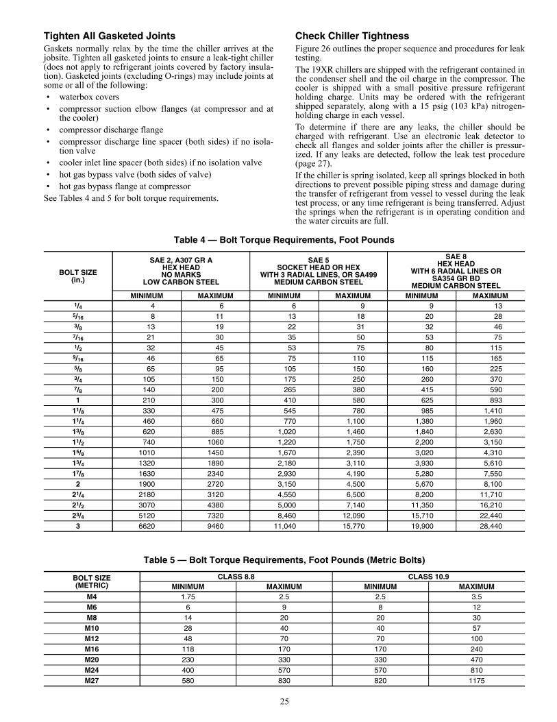
• electronic leak detector• absolute pressure manometer or wet-bulb vacuum indica-
tor (see Fig. 25)• insulation tester for compressor motor rated at motor de-
sign voltage
Fig. 25 — Electronic Micron Gage
Remove Shipping PackagingRemove any packaging material from the unit and starter.
Open Oil Circuit ValvesCheck to ensure the oil filter isolation valves are open by re-moving the valve cap and checking the valve stem.
A B C D E F G O/A
A — START INITIATED: Pre-start checks are made; evaporator pumpstarted.*
B — Condenser water pump started (5 seconds after A).C — Water flows verified (30 seconds to 5 minutes maximum after B).
Chilled water temperatures checked against control point. Guidevanes checked for closure. Oil pump started; tower fan controlenabled.
D — Oil pressure verified (15 seconds minimum, 300 seconds maximumafter C).
E — Compressor motor starts; compressor ontime and service ontimestart, 15-minute inhibit timer starts (10 seconds after D), total com-pressor starts advances by one, and the number of starts over a12-hour period advances by one.
F — SHUTDOWN INITIATED — Compressor motor stops; compressorontime and service ontime stop, and 1-minute inhibit timer starts.
G — Oil pump and evaporator pumps de-energized (60 seconds after F).Condenser pump and tower fan control may continue to operate ifcondenser pressure is high. Evaporator pump may continue if inRECYCLE mode.
O/A — Restart permitted (both inhibit timers expired: minimum of 15 min-utes after E; minimum of 1 minute after F).
* Auto Restart After Power Failure Timing sequence will be faster.
25
Tighten All Gasketed Joints Gaskets normally relax by the time the chiller arrives at thejobsite. Tighten all gasketed joints to ensure a leak-tight chiller(does not apply to refrigerant joints covered by factory insula-tion). Gasketed joints (excluding O-rings) may include joints atsome or all of the following:• waterbox covers• compressor suction elbow flanges (at compressor and at
the cooler)• compressor discharge flange• compressor discharge line spacer (both sides) if no isola-
tion valve• cooler inlet line spacer (both sides) if no isolation valve• hot gas bypass valve (both sides of valve)• hot gas bypass flange at compressor
See Tables 4 and 5 for bolt torque requirements.
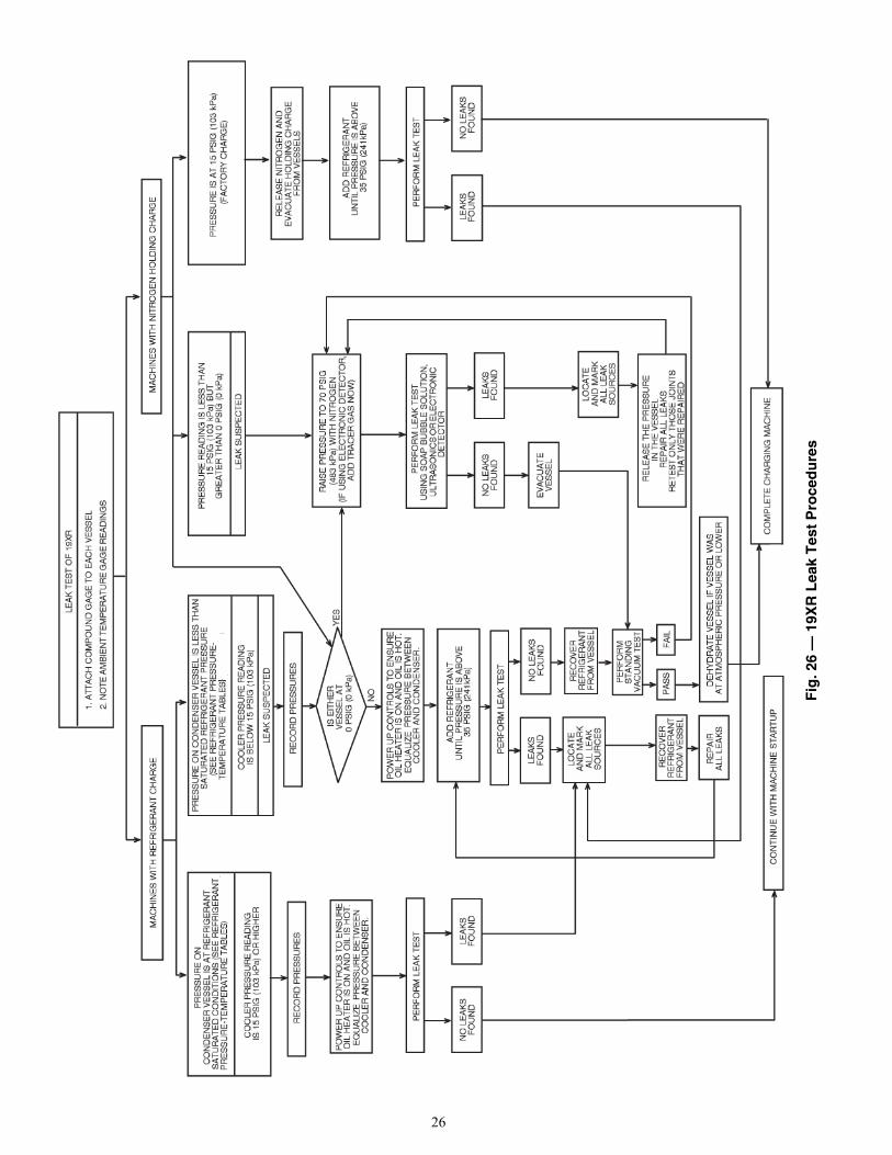
Check Chiller TightnessFigure 26 outlines the proper sequence and procedures for leaktesting.The 19XR chillers are shipped with the refrigerant contained inthe condenser shell and the oil charge in the compressor. Thecooler is shipped with a small positive pressure refrigerantholding charge. Units may be ordered with the refrigerantshipped separately, along with a 15 psig (103 kPa) nitrogen-holding charge in each vessel.To determine if there are any leaks, the chiller should becharged with refrigerant. Use an electronic leak detector tocheck all flanges and solder joints after the chiller is pressur-ized. If any leaks are detected, follow the leak test procedure(page 27).If the chiller is spring isolated, keep all springs blocked in bothdirections to prevent possible piping stress and damage duringthe transfer of refrigerant from vessel to vessel during the leaktest process, or any time refrigerant is being transferred. Adjustthe springs when the refrigerant is in operating condition andthe water circuits are full.
Table 4 — Bolt Torque Requirements, Foot Pounds
BOLT SIZE(in.)
SAE 2, A307 GR AHEX HEADNO MARKS
LOW CARBON STEEL
SAE 5SOCKET HEAD OR HEX
WITH 3 RADIAL LINES, OR SA499MEDIUM CARBON STEEL
SAE 8HEX HEAD
WITH 6 RADIAL LINES ORSA354 GR BD
MEDIUM CARBON STEELMINIMUM MAXIMUM MINIMUM MAXIMUM MINIMUM MAXIMUM
1/4 4 6 6 9 9 135/16 8 11 13 18 20 283/8 13 19 22 31 32 46
7/16 21 30 35 50 53 751/2 32 45 53 75 80 115
9/16 46 65 75 110 115 1655/8 65 95 105 150 160 2253/4 105 150 175 250 260 3707/8 140 200 265 380 415 5901 210 300 410 580 625 893
11/8 330 475 545 780 985 1,41011/4 460 660 770 1,100 1,380 1,96013/8 620 885 1,020 1,460 1,840 2,63011/2 740 1060 1,220 1,750 2,200 3,15015/8 1010 1450 1,670 2,390 3,020 4,31013/4 1320 1890 2,180 3,110 3,930 5,61017/8 1630 2340 2,930 4,190 5,280 7,5502 1900 2720 3,150 4,500 5,670 8,100
21/4 2180 3120 4,550 6,500 8,200 11,71021/2 3070 4380 5,000 7,140 11,350 16,21023/4 5120 7320 8,460 12,090 15,710 22,4403 6620 9460 11,040 15,770 19,900 28,440
Table 5 — Bolt Torque Requirements, Foot Pounds (Metric Bolts)
BOLT SIZE(METRIC)
CLASS 8.8 CLASS 10.9MINIMUM MAXIMUM MINIMUM MAXIMUM
M4 1.75 2.5 2.5 3.5M6 6 9 8 12M8 14 20 20 30
M10 28 40 40 57M12 48 70 70 100M16 118 170 170 240M20 230 330 330 470M24 400 570 570 810M27 580 830 820 1175
26
))))))))))))))))))))))))))))))))))))))))))))))))))) )))))
Fig
. 26
— 1
9XR
Lea
k T
est
Pro
ced
ure
s
a19-1151tf.eps
27
Refrigerant TracerCarrier recommends the use of an environmentally acceptablerefrigerant tracer for leak testing with an electronic detector.Ultrasonic leak detectors can also be used if the chiller is underpressure.
Leak Test ChillerDue to regulations regarding refrigerant emissions and the dif-ficulties associated with separating contaminants from the re-frigerant, Carrier recommends the following leak test proce-dure. Refer to Tables 6 and 7 for refrigerant pressure/tempera-ture values.1. If the pressure readings are normal for the chiller condition:
a. Evacuate the holding charge from the vessels, if present. b. Raise the chiller pressure, if necessary, by adding
refrigerant until pressure is at the equivalent saturatedpressure for the surrounding temperature. Followpumpout procedures in the Transfer Refrigerant fromPumpout Storage Tank to Chiller section, Steps 1a-e,page 45.
c. Leak test chiller as outlined in Steps 3 to 9.2. If the pressure readings are abnormal for the chiller condition:
a. Prepare to leak test chillers shipped with refrigerant(Step 2h).
b. Check for large leaks by connecting a nitrogen bottleand raising the pressure to 30 psig (207 kPa). Soaptest all joints. If the test pressure holds for 30 minutes,prepare the test for small leaks (Steps 2g and 2h).
c. Plainly mark any leaks that are found. d. Release the pressure in the system. e. Repair all leaks. f. Retest the joints that were repaired. g. After successfully completing the test for large leaks,
remove as much nitrogen, air, and moisture as possi-ble, given the fact that small leaks may be present inthe system. This can be accomplished by followingthe dehydration procedure outlined in the ChillerDehydration section, page 29.
h. Slowly raise the system pressure to a maximum of160 psig (1103 kPa) but no less than 35 psig
(241 kPa) for HFC-134a by adding refrigerant (below35 psig refrigerant must be added as a gas). Proceedwith the test for small leaks (Steps 3 to 9).
3. Check the chiller carefully with an electronic leak detectoror soap bubble solution.
4. Leak Determination — If an electronic leak detector indicatesa leak, use a soap bubble solution, if possible, to confirm.Total all leak rates for the entire chiller. Leakage at ratesgreater than 0.1% of the total charge per year must berepaired. Note the total chiller leak rate on the start-up report.
5. If no leak is found during the initial start-up procedures,complete the transfer of refrigerant gas from the storagetank to the chiller. Retest for leaks.
6. If no leak is found after a retest: a. Transfer the refrigerant to the storage tank and per-
form a standing vacuum test as outlined in the Stand-ing Vacuum Test section, below.
b. If the chiller fails the standing vacuum test, check forlarge leaks (Step 2b).
c. If the chiller passes the standing vacuum test, dehy-drate the chiller. Follow the procedure in the ChillerDehydration section, page 29. Charge the chiller withrefrigerant.
7. If a leak is found after a retest, pump the refrigerant backinto the storage tank or, if isolation valves are present,pump the refrigerant into the non-leaking vessel. See theTransfer Refrigerant from Pumpout Storage Tank toChiller section on page 45.
8. Transfer the refrigerant until the chiller pressure is at18 in. Hg (40 kPa absolute).
9. Repair the leak and repeat the procedure, beginning fromStep 2h, to ensure a leak-tight repair. (If the chiller isopened to the atmosphere for an extended period, evacuateit before repeating the leak test.)
Standing Vacuum Test When performing the standing vacuum test or chiller dehydra-tion, use a manometer or a digital vacuum gage. Dial gagescannot indicate the small amount of acceptable leakage duringa short period of time.1. Attach an absolute pressure manometer or digital vacuum
gage to the chiller.2. Evacuate the vessel to at least 18 in. Hg vac (41 kPa
[abs]), using a vacuum pump or the pumpout unit.3. Valve off the pump to hold the vacuum and record the
manometer or indicator reading.4. Check the leakage rate.
a. If the leakage rate is less than 0.05 in. Hg (0.17 kPa)in 24 hours, the chiller is sufficiently tight.
b. If the leakage rate exceeds 0.05 in. Hg (0.17 kPa) in24 hours, re-pressurize the vessel and test for leaks ifrefrigerant is available. If not, use nitrogen and arefrigerant tracer. Raise the vessel pressure in incre-ments until the leak is detected. If refrigerant is used,the maximum gas pressure is approximately 70 psig(483 kPa) for HFC-134a at normal ambient tempera-ture. If nitrogen is used, limit the leak test pressure to160 psig (1103 kPa) maximum.
5. Repair the leak, retest, and proceed with dehydration.
WARNINGDo not use air or oxygen as a means of pressurizing thechiller. Mixtures of HFC-134a and air can undergocombustion, resulting in equipment damage and possiblepersonal injury.
CAUTIONNever charge liquid refrigerant into the chiller if the pres-sure in the chiller is less than 35 psig (241 kPa) for HFC-134a or less than 39 psig (268 kPa) for R-513A. Charge asa gas only, with the cooler and condenser pumps running,until this pressure is reached, using PUMPDOWN/LOCK-OUT (located in the Maintenance menu) and TERMINATELOCKOUT mode on PIC 6 control interface. Flashing ofliquid refrigerant at low pressures can cause tube freeze-upand considerable damage.
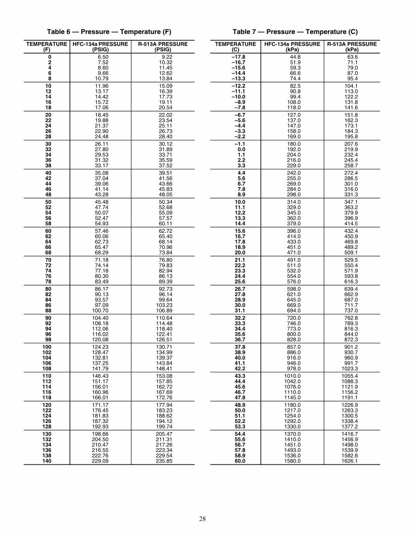
28
Table 6 — Pressure — Temperature (F)
TEMPERATURE(F)
HFC-134a PRESSURE (PSIG)
R-513A PRESSURE (PSIG)
0 6.50 9.222 7.52 10.324 8.60 11.456 9.66 12.628 10.79 13.84
10 11.96 15.0912 13.17 16.3914 14.42 17.7316 15.72 19.1118 17.06 20.5420 18.45 22.0222 19.88 23.5424 21.37 25.1126 22.90 26.7328 24.48 28.4030 26.11 30.1232 27.80 31.8934 29.53 33.7136 31.32 35.5938 33.17 37.5240 35.08 39.5142 37.04 41.5644 39.06 43.6646 41.14 45.8348 43.28 48.0550 45.48 50.3452 47.74 52.6854 50.07 55.0956 52.47 57.5758 54.93 60.1160 57.46 62.7262 60.06 65.4064 62.73 68.1466 65.47 70.9668 68.29 73.8470 71.18 76.8072 74.14 79.8374 77.18 82.9476 80.30 86.1378 83.49 89.3980 86.17 92.7382 90.13 96.1484 93.57 99.6486 97.09 103.2388 100.70 106.8990 104.40 110.6492 108.18 114.4894 112.06 118.4096 116.02 122.4198 120.08 126.51
100 124.23 130.71102 128.47 134.99104 132.81 139.37106 137.25 143.84108 141.79 148.41110 146.43 153.08112 151.17 157.85114 156.01 162.72116 160.96 167.69118 166.01 172.76120 171.17 177.94122 176.45 183.23124 181.83 188.62126 187.32 194.12128 192.93 199.74130 198.66 205.47132 204.50 211.31134 210.47 217.26136 216.55 223.34138 222.76 229.54140 229.09 235.85
Table 7 — Pressure — Temperature (C)
TEMPERATURE(C)
HFC-134a PRESSURE(kPa)
R-513A PRESSURE(kPa)
–17.8 44.8 63.6–16.7 51.9 71.1–15.6 59.3 79.0–14.4 66.6 87.0–13.3 74.4 95.4–12.2 82.5 104.1–11.1 90.8 113.0–10.0 99.4 122.2
–8.9 108.0 131.8–7.8 118.0 141.6–6.7 127.0 151.8–5.6 137.0 162.3–4.4 147.0 173.1–3.3 158.0 184.3–2.2 169.0 195.8–1.1 180.0 207.6
0.0 192.0 219.91.1 204.0 232.42.2 216.0 245.43.3 229.0 258.74.4 242.0 272.45.6 255.0 286.56.7 269.0 301.07.8 284.0 316.08.9 298.0 331.3
10.0 314.0 347.111.1 329.0 363.212.2 345.0 379.913.3 362.0 396.914.4 379.0 414.515.6 396.0 432.416.7 414.0 450.917.8 433.0 469.818.9 451.0 489.220.0 471.0 509.121.1 491.0 529.522.2 511.0 550.423.3 532.0 571.924.4 554.0 593.825.6 576.0 616.326.7 598.0 639.427.8 621.0 662.928.9 645.0 687.030.0 669.0 711.731.1 694.0 737.032.2 720.0 762.833.3 746.0 789.334.4 773.0 816.335.6 800.0 844.036.7 828.0 872.337.8 857.0 901.238.9 886.0 930.740.0 916.0 960.941.1 946.0 991.742.2 978.0 1023.343.3 1010.0 1055.444.4 1042.0 1088.345.6 1076.0 1121.946.7 1110.0 1156.247.8 1145.0 1191.148.9 1180.0 1226.950.0 1217.0 1263.351.1 1254.0 1300.552.2 1292.0 1338.453.3 1330.0 1377.254.4 1370.0 1416.755.6 1410.0 1456.956.7 1451.0 1498.057.8 1493.0 1539.958.9 1536.0 1582.660.0 1580.0 1626.1
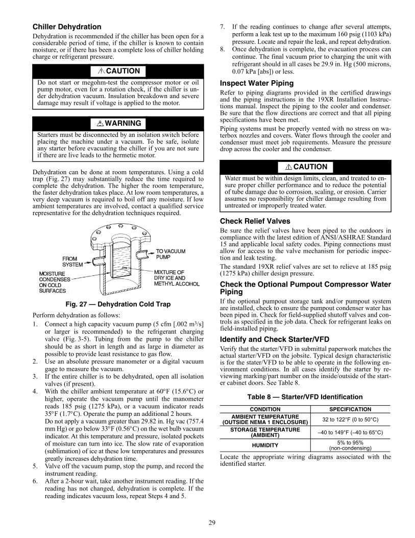
29
Chiller DehydrationDehydration is recommended if the chiller has been open for aconsiderable period of time, if the chiller is known to containmoisture, or if there has been a complete loss of chiller holdingcharge or refrigerant pressure.
Dehydration can be done at room temperatures. Using a coldtrap (Fig. 27) may substantially reduce the time required tocomplete the dehydration. The higher the room temperature,the faster dehydration takes place. At low room temperatures, avery deep vacuum is required to boil off any moisture. If lowambient temperatures are involved, contact a qualified servicerepresentative for the dehydration techniques required.
Fig. 27 — Dehydration Cold Trap
Perform dehydration as follows:1. Connect a high capacity vacuum pump (5 cfm [.002 m3/s]
or larger is recommended) to the refrigerant chargingvalve (Fig. 3-5). Tubing from the pump to the chillershould be as short in length and as large in diameter aspossible to provide least resistance to gas flow.
2. Use an absolute pressure manometer or a digital vacuumgage to measure the vacuum.
3. If the entire chiller is to be dehydrated, open all isolationvalves (if present).
4. With the chiller ambient temperature at 60F (15.6C) orhigher, operate the vacuum pump until the manometerreads 185 psig (1275 kPa), or a vacuum indicator reads35F (1.7C). Operate the pump an additional 2 hours.Do not apply a vacuum greater than 29.82 in. Hg vac (757.4mm Hg) or go below 33F (0.56C) on the wet bulb vacuumindicator. At this temperature and pressure, isolated pocketsof moisture can turn into ice. The slow rate of evaporation(sublimation) of ice at these low temperatures and pressuresgreatly increases dehydration time.
5. Valve off the vacuum pump, stop the pump, and record theinstrument reading.
6. After a 2-hour wait, take another instrument reading. If thereading has not changed, dehydration is complete. If thereading indicates vacuum loss, repeat Steps 4 and 5.
7. If the reading continues to change after several attempts,perform a leak test up to the maximum 160 psig (1103 kPa)pressure. Locate and repair the leak, and repeat dehydration.
8. Once dehydration is complete, the evacuation process cancontinue. The final vacuum prior to charging the unit withrefrigerant should in all cases be 29.9 in. Hg (500 microns,0.07 kPa [abs]) or less.
Inspect Water PipingRefer to piping diagrams provided in the certified drawingsand the piping instructions in the 19XR Installation Instruc-tions manual. Inspect the piping to the cooler and condenser.Be sure that the flow directions are correct and that all pipingspecifications have been met.Piping systems must be properly vented with no stress on wa-terbox nozzles and covers. Water flows through the cooler andcondenser must meet job requirements. Measure the pressuredrop across the cooler and the condenser.
Check Relief ValvesBe sure the relief valves have been piped to the outdoors incompliance with the latest edition of ANSI/ASHRAE Standard15 and applicable local safety codes. Piping connections mustallow for access to the valve mechanism for periodic inspec-tion and leak testing.The standard 19XR relief valves are set to relieve at 185 psig(1275 kPa) chiller design pressure.
Check the Optional Pumpout Compressor WaterPipingIf the optional pumpout storage tank and/or pumpout systemare installed, check to ensure the pumpout condenser water hasbeen piped in. Check for field-supplied shutoff valves and con-trols as specified in the job data. Check for refrigerant leaks onfield-installed piping.
Identify and Check Starter/VFDVerify that the starter/VFD in submittal paperwork matches theactual starter/VFD on the jobsite. Typical design characteristicis for the stater/VFD to be able to operate in the following en-vironment conditions. In all cases identify the starter by re-viewing marking/part number on the inside/outside of the start-er cabinet doors. See Table 8.
Locate the appropriate wiring diagrams associated with theidentified starter.
CAUTION
Do not start or megohm-test the compressor motor or oilpump motor, even for a rotation check, if the chiller is un-der dehydration vacuum. Insulation breakdown and severedamage may result if voltage is applied to the motor.
WARNINGStarters must be disconnected by an isolation switch beforeplacing the machine under a vacuum. To be safe, isolateany starter before evacuating the chiller if you are not sureif there are live leads to the hermetic motor.
CAUTION
Water must be within design limits, clean, and treated to en-sure proper chiller performance and to reduce the potentialof tube damage due to corrosion, scaling, or erosion. Carrierassumes no responsibility for chiller damage resulting fromuntreated or improperly treated water.
Table 8 — Starter/VFD Identification
CONDITION SPECIFICATIONAMBIENT TEMPERATURE
(OUTSIDE NEMA 1 ENCLOSURE) 32 to 122°F (0 to 50°C)
STORAGE TEMPERATURE (AMBIENT) –40 to 149°F (–40 to 65°C)
HUMIDITY 5% to 95%(non-condensing)
30
Mechanical Starter1. Check all field wiring connections for tightness, clearance
from moving parts, and correct connection.2. Check the contactor(s) to ensure they move freely. Check
the mechanical interlock between contactors to ensure that1S and 2M contactors cannot be closed at the same time.Check all other electro-mechanical devises, such as relays,for free movement. If the devices do not move freely, con-tact the starter manufacturer for replacement components.
3. Reapply starter control power (not main chiller power) tocheck the electrical functions.Ensure the starter (with relay 1CR closed) goes through acomplete and proper start cycle.
Benshaw RediStart MX3™ Solid-State Starter
1. Ensure all wiring connections are properly terminated tothe starter.
2. Verify the ground wire to the starter is installed properlyand is sufficient size.
3. Verify the motors are properly grounded to the starter.4. Verify the proper ac input voltage is brought into the
starter according to the certified drawings.5. Confirm the field wiring does not have external power
supply connected to the chiller controls/starter inputs.6. Apply power to the starter.
VFD StarterUse the following instructions to verify the condition of theinstallation:1. Turn off, lockout, and tag the input power to the drive.2. Wait a minimum of 5 minutes for the DC bus to discharge.3. All wiring should be installed in conformance with the
applicable local, national, and international codes(e.g.,NEC/CEC).
4. Remove any debris, such as metal shavings, from theenclosure. Metal shavings on power module enclosure willvoid drive warranty.
5. Check that there is adequate clearance around themachine.
6. Verify that the wiring to the terminal strip and the powerterminals is correct with no external power supplied to theinputs of the Carrier/starter controls.
7. Verify that all of the VFD power module circuit board con-nectors are fully engaged and taped in place.
8. Check that the wire size is within terminal specificationsand that the wires are tightened properly.
9. Check that specified branch circuit protection is installedand correctly rated.
10. Check that the incoming power is within 10% of chillernameplate voltage.
11. Verify that a properly sized ground wire is installed and asuitable earth ground is used. Check for and eliminate anygrounds between the power leads. Verify that all groundleads are unbroken.
Verify Condition of InstallationUse the following instructions to verify condition of installation:1. Turn off, lockout, and tag the input power to the drive.2. Wait a minimum of 5 minutes for the DC bus to discharge.3. All wiring should be installed in conformance with the
applicable local, national, and international codes(e.g.,NEC/CEC).
4. Remove any debris, such as metal shavings, from theenclosure. Metal shavings on power module enclosure willvoid drive warranty.
5. Check that there is adequate clearance around themachine.
6. Verify that the wiring to the terminal strip and the powerterminals is correct.
7. Verify that all of the VFD power module circuit board con-nectors are fully engaged and taped in place.
8. Check that the wire size is within terminal specificationsand that the wires are tightened properly.
9. Check that specified branch circuit protection is installedand correctly rated.
10. Check that the incoming power is within 10% of chillernameplate voltage.
11. Verify that a properly sized ground wire is installed and asuitable earth ground is used. Check for and eliminate anygrounds between the power leads. Verify that all groundleads are unbroken.
Inspect Wiring
1. Examine the wiring for conformance to the job wiring dia-grams and all applicable electrical codes.
2. On low-voltage compressors (600 v or less) connect avoltmeter across the power wires to the compressor starterand measure the voltage. Compare this reading to the volt-age rating on the compressor and starter/VFD nameplates.
3. Compare the ampere rating on the starter/VFD nameplateto rating on the compressor nameplate.
4. The starter/VFD for a centrifugal compressor motor mustcontain the components and terminals required for PIC6
WARNINGBE AWARE that certain automatic start arrangements canengage the starter/VFD. Open the disconnect ahead of thestarter/VFD in addition to shutting off the chiller or pump.Failure to do so could result in serious personal injury ofdeath from electric shock.
WARNINGThe main disconnect on the starter/VFD front panel maynot de-energize all internal circuits. Open all internal andremote disconnects before servicing the starter/VFD. Fail-ure to do so could result in serious personal injury or deathfrom electric shock.
WARNINGThis equipment is at line voltage when AC power is con-nected. Pressing the STOP button does not remove voltage.
CAUTIONAn isolation switch or circuit breaker must be open aheadof any VFD or solid-state starter when the chiller is in avacuum. If not, damage to the machine may result.
WARNING
Do not check the voltage supply without proper equipmentand precautions. Serious injury may result. Follow powercompany recommendations.
CAUTIONDo not apply any kind of test voltage, even for a rotationcheck, if the chiller is under a dehydration vacuum. Insula-tion breakdown and serious damage may result.
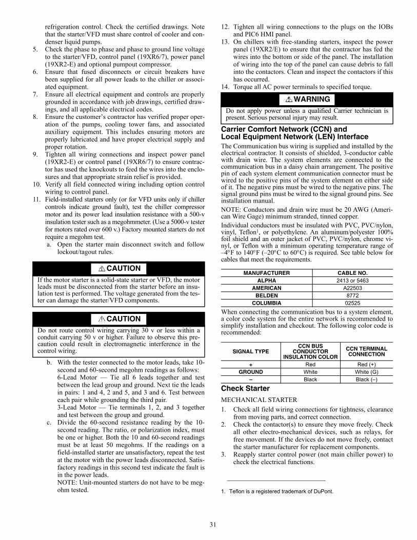
31
refrigeration control. Check the certified drawings. Notethat the starter/VFD must share control of cooler and con-denser liquid pumps.
5. Check the phase to phase and phase to ground line voltageto the starter/VFD, control panel (19XR6/7), power panel(19XR2-E) and optional pumpout compressor.
6. Ensure that fused disconnects or circuit breakers havebeen supplied for all power leads to the chiller or associ-ated equipment.
7. Ensure all electrical equipment and controls are properlygrounded in accordance with job drawings, certified draw-ings, and all applicable electrical codes.
8. Ensure the customer’s contractor has verified proper oper-ation of the pumps, cooling tower fans, and associatedauxiliary equipment. This includes ensuring motors areproperly lubricated and have proper electrical supply andproper rotation.
9. Tighten all wiring connections and inspect power panel(19XR2-E) or control panel (19XR6/7) to ensure contrac-tor has used the knockouts to feed the wires into the enclo-sures and that appropriate strain relief is provided.
10. Verify all field connected wiring including option controlwiring to control panel.
11. Field-installed starters only (or for VFD units only if chillercontrols indicate ground fault), test the chiller compressormotor and its power lead insulation resistance with a 500-vinsulation tester such as a megohmmeter. (Use a 5000-v testerfor motors rated over 600 v.) Factory mounted starters do notrequire a megohm test. a. Open the starter main disconnect switch and follow
lockout/tagout rules.
b. With the tester connected to the motor leads, take 10-second and 60-second megohm readings as follows:6-Lead Motor — Tie all 6 leads together and testbetween the lead group and ground. Next tie the leadsin pairs: 1 and 4, 2 and 5, and 3 and 6. Test betweeneach pair while grounding the third pair. 3-Lead Motor — Tie terminals 1, 2, and 3 togetherand test between the group and ground.
c. Divide the 60-second resistance reading by the 10-second reading. The ratio, or polarization index, mustbe one or higher. Both the 10 and 60-second readingsmust be at least 50 megohms. If the readings on afield-installed starter are unsatisfactory, repeat the testat the motor with the power leads disconnected. Satis-factory readings in this second test indicate the fault isin the power leads. NOTE: Unit-mounted starters do not have to be meg-ohm tested.
12. Tighten all wiring connections to the plugs on the IOBsand PIC6 HMI panel.
13. On chillers with free-standing starters, inspect the powerpanel (19XR2/E) to ensure that the contractor has fed thewires into the bottom or side of the panel. The installationof wiring into the top of the panel can cause debris to fallinto the contactors. Clean and inspect the contactors if thishas occurred.
14. Torque all AC power terminals to specified torque.
Carrier Comfort Network (CCN) and Local Equipment Network (LEN) InterfaceThe Communication bus wiring is supplied and installed by theelectrical contractor. It consists of shielded, 3-conductor cablewith drain wire. The system elements are connected to thecommunication bus in a daisy chain arrangement. The positivepin of each system element communication connector must bewired to the positive pins of the system element on either sideof it. The negative pins must be wired to the negative pins. Thesignal ground pins must be wired to the signal ground pins. Seeinstallation manual.NOTE: Conductors and drain wire must be 20 AWG (Ameri-can Wire Gage) minimum stranded, tinned copper.Individual conductors must be insulated with PVC, PVC/nylon,vinyl, Teflon1, or polyethylene. An aluminum/polyester 100%foil shield and an outer jacket of PVC, PVC/nylon, chrome vi-nyl, or Teflon with a minimum operating temperature range of–4F to 140F (–20C to 60C) is required. See table below forcables that meet the requirements.
When connecting the communication bus to a system element,a color code system for the entire network is recommended tosimplify installation and checkout. The following color code isrecommended:
Check StarterMECHANICAL STARTER
1. Check all field wiring connections for tightness, clearancefrom moving parts, and correct connection.
2. Check the contactor(s) to ensure they move freely. Checkall other electro-mechanical devices, such as relays, forfree movement. If the devices do not move freely, contactthe starter manufacturer for replacement components.
3. Reapply starter control power (not main chiller power) tocheck the electrical functions.
CAUTIONIf the motor starter is a solid-state starter or VFD, the motorleads must be disconnected from the starter before an insu-lation test is performed. The voltage generated from the tes-ter can damage the starter/VFD components.
CAUTIONDo not route control wiring carrying 30 v or less within aconduit carrying 50 v or higher. Failure to observe this pre-caution could result in electromagnetic interference in thecontrol wiring.
WARNINGDo not apply power unless a qualified Carrier technician ispresent. Serious personal injury may result.
1. Teflon is a registered trademark of DuPont.
MANUFACTURER CABLE NO.ALPHA 2413 or 5463
AMERICAN A22503BELDEN 8772
COLUMBIA 02525
SIGNAL TYPECCN BUS
CONDUCTOR INSULATION COLOR
CCN TERMINAL CONNECTION
+ Red Red (+)GROUND White White (G)
– Black Black (–)
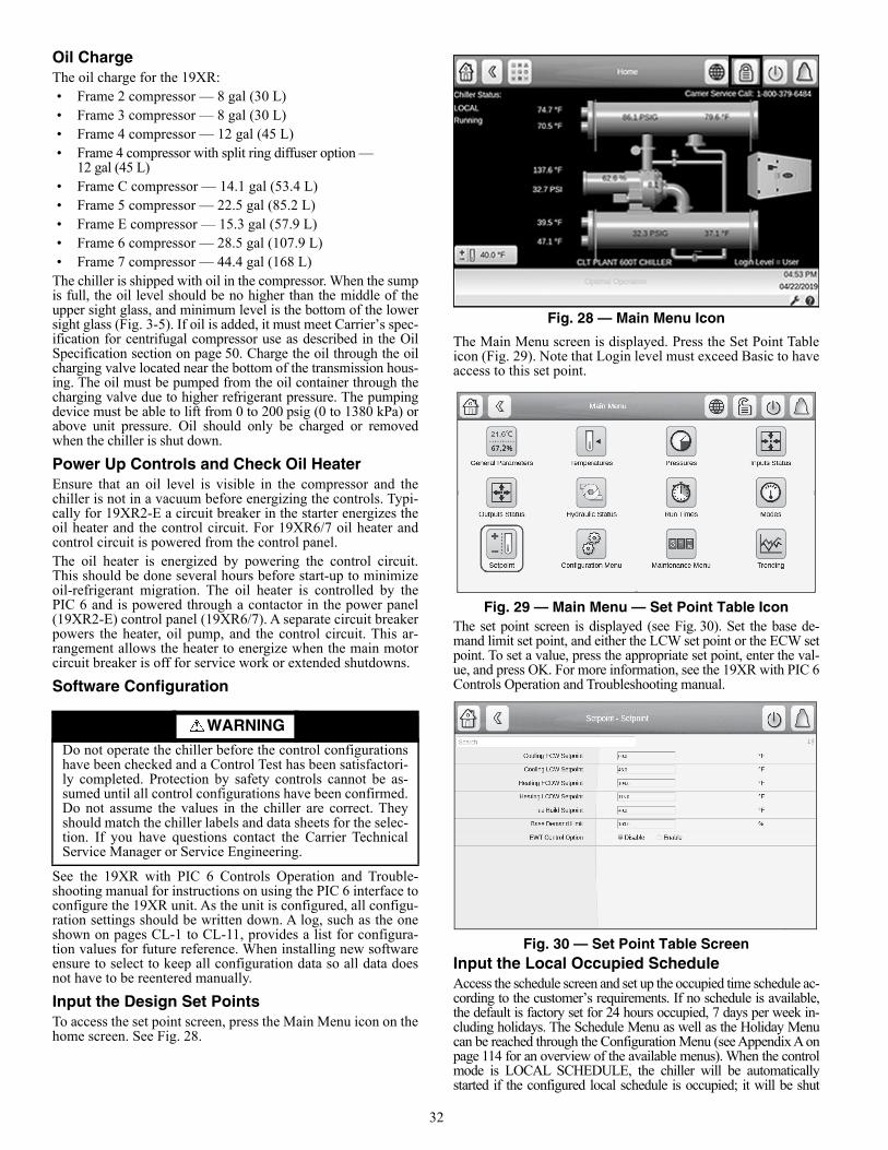
32
Oil ChargeThe oil charge for the 19XR:• Frame 2 compressor — 8 gal (30 L)• Frame 3 compressor — 8 gal (30 L)• Frame 4 compressor — 12 gal (45 L)• Frame 4 compressor with split ring diffuser option —
12 gal (45 L)• Frame C compressor — 14.1 gal (53.4 L)• Frame 5 compressor — 22.5 gal (85.2 L) • Frame E compressor — 15.3 gal (57.9 L) • Frame 6 compressor — 28.5 gal (107.9 L)• Frame 7 compressor — 44.4 gal (168 L)
The chiller is shipped with oil in the compressor. When the sumpis full, the oil level should be no higher than the middle of theupper sight glass, and minimum level is the bottom of the lowersight glass (Fig. 3-5). If oil is added, it must meet Carrier’s spec-ification for centrifugal compressor use as described in the OilSpecification section on page 50. Charge the oil through the oilcharging valve located near the bottom of the transmission hous-ing. The oil must be pumped from the oil container through thecharging valve due to higher refrigerant pressure. The pumpingdevice must be able to lift from 0 to 200 psig (0 to 1380 kPa) orabove unit pressure. Oil should only be charged or removedwhen the chiller is shut down.
Power Up Controls and Check Oil HeaterEnsure that an oil level is visible in the compressor and thechiller is not in a vacuum before energizing the controls. Typi-cally for 19XR2-E a circuit breaker in the starter energizes theoil heater and the control circuit. For 19XR6/7 oil heater andcontrol circuit is powered from the control panel.The oil heater is energized by powering the control circuit.This should be done several hours before start-up to minimizeoil-refrigerant migration. The oil heater is controlled by thePIC 6 and is powered through a contactor in the power panel(19XR2-E) control panel (19XR6/7). A separate circuit breakerpowers the heater, oil pump, and the control circuit. This ar-rangement allows the heater to energize when the main motorcircuit breaker is off for service work or extended shutdowns.
Software Configuration
See the 19XR with PIC 6 Controls Operation and Trouble-shooting manual for instructions on using the PIC 6 interface toconfigure the 19XR unit. As the unit is configured, all configu-ration settings should be written down. A log, such as the oneshown on pages CL-1 to CL-11, provides a list for configura-tion values for future reference. When installing new softwareensure to select to keep all configuration data so all data doesnot have to be reentered manually.
Input the Design Set PointsTo access the set point screen, press the Main Menu icon on thehome screen. See Fig. 28.
Fig. 28 — Main Menu Icon
The Main Menu screen is displayed. Press the Set Point Tableicon (Fig. 29). Note that Login level must exceed Basic to haveaccess to this set point.
Fig. 29 — Main Menu — Set Point Table IconThe set point screen is displayed (see Fig. 30). Set the base de-mand limit set point, and either the LCW set point or the ECW setpoint. To set a value, press the appropriate set point, enter the val-ue, and press OK. For more information, see the 19XR with PIC 6Controls Operation and Troubleshooting manual.
Fig. 30 — Set Point Table Screen Input the Local Occupied Schedule Access the schedule screen and set up the occupied time schedule ac-cording to the customer’s requirements. If no schedule is available,the default is factory set for 24 hours occupied, 7 days per week in-cluding holidays. The Schedule Menu as well as the Holiday Menucan be reached through the Configuration Menu (see Appendix A onpage 114 for an overview of the available menus). When the controlmode is LOCAL SCHEDULE, the chiller will be automaticallystarted if the configured local schedule is occupied; it will be shut
WARNINGDo not operate the chiller before the control configurationshave been checked and a Control Test has been satisfactori-ly completed. Protection by safety controls cannot be as-sumed until all control configurations have been confirmed.Do not assume the values in the chiller are correct. Theyshould match the chiller labels and data sheets for the selec-tion. If you have questions contact the Carrier TechnicalService Manager or Service Engineering.
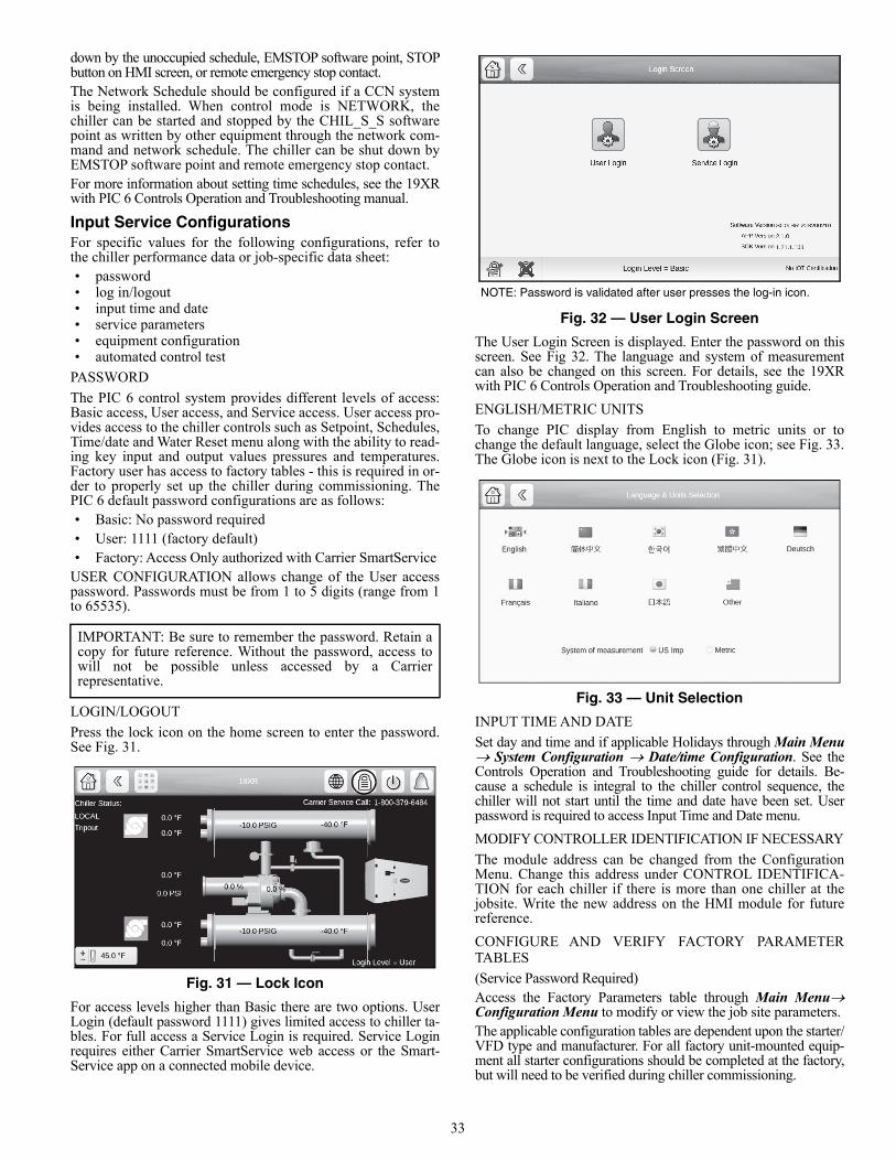
33
down by the unoccupied schedule, EMSTOP software point, STOPbutton on HMI screen, or remote emergency stop contact.The Network Schedule should be configured if a CCN systemis being installed. When control mode is NETWORK, thechiller can be started and stopped by the CHIL_S_S softwarepoint as written by other equipment through the network com-mand and network schedule. The chiller can be shut down byEMSTOP software point and remote emergency stop contact.For more information about setting time schedules, see the 19XRwith PIC 6 Controls Operation and Troubleshooting manual.
Input Service ConfigurationsFor specific values for the following configurations, refer tothe chiller performance data or job-specific data sheet:• password• log in/logout• input time and date• service parameters• equipment configuration• automated control test
PASSWORD
The PIC 6 control system provides different levels of access:Basic access, User access, and Service access. User access pro-vides access to the chiller controls such as Setpoint, Schedules,Time/date and Water Reset menu along with the ability to read-ing key input and output values pressures and temperatures.Factory user has access to factory tables - this is required in or-der to properly set up the chiller during commissioning. ThePIC 6 default password configurations are as follows:• Basic: No password required• User: 1111 (factory default)• Factory: Access Only authorized with Carrier SmartService
USER CONFIGURATION allows change of the User accesspassword. Passwords must be from 1 to 5 digits (range from 1to 65535).
LOGIN/LOGOUT
Press the lock icon on the home screen to enter the password.See Fig. 31.
Fig. 31 — Lock Icon
For access levels higher than Basic there are two options. UserLogin (default password 1111) gives limited access to chiller ta-bles. For full access a Service Login is required. Service Loginrequires either Carrier SmartService web access or the Smart-Service app on a connected mobile device.
Fig. 32 — User Login Screen
The User Login Screen is displayed. Enter the password on thisscreen. See Fig 32. The language and system of measurementcan also be changed on this screen. For details, see the 19XRwith PIC 6 Controls Operation and Troubleshooting guide.
ENGLISH/METRIC UNITS
To change PIC display from English to metric units or tochange the default language, select the Globe icon; see Fig. 33.The Globe icon is next to the Lock icon (Fig. 31).
Fig. 33 — Unit Selection
INPUT TIME AND DATE
Set day and time and if applicable Holidays through Main Menu System Configuration Date/time Configuration. See theControls Operation and Troubleshooting guide for details. Be-cause a schedule is integral to the chiller control sequence, thechiller will not start until the time and date have been set. Userpassword is required to access Input Time and Date menu.
MODIFY CONTROLLER IDENTIFICATION IF NECESSARY
The module address can be changed from the ConfigurationMenu. Change this address under CONTROL IDENTIFICA-TION for each chiller if there is more than one chiller at thejobsite. Write the new address on the HMI module for futurereference.
CONFIGURE AND VERIFY FACTORY PARAMETERTABLES
(Service Password Required)Access the Factory Parameters table through Main MenuConfiguration Menu to modify or view the job site parameters.The applicable configuration tables are dependent upon the starter/VFD type and manufacturer. For all factory unit-mounted equip-ment all starter configurations should be completed at the factory,but will need to be verified during chiller commissioning.
IMPORTANT: Be sure to remember the password. Retain acopy for future reference. Without the password, access towill not be possible unless accessed by a Carrierrepresentative.
NOTE: Password is validated after user presses the log-in icon.
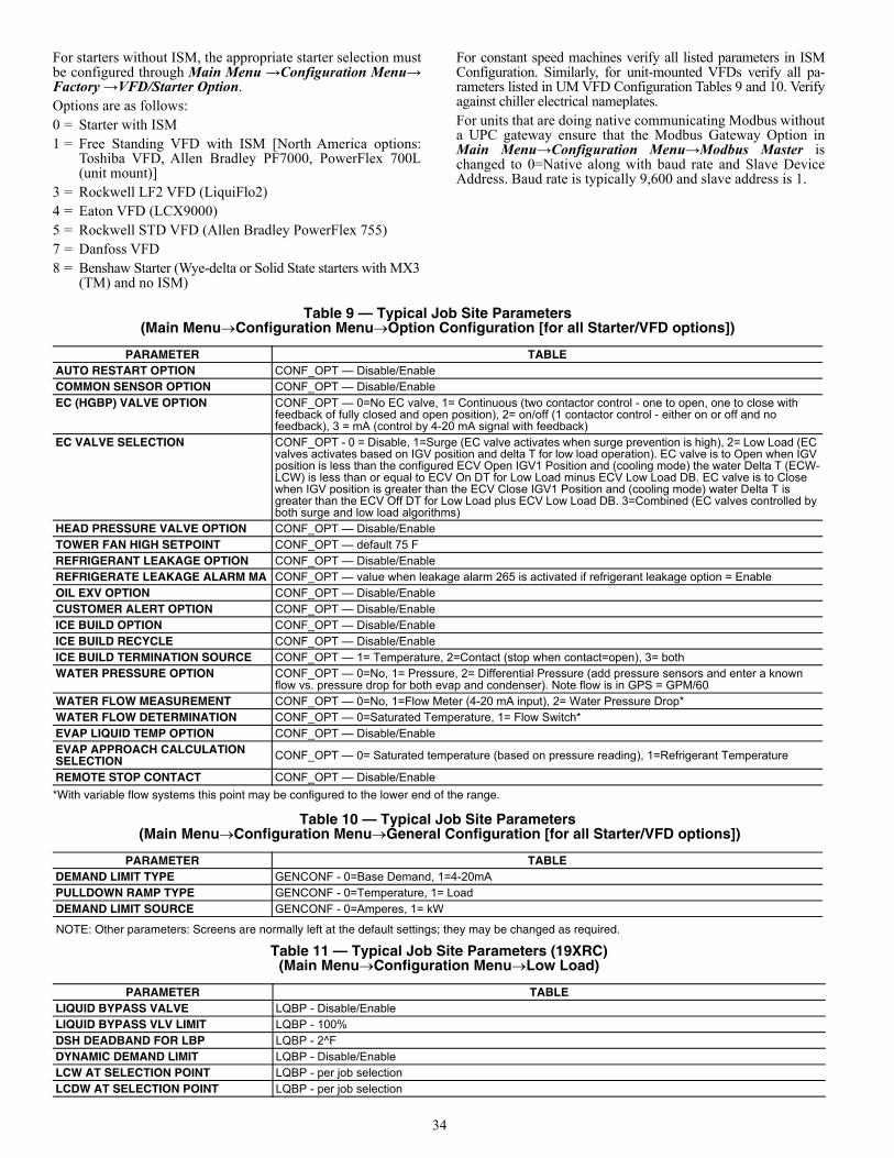
34
For starters without ISM, the appropriate starter selection mustbe configured through Main Menu →Configuration Menu→Factory →VFD/Starter Option. Options are as follows:0 = Starter with ISM1 = Free Standing VFD with ISM [North America options:
Toshiba VFD, Allen Bradley PF7000, PowerFlex 700L(unit mount)]
3 = Rockwell LF2 VFD (LiquiFlo2)4 = Eaton VFD (LCX9000)5 = Rockwell STD VFD (Allen Bradley PowerFlex 755)7 = Danfoss VFD8 = Benshaw Starter (Wye-delta or Solid State starters with MX3
(TM) and no ISM)
For constant speed machines verify all listed parameters in ISMConfiguration. Similarly, for unit-mounted VFDs verify all pa-rameters listed in UM VFD Configuration Tables 9 and 10. Verifyagainst chiller electrical nameplates.For units that are doing native communicating Modbus withouta UPC gateway ensure that the Modbus Gateway Option inMain Menu→Configuration Menu→Modbus Master ischanged to 0=Native along with baud rate and Slave DeviceAddress. Baud rate is typically 9,600 and slave address is 1.
*With variable flow systems this point may be configured to the lower end of the range.
NOTE: Other parameters: Screens are normally left at the default settings; they may be changed as required.
Table 9 — Typical Job Site Parameters(Main MenuConfiguration MenuOption Configuration [for all Starter/VFD options])
PARAMETER TABLEAUTO RESTART OPTION CONF_OPT — Disable/EnableCOMMON SENSOR OPTION CONF_OPT — Disable/EnableEC (HGBP) VALVE OPTION CONF_OPT — 0=No EC valve, 1= Continuous (two contactor control - one to open, one to close with
feedback of fully closed and open position), 2= on/off (1 contactor control - either on or off and no feedback), 3 = mA (control by 4-20 mA signal with feedback)
EC VALVE SELECTION CONF_OPT - 0 = Disable, 1=Surge (EC valve activates when surge prevention is high), 2= Low Load (EC valves activates based on IGV position and delta T for low load operation). EC valve is to Open when IGV position is less than the configured ECV Open IGV1 Position and (cooling mode) the water Delta T (ECW-LCW) is less than or equal to ECV On DT for Low Load minus ECV Low Load DB. EC valve is to Close when IGV position is greater than the ECV Close IGV1 Position and (cooling mode) water Delta T is greater than the ECV Off DT for Low Load plus ECV Low Load DB. 3=Combined (EC valves controlled by both surge and low load algorithms)
HEAD PRESSURE VALVE OPTION CONF_OPT — Disable/EnableTOWER FAN HIGH SETPOINT CONF_OPT — default 75 FREFRIGERANT LEAKAGE OPTION CONF_OPT — Disable/EnableREFRIGERATE LEAKAGE ALARM MA CONF_OPT — value when leakage alarm 265 is activated if refrigerant leakage option = EnableOIL EXV OPTION CONF_OPT — Disable/EnableCUSTOMER ALERT OPTION CONF_OPT — Disable/EnableICE BUILD OPTION CONF_OPT — Disable/EnableICE BUILD RECYCLE CONF_OPT — Disable/EnableICE BUILD TERMINATION SOURCE CONF_OPT — 1= Temperature, 2=Contact (stop when contact=open), 3= bothWATER PRESSURE OPTION CONF_OPT — 0=No, 1= Pressure, 2= Differential Pressure (add pressure sensors and enter a known
flow vs. pressure drop for both evap and condenser). Note flow is in GPS = GPM/60 WATER FLOW MEASUREMENT CONF_OPT — 0=No, 1=Flow Meter (4-20 mA input), 2= Water Pressure Drop*WATER FLOW DETERMINATION CONF_OPT — 0=Saturated Temperature, 1= Flow Switch*EVAP LIQUID TEMP OPTION CONF_OPT — Disable/EnableEVAP APPROACH CALCULATION SELECTION CONF_OPT — 0= Saturated temperature (based on pressure reading), 1=Refrigerant Temperature
REMOTE STOP CONTACT CONF_OPT — Disable/Enable
Table 10 — Typical Job Site Parameters (Main MenuConfiguration MenuGeneral Configuration [for all Starter/VFD options])
PARAMETER TABLEDEMAND LIMIT TYPE GENCONF - 0=Base Demand, 1=4-20mAPULLDOWN RAMP TYPE GENCONF - 0=Temperature, 1= LoadDEMAND LIMIT SOURCE GENCONF - 0=Amperes, 1= kW
Table 11 — Typical Job Site Parameters (19XRC)(Main MenuConfiguration MenuLow Load)
PARAMETER TABLELIQUID BYPASS VALVE LQBP - Disable/EnableLIQUID BYPASS VLV LIMIT LQBP - 100%DSH DEADBAND FOR LBP LQBP - 2^FDYNAMIC DEMAND LIMIT LQBP - Disable/EnableLCW AT SELECTION POINT LQBP - per job selectionLCDW AT SELECTION POINT LQBP - per job selection
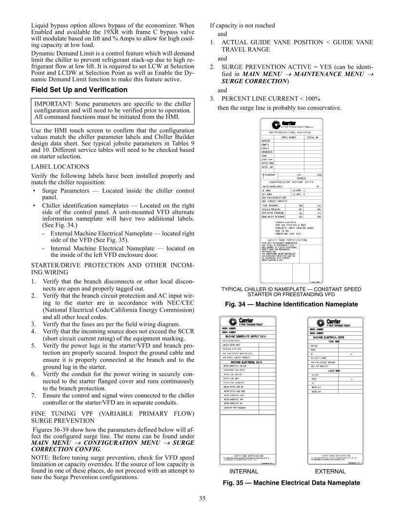
35
Liquid bypass option allows bypass of the economizer. WhenEnabled and available the 19XR with frame C bypass valvewill modulate based on lift and % Amps to allow for high cool-ing capacity at low load.Dynamic Demand Limit is a control feature which will demandlimit the chiller to prevent refrigerant stack-up due to high re-frigerant flow at low lift. It is required to set LCW at SelectionPoint and LCDW at Selection Point as well as Enable the Dy-namic Demand Limit function to make this feature active.
Field Set Up and Verification
Use the HMI touch screen to confirm that the configurationvalues match the chiller parameter labels and Chiller Builderdesign data sheet. See typical jobsite parameters in Tables 9and 10. Different service tables will need to be checked basedon starter selection.
LABEL LOCATIONS
Verify the following labels have been installed properly andmatch the chiller requisition:• Surge Parameters — Located inside the chiller control
panel.• Chiller identification nameplates — Located on the right
side of the control panel. A unit-mounted VFD alternateinformation nameplate will have two additional labels.(See Fig. 34.)- External Machine Electrical Nameplate — located right
side of the VFD (See Fig. 35). - Internal Machine Electrical Nameplate — located on
the inside of the left VFD enclosure door.
STARTER/DRIVE PROTECTION AND OTHER INCOM-ING WIRING
1. Verify that the branch disconnects or other local discon-nects are open and properly tagged out.
2. Verify that the branch circuit protection and AC input wir-ing to the starter are in accordance with NEC/CEC(National Electrical Code/California Energy Commission)and all other local codes.
3. Verify that the fuses are per the field wiring diagram.4. Verify that the incoming source does not exceed the SCCR
(short circuit current rating) of the equipment marking.5. Verify the power lugs in the starter/VFD and branch pro-
tection are properly secured. Inspect the ground cable andensure it is properly connected at the branch and to theground lug in the starter.
6. Verify the conduit for the power wiring in securely con-nected to the starter flanged cover and runs continuouslyto the branch protection.
7. Ensure the control and signal wires connected to the chillercontroller or the starter/VFD are in separate conduits.
FINE TUNING VPF (VARIABLE PRIMARY FLOW)SURGE PREVENTION
Figures 36-39 show how the parameters defined below will af-fect the configured surge line. The menu can be found underMAIN MENU CONFIGURATION MENU SURGECORRECTION CONFIG.NOTE: Before tuning surge prevention, check for VFD speedlimitation or capacity overrides. If the source of low capacity isfound in one of these places, do not proceed with an attempt totune the Surge Prevention configurations.
If capacity is not reached and
1. ACTUAL GUIDE VANE POSITION < GUIDE VANETRAVEL RANGE
and 2. SURGE PREVENTION ACTIVE = YES (can be identi-
fied in MAIN MENU MAINTENANCE MENU SURGE CORRECTION)
and 3. PERCENT LINE CURRENT < 100%
then the surge line is probably too conservative.
Fig. 34 — Machine Identification Nameplate
Fig. 35 — Machine Electrical Data Nameplate
IMPORTANT: Some parameters are specific to the chillerconfiguration and will need to be verified prior to operation.All command functions must be initiated from the HMI.
TYPICAL CHILLER ID NAMEPLATE — CONSTANT SPEED STARTER OR FREESTANDING VFD
a19-1881
SAFETY CODE CERTIFICATION
COMPRESSOR MOTOR DATA
R-
REFRIGERATION MACHINE
CARRIER CHARLOTTE
9701 OLD STATESVILLE ROAD
CHARLOTTE, NORTH CAROLINA 28269
MADE IN USA
PRODUCTION YEAR: 20XX
19XR05009801
A United Technologies CompanyTM
THIS UNIT IS DESIGNED,CONSTRUCTED,AND TESTED IN CONFORMANCE WITH ANSI/ASHRAE 15 (LATEST REVISION),
SPECIFICATION Z-415.IN ACCORDANCE WITH CARRIER AND OVERLOAD PROTECTION MUST BE THE COMPRESSOR MOTOR CONTROLLER REFRIGERATION.SAFETY CODE FOR MECHANICAL
TEST PRESSURE
DESIGN PRESSURE
CLR.WATER PRESSURE
COND.WATER PRESSURE
PSI
PSI
PSI
PSI
KPA
KPA
KPA
KPA
CAZTREH/ESAHP/STLOV
RL AMPS
OLT AMPS
LR AMPS Y-
LR AMPS D-
MAX FUSE/CIRCUIT BKR
MIN. CIRCUIT AMPACITY
LBS.
CHARGED
KGS.REFRIGERANT
MODEL NUMBER SERIAL NO.
MACHINE
COMP'R
COOLER
CONDENSER
ECON
STOR TANK
RATED iKW
RATED TONS
:
INTERNAL EXTERNAL
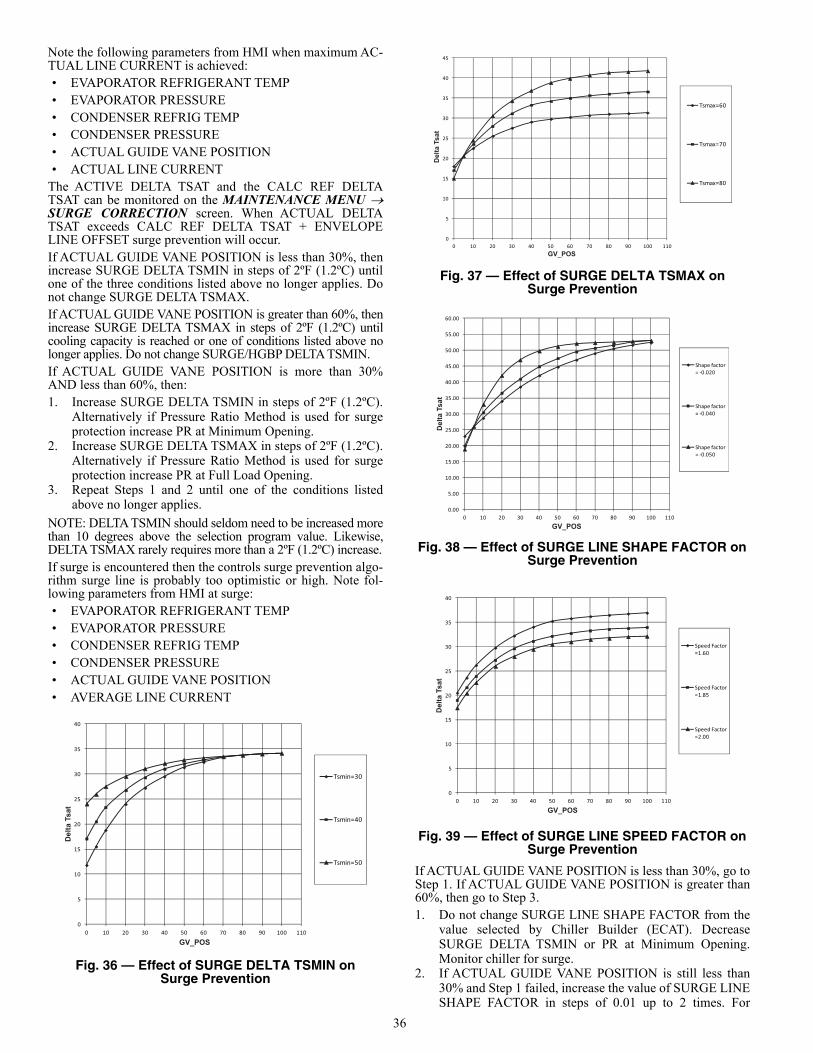
36
Note the following parameters from HMI when maximum AC-TUAL LINE CURRENT is achieved:• EVAPORATOR REFRIGERANT TEMP• EVAPORATOR PRESSURE• CONDENSER REFRIG TEMP• CONDENSER PRESSURE• ACTUAL GUIDE VANE POSITION• ACTUAL LINE CURRENT
The ACTIVE DELTA TSAT and the CALC REF DELTATSAT can be monitored on the MAINTENANCE MENU SURGE CORRECTION screen. When ACTUAL DELTATSAT exceeds CALC REF DELTA TSAT + ENVELOPELINE OFFSET surge prevention will occur.If ACTUAL GUIDE VANE POSITION is less than 30%, thenincrease SURGE DELTA TSMIN in steps of 2ºF (1.2ºC) untilone of the three conditions listed above no longer applies. Donot change SURGE DELTA TSMAX.If ACTUAL GUIDE VANE POSITION is greater than 60%, thenincrease SURGE DELTA TSMAX in steps of 2ºF (1.2ºC) untilcooling capacity is reached or one of conditions listed above nolonger applies. Do not change SURGE/HGBP DELTA TSMIN.If ACTUAL GUIDE VANE POSITION is more than 30%AND less than 60%, then:1. Increase SURGE DELTA TSMIN in steps of 2ºF (1.2ºC).
Alternatively if Pressure Ratio Method is used for surgeprotection increase PR at Minimum Opening.
2. Increase SURGE DELTA TSMAX in steps of 2ºF (1.2ºC).Alternatively if Pressure Ratio Method is used for surgeprotection increase PR at Full Load Opening.
3. Repeat Steps 1 and 2 until one of the conditions listedabove no longer applies.
NOTE: DELTA TSMIN should seldom need to be increased morethan 10 degrees above the selection program value. Likewise,DELTA TSMAX rarely requires more than a 2ºF (1.2ºC) increase.If surge is encountered then the controls surge prevention algo-rithm surge line is probably too optimistic or high. Note fol-lowing parameters from HMI at surge:• EVAPORATOR REFRIGERANT TEMP• EVAPORATOR PRESSURE• CONDENSER REFRIG TEMP• CONDENSER PRESSURE• ACTUAL GUIDE VANE POSITION• AVERAGE LINE CURRENT
Fig. 36 — Effect of SURGE DELTA TSMIN on Surge Prevention
Fig. 37 — Effect of SURGE DELTA TSMAX on Surge Prevention
Fig. 38 — Effect of SURGE LINE SHAPE FACTOR on Surge Prevention
Fig. 39 — Effect of SURGE LINE SPEED FACTOR on Surge Prevention
If ACTUAL GUIDE VANE POSITION is less than 30%, go toStep 1. If ACTUAL GUIDE VANE POSITION is greater than60%, then go to Step 3.1. Do not change SURGE LINE SHAPE FACTOR from the
value selected by Chiller Builder (ECAT). DecreaseSURGE DELTA TSMIN or PR at Minimum Opening.Monitor chiller for surge.
2. If ACTUAL GUIDE VANE POSITION is still less than30% and Step 1 failed, increase the value of SURGE LINESHAPE FACTOR in steps of 0.01 up to 2 times. For
a19-19590
5
10
15
20
25
30
35
40
0 10 20 30 40 50 60 70 80 90 100 110
Tsmin=30
Tsmin=40
Tsmin=50
GV_POS
Del
ta T
sat
a19-19600
5
10
15
20
25
30
35
40
45
0 10 20 30 40 50 60 70 80 90 100 110
Tsmax=60
Tsmax=70
Tsmax=80
GV_POS
Del
ta T
sat
0.00
5.00
10.00
15.00
20.00
25.00
30.00
35.00
40.00
45.00
50.00
55.00
60.00
0 10 20 30 40 50 60 70 80 90 100 110
Shape factor = -0.020
Shape factor = -0.040
Shape factor = -0.050
GV_POS
Del
ta T
sat
a19-1962
0
5
10
15
20
25
30
35
40
0 10 20 30 40 50 60 70 80 90 100 110
Speed Factor =1.60
Speed Factor =1.85
Speed Factor =2.00
GV_POS
Del
ta T
sat
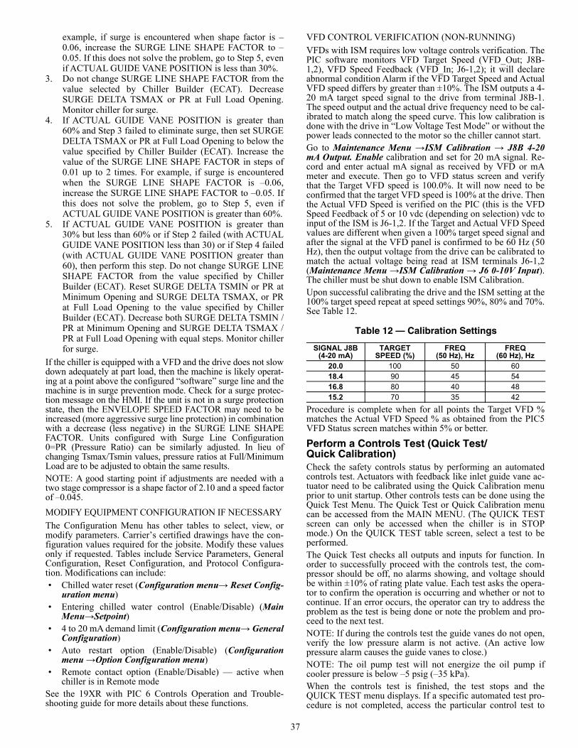
37
example, if surge is encountered when shape factor is –0.06, increase the SURGE LINE SHAPE FACTOR to –0.05. If this does not solve the problem, go to Step 5, evenif ACTUAL GUIDE VANE POSITION is less than 30%.
3. Do not change SURGE LINE SHAPE FACTOR from thevalue selected by Chiller Builder (ECAT). DecreaseSURGE DELTA TSMAX or PR at Full Load Opening.Monitor chiller for surge.
4. If ACTUAL GUIDE VANE POSITION is greater than60% and Step 3 failed to eliminate surge, then set SURGEDELTA TSMAX or PR at Full Load Opening to below thevalue specified by Chiller Builder (ECAT). Increase thevalue of the SURGE LINE SHAPE FACTOR in steps of0.01 up to 2 times. For example, if surge is encounteredwhen the SURGE LINE SHAPE FACTOR is –0.06,increase the SURGE LINE SHAPE FACTOR to –0.05. Ifthis does not solve the problem, go to Step 5, even ifACTUAL GUIDE VANE POSITION is greater than 60%.
5. If ACTUAL GUIDE VANE POSITION is greater than30% but less than 60% or if Step 2 failed (with ACTUALGUIDE VANE POSITION less than 30) or if Step 4 failed(with ACTUAL GUIDE VANE POSITION greater than60), then perform this step. Do not change SURGE LINESHAPE FACTOR from the value specified by ChillerBuilder (ECAT). Reset SURGE DELTA TSMIN or PR atMinimum Opening and SURGE DELTA TSMAX, or PRat Full Load Opening to the value specified by ChillerBuilder (ECAT). Decrease both SURGE DELTA TSMIN /PR at Minimum Opening and SURGE DELTA TSMAX /PR at Full Load Opening with equal steps. Monitor chillerfor surge.
If the chiller is equipped with a VFD and the drive does not slowdown adequately at part load, then the machine is likely operat-ing at a point above the configured “software” surge line and themachine is in surge prevention mode. Check for a surge protec-tion message on the HMI. If the unit is not in a surge protectionstate, then the ENVELOPE SPEED FACTOR may need to beincreased (more aggressive surge line protection) in combinationwith a decrease (less negative) in the SURGE LINE SHAPEFACTOR. Units configured with Surge Line Configuration0=PR (Pressure Ratio) can be similarly adjusted. In lieu ofchanging Tsmax/Tsmin values, pressure ratios at Full/MinimumLoad are to be adjusted to obtain the same results.NOTE: A good starting point if adjustments are needed with atwo stage compressor is a shape factor of 2.10 and a speed factorof –0.045.
MODIFY EQUIPMENT CONFIGURATION IF NECESSARY
The Configuration Menu has other tables to select, view, ormodify parameters. Carrier’s certified drawings have the con-figuration values required for the jobsite. Modify these valuesonly if requested. Tables include Service Parameters, GeneralConfiguration, Reset Configuration, and Protocol Configura-tion. Modifications can include:• Chilled water reset (Configuration menu→ Reset Config-
uration menu)• Entering chilled water control (Enable/Disable) (Main
Menu→Setpoint)• 4 to 20 mA demand limit (Configuration menu→ General
Configuration)• Auto restart option (Enable/Disable) (Configuration
menu →Option Configuration menu)• Remote contact option (Enable/Disable) — active when
chiller is in Remote modeSee the 19XR with PIC 6 Controls Operation and Trouble-shooting guide for more details about these functions.
VFD CONTROL VERIFICATION (NON-RUNNING)
VFDs with ISM requires low voltage controls verification. ThePIC software monitors VFD Target Speed (VFD_Out; J8B-1,2), VFD Speed Feedback (VFD_In; J6-1,2); it will declareabnormal condition Alarm if the VFD Target Speed and ActualVFD speed differs by greater than ±10%. The ISM outputs a 4-20 mA target speed signal to the drive from terminal J8B-1.The speed output and the actual drive frequency need to be cal-ibrated to match along the speed curve. This low calibration isdone with the drive in “Low Voltage Test Mode” or without thepower leads connected to the motor so the chiller cannot start. Go to Maintenance Menu →ISM Calibration → J8B 4-20mA Output. Enable calibration and set for 20 mA signal. Re-cord and enter actual mA signal as received by VFD or mAmeter and execute. Then go to VFD status screen and verifythat the Target VFD speed is 100.0%. It will now need to beconfirmed that the target VFD speed is 100% at the drive. Thenthe Actual VFD Speed is verified on the PIC (this is the VFDSpeed Feedback of 5 or 10 vdc (depending on selection) vdc toinput of the ISM is J6-1,2. If the Target and Actual VFD Speedvalues are different when given a 100% target speed signal andafter the signal at the VFD panel is confirmed to be 60 Hz (50Hz), then the output voltage from the drive can be calibrated tomatch the actual voltage being read at ISM terminals J6-1,2(Maintenance Menu →ISM Calibration → J6 0-10V Input).The chiller must be shut down to enable ISM Calibration.Upon successful calibrating the drive and the ISM setting at the100% target speed repeat at speed settings 90%, 80% and 70%.See Table 12.
Procedure is complete when for all points the Target VFD %matches the Actual VFD Speed % as obtained from the PIC5VFD Status screen matches within 5% or better.
Perform a Controls Test (Quick Test/Quick Calibration)Check the safety controls status by performing an automatedcontrols test. Actuators with feedback like inlet guide vane ac-tuator need to be calibrated using the Quick Calibration menuprior to unit startup. Other controls tests can be done using theQuick Test Menu. The Quick Test or Quick Calibration menucan be accessed from the MAIN MENU. (The QUICK TESTscreen can only be accessed when the chiller is in STOPmode.) On the QUICK TEST table screen, select a test to beperformed.The Quick Test checks all outputs and inputs for function. Inorder to successfully proceed with the controls test, the com-pressor should be off, no alarms showing, and voltage shouldbe within ±10% of rating plate value. Each test asks the opera-tor to confirm the operation is occurring and whether or not tocontinue. If an error occurs, the operator can try to address theproblem as the test is being done or note the problem and pro-ceed to the next test. NOTE: If during the controls test the guide vanes do not open,verify the low pressure alarm is not active. (An active lowpressure alarm causes the guide vanes to close.)NOTE: The oil pump test will not energize the oil pump ifcooler pressure is below –5 psig (–35 kPa).When the controls test is finished, the test stops and theQUICK TEST menu displays. If a specific automated test pro-cedure is not completed, access the particular control test to
Table 12 — Calibration Settings
SIGNAL J8B(4-20 mA)
TARGET SPEED (%)
FREQ(50 Hz), Hz
FREQ(60 Hz), Hz
20.0 100 50 6018.4 90 45 5416.8 80 40 4815.2 70 35 42
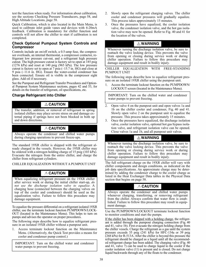
38
test the function when ready. For information about calibration,see the sections Checking Pressure Transducers, page 58, andHigh Altitude Locations, page 58.Quick Calibration, which is also located in the Main Menu, isused to calibrate inlet guide vanes and devices with 4-20mAfeedback. Calibration is mandatory for chiller function andcontrols will not allow the chiller to start if calibration is notcompleted.
Check Optional Pumpout System Controls andCompressorControls include an on/off switch, a 0.5-amp fuse, the compres-sor overloads, an internal thermostat, a compressor contactor, re-frigerant low pressure cut-out, and a refrigerant high pressurecutout. The high pressure cutout is factory set to open at 185 psig(1276 kPa) and reset at 140 psig (965 kPa). The low pressurecutout is factory set to open at 7 psia (–15.7 in. HG) and close at9 psia (–11.6 in. HG). Ensure the water-cooled condenser hasbeen connected. Ensure oil is visible in the compressor sightglass. Add oil if necessary.See the Pumpout and Refrigerant Transfer Procedures and Option-al Pumpout System Maintenance sections, pages 42 and 53, fordetails on the transfer of refrigerant, oil specifications, etc.
Charge Refrigerant into Chiller
The standard 19XR chiller is shipped with the refrigerant al-ready charged in the vessels. However, the 19XR chiller maybe ordered with a nitrogen holding charge of 15 psig (103 kPa).Evacuate the nitrogen from the entire chiller, and charge thechiller from refrigerant cylinders.
CHILLER EQUALIZATION WITHOUT A PUMPOUT UNIT
To equalize the pressure differential on a refrigerant isolated 19XRchiller, use the terminate lockout function PUMPDOWN/LOCK-OUT (located in the Maintenance Menu). This helps to turn onpumps and advises the operator on proper procedures. The following steps describe how to equalize refrigerant pres-sure in an isolated 19XR chiller without a pumpout unit.1. Access terminate lockout function on the Maintenance
Menu. (Alternatively, the Quick Test provides a means forcooler and condenser pump control.)
2. Slowly open the refrigerant charging valves. The chillercooler and condenser pressures will gradually equalize.This process takes approximately 15 minutes.
3. Once the pressures have equalized, the cooler isolationvalve, the condenser isolation valve, and the hot gas isola-tion valve may now be opened. Refer to Fig. 40 and 41 forthe location of the valves.
CHILLER EQUALIZATION WITH FREE-STANDINGPUMPOUT UNIT
The following steps describe how to equalize refrigerant pres-sure on an isolated 19XR chiller using the pumpout unit.1. Access the terminate lockout function on the PUMPDOWN/
LOCKOUT screen (located in the Maintenance Menu).
2. Open valve 4 on the pumpout unit and open valves 1a and1b on the chiller cooler and condenser, Fig. 40 and 41.Slowly open valve 2 on the pumpout unit to equalize thepressure. This process takes approximately 15 minutes.
3. Once the pressures have equalized, the discharge isolationvalve, cooler isolation valve, optional hot gas bypass isola-tion valve, and refrigerant isolation valve can be opened.Close valves 1a and 1b, and all pumpout unit valves.
The full refrigerant charge on the 19XR chiller will vary withchiller components and design conditions, as indicated on thejob data specifications. An approximate charge may be deter-mined by adding the condenser charge to the cooler charge aslisted in the Heat Exchanger Data tables in the Physical Datasection that begins on page 58.
Use the PUMPDOWN/LOCKOUT terminate lockout functionto monitor conditions and start the pumps.If the chiller has been shipped with a holding charge, the refriger-ant is added through the pumpout charging connection (Fig. 40and 41, valve 1b). First evacuate the nitrogen holding charge fromthe chiller vessels. Charge the refrigerant as a gas until the systempressure exceeds 35 psig (241 kPa) for HFC-134a or 39 psig(268 kPa) for R-513A. After the chiller is beyond this pressure therefrigerant should be charged as a liquid until all the recommend-ed refrigerant charge has been added. The charging valve (Fig. 40and 41, valve 7) can be used to charge liquid to the cooler if thecooler isolation valve (11) is present and is closed. Do not chargeliquid backwards through any of the floats to the condenser.
CAUTIONThe transfer, addition, or removal of refrigerant in springisolated chillers may place severe stress on and damage ex-ternal piping if springs have not been blocked in both upand down directions.
CAUTIONAlways operate the condenser and chilled water pumpsduring charging operations to prevent freeze-ups.
CAUTION
When equalizing refrigerant pressure on the 19XR chillerafter service work or during the initial chiller start-up, donot use the discharge isolation valve to equalize. Acharging hose (connected between the charging valves ontop of the cooler and condenser) should be used as theequalization valve. Failure to follow this procedure maydamage equipment.
IMPORTANT: Turn on the chilled water and condenserwater pumps to prevent freezing.
WARNINGWhenever turning the discharge isolation valve, be sure toreattach the valve locking device. This prevents the valvefrom opening or closing during service work or duringchiller operation. Failure to follow this procedure maydamage equipment and result in bodily injury.
CAUTION
Always operate the condenser and chilled water pumpswhenever charging, transferring, or removing refrigerantfrom the chiller. Always confirm that water flow is estab-lished. Failure to follow this procedure may result in equip-ment damage.
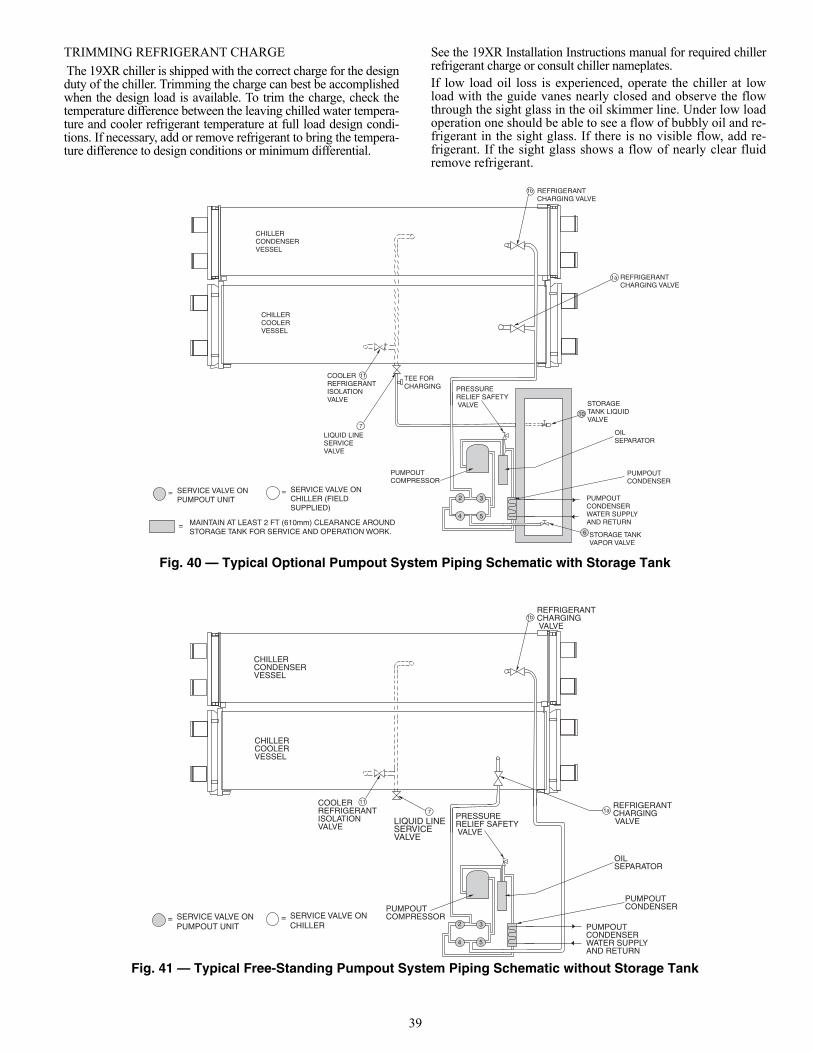
39
TRIMMING REFRIGERANT CHARGE
The 19XR chiller is shipped with the correct charge for the designduty of the chiller. Trimming the charge can best be accomplishedwhen the design load is available. To trim the charge, check thetemperature difference between the leaving chilled water tempera-ture and cooler refrigerant temperature at full load design condi-tions. If necessary, add or remove refrigerant to bring the tempera-ture difference to design conditions or minimum differential.
See the 19XR Installation Instructions manual for required chillerrefrigerant charge or consult chiller nameplates.If low load oil loss is experienced, operate the chiller at lowload with the guide vanes nearly closed and observe the flowthrough the sight glass in the oil skimmer line. Under low loadoperation one should be able to see a flow of bubbly oil and re-frigerant in the sight glass. If there is no visible flow, add re-frigerant. If the sight glass shows a flow of nearly clear fluidremove refrigerant.
Fig. 40 — Typical Optional Pumpout System Piping Schematic with Storage Tank
Fig. 41 — Typical Free-Standing Pumpout System Piping Schematic without Storage Tank
STORAGE TANK LIQUID VALVE
OIL SEPARATOR
PUMPOUT CONDENSER WATER SUPPLY AND RETURN
PUMPOUT CONDENSER
STORAGE TANK VAPOR VALVE
2 3
4 5
PRESSURE RELIEF SAFETY VALVE
PUMPOUT COMPRESSOR
TEE FOR CHARGING
REFRIGERANT CHARGING VALVE
COOLER REFRIGERANT ISOLATION VALVE
LIQUID LINE SERVICE VALVE
CHILLER CONDENSER VESSEL
CHILLER COOLER VESSEL
10
6
7
11
1a
1b
SERVICE VALVE ON PUMPOUT UNIT
= SERVICE VALVE ON CHILLER (FIELD SUPPLIED)
=
= MAINTAIN AT LEAST 2 FT (610mm) CLEARANCE AROUND STORAGE TANK FOR SERVICE AND OPERATION WORK.
REFRIGERANT CHARGING VALVE
OIL SEPARATOR
PUMPOUT CONDENSER WATER SUPPLY AND RETURN
PUMPOUT CONDENSER
2 3
4 5
PRESSURE RELIEF SAFETY VALVE
PUMPOUT COMPRESSOR
COOLER REFRIGERANT ISOLATION VALVE
REFRIGERANT CHARGING VALVE
CHILLER CONDENSER VESSEL
CHILLER COOLER VESSEL
7
11
1a
1b
SERVICE VALVE ON PUMPOUT UNIT
= SERVICE VALVE ON CHILLER
=
LIQUID LINE SERVICE VALVE
REFRIGERANT CHARGING VALVE
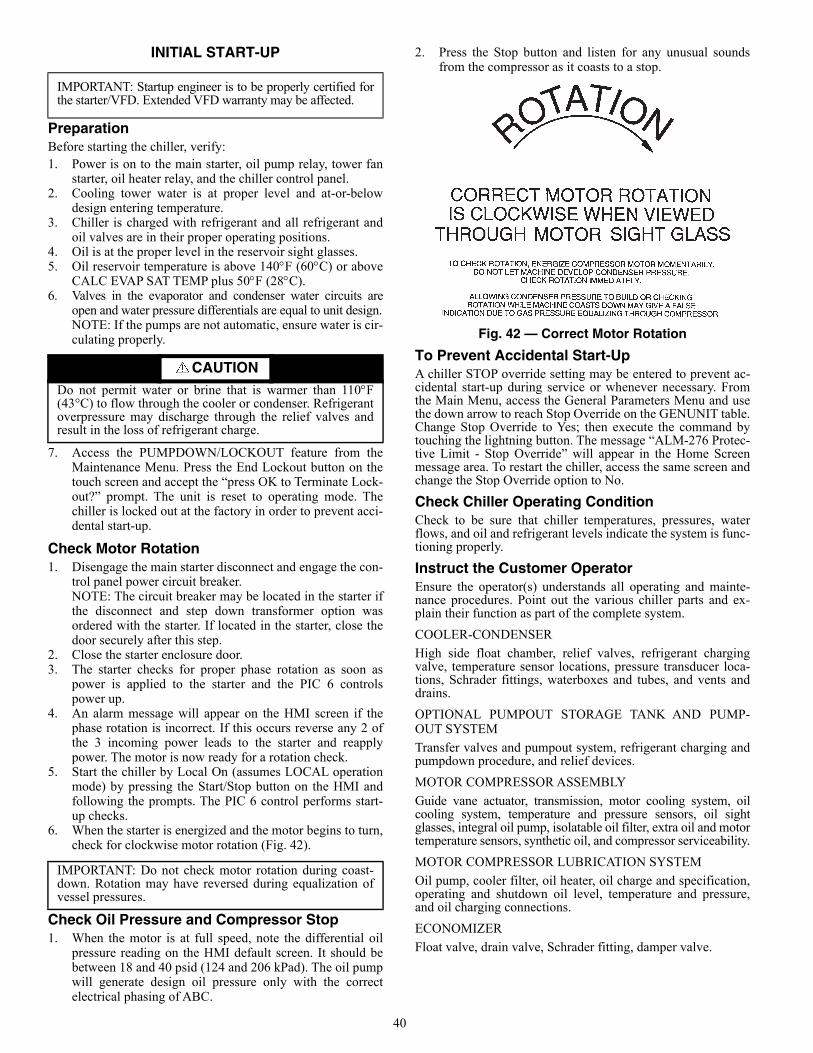
40
INITIAL START-UP
PreparationBefore starting the chiller, verify:1. Power is on to the main starter, oil pump relay, tower fan
starter, oil heater relay, and the chiller control panel.2. Cooling tower water is at proper level and at-or-below
design entering temperature.3. Chiller is charged with refrigerant and all refrigerant and
oil valves are in their proper operating positions.4. Oil is at the proper level in the reservoir sight glasses.5. Oil reservoir temperature is above 140F (60C) or above
CALC EVAP SAT TEMP plus 50F (28C).6. Valves in the evaporator and condenser water circuits are
open and water pressure differentials are equal to unit design.NOTE: If the pumps are not automatic, ensure water is cir-culating properly.
7. Access the PUMPDOWN/LOCKOUT feature from theMaintenance Menu. Press the End Lockout button on thetouch screen and accept the “press OK to Terminate Lock-out?” prompt. The unit is reset to operating mode. Thechiller is locked out at the factory in order to prevent acci-dental start-up.
Check Motor Rotation1. Disengage the main starter disconnect and engage the con-
trol panel power circuit breaker. NOTE: The circuit breaker may be located in the starter ifthe disconnect and step down transformer option wasordered with the starter. If located in the starter, close thedoor securely after this step.
2. Close the starter enclosure door.3. The starter checks for proper phase rotation as soon as
power is applied to the starter and the PIC 6 controlspower up.
4. An alarm message will appear on the HMI screen if thephase rotation is incorrect. If this occurs reverse any 2 ofthe 3 incoming power leads to the starter and reapplypower. The motor is now ready for a rotation check.
5. Start the chiller by Local On (assumes LOCAL operationmode) by pressing the Start/Stop button on the HMI andfollowing the prompts. The PIC 6 control performs start-up checks.
6. When the starter is energized and the motor begins to turn,check for clockwise motor rotation (Fig. 42).
Check Oil Pressure and Compressor Stop1. When the motor is at full speed, note the differential oil
pressure reading on the HMI default screen. It should bebetween 18 and 40 psid (124 and 206 kPad). The oil pumpwill generate design oil pressure only with the correctelectrical phasing of ABC.
2. Press the Stop button and listen for any unusual soundsfrom the compressor as it coasts to a stop.
Fig. 42 — Correct Motor Rotation
To Prevent Accidental Start-UpA chiller STOP override setting may be entered to prevent ac-cidental start-up during service or whenever necessary. Fromthe Main Menu, access the General Parameters Menu and usethe down arrow to reach Stop Override on the GENUNIT table.Change Stop Override to Yes; then execute the command bytouching the lightning button. The message “ALM-276 Protec-tive Limit - Stop Override” will appear in the Home Screenmessage area. To restart the chiller, access the same screen andchange the Stop Override option to No.
Check Chiller Operating ConditionCheck to be sure that chiller temperatures, pressures, waterflows, and oil and refrigerant levels indicate the system is func-tioning properly.
Instruct the Customer OperatorEnsure the operator(s) understands all operating and mainte-nance procedures. Point out the various chiller parts and ex-plain their function as part of the complete system.
COOLER-CONDENSER
High side float chamber, relief valves, refrigerant chargingvalve, temperature sensor locations, pressure transducer loca-tions, Schrader fittings, waterboxes and tubes, and vents anddrains.
OPTIONAL PUMPOUT STORAGE TANK AND PUMP-OUT SYSTEM
Transfer valves and pumpout system, refrigerant charging andpumpdown procedure, and relief devices.
MOTOR COMPRESSOR ASSEMBLY
Guide vane actuator, transmission, motor cooling system, oilcooling system, temperature and pressure sensors, oil sightglasses, integral oil pump, isolatable oil filter, extra oil and motortemperature sensors, synthetic oil, and compressor serviceability.
MOTOR COMPRESSOR LUBRICATION SYSTEM
Oil pump, cooler filter, oil heater, oil charge and specification,operating and shutdown oil level, temperature and pressure,and oil charging connections.
ECONOMIZER
Float valve, drain valve, Schrader fitting, damper valve.
IMPORTANT: Startup engineer is to be properly certified forthe starter/VFD. Extended VFD warranty may be affected.
CAUTIONDo not permit water or brine that is warmer than 110F(43°C) to flow through the cooler or condenser. Refrigerantoverpressure may discharge through the relief valves andresult in the loss of refrigerant charge.
IMPORTANT: Do not check motor rotation during coast-down. Rotation may have reversed during equalization ofvessel pressures.
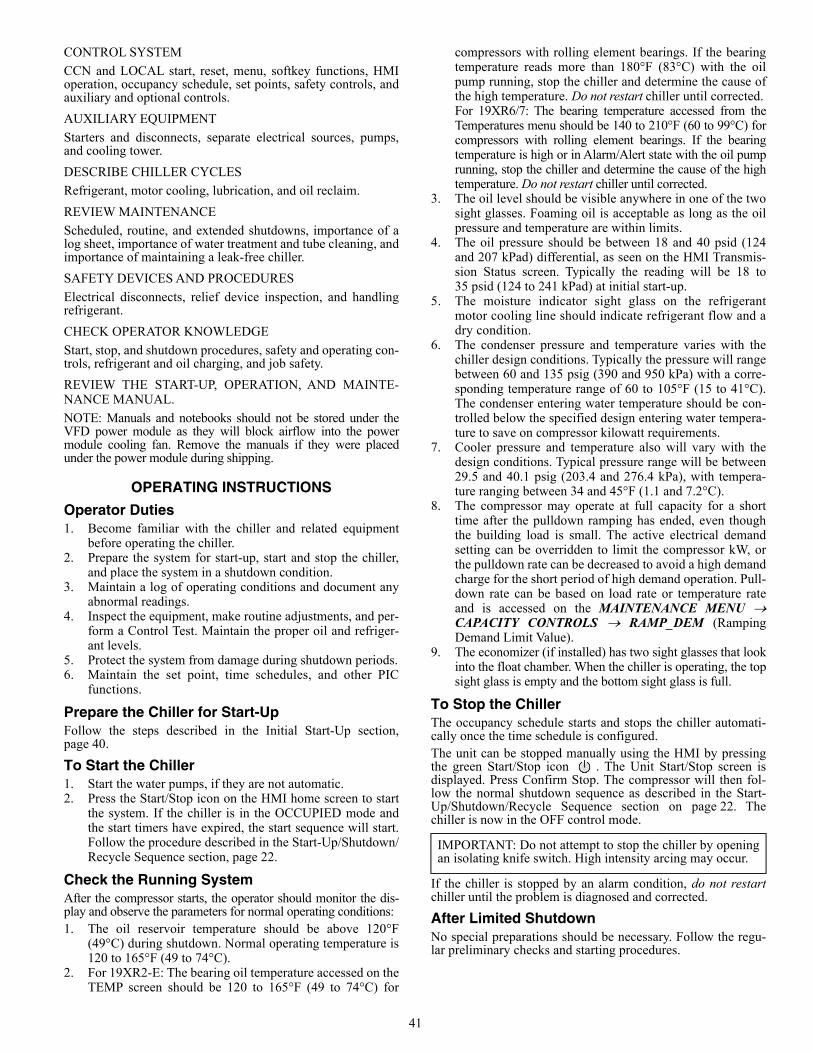
41
CONTROL SYSTEM
CCN and LOCAL start, reset, menu, softkey functions, HMIoperation, occupancy schedule, set points, safety controls, andauxiliary and optional controls.
AUXILIARY EQUIPMENT
Starters and disconnects, separate electrical sources, pumps,and cooling tower.
DESCRIBE CHILLER CYCLES
Refrigerant, motor cooling, lubrication, and oil reclaim.
REVIEW MAINTENANCE
Scheduled, routine, and extended shutdowns, importance of alog sheet, importance of water treatment and tube cleaning, andimportance of maintaining a leak-free chiller.
SAFETY DEVICES AND PROCEDURES
Electrical disconnects, relief device inspection, and handlingrefrigerant.
CHECK OPERATOR KNOWLEDGE
Start, stop, and shutdown procedures, safety and operating con-trols, refrigerant and oil charging, and job safety.
REVIEW THE START-UP, OPERATION, AND MAINTE-NANCE MANUAL.
NOTE: Manuals and notebooks should not be stored under theVFD power module as they will block airflow into the powermodule cooling fan. Remove the manuals if they were placedunder the power module during shipping.
OPERATING INSTRUCTIONS
Operator Duties1. Become familiar with the chiller and related equipment
before operating the chiller.2. Prepare the system for start-up, start and stop the chiller,
and place the system in a shutdown condition.3. Maintain a log of operating conditions and document any
abnormal readings.4. Inspect the equipment, make routine adjustments, and per-
form a Control Test. Maintain the proper oil and refriger-ant levels.
5. Protect the system from damage during shutdown periods.6. Maintain the set point, time schedules, and other PIC
functions.
Prepare the Chiller for Start-UpFollow the steps described in the Initial Start-Up section,page 40.
To Start the Chiller1. Start the water pumps, if they are not automatic.2. Press the Start/Stop icon on the HMI home screen to start
the system. If the chiller is in the OCCUPIED mode andthe start timers have expired, the start sequence will start.Follow the procedure described in the Start-Up/Shutdown/Recycle Sequence section, page 22.
Check the Running System After the compressor starts, the operator should monitor the dis-play and observe the parameters for normal operating conditions:1. The oil reservoir temperature should be above 120°F
(49°C) during shutdown. Normal operating temperature is120 to 165°F (49 to 74°C).
2. For 19XR2-E: The bearing oil temperature accessed on theTEMP screen should be 120 to 165°F (49 to 74°C) for
compressors with rolling element bearings. If the bearingtemperature reads more than 180°F (83°C) with the oilpump running, stop the chiller and determine the cause ofthe high temperature. Do not restart chiller until corrected.For 19XR6/7: The bearing temperature accessed from theTemperatures menu should be 140 to 210°F (60 to 99°C) forcompressors with rolling element bearings. If the bearingtemperature is high or in Alarm/Alert state with the oil pumprunning, stop the chiller and determine the cause of the hightemperature. Do not restart chiller until corrected.
3. The oil level should be visible anywhere in one of the twosight glasses. Foaming oil is acceptable as long as the oilpressure and temperature are within limits.
4. The oil pressure should be between 18 and 40 psid (124and 207 kPad) differential, as seen on the HMI Transmis-sion Status screen. Typically the reading will be 18 to35 psid (124 to 241 kPad) at initial start-up.
5. The moisture indicator sight glass on the refrigerantmotor cooling line should indicate refrigerant flow and adry condition.
6. The condenser pressure and temperature varies with thechiller design conditions. Typically the pressure will rangebetween 60 and 135 psig (390 and 950 kPa) with a corre-sponding temperature range of 60 to 105°F (15 to 41°C).The condenser entering water temperature should be con-trolled below the specified design entering water tempera-ture to save on compressor kilowatt requirements.
7. Cooler pressure and temperature also will vary with thedesign conditions. Typical pressure range will be between29.5 and 40.1 psig (203.4 and 276.4 kPa), with tempera-ture ranging between 34 and 45°F (1.1 and 7.2°C).
8. The compressor may operate at full capacity for a shorttime after the pulldown ramping has ended, even thoughthe building load is small. The active electrical demandsetting can be overridden to limit the compressor kW, orthe pulldown rate can be decreased to avoid a high demandcharge for the short period of high demand operation. Pull-down rate can be based on load rate or temperature rateand is accessed on the MAINTENANCE MENU CAPACITY CONTROLS RAMP_DEM (RampingDemand Limit Value).
9. The economizer (if installed) has two sight glasses that lookinto the float chamber. When the chiller is operating, the topsight glass is empty and the bottom sight glass is full.
To Stop the ChillerThe occupancy schedule starts and stops the chiller automati-cally once the time schedule is configured.The unit can be stopped manually using the HMI by pressingthe green Start/Stop icon . The Unit Start/Stop screen isdisplayed. Press Confirm Stop. The compressor will then fol-low the normal shutdown sequence as described in the Start-Up/Shutdown/Recycle Sequence section on page 22. Thechiller is now in the OFF control mode.
If the chiller is stopped by an alarm condition, do not restartchiller until the problem is diagnosed and corrected.
After Limited ShutdownNo special preparations should be necessary. Follow the regu-lar preliminary checks and starting procedures.
IMPORTANT: Do not attempt to stop the chiller by openingan isolating knife switch. High intensity arcing may occur.
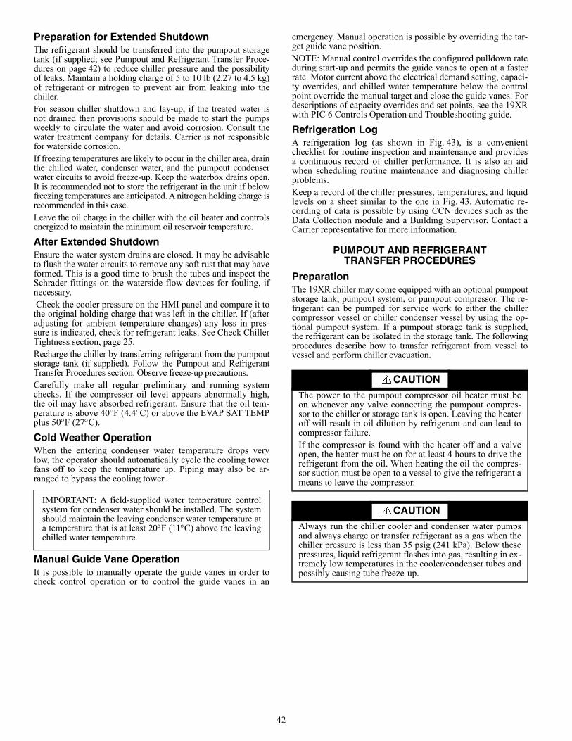
42
Preparation for Extended ShutdownThe refrigerant should be transferred into the pumpout storagetank (if supplied; see Pumpout and Refrigerant Transfer Proce-dures on page 42) to reduce chiller pressure and the possibilityof leaks. Maintain a holding charge of 5 to 10 lb (2.27 to 4.5 kg)of refrigerant or nitrogen to prevent air from leaking into thechiller.For season chiller shutdown and lay-up, if the treated water isnot drained then provisions should be made to start the pumpsweekly to circulate the water and avoid corrosion. Consult thewater treatment company for details. Carrier is not responsiblefor waterside corrosion. If freezing temperatures are likely to occur in the chiller area, drainthe chilled water, condenser water, and the pumpout condenserwater circuits to avoid freeze-up. Keep the waterbox drains open.It is recommended not to store the refrigerant in the unit if belowfreezing temperatures are anticipated. A nitrogen holding charge isrecommended in this case.Leave the oil charge in the chiller with the oil heater and controlsenergized to maintain the minimum oil reservoir temperature.
After Extended ShutdownEnsure the water system drains are closed. It may be advisableto flush the water circuits to remove any soft rust that may haveformed. This is a good time to brush the tubes and inspect theSchrader fittings on the waterside flow devices for fouling, ifnecessary. Check the cooler pressure on the HMI panel and compare it tothe original holding charge that was left in the chiller. If (afteradjusting for ambient temperature changes) any loss in pres-sure is indicated, check for refrigerant leaks. See Check ChillerTightness section, page 25.Recharge the chiller by transferring refrigerant from the pumpoutstorage tank (if supplied). Follow the Pumpout and RefrigerantTransfer Procedures section. Observe freeze-up precautions.Carefully make all regular preliminary and running systemchecks. If the compressor oil level appears abnormally high,the oil may have absorbed refrigerant. Ensure that the oil tem-perature is above 40°F (4.4°C) or above the EVAP SAT TEMPplus 50F (27C).
Cold Weather OperationWhen the entering condenser water temperature drops verylow, the operator should automatically cycle the cooling towerfans off to keep the temperature up. Piping may also be ar-ranged to bypass the cooling tower.
Manual Guide Vane Operation It is possible to manually operate the guide vanes in order tocheck control operation or to control the guide vanes in an
emergency. Manual operation is possible by overriding the tar-get guide vane position. NOTE: Manual control overrides the configured pulldown rateduring start-up and permits the guide vanes to open at a fasterrate. Motor current above the electrical demand setting, capaci-ty overrides, and chilled water temperature below the controlpoint override the manual target and close the guide vanes. Fordescriptions of capacity overrides and set points, see the 19XRwith PIC 6 Controls Operation and Troubleshooting guide.
Refrigeration LogA refrigeration log (as shown in Fig. 43), is a convenientchecklist for routine inspection and maintenance and providesa continuous record of chiller performance. It is also an aidwhen scheduling routine maintenance and diagnosing chillerproblems.Keep a record of the chiller pressures, temperatures, and liquidlevels on a sheet similar to the one in Fig. 43. Automatic re-cording of data is possible by using CCN devices such as theData Collection module and a Building Supervisor. Contact aCarrier representative for more information.
PUMPOUT AND REFRIGERANTTRANSFER PROCEDURES
PreparationThe 19XR chiller may come equipped with an optional pumpoutstorage tank, pumpout system, or pumpout compressor. The re-frigerant can be pumped for service work to either the chillercompressor vessel or chiller condenser vessel by using the op-tional pumpout system. If a pumpout storage tank is supplied,the refrigerant can be isolated in the storage tank. The followingprocedures describe how to transfer refrigerant from vessel tovessel and perform chiller evacuation.
IMPORTANT: A field-supplied water temperature controlsystem for condenser water should be installed. The systemshould maintain the leaving condenser water temperature ata temperature that is at least 20F (11C) above the leavingchilled water temperature.
CAUTIONThe power to the pumpout compressor oil heater must beon whenever any valve connecting the pumpout compres-sor to the chiller or storage tank is open. Leaving the heateroff will result in oil dilution by refrigerant and can lead tocompressor failure.If the compressor is found with the heater off and a valveopen, the heater must be on for at least 4 hours to drive therefrigerant from the oil. When heating the oil the compres-sor suction must be open to a vessel to give the refrigerant ameans to leave the compressor.
CAUTIONAlways run the chiller cooler and condenser water pumpsand always charge or transfer refrigerant as a gas when thechiller pressure is less than 35 psig (241 kPa). Below thesepressures, liquid refrigerant flashes into gas, resulting in ex-tremely low temperatures in the cooler/condenser tubes andpossibly causing tube freeze-up.
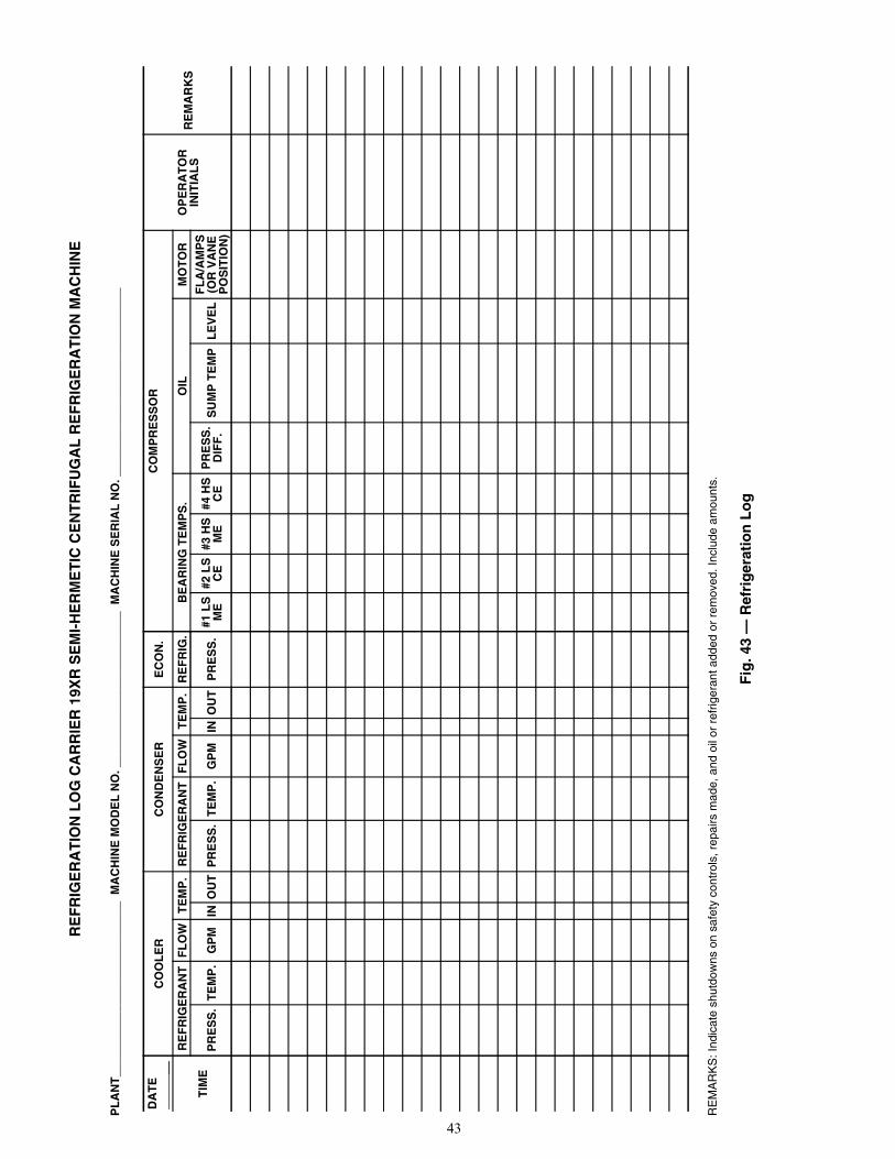
43
RE
FR
IGE
RA
TIO
N L
OG
CA
RR
IER
19X
R S
EM
I-H
ER
ME
TIC
CE
NT
RIF
UG
AL
RE
FR
IGE
RA
TIO
N M
AC
HIN
E
PL
AN
T__
____
____
____
____
____
____
_ M
AC
HIN
E M
OD
EL
NO
. ___
____
____
____
____
____
_ M
AC
HIN
E S
ER
IAL
NO
. ___
____
____
____
____
____
____
__
RE
MA
RK
S: I
ndic
ate
shut
dow
ns o
n sa
fety
con
trol
s, r
epai
rs m
ade,
and
oil
or r
efrig
eran
t add
ed o
r re
mov
ed. I
nclu
de a
mou
nts.
Fig
. 43
— R
efri
ger
atio
n L
og
DA
TE
__C
OO
LE
RC
ON
DE
NS
ER
EC
ON
.C
OM
PR
ES
SO
R
OP
ER
AT
OR
INIT
IAL
SR
EM
AR
KS
TIM
E
RE
FR
IGE
RA
NT
FL
OW
TE
MP
.R
EF
RIG
ER
AN
TF
LO
WT
EM
P.
RE
FR
IG.
BE
AR
ING
TE
MP
S.
OIL
MO
TO
R
PR
ES
S.
TE
MP
.G
PM
INO
UT
PR
ES
S.
TE
MP
.G
PM
INO
UT
PR
ES
S.
#1 L
SM
E#2
LS
CE
#3 H
SM
E#4
HS
CE
PR
ES
S.
DIF
F.
SU
MP
TE
MP
LE
VE
LF
LA
/AM
PS
(OR
VA
NE
PO
SIT
ION
)
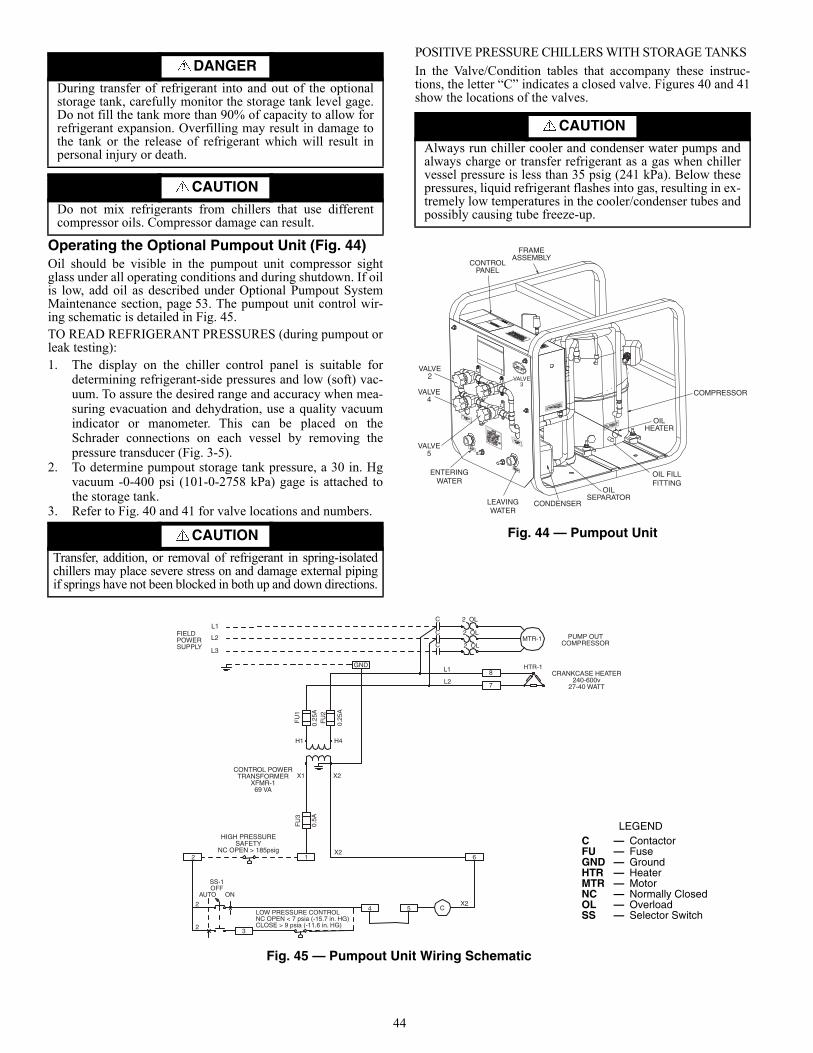
44
Operating the Optional Pumpout Unit (Fig. 44) Oil should be visible in the pumpout unit compressor sightglass under all operating conditions and during shutdown. If oilis low, add oil as described under Optional Pumpout SystemMaintenance section, page 53. The pumpout unit control wir-ing schematic is detailed in Fig. 45.TO READ REFRIGERANT PRESSURES (during pumpout orleak testing):1. The display on the chiller control panel is suitable for
determining refrigerant-side pressures and low (soft) vac-uum. To assure the desired range and accuracy when mea-suring evacuation and dehydration, use a quality vacuumindicator or manometer. This can be placed on theSchrader connections on each vessel by removing thepressure transducer (Fig. 3-5).
2. To determine pumpout storage tank pressure, a 30 in. Hgvacuum -0-400 psi (101-0-2758 kPa) gage is attached tothe storage tank.
3. Refer to Fig. 40 and 41 for valve locations and numbers.
POSITIVE PRESSURE CHILLERS WITH STORAGE TANKS
In the Valve/Condition tables that accompany these instruc-tions, the letter “C” indicates a closed valve. Figures 40 and 41show the locations of the valves.
Fig. 44 — Pumpout Unit
Fig. 45 — Pumpout Unit Wiring Schematic
DANGERDuring transfer of refrigerant into and out of the optionalstorage tank, carefully monitor the storage tank level gage.Do not fill the tank more than 90% of capacity to allow forrefrigerant expansion. Overfilling may result in damage tothe tank or the release of refrigerant which will result inpersonal injury or death.
CAUTION
Do not mix refrigerants from chillers that use differentcompressor oils. Compressor damage can result.
CAUTIONTransfer, addition, or removal of refrigerant in spring-isolatedchillers may place severe stress on and damage external pipingif springs have not been blocked in both up and down directions.
CAUTIONAlways run chiller cooler and condenser water pumps andalways charge or transfer refrigerant as a gas when chillervessel pressure is less than 35 psig (241 kPa). Below thesepressures, liquid refrigerant flashes into gas, resulting in ex-tremely low temperatures in the cooler/condenser tubes andpossibly causing tube freeze-up.
a23-1546
COMPRESSOR
OILSEPARATOR
CONDENSER LEAVINGWATER
ENTERINGWATER
VALVE5
VALVE4
VALVE2
CONTROLPANEL
FRAMEASSEMBLY
OILHEATER
VALVE3
OIL FILLFITTING
2 OL
2 OL
2 OLMTR-1
L1
L2
PUMP OUTCOMPRESSOR
CRANKCASE HEATER240-600v
27-40 WATT
GND
H1 H4
X1 X2
X2
HIGH PRESSURESAFETY
NC OPEN > 185psig
CONTROL POWERTRANSFORMER
XFMR-169 VA
C
C
C
8
7
HTR-1
FU
1
0.25
AF
U2
0.25
A
FU
3
0.5A
12
2
23
4
SS-1OFF
AUTO ON
LOW PRESSURE CONTROLNC OPEN < 7 psia (-15.7 in. HG)CLOSE > 9 psia (-11.6 in. HG)
5 CX2
6
FIELDPOWERSUPPLY
L1
L2
L3
LEGENDC — ContactorFU — FuseGND — GroundHTR — HeaterMTR — MotorNC — Normally ClosedOL — OverloadSS — Selector Switch
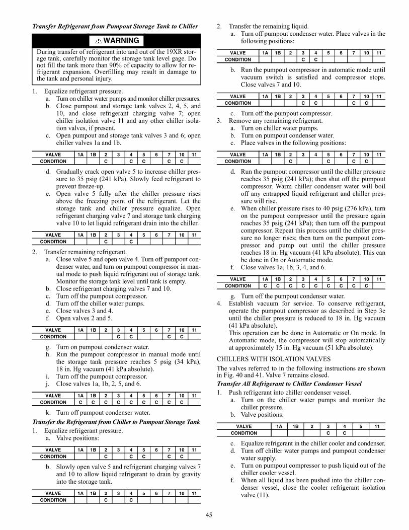
45
Transfer Refrigerant from Pumpout Storage Tank to Chiller
1. Equalize refrigerant pressure. a. Turn on chiller water pumps and monitor chiller pressures. b. Close pumpout and storage tank valves 2, 4, 5, and
10, and close refrigerant charging valve 7; openchiller isolation valve 11 and any other chiller isola-tion valves, if present.
c. Open pumpout and storage tank valves 3 and 6; openchiller valves 1a and 1b.
d. Gradually crack open valve 5 to increase chiller pres-sure to 35 psig (241 kPa). Slowly feed refrigerant toprevent freeze-up.
e. Open valve 5 fully after the chiller pressure risesabove the freezing point of the refrigerant. Let thestorage tank and chiller pressure equalize. Openrefrigerant charging valve 7 and storage tank chargingvalve 10 to let liquid refrigerant drain into the chiller.
2. Transfer remaining refrigerant. a. Close valve 5 and open valve 4. Turn off pumpout con-
denser water, and turn on pumpout compressor in man-ual mode to push liquid refrigerant out of storage tank.Monitor the storage tank level until tank is empty.
b. Close refrigerant charging valves 7 and 10. c. Turn off the pumpout compressor. d. Turn off the chiller water pumps. e. Close valves 3 and 4. f. Open valves 2 and 5.
g. Turn on pumpout condenser water. h. Run the pumpout compressor in manual mode until
the storage tank pressure reaches 5 psig (34 kPa),18 in. Hg vacuum (41 kPa absolute).
i. Turn off the pumpout compressor. j. Close valves 1a, 1b, 2, 5, and 6.
k. Turn off pumpout condenser water.
Transfer the Refrigerant from Chiller to Pumpout Storage Tank1. Equalize refrigerant pressure.
a. Valve positions:
b. Slowly open valve 5 and refrigerant charging valves 7and 10 to allow liquid refrigerant to drain by gravityinto the storage tank.
2. Transfer the remaining liquid. a. Turn off pumpout condenser water. Place valves in the
following positions:
b. Run the pumpout compressor in automatic mode untilvacuum switch is satisfied and compressor stops.Close valves 7 and 10.
c. Turn off the pumpout compressor.3. Remove any remaining refrigerant.
a. Turn on chiller water pumps. b. Turn on pumpout condenser water. c. Place valves in the following positions:
d. Run the pumpout compressor until the chiller pressurereaches 35 psig (241 kPa); then shut off the pumpoutcompressor. Warm chiller condenser water will boiloff any entrapped liquid refrigerant and chiller pres-sure will rise.
e. When chiller pressure rises to 40 psig (276 kPa), turnon the pumpout compressor until the pressure againreaches 35 psig (241 kPa); then turn off the pumpoutcompressor. Repeat this process until the chiller pres-sure no longer rises; then turn on the pumpout com-pressor and pump out until the chiller pressurereaches 18 in. Hg vacuum (41 kPa absolute). This canbe done in On or Automatic mode.
f. Close valves 1a, 1b, 3, 4, and 6.
g. Turn off the pumpout condenser water.4. Establish vacuum for service. To conserve refrigerant,
operate the pumpout compressor as described in Step 3euntil the chiller pressure is reduced to 18 in. Hg vacuum(41 kPa absolute).This operation can be done in Automatic or On mode. InAutomatic mode, the compressor will stop automaticallyat approximately 15 in. Hg vacuum (51 kPa absolute).
CHILLERS WITH ISOLATION VALVES
The valves referred to in the following instructions are shownin Fig. 40 and 41. Valve 7 remains closed.Transfer All Refrigerant to Chiller Condenser Vessel1. Push refrigerant into chiller condenser vessel.
a. Turn on the chiller water pumps and monitor thechiller pressure.
b. Valve positions:
c. Equalize refrigerant in the chiller cooler and condenser. d. Turn off chiller water pumps and pumpout condenser
water supply. e. Turn on pumpout compressor to push liquid out of the
chiller cooler vessel. f. When all liquid has been pushed into the chiller con-
denser vessel, close the cooler refrigerant isolationvalve (11).
WARNINGDuring transfer of refrigerant into and out of the 19XR stor-age tank, carefully monitor the storage tank level gage. Donot fill the tank more than 90% of capacity to allow for re-frigerant expansion. Overfilling may result in damage tothe tank and personal injury.
VALVE 1A 1B 2 3 4 5 6 7 10 11CONDITION C C C C C
VALVE 1A 1B 2 3 4 5 6 7 10 11CONDITION C C
VALVE 1A 1B 2 3 4 5 6 7 10 11CONDITION C C C C
VALVE 1A 1B 2 3 4 5 6 7 10 11CONDITION C C C C C C C C C
VALVE 1A 1B 2 3 4 5 6 7 10 11CONDITION C C C C C
VALVE 1A 1B 2 3 4 5 6 7 10 11CONDITION C C
VALVE 1A 1B 2 3 4 5 6 7 10 11CONDITION C C
VALVE 1A 1B 2 3 4 5 6 7 10 11CONDITION C C C C
VALVE 1A 1B 2 3 4 5 6 7 10 11CONDITION C C C C
VALVE 1A 1B 2 3 4 5 6 7 10 11CONDITION C C C C C C C C C
VALVE 1A 1B 2 3 4 5 11CONDITION C C
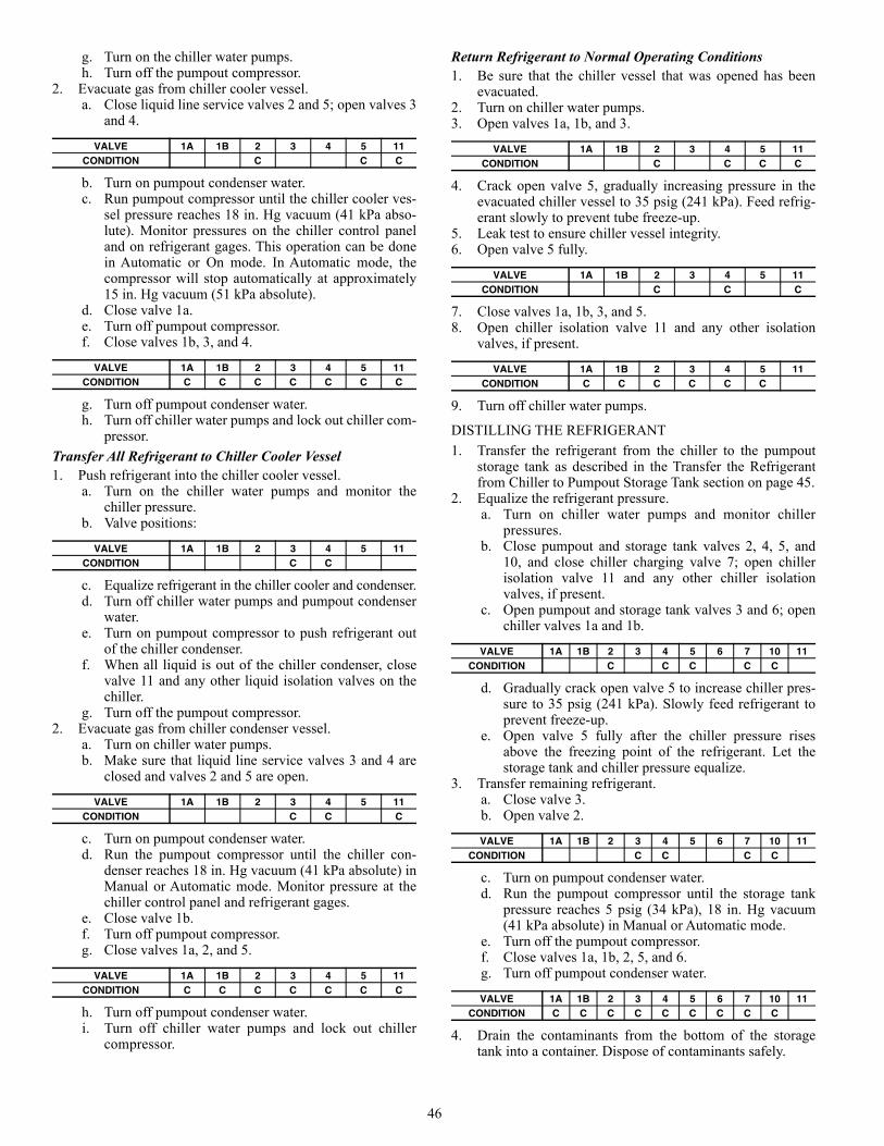
46
g. Turn on the chiller water pumps. h. Turn off the pumpout compressor.
2. Evacuate gas from chiller cooler vessel. a. Close liquid line service valves 2 and 5; open valves 3
and 4.
b. Turn on pumpout condenser water. c. Run pumpout compressor until the chiller cooler ves-
sel pressure reaches 18 in. Hg vacuum (41 kPa abso-lute). Monitor pressures on the chiller control paneland on refrigerant gages. This operation can be donein Automatic or On mode. In Automatic mode, thecompressor will stop automatically at approximately15 in. Hg vacuum (51 kPa absolute).
d. Close valve 1a. e. Turn off pumpout compressor. f. Close valves 1b, 3, and 4.
g. Turn off pumpout condenser water. h. Turn off chiller water pumps and lock out chiller com-
pressor.
Transfer All Refrigerant to Chiller Cooler Vessel1. Push refrigerant into the chiller cooler vessel.
a. Turn on the chiller water pumps and monitor thechiller pressure.
b. Valve positions:
c. Equalize refrigerant in the chiller cooler and condenser. d. Turn off chiller water pumps and pumpout condenser
water. e. Turn on pumpout compressor to push refrigerant out
of the chiller condenser. f. When all liquid is out of the chiller condenser, close
valve 11 and any other liquid isolation valves on thechiller.
g. Turn off the pumpout compressor.2. Evacuate gas from chiller condenser vessel.
a. Turn on chiller water pumps. b. Make sure that liquid line service valves 3 and 4 are
closed and valves 2 and 5 are open.
c. Turn on pumpout condenser water. d. Run the pumpout compressor until the chiller con-
denser reaches 18 in. Hg vacuum (41 kPa absolute) inManual or Automatic mode. Monitor pressure at thechiller control panel and refrigerant gages.
e. Close valve 1b. f. Turn off pumpout compressor. g. Close valves 1a, 2, and 5.
h. Turn off pumpout condenser water. i. Turn off chiller water pumps and lock out chiller
compressor.
Return Refrigerant to Normal Operating Conditions1. Be sure that the chiller vessel that was opened has been
evacuated.2. Turn on chiller water pumps.3. Open valves 1a, 1b, and 3.
4. Crack open valve 5, gradually increasing pressure in theevacuated chiller vessel to 35 psig (241 kPa). Feed refrig-erant slowly to prevent tube freeze-up.
5. Leak test to ensure chiller vessel integrity.6. Open valve 5 fully.
7. Close valves 1a, 1b, 3, and 5.8. Open chiller isolation valve 11 and any other isolation
valves, if present.
9. Turn off chiller water pumps.
DISTILLING THE REFRIGERANT
1. Transfer the refrigerant from the chiller to the pumpoutstorage tank as described in the Transfer the Refrigerantfrom Chiller to Pumpout Storage Tank section on page 45.
2. Equalize the refrigerant pressure. a. Turn on chiller water pumps and monitor chiller
pressures. b. Close pumpout and storage tank valves 2, 4, 5, and
10, and close chiller charging valve 7; open chillerisolation valve 11 and any other chiller isolationvalves, if present.
c. Open pumpout and storage tank valves 3 and 6; openchiller valves 1a and 1b.
d. Gradually crack open valve 5 to increase chiller pres-sure to 35 psig (241 kPa). Slowly feed refrigerant toprevent freeze-up.
e. Open valve 5 fully after the chiller pressure risesabove the freezing point of the refrigerant. Let thestorage tank and chiller pressure equalize.
3. Transfer remaining refrigerant. a. Close valve 3. b. Open valve 2.
c. Turn on pumpout condenser water. d. Run the pumpout compressor until the storage tank
pressure reaches 5 psig (34 kPa), 18 in. Hg vacuum(41 kPa absolute) in Manual or Automatic mode.
e. Turn off the pumpout compressor. f. Close valves 1a, 1b, 2, 5, and 6. g. Turn off pumpout condenser water.
4. Drain the contaminants from the bottom of the storagetank into a container. Dispose of contaminants safely.
VALVE 1A 1B 2 3 4 5 11CONDITION C C C
VALVE 1A 1B 2 3 4 5 11CONDITION C C C C C C C
VALVE 1A 1B 2 3 4 5 11CONDITION C C
VALVE 1A 1B 2 3 4 5 11CONDITION C C C
VALVE 1A 1B 2 3 4 5 11CONDITION C C C C C C C
VALVE 1A 1B 2 3 4 5 11CONDITION C C C C
VALVE 1A 1B 2 3 4 5 11CONDITION C C C
VALVE 1A 1B 2 3 4 5 11CONDITION C C C C C C
VALVE 1A 1B 2 3 4 5 6 7 10 11CONDITION C C C C C
VALVE 1A 1B 2 3 4 5 6 7 10 11CONDITION C C C C
VALVE 1A 1B 2 3 4 5 6 7 10 11CONDITION C C C C C C C C C
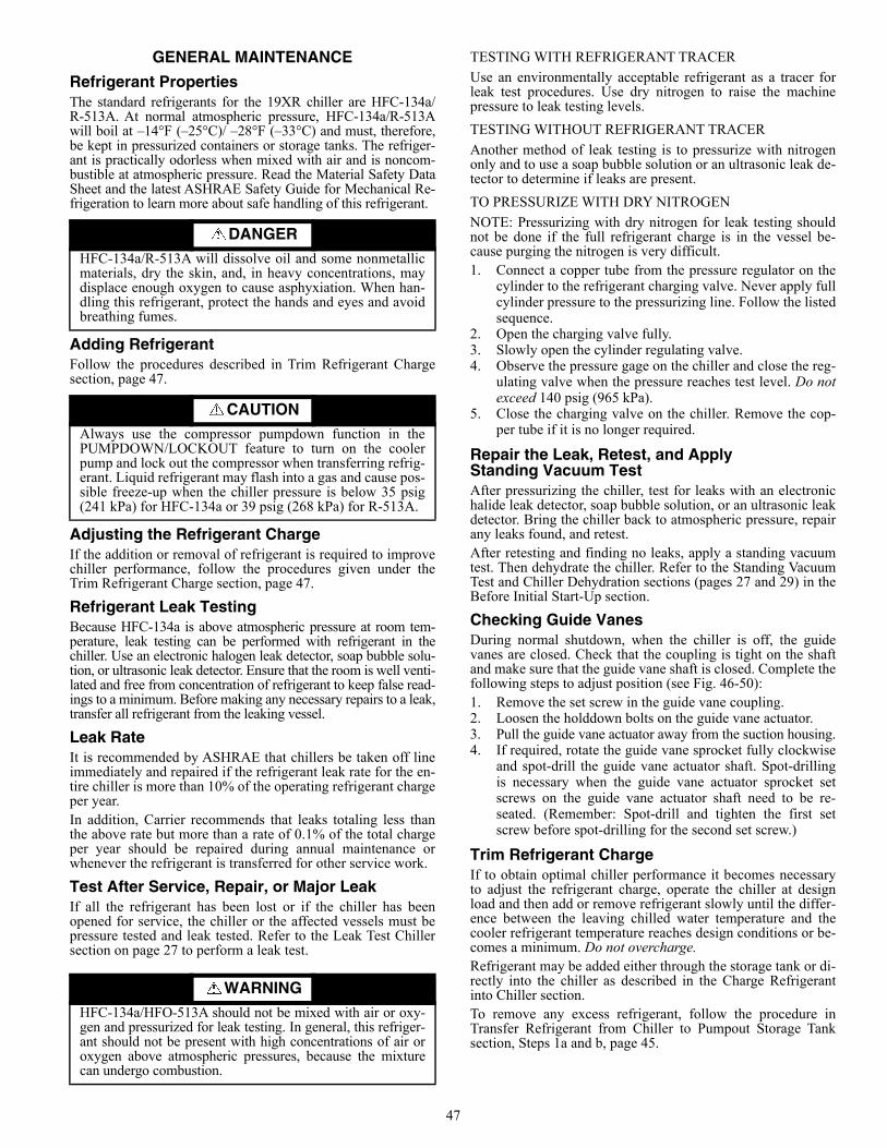
47
GENERAL MAINTENANCE
Refrigerant PropertiesThe standard refrigerants for the 19XR chiller are HFC-134a/R-513A. At normal atmospheric pressure, HFC-134a/R-513Awill boil at –14°F (–25°C)/ –28°F (–33°C) and must, therefore,be kept in pressurized containers or storage tanks. The refriger-ant is practically odorless when mixed with air and is noncom-bustible at atmospheric pressure. Read the Material Safety DataSheet and the latest ASHRAE Safety Guide for Mechanical Re-frigeration to learn more about safe handling of this refrigerant.
Adding RefrigerantFollow the procedures described in Trim Refrigerant Chargesection, page 47.
Adjusting the Refrigerant ChargeIf the addition or removal of refrigerant is required to improvechiller performance, follow the procedures given under theTrim Refrigerant Charge section, page 47.
Refrigerant Leak TestingBecause HFC-134a is above atmospheric pressure at room tem-perature, leak testing can be performed with refrigerant in thechiller. Use an electronic halogen leak detector, soap bubble solu-tion, or ultrasonic leak detector. Ensure that the room is well venti-lated and free from concentration of refrigerant to keep false read-ings to a minimum. Before making any necessary repairs to a leak,transfer all refrigerant from the leaking vessel.
Leak RateIt is recommended by ASHRAE that chillers be taken off lineimmediately and repaired if the refrigerant leak rate for the en-tire chiller is more than 10% of the operating refrigerant chargeper year.In addition, Carrier recommends that leaks totaling less thanthe above rate but more than a rate of 0.1% of the total chargeper year should be repaired during annual maintenance orwhenever the refrigerant is transferred for other service work.
Test After Service, Repair, or Major LeakIf all the refrigerant has been lost or if the chiller has beenopened for service, the chiller or the affected vessels must bepressure tested and leak tested. Refer to the Leak Test Chillersection on page 27 to perform a leak test.
TESTING WITH REFRIGERANT TRACER
Use an environmentally acceptable refrigerant as a tracer forleak test procedures. Use dry nitrogen to raise the machinepressure to leak testing levels.
TESTING WITHOUT REFRIGERANT TRACER
Another method of leak testing is to pressurize with nitrogenonly and to use a soap bubble solution or an ultrasonic leak de-tector to determine if leaks are present.
TO PRESSURIZE WITH DRY NITROGEN
NOTE: Pressurizing with dry nitrogen for leak testing shouldnot be done if the full refrigerant charge is in the vessel be-cause purging the nitrogen is very difficult.1. Connect a copper tube from the pressure regulator on the
cylinder to the refrigerant charging valve. Never apply fullcylinder pressure to the pressurizing line. Follow the listedsequence.
2. Open the charging valve fully.3. Slowly open the cylinder regulating valve.4. Observe the pressure gage on the chiller and close the reg-
ulating valve when the pressure reaches test level. Do notexceed 140 psig (965 kPa).
5. Close the charging valve on the chiller. Remove the cop-per tube if it is no longer required.
Repair the Leak, Retest, and Apply Standing Vacuum TestAfter pressurizing the chiller, test for leaks with an electronichalide leak detector, soap bubble solution, or an ultrasonic leakdetector. Bring the chiller back to atmospheric pressure, repairany leaks found, and retest.After retesting and finding no leaks, apply a standing vacuumtest. Then dehydrate the chiller. Refer to the Standing VacuumTest and Chiller Dehydration sections (pages 27 and 29) in theBefore Initial Start-Up section.
Checking Guide VanesDuring normal shutdown, when the chiller is off, the guidevanes are closed. Check that the coupling is tight on the shaftand make sure that the guide vane shaft is closed. Complete thefollowing steps to adjust position (see Fig. 46-50):1. Remove the set screw in the guide vane coupling.2. Loosen the holddown bolts on the guide vane actuator.3. Pull the guide vane actuator away from the suction housing.4. If required, rotate the guide vane sprocket fully clockwise
and spot-drill the guide vane actuator shaft. Spot-drillingis necessary when the guide vane actuator sprocket setscrews on the guide vane actuator shaft need to be re-seated. (Remember: Spot-drill and tighten the first setscrew before spot-drilling for the second set screw.)
Trim Refrigerant ChargeIf to obtain optimal chiller performance it becomes necessaryto adjust the refrigerant charge, operate the chiller at designload and then add or remove refrigerant slowly until the differ-ence between the leaving chilled water temperature and thecooler refrigerant temperature reaches design conditions or be-comes a minimum. Do not overcharge.Refrigerant may be added either through the storage tank or di-rectly into the chiller as described in the Charge Refrigerantinto Chiller section.To remove any excess refrigerant, follow the procedure inTransfer Refrigerant from Chiller to Pumpout Storage Tanksection, Steps 1a and b, page 45.
DANGER
HFC-134a/R-513A will dissolve oil and some nonmetallicmaterials, dry the skin, and, in heavy concentrations, maydisplace enough oxygen to cause asphyxiation. When han-dling this refrigerant, protect the hands and eyes and avoidbreathing fumes.
CAUTIONAlways use the compressor pumpdown function in thePUMPDOWN/LOCKOUT feature to turn on the coolerpump and lock out the compressor when transferring refrig-erant. Liquid refrigerant may flash into a gas and cause pos-sible freeze-up when the chiller pressure is below 35 psig(241 kPa) for HFC-134a or 39 psig (268 kPa) for R-513A.
WARNING
HFC-134a/HFO-513A should not be mixed with air or oxy-gen and pressurized for leak testing. In general, this refriger-ant should not be present with high concentrations of air oroxygen above atmospheric pressures, because the mixturecan undergo combustion.
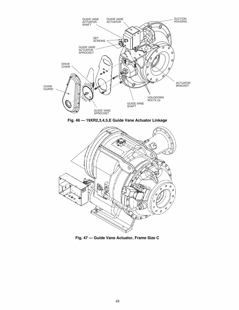
48
Fig. 46 — 19XR2,3,4,5,E Guide Vane Actuator Linkage
Fig. 47 — Guide Vane Actuator, Frame Size C
CHAINGUARD
DRIVECHAIN
GUIDE VANEACTUATORSPROCKET
SETSCREWS
GUIDE VANEACTUATOR
SUCTIONHOUSING
GUIDE VANEACTUATORSHAFT
ACTUATORBRACKET
HOLDDOWNBOLTS (3)
GUIDE VANESHAFT
GUIDE VANESPROCKET
OPEN
CLOSE
a19-1731
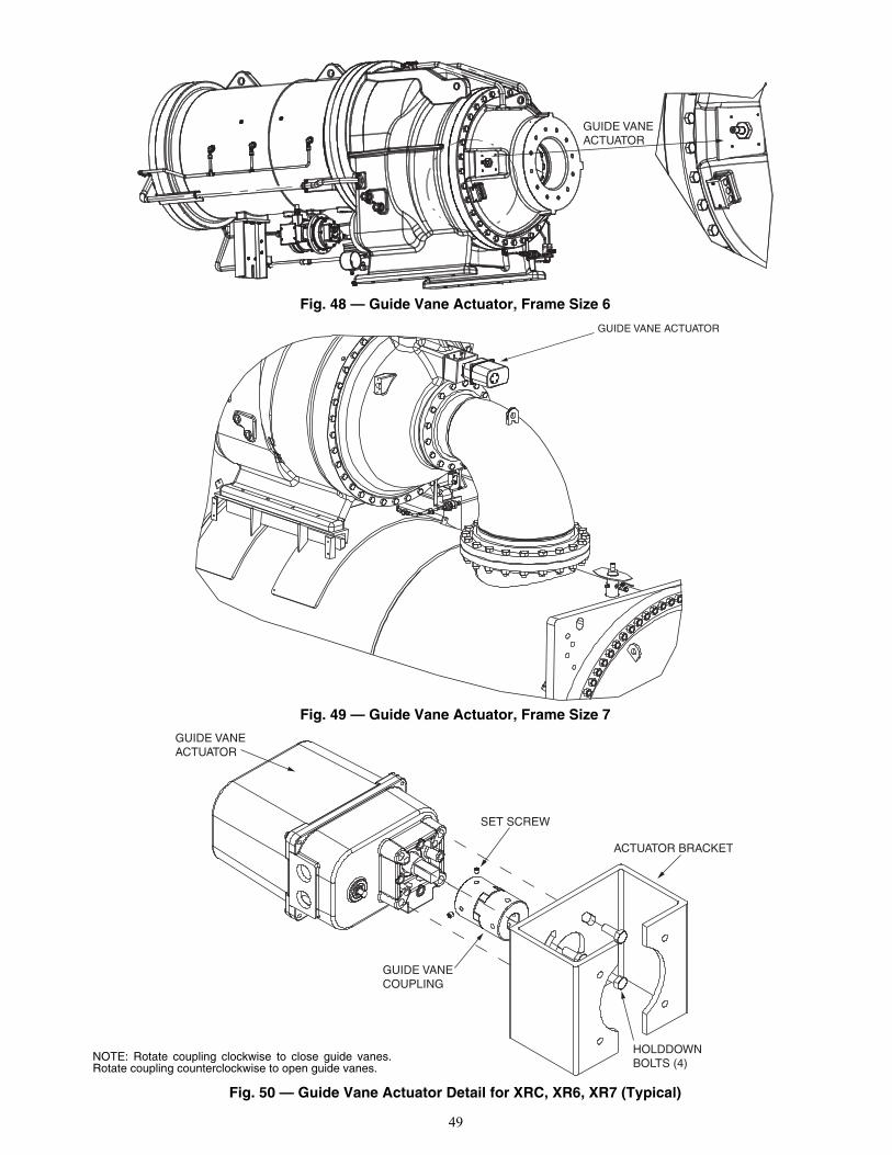
49
Fig. 48 — Guide Vane Actuator, Frame Size 6
Fig. 49 — Guide Vane Actuator, Frame Size 7
Fig. 50 — Guide Vane Actuator Detail for XRC, XR6, XR7 (Typical)
a19-2123
GUIDE VANEACTUATOR
GUIDE VANE ACTUATOR
GUIDE VANEACTUATOR
SET SCREW
GUIDE VANECOUPLING
ACTUATOR BRACKET
HOLDDOWNBOLTS (4)
a19-2128NOTE: Rotate coupling clockwise to close guide vanes.Rotate coupling counterclockwise to open guide vanes.
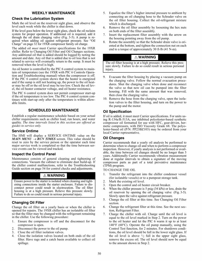
50
WEEKLY MAINTENANCE
Check the Lubrication SystemMark the oil level on the reservoir sight glass, and observe thelevel each week while the chiller is shut down.If the level goes below the lower sight glass, check the oil reclaimsystem for proper operation. If additional oil is required, add itthrough the oil drain charging valve (Fig. 3-5). A pump is re-quired when adding oil against refrigerant pressure. See “OilCharge” on page 32 for 19XR compressor family oil charge.The added oil must meet Carrier specifications for the 19XRchiller. Refer to Changing Oil Filter and Oil Changes sections.Any additional oil that is added should be logged by noting theamount and date. Any oil that is added due to oil loss that is notrelated to service will eventually return to the sump. It must beremoved when the level is high.An oil heater is controlled by the PIC 6 control system to main-tain oil temperature (see the 19XR with PIC 6 Controls Opera-tion and Troubleshooting manual) when the compressor is off.If the PIC 6 control system shows that the heater is energizedand if the sump is still not heating up, the power to the oil heat-er may be off or the oil level may be too low. Check the oil lev-el, the oil heater contactor voltage, and oil heater resistance.The PIC 6 control system does not permit compressor start-upif the oil temperature is too low. The PIC 6 control system con-tinues with start-up only after the temperature is within allow-able limits.
SCHEDULED MAINTENANCEEstablish a regular maintenance schedule based on your actualchiller requirements such as chiller load, run hours, and waterquality. The time intervals listed in this section are offered asguides to service only.
Service OntimeThe HMI will display a SERVICE ONTIME value on theMAIN MENU RUN TIMES screen. This value should bereset to zero by the service person or the operator each timemajor service work is completed so that the time between ser-vice events can be viewed and tracked.
Inspect the Control PanelMaintenance consists of general cleaning and tightening ofconnections. Vacuum the cabinet to eliminate dust build-up. Ifthe chiller control malfunctions, refer to the TroubleshootingGuide section on page 54 for control checks and adjustments.
Changing Oil FilterChange the oil filter on a yearly basis or when the chiller isopened for repairs. The 19XR chiller has an isolatable oil filterso that the filter may be changed with the refrigerant remainingin the chiller. Use the following procedure:1. Ensure the compressor is off and the disconnect for the
compressor is open.2. Disconnect the power to the oil pump.3. Close the oil filter isolation valves.4. Close the isolation valves located on both ends of the oil
filter. Have rags and a catch basin available to collect oilspillage.
5. Equalize the filter’s higher internal pressure to ambient byconnecting an oil charging hose to the Schrader valve onthe oil filter housing. Collect the oil-refrigerant mixturewhich is discharged.
6. Remove the oil filter assembly by loosening the hex nutson both ends of the filter assembly.
7. Insert the replacement filter assembly with the arrow onthe housing pointing away from the oil pump.
8. Rotate the assembly so that the Schrader drain valve is ori-ented at the bottom, and tighten the connection nut on eachend to a torque of approximately 30 ft-lb (41 N-m).
9. Evacuate the filter housing by placing a vacuum pump onthe charging valve. Follow the normal evacuation proce-dures. Shut the charging valve when done and reconnectthe valve so that new oil can be pumped into the filterhousing. Fill with the same amount that was removed;then close the charging valve.
10. Remove the hose from the charging valve, open the isola-tion valves to the filter housing, and turn on the power tothe pump and the motor.
Oil SpecificationIf oil is added, it must meet Carrier specifications. For units us-ing R-134a/R-513A, use inhibited polyolester-based syntheticcompressor oil formatted for use with HFC, gear-driven, her-metic compressors, with ISO Viscosity Grade 68. The polyo-lester-based oil (P/N: PP23BZ103) may be ordered from yourlocal Carrier representative.
Oil ChangesCarrier recommends that a yearly oil analysis be performed todetermine when to change oil and when to perform a compressorinspection. However, if yearly analysis is not performed or avail-able, the time between oil changes should be no longer than 5years. Additionally Carrier recommends vibration measurementdone at regular intervals to obtain a signature of the movingcompressor parts as part of a total preventive maintenance(TPM) program. TO CHANGE THE OIL1. Transfer the refrigerant into the chiller condenser vessel
(for isolatable vessels) or to a pumpout storage tank.2. Mark the existing oil level.3. Open the control and oil heater circuit breaker.4. When the chiller pressure is 5 psig (34 kPa) or less, drain the
oil reservoir by opening the oil charging valve (Fig. 3-5).Slowly open the valve against refrigerant pressure.
5. Change the oil filter at this time. See Changing Oil Filtersection.
6. Change the refrigerant filter at this time. See the next sec-tion, Refrigerant Filter.
7. Charge the chiller with oil. Charge until the oil level isequal to the oil level marked in Step 2. Turn on the powerto the oil heater and let the PIC 6 warm it up to at least140°F (60°C). Operate the oil pump manually, using theControl Test function, for 2 minutes. For shutdown condi-tions, the oil level should be full in the lower sight glass. Ifthe oil level is above 1/2 full in the upper sight glass,remove the excess oil. The oil level should now be equalto the amount shown in Step 2.
WARNINGEnsure power to the starter is isolated when cleaning and tight-ening connections inside the starter enclosure. Failure to dis-connect power could result in electrocution. The oil filterhousing is at a high pressure. Relieve this pressure slowly.Failure to do so could result in serious personal injury.
WARNING
The oil filter housing is at a high pressure. Relieve this pres-sure slowly. Failure to do so could result in serious personalinjury.
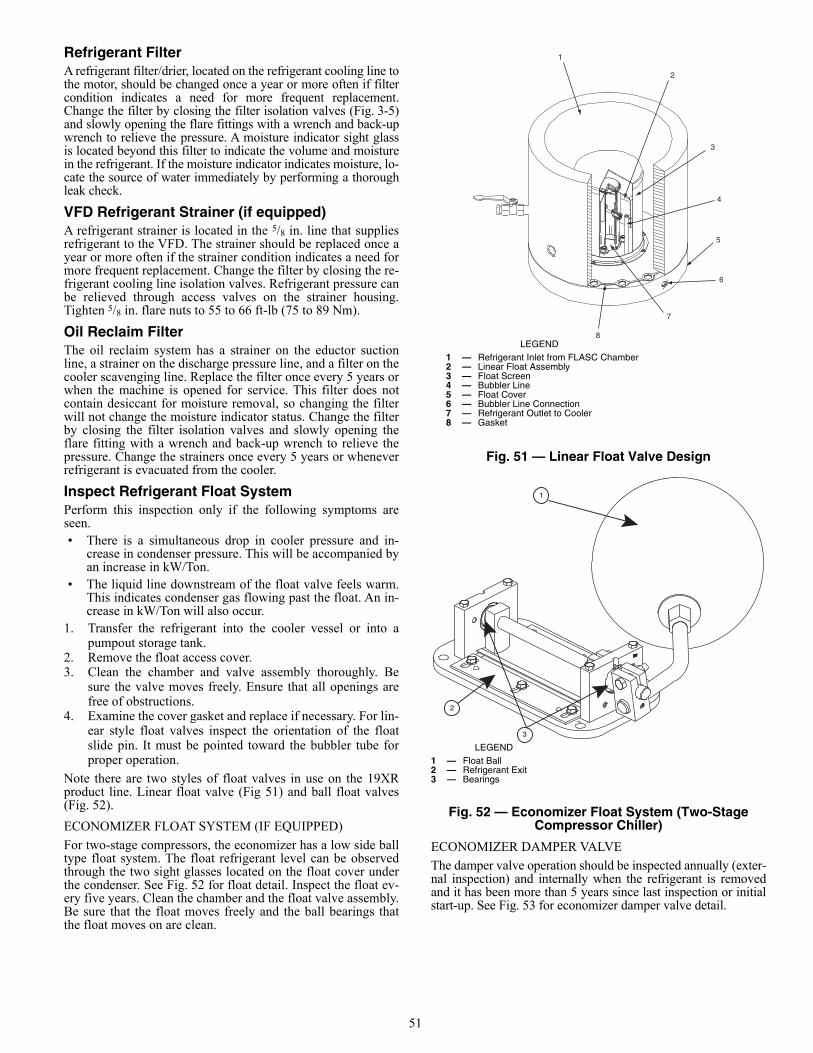
51
Refrigerant FilterA refrigerant filter/drier, located on the refrigerant cooling line tothe motor, should be changed once a year or more often if filtercondition indicates a need for more frequent replacement.Change the filter by closing the filter isolation valves (Fig. 3-5)and slowly opening the flare fittings with a wrench and back-upwrench to relieve the pressure. A moisture indicator sight glassis located beyond this filter to indicate the volume and moisturein the refrigerant. If the moisture indicator indicates moisture, lo-cate the source of water immediately by performing a thoroughleak check.
VFD Refrigerant Strainer (if equipped)A refrigerant strainer is located in the 5/8 in. line that suppliesrefrigerant to the VFD. The strainer should be replaced once ayear or more often if the strainer condition indicates a need formore frequent replacement. Change the filter by closing the re-frigerant cooling line isolation valves. Refrigerant pressure canbe relieved through access valves on the strainer housing.Tighten 5/8 in. flare nuts to 55 to 66 ft-lb (75 to 89 Nm).
Oil Reclaim FilterThe oil reclaim system has a strainer on the eductor suctionline, a strainer on the discharge pressure line, and a filter on thecooler scavenging line. Replace the filter once every 5 years orwhen the machine is opened for service. This filter does notcontain desiccant for moisture removal, so changing the filterwill not change the moisture indicator status. Change the filterby closing the filter isolation valves and slowly opening theflare fitting with a wrench and back-up wrench to relieve thepressure. Change the strainers once every 5 years or wheneverrefrigerant is evacuated from the cooler.
Inspect Refrigerant Float SystemPerform this inspection only if the following symptoms areseen.• There is a simultaneous drop in cooler pressure and in-
crease in condenser pressure. This will be accompanied byan increase in kW/Ton.
• The liquid line downstream of the float valve feels warm.This indicates condenser gas flowing past the float. An in-crease in kW/Ton will also occur.
1. Transfer the refrigerant into the cooler vessel or into apumpout storage tank.
2. Remove the float access cover.3. Clean the chamber and valve assembly thoroughly. Be
sure the valve moves freely. Ensure that all openings arefree of obstructions.
4. Examine the cover gasket and replace if necessary. For lin-ear style float valves inspect the orientation of the floatslide pin. It must be pointed toward the bubbler tube forproper operation.
Note there are two styles of float valves in use on the 19XRproduct line. Linear float valve (Fig 51) and ball float valves(Fig. 52).
ECONOMIZER FLOAT SYSTEM (IF EQUIPPED)
For two-stage compressors, the economizer has a low side balltype float system. The float refrigerant level can be observedthrough the two sight glasses located on the float cover underthe condenser. See Fig. 52 for float detail. Inspect the float ev-ery five years. Clean the chamber and the float valve assembly.Be sure that the float moves freely and the ball bearings thatthe float moves on are clean.
Fig. 51 — Linear Float Valve Design
Fig. 52 — Economizer Float System (Two-Stage Compressor Chiller)
ECONOMIZER DAMPER VALVE
The damper valve operation should be inspected annually (exter-nal inspection) and internally when the refrigerant is removedand it has been more than 5 years since last inspection or initialstart-up. See Fig. 53 for economizer damper valve detail.
1
2
3
4
5
6
7
8LEGEND
1 — Refrigerant Inlet from FLASC Chamber2 — Linear Float Assembly3 — Float Screen4 — Bubbler Line5 — Float Cover6 — Bubbler Line Connection7 — Refrigerant Outlet to Cooler8 — Gasket
a23-1632
1
2
3
LEGEND1 — Float Ball2 — Refrigerant Exit3 — Bearings
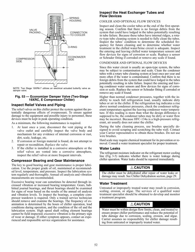
52
Fig. 53 — Economizer Damper Valve (Two-Stage 19XRC, E Compressor Chiller)
Inspect Relief Valves and PipingThe relief valves on this chiller protect the system against the po-tentially dangerous effects of overpressure. To ensure againstdamage to the equipment and possible injury to personnel, thesedevices must be kept in peak operating condition.As a minimum, the following maintenance is required.1. At least once a year, disconnect the vent piping at the
valve outlet and carefully inspect the valve body andmechanism for any evidence of internal corrosion or rust,dirt, scale, leakage, etc.
2. If corrosion or foreign material is found, do not attempt torepair or recondition. Replace the valve.
3. If the chiller is installed in a corrosive atmosphere or therelief valves are vented into a corrosive atmosphere,inspect the relief valves at more frequent intervals.
Compressor Bearing and Gear Maintenance The key to good bearing and gear maintenance is proper lubri-cation. Use the proper grade of oil, maintained at recommend-ed level, temperature, and pressure. Inspect the lubrication sys-tem regularly and thoroughly. Annual oil analysis and vibrationmeasurements are recommended.Excessive bearing wear can sometimes be detected through in-creased vibration or increased bearing temperature. Gears, bab-bitted journal bearings, and thrust bearings should be examinedfor signs of wear based on the results of the annual oil analysisand vibration levels. To inspect the bearings, a complete com-pressor teardown is required. Only a trained service technicianshould remove and examine the bearings. The frequency of ex-amination is determined by the hours of chiller operation, loadconditions during operation, and the condition of the oil and thelubrication system. High speed shaft rolling element bearingscannot be field inspected; excessive vibration is the primary signof wear or damage. If either symptom appears, contact an expe-rienced and responsible service organization for assistance.
Inspect the Heat Exchanger Tubes and Flow Devices
COOLER AND OPTIONAL FLOW DEVICES
Inspect and clean the cooler tubes at the end of the first operat-ing season. Confirm that there is no foreign debris from thesystem that could have lodged in the tubes potentially resultingin tube failure. Because these tubes have internal ridges, a rota-ry-type tube cleaning system is needed to fully clean the tubes.Inspect the tubes’ condition to determine the scheduled fre-quency for future cleaning and to determine whether watertreatment in the chilled water/brine circuit is adequate. Inspectthe entering and leaving chilled water temperature sensors andflow devices for signs of corrosion or scale. Replace a sensoror Schrader fitting if corroded or remove any scale if found.
CONDENSER AND OPTIONAL FLOW DEVICES
Since this water circuit is usually an open-type system, the tubesmay be subject to contamination and scale. Clean the condensertubes with a rotary tube cleaning system at least once per year andmore often if the water is contaminated. Confirm that there is noforeign debris from the system that could have lodged in the tubespotentially resulting in tube failure. Inspect the entering and leav-ing condenser water sensors and flow devices for signs of corro-sion or scale. Replace the sensor or Schrader fitting if corroded orremove any scale if found.Higher than normal condenser pressures, together with the in-ability to reach full refrigeration load, usually indicate dirtytubes or air in the chiller. If the refrigeration log indicates a riseabove normal condenser pressures, check the condenser refrig-erant temperature against the leaving condenser water tempera-ture. If this reading is more than what the design difference issupposed to be, the condenser tubes may be dirty or water flowmay be incorrect. Because HFC-134a is a high-pressure refrig-erant, air usually does not enter the chiller.During the tube cleaning process, use brushes specially de-signed to avoid scraping and scratching the tube wall. Contactyour Carrier representative to obtain these brushes. Do not usewire brushes.Hard scale may require chemical treatment for its prevention or re-moval. Consult a water treatment specialist for proper treatment.
Water LeaksThe refrigerant moisture indicator on the refrigerant motor coolingline (Fig. 3-5) indicates whether there is water leakage duringchiller operation. Water leaks should be repaired immediately.
Water TreatmentUntreated or improperly treated water may result in corrosion,scaling, erosion, or algae. The services of a qualified watertreatment specialist should be obtained to develop and monitora treatment program.
SPRINGHOUSING
CONNECTIONTO COOLER
O-RING
ECONOMIZERSIDECOMPRESSOR
SIDE
VALVEPACKING
NOTE: Two Stage 19XR6-7 utilizes an electrical actuated butterfly valve asdamper valve.
CAUTIONThe chiller must be dehydrated after repair of water leaks ordamage may result. See Chiller Dehydration section, page 29.
CAUTIONWater must be within design flow limits, clean, and treated toensure proper chiller performance and reduce the potential oftube damage due to corrosion, scaling, erosion, and algae.Carrier assumes no responsibility for chiller damage result-ing from untreated or improperly treated water.
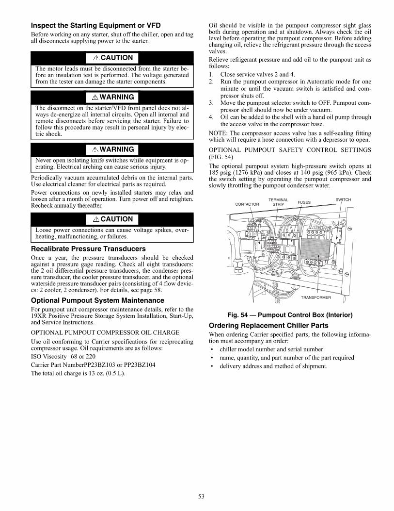
53
Inspect the Starting Equipment or VFDBefore working on any starter, shut off the chiller, open and tagall disconnects supplying power to the starter.
Periodically vacuum accumulated debris on the internal parts.Use electrical cleaner for electrical parts as required.Power connections on newly installed starters may relax andloosen after a month of operation. Turn power off and retighten.Recheck annually thereafter.
Recalibrate Pressure Transducers Once a year, the pressure transducers should be checkedagainst a pressure gage reading. Check all eight transducers:the 2 oil differential pressure transducers, the condenser pres-sure transducer, the cooler pressure transducer, and the optionalwaterside pressure transducer pairs (consisting of 4 flow devic-es: 2 cooler, 2 condenser). For details, see page 58.
Optional Pumpout System MaintenanceFor pumpout unit compressor maintenance details, refer to the19XR Positive Pressure Storage System Installation, Start-Up,and Service Instructions.
OPTIONAL PUMPOUT COMPRESSOR OIL CHARGE
Use oil conforming to Carrier specifications for reciprocatingcompressor usage. Oil requirements are as follows:ISO Viscosity 68 or 220Carrier Part NumberPP23BZ103 or PP23BZ104The total oil charge is 13 oz. (0.5 L).
Oil should be visible in the pumpout compressor sight glassboth during operation and at shutdown. Always check the oillevel before operating the pumpout compressor. Before addingchanging oil, relieve the refrigerant pressure through the accessvalves.Relieve refrigerant pressure and add oil to the pumpout unit asfollows:1. Close service valves 2 and 4.2. Run the pumpout compressor in Automatic mode for one
minute or until the vacuum switch is satisfied and com-pressor shuts off.
3. Move the pumpout selector switch to OFF. Pumpout com-pressor shell should now be under vacuum.
4. Oil can be added to the shell with a hand oil pump throughthe access valve in the compressor base.
NOTE: The compressor access valve has a self-sealing fittingwhich will require a hose connection with a depressor to open.
OPTIONAL PUMPOUT SAFETY CONTROL SETTINGS(FIG. 54)
The optional pumpout system high-pressure switch opens at185 psig (1276 kPa) and closes at 140 psig (965 kPa). Checkthe switch setting by operating the pumpout compressor andslowly throttling the pumpout condenser water.
Fig. 54 — Pumpout Control Box (Interior)
Ordering Replacement Chiller PartsWhen ordering Carrier specified parts, the following informa-tion must accompany an order:• chiller model number and serial number• name, quantity, and part number of the part required• delivery address and method of shipment.
CAUTION
The motor leads must be disconnected from the starter be-fore an insulation test is performed. The voltage generatedfrom the tester can damage the starter components.
WARNINGThe disconnect on the starter/VFD front panel does not al-ways de-energize all internal circuits. Open all internal andremote disconnects before servicing the starter. Failure tofollow this procedure may result in personal injury by elec-tric shock.
WARNINGNever open isolating knife switches while equipment is op-erating. Electrical arching can cause serious injury.
CAUTIONLoose power connections can cause voltage spikes, over-heating, malfunctioning, or failures.
a19-1569
CONTACTORTERMINAL
STRIP FUSES
TRANSFORMER
SWITCH
54
TROUBLESHOOTING GUIDE
OverviewThe PIC 6 control system has many features to help the opera-tor and technician troubleshoot a 19XR chiller.• The HMI shows the chiller’s actual operating conditions
and can be viewed while the unit is running.• The HMI default screen indicates when an alarm occurs.
Once all alarms have been cleared (by correcting the prob-lems), the HMI default screen indicates normal operation.For information about displaying and resetting alarms anda list of alert codes, see the 19XR with PIC 6 Controls Op-eration and Troubleshooting manual.
• The Configuration menu screens display information thathelps to diagnose problems with chilled water temperaturecontrol, chilled water temperature control overrides, hot gasbypass, surge algorithm status, and time schedule operation.
• The quick test feature facilitates the proper operation andtest of temperature sensors, pressure transducers, the guidevane actuator, diffuser actuator (if equipped), oil pump,water pumps, tower control, and other on/off outputs whilethe compressor is stopped. It also has the ability to lock offthe compressor and turn on water pumps for pumpout op-eration. The HMI shows the temperatures and pressures re-quired during these operations.
• If an operating fault is detected, an alarm indicator is dis-played on the HMI default screen. A more detailed mes-sage — along with a diagnostic message — is also storedin the Current Alarms table.
• Review the Alarms History table to view other less criticalevents which may have occurred. Compare timing of rele-vant events and alarms.
For detailed information about alarms, see the 19XR with PIC6 Controls Operation and Troubleshooting manual. Press thebell icon in the top right corner of the home screen to accesscurrent alarms and alarm history, and to reset alarms.
Checking Display MessagesThe first area to check when troubleshooting the 19XR is theHMI display. Status messages are displayed at the bottom ofthe screen, and the alarm icon indicates a fault. For a completelist of alarms, see the 19XR with PIC 6 Controls Operation andTroubleshooting manual.
Checking Temperature SensorsAll temperature sensors are thermistor-type sensors. Thismeans that the resistance of the sensor varies with temperature.All sensors have the same resistance characteristics. If the con-trols are on, determine sensor temperature by measuring volt-age drop; if the controls are powered off, determine sensortemperature by measuring resistance. Compare the readings tothe values listed in Tables 13 and 14. The water temperaturesensors can be calibrated to a value of 2.0°F (1.2°C).
RESISTANCE CHECK
Turn off the control power and, from the module, disconnect theterminal plug of the sensor in question. With a digital ohmmeter,measure sensor resistance between receptacles as designated bythe wiring diagram. The resistance and corresponding tempera-ture are listed in Tables 13 and 14. Check the resistance of bothwires to ground. This resistance should be infinite.
VOLTAGE DROP
The voltage drop across any energized sensor can be measuredwith a digital voltmeter while the control is energized. Tables13 and 14 list the relationship between temperature and sensorvoltage drop (volts dc measured across the energized sensor).Exercise care when measuring voltage to prevent damage tothe sensor leads, connector plugs, and modules. Sensors shouldalso be checked at the sensor plugs.
CAUTIONRelieve all refrigerant pressure or drain the water before re-moving any thermowell threaded into the refrigerant pres-sure boundary. Failure to do so could result in personal in-jury and equipment damage.
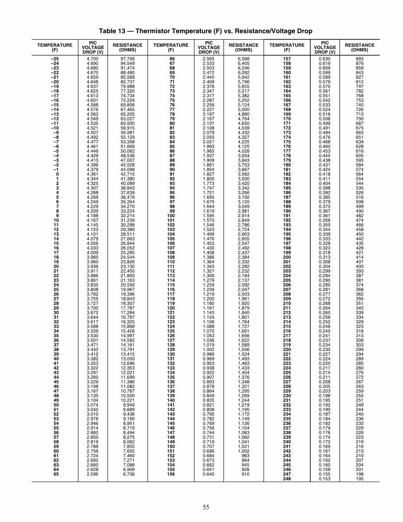
55
Table 13 — Thermistor Temperature (F) vs. Resistance/Voltage Drop
TEMPERATURE(F)
PICVOLTAGEDROP (V)
RESISTANCE(OHMS)
TEMPERATURE(F)
PICVOLTAGEDROP (V)
RESISTANCE(OHMS)
TEMPERATURE(F)
PICVOLTAGEDROP (V)
RESISTANCE(OHMS)
–25 4.700 97,706 66 2.565 6,568 157 0.630 893–24 4.690 94,549 67 2.533 6,405 158 0.619 876–23 4.680 91,474 68 2.503 6,246 159 0.609 859–22 4.670 88,480 69 2.472 6,092 160 0.599 843–21 4.659 85,568 70 2.440 5,942 161 0.589 827–20 4.648 82,737 71 2.409 5,796 162 0.579 812–19 4.637 79,988 72 2.378 5,655 163 0.570 797–18 4.625 77,320 73 2.347 5,517 164 0.561 782–17 4.613 74,734 74 2.317 5,382 165 0.551 768–16 4.601 72,229 75 2.287 5,252 166 0.542 753–15 4.588 69,806 76 2.256 5,124 167 0.533 740–14 4.576 67,465 77 2.227 5,000 168 0.524 726–13 4.562 65,205 78 2.197 4,880 169 0.516 713–12 4.549 63,027 79 2.167 4,764 170 0.508 700–11 4.535 60,930 80 2.137 4,650 171 0.499 687–10 4.521 58,915 81 2.108 4,539 172 0.491 675
–9 4.507 56,981 82 2.079 4,432 173 0.484 663–8 4.492 55,129 83 2.050 4,327 174 0.476 651–7 4.477 53,358 84 2.021 4,225 175 0.468 639–6 4.461 51,669 85 1.993 4,125 176 0.460 628–5 4.446 50,062 86 1.965 4,028 177 0.453 616–4 4.429 48,536 87 1.937 3,934 178 0.445 605–3 4.413 47,007 88 1.909 3,843 179 0.438 595–2 4.396 45,528 89 1.881 3,753 180 0.431 584–1 4.379 44,098 90 1.854 3,667 181 0.424 574
0 4.361 42,715 91 1.827 3,582 182 0.418 5641 4.344 41,380 92 1.800 3,500 183 0.411 5542 4.325 40,089 93 1.773 3,420 184 0.404 5443 4.307 38,843 94 1.747 3,342 185 0.398 5354 4.288 37,639 95 1.721 3,266 186 0.392 5265 4.269 36,476 96 1.695 3,192 187 0.385 5166 4.249 35,354 97 1.670 3,120 188 0.379 5087 4.229 34,270 98 1.644 3,049 189 0.373 4998 4.209 33,224 99 1.619 2,981 190 0.367 4909 4.188 32,214 100 1.595 2,914 191 0.361 482
10 4.167 31,239 101 1.570 2,849 192 0.356 47411 4.145 30,298 102 1.546 2,786 193 0.350 46612 4.123 29,389 103 1.523 2,724 194 0.344 45813 4.101 28,511 104 1.499 2,663 195 0.339 45014 4.079 27,663 105 1.476 2,605 196 0.333 44215 4.056 26,844 106 1.453 2,547 197 0.328 43516 4.033 26,052 107 1.430 2,492 198 0.323 42817 4.009 25,285 108 1.408 2,437 199 0.318 42118 3.985 24,544 109 1.386 2,384 200 0.313 41419 3.960 23,826 110 1.364 2,332 201 0.308 40720 3.936 23,130 111 1.343 2,282 202 0.304 40021 3.911 22,455 112 1.321 2,232 203 0.299 39322 3.886 21,800 113 1.300 2,184 204 0.294 38723 3.861 21,163 114 1.279 2,137 205 0.290 38124 3.835 20,556 115 1.259 2,092 206 0.285 37425 3.808 19,967 116 1.239 2,047 207 0.281 36826 3.782 19,396 117 1.219 2,003 208 0.277 36227 3.755 18,843 118 1.200 1,961 209 0.272 35628 3.727 18,307 119 1.180 1,920 210 0.268 35129 3.700 17,787 120 1.161 1,879 211 0.264 34530 3.672 17,284 121 1.143 1,840 212 0.260 33931 3.644 16,797 122 1.124 1,801 213 0.256 33432 3.617 16,325 123 1.106 1,764 214 0.252 32933 3.588 15,868 124 1.088 1,727 215 0.248 32334 3.559 15,426 125 1.070 1,691 216 0.245 31835 3.530 14,997 126 1.053 1,656 217 0.241 31336 3.501 14,582 127 1.036 1,622 218 0.237 30837 3.471 14,181 128 1.019 1,589 219 0.234 30338 3.442 13,791 129 1.002 1,556 220 0.230 29939 3.412 13,415 130 0.986 1,524 221 0.227 29440 3.382 13,050 131 0.969 1,493 222 0.224 28941 3.353 12,696 132 0.953 1,463 223 0.220 28542 3.322 12,353 133 0.938 1,433 224 0.217 28043 3.291 12,021 134 0.922 1,404 225 0.214 27644 3.260 11,699 135 0.907 1,376 226 0.211 27245 3.229 11,386 136 0.893 1,348 227 0.208 26746 3.198 11,082 137 0.878 1,321 228 0.205 26347 3.167 10,787 138 0.864 1,295 229 0.203 25948 3.135 10,500 139 0.849 1,269 230 0.198 25549 3.104 10,221 140 0.835 1,244 231 0.195 25150 3.074 9,949 141 0.821 1,219 232 0.192 24851 3.042 9,689 142 0.808 1,195 233 0.190 24452 3.010 9,436 143 0.795 1,172 234 0.187 24053 2.978 9,190 144 0.782 1,149 235 0.184 23654 2.946 8,951 145 0.769 1,126 236 0.182 23355 2.914 8,719 146 0.756 1,104 237 0.179 22956 2.882 8,494 147 0.744 1,083 238 0.176 22657 2.850 8,275 148 0.731 1,062 239 0.174 22358 2.819 8,062 149 0.719 1,041 240 0.172 21959 2.788 7,855 150 0.707 1,021 241 0.169 21660 2.756 7,655 151 0.696 1,002 242 0.167 21361 2.724 7,460 152 0.684 983 243 0.164 21062 2.692 7,271 153 0.673 964 244 0.162 20763 2.660 7,088 154 0.662 945 245 0.160 20464 2.628 6,909 155 0.651 928 246 0.158 20165 2.596 6,736 156 0.640 910 247 0.155 198
248 0.153 195
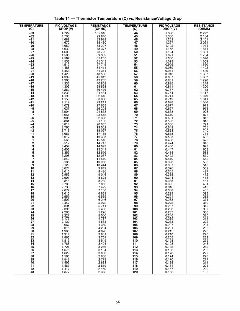
56
Table 14 — Thermistor Temperature (C) vs. Resistance/Voltage Drop
TEMPERATURE(C)
PIC VOLTAGEDROP (V)
RESISTANCE(OHMS)
TEMPERATURE(C)
PIC VOLTAGEDROP (V)
RESISTANCE(OHMS)
–33 4.722 105 616 44 1.338 2 272–32 4.706 99 640 45 1.300 2 184–31 4.688 93 928 46 1.263 2 101–30 4.670 88 480 47 1.227 2 021–29 4.650 83 297 48 1.192 1 944–28 4.630 78 377 49 1.158 1 871–27 4.608 73 722 50 1.124 1 801–26 4.586 69 332 51 1.091 1 734–25 4.562 65 205 52 1.060 1 670–24 4.538 61 343 53 1.029 1 609–23 4.512 57 745 54 0.999 1 550–22 4.486 54 411 55 0.969 1 493–21 4.458 51 341 56 0.941 1 439–20 4.429 48 536 57 0.913 1 387–19 4.399 45 819 58 0.887 1 337–18 4.368 43 263 59 0.861 1 290–17 4.336 40 858 60 0.835 1 244–16 4.303 38 598 61 0.811 1 200–15 4.269 36 476 62 0.787 1 158–14 4.233 34 484 63 0.764 1 117–13 4.196 32 613 64 0.741 1 079–12 4.158 30 858 65 0.719 1 041–11 4.119 29 211 66 0.698 1 006–10 4.079 27 663 67 0.677 971
–9 4.037 26 208 68 0.657 938–8 3.994 24 838 69 0.638 906–7 3.951 23 545 70 0.619 876–6 3.906 22 323 71 0.601 846–5 3.861 21 163 72 0.583 818–4 3.814 20 083 73 0.566 791–3 3.765 19 062 74 0.549 765–2 3.716 18 097 75 0.533 740–1 3.667 17 185 76 0.518 715
0 3.617 16 325 77 0.503 6921 3.565 15 513 78 0.488 6702 3.512 14 747 79 0.474 6483 3.459 14 023 80 0.460 6284 3.406 13 341 81 0.447 6085 3.353 12 696 82 0.434 5886 3.298 12 087 83 0.422 5707 3.242 11 510 84 0.410 5528 3.185 10 963 85 0.398 5359 3.129 10 444 86 0.387 518
10 3.074 9 949 87 0.376 50211 3.016 9 486 88 0.365 48712 2.959 9 046 89 0.355 47213 2.901 8 628 90 0.344 45814 2.844 8 232 91 0.335 44415 2.788 7 855 92 0.325 43116 2.730 7 499 93 0.316 41817 2.672 7 160 94 0.308 40518 2.615 6 839 95 0.299 39319 2.559 6 535 96 0.291 38220 2.503 6 246 97 0.283 37121 2.447 5 972 98 0.275 36022 2.391 5 711 99 0.267 34923 2.335 5 463 100 0.260 33924 2.280 5 226 101 0.253 33025 2.227 5 000 102 0.246 32026 2.173 4 787 103 0.239 31127 2.120 4 583 104 0.233 30228 2.067 4 389 105 0.227 29429 2.015 4 204 106 0.221 28630 1.965 4 028 107 0.215 27831 1.914 3 861 108 0.210 27032 1.865 3 701 109 0.205 26233 1.816 3 549 110 0.198 25534 1.768 3 404 111 0.193 24835 1.721 3 266 112 0.188 24236 1.675 3 134 113 0.183 23537 1.629 3 008 114 0.178 22938 1.585 2 888 115 0.174 22339 1.542 2 773 116 0.170 21740 1.499 2 663 117 0.165 21141 1.457 2 559 118 0.161 20542 1.417 2 459 119 0.157 20043 1.377 2 363 120 0.153 195
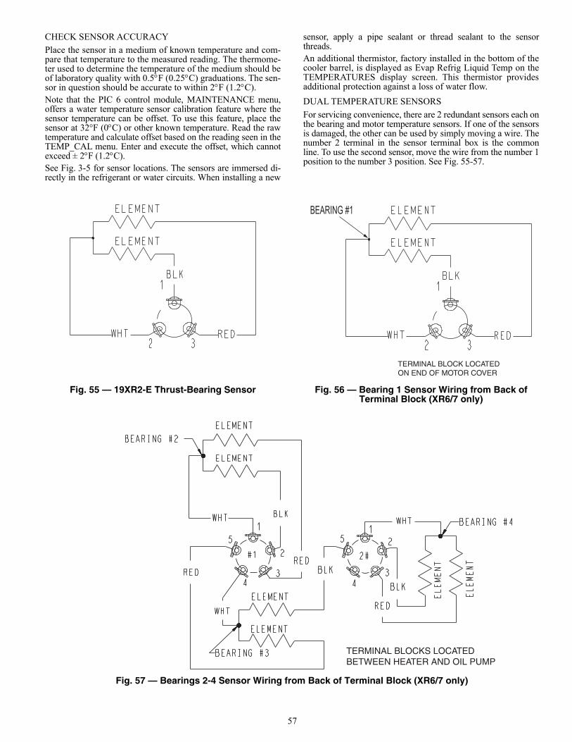
57
CHECK SENSOR ACCURACY
Place the sensor in a medium of known temperature and com-pare that temperature to the measured reading. The thermome-ter used to determine the temperature of the medium should beof laboratory quality with 0.5F (0.25C) graduations. The sen-sor in question should be accurate to within 2F (1.2C).Note that the PIC 6 control module, MAINTENANCE menu,offers a water temperature sensor calibration feature where thesensor temperature can be offset. To use this feature, place thesensor at 32°F (0C) or other known temperature. Read the rawtemperature and calculate offset based on the reading seen in theTEMP_CAL menu. Enter and execute the offset, which cannotexceed ± 2F (1.2C).See Fig. 3-5 for sensor locations. The sensors are immersed di-rectly in the refrigerant or water circuits. When installing a new
sensor, apply a pipe sealant or thread sealant to the sensorthreads.An additional thermistor, factory installed in the bottom of thecooler barrel, is displayed as Evap Refrig Liquid Temp on theTEMPERATURES display screen. This thermistor providesadditional protection against a loss of water flow.
DUAL TEMPERATURE SENSORS
For servicing convenience, there are 2 redundant sensors each onthe bearing and motor temperature sensors. If one of the sensorsis damaged, the other can be used by simply moving a wire. Thenumber 2 terminal in the sensor terminal box is the commonline. To use the second sensor, move the wire from the number 1position to the number 3 position. See Fig. 55-57.
Fig. 55 — 19XR2-E Thrust-Bearing Sensor Fig. 56 — Bearing 1 Sensor Wiring from Back of Terminal Block (XR6/7 only)
Fig. 57 — Bearings 2-4 Sensor Wiring from Back of Terminal Block (XR6/7 only)
BEARING #1
TERMINAL BLOCK LOCATEDON END OF MOTOR COVER
TERMINAL BLOCKS LOCATEDBETWEEN HEATER AND OIL PUMP
a19-2125
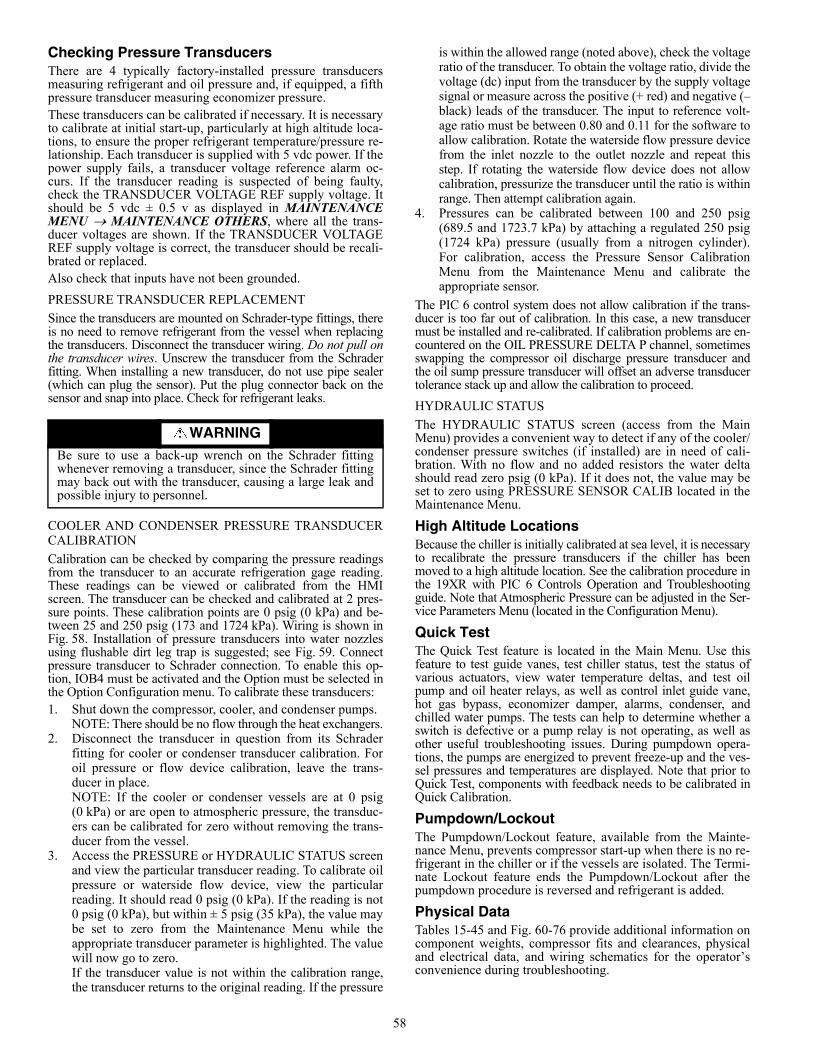
58
Checking Pressure TransducersThere are 4 typically factory-installed pressure transducersmeasuring refrigerant and oil pressure and, if equipped, a fifthpressure transducer measuring economizer pressure.These transducers can be calibrated if necessary. It is necessaryto calibrate at initial start-up, particularly at high altitude loca-tions, to ensure the proper refrigerant temperature/pressure re-lationship. Each transducer is supplied with 5 vdc power. If thepower supply fails, a transducer voltage reference alarm oc-curs. If the transducer reading is suspected of being faulty,check the TRANSDUCER VOLTAGE REF supply voltage. Itshould be 5 vdc ± 0.5 v as displayed in MAINTENANCEMENU MAINTENANCE OTHERS, where all the trans-ducer voltages are shown. If the TRANSDUCER VOLTAGEREF supply voltage is correct, the transducer should be recali-brated or replaced.Also check that inputs have not been grounded.
PRESSURE TRANSDUCER REPLACEMENT
Since the transducers are mounted on Schrader-type fittings, thereis no need to remove refrigerant from the vessel when replacingthe transducers. Disconnect the transducer wiring. Do not pull onthe transducer wires. Unscrew the transducer from the Schraderfitting. When installing a new transducer, do not use pipe sealer(which can plug the sensor). Put the plug connector back on thesensor and snap into place. Check for refrigerant leaks.
COOLER AND CONDENSER PRESSURE TRANSDUCERCALIBRATION
Calibration can be checked by comparing the pressure readingsfrom the transducer to an accurate refrigeration gage reading.These readings can be viewed or calibrated from the HMIscreen. The transducer can be checked and calibrated at 2 pres-sure points. These calibration points are 0 psig (0 kPa) and be-tween 25 and 250 psig (173 and 1724 kPa). Wiring is shown inFig. 58. Installation of pressure transducers into water nozzlesusing flushable dirt leg trap is suggested; see Fig. 59. Connectpressure transducer to Schrader connection. To enable this op-tion, IOB4 must be activated and the Option must be selected inthe Option Configuration menu. To calibrate these transducers:1. Shut down the compressor, cooler, and condenser pumps.
NOTE: There should be no flow through the heat exchangers.2. Disconnect the transducer in question from its Schrader
fitting for cooler or condenser transducer calibration. Foroil pressure or flow device calibration, leave the trans-ducer in place.NOTE: If the cooler or condenser vessels are at 0 psig(0 kPa) or are open to atmospheric pressure, the transduc-ers can be calibrated for zero without removing the trans-ducer from the vessel.
3. Access the PRESSURE or HYDRAULIC STATUS screenand view the particular transducer reading. To calibrate oilpressure or waterside flow device, view the particularreading. It should read 0 psig (0 kPa). If the reading is not0 psig (0 kPa), but within ± 5 psig (35 kPa), the value maybe set to zero from the Maintenance Menu while theappropriate transducer parameter is highlighted. The valuewill now go to zero. If the transducer value is not within the calibration range,the transducer returns to the original reading. If the pressure
is within the allowed range (noted above), check the voltageratio of the transducer. To obtain the voltage ratio, divide thevoltage (dc) input from the transducer by the supply voltagesignal or measure across the positive (+ red) and negative (–black) leads of the transducer. The input to reference volt-age ratio must be between 0.80 and 0.11 for the software toallow calibration. Rotate the waterside flow pressure devicefrom the inlet nozzle to the outlet nozzle and repeat thisstep. If rotating the waterside flow device does not allowcalibration, pressurize the transducer until the ratio is withinrange. Then attempt calibration again.
4. Pressures can be calibrated between 100 and 250 psig(689.5 and 1723.7 kPa) by attaching a regulated 250 psig(1724 kPa) pressure (usually from a nitrogen cylinder).For calibration, access the Pressure Sensor CalibrationMenu from the Maintenance Menu and calibrate theappropriate sensor.
The PIC 6 control system does not allow calibration if the trans-ducer is too far out of calibration. In this case, a new transducermust be installed and re-calibrated. If calibration problems are en-countered on the OIL PRESSURE DELTA P channel, sometimesswapping the compressor oil discharge pressure transducer andthe oil sump pressure transducer will offset an adverse transducertolerance stack up and allow the calibration to proceed.
HYDRAULIC STATUS
The HYDRAULIC STATUS screen (access from the MainMenu) provides a convenient way to detect if any of the cooler/condenser pressure switches (if installed) are in need of cali-bration. With no flow and no added resistors the water deltashould read zero psig (0 kPa). If it does not, the value may beset to zero using PRESSURE SENSOR CALIB located in theMaintenance Menu.
High Altitude LocationsBecause the chiller is initially calibrated at sea level, it is necessaryto recalibrate the pressure transducers if the chiller has beenmoved to a high altitude location. See the calibration procedure inthe 19XR with PIC 6 Controls Operation and Troubleshootingguide. Note that Atmospheric Pressure can be adjusted in the Ser-vice Parameters Menu (located in the Configuration Menu).
Quick TestThe Quick Test feature is located in the Main Menu. Use thisfeature to test guide vanes, test chiller status, test the status ofvarious actuators, view water temperature deltas, and test oilpump and oil heater relays, as well as control inlet guide vane,hot gas bypass, economizer damper, alarms, condenser, andchilled water pumps. The tests can help to determine whether aswitch is defective or a pump relay is not operating, as well asother useful troubleshooting issues. During pumpdown opera-tions, the pumps are energized to prevent freeze-up and the ves-sel pressures and temperatures are displayed. Note that prior toQuick Test, components with feedback needs to be calibrated inQuick Calibration.
Pumpdown/LockoutThe Pumpdown/Lockout feature, available from the Mainte-nance Menu, prevents compressor start-up when there is no re-frigerant in the chiller or if the vessels are isolated. The Termi-nate Lockout feature ends the Pumpdown/Lockout after thepumpdown procedure is reversed and refrigerant is added.
Physical DataTables 15-45 and Fig. 60-76 provide additional information oncomponent weights, compressor fits and clearances, physicaland electrical data, and wiring schematics for the operator’sconvenience during troubleshooting.
WARNINGBe sure to use a back-up wrench on the Schrader fittingwhenever removing a transducer, since the Schrader fittingmay back out with the transducer, causing a large leak andpossible injury to personnel.
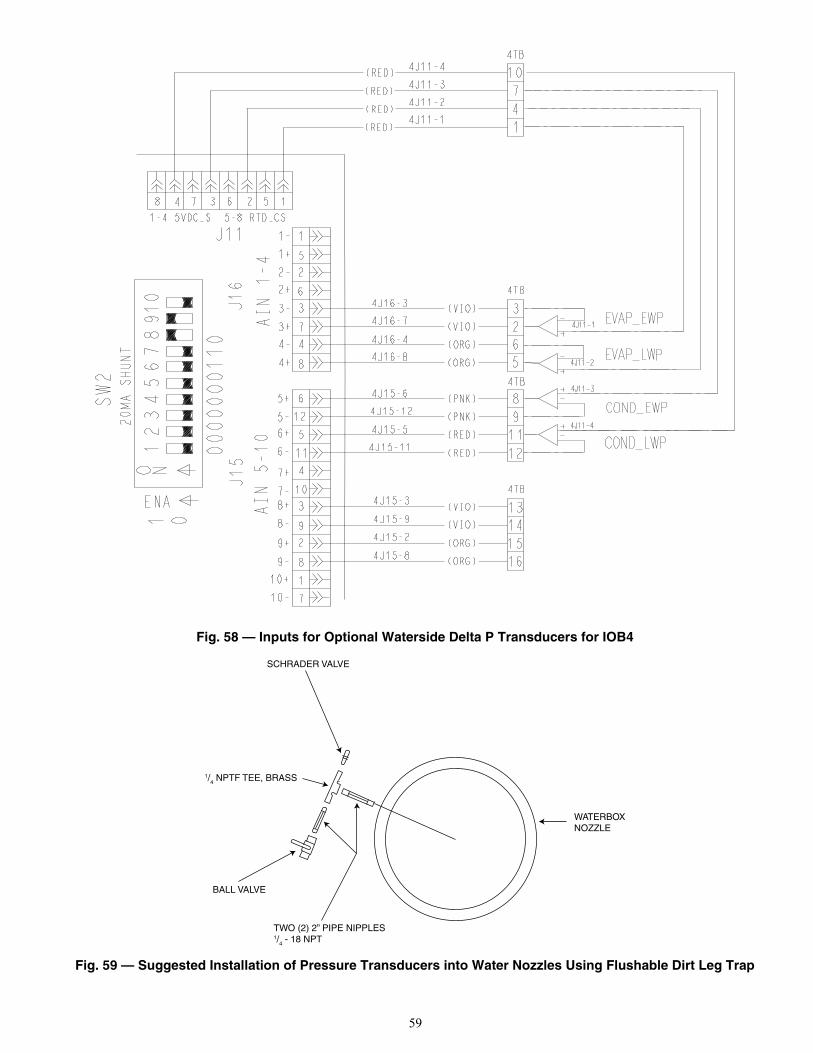
59
Fig. 58 — Inputs for Optional Waterside Delta P Transducers for IOB4
Fig. 59 — Suggested Installation of Pressure Transducers into Water Nozzles Using Flushable Dirt Leg Trap
SCHRADER VALVE
1/4 NPTF TEE, BRASS
BALL VALVE
TWO (2) 2” PIPE NIPPLES1/4 - 18 NPT
WATERBOXNOZZLE
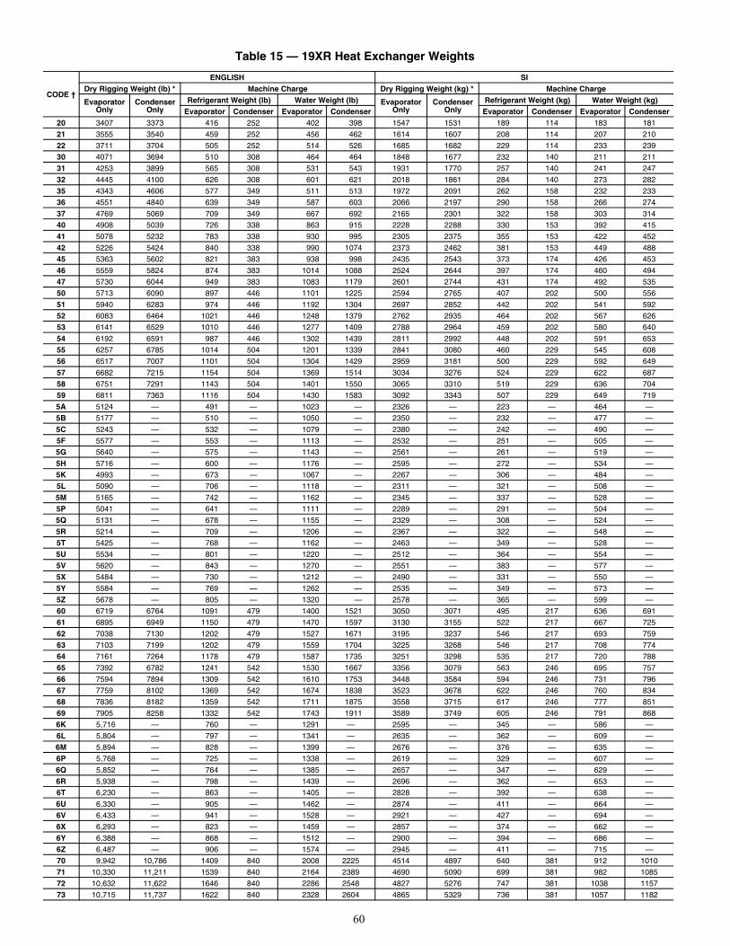
60
Table 15 — 19XR Heat Exchanger Weights
CODE †
ENGLISH SIDry Rigging Weight (lb) * Machine Charge Dry Rigging Weight (kg) * Machine Charge
EvaporatorOnly
CondenserOnly
Refrigerant Weight (lb) Water Weight (lb) EvaporatorOnly
CondenserOnly
Refrigerant Weight (kg) Water Weight (kg)Evaporator Condenser Evaporator Condenser Evaporator Condenser Evaporator Condenser
20 3407 3373 416 252 402 398 1547 1531 189 114 183 181
21 3555 3540 459 252 456 462 1614 1607 208 114 207 210
22 3711 3704 505 252 514 526 1685 1682 229 114 233 239
30 4071 3694 510 308 464 464 1848 1677 232 140 211 211
31 4253 3899 565 308 531 543 1931 1770 257 140 241 247
32 4445 4100 626 308 601 621 2018 1861 284 140 273 282
35 4343 4606 577 349 511 513 1972 2091 262 158 232 233
36 4551 4840 639 349 587 603 2066 2197 290 158 266 274
37 4769 5069 709 349 667 692 2165 2301 322 158 303 314
40 4908 5039 726 338 863 915 2228 2288 330 153 392 415
41 5078 5232 783 338 930 995 2305 2375 355 153 422 452
42 5226 5424 840 338 990 1074 2373 2462 381 153 449 488
45 5363 5602 821 383 938 998 2435 2543 373 174 426 453
46 5559 5824 874 383 1014 1088 2524 2644 397 174 460 494
47 5730 6044 949 383 1083 1179 2601 2744 431 174 492 535
50 5713 6090 897 446 1101 1225 2594 2765 407 202 500 556
51 5940 6283 974 446 1192 1304 2697 2852 442 202 541 592
52 6083 6464 1021 446 1248 1379 2762 2935 464 202 567 626
53 6141 6529 1010 446 1277 1409 2788 2964 459 202 580 640
54 6192 6591 987 446 1302 1439 2811 2992 448 202 591 653
55 6257 6785 1014 504 1201 1339 2841 3080 460 229 545 608
56 6517 7007 1101 504 1304 1429 2959 3181 500 229 592 649
57 6682 7215 1154 504 1369 1514 3034 3276 524 229 622 687
58 6751 7291 1143 504 1401 1550 3065 3310 519 229 636 704
59 6811 7363 1116 504 1430 1583 3092 3343 507 229 649 719
5A 5124 — 491 — 1023 — 2326 — 223 — 464 —
5B 5177 — 510 — 1050 — 2350 — 232 — 477 —
5C 5243 — 532 — 1079 — 2380 — 242 — 490 —
5F 5577 — 553 — 1113 — 2532 — 251 — 505 —
5G 5640 — 575 — 1143 — 2561 — 261 — 519 —
5H 5716 — 600 — 1176 — 2595 — 272 — 534 —
5K 4993 — 673 — 1067 — 2267 — 306 — 484 —
5L 5090 — 706 — 1118 — 2311 — 321 — 508 —
5M 5165 — 742 — 1162 — 2345 — 337 — 528 —
5P 5041 — 641 — 1111 — 2289 — 291 — 504 —
5Q 5131 — 678 — 1155 — 2329 — 308 — 524 —
5R 5214 — 709 — 1206 — 2367 — 322 — 548 —
5T 5425 — 768 — 1162 — 2463 — 349 — 528 —
5U 5534 — 801 — 1220 — 2512 — 364 — 554 —
5V 5620 — 843 — 1270 — 2551 — 383 — 577 —
5X 5484 — 730 — 1212 — 2490 — 331 — 550 —
5Y 5584 — 769 — 1262 — 2535 — 349 — 573 —
5Z 5678 — 805 — 1320 — 2578 — 365 — 599 —
60 6719 6764 1091 479 1400 1521 3050 3071 495 217 636 691
61 6895 6949 1150 479 1470 1597 3130 3155 522 217 667 725
62 7038 7130 1202 479 1527 1671 3195 3237 546 217 693 759
63 7103 7199 1202 479 1559 1704 3225 3268 546 217 708 774
64 7161 7264 1178 479 1587 1735 3251 3298 535 217 720 788
65 7392 6782 1241 542 1530 1667 3356 3079 563 246 695 757
66 7594 7894 1309 542 1610 1753 3448 3584 594 246 731 796
67 7759 8102 1369 542 1674 1838 3523 3678 622 246 760 834
68 7836 8182 1359 542 1711 1875 3558 3715 617 246 777 851
69 7905 8258 1332 542 1743 1911 3589 3749 605 246 791 868
6K 5,716 — 760 — 1291 — 2595 — 345 — 586 —
6L 5,804 — 797 — 1341 — 2635 — 362 — 609 —
6M 5,894 — 828 — 1399 — 2676 — 376 — 635 —
6P 5,768 — 725 — 1338 — 2619 — 329 — 607 —
6Q 5,852 — 764 — 1385 — 2657 — 347 — 629 —
6R 5,938 — 798 — 1439 — 2696 — 362 — 653 —
6T 6,230 — 863 — 1405 — 2828 — 392 — 638 —
6U 6,330 — 905 — 1462 — 2874 — 411 — 664 —
6V 6,433 — 941 — 1528 — 2921 — 427 — 694 —
6X 6,293 — 823 — 1459 — 2857 — 374 — 662 —
6Y 6,388 — 868 — 1512 — 2900 — 394 — 686 —
6Z 6,487 — 906 — 1574 — 2945 — 411 — 715 —
70 9,942 10,786 1409 840 2008 2225 4514 4897 640 381 912 1010
71 10,330 11,211 1539 840 2164 2389 4690 5090 699 381 982 1085
72 10,632 11,622 1646 840 2286 2548 4827 5276 747 381 1038 1157
73 10,715 11,737 1622 840 2328 2604 4865 5329 736 381 1057 1182
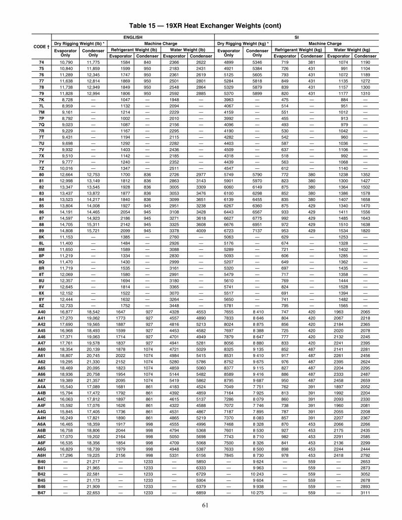
61
74 10,790 11,775 1584 840 2366 2622 4899 5346 719 381 1074 1190
75 10,840 11,859 1599 950 2183 2431 4921 5384 726 431 991 1104
76 11,289 12,345 1747 950 2361 2619 5125 5605 793 431 1072 1189
77 11,638 12,814 1869 950 2501 2801 5284 5818 849 431 1135 1272
78 11,738 12,949 1849 950 2548 2864 5329 5879 839 431 1157 1300
79 11,828 12,994 1806 950 2592 2885 5370 5899 820 431 1177 1310
7K 8,728 — 1047 — 1948 — 3963 — 475 — 884 —
7L 8,959 — 1132 — 2094 — 4067 — 514 — 951 —
7M 9,161 — 1214 — 2229 — 4159 — 551 — 1012 —
7P 8,792 — 1002 — 2010 — 3992 — 455 — 913 —
7Q 9,023 — 1087 — 2156 — 4096 — 493 — 979 —
7R 9,229 — 1167 — 2295 — 4190 — 530 — 1042 —
7T 9,431 — 1194 — 2115 — 4282 — 542 — 960 —
7U 9,698 — 1292 — 2282 — 4403 — 587 — 1036 —
7V 9,932 — 1403 — 2436 — 4509 — 637 — 1106 —
7X 9,510 — 1142 — 2185 — 4318 — 518 — 992 —
7Y 9,777 — 1240 — 2352 — 4439 — 563 — 1068 —
7Z 10,016 — 1347 — 2511 — 4547 — 612 — 1140 —
80 12,664 12,753 1700 836 2726 2977 5749 5790 772 380 1238 1352
81 12,998 13,149 1812 836 2863 3143 5901 5970 823 380 1300 1427
82 13,347 13,545 1928 836 3005 3309 6060 6149 875 380 1364 1502
83 13,437 13,872 1877 836 3053 3476 6100 6298 852 380 1386 1578
84 13,523 14,217 1840 836 3099 3651 6139 6455 835 380 1407 1658
85 13,804 14,008 1927 945 2951 3238 6267 6360 875 429 1340 1470
86 14,191 14,465 2054 945 3108 3428 6443 6567 933 429 1411 1556
87 14,597 14,923 2186 945 3271 3618 6627 6775 992 429 1485 1643
88 14,705 15,311 2142 945 3325 3608 6676 6951 972 429 1510 1638
89 14,808 15,721 2099 945 3378 4009 6723 7137 953 429 1534 1820
8K 11,153 — 1385 — 2760 — 5063 — 629 — 1253 —
8L 11,400 — 1484 — 2926 — 5176 — 674 — 1328 —
8M 11,650 — 1589 — 3088 — 5289 — 721 — 1402 —
8P 11,219 — 1334 — 2830 — 5093 — 606 — 1285 —
8Q 11,470 — 1430 — 2999 — 5207 — 649 — 1362 —
8R 11,719 — 1535 — 3161 — 5320 — 697 — 1435 —
8T 12,069 — 1580 — 2991 — 5479 — 717 — 1358 —
8U 12,357 — 1694 — 3180 — 5610 — 769 — 1444 —
8V 12,645 — 1814 — 3365 — 5741 — 824 — 1528 —
8X 12,152 — 1522 — 3070 — 5517 — 691 — 1394 —
8Y 12,444 — 1632 — 3264 — 5650 — 741 — 1482 —
8Z 12,733 — 1752 — 3448 — 5781 — 795 — 1565 —
A40 16,877 18,542 1647 927 4328 4553 7655 8 410 747 420 1963 2065
A41 17,270 19,062 1773 927 4557 4890 7833 8 646 804 420 2067 2218
A42 17,690 19,565 1887 927 4816 5213 8024 8 875 856 420 2184 2365
A45 16,968 18,493 1599 927 4453 4582 7697 8 388 725 420 2020 2078
A46 17,371 19,063 1714 927 4701 4949 7879 8 647 777 420 2132 2245
A47 17,761 19,578 1837 927 4941 5281 8056 8 880 833 420 2241 2395
A60 18,354 20,139 1878 1074 4721 5029 8325 9 135 852 487 2141 2281
A61 18,807 20,745 2022 1074 4984 5415 8531 9 410 917 487 2261 2456
A62 19,295 21,330 2152 1074 5280 5786 8752 9 675 976 487 2395 2624
A65 18,469 20,095 1823 1074 4859 5060 8377 9 115 827 487 2204 2295
A66 18,936 20,758 1954 1074 5144 5482 8589 9 416 886 487 2333 2487
A67 19,389 21,357 2095 1074 5419 5862 8795 9 687 950 487 2458 2659
A4A 15,540 17,089 1681 861 4183 4524 7049 7 751 762 391 1897 2052
A4B 15,794 17,472 1792 861 4392 4859 7164 7 925 813 391 1992 2204
A4C 16,063 17,812 1897 861 4615 5137 7286 8 079 860 391 2093 2330
A4F 15,592 17,076 1626 861 4322 4588 7072 7 746 738 391 1960 2081
A4G 15,845 17,405 1736 861 4531 4867 7187 7 895 787 391 2055 2208
A4H 16,249 17,821 1890 861 4865 5219 7370 8 083 857 391 2207 2367
A6A 16,465 18,359 1917 998 4555 4996 7468 8 328 870 453 2066 2266
A6B 16,758 18,806 2044 998 4794 5368 7601 8 530 927 453 2175 2435
A6C 17,070 19,202 2164 998 5050 5698 7743 8 710 982 453 2291 2585
A6F 16,535 18,356 1854 998 4709 5068 7500 8 326 841 453 2136 2299
A6G 16,829 18,739 1979 998 4948 5387 7633 8 500 898 453 2244 2444
A6H 17,296 19,225 2156 998 5331 6156 7845 8 730 978 453 2418 2792
B40 — 21,217 — 1233 — 5850 — 9 624 — 559 — 2653
B41 — 21,965 — 1233 — 6333 — 9 963 — 559 — 2873
B42 — 22,581 — 1233 — 6729 — 10 243 — 559 — 3052
B45 — 21,173 — 1233 — 5904 — 9 604 — 559 — 2678
B46 — 21,909 — 1233 — 6379 — 9 938 — 559 — 2893
B47 — 22,653 — 1233 — 6859 — 10 275 — 559 — 3111
Table 15 — 19XR Heat Exchanger Weights (cont)
CODE †
ENGLISH SIDry Rigging Weight (lb) * Machine Charge Dry Rigging Weight (kg) * Machine Charge
EvaporatorOnly
CondenserOnly
Refrigerant Weight (lb) Water Weight (lb) EvaporatorOnly
CondenserOnly
Refrigerant Weight (kg) Water Weight (kg)Evaporator Condenser Evaporator Condenser Evaporator Condenser Evaporator Condenser
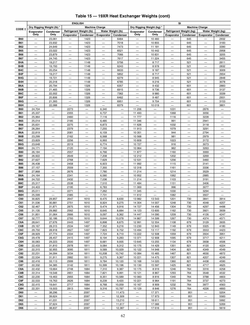
62
B60 — 23,061 — 1423 — 6464 — 10 460 — 645 — 2932
B61 — 23,932 — 1423 — 7018 — 10 855 — 645 — 3183
B62 — 24,649 — 1423 — 7473 — 11 181 — 645 — 3390
B65 — 23,022 — 1423 — 6521 — 10 442 — 645 — 2958
B66 — 23,879 — 1423 — 7066 — 10 831 — 645 — 3205
B67 — 24,745 — 1423 — 7617 — 11 224 — 645 — 3455
B4A — 19,217 — 1148 — 5756 — 8 717 — 521 — 2611
B4B — 19,793 — 1148 — 6243 — 8 978 — 521 — 2832
B4C — 20,254 — 1148 — 6633 — 9 187 — 521 — 3009
B4F — 19,217 — 1148 — 5852 — 8 717 — 521 — 2654
B4G — 19,721 — 1148 — 6279 — 8 945 — 521 — 2848
B4H — 20,318 — 1148 — 6785 — 9 216 — 521 — 3078
B6A — 20,794 — 1326 — 6357 — 9 432 — 601 — 2883
B6B — 21,465 — 1326 — 6915 — 9 736 — 601 — 3137
B6C — 22,002 — 1326 — 7362 — 9 980 — 601 — 3339
B6F — 20,806 — 1326 — 6462 — 9 487 — 601 — 2931
B6G — 21,393 — 1326 — 6951 — 9 704 — 601 — 3153
B6H — 22,088 — 1326 — 8379 — 10 019 — 601 — 3801
B60 24,704 — 2273 — 6,340 — 11 206 — 1031 — 2876 —
B61 25,337 — 2355 — 6,737 — 11 493 — 1068 — 3056 —
B62 25,964 — 2460 — 7,116 — 11 777 — 1116 — 3228 —
B65 25,014 — 2185 — 6,485 — 11 346 — 991 — 2941 —
B66 25,631 — 2275 — 6,873 — 11 626 — 1032 — 3118 —
B67 26,264 — 2379 — 7,255 — 11 913 — 1079 — 3291 —
B6A 22,819 — 2081 — 6,159 — 10 351 — 944 — 2794 —
B6B 23,299 — 2162 — 6,568 — 10 568 — 981 — 2979 —
B6C 23,829 — 2256 — 6,993 — 10 809 — 1023 — 3172 —
B6G 23,648 — 2019 — 6,774 — 10 727 — 916 — 3073 —
B6H 24,171 — 2120 — 7,194 — 10 964 — 962 — 3263 —
B80 26,184 — 2557 — 6,766 — 11 877 — 1160 — 3069 —
B81 26,922 — 2649 — 7,208 — 12 212 — 1202 — 3269 —
B82 27,627 — 2768 — 7,629 — 12 531 — 1256 — 3460 —
B85 26,438 — 2458 — 6,923 — 11 992 — 1115 — 3141 —
B86 27,157 — 2559 — 7,355 — 12 318 — 1161 — 3336 —
B87 27,868 — 2676 — 7,780 — 11 214 — 1214 — 3529 —
B8A 24,164 — 2341 — 6,580 — 10 952 — 1062 — 2885 —
B8B 24,722 — 2432 — 7,036 — 11 214 — 1103 — 3191 —
B8C 25,317 — 2538 — 7,510 — 11 484 — 1151 — 3406 —
B8F 24,403 — 2195 — 6,783 — 11 069 — 996 — 3077 —
B8G 25,011 — 2271 — 7,262 — 11 345 — 1030 — 3294 —
B8H 25,599 — 2385 — 7,731 — 11 612 — 1082 — 3507 —
C60 30,825 29,857 2647 1610 8,475 8,630 13 982 13 543 1201 730 3841 3914
C61 31,536 30,881 2751 1610 8,924 9,275 14 304 14 007 1248 730 4048 4207
C62 32,467 31,871 2875 1610 9,474 9,916 14 727 14 456 1304 730 4297 4498
C65 31,135 29,982 2562 1610 8,645 8,684 14 123 13 600 1162 730 3921 3939
C66 31,851 31,064 2666 1610 9,097 9,362 14 447 14 090 1209 730 4126 4247
C67 32,777 32,186 2793 1610 9,644 10,078 14 867 14 599 1267 730 4374 4571
C6A 28,641 27,676 2443 1497 6,898 8,675 12 991 12 554 1108 679 3129 3935
C6B 29,167 28,315 2534 1497 7,352 9,216 13 230 12 843 1149 679 3325 4180
C6C 29,750 28,918 2627 1497 7,823 9,752 13 494 13 117 1192 679 3553 4423
C6F 28,929 27,774 2334 1497 7,724 8,710 13 222 12 508 1059 679 3504 3951
C6G 29,478 28,457 2415 1497 8,194 9,283 13 371 12 908 1095 679 3717 4211
C6H 30,083 29,223 2500 1497 8,681 9,935 13 645 13 255 1134 679 3938 4506
C80 22,433 31,810 2978 1811 9,084 9,312 10 175 14 429 1351 821 4120 4224
C81 22,315 32,955 3095 1811 9,589 10,029 10 122 14 948 1404 821 4349 4549
C82 22,231 34,094 3234 1811 10,208 10,742 10 084 15 465 1467 821 4630 4872
C85 22,534 31,911 2882 1811 9,275 9,367 10 221 14 475 1307 821 4207 4249
C86 22,416 33,113 2999 1811 9,784 10,120 10 168 14 020 1360 821 4438 4590
C87 22,332 34,385 3142 1811 10,399 10,196 10 130 15 597 1425 821 4717 4625
C8A 22,432 19,664 2748 1684 7,310 9,387 10 175 8 919 1246 764 3316 4258
C8B 22,314 19,548 2851 1684 7,821 9,991 10 121 8 867 1293 764 3548 4532
C8C 22,230 19,463 2955 1684 8,351 10,589 10 083 8 816 1340 764 3788 4803
C8F 22,533 19,763 2626 1684 8,239 9,420 10 221 8 964 1191 764 3737 4273
C8G 22,415 19,641 2717 1684 8,768 10,059 10 167 8 909 1232 764 3977 4563
C8H 22,331 19,503 2813 1684 9,316 10,787 10 129 8 846 1276 764 4226 4893
D60 — 38,296 — 2097 — 11,473 — 17 371 — 951 — 5204
D61 — 39,624 — 2097 — 12,309 — 17 973 — 951 — 5583
D62 — 41,031 — 2097 — 13,210 — 18 611 — 951 — 5992
D65 — 37,624 — 2097 — 11,617 — 17 066 — 951 — 5269
D66 — 38,837 — 2097 — 12,387 — 17 616 — 951 — 5619
Table 15 — 19XR Heat Exchanger Weights (cont)
CODE †
ENGLISH SIDry Rigging Weight (lb) * Machine Charge Dry Rigging Weight (kg) * Machine Charge
EvaporatorOnly
CondenserOnly
Refrigerant Weight (lb) Water Weight (lb) EvaporatorOnly
CondenserOnly
Refrigerant Weight (kg) Water Weight (kg)Evaporator Condenser Evaporator Condenser Evaporator Condenser Evaporator Condenser
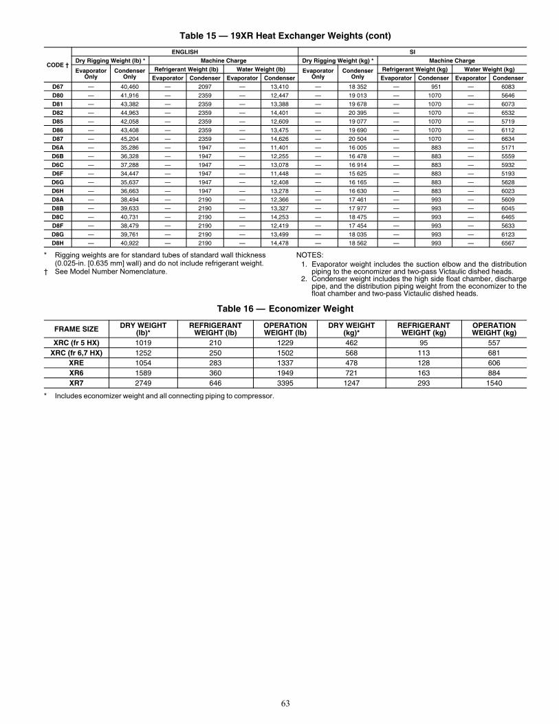
63
* Rigging weights are for standard tubes of standard wall thickness (0.025-in. [0.635 mm] wall) and do not include refrigerant weight.
† See Model Number Nomenclature.
NOTES:1. Evaporator weight includes the suction elbow and the distribution
piping to the economizer and two-pass Victaulic dished heads.2. Condenser weight includes the high side float chamber, discharge
pipe, and the distribution piping weight from the economizer to thefloat chamber and two-pass Victaulic dished heads.
* Includes economizer weight and all connecting piping to compressor.
D67 — 40,460 — 2097 — 13,410 — 18 352 — 951 — 6083
D80 — 41,916 — 2359 — 12,447 — 19 013 — 1070 — 5646
D81 — 43,382 — 2359 — 13,388 — 19 678 — 1070 — 6073
D82 — 44,963 — 2359 — 14,401 — 20 395 — 1070 — 6532
D85 — 42,058 — 2359 — 12,609 — 19 077 — 1070 — 5719
D86 — 43,408 — 2359 — 13,475 — 19 690 — 1070 — 6112
D87 — 45,204 — 2359 — 14,626 — 20 504 — 1070 — 6634
D6A — 35,286 — 1947 — 11,401 — 16 005 — 883 — 5171
D6B — 36,328 — 1947 — 12,255 — 16 478 — 883 — 5559
D6C — 37,288 — 1947 — 13,078 — 16 914 — 883 — 5932
D6F — 34,447 — 1947 — 11,448 — 15 625 — 883 — 5193
D6G — 35,637 — 1947 — 12,408 — 16 165 — 883 — 5628
D6H — 36,663 — 1947 — 13,278 — 16 630 — 883 — 6023
D8A — 38,494 — 2190 — 12,366 — 17 461 — 993 — 5609
D8B — 39,633 — 2190 — 13,327 — 17 977 — 993 — 6045
D8C — 40,731 — 2190 — 14,253 — 18 475 — 993 — 6465
D8F — 38,479 — 2190 — 12,419 — 17 454 — 993 — 5633
D8G — 39,761 — 2190 — 13,499 — 18 035 — 993 — 6123
D8H — 40,922 — 2190 — 14,478 — 18 562 — 993 — 6567
Table 15 — 19XR Heat Exchanger Weights (cont)
CODE †
ENGLISH SIDry Rigging Weight (lb) * Machine Charge Dry Rigging Weight (kg) * Machine Charge
EvaporatorOnly
CondenserOnly
Refrigerant Weight (lb) Water Weight (lb) EvaporatorOnly
CondenserOnly
Refrigerant Weight (kg) Water Weight (kg)Evaporator Condenser Evaporator Condenser Evaporator Condenser Evaporator Condenser
Table 16 — Economizer Weight
FRAME SIZE DRY WEIGHT(lb)*
REFRIGERANTWEIGHT (lb)
OPERATIONWEIGHT (lb)
DRY WEIGHT(kg)*
REFRIGERANTWEIGHT (kg)
OPERATIONWEIGHT (kg)
XRC (fr 5 HX) 1019 210 1229 462 95 557XRC (fr 6,7 HX) 1252 250 1502 568 113 681
XRE 1054 283 1337 478 128 606XR6 1589 360 1949 721 163 884XR7 2749 646 3395 1247 293 1540
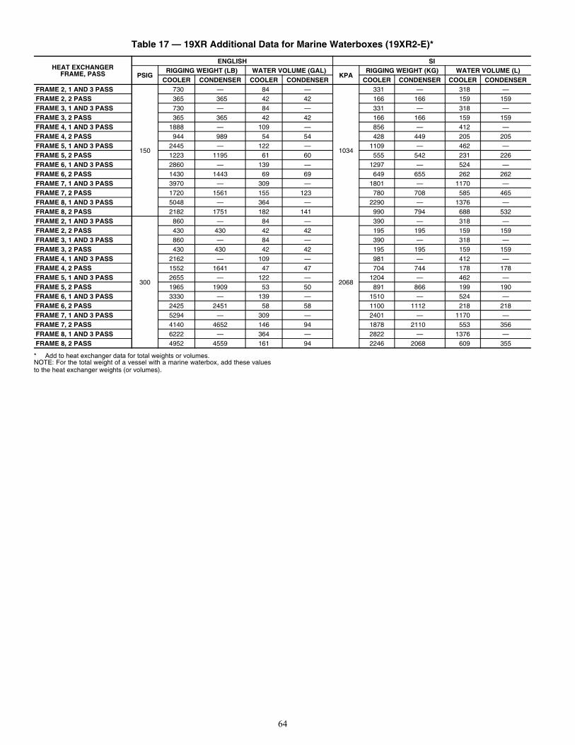
64
* Add to heat exchanger data for total weights or volumes.NOTE: For the total weight of a vessel with a marine waterbox, add these valuesto the heat exchanger weights (or volumes).
Table 17 — 19XR Additional Data for Marine Waterboxes (19XR2-E)*
HEAT EXCHANGER FRAME, PASS
ENGLISH SI
PSIGRIGGING WEIGHT (LB) WATER VOLUME (GAL)
KPARIGGING WEIGHT (KG) WATER VOLUME (L)
COOLER CONDENSER COOLER CONDENSER COOLER CONDENSER COOLER CONDENSERFRAME 2, 1 AND 3 PASS
150
730 — 84 —
1034
331 — 318 —FRAME 2, 2 PASS 365 365 42 42 166 166 159 159FRAME 3, 1 AND 3 PASS 730 — 84 — 331 — 318 —FRAME 3, 2 PASS 365 365 42 42 166 166 159 159FRAME 4, 1 AND 3 PASS 1888 — 109 — 856 — 412 —FRAME 4, 2 PASS 944 989 54 54 428 449 205 205FRAME 5, 1 AND 3 PASS 2445 — 122 — 1109 — 462 —FRAME 5, 2 PASS 1223 1195 61 60 555 542 231 226FRAME 6, 1 AND 3 PASS 2860 — 139 — 1297 — 524 —FRAME 6, 2 PASS 1430 1443 69 69 649 655 262 262FRAME 7, 1 AND 3 PASS 3970 — 309 — 1801 — 1170 —FRAME 7, 2 PASS 1720 1561 155 123 780 708 585 465FRAME 8, 1 AND 3 PASS 5048 — 364 — 2290 — 1376 —FRAME 8, 2 PASS 2182 1751 182 141 990 794 688 532FRAME 2, 1 AND 3 PASS
300
860 — 84 —
2068
390 — 318 —FRAME 2, 2 PASS 430 430 42 42 195 195 159 159FRAME 3, 1 AND 3 PASS 860 — 84 — 390 — 318 —FRAME 3, 2 PASS 430 430 42 42 195 195 159 159FRAME 4, 1 AND 3 PASS 2162 — 109 — 981 — 412 —FRAME 4, 2 PASS 1552 1641 47 47 704 744 178 178FRAME 5, 1 AND 3 PASS 2655 — 122 — 1204 — 462 —FRAME 5, 2 PASS 1965 1909 53 50 891 866 199 190FRAME 6, 1 AND 3 PASS 3330 — 139 — 1510 — 524 —FRAME 6, 2 PASS 2425 2451 58 58 1100 1112 218 218FRAME 7, 1 AND 3 PASS 5294 — 309 — 2401 — 1170 —FRAME 7, 2 PASS 4140 4652 146 94 1878 2110 553 356FRAME 8, 1 AND 3 PASS 6222 — 364 — 2822 — 1376 —FRAME 8, 2 PASS 4952 4559 161 94 2246 2068 609 355
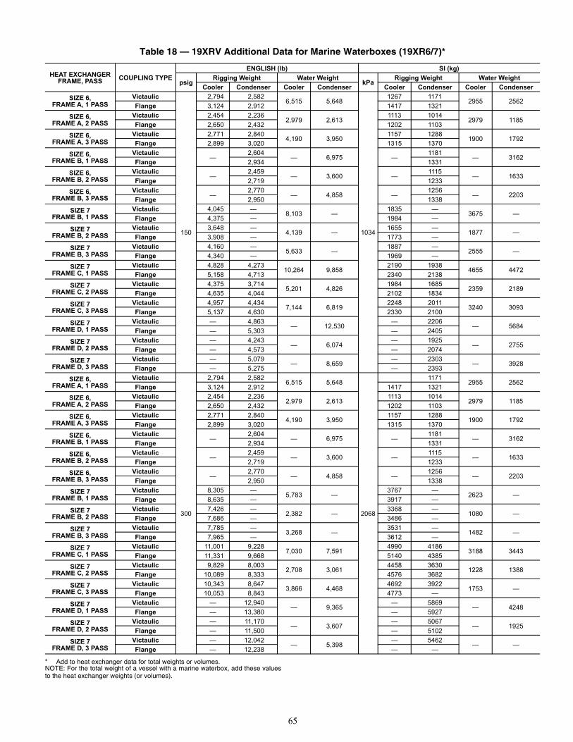
65
* Add to heat exchanger data for total weights or volumes.NOTE: For the total weight of a vessel with a marine waterbox, add these valuesto the heat exchanger weights (or volumes).
Table 18 — 19XRV Additional Data for Marine Waterboxes (19XR6/7)*
HEAT EXCHANGER FRAME, PASS COUPLING TYPE
ENGLISH (lb) SI (kg)
psigRigging Weight Water Weight
kPaRigging Weight Water Weight
Cooler Condenser Cooler Condenser Cooler Condenser Cooler Condenser
SIZE 6,FRAME A, 1 PASS
Victaulic
150
2,794 2,5826,515 5,648
1034
1267 11712955 2562
Flange 3,124 2,912 1417 1321SIZE 6,
FRAME A, 2 PASSVictaulic 2,454 2,236
2,979 2,6131113 1014
2979 1185Flange 2,650 2,432 1202 1103
SIZE 6,FRAME A, 3 PASS
Victaulic 2,771 2,8404,190 3,950
1157 12881900 1792
Flange 2,899 3,020 1315 1370SIZE 6,
FRAME B, 1 PASSVictaulic
—2,604
— 6,975 —1181
— 3162Flange 2,934 1331
SIZE 6,FRAME B, 2 PASS
Victaulic—
2,459— 3,600 —
1115— 1633
Flange 2,719 1233SIZE 6,
FRAME B, 3 PASSVictaulic
—2,770
— 4,858 —1256
— 2203Flange 2,950 1338
SIZE 7FRAME B, 1 PASS
Victaulic 4,045 —8,103 —
1835 —3675 —
Flange 4,375 — 1984 —SIZE 7
FRAME B, 2 PASSVictaulic 3,648 —
4,139 —1655 —
1877 —Flange 3,908 — 1773 —
SIZE 7FRAME B, 3 PASS
Victaulic 4,160 —5,633 —
1887 —2555 —
Flange 4,340 — 1969 —SIZE 7
FRAME C, 1 PASSVictaulic 4,828 4,273
10,264 9,8582190 1938
4655 4472Flange 5,158 4,713 2340 2138
SIZE 7FRAME C, 2 PASS
Victaulic 4,375 3,7145,201 4,826
1984 16852359 2189
Flange 4,635 4,044 2102 1834SIZE 7
FRAME C, 3 PASSVictaulic 4,957 4,434
7,144 6,8192248 2011
3240 3093Flange 5,137 4,630 2330 2100
SIZE 7FRAME D, 1 PASS
Victaulic — 4,863— 12,530
— 2206— 5684
Flange — 5,303 — 2405SIZE 7
FRAME D, 2 PASSVictaulic — 4,243
— 6,074— 1925
— 2755Flange — 4,573 — 2074
SIZE 7FRAME D, 3 PASS
Victaulic — 5,079— 8,659
— 2303— 3928
Flange — 5,275 — 2393SIZE 6,
FRAME A, 1 PASSVictaulic
300
2,794 2,5826,515 5,648
2068
11712955 2562
Flange 3,124 2,912 1417 1321SIZE 6,
FRAME A, 2 PASSVictaulic 2,454 2,236
2,979 2,6131113 1014
2979 1185Flange 2,650 2,432 1202 1103
SIZE 6,FRAME A, 3 PASS
Victaulic 2,771 2,8404,190 3,950
1157 12881900 1792
Flange 2,899 3,020 1315 1370SIZE 6,
FRAME B, 1 PASSVictaulic
—2,604
— 6,975 —1181
— 3162Flange 2,934 1331
SIZE 6,FRAME B, 2 PASS
Victaulic—
2,459— 3,600 —
1115— 1633
Flange 2,719 1233SIZE 6,
FRAME B, 3 PASSVictaulic
—2,770
— 4,858 —1256
— 2203Flange 2,950 1338
SIZE 7FRAME B, 1 PASS
Victaulic 8,305 —5,783 —
3767 —2623 —
Flange 8,635 — 3917 —SIZE 7
FRAME B, 2 PASSVictaulic 7,426 —
2,382 —3368 —
1080 —Flange 7,686 — 3486 —
SIZE 7FRAME B, 3 PASS
Victaulic 7,785 —3,268 —
3531 —1482 —
Flange 7,965 — 3612 —SIZE 7
FRAME C, 1 PASSVictaulic 11,001 9,228
7,030 7,5914990 4186
3188 3443Flange 11,331 9,668 5140 4385
SIZE 7FRAME C, 2 PASS
Victaulic 9,829 8,0032,708 3,061
4458 36301228 1388
Flange 10,089 8,333 4576 3682SIZE 7
FRAME C, 3 PASSVictaulic 10,343 8,647
3,866 4,4684692 3922
1753 —Flange 10,053 8,843 4773 —
SIZE 7FRAME D, 1 PASS
Victaulic — 12,940— 9,365
— 5869— 4248
Flange — 13,380 — 5927SIZE 7
FRAME D, 2 PASSVictaulic — 11,170
— 3,607— 5067
— 1925Flange — 11,500 — 5102
SIZE 7FRAME D, 3 PASS
Victaulic — 12,042— 5,398
— 5462— —
Flange — 12,238 — —
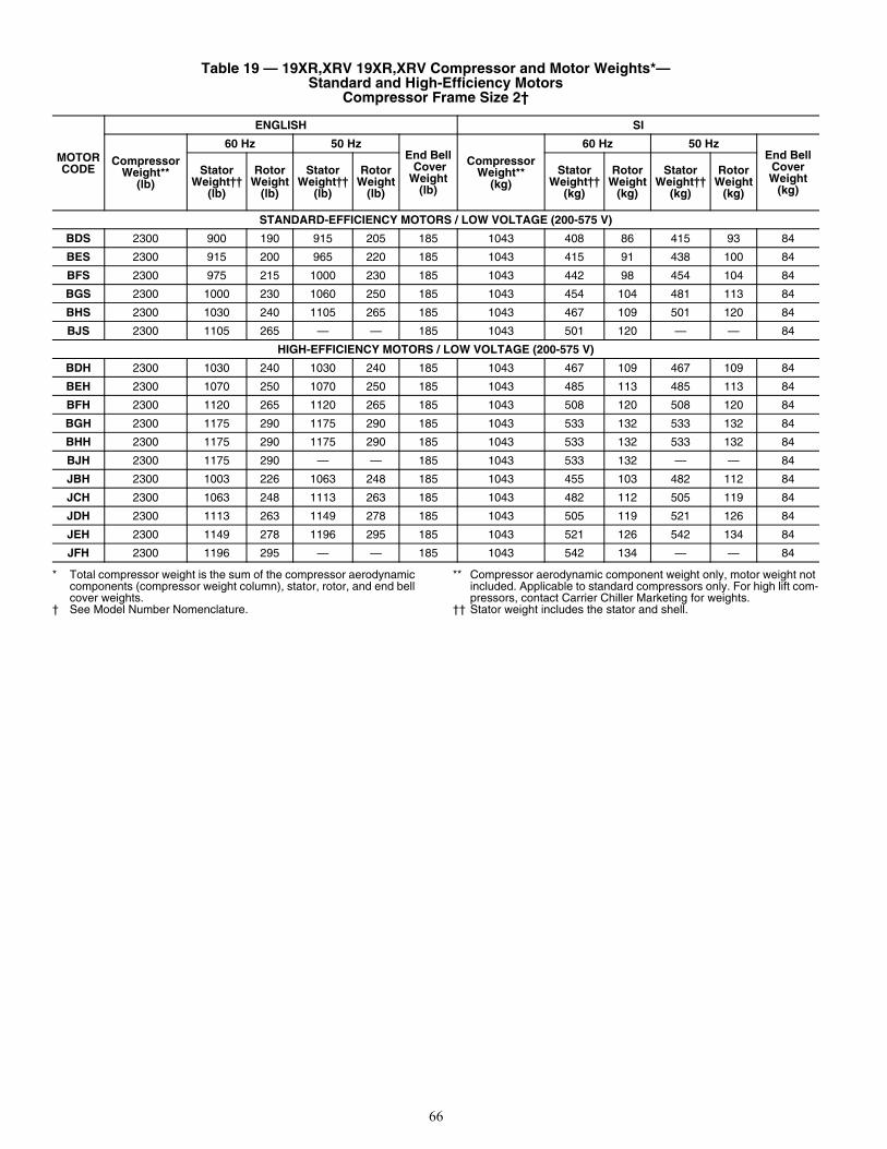
66
* Total compressor weight is the sum of the compressor aerodynamic components (compressor weight column), stator, rotor, and end bell cover weights.
† See Model Number Nomenclature.
** Compressor aerodynamic component weight only, motor weight not included. Applicable to standard compressors only. For high lift com-pressors, contact Carrier Chiller Marketing for weights.
†† Stator weight includes the stator and shell.
Table 19 — 19XR,XRV 19XR,XRV Compressor and Motor Weights*— Standard and High-Efficiency Motors
Compressor Frame Size 2†
MOTOR CODE
ENGLISH SI
Compressor Weight**
(lb)
60 Hz 50 HzEnd Bell CoverWeight
(lb)
Compressor Weight**
(kg)
60 Hz 50 HzEnd Bell
CoverWeight
(kg)
Stator Weight††
(lb)
Rotor Weight
(lb)
Stator Weight††
(lb)
Rotor Weight
(lb)
Stator Weight††
(kg)
Rotor Weight
(kg)
Stator Weight††
(kg)
Rotor Weight
(kg)
STANDARD-EFFICIENCY MOTORS / LOW VOLTAGE (200-575 V)
BDS 2300 900 190 915 205 185 1043 408 86 415 93 84
BES 2300 915 200 965 220 185 1043 415 91 438 100 84
BFS 2300 975 215 1000 230 185 1043 442 98 454 104 84
BGS 2300 1000 230 1060 250 185 1043 454 104 481 113 84
BHS 2300 1030 240 1105 265 185 1043 467 109 501 120 84
BJS 2300 1105 265 — — 185 1043 501 120 — — 84
HIGH-EFFICIENCY MOTORS / LOW VOLTAGE (200-575 V)
BDH 2300 1030 240 1030 240 185 1043 467 109 467 109 84
BEH 2300 1070 250 1070 250 185 1043 485 113 485 113 84
BFH 2300 1120 265 1120 265 185 1043 508 120 508 120 84
BGH 2300 1175 290 1175 290 185 1043 533 132 533 132 84
BHH 2300 1175 290 1175 290 185 1043 533 132 533 132 84
BJH 2300 1175 290 — — 185 1043 533 132 — — 84
JBH 2300 1003 226 1063 248 185 1043 455 103 482 112 84
JCH 2300 1063 248 1113 263 185 1043 482 112 505 119 84
JDH 2300 1113 263 1149 278 185 1043 505 119 521 126 84
JEH 2300 1149 278 1196 295 185 1043 521 126 542 134 84
JFH 2300 1196 295 — — 185 1043 542 134 — — 84
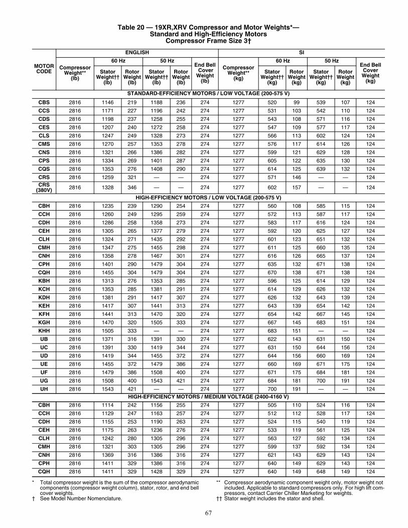
67
* Total compressor weight is the sum of the compressor aerodynamic components (compressor weight column), stator, rotor, and end bell cover weights.
† See Model Number Nomenclature.
** Compressor aerodynamic component weight only, motor weight not included. Applicable to standard compressors only. For high lift com-pressors, contact Carrier Chiller Marketing for weights.
†† Stator weight includes the stator and shell.
Table 20 — 19XR,XRV Compressor and Motor Weights*— Standard and High-Efficiency Motors
Compressor Frame Size 3†
MOTOR CODE
ENGLISH SI
Compressor Weight**
(lb)
60 Hz 50 HzEnd Bell CoverWeight
(lb)
Compressor Weight**
(kg)
60 Hz 50 HzEnd Bell
CoverWeight
(kg)
Stator Weight††
(lb)
Rotor Weight
(lb)
Stator Weight††
(lb)
Rotor Weight
(lb)
Stator Weight††
(kg)
Rotor Weight
(kg)
Stator Weight††
(kg)
Rotor Weight
(kg)
STANDARD-EFFICIENCY MOTORS / LOW VOLTAGE (200-575 V)
CBS 2816 1146 219 1188 236 274 1277 520 99 539 107 124
CCS 2816 1171 227 1196 242 274 1277 531 103 542 110 124
CDS 2816 1198 237 1258 255 274 1277 543 108 571 116 124
CES 2816 1207 240 1272 258 274 1277 547 109 577 117 124
CLS 2816 1247 249 1328 273 274 1277 566 113 602 124 124
CMS 2816 1270 257 1353 278 274 1277 576 117 614 126 124
CNS 2816 1321 266 1386 282 274 1277 599 121 629 128 124
CPS 2816 1334 269 1401 287 274 1277 605 122 635 130 124
CQS 2816 1353 276 1408 290 274 1277 614 125 639 132 124
CRS 2816 1259 321 — — 274 1277 571 146 — — 124CRS
(380V) 2816 1328 346 — — 274 1277 602 157 — — 124
HIGH-EFFICIENCY MOTORS / LOW VOLTAGE (200-575 V)
CBH 2816 1235 239 1290 254 274 1277 560 108 585 115 124
CCH 2816 1260 249 1295 259 274 1277 572 113 587 117 124
CDH 2816 1286 258 1358 273 274 1277 583 117 616 124 124
CEH 2816 1305 265 1377 279 274 1277 592 120 625 127 124
CLH 2816 1324 271 1435 292 274 1277 601 123 651 132 124
CMH 2816 1347 275 1455 298 274 1277 611 125 660 135 124
CNH 2816 1358 278 1467 301 274 1277 616 126 665 137 124
CPH 2816 1401 290 1479 304 274 1277 635 132 671 138 124
CQH 2816 1455 304 1479 304 274 1277 670 138 671 138 124
KBH 2816 1313 276 1353 285 274 1277 596 125 614 129 124
KCH 2816 1353 285 1381 291 274 1277 614 129 626 132 124
KDH 2816 1381 291 1417 307 274 1277 626 132 643 139 124
KEH 2816 1417 307 1441 313 274 1277 643 139 654 142 124
KFH 2816 1441 313 1470 320 274 1277 654 142 667 145 124
KGH 2816 1470 320 1505 333 274 1277 667 145 683 151 124
KHH 2816 1505 333 — — 274 1277 683 151 — — 124
UB 2816 1371 316 1391 330 274 1277 622 143 631 150 124
UC 2816 1391 330 1419 344 274 1277 631 150 644 156 124
UD 2816 1419 344 1455 372 274 1277 644 156 660 169 124
UE 2816 1455 372 1479 386 274 1277 660 169 671 175 124
UF 2816 1479 386 1508 400 274 1277 671 175 684 181 124
UG 2816 1508 400 1543 421 274 1277 684 181 700 191 124
UH 2816 1543 421 — — 274 1277 700 191 — — 124HIGH-EFFICIENCY MOTORS / MEDIUM VOLTAGE (2400-4160 V)
CBH 2816 1114 242 1156 255 274 1277 505 110 524 116 124
CCH 2816 1129 247 1163 257 274 1277 512 112 528 117 124
CDH 2816 1155 253 1190 263 274 1277 524 115 540 119 124
CEH 2816 1175 263 1236 276 274 1277 533 119 561 125 124
CLH 2816 1242 280 1305 296 274 1277 563 127 592 134 124
CMH 2816 1321 303 1305 296 274 1277 599 137 592 134 124
CNH 2816 1369 316 1386 316 274 1277 621 143 629 143 124
CPH 2816 1411 329 1386 316 274 1277 640 149 629 143 124
CQH 2816 1411 329 1428 329 274 1277 640 149 648 149 124
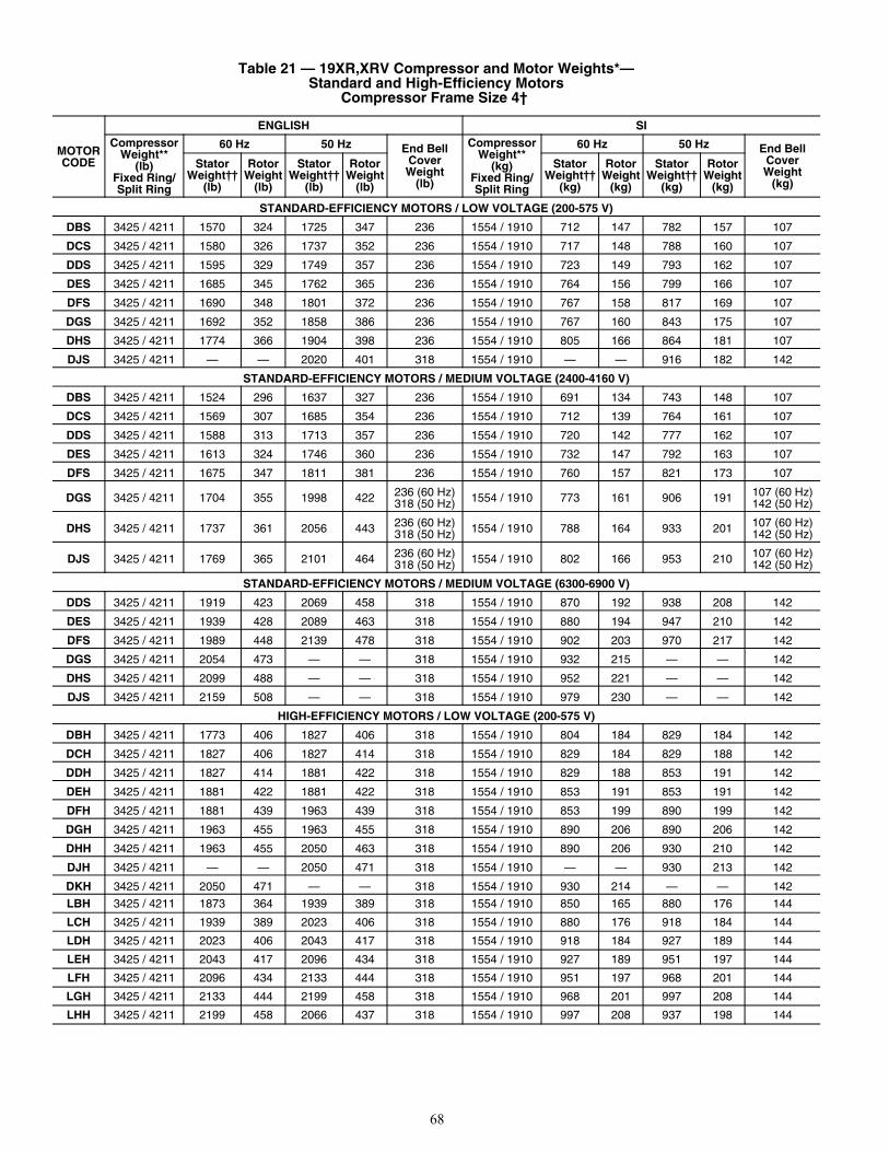
68
Table 21 — 19XR,XRV Compressor and Motor Weights*— Standard and High-Efficiency Motors
Compressor Frame Size 4†
MOTOR CODE
ENGLISH SI
CompressorWeight**
(lb) Fixed Ring/Split Ring
60 Hz 50 Hz End BellCoverWeight
(lb)
CompressorWeight**
(kg)Fixed Ring/Split Ring
60 Hz 50 Hz End BellCoverWeight
(kg)
StatorWeight††
(lb)
RotorWeight
(lb)
StatorWeight††
(lb)
RotorWeight
(lb)
StatorWeight††
(kg)
RotorWeight
(kg)
StatorWeight††
(kg)
RotorWeight
(kg)
STANDARD-EFFICIENCY MOTORS / LOW VOLTAGE (200-575 V)
DBS 3425 / 4211 1570 324 1725 347 236 1554 / 1910 712 147 782 157 107
DCS 3425 / 4211 1580 326 1737 352 236 1554 / 1910 717 148 788 160 107
DDS 3425 / 4211 1595 329 1749 357 236 1554 / 1910 723 149 793 162 107
DES 3425 / 4211 1685 345 1762 365 236 1554 / 1910 764 156 799 166 107
DFS 3425 / 4211 1690 348 1801 372 236 1554 / 1910 767 158 817 169 107
DGS 3425 / 4211 1692 352 1858 386 236 1554 / 1910 767 160 843 175 107
DHS 3425 / 4211 1774 366 1904 398 236 1554 / 1910 805 166 864 181 107
DJS 3425 / 4211 — — 2020 401 318 1554 / 1910 — — 916 182 142
STANDARD-EFFICIENCY MOTORS / MEDIUM VOLTAGE (2400-4160 V)
DBS 3425 / 4211 1524 296 1637 327 236 1554 / 1910 691 134 743 148 107
DCS 3425 / 4211 1569 307 1685 354 236 1554 / 1910 712 139 764 161 107
DDS 3425 / 4211 1588 313 1713 357 236 1554 / 1910 720 142 777 162 107
DES 3425 / 4211 1613 324 1746 360 236 1554 / 1910 732 147 792 163 107
DFS 3425 / 4211 1675 347 1811 381 236 1554 / 1910 760 157 821 173 107
DGS 3425 / 4211 1704 355 1998 422 236 (60 Hz)318 (50 Hz) 1554 / 1910 773 161 906 191 107 (60 Hz)
142 (50 Hz)
DHS 3425 / 4211 1737 361 2056 443 236 (60 Hz)318 (50 Hz) 1554 / 1910 788 164 933 201 107 (60 Hz)
142 (50 Hz)
DJS 3425 / 4211 1769 365 2101 464 236 (60 Hz)318 (50 Hz) 1554 / 1910 802 166 953 210 107 (60 Hz)
142 (50 Hz)
STANDARD-EFFICIENCY MOTORS / MEDIUM VOLTAGE (6300-6900 V)
DDS 3425 / 4211 1919 423 2069 458 318 1554 / 1910 870 192 938 208 142
DES 3425 / 4211 1939 428 2089 463 318 1554 / 1910 880 194 947 210 142
DFS 3425 / 4211 1989 448 2139 478 318 1554 / 1910 902 203 970 217 142
DGS 3425 / 4211 2054 473 — — 318 1554 / 1910 932 215 — — 142
DHS 3425 / 4211 2099 488 — — 318 1554 / 1910 952 221 — — 142
DJS 3425 / 4211 2159 508 — — 318 1554 / 1910 979 230 — — 142
HIGH-EFFICIENCY MOTORS / LOW VOLTAGE (200-575 V)
DBH 3425 / 4211 1773 406 1827 406 318 1554 / 1910 804 184 829 184 142
DCH 3425 / 4211 1827 406 1827 414 318 1554 / 1910 829 184 829 188 142
DDH 3425 / 4211 1827 414 1881 422 318 1554 / 1910 829 188 853 191 142
DEH 3425 / 4211 1881 422 1881 422 318 1554 / 1910 853 191 853 191 142
DFH 3425 / 4211 1881 439 1963 439 318 1554 / 1910 853 199 890 199 142
DGH 3425 / 4211 1963 455 1963 455 318 1554 / 1910 890 206 890 206 142
DHH 3425 / 4211 1963 455 2050 463 318 1554 / 1910 890 206 930 210 142
DJH 3425 / 4211 — — 2050 471 318 1554 / 1910 — — 930 213 142
DKH 3425 / 4211 2050 471 — — 318 1554 / 1910 930 214 — — 142
LBH 3425 / 4211 1873 364 1939 389 318 1554 / 1910 850 165 880 176 144
LCH 3425 / 4211 1939 389 2023 406 318 1554 / 1910 880 176 918 184 144
LDH 3425 / 4211 2023 406 2043 417 318 1554 / 1910 918 184 927 189 144
LEH 3425 / 4211 2043 417 2096 434 318 1554 / 1910 927 189 951 197 144
LFH 3425 / 4211 2096 434 2133 444 318 1554 / 1910 951 197 968 201 144
LGH 3425 / 4211 2133 444 2199 458 318 1554 / 1910 968 201 997 208 144
LHH 3425 / 4211 2199 458 2066 437 318 1554 / 1910 997 208 937 198 144
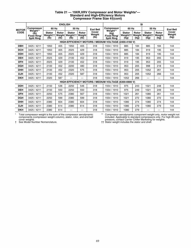
69
* Total compressor weight is the sum of the compressor aerodynamic components (compressor weight column), stator, rotor, and end bell cover weights.
† See Model Number Nomenclature.
** Compressor aerodynamic component weight only, motor weight not included. Applicable to standard compressors only. For high lift com-pressors, contact Carrier Chiller Marketing for weights.
†† Stator weight includes the stator and shell.
HIGH-EFFICIENCY MOTORS / MEDIUM VOLTAGE (2400-4160 V)
DBH 3425 / 4211 1950 405 1950 405 318 1554 / 1910 885 184 885 184 144
DCH 3425 / 4211 1950 405 2025 429 318 1554 / 1910 885 184 919 195 144
DDH 3425 / 4211 1950 405 2025 429 318 1554 / 1910 885 184 919 195 144
DEH 3425 / 4211 2025 429 2100 452 318 1554 / 1910 919 195 953 205 144
DFH 3425 / 4211 2025 429 2100 452 318 1554 / 1910 919 195 953 205 144
DGH 3425 / 4211 2100 452 2200 480 318 1554 / 1910 953 205 998 218 144
DHH 3425 / 4211 2100 452 2320 575 318 1554 / 1910 953 205 1052 261 144
DJH 3425 / 4211 2100 452 2320 587 318 1554 / 1910 953 205 1052 266 144
DKH 3425 / 4211 2320 587 — — 318 1554 / 1910 1052 266 — — 144
HIGH-EFFICIENCY MOTORS / MEDIUM VOLTAGE (6300-6900 V)
DDH 3425 / 4211 2150 536 2250 546 318 1554 / 1910 975 243 1021 248 144
DEH 3425 / 4211 2150 550 2250 550 318 1554 / 1910 975 249 1021 249 144
DFH 3425 / 4211 2250 575 2380 567 318 1554 / 1910 1021 261 1080 261 144
DGH 3425 / 4211 2250 599 2380 599 318 1554 / 1910 1021 272 1080 272 144
DHH 3425 / 4211 2380 604 2380 604 318 1554 / 1910 1080 274 1080 274 144
DJH 3425 / 4211 2380 614 2380 614 318 1554 / 1910 1080 279 1080 279 144
DKH 3425 / 4211 2380 614 — — 318 1554 / 1910 1080 279 — — 144
Table 21 — 19XR,XRV Compressor and Motor Weights*— Standard and High-Efficiency Motors
Compressor Frame Size 4†(cont)
MOTOR CODE
ENGLISH SI
CompressorWeight**
(lb) Fixed Ring/Split Ring
60 Hz 50 Hz End BellCoverWeight
(lb)
CompressorWeight**
(kg)Fixed Ring/Split Ring
60 Hz 50 Hz End BellCoverWeight
(kg)
StatorWeight††
(lb)
RotorWeight
(lb)
StatorWeight††
(lb)
RotorWeight
(lb)
StatorWeight††
(kg)
RotorWeight
(kg)
StatorWeight††
(kg)
RotorWeight
(kg)
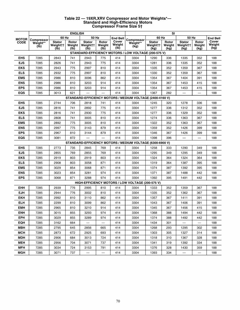
70
Table 22 — 19XR,XRV Compressor and Motor Weights*— Standard and High-Efficiency Motors
Compressor Frame Size 5†
MOTOR CODE
ENGLISH SI
CompressorWeight**
(lb)
60 Hz 50 Hz End BellCoverWeight
(lb)
CompressorWeight**
(kg)
60 Hz 50 Hz End BellCoverWeight
(kg)
StatorWeight††
(lb)
RotorWeight
(lb)
StatorWeight††
(lb)
RotorWeight
(lb)
StatorWeight††
(kg)
RotorWeight
(kg)
StatorWeight††
(kg)
RotorWeight
(kg)
STANDARD-EFFICIENCY MOTORS / LOW VOLTAGE (200-575 V)
EHS 7285 2843 741 2943 775 414 3304 1290 336 1335 352 188
EJS 7285 2826 741 2943 775 414 3304 1281 336 1335 352 188
EKS 7285 2943 775 2997 810 414 3304 1335 352 1359 367 188
ELS 7285 2932 775 2997 810 414 3304 1330 352 1359 367 188
EMS 7285 2986 810 3096 862 414 3304 1354 367 1404 391 188
ENS 7285 2986 810 3203 914 414 3304 1354 367 1453 415 188
EPS 7285 2986 810 3203 914 414 3304 1354 367 1453 415 188
EQS 7285 3013 621 — — 414 3304 1367 282 — — 188
STANDARD-EFFICIENCY MOTORS / MEDIUM VOLTAGE (2400-4160 V)
EHS 7285 2744 706 2818 741 414 3304 1245 320 1278 336 188
EJS 7285 2816 741 2892 775 414 3304 1277 336 1312 352 188
EKS 7285 2816 741 2930 775 414 3304 1277 336 1329 352 188
ELS 7285 2808 741 3005 810 414 3304 1274 336 1363 367 188
EMS 7285 2892 775 3005 810 414 3304 1322 352 1363 367 188
ENS 7285 2997 775 3143 879 414 3304 1359 352 1426 399 188
EPS 7285 2967 810 3144 879 414 3304 1346 367 1426 399 188
EQS 7285 3081 872 — — 414 3304 1398 396 — — 188
STANDARD-EFFICIENCY MOTORS / MEDIUM VOLTAGE (6300-6900 V)
EHS 7285 2773 735 2845 769 414 3304 1258 333 1290 349 188
EJS 7285 2855 769 2855 769 414 3304 1295 349 1295 349 188
EKS 7285 2919 803 2919 803 414 3304 1324 364 1324 364 188
ELS 7285 2908 803 3058 871 414 3304 1319 364 1387 395 188
EMS 7285 3029 854 3068 871 414 3304 1374 387 1392 395 188
ENS 7285 3023 854 3281 974 414 3304 1371 387 1488 442 188
EPS 7285 3068 871 3288 974 414 3304 1392 395 1491 442 188
HIGH-EFFICIENCY MOTORS / LOW VOLTAGE (200-575 V)
EHH 7285 2939 776 2995 810 414 3304 1333 352 1359 367 188
EJH 7285 2944 776 3002 810 414 3304 1335 352 1362 367 188
EKH 7285 2992 810 3110 862 414 3304 1357 367 1411 391 188
ELH 7285 2299 810 3099 862 414 3304 1043 367 1406 391 188
EMH 7285 2965 810 3210 914 414 3304 1345 367 1456 415 188
ENH 7285 3015 855 3293 974 414 3304 1368 388 1494 442 188
EPH 7285 3029 855 3289 974 414 3304 1374 388 1492 442 188
EQH 7285 3162 664 — — 414 3304 1434 301 — — 188
MBH 7285 2795 645 2856 665 414 3304 1268 293 1295 302 188
MCH 7285 2873 672 2925 693 414 3304 1303 305 1327 314 188
MDH 7285 2906 684 3013 724 414 3304 1318 310 1367 328 188
MEH 7285 2956 704 3071 737 414 3304 1341 319 1392 334 188
MFH 7285 3034 724 3153 791 414 3304 1376 328 1430 359 188
MGH 7285 3071 737 — — 414 3304 1393 334 — — 188
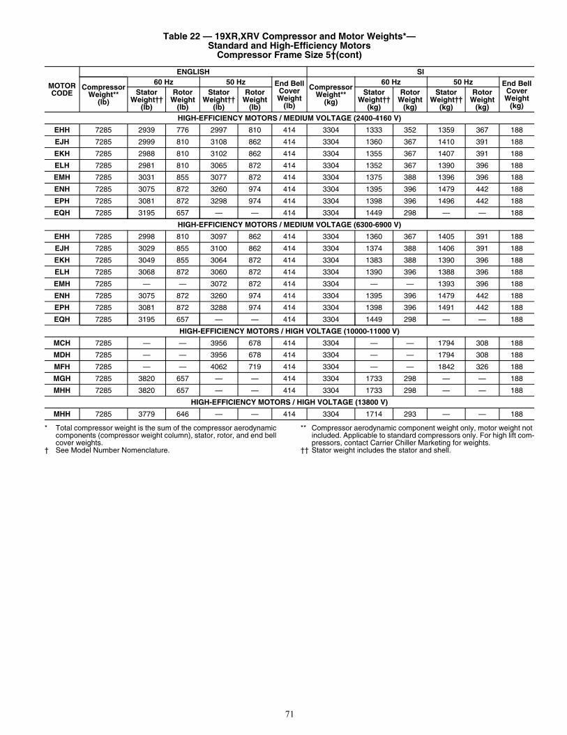
71
* Total compressor weight is the sum of the compressor aerodynamic components (compressor weight column), stator, rotor, and end bell cover weights.
† See Model Number Nomenclature.
** Compressor aerodynamic component weight only, motor weight not included. Applicable to standard compressors only. For high lift com-pressors, contact Carrier Chiller Marketing for weights.
†† Stator weight includes the stator and shell.
HIGH-EFFICIENCY MOTORS / MEDIUM VOLTAGE (2400-4160 V)
EHH 7285 2939 776 2997 810 414 3304 1333 352 1359 367 188
EJH 7285 2999 810 3108 862 414 3304 1360 367 1410 391 188
EKH 7285 2988 810 3102 862 414 3304 1355 367 1407 391 188
ELH 7285 2981 810 3065 872 414 3304 1352 367 1390 396 188
EMH 7285 3031 855 3077 872 414 3304 1375 388 1396 396 188
ENH 7285 3075 872 3260 974 414 3304 1395 396 1479 442 188
EPH 7285 3081 872 3298 974 414 3304 1398 396 1496 442 188
EQH 7285 3195 657 — — 414 3304 1449 298 — — 188
HIGH-EFFICIENCY MOTORS / MEDIUM VOLTAGE (6300-6900 V)
EHH 7285 2998 810 3097 862 414 3304 1360 367 1405 391 188
EJH 7285 3029 855 3100 862 414 3304 1374 388 1406 391 188
EKH 7285 3049 855 3064 872 414 3304 1383 388 1390 396 188
ELH 7285 3068 872 3060 872 414 3304 1390 396 1388 396 188
EMH 7285 — — 3072 872 414 3304 — — 1393 396 188
ENH 7285 3075 872 3260 974 414 3304 1395 396 1479 442 188
EPH 7285 3081 872 3288 974 414 3304 1398 396 1491 442 188
EQH 7285 3195 657 — — 414 3304 1449 298 — — 188
HIGH-EFFICIENCY MOTORS / HIGH VOLTAGE (10000-11000 V)
MCH 7285 — — 3956 678 414 3304 — — 1794 308 188
MDH 7285 — — 3956 678 414 3304 — — 1794 308 188
MFH 7285 — — 4062 719 414 3304 — — 1842 326 188
MGH 7285 3820 657 — — 414 3304 1733 298 — — 188
MHH 7285 3820 657 — — 414 3304 1733 298 — — 188
HIGH-EFFICIENCY MOTORS / HIGH VOLTAGE (13800 V)
MHH 7285 3779 646 — — 414 3304 1714 293 — — 188
Table 22 — 19XR,XRV Compressor and Motor Weights*— Standard and High-Efficiency Motors
Compressor Frame Size 5†(cont)
MOTOR CODE
ENGLISH SI
CompressorWeight**
(lb)
60 Hz 50 Hz End BellCoverWeight
(lb)
CompressorWeight**
(kg)
60 Hz 50 Hz End BellCoverWeight
(kg)
StatorWeight††
(lb)
RotorWeight
(lb)
StatorWeight††
(lb)
RotorWeight
(lb)
StatorWeight††
(kg)
RotorWeight
(kg)
StatorWeight††
(kg)
RotorWeight
(kg)
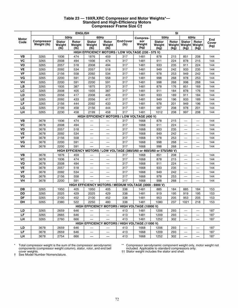
72
* Total compressor weight is the sum of the compressor aerodynamic components (compressor weight column), stator, rotor, and end bell cover weights.
† See Model Number Nomenclature.
** Compressor aerodynamic component weight only, motor weight not included. Applicable to standard compressors only.
†† Stator weight includes the stator and shell.
Table 23 — 19XR,XRC Compressor and Motor Weights*— Standard and High-Efficiency Motors
Compressor Frame Size C†
Motor Code
ENGLISH SI
Compressor Weight (lb)
50Hz 60HzEnd Cover
(lb)
Compres-sor
Weight (kg)
50Hz 60HzEnd
Cover (kg)
Stator Weight
(lb)
Rotor Weight
(lb)
Stator Weight
(lb)
Rotor Weight
(lb)
Stator Weight
(kg)
Rotor Weight
(kg)
Stator Weight
(kg)
Rotor Weight
(kg)HIGH EFFICIENCY MOTORS / LOW VOLTAGE (230 - 575 V)
VB 3265 1936 474 1876 459 317 1481 878 215 851 208 144VC 3265 2008 494 1936 474 317 1481 911 224 878 215 144VD 3265 2057 518 2008 494 317 1481 933 235 911 224 144VE 3265 2092 534 2057 518 317 1481 949 242 933 235 144VF 3265 2156 558 2092 534 317 1481 978 253 949 242 144VG 3265 2200 591 2156 558 317 1481 998 268 978 253 144VH 3265 2200 591 2200 591 317 1481 998 268 998 268 144LB 3265 1935 387 1875 373 317 1481 878 176 851 169 144LC 3265 2008 405 1935 387 317 1481 911 184 878 176 144LD 3265 2056 417 2008 405 317 1481 933 189 911 184 144LE 3265 2092 433 2056 417 317 1481 949 196 933 189 144LF 3265 2156 444 2092 433 317 1481 978 201 949 196 144LG 3265 2199 458 2156 444 317 1481 997 208 978 201 144LH 3265 2230 458 2199 458 317 1481 1012 208 997 208 144
HIGH EFFICIENCY MOTORS / LOW VOLTAGE (400 V)VB 3678 1936 474 — — 317 1668 878 215 — — 144VC 3678 2008 494 — — 317 1668 911 224 — — 144VD 3678 2057 518 — — 317 1668 933 235 — — 144VE 3678 2092 534 — — 317 1668 949 242 — — 144VF 3678 2156 558 — — 317 1668 978 253 — — 144VG 3678 2200 591 — — 317 1668 998 268 — — 144VH 3678 2200 591 — — 317 1668 998 268 — — 144
HIGH EFFICIENCY MOTORS / LOW VOLTAGE (380/3/60 or 460/3/60 or 575/3/60 V)VB 3678 1876 459 — — 317 1668 851 208 — — 144VC 3678 1936 474 — — 317 1668 878 215 — — 144VD 3678 2008 494 — — 317 1668 911 224 — — 144VE 3678 2057 518 — — 317 1668 933 235 — — 144VF 3678 2092 534 — — 317 1668 949 242 — — 144VG 3678 2156 558 — — 317 1668 978 253 — — 144VH 3678 2200 591 — — 317 1668 998 268 — — 144
HIGH EFFICIENCY MOTORS / MEDIUM VOLTAGE (3000 - 6900 V)DB 3265 1950 405 1950 405 338 1481 885 184 885 184 153DD 3265 2025 429 2025 429 338 1481 919 195 919 195 153DF 3265 2100 452 2100 452 338 1481 953 205 953 205 153DH 3265 2380 522 2250 480 338 1481 1080 237 1021 218 153
HIGH EFFICIENCY MOTORS / HIGH VOLTAGE (10000 V)LD 3265 2659 646 — — 413 1481 1206 293 — — 187LF 3265 2665 646 — — 413 1481 1209 293 — — 187LH 3265 2760 666 — — 413 1481 1252 302 — — 187
HIGH EFFICIENCY MOTORS / HIGH VOLTAGE (11000 V)LD 3678 2659 646 — — 413 1668 1206 293 — — 187LF 3678 2659 646 — — 413 1668 1209 293 — — 187LH 3678 2754 666 — — 413 1668 1252 302 — — 187
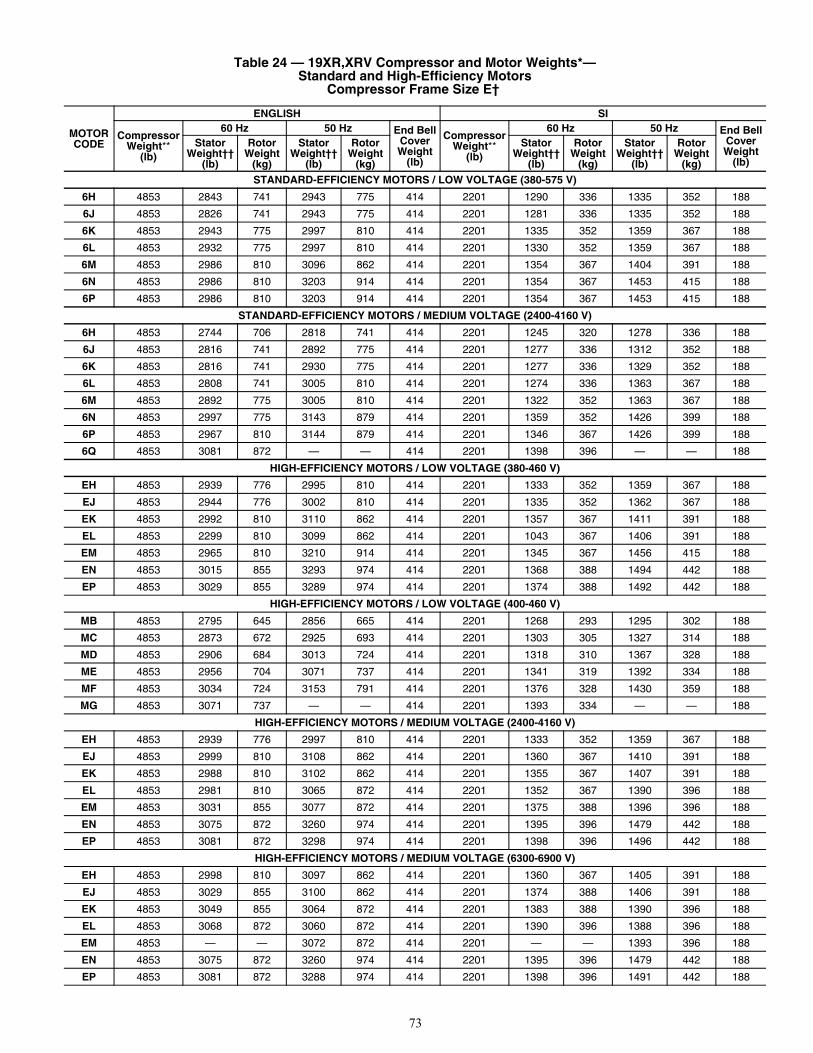
73
Table 24 — 19XR,XRV Compressor and Motor Weights*— Standard and High-Efficiency Motors
Compressor Frame Size E†
MOTOR CODE
ENGLISH SI
CompressorWeight**
(lb)
60 Hz 50 Hz End BellCoverWeight
(lb)
CompressorWeight**
(lb)
60 Hz 50 Hz End BellCoverWeight
(lb)
StatorWeight††
(lb)
RotorWeight
(kg)
StatorWeight††
(lb)
RotorWeight
(kg)
StatorWeight††
(lb)
RotorWeight
(kg)
StatorWeight††
(lb)
RotorWeight
(kg)
STANDARD-EFFICIENCY MOTORS / LOW VOLTAGE (380-575 V)
6H 4853 2843 741 2943 775 414 2201 1290 336 1335 352 188
6J 4853 2826 741 2943 775 414 2201 1281 336 1335 352 188
6K 4853 2943 775 2997 810 414 2201 1335 352 1359 367 188
6L 4853 2932 775 2997 810 414 2201 1330 352 1359 367 188
6M 4853 2986 810 3096 862 414 2201 1354 367 1404 391 188
6N 4853 2986 810 3203 914 414 2201 1354 367 1453 415 188
6P 4853 2986 810 3203 914 414 2201 1354 367 1453 415 188
STANDARD-EFFICIENCY MOTORS / MEDIUM VOLTAGE (2400-4160 V)
6H 4853 2744 706 2818 741 414 2201 1245 320 1278 336 188
6J 4853 2816 741 2892 775 414 2201 1277 336 1312 352 188
6K 4853 2816 741 2930 775 414 2201 1277 336 1329 352 188
6L 4853 2808 741 3005 810 414 2201 1274 336 1363 367 188
6M 4853 2892 775 3005 810 414 2201 1322 352 1363 367 188
6N 4853 2997 775 3143 879 414 2201 1359 352 1426 399 188
6P 4853 2967 810 3144 879 414 2201 1346 367 1426 399 188
6Q 4853 3081 872 — — 414 2201 1398 396 — — 188
HIGH-EFFICIENCY MOTORS / LOW VOLTAGE (380-460 V)
EH 4853 2939 776 2995 810 414 2201 1333 352 1359 367 188
EJ 4853 2944 776 3002 810 414 2201 1335 352 1362 367 188
EK 4853 2992 810 3110 862 414 2201 1357 367 1411 391 188
EL 4853 2299 810 3099 862 414 2201 1043 367 1406 391 188
EM 4853 2965 810 3210 914 414 2201 1345 367 1456 415 188
EN 4853 3015 855 3293 974 414 2201 1368 388 1494 442 188
EP 4853 3029 855 3289 974 414 2201 1374 388 1492 442 188
HIGH-EFFICIENCY MOTORS / LOW VOLTAGE (400-460 V)
MB 4853 2795 645 2856 665 414 2201 1268 293 1295 302 188
MC 4853 2873 672 2925 693 414 2201 1303 305 1327 314 188
MD 4853 2906 684 3013 724 414 2201 1318 310 1367 328 188
ME 4853 2956 704 3071 737 414 2201 1341 319 1392 334 188
MF 4853 3034 724 3153 791 414 2201 1376 328 1430 359 188
MG 4853 3071 737 — — 414 2201 1393 334 — — 188
HIGH-EFFICIENCY MOTORS / MEDIUM VOLTAGE (2400-4160 V)
EH 4853 2939 776 2997 810 414 2201 1333 352 1359 367 188
EJ 4853 2999 810 3108 862 414 2201 1360 367 1410 391 188
EK 4853 2988 810 3102 862 414 2201 1355 367 1407 391 188
EL 4853 2981 810 3065 872 414 2201 1352 367 1390 396 188
EM 4853 3031 855 3077 872 414 2201 1375 388 1396 396 188
EN 4853 3075 872 3260 974 414 2201 1395 396 1479 442 188
EP 4853 3081 872 3298 974 414 2201 1398 396 1496 442 188
HIGH-EFFICIENCY MOTORS / MEDIUM VOLTAGE (6300-6900 V)
EH 4853 2998 810 3097 862 414 2201 1360 367 1405 391 188
EJ 4853 3029 855 3100 862 414 2201 1374 388 1406 391 188
EK 4853 3049 855 3064 872 414 2201 1383 388 1390 396 188
EL 4853 3068 872 3060 872 414 2201 1390 396 1388 396 188
EM 4853 — — 3072 872 414 2201 — — 1393 396 188
EN 4853 3075 872 3260 974 414 2201 1395 396 1479 442 188
EP 4853 3081 872 3288 974 414 2201 1398 396 1491 442 188
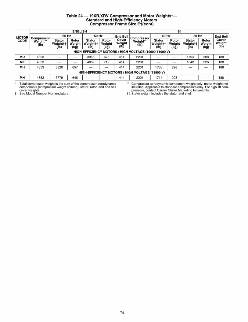
74
* Total compressor weight is the sum of the compressor aerodynamic components (compressor weight column), stator, rotor, and end bell cover weights.
† See Model Number Nomenclature.
** Compressor aerodynamic component weight only, motor weight not included. Applicable to standard compressors only. For high lift com-pressors, contact Carrier Chiller Marketing for weights.
†† Stator weight includes the stator and shell.
HIGH-EFFICIENCY MOTORS / HIGH VOLTAGE (10000-11000 V)
MD 4853 — — 3956 678 414 2201 — — 1794 308 188
MF 4853 — — 4062 719 414 2201 — — 1842 326 188
MH 4853 3820 657 — — 414 2201 1733 298 — — 188
HIGH-EFFICIENCY MOTORS / HIGH VOLTAGE (13800 V)
MH 4853 3779 646 — — 414 2201 1714 293 — — 188
Table 24 — 19XR,XRV Compressor and Motor Weights*— Standard and High-Efficiency Motors
Compressor Frame Size E†(cont)
MOTOR CODE
ENGLISH SI
CompressorWeight**
(lb)
60 Hz 50 Hz End BellCoverWeight
(lb)
CompressorWeight**
(lb)
60 Hz 50 Hz End BellCoverWeight
(lb)
StatorWeight††
(lb)
RotorWeight
(kg)
StatorWeight††
(lb)
RotorWeight
(kg)
StatorWeight††
(lb)
RotorWeight
(kg)
StatorWeight††
(lb)
RotorWeight
(kg)
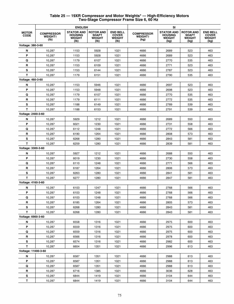
75
Table 25 — 19XR Compressor and Motor Weights* — High-Efficiency MotorsTwo-Stage Compressor Frame Size 6, 60 Hz
MOTOR CODE
ENGLISH SI
COMPRESSOR WEIGHT†
(lb)
STATOR AND HOUSING WEIGHT
(lb)
ROTOR AND SHAFT
WEIGHT(lb)
END BELL COVERWEIGHT
(lb)
COMPRESSOR WEIGHT†
(kg)
STATOR AND HOUSING WEIGHT
(kg)
ROTOR AND SHAFT
WEIGHT(kg)
END BELL COVERWEIGHT
(kg)
Voltage: 380-3-60
N 10,287 1153 5928 1021 4666 2689 523 463
P 10,287 1153 5928 1021 4666 2689 523 463
Q 10,287 1179 6107 1021 4666 2770 535 463
R 10,287 1153 6109 1021 4666 2771 523 463
S 10,287 1153 6144 1021 4666 2787 523 463
T 10,287 1179 6151 1021 4666 2790 535 463
Voltage: 460-3-60
N 10,287 1153 5946 1021 4666 2697 523 463
P 10,287 1153 5948 1021 4666 2698 523 463
Q 10,287 1179 6107 1021 4666 2770 535 463
R 10,287 1179 6111 1021 4666 2772 535 463
S 10,287 1188 6149 1021 4666 2789 539 463
T 10,287 1188 6153 1021 4666 2791 539 463
Voltage: 2400-3-60
N 10,287 5929 1212 1021 4666 2689 550 463
P 10,287 6021 1230 1021 4666 2731 558 463
Q 10,287 6112 1248 1021 4666 2772 566 463
R 10,287 6190 1264 1021 4666 2808 573 463
S 10,287 6268 1280 1021 4666 2843 581 463
T 10,287 6259 1280 1021 4666 2839 581 463
Voltage: 3300-3-60
N 10,287 5927 1212 1021 4666 2688 550 463
P 10,287 6019 1230 1021 4666 2730 558 463
Q 10,287 6110 1248 1021 4666 2771 566 463
R 10,287 6187 1264 1021 4666 2806 573 463
S 10,287 6263 1280 1021 4666 2841 581 463
T 10,287 6277 1280 1021 4666 2847 581 463
Voltage: 4160-3-60
N 10,287 6103 1247 1021 4666 2768 566 463
P 10,287 6103 1248 1021 4666 2768 566 463
Q 10,287 6103 1248 1021 4666 2768 566 463
R 10,287 6185 1264 1021 4666 2805 573 463
S 10,287 6268 1280 1021 4666 2843 581 463
T 10,287 6268 1280 1021 4666 2843 581 463
Voltage: 6900-3-60
N 10,287 6558 1316 1021 4666 2975 600 463
P 10,287 6559 1316 1021 4666 2975 600 463
Q 10,287 6559 1316 1021 4666 2975 600 463
R 10,287 6566 1316 1021 4666 2978 600 463
S 10,287 6574 1316 1021 4666 2982 600 463
T 10,287 6604 1351 1021 4666 2996 613 463
Voltage: 11000-3-60
N 10,287 6587 1351 1021 4666 2988 613 463
P 10,287 6587 1351 1021 4666 2988 613 463
Q 10,287 6587 1351 1021 4666 2988 613 463
R 10,287 6716 1385 1021 4666 3036 628 463
S 10,287 6844 1419 1021 4666 3104 644 463
T 10,287 6844 1419 1021 4666 3104 644 463
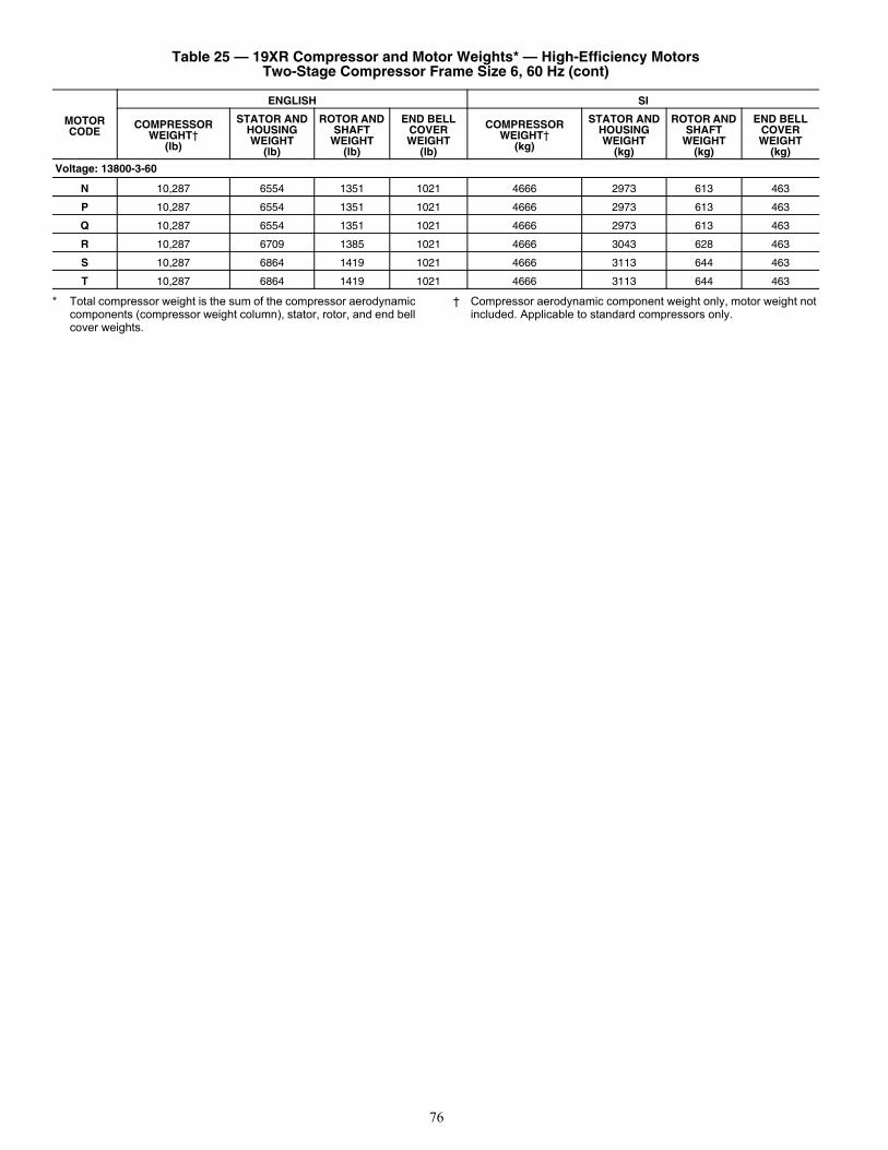
76
* Total compressor weight is the sum of the compressor aerodynamic components (compressor weight column), stator, rotor, and end bell cover weights.
† Compressor aerodynamic component weight only, motor weight not included. Applicable to standard compressors only.
Voltage: 13800-3-60
N 10,287 6554 1351 1021 4666 2973 613 463
P 10,287 6554 1351 1021 4666 2973 613 463
Q 10,287 6554 1351 1021 4666 2973 613 463
R 10,287 6709 1385 1021 4666 3043 628 463
S 10,287 6864 1419 1021 4666 3113 644 463
T 10,287 6864 1419 1021 4666 3113 644 463
Table 25 — 19XR Compressor and Motor Weights* — High-Efficiency MotorsTwo-Stage Compressor Frame Size 6, 60 Hz (cont)
MOTOR CODE
ENGLISH SI
COMPRESSOR WEIGHT†
(lb)
STATOR AND HOUSING WEIGHT
(lb)
ROTOR AND SHAFT
WEIGHT(lb)
END BELL COVERWEIGHT
(lb)
COMPRESSOR WEIGHT†
(kg)
STATOR AND HOUSING WEIGHT
(kg)
ROTOR AND SHAFT
WEIGHT(kg)
END BELL COVERWEIGHT
(kg)
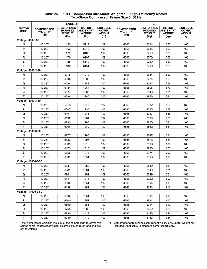
77
* Total compressor weight is the sum of the compressor aerodynamic components (compressor weight column), stator, rotor, and end bell cover weights.
† Compressor aerodynamic component weight only, motor weight not included. Applicable to standard compressors only.
Table 26 — 19XR Compressor and Motor Weights* — High-Efficiency Motors Two-Stage Compressor Frame Size 6, 50 Hz
MOTOR CODE
ENGLISH SI
COMPRESSOR WEIGHT†
(lb)
STATOR AND HOUSING WEIGHT
(lb)
ROTOR AND SHAFT
WEIGHT(lb)
END BELL COVERWEIGHT
(lb)
COMPRESSOR WEIGHT†
(kg)
STATOR AND HOUSING WEIGHT
(kg)
ROTOR AND SHAFT
WEIGHT(kg)
END BELL COVERWEIGHT
(kg)
Voltage: 400-3-50
N 10,287 1153 5917 1021 4666 2684 523 463
P 10,287 1153 5919 1021 4666 2685 523 463
Q 10,287 1179 6105 1021 4666 2769 535 463
R 10,287 1179 6107 1021 4666 2770 535 463
S 10,287 1188 6149 1021 4666 2789 539 463
T 10,287 1188 6151 1021 4666 2790 539 463
Voltage: 3000-3-50
N 10,287 5918 1212 1021 4666 2684 550 463
P 10,287 6006 1230 1021 4666 2724 558 463
Q 10,287 6094 1248 1021 4666 2764 566 463
R 10,287 6184 1264 1021 4666 2805 573 463
S 10,287 6274 1280 1021 4666 2846 581 463
T 10,287 6296 1280 1021 4666 2856 581 463
Voltage: 3300-3-50
N 10,287 5913 1212 1021 4666 2682 550 463
P 10,287 6007 1230 1021 4666 2725 558 463
Q 10,287 6101 1248 1021 4666 2767 566 463
R 10,287 6192 1264 1021 4666 2809 573 463
S 10,287 6283 1280 1021 4666 2850 581 463
T 10,287 6266 1280 1021 4666 2842 581 463
Voltage: 6300-3-50
N 10,287 6277 1280 1021 4666 2847 581 463
P 10,287 6333 1298 1021 4666 2873 589 463
Q 10,287 6389 1316 1021 4666 2898 600 463
R 10,287 6473 1316 1021 4666 2936 600 463
S 10,287 6556 1316 1021 4666 2974 600 463
T 10,287 6609 1351 1021 4666 2998 613 463
Voltage: 10000-3-50
N 10,287 6281 1280 1021 4666 2849 581 463
P 10,287 6281 1281 1021 4666 2849 581 463
Q 10,287 6281 1281 1021 4666 2849 581 463
R 10,287 6441 1316 1021 4666 2922 600 463
S 10,287 6600 1351 1021 4666 2994 613 463
T 10,287 6156 1351 1021 4666 2792 613 463
Voltage: 11000-3-50
N 10,287 6600 1351 1021 4666 2994 613 463
P 10,287 6600 1351 1021 4666 2994 613 463
Q 10,287 6600 1351 1021 4666 2994 613 463
R 10,287 6765 1385 1021 4666 3069 628 463
S 10,287 6930 1419 1021 4666 3143 644 463
T 10,287 6930 1419 1021 4666 3143 644 463
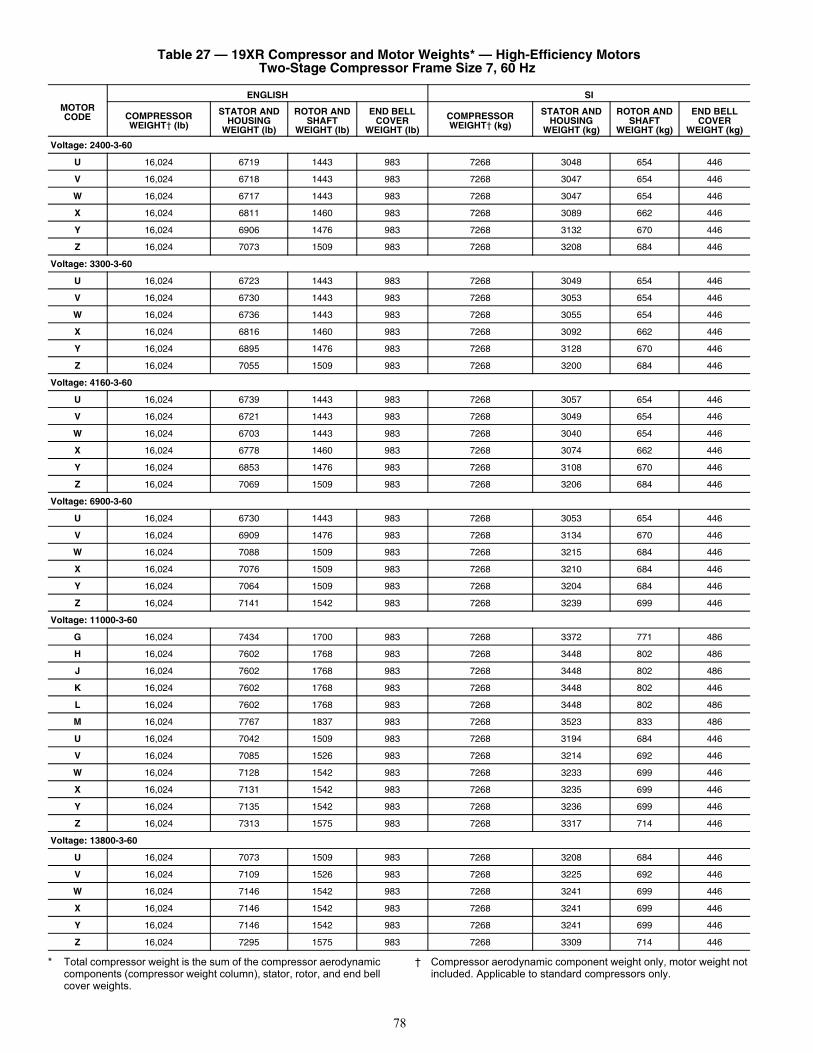
78
* Total compressor weight is the sum of the compressor aerodynamic components (compressor weight column), stator, rotor, and end bell cover weights.
† Compressor aerodynamic component weight only, motor weight not included. Applicable to standard compressors only.
Table 27 — 19XR Compressor and Motor Weights* — High-Efficiency MotorsTwo-Stage Compressor Frame Size 7, 60 Hz
MOTOR CODE
ENGLISH SI
COMPRESSOR WEIGHT† (lb)
STATOR AND HOUSING
WEIGHT (lb)
ROTOR AND SHAFT
WEIGHT (lb)
END BELL COVER
WEIGHT (lb)
COMPRESSOR WEIGHT† (kg)
STATOR AND HOUSING
WEIGHT (kg)
ROTOR AND SHAFT
WEIGHT (kg)
END BELL COVER
WEIGHT (kg)
Voltage: 2400-3-60
U 16,024 6719 1443 983 7268 3048 654 446
V 16,024 6718 1443 983 7268 3047 654 446
W 16,024 6717 1443 983 7268 3047 654 446
X 16,024 6811 1460 983 7268 3089 662 446
Y 16,024 6906 1476 983 7268 3132 670 446
Z 16,024 7073 1509 983 7268 3208 684 446
Voltage: 3300-3-60
U 16,024 6723 1443 983 7268 3049 654 446
V 16,024 6730 1443 983 7268 3053 654 446
W 16,024 6736 1443 983 7268 3055 654 446
X 16,024 6816 1460 983 7268 3092 662 446
Y 16,024 6895 1476 983 7268 3128 670 446
Z 16,024 7055 1509 983 7268 3200 684 446
Voltage: 4160-3-60
U 16,024 6739 1443 983 7268 3057 654 446
V 16,024 6721 1443 983 7268 3049 654 446
W 16,024 6703 1443 983 7268 3040 654 446
X 16,024 6778 1460 983 7268 3074 662 446
Y 16,024 6853 1476 983 7268 3108 670 446
Z 16,024 7069 1509 983 7268 3206 684 446
Voltage: 6900-3-60
U 16,024 6730 1443 983 7268 3053 654 446
V 16,024 6909 1476 983 7268 3134 670 446
W 16,024 7088 1509 983 7268 3215 684 446
X 16,024 7076 1509 983 7268 3210 684 446
Y 16,024 7064 1509 983 7268 3204 684 446
Z 16,024 7141 1542 983 7268 3239 699 446
Voltage: 11000-3-60
G 16,024 7434 1700 983 7268 3372 771 486
H 16,024 7602 1768 983 7268 3448 802 486
J 16,024 7602 1768 983 7268 3448 802 486
K 16,024 7602 1768 983 7268 3448 802 446
L 16,024 7602 1768 983 7268 3448 802 486
M 16,024 7767 1837 983 7268 3523 833 486
U 16,024 7042 1509 983 7268 3194 684 446
V 16,024 7085 1526 983 7268 3214 692 446
W 16,024 7128 1542 983 7268 3233 699 446
X 16,024 7131 1542 983 7268 3235 699 446
Y 16,024 7135 1542 983 7268 3236 699 446
Z 16,024 7313 1575 983 7268 3317 714 446
Voltage: 13800-3-60
U 16,024 7073 1509 983 7268 3208 684 446
V 16,024 7109 1526 983 7268 3225 692 446
W 16,024 7146 1542 983 7268 3241 699 446
X 16,024 7146 1542 983 7268 3241 699 446
Y 16,024 7146 1542 983 7268 3241 699 446
Z 16,024 7295 1575 983 7268 3309 714 446
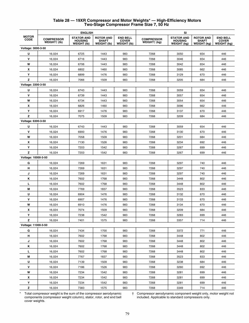
79
* Total compressor weight is the sum of the compressor aerodynamic components (compressor weight column), stator, rotor, and end bell cover weights.
† Compressor aerodynamic component weight only, motor weight not included. Applicable to standard compressors only.
Table 28 — 19XR Compressor and Motor Weights* — High-Efficiency MotorsTwo-Stage Compressor Frame Size 7, 50 Hz
MOTOR CODE
ENGLISH SI
COMPRESSOR WEIGHT† (lb)
STATOR AND HOUSING
WEIGHT (lb)
ROTOR AND SHAFT
WEIGHT (lb)
END BELL COVER
WEIGHT (lb)
COMPRESSOR WEIGHT† (kg)
STATOR AND HOUSING
WEIGHT (kg)
ROTOR AND SHAFT
WEIGHT (kg)
END BELL COVER
WEIGHT (kg)
Voltage: 3000-3-50
U 16,024 6725 1443 983 7268 3050 654 446
V 16,024 6716 1443 983 7268 3046 654 446
W 16,024 6706 1443 983 7268 3042 654 446
X 16,024 6802 1460 983 7268 3085 662 446
Y 16,024 6899 1476 983 7268 3129 670 446
Z 16,024 7066 1509 983 7268 3205 684 446
Voltage: 3300-3-50
U 16,024 6743 1443 983 7268 3059 654 446
V 16,024 6739 1443 983 7268 3057 654 446
W 16,024 6734 1443 983 7268 3054 654 446
X 16,024 6826 1460 983 7268 3096 662 446
Y 16,024 6917 1476 983 7268 3137 670 446
Z 16,024 7075 1509 983 7268 3209 684 446
Voltage: 6300-3-50
U 16,024 6743 1443 983 7268 3059 654 446
V 16,024 6900 1476 983 7268 3130 670 446
W 16,024 7058 1509 983 7268 3201 684 446
X 16,024 7130 1526 983 7268 3234 692 446
Y 16,024 7203 1542 983 7268 3267 699 446
Z 16,024 7203 1542 983 7268 3267 699 446
Voltage: 10000-3-50
G 16,024 7269 1631 983 7268 3297 740 446
H 16,024 7269 1631 983 7268 3297 740 446
J 16,024 7269 1631 983 7268 3297 740 446
K 16,024 7602 1768 983 7268 3448 802 446
L 16,024 7602 1768 983 7268 3448 802 446
M 16,024 7769 1837 983 7268 3523 833 446
U 16,024 6904 1476 983 7268 3132 670 446
V 16,024 6907 1476 983 7268 3133 670 446
W 16,024 6910 1476 983 7268 3134 670 446
X 16,024 7074 1509 983 7268 3209 684 446
Y 16,024 7238 1542 983 7268 3283 699 446
Z 16,024 7401 1575 983 7268 3357 714 446
Voltage: 11000-3-50
G 16,024 7434 1700 983 7268 3372 771 446
H 16,024 7602 1768 983 7268 3448 802 446
J 16,024 7602 1768 983 7268 3448 802 446
K 16,024 7602 1768 983 7268 3448 802 446
L 16,024 7602 1768 983 7268 3448 802 446
M 16,024 7767 1837 983 7268 3523 833 446
U 16,024 7139 1509 983 7268 3238 684 446
V 16,024 7186 1526 983 7268 3260 692 446
W 16,024 7234 1542 983 7268 3281 699 446
X 16,024 7234 1542 983 7268 3281 699 446
Y 16,024 7234 1542 983 7268 3281 699 446
Z 16,024 7383 1575 983 7268 3349 714 446
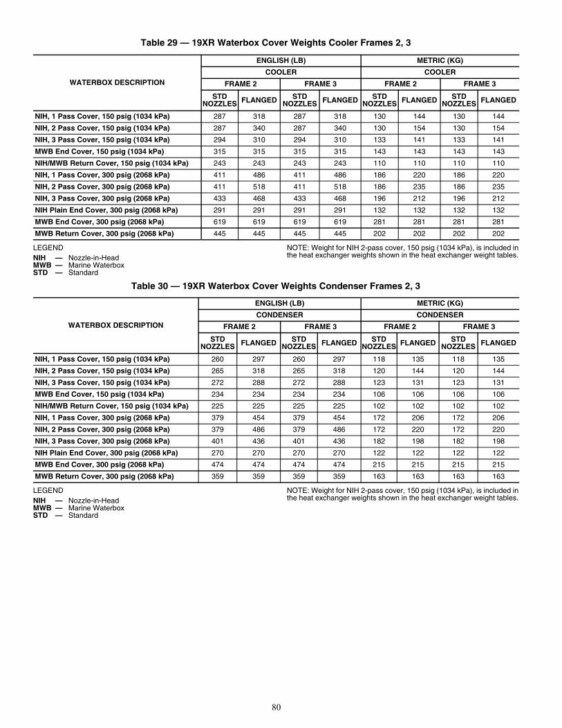
80
Table 29 — 19XR Waterbox Cover Weights Cooler Frames 2, 3
LEGEND NOTE: Weight for NIH 2-pass cover, 150 psig (1034 kPa), is included inthe heat exchanger weights shown in the heat exchanger weight tables.
Table 30 — 19XR Waterbox Cover Weights Condenser Frames 2, 3
LEGEND NOTE: Weight for NIH 2-pass cover, 150 psig (1034 kPa), is included inthe heat exchanger weights shown in the heat exchanger weight tables.
WATERBOX DESCRIPTION
ENGLISH (LB) METRIC (KG)
COOLER COOLER
FRAME 2 FRAME 3 FRAME 2 FRAME 3
STD NOZZLES FLANGED STD
NOZZLES FLANGED STD NOZZLES FLANGED STD
NOZZLES FLANGED
NIH, 1 Pass Cover, 150 psig (1034 kPa) 287 318 287 318 130 144 130 144
NIH, 2 Pass Cover, 150 psig (1034 kPa) 287 340 287 340 130 154 130 154
NIH, 3 Pass Cover, 150 psig (1034 kPa) 294 310 294 310 133 141 133 141
MWB End Cover, 150 psig (1034 kPa) 315 315 315 315 143 143 143 143
NIH/MWB Return Cover, 150 psig (1034 kPa) 243 243 243 243 110 110 110 110
NIH, 1 Pass Cover, 300 psig (2068 kPa) 411 486 411 486 186 220 186 220
NIH, 2 Pass Cover, 300 psig (2068 kPa) 411 518 411 518 186 235 186 235
NIH, 3 Pass Cover, 300 psig (2068 kPa) 433 468 433 468 196 212 196 212
NIH Plain End Cover, 300 psig (2068 kPa) 291 291 291 291 132 132 132 132
MWB End Cover, 300 psig (2068 kPa) 619 619 619 619 281 281 281 281
MWB Return Cover, 300 psig (2068 kPa) 445 445 445 445 202 202 202 202
NIH — Nozzle-in-HeadMWB — Marine WaterboxSTD — Standard
WATERBOX DESCRIPTION
ENGLISH (LB) METRIC (KG)
CONDENSER CONDENSER
FRAME 2 FRAME 3 FRAME 2 FRAME 3
STD NOZZLES FLANGED STD
NOZZLES FLANGED STD NOZZLES FLANGED STD
NOZZLES FLANGED
NIH, 1 Pass Cover, 150 psig (1034 kPa) 260 297 260 297 118 135 118 135
NIH, 2 Pass Cover, 150 psig (1034 kPa) 265 318 265 318 120 144 120 144
NIH, 3 Pass Cover, 150 psig (1034 kPa) 272 288 272 288 123 131 123 131
MWB End Cover, 150 psig (1034 kPa) 234 234 234 234 106 106 106 106
NIH/MWB Return Cover, 150 psig (1034 kPa) 225 225 225 225 102 102 102 102
NIH, 1 Pass Cover, 300 psig (2068 kPa) 379 454 379 454 172 206 172 206
NIH, 2 Pass Cover, 300 psig (2068 kPa) 379 486 379 486 172 220 172 220
NIH, 3 Pass Cover, 300 psig (2068 kPa) 401 436 401 436 182 198 182 198
NIH Plain End Cover, 300 psig (2068 kPa) 270 270 270 270 122 122 122 122
MWB End Cover, 300 psig (2068 kPa) 474 474 474 474 215 215 215 215
MWB Return Cover, 300 psig (2068 kPa) 359 359 359 359 163 163 163 163
NIH — Nozzle-in-HeadMWB — Marine WaterboxSTD — Standard
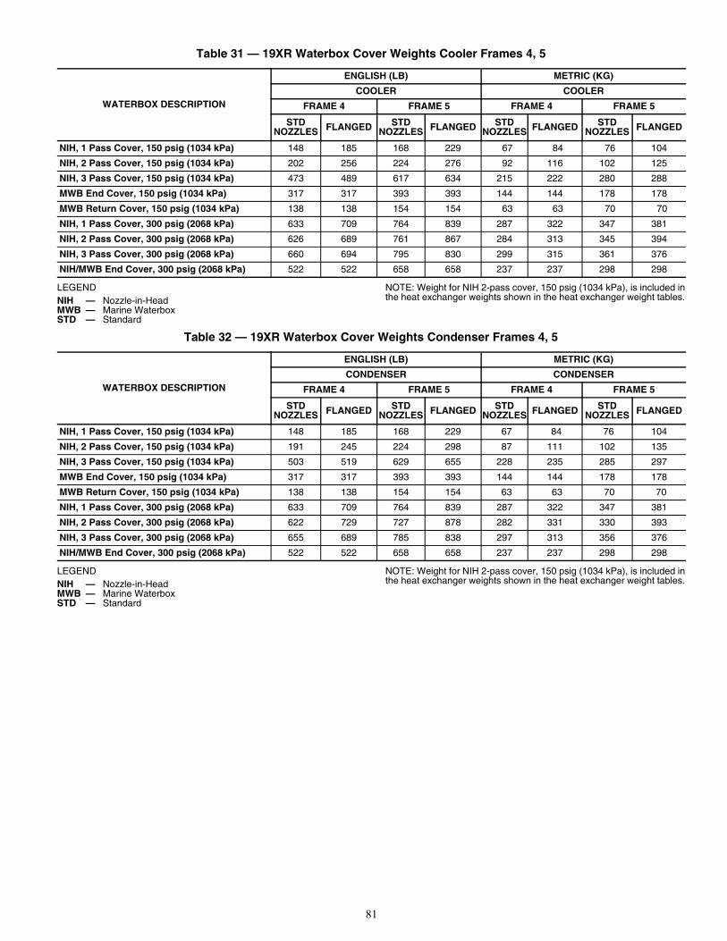
81
Table 31 — 19XR Waterbox Cover Weights Cooler Frames 4, 5
LEGEND NOTE: Weight for NIH 2-pass cover, 150 psig (1034 kPa), is included inthe heat exchanger weights shown in the heat exchanger weight tables.
Table 32 — 19XR Waterbox Cover Weights Condenser Frames 4, 5
LEGEND NOTE: Weight for NIH 2-pass cover, 150 psig (1034 kPa), is included inthe heat exchanger weights shown in the heat exchanger weight tables.
WATERBOX DESCRIPTION
ENGLISH (LB) METRIC (KG)
COOLER COOLER
FRAME 4 FRAME 5 FRAME 4 FRAME 5
STD NOZZLES FLANGED STD
NOZZLES FLANGED STD NOZZLES FLANGED STD
NOZZLES FLANGED
NIH, 1 Pass Cover, 150 psig (1034 kPa) 148 185 168 229 67 84 76 104
NIH, 2 Pass Cover, 150 psig (1034 kPa) 202 256 224 276 92 116 102 125
NIH, 3 Pass Cover, 150 psig (1034 kPa) 473 489 617 634 215 222 280 288
MWB End Cover, 150 psig (1034 kPa) 317 317 393 393 144 144 178 178
MWB Return Cover, 150 psig (1034 kPa) 138 138 154 154 63 63 70 70
NIH, 1 Pass Cover, 300 psig (2068 kPa) 633 709 764 839 287 322 347 381
NIH, 2 Pass Cover, 300 psig (2068 kPa) 626 689 761 867 284 313 345 394
NIH, 3 Pass Cover, 300 psig (2068 kPa) 660 694 795 830 299 315 361 376
NIH/MWB End Cover, 300 psig (2068 kPa) 522 522 658 658 237 237 298 298
NIH — Nozzle-in-HeadMWB — Marine WaterboxSTD — Standard
WATERBOX DESCRIPTION
ENGLISH (LB) METRIC (KG)
CONDENSER CONDENSER
FRAME 4 FRAME 5 FRAME 4 FRAME 5
STD NOZZLES FLANGED STD
NOZZLES FLANGED STD NOZZLES FLANGED STD
NOZZLES FLANGED
NIH, 1 Pass Cover, 150 psig (1034 kPa) 148 185 168 229 67 84 76 104
NIH, 2 Pass Cover, 150 psig (1034 kPa) 191 245 224 298 87 111 102 135
NIH, 3 Pass Cover, 150 psig (1034 kPa) 503 519 629 655 228 235 285 297
MWB End Cover, 150 psig (1034 kPa) 317 317 393 393 144 144 178 178
MWB Return Cover, 150 psig (1034 kPa) 138 138 154 154 63 63 70 70
NIH, 1 Pass Cover, 300 psig (2068 kPa) 633 709 764 839 287 322 347 381
NIH, 2 Pass Cover, 300 psig (2068 kPa) 622 729 727 878 282 331 330 393
NIH, 3 Pass Cover, 300 psig (2068 kPa) 655 689 785 838 297 313 356 376
NIH/MWB End Cover, 300 psig (2068 kPa) 522 522 658 658 237 237 298 298
NIH — Nozzle-in-HeadMWB — Marine WaterboxSTD — Standard
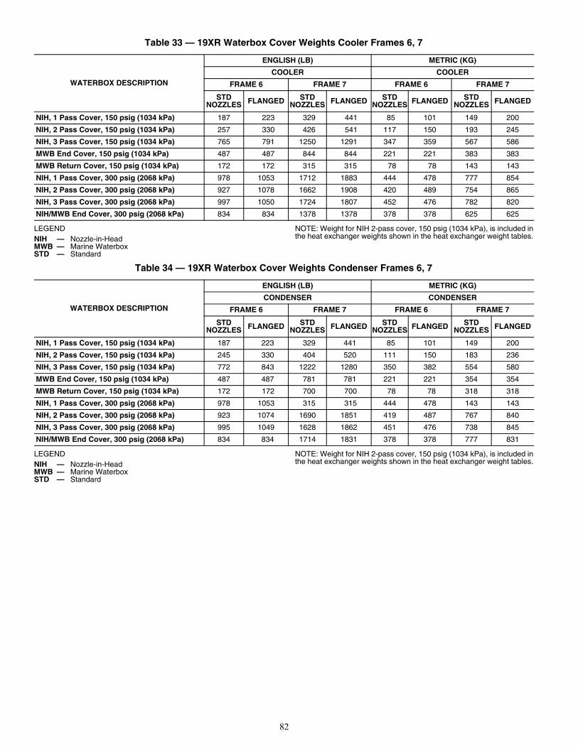
82
Table 33 — 19XR Waterbox Cover Weights Cooler Frames 6, 7
LEGEND NOTE: Weight for NIH 2-pass cover, 150 psig (1034 kPa), is included inthe heat exchanger weights shown in the heat exchanger weight tables.
Table 34 — 19XR Waterbox Cover Weights Condenser Frames 6, 7
LEGEND NOTE: Weight for NIH 2-pass cover, 150 psig (1034 kPa), is included inthe heat exchanger weights shown in the heat exchanger weight tables.
WATERBOX DESCRIPTION
ENGLISH (LB) METRIC (KG)
COOLER COOLER
FRAME 6 FRAME 7 FRAME 6 FRAME 7
STD NOZZLES FLANGED STD
NOZZLES FLANGED STD NOZZLES FLANGED STD
NOZZLES FLANGED
NIH, 1 Pass Cover, 150 psig (1034 kPa) 187 223 329 441 85 101 149 200
NIH, 2 Pass Cover, 150 psig (1034 kPa) 257 330 426 541 117 150 193 245
NIH, 3 Pass Cover, 150 psig (1034 kPa) 765 791 1250 1291 347 359 567 586
MWB End Cover, 150 psig (1034 kPa) 487 487 844 844 221 221 383 383
MWB Return Cover, 150 psig (1034 kPa) 172 172 315 315 78 78 143 143
NIH, 1 Pass Cover, 300 psig (2068 kPa) 978 1053 1712 1883 444 478 777 854
NIH, 2 Pass Cover, 300 psig (2068 kPa) 927 1078 1662 1908 420 489 754 865
NIH, 3 Pass Cover, 300 psig (2068 kPa) 997 1050 1724 1807 452 476 782 820
NIH/MWB End Cover, 300 psig (2068 kPa) 834 834 1378 1378 378 378 625 625
NIH — Nozzle-in-HeadMWB — Marine WaterboxSTD — Standard
WATERBOX DESCRIPTION
ENGLISH (LB) METRIC (KG)
CONDENSER CONDENSER
FRAME 6 FRAME 7 FRAME 6 FRAME 7
STD NOZZLES FLANGED STD
NOZZLES FLANGED STD NOZZLES FLANGED STD
NOZZLES FLANGED
NIH, 1 Pass Cover, 150 psig (1034 kPa) 187 223 329 441 85 101 149 200
NIH, 2 Pass Cover, 150 psig (1034 kPa) 245 330 404 520 111 150 183 236
NIH, 3 Pass Cover, 150 psig (1034 kPa) 772 843 1222 1280 350 382 554 580
MWB End Cover, 150 psig (1034 kPa) 487 487 781 781 221 221 354 354
MWB Return Cover, 150 psig (1034 kPa) 172 172 700 700 78 78 318 318
NIH, 1 Pass Cover, 300 psig (2068 kPa) 978 1053 315 315 444 478 143 143
NIH, 2 Pass Cover, 300 psig (2068 kPa) 923 1074 1690 1851 419 487 767 840
NIH, 3 Pass Cover, 300 psig (2068 kPa) 995 1049 1628 1862 451 476 738 845
NIH/MWB End Cover, 300 psig (2068 kPa) 834 834 1714 1831 378 378 777 831
NIH — Nozzle-in-HeadMWB — Marine WaterboxSTD — Standard
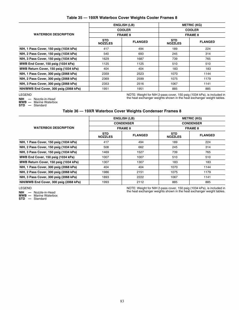
83
Table 35 — 19XR Waterbox Cover Weights Cooler Frames 8
LEGEND NOTE: Weight for NIH 2-pass cover, 150 psig (1034 kPa), is included inthe heat exchanger weights shown in the heat exchanger weight tables.
Table 36 — 19XR Waterbox Cover Weights Condenser Frames 8
LEGEND NOTE: Weight for NIH 2-pass cover, 150 psig (1034 kPa), is included inthe heat exchanger weights shown in the heat exchanger weight tables.
WATERBOX DESCRIPTION
ENGLISH (LB) METRIC (KG)
COOLER COOLER
FRAME 8 FRAME 8
STD NOZZLES FLANGED STD
NOZZLES FLANGED
NIH, 1 Pass Cover, 150 psig (1034 kPa) 417 494 189 224
NIH, 2 Pass Cover, 150 psig (1034 kPa) 540 693 245 314
NIH, 3 Pass Cover, 150 psig (1034 kPa) 1629 1687 739 765
MWB End Cover, 150 psig (1034 kPa) 1125 1125 510 510
MWB Return Cover, 150 psig (1034 kPa) 404 404 183 183
NIH, 1 Pass Cover, 300 psig (2068 kPa) 2359 2523 1070 1144
NIH, 2 Pass Cover, 300 psig (2068 kPa) 2369 2599 1075 1179
NIH, 3 Pass Cover, 300 psig (2068 kPa) 2353 2516 1067 1141
NIH/MWB End Cover, 300 psig (2068 kPa) 1951 1951 885 885
NIH — Nozzle-in-HeadMWB — Marine WaterboxSTD — Standard
WATERBOX DESCRIPTION
ENGLISH (LB) METRIC (KG)
CONDENSER CONDENSER
FRAME 8 FRAME 8
STD NOZZLES FLANGED STD
NOZZLES FLANGED
NIH, 1 Pass Cover, 150 psig (1034 kPa) 417 494 189 224
NIH, 2 Pass Cover, 150 psig (1034 kPa) 508 662 245 314
NIH, 3 Pass Cover, 150 psig (1034 kPa) 1469 1527 739 765
MWB End Cover, 150 psig (1034 kPa) 1007 1007 510 510
MWB Return Cover, 150 psig (1034 kPa) 1307 1307 183 183
NIH, 1 Pass Cover, 300 psig (2068 kPa) 404 404 1070 1144
NIH, 2 Pass Cover, 300 psig (2068 kPa) 1986 2151 1075 1179
NIH, 3 Pass Cover, 300 psig (2068 kPa) 1893 2222 1067 1141
NIH/MWB End Cover, 300 psig (2068 kPa) 1993 2112 885 885
NIH — Nozzle-in-HeadMWB — Marine WaterboxSTD — Standard
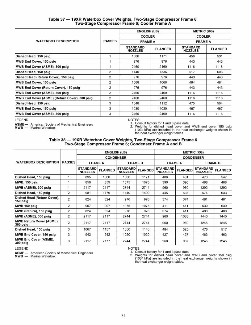
84
LEGEND NOTES:1. Consult factory for 1 and 3 pass data.2. Weights for dished head cover and MWB end cover 150 psig
(1034 kPa) are included in the heat exchanger weights shown inthe heat exchanger weight tables.
LEGEND NOTES:1. Consult factory for 1 and 3 pass data.2. Weights for dished head cover and MWB end cover 150 psig
(1034 kPa) are included in the heat exchanger weights shown inthe heat exchanger weight tables.
Table 37 — 19XR Waterbox Cover Weights, Two-Stage Compressor Frame 6 Two-Stage Compressor Frame 6; Cooler Frame A
WATERBOX DESCRIPTION PASSES
ENGLISH (LB) METRIC (KG)
COOLER COOLER
FRAME A FRAME A
STANDARD NOZZLES FLANGED STANDARD
NOZZLES FLANGED
Dished Head, 150 psig 1 1006 1171 456 531
MWB End Cover, 150 psig 1 976 976 443 443
MWB End Cover (ASME), 300 psig 1 2460 2460 1116 1116
Dished Head, 150 psig 2 1140 1336 517 606
Dished Head (Return Cover), 150 psig 2 976 976 443 443
MWB End Cover, 150 psig 2 1068 1068 484 484
MWB End Cover (Return Cover), 150 psig 2 976 976 443 443
MWB End Cover (ASME), 300 psig 2 2460 2460 1116 1116
MWB End Cover (ASME) (Return Cover), 300 psig 2 2460 2460 1116 1116
Dished Head, 150 psig 3 1048 1112 475 504
MWB End Cover, 150 psig 3 1030 1030 467 467
MWB End Cover (ASME), 300 psig 3 2460 2460 1116 1116
ASME— American Society of Mechanical EngineersMWB — Marine Waterbox
Table 38 — 19XR Waterbox Cover Weights, Two-Stage Compressor Frame 6 Two-Stage Compressor Frame 6; Condenser Frame A and B
WATERBOX DESCRIPTION PASSES
ENGLISH (LB) METRIC (KG)
CONDENSER CONDENSER
FRAME A FRAME B FRAME A FRAME B
STANDARD NOZZLES FLANGED STANDARD
NOZZLES FLANGED STANDARD NOZZLES FLANGED STANDARD
NOZZLES FLANGED
Dished Head, 150 psig 1 895 1060 1006 1171 406 481 473 547
MWB, 150 psig 1 859 859 1075 1075 390 390 488 488
MWB (ASME), 300 psig 1 2117 2117 2744 2744 960 960 1292 1292
Dished Head, 150 psig 2 981 1179 1140 1400 445 535 574 633
Dished Head (Return Cover), 150 psig 2 824 824 976 976 374 374 481 481
MWB 150 psig 2 907 907 1075 1075 411 411 630 630
MWB (Return), 150 psig 2 824 824 976 976 374 411 488 488
MWB (ASME), 300 psig 2 2117 2117 2744 2744 960 1083 1440 1440
MWB Return Cover (ASME), 300 psig 2 2117 2117 2744 2744 960 960 1245 1245
Dished Head, 150 psig 3 1067 1157 1050 1140 484 525 476 517
MWB End Cover, 150 psig 3 942 942 1020 1020 427 427 463 463
MWB End Cover (ASME), 300 psig 3 2117 2177 2744 2744 960 987 1245 1245
ASME— American Society of Mechanical EngineersMWB — Marine Waterbox
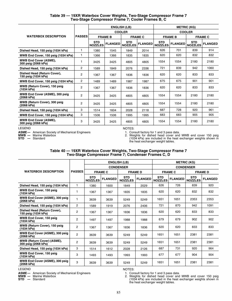
85
LEGEND NOTES:1. Consult factory for 1 and 3 pass data.2. Weights for dished head cover and MWB end cover 150 psig
(1034 kPa) are included in the heat exchanger weights shown inthe heat exchanger weight tables.
LEGEND NOTES:1. Consult factory for 1 and 3 pass data.2. Weights for dished head cover and MWB end cover 150 psig
(1034 kPa) are included in the heat exchanger weights shown inthe heat exchanger weight tables.
Table 39 — 19XR Waterbox Cover Weights, Two-Stage Compressor Frame 7 Two-Stage Compressor Frame 7; Cooler Frames B, C
WATERBOX DESCRIPTION PASSES
ENGLISH (LB) METRIC (KG)
COOLER COOLER
FRAME B FRAME C FRAME B FRAME C
STD NOZZLES FLANGED STD
NOZZLES FLANGED STD NOZZLES FLANGED STD
NOZZLES FLANGED
Dished Head, 150 psig (1034 kPa) 1 1380 1545 1849 2014 626 701 839 914
MWB End Cover, 150 psig (1034 kPa) 1 1366 1366 1835 1835 620 620 832 832
MWB End Cover (ASME), 300 psig (2068 kPa)
1 3425 3425 4805 4805 1554 1554 2180 2180
Dished Head, 150 psig (1034 kPa) 2 1589 1849 2076 2336 721 839 942 1060
Dished Head (Return Cover), 150 psig (1034 kPa)
2 1367 1367 1836 1836 620 620 833 833
MWB End Cover, 150 psig (1034 kPa) 2 1489 1489 1987 1987 675 675 901 901
MWB (Return Cover), 150 psig (1034 kPa)
2 1367 1367 1836 1836 620 620 833 833
MWB End Cover (ASME), 300 psig (2068 kPa)
2 3425 3425 4805 4805 1554 1554 2180 2180
MWB (Return Cover), 300 psig (2068 kPa)
2 3425 3425 4805 4805 1554 1554 2180 2180
Dished Head, 150 psig (1034 kPa) 3 1514 1604 2028 2118 687 728 920 961
MWB End Cover, 150 psig (1034 kPa) 3 1506 1506 1995 1995 683 683 905 905
MWB End Cover (ASME), 300 psig (2068 kPa)
3 3425 3425 4805 4805 1554 1554 2180 2180
ASME— American Society of Mechanical EngineersMWB — Marine WaterboxSTD — Standard
Table 40 — 19XR Waterbox Cover Weights, Two-Stage Compressor Frame 7 Two-Stage Compressor Frame 7; Condenser Frames C, D
WATERBOX DESCRIPTION PASSES
ENGLISH (LB) METRIC (KG)
CONDENSER CONDENSER
FRAME C FRAME D FRAME C FRAME D
STD NOZZLES FLANGED STD
NOZZLES FLANGED STD NOZZLES FLANGED STD
NOZZLES FLANGED
Dished Head, 150 psig (1034 kPa) 1 1380 1600 1849 2029 626 726 839 920
MWB End Cover, 150 psig (1034 kPa) 1 1367 1367 1835 1835 620 620 832 832
MWB End Cover (ASME), 300 psig (2068 kPa) 1 3639 3639 5249 5249 1651 1651 2353 2353
Dished Head, 150 psig (1034 kPa) 2 1589 1919 2076 2406 721 870 942 1091
Dished Head (Return Cover), 150 psig (1034 kPa) 2 1367 1367 1836 1836 620 620 833 833
MWB End Cover, 150 psig (1034 kPa) 2 1497 1497 1988 1988 679 679 902 902
MWB (Return Cover), 150 psig (1034 kPa) 2 1367 1367 1836 1836 620 620 833 833
MWB End Cover (ASME), 300 psig (2068 kPa) 2 3639 3639 5249 5249 1651 1651 2381 2381
MWB (Return Cover) (ASME), 300 psig (2068 kPa) 2 3639 3639 5249 5249 1651 1651 2381 2381
Dished Head, 150 psig (1034 kPa) 3 1514 1612 2028 2126 687 731 920 964
MWB End Cover, 150 psig (1034 kPa) 3 1493 1493 1993 1993 677 677 904 904
MWB End Cover (ASME), 300 psig (2068 kPa) 3 3639 3639 5249 5249 1651 1651 2381 2381
ASME— American Society of Mechanical EngineersMWB — Marine WaterboxSTD — Standard
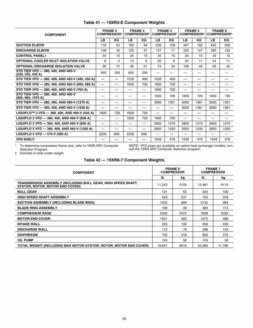
86
Table 41 — 19XR2-E Component Weights
* To determine compressor frame size, refer to 19XR,XRV Computer Selection Program.
† Included in total cooler weight.
NOTE: VFD sizes are available on select heat exchanger models; con-sult the 19XR,XRV Computer Selection program.
COMPONENTFRAME 2
COMPRESSOR*FRAME 3
COMPRESSOR*FRAME 4
COMPRESSOR*FRAME 5
COMPRESSOR*FRAME E
COMPRESSOR*
LB KG LB KG LB KG LB KG LB KG
SUCTION ELBOW 116 53 185 84 239 108 407 185 645 293
DISCHARGE ELBOW 100 45 125 57 157 71 325 147 290 132
CONTROL PANEL† 34 15 34 15 34 15 34 15 34 15
OPTIONAL COOLER INLET ISOLATION VALVE 8 4 13 6 20 9 24 11 24 11
OPTIONAL DISCHARGE ISOLATION VALVE 26 12 46 21 74 34 108 49 93 42STD TIER VFD — 380, 400, AND 460-V (230, 335, 445 A) 650 295 650 295 — — — — — —
STD TIER VFD — 380, 400, AND 460-V (485, 550 A) — — 1035 469 1035 469 — — — —
STD TIER VFD — 380, 400, AND 460-V (605, 680 A) — — 1600 726 1600 726 — — — —
STD TIER VFD — 380, 400, AND 460-V (765 A) — — — — 1600 726 — — — —STD TIER VFD — 380, 400, AND 460-V (855, 960, 1070 A) — — — — 1600 726 1600 726 1600 726
STD TIER VFD — 380, 400, AND 460-V (1275 A) — — — — 3000 1361 3000 1361 3000 1361
STD TIER VFD — 380, 400, AND 460-V (1530 A) — — — — — — 3000 1361 3000 1361
LIQUIFLO™ 2 VFD — 380, 400, AND 460-V (442 A) 1600 726 1600 726 — — — — — —
LIQUIFLO 2 VFD — 380, 400, AND 460-V (608 A) — — 1600 726 1600 726 — — — —
LIQUIFLO 2 VFD — 380, 400, AND 460-V (900 A) — — — — 2800 1270 2800 1270 2800 1270
LIQUIFLO 2 VFD — 380, 400, AND 460-V (1200 A) — — — — 2850 1293 2850 1293 2850 1293
LIQUIFLO 2 VFD — 575-V (390 A) 2200 998 2200 998 — — — — — —
VFD SHELF — — — — 1049 476 1049 476 1049 476
Table 42 — 19XR6-7 Component Weights
COMPONENTFRAME 6
COMPRESSOR FRAME 7
COMPRESSOR
lb kg lb kg
TRANSMISSION ASSEMBLY (INCLUDING BULL GEAR, HIGH SPEED SHAFT, STATOR, ROTOR, MOTOR END COVER) 11,243 5100 13,481 6115
BULL GEAR 121 55 220 100
HIGH SPEED SHAFT ASSEMBLY 523 237 700 318
SUCTION ASSEMBLY (INCLUDING BLADE RING) 1520 689 2125 964
BLADE RING ASSEMBLY 109 49 384 174
COMPRESSOR BASE 5450 2472 7898 3582
MOTOR END COVER 1021 463 1072 486
INTAKE WALL 220 100 959 435
DISCHARGE WALL 172 78 296 134
DIAPHRAGM 700 318 820 372
OIL PUMP 124 56 124 56
TOTAL WEIGHT (INCLUDING MAX MOTOR STATOR, ROTOR, MOTOR END COVER) 19,657 8916 25,983 11,786
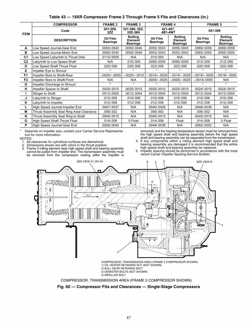
87
* Depends on impeller size, contact your Carrier Service Representa-tive for more information.
NOTES:1. All clearances for cylindrical surfaces are diametrical.2. Dimensions shown are with rotors in the thrust position.3. Frame 3 rolling element style high speed shaft and bearing assembly
cannot be pulled from impeller end. The transmission assembly mustbe removed from the compressor casting (after the impeller is
removed) and the bearing temperature sensor must be removed fromthe high speed shaft and bearing assembly before the high speedshaft and bearing assembly can be separated from the transmission.
4. If any components within a rolling element high speed shaft andbearing assembly are damaged it is recommended that the entirehigh speed shaft and bearing assembly be replaced.
5. Impeller spacing should be performed in accordance with the mostrecent Carrier Impeller Spacing Service Bulletin.
Fig. 60 — Compressor Fits and Clearances — Single-Stage Compressors
Table 43 — 19XR Compressor Frame 2 Through Frame 5 Fits and Clearances (in.)
ITEM
COMPRESSOR FRAME 2 FRAME 3 FRAME 4 FRAME 5
Code 201-299, 2ZZ
321-389, 3ZZ, 32E-38H
421-487, 4B1-4W7 501-599
DESCRIPTION Oil Film Bearings
RollingElementBearings
Oil Film Bearings
RollingElementBearings
Oil Film Bearings
Rolling Element Bearings
A Low Speed Journal-Gear End .0050/.0040 .0050/.0040 .0055/.0043 .0055/.0043 .0069/.0059 .0069/.0059B Low Speed Journal-Motor End .0050/.0040 .0050/.0040 .0053/.0043 .0053/.0043 .0065/.0055 .0065/.0055
C1 Low Speed Labyrinth to Thrust Disk .0115/.0055 N/A .010/.005 N/A N/A N/AC2 Labyrinth to Low Speed Shaft N/A .010/.005 .0095/.0055 .0095/.0055 .013/.009 .013/.009D Low Speed Shaft Thrust Float .020/.008 .020/.008 .023/.008 .023/.008 .020/.008 .020/.008E Impeller Eye to Shroud * * * * * *F1 Impeller Bore to Shaft-Rear –.0020/–.0005 –.0025/–.0010 –.0014/–.0029 –.0014/–.0029 –.0019/–.0005 –.0019/–.0005F2 Impeller Bore to Shaft-Front N/A N/A –.0005/–.0025 –.0005/–.0025 –.0014/.0000 N/AG Impeller Discharge to Shroud * * * * * *H Impeller Spacer to Shaft .0025/.0010 .0025/.0010 .0025/.0010 .0025/.0010 .0024/.0010 .0024/.0010I Slinger to Shaft .0013/.0005 .0012/.0004 .0012/.0004 .0012/.0004 .0012/.0004 .0012/.0004J Labyrinth to Slinger .013/.009 .010/.006 .010/.006 .010/.006 .010/.006 .010/.006K Labyrinth to Impeller .012/.008 .012/.008 .012/.008 .012/.008 .012/.008 .012/.008L High Speed Journal-Impeller End .0047/.0037 N/A .0040/.0028 N/A .0048/.0038 N/AM Thrust Assembly Seal Ring Axial Clearance .006/.002 N/A .006/.002 N/A .006/.002 N/AN Thrust Assembly Seal Ring to Shaft .0045/.0015 N/A .0045/.0015 N/A .0045/.0015 N/AO High Speed Shaft Thrust Float .014/.008 0 Float .014/.008 Float .014/.008 0 FloatP High Speed Journal-Gear End .0050/.0040 N/A .0048/.0038 N/A .0062/.0052 N/A
SEE VIEW A1 OR A2 A 2 3 SEE VIEW B
4
1
COMPRESSOR, TRANSMISSION AREA (FRAME 5 COMPRESSOR SHOWN)1) OIL HEATER RETAINING NUT (NOT SHOWN)2) BULL GEAR RETAINING BOLT3) DEMISTER BOLTS (NOT SHOWN)4) IMPELLER BOLT
D
COMPRESSOR, TRANSMISSION AREA (FRAME 5 COMPRESSOR SHOWN)
a19-1635
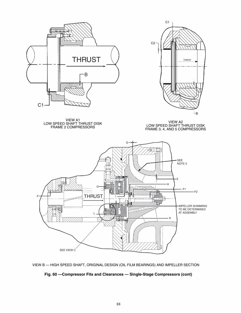
88
Fig. 60 —Compressor Fits and Clearances — Single-Stage Compressors (cont)
C1
B
THRUST THRUST
C1
C2
B
VIEW A1LOW SPEED SHAFT THRUST DISK
FRAME 2 COMPRESSORS
VIEW A2LOW SPEED SHAFT THRUST DISK
FRAME 3, 4, AND 5 COMPRESSORS
a19-1636
a19-1637
P
OF1
H
E
F2
K
I
J
IMPELLER SHIMMINGTO BE DETERMINEDAT ASSEMBLY
SEE VIEW C
THRUST
SEENOTE 5
G
L
VIEW B — HIGH SPEED SHAFT, ORIGINAL DESIGN (OIL FILM BEARINGS) AND IMPELLER SECTION
a19-1639
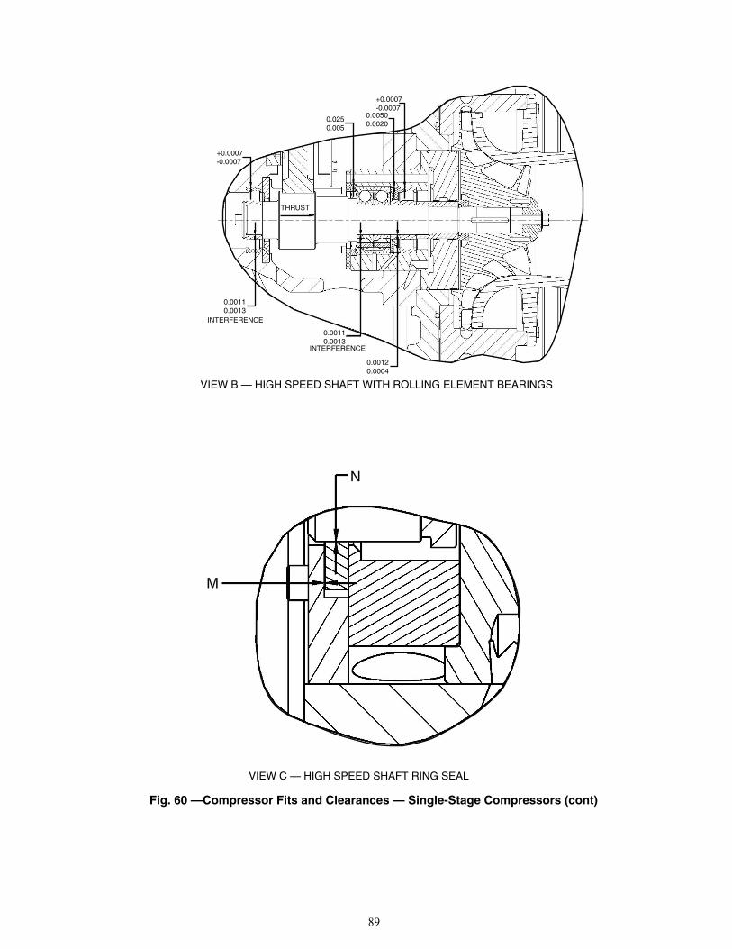
89
Fig. 60 —Compressor Fits and Clearances — Single-Stage Compressors (cont)
+0.0007-0.0007
0.00110.0013
THRUST
0.0250.005
INTERFERENCE
0.00110.0013
INTERFERENCE
+0.0007-0.0007
0.00500.0020
0.00120.0004
N
M
VIEW B — HIGH SPEED SHAFT WITH ROLLING ELEMENT BEARINGS
a19-1640
VIEW C — HIGH SPEED SHAFT RING SEAL
a19-1641
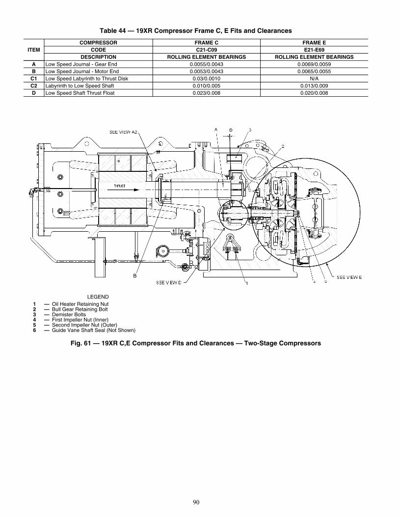
90
Fig. 61 — 19XR C,E Compressor Fits and Clearances — Two-Stage Compressors
Table 44 — 19XR Compressor Frame C, E Fits and Clearances
ITEMCOMPRESSOR FRAME C FRAME E
CODE C21-C09 E21-E69DESCRIPTION ROLLING ELEMENT BEARINGS ROLLING ELEMENT BEARINGS
A Low Speed Journal - Gear End 0.0055/0.0043 0.0069/0.0059B Low Speed Journal - Motor End 0.0053/0.0043 0.0065/0.0055
C1 Low Speed Labyrinth to Thrust Disk 0.03/0.0010 N/AC2 Labyrinth to Low Speed Shaft 0.010/0.005 0.013/0.009D Low Speed Shaft Thrust Float 0.023/0.008 0.020/0.008
B
LEGEND 1 — Oil Heater Retaining Nut2 — Bull Gear Retaining Bolt3 — Demister Bolts4 — First Impeller Nut (Inner)5 — Second Impeller Nut (Outer)6 — Guide Vane Shaft Seal (Not Shown)
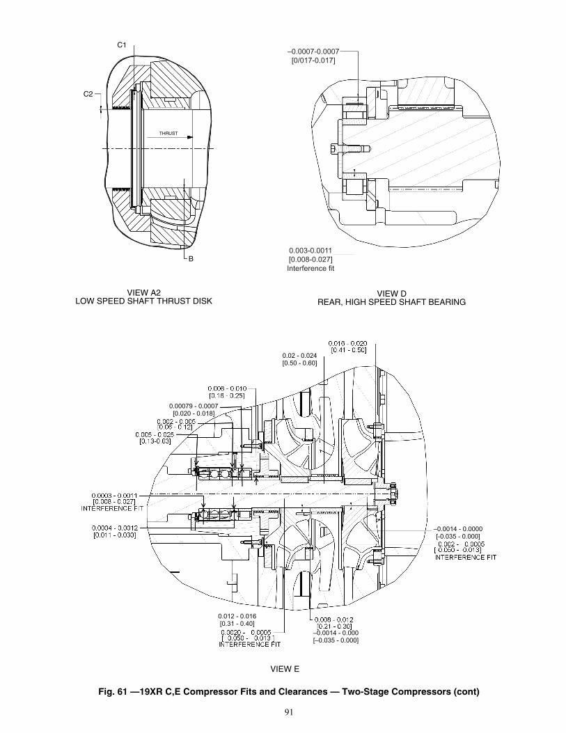
91
Fig. 61 —19XR C,E Compressor Fits and Clearances — Two-Stage Compressors (cont)
THRUST
C1
C2
B
–0.0007-0.0007[0/017-0.017]
0.003-0.0011[0.008-0.027]Interference fit
0.02 - 0.024[0.50 - 0.60]
–0.0014 - 0.000[–0.035 - 0.000]
0.012 - 0.016[0.31 - 0.40]
–0.0014 - 0.0000[-0.035 - 0.000]
0.00079 - 0.0007[0.020 - 0.018]
VIEW E
VIEW DREAR, HIGH SPEED SHAFT BEARING
VIEW A2LOW SPEED SHAFT THRUST DISK
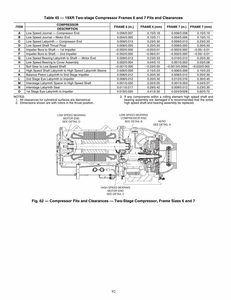
92
NOTES:1. All clearances for cylindrical surfaces are diametrical.2. Dimensions shown are with rotors in the thrust position.
3. If any components within a rolling element high speed shaft andbearing assembly are damaged it is recommended that the entirehigh speed shaft and bearing assembly be replaced.
Fig. 62 — Compressor Fits and Clearances — Two-Stage Compressor, Frame Sizes 6 and 7
Table 45 — 19XR Two-stage Compressor Frames 6 and 7 Fits and Clearances
ITEMCOMPRESSOR
FRAME 6 (in.) FRAME 6 (mm) FRAME 7 (in.) FRAME 7 (mm)DESCRIPTION
A Low Speed Journal — Compressor End 0.006/0.007 0.15/0.18 0.006/0.008 0.15/0.19B Low Speed Journal —Motor End 0.004/0.005 0.10/0.11 0.004/0.006 0.10/0.15C Low Speed Labyrinth — Compressor End 0.009/0.013 0.23/0.32 0.009/0.013 0.23/0.33D Low Speed Shaft Thrust Float 0.008/0.020 0.20/0.50 0.008/0.020 0.20/0.50E Impeller Bore to Shaft — 1st Impeller –0.002/0.000 –0.05/0.01 –0.002/0.000 –0.05/–0.01F Impeller Bore to Shaft — 2nd Impeller –0.002/0.000 –0.06/0.01 –0.002/0.000 –0.05/–0.01G Low Speed Bearing Labyrinth to Shaft — Motor End 0.009/0.013 0.23/0.33 0.010/0.012 0.25/0.30H Low Speed Bearing to Cover Assembly 0.002/0.004 0.04/0.10 0.001/0.003 0.03/0.08I Bull Gear to Low Speed Shaft –0.001/0.000 –0.03/0.00 –0.0013/0.0000 –0.033/0.000J High Speed Shaft Labyrinth to High Speed Labyrinth Sleeve 0.006/0.009 0.15/0.23 0.006/0.009 0.15/0.23K Balance Piston Labyrinth to 2nd Stage Impeller 0.008/0.012 0.20/0.30 0.008/0.012 0.20/0.30L 2nd Stage Eye Labyrinth to Impeller 0.008/0.012 0.20/0.30 0.012/0.016 0.30/0.40M Interstage Labyrinth Spacer to High Speed Shaft 0.001/0.002 0.02/0.05 0.001/0.003 0.04/0.07N Interstage Labyrinth Seal 0.011/0.017 0.29/0.42 0.009/0.012 0.23/0.30O 1st Stage Eye Labyrinth to Impeller 0.016/0.020 0.41/0.50 0.024/0/028 0.62/0.72
LOW SPEED BEARINGMOTOR END
SEE DETAIL D
LOW SPEED BEARINGCOMPRESSOR END
SEE DETAIL B AEROSEE DETAIL A
HIGH SPEED BEARINGMOTOR END
SEE DETAIL C
a19-2217
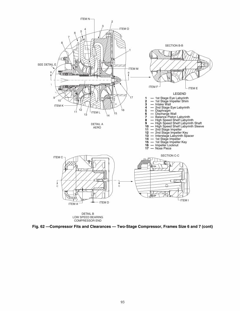
93
Fig. 62 —Compressor Fits and Clearances — Two-Stage Compressor, Frames Size 6 and 7 (cont)
BB
SEE DETAIL E
ITEM M
ITEM O
ITEM N
ITEM K
ITEM L
1
2
34
56
7
8
910
1112
13 1415
16
17
DETAIL AAERO
ITEM F ITEM E
SECTION B-B
a19-2277
CC
ITEM DITEM A
ITEM CSECTION C-C
ITEM I
DETAIL BLOW SPEED BEARINGCOMPRESSOR END
a19-2278
LEGEND 1 — 1st Stage Eye Labyrinth2 — 1st Stage Impeller Shim3 — Intake Wall4 — 2nd Stage Eye Labyrinth5 — Diaphragm6 — Discharge Wall7 — Balance Piston Labyrinth8 — High Speed Shelf Labyrinth9 — High Speed Shelf Labyrinth Shaft10 — High Speed Shelf Labyrinth Sleeve11 — 2nd Stage Impeller12 — 2nd Stage Impeller Key13 — Interstage Labyrinth Spacer14 — 1st Stage Impeller15 — 1st Stage Impeller Key16 — Impeller Locknut17 — Nose Piece

94
Fig. 62 —Compressor Fits and Clearances — Two-Stage Compressor, Frame Sizes 6 and 7 (cont)
DETAIL CHIGH SPEED BEARING
MOTOR ENDDETAIL D
LOW SPEED BEARINGMOTOR END
ITEM H
ITEM G
ITEM B
a19-2279
DETAIL EHIGH SPEED BEARING
COMPRESSOR END (XR6 SHOWN)
ITEM J
a19-2280
a19-2220

95
Fig. 63 — 19XRV Compressor Assembly Torques — Single and Two-Stage Compressors
CAUTIONUSE COPPER CONDUCTORS ONLYUTILISEZ DES CONDUCTEURS EN CUIVRE SEULMENT
ALWAYS USE 2 WRENCHES TO TIGHTEN• TERM INSULATOR TO MOTOR – 15-35 ft. lb.• BRASS NUT TO TERM INSULATOR – 3 ft. lb. max• ADAPTOR TO TERM STUD – 20-35 ft. lb.• LUG BOLTS (1/2")– 32-45 ft. lb.
Insulate entire connection with electrical insulationincluding 1 inch of cable insulation and 1 inch of theterm insulator.
!
TERMINAL STUD INSULATION
ADAPTERBRASS NUT
TERMINALINSULATOR
1
2
3
13
CAUTIONUSE COPPER CONDUCTORS ONLYUTILISEZ DES CONDUCTEURS EN CUIVRE SEULMENT
ALWAYS USE 2 WRENCHES TO TIGHTEN• TERM INSULATOR TO MOTOR – 15-35 ft. lb.• CABLE LUG NUT – 40-45 ft. lb.
Insulate entire connection with electrical insulationincluding 1 inch of cable insulation and 1 inch of theterm insulator.
!
TAPE TO EXTEND TO AND OVERLEAD WIRE INSULATION
AFTER ATTACHING LEAD, THIS AREATO BE WRAPPED WITH ONE LAYER OFTHERMAL INSULATION PUTTY AND ATLEAST FOUR LAYERS OF APPROPRIATEELECTRICAL INSULATING TAPE.
1
2
3
12
6
4
5
MOTOR LEAD INSTALLATION LABELS
19XRV COMPRESSOR ASSEMBLY TORQUES
19XRV COMPRESSOR ASSEMBLY TORQUES FRAME C, E
ITEM
COMPRESSOR FRAME 2 FRAME 3 FRAME 4 FRAME 4 FRAME 5
CODE 201-299, 2ZZ 321-389, 3ZZ, 32E-38H 421-487 4B1-4W7 501-599
DESCRIPTION FIXED DIFFUSER
WITH ROLLINGELEMENTBEARINGS
FIXED DIFFUSER
SPLIT RING DIFFUSER
SPLIT RING DIFFUSER
1 Oil Heater Retaining Nut — ft-lb (N·m) N/A 18-22 (25-30) 18-22 (25-30) 18-22 (25-30) 18-22 (25-30)2 Bull Gear Retaining Bolt — ft-lb (N·m) 80-90 (108-122) 80-90 (108-122) 80-90 (108-122) 80-90 (108-122) 80-90 (108-122)3 Demister Bolts — ft-lb (N·m) 15-19 (20-26) 15-19 (20-26) 15-19 (20-26) 15-19 (20-26) 15-19 (20-26)4 Impeller Bolt Torque — ft-lb (N·m) 32-48 (43-65) 55-60 (75-81) 55-60 (75-81) 55-60 (75-81) 160-225 (217-305)
ITEMCOMPRESSOR FRAME C FRAME E
CODE C21-C89 E31-E691 Oil Heater Retaining Nut — ft-lb (N·m) 18-22 (24-30) 18-22 (24-30)2 Bull Gear Retaining Bolt — ft-lb (N·m) 80-90 (108-122) 80-90 (108-122)3 Demister Bolts — ft-lb (N·m) 15-19 (20-26) 15-19 (20-26)4 Impeller Nut (Inner) — ft-lb (N·m) 100 (136) 250 (339)5 Impeller Nut (Outer) — ft-lb (N·m) 100 (136) 100 (136)6 Guide Vane Shaft Seal Nut — ft-lb (N·m) 25 (34) 25 (34)
a19-1642 a19-1643
Mandatory for medium/high voltage.
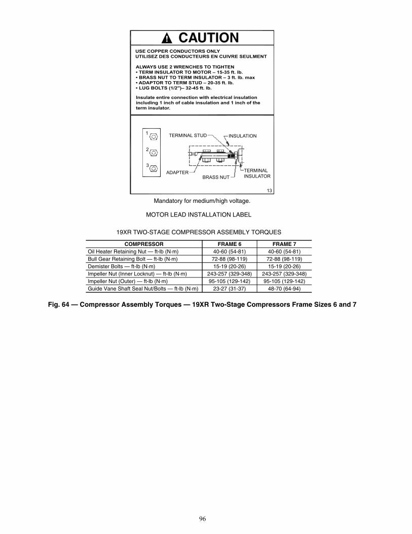
96
Fig. 64 — Compressor Assembly Torques — 19XR Two-Stage Compressors Frame Sizes 6 and 7
CAUTIONUSE COPPER CONDUCTORS ONLYUTILISEZ DES CONDUCTEURS EN CUIVRE SEULMENT
ALWAYS USE 2 WRENCHES TO TIGHTEN• TERM INSULATOR TO MOTOR – 15-35 ft. lb.• BRASS NUT TO TERM INSULATOR – 3 ft. lb. max• ADAPTOR TO TERM STUD – 20-35 ft. lb.• LUG BOLTS (1/2")– 32-45 ft. lb.
Insulate entire connection with electrical insulationincluding 1 inch of cable insulation and 1 inch of theterm insulator.
!
TERMINAL STUD INSULATION
ADAPTERBRASS NUT
TERMINALINSULATOR
1
2
3
13
MOTOR LEAD INSTALLATION LABEL
19XR TWO-STAGE COMPRESSOR ASSEMBLY TORQUES
COMPRESSOR FRAME 6 FRAME 7Oil Heater Retaining Nut — ft-lb (N·m) 40-60 (54-81) 40-60 (54-81)Bull Gear Retaining Bolt — ft-lb (N·m) 72-88 (98-119) 72-88 (98-119)Demister Bolts — ft-lb (N·m) 15-19 (20-26) 15-19 (20-26)Impeller Nut (Inner Locknut) — ft-lb (N·m) 243-257 (329-348) 243-257 (329-348)Impeller Nut (Outer) — ft-lb (N·m) 95-105 (129-142) 95-105 (129-142)Guide Vane Shaft Seal Nut/Bolts — ft-lb (N·m) 23-27 (31-37) 48-70 (64-94)
a19-1642 a19-1643Mandatory for medium/high voltage.
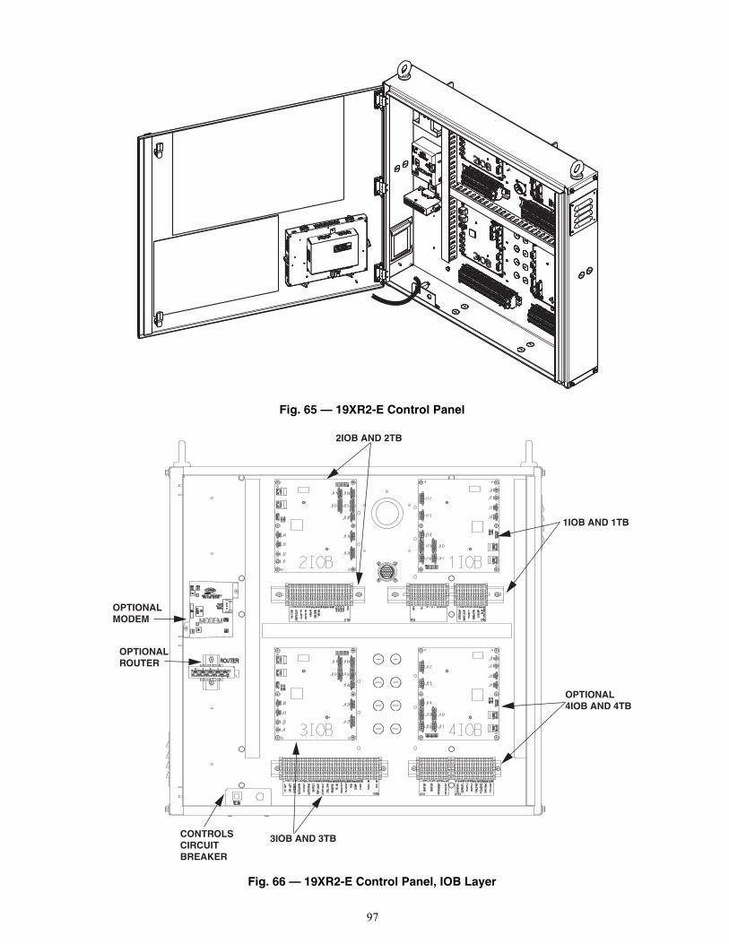
97
Fig. 65 — 19XR2-E Control Panel
Fig. 66 — 19XR2-E Control Panel, IOB Layer
2IOB AND 2TB
1IOB AND 1TB
OPTIONAL4IOB AND 4TB
3IOB AND 3TBCONTROLSCIRCUITBREAKER
OPTIONALROUTER
OPTIONALMODEM
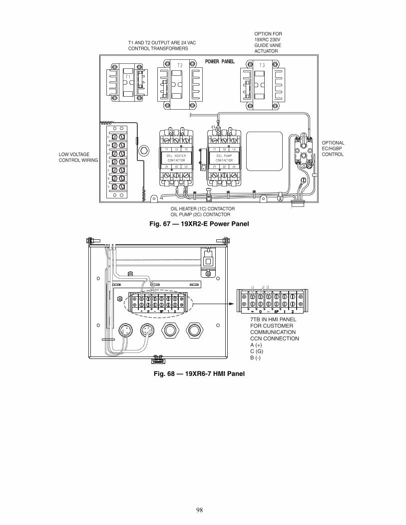
98
Fig. 67 — 19XR2-E Power Panel
Fig. 68 — 19XR6-7 HMI Panel
T1 AND T2 OUTPUT ARE 24 VAC CONTROL TRANSFORMERS
OPTION FOR 19XRC 230V GUIDE VANE ACTUATOR
LOW VOLTAGE CONTROL WIRING
OIL HEATER (1C) CONTACTOROIL PUMP (2C) CONTACTOR
OPTIONAL EC/HGBP CONTROL
a19-2251
7TB IN HMI PANELFOR CUSTOMERCOMMUNICATIONCCN CONNECTIONA (+)C (G)B (-)
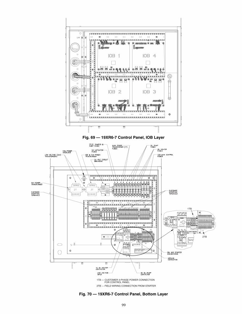
99
Fig. 69 — 19XR6-7 Control Panel, IOB Layer
Fig. 70 — 19XR6-7 Control Panel, Bottom Layer
1TB — CUSTOMER 3-PHASE POWER CONNECTION FOR CONTROL PANEL
2TB — FIELD WIRING CONNECTION FROM STARTER
1TB
2TB
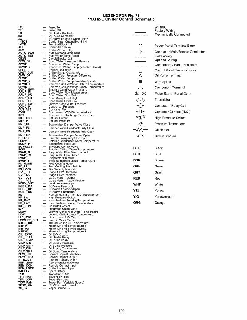
100
LEGEND FOR Fig. 71 19XR2-E Chiller Control Schematic
1FU — Fuse, 5A2FU — Fuse, 10A1C — Oil Heater Contactor2C — Oil Pump Contactor3C — EC Valve Solenoid Open Relay1-4IOB — Carrier Input Output Board 1-41-4TB — Terminal Block 1-4ALE — Chiller Alert RelayALM — Chiller Alarm RelayAUTO_DEM — Auto Demand Limit InputAUTO_RES — Auto Water Temp ResetCB2/3 — Circuit Breaker 2/3CDW_DP — Cond Water Pressure DifferenceCDWP — Condenser Water PumpCDWP_V — Condenser Water Pump (Variable Speed)CHRS — Chiller Run StatusCHST_OUT — Chiller Status Output mACHW_DP — Chilled Water Pressure DifferenceCHWP — Chilled Water PumpCHWP_V — Chilled Water Pump (Variable Speed)CHWR_T — Common Chilled Water Return TemperatureCHWS_T — Common Chilled Water Supply TemperatureCOND_EWP — Entering Cond Water PressureCOND_FL — Cond Water Flow MeasurementCOND_FS — Cond Water Flow SwitchCOND_LH — Cond Sump Level HighCOND_LL — Cond Sump Level LowCOND_LWP — Leaving Cond Water PressureCOND_P — Condenser PressureCUS_ALE — Customer AlertCVSI — Compressor VFD/Starter InterlockDGT — Compressor Discharge TemperatureDIFF_OUT — Diffuser OutputDIFF_P — Diffuser PressureDMP_CL — Economizer Damper Valve CloseDMP_FC — Damper Valve Feedback Fully CloseDMP_FO — Damper Valve Feedback Fully OpenDMP_OP — Economizer Damper Valve OpenE_STOP — Remote Emergency Stop InputECDW — Entering Condenser Water TemperatureECON_P — Economizer PressureEC VALVE — Envelope Control ValveECW — Entering Chilled Water TemperatureEVAP_FL — Evap Water Flow MeasurementEVAP_FS — Evap Water Flow SwitchEVAP_P — Evaporator PressureEVAP_T — Evap Refrigerant Liquid TemperatureFC_MODE — Free Cooling ModeFC_SS — Free Cooling Start SwitchFS_LOCK — Fire Security InterlockGV1_DEC — Stage 1 IGV DecreaseGV1_INC — Stage 1 IGV IncreaseGV1_OUT — Guide Vane 1 OutputGV1_POS — Guide Vane 1 Actual PositionHDPV_OUT — head pressure outputHGBP_MA — EC Valve FeedbackHGBP_OP — EC Valve Solenoid/OpenHGBP_OUT — EC Valve Output mAHMI — Human Machine Interface (Touch Screen)HP_SW — High Pressure SwitchHR_EWT — Heat Reclaim Entering TemperatureHR_LWT — Heat Reclaim Leaving TemperatureICE_CON — Ice Build ContactIGV — Integrated Guide VaneLCDW — Leaving Condenser Water TemperatureLCW — Leaving Chilled Water TemperatureLLC_EXV — Liquid Level EXV OutputLOWLIFT_OUT — Low Lift Valve OutputMTRB_OIL — Thrust Bearing Oil TemperatureMTRW1 — Motor Winding Temperature 1MTRW2 — Motor Winding Temperature 2MTRW3 — Motor Winding Temperature 3OIL_EXVO — Oil EVX OutputOIL_HEAT — Oil Heater RelayOIL_PUMP — Oil Pump RelayOILP_DIS — Oil Supply PressureOILP_SMP — Oil Sump PressureOILT_DIS — Oil Supply TemperatureOILT_SMP — Oil Sump TemperaturePOW_FDB — Power Request FeedbackPOW_REQ — Power Request OutputR_RESET — Remote Reset SensorREF_LEAK — Refrigerant Leak SensorREM_CON — Remote Contact InputREM_LOCK — Chiller Lockout InputSAFETY — Spare SafetyT1/2 — Transformer 1/2TFR_HIGH — Tower Fan HighTFR_LOW — Tower Fan LowTOW_FAN — Tower Fan (Variable Speed)VFDC_MA — FS VFD Load CurrentVS_SV — Vapor Source SV
WIRINGFactory WiringMechanically Connected
Power Panel Terminal Block
Conductor Male/Female ConductorField WiringOptional Wiring
Component / Panel Enclosure
Control Panel Terminal Block
Oil Pump Terminal
Wire Splice
Component Terminal
Motor Starter Panel Conn
Thermistor
Contactor / Relay Coil
Contactor Contact (N.O.)
High Pressure Switch
Pressure Transducer
Oil Heater
Circuit Breaker
BLK Black
BLU Blue
BRN Brown
GRN Green
GRY Gray
RED Red
WHT White
YEL Yellow
Y/G Yellow/green
ORG Orange
� �
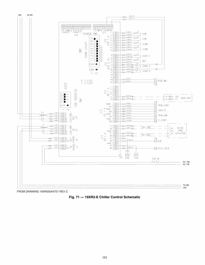
101
Fig. 71 — 19XR2-E Chiller Control Schematic
FROM DRAWING 19XR05044701 REV C
TO HMILEN
TO 1 TB+TO 1 TB-
LEN 24 VAC
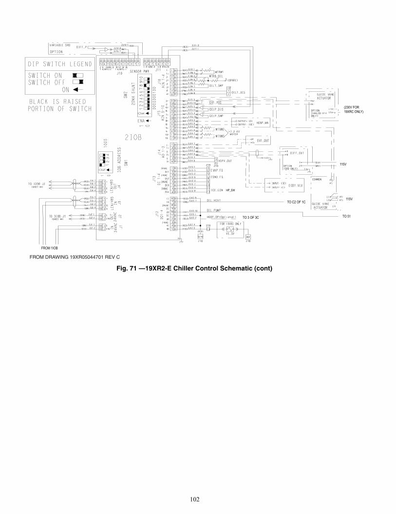
102
Fig. 71 —19XR2-E Chiller Control Schematic (cont)
FROM DRAWING 19XR05044701 REV C
HP_SW
FROM 1IOB
(230V FOR19XRC ONLY)
115V
115V
TO 51
TO C2 OF 1C
TO 3 OF 3C
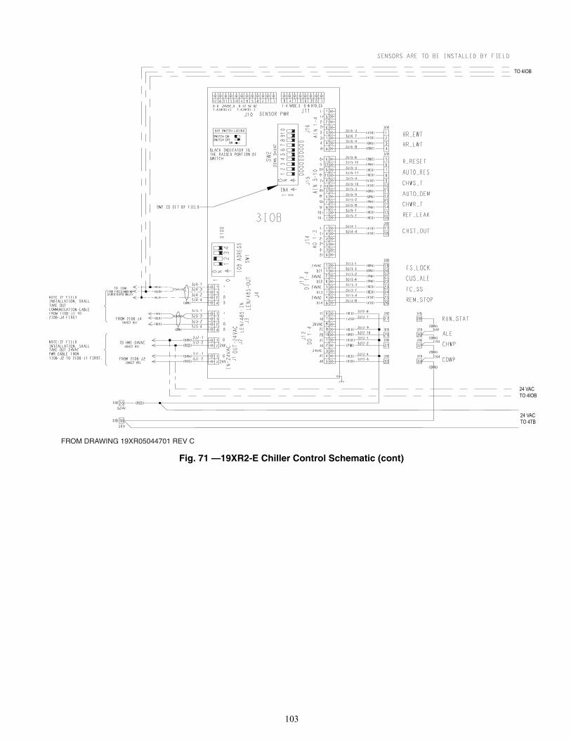
103
Fig. 71 —19XR2-E Chiller Control Schematic (cont)
FROM DRAWING 19XR05044701 REV C
TO 4IOB
24 VACTO 4IOB
24 VACTO 4TB
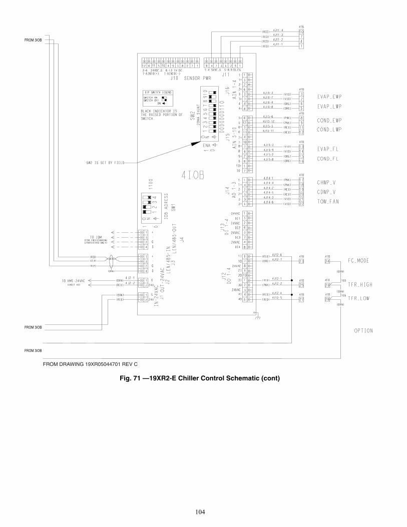
104
Fig. 71 —19XR2-E Chiller Control Schematic (cont)
FROM 3IOB
FROM 3IOB
FROM DRAWING 19XR05044701 REV C
FROM 3IOB
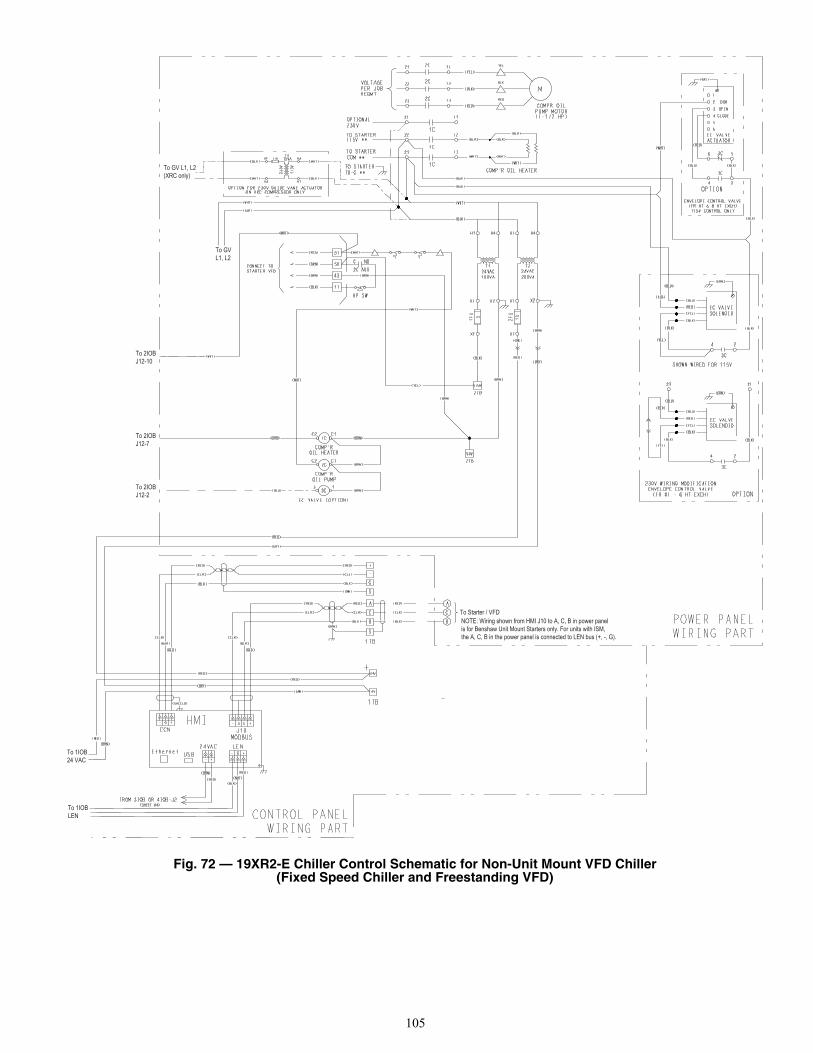
105
Fig. 72 — 19XR2-E Chiller Control Schematic for Non-Unit Mount VFD Chiller (Fixed Speed Chiller and Freestanding VFD)
To GV L1, L2(XRC only)
To GVL1, L2
To 2IOBJ12-10
To 2IOBJ12-7
To 2IOBJ12-2
To 1IOB24 VAC
To 1IOBLEN
To Starter / VFDNOTE: Wiring shown from HMI J10 to A, C, B in power panel is for Benshaw Unit Mount Starters only. For units with ISM, the A, C, B in the power panel is connected to LEN bus (+, -, G).
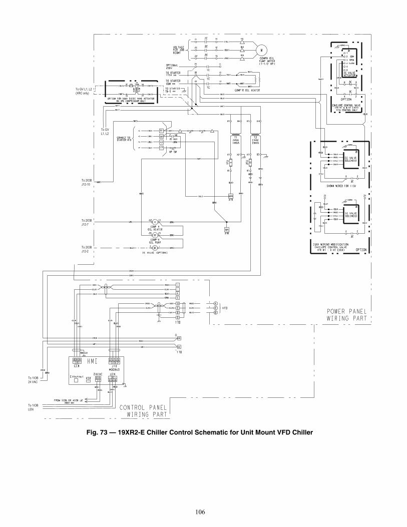
106
Fig. 73 — 19XR2-E Chiller Control Schematic for Unit Mount VFD Chiller
To GV L1, L2(XRC only)
To GVL1, L2
To 2IOBJ12-10
To 2IOBJ12-7
To 2IOBJ12-2
To 1IOB24 VAC
To 1IOBLEN
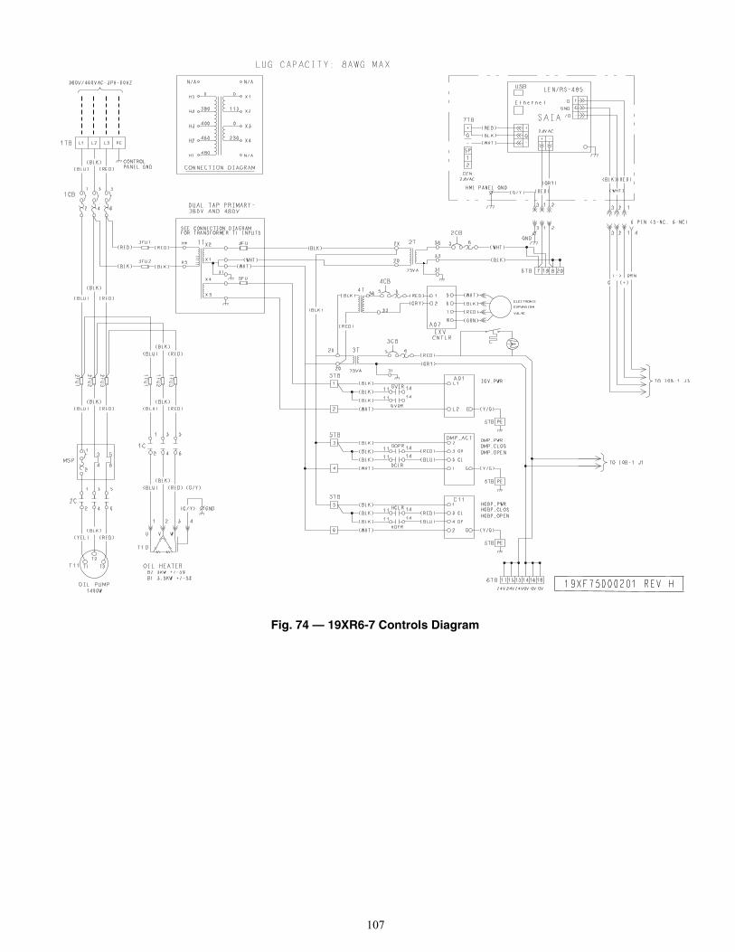
107
Fig. 74 — 19XR6-7 Controls Diagram
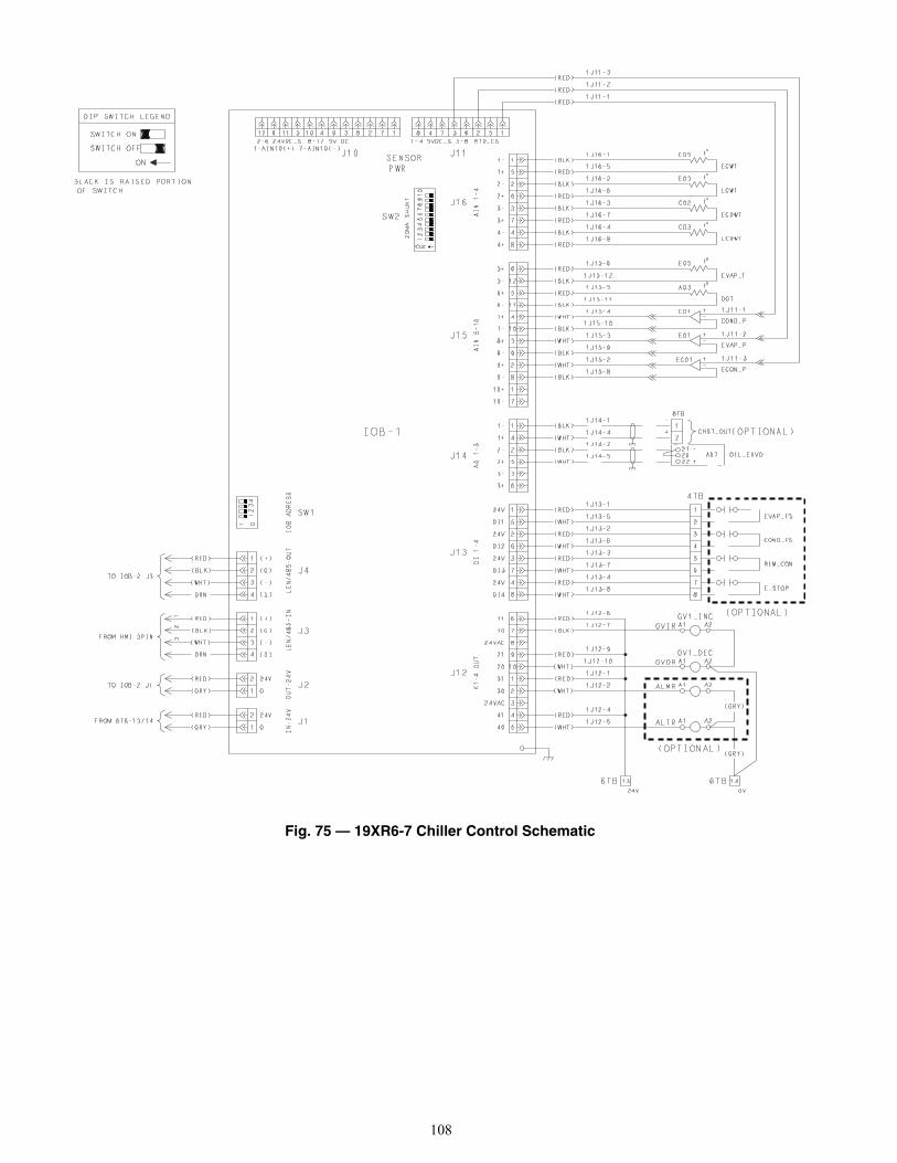
108
Fig. 75 — 19XR6-7 Chiller Control Schematic
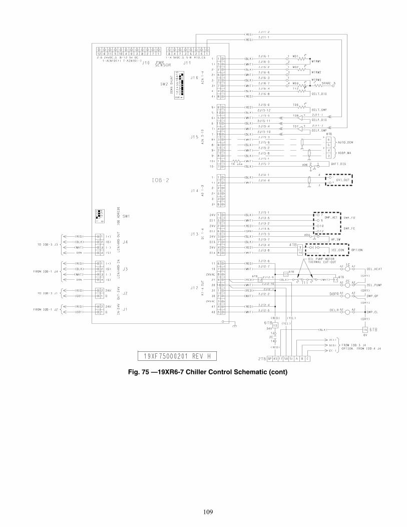
109
Fig. 75 —19XR6-7 Chiller Control Schematic (cont)

110
Fig. 75 —19XR6-7 Chiller Control Schematic (cont)
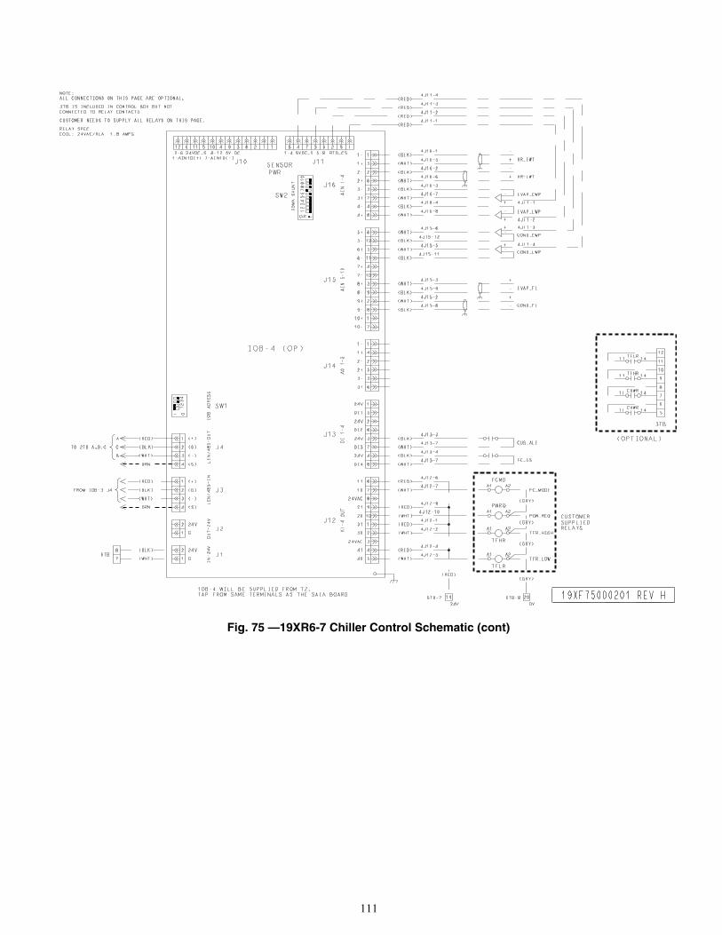
111
Fig. 75 —19XR6-7 Chiller Control Schematic (cont)
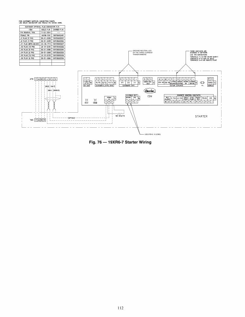
112
Fig. 76 — 19XR6-7 Starter Wiring
USE 8TB-9, 10 (IOB3)
GROUND NEUTRAL LEG OF THE THREE CURRENT TRANSFORMERS.
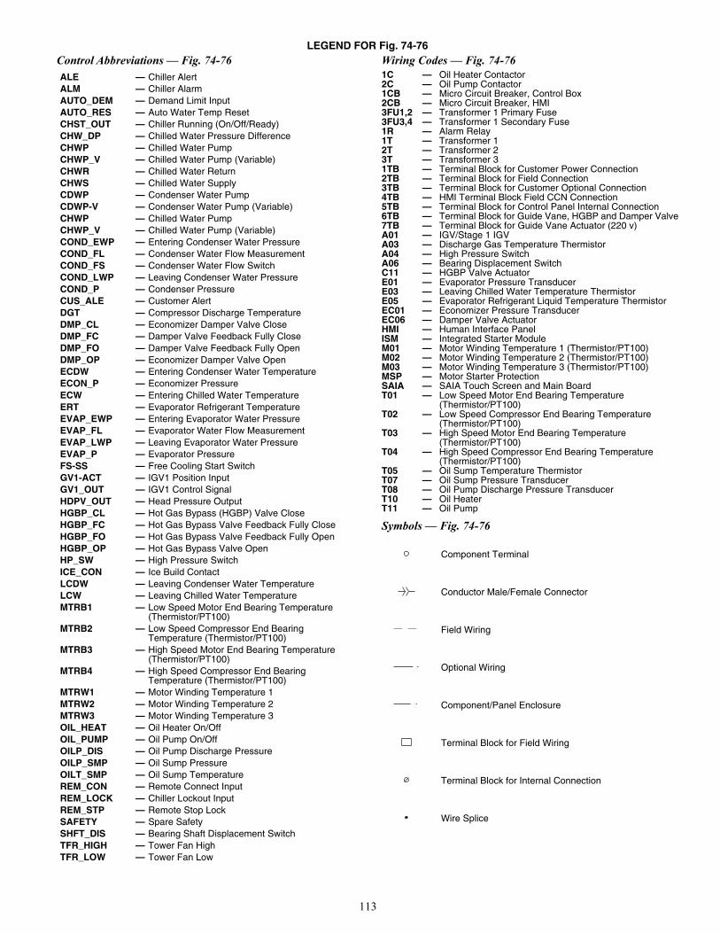
113
LEGEND FOR Fig. 74-76Control Abbreviations — Fig. 74-76 Wiring Codes — Fig. 74-76
Symbols — Fig. 74-76
ALE — Chiller AlertALM — Chiller AlarmAUTO_DEM — Demand Limit InputAUTO_RES — Auto Water Temp ResetCHST_OUT — Chiller Running (On/Off/Ready)CHW_DP — Chilled Water Pressure DifferenceCHWP — Chilled Water PumpCHWP_V — Chilled Water Pump (Variable)CHWR — Chilled Water ReturnCHWS — Chilled Water SupplyCDWP — Condenser Water PumpCDWP-V — Condenser Water Pump (Variable)CHWP — Chilled Water PumpCHWP_V — Chilled Water Pump (Variable)COND_EWP — Entering Condenser Water PressureCOND_FL — Condenser Water Flow MeasurementCOND_FS — Condenser Water Flow SwitchCOND_LWP — Leaving Condenser Water PressureCOND_P — Condenser PressureCUS_ALE — Customer AlertDGT — Compressor Discharge TemperatureDMP_CL — Economizer Damper Valve CloseDMP_FC — Damper Valve Feedback Fully CloseDMP_FO — Damper Valve Feedback Fully OpenDMP_OP — Economizer Damper Valve OpenECDW — Entering Condenser Water TemperatureECON_P — Economizer PressureECW — Entering Chilled Water TemperatureERT — Evaporator Refrigerant TemperatureEVAP_EWP — Entering Evaporator Water PressureEVAP_FL — Evaporator Water Flow MeasurementEVAP_LWP — Leaving Evaporator Water PressureEVAP_P — Evaporator PressureFS-SS — Free Cooling Start SwitchGV1-ACT — IGV1 Position InputGV1_OUT — IGV1 Control SignalHDPV_OUT — Head Pressure OutputHGBP_CL — Hot Gas Bypass (HGBP) Valve CloseHGBP_FC — Hot Gas Bypass Valve Feedback Fully CloseHGBP_FO — Hot Gas Bypass Valve Feedback Fully OpenHGBP_OP — Hot Gas Bypass Valve OpenHP_SW — High Pressure SwitchICE_CON — Ice Build ContactLCDW — Leaving Condenser Water TemperatureLCW — Leaving Chilled Water TemperatureMTRB1 — Low Speed Motor End Bearing Temperature
(Thermistor/PT100)MTRB2 — Low Speed Compressor End Bearing
Temperature (Thermistor/PT100)MTRB3 — High Speed Motor End Bearing Temperature
(Thermistor/PT100)MTRB4 — High Speed Compressor End Bearing
Temperature (Thermistor/PT100)MTRW1 — Motor Winding Temperature 1MTRW2 — Motor Winding Temperature 2MTRW3 — Motor Winding Temperature 3OIL_HEAT — Oil Heater On/OffOIL_PUMP — Oil Pump On/OffOILP_DIS — Oil Pump Discharge PressureOILP_SMP — Oil Sump PressureOILT_SMP — Oil Sump TemperatureREM_CON — Remote Connect InputREM_LOCK — Chiller Lockout InputREM_STP — Remote Stop LockSAFETY — Spare SafetySHFT_DIS — Bearing Shaft Displacement SwitchTFR_HIGH — Tower Fan HighTFR_LOW — Tower Fan Low
1C — Oil Heater Contactor2C — Oil Pump Contactor1CB — Micro Circuit Breaker, Control Box2CB — Micro Circuit Breaker, HMI3FU1,2 — Transformer 1 Primary Fuse3FU3,4 — Transformer 1 Secondary Fuse1R — Alarm Relay1T — Transformer 12T — Transformer 23T — Transformer 31TB — Terminal Block for Customer Power Connection2TB — Terminal Block for Field Connection3TB — Terminal Block for Customer Optional Connection4TB — HMI Terminal Block Field CCN Connection5TB — Terminal Block for Control Panel Internal Connection6TB — Terminal Block for Guide Vane, HGBP and Damper Valve7TB — Terminal Block for Guide Vane Actuator (220 v)A01 — IGV/Stage 1 IGVA03 — Discharge Gas Temperature ThermistorA04 — High Pressure SwitchA06 — Bearing Displacement SwitchC11 — HGBP Valve ActuatorE01 — Evaporator Pressure TransducerE03 — Leaving Chilled Water Temperature ThermistorE05 — Evaporator Refrigerant Liquid Temperature ThermistorEC01 — Economizer Pressure TransducerEC06 — Damper Valve ActuatorHMI — Human Interface PanelISM — Integrated Starter ModuleM01 — Motor Winding Temperature 1 (Thermistor/PT100)M02 — Motor Winding Temperature 2 (Thermistor/PT100)M03 — Motor Winding Temperature 3 (Thermistor/PT100)MSP — Motor Starter ProtectionSAIA — SAIA Touch Screen and Main Board T01 — Low Speed Motor End Bearing Temperature
(Thermistor/PT100)T02 — Low Speed Compressor End Bearing Temperature
(Thermistor/PT100)T03 — High Speed Motor End Bearing Temperature
(Thermistor/PT100)T04 — High Speed Compressor End Bearing Temperature
(Thermistor/PT100)T05 — Oil Sump Temperature ThermistorT07 — Oil Sump Pressure TransducerT08 — Oil Pump Discharge Pressure TransducerT10 — Oil HeaterT11 — Oil Pump
Component Terminal
Conductor Male/Female Connector
Field Wiring
Optional Wiring
Component/Panel Enclosure
Terminal Block for Field Wiring
Terminal Block for Internal Connection
Wire Splice
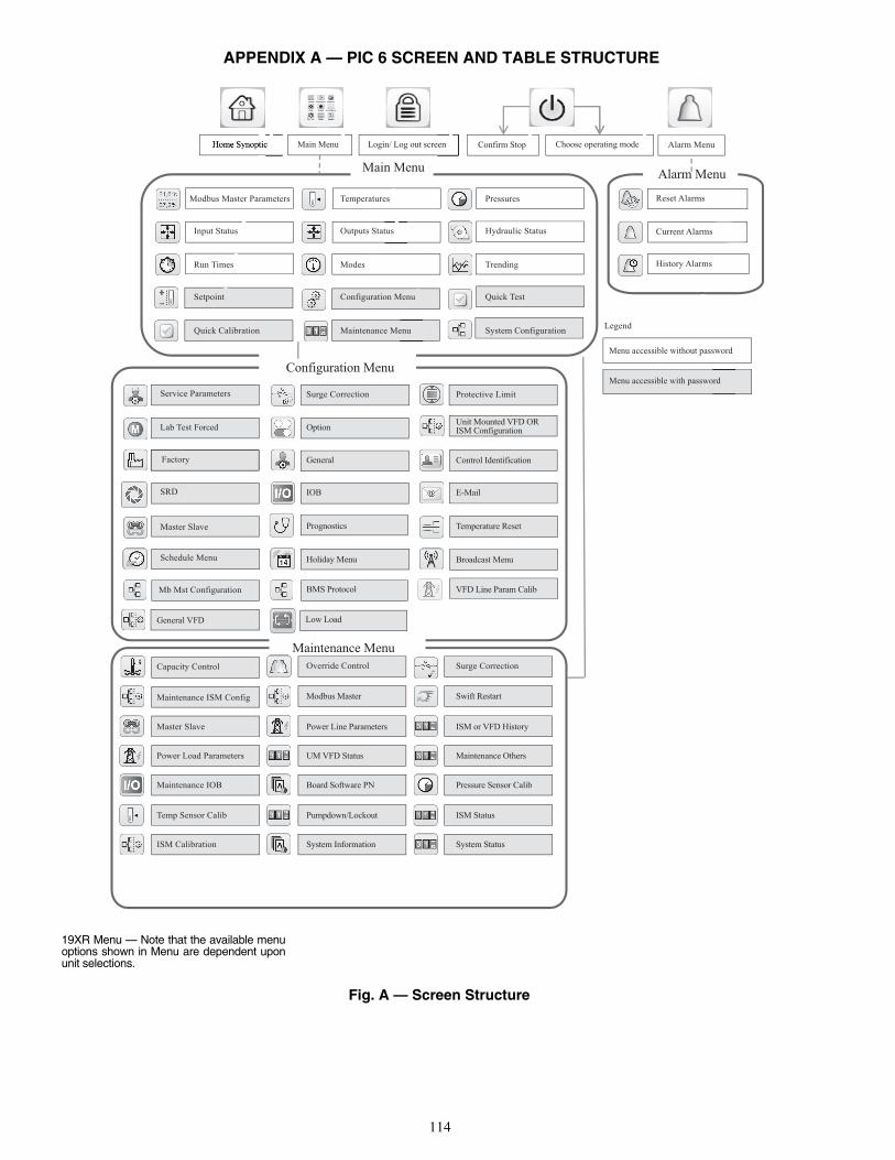
114
APPENDIX A — PIC 6 SCREEN AND TABLE STRUCTURE
Fig. A — Screen Structure
19XR Menu — Note that the available menuoptions shown in Menu are dependent uponunit selections.
General VFD
Lab Test Forced
Service Parameters
Factory
SRD
Master Slave
Schedule Menu
Mb Mst Configuration
Modbus Master Parameters
Input Status
Run Times
Setpoint
Quick Calibration
Temperatures
Outputs Status
Modes
Configuration Menu
Maintenance Menu
Pressures
Hydraulic Status
Trending
Quick Test
System Configuration
Protective Limit
Unit Mounted VFD ORISM Configuration
Control Identification
Temperature Reset
Broadcast Menu
VFD Line Param Calib
Surge Correction
Option
General
IOB
Prognostics
Holiday Menu
BMS Protocol
Maintenance ISM Config
Capacity Control
Master Slave
Power Load Parameters
Maintenance IOB
Temp Sensor Calib
ISM Calibration
Surge Correction
ISM or VFD History
Maintenance Others
Pressure Sensor Calib
ISM Status
System Status
Override Control
Modbus Master
Power Line Parameters
UM VFD Status
Board Software PN
Pumpdown/Lockout
System Information
Swift Restart
Maintenance Menu
Configuration Menu
Main MenuAlarm Menu
Reset Alarms
Current Alarms
History Alarms
Alarm MenuChoose operating modeConfirm StopLogin/ Log out screenMain MenuHome Synoptic
Legend
Menu accessible without password
Menu accessible with password
Low Load
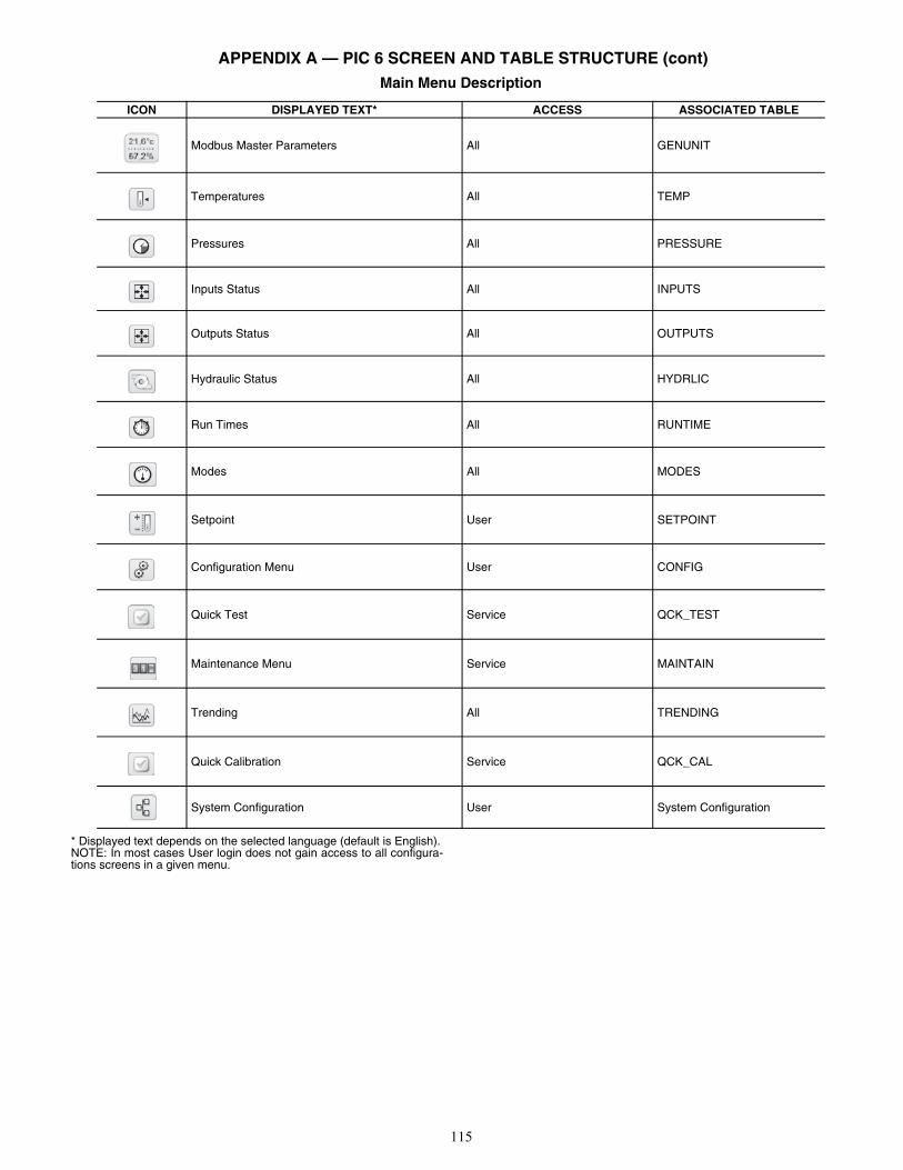
115
APPENDIX A — PIC 6 SCREEN AND TABLE STRUCTURE (cont)Main Menu Description
* Displayed text depends on the selected language (default is English).NOTE: In most cases User login does not gain access to all configura-tions screens in a given menu.
ICON DISPLAYED TEXT* ACCESS ASSOCIATED TABLE
Modbus Master Parameters All GENUNIT
Temperatures All TEMP
Pressures All PRESSURE
Inputs Status All INPUTS
Outputs Status All OUTPUTS
Hydraulic Status All HYDRLIC
Run Times All RUNTIME
Modes All MODES
Setpoint User SETPOINT
Configuration Menu User CONFIG
Quick Test Service QCK_TEST
Maintenance Menu Service MAINTAIN
Trending All TRENDING
Quick Calibration Service QCK_CAL
System Configuration User System Configuration
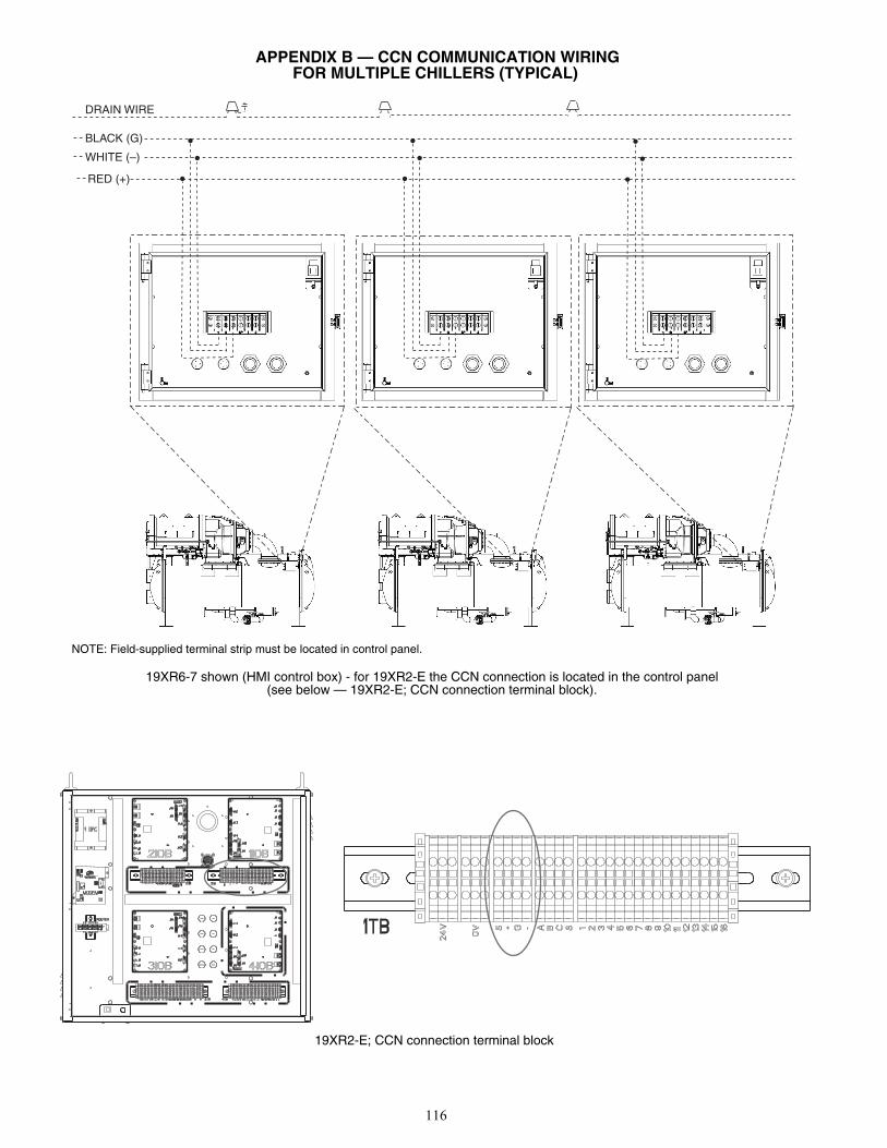
116
APPENDIX B — CCN COMMUNICATION WIRING FOR MULTIPLE CHILLERS (TYPICAL)
RED (+)
WHITE (–)
BLACK (G)
DRAIN WIRE
a19-2133NOTE: Field-supplied terminal strip must be located in control panel.
19XR6-7 shown (HMI control box) - for 19XR2-E the CCN connection is located in the control panel (see below — 19XR2-E; CCN connection terminal block).
19XR2-E; CCN connection terminal block

117
APPENDIX C — MAINTENANCE SUMMARY AND LOG SHEETS
19XR Maintenance Interval Requirements
NOTE: Equipment failures caused by lack of adherence to the Mainte-nance Interval Requirements may lose warranty coverage. See warrantyterms and conditions.
WEEKLY
COMPRESSOR Check Oil Level. CONTROLS Review PIC 6 Alarm/Alert History.
COOLER None. STARTER None.
CONDENSER None. OIL RECLAIM None.
MONTHLY
COMPRESSOR None. CONTROLS Perform an Automated Controls test.
COOLER None. STARTER None.
CONDENSER None. OIL RECLAIM None.
FIRST YEAR
COMPRESSORChange oil filter. Send oil sample out for anal-ysis. Change oil if required by analysis. Leak test.
CONTROLS Perform general cleaning. Tighten connections. Check pres-sure transducers. Confirm accuracy of thermistors.
COOLERInspect and clean cooler tubes. Inspect relief valves. Leak test. Verify water pressure differ-ential. Inspect water pumps and cooling tower.
STARTER Perform general cleaning. Tighten connections. Change VFD refrigerant strainer.
CONDENSER
Replace refrigerant filter/drier. Inspect and clean condenser tubes. Inspect relief valves. Leak test. Verify water pressure differential. Inspect water pumps and cooling tower.
OIL RECLAIM Inspect oil sump strainer.
ANNUALLY
COMPRESSORChange oil filter. Send oil sample out for anal-ysis. Change oil if required by analysis. Leak test.
CONTROLS Perform general cleaning. Tighten connections. Check pres-sure transducers. Confirm accuracy of thermistors.
COOLERInspect and clean cooler tubes. Inspect relief valves. Leak test. Verify water pressure differ-ential. Inspect water pumps and cooling tower.
STARTER Perform general cleaning. Tighten connections.
CONDENSER
Replace refrigerant filter/drier. Inspect and clean condenser tubes. Inspect relief valves. Leak test. Verify water pressure differential. Inspect water pumps and cooling tower.
OIL RECLAIM None.
STARTING EQUIPMENT
Follow all lockout-tagout procedures. Inspect inside of enclosure for contaminant build-up. Vacuum any accumulated dust or debris from internal parts. Use electronic cleaner as required.
EVERY 3-5 YEARS
COMPRESSOR None. CONTROLS None.
COOLER Perform eddy current test. STARTER None.
CONDENSER Inspect float valve and strainer. Perform eddy current test. OIL RECLAIM None.
EVERY 5 YEARS
COMPRESSOR Change oil charge (if required based on oil anal-ysis or if oil analysis has not been performed). CONTROLS None.
COOLER None. STARTER None.
CONDENSER None. OIL RECLAIM Inspect oil sump strainer. Inspect oil sump heater. Replace the oil reclaim filter.
SEASONAL SHUTDOWN
COMPRESSOR None. CONTROLS Do not disconnect control power.
COOLERIsolate and drain waterbox. Remove waterbox cover from one end. Use compressed air to clear tubes.
STARTER None.
CONDENSERIsolate and drain waterbox. Remove waterbox cover from one end. Use compressed air to clear tubes.
OIL RECLAIM None.
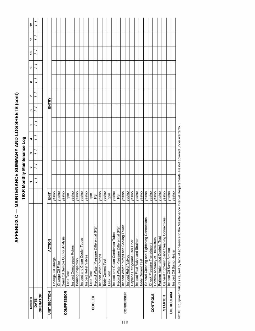
118
AP
PE
ND
IX C
— M
AIN
TE
NA
NC
E S
UM
MA
RY
AN
D L
OG
SH
EE
TS
(co
nt)
19X
R M
on
thly
Mai
nte
nan
ce L
og
NO
TE
: Equ
ipm
ent f
ailu
res
caus
ed b
y la
ck o
f adh
eren
ce to
the
Mai
nten
ance
Inte
rval
Req
uire
men
ts a
re n
ot c
over
ed u
nder
war
rant
y.
MO
NT
H1
23
45
67
89
1011
12D
AT
E
/ /
/ /
/ /
/ /
/ /
/ /
/ /
/ /
/ /
/ /
/ /
/ /
O
PE
RA
TO
R
UN
IT S
EC
TIO
NA
CT
ION
UN
ITE
NT
RY
CO
MP
RE
SS
OR
Cha
nge
Oil
Cha
rge
yes/
no
Cha
nge
Oil
Filt
erye
s/no
Sen
d O
il S
ampl
e O
ut fo
r A
naly
sis
yes/
noLe
ak T
est
ppm
Insp
ect C
ompr
esso
r R
otor
sye
s/no
Bea
ring
Insp
ectio
nye
s/no
CO
OL
ER
Insp
ect a
nd C
lean
Coo
ler
Tub
esye
s/no
Insp
ect R
elie
f Val
ves
yes/
noLe
ak T
est
ppm
Rec
ord
Wat
er P
ress
ure
Diff
eren
tial (
PS
I)P
SI
Insp
ect W
ater
Pum
psye
s/no
Edd
y C
urre
nt T
est
yes/
no
CO
ND
EN
SE
R
Leak
Tes
tpp
mIn
spec
t and
Cle
an C
onde
nser
Tub
esye
s/no
Rec
ord
Wat
er P
ress
ure
Diff
eren
tial (
PS
I)P
SI
Insp
ect W
ater
Pum
ps a
nd C
oolin
g T
ower
yes/
noIn
spec
t Rel
ief V
alve
sye
s/no
R
epla
ce R
efrig
eran
t Filt
er D
rier
yes/
noIn
spec
t Flo
at V
alve
and
Str
aine
rye
s/no
Edd
y C
urre
nt T
est
yes/
no
CO
NT
RO
LS
Gen
eral
Cle
anin
g an
d T
ight
enin
g C
onne
ctio
nsye
s/no
Che
ck P
ress
ure
Tra
nsdu
cers
yes/
noC
onfir
m A
ccur
acy
of T
herm
isto
rsye
s/no
Per
form
Aut
omat
ed C
ontr
ols
Tes
tye
s/no
ST
AR
TE
RG
ener
al T
ight
enin
g an
d C
lean
ing
Con
nect
ions
yes/
no
OIL
RE
CL
AIM
Insp
ect O
il S
ump
Str
aine
rye
s/no
Insp
ect O
il S
ump
Hea
ter
yes/
no
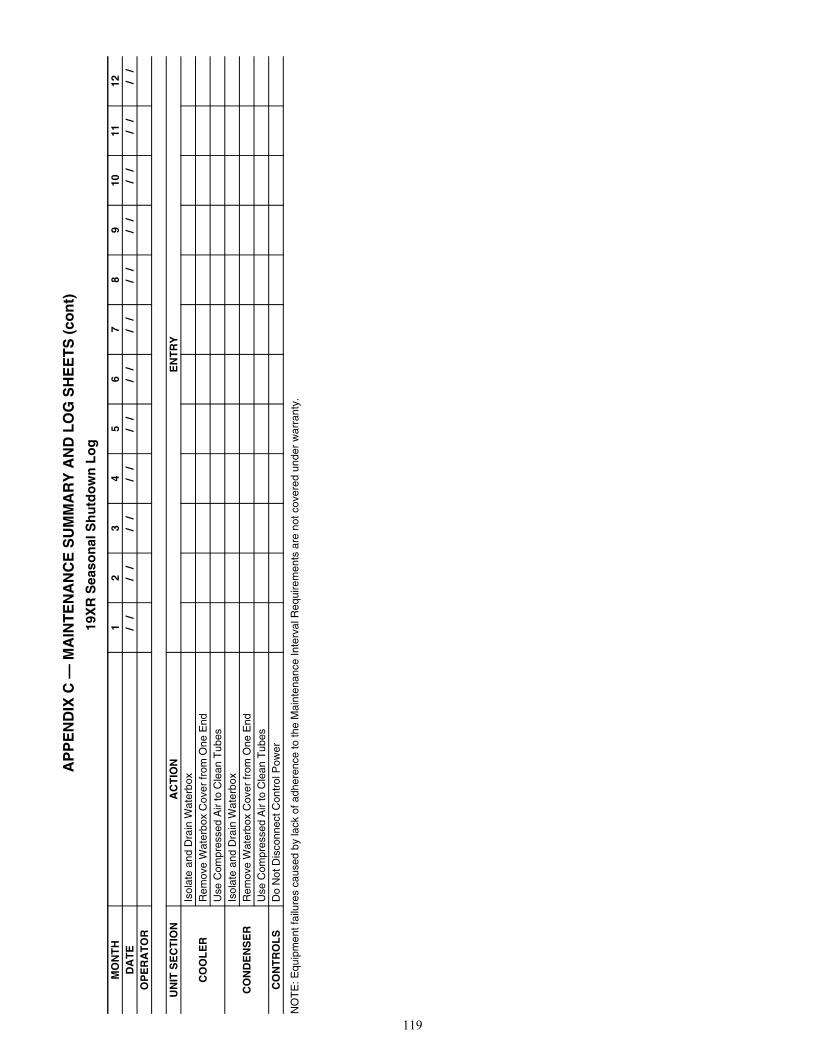
119
AP
PE
ND
IX C
— M
AIN
TE
NA
NC
E S
UM
MA
RY
AN
D L
OG
SH
EE
TS
(co
nt)
19X
R S
easo
nal
Sh
utd
ow
n L
og
NO
TE
: Equ
ipm
ent f
ailu
res
caus
ed b
y la
ck o
f adh
eren
ce to
the
Mai
nten
ance
Inte
rval
Req
uire
men
ts a
re n
ot c
over
ed u
nder
war
rant
y.
MO
NT
H1
23
45
67
89
1011
12D
AT
E
/ /
/ /
/ /
/ /
/ /
/ /
/ /
/ /
/ /
/ /
/ /
/ /
O
PE
RA
TO
R
UN
IT S
EC
TIO
NA
CT
ION
EN
TR
Y
CO
OL
ER
Isol
ate
and
Dra
in W
ater
box
Rem
ove
Wat
erbo
x C
over
from
One
End
Use
Com
pres
sed
Air
to C
lean
Tub
es
CO
ND
EN
SE
RIs
olat
e an
d D
rain
Wat
erbo
xR
emov
e W
ater
box
Cov
er fr
om O
ne E
ndU
se C
ompr
esse
d A
ir to
Cle
an T
ubes
CO
NT
RO
LS
Do
Not
Dis
conn
ect C
ontr
ol P
ower
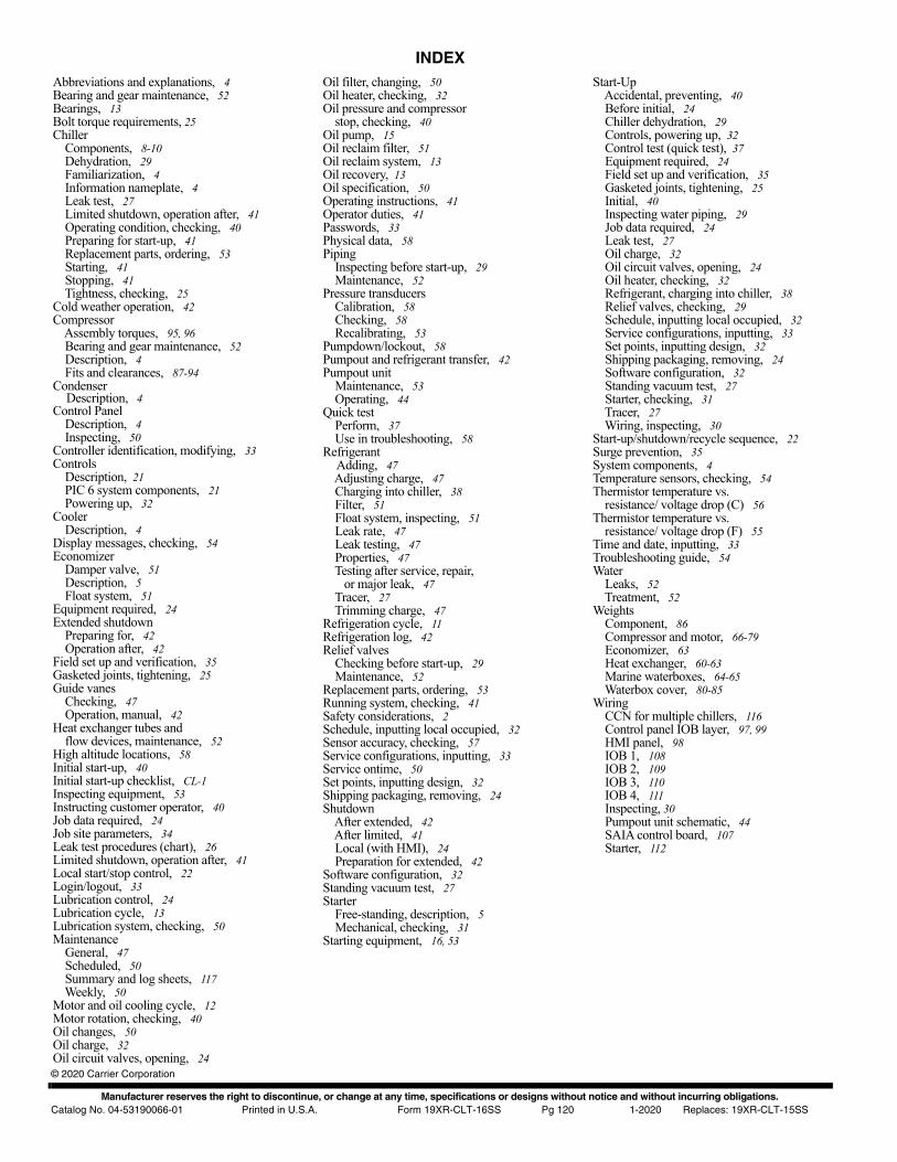
Manufacturer reserves the right to discontinue, or change at any time, specifications or designs without notice and without incurring obligations.Catalog No. 04-53190066-01 Printed in U.S.A. Form 19XR-CLT-16SS Pg 120 1-2020 Replaces: 19XR-CLT-15SS
© 2020 Carrier Corporation
INDEXAbbreviations and explanations, 4Bearing and gear maintenance, 52Bearings, 13Bolt torque requirements, 25Chiller Components, 8-10 Dehydration, 29 Familiarization, 4 Information nameplate, 4 Leak test, 27 Limited shutdown, operation after, 41 Operating condition, checking, 40 Preparing for start-up, 41 Replacement parts, ordering, 53 Starting, 41 Stopping, 41 Tightness, checking, 25Cold weather operation, 42Compressor Assembly torques, 95, 96 Bearing and gear maintenance, 52 Description, 4 Fits and clearances, 87-94Condenser Description, 4Control Panel Description, 4 Inspecting, 50Controller identification, modifying, 33Controls Description, 21 PIC 6 system components, 21 Powering up, 32Cooler Description, 4Display messages, checking, 54Economizer Damper valve, 51 Description, 5 Float system, 51Equipment required, 24Extended shutdown Preparing for, 42 Operation after, 42Field set up and verification, 35Gasketed joints, tightening, 25Guide vanes Checking, 47 Operation, manual, 42Heat exchanger tubes and flow devices, maintenance, 52High altitude locations, 58Initial start-up, 40Initial start-up checklist, CL-1Inspecting equipment, 53Instructing customer operator, 40Job data required, 24Job site parameters, 34Leak test procedures (chart), 26Limited shutdown, operation after, 41Local start/stop control, 22Login/logout, 33Lubrication control, 24Lubrication cycle, 13Lubrication system, checking, 50Maintenance General, 47 Scheduled, 50 Summary and log sheets, 117 Weekly, 50Motor and oil cooling cycle, 12Motor rotation, checking, 40Oil changes, 50Oil charge, 32Oil circuit valves, opening, 24
Oil filter, changing, 50Oil heater, checking, 32Oil pressure and compressor stop, checking, 40Oil pump, 15Oil reclaim filter, 51Oil reclaim system, 13Oil recovery, 13Oil specification, 50Operating instructions, 41Operator duties, 41Passwords, 33Physical data, 58Piping Inspecting before start-up, 29 Maintenance, 52Pressure transducers Calibration, 58 Checking, 58 Recalibrating, 53Pumpdown/lockout, 58Pumpout and refrigerant transfer, 42Pumpout unit Maintenance, 53 Operating, 44Quick test Perform, 37 Use in troubleshooting, 58Refrigerant Adding, 47 Adjusting charge, 47 Charging into chiller, 38 Filter, 51 Float system, inspecting, 51 Leak rate, 47 Leak testing, 47 Properties, 47 Testing after service, repair, or major leak, 47 Tracer, 27 Trimming charge, 47Refrigeration cycle, 11Refrigeration log, 42Relief valves Checking before start-up, 29 Maintenance, 52Replacement parts, ordering, 53Running system, checking, 41Safety considerations, 2Schedule, inputting local occupied, 32Sensor accuracy, checking, 57Service configurations, inputting, 33Service ontime, 50Set points, inputting design, 32Shipping packaging, removing, 24Shutdown After extended, 42 After limited, 41 Local (with HMI), 24 Preparation for extended, 42Software configuration, 32Standing vacuum test, 27Starter Free-standing, description, 5 Mechanical, checking, 31Starting equipment, 16, 53
Start-Up Accidental, preventing, 40 Before initial, 24 Chiller dehydration, 29 Controls, powering up, 32 Control test (quick test), 37 Equipment required, 24 Field set up and verification, 35 Gasketed joints, tightening, 25 Initial, 40 Inspecting water piping, 29 Job data required, 24 Leak test, 27 Oil charge, 32 Oil circuit valves, opening, 24 Oil heater, checking, 32 Refrigerant, charging into chiller, 38 Relief valves, checking, 29 Schedule, inputting local occupied, 32 Service configurations, inputting, 33 Set points, inputting design, 32 Shipping packaging, removing, 24 Software configuration, 32 Standing vacuum test, 27 Starter, checking, 31 Tracer, 27 Wiring, inspecting, 30Start-up/shutdown/recycle sequence, 22Surge prevention, 35System components, 4Temperature sensors, checking, 54Thermistor temperature vs. resistance/ voltage drop (C) 56Thermistor temperature vs. resistance/ voltage drop (F) 55Time and date, inputting, 33Troubleshooting guide, 54Water Leaks, 52 Treatment, 52Weights Component, 86 Compressor and motor, 66-79 Economizer, 63 Heat exchanger, 60-63 Marine waterboxes, 64-65 Waterbox cover, 80-85Wiring CCN for multiple chillers, 116 Control panel IOB layer, 97, 99 HMI panel, 98 IOB 1, 108 IOB 2, 109 IOB 3, 110 IOB 4, 111 Inspecting, 30 Pumpout unit schematic, 44 SAIA control board, 107 Starter, 112
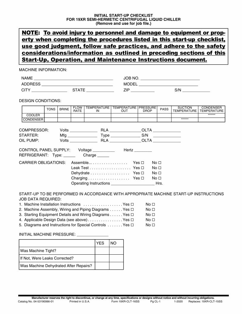
Manufacturer reserves the right to discontinue, or change at any time, specifications or designs without notice and without incurring obligations.Catalog No. 04-53190066-01 Printed in U.S.A. Form 19XR-CLT-16SS Pg CL-1 1-2020 Replaces: 19XR-CLT-15SS
INITIAL START-UP CHECKLISTFOR 19XR SEMI-HERMETIC CENTRIFUGAL LIQUID CHILLER
(Remove and use for job file.)
MACHINE INFORMATION:
DESIGN CONDITIONS:
CONTROL PANEL SUPPLY: Voltage __________ Hertz ________REFRIGERANT: Type: Charge
START-UP TO BE PERFORMED IN ACCORDANCE WITH APPROPRIATE MACHINE START-UP INSTRUCTIONSJOB DATA REQUIRED:1. Machine Installation Instructions . . . . . . . . . . . . . . . . . . Yes No 2. Machine Assembly, Wiring and Piping Diagrams . . . . . . Yes No 3. Starting Equipment Details and Wiring Diagrams . . . . . . Yes No 4. Applicable Design Data (see above) . . . . . . . . . . . . . . . . Yes No 5. Diagrams and Instructions for Special Controls . . . . . . . Yes No
INITIAL MACHINE PRESSURE:
NOTE: To avoid injury to personnel and damage to equipment or prop-erty when completing the procedures listed in this start-up checklist,use good judgment, follow safe practices, and adhere to the safetyconsiderations/information as outlined in preceding sections of thisStart-Up, Operation, and Maintenance Instructions document.
NAME JOB NO.
ADDRESS MODEL
CITY STATE ZIP S/N
TONS BRINE FLOWRATE
TEMPERATUREIN
TEMPERATUREOUT
PRESSUREDROP PASS SUCTION
TEMPERATURECONDENSER
TEMPERATURECOOLER ******
CONDENSER ******
COMPRESSOR: Volts RLA OLTA STARTER: Mfg Type S/N OIL PUMP: Volts RLA OLTA
CARRIER OBLIGATIONS: Assemble... . . . . . . . . . . . . . . . . Yes No Leak Test . . . . . . . . . . . . . . . . . . . Yes No Dehydrate . . . . . . . . . . . . . . . . . . Yes No Charging . . . . . . . . . . . . . . . . . . . Yes No Operating Instructions Hrs.
YES NO
Was Machine Tight?
If Not, Were Leaks Corrected?
Was Machine Dehydrated After Repairs?
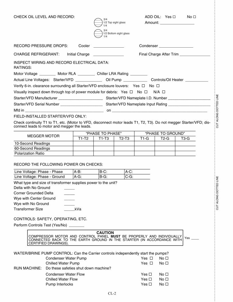
CL-2
- -
- -
- -
- -
- -
- -
- -
- -
- -
- -
- -
- -
- -
- -
- -
- -
- -
- -
- -
- -
- -
- -
- -
- -
- -
- -
- -
- -
- -
- -
- -
- -
- -
- -
- -
- -
- -
- -
- -
- -
- -
- -
- -
- -
- -
- -
- -
- -
- -
- -
- -
- -
- -
- -
- -
- -
- -
- -
- -
- -
- -
- -
- -
- -
- -
- -
- -
- -
- -
- -
- -
- -
- -
- -
- -
- -
- -
- -
- -
- -
- -
- -
- -
- -
- -
- -
- --
- -
- -
- -
- -
- -
- -
- -
- -
- -
-
CU
T A
LON
G D
OT
TE
D L
INE
CU
T A
LON
G D
OT
TE
D L
INE
RECORD PRESSURE DROPS: Cooler Condenser
CHARGE REFRIGERANT: Initial Charge Final Charge After Trim
INSPECT WIRING AND RECORD ELECTRICAL DATA:RATINGS:
Motor Voltage Motor RLA Chiller LRA Rating
Actual Line Voltages: Starter/VFD Oil Pump Controls/Oil Heater
Verify 6-in. clearance surrounding all Starter/VFD enclosure louvers: Yes No
Visually inspect down through top of power module for debris: Yes No N/A
Starter/VFD Manufacturer _____________________ Starter/VFD Nameplate I.D. Number ____________________
Starter/VFD Serial Number ____________________ Starter/VFD Nameplate Input Rating ____________________
Mfd in _____________________________________ on _____________________________________________
FIELD-INSTALLED STARTER/VFD ONLY:
Check continuity T1 to T1, etc. (Motor to VFD, disconnect motor leads T1, T2, T3). Do not megger Starter/VFD; dis-connect leads to motor and megger the leads.
RECORD THE FOLLOWING POWER ON CHECKS:
What type and size of transformer supplies power to the unit?Delta with No Ground _____Corner Grounded Delta _____Wye with Center Ground _____Wye with No Ground _____Transformer Size _____kVa
CONTROLS: SAFETY, OPERATING, ETC.
Perform Controls Test (Yes/No)
CHECK OIL LEVEL AND RECORD: ADD OIL: Yes No
Amount: 1/2 Top sight glass
1/2 Bottom sight glass
3/4
1/4
3/4
1/4
MEGGER MOTOR“PHASE TO PHASE” “PHASE TO GROUND”
T1-T2 T1-T3 T2-T3 T1-G T2-G T3-G10-Second Readings60-Second ReadingsPolarization Ratio
Line Voltage: Phase - Phase A-B: B-C: A-C:Line Voltage: Phase - Ground A-G: B-G: C-G:
CAUTIONCOMPRESSOR MOTOR AND CONTROL PANEL MUST BE PROPERLY AND INDIVIDUALLYCONNECTED BACK TO THE EARTH GROUND IN THE STARTER (IN ACCORDANCE WITHCERTIFIED DRAWINGS).
Yes
WATER/BRINE PUMP CONTROL: Can the Carrier controls independently start the pumps?Condenser Water Pump Yes No Chilled Water Pump Yes No
RUN MACHINE: Do these safeties shut down machine?
Condenser Water Flow Yes No Chilled Water Flow Yes No Pump Interlocks Yes No
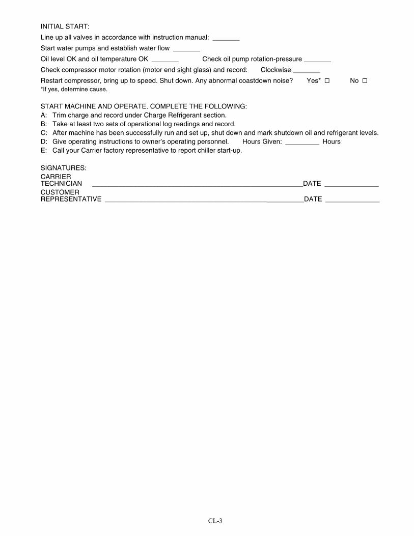
CL-3
INITIAL START:
Line up all valves in accordance with instruction manual:
Start water pumps and establish water flow
Oil level OK and oil temperature OK Check oil pump rotation-pressure
Check compressor motor rotation (motor end sight glass) and record: Clockwise
Restart compressor, bring up to speed. Shut down. Any abnormal coastdown noise? Yes* No *If yes, determine cause.
START MACHINE AND OPERATE. COMPLETE THE FOLLOWING:A: Trim charge and record under Charge Refrigerant section.B: Take at least two sets of operational log readings and record.C: After machine has been successfully run and set up, shut down and mark shutdown oil and refrigerant levels.D: Give operating instructions to owner’s operating personnel. Hours Given: HoursE: Call your Carrier factory representative to report chiller start-up.
SIGNATURES:CARRIERTECHNICIAN ___________________________________________ DATECUSTOMERREPRESENTATIVE ___________________________________________ DATE
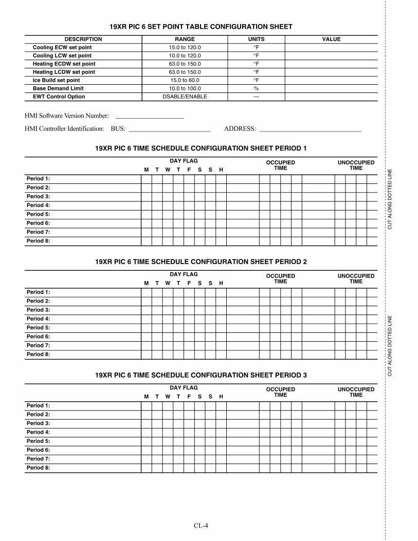
CL-4
- -
- -
- -
- -
- -
- -
- -
- -
- -
- -
- -
- -
- -
- -
- -
- -
- -
- -
- -
- -
- -
- -
- -
- -
- -
- -
- -
- -
- -
- -
- -
- -
- -
- -
- -
- -
- -
- -
- -
- -
- -
- -
- -
- -
- -
- -
- -
- -
- -
- -
- -
- -
- -
- -
- -
- -
- -
- -
- -
- -
- -
- -
- -
- -
- -
- -
- -
- -
- -
- -
- -
- -
- -
- -
- -
- -
- -
- -
- -
- -
- -
- -
- -
- -
- -
- -
- --
- -
- -
- -
- -
- -
- -
- -
- -
- -
-
CU
T A
LON
G D
OT
TE
D L
INE
CU
T A
LON
G D
OT
TE
D L
INE
19XR PIC 6 SET POINT TABLE CONFIGURATION SHEET
HMI Software Version Number:
HMI Controller Identification: BUS: ADDRESS:
19XR PIC 6 TIME SCHEDULE CONFIGURATION SHEET PERIOD 1
19XR PIC 6 TIME SCHEDULE CONFIGURATION SHEET PERIOD 2
19XR PIC 6 TIME SCHEDULE CONFIGURATION SHEET PERIOD 3
DESCRIPTION RANGE UNITS VALUE
Cooling ECW set point 15.0 to 120.0 °F
Cooling LCW set point 10.0 to 120.0 °F
Heating ECDW set point 63.0 to 150.0 °F
Heating LCDW set point 63.0 to 150.0 °F
Ice Build set point 15.0 to 60.0 °F
Base Demand Limit 10.0 to 100.0 %
EWT Control Option DSABLE/ENABLE —
DAY FLAG OCCUPIEDTIME
UNOCCUPIEDTIMEM T W T F S S H
Period 1:
Period 2:
Period 3:
Period 4:
Period 5:
Period 6:
Period 7:
Period 8:
DAY FLAG OCCUPIEDTIME
UNOCCUPIEDTIMEM T W T F S S H
Period 1:
Period 2:
Period 3:
Period 4:
Period 5:
Period 6:
Period 7:
Period 8:
DAY FLAG OCCUPIEDTIME
UNOCCUPIEDTIMEM T W T F S S H
Period 1:
Period 2:
Period 3:
Period 4:
Period 5:
Period 6:
Period 7:
Period 8:
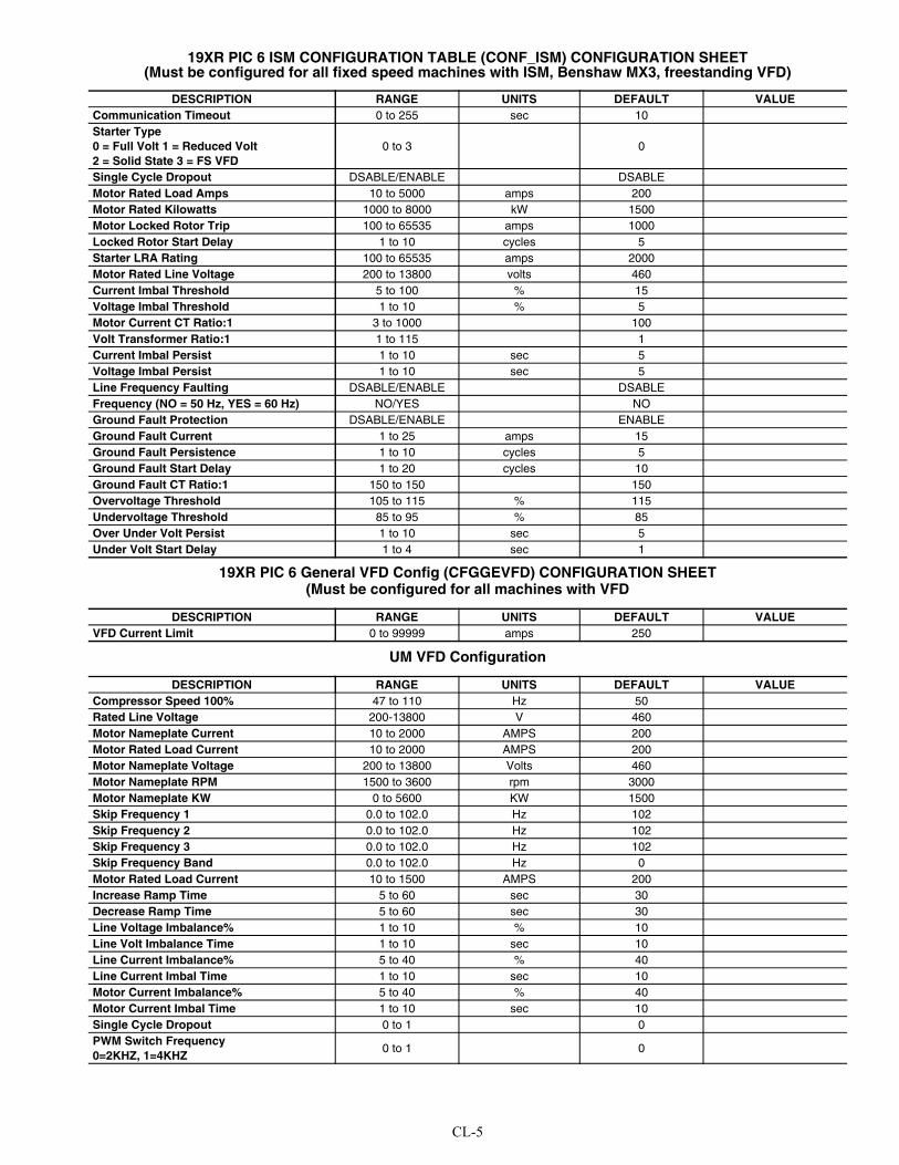
CL-5
19XR PIC 6 ISM CONFIGURATION TABLE (CONF_ISM) CONFIGURATION SHEET (Must be configured for all fixed speed machines with ISM, Benshaw MX3, freestanding VFD)
19XR PIC 6 General VFD Config (CFGGEVFD) CONFIGURATION SHEET (Must be configured for all machines with VFD
UM VFD Configuration
DESCRIPTION RANGE UNITS DEFAULT VALUECommunication Timeout 0 to 255 sec 10Starter Type0 = Full Volt 1 = Reduced Volt2 = Solid State 3 = FS VFD
0 to 3 0
Single Cycle Dropout DSABLE/ENABLE DSABLEMotor Rated Load Amps 10 to 5000 amps 200Motor Rated Kilowatts 1000 to 8000 kW 1500Motor Locked Rotor Trip 100 to 65535 amps 1000Locked Rotor Start Delay 1 to 10 cycles 5Starter LRA Rating 100 to 65535 amps 2000Motor Rated Line Voltage 200 to 13800 volts 460Current Imbal Threshold 5 to 100 % 15Voltage Imbal Threshold 1 to 10 % 5Motor Current CT Ratio:1 3 to 1000 100Volt Transformer Ratio:1 1 to 115 1Current Imbal Persist 1 to 10 sec 5Voltage Imbal Persist 1 to 10 sec 5Line Frequency Faulting DSABLE/ENABLE DSABLEFrequency (NO = 50 Hz, YES = 60 Hz) NO/YES NOGround Fault Protection DSABLE/ENABLE ENABLEGround Fault Current 1 to 25 amps 15Ground Fault Persistence 1 to 10 cycles 5Ground Fault Start Delay 1 to 20 cycles 10Ground Fault CT Ratio:1 150 to 150 150Overvoltage Threshold 105 to 115 % 115Undervoltage Threshold 85 to 95 % 85Over Under Volt Persist 1 to 10 sec 5Under Volt Start Delay 1 to 4 sec 1
DESCRIPTION RANGE UNITS DEFAULT VALUEVFD Current Limit 0 to 99999 amps 250
DESCRIPTION RANGE UNITS DEFAULT VALUECompressor Speed 100% 47 to 110 Hz 50Rated Line Voltage 200-13800 V 460Motor Nameplate Current 10 to 2000 AMPS 200Motor Rated Load Current 10 to 2000 AMPS 200Motor Nameplate Voltage 200 to 13800 Volts 460Motor Nameplate RPM 1500 to 3600 rpm 3000Motor Nameplate KW 0 to 5600 KW 1500Skip Frequency 1 0.0 to 102.0 Hz 102Skip Frequency 2 0.0 to 102.0 Hz 102Skip Frequency 3 0.0 to 102.0 Hz 102Skip Frequency Band 0.0 to 102.0 Hz 0Motor Rated Load Current 10 to 1500 AMPS 200Increase Ramp Time 5 to 60 sec 30Decrease Ramp Time 5 to 60 sec 30Line Voltage Imbalance% 1 to 10 % 10Line Volt Imbalance Time 1 to 10 sec 10Line Current Imbalance% 5 to 40 % 40Line Current Imbal Time 1 to 10 sec 10Motor Current Imbalance% 5 to 40 % 40Motor Current Imbal Time 1 to 10 sec 10Single Cycle Dropout 0 to 1 0PWM Switch Frequency0=2KHZ, 1=4KHZ
0 to 1 0
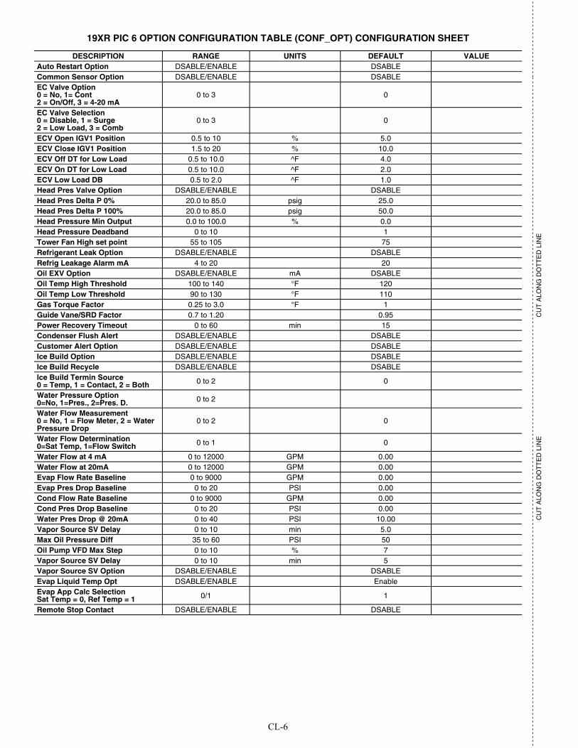
CL-6
- -
- -
- -
- -
- -
- -
- -
- -
- -
- -
- -
- -
- -
- -
- -
- -
- -
- -
- -
- -
- -
- -
- -
- -
- -
- -
- -
- -
- -
- -
- -
- -
- -
- -
- -
- -
- -
- -
- -
- -
- -
- -
- -
- -
- -
- -
- -
- -
- -
- -
- -
- -
- -
- -
- -
- -
- -
- -
- -
- -
- -
- -
- -
- -
- -
- -
- -
- -
- -
- -
- -
- -
- -
- -
- -
- -
- -
- -
- -
- -
- -
- -
- -
- -
- -
- -
- --
- -
- -
- -
- -
- -
- -
- -
- -
- -
-
CU
T A
LON
G D
OT
TE
D L
INE
CU
T A
LON
G D
OT
TE
D L
INE
19XR PIC 6 OPTION CONFIGURATION TABLE (CONF_OPT) CONFIGURATION SHEET
DESCRIPTION RANGE UNITS DEFAULT VALUEAuto Restart Option DSABLE/ENABLE DSABLECommon Sensor Option DSABLE/ENABLE DSABLEEC Valve Option0 = No, 1= Cont2 = On/Off, 3 = 4-20 mA
0 to 3 0
EC Valve Selection0 = Disable, 1 = Surge2 = Low Load, 3 = Comb
0 to 3 0
ECV Open IGV1 Position 0.5 to 10 % 5.0ECV Close IGV1 Position 1.5 to 20 % 10.0ECV Off DT for Low Load 0.5 to 10.0 ^F 4.0ECV On DT for Low Load 0.5 to 10.0 ^F 2.0ECV Low Load DB 0.5 to 2.0 ^F 1.0Head Pres Valve Option DSABLE/ENABLE DSABLEHead Pres Delta P 0% 20.0 to 85.0 psig 25.0Head Pres Delta P 100% 20.0 to 85.0 psig 50.0Head Pressure Min Output 0.0 to 100.0 % 0.0Head Pressure Deadband 0 to 10 1Tower Fan High set point 55 to 105 75Refrigerant Leak Option DSABLE/ENABLE DSABLERefrig Leakage Alarm mA 4 to 20 20Oil EXV Option DSABLE/ENABLE mA DSABLEOil Temp High Threshold 100 to 140 °F 120Oil Temp Low Threshold 90 to 130 °F 110Gas Torque Factor 0.25 to 3.0 °F 1Guide Vane/SRD Factor 0.7 to 1.20 0.95Power Recovery Timeout 0 to 60 min 15Condenser Flush Alert DSABLE/ENABLE DSABLECustomer Alert Option DSABLE/ENABLE DSABLEIce Build Option DSABLE/ENABLE DSABLEIce Build Recycle DSABLE/ENABLE DSABLEIce Build Termin Source0 = Temp, 1 = Contact, 2 = Both 0 to 2 0
Water Pressure Option0=No, 1=Pres., 2=Pres. D. 0 to 2
Water Flow Measurement0 = No, 1 = Flow Meter, 2 = Water Pressure Drop
0 to 2 0
Water Flow Determination0=Sat Temp, 1=Flow Switch 0 to 1 0
Water Flow at 4 mA 0 to 12000 GPM 0.00 Water Flow at 20mA 0 to 12000 GPM 0.00 Evap Flow Rate Baseline 0 to 9000 GPM 0.00 Evap Pres Drop Baseline 0 to 20 PSI 0.00 Cond Flow Rate Baseline 0 to 9000 GPM 0.00 Cond Pres Drop Baseline 0 to 20 PSI 0.00 Water Pres Drop @ 20mA 0 to 40 PSI 10.00 Vapor Source SV Delay 0 to 10 min 5.0 Max Oil Pressure Diff 35 to 60 PSI 50 Oil Pump VFD Max Step 0 to 10 % 7 Vapor Source SV Delay 0 to 10 min 5 Vapor Source SV Option DSABLE/ENABLE DSABLEEvap Liquid Temp Opt DSABLE/ENABLE EnableEvap App Calc SelectionSat Temp = 0, Ref Temp = 1 0/1 1
Remote Stop Contact DSABLE/ENABLE DSABLE
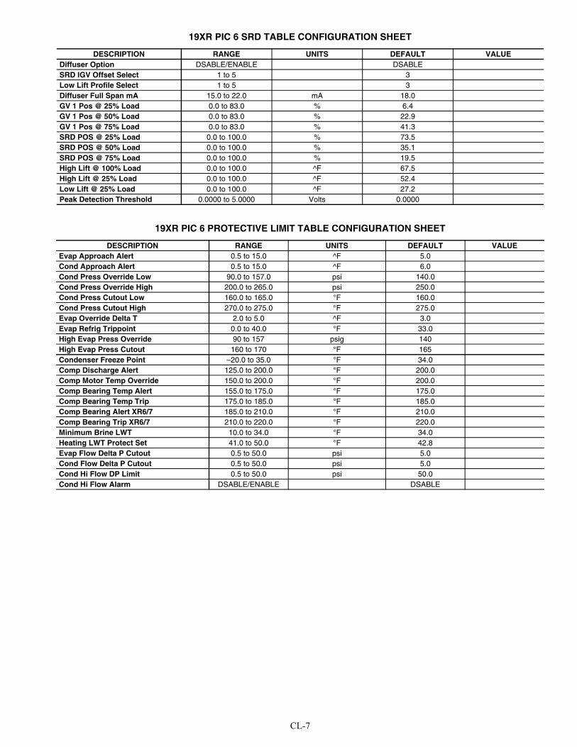
CL-7
19XR PIC 6 SRD TABLE CONFIGURATION SHEET
19XR PIC 6 PROTECTIVE LIMIT TABLE CONFIGURATION SHEET
DESCRIPTION RANGE UNITS DEFAULT VALUEDiffuser Option DSABLE/ENABLE DSABLESRD IGV Offset Select 1 to 5 3Low Lift Profile Select 1 to 5 3Diffuser Full Span mA 15.0 to 22.0 mA 18.0GV 1 Pos @ 25% Load 0.0 to 83.0 % 6.4GV 1 Pos @ 50% Load 0.0 to 83.0 % 22.9GV 1 Pos @ 75% Load 0.0 to 83.0 % 41.3SRD POS @ 25% Load 0.0 to 100.0 % 73.5SRD POS @ 50% Load 0.0 to 100.0 % 35.1SRD POS @ 75% Load 0.0 to 100.0 % 19.5High Lift @ 100% Load 0.0 to 100.0 ^F 67.5High Lift @ 25% Load 0.0 to 100.0 ^F 52.4Low Lift @ 25% Load 0.0 to 100.0 ^F 27.2Peak Detection Threshold 0.0000 to 5.0000 Volts 0.0000
DESCRIPTION RANGE UNITS DEFAULT VALUEEvap Approach Alert 0.5 to 15.0 ^F 5.0Cond Approach Alert 0.5 to 15.0 ^F 6.0Cond Press Override Low 90.0 to 157.0 psi 140.0Cond Press Override High 200.0 to 265.0 psi 250.0 Cond Press Cutout Low 160.0 to 165.0 °F 160.0Cond Press Cutout High 270.0 to 275.0 °F 275.0Evap Override Delta T 2.0 to 5.0 ^F 3.0Evap Refrig Trippoint 0.0 to 40.0 °F 33.0High Evap Press Override 90 to 157 psig 140High Evap Press Cutout 160 to 170 °F 165Condenser Freeze Point –20.0 to 35.0 °F 34.0Comp Discharge Alert 125.0 to 200.0 °F 200.0Comp Motor Temp Override 150.0 to 200.0 °F 200.0Comp Bearing Temp Alert 155.0 to 175.0 °F 175.0Comp Bearing Temp Trip 175.0 to 185.0 °F 185.0Comp Bearing Alert XR6/7 185.0 to 210.0 °F 210.0Comp Bearing Trip XR6/7 210.0 to 220.0 °F 220.0Minimum Brine LWT 10.0 to 34.0 °F 34.0Heating LWT Protect Set 41.0 to 50.0 °F 42.8Evap Flow Delta P Cutout 0.5 to 50.0 psi 5.0Cond Flow Delta P Cutout 0.5 to 50.0 psi 5.0Cond Hi Flow DP Limit 0.5 to 50.0 psi 50.0Cond Hi Flow Alarm DSABLE/ENABLE DSABLE
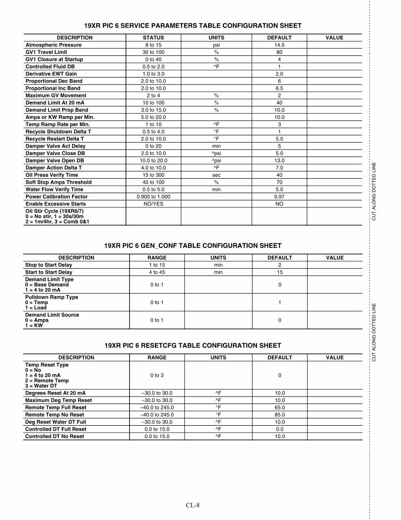
CL-8
- -
- -
- -
- -
- -
- -
- -
- -
- -
- -
- -
- -
- -
- -
- -
- -
- -
- -
- -
- -
- -
- -
- -
- -
- -
- -
- -
- -
- -
- -
- -
- -
- -
- -
- -
- -
- -
- -
- -
- -
- -
- -
- -
- -
- -
- -
- -
- -
- -
- -
- -
- -
- -
- -
- -
- -
- -
- -
- -
- -
- -
- -
- -
- -
- -
- -
- -
- -
- -
- -
- -
- -
- -
- -
- -
- -
- -
- -
- -
- -
- -
- -
- -
- -
- -
- -
- --
- -
- -
- -
- -
- -
- -
- -
- -
- -
-
CU
T A
LON
G D
OT
TE
D L
INE
CU
T A
LON
G D
OT
TE
D L
INE
19XR PIC 6 SERVICE PARAMETERS TABLE CONFIGURATION SHEET
19XR PIC 6 GEN_CONF TABLE CONFIGURATION SHEET
19XR PIC 6 RESETCFG TABLE CONFIGURATION SHEET
DESCRIPTION STATUS UNITS DEFAULT VALUEAtmospheric Pressure 8 to 15 psi 14.5GV1 Travel Limit 30 to 100 % 80GV1 Closure at Startup 0 to 40 % 4Controlled Fluid DB 0.5 to 2.0 ^F 1Derivative EWT Gain 1.0 to 3.0 2.0Proportional Dec Band 2.0 to 10.0 6Proportional Inc Band 2.0 to 10.0 6.5Maximum GV Movement 2 to 4 % 2Demand Limit At 20 mA 10 to 100 % 40Demand Limit Prop Band 3.0 to 15.0 % 10.0Amps or KW Ramp per Min. 5.0 to 20.0 10.0Temp Ramp Rate per Min. 1 to 10 ^F 3Recycle Shutdown Delta T 0.5 to 4.0 °F 1Recycle Restart Delta T 2.0 to 10.0 °F 5.0Damper Valve Act Delay 0 to 20 min 5Damper Valve Close DB 2.0 to 10.0 ^psi 5.0Damper Valve Open DB 10.0 to 20.0 ^psi 13.0Damper Action Delta T 4.0 to 10.0 ^F 7.0Oil Press Verify Time 15 to 300 sec 40Soft Stop Amps Threshold 40 to 100 % 70Water Flow Verify Time 0.5 to 5.0 min 5.0Power Calibration Factor 0.900 to 1.000 0.97Enable Excessive Starts NO/YES NOOil Stir Cycle (19XR6/7) 0 = No stir, 1 = 30s/30m2 = 1m/4hr, 3 = Comb 0&1
DESCRIPTION RANGE UNITS DEFAULT VALUEStop to Start Delay 1 to 15 min 2Start to Start Delay 4 to 45 min 15Demand Limit Type0 = Base Demand1 = 4 to 20 mA
0 to 1 0
Pulldown Ramp Type0 = Temp1 = Load
0 to 1 1
Demand Limit Source0 = Amps1 = KW
0 to 1 0
DESCRIPTION RANGE UNITS DEFAULT VALUETemp Reset Type0 = No1 = 4 to 20 mA2 = Remote Temp3 = Water DT
0 to 3 0
Degrees Reset At 20 mA –30.0 to 30.0 ^F 10.0Maximum Deg Temp Reset –30.0 to 30.0 ^F 10.0Remote Temp Full Reset –40.0 to 245.0 °F 65.0Remote Temp No Reset –40.0 to 245.0 °F 85.0Deg Reset Water DT Full –30.0 to 30.0 ^F 10.0Controlled DT Full Reset 0.0 to 15.0 ^F 0.0Controlled DT No Reset 0.0 to 15.0 ^F 10.0
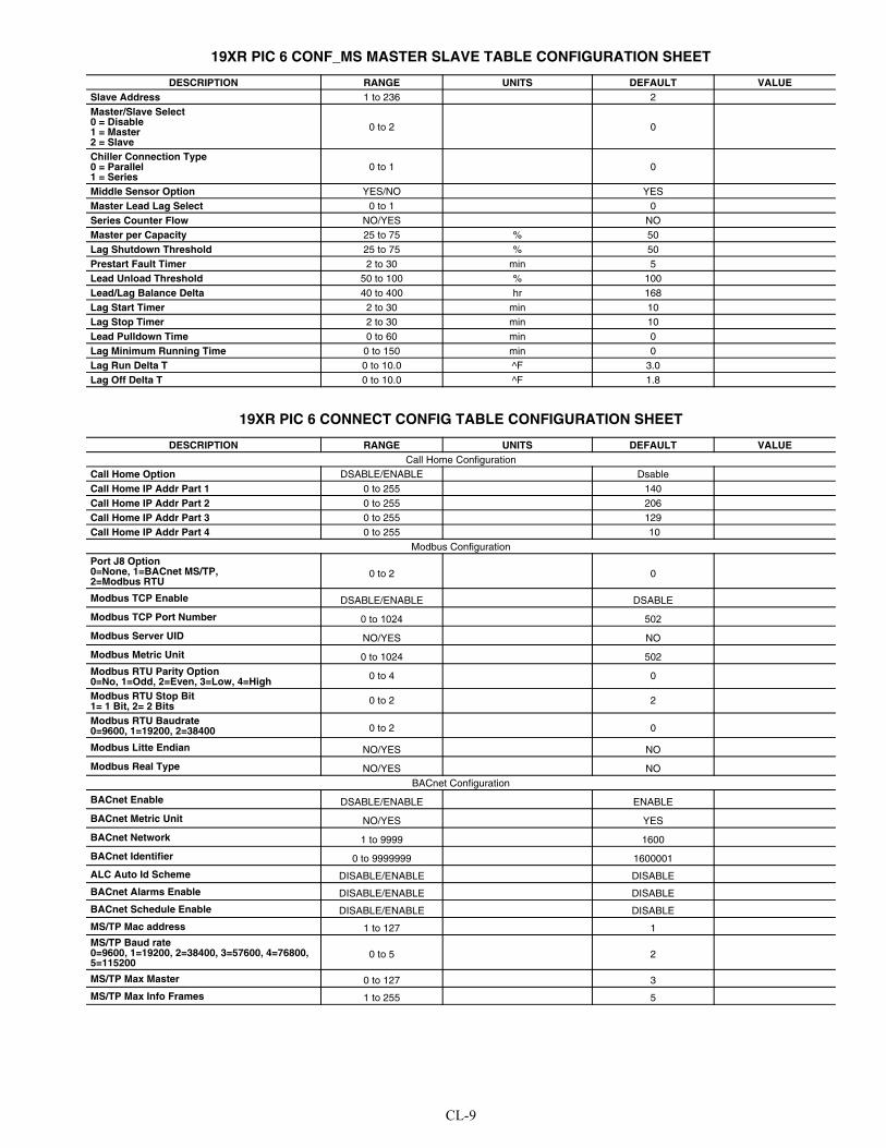
CL-9
19XR PIC 6 CONF_MS MASTER SLAVE TABLE CONFIGURATION SHEET
19XR PIC 6 CONNECT CONFIG TABLE CONFIGURATION SHEET
DESCRIPTION RANGE UNITS DEFAULT VALUESlave Address 1 to 236 2Master/Slave Select0 = Disable1 = Master2 = Slave
0 to 2 0
Chiller Connection Type0 = Parallel1 = Series
0 to 1 0
Middle Sensor Option YES/NO YESMaster Lead Lag Select 0 to 1 0Series Counter Flow NO/YES NOMaster per Capacity 25 to 75 % 50Lag Shutdown Threshold 25 to 75 % 50Prestart Fault Timer 2 to 30 min 5Lead Unload Threshold 50 to 100 % 100Lead/Lag Balance Delta 40 to 400 hr 168Lag Start Timer 2 to 30 min 10Lag Stop Timer 2 to 30 min 10Lead Pulldown Time 0 to 60 min 0Lag Minimum Running Time 0 to 150 min 0Lag Run Delta T 0 to 10.0 ^F 3.0Lag Off Delta T 0 to 10.0 ^F 1.8
DESCRIPTION RANGE UNITS DEFAULT VALUECall Home Configuration
Call Home Option DSABLE/ENABLE DsableCall Home IP Addr Part 1 0 to 255 140Call Home IP Addr Part 2 0 to 255 206Call Home IP Addr Part 3 0 to 255 129Call Home IP Addr Part 4 0 to 255 10
Modbus ConfigurationPort J8 Option0=None, 1=BACnet MS/TP, 2=Modbus RTU
0 to 2 0
Modbus TCP Enable DSABLE/ENABLE DSABLE
Modbus TCP Port Number 0 to 1024 502Modbus Server UID NO/YES NO
Modbus Metric Unit 0 to 1024 502Modbus RTU Parity Option0=No, 1=Odd, 2=Even, 3=Low, 4=High 0 to 4 0
Modbus RTU Stop Bit1= 1 Bit, 2= 2 Bits 0 to 2 2
Modbus RTU Baudrate0=9600, 1=19200, 2=38400 0 to 2 0
Modbus Litte Endian NO/YES NO
Modbus Real Type NO/YES NOBACnet Configuration
BACnet Enable DSABLE/ENABLE ENABLE
BACnet Metric Unit NO/YES YES
BACnet Network 1 to 9999 1600
BACnet Identifier 0 to 9999999 1600001
ALC Auto Id Scheme DISABLE/ENABLE DISABLE
BACnet Alarms Enable DISABLE/ENABLE DISABLE
BACnet Schedule Enable DISABLE/ENABLE DISABLE
MS/TP Mac address 1 to 127 1MS/TP Baud rate0=9600, 1=19200, 2=38400, 3=57600, 4=76800, 5=115200
0 to 5 2
MS/TP Max Master 0 to 127 3
MS/TP Max Info Frames 1 to 255 5

CL-10
- -
- -
- -
- -
- -
- -
- -
- -
- -
- -
- -
- -
- -
- -
- -
- -
- -
- -
- -
- -
- -
- -
- -
- -
- -
- -
- -
- -
- -
- -
- -
- -
- -
- -
- -
- -
- -
- -
- -
- -
- -
- -
- -
- -
- -
- -
- -
- -
- -
- -
- -
- -
- -
- -
- -
- -
- -
- -
- -
- -
- -
- -
- -
- -
- -
- -
- -
- -
- -
- -
- -
- -
- -
- -
- -
- -
- -
- -
- -
- -
- -
- -
- -
- -
- -
- -
- --
- -
- -
- -
- -
- -
- -
- -
- -
- -
-
CU
T A
LON
G D
OT
TE
D L
INE
CU
T A
LON
G D
OT
TE
D L
INE
19XR PIC 6 CFGSURGE SURGE CORRECTION CONFIG TABLE CONFIGURATION SHEET
19XR PIC 6 CTRL_ID CONTROL IDENTIFICATION TABLE CONFIGURATION SHEET
DESCRIPTION RANGE UNITS DEFAULT VALUESurge Line Configuration0=PR, 1=Delta T 0 to 1 0
IGV1 Pos Configuration0-Degree, 1=Percentage 0 to 1 0
Surge Delta Tsmax 0.0 to 150.0 °F 70.0
Surge Delta Tsmin 0.0 to 150.0 °F 45.0
PR at Full Load Opening 1.0000 to 5.0000 3.0000
PR at Min. Opening 1.0000 to 5.0000 1.5000
IGV1 Full Load Open Deg 90 to 120.0 degree 88.0
Sound Ctrl IGV1 Open Deg 10.0 to 40.0 degree 27.0
IGV1 Minimum Open Deg 0.0 to 10.0 degree 2.0
IGV1 Actuator Max Deg 90.0 to120.0 degree 109.0
Surge Line Offset 1.0 to 3.0 °F 2.0
Surge Line Lower Deadband 0.5 to 3.0 °F 1.5
Surge Line Upper Deadband 0.1 to 3.0 °F 1.5
Surge Line Shape Factor –1.000 to 0.000 –0.010
Sound Line Shape Factor 0.000 to 1.000 0.010
Surge Line Speed Factor 0.00 to 3.00 2.00
Surge Delay Time 0 to 120 sec 15
Surge Time Period 7 to 10 min 8
Surge Delta Amps % 5 to 40 % 20
Rampdown Factor 0 to 1 10 0
GV1 Close Step Surge 1.0 to 3.0 % 2.0
VFD Speed Step Surge 1.0 to 5.0 % 1.5
EC Valve Step Surge 1.0 to 10.0 % 4.0
Surge Profile Offset 0.0 to 5.0 ^F 0.0
High Efficiency Mode DSABLE/ENABLE DSABLE
High Noise Alert DSABLE/ENABLE DSABLE
Surge AI Enable DSABLE/ENABLE Enable
Surge AI Act Sw 0 to 1 0Surge AI Reset sw 0 to 10 0 000Surge AI Correct Sw 0 to 10 0 000AI Surge Threshold 0 to 100 1.0500AI Counts Bf Shutd 0 to 200 30
DESCRIPTION RANGE UNITS DEFAULT VALUECCN Element Number 0 to 239 1CCN Bus Number 0 to 239 0CCN Baud Rate 9600, 19200, 38400 9600Device Description — 19XRPIC6Location Description (User-defined 24-digit character string)Software Part Number: SCG-SR-2-20S200200Serial Number =
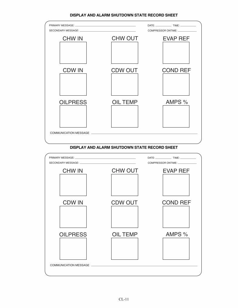
CL-11
DISPLAY AND ALARM SHUTDOWN STATE RECORD SHEET
DISPLAY AND ALARM SHUTDOWN STATE RECORD SHEET
PRIMARY MESSAGE:
SECONDARY MESSAGE:
DATE: TIME:
COMPRESSOR ONTIME:
CHW IN
OILPRESS
CHW OUT
OIL TEMP
CDW IN CDW OUT
EVAP REF
COND REF
AMPS %
COMMUNICATION MESSAGE
PRIMARY MESSAGE:
SECONDARY MESSAGE:
DATE: TIME:
COMPRESSOR ONTIME:
CHW IN
OILPRESS
CHW OUT
OIL TEMP
CDW IN CDW OUT
EVAP REF
COND REF
AMPS %
COMMUNICATION MESSAGE
Manufacturer reserves the right to discontinue, or change at any time, specifications or designs without notice and without incurring obligations.Catalog No. 04-53190066-01 Printed in U.S.A. Form 19XR-CLT-16SS Pg CL-12 1-2020 Replaces: 19XR-CLT-15SS
© 2020 Carrier Corporation
- -
- -
- -
- -
- -
- -
- -
- -
- -
- -
- -
- -
- -
- -
- -
- -
- -
- -
- -
- -
- -
- -
- -
- -
- -
- -
- -
- -
- -
- -
- -
- -
- -
- -
- -
- -
- -
- -
- -
- -
- -
- -
- -
- -
- -
- -
- -
- -
- -
- -
- -
- -
- -
- -
- -
- -
- -
- -
- -
- -
- -
- -
- -
- -
- -
- -
- -
- -
- -
- -
- -
- -
- -
- -
- -
- -
- -
- -
- -
- -
- -
- -
- -
- -
- -
- -
- --
- -
- -
- -
- -
- -
- -
- -
- -
- -
-
CU
T A
LON
G D
OT
TE
D L
INE
CU
T A
LON
G D
OT
TE
D L
INE