spectrophotometer cm-26dg/cm-26d/cm-25d
TRANSCRIPT
SpectrophotometerCM-26dGCM-26dCM-25d
En Instruction ManualPlease read before using the instrument.

i
Official names for applications and the like used in this manual(Designation in this manual) (Official name)
Bluetooth Bluetooth®
Trademarks• The Bluetooth® mark and logo are registered trademarks of The Bluetooth SIG, Inc. and are used under license.• The KONICA MINOLTA logo and symbol marks and SpectraMagic are registered trademarks of KONICA MINOLTA, Inc.
� Notification for California CustomersPerchlorate Material - Special handling may apply, see www.dtsc.ca.gov/hazardouswaste/perchlorate.

iii
� Safety SymbolsThe following symbols are used in this manual and on the product to prevent accidents that may occur because of incorrect use of the instrument.
Denotes an instruction regarding a safety warning or note.Read the instruction carefully to ensure safe and correct use.
Denotes a prohibited operation.This operation must never be performed.
Denotes an instruction.This instruction must be strictly adhered to.
Denotes an instruction.Be sure to disconnect the plug from the outlet.
Denotes a prohibited operation.Never disassemble the instrument.
This symbol indicates alternating current (AC).
This symbol indicates direct current (DC).
This symbol indicates class II protection against electric shock.
Notes on this Manual• Copying or reproduction of all or part of the contents of this manual without the permission of KONICA MINOLTA is strictly
prohibited.
• The contents of this manual are subject to change without prior notice.
• Every effort has been made in the preparation of this manual to ensure the accuracy of its contents. However, should you have any
questions or find any errors, please contact your retailer or a KONICA MINOLTA-authorized service facility.
• KONICA MINOLTA will not accept any responsibility for consequences arising from the use of the instrument.
1
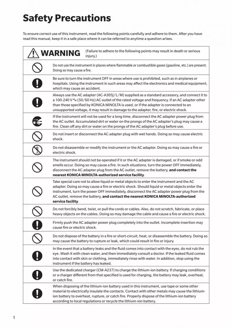
Safety PrecautionsTo ensure correct use of this instrument, read the following points carefully and adhere to them. After you have read this manual, keep it in a safe place where it can be referred to anytime a question arises.
WARNING (Failure to adhere to the following points may result in death or serious injury.)
Do not use the instrument in places where flammable or combustible gases (gasoline, etc.) are present.Doing so may cause a fire.
Be sure to turn the instrument OFF in areas where use is prohibited, such as in airplanes or hospitals. Using the instrument in such areas may affect the electronics and medical equipment, which may cause an accident.
Always use the AC adapter (AC-A305J/L/M) supplied as a standard accessory, and connect it to a 100-240 V (50/60 Hz) AC outlet of the rated voltage and frequency. If an AC adapter other than those specified by KONICA MINOLTA is used, or if the adapter is connected to an unsupported voltage, it may result in damage to the adapter, fire, or electric shock.
If the instrument will not be used for a long time, disconnect the AC adapter power plug from the AC outlet. Accumulated dirt or water on the prongs of the AC adapter’s plug may cause a fire. Clean off any dirt or water on the prongs of the AC adapter’s plug before use.
Do not insert or disconnect the AC adapter plug with wet hands. Doing so may cause electric shock.
Do not disassemble or modify the instrument or the AC adapter. Doing so may cause a fire or electric shock.
The instrument should not be operated if it or the AC adapter is damaged, or if smoke or odd smells occur. Doing so may cause a fire. In such situations, turn the power OFF immediately, disconnect the AC adapter plug from the AC outlet, remove the battery, and contact the nearest KONICA MINOLTA-authorized service facility.
Take special care not to allow liquid or metal objects to enter the instrument and the AC adapter. Doing so may cause a fire or electric shock. Should liquid or metal objects enter the instrument, turn the power OFF immediately, disconnect the AC adapter power plug from the AC outlet, remove the battery, and contact the nearest KONICA MINOLTA-authorized service facility.
Do not forcibly bend, twist, or pull the cords or cables. Also, do not scratch, fabricate, or place heavy objects on the cables. Doing so may damage the cable and cause a fire or electric shock.
Firmly push the AC adapter power plug completely into the outlet. Incomplete insertion may cause fire or electric shock.
Do not dispose of the battery in a fire or short-circuit, heat, or disassemble the battery. Doing so may cause the battery to rupture or leak, which could result in fire or injury.
In the event that a battery leaks and the fluid comes into contact with the eyes, do not rub the eye. Wash it with clean water, and then immediately consult a doctor. If the leaked fluid comes into contact with skin or clothing, immediately rinse with water. In addition, stop using the instrument if the battery has leaked.
Use the dedicated charger (CM-A237) to charge the lithium-ion battery. If charging conditions or a charger different from that specified is used for charging, the battery may leak, overheat, or catch fire.
When disposing of the lithium-ion battery used in this instrument, use tape or some other material to electrically insulate the contacts. Contact with other metals may cause the lithium-ion battery to overheat, rupture, or catch fire. Properly dispose of the lithium-ion battery according to local regulations or recycle the lithium-ion battery.

21
Do not touch the battery with wet hands. Doing so may result in electric shock or a malfunction.
Do not use, charge, or store the lithium-ion battery in a high-temperature environment. Doing so may cause the battery to overheat, catch fire, or rupture.
Do not throw or submit the lithium-ion battery to strong impacts such as from a fall from a high location. If the lithium-ion battery is deformed or if the built-in protection system is broken, an abnormal current or voltage may be applied to the battery during charging, which may cause the battery to overheat, rupture, or catch fire.
Do not step on the lithium-ion battery or pierce with a nail or hit with a hammer. If the lithium-ion battery is deformed or if the protection system is damaged, the battery may overheat, rupture, or catch fire.
Should an unusual odor, heat, discoloration, deformation, or other previously unnoticed abnormality occur during use, charging, or storage, remove the battery from the instrument or charger and discontinue use. Continued use of a battery in this condition may cause the battery to overheat, rupture, or catch fire.
If the lithium-ion battery is found to be leaking or emitting an unusual odor, keep the battery away from any open flames. The electrolytic solution from the battery may catch fire, causing rupture or fire.
Do not look directly at the lamp. The lamp is extremely bright and emits ultraviolet rays. Looking directly at the light may injure the eyes.
CAUTION (Failure to adhere to the following points may result in injury or damage to the instrument or other property.)
Do not place the instrument on an unstable or sloping surface. Doing so may result in the instrument dropping or overturning, causing injury. Be careful not to drop the instrument when carrying it as well.
Take care not to pinch yourself on the areas of the instrument that open and close. Doing so may result in injury.
Do not use the instrument if the specimen measuring port (measurement area) is in the line of sight. Doing so may result in injury to the eye.
Take sufficient care when handling the target mask with glass.The glass of the target mask may become cracked, resulting in injury.Also, when using a target mask with glass, be sure to use the wrist strap correctly when using the instrument.
When using the AC adapter, make sure, that an AC outlet is located near the instrument, and that the AC adapter plug can be connected to and disconnected from the AC outlet easily.
When cleaning the instrument, unplug the AC adapter plug from the outlet. Failure to do so may result in electric shock.
Do not use any battery other than that specified for use with the instrument. When inserting a battery into the instrument, be sure to insert the battery correctly according to the polarity (positive +, negative –) display on the instrument. Fire, injury, or stains on surroundings may occur if the battery is damaged or leaking.
Do not use a wet lithium-ion battery.Doing so may cause the battery to rupture or overheat, which could result in fire or injury.

3
Introduction
The CM-26d and CM-25d are spectrophotometers capable of measuring color and color differences in one measurement for use in a variety of industrial fields. Meanwhile, the CM-26dG is capable of measuring gloss in addition to color and color differences at the same time.
Packing materials of the productBe sure to keep all packing materials used for shipping the instrument (cardboard box, cushioning material, plastic bags, etc.). This instrument is a precision measuring instrument. When transporting the instrument to a service facility for maintenance or for other reasons, be sure to use the packing materials to minimize shock or vibration. If the packing materials are lost or damaged, contact a KONICA MINOLTA-authorized service facility.
� Notes on Use
Operating Environment• The AC adapter supplied as a standard accessory (AC-A305J/L/M) has been designed exclusively for indoor use. Outdoor use
is prohibited.
• This instrument is composed of precision electronic components. Never disassemble the instrument.
• Always use the AC adapter supplied as a standard accessory (AC-A305J/L/M) and connect it to a 100 to 240 V (50/60 Hz)
AC outlet. Use an AC power supply of the rated voltage (within ±10%).
• This instrument is a pollution level 2 product (equipment to be used primarily in manufacturing environments, laboratories,
warehouses, and similar locations). This instrument should be used in environments where exposure to metallic dust or
condensation is not a concern.
• This instrument is an overvoltage category I product (equipment for connection to circuits in which measures are taken to limit
transient overvoltage to an appropriately low level).
• Take care to prevent foreign matter from entering the instrument. Using the instrument while subjected to intrusion of water or
metals is extremely dangerous.
• Using the instrument in direct sunlight or near heating equipment can cause the internal temperature of the instrument to
become much higher than the ambient temperature, resulting in malfunction. Do not use the instrument in such areas.
• Avoid subjecting the instrument to sudden temperature changes and condensation.
• Do not use the instrument in areas where dust, smoke, or chemical gases are present, or in extremely humid environments.
• This instrument should be used in an environment with an ambient temperature between 5°C and 40°C and a relative humidity
of 80% or less (at 35°C) with no condensation. Use of the instrument outside this range will result in unsatisfactory performance.
• Do not use the instrument at altitudes higher than 2,000 m.
• Do not use the instrument near equipment that produces a strong magnetic field (such as speakers).
• To secure the instrument for use, make sure the instrument is firmly attached with no possibility of falling off. Failure to do so
may result in harm to the instrument or people and objects around the instrument.
System• Do not subject the instrument to strong vibrations or impacts.
• Do not pull, forcibly bend, or apply excessive force to the connected cables and cords. Doing so may cause the cable or cord to
break.
• Do not allow the specimen measuring port of the instrument to become dirty or subject the aperture to impact. Place the
instrument on the calibration stage when not in use.
• This instrument and the AC adapter are EMC Class B products. Use of the instrument and the AC adapter in home environments
may cause radio interference. Users may be required to take appropriate measures in such cases.
• If the instrument is exposed to strong external static electricity, the LCD may go blank or fail to display information correctly.
Communication with a connected external device may also be interrupted. In such cases, turn the power OFF and then ON
again. If black smudges appear on the LCD, wait until they disappear naturally.
• When turning the power OFF and then ON again, wait several seconds after turning the power OFF before turning the power
ON again.
• The instrument should be connected to a power source with as little noise as possible.
• When a malfunction or abnormal behavior occurs, turn the power OFF immediately, disconnect the AC adapter plug from the
AC outlet, and refer to P.143 “Troubleshooting”.
• Should the instrument break down, do not try to disassemble and repair the instrument. Contact a KONICA MINOLTA-
authorized service facility.

43
Backup Battery• Various settings are stored in the instrument’s built-in battery-powered backup memory. The backup battery will be charged
when the instrument is powered or when the lithium-ion battery is being charged, regardless of whether the power switch is
turned ON/OFF. The backup battery takes 20 hours to become fully charged, and there is no danger of overcharging. At full
charge, the backup battery can store data for up to one year. However, the backup battery may not be fully charged when the
instrument is purchased. The backup battery will charge as the instrument is being used.
• Do not attempt to replace the built-in backup battery. The battery should only be replaced by KONICA MINOLTA. To replace the
backup battery, please contact a KONICA MINOLTA-authorized service facility.
• It is recommended to manage important data and settings using the optional SpectraMagic NX software.
Calibration Plate• The calibration data for the calibration plate was measured at 23°C. To achieve the highest accuracy when measuring absolute
values, calibration and measurement should be performed at 23°C.
• Do not allow the calibration plate to become scratched or dirty.
• When the calibration plate is not in use, be sure to close the cap so that the plate is not exposed to light.
Power Source• Make sure that the power is turned OFF when the instrument is not in use.
• This instrument should be used with the lithium-ion battery installed. You cannot use the instrument connected to the AC
adapter only.
• Make sure the AC adapter output plug is not short-circuited. Doing so may cause a fire or electric shock.
• Do not connect the AC adapter to an overloaded electrical circuit. In addition, do not wrap or cover the AC adapter with cloth or
other material while in use. Doing so may cause an electric shock or fire.
• When removing the AC adapter from the instrument, first remove the power cord from the outlet, and then remove the output plug.
Battery• Use only the standard accessory lithium-ion battery or the optional accessory lithium-ion battery CM-A235 (RRC1120).
Absolutely do not use any other type of battery.
• The battery in the instrument will be charged from the power supplied through the USB cable regardless of whether the
instrument is turned ON or OFF.
• The battery is not charged upon purchase and must therefore be charged.
• The battery takes about 6 hours to become fully charged. There is no need to worry about overcharging.
• The lithium-ion battery will self-discharge. The battery will become unusable due to over discharging if left for a long period.
Charge the battery for at least one hour using the instrument or an optional battery charger at least semiannually.
• After using up the lithium-ion battery, do not leave it uncharged.
• Charging should be performed at between 5 and 40°C. Charging will not be performed outside this temperature range.
• If the lithium-ion battery will not be used for a long period, remove the battery from the instrument and store it in a location not
subject to high temperatures or high humidity.

5
� Notes on Storage• Storing the instrument in direct sunlight or near heating equipment can cause the internal temperature of the instrument to
become much higher than the ambient temperature, resulting in malfunction. Do not store the instrument in such areas.
• This instrument should be stored at a temperature between 0°C and 45°C with a relative humidity of 80% or less (at 35°C) and
no condensation. Storing the instrument in an environment with high temperatures and high humidity will result in
unsatisfactory performance. Storing the instrument together with the drying agent at or near room temperature is
recommended.
• Make sure that the instrument is not subjected to condensation when stored. In addition, take care to prevent rapid
temperature changes to prevent condensation from occurring when transporting the instrument to the storage location.
• Do not store the instrument in areas where dust, smoke, or chemical gases are present. Doing so may cause deterioration in
performance or a malfunction.
• Do not leave the instrument inside the cab or trunk of a vehicle. Otherwise, the temperature and/or humidity may exceed the
allowable range for storage, resulting in a malfunction.
• Dust inside the specimen measuring port may prevent accurate measurements from being performed. When the instrument is
not in use, cover the measuring port to prevent the intrusion of dust and the like.
• The calibration plate may become discolored if left exposed to light. Therefore, make sure to close the cap when the plate is not
in use in order to prevent the plate from being exposed to light.
• When not in use, store the instrument in the packing used for shipment or in the optional hard case and keep it in a safe place.
• Take care not to pinch yourself on the areas of the protective hard case that open and close. Doing so may cause injury.
� Notes on Cleaning• If the instrument becomes dirty, wipe it with a soft, dry cloth. Never use organic solvents (such as naphtha or thinner) or other
chemicals for cleaning.
• If there is dust or dirt on the lens or the receptor window, use a blower or the like to blow it off. Never use organic solvents (such
as naphtha or thinner) or other chemicals for cleaning.
• If the calibration plate becomes dirty, gently wipe the dirt off using the supplied cleaning cloth. If the dirt is excessive, wipe with
a cleaning cloth slightly moistened with ethanol. If the cleaning cloth is dirty, clean the cloth by washing it.
• If you are unable to remove dirt from the instrument through the above procedure, or if the instrument becomes scratched,
contact a KONICA MINOLTA-authorized service facility.
• If the specimen measuring port of the instrument becomes dirty, contact a KONICA MINOLTA-authorized service facility.
� Notes on Transporting• When transporting the instrument, be sure to use the packing materials to minimize shock or vibration.
• When sending the instrument in for service, package and send the instrument and all accessories.
� Maintenance and Inspection• To maintain measurement accuracy, the instrument should be inspected once a year. For information on inspection, contact
the nearest KONICA MINOLTA-authorized service facility.
Introduction (Cont.)

65
� Disposal Method• Make sure that the instrument, all accessories (including any used batteries), and the packing materials are
either disposed of or recycled correctly in accordance with local laws and regulations.• In the United States and Canada, you can recycle your lithium-ion battery through the Call2Recycle program.
For more information, in the United States visit www.call2recycle.org and in Canada visit www.call2recycle.ca.
7
Table of Contents
Safety Symbols ......................................................ii
Notes on this Manual .............................................ii
Introduction .....................................................3
Notes on Use ........................................................ 3
Notes on Storage .................................................. 5
Notes on Cleaning ................................................ 5
Notes on Transporting .......................................... 5
Maintenance and Inspection ................................. 5
Disposal Method ................................................... 6
Conventions ......................................................... 9
� Instrument Firmware Version ...................... 9
Chapter 1 Before Using the Instrument ... 10
Accessories.....................................................11
Standard Accessories .......................................... 11
Optional Accessories .......................................... 12
System Diagram .............................................14
Names and Functions of Parts .........................17
� Calibration Stage ...................................... 19
Cleaning the Components .................................. 20
� Zero Calibration Hole (Calibration Stage) ... 20
� White Calibration and Gloss Calibration*
(* CM-26dG only) ...................................... 20
� Target Mask............................................... 20
� Inside the Integrating Sphere .................... 20
Points to Remember .......................................21
Initial Settings ..................................................... 21
Control Panel ...................................................... 21
� Display (LCD Screen) ................................. 22
� Status bar ................................................. 23
� Operation Keys ......................................... 24
Menus ................................................................ 25
Data Saving ........................................................ 27
Chapter 2 Measurement ............... 28
Flow of Measurement .....................................29
Preparation ....................................................30
� Attach the Wrist Strap ............................... 30
� Inserting the Battery ................................. 31
� Connecting the AC Adapter ....................... 32
� Turning the Power ON/OFF ....................... 32
� Measurement Area Selection
(CM-26dG/CM-26d) ................................. 33
� Target Mask Replacement
(CM-26d/CM-25d) .................................... 33
� Staple-Type Target Mask ............................ 34
Calibration ......................................................35
Zero calibration................................................... 35
White Calibration and Gloss Calibration .............. 37
User calibration .................................................. 39
Setting a Specimen .........................................40
Viewfinder .......................................................... 40
Measurement .................................................41
Displaying the Measurement Results .................. 42
� <Sample> detail screen: Absolute value ..... 42
� <Sample> detail screen: “Difference” tab .... 43
� <Sample> detail screen: “Abs. & Diff.” Tab .... 43
� <Sample> detail screen: “Pass/Fail” tab .... 44
� <Sample> detail screen: “Custom” tab ...... 44
� <Sample> detail screen: “Abs. Graph” Tab .... 45
� <Sample> detail screen: “Diff. Graph” Tab .... 45
� <Sample> detail screen: “Spectral Graph” tab .... 46
� <Sample> List Screen ................................ 46
Measurement (Simple Mode) .............................. 48
Handling the Sample ......................................50
Print Data (Sample)............................................. 51
Edit name ........................................................... 52
Data Management (Sample) ............................... 53
� Delete ....................................................... 53
� Set Sample as Target ................................. 54
� Change Target Reference .......................... 55
� Change list position .................................. 56
� Delete All Data (Sample) ............................ 57
Auto Target (Sample) .......................................... 58
� Auto Target (Sample) ................................. 58
� Threshold (Sample) ................................... 59
Pass/Fail Judgment for Color Difference ..........60
Pass/Fail Judgment Based on Tolerances ............. 60
Color Difference Target Operation ...................62
Print Data (Target) .............................................. 63
Edit name ........................................................... 64
Data Management (Target) ................................. 65
� Delete ....................................................... 65
� Set group .................................................. 66
� Change list position .................................. 67
� Edit Target filter ......................................... 68
� Data Protection ......................................... 69
� Delete All Data (Target) .............................. 70
87
Pass/Fail ............................................................. 71
� Tolerance Settings ..................................... 72
� Tolerance List ............................................ 73
� Warning Level Setting ............................... 74
� Parametric Coefficient Setting ................... 75
Input Colorimetric Data ...................................... 76
� Color space ............................................... 76
� Input Data ................................................. 77
Default Data Settings .......................................... 79
� Tolerance List ............................................ 80
� Default Tolerance Setting .......................... 81
� Warning Level Setting ............................... 82
� Parametric Coefficient Setting ................... 83
� Set group .................................................. 84
Chapter 3 Setting ......................... 86
Measurement Condition Settings ....................87
Measurement Condition Settings ........................ 87
� Measurement mode .................................. 88
Opacity Measurement ........................................ 89
Measurement Option Settings ............................ 91
� Specular Component ................................ 92
� UV (100%/0%/100% + 0%/UVC) ............. 93
� Auto average (1 to 10) ............................... 94
� Manual average (1 to 30) ........................... 95
� SMC Function
(Outlier-Free Measurement) ...................... 96
� SMC Threshold .......................................... 97
� SMC Times ................................................ 98
Observation Condition Settings .......................... 99
� Observer/Illuminant 1 ............................ 100
� Observer/Illuminant 2 ............................ 102
Display Settings ................................................ 103
� Display type ............................................ 104
� Color space ............................................. 105
� Color difference equation ........................ 106
� Custom ................................................... 107
Instrument Settings ......................................108
Measurement Instrument Option Settings ........ 108
� User type ................................................ 109
� Display Language Settings ...................... 110
� Date Format Settings ............................... 111
� Clock Settings ......................................... 112
� Screen Brightness ................................... 113
� LCD Screen Display Orientation ............... 114
� Beep ....................................................... 115
� Auto Power Off ........................................ 116
� Password Setting .................................... 117
Chapter 4 Other Functions .......... 118
Connecting to an External Device ..................119
◎ Connecting to a Computer ........................119
Connecting via USB Cable ................................ 120
Connecting via Bluetooth ................................. 121
{ Instrument Preparation ........................... 121
• Connecting the Bluetooth Module ........... 121
Communication setup ...................................... 122
� Turning Bluetooth ON ............................. 122
{ Connecting to a Computer ...................... 124
◎ Connecting to a Printer/Barcode Reader ... 125
{ Printer/Barcode Reader Preparation ....... 125
Instrument Preparation ..................................... 126
� Registering a Bluetooth Address ............. 126
� PIN Code Configuration........................... 127
� Printing Data ........................................... 128
� Auto Print ............................................... 129
System Settings ............................................131
Calibration setup .............................................. 131
� Calibration Interval Messages.................. 132
� Annual Calibration Messages .................. 133
� User calibration ...................................... 134
� Zero calibration skip ................................ 135
Displaying Diagnosis Info. ................................. 136
Displaying the Instrument Information ............. 137
JOB Function ..................................................... 138
Chapter 5 Troubleshooting ......... 140
Message List .................................................141
Troubleshooting ...........................................143
Chapter 6 Appendix .................... 146
Fluorescence Measurement ..........................147
Specifications ...............................................148
Dimensions ..................................................150
User Equation and User Class .....UE-1

9
� Instrument Firmware VersionThe firmware version of the instrument can be viewed on the <Instrument Info> screen. For details, refer to P.137 “Displaying the Instrument Information” in this manual.
Start screenIndicates the initial screen from which the operation is commenced.
ScreenshotIndicates the state of the screen when the operation described in the procedure to the left is carried out.
� ConventionsThis manual describes how to safely operate CM-26d series products using a specific procedure to perform measurement.
· Viewing PagesSymbols used in this manual are explained below.* Explanatory pages are constructed as follows. (The content of the explanatory illustration will differ from the
actual page.)* Display screenshots used in the explanations may include different content and values, and may have a different
layout than the actual display.
104103
Setting
3
� Display typeConfigure the display type for the measurement results.
Memo All display types are selected when the instrument is shipped from the factory.
Operating Procedure Start the procedure from the <Measurement cond.> - <Display cond.> screen.
1 Use [▲] or [▼] to move the cursor to “Display type”, and then press the [Confirmation] key.The <Display type> screen is displayed.
2 Use [▲] or [▼] to move the cursor to the desired display type, and then press the [Confirmation] key.
Selections� Absolute value: Displays the absolute values of the
colorimetric and the gloss values.� Difference: Displays the color difference and gloss value
difference against the target. The measurement that failed the pass/fail judgment based on the tolerance will be highlighted in red.
� Abs. & Diff.: Displays the absolute value and the color difference and gloss value difference against the target. The measurement that failed the pass/fail judgment based on the tolerance will be highlighted in red.
� Pass/Fail: Determines whether the color difference and gloss value difference related to the target are within the tolerance range set in advance. If within the tolerance, the judgment will be displayed as “Pass”. If even one difference is not within the tolerance, the judgment will be displayed as “Fail”.
� Custom: Displays the display color value and index set under “Custom” as the two illuminants.� Abs. Graph: Displays a graph of the absolute values of the colorimetric and the gloss values.� Diff. Graph: Displays a graph showing the color difference and gloss value difference against the target.� Spectral Graph: Displays a graph showing the spectral reflectance. The [Confirmation] key can be used to
move the wavelength displaying the spectral reflectance value.
Memo A check mark means the item is selected.
3 After all settings have been configured, use [▲] or [▼] to move the cursor to “OK”, and then press the [Confirmation] key.The selection is confirmed and the screen returns to the previous screen.
Notes If [ESC] is pressed without pressing the [Confirmation] key, the settings will not be changed, and the screen
will return to the <Display cond.> screen.
ProcedureIndicates an operating procedure.
SettingsDescribes ranges and provides explanations regarding settings for the screen in question.
Memo
Provides useful information, supplementary explanations, and similar details.
Notes
Provides essential information for correct operation of the instrument. Always read this information before operating the instrument.

109
Before U
sing
th
e Instru
men
t
1Chapter 1
Chapter 1 Before Using the Instrument
Accessories.....................................................11
Standard Accessories .......................................... 11
Optional Accessories .......................................... 12
System Diagram .............................................14
Names and Functions of Parts .........................17
Cleaning the Components .................................. 20
Points to Remember .......................................21
Initial Settings ..................................................... 21
Control Panel ...................................................... 21
Menus ................................................................ 25
Data Saving ........................................................ 27

11
Standard and optional accessories are available with the instrument.Memo The shape of some products may be different from those shown.
*Not available in all areas.
� Standard AccessoriesAC Adapter AC-A305J/L/M (UBX305)*Used to supply power from an AC outlet to the instrument.Input: 100 to 240 V 50/60 Hz 0.15 AOutput: 5 V 1 A
Lithium-Ion Battery CM-A235 (RRC1120)*• Insert the battery into the instrument, and connect the instrument to
the AC adapter or to a computer using the IF-A28 USB cable to charge.
• The battery itself can also be charged using a separately sold charger.
Calibration Stage CM-A274 (for CM-26dG) /
CM-A275 (for CM-26d) / CM-A276 (for CM-25d)Used to perform calibration.
Wrist Strap CR-A73Used to prevent users from inadvertently dropping the instrument.
USB Cable (2 m) IF-A28Used to connect the instrument to a computer.When using the AC adapter, power will be supplied through the cable.
Target MaskDuring reflectance measurement with the CM-26d only, attaching an MAV or SAV target mask according to the set measurement area allows users to change the specimen measuring port size according to the specimen. (Included: {, Not included: —)
MAVCM-A272
SAVCM-A273
CM-26dG — —
CM-26d { {
CM-25d { —
MAV SAV
Accessories

1211
Before U
sing
th
e Instru
men
t
1
Spectrophotometer Configuration Tool CM-CT1 This PC software is used to configure display conditions and other settings as well as writing calibration data to measurement instruments from a computer.Visit https://www.konicaminolta.com/instruments/download/software/color/cmct/index.html.to download the tool.
Flat Type Battery Cover CM-A218Used when the measurement surface of a target specimen is lower than the bottom surface of the instrument.
Cleaning Cloth (* CM-26dG only)Used to clean the calibration plate.
� Optional AccessoriesStapler Type Target Mask CM-A268Used for easily determining the measurement area when performing color measurements.
Target SheetUsed to change the target sheet opening according to the main body target mask diameter. Attach the sheet to the stapler type target mask for use. (Included: {, Not included: —)
For glossCM-A269
MAV (Ø8 mm)CM-A270
SAV (Ø3 mm)CM-A271
CM-26dG { — —
CM-26d — { {
CM-25d — { —
Hard Case CM-A267Used for transporting the instrument and accessories.Memo May be included as a standard accessory in some regions.
Target Mask (MAV; w/ glass) CM-A277Used to protect the inside of the specimen measuring port when measuring in direct contact with powders or in an environment where the inside of the specimen measuring port may be affected by dust or liquid.Memo Cannot be used with the CM-26dG
Notes When using this target mask, the measurement accuracy
will be decreased due to the influence of the glass
element. This must be taken into account when comparing
samples using the standard accessory target mask.
Replacement lithium-ion battery CM-A235 (RRC1120)*This battery is a replacement for the standard lithium-ion battery.

13
Bluetooth module CM-A219*Used for establishing wireless communication and transferring data between the instrument and a computer or a printer.
Color Management Software SpectraMagic NX
(Ver. 2.9 or later) A PC software used to control the instrument and manage data
from a computer.
Charger CM-A237 (RRC-SCC 1120)*Used as the dedicated charger to charge the lithium-ion battery.An AC adapter for charging is included.
Color Plates (White, black, and 12 other colors)Used for simple diagnosis of instrument measurement performance (instrumental errors and repeatability).

1413
Before U
sing
th
e Instru
men
t
1
System Diagram
Computer(commercially available)
Battery Charger CM-A237*
Lithium-ion Battery(spare)
CM-A235*
OptionalAccessories
OptionalAccessories
AC AdapterAC-A305J/L/M*
Spectrophotometer Configuration ToolCM-CT1* Available for download on the Web
USB Cable (2 m)IF-A28
Wrist StrapCR-A73
Flat Type Battery CoverCM-A218
Lithium-ion BatteryCM-A235*
Standard Accessories
Calibration Stage(for CM-26dG)CM-A274
SpectrophotometerCM-26dG
Cleaning Cloth
Standard Accessories
Optional Accessories
Connection possible
Bluetooth ModuleCM-A219*
Bluetooth Printer(commercially available)
Hard Case **CM-A267
Color Plates(14 colors)
(Other rolled paper)
Color Data SoftwareSpectraMagic NX
Stapler TypeTarget MaskCM-A268
Target Sheet(for gloss)CM-A269
CM-26dG
* Depending on the location, some accessories may not be available.** May be included as a standard accessory in some regions.Memo The shape of some products may be different from those shown.

15
CM-26d
Computer(commercially available)
Battery Charger CM-A237*
Lithium-ion Battery(spare)
CM-A235*
OptionalAccessories
OptionalAccessories
SpectrophotometerCM-26d
Target Mask(MAV)
CM-A272
Target Mask(SAV)
CM-A273
AC AdapterAC-A305J/L/M*
USB Cable (2 m)IF-A28
Wrist StrapCR-A73
Flat Type Battery CoverCM-A218
Lithium-ion BatteryCM-A235*
Calibration Stage (for CM-26d) CM-A275
Standard Accessories
Optional Accessories
Connection possible
Spectrophotometer Configuration ToolCM-CT1* Available for download on the Web
Standard Accessories
Bluetooth ModuleCM-A219*
Bluetooth Printer(commercially available)
Hard Case **CM-A267
Color Plates(14 colors)
(Other rolled paper)
Color Data SoftwareSpectraMagic NX
Target Sheet(MAV)
CM-A270
Target Sheet(SAV)
CM-A271
Stapler TypeTarget MaskCM-A268
Target Mask(MAV; w/ glass)
CM-A277
* Depending on the location, some accessories may not be available.** May be included as a standard accessory in some regions.Memo The shape of some products may be different from those shown.

1615
Before U
sing
th
e Instru
men
t
1
Computer(commercially available)
Battery Charger CM-A237*
Lithium-ion Battery(spare)
CM-A235*
OptionalAccessories
OptionalAccessories
AC AdapterAC-A305J/L/M*
USB Cable (2 m)IF-A28
Wrist StrapCR-A73
Flat Type Battery CoverCM-A218
Lithium-ion BatteryCM-A235*
Calibration Stage(for CM-25d) CM-A276
SpectrophotometerCM-25d
Target Mask(MAV)
CM-A272
Standard Accessories
Optional Accessories
Connection possible
Spectrophotometer Configuration ToolCM-CT1* Available for download on the Web
Standard Accessories
Target Mask(MAV; w/ glass)
CM-A277
Hard Case **CM-A267
Bluetooth ModuleCM-A219*
Bluetooth Printer(commercially available)
Color Plates(14 colors)
(Other rolled paper)
Color Data SoftwareSpectraMagic NX
Target Sheet (MAV)CM-A270
Stapler TypeTarget MaskCM-A268
CM-25d
* Depending on the location, some accessories may not be available.** May be included as a standard accessory in some regions.Memo The shape of some products may be different from those shown.

17
Names and Functions of Parts
① Viewfinder (Specimen confirmation window)
Using the viewfinder, users can confirm the measurement location of the specimen. Open the shutter to check the measurement location of the specimen.
② Viewfinder lever This lever opens the specimen confirmation window.
③ LCD screen Displays setting items, measurement results and messages.
④ Control panel Used to switch screens or select/determine/save setting items. For details, refer to P.24 “Operation Keys”.
⑤ Charging lamp Lights up orange when charging via USB power. When charging is complete, the lamp will turn green.
⑥ Power switch Used to turn ON/OFF power. The instrument switches between ON/OFF every time the power switch is pressed.
⑦ USB connection terminal (Mini-B type)
Used to connect the instrument to a computer with the supplied USB cable (IF-A28).
⑧ Wrist strap attachment hole Used to attach the wrist strap.
⑨ Measurement button Used to perform measurement. A measurement button can be found on both the right and left sides of the instrument. Either button can be used for measurement.
③②①
⑧
⑦
⑨
④ ⑤ ⑥

1817
Before U
sing
th
e Instru
men
t
1
⑩ Sample surface aperture This is the aperture for measuring samples.
⑪ Measurement area switch Switches the measurement area.
Memo The CM-25d does not include a switch.
⑫ Mounting screw holes for accessories
Used to mount accessories.
⑬ Battery cover Slide this cover open to replace the battery or to attach the Bluetooth module.
Memo When the measurement surface and the bottom of the instrument are the same height, the standard battery cover should be used. When the measurement surface is lower than the bottom of the instrument, the supplied flat-type cover should be used.
⑩ ⑪⑫ ⑬
19
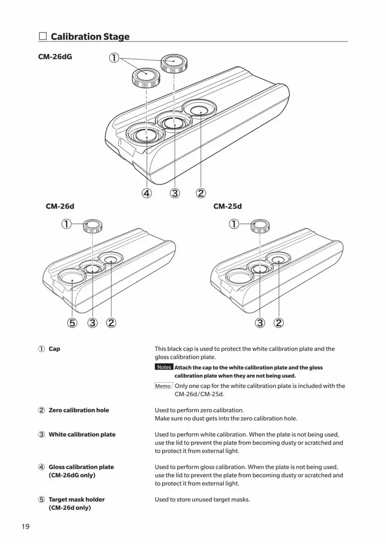
① Cap This black cap is used to protect the white calibration plate and the gloss calibration plate.
Notes Attach the cap to the white calibration plate and the gloss
calibration plate when they are not being used.
Memo Only one cap for the white calibration plate is included with the CM-26d/CM-25d.
② Zero calibration hole Used to perform zero calibration.Make sure no dust gets into the zero calibration hole.
③ White calibration plate Used to perform white calibration. When the plate is not being used, use the lid to prevent the plate from becoming dusty or scratched and to protect it from external light.
④ Gloss calibration plate (CM-26dG only)
Used to perform gloss calibration. When the plate is not being used, use the lid to prevent the plate from becoming dusty or scratched and to protect it from external light.
⑤ Target mask holder(CM-26d only)
Used to store unused target masks.
� Calibration Stage
CM-26dG
CM-26d CM-25d
①
③④ ②
⑤ ③ ②
①
③ ②
①

2019
Before U
sing
th
e Instru
men
t
1
� Cleaning the Components
� Zero Calibration Hole (Calibration Stage)Use a blower to blow off any dust on the inclined surface inside the zero calibration hole. In addition, direct cleaning with the blower can be performed by removing the cover. If the dirt does not come off easily, wipe using a soft cloth soaked in ethanol. In such cases, be careful not to leave behind fingerprints or the like.
� White Calibration and Gloss Calibration* (* CM-26dG only)• If the white calibration plate or the gloss calibration plate becomes
dirty, gently wipe the dirt off using the cleaning cloth* included as a
standard accessory.
• If the dirt on the white calibration plate or the gloss calibration plate
does not come off easily, wipe using a cloth soaked in ethanol.
• When a part other than the calibration plate becomes dirty, lightly
wipe the dirt off with a cloth dampened with water or soapy water.
Notes • Be careful not to scratch the calibration plate.
• Never use solvents such as thinner or naphtha.
• Scratches or dirt on the white calibration plate or the
gloss calibration plate may affect measurement
values.
� Target MaskCM-26dG• Use a blower to blow off dirt or dust on the target mask.
• If the dirt on the outside surface of the target mask does not come off easily, wipe using a soft cloth soaked in ethanol.
Notes Do not touch the painted surface of the integrating sphere.
CM-26d, -25d, MAV target mask (with glass)• Use a blower to blow off dirt or dust on the target mask.
• If the dirt on the outside or inside surface of the target mask does not come off easily, remove the target mask from the
instrument, and wipe the target mask using a soft cloth soaked in ethanol.
Notes • Take sufficient care when handling the target mask with glass.
The glass of the target mask may become cracked, resulting in injury.
• Remove any iron on magnets of the target mask mounting surface.
� Inside the Integrating SphereUse a blower to blow off dust or dirt inside the integrating sphere.
Notes Do not touch the white-coated inner surface of the integrating sphere, wipe it with a cloth or put an object
inside it. If the target mask is dirty, and the dirt cannot be removed by a blower or the like, contact a KONICA
MINOLTA-authorized service facility.
Calibration plate

21
Points to Remember
� Initial SettingsWhen first turning the instrument ON after purchasing, the language setting screen will be displayed. Please select the language. The language selection menu can be displayed by turning ON the instrument while holding down [MENU].The display language can be selected from 11 languages including English.For details, refer to P.108 “Measurement Instrument Option Settings”.
� Control PanelThe front of the instrument contains the LCD screen, upon which the instrument displays measurement results and messages, and the control keys, which are used to set measurement options or to change displays.
LCD screen
Control panel

2221
Before U
sing
th
e Instru
men
t
1
� Display (LCD Screen)The LCD screen displays measurement settings, measurement results, and messages. It also indicates the status of the instrument with icons.The basic screen layout is shown below.
Status bar
Data/graph display area
Data number and name
Target reference (sample) /Affiliated group (target)
Target/Sample
Measurement date/time
Observer/Illuminant 1
Display type of currently displayed screen
“!” is displayed when the calibration interval has arrived, when measurement is performed with an insufficient amount of light, or when the sample is outside the guaranteed range.
Measurement area
Color is applied when the tolerance is exceeded or when a warning occurs. (sample)
UV setting: Displays the UV setting status.
Observer/Illuminant 2
Pass/fail resultA different mark or background color will be applied according to the result.
Target to be used for association with the next measurement or filter (target)

23
� Status barThis section describes the icons displayed at the top of the screen.
① ② ③ ④ ⑤ ⑥ ⑦ ⑧ ⑨ ⑩
Display Description (Status) Meaning
① / None/
/
//
/ None
/ None
/ None/
/ // / / / / / /
/ /
/ / /
Instrument diagnosis result Pass / Check required / No diagnosis
(* Support for this function is planned with optional PC software. It is not currently available.)
②
/ None/
/
//
/ None
/ None
/ None/
/ // / / / / / /
/ /
/ / /
Specular component status SCI / SCE / SCI+SCE
③
/ None/
/
//
/ None
/ None
/ None/
/ // / / / / / /
/ /
/ / /
UV setting UV 100% / UV 0% / UV 100% + 0% /UVC (UV control)
④
/ None/
/
//
/ None
/ None
/ None/
/ // / / / / / /
/ /
/ / /
Measurement area MAV / SAV
⑤
/ None/
/
//
/ None
/ None
/ None/
/ // / / / / / /
/ /
/ / /
Calibration status Measurement possible / Measurement possible (calibration recommended) / Calibration required
⑥
/ None/
/
//
/ None
/ None
/ None/
/ // / / / / / /
/ /
/ / /
Auto print Auto print ON / OFF
⑦
/ None/
/
//
/ None
/ None
/ None/
/ // / / / / / /
/ /
/ / /
Bluetooth communication Bluetooth communication ON / OFF
⑧
/ None/
/
//
/ None
/ None
/ None/
/ // / / / / / /
/ /
/ / /
Wired communicationCommunication ON / Communication key ON / Communication OFF
⑨
/ None/
/
//
/ None
/ None
/ None/
/ // / / / / / /
/ /
/ / /
Power status Battery capacity (Full/OK/Low) / Charging / External power/battery status (Full/OK/Low/None)
⑩
/ None/
/
//
/ None
/ None
/ None/
/ // / / / / / /
/ /
/ / /
Current time Hour: Minute
2423
Before U
sing
th
e Instru
men
t
1
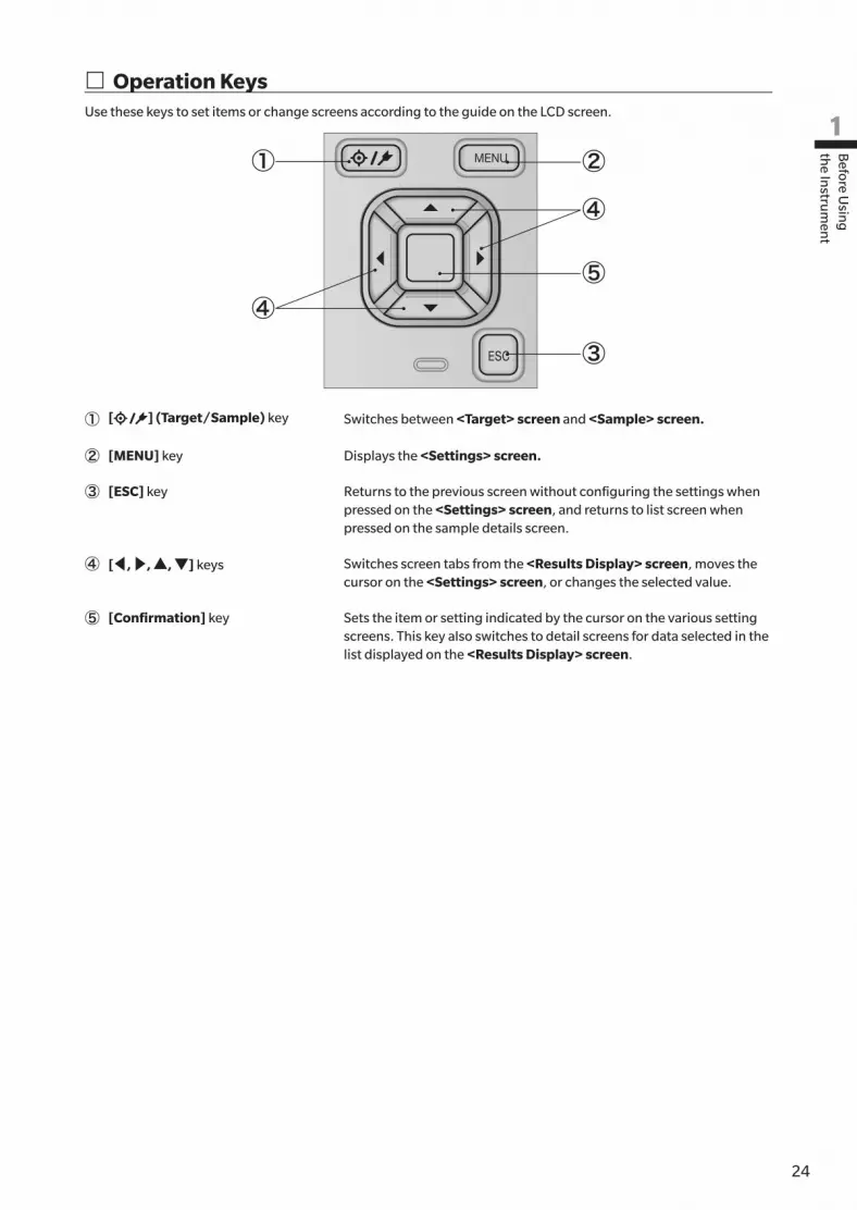
� Operation KeysUse these keys to set items or change screens according to the guide on the LCD screen.
②
⑤
③
④
①
④
① [ ] (Target/Sample) key Switches between <Target> screen and <Sample> screen.
② [MENU] key Displays the <Settings> screen.
③ [ESC] key Returns to the previous screen without configuring the settings when pressed on the <Settings> screen, and returns to list screen when pressed on the sample details screen.
④ [◀, ▶, ▲, ▼] keys Switches screen tabs from the <Results Display> screen, moves the cursor on the <Settings> screen, or changes the selected value.
⑤ [Confirmation] key Sets the item or setting indicated by the cursor on the various setting screens. This key also switches to detail screens for data selected in the list displayed on the <Results Display> screen.

25
� Menus
Target menuPrint data P.63
Edit name P.64
Data managementDelete data P.65
OK/CancelSet group P.66
OK/CancelEdit group
Change list position P.67Target value No. selection
Edit Target filter P.68OFF / Only saved data / Only group
Protect data P.69OFF/ON
Delete all data P.70OK/Cancel
Pass/FailEdit tolerance P.72
OK/Cancel
Tolerance list P.73Index selection
Warning level P.740 to 100%
Parametric coef. P.75l (CMC), c (CMC),l (ΔE*94), c (ΔE*94), h (ΔE*94), l (ΔE00), c (ΔE00), h (ΔE00)
Input colorimetric data
Color space P.76
XYX/L*a*b*/Hunter Lab
Input data P.77
Sample menuPrint data P.51
Edit name P.52
Data managementDelete data P.53
OK/Cancel
Set Sample as Target P.54Target No. selection
Change Target Reference P.55Target No. selection
Change list position P.56Sample No. selection
Delete all data P.57OK/Cancel
Auto target
Auto target P.58
OFF/ON
Threshold P.59
0.01 to 9.99Measurement cond.
Measurement mode P.88Color & Gloss / Color only / Gloss only / Opacity
Measurement setupSpecular component P.92
SCI / SCE / SCI+SCE
UV P.93UV100% / UV0% / UV100%+0% / UVC
Auto average P.941 to 10 times
Manual average P.951 to 30 times
Manual average option (SMC average option) P.95
Manual save / Auto save
SMC P.96OFF/ON
SMC Threshold P.970.01 to 9.99
SMC Times P.983 to 10 times
Observer/IlluminantObserver/Illuminant 1 P.100
2°A/C/D50/D65/ID50/ID65/F2/F6/F7/F8/F10/F11/F12/User10°A/C/D50/D65/ID50/ID65/F2/F6/F7/F8/F10/F11/F12/User
Observer/Illuminant 2 P.1022°A/C/D50/D65/ID50/ID65/F2/F6/F7/F8/F10/F11/F12/User10°A/C/D50/D65/ID50/ID65/F2/F6/F7/F8/F10/F11/F12/User/None
Display cond.Display type P.104
Absolute value, Difference, Abs. & Diff., Pass/Fail, Custom, Abs. Graph, Diff. Graph, Spectral Graph
Color space P.105L*a*b*, L*C*h, Hunter Lab, Yxy, XYZ, Munsell (C)

2625
Before U
sing
th
e Instru
men
t
1Color difference equation P.106ΔE*ab, CMC, ΔE*94, ΔE00, ΔE (Hunter), ΔE99o, FMC2
Custom 01 to 14 P.107L*, a*, b*, ΔL*, Δa*, Δb*, C*, h, ΔC*, ΔH*, L, a, b, ΔL, Δa, Δb, X, Y, Z, DXYZ, DX, DY, DZ, ΔX, ΔY, ΔZ, x, y, Δx, Δy, H, V, C, ΔE*ab, CMC, ΔE*94, ΔE00, ΔE (Hunter), MI, GU, ΔGU, WIe, ΔWIe, WIc, ΔWIc, Tint, ΔTint, YIe, ΔYIe, YId, ΔYId, B, ΔB, ΔE99o, Greyscale (ISO A105), WI (Ganz), ΔWI (Ganz), Tint (Ganz), ΔTint (Ganz), Staining ISO 105-A04, FMC2, ΔL(FMC2), ΔCr-g(FMC2), ΔCy-b(FMC2), K/S St(ΔE*), K/S St(MAX Abs), K/S St(Apparent) , UE1, UC1, UE2, UC2, UE3, UC3, --- (None)
* Underlined items become 8°GU for CM-26d/CM-25d.
Instrument ModeNormal/Simple
Default data setup P.79Default tolerance P.81
OK/Cancel
Warning level P.820 to 100%
Parametric coef. P.83l (CMC), c (CMC),l (ΔE*94), c (ΔE*94), h (ΔE*94), l (ΔE00), c (ΔE00), h (ΔE00)
Set group P.84Group number selection →Group name setting
Calibration setupCalibration interval P.132
01 to 24 hours
Annual calibration P.133OFF/ON
User calibration P.134OFF/ON
Zero calibration skip P.135Disable/Enable
Communication setupAuto print P.129
OFF/ON
Bluetooth P.122OFF/ON
Meter PIN code P.1234 to 8 digits (Initial value is "0000")
Printer address P.126000000000000
Printer PIN code P.1274 to 8 digits (Initial value is "0000")
Scanner address P.126000000000000
Scanner PIN code P.1274 to 8 digits (Initial value is "0000")
Instrument setupUser type P.109
Administrator / Worker
Language P.110English / 日本語 / Deutsch / Français / Español / Italiano / 中文 / Português / Polski / Русский язык / Türkçe
Date format P.111[yyyy/mm/dd]/[mm/dd/yyyy]/[dd/mm/yyyy]
Date & time P.1120000/00/00 00:00
Brightness P.1135/4/3/2/1
Direction P.114
Beep P.115OFF/ON
Auto power off P.11600 to 60 minutes
Password setting P.1178 digits (Initial value is "00000000")
Diagnosis info. P.136Diagnosis info. display
Instrument info. P.137Product name, Version, Serial No.
CalibrationCalibration (Including Zero Cal.) P.35
Zero calibration → White calibration → Gloss calibration
Calibration (Excluding Zero Cal.) P.37White calibration → Gloss calibration
JOBJOB 1 to 5

27
� Data SavingData used with this instrument are saved automatically within the instrument.Data on the instrument can also be imported to a computer using the optional accessory Color Data Software “SpectraMagic NX”.

2827
Measu
remen
t
2
Chapter 2
Chapter 2 Measurement
Flow of Measurement .....................................29
Preparation ....................................................30
Calibration ......................................................35
Zero calibration................................................... 35
White Calibration and Gloss Calibration .............. 37
User calibration .................................................. 39
Setting a Specimen .........................................40
Viewfinder .......................................................... 40
Measurement .................................................41
Displaying the Measurement Results .................. 42
Measurement (Simple Mode) .............................. 48
Handling the Sample ......................................50
Print Data (Sample)............................................. 51
Edit name ........................................................... 52
Data Management (Sample) ............................... 53
Auto Target (Sample) .......................................... 58
Pass/Fail Judgment for Color Difference ..........60
Pass/Fail Judgment Based on Tolerances ............. 60
Color Difference Target Operation ...................62
Print Data (Target) .............................................. 63
Edit name ........................................................... 64
Data Management (Target) ................................. 65
Pass/Fail ............................................................. 71
Input Colorimetric Data ...................................... 76
Default Data Settings .......................................... 79

29
� Optional settings � Basic procedure � Simple measurement
Turning the Power ON (P.32)Turning the Power ON
(P.32)
↓Language selection (P.110) * As necessary (after initialization, etc.)
↓ ↓Measurement cond. setting (P.99)
Skip the initial calibration screen
↓
Measurement area selection (P.33)* When required depending on the
measurement conditions
↓
Zero calibration (P.35)* Only when required (when changing
the measurement conditions, etc.)
↓White calibration (P.37) ↓
↓
When “Change to simple mode?” appears,
select "Yes”
Gloss calibration (* CM-26dG only)
↓ ↓* When color difference is
measured* When color difference
is not measured
↓Color difference target settings
(P.41)(Procedure)
(1) Open the <Target> screen.
(2) Select the target number.(3) Measure the color
difference target.
↓ ↓Pass/fail judgment criteria settings
(P.71)
Measurement (Simple mode) (P.48)
↓ ↓Measurement (P.41)(Procedure)
(1) Open the <Sample> screen.(2) Measure the sample.
↓ ↓End End
* Configure measurement/observation conditions and perform calibration as necessary.
Flow of Measurement

3029
Measu
remen
t
2
� Attach the Wrist StrapAttaching the Wrist Strap
Wrist strap attaching position
Preparation
31
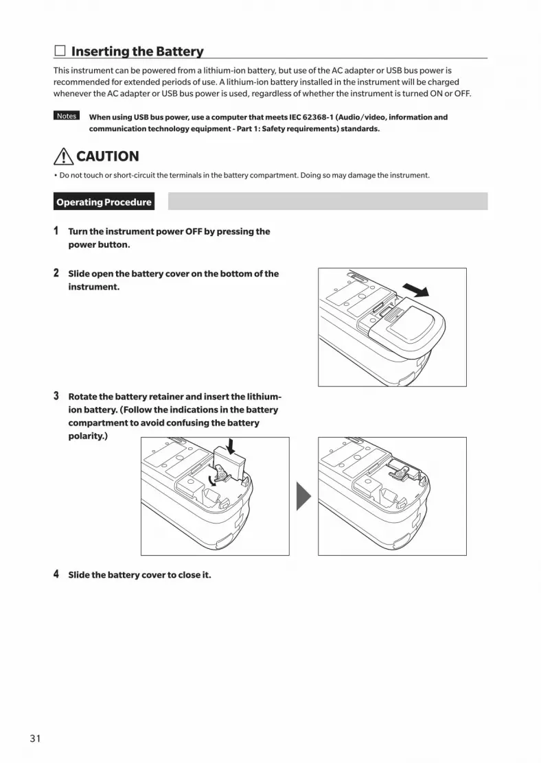
� Inserting the BatteryThis instrument can be powered from a lithium-ion battery, but use of the AC adapter or USB bus power is recommended for extended periods of use. A lithium-ion battery installed in the instrument will be charged whenever the AC adapter or USB bus power is used, regardless of whether the instrument is turned ON or OFF.
Notes When using USB bus power, use a computer that meets IEC 62368-1 (Audio/video, information and
communication technology equipment - Part 1: Safety requirements) standards.
CAUTION• Do not touch or short-circuit the terminals in the battery compartment. Doing so may damage the instrument.
Operating Procedure
1 Turn the instrument power OFF by pressing the power button.
2 Slide open the battery cover on the bottom of the instrument.
3 Rotate the battery retainer and insert the lithium-ion battery. (Follow the indications in the battery compartment to avoid confusing the battery polarity.)
4 Slide the battery cover to close it.
3231
Measu
remen
t
2
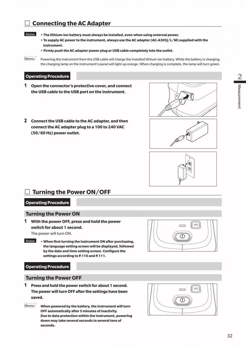
� Connecting the AC Adapter
Notes • The lithium-ion battery must always be installed, even when using external power.
• To supply AC power to the instrument, always use the AC adapter (AC-A305J/L/M) supplied with the
instrument.
• Firmly push the AC adapter power plug or USB cable completely into the outlet.
Memo Powering the instrument from the USB cable will charge the installed lithium-ion battery. While the battery is charging, the charging lamp on the instrument’s panel will light up orange. When charging is complete, the lamp will turn green.
Operating Procedure
1 Open the connector’s protective cover, and connect the USB cable to the USB port on the instrument.
2 Connect the USB cable to the AC adapter, and then connect the AC adapter plug to a 100 to 240 VAC (50/60 Hz) power outlet.
� Turning the Power ON/OFF
Operating Procedure
Turning the Power ON1 With the power OFF, press and hold the power
switch for about 1 second.The power will turn ON.
Notes • When first turning the instrument ON after purchasing, the language setting screen will be displayed, followed by the date and time setting screen. Configure the settings according to P.110 and P.111.
Operating Procedure
Turning the Power OFF1 Press and hold the power switch for about 1 second.
The power will turn OFF after the settings have been saved.
Memo When powered by the battery, the instrument will turn OFF automatically after 5 minutes of inactivity.
Due to data protection within the instrument, powering down may take several seconds to several tens of seconds.

33
� Measurement Area Selection (CM-26dG/CM-26d)Select the measurement area.The selected measurement area can be checked on the status bar displayed on the screen. (Refer to P.23.)
Operating Procedure Operate the measurement area switch on the instrument.
1 Use the measurement area switch on the bottom of the instrument to set the measurement area to MAV or SAV.
MAV SAV
Setting{ MAV : Measurement area of 8 mm (10×7 mm with gloss measurement){ SAV : Measurement area of 3 mm
� Target Mask Replacement (CM-26d/CM-25d)Replace the target mask according to the sample to measure.
Notes • Fit the target mask securely so that the
bottom is parallel to the instrument.
• Make sure the measurement area set for
the instrument matches the diameter of
the target mask being used.
Using the optional stapler type target mask (CM-A268) makes it possible to accurately aim where measurement will be performed.

3433
Measu
remen
t
2
� Staple-Type Target Mask
� Attaching the Target MaskAttach the stapler type target mask so that the two protrusions of the target mask are inserted into the 2 holes on the bottom of the instrument, and push in until the tab on the rear end of the target mask catches on the instrument and clicks.
Push down slowly
Stapler type target maskCM-A268
Align
Click
Memo • Secure the target mask by tightening screws into the mounting screw holes for accessories on the instrument (refer to P.18).
• Use any of the following screws to secure the target mask. ① CM-A280 (Stapler type target mask coupling screws) ② Screws with the following dimensions: M3 (thread size) × 4 mm (length) × Ø5.5 to 6 (head diameter) × 2 mm or
less (head height)
Notes Using screws other than the above may result in damage to the instrument or the target mask, scratches on the measurement sample, or incorrect measurement values.
� Attaching/Removing the Target Sheet
1. Attach a target sheet to the stapler type target mask as necessary for the application.
For glossCM-A269
(CM-26dG only)
MAV (Ø8 mm)CM-A270
SAV (Ø3 mm)CM-A271
2. Align the notch and rotate in the direction indicated by the arrow.
3. The sheet will be locked when a “click” is heard.• Perform the procedure in reverse to remove.
Turn
Click

35
Select the measurement area using the switch beforehand.Three types of calibration can be performed with this instrument.• Zero calibration : Only the amount of stray light is measured in advance in order to eliminate the effects of the stray light.
• White calibration : The reflectance is measured in advance using a known calibration plate in order to provide a reflectance scale.
• Gloss calibration : The gloss is measured in advance using a known calibration plate in order to provide a gloss scale.
This calibration is performed after white calibration with this instrument. (CM-26dG only)
Calibration StageUse a calibration stage with the same number as that printed on the nameplate of the instrument.
Newly purchased calibration stages will have a different number than that shown on the nameplate of the instrument. Make sure
the calibration plate ID displayed on the <Calibration> screen matches the calibration stage number.
Calibration data will need to be written (updated) any time you purchase a new calibration stage. Use the CM-CT1 standard accessory
PC software to write calibration data. For details, refer to “New White Calibration Plate / Gloss Calibration Plate” in the CM-CT1 manual.
� Zero calibrationSince this instrument stores the data of the previous zero calibration, repeating zero calibration every time the instrument is turned ON is not necessary. If, however, the measurement conditions change greatly, the instrument is not used for a long period of time, or when using a MAV target mask (with glass), zero calibration must be performed before white calibration.
Memo • The effects of stray light (i.e., light generated due to the flare characteristics of the optical system) will be
compensated for automatically by the zero calibration data.
• The amount of stray light may change because of dust or dirt that has collected in the optical system, humidity,
repeated operation, or vibration and shock exerted on the instrument. In this case, performing zero calibration
periodically is recommended.
Notes • If the instrument is not used for long periods of time, the zero calibration data stored in the instrument may
be lost. If the data is lost, zero calibration must be performed again.
• Before using the MAV target mask (with glass), it is necessary to set “Zero cal. skippable” (P.135) to “OFF” in
advance.
Operating Procedure Start the procedure from the measurement screen.
1 Press [MENU], and then use [◀] or [▶] to display the <Calibration> screen.
Notes • The following screen prompting calibration is
displayed when the instrument starts up. If zero
calibration has not been performed, the cursor will
appear on “Calibration (Including Zero Cal.)”.
Otherwise, the cursor will appear on “Calibration
(Excluding Zero Cal.)”.
Zero calibration date2016/07/21 08:46:13
White calibration date2016/07/21 08:46:32
Gloss calibration date2016/07/21 08:46:54
CalibrationCalibration
(Excluding Zero Cal.)
Calibration(Including Zero Cal.)
Calibration

3635
Measu
remen
t
2
2 Use [] or [] to move the cursor to “Calibration (Including Zero Cal.)”, and then press the [Confirmation] key.
3 Set the instrument in the calibration stage to measure the calibration stage’s zero calibration hole.
4 Press the measurement button.Zero calibration will be performed.
Notes • Do not move the instrument until zero calibration is
complete.
When zero calibration is completed, a screen prompting white calibration is displayed. Continue to step 3 on the following page to perform white calibration.
Please set the instrument on the zero calibration box and press the measurement button.
Calibration stage
Place the instrument on the calibration stage according to the marks.
Calibration stage
Place the instrument on the calibration stage according to the marks.
Calibration stage
Place the instrument on the calibration stage according to the marks.
Calibrating to zero
CALIBRATION

37
� White Calibration and Gloss CalibrationA message prompting white calibration is displayed on the instrument after the power is turned ON.
Memo • If the calibration interval is turned ON and a time is configured, a message prompting white calibration will be
displayed the next time the power is turned ON or when measurement is performed after the set time has passed
since the previous white calibration. (Refer to P.132 “Calibration Interval Messages”)
• The reading may fluctuate slightly due to changes in the ambient temperature or due to heat generation caused by
repeated operation of the instrument. In such cases, perform white calibration regularly.
• Calibration details may vary according to the measurement mode (refer to P.88). When the measurement mode is
set to “Color & Gloss”, white calibration and gloss calibration will be performed. When the mode is set to “Color
only”, only white calibration will be performed. When the mode is set to “Gloss only”, only gloss calibration will be
performed.
Notes • White calibration must be performed at the same temperature at which measurement will be performed.
• Perform white calibration after the instrument has had time to adapt to the ambient temperature.
Operating Procedure Start the procedure from the measurement screen.
Although white calibration can be performed from the prompt when the power is turned ON and from the screen following zero calibration, the following explains the procedure to perform white calibration from the measurement screen.
1 Press [MENU], and then use [◀] or [▶] to display the <Calibration> screen.
Notes • The following screen prompting calibration is
displayed when the instrument starts up. If zero
calibration has not been performed, the cursor will
appear on “Calibration (Including Zero Cal.)”.
Otherwise, the cursor will appear on “Calibration
(Excluding Zero Cal.)”.
2 Use [▲] or [▼] to move the cursor to “Calibration (Excluding Zero Cal.)”, and then press the [Confirmation] key.
Calibration(Excluding Zero Cal.)
Calibration(Including Zero Cal.)
Calibration
Zero calibration date2016/07/21 08:46:13
White calibration date2016/07/21 08:46:32
Gloss calibration date2016/07/21 08:46:54

3837
Measu
remen
t
2
3 Set the instrument in the calibration stage in order to measure the calibration stage’s white calibration plate.
Notes • Verify that the White ID shown on the screen and the
calibration stage number match.
Calibration stage
Place the instrument on the calibration stage according to the marks.
Calibration stage
Place the instrument on the calibration stage according to the marks.
Calibration stage
Place the instrument on the calibration stage according to the marks.
4 Press the measurement button.White calibration will be performed.
Notes • Do not move the instrument until white calibration is
complete.
After white calibration is complete, a screen prompting gloss calibration will be displayed.
5 Set the instrument in the calibration staged in order to measure the calibration stage’s gloss calibration plate.
Notes • Gloss calibration is only available with the 26dG.
• Verify that the Gloss ID shown on the screen and the
calibration stage number match.
Calibration stage
Place the instrument on the calibration stage according to the marks.
Calibration stage
Place the instrument on the calibration stage according to the marks.
Calibration stage
Place the instrument on the calibration stage according to the marks.
6 Press the measurement button.Gloss calibration will be performed.
Notes • Do not move the instrument until gloss calibration is
complete.
When gloss calibration is completed, the screen returns to the <Sample> screen.
Please set the instrument on the white calibration plate and press the measurement button.
White ID: xxxxxxx
Calibrating to white
CALIBRATION
Please set the instrument on the gloss calibration plate and press the measurement button.
Gloss ID: xxxxxxx
Gloss calibrating
CALIBRATION
39
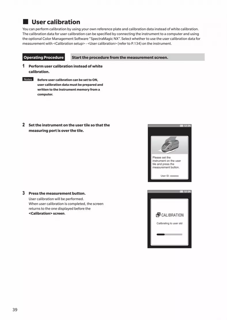
� User calibrationYou can perform calibration by using your own reference plate and calibration data instead of white calibration. The calibration data for user calibration can be specified by connecting the instrument to a computer and using the optional Color Management Software “SpectraMagic NX”. Select whether to use the user calibration data for measurement with <Calibration setup> - <User calibration> (refer to P.134) on the instrument.
Operating Procedure Start the procedure from the measurement screen.
1 Perform user calibration instead of white calibration.
Notes Before user calibration can be set to ON,
user calibration data must be prepared and
written to the instrument memory from a
computer.
2 Set the instrument on the user tile so that the measuring port is over the tile.
3 Press the measurement button.User calibration will be performed.When user calibration is completed, the screen returns to the one displayed before the <Calibration> screen.
Please set the instrument on the user tile and press the measurement button.
User ID: xxxxxxx
Calibrating to user std
CALIBRATION

4039
Measu
remen
t
2
Refer to P.33 for preparations to perform before measurement according to the specimen being measured and the application.
1. Switch the measurement area (CM-26dG/CM-26d).2. Replace the target mask (CM-26d).3. Set the instrument on top of the specimen.
Setting a Specimen
� ViewfinderSwitching the measurement area allows users to check the measurement point of a specimen when aligning the instrument and the target are necessary, such as when the measurement location is small.
How to Use
1 Set the instrument on top of the specimen.
2 Slide the viewfinder lever to open the viewfinder.
Viewfinder
Viewfinder lever
3 As the viewfinder opens, a white LED will turn ON, illuminating the specimen within the range of measurement.
Memo When using the CM-26dG, the range of measurement will be illuminated according to the set measurement area
(MAV/SAV) when the measurement button is pressed.
4 Look into the viewfinder and adjust the position of the specimen.
5 Close the viewfinder. (The white LED will turn OFF.)
Notes If the reflectance of the specimen to be measured is low, the measurement range may not be clearly
visible even when illuminated by a white LED. Also, if the specimen has a mirror surface or a surface
similar to a mirror surface, the illumination light may not be clearly visible. In such cases, use the optional
stapler type target mask (CM-A268).

41
Notes • Prior to the start of measurement, be sure to perform white calibration. For details, refer to “White
Calibration and Gloss Calibration” on P.37.
• To display the color difference, color difference target must be set before measurement.
• To measure a target, select the target number before measurement.
• For accurate measurements, measure under the same conditions (surrounding temperature, etc.).
Operating Procedure
1 Press [ ] to bring up the [Target] or [Sample] screen, depending on the objective.The <Target> screen or the <Sample> screen is displayed.Note: If the menu screen is displayed, press [ESC] and perform the operation after the Results Display screen is displayed.
2 Set the specimen measuring port on the sample to measure.• Take care to prevent floating or tilting from occurring.• Using the optional stapler type target mask (CM-A268) makes it possible to determine the measurement
position more accurately.
Measuring
MEASURING
To measure concave surfaces, as shown in the following figure, use the standard accessory flat type battery cover (CM-A218).
3 Press the measurement button.The specimen is measured and the results are displayed on the screen.• The selected number will be used as the target data
number. If data is already present for that number, a confirmation dialog will ask if the data should be overwritten. Press the [Confirmation] key to overwrite.
• The sample No. is automatically assigned sequentially in the order of measurements.
Memo • When the number of sample data sets stored in the memory reaches 5,100, “The device memory is full. Please delete
some data to measure.” will be displayed, indicating that some data sets must be deleted before measurement is
possible.
Measurement

4241
Measu
remen
t
2
� Displaying the Measurement ResultsAt the end of measurement, the measurement results will be displayed on the LCD according to the specified conditions. Typical measurement result screens are shown below.
Memo You can switch the tab of the measurement screen with the ◀ or ▶ of the cross key.
You can switch the sample No. with the ▲ or ▼.
No GU value is displayed with CM-26d/CM-25d.
� <Sample> detail screen: Absolute value
① Specular component mode used for the measurement② Current UV setting (not shown when set to UV 0%)③ Current measurement area④ Calibration completed⑤ Automatic printing from serial printer set to ON (OFF when the icon is not displayed)⑥ Current time * For details of the status bar items ① to ⑥, refer to P.23.⑦ Target/Sample⑧ No. of the currently selected color difference target data⑨ Pass/fail judgment (When the result is “Pass”, the background is shown in green. When the result is “Fail”, the
background is shown in orange.)⑩ Sample No.⑪ Date and time of the measurement⑫ Data No. of the color difference target data used for the measurement⑬ UV setting used for the measurement⑭ Measurement area used for the measurement⑮ Sample data (Use ◀ or ▶ to switch tabs)⑯ An exclamation mark ( ! ) will be displayed for measurements that are beyond the guaranteed range or when
measurement is performed even though a light intensity decrease warning or measurement out-of-range warning has occurred.
① ⑤ ⑥
⑬ ⑭ ⑯
⑧⑨
⑮
⑦⑩
⑪⑫
②③ ④
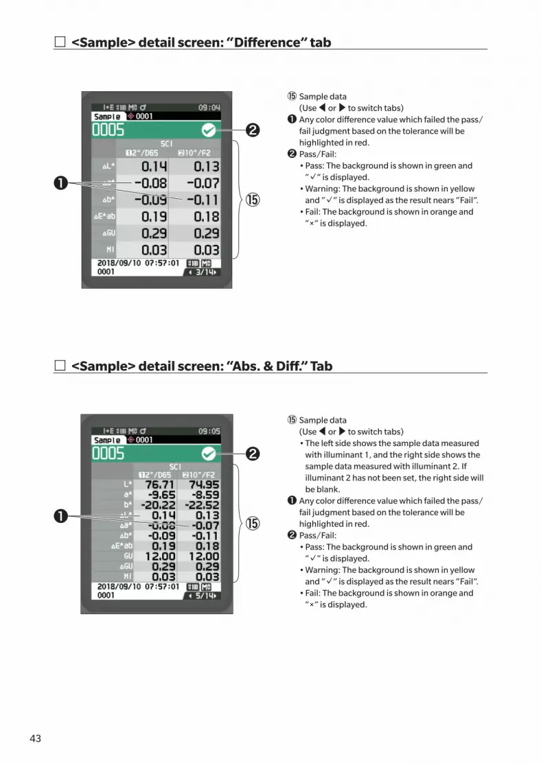
43
� <Sample> detail screen: “Difference” tab
� <Sample> detail screen: “Abs. & Diff.” Tab
⑮ Sample data (Use ◀ or ▶ to switch tabs)
❶ Any color difference value which failed the pass/fail judgment based on the tolerance will be highlighted in red.
❷ Pass/Fail: • Pass: The background is shown in green and
“✓” is displayed. • Warning: The background is shown in yellow
and “✓” is displayed as the result nears “Fail”. • Fail: The background is shown in orange and
“×” is displayed.
⑮ Sample data (Use ◀ or ▶ to switch tabs)
• The left side shows the sample data measured with illuminant 1, and the right side shows the sample data measured with illuminant 2. If illuminant 2 has not been set, the right side will be blank.
❶ Any color difference value which failed the pass/fail judgment based on the tolerance will be highlighted in red.
❷ Pass/Fail: • Pass: The background is shown in green and
“✓” is displayed. • Warning: The background is shown in yellow
and “✓” is displayed as the result nears “Fail”. • Fail: The background is shown in orange and
“×” is displayed.
❷
❷
⑮
⑮
❶
❶

4443
Measu
remen
t
2
� <Sample> detail screen: “Pass/Fail” tab
� <Sample> detail screen: “Custom” tab
Pass/Fail: • Pass: The background is shown in green and “✓
Pass” is displayed. • Warning: The background is shown in yellow
and “✓ Warning” is displayed as the result nears “Fail”.
• Fail: The background is shown in orange and “× Fail” is displayed.
⑮ Sample data (Use ◀ or ▶ to switch tabs)
• This tab is displayed when the display setting of “Custom” is set to ON. For the procedure of setting “Show Custom Data Screen” to ON/OFF, refer to P.107.
Memo To set the items displayed on the “Custom”
screen, you need to use the optional accessory
Color Management Software SpectraMagic NX.
For details, refer to the instruction manual of
SpectraMagic NX.⑮

45
� <Sample> detail screen: “Abs. Graph” Tab
� <Sample> detail screen: “Diff. Graph” Tab
⑮ Sample data (Use ◀ or ▶ to switch tabs)
❶ L* axis (colorimetric graph)❷ a* axis (colorimetric graph)❸ b* axis (colorimetric graph)❹ Scales for the axes❺ Color difference target measurement point
⑮ Sample data (Use ◀ or ▶ to switch tabs)
❶ ΔL* axis (color difference graph)❷ Δa* axis (color difference graph)❸ Δb* axis (color difference graph)❹ Color difference tolerance❺ Measurement point: Plotted with a light-blue
circle (○).❻ Color difference target measurement point: This
is the origin point of the graph.
Notes The measuring point will not be shown on the
graph when no color difference target is set
for the sample data.
⑮
⑮
❶ ❸
❸
❷
❷❹
❺
❶
❹
❻
❺

4645
Measu
remen
t
2
� <Sample> detail screen: “Spectral Graph” tab
� <Sample> List ScreenEvery time the [ESC] button is pressed, the screen is switched between the <Sample> detail screen and <Sample> list screen.
Memo Measurement can be performed on either the <Sample> detail screen or <Sample> list screen.
⑮ Sample data (Use ◀ or ▶ to switch tabs)
❶ Axis of spectral reflectance❷ Spectral graph of sample (SCI):
Shown with a solid black line.❸ Spectral graph of sample (SCE):
Shown with a solid blue line.
⑩ Sample No.⑪ Date and time of the measurement⑰ Pseudocolor expressing the sample data is
displayed.
⑮❶
❸
❷
⑰⑩⑪

47
Screen transition
The detail screen is displayed only for screens with the appropriate format selected under <Display type>.
[Target] List
(Target/Sample)(Target/Sample)
[Sample] List
[Target] Details
[Sample] Details
Use [◀] or [▶] to go to the next display type.
Use [◀] or [▶] to go to the next display type.
Use [◀] or [▶] to move between pages.
Use [◀] or [▶] to move between pages.
Absolute value (SCI/SCE)
Custom ①/②
◀ ▶/◀
▶/◀▶/◀
▶/◀
▶/◀
▶/◀
▶/◀
▶/◀
▶
SetESC→←
ESC
SetESC→←
ESC
Difference
Abs. Graph
Abs. & Diff.
Color Difference Graph
Pass/Fail
Spectral Graph
Absolute value (SCI/SCE)
◀ ▶/◀ ▶/◀▶/◀ ▶/◀ ▶
Custom ①/②Abs. & Diff. (SCI/SCE) Abs. Graph Spectral Graph

4847
Measu
remen
t
2
� Measurement (Simple Mode)Used to easily confirm color differences. The menu items that can be set in Simple mode are as follows.
Setting Procedure
1 Set to “Simple mode”.
Press [ESC] to skip the calibration displayed immediately after turning the power ON.
Set “Simple mode” under <Setting> - <Instrument Mode>.
Zero calibration date
White calibration date
Gloss calibration date
Calibration
Calibration(Excluding Zero Cal.)
Calibration(Including Zero Cal.)
Warning
Change to simple mode?
Yes No
When “Change to simple mode?” appears on the screen, select “Yes”.
or
Press the [Target/Sample] buttonor the [ESC] button to switch to the Simple Measurement screen.
2 Measuring a target: Absolute value measurement
Press the measurement button.
3 Measuring a sample: Difference measurement
Press the measurement button.
Notes • Data is not saved when measuring in Simple mode.
• Opacity mode cannot be selected while in Simple mode. In addition, Simple mode cannot be selected while
in Opacity mode.

49
4 Press the measurement button to continue measuring color differences. To change the target, press [Target/Sample] to measure the target again.
Memo To exit Simple mode, turn the instrument OFF or select “Normal” under [MENU] - <Settings> - <Instrument
setup>.

5049
Measu
remen
t
2
The <Sample menu> screen allows the following operations for the sample.
<Print data> Print the current sample with the printer.
<Edit name> Name the sample.
<Data management> • Delete data : Delete the selected sample. • Set Sample as Target : Set sample as target data. • Change Target reference : Change target reference. • Change list position : Jump to the specified sample. • Delete all data : Delete all samples.<Auto target> During measurement, the color difference target with the smallest color difference
value is automatically selected.
Setting Procedure Start the procedure from the measurement screen.
1 Press [MENU], and then use [◀] or [▶] to display the <Sample menu> screen.
Memo To return to the previous screen, press [MENU] or [ESC].
Handling the Sample

51
� Print Data (Sample)Print the sample. The instrument must be connected to the serial printer in advance. For instructions on how to connect the instrument to a serial printer, refer to P.125 “Connecting to a Printer/Barcode Reader”.
Notes • Display the sample to be printed on the <Sample> screen in advance.
• If a proper connection is not established, printing will not be possible.
• Even if the printer is connected correctly, printing may not be possible under some circumstances, such as if
the printer is turned OFF when printing.
Display the sample to be printed on the <Sample> screen in advance.
Setting Procedure Start the procedure from the <Sample menu> screen.
1 Use [▲] or [▼] to move the cursor to “Print data”, and press the [Confirmation] key to display the <Print data> screen. Printing will begin from the connected printer.When printing is complete, the screen returns to the <Sample> screen.
Notes The <Print data> screen is displayed even when data will
not be printed properly due to an improper printer
connection or other problem.

5251
Measu
remen
t
2
� Edit nameName the sample.
Display the name of the sample to be edited on the <Sample> screen in advance.
Setting Procedure Start the procedure from the <Sample menu> screen.
1 Use [▲] or [▼] to move the cursor to “Edit name”, and then press the [Confirmation] key.The <Edit name> screen is displayed.
2 Use [▲]/[▼] or [◀]/[▶] to move the cursor between characters, and then press the [Confirmation] key.• Up to 30 characters can be used.• The selected character is displayed in the text box.• If the name is obtained from the barcode reader, the
name will be set as the name for the sample.
3 Repeat step 2 until the necessary characters have been entered.• To delete the character to the left of the cursor in the text
box, move the cursor to [×] and press the [Confirmation] key.
4 After inputting the characters, move the cursor to [OK] and press the [Confirmation] key.The setting is confirmed and the screen returns to the <Sample> screen.
Memo • If [ESC] is pressed during configuration, or if the cursor is
moved to “Cancel” and the [Confirmation] key is
pressed, the settings will not be changed and the screen
will return to the <Sample menu> screen.
• When using a barcode reader, barcodes can be used on
the <Edit name> screen. Refer to P.125 to P.127
“Connecting to a Printer/Barcode Reader” for information
on connecting a barcode reader.

53
� Data Management (Sample)Sample data management allows users to delete a sample, copy the sample to the target, change the link to the target, change the list position, and delete all data.
Setting Procedure Start the procedure from the <Sample menu> screen.
1 Use [▲] or [▼] to move the cursor to “Data management”, and then press the [Confirmation] key to display the <Data management> screen.
� DeleteDelete the sample.Display the sample to be deleted on the <Sample> screen in advance.
Setting Procedure Start the procedure from the <Sample menu> - <Data management> screen.
1 Use [▲] or [▼] to move the cursor to “Delete data”, and then press the [Confirmation] key.The <Delete data> screen is displayed.
2 Use [◀] or [▶] to move the cursor to “OK” and press the [Confirmation] key to delete.
Memo When data is deleted, the subsequent sample data numbers
will be reassigned, reducing each by one.
• When the deletion is complete, the screen returns to the <Sample>
screen.
• Moving the cursor to “Cancel” and pressing the [Confirmation] key
will cancel the deletion, and the screen will return to the <Data
management> screen.

5453
Measu
remen
t
2
� Set Sample as TargetSample data can be copied to target data and registered.Display the sample to be set as the target on the <Sample> screen in advance.
Setting Procedure Start the procedure from the <Sample menu> - <Data management> screen.
Memo • Color difference targets are stored with setting numbers from 0001 to 2500 being assigned. Even if the data at some
point is deleted, these setting numbers do not change. It is useful to group data by assigning numbers of specific digits.
• To set more accurate color difference target data, use average measurement to measure the target specimen. For
details, refer to the section on average measurement (P.94 and 95).
Notes • Unlike with samples, the numbers assigned to color difference target data do not change automatically.
When measuring colors continuously to set color difference targets, the cursor must be moved manually to
set each data.
• This function cannot be used if the target is protected or if the filter is enabled.
1 Use [▲] or [▼] to move the cursor to “Set Sample as Target”, and then press the [Confirmation] key.The <Set Sample as Target> screen is displayed.
2 The target data number being used will be displayed. Use [▲] or [▼] to move the cursor to the color difference target number, and then press the [Confirmation] key. When the target data is set, the screen returns to the <Target> screen.• If [ESC] is pressed without pressing the [Confirmation]
key, the screen will return to the <Target> screen.
Notes If a number to which color difference target data has
already been set is selected, a message is displayed to
confirm overwriting. Use [◀] or [▶] to select “OK”.
Moving the cursor to “Cancel” and pressing the
[Confirmation] key will cancel the deletion, and the
screen will return to the <Data management> screen.

55
� Change Target ReferenceThe target data acting as a reference for the sample can be changed.Display the sample for which the target reference is to be changed on the <Sample> screen in advance.
Setting Procedure Start the procedure from the <Sample menu> - <Data management> screen.
1 Use [▲] or [▼] to move the cursor to “Change Target reference”, and then press the [Confirmation] key.The <Change Target reference> screen is displayed.
Notes • If a target with different measurement conditions is
specified, an error message will be displayed. Change
to a target with the same measurement conditions.
2 The target data number being used will be displayed. Use [▲] or [▼] to move the cursor to the color difference target number, and then press the [Confirmation] key. When the target data is set, the screen returns to the <Sample> screen.• If [ESC] is pressed, the target changes will not be
applied and the screen will return to the <Data management> screen.
Notes • If a number to which no color difference target data
has been set, the target will be determined as “None”
and the color difference and pass/fail judgment will
not be displayed.

5655
Measu
remen
t
2
� Change list positionSpecifying sample numbers allows for specified sample to be selected without the need to scroll the screen.
Setting Procedure Start the procedure from the <Sample menu> - <Data management> screen.
1 Use [▲] or [▼] to move the cursor to “Change list position”, and then press the [Confirmation] key.The <Change list position> screen is displayed.
2 ▲ and ▼ will be displayed above and below the data number. Use [▲] or [▼] to specify a value. Use [◀] or [▶] to move between digits.
3 Press the [Confirmation] key.The selection is confirmed and the screen returns to the <Sample> screen.
Notes If [ESC] is pressed without pressing the [Confirmation]
key, the settings will not be changed and the screen will
return to the <Data management> screen.
Notes Numbers with no measurement data cannot be selected.

57
� Delete All Data (Sample)Delete all samples.
Setting Procedure Start the procedure from the <Sample menu> - <Data management> screen.
1 Use [▲] or [▼] to move the cursor to “Delete all data”, and then press the [Confirmation] key.The <Delete all data> screen is displayed.
2 Use [◀] or [▶] to move the cursor to “OK” and press the [Confirmation] key to delete all data.• When the deletion is complete, the screen returns to the
<Sample> screen.• Moving the cursor to “Cancel” and pressing the
[Confirmation] key will cancel the deletion of all data, and the screen will return to the <Data management> screen.

5857
Measu
remen
t
2
� Auto Target (Sample)During measurement, the color difference target with the smallest color difference value is automatically selected.Color difference targets with a smaller color difference value than the preset threshold are displayed in ascending order from the target with the smallest color difference. The color difference target to use can be selected from among the displayed targets. If only one color difference target has a color difference value less than the threshold, that color difference target will be automatically selected.
Memo The color difference is calculated using the color difference equation set for the instrument.
Notes • Do not use this function to manage the color difference from a specific target.
• This function is not applied to sample data obtained before the function was turned ON.
Setting Procedure Start the procedure from the <Sample menu> screen.
1 Use [▲] or [▼] to move the cursor to “Auto Target”, and then press the [Confirmation] key to display the <Auto Target> screen.
� Auto Target (Sample)
Setting Procedure Start the procedure from the <Sample menu> - <Auto Target> screen.
1 Use [▲] or [▼] to move the cursor to “Auto Target”, and then press the [Confirmation] key.The <Auto Target> screen is displayed.

59
2 Use [▲] or [▼] to move the cursor to “ON” or “OFF”.Settings{ ON : The automatic target selection function will be
used.{ OFF : The automatic target selection function will not
be used.
3 Press the [Confirmation] key.The selection is confirmed and the screen returns to the <Auto Target> screen.
� Threshold (Sample)Sets the threshold to be used for the automatic target selection function.
Setting Procedure Start the procedure from the <Sample menu> - <Auto Target> screen.
1 Use [▲] or [▼] to move the cursor to “Threshold”, and then press the [Confirmation] key.The <Threshold> screen is displayed.
2 ▲ and ▼ are displayed above and below the number to be set. Use [▲] or [▼] to specify a value.Settings{ 0.01 to 9.99
3 Press the [Confirmation] key.The selection is confirmed and the screen returns to the <Auto Target> screen.
Notes If [ESC] is pressed without pressing the [Confirmation]
key, the settings will not be changed and the screen will
return to the <Auto Target> screen.

6059
Measu
remen
t
2
With this instrument, tolerances can be set for the color difference target of the sample to perform judgment. For the procedure on setting tolerances, refer to P.72 “Tolerance Settings” and P.81 “Default Tolerance Settings”.
If color difference target data is deleted, neither the color difference display for the data nor the pass/fail judgment based on the tolerances set to the data will be performed. If other color difference target data is selected, or another color difference target is assigned to the color difference target number of the deleted data, recalculations and pass/fail judgments will be performed.
� Pass/Fail Judgment Based on TolerancesIf the measured color difference is outside the tolerances set for the color difference target, the value will be highlighted in red to indicate that the judgment result is “Fail”. By setting the warning level (P.82), even if the sample does not exceed the tolerance, that item will be highlighted with the warning color and a warning will be issued if the sample nears the tolerance. Both maximum and minimum tolerances can be set for each color difference target.Pass/fail judgments based on tolerances are displayed as follows.
Notes Before using this function, the tolerances must be set.
Pass/Fail Judgment for Color Difference

61
<Sample> display screen
Notes If no relevant target data has been set, no color difference value or pass/fail mark will be displayed.
{ Display when all color differences and gloss value differences do not exceed or near the tolerance
Absolute value, Difference, Abs. & Diff., and Custom screens
Ex.: Abs. & Diff. screen Pass/Fail screen
“PASS” is printed in the print output. The pass mark and “Pass” are displayed.
{ Display when any color difference or gloss value difference nears the tolerance
Absolute value, Difference, Abs. & Diff., and Custom screens
Ex.: Abs. & Diff. screen Pass/Fail screen
“WARN” is printed in the print output, and “w” is appended after any value near the tolerance.
“Warning” is displayed, and the mark changes to yellow.
{ Display when any color difference or gloss value difference exceeds the tolerance
Absolute value, Difference, Abs. & Diff., and Custom screens
Ex.: Abs. & Diff. screen Pass/Fail screen
“FAIL” is printed in the print output, and “×” is appended after any value that exceeds the tolerance.
A orange fail mark and “Fail” are displayed.
← Mark signifying a “Pass” judgment
← The pass judgment mark and the background color are changed to yellow.
← The background of any value close to the tolerance is changed to yellow.
← The fail judgment mark and the background color are changed to orange.
← The background of any value that exceeds the tolerance is changed to orange.

6261
Measu
remen
t
2
To measure the color difference between two specimens, the color of one of the specimens must be set as the color difference target. This instrument can store up to 1,000 targets and 5,100 samples.
Memo • Color difference target data is stored with setting numbers from 0001 to 1000 being assigned. Even if the data at
some point is deleted, these setting numbers do not change. It is useful to group data by assigning numbers of
specific digits.
• To set more accurate color difference target data, use average measurement to measure the target specimen. For
details, refer to the section on average measurement (P.94 and 95).
Notes • Be sure to perform white calibration before setting color difference targets.
• To ensure measurement accuracy, make sure to keep ambient conditions (temperature, etc.) constant.
The <Target menu> screen allows the following operations for target data.
<Print data>Print the current target data with the printer.
<Edit name>Name the target data.
<Data management>• Delete data : Delete the selected target data.• Set group : Configure the target group.• Change list position : Jump to the specified target data.• Edit Target filter : Displays the target data that meets the specified conditions.• Protect data : Protects all target data. New measurements are still possible.• Delete all data : Deletes all of the target data.
<Input Colorimetric data>Set the target by numerical input.
Operating Procedure Start the procedure from the measurement screen.
1 Press [MENU], and then use [◀] or [▶] to display the <Target menu> screen.
Memo To return to the previous screen, press [MENU] or [ESC].
Color Difference Target Operation

63
� Print Data (Target)Print the target data. The instrument must be connected to the serial printer in advance. For instructions on how to connect the instrument to a serial printer, refer to P.125 “Printer Connection”.
Notes • Display the target to be printed on the <Target> screen in advance.
• If a proper connection is not established, printing will not be possible.
• Even if the printer is connected correctly, printing may not be possible under some circumstances, such as if
the printer is turned OFF when printing.
Operating Procedure Start the procedure from the <Target menu> screen.
1 Use [▲] or [▼] to move the cursor to “Print data”, and press the [Confirmation] key to display the <Print data> screen. Printing will begin from the connected printer.When the printing is complete, the screen returns to the <Target> screen.
Notes The <Print data> screen is displayed even when data will
not be printed properly due to an improper printer
connection or other problem.

6463
Measu
remen
t
2
� Edit nameName the color difference target data.
Operating Procedure Start the procedure from the <Target menu> screen.
1 Use [▲] or [▼] to move the cursor to “Edit name”, and then press the [Confirmation] key.The <Edit name> screen is displayed.
2 Use [▲]/[▼] or [◀]/[▶] to move the cursor between characters, and then press the [Confirmation] key.• Up to 30 characters can be used.• The selected character is displayed in the text box.
3 Repeat step 2 until the necessary characters have been entered.• To delete the character to the left of the cursor in the text
box, move the cursor to [×] and press the [Confirmation] key.
4 After inputting the characters, move the cursor to [OK] and press the [Confirmation] key.The setting is confirmed and the screen returns to the <Target> screen.
Memo • If [ESC] is pressed during configuration, or if the cursor is
moved to “Cancel” and the [Confirmation] key is
pressed, the settings will not be changed and the screen
will return to the <Target menu> screen.
• When using a barcode reader, barcodes can be used on
the <Edit name> screen. Refer to P.125 to P.127
“Connecting to a Printer/Barcode Reader” for information
on connecting a barcode reader.

65
� Data Management (Target)Target data management allows users to enforce target data restrictions, perform grouping, change list positions, edit target filters, protect data, and delete all data.
Operating Procedure Start the procedure from the <Target menu> screen.
1 Use [▲] or [▼] to move the cursor to “Data management”, and then press the [Confirmation] key to display the <Data management> screen.
� DeleteDelete the target data.Display the target to be deleted on the <Target> screen in advance.
Operating Procedure Start the procedure from the <Target menu> - <Data management> screen.
1 Use [▲] or [▼] to move the cursor to “Delete data”, and then press the [Confirmation] key.The <Delete data> screen is displayed.
2 Use [◀] or [▶] to move the cursor to “OK” and press the [Confirmation] key to delete.
Memo Even if deletion is performed, numbers do not shift upward.
That number for that measurement is instead left blank.
• When the deletion is complete, the screen returns to the <Target> screen.
• Moving the cursor to “Cancel” and pressing the [Confirmation] key will cancel the deletion, and the screen will return to the <Data management> screen.

6665
Measu
remen
t
2
� Set groupIn order to facilitate classification of targets into groups, up to five groups to which data should be categorized can be configured. After the targets have been registered to a group, the filtering function can be used to display only the selected target data. This section describes the registration of a group.
Memo • If a new target is measured, the measurement will be assigned to the appropriate group according to the default
settings.
• Display the group of the target to be set on the <Target> screen in advance.
Operating Procedure Start the procedure from the <Target menu> - <Data management> screen.
1 Use [▲] or [▼] to move the cursor to “Set group”, and then press the [Confirmation] key.The <Edit group> screen is displayed.
2 Use [▲] or [▼] to move to the cursor to the group number column to which the current target should be applied, and then press the [Confirmation] key.
3 Use [▲] or [▼] to move the cursor to select the group value to which the target should be applied, and then press the [Confirmation] key.The selection is confirmed and the screen returns to the <Target> screen.
Memo Group names configured in advance through <Default data
setup> in accordance with group numbers are displayed.
4 Select “OK”. Selecting “Cancel” will cause the display to return to the <Data management> screen without changing the settings.
Notes If [ESC] is pressed without pressing the [Confirmation]
key, the settings will not be changed and the screen will
return to the <Data management> screen.

67
� Change list positionSpecifying target numbers allows for specified targets to be displayed without the need to scroll the screen.
Operating Procedure Start the procedure from the <Target menu> - <Data management> screen.
1 Use [▲] or [▼] to move the cursor to “Change list position”, and then press the [Confirmation] key.The <Change list position> screen is displayed.
2 ▲ and ▼ will be displayed above and below the data number. Use [▲] or [▼] to specify a value. Use [◀] or [▶] to move between digits.
3 Press the [Confirmation] key.The selection is confirmed and the screen returns to the <Target> screen.
Notes If [ESC] is pressed without pressing the [Confirmation]
key, the settings will not be changed and the screen will
return to the <Data management> screen.

6867
Measu
remen
t
2
� Edit Target filterThe filter function makes searching for a target easier. The function allows only selected target data to be displayed by selecting only saved data or by selecting a group created in advance.
Memo The Edit Target filter is set to “OFF” when the instrument is shipped from the factory.
Operating Procedure Start the procedure from the <Target menu> - <Data management> screen.
1 Use [▲] or [▼] to move the cursor to “Edit Target filter”, and then press the [Confirmation] key.The <Edit Target filter> screen is displayed.
2 Use [▲] or [▼] to move the cursor to the desired item.
Settings{ OFF : All target data will be displayed.{ only saved data : Displays only numbers for the saved
target.{ only group : Only targets that satisfy all of the
group conditions displayed below are displayed. Select and press the [Confirmation] key to display the group selection screen. With the cursor on the group numbers, press the [Confirmation] key. Using [▲] or [▼] to select the group number displays the group name set for the default group. Press the [Confirmation] key to confirm, and press [OK] to return to the <Data management> screen.
3 Press the [Confirmation] key. (With [OFF] and [only saved data])The selection is confirmed and the screen returns to the <Target> screen.
Notes If [ESC] is pressed without pressing the [Confirmation]
key, the settings will not be changed and the screen will
return to the <Data management> screen.

69
� Data ProtectionData protection can be specified so that the saved target settings will not be deleted or changed by accident. When the data protection is set, some menu options relating to the target cannot be selected, and target overwrite measurement cannot be performed.
Memo Protect data is set to “OFF” when the instrument is shipped from the factory.
Operating Procedure Start the procedure from the <Target menu> - <Data management> screen.
1 Use [▲] or [▼] to move the cursor to “Protect data”, and then press the [Confirmation] key.The <Protect data> screen is displayed.
2 Use [▲] or [▼] to move the cursor to the desired item.
Settings{ OFF : Do not protect any data.{ ON : Protect all data.
3 Press the [Confirmation] key.The selection is confirmed and the screen returns to the <Data management> screen. When protection is turned ON, the key icon indicating data protection is turned ON will be displayed in the status bar.
Notes If [ESC] is pressed without pressing the [Confirmation]
key, the settings will not be changed and the screen will
return to the <Data management> screen.

7069
Measu
remen
t
2
� Delete All Data (Target)Delete all the color difference target data that have been set.
Notes When the data is protected, “Delete all data” cannot be selected on the <Data management> screen.
Operating Procedure Start the procedure from the <Target menu> - <Data management> screen.
1 Use [▲] or [▼] to move the cursor to “Delete all data”, and then press the [Confirmation] key.The <Delete all data> screen is displayed.
2 Use [◀] or [▶] to move the cursor to “OK” and press the [Confirmation] key to delete all data.• When the deletion is complete, the screen returns to the
<Target> screen.• Moving the cursor to “Cancel” and pressing the
[Confirmation] key will cancel the deletion of all data, and the screen will return to the <Data management> screen.
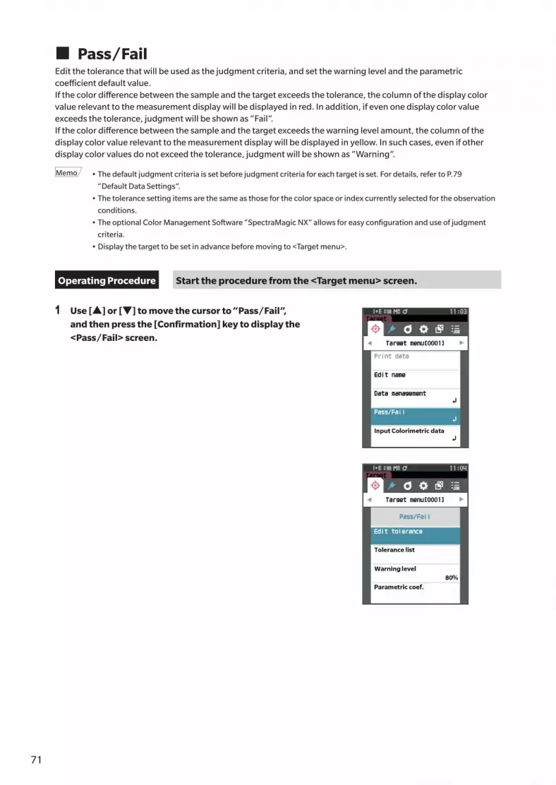
71
� Pass/FailEdit the tolerance that will be used as the judgment criteria, and set the warning level and the parametric coefficient default value.If the color difference between the sample and the target exceeds the tolerance, the column of the display color value relevant to the measurement display will be displayed in red. In addition, if even one display color value exceeds the tolerance, judgment will be shown as “Fail”.If the color difference between the sample and the target exceeds the warning level amount, the column of the display color value relevant to the measurement display will be displayed in yellow. In such cases, even if other display color values do not exceed the tolerance, judgment will be shown as “Warning”.
Memo • The default judgment criteria is set before judgment criteria for each target is set. For details, refer to P.79
“Default Data Settings”.
• The tolerance setting items are the same as those for the color space or index currently selected for the observation
conditions.
• The optional Color Management Software “SpectraMagic NX” allows for easy configuration and use of judgment
criteria.
• Display the target to be set in advance before moving to <Target menu>.
Operating Procedure Start the procedure from the <Target menu> screen.
1 Use [▲] or [▼] to move the cursor to “Pass/Fail”, and then press the [Confirmation] key to display the <Pass/Fail> screen.

7271
Measu
remen
t
2
� Tolerance SettingsSpecify the tolerance used for pass/fail judgment of measured for each target.
Operating Procedure Start the procedure from the <Target menu> - <Pass/Fail> screen.
1 Use [▲] or [▼] to move the cursor to “Edit tolerance”, and then press the [Confirmation] key.The tolerance list screen is displayed.
2 Use [▲] or [▼] to move the cursor to the item to set, and then press the [Confirmation] key.The <Edit tolerance> screen is displayed.
3 Use [▲]/[▼] and [◀]/[▶] to move the cursor to the item to set, and then press the [Confirmation] key to change the setting.• When the selected item is not currently checked,
pressing the [Confirmation] key causes the item to be checked, after which the setting value can be changed.
• Press [◀] or [▶] to move the cursor to the setting value area. Pressing the [Confirmation] key causes the cursor to appear on the value. Press [▲] or [▼] to change the value.
Move the cursor between the digits of the value by pressing [◀] or [▶].
Settings{ x / y : -0.2000 to 0.2000{ Equation / MI : 0.00 to 20.00{ Other than the above : -20.00 to 20.00• Press the [Confirmation] key to confirm every time the
setting of an item is changed.
4 After all settings have been configured, use [▲] or [▼] to move the cursor to “OK”, and then press the [Confirmation] key.The setting is confirmed and the screen returns to the <Pass/Fail> screen.Pressing the [ESC] while configuring the settings will prevent the settings on the currently opened screen from being applied and revert all settings to the previous condition.
5 Press [ESC] to return to the <Pass/Fail> screen.

73
� Tolerance List Select the index used for sample pass/fail judgment.
Operating Procedure Start the procedure from the <Target menu> - <Pass/Fail> screen.
1 Use [▲] or [▼] to move the cursor to “Tolerance list”, and then press the [Confirmation] key.The available tolerances are displayed.
2 Use [▲] or [▼] to move the cursor to the item to set, and then press the [Confirmation] key.• When the selected item is not currently checked,
pressing the [Confirmation] key causes the item to be checked. When the selected item is currently checked, pressing the [Confirmation] key causes the item to be unchecked.
• Up to 14 indexes can be selected.
3 After all settings have been configured, use [▲] or [▼] to move the cursor to “OK”, and then press the [Confirmation] key.The setting is confirmed and the screen returns to the <Pass/Fail> screen.Pressing the [ESC] while configuring the settings will prevent the settings on the currently opened screen from being applied and revert all settings to the previous condition.
4 Press [ESC] to return to the <Pass/Fail> screen.

7473
Measu
remen
t
2
� Warning Level SettingWhen a warning level is set, warnings will be displayed when the measured data nears but does not exceed the tolerance.
Operating Procedure Start the procedure from the <Target menu> - <Pass/Fail> screen.
1 Use [▲] or [▼] to move the cursor to “Warning level”, and then press the [Confirmation] key.The <Warning level> screen is displayed.
2 Use [▲] or [▼] to change the value.Settings{ 000 to 100%
3 Press the [Confirmation] key after completing the changes.The setting is confirmed and the screen returns to the <Pass/Fail> screen.
Notes If [ESC] is pressed during configuration, the settings will
not be changed and the screen will return to the <Pass/
Fail> screen.

75
� Parametric Coefficient SettingSpecify the parametric coefficient used for pass/fail judgment of a sample for each target.
Operating Procedure Start the procedure from the <Target menu> - <Pass/Fail> screen.
1 Use [▲] or [▼] to move the cursor to “Parametric coef.”, and then press the [Confirmation] key.The <Parametric coef.> screen is displayed.
2 Use [▲] or [▼] to move the cursor to the item to set, and then press the [Confirmation] key.The <Parametric coef.> edit screen is displayed.
3 Use [▲] or [▼] to move the cursor to the item to set, and press the [Confirmation] key to change the setting.• Pressing the [Confirmation] key causes the cursor to
appear on the value. Press [▲] or [▼] to change the value. Move the cursor between the digits of the value by pressing [◀] or [▶].
Settings{ 0.01 to 9.99• Press the [Confirmation] key to confirm every time the
setting of an item is changed.
4 After all settings have been configured, use [▲] or [▼] to move the cursor to “OK”, and then press the [Confirmation] key.The setting is confirmed and the screen returns to the <Pass/Fail> screen.
Memo If SCI+SCE is set for “Specular Component” under
<Measurement setup>, use [◀] or [▶] to switch between
SCI and SCE.
Notes If [ESC] is pressed during configuration, the settings will
not be changed and the screen will return to the <Pass/
Fail> screen.
5 Press [ESC] to return to the <Pass/Fail> screen.

7675
Measu
remen
t
2
� Input Colorimetric DataSet the target by numerical input.Select or specify the following items as the Input Colorimetric data.• Color space: XYZ / L*a*b* / Hunter Lab• Input Data: Enter the numeric value of the color space set above
Operating Procedure Start the procedure from the <Target menu> screen.
1 Use [▲] or [▼] to move the cursor to “Input Colorimetric data”, and then press the [Confirmation] key to display the <Input Colorimetric data> screen.
� Color spaceSpecify which color space to input the colorimetric data.
Operating Procedure Start the procedure from the <Target menu> - <Input Colorimetric data> screen.
1 Use [▲] or [▼] to move the cursor to “Color space”, and then press the [Confirmation] key.The <Color space> screen is displayed.

77
2 Use [▲] or [▼] to move the cursor to the item to set.
Settings{ XYZ : XYZ color space{ L*a*b* : L*a*b* color space{ Hunter Lab : Hunter Lab color space
3 Press the [Confirmation] key. The setting is confirmed and the screen returns to the
<Input Colorimetric data> screen.
Notes If [ESC] is pressed during configuration, the settings will
not be changed and the screen will return to the <Input
Colorimetric data> screen.
� Input DataCreate the color values for the color space selected in “Input Colorimetric data”-“Color space”.
Operating Procedure Start the procedure from the <Target menu> - <Input Colorimetric data> screen.
1 Use [▲] or [▼] to move the cursor to “Input Data”, and then press the [Confirmation] key.The Input data list screen is displayed.
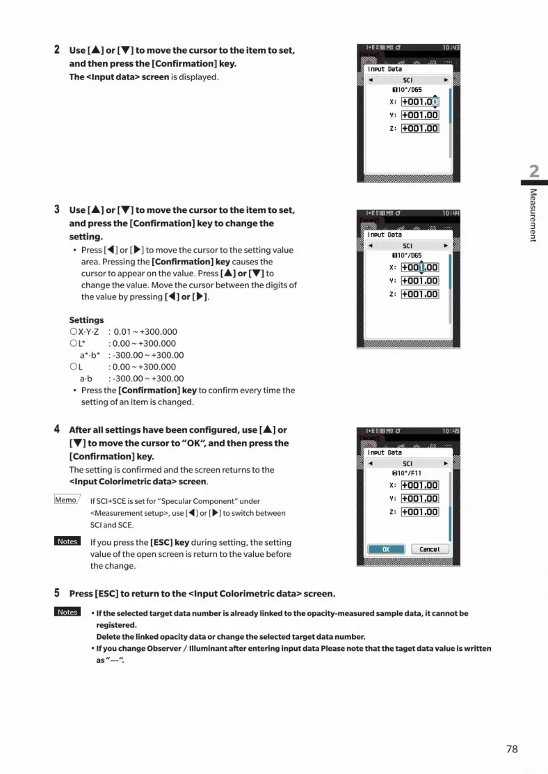
7877
Measu
remen
t
2
2 Use [▲] or [▼] to move the cursor to the item to set, and then press the [Confirmation] key.The <Input data> screen is displayed.
3 Use [▲] or [▼] to move the cursor to the item to set, and press the [Confirmation] key to change the setting.• Press [◀] or [▶] to move the cursor to the setting value
area. Pressing the [Confirmation] key causes the cursor to appear on the value. Press [▲] or [▼] to change the value. Move the cursor between the digits of the value by pressing [◀] or [▶].
Settings{ X·Y·Z : 0.01 ~ +300.000 { L* : 0.00 ~ +300.000 a*·b* : -300.00 ~ +300.00{ L : 0.00 ~ +300.000 a·b : -300.00 ~ +300.00• Press the [Confirmation] key to confirm every time the
setting of an item is changed.
4 After all settings have been configured, use [▲] or [▼] to move the cursor to “OK”, and then press the [Confirmation] key.The setting is confirmed and the screen returns to the <Input Colorimetric data> screen.
Memo If SCI+SCE is set for “Specular Component” under
<Measurement setup>, use [◀] or [▶] to switch between
SCI and SCE.
Notes If you press the [ESC] key during setting, the setting value of the open screen is return to the value before the change.
5 Press [ESC] to return to the <Input Colorimetric data> screen.
Notes • If the selected target data number is already linked to the opacity-measured sample data, it cannot be
registered.
Delete the linked opacity data or change the selected target data number.
• If you change Observer / Illuminant after entering input data Please note that the taget data value is written
as “---”.

79
� Default Data SettingsThis instrument allows pass/fail judgment criteria to be set for individual color difference target data. Until such judgment criteria are set, the instrument is set with the default tolerance. Users can edit the tolerance that will be used as the judgment criteria as well as edit the warning level and the parametric coefficient default value.
Memo • When a new target is measured, the default settings are initially applied.
• The default judgment criteria is set before judgment criteria for each target is set.
• Changing the default judgment criteria after the judgment criteria has already been set for individual targets, the
judgment criteria specified for these targets will not be changed.
• The optional Color Management Software “SpectraMagic NX” allows for easy configuration and use of judgment
criteria.
Operating Procedure Start the procedure from the measurement screen.
1 Press [MENU], and then use [◀] or [▶] to display the <Setting> screen.
2 Use [▲] or [▼] to move the cursor to “Default data setup”, and then press the [Confirmation] key to display the <Default data setup> screen.

8079
Measu
remen
t
2
� Tolerance List Select the default index used for sample pass/fail judgment.
Operating Procedure Start the procedure from the <Setting> - <Default data setup> screen.
1 Use [▲] or [▼] to move the cursor to “Tolerance list”, and then press the [Confirmation] key.The available tolerances are displayed.
2 Use [▲] or [▼] to move the cursor to the item to set, and then press the [Confirmation] key.• When the selected item is not currently checked,
pressing the [Confirmation] key causes the item to be checked. When the selected item is currently checked, pressing the [Confirmation] key causes the item to be unchecked.
• Up to 14 indexes can be selected.
3 After all settings have been configured, use [▲] or [▼] to move the cursor to “OK”, and then press the [Confirmation] key.The setting is confirmed and the screen returns to the <Default data setup> screen.Pressing the [ESC] while configuring the settings will prevent the settings on the currently opened screen from being applied and revert all settings to the previous condition.
4 Press [ESC] to return to the <Default data setup> screen.

81
� Default Tolerance Setting
Memo • The default tolerance is set to the following values when the instrument is shipped from the factory.
Lower limit: -1.00 / Upper limit: 1.00
Δx, Δy Lower limit: -0.0100 / Upper limit: 0.0100
Operating Procedure Start the procedure from the <Setting> - <Default data setup> screen.
1 Move the cursor to “Default tolerance”, and then press the [Confirmation] key.The tolerance list screen is displayed.
2 Use [▲] or [▼] to move the cursor to the item to set, and then press the [Confirmation] key.The <Edit tolerance> screen is displayed.
3 Use [▲]/[▼] and [◀]/[▶] to move the cursor to the item to set, and then press the [Confirmation] key to change the setting.• When the selected item is not currently checked,
pressing the [Confirmation] key causes the item to be checked, after which the setting value can be changed.
• Press [◀] or [▶] to move the cursor to the setting value area. Pressing the [Confirmation] key causes the cursor to appear on the value. Press [▲] or [▼] to change the value. Move the cursor between the digits of the value by pressing [◀] or [▶].
Settings{ x / y : -0.2000 to 0.2000{ Equation / MI : 0.00 to 20.00{ Other than the above : -20.00 to 20.00• Press the [Confirmation] key to confirm every time the
setting of an item is changed.
4 After all settings have been configured, use [▲] or [▼] to move the cursor to “OK”, and then press the [Confirmation] key.The setting is confirmed and the screen returns to the <Edit tolerance> screen.
Memo If SCI+SCE is set for “Specular Component” under
<Measurement setup>, use [◀] or [▶] to switch between
SCI and SCE.
5 Press [ESC] to return to the <Default data setup> screen.

8281
Measu
remen
t
2
� Warning Level Setting
Memo The warning level is set to “80%” when the instrument is shipped from the factory.
Operating Procedure Start the procedure from the <Setting> - <Default data setup> screen.
1 Use [▲] or [▼] to move the cursor to “Warning level”, and then press the [Confirmation] key.The <Warning level> screen is displayed.
2 Use [▲] or [▼] to change the value.Settings{ 000 to 100%
3 Press the [Confirmation] key after completing the changes.The setting is confirmed and the screen returns to the <Default data setup> screen.
Notes If [ESC] is pressed during configuration, the settings will
not be changed and the screen will return to the
<Default data setup> screen.

83
� Parametric Coefficient Setting
Memo The parametric coefficient is set to “1.00” when the instrument is shipped from the factory.
Operating Procedure Start the procedure from the <Setting> - <Default data setup> screen.
1 Use [▲] or [▼] to move the cursor to “Parametric coef.”, and then press the [Confirmation] key.The <Parametric coef.> screen is displayed.
2 Use [▲] or [▼] to move the cursor to the item to be set, and then press the [Confirmation] key.The <Parametric coef.> edit screen is displayed.
3 Use [▲] or [▼] to move the cursor to the item to set, and press the [Confirmation] key to change the setting.• Pressing the [Confirmation] key causes the cursor to
appear on the value. Press [▲] or [▼] to change the value. Move the cursor between the digits of the value by pressing [◀] or [▶].
Settings{ 0.01 to 9.99• Press the [Confirmation] key to confirm every time the
setting of an item is changed.
4 After all settings have been configured, use [▲] or [▼] to move the cursor to “OK”, and then press the [Confirmation] key.The setting is confirmed and the screen returns to the <Parametric coef.> screen.
Memo If SCI+SCE is set for “Specular Component” under
<Measurement setup>, use [◀] or [▶] to switch between
SCI and SCE.
Notes If [ESC] is pressed during setup, the settings will not be
changed and the screen will return to the <Parametric coef.>
screen.
5 Press [ESC] to return to the <Default data setup> screen.

8483
Measu
remen
t
2
� Set groupCreate groups for registering targets in advance.
Memo No group name is set when the instrument is shipped from the factory.
Operating Procedure Start the procedure from the <Setting> - <Default data setup> screen.
1 Use [▲] or [▼] to move the cursor to “Set group”, and then press the [Confirmation] key.The <Edit group> screen is displayed.The currently selected group numbers and names will be displayed in the upper table. The group is set by default when the target is measured.The cursor will appear in the lower area with group numbers.Configure the group name.
2 Use [▲] or [▼] to move the cursor to the group number of the group to edit. Numbers with blank names have not yet been set as a group. Assigning a name will register the number as a group. Users can also edit the names of existing groups.Groups 01 through 50 can be set with up to 5 groups being available for registration.
3 Check the box of the number to register to edit the name.The <Edit name> screen is displayed.
Memo Checking the box registers the number to the table above,
and when the target is measured, the number is
automatically assigned to the affiliated group. To delete the
information from the table, uncheck the box.
4 Use [▲]/[▼] or [◀]/[▶] to move the cursor between characters, and then press the [Confirmation] key.• Up to 30 characters can be used.• The selected character is displayed in the text box.

85
5 Repeat step 2 until the necessary characters have been entered.
• To delete the character to the left of the cursor in the text box,
move the cursor to [×] and press the [Confirmation] key.
6 After inputting the characters, move the cursor to [OK] and press the [Confirmation] key.The setting is confirmed and the screen returns to the <Set group> screen.
Memo If [ESC] is pressed during configuration, or if the cursor is
moved to “Cancel” and the [Confirmation] key is pressed,
the settings will not be changed and the screen will return to
the <Set group> screen.
7 Move the cursor to [OK] (located below 05, which is at the very bottom), and press the [Confirmation] key.
The screen will return to the <Default data setup> screen.Be aware that failure to press the [Confirmation] key on [OK] will cancel all data. Proceed with caution.

8685
Setting
3
Chapter 3
Chapter 3 Setting
Measurement Condition Settings ....................87
Measurement Condition Settings ........................ 87
Opacity Measurement ........................................ 89
Measurement Option Settings ............................ 91
Observation Condition Settings .......................... 99
Display Settings ................................................ 103
Instrument Settings ......................................108
Measurement Instrument Option Settings ........ 108

87
This instrument requires measurement condition settings (measurement mode, average count, observer/illuminant, and display) to be configured before measurement can be started.
� Measurement Condition SettingsTo set measurement conditions, select the setting from the <Measurement cond.> menu. The following four items can be specified as the measurement conditions:• Measurement mode : Select the combination of colorimetry and gloss measurement.• Measurement setup : Specify the number of measurements for automatic and manual averaging.• Observer/Illuminant : Configure the two observers/illuminants.• Display cond. : Configure the display type, color space, color difference equation, and 14 custom display items.
Operating Procedure
1 Press [MENU], and then use [◀] or [▶] to display the <Measurement cond.> menu screen.
Memo To return to the previous screen, press [MENU] or [ESC].
Measurement Condition Settings

8887
Setting
3
� Measurement modeSelect a measurement mode.
Memo The measurement mode is set to “Color & Gloss” when shipped from the factory.
Operating Procedure Start the procedure from the <Measurement cond.> screen.
1 Use [▲] or [▼] to move the cursor to “Measurement mode”, and then press the [Confirmation] key.The <Measurement mode> screen is displayed.
2 Use [▲] or [▼] to move the cursor to the desired measurement mode.
Selections{ Color & Gloss: Colorimetry + Gloss measurement
(* CM-26dG only){ Color only: Colorimetry{ Gloss only: Gloss measurement (* CM-26dG only){ Opacity: Opacity value measurement
3 Press the [Confirmation] key to confirm, and then press [ESC].The selection is confirmed and the screen returns to the previous screen.
Notes If [ESC] is pressed without pressing the [Confirmation]
key, the settings will not be changed and the screen will
return to the previous screen.

89
� Opacity MeasurementThe transparency and opacity of paper are displayed as numerical values.If the specimen is opaque, the value is determined only by the brightness of the specimen with no influence from the background, so the value for a white background will be the same as for a black background, and the opacity value (OP value) will be 100%.
Memo Manual averaging and SMC measurement cannot be used in Opacity mode, and the measurement conditions are only
SCI or SCE. SCI+SCE cannot be selected.
Notes To measure in Opacity mode, the target must also be measured in Opacity mode. In addition, when measuring
according to a specific international standard, the visual field and the light source must also be set according
to the standard.
Preparation
1 Select “Opacity” under <Measurement cond.> - <Measurement mode>.
2 Press [ESC] on the menu screen to display the <Target> screen.From the sample screen, press [ ] key to display the <Target> screen.
Operating Procedure
1 Selecting or measuring a targetSelect a target measured beforehand in Opacity mode, or measure a new target in Opacity mode. Press the cancel button during the operation to return to the screen before measurement.
[Confirmation] keyor
Measurement button
[Confirmation] keyor
Measurement button
2 Measuring a samplePress the cancel button during the operation to return to the screen before measurement.
[Confirmation] keyor
Measurement button
[Confirmation] keyor
Measurement button

9089
Setting
3
3 Displaying the results
Opacity value (OP value)Color difference value
White backgroundL*a*b value
Black backgroundL*a*b value
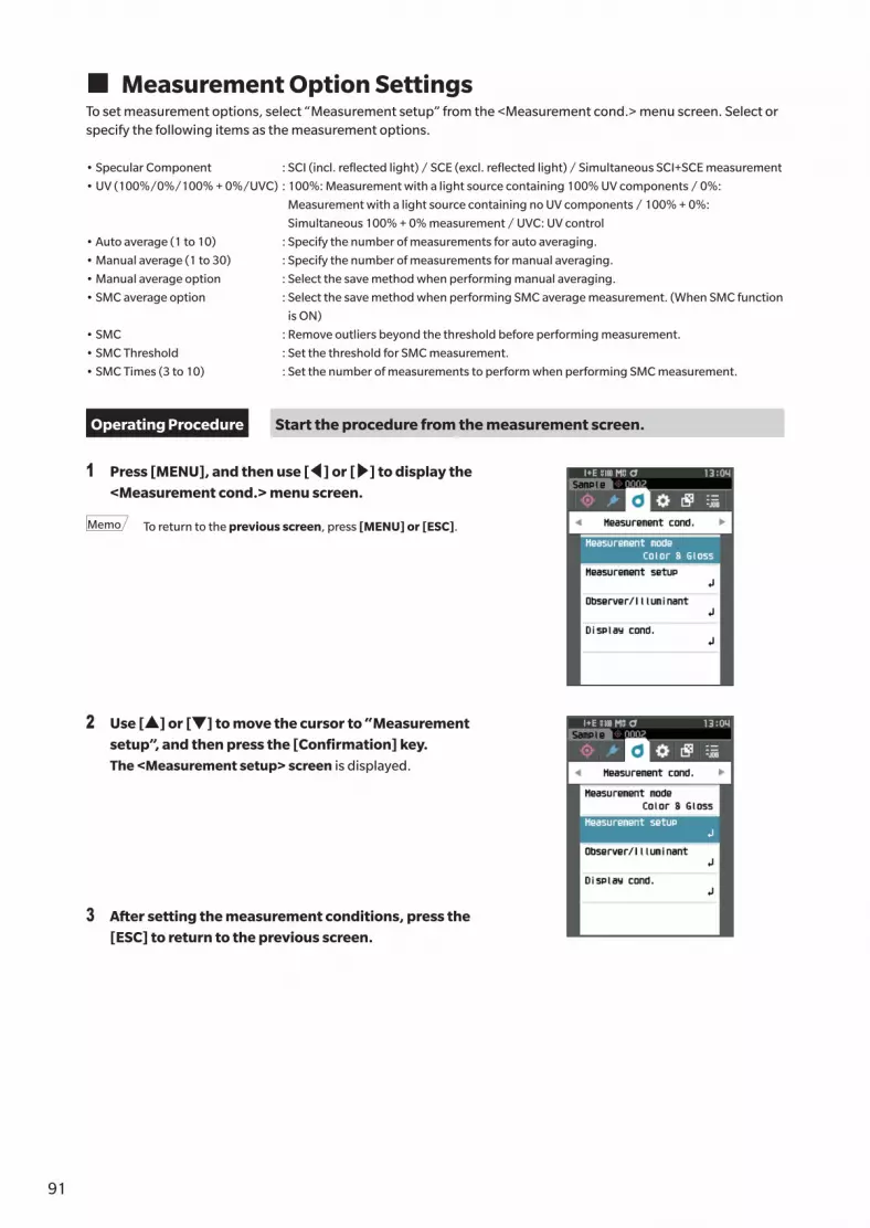
91
� Measurement Option SettingsTo set measurement options, select “Measurement setup” from the <Measurement cond.> menu screen. Select or specify the following items as the measurement options.
• Specular Component : SCI (incl. reflected light) / SCE (excl. reflected light) / Simultaneous SCI+SCE measurement
• UV (100%/0%/100% + 0%/UVC) : 100%: Measurement with a light source containing 100% UV components / 0%:
Measurement with a light source containing no UV components / 100% + 0%:
Simultaneous 100% + 0% measurement / UVC: UV control
• Auto average (1 to 10) : Specify the number of measurements for auto averaging.
• Manual average (1 to 30) : Specify the number of measurements for manual averaging.
• Manual average option : Select the save method when performing manual averaging.
• SMC average option : Select the save method when performing SMC average measurement. (When SMC function
is ON)
• SMC : Remove outliers beyond the threshold before performing measurement.
• SMC Threshold : Set the threshold for SMC measurement.
• SMC Times (3 to 10) : Set the number of measurements to perform when performing SMC measurement.
Operating Procedure Start the procedure from the measurement screen.
1 Press [MENU], and then use [◀] or [▶] to display the <Measurement cond.> menu screen.
Memo To return to the previous screen, press [MENU] or [ESC].
2 Use [▲] or [▼] to move the cursor to “Measurement setup”, and then press the [Confirmation] key.The <Measurement setup> screen is displayed.
3 After setting the measurement conditions, press the [ESC] to return to the previous screen.

9291
Setting
3
� Specular ComponentSelect the method for processing the sample specular reflection light.
Memo The specular component is set to “SCI + SCE” when the instrument is shipped from the factory.
Operating Procedure Start the procedure from the <Measurement cond.> - <Measurement setup> screen.
1 Use [▲] or [▼] to move the cursor to “Specular Component”, and then press the [Confirmation] key.
2 Use [▲] or [▼] to move the cursor to the item to set, and then press the [Confirmation] key.
Settings{ SCI : Measurement using a light source that
contains specular reflection light.{ SCE : Measurement using a light source that does
not contain specular reflection light.{ SCI+SCE : Displays the results of both SCI and SCE
measurements.
3 Press the [Confirmation] key.The selection is confirmed and the screen returns to the <Measurement setup> screen.
Notes If [ESC] is pressed without pressing the [Confirmation]
key, the settings will not be changed and the screen will
return to the <Measurement setup> screen.

93
� UV (100%/0%/100% + 0%/UVC)This instrument is equipped with a UV 0% option as a UV-free light source (with all UV rays up to 390 nm eliminated). Select the UV level according to the type of fluorescent agent being measured and the measuring method specified by the standard being followed.
Memo UV is set to “UV100%” when the instrument is shipped from the factory.
Operating Procedure Start the procedure from the <Measurement cond.> - <Measurement setup> screen.
1 Use [▲] or [▼] to move the cursor to “UV”, and then press the [Confirmation] key.
2 Use [▲] or [▼] to move the cursor to the item to set, and then press the [Confirmation] key.
Settings{ UV100% : Measurement with a light source
containing 100% UV components{ UV0% : Measurement with a light source
containing no UV components{ UV100% + 0% : Simultaneous UV 100% + UV 0%
measurement{ UVC : UV control available
Memo • UVC (UV control) is available only on firmware version 1.10
or later.
• The UV control setting is configured using the optional
color management software SpectraMagic NX (Ver.3.0 or
later). The setting is displayed and available only when
output UV coefficients have been downloaded.
• UV100% + 0% can only be used when the specular
component is set to SCI or SCE.
3 Press the [Confirmation] key.The selection is confirmed and the screen returns to the <Measurement setup> screen.
Notes If [ESC] is pressed without pressing the [Confirmation]
key, the settings will not be changed and the screen will
return to the <Measurement setup> screen.

9493
Setting
3
� Auto average (1 to 10)Specify the number of measurements for auto averaging. Every time the measurement button is pressed, the average of the data obtained from the specified number of continuous measurements is determined as sample data.
Memo “1” is set as the number of measurements for automatic averaging when the instrument is shipped from the factory.
Operating Procedure Start the procedure from the <Measurement cond.> - <Measurement setup> screen.
1 Use [▲] or [▼] to move the cursor to “Auto average”, and then press the [Confirmation] key.
2 ▲ and ▼ will be displayed above and below the count in the count selection. Use [▲] or [▼] to specify a value.
Settings{ 1 to 10 times:
Specify the number of measurements, from 1 to 10, to perform when using auto averaging.
3 Press the [Confirmation] key.The selection is confirmed and the screen returns to the <Measurement setup> screen.
Notes If [ESC] is pressed without pressing the [Confirmation]
key, the settings will not be changed and the screen will
return to the <Measurement setup> screen.

95
� Manual average (1 to 30)Specify the number of measurements for manual averaging. The average of the data obtained from the measurements conducted by pressing the measurement button the specified number of times is determined as sample data.
Memo “1” is set as the number of measurements for manual averaging when the instrument is shipped from the factory.
Operating Procedure Start the procedure from the <Measurement cond.> - <Measurement setup> screen.
1 Use [▲] or [▼] to move the cursor to “Manual average”, and then press the [Confirmation] key.
2 ▲ and ▼ will be displayed above and below the count in the count selection. Use [▲] or [▼] to specify a value.
Settings{ 1 to 30 times:
Specify the number of measurements, from 1 to 30, to perform when using manual averaging.
3 Press the [Confirmation] key.The selection is confirmed and the screen returns to the <Measurement setup> screen.
Notes If [ESC] is pressed without pressing the [Confirmation]
key, the settings will not be changed and the screen will
return to the <Measurement setup> screen.
With manual average measurement, measurement is performed for the configured number of times the measurement button is pressed, and the average value of those measurements is saved as a single measurement.Selecting “Undo” after a measurement allows users to perform the previous measurement again.
After the set number of measurements has been performed, the average can be saved by selecting “Save”.To save the average automatically after the set number of measurements has been performed, select “Auto save” under “Measurement cond.” - “Measurement setup” - “Manual average option”.
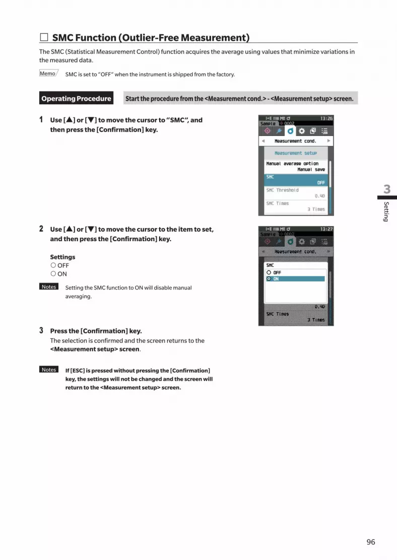
9695
Setting
3
� SMC Function (Outlier-Free Measurement)The SMC (Statistical Measurement Control) function acquires the average using values that minimize variations in the measured data.
Memo SMC is set to “OFF” when the instrument is shipped from the factory.
Operating Procedure Start the procedure from the <Measurement cond.> - <Measurement setup> screen.
1 Use [▲] or [▼] to move the cursor to “SMC”, and then press the [Confirmation] key.
2 Use [▲] or [▼] to move the cursor to the item to set, and then press the [Confirmation] key.
Settings{ OFF{ ON
Notes Setting the SMC function to ON will disable manual
averaging.
3 Press the [Confirmation] key.The selection is confirmed and the screen returns to the <Measurement setup> screen.
Notes If [ESC] is pressed without pressing the [Confirmation]
key, the settings will not be changed and the screen will
return to the <Measurement setup> screen.
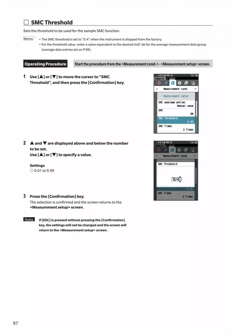
97
� SMC ThresholdSets the threshold to be used for the sample SMC function.
Memo • The SMC threshold is set to “0.4” when the instrument is shipped from the factory.
• For the threshold value, enter a value equivalent to the desired σΔE*ab for the average measurement data group
(average data entries set on P.98).
Operating Procedure Start the procedure from the <Measurement cond.> - <Measurement setup> screen.
1 Use [▲] or [▼] to move the cursor to “SMC Threshold”, and then press the [Confirmation] key.
2 ▲ and ▼ are displayed above and below the number to be set. Use [▲] or [▼] to specify a value.
Settings{ 0.01 to 9.99
3 Press the [Confirmation] key.The selection is confirmed and the screen returns to the <Measurement setup> screen.
Notes If [ESC] is pressed without pressing the [Confirmation]
key, the settings will not be changed and the screen will
return to the <Measurement setup> screen.

9897
Setting
3
� SMC TimesSets the threshold to be used for the sample SMC function.Sets the number of measurements to perform when performing SMC average measurement. The average of the data obtained from the measurements conducted by pressing the measurement button several times is determined. The maximum number of measurements at this time is specified number in the setting + four times.
Memo “3” is set as the number of measurements for SMC averaging when the instrument is shipped from the factory.
Operating Procedure Start the procedure from the <Measurement cond.> - <Measurement setup> screen.
1 Use [▲] or [▼] to move the cursor to “SMC Times”, and then press the [Confirmation] key.
2 ▲ and ▼ will be displayed above and below the count in the count selection. Use [▲] or [▼] to specify a value.
Settings{ 3 to 10 times
3 Press the [Confirmation] key.The selection is confirmed and the screen returns to the <Measurement setup> screen.
Notes If [ESC] is pressed without pressing the [Confirmation]
key, the settings will not be changed and the screen will
return to the <Measurement setup> screen.
With SMC average measurement, measurement is performed for the configured number of times the measurement button is pressed, and the average value of those measurements is saved as a single measurement.After the set number of measurements has been performed, the average can be saved by selecting “Save”.To save the average automatically after the set number of measurements has been performed, select “Auto save” under “Measurement cond.” - “Measurement setup” - “SMC average option”.

99
� Observation Condition SettingsTo set observation conditions, select “Observer/Illuminant” from the <Measurement cond.> menu screen.The following two observer/illuminant settings can be configured for the observation conditions.• Observer/Illuminant 1: Select the observer/illuminant used to measure the colorimetric value.
• Observer/Illuminant 2: Select the secondary illuminant used for MI (metamerism index) calculation, etc.
Operating Procedure Start the procedure from the measurement screen.
1 Press [MENU], and then use [◀] or [▶] to display the <Measurement cond.> menu screen.
Memo To return to the previous screen, press [MENU] or [ESC].
2 Use [▲] or [▼] to move the cursor to “Observer/Illuminant”, and then press the [Confirmation] key.The <Observer/Illuminant> screen is displayed.
3 After setting the observer/illuminant, press [ESC] to return to the previous screen.

10099
Setting
3
� Observer/Illuminant 1Select an observer angle of either 2° or 10° and the illuminant used to measure colorimetric value.
Memo Observer/Illuminant 1 is set to “10°/D65” when the instrument is shipped from the factory.
Operating Procedure Start the procedure from the <Measurement cond.> - <Observer/Illuminant> screen.
1 Use [▲] or [▼] to move the cursor to “Observer/Illuminant 1”, and then press the [Confirmation] key.The <Observer/Illuminant 1> screen is displayed.The scroll bar on the right of the screen shows that there are additional observer/illuminant settings that cannot fit on the screen.
2 Use [▲] or [▼] to move the cursor to the desired item.Moving the cursor past the top or bottom of the list will show additional observers/illuminants that cannot fit on the screen.
Settings{ 2°: 2° observer angle (CIE 1931){ 10°: 10° observer angle (CIE 1964)and{ A : Standard illuminant A (Incandescent lamp,
Color temperature: 2856K){ C : Illuminant C (Daylight, Small relative value of
spectral distribution in the ultraviolet region; Color temperature: 6774K)
{ D65 : Standard illuminant D65
(Daylight, Color temperature: 6504K){ D50 : Standard illuminant D
50 (Daylight, Color temperature: 5003K)
{ ID65 : Indoor daylight illuminant ID65 (Daylight after passing through window glass, Color temperature: 6504K){ ID50 : Indoor daylight illuminant ID50 (Daylight after passing through window glass, Color temperature: 5003K){ F2 : Cool white (fluorescent lamp){ F6 : Cool white (fluorescent lamp){ F7 : Color rendering A daylight natural (fluorescent lamp){ F8 : Color rendering AAA natural white (fluorescent lamp){ F10 : 3-band type natural white (fluorescent lamp){ F11 : 3-band type cool white (fluorescent lamp){ F12 : 3-band type warm white (fluorescent lamp){ User : User-configured illuminant
(* Optional Color Management Software SpectraMagic NX is required for setting user-configured illuminants. Note that the name configured in SpectraMagic NX will be displayed.)

101
3 Press the [Confirmation] key.The selection is confirmed and the screen returns to the <Observer/Illuminant> screen.
Notes If [ESC] is pressed without pressing the [Confirmation]
key, the settings will not be changed and the screen will
return to the <Observer/Illuminant> screen.

102101
Setting
3
� Observer/Illuminant 2Select the secondary illuminant used for MI (metamerism index) calculation, etc.
Memo Observer/Illuminant 2 is set to “10°/F11” when the instrument is shipped from the factory.
Operating Procedure Start the procedure from the <Measurement cond.> - <Observer/Illuminant> screen.
1 Use [▲] or [▼] to move the cursor to “Observer/Illuminant 2”, and then press the [Confirmation] key.The <Observer/Illuminant 2> screen is displayed.
2 Use [▲] or [▼] to move the cursor to the desired item.
Settings{ The setting values are the same as those for “Observer/
Illuminant 1” or “None”.
3 Press the [Confirmation] key.The selection is confirmed and the screen returns to the <Observer/Illuminant> screen.
Notes If [ESC] is pressed without pressing the [Confirmation]
key, the settings will not be changed and the screen will
return to the <Observer/Illuminant> screen.

103
� Display SettingsTo set display settings, select “Display cond.” from the <Measurement cond.> menu screen. The following four items (three items and 14 custom display items) can be specified as the display conditions.• Display type : Select the screen to be displayed.
• Color space : Select the color space to be displayed.
• Equation : Select the color for which the color difference will be measured.
• Custom (01 to 14) : Select which options to add to the display, such as display color value, index, and color difference.
Operating Procedure Start the procedure from the measurement screen.
1 Press [MENU], and then use [◀] or [▶] to display the <Measurement cond.> menu screen.
Memo To return to the previous screen, press [MENU] or [ESC].
2 Use [▲] or [▼] to move the cursor to “Display cond.”, and then press the [Confirmation] key.The <Display cond.> screen is displayed.
3 After setting the display conditions, press [ESC] to return to the previous screen.

104103
Setting
3
� Display typeConfigure the display type for the measurement results.
Memo All display types are selected when the instrument is shipped from the factory.
Operating Procedure Start the procedure from the <Measurement cond.> - <Display cond.> screen.
1 Use [▲] or [▼] to move the cursor to “Display type”, and then press the [Confirmation] key.The <Display type> screen is displayed.
2 Use [▲] or [▼] to move the cursor to the desired display type, and then press the [Confirmation] key.
Selections� Absolute value: Displays the absolute values of the
colorimetric and the gloss values.� Difference: Displays the color difference and gloss value
difference against the target. The measurement that failed the pass/fail judgment based on the tolerance will be highlighted in red.
� Abs. & Diff.: Displays the absolute value and the color difference and gloss value difference against the target. The measurement that failed the pass/fail judgment based on the tolerance will be highlighted in red.
� Pass/Fail: Determines whether the color difference and gloss value difference related to the target are within the tolerance range set in advance. If within the tolerance, the judgment will be displayed as “Pass”. If even one difference is not within the tolerance, the judgment will be displayed as “Fail”.
� Custom: Displays the display color value and index set under “Custom” as the two illuminants.� Abs. Graph: Displays a graph of the absolute values of the colorimetric and the gloss values.� Diff. Graph: Displays a graph showing the color difference and gloss value difference against the target.� Spectral Graph: Displays a graph showing the spectral reflectance. The [Confirmation] key can be used to
move the wavelength displaying the spectral reflectance value.
Memo A check mark means the item is selected.
3 After all settings have been configured, use [▲] or [▼] to move the cursor to “OK”, and then press the [Confirmation] key.The selection is confirmed and the screen returns to the previous screen.
Notes If [ESC] is pressed without pressing the [Confirmation] key, the settings will not be changed, and the screen
will return to the <Display cond.> screen.

105
� Color spaceSelect the color space to be used.
Memo The color space is set to “L*a*b*” when the instrument is shipped from the factory.
Operating Procedure Start the procedure from the <Measurement cond.> - <Display cond.> screen.
1 Use [▲] or [▼] to move the cursor to “Color space”, and then press the [Confirmation] key.The <Color space> selection screen is displayed.
2 Use [▲] or [▼] to move the cursor to the desired color space.
Selections{ L*a*b*: L*a*b* color space{ L*C*h: L*C*h color space{ Hunter Lab: Hunter Lab color space{ Yxy: Yxy color space{ XYZ: XYZ color space{ Munsell (C): Munsell color space
3 Press the [Confirmation] key to confirm, and then press [ESC].The selection is confirmed and the screen returns to the previous screen.
Notes If [ESC] is pressed without pressing the [Confirmation]
key, the settings will not be changed, and the screen will
return to the <Display cond.> screen.

106105
Setting
3
� Color difference equationSelect the color difference equation to be used.
Memo The color difference equation is set to “ΔE*ab” when the instrument is shipped from the factory.
Operating Procedure Start the procedure from the <Measurement cond.> - <Display cond.> screen.
1 Use [▲] or [▼] to move the cursor to “Equation”, and then press the [Confirmation] key.The <Equation> screen is displayed.
2 Use [▲] or [▼] to move the cursor to the desired color difference equation.
Selections{ ΔE*ab: ΔE*ab (CIE1976) color difference equation{ CMC: CMC color difference equation; Parameters can be
changed.{ ΔE*94: ΔE*94 (CIE 1994) color difference equation;
Parameters can be changed.{ ΔE00: ΔE00 (CIE DE 2000) color difference equation;
Parameters can be changed.{ ΔE (Hunter): Hunter Lab color difference equation{ ΔE99o: ΔE99o (DIN99o) color difference equation { FMC2: FMC2 color difference equation
3 Press the [Confirmation] key to confirm, and then press [ESC].The selection is confirmed and the screen returns to the previous screen.
Notes If [ESC] is pressed without pressing the [Confirmation]
key, the settings will not be changed, and the screen will
return to the <Display cond.> screen.

107
� CustomSelect the items, including the color space, color difference equation, or index, to be used. Up to 14 items (Custom 01 to Custom 14) to be displayed can be set. This selection screen is available when the user index has been set with the optional Color Management Software SpectraMagic NX (CM-S100w) in advance. In this case, the name configured in SpectraMagic NX will be displayed.
Operating Procedure Start the procedure from the <Measurement cond.> - <Display cond.> screen.
1 Use [▲] or [▼] to move the cursor to “Custom xx (01 to 14)”, and then press the [Confirmation] key.The screen for selecting the display items is displayed.The scroll bar at the right on the screen shows that there are additional display items that cannot fit on the screen.
2 Use [▲] or [▼] to move the cursor to the desired display item.Moving the cursor past the top or bottom of the list will show additional display items that cannot fit on the screen.
SettingsThe following indexes as well as display color values and color differences for color spaces that can be configured under color space and color difference equation can be set.{ WIe (WI E313-73) and ΔWIe : Whiteness index (ASTM E313-73){ WIc (WI CIE) and ΔWIe : Whiteness index (CIE 1982/
ASTM E313-98 (D65 Light source) ){ Tint (Tint CIE) and ΔTint : Tint (CIE 1982/ASTM E313-98
(D65 Light source) ){ YIe (YI E313-73) and ΔYIe : Yellowness index (ASTM E313-73){ YId (YI D1925) and ΔYId : Yellowness index (ASTM D1925){ B (ISO B) and ΔB : Brightness{ DXYZ/DX/DY/DZ : Tristimulus Strength{ MI : Metamerism{ GU, ΔGU : CM-26dG : Gloss index
8°GU : CM-26d, 25d { ΔE99o : ΔE99o (DIN99o) color difference equation { Greyscale (ISO A105) : Grey Scale (ISO 105-A05){ WI (Ganz) and Δ WI (Ganz) : Whiteness index (Ganz & Griesser){ Tint (Ganz) and Δ Tint (Ganz) : Tint (Ganz & Griesser){ Staining ISO 105-A04 : Staining degree (ISO 105-A04){ FMC-2 : FMC-2 color difference equation{ ΔL(FMC2){ ΔCr-g(FMC2){ ΔCy-b(FMC2){ K/S St (ΔE*) : K/S concentration (differential comparison equation (ΔE*ab)){ K/S St (MAX Abs) : K/S concentration (maximum absorption wavelength formula){ K/S St (Apparent) : K/S concentration (full wavelength formula){ None{ UE1 to UE3 : User index{ UC1 to UC3 : User class

108107
Setting
3
3 Press the [Confirmation] key to confirm, and then press [ESC].The selection is confirmed and the screen returns to the previous screen.
Notes If [ESC] is pressed without pressing the [Confirmation] key, the settings will not be changed, and the screen
will return to the <Display cond.> screen.
� Measurement Instrument Option SettingsTo set measurement instrument options, select “Instrument setup” from the <Setting> screen.
Operating Procedure Start the procedure from the measurement screen.
1 Press [MENU], and then use [◀] or [▶] to display the <Setting> screen.
Memo To return to the previous screen, press [MENU] or [ESC].
2 Use [▲] or [▼] to move the cursor to “Instrument setup”, and then press the [Confirmation] key.The <Instrument setup> screen is displayed.
3 After setting the measurement instrument conditions, press [ESC] to return to the previous screen.
Instrument Settings

109
� User typeSettings can be protected for each user.
Memo The user type is set to “Administrator” when the instrument is shipped from the factory.
Operating Procedure Start the procedure from the <Setting> - <Instrument setup> screen.
1 Use [▲] or [▼] to move the cursor to “User type”, and then press the [Confirmation] key.The <User type> setting screen is displayed.
2 Use [▲] or [▼] to move the cursor and select the user type.
Selections{ Administrator: All settings can be changed.{ Worker: Some settings cannot be changed.
Memo The operations that workers can perform are as follows.
• “Sample” browsing/measurement/printing/deletion
• “Target” browsing/printing
• Calibration
• Instrument info. displaying
• Changing the user type
Notes Settings for operations that workers can perform can be
changed using the CM-CT1 software included as a
standard accessory.
Memo It is possible to set a password for changing workers to
administrators. For details, read P.117 “Password Setting”.
3 Press the [Confirmation] key to confirm, and then press [ESC].The selection is confirmed and the screen returns to the <Instrument setup> screen.
Notes If [ESC] is pressed without pressing the [Confirmation]
key, the settings will not be changed, and the screen will
return to the <Instrument setup> screen.

110109
Setting
3
� Display Language SettingsThis instrument allows the display language to be set.Pressing and holding [MENU] while starting up the instrument also displays the language setting screen.
Memo The language is set to “English” when the instrument is shipped from the factory.
Notes When the backup battery of the instrument has gone dead, the display language is reset to “English”.
Operating Procedure Start the procedure from the <Setting> - <Instrument setup> screen.
1 Use [▲] or [▼] to move the cursor to “Language”, and then press the [Confirmation] key.The <Language> screen is displayed.The scroll bar at the right on the <Language> screen shows that there are additional language settings that cannot fit on the screen.
2 Use [▲] or [▼] to move the cursor to the desired language.Moving the cursor past the top or bottom of the list will show additional language settings that cannot fit on the screen.
Settings{ English{ Japanese{ German{ French{ Spanish{ Italian{ Chinese{ Portuguese{ Polish{ Russian{ Turkish
3 Press the [Confirmation] key to confirm, and then press [ESC].The selection is confirmed and the screen returns to the <Instrument setup> screen.
Notes If [ESC] is pressed without pressing the [Confirmation]
key, the settings will not be changed, and the screen will
return to the <Instrument setup> screen.

111
� Date Format SettingsThe format of the date displayed on the screen can be changed.
Memo The date format is set to “yyyy/mm/dd” when the instrument is shipped from the factory.
Operating Procedure Start the procedure from the <Setting> - <Instrument setup> screen.
1 Use [▲] or [▼] to move the cursor to “Date format”, and then press the [Confirmation] key.The <Date format> screen is displayed.
2 Use [▲] or [▼] to move the cursor to the desired measurement mode.
Settings{ yyyy/mm/dd : The date is displayed in year/month/day
order.{ mm/dd/yyyy : Display the date in the format of month/
day/year.{ dd/mm/yyyy : Display the date in the format of day/
month/year.
3 Press the [Confirmation] key to confirm, and then press [ESC].The selection is confirmed and the screen returns to the <Instrument setup> screen.
Notes If [ESC] is pressed without pressing the [Confirmation]
key, the settings will not be changed, and the screen will
return to the <Instrument setup> screen.

112111
Setting
3
� Clock SettingsThis instrument has a built-in clock to record the date and time of measurement. Because the date and time have been set at the factory, there is no need to change these settings under normal conditions. If necessary, however, the date and time settings may be configured.
Operating Procedure Start the procedure from the <Setting> - <Instrument setup> screen.
1 Use [▲] or [▼] to move the cursor to “Date & time”, and then press the [Confirmation] key.The <Date & time> setting screen is displayed.
2 Use [▲] or [▼] to move the cursor to the item to be set, and then press the [Confirmation] key.The cursor color turns to blue and ▲ and ▼ are displayed above and below the cursor.
3 Use [▲] or [▼] to change the value.Settings{ Year : 2000 to 2099{ Month : 1 to 12{ Day : 1 to 28, 29, 30 and 31{ Hour : 0 to 23{ Minute : 0 to 59{ Second : 0 to 59• The value increases/decreases by one with each button
press.• Holding down [▲] or [▼] increases/decreases the
value by one continuously.• Use [◀] or [▶] to move between digits.
4 Press the [Confirmation] key.The setting is confirmed.
Notes If [ESC] is pressed without pressing the [Confirmation]
key, the settings will not be changed.
5 Repeat Steps 2 to 4 for each of the date (Year/Month/Day) and time (Hour : Minute : Second) parameters.
6 After all settings have been configured, use [▲] or [▼] to move the cursor to “OK”, and then press the [Confirmation] key.The selection is confirmed and the screen returns to the <Instrument setup> screen.
Notes If [ESC] is pressed without pressing the [Confirmation]
key, the settings will not be changed and the screen will
return to the <Instrument setup> screen.

113
� Screen BrightnessThe brightness of the LCD can be set in five levels. Selecting a darker level is effective for power saving.
Memo Screen brightness is set to “3 (Standard)” when the instrument is shipped from the factory.
Operating Procedure Start the procedure from the <Setting> - <Instrument setup> screen.
1 Use [▲] or [▼] to move the cursor to “Brightness”, and then press the [Confirmation] key.The <Brightness> setting screen is displayed.
2 Use [▲] or [▼] to move the cursor to the desired brightness.
Settings5 (Light)43 (Standard)21 (Dark)
3 Press the [Confirmation] key to confirm, and then press [ESC].The selection is confirmed and the screen returns to the <Instrument setup> screen.
Notes If [ESC] is pressed without pressing the [Confirmation]
key, the settings will not be changed, and the screen will
return to the <Instrument setup> screen.

114113
Setting
3
� LCD Screen Display OrientationDepending on how the instrument is held, the display may be more visible upside-down. This function allows the display to be set to a different orientation in such instances.
Operating Procedure Start the procedure from the <Setting> - <Instrument setup> screen.
1 Use [▲] or [▼] to move the cursor to “Direction”, and then press the [Confirmation] key.The display will flip upside-down and return to the <Instrument setup> screen.

115
� BeepOperation sounds can be set to ON or OFF.
Memo The “Beep” setting is set to “ON” when the instrument is shipped from the factory.
Operating Procedure Start the procedure from the <Setting> - <Instrument setup> screen.
1 Use [▲] or [▼] to move the cursor to “Beep”, and then press the [Confirmation] key.The <Beep> setting screen is displayed.
2 Use [▲] or [▼] to move the cursor to select ON or OFF.Settings{ OFF{ ON (Standard)
3 Press the [Confirmation] key to confirm, and then press [ESC].The selection is confirmed and the screen returns to the <Instrument setup> screen.
Notes If [ESC] is pressed without pressing the [Confirmation]
key, the settings will not be changed, and the screen will
return to the <Instrument setup> screen.

116115
Setting
3
� Auto Power OffThe amount of time before switching the power off can be set.
Memo Auto power off is set to “30 (minutes)” when the instrument is shipped from the factory.
Operating Procedure Start the procedure from the <Setting> - <Instrument setup> screen.
1 Use [▲] or [▼] to move the cursor to “Auto power off”, and then press the [Confirmation] key. The <Auto power off> setting screen is displayed.
2 Use [▲] or [▼] to change the value.Settings{ 00 to 60 minutes
Memo Setting to “00” minutes will change the setting to “Do not
power off”.
3 Press the [Confirmation] key to confirm, and then press [ESC].The selection is confirmed and the screen returns to the <Instrument setup> screen.
Notes If [ESC] is pressed without pressing the [Confirmation]
key, the settings will not be changed, and the screen will
return to the <Instrument setup> screen.

117
� Password SettingThe password required for changing the user type from a worker to an administrator can be configured in the instrument setup.
Operating Procedure Start the procedure from the <Setting> - <Instrument setup> screen.
1 Use [▲] or [▼] to move the cursor to “Password Setting”, and then press the [Confirmation] key.The <Password Setting> screen is displayed.
2 Use [◀]/[▶] or [▲]/[▼] to set the password.Settings8 digits (Initial value "00000000": No set password)
3 Press the [Confirmation] key.The selection is confirmed and the screen returns to the <Measurement setup> screen.
Notes If [ESC] is pressed without pressing the [Confirmation]
key, the settings will not be changed and the screen will
return to the <Measurement setup> screen.

118117
Oth
er Fu
nction
s
4
Chapter 4
Chapter 4 Other Functions
Connecting to an External Device ..................119
Connecting to a Computer ...........................119
Connecting via USB Cable ................................ 120
Connecting via Bluetooth ................................. 121
Communication setup ...................................... 122
Connecting to a Printer/Barcode Reader ......125
Instrument Preparation ..................................... 126
System Settings ............................................131
Calibration setup .............................................. 131
Displaying Diagnosis Info. ................................. 136
Displaying the Instrument Information ............. 137
JOB Function ..................................................... 138

119
Connecting to an External Device
◎ Connecting to a ComputerThere are two methods for connecting the instrument to a computer: connecting using the USB cable or via the Instrument’s Bluetooth function.
Notes • To use the instrument’s Bluetooth function to connect to a computer with Bluetooth communication
capabilities, the optional CM-A219 Bluetooth module must be correctly connected to the instrument and a
Bluetooth communication channel must be opened through the computer’s utilities function.
• When connections using the USB cable and using Bluetooth communication are established, priority will be
given to the connection using the USB cable.
Memo • When connected to a computer, the wireless communication or the wired communication mark is displayed on the
LCD screen (refer to P.23 “Status bar”), and the measurement button and operation keys on the instrument are
disabled.
• If a command to enable the measuring button is sent from the computer, measurement will be possible by pressing
the measurement button on the instrument. Note that, at this time, sample is transferred to the computer without
being stored in the instrument memory.
• To connect the instrument to a computer, use of software that enables connection and operation of the instrument is
recommended.
This instrument includes a USB connection terminal and a Bluetooth function (when the optional Bluetooth module is attached). The supplied USB cable (IF-A26) can be used to connect the instrument to a computer, or the Bluetooth communication function can be used to connect the instrument to a computer or a printer, allowing for data communication and printing.
Notes When the instrument is exposed to strong external static electricity or is affected by ambient interference
during communication with an external device, the communication may be interrupted. In this case, turn the
power OFF and then turn it ON again.
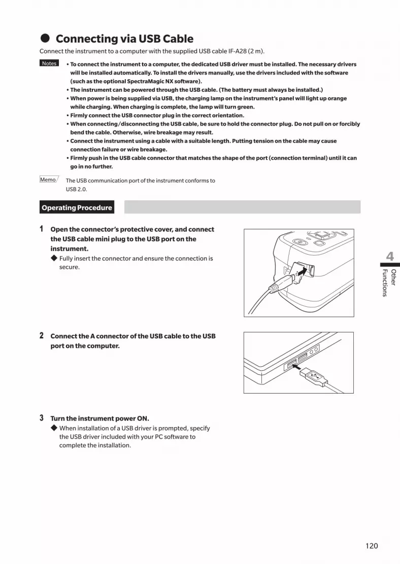
120119
Oth
er Fu
nction
s
4
z Connecting via USB Cable Connect the instrument to a computer with the supplied USB cable IF-A28 (2 m).
Notes • To connect the instrument to a computer, the dedicated USB driver must be installed. The necessary drivers
will be installed automatically. To install the drivers manually, use the drivers included with the software
(such as the optional SpectraMagic NX software).
• The instrument can be powered through the USB cable. (The battery must always be installed.)
• When power is being supplied via USB, the charging lamp on the instrument’s panel will light up orange
while charging. When charging is complete, the lamp will turn green.
• Firmly connect the USB connector plug in the correct orientation.
• When connecting/disconnecting the USB cable, be sure to hold the connector plug. Do not pull on or forcibly
bend the cable. Otherwise, wire breakage may result.
• Connect the instrument using a cable with a suitable length. Putting tension on the cable may cause
connection failure or wire breakage.
• Firmly push in the USB cable connector that matches the shape of the port (connection terminal) until it can
go in no further.
Memo The USB communication port of the instrument conforms to
USB 2.0.
Operating Procedure
1 Open the connector’s protective cover, and connect the USB cable mini plug to the USB port on the instrument.
◆ Fully insert the connector and ensure the connection is secure.
2 Connect the A connector of the USB cable to the USB port on the computer.
3 Turn the instrument power ON. ◆ When installation of a USB driver is prompted, specify the USB driver included with your PC software to complete the installation.

121
z Connecting via BluetoothConnect the instrument to a printer with Bluetooth communication functionality using the optional Bluetooth module.
Notes • The instrument’s Bluetooth function enables data communication with a connected computer and printing
from a Bluetooth printer. Connecting to both a computer and a printer/barcode reader at the same time,
however, is not possible.
• A simultaneous connection via the USB cable and the Bluetooth function is not possible. Should both
connections be established at the same time, priority will be given to the connection via USB cable.
Memo To connect the instrument to a computer via the Bluetooth function, appropriate preparations for Bluetooth
communication must be performed in advance for both the instrument and the printer.
{ Instrument PreparationConnect the optional Bluetooth module CM-A219.Turn ON the instrument’s Bluetooth function and configure the PIN code on the instrument as required.
• Connecting the Bluetooth Module
Operating Procedure
1 Slide open the instrument’s battery cover and attach the Bluetooth module.
A line can be seen on the side of the module.
Notes When inserting the Bluetooth module, please note that
the module will be slightly loose. Pushing forcibly on the
module may damage the connector if the module and the
connector on the instrument are not aligned correctly.
The module and the connector on the instrument will be
aligned correctly if the line on the side of the module is
no longer visible when the module is dropped into the
slot. Push the module in from this position until it clicks
(approx. 1 mm).
2 Slide the battery cover to close it. Insert with the orientation aligned to this position.

122121
Oth
er Fu
nction
s
4
� Communication setupTurn ON the Bluetooth function and configure the meter PIN code.
Operating Procedure Start the procedure from the measurement screen.
1 Press [MENU], and then use [◀] or [▶] to display the <Setting> screen.
Memo To return to the previous screen, press [MENU] or [ESC].
2 Use [▲] or [▼] to move the cursor to “Communication setup”, and then press the [Confirmation] key.The <Communication setup> screen is displayed.
� Turning Bluetooth ON
Memo The Bluetooth function is set to “OFF” when the instrument is shipped from the factory.
Operating Procedure Start the procedure from the <Setting> - <Communication setup> screen.
1 Use [▲] or [▼] to move the cursor to “Bluetooth”, and then press the [Confirmation] key.The <Bluetooth> screen is displayed.

123
2 Use [▲] or [▼] to move the cursor to “ON”, and then press the [Confirmation] key.The instrument’s Bluetooth function is turned ON and the display will return to the <Communication setup> screen. The Bluetooth icon will be displayed in the status bar.To configure the Bluetooth PIN code, go to step 3 to continue.
3 Use [▲] or [▼] to move the cursor to “Meter PIN code”, and then press the [Confirmation] key.The <PIN code setting> screen is displayed.• The initial personal identification number (PIN) code is
“0000”.
4 Use [▲], [▼], [◀], or [▶] to select the value for the PIN code, and then press the [Confirmation] key to input each value.• The PIN should consist of between four and eight
numbers (0 to 9).
5 After inputting the value, move the cursor to [OK] and press the [Confirmation] key.The display will return to the <Communication setup> screen.

124123
Oth
er Fu
nction
s
4
{ Connecting to a ComputerWith the computer as a host, a connection to the instrument can be established using Bluetooth communication.
Operating Procedure
1 Verify that the instrument power has been turned ON.
2 Verify that the Bluetooth function on the instrument has been turned ON. Also make sure the Bluetooth function is not being used to connect to a printer and that the USB cable is not being used to connect to the computer.
3 Start the Bluetooth utility on the computer.
4 Search for nearby Bluetooth devices, and select “CM-A219” from the list of displayed devices.
5 Enter the PIN code for the instrument (refer to step 4 on P.123) on the computer.
6 Open the Bluetooth serial port to connections.Once the connection has been established, the remote icon will be displayed in the status bar on the instrument.

125
◎ Connecting to a Printer/Barcode ReaderConnecting the instrument to a printer or barcode reader via the Bluetooth function enables printing of various data such as measurement results or scanning of names for data to save to the instrument.
Notes • With the optional accessory CM-A219 Bluetooth module installed, the Bluetooth function of this instrument
enables data communication to a computer, data printing to the bluetooth printer, and reading of data
names from a barcode reader. However, connecting to both the Bluetooth module and a computer is not
possible.
• Printing is possible at distances up to 10 m, but the distance at which operation can be performed properly
depends on the wireless environment around the device.
• The instrument can only output text to the printer. Note that even if spectral graphs, color difference graphs,
or other graphics are selected in the display type of the instrument, no graph will be printed.
Memo • To connect the instrument to a printer or barcode reader via the Bluetooth function, appropriate preparations for
Bluetooth communication must be performed in advance for both the instrument and the printer or barcode reader.
• Bluetooth communication with the instrument supports the Serial Port Profile (SPP).
Note that some printers and barcode readers may not operate correctly even if SPP is supported. Use equipment
recommended by a KONICA MINOLTA-authorized service facility.
{ Printer/Barcode Reader PreparationThe following section describes the preparations required for ensuring that the instrument recognizes the bluetooth printer or a barcode reader as a Bluetooth device.
Notes This section describes general procedures. For more information, please refer to the instruction manuals
included with the Bluetooth printer and the barcode reader.
Operating Procedure
1 Ensure use of the Bluetooth printer / barcode reader is possible.
◆ Verify that the printer/bacode reader communication mode is set to Bluetooth. In addition, charge the battery and load printer paper as required.
2 Verify the Bluetooth address and PIN code of the printer/barcode reader.

126125
Oth
er Fu
nction
s
4
{ Instrument PreparationConnecting the Bluetooth module to the instrument, and turn ON the instrument’s Bluetooth function. (Refer to P.121.)
Notes Until the instrument’s Bluetooth function is turned ON, registration and automatic printing configuration of
the Bluetooth printer/reader is not possible.
� Registering a Bluetooth Address
Operating Procedure Start the procedure from the <Setting> - <Communication setup> screen.
1 Use [▲] or [▼] to move the cursor to “Printer address” / “Scanner address”, and then press the[Confirmation] key.The <Printer address> / <Scanner address> screen is displayed.
2 Enter the address of the Bluetooth device to be connected.
3 After inputting the characters, move the cursor to [OK] and press the [Confirmation] key.The printer/barcode reader will be registered as an I/O device for the instrument, and the display will return to the <Communication setup> screen.
Memo If [ESC] is pressed during configuration, or if the cursor is moved to “Cancel” and the [Confirmation] key is pressed,
the settings will not be changed, and the screen will return to the <Communication setup> screen.

127
� PIN Code ConfigurationEnter the PIN set for the printer/barcode reader (already confirmed).
Operating Procedure Start the procedure from the <Setting> - <Communication setup> screen.
1 Use [▲] or [▼] to move the cursor to “Printer PIN code” or “Scanner PIN code”, and then press the [Confirmation] key.• The initial personal identification number (PIN) code is “0000”.
2 Use [▲], [▼], [◀], or [▶] to enter the PIN code.• The PIN should consist of between four and eight numbers (0 to 9).
3 After inputting the value, move the cursor to [OK] and press the [Confirmation] key.The printer/barcode reader will be connectable as an I/O device for the instrument, and the display will return to the <Communication setup> screen.
Memo If [ESC] is pressed during configuration, or if the cursor is moved to “Cancel” and the [Confirmation] key is pressed,
the settings will not be changed, and the screen will return to the <Communication setup> screen.
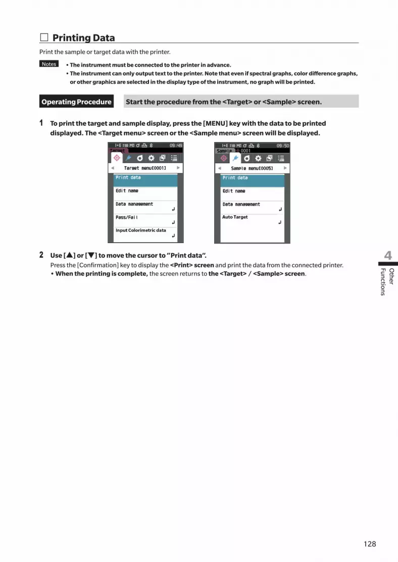
128127
Oth
er Fu
nction
s
4
� Printing DataPrint the sample or target data with the printer.
Notes • The instrument must be connected to the printer in advance.
• The instrument can only output text to the printer. Note that even if spectral graphs, color difference graphs,
or other graphics are selected in the display type of the instrument, no graph will be printed.
Operating Procedure Start the procedure from the <Target> or <Sample> screen.
1 To print the target and sample display, press the [MENU] key with the data to be printed displayed. The <Target menu> screen or the <Sample menu> screen will be displayed.
2 Use [▲] or [▼] to move the cursor to “Print data”.Press the [Confirmation] key to display the <Print> screen and print the data from the connected printer.• When the printing is complete, the screen returns to the <Target> / <Sample> screen.

129
� Auto Print Measurement results can be automatically printed for every measurement.
Notes • The instrument must be connected to the printer in advance.
• The instrument can only output text to the printer. Note that even if spectral graphs, color difference graphs,
or other graphics are selected in the display type of the instrument, no graph will be printed.
Memo Auto print is set to “OFF” when the instrument is shipped from the factory.
Operating Procedure Start the procedure from the <Setting> - <Communication setup> screen.
1 Use [▲] or [▼] to move the cursor to “Auto print”, and then press the [Confirmation] key.The <Auto print> screen is displayed.
2 Use [▲] or [▼] to move the cursor to “ON”, and then press the [Confirmation] key.The Auto Print function will turn ON, and printing will be performed every time measurement is performed. After the settings have been configured, the display will return to the <Communication setup> screen.
Print Example 1Display type set to “Spectral Graph”
S/N 10000103 SAMPLE0011 PASS SCI 360nm 28.83 560nm 48.80 370nm 31.03 570nm 41.93 530nm 60.74 730nm 41.90 540nm 56.24 740nm 40.02 550nm 51.09 SCE 360nm 27.74 560nm 44.82 370nm 29.93 570nm 40.97
530nm 59.63 730nm 40.75 540nm 55.14 740nm 47.83 550nm 50.06 2018/08/08 12:32:14 MAV TARGET0001 UV100%
S/N 10000103SAMPLE0012 PASS
2/D65 10/F2 SCI dL* -0.40 -0.39 da* -0.19 -0.13 db* -0.04 -0.01 dE*ab 0.44 0.41 MI 0.06 0.06 SCE dL* -0.37 -0.10 da* -0.19 -0.14 db* 0.06 0.04 dE*ab 0.42 0.40 dGU -0.21 -0.21 MI 0.06 0.062018/08/06 13:40:41 MAV TARGET0001 UV100%
S/N 10000103SAMPLE0013 PASS
2/D65 10/F2 SCI L* 76.97 75.22 a* -9.75 -8.65 b* -20.08 -22.39 dL* 0.40 0.40 da* -0.18 -0.13 db* 0.05 0.02 dE*ab 0.44 0.42 dGU -0.17 -0.17 MI 0.06 0.06 SCE L* 76.33 74.57 a* -9.85 -8.73 b* -20.11 -22.42 dL* 0.37 0.36 da* -0.19 -0.14 db* 0.07 0.05 dE*ab 0.42 0.39 GU 11.54 11.54 dGU -0.17 -0.17 MI 0.06 0.062018/08/08 12:32:08 MAV TARGET0001 UV100%
S/N 10000103SAMPLE0019
2/D65 10/F2 SCI OP 92.17 92.06 dOP -0.73 -0.752018/08/07 13:49:22 MAV TARGET0005 UV100%

130129
Oth
er Fu
nction
s
4
Memo If the color difference result is “Fail”, an “×” will be printed after the value.
If the value approaches the tolerance, “w” is appended after the value.
Print Example 2Display type set to “Diff. Graph”
Print Example 3Display type set to “Abs. & Diff.”
Print Example 4Opacity measurement
Items marked with are not displayed with the CM-25d.
S/N 10000103 SAMPLE0011 PASS SCI 360nm 28.83 560nm 48.80 370nm 31.03 570nm 41.93 530nm 60.74 730nm 41.90 540nm 56.24 740nm 40.02 550nm 51.09 SCE 360nm 27.74 560nm 44.82 370nm 29.93 570nm 40.97
530nm 59.63 730nm 40.75 540nm 55.14 740nm 47.83 550nm 50.06 2018/08/08 12:32:14 MAV TARGET0001 UV100%
S/N 10000103SAMPLE0012 PASS
2/D65 10/F2 SCI dL* -0.40 -0.39 da* -0.19 -0.13 db* -0.04 -0.01 dE*ab 0.44 0.41 MI 0.06 0.06 SCE dL* -0.37 -0.10 da* -0.19 -0.14 db* 0.06 0.04 dE*ab 0.42 0.40 dGU -0.21 -0.21 MI 0.06 0.062018/08/06 13:40:41 MAV TARGET0001 UV100%
S/N 10000103SAMPLE0013 PASS
2/D65 10/F2 SCI L* 76.97 75.22 a* -9.75 -8.65 b* -20.08 -22.39 dL* 0.40 0.40 da* -0.18 -0.13 db* 0.05 0.02 dE*ab 0.44 0.42 dGU -0.17 -0.17 MI 0.06 0.06 SCE L* 76.33 74.57 a* -9.85 -8.73 b* -20.11 -22.42 dL* 0.37 0.36 da* -0.19 -0.14 db* 0.07 0.05 dE*ab 0.42 0.39 GU 11.54 11.54 dGU -0.17 -0.17 MI 0.06 0.062018/08/08 12:32:08 MAV TARGET0001 UV100%
S/N 10000103SAMPLE0019
2/D65 10/F2 SCI OP 92.17 92.06 dOP -0.73 -0.752018/08/07 13:49:22 MAV TARGET0005 UV100%

131
This section explains how to configure calibration, how to display the instrument diagnosis info., and how to display the instrument info.
Operating Procedure Start the procedure from the measurement screen.
1 Press [MENU], and then use [◀] or [▶] to display the <Setting> screen.
Memo To return to the previous screen, press [MENU] or [ESC].
� Calibration setupConfigure the instrument calibration settings.
Operating Procedure Start the procedure from the <Setting> screen.
1 Use [▲] or [▼] to move the cursor to “Calibration setup”, and then press the [Confirmation] key.
System Settings

132131
Oth
er Fu
nction
s
4
� Calibration Interval MessagesIf the instrument has not been used for an extended period of time since the previous measurement, a message prompting white calibration will appear after start-up and before measurement. The time interval between the previous calibration and when the message is displayed can be configured.
Memo The interval until the calibration is displayed is set to “8 hours” when the instrument is shipped from the factory.
Operating Procedure Start the procedure from the <Calibration setup> screen.
1 Use [▲] or [▼] to move the cursor to “Calibration interval”, and then press the [Confirmation] key.
2 ▲ and ▼ will be displayed above and below the numbers representing the time until the message is displayed. Use [▲] or [▼] to specify a value.
Settings{ 1 to 24 h: Set the time interval between the previous
calibration and when the message should be displayed to between 1 and 24 hours.
3 Press the [Confirmation] key.The selection is confirmed and the screen returns to the <Calibration setup> screen.
Notes If [ESC] is pressed without pressing the [Confirmation]
key, the settings will not be changed and the screen will
return to the <Calibration setup> screen.

133
� Annual Calibration MessagesAs the time for periodic calibration approaches, the instrument shows a message reading “Regularly scheduled device calibration is required. Please contact the nearest service center.” at start-up to recommend annual service recalibration.The annual calibration message can be set to be shown or to be hidden when the recommended recalibration time comes.
Notes Regardless of displaying annual calibration message, it is recommended to request regular calibration
through our service department.
Memo Display of the annual calibration message is set to “ON (Display)” when the instrument is shipped from the factory.
Operating Procedure Start the procedure from the <Setting> - <Calibration setup> screen.
1 Press [MENU].The <Annual calibration> screen is displayed.Settings{ OFF : The message about annual calibration will not be
displayed.{ ON : The message about annual calibration will be
displayed.
2 Use [◀] or [▶] to move the cursor to select “OFF” or “ON”.
Memo If the annual calibration notification message is set to ON,
the annual calibration message will be displayed as the
specified day nears. The date of the next calibration is
specified upon initial startup or during KONICA MINOLTA
calibration service (or maintenance) and cannot be changed.
3 Press the [Confirmation] key.The selection is confirmed and the screen returns to the <Setting> screen.
Notes If [ESC] is pressed without pressing the [Confirmation]
key, the settings will not be changed and the screen will
return to the <Setting> screen.
Warning
Regularly scheduled device calibration is required.
Please contact the nearest service center.

134133
Oth
er Fu
nction
s
4
� User calibration You can perform calibration by using your own reference plate and calibration data instead of white calibration. The calibration data for user calibration can be specified by connecting the instrument to a computer and using the optional Color Management Software “SpectraMagic NX”. Users can select whether to use the user calibration data for measurement.
Operating Procedure Start the procedure from the <Setting> - <Calibration setup> screen.
1 Press [MENU].The <User calibration> screen is displayed.
Settings{ OFF : User calibration cannot be performed.{ ON : User calibration can be performed.
2 Use [◀], [▲], [▶], or [▼] to move the cursor to select “OFF” or “ON”.
3 Press the [Confirmation] key.The selection is confirmed and the screen returns to the <Calibration setup> screen.
Notes If [ESC] is pressed without pressing the [Confirmation]
key, the settings will not be changed and the screen will
return to the <Calibration setup> screen.OFF
ON
User calibration
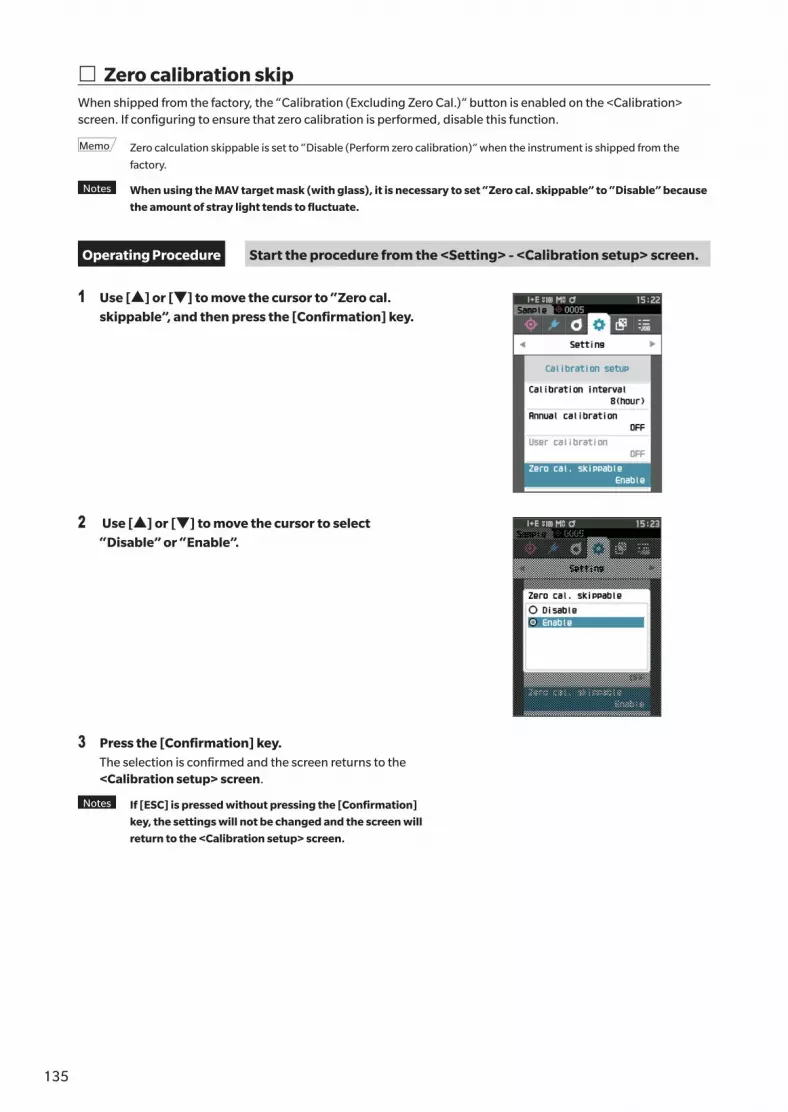
135
� Zero calibration skipWhen shipped from the factory, the “Calibration (Excluding Zero Cal.)” button is enabled on the <Calibration> screen. If configuring to ensure that zero calibration is performed, disable this function.
Memo Zero calculation skippable is set to “Disable (Perform zero calibration)” when the instrument is shipped from the
factory.
Notes When using the MAV target mask (with glass), it is necessary to set “Zero cal. skippable” to “Disable” because
the amount of stray light tends to fluctuate.
Operating Procedure Start the procedure from the <Setting> - <Calibration setup> screen.
1 Use [▲] or [▼] to move the cursor to “Zero cal. skippable”, and then press the [Confirmation] key.
2 Use [▲] or [▼] to move the cursor to select “Disable” or “Enable”.
3 Press the [Confirmation] key.The selection is confirmed and the screen returns to the <Calibration setup> screen.
Notes If [ESC] is pressed without pressing the [Confirmation]
key, the settings will not be changed and the screen will
return to the <Calibration setup> screen.

136135
Oth
er Fu
nction
s
4
� Displaying Diagnosis Info.The results of the instrument status diagnosis using optional PC software are displayed.(* Support for this function is planned with optional PC software. It is not currently available.)
Operating Procedure Start the procedure from the <Setting> screen.
1 Use [▲] or [▼] to move the cursor to “Diagnosis info.”, and then press the [Confirmation] key.
2 The instrument status is diagnosed and the results are displayed.
Display
3 Press [ESC].The display will return to the <Setting> screen.

137
� Displaying the Instrument InformationDisplay the product name, version, and serial number of the instrument.
Operating Procedure Start the procedure from the <Setting> screen.
1 Use [▲] or [▼] to move the cursor to “Instrument info.”, and then press the [Confirmation] key.
2 The instrument information is displayed.Display Items{ Product name: Instrument product name{ Version: Instrument firmware version{ Serial No.: Instrument serial No.
3 Press [ESC].The display will return to the <Setting> screen.

138137
Oth
er Fu
nction
s
4
� JOB FunctionAdministrators can pre-register to the instrument workflows to be performed by the worker, allowing the worker to perform
measurement according to the registered workflow. This selection screen is available when the job has been set in advance with
the optional Color Management Software SpectraMagic NX.
Notes • Communication via USB is recommended when configuring JOB settings using the optional Color Management
Software SpectraMagic NX. Configuration of the JOB function is possible via Bluetooth communication, but
transferring settings and images between the computer and the measuring instrument will take time.
• Exiting JOB mode will cause the observation conditions under JOB settings to be reset and the main unit’s
observation conditions to be restored. As such, if the JOB setting observation conditions differ from the main unit
observation conditions, pass/fail results may differ between during JOB execution and after exiting the mode.
Operating Procedure Start the procedure from the measurement screen.
1 Press [MENU], and then use [◀] or [▶] to display the <JOB> screen.
Memo To return to the previous screen, press [MENU] or [ESC].
2 Use [▲] or [▼] to move the cursor to the job to be used.
3 Follow the on-screen instructions to perform measurement.
Notes • Up to 5 types of jobs can be registered.
• Calibration according to the measurement conditions
being used within the job must be performed in
advance.
Opacity measurement cannot be performed while in
JOB mode.
The operations for the various keys on the instrument are as follows. • [▲] / [▼] key ... Used to switch the data display type
(SCI, SCE, or Pass or Fail).• [◀] / [▶] ... Used to select the Option Item.• [Confirmation] key... Used to execute the Option Item
selected by the cursor.• [Target/Sample] key ... Operation step : Disabled Result step : Disabled• [Menu] ... Disabled• [ESC] key ... Used to end a job in progress through a warning
message. Users can select “YES” or “NO” for the warning. Selecting “YES” will cause the screen to return to the JOB selection screen. Selecting “NO” will maintain the current step.
• [MES] key ... Operation step : Performs measurement and moves to the
next step. Result step : Moves to the next step.
• << ... Moves to the previous step. When returning to the Operation step, the data measured in the Operation step will be discarded, so performing measurement again will be necessary.
• > ... Moves to the next step. This key is not displayed in the Operation step.
• >> ... Moves to the next Operation step.
<Operation step>
<Result step>

139
MEMO

140139
Troubleshooting
5
Chapter 5
Chapter 5 Troubleshooting
Message List .................................................141
Troubleshooting ...........................................143

141
Message List
Error message: The operation is not correct. Follow the instructions displayed immediately.
ER1_32 There was an error with color measurement device. Restart and try measuring again.If the error occurs again, please contact the nearest service center.
ER1_33 There was an error with the gloss measurement device. Restart and try measuring again.If the error occurs again, please contact the nearest service center.
ER1_34 There is no xenon output. Restart and try measuring again.If the error occurs again, please contact the nearest service center.
ER1_35 There is no LED output. Restart and try measuring again.If the error occurs again, please contact the nearest service center.
ER1_36 The battery status cannot be obtained. Please contact the nearest service center.
ER1_39 There was an error writing to the memory. Restart and try again.If the error occurs again, please contact the nearest service center.
ER1_40 A memory error has occurred. Please contact the nearest service center.
ER1_41 The USB device is not working. Restart the device.If the error occurs again, please contact the nearest service center.
ER1_42 The USB host is not working. Restart the device.If the error occurs again, please contact the nearest service center.
ER1_43 An error has occurred with the clock IC. Please contact the nearest service center.
ER1_47 Connection to the printer failed. Please check the power and the settings.
Warning: Continued use will result in incorrect operation. Follow the instructions displayed as soon as possible.
ER1_31 The power supply voltage is insufficient. Please charge.
WR1_1 The power supply voltage is low. Please charge.
WR1_3 Xenon output has dropped. Replacement is recommended.
WR1_4 The LED output has dropped. Replacement is recommended.
WR1_7 The battery is low. Replace the battery.

142141
Troubleshooting
5
Caution: The setting or operation is not correct.
ER1_5 The target mask is wrong.
ER1_15 The target is protected. See P.69
ER1_18 The data could not be calculated.
ER1_19 Data is outside the range of guaranteed performance.
ER1_20 The input data is incorrect.
ER1_21 No target was found.
ER1_22 The measurement variation exceeds the threshold. Measure again.
ER1_23 You have reached the maximum number of possible measurements.
ER1_25 Cannot be used in the current mode.
ER1_26 This sample cannot be referenced to the selected target.
ER1_45 Only administrators can control this function. See P.109
ER1_48 The date is incorrect. See P.112
ER1_49 The set tolerance range is incorrect. Please check the upper and lower limits. P.72 and 81.
WR1_8 Please retry the measurement.Press the measurement button to measure and update to the most recent data.
Display: The flow of operation is displayed. Perform the operation according to the information displayed.
ER1_1 Regularly scheduled device calibration is required. Please contact the nearest service center.
See P.133
ER1_2 Regularly scheduled device calibration is approaching. Please contact the nearest service center.
See P.133
ER1_3 Please set the instrument on the zero calibration box and calibrate. See P.35
ER1_4 Perform zero calibration. See P.35
ER1_6 Please set the instrument on the white calibration plate and calibrate. See P.37
ER1_7 Perform white calibration. See P.37
ER1_8 Configure the white calibration data. See P.37
ER1_9 Please set the instrument on the gloss calibration plate and calibrate. See P.38
ER1_10 Perform gloss calibration. See P.38
ER1_11 Configure the gloss calibration data. See P.37
ER1_12 Please set the instrument on the user calibration plate and calibrate. See P.39
ER1_13 Perform user calibration. See P.39
ER1_14 Configure the user calibration data. See P.39
ER1_16 The device memory is full. Please delete some data to measure. P.41 and 53.
ER1_17 Specify at least one.
ER1_24 Please change the measurement area.
ER1_38 Please close the viewfinder. See P.40
ER1_50 Calibration is required. Would you like to calibrate now? See P.35
WR1_9 Data is being saved. Please wait until the power turns off.
WR1_10 Data is being processed. Please wait.
WR1_2 Calibration is recommended. Would you like to calibrate now? P.35 and 132.

143
Troubleshooting
If an abnormality has occurred with the instrument, take the necessary actions as given in the table below. If the instrument still does not work properly, turn the power OFF and temporarily disconnect the battery. Reinsert the battery and turn the power back ON. If the symptom remains, contact a KONICA MINOLTA-authorized service facility.
Symptom Check Point Action
The instrument does not start up even though the power is ON, or it turns off immediately.
Has the battery been inserted correctly?Is the battery dead?
Insert the battery correctly, or use the AC adapter or USB bus power to charge the battery.
Measurement cannot be performed even by pressing the measurement button.
Is measurement still in progress?
Wait until the beep indicates that measurement is complete, or verify that the LCD has changed before performing the operation.No beep can be heard.P.115 “Beep”, and check the beep settings.
Is a screen where measurement is possible displayed?
The measurement button must be pressed while a screen that allows measurement (e.g. Calibration, Target, or Sample screen) is shown.
Is the viewfinder open? Use the viewfinder lever to securely close the viewfinder.If the inside of the integrating sphere is illuminated and shining, the viewfinder lever is not closed.Remove any foreign matter, etc. caught in the viewfinder lever components.
Measurement results are abnormal.
Is the specimen placed properly?
The measurement results may be affected if measurement light leaks. Set the instrument so that the sample is as close to the target mask surface as possible.
Is there any foreign material on the surface of the target mask or around the specimen measuring surface?
Measurement results may be affected if foreign matter becomes caught between the specimen and the target mask surface. Clean the specimen surface or the target mask measurement surface according to the specified method.
Are there marks on the surface of the target mask around the specimen measuring port?
If the sample and the target mask surface are not in contact due to a dent or the like, the measurement results may be affected. To replace the target mask, please contact a KONICA MINOLTA-authorized service facility.
Is there foreign matter or other dirt adhering to the inside of the integrating sphere?
Foreign matter or dirt larger than several mm may affect the measurement results. Foreign matter and dust inside the integrating sphere can easily scratch the barium sulfate paint on the inside of the sphere. Use a blower to blow off those objects. If such objects cannot be removed with the blower, zero calibration and white calibration may improve performance.
Is the target mask attached correctly? (CM-26d, CM-25d)
P.33Read “Replacing the Target Mask”, and attach the target mask correctly.
Is proper calibration data used?
Calibration data is written to the instrument using the standard accessory spectrophotometer configuration tool CM-CT1. Verify that the calibration plate is correct for the input calibration data before performing white calibration, gloss calibration, or user calibration.
Was white calibration performed correctly?
P.37Read “White Calibration and Gloss Calibration” to perform white calibration or gloss calibration properly.
Was gloss calibration performed correctly?
Was zero calibration performed correctly?
P.35 “Zero calibration” and perform zero calibration properly.

144143
Troubleshooting
5
Symptom Check Point Action
Measurement results fluctuate.
Is the instrument and specimen kept stationary during measurement?
Do not allow the instrument and specimen to move during measurement. Use averaging measurement as needed.
Data cannot be transferred to a computer from the instrument.No commands from the computer are being accepted.
Is the USB cable connected correctly?
Properly connect the instrument’s USB connecting terminal to the computer’s USB port with the USB cable supplied with the instrument.
Has Bluetooth communication been established?
Install and connect the Bluetooth module correctly.
Printing is not possible. Has Bluetooth communication been established?
Install and connect the Bluetooth module correctly.
Samples and settings are not held in memory and disappear immediately.
The instrument’s backup battery may be low immediately after purchase or following a period of prolonged non-use. Turn the instrument ON to charge the backup battery. Under this condition, the backup battery will be fully charged in 20 hours.
The backup battery in the instrument should last 10 years under normal use. If the instrument fails to retain data in memory even after the battery has been fully charged, however, the battery has likely reached the end of its life and requires replacement. To replace the backup battery, please contact a KONICA MINOLTA-authorized service facility.

145
MEMO

146145
Ap
pen
dix
6
Chapter 6
Chapter 6 Appendix
Fluorescence Measurement ..........................147
Specifications ...............................................148
Dimensions ..................................................150

147
Fluorescence Measurement
This instrument features both a UV full xenon lamp and a UV cut xenon lamp. Fluorescence reflectance is calculated through numerical processing of the reflectance from these two light sources.
With fluorescence calibrationTo ensure accurate fluorescence reflectance measurement, fluorescence calibration can be performed via SpectraMagic NX (Ver.3.0 or later).
Finding the fluorescence reflectanceThe fluorescence amount is determined for each reflectance wavelength under both the UV full light source and the UV cut light source by measuring a fluorescence standard plate. The fluorescence correction coefficient is determined to ensure the measured values are matched to the given target values.(Calibration example: Profile mode)
The fluorescence correction coefficient is used to determine the fluorescence reflectance through numerical processing of a measurement object’s reflectance under the UV full light source and under the UV cut light source.(The reflectance of the cut wavelength region for UV cut lighting is uniform at 0%.)This allows the instrument to approximate the output fluorescence amount under any reference light source, such as a D65 light source, without increasing or decreasing the amount of UV light as with conventional models.
Without fluorescence calibrationThe spectral distribution characteristics of the instrument’s UV full xenon lamp are close to that of a D65 light source, making it possible to measure fluorescence reflectance with ordinary reflectance measurement if strict accuracy is not required for the fluorescence measurement.
UV cut light sourceThis instrument is equipped with a UV 400 option as a UV cut light source (with all UV rays up to 390 nm eliminated).
Under UV full light source
Under UV cut light source
Under D65 light source(Input target value)
Under UV full light source
Under UV cut light source
Correction coe�cient = b/a
Under D65 light source b a

148147
Ap
pen
dix
6
Specifications
Model CM-26dG CM-26d CM-25d
Color
Illumination/viewing system
di: 8°, de: 8° (diffuse illumination: 8° viewing)SCI (specular component included) / SCE (specular component excluded) switchableISO 7724/1, CIE No.15, DIN 5033 Teil 7, JIS Z 8722 Condition “c”
Integrating sphere Ø54 mmDetector Dual 40-element silicon photodiode arrays Dual 32-element silicon
photodiode arraysSpectral separation device
Planar diffraction grating
Wavelength range 360 to 740 nm 400 to 700 nmWavelength pitch 10 nmHalf bandwidth Approx. 10 nmReflectance measurement range
0 to 175%; Display resolution: 0.01%
Light source Pulsed xenon lamp ×2 Pulsed xenon lamp ×1(with UV cut filter)
Illumination area 12 × 12.5 mm (circle + ellipse)
MAV : Ø12 mmSAV : Ø6 mm
MAV : Ø12 mm
Measurement area MAV: Ø8 mm, SAV: Ø3 mm MAV : Ø8 mmRepeatability Standard deviation within ΔE*ab 0.02 Standard deviation within
ΔE*ab 0.04(When a white calibration plate is measured 30 times at 5-second intervals after white calibration under Konica Minolta standard measurement conditions)
Inter-instrument agreement
Within ΔE*ab 0.12 Within ΔE*ab 0.2(Based on average for 12 BCRA Series II color tiles; MAV SCI; compared to values measured with a master body under Konica Minolta standard measurement conditions)
UV setting 100% / 0% / 100% + 0% / Adjusted (Instantaneous numerical adjustment of UV with no mechanical filter movement required)*1; 400 nm UV cutoff filter
No adjustment function (UV0%)
Observer 2° observer angle, 10° observer angleIlluminant A, C, D50, D65, F2, F6, F7, F8, F10, F11, F12, ID50, ID65, User-defined illuminant*2
(Simultaneous evaluation with two light sources possible)Display items Colorimetric values/graph, color difference values/graph, spectral graph, pass/fail
judgment, pseudocolorColorimetric values
L*a*b*, L*C*h, Hunter Lab, Yxy, XYZ, FMC2, and color difference in these spaces; Munsell (C)
Indices MI, WI (ASTM E313-73), YI (ASTM E313-73, ASTM D1925), ISO brightness (ISO 2470), WI/Tint (CIE/Ganz), Tristimulus Strength, Opacity, Grey Scale (ISO 105-A05), K/S strength (Apparent (ΔE*ab)), Maximum absorption, Total wavelength), Staining degree (ISO 105-A04), User index*2
MI, W (I ASTM E313-73), YI (ASTM E313-73, ASTM D1925), ISO brightness (ISO 2470), WI/Tint (CIE/Ganz), Tristimulus Strength, Opacity, Grey Scale (ISO 105-A05), 8° gloss value, K/S strength (Apparent (ΔE*ab)), Maximum absorption, Total wavelength), Staining degree (ISO 105-A04), User index*2
MI, W (I ASTM E313-73), YI (ASTM E313-73, ASTM D1925), ISO brightness (ISO 2470), WI/Tint (CIE), Tristimulus Strength, Opacity, Grey Scale (ISO 105-A05), 8° gloss value, K/S strength (Apparent (ΔE*ab)), Maximum absorption, Total wavelength), Staining degree (ISO 105-A04), User index*2
Color difference equations
ΔE*ab (CIE1976) / ΔE94 (CIE1994) / ΔE00 (CIE2000) / CMC (l:c) / Hunter ΔE / DIN99o / FMC2
Applicable standards ISO 7724/1, CIE No.15, DIN 5033 Teil 7, JIS Z 8722 Condition “c”
*1 Firmware version 1.10 or later and optional Color Management Software SpectraMagic NX (Ver. 3.0 or later) is required to use UV Adjusted setting.
*2 Optional Color Management Software SpectraMagic NX (Ver. 2.9 or later) is required for setting user-configured illuminants or user indexes.

149
Model CM-26dG CM-26d CM-25d
Gloss
Measurement angle 60° — —Light source White LED — —Detector Silicon photodiode — —Color sensitivity Spectrally adjusted to CIE
photopic luminous efficiency V(λ) under CIE illuminant C
— —
Measurement range 0 to 200 GU;Display resolution: 0.01 GU
— —
Measurement area MAV : 10×7 mm, ellipseSAV : Ø3 mm
— —
Repeatability Standard deviation0 to 10 GU: Within 0.1 GU10 to 100 GU: Within 0.2 GU100 to 200 GU: Within 0.2% of indicated value(When measured 30 times at 5-second intervals after calibration under Konica Minolta standard measurement conditions)
— —
Inter-instrument agreement
0 to 10 GU: Within ±0.2 GU10 to 100 GU: Within ±0.5 GU(MAV; compared to values measured with a master body under KONICA MINOLTA standard measurement conditions)
— —
Applicable standards
JIS Z8741 (MAV), JIS K5600, ISO 2813, ISO 7668 (MAV), ASTM D523-08, ASTM D2457-13, DIN 67530
— —
Measurement time Approx. 1 sec. (Measurement mode: SCI + Gloss or SCE + Gloss)
Approx. 0.7 sec. (Measurement mode: SCI or SCE)
(From pressing measuring button to measurement completion)Minimum measurement interval
Approx. 2 sec(Measurement mode: SCI + gloss or SCE + gloss)
Approx. 1.5 sec(Measurement mode: SCI or SCE)
Data memory 1,000 target data + 5,100 sample dataBattery performance Measurement mode: SCI +
Gloss or SCE + GlossMeasurement mode: SCI or SCE
Approx. 3,000 measurements (approx. 1,000 measurements when using Bluetooth) when measurements are taken at 10-second intervals at 23°C with the dedicated lithium battery
Viewfinder function Available (with white LED illumination)Display 2.7-inch TFT color LCD with reversible portrait viewing modeDisplay language English, Japanese , German, French, Italian, Spanish, Simplified Chinese, Portuguese,
Russian, Turkish, PolishInterface USB 2.0; Bluetooth (SPP-compatible. Optional Bluetooth module required)Power Dedicated lithium-ion battery (removable), USB bus power (with lithium-ion battery
installed), Dedicated AC adapter (with lithium-ion battery installed)Charging time Approx. 6 hOperating temperature/humidity range
Temperature: 5 to 40°C, Relative humidity: 80% or less (at 35°C) with no condensation
Storage Temperature/humidity range
Temperature: 0 to 45°C, Relative humidity: 80% or less (at 35°C) with no condensation
Size Approx. 81 (W) × 93 (H) × 229 (D) mmWeight Approx. 660 g Approx. 630 g Approx. 620 g

150149
Ap
pen
dix
6
Dimensions
MAV SAV
* Not available on the CM-25d.
(Unit: mm)CM-26dG / CM-26d / CM-25d
< CAUTION >
● KONICA MINOLTA WILL NOT BE LIABLE FOR ANY DAMAGES RESULTING FROM THE MISUSE, MISHANDLING, UNAUTHORIZED MODIFICATION, ETC. OF THIS PRODUCT, OR FOR ANY INDIRECT OR INCIDENTAL DAMAGES (INCLUDING BUT NOT LIMITED TO LOSS OF BUSINESS PROFITS, INTERRUPTION OF BUSINESS, ETC.) DUE TO THE USE OF OR INABILITY TO USE THIS PRODUCT.

UE-1
User Equation and User Class
• The User Equation (User Index) function allows users to input an equation defined by the user and using values currently set for display on the instrument, and have the instrument show the results of the user-defined equation.
• The User Class function allows users to classify measurements into groups (such as grades or ranks) according to the results of a defined User Equation.
Registering a User Equation and/or User Class on the instrumentThe User Equation and/or User Class can be registered on the instrument using Color Data Software SpectraMagic NX.• The User Class is defined based on the User Equation of the same number. For example, UC1 is defined based on
UE1. If no User Equation is defined for the selected UC number, the User Class definition will not be used.
Displaying the results of a User Equation and/or User Class on the instrument
The calculated results for a User Equation and/or User Class can be displayed by selecting UE1 to UE3 (User Equation 1 to 3) and/or UC1 to UC3 (User Class 1 to 3) in a Custom screen of Display cond. on the instrument. (See Display Settings in the Instruction Manual for the instrument.)
Measurement valuesThe following measurement values can be used in User Equation.• The measurement values to be used in the User Equation and to be displayed on Custom screen must be set to
be displayed on the instrument in the Display type, Color space, Equation, or Custom screen of Display cond. on the instrument. (See Display Settings in the Instruction Manual for the instrument.)
• Measurement values not listed in the table below cannot be used.
L* a* b* C* h
L(Hunter) a(Hunter) b(Hunter) X Y
Z x y GU ΔL*
Δa* Δb* ΔC* ΔH* ΔL(Hunter)
Δa(Hunter) Δb(Hunter) ΔX ΔY ΔZ
Δx Δy ΔGU ΔE*ab CMC
ΔE*94 ΔE00 ΔE(Hunter) MI WI(E313-73)
ΔWI(E313-73) WI(CIE) ΔWI(CIE) Tint(CIE) ΔTint(CIE)
YI(E313-73) ΔYI(E313-73) YI(D1925) ΔYI(D1925) B(ISO)
ΔB(ISO)
Refer to Input Format below.
FunctionsThe following functions can be used in User Equation.
Mathematical functions Trigonometric functions Other functions
addition, subtraction, multiplication, division
sin, cos, tan, sin-1, cos-1, tan-1
square, square root, absolute value, logarithm, natural logarithm, exponent, power
Refer to Input Format below.

UE-2
User Equation Input example
To input the equation for ΔE*ab
as a User Equation, it would be:SQRT(POW([DL])+POW([DA])+POW([DB]))
Input FormatA User Equation is defined using numbers and strings for measurement value variables and functions.
• Parameter strings are explained in Input Format below. • The total length of a User Equation definition including numbers and string parameters is 200 characters.
Numerical constantsNumbers can be input as constants using 0 to 9 and the decimal point. Although there is no limit on the number of decimal places that can be input, the number of significant digits for calculations is 5 places.
Measurement value variablesFor CM-25cG
Variable Measurement value Variable Measurement value Variable Measurement value
[L] L* [A] a* [B] b*
[DL] ΔL* [DA] Δa* [DB] Δb*
[C] C* [H] H
[DC] ΔC* [DH] ΔH*
[HL] L(Hunter) [HA] a(Hunter) [HB] b(Hunter)
[DHL] ΔL(Hunter) [DHA] Δa(Hunter) [DHB] Δb(Hunter)
[X] X [Y] Y [Z] Z
[DX] ΔX [DY] ΔY [DZ] ΔZ
[SX] x [SY] y
[DSX] Δx [DSY] Δy
[GU] GU [DGU] ΔGU
[DE] ΔE*ab [CMC] CMC [DE94] ΔE*94
[DE00] ΔE00 [DEH] ΔE(Hunter) [MI] MI
[WIE] WI E313-73 [WIC] WI CIE [TINT] Tint CIE
[DEWI] ΔWI E313-73 [DWIC] ΔWI CIE [DTINT] ΔTint CIE
[YIE] YI E313-73 [YID] YI D1925 [BISO] B(ISO)
[DYIE] ΔYI E313-73 [DYID] ΔYI D1925 [DBISO] ΔB(ISO)

UE-3
For CM-26dG, CM-26d, CM-25dCommon variables
• Calculations will be performed using the SCI/SCE setting of the current screen. In the SCI screen, SCI values will be used and in the SCE screen, SCE values will be used.
Variable Measurement value Variable Measurement value Variable Measurement value
[L] L* [A] a* [B] b*
[DL] ΔL* [DA] Δa* [DB] Δb*
[C] C* [H] H
[DC] ΔC* [DH] ΔH*
[HL] L(Hunter) [HA] a(Hunter) [HB] b(Hunter)
[DHL] ΔL(Hunter) [DHA] Δa(Hunter) [DHB] Δb(Hunter)
[X] X [Y] Y [Z] Z
[DX] ΔX [DY] ΔY [DZ] ΔZ
[SX] x [SY] y
[DSX] Δx [DSY] Δy
[GU] GU [DGU] ΔGU
[DE] ΔE*ab [CMC] CMC [DE94] ΔE*94
[DE00] ΔE00 [DEH] ΔE(Hunter) [MI] MI
[WIE] WI E313-73 [WIC] WI CIE [TINT] Tint CIE
[DEWI] ΔWI E313-73 [DWIC] ΔWI CIE [DTINT] ΔTint CIE
[YIE] YI E313-73 [YID] YI D1925 [BISO] B(ISO)
[DYIE] ΔYI E313-73 [DYID] ΔYI D1925 [DBISO] ΔB(ISO)
• GU and ΔGU can be used only with CM-26dG. UVfull+UVcut is available only with CM-26dG and 26d devices.

UE-4
SCI variablesSCI values will be used even if the SCE screen is selected.
• Instrument Specular Component setting must include SCI.
Variable Measurement value Variable Measurement value Variable Measurement value
[LI] L* [AI] a* [BI] b*
[DLI] ΔL* [DAI] Δa* [DBI] Δb*
[CI] C* [HI] H
[DCI] ΔC* [DHI] ΔH*
[HLI] L(Hunter) [HAI] a(Hunter) [HBI] b(Hunter)
[DHLI] ΔL(Hunter) [DHAI] Δa(Hunter) [DHBI] Δb(Hunter)
[XI] X [YI] Y [ZI] Z
[DXI] ΔX [DYI] ΔY [DZI] ΔZ
[SXI] x [SYI] y
[DSXI] Δx [DSYI] Δy
[GUI] GU [DGUI] ΔGU
[DEI] ΔE*ab [CMCI] CMC [DE94I] ΔE*94
[DE00I] ΔE00 [DEHI] ΔE(Hunter) [MII] MI
[WIEI] WI E313-73 [WICI] WI CIE [TINTI] Tint CIE
[DEWII] ΔWI E313-73 [DWICI] ΔWI CIE [DTINTI] ΔTint CIE
[YIEI] YI E313-73 [YIDI] YI D1925 [BISOI] B(ISO)
[DYIEI] ΔYI E313-73 [DYIDI] ΔYI D1925 [DBISOI] ΔB(ISO)

UE-5
SCE variablesSCE values will be used even if the SCI screen is selected.
• instrument Specular Component setting must include SCE.
Variable Measurement value Variable Measurement value Variable Measurement value
[LE] L* [AE] a* [BE] b*
[DLE] ΔL* [DAE] Δa* [DBE] Δb*
[CE] C* [HE] H
[DCE] ΔC* [DHE] ΔH*
[HLE] L(Hunter) [HAE] a(Hunter) [HBE] b(Hunter)
[DHLE] ΔL(Hunter) [DHAE] Δa(Hunter) [DHBE] Δb(Hunter)
[XE] X [YE] Y [ZE] Z
[DXE] ΔX [DYE] ΔY [DZE] ΔZ
[SXE] x [SYE] y
[DSXE] Δx [DSYE] Δy
[GUE] GU [DGUE] ΔGU
[DEE] ΔE*ab [CMCE] CMC [DE94E] ΔE*94
[DE00E] ΔE00 [DEHE] ΔE(Hunter) [MIE] MI
[WIEE] WI E313-73 [WICE] WI CIE [TINTE] Tint CIE
[DEWIE] ΔWI E313-73 [DWICE] ΔWI CIE [DTINTE] ΔTint CIE
[YIEE] YI E313-73 [YIDE] YI D1925 [BISOE] B(ISO)
[DYIEE] ΔYI E313-73 [DYIDE] ΔYI D1925 [DBISOE] ΔB(ISO)
UVfull+UVcut simultaneous measurement dataUVfull * UVfull values will also be used on the UVcut screen.
Variable Measurement value Variable Measurement value Variable Measurement value
[LF] L* [AF] a* [BF] b*
[DLF] ΔL* [DAF] Δa* [DBF] Δb*
[CF] C* [HF] h
[DCF] ΔC* [DHF] ΔH*
[HLF] L(Hunter) [HAF] a(Hunter) [HBF] b(Hunter)
[DHLF] ΔL(Hunter) [DHAF] Δa(Hunter) [DHBF] Δb(Hunter)
[XF] X [YF] Y [ZF] Z
[DXF] ΔX [DYF] ΔY [DZF] ΔZ
[SXF] x [SYF] y
[DSXF] Δx [DSYF] Δy
[DEF] ΔE*ab [CMCF] CMC [DE94F] ΔE*94
[DE00F] ΔE00 [DEHF] ΔE(Hunter) [MIF] MI
[WIEF] WI E313-73 [WICF] WI CIE [TINTF] Tint CIE
[DEWIF] ΔWI E313-73 [DWICF] ΔWI CIE [DTINTF] ΔTint CIE
[YIEF] YI E313-73 [YIDF] YI D1925 [BISOF] B(ISO)
[DYIEF] ΔYI E313-73 [DYIDF] ΔYI D1925 [DBISOF] ΔB(ISO)

UE-6
Uvcut * UVcut values will also be used on the UVfull screen.
Variable Measurement value Variable Measurement value Variable Measurement value
[LC] L* [AC] a* [BC] b*
[DLC] ΔL* [DAC] Δa* [DBC] Δb*
[CC] C* [HC] h
[DCC] ΔC* [DHC] ΔH*
[HLC] L(Hunter) [HAC] a(Hunter) [HBC] b(Hunter)
[DHLC] ΔL(Hunter) [DHAC] Δa(Hunter) [DHBC] Δb(Hunter)
[XC] X [YC] Y [ZC] Z
[DXC] ΔX [DYC] ΔY [DZC] ΔZ
[SXC] x [SYC] y
[DSXC] Δx [DSYC] Δy
[DEC] ΔE*ab [CMCC] CMC [DE94C] ΔE*94
[DE00C] ΔE00 [DEHC] ΔE(Hunter) [MIC] MI
[WIEC] WI E313-73 [WICC] WI CIE [TINTC] Tint CIE
[DEWIC] ΔWI E313-73 [DWICC] ΔWI CIE [DTINTC] ΔTint CIE
[YIEC] YI E313-73 [YIDC] YI D1925 [BISOC] B(ISO)
[DYIEC] ΔYI E313-73 [DYIDC] ΔYI D1925 [DBISOC] ΔB(ISO)
Example of User Equation results when using common, SCI only, and SCE only variables in SCI and SCE screens
SCI screen SCE screen
[L] 100 50
[L]+[LI]+[LE] 250 (= 100+100+50) 200 (=50+100+50)
Example of UVfull+UVcut simultaneous measurement data display results
UV100 UV0
[L] 100 50
[L]+[LF]+[LC] 250 (= 100+100+50) 200 (=50+100+50)
Functions
Function string Usage example Explanation
+ A+B = A + B
- A-B = A - B
* A*B = A × B
/ A/B = A ⁄ B
POW POW(A) = A2
SQRT SQRT(A) =
ABS ABS(A) = |A| (Absolute value of A)
SIN SIN(A) = sin A (where A is in degrees)
COS COS(A) = cos A (where A is in degrees)
TAN TAN(A) = tan A (where A is in degrees)
ASIN ASIN(A) = sin-1 A (where A is in degrees)
ACOS ACOS(A) = cos-1 A (where A is in degrees)
ATAN ATAN(A) = tan-1 A (where A is in degrees)
LOG LOG(A) = log A
LN LN(A) = ln A
EXP EXP(A) = eA
POW2 POW2(A,B) = AB
A

UE-7
User Class The User Class classifies measurements according to the results of the User Equation having the same number (for example, UC1 classifies measurements according to the results of UE1).
Input ExampleTo classify measurements into 5 classes A, B, C, D, E based on the following conditions:
User Equation result Class
UE ≥ 4 A
UE ≥ 3 B
UE ≥ 2 C
UE ≥ 1 D
UE < 1 E
the class definition would be:CLASS(4, “A”, 4, “B”, 3, “C”, 2, “D”, 1, “E”)
Input Format
CLASS(n, “str1”, d1, “str2”, d2, “str3”, d3, …)where
n Number of class thresholds (= number of classes - 1)
str1 Class label for class threshold 1. This label will be applied to UE values greater than class threshold 1.
d1 Class threshold 1
str2 Class label for class threshold 2. This label will be applied to UE values greater than class threshold 2 but less than class threshold 1.
d2 Class threshold 2
str3 Class label for class threshold 3. This label will be applied to UE values greater than class threshold 3 but less than class threshold 2.
d3 Class threshold 3
:
:
• n maximum value: 50• Class label str maximum length: 6 characters• Usable characters for class labels str are shown in the table on the following page.• Class threshold d maximum length: 20 characters, but the number of significant digits used for calculations is 5.• Classes should be input in order from classes with the largest threshold to the smallest threshold.• Overall maximum length including “CLASS()”: 200 characters• If User Class will not be used, do not input a User Class definition.• Class definition parameters are separated by commas “,”.• Period “.” is used for the decimal point.
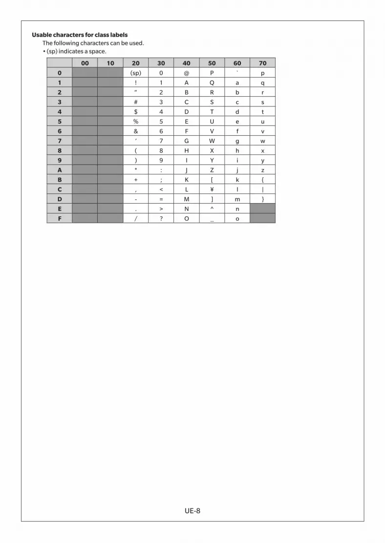
UE-8
Usable characters for class labelsThe following characters can be used.• (sp) indicates a space.
00 10 20 30 40 50 60 70
0 (sp) 0 @ P ` p
1 ! 1 A Q a q
2 “ 2 B R b r
3 # 3 C S c s
4 $ 4 D T d t
5 % 5 E U e u
6 & 6 F V f v
7 ’ 7 G W g w
8 ( 8 H X h x
9 ) 9 I Y i y
A * : J Z j z
B + ; K [ k {
C , < L ¥ l |
D - = M ] m }
E . > N ^ n
F / ? O _ o

En 9222-AC5J-12 ©2018-2021 KONICA MINOLTA, INC. CBHADA