specifications for design, supply, installation & commissioning of
TRANSCRIPT
1
SPECIFICATIONS FOR DESIGN, SUPPLY, INSTALLATION & COMMISSIONING OF
NEW AIR COOLED CHILLER SYSTEM
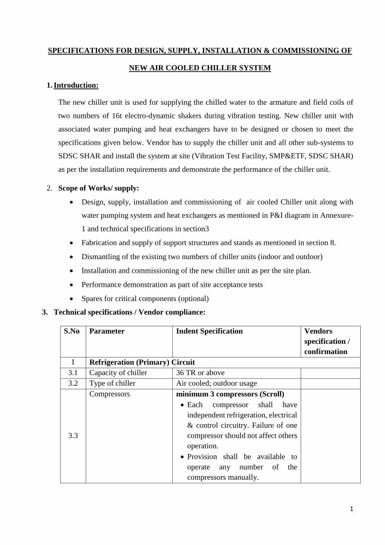
1. Introduction:
The new chiller unit is used for supplying the chilled water to the armature and field coils of
two numbers of 16t electro-dynamic shakers during vibration testing. New chiller unit with
associated water pumping and heat exchangers have to be designed or chosen to meet the
specifications given below. Vendor has to supply the chiller unit and all other sub-systems to
SDSC SHAR and install the system at site (Vibration Test Facility, SMP&ETF, SDSC SHAR)
as per the installation requirements and demonstrate the performance of the chiller unit.
2. Scope of Works/ supply:
Design, supply, installation and commissioning of air cooled Chiller unit along with
water pumping system and heat exchangers as mentioned in P&I diagram in Annexure-
1 and technical specifications in section3
Fabrication and supply of support structures and stands as mentioned in section 8.
Dismantling of the existing two numbers of chiller units (indoor and outdoor)
Installation and commissioning of the new chiller unit as per the site plan.
Performance demonstration as part of site acceptance tests
Spares for critical components (optional)
3. Technical specifications / Vendor compliance:
S.No Parameter Indent Specification Vendors
specification /
confirmation
I Refrigeration (Primary) Circuit
3.1 Capacity of chiller 36 TR or above
3.2 Type of chiller Air cooled; outdoor usage
3.3
Compressors
minimum 3 compressors (Scroll)
Each compressor shall have
independent refrigeration, electrical
& control circuitry. Failure of one
compressor should not affect others
operation.
Provision shall be available to
operate any number of the
compressors manually.
2
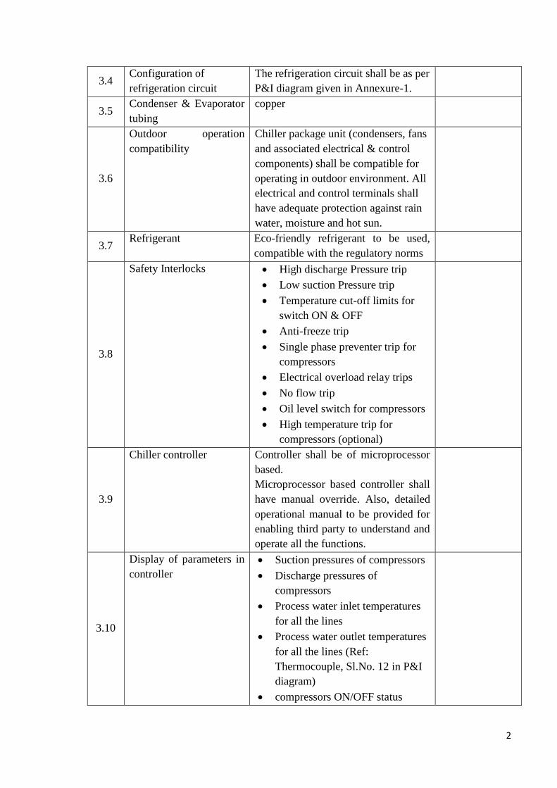
3.4 Configuration of
refrigeration circuit
The refrigeration circuit shall be as per
P&I diagram given in Annexure-1.
3.5 Condenser & Evaporator
tubing
copper
3.6
Outdoor operation
compatibility
Chiller package unit (condensers, fans
and associated electrical & control
components) shall be compatible for
operating in outdoor environment. All
electrical and control terminals shall
have adequate protection against rain
water, moisture and hot sun.
3.7 Refrigerant Eco-friendly refrigerant to be used,
compatible with the regulatory norms
3.8
Safety Interlocks High discharge Pressure trip
Low suction Pressure trip
Temperature cut-off limits for
switch ON & OFF
Anti-freeze trip
Single phase preventer trip for
compressors
Electrical overload relay trips
No flow trip
Oil level switch for compressors
High temperature trip for
compressors (optional)
3.9
Chiller controller Controller shall be of microprocessor
based.
Microprocessor based controller shall
have manual override. Also, detailed
operational manual to be provided for
enabling third party to understand and
operate all the functions.
3.10
Display of parameters in
controller
Suction pressures of compressors
Discharge pressures of
compressors
Process water inlet temperatures
for all the lines
Process water outlet temperatures
for all the lines (Ref:
Thermocouple, Sl.No. 12 in P&I
diagram)
compressors ON/OFF status
3
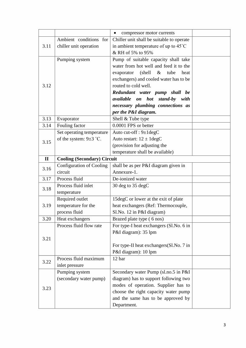
compressor motor currents
3.11
Ambient conditions for
chiller unit operation
Chiller unit shall be suitable to operate
in ambient temperature of up to 45˚C
& RH of 5% to 95%
3.12
Pumping system Pump of suitable capacity shall take
water from hot well and feed it to the
evaporator (shell & tube heat
exchangers) and cooled water has to be
routed to cold well.
Redundant water pump shall be
available on hot stand-by with
necessary plumbing connections as
per the P&I diagram.
3.13 Evaporator Shell & Tube type
3.14 Fouling factor 0.0001 FPS or better
3.15
Set operating temperature
of the system: 9±3 ˚C.
Auto cut-off : 9±1degC
Auto restart: 12 ± 1degC
(provision for adjusting the
temperature shall be available)
II Cooling (Secondary) Circuit
3.16 Configuration of Cooling
circuit
shall be as per P&I diagram given in
Annexure-1.
3.17 Process fluid De-ionized water
3.18 Process fluid inlet
temperature
30 deg to 35 degC
3.19
Required outlet
temperature for the
process fluid
15degC or lower at the exit of plate
heat exchangers (Ref: Thermocouple,
Sl.No. 12 in P&I diagram)
3.20 Heat exchangers Brazed plate type ( 6 nos)
3.21
Process fluid flow rate For type-I heat exchangers (Sl.No. 6 in
P&I diagram): 35 lpm
For type-II heat exchangers(Sl.No. 7 in
P&I diagram): 10 lpm
3.22 Process fluid maximum
inlet pressure
12 bar
3.23
Pumping system
(secondary water pump)
Secondary water Pump (sl.no.5 in P&I
diagram) has to support following two
modes of operation. Supplier has to
choose the right capacity water pump
and the same has to be approved by
Department.
4
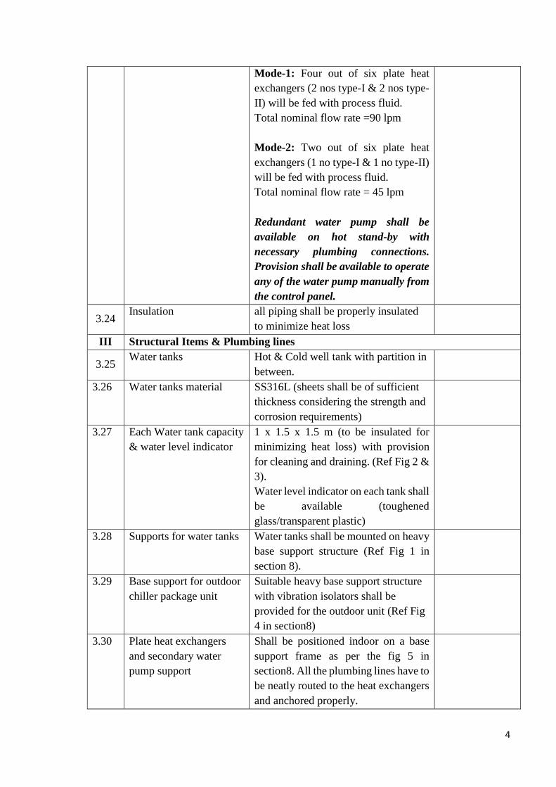
Mode-1: Four out of six plate heat
exchangers (2 nos type-I & 2 nos type-
II) will be fed with process fluid.
Total nominal flow rate =90 lpm
Mode-2: Two out of six plate heat
exchangers (1 no type-I & 1 no type-II)
will be fed with process fluid.
Total nominal flow rate = 45 lpm
Redundant water pump shall be
available on hot stand-by with
necessary plumbing connections.
Provision shall be available to operate
any of the water pump manually from
the control panel.
3.24 Insulation all piping shall be properly insulated
to minimize heat loss
III Structural Items & Plumbing lines
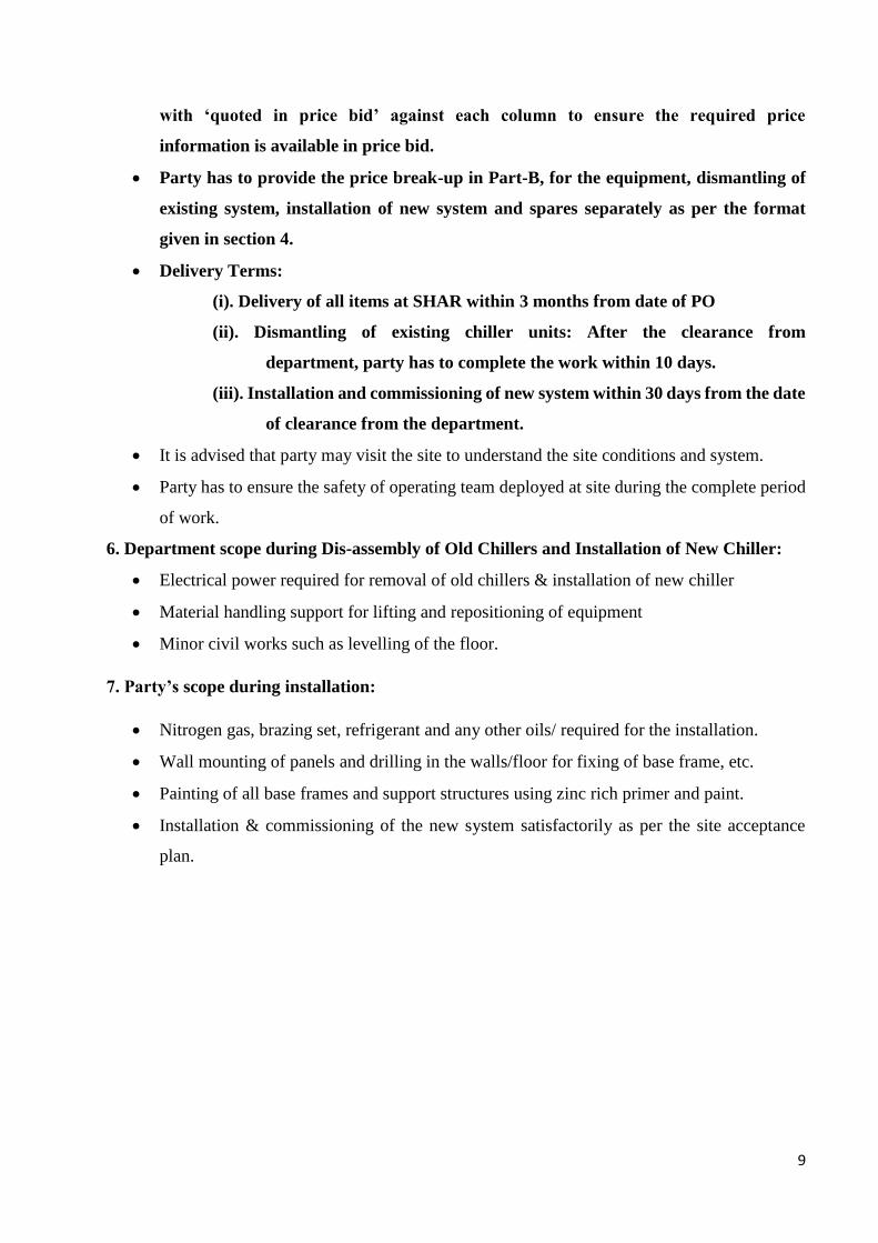
3.25 Water tanks Hot & Cold well tank with partition in
between.
3.26 Water tanks material SS316L (sheets shall be of sufficient
thickness considering the strength and
corrosion requirements)
3.27 Each Water tank capacity
& water level indicator
1 x 1.5 x 1.5 m (to be insulated for
minimizing heat loss) with provision
for cleaning and draining. (Ref Fig 2 &
3).
Water level indicator on each tank shall
be available (toughened
glass/transparent plastic)
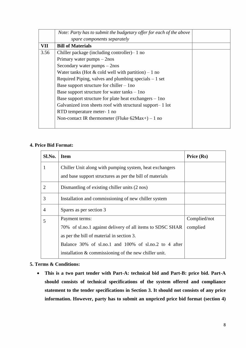
3.28 Supports for water tanks Water tanks shall be mounted on heavy
base support structure (Ref Fig 1 in
section 8).
3.29 Base support for outdoor
chiller package unit
Suitable heavy base support structure
with vibration isolators shall be
provided for the outdoor unit (Ref Fig
4 in section8)
3.30 Plate heat exchangers
and secondary water
pump support
Shall be positioned indoor on a base
support frame as per the fig 5 in
section8. All the plumbing lines have to
be neatly routed to the heat exchangers
and anchored properly.
5
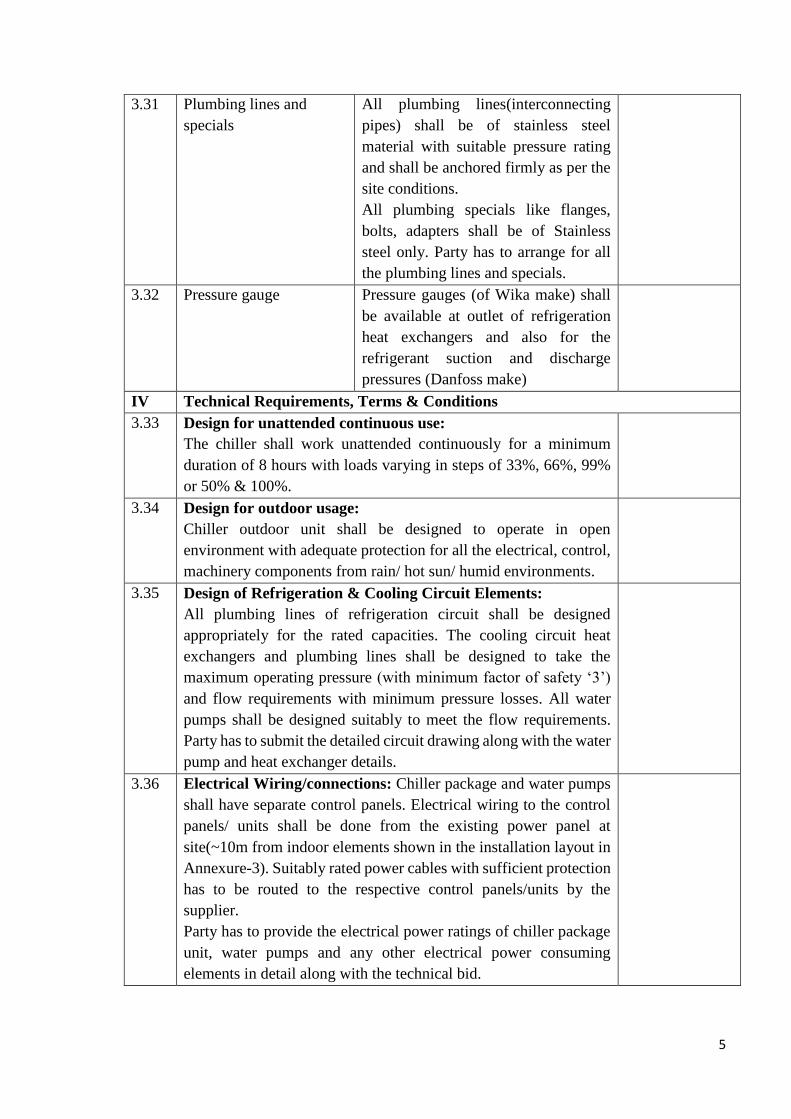
3.31 Plumbing lines and
specials
All plumbing lines(interconnecting
pipes) shall be of stainless steel
material with suitable pressure rating
and shall be anchored firmly as per the
site conditions.
All plumbing specials like flanges,
bolts, adapters shall be of Stainless
steel only. Party has to arrange for all
the plumbing lines and specials.
3.32 Pressure gauge Pressure gauges (of Wika make) shall
be available at outlet of refrigeration
heat exchangers and also for the
refrigerant suction and discharge
pressures (Danfoss make)
IV Technical Requirements, Terms & Conditions
3.33 Design for unattended continuous use:
The chiller shall work unattended continuously for a minimum
duration of 8 hours with loads varying in steps of 33%, 66%, 99%
or 50% & 100%.
3.34 Design for outdoor usage:
Chiller outdoor unit shall be designed to operate in open
environment with adequate protection for all the electrical, control,
machinery components from rain/ hot sun/ humid environments.
3.35 Design of Refrigeration & Cooling Circuit Elements:
All plumbing lines of refrigeration circuit shall be designed
appropriately for the rated capacities. The cooling circuit heat
exchangers and plumbing lines shall be designed to take the
maximum operating pressure (with minimum factor of safety ‘3’)
and flow requirements with minimum pressure losses. All water
pumps shall be designed suitably to meet the flow requirements.
Party has to submit the detailed circuit drawing along with the water
pump and heat exchanger details.
3.36 Electrical Wiring/connections: Chiller package and water pumps
shall have separate control panels. Electrical wiring to the control
panels/ units shall be done from the existing power panel at
site(~10m from indoor elements shown in the installation layout in
Annexure-3). Suitably rated power cables with sufficient protection
has to be routed to the respective control panels/units by the
supplier.
Party has to provide the electrical power ratings of chiller package
unit, water pumps and any other electrical power consuming
elements in detail along with the technical bid.
6
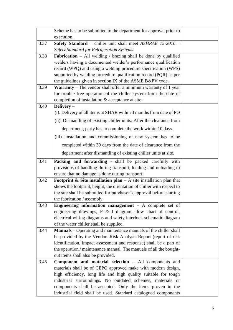
Scheme has to be submitted to the department for approval prior to
execution.
3.37 Safety Standard – chiller unit shall meet ASHRAE 15-2016 –
Safety Standard for Refrigeration Systems.
3.38 Fabrication – All welding / brazing shall be done by qualified
welders having a documented welder’s performance qualification
record (WPQ) and using a welding procedure specification (WPS)
supported by welding procedure qualification record (PQR) as per
the guidelines given in section IX of the ASME B&PV code.
3.39 Warranty – The vendor shall offer a minimum warranty of 1 year
for trouble free operation of the chiller system from the date of
completion of installation & acceptance at site.
3.40 Delivery –
(i). Delivery of all items at SHAR within 3 months from date of PO
(ii). Dismantling of existing chiller units: After the clearance from
department, party has to complete the work within 10 days.
(iii). Installation and commissioning of new system has to be
completed within 30 days from the date of clearance from the
department after dismantling of existing chiller units at site.
3.41 Packing and forwarding - shall be packed carefully with
provisions of handling during transport, loading and unloading to
ensure that no damage is done during transport.
3.42 Footprint & Site installation plan – A site installation plan that
shows the footprint, height, the orientation of chiller with respect to
the site shall be submitted for purchaser’s approval before starting
the fabrication / assembly.
3.43 Engineering information management – A complete set of
engineering drawings, P & I diagram, flow chart of control,
electrical wiring diagrams and safety interlock schematic diagram
of the water chiller shall be supplied.
3.44 Manuals – Operating and maintenance manuals of the chiller shall
be provided by the Vendor. Risk Analysis Report (report of risk
identification, impact assessment and response) shall be a part of
the operation / maintenance manual. The manuals of all the bought-
out items shall also be provided.
3.45 Component and material selection – All components and
materials shall be of CEPO approved make with modern design,
high efficiency, long life and high quality suitable for tough
industrial surroundings. No outdated schemes, materials or
components shall be accepted. Only the items proven in the
industrial field shall be used. Standard catalogued components
7
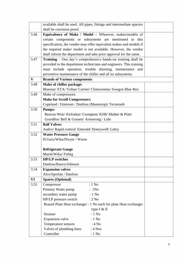
available shall be used. All pipes, fittings and intermediate spacers
shall be corrosion proof.
3.46 Equivalence of Make / Model – Wherever, makes/models of
certain components or subsystems are mentioned in this
specification, the vendor may offer equivalent makes and models if
the required make/ model is not available. However, the vendor
shall inform the department and take prior approval for the same.
3.47 Training – One day’s comprehensive hands-on training shall be
provided to the department technicians and engineers. This training
must include operation, trouble shooting, maintenance and
preventive maintenance of the chiller and all its subsystems.
V Brands of Various components
3.48 Make of chiller package:
Bluestar/ ETA/ Voltas/ Carrier/ Climaveneta/ Swegon Blue Box
3.49 Make of compressors:
Make for Scroll Compressors:
Copeland / Emerson / Danfoss (Maneurop)/ Tecumseh
3.50 Pumps:
Beacon Weir/ Kirloskar/ Crompton/ KSB/ Mather & Platt/
Grundfos/ Bell & Gossett/ Armstrong / Lubi
3.51 Ball Valves:
Audco/ Rapid control/ Emerald/ Honeywell/ Lehry
3.52 Water Pressure Gauge
H.Guru/Wika/Dwyer / Waree
Refrigerant Gauge
Marsh/Wika/ Fiebig
3.53 HP/LP switches
Danfoss/Ranco/Johnson
3.54 Expansion valves
Alco/Sporlan / Danfoss
VI Spares (Optional)
3.55 Compressor : 1 No
Primary Water pump : 1No
secondary water pump : 1 No
HP/LP pressure switch : 2 No
Brazed Plate Heat exchanger : 1 No each for plate Heat exchanger
type-I & II
Strainer : 1 No
Expansion valve : 1 No
Temperature sensors : 4 No
Valves of plumbing lines : 4 Nos
Controller : 1 No
8
Note: Party has to submit the budgetary offer for each of the above
spare components separately
VII Bill of Materials
3.56
Chiller package (including controller)– 1 no
Primary water pumps – 2nos
Secondary water pumps – 2nos
Water tanks (Hot & cold well with partition) – 1 no
Required Piping, valves and plumbing specials – 1 set
Base support structure for chiller – 1no
Base support structure for water tanks – 1no
Base support structure for plate heat exchangers – 1no
Galvanized iron sheets roof with structural support– 1 lot
RTD temperature meter- 1 no
Non-contact IR thermometer (Fluke 62Max+) – 1 no
4. Price Bid Format:
Sl.No. Item Price (Rs)
1 Chiller Unit along with pumping system, heat exchangers
and base support structures as per the bill of materials
2 Dismantling of existing chiller units (2 nos)
3 Installation and commissioning of new chiller system
4 Spares as per section 3
5 Payment terms:
70% of sl.no.1 against delivery of all items to SDSC SHAR
as per the bill of material in section 3.
Balance 30% of sl.no.1 and 100% of sl.no.2 to 4 after
installation & commissioning of the new chiller unit.
Complied/not
complied
5. Terms & Conditions:
This is a two part tender with Part-A: technical bid and Part-B: price bid. Part-A
should consists of technical specifications of the system offered and compliance
statement to the tender specifications in Section 3. It should not consists of any price
information. However, party has to submit an unpriced price bid format (section 4)
9
with ‘quoted in price bid’ against each column to ensure the required price
information is available in price bid.
Party has to provide the price break-up in Part-B, for the equipment, dismantling of
existing system, installation of new system and spares separately as per the format
given in section 4.
Delivery Terms:
(i). Delivery of all items at SHAR within 3 months from date of PO
(ii). Dismantling of existing chiller units: After the clearance from
department, party has to complete the work within 10 days.
(iii). Installation and commissioning of new system within 30 days from the date
of clearance from the department.
It is advised that party may visit the site to understand the site conditions and system.
Party has to ensure the safety of operating team deployed at site during the complete period
of work.
6. Department scope during Dis-assembly of Old Chillers and Installation of New Chiller:
Electrical power required for removal of old chillers & installation of new chiller
Material handling support for lifting and repositioning of equipment
Minor civil works such as levelling of the floor.
7. Party’s scope during installation:
Nitrogen gas, brazing set, refrigerant and any other oils/ required for the installation.
Wall mounting of panels and drilling in the walls/floor for fixing of base frame, etc.
Painting of all base frames and support structures using zinc rich primer and paint.
Installation & commissioning of the new system satisfactorily as per the site acceptance
plan.
10
8. Water Tank & Support Structures:
Fig 1. Water tanks with support structure
Fig 2. Configuration of water tanks
1 m
11
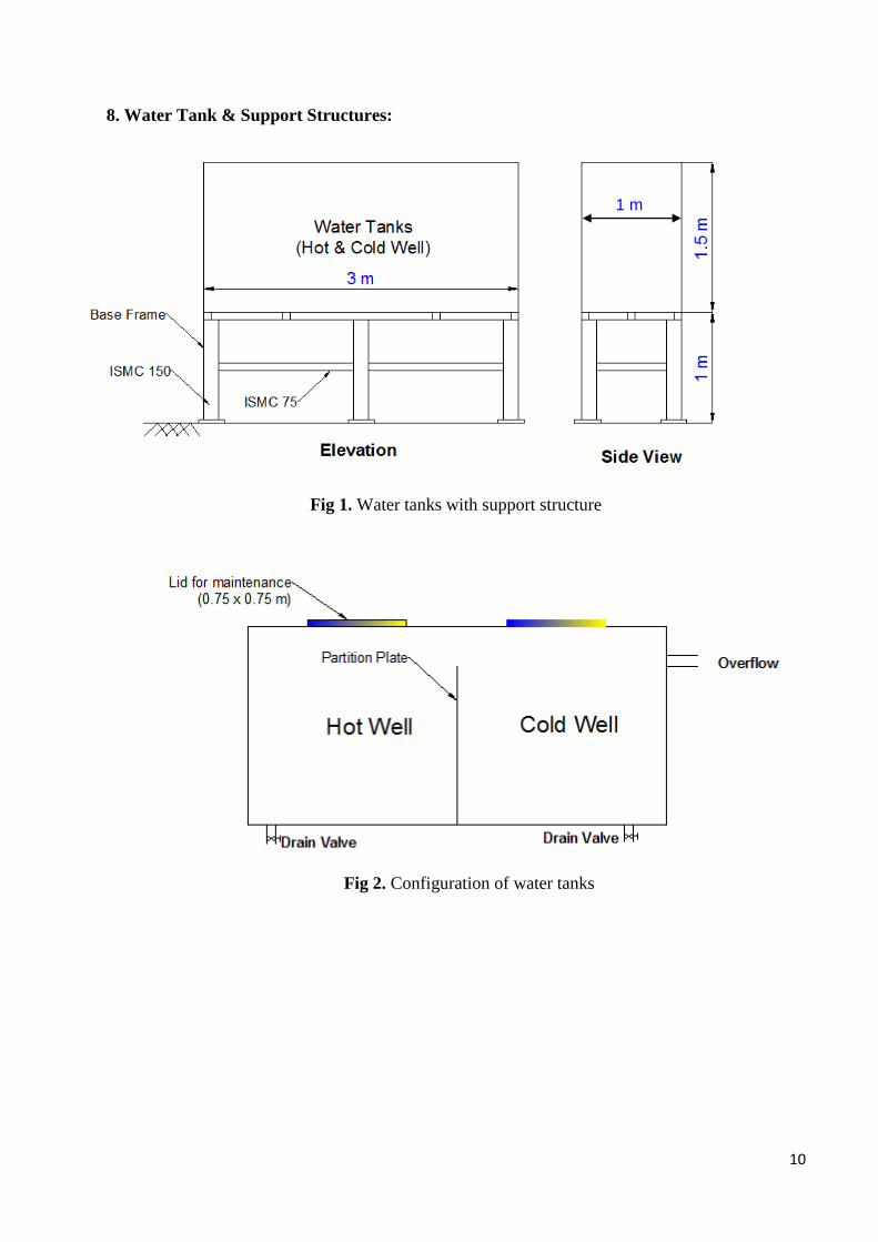
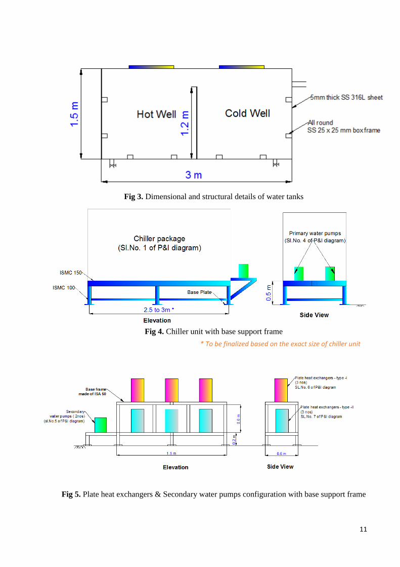
Fig 3. Dimensional and structural details of water tanks
Fig 4. Chiller unit with base support frame
Fig 5. Plate heat exchangers & Secondary water pumps configuration with base support frame
* To be finalized based on the exact size of chiller unit
12
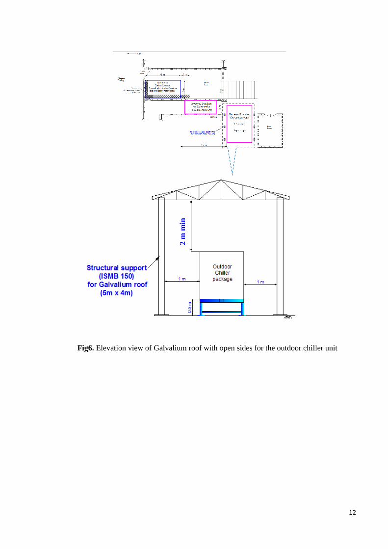
Fig6. Elevation view of Galvalium roof with open sides for the outdoor chiller unit
2 m
min
13
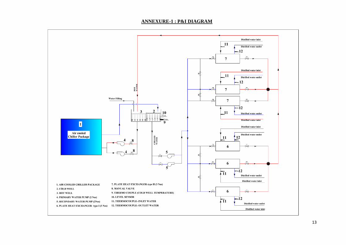
ANNEXURE-1 : P&I DIAGRAM
14
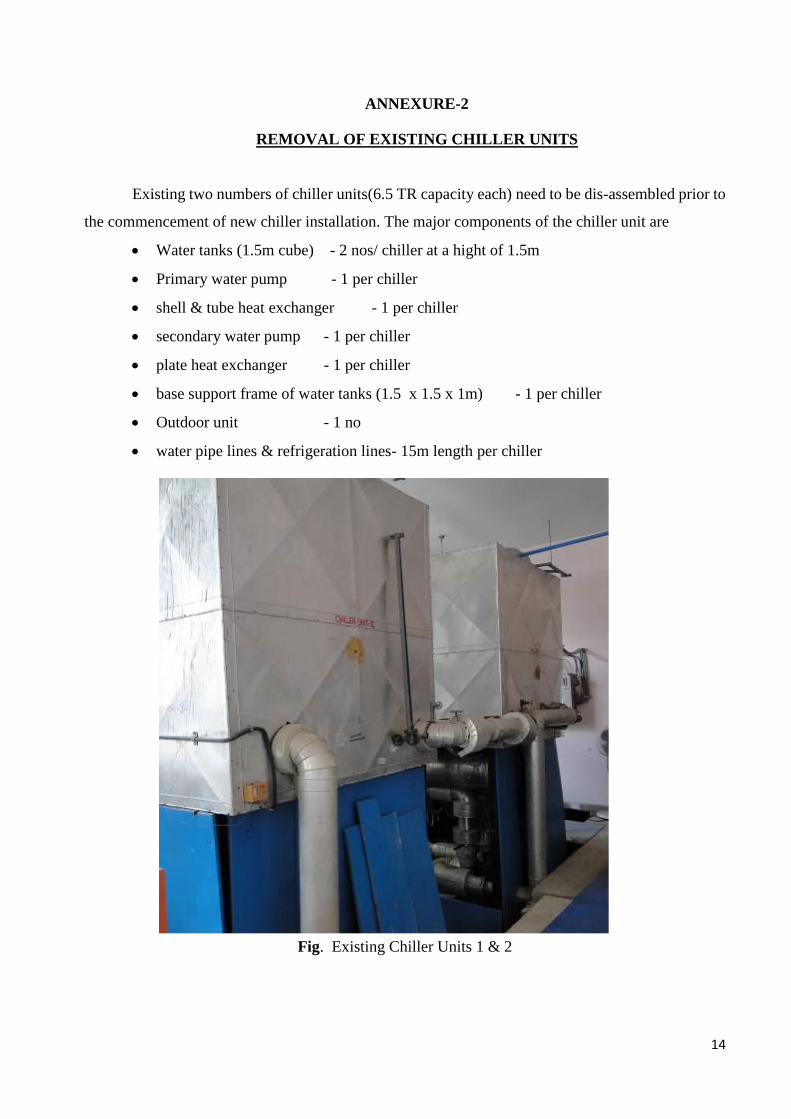
ANNEXURE-2
REMOVAL OF EXISTING CHILLER UNITS
Existing two numbers of chiller units(6.5 TR capacity each) need to be dis-assembled prior to
the commencement of new chiller installation. The major components of the chiller unit are
Water tanks (1.5m cube) - 2 nos/ chiller at a hight of 1.5m
Primary water pump - 1 per chiller
shell & tube heat exchanger - 1 per chiller
secondary water pump - 1 per chiller
plate heat exchanger - 1 per chiller
base support frame of water tanks (1.5 x 1.5 x 1m) - 1 per chiller
Outdoor unit - 1 no
water pipe lines & refrigeration lines- 15m length per chiller
Fig. Existing Chiller Units 1 & 2
15
ANNEXURE-3
INSTALLATION & COMMISSIONING OF NEW CHILLER UNIT
1. Civil Levelling Works Prior to Installation:
After removal of the existing chiller units, the site has to be levelled. This minor civil work
will be performed by the department and installation of the new chiller unit has to be commenced
subsequently by the supplier.
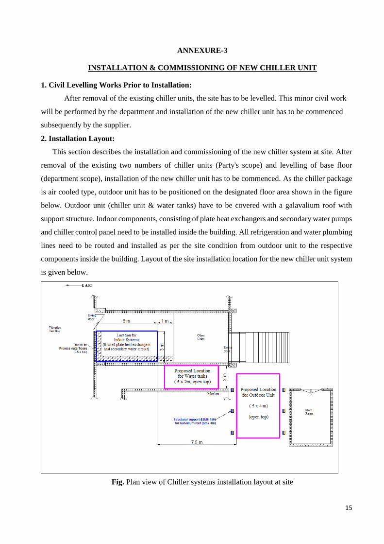
2. Installation Layout:
This section describes the installation and commissioning of the new chiller system at site. After
removal of the existing two numbers of chiller units (Party's scope) and levelling of base floor
(department scope), installation of the new chiller unit has to be commenced. As the chiller package
is air cooled type, outdoor unit has to be positioned on the designated floor area shown in the figure
below. Outdoor unit (chiller unit & water tanks) have to be covered with a galavalium roof with
support structure. Indoor components, consisting of plate heat exchangers and secondary water pumps
and chiller control panel need to be installed inside the building. All refrigeration and water plumbing
lines need to be routed and installed as per the site condition from outdoor unit to the respective
components inside the building. Layout of the site installation location for the new chiller unit system
is given below.
Fig. Plan view of Chiller systems installation layout at site
16
1.2 Mounting of Outdoor Unit:
Outdoor unit has to be mounted on a heavy base frame with suitable vibration isolators. All
elements need to be painted with zinc rich primer and paint to avoid corrosion in compliance with
coastal environment usage. All electrical & control terminal connections on the outdoor unit shall be
properly insulated and compatible for outdoor usage. Structural galvalium roof has to be made for
the outdoor unit with a span of 5m x 3m by keeping minimum 2m clearance on top of the unit for air
circulation to the condenser fans.
1.3 Mounting of Water Tanks:
Water tanks (Cold & hot wells) have to be mounted on heavy base structure with proper insulation.
Both water tanks shall have level switch fitted to suitable levels and shall be linked to controller
display for identifying the interlock. Water tank inlet top-up water line shall be fitted with floats and
tank shall have a man hole entry and drain plugs for cleaning as shown in the figure 1 to 3.
1.4 Refrigeration Circuit Water Pumps:
Refrigerant charging shall be done to all the compressors to the required pressures using the
standard procedure.
Water pumps in the refrigeration circuit shall be installed indoor on suitable pedestals. Water
lines of the pump suction & delivery shall be properly insulated and anchored.
1.5 Cooling Circuit Installation:
All cooling circuit elements shall be installed in-doors.
Water pumps of the cooling (or secondary) circuit shall be installed on suitable pedestals
and all plate heat exchangers need to be installed neatly and in organized manner and
shall be anchored to the base frame firmly.
All water plumbing lines shall be routed properly for minimum pressure losses.
Inter-connecting lines between heat exchangers shall be properly routed for ease of
operation. Proper space and provision shall be provided for connecting and disconnecting
the process water lines easily.
Water tanks (cold & hot well) shall be installed on a heavy base structure and shall be
anchored firmly. Water lines shall be adequately sized for meeting the requirements
stipulated in the specifications. All water lines also shall be properly anchored to support
structure.
17
1.6 Control Connections:
Wiring of all control elements shall be routed professionally with labels on both ends for easy
identification.
1.7 Electrical Power Connections:
Electrical power connections to the supplied unit from the distribution panel situated within
10m from control panel is the responsibility of the party. Chiller unit and water pumps operation
control panel shall be separate. Party has to carry out the electrical wiring as per the standard
procedures with reputed brand power cables suitable for outdoor use and shall be routed,
anchored/covered suiting to the site condition.
18
Annexure-4
Site Acceptance Tests
1. Preliminary Tests:
1.1 Plumbing Connections:
Complete all the plumb line connections as per the P&I diagram.
Ensure suitable insulation is provided for all the plumbing lines and properly anchored
1.2 Control Line Connections:
Carry out all the control line connections as required according to the P&I diagram
1.3 Pressure leak test:
All the refrigerant lines to be verified for both vacuum and positive pressure if any
customization is done on the standard chiller package unit.
Vacuum leak test:
Vacuum leak test on all the refrigerant piping has to be performed using a vacuum
pump
Run the vacuum pump for a duration of 2 to 3 hours to remove all the gases and
moisture trapped in the tubing.
Close the vacuuming valve and angle valves of compressor and hold it for a duration
of minimum 4 hours and ensure that the pressure leak in the line is <500 microns. If
yes, the vacuum leak test is done. If no, then there is a leak which has to be rectified
and re-vacuuming has to be done once again.
Pressure Test of Plumbing Lines:
All plumbing lines shall be pressure tested with nitrogen gas to the 1.1 times the
maximum operating pressure and demonstrate the leak tightness of all the joints.
Maximum deviation in pressure shall be less than 2 to 3 psi.
Check all the joints with snoop solution and ensure the leak tightness
Party has to arrange for the necessary items required for the pressure test.
1.4 Chiller Unit Runs:
Check whether the interlocks are functioning normally and system is shutting down
smoothly by simulating each interlock.
19
Run the chiller unit and record all the currents of compressors (at no load and full load)
and water pumps
Run the chiller and record whether the cut-off and cut-in are happening as per the setting
Run the chiller and note down the time needed for cooling the water tank (with full water)
to cut-off temperature with all compressors and reduced number of compressors. Also,
record the ambient temperature and humidity.
S a t i sh Dhawan Spac e Cen t e r SHAR S a t i sh Dhawan Spac e Cen t e r SHAR S a t i sh Dhawan Spac e Cen t e r SHAR S a t i sh Dhawan Spac e Cen t e r SHAR
Welcome, Materials Master (isro)31 August 2017,
17:16:08 IST
MAIN VIEW HELP
Preview For STANDARD TERMS AND CONDITIONS
Page Destination: Tender Header Format Type : Normal
. :
GOVERNMENT OF INDIA
DEPARTMENT OF SPACE
SATISH DHAWAN SPACE CENTRE
PURCHASE DIVISION
Tele No.08623-225023/225174/225127 Fax No.08623-225170/22-5028 e-Mail ID : [email protected], [email protected], [email protected]
STANDARD TERMS & CONDITIONS
1.OFFERS SHALL BE SENT ONLINE ONLY USING STANDARD DIGITAL SIGNATURE CERTIFICATE OF CLASS III WITH ENCRYPTION / DECRYPTION. THE TENDERS AUTHORISED ONLINE ON OR BEFORE THE OPEN AUTHORISATION DATE AND TIME ONLY WILL BE CONSIDERED AS VALID TENDERS EVEN THOUGH THE BIDS ARE SUBMITTED ONLINE.
2.THE TENDERER MUST AUTHORISE BID OPENING WITHIN THE TIME STIPULATED IN THE SCHEDULE BY SDSC SHAR. OTHERWISE THE ONLINE BID SUBMITTED WILL NOT BE CONSIDERED FOR EVALUATION. PHYSICAL COPY WILL NOT BE CONSIDERED EVEN THOUGH IT IS RECEIVED BEFORE THE BID SUBMISSION DATE. In case of two-part tenders, parties shall submit their offers as follows:-
1) Part-I – Techno-commercial Bid (No price details shall be mentioned in this bid and shall not upload the details of price along with the techno-commercial bid) 2) Part-II – Price Bid
In view of Two Part Tender, the Offers submitted contrary to above instructions will be summarily rejected. 3.In case, the tenderer is not interested to participate in the tender, the tenderer shall submit regret letter giving reasons, failing which future enquiries will not be sent. 4.Offer Validity: The validity of the offers / tenders should be 90 days (in case of single part tender) and 120 days (in case two part
tender) from the date of opening of the tenders. Tenders with offer validity less than the period mentioned above, will not be considered for evaluation. 5.GST - GST and/or other duties/levies legally leviable and intended to be claimed should be distinctly shown separately in the tender. GST details are given below
GSTIN: 37AAAGS1366J1Z1 LEGAL NAME : SATISH DHAWAN SPACE CENTRE SHAR VALIDITY FROM:29/08/2017
TYPE OF REGISTRATION:REGULAR 6.Customs Duty - SDSC-SHAR is eligible for 100% Customs Duty exemption as per Notification No. 050/2017 539 (b) Dt: 30.06.2017.
This may be taken into account while quoting for import items, if any. In case tenderers offering items considering customs duty exemption, they should also indicate the bill of materials and price, separately, with Customs Duty component and terms and conditions thereto. 8.Advance Payment - Wherever advance payment is requested, Bank Guarantee from any Nationalized Bank/Scheduled Bank should be
furnished. In case of advance payments, if the party is not supplying the material within the delivery schedule, interest will be levied as per the Prime Lending Rate of RBI plus 2% penal interest. Interest will be loaded for advance payments/stage payments as per the prime lending rate of RBI and will be added to the landed cost for comparison purpose. In case of different milestone payments submitted by the parties, a standard and transparent methodology like NPV will be adopted for evaluating the offers.
9.Liquidated Damages - In all cases, delivery schedule indicated in the Purchase Order/Contract is the essence of the contract and if the party fails to deliver the material within the delivery schedule, Liquidated Damages will be levied @ 0.5% per week or part thereof subject to a maximum of 10% of total order value. 10.Performance Bank Guarantee - Performance Bank Guarantee for 10% of the order value should be furnished in the form of Bank
Guarantee from nationalized/scheduled bank or by Demand Draft valid till warranty period plus sixty days as claim period.
Page 1 of 3
11.Security Deposit – Security Deposit for 10% of the order value is mandatory, if the ordered value is Rs.5.00 lakhs and above. Party shall furnish the Security Deposit in the form of Bank Guarantee from nationalized/scheduled bank or by Demand Draft valid till
completion of the contract period plus sixty days towards claim period for faithful execution of the contract. 12.BANK GUARANTEE FOR FIM: Supplier has to submit Bank guarantee for equal value of Free Issue of Materials (FIM) issued by the Department from Nationalised / Scheduled Bank valid till receipt and acceptance of supply and satisfactory accounting of FIM plus sixty days as claim period.
13.The delivery period mentioned in the tender enquiry, IF ANY, is with the stipulation that no credit will be given for earlier deliveries and offers with delivery beyond the period will be treated as unresponsive. 14.The Department will have the option to consider more than one source of supply and final orders will be given accordingly.
15.The bidders should note that conditional discounts would not have edge in the evaluation process of tenders. 16.Non-acceptance of any conditions wherever called for related to Guarantee/ Warranty, Performance Bank Guarantee, Security Deposit, Liquidated damages are liable for disqualification. 17.Wherever installation/ commissioning involved, the guarantee/warrantee period shall reckon only from the date of installation and
commissioning. 18.Purchase/Price Preference will be extended to the MSMEs under the Public Procurement Policy for MSMEs formulated under the Micro, Small and Medium Enterprises Development Act, 2006 and instructions issued by Government of India from time to time. Vendors who would like to avail the benefit of MSME should clearly mention the same and submit all the documentary evidences to substantiate their claim along with tender itself.
19.The drawings, specifications, end use etc., given by the Centre/Unit along with the tender enquiry are confidential and shall not be disclosed to any third party. 20.SPECIAL CONDITIONS FOR SUBMITTING QUOTATIONS IN FOREIGN CURRENCY BY THE INDIAN AGENTS
The Tenderer should submit the following documents/information while quoting:- a)Foreign Principal's proforma invoice/quote indicating the commission payable to the Indian Agent and nature of after sales service to be rendered by the Indian Agent. b)Copy of Agency agreement with the Foreign Principal and the Indian Agent, precise relationship between them and their mutual
interest in the business. c)Registration and item empanelment of the Indian Agent. d)Agency Commission will be paid only Indian Currency.
e)Compliance of the tax laws by the Indian Agent. 21. High Sea Sales- Against High Sea Sale transactions: a.Offers shall be on all inclusive basis including delivery upto Sriharikota at the risk and cost of the supplier. Customs Clearance is the responsibility of the supplier and at his cost and risk.
b.100% payment will be made within 30 days after receipt and acceptance of the items at our site. c. GST as applicable d.Customs Duty Exemption Certificate and other relevant documents required for Customs clearance will be provided.
e.High Sea Sales Agreement furnished by the supplier in accordance with the terms and conditions of our purchase order will be signed and issued by SDSC-SHAR. 22.The following information/ documents are to be submitted wherever applicable.
1.Product Literature 2.Core banking account number of SBI, RTGS Details 3.PAN No. in quotation and invoices
4.GST Registration details. 5.In case of MSME, registration details / documents from Competent Authority. 23.EXCLUSION OF TENDERS
The following tenders shall be summarily rejected from the procurement process a.Tenders received from vendors who have not qualified in terms of their registration. b.Tenders received against publishing of a limited tender in the CPP portal.
c.Tenders of vendors who have been removed from the vendor list or banned/debarred from having business dealings. d.Unsolicited tenders from vendors. e.The tenders which materially depart from the requirements specified in the tender document or which contain false information.
f.The tenders which are not accompanied by the prescribed Earnest Money Deposit. g.The tenders of vendors who have not agreed to furnish Security Deposit, Performance Bank Guarantee and Liquidated Damages. h.The validity of the tenders is shorter than the period specified in the tender enquiry.
i.The tenders received from vendors or their agents or anyone acting on their behalf, who have promised or given to any official of the Centre/Unit/Department, a gratification in any form, or anything of value, so as to unduly influence the procurement process. j.The tenders received from vendors, who, in the opinion of the Centre/Unit, have a conflict of interest materially affecting fair competition.
Page 2 of 3

k.The tenders received from Indian agents on behalf of their foreign Principals/OEMs (in cases where the Principals/OEMs also submit their tenders simultaneously for the same item/product in the same tender).
l.In case two or more tenders are received from an Indian agent on behalf of more than one foreign Principal/OEM, in the same tender for the same item/product. m.If a firm quotes ‘NIL’ charges / consideration, the bid shall be treated as un-responsive and will not be considered.
Page 3 of 3