specification for oil and gas separators - petroleum courses
TRANSCRIPT
Specification for Oil and Gas Separators
API SPECIFICATION 12J (SPEC 12J) SEVENTH EDITION, OCTOBER 1,1989
American Petroleum Institute 1220 L Street, Northwest Washington, DC 20005 11'
COPYRIGHT American Petroleum InstituteLicensed by Information Handling ServicesCOPYRIGHT American Petroleum InstituteLicensed by Information Handling Services
Issued by AMERICAN PETROLEUM INSTITUTE
Production Department
FOR INFORMATION CONCERNING TECHNICAL CONTENTS OF THIS PUBLICATION CONTACT THE API PRODUCTION DEPARTMENT,
SEE BACK SIDE FOR INFORMATION CONCERNING HOWTO OBTAIN ADDITIONAL COPIES OF THIS PUBLICATION.
2535 ONE MAIN PLACE, DALLAS, TX 75202-3904 - (214) 748-3841.
Users of this publication should become familiar with its scope and content, including any provisions it may have regarding marking of
manufactured products. This document is intended to supplement rather than replace individual engineering judgment.
OFFICIAL PUBLICATION
REG. U S . PATENT OFFICE
Copyright @ 1989 American Petroleum Institute
COPYRIGHT American Petroleum InstituteLicensed by Information Handling ServicesCOPYRIGHT American Petroleum InstituteLicensed by Information Handling Services

Page Foreword.. .......................................................... 2 Policy ............................................................... 3 Section 1: Scope ..................................................... 4 Section 2: Definitions ................................................ 4 Section 3: Material .................................................. 5 Section 4: Design .................................................... 5 Section 5: Fabrication, Testing, and Painting.. ........................ 6 Section 6: Marking .................................................. 7 Section 7: Inspection and Rejection ................................... 8 Appendix A: Process Considerations .................................. 8 Appendix B: Corrosion Guidelines .................................... 12 Appendix C: Design and Sizing Calculations .......................... 13
Appendix E: Separator Design Information ........................... 16 Appendix F: Use of Monogram ....................................... 18
Appendix D: Separator Sizing Example Calculation . . . . . . . . . . . . . . . . . . . 15
FOREWORD a. This specification is under the jurisdiction of the
API Committee on Standardization of Production Equip- ment.
Attention Users of this Publication: Portions of this publication have been changed from the previous edi- tion. The location of changes has been marked with a bar in the margin. In some cases the changes are signif- icant, while in other cases the changes reflect minor editorial adjustments. The bar notations in the margins are provided as an aid to users to identify those parts of this publication that have been changed from the pre- vious edition, but API makes no warranty as to the accuracy of such bar notations.
NOTE: This edition supersedes the sixth edition, and Requests for permission to reproduce or translate all includes revisions approved at the 1988 Standardization or any part of the material published herein should be Conference as reported in Circ PS-1858 and subse- addressed to the Director, American Petroleum Institute, quently approved by letter ballot. Production Department, 2535 One Main Place, Dallas
TX 75202.
COPYRIGHT American Petroleum InstituteLicensed by Information Handling ServicesCOPYRIGHT American Petroleum InstituteLicensed by Information Handling Services
Spec 12J: Oil Gas Separators 3
POLICY
API PUBLICATIONS NECESSARILY ADDRESS PROBLEMS OF A GENERAL NATURE. WITH RESPECT TO PARTICULAR CIRCUMSTANCES,
ULATIONS SHOULD BE REVIEWED. LOCAL, STATE AND FEDERAL LAWS AND REG-
API IS NOT UNDERTAKING TO MEET DUTIES
PLIERS TO WARN AND PROPERLY TRAIN AND
POSED, CONCERNING HEALTH AND SAFETY RISKS AND PRECAUTIONS, NOR UNDERTAKING THEIR OBLIGATIONS UNDER LOCAL, STATE, OR FEDERAL LAWS.
O F EMPLOYERS, MANUFACTURERS OR SUP-
EQUIP THEIR EMPLOYEES, AND OTHERS EX-
NOTHING CONTAINED IN ANY API PUBLICA- TION IS TO B E CONSTRUED AS GRANTING ANY RIGHT, BY IMPLICATION OR OTHERWISE, FOR THE MANUFACTURE, SALE, OR USE OF ANY METHOD, APPARATUS, OR PRODUCT COVERED BY LETTERS PATENT. NEITHER SHOULD ANY-
THING CONTAINED IN THE PUBLICATION BE . CONSTRUED AS INSURING ANYONE AGAINST LIABILITY FOR INFRINGEMENT OF LETTERS PATENT.
GENERALLY, API STANDARDS ARE REVIEWED AND REVISED, REAFFIRMED, OR WITHDRAWN AT LEAST EVERY FIVE YEARS. SOMETIMES A
WILL BE ADDED TO THIS REVIEW CYCLE. THIS PUBLICATION WILL NO LONGER BE IN EFFECT FIVE YEARS AFTER ITS PUBLICATION DATE AS AN OPERATIVE API STANDARD OR, WHERE AN EXTENSION HAS BEEN GRANTED, UPON REPUBLICATION. STATUS OF THE PUBLICATION
ONE-TIME EXTENSION OF UP TO TWO YEARS
CAN BE ASCERTAINED FROM THE API AUTHOR- ING DEPARTMENT (TEL. 214-748-3841). A CATALOG OF API PUBLICATIONS AND MATERIALS IS
TERLY BY API, 1220 L ST., N.W., WASHINGTON, D.G. 20005.
PUBLISHED ANNUALLY AND UPDATED QUAR-
COPYRIGHT American Petroleum InstituteLicensed by Information Handling ServicesCOPYRIGHT American Petroleum InstituteLicensed by Information Handling Services
SPEC L2J-B7 1 0732270 0071047 5
4 American Petroleum Institute
SECTION 1 SCOPE
1.1 Coverage. This specification covers minimum requirements for the design, fabrication, and shop test- ing of oilfield type oil and gas separators and/or oil-gas- water separators used in the production of oil and/or gas, and usually located but not limited to some point on the producing flowline between the wellhead and pipeline. Separators covered by this specification may be vertical, spherical, or single or double barrel hori- zontal. Unless otherwise agreed upon between the pur- chaser and the manufacturer, the jurisdiction of this specification terminates with the pressure vessel as defined in the Scope of Section VIII, Division 1 of the ASME Boiler and Presswe Vessel Code', hereinafter referred to as the ASME Code. Pressure vessels covered by this specification are normally classified as natural resource vessels by API 510 Pressure Vessel Inspection Code? Separators outside the scope of this specification include centrifugal separators, filter separators, and desanding separators.
1.2 American Petroleum Institute (API) Specifica- tions are published as aids to the procurement of stand- ardized equipment and materials, as well as instruc- tions to manufacturers of equipment or materials
'Available from the American Society of Mechanical Engineers, 345 East 47th Street, New York, New York 10017.
*Available from American Petroleum Institute, 1220 L Street, N.W., Washington. D.C. 20005.
covered by an API Specification. These Specifications are not intended to obviate the need for sound engineer- ing, nor to inhibit in any way anyone from purchasing or producing products to other specifications.
1.3 The formulation and publication of API Specifi- cations and the API monogram program is not intended in any way to inhibit the purchase of products from companies not licensed to use the API monogram.
1.4 API Specifications may be used by anyone desir- ing to do so, and diligent effort has been made by the Institute to assure the accuracy and reliability of the data contained therein. However, the Institute makes no representation, warranty, or guarantee in connection with the publication of any API Specification and hereby expressly disclaims any liability or responsibility for loss or damage resulting from i t s use, for any violation of any federal, state, or municipal regulation with which an API Specification may conflict, or for the infringement of any patent resulting from the use of an API Specification.
1.5 Any manufacturer producing equipment or mate- rials represented as conforming with an API Specifica- tion is responsible for complying with all the provisions of that Specification. The American Petroleum Institute does not represent, warrant or guarantee that such prod- ucts do in fact conform to the applicable API standard or specification.
SECTION 2 DEFINITIONS
2.1 Introduction. The separation of gas and liquids primarily relies on physical differences in the phases. This section covers mechanical separation of liquids and gases.
2.2 Terminology. A separator vessel may be re- ferred to as a knockout, trap, scrubber, flash chamber, or expansion vessel as well as the original term. This terminology is applied regardless of shape. Generally, the following definitions are regarded as basic:
2.2.1 Separator - A separator is a vessel used in the field to remove wellstream liquid(s) from gas components. The separator may be either two-phase or three-phase. Two- phase separators remove the total liquid from the gas, while three-phase separators also remove free water from the hydrocar- bon liquid.
2.2.2 Scrubber - A scrubber is a type of sepa- rator which has been designed to handle flow streams with unusually high gas-to- liquid ratios. These are commonly used in conjunction with dehydrators, extraction plants, instruments, or compressors for pro- tection from entrained liquids.
2.2.3 Knockout - A knockout is a type of separator which falls into one of two cate- gories: free water and total liquid knock- outs.
a. The free water knockout is a vessel used to separate free water from a flow stream of gas, oil, and water. The gas and oil usually leave the vessel through the same outlet to be processed by other equipment. The water is removed for disposal.
0873 c- 1
COPYRIGHT American Petroleum InstituteLicensed by Information Handling ServicesCOPYRIGHT American Petroleum InstituteLicensed by Information Handling Services

Spec 12J: Oil Gas Separators 5
b. The total liquid knockout is normally used to remove the combined liquids from a gas stream.
. 2.3 Maximum Allowable Working Pressure - The maximum allowable working pressure (MAWP) is the maximum pressure, permissible by the ASME Code, at the top of the separator in its normal operating position for a designated temperature.
2.4 Operat ing Pressure - The operating pressure is the pressure in the vessel during normal operation. The operating pressure shall not exceed the MAWP, and is usually kept at a suitable level below the setting of the pressure relieving devices to prevent their fre- quent opening. (See Appendix A.)
2.5 Corrosion. Corrosion is defined as the destruc- tion of a metal by chemical or electrochemical reaction with its environment. (See Appendix B.)
SECTION 3 MATERIAL
3.1 ASME Code. Separators furnished to this speci- fication shall conform to the material requirements stipulated in the latest edition of the ASME Code.
3.2 Material selection for corrosive fluids should be selected based on a review of related API or NACE publications for materials that conform to Paragraph 3.1. Consideration should be given to material selection as it relates to weight loss, sulphide stress cracking, chloride stress cracking, or otherforms of corrosion. It is the responsibility of the user to determine what consid- eration for corrosion should be made to the vessel dur-
ing i t s intended life. (Reference ASME Code, as appli- cable to corrosion.) Corrosion guidelines are given in I Appendix B.
3.3 Corrosion consideration for separators furnished to this specification shall be for the pressure containing parts of the vessel onlg, and as can be identified as fall- ing within the requirements of the applicable sections of the ASME Code. Corrosion considerations for vessel internals (non-pressure parts) is by mutual agreement between the purchaser and the manufacturer and not a part of this specification.
SECTION 4 DESIGN
4.1 Type, Size, Pressure and Tempera ture Rat - 4.2 Typical Process Design and Sizing Calculations ings - Separators furnished to this specification may be vertical, horizontal, or spherical, and are available in
are given in Appendix C.
sizes and maximum allowable working pressure ratings shown in Tables 4.1, 4.2, and 4.3. The following tables mation is
I 4.3 A suggested checklist of separator design infor- in Appendix E.
are for nominal industry standards. Available sizes and working pressures may vary from the stated ratings. Other sizes, pressure, and temperature ratings may be furnished by agreement between purchaser and manu- facturer.
4.4 Appendix D gives an example calculation for separator sizing.
TABLE 4.1 HORIZONTAL SEPARATORS
SIZE AND WORKING PRESSURE RATINGS
Nominal Diameter, Inches
Maximum Allowable Working Pressure, PSIG @ 130°F. I A r ,
12% ... 230 600 1000 1200 1440 2000 16 ... 230 600 1000 1200 1440 2000 20 125 230 600 1000 1200 1440 2000 24 125 230 600 1000 1200 1440 2000 30 125 230 600 1000 1200 1440 2000 36 125 230 600 1000 1200 1440 2000 42 125 230 600 1000 1200 1440 2000 48 125 230 600 1000 1200 1440 2000 54 125 230. 600 1000 1200 1440 2000 60 125 230 600 1000 1200 1440 2000
1 Notes: a. Shell length is generally expanded in 2% -foot increments measured from head seam to head seam and is typically 5 feet, 7% feet, or 10 feet. A minimum length-to-diameter ratio of 2.0 is normally used.
b. Vessel diameter is generally expanded in 6 inch increments, measured either as outside diameter (OD) or inside diameter (ID). OD separators are normally furnished up to 24 inch diameter. Separators above this size may be either OD or ID vessels. - . .
0874 c-2
COPYRIGHT American Petroleum InstituteLicensed by Information Handling ServicesCOPYRIGHT American Petroleum InstituteLicensed by Information Handling Services
SPEC L 2 J - 8 9 0732290 0u7ll05i3p
6 American Petroleum Institute
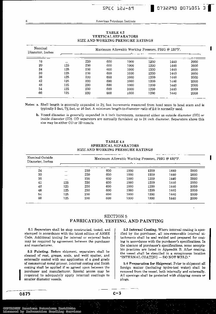
TABLE 4.2 VERTICAL SEPARATORS
SIZE AND WORKING PRESSURE RATINGS
Nominal Maximum Allowable Working Pressure, PSIG @ 130’F. I Diameter, Inches A ,
16 ... 230 600 1000 1200 1440 2000 20 125 230 600 1000 1200 1440 2000 24 125 230 600 1000 1200 1440 2000 30 125 230 600 1000 1200 1440 2000 36 125 230 600 1000 1200 1440 2000 42 125 230 600 1000 1200 1440 2000 48 125 230 600 1000 1200 1440 2000 54 125 230 600 1000 1200 1440 2000 60 125 230 600 1000 1200 1440 2000
Notes: a. Shell length is generally expanded in 2% foot increments measured from head seam to head seam and is typically 5 feet, 7% feet, or 10 feet. A minimum length-to-diameter ratio of 2.0 is normally used.
b. Vessel diameter is generally expanded in 6 inch increments, measured either as outside diameter (OD) or inside diameter (ID). OD separators are normally furnished up to 24 inch diameter. Separators above this size may be either OD or ID vessels.
TABLE 4.3 SPHERICAL SEPARATORS
SIZE AND WORKING PRESSURE RATINGS
Nominal Outside Maximum Allowable Working Pressure, PSIG @ 130’F. I Diameter, Inches *
I
24 30 36 41 42 48 54 60
...
...
125 125 125 125 125
...
230 230 230 230 230 230 230 230
600 600 600 600 600 600 600 600
1000 1000 1000 1000 1000 1000 1000 1000
1200 1200 1200 1200 1200 1200 1200 1200
1440 1440 1440 1440 1440 1440 1440 1440
2000 2000 2000 2000 2000 2000 2000 2000
SECTION 5 FABRICATION, TESTING, AND PAINTING
5.1 Separators shall be shop constructed, tested, and stamped in accordance with the latest edition of ASME Code. Additional testing for internal or external leaks may be required by agreement between the purchaser and manufacturer.
5.2 Painting. Before shipment, separators shall be cleaned of rust, grease, scale, and weld spatter, and externally coated with one application of a good grade of commercial metal primer. Internal coating and finish coating shall be applied if so agreed upon between the purchaser and manufacturer. Special access may be required to adequately apply internal coatings to smaller diameter vessels. I
5.3 Internal Coating. Where internal coating is spec- ified by the purchaser, all non-removable internal at- tachments shall be seal welded and prepared for coat- ing in accordance with the purchaser’s specifications. In the absence of purchaser’s specifications, some accepta- ble practices are listed in Appendix B. After coating, the vessel shall be stenciled in a conspicuous location “INTERNAL COATING - DO NOT WELD.”
5.4 Preparat ion for Shipment. Prior to shipment all foreign matter (including hydro-test water) shall be removed from the vessel, both internally and externally. All openings shall be protected with shipping covers or plugs.
COPYRIGHT American Petroleum InstituteLicensed by Information Handling ServicesCOPYRIGHT American Petroleum InstituteLicensed by Information Handling Services
SPEC 32J-87 I 07322qo 0073052 r Spec 1 2 J Oil Gas Separators 7
SECTION 6 MARKING
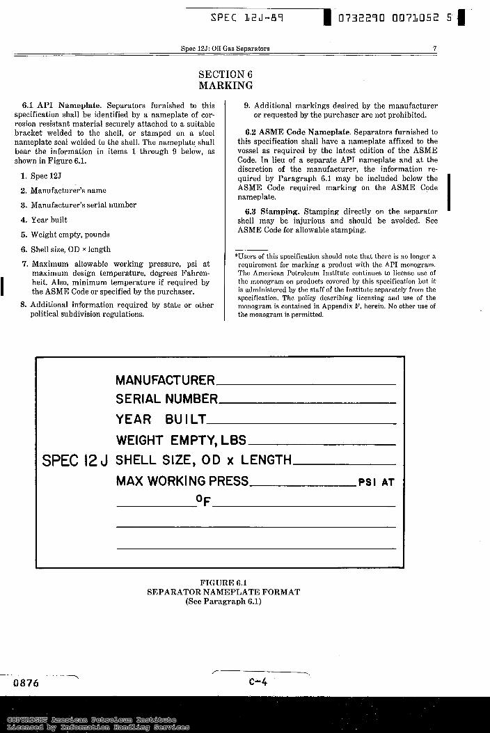
6.1 API Nameplate. Separators furnished to this specification shall be identified by a nameplate of cor- rosion resistant material securely attached to a suitable bracket welded to the shell, or stamped on a steel nameplate seal welded to the shell. The nameplate shall bear the information in items 1 through 9 below, as shown in Figure 6.1.
1. Spec 125
2. Manufacturer’s name
3. Manufacturer’s serial number
4. Year built
5. Weight empty, pounds
6. Shell size, OD x length
7. Maximum allowable working pressure, psi a t maximum design temperature, degrees Fahren- heit. Also, minimum temperature if required by the ASME Code or specified by the purchaser. I
8. Additional information required by state or other political subdivision regulations.
9. Additional markings desired by the manufacturer or requested by the purchaser are not prohibited.
6.2 ASME Code Nameplate. Separators furnished to this specification shall have a nameplate affixed to the vessel as required by the latest edition of the ASME Code. In lieu of a separate API nameplate and at the discretion of the manufacturer, the information re- quired by Paragraph 6.1 may be included below the ASME Code required marking on the ASME Code nameplate.
6.3 Stamping. Stamping directly on the separator shell may be injurious and should be avoided. See ASME Code for allowable stamping.
*Users of this specification should note that there is no longer a requirement for marking a product with the API monogram. The American Petroleum Institute continues to license use of the monogram on products covered by this specification but it is administered by the staff of the Institute separately from the specification. The policy describing licensing and use of the monogram is contained in Appendix F, herein. No other use of the monogram is permitted.
SPEC 12 J
MANUFACTURER SERIAL NUMBER YEAR BU I LT WEIGHT EMPTY, LBS SHELL SIZE, OD x LENGTH
MAX WORKING PRESS PSI AT
OF
~~~ ~ ~ -
FIGURE 6.1 SEPARATOR NAMEPLATE FORMAT
(See Paragraph 6.1)
COPYRIGHT American Petroleum InstituteLicensed by Information Handling ServicesCOPYRIGHT American Petroleum InstituteLicensed by Information Handling Services
SPEC 1 2 J - 8 7 0732270 0 0 7 ~ ~ ~ ~ r 8 American Petroleum Institute
SECTION 7 INSPECTION AND REJECTION
7.1 ASME Code Inspection. The Authorized Inspec- tor required by the ASME Code shall make all inspec- tions specifically required by the Code plus such other inspections believed necessary to certify that all vessels authorized to be stamped with the Code symbol meet all of the applicable requirements of the Code. The Authorized Inspector shall sign the Certificate of In- spection on the Manufacturers Data Report when the vessel, to the best of the inspector’s knowledge and belief, is complete and is in compliance with all the provisions of the Code.
7.2 Inspection by the Purchaser. Where additional inspection is required by the purchaser, the extent of such inspection should be stated on the purchase order. Where the inspector representing the purchaser desires to inspect separators purchased or witness any specifi- cation tests or evaluate the results of any nondestruc- tive examinations, the manufacturer shall give reason- able notice of the time at which such inspections should be made.
7.3 Inspection. While work on the contract of the purchaser is being performed, the inspector represent- ing the purchaser shall have free entry at all times to all parts of the manufacturer’s works which concern
APPENDIX A PROCESS CONSIDERATIONS
A.l This Appendix provides a general discussion of the functional requirements of Oil and Gas Separators and their controls as used in this specification.
A.2 Separator Components. The function of a sep- arator is to provide removal of free gas from oil and/or water at a specific pressure and temperature. For effi- cient and stable operation over a wide range of condi- tions, a gas-liquid separator normally has the following features:
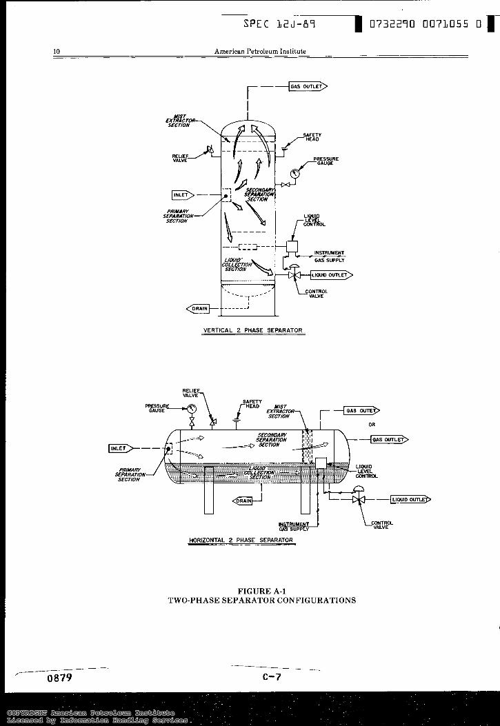
A.2.1 Primary Separation Section - This sec- tion is for removing the bulk of the liquid in the inlet stream. Liquid slugs and large liquid particles are removed first to mini- mize gas turbulence and re-entrainment of liquid particles in preparation for the sec- ond step of separation. To do this, it is usu- ally necessary to absorb the momentum and change the direction of flow by some form of inlet baffling.
A.2.2 Secondary Sepa ra t ion Sec t ion - The major separation principle in this section is
. 0877 c-5
-\
the manufacture of the material ordered. The manufac- turer shall afford, without charge, all reasonable facili- ties to satisfy the inspector that the material is being manufactured in accordance with this specification. All inspections shall be made at the place of manufacture prior to shipment unless otherwise specified on the pur- chase order, and shall be so conducted as not to inter- fere unnecessarily with the manufacturer’s operations.
7.4 Rejection. Material which shows injurious de- fects on initial inspection or subsequent to acceptance at manufacturer’s works, or which proves defective when properly applied in service, may be rejected, and the manufacturer so notified. If tests that require the destruction of material are made at other than the place of manufacture, the purchaser shall pay for material complying with all of the provisions of this specification, but shall not pay for any material which fails to meet the specifications.
7.5 Compliance. The manufacturer is responsible for complying with all of the provisions of this specifica- tion. The purchaser may make any investigation neces- sary to be assured of compliance by the manufacturer and may reject any material that does not comply with this specification.
gravity settling of liquid from the gas stream after i t s velocity has been reduced. The efficiency of this section depends on the gas and liquid properties, particle size and degree of gas turbulence. Some designs use internal baffling to reduce turbulence and to dissipate foam. The baffles may also act as droplet collectors.
A.2.3 Liquid Accumulator Section - The liq- uid(s) is (are) collected in this section. The liquid should have a minimum of disturb- ance from the flowing gas stream. Suffi- cient capacity is necessary to allow for surges and to provide the retention time necessary for efficient separation of gas breaking out of solution and separation of free water from oil in three-phase separa- tors. A vortex breaker may be located over the liquid outlet nozzle(s) to prevent gas or oil entrainment with the bottom liquid.
A.2.4 Mist Extraction Section - The mist ex- tractor of the coalescing section can be one
COPYRIGHT American Petroleum InstituteLicensed by Information Handling ServicesCOPYRIGHT American Petroleum InstituteLicensed by Information Handling Services
Spec 12J: Oil Gas Separafors
of several designs (a series of vanes, woven wire mesh pad or a centrifugal device). The mist extractor removes from the gas stream the small droplets (normally down to 10 micron diameter) of liquid before the gas leaves the vessel. Liquid carryover is normally less than 0.1 gallon per MMSCF.
A.2.5 Process Controls - The operating pres- sure may be controlled by a weight loaded, spring loaded, or pilot operated gas back pressure valve. Where the gas is being de- livered to a pipeline, the minimum separa- tor pressure is usually set by the transmis- sion or gathering system pressure. Separa- tors should be equipped with one or more liquid level controls. Usually a liquid level control for the liquid accumulation section of two-phase separators activates a liquid dump valve to maintain the required liquid level. Two liquid level control systems are
9
allowable working pressure (MAWP). The rupture disk is normally selected to relieve above the set pressure of the relief valve. The pressure relief devices need not be provided by the separator manufacturer, but over-pressure protection shall be pro- vided prior to placing the separator in serv- ice. The purchaser should determine who has the responsibility to furnish relief de- vices.
A.2.7 Discharge Lines - Discharge lines from pressure relief devices should receive con- sideration on an individual basis. A de- tailed discussion is beyond the scope of this standard. Recommendations for discharge line consideration may be obtained from Appendix M, Installation and Operation, of the ASME Code as well as API RP 520, “Design and Installation of Pressure Reliev- ing Systems in Refineries” and API RP 521,
normally used for three-phase separators. “Guide for Pressure Relief Systems and Internal weirs and baffles are used in con- Depressuring Systems.” junction with these liquid level controls. Separators are equipped with gauge glasses or sight glasses to indicate one or two lev- els. A pressure gauge and thermometer well are usually installed on separators.
A.2.6 Relief Devices - All separators, regard- less of size or pressure, shall be provided with pressure protective devices and set in accordance with ASME Code requirements. Multiple pressure relieving devices such as a pressure relief valve in conjunction with a rupture disk may be used to provide the necessary relieving capacity. The relief valve is normally set at the maximum
A.2.8 When specified by the purchaser, separa- tors may be equipped with other controls and accessories such as the following: a. Inlet shut-in valve b. Pressure sensor or conrol c. Level sensor or control d. Temperature sensor or control
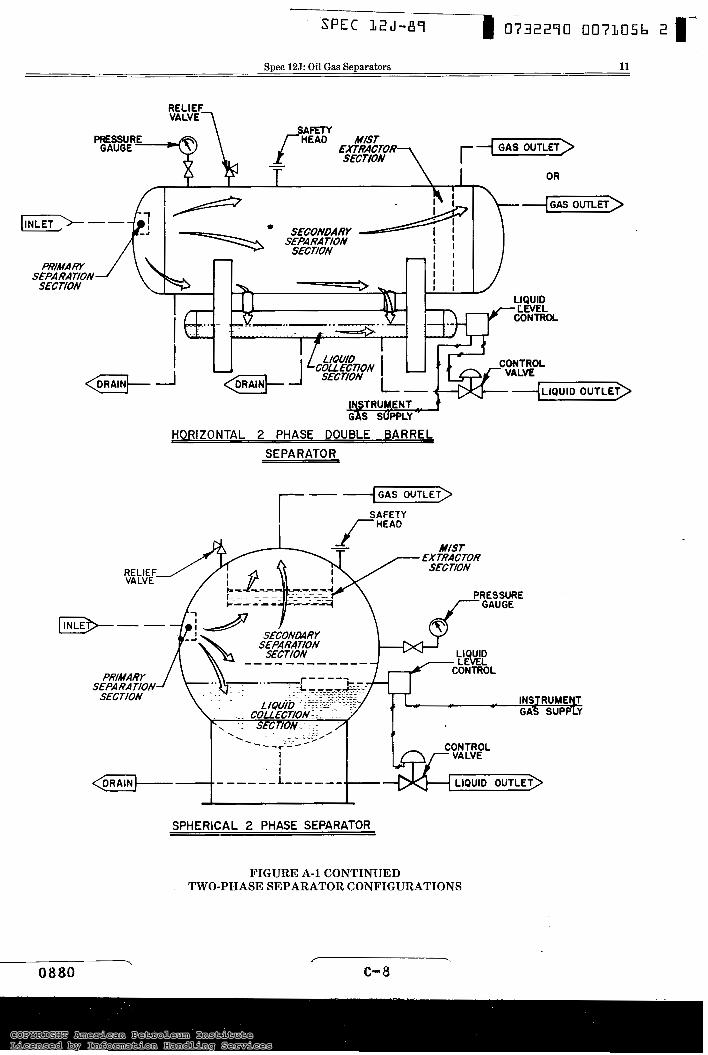
A.3 Separator Shapes - There are three different shapes of separators: vertical, horizontal, and spherical. The four main components are located differently in the various vessels. In Figure A-1 are given typical two- phase separator configurations for vertical, horizontal, and spherical separators.
COPYRIGHT American Petroleum InstituteLicensed by Information Handling ServicesCOPYRIGHT American Petroleum InstituteLicensed by Information Handling Services
SPEC L Z J - r m 0732270 0073055 O r 10 American Petroleum Institute
r-+ GAS OUTLET
I
VALVE
VERTICAL 2 PHASE SEPARATOR
"
PRIMARY
SECTION SEPARATION-
RELIEF VALVET
\
HORIZONTAL 2 PHASE SEPARATOR
FIGURE A-1 TWO-PHASE SEPARATOR CONFIGURATIONS
COPYRIGHT American Petroleum InstituteLicensed by Information Handling ServicesCOPYRIGHT American Petroleum InstituteLicensed by Information Handling Services
Spec 12J: Oil Gas Separators 11
RELIEF V A L V E ~
HORIZONTAL 2 PHASE DOUBLE BARREL SEPARATOR
""""""
SEPARA TIOU .. .. . . .. . - . INSJRUMEELT
GAS SUPPLY
I I
-. I ."""L """.
SPHERICAL 2 PHASE SEPARATOR
FIGURE A-1 CONTINUED TWO-PHASE SEPARATOR CONFIGURATIONS
COPYRIGHT American Petroleum InstituteLicensed by Information Handling ServicesCOPYRIGHT American Petroleum InstituteLicensed by Information Handling Services
I
S P E C - 1 2 J - 8 9 - 1 0732270 0073057 Y
B.1.4 Some of the other factors that influence corrosion in a given vessel include: temper- ature, pressure, fluid velocities, metal stress and heat treatment, vessel surface condition, and time.
B.2 Corrosive Environment Practices.
B.2.1 If the environment is judged as being sub- ject to SSC from the criteria of NACE MR-01-75 as stated in B.1.2 above, then all provisions of this NACE Standard as apply to the vessel materials and construc- tion shall be followed.
B.2.2 If the environment is judged as corrosive from any of the other criteria stated in B.1.2 above, the intent of this specification will be met provided any one or combina- tion of the following practices are used:
a. An allowance for corrosion to the vessel parts may be made according to the ASME Code, Appendix E, Suggested Good Practices Regarding Corrosion Allowance.
I b. Either sacrificial or impressed current
anodes may be used, providing that the area of the corrosion attack can physi- cally be protected by use of these anodes (NACE Ref. RP-05-75).
c. Corrosion effects may be controlled with holiday-free internal coatings on all exposed metal surfaces. NACE Standards RP-01-81 (Recommended Practice: Liquid Applied Intemal Pro- tective Linings and Coatings for Oil Field Production Equipment) and RP- 01-78 (Design, Fabrication, and Surface Finish of Metal Tanks and Vessels to be lined fo r Chemical Immersion Selvice) present guidelines and procedures for coating vessels such as oil and gas separators.
d. Corrosion effects may be disregarded provided they can be shown to be neg- ligible or entirely absent on a historical basis. However, the system should be monitored periodically for possible new corrosion (Reference API 510).
e. Corrosion effects may be reasonably controlled with chemical inhibitor treat- ments.
B.2.3 Post weld heat treatment is recommended for carbon steel vessels for use in acid gas (containing hydrogen sulfide and/or car- bon dioxide) service. Post weld heat treat- ment may be required by ASME Code regardless of corrosion considerations.
c-9
COPYRIGHT American Petroleum InstituteLicensed by Information Handling ServicesCOPYRIGHT American Petroleum InstituteLicensed by Information Handling Services
Spec 12J: Oil Gas Separators 13
APPENDIX C DESIGN AND SIZING CALCULATIONS
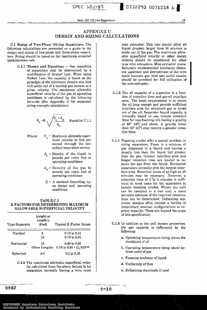
C.l Sizing of Two-Phase Oil-Gas Separators. The following calculations are presented as a guide to the design and sizing of two-phase and three-phase separa- tors. Sizing should be based on the maximum expected instantaneous rate.
C. l . l Theory and Equations - Gas capacities of separators may be determined by a modification of Stokes' Law. When using Stokes' Law, the capacity is based on the principle of the minimum droplet size that will settle out of a moving gas stream at a given velocity. The maximum allowable superficial velocity of the gas at operating conditions is calculated by the following formula: (See Appendix D for separator sizing example calculation.)
v, =K $ ! E q u a t i o n G.1.1
Where: Va = Maximum allowable super- ficial velocity in feet per second through the sec- ondary separation section
d, = Density of the liquid in pounds per cubic foot at operating conditions
d, = Densi ty of t h e gas in pounds per cubic foot at operating conditions
K = A constant depending up- on design and operating conditions
TABLE C.1 K FACTORS FOR DETERMINING MAXIMUM
ALLOWABLE SUPERFICIAL VELOCITY
Height or Length L
Type Separator (F'eet) Typical K Factor Range
Vertical 5 0.12 to 0.24 10 0.18 to 0.35
Horizontal 10 0.40 to 0.50 Other Lengths 0.40 to 0.50 X (L/10)0.56
Spherical All 0.2 to 0.35
C.1.2 The maximum allowable superficial veloc- ity calculated from the above factors is for separators normally having a wire mesh
mist extractor. This rate should allow all liquid droplets larger than 10 microns to settle out of the gas. The maximum allow- able superficial velocity or other design criteria should be considered for other type mist extractors. Mist extractor manu- facturer's recommended minimum distan- ces upstream and downstream of the wire mesh between gas inlet and outlet nozzles should be provided for full utilization of the mist extractor.
C.1.3 The oil capacity of a separator is a func- tion of retention time and gas-oil interface area. The basic requirement is to retain the oil long enough and provide sufficient interface area for entrained gas to break out of the oil. Separator liquid capacity i? normally based on one minute retention time for non-foaming oils having a gravity of 35' API and above. A gravity lower than 35O API may require a greater reten- tion time.
6.1.4 Foaming crudes offer a special problem in sizing separators. Foam is a mixture of gas dispersed in a liquid and having a density less than the liquid but greater than the gas. Greater interface area and longer retention time are needed to re- move the gas from the liquid. Horizontal separators normally give the largest inter- face area. Retention times of as high as 15 minutes may be necessary. However, a retention time of 2 'to 5 minutes is suffi- cient in most cases for the separators to handle foaming crudes. Where the well can be sampled in a test unit, a more accurate estimate of the required retention time- can be determined. Defoaming sep- arator designs often include a variety of proprietary internal configurations to im- prove capacity. These are beyond the scope of this specification.
C.1.5 In addition to the well stream properties, the gas capacity is influenced by the following:
a. Operating temperature being above the cloudpoint of oil
b. Operating temperature being above hy- drate point of gas
c. Foaming tendency of liquid
d. Uniformity of flow
e. Defoaming chemicals; if used
. c-1 o
COPYRIGHT American Petroleum InstituteLicensed by Information Handling ServicesCOPYRIGHT American Petroleum InstituteLicensed by Information Handling Services
14 American Petroleum Institute
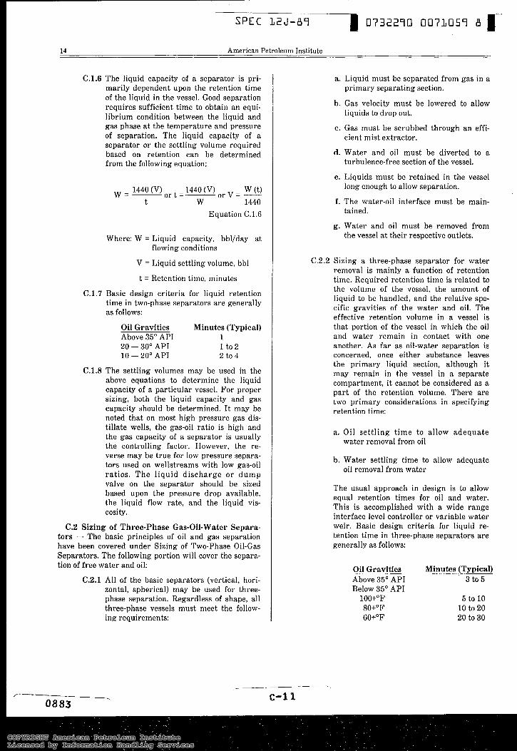
C.1.6 The liquid capacity of a separator is pri- marily dependent upon the retention time of the liquid in the vessel. Good separation requires sufficient time to obtain an equi- librium condition between the liquid and gas phase at the temperature and pressure of separation. The liquid capacity of a separator or the settling volume required based on retention can be determined from the following equation:
W=- 1440 (V) 1440 (V) ar t=- W (t) o r V = - t W 1440
Equation C.1.6
Where: W = Liquid capacity, bbl/day at flowing conditions
V = Liquid settling volume, bbl
t = Retention time, minutes
C.1.7 Basic design criteria for liquid retention time in two-phase separators are generally as follows:
Oil Gravities Minutes (Typical) Above 35" API 1 20 - 30" API 1 to2 10 - 20" API 2 to 4
C.1.8 The settling volumes may be used in the above equations to determine the liquid capacity of a particular vessel. For proper sizing, both the liquid capacity and gas capacity should be determined. It may be noted that on most high pressure gas dis- tillate wells, the gas-oil ratio is high and the gas capacity of a separator is usually the controlling factor. However, the re- verse may be true for low pressure separa- tors used on wellstreams with low gas-oil ratios. The l iquid discharge or dump valve on the separator should be sized based upon the pressure drop available, the liquid flow rate, and the liquid vis- cosity.
C.2 Sizing of Three-phase Gas-Oil-Water Separa- tors - The basic principles of oil and gas separation have been covered under Sizing of Two-Phase Oil-Gas Separators. The following portion will cover the separa- tion of free water and oil:
C.2.1 All of the basic separators (vertical, hori- zontal, spherical) may be used for three- phase separation. Regardless of shape, all three-phase vessels must meet the follow- ing requirements:
a. Liquid must be separated from gas in a primary separating section.
b. Gas velocity must be lowered to allow liquids to drop out.
c. Gas must be scrubbed through an effi- cient mist extractor.
d. Water and oil must be diverted to a turbulence-free section of the vessel.
e. Liquids must be retained in the vessel long enough to allow separation.
f . The water-oil interface must be main- tained.
g. Water and oil must be removed from the vessel a t their respective outlets.
C.2.2 Sizing a three-phase separator for water removal is mainly a function of retention time. Required retention time is related to the volume of the vessel, the amount of liquid to be handled, and the relative spe- cific gravities of the water and oil. The effective retention volume in a vessel is that portion of the vessel in which the oil and water remain in contact with one another. As far as oil-water separation is concerned, once either substance leaves the primary liquid section, although it may remain in the vessel in a separate compartment, i t cannot be considered as a part of the retention volume. There are two primary considerations in specifying retention time:
a. O i l se t t l ing t ime t o allow adequate water removal from oil
b. Water settling time to allow adequate oil removal from water
The usual approach in design is to allow equal retention times for oil and water. This is accomplished with a wide range interface level controller or variable water weir. Basic design criteria for liquid re- tention time in three-phase separators are generally as follows:
Oil Gravities Minutes (Typical) Above 35O API 3 to 5 Below 35" API
100+"F 5 to 10 80+"F 10 to 20 60+"F 20 to 30
"
c-1 1
COPYRIGHT American Petroleum InstituteLicensed by Information Handling ServicesCOPYRIGHT American Petroleum InstituteLicensed by Information Handling Services
Spec 12J: Oil Gas Separators 15
C.3 Separator Selection - The following procedure may be used when selecting a separator for a particular application:
C.3.1 Determine which shape fits the particular installation best considering space, mount- ing, and ease of access for maintenance. Both present and future operating condi- tions should be considered.
C.3.2 Determine whether unusual well stream conditions (foam, sand, etc.) would make the vessel selected difficult to operate or maintain.
C.3.3 Determine whether over-all economics is affected by the installation or portability of the shape selected.
C.3.4 M-ake certain that all design requirements such as heating coils for paraffin or hy- drates and three-phasing for water remov- al have been considered and are compati- ble with the shape selected.
C.3.5 Consider possible liquid slugging of the separator.
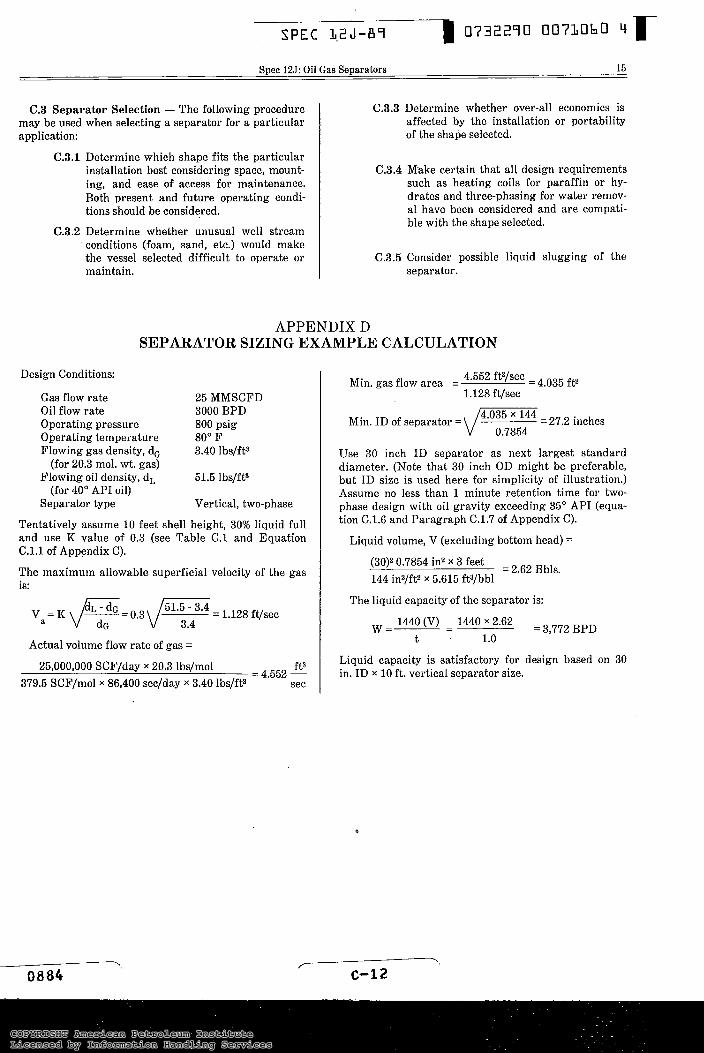
APPENDIX D SEPARATOR SIZING EXAMPLE CALCULATION
Design Conditions:
Gas flow rate 25 MMSCFD Oil flow rate 3000 BPD Operating pressure 800 psig Operating temperature 80" F Flowing gas density, d, 3.40 lbs/ft3
Flowing oil density, d, 51.5 lbs/ft3
Separator type Vertical, two-phase
Tentatively assume 10 feet shell height, 30% liquid full and use K value of 0.3 (see Table C.l and Equation C.l.l of Appendix C).
The maximum allowable superficial velocity of the gas is:
(for 20.3 mol. wt. gas)
(for 40" API oil)
Actual volume flow rate of gas =
25,000,000 SCF/day x 20.3 lbs/mol ft3 379.5 SCF/mol x 86,400 sec/day X 3.40 lbs/ft3 sec
= 4.552 -
Min. gas flow area = 4.552 ft3/sec = 4.035 ft2
1.128 ft/sec
Min. ID of separator = d T = 27.2 inches
Use 30 inch ID separator as next largest standard diameter. (Note that 30 inch OD might be preferable, but ID size is used here for simplicity of illustration.) Assume no less than 1 minute retention time for two- phase design with oil gravity exceeding 35" API (equa- tion CL6 and Paragraph C.1.7 of Appendix C).
Liquid volume, V (excluding bottom head) =
(30)2 0.7854 in2 x 3 feet 144 inZ/ft2 X 5.615 ft3/bbl
= 2.62 Bbls.
The liquid capacity of the separator is:
W=----- 1440 (V) - - 1440 x 2.62 = 3,772 BPD
Liquid capacity is satisfactory for design based on 30 in. ID x 10 ft. vertical separator size.
t . 1.0
O
COPYRIGHT American Petroleum InstituteLicensed by Information Handling ServicesCOPYRIGHT American Petroleum InstituteLicensed by Information Handling Services

I
I. Operating Conditions:
A. Liquid Volumes
1. Oil/Condensate: Barrels/Day Gravity: O API Viscosity ~ CP
2. Water: Barrels/Day Sp. Gr.: (Water = 1.0)
B. Oil/Condensate Characteristics
1. Foaming: Nil Moderate Severe
2. Paraffin Problem: N o Y e s - ( I f Yes, give cloud p o i n t ) O F
3. Slug Flow: N o Y e s - (If Yes, give details such as maximum liquid rate, slug volume, etc., or
suggest surge factor.)
~~~
SPEC L2J-89 D 0732290 00710bL b r 16 American Petroleum Institute
APPENDIX E SEPARATOR DESIGN INFORMATION
. r
O885 . ~- - c-1 3
C. Gas: MMSCFD Sp. G r . : ( A i r = 1.0)
D. Operating Temperature ("F): Max Min
E. Operating Pressure (psig): Max Min
F. H2S Content: Mole % CO, Content: Mole %
G. Geographical Location:
II. Design Requirements:
A. Type: Vertical Horizontal Spherical
Manufacturer's Recommendation:
Two-Phase Three-phase
B. Design Pressure: psig at Temperature "F
C. Type Mist Extractor: (Specify)
D. Liquid Retention Time:
E. Corrosion A l l o w a n c e : ( i n c h e s )
F. Corrosion Allowance for Non-Pressure Internal Parts: (inches)
G . NACE MR-01-75 Required: No- Yes-
H. Special Stress Relieving: No- Y es-
Specify if Yes:
I. API RP 14C Safety Systems Required: No- Yes-
III. Coatings:
A. External: Mfgr. Std.- Other-
Specify if Other:
B. Internal: (Specify)
C. Cathodic Protection: (Specify)
COPYRIGHT American Petroleum InstituteLicensed by Information Handling ServicesCOPYRIGHT American Petroleum InstituteLicensed by Information Handling Services
Spec 125: Oil Gas Separators 17
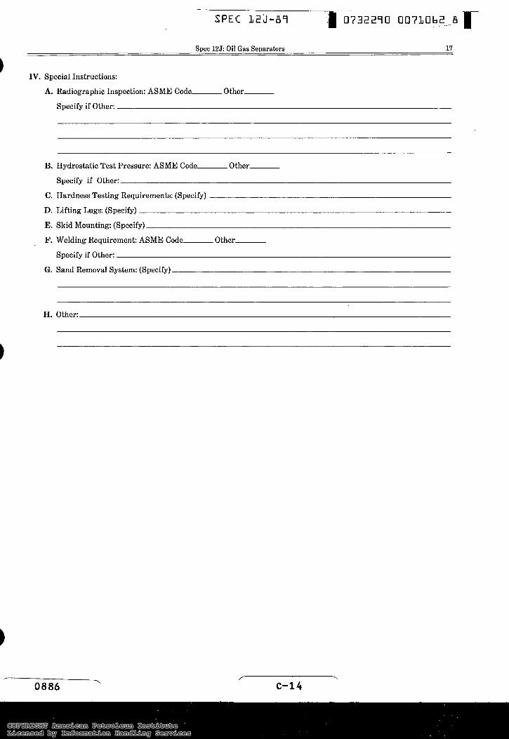
IV. Special Instructions:
A. Radiographic Inspection: ASME Code- Other-
C.
D.
E.
F.
Specify if Other:
Hydrostatic Test Pressure: ASME Code-_- Other-
Specify if Other:
Hardness Testing Requirements: (Specify)
Lifting Lugs: (Specify)
Skid Mounting: (Specify)
Welding Requirement: ASME Code- Other-
Specify if Other:
Sand Removal System: (Specify)
Other:
r .. 0886 C - 1 4
COPYRIGHT American Petroleum InstituteLicensed by Information Handling ServicesCOPYRIGHT American Petroleum InstituteLicensed by Information Handling Services
SPEC L2J-BS
18 American Petroleum Institute
APPENDIX F USE OF API MONOGRAM
The API monogram is a registered trademark
of the American Petroleum Institute. A
Manufacturers desiring to warrant that art icles manufactured or sold by them conform with this specification shall obtain the license to use the Offi- cial API Monogram.
The original resolutions adopted by the Board of Directors of the American Petroleum Institute on Oct. 20, 1924. embodied the purpose and conditions under which such official monogram may be used.
The following restatement of the resolution was adopted by the Board of Directors on Nov. 14, 1977.
WHEREAS, The Board of Directors of the American Petroleum Institute has caused a review of the Insti- tute’s program for licensing the use of the API mono- gram and
WHEREAS, It now appears desirable to restate and clarify such licensing policy and to confirm and make explicitly clear that it is the licensees, not API, who make the representation and warranty that the equip- ment or material on which they have affixed the API monogram meets the applicable standards and specifi- cations prescribed by the Institute:
NOW, THEREFORE, BE IT RESOLVED, That the purpose of the voluntary Standardization Program and the Monogram Program of the American Petroleum Institute is to establish a procedure by which purchas- ers of petroleum equipment and material may identify such equipment and materials as are represented and warranted by the manufacturers thereof to conform to applicable standards and specifications of the American Petroleum Institute: and be it further
RESOLVED, That the previous action under which the following monogram was adopted as the official monogram of the American Petroleum Institute is
BE IT FURTHER RESOLVED, That the American Petroleum Institute’s monogram and standardization programs have been beneficial to the general public as well as the petroleum industry and should be continued and the Secretary is hereby authorized to license the use of the monogram to anyone desiring to do so under such terms and conditions as may be authorized by the Board of Directors of the American Petroleum Insti- tute, provided that the licensee shall agree that the use of the monogram by such licensee shall constitute the licensee’s representation and warranty that equipment and materials bearing such monogram complies with the applicable standards and specifications of the American Petroleum Institute: and that licensee shall affix the monogram in the following manner:
/ . 0887
BE IT FURTHER RESOLVED, That the words “Official Publication” shall be incorporated with said monogram on all such standards and specifications that may hereafter be adopted and published by the American Petroleum Institute, as follows:
OFFICIAL PUBLICATION
!P REG. U.S. PATENT OFFICE
F.l API Monogram. The API monogram - @ - is a registered trademark/servicemark of the American Petroleum Institute. Authorization to use the mono- gram is granted by the Institute to qualified licensees for use as a warranty that they have obtained a valid license to use the monogram and that each individual item which bears the monogram conformed, in every detail, with the API Specification applicable at the time of manufacture. However, the American Petro- leum Institute does not represent, warrant or guarantee that products bearing the API monogram do in fact conform to the applicable API standard or specifica- tion. Such authorization does not include use of the monogram on letterheads or in advertising without the express statement of fact describing the scope of licen- see’s authorization and further does not include use of the monogram, the name AMERICAN PETROLEUM INSTITUTE or the description “API” in any advertis- ing or otherwise to indicate API approval or endorse- ment of products.
The formulation and publication of API Specifications and the API monogram program is not intended in any way to inhibit the purchase of products from companies not licensed to use the API monogram.
F.2 Application for authority to Use Monogram. Manufacturers desiring to warrant that products manu- factured by them comply with the requirements of a given API specification may apply for a license to use the monogram with forms provided in an appendix to each specification.
The “Agreement” form must be submitted in duplicate for each specification under which monogram rights are desired. One “Statement of Manufacturer’s Qualifi- cations” is required for each facility.
A manufacturer desiring to apply the monogram at more than one facility (a facility is any manufacturing location) must submit a separate application for each facility.
Applicants shall have an approved functioning quality program in conformance with API Spec Q1 prior to being issued a license to use the API monogram.
F.3 Authorization to Use the Monogram. A deci- sion to award or withhold monogram rights will be made by the staff of the Institute. A survey of the applicant’s facilities will be made by an approved Insti- tute surveyor prior to a decision to approve or withhold
COPYRIGHT American Petroleum InstituteLicensed by Information Handling ServicesCOPYRIGHT American Petroleum InstituteLicensed by Information Handling Services
Spec 125: Oil Gas Separators 19
the license. The basis of the survey shall be the appro- priate product Specification and all applicable portions of API Spec &l.
For a manufacturer having more than one facility (plant), each facility will be judged separately and if determined to be eligible for authorization to use the monogram will be granted a separate license for each Specification, or part thereof, under which authoriza- tion is granted. The application of the monogram may not be subcontracted.
F.4 Fee for Use of Monogram.
Initial Authorization Fee. The applicant will be invoiced an initial authorization fee for the first Spec- ification included in the application, and a separate fee for each additional Specification included in the application. The applicant will also be invoiced for the surveyor’s fee.
Annual Renewal Fee. In addition to the initial authorization fee, licensees will be assessed an annual renewal fee for each specification under which he is authorized to use the monogram. Applicants issued monogram certificates dated November 1 through December 31 shall not be required to pay a renewal fee for the following year.
The fees assessed are to defray the cost of the Mono- gram Program.
F.5 Periodic Surveys. Existing licensees .must be periodically surveyed by an approved Institute surveyor to determine whether or not they continue to qualify for authorization to use the monogram. The frequency of the periodic surveys will be at the discretion of the staff of the Institute. The surveyor’s fee and expenses for making a periodic survey will be paid by the Institute.
F.6 Cancellation of Monogram Rights. The right to use the monogram is subject to cancellation for the fol- lowing causes:
a. Applying the monogram on any product that does not meet the Specification.
b. Failure to maintain reference master gages in accordance with the Specifications.
c. Failure to meet the requirements of any resurvey.
d. Failure to pay the annual renewal fee for use of the monogram.
e. For any other reason satisfactory to the Executive Committee on Standardization of Oilfield Equip- ment and Materials.
F.7 Reinstatement of Monogram Rights. Manufac- turers whose authorization to use the monogram has been cancelled may request reinstatement at any time. If a request for reinstatement is made within sixty (60) days after cancellation, and if the reason for cancella- tion has been corrected, no new application is neces-
sary. A resurvey of the manufacturer’s facilities will be made by an approved Institute surveyor prior to a deci- sion to reinstate monogram rights. The manufacturer will be invoiced for this resurvey regardless of the Institute’s decision on reinstatement. If the resurvey indicates that the manufacturer is qualified, the license will be reissued.
Request for reinstatement made more than sixty (60) days after cancellation shall be treated as a new appli- cation unless circumstances dictate an extension of this time period as agreed upon by the API staff.
F.8 Appeals.
An interested party may appeal a decision by the API staff to withhold monogram rights. Appeals shall be directed to the Director, API Production Department and handled by the General Committee of the Produc- tion Department with a further right of appeal to the API Management Committee. Competing suppliers or manufacturers of the product or service to which the standard applies or might apply may not be involved in appeals. The General Committee and the Management Committee may convene appeals boards to hear and act on appeals.
F.9 Marking. The following marking requirements apply to licensed manufacturers using the API mono- gram on products covered by this specification.
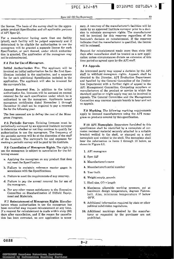
F.10 API Nameplate. Separators furnished to this specification shall be identified by a nameplate of cor- rosion resistant material securely attached to a suitable bracket welded to the shell, or stamped on a steel nameplate seal welded to the shell. The nameplate shall bear the information in items 1 through 10 below, as shown in Figure 6.1.
1. API monogram
2. Spec 125
3. Manufacturer’s name
4. Manufacturer’s serial number
5. Year built
6. Weight empty, pounds
7. Shell size, OD X length
8. Maximum allowable working pressure, psi at maximum design temperature, degrees Fahren- hei t . Also, minimum temperature if below -20°F.
9. Additional information required by state or other political subdivision regulations.
10. Additional markings desired by the manufac- turer or requested by the purchaser are not prohibited.
F- \
D-2
COPYRIGHT American Petroleum InstituteLicensed by Information Handling ServicesCOPYRIGHT American Petroleum InstituteLicensed by Information Handling Services
SPEC L 2 J - 8 7 07322q0 0073065 p 20 American Petroleum Institute
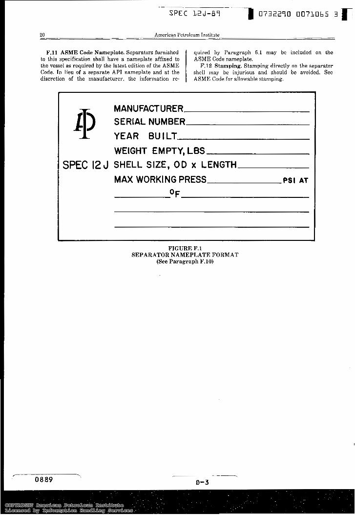
F.ll ASME Code Nameplate. Separators furnished to this specification shall have a nameplate affixed to the vessel as required by the latest edition of the ASME Code. In lieu of a separate API nameplate and at the discretion of the manufacturer, the information re-
quired by Paragraph 6.1 may be included on the ASME Code nameplate.
F.12 Stamping. Stamping directly on the separator shell may be injurious and should be avoided. See ASME Code for allowable stamping.
MANUFACTURER 11) ;;;;L ;;;;;R
WEIGHT EMPTY, LBS SPEC 12 J SHELL SIZE, OD x LENGTH
MAX WORKING PRESS PSI AT
FIGURE F.l SEPARATOR NAMEPLATE FORMAT
(See P a r a g r a p h F.lO)
COPYRIGHT American Petroleum InstituteLicensed by Information Handling ServicesCOPYRIGHT American Petroleum InstituteLicensed by Information Handling Services
~
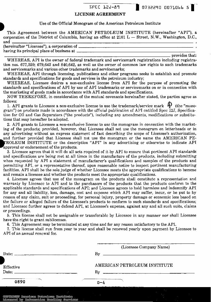
SPEC 32J-87 D 0732270 0073066 5 r LICENSE AGREEMENT
B Use of the Official Monogram of the American Petroleum Institute
This Agreement between the AMERICAN PETROLEUM INSTITUTE (hereinafter “API’’), a corporation of the District of Columbia, having an office at 2101 L - Street, N.W., Washington, D.C., and i
(hereinafter “Licensee”), a corporation of 9
having its principal place of business at provides that:
WHEREAS, API is the owner of federal trademark and servicemark registrations including registra- tion nos. 677,359; 679,642 and 840,642, as well as the owner of common law rights to such trademarks and servicemarks and various other trademarks and servicemarks;
WHEREAS, API through licensing, publications and other programs seeks to establish and promote standards and specifications for goods and services in the petroleum industry;
WHEREAS, Licensee desires a non-exclusive license from API for the purpose of promoting the standards and specifications of API by use of API trademarks or servicemarks on or in connection with the marketing of goods made in accordance with API standards and specifications.
NOW THEREFORE, in consideration of the mutual covenants hereinafter stated, the parties agree as follows:
1. API grants to Licensee a non-exclusive license to use the trademark/service mark 4 (the “mono- gram”) on products made in accordance with the official publication of API entitled Spec 125, Specifica- tion for Oil and Gas Separators (“the products”), including any amendments, modifications or substitu- tions that may hereafter be adopted.
2. API grants to Licensee a non-exclusive license to use the monogram in connection with the market- ing of the products; provided, however, that Licensee shall not use the monogram on letterheads or in any advertising without an express statement of fact describing the scope of Licensee’s authorization, and further provided that Licensee shall not use the monogram or the name the AMERICAN PE-
ROLEUM INSTITUTE or the description “API” in any advertising or otherwise to indicate API approval or endorsement of the products.
3. Licensee agrees that it will do all acts required of it by API to ensure that pertinent API standards and specifications are being met at all times in the manufacture of the products, including submitting when requested by API a statement of manufacturer’s qualifications and samples of the products and permitting API, or a representative thereof, upon reasonable notice to inspect pertinent mancfacturing facilities. API shall be the sole judge of whether Licensee meets the appropriate qualifications to become and remain a licensee and whether the products meet the appropriate qualifications. 4. Licensee agrees that use of the monogram on the products shall constitute a representation and
warranty by Licensee to API and to the purchasers of the products that the products conform to the applicable standards and specifications of API; and Licensee agrees to hold harmless and indemnify API for any and al.1 liability, loss, damage, cost and expense which API may suffer, incur, or be put to by reason of any claim, suit or proceeding, for personal injury, property damage or economic loss based on the failure or alleged failure of the Licensee’s products to conform to such standards and specifications; and Licensee further agrees to defend API, at Licensee’s expense, against any and all such suits, claims or proceedings.
5. This license shall not be assignable or transferable by Licensee in any manner nor shall Licensee have the right to grant sublicenses.
6. This Agreement may be terminated at any time and for any reason satisfactory to the API. 7. This license shall run from year to year and shall be renewed yearly upon payment by Licensee to
)P
API of an annual renewal fee.
(Licensee Company Name) Date: BY
Effective AMERICAN-PETROLEUM INSTITUTE Date: BY
COPYRIGHT American Petroleum InstituteLicensed by Information Handling ServicesCOPYRIGHT American Petroleum InstituteLicensed by Information Handling Services
SPEC L 2 J - 8 7
American Petroleum Institute
7
D-S
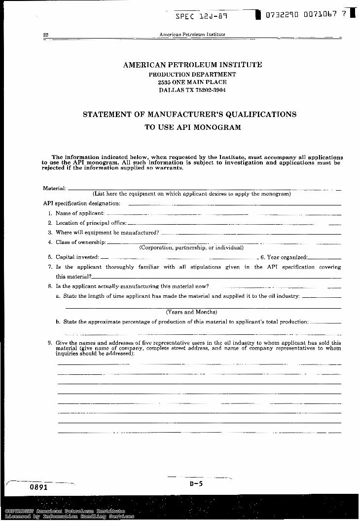
AMERICAN PETROLEUM INSTITUTE PRODUCTION DEPARTMENT
2535 ONE MAIN PLACE DALLAS TX 75202-3904
STATEMENT OF MANUFACTURER’S QUALIFICATIONS
TO USE API MONOGRAM
to use the API monogram. All such information is subject to investigation and applications must be rejected if the information supplied so warrants.
The information indicated below, when requested by the Institute, must accompany all applications
Material: (List here the equipment on which applicant desires to apply the monogram)
API specification designation:
1. Name of applicant:
2. Location of principal office:
3. Where will equipment be manufactured?
4. Class of ownership: (Corporation, partnership, or individual)
5. Capital invested: 6. Year organized:
7. Is the applicant thoroughly familiar with all stipulations given in the API specification covering
this material?
8. Is the applicant actually-manufacturing this material now?
a. State the length of time applicant has made the material and supplied it to the oil industry:
(Years and Months)
b. State the approximate percentage of production of this material to applicant’s total production:
9. Give the names and addresses of five representative users in the oil industry to whom applicant has sold this
inquiries should be addressed): material (give name of company, complete street address, and name of company representatives to whom
COPYRIGHT American Petroleum InstituteLicensed by Information Handling ServicesCOPYRIGHT American Petroleum InstituteLicensed by Information Handling Services
~~
SPEC L2J-87 D 07322qo 0073068
Spec 12J: Oil Gas Separators 23
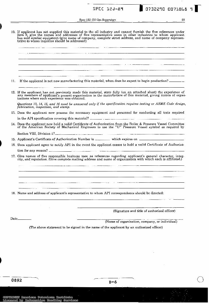
1 10. If applicant has not supplied this material to the oil industry and cannot furnish the five references under
item 9, give the names and addresses of five representative users in other industries to whom applicant has sold similar equipment (give name of company, complete street address, and name of company represen- tative to whom inquiries should be addressed):
1 l.
12.
15.
14.
15. 1 16.
17.
If the applicant is not now manufacturing this material, when does he expect to begin production? ~-
If the applicant has not previously made this material, state fully (on a n attached sheet) the experience of any members of applicant’s present organization in the manufacture of this material, giving names of organ- izations where such experience was obtained.
Questions 13, 14, 15, and 16 need be answered only if the specification requires testing or ASME Code design, fabricatron, inspectron, and stamp.
Does the applicant now possess the necessary equipment and personnel for conducting all tests required
in the API specification covering this material?
of the American Society of Mechanical Engineers to use the U” Pressure Vessel symbol as required by Does the applicant now hold a valid Certificate of Authorization !rom the Boiler & Pressure Vessel Committee
Section VIII, Division I? Applicant’s Certificate of Authorization Number is which expires on
Does applicant agree to notify APT in the event the applicant ceases to hold a valid Certificate of Authoriza-
tion for any reason?
Give names of five responsible business men as references regarding applicant’s general character, integ- rity, and reputation. (Give complete mailing address and name of organization with which each is affiliated.)
18.
~~ ~
Name and address of applicant’s representative to whom API correspondence should be directed:
(Signature and title of authorized officer)
Date- (Name of organization, company, or individual)
(The above statement to be signed in the name of the applicant by an authorized officer)
COPYRIGHT American Petroleum InstituteLicensed by Information Handling ServicesCOPYRIGHT American Petroleum InstituteLicensed by Information Handling Services
Order No. 81 1-06500
Additional copies available from AMERICAN PETROLEUM INSTITUTE Publications and Distribution Section 1220 L Street, NW - Washington, DC 20005 (202) 682-8375
COPYRIGHT American Petroleum InstituteLicensed by Information Handling ServicesCOPYRIGHT American Petroleum InstituteLicensed by Information Handling Services