space resources : energy, power, and transport - lunar and
TRANSCRIPT
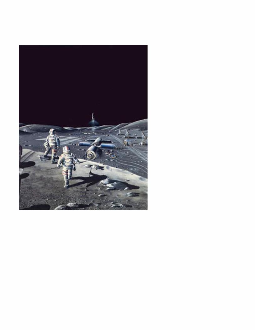
Frontispiece
Advanced Lunar Base In this panorama of an advanced lunar base, the main habitation modules in the background to the right are shown being covered by lunar soil for radiation protection. The modules on the far right are reactors in which lunar soil is being processed to provide oxygen. Each reactor is heated by a solar mirror. The vehicle near them is collecting liquid oxygen from the reactor complex and will transport it to the launch pad in the background, where a tanker is just lifting off. The mining pits are shown just behind the foreground figure on the left. The geologists in the foreground are looking for richer ores to mine. Artist: Dennis Davidson
NASA SP-509, vol. 2
Space Resources
Energy, Power, and Transport
Editors Mary Fae McKay, David S. McKay, and Michael B. Duke
Lyndon B. Johnson Space Center Houston, Texas
1992
For sale by the U.S. Government Printing Office
Superintendent of Documents, Mail Stop: SSOP, Washington, DC 20402-9328
ISBN 0-16-038062-6
National Aeronautics and Space Administration Scientific and Technical Information Program Washington, DC 1992
Technical papers derived from a NASA-ASEE summer study held at the California Space Institute in 1984.
Library of Congress Cataloging-in-Publication Data Space resources : energy, power, and transport / editors, Mary Fae McKay, David S. McKay, and Michael B. Duke. x, 174 p. : ill. ; 28 cm.—(NASA SP ; 509 : vol. 2) 1. Outer space—Exploration—United States. 2. Natural resources. 3. Space industrialization—United States. I. McKay, Mary Fae. II. McKay, David S. III. Duke, Michael B. IV. United States. National Aeronautics and Space Administration. Scientific and Technical Information Program. V. Series. TL789.8.U5S595 1992 92-4468 333.7’0999—dc20
Preface
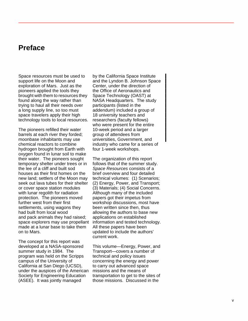
Space resources must be used to support life on the Moon and exploration of Mars. Just as the pioneers applied the tools they brought with them to resources they found along the way rather than trying to haul all their needs over a long supply line, so too must space travelers apply their high technology tools to local resources. The pioneers refilled their water barrels at each river they forded; moonbase inhabitants may use chemical reactors to combine hydrogen brought from Earth with oxygen found in lunar soil to make their water. The pioneers sought temporary shelter under trees or in the lee of a cliff and built sod houses as their first homes on the new land; settlers of the Moon may seek out lava tubes for their shelter or cover space station modules with lunar regolith for radiation protection. The pioneers moved further west from their first settlements, using wagons they had built from local wood and pack animals they had raised; space explorers may use propellant made at a lunar base to take them on to Mars. The concept for this report was developed at a NASA-sponsored summer study in 1984. The program was held on the Scripps campus of the University of California at San Diego (UCSD), under the auspices of the American Society for Engineering Education (ASEE). It was jointly managed
by the California Space Institute and the Lyndon B. Johnson Space Center, under the direction of the Office of Aeronautics and Space Technology (OAST) at NASA Headquarters. The study participants (listed in the addendum) included a group of 18 university teachers and researchers (faculty fellows) who were present for the entire 10-week period and a larger group of attendees from universities, Government, and industry who came for a series of four 1-week workshops. The organization of this report follows that of the summer study. Space Resources consists of a brief overview and four detailed technical volumes: (1) Scenarios; (2) Energy, Power, and Transport; (3) Materials; (4) Social Concerns. Although many of the included papers got their impetus from workshop discussions, most have been written since then, thus allowing the authors to base new applications on established information and tested technology. All these papers have been updated to include the authors’ current work. This volume—Energy, Power, and Transport—covers a number of technical and policy issues concerning the energy and power to carry out advanced space missions and the means of transportation to get to the sites of those missions. Discussed in the
v
first half of this volume are the technologies which might be used to provide power and a variety of ways to convert power from one form to another, store it, move it wherever it is needed, and use it. In the second half of this volume are discussed various kinds of transportation including both interplanetary systems and surface systems. This is certainly not the first report to urge the utilization of space resources in the development of space activities. In fact, Space Resources may be seen as the third of a trilogy of NASA Special Publications reporting such ideas arising from similar studies. It has been preceded by Space Settlements: A Design Study (NASA SP-413) and Space Resources and Space Settlements (NASA SP-428). And other, contemporaneous reports have responded to the same themes. The National Commission on Space, led by Thomas Paine, in Pioneering the Space Frontier, and the NASA task force led by astronaut Sally Ride, in Leadership and America’s Future in Space, also emphasize expansion of the space infrastructure; more detailed exploration of the Moon, Mars,
and asteroids; an early start on the development of the technology necessary for using space resources; and systematic development of the skills necessary for long-term human presence in space. Our report does not represent any Government-authorized view or official NASA policy. NASA’s official response to these challenging opportunities must be found in the reports of its Office of Exploration, which was established in 1987. That office’s report, released in November 1989, of a 90-day study of possible plans for human exploration of the Moon and Mars is NASA’s response to the new initiative proposed by President Bush on July 20, 1989, the 20th anniversary of the Apollo 11 landing on the Moon: “First, for the coming decade, for the 1990s, Space Station Freedom, our critical next step in all our space endeavors. And next, for the new century, back to the Moon, back to the future, and this time, back to stay. And then a journey into tomorrow, a journey to another planet, a manned mission to Mars.” This report, Space Resources, offers substantiation for NASA’s bid to carry out that new initiative.
vi
Contents
ENERGY AND POWER: Introduction ............................. 1 by Rocco Fazzolare Power System Requirements .................................................. 4 by Edmund J. Conway
Low Earth Orbit (LEO) ............................................................ 4 Geosynchronous Earth Orbit (GEO) ..................................... 5 Moon ........................................................................................ 6 Mars ......................................................................................... 10 Asteroids ................................................................................. 11
Technologies .............................................................................. 12 by Henry W. Brandhorst, Jr.
Photovoltaic Technology ....................................................... 12 Solar Dynamic Technology .................................................... 21 Direct Use of Solar Energy ..................................................... 25 Energy Storage . ...................................................................... 25 Power Management and Distribution ................................... 31 Nuclear Energy Technology .................................................. 32 by David Buden
Radioisotope Generators .................................................... 32 Current Status ................................................................. 32 Future Developments ....................................................... 39
Nuclear Reactor Power Plants ............................................ 39 Current Status ................................................................. 39 Future Developments ....................................................... 47
Public Safety and the Use of Nuclear Reactors in Space ... 51 Policy and Goals .............................................................. 51 The Safety Review Process .............................................. 54
References .......................................................................... 56 Thermal Management in Space ............................................. 57 by Abe Hertzberg
Space-Based Power Generating Systems .......................... 58 Heat Rejection Systems ...................................................... 61
Heat Pipes ...................................................................... 61 Pump Loop System .......................................................... 63
Advanced Radiator Concepts ............................................. 65 Improved Conventional Approaches .................................. 65 The Liquid Droplet Radiator .............................................. 65 Belt Radiator Concepts .................................................... 68
vii
Laser Power Transmission ............................................... 70 by Edmund J. Conway Solar-Pumped Photodissociation Lasers ....................... 71 Solar-Pumped Photoexcitation Lasers ........................... 73 Indirect Photoexcitation Lasers ...................................... 74 References . .................................................................... 75 Conclusions .............................................................................. 76 by Henry W. Brandhorst, Jr. TRANSPORT: Introduction ................................................ 82 by William Lewis and Sanders D. Rosenberg
Transportation System Requirements ................................ 85 Surface-to-Orbit Transportation ........................................ 87 Orbit-to-Orbit Transportation ............................................. 91 Surface Transportation (On the Moon) ............................. 93
Effects of Developing Nonterrestrial Resources ............... 95 Remarks ................................................................................. 95 References ............................................................................. 96
Utilization of Space Resources in the Space Transportation System ................................... 97 by Michael C. Simon
Analysis Methodology .......................................................... 97 Results of the Analysis ........................................................ 101 Technology Development Required To Improve Performance .................................................. 104
Aluminum-Fueled Rockets for the Space Transportation System ................................. 109 by Andrew H. Cutler
Introduction ........................................................................... 109 Background ........................................................................... 110 Aluminum Availability in LEO .............................................. 110 Aluminum as a Propellant .................................................... 112 Propellant Demand in LEO ................................................... 113 Aluminum-Fueled Engines for OTV Propulsion ................. 114 Conclusion ............................................................................ 116 References ............................................................................. 116
viii
Electromagnetic Launch of Lunar Material ........................... 117 by William R. Snow and Henry H. Kolm
Introduction ............................................................................... 117 Lunar Oxygen Supply Concept ............................................... 118 Electromagnetic Launcher History ......................................... 121 Electromagnetic Launcher Coilgun Principles ...................... 124 Quenchgun Principles .............................................................. 125 A Lunar Superconducting Quenchgun Design ...................... 128
The Quenchgun Barrel .......................................................... 128 The Carriage and the Liquid Oxygen Tank ........................... 130 The Carriage Decelerating Barrel ......................................... 130 Carriage Retrieval ................................................................. 131 System Description ............................................................... 131
References ................................................................................ 134 Tethers ........................................................................................... 136 by Andrew H. Cutler and Joseph A. Carroll
Tether Characteristics .............................................................. 137 Tether Propulsion ..................................................................... 139
Basics ................................................................................... 139 Propulsion via Momentum Transfer ...................................... 140 Electrodynamic Tether Propulsion ........................................ 142 Planetary Exploration ............................................................ 143
Conclusions About Tethers ..................................................... 144 References ................................................................................ 146 Appendix ................................................................................... 147
Electric Propulsion ...................................................................... 151 by Philip W. Garrison
Candidate Systems ................................................................... 153 Technology Needs .................................................................... 158 Impact of Scenarios Utilizing Nonterrestrial Materials .......... 158 References ................................................................................ 159
Beamed Energy Propulsion ....................................................... 160 by James M. Shoji
Solar Thermal Propulsion ........................................................ 161 Laser Thermal Propulsion ....................................................... 166 Laser Electric Propulsion ........................................................ 169 by Edmund J. Conway Use of Nonterrestrial Resources for Beamed Energy Propulsion ........................................... 169 References ................................................................................ 171
ix
Energy and Power: Introduction Rocco Fazzolare This workshop was directed to identify the energy and power needed to support activities in space, beyond the NASA Space Station Program, up to 2010. Solar and nuclear heat sources are the basis of the production of energy in space. In this section we address stationary systems on a space platform and on the surface of a planetary body. Energy sources, conversion technology, heat rejection, and the delivery of power to the user—important elements that must be considered in system design—may vary according to system use.
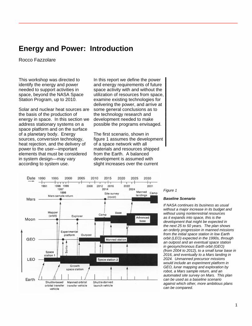
In this report we define the power and energy requirements of future space activity with and without the utilization of resources from space, examine existing technologies for delivering the power, and arrive at some general conclusions as to the technology research and development needed to make possible the programs envisaged. The first scenario, shown in figure 1 assumes the development of a space network with all materials and resources shipped from the Earth. A balanced development is assumed with slight increases over the current
Figure 1
Baseline Scenario
If NASA continues its business as usual without a major increase in its budget and without using nonterrestrial resources as it expands into space, this is the development that might be expected in the next 25 to 50 years. The plan shows an orderly progression in manned missions from the initial space station in low Earth orbit (LEO) expected in the 1990s, through an outpost and an eventual space station in geosynchronous Earth orbit (GEO) (from 2004 to 2012), to a small lunar base in 2016, and eventually to a Mars landing in 2024. Unmanned precursor missions would include an experiment platform in GEO, lunar mapping and exploration by robot, a Mars sample return, and an automated site survey on Mars. This plan can be used as a baseline scenario against which other, more ambitious plans can be compared.
1
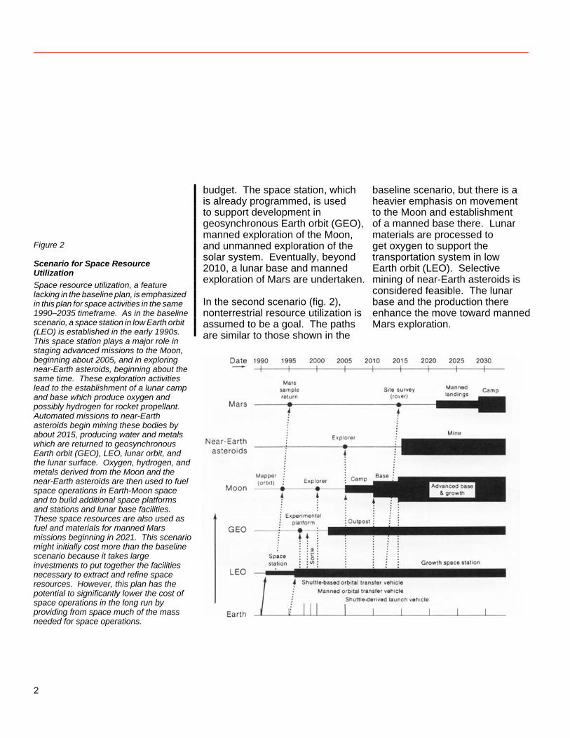
Figure 2
Scenario for Space Resource Utilization Space resource utilization, a feature lacking in the baseline plan, is emphasized in this plan for space activities in the same 1990–2035 timeframe. As in the baseline scenario, a space station in low Earth orbit (LEO) is established in the early 1990s. This space station plays a major role in staging advanced missions to the Moon,
budget. The space station, which is already programmed, is used to support development in geosynchronous Earth orbit (GEO), manned exploration of the Moon, and unmanned exploration of the solar system. Eventually, beyond 2010, a lunar base and manned exploration of Mars are undertaken. In the second scenario (fig. 2), nonterrestrial resource utilization is assumed to be a goal. The paths are similar to those shown in the
baseline scenario, but there is a heavier emphasis on movement to the Moon and establishment of a manned base there. Lunar materials are processed to get oxygen to support the transportation system in low Earth orbit (LEO). Selective mining of near-Earth asteroids is considered feasible. The lunar base and the production there enhance the move toward manned Mars exploration.
beginning about 2005, and in exploring near-Earth asteroids, beginning about the same time. These exploration activities lead to the establishment of a lunar camp and base which produce oxygen and possibly hydrogen for rocket propellant. Automated missions to near-Earth asteroids begin mining these bodies by about 2015, producing water and metals which are returned to geosynchronous Earth orbit (GEO), LEO, lunar orbit, and the lunar surface. Oxygen, hydrogen, and metals derived from the Moon and the near-Earth asteroids are then used to fuel space operations in Earth-Moon space and to build additional space platforms and stations and lunar base facilities. These space resources are also used as fuel and materials for manned Mars missions beginning in 2021. This scenario might initially cost more than the baseline scenario because it takes large investments to put together the facilities necessary to extract and refine space resources. However, this plan has the potential to significantly lower the cost of space operations in the long run by providing from space much of the mass needed for space operations.
2
This section of the report includes two subsections describing “Power System Requirements” in space and the “Technologies” needed to fulfill these requirements. In the first paper, Ed Conway estimates the requirements for power to support the two scenarios, focusing on the requirements for activities at these nodes: low Earth orbit, geosynchronous Earth orbit, the Moon, Mars, and asteroids. He identifies the appropriate technologies for each activity. Henry Brandhorst then describes the solar-energy-related technologies that may be applicable, focusing on photovoltaics and solar dynamics.
Dave Buden explores the development of nuclear power supplies for space applications. Abe Hertzberg addresses the problem of thermal management in space and describes a liquid droplet radiator. Conway discusses laser transmission of power, which if developed can influence the evolution of larger, more centralized, space power-generation stations. Finally, Brandhorst discusses the implications of space power development for the missions to be carried out within the two broad scenarios; he advances the recommendations of the workshop in this area.
3
Power System Requirements Edmund J. Conway
We estimated the electrical power required for each mission in the baseline model (fig. 1) and in the alternative model (fig. 2), according to the specific energy-using activities and operations shown. We then identified appropriate technologies to meet these power requirements, using such criteria as, Can the technology fully meet the requirement? and, Can the technology be ready at least 5 years before the mission? In some cases, there were competing technologies for the same mission. Low Earth Orbit (LEO) The initial space station, scheduled for the mid-1990s, will have 75–300 kW (electric) of continuous bus power. Mid- to late 1980s’ solar photovoltaic technology is the only proven power-generating option available. However, solar photovoltaic systems require large arrays and consequently produce substantial drag. To provide power above the 75-kW level, two technologies could compete: solar dynamic (solar thermal with
Stirling-, Brayton-, or Rankine-cycle conversion) and nuclear thermal (with thermoelectric, thermionic, or dynamic conversion). Both technologies are now in developmental phases. A second-generation space station appears in the baseline model at 2008. It would be needed for large-scale space processing of terrestrial materials. Space Station 2 would require from one to tens of megawatts. Such a mission would provide a major pull on the power-generating technologies. The current choice would appear to be some type of nuclear power system. For power requirements above 1 megawatt, serious technology issues also arise in electrical power management (high voltage and current) and thermal management (how to dispose of 1 MW of low-temperature heat). Electrical power management would require both a new philosophy and some new technology. Thermal management would require such new technology as a large liquid droplet radiator.
4
Geosynchronous Earth Orbit (GEO) By the late 1990s, a geosynchronous experimental science platform would require up to 10 kW. This requirement could be met by solar photovoltaic power. Advanced lightweight power generation and storage systems might be required if the present limitations on payload mass to GEO have not been eased significantly. Such systems, including those with gallium arsenide solar cells in high specific-power chemical storage, are in research stage now. By 2004, a GEO shack or temporarily inhabited repair shop on the platform will allow for human-tended and interchangeable experiments. To operate in the
repair shop, the human tenders would need additional power, on the order of 10 kW. This power could be supplied by the visiting spacecraft. Solar photovoltaic technology, similar to that already mentioned for the platform, could be used. A manned GEO station could be required beyond 2010. The power level anticipated and the enabling technology are similar to those of the LEO growth space station. Thus geosynchronous Earth orbit provides no new power challenges.
5
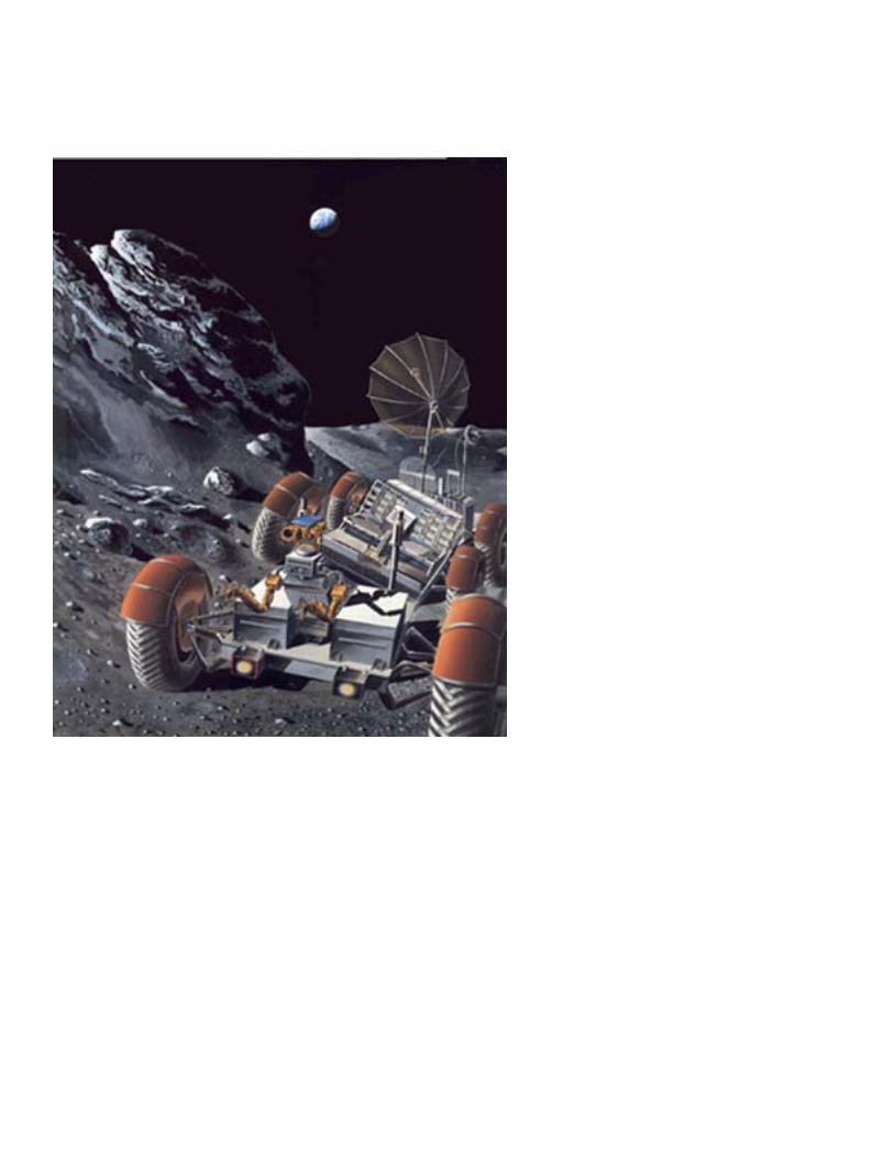
Moon An orbital lunar mapper in the mid- to late 1990s has only small power requirements, which can be met by 1980s’ technology. An unmanned surface explorer (compare (fig. 3), beginning in 2004 would require
only a few (2–5) kilowatts continuously, for movement, surface coring, analysis, and telemetry. A radioisotope generator (compare fig. 4) with dynamic conversion is the technology of choice.
Figure 3
Lunar Rover Used on the Apollo 17 Mission An automated unmanned version of this rover might be useful on future lunar missions. While seemingly simple, this Apollo Rover contained many of the elements necessary for a completely unmanned rover—a sophisticated redundant power system, power steering, automatic thermal control, a dust control system, and a self-contained navigation system which kept track of the location of the Rover at all times. The Apollo 17 Rover, using two 36-volt silver-zinc batteries rated at 121 amp- hours each, traveled a maximum distance from the Lunar Module (LM) of 7.6 km. For long unmanned traverses, battery power would probably not be practical because of the relatively low energy density of batteries. A completely automated rover with an artificial intelligence (AI) system or a teleoperated rover are two possible versions for future applications. NASA photo: AS17-146-22367
6
Figure 4
a. Radioisotope Thermoelectric Generator This radioisotope thermoelectric generator (RTG) was the power source for the Apollo lunar surface experiments package (ALSEP) on the Apollo 16 mission. This power generator contains fins for radiating away excess heat. On this mission it powered an active seismic experiment (see accompanying fig.), a passive seismic experiment, a surface magnetometer, a heat flow experiment, and the central control and communications station. NASA photo: AS16-113-18352 b. Mortar Firing Assembly for the Active Seismic Experiment This assembly in the ALSEP was designed to fire four grenades out to a maximum distance of 1.5 km. The grenades were designed to explode on impact, generating a seismic signal which would be picked up by a string of three geophones. On the actual mission, only three of the grenades were used and the maximum distance traveled was about 900 m. This experiment determined the thickness and seismic velocity of the near-surface structure at the Apollo 16 site. NASA photo: AS16-113-18380
7
By 2010, a lunar camp, to be inhabited only during the 2 weeks of lunar day, would initially require 25 kW, supplied by a solar photovoltaic system. This initial power level could be augmented during future visits using similar or improved photovoltaic technology. Or the lunar camp’s power system could grow, in the same manner as that of the space station, to include solar dynamic or nuclear supplies. The initial power level is suitable for crew life support, lunar science, and light work, but it does not
provide the storable energy for heat and life support during the lunar night. For full-time habitation, the camp and later the base would rely on nuclear power supplying a few hundred kilowatts. (See the analogy in figure 5.) High power requirements away from the base for transportation or mining could be supplied by a separate source or by transmission. Point-to-point beamed transmission along the surface or between surface and space is possible.
Figure 5
a. Spartan Lunar Base The early lunar base may consist of several modules similar to habitation and laboratory modules for the space station, which can be transported to the lunar surface and covered with lunar regolith for radiation protection. In many ways this early base would be like the American Station at the South Pole, which is probably the closest thing we have to a base on another planet. NASA photo: S78-23251
8
b. South Pole Station The South Pole station is continuously occupied, but crewmembers arrive or depart only during the summer season. While the occupants can venture outside with protective clothing (“space suits”) during the winter, they are mostly dependent on the shelter provided by the geodesic dome and the buildings within the dome, much as they would be at a Moon or Mars base. Analogous to the Antarctic winter is the lunar night. More power would be required for heating and lighting in both cases. Even more important on the Moon, solar power would not be available at night unless massive storage was provided. Continuous occupation of a lunar base would probably rely on nuclear power. Photo: Michael E. Zolensky
9
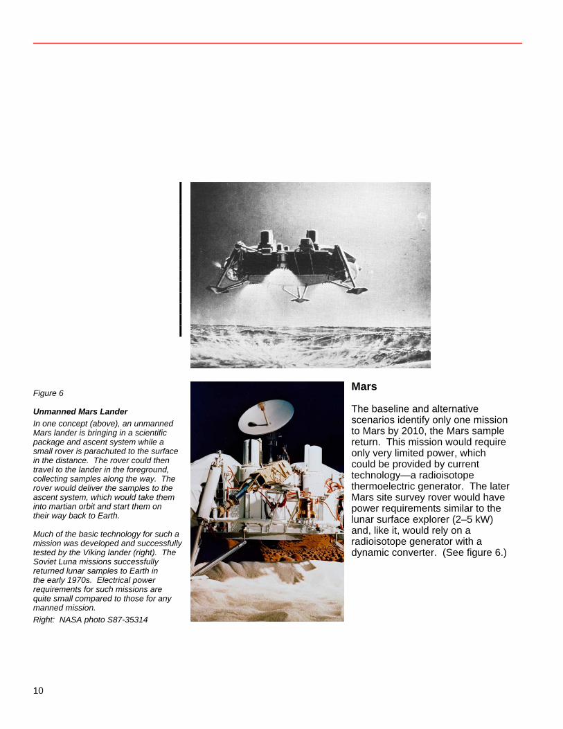
Figure 6
Unmanned Mars Lander In one concept (above), an unmanned Mars lander is bringing in a scientific package and ascent system while a small rover is parachuted to the surface in the distance. The rover could then travel to the lander in the foreground, collecting samples along the way. The rover would deliver the samples to the ascent system, which would take them into martian orbit and start them on their way back to Earth. Much of the basic technology for such a mission was developed and successfully tested by the Viking lander (right). The Soviet Luna missions successfully returned lunar samples to Earth in the early 1970s. Electrical power requirements for such missions are quite small compared to those for any manned mission. Right: NASA photo S87-35314
Mars The baseline and alternative scenarios identify only one mission to Mars by 2010, the Mars sample return. This mission would require only very limited power, which could be provided by current technology—a radioisotope thermoelectric generator. The later Mars site survey rover would have power requirements similar to the lunar surface explorer (2–5 kW) and, like it, would rely on a radioisotope generator with a dynamic converter. (See figure 6.)
10
Asteroids The alternative model (fig. 2) includes unmanned exploration of an asteroid beginning in 2005. This involves activities and power requirements similar to those for the earlier lunar surface explorer and could be handled by a similar system.
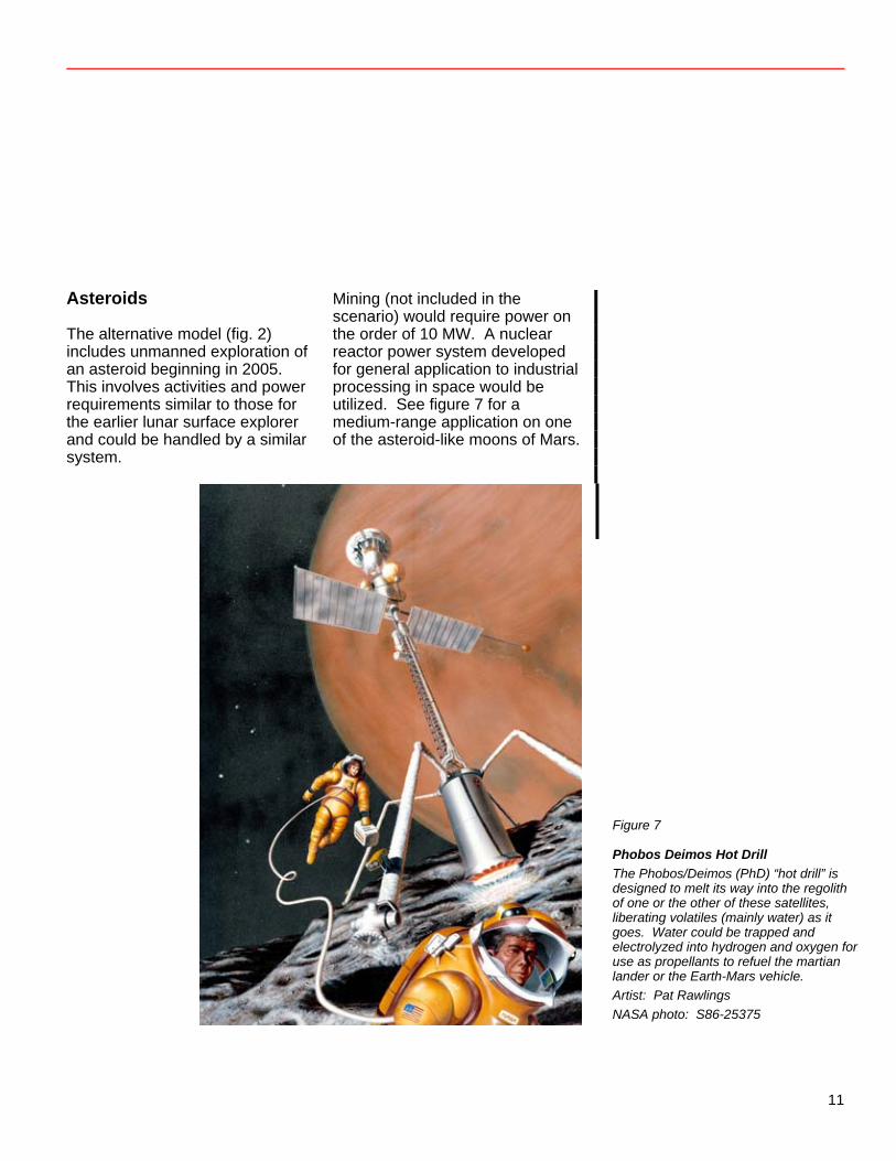
Mining (not included in the scenario) would require power on the order of 10 MW. A nuclear reactor power system developed for general application to industrial processing in space would be utilized. See figure 7 for a medium-range application on one of the asteroid-like moons of Mars.
Figure 7
Phobos Deimos Hot Drill The Phobos/Deimos (PhD) “hot drill” is designed to melt its way into the regolith of one or the other of these satellites, liberating volatiles (mainly water) as it goes. Water could be trapped and electrolyzed into hydrogen and oxygen for use as propellants to refuel the martian lander or the Earth-Mars vehicle. Artist: Pat Rawlings NASA photo: S86-25375
11
Technologies Henry W. Brandhorst, Jr.
Photovoltaic Technology Solar cells have been the workhorse of the space program for nearly all missions lasting longer than a few weeks. Several components are needed for reliable power production from solar cells. Solar cells must be interconnected to provide the requisite voltage and current levels. This matrix must be supported on a substrate such as aluminum honeycomb or a plastic like Kapton. The individual cells also must be covered to provide protection against the electrons and protons found in the Earth’s radiation belt and in ejecta from the Sun. Finally, some sort of deployment or erection mechanism must be supplied to extend the solar array from the spacecraft. The mass of the system is made up of these components, along with the power management and distribution system and the storage system needed to provide power during the dark phase. Currently silicon solar cells are the prime power source for satellite use. Maximum individual efficiency is about 14 percent in volume
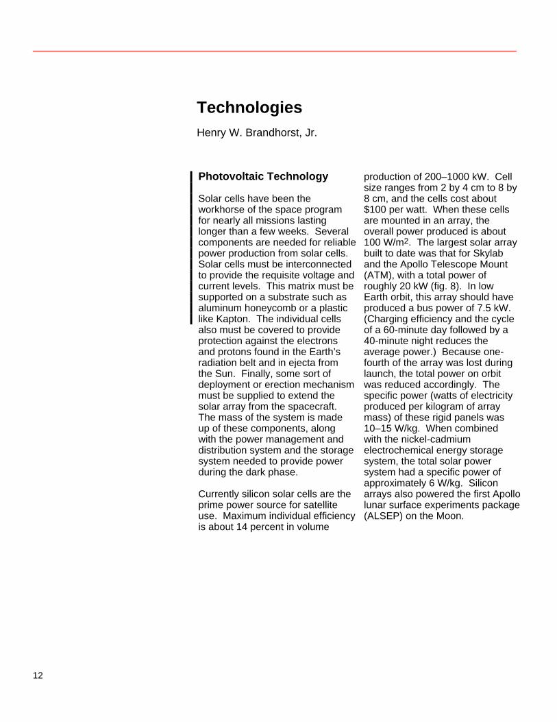
production of 200–1000 kW. Cell size ranges from 2 by 4 cm to 8 by 8 cm, and the cells cost about $100 per watt. When these cells are mounted in an array, the overall power produced is about 100 W/m2. The largest solar array built to date was that for Skylab and the Apollo Telescope Mount (ATM), with a total power of roughly 20 kW (fig. 8). In low Earth orbit, this array should have produced a bus power of 7.5 kW. (Charging efficiency and the cycle of a 60-minute day followed by a 40-minute night reduces the average power.) Because one-fourth of the array was lost during launch, the total power on orbit was reduced accordingly. The specific power (watts of electricity produced per kilogram of array mass) of these rigid panels was 10–15 W/kg. When combined with the nickel-cadmium electrochemical energy storage system, the total solar power system had a specific power of approximately 6 W/kg. Silicon arrays also powered the first Apollo lunar surface experiments package (ALSEP) on the Moon.
12
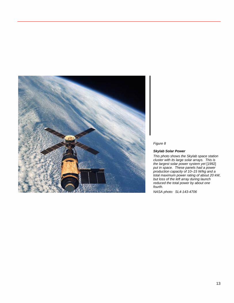
Figure 8
Skylab Solar Power This photo shows the Skylab space station cluster with its large solar arrays. This is the largest solar power system yet [1992] put in space. These panels had a power production capacity of 10–15 W/kg and a total maximum power rating of about 20 kW, but loss of the left array during launch reduced the total power by about one fourth. NASA photo: SL4-143-4706
13
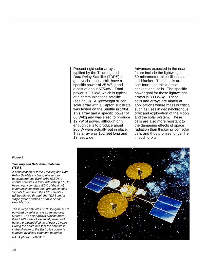
Present rigid solar arrays, typified by the Tracking and Data Relay Satellite (TDRS) in geosynchronous orbit, have a specific power of 25 W/kg and a cost of about $750/W. Total power is 2.7 kW, which is typical of a communications satellite (see fig. 9). A lightweight silicon solar array with a Kapton substrate was tested on the Shuttle in 1984. This array had a specific power of 66 W/kg and was sized to produce 12 kW of power, although only enough cells to produce about 200 W were actually put in place. This array was 102 feet long and 13 feet wide.
Advances expected in the near future include the lightweight, 50-micrometer-thick silicon solar cell blanket. These cells are one-fourth the thickness of conventional cells. The specific power goal for these lightweight arrays is 300 W/kg. These cells and arrays are aimed at applications where mass is critical, such as uses in geosynchronous orbit and exploration of the Moon and the solar system. These cells are also more resistant to the damaging effects of space radiation than thicker silicon solar cells and thus promise longer life in such orbits.
Figure 9
Tracking and Data Relay Satellite (TDRS) A constellation of three Tracking and Data Relay Satellites is being placed into geosynchronous Earth orbit (GEO) to enable satellites in low Earth orbit (LEO) to be in nearly constant (80% of the time) communication with their ground stations. Signals to and from the LEO satellites will be relayed through the TDRS and a single ground station at White Sands, New Mexico. These large satellites (2200 kilograms) are powered by solar arrays spanning over 50 feet. The solar arrays provide more than 1700 watts of electrical power and have a projected lifetime of over 10 years. During the short time that the satellite is in the shadow of the Earth, full power is supplied by nickel-cadmium batteries. NASA photo: S80-34185
14
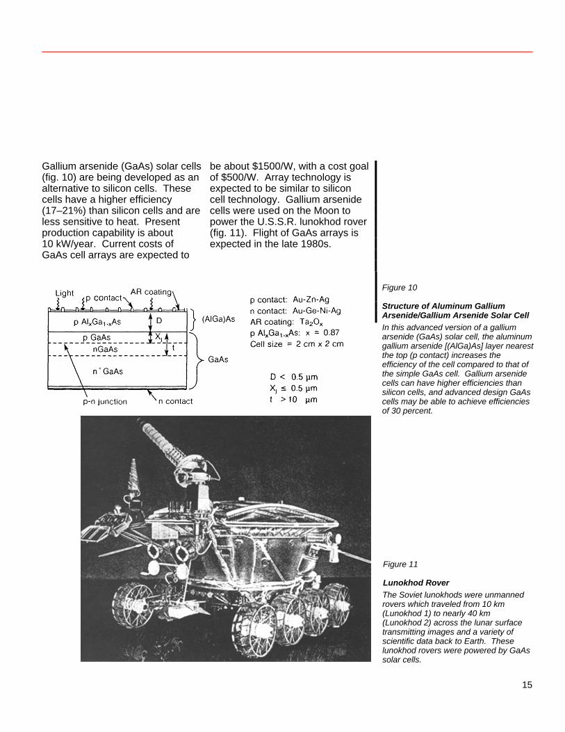
Gallium arsenide (GaAs) solar cells (fig. 10) are being developed as an alternative to silicon cells. These cells have a higher efficiency (17–21%) than silicon cells and are less sensitive to heat. Present production capability is about 10 kW/year. Current costs of GaAs cell arrays are expected to
be about $1500/W, with a cost goal of $500/W. Array technology is expected to be similar to silicon cell technology. Gallium arsenide cells were used on the Moon to power the U.S.S.R. lunokhod rover (fig. 11). Flight of GaAs arrays is expected in the late 1980s.
Figure 10
Structure of Aluminum Gallium Arsenide/Gallium Arsenide Solar Cell In this advanced version of a gallium arsenide (GaAs) solar cell, the aluminum gallium arsenide [(AlGa)As] layer nearest the top (p contact) increases the efficiency of the cell compared to that of the simple GaAs cell. Gallium arsenide cells can have higher efficiencies than silicon cells, and advanced design GaAs cells may be able to achieve efficiencies of 30 percent. Figure 11
Lunokhod Rover The Soviet lunokhods were unmanned rovers which traveled from 10 km (Lunokhod 1) to nearly 40 km (Lunokhod 2) across the lunar surface transmitting images and a variety of scientific data back to Earth. These lunokhod rovers were powered by GaAs solar cells.
15
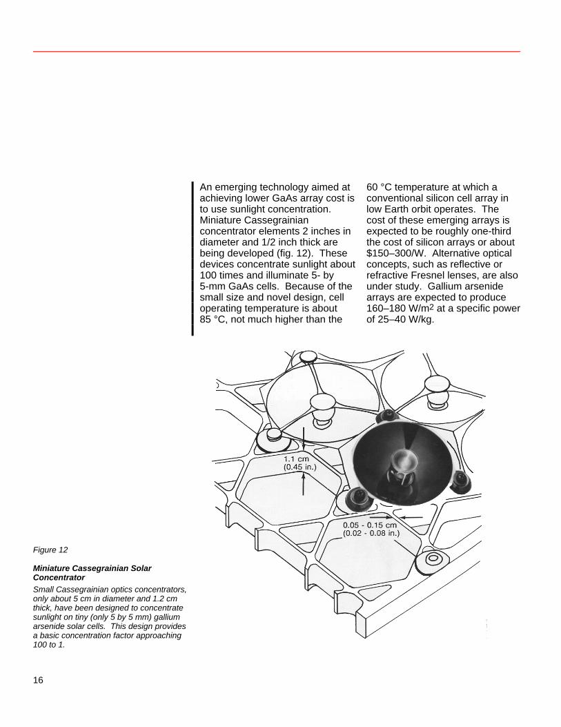
An emerging technology aimed at achieving lower GaAs array cost is to use sunlight concentration. Miniature Cassegrainian concentrator elements 2 inches in diameter and 1/2 inch thick are being developed (fig. 12). These devices concentrate sunlight about 100 times and illuminate 5- by 5-mm GaAs cells. Because of the small size and novel design, cell operating temperature is about 85 °C, not much higher than the
60 °C temperature at which a conventional silicon cell array in low Earth orbit operates. The cost of these emerging arrays is expected to be roughly one-third the cost of silicon arrays or about $150–300/W. Alternative optical concepts, such as reflective or refractive Fresnel lenses, are also under study. Gallium arsenide arrays are expected to produce 160–180 W/m2 at a specific power of 25–40 W/kg.
Figure 12
Miniature Cassegrainian Solar Concentrator Small Cassegrainian optics concentrators, only about 5 cm in diameter and 1.2 cm thick, have been designed to concentrate sunlight on tiny (only 5 by 5 mm) gallium arsenide solar cells. This design provides a basic concentration factor approaching 100 to 1.
16
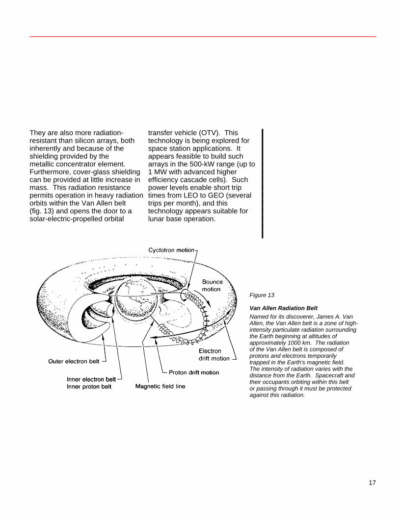
They are also more radiation-resistant than silicon arrays, both inherently and because of the shielding provided by the metallic concentrator element. Furthermore, cover-glass shielding can be provided at little increase in mass. This radiation resistance permits operation in heavy radiation orbits within the Van Allen belt (fig. 13) and opens the door to a solar-electric-propelled orbital
transfer vehicle (OTV). This technology is being explored for space station applications. It appears feasible to build such arrays in the 500-kW range (up to 1 MW with advanced higher efficiency cascade cells). Such power levels enable short trip times from LEO to GEO (several trips per month), and this technology appears suitable for lunar base operation.
Figure 13
Van Allen Radiation Belt Named for its discoverer, James A. Van Allen, the Van Allen belt is a zone of high-intensity particulate radiation surrounding the Earth beginning at altitudes of approximately 1000 km. The radiation of the Van Allen belt is composed of protons and electrons temporarily trapped in the Earth's magnetic field. The intensity of radiation varies with the distance from the Earth. Spacecraft and their occupants orbiting within this belt or passing through it must be protected against this radiation.
17
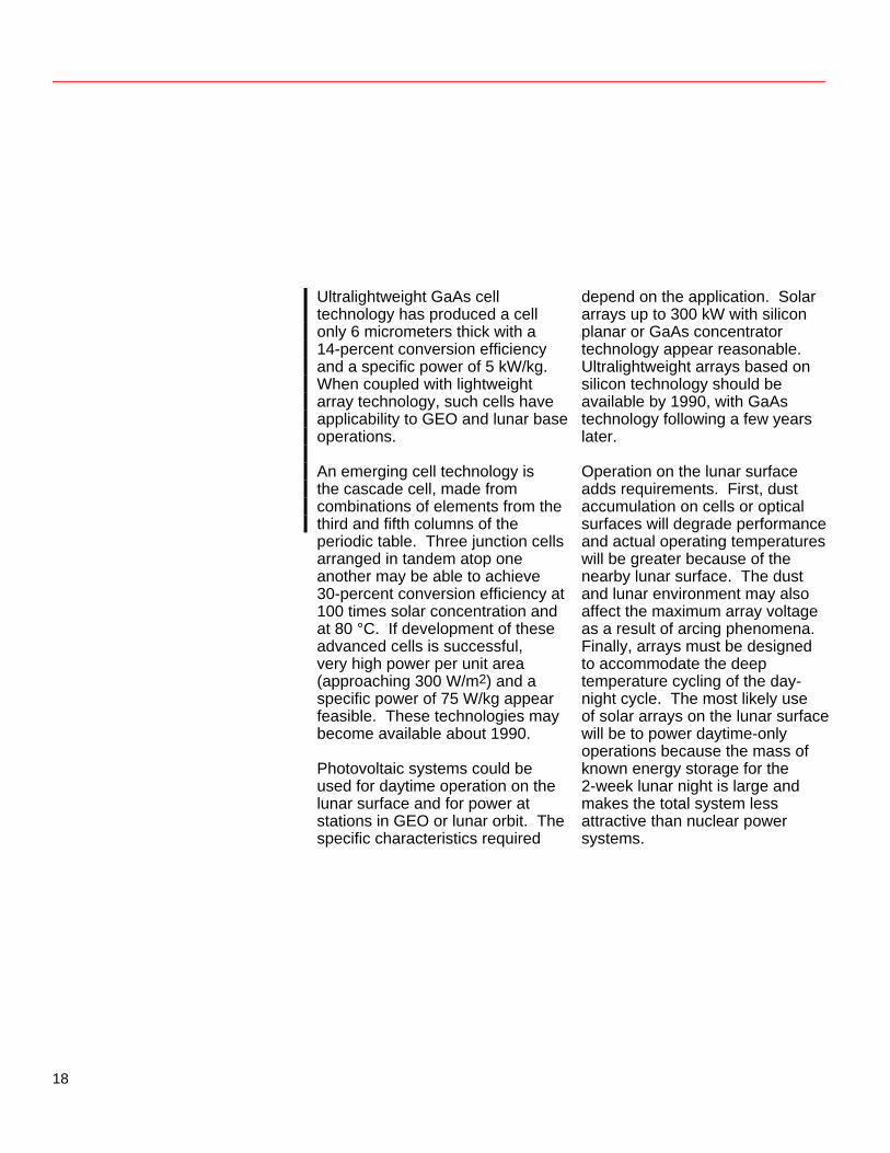
Ultralightweight GaAs cell technology has produced a cell only 6 micrometers thick with a 14-percent conversion efficiency and a specific power of 5 kW/kg. When coupled with lightweight array technology, such cells have applicability to GEO and lunar base operations. An emerging cell technology is the cascade cell, made from combinations of elements from the third and fifth columns of the periodic table. Three junction cells arranged in tandem atop one another may be able to achieve 30-percent conversion efficiency at 100 times solar concentration and at 80 °C. If development of these advanced cells is successful, very high power per unit area (approaching 300 W/m2) and a specific power of 75 W/kg appear feasible. These technologies may become available about 1990. Photovoltaic systems could be used for daytime operation on the lunar surface and for power at stations in GEO or lunar orbit. The specific characteristics required
depend on the application. Solar arrays up to 300 kW with silicon planar or GaAs concentrator technology appear reasonable. Ultralightweight arrays based on silicon technology should be available by 1990, with GaAs technology following a few years later. Operation on the lunar surface adds requirements. First, dust accumulation on cells or optical surfaces will degrade performance and actual operating temperatures will be greater because of the nearby lunar surface. The dust and lunar environment may also affect the maximum array voltage as a result of arcing phenomena. Finally, arrays must be designed to accommodate the deep temperature cycling of the day-night cycle. The most likely use of solar arrays on the lunar surface will be to power daytime-only operations because the mass of known energy storage for the 2-week lunar night is large and makes the total system less attractive than nuclear power systems.
18
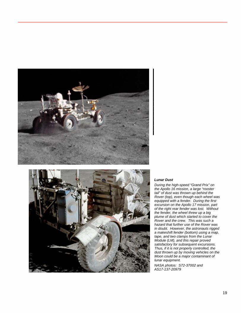
Lunar Dust During the high-speed “Grand Prix” on the Apollo 16 mission, a large “rooster tail” of dust was thrown up behind the Rover (top), even though each wheel was equipped with a fender. During the first excursion on the Apollo 17 mission, part of the right rear fender was lost. Without the fender, the wheel threw up a big plume of dust which started to cover the Rover and the crew. This was such a hazard that further use of the Rover was in doubt. However, the astronauts rigged a makeshift fender (bottom) using a map, tape, and two clamps from the Lunar Module (LM), and this repair proved satisfactory for subsequent excursions. Thus, if it is not properly controlled, the dust thrown up by moving vehicles on the Moon could be a major contaminant of lunar equipment. NASA photos: S72-37002 and AS17-137-20979
19
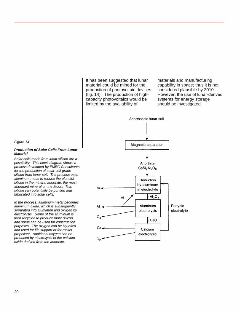
It has been suggested that lunar material could be mined for the production of photovoltaic devices (fig. 14). The production of high-capacity photovoltaics would be limited by the availability of
materials and manufacturing capability in space; thus it is not considered plausible by 2010. However, the use of lunar-derived systems for energy storage should be investigated.
Figure 14
Production of Solar Cells From Lunar Material Solar cells made from lunar silicon are a possibility. This block diagram shows a process developed by EMEC Consultants for the production of solar-cell-grade silicon from lunar soil. The process uses aluminum metal to reduce the plentiful silicon in the mineral anorthite, the most abundant mineral on the Moon. This silicon can potentially be purified and fabricated into solar cells. In the process, aluminum metal becomes aluminum oxide, which is subsequently separated into aluminum and oxygen by electrolysis. Some of the aluminum is then recycled to produce more silicon, and some can be used for construction purposes. The oxygen can be liquefied and used for life support or for rocket propellant. Additional oxygen can be produced by electrolysis of the calcium oxide derived from the anorthite.
20
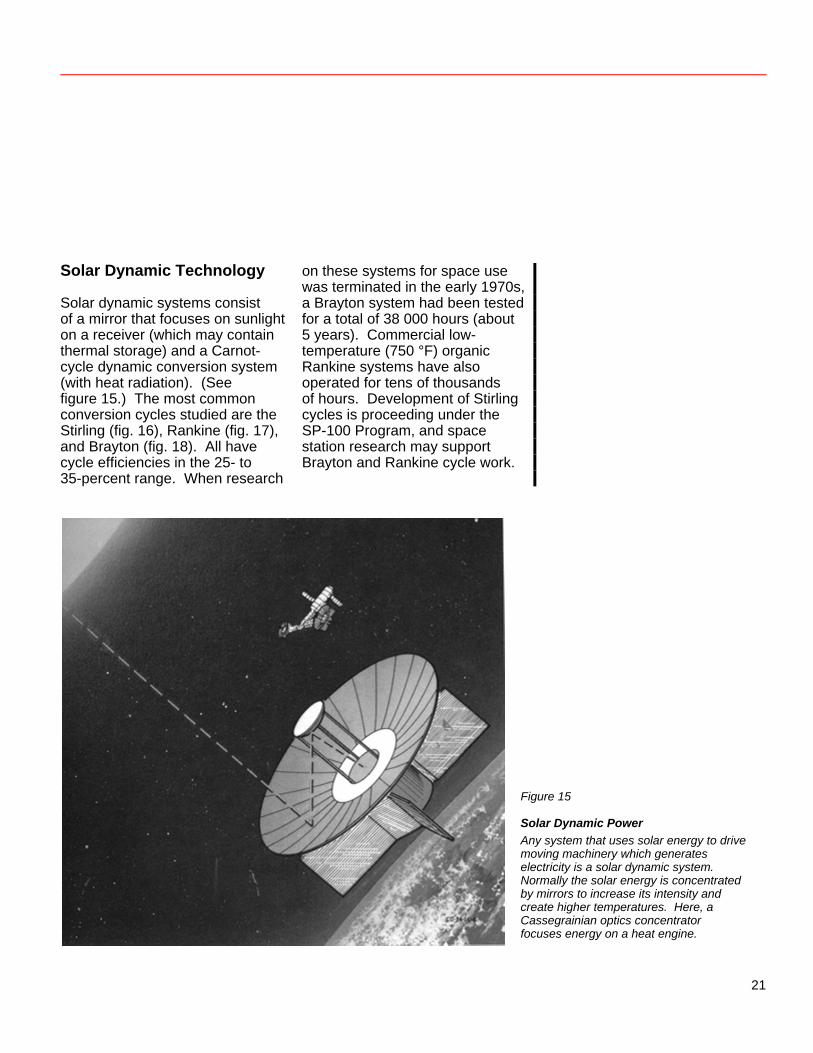
Solar Dynamic Technology Solar dynamic systems consist of a mirror that focuses on sunlight on a receiver (which may contain thermal storage) and a Carnot-cycle dynamic conversion system (with heat radiation). (See figure 15.) The most common conversion cycles studied are the Stirling (fig. 16), Rankine (fig. 17), and Brayton (fig. 18). All have cycle efficiencies in the 25- to 35-percent range. When research
on these systems for space use was terminated in the early 1970s, a Brayton system had been tested for a total of 38 000 hours (about 5 years). Commercial low-temperature (750 °F) organic Rankine systems have also operated for tens of thousands of hours. Development of Stirling cycles is proceeding under the SP-100 Program, and space station research may support Brayton and Rankine cycle work.
Figure 15
Solar Dynamic Power Any system that uses solar energy to drive moving machinery which generates electricity is a solar dynamic system. Normally the solar energy is concentrated by mirrors to increase its intensity and create higher temperatures. Here, a Cassegrainian optics concentrator focuses energy on a heat engine.
21
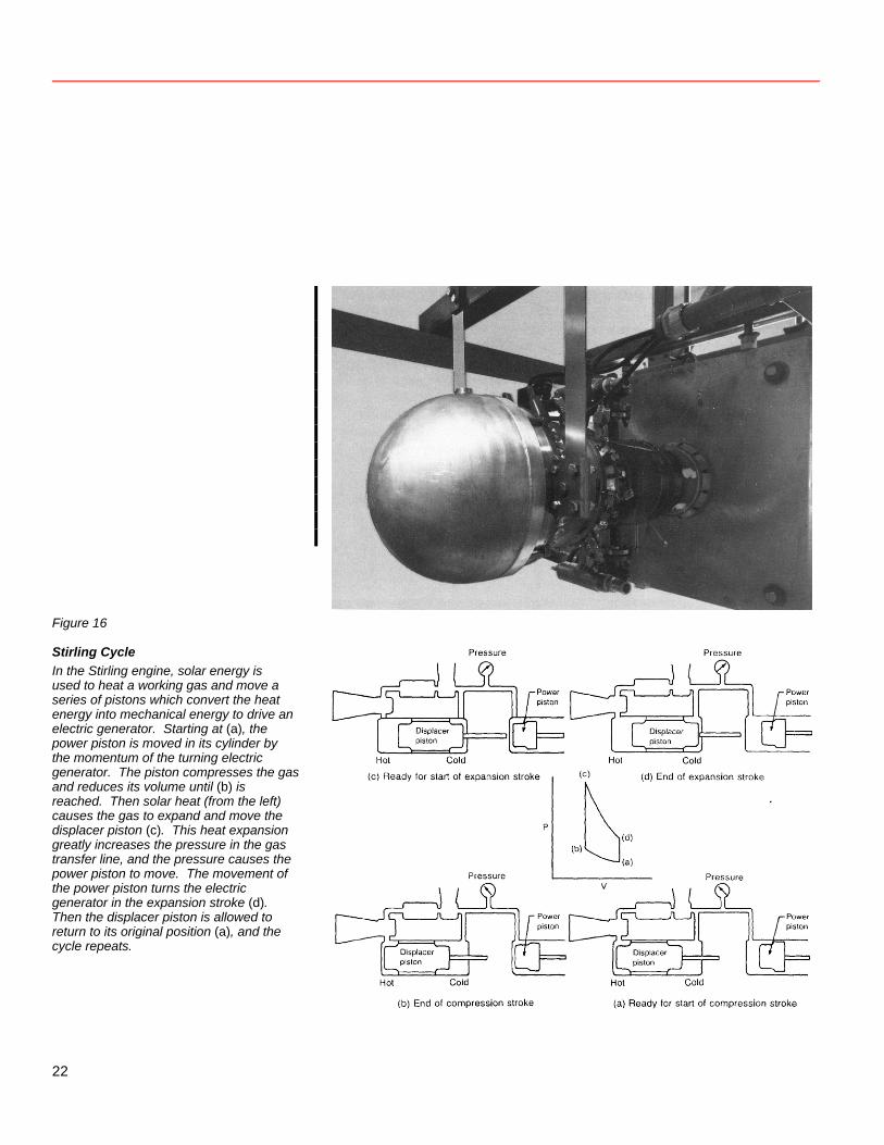
Figure 16
Stirling Cycle In the Stirling engine, solar energy is used to heat a working gas and move a series of pistons which convert the heat energy into mechanical energy to drive an electric generator. Starting at (a), the power piston is moved in its cylinder by the momentum of the turning electric generator. The piston compresses the gas and reduces its volume until (b) is reached. Then solar heat (from the left) causes the gas to expand and move the displacer piston (c). This heat expansion greatly increases the pressure in the gas transfer line, and the pressure causes the power piston to move. The movement of the power piston turns the electric generator in the expansion stroke (d). Then the displacer piston is allowed to return to its original position (a), and the cycle repeats.
22
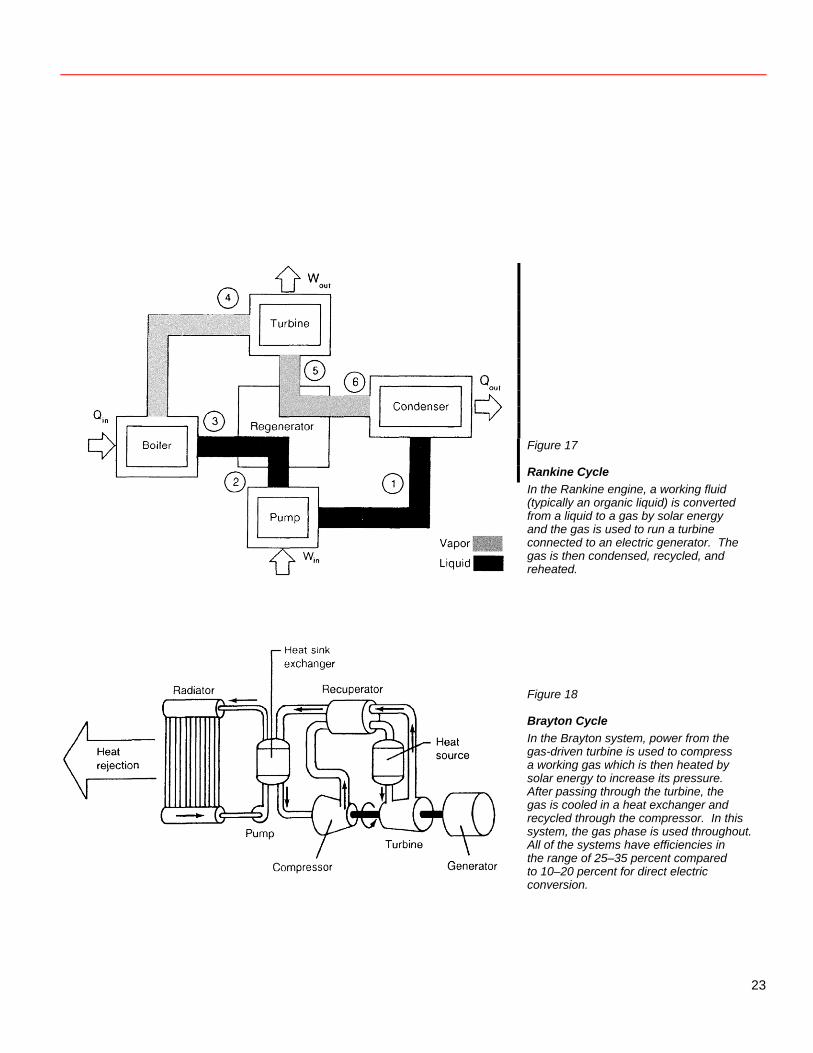
Figure 17
Rankine Cycle In the Rankine engine, a working fluid (typically an organic liquid) is converted from a liquid to a gas by solar energy and the gas is used to run a turbine connected to an electric generator. The gas is then condensed, recycled, and reheated. Figure 18
Brayton Cycle In the Brayton system, power from the gas-driven turbine is used to compress a working gas which is then heated by solar energy to increase its pressure. After passing through the turbine, the gas is cooled in a heat exchanger and recycled through the compressor. In this system, the gas phase is used throughout. All of the systems have efficiencies in the range of 25–35 percent compared to 10–20 percent for direct electric conversion.
23
Critical system elements are, first, the heat receiver, especially if it includes thermal storage, and, second, lightweight precision collectors operating at 200- to 1000-times concentration. For lunar surface operation during the day, no thermal storage is required. As in the electrochemical storage case, extensive amounts of thermal storage would be required to meet the demands of the 2-week nights. If lunar materials having proper thermal characteristics were available for storage (questionable at this time), it is possible that solar dynamic systems could provide complete power night and day. Further study is required to substantiate this possibility. Studies on solar Brayton cycles for the LEO space station show that a mirror 21 meters in diameter could produce 80 kW, while a mirror 8.2 meters in diameter could produce 10 kW. Were these size systems to be in continuous sunlight, the comparable powers
would be roughly 175 and 22 kW, with system specific powers of 13 and 10 W/kg. Because thermal storage is one-half the total system mass, eliminating such storage (for lunar day-only operation) would increase system specific power to 26 and 20 W/kg, respectively. With system improvements (mirrors, receivers, radiators), and including other Carnot-cycle engines, specific powers around 40 W/kg (with no thermal storage) are possible at operating temperatures between 1100 and 1300 K. With space station support and with long-term advanced research support, high-performance solar dynamic systems could be available by the year 2000. These systems require that the waste heat be rejected. Thermal management (radiators, heat sinks) remains a critical technology for solar thermal dynamic systems, just as it does for nuclear power systems.
24
Direct Use of Solar Energy Many industrial processes have substantial need for high quality thermal energy. Such applications as volatilization, evaporation, and melting can use thermal energy directly, without an electrical intermediary (fig. 19). The basic elements needed are lightweight mirrors and receivers that can collect, distribute, and deliver thermal energy to its point of use. Technology for direct utilization of solar radiation is being developed for terrestrial applications. Energy Storage Energy storage is required to provide power for operations during dark times. The nickel-cadmium battery has been the common
energy storage companion for solar cells on satellites. Specific energy densities (energy per unit mass) of 10 Whr/kg are common at the 10- to 20-percent depths of discharge used to provide cycle life. As a rule, the energy storage subsystem is the heaviest and largest part of a solar power system. Furthermore, NiCd batteries are sensitive to overcharge; hence, each cell must be carefully controlled. This need poses additional system constraints as power system voltage increases to the 100-kilowatt level and beyond. Individual pressure vessel (IPV) nickel-hydrogen battery systems are being developed to provide increased energy densities (fig. 20). These batteries provide about 15–20 Whr/kg for GEO
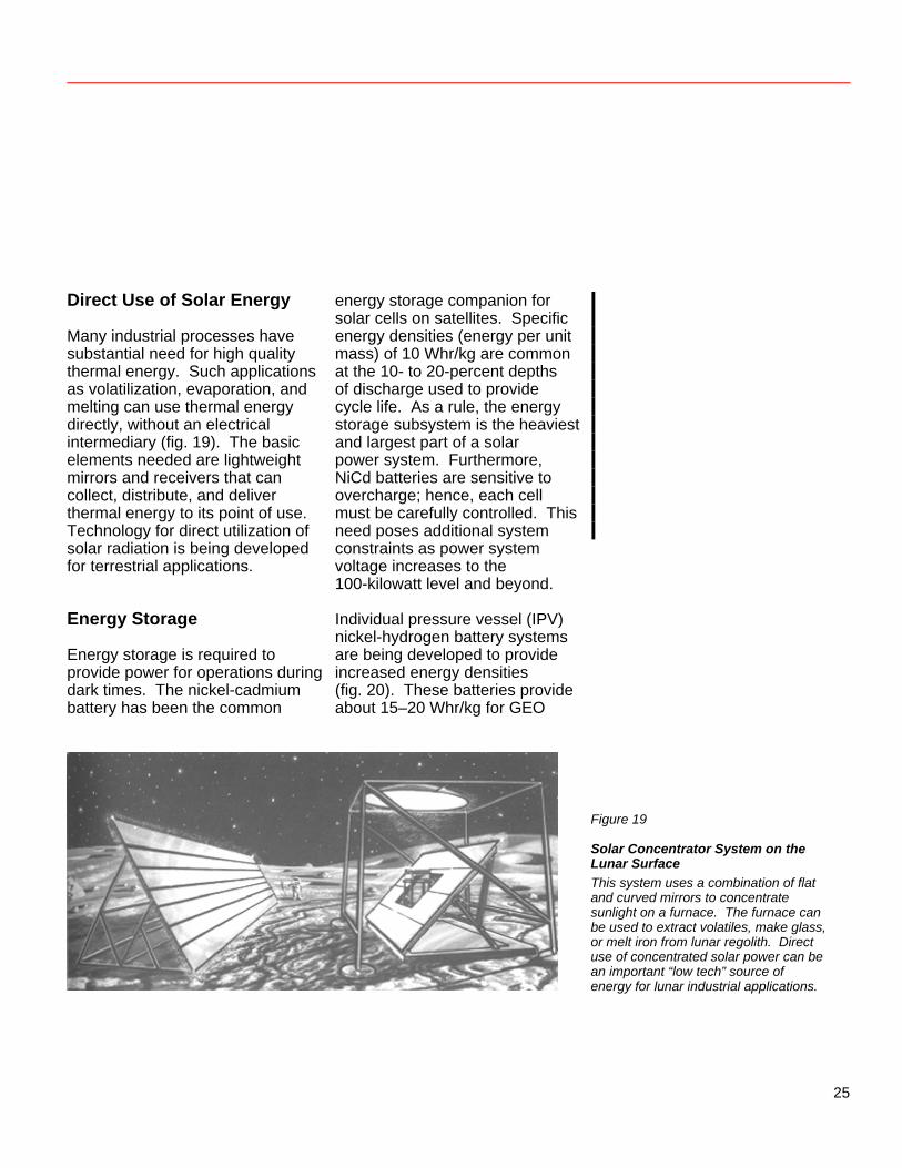
Figure 19
Solar Concentrator System on the Lunar Surface This system uses a combination of flat and curved mirrors to concentrate sunlight on a furnace. The furnace can be used to extract volatiles, make glass, or melt iron from lunar regolith. Direct use of concentrated solar power can be an important “low tech” source of energy for lunar industrial applications.
25
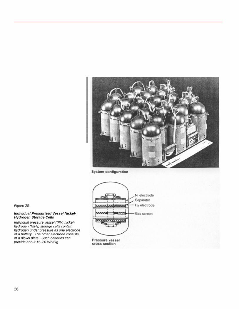
Figure 20
Individual Pressurized Vessel Nickel-Hydrogen Storage Cells Individual pressure vessel (IPV) nickel-hydrogen (NiH2) storage cells contain hydrogen under pressure as one electrode of a battery. The other electrode consists of a nickel plate. Such batteries can provide about 15–20 Whr/kg.
26
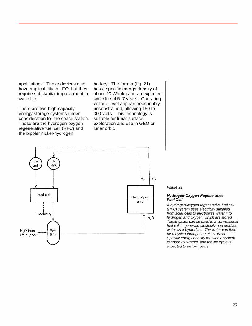
applications. These devices also have applicability to LEO, but they require substantial improvement in cycle life. There are two high-capacity energy storage systems under consideration for the space station. These are the hydrogen-oxygen regenerative fuel cell (RFC) and the bipolar nickel-hydrogen
battery. The former (fig. 21) has a specific energy density of about 20 Whr/kg and an expected cycle life of 5–7 years. Operating voltage level appears reasonably unconstrained, allowing 150 to 300 volts. This technology is suitable for lunar surface exploration and use in GEO or lunar orbit.
Figure 21
Hydrogen-Oxygen Regenerative Fuel Cell A hydrogen-oxygen regenerative fuel cell (RFC) system uses electricity supplied from solar cells to electrolyze water into hydrogen and oxygen, which are stored. These gases can be used in a conventional fuel cell to generate electricity and produce water as a byproduct. The water can then be recycled through the electrolyzer. Specific energy density for such a system is about 20 Whr/kg, and the life cycle is expected to be 5–7 years.
27
Technology advances may offer energy densities of 1000 Whr/kg to lunar applications. A fuel cell separates power delivered from energy stored. Power is determined by the area of the plates; energy, by the volume of the reactants. Thus, when energy densities of 1000 Whr/kg are combined with lightweight solar arrays and high-voltage power management systems, the overall system promises specific powers near 500 W/kg. It should be noted, however, that the mass of a 1000-Whr/kg storage system to provide 100 kW of power during lunar night would be roughly 33 600 kg. The bipolar NiH2 technology marries battery and fuel cell technologies to the benefit of both. Chief advantages are substantially increased cycle life over IPV NiH2, easy high-voltage battery design by adding more plates, and extremely high discharge capability (20 times charging rate). Bipolar NiH2 systems appear equivalent in mass to state-of-the-art regenerative fuel cells at 100-kW capacities. However, this technology lags that of the hydrogen-oxygen RFC by several years. Furthermore, substantial improvement in basic understanding and in plate and separator technology is required before these cells can even begin
to approach the 1000-Whr/kg potential of the hydrogen-oxygen regenerative fuel cell. Two additional systems appear capable of high storage densities. These are the rechargeable lithium battery and the hydrogen-halogen (Br, CI) regenerative fuel cell. Both technologies are in infant stages of development, with issues of materials, cycle life, current densities, separators, and electrolytes. With additional research emphasis, these systems could become available between 1995 and 2000. Because mass is at such a premium on the Moon, and because the energy storage system is the most massive part of a photovoltaic system that supplies continuous power, additional effort should be directed toward innovative energy storage technologies, electrochemical and other. Flywheels are one example of mechanical energy storage (fig. 22). Although flywheels probably can store in excess of 100 Whr/kg, the overall systems are still heavy (10 Whr/kg) at present. Although these systems may be capable of long lives, this capability has not yet been demonstrated, nor have all failure modes and safety needs been identified.
28
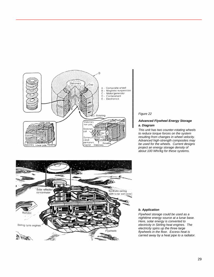
Figure 22
Advanced Flywheel Energy Storage a. Diagram This unit has two counter-rotating wheels to reduce torque forces on the system resulting from changes in wheel velocity. Advanced high-strength composites may be used for the wheels. Current designs project an energy storage density of about 100 Whr/kg for these systems. b. Application Flywheel storage could be used as a nighttime energy source at a lunar base. Here, solar energy is converted to electricity in Stirling heat engines. The electricity spins up the three large flywheels in the floor. Excess heat is carried away by a heat pipe to a radiator.
29
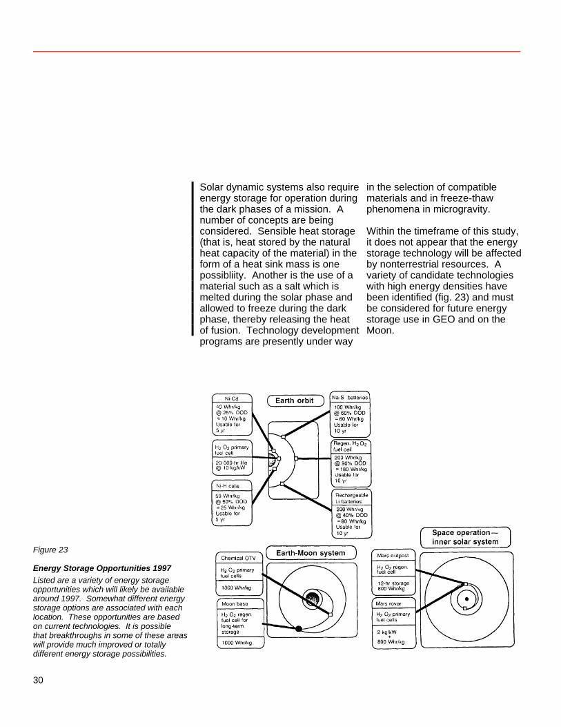
Solar dynamic systems also require energy storage for operation during the dark phases of a mission. A number of concepts are being considered. Sensible heat storage (that is, heat stored by the natural heat capacity of the material) in the form of a heat sink mass is one possibliity. Another is the use of a material such as a salt which is melted during the solar phase and allowed to freeze during the dark phase, thereby releasing the heat of fusion. Technology development programs are presently under way
in the selection of compatible materials and in freeze-thaw phenomena in microgravity. Within the timeframe of this study, it does not appear that the energy storage technology will be affected by nonterrestrial resources. A variety of candidate technologies with high energy densities have been identified (fig. 23) and must be considered for future energy storage use in GEO and on the Moon.
Figure 23
Energy Storage Opportunities 1997 Listed are a variety of energy storage opportunities which will likely be available around 1997. Somewhat different energy storage options are associated with each location. These opportunities are based on current technologies. It is possible that breakthroughs in some of these areas will provide much improved or totally different energy storage possibilities.
30
Power Management and Distribution Existing spacecraft power systems are 28 volts dc. This voltage level and type was adequate for the few-kilowatt, dedicated-load missions to date. With the nearly 100-kilowatt electrical power requirements of the space station, however, significantly higher voltage levels and a high-frequency, ac utility-type distribution system are required to deliver this power efficiently to a broad spectrum of national and international users. Compared to existing systems, a 20-kHz ac power management and distribution system provides higher efficiency, lower cost, and improved benefits. The proposed 20-kHz system is based on rapid semiconductor switching, low stored reactive energy, and cycle-by-cycle control of energy flow. This system allows the voltage and wave shapes to be tailored to meet a variety of load requirements, improves crew safety, and provides compatibility with all types of energy sources—photovoltaic, solar dynamic, electrochemical, rotating machines, and nuclear.
Voltage levels on exterior surfaces will likely be set in the 150- to 300-V range by LEO plasma interaction effects. Inside the modules, however, a single-phase, sinusoidal-waveform, 20-kHz distribution system, with a well-regulated 220- or 440-V (root mean square) bus, will minimize wiring mass, transformer weight, conversion steps, and parts. Such a distribution system will provide attendant reductions in the sensing and control complexities required by a redundantly distributed power system with multiple energy sources. Component technology and microprocessor-based innovations in system autonomy will be in hand by the early 1990s to enhance the power system. Requirements pertinent to nuclear systems, such as hardening and high temperature operation, are being addressed by the SP-100 Program, under which NASA, the Department of Energy, and the Department of Defense are developing space reactor technology.
31
As power requirements build to the 1- to 10-megawatt level for future space and lunar base missions, however, it is likely that either the bus voltage must leap to the kilovolt level or current levels must increase with paralleling and phase control. In either case, new semiconductors and other components and more switchgear, cabling, and connectors will be required. Designs for operating in the lunar environment, where dust may provide severe environmental interactions, will be especially critical. Early research into all these types of hardware is warranted. We envision that both ac and dc equipment of various types and voltage levels will be routinely used in orbit and on planetary surfaces. As in the previous cases, it is unlikely that nonterrestrial resources will affect power management and distribution
systems by 2010. Rather, it is the power system that will enable utilization of nonterrestrial resources. Nuclear Energy Technology David Buden Radioisotope Generators Current status: Radioisotope generators use the spontaneous decay of plutonium-238 as a heat source. The energy has traditionally been converted to electricity by means of thermocouples placed next to the heat source. (See figure 24). Radioisotope generators have been launched in 21 spacecraft, beginning with the successful flight of a space nuclear auxiliary power (SNAP-3A) source in 1961. A summary of launches is shown in table 1.
32
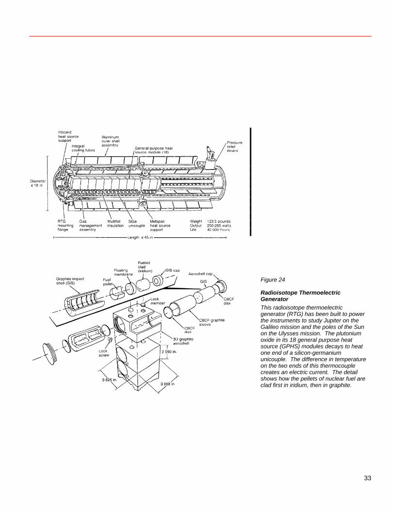
Figure 24
Radioisotope Thermoelectric Generator This radioisotope thermoelectric generator (RTG) has been built to power the instruments to study Jupiter on the Galileo mission and the poles of the Sun on the Ulysses mission. The plutonium oxide in its 18 general purpose heat source (GPHS) modules decays to heat one end of a silicon-germanium unicouple. The difference in temperature on the two ends of this thermocouple creates an electric current. The detail shows how the pellets of nuclear fuel are clad first in iridium, then in graphite.
33
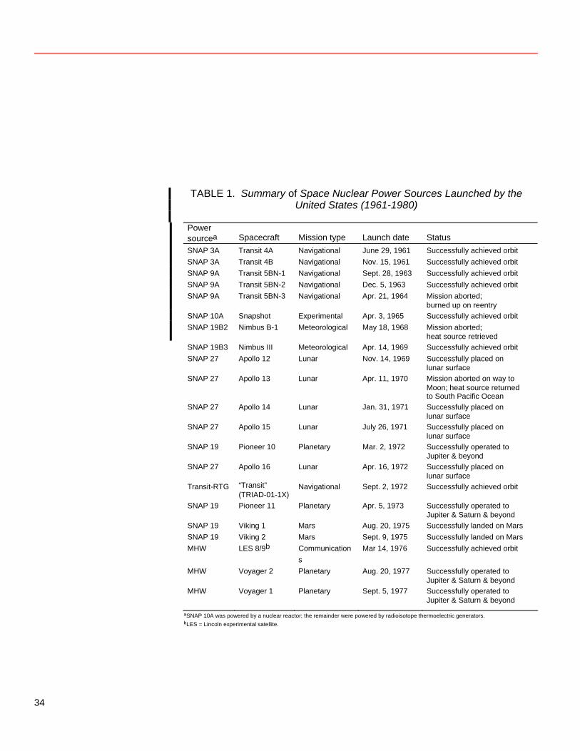
TABLE 1. Summary of Space Nuclear Power Sources Launched by the United States (1961-1980)
Power
sourcea Spacecraft
Mission type
Launch date
Status
SNAP 3A Transit 4A Navigational June 29, 1961 Successfully achieved orbit SNAP 3A Transit 4B Navigational Nov. 15, 1961 Successfully achieved orbit SNAP 9A Transit 5BN-1 Navigational Sept. 28, 1963 Successfully achieved orbit SNAP 9A Transit 5BN-2 Navigational Dec. 5, 1963 Successfully achieved orbit SNAP 9A Transit 5BN-3 Navigational Apr. 21, 1964 Mission aborted;
burned up on reentry SNAP 10A Snapshot Experimental Apr. 3, 1965 Successfully achieved orbit SNAP 19B2 Nimbus B-1 Meteorological May 18, 1968 Mission aborted;
heat source retrieved SNAP 19B3 Nimbus III Meteorological Apr. 14, 1969 Successfully achieved orbit SNAP 27 Apollo 12 Lunar Nov. 14, 1969 Successfully placed on
lunar surface SNAP 27 Apollo 13 Lunar Apr. 11, 1970 Mission aborted on way to
Moon; heat source returned to South Pacific Ocean
SNAP 27 Apollo 14 Lunar Jan. 31, 1971 Successfully placed on lunar surface
SNAP 27 Apollo 15 Lunar July 26, 1971 Successfully placed on lunar surface
SNAP 19 Pioneer 10 Planetary Mar. 2, 1972 Successfully operated to Jupiter & beyond
SNAP 27 Apollo 16 Lunar Apr. 16, 1972 Successfully placed on lunar surface
Transit-RTG “Transit” (TRIAD-01-1X)
Navigational Sept. 2, 1972 Successfully achieved orbit
SNAP 19 Pioneer 11 Planetary Apr. 5, 1973 Successfully operated to Jupiter & Saturn & beyond
SNAP 19 Viking 1 Mars Aug. 20, 1975 Successfully landed on Mars SNAP 19 Viking 2 Mars Sept. 9, 1975 Successfully landed on Mars MHW LES 8/9b Communication
s Mar 14, 1976 Successfully achieved orbit
MHW Voyager 2 Planetary Aug. 20, 1977 Successfully operated to Jupiter & Saturn & beyond
MHW Voyager 1 Planetary Sept. 5, 1977 Successfully operated to Jupiter & Saturn & beyond
aSNAP 10A was powered by a nuclear reactor; the remainder were powered by radioisotope thermoelectric generators. bLES = Lincoln experimental satellite.
34
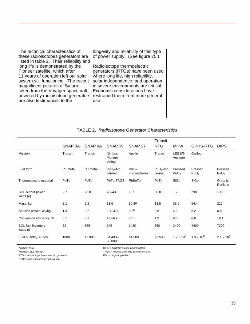
The technical characteristics of these radioisotopes generators are listed in table 2. Their reliability and long life is demonstrated by the Pioneer satellite, which after 11 years of operation left our solar system still functioning. The recent magnificent pictures of Saturn taken from the Voyager spacecraft powered by radioisotope generators are also testimonials to the
longevity and reliability of this type of power supply. (See figure 25.) Radioisotope thermoelectric generators (RTGs) have been used where long life, high reliability, solar independence, and operation in severe environments are critical. Economic considerations have restrained them from more general use.
TABLE 2. Radioisotope Generator Characteristics
SNAP 3A SNAP 9A
SNAP 19
SNAP 27
Transit-RTG
MHW
GPHS-RTG
DIPS
Mission Transit Transit Nimbus Pioneer Viking
Apollo Transit LES 8/9 Voyager
Galileo
Fuel form Pu metal Pu metal PuO2-Mo cermet
PuO2 microspheres
PuO2-Mo cermet
Pressed PuO2
Pressed PuO2
Pressed PuO2
Thermoelectric material PbTe PbTe PbTe-TAGS PbSnTe PbTe SiGe SiGe Organic Rankine
BOL output power watts (e)
2.7 26.8 28–43 63.5 36.8 150 290 1300
Mass, kg 2.1 2.2 13.6 30.8a 13.5 38.5 54.4 215
Specific power, We/kg 1.3 2.2 2.1–3.0 3.2b 2.6 4.2 5.2 6.0
Conversion efficiency, % 5.1 5.1 4.5–6.2 5.0 4.2 6.6 6.6 18.1
BOL fuel inventory watts (t)
52 565 645 1480 850 2400 4400 7200
Fuel quantity, curies 1800 17 000 34 400–0 000 8
44 500 25 500 7.7 × 10⁴ 1.3 × 10⁵ 2.1 × 10⁵
aWithout cask. DIPS = dynamic isotope power system blncludes 11.1-kg cask. TAGS = tellurlde antimony germanium silver RTG = radioisotope thermoelectric generator BOL = beginning-of-life GPHS = general purpose heat source
35
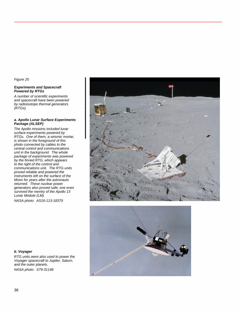
Figure 25
Experiments and Spacecraft Powered by RTGs A number of scientific experiments and spacecraft have been powered by radioisotope thermal generators (RTGs). a. Apollo Lunar Surface Experiments Package (ALSEP) The Apollo missions included lunar surface experiments powered by RTGs. One of them, a seismic mortar, is shown in the foreground of this photo connected by cables to the central control and communications unit in the background. The whole package of experiments was powered by the finned RTG, which appears to the right of the control and communications unit. The RTG units proved reliable and powered the instruments left on the surface of the Moon for years after the astronauts returned. These nuclear power generators also proved safe; one even survived the reentry of the Apollo 13 Lunar Module (LM). NASA photo: AS16-113-18379 b. Voyager RTG units were also used to power the Voyager spacecraft to Jupiter, Saturn, and the outer planets. NASA photo: S79-31146
36
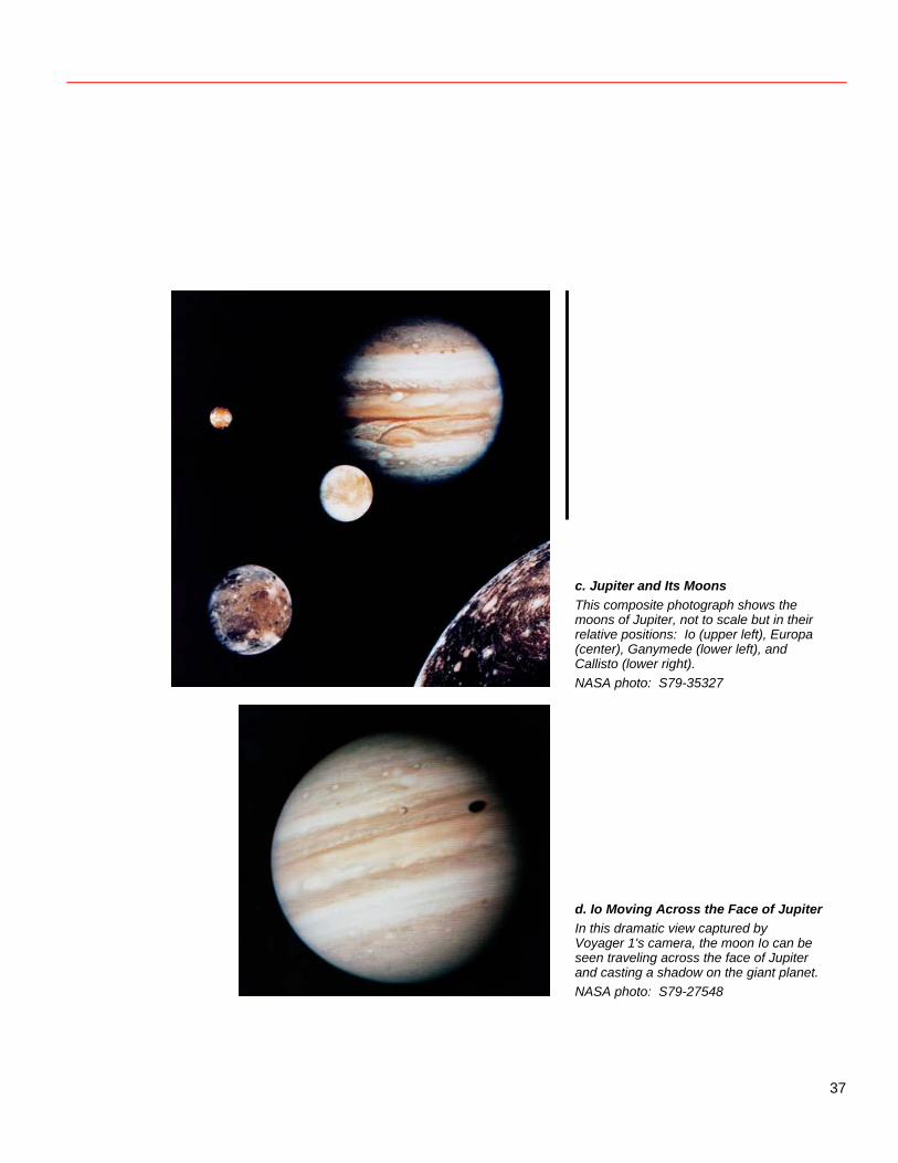
c. Jupiter and Its Moons This composite photograph shows the moons of Jupiter, not to scale but in their relative positions: Io (upper left), Europa (center), Ganymede (lower left), and Callisto (lower right). NASA photo: S79-35327 d. Io Moving Across the Face of Jupiter In this dramatic view captured by Voyager 1's camera, the moon Io can be seen traveling across the face of Jupiter and casting a shadow on the giant planet. NASA photo: S79-27548
37
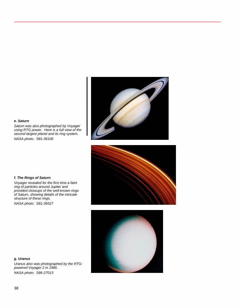
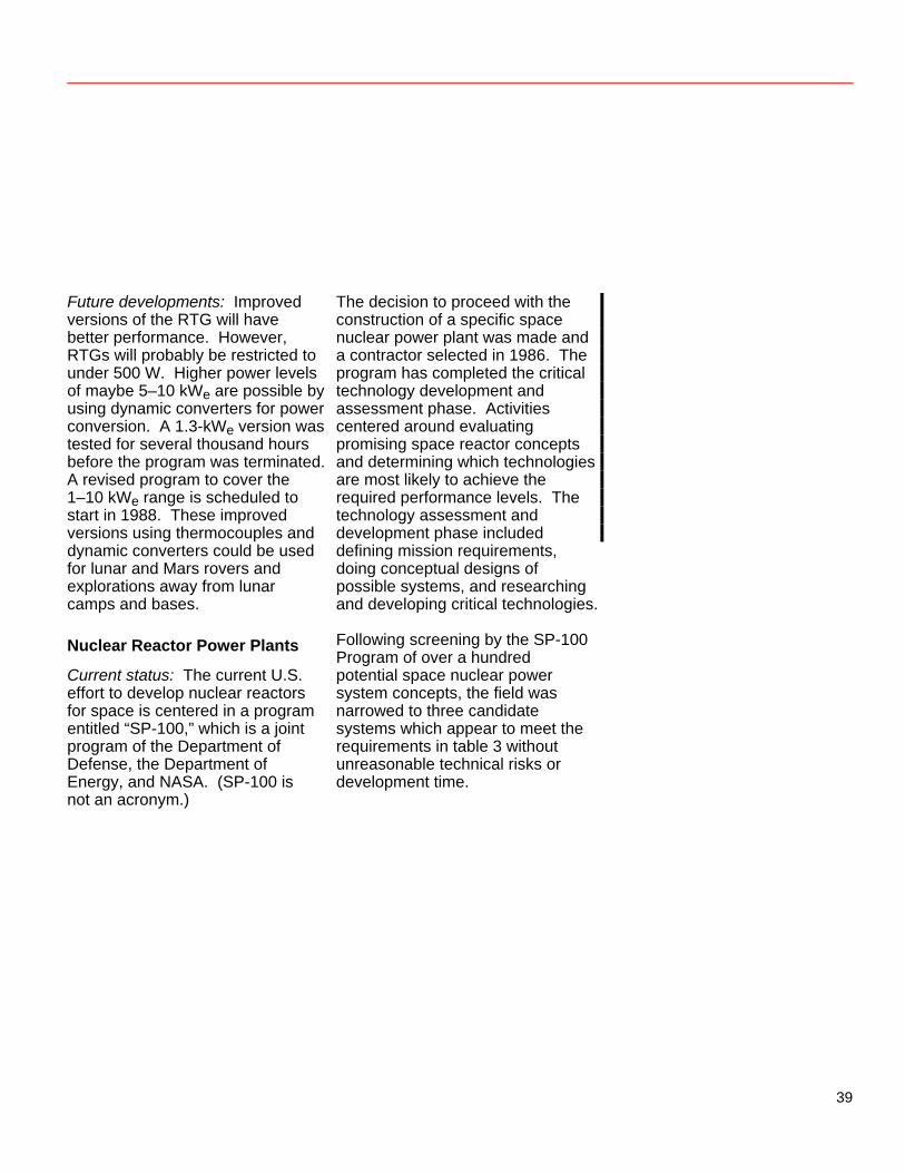
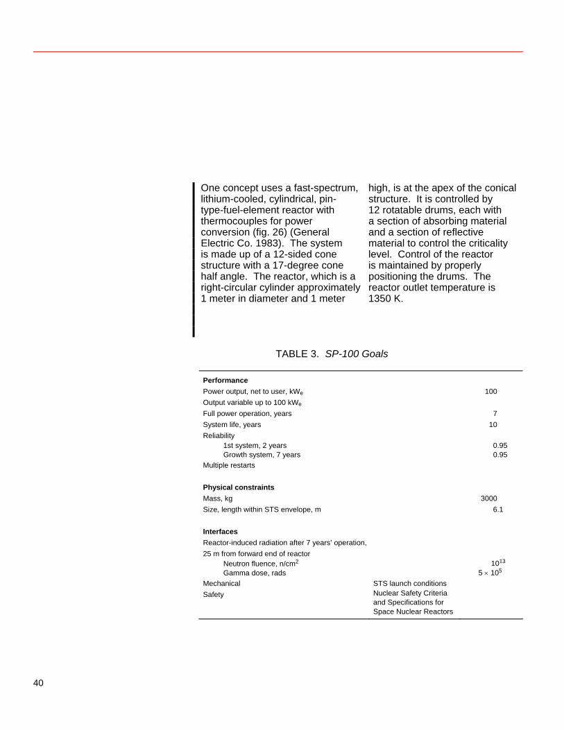
e. Saturn Saturn was also photographed by Voyager using RTG power. Here is a full view of the second largest planet and its ring system. NASA photo: S81-36106 f. The Rings of Saturn Voyager revealed for the first time a faint ring of particles around Jupiter and provided closeups of the well-known rings of Saturn, showing details of the intricate structure of these rings. NASA photo: S81-36527 g. Uranus Uranus also was photographed by the RTG-powered Voyager 2 in 1986. NASA photo: S86-27013
38
Future developments: Improved versions of the RTG will have better performance. However, RTGs will probably be restricted to under 500 W. Higher power levels of maybe 5–10 kWe are possible by using dynamic converters for power conversion. A 1.3-kWe version was tested for several thousand hours before the program was terminated. A revised program to cover the 1–10 kWe range is scheduled to start in 1988. These improved versions using thermocouples and dynamic converters could be used for lunar and Mars rovers and explorations away from lunar camps and bases. Nuclear Reactor Power Plants Current status: The current U.S. effort to develop nuclear reactors for space is centered in a program entitled “SP-100,” which is a joint program of the Department of Defense, the Department of Energy, and NASA. (SP-100 is not an acronym.)
The decision to proceed with the construction of a specific space nuclear power plant was made and a contractor selected in 1986. The program has completed the critical technology development and assessment phase. Activities centered around evaluating promising space reactor concepts and determining which technologies are most likely to achieve the required performance levels. The technology assessment and development phase included defining mission requirements, doing conceptual designs of possible systems, and researching and developing critical technologies. Following screening by the SP-100 Program of over a hundred potential space nuclear power system concepts, the field was narrowed to three candidate systems which appear to meet the requirements in table 3 without unreasonable technical risks or development time.
39
One concept uses a fast-spectrum, lithium-cooled, cylindrical, pin- type-fuel-element reactor with thermocouples for power conversion (fig. 26) (General Electric Co. 1983). The system is made up of a 12-sided cone structure with a 17-degree cone half angle. The reactor, which is a right-circular cylinder approximately 1 meter in diameter and 1 meter
high, is at the apex of the conical structure. It is controlled by 12 rotatable drums, each with a section of absorbing material and a section of reflective material to control the criticality level. Control of the reactor is maintained by properly positioning the drums. The reactor outlet temperature is 1350 K.
TABLE 3. SP-100 Goals
Performance Power output, net to user, kWe 100 Output variable up to 100 kWe Full power operation, years 7 System life, years 10 Reliability
1st system, 2 years 0.95 Growth system, 7 years 0.95
Multiple restarts Physical constraints Mass, kg 3000 Size, length within STS envelope, m 6.1 Interfaces Reactor-induced radiation after 7 years’ operation, 25 m from forward end of reactor
Neutron fluence, n/cm2 1013 Gamma dose, rads 5 × 10⁵
Mechanical STS launch conditions Safety Nuclear Safety Criteria
and Specifications for Space Nuclear Reactors
40
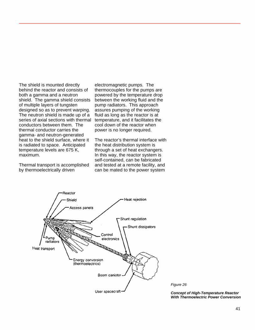
The shield is mounted directly behind the reactor and consists of both a gamma and a neutron shield. The gamma shield consists of multiple layers of tungsten designed so as to prevent warping. The neutron shield is made up of a series of axial sections with thermal conductors between them. The thermal conductor carries the gamma- and neutron-generated heat to the shield surface, where it is radiated to space. Anticipated temperature levels are 675 K, maximum. Thermal transport is accomplished by thermoelectrically driven
electromagnetic pumps. The thermocouples for the pumps are powered by the temperature drop between the working fluid and the pump radiators. This approach assures pumping of the working fluid as long as the reactor is at temperature, and it facilitates the cool down of the reactor when power is no longer required. The reactor’s thermal interface with the heat distribution system is through a set of heat exchangers. In this way, the reactor system is self-contained, can be fabricated and tested at a remote facility, and can be mated to the power system
Figure 26
Concept of High-Temperature Reactor With Thermoelectric Power Conversion
41
downstream. Access panels are provided on the main body to facilitate the connection of the heat distribution system to the heat exchanger. Thermoelectric elements for converting thermal energy to electric power are bonded to the internal surfaces of the heat rejection panels and accept heat from the source heat pipe assembly. The heat rejection surfaces are beryllium sheets with titanium potassium heat pipes brazed to the surface to distribute and carry the heat to the deployable panels, which are needed for additional heat rejection. The deployable panels are thermally coupled
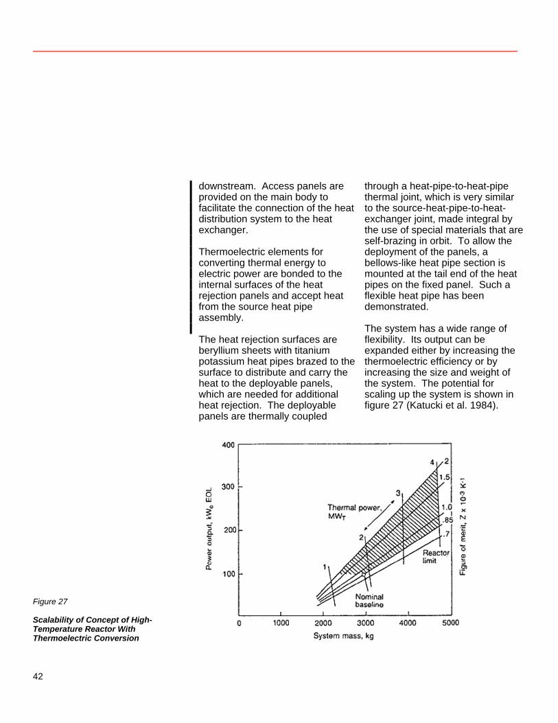
through a heat-pipe-to-heat-pipe thermal joint, which is very similar to the source-heat-pipe-to-heat-exchanger joint, made integral by the use of special materials that are self-brazing in orbit. To allow the deployment of the panels, a bellows-like heat pipe section is mounted at the tail end of the heat pipes on the fixed panel. Such a flexible heat pipe has been demonstrated. The system has a wide range of flexibility. Its output can be expanded either by increasing the thermoelectric efficiency or by increasing the size and weight of the system. The potential for scaling up the system is shown in figure 27 (Katucki et al. 1984).
Figure 27
Scalability of Concept of High-Temperature Reactor With Thermoelectric Conversion
42
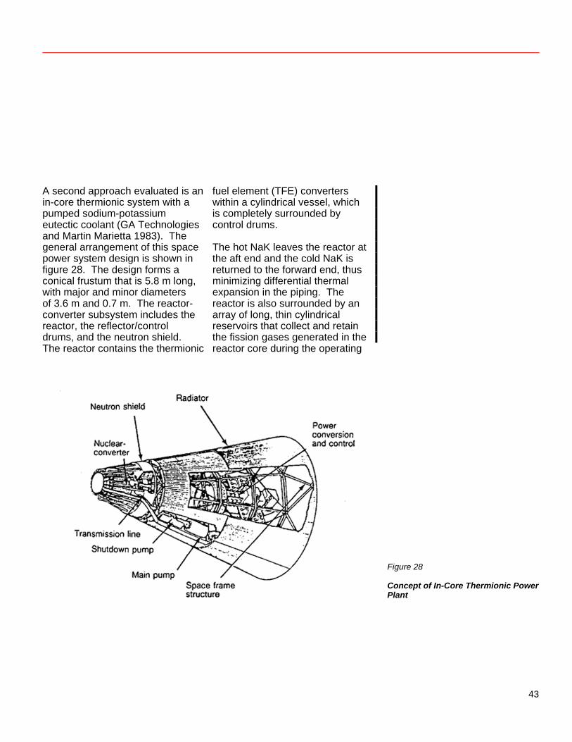
A second approach evaluated is an in-core thermionic system with a pumped sodium-potassium eutectic coolant (GA Technologies and Martin Marietta 1983). The general arrangement of this space power system design is shown in figure 28. The design forms a conical frustum that is 5.8 m long, with major and minor diameters of 3.6 m and 0.7 m. The reactor-converter subsystem includes the reactor, the reflector/control drums, and the neutron shield. The reactor contains the thermionic
fuel element (TFE) converters within a cylindrical vessel, which is completely surrounded by control drums. The hot NaK leaves the reactor at the aft end and the cold NaK is returned to the forward end, thus minimizing differential thermal expansion in the piping. The reactor is also surrounded by an array of long, thin cylindrical reservoirs that collect and retain the fission gases generated in the reactor core during the operating
Figure 28
Concept of In-Core Thermionic Power Plant
43
life of the system. Waste heat is removed from the primary loop through the heat exchanger. The energy is transferred through the heat-sink heat exchanger to heat pipes that form the radiating surfaces for rejection of heat to space. Within the reactor vessel are 176 TFEs, a grid plate to support the TFEs at one end, a tungsten gamma shield, and the eutectic NaK coolant. Each TFE is welded into the flattop head of the vessel but allowed to move axially in the grid plate. Expansion is expected to be small, since the TFE sheath tubes and reactor vessel are both made of an alloy of niobium and
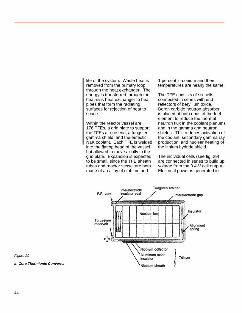
1 percent zirconium and their temperatures are nearly the same. The TFE consists of six cells connected in series with end reflectors of beryllium oxide. Boron carbide neutron absorber is placed at both ends of the fuel element to reduce the thermal neutron flux in the coolant plenums and in the gamma and neutron shields. This reduces activation of the coolant, secondary gamma ray production, and nuclear heating of the lithium hydride shield. The individual cells (see fig. 29) are connected in series to build up voltage from the 0.4-V cell output. Electrical power is generated in
Figure 29
In-Core Thermionic Converter
44
the space between the tungsten emitter and the niobium collector, and the electrical current output is conducted from one cell to the next through the tungsten stem of the emitter and the tantalum transition piece. The UO2 fuel is held in place and supported during launch by a retention device designed to retract when the fuel expands upon heating. The alignment spring at the base of the emitter centers the emitter in the collector to maintain a uniform interelectrode spacing. It also restrains the emitter against launch vibration to prevent large displacements and limit stresses in the thin stem at the other end of the emitter. Fission gases are vented from the UO2 fuel to prevent the buildup of pressures that would cause creep deformation of the tungsten emitter and close the interelectrode space. Fission gases are kept separate from the cesium (used to reduce the space charge effect) by the ceramic-to-metal seal and the arrangement of passages through the emitter cap and transition piece. Reactor control is provided by the rotation of the 20 cylindrical control drums surrounding the
reactor. The heat transport subsystem is a single loop that includes all of the NaK plumbing aft of the reactor, the heat-sink heat exchanger, and the radiator. The 100-mm-diameter NaK lines to and from the reactor are routed inside helical grooves in the outer surface of the neutron shield and then pass along the inside surface of the radiator to connect to the heat-sink heat exchanger. The configuration of the NaK lines along the shield is helical, rather than straight, to avoid degradation of the shield performance due to neutron streaming in the pipe channels. The helical channels in the shield are also occupied by the electrical transmission lines, which are flattened in cross section and are routed over the NaK lines to serve as meteoroid protection. Electromagnetic pumping is used to circulate the NaK during normal operation and during shutdown. Two electromagnetic pumps are provided in the cold leg of the NaK circuit: an annular linear-induction pump to serve as the main pump and a parallel thermoelectromagnetic pump (with a check valve) to provide shutdown pumping capability.
45
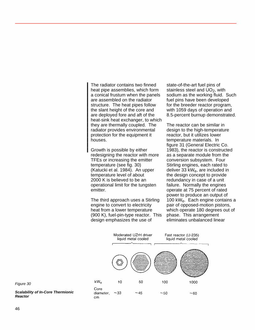
The radiator contains two finned heat pipe assemblies, which form a conical frustum when the panels are assembled on the radiator structure. The heat pipes follow the slant height of the core and are deployed fore and aft of the heat-sink heat exchanger, to which they are thermally coupled. The radiator provides environmental protection for the equipment it houses. Growth is possible by either redesigning the reactor with more TFEs or increasing the emitter temperature (see fig. 30) (Katucki et al. 1984). An upper temperature level of about 2000 K is believed to be an operational limit for the tungsten emitter. The third approach uses a Stirling engine to convert to electricity heat from a lower temperature (900 K), fuel-pin-type reactor. This design emphasizes the use of
state-of-the-art fuel pins of stainless steel and UO2, with sodium as the working fluid. Such fuel pins have been developed for the breeder reactor program, with 1059 days of operation and 8.5-percent burnup demonstrated. The reactor can be similar in design to the high-temperature reactor, but it utilizes lower temperature materials. In figure 31 (General Electric Co. 1983), the reactor is constructed as a separate module from the conversion subsystem. Four Stirling engines, each rated to deliver 33 kWe, are included in the design concept to provide redundancy in case of a unit failure. Normally the engines operate at 75 percent of rated power to produce an output of 100 kWe. Each engine contains a pair of opposed-motion pistons, which operate 180 degrees out of phase. This arrangement eliminates unbalanced linear
Figure 30
Scalability of In-Core Thermionic Reactor
46
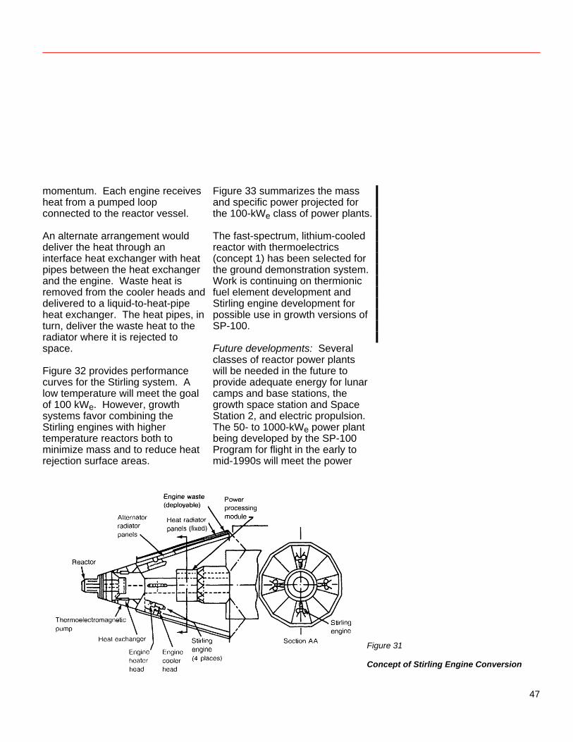
momentum. Each engine receives heat from a pumped loop connected to the reactor vessel. An alternate arrangement would deliver the heat through an interface heat exchanger with heat pipes between the heat exchanger and the engine. Waste heat is removed from the cooler heads and delivered to a liquid-to-heat-pipe heat exchanger. The heat pipes, in turn, deliver the waste heat to the radiator where it is rejected to space. Figure 32 provides performance curves for the Stirling system. A low temperature will meet the goal of 100 kWe. However, growth systems favor combining the Stirling engines with higher temperature reactors both to minimize mass and to reduce heat rejection surface areas.
Figure 33 summarizes the mass and specific power projected for the 100-kWe class of power plants. The fast-spectrum, lithium-cooled reactor with thermoelectrics (concept 1) has been selected for the ground demonstration system. Work is continuing on thermionic fuel element development and Stirling engine development for possible use in growth versions of SP-100. Future developments: Several classes of reactor power plants will be needed in the future to provide adequate energy for lunar camps and base stations, the growth space station and Space Station 2, and electric propulsion. The 50- to 1000-kWe power plant being developed by the SP-100 Program for flight in the early to mid-1990s will meet the power
Figure 31
Concept of Stirling Engine Conversion
47
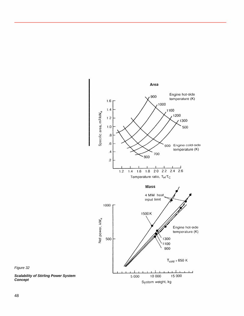
Figure 32
Scalability of Stirling Power System Concept
48
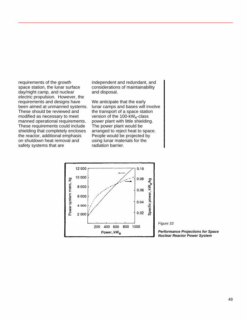
requirements of the growth space station, the lunar surface day/night camp, and nuclear electric propulsion. However, the requirements and designs have been aimed at unmanned systems. These should be reviewed and modified as necessary to meet manned operational requirements. These requirements could include shielding that completely encloses the reactor, additional emphasis on shutdown heat removal and safety systems that are
independent and redundant, and considerations of maintainability and disposal. We anticipate that the early lunar camps and bases will involve the transport of a space station version of the 100-kWe-class power plant with little shielding. The power plant would be arranged to reject heat to space. People would be projected by using lunar materials for the radiation barrier.
Figure 33
Performance Projections for Space Nuclear Reactor Power System
49
Space Station 2, requiring 1–10 MWe, would need a new class of reactor plants. Major changes in reactor designs may be called for, such as higher temperatures, refuelability, and maintainability of certain components. Significant improvements in power conversion and heat rejection are also necessary. The power conversion will probably work at a higher temperature; innovative design through in-core thermionics is being evaluated as an alternative. Heat rejection will need a deployable system that uses a
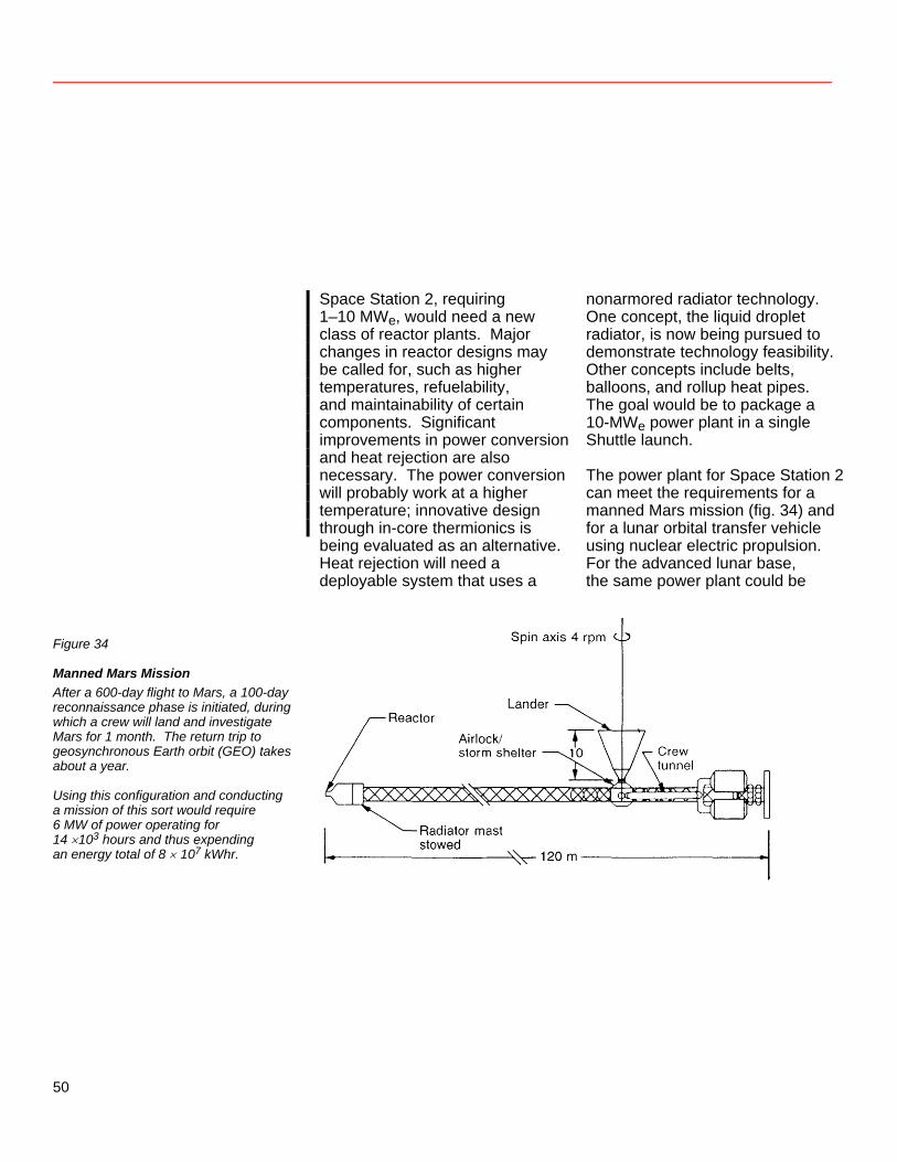
nonarmored radiator technology. One concept, the liquid droplet radiator, is now being pursued to demonstrate technology feasibility. Other concepts include belts, balloons, and rollup heat pipes. The goal would be to package a 10-MWe power plant in a single Shuttle launch. The power plant for Space Station 2 can meet the requirements for a manned Mars mission (fig. 34) and for a lunar orbital transfer vehicle using nuclear electric propulsion. For the advanced lunar base, the same power plant could be
Figure 34
Manned Mars Mission After a 600-day flight to Mars, a 100-day reconnaissance phase is initiated, during which a crew will land and investigate Mars for 1 month. The return trip to geosynchronous Earth orbit (GEO) takes about a year. Using this configuration and conducting a mission of this sort would require 6 MW of power operating for 14 ×103 hours and thus expending an energy total of 8 × 10⁷ kWhr.
50
used. Again, lunar soil could provide shielding. However, if a mining and materials fabrication capability were in place, it could be used to fabricate a specially designed heat rejection subsystem. Doing so could produce a major savings in mass transfer from Earth. Several innovative designs are possible, such as continuous ejection and collection of fluid or solid particles. Public Safety and the Use of Nuclear Reactors in Space Policy and goals: The policy of the United States for all U.S. nuclear power sources used in space is to ensure that the probability of release of radioactive materials and the amounts released are such that an undue risk is not presented, considering the benefits of the mission (U.S. Department of Energy 1982). Safety criteria are specified for the design of the SP-100 space nuclear reactor power plant;
safety is to be built into the design, not just added on. The restriction of radiation exposure (DOE 1982) depends on reducing the probability of an accident that might release radioactive materials into the environment and on limiting the magnitude of such a release should one occur. Space nuclear power applications must keep the radiation exposure of astronauts, occupational workers (e.g., ground support personnel), and members of the general public “as low as reasonably achievable” during all mission phases, normal and abnormal. According to recommended standards (U.N. General Assembly paper 1980), the maximum accumulated doses for closely involved workers and for the general population are those listed in table 4. Allowable doses for astronauts are generally in the same range as those allowed for radiation workers.
51
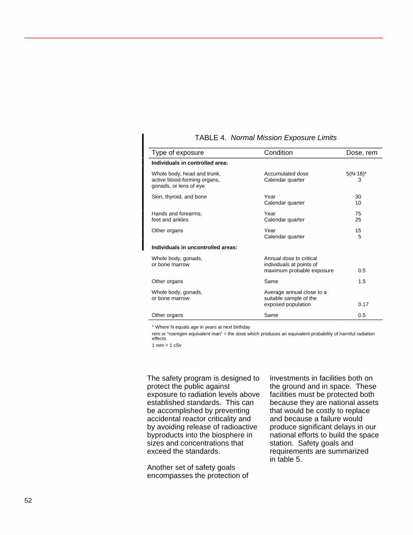
TABLE 4. Normal Mission Exposure Limits
Type of exposure Condition Dose, rem Individuals in controlled area: Whole body, head and trunk,
active blood-forming organs, gonads, or lens of eye
Accumulated dose Calendar quarter
5(N-18)* 3
Skin, thyroid, and bone Year
Calendar quarter 30 10
Hands and forearms,
feet and ankles Year Calendar quarter
75 25
Other organs Year
Calendar quarter 15 5
Individuals in uncontrolled areas: Whole body, gonads,
or bone marrow Annual dose to critical individuals at points of maximum probable exposure
0.5 Other organs Same 1.5 Whole body, gonads,
or bone marrow Average annual close to a suitable sample of the exposed population
0.17 Other organs Same 0.5
* Where N equals age in years at next birthday rem or “roentgen equivalent man” = the dose which produces an equivalent probability of harmful radiation effects 1 rem = 1 cSv
The safety program is designed to protect the public against exposure to radiation levels above established standards. This can be accomplished by preventing accidental reactor criticality and by avoiding release of radioactive byproducts into the biosphere in sizes and concentrations that exceed the standards. Another set of safety goals encompasses the protection of
investments in facilities both on the ground and in space. These facilities must be protected both because they are national assets that would be costly to replace and because a failure would produce significant delays in our national efforts to build the space station. Safety goals and requirements are summarized in table 5.
52

TABLE 5. Safety Goals and Requirements
Goals Reasons Design requirements Assure the existence of normal conditions before launch to avoid special handling or precautions.
To protect workers and astronauts
The reactor shall not be operated (except for zero power testing) until a stable orbit or flight path is achieved.
There must be two independent systems to reduce eactivity to a subcritical state. r
Unirradiated fuel shall pose no significant
nvironmental hazard. e
Prevent inadvertent criticality.
To ensure that the public is not exposed to levels of adiation that exceed standards r
The reactor must remain subcritical if immersed in water or another fluid.
To protect the Shuttle crew The reactor must have a significant negative ower coefficient. p
The reactor must be subcritical in an Earth-impact
ccident. a
A
reactor safety system must be incorporated.
T
here must be quality assurance standards.
A positive-coded telemetry system must be used or reactor startup. f
There must be redundant control and safety
ystems. s
There must be independent sources of electrical power for the reactor control system, the reactor protection ystem, and the reactor communication system. s
There must be instrumentation to continuously
onitor reactor status. m
Avoid release of radioactive byproducts in concentrations exceeding radiological standards.
To ensure that the public is not exposed to radiation levels that exceed standards and to protect the biosphere against concentration of radioactive elements above afety standards s
An orbital boost system must be provided for short-lived orbits. There must be spacecraft attitude controllers for the communication and boost systems.
Avoid unplanned core destruction.
To protect space investments and to avoid contamination of volumes of the space environment
An independent system for decay heat removal must be provided for shutdown situations. There must be two independent systems to reduce eactivity to a subcritical state. r
A positive-coded signal must be used to operate
he reactor. t
There must be two independent reactor protection ystems. s
Fault-detection systems must be provided for the
eactor protection systems. r
53
The safety review process: The United States requires an analysis of each space mission involving nuclear material to assess the potential radiological risk to the biosphere. The process begins when the space mission is defined and the design is conceived. The safety review process continues through launch safety analysis, approval to launch, and proper nuclear power source disposal. The developer of the nuclear power source is responsible for performing the nuclear safety analyses for the system. Results of these safety analyses are reported at least three times during the development cycle in documents entitled Preliminary Safety Analysis Report (PSAR), Updated Safety Analysis Report (USAR), and Final Safety Analysis Report (FSAR). The Preliminary Safety Analysis Report is issued 120 days after a design concept is selected. It contains a description of the design, a failure mode analysis, and a nuclear safety analysis. The latter two requirements are based on the safety research data for the
development of heat sources, historical heat source design information, and the requirements set forth in the guidelines written by the Department of Energy (DOE). At this stage of system development, the failure mode analysis is based on the response to potential accident environments and on design limitations established by the guidelines. The Updated Safety Analysis Report is issued 90 days after the design is set. It is similar in form to the preliminary report. Additional requirements include a description of the mission on which the system is to be used and an update of the failure mode analysis using data from the developmental tests performed to set the design. The Final Safety Analysis Report is issued approximately 1 year before the scheduled launch and is similar in format to the earlier reports. This report provides final system, mission, and safety assessment data, factoring in the results of the verification and qualification test programs. Thus, the final assessment is based on the actual mission environments.
54
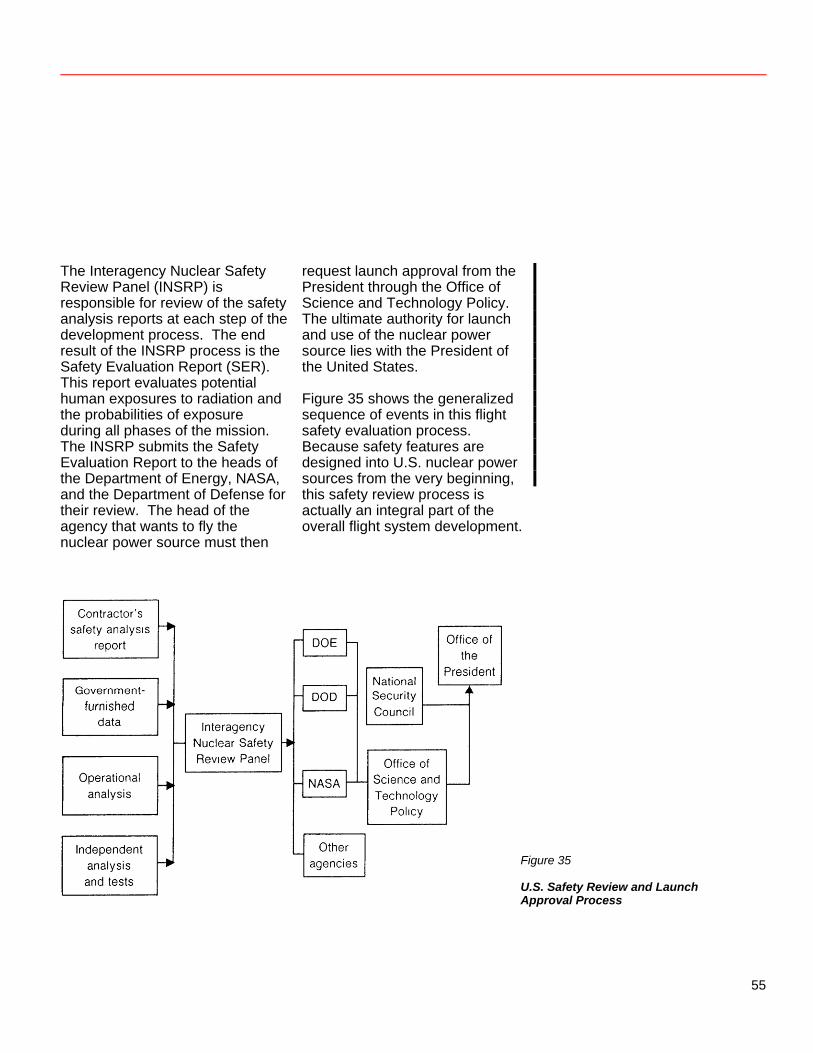
The Interagency Nuclear Safety Review Panel (INSRP) is responsible for review of the safety analysis reports at each step of the development process. The end result of the INSRP process is the Safety Evaluation Report (SER). This report evaluates potential human exposures to radiation and the probabilities of exposure during all phases of the mission. The INSRP submits the Safety Evaluation Report to the heads of the Department of Energy, NASA, and the Department of Defense for their review. The head of the agency that wants to fly the nuclear power source must then
request launch approval from the President through the Office of Science and Technology Policy. The ultimate authority for launch and use of the nuclear power source lies with the President of the United States. Figure 35 shows the generalized sequence of events in this flight safety evaluation process. Because safety features are designed into U.S. nuclear power sources from the very beginning, this safety review process is actually an integral part of the overall flight system development.
Figure 35
U.S. Safety Review and Launch Approval Process
55
References GA Technologies and Martin Marietta. 1983. Conceptual Design Studies in Support of the SP-100 Program. Report No. GA-C17354, LaJolla, CA, Dec. 9. General Electric Co. 1983. SP-100 Conceptual Design Study. Doc. No. 835SDS4262, Valley Forge, PA, Dec. 7. Katucki, R.; A. Josloff; A. Kirpech; and F. Florio. 1984. Evolution of Systems Concepts for a 100-kWe-Class Space Nuclear Power System. Proc. 1st Symp. on Space Nuclear Power Systems, Univ. of New Mexico, pp. 149–164.
U.N. General Assembly. 1980. Questions Relating to the Use of Nuclear Power Sources in Outer Space. See U.S. working paper Studies on Technical Aspects and Safety Measures of Nuclear Power Sources in Outer Space. A/AC.105/C.1/WG.V/L.8, Jan. 25. U.S. Department of Energy. 1982. Nuclear Safety Criteria and Specifications for Space Nuclear Reactors. OSNP-1, Rev. 0, Aug.
56
Thermal Management in Space Abe Hertzberg The vehicles and habitats associated with space industrialization and the exploitation of nonterrestrial resources will inevitably require energy systems far exceeding the current requirements of scientific and exploratory missions. Because of the extended duration of these missions, it is not possible to consider systems involving expendables such as non-regeneratable fuel cells. Therefore, these missions become hostages to the capability of continuous-power energy systems. These systems will need to provide hundreds of kilowatts to tens of megawatts of electrical power to a product fabrication system, whether it uses terrestrial or nonterrestrial raw materials. Because the power system will be located in an essentially airless environment, rejecting waste heat becomes a limiting aspect of it. In the following paragraphs, I will review space-based or asteroidal and lunar based power generating
systems, as well as the capability of existing technologies to dissipate this heat into the airless environment of space. It should be pointed out that in a vacuum environment, convection is no longer available and the only mechanism of rejecting heat is radiation. Radiation follows the Stefan-Boltzmann Law E = σT4 where E = the energy rejected σ, the Stefan-Boltzmann constant, = 5.67 W m-2 K-4 T = the temperature at which the heat is radiated That is, the total amount of heat radiated is proportional to the surface area of the radiator. And the lower the radiation temperature, the larger the radiator area (and thus the radiator mass, for a given design) must be. The radiator can only reject heat when the temperature is higher than that of the environment. In space, the optimum radiation efficiency is gained by aiming the radiator at free space. Radiating
57
toward an illuminated surface is less effective, and the radiator must be shielded from direct sunlight. The rejection of heat at low temperatures, such as would be the case in environmental control and in the thermal management of a materials processing unit, is particularly difficult. Therefore, the design and operation of the heat rejection system is crucial for an efficient space-based energy system. Space-Based Power Generating Systems In a previous paper, space-based power generating systems have been described in detail. Solar photovoltaic systems have a generating capability of up to several hundred kilowatts. The power output range of solar thermal systems is expected to be one hundred to perhaps several hundred kilowatts. While in principle these power systems can be expanded into the megawatt region, the prohibitive demands for collection area and lift capacity would appear to rule out such expansion. Megawatt and multimegawatt nuclear power
reactors adapted for the space environment appear to offer a logical alternative. In this paper, I deal only with the burdens these three types of power system will place on the heat management system. Solar photovoltaics themselves will not burden the power generating system with a direct heat rejection requirement, since the low energy density of the system requires such a great collection area that it allows rejection of waste radiant energy. However, if these systems are to be employed in low Earth orbit or on a nonterrestrial surface, then a large amount of energy storage equipment will be required to ensure a continuous supply of power (as the devices do not collect energy at night). And the round-trip inefficiencies of even the best energy storage system today will require that a large fraction—perhaps 25 percent—of the electrical power generated must be dissipated as waste heat and at low temperatures. Solar thermal systems, which include a solar concentrator and a dynamic energy conversion system, are presumed to operate at relatively high temperatures
58
(between 1000 and 2000 K). The efficiencies of the energy conversion system will lie in the range of 15 to perhaps 30 percent. Therefore we must consider rejecting between 70 and 85 percent of the energy collected. In general, the lower the thermal efficiency, the higher the rejection temperature and the smaller the radiating area required. As with solar photovoltaic systems, the inefficiencies of the energy storage system will have to be faced by the heat rejection system, unless high temperature thermal storage is elected. The current concepts for nuclear power generating systems involve reactors working with relatively low-efficiency energy conversion systems which reject virtually all of the usable heat of the reactor but at a relatively high temperature. Despite the burdens that this low efficiency places on nuclear fuel use, the energy density of nuclear systems is so high that the fuel use factor is not expected to be significant.
In all of these systems the output power used by the production system in environmental control and manufacturing (except for a small fraction which might be stored as endothermic heat in the manufactured product) will have to be rejected at temperatures approaching 300 K. I think it fair to state that, in many of the sketches of space industrial plants I have seen, the power system is little more than a cartoon because it lacks sufficient detail to address the problem of thermal management. We must learn to maintain an acceptable thermal environment, because it is expected to become a dominant engineering consideration in a complex factory and habitat infrastructure. As an example of the severity of this problem, let us examine the case of a simple nuclear power plant whose energy conversion efficiency from thermal to electric is approximately 10 percent. The plant is to generate 100 kW of
59
useful electricity. The reactor operates at approximately 800 K, and a radiator with emissivity equal to 0.85 would weigh about 10 kg/m2. The thermal power to be dissipated from the reactor would be about 1 MW. From the Stefan Boltzmann Law, the area of the radiator would be about 50 m2 and the mass approximately 500 kg. This seems quite reasonable. However, we must assume that the electricity generated by the power plant, which goes into life support systems and small-scale manufacturing, would eventually have to be dissipated also, but at a much lower temperature (around
300 K). Assuming an even better, aluminum radiator of about 5 kg/m2, with again an emissivity of 0.85, in this case we find that the area of the low temperature heat rejection component is 256 m2, with a mass approaching 1300 kg.* Therefore, we can see that the dominant heat rejection problem is not that of the primary power plant but that of the energy that is used in life support and manufacturing, which must be rejected at low temperatures. Using the waste heat from the nuclear power plant for processing may be effective. But, ironically, doing so will in turn require more radiator surface to radiate the lower temperature waste heat.
*Using the Stefan-Boltzmann Law, E1 = 5.67 × 10⁻⁸ W m-2 K-4 (800 K)4 = 5.67 × 10⁻⁸ W m-2 K-4 × 4096 × 108 K4 = 5.67 W m-2 × 4.10 × 103 E1 23.3 kW m-2 900 kW ÷ 23.3 kW m-2 = 38.6 m2 and 38.6 m2 ÷ 0.85 = 45.4 m2 E2 = 5.67 × 10⁻⁸ W m-2 K-4 (300 K)4 = 5.67 × 10⁻⁸ W m-2 K-4 × 81 × 108 K4 = 5.67 W m-2 × 81 E2 = 459 W m-2 100 kW ÷ 459 W m-2 = 0.2179 × 10³ m2 = 218 m2 and 218 m2 ÷ 0.85 = 256 m2
60
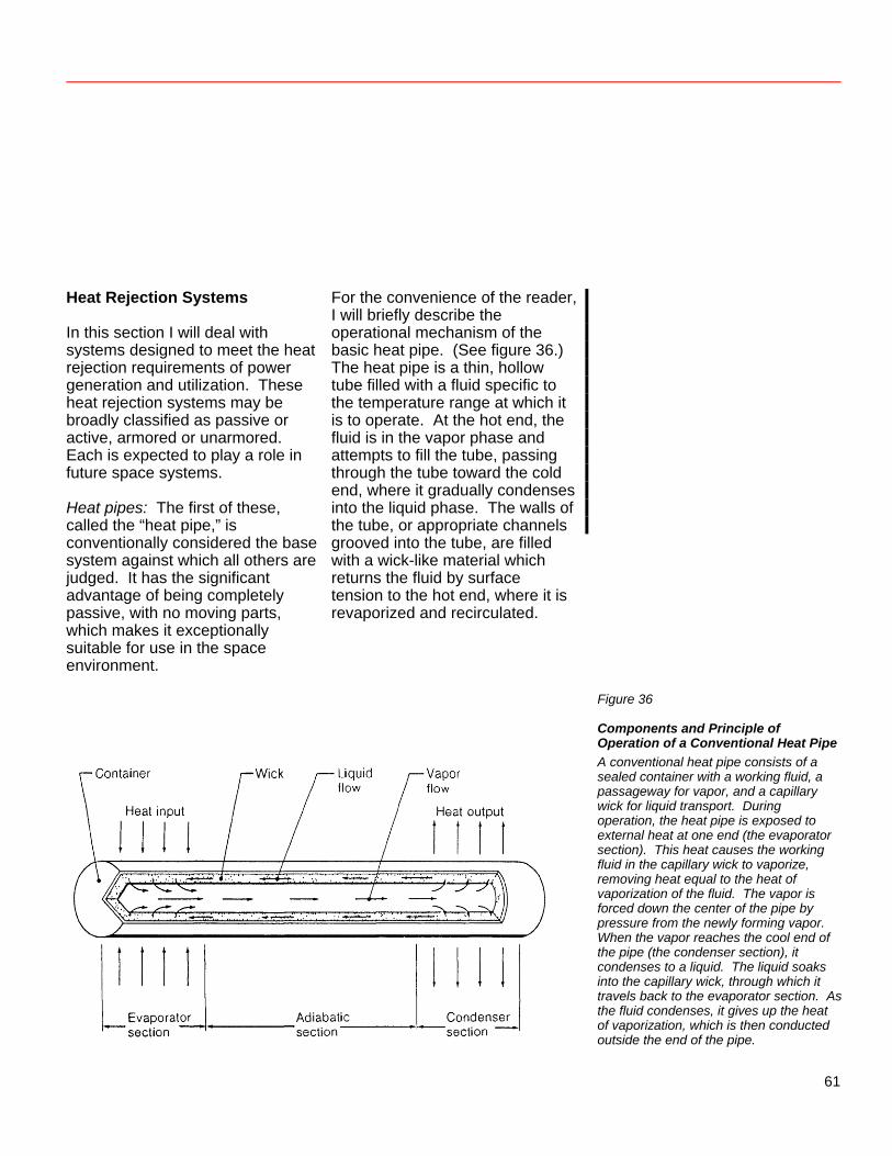
Heat Rejection Systems In this section I will deal with systems designed to meet the heat rejection requirements of power generation and utilization. These heat rejection systems may be broadly classified as passive or active, armored or unarmored. Each is expected to play a role in future space systems. Heat pipes: The first of these, called the “heat pipe,” is conventionally considered the base system against which all others are judged. It has the significant advantage of being completely passive, with no moving parts, which makes it exceptionally suitable for use in the space environment.
For the convenience of the reader, I will briefly describe the operational mechanism of the basic heat pipe. (See figure 36.) The heat pipe is a thin, hollow tube filled with a fluid specific to the temperature range at which it is to operate. At the hot end, the fluid is in the vapor phase and attempts to fill the tube, passing through the tube toward the cold end, where it gradually condenses into the liquid phase. The walls of the tube, or appropriate channels grooved into the tube, are filled with a wick-like material which returns the fluid by surface tension to the hot end, where it is revaporized and recirculated.
Figure 36
Components and Principle of Operation of a Conventional Heat Pipe A conventional heat pipe consists of a sealed container with a working fluid, a passageway for vapor, and a capillary wick for liquid transport. During operation, the heat pipe is exposed to external heat at one end (the evaporator section). This heat causes the working fluid in the capillary wick to vaporize, removing heat equal to the heat of vaporization of the fluid. The vapor is forced down the center of the pipe by pressure from the newly forming vapor. When the vapor reaches the cool end of the pipe (the condenser section), it condenses to a liquid. The liquid soaks into the capillary wick, through which it travels back to the evaporator section. As the fluid condenses, it gives up the heat of vaporization, which is then conducted outside the end of the pipe.
61
Essentially the system is a small vapor cycle which uses the temperature difference between the hot and cold ends of the tube as a pump to transport heat, taking full advantage of the heat of vaporization of the particular fluid. The fluid must be carefully selected to match the temperature range of operation. For example, at very high temperatures a metallic substance with a relatively high vaporization temperature, such as sodium or potassium, may be used. However, this choice puts a constraint on the low temperature end since, if the fluid freezes into a solid at the low temperature end, operation would cease until the relatively inefficient conduction of heat along the walls could melt it. At low temperatures a fluid with a low vaporization temperature, such as ammonia, might well be used, with similar constraints. The temperature may not be so high as to dissociate the ammonia at the hot end or so low as to freeze the ammonia at the cold end. With proper design, heat pipes are an appropriate and convenient tool
for thermal management in space systems. For example, at modest temperatures, the heat pipe could be made of aluminum, because of its relatively low density and high strength. Fins could be added to the heat pipe to increase its heat dissipation area. The aluminum, in order to be useful, must be thin enough to reduce the mass carried into space yet thick enough to offer reasonable resistance to meteoroid strikes. A very carefully designed solid surface radiator made out of aluminum has the following capabilities in principle: The mass is approximately 5 kg/m2 with an emissivity of 0.85; the usable temperature range is limited by the softening point of aluminum (about 700 K). At higher temperatures, where refractory metals are needed, it would be necessary to multiply the mass of the radiator per square meter by at least a factor of 3. Nevertheless, from 700 K up to perhaps 900 K, the heat pipe radiator is still a very efficient method of rejecting heat.
62
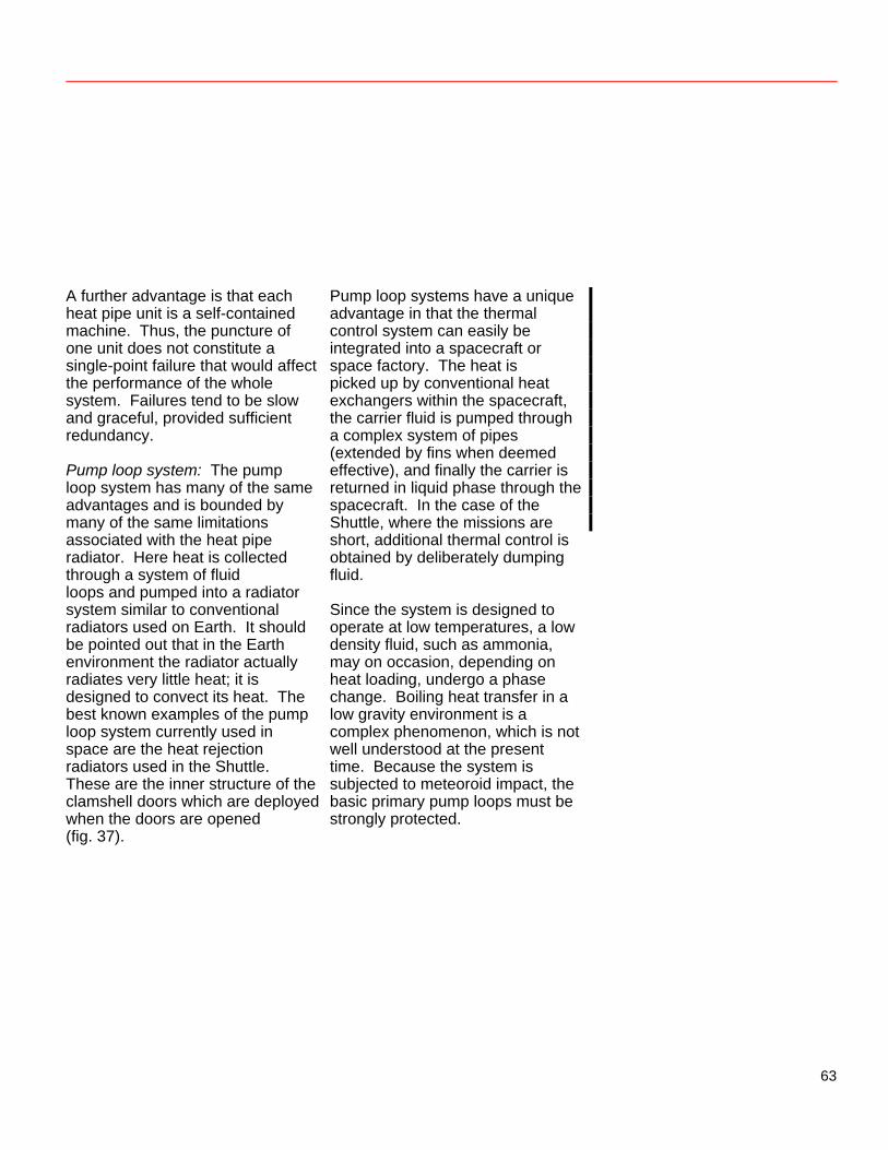
A further advantage is that each heat pipe unit is a self-contained machine. Thus, the puncture of one unit does not constitute a single-point failure that would affect the performance of the whole system. Failures tend to be slow and graceful, provided sufficient redundancy. Pump loop system: The pump loop system has many of the same advantages and is bounded by many of the same limitations associated with the heat pipe radiator. Here heat is collected through a system of fluid loops and pumped into a radiator system similar to conventional radiators used on Earth. It should be pointed out that in the Earth environment the radiator actually radiates very little heat; it is designed to convect its heat. The best known examples of the pump loop system currently used in space are the heat rejection radiators used in the Shuttle. These are the inner structure of the clamshell doors which are deployed when the doors are opened (fig. 37).
Pump loop systems have a unique advantage in that the thermal control system can easily be integrated into a spacecraft or space factory. The heat is picked up by conventional heat exchangers within the spacecraft, the carrier fluid is pumped through a complex system of pipes (extended by fins when deemed effective), and finally the carrier is returned in liquid phase through the spacecraft. In the case of the Shuttle, where the missions are short, additional thermal control is obtained by deliberately dumping fluid. Since the system is designed to operate at low temperatures, a low density fluid, such as ammonia, may on occasion, depending on heat loading, undergo a phase change. Boiling heat transfer in a low gravity environment is a complex phenomenon, which is not well understood at the present time. Because the system is subjected to meteoroid impact, the basic primary pump loops must be strongly protected.
63
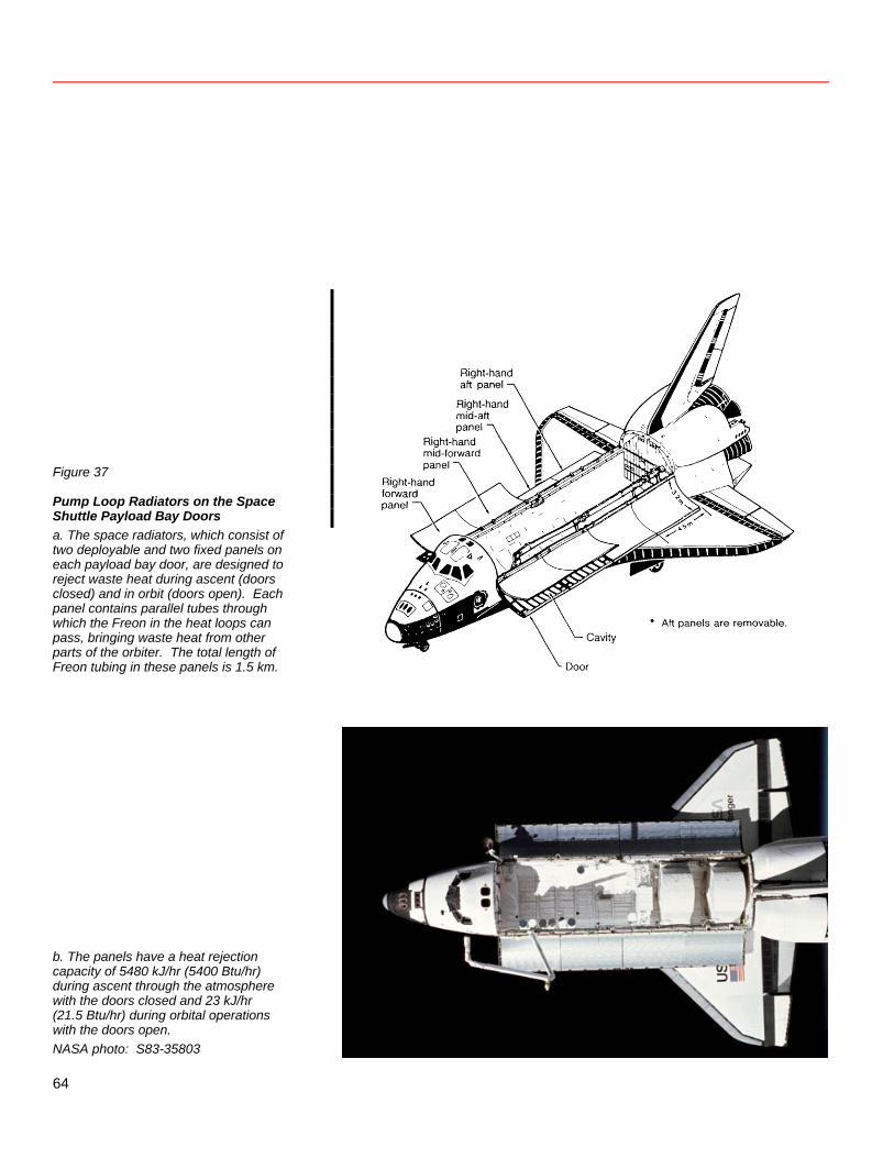
Figure 37
Pump Loop Radiators on the Space Shuttle Payload Bay Doors a. The space radiators, which consist of two deployable and two fixed panels on each payload bay door, are designed to reject waste heat during ascent (doors closed) and in orbit (doors open). Each panel contains parallel tubes through which the Freon in the heat loops can pass, bringing waste heat from other parts of the orbiter. The total length of Freon tubing in these panels is 1.5 km.
b. The panels have a heat rejection capacity of 5480 kJ/hr (5400 Btu/hr) during ascent through the atmosphere with the doors closed and 23 kJ/hr (21.5 Btu/hr) during orbital operations with the doors open. NASA photo: S83-35803
64
Despite these drawbacks, pump loop systems will probably be used in conjunction with heat pipe systems as thermal control engineers create a viable space environment. These armored (closed) systems are rather highly developed and amenable to engineering analysis. They have already found application on Earth and in space. A strong technology base has been built up, and there exists a rich literature for the scientist-engineer to draw on in deriving new concepts. Advanced Radiator Concepts The very nature of the problems just discussed has led to increased efforts on the part of the thermal management community to examine innovative approaches which offer the potential of increased performance and, in many cases, relative invulnerability to meteoroid strikes. Although I cannot discuss all of these new approaches, I will briefly describe some of the approaches under study as examples of the direction of current thinking. Improved conventional approaches: The continuing search for ways to improve the performance of heat pipes has already shown that significant improvements in the heat pumping capacity of the heat
pipe can be made by clever modifications to the return wick loop. Looking further downline at the problem of deployability, people are exploring flexible heat pipes and using innovative thinking. For example, a recent design has the heat pipes collapsing into a sheet as they are rolled up, the same way a toothpaste tube does. Thus, the whole ensemble may be rolled up into a relatively tight bundle for storing and deploying. However, because the thin-walled pipes are relatively fragile and easily punctured by meteoroids, more redundancy must be provided. The same principles, of course, can be applied to a pump loop system and may be of particular importance when storage limits must be considered. These are only examples of the various approaches taken, and we may confidently expect a steady improvement in the capability of conventional thermal management systems. The liquid droplet radiator: The basic concept of the liquid droplet radiator is to replace a solid surface radiator by a controlled stream of droplets. The droplets are sprayed across a region in which they radiate their heat; then they are recycled to the hotter part of the system. (See figure 38.)
65
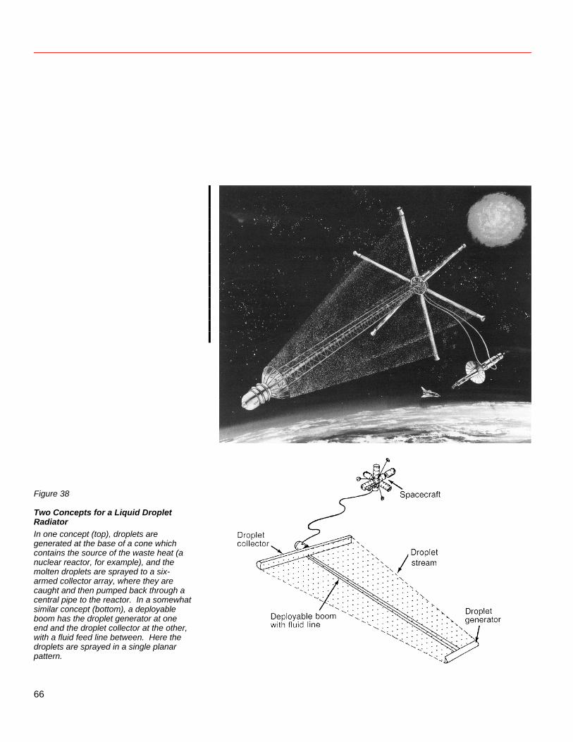
Figure 38
Two Concepts for a Liquid Droplet Radiator In one concept (top), droplets are generated at the base of a cone which contains the source of the waste heat (a nuclear reactor, for example), and the molten droplets are sprayed to a six- armed collector array, where they are caught and then pumped back through a central pipe to the reactor. In a somewhat similar concept (bottom), a deployable boom has the droplet generator at one end and the droplet collector at the other, with a fluid feed line between. Here the droplets are sprayed in a single planar pattern.
66
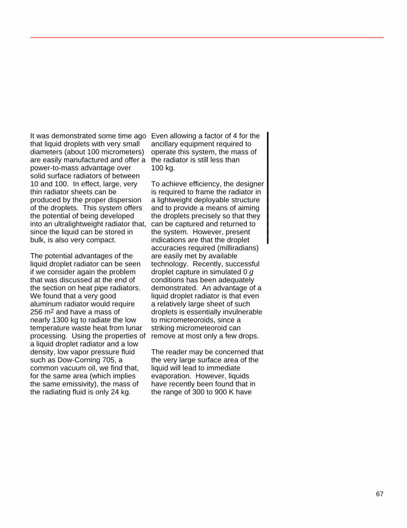
It was demonstrated some time ago that liquid droplets with very small diameters (about 100 micrometers) are easily manufactured and offer a power-to-mass advantage over solid surface radiators of between 10 and 100. In effect, large, very thin radiator sheets can be produced by the proper dispersion of the droplets. This system offers the potential of being developed into an ultralightweight radiator that, since the liquid can be stored in bulk, is also very compact. The potential advantages of the liquid droplet radiator can be seen if we consider again the problem that was discussed at the end of the section on heat pipe radiators. We found that a very good aluminum radiator would require 256 m2 and have a mass of nearly 1300 kg to radiate the low temperature waste heat from lunar processing. Using the properties of a liquid droplet radiator and a low density, low vapor pressure fluid such as Dow-Corning 705, a common vacuum oil, we find that, for the same area (which implies the same emissivity), the mass of the radiating fluid is only 24 kg.
Even allowing a factor of 4 for the ancillary equipment required to operate this system, the mass of the radiator is still less than 100 kg. To achieve efficiency, the designer is required to frame the radiator in a lightweight deployable structure and to provide a means of aiming the droplets precisely so that they can be captured and returned to the system. However, present indications are that the droplet accuracies required (milliradians) are easily met by available technology. Recently, successful droplet capture in simulated 0 g conditions has been adequately demonstrated. An advantage of a liquid droplet radiator is that even a relatively large sheet of such droplets is essentially invulnerable to micrometeoroids, since a striking micrometeoroid can remove at most only a few drops. The reader may be concerned that the very large surface area of the liquid will lead to immediate evaporation. However, liquids have recently been found that in the range of 300 to 900 K have
67
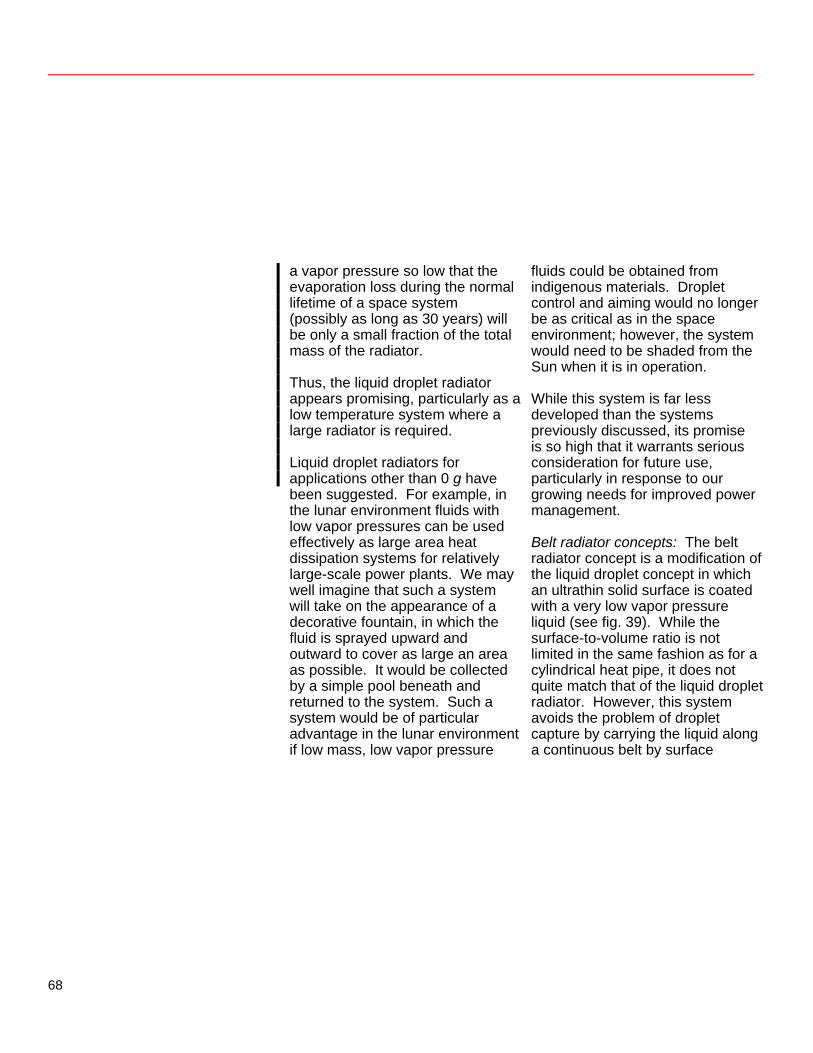
a vapor pressure so low that the evaporation loss during the normal lifetime of a space system (possibly as long as 30 years) will be only a small fraction of the total mass of the radiator. Thus, the liquid droplet radiator appears promising, particularly as a low temperature system where a large radiator is required. Liquid droplet radiators for applications other than 0 g have been suggested. For example, in the lunar environment fluids with low vapor pressures can be used effectively as large area heat dissipation systems for relatively large-scale power plants. We may well imagine that such a system will take on the appearance of a decorative fountain, in which the fluid is sprayed upward and outward to cover as large an area as possible. It would be collected by a simple pool beneath and returned to the system. Such a system would be of particular advantage in the lunar environment if low mass, low vapor pressure
fluids could be obtained from indigenous materials. Droplet control and aiming would no longer be as critical as in the space environment; however, the system would need to be shaded from the Sun when it is in operation. While this system is far less developed than the systems previously discussed, its promise is so high that it warrants serious consideration for future use, particularly in response to our growing needs for improved power management. Belt radiator concepts: The belt radiator concept is a modification of the liquid droplet concept in which an ultrathin solid surface is coated with a very low vapor pressure liquid (see fig. 39). While the surface-to-volume ratio is not limited in the same fashion as for a cylindrical heat pipe, it does not quite match that of the liquid droplet radiator. However, this system avoids the problem of droplet capture by carrying the liquid along a continuous belt by surface
68
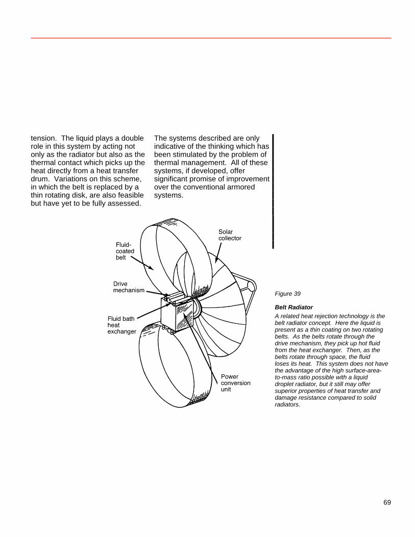
tension. The liquid plays a double role in this system by acting not only as the radiator but also as the thermal contact which picks up the heat directly from a heat transfer drum. Variations on this scheme, in which the belt is replaced by a thin rotating disk, are also feasible but have yet to be fully assessed.
The systems described are only indicative of the thinking which has been stimulated by the problem of thermal management. All of these systems, if developed, offer significant promise of improvement over the conventional armored systems.
Figure 39
Belt Radiator A related heat rejection technology is the belt radiator concept. Here the liquid is present as a thin coating on two rotating belts. As the belts rotate through the drive mechanism, they pick up hot fluid from the heat exchanger. Then, as the belts rotate through space, the fluid loses its heat. This system does not have the advantage of the high surface-area- to-mass ratio possible with a liquid droplet radiator, but it still may offer superior properties of heat transfer and damage resistance compared to solid radiators.
69
Laser Power Transmission Edmund J. Conway Since their development, lasers have offered the potential of projecting large amounts of power onto a distant, small area. (Laser power was once measured in “gillettes,” the thickness in number of razor blades it took to just stop the beam.) Initially, this characteristic seemed good for weapons (e.g., the laser rifle) and mining (thermal fracture or vaporization of rock). Actual applications later developed in the areas of cutting (anything from sheet metal to cloth), welding, scribing, and surgery. One of the earliest proposals for the application of a high-powered laser in the civilian space program was made by Kantrowitz (1972). He proposed an Earth-to-orbit launch system in which a laser on the ground supplied thermal energy to a single species of rocket propellant (such as hydrogen). The removal of the oxidizer, no longer needed to release chemical energy for propulsion, reduced the lift-off weight of Earth-launched vehicles. This and similar proposals on power and propulsion generated a great deal of speculation and
study in the 1970s. These activities, although generally incomplete and sometimes contradictory, identified several themes: • Lower cost power and propulsion
is key to the development of near-Earth space.
• Solar- and nuclear-powered
lasers have the characteristics for high payoff in space applications.
• Expensive transportation
applications show high potential for cost reduction through the use of remote laser power.
• Economical power beaming in
space requires multiple customers who cannot use available (solar photovoltaic) power sources.
• High laser conversion efficiency
is a key power-beaming challenge.
• NASA laser power requirements
are very different from those of DOD and DOE, but NASA can benefit from the breadth of basic research generated by the programs of other agencies.
70
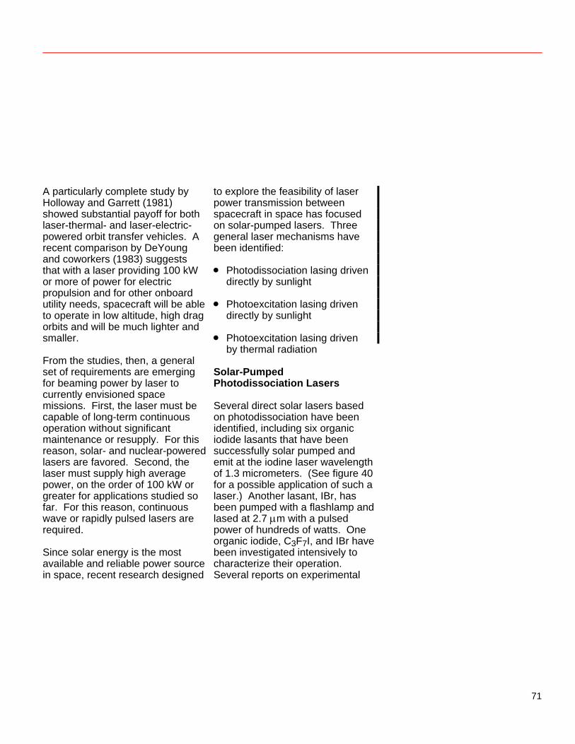
A particularly complete study by Holloway and Garrett (1981) showed substantial payoff for both laser-thermal- and laser-electric-powered orbit transfer vehicles. A recent comparison by DeYoung and coworkers (1983) suggests that with a laser providing 100 kW or more of power for electric propulsion and for other onboard utility needs, spacecraft will be able to operate in low altitude, high drag orbits and will be much lighter and smaller. From the studies, then, a general set of requirements are emerging for beaming power by laser to currently envisioned space missions. First, the laser must be capable of long-term continuous operation without significant maintenance or resupply. For this reason, solar- and nuclear-powered lasers are favored. Second, the laser must supply high average power, on the order of 100 kW or greater for applications studied so far. For this reason, continuous wave or rapidly pulsed lasers are required. Since solar energy is the most available and reliable power source in space, recent research designed
to explore the feasibility of laser power transmission between spacecraft in space has focused on solar-pumped lasers. Three general laser mechanisms have been identified: • Photodissociation lasing driven
directly by sunlight • Photoexcitation lasing driven
directly by sunlight • Photoexcitation lasing driven
by thermal radiation Solar-Pumped Photodissociation Lasers Several direct solar lasers based on photodissociation have been identified, including six organic iodide lasants that have been successfully solar pumped and emit at the iodine laser wavelength of 1.3 micrometers. (See figure 40 for a possible application of such a laser.) Another lasant, IBr, has been pumped with a flashlamp and lased at 2.7 μm with a pulsed power of hundreds of watts. One organic iodide, C3F7I, and IBr have been investigated intensively to characterize their operation. Several reports on experimental
71
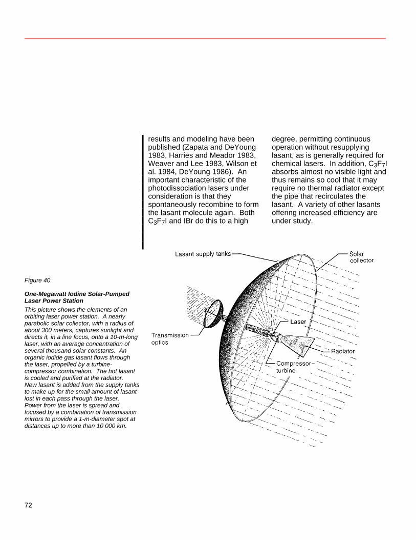
results and modeling have been published (Zapata and DeYoung 1983, Harries and Meador 1983, Weaver and Lee 1983, Wilson et al. 1984, DeYoung 1986). An important characteristic of the photodissociation lasers under consideration is that they spontaneously recombine to form the lasant molecule again. Both C3F7I and IBr do this to a high
degree, permitting continuous operation without resupplying lasant, as is generally required for chemical lasers. In addition, C3F7I absorbs almost no visible light and thus remains so cool that it may require no thermal radiator except the pipe that recirculates the lasant. A variety of other lasants offering increased efficiency are under study.
Figure 40
One-Megawatt Iodine Solar-Pumped Laser Power Station This picture shows the elements of an orbiting laser power station. A nearly parabolic solar collector, with a radius of about 300 meters, captures sunlight and directs it, in a line focus, onto a 10-m-long laser, with an average concentration of several thousand solar constants. An organic iodide gas lasant flows through the laser, propelled by a turbine-compressor combination. The hot lasant is cooled and purified at the radiator. New lasant is added from the supply tanks to make up for the small amount of lasant lost in each pass through the laser. Power from the laser is spread and focused by a combination of transmission mirrors to provide a 1-m-diameter spot at distances up to more than 10 000 km.
72
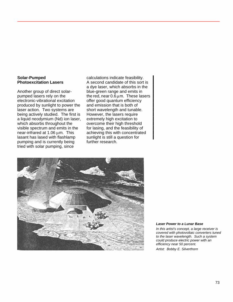
Solar-Pumped Photoexcitation Lasers Another group of direct solar-pumped lasers rely on the electronic-vibrational excitation produced by sunlight to power the laser action. Two systems are being actively studied. The first is a liquid neodymium (Nd) ion laser, which absorbs throughout the visible spectrum and emits in the near-infrared at 1.06 μm. This lasant has lased with flashlamp pumping and is currently being tried with solar pumping, since
calculations indicate feasibility. A second candidate of this sort is a dye laser, which absorbs in the blue-green range and emits in the red, near 0.6 μm. These lasers offer good quantum efficiency and emission that is both of short wavelength and tunable. However, the lasers require extremely high excitation to overcome their high threshold for lasing, and the feasibility of achieving this with concentrated sunlight is still a question for further research.
Laser Power to a Lunar Base In this artist’s concept, a large receiver is covered with photovoltaic converters tuned to the laser wavelength. Such a system could produce electric power with an efficiency near 50 percent. Artist: Bobby E. Silverthorn
73
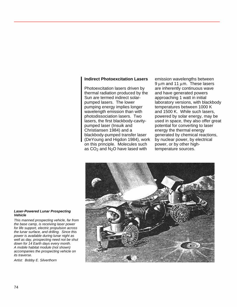
Indirect Photoexcitation Lasers Photoexcitation lasers driven by thermal radiation produced by the Sun are termed indirect solar-pumped lasers. The lower pumping energy implies longer wavelength emission than with photodissociation lasers. Two lasers, the first blackbody-cavity-pumped laser (Insuik and Christiansen 1984) and a blackbody-pumped transfer laser (DeYoung and Higdon 1984), work on this principle. Molecules such as CO2 and N2O have lased with
emission wavelengths between 9 μm and 11 μm. These lasers are inherently continuous wave and have generated powers approaching 1 watt in initial laboratory versions, with blackbody temperatures between 1000 K and 1500 K. While such lasers, powered by solar energy, may be used in space, they also offer great potential for converting to laser energy the thermal energy generated by chemical reactions, by nuclear power, by electrical power, or by other high- temperature sources.
Laser-Powered Lunar Prospecting Vehicle This manned prospecting vehicle, far from the base camp, is receiving laser power for life support, electric propulsion across the lunar surface, and drilling. Since this power is available during lunar night as well as day, prospecting need not be shut down for 14 Earth days every month. A mobile habitat module (not shown) accompanies the prospecting vehicle on its traverse. Artist: Bobby E. Silverthorn
74
References DeYoung, R. J.; W. D. Tepper; E. J. Conway; and D. H. Humes. 1983. Preliminary Comparison of Laser and Solar Space Power Systems. Proc. 18th Intersociety Energy Conversion Eng. Conf., Aug. DeYoung, Russell J. 1986. Low Threshold Solar-Pumped Iodine Laser. J. Quantum Electronics, vol. QE-22 (July), pp. 1019–1023. Inst. Elec. & Electron. Eng. DeYoung, Russell J., and N. F. Higdon. 1984. A Blackbody-Pumped CO2-N2 Transfer Laser. NASA TP-2347, Aug. Harries, Wynford L., and Willard E. Meador. 1983. Kinetic Modeling of an IBr Solar-Pumped Laser. Space Solar Power Review 4:189–202. Holloway, Paul F., and L. B. Garrett. 1981. Comparative Analyses of Space-to-Space Central Power Stations. NASA TP-1955, Dec.
Insuik, Robin J., and Walter H. Christiansen. 1984. A Radiatively Pumped CW CO2 Laser. J. Quantum Electronics, vol. QE-20 (June), pp. 622–625. Inst. Elec. & Electron. Eng. Kantrowitz, Arthur. 1972. Propulsion to Orbit by Ground-Based Lasers. Astronaut. & Aeronaut. 10 (May): 74–76. American Inst. Aeronaut. & Astronaut. Weaver, Willard R., and Ja H. Lee. 1983. A Solar-Pumped Gas Laser for the Direct Conversion of Solar Energy. J. Energy 7 (Nov.–Dec.): 498–501. Wilson, John W.; Y. Lee; Willard R. Weaver; Donald H. Humes; and Ja H. Lee. 1984. Threshold Kinetics of a Solar Simulator Pumped Iodine Laser. NASA TP-2241, Feb. Zapata, Luis E., and Russell J. DeYoung. 1983. Flashlamp Pumped Iodine Monobromide Laser Characteristics. J. Applied Physics 54 (April): 1686–1692.
75
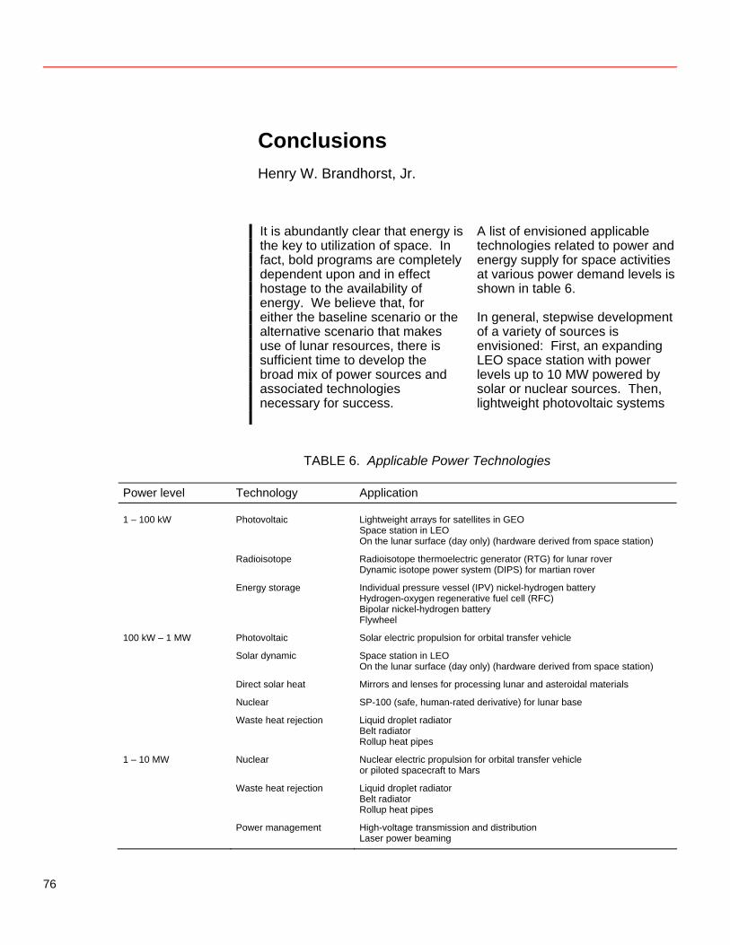
Conclusions Henry W. Brandhorst, Jr.
It is abundantly clear that energy is the key to utilization of space. In fact, bold programs are completely dependent upon and in effect hostage to the availability of energy. We believe that, for either the baseline scenario or the alternative scenario that makes use of lunar resources, there is sufficient time to develop the broad mix of power sources and associated technologies necessary for success.
A list of envisioned applicable technologies related to power and energy supply for space activities at various power demand levels is shown in table 6. In general, stepwise development of a variety of sources is envisioned: First, an expanding LEO space station with power levels up to 10 MW powered by solar or nuclear sources. Then, lightweight photovoltaic systems
TABLE 6. Applicable Power Technologies
Power level Technology Application 1 – 100 kW Photovoltaic Lightweight arrays for satellites in GEO Space station in LEO On the lunar surface (day only) (hardware derived from space station)
Radioisotope Radioisotope thermoelectric generator (RTG) for lunar rover Dynamic isotope power system (DIPS) for martian rover
Energy storage Individual pressure vessel (IPV) nickel-hydrogen battery Hydrogen-oxygen regenerative fuel cell (RFC) Bipolar nickel-hydrogen battery Flywheel
100 kW – 1 MW Photovoltaic Solar electric propulsion for orbital transfer vehicle
Solar dynamic Space station in LEO On the lunar surface (day only) (hardware derived from space station)
Direct solar heat Mirrors and lenses for processing lunar and asteroidal materials
Nuclear SP-100 (safe, human-rated derivative) for lunar base
Waste heat rejection Liquid droplet radiator Belt radiator Rollup heat pipes
1 – 10 MW Nuclear Nuclear electric propulsion for orbital transfer vehicle or piloted spacecraft to Mars
Waste heat rejection Liquid droplet radiator Belt radiator Rollup heat pipes
Power management High-voltage transmission and distribution Laser power beaming
76
for GEO and lunar surface operation. It is likely that lunar camps staffed only during the day could derive all their power (25–100 kW) from solar arrays. Lightweight electrochemical storage systems such as hydrogen-oxygen regenerative fuel cells would find use at GEO and, in concert with solar arrays, would power surface-roving vehicles and machines. When full-time staffing becomes appropriate, we believe that nuclear systems are the most likely source of power. Power levels in the 100–1000 kW range would be derived from lunar-modified SP-100-class designs, while powers in the 1–10 MW range would be derivatives of civil and military multimegawatt nuclear developments. These man-rated, safe nuclear systems would simply be used as power demands warranted. Thus, for a lunar base, photovoltaic (or solar dynamic) systems would be used initially for daytime operation, SP-100-class systems would be used for full time staffing at power levels to 1 MW (by replication or design), and these would be followed by multimegawatt systems for the
1–10 MW needs. Similar progress is envisioned for either scenario for GEO operations and asteroid and Mars exploration. Attention must also be paid to the impact of the lunar, asteroidal, or martian environment on parameters of the power system. We consider it unlikely that use of nonterrestrial resources will affect power system development before 2010. It is rather the opposite: power systems will enable the development and use of nonterrestrial resources. Significant advances in the areas of nuclear power development and beamed power transmission will be made by both the military and the civilian space program. Full advantage must be taken of such corollary developments. It should be noted that development of the 1- to 10-MW class of nuclear (or even solar) power systems will have a profound influence on the state and direction of the electric propulsion programs. These power levels enable electrically propelled orbital transfer vehicles and interplanetary explorers to travel to the outermost fringes of the solar system with larger payloads and shorter trip times than chemical
77
systems. In view of these potentialities, a strong emphasis on developing such propulsion systems is warranted. Assuming that current programs in photovoltaics and in the SP-100 nuclear plant continue, the following are considered critical technological issues for further research and development. They are presented in order of priority. By piggybacking atop and augmenting existing programs, we can ensure timely development of the requisite systems. 1. SP-100-derivative nuclear
power system capable of providing power to 1 MW in an environment safe for humans
2. Large-scale photovoltaic
arrays; solar dynamic power conversion suitable for space, using collectors that concentrate sunlight
3. Solar furnaces and process heat applications suitable for processing space resources at high temperatures
4. Multimegawatt (1–10 MW)
nuclear power-generating systems for electricity and heat
5. Thermal rejection systems to
reject waste heat from the power conversion system, processing, and environmental conditioning (New concepts for efficient radiation are required; the use of lunar subsurface rejection should be investigated.)
6. High-voltage electric
transmission and distribution of multimegawatt power
7. Thermal energy control and
distribution for both manned and unmanned systems
78
8. Lightweight, rechargeable thermal and electrical storage
9. Machine design including
human factors; robotics to substitute for humans in hostile environments
10. Laser technology for solar and
infrared sources to beam power in space
11. Environmental interactions in
space associated with energy sources, processing, and work in space; i.e., the impact of foreign materials and pollutants
A broadly based program aimed at developing solar and nuclear power systems to the multimegawatt level is of the highest priority. For brevity’s sake, we have discussed only a few of the variety of long-range, innovative energy-related programs supported by NASA, DOD, DOE, and industry. To ensure a broadly based, innovative program, a portion (up to 5%) of the funds allocated for space power research should be devoted to areas that may permit radical advance and extremely high payoff, albeit at high risk.
79

Heavy Lift Launch Vehicle An unmanned heavy lift launch vehicle derived from the Space Shuttle to lower the cost of transporting material to Earth orbit would make it feasible to transport to orbit elements of a lunar base or a manned spacecraft destined for Mars. Its first stage would be powered by two solid rocket boosters, shown here after separation. Its second stage would be powered by an engine cluster at the aft end of the fuel tank that forms the central portion of the vehicle. All this pushes the payload module located at the forward end. This payload module can carry payloads up to 30 feet (9.1 meters) in diameter and 60 feet (18.3 meters) in length and up to 5 times as heavy as those carried by the Shuttle orbiter. Artist: Dennis Davidson
80
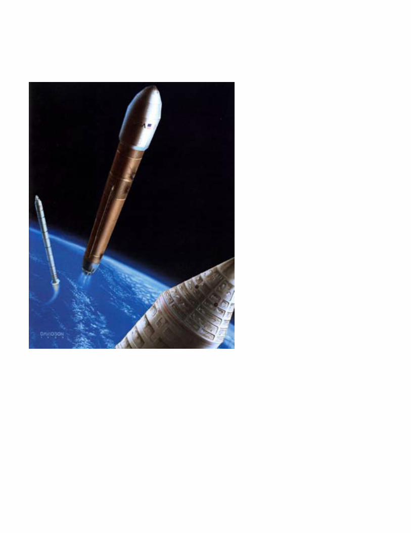
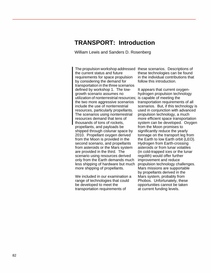
TRANSPORT: Introduction William Lewis and Sanders D. Rosenberg
The propulsion workshop addressed the current status and future requirements for space propulsion by considering the demand for transportation in the three scenarios defined by workshop 1. The low-growth scenario assumes no utilization of nonterrestrial resources; the two more aggressive scenarios include the use of nonterrestrial resources, particularly propellants. The scenarios using nonterrestrial resources demand that tens of thousands of tons of rockets, propellants, and payloads be shipped through cislunar space by 2010. Propellant oxygen derived from the Moon is provided in the second scenario, and propellants from asteroids or the Mars system are provided in the third. The scenario using resources derived only from the Earth demands much less shipping of hardware but much more shipping of propellants. We included in our examination a range of technologies that could be developed to meet the transportation requirements of
these scenarios. Descriptions of these technologies can be found in the individual contributions that follow this introduction. It appears that current oxygen-hydrogen propulsion technology is capable of meeting the transportation requirements of all scenarios. But, if this technology is used in conjunction with advanced propulsion technology, a much more efficient space transportation system can be developed. Oxygen from the Moon promises to significantly reduce the yearly tonnage on the transport leg from the Earth to low Earth orbit (LEO). Hydrogen from Earth-crossing asteroids or from lunar volatiles (in cold-trapped ices or the lunar regolith) would offer further improvement and reduce propulsion technology challenges. Mars missions are supportable by propellants derived in the Mars system, probably from Phobos. Unfortunately, these opportunities cannot be taken at current funding levels.
82
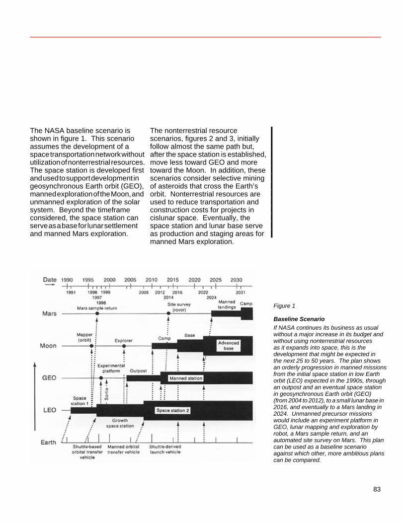
The NASA baseline scenario is shown in figure 1. This scenario assumes the development of a space transportation network without utilization of nonterrestrial resources. The space station is developed first and used to support development in geosynchronous Earth orbit (GEO), manned exploration of the Moon, and unmanned exploration of the solar system. Beyond the timeframe considered, the space station can serve as a base for lunar settlement and manned Mars exploration.
The nonterrestrial resource scenarios, figures 2 and 3, initially follow almost the same path but, after the space station is established, move less toward GEO and more toward the Moon. In addition, these scenarios consider selective mining of asteroids that cross the Earth’s orbit. Nonterrestrial resources are used to reduce transportation and construction costs for projects in cislunar space. Eventually, the space station and lunar base serve as production and staging areas for manned Mars exploration.
Figure 1
Baseline Scenario If NASA continues its business as usual without a major increase in its budget and without using nonterrestrial resources as it expands into space, this is the development that might be expected in the next 25 to 50 years. The plan shows an orderly progression in manned missions from the initial space station in low Earth orbit (LEO) expected in the 1990s, through an outpost and an eventual space station in geosynchronous Earth orbit (GEO) (from 2004 to 2012), to a small lunar base in 2016, and eventually to a Mars landing in 2024. Unmanned precursor missions would include an experiment platform in GEO, lunar mapping and exploration by robot, a Mars sample return, and an automated site survey on Mars. This plan can be used as a baseline scenario against which other, more ambitious plans can be compared.
83
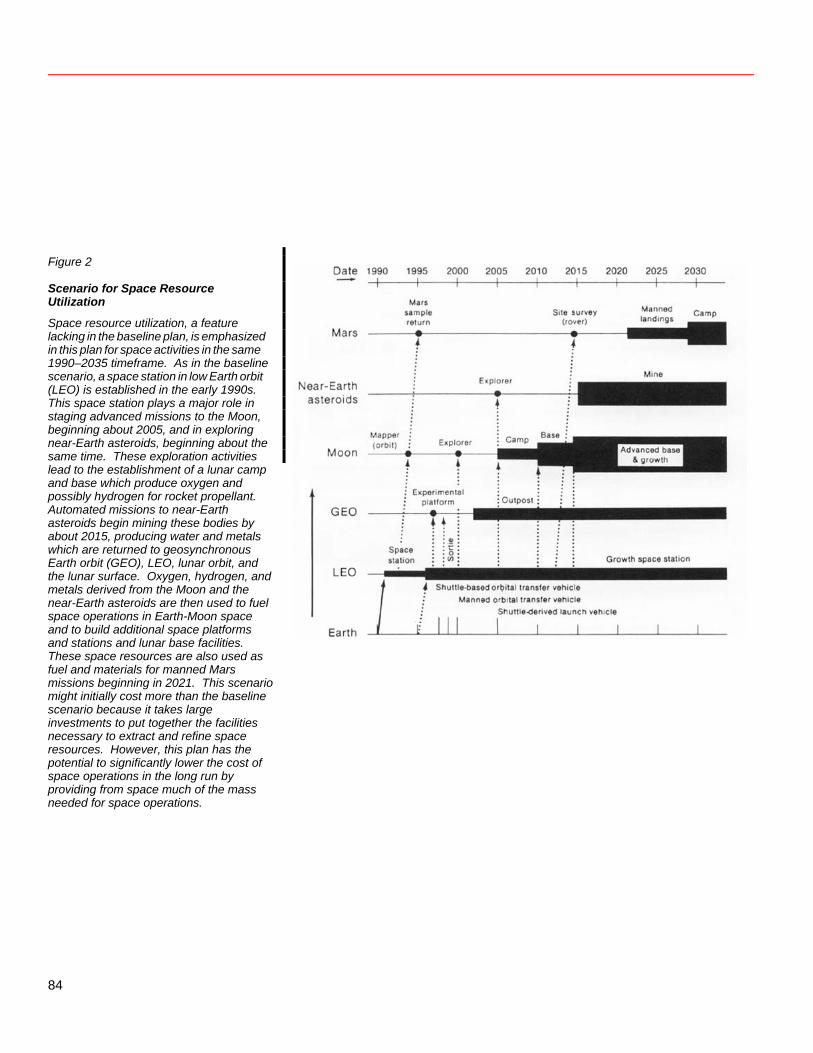
Figure 2
Scenario for Space Resource Utilization
Space resource utilization, a feature lacking in the baseline plan, is emphasized in this plan for space activities in the same 1990–2035 timeframe. As in the baseline scenario, a space station in low Earth orbit (LEO) is established in the early 1990s. This space station plays a major role in staging advanced missions to the Moon, beginning about 2005, and in exploring near-Earth asteroids, beginning about the same time. These exploration activities lead to the establishment of a lunar camp and base which produce oxygen and possibly hydrogen for rocket propellant. Automated missions to near-Earth asteroids begin mining these bodies by about 2015, producing water and metals which are returned to geosynchronous Earth orbit (GEO), LEO, lunar orbit, and the lunar surface. Oxygen, hydrogen, and metals derived from the Moon and the near-Earth asteroids are then used to fuel space operations in Earth-Moon space and to build additional space platforms and stations and lunar base facilities. These space resources are also used as fuel and materials for manned Mars missions beginning in 2021. This scenario might initially cost more than the baseline scenario because it takes large investments to put together the facilities necessary to extract and refine space resources. However, this plan has the potential to significantly lower the cost of space operations in the long run by providing from space much of the mass needed for space operations.
84
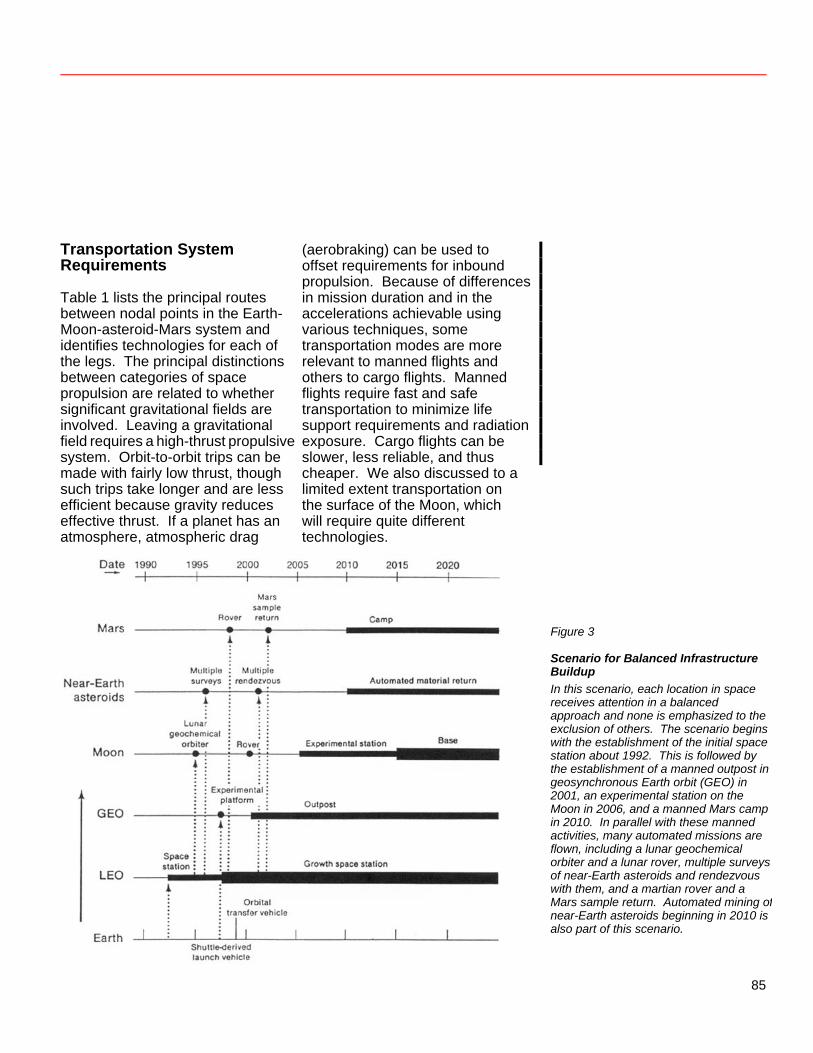
Transportation System Requirements Table 1 lists the principal routes between nodal points in the Earth-Moon-asteroid-Mars system and identifies technologies for each of the legs. The principal distinctions between categories of space propulsion are related to whether significant gravitational fields are involved. Leaving a gravitational field requires a high-thrust propulsive system. Orbit-to-orbit trips can be made with fairly low thrust, though such trips take longer and are less efficient because gravity reduces effective thrust. If a planet has an atmosphere, atmospheric drag
(aerobraking) can be used to offset requirements for inbound propulsion. Because of differences in mission duration and in the accelerations achievable using various techniques, some transportation modes are more relevant to manned flights and others to cargo flights. Manned flights require fast and safe transportation to minimize life support requirements and radiation exposure. Cargo flights can be slower, less reliable, and thus cheaper. We also discussed to a limited extent transportation on the surface of the Moon, which will require quite different echnologies. t
Figure 3
Scenario for Balanced Infrastructure Buildup In this scenario, each location in space receives attention in a balanced approach and none is emphasized to the exclusion of others. The scenario begins with the establishment of the initial space station about 1992. This is followed by the establishment of a manned outpost in geosynchronous Earth orbit (GEO) in 2001, an experimental station on the Moon in 2006, and a manned Mars camp in 2010. In parallel with these manned activities, many automated missions are flown, including a lunar geochemical orbiter and a lunar rover, multiple surveys of near-Earth asteroids and rendezvous with them, and a martian rover and a Mars sample return. Automated mining ofnear-Earth asteroids beginning in 2010 is also part of this scenario.
85
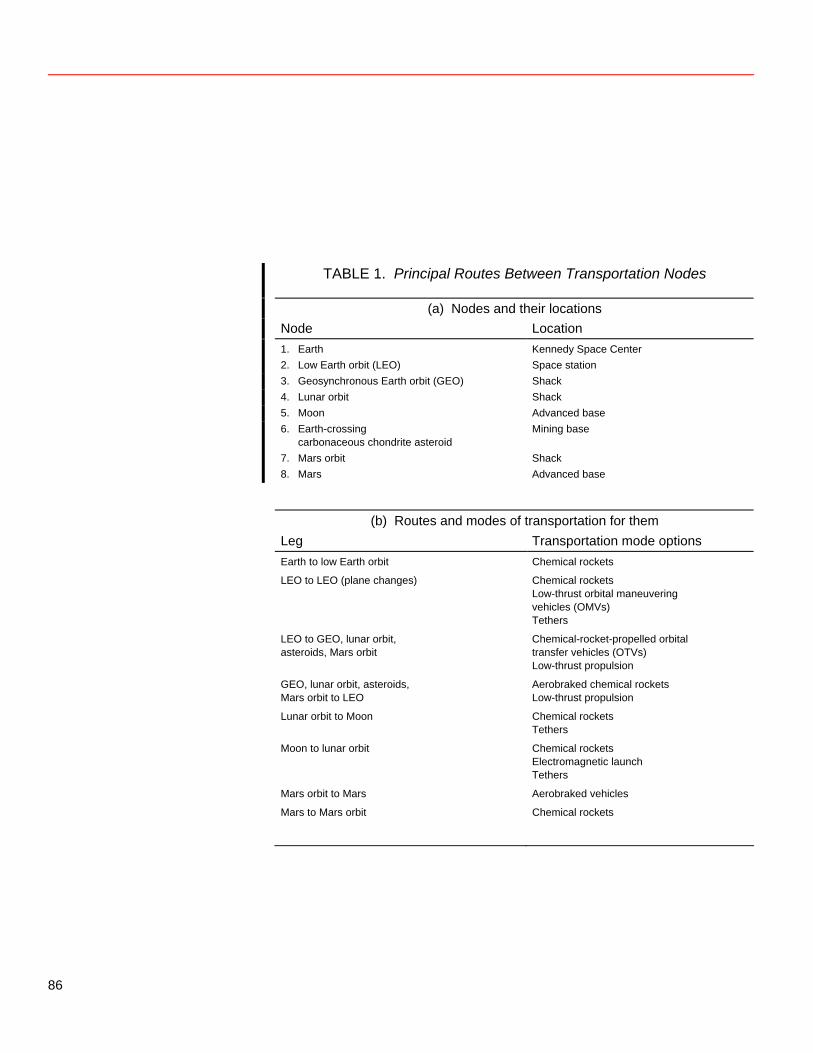
TABLE 1. Principal Routes Between Transportation Nodes
(a) Nodes and their locations Node Location 1. Earth Kennedy Space Center 2. Low Earth orbit (LEO) Space station 3. Geosynchronous Earth orbit (GEO) Shack 4. Lunar orbit Shack 5. Moon Advanced base 6. Earth-crossing
carbonaceous chondrite asteroid Mining base
7. Mars orbit Shack 8. Mars Advanced base (b) Routes and modes of transportation for them Leg Transportation mode options Earth to low Earth orbit Chemical rockets
LEO to LEO (plane changes) Chemical rockets Low-thrust orbital maneuvering
vehicles (OMVs) Tethers
LEO to GEO, lunar orbit, asteroids, Mars orbit
Chemical-rocket-propelled orbital transfer vehicles (OTVs)
Low-thrust propulsion
GEO, lunar orbit, asteroids, Mars orbit to LEO
Aerobraked chemical rockets Low-thrust propulsion
Lunar orbit to Moon Chemical rockets Tethers
Moon to lunar orbit Chemical rockets Electromagnetic launch Tethers
Mars orbit to Mars Aerobraked vehicles
Mars to Mars orbit Chemical rockets
86
The baseline scenario could be implemented with the Space Shuttle, Shuttle-derived launch vehicles (SDLVs), and orbital transfer vehicles (OTVs). The nonterrestrial resource scenarios require the development of additional systems. While it is technically possible to establish the transportation network for these scenarios with oxygen-hydrogen (OH) rockets alone, the expense of operating the transportation network, even for the baseline scenario, could be reduced by the introduction of non-OH rocket technologies. Let us consider briefly the technologies that could be used for three categories of transportation: surface-to-orbit, orbit-to-orbit, and surface. Surface-to-Orbit Transportation (Earth to Orbit, Moon to Lunar Orbit, Mars to Mars Orbit) Transportation from the Earth’s surface to orbit is conventionally accomplished using chemical rockets. There seems no readily available substitute for such rockets on this leg. Shuttle-derived launch vehicles or, if traffic becomes heavy enough, heavy lift launch vehicles (HLLVs) could provide Earth-to-orbit transportation at a lower cost than does the current Space Shuttle
system. (See Salkeld and Beichel 1973, Eldred 1982 and 1984, and Davis 1983.) These systems gain efficiency by eliminating man-rated elements and reducing system weight, rather than by improving the rocket engine (although some improvements in rocket engines are still attainable). It may be worthwhile to develop such vehicles for cargo transport in the baseline scenario over the next 20 years. And the scenarios using nonterrestrial materials require such vehicles for cost-effectiveness. Transportation from the lunar surface to orbit could be accomplished using OH rockets. The advantages of choosing OH rockets are summarized in table 2 by Sandy Rosenberg, who points out that oxygen-hydrogen propulsion is likely to persist simply because the large amount of effort that has gone into its development has led to a level of understanding which surpasses that of any alternative propulsion system. In a separate paper, Mike Simon considers the use of OH rockets in a systems sense, showing how the introduction of nonterrestrial propellants can affect the overall system performance and, eventually, reduce the cost.
87
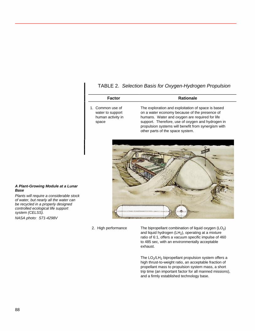
TABLE 2. Selection Basis for Oxygen-Hydrogen Propulsion
Factor Rationale
1. Common use of water to support human activity in space
The exploration and exploitation of space is based on a water economy because of the presence of humans. Water and oxygen are required for life support. Therefore, use of oxygen and hydrogen in propulsion systems will benefit from synergism with other parts of the space system.
A Plant-Growing Module at a Lunar Base Plants will require a considerable stock of water, but nearly all the water can be recycled in a properly designed controlled ecological life support system (CELSS). NASA photo: S71-4298V
2. High performance The bipropellant combination of liquid oxygen (LO2) and liquid hydrogen (LH2), operating at a mixture ratio of 6:1, offers a vacuum specific impulse of 460 to 485 sec, with an environmentally acceptable exhaust.
The LO2/LH2 bipropellant propulsion system offers a
high thrust-to-weight ratio, an acceptable fraction of propellant mass to propulsion system mass, a short trip time (an important factor for all manned missions), and a firmly established technology base.
88
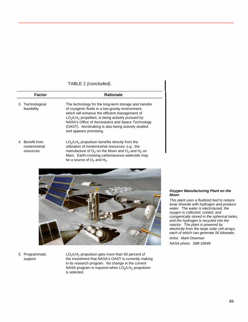
TABLE 2 (concluded).
Factor Rationale 3. Technological
feasibility
The technology for the long-term storage and transfer of cryogenic fluids in a low-gravity environment, which will enhance the efficient management of LO2/LH2 propellant, is being actively pursued by NASA’s Office of Aeronautics and Space Technology (OAST). Aerobraking is also being actively studied and appears promising.
4. Benefit from nonterrestrial resources
LO2/LH2 propulsion benefits directly from the utilization of nonterrestrial resources; e.g., the manufacture of O2 on the Moon and O2 and H2 on Mars. Earth-crossing carbonaceous asteroids may be a source of O2 and H2.
Oxygen Manufacturing Plant on the Moon This plant uses a fluidized bed to reduce lunar ilmenite with hydrogen and produce water. The water is electrolyzed, the oxygen is collected, cooled, and cryogenically stored in the spherical tanks, and the hydrogen is recycled into the reactor. The plant is powered by electricity from the large solar cell arrays, each of which can generate 56 kilowatts. Artist: Mark Dowman NASA photo: S88-33648
5. Programmatic
support
LO2/LH2 propulsion gets more than 90 percent of the investment that NASA’s OAST is currently making in its research program. No change in the current NASA program is required when LO2/LH2 propulsion is selected.
89
Specific Impulse (Isp) Specific impulse (Isp) is a measure of the performance of a rocket engine. It is equal to the thrust generated F divided by the weight flow rate w of the propellant used: . Isp = F/ w Its units turn out to be seconds. In the English system, pounds of force (mass times acceleration or Ib ft/sec2) divided by pounds of weight (mass times gravity or lb ft/sec2) per second equal seconds. In the metric system, newtons (kgm/sec2) divided by kilograms (kg) times gravity (m/sec2) per second equal seconds. Specific impulse is also equivalent to the effective exhaust velocity divided by the gravitational acceleration. This relationship can also be derived from a consideration of the units. Force, or mass times acceleration, can be seen as mass per second times velocity. Weight flow rate, or mass times gravity per second, can be taken as mass per second times gravity. Thus, specific impulse equals velocity (m/sec) divided by gravity (m/sec2), or seconds again.
Other rocket propellants derived from nonterrestrial materials could also find use in the future. Andy Cutler considers an oxygen-hydrogen-aluminum engine as a possibility. Such an engine could use oxygen and hydrogen derived from lunar or asteroidal materials and could also provide a second use for the Space Shuttle’s aluminum external tanks, which are currently thrown away. Among the alternative technologies that may be useful are electromagnetic launchers capable of launch from the Moon to low lunar orbit and of propelling vehicles in space. The Department of Defense is funding a program of significant size in electromagnetic
launch; the results of this program might be fairly cheaply adapted to the space environment. This concept is considered in a paper by Bill Snow. Several other technologies may be of value in surface-to-orbit transportation. Tethers, in particular, can permit an orbiting station to acquire momentum from a high Isp propulsion device over long periods of time and quickly transfer it to a vehicle that needs the momentum to gain orbital velocity on launch from the Moon (Carroll 1984 and 1986, Carroll and Cutler 1984). In effect, high Isp is combined with high thrust, although only briefly. Andy Cutler discusses this idea.
90
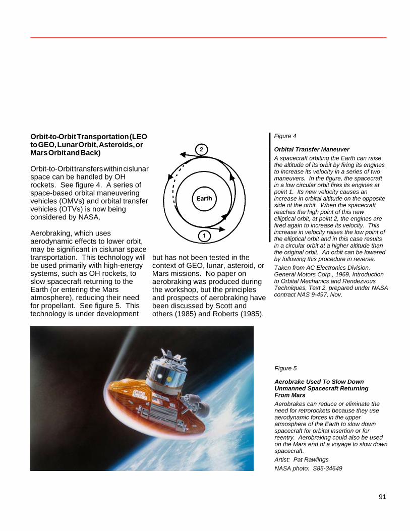
Orbit-to-Orbit Transportation (LEO to GEO, Lunar Orbit, Asteroids, or Mars Orbit and Back) Orbit-to-Orbit transfers within cislunar space can be handled by OH rockets. See figure 4. A series of space-based orbital maneuvering vehicles (OMVs) and orbital transfer vehicles (OTVs) is now being considered by NASA. Aerobraking, which uses aerodynamic effects to lower orbit, may be significant in cislunar space transportation. This technology will be used primarily with high-energy systems, such as OH rockets, to slow spacecraft returning to the Earth (or entering the Mars atmosphere), reducing their need for propellant. See figure 5. This technology is under development
but has not been tested in the context of GEO, lunar, asteroid, or Mars missions. No paper on aerobraking was produced during the workshop, but the principles and prospects of aerobraking have been discussed by Scott and others (1985) and Roberts (1985).
Figure 4
Orbital Transfer Maneuver A spacecraft orbiting the Earth can raise the altitude of its orbit by firing its engines to increase its velocity in a series of two maneuvers. In the figure, the spacecraft in a low circular orbit fires its engines at point 1. Its new velocity causes an increase in orbital altitude on the opposite side of the orbit. When the spacecraft reaches the high point of this new elliptical orbit, at point 2, the engines are fired again to increase its velocity. This increase in velocity raises the low point of the elliptical orbit and in this case results in a circular orbit at a higher altitude than the original orbit. An orbit can be lowered by following this procedure in reverse. Taken from AC Electronics Division, General Motors Corp., 1969, Introduction to Orbital Mechanics and Rendezvous Techniques, Text 2, prepared under NASA contract NAS 9-497, Nov.
Figure 5
Aerobrake Used To Slow Down Unmanned Spacecraft Returning From Mars Aerobrakes can reduce or eliminate the need for retrorockets because they use aerodynamic forces in the upper atmosphere of the Earth to slow down spacecraft for orbital insertion or for reentry. Aerobraking could also be used on the Mars end of a voyage to slow down spacecraft. Artist: Pat Rawlings NASA photo: S85-34649
91
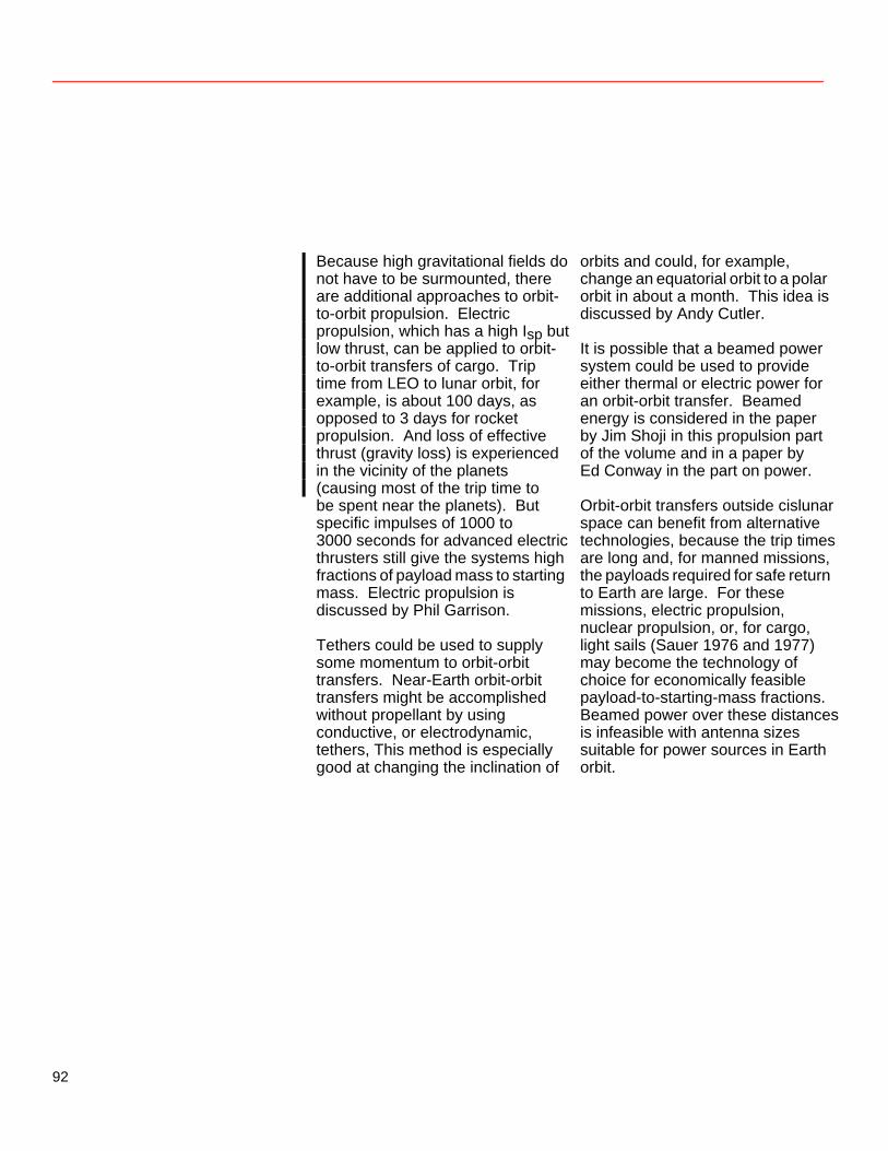
Because high gravitational fields do not have to be surmounted, there are additional approaches to orbit- to-orbit propulsion. Electric propulsion, which has a high Isp but low thrust, can be applied to orbit- to-orbit transfers of cargo. Trip time from LEO to lunar orbit, for example, is about 100 days, as opposed to 3 days for rocket propulsion. And loss of effective thrust (gravity loss) is experienced in the vicinity of the planets (causing most of the trip time to be spent near the planets). But specific impulses of 1000 to 3000 seconds for advanced electric thrusters still give the systems high fractions of payload mass to starting mass. Electric propulsion is discussed by Phil Garrison. Tethers could be used to supply some momentum to orbit-orbit transfers. Near-Earth orbit-orbit transfers might be accomplished without propellant by using conductive, or electrodynamic, tethers, This method is especially good at changing the inclination of
orbits and could, for example, change an equatorial orbit to a polar orbit in about a month. This idea is discussed by Andy Cutler. It is possible that a beamed power system could be used to provide either thermal or electric power for an orbit-orbit transfer. Beamed energy is considered in the paper by Jim Shoji in this propulsion part of the volume and in a paper by Ed Conway in the part on power. Orbit-orbit transfers outside cislunar space can benefit from alternative technologies, because the trip times are long and, for manned missions, the payloads required for safe return to Earth are large. For these missions, electric propulsion, nuclear propulsion, or, for cargo, light sails (Sauer 1976 and 1977) may become the technology of choice for economically feasible payload-to-starting-mass fractions. Beamed power over these distances is infeasible with antenna sizes suitable for power sources in Earth orbit.
92
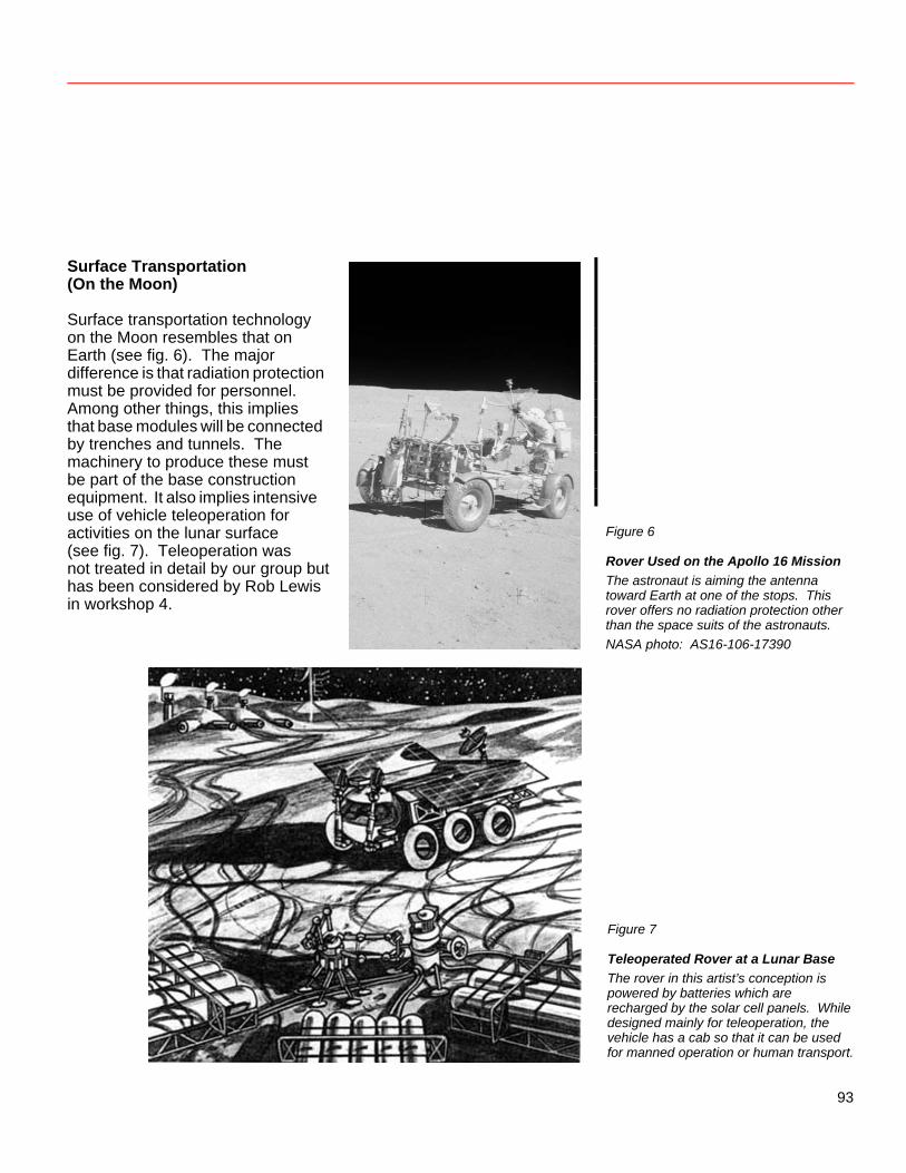
Surface Transportation (On the Moon) Surface transportation technology on the Moon resembles that on Earth (see fig. 6). The major difference is that radiation protection must be provided for personnel. Among other things, this implies that base modules will be connected by trenches and tunnels. The machinery to produce these must be part of the base construction equipment. It also implies intensive use of vehicle teleoperation for activities on the lunar surface (see fig. 7). Teleoperation was not treated in detail by our group but has been considered by Rob Lewis in workshop 4.
Figure 6
Rover Used on the Apollo 16 Mission The astronaut is aiming the antenna toward Earth at one of the stops. This rover offers no radiation protection other than the space suits of the astronauts. NASA photo: AS16-106-17390
Figure 7
Teleoperated Rover at a Lunar Base The rover in this artist’s conception is powered by batteries which are recharged by the solar cell panels. While designed mainly for teleoperation, the vehicle has a cab so that it can be used for manned operation or human transport.
93
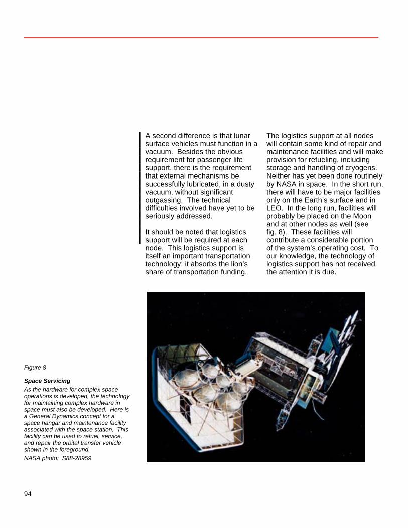
A second difference is that lunar surface vehicles must function in a vacuum. Besides the obvious requirement for passenger life support, there is the requirement that external mechanisms be successfully lubricated, in a dusty vacuum, without significant outgassing. The technical difficulties involved have yet to be seriously addressed. It should be noted that logistics support will be required at each node. This logistics support is itself an important transportation technology; it absorbs the lion’s share of transportation funding.
The logistics support at all nodes will contain some kind of repair and maintenance facilities and will make provision for refueling, including storage and handling of cryogens. Neither has yet been done routinely by NASA in space. In the short run, there will have to be major facilities only on the Earth’s surface and in LEO. In the long run, facilities will probably be placed on the Moon and at other nodes as well (see fig. 8). These facilities will contribute a considerable portion of the system’s operating cost. To our knowledge, the technology of logistics support has not received the attention it is due.
Figure 8
Space Servicing As the hardware for complex space operations is developed, the technology for maintaining complex hardware in space must also be developed. Here is a General Dynamics concept for a space hangar and maintenance facility associated with the space station. This facility can be used to refuel, service, and repair the orbital transfer vehicle shown in the foreground. NASA photo: S88-28959
94
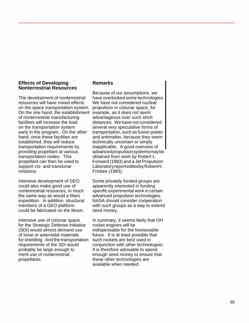
Effects of Developing Nonterrestrial Resources The development of nonterrestrial resources will have mixed effects on the space transportation system. On the one hand, the establishment of nonterrestrial manufacturing facilities will increase the load on the transportation system early in the program. On the other hand, once these facilities are established, they will reduce transportation requirements by providing propellant at various transportation nodes. This propellant can then be used to support cis- and translunar missions. Intensive development of GEO could also make good use of nonterrestrial resources, in much the same way as would a Mars expedition. In addition, structural members of a GEO platform could be fabricated on the Moon. Intensive use of cislunar space for the Strategic Defense Initiative (SDI) would almost demand use of lunar or asteroidal materials for shielding. And the transportation requirements of the SDI would probably be large enough to merit use of nonterrestrial propellants.
Remarks Because of our assumptions, we have overlooked some technologies. We have not considered nuclear propulsion in cislunar space, for example, as it does not seem advantageous over such short distances. We have not considered several very speculative forms of transportation, such as fusion power and antimatter, because they seem technically uncertain or simply inapplicable. A good overview of advanced propulsion systems may be obtained from work by Robert L. Forward (1983) and a Jet Propulsion Laboratory report edited by Robert H. Frisbee (1983). Some privately funded groups are apparently interested in funding specific experimental work in certain advanced propulsion technologies. NASA should consider cooperation with such groups as a way to extend seed money. In summary, it seems likely that OH rocket engines will be indispensable for the foreseeable future. It is at least possible that such rockets are best used in conjunction with other technologies. It is therefore advisable to spend enough seed money to ensure that these other technologies are available when needed.
95
References Frisbee, Robert H. 1983. Ultra High Performance Propulsion for Planetary Spacecraft. Final Reports for FY ’82 (JPL Report D-1097) and FY ’83 (JPL Report D1 194). Jet Propulsion Laboratory, California Institute of Technology, Pasadena, CA, Oct. & Dec.
Carroll, Joseph A. 1984. A
Scenario for Evolution of Tether Uses on a Space Station. AIAA-84-1110-CP, AIAA/NASA Space Systems Technology Conf., Costa Mesa, CA, June 5–7.
_____. 1986. Tether Applications
in Space Transportation. Acta Astronautica 13 (April): 165–174.
Roberts, B. B. 1985. Systems Analysis and Technology Development for the NASA Orbit Transfer Vehicle. AIAA-85-0965, AIAA 20th Thermophysics Conf., Williamsburg, VA, June 19–21.
Carroll, Joseph A., and Andrew H.
Cutler. 1984. Potential Uses of Tethers in Space Transportation. AIAA/SAE/ASME 20th Joint Propulsion Conf., Cincinnati, OH, June 11–13.
Salkeld, Robert, and Rudi Beichel. 1973. Reusable One-Stage-to-Orbit Shuttles: Brightening Prospects. Astronaut. & Aeronaut. 11 (June): 48–58.
Davis, H. P. 1983. Lunar Base Space Transportation System: [Report of] Preliminary Concepts to NASA Johnson Space Center. EEI Report 83-78. Houston: Eagle Engineering, Inc., Nov. 9.
Sauer, Carl G., Jr. 1976. Optimum Solar-Sail Interplanetary Trajectories. AIAA/AAS Astrodynamics Conf., San Diego, CA, Aug. 18–20.
Eldred, Charles H. 1982. Shuttle for the 21st Century. AIAA/DFGLR/ AAS/BIS Space Systems Conf., Washington, DC, Oct. 18–20.
______. 1977. A Comparison of Solar Sail and Ion Drive Trajectories for a Halley’s Comet Rendezvous Mission. AAS/AIAA Astrodynamics Conf., Jackson, WY, Sept. 7–9.
______. 1984. STS II—Beyond Shuttle. AIAA-84-1126-CP, AIAA/ NASA Space Systems Technology Conf., Costa Mesa, CA, June 5–7.
Scott, Carl D., et al. 1985. Design Study of an Integrated Aerobraking Orbital Transfer Vehicle. NASA TM-58264, March.
Forward, Robert L. 1983. Alternate Propulsion Energy Sources. Air Force Contract F04611-83-C-0013, May 24.
96
Utilization of Space Resources in the Space Transportation System Michael C. Simon Utilization of space resources (i.e., raw materials obtained from nonterrestrial sources) has often been cited as a prerequisite for large-scale industrialization and habitation of space. While transportation of extremely large quantities of material from Earth would be costly and potentially destructive to our environment, vast quantities of usable resources might be derived from the Moon, the asteroids, and other celestial objects in a cost-effective and environmentally benign manner. Of more immediate interest to space program planners is the economic feasibility of using space resources to support near-term space activities, such as scientific and commercial missions in the 2000–2010 timeframe. Liquid oxygen for use as a propellant in a space-based transportation system appears to be the space resource that has the firmest near-term requirement for quantities great enough to be produced economically in a nonterrestrial setting. This paper identifies the factors most likely to influence the economics of near-term space resource utilization. The analysis is based on a scenario for producing liquid oxygen from lunar ore.
Analysis Methodology The primary purpose of the parametric cost model developed as part of this study is to identify the factors that have the greatest influence on the economics of space resource utilization. In the near term, this information can be used to devise strategies for technology development so that capabilities developed will produce cost-effective results. Predicting the actual costs of particular scenarios for space resource utilization is only a secondary objective of this analysis. Estimates are made and dollar values are assigned principally to allow comparison of options. Since the technologies for space resource utilization are in an early stage of development, it is premature to state conclusively whether mining the Moon, asteroids, or other celestial bodies makes economic sense. The parametric model is designed more for flexibility than for precision. Although preliminary estimates indicate that production of oxygen from lunar ore is a project that is likely to yield an economic payback, this activity was selected
97
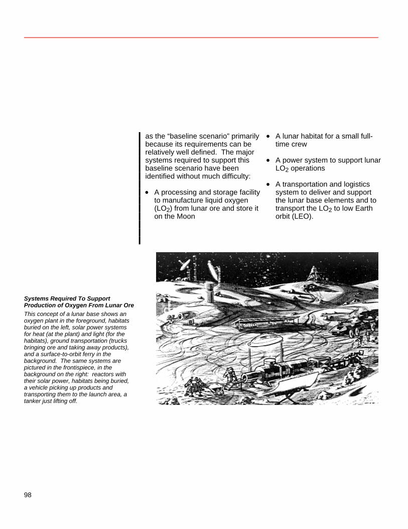
as the “baseline scenario” primarily because its requirements can be relatively well defined. The major systems required to support this baseline scenario have been identified without much difficulty: • A processing and storage facility
to manufacture liquid oxygen (LO2) from lunar ore and store it on the Moon
• A lunar habitat for a small full-time crew
• A power system to support lunar
LO2 operations • A transportation and logistics
system to deliver and support the lunar base elements and to transport the LO2 to low Earth orbit (LEO).
Systems Required To Support Production of Oxygen From Lunar Ore This concept of a lunar base shows an oxygen plant in the foreground, habitats buried on the left, solar power systems for heat (at the plant) and light (for the habitats), ground transportation (trucks bringing ore and taking away products), and a surface-to-orbit ferry in the background. The same systems are pictured in the frontispiece, in the background on the right: reactors with their solar power, habitats being buried, a vehicle picking up products and transporting them to the launch area, a tanker just lifting off.
98
Once these major support systems were defined, fifteen key variables were identified as influencing the cost of developing and operating these systems (table 3). Cost variables were generalized so that the parametric model could be adapted to the evaluation of alternative scenarios. Next, equations were developed to calculate capital and operations costs as functions of these variables. Using the codes and units detailed in table 3, these equations are Capital cost = (p × cp) + (nt × cn)
+ (nm × cu) + cf + ct × [(p x mp) + (nm × mm) + mf]
Operations cost = ct × {(nr × mm)
+ [(1-d) × 125 000]} + (nb × nf × $100 000)
where the capital cost is defined as the total cost of developing, building, and installing the lunar base elements (including transportation costs) and the operations cost is the annual cost of manufacturing 1 million kilograms (1000 metric tons) of LO2 per year and delivering
to LEO as much of this LO2 as possible. The term in square brackets [(1-d) × 125 000] in the operations cost equation reflects the assumptions that a portion (1-d) of the LO2 produced on the Moon is used as propellant to deliver the remaining LO2 (d) to LEO and that 1 kilogram of hydrogen must be delivered from Earth to the Moon for every 8 kilograms of oxygen used as propellant for the Moon-to-LEO leg (125 000 kg of hydrogen for the projected annual production of 1 million kg of oxygen). The higher-than-usual mixture ratio of 8:1 was selected for the baseline case after initial analyses showed that the resultant reduction in the hydrogen requirement offers substantial economic benefits. The constant cost ($100 000) in the operations cost equation is the cost of ground support per provider per year. The variable that precedes this constant, nf, is a ground support overhead factor which is multiplied by the labor cost to obtain total ground support cost.
99
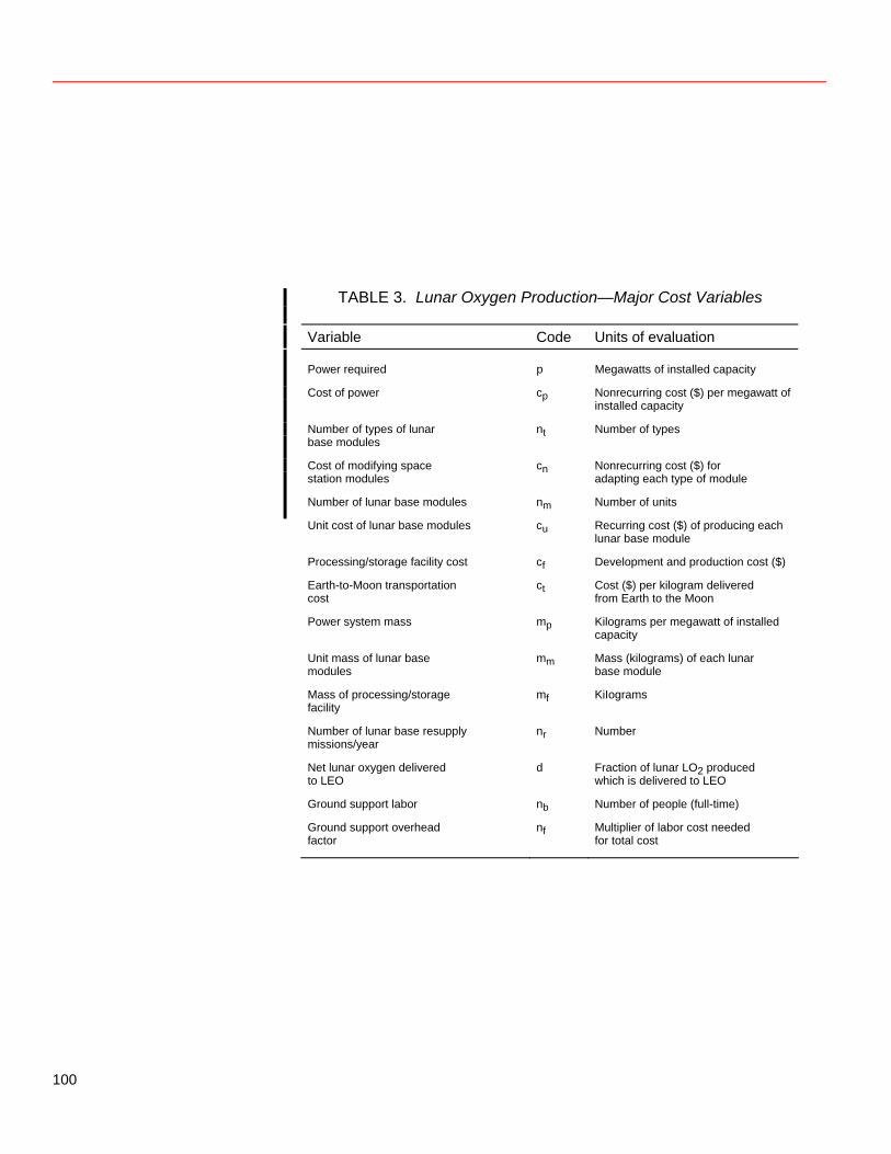
TABLE 3. Lunar Oxygen Production—Major Cost Variables
Variable Code Units of evaluation
Power required p Megawatts of installed capacity
Cost of power cp Nonrecurring cost ($) per megawatt of installed capacity
Number of types of lunar base modules
nt Number of types
Cost of modifying space station modules
cn Nonrecurring cost ($) for adapting each type of module
Number of lunar base modules nm Number of units
Unit cost of lunar base modules cu Recurring cost ($) of producing each lunar base module
Processing/storage facility cost cf Development and production cost ($)
Earth-to-Moon transportation cost
ct Cost ($) per kilogram delivered from Earth to the Moon
Power system mass mp Kilograms per megawatt of installed capacity
Unit mass of lunar base modules
mm Mass (kilograms) of each lunar base module
Mass of processing/storage facility
mf KiIograms
Number of lunar base resupply missions/year
nr Number
Net lunar oxygen delivered to LEO
d Fraction of lunar LO2 produced which is delivered to LEO
Ground support labor nb Number of people (full-time)
Ground support overhead factor
nf Multiplier of labor cost needed for total cost
100
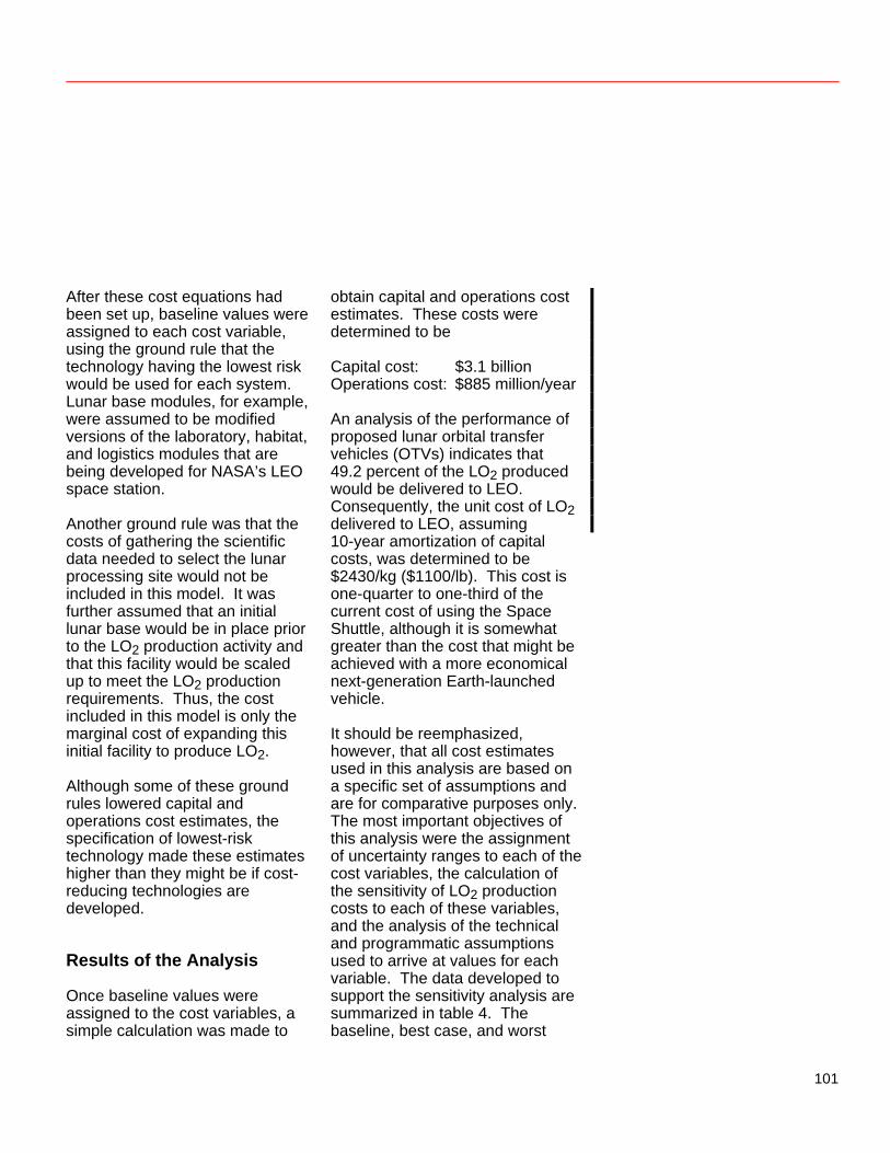
After these cost equations had been set up, baseline values were assigned to each cost variable, using the ground rule that the technology having the lowest risk would be used for each system. Lunar base modules, for example, were assumed to be modified versions of the laboratory, habitat, and logistics modules that are being developed for NASA’s LEO space station. Another ground rule was that the costs of gathering the scientific data needed to select the lunar processing site would not be included in this model. It was further assumed that an initial lunar base would be in place prior to the LO2 production activity and that this facility would be scaled up to meet the LO2 production requirements. Thus, the cost included in this model is only the marginal cost of expanding this initial facility to produce LO2. Although some of these ground rules lowered capital and operations cost estimates, the specification of lowest-risk technology made these estimates higher than they might be if cost-reducing technologies are developed. Results of the Analysis Once baseline values were assigned to the cost variables, a simple calculation was made to
obtain capital and operations cost estimates. These costs were determined to be Capital cost: $3.1 billion Operations cost: $885 million/year An analysis of the performance of proposed lunar orbital transfer vehicles (OTVs) indicates that 49.2 percent of the LO2 produced would be delivered to LEO. Consequently, the unit cost of LO2 delivered to LEO, assuming 10-year amortization of capital costs, was determined to be $2430/kg ($1100/lb). This cost is one-quarter to one-third of the current cost of using the Space Shuttle, although it is somewhat greater than the cost that might be achieved with a more economical next-generation Earth-launched vehicle. It should be reemphasized, however, that all cost estimates used in this analysis are based on a specific set of assumptions and are for comparative purposes only. The most important objectives of this analysis were the assignment of uncertainty ranges to each of the cost variables, the calculation of the sensitivity of LO2 production costs to each of these variables, and the analysis of the technical and programmatic assumptions used to arrive at values for each variable. The data developed to support the sensitivity analysis are summarized in table 4. The baseline, best case, and worst
101
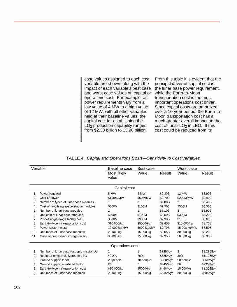
case values assigned to each cost variable are shown, along with the impact of each variable’s best case and worst case values on capital or operations cost. For example, as power requirements vary from a low value of 4 MW to a high value of 12 MW, with all other variables held at their baseline values, the capital cost for establishing the LO2 production capability ranges from $2.30 billion to $3.90 billion.
From this table it is evident that the principal driver of capital cost is the lunar base power requirement, while the Earth-to-Moon transportation cost is the most important operations cost driver. Since capital costs are amortized over a 10-year period, the Earth-to-Moon transportation cost has a much greater overall impact on the cost of lunar LO2 in LEO. If this cost could be reduced from its
TABLE 4. Capital and Operations Costs—Sensitivity to Cost Variables
Variable Baseline case Best case Worst case Most likely
value Value Result Value Result
Capital cost 1. Power required 8 MW 4 MW $2.30B 12 MW $3.90B 2. Cost of power $100M/MW $50M/MW $2.708 $200M/MW $3.908 3. Number of types of lunar base modules 1 0 $2.80B 2 $3.40B 4. Cost of modifying space station modules $300M $100M $2.908 $500M $3.30B 5. Number of lunar base modules 1 1 $3.10B 3 $3.90B 6. Unit cost of lunar base modules $200M $100M $3.00B $300M $3.20B 7. Processing/storage facility cost $500M $300M $2.90B $1.0B $3.60B 8. Earth-to-Moon transportation cost $10 000/kg $5000/kg $2.45B $15 000/kg $3.75B 9. Power system mass 10 000 kg/MW 5000 kg/MW $2.70B 15 000 kg/MW $3.50B 10. Unit mass of lunar base modules 20 000 kg 15 000 kg $3.05B 30 000 kg $3.20B 11. Mass of processing/storage facility 30 000 kg 15 000 kg $2.95B 50 000 kg $3.30B
Operations cost 1. Number of lunar base resupply missions/yr 1 1 $885M/yr 3 $1.285B/yr 2. Net lunar oxygen delivered to LEO 49.2% 70% $625M/yr 30% $1.125B/yr 3. Ground support labor 20 people 10 people $860M/yr 50 people $960M/yr 4. Ground support overhead factor 25 5 $845M/yr 50 $935M/yr 5. Earth-to-Moon transportation cost $10 000/kg $5000/kg $468M/yr 15 000/kg $1.303B/yr 6. Unit mass of lunar base modules 20 000 kg 15 000/kg $835M/yr 30 000 kg $985M/yr
102
baseline value of $10 000 to its best case value of $5000 per kilogram delivered to the Moon, capital cost would drop from $3.1 billion to $2.45 billion, operations cost would decline from $885 million/year to $468 million/ year, and the cost of lunar LO2 would be reduced from $2430/kg to $1450/kg. Conversely, at its worst case value of $15 000/kg, the Earth-to-Moon transportation cost would drive capital cost up to $3.75 billion, operations cost to $1.303 billion/year, and the cost of lunar LO2 to $3410/kg.
An alternative approach to showing the impacts of the cost variables is illustrated in table 5. It lists the effect of each cost variable in terms of percentage changes in the capital or operations cost and in the cost per kilogram of LO2 produced (with a 10-year amortization of capital cost). In this table the variables are ranked in order of their impact on the LO2 cost/kg. The influence of each variable is calculated as an “impact factor” equal to the average of the percentage changes in LO2 cost/kg due to the best-case and worst-case values of the variable.
TABLE 5. Sensitivity of Capital, Operations, and Oxygen Production Costs to Ranges of Cost Variables
Variable Sensitivity Best case Worst case Impact ranking Change in
total cost Change in LO2 cost/kg
Change total cost
Change in LO2 cost/kg
factor
Capital cost Earth-to-Moon transportation cost 1 -21% - 40%* + 21% + 40% 40 Power required 2 -26% - 7% + 26% + 7% 7 Unit mass of lunar base modules 3 - 2% - 4%* + 3% + 9% 7 Cost of power 4 -13% - 3% + 26% + 7% 5 Number of lunar base modules 5 0% 0% + 26% + 7% 4 Processing/storage facility cost 6 - 6% - 2% + 16% + 4% 3 Power system mass 7 -13% - 3% + 13% + 3% 3 Number of types of lunar base modules 8 -10% - 3% + 10% + 3% 3 Cost of modifying space station modules 9 - 6% - 2% + 6% + 2% 2 Mass of processing/storage facility 10 - 5% - 1% + 6% + 2% 2 Unit cost of lunar base modules 11 - 3% - 1% + 3% + 1% 1
Operations cost Net lunar oxygen delivered to LEO 1 -29% -45% + 27% + 97% 71 Earth-to-Moon transportation cost 2 -47% - 40%* + 47% + 40% 40 Number of lunar base resupply missions/yr 3 0% 0% + 45% + 13% 7 Unit mass of lunar base modules 4 - 6% - 4%* + 11% + 9% 7 Ground support labor 5 - 3% - 3% + 8% + 6% 5 Ground support overhead factor 6 - 5% - 3% + 6% + 4% 4 *Impact based on changes in both capital cost and operations cost.
103
From these impact factors it is clear that two of the cost variables are far more important than all the rest: net lunar oxygen delivered to LEO and Earth-to-Moon transportation cost. The percentage of lunar-produced oxygen delivered to LEO is important because of its double impact. As the percentage of LO2 delivered declines, LO2 cost/kg increases not only because less LO2 is delivered but also because more hydrogen must be transported from the Earth to match the LO2 used as propellant from the Moon to LEO. The six operations cost variables are among the nine most important, largely because the impact of capital cost is spread out over the 10-year amortization period. The relative significance of the operations cost leads to the important observation that LO2 production costs may be reduced substantially by increasing capital expenditure on technologies that can reduce operations cost. One such technology is Earth-to-Moon transportation, which has a tremendous impact on operations cost. Capital cost factors, such as the mass and cost of the power system and of the processing/ storage facility, have much less impact on LO2 cost/kg.
Technology Development Required To Improve Performance It is not possible to conclude, on the basis of this analysis, that production of liquid oxygen from lunar materials is justifiable on economic grounds. Although the cost estimates for the baseline scenario are encouraging, a number of technologies with significant impact on LO2 production costs must be explored. The performance and cost of space-based orbital transfer vehicles is the most critical technology issue. Developing a low-cost OTV is a fundamental requirement for cost-effective utilization of space resources because the OTV is the single most effective means of reducing Earth-to-Moon transportation cost. Another key issue is the cost of hydrogen used for launching payloads from the Moon. Production of lunar LO2 would be far more cost-effective if a capability for the co-production of lunar hydrogen could be developed (even though capital cost might increase substantially). Although relatively large quantities of lunar
104
ore would need to be processed, the additional cost of lunar hydrogen production could be offset by a savings of over $600 million/year in transportation cost. Production of some alternative propellant constituent, such as aluminum, also might offer an opportunity for reducing or eliminating costly import of fuels from Earth. However, this example would require the development of an aluminum-burning space engine. A third category that seems to have substantial impact on the economics of lunar resource utilization is the technologies influencing lunar base resupply requirements. Increasing lunar base automation, closing the lunar base life support system, and other steps to reduce the frequency and scale of resupply missions appear to have a high likelihood of providing economic benefits and should be given particular emphasis in future studies. If all three of these objectives were met to the greatest extent possible (i.e., if Earth-to-Moon transportation cost were reduced to its best case value, if hydrogen transportation requirements were eliminated, and if lunar base resupply requirements were eliminated), the cost of lunar
LO2 delivered to LEO would be reduced from $2430/kg to $600/kg, or about $270/lb. These figures assume no change in capital cost; but, even if capital cost were doubled to achieve these capabilities, LO2 cost would be reduced to approximately $1100/kg—less than half the baseline cost. Twenty-five key technology issues influencing these and the other cost variables in LO2 production are presented in table 6. In this table, a dark square indicates a strong impact of that technology issue on the cost variable, a light square indicates a moderate impact, and no square indicates little or no impact. The selection and evaluation of these technology issues was made by a panel of experts convened for the purpose, not by a quantitative analysis. The fifteen cost variables ranked as in table 5 are listed across the top of table 6 in descending order of importance. Hence, table 6 is a graphic representation of the relative importance of the technologies based on three considerations: total number of squares, number of dark squares, and distribution of squares to the left of the chart (i.e., toward the most important cost variables).
105

106
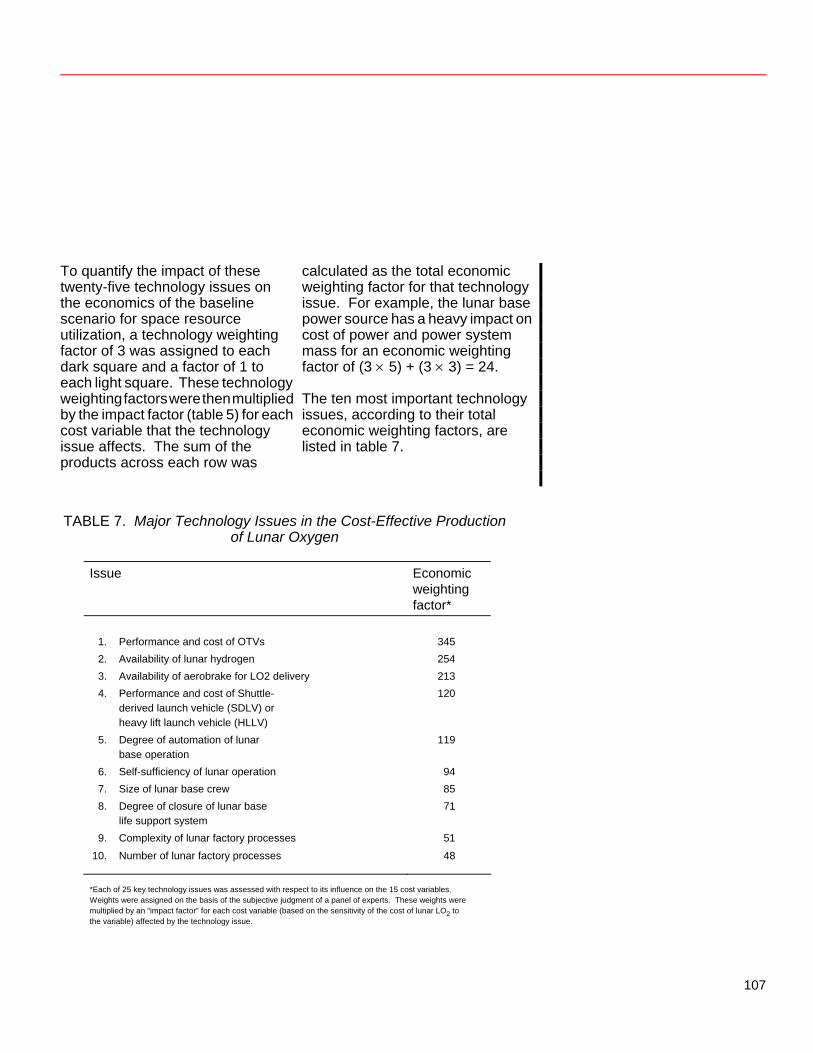
To quantify the impact of these twenty-five technology issues on the economics of the baseline scenario for space resource utilization, a technology weighting factor of 3 was assigned to each dark square and a factor of 1 to each light square. These technology weighting factors were then multiplied by the impact factor (table 5) for each cost variable that the technology issue affects. The sum of the products across each row was
calculated as the total economic weighting factor for that technology issue. For example, the lunar base power source has a heavy impact on cost of power and power system mass for an economic weighting factor of (3 × 5) + (3 × 3) = 24. The ten most important technology issues, according to their total economic weighting factors, are listed in table 7.
TABLE 7. Major Technology Issues in the Cost-Effective Production
of Lunar Oxygen
Issue Economic weighting factor*
1. Performance and cost of OTVs 345 2. Availability of lunar hydrogen 254 3. Availability of aerobrake for LO2 delivery 213 4. Performance and cost of Shuttle-
derived launch vehicle (SDLV) or heavy lift launch vehicle (HLLV)
120
5. Degree of automation of lunar base operation
119
6. Self-sufficiency of lunar operation 94 7. Size of lunar base crew 85 8. Degree of closure of lunar base
life support system 71
9. Complexity of lunar factory processes 51
10. Number of lunar factory processes 48
*Each of 25 key technology issues was assessed with respect to its influence on the 15 cost variables. Weights were assigned on the basis of the subjective judgment of a panel of experts. These weights were multiplied by an “impact factor” for each cost variable (based on the sensitivity of the cost of lunar LO2 to the variable) affected by the technology issue.
107
Finally, it is important that parametric cost analyses such as this one be used to assess a variety of space resource utilization scenarios. Use of lunar ore for production of construction materials is one such option, although to be cost-effective this type of enterprise would probably require a dramatic increase in space activity. Another option that merits careful consideration is the development of asteroidal resources. Both rocket propellants and construction materials could be derived from asteroids; and, while the up-front cost of asteroid utilization would probably exceed the capital expenditure required for lunar development, operations cost could be substantially lower. Further analysis of all these opportunities
needs to be carried out over the next several years before a commitment is made to any particular plan for space resource utilization. As new technologies are developed, the reliability of cost estimates for space resource utilization will improve. Eventually, it will be possible to generate cost estimates of sufficient fidelity to support detailed definition of space utilization objectives. An important step in this process will be the adaptation of this parametric model and similar techniques to the evaluation of a broad range of space resource development options.
108
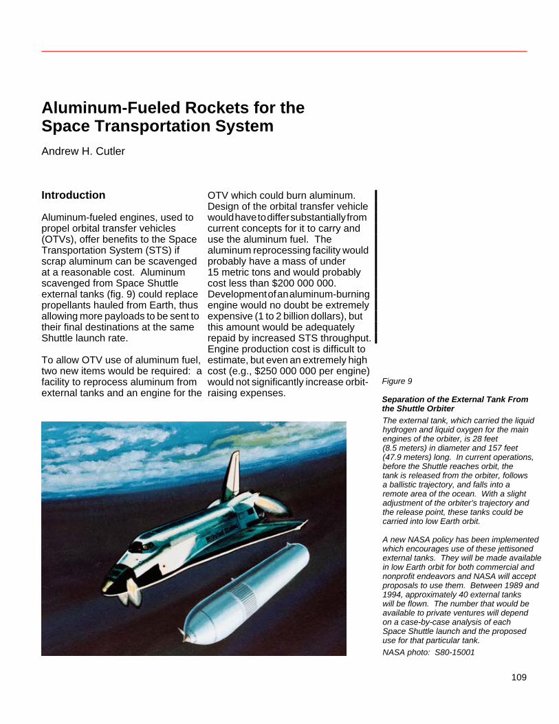
Aluminum-Fueled Rockets for the Space Transportation System Andrew H. Cutler Introduction Aluminum-fueled engines, used to propel orbital transfer vehicles (OTVs), offer benefits to the Space Transportation System (STS) if scrap aluminum can be scavenged at a reasonable cost. Aluminum scavenged from Space Shuttle external tanks (fig. 9) could replace propellants hauled from Earth, thus allowing more payloads to be sent to their final destinations at the same Shuttle launch rate. To allow OTV use of aluminum fuel, two new items would be required: a facility to reprocess aluminum from external tanks and an engine for the
OTV which could burn aluminum. Design of the orbital transfer vehicle would have to differ substantially from current concepts for it to carry and use the aluminum fuel. The aluminum reprocessing facility would probably have a mass of under 15 metric tons and would probably cost less than $200 000 000. Development of an aluminum-burning engine would no doubt be extremely expensive (1 to 2 billion dollars), but this amount would be adequately repaid by increased STS throughput. Engine production cost is difficult to estimate, but even an extremely high cost (e.g., $250 000 000 per engine) would not significantly increase orbit-raising expenses.
Figure 9
Separation of the External Tank From the Shuttle Orbiter
The external tank, which carried the liquid hydrogen and liquid oxygen for the main engines of the orbiter, is 28 feet (8.5 meters) in diameter and 157 feet (47.9 meters) long. In current operations, before the Shuttle reaches orbit, the tank is released from the orbiter, follows a ballistic trajectory, and falls into a remote area of the ocean. With a slight adjustment of the orbiter’s trajectory and the release point, these tanks could be carried into low Earth orbit. A new NASA policy has been implemented which encourages use of these jettisoned external tanks. They will be made available in low Earth orbit for both commercial and nonprofit endeavors and NASA will accept proposals to use them. Between 1989 and 1994, approximately 40 external tanks will be flown. The number that would be available to private ventures will depend on a case-by-case analysis of each Space Shuttle launch and the proposed use for that particular tank. NASA photo: S80-15001
109
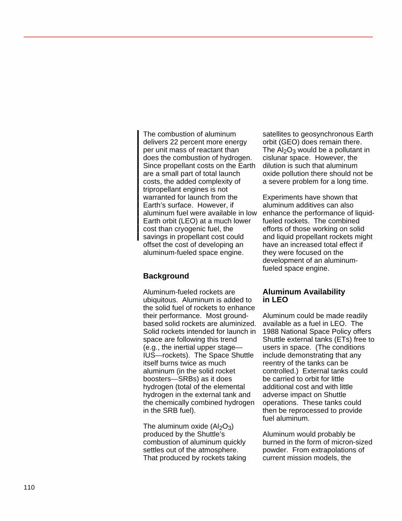
The combustion of aluminum delivers 22 percent more energy per unit mass of reactant than does the combustion of hydrogen. Since propellant costs on the Earth are a small part of total launch costs, the added complexity of tripropellant engines is not warranted for launch from the Earth’s surface. However, if aluminum fuel were available in low Earth orbit (LEO) at a much lower cost than cryogenic fuel, the savings in propellant cost could offset the cost of developing an aluminum-fueled space engine. Background Aluminum-fueled rockets are ubiquitous. Aluminum is added to the solid fuel of rockets to enhance their performance. Most ground-based solid rockets are aluminized. Solid rockets intended for launch in space are following this trend (e.g., the inertial upper stage—IUS—rockets). The Space Shuttle itself burns twice as much aluminum (in the solid rocket boosters—SRBs) as it does hydrogen (total of the elemental hydrogen in the external tank and the chemically combined hydrogen in the SRB fuel). The aluminum oxide (Al2O3) produced by the Shuttle’s combustion of aluminum quickly settles out of the atmosphere. That produced by rockets taking
satellites to geosynchronous Earth orbit (GEO) does remain there. The Al2O3 would be a pollutant in cislunar space. However, the dilution is such that aluminum oxide pollution there should not be a severe problem for a long time. Experiments have shown that aluminum additives can also enhance the performance of liquid-fueled rockets. The combined efforts of those working on solid and liquid propellant rockets might have an increased total effect if they were focused on the development of an aluminum-fueled space engine. Aluminum Availability in LEO Aluminum could be made readily available as a fuel in LEO. The 1988 National Space Policy offers Shuttle external tanks (ETs) free to users in space. (The conditions include demonstrating that any reentry of the tanks can be controlled.) External tanks could be carried to orbit for little additional cost and with little adverse impact on Shuttle operations. These tanks could then be reprocessed to provide fuel aluminum. Aluminum would probably be burned in the form of micron-sized powder. From extrapolations of current mission models, the
110
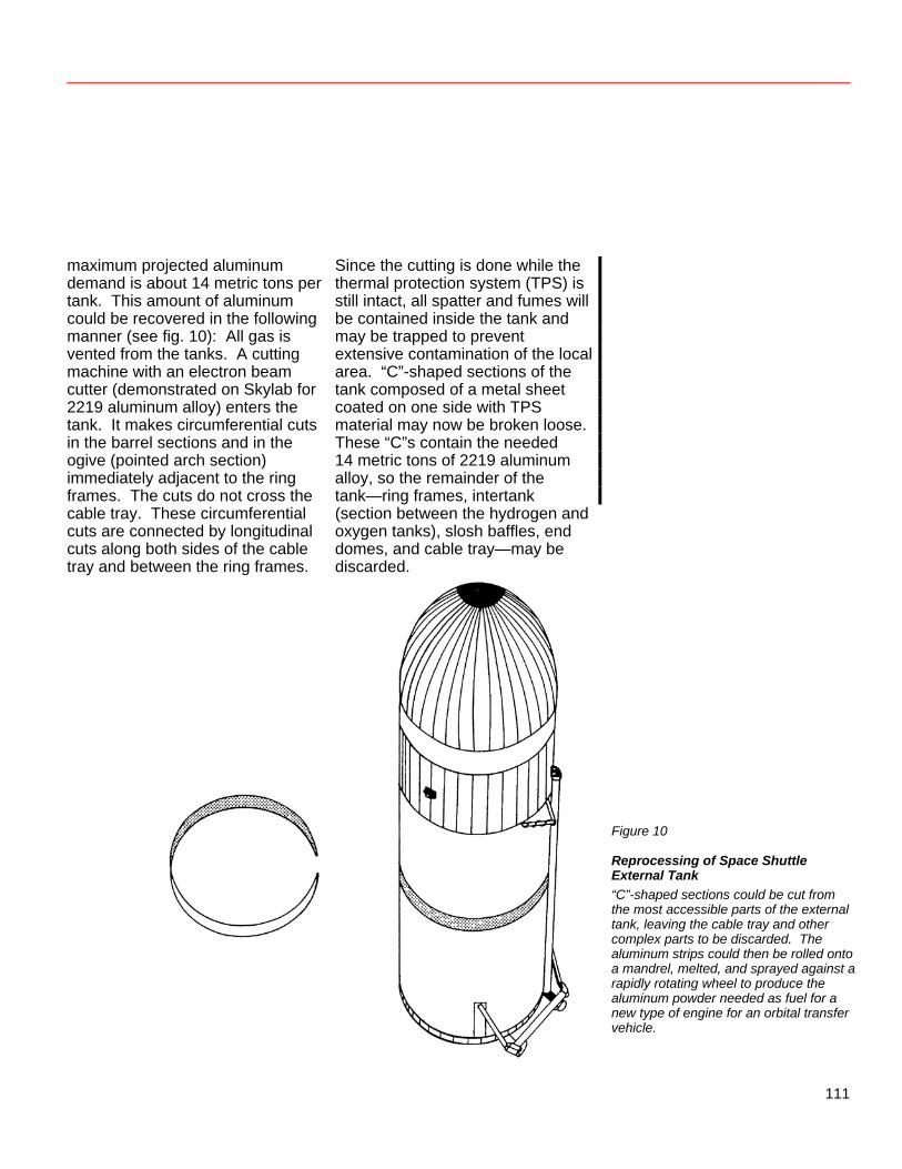
maximum projected aluminum demand is about 14 metric tons per tank. This amount of aluminum could be recovered in the following manner (see fig. 10): All gas is vented from the tanks. A cutting machine with an electron beam cutter (demonstrated on Skylab for 2219 aluminum alloy) enters the tank. It makes circumferential cuts in the barrel sections and in the ogive (pointed arch section) immediately adjacent to the ring frames. The cuts do not cross the cable tray. These circumferential cuts are connected by longitudinal cuts along both sides of the cable tray and between the ring frames.
Since the cutting is done while the thermal protection system (TPS) is still intact, all spatter and fumes will be contained inside the tank and may be trapped to prevent extensive contamination of the local area. “C”-shaped sections of the tank composed of a metal sheet coated on one side with TPS material may now be broken loose. These “C”s contain the needed 14 metric tons of 2219 aluminum alloy, so the remainder of the tank—ring frames, intertank (section between the hydrogen and oxygen tanks), slosh baffles, end domes, and cable tray—may be discarded.
Figure 10
Reprocessing of Space Shuttle External Tank “C”-shaped sections could be cut from the most accessible parts of the external tank, leaving the cable tray and other complex parts to be discarded. The aluminum strips could then be rolled onto a mandrel, melted, and sprayed against a rapidly rotating wheel to produce the aluminum powder needed as fuel for a new type of engine for an orbital transfer vehicle.
111
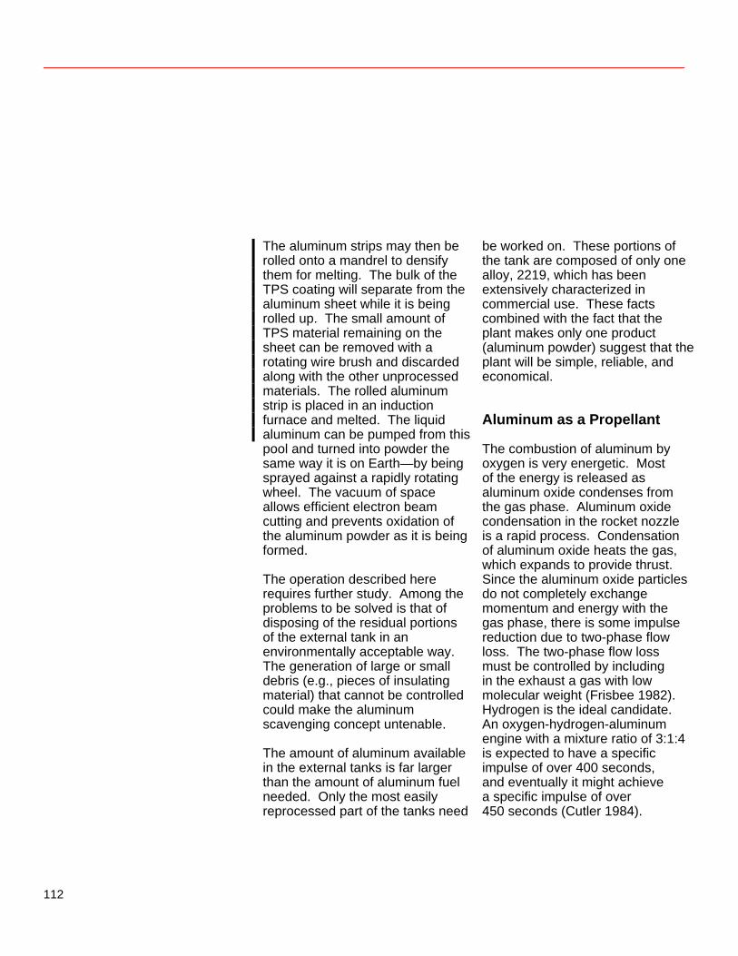
The aluminum strips may then be rolled onto a mandrel to densify them for melting. The bulk of the TPS coating will separate from the aluminum sheet while it is being rolled up. The small amount of TPS material remaining on the sheet can be removed with a rotating wire brush and discarded along with the other unprocessed materials. The rolled aluminum strip is placed in an induction furnace and melted. The liquid aluminum can be pumped from this pool and turned into powder the same way it is on Earth—by being sprayed against a rapidly rotating wheel. The vacuum of space allows efficient electron beam cutting and prevents oxidation of the aluminum powder as it is being formed. The operation described here requires further study. Among the problems to be solved is that of disposing of the residual portions of the external tank in an environmentally acceptable way. The generation of large or small debris (e.g., pieces of insulating material) that cannot be controlled could make the aluminum scavenging concept untenable. The amount of aluminum available in the external tanks is far larger than the amount of aluminum fuel needed. Only the most easily reprocessed part of the tanks need
be worked on. These portions of the tank are composed of only one alloy, 2219, which has been extensively characterized in commercial use. These facts combined with the fact that the plant makes only one product (aluminum powder) suggest that the plant will be simple, reliable, and economical. Aluminum as a Propellant The combustion of aluminum by oxygen is very energetic. Most of the energy is released as aluminum oxide condenses from the gas phase. Aluminum oxide condensation in the rocket nozzle is a rapid process. Condensation of aluminum oxide heats the gas, which expands to provide thrust. Since the aluminum oxide particles do not completely exchange momentum and energy with the gas phase, there is some impulse reduction due to two-phase flow loss. The two-phase flow loss must be controlled by including in the exhaust a gas with low molecular weight (Frisbee 1982). Hydrogen is the ideal candidate. An oxygen-hydrogen-aluminum engine with a mixture ratio of 3:1:4 is expected to have a specific impulse of over 400 seconds, and eventually it might achieve a specific impulse of over 450 seconds (Cutler 1984).
112
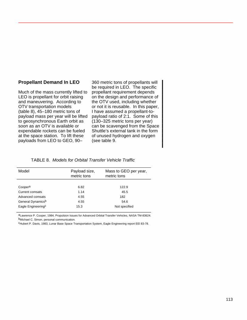
Propellant Demand In LEO Much of the mass currently lifted to LEO is propellant for orbit raising and maneuvering. According to OTV transportation models (table 8), 45–180 metric tons of payload mass per year will be lifted to geosynchronous Earth orbit as soon as an OTV is available or expendable rockets can be fueled at the space station. To lift these payloads from LEO to GEO, 90–
360 metric tons of propellants will be required in LEO. The specific propellant requirement depends on the design and performance of the OTV used, including whether or not it is reusable. In this paper, I have assumed a propellant-to-payload ratio of 2:1. Some of this (130–325 metric tons per year) can be scavenged from the Space Shuttle’s external tank in the form of unused hydrogen and oxygen (see table 9.
TABLE 8. Models for Orbital Transfer Vehicle Traffic
Model Payload size, metric tons
Mass to GEO per year, metric tons
Coopera 6.82 122.9 Current comsats 1.14 45.5 Advanced comsats 4.55 182 General Dynamicsb 4.55 54.6 Eagle Engineeringc 15.3 Not specified
aLawrence P. Cooper, 1984, Propulsion Issues for Advanced Orbital Transfer Vehicles, NASA TM-83624. bMichael C. Simon, personal communication. cHubert P. Davis, 1983, Lunar Base Space Transportation System, Eagle Engineering report EEl 83-78.
113
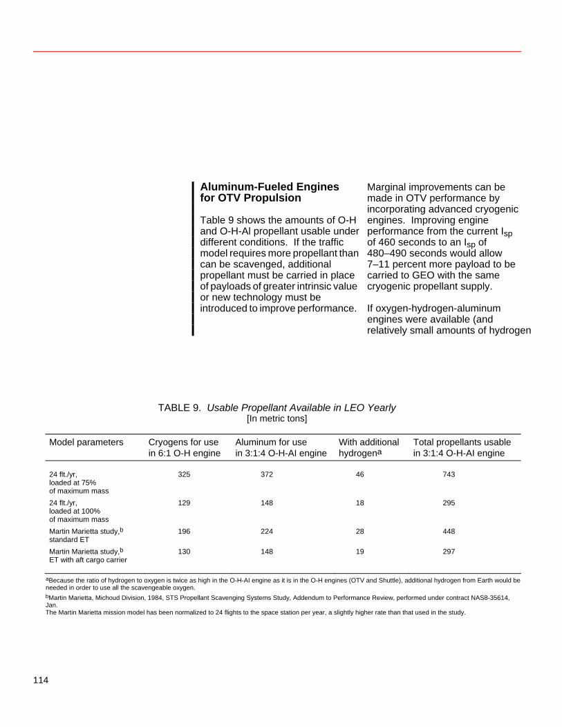
Aluminum-Fueled Engines for OTV Propulsion Table 9 shows the amounts of O-H and O-H-Al propellant usable under different conditions. If the traffic model requires more propellant than can be scavenged, additional propellant must be carried in place of payloads of greater intrinsic value or new technology must be introduced to improve performance.
Marginal improvements can be made in OTV performance by incorporating advanced cryogenic engines. Improving engine performance from the current Isp of 460 seconds to an Isp of 480–490 seconds would allow 7–11 percent more payload to be carried to GEO with the same cryogenic propellant supply. If oxygen-hydrogen-aluminum engines were available (and relatively small amounts of hydrogen
TABLE 9. Usable Propellant Available in LEO Yearly [In metric tons]
Model parameters Cryogens for use
in 6:1 O-H engine Aluminum for use in 3:1:4 O-H-AI engine
With additional hydrogena
Total propellants usable in 3:1:4 O-H-AI engine
24 flt./yr,
loaded at 75% of maximum mass
325 372 46 743
24 flt./yr, loaded at 100% of maximum mass
129 148 18 295
Martin Marietta study,b standard ET
196 224 28 448
Martin Marietta study,b ET with aft cargo carrier
130 148 19 297
aBecause the ratio of hydrogen to oxygen is twice as high in the O-H-AI engine as it is in the O-H engines (OTV and Shuttle), additional hydrogen from Earth would be needed in order to use all the scavengeable oxygen. bMartin Marietta, Michoud Division, 1984, STS Propellant Scavenging Systems Study, Addendum to Performance Review, performed under contract NAS8-35614, Jan. The Martin Marietta mission model has been normalized to 24 flights to the space station per year, a slightly higher rate than that used in the study.
114
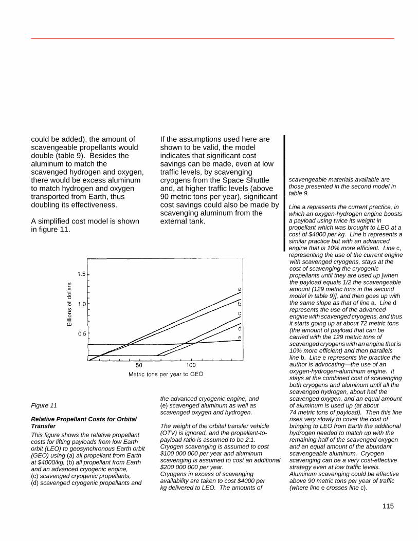
could be added), the amount of scavengeable propellants would double (table 9). Besides the aluminum to match the scavenged hydrogen and oxygen, there would be excess aluminum to match hydrogen and oxygen transported from Earth, thus doubling its effectiveness. A simplified cost model is shown in figure 11.
If the assumptions used here are shown to be valid, the model indicates that significant cost savings can be made, even at low traffic levels, by scavenging cryogens from the Space Shuttle and, at higher traffic levels (above 90 metric tons per year), significant cost savings could also be made by scavenging aluminum from the external tank.
scavengeable materials available are those presented in the second model in table 9. Line a represents the current practice, in which an oxygen-hydrogen engine boosts a payload using twice its weight in propellant which was brought to LEO at a cost of $4000 per kg. Line b represents a similar practice but with an advanced engine that is 10% more efficient. Line c, representing the use of the current engine
with scavenged cryogens, stays at the cost of scavenging the cryogenic propellants until they are used up [when the payload equals 1/2 the scavengeable amount (129 metric tons in the second model in table 9)], and then goes up with the same slope as that of line a. Line d represents the use of the advanced engine with scavenged cryogens, and thus it starts going up at about 72 metric tons (the amount of payload that can be carried with the 129 metric tons of scavenged cryogens with an engine that is 10% more efficient) and then parallels line b. Line e represents the practice the author is advocating—the use of an oxygen-hydrogen-aluminum engine. It stays at the combined cost of scavenging both cryogens and aluminum until all the scavenged hydrogen, about half the
Figure 11
Relative Propellant Costs for Orbital Transfer This figure shows the relative propellant costs for lifting payloads from low Earth orbit (LEO) to geosynchronous Earth orbit (GEO) using (a) all propellant from Earth at $4000/kg, (b) all propellant from Earth and an advanced cryogenic engine, (c) scavenged cryogenic propellants, (d) scavenged cryogenic propellants and
the advanced cryogenic engine, and (e) scavenged aluminum as well as scavenged oxygen and hydrogen. The weight of the orbital transfer vehicle (OTV) is ignored, and the propellant-to-payload ratio is assumed to be 2:1. Cryogen scavenging is assumed to cost $100 000 000 per year and aluminum scavenging is assumed to cost an additional $200 000 000 per year. Cryogens in excess of scavenging availability are taken to cost $4000 per kg delivered to LEO. The amounts of
scavenged oxygen, and an equal amount of aluminum is used up (at about 74 metric tons of payload). Then this line rises very slowly to cover the cost of bringing to LEO from Earth the additional hydrogen needed to match up with the remaining half of the scavenged oxygen and an equal amount of the abundant scavengeable aluminum. Cryogen scavenging can be a very cost-effective strategy even at low traffic levels. Aluminum scavenging could be effective above 90 metric tons per year of traffic (where line e crosses line c).
115
Conclusion Aluminum-fueled space engines may be more economical than advanced cryogenic engines in the regimes where advanced engines can offer significant savings over current technology (that is, where there is enough traffic that the benefits from improved performance exceed the cost of developing a new engine). Thus, assuming that all programs for the development of new engines have about the same cost, any argument which justifies developing advanced oxygen-hydrogen engines justifies investigating the development of an aluminum-fueled space engine. The most economical way to run an OTV program may be to rely on an OTV with a current RL-10 engine until propellant demand is near the scavenged supply and then change over to an OTV propelled by an oxygen-hydrogen-aluminum engine.
References Cutler, Andrew H. 1984. H2/O2/Al Engines and Their Application to OTV’s. Paper IAF-84-314, 35th Int. Astronaut. Fed. Congress, Lausanne, Switzerland, Oct. 5–12. Frisbee, Robert H. 1982. Ultra High Performance Propulsion for Planetary Spacecraft. JPL Report D-1097. Jet Propulsion Laboratory, California Institute of Technology, Pasadena, CA.
116
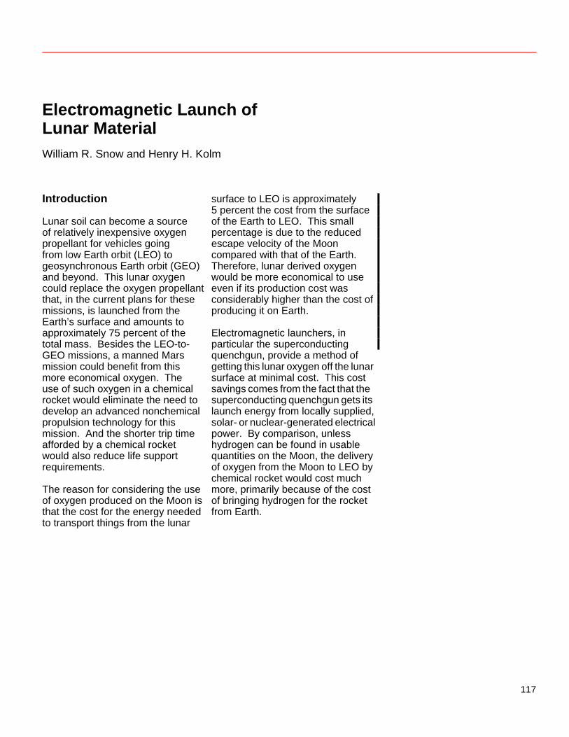
Electromagnetic Launch of Lunar Material William R. Snow and Henry H. Kolm Introduction Lunar soil can become a source of relatively inexpensive oxygen propellant for vehicles going from low Earth orbit (LEO) to geosynchronous Earth orbit (GEO) and beyond. This lunar oxygen could replace the oxygen propellant that, in the current plans for these missions, is launched from the Earth’s surface and amounts to approximately 75 percent of the total mass. Besides the LEO-to-GEO missions, a manned Mars mission could benefit from this more economical oxygen. The use of such oxygen in a chemical rocket would eliminate the need to develop an advanced nonchemical propulsion technology for this mission. And the shorter trip time afforded by a chemical rocket would also reduce life support requirements. The reason for considering the use of oxygen produced on the Moon is that the cost for the energy needed to transport things from the lunar
surface to LEO is approximately 5 percent the cost from the surface of the Earth to LEO. This small percentage is due to the reduced escape velocity of the Moon compared with that of the Earth. Therefore, lunar derived oxygen would be more economical to use even if its production cost was considerably higher than the cost of producing it on Earth. Electromagnetic launchers, in particular the superconducting quenchgun, provide a method of getting this lunar oxygen off the lunar surface at minimal cost. This cost savings comes from the fact that the superconducting quenchgun gets its launch energy from locally supplied, solar- or nuclear-generated electrical power. By comparison, unless hydrogen can be found in usable quantities on the Moon, the delivery of oxygen from the Moon to LEO by chemical rocket would cost much more, primarily because of the cost of bringing hydrogen for the rocket from Earth.
117
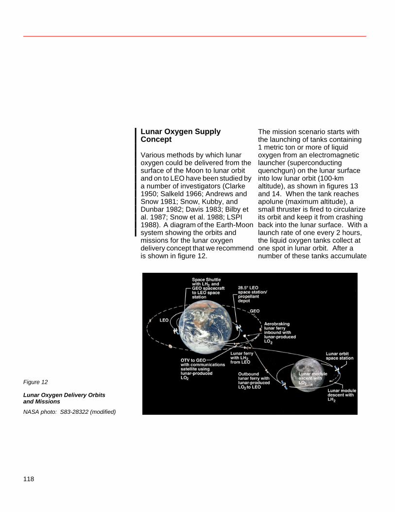
Lunar Oxygen Supply Concept Various methods by which lunar oxygen could be delivered from the surface of the Moon to lunar orbit and on to LEO have been studied by a number of investigators (Clarke 1950; Salkeld 1966; Andrews and Snow 1981; Snow, Kubby, and Dunbar 1982; Davis 1983; Bilby et al. 1987; Snow et al. 1988; LSPI 1988). A diagram of the Earth-Moon system showing the orbits and missions for the lunar oxygen delivery concept that we recommend is shown in figure 12.
The mission scenario starts with the launching of tanks containing 1 metric ton or more of liquid oxygen from an electromagnetic launcher (superconducting quenchgun) on the lunar surface into low lunar orbit (100-km altitude), as shown in figures 13 and 14. When the tank reaches apolune (maximum altitude), a small thruster is fired to circularize its orbit and keep it from crashing back into the lunar surface. With a launch rate of one every 2 hours, the liquid oxygen tanks collect at one spot in lunar orbit. After a number of these tanks accumulate
Figure 12
Lunar Oxygen Delivery Orbits and Missions
NASA photo: S83-28322 (modified)
118
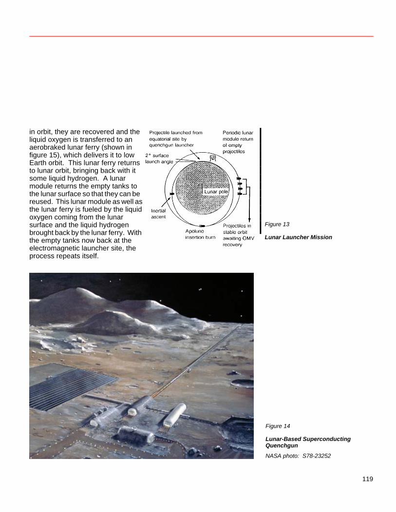
in orbit, they are recovered and the liquid oxygen is transferred to an aerobraked lunar ferry (shown in figure 15), which delivers it to low Earth orbit. This lunar ferry returns to lunar orbit, bringing back with it some liquid hydrogen. A lunar module returns the empty tanks to the lunar surface so that they can be reused. This lunar module as well as the lunar ferry is fueled by the liquid oxygen coming from the lunar surface and the liquid hydrogen brought back by the lunar ferry. With the empty tanks now back at the electromagnetic launcher site, the process repeats itself.
Figure 13
Lunar Launcher Mission
Figure 14
Lunar-Based Superconducting Quenchgun
NASA photo: S78-23252
119
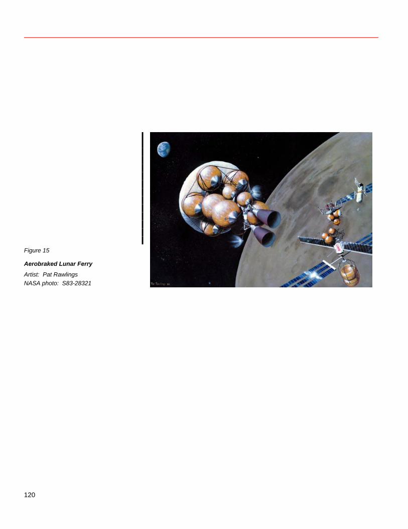
Figure 15
Aerobraked Lunar Ferry
Artist: Pat Rawlings NASA photo: S83-28321
120
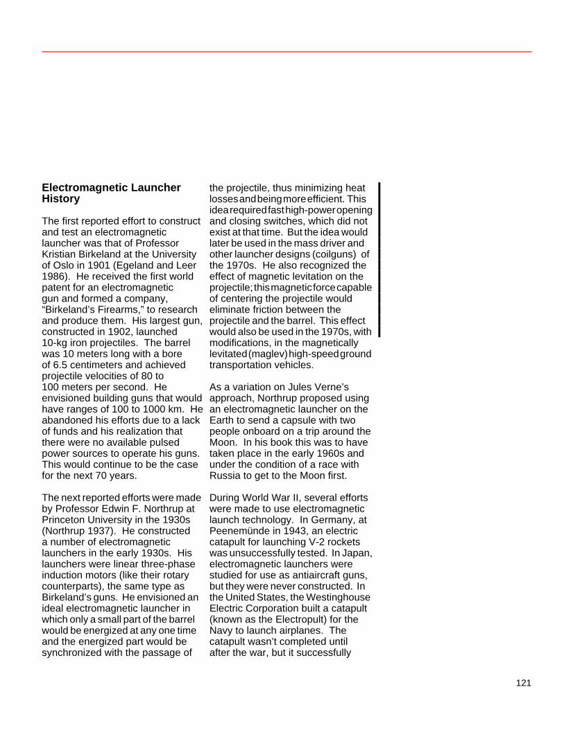
Electromagnetic Launcher History The first reported effort to construct and test an electromagnetic launcher was that of Professor Kristian Birkeland at the University of Oslo in 1901 (Egeland and Leer 1986). He received the first world patent for an electromagnetic gun and formed a company, “Birkeland’s Firearms,” to research and produce them. His largest gun, constructed in 1902, launched 10-kg iron projectiles. The barrel was 10 meters long with a bore of 6.5 centimeters and achieved projectile velocities of 80 to 100 meters per second. He envisioned building guns that would have ranges of 100 to 1000 km. He abandoned his efforts due to a lack of funds and his realization that there were no available pulsed power sources to operate his guns. This would continue to be the case for the next 70 years. The next reported efforts were made by Professor Edwin F. Northrup at Princeton University in the 1930s (Northrup 1937). He constructed a number of electromagnetic launchers in the early 1930s. His launchers were linear three-phase induction motors (like their rotary counterparts), the same type as Birkeland’s guns. He envisioned an ideal electromagnetic launcher in which only a small part of the barrel would be energized at any one time and the energized part would be synchronized with the passage of
the projectile, thus minimizing heat losses and being more efficient. This idea required fast high-power opening and closing switches, which did not exist at that time. But the idea would later be used in the mass driver and other launcher designs (coilguns) of the 1970s. He also recognized the effect of magnetic levitation on the projectile; this magnetic force capable of centering the projectile would eliminate friction between the projectile and the barrel. This effect would also be used in the 1970s, with modifications, in the magnetically levitated (maglev) high-speed ground transportation vehicles. As a variation on Jules Verne’s approach, Northrup proposed using an electromagnetic launcher on the Earth to send a capsule with two people onboard on a trip around the Moon. In his book this was to have taken place in the early 1960s and under the condition of a race with Russia to get to the Moon first. During World War II, several efforts were made to use electromagnetic launch technology. In Germany, at Peenemünde in 1943, an electric catapult for launching V-2 rockets was unsuccessfully tested. In Japan, electromagnetic launchers were studied for use as antiaircraft guns, but they were never constructed. In the United States, the Westinghouse Electric Corporation built a catapult (known as the Electropult) for the Navy to launch airplanes. The catapult wasn’t completed until after the war, but it successfully
121
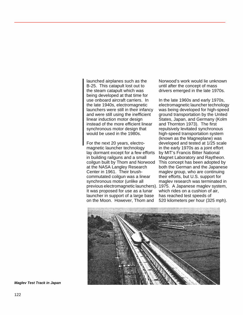
launched airplanes such as the B-25. This catapult lost out to the steam catapult which was being developed at that time for use onboard aircraft carriers. In the late 1940s, electromagnetic launchers were still in their infancy and were still using the inefficient linear induction motor design instead of the more efficient linear synchronous motor design that would be used in the 1980s. For the next 20 years, electro-magnetic launcher technology lay dormant except for a few efforts in building railguns and a small coilgun built by Thom and Norwood at the NASA Langley Research Center in 1961. Their brush-commutated coilgun was a linear synchronous motor (unlike all previous electromagnetic launchers). It was proposed for use as a lunar launcher in support of a large base on the Moon. However, Thom and
Norwood’s work would lie unknown until after the concept of mass drivers emerged in the late 1970s. In the late 1960s and early 1970s, electromagnetic launcher technology was being developed for high-speed ground transportation by the United States, Japan, and Germany (Kolm and Thornton 1973). The first repulsively levitated synchronous high-speed transportation system (known as the Magneplane) was developed and tested at 1/25 scale in the early 1970s as a joint effort by MIT’s Francis Bitter National Magnet Laboratory and Raytheon. This concept has been adopted by both the German and the Japanese maglev group, who are continuing their efforts, but U.S. support for maglev research was terminated in 1975. A Japanese maglev system, which rides on a cushion of air, has reached test speeds of 520 kilometers per hour (325 mph).
Maglev Test Track in Japan
122
An offshoot of this maglev research resulted in the concept of the mass driver by Professor Gerard K. O’Neill of Princeton University in 1974. It was based on features of the Magneplane, like magnetic levitation and superconducting armature coils, but the drive circuit was based on the resonant transfer of energy from capacitors rather than on a three-phase power supply. The mass driver was proposed as a means for launching raw materials (payloads of 1–10 kg size at launch rates of 1–10 per second) from a lunar base to a construction site in space. The mass driver was studied extensively for missions of this type, during three NASA Ames summer studies in 1975, 1976, and 1977 (Billingham, Gilbreath, and O’Leary 1979) and subsequently
at MIT and Princeton University (Snow 1982). The first lunar launcher proof of concept model was constructed in 1977 by a group of students at the MIT Francis Bitter National Magnet Laboratory; it is shown in figure 16. The energy storage capacitors in the mass driver dominate its mass and cost. And, because capacitors have a low energy density, they are especially unsuitable for an electromagnetic launcher of lunar oxygen, facing the requirements of a larger payload mass at a lower launch rate. Looking for an alternative way to launch nuclear waste from the surface of the Earth, Henry Kolm in 1978 developed the idea of the superconducting quenchgun (Kolm
Figure 16
Mass Driver I During Construction While Gerard K. O’Neill, a Princeton physics professor, was on sabbatical as the Hunsaker Professor of Aeronautics at MIT in 1976–77, he and Henry Kolm, one of the cofounders of the Francis Bitter National Magnet Laboratory, led a team of students in building Mass Driver I. Shown here are Bill Snow, Kevin Fine, Jonah Garbus, O’Neill, Kolm, and Eric Drexler. In 1977 it was widely believed that a highly advanced mass driver, using the most sophisticated materials and design, could achieve at best 50 gravities of acceleration. However, even this primitive model, built from about $3000 worth of scrounged equipment, demonstrated an acceleration of over 30 g’s. Courtesy of Space Studies Institute NASA photo: S89-36113
123
et al. 1979, Graneau 1980). The quenchgun is analogous to the Carnot engine in thermodynamics—the ideal launcher capable of achieving the maximum theoretically possible efficiency. It eliminates the need for energy storage capacitors. Quenchguns store the entire launch energy in the superconducting barrel coils and transfer it to the projectile almost without loss. The quenchgun concept was not pursued in 1978 because it was considered impractical for any tactical terrestrial applications of interest at the time. High-temperature superconductors or better refrigerators would be required. However, the quenchgun is practical, even with existing low-temperature superconductors, on the cold lunar surface. A proof-of-concept model of the quenchgun was built and successfully tested in 1985 using normal conductors and silicon-controlled rectifier (SCR) switches (Snow and Mongeau 1985). Electromagnetic Launcher Coilgun Principles Coilguns achieve acceleration by the Lorentz force exerted by one or more current-carrying barrel coils on one or more current-carrying projectile coils. The barrel and projectile coils can be coaxial
or coplanar, as long as they are inductively coupled to each other. The thrust generated is simply the product of the two coil currents times a proportionality constant. This constant is the mutual inductance gradient between the projectile coil and the barrel coil. The mutual inductance gradient for a coilgun is typically about 100 times as large as that for a railgun. As a result, the coilgun generates 100 times more thrust for a given heat loss. This large thrust is generated only when the two coils are in close proximity to each other. Therefore, coilguns require that the barrel coil current must be synchronized with the passing projectile. When normal conductors are used, this current must be supplied by a pulsed power source to minimize energy loss due to conductor heating. In the mass driver, the synchronization was accomplished by triggering the resonant capacitor discharge to coincide with the passage of the projectile. Capacitors unfortunately have too low an energy density to be practical, and it becomes necessary to use inductive energy storage when megajoules of launch energy are needed. Unfortunately it is difficult to commutate (turn the current in a coil on or off) inductively stored energy. This can be accomplished
124
by the use of brushes located on the projectile to synchronize the barrel current with that in the projectile. However, brushes are not suited to the large energies and vacuum environment of the lunar launcher mission, and the wear they would cause is unacceptable in such a mission. The only reasonable option for this mission is the superconducting quenchgun, which is capable of storing the entire launch energy in its barrel without loss and of commutating it synchronously without brushes. Quenchgun Principles The quenchgun consists of a superconducting solenoid barrel divided up into a number of short, current-carrying barrel coils. Each of the barrel coils is open-circuited (after the barrel coil current has been de-induced) at the instant the projectile coil passes through it. When the projectile reaches the muzzle, nearly all of the energy initially stored in the barrel will have been transferred to the projectile in the form of kinetic energy. The unique feature of the quenchgun is the superconducting barrel coils. Ordinary conductors cannot store the entire launch energy in the barrel coils very efficiently for more than 1 second. Superconductors, on the other hand, can store this launch energy
without loss for an indefinite period of time. Because of this feature, the superconducting quenchgun can be charged up between firings. Thus the superconducting barrel requires only 1/10 000 the power required by a non-superconducting barrel. To provide the very high pulse power needed in a non-superconducting barrel, the source would have to be some sort of rotating machinery (with bearings that would wear), such as a flywheel/pulsed alternator. The power for a superconducting barrel can instead be derived from a much simpler and smaller solar or nuclear source. This is the key feature that makes the superconducting quenchgun a much more practical device for lunar launching than any other electromagnetic launcher. The operation of a superconducting quenchgun is illustrated in figure 17. It consists simply of a row of short coaxial superconducting barrel coils, with an oversized injection coil at the breech. The projectile coil is at rest in the breech, as shown in the first of the three diagrams. It does not need to be superconducting, as long as its characteristic time constant is longer than the launch time. This time constant increases with size, and at the size proposed aluminum or beryllium alloys meet the requirement if they are precooled to about 80 K. To initiate the launch, it is necessary merely to
125
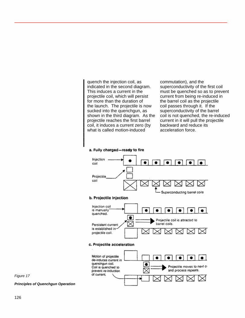
quench the injection coil, as indicated in the second diagram. This induces a current in the projectile coil, which will persist for more than the duration of the launch. The projectile is now sucked into the quenchgun, as shown in the third diagram. As the projectile reaches the first barrel coil, it induces a current zero (by what is called motion-induced
commutation), and the superconductivity of the first coil must be quenched so as to prevent current from being re-induced in the barrel coil as the projectile coil passes through it. If the superconductivity of the barrel coil is not quenched, the re-induced current in it will pull the projectile backward and reduce its acceleration force.
Figure 17
Principles of Quenchgun Operation
126
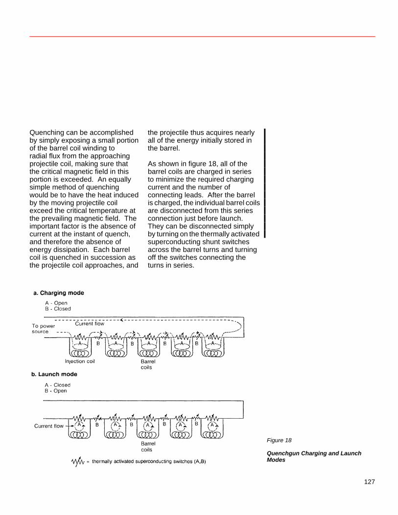
Quenching can be accomplished by simply exposing a small portion of the barrel coil winding to radial flux from the approaching projectile coil, making sure that the critical magnetic field in this portion is exceeded. An equally simple method of quenching would be to have the heat induced by the moving projectile coil exceed the critical temperature at the prevailing magnetic field. The important factor is the absence of current at the instant of quench, and therefore the absence of energy dissipation. Each barrel coil is quenched in succession as the projectile coil approaches, and
the projectile thus acquires nearly all of the energy initially stored in the barrel. As shown in figure 18, all of the barrel coils are charged in series to minimize the required charging current and the number of connecting leads. After the barrel is charged, the individual barrel coils are disconnected from this series connection just before launch. They can be disconnected simply by turning on the thermally activated superconducting shunt switches across the barrel turns and turning off the switches connecting the turns in series.
Figure 18
Quenchgun Charging and Launch Modes
127
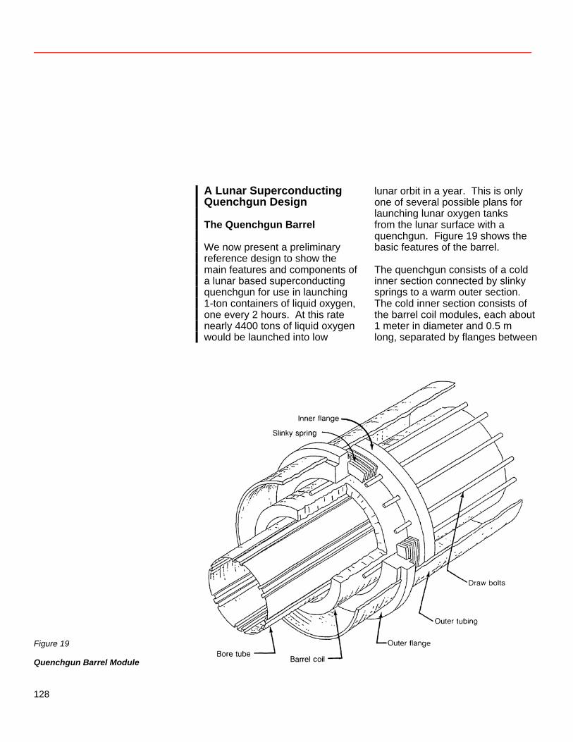
A Lunar Superconducting Quenchgun Design The Quenchgun Barrel We now present a preliminary reference design to show the main features and components of a lunar based superconducting quenchgun for use in launching 1-ton containers of liquid oxygen, one every 2 hours. At this rate nearly 4400 tons of liquid oxygen would be launched into low
lunar orbit in a year. This is only one of several possible plans for launching lunar oxygen tanks from the lunar surface with a quenchgun. Figure 19 shows the basic features of the barrel. The quenchgun consists of a cold inner section connected by slinky springs to a warm outer section. The cold inner section consists of the barrel coil modules, each about 1 meter in diameter and 0.5 m long, separated by flanges between
Figure 19
Quenchgun Barrel Module
128
neighboring coils and compressed by 16 draw bolts which pass through holes in the flanges. Cooling is provided by a forced flow system of supercritical helium using small-diameter stainless steel tubing, which is not shown. Superinsulation is used as a radiation heat shield between the warm outer section and the cold inner section. The cold inner section is connected to the warm outer section by slinky springs as shown; they are made of fiber-reinforced composite (to avoid high induced voltages). These springs provide a very long heat conduction path and at the same time permit the inner cold section to recoil. During the instant of recoil, the inner flanges thus transmit the very strong axial forces directly to the outer flanges through the completely
compressed slinky springs, causing a temporarily high heat leak. When the barrel is not undergoing recoil, however, the heat leak through the slinky springs is very low, approximately 1 watt per ton of suspended cold system mass. Any rigid suspension system capable of withstanding the recoil force would involve about 100 times this heat leak. The only metal components of the entire launcher are the superconducting coils, the draw bolts, and the stainless steel cooling tubes for the supercritical helium refrigeration system. Inner tube, outer tube, and all flanges are reinforced composite. Metal cannot be used too near the barrel coils because it would carry very high induced circumferential currents.
129
The Carriage and the Liquid Oxygen Tank The projectile consists of two major components, as shown in figure 20. One is the tank that contains the liquid oxygen which is to be delivered to low lunar orbit. This tank has an apolune kick motor on one end which is used to circularize the orbit. Orientation of the tank for proper altitude control is accomplished by spin stabilization. Since this tank must be returned to the lunar surface for reuse, its mass must be minimized. It only needs to be strong enough to handle loads experienced after launch. To withstand the high acceleration force placed on it during launch, it rests inside a carriage that can take this force. This carriage contains the projectile (armature) coil made from aluminum or beryllium, and stress containment is provided by a graphite-reinforced hoop. Since the
carriage is decelerated at the launcher site, it never leaves the Moon and thereby improves the efficiency of delivering oxygen. The Carriage Decelerating Barrel For deceleration, the barrel coils are connected in series and no commutation is required. The decelerating barrel coils are energized with a suitable current level in the opposing direction. As the projectile coil enters the decelerator, both the barrel coil current and the projectile coil current increase progressively, until the carriage is brought to rest and clamped mechanically at its stopping position. If not clamped, it would simply rebound. The projectile coil current is then allowed to decay. The superconducting barrel coil in the decelerator can be connected to the accelerating barrel coils so that a fraction of the braking energy is reused for the next launch.
Figure 20
Quenchgun Carriage and Liquid Oxygen Tank
130
Carriage Retrieval A mechanical retrieval mechanism is used to return the carriage to the breech after a launch. One possible retrieval mechanism is a self-propelled “mole” powered through an umbilical cable. It normally rests in a dead siding behind the carriage/ tank insertion position at the breech. To retrieve the carriage, it propels itself to the decelerating section, connects mechanically to the carriage, and pulls the carriage back to the breech either by itself or by retracting a cable attached back at the breech.
System Description The system design is based on launching a 1-ton payload of liquid oxygen every 2 hours into low lunar orbit. A block diagram of the components of a superconducting quenchgun is shown in figure 21. The overall use of the superconducting quenchgun in supplying liquid oxygen from the Moon is shown in figure 22. And a summary of the superconducting quenchgun specifications for this reference design is presented in table 10.
Figure 21
Quenchgun Components
131
Figure 22
Quenchgun Operation
132
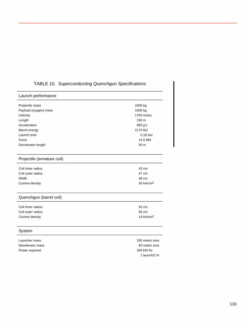
TABLE 10. Superconducting Quenchgun Specifications Launch performance
Projectile mass 1500 kg
Payload (oxygen) mass 1000 kg Velocity 1700 m/sec Length 150 m Acceleration 983 g’s Barrel energy 2170 MJ Launch time 0.18 sec Force 14.5 MN Decelerator length 50 m
Projectile (armature coil)
Coil inner radius 43 cm
Coil outer radius 47 cm Width 48 cm Current density 30 kA/cm2
Quenchgun (barrel coil)
Coil inner radius 52 cm
Coil outer radius 56 cm Current density 14 kA/cm2
System
Launcher mass 250 metric tons
Decelerator mass 83 metric tons Power required 350 kW for
1 launch/2 hr
133
References Andrews, D. G., and W. R. Snow. 1981. The Supply of Lunar Oxygen to Low Earth Orbit. In Space Manufacturing 4, Proc. 5th Princeton/AIAA Conf., ed. Jerry Grey and Lawrence A. Hamdan, 173–179. New York: AIAA. Bilby, Curt; Hubert P. Davis; Stewart Nozette; Mircea Driga; and Randy Kamm. 1987. A Lunar Electromagnetic Launcher. Final Report for the Large Scale Programs Institute. Center for Space Research & Center for Electromechanics, Univ. of Texas at Austin, May. Billingham, John; William Gilbreath, and Brian O’Leary, eds. 1979. Space Resources and Space Settlements [technical papers derived from the 1977 Summer Study at NASA Ames Research Center, Moffett Field, CA]. NASA SP-428. Clarke, Arthur C. 1950. Electromagnetic Launching as a Major Contribution to Space-Flight. J. British Interplanetary Soc. 9 (6): 261–267. Reprinted in Arthur C. Clarke, Ascent to Orbit: A Scientific Autobiography (New York: John Wiley & Sons, 1984).
Davis, Hubert P. 1983. Lunar Oxygen Impact Upon STS Effectiveness. Report EEI 83-63. Houston: Eagle Engineering, Inc., May. Egeland, A., and E. Leer. 1986. Professor Kr. Birkeland: His Life and Work. IEEE Transactions on Plasma Science, vol. PS-14, no. 6 (Dec.), pp. 666–677. Graneau, Peter. 1980. Self-Energized Superconducting Mass Driver for Space Launching. In Proc. Conf. on Electromagnetic Guns and Launchers (Part II), Nov. 4–6, 1980, ed. John Bennett, Ted Gora, and Peter Kemmey. U.S. Army, Picatinny Arsenal, NJ. Kolm, H. H., and R. D. Thornton. 1973. Electromagnetic Flight. Sci. Am. 229 (4): 17–25. Kolm, Henry; Kevin Fine; Peter Mongeau; and Fred Williams. 1979. Electromagnetic Propulsion Alternatives. In Space Manufacturing Facilities III, Proc. 4th Princeton/AIAA Conf., ed. Jerry Grey and Christine Krop, 299–306. New York: AIAA.
134
LSPI (Large Scale Programs Institute), Austin, TX, and EML Research, Inc., Hudson, MA. 1988. Application of Superconductivity Technology to the Lunar Electromagnetic Launcher Concept. Presentation June 20. Northrup, Edwin F. 1937. Zero to Eighty (Being my lifetime doings, reflections, and inventions; also my journey around the Moon by Akkad Pseudoman). Princeton, NJ: Princeton Univ. Press. Salkeld, R. J. 1966. Economic Implications of Extracting Propellants from the Moon. J. Spacecraft & Rockets 3 (2): 254–261. Snow, W. R., and P. Mongeau. 1985. Collapsing Front Coilgun with Brushless Commutation. In Proc. 5th IEEE Pulsed Power Conf., ed. P. J. Turchi and M. F. Rose, 530–533. Now York: IEEE. Snow, William; Peter Mongeau; Reinhardt Willig; and Henry Kolm. 1988. Preliminary Design of a Superconducting Quenchgun for Launching One Ton Payloads from the Lunar Surface. Final Report for the Large Scale Programs Institute. Hudson, MA: EML Research, Inc., May.
Snow, William R. 1982. Mass Driver-Two Research Final Report [under grant no. NSG-3176). Cleveland, OH: NASA Lewis Research Center, Aug. Snow, William R.; Joel A. Kubby; and R. Scott Dunbar. 1981. A Small Scale Lunar Launcher for Early Lunar Material Utilization. In Space Manufacturing 4, Proc. 5th Princeton/AIAA Conf., ed. Jerry Grey and Lawrence A. Hamdan, 157–171. New York: AIAA. Thom, K., and J. Norwood. 1961. Theory of an Electromagnetic Mass Accelerator for Achieving Hypervelocities. Hampton, VA: NASA Langley Research Center, June.
135
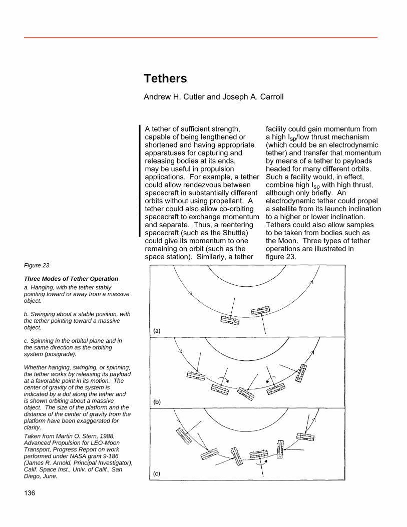
Tethers Andrew H. Cutler and Joseph A. Carroll
A tether of sufficient strength, capable of being lengthened or shortened and having appropriate apparatuses for capturing and releasing bodies at its ends, may be useful in propulsion applications. For example, a tether could allow rendezvous between spacecraft in substantially different orbits without using propellant. A tether could also allow co-orbiting spacecraft to exchange momentum and separate. Thus, a reentering spacecraft (such as the Shuttle) could give its momentum to one remaining on orbit (such as the space station). Similarly, a tether
facility could gain momentum from a high Isp/low thrust mechanism (which could be an electrodynamic tether) and transfer that momentum by means of a tether to payloads headed for many different orbits. Such a facility would, in effect, combine high Isp with high thrust, although only briefly. An electrodynamic tether could propel a satellite from its launch inclination to a higher or lower inclination. Tethers could also allow samples to be taken from bodies such as the Moon. Three types of tether operations are illustrated in figure 23.
Figure 23
Three Modes of Tether Operation a. Hanging, with the tether stably pointing toward or away from a massive object. b. Swinging about a stable position, with the tether pointing toward a massive object. c. Spinning in the orbital plane and in the same direction as the orbiting system (posigrade). Whether hanging, swinging, or spinning, the tether works by releasing its payload at a favorable point in its motion. The center of gravity of the system is indicated by a dot along the tether and is shown orbiting about a massive object. The size of the platform and the distance of the center of gravity from the platform have been exaggerated for clarity. Taken from Martin O. Stern, 1988, Advanced Propulsion for LEO-Moon Transport, Progress Report on work performed under NASA grant 9-186 (James R. Arnold, Principal Investigator), Calif. Space Inst., Univ. of Calif., San Diego, June.
136
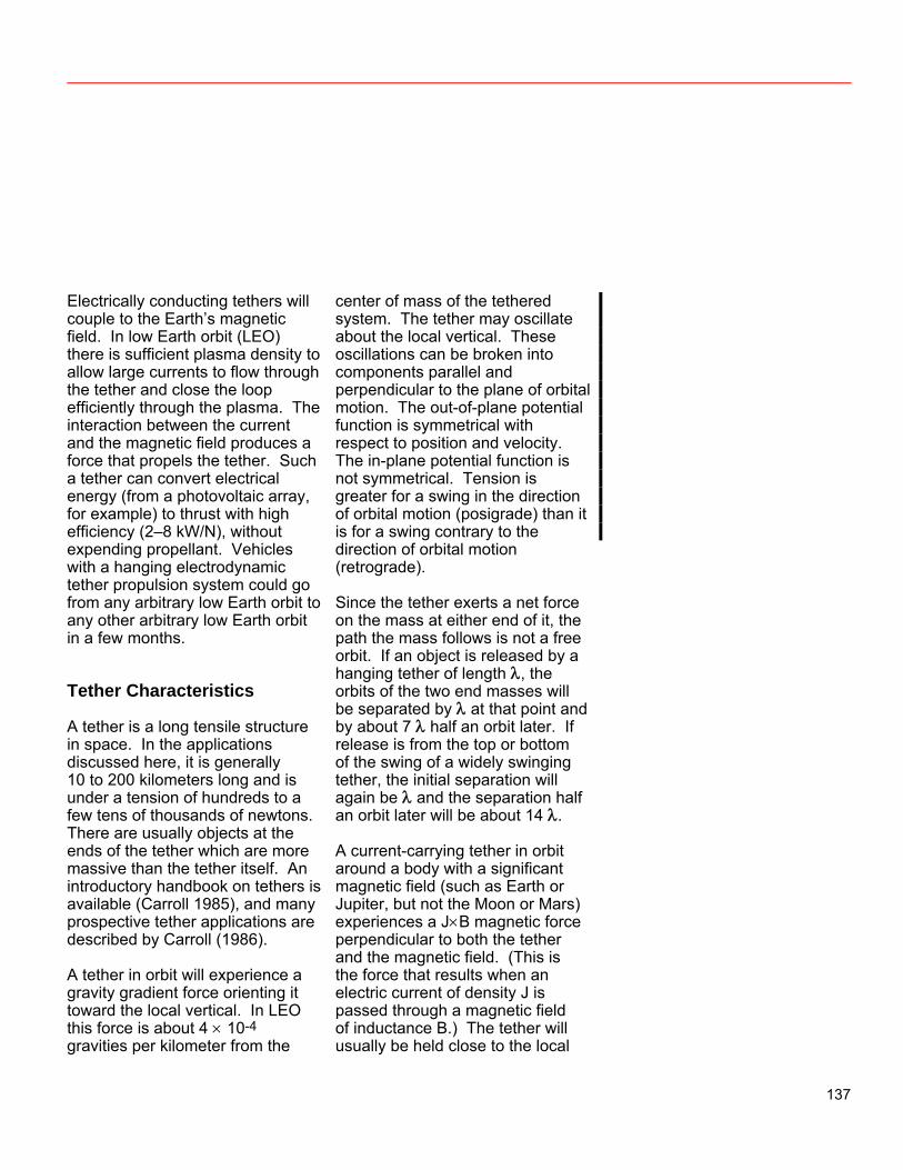
Electrically conducting tethers will couple to the Earth’s magnetic field. In low Earth orbit (LEO) there is sufficient plasma density to allow large currents to flow through the tether and close the loop efficiently through the plasma. The interaction between the current and the magnetic field produces a force that propels the tether. Such a tether can convert electrical energy (from a photovoltaic array, for example) to thrust with high efficiency (2–8 kW/N), without expending propellant. Vehicles with a hanging electrodynamic tether propulsion system could go from any arbitrary low Earth orbit to any other arbitrary low Earth orbit in a few months. Tether Characteristics A tether is a long tensile structure in space. In the applications discussed here, it is generally 10 to 200 kilometers long and is under a tension of hundreds to a few tens of thousands of newtons. There are usually objects at the ends of the tether which are more massive than the tether itself. An introductory handbook on tethers is available (Carroll 1985), and many prospective tether applications are described by Carroll (1986). A tether in orbit will experience a gravity gradient force orienting it toward the local vertical. In LEO this force is about 4 × 10⁻⁴ gravities per kilometer from the
center of mass of the tethered system. The tether may oscillate about the local vertical. These oscillations can be broken into components parallel and perpendicular to the plane of orbital motion. The out-of-plane potential function is symmetrical with respect to position and velocity. The in-plane potential function is not symmetrical. Tension is greater for a swing in the direction of orbital motion (posigrade) than it is for a swing contrary to the direction of orbital motion (retrograde). Since the tether exerts a net force on the mass at either end of it, the path the mass follows is not a free orbit. If an object is released by a hanging tether of length λ, the orbits of the two end masses will be separated by λ at that point and by about 7 λ half an orbit later. If release is from the top or bottom of the swing of a widely swinging tether, the initial separation will again be λ and the separation half an orbit later will be about 14 λ. A current-carrying tether in orbit around a body with a significant magnetic field (such as Earth or Jupiter, but not the Moon or Mars) experiences a J×B magnetic force perpendicular to both the tether and the magnetic field. (This is the force that results when an electric current of density J is passed through a magnetic field of inductance B.) The tether will usually be held close to the local
137
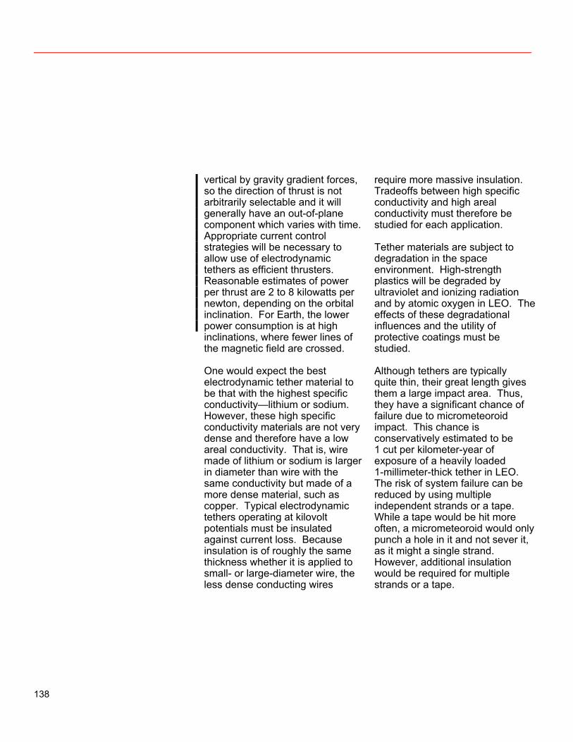
vertical by gravity gradient forces, so the direction of thrust is not arbitrarily selectable and it will generally have an out-of-plane component which varies with time. Appropriate current control strategies will be necessary to allow use of electrodynamic tethers as efficient thrusters. Reasonable estimates of power per thrust are 2 to 8 kilowatts per newton, depending on the orbital inclination. For Earth, the lower power consumption is at high inclinations, where fewer lines of the magnetic field are crossed. One would expect the best electrodynamic tether material to be that with the highest specific conductivity—lithium or sodium. However, these high specific conductivity materials are not very dense and therefore have a low areal conductivity. That is, wire made of lithium or sodium is larger in diameter than wire with the same conductivity but made of a more dense material, such as copper. Typical electrodynamic tethers operating at kilovolt potentials must be insulated against current loss. Because insulation is of roughly the same thickness whether it is applied to small- or large-diameter wire, the less dense conducting wires
require more massive insulation. Tradeoffs between high specific conductivity and high areal conductivity must therefore be studied for each application. Tether materials are subject to degradation in the space environment. High-strength plastics will be degraded by ultraviolet and ionizing radiation and by atomic oxygen in LEO. The effects of these degradational influences and the utility of protective coatings must be studied. Although tethers are typically quite thin, their great length gives them a large impact area. Thus, they have a significant chance of failure due to micrometeoroid impact. This chance is conservatively estimated to be 1 cut per kilometer-year of exposure of a heavily loaded 1-millimeter-thick tether in LEO. The risk of system failure can be reduced by using multiple independent strands or a tape. While a tape would be hit more often, a micrometeoroid would only punch a hole in it and not sever it, as it might a single strand. However, additional insulation would be required for multiple strands or a tape.
138
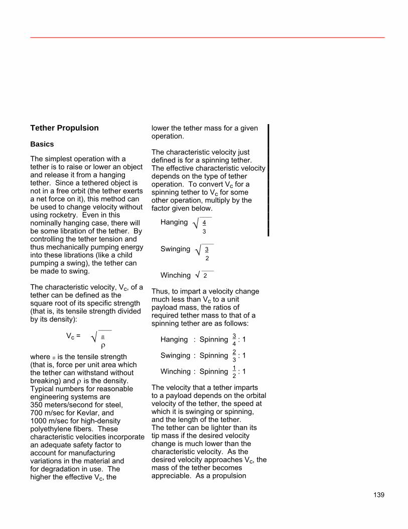
Tether Propulsion Basics The simplest operation with a tether is to raise or lower an object and release it from a hanging tether. Since a tethered object is not in a free orbit (the tether exerts a net force on it), this method can be used to change velocity without using rocketry. Even in this nominally hanging case, there will be some libration of the tether. By controlling the tether tension and thus mechanically pumping energy into these librations (like a child pumping a swing), the tether can be made to swing. The characteristic velocity, Vc, of a tether can be defined as the square root of its specific strength (that is, its tensile strength divided by its density): ___
Vc = √ s
ρ where s is the tensile strength (that is, force per unit area which the tether can withstand without breaking) and ρ is the density. Typical numbers for reasonable engineering systems are 350 meters/second for steel, 700 m/sec for Kevlar, and 1000 m/sec for high-density polyethylene fibers. These characteristic velocities incorporate an adequate safety factor to account for manufacturing variations in the material and for degradation in use. The higher the effective Vc, the
lower the tether mass for a given operation. The characteristic velocity just defined is for a spinning tether. The effective characteristic velocity depends on the type of tether operation. To convert Vc for a spinning tether to Vc for some other operation, multiply by the factor given below.
___ Hanging √ 4
3 ___ Swinging √ 3
2 ___ Winching √ 2
Thus, to impart a velocity change much less than Vc to a unit payload mass, the ratios of required tether mass to that of a spinning tether are as follows:
Hanging : Spinning 3 4
: 1
Swinging : Spinning 2 3
: 1
Winching : Spinning 1 2
: 1
The velocity that a tether imparts to a payload depends on the orbital velocity of the tether, the speed at which it is swinging or spinning, and the length of the tether. The tether can be lighter than its tip mass if the desired velocity change is much lower than the characteristic velocity. As the desired velocity approaches Vc, the mass of the tether becomes appreciable. As a propulsion
139
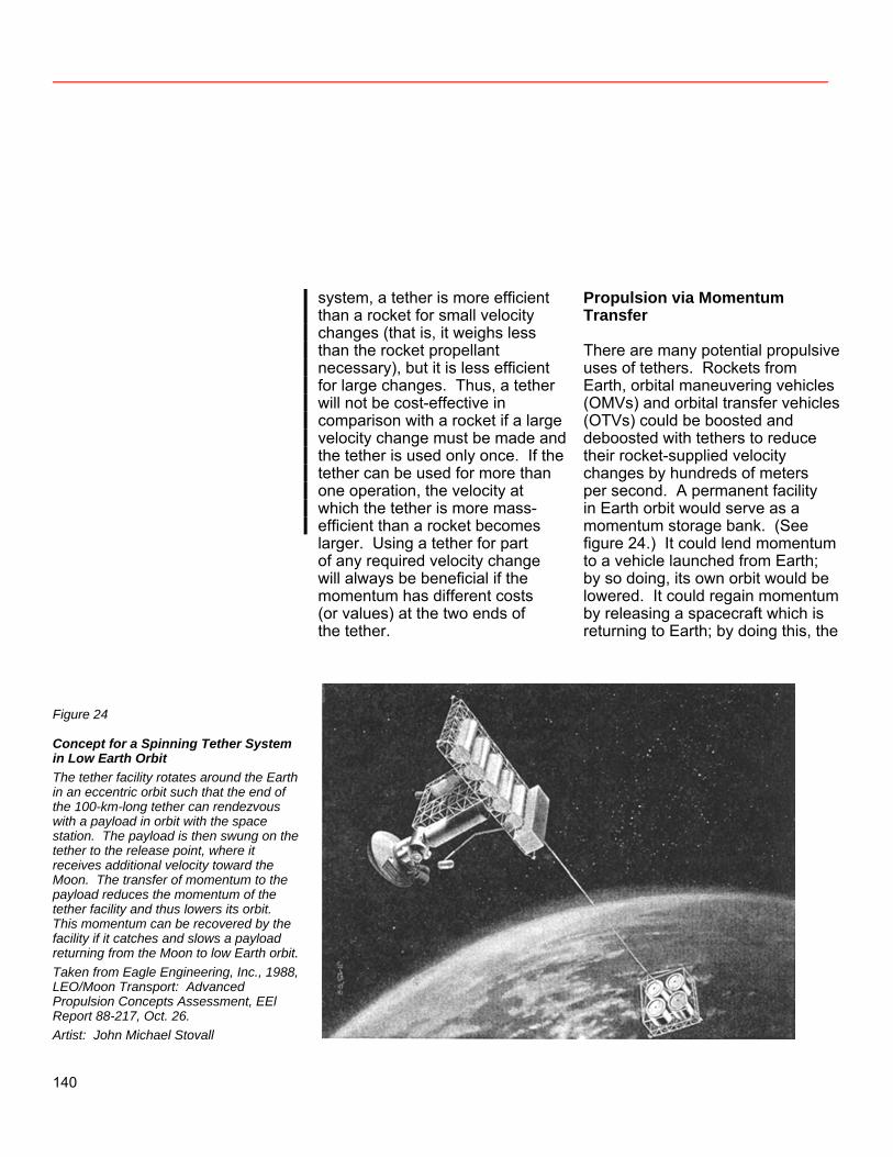
system, a tether is more efficient than a rocket for small velocity changes (that is, it weighs less than the rocket propellant necessary), but it is less efficient for large changes. Thus, a tether will not be cost-effective in comparison with a rocket if a large velocity change must be made and the tether is used only once. If the tether can be used for more than one operation, the velocity at which the tether is more mass-efficient than a rocket becomes larger. Using a tether for part of any required velocity change will always be beneficial if the momentum has different costs (or values) at the two ends of the tether.
Propulsion via Momentum Transfer There are many potential propulsive uses of tethers. Rockets from Earth, orbital maneuvering vehicles (OMVs) and orbital transfer vehicles (OTVs) could be boosted and deboosted with tethers to reduce their rocket-supplied velocity changes by hundreds of meters per second. A permanent facility in Earth orbit would serve as a momentum storage bank. (See figure 24.) It could lend momentum to a vehicle launched from Earth; by so doing, its own orbit would be lowered. It could regain momentum by releasing a spacecraft which is returning to Earth; by doing this, the
Figure 24
Concept for a Spinning Tether System in Low Earth Orbit The tether facility rotates around the Earth in an eccentric orbit such that the end of the 100-km-long tether can rendezvous with a payload in orbit with the space station. The payload is then swung on the tether to the release point, where it receives additional velocity toward the Moon. The transfer of momentum to the payload reduces the momentum of the tether facility and thus lowers its orbit. This momentum can be recovered by the facility if it catches and slows a payload returning from the Moon to low Earth orbit. Taken from Eagle Engineering, Inc., 1988, LEO/Moon Transport: Advanced Propulsion Concepts Assessment, EEl Report 88-217, Oct. 26. Artist: John Michael Stovall
140
facility’s orbit would be raised. Space-based vehicles (OMVs and OTVs) could also benefit. If the tether propelling it broke, the OMV or OTV could rely on built-in propulsive capability to return to the space station and try again. This operation is described in more detail in the appendix. The greater the tether facility mass, the smaller the effect on its orbit produced by the momentum loaned to it or borrowed from it. Thus, accumulating mass would be desirable and would give the system more flexibility. Mass could be accumulated at the facility by collecting massive disposable items, such as external tanks. Tether operations that provide velocity changes of up to 1000 m/sec are feasible using currently available materials. Larger velocity changes are possible, but they require tapered tethers more massive than the payloads boosted. The net impulse invested in the OMVs and OTVs, in their payloads, and in the propellant they consume must be made up. It could be made up by a second tether at the same orbiting facility. This second tether would be an electrodynarnic tether with a solar power source. It would slowly convert solar-generated electricity to thrust. This tether thruster would work continuously at low thrust (high specific impulse) to raise the facility’s
orbit. Periodically, the orbit would suddenly be lowered when the other tether—the one providing high thrust—accelerated a payload. As this thruster would not travel with the payloads or undergo significant velocity changes, it could have a relatively large inert mass, compared to that permissible on an OTV. The expense of transporting the thruster mass into orbit would quickly be paid for in vehicle propellant savings. Other advantages to such a thruster are that it would be accessible for maintenance and repair at all times and that its power supply would not be repeatedly exposed to radiation trapped in the Van Allen belt. Its duty cycle would have to be high enough to provide impulse at the rate that OMV and OTV launches used it up. The mass of the tether facility would damp out small variations in orbital energy due to tethered boosts and erratic thruster use. This tether system could be located at the space station. If so, tethered rendezvous, boost, and deboost would have an impact on space station design. These operations would exert net forces on the space station. Using ambitious Shuttle capture schemes, these forces would be much larger than the forces from any other operation. Solar cell arrays and other extended structures would be particularly sensitive to such forces.
141
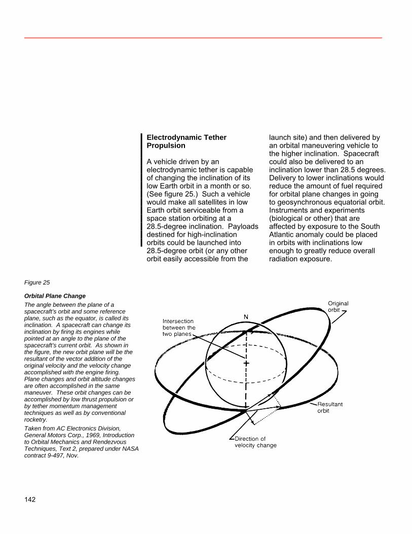
Electrodynamic Tether Propulsion A vehicle driven by an electrodynamic tether is capable of changing the inclination of its low Earth orbit in a month or so. (See figure 25.) Such a vehicle would make all satellites in low Earth orbit serviceable from a space station orbiting at a 28.5-degree inclination. Payloads destined for high-inclination orbits could be launched into 28.5-degree orbit (or any other orbit easily accessible from the
launch site) and then delivered by an orbital maneuvering vehicle to the higher inclination. Spacecraft could also be delivered to an inclination lower than 28.5 degrees. Delivery to lower inclinations would reduce the amount of fuel required for orbital plane changes in going to geosynchronous equatorial orbit. Instruments and experiments (biological or other) that are affected by exposure to the South Atlantic anomaly could be placed in orbits with inclinations low enough to greatly reduce overall radiation exposure.
Figure 25
Orbital Plane Change The angle between the plane of a spacecraft’s orbit and some reference plane, such as the equator, is called its inclination. A spacecraft can change its inclination by firing its engines while pointed at an angle to the plane of the spacecraft’s current orbit. As shown in the figure, the new orbit plane will be the resultant of the vector addition of the original velocity and the velocity change accomplished with the engine firing. Plane changes and orbit altitude changes are often accomplished in the same maneuver. These orbit changes can be accomplished by low thrust propulsion or by tether momentum management techniques as well as by conventional rocketry. Taken from AC Electronics Division, General Motors Corp., 1969, Introduction to Orbital Mechanics and Rendezvous Techniques, Text 2, prepared under NASA contract 9-497, Nov.
142
Because its electrodynamic tether would need a relatively dense plasma to close the current loop, such an OMV would be limited to low Earth orbits. With currently projected solar or nuclear power sources, an electrodynamic OMV could move a payload heavier than itself from a 28.5-degree orbit to a 104-degree orbit in a few months. Thus, all payloads for high-inclination orbits could be launched due east to maximize mass on orbit and then be moved to their final destination. This two-step method could double the Shuttle’s capacity to deploy payloads destined for high-inclination orbits. This method would also allow any low-Earth-orbit satellite to be returned to the space station for servicing and then be redeployed. An alternative means of turning spacecraft power into orbital changes is by mechanically pumping a tethered system in resonance with its orbital period (to couple to orbital eccentricity or to nonspherical terms in the gravitational field). This means would be less effective than an electrodynamic tether at low altitudes, but it could be superior at altitudes from 3000 to 8000 km. Accelerations at these altitudes are less than 1/20th those achievable in LEO. Above these altitudes, neither mechanical nor electrodynamic tether propulsion is effective.
Planetary Exploration Sample recovery from celestial bodies is a challenging propulsion problem. Conventional approaches require large, low-specific-impulse propulsion systems to provide enough thrust to land and take off again. Sampling is restricted to a small area because of the difficulty of moving about on the surface of the body. Tethers offer a unique and desirable solution to this problem. With currently available engineering materials, it is possible to sample from orbit the surface of bodies the size of the Moon and smaller which have no appreciable atmosphere. A long tether would be deployed from an orbiting spacecraft and spun so that its tip touched the body’s surface at a relative velocity near 0. Such a vehicle in polar orbit around a celestial body could, in principle, sample any place on the body’s surface. A high-specific-impulse, low-thrust propulsion system (which could not land on the body’s surface) could be used to accumulate momentum for such sample-boosting operations. Most small bodies on which this operation is practical do not have enough plasma or magnetic field to allow the use of electrodynamic tethers. A lunar polar orbiting skyhook equipped with ten 200-kg tapered
143
Kevlar tethers (or ten 50-kg Allied-1000 tethers) could recover about 700 10-kg samples from any desired locations on the lunar surface. Using an electric thruster with a specific impulse of 1000 seconds in conjunction with such a mechanical tether system, the ratio of recovered samples to tethers and propellant is 2.2 : 1 (or 4.3 : 1 for the lighter tethers). Reasonably sized vehicles (5 000–10 000 kg) could return many large samples of material from the Moon or any of the satellites of the outer planets using this technique. Tether life will be limited by micrometeoroid damage. Using multiple tethers allows missions to be planned on the basis of average tether life, and, if the actual life is
shorter than expected, such use allows a rational sampling program to be built. Conclusions About Tethers Tethers for rendezvous, boost, and deboost can be deployed and in use by the year 2000. Electrodynamic tether OMVs could be ready by the same year. The only problems may be plasma coupling and plasma conductivity, both of which are to be measured by the Tethered Satellite System experiment in the next 5 years (see fig. 26). A lunar surface sampling tether is possible by 2000 and reasonable by 2010. Tether sampling of other small bodies could follow rapidly.
144
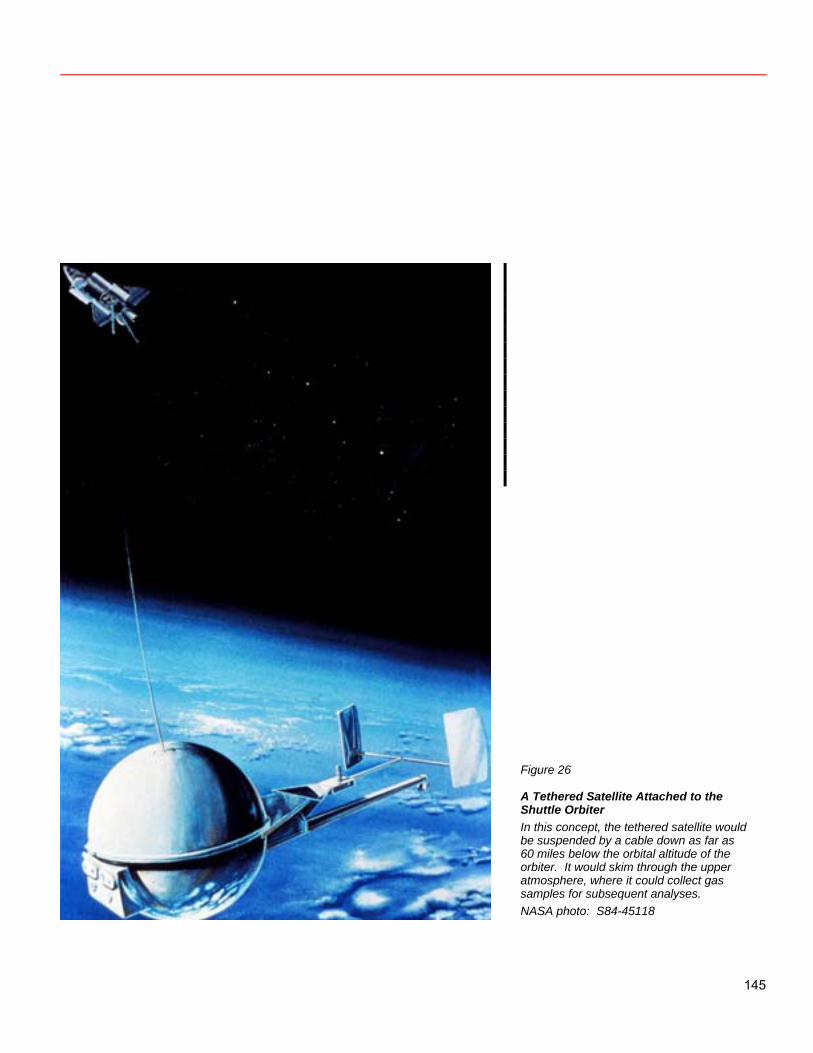
Figure 26
A Tethered Satellite Attached to the Shuttle Orbiter In this concept, the tethered satellite would be suspended by a cable down as far as 60 miles below the orbital altitude of the orbiter. It would skim through the upper atmosphere, where it could collect gas samples for subsequent analyses. NASA photo: S84-45118
145
Use of tethers implies important changes in propulsion for low Earth orbit and elsewhere. Significant efficiencies can be gained using tethers in combination with conventional rockets. Operations will be different, however, and substantial development of operational procedures will be necessary. There are some specific research questions which will have significant impact on tether systems and which can be addressed now. These questions concern electrical coupling to the space plasma; developing materials with high specific strength; degradation of high-strength polymers in the space environment; micrometeoroid hazards; minimizing wire-plus-insulation mass for materials with high specific conductivity, such as lithium, sodium, and aluminum; tether behavior under perturbations; and tether control laws.
Tethers can do things that rockets and reaction thrusters cannot. They could be a valuable enhancement to the Space Transportation System. Tethers cannot replace rockets and reaction thrusters, but reaction thrusters and rockets cannot replace tethers, either. The combination of tethers and thrusters is much more capable than either one alone. References Carroll, J. A. 1985. Guidelines for Analysis of Tether Applications. Available from Marshall Space Flight Center. Carroll, J. A. 1986. Tether Applications in Space Transportation. Acta Astronautica 13 (April): 165–174.
146
Appendix Tethers may be used to mediate Shuttle-to-space-station rendezvous. One part of the space station may be a transportation node, which serves as a service and propellant-transfer area and as a momentum storage device. The Shuttle could be launched into a 73- by 400-kilometer direct-insertion trajectory and rendezvous with a 55-kilometer tether hanging down from the space station at Shuttle apogee. The tether would then be reeled in to recover the Shuttle. After the Shuttle completed its operations at the space station, it could be swung down and back at the end of the 55-kilometer tether. Such tethered rendezvous between the Shuttle and the space station have a flexibility that contributes to both safety and reliability. The multistrand tether would have an orbital maneuvering vehicle at its tip; both would be deployed and checked before the Shuttle was launched. If the tether broke during the 6 hours between
deployment and rendezvous, the OMV could take the Shuttle to the station. If both the tether and the OMV failed, the Shuttle could use its orbital maneuvering system (OMS) to climb to the space station’s altitude, provided it carried enough OMS propellant. If it did not, then the Shuttle could abort to a lower orbit and await another OMV, if one was available. The probability that one strand of a tether would be cut by micrometeoroids during a 6-hour period is less than once in 1250 flights for a tether sized to take the required load. The probability that the OMV would fail during this time is also low. The chances of successful rendezvous are also enhanced by the tether method. If the Shuttle failed to rendezvous with the tether tip, the OMV could be released to rendezvous with the co-orbital Shuttle using free-fall techniques. (In this case, it would be necessary to burn OMS fuel to raise the Shuttle’s perigee to about 185 kilometers to prevent reentry.)
147
Reeling the Shuttle up to the space station by tether would save 6 tons of OMS propellant. It would cost about 1200 pounds of OMS propellant per minute for the Shuttle to hover near the tether tip. So, the quicker the connection is made, the greater the savings in propellant. Lowering the Shuttle by tether to allow it to reenter the atmosphere would save a further 3 tons of OMS propellant and recover more momentum from the Shuttle than was loaned to it. The added
momentum would reduce or eliminate the need to make up for space station drag. Since there are commercial plans to use OMS-type propellant (monomethylhydrazine oxidized by nitrogen tetroxide) for integral rockets to boost satellites to geosynchronous equatorial orbit, OMS propellant will be a valuable commodity and saving it will be desirable even in cases where the mass savings cannot be converted into extra payload.
148
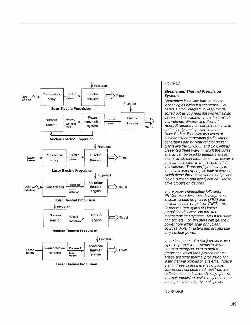
Figure 27
Electric and Thermal Propulsion Systems Sometimes it’s a little hard to tell the technologies without a scorecard. So here’s a block diagram to keep things sorted out as you read the two remaining papers in this volume. In the first half of this volume, “Energy and Power,” Henry Brandhorst described photovoltaic and solar dynamic power sources, Dave Buden discussed two types of nuclear power generation (radioisotope generators and nuclear reactor power plants like the SP-100), and Ed Conway presented three ways in which the Sun’s energy can be used to generate a laser beam, which can then transmit its power to a distant use site. In the second half of this volume, “Transport,” particularly in these last two papers, we look at ways in which these three main sources of power (solar, nuclear, and laser) can be used to drive propulsion devices. In the paper immediately following, Phil Garrison describes developments in solar electric propulsion (SEP) and nuclear electric propulsion (NEP). He discusses three types of electric propulsion devices: ion thrusters, magnetoplasmadynamic (MPD) thrusters, and arc jets. Ion thrusters can get their power from either solar or nuclear sources; MPD thrusters and arc jets use only nuclear power. In the last paper, Jim Shoji presents two types of propulsion systems in which beamed energy is used to heat a propellant, which then provides thrust. These are solar thermal propulsion and laser thermal propulsion systems. Notice that in these cases there is no power conversion; concentrated heat from the radiation source is used directly. [A solar thermal propulsion device may be seen as analogous to a solar dynamic power (continued)
149
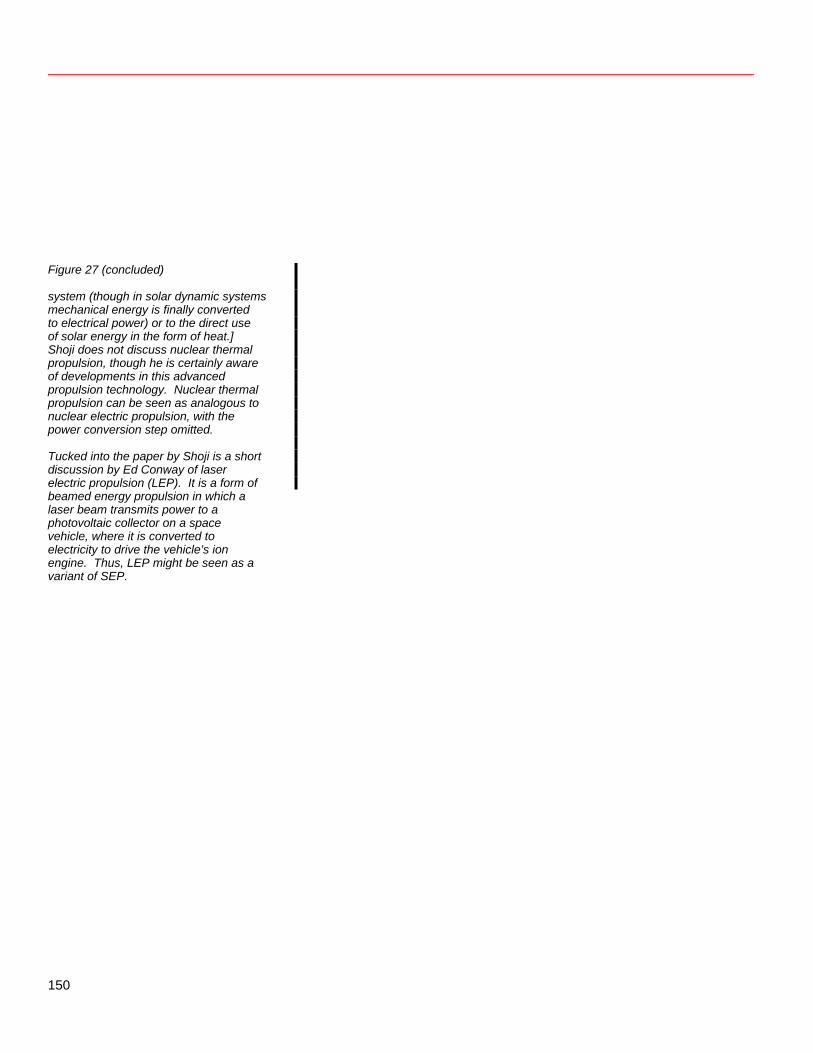
Figure 27 (concluded)
system (though in solar dynamic systems mechanical energy is finally converted to electrical power) or to the direct use of solar energy in the form of heat.] Shoji does not discuss nuclear thermal propulsion, though he is certainly aware of developments in this advanced propulsion technology. Nuclear thermal propulsion can be seen as analogous to nuclear electric propulsion, with the power conversion step omitted. Tucked into the paper by Shoji is a short discussion by Ed Conway of laser electric propulsion (LEP). It is a form of beamed energy propulsion in which a laser beam transmits power to a photovoltaic collector on a space vehicle, where it is converted to electricity to drive the vehicle’s ion engine. Thus, LEP might be seen as a variant of SEP.
150
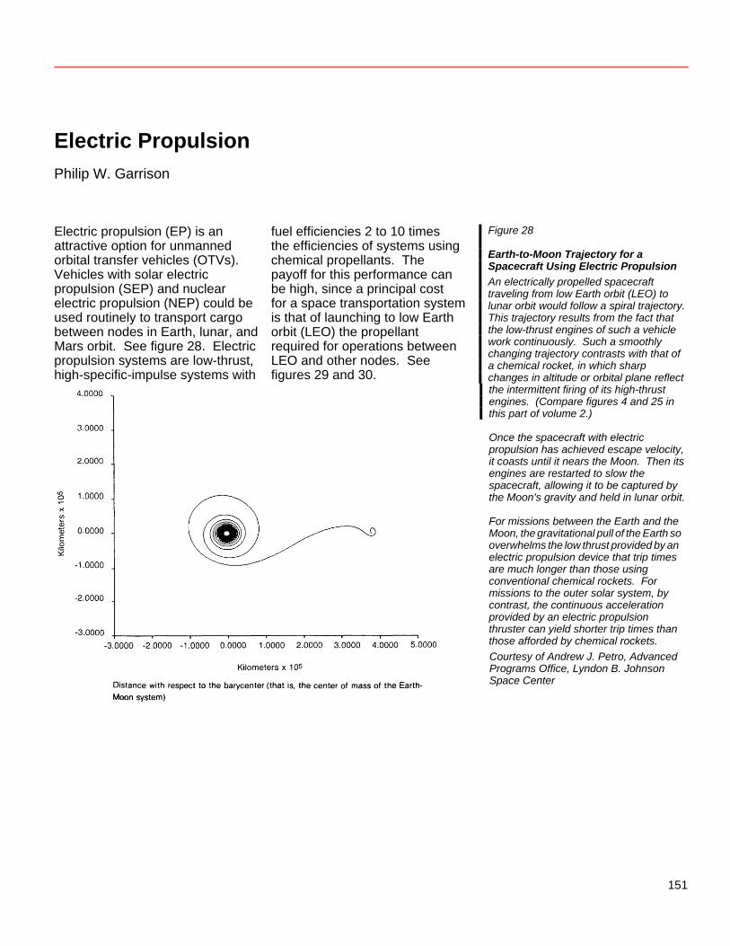
Electric Propulsion Philip W. Garrison Electric propulsion (EP) is an attractive option for unmanned orbital transfer vehicles (OTVs). Vehicles with solar electric propulsion (SEP) and nuclear electric propulsion (NEP) could be used routinely to transport cargo between nodes in Earth, lunar, and Mars orbit. See figure 28. Electric propulsion systems are low-thrust, high-specific-impulse systems with
fuel efficiencies 2 to 10 times the efficiencies of systems using chemical propellants. The payoff for this performance can be high, since a principal cost for a space transportation system is that of launching to low Earth orbit (LEO) the propellant required for operations between LEO and other nodes. See figures 29 and 30.
Figure 28
Earth-to-Moon Trajectory for a Spacecraft Using Electric Propulsion An electrically propelled spacecraft traveling from low Earth orbit (LEO) to lunar orbit would follow a spiral trajectory. This trajectory results from the fact that the low-thrust engines of such a vehicle work continuously. Such a smoothly changing trajectory contrasts with that of a chemical rocket, in which sharp changes in altitude or orbital plane reflect
the intermittent firing of its high-thrust engines. (Compare figures 4 and 25 in this part of volume 2.) Once the spacecraft with electric propulsion has achieved escape velocity, it coasts until it nears the Moon. Then its engines are restarted to slow the spacecraft, allowing it to be captured by the Moon’s gravity and held in lunar orbit. For missions between the Earth and the Moon, the gravitational pull of the Earth so overwhelms the low thrust provided by an electric propulsion device that trip times are much longer than those using conventional chemical rockets. For missions to the outer solar system, by contrast, the continuous acceleration provided by an electric propulsion thruster can yield shorter trip times than those afforded by chemical rockets. Courtesy of Andrew J. Petro, Advanced Programs Office, Lyndon B. Johnson Space Center
151
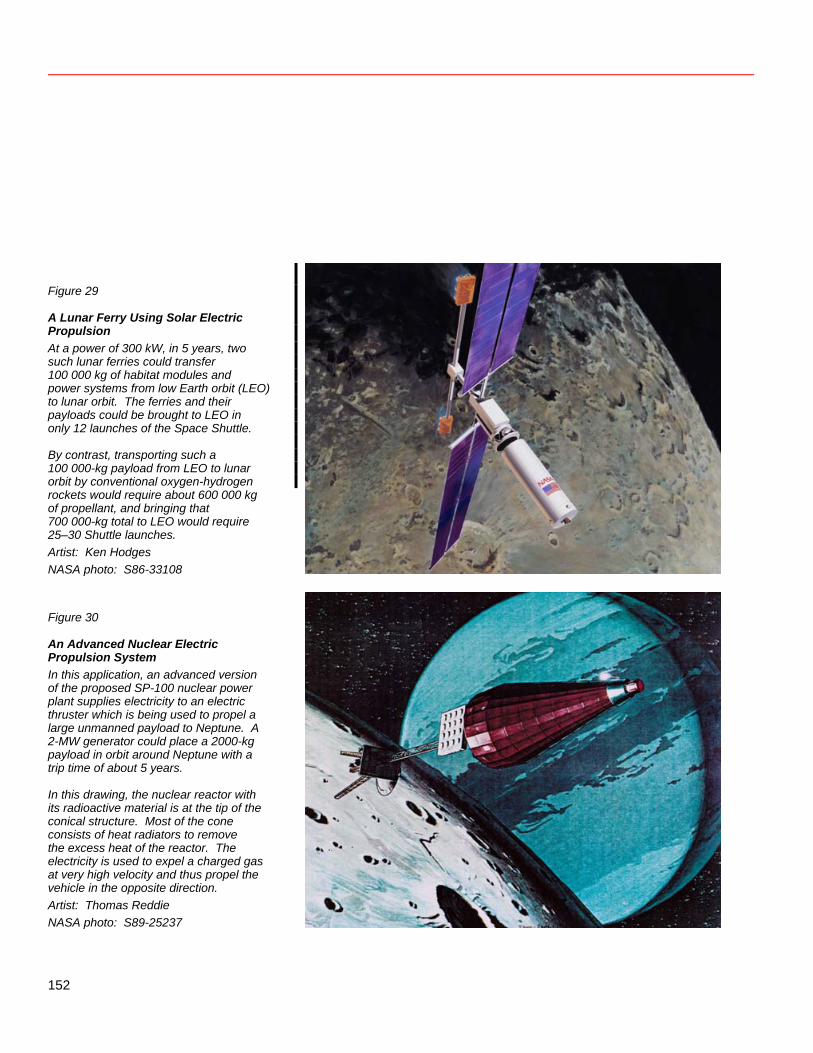
Figure 29
A Lunar Ferry Using Solar Electric Propulsion At a power of 300 kW, in 5 years, two such lunar ferries could transfer 100 000 kg of habitat modules and power systems from low Earth orbit (LEO) to lunar orbit. The ferries and their payloads could be brought to LEO in only 12 launches of the Space Shuttle. By contrast, transporting such a 100 000-kg payload from LEO to lunar orbit by conventional oxygen-hydrogen rockets would require about 600 000 kg of propellant, and bringing that 700 000-kg total to LEO would require 25–30 Shuttle launches. Artist: Ken Hodges NASA photo: S86-33108 Figure 30
An Advanced Nuclear Electric Propulsion System In this application, an advanced version of the proposed SP-100 nuclear power plant supplies electricity to an electric thruster which is being used to propel a large unmanned payload to Neptune. A 2-MW generator could place a 2000-kg payload in orbit around Neptune with a trip time of about 5 years. In this drawing, the nuclear reactor with its radioactive material is at the tip of the conical structure. Most of the cone consists of heat radiators to remove the excess heat of the reactor. The electricity is used to expel a charged gas at very high velocity and thus propel the vehicle in the opposite direction. Artist: Thomas Reddie NASA photo: S89-25237
152
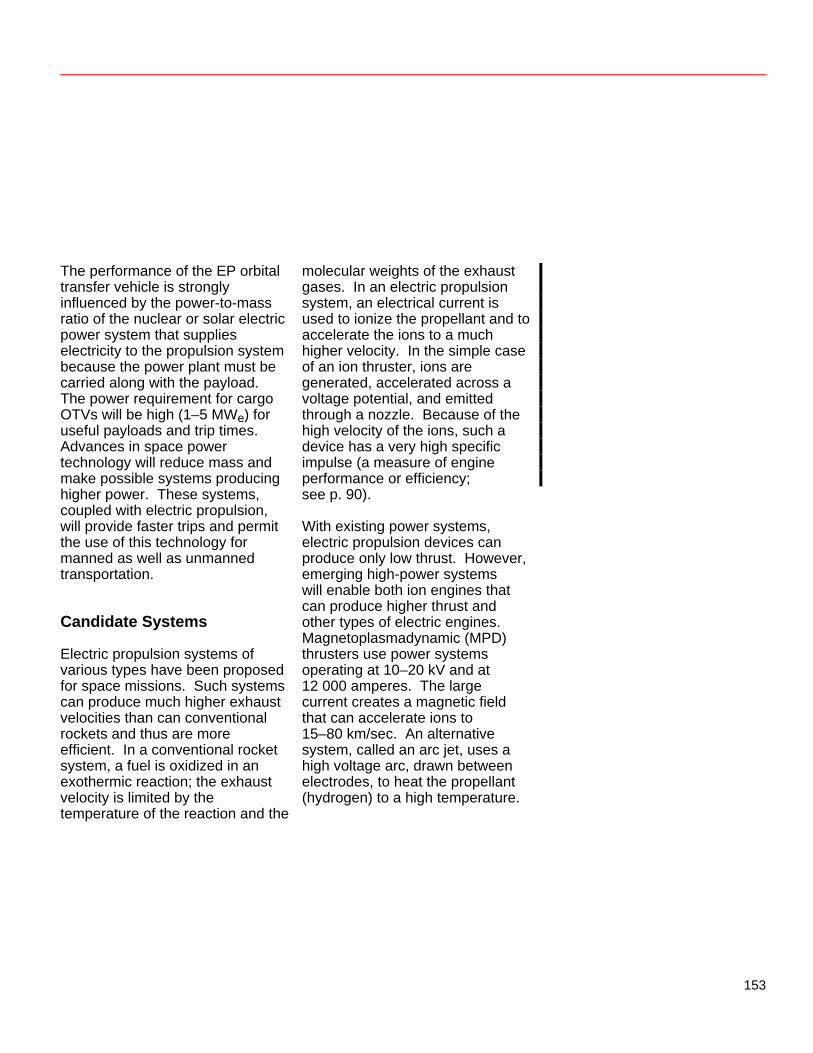
The performance of the EP orbital transfer vehicle is strongly influenced by the power-to-mass ratio of the nuclear or solar electric power system that supplies electricity to the propulsion system because the power plant must be carried along with the payload. The power requirement for cargo OTVs will be high (1–5 MWe) for useful payloads and trip times. Advances in space power technology will reduce mass and make possible systems producing higher power. These systems, coupled with electric propulsion, will provide faster trips and permit the use of this technology for manned as well as unmanned transportation. Candidate Systems Electric propulsion systems of various types have been proposed for space missions. Such systems can produce much higher exhaust velocities than can conventional rockets and thus are more efficient. In a conventional rocket system, a fuel is oxidized in an exothermic reaction; the exhaust velocity is limited by the temperature of the reaction and the
molecular weights of the exhaust gases. In an electric propulsion system, an electrical current is used to ionize the propellant and to accelerate the ions to a much higher velocity. In the simple case of an ion thruster, ions are generated, accelerated across a voltage potential, and emitted through a nozzle. Because of the high velocity of the ions, such a device has a very high specific impulse (a measure of engine performance or efficiency; see p. 90). With existing power systems, electric propulsion devices can produce only low thrust. However, emerging high-power systems will enable both ion engines that can produce higher thrust and other types of electric engines. Magnetoplasmadynamic (MPD) thrusters use power systems operating at 10–20 kV and at 12 000 amperes. The large current creates a magnetic field that can accelerate ions to 15–80 km/sec. An alternative system, called an arc jet, uses a high voltage arc, drawn between electrodes, to heat the propellant (hydrogen) to a high temperature.
153
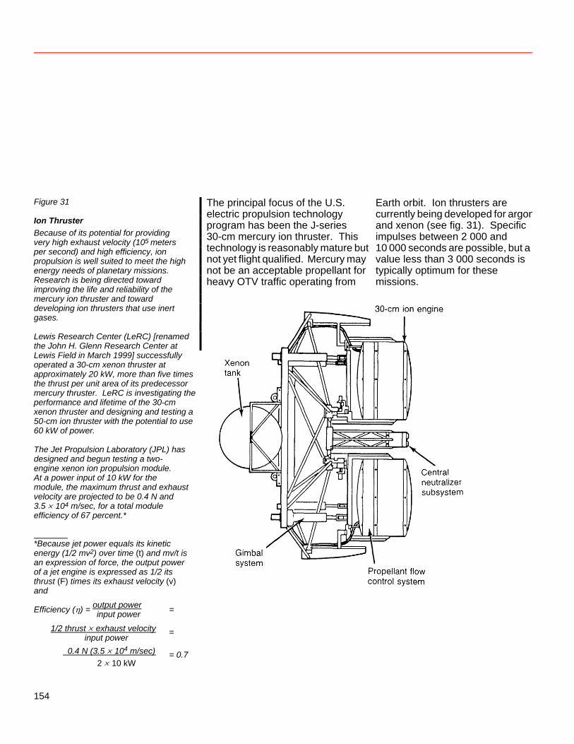
Figure 31
Ion Thruster Because of its potential for providing very high exhaust velocity (105 meters per second) and high efficiency, ion propulsion is well suited to meet the high energy needs of planetary missions. Research is being directed toward improving the life and reliability of the
The principal focus of the U.S. electric propulsion technology program has been the J-series 30-cm mercury ion thruster. This technology is reasonably mature but not yet flight qualified. Mercury may not be an acceptable propellant for heavy OTV traffic operating from
Earth orbit. Ion thrusters are currently being developed for argonand xenon (see fig. 31). Specific impulses between 2 000 and 10 000 seconds are possible, but a value less than 3 000 seconds is typically optimum for these missions.
mercury ion thruster and toward developing ion thrusters that use inert gases. Lewis Research Center (LeRC) [renamed the John H. Glenn Research Center at Lewis Field in March 1999] successfully operated a 30-cm xenon thruster at approximately 20 kW, more than five times the thrust per unit area of its predecessor mercury thruster. LeRC is investigating the performance and lifetime of the 30-cm xenon thruster and designing and testing a 50-cm ion thruster with the potential to use 60 kW of power. The Jet Propulsion Laboratory (JPL) has designed and begun testing a two- engine xenon ion propulsion module. At a power input of 10 kW for the module, the maximum thrust and exhaust velocity are projected to be 0.4 N and 3.5 × 10⁴ m/sec, for a total module efficiency of 67 percent.* *Because jet power equals its kinetic energy (1/2 mv2) over time (t) and mv/t is an expression of force, the output power of a jet engine is expressed as 1/2 its thrust (F) times its exhaust velocity (v) and Efficiency (η) = output power = input power 1/2 thrust × exhaust velocity = input power 0.4 N ( 3.5 × 10⁴ m/sec)
= 0.7 2 × 10 kW
154
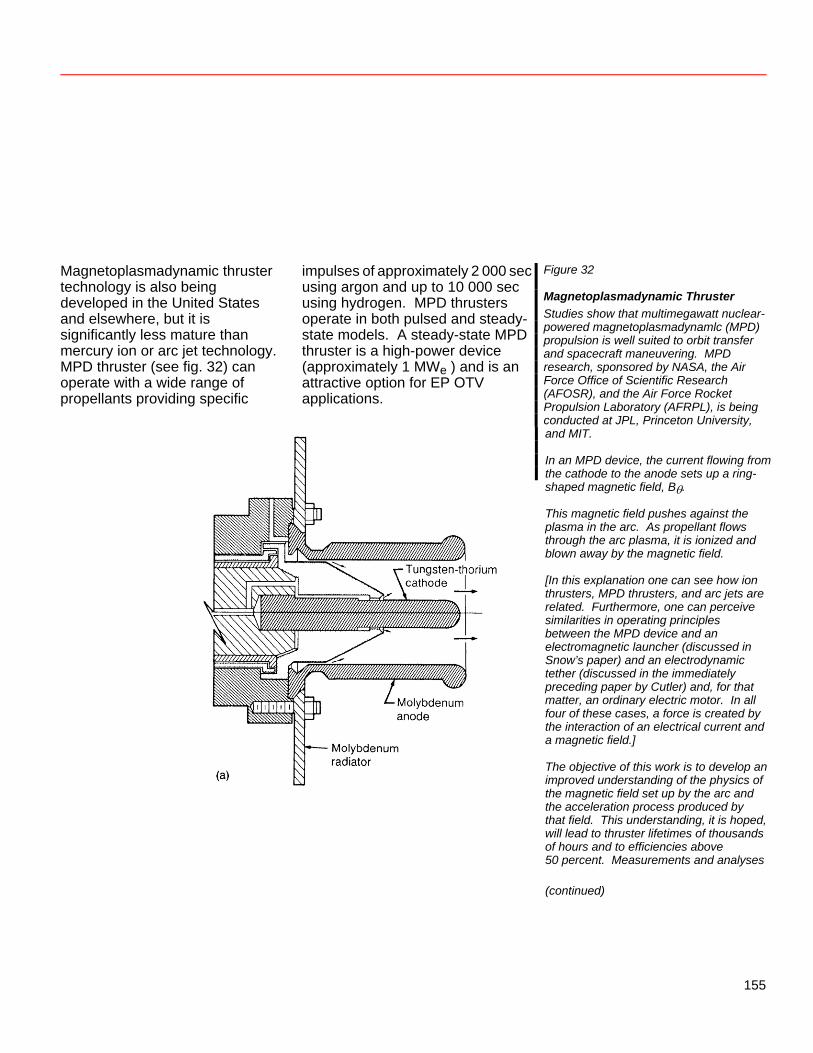
Magnetoplasmadynamic thruster technology is also being developed in the United States and elsewhere, but it is significantly less mature than mercury ion or arc jet technology. MPD thruster (see fig. 32) can operate with a wide range of propellants providing specific
impulses of approximately 2 000 sec using argon and up to 10 000 sec using hydrogen. MPD thrusters operate in both pulsed and steady-state models. A steady-state MPD thruster is a high-power device (approximately 1 MWe ) and is an attractive option for EP OTV applications.
Figure 32
Magnetoplasmadynamic Thruster Studies show that multimegawatt nuclear-powered magnetoplasmadynamlc (MPD) propulsion is well suited to orbit transfer and spacecraft maneuvering. MPD research, sponsored by NASA, the Air Force Office of Scientific Research (AFOSR), and the Air Force Rocket Propulsion Laboratory (AFRPL), is being conducted at JPL, Princeton University,
and MIT. In an MPD device, the current flowing from the cathode to the anode sets up a ring- shaped magnetic field, Bθ. This magnetic field pushes against the plasma in the arc. As propellant flows through the arc plasma, it is ionized and blown away by the magnetic field. [In this explanation one can see how ion thrusters, MPD thrusters, and arc jets are related. Furthermore, one can perceive similarities in operating principles between the MPD device and an electromagnetic launcher (discussed in Snow’s paper) and an electrodynamic tether (discussed in the immediately preceding paper by Cutler) and, for that matter, an ordinary electric motor. In all four of these cases, a force is created by the interaction of an electrical current and a magnetic field.] The objective of this work is to develop an improved understanding of the physics of the magnetic field set up by the arc and the acceleration process produced by that field. This understanding, it is hoped, will lead to thruster lifetimes of thousands of hours and to efficiencies above 50 percent. Measurements and analyses (continued)
155
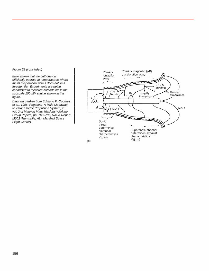
Figure 32 (concluded)
have shown that the cathode can efficiently operate at temperatures where metal evaporation from it does not limit thruster life. Experiments are being conducted to measure cathode life in the subscale 100-kW engine shown in this figure. Diagram b taken from Edmund P. Coomes et al., 1986, Pegasus: A Multi-Megawatt Nuclear Electric Propulsion System, in vol. 2 of Manned Mars Missions Working Group Papers, pp. 769–786, NASA Report M002 (Huntsville, AL: Marshall Space Flight Center).
156
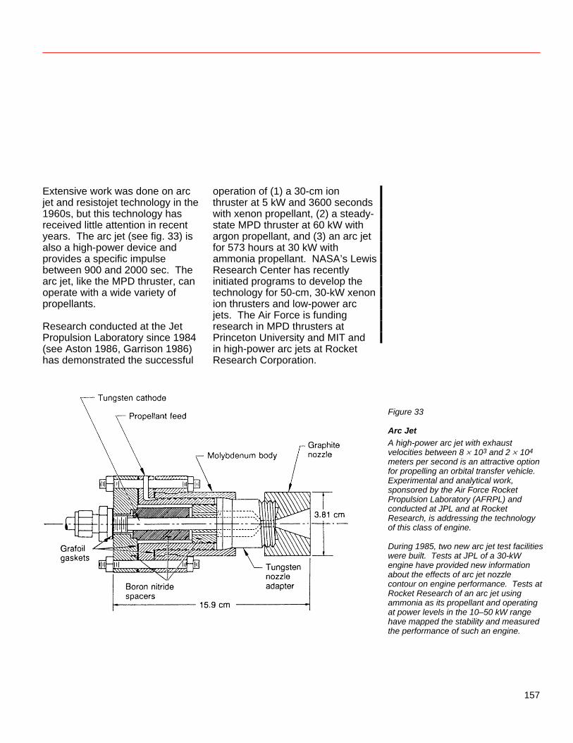
Extensive work was done on arc jet and resistojet technology in the 1960s, but this technology has received little attention in recent years. The arc jet (see fig. 33) is also a high-power device and provides a specific impulse between 900 and 2000 sec. The arc jet, like the MPD thruster, can operate with a wide variety of propellants. Research conducted at the Jet Propulsion Laboratory since 1984 (see Aston 1986, Garrison 1986) has demonstrated the successful
operation of (1) a 30-cm ion thruster at 5 kW and 3600 seconds with xenon propellant, (2) a steady-state MPD thruster at 60 kW with argon propellant, and (3) an arc jet for 573 hours at 30 kW with ammonia propellant. NASA’s Lewis Research Center has recently initiated programs to develop the technology for 50-cm, 30-kW xenon ion thrusters and low-power arc jets. The Air Force is funding research in MPD thrusters at Princeton University and MIT and in high-power arc jets at Rocket Research Corporation.
Figure 33
Arc Jet A high-power arc jet with exhaust velocities between 8 × 10³ and 2 × 10⁴ meters per second is an attractive option for propelling an orbital transfer vehicle. Experimental and analytical work, sponsored by the Air Force Rocket Propulsion Laboratory (AFRPL) and conducted at JPL and at Rocket Research, is addressing the technology of this class of engine. During 1985, two new arc jet test facilities were built. Tests at JPL of a 30-kW engine have provided new information about the effects of arc jet nozzle contour on engine performance. Tests at Rocket Research of an arc jet using ammonia as its propellant and operating at power levels in the 10–50 kW range have mapped the stability and measured the performance of such an engine.
157
Technology Needs Because of the difficulty of developing larger ion thrusters, large numbers of ion thrusters are required for a multimegawatt OTV. Steady-state MPD thrusters and arc jets are likely to be better suited to the cargo OTV application. Of the two, the arc jet is the more mature technology. The funding for each of the above EP technologies is nearly subcritical because there is no established mission requirement for the technology. Increased funding will be necessary to make this technology available for the scenarios under consideration. Impact of Scenarios Utilizing Nonterrestrial Materials Nonterrestrial material utilization has two potential impacts on EP technology needs. If a demand for large quantities of lunar materials is established, electric propulsion is a highly competitive option for transporting both the bulk materials needed to construct the bases and factories for such an operation and the raw materials and products
output by it. Electrically propelled OTVs, such as the lunar ferry described in figure 29, can beneficially supplant chemically propelled vehicles when cargo traffic to and from the Moon reaches some level, perhaps 100 metric tons (100 000 kg) per year. The second impact concerns the ability of the transportation system to rely on nonterrestrial resources for resupply of consumables. All other aspects being equal, a system that can be resupplied from local resources is clearly preferred. However, the most readily available lunar propellant, oxygen, is not well suited to EP operations. Significant technology advances are required to operate any of the EP devices with oxygen, the principal technology barriers being the development of techniques to prevent the rapid oxidation of high-temperature thruster components. On the other hand, if hydrogen could be obtained from lunar (or asteroidal) sources, it would significantly enhance the performance of the EP OTV as well as benefit the oxygen-hydrogen chemical propulsion vehicles needed for high-thrust surface-to-orbit operations.
158
References Aston, Graeme. 1986. Advanced Electric Propulsion for Interplanetary Missions. Paper AAS-86-259, 33rd Annual Meeting of American Astronautical Society, Boulder, Oct. 26–29. Garrison, Philip W. 1986. Advanced Propulsion Activities in the USA. Paper IAF86-170, 37th Congress Int. Astronaut. Fed., Innsbruck, Austria, Oct. 4–11.
159
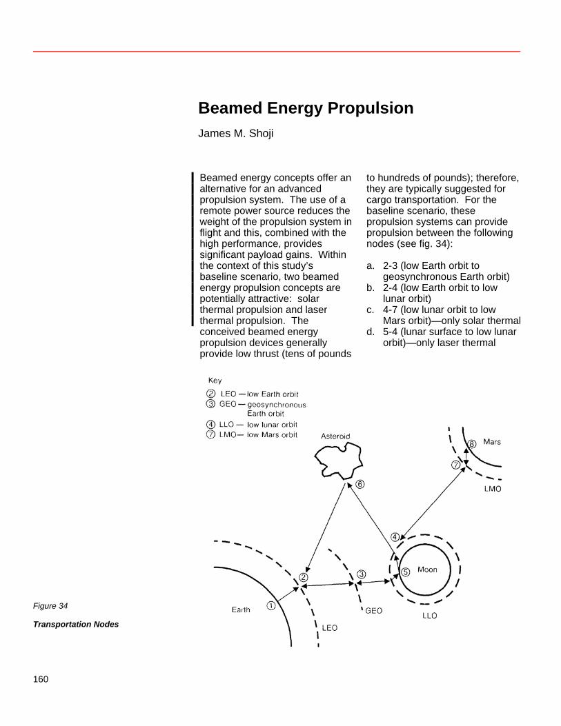
Beamed Energy Propulsion James M. Shoji
Beamed energy concepts offer an alternative for an advanced propulsion system. The use of a remote power source reduces the weight of the propulsion system in flight and this, combined with the high performance, provides significant payload gains. Within the context of this study’s baseline scenario, two beamed energy propulsion concepts are potentially attractive: solar thermal propulsion and laser thermal propulsion. The conceived beamed energy propulsion devices generally provide low thrust (tens of pounds
to hundreds of pounds); therefore, they are typically suggested for cargo transportation. For the baseline scenario, these propulsion systems can provide propulsion between the following nodes (see fig. 34): a. 2-3 (low Earth orbit to
geosynchronous Earth orbit) b. 2-4 (low Earth orbit to low
lunar orbit) c. 4-7 (low lunar orbit to low
Mars orbit)—only solar thermal d. 5-4 (lunar surface to low lunar
orbit)—only laser thermal
Figure 34
Transportation Nodes
160
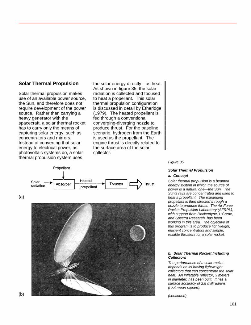
Solar Thermal Propulsion Solar thermal propulsion makes use of an available power source, the Sun, and therefore does not require development of the power source. Rather than carrying a heavy generator with the spacecraft, a solar thermal rocket has to carry only the means of capturing solar energy, such as concentrators and mirrors. Instead of converting that solar energy to electrical power, as photovoltaic systems do, a solar thermal propulsion system uses
the solar energy directly—as heat. As shown in figure 35, the solar radiation is collected and focused to heat a propellant. This solar thermal propulsion configuration is discussed in detail by Etheridge (1979). The heated propellant is fed through a conventional converging-diverging nozzle to produce thrust. For the baseline scenario, hydrogen from the Earth is used as the propellant. The engine thrust is directly related to the surface area of the solar collector.
(a)
(b)
Figure 35
Solar Thermal Propulsion a. Concept Solar thermal propulsion is a beamed energy system in which the source of power is a natural one—the Sun. The Sun’s rays are concentrated and used to heat a propellant. The expanding propellant is then directed through a nozzle to produce thrust. The Air Force Rocket Propulsion Laboratory (AFRPL), with support from Rocketdyne, L’Garde, and Spectra Research, has been working in this area. The objective of this program is to produce lightweight, efficient concentrators and simple, reliable thrusters for a solar rocket. b. Solar Thermal Rocket Including Collectors The performance of a solar rocket depends on its having lightweight collectors that can concentrate the solar heat. An inflatable reflector, 3 meters in diameter, has been built. It has a surface accuracy of 2.8 milliradians (root mean square). (continued)
161
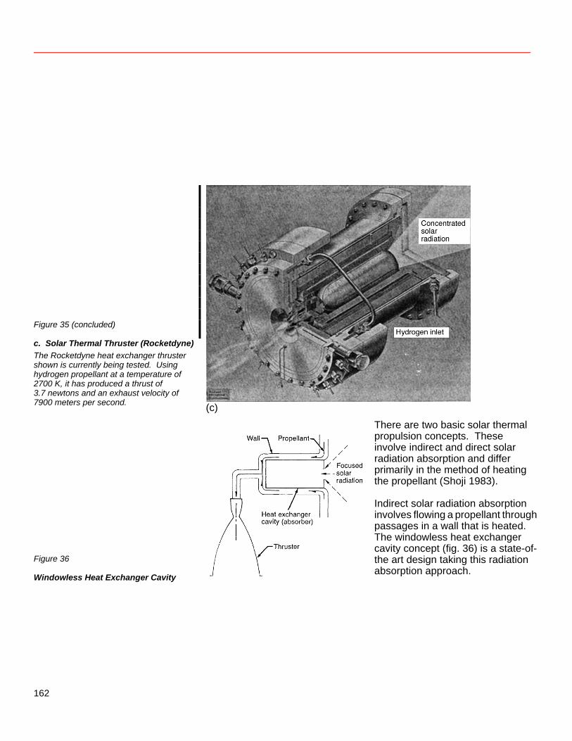
Figure 35 (concluded)
c. Solar Thermal Thruster (Rocketdyne) The Rocketdyne heat exchanger thruster shown is currently being tested. Using hydrogen propellant at a temperature of 2700 K, it has produced a thrust of 3.7 newtons and an exhaust velocity of 7900 meters per second.
(c)
Figure 36
Windowless Heat Exchanger Cavity
There are two basic solar thermal propulsion concepts. These involve indirect and direct solar radiation absorption and differ primarily in the method of heating the propellant (Shoji 1983). Indirect solar radiation absorption involves flowing a propellant through passages in a wall that is heated. The windowless heat exchanger cavity concept (fig. 36) is a state-of-the art design taking this radiation absorption approach.
162
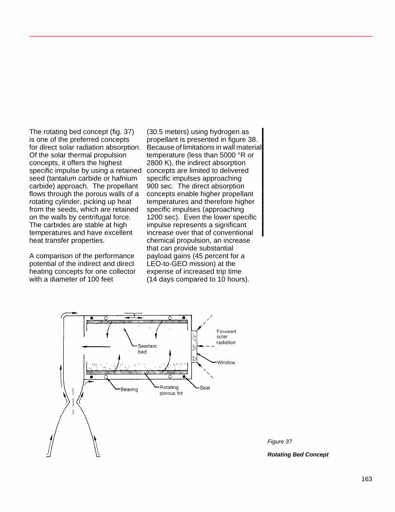
The rotating bed concept (fig. 37) is one of the preferred concepts for direct solar radiation absorption. Of the solar thermal propulsion concepts, it offers the highest specific impulse by using a retained seed (tantalum carbide or hafnium carbide) approach. The propellant flows through the porous walls of a rotating cylinder, picking up heat from the seeds, which are retained on the walls by centrifugal force. The carbides are stable at high temperatures and have excellent heat transfer properties. A comparison of the performance potential of the indirect and direct heating concepts for one collector with a diameter of 100 feet
(30.5 meters) using hydrogen as propellant is presented in figure 38. Because of limitations in wall material temperature (less than 5000 °R or 2800 K), the indirect absorption concepts are limited to delivered specific impulses approaching 900 sec. The direct absorption concepts enable higher propellant temperatures and therefore higher specific impulses (approaching 1200 sec). Even the lower specific impulse represents a significant increase over that of conventional chemical propulsion, an increase that can provide substantial payload gains (45 percent for a LEO-to-GEO mission) at the expense of increased trip time (14 days compared to 10 hours).
Figure 37
Rotating Bed Concept
163
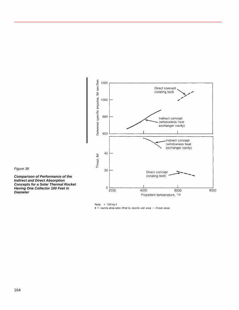
Figure 38
Comparison of Performance of the Indirect and Direct Absorption Concepts for a Solar Thermal Rocket Having One Collector 100 Feet in Diameter
164
The state of the art of solar thermal propulsion is that the absorber/thruster of the indirect solar radiation absorption approach is in the proof-of-principle stage. Small-scale hardware has been designed and fabricated for the Air Force Rocket Propulsion Laboratory (AFRPL) for ground test evaluation (see fig. 35). In order to provide solar thermal propulsion for the baseline mission scenario, a number of technology advances must be made, including the following: 1. Propulsion system
a. Indirect solar radiation absorption concept • Further high-temperature
material fabrication and process technology
• Concept design and development
b. Direct solar radiation absorption concept • Subcomponent and
component technology • Concept design and
development c. Engine system
• Absorber concept selection • Complete engine system
design and development
2. Collector/concentrator—component technology associated with large inflated collector a. Structural design b. High concentration ratios c. Deployment approach and
design d. Collector surface accuracy
3. Vehicle a. Collector/concentrator
integration b. Sun-tracking system c. Long-term-storage of liquid
hydrogen for LLO-to-LMO missions
Details of the technology needs are outlined by Caveny (1984). An acceleration in the technology schedule and an increase in funding level would be required to provide solar thermal propulsion for the LEO-to-GEO leg for the year 2000 and to support the lunar and Mars missions in the baseline scenario.
165
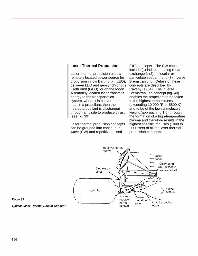
Laser Thermal Propulsion Laser thermal propulsion uses a remotely located power source for propulsion in low Earth orbit (LEO), between LEO and geosynchronous Earth orbit (GEO), or on the Moon. A remotely located laser transmits energy to the transportation system, where it is converted to heat in a propellant; then the heated propellant is discharged through a nozzle to produce thrust (see fig. 39). Laser thermal propulsion concepts can be grouped into continuous wave (CW) and repetitive pulsed
(RP) concepts. The CW concepts include (1) indirect heating (heat exchanger), (2) molecular or particulate seedant, and (3) inverse Bremstrahlung. Details of these concepts are described by Caveny (1984). The inverse Bremstrahlung concept (fig. 40) enables the propellant to be taken to the highest temperatures (exceeding 10 000 °R or 5500 K) and to be of the lowest molecular weight (approaching 1.0) through the formation of a high-temperature plasma and therefore results in the highest specific impulses (1000 to 2000 sec) of all the laser thermal propulsion concepts.
Figure 39
Typical Laser Thermal Rocket Concept
166
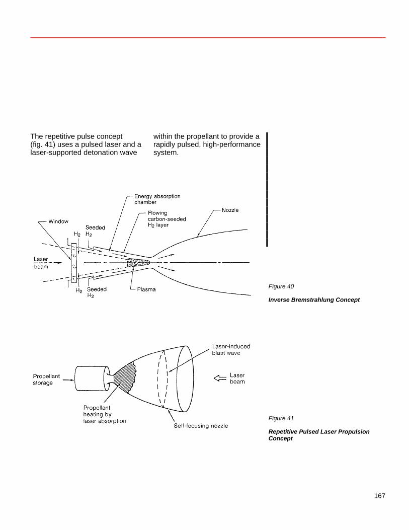
The repetitive pulse concept (fig. 41) uses a pulsed laser and a laser-supported detonation wave
within the propellant to provide a rapidly pulsed, high-performance system.
Figure 40
Inverse Bremstrahlung Concept Figure 41
Repetitive Pulsed Laser Propulsion Concept
167
The state of the art of laser thermal propulsion has been constrained by the available funding and is dependent on the development of a laser system capable of transmitting high levels (multimegawatts) of power. Analytical and experimental studies have been conducted to investigate the physics involved in plasma initiation and formation for the inverse Bremstrahlung approach. Also, initial small-scale RP thruster experiments have been conducted (Caveny 1984). NASA’s plans include an experimental CW laser thruster. The technology advances required to provide laser thermal propulsion include the following: 1. Thruster
a. Thruster cooling approach The high plasma temperatures (greater than 20 000 °R or 11 000 K) and the high specific impulse involved make satisfactory cooling difficult. A combination of regenerative and/or transpiration cooling with high-temperature wall materials may be required.
b. Window design and cooling • High transmittance • Low absorptivity • High strength at high
temperatures
2. Collector/concentrator a. Surface accuracy
Although laser thermal propulsion concentrators will be smaller than those for solar thermal propulsion, the requirement for surface accuracy may be more stringent because of the short wavelengths involved.
Other concentrator technologies are similar to those of the solar concentrator: b. High concentration ratios c. Structural design d. Deployment approach and
design
3. Vehicle a. Collector/concentrator
integration b. Long-term cryogenic
propellant storage Further specific technology requirements for both CW and RP laser thermal propulsion concepts are presented by Caveny (1984). In addition, an accurate laser-vehicle tracking system is essential. For laser thermal propulsion to become a viable approach, the current NASA plan would need to be accelerated, funding increased, and a space-based laser system developed.
168
Laser Electric Propulsion Edmund J. Conway In laser electric propulsion (LEP), power is beamed to a photovoltaic collector on a space vehicle, where it is converted to electricity for an ion engine (Holloway and Garrett 1981). The central power station can remain fixed, generating the laser beam and aiming it at the spacecraft receiver. Because of the high power in the laser beam, the spacecraft photovoltaic converter can be reduced in area (and thus mass), with respect to the array of a solar electric propulsion (SEP) system, by a factor of 102 to 104. As a laser photovoltaic array can be 50-percent efficient while solar photovoltaic array efficiency will not exceed 20 percent, the radiator area can also be significantly reduced. The reduced size of the converter and radiator implies a much reduced drag (compared to SEP) in low orbit. Moreover, ion engines are well developed, having high specific impulse, low thrust, and long life.
Use of Nonterrestrial Resources for Beamed Energy Propulsion Beamed energy propulsion alternatives utilizing propellants produced from nonterrestrial resources are summarized in table 11. In general, for both solar and laser thermal propulsion concepts, the availability of oxygen as propellant through lunar soil processing is not expected to be attractive because of the difficulty of achieving the required high-temperature oxygen-resistant materials for the thruster, the poor cooling capacity of oxygen, and the low specific impulse potential of oxygen. Even if these problems were solved, a performance and cost tradeoff analysis must be performed to quantify any gains. The oxygen would be available for missions originating from or returning to the lunar surface. The availability of water from Earth-crossing asteroids (or from the moons of Mars, Phobos and Deimos) transported to LEO would enable water electrolysis to produce hydrogen and oxygen.
169
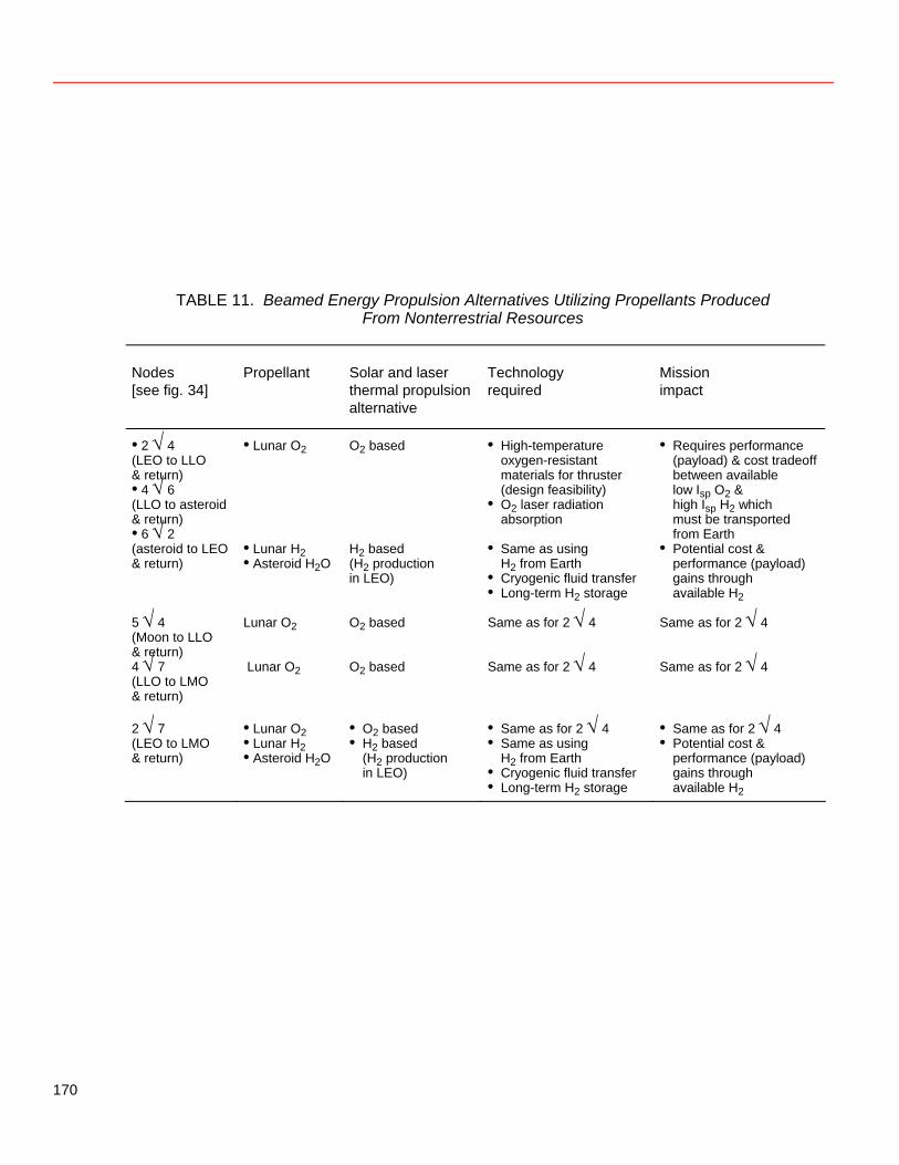
TABLE 11. Beamed Energy Propulsion Alternatives Utilizing Propellants Produced From Nonterrestrial Resources
Nodes [see fig. 34]
Propellant Solar and laser thermal propulsion alternative
Technology required
Mission impact
• 2 √ 4 (LEO to LLO & return) • 4 √ 6 (LLO to asteroid & return) • 6 √ 2
• Lunar O2 O2 based • High-temperature oxygen-resistant materials for thruster (design feasibility)
• O2 laser radiation absorption
• Requires performance (payload) & cost tradeoff between available low Isp O2 & high Isp H2 which must be transported from Earth
(asteroid to LEO & return)
• Lunar H2 • Asteroid H2O
H2 based (H2 production in LEO)
• Same as using H2 from Earth
• Cryogenic fluid transfer • Long-term H2 storage
• Potential cost & performance (payload) gains through available H2
5 √ 4 (Moon to LLO & return)
Lunar O2 O2 based Same as for 2 √ 4 Same as for 2 √ 4
4 √ 7 (LLO to LMO & return)
Lunar O2 O2 based Same as for 2 √ 4 Same as for 2 √ 4
2 √ 7 (LEO to LMO & return)
• Lunar O2 • Lunar H2 • Asteroid H2O
• O2 based • H2 based
(H2 production in LEO)
• Same as for 2 √ 4 • Same as using
H2 from Earth • Cryogenic fluid transfer • Long-term H2 storage
• Same as for 2 √ 4 • Potential cost &
performance (payload) gains through available H2
170
The hydrogen produced could be used in both the solar and laser thermal propulsion concepts. Another possible nonterrestrial source of hydrogen is lunar soil. Hydrogen implanted by the solar wind is present in abundances of about 40 ppm in the bulk soil and up to 300 ppm in fine-grained fractions. Extraction of this hydrogen is being studied to determine whether it is economically attractive compared to importing hydrogen from Earth. An abundance of 300 ppm hydrogen by weight is equivalent to 2700 ppm, or 0.27 percent, water. This amount of hydrogen has been found in the fine-grained (less than 20 micrometers in diameter) fractions of some mature lunar soils. The technology required to use this hydrogen is the same as that to use hydrogen brought from the Earth in the baseline scenario. Additional technology needed for the alternative scenario includes long-term cryogenic propellant storage. Again, a performance and cost tradeoff analysis is required to evaluate the gains achieved through the availability of hydrogen.
References Caveny, Leonard H., ed. 1984. Orbit-Raising and Maneuvering Propulsion: Research Status and Needs. Progress in Astronautics and Aeronautics, vol. 89. Etheridge, F. G. 1979. Solar-Rocket System Concept Analysis: Final Technical Report. AFRPL-TR-79-79, Nov. Holloway, Paul F., and L. B. Garrett. 1981. Comparative Analyses of Space-to-Space Central Power Stations. NASA TP-1955, Dec. Shoji, J. M. 1983. Performance Potential of Advanced Solar Thermal Propulsion. AlAA 83-1307, June.
171
Addendum: Participants
The managers of the 1984 summer study were David S. McKay, Summer Study Co-Director and Workshop Manager Lyndon B. Johnson Space Center Stewart Nozette, Summer Study Co-Director California Space Institute James Arnold, Director of the California Space Institute Stanley R. Sadin, Summer Study Sponsor for the Office of Aeronautics and Space Technology NASA Headquarters
Those who participated in the 10-week summer study as faculty fellows were the following: James D. Burke Jet Propulsion Laboratory James L. Carter University of Texas, Dallas David R. Criswell California Space Institute Carolyn Dry Virginia Polytechnic Institute Rocco Fazzolare University of Arizona Tom W. Fogwell Texas A & M University Michael J. Gaffey Rensselaer Polytechnic Institute Nathan C. Goldman University of Texas, Austin Philip R. Harris California Space Institute Karl R. Johansson North Texas State University Elbert A. King University of Houston, University Park Jesa Kreiner California State University, Fullerton John S. Lewis University of Arizona Robert H. Lewis Washington University, St. Louis William Lewis Clemson University James Grier Miller University of California, Los Angeles Sankar Sastri New York City Technical College Michele Small California Space Institute
172
Participants in the 1-week workshops included the following: Constance F. Acton Bechtel Power Corp. William N. Agosto Lunar Industries, Inc. A. Edward Bence Exxon Mineral Company Edward Bock General Dynamics David F. Bowersox Los Alamos National Laboratory Henry W. Brandhorst, Jr. NASA Lewis Research Center David Buden NASA Headquarters Edmund J. Conway NASA Langley Research Center Gene Corley Portland Cement Association Hubert Davis Eagle Engineering Michael B. Duke NASA Johnson Space Center Charles H. Eldred NASA Langley Research Center Greg Fawkes Pegasus Software Ben R. Finney University of Hawaii Philip W. Garrison Jet Propulsion Laboratory Richard E. Gertsch Colorado School of Mines Mark Giampapa University of Arizona Charles E. Glass University of Arizona Charles L. Gould Rockwell International Joel S. Greenberg Princeton Synergetics, Inc. Larry A. Haskin Washington University, St. Louis Abe Hertzberg University of Washington Walter J. Hickell Yukon Pacific Christian W. Knudsen Carbotek, Inc. Eugene Konecci University of Texas, Austin George Kozmetsky University of Texas, Austin John Landis Stone & Webster Engineering Corp. T. D. Lin Construction Technology Laboratories John M. Logsdon George Washington University Ronald Maehl RCA Astro-Electronics Thomas T. Meek Los Alamos National Laboratory Wendell W. Mendell NASA Johnson Space Center George Mueller Consultant Kathleen J. Murphy Consultant Barney B. Roberts NASA Johnson Space Center Sanders D. Rosenberg Aerojet TechSystems Company Robert Salkeld Consultant Donald R. Saxton NASA Marshall Space Flight Center James M. Shoji Rockwell International Michael C. Simon General Dynamics William R. Snow Electromagnetic Launch Research, Inc. Robert L. Staehle Jet Propulsion Laboratory Frank W. Stephenson, Jr. NASA Headquarters Wolfgang Steurer Jet Propulsion Laboratory Richard Tangum University of Texas, San Antonio Mead Treadwell Yukon Pacific Terry Triffet University of Arizona J. Peter Vajk Consultant Jesco von Puttkamer NASA Headquarters Scott Webster Orbital Systems Company Gordon R. Woodcock Boeing Aerospace Company
173
The following people participated in the summer study as guest speakers and consultants: Edwin E. “Buzz” Aldrin Research & Engineering Consultants Rudi Beichel Aerojet TechSystems Company David G. Brin California Space Institute Joseph A. Carroll California Space Institute Manuel L. Cruz Jet Propulsion Laboratory Andrew H. Cutler California Space Institute Christopher England Engineering Research Group Edward A. Gabris NASA Headquarters Peter Harnmerling LaJolla Institute Eleanor F. Helin Jet Propulsion Laboratory Nicholas Johnson Teledyne Brown Engineering Joseph P. Kerwin NASA Johnson Space Center Joseph P. Loftus NASA Johnson Space Center Budd Love Consultant John J. Martin NASA Headquarters John Meson Defense Advanced Research Projects Agency Tom Meyer Boulder Center for Science and Policy John C. Niehoff Science Applications International Tadahiko Okumura Shimizu Construction Company Thomas O. Paine Consultant William L. Quaide NASA Headquarters Namika Raby University of California, San Diego Donald G. Rea Jet Propulsion Laboratory Gene Roddenberry Writer Harrison H. “Jack” Schmitt Consultant Richard Schubert NASA Headquarters Elie Shneour Biosystems Associates, Ltd. Martin Spence Shimizu Construction Company James B. Stephens Jet Propulsion Laboratory Pat Sumi San Diego Unified School District Robert Waldron Rockwell International Simon P. Worden Department of Defense William Wright Defense Advanced Research Projects Agency
174