s.no. description standards / codes 38 criteria for
TRANSCRIPT

Document No. A672-999-16-48-EDB-1001
Rev No. 1
Engineering Design Basis(Structural)
Page 6 of 23
Template No. 5-0000-0001-T2 Rev. 1 Copyrights EIL – All rights reserved
S.No. Description Standards / Codes 38 Criteria for earthquake resistant design of
structures IS:1893
39 Code of practice for design & construction of foundations in soil - general requirements
IS:1904
40 Code of practice for structural use of un-reinforced masonry
IS:1905
41 Specification for Plain Washers IS:2016 42 Hot Rolled Low, Medium and High Tensile
Structural Steel IS:2062
43 Specification for Sand for Masonry Mortars IS:2116 44 Specification for Concrete Masonry Units IS:2185 45 Code of Practice for Brickworks IS:2212 46 Code of Practice for Preparation and Use of
Masonry Mortars IS:2250
47 Steel Wire Ropes for General Engineering Purposes - Specification
IS:2266
48 Specification for Thimbles for Wire Ropes IS:2315 49 Bulldog Grips - Specification IS:2361 50 Methods of Test For Aggregates for Concrete
(Part-II) IS:2386
51 Methods for Sampling of Aggregates for Concrete
IS:2430
52 Drop Forged Sockets for Wire Ropes for General Engineering Purposes
IS:2485
53 Recommended practice for hot dipped galvanising of iron and steel
IS:2629
54 Methods for testing uniformity of coating of zinc coated articles
IS:2633
55 Integral Waterproofing Compounds for Cement Mortar and Concrete -Specification
IS:2645
56 Code of practice for Design and construction of Pile foundations
IS:2911
57 Code of practice for design & construction of raft foundations
IS:2950
58 Code of practice for design & construction of machine foundations
IS:2974
59 Methods of Sampling and Test (Physical and Chemical) for Water and Wastewater
IS:3025
60 Specification for Bitumen Mastic for use in Water-Proofing of Roofs
IS:3037
61 Specification for Bitumen Primer for use in Waterproofing and Damp- Proofing
IS:3384
62 Code of practice for concrete structures for storage of liquids
IS:3370
63 Specification for Ballies for General Purposes IS:3337 64 Specification for Masonry Cement IS:3466 65 Methods of Tests of Burnt Clay Building
Bricks IS:3495
66 Steel Chequered Plates - Specification IS:3502 67 Specification for Structural Timber in Building IS:3629 68 Specification for High Strength Structural
Bolts IS:3757
Page 787 of 2624
Document No. A672-999-16-48-EDB-1001
Rev No. 1
Engineering Design Basis(Structural)
Page 7 of 23
Template No. 5-0000-0001-T2 Rev. 1 Copyrights EIL – All rights reserved
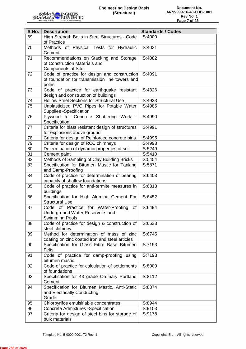
S.No. Description Standards / Codes 69 High Strength Bolts in Steel Structures - Code
of Practice IS:4000
70 Methods of Physical Tests for Hydraulic Cement
IS:4031
71 Recommendations on Stacking and Storage of Construction Materials and Components at Site
IS:4082
72 Code of practice for design and construction of foundation for transmission line towers and poles
IS:4091
73 Code of practice for earthquake resistant design and construction of buildings
IS:4326
74 Hollow Steel Sections for Structural Use IS:4923 75 Unplasticized PVC Pipes for Potable Water
Supplies -Specification IS:4985
76 Plywood for Concrete Shuttering Work - Specification
IS:4990
77 Criteria for blast resistant design of structures for explosions above ground
IS:4991
78 Criteria for design of Reinforced concrete bins IS:4995 79 Criteria for design of RCC chimneys IS:4998 80 Determination of dynamic properties of soil IS:5249 81 Cement paint IS:5410 82 Methods of Sampling of Clay Building Bricks IS:5454 83 Specification for Bitumen Mastic for Tanking
and Damp-Proofing IS:5871
84 Code of practice for determination of bearing capacity of shallow foundations
IS:6403
85 Code of practice for anti-termite measures inbuildings
IS:6313
86 Specification for High Alumina Cement For Structural Use
IS:6452
87 Code of Practice for Water-Proofing of Underground Water Reservoirs and Swimming Pools
IS:6494
88 Code of practice for design & construction of steel chimney
IS:6533
89 Method for determination of mass of zinc coating on zinc coated iron and steel articles
IS:6745
90 Specification for Glass Fibre Base Bitumen Felts
IS:7193
91 Code of practice for damp-proofing using bitumen mastic
IS:7198
92 Code of practice for calculation of settlements of foundations
IS:8009
93 Specification for 43 grade Ordinary Portland Cement
IS:8112
94 Specification for Bitumen Mastic, Anti-Static and Electrically Conducting Grade
IS:8374
95 Chlorpyrifos emulsifiable concentrates IS:8944 96 Concrete Admixtures -Specification IS:9103 97 Criteria for design of steel bins for storage of
bulk materials IS:9178
Page 788 of 2624
Document No. A672-999-16-48-EDB-1001
Rev No. 1
Engineering Design Basis(Structural)
Page 8 of 23
Template No. 5-0000-0001-T2 Rev. 1 Copyrights EIL – All rights reserved
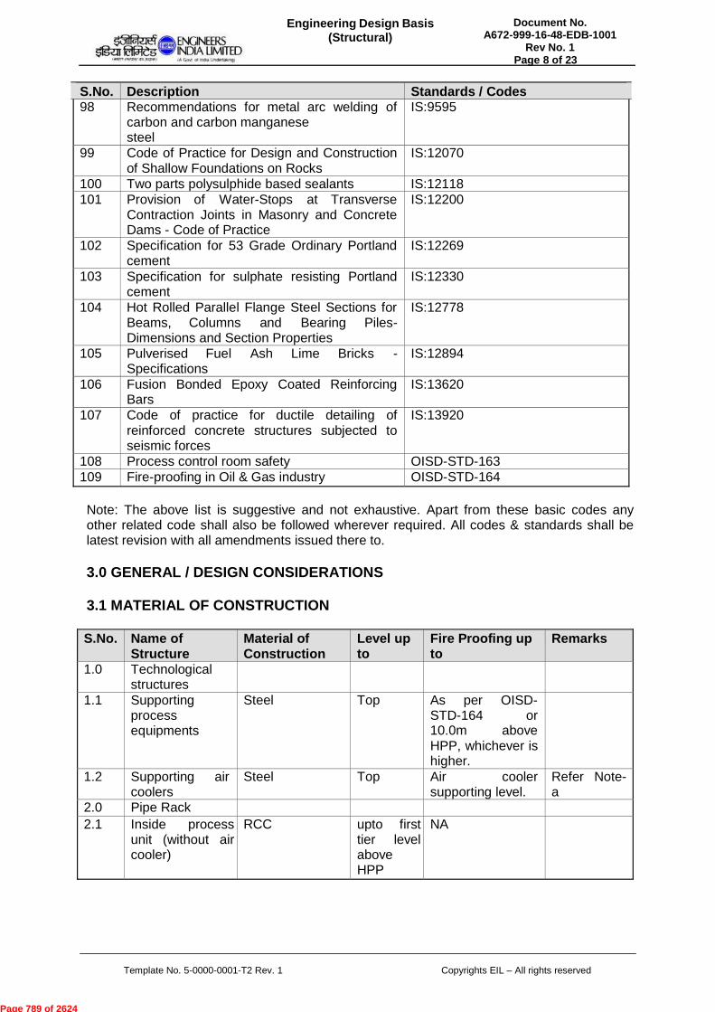
S.No. Description Standards / Codes 98 Recommendations for metal arc welding of
carbon and carbon manganese steel
IS:9595
99 Code of Practice for Design and Construction of Shallow Foundations on Rocks
IS:12070
100 Two parts polysulphide based sealants IS:12118 101 Provision of Water-Stops at Transverse
Contraction Joints in Masonry and Concrete Dams - Code of Practice
IS:12200
102 Specification for 53 Grade Ordinary Portland cement
IS:12269
103 Specification for sulphate resisting Portland cement
IS:12330
104 Hot Rolled Parallel Flange Steel Sections for Beams, Columns and Bearing Piles- Dimensions and Section Properties
IS:12778
105 Pulverised Fuel Ash Lime Bricks - Specifications
IS:12894
106 Fusion Bonded Epoxy Coated Reinforcing Bars
IS:13620
107 Code of practice for ductile detailing of reinforced concrete structures subjected to seismic forces
IS:13920
108 Process control room safety OISD-STD-163 109 Fire-proofing in Oil & Gas industry OISD-STD-164
Note: The above list is suggestive and not exhaustive. Apart from these basic codes any other related code shall also be followed wherever required. All codes & standards shall be latest revision with all amendments issued there to.
3.0 GENERAL / DESIGN CONSIDERATIONS
3.1 MATERIAL OF CONSTRUCTION
S.No. Name of
Structure Material of Construction
Level up to
Fire Proofing up to
Remarks
1.0 Technological structures
1.1 Supporting process equipments
Steel Top As per OISD- STD-164 or 10.0m above HPP, whichever is higher.
1.2 Supporting air coolers
Steel Top Air cooler supporting level.
Refer Note- a
2.0 Pipe Rack 2.1 Inside process
unit (without air cooler)
RCC upto first tier level above HPP
NA
Page 789 of 2624

Document No. A672-999-16-48-EDB-1001
Rev No. 1
Engineering Design Basis(Structural)
Page 9 of 23
Template No. 5-0000-0001-T2 Rev. 1 Copyrights EIL – All rights reserved
S.No. Name of
Structure Material of Construction
Level up to
Fire Proofing up to
Remarks
2.2 Inside process unit (without air cooler)
Steel Above RCC portion upto top
As per OISD- STD-164 or 10.0m above HPP,whichever is higher.
2.3 Inside process unit(with air cooler)
RCC upto firsttier level above HPP
NA Refer Note-a
2.4 Inside process unit(with air cooler)
Steel Above RCC portion upto top
Air cooler supporting level.
2.5 Offsite area Steel Top NA 3.0 All Shed type
structures e.g. compressor house,pump house etc.
Steel Top NA Ref. Note-b
4.0 All plant & non- plant buildings, including blast- resistant buildings
RCC Top NA Ref. Note-c
5.0 All enabling buildings e.g. Warehouse, cement godown etc.
RCC/ Steel Top NA Ref. Note-d
6.0 Cable trenches Precast/Cast-in- situ RCC
NA
Notes:
a) Blind floor below air cooler shall be in RCC over metal decking (left-in-shuttering)
b) Roofing & side cladding shall be as per Engineering Design Basis - Architectural.
c) Buildings shall have RCC floors & masonry infill walls, however blast-resistant buildings shall have RCC walls.
d) Material of construction for buildings shall be as per Engineering Design Basis - Architectural.
e) Electro-forged galvanized grating shall be used for flooring at all operating floors, unless RCC floor is required from operations considerations (e.g. blind floor below air coolers supported on technological structure & pipe rack, plant & non-plant buildings), however chequered plate shall be provided for walkway along crane girders.
f) Fire-proofing material for steel structures wherever required, shall be as follows: i) Concrete for structures, supporting transfer line & two phase flow line above 6" diameter. ii) Vermiculite for all other structures, however fire-proofing upto 1.8 m from HPP shall be in concrete.
Page 790 of 2624

Document No. A672-999-16-48-EDB-1001
Rev No. 1
Engineering Design Basis(Structural)
Page 10 of 23
Template No. 5-0000-0001-T2 Rev. 1 Copyrights EIL – All rights reserved
3.2 LOADS
3.2.1 DEAD LOADS
The weight of all permanent construction, including foundation, walls, floors, roofs, partitions, fire-proofing, stairways and fixed service and other equipments including all fixtures, platforms, ladders and attached piping but excluding their content. If piping weight is not indicated separately or included in the weight of the equipment, the same shall be taken as 10% of the weight of the equipment. Component of soil backfill weight over foundation slab shall be considered as foundation dead load.
The dead load of false ceiling shall be considered as 0.75KN/sqm, wherever required.
The unit weight of materials in general, should be in accordance with IS: 875. Part-1. Also, the following unit weights should be considered for the purpose of Design:
Reinforced Concrete - 25.0 kN/m3 Plain Concrete - 24.0 kN/m3 Structural Steel - 78.5 kN/m3 Backfill Soil - 18.0 kN/m3 Brickwork - 19.0 kN/m3
3.2.2 IMPOSED LOADS
Following may be considered under Imposed Loads:
3.2.2.1 LIVE LOADS
Live loads shall, in general, be as per IS:875. However, the following minimum live loads shall be considered in the design of structures to account for maintenance and erection as well:
S.No. Title / Description Value UOM Remarks 1.0 Process Building/
Technological Structure (open/ closed)
1.1 Operating area 5.0 kN/sqm 1.2 Maintenance area 7.5 kN/sqm 2.0 Compressor House/
TG house
2.1 Operating area 7.5 kN/sqm 2.2 Maintenance area 7.5 kN/sqm (or as specified by
machine vendor) 3.0 Service platform 3.1 Vessel/ Tower 3.0 kN/sqm 3.2 Isolated platform (for
valve operation) 2.5 kN/sqm
3.3 Access way 2.5 kN/sqm 3.4 Cross over 2.0 kN/sqm 4.0 Sub-station/ Control
room floors
Page 791 of 2624
Document No. A672-999-16-48-EDB-1001
Rev No. 1
Engineering Design Basis(Structural)
Page 11 of 23
Template No. 5-0000-0001-T2 Rev. 1 Copyrights EIL – All rights reserved
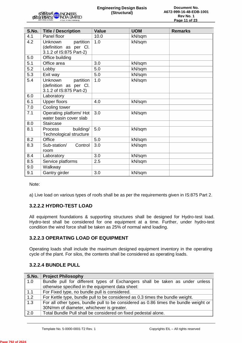
S.No. Title / Description Value UOM Remarks 4.1 Panel floor 10.0 kN/sqm 4.2 Unknown partition
(definition as per Cl. 3.1.2 of IS:875 Part-2)
1.0 kN/sqm
5.0 Office building 5.1 Office area 3.0 kN/sqm 5.2 Lobby 5.0 kN/sqm 5.3 Exit way 5.0 kN/sqm 5.4 Unknown partition
(definition as per Cl. 3.1.2 of IS:875 Part-2)
1.0 kN/sqm
6.0 Laboratory 6.1 Upper floors 4.0 kN/sqm 7.0 Cooling tower 7.1 Operating platform/ Hot
water basin cover slab 3.0 kN/sqm
8.0 Staircase 8.1 Process building/
Technological structure 5.0 kN/sqm
8.2 Office 5.0 kN/sqm 8.3 Sub-station/ Control
room 3.0 kN/sqm
8.4 Laboratory 3.0 kN/sqm 8.5 Service platforms 2.5 kN/sqm 9.0 Walkway 9.1 Gantry girder 3.0 kN/sqm
Note:
a) Live load on various types of roofs shall be as per the requirements given in IS:875 Part 2.
3.2.2.2 HYDRO-TEST LOAD
All equipment foundations & supporting structures shall be designed for Hydro-test load. Hydro-test shall be considered for one equipment at a time. Further, under hydro-test condition the wind force shall be taken as 25% of normal wind loading.
3.2.2.3 OPERATING LOAD OF EQUIPMENT
Operating loads shall include the maximum designed equipment inventory in the operating cycle of the plant. For silos, the contents shall be considered as operating loads.
3.2.2.4 BUNDLE PULL
S.No. Project Philosophy 1.0 Bundle pull for different types of Exchangers shall be taken as under unless
otherwise specified in the equipment data sheet: 1.1 For Fixed type, no bundle pull is considered. 1.2 For Kettle type, bundle pull to be considered as 0.3 times the bundle weight. 1.3 For all other types, bundle pull to be considered as 0.86 times the bundle weight or
30N/mm of diameter, whichever is greater. 2.0 Total Bundle Pull shall be considered on fixed pedestal alone.
Page 792 of 2624
Document No. A672-999-16-48-EDB-1001
Rev No. 1
Engineering Design Basis(Structural)
Page 12 of 23
Template No. 5-0000-0001-T2 Rev. 1 Copyrights EIL – All rights reserved
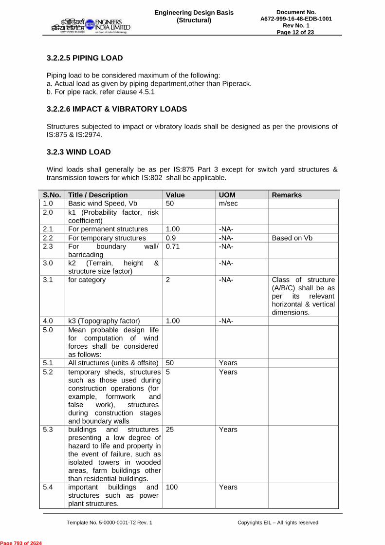
3.2.2.5 PIPING LOAD
Piping load to be considered maximum of the following: a. Actual load as given by piping department,other than Piperack. b. For pipe rack, refer clause 4.5.1
3.2.2.6 IMPACT & VIBRATORY LOADS
Structures subjected to impact or vibratory loads shall be designed as per the provisions of IS:875 & IS:2974.
3.2.3 WIND LOAD
Wind loads shall generally be as per IS:875 Part 3 except for switch yard structures & transmission towers for which IS:802 shall be applicable.
S.No. Title / Description Value UOM Remarks 1.0 Basic wind Speed, Vb 50 m/sec 2.0 k1 (Probability factor, risk
coefficient)
2.1 For permanent structures 1.00 -NA- 2.2 For temporary structures 0.9 -NA- Based on Vb 2.3 For boundary wall/
barricading 0.71 -NA-
3.0 k2 (Terrain, height & structure size factor)
-NA-
3.1 for category 2 -NA- Class of structure(A/B/C) shall be as per its relevant horizontal & verticaldimensions.
4.0 k3 (Topography factor) 1.00 -NA- 5.0 Mean probable design life
for computation of wind forces shall be considered as follows:
5.1 All structures (units & offsite) 50 Years 5.2 temporary sheds, structures
such as those used during construction operations (for example, formwork and false work), structures during construction stages and boundary walls
5 Years
5.3 buildings and structures presenting a low degree of hazard to life and property in the event of failure, such as isolated towers in wooded areas, farm buildings other than residential buildings.
25 Years
5.4 important buildings and structures such as power plant structures.
100 Years
Page 793 of 2624
Document No. A672-999-16-48-EDB-1001
Rev No. 1
Engineering Design Basis(Structural)
Page 13 of 23
Template No. 5-0000-0001-T2 Rev. 1 Copyrights EIL – All rights reserved
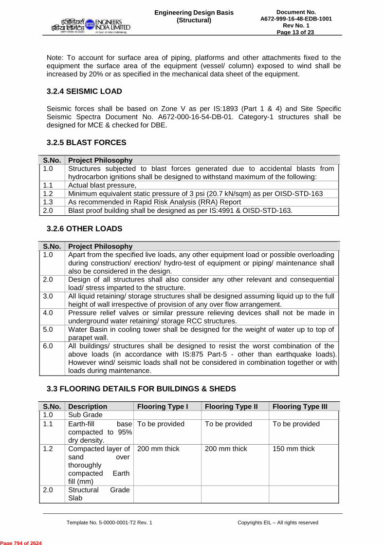
Note: To account for surface area of piping, platforms and other attachments fixed to the equipment the surface area of the equipment (vessel/ column) exposed to wind shall be increased by 20% or as specified in the mechanical data sheet of the equipment.
3.2.4 SEISMIC LOAD
Seismic forces shall be based on Zone V as per IS:1893 (Part 1 & 4) and Site Specific Seismic Spectra Document No. A672-000-16-54-DB-01. Category-1 structures shall be designed for MCE & checked for DBE.
3.2.5 BLAST FORCES
S.No. Project Philosophy 1.0 Structures subjected to blast forces generated due to accidental blasts from
hydrocarbon ignitions shall be designed to withstand maximum of the following: 1.1 Actual blast pressure, 1.2 Minimum equivalent static pressure of 3 psi (20.7 kN/sqm) as per OISD-STD-163 1.3 As recommended in Rapid Risk Analysis (RRA) Report 2.0 Blast proof building shall be designed as per IS:4991 & OISD-STD-163.
3.2.6 OTHER LOADS
S.No. Project Philosophy 1.0 Apart from the specified live loads, any other equipment load or possible overloading
during construction/ erection/ hydro-test of equipment or piping/ maintenance shall also be considered in the design.
2.0 Design of all structures shall also consider any other relevant and consequential load/ stress imparted to the structure.
3.0 All liquid retaining/ storage structures shall be designed assuming liquid up to the full height of wall irrespective of provision of any over flow arrangement.
4.0 Pressure relief valves or similar pressure relieving devices shall not be made in underground water retaining/ storage RCC structures.
5.0 Water Basin in cooling tower shall be designed for the weight of water up to top of parapet wall.
6.0 All buildings/ structures shall be designed to resist the worst combination of the above loads (in accordance with IS:875 Part-5 - other than earthquake loads). However wind/ seismic loads shall not be considered in combination together or with loads during maintenance.
3.3 FLOORING DETAILS FOR BUILDINGS & SHEDS
S.No. Description Flooring Type I Flooring Type II Flooring Type III 1.0 Sub Grade 1.1 Earth-fill base
compacted to 95% dry density.
To be provided To be provided To be provided
1.2 Compacted layer of sand over thoroughly compacted Earth fill (mm)
200 mm thick 200 mm thick 150 mm thick
2.0 Structural Grade Slab
Page 794 of 2624

Document No. A672-999-16-48-EDB-1001
Rev No. 1
Engineering Design Basis(Structural)
Page 14 of 23
Template No. 5-0000-0001-T2 Rev. 1 Copyrights EIL – All rights reserved
S.No. Description Flooring Type I Flooring Type II Flooring Type III2.1 Lean concrete
1:5:10 over sand layer (mm)
50 mm thick 50 mm thick 50 mm thick
2.2 Structural non- suspended slab in M25 Grade concrete (Reinforced with 8 mm dia bars @ 200 c/c both ways) over lean concrete
150 mm thick slabwith reinforcement placed centrally.
150 mm thick slabwith reinforcement placed in two layers (at top & bottom).
100 mm thick slabwithout reinforcement.
Note:
a) Flooring details as given above shall be adopted for the non-suspended ground floor slabs for buildings & sheds only as categorized for various flooring types.
b) Flooring Type I shall be considered for Plant Buildings such as Control Rooms, Sub- Stations, Pump Houses, Utility Compressor Houses, Parking Areas, Stores, Porches.
c) Flooring Type II shall be considered for Ware Houses, Workshops, Cement Godowns, Fire Stations, Process Compressor Houses.
d) Flooring Type III shall be considered for Non-plant Buildings such as Administration, Laboratory, Canteen, Time Office, Gate House, Training Centre, Guest House, Residential buildings.
e) Floor finish for all the above three types of flooring shall be as per Engineering Design Basis - Architectural.
f) Reinforcement steel shall be as per clause 4.2.3 of this document.
g) 20 mm gap to be provided between floor slab and equipment foundation/ column and shall be sealed using joint sealing compound.
h) Outdoor pavements shall be as per Engineering Design Basis - General Civil.
4.0 SPECIFIC DESIGN CONSIDERATIONS
4.1 FOUNDATION DESIGN
4.1.1 MINIMUM REQUIREMENTS
S.No. Project Philosophy 1.0 Minimum depth of foundation for all structures/ buildings shall be as per
Geotechnical Recommendations. 2.0 Factors of safety against overturning and sliding shall be as per clause 4.1.2 of this
document. 3.0 For stability checks the weight of soil as overburden (soil backfill weight over
foundation slab) shall be as per clause 4.1.2 of this document. 4.0 The design ground water level shall be as per the Geotechnical Recommendations
and the hydrostatic pressure shall be adequately accounted for in design.
Page 795 of 2624
Document No. A672-999-16-48-EDB-1001
Rev No. 1
Engineering Design Basis(Structural)
Page 15 of 23
Template No. 5-0000-0001-T2 Rev. 1 Copyrights EIL – All rights reserved
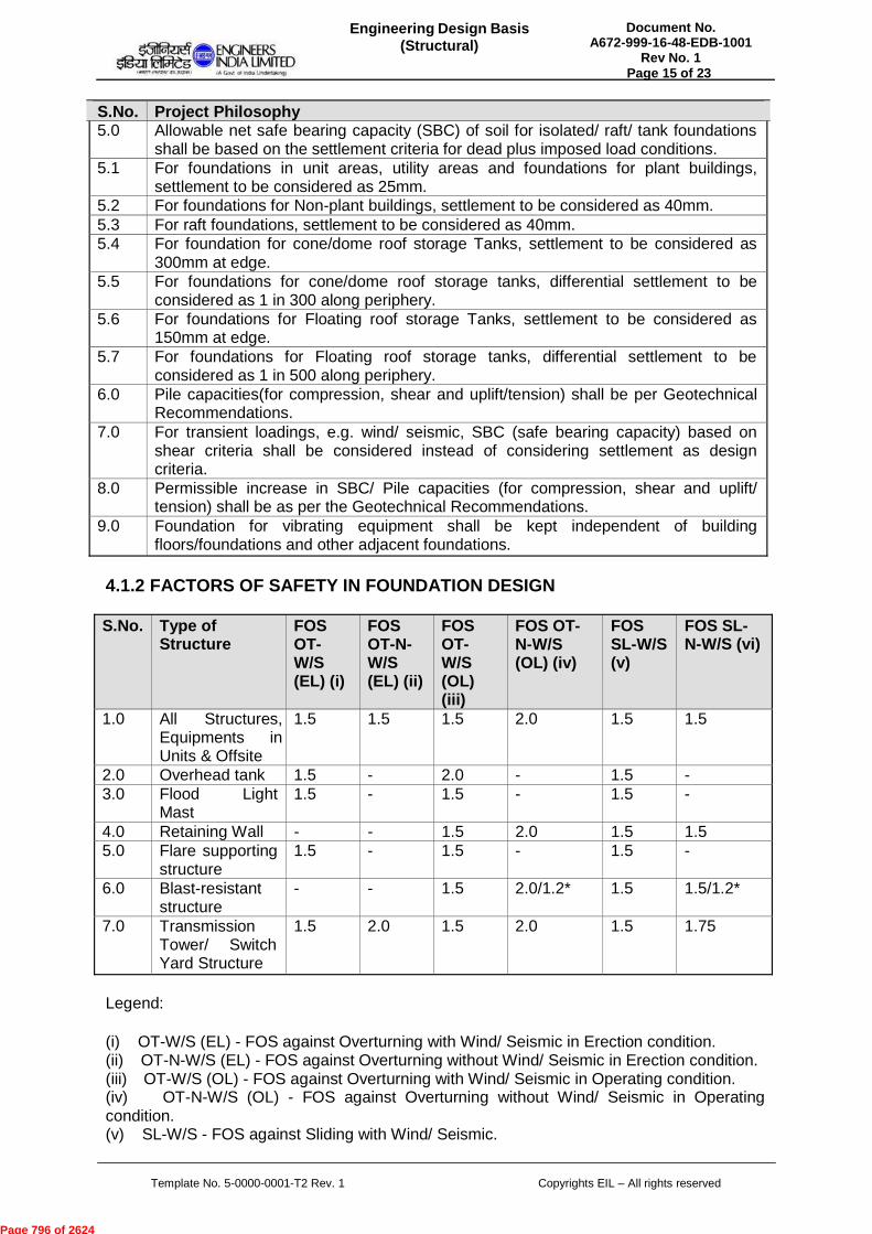
S.No. Project Philosophy 5.0 Allowable net safe bearing capacity (SBC) of soil for isolated/ raft/ tank foundations
shall be based on the settlement criteria for dead plus imposed load conditions. 5.1 For foundations in unit areas, utility areas and foundations for plant buildings,
settlement to be considered as 25mm. 5.2 For foundations for Non-plant buildings, settlement to be considered as 40mm. 5.3 For raft foundations, settlement to be considered as 40mm. 5.4 For foundation for cone/dome roof storage Tanks, settlement to be considered as
300mm at edge. 5.5 For foundations for cone/dome roof storage tanks, differential settlement to be
considered as 1 in 300 along periphery. 5.6 For foundations for Floating roof storage Tanks, settlement to be considered as
150mm at edge. 5.7 For foundations for Floating roof storage tanks, differential settlement to be
considered as 1 in 500 along periphery. 6.0 Pile capacities(for compression, shear and uplift/tension) shall be per Geotechnical
Recommendations. 7.0 For transient loadings, e.g. wind/ seismic, SBC (safe bearing capacity) based on
shear criteria shall be considered instead of considering settlement as design criteria.
8.0 Permissible increase in SBC/ Pile capacities (for compression, shear and uplift/ tension) shall be as per the Geotechnical Recommendations.
9.0 Foundation for vibrating equipment shall be kept independent of building floors/foundations and other adjacent foundations.
4.1.2 FACTORS OF SAFETY IN FOUNDATION DESIGN
S.No. Type of
Structure FOS OT- W/S (EL) (i)
FOS OT-N- W/S (EL) (ii)
FOS OT- W/S (OL) (iii)
FOS OT- N-W/S (OL) (iv)
FOS SL-W/S (v)
FOS SL- N-W/S (vi)
1.0 All Structures, Equipments in Units & Offsite
1.5 1.5 1.5 2.0 1.5 1.5
2.0 Overhead tank 1.5 - 2.0 - 1.5 - 3.0 Flood Light
Mast 1.5 - 1.5 - 1.5 -
4.0 Retaining Wall - - 1.5 2.0 1.5 1.5 5.0 Flare supporting
structure 1.5 - 1.5 - 1.5 -
6.0 Blast-resistant structure
- - 1.5 2.0/1.2* 1.5 1.5/1.2*
7.0 Transmission Tower/ Switch Yard Structure
1.5 2.0 1.5 2.0 1.5 1.75
Legend:
(i) OT-W/S (EL) - FOS against Overturning with Wind/ Seismic in Erection condition. (ii) OT-N-W/S (EL) - FOS against Overturning without Wind/ Seismic in Erection condition. (iii) OT-W/S (OL) - FOS against Overturning with Wind/ Seismic in Operating condition. (iv) OT-N-W/S (OL) - FOS against Overturning without Wind/ Seismic in Operating condition. (v) SL-W/S - FOS against Sliding with Wind/ Seismic.
Page 796 of 2624
Document No. A672-999-16-48-EDB-1001
Rev No. 1
Engineering Design Basis(Structural)
Page 16 of 23
Template No. 5-0000-0001-T2 Rev. 1 Copyrights EIL – All rights reserved
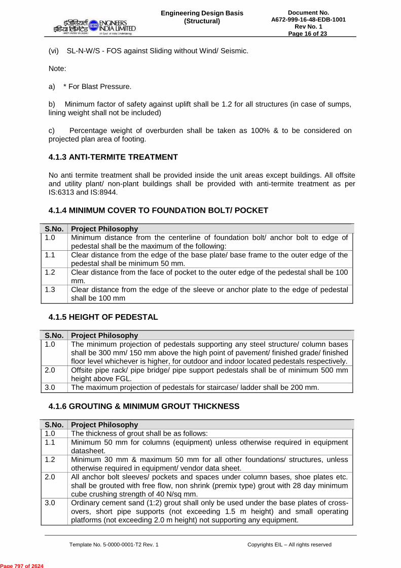
(vi) SL-N-W/S - FOS against Sliding without Wind/ Seismic.
Note:
a) * For Blast Pressure.
b) Minimum factor of safety against uplift shall be 1.2 for all structures (in case of sumps, lining weight shall not be included)
c) Percentage weight of overburden shall be taken as 100% & to be considered on projected plan area of footing.
4.1.3 ANTI-TERMITE TREATMENT
No anti termite treatment shall be provided inside the unit areas except buildings. All offsite and utility plant/ non-plant buildings shall be provided with anti-termite treatment as per IS:6313 and IS:8944.
4.1.4 MINIMUM COVER TO FOUNDATION BOLT/ POCKET
S.No. Project Philosophy 1.0 Minimum distance from the centerline of foundation bolt/ anchor bolt to edge of
pedestal shall be the maximum of the following: 1.1 Clear distance from the edge of the base plate/ base frame to the outer edge of the
pedestal shall be minimum 50 mm. 1.2 Clear distance from the face of pocket to the outer edge of the pedestal shall be 100
mm. 1.3 Clear distance from the edge of the sleeve or anchor plate to the edge of pedestal
shall be 100 mm
4.1.5 HEIGHT OF PEDESTAL
S.No. Project Philosophy 1.0 The minimum projection of pedestals supporting any steel structure/ column bases
shall be 300 mm/ 150 mm above the high point of pavement/ finished grade/ finished floor level whichever is higher, for outdoor and indoor located pedestals respectively.
2.0 Offsite pipe rack/ pipe bridge/ pipe support pedestals shall be of minimum 500 mm height above FGL.
3.0 The maximum projection of pedestals for staircase/ ladder shall be 200 mm.
4.1.6 GROUTING & MINIMUM GROUT THICKNESS
S.No. Project Philosophy 1.0 The thickness of grout shall be as follows: 1.1 Minimum 50 mm for columns (equipment) unless otherwise required in equipment
datasheet. 1.2 Minimum 30 mm & maximum 50 mm for all other foundations/ structures, unless
otherwise required in equipment/ vendor data sheet. 2.0 All anchor bolt sleeves/ pockets and spaces under column bases, shoe plates etc.
shall be grouted with free flow, non shrink (premix type) grout with 28 day minimum cube crushing strength of 40 N/sq mm.
3.0 Ordinary cement sand (1:2) grout shall only be used under the base plates of cross- overs, short pipe supports (not exceeding 1.5 m height) and small operating platforms (not exceeding 2.0 m height) not supporting any equipment.
Page 797 of 2624
Document No. A672-999-16-48-EDB-1001
Rev No. 1
Engineering Design Basis(Structural)
Page 17 of 23
Template No. 5-0000-0001-T2 Rev. 1 Copyrights EIL – All rights reserved
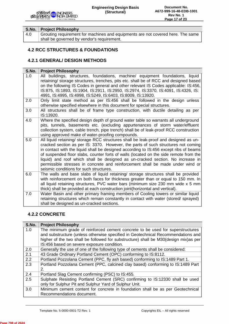
S.No. Project Philosophy 4.0 Grouting requirement for machines and equipments are not covered here. The same
shall be governed by vendor's requirement.
4.2 RCC STRUCTURES & FOUNDATIONS
4.2.1 GENERAL/ DESIGN METHODS
S.No. Project Philosophy 1.0 All buildings, structures, foundations, machine/ equipment foundations, liquid
retaining/ storage structures, trenches, pits etc. shall be of RCC and designed based on the following IS Codes in general and other relevant IS Codes applicable: IS:456, IS:875, IS:1893, IS:1904, IS:2911, IS:2950, IS:2974, IS:3370, IS:4091, IS:4326, IS: 4991, IS:4995, IS:4998, IS:5249, IS:6403, IS:8009, IS:13920.
2.0 Only limit state method as per IS:456 shall be followed in the design unless otherwise specified elsewhere in this document for special structures.
3.0 All structures shall be of frame type construction, with ductile detailing as per IS:13920.
4.0 Where the specified design depth of ground water table so warrants all underground pits, tunnels, basements etc. (excluding appurtenances of storm water/effluent collection system, cable trench, pipe trench) shall be of leak-proof RCC construction using approved make of water-proofing compounds.
5.0 All liquid retaining/ storage RCC structures shall be leak-proof and designed as un- cracked section as per IS: 3370. However, the parts of such structures not coming in contact with the liquid shall be designed according to IS:456 except ribs of beams of suspended floor slabs, counter forts of walls (located on the side remote from the liquid) and roof which shall be designed as un-cracked section. No increase in permissible stresses in concrete and reinforcement shall be made under wind or seismic conditions for such structures.
6.0 The walls and base slabs of liquid retaining/ storage structures shall be provided with reinforcement on both faces for thickness greater than or equal to 150 mm. In all liquid retaining structures, PVC water bars (minimum size 230 mm wide x 5 mm thick) shall be provided at each construction joint(horizontal and vertical).
7.0 Water Basin and other primary framing members of Cooling towers or similar liquid retaining structures which remain constantly in contact with water (stored/ sprayed) shall be designed as un-cracked sections.
4.2.2 CONCRETE
S.No. Project Philosophy 1.0 The minimum grade of reinforced cement concrete to be used for superstructures
and substructure (unless otherwise specified in Geotechnical Recommendations and higher of the two shall be followed for substructure) shall be M30(design mix)as per IS:456 based on severe exposure condition.
2.0 Generally the use of one of the following type of cements shall be considered: 2.1 43 Grade Ordinary Portland Cement (OPC) conforming to IS:8112. 2.2 Portland Pozzolana Cement (PPC, fly ash based) conforming to IS:1489 Part 1. 2.3 Portland Pozzolana Cement (PPC, calcined clay based) conforming to IS:1489 Part
2. 2.4 Portland Slag Cement confirming (PSC) to IS:455. 2.5 Sulphate Resisting Portland Cement (SRC) confirming to IS:12330 shall be used
only for Sulphur Pit and Sulphur Yard of Sulphur Unit. 3.0 Minimum cement content for concrete in foundation shall be as per Geotechnical
Recommendations document.
Page 798 of 2624

Document No. A672-999-16-48-EDB-1001
Rev No. 1
Engineering Design Basis(Structural)
Page 18 of 23
Template No. 5-0000-0001-T2 Rev. 1 Copyrights EIL – All rights reserved
S.No. Project Philosophy 4.0 75 mm thick lean concrete of grade 1:5:10(nominal mix) shall be provided under all
RCC foundations (except under base slab of liquid retaining structures). The lean concrete shall extend 50 mm beyond the foundation edges on all sides.
5.0 100 mm thick lean concrete of grade M15(nominal mix) shall be provided under base slab of liquid retaining structures. The lean concrete shall extend 75 mm beyond the foundation edges on all sides.
6.0 Plain Cement Concrete (PCC) mud mat of grade M20(nominal mix) of minimum 150 mm thickness shall be provided under all masonry wall foundations.
7.0 Plain cement concrete of grade M20 or 1:1.5:3 of minimum 40 mm thickness shall be provided as damp proof course at plinth level of all masonry walls and to be coated with bitumen emulsion.
8.0 Crystalline water-proofing compound of approved make shall be mixed with concrete for all liquid retaining/ leak-proof structures.
9.0 From durability considerations the minimum cement content and maximum free water-cement ratio shall be as per clause 4.2.2.1 of this document.
10.0 However, the maximum cement content shall not exceed 450 kg/cum.
4.2.2.1 MINIMUM CEMENT CONTENT & MAXIMUM WATER-CEMENT RATIO
Minimum cement content & maximum water-cement ratio shall be corresponding to the grade of concrete shall be as per Table 5 of IS:456.
4.2.3 REINFORCEMENT BARS
S.No. Project Philosophy 1.0 High strength deformed TMT bars of grade Fe500D conforming to IS:1786 shall be
used as reinforcement for all structures. 2.0 18 gauge black soft annealed SWG wire shall be used for binding of reinforcement
bars. 3.0 Corrosion protection of reinforcement bars: 3.1 Bi-polar concrete penetrating corrosion inhibiting admixture shall be used in all
concrete works. 4.0 Minimum and maximum bar spacing for foundations, slabs, stirrups for Beams, Ties
for columns, pedestals, Walls etc. should be 100mm and 300mm respectively. Bar spacing should be provided in multiples of 25mm.
5.0 Minimum bar diameter: 5.1 Piles-main bars----------------------------------------- 12mm 5.2 Piles – Ties----------------------------------------------- 8mm 5.3 Major Foundation e.g. Raft --------------------------- 12mm 5.4 Block Foundation-Main Bars ------------------------- 12mm 5.5 Block Foundation - Tie Bars -------------------------- 12mm 5.6 Minor Foundation (Local foundation etc.) ----------- 12mm 5.7 Column, Pedestal - Main Bars ------------------------- 12mm 5.8 Column, Pedestal – Ties --------------------------------- 8mm 5.9 Beam - Main Bars ------------------------------------------ 12mm 5.10 Beam - Anchor Bars -------------------------------------- 10mm 5.11 Beam – Stirrups -------------------------------------------- 8mm 5.12 Slab & Wall - Main Bars ---------------------------------- 10mm 5.13 Slab & Wall - Distribution Bars --------------------------- 8mm 5.14 Minor Elements such as Chajjas, Lintel Beams, etc --- 8mm 5.15 Slab and Wall for Blast proof building ------------------ 12mm
Page 799 of 2624

Document No. A672-999-16-48-EDB-1001
Rev No. 1
Engineering Design Basis(Structural)
Page 19 of 23
Template No. 5-0000-0001-T2 Rev. 1 Copyrights EIL – All rights reserved
4.2.4 MINIMUM COVER TO MAIN REINFORCEMENT
Clear cover shall be considered over links/ stirrups/ ties. Unless otherwise specified in Geotechnical Recommendations, minimum clear cover to RCC elements shall be provided as follows:
S.No. Title / Description Value UOM 1.0 Foundation slab, base slab,
pedestal, plinth beam 50 mm
2.0 Pile Cap 2.1 Bottom face 100 mm 2.2 Top & sides 50 mm 3.0 Retaining Wall, Basement
and Pit Wall:
3.1 Face in contact with earth 50 mm 3.2 Free face 30 mm 4.0 Column 50 mm 5.0 Tie beam, Floor beam, Roof
beam 40 mm
6.0 Floor slab, Roof slab, Canopy, Lintel
30 mm
7.0 Liquid retaining structure 7.1 Face in contact with liquid 30 mm 7.2 Face away from liquid but in
contact with earth 50 mm
7.3 Free face 30 mm
4.2.5 MINIMUM THICKNESS OF STRUCTURAL CONCRETE ELEMENT
The following minimum thickness shall be followed:
S.No. Title / Description Value UOM 1.0 Footings (all types, with or
without beams) 300 mm
2.0 Tapered Footing 150(At edge) 300(Average)
mm
3.0 Pile Cap 500 mm 4.0 Liquid retaining/ Leak-proof
structure/ Basement/ Pit:
4.1 Base slab 300 mm 4.2 Walls 150 mm 5.0 Floor/ Roof Slab, Walkway,
Canopy slab 150 mm
6.0 Cable/ Pipe Trench/ Launder Walls & Base Slab
125 mm
7.0 Parapet 100 mm 8.0 Louver/ Fin 100 mm 9.0 Louver (in contact with
liquid) 125 mm
10.0 Precast Trench Cover/ Precast Floor Slab
125 mm
4.3 STEEL STRUCTURES
Page 800 of 2624
Document No. A672-999-16-48-EDB-1001
Rev No. 1
Engineering Design Basis(Structural)
Page 20 of 23
Template No. 5-0000-0001-T2 Rev. 1 Copyrights EIL – All rights reserved
4.3.1 GENERAL/ DESIGN METHODS
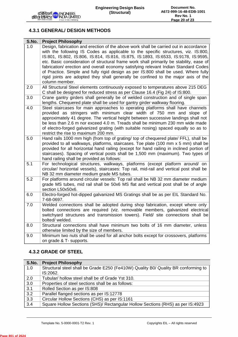
S.No. Project Philosophy 1.0 Design, fabrication and erection of the above work shall be carried out in accordance
with the following IS Codes as applicable to the specific structures, viz. IS:800, IS:801, IS:802, IS:806, IS:814, IS:816, IS:875, IS:1893, IS:6533, IS:9178, IS:9595, etc. Basic consideration of structural frame work shall primarily be stability, ease of fabrication/ erection and overall economy satisfying relevant Indian Standard Codes of Practice. Simple and fully rigid design as per IS:800 shall be used. Where fully rigid joints are adopted they shall generally be confined to the major axis of the column member.
2.0 All Structural Steel elements continuously exposed to temperatures above 215 DEG C shall be designed for reduced stress as per Clause 16.4 (Fig 24) of IS:800.
3.0 Crane gantry girders shall generally be of welded construction and of single span lengths. Chequered plate shall be used for gantry girder walkway flooring.
4.0 Steel staircases for main approaches to operating platforms shall have channels provided as stringers with minimum clear width of 750 mm and slope of approximately 41 degree. The vertical height between successive landings shall not be less than 2.6 m nor exceed 4.0 m. Treads shall be minimum 230 mm wide made of electro-forged galvanized grating (with suitable nosing) spaced equally so as to restrict the rise to maximum 200 mm.
5.0 Hand rails 1000 mm high (from top of grating/ top of chequered plate/ FFL), shall be provided to all walkways, platforms, staircases. Toe plate (100 mm x 5 mm) shall be provided for all horizontal hand railing (except for hand railing in inclined portion of staircases). Spacing of vertical posts shall be 1,500 mm (maximum). Two types of hand railing shall be provided as follows:
5.1 For technological structures, walkways, platforms (except platform around/ on circular/ horizontal vessels), staircases: Top rail, mid-rail and vertical post shall be NB 32 mm diameter medium grade MS tubes.
5.2 For platforms around circular vessels: Top rail shall be NB 32 mm diameter medium grade MS tubes, mid rail shall be 50x6 MS flat and vertical post shall be of angle section L50x50x6.
6.0 Electro-forged hot-dipped galvanized MS Gratings shall be as per EIL Standard No. 7-68-0697.
7.0 Welded connections shall be adopted during shop fabrication, except where only bolted connections are required (viz. removable members, galvanized electrical switchyard structures and transmission towers). Field/ site connections shall be bolted/ welded.
8.0 Structural connections shall have minimum two bolts of 16 mm diameter, unless otherwise limited by the size of members.
9.0 Minimum two nuts shall be used for all anchor bolts except for crossovers, platforms on grade & T- supports.
4.3.2 GRADE OF STEEL
S.No. Project Philosophy 1.0 Structural steel shall be Grade E250 (Fe410W) Quality B0/ Quality BR conforming to
IS:2062. 2.0 Tubular/ hollow steel shall be of Grade Yst 310. 3.0 Properties of steel sections shall be as follows: 3.1 Rolled Section as per IS:808 3.2 Parallel flanged sections as per IS:12778 3.3 Circular Hollow Sections (CHS) as per IS:1161 3.4 Square Hollow Sections (SHS)/ Rectangular Hollow Sections (RHS) as per IS:4923
Page 801 of 2624

Document No. A672-999-16-48-EDB-1001
Rev No. 1
Engineering Design Basis(Structural)
Page 21 of 23
Template No. 5-0000-0001-T2 Rev. 1 Copyrights EIL – All rights reserved
4.3.3 LIMITING PERMISSIBLE STRESSES
S.No. Project Philosophy 1.0 Permissible stresses in structural members shall be as follows: 1.1 Hot rolled sections (excluding transmission towers and switchyard structures) as
specified in IS:800 1.2 Cold formed light gauge sections as specified in IS:801 1.3 Transmission towers & switchyard structures as specified in IS:802 1.4 Tubular structures as specified in IS:806 2.0 Permissible stresses in bolts shall be as follows: 2.1 Hot rolled sections (excluding transmission towers and switchyard structures) as
specified in IS:800 2.2 Cold formed light gauge sections as specified in IS:801 2.3 Transmission towers & switchyard structures as specified in IS:802 3.0 Permissible stresses in welds shall be as follows: 3.1 Cold formed light gauge sections as specified in IS:801 3.2 Metal Arc Welding as specified in IS:816
4.3.4 LIMITING DEFLECTION
4.3.4.1 LIMITING VERTICAL DEFLECTION
The limiting permissible vertical deflection for structural steel members shall be as specified below, where 'L' represents the span:
S.No. Title / Description Value UOM 1.0 Gantry girder for electric
overhead crane (capacity up to 50 T)
L/750 Same as 'L'
2.0 Gantry girder for electric overhead crane (capacity over 50 T)
L/1000 Same as 'L'
3.0 Gantry girder for manuallyoperated crane
L/500 Same as 'L'
4.0 Girder/ beam for supporting dynamic equipment/hoist
L/450 Same as 'L'
5.0 Purlins supporting any type of roofing material under (dead load + live load) or (dead load + wind load) conditions
L/200 Same as 'L'
Note:
a) Limiting permissible vertical deflection for grating/chequered plate shall be L/200 or 6mm whichever is minimum.
b) Limiting permissible vertical deflection for other structures/ structural components,not covered in the above table, shall be as specified in relevant BIS Codes.
4.3.4.2 LIMITING HORIZONTAL DEFLECTION
The limiting permissible horizontal deflection for structural steel members shall be as specified below, where 'H' represents the height:
Page 802 of 2624

Document No. A672-999-16-48-EDB-1001
Rev No. 1
Engineering Design Basis(Structural)
Page 22 of 23
Template No. 5-0000-0001-T2 Rev. 1 Copyrights EIL – All rights reserved
S.No. Title / Description Value UOM 1.0 Multi storeyed steel structure/
building H/325 Same as 'H'
2.0 Flare stack supporting structure
H/200 Same as 'H'
4.3.5 MINIMUM THICKNESS
The minimum thickness of various structural components (hot rolled sections) shall be as given:
S.No. Title / Description Value UOM Remarks 1.0 Trusses, purlins, side
girts & bracings 6 mm
2.0 Columns, beams 7 mm 3.0 Gussets in trusses &
girders
3.1 upto and including 12m span
8 mm
3.2 above 12m span 10 mm 4.0 Stiffeners 8 mm 5.0 Base plates 10 mm 6.0 Chequered plate 6 mm (on plain) 7.0 Grating 3 mm
Notes:
a) For transmission towers & switchyard structures the minimum thickness of various structural components shall be as per IS: 802.
b) The minimum thickness for rolled beams and channels shall be mean flange thickness regardless of the web thickness.
c) The minimum thickness of structural components (except gratings & chequered plates) which are directly exposed to weather and inaccessible for repainting shall be 8 mm.
d) The minimum thickness of tubes shall be as specified in IS:806.
e) Structural members exposed to marked corrosive action shall be increased in thickness or otherwise suitably protected against corrosion.
4.3.6 ELECTRICAL SWITCHYARD STRUCTURE & TRANSMISSION TOWER
S.No. Project Philosophy 1.0 All electrical switchyard structure and transmission tower shall be of structural steel
with bolted connections and designed as per of IS:802 2.0 Structural steel members including bolts, nuts and washers shall be hot dip
galvanized in accordance with relevant IS Codes. The Zinc coating on tower members shall not be less than 900 g/sqm of the surface area
4.3.7 PROTECTIVE COATING
Protective Coating (including surface preparation, shop primer, field primer & finish coat) to
Page 803 of 2624
Document No. A672-999-16-48-EDB-1001
Rev No. 1
Engineering Design Basis(Structural)
Page 23 of 23
Template No. 5-0000-0001-T2 Rev. 1 Copyrights EIL – All rights reserved
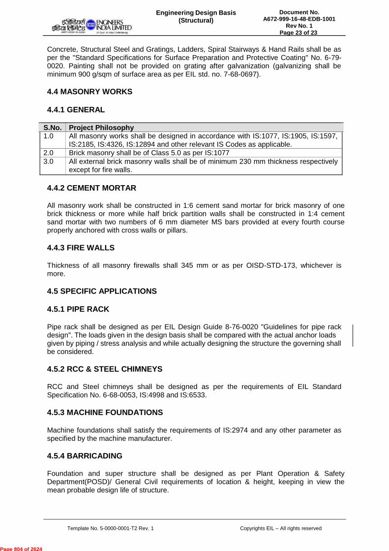
Concrete, Structural Steel and Gratings, Ladders, Spiral Stairways & Hand Rails shall be as per the "Standard Specifications for Surface Preparation and Protective Coating" No. 6-79- 0020. Painting shall not be provided on grating after galvanization (galvanizing shall be minimum 900 g/sqm of surface area as per EIL std. no. 7-68-0697).
4.4 MASONRY WORKS
4.4.1 GENERAL
S.No. Project Philosophy 1.0 All masonry works shall be designed in accordance with IS:1077, IS:1905, IS:1597,
IS:2185, IS:4326, IS:12894 and other relevant IS Codes as applicable. 2.0 Brick masonry shall be of Class 5.0 as per IS:1077 3.0 All external brick masonry walls shall be of minimum 230 mm thickness respectively
except for fire walls.
4.4.2 CEMENT MORTAR
All masonry work shall be constructed in 1:6 cement sand mortar for brick masonry of one brick thickness or more while half brick partition walls shall be constructed in 1:4 cement sand mortar with two numbers of 6 mm diameter MS bars provided at every fourth course properly anchored with cross walls or pillars.
4.4.3 FIRE WALLS
Thickness of all masonry firewalls shall 345 mm or as per OISD-STD-173, whichever is more.
4.5 SPECIFIC APPLICATIONS
4.5.1 PIPE RACK
Pipe rack shall be designed as per EIL Design Guide 8-76-0020 "Guidelines for pipe rack design". The loads given in the design basis shall be compared with the actual anchor loads given by piping / stress analysis and while actually designing the structure the governing shall be considered.
4.5.2 RCC & STEEL CHIMNEYS
RCC and Steel chimneys shall be designed as per the requirements of EIL Standard Specification No. 6-68-0053, IS:4998 and IS:6533.
4.5.3 MACHINE FOUNDATIONS
Machine foundations shall satisfy the requirements of IS:2974 and any other parameter as specified by the machine manufacturer.
4.5.4 BARRICADING
Foundation and super structure shall be designed as per Plant Operation & Safety Department(POSD)/ General Civil requirements of location & height, keeping in view the mean probable design life of structure.
Page 804 of 2624

VENDOR DATA REQUIREMENTS
FOR
COMPRESSED AIR & CRYOGENIC NITROGEN
PLANT PACKAGE, APL-ASSAM
0 02-NOV-2015 ISSUED FOR BIDS RD RD DA
Rev.No.
Date Purpose Prepared by Checked by Approved by
VENDOR DATA REQUIREMENTSFOR
COMPRESSED AIR & CRYOGENICNITROGEN PLANT PACKAGE, APL-ASSAM of 3
Document No.A672-014-81-41-VDR-4010
Rev. 0
Page 1
Format No. EIL-1642-1924 Rev.1 Copyright EIL - All rights reserved
Page 805 of 2624
VENDOR DATA REQUIREMENTS
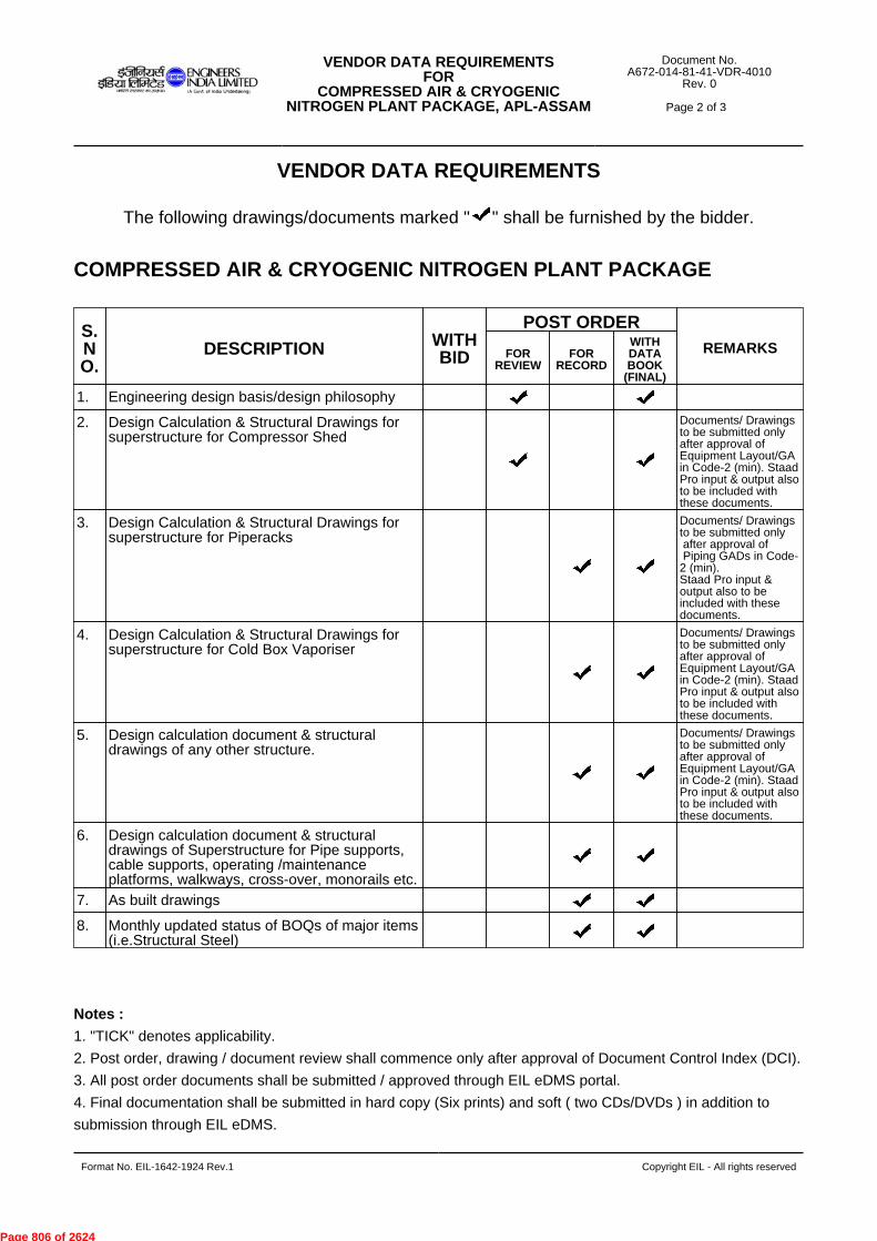
The following drawings/documents marked " " shall be furnished by the bidder.
COMPRESSED AIR & CRYOGENIC NITROGEN PLANT PACKAGE
Notes :
1. "TICK" denotes applicability.
2. Post order, drawing / document review shall commence only after approval of Document Control Index (DCI).
3. All post order documents shall be submitted / approved through EIL eDMS portal.
4. Final documentation shall be submitted in hard copy (Six prints) and soft ( two CDs/DVDs ) in addition to
submission through EIL eDMS.
S.NO.
DESCRIPTION WITHBID
POST ORDERREMARKSFOR
REVIEWFOR
RECORD
WITHDATABOOK
(FINAL)
1. Engineering design basis/design philosophy
2. Design Calculation & Structural Drawings forsuperstructure for Compressor Shed
Documents/ Drawingsto be submitted onlyafter approval ofEquipment Layout/GAin Code-2 (min). StaadPro input & output alsoto be included withthese documents.
3. Design Calculation & Structural Drawings forsuperstructure for Piperacks
Documents/ Drawingsto be submitted only after approval of Piping GADs in Code-2 (min).Staad Pro input &output also to beincluded with thesedocuments.
4. Design Calculation & Structural Drawings forsuperstructure for Cold Box Vaporiser
Documents/ Drawingsto be submitted onlyafter approval ofEquipment Layout/GAin Code-2 (min). StaadPro input & output alsoto be included withthese documents.
5. Design calculation document & structuraldrawings of any other structure.
Documents/ Drawingsto be submitted onlyafter approval ofEquipment Layout/GAin Code-2 (min). StaadPro input & output alsoto be included withthese documents.
6. Design calculation document & structuraldrawings of Superstructure for Pipe supports,cable supports, operating /maintenanceplatforms, walkways, cross-over, monorails etc.
7. As built drawings
8. Monthly updated status of BOQs of major items(i.e.Structural Steel)
VENDOR DATA REQUIREMENTSFOR
COMPRESSED AIR & CRYOGENICNITROGEN PLANT PACKAGE, APL-ASSAM of 3
Document No.A672-014-81-41-VDR-4010
Rev. 0
Page 2
Format No. EIL-1642-1924 Rev.1 Copyright EIL - All rights reserved
Page 806 of 2624
5. Refer - 6-78-0001: Specification for quality management system from Bidders.
6. Refer - 6-78-0002: Specification for documentation requirements from Contractors.
7. Refer - 6-78-0003: Specification for documentation requirement from Suppliers.
8. All drawings & documents shall be submitted in A4 or A3 paper sizes. Documents in higher paper size shall
be submitted in exceptional circumstances or as indicated in the MR/Tender.
9. Post order- The schedule of drawing / data submission shall be mutually agreed between EIL & the bidder /
contractor / supplier during finalization of Document Control Index (DCI).
10. "@" indicates submission of documents to Inspection Agency.
11. Bill of Material shall form part of the respective drawing.
12. Also refer other department's VDR :-
13. Electrical
14. Instrumentation
15. Packaged Equipment
16. Static Equipment
17. Rotating Equipment
18. Piping
19. Pipeline
20. Heat & Mass Transfer
VENDOR DATA REQUIREMENTSFOR
COMPRESSED AIR & CRYOGENICNITROGEN PLANT PACKAGE, APL-ASSAM of 3
Document No.A672-014-81-41-VDR-4010
Rev. 0
Page 3
Format No. EIL-1642-1924 Rev.1 Copyright EIL - All rights reserved
Page 807 of 2624

DRAWINGS STRUCTURAL
COMPRESSED AIR AND CRYOGENIC NITROGEN PLANT PACKAGE
APL-ASSAM
A672-014-81-41-DR-4010 Rev.0
Page 1 of 2
0 29.10.2015 ISSUED FOR BIDS RD RD DA
Rev. No
Date Purpose Prepared
by Checked
by Approved
by
Format No. EIL-1641-1924 Rev.1 Copyright EIL – All rights reserved
DRAWINGS
(STRUCTURAL)
COMPRESSED AIR AND CRYOGENIC NITROGEN PLANT PACKAGE
PROJECT: INTEGRATED METHANOL & ACETIC ACID PROJECT OWNER : M/s ASSAM PETROCHEMICALS LTD. (APL) PMC : ENGINEERS INDIA LIMITED JOB NO. : A672
Page 808 of 2624

DRAWINGS STRUCTURAL
COMPRESSED AIR AND CRYOGENIC NITROGEN PLANT PACKAGE
APL-ASSAM
A672-014-81-41-DR-4010-Rev.0
Page 2 of 2
Format No. EIL-1641-1924 Rev.1 Copyright EIL – All rights reserved
LIST OF DRAWINGS
NIL
Page 809 of 2624

INSTALLATION STANDARDS STRUCTURAL
COMPRESSED AIR AND CRYOGENIC NITROGEN PLANT PACKAGE
APL-ASSAM
A672-014-81-41-IS-4010-Rev.1
Page 1 of 2
1 04.11.2015 ISSUED FOR BIDS AM RD DA/JS
0 02.11.2015 ISSUED FOR BIDS AM RD DA/JS
Rev. No
Date Purpose Prepared
by Checked
by Approved
by
Format No. EIL-1641-1924 Rev.1 Copyright EIL – All rights reserved
INSTALLATION STANDARDS
(STRUCTURAL)
COMPRESSED AIR AND CRYOGENIC NITROGEN PLANT PACKAGE
PROJECT: INTEGRATED METHANOL & ACETIC ACID PROJECT OWNER : M/s ASSAM PETROCHEMICALS LTD. (APL) PMC : ENGINEERS INDIA LIMITED JOB NO. : A672
Page 810 of 2624
INSTALLATION STANDARDS STRUCTURAL
COMPRESSED AIR AND CRYOGENIC NITROGEN PLANT PACKAGE
APL-ASSAM
A672-014-81-41-IS-4010-Rev.1
Page 2 of 2
Format No. EIL-1641-1924 Rev.1 Copyright EIL – All rights reserved
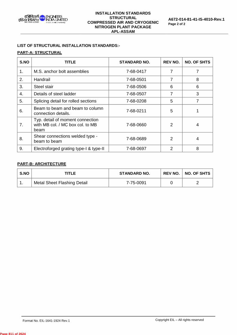
LIST OF STRUCTURAL INSTALLATION STANDARDS:-
PART-A: STRUCTURAL
S.NO TITLE STANDARD NO. REV NO. NO. OF SHTS
1. M.S. anchor bolt assemblies 7-68-0417 7 7
2. Handrail 7-68-0501 7 8
3. Steel stair 7-68-0506 6 6
4. Details of steel ladder 7-68-0507 7 3
5. Splicing detail for rolled sections 7-68-0208 5 7
6. Beam to beam and beam to column connection details.
7-68-0211 5 1
7. Typ. detail of moment connection with MB col. / MC box col. to MB beam
7-68-0660 2 4
8. Shear connections welded type - beam to beam
7-68-0689 2 4
9. Electroforged grating type-I & type-II 7-68-0697 2 8
PART-B: ARCHITECTURE
S.NO TITLE STANDARD NO. REV NO. NO. OF SHTS
1. Metal Sheet Flashing Detail 7-75-0091 0 2
Page 811 of 2624
STANDARD SPECIFICATIONS STRUCTURAL
COMPRESSED AIR AND CRYOGENIC NITROGEN PLANT PACKAGE
APL-ASSAM
A672-014-81-41-SS-4010-Rev.2
Page 1 of 2
2 03.01.17 ISSUED FOR BIDS RM RK VKG
1 02.11.15 ISSUED FOR BIDS AM RD DA/JS
0 29.10.15 ISSUED FOR BIDS RD RD DA
Rev. No
Date Purpose Prepared
by Checked
by Approved
by
Format No. EIL-1641-1924 Rev.1 Copyright EIL – All rights reserved
STANDARD SPECIFICATIONS
(STRUCTURAL)
COMPRESSED AIR AND CRYOGENIC NITROGEN PLANT PACKAGE
PROJECT: INTEGRATED METHANOL & ACETIC ACID PROJECT OWNER : M/s ASSAM PETROCHEMICALS LTD. (APL) PMC : ENGINEERS INDIA LIMITED JOB NO. : A672
Page 812 of 2624

STANDARD SPECIFICATIONS STRUCTURAL
COMPRESSED AIR AND CRYOGENIC NITROGEN PLANT PACKAGE
APL-ASSAM
A672-014-81-41-SS-4010-Rev.1
Page 2 of 2
Format No. EIL-1641-1924 Rev.1 Copyright EIL – All rights reserved
LIST OF STRUCTURAL STANDARD SPECIFICATIONS:
PART-A: STRUCTURAL
S.NO STANDARD SPECIFICATION SPECIFICATION NO
REV NO
NO OF SHEETS
1. Standard specification civil - structural lump-sum turn-key works (LSTK works) general requirements
6-68-0021 0 7+23
2. Standard specification civil - structural lump-sum turn-key works (LSTK works) material & construction
6-68-0022 0 14
3.
Standard specification civil & structural works passive fire proofing of steel structures (hydrocarbon pool fire).
6-68-0033 7 16
4. Standard specification for HSE Management at construction site
6-82-0001 6 87
5. Inspection & Test Plan (ITP) for Civil, Structural & Architectural Works (EPCC / LSTK Contracts)
6-82-2700 1 37
6. Standard specification for surface preparation and protective coating
A672-000-79-41-PLS-01
0 49
PART-B: ARCHITECTURE
S.NO STANDARD SPECIFICATION SPECIFICATION NO
REV NO
NO OF SHEETS
1. Standard Specification for Floor finishing
6-75-0002 6 15
2. Standard Specification for Roofing 6-75-0008 5 08
Page 813 of 2624
TECHNICAL COMPLIANCE (STRUCTURAL)
COMPRESSED AIR AND CRYOGENIC NITROGEN PLANT PACKAGE
APL-ASSAM
A672-014-81-41-TCL-4010
REV. 0 Page 1 of 3
0 29.10.2015 ISSUED FOR BIDS RD RD DA
Rev. No
Date Purpose Prepared
by Checked
by Approved
by
Format No. EIL-1641-1924 Rev.1 Copyright EIL – All rights reserved
TECHNICAL COMPLIANCE
(STRUCTURAL)
COMPRESSED AIR AND CRYOGENIC
NITROGEN PLANT PACKAGE
PROJECT: INTEGRATED METHANOL & ACETIC ACID PROJECT OWNER : M/s ASSAM PETROCHEMICALS LTD. (APL) PMC : ENGINEERS INDIA LIMITED JOB NO. : A672
Bidder’s signature and stamp
Page 814 of 2624
TECHNICAL COMPLIANCE (STRUCTURAL)
COMPRESSED AIR AND CRYOGENIC NITROGEN PLANT PACKAGE
APL-ASSAM
A672-014-81-41-TCL-4010
REV. 0 Page 2 of 3
Format No. EIL-1641-1924 Rev.1 Copyright EIL – All rights reserved
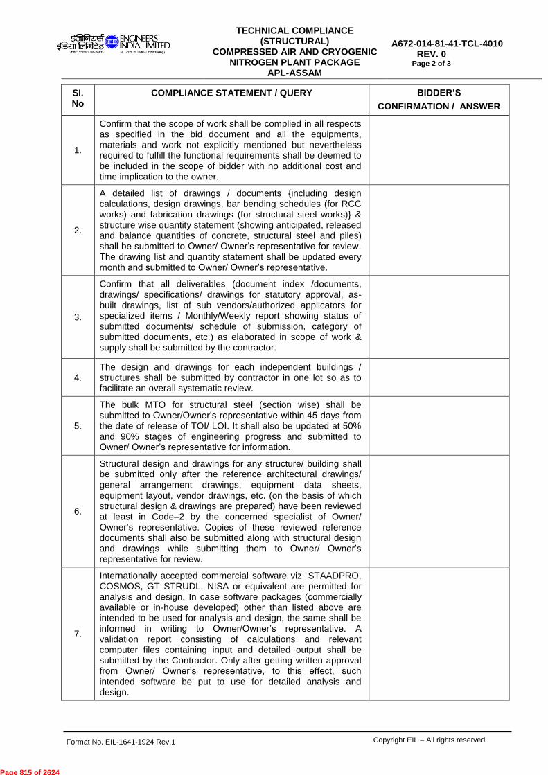
SI. No
COMPLIANCE STATEMENT / QUERY BIDDER’S
CONFIRMATION / ANSWER
1.
Confirm that the scope of work shall be complied in all respects as specified in the bid document and all the equipments, materials and work not explicitly mentioned but nevertheless required to fulfill the functional requirements shall be deemed to be included in the scope of bidder with no additional cost and time implication to the owner.
2.
A detailed list of drawings / documents {including design calculations, design drawings, bar bending schedules (for RCC works) and fabrication drawings (for structural steel works)} & structure wise quantity statement (showing anticipated, released and balance quantities of concrete, structural steel and piles) shall be submitted to Owner/ Owner’s representative for review. The drawing list and quantity statement shall be updated every month and submitted to Owner/ Owner’s representative.
3.
Confirm that all deliverables (document index /documents, drawings/ specifications/ drawings for statutory approval, as-built drawings, list of sub vendors/authorized applicators for specialized items / Monthly/Weekly report showing status of submitted documents/ schedule of submission, category of submitted documents, etc.) as elaborated in scope of work & supply shall be submitted by the contractor.
4. The design and drawings for each independent buildings / structures shall be submitted by contractor in one lot so as to facilitate an overall systematic review.
5.
The bulk MTO for structural steel (section wise) shall be submitted to Owner/Owner’s representative within 45 days from the date of release of TOI/ LOI. It shall also be updated at 50% and 90% stages of engineering progress and submitted to Owner/ Owner’s representative for information.
6.
Structural design and drawings for any structure/ building shall be submitted only after the reference architectural drawings/ general arrangement drawings, equipment data sheets, equipment layout, vendor drawings, etc. (on the basis of which structural design & drawings are prepared) have been reviewed at least in Code–2 by the concerned specialist of Owner/ Owner’s representative. Copies of these reviewed reference documents shall also be submitted along with structural design and drawings while submitting them to Owner/ Owner’s representative for review.
7.
Internationally accepted commercial software viz. STAADPRO, COSMOS, GT STRUDL, NISA or equivalent are permitted for analysis and design. In case software packages (commercially available or in-house developed) other than listed above are intended to be used for analysis and design, the same shall be informed in writing to Owner/Owner’s representative. A validation report consisting of calculations and relevant computer files containing input and detailed output shall be submitted by the Contractor. Only after getting written approval from Owner/ Owner’s representative, to this effect, such intended software be put to use for detailed analysis and design.
Page 815 of 2624
TECHNICAL COMPLIANCE (STRUCTURAL)
COMPRESSED AIR AND CRYOGENIC NITROGEN PLANT PACKAGE
APL-ASSAM
A672-014-81-41-TCL-4010
REV. 0 Page 3 of 3
Format No. EIL-1641-1924 Rev.1 Copyright EIL – All rights reserved
SI. No
COMPLIANCE STATEMENT / QUERY BIDDER’S
CONFIRMATION / ANSWER
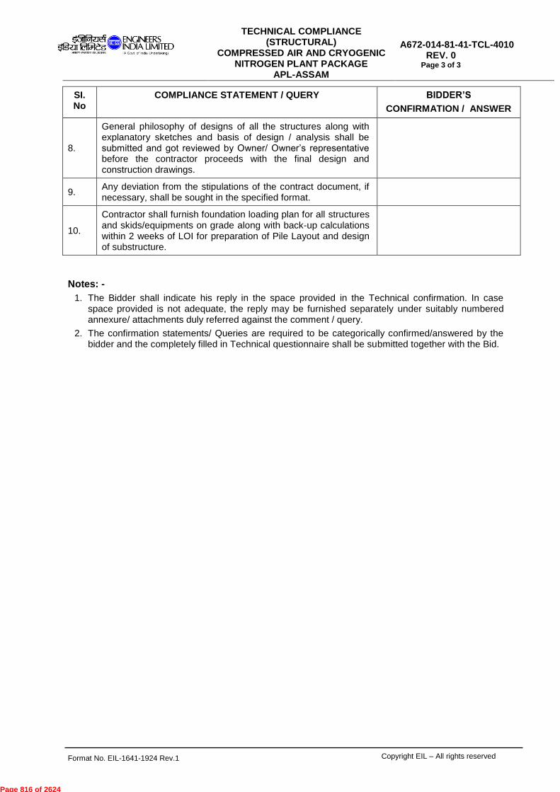
8.
General philosophy of designs of all the structures along with explanatory sketches and basis of design / analysis shall be submitted and got reviewed by Owner/ Owner’s representative before the contractor proceeds with the final design and construction drawings.
9. Any deviation from the stipulations of the contract document, if necessary, shall be sought in the specified format.
10.
Contractor shall furnish foundation loading plan for all structures and skids/equipments on grade along with back-up calculations within 2 weeks of LOI for preparation of Pile Layout and design of substructure.
Notes: -
1. The Bidder shall indicate his reply in the space provided in the Technical confirmation. In case space provided is not adequate, the reply may be furnished separately under suitably numbered annexure/ attachments duly referred against the comment / query.
2. The confirmation statements/ Queries are required to be categorically confirmed/answered by the bidder and the completely filled in Technical questionnaire shall be submitted together with the Bid.
Page 816 of 2624

COSTRUCTION SUPERVISION & MANAGEMENT BY PACKAGE CONTRACTOR
FOR COMPRESSED AIR & CRYOGENIC NITROGEN PLANT PACKAGE
Document No. A672-00-014-19-41-0001 Rev 1 Page 1 of 24
Copyright EIL – All rights reserved
CONSTRUCTION SUPERVISION AND MANAGEMENT BY PACKAGE
CONTRACTOR
FOR
COMPRESSED AIR AND CRYOGENIC NITROGEN PLANT PACKAGE
PROJECT : INTEGRATED METHANOL & ACETIC ACID PROJECT
OWNER : ASSAM PETROCHEMICALS LIMITED PMC : ENGINEERS INDIA LTD. JOB NO. : A672
1 01.01.2018 REVISED FOR BID PKR RK CGM (C)
0 09.10.2015 ISSUED FOR BID AKS RK GM(C)
Rev. No Date Purpose Prepare
d by Checked
by Approved
by
Page 817 of 2624

COSTRUCTION SUPERVISION & MANAGEMENT BY PACKAGE CONTRACTOR
FOR COMPRESSED AIR & CRYOGENIC NITROGEN PLANT PACKAGE
Document No. A672-00-014-19-41-0001 Rev 1 Page 2 of 24
Copyrights EIL – All rights reserved
CONSTRUCTION SUPERVISION AND MANAGEMENT
TABLE OF CONTENTS
____________________________________________________________________ CLAUSE NO. TITLE PAGE NO. _____________________________________________________________________ 1.0 General 3 2.0 Execution on works 5 3.0 Execution Plans 7 4.0 Temporary Facilities 8 5.0 Construction Planning, Scheduling, Monitoring 9 & Reporting 6.0 Quality assurance and Quality Control (QA/QC) 9 7.0 Warehouse Management & Material Control 9 8.0 Field Engineering 10 9.0 Field Tendering 10 10.0 Field Purchase 10 11.0 Health, Safety and Environment (HSE) Management 11 12.0 House Keeping 11 13.0 Industrial Labour Relations 11 14.0 Construction Equipments 12 15.0 Construction Manpower 13 16.0 Interface with other CONTRACTORS 14 17.0 Check List for Inspection of Flanged Joints 15 18.0 Colour Coding of Piping Material 15 APPENDIX - A QUALITY ASSURRANCE AND QUALITY CONTROL MANAGEMENT
DURING CONSTRUCTION
APPENDIX - B HEALTH, SAFETY AND ENVIRONMENT (HSE) MANAGEMENT DURING CONSTRUCTION
List of Attachments: Attachment-I Inspection & Test Plans (ITPs) for Construction Works A672-00-19-41-2000, Rev 1 Attachment-II Standard Specification for Positive Material
Identification (PMI) at Construction Sites 6-82-0002, Rev.3
Attachment-III Standard Specification for Colour Coding of Piping Materials
6-82-0003, Rev.2
Attachment-IV Standard Specification for Application of Torque and Hydraulic Bolt Tension for Flange Joints
6-76-0002, Rev.2
Attachment-V Standard Specification for Erection of Equipment and Machinery
6-76-0001, Rev.3
Attachment-VI Calibration Requirement of Monitoring & Measuring devices at Construction sites
7-82-0002, Rev.0
Attachment-VII Format for Observation on Quality Aspects (OQA) A672-00-014-19-41-0001 F1 Attachment-VIII Format for Observation on Safety Aspects (OSA) A672-00-014-19-41-0001 F2
Page 818 of 2624

COSTRUCTION SUPERVISION & MANAGEMENT BY PACKAGE CONTRACTOR
FOR COMPRESSED AIR & CRYOGENIC NITROGEN PLANT PACKAGE
Document No. A672-00-014-19-41-0001 Rev 1 Page 3 of 24
Copyrights EIL – All rights reserved
1.0 GENERAL
1.1 The Contractor shall construct Plant/Facilities in accordance with the requirements of the Technical Standards/ Specifications, with proven/good engineering practices and procedures. Such Facilities shall be safe, reliable and suitable for their intended purpose.
1.2 The Contractor shall provide all supervision, labour, construction equipments, tools & tackles, materials and consumables, temporary facilities, Construction utilities etc. and render all support services necessary for the construction. Provision of construction power and water shall be as per Special Conditions of Contract (SCC)/ General Conditions of Contract (GCC).
1.3 The Contractor shall plan, execute, manage and control all the construction activities for the
facilities forming a part of this contract.
1.4 The Contractor shall ensure insurance coverage for all the personnel engaged by him for the work as per statutory rules, regulations and local laws.
1.5 The Contractor shall insure all the materials and equipments against fire, flood, earthquake, theft,
etc. as per SCC/ GCC brought for the job till the Plant/Facilities are commissioned and handed over to the OWNER.
1.6 The Contractor to ensure mechanizing the construction activities to a great extent.
1.7 The Contractor is deemed to have full knowledge of the applicable laws and regulations,
conditions of labour, local conditions, the SITE conditions, environmental aspects and shall comply with the requirements thereof.
1.8 The Contractor is required to organize and mobilize Construction Management Services in a
systematic and sequential manner to ensure that the Plant installation is carried out in accordance with the approved engineering drawings, specifications, standards, QA/QC procedures etc. and its mechanical completion is achieved within targeted time schedule. Construction Management and Supervision is to be carried out by the Contractor himself by deploying persons on his rolls and this activity is not to be sub-contracted in any case.
For this purpose, the Contractor shall deploy a Construction Management Team headed by a qualified & experienced person at site. The Construction Management team shall include engineers/ specialists in QA/QC, Project Control (Planning, scheduling, monitoring), contracts, construction supervision, progress measurement/billing, safety, warehousing, purchasing etc. Key personnel including the Head should have sufficient qualification/experience and should not be changed without concurrence from Owner/PMC.
Curriculum vitae of all key Construction Personnel shall be submitted to Owner/PMC at least 3 months before deployment. Owner/PMC reserve the right to interview these personnel before their mobilization.
1.9 The Contractor shall ensure delegation of adequate and sufficient powers (including financial) to the Head of his Construction Team for effective and smooth functioning of the construction management. HO support shall be provided to the Head of Construction Team at site during construction on all matters of project execution including the following: - Field engineering. - Vendor specialists required during construction. - Rectification/replacement of defective supplies, if any, noticed during construction. - Expediting replacement of imported items found short/damaged. - Required documentation for the material inspection at site
Page 819 of 2624

COSTRUCTION SUPERVISION & MANAGEMENT BY PACKAGE CONTRACTOR
FOR COMPRESSED AIR & CRYOGENIC NITROGEN PLANT PACKAGE
Document No. A672-00-014-19-41-0001 Rev 1 Page 4 of 24
Copyrights EIL – All rights reserved
- Compilation and submission of Field Inspection documents in requisite copies as per contract
- Documentation to meet statutory requirements.
1.10 The construction supervision, co-ordination and management activities shall be carried out by the Contractor in accordance with the construction procedures developed and submitted by the Contractor and approved by Owner/PMC. Contractor shall prepare construction schedules within the framework of overall contract schedule and submit to Owner/PMC for approval. Contractor shall plan, execute, monitor and control construction activities as per the approved construction schedule.
Contractor shall depute a project team at site during construction phase under a project coordinator for providing above-mentioned support to the Head of Construction Team.
1.11 Most of the civil construction materials like cement, reinforcement bars, aggregates, bricks, and structural steel are available locally. However, the material like cement, reinforcement bars and structural steel shall be procured from approved vendors only. The Contractor shall establish and maintain a material testing laboratory for carrying on field tests during execution of contracts under different disciplines by sub-contractor’s, at no extra cost to OWNER. The entire test equipments deployed shall have valid test/calibration certificates traceable to relevant national/ international standards. Such material tests, for which testing facility at site is not established, shall be carried out by Contractor at testing laboratories approved by Owner/PMC at no extra cost. Contractor shall maintain the test records and the same shall be made available for review/ inspection of Owner/PMC. Further, Owner/PMC reserve the right to witness/ inspect testing at the laboratory at no extra cost to Owner/PMC.
1.12 Construction supervision and management functions to be performed by the Contractor shall
include the following as key functions for effective execution, monitoring and control: - Planning, scheduling, monitoring & reporting. - Construction supervision, discipline wise. - Quality assurance and quality control, discipline wise. - Shipping, custom clearances, inland transportation - Warehouse management and material control. - Field engineering/Purchase. - Health, Safety and Environment (HSE) Management - Personnel/administration/Industrial Relations - Billing and invoicing - Finance and Accounts - Security
1.13 Whenever the hookup is to be done with the facilities under operation, efforts shall be made by
the Contractor to complete the work and restore the system expeditiously. If required the work shall be continued round the clock.
1.14 Over Dimensional cargo movement to the erection site is included in the scope of the Contractor.
The Contractor shall carry out the route survey and report shall be submitted to Owner/PMC well in advance. All the clearances, approval from government agencies, local bodies, private parties, police, electricity / telephone departments, Railway authorities, PWD, Highway authorities, various departments of OWNER etc. for moving the ODC cargo is included in the CONTRACTOR’s scope. Before each movement, copy of the major clearance obtained shall be forwarded to Owner/PMC. The cost /deposits of such approval, which may be incurred by the Contractor, shall be included in the lump sum price.
Page 820 of 2624
COSTRUCTION SUPERVISION & MANAGEMENT BY PACKAGE CONTRACTOR
FOR COMPRESSED AIR & CRYOGENIC NITROGEN PLANT PACKAGE
Document No. A672-00-014-19-41-0001 Rev 1 Page 5 of 24
Copyrights EIL – All rights reserved
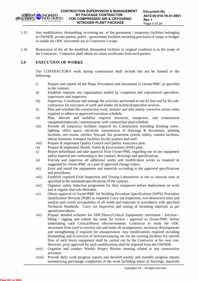
1.15 Any modification, dismantling, re-routing etc. of the permanent / temporary facilities belonging to OWNER, private parties, public / government facilities including provision of ramps at bridges to enable the ODC movement are in Contractor’s scope.
1.16 Restoration of the all the modified, dismantled facilities to original condition is in the scope of
the Contractor. Contractor shall obtain no claim certificates from such parties. 2.0 EXECUTION OF WORKS
The CONTRACTOR'S work during construction shall include but not be limited to the following: i) Prepare and submit all the Plans, Procedures and documents to Owner/PMC as specified
in the contract. ii) Establish requisite site organization staffed by competent and experienced specialists,
supervisors and inspectors. iii) Supervise, Coordinate and manage the activities performed at site by him and by his sub-
contractors for execution of work and render all technical/specialist services. v) Plan and schedule the construction work, monitor and take timely corrective action when
required to adhere to approved execution schedule. vi) Plan, allocate and mobilize required resources, manpower, and construction
equipment/materials, commensurate with construction plan/schedule. vii) Provide all temporary facilities required for Construction including drinking water,
lighting, office space, electronic transmission of drawings & documents, printing facilities, rest rooms, crèches, first-aid, fire protection system, toilets, canteen facilities, labour hutments, transport facilities for the workers and staff.
viii) Prepare & implement Quality Control and Quality Assurance plan. ix) Prepare & implement Health, Safety & Environment (HSE) plan. x) Report beforehand and take approval from Owner/PMC regarding use of any equipment
and/or material not conforming to the contract, drawings and specifications. xi) Execute and supervise all additional works and modification works as required or
suggested by Owner/PMC as a part of approved change orders. xii) Erect and install the equipments and materials according to the approved specifications
and procedures. xiii) Establish required Field Inspection and Testing Laboratories at site to carryout tests as
specified in the standards/specifications of the contract. xiv) Organize safety induction programme for their manpower before deployment on work
and at regular intervals thereafter. xv) Obtain approval of Owner/PMC for Welding Procedure Specifications (WPS)/ Procedure
Qualification Records (PQR) as required. Carry out inspection, non-destructive tests and analyze and certify acceptability of all welds and materials in accordance with specified Technical Standards. Carry out inspection and testing of incoming materials as per agreed procedures.
xvi) Prepare detailed schemes for ODC/Heavy/Critical Equipments' movement / erection / lifting / rigging and submit the same for review / approval to Owner/PMC before undertaking such Critical/Heavy lifts/movements. Contractor to study the ODC movement from yard to erection site and make all arrangements, necessary developments and strengthening if required for transportation. Any modifications required including dismantling and re-erection of structures/piping, etc for the existing facilities for smooth flow of such heavy equipment shall be carried out by the Contractor at his own cost. However, prior approval for such modifications shall be required from the OWNER.
xvii) Organize and conduct Weekly Project Review meeting related to site construction activities.
xviii) Provide daily work progress reports and detailed weekly and monthly progress reports summarizing percentage completion of the work including status of drawings, materials
Page 821 of 2624
COSTRUCTION SUPERVISION & MANAGEMENT BY PACKAGE CONTRACTOR
FOR COMPRESSED AIR & CRYOGENIC NITROGEN PLANT PACKAGE
Document No. A672-00-014-19-41-0001 Rev 1 Page 6 of 24
Copyrights EIL – All rights reserved
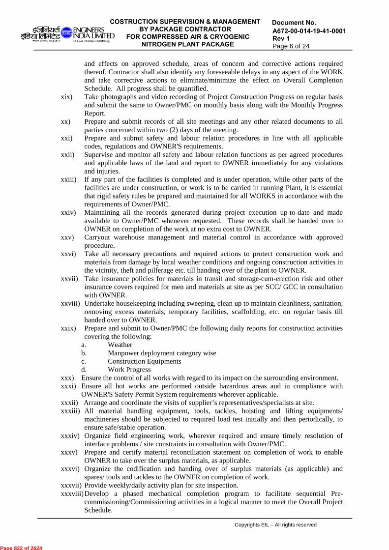
and effects on approved schedule, areas of concern and corrective actions required thereof. Contractor shall also identify any foreseeable delays in any aspect of the WORK and take corrective actions to eliminate/minimize the effect on Overall Completion Schedule. All progress shall be quantified.
xix) Take photographs and video recording of Project Construction Progress on regular basis and submit the same to Owner/PMC on monthly basis along with the Monthly Progress Report.
xx) Prepare and submit records of all site meetings and any other related documents to all parties concerned within two (2) days of the meeting.
xxi) Prepare and submit safety and labour relation procedures in line with all applicable codes, regulations and OWNER'S requirements.
xxii) Supervise and monitor all safety and labour relation functions as per agreed procedures and applicable laws of the land and report to OWNER immediately for any violations and injuries.
xxiii) If any part of the facilities is completed and is under operation, while other parts of the facilities are under construction, or work is to be carried in running Plant, it is essential that rigid safety rules be prepared and maintained for all WORKS in accordance with the requirements of Owner/PMC.
xxiv) Maintaining all the records generated during project execution up-to-date and made available to Owner/PMC whenever requested. These records shall be handed over to OWNER on completion of the work at no extra cost to OWNER.
xxv) Carryout warehouse management and material control in accordance with approved procedure.
xxvi) Take all necessary precautions and required actions to protect construction work and materials from damage by local weather conditions and ongoing construction activities in the vicinity, theft and pilferage etc. till handing over of the plant to OWNER.
xxvii) Take insurance policies for materials in transit and storage-cum-erection risk and other insurance covers required for men and materials at site as per SCC/ GCC in consultation with OWNER.
xxviii) Undertake housekeeping including sweeping, clean up to maintain cleanliness, sanitation, removing excess materials, temporary facilities, scaffolding, etc. on regular basis till handed over to OWNER.
xxix) Prepare and submit to Owner/PMC the following daily reports for construction activities covering the following:
a. Weather b. Manpower deployment category wise c. Construction Equipments d. Work Progress
xxx) Ensure the control of all works with regard to its impact on the surrounding environment. xxxi) Ensure all hot works are performed outside hazardous areas and in compliance with
OWNER'S Safety Permit System requirements wherever applicable. xxxii) Arrange and coordinate the visits of supplier’s representatives/specialists at site. xxxiii) All material handling equipment, tools, tackles, hoisting and lifting equipments/
machineries should be subjected to required load test initially and then periodically, to ensure safe/stable operation.
xxxiv) Organize field engineering work, wherever required and ensure timely resolution of interface problems / site constraints in consultation with Owner/PMC.
xxxv) Prepare and certify material reconciliation statement on completion of work to enable OWNER to take over the surplus materials, as applicable.
xxxvi) Organize the codification and handing over of surplus materials (as applicable) and spares/ tools and tackles to the OWNER on completion of work.
xxxvii) Provide weekly/daily activity plan for site inspection. xxxviii) Develop a phased mechanical completion program to facilitate sequential Pre-
commissioning/Commissioning activities in a logical manner to meet the Overall Project Schedule.
Page 822 of 2624

COSTRUCTION SUPERVISION & MANAGEMENT BY PACKAGE CONTRACTOR
FOR COMPRESSED AIR & CRYOGENIC NITROGEN PLANT PACKAGE
Document No. A672-00-014-19-41-0001 Rev 1 Page 7 of 24
Copyrights EIL – All rights reserved
xxxviii) Remove / demolish all temporary structures/ establishments/ facilities created by the Contractor / his sub-contractors during the execution of the work and restore the site to its original condition.
xxxix) Organize and conduct Positive Material Identification (PMI) of incoming materials and of materials & welds after erection/installation, but prior to hydro testing of facilities, using Portable Alloy Analyzer with print out facility as per procedure approved by Owner/PMC (Refer Document No. 6-82-0002). Any non-conformance detected shall be removed and replaced prior to final hydro testing.
xl) Develop colour coding scheme (to avoid mix up during fabrication and erection) for piping material and get it approved from Owner/PMC.
xli) Carry out tightening of flange joints by using hydraulic tensioner/ torque wrench as per specifications. Contractor shall ensure that stud bolts are ordered extra long to facilitate tensioning.
Contractor shall draw up a detailed activity list of pre shutdown activities and shutdown activities (wherever applicable) and submit the same for the approval of the Owner/PMC. All endeavors shall be made to maximize the pre-fabrication before the planned shut down and to minimize the work during shutdown period. All such activities shall be identified and appropriately planned for temporary supports, scaffolding, clamping arrangements, enabling works, etc. so that the quantum of the work during the shutdown can be minimized.
3.0 EXECUTION PLANS
Contractor shall submit Construction Execution Plan to Owner/PMC for review/approval during kick-off meeting. The Plan shall detail the execution methodology of the Contractor during construction phase of the project covering following aspects as minimum –
3.1 Construction Management Plan
Contractor shall submit Construction Management Plan to Owner/PMC for approval during kick-off meeting. The Plan shall detail the management methodology to be applied during the construction phase of the Project, along with a list of procedures to be utilized in undertaking the work. All reference procedures and detail work plans referred to in this document must be submitted for review and approval by Owner/PMC at least (4) four weeks in advance of actual commencement of the activity concerned.
3.2 Construction Execution Plan:
It shall include the following as minimum:
3.2.1 Contractor’s manpower and man-hour histogram by major section and discipline and their manpower deployment schedule on monthly basis.
3.2.2 Major equipment mobilization plan on monthly basis with short description. Contractor to develop this plan with due consideration to maximize the mechanization of construction activities. Other plans of Contractor and procedures to be submitted at least four (4) weeks prior to start of respective activity at site, include the following as a minimum: a. Develop/ prepare pre-shut down/ shut down and post shut down plan including resource
mobilization plan and submit to Owner/PMC for approval(where applicable).
Page 823 of 2624

COSTRUCTION SUPERVISION & MANAGEMENT BY PACKAGE CONTRACTOR
FOR COMPRESSED AIR & CRYOGENIC NITROGEN PLANT PACKAGE
Document No. A672-00-014-19-41-0001 Rev 1 Page 8 of 24
Copyrights EIL – All rights reserved
b. Develop/ prepare construction/erection plan/procedures and submit to Owner/ PMC for approval.
c. Temporary facilities, etc. d. Piling plan (if applicable) e. Barricading Plan (if required). f. Scaffolding plan g. Excavation and underground work plan h. Heavy transport and heavy lifting plan (Rigging Plan), if applicable i. Pre-fabrication plan j. Other activity plans e.g. piping, equipment and steel structure erection plan etc. k. Monsoon counter measures and preparation l. Emergency Evacuation Procedure m. Storm Management Plan n. Schemes to carry out works in inclement weather Contractor shall ensure that lay down area (as applicable) given to him shall be utilized optimally.
3.3 Sub-Contracting Plan
If Contractor proposes to engage sub-contractor(s) for the execution of some of the activities at site, a preliminary sub-contracting plan along with the identified scope of work for each sub-contract shall be furnished by the Contractor to the Owner/PMC at the time of Kick off meeting. However, the credentials of proposed Sub-contractor(s)’s shall be submitted by the Contractor at site, which shall be evaluated by Owner/PMC for acceptance. Contractor shall not be permitted to change the sub-contractor under any circumstances without prior approval of Owner/PMC. Non-compliance of the above shall be strictly dealt within relevant provision(s) of the contract. The sub-contracting plan shall cover
i) Sub-contracting philosophy and plan ii) List and scope of work of each subcontract iii) Subcontract administration plan iv) Organization chart of each sub-contractor.
The list and major scope of each subcontract shall not be changed from those of the Contractor’s plan unless specially approved by OWNER.
4.0 TEMPORARY FACILITIES The Contractor shall arrange the following temporary facilities as the minimum (including for his sub-contractors also): i) Exact location of temporary work area, access and general layout inside the area. ii) Planning and description of the temporary facilities such as:
a. Identification of borrow earth area/ excess earth dumping yards (if required) b. Fabrication yard along with monsoon protection measures for prefabrication of
piping, structural works, assembly of structural modules, Covered work shop / Refractory lining (if required), Surface preparation and Primer/ finish paint, batching plant, (if required) etc and Warehouse (Covered storage yard, Open storage yard and Air conditioned storage space, if required)
c. Site office for their staff. d. Temporary roads including access road to Plant, fencing and gates e. Security, watch & ward, security gates, etc.
Page 824 of 2624
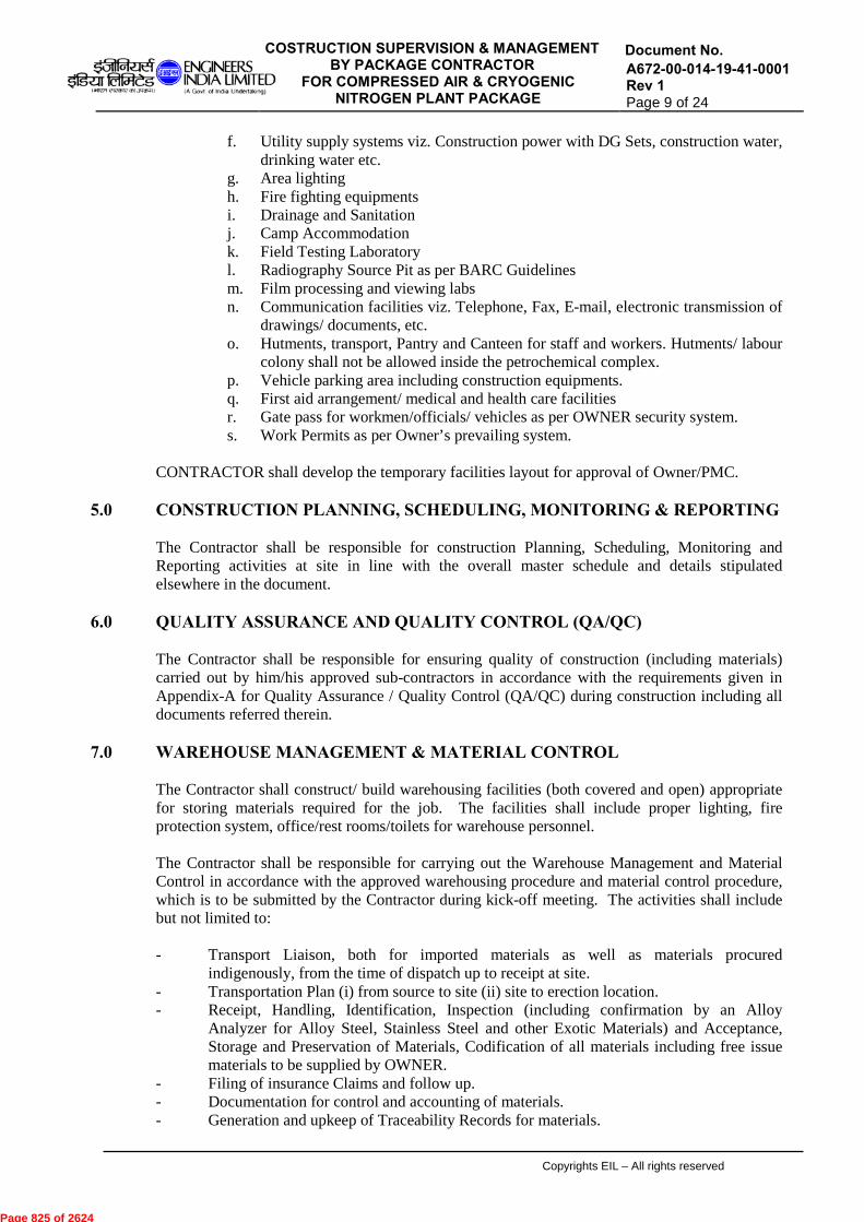
COSTRUCTION SUPERVISION & MANAGEMENT BY PACKAGE CONTRACTOR
FOR COMPRESSED AIR & CRYOGENIC NITROGEN PLANT PACKAGE
Document No. A672-00-014-19-41-0001 Rev 1 Page 9 of 24
Copyrights EIL – All rights reserved
f. Utility supply systems viz. Construction power with DG Sets, construction water, drinking water etc.
g. Area lighting h. Fire fighting equipments i. Drainage and Sanitation j. Camp Accommodation k. Field Testing Laboratory l. Radiography Source Pit as per BARC Guidelines m. Film processing and viewing labs n. Communication facilities viz. Telephone, Fax, E-mail, electronic transmission of
drawings/ documents, etc. o. Hutments, transport, Pantry and Canteen for staff and workers. Hutments/ labour
colony shall not be allowed inside the petrochemical complex. p. Vehicle parking area including construction equipments. q. First aid arrangement/ medical and health care facilities r. Gate pass for workmen/officials/ vehicles as per OWNER security system. s. Work Permits as per Owner’s prevailing system.
CONTRACTOR shall develop the temporary facilities layout for approval of Owner/PMC.
5.0 CONSTRUCTION PLANNING, SCHEDULING, MONITORING & REPORTING The Contractor shall be responsible for construction Planning, Scheduling, Monitoring and Reporting activities at site in line with the overall master schedule and details stipulated elsewhere in the document.
6.0 QUALITY ASSURANCE AND QUALITY CONTROL (QA/QC) The Contractor shall be responsible for ensuring quality of construction (including materials) carried out by him/his approved sub-contractors in accordance with the requirements given in Appendix-A for Quality Assurance / Quality Control (QA/QC) during construction including all documents referred therein.
7.0 WAREHOUSE MANAGEMENT & MATERIAL CONTROL The Contractor shall construct/ build warehousing facilities (both covered and open) appropriate for storing materials required for the job. The facilities shall include proper lighting, fire protection system, office/rest rooms/toilets for warehouse personnel. The Contractor shall be responsible for carrying out the Warehouse Management and Material Control in accordance with the approved warehousing procedure and material control procedure, which is to be submitted by the Contractor during kick-off meeting. The activities shall include but not limited to: - Transport Liaison, both for imported materials as well as materials procured
indigenously, from the time of dispatch up to receipt at site. - Transportation Plan (i) from source to site (ii) site to erection location. - Receipt, Handling, Identification, Inspection (including confirmation by an Alloy
Analyzer for Alloy Steel, Stainless Steel and other Exotic Materials) and Acceptance, Storage and Preservation of Materials, Codification of all materials including free issue materials to be supplied by OWNER.
- Filing of insurance Claims and follow up. - Documentation for control and accounting of materials. - Generation and upkeep of Traceability Records for materials.
Page 825 of 2624

COSTRUCTION SUPERVISION & MANAGEMENT BY PACKAGE CONTRACTOR
FOR COMPRESSED AIR & CRYOGENIC NITROGEN PLANT PACKAGE
Document No. A672-00-014-19-41-0001 Rev 1 Page 10 of 24
Copyrights EIL – All rights reserved
- Materials Control & Issue. - Inventory Checks. - Field Requisition and Purchase. - Spare & Tools including handing over of mandatory Spares/Tools to the OWNER as per
the terms of the contract. - Material Appropriation and Handing Over of all items to OWNER with Owner’s
codification system as per terms of contract. - Security. - Taking up with suppliers on short supplied items and placing replacement orders for
lost/damaged items. - Intimating to there HO regarding short/lost/damaged items received at site and further
replacement action, as applicable.
Contractor shall generate and issue following reports: - Fortnightly statement of consignments in transit. - Daily report of material received. - Material receipt status and inventory status w.r.t. material delivery schedule - Material Inspection Report with respect to materials received at site - Report on Over/Short/Reject/Damage (OSRD) receipts against each consignment on
receipt at warehouse. - Weekly status of consignments, Material Receipt Report (MRRs) - Monthly status of field purchase. - Monthly status of over, short, reject & damage (OSRD) settlement. - Monthly status of piping material MTO V/s Actual receipt. - Log Register of Rotating Equipments maintenance - Daily Stock Position of Cement - Any other report as desired by Owner/PMC.
8.0 FIELD ENGINEERING
Contractor shall be responsible for controlling and issue of technical drawings and documents, preparation of field sketches, field modifications, checking/preparation of as- built drawings, etc. Contractor should have adequate facilities for incorporating field changes, preparation of As-built drawings, Printing machines and Drawing & Document Control System.
9.0 FIELD TENDERING Contractor shall be responsible for carrying out field tendering activities, as required from the site itself.
10.0 FIELD PURCHASE Contractor shall be responsible for carrying out field purchase activities, as required. Field Purchase items are restricted to those required for running and maintenance of the field offices, items required to expedite construction work and items found short, missing or damaged against the main order when received at the site. Any material purchased from field for usage in the plant should have proper inspection certificate and should be purchased from Owner/PMC approved suppliers. If required by Owner/PMC, check testing of the material samples selected by Owner/PMC shall be carried out by Contractor without any extra commercial implication.
Page 826 of 2624

COSTRUCTION SUPERVISION & MANAGEMENT BY PACKAGE CONTRACTOR
FOR COMPRESSED AIR & CRYOGENIC NITROGEN PLANT PACKAGE
Document No. A672-00-014-19-41-0001 Rev 1 Page 11 of 24
Copyrights EIL – All rights reserved
11.0 HEALTH, SAFETY AND ENVIRONMENT (HSE) MANAGEMENT
The CONTRACTOR shall be responsible for Health, Safety and Environment (HSE) Management at construction site for the construction activities to be carried out by the him/his approved sub-contractors in accordance with the requirements mentioned in Appendix-B for Health, Safety and Environment Management during construction. Contractor shall be working in an operating refinery. All measures required for safe construction are to be ensured. Besides all personnel employed in the job to follow safety requirements of Owner/PMC, the movement of Contractor’s personnel will be restricted to their workplace only.
12.0 HOUSE KEEPING It is the responsibility of the Contractor to maintain general cleanliness and proper housekeeping at work site. Contractor shall organize disposal of excavated earth /garbage/ rubbish/scrap, etc. on day to day basis to identified disposal areas/safe areas and forward daily report for the same indicating the details of men and machinery deployed for the purpose; if asked by Owner/PMC. Wastage and serviceable/ unserviceable scrap generated during dismantling and regular works shall be segregated and dumped in designated locations in consultation with Owner/PMC. Earth and landfill materials shall be dumped at locations identified by Owner/PMC, otherwise outside the Project Site and the required fees charged by the local authorities shall be borne by the Contractor without any extra cost to OWNER.
13.0 INDUSTRIAL LABOUR RELATIONS Contractor shall be responsible for industrial relation functions and implementation of labour laws at site. Contractor's staff shall be suitably trained and experienced in Labour Relation functions so as to ensure a good relationship with labour and to prevent the occurrence of industrial disputes resulting in subsequent delays or work stoppages. In particular, Contractor shall maintain close liaison with Owner/PMC. Contractor shall maintain proper liaison with Statutory Authorities and local bodies and shall be responsible to implement and observe all statutory laws at site. CONTRACTOR must have in his staff; a well experienced Labour Relation Officer, preferably from local area. Contractor shall maintain the records of wages paid in a wage register, PF, etc. as per statutory regulations. Contractor shall report immediately to Owner/PMC any problems including labour disputes, fight, and work stoppages. A written report shall be submitted to Owner/PMC within 24 hours of the incident. Contractor must submit a Labour Relation Plan including their sub-contractor(s) prior to the start of the work/within one month of award of the contract, whichever is earlier, mentioning as a minimum:
- A detailed estimate of the number of labour, both indirect and direct, sorted by craft. - Outline recruiting plans for all manpower requirements. - Identify personnel involved with labour relations and outline procedures to mitigate
labour disputes & problems. - Labour welfare plan
Page 827 of 2624

COSTRUCTION SUPERVISION & MANAGEMENT BY PACKAGE CONTRACTOR
FOR COMPRESSED AIR & CRYOGENIC NITROGEN PLANT PACKAGE
Document No. A672-00-014-19-41-0001 Rev 1 Page 12 of 24
Copyrights EIL – All rights reserved
Contractor shall hold labour relations meeting twice a month with their work force as well as a separate meeting with the OWNER.
14.0 CONSTRUCTION EQUIPMENTS The Contractor is required to organize and mobilize the construction equipments and other tools/tackles in a sequential manner and ensure that plant installation is carried out in a mechanized manner to the extent possible and its mechanical completion is achieved within targeted time schedule. Contractor shall ensure deployment of the following construction equipment as a minimum as per requirement to the maximum extent –
i. Cranes of different capacities ii. Tower crane, if required
iii. Portable Alloy Analyzers with print out facility iv. X-ray and Radiography sources, as required v. Stress Relieving Equipments with Recording facility, as required
vi. All weather fabrication sheds vii. Blast cleaning and Painting Shop, as required.
viii. Welding machines ix. DG sets x. Electrical and Instrumentation equipments/measuring devices etc.
xi. Bevel Cutting Machines xii. Test Pumps
xiii. Compressors xiv. Gas and Mechanical cutting devices xv. Various inspection / measuring devices
The Contractor shall, without prejudice to his responsibility to execute and complete the work strictly as per the specifications and other laid down procedures, execute all the work by mechanizing the construction activities to the maximum extent by deploying all necessary construction equipments/machinery of adequate capacities and numbers. Contractor shall be responsible for arranging all facilities for torque tightening/tensioning of bolts/fasteners as specified. Contractor shall ensure that stud bolts are ordered extra long by one diameter to facilitate tensioning. Guidelines for torque tightening/tensioning are specified in specifications for boxing up of flanged joints, as referred in APPENDIX- A. In order to minimize fabrication at site, Contractor to fabricate all (major) fabricated items at their vendor works to the maximum extent possible due to limitation of space at site and transported to site with maximum length of consignment transportable by sea and road. Contractor shall carry out the route survey/ study for transportation of 'Over Dimensioned Consignments' including waterways from source of manufacture/supply to site well in advance of placement of order to ensure unhindered transportation of the same to construction site. Contractor shall arrange Cranes of suitable capacities to match with the erection requirements. Crane movement roads are to be clearly identified and marked on the plot plan before planning of such movement. Construction of hard stands for positioning of crane in the fabrication yard and at erection site/locations including approach roads to the hard stands from the plant roads shall be Contractor’s responsibility. The hard stands shall be suitable for the crane loads (self load + equipment load) to facilitate erection works and to be tested for any settlement. For the purpose of Equipment/ Structural steel Erection, the Contractor shall deploy a Rigging team headed by a Rigging Foreman/Engineer reporting to concerned Area Engineer. Area Engineer should be well conversant with various erection techniques and shall be
Page 828 of 2624

COSTRUCTION SUPERVISION & MANAGEMENT BY PACKAGE CONTRACTOR
FOR COMPRESSED AIR & CRYOGENIC NITROGEN PLANT PACKAGE
Document No. A672-00-014-19-41-0001 Rev 1 Page 13 of 24
Copyrights EIL – All rights reserved
responsible for preparing erection schemes in accordance with the approved procedures and based on crane manuals and suiting to plant layout. Area Engineer shall have to foresee various other construction activities in the surroundings areas while planning erection schemes including safety aspects of man and machinery also. Contractor shall prepare erection schedule in line with the overall project schedule of the Plant in phased manner with erection schemes of various equipments, vessels and submit to Owner/PMC for approval, Monitoring and control of erection schedule and erection activities shall be carried out by the contractor as per the approved construction procedures. For efficient working and maintenance of construction aids, Contractor shall establish and maintain crane yard / workshop equipped with regular maintenance facilities for various construction aids for carrying out routine field maintenance during performance of the contract. Temporary approach road and hard stands, wherever required for the movement of the Cranes and other vehicles for equipment erection and transportation of material shall be properly planned and made by the Contractor. Weekly/fortnightly maintenance shall be planned in such a way that the same does not hamper the erection schedule. During performances of the work, Contractor must ensure that structures, materials and equipments are adequately braced with Guys, Struts or any other means as deemed fit & approved by Owner/PMC. Such means shall be supplied and installed by the Contractor as required till the erection works is satisfactorily completed. Such guys, shoring, bracing, strutting, planking supports etc. shall not interfere with the work of other agencies and shall not damage or cause distortion to works executed by other agencies. All lifting tools, tackles and cranes shall be tested periodically by statutory/ competent authorities for their load carrying capacity. Such relevant valid/test certificates shall be submitted to Owner/PMC for review before actual use of the tools, tackles and cranes. Contractor shall submit the construction equipment deployment schedule at the time of kick off meeting. Daily construction equipment deployment report will also be submitted by the Contractor to Owner/PMC in the Performa approved by Engineer In charge. Contractor shall ensure the timely augmentation of the men, equipments and machinery depending upon the exigencies of the work to meet the overall project schedule and as per instructions of Owner/PMC.
15.0 CONSTRUCTION MANPOWER The Contractor is required to organize and mobilize construction staff/ manpower in a sequential manner to ensure that the work is carried out in accordance with the construction schedule. Mobilization of construction staff should be such that the progress achieved in phased manner should match with the overall Project Schedule. Key Personnel i.e. Resident Construction Manager, Site In-charge, Lead QA/QC Engineer, Lead Planning Engineer, Safety officer, Discipline Engineer for execution of job shall be deployed meeting the qualification and experience requirement of Document No. 7-82-0003. For this purpose, the Contractor shall clearly indicate in his construction methodology whether work shall be done departmentally or by engaging sub-contractor or the combination of both. Contractor shall prepare detailed methodology for the work to be carried out departmentally as well as through sub-contractors clearly, defining the scope and responsibility of Contractor and his sub-contractors. The works of all sub-contractors shall be managed by the construction staff of the main Contractor who shall perform the duties of construction management and shall administer, coordinate, and inspect the works of the sub-contractor(s) and be responsible for the Quality and
Page 829 of 2624
COSTRUCTION SUPERVISION & MANAGEMENT BY PACKAGE CONTRACTOR
FOR COMPRESSED AIR & CRYOGENIC NITROGEN PLANT PACKAGE
Document No. A672-00-014-19-41-0001 Rev 1 Page 14 of 24
Copyrights EIL – All rights reserved
timely completion of respective works. The Contractor shall establish the pre-requisites for successful completion of sub-contractor (s) work. However, by deploying the sub-contractor (s), as approved by Owner/PMC for any discipline, does not absolve the Contractor of his total responsibility under the subject contract. The Contractor must note that in case of any sub-contractors' failure to execute the works as per standards/specifications/drawings and/or negligence & disobedience in carrying out any order or instruction of Owner/PMC, the same shall be viewed very seriously and any action as deemed fit in accordance with provision(s) of the contract shall be taken by Owner/PMC. Contractor shall submit the construction manpower deployment schedule at the time of kick off meeting. Daily construction manpower deployment report shall also be submitted by the Contractor to Owner/PMC on approved format. Any additional manpower of any category required to be deployed during the actual execution of the work to meet the Project time schedule and as instructed by Owner/PMC, shall be mobilized by the Contractor within a reasonable time. Mobilization of such additional manpower by the Contractor shall not entitle him for any additional compensation at all. All construction supervision, coordination and management activities shall be carried out by the Contractor in accordance with the construction procedures approved by Owner/PMC. Contractor shall prepare construction schedules based on the Overall Project Schedule and submit the same to Owner/PMC for approval. Monitoring and control of the construction activities shall be carried out as per the approved construction schedule & procedures. During the execution of works at site, if the Contractor engages sub-contractor (s) for execution of works at site as per approval obtained from Owner/PMC in line with contract provision(s) and in the event sub-contractor complains in writing to the Owner with regard to the non-payment of their dues from the Contractor for the works executed by them (excluding final payments and payments due after termination of sub-contractors' services by the main Contractor), Owner/PMC reserves the right to make such payment to the sub-contractors directly based on approved measurements with due notice to the Contractor. Owner/PMC shall release such payments to sub-contractor at the cost and risk of the Contractor in order to ensure smooth execution of work at site. All such payments made by Owner/PMC to the sub-contractor(s) shall be deducted from the running account bills or any other payments due to the Contractor. The above provisions shall also be applicable in case of construction materials procured at site by the Contractor from the suppliers.
16.0 INTERFACE WITH OTHER CONTRACTORS Contractor shall ensure that his interface with other Contractors is smooth and cordial. In case of any dispute, Owner/PMC decision shall be binding. Owner/PMC may arrange weekly/fortnightly/monthly interface meetings. The Contractor shall depute concerned personnel to attend these meetings. Generally, the following interfaces may be present: • Contractor shall allow movement of persons/ material/ equipment/ vehicles belonging to
other Contractors or Owner/PMC through the roads constructed by him. • Contractor shall coordinate with ‘neighboring’ contractors for maintaining
elevations/levels of various interconnecting services. • Contractor shall not dump his earth, scrap or any material in other Contractors’ area. He
shall cooperate with Owner/PMC in maintaining good housekeeping throughout the complex.
Page 830 of 2624
COSTRUCTION SUPERVISION & MANAGEMENT BY PACKAGE CONTRACTOR
FOR COMPRESSED AIR & CRYOGENIC NITROGEN PLANT PACKAGE
Document No. A672-00-014-19-41-0001 Rev 1 Page 15 of 24
Copyrights EIL – All rights reserved
• Contractor shall ensure proper drainage and no water logging in his area/other areas. • If requested by the Owner/PMC, Contractor shall allow testing of materials of other
Contractors in his laboratory, in case of emergency. • Contractor shall clearly define in the interface meeting with other contractors their
erection / construction interface at their Battery limits.
17.0 CHECKLIST FOR INSPECTION OF FLANGED JOINTS Requirements specified in EIL standard specification for application of torque and hydraulic bolt tension for flange joints No. 6-76-0002 shall also be followed by the Contractor.
18.0 COLOUR CODING OF PIPING MATERIAL
Specification for colour coding of Stored Piping Material No. 6-82-0003 shall be uniformly followed for the entire facilities.
Page 831 of 2624
COSTRUCTION SUPERVISION & MANAGEMENT BY PACKAGE CONTRACTOR
FOR COMPRESSED AIR & CRYOGENIC NITROGEN PLANT PACKAGE
Document No. A672-00-014-19-41-0001 Rev 1 Page 16 of 24
Copyrights EIL – All rights reserved
APPENDIX - A
QUALITY ASSURANCE
AND
QUALITY CONTROL
DURING CONSTRUCTION PHASE
Page 832 of 2624
COSTRUCTION SUPERVISION & MANAGEMENT BY PACKAGE CONTRACTOR
FOR COMPRESSED AIR & CRYOGENIC NITROGEN PLANT PACKAGE
Document No. A672-00-014-19-41-0001 Rev 1 Page 17 of 24
Copyrights EIL – All rights reserved
TABLE OF CONTENTS
_____________________________________________________________________ CLAUSE NO. TITLE PAGE NO. _______________________________________________________________________________ 1.0 SCOPE 18 2.0 RESPONSIBILITY 18 3.0 METHODOLOGY 3.1 PROCUREMENT OF MATERIALS REQUIRED 18 FOR THE CONSTRUCTION WORKS 3.2 EXECUTION OF WORKS 18 3.3 QA/ QC AUDITS 20 4.0 DOCUMENTATION AND RECORDS 21
Page 833 of 2624
COSTRUCTION SUPERVISION & MANAGEMENT BY PACKAGE CONTRACTOR
FOR COMPRESSED AIR & CRYOGENIC NITROGEN PLANT PACKAGE
Document No. A672-00-014-19-41-0001 Rev 1 Page 18 of 24
Copyrights EIL – All rights reserved
1.0 SCOPE This document shall be applicable to all construction works to be executed by Contractor.
2.0 RESPONSIBILITY It is Contractor’s prime responsibility to arrange/produce the product conforming to contract specifications and inspect all equipment, materials and works at various stages of execution as per the approved QA Plans. In addition, they have to coordinate all efforts in this regard directly with the Owner/PMC and other involved agencies to give adequate confidence that the activities are performed as per agreed ITPs and necessary documentation is available. Contractor shall deploy an exclusive team of Quality control Engineers and Supervisors for ensuring the quality of works executed at site on day to day basis. Verification by Owner/PMC or his representative at any stage shall not relieve Contractor of his responsibility towards quality of the product. The Contractor shall comply with all statutory rules & regulations in force during execution of work and interface with such authorities as required.
3.0 METHODOLOGY The management of construction quality control is divided into the following categories: - (1) Procurement of materials required for the construction work. (2) Execution of work (3) QA/QC Audits
3.1 PROCUREMENT OF MATERIALS REQUIRED FOR THE CONSTRUCTION WORK
The Contractor shall develop list(s) defining the items to be procured along with proposed Vendors for approval of the Owner/PMC. The list shall comprise of all items except vessels, equipments, pumps, electrical/ instrumentation panels etc. which may be available directly ready for installation or requiring small fabrication as per requirement. The vendor list shall be in line with the contract document. In case, no vendor list exists in the contract for a particular item, the Contractor shall propose a list of Vendors to Owner/PMC. Contractor has to satisfy himself with the capability of the vendor to deliver the product in time with quality before proposing him as a prospective vendor. Contractor shall submit the QA/QC plans for all major items and carry out their procurement in line with the approved plans. The categorization plan shall be submitted by contractor in line with the contract requirement. The Contractor can either provide his own adequate qualified staff for inspection or employ a separate third- party inspection agency with prior approval to carry out these functions. Involvement of Owner/PMC in the quality control plan, if required, shall be defined during approval of the same.
3.2 EXECUTION OF WORK (i) The QA plans for execution shall be developed by the Contractor. Owner/PMC’s
approval for the same shall be taken well before start of the work. The final Inspection & Test Plans (ITPs) and formats, based on the indicative ITPs (Refer document no. A672-00-19-41-2000) enclosed elsewhere in package, shall be developed by the Contractor as per contract specifications for approval by Owner/PMC. For the activities which are identified as Witness or Hold Point, specific inspection call shall be raised by the Contractor with Owner/PMC in the requisite format well in advance.
The indicative ITPs enclosed in the feed package are for guidance to the Contractor and may not cover some of the activities to be performed during execution of works under the
Page 834 of 2624
COSTRUCTION SUPERVISION & MANAGEMENT BY PACKAGE CONTRACTOR
FOR COMPRESSED AIR & CRYOGENIC NITROGEN PLANT PACKAGE
Document No. A672-00-014-19-41-0001 Rev 1 Page 19 of 24
Copyrights EIL – All rights reserved
scope of this contract. The Contractor shall develop Inspection & Test Plans and Formats for all such activities also and submit the same to Owner/PMC for approval, before actually undertaking such activities. Contractor shall be completely responsible for management of approved quality plans and Owner/PMC involvement will be only of Surveillance in nature to randomly check the works at selective/critical junctures. Their role shall be to monitor that the Contractor is executing the quality plans as per the approved drawings, employing adequately qualified staff and other resources for various items of works. Any deviation to the specifications shall be brought to the notice of Owner/PMC in prescribed formats by Contractor for approval.
(ii) It is likely that the Contractor may engage sub-contractor(s)/vendors for performance of the work. Contractor shall be responsible for ensuring the implementation of approved QA plan, contract specifications and contract conditions through their sub-contractors to achieve the quality during all stages of construction. It shall be the responsibility of the Contractor to ensure proper coordination between his sub- contractor(s) and other agencies working at site. The sub-contractor(s)/vendors selection shall be done after evaluation by the Contractor in line with contract requirements and shall be got approved by Owner/PMC before engaging them for the works.
(iii) Storage
All the materials procured shall be stored/stacked as per the standard norms and as recommended in various clauses of relevant codes and contract document. The storage of material shall be such as to avoid damage to life/properties (physical and chemical) of the materials. The storage shall not cause deterioration, rusting, mix-up etc. and hamper the other related works in any way. Contractor shall submit his detailed warehouse plan for Owner/PMC approval to manage the above in open/covered areas. The materials susceptible to fire shall be kept away in a separate protected place. In general, the materials shall be kept systematically in order of their class, batch number and identification number, so that they are accessible for the inspection by Owner/PMC whenever required and to avoid the mix up in those materials.
(iv) Use
The materials shall be stacked in such a way that the lot, which is procured first, will be consumed first. For materials which are having specific expiry date/ shelf life shall not be used beyond that date and shall be removed from site. Wherever there is any doubt about the change in properties of the materials, such materials shall be sent to reputed approved laboratory for testing and acceptance.
(v) Inspection
The Contractor shall be responsible for carrying out inspection of the materials brought at site and conducting tests/ checks (at site or in approved laboratories) at predefined frequencies as per contract. It is the responsibility of the Contractor to ensure that the materials used at site shall conform to relevant codes/ standards and Manufacturer Test Certificates are available for correlation as and when required. The Contractor shall maintain the records of all materials brought at site and tests conducted on them.
Page 835 of 2624

COSTRUCTION SUPERVISION & MANAGEMENT BY PACKAGE CONTRACTOR
FOR COMPRESSED AIR & CRYOGENIC NITROGEN PLANT PACKAGE
Document No. A672-00-014-19-41-0001 Rev 1 Page 20 of 24
Copyrights EIL – All rights reserved
(vi) In process and final Inspection
Contractor shall be responsible to arrange verification of products during in- process and final inspection. Relevant checks and tests shall be arranged for the works performed and records maintained. Tolerances achieved with respect to contract specification and execution drawings for various activities/processes shall be ascertained and submitted to Owner/PMC for approval. Efforts shall be made to keep checks and controls in such a way that a non-conforming product is avoided. However, if in an isolated case, the tolerances are beyond the acceptable values given in the contract/execution drawings/codes, non-conformance resolution/Deviation permit need to be raised by the Contractor and got approved/resolved from Owner/PMC. The Contractor shall arrange verification of ingredients used and validation of the software used at the batching plant(s). Owner/PMC reserve the right to inspect the working of batching plant including validation of the software used and calibration of measuring & monitoring devices any time. The Contractor shall ensure the quality of the concrete delivered by the transit mixers, as applicable and maintain verifiable records. Contractor will carryout Inspection, Non-destructive Tests and analyze and certify acceptability of all welds, materials and works in accordance with specified technical standards/International standards and carryout inspection and testing of incoming materials as per agreed procedures. Contractor shall mobilize Portable Alloy Analyser (s) with printout facility and carry out 'Positive Material Identification (PMI)' of incoming materials and welds after erection/installation but prior to hydro-testing inline with specification no. 6-76-0002. Any non-conformance detected shall be removed and replaced prior to final hydro testing. The Contractor shall develop color coding scheme of stored piping materials to avoid mixing up of material at different stages of construction and submit it to Owner/PMC for approval.
vii) Any Observation on quality aspects, Owner/PMC shall raise observation in attached OQA format, which has to be acknowledged & compliance to be done by the contractor within the agreed time period.
viii) The Contractor shall follow the requirements given for control of monitoring and measuring devices (Refer Document No. 7-82-0002).
3.3 QA/QC AUDITS
During the execution of the works, Contractor shall carry out periodical Quality Audits at least quarterly in all areas of work. These audits will be conducted by a team of specialists in the respective areas. The auditors shall not be directly involved in the jobs being audited. The Contractor shall prepare an Audit Plan and Procedure and submit the same to Owner/PMC for approval. A copy of the Audit Report containing the findings of the Audit team will be submitted to Owner/PMC. After completion of rectification/modifications/corrective actions on the issues indicated in Audit Report, Compliance Report shall be submitted by the Contractor to Owner/PMC for review.
Page 836 of 2624
COSTRUCTION SUPERVISION & MANAGEMENT BY PACKAGE CONTRACTOR
FOR COMPRESSED AIR & CRYOGENIC NITROGEN PLANT PACKAGE
Document No. A672-00-014-19-41-0001 Rev 1 Page 21 of 24
Copyrights EIL – All rights reserved
Over and above the Contractor’s Internal QA/QC Audits outlined above, Owner/PMC shall also reserve the right to conduct QA/QC audits at the frequency decided by them. Contractor shall participate and provide full support to the Audit Team and furnish all documents/reports/records as desired by the Audit Team. The Contractor shall take all actions required to comply with the findings of the Audit Report and issue regular Compliance Reports for the same to Owner/PMC till all the findings of the Audit Report are fully complied. In case major Non conformities are observed during execution of the works Owner/PMC reserve the right to appoint an independent person/Third Party Agency to conduct QA/QC Systems Audit for full/part of the facilities being executed by the Contractor. This audit will be in addition to the audits described above and may be carried out intermittently/continuously for all or part of the facilities being executed by the Contractor. Contractor shall bear the total cost of such audits and shall participate & provide full support to the Audit Team and ensure compliance of the audit observations.
4.0 DOCUMENTATION AND RECORDS All the necessary documentation & records shall be maintained by Contractor till completion of project and handed over to Owner/PMC in requisite copies as a part of completion documents. Wherever Owner/PMC personnel were directly involved particularly in witness and hold point, the copies of the records shall also be provided to personnel on completing inspection of those activities. The documentation & records shall include the following as a minimum but not limited to: i) Approved Quality Assurance Plan ii) Approved Inspection and Test Plans iii) Inspection and test documents covering
a) Manufacturer Test Certificate b) Material Receipt Report including Inspection Release Note, if applicable
and Site Inspection and acceptance Report on quality and quantity of material
c) Site test/laboratory test Report reviewed by Contractor for acceptance vis-à-vis to contract/code requirements for materials/including PMI report at warehouse.
d) In process Verification reports of Contractor representative and Owner/PMC as applicable
e) Final verification report including any test checks done for compliance f) As-built vis-à-vis to contract/drawings including tolerances g) As-built for erection h) Non conformance resolution raised by Contractor / Owner/PMC i) Concession/Deviation approval by Owner/PMC j) Change order approval by Owner/PMC incase there is variation from
contract k) QA/QC Audit Reports and compliance Reports thereof l) Mechanical Completion formats
Page 837 of 2624
COSTRUCTION SUPERVISION & MANAGEMENT BY PACKAGE CONTRACTOR
FOR COMPRESSED AIR & CRYOGENIC NITROGEN PLANT PACKAGE
Document No. A672-00-014-19-41-0001 Rev 1 Page 22 of 24
Copyrights EIL – All rights reserved
APPENDIX-B
HEALTH, SAFETY AND
ENVIRONMENT (HSE) MANAGEMENT
DURING CONSTRUCTION
Page 838 of 2624
COSTRUCTION SUPERVISION & MANAGEMENT BY PACKAGE CONTRACTOR
FOR COMPRESSED AIR & CRYOGENIC NITROGEN PLANT PACKAGE
Document No. A672-00-014-19-41-0001 Rev 1 Page 23 of 24
Copyrights EIL – All rights reserved
TABLE OF CONTENTS
__________________________________________________________________________ CLAUSE NO. TITLE PAGE NO. _____________________________________________________________________________________ 1.0 GENERAL REQUIREMENT 24
Page 839 of 2624

COSTRUCTION SUPERVISION & MANAGEMENT BY PACKAGE CONTRACTOR
FOR COMPRESSED AIR & CRYOGENIC NITROGEN PLANT PACKAGE
Document No. A672-00-014-19-41-0001 Rev 1 Page 24 of 24
Copyrights EIL – All rights reserved
GENERAL REQUIREMENTS
1.0 Standard specification for Health, Safety and Environment (HSE) Management (Spec. No. 6-82-0001), is required to be followed by Contractor during Construction Phase at site.
2.0 Contractor shall have a documented HSE policy to cover commitment of the organization to ensure Health, Safety and Environment aspects in the line of operation.
3.0 It is the responsibility of the Contractor to ensure that safe construction procedures are complied
with. Contractor will also ensure that adequate First Aid medical facilities are available for emergency purpose and that safety practices as per the approved safety procedure are followed by his sub-contractors also. Contractor to ensure safety measures at the minimum like: a) The use of safety gadgets, viz. safety goggles, helmets, safety shoes, full body harness,
provision of safety net for construction at higher elevations and provision of toe boards in scaffolding platforms, etc.
b) All hot works must be performed by ensuring compliance to the requirements as specified by the Owner from time to time.
c) Barricading of crane movement areas / Radiography areas d) Proper earthing of equipments. e) Proper shoring / strutting of Excavated Areas, as applicable. f) Cylinders of inflammable gases to be stacked upright.
To assist in the development of an effective safety program, a safety checklist for various jobs shall be developed by the Contractor and the same shall be adhered to by the Contractor's Site-In-charge. The responsibilities of the Contractor will include but not limited to: - Coordination and supervision of the details of the job safety programme. - Initiation of accident reporting, investigation and follow-up actions. - Preparation of periodic accident summaries. - Periodic Accident Analysis Reports - Tallying safety inspection of the job and submission of summary inspection report to
Owner/PMC. - Obtaining work permits from the OWNER, wherever applicable. - Check the fitness of cranes and other hoisting equipments on periodic basis/before all
major lifts and submit to Owner/PMC valid/latest test certificates of tackles used for lifting.
- Submission of any other report required by Owner/ PMC. - Conduct HSE Audit at predefined frequencies and assist Owner/PMC /TPI during
conductance of their HSE Audits. - Ensure closure of NCs observed during the above audits.
4.0 Any Observation on Safety aspects, Owner/PMC shall raise observation in attached OSA format,
which has to be acknowledged & compliance to be done by the contractor within the agreed time period.
Page 840 of 2624

ATTACHMENT – I
Page 841 of 2624

INSPECTION TEST PLAN FOR CONSTRUCTION
WORKS
Doc No:
A672-00-19-41-2000 Rev.1 Page 1 of 2
INSPECTION & TEST PLAN (ITP)
FOR
CONSTRUCTION WORKS
Page 842 of 2624

INSPECTION TEST PLAN FOR CONSTRUCTION
WORKS
Doc No:
A672-00-19-41-2000 Rev.1 Page 2 of 2
Copyright EIL –All rights reserved
TABLE OF CONTENTS
S.NO
DESCRIPTION DOCUMENT NO. REV.
1. Inspection & Test Pla ns for Mechanical works 6-82-2100 2
2 Inspection & Test Plans for General works 6-82-2500
2
3 Inspection & Tes t Plans for Instrument ation works 6-82-2600
2
4. Indicative Inspection & Test Plans for Civil/Structural/Architectural works 6-82-2700
2
5. Indicative Inspection & Test Plans for Electrical works 6-82-2800
2
6. Inspection & Te st Plan for Incoming materials 6-82-1010
1
Page 843 of 2624

2 09.11.2015 REVISED AND REISSUED
I 04.07.2011 REVISED AND REISSUED
DJ S ft- TKS SC
SM
SM
MKG
ISIOTR? ENGINEERS INSPECTION & TEST PLAN ,tir es INDIA LIMITED MECHANICAL WORKS WW1 2120517 ,7,13W.) IA Gov' of India Undertak.g)
STANDARD SPECIFICATION No.
6-82-2100 Rev. 2 Page 1 of 42
4•ZRcpci m-re cric61 vt14-41-4-1)
1Ali8Tur ti4 Tithfrur Outetcrt)
INSPECTION & TEST PLAN (ITP) FOR MECHANICAL WORKS (EPCC/LSTK CONTRACTS)
ISSUED AS STANDARD 0 31.03.2006 SPECIFICATION AS MPJ RSG
Standards Standards
Prepared Checked Committee Bureau
by by Convenor Chairman
Approved by
Rev Date Purpose
No
Format No. 8-00-0001-F1 Rev. 0 Copyright EIL —All rights reserved
Page 844 of 2624
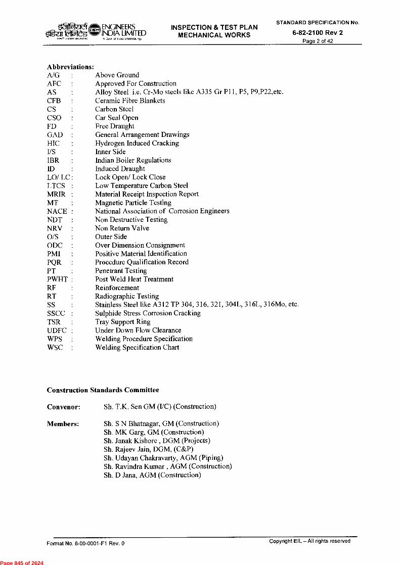
ENGINEERS INSPECTION & TEST PLAN Igaf laf5teg INDIA LIMITED
MECHANICAL WORKS
1411E, eit'Ore 4,7,1P. , IA GOA 01 India Undertaking)
STANDARD SPECIFICATION No.
6-82-2100 Rev 2 Page 2 of 42
Abbreviations: A/G Above Ground AFC Approved For Construction AS Alloy Steel i.e. Cr-Mo steels like A335 Gr P11, P5, P9,P22,etc. CFB Ceramic Fibre Blankets CS Carbon Steel CSO Car Seal Open FD Free Draught GAD : General Arrangement Drawings HIC Hydrogen Induced Cracking I/S Inner Side IBR Indian Boiler Regulations ID : Induced Draught LO/ LC: Lock Open/ Lock Close LTCS : Low Temperature Carbon Steel MRIR : Material Receipt Inspection Report MT : Magnetic Particle Testing NACE : National Association of Corrosion Engineers NDT : Non Destructive Testing NRV : Non Return Valve 0/S Outer Side ODC : Over Dimension Consignment PMI Positive Material Identification PQR Procedure Qualification Record PT Penetrant Testing PWHT : Post Weld Heat Treatment RF Reinforcement RT Radiographic Testing SS Stainless Steel like A312 TP 304, 316, 321, 304L, 316L, 316Mo, etc. SSCC : Sulphide Stress Corrosion Cracking TSR Tray Support Ring UDFC : Under Down Flow Clearance WPS Welding Procedure Specification WSC : Welding Specification Chart
Construction Standards Committee
Convenor: Sh. T.K. Sen GM (I/C) (Construction)
Members: Sh. S N Bhatnagar, GM (Construction) Sh. MK Garg, GM (Construction) Sh. Janak Kishore , DGM (Projects) Sh. Rajeev Jain, DGM, (C&P) Sh. Udayan Chakravarty, AGM (Piping) Sh. Ravindra Kumar , AGM (Construction) Sh. D Jana, AGM (Construction)
Format No. 8-00-0001-F1 Rev. 0 Copyright EIL — All rights reserved
Page 845 of 2624

INSPECTION & TEST PLAN
MECHANICAL WORKS
STANDARD SPECIFICATION No.
6-82-2100 Rev 2 Page 3 of 42
Format No. 8-00-0001-F1 Rev. 0 Copyright EIL – All rights reserved
CONTENTS
S.NO DESCRIPTION DOCUMENT NO. PAGE
NO.
ITPs FOR Mechanical works
1. Above Ground Piping 2110 5-7
2. Column Internals 2120 8-9
3. Fired Heaters 2130 10-13
4. Refractory And Insulation
Works(Fired Heaters) 2140 14-19
5. Equipment Erection (Static) 2150 20-22
6. Equipment Erection (Rotary) 2160 23-25
7. Installation /Erection and
testing of Cranes (EOT/HOT)
2170 26
8. Storage tanks 2180 27-31
9. Surface Preparation and Painting 2190 32-33
10. Insulation works 2200 34
FORMATS
11. Checklist for Mechanical Clearance - A/G Piping
M-01 35-38
12. Hydro test Pack Punch list M-02 39
13. Release for Hydro Test – A/G
Piping M-03 40
14. Piping Hydro Test Record – A/G
Piping M-04 41
15. Authorization for Modification Of
Piping Joints M-05 42
Page 846 of 2624
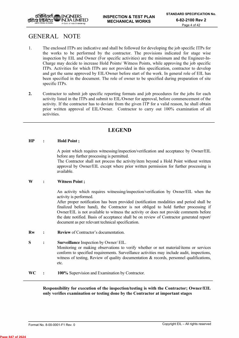
INSPECTION & TEST PLAN
MECHANICAL WORKS
STANDARD SPECIFICATION No.
6-82-2100 Rev 2 Page 4 of 42
Format No. 8-00-0001-F1 Rev. 0 Copyright EIL – All rights reserved
GENERAL NOTE 1. The enclosed ITPs are indicative and shall be followed for developing the job specific ITPs for
the works to be performed by the contractor. The provisions indicated for stage wise inspection by EIL and Owner (For specific activities) are the minimum and the Engineer-In-Charge may decide to increase Hold Points/ Witness Points, while approving the job specific ITPs. Activities for which ITPs are not provided in this specification, contractor to develop and get the same approved by EIL/Owner before start of the work. In general role of EIL has been specified in the document. The role of owner to be specified during preparation of site specific ITPs.
2. Contractor to submit job specific reporting formats and job procedures for the jobs for each
activity listed in the ITPs and submit to EIL/Owner for approval, before commencement of the activity. If the contractor has to deviate from the given ITP for a valid reason, he shall obtain prior written approval of EIL/Owner. Contractor to carry out 100% examination of all activities.
LEGEND HP : Hold Point ;
A point which requires witnessing/inspection/verification and acceptance by Owner/EIL before any further processing is permitted. The Contractor shall not process the activity/item beyond a Hold Point without written approval by Owner/EIL except where prior written permission for further processing is available.
W : Witness Point ; An activity which requires witnessing/inspection/verification by Owner/EIL when the activity is performed. After proper notification has been provided (notification modalities and period shall be finalized before hand), the Contractor is not obliged to hold further processing if Owner/EIL is not available to witness the activity or does not provide comments before the date notified. Basis of acceptance shall be on review of Contractor generated report/ document as per relevant technical specification.
Rw : Review of Contractor’s documentation.
S : Surveillance Inspection by Owner/ EIL. Monitoring or making observations to verify whether or not material/items or services conform to specified requirements. Surveillance activities may include audit, inspections, witness of testing, Review of quality documentation & records, personnel qualifications, etc.
WC : 100% Supervision and Examination by Contractor.
Responsibility for execution of the inspection/testing is with the Contractor; Owner/EIL only verifies examination or testing done by the Contractor at important stages
Page 847 of 2624
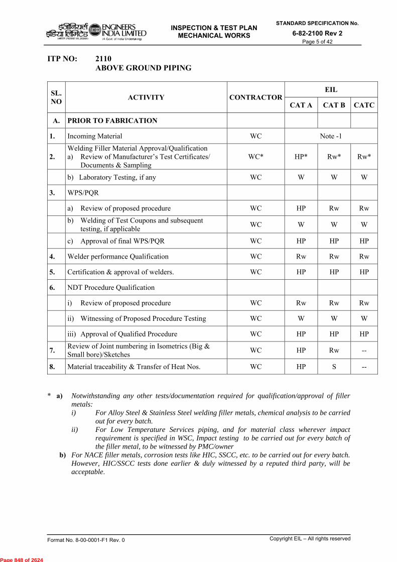
INSPECTION & TEST PLAN
MECHANICAL WORKS
STANDARD SPECIFICATION No.
6-82-2100 Rev 2 Page 5 of 42
Format No. 8-00-0001-F1 Rev. 0 Copyright EIL – All rights reserved
ITP NO: 2110 ABOVE GROUND PIPING
SL. NO
ACTIVITY CONTRACTOR EIL
CAT A CAT B CATC
A. PRIOR TO FABRICATION
1. Incoming Material WC Note -1
2. Welding Filler Material Approval/Qualification a) Review of Manufacturer’s Test Certificates/
Documents & Sampling WC* HP* Rw* Rw*
b) Laboratory Testing, if any WC W W W
3. WPS/PQR
a) Review of proposed procedure WC HP Rw Rw
b) Welding of Test Coupons and subsequent
testing, if applicable WC W W W
c) Approval of final WPS/PQR WC HP HP HP
4. Welder performance Qualification WC Rw Rw Rw
5. Certification & approval of welders. WC HP HP HP
6. NDT Procedure Qualification
i) Review of proposed procedure WC Rw Rw Rw
ii) Witnessing of Proposed Procedure Testing WC W W W
iii) Approval of Qualified Procedure WC HP HP HP
7. Review of Joint numbering in Isometrics (Big & Small bore)/Sketches
WC HP Rw --
8. Material traceability & Transfer of Heat Nos. WC HP S --
* a) Notwithstanding any other tests/documentation required for qualification/approval of filler
metals: i) For Alloy Steel & Stainless Steel welding filler metals, chemical analysis to be carried
out for every batch. ii) For Low Temperature Services piping, and for material class wherever impact
requirement is specified in WSC, Impact testing to be carried out for every batch of the filler metal, to be witnessed by PMC/owner
b) For NACE filler metals, corrosion tests like HIC, SSCC, etc. to be carried out for every batch. However, HIC/SSCC tests done earlier & duly witnessed by a reputed third party, will be acceptable.
Page 848 of 2624
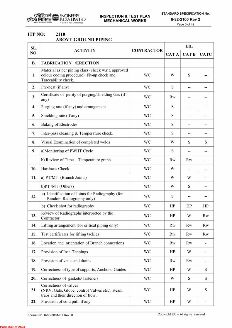
INSPECTION & TEST PLAN
MECHANICAL WORKS
STANDARD SPECIFICATION No.
6-82-2100 Rev 2 Page 6 of 42
Format No. 8-00-0001-F1 Rev. 0 Copyright EIL – All rights reserved
ITP NO: 2110 ABOVE GROUND PIPING
SL. NO.
ACTIVITY CONTRACTOREIL
CAT A CAT B CATC
B. FABRICATION /ERECTION
1. Material as per piping class (check w.r.t. approved colour coding procedure), Fit-up check and Traceability check.
WC W S --
2. Pre-heat (if any) WC S -- --
3. Certificate of purity of purging/shielding Gas (if any)
WC Rw -- --
4. Purging rate (if any) and arrangement WC S -- --
5. Shielding rate (if any) WC S -- --
6. Baking of Electrodes WC S -- --
7. Inter-pass cleaning & Temperature check. WC S -- --
8. Visual Examination of completed welds WC W S S
9. a)Monitoring of PWHT Cycle WC S -- --
b) Review of Time – Temperature graph WC Rw Rw --
10. Hardness Check WC W -- --
11. a) PT/MT (Branch Joints) WC W W --
b)PT /MT (Others) WC W S --
12. a) Identification of Joints for Radiography (for
Random Radiography only) WC S -- --
b) Check shot for radiography WC HP HP HP
13. Review of Radiographs interpreted by the Contractor
WC HP W Rw
14. Lifting arrangement (for critical piping only) WC Rw Rw Rw
15. Test certificates for lifting tackles WC Rw Rw Rw
16. Location and orientation of Branch connections WC Rw Rw -
17. Provision of Inst. Tappings WC HP W -
18. Provision of vents and drains WC Rw Rw -
19. Correctness of type of supports, Anchors, Guides WC HP W S
20. Correctness of gaskets/ fasteners WC W S S
21. Correctness of valves (NRV, Gate, Globe, control Valves etc.), steam traps and their direction of flow.
WC HP W S
22. Provision of cold pull, if any. WC HP W -
Page 849 of 2624
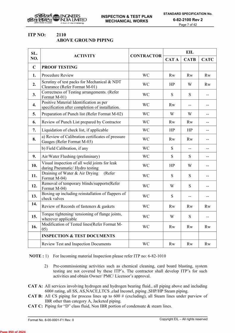
INSPECTION & TEST PLAN
MECHANICAL WORKS
STANDARD SPECIFICATION No.
6-82-2100 Rev 2 Page 7 of 42
Format No. 8-00-0001-F1 Rev. 0 Copyright EIL – All rights reserved
ITP NO: 2110 ABOVE GROUND PIPING
SL. NO.
ACTIVITY CONTRACTOREIL
CAT A CATB CATC
C PROOF TESTING
1. Procedure Review WC Rw Rw Rw
2. Scrutiny of test packs for Mechanical & NDT Clearance (Refer Format M-01) WC HP W Rw
3. Correctness of Testing arrangements. (Refer Format M-01)
WC S S --
4. Positive Material Identification as per specification after completion of installation.
WC Rw -- --
5. Preparation of Punch list (Refer Format M-02) WC W W --
6. Review of Punch List prepared by Contractor WC Rw Rw --
7. Liquidation of check list, if applicable WC HP HP --
8. a) Review of Calibration certificates of pressure Gauges (Refer Format M-03)
WC Rw Rw --
b) Field Calibration, if any WC S -- --
9. Air/Water Flushing (preliminary) WC S S --
10. Visual inspection of all weld joints for leak during Pneumatic/ Hydro testing
WC HP W --
11. Draining of Water & Air Drying (Refer Format M-04)
WC S S --
12. Removal of temporary blinds/supports(Refer Format M-04)
WC W S --
13. Boxing up including reinstallation of flappers of check valves
WC S -- --
14.
Review of Records of fasteners & gaskets WC Rw Rw Rw
15. Torque tightening/ tensioning of flange joints, wherever applicable
WC W S --
16. Modification of Tested lines(Refer Format M-05)
WC Rw Rw Rw
INSPECTION & TEST DOCUMENTS
Review Test and Inspection Documents WC Rw Rw Rw
NOTE : 1) For Incoming material Inspection please refer ITP no: 6-82-1010 2) Pre-commissioning activities such as chemical cleaning, card board blasting, system
testing are not covered by these ITP’s. The contractor shall develop ITP’s for such activities and obtain Owner/ PMC/ Licensor’s approval.
CAT A: All services involving hydrogen and hydrogen bearing fluid., all piping above and including
600# rating, all SS, AS,NACE,LTCS ,clad Inconel, piping ,SHP/HP Steam piping. CAT B: All CS piping for process lines up to 600 # (excluding), all Steam lines under purview of
IBR other than category A, Jacketed piping. CAT C: Piping for “D” class fluid, Non IBR portion of condensate & steam lines.
Page 850 of 2624

INSPECTION & TEST PLAN
MECHANICAL WORKS
STANDARD SPECIFICATION No.
6-82-2100 Rev 2 Page 8 of 42
Format No. 8-00-0001-F1 Rev. 0 Copyright EIL – All rights reserved
ITP NO: 2120 COLUMN INTERNALS
SL. NO.
ACTIVITY CONTRACTOR EIL
CAT A
INSTALLATION OF COLUMN INTERNALS
A. Before Installation
1. Internal Installation Procedure including identification of confined space hazards & mitigation thereof
WC Rw
2. Material inspection WC Note-1
3. Level check on TSRs WC S
4. Check for down comer clearance and Tray clearance WC S
5. Distance between TSRs WC S
B. After Installation - Check for
1. Exit weir height WC S
2. UDFC WC S
3. Tightness of bolts WC S
4. Orientation and tightness of clamps WC S
5. Provision of lock nuts/seal plates WC HP
Page 851 of 2624

INSPECTION & TEST PLAN
MECHANICAL WORKS
STANDARD SPECIFICATION No.
6-82-2100 Rev 2 Page 9 of 42
Format No. 8-00-0001-F1 Rev. 0 Copyright EIL – All rights reserved
ITP NO: 2120 COLUMN INTERNALS SL. NO.
ACTIVITY CONTRACTOR EIL
CAT A
6. Correctness of installation of shimming/bolting for top down comer
WC HP**
7. Correctness of gasket (if any) WC S
8. Tray to tray distance and level of trays
WC S
9. Leak testing of seal pans as applicable WC S
10. Damaged, missing valves and valve movements for valve trays WC S
11. Fitting of proper valve combination WC S
12. Damage to deck components WC S
13. Level and alignment of inlet weir and exit weir WC S
14. Check for proper location of slots on tray components WC S
16. Check for Gaps at down comer ends WC S
17. Removal of temporary plugs after testing WC S
18. Cleaning of all trays & inside of equipment WC* HP
19. Certification of installation by Vendor’s representative Final boxing up, if any.
WC* HP**
INSPECTION & TEST DOCUMENTS
Review Test and Inspection Documents
Vendor Representative to Check 100% ** By Owner/Process Licensor NOTE : 1) For Incoming material Inspection please refer ITP no: 6-82-1010 CAT A: All works
Page 852 of 2624
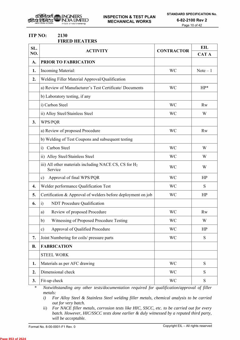
INSPECTION & TEST PLAN
MECHANICAL WORKS
STANDARD SPECIFICATION No.
6-82-2100 Rev 2 Page 10 of 42
Format No. 8-00-0001-F1 Rev. 0 Copyright EIL – All rights reserved
ITP NO: 2130 FIRED HEATERS
SL. NO.
ACTIVITY CONTRACTOR EIL
CAT A
A. PRIOR TO FABRICATION
1. Incoming Material: WC Note – 1
2. Welding Filler Material Approval/Qualification
a) Review of Manufacturer’s Test Certificate/ Documents WC HP*
b) Laboratory testing, if any
i) Carbon Steel WC Rw
ii) Alloy Steel/Stainless Steel WC W
3. WPS/PQR
a) Review of proposed Procedure WC Rw
b) Welding of Test Coupons and subsequent testing
i) Carbon Steel WC W
ii) Alloy Steel/Stainless Steel WC W
iii) All other materials including NACE CS, CS for H2 Service
WC W
c) Approval of final WPS/PQR WC HP
4. Welder performance Qualification Test WC S
5. Certification & Approval of welders before deployment on job WC HP
6. i) NDT Procedure Qualification
a) Review of proposed Procedure WC Rw
b) Witnessing of Proposed Procedure Testing WC W
c) Approval of Qualified Procedure WC HP
7. Joint Numbering for coils/ pressure parts WC S
B. FABRICATION
STEEL WORK
1. Materials as per AFC drawing WC S
2. Dimensional check WC S
3. Fit-up check WC S
* Notwithstanding any other tests/documentation required for qualification/approval of filler metals: i) For Alloy Steel & Stainless Steel welding filler metals, chemical analysis to be carried
out for very batch. ii) For NACE filler metals, corrosion tests like HIC, SSCC, etc. to be carried out for every
batch. However, HIC/SSCC tests done earlier & duly witnessed by a reputed third party, will be acceptable.
Page 853 of 2624
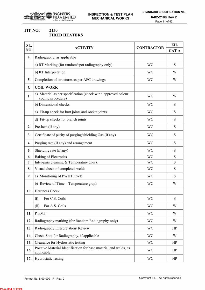
INSPECTION & TEST PLAN
MECHANICAL WORKS
STANDARD SPECIFICATION No.
6-82-2100 Rev 2 Page 11 of 42
Format No. 8-00-0001-F1 Rev. 0 Copyright EIL – All rights reserved
ITP NO: 2130 FIRED HEATERS
SL. NO.
ACTIVITY CONTRACTOR EIL
CAT A
4. Radiography, as applicable
a) RT Marking (for random/spot radiography only) WC S
b) RT Interpretation WC W
5. Completion of structures as per AFC drawings WC W
C COIL WORK
1. a) Material as per specification (check w.r.t. approved colour
coding procedure) WC W
b) Dimensional checks WC S
c) Fit-up check for butt joints and socket joints WC S
d) Fit-up checks for branch joints WC S
2. Pre-heat (if any) WC S
3. Certificate of purity of purging/shielding Gas (if any) WC S
4. Purging rate (if any) and arrangement WC S
5. Shielding rate (if any) WC S
6. Baking of Electrodes WC S
7. Inter-pass cleaning & Temperature check WC S
8. Visual check of completed welds WC S
9. a) Monitoring of PWHT Cycle WC S
b) Review of Time – Temperature graph WC W
10. Hardness Check
(i) For C.S. Coils WC S
(ii) For A.S. Coils WC W
11. PT/MT WC W
12. Radiography marking (for Random Radiography only) WC W
13. Radiography Interpretation/ Review WC HP
14. Check Shot for Radiography, if applicable WC W
15. Clearance for Hydrostatic testing WC HP
16. Positive Material Identification for base material and welds, as applicable
WC HP
17. Hydrostatic testing WC HP
Page 854 of 2624

INSPECTION & TEST PLAN
MECHANICAL WORKS
STANDARD SPECIFICATION No.
6-82-2100 Rev 2 Page 12 of 42
Format No. 8-00-0001-F1 Rev. 0 Copyright EIL – All rights reserved
ITP NO: 2130 FIRED HEATERS
SL. NO
ACTIVITY CONTRACTOR EIL
CAT A
D. ERECTION
1. Review of foundation check as per AFC drawing WC HP
2. Lifting of radiant section columns and their alignment WC S
3. Bottom plate fit-up & welding WC S
4. Radiant shell courses fit-up & welding WC S
5. Weld visual inspection WC S
6. Review of radiographs interpreted by the contractors WC W
7. Cutout
a) Marking for burners, sight doors, soot blowers WC S
b) Marking for balance cut outs WC S
c) Cutting WC S
8. Coil erection in Radiant section
a) Fixing of coil support castings WC S
b) Clearance for erection of coil WC S
c) Alignment of completed coil work WC W
9. Assembly and erection of convection box
a) Erection procedure Review WC S
b) Structural including plate work WC S
c) End tube sheets and intermediate tube sheets with
support brackets WC S
d) Clearance of coil erection WC W
e) Erection of box (If applicable) WC W
10. Check Shot for radiography for coil field joints, if applicable WC W
11. Clearance for Hydro test WC HP
12. Hydro test WC HP
Page 855 of 2624
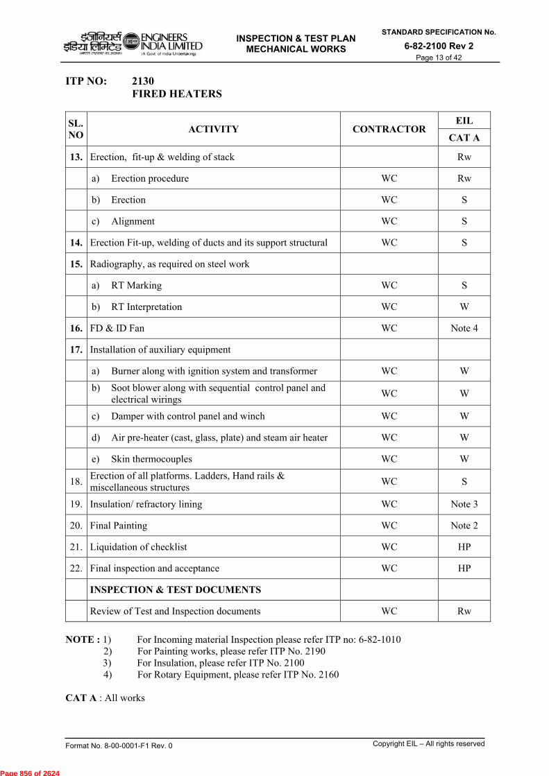
INSPECTION & TEST PLAN
MECHANICAL WORKS
STANDARD SPECIFICATION No.
6-82-2100 Rev 2 Page 13 of 42
Format No. 8-00-0001-F1 Rev. 0 Copyright EIL – All rights reserved
ITP NO: 2130 FIRED HEATERS
SL. NO
ACTIVITY CONTRACTOR EIL
CAT A
13. Erection, fit-up & welding of stack Rw
a) Erection procedure WC Rw
b) Erection WC S
c) Alignment WC S
14. Erection Fit-up, welding of ducts and its support structural WC S
15. Radiography, as required on steel work
a) RT Marking WC S
b) RT Interpretation WC W
16. FD & ID Fan WC Note 4
17. Installation of auxiliary equipment
a) Burner along with ignition system and transformer WC W
b) Soot blower along with sequential control panel and
electrical wirings WC W
c) Damper with control panel and winch WC W
d) Air pre-heater (cast, glass, plate) and steam air heater WC W
e) Skin thermocouples WC W
18. Erection of all platforms. Ladders, Hand rails & miscellaneous structures
WC S
19. Insulation/ refractory lining WC Note 3
20. Final Painting WC Note 2
21. Liquidation of checklist WC HP
22. Final inspection and acceptance WC HP
INSPECTION & TEST DOCUMENTS
Review of Test and Inspection documents WC Rw
NOTE : 1) For Incoming material Inspection please refer ITP no: 6-82-1010 2) For Painting works, please refer ITP No. 2190 3) For Insulation, please refer ITP No. 2100 4) For Rotary Equipment, please refer ITP No. 2160 CAT A : All works
Page 856 of 2624
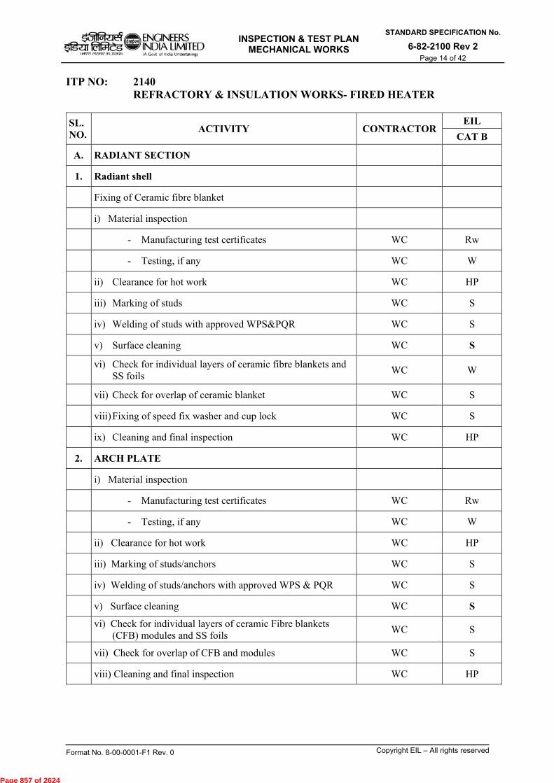
INSPECTION & TEST PLAN
MECHANICAL WORKS
STANDARD SPECIFICATION No.
6-82-2100 Rev 2 Page 14 of 42
Format No. 8-00-0001-F1 Rev. 0 Copyright EIL – All rights reserved
ITP NO: 2140 REFRACTORY & INSULATION WORKS- FIRED HEATER
SL. NO.
ACTIVITY CONTRACTOR EIL
CAT B
A. RADIANT SECTION
1. Radiant shell
Fixing of Ceramic fibre blanket
i) Material inspection
- Manufacturing test certificates WC Rw
- Testing, if any WC W
ii) Clearance for hot work WC HP
iii) Marking of studs WC S
iv) Welding of studs with approved WPS&PQR WC S
v) Surface cleaning WC S
vi) Check for individual layers of ceramic fibre blankets and
SS foils WC W
vii) Check for overlap of ceramic blanket WC S
viii) Fixing of speed fix washer and cup lock WC S
ix) Cleaning and final inspection WC HP
2. ARCH PLATE
i) Material inspection
- Manufacturing test certificates WC Rw
- Testing, if any WC W
ii) Clearance for hot work WC HP
iii) Marking of studs/anchors WC S
iv) Welding of studs/anchors with approved WPS & PQR WC S
v) Surface cleaning WC S
vi) Check for individual layers of ceramic Fibre blankets
(CFB) modules and SS foils WC S
vii) Check for overlap of CFB and modules WC S
viii) Cleaning and final inspection WC HP
Page 857 of 2624

INSPECTION & TEST PLAN
MECHANICAL WORKS
STANDARD SPECIFICATION No.
6-82-2100 Rev 2 Page 15 of 42
Format No. 8-00-0001-F1 Rev. 0 Copyright EIL – All rights reserved
ITP NO: 2140 REFRACTORY & INSULATION WORKS- FIRED HEATER SL. NO.
ACTIVITY CONTRACTOR EIL
CAT B
3. FLOOR PLATE
Laying of castable/fire bricks
i) Material inspection
- Manufacturing test certificates WC Rw
- Testing, if any WC W
ii) Clearance for hot work WC HP
iii) Surface cleaning WC S
iv) Check Shelf life prior to application WC W
v) Check for undulations on floor WC S
vi) Check for castable mix WC W
vii) Check for proper compaction WC S
viii) Check for thickness of castable WC S
ix) Curing WC S
x) Cleaning after laying of castable WC S
xi) Check for cracks and repair WC W
xii) Fixing of tar paper, if applicable WC S
xiii) Cleaning and final inspection WC HP
B. CONVECTION SECTION
1) CONVECTION WALLS
Laying of castable
i) Material inspection
- Manufacturing test certificates WC Rw
- Testing, if any - Manufacturing test certificates WC W
Page 858 of 2624
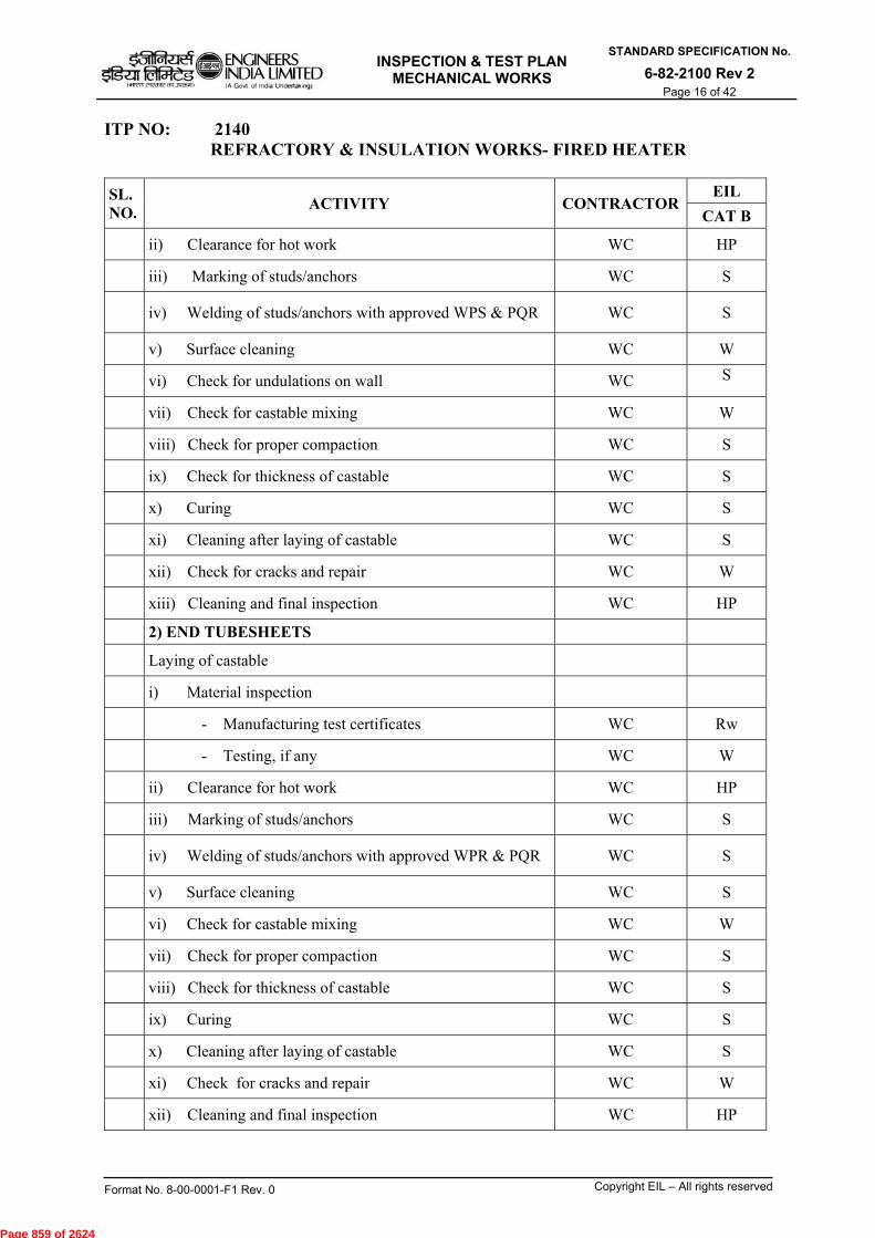
INSPECTION & TEST PLAN
MECHANICAL WORKS
STANDARD SPECIFICATION No.
6-82-2100 Rev 2 Page 16 of 42
Format No. 8-00-0001-F1 Rev. 0 Copyright EIL – All rights reserved
ITP NO: 2140 REFRACTORY & INSULATION WORKS- FIRED HEATER
SL. NO.
ACTIVITY CONTRACTOR EIL
CAT B
ii) Clearance for hot work WC HP
iii) Marking of studs/anchors WC S
iv) Welding of studs/anchors with approved WPS & PQR WC S
v) Surface cleaning WC W
vi) Check for undulations on wall WC S
vii) Check for castable mixing WC W
viii) Check for proper compaction WC S
ix) Check for thickness of castable WC S
x) Curing WC S
xi) Cleaning after laying of castable WC S
xii) Check for cracks and repair WC W
xiii) Cleaning and final inspection WC HP
2) END TUBESHEETS
Laying of castable
i) Material inspection
- Manufacturing test certificates WC Rw
- Testing, if any WC W
ii) Clearance for hot work WC HP
iii) Marking of studs/anchors WC S
iv) Welding of studs/anchors with approved WPR & PQR WC S
v) Surface cleaning WC S
vi) Check for castable mixing WC W
vii) Check for proper compaction WC S
viii) Check for thickness of castable WC S
ix) Curing WC S
x) Cleaning after laying of castable WC S
xi) Check for cracks and repair WC W
xii) Cleaning and final inspection WC HP
Page 859 of 2624

INSPECTION & TEST PLAN
MECHANICAL WORKS
STANDARD SPECIFICATION No.
6-82-2100 Rev 2 Page 17 of 42
Format No. 8-00-0001-F1 Rev. 0 Copyright EIL – All rights reserved
ITP NO: 2140 REFRACTORY & INSULATION WORKS- FIRED HEATER SL. NO.
ACTIVITY CONTRACTOR EIL
CAT B
3) BREECHING PLATE
Laying of castable
i) Material inspection
- Manufacturing test certificates WC Rw
- Testing, if any WC W
ii) Clearance for hot work WC HP
iii) Marking of studs/anchors WC S
iv) Welding of studs/anchors with approved WPR & PQR WC S
v) Surface cleaning WC S
vi) Check for undulations on plate WC S
vii) Check for castable mixing WC W
viii) Check for proper compaction WC S
ix) Check for thickness of castable WC S
x) Curing WC S
xi) Cleaning after laying of castable WC S
xii) Check for cracks and repair WC W
xiii) Cleaning and final inspection WC HP
4) HEADER BOX
Laying of castable
i) Material inspection
- Manufacturing test certificates WC Rw
- Testing, if any WC W
ii) Clearance for hot work WC HP
iii) Marking of studs/anchors WC S
iv) Welding of studs/anchors with approved WPR & PQR WC S
v) Surface cleaning WC S
vi) Check for undulations on box WC S
vii) Check for castable mixing WC W
viii) Check for proper compaction WC S
ix) Check for thickness of castable WC S
x) Curing WC S
xi) Cleaning after laying of castable WC S
xii) Check for cracks and repair WC W
xiii) Cleaning and final inspection WC HP
Page 860 of 2624
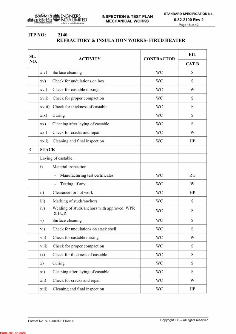
INSPECTION & TEST PLAN
MECHANICAL WORKS
STANDARD SPECIFICATION No.
6-82-2100 Rev 2 Page 18 of 42
Format No. 8-00-0001-F1 Rev. 0 Copyright EIL – All rights reserved
ITP NO: 2140 REFRACTORY & INSULATION WORKS- FIRED HEATER
SL. NO.
ACTIVITY CONTRACTOR EIL
CAT B
xiv) Surface cleaning WC S
xv) Check for undulations on box WC S
xvi) Check for castable mixing WC W
xvii) Check for proper compaction WC S
xviii) Check for thickness of castable WC S
xix) Curing WC S
xx) Cleaning after laying of castable WC S
xxi) Check for cracks and repair WC W
xxii) Cleaning and final inspection WC HP
C STACK
Laying of castable
i) Material inspection
- Manufacturing test certificates WC Rw
- Testing, if any WC W
ii) Clearance for hot work WC HP
iii) Marking of studs/anchors WC S
iv) Welding of studs/anchors with approved WPR
& PQR WC S
v) Surface cleaning WC S
vi) Check for undulations on stack shell WC S
vii) Check for castable mixing WC W
viii) Check for proper compaction WC S
ix) Check for thickness of castable WC S
x) Curing WC S
xi) Cleaning after laying of castable WC S
xii) Check for cracks and repair WC W
xiii) Cleaning and final inspection WC HP
Page 861 of 2624

INSPECTION & TEST PLAN
MECHANICAL WORKS
STANDARD SPECIFICATION No.
6-82-2100 Rev 2 Page 19 of 42
Format No. 8-00-0001-F1 Rev. 0 Copyright EIL – All rights reserved
ITP NO: 2140 REV 1 REFRACTORY & INSULATION WORKS- FIRED HEATER SL. NO.
ACTIVITY CONTRACTOR EIL
CAT BD HOT AIR DUCT
i) Material inspection
- Manufacturing test certificates WC Rw
- Testing, if any WC W
ii) Clearance for insulation WC HP
iii) External Surface cleaning WC S
iv) Provide spacer rings/anchors WC S
v) Check for thickness of the mineral wool insulation WC S
vi) Check for staggering of joints in insulation WC S
vii) Check for providing expansion joints WC W
viii) Overlapping of metal sheet as per specification WC S
ix) Overlap on joints for Aluminium sheeting as per
specifications WC W
x) Sealing Aluminium sheeting WC S
Final inspection & acceptance WC HP
E INSPECTION & TEST DOCUMENTS
Review Test and Inspection Documents WC Rw
CAT B: All works.
Page 862 of 2624

INSPECTION & TEST PLAN
MECHANICAL WORKS
STANDARD SPECIFICATION No.
6-82-2100 Rev 2 Page 20 of 42
Format No. 8-00-0001-F1 Rev. 0 Copyright EIL – All rights reserved
ITP NO: 2150 EQUIPMENT ERECTION (STATIC)
SL. NO
ACTIVITY CONTRACTOR EIL
CAT A CAT B CAT C
EQUIPMENT ERECTION (STATIC)
1. BEFORE ERECTION
a. Review of foundation acceptance report WC HP Rw Rw
b. Incoming material WC Note-1 Note-1 Note-1
c. Readiness for erection
i) Centre line marking on equipment and
foundation WC S -- --
ii) Level of foundation (shims/ packing with
marking to be prepared & kept ready) WC S -- --
iii) Correctness of no. & size of Foundation bolts WC S -- --
iv) Hole dia and no. of holes in base/ structure of
equipment columns WC S -- --
v) Matching equipment base bolt holes with
actual foundation bolt layout WC S -- --
vi) Marking orientation WC S -- --
vii) Checking the threads of bolts & nuts WC S -- --
viii) Chipping & roughening of foundation WC S -- --
d. Outside cleaning, coating/wrapping, painting (for underground equipment only)
WC HP W --
Page 863 of 2624
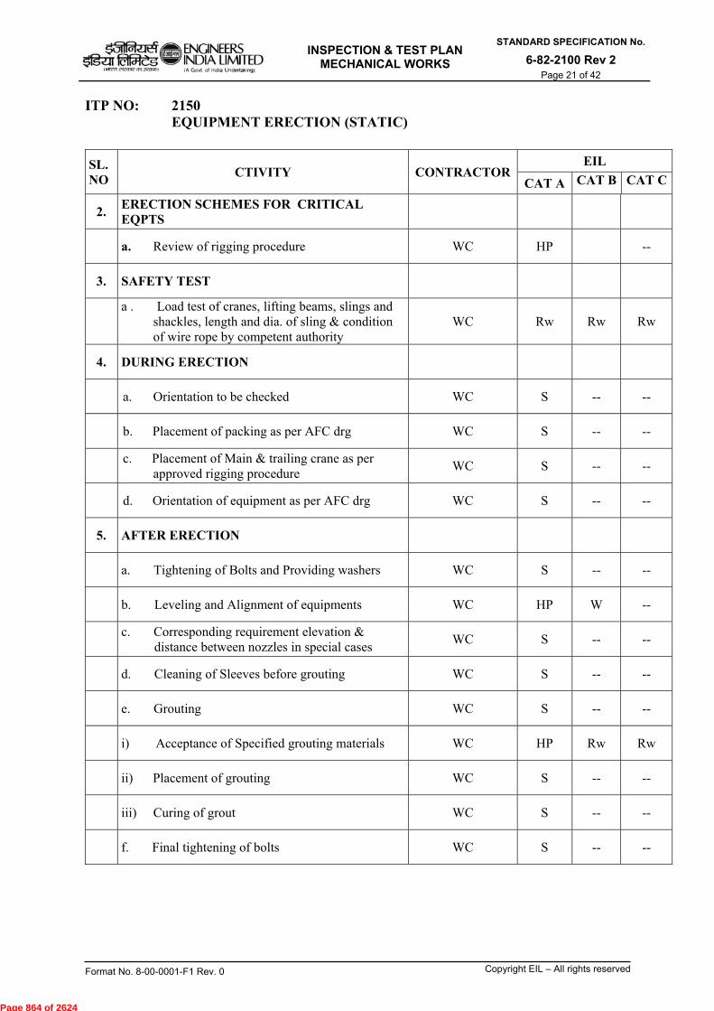
INSPECTION & TEST PLAN
MECHANICAL WORKS
STANDARD SPECIFICATION No.
6-82-2100 Rev 2 Page 21 of 42
Format No. 8-00-0001-F1 Rev. 0 Copyright EIL – All rights reserved
ITP NO: 2150 EQUIPMENT ERECTION (STATIC)
SL. NO
CTIVITY CONTRACTOR EIL
CAT A CAT B CAT C
2. ERECTION SCHEMES FOR CRITICAL EQPTS
a. Review of rigging procedure WC HP --
3. SAFETY TEST
a . Load test of cranes, lifting beams, slings and
shackles, length and dia. of sling & condition of wire rope by competent authority
WC Rw Rw Rw
4. DURING ERECTION
a. Orientation to be checked WC S -- --
b. Placement of packing as per AFC drg WC S -- --
c. Placement of Main & trailing crane as per approved rigging procedure
WC S -- --
d. Orientation of equipment as per AFC drg WC S -- --
5. AFTER ERECTION
a. Tightening of Bolts and Providing washers WC S -- --
b. Leveling and Alignment of equipments WC HP W --
c. Corresponding requirement elevation & distance between nozzles in special cases
WC S -- --
d. Cleaning of Sleeves before grouting WC S -- --
e. Grouting WC S -- --
i) Acceptance of Specified grouting materials WC HP Rw Rw
ii) Placement of grouting WC S -- --
iii) Curing of grout WC S -- --
f. Final tightening of bolts WC S -- --
Page 864 of 2624
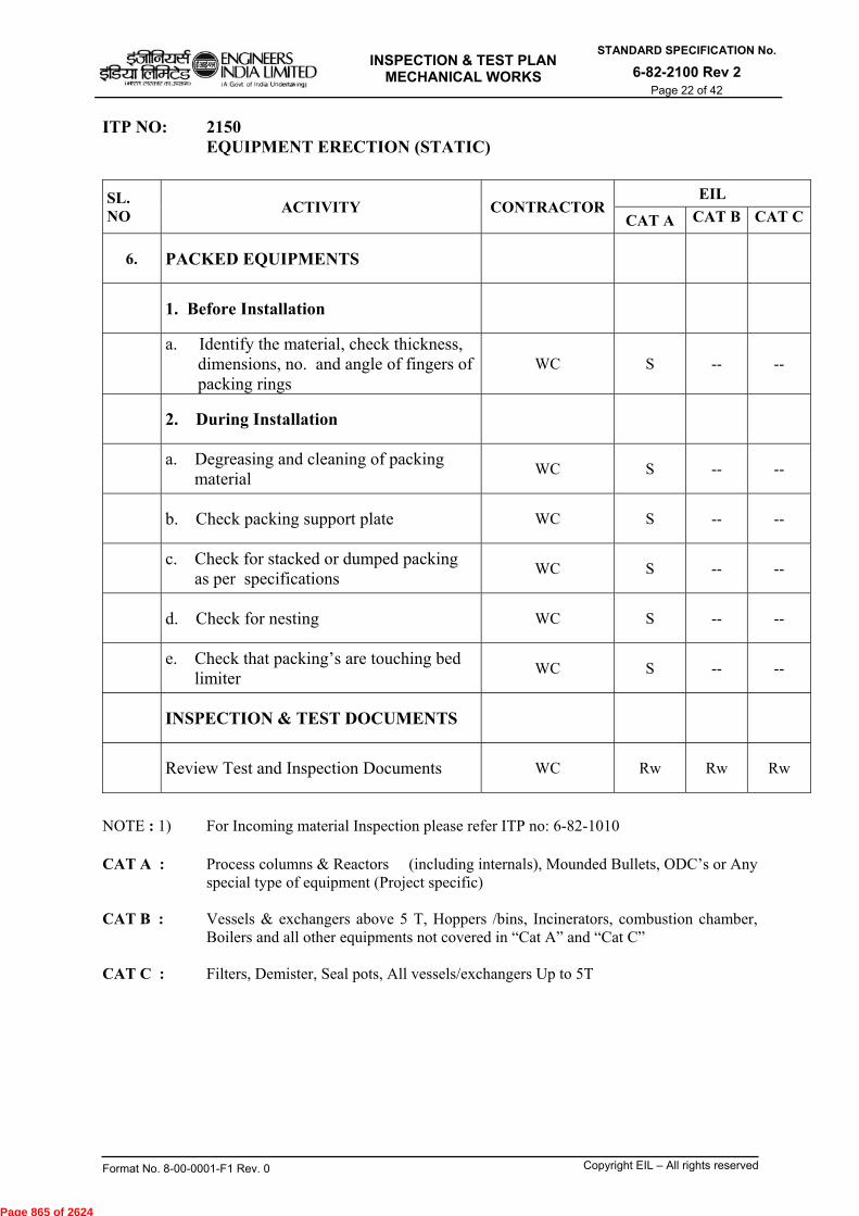
INSPECTION & TEST PLAN
MECHANICAL WORKS
STANDARD SPECIFICATION No.
6-82-2100 Rev 2 Page 22 of 42
Format No. 8-00-0001-F1 Rev. 0 Copyright EIL – All rights reserved
ITP NO: 2150 EQUIPMENT ERECTION (STATIC)
SL. NO
ACTIVITY CONTRACTOR EIL
CAT A CAT B CAT C
6. PACKED EQUIPMENTS
1. Before Installation
a. Identify the material, check thickness,
dimensions, no. and angle of fingers of packing rings
WC S -- --
2. During Installation
a. Degreasing and cleaning of packing
material WC S -- --
b. Check packing support plate WC S -- --
c. Check for stacked or dumped packing
as per specifications WC S -- --
d. Check for nesting WC S -- --
e. Check that packing’s are touching bed
limiter WC S -- --
INSPECTION & TEST DOCUMENTS
Review Test and Inspection Documents WC Rw Rw Rw
NOTE : 1) For Incoming material Inspection please refer ITP no: 6-82-1010 CAT A : Process columns & Reactors (including internals), Mounded Bullets, ODC’s or Any
special type of equipment (Project specific) CAT B : Vessels & exchangers above 5 T, Hoppers /bins, Incinerators, combustion chamber,
Boilers and all other equipments not covered in “Cat A” and “Cat C” CAT C : Filters, Demister, Seal pots, All vessels/exchangers Up to 5T
Page 865 of 2624
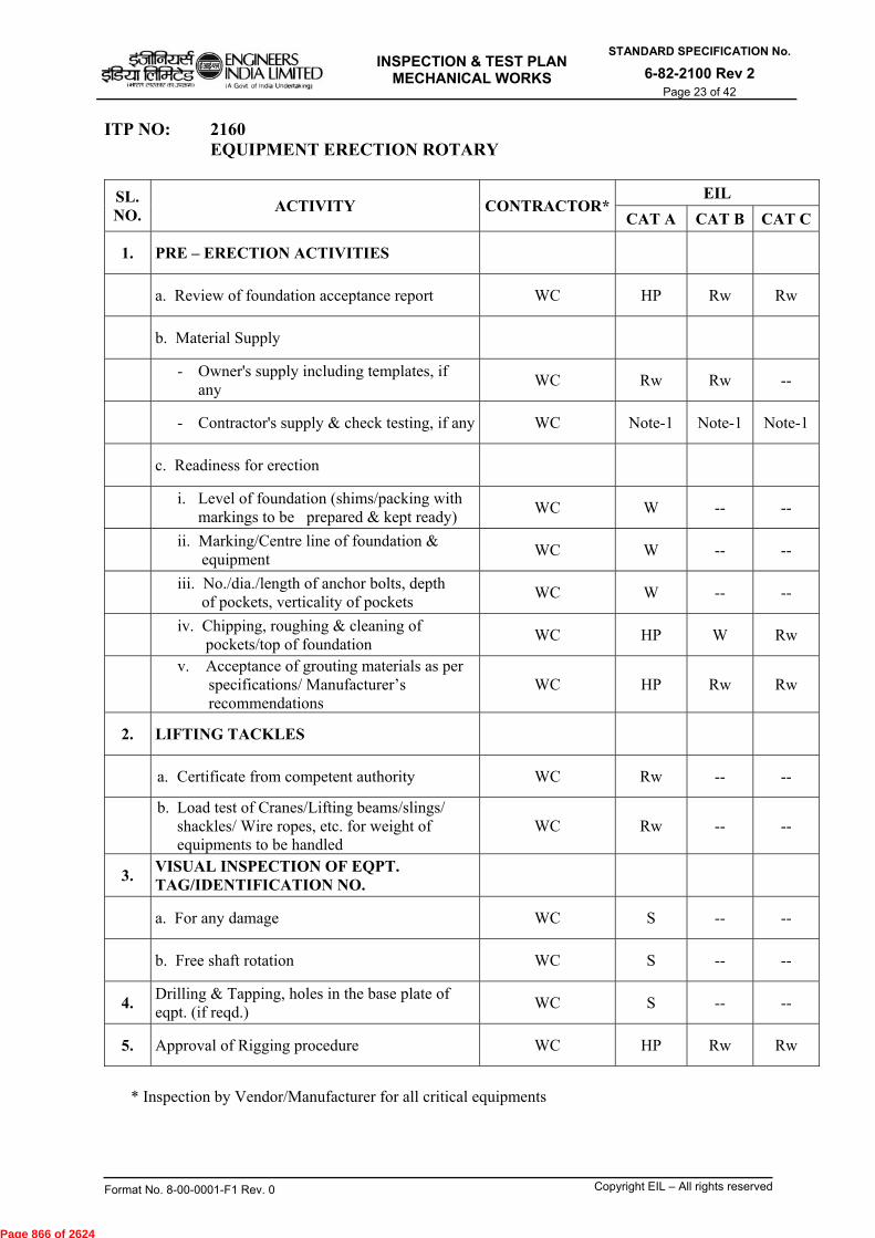
INSPECTION & TEST PLAN
MECHANICAL WORKS
STANDARD SPECIFICATION No.
6-82-2100 Rev 2 Page 23 of 42
Format No. 8-00-0001-F1 Rev. 0 Copyright EIL – All rights reserved
ITP NO: 2160 EQUIPMENT ERECTION ROTARY
SL. NO.
ACTIVITY CONTRACTOR*EIL
CAT A CAT B CAT C
1. PRE – ERECTION ACTIVITIES
a. Review of foundation acceptance report WC HP Rw Rw
b. Material Supply
- Owner's supply including templates, if
any WC Rw Rw --
- Contractor's supply & check testing, if any WC Note-1 Note-1 Note-1
c. Readiness for erection
i. Level of foundation (shims/packing with
markings to be prepared & kept ready) WC W -- --
ii. Marking/Centre line of foundation & equipment
WC W -- --
iii. No./dia./length of anchor bolts, depth of pockets, verticality of pockets
WC W -- --
iv. Chipping, roughing & cleaning of pockets/top of foundation
WC HP W Rw
v. Acceptance of grouting materials as per
specifications/ Manufacturer’s recommendations
WC HP Rw Rw
2. LIFTING TACKLES
a. Certificate from competent authority WC Rw -- --
b. Load test of Cranes/Lifting beams/slings/
shackles/ Wire ropes, etc. for weight of equipments to be handled
WC Rw -- --
3. VISUAL INSPECTION OF EQPT. TAG/IDENTIFICATION NO.
a. For any damage WC S -- --
b. Free shaft rotation WC S -- --
4. Drilling & Tapping, holes in the base plate of eqpt. (if reqd.)
WC S -- --
5. Approval of Rigging procedure WC HP Rw Rw
* Inspection by Vendor/Manufacturer for all critical equipments
Page 866 of 2624
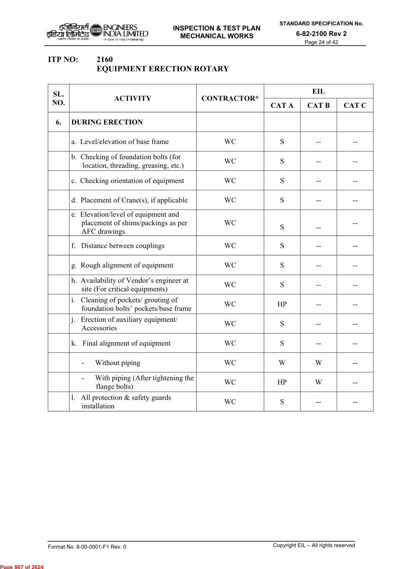
INSPECTION & TEST PLAN
MECHANICAL WORKS
STANDARD SPECIFICATION No.
6-82-2100 Rev 2 Page 24 of 42
Format No. 8-00-0001-F1 Rev. 0 Copyright EIL – All rights reserved
ITP NO: 2160 EQUIPMENT ERECTION ROTARY
SL. NO.
ACTIVITY CONTRACTOR* EIL
CAT A CAT B CAT C
6. DURING ERECTION
a. Level/elevation of base frame WC S -- --
b. Checking of foundation bolts (for location, threading, greasing, etc.)
WC S -- --
c. Checking orientation of equipment WC S -- --
d. Placement of Crane(s), if applicable WC S -- --
e. Elevation/level of equipment and
placement of shims/packings as per AFC drawings
WC
S
-- --
f. Distance between couplings WC S -- --
g. Rough alignment of equipment WC S -- --
h. Availability of Vendor’s engineer at
site (For critical equipments) WC S -- --
i. Cleaning of pockets/ grouting of
foundation bolts’ pockets/base frame WC HP -- --
j. Erection of auxiliary equipment/
Accessories WC S -- --
k. Final alignment of equipment WC S -- --
- Without piping WC W W --
- With piping (After tightening the
flange bolts) WC HP W --
l. All protection & safety guards
installation WC S -- --
Page 867 of 2624

INSPECTION & TEST PLAN
MECHANICAL WORKS
STANDARD SPECIFICATION No.
6-82-2100 Rev 2 Page 25 of 42
Format No. 8-00-0001-F1 Rev. 0 Copyright EIL – All rights reserved
ITP NO: 2160 EQUIPMENT ERECTION ROTARY
SL. NO.
ACTIVITY CONTRACTOR*EIL
CAT A CAT B CAT C
7. POST ERECTION ACTIVITIES
a. Curing of grout WC S -- --
b. Auxiliary connections to be mounted on eqpts as per drawing
WC S -- --
c. Final tightening of bolts WC S -- --
d. Chemical cleaning of equipment parts/
connected piping WC S -- --
e. Boxing up of equipment & connected
piping WC S -- --
f. Log book maintenance (For rotating of shaft and any other activity to be performed as per vendor’s
recommendations)
WC S -- --
g. No load run of motors WC HP W Rw
h. Re-coupling of motor & reconfirmation
of alignment WC HP W Rw
INSPECTION & TEST DOCUMENTS
Review Test and Inspection Documents WC S -- --
* Inspection by Vendor/Manufacturer for all critical equipments
NOTE : 1) For Incoming material Inspection please refer ITP no: 6-82-1010
CAT A : Compressors, Pumps ( ratings>15 KW), Turbines & Diesel Engines, Rotary Driers or Any
special type of equipment ( Project specific) CAT B : All types of pumps excluding category A & C, Fans & Blowers Conveyors & Material
handling Equipment CAT C : Metering & Dosing Pumps, etc.
Page 868 of 2624

INSPECTION & TEST PLAN
MECHANICAL WORKS
STANDARD SPECIFICATION No.
6-82-2100 Rev 2 Page 26 of 42
Format No. 8-00-0001-F1 Rev. 0 Copyright EIL – All rights reserved
ITP NO: 2170 INSTALLATION/ERECTION & TESTING OF CRANES (EOT/HOT)
SL. NO.
ACTIVITY CONTRACTOR EIL
CAT A CAT B CAT C
1. BEFORE ERECTION
a. Execution scheme of equipment
foundation WC Rw
b. Materials supply WC Note-1 Note-1 Note-1
c. Readiness for erection WC W -- --
i. Structural steel girder span centre to
centre & elevation difference WC W -- --
ii. Check centre to centre distance of rails, gaps, elevations, crab wheels distances
WC W -- --
iii. Check buffer stops WC W -- --
2 a. Erection and assembly of components like LT, Crane Girders, Crab, Platforms, etc.
WC S -- --
b. Review of hoist ropes and assembly of hook blocks
WC S -- --
3. a. Electrical installation, testing & no load test of motors
WC S -- --
b. Coupling of motors to drivers WC S -- --
4. NO LOAD TEST
a. Winding & unwinding test WC W -- --
b. Traversing test WC W -- --
c. Traveling test WC W -- --
5. LOAD TEST
a. Winding & unwinding test WC HP W Rw
b. Traversing test WC HP W Rw
c. Traveling test WC HP W Rw
d. Load & over load testing WC HP W Rw
e. Deflection of girder WC HP W Rw
INSPECTION & TEST DOCUMENTS
Review Test and Inspection Documents WC Rw Rw Rw
NOTE : 1) For Incoming material Inspection please refer ITP no: 6-82-1010 CAT A: Special purpose M/C viz. Pot tending M/c CAT B: All EOT cranes with capacity 10T and above CAT C : All EOT /HOT cranes with capacity below 10T
Page 869 of 2624
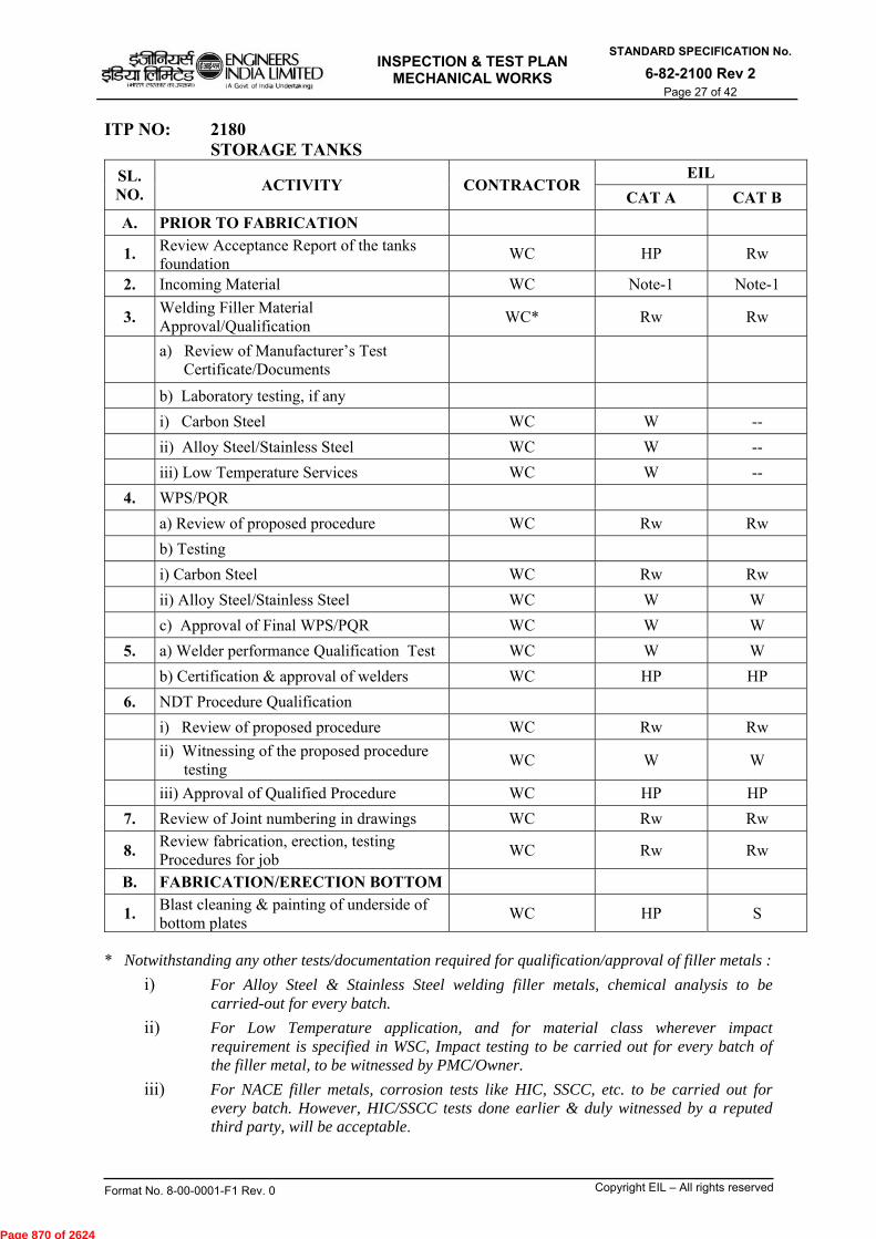
INSPECTION & TEST PLAN
MECHANICAL WORKS
STANDARD SPECIFICATION No.
6-82-2100 Rev 2 Page 27 of 42
Format No. 8-00-0001-F1 Rev. 0 Copyright EIL – All rights reserved
ITP NO: 2180 STORAGE TANKS
SL. NO.
ACTIVITY CONTRACTOR EIL
CAT A CAT B
A. PRIOR TO FABRICATION
1. Review Acceptance Report of the tanks foundation
WC HP Rw
2. Incoming Material WC Note-1 Note-1
3. Welding Filler Material Approval/Qualification
WC* Rw Rw
a) Review of Manufacturer’s Test Certificate/Documents
b) Laboratory testing, if any
i) Carbon Steel WC W --
ii) Alloy Steel/Stainless Steel WC W --
iii) Low Temperature Services WC W --
4. WPS/PQR
a) Review of proposed procedure WC Rw Rw
b) Testing
i) Carbon Steel WC Rw Rw
ii) Alloy Steel/Stainless Steel WC W W
c) Approval of Final WPS/PQR WC W W
5. a) Welder performance Qualification Test WC W W
b) Certification & approval of welders WC HP HP
6. NDT Procedure Qualification
i) Review of proposed procedure WC Rw Rw
ii) Witnessing of the proposed procedure testing
WC W W
iii) Approval of Qualified Procedure WC HP HP
7. Review of Joint numbering in drawings WC Rw Rw
8. Review fabrication, erection, testing Procedures for job
WC Rw Rw
B. FABRICATION/ERECTION BOTTOM
1. Blast cleaning & painting of underside of bottom plates
WC HP S
* Notwithstanding any other tests/documentation required for qualification/approval of filler metals :
i) For Alloy Steel & Stainless Steel welding filler metals, chemical analysis to be carried-out for every batch.
ii) For Low Temperature application, and for material class wherever impact requirement is specified in WSC, Impact testing to be carried out for every batch of the filler metal, to be witnessed by PMC/Owner.
iii) For NACE filler metals, corrosion tests like HIC, SSCC, etc. to be carried out for every batch. However, HIC/SSCC tests done earlier & duly witnessed by a reputed third party, will be acceptable.
Page 870 of 2624

INSPECTION & TEST PLAN
MECHANICAL WORKS
STANDARD SPECIFICATION No.
6-82-2100 Rev 2 Page 28 of 42
Format No. 8-00-0001-F1 Rev. 0 Copyright EIL – All rights reserved
ITP NO: 2180 STORAGE TANKS
SL. NO
ACTIVITY CONTRACTOREIL
CAT A CATB
2. Plate lay out, overlap and fit up WC S --
3. Sequence of welding WC S --
4. Size and positioning of backing plate for annular plates
WC S --
5. Baking of electrodes WC S --
6. Inter-pass cleaning WC W --
7. Visual check of welding WC W S
8. PT/MT/NDT of annular plate butt welds and bottom plate butt welds (As applicable)
WC W S
9. Vacuum box test for bottom plate welding WC W S
SHELL
1. Shell course alignments and fit-up of vertical and circumferential joints before welding
WC W S
2. a) Check Shell diameter, circularity,
perpendicularity, straight edge before welding.
WC W S
b) Check Shell diameter, circularity,
perpendicularity straight edge after welding, WC W S
3. Visual check of welding and Back chipping WC S -
4. Inner side welding visual check WC S -
5. Location, size, alignment and fit-up of nozzles & other openings
WC W W
6. R.F. Pads fit-up/welding WC S -
7. PWHT of shell, RF pads, Nozzles, manholes, etc. (As applicable)
WC S S
8. Radiography marking (for Random radiography only)
WC W W
9. Curb angle and Wind girders fit-up/welding WC S Rw
Page 871 of 2624

INSPECTION & TEST PLAN
MECHANICAL WORKS
STANDARD SPECIFICATION No.
6-82-2100 Rev 2 Page 29 of 42
Format No. 8-00-0001-F1 Rev. 0 Copyright EIL – All rights reserved
ITP NO: 2180 STORAGE TANKS
SL. NO
ACTIVITY CONTRACTOREIL
CAT A CATB
10. PT/MT of nozzles, wind girders and other attachments (as applicable)
WC W S
11. RF pads pneumatic test WC W W
12. Shell to bottom fit up WC W S
13. Shell to bottom I/S welding root run visual/Oil chalk test
WC W S
14. Shell to bottom O/S welding visual and PT WC W S
15. Fabrication and erection of stair ways WC S --
16. Cleats welding for insulation WC S --
17. Review of radiographs interpreted by the contractors
WC HP Rw
FIXED ROOF
1. Blast cleaning and painting Roof Structure, underside of Roof plates
WC W S
2. Location and Welding of Roof supports WC S --
3. Alignment and welding of Roof structures WC S --
4. Plate layout, overlap and fit-up WC S --
5. Visual check of roof welds WC S --
6. Location, size and alignment of roof nozzles, man-holes vents, etc.
WC W S
7. PWHT (as applicable)
i) Procedure Review WC Rw Rw
ii) PWHT cycle monitoring WC W --
iii) Time-Temp Chart Review WC W Rw
8. RF pads fit-up & Welding WC S --
9. RF pad pneumatic testing WC W S
10. PT/MT of Nozzles, vents & other attachments WC W S
11. Welding of Roof plate with shell/ curb angle WC S --
Page 872 of 2624
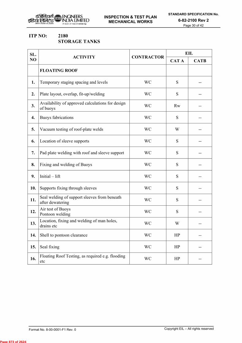
INSPECTION & TEST PLAN
MECHANICAL WORKS
STANDARD SPECIFICATION No.
6-82-2100 Rev 2 Page 30 of 42
Format No. 8-00-0001-F1 Rev. 0 Copyright EIL – All rights reserved
ITP NO: 2180 STORAGE TANKS
SL. NO
ACTIVITY CONTRACTOREIL
CAT A CATB
FLOATING ROOF
1. Temporary staging spacing and levels WC S --
2. Plate layout, overlap, fit-up/welding WC S --
3. Availability of approved calculations for design of buoys
WC Rw --
4. Buoys fabrications WC S --
5. Vacuum testing of roof-plate welds WC W --
6. Location of sleeve supports WC S --
7. Pad plate welding with roof and sleeve support WC S --
8. Fixing and welding of Buoys WC S --
9. Initial – lift WC S --
10. Supports fixing through sleeves WC S --
11. Seal welding of support sleeves from beneath after dewatering
WC S --
12. Air test of Buoys Pontoon welding
WC S --
13. Location, fixing and welding of man holes, drains etc
WC W --
14. Shell to pontoon clearance WC HP --
15. Seal fixing WC HP --
16. Floating Roof Testing, as required e.g. flooding etc
WC HP --
Page 873 of 2624

INSPECTION & TEST PLAN
MECHANICAL WORKS
STANDARD SPECIFICATION No.
6-82-2100 Rev 2 Page 31 of 42
Format No. 8-00-0001-F1 Rev. 0 Copyright EIL – All rights reserved
ITP NO: 2180 STORAGE TANKS
SL. NO
ACTIVITY CONTRACTOREIL
CAT A CATB
C. TESTING
1. Correctness of testing arrangements especially size of blind flanges/vents/drains/ temporary piping
WC S --
2. Mechanical / Inspection clearances WC HP HP
3. Earthing of ladder & shell WC W W
4. Settlement readings during water filling WC W Rw
5. Hammer test WC W W
6. Air pressure test WC W W
7. Vacuum test WC W W
8. Roof collapsibility test in case of floating roof tanks
WC W W
9. Calibration of tanks from Statutory authorities WC Rw Rw
INSPECTION & TEST DOCUMENTS
Review Test and Inspection Documents WC Rw Rw
NOTE: 1) For Incoming material Inspection please refer ITP No: 6-82-1010 2) For Painting works, please refer ITP No. 2190 3) For Insulation, please refer ITP No. 2200 CAT A: All Site fabricated steel storage tanks for process fluid /Hydrocarbon, floating roof,
tanks having capacity 600 cum or 10 m dia and 8 m height.
CAT B: Site fabricated steel storage tanks for Raw water, Fire water, waste water, DM water, etc. and all tanks not covered under “CAT A”
Page 874 of 2624
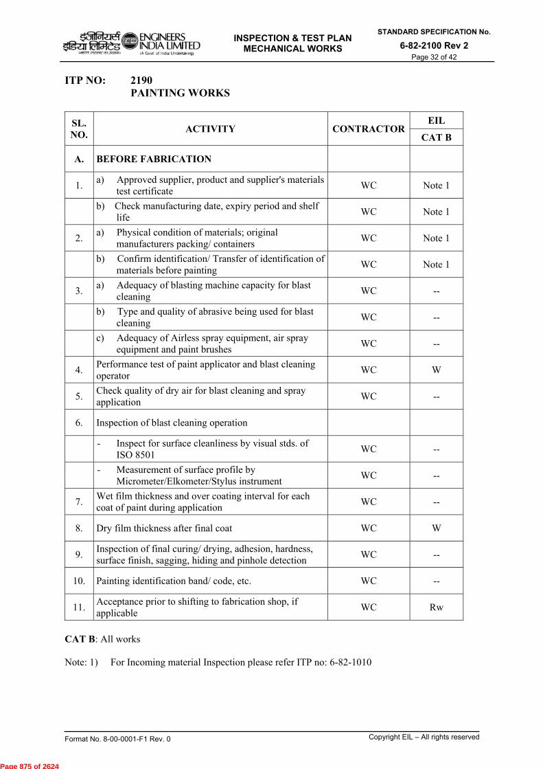
INSPECTION & TEST PLAN
MECHANICAL WORKS
STANDARD SPECIFICATION No.
6-82-2100 Rev 2 Page 32 of 42
Format No. 8-00-0001-F1 Rev. 0 Copyright EIL – All rights reserved
ITP NO: 2190 PAINTING WORKS
SL. NO.
ACTIVITY CONTRACTOR EIL
CAT B
A. BEFORE FABRICATION
1. a) Approved supplier, product and supplier's materials
test certificate WC Note 1
b) Check manufacturing date, expiry period and shelf
life WC Note 1
2. a) Physical condition of materials; original
manufacturers packing/ containers WC Note 1
b) Confirm identification/ Transfer of identification of
materials before painting WC Note 1
3. a) Adequacy of blasting machine capacity for blast
cleaning WC --
b) Type and quality of abrasive being used for blast
cleaning WC --
c) Adequacy of Airless spray equipment, air spray
equipment and paint brushes WC --
4. Performance test of paint applicator and blast cleaning operator
WC W
5. Check quality of dry air for blast cleaning and spray application
WC --
6. Inspection of blast cleaning operation
- Inspect for surface cleanliness by visual stds. of
ISO 8501 WC --
- Measurement of surface profile by
Micrometer/Elkometer/Stylus instrument WC --
7. Wet film thickness and over coating interval for each coat of paint during application WC --
8. Dry film thickness after final coat WC W
9. Inspection of final curing/ drying, adhesion, hardness, surface finish, sagging, hiding and pinhole detection
WC --
10. Painting identification band/ code, etc. WC --
11. Acceptance prior to shifting to fabrication shop, if applicable
WC Rw
CAT B: All works Note: 1) For Incoming material Inspection please refer ITP no: 6-82-1010
Page 875 of 2624

INSPECTION & TEST PLAN
MECHANICAL WORKS
STANDARD SPECIFICATION No.
6-82-2100 Rev 2 Page 33 of 42
Format No. 8-00-0001-F1 Rev. 0 Copyright EIL – All rights reserved
ITP NO: 2190 PAINTING WORKS
SL. NO.
ACTIVITY CONTRACTOR EIL
CAT B
B. AFTER INSTALLATION
1. a) Approved supplier product :
Suppliers materials test certificate WC Note 1
b) Manufacturing date, expiry period
and shelf life WC Note 1
2. Physical condition of materials; original manufacturers packing/ containers WC Note 1
3. Confirm completion of
a) Hydrostatic testing of piping WC --
b) Mechanical clearance of structure &
equipment’s WC --
4. a) Adequacy of surface preparation
tools and tackles WC --
b) Check the quality of surface
preparation WC --
5. a) Performance test for paint applicator
for spray application WC Rw
b) Adequacy of airless spray equipment and air spray equipment and paint brushes and quality of dry air for paint application
WC --
6. Wet film thickness and over coating interval for each coat of application
WC --
7. Dry film thickness after final coat WC S
8. Identification of colour bands, direction marking
WC --
9. Identification of colour bands, direction marking
WC --
10. Final Acceptance WC HP
INSPECTION & TEST DOCUMENTS
Review Test and Inspection Documents WC Rw
CAT B: All works Note : 1) For Incoming material Inspection please refer ITP no: 6-82-1010
Page 876 of 2624

INSPECTION & TEST PLAN
MECHANICAL WORKS
STANDARD SPECIFICATION No.
6-82-2100 Rev 2 Page 34 of 42
Format No. 8-00-0001-F1 Rev. 0 Copyright EIL – All rights reserved
ITP NO: 2200 INSULATION WORKS SL. NO
ACTIVITY CONTRACTOR EIL CATB
1. PRIOR TO APPLICATION OF INSULATION
a. Material Test certificates from supplier of insulation material and acceptance thereof
WC Note 1
b. Check testing, if required WC Note 1
2. DURING APPLICATION OF INSULATION
a. Surface preparation WC --
b. Fixing of spacer rings and checking their spacing WC --
c. Fixing of support rings and checking their spacing
in case of vertical piping WC --
d. Fixing of insulation lugs and angle rings in case
of vessels, tanks, etc WC --
e. Thickness of insulation WC --
f. Aluminium foil for S.S. Piping/Vessels WC --
g. Overlap of cladding at vertical and horizontal
joints WC --
h. Expansion joints, if any WC --
i. Inspection windows WC --
j. S.S. foil for S.S. piping WC --
k. Final finish WC W
3. ADDITIONAL CHECKS FOR COLD INSULATION
a. Wooden supports WC --
b. Vapour barrier WC --
c. Vapour sealant WC --
d. Insul coat WC --
Review Test and Inspection Documents WC Rw
Note 1) For Incoming material Inspection please refer ITP no: 6-82-1010 CAT B: All works
Page 877 of 2624
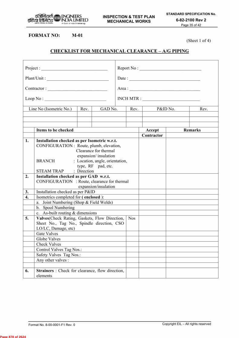
INSPECTION & TEST PLAN
MECHANICAL WORKS
STANDARD SPECIFICATION No.
6-82-2100 Rev 2 Page 35 of 42
Format No. 8-00-0001-F1 Rev. 0 Copyright EIL – All rights reserved
FORMAT NO: M-01 (Sheet 1 of 4)
CHECKLIST FOR MECHANICAL CLEARANCE – A/G PIPING
Project : ______________________________ Plant/Unit : ____________________________ Contractor : ___________________________ Loop No : ____________________________
Report No : ____________________________ Date : ________________________________ Area : ________________________________ INCH MTR : __________________________
Line No (Isometric No.) Rev. GAD No. Rev. P&ID No. Rev. Items to be checked Accept Remarks Contractor 1. Installation checked as per Isometric w.r.t.
CONFIGURATION : Route, plumb, elevation, Clearance for thermal expansion/ insulation BRANCH : Location, angle, orientation, type, RF pad, etc. STEAM TRAP : Direction
2. Installation checked as per GAD w.r.t. CONFIGURATION : Route, clearance for thermal expansion/insulation
3. Installation checked as per P&ID 4. Isometrics completed for ( enclosed ): a. Joint Numbering (Shop & Field Welds) b. Spool Numbering c. As-built routing & dimensions 5. Valves(Check Rating, Gaskets, Flow Direction,
Sheet No., Tag No., Spindle direction, CSO LO/LC, Damage, etc)
Nos
Gate Valves Globe Valves Check Valves Control Valves Tag Nos.: Safety Valves Tag Nos.: Any other valves : 6. Strainers : Check for clearance, flow direction,
elements
Page 878 of 2624
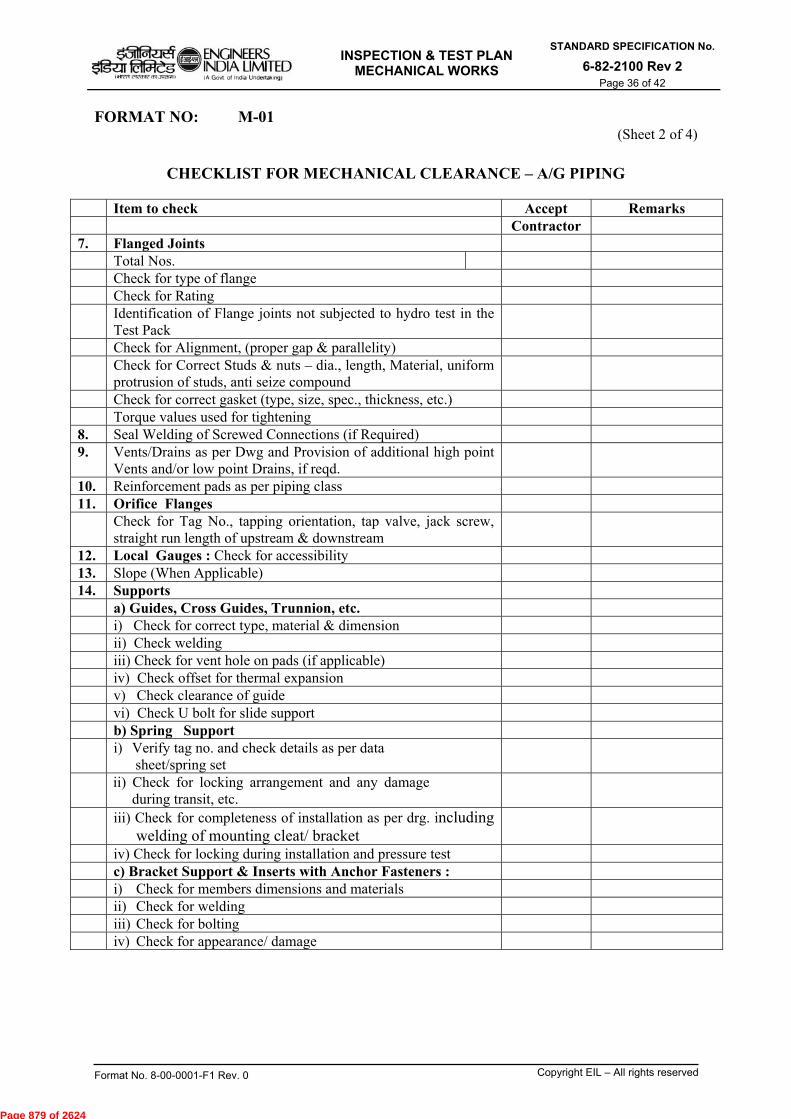
INSPECTION & TEST PLAN
MECHANICAL WORKS
STANDARD SPECIFICATION No.
6-82-2100 Rev 2 Page 36 of 42
Format No. 8-00-0001-F1 Rev. 0 Copyright EIL – All rights reserved
FORMAT NO: M-01 (Sheet 2 of 4)
CHECKLIST FOR MECHANICAL CLEARANCE – A/G PIPING
Item to check Accept Remarks Contractor 7. Flanged Joints Total Nos. Check for type of flange Check for Rating Identification of Flange joints not subjected to hydro test in the
Test Pack
Check for Alignment, (proper gap & parallelity) Check for Correct Studs & nuts – dia., length, Material, uniform
protrusion of studs, anti seize compound
Check for correct gasket (type, size, spec., thickness, etc.) Torque values used for tightening 8. Seal Welding of Screwed Connections (if Required) 9. Vents/Drains as per Dwg and Provision of additional high point
Vents and/or low point Drains, if reqd.
10. Reinforcement pads as per piping class 11. Orifice Flanges Check for Tag No., tapping orientation, tap valve, jack screw,
straight run length of upstream & downstream
12. Local Gauges : Check for accessibility 13. Slope (When Applicable) 14. Supports a) Guides, Cross Guides, Trunnion, etc. i) Check for correct type, material & dimension ii) Check welding iii) Check for vent hole on pads (if applicable) iv) Check offset for thermal expansion v) Check clearance of guide vi) Check U bolt for slide support b) Spring Support i) Verify tag no. and check details as per data
sheet/spring set
ii) Check for locking arrangement and any damage during transit, etc.
iii) Check for completeness of installation as per drg. including welding of mounting cleat/ bracket
iv) Check for locking during installation and pressure test c) Bracket Support & Inserts with Anchor Fasteners : i) Check for members dimensions and materials ii) Check for welding iii) Check for bolting iv) Check for appearance/ damage
Page 879 of 2624

INSPECTION & TEST PLAN
MECHANICAL WORKS
STANDARD SPECIFICATION No.
6-82-2100 Rev 2 Page 37 of 42
Format No. 8-00-0001-F1 Rev. 0 Copyright EIL – All rights reserved
FORMAT NO: M-01 (Sheet 3 of 4)
CHECKLIST FOR MECHANICAL CLEARANCE – A/G PIPING
Item to check Accept Remarks Contractor 15. Vents/ Drains - As per drg. - Orientation of valve handles - Clearance for hose - Requirement of additional vents/ drains (highest/lowest pt.) 16. Earthings a) Check for location b) Check for dimension of lug welding 17. Joists History sheets enclosed for : 17.1 Material Traceability as per Procedure No:__________
(refer enclosed suggested Format)
17.2 Fit ups checked 17.3 NDT Complete (Radiography, MT, PT) 17.4 Stress Relieving & Hardness check complete 17.5 Positive Material Identification (PMI) Checked for Removal/Blinding-off of: a. Control, Safety and Check Valves b. In-Line Instruments c. Rupture Discs d. Equipment Nozzles e. Others 18. Supports and Weld/Flanged/Screwed connections free from insulation or other coverage` 19. Checked Installation of (Indicate Location in Drawings) a. Temporary Blinds/Spades b. Temporary Strainers c. Temporary Dummy-Spools d. Temporary Gaskets e. Others 20. Expansion Bellows a) Checks prior to installations - Physical damages - Transit locks are intact - Dimensions as per drgs. b) Check during installation - Parallelity of mating flanges - Face to face dimension of mating flanges - Concentricity of mating flanges - No stress on expansion bellows - Record
Page 880 of 2624
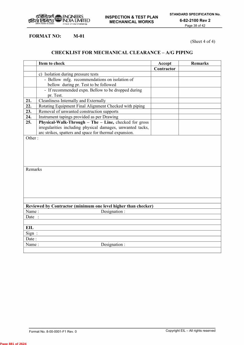
INSPECTION & TEST PLAN
MECHANICAL WORKS
STANDARD SPECIFICATION No.
6-82-2100 Rev 2 Page 38 of 42
Format No. 8-00-0001-F1 Rev. 0 Copyright EIL – All rights reserved
FORMAT NO: M-01 (Sheet 4 of 4)
CHECKLIST FOR MECHANICAL CLEARANCE – A/G PIPING
Item to check Accept Remarks Contractor c) Isolation during pressure tests - Bellow mfg. recommendations on isolation of
bellow during pr. Test to be followed
- If recommended expn. Bellow to be dropped during pr. Test.
21. Cleanliness Internally and Externally 22. Rotating Equipment Final Alignment Checked with piping 23. Removal of unwanted construction supports 24. Instrument tapings provided as per Drawing 25. Physical-Walk-Through – The – Line, checked for gross
irregularities including physical damages, unwanted tacks, arc strikes, spatters and space for thermal expansion.
Other : Remarks Reviewed by Contractor (minimum one level higher than checker) Name : Designation : Date : EIL Sign : Date : Name : Designation :
Page 881 of 2624
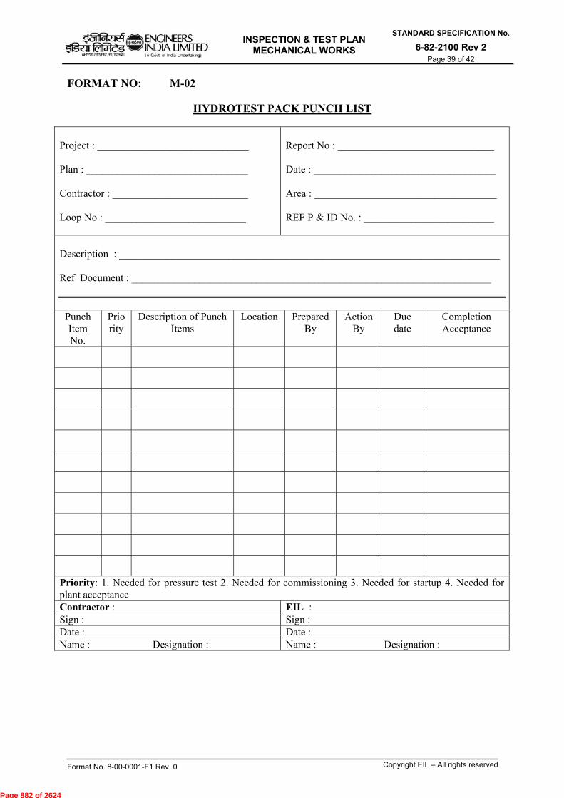
INSPECTION & TEST PLAN
MECHANICAL WORKS
STANDARD SPECIFICATION No.
6-82-2100 Rev 2 Page 39 of 42
Format No. 8-00-0001-F1 Rev. 0 Copyright EIL – All rights reserved
FORMAT NO: M-02
HYDROTEST PACK PUNCH LIST
Project : _____________________________ Plan : _______________________________ Contractor : __________________________ Loop No : ___________________________
Report No : ______________________________ Date : ___________________________________ Area : ___________________________________ REF P & ID No. : _________________________
Description : _________________________________________________________________________ Ref Document : _____________________________________________________________________
Punch Item No.
Priority
Description of Punch Items
Location Prepared By
Action By
Due date
Completion Acceptance
Priority: 1. Needed for pressure test 2. Needed for commissioning 3. Needed for startup 4. Needed for plant acceptance Contractor : EIL : Sign : Sign : Date : Date : Name : Designation : Name : Designation :
Page 882 of 2624

INSPECTION & TEST PLAN
MECHANICAL WORKS
STANDARD SPECIFICATION No.
6-82-2100 Rev 2 Page 40 of 42
Format No. 8-00-0001-F1 Rev. 0 Copyright EIL – All rights reserved
FORMAT NO: M-03
RELEASE FOR HYDRO TEST– A/G PIPING
Project : ______________________________ Plan : ________________________________ Contractor : ___________________________ Loop No : ____________________________
Report No : __________________________ Date : _______________________________ Area : _______________________________ REF P & ID No. : _____________________ INCH MTR : _________________________ From ________________ To _____________
Line No. (s) Isometric No. (s) P&ID No. (s) Test Medium : Test Duration : Design/Test Pressure : Test Pressure Gauge No. Range Calibration Certificate No.: Gauge Calibration Date:
Items to check Accept Witness Contractor EIL
Field Installation Checklist Prior to Hydrotest Signed Punch list Prepared Yes No Pre-hydrotest punch items cleared Accessibility to Inspection/Witness Locations Capacity of pressurizing pump checked Cordon off area for high pressure testing, as required Pre-hydrotest flushing carried out IBR/Others test Witnessing Required Yes No
System Released for Pressure Testing : Contractor :
EIL:
Sign : Name : Sign : Name : Date : Date : Designation : Designation:
Page 883 of 2624

INSPECTION & TEST PLAN
MECHANICAL WORKS
STANDARD SPECIFICATION No.
6-82-2100 Rev 2 Page 41 of 42
Format No. 8-00-0001-F1 Rev. 0 Copyright EIL – All rights reserved
FORMAT NO: M-04
PIPING HYDROTEST RECORD – A/G PIPING
ACTIVITY Date Time
Water Filling and Venting started at
Water Filling Completed
Vents Closed
Isolation of Pressurizing pump
Test completed at :
- Water drained
- Air drying done
- Temp Blinds Removed
- Checked for reinstallation of a. Control & Safety vales b. On line Instruments c. Rupture disks d. Others
- Cold setting of spring supports carried out
- Test Result Acceptable Not Acceptable Contractor :
EIL :
Sign :
Sign:
Date : Date: Name : Designation Name: Designation:
Page 884 of 2624

INSPECTION & TEST PLAN
MECHANICAL WORKS
STANDARD SPECIFICATION No.
6-82-2100 Rev 2 Page 42 of 42
Format No. 8-00-0001-F1 Rev. 0 Copyright EIL – All rights reserved
FORMAT NO: M-05 AUTHORISATION FOR MODIFICATION OF PIPING JOINTS
Indicative format for Authorizing/Recording of Modification of Piping Joints after Mechanical clearance /NDT
Clearance/ Hydro Testing /Pneumatic Testing of pressure Test Packages/Loops in piping jobs.
Job No. : Unit No.: Report No: Date:
Owner/Client : PMC : Contractor :
Pressure Test Package No.:
System Name/No. :
Previous Hydrotest Date :
Drawing No : Line No. : Joint Nos. to be modified (attach sketch) : Size & type of joint : New Joint Nos. : Deleted Joint Nos. : Modification Joint Nos. :
Reason for Modification :
A) Proposed checks/NDT / Testing after Modification
1. Fit up and Traceability. :
2. PMI Checks : Mark ‘√’ in box as necessary 3. MPI Test : PT (root/final) : RT : 4. PWHT/Hardness : Required. : Not Required. : 5. Hydrotesting : Pneumatic Test :
Authorized Signatory (note-1) Name
Signature
Date
B) Proposal Accepted by EIL ( note-2) Area Co-ordinator Welding/ NDT Incharge
Name
Signature
Date
Clearance/Acceptance after modifications (All Supporting Documents enclosed)
Mechanical clearance: Contractor Mech. Signature. EIL Mech. Signature.
NDT Clearance : Contractor QA/QC. Signature. EIL Welding/NDT Signature.
Testing Acceptance : Contractor Mech. Signature. EIL Mech. Signature.
Final acceptance after Modification Contractor EIL
Name
Signature
Date
Note: 1. Authorized signatory (*): RCM/ Site In charge of execution agency 2. RCM/SIC of EIL may seek opinion of Engineering, prior to acceptance of proposal from
LSTK contractor as necessary.
Page 885 of 2624
,Xol)OgZIT Weg rair2 e/oa, ,eaffsA/
ENGINEERS INDIA LIMITED IA Gov) of India Undertaking
INSPECTION & TEST PLAN FOR GENERAL WORKS
(EPCC / LSTK CONTRACTS)
STANDARD SPECIFICATION No.
6-82-2500 Rev 2 Page 1 of 15
coleiT uct)tvci tin 41311)
1W-tteTur tr4 tr-41-aur eil.71-1 (31-rtelfb
INSPECTION & TEST PLAN (ITP) FOR GENERAL WORKS
(EPCC/LSTK CONTRACTS)
•.1, g Al !Ai . \ — , ) "• ' .
2 19.02.2016 REVISED AND REISSUED Df tl ge, N
AKM TKS SC
1 04.07.2011 REVISED AND REISSUED SM SM MKG DM
0 14.07.2006 ISSUED AS STANDARD SPECIFICATION AS MPJ VNP VJN
Rev. No.
Date Purpose Prepared Checked
by by
Standards Standards Committee Bureau Convenor Chairman
Approved by
Format No. 8-00-0001-F1 Rev. 0 Copyright EIL — All rights reserved
Page 886 of 2624
INSPECTION & TEST PLAN FOR GENERAL WORKS
(EPCC / LSTK CONTRACTS)
STANDARD SPECIFICATION No.
6-82-2500 Rev 2 Page 2 of 15
Format No. 8-00-0001-F1 Rev. 0 Copyright EIL – All rights reserved
Abbreviations: AFC : Approved For Construction CF : Ceramic Fibre PMC : Project Management Consultant SS : Stainless Steel like A312 TP 304, 316, 321, 304L, 316L, 316Mo, etc. Construction Standards Committee Convenor: Sh. T.K. Sen ,ED (Construction) Members: Sh. SN Bhatnagar, GM (Construction) Sh. MK Garg, GM (Construction) Sh. A K Mishra, GM (Construction) Sh. Janak Kishore, DGM (Projects) Sh. Rajeev Jain, DGM, (C&P) Sh. Udayan Chakravarty, AGM (Piping) Sh. Ravindra Kumar, AGM (Construction) Sh. D Jana, AGM (Construction)
Page 887 of 2624

INSPECTION & TEST PLAN FOR GENERAL WORKS
(EPCC / LSTK CONTRACTS)
STANDARD SPECIFICATION No.
6-82-2500 Rev 2 Page 3 of 15
Format No. 8-00-0001-F1 Rev. 0 Copyright EIL – All rights reserved
CONTENTS
S. NO. DESCRIPTION DOCUMENT NO. PAGE NO.
ITPs for General Works
1. Painting Works 2501 5-6
2. Insulation works 2505 7
3. Refractory Lining 2510 8-9
4. Ceramic Fiber Lining 2515 10
Formats for General Works
1. Field Painting Primer/ Finish Paint for Structural Steel
G -01 11
2. Field Painting Primer/ Finish Paint of Equipment
G -02 12
3. Field Painting Primer/ Finish Paint (Piping) G -03 13
4. Inspection Report for Insulation Work - Equipment
G -04 14
5. Inspection Report for Insulation Work - Piping
G -05 15
Page 888 of 2624
INSPECTION & TEST PLAN FOR GENERAL WORKS
(EPCC / LSTK CONTRACTS)
STANDARD SPECIFICATION No.
6-82-2500 Rev 2 Page 4 of 15
Format No. 8-00-0001-F1 Rev. 0 Copyright EIL – All rights reserved
GENERAL NOTE The enclosed ITPs are indicative and shall be followed for developing the job specific ITPs for the works to be performed by the contractor. The provisions indicated for stage wise inspection by EIL/Owner (for specific activities) are the minimum and the Engineer-In-Charge may decide to increase Hold Points/ Witness Points while approving the job specific ITPs. Activities for which ITP’s are not provided in this specification, contractor to develop and get the same approved by EIL/Owner before start of the work. In general, role of EIL has been specified in the document. The role of owner to be specified during preparation of site specific ITPs. Contractor to submit job specific reporting formats with the aid of enclosed sample reporting formats and job procedures for the jobs for which ITP’s are attached and submit to EIL/Owner for approval, before commencement of the activity. If the contractor has to deviate from the given ITP for a valid reason, he shall obtain prior written approval of EIL/Owner. Contractor to carry out 100% examination of all activities.
LEGEND HP : Hold Point ;
A point which requires witnessing/inspection/verification and acceptance by Owner/EIL before any further processing is permitted. The Contractor shall not process the activity/item beyond a Hold Point without written approval by Owner/EIL except where prior written permission for further processing is available.
W : Witness Point ; An activity which requires witnessing/inspection/verification by Owner/EIL when the activity is performed. After proper notification has been provided (notification modalities and period shall be finalized before hand), the Contractor is not obliged to hold further processing if Owner/EIL is not available to witness the activity or does not provide comments before the date notified. In such cases, basis of acceptance shall be review of Contractor generated report/document as per relevant technical specification.
Rw : Review of Contractor’s documentation.
S : Surveillance Inspection by Owner/ EIL. Monitoring or making observations to verify whether or not material/items or services conform to specified requirements. Surveillance activities may include audit, inspections, witness of testing, Review of quality documentation & records, personnel qualifications, etc.
WC : 100% Supervision and Examination by Contractor.
Responsibility for execution of the inspection/testing is with the Contractor; Owner/EIL only verifies examination or testing done by the Contractor at important stages
Page 889 of 2624
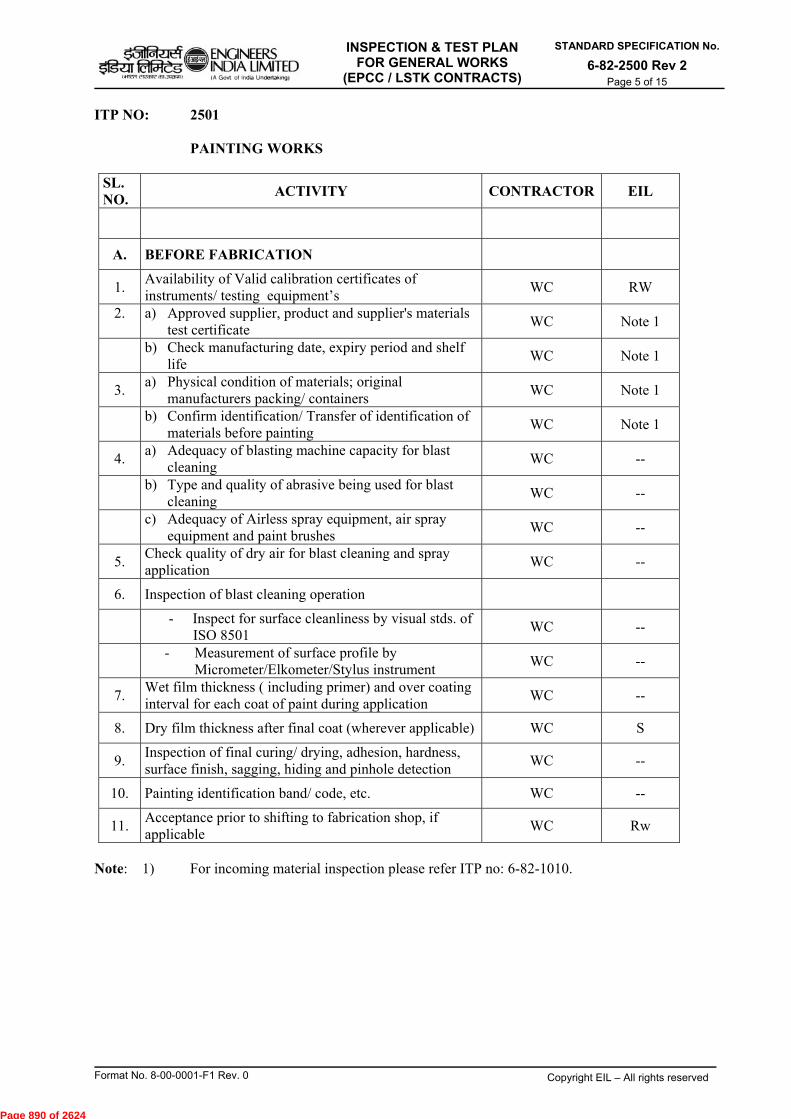
INSPECTION & TEST PLAN FOR GENERAL WORKS
(EPCC / LSTK CONTRACTS)
STANDARD SPECIFICATION No.
6-82-2500 Rev 2 Page 5 of 15
Format No. 8-00-0001-F1 Rev. 0 Copyright EIL – All rights reserved
ITP NO: 2501 PAINTING WORKS
SL. NO.
ACTIVITY CONTRACTOR EIL
A. BEFORE FABRICATION
1. Availability of Valid calibration certificates of instruments/ testing equipment’s
WC RW
2.
a) Approved supplier, product and supplier's materials test certificate
WC Note 1
b) Check manufacturing date, expiry period and shelf
life WC Note 1
3. a) Physical condition of materials; original
manufacturers packing/ containers WC Note 1
b) Confirm identification/ Transfer of identification of
materials before painting WC Note 1
4. a) Adequacy of blasting machine capacity for blast
cleaning WC --
b) Type and quality of abrasive being used for blast
cleaning WC --
c) Adequacy of Airless spray equipment, air spray
equipment and paint brushes WC --
5. Check quality of dry air for blast cleaning and spray application
WC --
6. Inspection of blast cleaning operation
- Inspect for surface cleanliness by visual stds. of
ISO 8501 WC --
- Measurement of surface profile by
Micrometer/Elkometer/Stylus instrument WC --
7. Wet film thickness ( including primer) and over coating interval for each coat of paint during application
WC --
8. Dry film thickness after final coat (wherever applicable) WC S
9. Inspection of final curing/ drying, adhesion, hardness, surface finish, sagging, hiding and pinhole detection
WC --
10. Painting identification band/ code, etc. WC --
11. Acceptance prior to shifting to fabrication shop, if applicable
WC Rw
Note: 1) For incoming material inspection please refer ITP no: 6-82-1010.
Page 890 of 2624

INSPECTION & TEST PLAN FOR GENERAL WORKS
(EPCC / LSTK CONTRACTS)
STANDARD SPECIFICATION No.
6-82-2500 Rev 2 Page 6 of 15
Format No. 8-00-0001-F1 Rev. 0 Copyright EIL – All rights reserved
ITP NO: 2501 PAINTING WORKS
SL. NO.
ACTIVITY CONTRACTOR EIL
B. AFTER INSTALLATION
1. a) Approved supplier product : Suppliers
materials test certificate WC Note 1
b) Manufacturing date, expiry period and
shelf life WC Note 1
2. Physical condition of materials; original manufacturers packing/ containers
WC Note 1
3. Confirm completion of
a) Hydrostatic testing of piping WC --
b) Mechanical clearance of structure &
equipment’s WC --
4. a) Adequacy of surface preparation tools and
tackles WC --
b) Check the quality of surface preparation WC --
5. a) Performance test for paint applicator for
spray application WC --
b) Adequacy of airless spray equipment and
air spray equipment and paint brushes and quality of dry air for paint application
WC --
6. Wet film thickness and over coating interval for each coat of application
WC --
7. Dry film thickness after final coat WC S
8. Identification of color bands, direction marking
WC --
9. Identification of color bands, direction marking
WC --
10. Final Acceptance WC HP
INSPECTION & TEST DOCUMENTS
Review Test and Inspection Documents
WC Rw
Note: 1) For incoming material inspection please refer ITP no: 6-82-1010.
Page 891 of 2624

INSPECTION & TEST PLAN FOR GENERAL WORKS
(EPCC / LSTK CONTRACTS)
STANDARD SPECIFICATION No.
6-82-2500 Rev 2 Page 7 of 15
Format No. 8-00-0001-F1 Rev. 0 Copyright EIL – All rights reserved
ITP NO: 2505 INSULATION WORKS
SL. NO.
ACTIVITY CONTRACTOR EIL
1. PRIOR TO APPLICATION OF INSULATION
a. Material Test certificates from supplier of
insulation material and acceptance thereof WC Note 1
b. Check testing, if required WC Note 1
2. DURING APPLICATION OF INSULATION
a. Surface preparation WC --
b. Fixing of spacer rings and checking their spacing
WC
--
c. Fixing of support rings and checking their
spacing in case of vertical piping WC --
d. Fixing of insulation lugs and angle rings in case
of vessels, tanks, etc. WC
--
e. Thickness of insulation WC --
f. Aluminium foil for S.S. Piping/Vessels WC --
g. Overlap of cladding at vertical and horizontal
joints WC --
h. Expansion joints, if any WC --
i. Inspection windows WC --
j. S.S. foil for S.S. piping WC --
k. Final finish WC W
3. ADDITIONAL CHECKS FOR COLD INSULATION
a. Wooden supports WC --
b. Vapour barrier WC --
c. Vapour sealant WC --
d. Insul coat WC --
Review Test and Inspection Documents WC Rw
Note: 1) For incoming material inspection please refer ITP no: 6-82-1010.
Page 892 of 2624
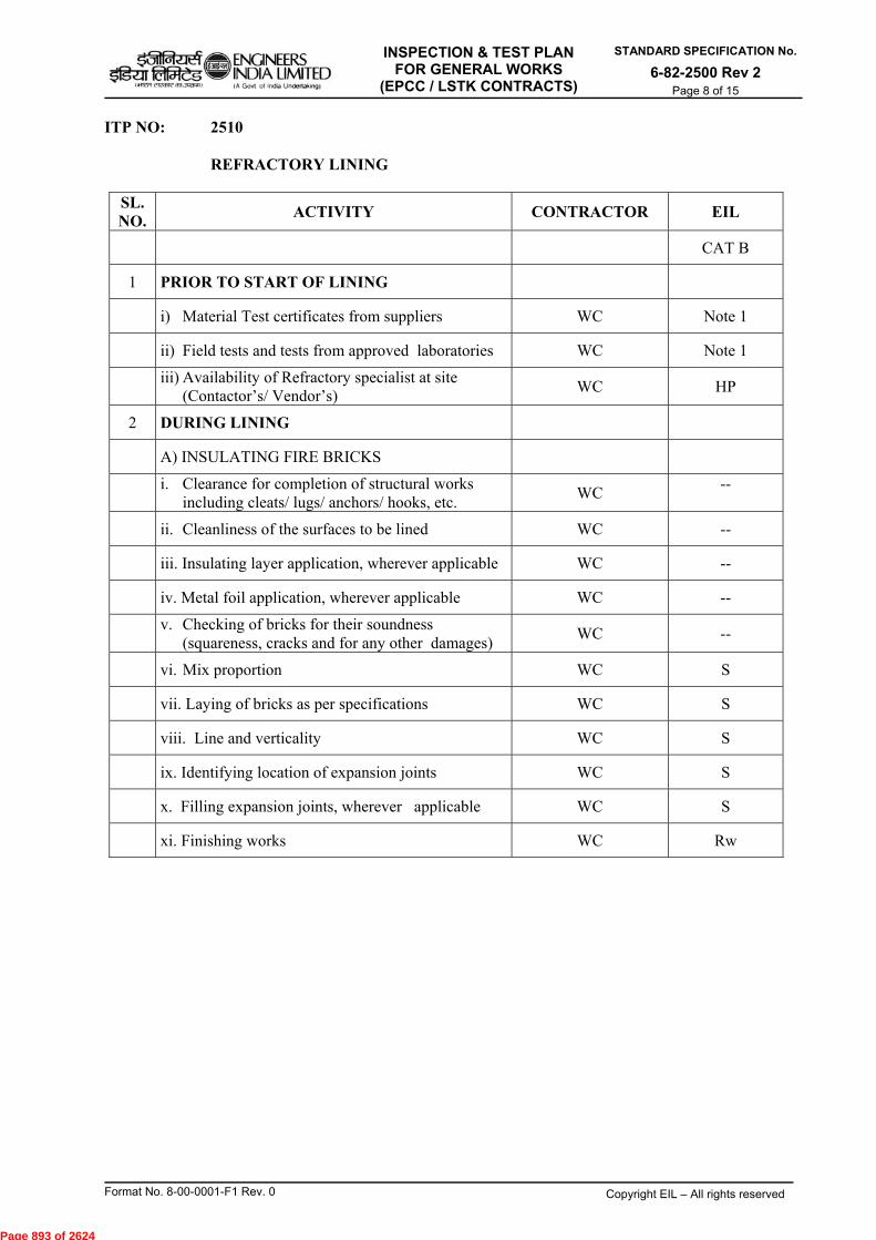
INSPECTION & TEST PLAN FOR GENERAL WORKS
(EPCC / LSTK CONTRACTS)
STANDARD SPECIFICATION No.
6-82-2500 Rev 2 Page 8 of 15
Format No. 8-00-0001-F1 Rev. 0 Copyright EIL – All rights reserved
ITP NO: 2510 REFRACTORY LINING
SL. NO.
ACTIVITY CONTRACTOR EIL
CAT B
1 PRIOR TO START OF LINING
i) Material Test certificates from suppliers WC Note 1
ii) Field tests and tests from approved laboratories WC Note 1
iii) Availability of Refractory specialist at site
(Contactor’s/ Vendor’s) WC HP
2 DURING LINING
A) INSULATING FIRE BRICKS
i. Clearance for completion of structural works
including cleats/ lugs/ anchors/ hooks, etc. WC
--
ii. Cleanliness of the surfaces to be lined WC --
iii. Insulating layer application, wherever applicable WC --
iv. Metal foil application, wherever applicable WC --
v. Checking of bricks for their soundness (squareness, cracks and for any other damages)
WC --
vi. Mix proportion WC S
vii. Laying of bricks as per specifications WC S
viii. Line and verticality WC S
ix. Identifying location of expansion joints WC S
x. Filling expansion joints, wherever applicable WC S
xi. Finishing works WC Rw
Page 893 of 2624

INSPECTION & TEST PLAN FOR GENERAL WORKS
(EPCC / LSTK CONTRACTS)
STANDARD SPECIFICATION No.
6-82-2500 Rev 2 Page 9 of 15
Format No. 8-00-0001-F1 Rev. 0 Copyright EIL – All rights reserved
ITP NO: 2510 REFRACTORY LINING
SL. NO
ACTIVITY CONTRACTOR EIL
B) INSULATING CASTABLE CONCRETE
i. Clearance for completion of structural steel
work including cleats/ support lugs/ anchors/hooks, etc.
WC S
ii. Cleanliness of the surface to be lined WC S
iii. Insulating layer application, wherever
applicable WC
--
iv. Metal foil application, wherever applicable WC --
v. Fixing of wire mesh WC --
vi. Fixing of shuttering/ scaffolding and
providing pockets for pouring mortar WC --
vii. Mix proportion WC
viii. Identifying location of expansion joints WC --
ix. Ramming of mortar for achieving uniform
density WC --
x. Filling expansion joints, wherever applicable WC --
xi. Wetting of previous layer prior to casting the
Construction joints WC --
xii. Pointing WC --
xiii. Curing WC --
INSPECTION & TEST DOCUMENTS
Review Test and Inspection Documents WC Rw
Note: 1) For incoming material inspection please refer ITP no: 6-82-1010.
2) Surveillance/witness may be increased in case of boilers, heaters, etc. as per specific requirements given in the specifications.
Page 894 of 2624
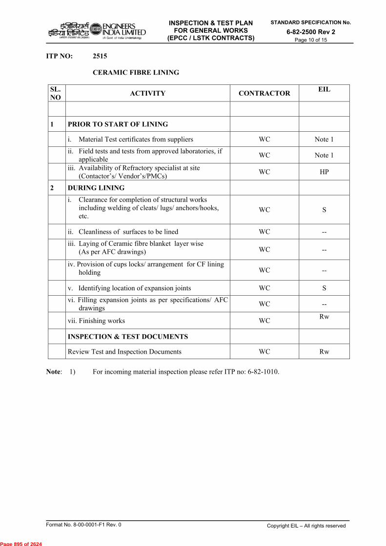
INSPECTION & TEST PLAN FOR GENERAL WORKS
(EPCC / LSTK CONTRACTS)
STANDARD SPECIFICATION No.
6-82-2500 Rev 2 Page 10 of 15
Format No. 8-00-0001-F1 Rev. 0 Copyright EIL – All rights reserved
ITP NO: 2515 CERAMIC FIBRE LINING
SL. NO
ACTIVITY CONTRACTOR EIL
1 PRIOR TO START OF LINING
i. Material Test certificates from suppliers WC Note 1
ii. Field tests and tests from approved laboratories, if
applicable WC Note 1
iii. Availability of Refractory specialist at site
(Contactor’s/ Vendor’s/PMCs) WC HP
2 DURING LINING
i. Clearance for completion of structural works including welding of cleats/ lugs/ anchors/hooks, etc.
WC S
ii. Cleanliness of surfaces to be lined WC --
iii. Laying of Ceramic fibre blanket layer wise
(As per AFC drawings) WC --
iv. Provision of cups locks/ arrangement for CF lining
holding WC --
v. Identifying location of expansion joints WC S
vi. Filling expansion joints as per specifications/ AFC
drawings WC --
vii. Finishing works WC Rw
INSPECTION & TEST DOCUMENTS
Review Test and Inspection Documents WC Rw
Note: 1) For incoming material inspection please refer ITP no: 6-82-1010.
Page 895 of 2624
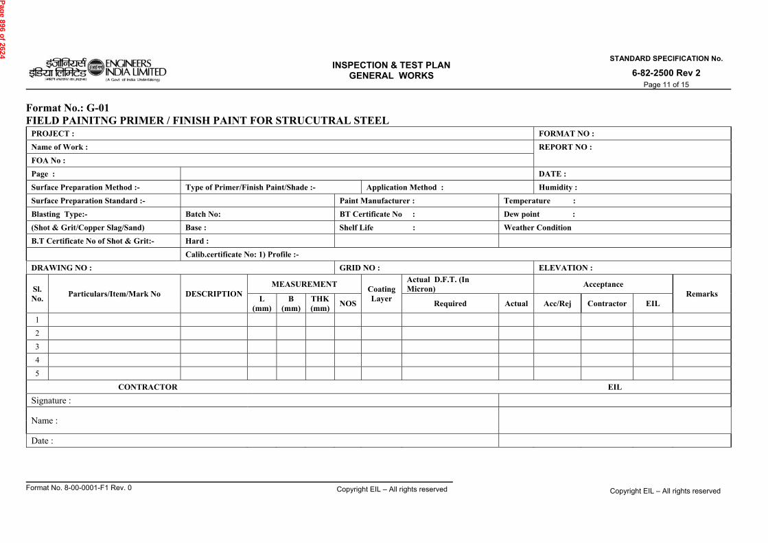
INSPECTION & TEST PLAN
GENERAL WORKS
STANDARD SPECIFICATION No.
6-82-2500 Rev 2 Page 11 of 15
Format No. 8-00-0001-F1 Rev. 0 Copyright EIL – All rights reserved Copyright EIL – All rights reserved
Format No.: G-01 FIELD PAINITNG PRIMER / FINISH PAINT FOR STRUCUTRAL STEEL
PROJECT : FORMAT NO :
Name of Work : REPORT NO :
FOA No :
Page : DATE :
Surface Preparation Method :- Type of Primer/Finish Paint/Shade :- Application Method : Humidity :
Surface Preparation Standard :- Paint Manufacturer : Temperature :
Blasting Type:- Batch No: BT Certificate No : Dew point :
(Shot & Grit/Copper Slag/Sand) Base : Shelf Life : Weather Condition
B.T Certificate No of Shot & Grit:- Hard :
Calib.certificate No: 1) Profile :-
DRAWING NO : GRID NO : ELEVATION :
Sl. No.
Particulars/Item/Mark No DESCRIPTION MEASUREMENT
Coating Layer
Actual D.F.T. (In Micron)
Acceptance Remarks
L (mm)
B (mm)
THK (mm)
NOS Required Actual Acc/Rej Contractor EIL
1
2
3
4
5
CONTRACTOR EIL
Signature :
Name :
Date :
Pag
e 896 of 2624
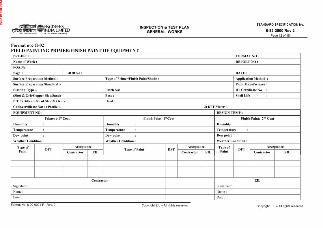
INSPECTION & TEST PLAN
GENERAL WORKS
STANDARD SPECIFICATION No.
6-82-2500 Rev 2 Page 12 of 15
Format No. 8-00-0001-F1 Rev. 0 Copyright EIL – All rights reserved Copyright EIL – All rights reserved
Format no: G-02 FIELD PAINTING PRIMER/FINISH PAINT OF EQUIPMENT
PROJECT : FORMAT NO :
Name of Work : REPORT NO :
FOA No :
Page : JOB No : DATE :
Surface Preparation Method :- Type of Primer/Finish Paint/Shade :- Application Method :
Surface Preparation Standard :- Paint Manufacturer :
Blasting Type:- Batch No: BT Certificate No :
(Shot & Grit/Copper Slag/Sand) Base : Shelf Life :
B.T Certificate No of Shot & Grit:- Hard :
Calib.certificate No: 1) Profile :- 2) DFT Meter :-
EQUIPMENT NO: DESIGN TEMP :
Primer :-1st Coat Finish Paint: 1st Coat Finish Paint: 2nd Coat
Humidity : Humidity : Humidity :
Temperature : Temperature : Temperature :
Dew point : Dew point : Dew point :
Weather Condition : Weather Condition : Weather Condition :
Type of Paint
DFT Acceptance
Type of Paint DFT Acceptance Type of
Paint DFT
Acceptance
Contractor EIL Contractor EIL Contractor EIL
Contractor EIL
Signature : Signature :
Name : Name :
Date : Date :
Pag
e 897 of 2624
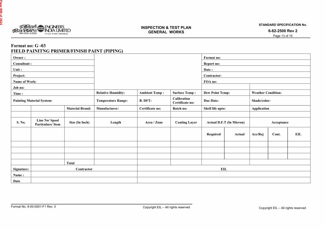
INSPECTION & TEST PLAN
GENERAL WORKS
STANDARD SPECIFICATION No.
6-82-2500 Rev 2 Page 13 of 15
Format No. 8-00-0001-F1 Rev. 0 Copyright EIL – All rights reserved Copyright EIL – All rights reserved
Format no: G -03 FIELD PAINITNG PRIMER/FINISH PAINT (PIPING)
Owner :
Format no:
Consultant : Report no:
Unit : Date :
Project: Contractor:
Name of Work: FOA no:
Job no:
Time : Relative Humidity: Ambient Temp : Surface Temp : Dew Point Temp: Weather Condition:
Painting Material System: Temperature Range: B. DFT: Calibration Certificate no:
Due Date: Shade/color:
Material Brand: Manufacturer: Certificate no: Batch no: Shelf life upto: Application
S. No. Line No/ Spool
Particulars/ Item Size (In Inch) Length Area / Zone Coating Layer Actual D.F.T (In Micron) Acceptance
Required Actual
Acc/Rej Cont. EIL
Total
Signature: Contractor EIL
Name :
Date
Pag
e 898 of 2624
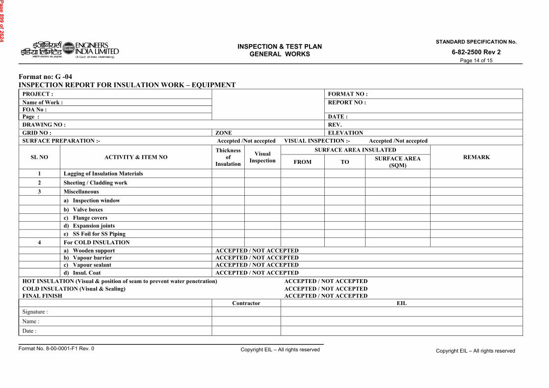
INSPECTION & TEST PLAN
GENERAL WORKS
STANDARD SPECIFICATION No.
6-82-2500 Rev 2 Page 14 of 15
Format No. 8-00-0001-F1 Rev. 0 Copyright EIL – All rights reserved Copyright EIL – All rights reserved
Format no: G -04 INSPECTION REPORT FOR INSULATION WORK – EQUIPMENT
PROJECT :
FORMAT NO :
Name of Work : REPORT NO : FOA No : Page : DATE : DRAWING NO : REV.
GRID NO : ZONE ELEVATION SURFACE PREPARATION :- Accepted /Not accepted VISUAL INSPECTION :- Accepted /Not accepted
SL NO ACTIVITY & ITEM NO Thickness
of Insulation
Visual Inspection
SURFACE AREA INSULATED REMARK
FROM TO SURFACE AREA
(SQM)
1 Lagging of Insulation Materials
2 Sheeting / Cladding work
3 Miscellaneous
a) Inspection window
b) Valve boxes
c) Flange covers d) Expansion joints
e) SS Foil for SS Piping
4 For COLD INSULATION a) Wooden support ACCEPTED / NOT ACCEPTED b) Vapour barrier ACCEPTED / NOT ACCEPTED c) Vapour sealant ACCEPTED / NOT ACCEPTED d) Insul. Coat ACCEPTED / NOT ACCEPTED
HOT INSULATION (Visual & position of seam to prevent water penetration) ACCEPTED / NOT ACCEPTED COLD INSULATION (Visual & Sealing) ACCEPTED / NOT ACCEPTED FINAL FINISH ACCEPTED / NOT ACCEPTED
Contractor EIL
Signature :
Name :
Date :
Pag
e 899 of 2624

INSPECTION & TEST PLAN
GENERAL WORKS
STANDARD SPECIFICATION No.
6-82-2500 Rev 2 Page 15 of 15
Format No. 8-00-0001-F1 Rev. 0 Copyright EIL – All rights reserved Copyright EIL – All rights reserved
Format no: G - 05 INSPECTION REPORT FOR INSULATION WORK - PIPING
PROJECT :
FORMAT NO :
Name of Work : REPORT NO :
FOA No :
Page : DATE :
SR. NO.
LINE NO. DIA R.
Mtr. OP.
TEMP
INSULATION SPACER RING MOISTURE BARRIER
HEAT TRACER PUTTY APPLICATION
FIXING OF ALUMINIUM SHEET REMARKS
TYP THK QTY Cont. EIL CONT. EIL QTY CONT. EIL QTY CONT. EIL
REMARKS:
CONTRACTOR EIL
Signature
Name
Date
Pag
e 900 of 2624

INSPECTION & TEST PLAN ENGINEERS INDIA LIMITED FOR FIELD INSTRUMENTATION ( A Govt of India Undertaking( WORKS (EPCC/ LSTK CONTRACTS)
STANDARD SPECIFICATION No.
2-aids I Nreff eleane an jcmnf
6-82-2600 Rev. 2 Page 1 of 32
OS * .e5r2%+1 le1
((Llitildl/VcOtVc1 • -ict)1 tin 41311)
-WU -1=4-effur t7-4 tr-tturrr t41.71--1 I Outellb
INSPECTION & TEST PLAN (ITP) FOR
FIELD INSTRUMENTATION WORKS (EPCC/LSTK CONTRACTS)
1), ( 2-t•I'sjj
2 19.02.2016 REVISED AND REISSUED 13%\`' DJ AKM TKS SC
1 04.07.2011 REVISED AND REISSUED SM SM MKG DM
0 24.08.2006 ISSUED AS STANDARD SPECIFICATION AS MPJ VNP VJN
Rev. No
Date Purpose Prepared
by Checked
by
Standards Committee Convenor
Standards Bureau
Chairman
Approved by
Format No. 8-00-0001-F1 Rev 1 Copyright EIL — All rights reserved
Page 901 of 2624

INSPECTION & TEST PLAN FOR FIELD INSTRUMENTATION
WORKS (EPCC/ LSTK CONTRACTS)
STANDARD SPECIFICATION No.
6-82-2600 Rev 2 Page 2 of 32
Format No. 8-00-0001-F1 Rev 1 Copyright EIL – All rights reserved
Abbreviations: A/G : Above Ground AS : Alloy Steel i.e. Cr-Mo steels like A335 Gr P11, P5, P9, P22, etc. CS : Carbon Steel CSO : Car Seal Open DCS : Digital Control System DPT : Dye Penetration Testing FTB : Field Terminal Block GAD : General Arrangement Drawings HIC : Hydrogen Induced Cracking ITP : Inspection & Test Plan JB : Junction Box LCP : Local Control Panel LO/ LC : Lock Open/ Lock Close MPI : Magnetic Particle Inspection MT : Magnetic Particle Testing NACE : National Association of Corrosion Engineers NDT : Non Destructive Testing NRV : Non Return Valve P&ID : Piping & Instrumentation Diagrams PLC : Programmable Logic Controller PMI : Positive Material Identification PMS : Piping Material Specification PQR : Procedure Qualification Record PT : Penetrant Testing PVC : Poly Vinyl Chloride PWHT : Post Weld Heat Treatment QA/QC : Quality Assurance/ Quality Control RF : Reinforcement SS : Stainless Steel like A312 TP 304, 316, 321, 304L, 316L, 316Mo, etc. SSCC : Sulphide Stress Corrosion Cracking WPS : Welding Procedure Specification WPS : Welding Procedure Specification Construction Standards Committee Convenor: Sh. T.K. Sen, ED (Construction) Members: Sh. SN Bhatnagar, GM (Construction)
Sh. MK Garg, GM (Construction) Sh. A K Mishra, GM (Construction) Sh. Janak Kishore, DGM (Projects) Sh. Rajeev Jain, DGM, (C&P) Sh. Udayan Chakravarty, AGM (Piping) Sh. Ravindra Kumar, AGM (Construction) Sh. D Jana, AGM (Construction)
Page 902 of 2624
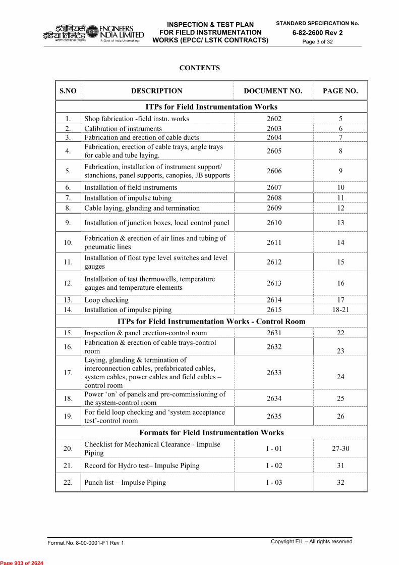
INSPECTION & TEST PLAN FOR FIELD INSTRUMENTATION
WORKS (EPCC/ LSTK CONTRACTS)
STANDARD SPECIFICATION No.
6-82-2600 Rev 2 Page 3 of 32
Format No. 8-00-0001-F1 Rev 1 Copyright EIL – All rights reserved
CONTENTS
S.NO DESCRIPTION DOCUMENT NO. PAGE NO.
ITPs for Field Instrumentation Works
1. Shop fabrication -field instn. works 2602 5 2. Calibration of instruments 2603 6 3. Fabrication and erection of cable ducts 2604 7
4. Fabrication, erection of cable trays, angle trays for cable and tube laying.
2605 8
5. Fabrication, installation of instrument support/ stanchions, panel supports, canopies, JB supports
2606 9
6. Installation of field instruments 2607 10
7. Installation of impulse tubing 2608 11 8. Cable laying, glanding and termination 2609 12
9. Installation of junction boxes, local control panel 2610 13
10. Fabrication & erection of air lines and tubing of pneumatic lines
2611 14
11. Installation of float type level switches and level gauges
2612 15
12. Installation of test thermowells, temperature gauges and temperature elements
2613 16
13. Loop checking 2614 17 14. Installation of impulse piping 2615 18-21
ITPs for Field Instrumentation Works - Control Room
15. Inspection & panel erection-control room 2631 22
16. Fabrication & erection of cable trays-control room
2632
23
17.
Laying, glanding & termination of interconnection cables, prefabricated cables, system cables, power cables and field cables –control room
2633
24
18. Power ‘on’ of panels and pre-commissioning of the system-control room
2634 25
19. For field loop checking and ‘system acceptance test’-control room
2635 26
Formats for Field Instrumentation Works
20. Checklist for Mechanical Clearance - Impulse Piping
I - 01 27-30
21. Record for Hydro test– Impulse Piping I - 02 31
22. Punch list – Impulse Piping I - 03 32
Page 903 of 2624
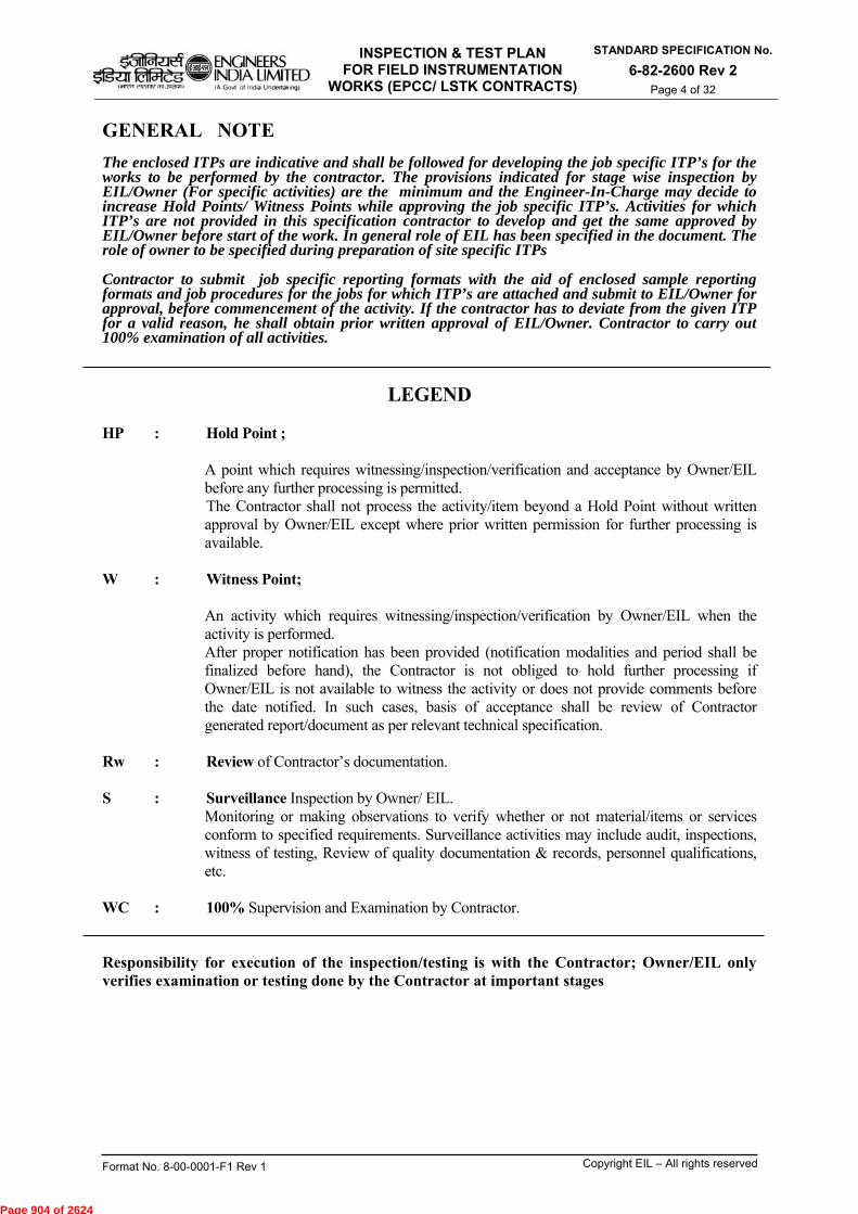
INSPECTION & TEST PLAN FOR FIELD INSTRUMENTATION
WORKS (EPCC/ LSTK CONTRACTS)
STANDARD SPECIFICATION No.
6-82-2600 Rev 2 Page 4 of 32
Format No. 8-00-0001-F1 Rev 1 Copyright EIL – All rights reserved
GENERAL NOTE The enclosed ITPs are indicative and shall be followed for developing the job specific ITP’s for the works to be performed by the contractor. The provisions indicated for stage wise inspection by EIL/Owner (For specific activities) are the minimum and the Engineer-In-Charge may decide to increase Hold Points/ Witness Points while approving the job specific ITP’s. Activities for which ITP’s are not provided in this specification contractor to develop and get the same approved by EIL/Owner before start of the work. In general role of EIL has been specified in the document. The role of owner to be specified during preparation of site specific ITPs Contractor to submit job specific reporting formats with the aid of enclosed sample reporting formats and job procedures for the jobs for which ITP’s are attached and submit to EIL/Owner for approval, before commencement of the activity. If the contractor has to deviate from the given ITP for a valid reason, he shall obtain prior written approval of EIL/Owner. Contractor to carry out 100% examination of all activities.
LEGEND HP : Hold Point ;
A point which requires witnessing/inspection/verification and acceptance by Owner/EIL before any further processing is permitted. The Contractor shall not process the activity/item beyond a Hold Point without written approval by Owner/EIL except where prior written permission for further processing is available.
W : Witness Point; An activity which requires witnessing/inspection/verification by Owner/EIL when the activity is performed. After proper notification has been provided (notification modalities and period shall be finalized before hand), the Contractor is not obliged to hold further processing if Owner/EIL is not available to witness the activity or does not provide comments before the date notified. In such cases, basis of acceptance shall be review of Contractor generated report/document as per relevant technical specification.
Rw : Review of Contractor’s documentation.
S : Surveillance Inspection by Owner/ EIL. Monitoring or making observations to verify whether or not material/items or services conform to specified requirements. Surveillance activities may include audit, inspections, witness of testing, Review of quality documentation & records, personnel qualifications, etc.
WC : 100% Supervision and Examination by Contractor.
Responsibility for execution of the inspection/testing is with the Contractor; Owner/EIL only verifies examination or testing done by the Contractor at important stages
Page 904 of 2624
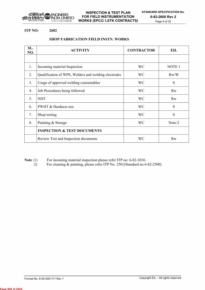
INSPECTION & TEST PLAN FOR FIELD INSTRUMENTATION
WORKS (EPCC/ LSTK CONTRACTS)
STANDARD SPECIFICATION No.
6-82-2600 Rev 2 Page 5 of 32
Format No. 8-00-0001-F1 Rev 1 Copyright EIL – All rights reserved
ITP NO: 2602 SHOP FABRICATION FIELD INSTN. WORKS
SL. NO.
ACTIVITY CONTRACTOR EIL
1. Incoming material Inspection WC NOTE 1
2. Qualification of WPS, Welders and welding electrodes WC Rw/W
3. Usage of approved welding consumables WC S
4. Job Procedures being followed WC Rw
5. NDT WC Rw
6. PWHT & Hardness test WC S
7. Shop testing WC S
8. Painting & Storage WC Note-2
INSPECTION & TEST DOCUMENTS
Review Test and Inspection documents WC Rw
Note :1) For incoming material inspection please refer ITP no: 6-82-1010. 2) For cleaning & painting, please refer ITP No. 2501(Standard no 6-82-2500)
Page 905 of 2624
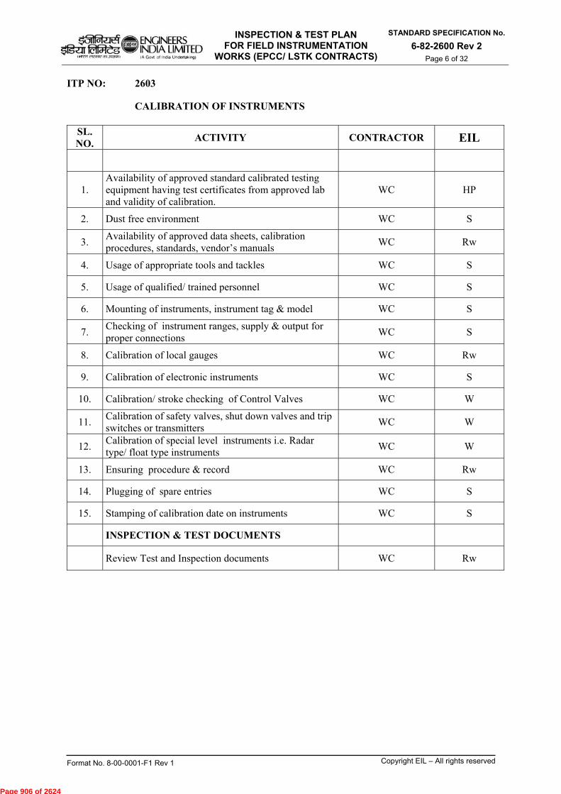
INSPECTION & TEST PLAN FOR FIELD INSTRUMENTATION
WORKS (EPCC/ LSTK CONTRACTS)
STANDARD SPECIFICATION No.
6-82-2600 Rev 2 Page 6 of 32
Format No. 8-00-0001-F1 Rev 1 Copyright EIL – All rights reserved
ITP NO: 2603 CALIBRATION OF INSTRUMENTS
SL. NO.
ACTIVITY CONTRACTOR EIL
1. Availability of approved standard calibrated testing equipment having test certificates from approved lab and validity of calibration.
WC HP
2. Dust free environment WC S
3. Availability of approved data sheets, calibration procedures, standards, vendor’s manuals
WC Rw
4. Usage of appropriate tools and tackles WC S
5. Usage of qualified/ trained personnel WC S
6. Mounting of instruments, instrument tag & model WC S
7. Checking of instrument ranges, supply & output for proper connections
WC S
8. Calibration of local gauges WC Rw
9. Calibration of electronic instruments WC S
10. Calibration/ stroke checking of Control Valves WC W
11. Calibration of safety valves, shut down valves and trip switches or transmitters
WC W
12. Calibration of special level instruments i.e. Radar type/ float type instruments
WC W
13. Ensuring procedure & record WC Rw
14. Plugging of spare entries WC S
15. Stamping of calibration date on instruments WC S
INSPECTION & TEST DOCUMENTS
Review Test and Inspection documents WC Rw
Page 906 of 2624
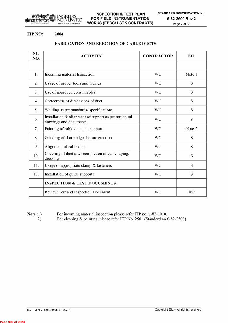
INSPECTION & TEST PLAN FOR FIELD INSTRUMENTATION
WORKS (EPCC/ LSTK CONTRACTS)
STANDARD SPECIFICATION No.
6-82-2600 Rev 2 Page 7 of 32
Format No. 8-00-0001-F1 Rev 1 Copyright EIL – All rights reserved
ITP NO: 2604 FABRICATION AND ERECTION OF CABLE DUCTS
SL. NO.
ACTIVITY CONTRACTOR EIL
1. Incoming material Inspection WC Note 1
2. Usage of proper tools and tackles WC S
3. Use of approved consumables WC S
4. Correctness of dimensions of duct WC S
5. Welding as per standards/ specifications WC S
6. Installation & alignment of support as per structural drawings and documents
WC S
7. Painting of cable duct and support WC Note-2
8. Grinding of sharp edges before erection WC S
9. Alignment of cable duct WC S
10. Covering of duct after completion of cable laying/ dressing
WC S
11. Usage of appropriate clamp & fasteners WC S
12. Installation of guide supports WC S
INSPECTION & TEST DOCUMENTS
Review Test and Inspection Document WC Rw
Note :1) For incoming material inspection please refer ITP no: 6-82-1010. 2) For cleaning & painting, please refer ITP No. 2501 (Standard no 6-82-2500)
Page 907 of 2624

INSPECTION & TEST PLAN FOR FIELD INSTRUMENTATION
WORKS (EPCC/ LSTK CONTRACTS)
STANDARD SPECIFICATION No.
6-82-2600 Rev 2 Page 8 of 32
Format No. 8-00-0001-F1 Rev 1 Copyright EIL – All rights reserved
ITP NO: 2605
FABRICATION, ERECTION OF CABLE TRAYS, ANGLE TRAYS FOR CABLE AND TUBE LAYING.
SL. NO.
ACTIVITY CONTRACTOR EIL
1. Incoming material Inspection WC Note 1
2. Correct size and routing of tray/ angle WC S/Rw
3. Ensure separation of cable trays for power & signal/ Thermocouple cables
WC S
4. Supports as per standards/ specifications WC S
5. Removal of sharp edges and sharp bends WC --
6. Fastening/ welding of trays/ angles WC S
7. Check for fouling with piping & structures WC S
8. Check for any obstruction/ free access for maintenance WC S
INSPECTION & TEST DOCUMENTS
Review Test and Inspection Document WC Rw
Note :1) For incoming material inspection please refer ITP no: 6-82-1010.
Page 908 of 2624

INSPECTION & TEST PLAN FOR FIELD INSTRUMENTATION
WORKS (EPCC/ LSTK CONTRACTS)
STANDARD SPECIFICATION No.
6-82-2600 Rev 2 Page 9 of 32
Format No. 8-00-0001-F1 Rev 1 Copyright EIL – All rights reserved
ITP NO: 2606
FABRICATION, INSTALLATION OF INSTRUMENT SUPPORT/ STANCHIONS, PANEL SUPPORTS, CANOPIES, JB SUPPORTS
SL. NO.
ACTIVITY CONTRACTOR EIL
1. Incoming material Inspection WC Note 1
2. Usage of proper tools and tackles WC --
3. Availability of approved junction box layout and Instrument location plan
WC Rw
4. Location of Junction Box & Instrument Stanchions (from access point of view & installation standards)
WC S
5. Correctness of dimensions, height, etc. WC --
6. Approved welder, consumables, standards
WC Rw
7. Check for installation, hole to hole dimension & alignment/ fit-up
WC S
8. Removal of sharp edges WC --
9. Painting WC Note-2
10. Physical walk through the line WC --
11. Easy access for maintenance WC S
INSPECTION & TEST DOCUMENTS
Review Test and Inspection Document WC Rw
Note :1) For incoming material inspection please refer ITP no: 6-82-1010. 2) For cleaning & painting, please refer ITP No. 2501(Standard no 6-82-2500)
Page 909 of 2624

INSPECTION & TEST PLAN FOR FIELD INSTRUMENTATION
WORKS (EPCC/ LSTK CONTRACTS)
STANDARD SPECIFICATION No.
6-82-2600 Rev 2 Page 10 of 32
Format No. 8-00-0001-F1 Rev 1 Copyright EIL – All rights reserved
ITP NO: 2607
INSTALLATION OF FIELD INSTRUMENTS
SL. NO.
ACTIVITY CONTRACTOR EIL
1. Availability of approved location plans, piping GADs, P&ID, vendor’s manual, etc.
WC Rw
2. Installation of proper support/ instrument stanchion, canopy
WC S
3. Instrument tag as per P&ID and model & make as per instrument data sheet
WC --
4. Physical walk through the line WC --
5. Alignment of the instruments WC S
6. Mounting of accessories as per instrument data sheet WC S
7. Visibility & maintenance clearance WC S
INSPECTION & TEST DOCUMENTS
Review Test and Inspection Document WC Rw
Page 910 of 2624
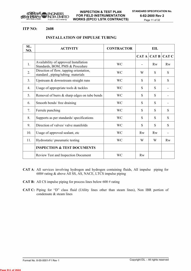
INSPECTION & TEST PLAN FOR FIELD INSTRUMENTATION
WORKS (EPCC/ LSTK CONTRACTS)
STANDARD SPECIFICATION No.
6-82-2600 Rev 2 Page 11 of 32
Format No. 8-00-0001-F1 Rev 1 Copyright EIL – All rights reserved
ITP NO: 2608 INSTALLATION OF IMPULSE TUBING
SL. NO.
ACTIVITY CONTRACTOR EIL
CAT A CAT B CAT C
1. Availability of approved Installation Standards, BOM, PMS & Procedure
WC - Rw Rw
2. Direction of flow, tapping orientation, standard , piping/tubing materials
WC W S S
3. Upstream & downstream straight runs WC S S S
4. Usage of appropriate tools & tackles WC S S -
5. Removal of burrs & sharp edges on tube bends WC S S -
6. Smooth bends/ free draining WC S S -
7. Ferrule punching WC S S S
8. Supports as per standards/ specifications WC S S S
9. Direction of valves/ valve manifolds WC S S S
10. Usage of approved sealant, etc WC Rw Rw -
11. Hydrostatic/ pneumatic testing WC W W Rw
INSPECTION & TEST DOCUMENTS
Review Test and Inspection Document WC Rw
CAT A: All services involving hydrogen and hydrogen containing fluids, All impulse piping for
600# rating & above All SS, AS, NACE, LTCS impulse piping CAT B: All CS impulse piping for process lines below 600 # rating CAT C: Piping for “D” class fluid (Utility lines other than steam lines), Non IBR portion of
condensate & steam lines
Page 911 of 2624

INSPECTION & TEST PLAN FOR FIELD INSTRUMENTATION
WORKS (EPCC/ LSTK CONTRACTS)
STANDARD SPECIFICATION No.
6-82-2600 Rev 2 Page 12 of 32
Format No. 8-00-0001-F1 Rev 1 Copyright EIL – All rights reserved
ITP NO: 2609
CABLE LAYING, GLANDING AND TERMINATION
SL. NO.
ACTIVITY CONTRACTOR EIL
1. Incoming Material Inspection for Cables, Glands etc. WC Note 1
2. Correctness of cable type as per schedule WC S
3. Measurement & routing WC --
4. Check cable for continuity, insulation resistance, megger values
WC Rw
5. Identification tags/ tag plates and proper dressing & clamping
WC --
6. Separation of signal/ thermocouple and power cables WC S
7. Proper glands as per area classification, size of cable, JB entry, etc.
WC S
8. Identification/ ferrule and dressing inside junction boxes and instrument
WC --
9. Crimpable type lugs and proper crimping WC --
10. Telephone wire connection inside JB WC --
11. Shield wire dressing/ sleeving and termination WC --
12. Insulation of shield wire on instrument end WC --
INSPECTION & TEST DOCUMENTS
Review Test and Inspection Document WC Rw
Note : 1) For incoming material inspection please refer ITP no: 6-82-1010.
Page 912 of 2624

INSPECTION & TEST PLAN FOR FIELD INSTRUMENTATION
WORKS (EPCC/ LSTK CONTRACTS)
STANDARD SPECIFICATION No.
6-82-2600 Rev 2 Page 13 of 32
Format No. 8-00-0001-F1 Rev 1 Copyright EIL – All rights reserved
ITP NO: 2610
INSTALLATION OF JUNCTION BOXES, LOCAL CONTROL PANEL
SL. NO.
ACTIVITY CONTRACTOR EIL
1. Incoming Material Inspection WC Note 1
2. Check suitability as per specified hazardous area classification
WC Rw
3. Check Correctness of cable entries WC --
4. Alignment WC --
5. Tightening of fasteners WC --
6. Tightening & numbering of terminal blocks WC --
7. Availability of telephone sockets (for JB’s) & earthing point
WC --
8. Earthing of JB/ LCP WC S
9. Plugging of spare entries with correct plugs WC S
10. Wiring of various hardware in LCP as per approved wiring drawings
WC S
11. Protection of JB and LCP (Canopy, weather shed) WC S
INSPECTION & TEST DOCUMENTS
Review Test and Inspection Document WC Rw
Note : 1) For incoming material inspection please refer ITP no: 6-82-1010.
Page 913 of 2624

INSPECTION & TEST PLAN FOR FIELD INSTRUMENTATION
WORKS (EPCC/ LSTK CONTRACTS)
STANDARD SPECIFICATION No.
6-82-2600 Rev 2 Page 14 of 32
Format No. 8-00-0001-F1 Rev 1 Copyright EIL – All rights reserved
ITP NO: 2611
FABRICATION & ERECTION OF AIR LINES AND TUBING OF PNEUMATIC LINES
SL. NO.
ACTIVITY CONTRACTOR EIL
1. Incoming Material Inspection WC Note 1
2.
Availability of AFC drawings for air / pneumatic distribution line
WC Rw
3. Usage of correct size, thread, etc. Jigs/ die sets for threading of pipes
WC --
4. Proper packing material/ sealant used at threaded joints
WC --
5. Providing three piece union at each loop for easy maintenance
WC --
6. Slope of Air Lines, provision of drain valves at lowest point on main header / Drain & Vent assemblies, isolation valves (Ball valves)
WC S
7. Tightening of joints WC --
8. Supporting and clamping WC S
9. Test air lines as per standards/ specifications and record
WC W
10. Check for inlet, outlet, signal, test and drain connection on the instrument
WC S
11. Correct supply as per data sheets WC --
12. Flush Air lines before pneumatic tubing connection to instruments
WC --
13. Punching of ferrules WC --
14. Tagging at both ends of tubes WC --
15. Test pneumatic tubing as per standards/ specifications and record
WC S
INSPECTION & TEST DOCUMENTS
Review Test and Inspection Document WC Rw
Note : 1) For incoming material inspection please refer ITP no: 6-82-1010.
Page 914 of 2624
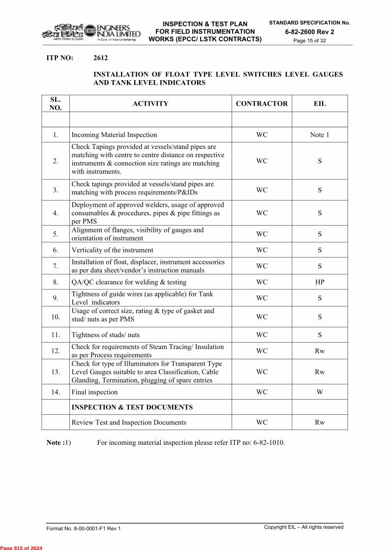
INSPECTION & TEST PLAN FOR FIELD INSTRUMENTATION
WORKS (EPCC/ LSTK CONTRACTS)
STANDARD SPECIFICATION No.
6-82-2600 Rev 2 Page 15 of 32
Format No. 8-00-0001-F1 Rev 1 Copyright EIL – All rights reserved
ITP NO: 2612
INSTALLATION OF FLOAT TYPE LEVEL SWITCHES LEVEL GAUGES AND TANK LEVEL INDICATORS
SL. NO.
ACTIVITY CONTRACTOR EIL
1. Incoming Material Inspection WC Note 1
2.
Check Tapings provided at vessels/stand pipes are matching with centre to centre distance on respective instruments & connection size ratings are matching with instruments.
WC S
3. Check tapings provided at vessels/stand pipes are matching with process requirements/P&IDs WC S
4. Deployment of approved welders, usage of approved consumables & procedures, pipes & pipe fittings as per PMS
WC S
5. Alignment of flanges, visibility of gauges and orientation of instrument
WC S
6. Verticality of the instrument WC S
7. Installation of float, displacer, instrument accessories as per data sheet/vendor’s instruction manuals
WC S
8. QA/QC clearance for welding & testing WC HP
9. Tightness of guide wires (as applicable) for Tank Level indicators
WC S
10. Usage of correct size, rating & type of gasket and stud/ nuts as per PMS WC S
11. Tightness of studs/ nuts WC S
12. Check for requirements of Steam Tracing/ Insulation as per Process requirements
WC Rw
13. Check for type of Illuminators for Transparent Type Level Gauges suitable to area Classification, Cable Glanding, Termination, plugging of spare entries
WC Rw
14. Final inspection WC W
INSPECTION & TEST DOCUMENTS
Review Test and Inspection Documents WC Rw
Note :1) For incoming material inspection please refer ITP no: 6-82-1010.
Page 915 of 2624

INSPECTION & TEST PLAN FOR FIELD INSTRUMENTATION
WORKS (EPCC/ LSTK CONTRACTS)
STANDARD SPECIFICATION No.
6-82-2600 Rev 2 Page 16 of 32
Format No. 8-00-0001-F1 Rev 1 Copyright EIL – All rights reserved
ITP NO: 2613
INSTALLATION OF TEST THERMOWELLS, TEMPERATURE GAUGES AND TEMPERATURE ELEMENTS
SL. NO.
ACTIVITY CONTRACTOR EIL
1. Incoming Material Inspection WC Note-1
2. Correctness of range, rating, immersion length (U length), Instrument tags as per P&ID/ Instrument data sheets
WC Note-1
3. Check for tapping size, orientation, location as per P&ID
WC --
4. Usage of correct size, rating & type of gasket and stud/ nuts as per PMS
WC Note-1
5. Installation of temperature element head & assemblies WC S
6. Tightness of studs/ nuts WC S
7. Visibility & orientation of gauges WC --
8. Plugging of spare entries with correct size plugs WC --
INSPECTION & TEST DOCUMENTS
Review Test and Inspection Documents WC Rw
Note : 1) For incoming material inspection please refer ITP no: 6-82-1010.
Page 916 of 2624

INSPECTION & TEST PLAN FOR FIELD INSTRUMENTATION
WORKS (EPCC/ LSTK CONTRACTS)
STANDARD SPECIFICATION No.
6-82-2600 Rev 2 Page 17 of 32
Format No. 8-00-0001-F1 Rev 1 Copyright EIL – All rights reserved
ITP NO: 2614 LOOP CHECKING
SL. NO.
ACTIVITY CONTRACTOR EIL
1. Completeness of installation as per standards & specifications
WC Rw
2. Liquidation of punch list as per ITP WC Rw
3. Availability of standard calibrated equipment WC Rw
4. Coordination with DCS vendor WC S
5. Loop checking
a) From instrument to junction box WC S
b) From Instrument to control room WC W
6. Recalibrate/ fine tune instruments for accurate response if required
WC W
7. Check for inter locks and response of final control elements
WC W
8. Ensure proper response and record WC Rw
9. Loop acceptance WC HP
INSPECTION & TEST DOCUMENTS
Review Test and Inspection Documents WC Rw
Page 917 of 2624
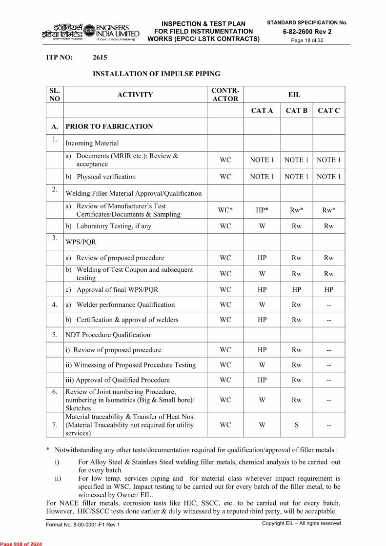
INSPECTION & TEST PLAN FOR FIELD INSTRUMENTATION
WORKS (EPCC/ LSTK CONTRACTS)
STANDARD SPECIFICATION No.
6-82-2600 Rev 2 Page 18 of 32
Format No. 8-00-0001-F1 Rev 1 Copyright EIL – All rights reserved
ITP NO: 2615 INSTALLATION OF IMPULSE PIPING
SL. NO
ACTIVITY CONTR- ACTOR
EIL
CAT A CAT B CAT C
A. PRIOR TO FABRICATION
1.
Incoming Material
a) Documents (MRIR etc.): Review & acceptance
WC NOTE 1 NOTE 1 NOTE 1
b) Physical verification WC NOTE 1 NOTE 1 NOTE 1
2.
Welding Filler Material Approval/Qualification
a) Review of Manufacturer’s Test Certificates/Documents & Sampling
WC* HP* Rw* Rw*
b) Laboratory Testing, if any WC W Rw Rw
3.
WPS/PQR
a) Review of proposed procedure WC HP Rw Rw
b) Welding of Test Coupon and subsequent
testing WC W Rw Rw
c) Approval of final WPS/PQR WC HP HP HP
4. a) Welder performance Qualification WC W Rw --
b) Certification & approval of welders WC HP Rw --
5. NDT Procedure Qualification
i) Review of proposed procedure WC HP Rw --
ii) Witnessing of Proposed Procedure Testing WC W Rw --
iii) Approval of Qualified Procedure WC HP Rw --
6.
Review of Joint numbering Procedure, numbering in Isometrics (Big & Small bore)/ Sketches
WC W
Rw
--
7. Material traceability & Transfer of Heat Nos. (Material Traceability not required for utility services)
WC W S --
* Notwithstanding any other tests/documentation required for qualification/approval of filler metals :
i) For Alloy Steel & Stainless Steel welding filler metals, chemical analysis to be carried out for every batch.
ii) For low temp. services piping and for material class wherever impact requirement is specified in WSC, Impact testing to be carried out for every batch of the filler metal, to be witnessed by Owner/ EIL.
For NACE filler metals, corrosion tests like HIC, SSCC, etc. to be carried out for every batch. However, HIC/SSCC tests done earlier & duly witnessed by a reputed third party, will be acceptable.
Page 918 of 2624

INSPECTION & TEST PLAN FOR FIELD INSTRUMENTATION
WORKS (EPCC/ LSTK CONTRACTS)
STANDARD SPECIFICATION No.
6-82-2600 Rev 2 Page 19 of 32
Format No. 8-00-0001-F1 Rev 1 Copyright EIL – All rights reserved
ITP NO: 2615
INSTALLATION OF IMPULSE PIPING
SL. NO. ACTIVITY
CONTR-ACTOR
EIL
CAT A CATB CATC
B. FABRICATION (SHOP & FIELD)
1. Material as per piping class (check w.r.t. approved colour coding procedure), Fit-up check and Traceability check
WC S -- --
2. Pre-heat (if any) WC S -- --
3. Certificate of purity of purging/shielding Gas (if any) WC S -- --
4. Purging rate (if any) and arrangement WC S -- --
5. Shielding rate (if any) WC S -- --
6. Baking of Electrodes WC S -- --
7. Inter-pass cleaning & Temperature check WC S -- --
8. Visual Examination of completed welds WC W S --
9. a) Monitoring of PWHT Cycle WC S -- --
b) Review of Time – Temperature graph WC Rw Rw Rw
c) Hardness Check WC S -- --
10. PT/MT WC W S --
11. Identification of Joints for Radiography (for Random Radiography only)
WC S -- --
12. Review of Radiographs interpreted by the Contractor WC HP W Rw
Page 919 of 2624
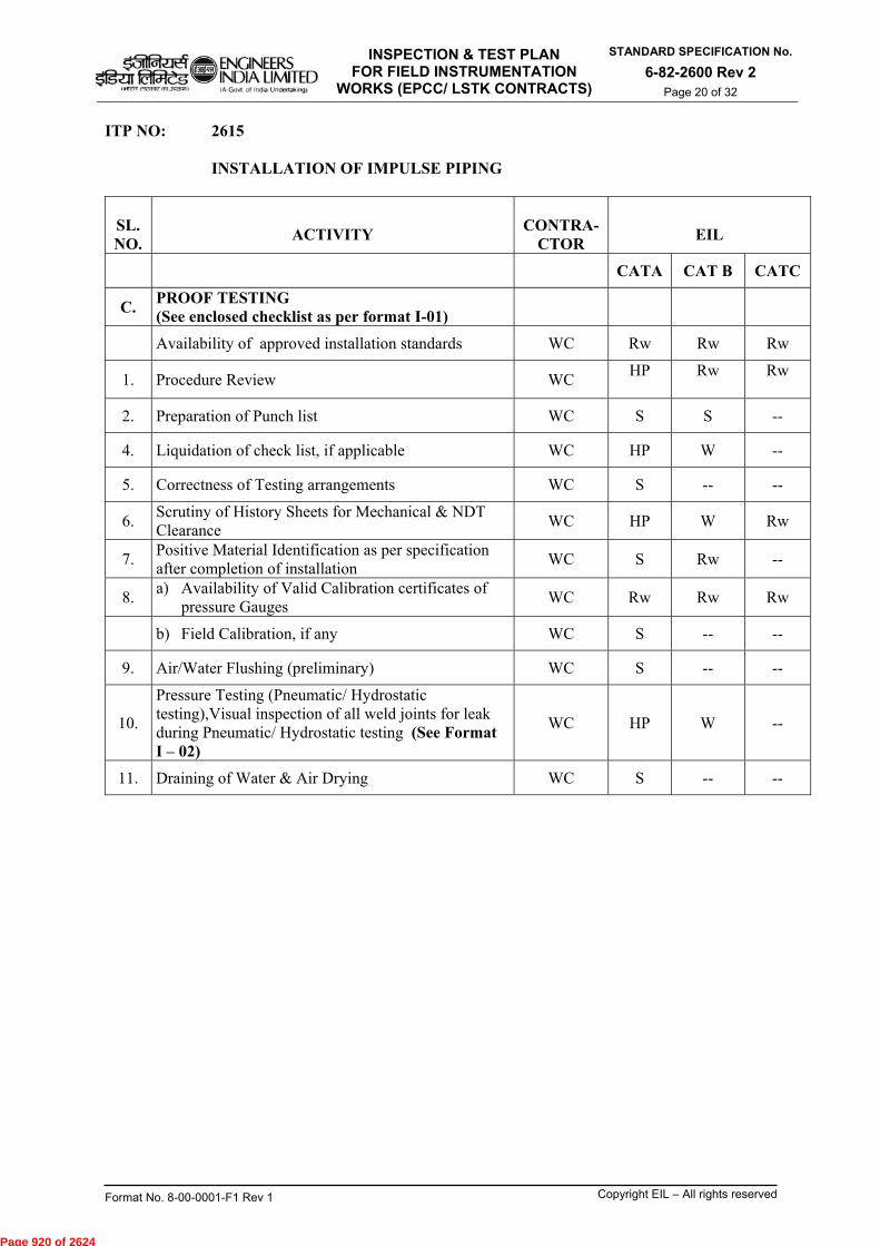
INSPECTION & TEST PLAN FOR FIELD INSTRUMENTATION
WORKS (EPCC/ LSTK CONTRACTS)
STANDARD SPECIFICATION No.
6-82-2600 Rev 2 Page 20 of 32
Format No. 8-00-0001-F1 Rev 1 Copyright EIL – All rights reserved
ITP NO: 2615
INSTALLATION OF IMPULSE PIPING
SL. NO.
ACTIVITY
CONTRA-
CTOR
EIL
CATA CAT B CATC
C. PROOF TESTING (See enclosed checklist as per format I-01)
Availability of approved installation standards WC Rw Rw Rw
1. Procedure Review WC HP
Rw
Rw
2. Preparation of Punch list WC S S --
4. Liquidation of check list, if applicable WC HP W --
5. Correctness of Testing arrangements WC S -- --
6. Scrutiny of History Sheets for Mechanical & NDT Clearance
WC HP W Rw
7. Positive Material Identification as per specification after completion of installation
WC S Rw --
8. a) Availability of Valid Calibration certificates of
pressure Gauges WC Rw Rw Rw
b) Field Calibration, if any WC S -- --
9. Air/Water Flushing (preliminary) WC S -- --
10.
Pressure Testing (Pneumatic/ Hydrostatic testing),Visual inspection of all weld joints for leak during Pneumatic/ Hydrostatic testing (See Format I – 02)
WC HP W --
11. Draining of Water & Air Drying WC S -- --
Page 920 of 2624
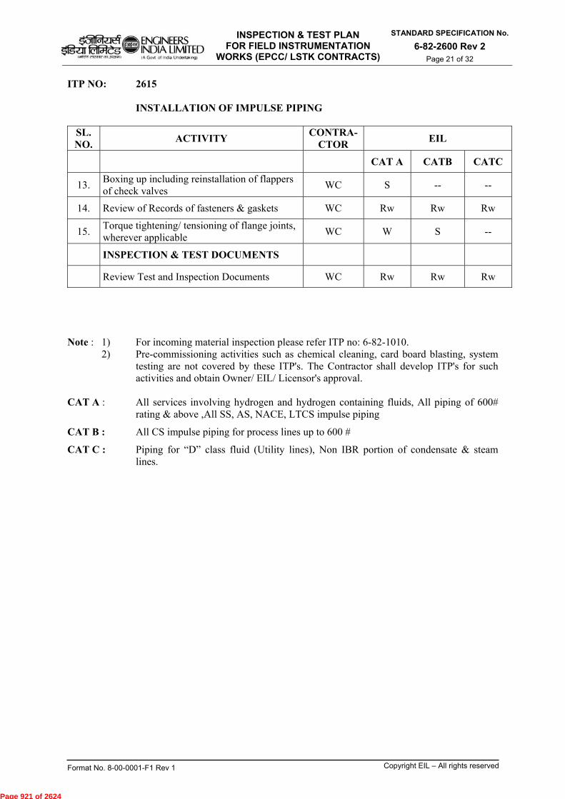
INSPECTION & TEST PLAN FOR FIELD INSTRUMENTATION
WORKS (EPCC/ LSTK CONTRACTS)
STANDARD SPECIFICATION No.
6-82-2600 Rev 2 Page 21 of 32
Format No. 8-00-0001-F1 Rev 1 Copyright EIL – All rights reserved
ITP NO: 2615
INSTALLATION OF IMPULSE PIPING
SL. NO.
ACTIVITY CONTRA-
CTOR EIL
CAT A CATB CATC
13. Boxing up including reinstallation of flappers of check valves
WC S -- --
14. Review of Records of fasteners & gaskets WC Rw Rw Rw
15. Torque tightening/ tensioning of flange joints, wherever applicable
WC W S --
INSPECTION & TEST DOCUMENTS
Review Test and Inspection Documents WC Rw Rw Rw
Note : 1) For incoming material inspection please refer ITP no: 6-82-1010.
2) Pre-commissioning activities such as chemical cleaning, card board blasting, system testing are not covered by these ITP's. The Contractor shall develop ITP's for such activities and obtain Owner/ EIL/ Licensor's approval.
CAT A : All services involving hydrogen and hydrogen containing fluids, All piping of 600#
rating & above ,All SS, AS, NACE, LTCS impulse piping
CAT B : All CS impulse piping for process lines up to 600 #
CAT C : Piping for “D” class fluid (Utility lines), Non IBR portion of condensate & steam lines.
Page 921 of 2624

INSPECTION & TEST PLAN FOR FIELD INSTRUMENTATION
WORKS (EPCC/ LSTK CONTRACTS)
STANDARD SPECIFICATION No.
6-82-2600 Rev 2 Page 22 of 32
Format No. 8-00-0001-F1 Rev 1 Copyright EIL – All rights reserved
ITP NO: 2631
INSPECTION & PANEL ERECTION - CONTROL ROOM
SL. NO.
ACTIVITY CONTRACTOR EIL
1. Receipt of materials/ panels as per purchase requisition, inspection release note, bill of materials, etc.
WC Note 1
2. Storage of materials at site WC S
3. Shifting of panels into the control room without damage
WC S
4. Check for Hole to hole dimensions of the base frames with the as built drawings of the panels
WC S
5. Check alignment, fastening, welding & painting of the base frame.
WC S
6. Erection of panels as per approved layout drawing, after completion of all welding works
WC S
7. Tagging/identification of panels WC W
INSPECTION & TEST DOCUMENTS
Review Test and Inspection Documents WC Rw
Note: 1) For incoming material inspection please refer ITP no: 6-82-1010.
Page 922 of 2624
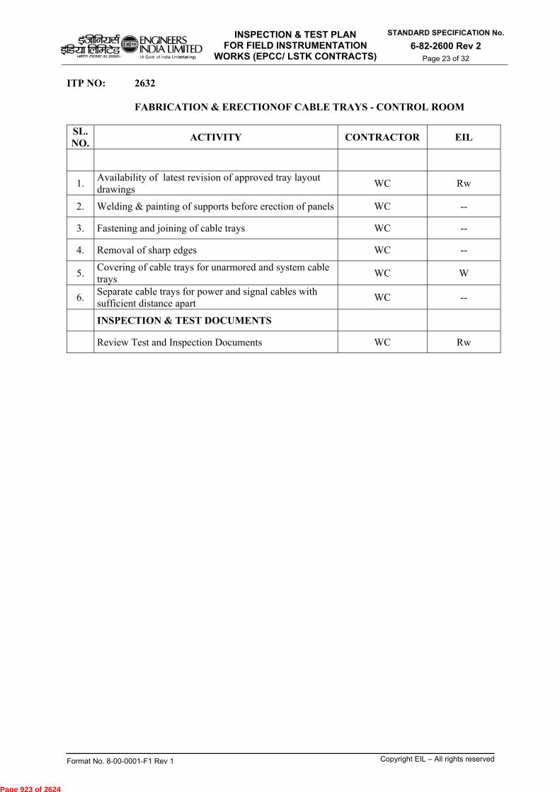
INSPECTION & TEST PLAN FOR FIELD INSTRUMENTATION
WORKS (EPCC/ LSTK CONTRACTS)
STANDARD SPECIFICATION No.
6-82-2600 Rev 2 Page 23 of 32
Format No. 8-00-0001-F1 Rev 1 Copyright EIL – All rights reserved
ITP NO: 2632
FABRICATION & ERECTIONOF CABLE TRAYS - CONTROL ROOM
SL. NO.
ACTIVITY CONTRACTOR EIL
1. Availability of latest revision of approved tray layout drawings
WC Rw
2. Welding & painting of supports before erection of panels WC --
3. Fastening and joining of cable trays WC --
4. Removal of sharp edges WC --
5. Covering of cable trays for unarmored and system cable trays
WC W
6. Separate cable trays for power and signal cables with sufficient distance apart
WC --
INSPECTION & TEST DOCUMENTS
Review Test and Inspection Documents WC Rw
Page 923 of 2624

INSPECTION & TEST PLAN FOR FIELD INSTRUMENTATION
WORKS (EPCC/ LSTK CONTRACTS)
STANDARD SPECIFICATION No.
6-82-2600 Rev 2 Page 24 of 32
Format No. 8-00-0001-F1 Rev 1 Copyright EIL – All rights reserved
ITP NO: 2633
LAYING, GLANDING & TERMINATION OF INTERCONNECTION CABLES, PREFABRICATED CABLES, SYSTEM CABLES, POWER CABLES AND FIELD CABLES – CONTROL ROOM
SL. NO.
ACTIVITY CONTRACTOR EIL
1. Correct size & type of cables as per cable schedule WC Note 1
2. Testing of cable before laying as per specification (continuity, megger, etc.), as applicable
WC Rw
3. Check for exact distance and cables cutting accordingly WC Rw
4. Tag on cables as per specification WC --
5. Availability of proper cable gland size, type of specified thread
WC Rw
6. Tightening of check nut (after termination) WC --
7. Cable continuity & insulation resistance, as applicable WC --
8. Dressing of cables inside PVC Duct and covering of PVC Duct after complete cabling.
WC --
9. Ferruling of cables WC --
10. Usage of sleeved crimpable type lugs WC --
11. Crimping of lugs WC --
12. Tightness of cables in the terminal block WC S
13. Numbering of terminal blocks WC --
14. Continuity of fuses in terminal blocks WC S
INSPECTION & TEST DOCUMENTS
Review Test and Inspection Documents WC Rw
Note : 1) For incoming material inspection please refer ITP no: 6-82-1010.
Page 924 of 2624
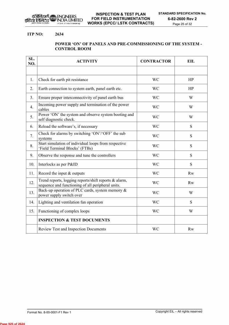
INSPECTION & TEST PLAN FOR FIELD INSTRUMENTATION
WORKS (EPCC/ LSTK CONTRACTS)
STANDARD SPECIFICATION No.
6-82-2600 Rev 2 Page 25 of 32
Format No. 8-00-0001-F1 Rev 1 Copyright EIL – All rights reserved
ITP NO: 2634
POWER ‘ON’ OF PANELS AND PRE-COMMISSIONING OF THE SYSTEM -CONTROL ROOM
SL. NO.
ACTIVITY CONTRACTOR EIL
1. Check for earth pit resistance WC HP
2. Earth connection to system earth, panel earth etc. WC HP
3. Ensure proper interconnectivity of panel earth bus WC W
4. Incoming power supply and termination of the power cables
WC W
5. Power ‘ON’ the system and observe system booting and self diagnostic check.
WC W
6. Reload the software’s, if necessary WC S
7. Check for alarms by switching ‘ON’/‘OFF’ the sub systems
WC S
8. Start simulation of individual loops from respective ‘Field Terminal Blocks’ (FTBs)
WC S
9. Observe the response and tune the controllers WC S
10. Interlocks as per P&ID WC S
11. Record the input & outputs WC Rw
12. Trend reports, logging reports/shift reports & alarm, sequence and functioning of all peripheral units.
WC Rw
13. Back-up operation of PLC cards, system memory & power supply switch over
WC W
14. Lighting and ventilation fan operation WC S
15. Functioning of complex loops WC W
INSPECTION & TEST DOCUMENTS
Review Test and Inspection Documents WC Rw
Page 925 of 2624

INSPECTION & TEST PLAN FOR FIELD INSTRUMENTATION
WORKS (EPCC/ LSTK CONTRACTS)
STANDARD SPECIFICATION No.
6-82-2600 Rev 2 Page 26 of 32
Format No. 8-00-0001-F1 Rev 1 Copyright EIL – All rights reserved
ITP NO: 2635
FOR FIELD LOOP CHECKING AND ‘SYSTEM ACCEPTANCE TEST’ - CONTROL ROOM
SL. NO.
ACTIVITY CONTRACTOR EIL
1. Coordination with field contractor for loop checking. WC S
2. Availability of record as per loop checking sheet duly signed
WC HP
3. Availability of record as per loop checking sheet duly signed
WC W
4. Operation of sub systems and peripheral systems WC W
5. ‘Back-up’ system operations WC W
6. Ensure feedback/commands from/to electrical system WC W
7. System acceptance WC HP
INSPECTION & TEST DOCUMENTS
Review Test and Inspection Documents WC Rw
Page 926 of 2624
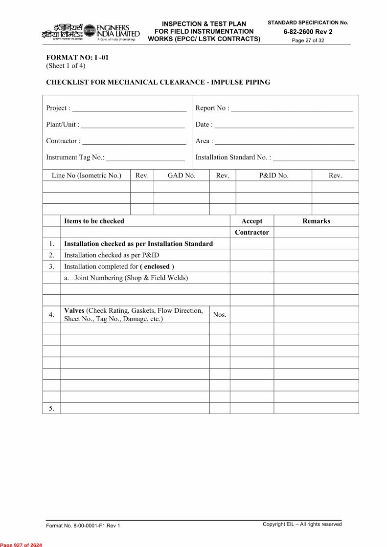
INSPECTION & TEST PLAN FOR FIELD INSTRUMENTATION
WORKS (EPCC/ LSTK CONTRACTS)
STANDARD SPECIFICATION No.
6-82-2600 Rev 2 Page 27 of 32
Format No. 8-00-0001-F1 Rev 1 Copyright EIL – All rights reserved
FORMAT NO: I -01 (Sheet 1 of 4) CHECKLIST FOR MECHANICAL CLEARANCE - IMPULSE PIPING Project : ________________________________ Plant/Unit : _____________________________ Contractor : _____________________________ Instrument Tag No.: ______________________
Report No : __________________________________ Date : _______________________________________ Area : _______________________________________ Installation Standard No. : _______________________
Line No (Isometric No.) Rev. GAD No. Rev. P&ID No. Rev.
Items to be checked Accept Remarks
Contractor
1. Installation checked as per Installation Standard
2. Installation checked as per P&ID
3. Installation completed for ( enclosed )
a. Joint Numbering (Shop & Field Welds)
4. Valves (Check Rating, Gaskets, Flow Direction, Sheet No., Tag No., Damage, etc.)
Nos.
5.
Page 927 of 2624
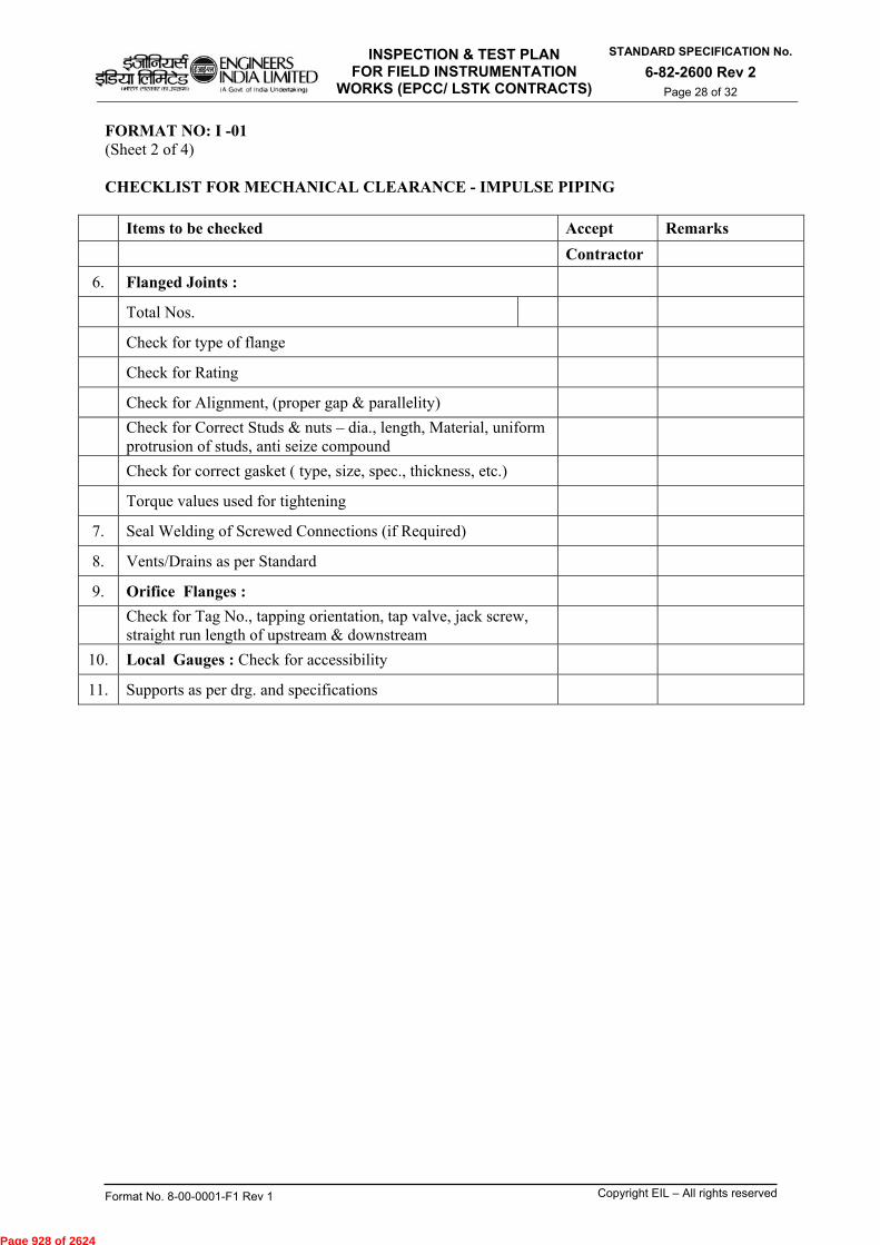
INSPECTION & TEST PLAN FOR FIELD INSTRUMENTATION
WORKS (EPCC/ LSTK CONTRACTS)
STANDARD SPECIFICATION No.
6-82-2600 Rev 2 Page 28 of 32
Format No. 8-00-0001-F1 Rev 1 Copyright EIL – All rights reserved
FORMAT NO: I -01 (Sheet 2 of 4) CHECKLIST FOR MECHANICAL CLEARANCE - IMPULSE PIPING
Items to be checked Accept Remarks
Contractor
6. Flanged Joints :
Total Nos.
Check for type of flange
Check for Rating
Check for Alignment, (proper gap & parallelity)
Check for Correct Studs & nuts – dia., length, Material, uniform protrusion of studs, anti seize compound
Check for correct gasket ( type, size, spec., thickness, etc.)
Torque values used for tightening
7. Seal Welding of Screwed Connections (if Required)
8. Vents/Drains as per Standard
9. Orifice Flanges :
Check for Tag No., tapping orientation, tap valve, jack screw, straight run length of upstream & downstream
10. Local Gauges : Check for accessibility
11. Supports as per drg. and specifications
Page 928 of 2624
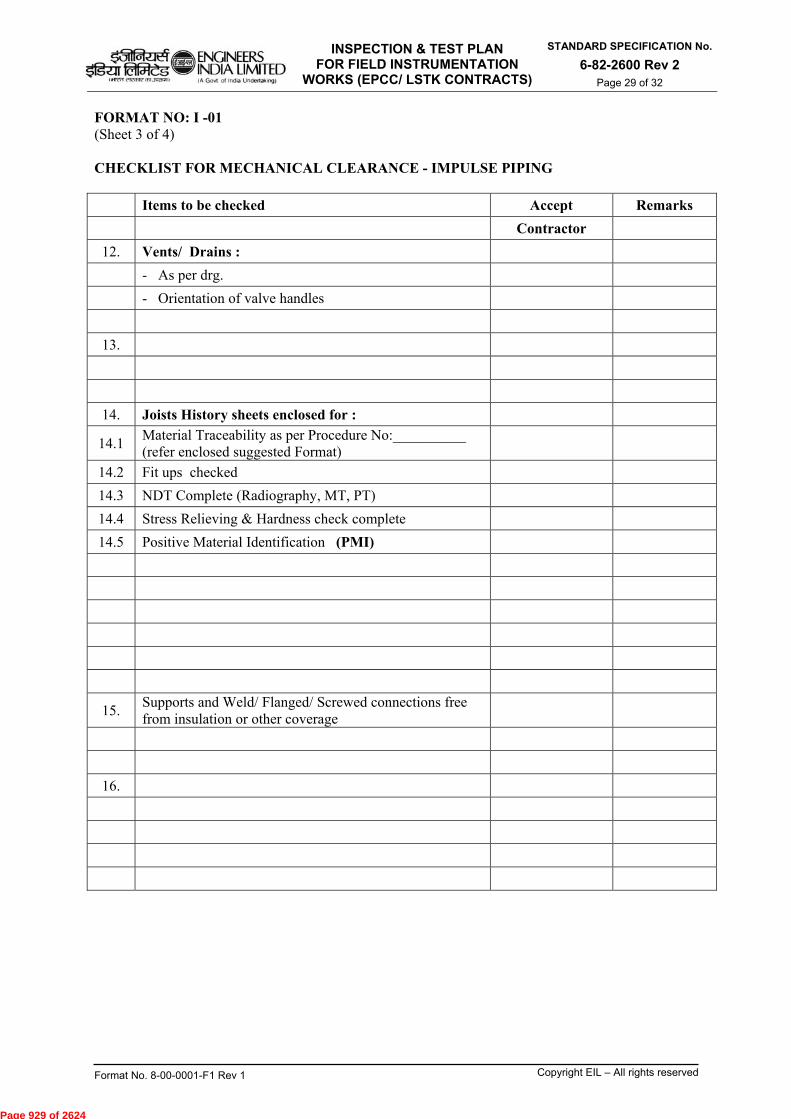
INSPECTION & TEST PLAN FOR FIELD INSTRUMENTATION
WORKS (EPCC/ LSTK CONTRACTS)
STANDARD SPECIFICATION No.
6-82-2600 Rev 2 Page 29 of 32
Format No. 8-00-0001-F1 Rev 1 Copyright EIL – All rights reserved
FORMAT NO: I -01 (Sheet 3 of 4) CHECKLIST FOR MECHANICAL CLEARANCE - IMPULSE PIPING
Items to be checked Accept Remarks
Contractor
12. Vents/ Drains :
- As per drg.
- Orientation of valve handles
13.
14. Joists History sheets enclosed for :
14.1 Material Traceability as per Procedure No:__________ (refer enclosed suggested Format)
14.2 Fit ups checked
14.3 NDT Complete (Radiography, MT, PT)
14.4 Stress Relieving & Hardness check complete
14.5 Positive Material Identification (PMI)
15. Supports and Weld/ Flanged/ Screwed connections free from insulation or other coverage
16.
Page 929 of 2624
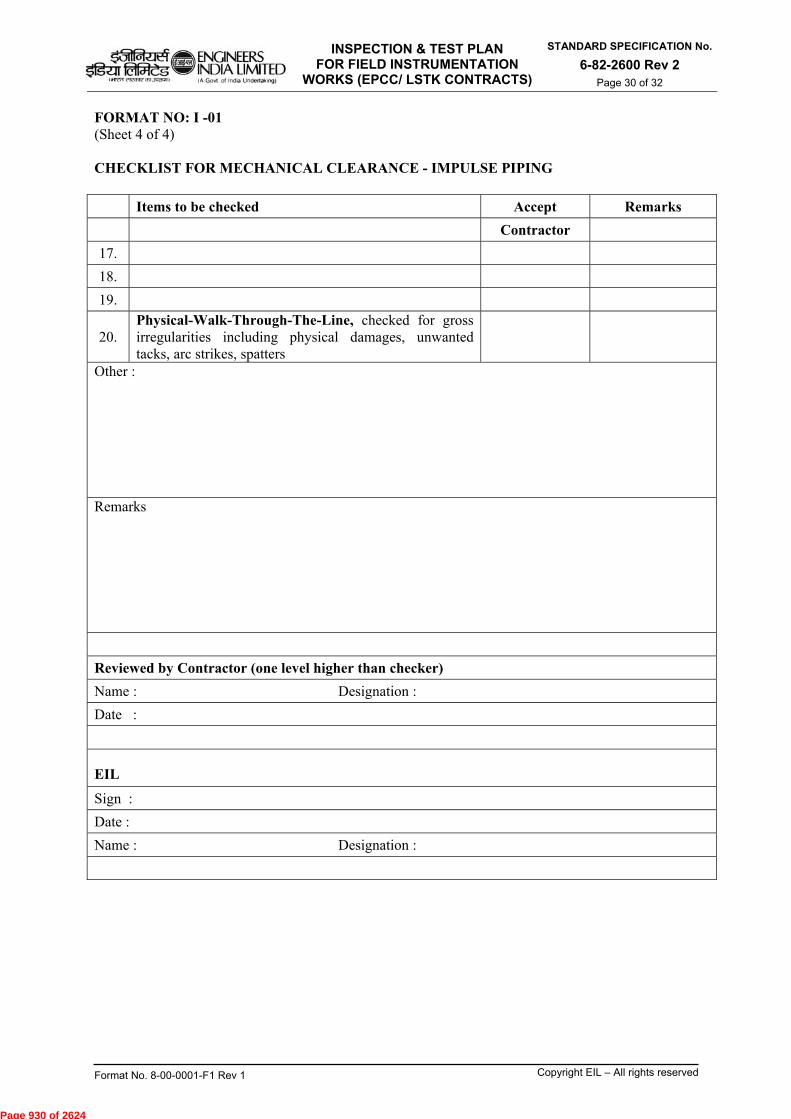
INSPECTION & TEST PLAN FOR FIELD INSTRUMENTATION
WORKS (EPCC/ LSTK CONTRACTS)
STANDARD SPECIFICATION No.
6-82-2600 Rev 2 Page 30 of 32
Format No. 8-00-0001-F1 Rev 1 Copyright EIL – All rights reserved
FORMAT NO: I -01 (Sheet 4 of 4) CHECKLIST FOR MECHANICAL CLEARANCE - IMPULSE PIPING
Items to be checked Accept Remarks
Contractor
17.
18.
19.
20. Physical-Walk-Through-The-Line, checked for gross irregularities including physical damages, unwanted tacks, arc strikes, spatters
Other : Remarks
Reviewed by Contractor (one level higher than checker)
Name : Designation :
Date :
EIL
Sign :
Date :
Name : Designation :
Page 930 of 2624
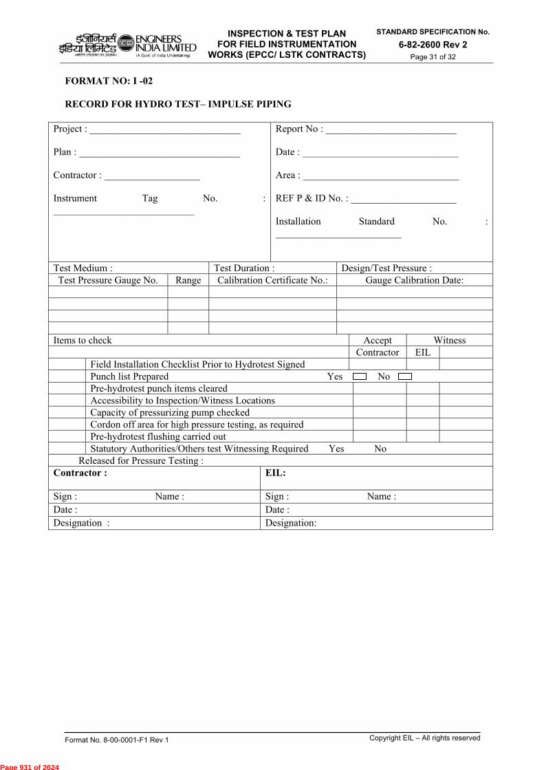
INSPECTION & TEST PLAN FOR FIELD INSTRUMENTATION
WORKS (EPCC/ LSTK CONTRACTS)
STANDARD SPECIFICATION No.
6-82-2600 Rev 2 Page 31 of 32
Format No. 8-00-0001-F1 Rev 1 Copyright EIL – All rights reserved
FORMAT NO: I -02 RECORD FOR HYDRO TEST– IMPULSE PIPING
Project : ______________________________ Plan : ________________________________ Contractor : ___________________ Instrument Tag No. : ____________________________
Report No : __________________________ Date : _______________________________ Area : _______________________________ REF P & ID No. : _____________________ Installation Standard No. : _________________________
Test Medium : Test Duration : Design/Test Pressure : Test Pressure Gauge No. Range Calibration Certificate No.: Gauge Calibration Date:
Items to check Accept Witness Contractor EIL
Field Installation Checklist Prior to Hydrotest Signed Punch list Prepared Yes No Pre-hydrotest punch items cleared Accessibility to Inspection/Witness Locations Capacity of pressurizing pump checked Cordon off area for high pressure testing, as required Pre-hydrotest flushing carried out Statutory Authorities/Others test Witnessing Required Yes No
Released for Pressure Testing : Contractor :
EIL:
Sign : Name : Sign : Name : Date : Date : Designation : Designation:
Page 931 of 2624
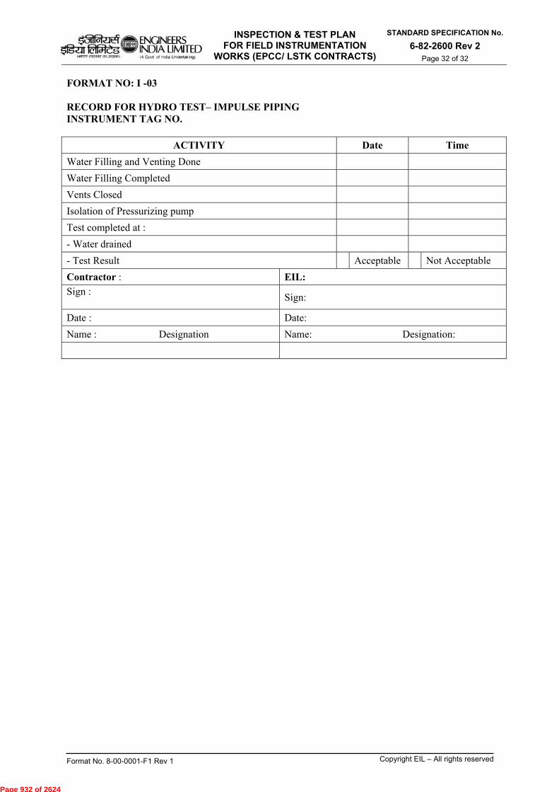
INSPECTION & TEST PLAN FOR FIELD INSTRUMENTATION
WORKS (EPCC/ LSTK CONTRACTS)
STANDARD SPECIFICATION No.
6-82-2600 Rev 2 Page 32 of 32
Format No. 8-00-0001-F1 Rev 1 Copyright EIL – All rights reserved
FORMAT NO: I -03 RECORD FOR HYDRO TEST– IMPULSE PIPING INSTRUMENT TAG NO.
ACTIVITY Date Time
Water Filling and Venting Done
Water Filling Completed
Vents Closed
Isolation of Pressurizing pump
Test completed at :
- Water drained
- Test Result Acceptable Not Acceptable
Contractor : EIL:
Sign :
Sign:
Date : Date:
Name : Designation Name: Designation:
Page 932 of 2624

ENGINEERS Ifgar faileg INDIA LIMITED
(A Govt of India Undertaking) Oren ei2M77
INSPECTION & TEST PLAN FOR CIVIL,STRUCTURAL & ARCHITECTURAL WORKS (EPCC/LSTK CONTRACTS)
STANDARD SPECIFICATION No.
6-82-2700 Rev 2 Page 1 of 37
nci , Lam' itscom coma (it-flat-11/ vcotvc-i c61 tira4131-1)
-1WtkEurr titteTur ei1.71 Outettft)
INSPECTION & TEST PLAN (ITP) CIVIL, STRUCTURAL &
ARCHITECTURAL WORKS (EPCC/LSTK CONTRACTS)
1A1- 2 19.02.2016 REVISED AND REISSUED
DJ AKM TKS SC
1 04.07.2011 REVISED AND REISSUED SM SM MKG DM
0 17.10.2005 ISSUED AS STANDARD SPECIFICATION MPJ SPS VNP VJN
Rev. No
Date Purpose Prepared
by Checked
by
Standards Committee Convenor
Standards Bureau
Chairman
Approved by
Format No. 8-00-0001-F1 Rev. 0 Copyright EIL — All rights reserved
Page 933 of 2624
INSPECTION & TEST PLAN FOR CIVIL,STRUCTURAL & ARCHITECTURAL WORKS (EPCC/LSTK CONTRACTS)
STANDARD SPECIFICATION No.
6-82-2700 Rev 2
Page 2 of 37
Format No. 8-00-0001-F1 Rev. 0 Copyright EIL – All rights reserved
Abbreviations: AFC : Approved For Construction BM : Bench Mark CI : Cast Iron CPT : Cone Penetration Test GI : Galvanized Iron IRC : Indian Road Congress JB : Junction Box MS : Mild Steel MT : Magnetic Particle Testing NDT : Non Destructive Testing PCC : Plain Cement Concrete PQR : Procedure Qualification Record PT : Penetration Testing PVC : Poly Vinyl Chloride PWHT : Post Weld Heat Treatment RCC : Reinforced Cement Concrete RF : Reinforcement SPT : Standard Penetration Test U/G : Under Ground WBM : Water Bound Macadam WPS : Welding Procedure Specification Construction Standards Committee Convenor: Sh. T.K. Sen, ED (C) Members: Sh. SN Bhatnagar, GM (Construction) Sh. MK Garg, GM (Construction) Sh. A K Mishra, GM (Construction) Sh. Janak Kishore, DGM (Projects) Sh. Rajeev Jain, DGM, (C&P) Sh. Udayan Chakravarty, AGM (Piping) Sh. Ravindra Kumar, AGM (Construction) Sh. D Jana, AGM (Construction)
Page 934 of 2624
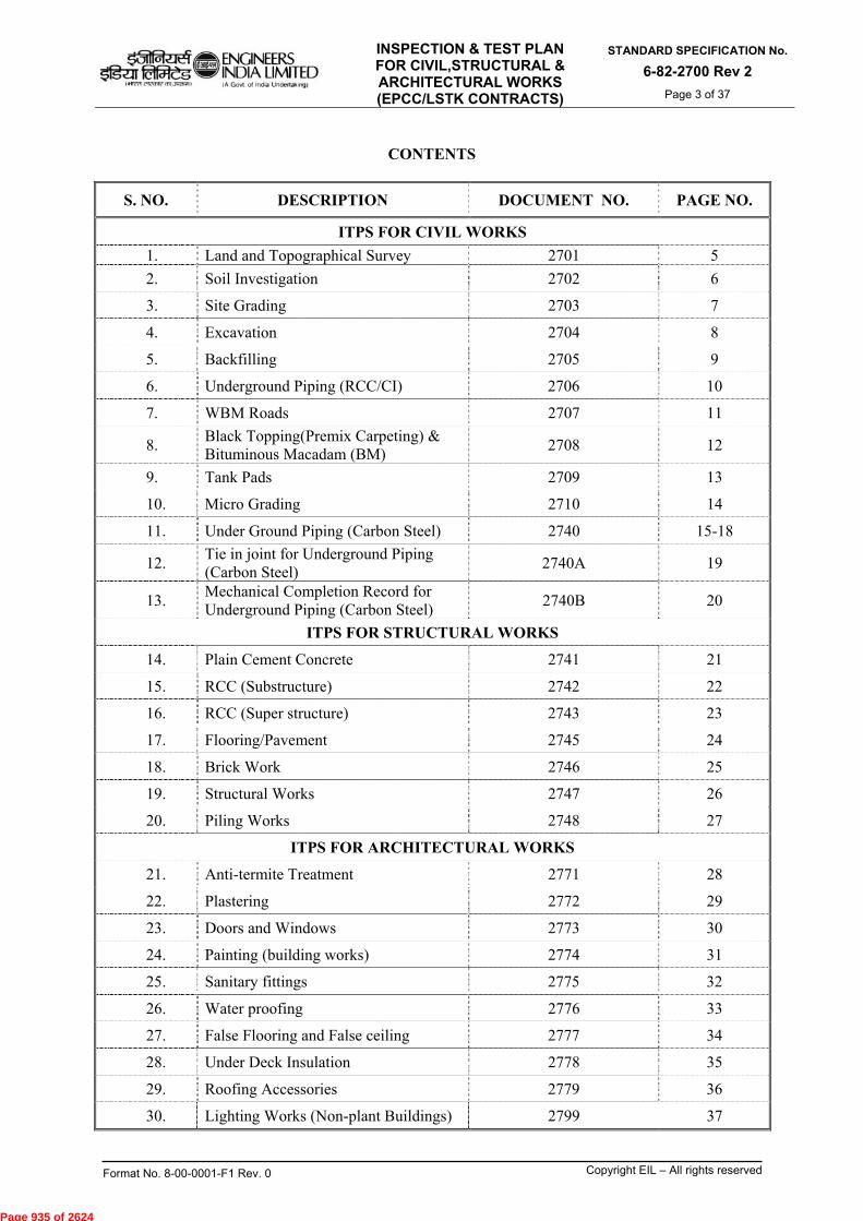
INSPECTION & TEST PLAN FOR CIVIL,STRUCTURAL & ARCHITECTURAL WORKS (EPCC/LSTK CONTRACTS)
STANDARD SPECIFICATION No.
6-82-2700 Rev 2
Page 3 of 37
Format No. 8-00-0001-F1 Rev. 0 Copyright EIL – All rights reserved
CONTENTS
S. NO. DESCRIPTION DOCUMENT NO. PAGE NO.
ITPS FOR CIVIL WORKS
1. Land and Topographical Survey 2701 5
2. Soil Investigation 2702 6
3. Site Grading 2703 7
4. Excavation 2704 8
5. Backfilling 2705 9
6. Underground Piping (RCC/CI) 2706 10
7. WBM Roads 2707 11
8. Black Topping(Premix Carpeting) & Bituminous Macadam (BM)
2708 12
9. Tank Pads 2709 13
10. Micro Grading 2710 14
11. Under Ground Piping (Carbon Steel) 2740 15-18
12. Tie in joint for Underground Piping (Carbon Steel)
2740A 19
13. Mechanical Completion Record for Underground Piping (Carbon Steel)
2740B 20
ITPS FOR STRUCTURAL WORKS
14. Plain Cement Concrete 2741 21
15. RCC (Substructure) 2742 22
16. RCC (Super structure) 2743 23
17. Flooring/Pavement 2745 24
18. Brick Work 2746 25
19. Structural Works 2747 26
20. Piling Works 2748 27
ITPS FOR ARCHITECTURAL WORKS
21. Anti-termite Treatment 2771 28
22. Plastering 2772 29
23. Doors and Windows 2773 30
24. Painting (building works) 2774 31
25. Sanitary fittings 2775 32
26. Water proofing 2776 33
27. False Flooring and False ceiling 2777 34
28. Under Deck Insulation 2778 35
29. Roofing Accessories 2779 36
30. Lighting Works (Non-plant Buildings) 2799 37
Page 935 of 2624
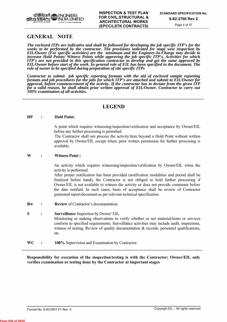
INSPECTION & TEST PLAN FOR CIVIL,STRUCTURAL & ARCHITECTURAL WORKS (EPCC/LSTK CONTRACTS)
STANDARD SPECIFICATION No.
6-82-2700 Rev 2
Page 4 of 37
Format No. 8-00-0001-F1 Rev. 0 Copyright EIL – All rights reserved
GENERAL NOTE The enclosed ITPs are indicative and shall be followed for developing the job specific ITP’s for the works to be performed by the contractor. The provisions indicated for stage wise inspection by EIL/Owner (For specific activities) are the minimum and the Engineer-In-Charge may decide to increase Hold Points/ Witness Points while approving the job specific ITP’s. Activities for which ITP’s are not provided in this specification contractor to develop and get the same approved by EIL/Owner before start of the work. In general role of EIL has been specified in the document. The role of owner to be specified during preparation of site specific ITPs Contractor to submit job specific reporting formats with the aid of enclosed sample reporting formats and job procedures for the jobs for which ITP’s are attached and submit to EIL/Owner for approval, before commencement of the activity. If the contractor has to deviate from the given ITP for a valid reason, he shall obtain prior written approval of EIL/Owner. Contractor to carry out 100% examination of all activities.
LEGEND HP : Hold Point;
A point which requires witnessing/inspection/verification and acceptance by Owner/EIL before any further processing is permitted. The Contractor shall not process the activity/item beyond a Hold Point without written approval by Owner/EIL except where prior written permission for further processing is available.
W : Witness Point ; An activity which requires witnessing/inspection/verification by Owner/EIL when the activity is performed. After proper notification has been provided (notification modalities and period shall be finalized before hand), the Contractor is not obliged to hold further processing if Owner/EIL is not available to witness the activity or does not provide comments before the date notified. In such cases, basis of acceptance shall be review of Contractor generated report/document as per relevant technical specification.
Rw : Review of Contractor’s documentation.
S : Surveillance Inspection by Owner/ EIL. Monitoring or making observations to verify whether or not material/items or services conform to specified requirements. Surveillance activities may include audit, inspections, witness of testing, Review of quality documentation & records, personnel qualifications, etc.
WC : 100% Supervision and Examination by Contractor.
Responsibility for execution of the inspection/testing is with the Contractor; Owner/EIL only verifies examination or testing done by the Contractor at important stages
Page 936 of 2624
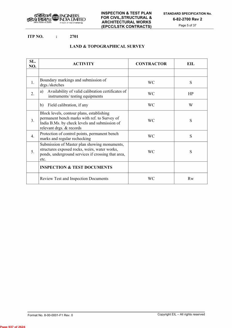
INSPECTION & TEST PLAN FOR CIVIL,STRUCTURAL & ARCHITECTURAL WORKS (EPCC/LSTK CONTRACTS)
STANDARD SPECIFICATION No.
6-82-2700 Rev 2
Page 5 of 37
Format No. 8-00-0001-F1 Rev. 0 Copyright EIL – All rights reserved
ITP NO. : 2701 LAND & TOPOGRAPHICAL SURVEY SL. NO.
ACTIVITY CONTRACTOR EIL
1. Boundary markings and submission of drgs./sketches
WC S
2. a) Availability of valid calibration certificates of
instruments/ testing equipments WC HP
b) Field calibration, if any WC W
3.
Block levels, contour plans, establishing permanent bench marks with ref. to Survey of India B.Ms. by check levels and submission of relevant drgs. & records
WC S
4. Protection of control points, permanent bench marks and regular rechecking
WC S
5.
Submission of Master plan showing monuments, structures exposed rocks, weirs, water works, ponds, underground services if crossing that area, etc.
WC S
INSPECTION & TEST DOCUMENTS
Review Test and Inspection Documents WC Rw
Page 937 of 2624

INSPECTION & TEST PLAN FOR CIVIL,STRUCTURAL & ARCHITECTURAL WORKS (EPCC/LSTK CONTRACTS)
STANDARD SPECIFICATION No.
6-82-2700 Rev 2
Page 6 of 37
Format No. 8-00-0001-F1 Rev. 0 Copyright EIL – All rights reserved
ITP NO. : 2702 SOIL INVESTIGATION SL. NO.
ACTIVITY CONTRACTOR EIL
1. Positioning of test location WC S
2. a) Availability of valid calibration certificates of
instruments/ testing equipments WC HP
b) Field calibration, if any WC W
3. Boring & sampling WC S
4. In-situ testing (SPT, CPT, Plate load test, Soil Resistivity, Block vibration test, etc.)
WC S
5. Lab testing (as applicable) WC W/ Rw
6. Monitoring of water level WC S
INSPECTION & TEST DOCUMENTS
Review Test and Inspection Documents WC Rw
Page 938 of 2624
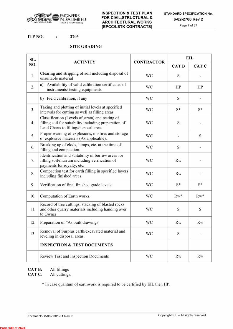
INSPECTION & TEST PLAN FOR CIVIL,STRUCTURAL & ARCHITECTURAL WORKS (EPCC/LSTK CONTRACTS)
STANDARD SPECIFICATION No.
6-82-2700 Rev 2
Page 7 of 37
Format No. 8-00-0001-F1 Rev. 0 Copyright EIL – All rights reserved
ITP NO. : 2703 SITE GRADING
SL. NO.
ACTIVITY CONTRACTOR EIL
CAT B CAT C
1. Clearing and stripping of soil including disposal of unsuitable material
WC S -
2. a) Availability of valid calibration certificates of
instruments/ testing equipments WC HP HP
b) Field calibration, if any WC S -
3. Taking and plotting of initial levels at specified intervals for cutting as well as filling areas
WC S* S*
4. Classification (Levels of strata) and testing of filling soil for suitability including preparation of Lead Charts to filling/disposal areas.
WC S -
5. Proper warning of explosions, misfires and storage of explosive materials (As applicable).
WC - S
6. Breaking up of clods, lumps, etc. at the time of filling and compaction.
WC S -
7. Identification and suitability of borrow areas for filling soil/murrum including verification of payments for royalty, etc.
WC Rw -
8. Compaction test for earth filling in specified layers including finished areas.
WC Rw -
9. Verification of final finished grade levels. WC S* S*
10. Computation of Earth works. WC Rw* Rw*
11. Record of tree cuttings, stacking of blasted rocks and other quarry materials including handing over to Owner
WC S S
12. Preparation of “As built drawings WC Rw Rw
13. Removal of Surplus earth/excavated material and leveling in disposal areas.
WC S -
INSPECTION & TEST DOCUMENTS
Review Test and Inspection Documents WC Rw Rw
CAT B: All fillings CAT C: All cuttings.
* In case quantum of earthwork is required to be certified by EIL then HP.
Page 939 of 2624
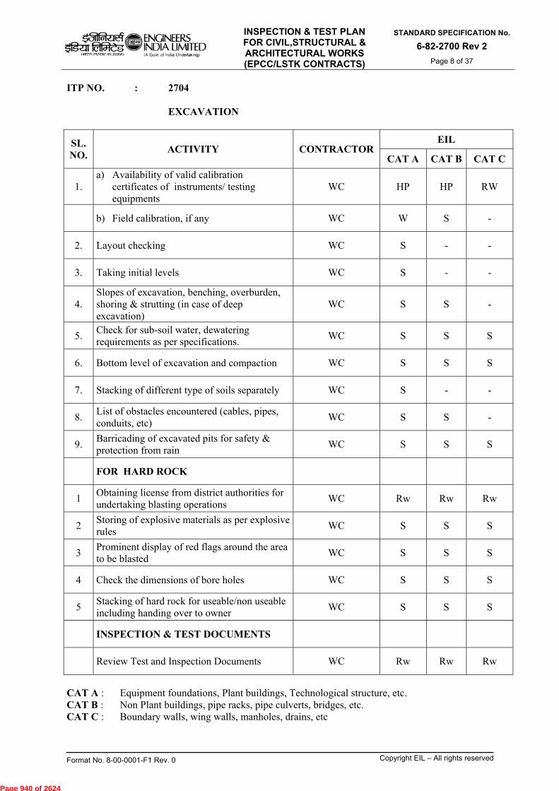
INSPECTION & TEST PLAN FOR CIVIL,STRUCTURAL & ARCHITECTURAL WORKS (EPCC/LSTK CONTRACTS)
STANDARD SPECIFICATION No.
6-82-2700 Rev 2
Page 8 of 37
Format No. 8-00-0001-F1 Rev. 0 Copyright EIL – All rights reserved
ITP NO. : 2704 EXCAVATION
SL. NO.
ACTIVITY CONTRACTOR EIL
CAT A CAT B CAT C
1. a) Availability of valid calibration
certificates of instruments/ testing equipments
WC HP HP RW
b) Field calibration, if any WC W S -
2. Layout checking WC S - -
3. Taking initial levels WC S - -
4. Slopes of excavation, benching, overburden, shoring & strutting (in case of deep excavation)
WC S S -
5. Check for sub-soil water, dewatering requirements as per specifications.
WC S S S
6. Bottom level of excavation and compaction WC S S S
7. Stacking of different type of soils separately WC S - -
8. List of obstacles encountered (cables, pipes, conduits, etc)
WC S S -
9. Barricading of excavated pits for safety & protection from rain
WC S S S
FOR HARD ROCK
1 Obtaining license from district authorities for undertaking blasting operations
WC Rw Rw Rw
2 Storing of explosive materials as per explosive rules
WC S S S
3 Prominent display of red flags around the area to be blasted
WC S S S
4 Check the dimensions of bore holes WC S S S
5 Stacking of hard rock for useable/non useable including handing over to owner
WC S S S
INSPECTION & TEST DOCUMENTS
Review Test and Inspection Documents WC Rw Rw Rw
CAT A : Equipment foundations, Plant buildings, Technological structure, etc. CAT B : Non Plant buildings, pipe racks, pipe culverts, bridges, etc. CAT C : Boundary walls, wing walls, manholes, drains, etc
Page 940 of 2624

INSPECTION & TEST PLAN FOR CIVIL,STRUCTURAL & ARCHITECTURAL WORKS (EPCC/LSTK CONTRACTS)
STANDARD SPECIFICATION No.
6-82-2700 Rev 2
Page 9 of 37
Format No. 8-00-0001-F1 Rev. 0 Copyright EIL – All rights reserved
ITP NO. : 2705 BACK FILLING
SL. NO.
ACTIVITY CONTRACTOREIL
CAT A CAT B CAT C
1. Selection of materials/selected earth WC W S S
2. Check for treatment of soil, if any WC S S -
3. a) Availability of valid calibration certificates of instruments/ testing equipments
WC HP HP HP
b) Field calibration, if any WC W S -
4. Filling in specified layers, consolidating, watering.
WC S - -
5. Compaction tests for layers WC W S Rw
6. Filling to required levels WC S - -
INSPECTION & TEST DOCUMENTS
Review Test and Inspection Documents WC Rw Rw Rw
CAT A: Equipment foundations, Plant buildings, Technological structure, etc. CAT B: Non Plant buildings, pipe racks, pipe culverts, bridges, etc. CAT C: Boundary walls, wing walls, manholes, drains, etc
Page 941 of 2624

INSPECTION & TEST PLAN FOR CIVIL,STRUCTURAL & ARCHITECTURAL WORKS (EPCC/LSTK CONTRACTS)
STANDARD SPECIFICATION No.
6-82-2700 Rev 2
Page 10 of 37
Format No. 8-00-0001-F1 Rev. 0 Copyright EIL – All rights reserved
ITP NO. : 2706 UNDERGROUND PIPING (RCC/ CI)
SL. NO.
ACTIVITY CONTRACTOR EIL
CAT B CAT C
1. Checking of material WC NOTE 1 NOTE 1
2. Adequate slope, benching in excavation for safety purposes (if required)
WC S
3. Layout, line & level WC S -
4. Laying & jointing, grouting at manholes/chambers WC S -
5. Check for supports/ firm bed/ sub soil water level WC S -
6. Testing for leakages by blocking pipe ends WC W W
7. Hydro-testing and other tests, Removal of blockages, Cleaning & flushing of system
WC W W
8. Backfilling in layers WC Rw Rw
9. Check for MS rungs in proper position, inlet/outlet pipe levels in manholes
WC S S
10. Preparation of “As-built drawings” WC Rw Rw
INSPECTION & TEST DOCUMENTS
Review Test and Inspection Documents WC Rw Rw
NOTE : 1) For incoming material inspection please refer ITP no: 6-82-1010. CAT B: Main Plant Buildings, Utilities, Offsites etc. CAT C: Non Plant Buildings, Technological Buildings, Admn. Buildings, Gate House, Security
Rooms, etc.
Page 942 of 2624
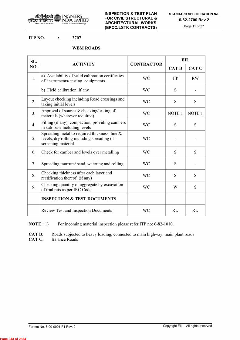
INSPECTION & TEST PLAN FOR CIVIL,STRUCTURAL & ARCHITECTURAL WORKS (EPCC/LSTK CONTRACTS)
STANDARD SPECIFICATION No.
6-82-2700 Rev 2
Page 11 of 37
Format No. 8-00-0001-F1 Rev. 0 Copyright EIL – All rights reserved
ITP NO. : 2707 WBM ROADS
SL. NO.
ACTIVITY CONTRACTOR EIL
CAT B CAT C
1. a) Availability of valid calibration certificates of instruments/ testing equipments
WC HP RW
b) Field calibration, if any WC S -
2. Layout checking including Road crossings and taking initial levels
WC S S
3. Approval of source & checking/testing of materials (wherever required)
WC NOTE 1 NOTE 1
4. Filling (if any), compaction, providing cambers in sub-base including levels
WC S S
5. Spreading metal to required thickness, line & levels, dry rolling including spreading of screening material
WC - -
6. Check for camber and levels over metalling WC S S
7. Spreading murrum/ sand, watering and rolling WC S -
8. Checking thickness after each layer and rectification thereof (if any)
WC S S
9. Checking quantity of aggregate by excavation of trial pits as per IRC Code
WC W S
INSPECTION & TEST DOCUMENTS
Review Test and Inspection Documents WC Rw Rw
NOTE : 1) For incoming material inspection please refer ITP no: 6-82-1010. CAT B: Roads subjected to heavy loading, connected to main highway, main plant roads CAT C: Balance Roads
Page 943 of 2624

INSPECTION & TEST PLAN FOR CIVIL,STRUCTURAL & ARCHITECTURAL WORKS (EPCC/LSTK CONTRACTS)
STANDARD SPECIFICATION No.
6-82-2700 Rev 2
Page 12 of 37
Format No. 8-00-0001-F1 Rev. 0 Copyright EIL – All rights reserved
ITP NO. : 2708 BLACK TOPPING (PREMIX CARPETING) & BITUMINOUS MACADAM (BM)
SL. NO.
ACTIVITY CONTRACTOR EIL
1. Approval of source of materials WC Note 1
2. a) Availability of valid calibration certificates of
instruments/ testing equipments WC HP
b) Field calibration, if any WC S
3. Surface preparation & check for camber/level WC S
4. Checking/ testing of material wherever required WC W
5. Tack coat application WC -
6. Laying of Premix carpeting/ BM including rolling WC S
7. Application of Seal coat WC -
8. Check for camber and levels WC S
9. Check for bitumen temperature and consumption WC S
10. Thickness check of Premix carpet/ BM WC S
11. Removal of surplus earth WC -
12. Berm preparation WC -
13. Final Inspection WC W
INSPECTION & TEST DOCUMENTS
Review Test and Inspection Documents WC Rw
NOTE : 1) For incoming material inspection please refer ITP no: 6-82-1010.
Page 944 of 2624

INSPECTION & TEST PLAN FOR CIVIL,STRUCTURAL & ARCHITECTURAL WORKS (EPCC/LSTK CONTRACTS)
STANDARD SPECIFICATION No.
6-82-2700 Rev 2
Page 13 of 37
Format No. 8-00-0001-F1 Rev. 0 Copyright EIL – All rights reserved
ITP NO. : 2709 TANK PADS
SL. NO.
ACTIVITY CONTRACTOR EIL
CAT A CAT B
1. Approval of source of materials WC NOTE 1 NOTE 1
2. Stripping the area WC - -
3. a) Availability of valid calibration certificates of instruments/ testing equipments
WC HP RW
b) Field calibration, if any WC W S
4. Layout and marking of ground level WC S -
5. Excavation to required level, compaction of sub-base
WC W S
6. Checking/ testing of materials WC W S
7. Filling selected materials in specified layers, rolling, watering
WC S -
8. Compaction tests WC W Rw
9. Gravel filling under annular ring with compaction and adding graded filler material (As applicable)
WC W S
10. Anti-corrosive layer, consolidation WC S -
11. Premix carpeting on side slopes WC S S
12. Preparation of “As-built drawing” for erection WC Rw Rw
13. Check for settlement of pads during hydro testing of tanks
WC W S
INSPECTION & TEST DOCUMENTS
Review Test and Inspection Documents WC Rw Rw
NOTE : 1) For incoming material inspection please refer ITP no: 6-82-1010. CAT A: All Site fabricated steel storage tanks for process fluid/ Hydrocarbon, floating roof,
tanks having capacity 600cum or 10m dia. and 8 m height. CAT B: Site fabricated steel storage tanks for Raw water, Fire water, waste water, DM water, etc.
and all tanks not covered under “CAT A”.
Page 945 of 2624

INSPECTION & TEST PLAN FOR CIVIL,STRUCTURAL & ARCHITECTURAL WORKS (EPCC/LSTK CONTRACTS)
STANDARD SPECIFICATION No.
6-82-2700 Rev 2
Page 14 of 37
Format No. 8-00-0001-F1 Rev. 0 Copyright EIL – All rights reserved
ITP NO. : 2710 MICRO GRADING SL. NO.
ACTIVITY CONTRACTOR EIL
1. a) Availability of valid calibration certificates
of instruments/ testing equipments WC RW
b) Field calibration, if any WC -
2. Taking initial levels WC S
3. Clearing/ Removal of extra soil, debris, etc. from site by transportation
WC -
4. Taking final levels WC S
5. Verification of gradient of ground WC -
6. Finishing of ground surface by hand compactor/ Roller (As applicable)
WC S
7. Final inspection WC W
INSPECTION & TEST DOCUMENTS
Review Test and Inspection Documents WC Rw
Page 946 of 2624

INSPECTION & TEST PLAN FOR CIVIL,STRUCTURAL & ARCHITECTURAL WORKS (EPCC/LSTK CONTRACTS)
STANDARD SPECIFICATION No.
6-82-2700 Rev 2
Page 15 of 37
Format No. 8-00-0001-F1 Rev. 0 Copyright EIL – All rights reserved
ITP NO. : 2740 FOR UNDERGROUND PIPING (CARBON STEEL)
SL. NO
ACTIVITY CONTRACTOREIL
CAT B CAT C
A. PRIOR TO FABRICATION
1 Incoming materials WC NOTE 1 NOTE 1
2. Welding Filler Material Approval/Qualification
i) Review of Manufacturer's Test Certificates/
other documents WC RW RW
ii) Testing, if any WC Rw Rw
3. WPS/PQR
i) Review of proposed Procedure WC Rw Rw
ii) Welding of test coupon and subsequent
Testing, if applicable WC W W
iii) Approval of Final WPS/PQR WC HP HP
4 Certification & approval of welders WC Rw Rw
5. NDT Procedure Qualification
i) Review of proposed Procedure WC Rw Rw
ii) Testing WC Rw Rw
iii) Approval of NDT procedure WC HP HP
6. Preparation of sketches from General Arrangement drawings
WC Rw -
7. Joint numbering WC Rw -
8. Approval of colour coding scheme WC Rw -
9. Monitoring of colour coding on pipes & fittings WC S -
B. FABRICATION (SHOP & FIELD)
1. Material as per piping class (check w.r.t. approved colour coding procedure)
WC W
i) Fit-up check ii) Dimensional check
WC WC
S S
Rw Rw
NOTE : 1) For incoming material inspection please refer ITP no: -6-82-1010. CAT B : All pressure lines, Fire Water line, Cooling Water line, etc. CAT C : Balance Works
Page 947 of 2624
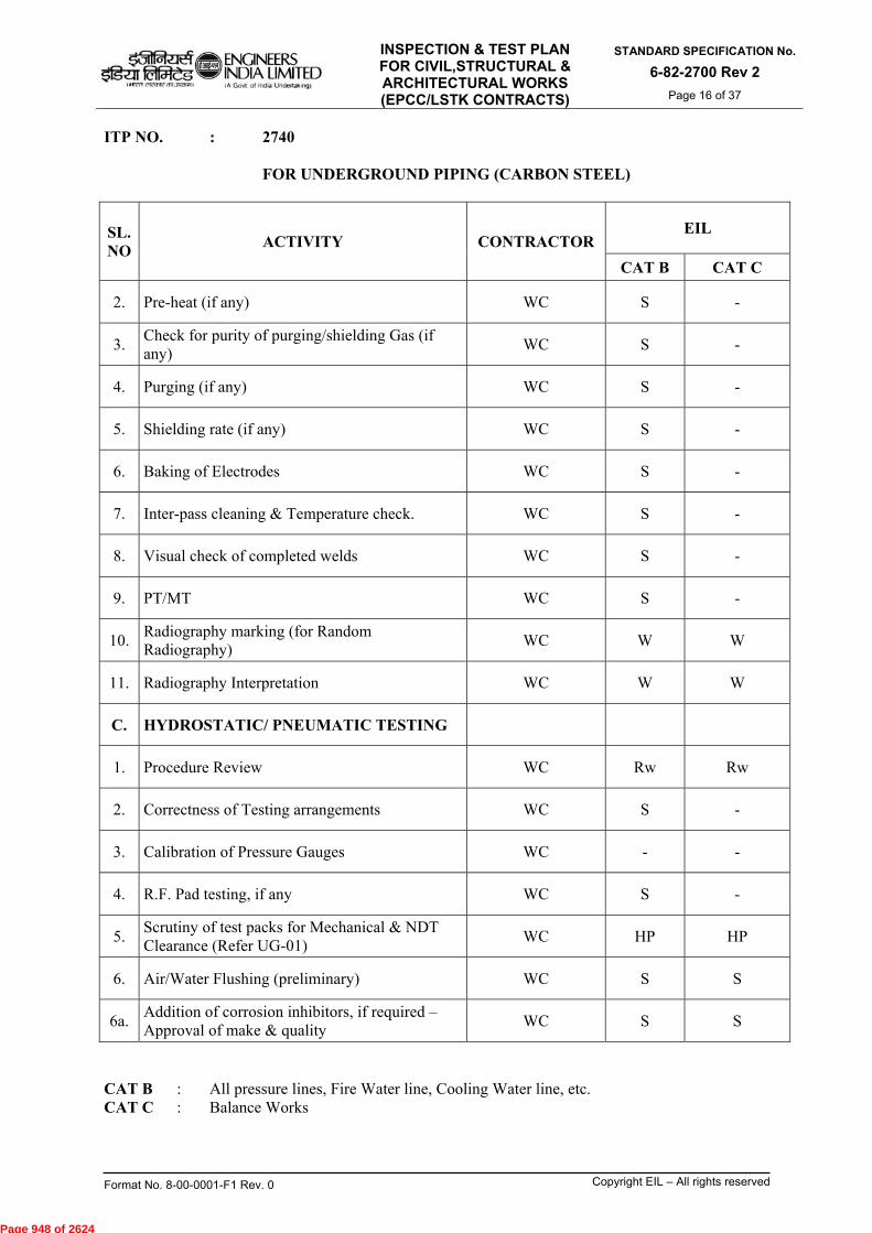
INSPECTION & TEST PLAN FOR CIVIL,STRUCTURAL & ARCHITECTURAL WORKS (EPCC/LSTK CONTRACTS)
STANDARD SPECIFICATION No.
6-82-2700 Rev 2
Page 16 of 37
Format No. 8-00-0001-F1 Rev. 0 Copyright EIL – All rights reserved
ITP NO. : 2740 FOR UNDERGROUND PIPING (CARBON STEEL)
SL. NO
ACTIVITY CONTRACTOR EIL
CAT B CAT C
2. Pre-heat (if any) WC S -
3. Check for purity of purging/shielding Gas (if any)
WC S -
4. Purging (if any) WC S -
5. Shielding rate (if any) WC S -
6. Baking of Electrodes WC S -
7. Inter-pass cleaning & Temperature check. WC S -
8. Visual check of completed welds WC S -
9. PT/MT WC S -
10. Radiography marking (for Random Radiography)
WC W W
11. Radiography Interpretation WC W W
C. HYDROSTATIC/ PNEUMATIC TESTING
1. Procedure Review WC Rw Rw
2. Correctness of Testing arrangements WC S -
3. Calibration of Pressure Gauges WC - -
4. R.F. Pad testing, if any WC S -
5. Scrutiny of test packs for Mechanical & NDT Clearance (Refer UG-01)
WC HP HP
6. Air/Water Flushing (preliminary) WC S S
6a. Addition of corrosion inhibitors, if required – Approval of make & quality
WC S S
CAT B : All pressure lines, Fire Water line, Cooling Water line, etc. CAT C : Balance Works
Page 948 of 2624
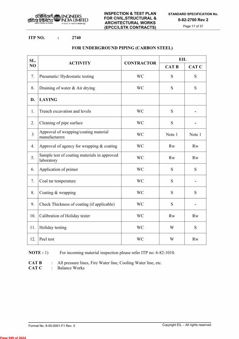
INSPECTION & TEST PLAN FOR CIVIL,STRUCTURAL & ARCHITECTURAL WORKS (EPCC/LSTK CONTRACTS)
STANDARD SPECIFICATION No.
6-82-2700 Rev 2
Page 17 of 37
Format No. 8-00-0001-F1 Rev. 0 Copyright EIL – All rights reserved
ITP NO. : 2740 FOR UNDERGROUND PIPING (CARBON STEEL)
SL. NO
ACTIVITY CONTRACTOR EIL
CAT B CAT C
7. Pneumatic/ Hydrostatic testing WC S S
8. Draining of water & Air drying WC S S
D. LAYING
1. Trench excavation and levels WC S -
2. Cleaning of pipe surface WC S -
3 Approval of wrapping/coating material manufacturers
WC Note 1 Note 1
4. Approval of agency for wrapping & coating WC Rw Rw
5. Sample test of coating materials in approved laboratory
WC Rw Rw
6. Application of primer WC S S
7. Coal tar temperature WC S -
8. Coating & wrapping WC S S
9. Check Thickness of coating (if applicable) WC S -
10. Calibration of Holiday tester WC Rw Rw
11. Holiday testing WC W S
12. Peel test WC W Rw
NOTE : 1) For incoming material inspection please refer ITP no: 6-82-1010. CAT B : All pressure lines, Fire Water line, Cooling Water line, etc. CAT C : Balance Works
Page 949 of 2624
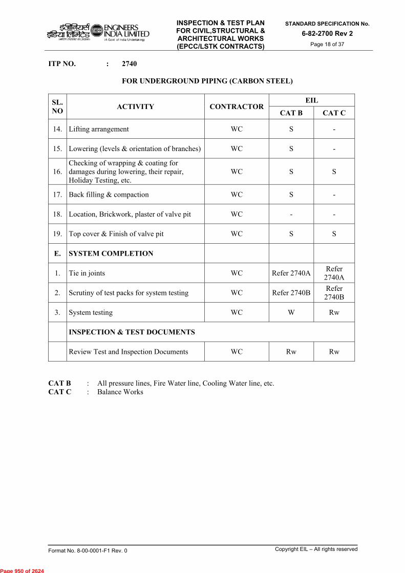
INSPECTION & TEST PLAN FOR CIVIL,STRUCTURAL & ARCHITECTURAL WORKS (EPCC/LSTK CONTRACTS)
STANDARD SPECIFICATION No.
6-82-2700 Rev 2
Page 18 of 37
Format No. 8-00-0001-F1 Rev. 0 Copyright EIL – All rights reserved
ITP NO. : 2740 FOR UNDERGROUND PIPING (CARBON STEEL)
SL. NO
ACTIVITY CONTRACTOR EIL
CAT B CAT C
14. Lifting arrangement WC S -
15. Lowering (levels & orientation of branches) WC S -
16. Checking of wrapping & coating for damages during lowering, their repair, Holiday Testing, etc.
WC S S
17. Back filling & compaction WC S -
18. Location, Brickwork, plaster of valve pit WC - -
19. Top cover & Finish of valve pit WC S S
E. SYSTEM COMPLETION
1. Tie in joints WC Refer 2740A Refer
2740A
2. Scrutiny of test packs for system testing WC Refer 2740B Refer 2740B
3. System testing WC W Rw
INSPECTION & TEST DOCUMENTS
Review Test and Inspection Documents WC Rw Rw
CAT B : All pressure lines, Fire Water line, Cooling Water line, etc. CAT C : Balance Works
Page 950 of 2624

INSPECTION & TEST PLAN FOR CIVIL,STRUCTURAL & ARCHITECTURAL WORKS (EPCC/LSTK CONTRACTS)
STANDARD SPECIFICATION No.
6-82-2700 Rev 2
Page 19 of 37
Format No. 8-00-0001-F1 Rev. 0 Copyright EIL – All rights reserved
ITP NO. : 2740A TIE IN JOINTS FOR UNDERGROUND PIPING (CARBON STEEL)
SL. NO.
ACTIVITY CONTRACTOR EIL
A. Fit up WC W
B. Root Run DP WC W
C. Final Run DP WC W
D. Radiograph Review WC HP
E. PWHT Hardness WC RW
F. RF Pad Testing WC HP
G. Cleaning & Priming WC S
H. Coating, Wrapping WC W
I. Peel Test WC HP
J. Holiday Testing WC HP
K. Checking For Any Damage In Wrapping & Coating After Lowering, Their Repair Holiday Testing, Etc.
WC W
L Back Filling WC S
Page 951 of 2624

INSPECTION & TEST PLAN FOR CIVIL,STRUCTURAL & ARCHITECTURAL WORKS (EPCC/LSTK CONTRACTS)
STANDARD SPECIFICATION No.
6-82-2700 Rev 2
Page 20 of 37
Format No. 8-00-0001-F1 Rev. 0 Copyright EIL – All rights reserved
ITP NO. : 2740B MECHANICAL COMPLETION RECORD FOR
UNDERGROUND PIPING (CARBON STEEL) SL. NO.
ACTIVITY CONTRACTOR EIL
CAT B CAT C
1. Clearance for flushing & testing WC Rw Rw
1a. Mechanical clearance
- Conformity with drawing
WC HP
Rw
- Material as per Specification WC Rw Rw
1b. Welding & NDT clearance
- Material as per Specification WC Rw Rw
- Fit-up check record WC Rw Rw
- Visual check of completed welds WC Rw -
- PT/MT WC Rw Rw
- Radiography WC Rw Rw
- PWHT & hardness WC Rw Rw
- RF pad testing WC Rw Rw
2. Flushing & Pressure testing WC W W
3. Coating & wrapping
- Surface preparation WC Rw -
- Primer application WC Rw Rw
- Coating, wrapping & peel test WC Rw -
- Holiday check WC Rw Rw
4. Laying
- Trench leveling WC Rw Rw
- Lowering & checking for damages in wrapping & coating, their repair, Holiday testing, etc.
WC Rw Rw
- Backfilling WC Rw Rw
CAT B : All pressure lines, Fire Water line, Cooling Water line, etc. CAT C : Balance works
Page 952 of 2624
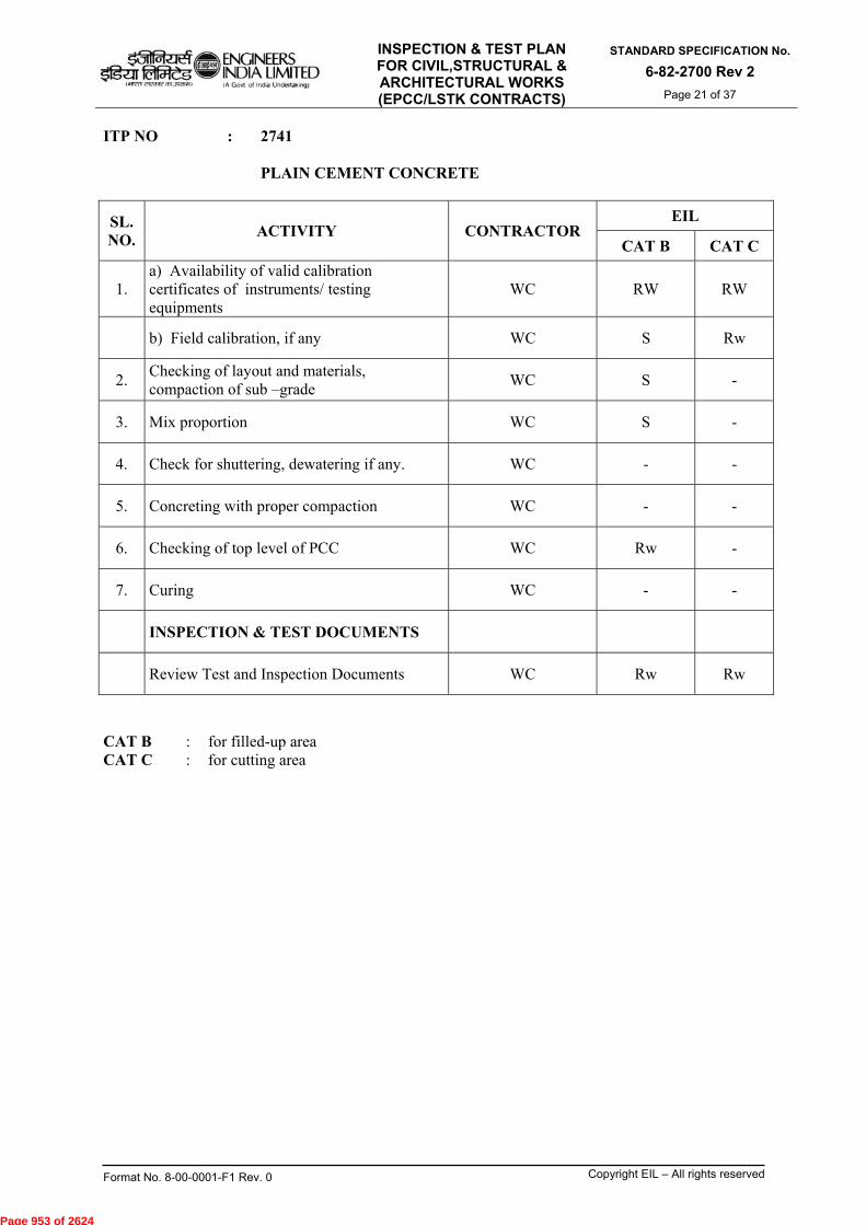
INSPECTION & TEST PLAN FOR CIVIL,STRUCTURAL & ARCHITECTURAL WORKS (EPCC/LSTK CONTRACTS)
STANDARD SPECIFICATION No.
6-82-2700 Rev 2
Page 21 of 37
Format No. 8-00-0001-F1 Rev. 0 Copyright EIL – All rights reserved
ITP NO : 2741 PLAIN CEMENT CONCRETE
SL. NO.
ACTIVITY CONTRACTOR EIL
CAT B CAT C
1. a) Availability of valid calibration certificates of instruments/ testing equipments
WC RW RW
b) Field calibration, if any WC S Rw
2. Checking of layout and materials, compaction of sub –grade
WC S -
3. Mix proportion WC S -
4. Check for shuttering, dewatering if any. WC - -
5. Concreting with proper compaction WC - -
6. Checking of top level of PCC WC Rw -
7. Curing WC - -
INSPECTION & TEST DOCUMENTS
Review Test and Inspection Documents WC Rw Rw
CAT B : for filled-up area CAT C : for cutting area
Page 953 of 2624

INSPECTION & TEST PLAN FOR CIVIL,STRUCTURAL & ARCHITECTURAL WORKS (EPCC/LSTK CONTRACTS)
STANDARD SPECIFICATION No.
6-82-2700 Rev 2
Page 22 of 37
Format No. 8-00-0001-F1 Rev. 0 Copyright EIL – All rights reserved
ITP NO : 2742 REINFORCED CEMENT CONCRETE (SUBSTRUCTURE)
SL. NO.
ACTIVITY CONTRACTOR EIL
CAT A CAT B CAT C
1 Approval of source of materials WC HP HP Rw
2. a) Availability of valid calibration certificates of instruments/ testing equipments
WC HP HP HP
b) Field calibration, if any WC Rw Rw Rw
3. Checking of layout & condition of PCC/ leveling course
WC S S -
4. Incoming material checking WC NOTE 1 NOTE 1 NOTE 1
5. Design of mix &establishment of strength at site by trial mix
WC HP HP HP
6. Check for line & level of shuttering including its condition, quality and rigidity.
WC S S -
7. Check for sub-soil water & dewatering arrangement, if any
WC S S -
8. Reinforcement & covers to reinforcement WC S S S
9. Inserts, Anchor bolts and pipe sleeves, pockets, dowels, etc.
WC S S S
10. Pour Card WC W W Rw
11. Check for obstacles encountered (Electrical conduits, pipe lines, etc.)
WC S S -
12. Concreting, testing, compaction & finishing WC W S Rw
13. Casting of cubes WC S S S
14. Curing WC S S -
15. Testing of cubes WC W W W
16. Removal of shuttering WC S - -
17. Check for water tightness, rendering, if any WC S S S
18. Preparation of As-built drawings WC Rw Rw Rw
INSPECTION & TEST DOCUMENTS
Review Test and Inspection Documents WC Rw Rw Rw
NOTE : 1) For incoming material inspection please refer ITP no: 6-82-1010. CAT A: Critical foundations of equipments i.e. compressors, reactors, columns, stacks,
foundations subjected to dynamic loading and any other foundation with RCC Quantity > 250 Cum in single pour ,etc.
CAT B: Unit Pipe racks, plant buildings and other equipment foundations not covered in category A, etc
CAT C: Non critical pipe racks (branch pipe, offsite pipe rack, etc.) non-plant buildings, pipe sleepers, manhole, catch pit and balance works.
Page 954 of 2624
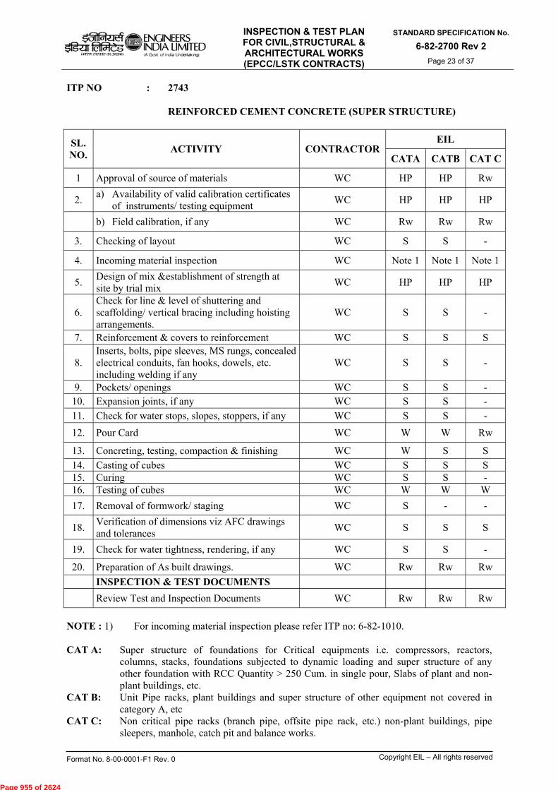
INSPECTION & TEST PLAN FOR CIVIL,STRUCTURAL & ARCHITECTURAL WORKS (EPCC/LSTK CONTRACTS)
STANDARD SPECIFICATION No.
6-82-2700 Rev 2
Page 23 of 37
Format No. 8-00-0001-F1 Rev. 0 Copyright EIL – All rights reserved
ITP NO : 2743 REINFORCED CEMENT CONCRETE (SUPER STRUCTURE)
SL. NO.
ACTIVITY CONTRACTOR EIL
CATA CATB CAT C
1 Approval of source of materials WC HP HP Rw
2. a) Availability of valid calibration certificates
of instruments/ testing equipment WC HP HP HP
b) Field calibration, if any WC Rw Rw Rw
3. Checking of layout WC S S -
4. Incoming material inspection WC Note 1 Note 1 Note 1
5. Design of mix &establishment of strength at site by trial mix
WC HP HP HP
6. Check for line & level of shuttering and scaffolding/ vertical bracing including hoisting arrangements.
WC S S -
7. Reinforcement & covers to reinforcement WC S S S
8. Inserts, bolts, pipe sleeves, MS rungs, concealed electrical conduits, fan hooks, dowels, etc. including welding if any
WC S S -
9. Pockets/ openings WC S S - 10. Expansion joints, if any WC S S -
11. Check for water stops, slopes, stoppers, if any WC S S -
12. Pour Card WC W W Rw
13. Concreting, testing, compaction & finishing WC W S S
14. Casting of cubes WC S S S 15. Curing WC S S - 16. Testing of cubes WC W W W
17. Removal of formwork/ staging WC S - -
18. Verification of dimensions viz AFC drawings and tolerances
WC S S S
19. Check for water tightness, rendering, if any WC S S -
20. Preparation of As built drawings. WC Rw Rw Rw
INSPECTION & TEST DOCUMENTS
Review Test and Inspection Documents WC Rw Rw Rw
NOTE : 1) For incoming material inspection please refer ITP no: 6-82-1010. CAT A: Super structure of foundations for Critical equipments i.e. compressors, reactors,
columns, stacks, foundations subjected to dynamic loading and super structure of any other foundation with RCC Quantity > 250 Cum. in single pour, Slabs of plant and non- plant buildings, etc.
CAT B: Unit Pipe racks, plant buildings and super structure of other equipment not covered in category A, etc
CAT C: Non critical pipe racks (branch pipe, offsite pipe rack, etc.) non-plant buildings, pipe sleepers, manhole, catch pit and balance works.
Page 955 of 2624

INSPECTION & TEST PLAN FOR CIVIL,STRUCTURAL & ARCHITECTURAL WORKS (EPCC/LSTK CONTRACTS)
STANDARD SPECIFICATION No.
6-82-2700 Rev 2
Page 24 of 37
Format No. 8-00-0001-F1 Rev. 0 Copyright EIL – All rights reserved
ITP NO : 2745 RCC PAVEMENT/FLOORING
SL. NO.
ACTIVITY CONTRACTOR EIL
1. Approval of source of materials WC Rw
2. a) Availability of valid calibration certificates of
instruments/ testing equipments WC HP
b) Field calibration, if any WC S
3. Layout checking/ excavation of all new foundations WC -
4. Incoming material inspection WC NOTE 1
5. Design of mix &establishment of strength at site by trial mix
WC HP
6. Check for proper back filling/compaction/ completion of sub - Structure works
WC S
7. Check for edges of shuttering, alternate panels WC -
8. Check for slopes, thickness of flooring WC S
9. Shuttering, reinforcement (as applicable) WC -
10. Check for expansion joints/ Construction joints WC S
11. Check for concealed pipe embedment, earthing, if any WC -
12. Check for dividing strips, as applicable WC S
13. Concreting, finishing, etc WC S
14. Checking for line, levels, slopes, joints, thickness of flooring viz. AFC drawings
WC S
15. Curing WC S
16. Grinding & polishing, as applicable WC S
17. Testing of concrete cubes (as applicable) WC W
18. Preparation of “As Built Drawings” WC Rw
INSPECTION & TEST DOCUMENTS
Review Test and Inspection Documents WC Rw
NOTE : 1) For incoming material inspection please refer ITP no: 6-82-1010.
Page 956 of 2624
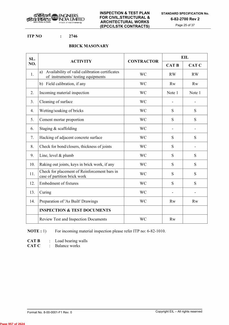
INSPECTION & TEST PLAN FOR CIVIL,STRUCTURAL & ARCHITECTURAL WORKS (EPCC/LSTK CONTRACTS)
STANDARD SPECIFICATION No.
6-82-2700 Rev 2
Page 25 of 37
Format No. 8-00-0001-F1 Rev. 0 Copyright EIL – All rights reserved
ITP NO : 2746 BRICK MASONARY
SL. NO.
ACTIVITY CONTRACTOR EIL
CAT B CAT C
1. a) Availability of valid calibration certificates
of instruments/ testing equipments WC RW RW
b) Field calibration, if any WC Rw Rw
2. Incoming material inspection WC Note 1 Note 1
3. Cleaning of surface WC - -
4. Wetting/soaking of bricks WC S S
5. Cement mortar proportion WC S S
6. Staging & scaffolding WC - -
7. Hacking of adjacent concrete surface WC S S
8. Check for bond/closers, thickness of joints WC S -
9. Line, level & plumb WC S S
10. Raking out joints, keys in brick work, if any WC S S
11. Check for placement of Reinforcement bars in case of partition brick work
WC S S
12. Embedment of fixtures WC S S
13. Curing WC - -
14. Preparation of 'As Built' Drawings WC Rw Rw
INSPECTION & TEST DOCUMENTS
Review Test and Inspection Documents WC Rw
NOTE : 1) For incoming material inspection please refer ITP no: 6-82-1010. CAT B : Load bearing walls CAT C : Balance works
Page 957 of 2624

INSPECTION & TEST PLAN FOR CIVIL,STRUCTURAL & ARCHITECTURAL WORKS (EPCC/LSTK CONTRACTS)
STANDARD SPECIFICATION No.
6-82-2700 Rev 2
Page 26 of 37
Format No. 8-00-0001-F1 Rev. 0 Copyright EIL – All rights reserved
ITP NO : 2747 STRUCTURAL STEEL WORKS
S. NO
ACTIVITY CONTRA-
CTOR EIL
CAT A CAT B CAT CA PRE – FABRICATION ACTIVITIES
1. a) Availability of valid calibration certificates of
instruments/ testing equipments WC HP HP RW
b) Field calibration, if any WC S S Rw 2. Incoming material inspection WC Note 1 Note 1 Note 1 3. Welding Filler material approval/ qualification a) Manufacturing test certificates/ documents WC Rw Rw Rw b) Testing, if any WC W W W
4. Approval of WPS/ PQR WC HP HP HP 5. Welders performance qualification WC W W Rw 6. Layout checking WC S - - 7. Welding equipment and accessories WC S - - 8. Preparation and approval of Fabrication drawings WC Rw Rw - B FABRICATION ACTIVITIES 1. Materials as per design drawing WC Rw Rw Rw 2. Check straightness and non-warping of members WC S S -
3. Dimensional and fit-up checks including provision of slopes for deflection wherever required
WC S S -
4. Visual check for welding WC S S -
5. Grinding including surface preparation for painting and application of primer
WC S S Rw
6. Checking paint as per specs, shelf-life, etc. WC S S - 7. Application of specified paint, painting thickness, etc. WC S S - C FIELD ERECTION ACTIVITIES
1. Lifting arrangements including test certificates of lifting tackles
WC S S Rw
2. Correctness of location WC S - - 3. Orientation of bracing, lugs WC S - - 4. Alignment & levels WC S - - 5. Field welding (if any) WC S S - 6. Grouting WC S S - 7. Finishing coat of paint, thickness of paint etc. WC S S S 8. Preparation of As-built drawings WC Rw Rw Rw INSPECTION & TEST DOCUMENTS Review Test and Inspection Documents WC Rw Rw Rw
NOTE : 1) For incoming material inspection please refer ITP no: 6-82-1010. CAT A: Steel structures pertaining to equipments i.e. compressors, reactors, columns, stacks,
Technological structures. CAT B: Steel structures pertaining to Unit Pipe racks, and other equipments not covered in
category A, etc. CAT C: Steel structures of Non critical pipe racks (branch pipe, offsite pipe rack, etc) plant
buildings and non-plant buildings, pipe sleepers, manhole, catch pit, walkways, platforms at grade levels, etc.
Page 958 of 2624

INSPECTION & TEST PLAN FOR CIVIL,STRUCTURAL & ARCHITECTURAL WORKS (EPCC/LSTK CONTRACTS)
STANDARD SPECIFICATION No.
6-82-2700 Rev 2
Page 27 of 37
Format No. 8-00-0001-F1 Rev. 0 Copyright EIL – All rights reserved
ITP NO : 2748 PILING WORKS
SL. NO.
ACTIVITY CONTRACTOR EIL
CAT A CAT B CAT C
1. Approval of source of materials WC Rw Rw Rw
2. Layout and ground level WC S S -
3. Incoming material inspection WC Note 1 Note 1 Note 1
4. Design of mix &establishment of strength at site by trial mix
WC HP HP HP
5. Driving of piles & check for set point WC S S -
6. Check for depth of bore and lowering of cage measuring
WC S - -
7. Pour Card WC HP HP Rw
8. Concreting, testing WC W S S
9. Casting of cubes/Testing WC W S/W S
10. Check for cut off level of concreting & quantity of concrete poured
WC S - -
11. Lifting of casing pipe WC S S -
12. Pile load tests (lateral/vertical/cyclic/pull out)
WC W Rw Rw
13. Submission of pile load test report WC Rw Rw Rw
INSPECTION & TEST DOCUMENTS
Review Test and Inspection Documents WC Rw Rw Rw
NOTE : 1) For incoming material inspection please refer ITP no: 6-82-1010. CAT A: Critical foundations of equipments i.e. compressors, reactors, columns, stacks,
foundations subjected to dynamic loading and any other foundation with RCC Quantity > 250 Cum in single pour ,Technological structures, etc.
CAT B: Unit Pipe racks, plant buildings and other equipment foundations not covered in category
A, etc. CAT C: Non critical pipe racks(branch pipe, offsite pipe rack, etc.) non-plant buildings ,pipe
sleepers, manhole, catch pit, etc.
Page 959 of 2624
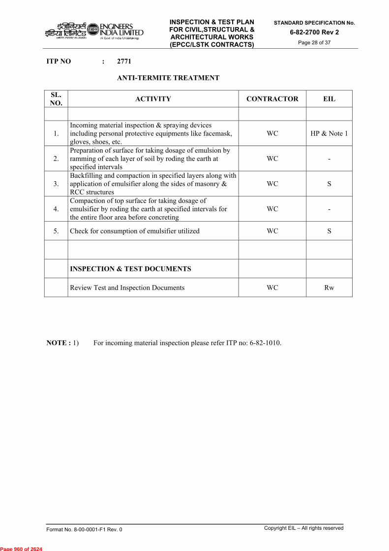
INSPECTION & TEST PLAN FOR CIVIL,STRUCTURAL & ARCHITECTURAL WORKS (EPCC/LSTK CONTRACTS)
STANDARD SPECIFICATION No.
6-82-2700 Rev 2
Page 28 of 37
Format No. 8-00-0001-F1 Rev. 0 Copyright EIL – All rights reserved
ITP NO : 2771 ANTI-TERMITE TREATMENT
SL. NO.
ACTIVITY CONTRACTOR EIL
1. Incoming material inspection & spraying devices including personal protective equipments like facemask, gloves, shoes, etc.
WC HP & Note 1
2. Preparation of surface for taking dosage of emulsion by ramming of each layer of soil by roding the earth at specified intervals
WC -
3. Backfilling and compaction in specified layers along with application of emulsifier along the sides of masonry & RCC structures
WC S
4. Compaction of top surface for taking dosage of emulsifier by roding the earth at specified intervals for the entire floor area before concreting
WC -
5. Check for consumption of emulsifier utilized WC S
INSPECTION & TEST DOCUMENTS
Review Test and Inspection Documents WC Rw
NOTE : 1) For incoming material inspection please refer ITP no: 6-82-1010.
Page 960 of 2624
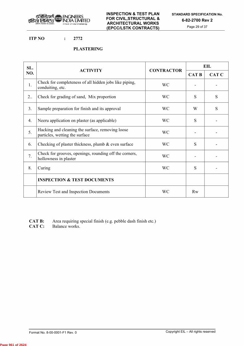
INSPECTION & TEST PLAN FOR CIVIL,STRUCTURAL & ARCHITECTURAL WORKS (EPCC/LSTK CONTRACTS)
STANDARD SPECIFICATION No.
6-82-2700 Rev 2
Page 29 of 37
Format No. 8-00-0001-F1 Rev. 0 Copyright EIL – All rights reserved
ITP NO : 2772 PLASTERING
SL. NO.
ACTIVITY CONTRACTOR EIL
CAT B CAT C
1. Check for completeness of all hidden jobs like piping, conduiting, etc.
WC - -
2.. Check for grading of sand, Mix proportion WC S S
3. Sample preparation for finish and its approval WC W S
4. Neeru application on plaster (as applicable) WC S -
5. Hacking and cleaning the surface, removing loose particles, wetting the surface
WC - -
6. Checking of plaster thickness, plumb & even surface WC S -
7. Check for grooves, openings, rounding off the corners, hollowness in plaster
WC - -
8. Curing WC S -
INSPECTION & TEST DOCUMENTS
Review Test and Inspection Documents WC Rw
CAT B: Area requiring special finish (e.g. pebble dash finish etc.) CAT C: Balance works.
Page 961 of 2624
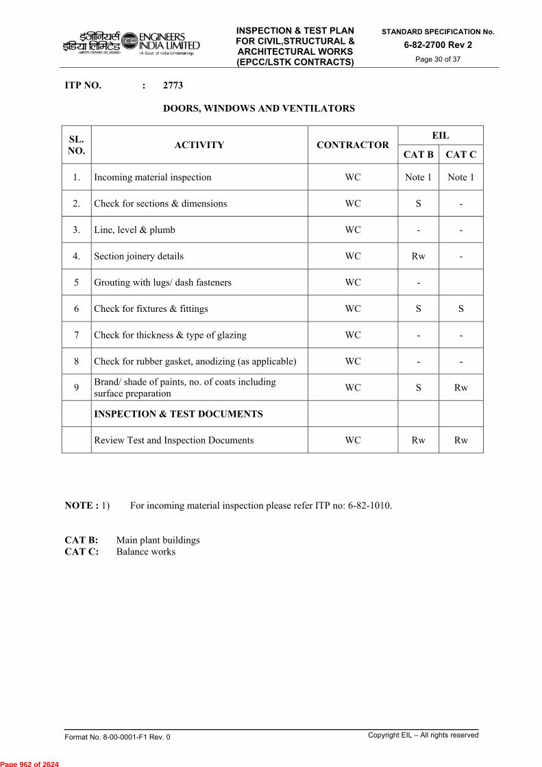
INSPECTION & TEST PLAN FOR CIVIL,STRUCTURAL & ARCHITECTURAL WORKS (EPCC/LSTK CONTRACTS)
STANDARD SPECIFICATION No.
6-82-2700 Rev 2
Page 30 of 37
Format No. 8-00-0001-F1 Rev. 0 Copyright EIL – All rights reserved
ITP NO. : 2773 DOORS, WINDOWS AND VENTILATORS
SL. NO.
ACTIVITY CONTRACTOR EIL
CAT B CAT C
1. Incoming material inspection WC Note 1 Note 1
2. Check for sections & dimensions WC S -
3. Line, level & plumb WC - -
4. Section joinery details WC Rw -
5 Grouting with lugs/ dash fasteners WC -
6 Check for fixtures & fittings WC S S
7 Check for thickness & type of glazing WC - -
8 Check for rubber gasket, anodizing (as applicable) WC - -
9 Brand/ shade of paints, no. of coats including surface preparation
WC S Rw
INSPECTION & TEST DOCUMENTS
Review Test and Inspection Documents WC Rw Rw
NOTE : 1) For incoming material inspection please refer ITP no: 6-82-1010. CAT B: Main plant buildings CAT C: Balance works
Page 962 of 2624

INSPECTION & TEST PLAN FOR CIVIL,STRUCTURAL & ARCHITECTURAL WORKS (EPCC/LSTK CONTRACTS)
STANDARD SPECIFICATION No.
6-82-2700 Rev 2
Page 31 of 37
Format No. 8-00-0001-F1 Rev. 0 Copyright EIL – All rights reserved
ITP NO. : 2774 PAINTING (BUILDING WORKS)
SL. NO.
ACTIVITY CONTRACTOR EIL
CAT B CAT C
1. Completion of surface preparation WC - -
2. Incoming material inspection WC Note 1 Note 1
3. Confirmation of colour, shade & brand HP - -
4. Check for number of coats and thickness WC S -
5. Curing, if any WC S -
INSPECTION & TEST DOCUMENTS
Review Test and Inspection Documents WC Rw Rw
NOTE : 1) For incoming material inspection please refer ITP no: 6-82-1010. CAT B: Main plant buildings CAT C: Balance works
Page 963 of 2624

INSPECTION & TEST PLAN FOR CIVIL,STRUCTURAL & ARCHITECTURAL WORKS (EPCC/LSTK CONTRACTS)
STANDARD SPECIFICATION No.
6-82-2700 Rev 2
Page 32 of 37
Format No. 8-00-0001-F1 Rev. 0 Copyright EIL – All rights reserved
ITP NO. : 2775 SANITARY FITTINGS
SL. NO.
ACTIVITY
CONTRACTOR
EIL
CAT B CAT C
1. Incoming material inspection WC Note 1 Note 1
2. Checking of sample (as applicable) WC S -
3. Check completeness of finishing works w.r.t. line, level & position
WC S -
4. Check proper fixing of the sanitary fittings to give aesthetic appeal
WC S -
5. Check for leakage WC S Rw
INSPECTION & TEST DOCUMENTS
Review Test and Inspection Documents WC Rw Rw
NOTE : 1) For incoming material inspection please refer ITP no: 6-82-1010. CAT B: Main plant buildings CAT C: Balance works
Page 964 of 2624
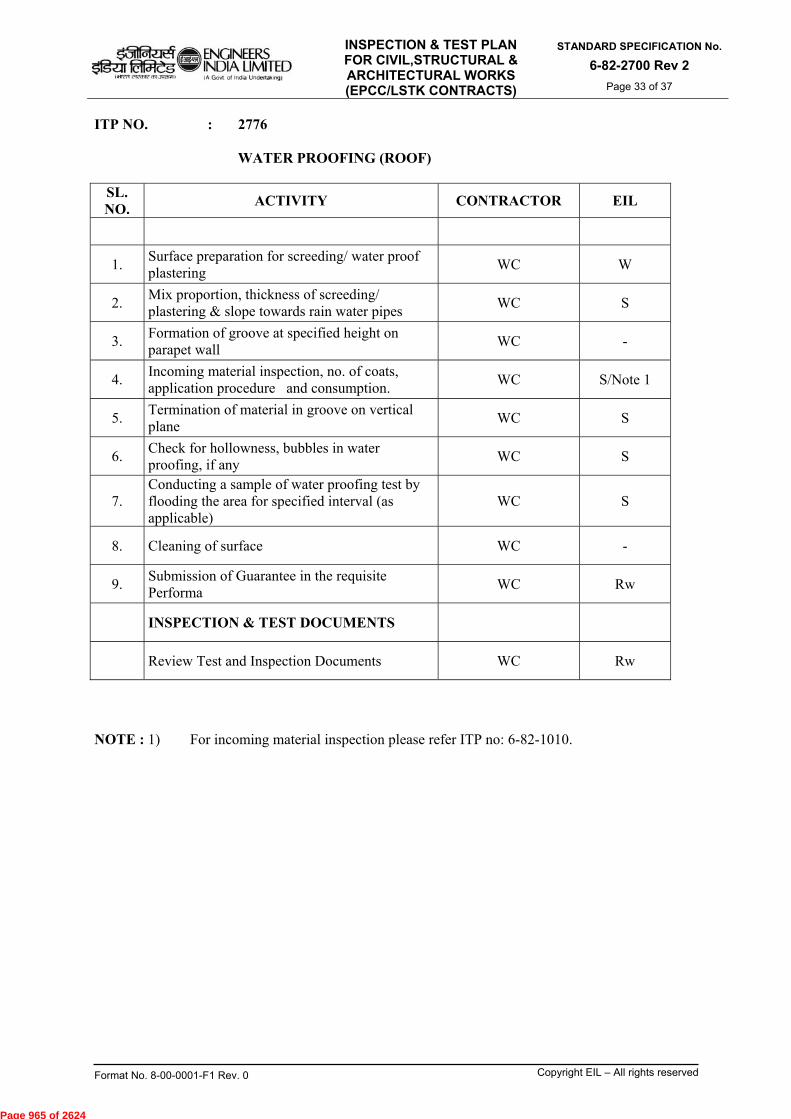
INSPECTION & TEST PLAN FOR CIVIL,STRUCTURAL & ARCHITECTURAL WORKS (EPCC/LSTK CONTRACTS)
STANDARD SPECIFICATION No.
6-82-2700 Rev 2
Page 33 of 37
Format No. 8-00-0001-F1 Rev. 0 Copyright EIL – All rights reserved
ITP NO. : 2776 WATER PROOFING (ROOF)
SL. NO.
ACTIVITY CONTRACTOR EIL
1. Surface preparation for screeding/ water proof plastering
WC W
2. Mix proportion, thickness of screeding/ plastering & slope towards rain water pipes
WC S
3. Formation of groove at specified height on parapet wall
WC -
4. Incoming material inspection, no. of coats, application procedure and consumption.
WC S/Note 1
5. Termination of material in groove on vertical plane
WC S
6. Check for hollowness, bubbles in water proofing, if any
WC S
7. Conducting a sample of water proofing test by flooding the area for specified interval (as applicable)
WC S
8. Cleaning of surface WC -
9. Submission of Guarantee in the requisite Performa
WC Rw
INSPECTION & TEST DOCUMENTS
Review Test and Inspection Documents WC Rw
NOTE : 1) For incoming material inspection please refer ITP no: 6-82-1010.
Page 965 of 2624
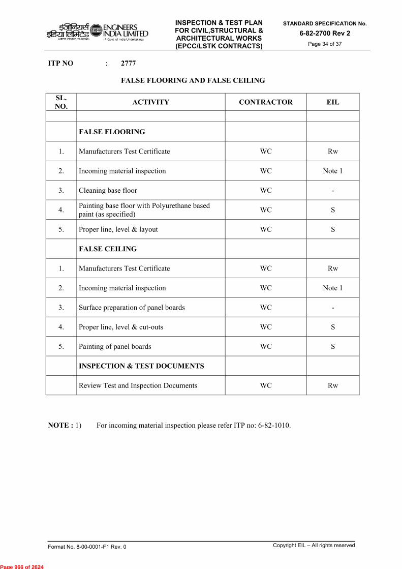
INSPECTION & TEST PLAN FOR CIVIL,STRUCTURAL & ARCHITECTURAL WORKS (EPCC/LSTK CONTRACTS)
STANDARD SPECIFICATION No.
6-82-2700 Rev 2
Page 34 of 37
Format No. 8-00-0001-F1 Rev. 0 Copyright EIL – All rights reserved
ITP NO : 2777 FALSE FLOORING AND FALSE CEILING
SL. NO.
ACTIVITY CONTRACTOR EIL
FALSE FLOORING
1. Manufacturers Test Certificate WC Rw
2. Incoming material inspection WC Note 1
3. Cleaning base floor WC -
4. Painting base floor with Polyurethane based paint (as specified)
WC S
5. Proper line, level & layout WC S
FALSE CEILING
1. Manufacturers Test Certificate WC Rw
2. Incoming material inspection WC Note 1
3. Surface preparation of panel boards WC -
4. Proper line, level & cut-outs WC S
5. Painting of panel boards WC S
INSPECTION & TEST DOCUMENTS
Review Test and Inspection Documents WC Rw
NOTE : 1) For incoming material inspection please refer ITP no: 6-82-1010.
Page 966 of 2624
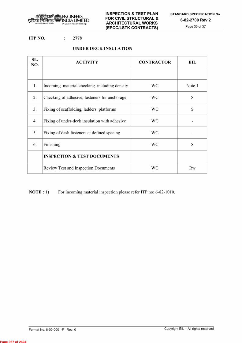
INSPECTION & TEST PLAN FOR CIVIL,STRUCTURAL & ARCHITECTURAL WORKS (EPCC/LSTK CONTRACTS)
STANDARD SPECIFICATION No.
6-82-2700 Rev 2
Page 35 of 37
Format No. 8-00-0001-F1 Rev. 0 Copyright EIL – All rights reserved
ITP NO. : 2778 UNDER DECK INSULATION
SL. NO.
ACTIVITY CONTRACTOR EIL
1. Incoming material checking including density WC Note 1
2. Checking of adhesive, fasteners for anchorage WC S
3. Fixing of scaffolding, ladders, platforms WC S
4. Fixing of under-deck insulation with adhesive WC -
5. Fixing of dash fasteners at defined spacing WC -
6. Finishing WC S
INSPECTION & TEST DOCUMENTS
Review Test and Inspection Documents WC Rw
NOTE : 1) For incoming material inspection please refer ITP no: 6-82-1010.
Page 967 of 2624

INSPECTION & TEST PLAN FOR CIVIL,STRUCTURAL & ARCHITECTURAL WORKS (EPCC/LSTK CONTRACTS)
STANDARD SPECIFICATION No.
6-82-2700 Rev 2
Page 36 of 37
Format No. 8-00-0001-F1 Rev. 0 Copyright EIL – All rights reserved
ITP NO. : 2779 ROOFING ACCESSORIES
SL. NO.
ACTIVITY CONTRACTOREIL
CAT B CAT C
1. Incoming material inspection WC HP/Note 1 HP/Note 1
2. Check for mitring, overhang, laps, etc. WC S -
3. Slopes line, level of sheets, barge boards, ridges & gutters, overhang of sheets
WC S -
4. Bolting by drilling only, length of bolts, nos., anodizing and type of washers
WC S -
5. Check for slopes of rain gutters, down take pipes, north lighting curves/ supports for gutters
WC S -
6. Check for leakage/ passing of light WC S -
INSPECTION & TEST DOCUMENTS
Review Test and Inspection Documents WC Rw Rw
NOTE : 1) For incoming material inspection please refer ITP no: 6-82-1010.
2) Fixing arrangement need to be reviewed with respect to contract specifications. CAT B: Important structures (e.g. Compressor House, Warehouse and Pump House etc.) CAT C: Balance works.
Page 968 of 2624
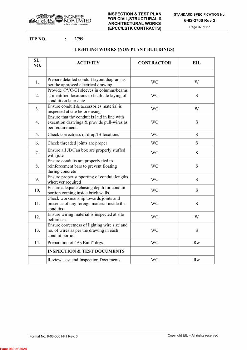
INSPECTION & TEST PLAN FOR CIVIL,STRUCTURAL & ARCHITECTURAL WORKS (EPCC/LSTK CONTRACTS)
STANDARD SPECIFICATION No.
6-82-2700 Rev 2
Page 37 of 37
Format No. 8-00-0001-F1 Rev. 0 Copyright EIL – All rights reserved
ITP NO. : 2799 LIGHTING WORKS (NON PLANT BUILDINGS)
SL. NO.
ACTIVITY CONTRACTOR EIL
1. Prepare detailed conduit layout diagram as per the approved electrical drawing
WC W
2. Provide /PVC/GI sleeves in columns/beams at identified locations to facilitate laying of conduit on later date.
WC S
3. Ensure conduit & accessories material is inspected at site before using
WC W
4. Ensure that the conduit is laid in line with execution drawings & provide pull-wires as per requirement.
WC S
5. Check correctness of drop/JB locations WC S
6. Check threaded joints are proper WC S
7. Ensure all JB/Fan box are properly stuffed with jute
WC S
8. Ensure conduits are properly tied to reinforcement bars to prevent floating during concrete
WC S
9. Ensure proper supporting of conduit lengths wherever required
WC S
10. Ensure adequate chasing depth for conduit portion coming inside brick walls
WC S
11. Check workmanship towards joints and presence of any foreign material inside the conduits
WC S
12. Ensure wiring material is inspected at site before use
WC W
13. Ensure correctness of lighting wire size and no. of wires as per the drawing in each conduit portion
WC S
14. Preparation of "As Built" drgs. WC Rw
INSPECTION & TEST DOCUMENTS
Review Test and Inspection Documents WC Rw
Page 969 of 2624

2 19.02.2016 REVISED AND REISSUED °' a'A AKM TKS
1 04.07.2011 REVISED AND REISSUED SM SM MKG
0 12.09.2006 ISSUED AS STANDARD SPECIFICATION AS MPJ VNP
Rev. No Date Purpose
Prepared by
Checked by
Standards Committee Convenor
10:13\./ SC
DM
VC
Standards Bureau
Chairman
Approved by
INSPECTION & TEST PLAN FOR ELECTRICAL WORKS (EPCC/LSTK CONTRACTS)
STANDARD SPECIFICATION No.
6-82-2800 Rev. 2 Page 1 of 21
1`--11ReJel
ENGINEERS Ogar fettarez INDIA LIMITED
WO, 212m? 313,70.1) (A Govt of India Undertaking)
w-1 (iL(Iatrii uct,vci e•-ic61 tiRql3T1)
IW-affrur vq' trawl- til%n --I Outetcrt)
INSPECTION & TEST PLAN (ITP) FOR ELECTRICAL WORKS (EPCC/LSTK CONTRACTS)
Format No. 8-00-0001-F1 Rev 1 Copyright EIL — All rights reserved
Page 970 of 2624
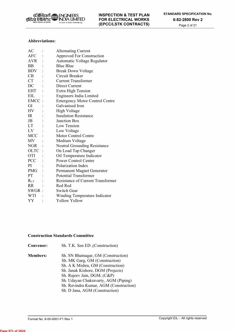
INSPECTION & TEST PLAN FOR ELECTRICAL WORKS (EPCC/LSTK CONTRACTS)
STANDARD SPECIFICATION No.
6-82-2800 Rev 2 Page 2 of 21
Format No. 8-00-0001-F1 Rev 1 Copyright EIL – All rights reserved
Abbreviations: AC : Alternating Current AFC : Approved For Construction AVR : Automatic Voltage Regulator BB : Blue Blue BDV : Break Down Voltage CB : Circuit Breaker CT : Current Transformer DC : Direct Current EHT : Extra High Tension EIL : Engineers India Limited EMCC : Emergency Motor Control Centre GI : Galvanised Iron HV : High Voltage IR : Insulation Resistance JB : Junction Box LT : Low Tension LV : Low Voltage MCC : Motor Control Centre MV : Medium Voltage NGR : Neutral Grounding Resistance OLTC : On Load Tap Changer OTI : Oil Temperature Indicator PCC : Power Control Centre PI : Polarization Index PMG : Permanent Magnet Generator PT : Potential Transformer RCT : Resistance of Current Transformer RR : Red Red SWGR : Switch Gear WTI : Winding Temperature Indicator YY : Yellow Yellow Construction Standards Committee Convenor: Sh. T.K. Sen ED ,(Construction) Members: Sh. SN Bhatnagar, GM (Construction)
Sh. MK Garg, GM (Construction) Sh. A K Mishra, GM (Construction) Sh. Janak Kishore, DGM (Projects) Sh. Rajeev Jain, DGM, (C&P) Sh. Udayan Chakravarty, AGM (Piping) Sh. Ravindra Kumar, AGM (Construction) Sh. D Jana, AGM (Construction)
Page 971 of 2624

INSPECTION & TEST PLAN FOR ELECTRICAL WORKS (EPCC/LSTK CONTRACTS)
STANDARD SPECIFICATION No.
6-82-2800 Rev 2 Page 3 of 21
Format No. 8-00-0001-F1 Rev 1 Copyright EIL – All rights reserved
CONTENTS
S.NO DESCRIPTION DOCUMENT NO. PAGE
NO.
ITPs for Electrical Works
1. Installation/ erection & testing of transformer 2801 5-7
2. Installation/ erection & testing of motor 2805 8-9
3. Installation/ erection & testing of generator 2810 10-11
4. Installation/ erection & testing of switch gears/ PCC/ MCC/ EMCC
2815 12 - 13
5. Installation/ erection & testing of EHT/ HT main bus and allied equipments
2820 14
6. Cable laying 2825 15-16
7. Lighting system 2830 17
8. Earthing system 2835 18-19
9. Installation of bus duct 2840 20
10. Cable termination 2845 21
Page 972 of 2624

INSPECTION & TEST PLAN FOR ELECTRICAL WORKS (EPCC/LSTK CONTRACTS)
STANDARD SPECIFICATION No.
6-82-2800 Rev 2 Page 4 of 21
Format No. 8-00-0001-F1 Rev 1 Copyright EIL – All rights reserved
GENERAL NOTE The enclosed ITPs are indicative and shall be followed for developing the job specific ITP’s for the works to be performed by the contractor. The provisions indicated for stage wise inspection by EIL/Owner (For specific activities) are the minimum and the Engineer-In-Charge may decide to increase Hold Points/ Witness Points while approving the job specific ITP’s. Activities for which ITP’s are not provided in this specification, contractor to develop and get the same approved by EIL/Owner before start of the work. In general role of EIL has been specified in the document. The role of owner to be specified during preparation of site specific ITPs Contractor to submit job specific reporting formats with the aid of enclosed sample reporting formats and job procedures for the jobs for which ITP’s are attached and submit to EIL/Owner for approval, before commencement of the activity. If the contractor has to deviate from the given ITP for a valid reason, he shall obtain prior written approval of EIL/Owner. Contractor to carry out 100% examination of all activities.
LEGEND HP : Hold Point ;
A point which requires witnessing/inspection/verification and acceptance by Owner/EIL before any further processing is permitted. The Contractor shall not process the activity/item beyond a Hold Point without written approval by Owner/EIL except where prior written permission for further processing is available.
W : Witness Point ; An activity which requires witnessing/inspection/verification by Owner/EIL when the activity is performed. After proper notification has been provided (notification modalities and period shall be finalized before hand), the Contractor is not obliged to hold further processing if Owner/EIL is not available to witness the activity or does not provide comments before the date notified. In such cases, basis of acceptance shall be review of Contractor generated report/document as per relevant technical specification.
Rw : Review of Contractor’s documentation.
S : Surveillance Inspection by Owner/ EIL. Monitoring or making observations to verify whether or not material/items or services conform to specified requirements. Surveillance activities may include audit, inspections, witness of testing, Review of quality documentation & records, personnel qualifications, etc.
WC : 100% Supervision and Examination by Contractor.
Responsibility for execution of the inspection/testing is with the Contractor; Owner/EIL only verifies examination or testing done by the Contractor at important stages
Page 973 of 2624

INSPECTION & TEST PLAN FOR ELECTRICAL WORKS (EPCC/LSTK CONTRACTS)
STANDARD SPECIFICATION No.
6-82-2800 Rev 2 Page 5 of 21
Format No. 8-00-0001-F1 Rev 1 Copyright EIL – All rights reserved
ITP NO.: 2801
INSTALLATION/ ERECTION & TESTING OF TRANSFORMER
Sl. No.
Activity Contractor EIL
CAT A CAT B CAT C
1. Incoming Material inspection at site WC Note-1 Note-1 Note-1
2.
Check foundation, its cleanliness, level and centre lines, Anchor bolts/insert plates, their position & straightness, flatness of contacting surface for transformer skid. In case of Rail mounted type, check centre line and levels of rails.
WC S S S
3. Check the Transformer no. and rating as per drawings and purged gas/ air pressure & oil leakage, physical damage etc.
WC S -- --
4. Check availability of all accessories and Transformer oil
WC S -- --
5. Check sequence of installation e.g. main tank first + radiators + accessories + internal check as per installation flow chart.
WC S -- --
6. Ensure the cleanliness of connecting part e.g. flange parts and maintenance of duly tight blank flanges until commencement of assembly
WC S -- --
7.
Check bushing cracks, chips or presence of paint or dirt. Bushing should be cleaned as per vendor’s instruction. Check explosion vent assembly & healthiness of diaphragm
WC S -- --
8.
Ensure the internal check by vendors’ Engineer/supervisor and submission of report to Owner/ EIL duly signed by him and by the contractor
WC Rw -- --
9.
After completing assembly of all parts, filling of tank and OLTC with transformer oil, operation of OLTC ( prior to filling the Transformer oil, each drum must be tested against di-electric strength for minimum as per specifications )
WC S -- --
Page 974 of 2624

INSPECTION & TEST PLAN FOR ELECTRICAL WORKS (EPCC/LSTK CONTRACTS)
STANDARD SPECIFICATION No.
6-82-2800 Rev 2 Page 6 of 21
Format No. 8-00-0001-F1 Rev 1 Copyright EIL – All rights reserved
ITP NO.: 2801
INSTALLATION/ ERECTION & TESTING OF TRANSFORMER (contd.)
Sl. No.
Activity Contractor EIL
CAT A CAT B CAT C
10. Check & ensure bus duct connection at both ends including torque checking of bolt.
WC S S S
11.
Ensure cable connection at the cable & box, their colour coding & tightness. Use of spring and flat washers on the appropriate faces to be confirmed) and cleanliness of lapping surfaces. For multiple cable connection, check for correctness of RR, YY, BB grouping
WC S -- --
12. If specified, fill the cable end box with tested transformer oil and ensure oil levels
WC S -- --
13. Check the use of proper size conductors/ cables for HV/LV, neutral connection and their connection to NGR or earth grid/ earth point
WC S -- --
14. Check equipment earthing, connections, tightness and earth resistance value on each earth pit
WC S -- --
15. Ensure earthing of tertiary winding if applicable WC S -- --
16. Check leakage and oil level WC S -- --
17. Check oil filtration before energisation on & check BDV of oil(as applicable)
WC S -- --
18. Check proper installation of Dessicants (reactivate the silica gel to blue; oil traps to be filled up)
WC S -- --
19. Measure winding resistance at each tap WC S -- --
20. a) Test insulation resistance & PI WC S -- --
b) Ensure heat run/ dehydration of transformer WC W S --
c) Check final IR value after dehydration and
temp. Vs IR curve to ensure drying WC S S --
21. Test vector group polarity, magnetizing current, magnetic balancing
WC W -- --
Page 975 of 2624

INSPECTION & TEST PLAN FOR ELECTRICAL WORKS (EPCC/LSTK CONTRACTS)
STANDARD SPECIFICATION No.
6-82-2800 Rev 2 Page 7 of 21
Format No. 8-00-0001-F1 Rev 1 Copyright EIL – All rights reserved
ITP NO.: 2801
INSTALLATION/ ERECTION & TESTING OF TRANSFORMER (contd.) Sl. No.
Activity Contractor EIL
CAT A CAT B CAT C
22. Test transformation ratio at each tap points (injecting 3 phase, 415 V at primary)
WC W S --
23. Ensure laying, termination & connection of all control &Signal cables as per cable schedule
WC S -- --
24. Check Bucholtz's relay operation by air injection for both transformer & OLTC, MOG for alarm and trip contacts’ function
WC W S --
25. Check setting of Fan control (auto & manual), OTI, WTI - alarm and trip
WC W S --
26. Check tap changer control/ operation- both auto & manual – without energizing the transformer. Ensure master/ followers’ correct functioning
WC W -- --
27.
Final residual check to confirm removal of all temporary supports/ spacers, tags, accumulation of air in Buchhelz relay, oil, if any, etc., which might have been used as protection/ and identification during transportation and erection
WC S -- --
28. Check operation of cooling system WC S -- --
29. Stability check, (Restricted (64R)/ standby Earth fault (51G)/ Transformer differential(87T), (as applicable)
WC W -- --
30. Check CT Ratio & Polarity WC W S --
31. Check Transformer protection relay settings as per Relay Setting chart
WC W S --
32. Mechanical Acceptance Test/ Energisation protocol of transformer
WC HP HP Rw
33. Size/ type of gravel for filling in yard as per specification / drawing
WC S S --
INSPECTION & TEST DOCUMENTS
Review Test and Inspection Documents WC Rw Rw Rw
NOTE : 1) For incoming material inspection please refer ITP no: 6-82-1010 CAT A: Power & Distribution Transformers, CAT B: Lighting transformers CAT C : Miscellaneous transformers like isolation transformers, etc.
Page 976 of 2624

INSPECTION & TEST PLAN FOR ELECTRICAL WORKS (EPCC/LSTK CONTRACTS)
STANDARD SPECIFICATION No.
6-82-2800 Rev 2 Page 8 of 21
Format No. 8-00-0001-F1 Rev 1 Copyright EIL – All rights reserved
ITP NO.: 2805
INSTALLATION/ ERECTION & TESTING OF MOTOR Sl. No.
Activity Contractor EIL
CAT A CAT B CAT C
1. Incoming material inspection WC Note-1 Note-1 Note-1
2.
Check for foundation, it’s level & centre line markings, ensure the depth of anchor grouting pockets and straightness of anchor bolts. Foundation should be thoroughly cleaned before placement of motor
WC Rw Rw Rw
3. Check motor name plate, identify the equipment referring to vendor’s shop floor test certificate and construction drawing
WC S S --
4. Check type of motor as per area classification drgs duly approved by the Competent Authority
WC S S S
5.
Check for installation of motor, its leveling, alignment and coupling with driven equipment (before coupling magnetic centering must be ensured )
WC Rw Rw Rw
6. Ensure fixing of all accessories, temperature indicators, cooling system, lubricating pumps, etc.
WC S -- --
7. Ensure pedestal insulation WC S -- --
8. Check lubrication of bearings, their suitability and level. For lubricants, vendor instructions and specifications to be followed
WC W S --
9. Ensure sealing of all exposed outlets during erection/ assembly
WC S -- --
10. Ensure air-gap as per vendor instruction (for big machines assembled at site)
WC S -- --
11. Ensure all spacers and blockings used for transportation and erection have been removed
WC S -- Rw
12. Check proper earthing of the motor and earth connection
WC W S S
Page 977 of 2624

INSPECTION & TEST PLAN FOR ELECTRICAL WORKS (EPCC/LSTK CONTRACTS)
STANDARD SPECIFICATION No.
6-82-2800 Rev 2 Page 9 of 21
Format No. 8-00-0001-F1 Rev 1 Copyright EIL – All rights reserved
ITP NO.: 2805
INSTALLATION/ ERECTION & TESTING OF MOTOR Sl. No.
Activity Contractor EIL
CAT A CAT B CAT C
13. a. Check IR and PI for the motor and IR for auxiliary circuits like heaters and Thermal detectors, excitor (for synchronous motor ), etc.
WC W S --
b. In case of low IR/ PI, Improve IR value as per
spec/ suitable method as per vendors’ recommendation.
WC W S --
14. Measure winding Resistance (if specified in spec) WC S S --
15.
Inspect space heater and control cable connections. Ensure the tightness of connection, proper glanding & earthing of armour, correct phase sequence of supply cable as per mark and closing the covers of terminal boxes.
WC S -- --
16. Check for de-coupling of motor for no-load run and ensure re-coupling of the motor after verification of original alignment.
WC W S --
17. Set the temperature indicators (alarm/ trip) and vibration monitors (if any)
WC S -- --
18. Check motor protection relay settings as per Relay Setting diagram
WC W W --
19.
Check provision of CTs in power/ neutrals as per requirement of specifications. Visually check name plates of CT’s and ensure their ratio, accuracy class and proper grounding as per approved drawings. Test their polarity ratio and stability. Do the cable termination at CT terminal boxes.
WC HP HP Rw
20 Check operation of synchronizing panel for synchronous motor.
WC S -- --
21. Perform no load run of motor - record vibration, Temp rise, current, speed, Starting current/No load current etc.
WC W W --
22. Mechanical Acceptance Test/Energisation Protocol WC HP HP Rw
INSPECTION & TEST DOCUMENTS
Review Test and Inspection Documents WC Rw Rw Rw
NOTE : 1) For incoming material inspection please refer ITP no: 6-82-1010 CAT A : HV& MV motors above 110 KW, all MV motors in hazardous area CAT B : MV motors up to 110 KW in non hazardous area CAT C : Others .
Page 978 of 2624
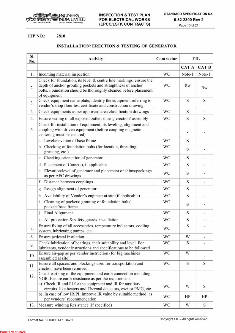
INSPECTION & TEST PLAN FOR ELECTRICAL WORKS (EPCC/LSTK CONTRACTS)
STANDARD SPECIFICATION No.
6-82-2800 Rev 2 Page 10 of 21
Format No. 8-00-0001-F1 Rev 1 Copyright EIL – All rights reserved
ITP NO.: 2810 INSTALLATION/ ERECTION & TESTING OF GENERATOR
Sl. No.
Activity Contractor EIL
CAT A CAT B
1. Incoming material inspection WC Note-1 Note-1
2.
Check for foundation, its level & centre line markings, ensure the depth of anchor grouting pockets and straightness of anchor bolts. Foundation should be thoroughly cleaned before placement of equipment
WC
Rw
Rw
3. Check equipment name plate, identify the equipment referring to vendor’s shop floor test certificate and construction drawing
WC
S
S
4. Check equipments as per approved area classification drawings WC S -
5. Ensure sealing of all exposed outlets during erection/ assembly WC S S
6. Check for installation of equipment, its leveling, alignment and coupling with driven equipment (before coupling magnetic centering must be ensured)
- -
-
a. Level/elevation of base frame WC S -
b. Checking of foundation bolts (for location, threading,
greasing, etc.) WC
S -
c. Checking orientation of generator WC S -
d. Placement of Crane(s), if applicable WC S -
e. Elevation/level of generator and placement of shims/packings
as per AFC drawings WC S -
f. Distance between couplings WC S -
g. Rough alignment of generator WC S -
h. Availability of Vendor’s engineer at site (if applicable) WC S -
i. Cleaning of pockets/ grouting of foundation bolts’
pockets/base frame WC
S -
j. Final Alignment WC S -
k. All protection & safety guards installation WC S -
7. Ensure fixing of all accessories, temperature indicators, cooling system, lubricating pumps, etc
WC S
-
8. Ensure pedestal insulation WC W -
9. Check lubrication of bearings, their suitability and level. For lubricants, vendor instructions and specifications to be followed
WC
S
-
10. Ensure air-gap as per vendor instruction (for big machines assembled at site)
WC
W
-
11. Ensure all spacers and blockings used for transportation and erection have been removed
WC
S
S
12. Check earthing of the equipment and earth connection including NGR. Ensure earth resistance as per the requirement
a) Check IR and PI for the equipment and IR for auxiliary
circuits like heaters and Thermal detectors, excitor PMG, etc.WC W S
b) In case of low IR/PI, Improve IR value by suitable method as
per vendors’ recommendation WC HP HP
13. Measure winding Resistance (if specified) WC W S
Page 979 of 2624
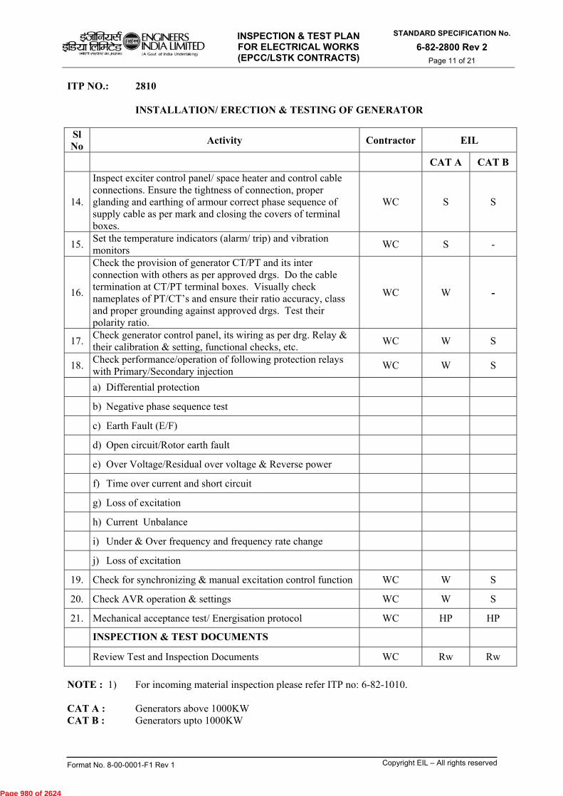
INSPECTION & TEST PLAN FOR ELECTRICAL WORKS (EPCC/LSTK CONTRACTS)
STANDARD SPECIFICATION No.
6-82-2800 Rev 2 Page 11 of 21
Format No. 8-00-0001-F1 Rev 1 Copyright EIL – All rights reserved
ITP NO.: 2810 INSTALLATION/ ERECTION & TESTING OF GENERATOR
Sl No
Activity Contractor EIL
CAT A CAT B
14.
Inspect exciter control panel/ space heater and control cable connections. Ensure the tightness of connection, proper glanding and earthing of armour correct phase sequence of supply cable as per mark and closing the covers of terminal boxes.
WC S S
15. Set the temperature indicators (alarm/ trip) and vibration monitors
WC S -
16.
Check the provision of generator CT/PT and its inter connection with others as per approved drgs. Do the cable termination at CT/PT terminal boxes. Visually check nameplates of PT/CT’s and ensure their ratio accuracy, class and proper grounding against approved drgs. Test their polarity ratio.
WC W -
17. Check generator control panel, its wiring as per drg. Relay & their calibration & setting, functional checks, etc.
WC W S
18. Check performance/operation of following protection relays with Primary/Secondary injection
WC W S
a) Differential protection
b) Negative phase sequence test
c) Earth Fault (E/F)
d) Open circuit/Rotor earth fault
e) Over Voltage/Residual over voltage & Reverse power
f) Time over current and short circuit
g) Loss of excitation
h) Current Unbalance
i) Under & Over frequency and frequency rate change
j) Loss of excitation
19. Check for synchronizing & manual excitation control function WC W S
20. Check AVR operation & settings WC W S
21. Mechanical acceptance test/ Energisation protocol WC HP HP
INSPECTION & TEST DOCUMENTS
Review Test and Inspection Documents WC Rw Rw
NOTE : 1) For incoming material inspection please refer ITP no: 6-82-1010. CAT A : Generators above 1000KW CAT B : Generators upto 1000KW
Page 980 of 2624
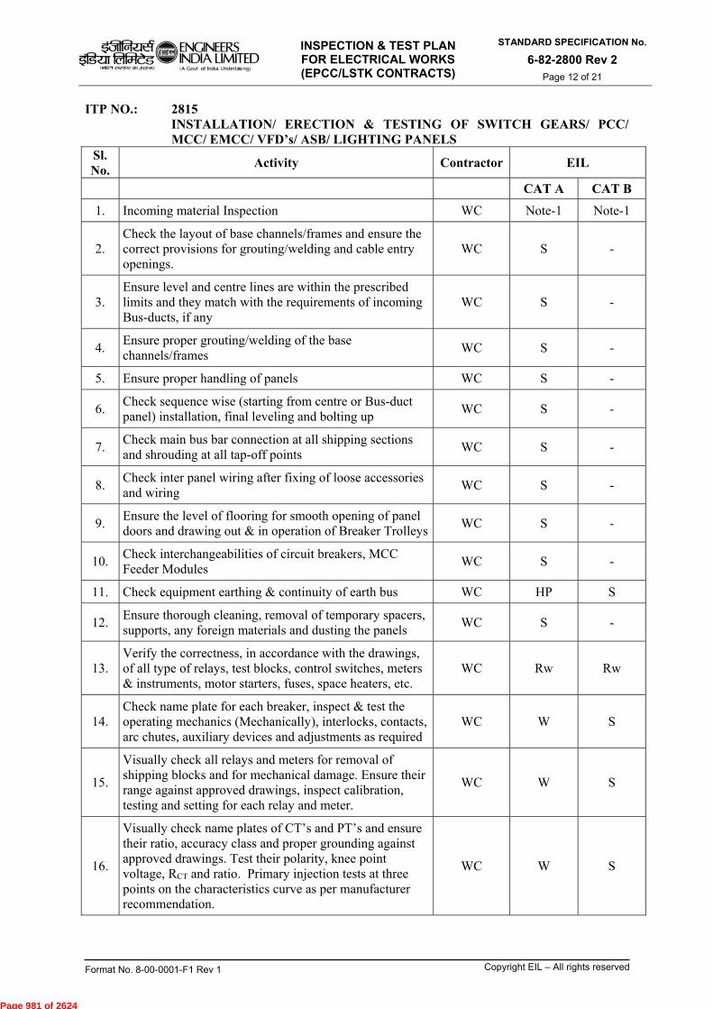
INSPECTION & TEST PLAN FOR ELECTRICAL WORKS (EPCC/LSTK CONTRACTS)
STANDARD SPECIFICATION No.
6-82-2800 Rev 2 Page 12 of 21
Format No. 8-00-0001-F1 Rev 1 Copyright EIL – All rights reserved
ITP NO.: 2815 INSTALLATION/ ERECTION & TESTING OF SWITCH GEARS/ PCC/ MCC/ EMCC/ VFD’s/ ASB/ LIGHTING PANELS
Sl. No.
Activity Contractor EIL
CAT A CAT B
1. Incoming material Inspection WC Note-1 Note-1
2. Check the layout of base channels/frames and ensure the correct provisions for grouting/welding and cable entry openings.
WC S -
3. Ensure level and centre lines are within the prescribed limits and they match with the requirements of incoming Bus-ducts, if any
WC S -
4. Ensure proper grouting/welding of the base channels/frames
WC S -
5. Ensure proper handling of panels WC S -
6. Check sequence wise (starting from centre or Bus-duct panel) installation, final leveling and bolting up
WC S -
7. Check main bus bar connection at all shipping sections and shrouding at all tap-off points
WC S -
8. Check inter panel wiring after fixing of loose accessories and wiring
WC S -
9. Ensure the level of flooring for smooth opening of panel doors and drawing out & in operation of Breaker Trolleys
WC S -
10. Check interchangeabilities of circuit breakers, MCC Feeder Modules
WC S -
11. Check equipment earthing & continuity of earth bus WC HP S
12. Ensure thorough cleaning, removal of temporary spacers, supports, any foreign materials and dusting the panels
WC S -
13. Verify the correctness, in accordance with the drawings, of all type of relays, test blocks, control switches, meters & instruments, motor starters, fuses, space heaters, etc.
WC Rw Rw
14. Check name plate for each breaker, inspect & test the operating mechanics (Mechanically), interlocks, contacts, arc chutes, auxiliary devices and adjustments as required
WC W S
15.
Visually check all relays and meters for removal of shipping blocks and for mechanical damage. Ensure their range against approved drawings, inspect calibration, testing and setting for each relay and meter.
WC W S
16.
Visually check name plates of CT’s and PT’s and ensure their ratio, accuracy class and proper grounding against approved drawings. Test their polarity, knee point voltage, RCT and ratio. Primary injection tests at three points on the characteristics curve as per manufacturer recommendation.
WC W
S
Page 981 of 2624
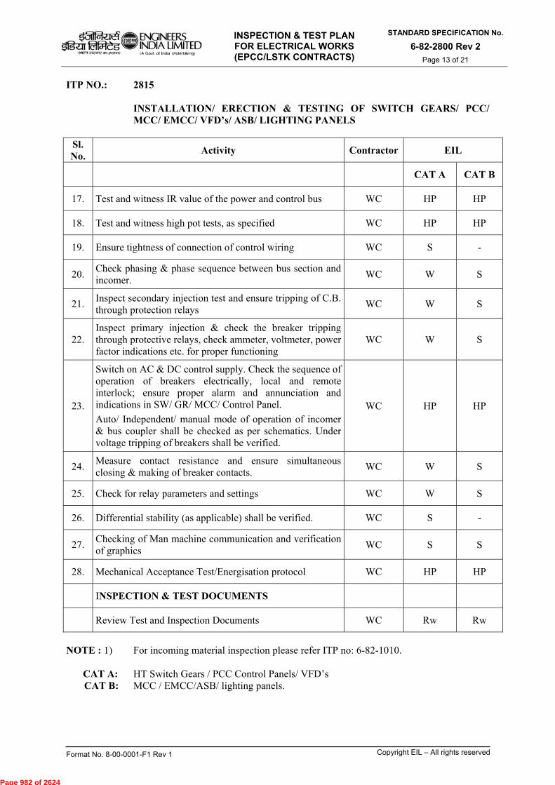
INSPECTION & TEST PLAN FOR ELECTRICAL WORKS (EPCC/LSTK CONTRACTS)
STANDARD SPECIFICATION No.
6-82-2800 Rev 2 Page 13 of 21
Format No. 8-00-0001-F1 Rev 1 Copyright EIL – All rights reserved
ITP NO.: 2815
INSTALLATION/ ERECTION & TESTING OF SWITCH GEARS/ PCC/ MCC/ EMCC/ VFD’s/ ASB/ LIGHTING PANELS
Sl. No.
Activity Contractor EIL
CAT A CAT B
17. Test and witness IR value of the power and control bus WC HP HP
18. Test and witness high pot tests, as specified WC HP HP
19. Ensure tightness of connection of control wiring WC S -
20. Check phasing & phase sequence between bus section and incomer.
WC W S
21. Inspect secondary injection test and ensure tripping of C.B. through protection relays
WC W S
22. Inspect primary injection & check the breaker tripping through protective relays, check ammeter, voltmeter, power factor indications etc. for proper functioning
WC W S
23.
Switch on AC & DC control supply. Check the sequence of operation of breakers electrically, local and remote interlock; ensure proper alarm and annunciation and indications in SW/ GR/ MCC/ Control Panel.
Auto/ Independent/ manual mode of operation of incomer & bus coupler shall be checked as per schematics. Under voltage tripping of breakers shall be verified.
WC HP HP
24. Measure contact resistance and ensure simultaneous closing & making of breaker contacts.
WC W S
25. Check for relay parameters and settings WC W S
26. Differential stability (as applicable) shall be verified. WC S -
27. Checking of Man machine communication and verification of graphics
WC S S
28. Mechanical Acceptance Test/Energisation protocol WC HP HP
INSPECTION & TEST DOCUMENTS
Review Test and Inspection Documents WC Rw Rw
NOTE : 1) For incoming material inspection please refer ITP no: 6-82-1010.
CAT A: HT Switch Gears / PCC Control Panels/ VFD’s CAT B: MCC / EMCC/ASB/ lighting panels.
Page 982 of 2624
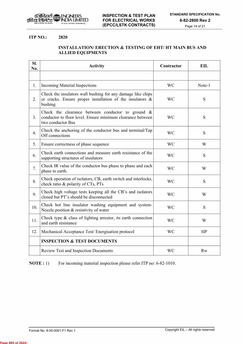
INSPECTION & TEST PLAN FOR ELECTRICAL WORKS (EPCC/LSTK CONTRACTS)
STANDARD SPECIFICATION No.
6-82-2800 Rev 2 Page 14 of 21
Format No. 8-00-0001-F1 Rev 1 Copyright EIL – All rights reserved
ITP NO.: 2820
INSTALLATION/ ERECTION & TESTING OF EHT/ HT MAIN BUS AND ALLIED EQUIPMENTS
Sl. No.
Activity Contractor EIL
1. Incoming Material Inspections WC Note-1
2. Check the insulators wall bushing for any damage like chips or cracks. Ensure proper installation of the insulators & bushing
WC S
3. Check the clearance between conductor to ground & conductor to floor level. Ensure minimum clearance between two conductor Bus
WC S
4. Check the anchoring of the conductor bus and terminal/Tap Off connections
WC S
5. Ensure correctness of phase sequence WC W
6. Check earth connections and measure earth resistance of the supporting structures of insulators
WC S
7. Check IR value of the conductor bus phase to phase and each phase to earth.
WC W
8. Check operation of isolators, CB, earth switch and interlocks, check ratio & polarity of CTs, PTs
WC S
9. Check high voltage tests keeping all the CB’s and isolators closed but PT’s should be disconnected
WC W
10. Check hot line insulator washing equipment and system- Nozzle position & resistivity of water
WC S
11. Check type & class of lighting arrestor, its earth connection and earth resistance
WC W
12. Mechanical Acceptance Test/ Energisation protocol WC HP
INSPECTION & TEST DOCUMENTS
Review Test and Inspection Documents WC Rw
NOTE : 1) For incoming material inspection please refer ITP no: 6-82-1010.
Page 983 of 2624

INSPECTION & TEST PLAN FOR ELECTRICAL WORKS (EPCC/LSTK CONTRACTS)
STANDARD SPECIFICATION No.
6-82-2800 Rev 2 Page 15 of 21
Format No. 8-00-0001-F1 Rev 1 Copyright EIL – All rights reserved
ITP NO.: 2825
CABLE LAYING
Sl. No.
Activity Contractor EIL
CAT B CAT C
1. Incoming material Inspection WC Note-1 Note-1
2. Survey the cable route as per AFC drawings, identify any possible obstruction like road/pipe rack crossing, heat sources etc. and finalize the cable route
WC S S
3. Complete all road/pipe crossings etc. as per drawing/requirement
WC S S
4. Prepare cable drum schedule to avoid wastage and minimize cable joints
WC Rw Rw
5. Ensure entire route is available for cable trench WC S S
6. Ensure availability of cables of required size and length WC S S
7. Verify the dimensions of buried trench as per AFC drawings (in case of buried cables)
WC S S
8. Ensure readiness of cable trays and installation of GI pipes (for cable protection) wherever required
WC S S
9. Ensure the initial bed of sand is provided as per standard and of required thickness
WC S S
10. Lay cables as per the cable schedule, minimizing criss-crossing of cables within the trench (1st layer). Check IR Values in drum before laying.
WC S S
11. Provide cable tags at specified locations WC Rw Rw
12. Record IR value of cables of first layer after sand filling WC W S
13. Provide second layer of sand, and ensure proper clearance between HT/LT cables (wherever applicable)
WC S --
14. Complete layer wise laying of cables and sand filling WC S --
15. Record IR value of cables of each layer after sand filling WC S --
16. Provide final layer of sand WC S --
17. Ensure cable trenches in hazardous areas are filled with sand
WC S --
Page 984 of 2624

INSPECTION & TEST PLAN FOR ELECTRICAL WORKS (EPCC/LSTK CONTRACTS)
STANDARD SPECIFICATION No.
6-82-2800 Rev 2 Page 16 of 21
Format No. 8-00-0001-F1 Rev 1 Copyright EIL – All rights reserved
ITP NO.: 2825 CABLE LAYING
NOTE : 1) For incoming material inspection please refer ITP no: 6-82-1010. CAT B : All HT/HV cable works. CAT C : All LT/MV cable works and control cable laying works.
Sl. No.
Activity Contractor EIL
CAT B CAT C
18. Provide bricks/slabs for cable protection in buried trenches WC S --
19. Back fill the trenches with earth and compact properly after ensuring the completion of earthing works, if any as per earthing layout drawings.
WC S --
20. Install cover slabs and seal the trenches in plant/offsite areas after ensuring the completion of earthing works, if any.
WC S --
21. Remove surplus earth generated as per provisions in the contract.
WC S --
22. Hi pot test of cables as required.(as applicable) WC W W
23. Provide cable markers as per the specifications at identified locations
WC Rw Rw
INSPECTION & TEST DOCUMENTS
Review Test and Inspection Documents WC Rw Rw
Page 985 of 2624
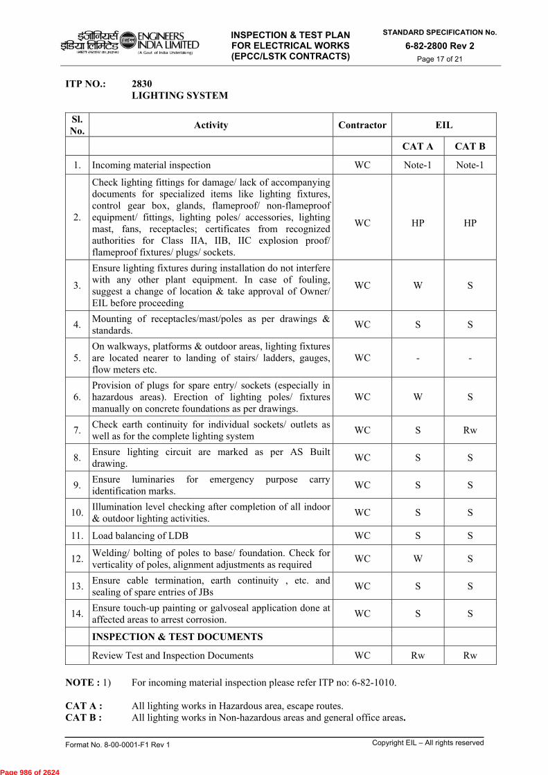
INSPECTION & TEST PLAN FOR ELECTRICAL WORKS (EPCC/LSTK CONTRACTS)
STANDARD SPECIFICATION No.
6-82-2800 Rev 2 Page 17 of 21
Format No. 8-00-0001-F1 Rev 1 Copyright EIL – All rights reserved
ITP NO.: 2830 LIGHTING SYSTEM
Sl. No.
Activity Contractor EIL
CAT A CAT B
1. Incoming material inspection WC Note-1 Note-1
2.
Check lighting fittings for damage/ lack of accompanying documents for specialized items like lighting fixtures, control gear box, glands, flameproof/ non-flameproof equipment/ fittings, lighting poles/ accessories, lighting mast, fans, receptacles; certificates from recognized authorities for Class IIA, IIB, IIC explosion proof/ flameproof fixtures/ plugs/ sockets.
WC
HP
HP
3.
Ensure lighting fixtures during installation do not interfere with any other plant equipment. In case of fouling, suggest a change of location & take approval of Owner/ EIL before proceeding
WC W S
4. Mounting of receptacles/mast/poles as per drawings & standards.
WC S S
5. On walkways, platforms & outdoor areas, lighting fixtures are located nearer to landing of stairs/ ladders, gauges, flow meters etc.
WC - -
6. Provision of plugs for spare entry/ sockets (especially in hazardous areas). Erection of lighting poles/ fixtures manually on concrete foundations as per drawings.
WC W S
7. Check earth continuity for individual sockets/ outlets as well as for the complete lighting system
WC S Rw
8. Ensure lighting circuit are marked as per AS Built drawing.
WC S S
9. Ensure luminaries for emergency purpose carry identification marks.
WC S S
10. Illumination level checking after completion of all indoor & outdoor lighting activities.
WC S S
11. Load balancing of LDB WC S S
12. Welding/ bolting of poles to base/ foundation. Check for verticality of poles, alignment adjustments as required
WC W S
13. Ensure cable termination, earth continuity , etc. and sealing of spare entries of JBs
WC S S
14. Ensure touch-up painting or galvoseal application done at affected areas to arrest corrosion.
WC S S
INSPECTION & TEST DOCUMENTS
Review Test and Inspection Documents WC Rw Rw
NOTE : 1) For incoming material inspection please refer ITP no: 6-82-1010. CAT A : All lighting works in Hazardous area, escape routes. CAT B : All lighting works in Non-hazardous areas and general office areas.
Page 986 of 2624
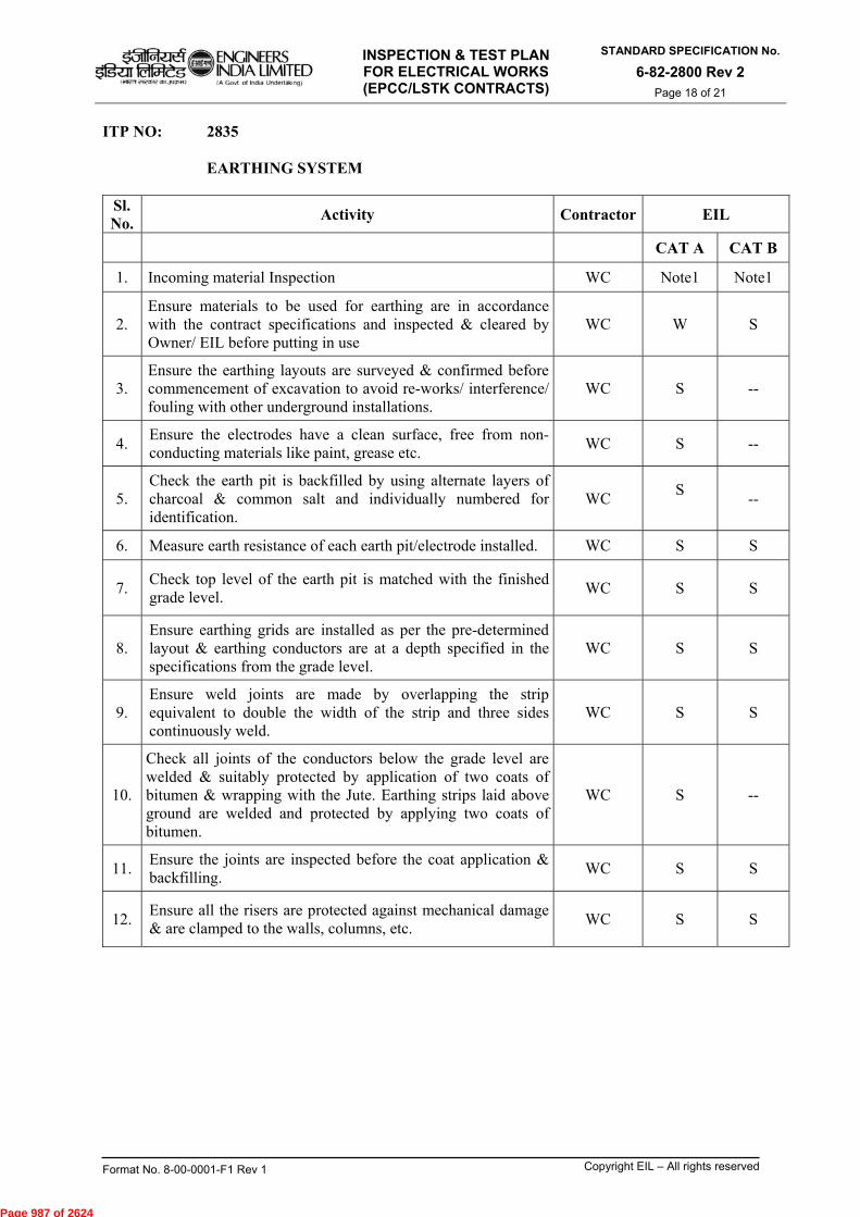
INSPECTION & TEST PLAN FOR ELECTRICAL WORKS (EPCC/LSTK CONTRACTS)
STANDARD SPECIFICATION No.
6-82-2800 Rev 2 Page 18 of 21
Format No. 8-00-0001-F1 Rev 1 Copyright EIL – All rights reserved
ITP NO: 2835
EARTHING SYSTEM
Sl. No.
Activity Contractor EIL
CAT A CAT B
1. Incoming material Inspection WC Note1 Note1
2. Ensure materials to be used for earthing are in accordance with the contract specifications and inspected & cleared by Owner/ EIL before putting in use
WC W S
3. Ensure the earthing layouts are surveyed & confirmed before commencement of excavation to avoid re-works/ interference/ fouling with other underground installations.
WC S --
4. Ensure the electrodes have a clean surface, free from non-conducting materials like paint, grease etc.
WC S --
5. Check the earth pit is backfilled by using alternate layers of charcoal & common salt and individually numbered for identification.
WC S
--
6. Measure earth resistance of each earth pit/electrode installed. WC S S
7. Check top level of the earth pit is matched with the finished grade level.
WC S
S
8. Ensure earthing grids are installed as per the pre-determined layout & earthing conductors are at a depth specified in the specifications from the grade level.
WC S S
9. Ensure weld joints are made by overlapping the strip equivalent to double the width of the strip and three sides continuously weld.
WC S
S
10.
Check all joints of the conductors below the grade level are welded & suitably protected by application of two coats of bitumen & wrapping with the Jute. Earthing strips laid above ground are welded and protected by applying two coats of bitumen.
WC S --
11. Ensure the joints are inspected before the coat application & backfilling.
WC S S
12. Ensure all the risers are protected against mechanical damage & are clamped to the walls, columns, etc.
WC S
S
Page 987 of 2624
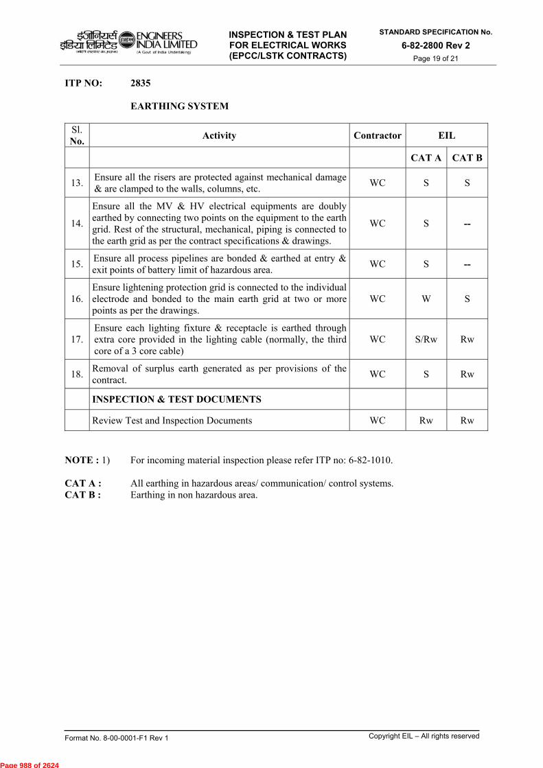
INSPECTION & TEST PLAN FOR ELECTRICAL WORKS (EPCC/LSTK CONTRACTS)
STANDARD SPECIFICATION No.
6-82-2800 Rev 2 Page 19 of 21
Format No. 8-00-0001-F1 Rev 1 Copyright EIL – All rights reserved
ITP NO: 2835
EARTHING SYSTEM
Sl. No.
Activity Contractor EIL
CAT A CAT B
13. Ensure all the risers are protected against mechanical damage & are clamped to the walls, columns, etc.
WC S S
14.
Ensure all the MV & HV electrical equipments are doubly earthed by connecting two points on the equipment to the earth grid. Rest of the structural, mechanical, piping is connected to the earth grid as per the contract specifications & drawings.
WC S --
15. Ensure all process pipelines are bonded & earthed at entry & exit points of battery limit of hazardous area.
WC S --
16. Ensure lightening protection grid is connected to the individual electrode and bonded to the main earth grid at two or more points as per the drawings.
WC W S
17. Ensure each lighting fixture & receptacle is earthed through extra core provided in the lighting cable (normally, the third core of a 3 core cable)
WC S/Rw Rw
18. Removal of surplus earth generated as per provisions of the contract.
WC S Rw
INSPECTION & TEST DOCUMENTS
Review Test and Inspection Documents WC Rw Rw
NOTE : 1) For incoming material inspection please refer ITP no: 6-82-1010. CAT A : All earthing in hazardous areas/ communication/ control systems. CAT B : Earthing in non hazardous area.
Page 988 of 2624

INSPECTION & TEST PLAN FOR ELECTRICAL WORKS (EPCC/LSTK CONTRACTS)
STANDARD SPECIFICATION No.
6-82-2800 Rev 2 Page 20 of 21
Format No. 8-00-0001-F1 Rev 1 Copyright EIL – All rights reserved
ITP NO.: 2840 INSTALLATION OF BUS DUCT Sl. No.
Activity Contractor EIL
1. Incoming Material inspection at site WC Note 1
2. Ensure that the switch board terminal box & the transformer terminal boxes are inspected & cleared before proceeding to the bus duct installation.
WC S
3. Check the equipment no. and rating as per drawings, no physical damage, etc.
WC S
4. Check availability of all accessories WC S
5. Inspect the bus duct insulators for any physical damage occurred during the transit.
WC S
6. Check bushing cracks, chips or presence of paint or dirt. Bushing cleaned as per vendor’s instruction.
S
7. Ensure various sections of the bus duct enclosures are coupled together by using proper gaskets & bellows as specified.
WC S
8. Ensure the bus bars are properly fixed & coupled on the insulator and correct phases are connected at both ends.
WC W
9. Ensure bus bar bolts are tightened to the required torque values) using calibrated torque wrench.
WC S
10. Ensure bus bar joints are insulated using manufacturers recommended materials, wherever required.
WC --
11. Prior to closing of the bus duct cover, ensure that the bus duct enclosures are cleared of tools/ loose materials and debris.
WC W
12. Ensure enclosure of bus duct & support structures earthed (to the earthing grid) as per drawing.
WC S
13. Check touch up painting wherever required on completion of installation.
S
14. Ensure wall sealing is done & sun shields provided as per drawings.
WC S
15. Ensure bus bar joints are cleaned/ polished & not oxidised before bolt-up connection.
WC W
16. Ensure provisions of breathers/silica gel WC S
17. Ensure provision of heaters and recording of its IR value WC S
INSPECTION & TEST DOCUMENTS
Review Test and Inspection Documents WC Rw
NOTE : 1) For incoming material inspection please refer ITP no: 6-82-1010.
Page 989 of 2624
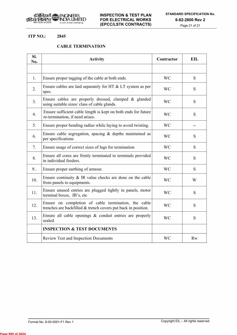
INSPECTION & TEST PLAN FOR ELECTRICAL WORKS (EPCC/LSTK CONTRACTS)
STANDARD SPECIFICATION No.
6-82-2800 Rev 2 Page 21 of 21
Format No. 8-00-0001-F1 Rev 1 Copyright EIL – All rights reserved
ITP NO.: 2845 CABLE TERMINATION
Sl. No.
Activity Contractor EIL
1. Ensure proper tagging of the cable at both ends. WC S
2. Ensure cables are laid separately for HT & LT system as per spec.
WC S
3. Ensure cables are properly dressed, clamped & glanded using suitable sizes/ class of cable glands.
WC S
4. Ensure sufficient cable length is kept on both ends for future re-termination, if need arises.
WC S
5. Ensure proper bending radius while laying to avoid twisting. WC --
6. Ensure cable segregation, spacing & depths maintained as per specifications
WC S
7. Ensure usage of correct sizes of lugs for termination WC S
8. Ensure all cores are firmly terminated to terminals provided in individual feeders.
WC S
9.. Ensure proper earthing of armour. WC S
10. Ensure continuity & IR value checks are done on the cable from panels to equipments.
WC W
11. Ensure unused entries are plugged tightly in panels, motor terminal boxes, JB’s, etc
WC S
12. Ensure on completion of cable termination, the cable trenches are backfilled & trench covers put back in position.
WC S
13. Ensure all cable openings & conduit entries are properly sealed.
WC S
INSPECTION & TEST DOCUMENTS
Review Test and Inspection Documents WC Rw
Page 990 of 2624

INSPECTION & TEST PLAN FOR STANDARD SPECIFICATION No.
ENGINEERS INCOMING MATERIAL 6-82-1010 Rev.1 51ga faf5t-egAW INDIA LIMITED CHECKING FOR CONTRACTOR'S
SUPPLIED MATERIALS
ctl4it vi-wrrt Trt !JIM -1=v 1i1,.n wfq- ac
1W-41-49-17r traffur ei1.71--11 (3Trittifb
INSPECTION & TEST PLAN (ITP) FOR INCOMING MATERIAL
CHECKING FOR CONTRACTOR'S SUPPLIED MATERIALS
C\P ? vik-V° ,ANO
1 14.10.2015 REVISED AND REISSUED MKG TKS SC
0 04.07.2011 ISSUED FOR IMPLEMENTATION SM SM MKG DM
Rev. No Date Purpose
Prepared by
Checked by
Standards Committee Convenor
Standards Bureau
Chairman
Approved by
Format No. 8-00-0001-F1 Rev. 0 Copyright EIL — All rights reserved
Hawn errant' troJOitiotit (A Govt of India Undertalong) Page 1 of 8
Page 991 of 2624

$1gmil
02ft ormre tnI,T40.1)
ENGINEERS INDIA LIMITED (A Govt of India Undertaking)
INSPECTION & TEST PLAN FOR INCOMING MATERIAL
CHECKING FOR CONTRACTOR'S SUPPLIED MATERIALS
STANDARD SPECIFICATION No.
6-82-1010 Rev.1
Page 2 of 8
Abbreviations:
ATT : . Anti Termite Treatment CGI •
. Corrugated Galvanized Iron CS•
. Carbon Steel EOT •
. Electric Operated Traction FLM •
. Flood Light Mast HOT •
. Heat Operated Traction HT •
. High Tension HV •
. High voltage IMIR •
. Incoming Material Inspection Report. IRN •
. Inspection Release Note ITP •
. Inspection Test Plan
KW : . Kilo Watt LR •
. Lorry Receipt LT Low Tension LV Low Voltage LEL Low Explosive Detectors
MOC : Material of Construction
MTC : Manufacture Test Certificate
NACE : National Association of Corrosion Engineers
PLC : Programmable Logic Control
PRDS : Pressure Reducing and De-superheating Stations
QAP : Quality Assurance Plan
RCC : Reinforced Cement Concrete SS : Stainless Steel TC : Test Certificate
TPIA : Third Party Inspection Agency
Construction Standards Committee
Convenor: Sh. T.K. Sen, GM (I/C) (Construction)
Members: Sh. S N Bhatnagar, GM (Construction) Sh. MK Garg, GM (Construction) Sh. Janak Kishore, DGM (Projects) Sh. Rajeev Jain, DGM, (C&P) Sh. Udayan Chakravarty, AGM (Piping) Sh. Ravindra Kumar, AGM (Construction) Sh. D Jana, AGM (Construction)
Format No. 8-00-0001-F1 Rev. 0
Copyright EIL — All rights reserved
Page 992 of 2624

ei 51?-a faileg
clecnre I JJor1.1,
ENGINEERS INDIA LIMITED IA Govt of India Undertaking)
INSPECTION & TEST PLAN FOR INCOMING MATERIAL
CHECKING FOR CONTRACTOR'S SUPPLIED MATERIALS
STANDARD SPECIFICATION No.
6-82-1010 Rev.1
Page 3 of 8
CONTENTS
S.NO. DESCRIPTION PAGE NO.
1. General Note & Legend
04
2. Inspection & Test Plan
05
Format for Incoming Material Inspection Report
08
Format No. 8-00-0001-F1 Rev. 0
Copyright EIL — All rights reserved
Page 993 of 2624

ei ENGINEERS Ifgar 251eg J INDIA LIMITED
(A Govt of India Undeflakeng)
INSPECTION & TEST PLAN FOR INCOMING MATERIAL
CHECKING FOR CONTRACTOR'S SUPPLIED MATERIALS
STANDARD SPECIFICATION No.
6-82-1010 Rev.1 Page 4 of 8
I>irerf cArcmeall..Aat.)
GENERAL NOTE
1. The enclosed ITP is indicative and shall be followed for developing the job specific 1TP for checking of incoming material supplied by contractor. The provisions indicated for stage wise inspection by EIL/ Owner are the minimum and the Engineer-In-Charge may decide to increase Hold Points/ Witness Points. Activities not included in the ITP shall be included by the contractor in job specific ITP and the same to be approved by EIL/Owner before start of the work.
2. Contractor to prepare job specific reporting format with the aid of enclosed sample reporting format and job procedure for inspection coverage as per the ITP. Same shall be submitted to EIL/Owner for approval, before commencement of the job. If the contractor has to deviate from the given ITP for a valid reason, he shall obtain prior written approval of EIL/Owner. Contractor to carry out 100% examination of all activities.
LEGEND
HP : Hold Point
A point which requires inspection/verification and acceptance by Owner/EIL before any further processing is permitted. The Contractor shall not process the activity/item beyond a Hold Point without written approval by Owner/EIL except where prior written permission for further processing is available.
W Witness Point
An activity which requires witnessing by Owner/EIL when the activity is performed. After proper notification has been provided (notification modalities and period shall be finalized before hand), the Contractor is not obliged to hold further processing if Owner/EIL is not available to witness the activity or does not provide comments before the date notified. In such cases basis of acceptance shall be review of Contractor generated report/document as per relevant technical specification.
Rw Review of Contractor's documentation.
S Surveillance Inspection by Owner/ EIL.
Monitoring or making observations to verify whether or not material/items or services conform to specified requirements. Surveillance activities may include audit, inspections, witness of testing, review of quality documentation & records, personnel qualifications, etc.
WC : 100% Supervision and Examination by Contractor.
Responsibility for execution of the inspection/testing is with the Contractor; Owner/EIL only verifies examination or testing done by the Contractor at important stages.
Format No. 8-00-0001-F1 Rev. 0
Copyright EIL — All rights reserved
Page 994 of 2624
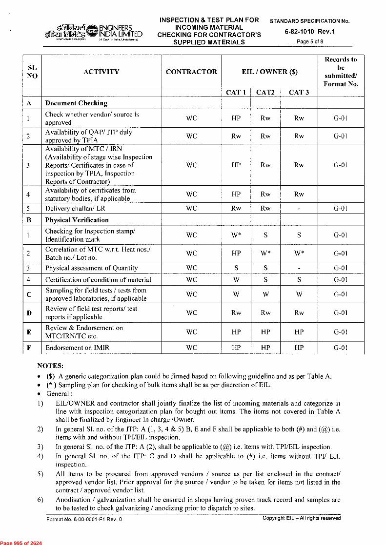
5/1gZIT Of5ieg .71W71 ciecrne a3441,11f
ENGINEERS INDIA LIMITED (A Govt of India Undettaking)
INSPECTION & TEST PLAN FOR INCOMING MATERIAL
CHECKING FOR CONTRACTOR'S SUPPLIED MATERIALS
STANDARD SPECIFICATION No.
6-82-1010 Rev.1
Page 5 of 8
SL NO
ACTIVITY CONTRACTOR EIL / OWNER ($)
Records to be
submitted/ Format No.
CAT 1 CAT2 CAT 3
A Document Checking
1 Check whether vendor/ source is approved
WC HP Rw Rw G-01
2 Availability of QAP/ ITP duly approved by TPIA
WC Rw Rw Rw G-01
3
Availability of MTC / IRN (Availability of stage wise Inspection Reports/ Certificates in case of inspection by TPIA, Inspection Reports of Contractor)
WC HP Rw Rw G-01
4 Availability of certificates from statutory bodies, if applicable
WC HP Rw Rw
5 Delivery challan/ LR WC Rw Rw - G-01
B Physical Verification
1 Checking for Inspection stamp/ Identification mark
WC W* S S G-01
2 Correlation of MTC w.r.t. Heat nos./ Batch no./ Lot no.
WC HP W* W* G-01
3 Physical assessment of Quantity WC S S - G-01
4 Certification of condition of material WC W S S G-01
C Sampling for field tests / tests from approved laboratories, if applicable
WC W W W G-01
D Review of field test reports/ test reports if applicable
WC Rw Rw Rw G-01
E Review & Endorsement on MTC/IRN/TC etc.
WC HP HP HP G-01
F Endorsement on IMIR WC HP HP HP G-01
NOTES:
• ($) A generic categorization plan could be firmed based on following guideline and as per Table A. • (* ) Sampling plan for checking of bulk items shall be as per discretion of EIL. • General : 1) EIL/OWNER and contractor shall jointly finalize the list of incoming materials and categorize in
line with inspection categorization plan for bought out items. The items not covered in Table A shall be finalized by Engineer In charge /Owner.
2) In general SI. no. of the ITP: A (1, 3, 4 & 5) B, E and F shall be applicable to both (#) and (@) i.e. items with and without TPI/EIL inspection.
3) In general Sl. no. of the ITP: A (2), shall be applicable to (@) i.e. items with TPI/EIL inspection. 4) In general Sl. no. of the ITP: C and D shall be applicable to (#) i.e. items without TPI/ EIL
inspection. 5) All items to be procured from approved vendors / source as per list enclosed in the contract/
approved vendor list. Prior approval for the source / vendor to be taken for items not listed in the contract / approved vendor list.
6) Anodisation / galvanization shall be ensured in shops having proven track record and samples are to be tested to check galvanizing / anodizing prior to dispatch to sites.
Format No. 8-00-0001-F1 Rev. 0
Copyright EIL — All rights reserved
Page 995 of 2624
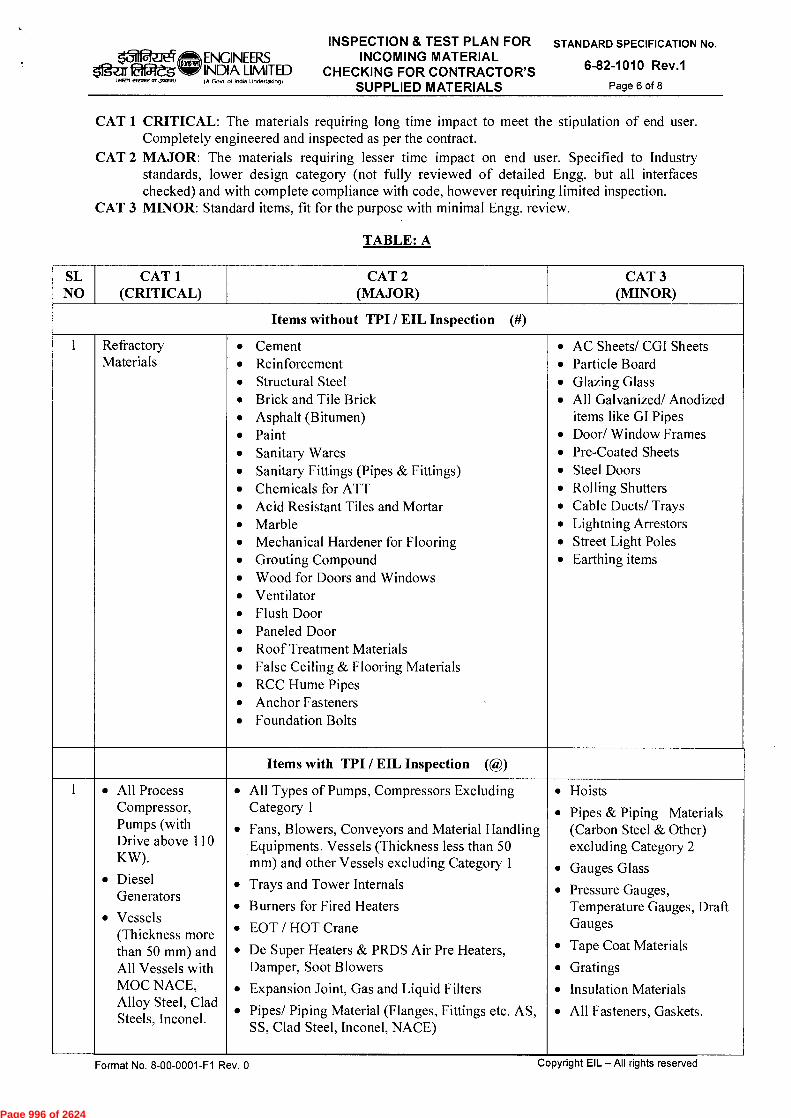
$1g-ar Eifgeg lairen rirme =Join.°
ENGINEERS INDIA LIMITED (A Gout of India Undeffalong)
INSPECTION & TEST PLAN FOR INCOMING MATERIAL
CHECKING FOR CONTRACTOR'S SUPPLIED MATERIALS
STANDARD SPECIFICATION No.
6-82-1010 Rev.1 Page 6 of 8
CAT 1 CRITICAL: The materials requiring long time impact to meet the stipulation of end user. Completely engineered and inspected as per the contract.
CAT 2 MAJOR: The materials requiring lesser time impact on end user. Specified to Industry standards, lower design category (not fully reviewed of detailed Engg. but all interfaces checked) and with complete compliance with code, however requiring limited inspection.
CAT 3 MINOR: Standard items, fit for the purpose with minimal Engg. review.
TABLE: A
SL NO
CAT 1 (CRITICAL)
CAT 2 (MAJOR)
CAT 3 (MINOR)
Items without TPI / EIL Inspection (#)
1 Refractory Materials
• Cement • Reinforcement • Structural Steel • Brick and Tile Brick • Asphalt (Bitumen) • Paint • Sanitary Wares • Sanitary Fittings (Pipes & Fittings) • Chemicals for ATT • Acid Resistant Tiles and Mortar • Marble • Mechanical Hardener for Flooring • Grouting Compound • Wood for Doors and Windows • Ventilator • Flush Door • Paneled Door • Roof Treatment Materials • False Ceiling & Flooring Materials • RCC Hume Pipes • Anchor Fasteners • Foundation Bolts
• AC Sheets/ CGI Sheets • Particle Board • Glazing Glass • All Galvanized/ Anodized
items like GI Pipes • Door/ Window Frames • Pre-Coated Sheets • Steel Doors • Rolling Shutters • Cable Ducts/ Trays • Lightning Arrestors • Street Light Poles • Earthing items
Items with TPI / EIL Inspection (@)
1 • All Process Compressor, Pumps (with Drive above 110 KW).
• Diesel Generators
• Vessels (Thickness more than 50 mm) and All Vessels with MOC NACE, Alloy Steel, Clad Steels, Inconel.
• All Types of Pumps, Compressors Excluding Category 1
• Fans, Blowers, Conveyors and Material Handling Equipments. Vessels (Thickness less than 50 mm) and other Vessels excluding Category 1
• Trays and Tower Internals
• Burners for Fired Heaters
• EOT / HOT Crane
• De Super Heaters & PRDS Air Pre Heaters, Damper, Soot Blowers
• Expansion Joint, Gas and Liquid Filters
• Pipes/ Piping Material (Flanges, Fittings etc. AS, SS, Clad Steel, Inconel, NACE)
• Hoists
• Pipes & Piping Materials (Carbon Steel & Other) excluding Category 2
• Gauges Glass
• Pressure Gauges, Temperature Gauges, Draft Gauges
• Tape Coat Materials
• Gratings
• Insulation Materials
• All Fasteners, Gaskets.
Format No. 8-00-0001-F1 Rev. 0
Copyright EIL — All rights reserved
Page 996 of 2624
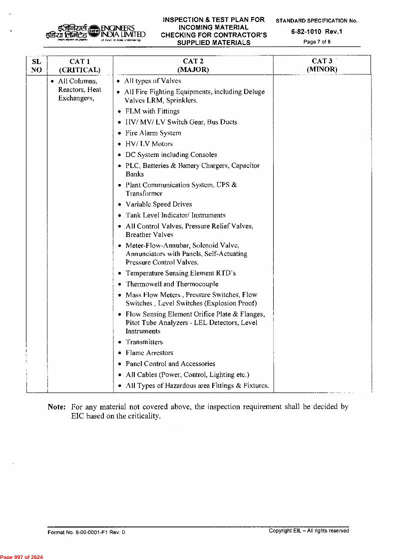
INSPECTION & TEST PLAN FOR ENGINEERS INCOMING MATERIAL
51g-ar lea& INDIA LIMITED CHECKING FOR CONTRACTOR'S SUPPLIED MATERIALS
STANDARD SPECIFICATION No.
6-82-1010 Rev.1
Page 7 of 8 I NWT acme =own,
( A Gov( of India Undeffalang)
SL NO
CAT 1 (CRITICAL)
CAT 2 (MAJOR)
CAT 3 (MINOR)
• All Columns, • All types of Valves Reactors, Heat • All Fire Fighting Equipments, including Deluge Exchangers, Valves LRM, Sprinklers.
• FLM with Fittings
• HV/ MV/ LV Switch Gear, Bus Ducts
• Fire Alarm System
• HV/ LV Motors
• DC System including Consoles
• PLC, Batteries & Battery Chargers, Capacitor Banks
• Plant Communication System, UPS & Transformer
• Variable Speed Drives
• Tank Level Indicator/ Instruments
• All Control Valves, Pressure Relief Valves, Breather Valves
• Meter-Flow-Annubar, Solenoid Valve, Annunciators with Panels, Self-Actuating Pressure Control Valves.
• Temperature Sensing Element RTD's
• Thermowell and Thermocouple
• Mass Flow Meters , Pressure Switches, Flow Switches , Level Switches (Explosion Proof)
• Flow Sensing Element Orifice Plate & Flanges, Pitot Tube Analyzers - LEL Detectors, Level Instruments
• Transmitters
• Flame Arrestors
• Panel Control and Accessories
• All Cables (Power, Control, Lighting etc.)
• All Types of Hazardous area Fittings & Fixtures.
Note: For any material not covered above, the inspection requirement shall be decided by EIC based on the criticality.
Format No. 8-00-0001-F1 Rev. 0
Copyright EIL — All rights reserved
Page 997 of 2624
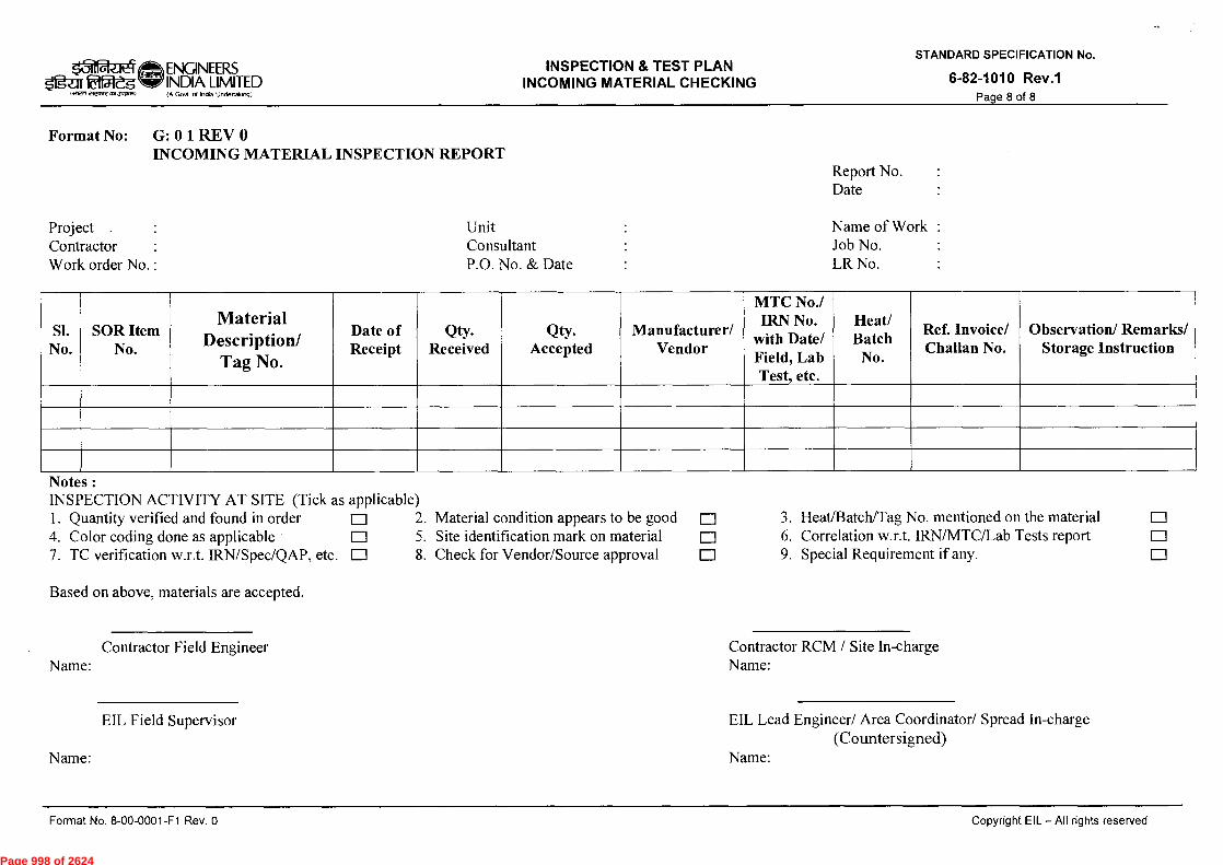
1.12, eiesmt 051.7CRIVA,
INSPECTION & TEST PLAN INCOMING MATERIAL CHECKING
ll~iei ENGINEERS tif5Veg INDIA LIMITED
(A Govt of India Unclettok ,N)
6-82-1010 Rev.1 Page 8 of 8
STANDARD SPECIFICATION No.
Format No: G: 0 1 REV 0 INCOMING MATERIAL INSPECTION REPORT
Report No. Date
Project
Unit
Name of Work : Contractor
Consultant
Job No. Work order No. :
P.O. No. & Date
LR No.
Sl. No.
SOR Item No.
Material Description/
Tag No.
Date of Receipt
Qty. Received
Qty. Accepted
Manufacturer/ Vendor
MTC No./ IRN No.
with Date/ Field, Lab Test, etc.
Heat/ Batch
No.
Ref. Invoice/ Challan No.
Observation/ Remarks/ Storage Instruction
Notes : INSPECTION ACTIVITY AT SITE (Tick as applicable) 1. Quantity verified and found in order 0 2. Material condition appears to be good p 3. Heat/Batch/Tag No. mentioned on the material 0 4. Color coding done as applicable D 5. Site identification mark on material 0 6. Correlation w.r.t. IRN/MTC/Lab Tests report 0 7. TC verification w.r.t. IRN/Spec/QAP, etc. 0 8. Check for Vendor/Source approval 0 9. Special Requirement if any. D
Based on above, materials are accepted.
Name: Contractor Field Engineer Contractor RCM / Site In-charge
Name:
EIL Field Supervisor
EIL Lead Engineer/ Area Coordinator/ Spread In-charge (Countersigned)
Name:
Name:
Format No. 8-00-0001-F1 Rev. 0
Copyright EIL — AR rights reserved
Page 998 of 2624

ATTACHMENT – II
Page 999 of 2624
STANDARD SPECIFICATION
e..10 ENGINEERS FOR POSITIVE MATERIAL
ig.elikueg INDIA LIMITED IDENTIFICATION AT
jVrmrz any (A Govt of InOta Undenalongl
CONSTRUCTION SITES
STANDARD SPECIFICATION No.
6-82-0002 Rev. 3
Page 1 of 9
f914131 TETe *ict) RI clicb 141-1:13t
LIV11.1 icrR fq-1-4-R-r
STANDARD SPECIFICATION FOR
POSITIVE MATERIAL IDENTIFICATION AT
CONSTRUCTION SITES
3 12/10/2015 Revised and updated TKS SC
2 14/11/2011 Revised and updated SM SM MKG DM
1 02/01/2007 Revised and updated AS MPJ VNP VC
0 22/07/2002 Issued as Standard Specification MPJ MPJ RSG GRR
Standards Standards
Rev. No Date Purpose
Prepared by
Checked by
Committee Convenor
Bureau Chairman
Approved by
Format No. 8-00-0001-F1 Rev. 0
Copyright EIL — All rights reserved
Page 1000 of 2624

STANDARD SPECIFICATION FOR POSITIVE MATERIAL
IDENTIFICATION AT CONSTRUCTION SITES
lif~ei ~c
Ogeir CSC W1 INDIA LIMITED
IA Govl of India Undertaking)
STANDARD SPECIFICATION No.
6-82-0002 Rev. 3 Page 2 of 9
Abbreviations:
API American Petroleum Institute
ASM American Society for Metals
ASME American Society of Mechanical Engineers
ASTM American Society for Testing and Materials
EIL Engineers India Limited
ITP Inspection Test Plan
PMI Positive Material Identification
RTJ Ring Type Joint
TPI/ TPIA Third Party Inspection / Third Party Inspection Agency
CS Carbon Steel
AS Alloy Steel
SS Stainless Steel
Construction Standards Committee
Convenor: Sh. T.K. Sen GM (I/C) (Construction)
Members: Sh. S N Bhatnagar, GM (Construction) Sh. MK Garg, GM (Construction) Sh. Janak Kishore , DGM (Projects) Sh. Rajeev Jain, DGM, (C&P) Sh. Udayan Chakravarty, AGM (Piping) Sh. Ravindra Kumar , AGM (Construction) Sh. D Jana, AGM (Construction)
Copyright EIL — All rights reserved Format No. 8-00-0001-F1 Rev. 0
Page 1001 of 2624
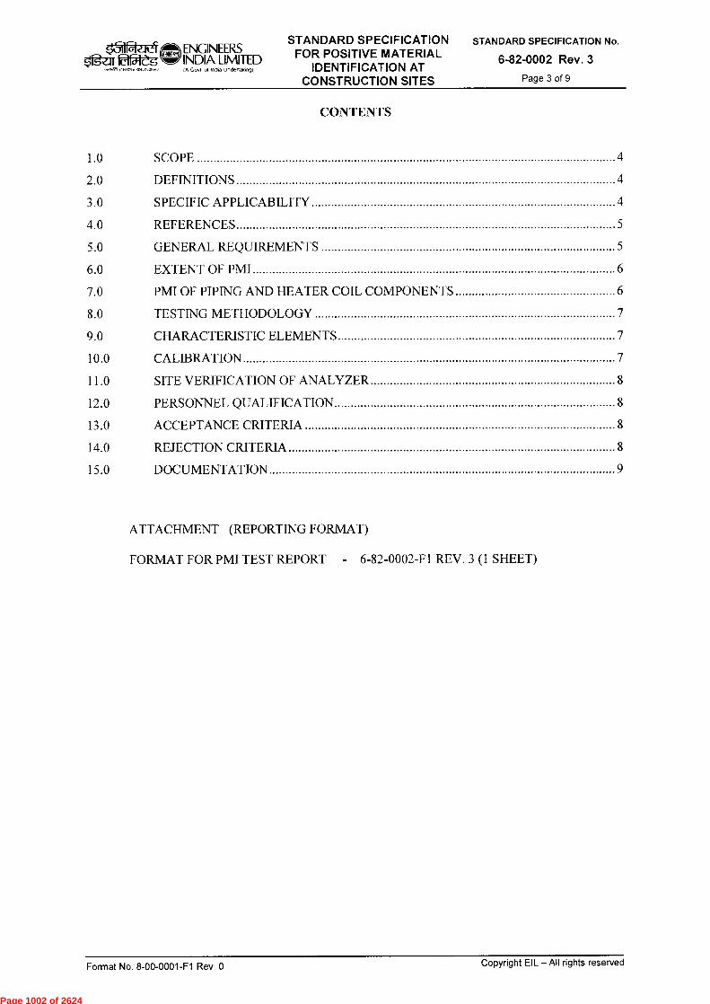
zl ENGINEERS INDIA LIMITED (A Govt of India Undertaking)
STANDARD SPECIFICATION FOR POSITIVE MATERIAL
IDENTIFICATION AT CONSTRUCTION SITES
STANDARD SPECIFICATION No.
6-82-0002 Rev. 3
Page 3 of 9 • eircAle „No,"
CONTENTS
1.0 SCOPE 4
2.0 DEFINITIONS 4
3.0 SPECIFIC APPLICABILITY 4
4.0 REFERENCES 5
5.0 GENERAL REQUIREMENTS 5
6.0 EXTENT OF PMI 6
7.0 PMI OF PIPING AND HEATER COIL COMPONENTS 6
8.0 TESTING METHODOLOGY 7
9.0 CHARACTERISTIC ELEMENTS 7
10.0 CALIBRATION 7
11.0 SITE VERIFICATION OF ANALYZER 8
12.0 PERSONNEL QUALIFICATION 8
13.0 ACCEPTANCE CRITERIA 8
14.0 REJECTION CRITERIA 8
15.0 DOCUMENTATION 9
ATTACHMENT (REPORTING FORMAT)
FORMAT FOR PMI TEST REPORT - 6-82-0002-F1 REV. 3 (1 SHEET)
Format No. 8-00-0001-F1 Rev. 0 Copyright EIL — All rights reserved
Page 1002 of 2624
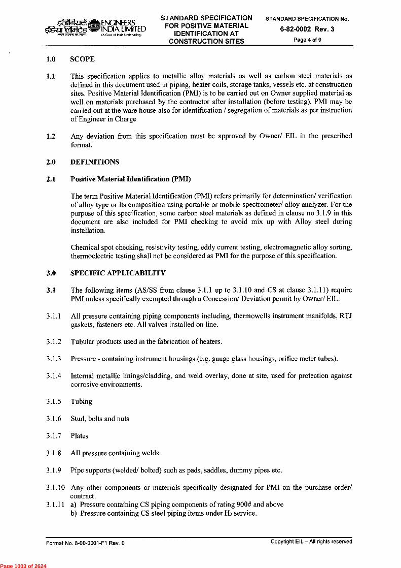
k3i Ogea tlfReg
IItqf 292,11,77 dAJATI.:1( (A GoA of India Undertakong)
ENGINEERS INDIA LIMITED
STANDARD SPECIFICATION FOR POSITIVE MATERIAL
IDENTIFICATION AT CONSTRUCTION SITES
STANDARD SPECIFICATION No.
6-82-0002 Rev. 3
Page 4 of 9
1.0 SCOPE
1.1
This specification applies to metallic alloy materials as well as carbon steel materials as defined in this document used in piping, heater coils, storage tanks, vessels etc. at construction sites. Positive Material Identification (PMI) is to be carried out on Owner supplied material as well on materials purchased by the contractor after installation (before testing). PMI may be carried out at the ware house also for identification / segregation of materials as per instruction of Engineer in Charge
1.2 Any deviation from this specification must be approved by Owner/ Ell, in the prescribed format.
2.0 DEFINITIONS
2.1 Positive Material Identification (PMI)
The term Positive Material Identification (PMI) refers primarily for determination/ verification of alloy type or its composition using portable or mobile spectrometer/ alloy analyzer. For the purpose of this specification, some carbon steel materials as defined in clause no 3.1.9 in this document are also included for PMI checking to avoid mix up with Alloy steel during installation.
Chemical spot checking, resistivity testing, eddy current testing, electromagnetic alloy sorting, thermoelectric testing shall not be considered as PMI for the purpose of this specification.
3.0 SPECIFIC APPLICABILITY
3.1 The following items (AS/SS from clause 3.1.1 up to 3.1.10 and CS at clause 3.1.11) require PMI unless specifically exempted through a Concession/ Deviation permit by Owner/ EIL.
3.1.1 All pressure containing piping components including, thermowells instrument manifolds, RTJ gaskets, fasteners etc. All valves installed on line.
3.1.2 Tubular products used in the fabrication of heaters.
3.1.3 Pressure - containing instrument housings (e.g. gauge glass housings, orifice meter tubes).
3.1.4 Internal metallic linings/cladding, and weld overlay, done at site, used for protection against corrosive environments.
3.1.5 Tubing
3.1.6 Stud, bolts and nuts
3.1.7 Plates
3.1.8 All pressure containing welds.
3.1.9 Pipe supports (welded/ bolted) such as pads, saddles, dummy pipes etc.
3.1.10 Any other components or materials specifically designated for PMI on the purchase order/ contract.
3.1.11 a) Pressure containing CS piping components of rating 900# and above b) Pressure containing CS steel piping items under 1-12 service.
Format No. 8-00-0001-F1 Rev. 0
Copyright EIL — All rights reserved
Page 1003 of 2624
Ogar f6151-eg I airen elecnye ea dr-rcre)
ENGINEERS INDIA LIMITED (A Goer or Ind. Undertaking)
STANDARD SPECIFICATION FOR POSITIVE MATERIAL
IDENTIFICATION AT CONSTRUCTION SITES
STANDARD SPECIFICATION No.
6-82-0002 Rev. 3
Page 5 of 9
c) Pressure Containing CS Piping where substitution of hardenable alloy materials in carbon steel piping systems may result to failure and loss of containment in process services like wet hydrogen sulfide (H2S), hydrofluoric acid (HF), sulfuric acid (H2SO4) services etc.
3.2 Exclusions
The following items are exempted unless specifically designated for PMI in the purchase order/contract:
3.2.1 Gaskets (spiral wound or carbon steel only).
3.2.2 Internal instrument parts.
3.2.3 Internal machinery parts.
3.2.4 Internal non pressure - containing baffles, trays, tray clips, supports, pall-rings, support rings, etc.
3.2.5 Electrical components.
3.2.6 Internal valve components.
3.2.7 Compression-type ferrules and fittings for use with 3/4 inch (19mm) outside diameter and smaller tubing.
3.2.8 All carbon steel piping components (including carbon steel pipe supports) other than those specified at 3.1.11.
3.2.9 All carbon steel Studs/ bolts/ nuts.
3.2.10 Carbon Steel Plates.
4.0 REFERENCES
American Society of Mechanical Engineers (ASME) BPV Code Section-II Part A, B and C.
ASME B 31.3
American Society for Testing and Materials (ASTM): As applicable
Material Verification Program for New and Existing Alloy Piping Systems: API RP 578
Any other material specification referenced by the Purchase Order/Contract.
IS 1239, IS 3589 and other relevant BIS codes.
5.0 GENERAL REQUIREMENTS
5.1 The test methods outlined in this specification are intended to identify the nominal composition of alloy/ Stainless steel materials. These test methods are not intended to establish the conformance of a material to a particular specification.
5.2 PMI shall not be considered as a substitute for required mill test reports listing chemical composition. In addition, mill test reports shall not be considered as confirming alloy/ composition verification.
Format No. 8-00-0001-F1 Rev. 0 Copyright EIL — All rights reserved
Page 1004 of 2624

ei Ifgar felf5leg
471TA" 212.5r7 051.30051.1)
ENGINEERS INDIA LIMITED A Govt of India Undenakmg)
STANDARD SPECIFICATION FOR POSITIVE MATERIAL
IDENTIFICATION AT CONSTRUCTION SITES
STANDARD SPECIFICATION No.
6-82-0002 Rev. 3
Page 6 of 9
5.3 The PMI activity shall be included in the overall quality plan and Inspection & Test Plan for fabrication/ erection. The contractor shall submit to EIL/ Owner, a procedure for PMI to comply with the requirements of this specification. Approval of PMI procedure shall be obtained from Owner/ EIL prior to commencement of fabrication/ erection as the case may be.
5.4 Contractor shall engage reputed TPIA specified in the contract to witness inspection at site and accordingly submit ITP for review of owner/ ELL. In case list of approved TPIA is not available in contract, prior approval shall be taken before engagement of TPIA.
5.5 A copy of PMI records duly verified by TPIA shall be submitted to Owner/ EIL.
5.6 After installation, but prior to hydrostatic testing/ painting/ insulation, the contractor shall examine all components requiring PMI for proper compliance to this specification. A record of this final check duly endorsed by TPIA, as specified below, shall be submitted to EIL/ Owner and made part of the permanent inspection records.
5.6.1 Owner Supplied Material
Records signed by contractor and duly verified by TPIA (engaged by contractor)/ and reviewed by EIL/ Owner shall be generated as part of the receiving inspection at warehouse.
5.6.2 Contractor Supplied Material
Records signed by contractor and certified by an approved third party inspection agency.
5.7 After acceptance, all components shall be marked with a suitable and readily visible paint mark. These markings are in addition to markings / colour coding required by other codes/ specifications/ Technical Notes.
5.8 Controls shall be established to keep the non conforming items identified till proper resolution of non conformity.
5.9 ELL/ Owner shall have the right to witness the performance of any PMI test.
6.0 EXTENT OF PMI
PMI shall be done on each component (100 percent PMI inspection) including welds (Except carbon steel Piping welds), unless specifically exempted by Owner/ EIL.
PMI shall be done on pipe supports (welded/ bolted) such as pads, saddles, dummy pipes etc. (100 percent PMI inspection) in all piping systems of alloy material
PMI shall be done on all bolts and nuts (100 percent PMI inspection) of flange joints in all piping systems of alloy material.
7.0 PMI OF PIPING AND HEATER COIL COMPONENTS
PMI testing (irrespective of PMI done at earlier stages) shall be carried out when piping loops/ heater coils have been cleared for hydrostatic testing by EIL/ Owner. Hydrostatic Testing shall be carried out only when non conforming components have been replaced with conforming components and subsequent Non Destructive Testing, Post Weld Heat-Treatment, Hardness checking and re verification by PMI etc., as required by specifications have been completed. PMI records shall form a part of piping/ heater inspection records. Contractor shall demonstrate to EIL that each & every component of the piping system and heater coils has been subjected to PMI by providing line wise records of PMI duly endorsed by TPIA
Format No. 8-00-0001-F1 Rev. 0
Copyright EIL — All rights reserved
Page 1005 of 2624
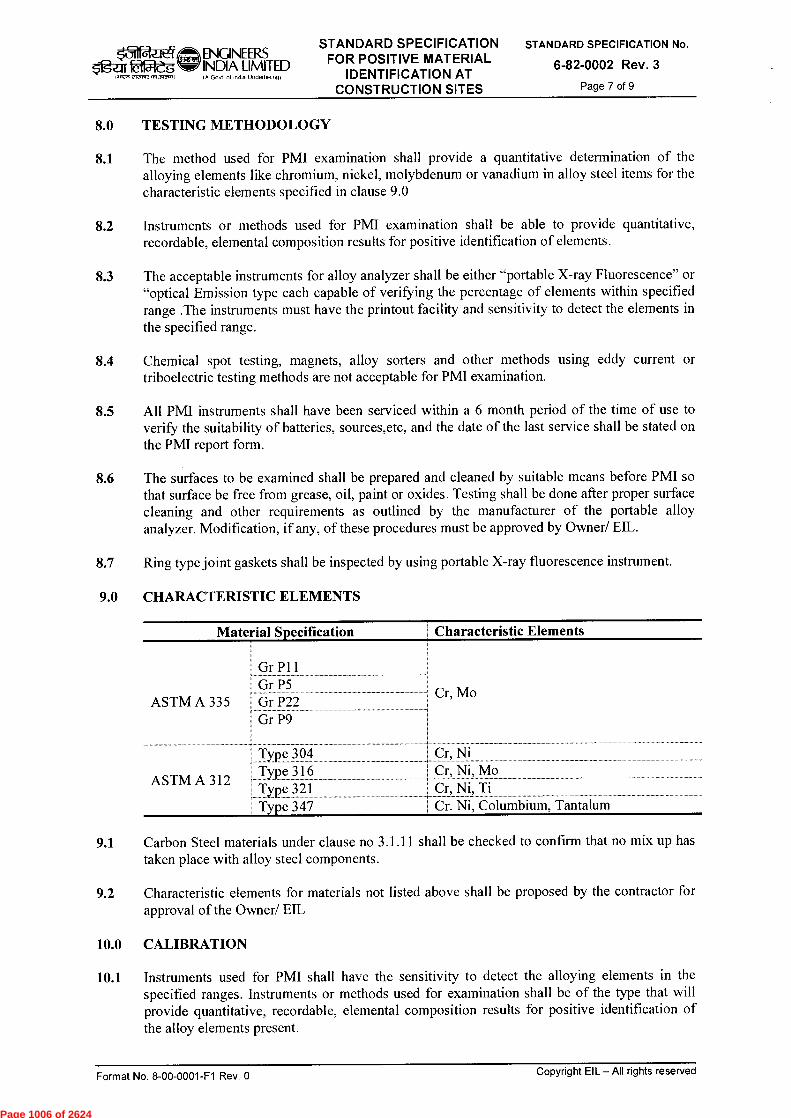
Material Specification
Characteristic Elements
GrP11 Gr P5
ASTM A 3351 Gr P22 Gr P9
Type 304 Type 316 Type 321 Type 347
r, Ni r, Ni, Mo r, Ni, Ti
Cr. Ni, Columbium, Tantalum
ASTM A 312
I Cr, Mo
Og-ez tifgleg ,..,enetecnre mst l
ENGINEERS INDIA LIMITED (A Govt of India Undertakmg)
STANDARD SPECIFICATION FOR POSITIVE MATERIAL
IDENTIFICATION AT CONSTRUCTION SITES
STANDARD SPECIFICATION No.
6-82-0002 Rev. 3 Page 7 of 9
8.0 TESTING METHODOLOGY
8.1 The method used for PMI examination shall provide a quantitative determination of the alloying elements like chromium, nickel, molybdenum or vanadium in alloy steel items for the characteristic elements specified in clause 9.0
8.2 Instruments or methods used for PMI examination shall be able to provide quantitative, recordable, elemental composition results for positive identification of elements.
8.3 The acceptable instruments for alloy analyzer shall be either "portable X-ray Fluorescence" or "optical Emission type each capable of verifying the percentage of elements within specified range .The instruments must have the printout facility and sensitivity to detect the elements in the specified range.
8.4 Chemical spot testing, magnets, alloy sorters and other methods using eddy current or triboelectric testing methods are not acceptable for PMI examination.
8.5 All PMI instruments shall have been serviced within a 6 month period of the time of use to verify the suitability of batteries, sources,etc, and the date of the last service shall be stated on the PMI report form.
8.6 The surfaces to be examined shall be prepared and cleaned by suitable means before PMI so that surface be free from grease, oil, paint or oxides. Testing shall be done after proper surface cleaning and other requirements as outlined by the manufacturer of the portable alloy analyzer. Modification, if any, of these procedures must be approved by Owner/ EIL.
8.7 Ring type joint gaskets shall be inspected by using portable X-ray fluorescence instrument.
9.0 CHARACTERISTIC ELEMENTS
9.1 Carbon Steel materials under clause no 3.1.11 shall be checked to confirm that no mix up has taken place with alloy steel components.
9.2 Characteristic elements for materials not listed above shall be proposed by the contractor for approval of the Owner/ EIL
10.0 CALIBRATION
10.1 Instruments used for PMI shall have the sensitivity to detect the alloying elements in the specified ranges. Instruments or methods used for examination shall be of the type that will provide quantitative, recordable, elemental composition results for positive identification of the alloy elements present.
Format No. 8-00-0001-F1 Rev. 0 Copyright EIL — All rights reserved
Page 1006 of 2624
Oge-11 tameg INIErer erenvz asTawnisso
ENGINEER S INDIA UMITED (A Govt of India Undertaking)
STANDARD SPECIFICATION FOR POSITIVE MATERIAL
IDENTIFICATION AT CONSTRUCTION SITES
STANDARD SPECIFICATION No.
6-82-0002 Rev. 3
Page 8 of 9
10.2 Each alloy analyzer shall be calibrated using known alloy standards for intended materials to be checked by PMI. A calibration certification from the Manufacturer or his authorized agency shall be submitted to EIL/ Owner for records.
10.3 EIL/ Owner shall review the procedure and qualification and witness sample alloy/ carbon steel materials verification tests to confirm that the procedures, equipment and personnel are capable of providing consistent and accurate results. Certified samples, with full traceability, of a known alloy materials/ carbon steel materials shall be available for use as a random spot checking on instrument calibration.
11.0 SITE VERIFICATION OF ANALYZER
Verification using Standard samples supplied by institutes such as ASM (American Society of Metals) for the intended materials type and grade shall be performed each day before using the analyzer. Such verification shall be done again if PMI test is to be performed on different grade or type of material.
12.0 PERSONNEL QUALIFICATION
The persons performing the PMI test should be knowledgeable about properties of material, all aspects of operation of PMI equipment including the method of testing. Qualification/ experience documents of the person performing the PMI test including his training and experience shall be submitted to Ell,/ Owner for review and approval.
13.0 ACCEPTANCE CRITERIA
13.1 Base Metal
PMI test results showing presence of characteristic elements upto 10% less than the minimum specified value in the material specification and upto 10% more than the maximum specified value in the material specification shall be acceptable.
13.2 Deposited Weld Metal
For deposited weld metal between base metals of the same specification using matching consumables, the recorded presence of characteristic elements upto 12.5% less than the minimum specified value in the welding consumables specification and upto 12.5% more than the maximum specified value in the welding consumable specification shall be acceptable.
14.0 REJECTION CRITERIA
14.1 If the PMI test results fall outside the acceptable range as given in 13.0 above, the contractor shall obtain a quantitative check analysis performed by a laboratory acceptable to EIL/ Owner for a complete chemical analysis. Results of this analysis shall be submitted to ER,/ Owner, with contractor's recommendation, for final decision.
Decision of EIL/ Owner shall be final in this regard.
14.2 If any material component or weld is found unacceptable, all other represented materials (e.g. in case of fasteners, supports) or welds shall be considered suspect. In such cases, the contractor has the following options:
14.2.1 Scrapping all those represented materials or components and replacing with new components or welds.
14.2.2 Performing 100% examination of the remainder of the represented materials/ components and replacing each item that fails the PMI check.
Format No. 8-00-0001-F1 Rev. 0
Copyright EIL — All rights reserved
Page 1007 of 2624
ENGINEERS igzir aft INDIA LIMITED
(A Govt of Indio Undertaking) 1.11, e-1,4+, 471 J40.0
STANDARD SPECIFICATION FOR POSITIVE MATERIAL
IDENTIFICATION AT CONSTRUCTION SITES
STANDARD SPECIFICATION No.
6-82-0002 Rev. 3 Page 9 of 9
14.2.3 If the performance of any verification activity is unacceptable to EIL/ Owner or if any material has been incorrectly identified, all further tests shall be subject to EIL/ Owner approval until the problem is corrected.
15.0 DOCUMENTATION
15.1 Print out from alloy analyzer, in original, duly verified by the TPIA engaged by contractor, Contractor and PMI agency.
15.2 PMI report as per format No. 6-82-0002-F1
15.3 Basis and action for resolving and documenting PMI non conformances.
15.4 Contractor shall demonstrate to EIL/ Owner that all components requiring PMI have been subjected to PMI testing and accepted.
Format No. 8-00-0001-F1 Rev. 0 Copyright EIL — All rights reserved
Page 1008 of 2624

ATTACHMENT – III
Page 1009 of 2624
RKD SC
k31 ENQNEERS f&fMeg~ INDIA LIMITED
1.11W, 212ZIWA513PCMI/ I A Govt ot Incha Undertaking)
STANDARD SPECIFICATION FOR COLOUR CODING OF
PIPING MATERIAL
STANDARD SPECIFICATION No.
6-82-0003 Rev.2 Page 1 of 12
trrferrr ~,11 -trr
t'q rafgkii
STANDARD SPECIFICATION FOR
COLOUR CODING OF
PIPING MATERIAL
2 25/06/2014 Revised and updated SM
1 10/07/2009 Revised and updated SM
0 30/05/2003 Issued as Standard Specification RKN
Rev. No
Date Purpose Prepared
by
SM RKD ND
MPJ RSG SKG
Standards Standards Checked Comm ittee Bureau
by Convenor Chairman
Approved by
Format No. 8-00-0001-F1 Rev. 0 Copyright EIL — All rights reserved
Page 1010 of 2624
■71 -"ENGINEERS STANDARD SPECIFICATION
OfjesW INDIA LIMITED FOR COLOUR CODING OF PIPING MATERIAL
STANDARD SPECIFICATION No.
6-82-0003 Rev.2 Page 2 of 12
1.1,M CWW17,2513~1 IA Govt ol InOia Undettalong)
Abbreviations:
API American Petroleum Institute
ASTM American Society for Testing & Materials
BIS Bureau of Indian Standards
EIL Engineers India Limited
IBR Indian Boiler Regulatory
IS Indian Standard
Construction Standards Committee
Convenor: Sh. RK Das, ED (Construction)
Members : Sh. M Deshpande, GM (Construction) Sh. M Natarajan, GM (C&P) Sh. Rakesh Nanda, GM (Piping) Sh. S Mukherjee, DGM (Construction) Sh. Janak Kishore, DGM (Projects) Sh. D Jana, AGM (Construction)
Format No. 8-00-0001-F1 Rev. 0 Copyright EIL —All rights reserved
Page 1011 of 2624
‘31 $'guri8ffileg Iff271
ENGINEERS STANDARD SPECIFICATION INDIA LIMITED FOR COLOUR CODING OF IA Govt of Inda Unclertak.9) PIPING MATERIAL
STANDARD SPECIFICATION No.
6-82-0003 Rev.2 Page 3 of 12
CONTENTS
1.0 SCOPE 4
2.0 REFERENCES 4
3.0 GENERAL GUIDELINES FOR IDENTIFICATION BY COLOUR CODING 4
4.0 IDENTIFICATION COLOURS 4
5.0 METHOD OF COLOUR CODING 4
6.0 TABLE: THE FOLLOWING TABLES SHALL FORM AN INTEGRAL PART OF THIS SPECIFICATION 5
TABLE - 1 BASIC COLOURS FOR IDENTIFICATION 6
TABLE - 2 COLOUR CODES FOR PIPES, FITTINGS & FORGINGS 7
TABLE - 3 COLOUR CODE- STUDS/BOLTS AND NUTS 9
TABLE - 4 COLOUR CODE FOR GASKETS 10
ANNEXURE-1 SCHEMATIC REPRESENTATION OF COLOUR IDENTIFICATION 11
Format No. 8-00-0001-F1 Rev. 0 Copyright EIL — All rights reserved
Page 1012 of 2624

STANDARD SPECIFICATION No.
6-82-0003 Rev.2 Page 4 of 12
$igz-Jr 2r51-g 1~",, eizawan~)
ENGINEERS STANDARD SPECIFICATION INDIA LIMITED FOR COLOUR CODING OF IA Govt ol Inda UnderlaNing) PIPING MATERIAL
1.0 SCOPE
This standard covers the method of identification of the piping materials by coloring using paints in order to avoid mix-up between materials of different metallurgy but similar in physical appearance.
2.0 REFERENCES
The following Code shall be referred to as and when required for resolution of colour shades.
IS: 5-2007: Colours for ready Mixed Paints and Enamels
RAL K5 Classic Edition 2006
3.0 GENERAL GUIDELINES FOR IDENTIFICATION BY COLOUR CODING
i. Materials shall be painted with one colour or combination of colours as set out in this specification.
ii. Paints used for colour coding shall be of quality so as to last for at least 5 years.
iii. Studs/Bolts and Nuts shall be painted.
iv. Colour Identification is not required on Austenitic Steel.
v. Colour identification is not required on galvanized-materials and non-ferrous metals such as copper, lead, aluminum because they are easily distinguished by their specific color and character.
vi. Special items like bellows, strainer, steam traps, valves do not require colour identification as these items are tagged with their identification.
vii. Discrimination colour shall be marked on the inner and outer surface of pipes & fittings.
4.0 IDENTIFICATION COLOURS
i. Paint colours to be used for identification shall be in accordance with Table-1.
ii. Application of various colours for identification shall be as per clause 5.0 of this standard.
5.0 METHOD OF COLOUR CODING
i. Colours and locations of colour identification on pipes, fittings, flanges, gaskets, studs/bolts, nuts shall be in accordance with Table-2 to 4 and Annexure-1.
ü. The identification colour on gaskets shall be painted on the peripheral face of each gasket (refer Annexure-1).
iii. Ends of the materials to be welded shall not be painted.
iv. Width of colour band shall be a minimum of 12 mm for less than 3 inch size components and 25mm for 3 inch and larger sizes, unless otherwise specified.
The length of inner surface painting
Copyright EIL —All rights reserved Format No. 8-00-0001-F1 Rev. 0
Page 1013 of 2624

ENGINEERS STANDARD SPECIFICATION INDIA LIMITED FOR COLOUR CODING OF (A Govt of inda undertak,N) PIPING MATERIAL
STANDARD SPECIFICATION No.
6-82-0003 Rev.2 Page 5 of 12
Shall be not less than 4 inch (100 mm) at both ends of pipes and shall start 2 inch (50mm) from pipe ends. Shall be about 2 inch (50 mm) at any one end of fittings.
v. Wherever combination of two or more colours is specified, materials shall be painted in parallel colour bands as close to each other as possible (Refer Annexure-1).
vi. Paints containing chlorine, chlorides, sulphur, lead, zinc or any contents detrimental to materials are not acceptable. The contractor shall satisfy and produce documents/carry out tests as required by the owner/EIL.
vii. A query shall be raised with EIL for materials not covered by this specification.
viii. If continuous stenciling of material specification is available then colour coding on stainless steel material may be avoided.
6.0 TABLE: THE FOLLOWING TABLES SHALL FORM AN INTEGRAL PART OF THIS SPECIFICATION
Table No. Tittle
1. Basic colour of identification
2. Colour identification on pipes, fitting and flanges
3. Colour identification on Bolts/Nuts/studs
4. Colour identification on Gaskets
Annexure-1 Schematic representation of colour identification
Format No. 8-00-0001-F1 Rev. 0 Copyright EIL —All rights reserved
Page 1014 of 2624
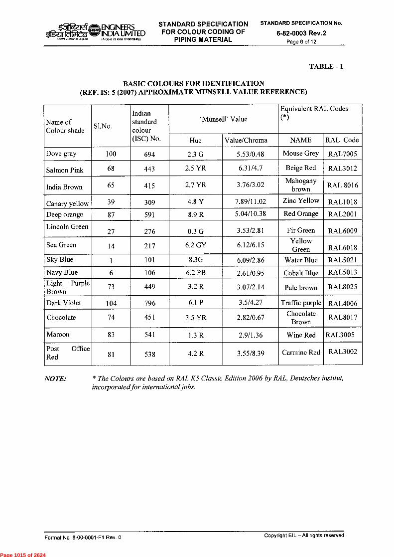
k31 Of5leg ewasre‘lx~1)
ENGINEERS STANDARD SPECIFICATION INDIA LIMITED FOR COLOUR CODING OF (A Govt of )ndo Uneertakm9) PIPING MATERIAL
STANDARD SPECIFICATION No.
6-82-0003 Rev.2 Page 6 of 12
TABLE - 1
BASIC COLOURS FOR IDENTIFICATION (REF. IS: 5 (2007) APPROXIMATE MUNSELL VALDE REFERENCE)
Name of Colour shade
SI. No.
Indian standard colour (ISC) No.
`Munsell' Value
Equivalent RAL Codes
(*)
Hue Value/Chroma NAME RAL Code
Dove gray 100 694 2.3 G 5.53/0.48 Mouse Grey RAL7005
Salmon Pink 68 443 2.5 YR 6.31/4.7 Beige Red RAL3012
India Brown 65 415 2.7 YR 3.76/3.02 Mahogany
brown
RAL 8016
Canary yellow 39 309 4.8 Y 7.89/11.02 Zinc Yellow RAL1018
Deep orange 87 591 8.9 R 5.04/10.38 Red Orange RAL2001
Lincoln Green 27 276 0.3 G 3.53/2.81 Fir Green RAL6009
Sea Green 14 217 6.2 GY 6.12/6.15 Yellow
Green RAL6018
Sky Blue 1 101 8.3G 6.09/2.86 Water Blue RAL5021
Navy Blue 6 106 6.2 PB 2.61/0.95 Cobalt Blue RAL5013
Light Purple Brown
73 449 3.2 R 3.07/2.14 Pale brown RAL8025
Dark Violet 104 796 6.1 P 3.5/4.27 Traffic purple RAL4006
Chocolate 74 451 3.5 YR 2.82/0.67 Chocolate
Brown RAL8017
Maroon 83 541 1.3 R 2.9/1.36 Wine Red RAL3005
Post Office Red 81 538 4.2 R 3.55/8.39 Carmine Red RAL3002
NOTE: * The Colours are based on RAL K5 Classic Edition 2006 by RAL, Deutsches institut, incorporated for international jobs.
Format No. 8-00-0001-F1 Rev. 0 Copyright EIL — All rights reserved
Page 1015 of 2624
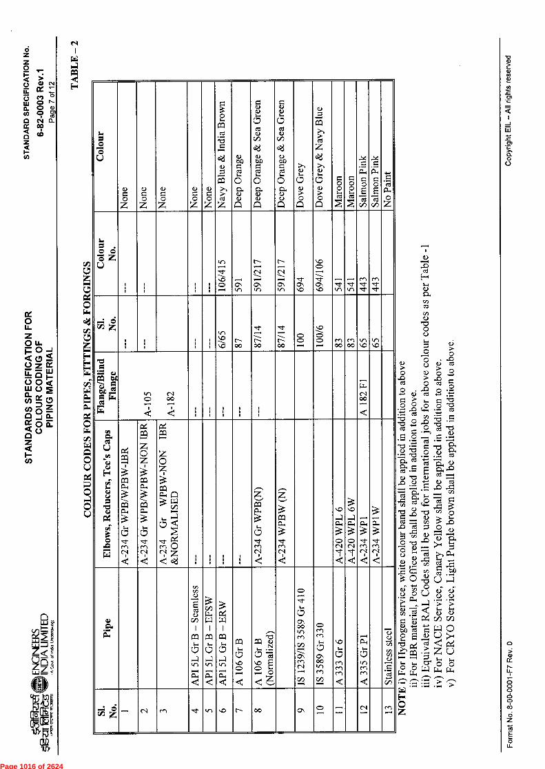
L.>
TA
BLE
— 2
"c3 r-.
ST
AN
DA
RD
SP
EC
IFIC
AT
ION
No
.
6-82
-000
3 R
ev.1
Co
pyr
ight E
IL —
All
righ
ts rese
rve
d
o cn cO
O c.)
o
OO czt
(1) o . Q •2
• s-,
0 0 0 -0 1-i czt •
- (. • czt -4•-■
v) • •-•
"C:3 o ̂c, . •■•-, c‘:3 0 cz; "I:73 •
C • ,C1).
icg 5
"C, - Cv3 cc cl T=1, cu
,SZ> ,u
+A ,•C+
• ci)
1.) ?,,4 c "10 ,c) Ov) 0
(1) cc)
czt O eD ci)
. 1")
'/) "è., 0 .•c)
c.)° P-4 cll cll c„) • ̂. r+-■•' bo
,c,c/D (1)
t/i
O el; C.) 0 C,-)
" •E •E ci)
(1) Ci)
).
r,4 czs Z „ O O
c) 0 u.4 •- •- •-
Fo
rmat N
o. 8
-00-0
001-F
7 R
ev.
0
Col
our
Non
e
0 Z Z
0 Z 0
Z 0
Nav
y B
lue &
Indi
a B
row
n 11
a) t>.1) cz) c),
(1)
(21(1.)
Dee
p O
rang
e &
Sea
Gre
en
Dee
p O
rang
e &
Sea
Gre
en
Dov
e G
rey
Dov
e G
rey
& N
avy
Blu
e
Mar
oon
Mar
oon
Salm
on P
ink
Salm
on P
ink
No
Pai
nt
1., 0 0 0 az r..)
1 1 i 1 1 i i 1 106/
415
1 59
1
591/
217
591/
217
.d- 0•■
.LD C) .--, -1- C■
,--, .1- kr) 5
41
c+1 •:t- d•
cr) •zt •1-
,—, • 0
1 I i I i i 1 1
1 kr) ----- ■C) 87
87/1
4
87/1
4
O O ,--,
C) .......
O ,--,
rel 00
en 00
Fla
nge/
Blin
d F
lan
e
in C) o
(--)o ,—, ---.,
1 I e 1 1 i 1 l 1
1 I 1 , 1 I A
182
Fl
Elb
ows,
Red
ucer
s, T
ee's
Cap
s
A-2
34
Gr
WP
B/W
PBW
-IB
R
A-2
34 G
r W
PB
/WPB
W-N
ON
IBR
1
A-2
34 G
r W
PB
W-N
ON
IBR
&
NO
RM
AL
ISE
D
I I I
I I I
I I I
I I I A
-234
Gr
WP
B(N
)
A-2
34 W
PB
W (N
)
A-4
20 W
PL
6
1A
-420 W
PL
6W
A-2
34
WP
1 I A
-23
4 W
P1W
0.) a.,
API
5L
Gr B
— S
eam
less
Cr) T-1
0:1 :5
kr, .
.d AP
I 5L
Gr
B —
ER
W
A 10
6 G
r B
A 106 G
r B
(N
orm
aliz
ed)
IS 12
39/I
S 3589 G
r 41
0
IS 3589 G
r 33
0
1A
333 G
r 6
,-ti o.
kr, en en
.< Stai
nles
s st
eel
coH—• c'., ,__, ,....„1, ,,, .1- kn \ C) li."--- 00 01 C) —, ,-, .....
1 12
cf-) -..
Page 1016 of 2624

TA
BL
E -
2
Paae 8
of 12
ST
AN
DA
RD
SP
EC
IFIC
AT
ION
No
.
6-82
-00
03
Rev
.1
CO
LO
UR
CO
DE
S F
OR
PI P
ES,
FIT
TIN
GS
& F
OR
GIN
GS
(...
. Con
td.)
1.0
0
© L) L
inco
ln G
reen
II
Lin
coln
Gre
en
Sky
Blu
e
Sky
Blu
e
Sea
Gre
en
Sea
Gre
en
Nav
y B
lue
Nav
y B
lue
Dar
k V
iole
t
Dar
k V
iole
t
Cho
cola
te
Cho
cola
te
;«I
0
0 C3 U z 27
6 \ ,0 S (^4
el (;) .--.1
, C) .-1 21
7 r."..
C•1
‘••0 C, •—■
1/4.0 C) ,--,
'.0 01 l"---
'4:› CT r---
,' ii> d•
,., li-1 d-
0 Olmc;,31 z
27
C"-- C X.1 1•••••4 7 14
d- ,, '4D '4:) 10
4
104
d' r.....
.'t ir....
Fla
nge/
Blin
d F
lang
e
A 1
82 F
11
A 18
2 F
12
i e 1 A
182 F2
2
e e A
182
F5
e e e A
182 F9
e e A
182F
91
I e
Elb
ows,
R
educ
ers,
T
ee's
C
aps
A-2
34
WP1
1
A-2
34 W
P11W
A-2
34 W
P12
A-2
34 W
P12W
A-2
34 W
P22
A 23
4 W
P22W
A-2
34
WP5
A-2
34 W
P5W
A-2
34 W
P9
A-2
34 W
P9W
A-2
34 W
P91
A-2
34
WP9
1W
a.> ts..
1:::ii A335 G
rP
11
A 691 Gr
1.25
Cr
CL
.42
(EF
W)
A 33
5 G
r P1
2 Cs1 C•11
;(.5
Ln rn en
< A 691 Gr
2.25 Cr
CL
.42
(EF
W)
A 33
5 G
r P5 CT
c5
Lr) en en
< A33
5Gr
P91
• zc:; 7.)
.d- 15 9
1
S
II 18
<3.■
E-1
Co
pyr
ight E
IL —
All
rights
rese
rve
d F
orm
at N
o. 8
-00-0
00
1-F
7 Re
v. 0
Page 1017 of 2624

O u_ z o u-p o < o
z LT. (3. 1.12 • o w o<
z o o_- c)
< o G. • o
z
ST
AN
DA
RD
SP
EC
IFIC
AT
ION
No
.
6-82
-000
3 R
ev.1
!".
a)
czt H
a)
cz$ a)
c.)
O O c.) a)
0 cz
▪
t
0 • cC
0 4c-4
• a)
• o
(4-4 cu
r=4
0 cl
c/) cu (I) cu 0
ao)
cct
• ftS c>
O cr, ;-T-4
0
Co
pyr
ight
EIL
— A
ll r ig
hts
re
serv
ed
For
mat
No
. 8-0
0-0
00
1-F
7 R
ev. 0
CO
LO
UR
SHA
DE
S
Can
ary
Yel
low
Can
ary
Yel
low
Indi
a B
row
n
Indi
a B
row
n
Lin
coln
Gre
en
Lin
coln
Gre
en
Cho
cola
te
Lig
ht P
urpl
e B
row
n
Lig
ht P
urpl
e B
row
n
IND
IAN
STD
. C
OL
OU
R (
ISC
) NO
.
cT C0 rn
CT CD cf-)
kr) ,-- d-
kr) -1 d-
0 r-- C\1
■0 I-- c\1
--1 kr) d-
CT d- d-
CT d- d-
c5 z
c.) c, rn 0, rn
v-, ■0
L.,- \.0
r- C\I
r- C■1
,,r C--
rn s
rn s
AST
M D
ESI
GN
AT
ION
A 1
93 G
R B
7
A 194 G
R 2
H
A 307 G
RB
A 3
0 7 G
R B
A 19
3 G
RB
16
A 19
4 G
R 4
A320 G
RL
7
A320 G
RB
8
A 194 G
R 8
.±:: 0 r4
,_, z ,=,, 0
r2a) ,..., z •■-■
rit +, z 0
--,
0:1
;_4-4
GC)
,_,
Z
Page 1018 of 2624
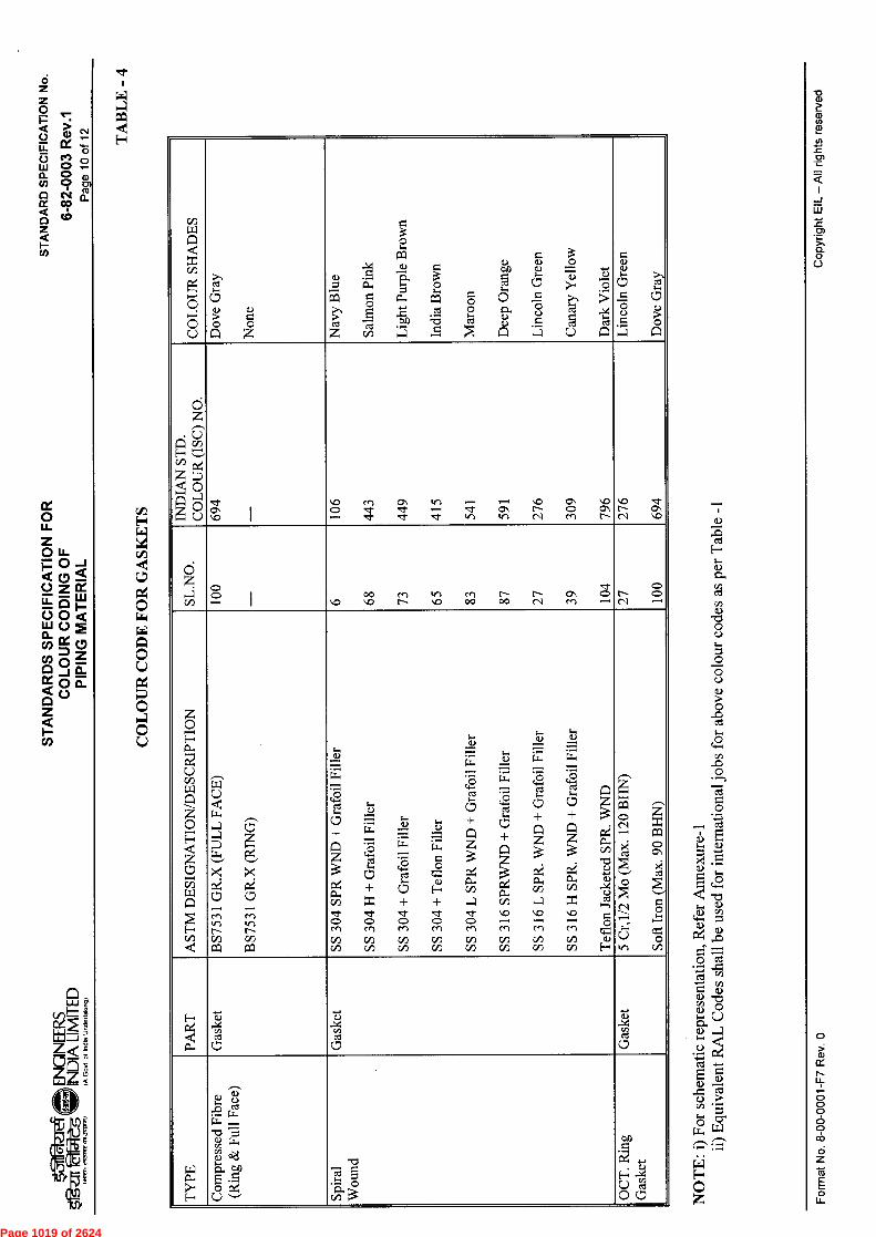
ST
AN
DA
RD
SP
EC
IFIC
AT
ION
No
.
6-82
-000
3 R
ev.1
o
CL
TA
BL
E -
4
CO
LO
UR
SH
AD
ES
Dov
e G
ray
Non
e
.o 4
c, , , Z
-_ o
v)
o o
r:Z
`9
r=1.
4" . ,--1
7, d 'r:Ej
5 .5,
- g E
c . 5 P-)'
o i...
C7 ,.5 o ,-) .,5 a
o ..,,
2 ed c..)
o ...., >.
- ,.. ed t: L
inco
ln G
reen
Dov
e G
ray
IND
IAN
ST
D.
CO
LO
UR
(IS
C)
NO
.
,r C■ ■D I
,z) CD ,--1
en •:1- .1-
c, .1" .1-
v-, ,—, •ci-
— .:I- In
— CN ,f)
■0 C-- C sl
CN <0 en
■D CN C--
■0 C--- r■1
•z1" CN VD
d z • C/)
c> ,--. 1 ■D
00 ■O
M C---
kr■ ■D
m 00
Ir-- 00
r"-- C■1
C7■ Cn
• O ,—.
S rsl
o C;) •—.
AS
TM
DE
SIG
NA
TIO
N/D
ES
CR
IPT
ION
BS
75
31
GR
.X (
FU
LL
FA
CE
)
BS
753
1 G
R.X
(R
ING
)
SS
30
4 SP
R W
ND
+ G
rafo
il F
ille
r
SS
30
4 H
+ G
rafo
il F
ille
r
SS
304 +
Gra
foil
Fil
ler
SS
304 +
Tef
lon
Fil
ler
SS
304 L
SP
R W
ND
+ G
rafo
il F
ille
r
SS
31
6 SP
RW
ND
+ G
rafo
il F
ille
r
SS
316 L
SP
R. W
ND
+ G
rafo
il F
ille
r
SS
31
6 H
SP
R.
WN
D +
Gra
foil
Fil
ler
Tef
lon
Jack
eted
SP
R. W
ND
5 Cr,
1/2
Mo
(Max
. 12
0 B
HN
)
Sof
t Iro
n (M
ax. 9
0 B
HN
)
C4 < P.
,--,
C' 0
E--, 7
-■-■
c" c0
(.7 Gas
ket
:,., ›. [-.
W
Com
pres
sed F
ibre
(R
ing &
Ful
l Fac
e)
• a., o v, 3 O
CT
. Rin
g G
aske
t
Cop
yrigh
t EIL
—A
ll rig
hts
res
rve
d F
orm
at N
o. 8
-00-
000
1-F
7 Rev
. 0
Page 1019 of 2624

X77-7.-M-71777-77-777777777-777714
STANDARD SPECIFICATION No.
k31 ENG1NEERS STANDARDS SPECIFICATION
FOR COLOUR CODING OF Og-af la5le;g INDIA LIMITED PIPING MATERIAL IA Govl of lnOo Undertaking)
ONE COLOUR IWO COLOUR
B. COLOUR IDENTIFICATION OF FITTINGS
6-82-0003 Rev.2 Page 11 of 12
ANNEXURE-1
SCHEMATIC REPRESENTATION OF COLOUR IDENTIFICATION
A. COLOUR IDENTIFICATION OF PIPES
EIBOW
ONE COIOUR
TWO COLOURS
REOUCER
ONE COLOUR
TWO COLOURS
TEE
ONE OR IWO COLDURiS)
STUES ENO 4' •
ONE OR TWO COLOUR1S)
CAP
COUPL1NG
ONE OR TWO COLOUR(S)
ONE OR 1W3 COLOUR1S)
Copyright EIL — All rights reserved Format No. 8-00-0001-F1 Rev. 0
Page 1020 of 2624
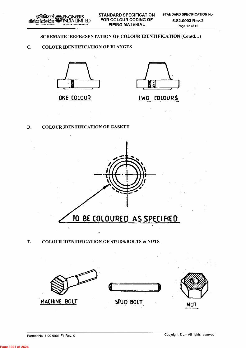
10 BE COLOUREO AS SkCIFIE0
MACHINE BOIT SiU0 BOIT NUT
ENGINEERS STANDARD SPECIFICATION INDIA LIMITED FOR COLOUR CODING OF
STANDARD SPECIFICATION No.
6-82-0003 Rev.2 Page 12 of 12
+~.rreaxr aaJaael (A Govt of lnOa Unde(taking) PIPING MATERIAL
SCHEMATIC REPRESENTATION OF COLOUR IDENTIFICATION (Contd...)
C. COLOUR IDENTIFICATION OF FLANGES
ONE COLOUR TWO COLOURS
D. COLOUR IDENTIFICATION OF GASKET
E. COLOUR IDENTIFICATION OF STUDS/BOLTS & NUTS
Format No. 8-00-0001-F1 Rev. 0
Copyright EIL —All rights reserved
Page 1021 of 2624

ATTACHMENT – IV
Page 1022 of 2624
cek 2 04-05-2616 Issued for Implementation
PG SVRS
1 26-05-2008 Issued for Implementation PG KPS
0 15-05-2003 Issued for Implementation PG KPS
Rev. No Date Purpose
Prepared by
Checked by
,c0 RP RN
AA VC
VC SKG
Standards Standards Committee Bureau Convenor Chairman
Approved by
401 el ENGINEERS STANDARD SPECIFICATION FOR STANDARD SPECIFICATION No.
Igar laigtft INDIA LIMITED APPLICATION OF TORQUE AND HYDRAULIC 6-76-0002 Rev. 2 Govt of Indla Unde,lak ■ NI BOLT TENSION FOR FLANGE JOINTS Page 1 of 33 wren riercure 011,Cr.1)
tfflq. ‘711 icrR
-4ff-37V (tr4) 14ifeict) ealgt
-4 argErITT 4itian 1-4r9tT
STANDARD SPECIFICATION FOR APPLICATION OF TORQUE AND
HYDRAULIC BOLT TENSION FOR FLANGE JOINTS
Format No. 8-00-0001-F1 Rev. 0 Copyright EIL — All rights reserved
Page 1023 of 2624

if ENGINEERS STANDARD SPECIFICATION FOR STANDARD SPECIFICATION No.
tiPteg INDIA LIMITED APPLICATION OF TORQUE AND HYDRAULIC 6-76-0002 Rev. 2 (Wen' eirage c7,1,maqq, (A Gaut at indta Undettakalq; BOLT TENSION FOR FLANGE JOINTS Page 2 of 33
Abbreviations:
ASME American Society of Mechanical Engineers
PMS Piping Material Specification
General Engineering Standards Committee
Convenor : Ms. R. Priyamvada
Members : Mr. R.K. Trivedi Mr. B.R. Bhogal Mr. Rajanji Srivastava Mr. R.B. Bhutda Mr. Amrendra Kumar Ms. N.P. Guha
Format No. 8-00-0001-F1 Rev. 0 Copyrights EIL — All rights reserved
Page 1024 of 2624
ENGINEERS STANDARD SPECIFICATION FOR STANDARD SPECIFICATION No.
INDIA LIMITED APPLICATION OF TORQUE AND HYDRAULIC 6-76-0002 Rev. 2 ligar 051--eg IOWA CleCPIdITIJ,ILITA) IA Govt of India undeltak,n1 BOLT TENSION FOR FLANGE JOINTS Page 3 of 33
CONTENTS
1.0 PURPOSE 4
2.0 SCOPE 4
3.0 REFERENCES 4
4.0 DEFINITIONS 4
5.0 METHODOLOGY AND CONTROL 4
6.0 RESPONSIBILITIES / APPROVALS 11
7.0 DOCUMENTATION 11
ANNEXURE-I 32
ANNEXURE-II 33
Format No. 8-00-0001-F1 Rev. 0 Copyrights EIL — All rights reserved
Page 1025 of 2624

ENGINEERS STANDARD SPECIFICATION FOR STANDARD SPECIFICATION No. k1 u
Ifgof INDIA LIMITED APPLICATION OF TORQUE AND HYDRAULIC 6-76-0002 Rev. 2 BOLT TENSION FOR FLANGE JOINTS Page 4 of 33 Nreff ele4n2 051.1.70,-.11
1.0 PURPOSE
The purpose of this specification is to describe the methodology for preparation of bolted flange joints by controlled bolt tightening during construction and commissioning stage of process plant piping. This specification shall be used in conjunction with the special process/project requirements and the licensor/vendor recommendations.
2.0 SCOPE
This specification covers ASME B16.5 and ASME B16.47 Series B bolted flanged joints, involving identical pair of flanges, which are tightened by means of either hydraulic bolt tensioning or calibrated torque wrenches.
3.0 REFERENCES
EIL Spec no. 6-44-0005 Rev 5
-
Standard Piping Material Specification EIL Doc no. 5-7700-0120 Procedure for identification and boxing up of flange joints
not subjected to hydrostatic test at site ASME B 16.5
-
Pipe Flanges and Flanged Fittings (1/2" to 24" NPS) ASME B 16.47 Series B Pipe Flanges and Flanged Fittings (26" to 60" NPS) ASME B31.3
-
Process Piping BP RP 42-2 British Petroleum Recommended Practice: Bolting for
flange joints ASME Section VIII Division 1 - Boiler and Pressure Vessel Code and Division 2, 2013
4.0 DEFINITIONS
None.
5.0 METHODOLOGIES AND CONTROL
5.1 Identification of joints for controlled bolt tightening
Controlled bolt tightening can be done either by application of calculated bolt tension with hydraulic tensioner or by application of calculated bolt torque with calibrated torque wrenches. The criteria for selection of joints for these two application procedure are given below.
5.1.1 Hydraulic Bolt tensioning
Hydraulic bolt tensioning shall be applied for all joints where the bolt sizes match the criteria outlined in Table 1, except those in the category 'ID' services. Category 'ID' service is defined in ASME B31.3.
Format No. 8-00-0001-F1 Rev. 0 Copyrights EIL — All rights reserved
Page 1026 of 2624
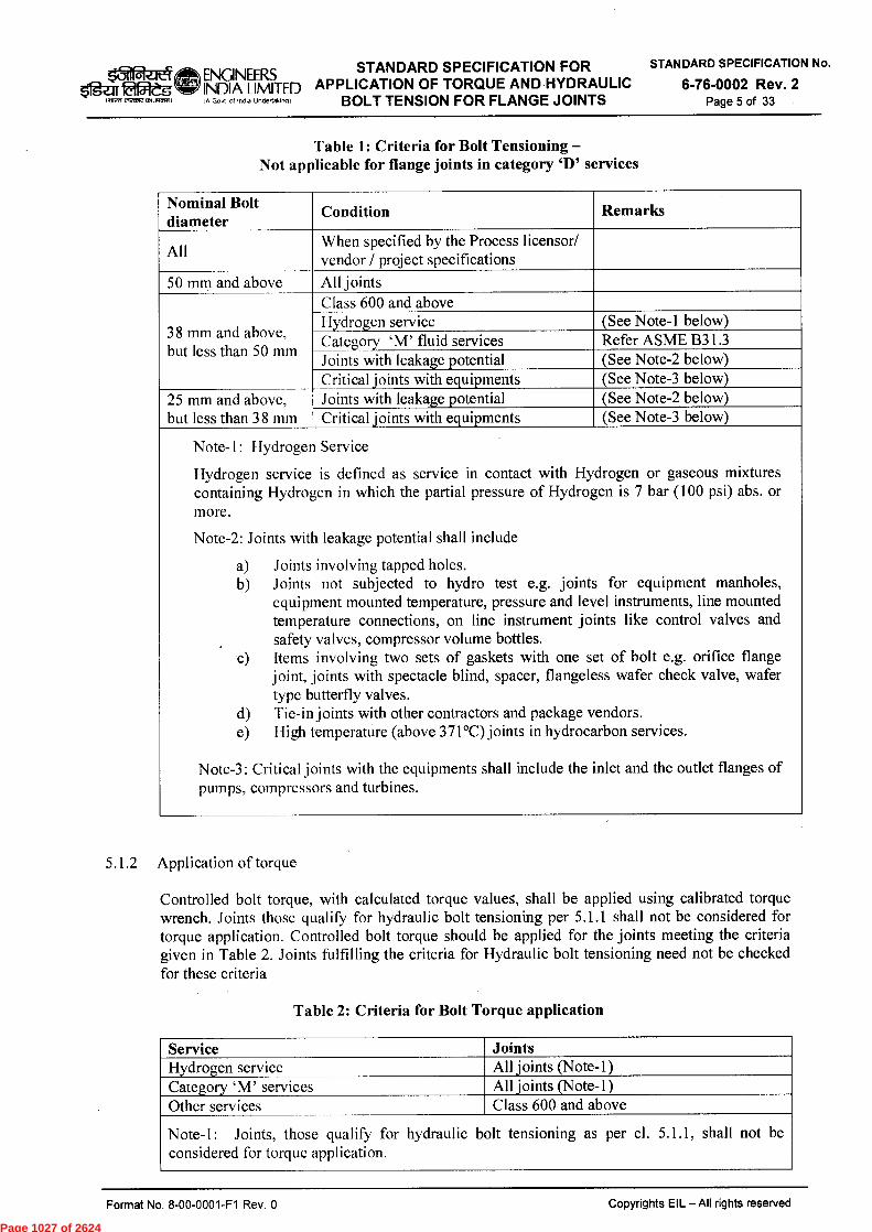
lotei ENGINEERS STANDARD SPECIFICATION FOR STANDARD SPECIFICATION No.
Zgar weg INDIA LIMITED APPLICATION OF TORQUE AND HYDRAULIC 6-76-0002 Rev. 2 IfirerrelecroecTI.FRIm) IA Gavt Indta Undertakirp) BOLT TENSION FOR FLANGE JOINTS Page 5 of 33
Table 1: Criteria for Bolt Tensioning — Not applicable for flange joints in category 'D' services
Nominal Bolt diameter
Condition Remarks
All When specified by the Process licensor/ vendor / project specifications
50 mm and above All joints
38 mm and above, but less than 50 mm
Class 600 and above Hydrogen service (See Note-1 below) Category 'M' fluid services Refer ASME B31.3 Joints with leakage potential (See Note-2 below) Critical joints with equipments (See Note-3 below)
25 mm and above, but less than 38 mm
Joints with leakage potential (See Note-2 below) Critical joints with equipments (See Note-3 below)
Note-1: Hydrogen Service
Hydrogen service is defined as service in contact with Hydrogen or gaseous mixtures containing Hydrogen in which the partial pressure of Hydrogen is 7 bar (100 psi) abs. or more.
Note-2: Joints with leakage potential shall include
a) Joints involving tapped holes. b) Joints not subjected to hydro test e.g. joints for equipment manholes,
equipment mounted temperature, pressure and level instruments, line mounted temperature connections, on line instrument joints like control valves and safety valves, compressor volume bottles.
c) Items involving two sets of gaskets with one set of bolt e.g. orifice flange joint, joints with spectacle blind, spacer, flangeless wafer check valve, wafer type butterfly valves.
d) Tie-in joints with other contractors and package vendors. e) High temperature (above 371°C) joints in hydrocarbon services.
Note-3: Critical joints with the equipments shall include the inlet and the outlet flanges of pumps, compressors and turbines.
5.1.2 Application of torque
Controlled bolt torque, with calculated torque values, shall be applied using calibrated torque wrench. Joints those qualify for hydraulic bolt tensioning per 5.1.1 shall not be considered for torque application. Controlled bolt torque should be applied for the joints meeting the criteria given in Table 2. Joints fulfilling the criteria for Hydraulic bolt tensioning need not be checked for these criteria
Table 2: Criteria for Bolt Torque application
Service Joints Hydrogen service All joints (Note-1) Category 'M' services All joints (Note-1) Other services Class 600 and above
Note-1: Joints, those qualify for hydraulic bolt tensioning as per cl. 5.1.1, shall not be considered for torque application.
Copyrights EIL — All rights reserved Format No. 8-00-0001-F1 Rev. 0
Page 1027 of 2624
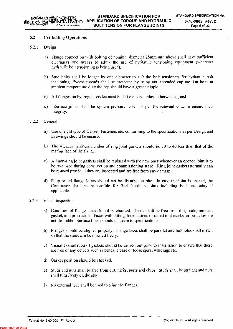
ENGINEERS STANDARD SPECIFICATION FOR STANDARD SPECIFICATION No.
INDIA LIMITED APPLICATION OF TORQUE AND HYDRAULIC 6-76-0002 Rev. 2 Ifgar fad& IA GOVI of Indla Undertaking, BOLT TENSION FOR FLANGE JOINTS Page 6 of 33
5.2 Pre-bolting Operations
5.2.1 Design
a) Flange connection with bolting of nominal diameter 25mm and above shall have sufficient clearances and access to allow the use of hydraulic tensioning equipment (wherever hydraulic bolt tensioning is being used).
b) Stud bolts shall be longer by one diameter to suit the bolt tensioners for hydraulic bolt tensioning. Excess threads shall be protected by using nut, threaded cap etc. On bolts at ambient temperature duty the cap should have a grease nipple.
c) All flanges on hydrogen service must be left exposed unless otherwise agreed.
d) Interface joints shall be system pressure tested as per the relevant code to ensure their integrity.
5.2.2 General
a) Use of right type of Gasket, Fasteners etc. conforming to the specifications as per Design and Drawings should be ensured.
b) The Vickers hardness number of ring joint gaskets should be 30 to 40 less than that of the mating face of the flange.
c) All non-ring joint gaskets shall be replaced with the new ones whenever an opened joint is to be re-closed during construction and commissioning stage. Ring joint gaskets normally can be re-used provided they are inspected and are free from any damage
d) Shop tested flange joints should not be disturbed at site. In case the joint is opened, the Contractor shall be responsible for final hook-up joints including bolt tensioning if applicable.
5.2.3 Visual inspection
a) Condition of flange faces should be checked. Those shall be free from dirt, scale, remnant gasket, and protrusions. Faces with pitting, indentations or radial tool marks, or scratches are not desirable. Surface finish should conform to specifications.
b) Flanges should be aligned properly. Flange faces shall be parallel and boltholes shall match so that the studs can be inserted freely.
c) Visual examination of gaskets should be carried out prior to installation to ensure that these are free of any defects such as bends, crease or loose spiral windings etc.
d) Gasket position should be checked.
e) Studs and nuts shall be free from dirt, nicks, burrs and chips. Studs shall be straight and nuts shall turn freely on the stud.
f) No external load shall be used to align the flanges.
Format No. 8-00-0001-F1 Rev. 0 Copyrights EIL — All rights reserved
Page 1028 of 2624

ENGINEERS STANDARD SPECIFICATION FOR STANDARD SPECIFICATION No.
INDIA LIMITED APPLICATION OF TORQUE AND HYDRAULIC 6-76-0002 Rev. 2 laOleg (.11-effereiMMWrirm (A Govt of Ind a Undertaktngi BOLT TENSION FOR FLANGE JOINTS Page 7 of 33
5.2.4 Corrective measures
a) Faces with pitting, indentations or radial tool marks, or scratches that form leakage paths or with the surface finish not in accordance with design requirements shall be replaced or re-machined to specified surface finish.
b) If necessary, gasket-seating face should be cleaned using wire brush (SS bristles on alloy components) and/or suitable solvent.
c) Damaged gaskets shall be replaced.
d) If holding gasket in place after installation is a problem, a thin adhesive tape should be used along the outside edge of gasket.
5.2.5 Lubrication/anti-seize compound
a) Threads and nuts to flange contact face should be lubricated with suitable lubricant. Thread compound or lubricant, suitable for line temperature, may be used.
b) Gaskets should not be lubricated.
c) Lubricant shall not be applied on bolts, used in oxygen services.
d) Some of the types of lubricants used are as follows:
Molybdenum Lead oxide (graphite based) Molykote G-n plus Molykote P37 Molykote HSC Plus / Never Seez nickel special API SA2 Molykote 1000 Machine oil Graphite grease
5.2.6 Assembly
a) Suitable lubricant (refer cl. 5.2.5) to be applied to the threads and the face of the nut that contacts the flange.
b) Four studs should be placed in positions 1, 2, 3 and 4 according to "Stud Tightening Pattern" in Fig.1, as centring guides for the gasket.
c) Balance studs should be inserted next.
d) Nuts should be run down by hand in such a way that an equal number of threads project at each end.
5.2.7 Torque/tension calculation
a) EIL software FLTRQ16.5 is used for calculation. The stress analysis part of this software primarily follows the procedure outlined in ASME Section VIII Division 1/ Division 2.
b) Basic formulae used for torque calculation takes care of friction between bolt threads and nut threads as well as that between nut and back face of flange.
Format No. 8-00-0001-F1 Rev. 0 Copyrights EIL—All rights reserved
Page 1029 of 2624
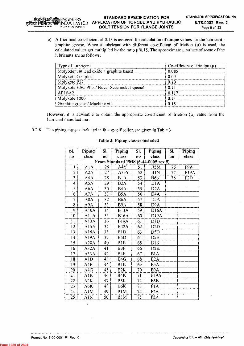
Type of Lubricant Molybdenum lead oxide + graphite based Molykote G-n plus Molykote P37 Molykote I ISC Plus / Never Seez nickel special API SA2 Molykote 1000 Graphite grease / Machine oil
Co-efficient of friction (pt) 0.085 0.09 0.10 0.11 0.117 0.13 0.15
/6iiia4-1t4 ENGINEERS STANDARD SPECIFICATION FOR STANDARD SPECIFICATION No.
APPLICATION OF TORQUE AND HYDRAULIC 6-76-0002 Rev. 2 faateg INDIA LIMITED etra,re m1071'411 fA Gavt of Indta Uncle!takalgi BOLT TENSION FOR FLANGE JOINTS Page 8 of 33
c) A frictional co-efficient of 0.15 is assumed for calculation of torque values for the lubricant -graphite grease. When a lubricant with different co-efficient of friction (ii) is used, the calculated values get multiplied by the ratio 11/0.15. The approximate IA values of some of the lubricants are as follows:
However, it is advisable to obtain the appropriate co-efficient of friction (.t) value from the lubricant manufacturer.
5.2.8 The piping classes included in this specification are given in Table 3
Table 3: Piping classes included
SI. no
Piping class
SI. no
Piping class
SI. no
Piping class
SI. no
Piping class
From Standard PMS (6-44-0005 rev 5) A1A 26 A4Y 51 B5M 76 F9A
2 A2A 27 A33Y 52 B1N 77 F19A 3 A4A 28 BIA 53 B6N 78 F2D 4 A5A 29 B2A 54 D1A 5 A6A 30 B4A 55 D2A 6 A7A 31 B5A 56 D4A 7 A8A 32 B6A 57 D5A 8 A9A 33 B9A 58 D9A 9 AIOA 34 B13A 59 D16A
10 Al IA 35 B16A 60 D19A 11 A13A 36 B19A 61 D1D 12 A 15A 37 B32A 62 D2D 13 AI6A 38 BM 63 D5D 14 AI9A 39 B5D 64 D5E 15 A20A 40 B1E 65 D1K 16 A32A 41 B3F 66 D2K 17 A33A 42 B4F 67 E1A 18 AID 43 B4G 68 E2A 19 A4F 44 BIK 69 E5A 20 A4G 45 B2K 70 E9A 21 AlK 46 B4K 71 El9A 22 A2K 47 B5K 72 E5E 23 A6K 48 B6K 73 F 1 A 24 A 1 M 49 B1M 74 F2A 25 AIN 50 B3M 75 F5A
Format No. 8-00-0001-F1 Rev. 0
Copyrights EIL — All rights reserved
Page 1030 of 2624

dafaei ENGNEERS STANDARD SPECIFICATION FOR STANDARD SPECIFICATION No.
Etigieg INDIA LIMITED APPLICATION OF TORQUE AND HYDRAULIC 6-76-0002 Rev. 2 wrent-...r.wrmr,0 (A Govt of Indw Undeltak.ngl BOLT TENSION FOR FLANGE JOINTS Page 9 of 33
5.2.9 Torque and tension values
Table 4 contains the tension and torque values to be used for bolt tightening using hydraulic bolt tensioner and torque wrench respectively. These values are listed piping class and size wise. The tension values specified are the target load per bolt intended after the bolt tensioning operation is complete. This means any allowance inherent in bolt tensioning equipment (viz. backlash etc.) shall also to be taken care of as recommended by the equipment manufacturer.
5.2.10 Notes to Torque and tension values in Table 4
a) The maximum allowed design pressure & temperature combination and test pressure values are listed in Table 4. These values corresponds to PMS rating table values, except as stated in c) below. Recalculation of torque and tension is necessary if design condition exceeds these limits.
b) Values in the table are not valid if the design conditionfor pipe wall thickness calculation is lower than 80% of the class rating condition. Recalculation of torque and tension is necessary in such cases.
It may be noted that for the sizes above 24" and rating class above 150 (except B1A), the calculations are carried out for 80% of the pressure used for sizes up to 24".
d) Torque / tension computation of sizes and pipe thickness, which are not covered in the respective classes of the standard PMS, are carried out based on approximate calculated pipe thickness for the specified pressure and temperature condition.
e) Suffixes to the rating class numbers denote the flange dimensional standard and are as follows:
S - ASME B16.5 B - ASME B16.47 Series B
f) The values in the tables are not valid for other flange dimensional standards, e.g., ASME B 16.47 Series A, AWWA(American Water Works association) etc.
g) All pressure values are in kg/cm2 and all temperature values are in °C
5.3 Bolting Operation
5.3.1 General
a) Categorisation of joints for tension or torque application shall be as per cl. 5.1.
b) Bolt tightening tension or torque value shall be as per cl. 5.2.8.
c) Guidelines and safety requirements provided by the manufacturer bolt tightening equipment should be followed.
5.3.2 Hydraulic bolt tension application
a) Hydraulic pressure adequate to get the target bolt load can be calculated dividing the bolt load by the load cell hydraulic seal area. This pressure should be applied simultaneously to all load cells.
b) 4 load cells equally spaced should be used.
Format No. 8-00-0001-F1 Rev. 0 Copyrights EIL — All rights reserved
Page 1031 of 2624
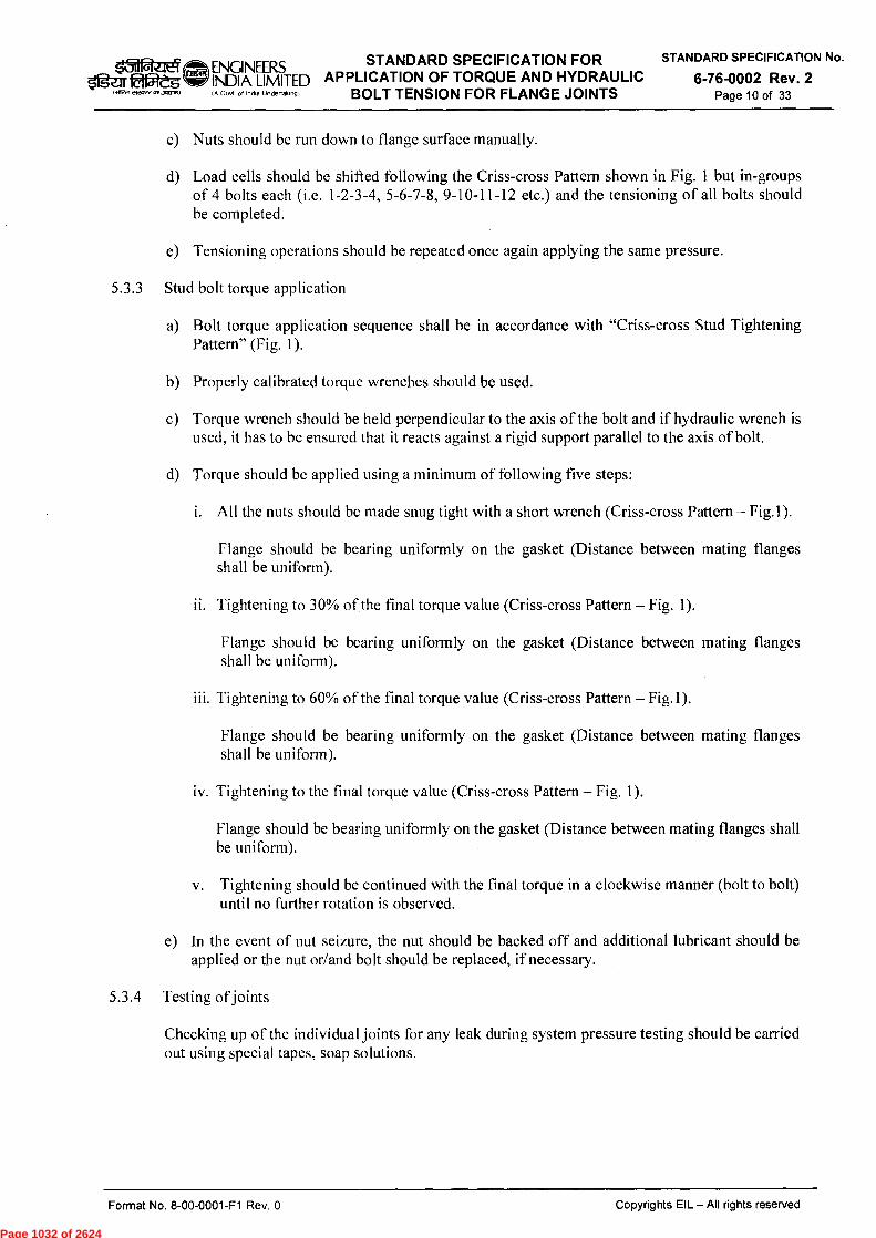
ENGINEERS STANDARD SPECIFICATION FOR STANDARD SPECIFICATION No.
6-76-0002 Rev. 2 ,511 Peit4
51geir lat5Itg (7112K era:7:V 0,13M177:11
INDIA LIMITED APPLICATION OF TORQUE AND HYDRAULIC BOLT TENSION FOR FLANGE JOINTS Page 10 of 33
c) Nuts should be run down to flange surface manually.
d) Load cells should be shifted following the Criss-cross Pattern shown in Fig. 1 but in-groups of 4 bolts each (i.e. 1-2-3-4, 5-6-7-8, 9-10-11-12 etc.) and the tensioning of all bolts should be completed.
e) Tensioning operations should be repeated once again applying the same pressure.
5.3.3 Stud bolt torque application
a) Bolt torque application sequence shall be in accordance with "Criss-cross Stud Tightening Pattern" (Fig. 1).
b) Properly calibrated torque wrenches should be used.
c) Torque wrench should be held perpendicular to the axis of the bolt and if hydraulic wrench is used, it has to be ensured that it reacts against a rigid support parallel to the axis of bolt.
d) Torque should be applied using a minimum of following five steps:
i. All the nuts should be made snug tight with a short wrench (Criss-cross Pattern — Fig.1).
Flange should be bearing uniformly on the gasket (Distance between mating flanges shall be uniform).
ii. Tightening to 30% of the final torque value (Criss-cross Pattern — Fig. 1).
Flange should be bearing uniformly on the gasket (Distance between mating flanges shall be uniform).
iii. Tightening to 60% of the final torque value (Criss-cross Pattern — Fig.1).
Flange should be bearing uniformly on the gasket (Distance between mating flanges shall be uniform).
iv. Tightening to the final torque value (Criss-cross Pattern — Fig. 1).
Flange should be bearing uniformly on the gasket (Distance between mating flanges shall be uniform).
v. Tightening should be continued with the final torque in a clockwise manner (bolt to bolt) until no further rotation is observed.
e) In the event of nut seizure, the nut should be backed off and additional lubricant should be applied or the nut or/and bolt should be replaced, if necessary.
5.3.4 Testing of joints
Checking up of the individual joints for any leak during system pressure testing should be carried out using special tapes, soap solutions.
Format No. 8-00-0001-F1 Rev. 0 Copyrights EIL — All rights reserved
Page 1032 of 2624
ENGINEERS STANDARD SPECIFICATION FOR STANDARD SPECIFICATION No.
zga fiVeg INDIA LIMITED APPLICATION OF TORQUE AND HYDRAULIC 6-76-0002 Rev. 2 (A G.rt of Inca Undertaking) BOLT TENSION FOR FLANGE JOINTS Page 11 of 33 I iireK clew/2 MIJMI111)
6.0 RESPONSIBILITIES / APPROVALS
6.1 All procedures/documents to be used during Construction should be submitted by the Contractor to Engineer-in-charge at site in advance.
6.2 The equipment supplier shall be subjected to EIL/Owner approval.
6.3 The details of hydraulic tensioner equipment to be used for tightening shall be intimated to Engineer-in-charge before application.
6.4 Boxing up and tightening of flange joints shall be done by skilled technicians, qualified and approved by Contractor and EIL/Owner.
6.5 Any conflict between the requirements of this standard and related codes, standards, data sheets, drawings, requisitions etc. shall be referred to client / consultant. Agency carrying out bolt tightening shall list and describe all the deviations from this specification and the related codes
7.0 DOCUMENTATION
7.1 History sheet for flange joints shall be maintained as per Annexure-I.
7.2 Sequence of the activities involved for reopening/ making/ blinding/ de-blinding/ wedge opening of flange joints shall be as per Annexure-II.
7.3 All joints shall be boxed-up and the record shall be maintained of salient points and names of the persons involved in the execution/inspection of boxing-up operation.
7.4 All critical joints shall be boxed-up under the supervision of the Contractor's representative and EIL's Engineer-in-charge or his representative and separate records shall be maintained for such joints.
7.5 Box up records of interface joints and on-line instrument joints, like control valves, safety valves, turbine flow meters etc., which are not subjected to hydrotest shall be maintained separately.
7.6 If mentioned in project specification, complete set of bolt Tensioning Equipment/ Torque Wrenches shall be supplied by Contractor to the Owner after commissioning of the plant, as mandatory spares.
Format No. 8-00-0001-F1 Rev. 0 Copyrights EIL — All rights reserved
Page 1033 of 2624
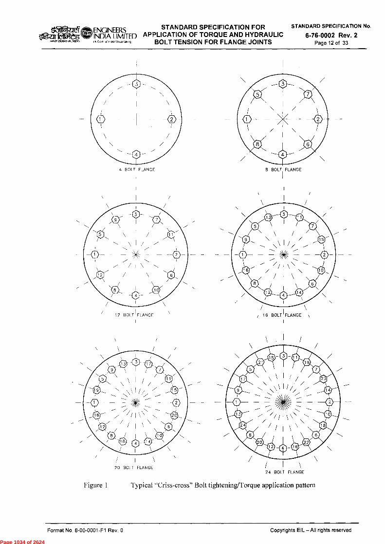
STANDARD SPECIFICATION FOR STANDARD SPECIFICATION No. ENGINEERS
ligulag6 INDIA LIMITED APPLICATION OF TORQUE AND HYDRAULIC 6-76-0002 Rev. 2 (A Govt of Intha Undettakingl BOLT TENSION FOR FLANGE JOINTS Page 12 of 33 IfiRR'rieerot andwnwl
4 BOLT FLANGE 8 BOLT FLANGE
12 BOLT FLANGE / 16 BOLT 1 FLANGE
20 BOLT FLANGE 24 BOLT FLANGE
Figure 1 Typical "Criss-cross" Bolt tightening/Torque application pattern
Copyrights EIL — All rights reserved Format No. 8-00-0001-F1 Rev. 0
Page 1034 of 2624
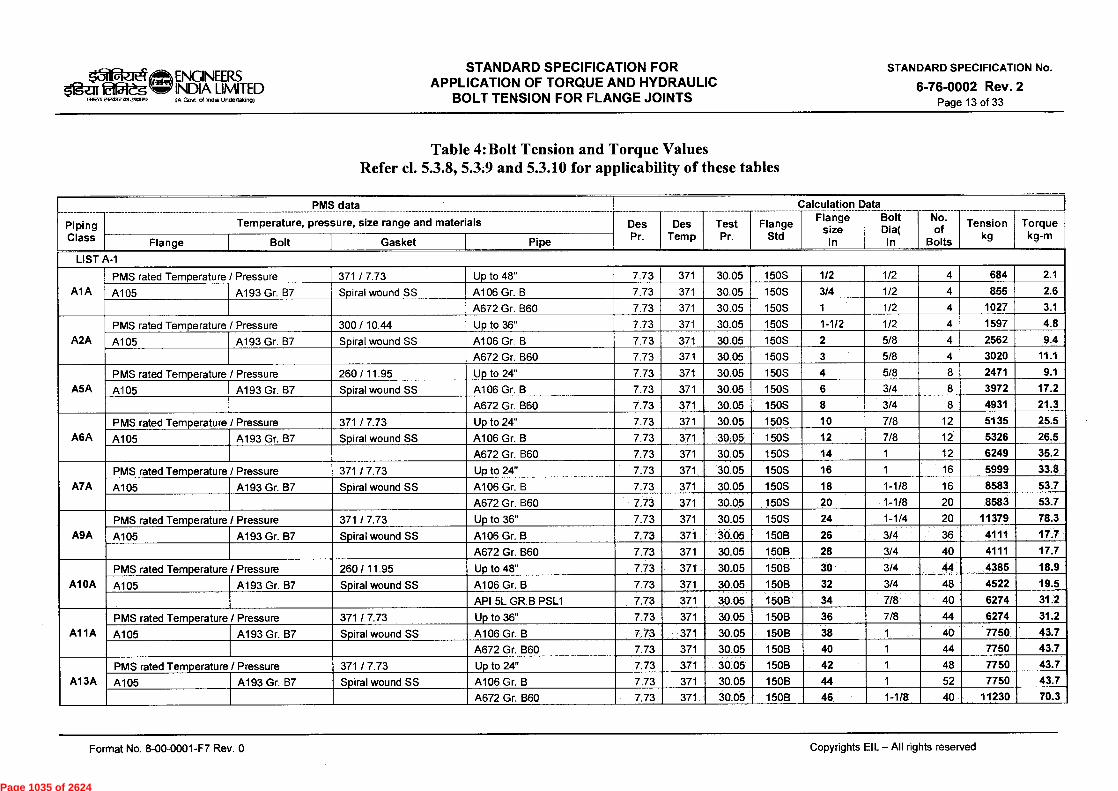
afa_lei ENGINEERS Oges Rift NDIA LIMITED
(awn eiwb2 dada.) IA Govt d India Undertaking)
STANDARD SPECIFICATION FOR APPLICATION OF TORQUE AND HYDRAULIC
BOLT TENSION FOR FLANGE JOINTS
STANDARD SPECIFICATION No.
6-76-0002 Rev. 2 Page 13 of 33
Table 4:Bolt Tension and Torque Values Refer cl. 5.3.8, 5.3.9 and 5.3.10 for applicability of these tables
Piping 1 Class
PMS data
Tem perature, pressure, size range and materials Des Pr.
Des Temp
Test Pr.
- Flange
Std
Calculation Flange
size In
Data Bolt
ia( In
No . of
Bolts
Tension kg
Torque kg-m
Flange Bolt Gasket Pipe
LIST A-1
A1A PMS rated Temperature / Pressure 371 / 7.73 Up to 48" 7.73 371 30.05 150S 1/2 1/2 4 684 2.1
A105 A193 Gr. B7 Spiral wound SS A106 Gr. B 7.73 371 30.05 150S 3/4 1/2 4 855 2.6
A672 Gr. B60 7.73 371 30.05 150S 1 1/2 4 1027 3.1
A2A PMS rated Temperature / Pressure 300 / 10.44 Up to 36" 7.73 371 30.05 150S 1-1/2 1/2 4 1597 4.8
A105 A193 Gr. B7 Spiral wound SS A106 Gr. B 7.73 371 30.05 150S 2 5/8 4 2562 9.4
A672 Gr. B60 7.73 371 30.05 150S 3 5/8 4 3020 11.1
A5A PMS rated Temperature / Pressure 260 / 11.95 Up to 24" 7.73 371 30.05 150S 4 5/8 8 2471 9.1
A105 A193 Gr. B7 Spiral wound SS A106 Gr. B 7.73 371 30.05 150S 6 3/4 8 3972 17.2
A672 Gr. B60 7.73 371 30.05 150S 8 3/4 8 4931 21.3
A6A PMS rated Temperature / Pressure 371 / 7.73 Up to 24" 7.73 371 30.05 150S 10 7/8 12 5135 25.5
A105 A193 Gr. B7 Spiral wound SS A106 Gr. B 7.73 371 30.05 150S 12 7/8 12 5326 26.5
A672 Gr. B60 7.73 371 30.05 150S 14 1 12 6249 35.2
A7A PMS rated Temperature / Pressure 371 / 7.73 Up to 24" 7.73 371 30.05 150S 16 1 16 5999 33.8
A105 A193 Gr. B7 Spiral wound SS A106 Gr. B 7.73 371 30.05 150S 18 1-1/8 16 8583 53.7
A672 Gr. B60 7.73 371 30.05 150S 20 1-1/8 20 8583 53.7
A9A PMS rated Temperature / Pressure 371 / 7.73 Up to 36" 7.73 371 30.05 150S 24 1-1/4 20 11379 78.3
A105 A193 Gr. B7 Spiral wound SS A106 Gr. B 7.73 371 30.05 150B 26 3/4 36 4111 17.7
A672 Gr. B60 7.73 371 30.05 150B 28 3/4 40 4111 17.7
AlOA PMS rated Temperature / Pressure 260 / 11.95 Up to 48" 7.73 371 30.05 150B 30 3/4 44 4385 18.9
A105 A193 Gr. B7 Spiral wound SS A106 Gr. B 7.73 371 30.05 150B 32 3/4 48 4522 19.5
API 5L GR.B PSL1 7.73 371 30.05 150B 34 7/8 40 6274 31.2
AVIA PMS rated Temperature / Pressure 371 / 7.73 Up to 36" 7.73 371 30.05 150B 36 7/8 44 6274 31.2
A105 A193 Gr. B7 Spiral wound SS A106 Gr. B 7.73 371 30.05 150B 38 1 40 7750 43.7
A672 Gr. B60 7.73 371 30.05 150B 40 1 44 7750 43.7
A13A PMS rated Temperature / Pressure 371 / 7.73 Up to 24" 7.73 371 30.05 150B 42 1 48 7750 43.7
A105 A193 Gr. B7 Spiral wound SS A106 Gr. B 7.73 371 30.05 150B 44 1 52 7750 43.7
A672 Gr. B60 7.73 371 30.05 150B 46 1-1/8 40 11230 70.3
Format No. 8-00-0001-F7 Rev. 0
Copyrights EIL - All rights reserved
Page 1035 of 2624
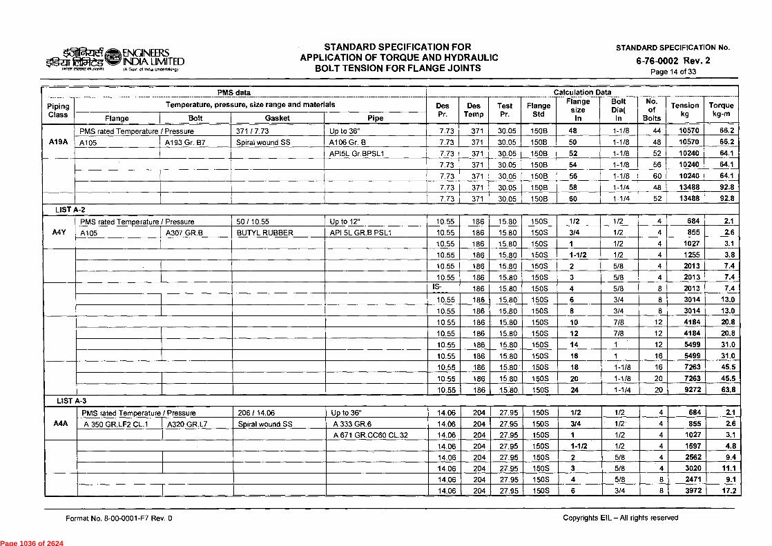
don- ei 215reg
1.112ff eleaRt
ENGINEERS INDIA LIMITED IA Govt of India undertaking)
STANDARD SPECIFICATION FOR APPLICATION OF TORQUE AND HYDRAULIC
BOLT TENSION FOR FLANGE JOINTS
STANDARD SPECIFICATION No.
6-76-0002 Rev. 2 Page 14 of 33
Piping
PMS data- -
Temperature, pressure, size range and materials Des Pr.
Des Temp
Test Pr.
Flange Std
Calculation Flange
size In
Data Bolt
Dia( In
No. of
Bolts
Tension kg
Torque kg-m Class Flange Bolt Gasket Pipe
A19A PMS rated Temperature / Pressure 371 / 7.73 Up to 36" 7.73 371 30.05 150B 48 1-1/8 44 10570 66.2
A105 A193 Gr. B7 Spiral wound SS A106 Gr. B 7.73 371 30.05 150B 50 1-1/8 48 10570 66.2
API5L Gr.BPSL1 7.73 371 30.05 150B 52 1-1/8 52 10240 64.1
7.73 371 30.05 150B 54 1-1/8 56 10240 64.1
7.73 371 30.05 150B 56 1-1/8 60 10240 64.1
■ 7.73 371 30.05 150B 58 1-1/4 48 13488 92.8
7.73 371 30.05 150B 60 1-1/4 52 13488 92.8
LIST A-2
A4Y PMS rated Temperature / Pressure 50 / 10.55 Up to 12" 10.55 186 15.80 150S 1/2 1/2 4 684 2.1
A105 A307 GR.B BUTYL RUBBER API 5L GR.B PSL1 10.55 186 15.80 150S 3/4 1/2 4 855 2.6
10.55 186 15.80 150S 1 1/2 4 1027 3.1
10.55 186 15.80 150S 1-1/2 1/2 4 1255 3.8
10.55 186 15.80 150S 2 5/8 4 2013 7.4
10.55 186 15.80 150S 3 5/8 4 2013 7.4 IS- _ 186 15.80 150S 4 5/8 8 2013 7.4
10.55 186 15.80 150S 6 3/4 8 3014 13.0
10.55 186 15.80 150S 8 3/4 8 3014 13.0
10.55 186 15.80 150S 10 7/8 12 4184 20.8
10.55 186 15.80 150S 12 7/8 12 4184 20.8
10.55 186 15.80 150S 14 1 12 5499 31.0
10.55 186 15.80 150S 16 1 16 5499 31.0
10.55 186 15.80 150S 18 1-1/8 16 7263 45.5
10.55 186 15.80 150S 20 1-1/8 20 7263 45.5
10.55 186 15.80 150S 24 1-1/4 20 9272 63.8
LIST A-3
A4A PMS rated Temperature / Pressure 206 / 14.06 Up to 36" 14.06 204 27.95 150S 1/2 1/2 4 684 2.1
A 350 GR.LF2 CL.1 A320 GR.L7 Spiral wound SS A 333 GR.6 14.06 204 27.95 150S 3/4 1/2 4 855 2.6
A 671 GR.CC60 CL.32 14.06 204 27.95 150S 1 1/2 4 1027 3.1
14.06 204 27.95 150S 1-1/2 1/2 4 1597 4.8
14.06 204 27.95 150S 2 5/8 4 2562 9.4
14.06 204 27.95 150S 3 5/8 4 3020 11.1
14.06 204 27.95 150S 4 5/8 8 2471 9.1
14.06 204 27.95 150S 6 3/4 8 3972 17.2
Format No. 8-00-0001-F7 Rev. 0
Copyrights EIL - All rights reserved
Page 1036 of 2624
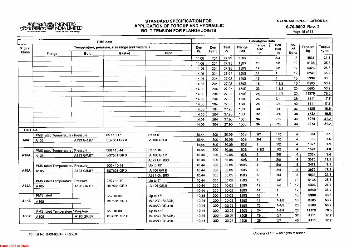
INIEW
STANDARD SPECIFICATION FOR APPLICATION OF TORQUE AND HYDRAULIC
BOLT TENSION FOR FLANGE JOINTS
II .21 ENGINEERS ligar Etreg IN
LJMITED (A Gov( of (Ma Undertaking)
STANDARD SPECIFICATION No.
6-76-0002 Rev. 2 Page 15 of 33
--Piping Class
PMS data
Temperature, pressure, size range and materials Des Pr.
Des Temp
Test Pr.
Flange
Data
Std
jCalculation Flange
size In
Bolt Dia(
In
No. of
Bolts
Tension kg
Torque kg-m
Flange Bolt Gasket Pipe
14.06 204 27.95 150S 8 3/4 8 4931 21.3
14.06 204 27.95 150S 10 7/8 12 5135 25.5
14.06 204 27.95 150S 12 7/8 12 5326 26.5
14.06 204 27.95 150S 14 1 12 6249 35.2
14.06 204 27.95 150S 16 1 16 5999 33.8
14.06 204 27.95 150S 18 1-1/8 16 8583 53.7
14.06 204 27.95 150S 20 1-1/8 20 8583 53.7
14.06 204 27.95 150S 24 1-1/4 20 11379 78.3
14.06 204 27.95 150B 26 3/4 36 4111 17.7
14.06 204 27.95 150B 28 3/4 40 4111 17.7
14.06 204 27.95 150B 30 3/4 44 4385 18.9
14.06 204 27.95 150B 32 3/4 48 4522 19.5
14.06 204 27.95 150B 34 7/8 40 6274 31.2
14.06 204 27.95 150B 36 7/8 44 6274 31.2
LIST A-4
A8A PMS rated Temperature / Pressure 65 / 19.17 Up to 6" 10.44 300 30.05 150S 1/2 1/2 4 684 2.1
A105 A193 GR.B7 BS7531 GR X A 106 GR.B 10.44 300 30.05 150S 3/4 1/2 4 855 2.6
10.44 300 30.05 150S 1 1/2 4 1027 3.1
A15A PMS rated Temperature / Pressure 300 / 10.44 Up to 16" 10.44 300 30.05 150S 1-1/2 1/2 4 1597 4.8
A105 A193 GR.B7 BS7531 GR X A 106 GR.B 10.44 300 30,05 150S 2 5/8 4 2562 9.4
A672 Gr. B60 10.44 300 30.05 150S 3 5/8 4 3020 11.1
A20A PMS rated Temperature / Pressure 300 / 10.44 Up to 18" 10.44 300 30.05 150S 4 5/8 8 2471 9.1
A105 A193 GR.B7 BS7531 GR X A 106 GR.B 10.44 300 30.05 150S 6 3/4 8 3972 17.2
A672 Gr. B60 10.44 300 30.05 150S 8 3/4 8 4931 21.3
A32A PMS rated Temperature / Pressure 280 / 11.19 Up to 3" 10.44 300 30.05 150S 10 7/8 12 5135 25.5
A105 A193 GR.B7 BS7531 GR X A 106 GR.B 10.44 300 30.05 150S 12 7/8 12 5326 26.5
10.44 300 30.05 150S 14 1 12 6249 35.2
A33A
PMS rated 65 / 16.00 Up to 48" 10.44 300 30.05 150S 16 1 16 5999 33.8
A105 BS7531 GR X IS-1239 (BLACK) 10.44 300 30.05 150S 18 1-1/8 16 8583 53.7
IS-3589 GR.410 10.44 300 30.05 150S 20 1-1/8 20 8583 53.7
A33Y PMS rated Temperature / Pressure 65 / 16.00 Up to 48" 10.44 300 30.05 150S 24 1-1/4 20 11379 78.3
A105 A193 GR.B7 BS7531 GR X IS-1239 (BLACK) 10.44 300 30.05 150B 26 3/4 36 4111 17.7
IS-3589 GR.410 10.44 300 30.05 150B 28 3/4 40 4111 17.7
Format No. 8-00-0001-F7 Rev. 0 Copyrights EIL - All rights reserved
Page 1037 of 2624
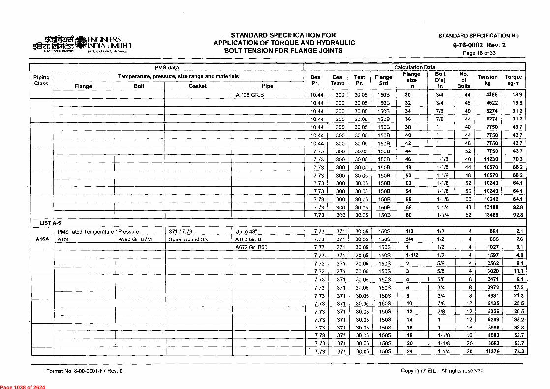
ENGINEERS INDIA LIMITED
STANDARD SPECIFICATION FOR APPLICATION OF TORQUE AND HYDRAULIC
BOLT TENSION FOR FLANGE JOINTS
IMPTI-e? ttiji-au ,A Govt of Inds Undertaking)
STANDARD SPECIFICATION No.
6-76-0002 Rev. 2 Page 16 of 33
Piping
PMS data_
Temperature, pressure, size range and materials Des Pr.
Des i Temp
Test Pr.
Flange Std
__Calculation Flange
size In
Data Bolt Dia(
In
No. of
Bolts
Tension kg
Torque kg-m Class Flange Bolt Gasket Pipe
A 106 GR.B 10.44 300 30.05 150B 30 3/4 44 4385 18.9
10.44 300 30.05 150B 32 3/4 48 4522 19.5
10.44 300 30.05 150B 34 7/8 40 6274 31.2
10.44 300 30.05 150B 36 7/8 44 6274 31.2
10.44 300 30.05 150B 38 1 40 7750 43.7
10.44 300 30.05 150B 40 1 44 7750 43.7
10.44 300 30.05 150B 42 1 48 7750 43.7
7.73 300 30.05 150B 44 1 52 7750 43.7
7.73 300 30.05 150B 46 1-1/8 40 11230 70.3
7.73 300 30.05 150B 48 1-1/8 44 10570 66.2
7.73 300 30.05 150B 50 1-1/8 48 10570 66.2
7.73 300 30.05 150B 52 1-1/8 52 10240 64.1
7.73 300 30.05 150B 54 1-1/8 56 10240 64.1
7.73 300 30.05 150B 56 1-1/8 60 10240 64.1
7.73 300 30.05 150B 58 1-1/4 48 13488 92.8
7.73 300 30.05 150B 60 1-1/4 52 13488 92.8
LIST A-5
A16A
PMS rated Temperature / Pressure 371 / 7.73 Up to 48" 7.73 371 30.05 150S 1/2 1/2 4 684 2.1
A105 A193 Gr. B7M Spiral wound SS A106 Gr. B 7.73 371 30.05 150S 3/4 1/2 4 855 2.6
A672 Gr. B60 7.73 371 30.05 150S 1 1/2 4 1027 3.1
7.73 371 30.05 150S 1-112 1/2 4 1597 4.8
7.73 371 30.05 150S 2 5/8 4 2562 9.4
7.73 371 30.05 150S 3 5/8 4 3020 11.1
7.73 371 30.05 150S 4 5/8 8 2471 9.1
7.73 371 30.05 150S 6 3/4 8 3972 17.2
7.73 371 30.05 150S 8 3/4 8 4931 21.3
.
7.73 371 30.05 150S 10 7/8 12 5135 25.5
7.73 371 30.05 150S 12 7/8 12 5326 26.5
7.73 371 30.05 150S 14 1 12 6249 35.2
7.73 371 30.05 150S 16 1 16 5999 33.8
7.73 371 30.05 150S 18 1-1/8 16 8583 53.7
7.73 371 30.05 150S 20 1-1/8 20 8583 53.7
7.73 371 30.05 150S 24 1-1/4 20 11379 78.3
Format No. 8-00-0001-F7 Rev. 0
Copyrights EIL - All rights reserved
Page 1038 of 2624

1>WW elETIR2 0510112.1)
STANDARD SPECIFICATION FOR APPLICATION OF TORQUE AND HYDRAULIC
BOLT TENSION FOR FLANGE JOINTS
t31 .2.J ENGINEERS fai5Vdg INDIA LIMITED
IA Govt of India Undertaiong)
STANDARD SPECIFICATION No.
6-76-0002 Rev. 2 Page 17 of 33
Piping Class
PMS data _ ___
Temperature, pressure, size range and materials Des Pr.
Des Temp
Test Pr.
Flange Std
Calculation Flange
size In
Data Bolt
Dia( In
No. of
Bolts
Tension kg kg-m
Torque
Flange Bolt Gasket Pipe
LIST A-6
AID PMS rated Temperature / Pressure 371 / 7.73 Up to 24" 7.73 371 30.57 150S 1/2 1/2 4 798 2.4
A182 Gr.F11 CL.2 A193 Gr.B16 Spiral wound SS A335 Gr.P11 7.73 371 30.57 150S 3/4 1/2 4 970 2.9
A691 Gr.1.25Cr CL.42 7.73 371 30.57 150S 1 1/2 4 1141 3.4
A4F
PMS rated 371 / 7.73 Up to 24" 7.73 371 30.57 150S 1-1/2 1/2 4 1540 4.6
A182 Gr.F5 A193 Gr.B16 Spiral wound SS A 335 GR.P5 7.73 371 30.57 150S 2 5/8 4 2745 10.1
A 691 GR.5Cr CL.42 7.73 371 30.57 150S 3 5/8 4 3020 11.1
7.73 371 30.57 150S 4 5/8 8 3020 11.1
7.73 371 30.57 150S 6 3/4 8 5205 22.5
7.73 371 30.57 150S 8 3/4 8 5274 22.8
7.73 371 30.57 150S 10 7/8 12 6277 31.2
7.73 371 30.57 150S 12 7/8 12 6277 31.2
7.73 371 30.57 150S 14 1 12 8249 46.5
7.73 371 30.57 150S 16 1 16 7249 40.9
7.73 371 30.57 150S 18 1-1/8 16 11885 74.4
7.73 371 30.57 150S 20 1-1/8 20 11554 72.4
7.73 371 30.57 150S 24 1-1/4 20 14751 101.5
7.73 371 30.57 150B 26 3/4 36 4109 17.7
7.73 371 30.57 150B 28 3/4 40 4383 18.9
7.73 371 30.57 150B 30 3/4 44 4520 19.5
7.73 371 30.57 150B 32 3/4 48 4794 20.7
7.73 371 30.57 150B 34 7/8 40 6847 34.0
7.73 371 30.57 150B 36 7/8 44 7037 35.0
7.73 371 30.57 150B 38 1 40 8748 49.3
7.73 371 30.57 150B 40 1 44 8748 49.3
7.73 371 30.57 150B 42 1 48 8498 47.9
LIST A-7
A4G PMS rated Temperature / Pressure 371 / 7.73 Up to 24" 7.73 371 30.57 150S 1/2 1/2 4 798 2.4
A182 Gr.F9 A193 Gr.B16 Spiral wound SS A 335 GR.P9 7.73 371 30.57 150S 3/4 1/2 4 970 2.9
A 691 GR.9Cr CL.42 7.73 371 30.57 150S 1 1/2 4 1255 3.8
7.73 371 30.57 150S 1-1/2 1/2 4 1825 5.5
7.73 371 30.57 150S 2 5/8 4 3203 11.8
7.73 371 30.57 150S 3 5/8 4 3386 12.4
Format No. 8-00-0001-F7 Rev. 0
Copyrights EIL - All rights reserved
Page 1039 of 2624

STANDARD SPECIFICATION FOR APPLICATION OF TORQUE AND HYDRAULIC
BOLT TENSION FOR FLANGE JOINTS
STANDARD SPECIFICATION No.
6-76-0002 Rev. 2 Page 18 of 33
ENGINEERS Igar Et154- g NDIA LIMITED
I Wen ereS2 ansornair (A Govt of India Undertaking)
=i)
Piping Class
--- PMS data
Temperature, pressure, size range and materials ____ ________ ______
Des Pr.
_____ _____
Des Temp
Test Pr.
Flange Std
Calculation Flange
size In
Data Bolt -'--
Dia( In
No. of
Bolts
Tension kg
Torque kg-m Flange Bolt Gasket Pipe
7.73 371 30.57 150S 4 5/8 8 3386 12.4
7.73 371 30.57 150S 6 3/4 8 5342 23.1
7.73 371 30.57 150S 8 3/4 8 5342 23.1
7.73 371 30.57 150S 10 7/8 12 7037 35.0
7.73 371 30.57 150S 12 7/8 12 6847 34.0
7.73 371 30.57 150S 14 1 12 8748 49.3
7.73 371 30.57 150S 16 1 16 7999 45.1
7.73 371 30.57 150S 18 1-1/8 16 12215 76.5
7.73 371 30.57 150S 20 1-1/8 20 11885 74.4
7.73 371 30.57 150S 24 1-1/4 20 15594 107.3
7.73 371 30.57 150B 26 3/4 36 4383 18.9
7.73 371 30.57 150B 28 3/4 40 4589 19.8
7.73 371 30.57 150B 30 3/4 44 4726 20.4
7.73 371 30.57 150B 32 3/4 48 5137 22.2
7.73 371 30.57 150B 34 7/8 40 7132 35.5
7.73 371 30.57 150B 36 7/8 44 7132 35.5
7.73 371 30.57 150B 38 1 40 9123 51.4
7.73 371 30.57 150B 40 1 44 9123 51.4
7.73 371 30.57 1508 42 1 48 8998 50.7 LIST A-8
A2K PMS rated Temperature / Pressure 120 / 15.32 Up to 24" 15.32 120 29.00 150S 1/2 1/2 4 570 1.7
A 182 GR.F304 A320 GR.B8CL.2 Spiral wound SS A 312 TP304 15.32 120 29.00 150S 3/4 1/2 4 855 2.6
A 358 GR.304 15.32 120 29.00 150S 1 1/2 4 1141 3.4
15.32 120 29.00 150S 1-1/2 1/2 4 1597 4.8
15.32 120 29.00 150S 2 5/8 4 2379 8.7
15.32 120 29.00 150S 3 5/8 4 3203 11.8
15.32 120 29.00 150S 4 5/8 8 2837 10.4
15.32 120 29.00 150S 6 3/4 8 4383 18.9
15.32 120 29.00 150S 8 3/4 8 5068 21.9
15.32 120 29.00 150S 10 7/8 12 5516 27.4
15.32 120 29.00 150S 12 7/8 12 5896 29.3
15.32 120 29.00 150S 14 1 12 7499 42.3
15.32 120 29.00 150S 16 1 16 6749 38.1
Format No. 8-00-0001-F7 Rev. 0
Copyrights EIL - All rights reserved
Page 1040 of 2624

ENGINEERS INDIA LIMITED
STANDARD SPECIFICATION FOR APPLICATION OF TORQUE AND HYDRAULIC
BOLT TENSION FOR FLANGE JOINTS
In Ifgar tlatu
ranenevemean.yerm) (A Goof of India Undertaking)
STANDARD SPECIFICATION No.
6-76-0002 Rev. 2 Page 19 of 33
------------ Piping Class
PMS data ----------- ---
Temperature, pressure, size range and materials __________
Des Pr.
Des Temp
Test Pr.
Flange Std
Calculation Flange
size In
Data Bolt Dia(
In
No. of
Bolts
Tension kg
Torque kg-m Flange Bolt Gasket Pipe
15.32 120 29.00 150S 18 1-1/8 16 9574 59.9
15.32 120 29.00 150S 20 1-1/8 20 9574 59.9
15.32 120 29.00 150S 24 1-1/4 20 12644 87.0
15.32 120 29.00 150B 26 3/4 36 4109 17.7
15.32 120 29.00 150B 28 3/4 40 4246 18.3
15.32 120 29.00 150B 30 3/4 44 4383 18.9
15.32 120 29.00 150B 32 3/4 48 4520 19.5
15.32 120 29.00 150B 34 7/8 40 5896 29.3
15.32 120 29.00 150B 36 7/8 44 5991 29.8 LIST A-9
A1K PMS rated Temperature / Pressure 371 / 7.73 Up to 24" 7.73 371 29.00 150S 1/2 1/2 4 570 1.7
A 182 GR.F304 A193 GR.B7 Spiral wound SS A 312 TP304 7.73 371 29.00 150S 3/4 1/2 4 798 2.4
A 105 A 358 GR.304 7.73 371 29.00 150S 1 1/2 4 913 2.7
A6K PMS rated Temperature / Pressure 371 / 7.73 Up to 24" 7.73 371 29.00 150S 1-1/2 1/2 4 1141 3.4 A 182 GR.F304L A193 GR.B7 Spiral wound SS A 312 TP304L 7.73 371 29.00 150S 2 5/8 4 2562 9.4 A 105 A 358 GR.304L 7.73 371 29.00 150S 3 5/8 4 3020 11.1
7.73 371 29.00 150S 4 5/8 8 2471 9.1
7.73 371 29.00 150S 6 3/4 8 3972 17.2
7.73 371 29.00 150S 8 3/4 8 4931 21.3
7.73 371 29.00 150S 10 7/8 12 5135 25.5
7.73 371 29.00 150S 12 7/8 12 5326 26.5
7.73 371 29.00 150S 14 1 12 6249 35.2
7.73 371 29.00 150S 16 1 16 5999 33.8
7.73 371 29.00 150S 18 1-1/8 16 8583 53.7
7.73 371 29.00 150S 20 1-1/8 20 8583 53.7
7.73 371 29.00 150S 24 1-1/4 20 11379 78.3 LIST A-10
AIM PMS rated Temperature / Pressure 371 / 7.73 Up to 24" 7.73 371 29.00 150S 1/2 1/2 4 570 1.7 A 182 GR.F316 A193 GR.B7 Spiral wound SS A 312 TP316 7.73 371 29.00 150S 3/4 1/2 4 798 2.4 A 105 A 358 GR.316 7.73 371 29.00 150S 1 1/2 4 913 2.7
7.73 371 29.00 150S 1-1/2 1/2 4 1141 3.4
7.73 371 29.00 150S 2 5/8 4 2562 9.4
7.73 371 29.00 150S 3 5/8 4 3020 11.1
Format No. 8-00-0001-F7 Rev. 0
Copyrights EIL - An rights reserved
Page 1041 of 2624

IA Govl of India Undertaking)
STANDARD SPECIFICATION FOR APPLICATION OF TORQUE AND HYDRAULIC
BOLT TENSION FOR FLANGE JOINTS
46-11 ENGINEERS Ogar 18154ft WA LIMITED
10,1?ff el:2MP 051.3.10.1)
STANDARD SPECIFICATION No.
6-76-0002 Rev. 2 Page 20 of 33
Piping Class
----- PMS data ___ ____ ___
Temperature, pressure, size range and materials Des Pr.
Des Temp
Test Pr.
________
Flange Std
Flange size
In
Data Bolt Dia(
In
No . of
Bolts
__ _
Tension kg
_
Torque kg-m Flange Bolt Gasket Pipe
7.73 371 29.00 150S 4 5/8 8 2471 9.1
7.73 371 29.00 150S 6 3/4 8 3972 17.2
7.73 371 29.00 150S 8 3/4 8 4931 21.3
7.73 371 29.00 150S 10 7/8 12 5135 25.5
7.73 371 29.00 150S 12 7/8 12 5326 26.5
7.73 371 29.00 150S 14 1 12 6249 35.2
7.73 371 29.00 150S 16 1 16 5999 33.8
7.73 371 29.00 150S 18 1-1/8 16 8583 53.7
7.73 371 29.00 150S 20 1-1/8 20 8583 53.7
7.73 371 29.00 150S 24 1-1/4 20 11379 78.3 LIST A-11
A1N PMS rated Temperature / Pressure 371 / 7.73 Up to 24" 7.73 371 24.26 150S 1/2 1/2 4 570 1.7
A 182 GR.F316L A193 GR.B7 Spiral wound SS A 312 TP316L 7.73 371 24.26 150S 3/4 1/2 4 798 2.4
A 105 A 358 GR.316L 7.73 371 24.26 150S 1 1/2 4 913 2.7
7.73 371 24.26 150S 1-1/2 1/2 4 1426 4.3
7.73 371 24.26 150S 2 5/8 4 2562 9.4
7.73 371 24.26 150S 3 5/8 4 3020 11.1
7.73 371 24.26 150S 4 5/8 8 2471 9.1
7.73 371 24.26 150S 6 3/4 8 3972 17.2
7.73 371 24.26 150S 8 3/4 8 4931 21.3
7.73 371 24.26 150S 10 7/8 12 5135 25.5
7.73 371 24.26 150S 12 7/8 12 5326 26.5
7.73 371 24.26 150S 14 1 12 6249 35.2
7.73 371 24.26 150S 16 1 16 5999 33.8
7.73 371 24.26 150S 18 1-1/8 16 8583 53.7
7.73 371 24.26 150S 20 1-1/8 20 8583 53.7
7.73 371 24.26 150S 24 1-1/4 20 11379 78.3 LIST B-1
B1A PMS rated Temperature / Pressure 427 / 28.82 Up to 24" 28.82 427 79.10 300S 1/2 1/2 4 741 2.2
A105 A193 GR.B7 Spiral wound SS A 106 GR.B 28.82 427 79.10 300S 3/4 5/8 4 1373 5.0
A 672 GR.B60 CL.12 28.82 427 79.10 300S 1 5/8 4 1647 6.0
B2A PMS rated Temperature / Pressure 427 / 28.82 Up to 24" 28.82 427 79.10 300S 1-1/2 3/4 4 2740 11.8
A105 A193 GR.B7 S.iral wound SS A 106 GR.B 28.82 427 79.10 300S 2 5/8 8 2105 7.7
Format No. 8-00-0001-F7 Rev. 0
Copyrights EIL - All rights reserved
Page 1042 of 2624
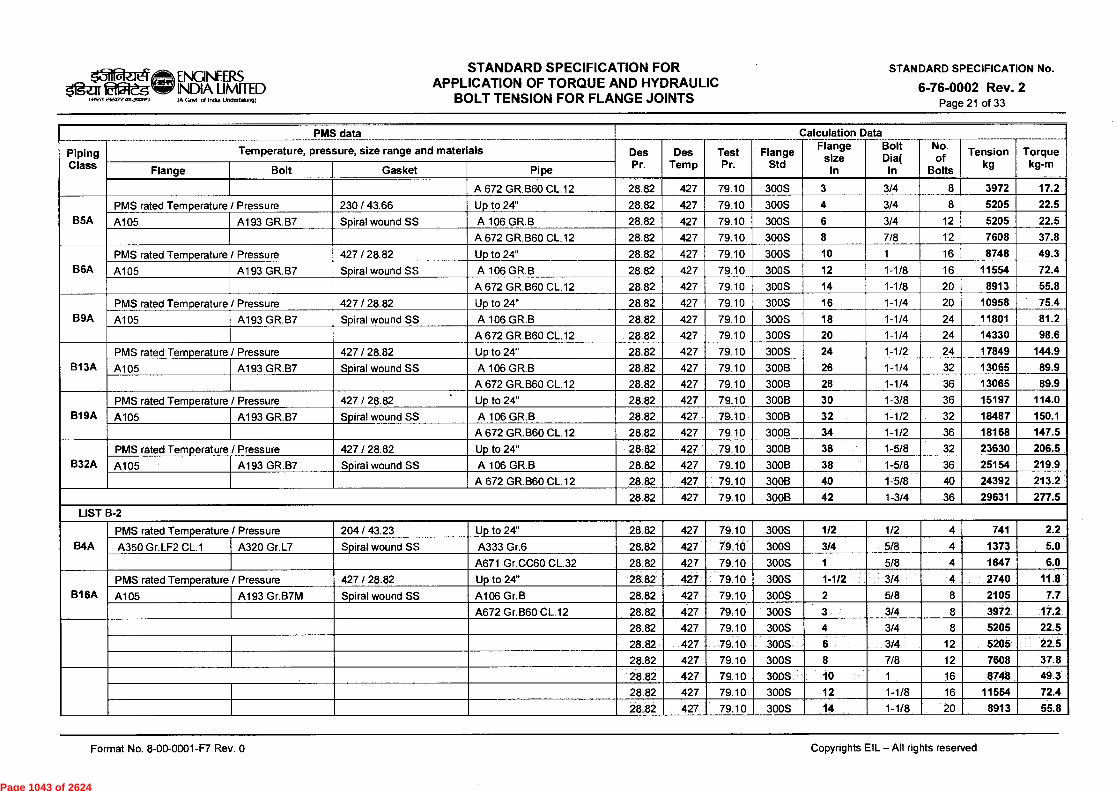
ENGINEERS
Igar Etiteg NDIA LIMITED
own eiewz MIJR11.1 IA Govt d India UndertMonco
STANDARD SPECIFICATION FOR APPLICATION OF TORQUE AND HYDRAULIC
BOLT TENSION FOR FLANGE JOINTS
STANDARD SPECIFICATION No.
6-76-0002 Rev. 2 Page 21 of 33
Piping Class
- PMS data
Temperature, pressure, size range and materials Des j Pr.
Des Temp
Test Pr.
Flange Std
Calculation Flange
sIn
e sine
Data Bolt D
Iian
( No. of
Bolts
Tension kg
Torque kg-m
Flange Bolt Gasket Pipe
A 672 GR.B60 CL.12 28.82 427 79.10 300S 3 3/4 8 3972 17.2
B5A PMS rated Temperature / Pressure 230 / 43.66 Up to 24" 28.82 427 79.10 300S 4 3/4 8 5205 22.5
A105 A193 GR.B7 Spiral wound SS A 106 GR.B 28.82 427 79.10 300S 6 3/4 12 5205 22.5
A 672 GR.B60 CL.12 28.82 427 79.10 300S 8 7/8 12 7608 37.8
B6A PMS rated Temperature / Pressure 427 / 28.82 Up to 24" 28.82 427 79.10 300S 10 1 16 8748 49.3
A105 A193 GR.B7 Spiral wound SS A 106 GR.B 28.82 427 79.10 300S 12 1-1/8 16 11554 72.4
A 672 GR.B60 CL.12 28.82 427 79.10 300S 14 1-1/8 20 8913 55.8
B9A PMS rated Temperature / Pressure 427 / 28.82 Up to 24" 28.82 427 79.10 300S 16 1-1/4 20 10958 75.4
A105 A193 GR.B7 Spiral wound SS A 106 GR.B 28.82 427 79.10 300S 18 1-1/4 24 11801 81.2
A 672 GR.B60 CL.12 28.82 427 79.10 300S 20 1-1/4 24 14330 98.6
B13A PMS rated Temperature / Pressure 427 / 28.82 Up to 24" 28.82 427 79.10 300S 24 1-1/2 24 17849 144.9
A105 A193 GR.B7 Spiral wound SS A 106 GR.B 28.82 427 79.10 300B 26 1-1/4 32 13065 89.9
A 672 GR.B60 CL.12 28.82 427 79.10 300B 28 1-1/4 36 13065 89.9
B19A PMS rated Temperature / Pressure 427 / 28.82 Up to 24" 28.82 427 79.10 300B 30 1-3/8 36 15197 114.0
A105 A193 GR.B7 Spiral wound SS A 106 GR.B 28.82 427 79.10 300B 32 1-1/2 32 18487 150.1
A 672 GR.B60 CL.12 28.82 427 79.10 300B 34 1-1/2 36 18168 147.5
B32A PMS rated Temperature / Pressure 427 / 28.82 Up to 24" 28.82 427 79.10 300B 36 1-5/8 32 23630 206.5
A105 A193 GR.B7 Spiral wound SS A 106 GR.B 28.82 427 79.10 300B 38 1-5/8 36 25154 219.9
A 672 GR.B60 CL.12 28.82 427 79.10 300B 40 1-5/8 40 24392 213.2
28.82 427 79.10 300B 42 1-3/4 36 29631 277.5
LIST B-2
B4A PMS rated Temperature / Pressure 204 / 43.23 Up to 24" 28.82 427 79.10 300S 1/2 1/2 4 741 2.2
A350 Gr.LF2 CL.1 A320 Gr.L7 Spiral wound SS A333 Gr.6 28.82 427 79.10 300S 3/4 5/8 4 1373 5.0
A671 Gr.CC60 CL.32 28.82 427 79.10 300S 1 5/8 4 1647 6.0
B16A PMS rated Temperature / Pressure 427 / 28.82 Up to 24" 28.82 427 79.10 300S 1-1/2 3/4 4 2740 11.8
A105 A193 Gr.B7M Spiral wound SS A106 Gr.B 28.82 427 79.10 300S 2 5/8 8 2105 7.7
A672 Gr.B60 CL.12 28.82 427 79.10 300S 3 3/4 8 3972 17.2
28.82 427 79.10 300S 4 3/4 8 5205 22.5
28.82 427 79.10 300S 6 3/4 12 5205 22.5
28.82 427 79.10 300S 8 7/8 12 7608 37.8
28.82 427 79.10 300S 10 1 16 8748 49.3
28.82 427 79.10 300S 12 1-1/8 16 11554 72.4
28.82 427 79.10 300S 14 1-1/8 20 8913 55.8
Format No. 8-00-0001-F7 Rev. 0
Copyrights EIL - All rights reserved
Page 1043 of 2624

(A Govt d helm Undertaking)
STANDARD SPECIFICATION FOR APPLICATION OF TORQUE AND HYDRAULIC
BOLT TENSION FOR FLANGE JOINTS al ENGINEERS
sirteg INDIA LIMITED INRK el2X412 COIJMIRI)
STANDARD SPECIFICATION No.
6-76-0002 Rev. 2 Page 22 of 33
Piping Class
PMS data _
Temperature, pressure, size range and materials __
Des Pr.
Des Temp
______
Test Pr.
Flange Std
_ Data Flange
size In
Bolt Dia(
In
_._ No. of
Bolts
Tension kg
Torque kg-m Flange Bolt Gasket Pipe
28.82 427 79.10 300S 16 1-1/4 20 10958 75.4
28.82 427 79.10 300S 18 1-1/4 24 11801 81.2
28.82 427 79.10 300S 20 1-1/4 24 14330 98.6
28.82 427 79.10 300S 24 1-1/2 24 17849 144.9
28.82 427 79.10 3008 26 1-1/4 32 13065 89.9
28.82 427 79.10 300B 28 1-1/4 36 13065 89.9
28.82 427 79.10 300B 30 1-3/8 36 15197 114.0 LIST B-3
B1 D PMS rated Temperature / Pressure 538 / 15.11 Up to 24" 15.11 538 79.10 300S 1/2 1/2 4 741 2.2
A182 Gr. F11 Cl. 2 A193 Gr. B16 Spiral wound SS A335 Gr. P11 15.11 538 79.10 300S 3/4 5/8 4 1007 3.7
A691 Gr.1.25Cr CI.42 15.11 538 79.10 300S 1 5/8 4 1647 6.0
B5D
•
PMS rated Temperature / Pressure 538 / 15.11 Up to 24" 15.11 538 79.10 300S 1-1/2 3/4 4 3014 13.0
A182 Gr. F11 Cl. 2 A193 Gr. B16 Spiral wound SS A335 Gr. P11 15.11 538 79.10 300S 2 5/8 8 2196 8.1
A691 Gr.1.25Cr C1.42 15.11 538 79.10 300S 3 3/4 8 4794 20.7
B3F PMS rated Temperature / Pressure 538 / 14.06 Up to 24" 15.11 538 79.10 300S 4 3/4 8 5205 22.5
A 182 GR.F5 A193 GR.B16 Spiral wound SS A 335 GR.P5 15.11 538 79.10 300S 6 3/4 12 5205 22.5
A 691 GR5CR CL.42 15.11 538 79.10 300S 8 7/8 12 7228 35.9
B4F PMS rated Temperature / Pressure 538 / 14.06 Up to 24" 15.11 538 79.10 300S 10 1 16 9498 53.6
A 182 GR.F5 A193 GR.B16 Spiral wound SS A 335 GR.P5 15.11 538 79.10 300S 12 1-1/8 16 11885 74.4
A 691 Gr. 5CR CL.42 15.11 538 79.10 300S 14 1-1/8 20 9574 59.9
15.11 538 79.10 300S 16 1-1/4 20 11801 81.2
15.11 538 79.10 300S 18 1-1/4 24 12222 84.1
15.11 538 79.10 300S 20 1-1/4 24 14751 101.5
15.11 538 79.10 300S 24 1-1/2 24 17849 144.9
12.09 538 63.28 300B 26 1-1/4 32 10958 75.4
12.09 538 63.28 3008 28 1-1/4 36 10958 75.4
12.09 538 63.28 300B 30 1-3/8 36 12577 94.3
12.09 538 63.28 3008 32 1-1/2 32 15937 129.4
12.09 538 63.28 300B 34 1-1/2 36 15299 124.2
12.09 538 63.28 300B 36 1-5/8 32 19819 173.2
12.09 538 63.28 300B 38 1-5/8 36 22105 193.2
12.09 538 63.28 300B 40 1-5/8 40 21343 186.5
12.09 538 63.28 300B 42 1-3/4 36 26937 252.3
Format No. 8-00-0001-F7 Rev. 0
Copyrights EIL - All rights reserved
Page 1044 of 2624

laReiel ENGINEERS Oges Etwelg w.- INDIA LIMITED
(awn efiesfr MIJR1H11 IA Gout of India Undertaking)
STANDARD SPECIFICATION FOR APPLICATION OF TORQUE AND HYDRAULIC
BOLT TENSION FOR FLANGE JOINTS
STANDARD SPECIFICATION No.
6-76-0002 Rev. 2 Page 23 of 33
Piping Class
----- PMS data ___ '
Temperature, pressure, size range and materials Des Pr.
Des Temp
Test Pr.
Flange Std
Calculation Flange
size In
Data Bolt
Dia( In
No. of
Bolts
Tension kg
Torque kg-m Flange Bolt Gasket Pipe
LIST B-4
B1E PMS rated Temperature / Pressure 538 / 18.63 Up to 24" 18.63 538 79.10 300S 1/2 1/2 4 855 2.6
A 182 GR.F22 CL.3 A193 Gr. B16 Spiral wound SS A335 Gr. P22 18.63 538 79.10 300S 3/4 5/8 4 1098 4.0
A691 Gr.2.25Cr C1.42 18.63 538 79.10 300S 1 5/8 4 1830 6.7
B4G PMS rated Temperature / Pressure 538 / 17,92 Up to 24" 18.63 538 79.10 300S 1-1/2 3/4 4 3287 14.2
A 182 GR.F9 A193 GR.B16 Spiral wound SS A 335 GR.P9 18.63 538 79.10 300S 2 5/8 8 2288 8.4
A 691 GR9CR CL.42 18.63 538 79.10 300S 3 3/4 8 4931 21.3
18.63 538 79.10 300S 4 3/4 8 5342 23.1
18.63 538 79.10 300S 6 3/4 12 5342 23.1
18.63 538 79.10 300S 8 7/8 12 7418 36.9
18.63 538 79.10 300S 10 1 16 9748 55.0
18.63 538 79.10 300S 12 1-1/8 16 12215 76.5
18.63 538 79.10 300S 14 1-1/8 20 10234 64.1
18.63 538 79.10 300S 16 1-1/4 20 12644 87.0
18.63 538 79.10 300S 18 1-1/4 24 13065 89.9
18.63 538 79.10 300S 20 1-1/4 24 15173 104.4
18.63 538 79.10 300S 24 1-1/2 24 18487 150.1
14.90 538 63.28 300B 26 1-1/4 32 11801 81.2
14.90 538 63.28 300B 28 1-1/4 36 11801 81.2
14.90 538 63.28 300B 30 1-3/8 36 13625 102.2
14.90 538 63.28 300B 32 1-1/2 32 17212 139.8
14.90 538 63.28 300B 34 1-1/2 36 16574 134.6
14.90 538 63.28 300B 36 1-5/8 32 21343 186.5
14.90 538 63.28 300B 38 1-5/8 36 23630 206.5
14.90 538 63.28 300B 40 1-5/8 40 22868 199.9
14.90 538 63.28 300B 42 1-3/4 36 28733 269.1 LIST B-5
B6K PMS rated Temperature / Pressure 427 / 24.25 Up to 24" 24.25 427 63.27 300S 1/2 1/2 4 570 1.7
A 182 GR.F304L A193 GR.B7 Spiral wound SS A 312 TP304L 24.25 427 63.27 3008 3/4 5/8 4 915 3.4
A 358 TP304L CL.1 24.25 ' 427 63.27 300S 1 5/8 4 1281 4.7
24.25 427 63.27 300S 1-1/2 3/4 4 2192 9.5
24.25 427 63.27 300S 2 5/8 8 1464 5.4
24.25 427 63.27 300S 3 3/4 8 2466 10.6
Format No. 8-00-0001-F7 Rev. 0
Copyrights EIL - All rights reserved
Page 1045 of 2624
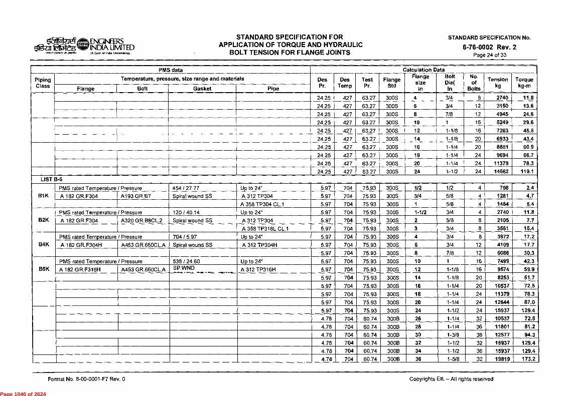
ENGINEERS INDIA LIMITED IA Govt of India Undertaking)
STANDARD SPECIFICATION FOR APPLICATION OF TORQUE AND HYDRAULIC
BOLT TENSION FOR FLANGE JOINTS
STANDARD SPECIFICATION No.
6-76-0002 Rev. 2 Page 24 of 33
/gar 1 Wen 2122072 0.11 01i7.)
Piping Class
PMS data -------- --
________ _____
Temperature, pressure, size range and materials Des Pr.
.....
Des Temp
Test Pr.
_
Flange Std
Flange size
In
Data Bolt Dia(
In
No. of
Bolts
_
Tension kg
Torque kg-m
Flange Bolt Gasket Pipe
24.25 427 63.27 300S 4 3/4 8 2740 11.8
24.25 427 63.27 300S 6 3/4 12 3150 13.6
24.25 427 63.27 300S 8 7/8 12 4945 24.6
24.25 427 63.27 300S 10 1 16 5249 29.6
24.25 427 63.27 300S 12 1-1/8 16 7263 45.5
24.25 427 63.27 300S 14 1-1/8 20 6933 43.4
24.25 427 63.27 300S 16 1-1/4 20 8851 60.9
24.25 427 63.27 300S 18 1-1/4 24 9694 66.7
24.25 427 63.27 300S 20 1-1/4 24 11379 78.3
24.25 427 63.27 300S 24 1-1/2 24 14662 119.1 LIST B-6
B1K PMS rated Temperature / Pressure 454 / 27.77 Up to 24" 5.97 704 75.93 300S 1/2 1/2 4 798 2.4
A 182 GR.F304 A193 GR.B7 Spiral wound SS A 312 TP304 5.97 704 75.93 300S 3/4 5/8 4 1281 4.7
A 358 TP304 CL.1 5.97 704 75.93 300S 1 5/8 4 1464 5.4
B2K PMS rated Temperature / Pressure 120 / 40.14 Up to 24" 5.97 704 75.93 300S 1-1/2 3/4 4 2740 11.8
A 182 GR.F304 A320 GR.B8CL.2 Spiral wound SS A 312 TP304 5.97 704 75.93 300S 2 5/8 8 2105 7.7
A 358 TP316L CL.1 5.97 704 75.93 300S 3 3/4 8 3561 15.4
B4K PMS rated Temperature / Pressure 704 / 5.97 Up to 24" 5.97 704 75.93 300S 4 3/4 8 3972 17.2
A 182 GR.F304H A453 GR.660CL.A Spiral wound SS A 312 TP304H 5.97 704 75.93 300S 6 3/4 12 4109 17.7
5.97 704 75.93 300S 8 7/8 12 6086 30.3
B5K PMS rated Temperature / Pressure 538 / 24.60 Up to 24" 5.97 704 75.93 300S 10 1 16 7499 42.3
A 182 GR.F316H A453 GR.660CL.A SP.WND A 312 TP316H 5.97 704 75.93 300S 12 1-1/8 16 9574 59.9
5.97 704 75.93 300S 14 1-1/8 20 8253 51.7
5.97 704 75.93 300S 16 1-1/4 20 10537 72.5
5.97 704 75.93 300S 18 1-1/4 24 11379 78.3
5.97 704 75.93 300S 20 1-1/4 24 12644 87.0
5.97 704 75.93 300S 24 1-1/2 24 15937 129.4
4.78 704 60.74 300B 26 1-1/4 32 10537 72.5
4.78 704 60.74 300B 28 1-1/4 36 11801 81.2
4.78 704 60.74 300B 30 1-3/8 36 12577 94.3
4.78 704 60.74 300B 32 1-1/2 32 15937 129.4
4.78 704 60.74 300B 34 1-1/2 36 15937 129.4
4.78 704 60.74 300B 36 1-5/8 32 19819 173.2
Format No. 8-00-0001-F7 Rev. 0
Copyrights EIL - All rights reserved
Page 1046 of 2624
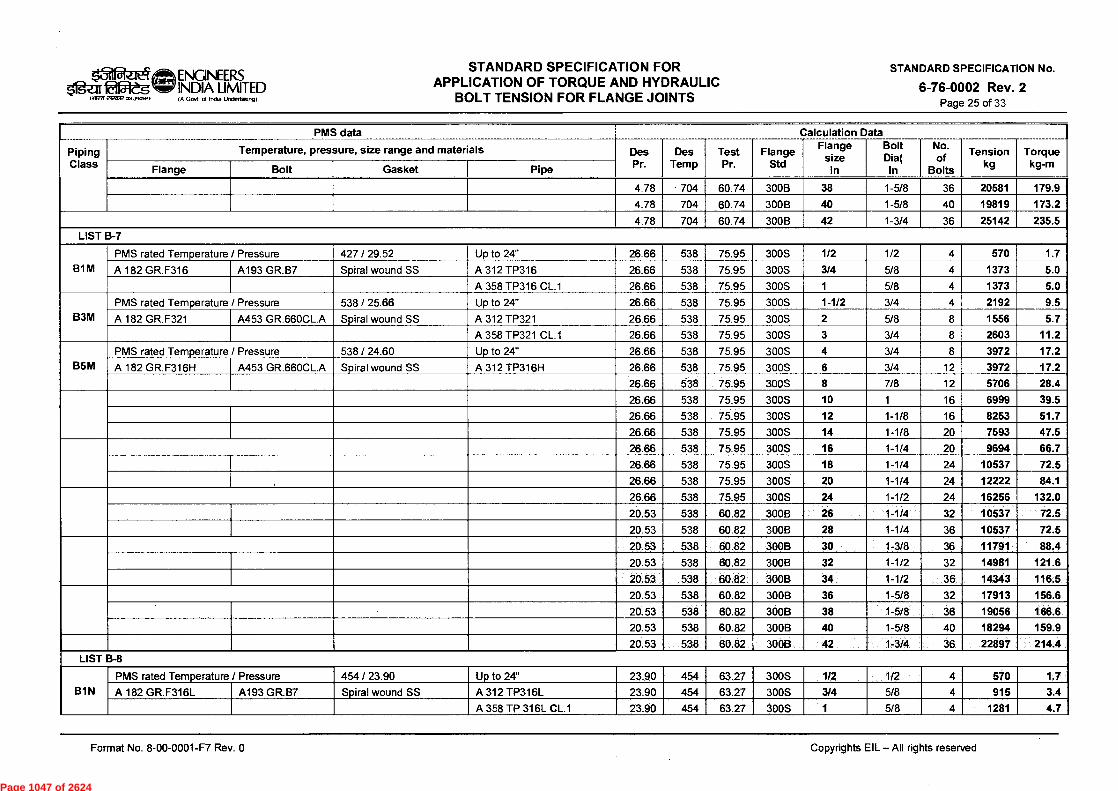
ENGINEERS INDIA LIMITED (A Govt of Ind Undeftalung)
STANDARD SPECIFICATION FOR APPLICATION OF TORQUE AND HYDRAULIC
BOLT TENSION FOR FLANGE JOINTS
STANDARD SPECIFICATION No.
6-76-0002 Rev. 2 Page 25 of 33
Ifgar Elf5i-jeg lailiWeizasTera.ywrai,
- Piping Class
PMS data _ - Temperature, pressure, size range and materials Des
Pr. Des
Temp
--- Test Pr.
_____
Flange Std
Flange size
In
Data Bolt Dia( In
-------- No. of
Bolts
------ --- Tension
kg Torque
kg-m Flange Bolt Gasket Pipe
4.78 - 704 60.74 300B 38 1-5/8 36 20581 179.9
4.78 704 60.74 300B 40 1-5/8 40 19819 173.2
4.78 704 60.74 300B 42 1-3/4 36 25142 235.5 LIST B-7
BIM PMS rated Temperature / Pressure 427 / 29.52 Up to 24" 26.66 538 75.95 300S 1/2 1/2 4 570 1.7
A 182 GR.F316 A193 GR.B7 Spiral wound SS A 312 TP316 26.66 538 75.95 300S 3/4 5/8 4 1373 5.0
A 358 TP316 CL.1 26.66 538 75.95 300S 1 5/8 4 1373 5.0
B3M PMS rated Temperature / Pressure 538 / 25.66 Up to 24" 26.66 538 75.95 300S 1-1/2 3/4 4 2192 9.5
A 182 GR.F321 A453 GR.660CL.A Spiral wound SS A 312 TP321 26.66 538 75.95 300S 2 5/8 8 1556 5.7
A 358 TP321 CL.1 26.66 538 75.95 300S 3 3/4 8 2603 11.2
B5M PMS rated Temperature / Pressure 538 / 24.60 Up to 24" 26.66 538 75.95 300S 4 3/4 8 3972 17.2
A 182 GR.F316H A453 GR.660CL.A Spiral wound SS A 312 TP316H 26.66 538 75.95 300S 6 3/4 12 3972 17.2
26.66 538 75.95 300S 8 7/8 12 5706 28.4
26.66 538 75.95 300S 10 1 16 6999 39.5
26.66 538 75.95 300S 12 1-1/8 16 8253 51.7
26.66 538 75.95 300S 14 1-1/8 20 7593 47.5
26.66 538 75.95 300S 16 1-1/4 20 9694 66.7
26.66 538 75.95 300S 18 1-1/4 24 10537 72.5
26.66 538 75.95 300S 20 1-1/4 24 12222 84.1
26.66 538 75.95 300S 24 1-1/2 24 16256 132.0
20.53 538 60.82 300B 26 1-1/4 32 10537 72.5
20.53 538 60.82 300B 28 1-1/4 36 10537 72.5
20.53 538 60.82 300B 30 1-3/8 36 11791 88.4
20.53 538 60.82 300B 32 1-1/2 32 14981 121.6
20.53 538 60.82 300B 34 1-1/2 36 14343 116.5
20.53 538 60.82 300B 36 1-5/8 32 17913 156.6
20.53 538 60.82 300B 38 1-5/8 36 19056 166.6
20.53 538 60.82 300B 40 1-5/8 40 18294 159.9
20.53 538 60.82 300B 42 1-3/4 36 22897 214.4 LIST B-8
B1N PMS rated Temperature / Pressure 454 / 23.90 Up to 24" 23.90 454 63.27 300S 1/2 1/2 4 570 1.7
A 182 GR.F316L A193 GR.B7 Spiral wound SS A 312 TP316L 23.90 454 63.27 300S 3/4 5/8 4 915 3.4
A 358 TP 316L CL.1 23.90 454 63.27 300S 1 5/8 4 1281 4.7
Format No. 8-00-0001-F7 Rev. 0
Copyrights EIL -All rights reserved
Page 1047 of 2624

STANDARD SPECIFICATION FOR APPLICATION OF TORQUE AND HYDRAULIC
BOLT TENSION FOR FLANGE JOINTS
STANDARD SPECIFICATION No.
6-76-0002 Rev. 2 Page 26 of 33
1=gz-ir fatgieg town eiroRe „num)
ro„:„Th ENGINEERS INDIA LIMITED IA Govt India Undertaking)
Piping Class
PMS data ___________________ - Temperature, pressure, size range and materials Des
Pr.
____________
Des Temp
____________
Test Pr.
Flange Std
____________ Calculation Data Fla
sizenge
I Dia(Bolt
In In
No. - of 1
Tension kg
Bolts
Torque kg-m
Flange Bolt Gasket Pipe
B6N PMS rated Temperature / Pressure 427 / 24.25 Up to 24" 23.90 454 63.27 300S 1-1/2 3/4 4 2192 9.5
A 182 GR.F316L A193 GR.B7 Spiral wound SS A 312 TP316L 23.90 454 63.27 300S 2 5/8 8 1464 5.4
A 358 TP 316L CL.1 23.90 454 63.27 300S 3 3/4 8 2466 10.6
23.90 454 63.27 300S 4 3/4 8 2740 11.8
23.90 454 63.27 300S 6 3/4 12 3150 13.6
23.90 454 63.27 300S 8 7/8 12 4945 24.6
23.90 454 63.27 300S 10 1 16 5249 29.6
23.90 454 63.27 300S 12 1-1/8 16 7263 45.5
23.90 454 63.27 300S 14 1-1/8 20 6933 43.4
23.90 454 63.27 300S 16 1-1/4 20 8851 60.9
23.90 454 63.27 300S 18 1-1/4 24 9694 66.7
23.90 454 63.27 300S 20 1-1/4 24 11379 78.3
23.90 454 63.27 300S 24 1-1/2 24 14662 119.1
LIST D-1
D1A
PMS rated Temperature / Pressure 427 / 58.00 Up to 24" 58.00 427 156.08 600S 1/2 1/2 4 970 2.9
A105 A193 GR.B7 Spiral wound SS A 106 GR.B 58.00 427 156.08 600S 3/4 5/8 4 1373 5.0
A 672 GR.B60 CL.12 58.00 427 156.08 600S 1 5/8 4 2013 7.4
D2A PMS rated Temperature / Pressure 427 / 58.00 Up to 24" 58.00 427 156.08 600S 1-1/2 3/4 4 4520 19.5
A105 A193 GR.B7 Spiral wound SS A 106 GR.B 58.00 427 156.08 600S 2 5/8 8 3112 11.4
A 672 GR.B60 CL.12 58.00 427 156.08 600S 3 3/4 8 5205 22.5
D5A PMS rated Temperature / Pressure 230 / 86.96 Up to 20" 58.00 427 156.08 600S 4 7/8 8 7228 35.9
A105 A193 GR.B7 Spiral wound SS A 106 GR.B 58.00 427 156.08 600S 6 1 12 8998 50.7
A 672 GR.B60 CL.22 58.00 427 156.08 600S 8 1-1/8 12 12875 80.6
D9A
PMS rated Temperature / Pressure 427 / 58.00 Up to 20" 58.00 427 156.08 600S 10 1-1/4 16 14751 101.5
A105 A193 GR.B7 Spiral wound SS A 106 GR.B 58.00 427 156.08 600S 12 1-1/4 20 14751 101.5
A 672 GR.B60 CL.12 58.00 427 156.08 600S 14 1-3/8 20 17294 129.7
D16A PMS rated Temperature / Pressure 427 / 58.00 Up to 24" 58.00 427 156.08 600S 16 1-1/2 20 21037 170.8
A105 A193 GR.B7M Spiral wound SS A 106 GR.B 58.00 427 156.08 600S 18 1-5/8 20 27441 239.8
A 672 GR.B60 CL.22 58.00 427 156.08 600S 20 1-5/8 24 26679 233.2
D19A PMS rated Temperature / Pressure 427 / 58.00 Up to 24" 58.00 427 156.08 600S 24 1-7/8 24 34482 343.7
A105 A193 GR.B7 Spiral wound SS A 106 GR.B 46.40 427 124.90 600B 26 1-5/8 28 25917 226.5
A 672 GR.B60 CL.22 46.40 427 124.90 600B 28 1-3/4 28 28733 269.1
46.40 427 124.90 600B 30 1-7/8 28 35527 354.2
Format No. 8-00-0001-F7 Rev. 0
Copyrights EIL - All rights reserved
Page 1048 of 2624
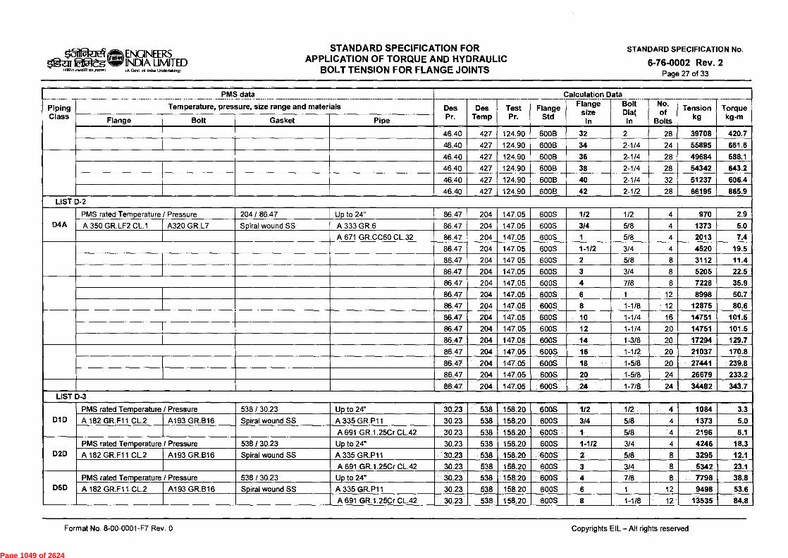
\i=i) ENGINEERS INDIA LIMITED lig ea fdlaitg
men ei2z62 0,1,3q217.11 IA Govt of Inds Undertaking)
STANDARD SPECIFICATION FOR APPLICATION OF TORQUE AND HYDRAULIC
BOLT TENSION FOR FLANGE JOINTS
STANDARD SPECIFICATION No.
6-76-0002 Rev. 2 Page 27 of 33
Piping Class
- ___ PMS data
- Temper Temperature, pressure, size range and materials
____
Des Pr. Pr
Des Tem Temp
Test Pr Pr.
Flange Std
Calculation Flange
size In
Data Bolt Dia( In
No. of
Bolts
Tension kg
_
Torque kg-m Flange Bolt Gasket Pipe
46.40 427 124.90 600B 32 2 28 39708 420.7
46.40 427 124.90 600B 34 2-1/4 24 55895 661.6
46.40 427 124.90 600B 36 2-1/4 28 49684 588.1
46.40 427 124.90 600B 38 2-1/4 28 54342 643.2
46.40 427 124.90 600B 40 2-1/4 32 51237 606.4
46.40 427 _ 124.90 600B 42 2-1/2 28 66195 865.9 LIST D-2
D4A PMS rated Temperature / Pressure 204 / 86.47 Up to 24" 86.47 204 147.05 600S 1/2 1/2 4 970 2.9
A 350 GR.LF2 CL.1 A320 GR.L7 Spiral wound SS A 333 GR.6 86.47 204 147.05 600S 3/4 5/8 4 1373 5.0
A 671 GR.CC60 CL.32 86.47 204 147.05 600S 1 5/8 4 2013 7.4
86.47 204 147.05 600S 1-1/2 3/4 4 4520 19.5
86.47 204 147.05 600S 2 5/8 8 3112 11.4
86.47 204 147.05 600S 3 3/4 8 5205 22.5
86.47 204 147.05 600S 4 7/8 8 7228 35.9
86.47 204 147.05 600S 6 1 12 8998 50.7
86.47 204 147.05 600S 8 1-1/8 • 12 12875 80.6
86.47 204 147.05 600S 10 1-1/4 16 14751 101.5
86.47 204 147.05 600S 12 1-1/4 20 14751 101.5
86.47 204 147.05 600S 14 1-3/8 20 17294 129.7
86.47 204 147.05 600S 16 1-1/2 20 21037 170.8
86.47 204 147.05 600S 18 1-5/8 20 27441 239.8
86.47 204 147.05 600S 20 1-5/8 24 26679 233.2
86.47 204 147.05 600S 24 1-7/8 24 34482 343.7 LIST D-3
DID
PMS rated Temperature / Pressure 538 / 30.23 Up to 24" 30.23 538 158.20 600S 1/2 1/2 4 1084 3.3
A 182 GR.F11 CL.2 A193 GR.B16 Spiral wound SS A 335 GR.P11 30.23 538 158.20 600S 3/4 5/8 4 1373 5.0
A 691 GR.1.25Cr CL.42 30.23 538 158.20 600S 1 5/8 4 2196 8.1
D2D PMS rated Temperature / Pressure 538 / 30.23 Up to 24" 30.23 538 158.20 600S 1-1/2 3/4 4 4246 18.3
A 182 GR.F11 CL.2 A193 GR.B16 Spiral wound SS A 335 GR.P11 30.23 538 158.20 600S 2 5/8 8 3295 12.1
A 691 GR.1.25Cr CL.42 30.23 538 158.20 600S 3 3/4 8 5342 23.1
D5D
PMS rated Temperature / Pressure 538 / 30.23 Up to 24" 30.23 538 158.20 600S 4 7/8 8 7798 38.8
A 182 GR.F11 CL.2 A193 GR.B16 Spiral wound SS A 335 GR.P11 30.23 538 158.20 600S 6 1 12 9498 53.6
A 691 GR.1.25Cr CL.42 30.23 538 158.20 600S 8 1-1/8 12 13535 84.8
Format No. 8-00-0001-F7 Rev. 0
Copyrights EIL - All rights reserved
Page 1049 of 2624
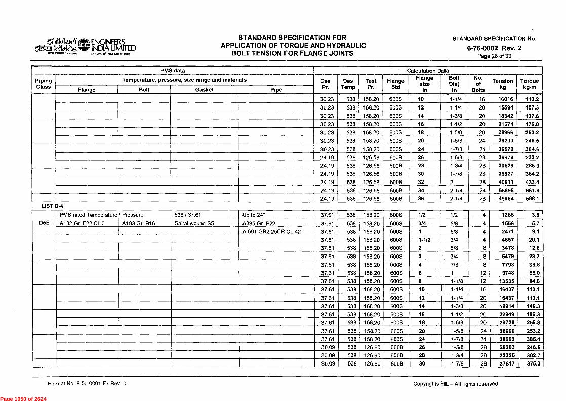
(A Gavt of Kau Undertaking)
STANDARD SPECIFICATION FOR APPLICATION OF TORQUE AND HYDRAULIC
BOLT TENSION FOR FLANGE JOINTS
of 4 ENGINEERS Ogell kit5teg INDIA LIMITED
iNIEW2122612C11513)
STANDARD SPECIFICATION No.
6-76-0002 Rev. 2 Page 28 of 33
Piping Class
PMS data ____
Temperature, pressure, size range and materials Des Pr.
_
Des Temp
Test Pr.
___
Flange Std
Calculation Data Flange I Bolt I No.
size Dia( of In In Bolts
Tension kg
Torque kg-m Flange Bolt Gasket Pipe
30.23 538 158.20 600S 10 1-1/4 16 16016 110.2
30.23 538 158.20 600S 12 1-1/4 20 15594 107.3
30.23 538 158.20 600S 14 1-3/8 20 18342 137.6
30.23 538 158.20 600S 16 1-1/2 20 21674 176.0
30.23 538 158.20 600S 18 1-5/8 20 28966 253.2
30.23 538 158.20 600S 20 1-5/8 24 28203 246.5
30.23 538 158.20 600S 24 1-7/8 24 36572 364.6
24.19 538 126.56 600B 26 1-5/8 28 26679 233.2
24.19 538 126.56 6008 28 1-3/4 28 30529 285.9
24.19 538 126.56 600B 30 1-7/8 28 35527 354.2
24.19 538 126.56 600B 32 2 28 40911 433.4
24.19 538 126.56 600B 34 2-1/4 24 55895 661.6
24.19 538 126.56 600B 36 2-1/4 28 49684 588.1 LIST D-4
D5E PMS rated Temperature / Pressure 538 / 37.61 Up to 24" 37.61 538 158.20 600S 1/2 1/2 4 1255 3.8
A182 Gr. F22 CI. 3 A193 Gr. B16 Spiral wound SS A335 Gr. P22 37.61 538 158.20 600S 314 5/8 4 1556 5.7
A 691 GR2.25CR CL.42 37.61 538 158.20 600S 1 5/8 4 2471 9.1
37.61 538 158.20 600S 1-1/2 3/4 4 4657 20.1
37.61 538 158.20 600S 2 5/8 8 3478 12.8
37.61 538 158.20 600S 3 3/4 8 5479 23.7
37.61 538 158.20 600S 4 7/8 8 7798 38.8
37.61 538 158.20 600S 6 1 12 9748 55.0
37.61 538 158.20 600S 8 1-1/8 12 13535 84.8
37.61 538 158.20 600S 10 1-1/4 16 16437 113.1
37.61 538 158.20 600S 12 1-1/4 20 16437 113.1
37.61 538 158.20 600S 14 1-3/8 20 19914 149.3
37.61 538 158.20 600S 16 1-1/2 20 22949 186.3
37.61 538 158.20 600S 18 1-5/8 20 29728 259.8
37.61 538 158.20 600S 20 1-5/8 24 28966 253.2
37.61 538 158.20 600S 24 1-7/8 24 38662 385.4
30.09 538 126.60 600B 26 1-5/8 28 28203 246.5
30.09 538 126.60 600B 28 1-3/4 28 32325 302.7
30.09 538 126.60 600B 30 1-7/8 28 37617 375.0
Format No. 8-00-0001-F7 Rev. 0
Copyrights EIL - All rights reserved
Page 1050 of 2624

ENGINEERS INDIA LIMITED (A Govt of India Undertaking)
STANDARD SPECIFICATION FOR APPLICATION OF TORQUE AND HYDRAULIC
BOLT TENSION FOR FLANGE JOINTS
STANDARD SPECIFICATION No.
6-76-0002 Rev. 2 Page 29 of 33
ster i;taft. iaaiTii eizasz 4713,18.11
Piping Class
PMS data
Temperature, pressure, size range and materials Des Pr.
___ __
Des Temp
..._
Test Pr.
Flange Std
Calculation Flange
size In
Data Bolt Dia(
In
No. of
Bolts
___
Tension kg
Torque kg-m Flange Bolt Gasket Pipe
30.09 538 126.60 600B 32 2 28 43318 458.9
30.09 538 126.60 600B 34 2-1/4 24 59000 698.3
30.09 538 126.60 600B 36 2-1/4 28 52789 624.8 LIST D-5
D1K PMS rated Temperature / Pressure 454 / 55.54 Up to 24" 55.54 454 114.00 600S 1/2 1/2 4 627 1.9
A 182 GR.F304 A193 GR.B7 Spiral wound SS A 312 TP304 55.54 454 114.00 600S 3/4 5/8 4 915 3.4
A 358 TP304 CL.1 55.54 454 114.00 600S 1 5/8 4 1281 4.7
D2K PMS rated Temperature / Pressure 120 / 80.12 Up to 24" 55.54 454 114.00 600S 1-1/2 3/4 4 2466 10.6
A 182 GR.F304 A320 GR.B8CL.2 Spiral wound SS A 312 TP304 55.54 454 114.00 600S 2 5/8 8 1647 6.0
A 358 TP304 CL.1 55.54 454 114.00 600S 3 3/4 8 3150 13.6
55.54 454 114.00 600S 4 7/8 8 5135 25.5
55.54 454 114.00 600S 6 1 12 6249 35.2
55.54 454 114.00 600S 8 1-1/8 12 8913 55.8
55.54 454 114.00 600S 10 1-1/4 16 9272 63.8
55.54 454 114.00 600S 12 1-1/4 20 10115 69.6
55.54 454 114.00 600S 14 1-3/8 20 12053 90.4
55.54 454 114.00 600S 16 1-1/2 20 15299 124.2
55.54 454 114.00 600S 18 1-5/8 20 19056 166.6
55.54 454 114.00 600S 20 1-5/8 24 19056 166.6
55.54 454 114.00 600S 24 1-7/8 24 25078 250.0
44.44 454 91.20 600B 26 1-5/8 28 18294 159.9
44.44 454 91.20 600B 28 1-3/4 28 20652 193.4
44,44 454 91.20 600B 30 1-7/8 28 24033 239.6 LIST E-1
ElA PMS rated Temperature / Pressure 427 / 86.83 Up to 24" 86.83 427 234.12 900S 1/2 3/4 4 2877 11.9
A105 A193 GR.B7 RTJ - Soft Iron A 106 GR.B 86.83 427 234.12 900S 3/4 314 4 3698 15.3
A 672 GR.B60 CL. 12 86.83 427 234.12 900S 1 7/8 4 4565 21.7
E2A PMS rated Temperature / Pressure 427 / 86.83 Up to 24" 86.83 427 234.12 900S 1-1/2 1 4 6999 37.7
A105 A193 GR.B7 RTJ - Soft Iron A 106 GR.B 86.83 427 234.12 900S 2 7/8 8 5135 24.4
A 672 GR.B60 CL. 12 86.83 427 234.12 900S 3 7/8 8 6847 32.6
E5A PMS rated Temperature / Pressure 230 / 130.63 Up to 24" 86.83 427 234.12 900S 4 1-1/8 8 8583 51.4
A105 A193 GR.B7 RTJ - Soft Iron A 106 GR.B 86.83 427 234.12 900S 6 1-1/8 12 10234 61.3
A 672 GR.B60 CL. 12 86.83 427 234.12 900S 8 1-3/8 12 15197 109.0
Format No. 8-00-0001-F7 Rev. 0
Copyrights EIL - All rights reserved
Page 1051 of 2624

laf54-eg- landar didan-R dil,rarna,0
ENGINEERS INDIA LIMITED IA G0 CA India Undertaking)
STANDARD SPECIFICATION FOR APPLICATION OF TORQUE AND HYDRAULIC
BOLT TENSION FOR FLANGE JOINTS
STANDARD SPECIFICATION No.
6-76-0002 Rev. 2 Page 30 of 33
Pi in p' g Class
Tem erature ressure, size ran a and materials P r P 9 Des Pr.
Des Temp
Test Pr.
Flange Std
Flange size
In
Bolt Dia(
In
No. of
Bolts
Tension kg
Torque kg-m Flange Bolt Gasket Pipe
E9A PMS rated Temperature / Pressure 427 / 86.83 Up to 24" 86.83 427 234.12 900S 10 1-3/8 16 16245 116.5 A105 A193 GR.B7 RTJ - Soft Iron A 106 GR.B 86.83 427 234.12 900S 12 1-3/8 20 17294 124.1
A 672 GR.B60 CL. 12 86.83 427 234.12 900S 14 1-1/2 20 21674 168.3
E19A PMS rated Temperature / Pressure 427 / 86.83 Up to 24" 86.83 427 234.12 900S 16 1-5/8 20 26679 223.0 A105 A193 GR.B7 RTJ - Soft Iron A 106 GR.B 86.83 427 234.12 900S 18 1-7/8 20 35527 338.8
A 672 GR.B60 CL. 12 86.83 427 234.12 900S 20 2 20 40911 414.6
86.83 427 234.12 900S 24 2-1/2 20 62301 779.5
69.47 427 187.30 900B 26 2-1/2 20 60354 755.2
69.47 427 187.30 900B 28 2-3/4 20 66799 915.6
69.47 427 187.30 900B 30 3 20 77472 1152.8 LIST E-2
E5E PMS rated Temperature / Pressure 538 / 56.24 Up to 24" 56.24 538 237.28 900S 1/2 3/4 4 3150 13.0 A182 Gr. F22 CI. 3 A193 Gr. B16 RTJ - 5Cr-0.5Mo A335 Gr. P22 56.24 538 237.28 900S 3/4 3/4 4 3835 15.8
A 691 GR2.25CR CL.42 56.24 538 237.28 900S 1 7/8 4 5326 25.3
Up to 20" 56.24 538 237.28 900S 1-1/2 1 4 7749 41.8
A 335 GR.P11 56.24 538 237.28 900S 2 7/8 8 5896 28.0
A 691 GR.1.25Cr CL. 42 56.24 538 237.28 900S 3 7/8 8 6467 30.7
56.24 538 237.28 900S 4 1-1/8 8 9904 59.3
56.24 538 237.28 900S 6 1-1/8 12 10894 65.3
56.24 538 237.28 900S 8 1-3/8 12 16245 116.5
56.24 538 237.28 900S 10 1-3/8 16 16770 120.3
56.24 538 237.28 900S 12 1-3/8 20 17818 127.8
56.24 538 237.28 900S 14 1-1/2 20 22949 178.2
56.24 538 237.28 900S 16 1-5/8 20 28203 235.8
56.24 538 237.28 900S 18 1-7/8 20 36572 348.7
56.24 538 237.28 900S 20 2 20 44521 451.1
56.24 538 237.28 900S 24 2-1/2 20 68142 852.6
56.24 538 189.83 900B 26 2-1/2 20 64248 803.9
56.24 538 189.83 900B 28 2-3/4 20 73956 1013.8
56.24 538 189.83 900B 30 3 20 83211 1238.2 LIST F-1
PMS rated Temperature / Pressure 427 / 144.83 Up to 24" 144.83 427 390.74 1500S 1/2 3/4 4 3014 12.4 A105 A193 GR.B7 RTJ - Soft Iron A 106 GR.B 144.83 427 390.74 1500S 3/4 3/4 4 3972 16.4
Format No. 8-00-0001-F7 Rev. 0
Copyrights EIL - All rights reserved
Page 1052 of 2624
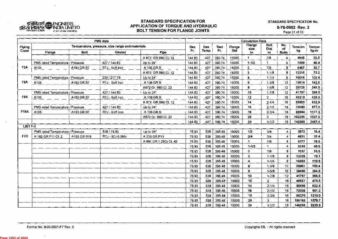
ENGINEERS INDIA LIMITED IA Gent of India Undertaking)
STANDARD SPECIFICATION FOR APPLICATION OF TORQUE AND HYDRAULIC
BOLT TENSION FOR FLANGE JOINTS
STANDARD SPECIFICATION No.
6-76-0002 Rev. 2 Page 31 of 33
„21 s~lr kitOieg
(awn riraale ils1.3R117,0
Er I
________
Piping Class
____________ PMS data --- ----- ----
Temperature, pressure, size range and materials Des Pr.
Des Temp
Test Pr.
Flange Std
Calculation Flange
size In
Data Bolt
Dia( In
NO.-- of
Bolts
Tension kg
Torque kg-m Flange Bolt Gasket Pipe
A 672 GR.B60 CL.12 144.83 427 390.74 1500S 1 7/8 4 4945 23.5
F2A PMS rated Temperature / Pressure 427 / 144.83 Up to 24" 144.83 427 390.74 1500S 1-1/2 1 4 7499 40.4
A105 A193 GR.B7 RTJ - Soft Iron A 106 GR.B 144.83 427 390.74 1500S 2 7/8 8 6467 30.7
A 672 GR.B60 CL.12 144.83 427 390.74 1500S 3 1-1/8 8 12215 73.2
F5A PMS rated Temperature / Pressure 230 / 217.79 Up to 24" 144.83 427 390.74 1500S 4 1-1/4 8 16016 105.4
A105 A193 GR.B7 RTJ - Soft Iron A 106 GR.B 144.83 427 390.74 1500S 6 1-3/8 12 19914 142.8
A672 Gr. B60 Cl. 22 144.83 427 390.74 1500S 8 1-5/8 12 29728 248.5
F9A PMS rated Temperature / Pressure 427 / 144.83 Up to 24" 144.83 427 390.74 1500S 10 1-7/8 12 41797 398.5
A105 A193 GR.B7 RTJ - Soft Iron A 106 GR.B 144.83 427 390.74 1500S 12 2 16 43318 439.0
A 672 GR.B60 CL.12 144.83 427 390.74 1500S 14 2-1/4 16 55895 632.8
F19A PMS rated Temperature / Pressure 427 / 144.83 Up to 24" 144.83 427 390.74 1500S 16 2-1/2 16 70089 877.0
A105 A193 GR.B7 RTJ - Soft Iron A 106 GR.B 144.83 427 390.74 1500S 18 2-3/4 16 85884 1177.3
A672 Gr. B60 Cl. 22 144.83 427 390.74 1500S 20 3 16 103296 1537.0
144.83 427 390.74 1500S 24 3-1/2 16 142889 2467.4 LIST F-2
F2D PMS rated Temperature / Pressure • 538 / 75.93 Up to 24" 75.93 538 395.48 1500S 1/2 3/4 4 3972 16.4
A 182 GR.F11 CL.2 A193 GR.B16 RTJ - 5Cr-0.5Mo A 335 GR.P11 75.93 538 395.48 1500S 3/4 3/4 4 4931 20.4
A 691 GR.1.25Cr CL.42 75.93 538 395.48 1500S 1 7/8 4 6277 29.8
75.93 538 395.48 1500S 1-1/2 1 4 9248 49.9
75.93 538 395.48 1500S 2 7/8 8 7037 33.5
75.93 538 395.48 1500S 3 1-1/8 8 13205 79.1
75.93 538 395.48 1500S 4 1-1/4 8 16858 110.9
75.93 538 395.48 1500S 6 1-3/8 12 20962 150.4
75.93 538 395.48 1500S 8 1-5/8 12 30490 254.9
75.93 538 395.48 1500S 10 1-7/8 12 41797 398.5
75.93 538 395.48 1500S 12 16 46927 475.5
75.93 538 395.48 1500S 14 2-1/4 16 55895 632.8
75.93 538 395.48 1500S 16 2-1/2 16 72036 901.3
75.93 538 395.48 1500S 18 2-3/4 16 88270 1210.0
75.93 538 395.48 1500S 20 3 16 106165 1579.7
75.93 538 395.48 1500S 24 3-1/2 16 146858 2535.9
Format No. 8-00-0001-F7 Rev. 0
Copyrights EIL - All rights reserved
Page 1053 of 2624
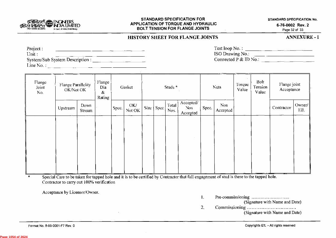
IA Govt d Intha Undertaking)
STANDARD SPECIFICATION FOR APPLICATION OF TORQUE AND HYDRAULIC
BOLT TENSION FOR FLANGE JOINTS
LI n ENGINEERS Isar ktiegS INDIA LJMITED
to IEW eiRTUR CM.1.707.1)
STANDARD SPECIFICATION No.
6-76-0002 Rev. 2 Page 32 of 33
HISTORY SHEET FOR FLANGE JOINTS
ANNEXURE - I
Project : Unit : System/Sub System Description : Line No. :
Test loop No. : ISO Drawing No.: Connected P & ID No.:
Flange Joint No.
Flange Parallelity OK/Not OK
Flange Dia &
Rating
Gasket Studs * Nuts Torque Value
Bolt Tension Value
Flange joint Acceptance
Upstream Down Stream
Spec. OK/
Not OK Size Spec
Total Nos.
Accepted/ Nos
Accepted Spec.
Nos Accepted
Contractor Owner/
EIL
Special Care to be taken for tapped hole and it is to be certified by Contractor that full engagement of stud is there to the tapped hole. Contractor to carry out 100% verification
Acceptance by Licensor/Owner. 1. Pre-commissioning
(Signature with Name and Date) 2. Commissioning
(Signature with Name and Date)
Copyrights EIL-All rights reserved Format No. 8-00-0001-F7 Rev. 0
Page 1054 of 2624
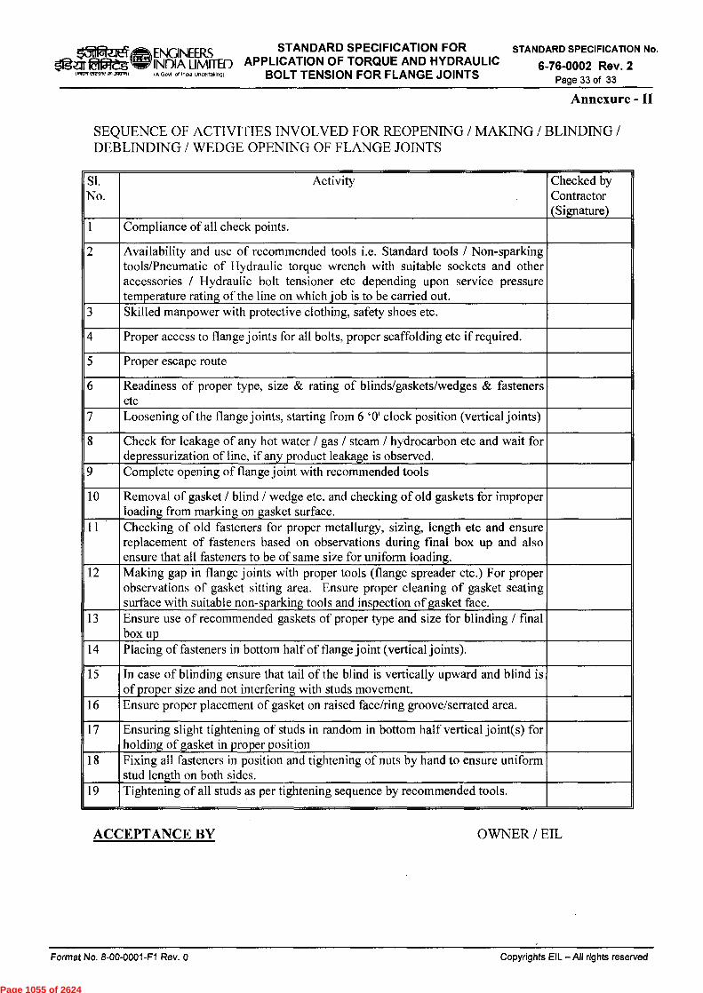
ENGINEERS STANDARD SPECIFICATION FOR APPLICATION OF TORQUE AND HYDRAULIC
STANDARD SPECIFICATION No. 4-1
Zgar EtOleg INDIA LIMITED 6-76-0002 Rev. 2 INITerrwartandvINPI (A Govt of IndLa undertaking] BOLT TENSION FOR FLANGE JOINTS Page 33 of 33
Annexure - II
SEQUENCE OF ACTIVITIES INVOLVED FOR REOPENING / MAKING / BLINDING / DEBLINDING / WEDGE OPENING OF FLANGE JOINTS
Si. No.
Activity Checked by Contractor (Signature)
1 Compliance of all check points.
2 Availability and use of recommended tools i.e. Standard tools / Non-sparking tools/Pneumatic of Hydraulic torque wrench with suitable sockets and other accessories / Hydraulic bolt tensioner etc depending upon service pressure temperature rating of the line on which job is to be carried out.
3 Skilled manpower with protective clothing, safety shoes etc.
4 Proper access to flange joints for all bolts, proper scaffolding etc if required.
5 Proper escape route
6 Readiness of proper type, size & rating of blinds/gaskets/wedges & fasteners etc
7 Loosening of the flange joints, starting from 6 '0' clock position (vertical joints)
8 Check for leakage of any hot water / gas / steam / hydrocarbon etc and wait for depressurization of line, if any product leakage is observed.
9 Complete opening of flange joint with recommended tools
10 Removal of gasket / blind / wedge etc. and checking of old gaskets for improper loading from marking on gasket surface.
11 Checking of old fasteners for proper metallurgy, sizing, length etc and ensure replacement of fasteners based on observations during final box up and also ensure that all fasteners to be of same size for uniform loading.
12 Making gap in flange joints with proper tools (flange spreader etc.) For proper observations of gasket sitting area. Ensure proper cleaning of gasket seating surface with suitable non-sparking tools and inspection of gasket face.
13 Ensure use of recommended gaskets of proper type and size for blinding / final box up
14 Placing of fasteners in bottom half of flange joint (vertical joints).
15 In case of blinding ensure that tail of the blind is vertically upward and blind is of proper size and not interfering with studs movement.
16 Ensure proper placement of gasket on raised face/ring groove/serrated area.
17 Ensuring slight tightening of studs in random in bottom half vertical joint(s) for holding of gasket in proper position
18 Fixing all fasteners in position and tightening of nuts by hand to ensure uniform stud length on both sides.
19 Tightening of all studs as per tightening sequence by recommended tools.
ACCEPTANCE BY
OWNER / EIL
Format No. 8-00-0001-F1 Rev. 0
Copyrights EIL — All rights reserved
Page 1055 of 2624

ATTACHMENT – V
Page 1056 of 2624

Oziei ENGINEERS STANDARD SPECIFICATION STANDARD SPECIFICATION No
ria
itge.n 99:5,s, & MACHINERY INDIA LIMITED FOR ERECTION OF EQUIPMENT 6-76-0001 Rev. 3
Page 1 of 22
6*k-cm vd zit *r TWIT tq &Hot Far4t2T
STANDARD SPECIFICATION FOR
ERECTION OF EQUIPMENT & MACHINERY
2 03.09.2008 Revised & Reissued DM PKR AA VC
1 30.05.2008 Revised & Reissued DM PKR AA VC
0 25.04.2001 Issued as Standard Specification DM AM MR MI
Rev. No Date Purpose Prepared
by Checked
by
Standards Committee Convenor
Standards Bureau
Chairman
Approved by
Format No. 8-00-0001-F1 Rev. 0
Copyright EIL — All rights reserved
Page 1057 of 2624

ENGINEERS STANDARD SPECIFICATION FOR STANDARD SPECIFICATION No.
INDIA LIMITED ERECTION OF EQUIPMENT & 6-76-0001 Rev. 3 IA Gobi of India Undetakingi MACHINERY Page 2 of 22
zier SiglIT °far
Abbreviations:
ASME American Society of Mechanical Engineers
EC Erection Contractor
EIC Engineer-in-charge
ELCB Earth Leakage Circuit Breaker
GAD General Arrangement Drawing
IS Indian Standard
NDT Non Destructive Testing
SS Stainless Steel
General Engg. Standards Committee
Convenor : Members :
Mr. Vinay Kumar Mr. S. Chanda Mr. J.M. Singh Mr. D. Khare Ms.Vartika Shukla Mr. M.P. Jain Ms. N.P. Guha Mr. Rakesh Nanda
Format No. 8-00-0001-F1 Rev. 0 Copyright EIL — All rights reserved
Page 1058 of 2624
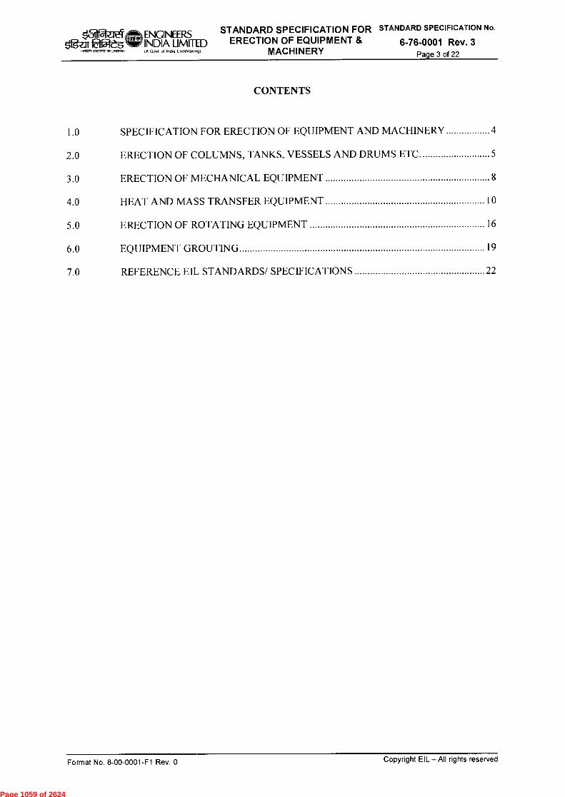
fazieT to ENGINEERS STANDARD SPECIFICATION FOR STANDARD SPECIFICATION No.
Ogelf laliteS INDIA LIMITED ERECTION OF EQUIPMENT & 6-76-0001 Rev. 3 MACHINERY Page 3 of 22
CONTENTS
1.0 SPECIFICATION FOR ERECTION OF EQUIPMENT AND MACHINERY 4
2.0 ERECTION OF COLUMNS, TANKS, VESSELS AND DRUMS ETC 5
3.0 ERECTION OF MECHANICAL EQUIPMENT 8
4.0 HEAT AND MASS TRANSFER EQUIPMENT 10
5.0 ERECTION OF ROTATING EQUIPMENT 16
6.0 EQUIPMENT GROUTING 19
7.0 REFERENCE EIL STANDARDS/ SPECIFICATIONS 22
Format No. 8-00-0001-F1 Rev. 0 Copyright EIL—All rights reserved
Page 1059 of 2624
ENGINEERS STANDARD SPECIFICATION FOR STANDARD SPECIFICATION No.
INDIA LIMITED ERECTION OF EQUIPMENT & 6-76-0001 Rev. 3 Page 4 of 22
A O,l of India underlakPrigi MACHINERY
1.0 SPECIFICATION FOR ERECTION OF EQUIPMENT AND MACHINERY
1.1 Scope
This specification covers technical requirements for erection of all static and rotating equipment by erection contractor at site. This specification is applicable for all the erection tenders operated by EIL.
1.2 General
1.2.1 All necessary handling equipments, tools, tackles and precision instruments for carrying out the works as specified shall be provided by the Erection Contractor (EC) at his cost. EC must provide all tools and gauges for erection and alignment. Special tools, if any, received as part of machinery, will be given to EC for erection purposes, which shall be returned in good condition after use. Suitable deductions will be made by the Engineer-in-Charge (EIC) in case of loss or damage of the special tools. The value of such loss or damage will be decided by the EIC and EC shall be bound by such a decision.
1.2.2 Equipment Manufacturer's recommendations regarding preservation during storage at site and detailed specifications for the installation alongwith layout drawings, general arrangement/equipment outline drawings and sub-assembly drawings of the various equipment and machinery will be provided to EC during the performance of work. The requirements stipulated in these shall be fulfilled by EC in addition to what is stated in this specification. Erection shall be carried out as per the instructions and supervision of Machinery manufacturer's representative, wherever such supervisory services are applicable.
1.2.3 All the items of work covered in the tender shall be carried out as per this Specification and other details to be furnished to EC. However, EIC reserves the right to give additional/alternative specifications and instructions, at any time, for execution of any particular work and EC shall execute such works in accordance with such additional/alternative specifications and instructions of the EIC. Such a step taken by the EIC shall not constitute a breach of the contract.
1.3 Preparation for Erection
1.3.1 EC shall be responsible for organising the lifting of the equipment in the proper sequence, so that orderly progress of the work is ensured and access routes for erecting the other equipment are kept open.
Rigging procedure for all the major lifts (above 10 MT) and at maximum crane capacity shall be submitted by EC for the approval of EIC. However, approval to rigging procedure proposed by EC shall not relieve EC from his responsibility in following the proper lifting/erection methods on ensuring orderly .
1.3.2 Orientation of all foundations, elevations, length and disposition of anchor bolts and diameter of holes in the supports saddles shall be checked by EC, well in advance. Minor rectifications including chipping of foundations as the case may be, shall be carried out by EC after obtaining prior approval of EIC. EC shall also be provided with the necessary structural drawings and piping layouts etc. wherever required for reference. EC shall crosscheck such piping and structural drawings with actual construction at site and in case of any mismatch inform the EIC before taking up the erection.
Format No. 8-00-0001-F1 Rev. 0 Copyright EIL—All rights reserved
Page 1060 of 2624

ENGINEERS STANDARD SPECIFICATION FOR STANDARD SPECIFICATION No.
INDIA LIMITED ERECTION OF EQUIPMENT & 6-76-0001 Rev. 3 5fgar fakres IA Govl 01 haw undeptakingl MACHINERY Page 5 of 22
1.3.3 During the performance of the work, EC shall keep structures, materials or equipments adequately braced by guys, struts or otherwise approved means which shall be supplied and installed by EC as required till the installation work is satisfactorily completed. Such guys, shoring , bracing, strutting, planking supports etc. shall not interfere with the work of other agencies and shall not damage or cause distortion to other works executed by him or other agencies.
2.0 ERECTION OF COLUMNS, TANKS, VESSELS AND DRUMS ETC.
2.1 Scope of work of Erection Contractor
(a) Preparation of erection scheme and rigging procedure and obtaining its approval from EIC wherever necessary.
(b) Withdrawal of equipments from Owner's storage point, checking and reporting its conditions, transporting the same to EC's stores of work site including unloading etc.
(c) Erection on foundations furnished by Owner including aligning, levelling and grouting.
(d) Assembly and fixing of demisters, grids, internal distributors and other internal fittings in Columns, Vessels etc.
(e) Filling of Columns, Reactors, Vessels/Drums etc. with Raschig rings, supporting elements, sand, concrete etc. as required.
(0 Welding of washers for equipments, erection of pipe davit & minor welding of their parts as per specifications and instruction of EIC.
(g) Assembly & erection of Agitator (Mixer) along with drive unit (Motor) including all accessories for vessels/drums/reactors (wherever indicated) as per specification drawings & instructions of EIC.
(h) Flushing, cleaning and drying of Columns, Vessels/Drums etc.
(i) Completing the equipments in all respects for commissioning the plant as per drawings, specifications & instructions of EIC.
0) Any modification in the erected Columns, Reactors, Vessels/Drums to the complete satisfaction of EIC.
2.2 General Conditions of Erection
2.2.1 Unless otherwise specified Columns, Vessels, Drums etc. will be generally supplied to the Erection Contractor in single piece and EC will not be required to carry out any assembly or welding. In case column is supplied in multiple pieces and erection of the equipment is not possible in single piece, EC shall be responsible for lifting the pieces, for aligning, welding and hydrotest etc. in vertical position under the supervision of column Supplier (Fabricator). However, EIC shall be responsible for coordination between Erection Contractor & Fabricator. The schedule of quantities (SO()) for equipment erection enclosed with the tender document outlines details of each equipment such as diameter, overall height, type of support (saddle/skirt/leg/bracket), position (horizontal or vertical) and approximate erection weight etc. However the erection elevation and location of equipment shall be as per the piping layout drawing enclosed with the tender.
Copyright EIL — All rights reserved Format No. 8-00-0001-F1 Rev. 0
Page 1061 of 2624
ENGINEERS STANDARD SPECIFICATION FOR STANDARD SPECIFICATION No.
INDIA LIMITED ERECTION OF EQUIPMENT & 6-76-0001 Rev. 3 0 Gov' of Indra Undettakingl MACHINERY Page 6 of 22
INIFEzie? SIgt-IT "keg
2.2.2 Rigging procedures and erection schemes for all the heavy lifts weighing 10 MT & above shall be prepared by EC and got approved by EIC. Approval by EIC shall not relieve EC of his responsibilities. The details to be submitted will include the location of equipment from where it will be lifted, location of crane(s), details of crane(s) (like configuration, boom length, operating radius, boom point elevation, clearance underside the boom and the equipment, lifting capacity, counter weights to be deployed, holds on any neighbouring foundations, structures, equipments etc.), the load chart of the crane(s), design of the lifting tackles like spreader beam, D-shackles, wire rope slings etc. Unless the erection scheme and rigging procedures are approved by EIC, erection of such equipments shall not be undertaken in any case by EC.
2.2.3 Before starting the erection of Columns, Vessels etc., top surface of the foundations is to be cleared/chipped, roughened to obtain proper bond, while grouting. Also the sleeves are to be cleaned before erecting the equipments. Line (orientation) and levels are to be marked on all the foundations to facilitate checking of alignment.
EC shall also check the correct elevation and orientation of civil, structural foundations, before proceeding with the erection work. Discrepancy, if any, shall be brought to the notice of EIC. However, minor rectifications and chipping of foundations upto a thickness of 15 mm in foundation height shall be carried out at no extra cost, by the EC. EC shall be responsible for supply of levelling plates, (if required) and shall carry out levelling of equipment under the directions of EIC.
2.2.4 While handling, transporting or erecting the equipments, care shall be taken not to damage the nozzles, instrument connections, structural clips etc. EC shall also take care of the orientation of the nozzles and other connections of the equipments while erecting the same and ensure compliance with the drawings and specifications supplied. Discrepancy, if any, in the number/orientation of the nozzles, cleats etc. should be brought to the notice of the EIC before actual erection is started.
2.2.5 Verticality of the Columns, ReactorsNessels shall be checked with theodolites. After erection the equipment shall be levelled and properly aligned with necessary shims and wedges supplied by EC, at his cost. After the level, alignment and verticality etc. are checked and approved by EIC, EC shall carry out grouting.
2.2.6 EC shall produce recent test certificates of the slings which they will be using for erection work. However, retesting of the slings shall be done at site by EC at his cost, as and when required by EIC. The weights of test loads shall be as per IS-807. The test loads shall be supplied by EC at his cost. Tested slings will be punched for test loads and date of testing as directed by EIC.
2.2.7 EC shall also carry out the assembly, erection, levelling and alignment of all types of weir plates, baffles, distributors, collectors, spray nozzles, demisters, grids and other internal fittings etc. Work shall be carried out as per manufacturer's standards/specifications which shall be made available to EC at the time of erection. Raschig rings, molecular sieves, intalax saddles packing and other types of tower packings such as sand, catalyst etc. and SS wire mesh shall be loaded into sections of Vessels, Columns as per specifications and drawings. Details for internals to be installed by EC shall be as per separate schedule of quantities enclosed with the tender document. All packings except clay and lime stone shall be washed with water before filling. Bottom layers, if required, shall be arranged as directed and random filling shall be done afterwards with equipment filled with water. Installation of packings, shall be done only after flushing and cleaning of Columns/Vessels and completed to the satisfaction of EIC.
Copyright EIL — All rights reserved Format No. 8-00-0001-F1 Rev. 0
Page 1062 of 2624

ENGINEERS STANDARD SPECIFICATION FOR STANDARD SPECIFICATION No.
INDIA LIMITED ERECTION OF EQUIPMENT & 6-76-0001 Rev. 3 MACHINERY Page 7 of 22
laratlei * la g,
2.2.8 EC shall carry out minor welding for attachment of prefabricated pipe davit parts such as rain covers, handles etc. with pipe davit, during or after erection of the same as per the manufacturer's specifications, at no extra cost to the Owner.
2.2.9 EC shall execute erection of wooden pillow for saddle support for cold horizontal vessels wherever necessary as indicated on the drawings/ EIL STD 7-12-0003 and as per the instructions of EIC.
2.2.10 EC shall execute assembly & erection of agitator/mixer along with drive unit including all accessories as per supplier's instructions, specification drawings & instructions of EIC.
2.3 Flushing & Cleaning of Columns, Vessels, Drums etc.
2.3.1 After the erection, alignment and grouting of these equipments are complete, flushing and cleaning shall be carried out by EC as per specifications and instructions of EIC.
2.3.2 After flushing, cleaning and draining, equipments shall be dried by compressed air at the pressure and for duration decided by the EIC. The Vessel interior shall be thoroughly inspected to the complete satisfaction of EIC before it is finally boxed up. Boxing up of manholes and handholes shall be leak proof. All joints which need remaking, shall be remade. Compressed air for drying shall be arranged by EC.
2.4 Inspection and Acceptance Limits for Level and Alignment
2.4.1 Co-ordinates of foundations/supporting structures/mounting holes etc. shall be checked with respect to the plot plans by EC.
2.4.2 Before equipments are placed on foundations, orientations shall be checked with respect to piping drawings.
2.4.3 When equipments are firmly bolted down but prior to grouting, verticality of all the Columns, vertical vessels etc. shall be checked by using theodolite. Tolerances for equipment after erection shall be as per EIL Standard 7-12-0001. The allowable deviation from plumb line shall be 1 mm per metre height, subject to maximum of 15 mm unless otherwise stated on the drawings.
2.4.4 Horizontal Vessels shall be checked for level across machined face of nozzle flanges with precision level.
2.5 Additional requirements for Underground buried vessels
2.5.1 Underground vessels for operating temp upto 60°C
The vessels shall be supplied at site with one coat of inorganic zinc silicate primer duly applied on its external surfaces as per Spec. 6-79-0020. All other works such as application of coaltar enamel, as per 6-79-0020 & wrapping and coating as per EIL Spec. 6-79-0011 shall be carried out by EC. This shall include necessary materials, tools and tackles to complete the Job in all respect as per the instructions of EIC.
2.5.2 Underground Vessels for operating temp. Above 60°C and upto 300°C
The vessels shall be supplied at site with one coat of inorganic zinc silicate primer as per Spec. 6-79-0020 duly applied on its external surfaces. EC shall be required to carryout touch-up and repair of outside primer before erection of equipment.
Copyright EIL—All rights reserved Format No. 8-00-0001-F1 Rev. 0
Page 1063 of 2624
STANDARD SPECIFICATION FOR STANDARD SPECIFICATION No.
ERECTION OF EQUIPMENT & 6-76-0001 Rev. 3 MACHINERY Page 8 of 22
a farm a ENGINEERS slig2li EVIegU INDIA LIMITED
IA Gori al India undenakrnyi
2.5.3 EC shall do the necessary excavation, backfilling and removal of surplus earth at the site as per the directions of the EIC. EC's rate shall include the excavation, blast cleaning, painting, wrapping by kraft paper, placing and fixing of Vessels, backfilling and removal of excess earth.
3.0 ERECTION OF MECHANICAL EQUIPMENT
3.1 Scope of Work of Erection Contractor
The scope of EC shall consist of withdrawal and transportation of equipments and accessories from Owner's stores to site, assembly of loose supplied components/parts erection of equipment on foundations, levelling, aligning and grouting, preparation of equipments for trial runs and hand over in fit condition for the start up of the plant as per instructions of EIC.
3.2 Details of Owner Supplied Equipments
Equipments to be erected shall be supplied by the owner. Equipments may be supplied in any of the following conditions.
Single equipment such as filter, static mixer, silencer etc.
Skid mounted equipment, fully assembled.
Skid mounted equipment with some items supplied loose or as subassemblies involving interconnections also.
System comprising of many equipments, skids with interconnected piping & hook up.
3.3 Technical Requirements
3.3.1 All equipment/machinery erection shall be done by experienced fitters. For this purpose EC shall employ an experienced erection supervisor and crew who have done similar jobs.
3.3.2 EC shall study the layout drawings, for the machineries and equipments with their auxiliaries, controls defining scope of supply.
3.3.3 Equipments shall be checked for any damages as a result of transport, handling and defects, if any, shall be reported to the EIC. Rectification of defects shall be carried out in accordance with approved procedure.
3.3.4 Correct procedures for handling of equipment & installation on the foundation shall be followed as given in the manufacturer's manual. In case of non-availability of such procedures, EC shall develop & submit handling procedures for all equipment weighing more than 10 metric tonnes. The handling procedure shall be approved by the EIC.
3.3.5 EC shall check the correctness of equipment foundations or supporting structures as per the drawings. Equipment/Skid foot print dimensions shall be verified to match with the foundation. Minor chipping of foundation, pockets if required shall be carried out by EC.
3.3.6 All accessories like pressure gauges, seal oil, cooling water & Lube oil headers etc., shall be tagged and separately kept in Contractor's stores till erection. All flanged connections and openings shall be kept blanked with dummies, plugs to prevent entry of foreign particles.
3.3.7 Equipments shall be installed on the foundations in proper sequence. Incase the equipments are delivered in subassemblies, EC shall do the assembly work as per manufacturer's instructions.
3.3.8 Equipments shall be installed in the correct orientation and alignment.
Copyright EIL — All rights reserved Format No. 8-00-0001-F1 Rev. 0
Page 1064 of 2624
filPA; ENGINEERS STANDARD SPECIFICATION FOR STANDARD SPECIFICATION No.
5ittif EffileS ‘71? INDIA LIMITED ERECTION OF EQUIPMENT & 6-76-0001 Rev. 3 GoN at India Undenakg,91 MACHINERY Page 9 of 22
3.3.9 After installation and levelling the equipment shall be grouted with the specified grouting applied to the baseplate and support.
3.3.10 EC shall remove all the packing and protective devices used during transport and handling from the equipment such as shock absorbent materials from machined faces, blocking of shafts or rolling bearings & restraining devices from instruments, safety devices and protective equipments.
3.3.11 After the grouting is set & cured, the foundation bolts shall be checked to make sure that they are in straight and vertical position and properly tightened. Shims, if used, shall be on either side of the foundation bolts.
3.3.12 Desiccant, catalyst where supplied loose shall be loaded on to the respective vessels in specified quantities as per the suppliers instructions.
3.3.13 Internals, where supplied loose shall be assembled as per the drawings and manufacturer's instructions.
3.3.14 Unless otherwise specified, all the instruments such as pressure gauges, sight glasses temperature recorders etc. including instrument panels, if any, supplied along with the equipment with necessary connections, shall be installed by EC as part of Equipment erection.
3.3.15 Equipments shall be checked for final cleanliness before boxing up.
3.3.16 Any interconnected piping & ducting shall be properly installed and supported. EC shall connect the gas, steam, air, utility piping, instruments, oil piping etc. as per manufacturer's drawings, specifications and instructions of the EIC.
3.3.17 Safety devices shall be correctly installed.
3.3.18 Ladders, platforms, walkways shall be correctly installed with handrails, and flooring shall be properly secured.
3.3.19 Field welding, where specified shall be in accordance with the specified procedures and NDT tests where specified shall be carried out. Results of NDT tests shall be recorded.
3.3.20 Equipment alignment & couplings shall comply with tolerances specified in manufacturer's drawings and manuals. Provisions of dowel pins or similar arrangements for retaining the alignment shall be carried out.
3.3.21 After the piping has been connected, the alignment shall be checked by EC again, to ensure that piping connections do not induce any undue stresses on the Equipments. After making necessary corrections on the piping, if any, realignment shall be done by EC to ensure that no undue stresses are induced on the equipment.
3.3.22 Painting, insulation & fireproofing where specified shall be carried out in accordance with the applicable specifications attached in the tender document.
3.3.23 Any alterations, deviations made during equipment erection with respect to manufacturer's drawings or instructions shall be duly recorded and approval shall be taken from the EIC.
3.3.24 Any special tools, tackles supplied along with the equipment and used during installation shall be returned to the stores through the EIC.
3.3.25 Any protection of the equipment after installation, if required shall be carried out in accordance of the instructions of the EIC.
Format No. 8-00-0001-F1 Rev. 0 Copyright EL—All rights reserved
Page 1065 of 2624
apA ENGINEERS STANDARD SPECIFICATION FOR STANDARD SPECIFICATION No.
Sigar talegWINIDIA LIMITED ERECTION OF EQUIPMENT & 6-76-0001 Rev. 3 .Rn el7mTV aezmil IA Govt of India uncienakiv MACHINERY Page 10 of 22
3.4 Trial Runs
3.4.1 Wherever specified, Machinery & Equipment erected & installed by EC under the supervision of Machinery/Equipment supplier shall be subjected to trial runs in accordance with clause 5.4 of this specification. Job specific trial run procedure, if specified, supersedes the trial run procedure as described in clause 5.4.
3.5 System Start-up
During this phase of work, EC shall provide as part of his work necessary skilled personnel as per requirement of EIC. Any defects noticed in the Equipment shall be made good by EC at his cost if such defects are attributable to him.
4.0 HEAT AND MASS TRANSFER EQUIPMENT
This section covers the minimum requirements for erection of the following equipment by the EC.
Deaerator Trays/tower Internals And Tower Packings Separators And Internals Shell And Tube Heat Exchangers Double Pipe Exchangers Electric Heaters Plate Exchangers Plate Fin Exchangers Sulphur Recovery Unit Equipment like Combustion Chambers, Waste Heat Boilers, Sulphur Condensers, Incinerators, Burners, Etc. Waste Heat Recovery Units
- Desalters Vacuum Ejectors Ejector Condensers
4.1 Scope of Work of Erection Contractor
4.1.1 Preparation of erection scheme and rigging procedure and obtaining its approval from EIC wherever necessary.
4.1.2 Withdrawal of equipment from Owner's storage point, checking and reporting its conditions, transporting the same to EC's stores and work site including unloading etc.
4.1.3 Preparation of foundation by chipping & installation of base plates for foundations. Minor rectifications & chipping of foundations up to a thickness of 15 mm due to error in foundation height, shall be carried out by the EC at no extra cost
4.1.4 Before starting the erection, top surface of the foundations are to be cleaned/chipped/roughened to obtain proper bond while grouting. Line (Orientation) & Levels are also to be marked on the respective foundations prior to erection to facilitate checking of alignment.
4.1.5 Supply of necessary shims, levelling plates, wedges, sliding base plate.
4.1.6 Erection on foundations furnished by Owner including aligning, levelling and grouting.
Format No. 8-00-0001-F1 Rev. 0 Copyright Ell - All rights reserved
Page 1066 of 2624
ENGINEERS STANDARD SPECIFICATION FOR STANDARD SPECIFICATION No.
INDIA LIMITED ERECTION OF EQUIPMENT & 6-76-0001 Rev. 3 A GOY, 0( India Undett.,ng) MACHINERY Page 11 of 22
lociMewl 5gTzIT felf5lt°,
4.1.7 Assembly and fixing of trays, tower internals (distributor, bed limiter, support plate, chimney trays, vapour distributor etc.), demisters, grids, internal distributors and other internal fittings in columns, vessels etc.
4.1.8 Installation of transformers on desalters and their electrical connection to electrode grid etc.
4.1.9 Welding of chimney trays, lattice girders, beams etc. wherever required.
4.1.10 Carrying out minor adjustments, modifications, seal welding of seal plates etc. wherever necessary during installation.
4.1.11 Checking of installed trays & tower internals and filling of installation formats as referred in 6-14-0016.
4.1.12 Filling of columns, vessels/drums etc. with Raschig rings/Pall rings/ Structured packing, as required.
4.1.13 Welding of washers for equipment, erection of pipe davit & minor welding of their parts as per specifications and instruction of EIC.
4.1.14 Hydrotesting of shell and tube heat exchangers if the time gap between last hydrotest is more than six months or in case it is found to be necessary by EIC. Procedure is given in para 4.3 & 4.4 below. EC to note that any equipment which are refractory lined at shop shall not be hydrotested.
4.1.15 Flushing, cleaning and drying of equipment using compressed air and blinding to prevent ingress of rain, dust etc.
4.1.16 Installation of refractory lining, brick lining, ceramic boards etc., as per specifications, recommendations of manufacturer and instructions of EIC.
4.1.17 Mounting of instruments like safety valves, rupture disks, sight glasses etc as required.
4.1.18 Completing the equipment in all respects for the commissioning of the plant as per drawings, specifications & instructions of EIC.
4.1.19 Any modification in the equipment to the complete satisfaction of EIC.
4.1.20 In addition to the above EC may be called upon to do other jobs like rectification of defects etc. as per instructions of EIC.
4.2 General Conditions of Erection
4.2.1 All carbon steel components of trays/tower internals shall be cleaned to remove rust preventive coating.
4.2.2 All welding shall be done by qualified welders only. The electrodes/filler material to be used shall be compatible with the metallurgy of component and shall be used only after prior approval of EIC.
4.2.3 A proposed Welding Procedure Specification (WPS) shall be submitted to EIL/ Owner's Inspector for his approval. On approval, a Procedure Qualification Test (PQT) shall be conducted which shall be witnessed by EIL/Owner's Inspector. On acceptance of all tests as per ASME Section IX, a final WPS along with Procedure Qualification Record (PQR) shall be submitted. Production welding shall start only after approval of final WPS/PQR and
Copyright EIL — All rights reserved Format No. 8-00-0001-F1 Rev. 0
Page 1067 of 2624
lardaeg (LtSit ENGINEERS STANDARD SPECIFICATION FOR STANDARD SPECIFICATION No.
SIgof latiregW INDIA LIMITED ERECTION OF EQUIPMENT & 6-76-0001 Rev. 3 .2/7 erenw7 nnn IA Gcnn ol India Undenavingi MACHINERY Page 12 of 22
qualification of welders as per ASME Section IX. EIL/Owner's Inspector may accept previously qualified WPS/PQR at his sole discretion.
4.2.4 Lattice girders wherever provided for supporting tray & tower internals have been designed in such a way that various components pass through column manway. Components/parts of lattice girders are to be welded inside the column as per respective drawings. EC shall also ensure that all parts of lattice girder are properly welded & levelness of the lattice girder shall be checked before & after the welding. The limits of levelness as mentioned in GA drawings shall be adhered to.
4.2.5 The rigging procedure shall include the following as a minimum:
Location of equipment from where it will be lifted, location of crane(s), details of crane(s) (like configuration, boom length, operating radius, boom point elevation, clearance underside the boom and the equipment, lifting capacity, counter weights to be deployed, holds on any neighbouring foundations, structures, equipment etc.), the load chart of the crane(s), design of the lifting tackles like spreader beam, D-shackles, wire rope slings etc. Unless the erection scheme and rigging procedures are approved by the EIC, erection of equipment shall not be undertaken in any case by the EC.
4.2.6 While handling, transporting or erecting the equipment, care shall be taken not to damage the nozzles, instrument connections, structural clips, refractory lining etc. EC shall also take care of the orientation of the nozzles and other connections of the equipment while erecting the same and ensure compliance with the drawings and specifications supplied. Discrepancy, if any, in the number/orientation of the nozzles, cleats etc. should be brought to the notice of the EIC before actual erection is started.
4.2.7 After erection, the equipment shall be levelled and properly aligned with necessary shims and wedges supplied by EC, at his cost. After the level, alignment and verticality etc. are checked and approved by EIC, EC shall carry out grouting.
4.2.8 EC shall produce recent test certificates of the slings which they will be using for erection work. However, retesting of the slings shall be done at site by the EC at his cost, as and when required by the EIC. The weights of test loads shall be as per IS-807. The test loads shall be supplied by EC at his cost. Tested slings will be punched for test loads and date of testing as directed by ETC.
4.2.9 EC shall also carry out the assembly, erection, levelling and alignment of all types of weir plates, baffles, distributors, collectors, spray nozzles, demisters, grids and other internal fittings etc. Work shall be carried out as per manufacturer's standards/specifications which shall be made available to EC at the time of erection. Raschig rings/Pall rings/Structured packing, molecular sieves, intalox saddles packing and other types of tower packing such as sand, catalyst etc. and SS wire mesh shall be loaded into sections of vessels, columns as per specifications and drawings. Details for internals to be installed by EC shall be as per separate schedule of quantities enclosed with the tender document. All packing except clay and lime stone shall be washed with water before filling. Bottom layers, if required, shall be arranged as directed and random filling shall be done afterwards with equipment filled with water. Installation of packing, shall be done only after flushing and cleaning of columns/vessels and completed to the satisfaction of EIC.
4.2.10 EC shall carry out minor welding for attachment of prefabricated pipe davit parts such as rain covers, handles etc. with pipe davit, during or after erection of the same as per the manufacturer's specifications, at no extra cost to the Owner.
4.2.11 EC shall install base plate over the sliding end foundation before erection of shell and tube exchangers.
Format No. 8-00-0001-F1 Rev. 0 Copyright EIL - All rights reserved
Page 1068 of 2624
latfaeleg ft ENGINEERS STANDARD SPECIFICATION FOR STANDARD SPECIFICATION No.
sitZ r laigleg NIP INDIA LIMITED ERECTION OF EQUIPMENT & 6-76-0001 Rev. 3 IA Gent 01 Inda Undenaing) MACHINERY Page 13 of 22
4.2.12 Levelling and plumbness shall be approved by EIC and shall be checked using theodolite before grouting and final finishing of the foundations. The record of the same shall be maintained.
4.2.13 EC to ensure that shell and tube exchangers shall be firmly bolted down to foundations at the fixed end. Further EC to ensure that foundation bolts at the sliding saddle end are at the centre of slotted holes & nuts at sliding end are only hand tightened. Projected bolt threads shall be properly protected by application of grease etc. to avoid rusting and for facilitating free movement of nuts.
4.2.14 EC shall ensure that no equipment is subjected to any corrosion during any stage during his period of work till handling over to EIC/Client.
4.2.15 Instruments, as required, shall be mounted by EC. On instructions of EIC, EC shall also remove and hand over the instruments to EIC for calibrations. During this period, EC shall cover all openings to protect the equipment.
4.2.16 Before transportation to site, EC shall check and report to EIC on the condition of equipment, specifically highlighting the nitrogen pressure indicated in the nitrogen gauges and the absence of blinds on any of the nozzles.
4.2.17 In case the shell and tube exchangers are to be stacked, but have been stored as single shells at the store, then EC shall erect the bottom most shell, then erect other shell(s) sequentially using the nozzle gaskets/bolting and saddle bolting supplied by owner. Additional shims, if necessary, shall be supplied by EC. If the exchangers do not have interconnecting nozzles, then nozzle elevations shall be maintained as per piping GAD.
4.2.18 All equipment, consumable and other accessories required for completion of the job shall be arranged by the EC. This would include but not limited to cranes, tools and tackles, manpower etc; machinery for cutting, grinding , drilling etc. of base plates; instruments like dumpy level, plumb lines, Engineer's levels, precision levels, theodolite, straight edges etc. for checking the alignment/erection accuracy, hydrostatic testing pumps, potable water for hydrotesting, necessary materials including making the arrangements for hydro-testing, hoses, compressed air supply, pressure gauge, sealing taps, blinds, shims and wedges for alignment etc.
4.2.19 EC shall execute the erection of wooden pillows for saddle supports for cold equipment as indicated in schedule of quantities, EIL standard 7-12-002 and instructions of EIC.
4.2.20 For bought out items like plate exchangers, plate fin exchangers, electric heater, etc. vendor's instructions shall be followed.
4.2.21 For erection of piping of ejector system, EC shall follow relevant erection specification of piping for the project.
4.2.22 EC shall check the health of the equipment refractory lined at shop on receipt and shall report any defect or damage in the same to EIC. During installation all precautions shall be taken to avoid any damage to refractory lining. Any damage to refractory during erection shall be repaired by EC at his own cost without loss of time.
4.2.23 Wherever equipment with refractory are bolted or welded at the girth joints, the gaps between the refractory shall be suitably filled with ceramic fiber of suitable grade as given in the drawings or other relevant documents of the equipment.
4.2.24 Refer section 1.0 (General) for additional requirements.
Format No. 8-00-0001-F1 Rev. 0
Copyright EIL—All rights reserved
Page 1069 of 2624

ENGINEERS STANDARD SPECIFICATION FOR STANDARD SPECIFICATION No. kr,
INDIA LIMITED ERECTION OF EQUIPMENT & 6-76-0001 Rev. 3 IA Govt ol India Underlaying) MACHINERY Page 14 of 22
it rth
4.3 Hydrotesting of Shell and Tube Exchangers including Condensers
4.3.1 These shall hydrotested at site using potable water. Hydrotesting of both shell and tube sides shall be carried out as per procedure given below or as per instructions of EIC. For exchangers fitted with SS bellow or SS part, potable water with max. 25 ppm chlorides shall be used for hydrotesting.
4.3.2 Suitable pump set, piping, test pressure gauges and other instruments, water-hoses, temporary gaskets, metallic blinds, bolts, nuts, consumable and other temporary arrangements and equipment for testing shall be provided by the EC at his cost. Test pressure gauges shall be calibrated by the EC and got approved from EIC.
4.3.3 Stacked exchangers shall be hydrotested in stacked conditions.
4.3.4 Test pressure shall be as indicated in the name plates mounted on each exchangers. Duration of hydrotest shall be at least one hour. Test pressures and duration of hydrotest may be reduced by EIC. Minimum test water temperature shall be 20°C.
4.3.5 Any defects noticed during hydrotesting shall be repaired by EC as per the procedure approved by EIC. Cost for rectifying defects, not attributable to the EC shall be paid separately.
4.3.6 No equipment shall in general form part of the piping loop during hydrotesting and shall be blinded off, except when instructed otherwise by EIC.
4.3.7 EC to take adequate care during pressurising & depressurising the equipment. EC shall also take care of any instruction given regarding hydrotest in the exchanger drawing.
4.4 Hydrotesting Procedure
4.4.1 Shell side & tube side shall be hydrotested separately, unless specified otherwise. If both sides are to be tested together, a warning plate would be fixed to the exchanger, and the instructions given therein are to be followed.
4.4.2 The side, shell or tube which ever to be tested at higher pressure shall be taken first.
4.4.3 During hydrotest all gasket joints should be checked for any leakage. In case of leakage from any gasket joint, bolting at that joint shall be further tightened following proper tightening sequence (bolts should not be overtightened or tightened by hammering). In case it is not possible to stop leakage by bolt tightening, drain the water in exchanger & replace gasket at that joint by new gasket (gasket will be supplied by owner). After replacing gasket exchanger must be again hydrotested with same procedure to ensure leak tightness.
4.4.4 In case of floating head heat exchangers, if it is found during hydrotest that the pressure is dropping, while the external gasketed joints are not leaking, this could be due to floating head gasket joint leakage. This shall be further investigated, by removing shell cover & pressurising tube side to check the floating head gasket joint leakage. In case of leakage observed at floating head flange joint, replace floating head gasket by new gasket. After replacing gasket exchanger must be again hydrotested first on tube side & then on shell side with same procedure to ensure leak tightness of gasket joints.
In case of heat exchangers with shell side hydrotest pressure higher than tube side, it is possible that above procedure (with tube side hydrotest to detect floating head gasket leakage) may not help. Absence of leakage during this test is not conclusive in such a case, as the shell side pressure was dropping during hydrotest. In such a case, floating head gasket shall in any case be replaced and then equipment retested to ensure leak tightness.
Copyright EIL — All rights reserved Format No. 8-00-0001-F1 Rev. 0
Page 1070 of 2624
$afae'eget ENGINEERS STANDARD SPECIFICATION FOR STANDARD SPECIFICATION No.
Ogal" laMeg W INDIA LIMITED ERECTION OF EQUIPMENT & 6-76-0001 Rev. 3 +nen eixanvmoan) T. Gort ol Intha Undertaing) MACHINERY Page 15 of 22
4.4.5 When hydrotested as per above procedure after floating head gasket replacement, if it is observed that test pressure is still dropping, this could mean leakage from tube to tubesheet joint. For such cases matter shall be reported to EIC for further investigations/instructions.
4.5 Flushing & Cleaning
4.5.1 After the erection, alignment and grouting of these equipment are complete, and after hydrotest if any, flushing and cleaning shall be carried out by EC as per specifications and instructions of the EIC.
4.5.2 After flushing, cleaning and draining, equipment shall be dried by compressed air at the pressure and for duration decided by EIC. The equipment interior shall be thoroughly inspected to the complete satisfaction of EIC before it is finally boxed up. Boxing up of manholes and handholes shall be leak proof. All joints which need remaking, shall be remade. Compressed air for drying shall be arranged by EC at his cost.
4.6 Inspection and Acceptance Limits for Level & Alignment
4.6.1 Co-ordinates of foundations/supporting structures/mounting holes etc. shall be checked with respect to the plot plans by EC.
4.6.2 Before equipment are placed on foundations, orientations shall be checked with respect to piping drawings.
4.6.3 When equipment are firmly bolted down but prior to grouting, verticality of all equipment shall be checked by using theodolite. Tolerances for equipment after erection shall be as per EIL Standard 7-12-0001. The allowable deviation from plumb line shall be 1 mm per metre height, subject to maximum of 6 mm.
4.6.4 Horizontal equipment shall be checked for level across machined face of nozzle flanges with precision level.
4.6.5 Difference in elevation of centerline from one end to the other end shall not be more than 1 mm per meter and limited to ± 3 mm maximum. Further elevation difference shall be such as to ensure complete draining of equipment.
4.6.6 Survey of column inside and checking the levelness of support rings, location of bolting bars to ensure that the same are as per column drawings and within tolerances specified in standard 7-14-0001. In case these are not within permissible tolerances, the same shall be reported to EIC for necessary rectification/modification.
4.7 Safety, Health & Environment
EC shall install an exhaust fan for exhaling welding/ cutting fumes etc. and to maintain adequate oxygen level, before any work is started inside confined spaces (i.e. columns). Adequate ventilation shall be maintained at all times. Gas/LPG cylinders shall not be taken inside confined space. When a worker/supervisor enters a confined space, it shall be mandatory to have a second man as standby. Safety belts shall be worn while entering columns, if there is a danger of falling. All ladders/stair cases shall be in place before any item is offered to owner's inspectors. Rope ladders/scaffolding shall be provided inside the column in case tower internals are not easily approachable from column manhole. Low voltage (24 V) lamps equipped with guards shall be used to prevent accidental contact with bulb. All electrical connections shall be through ELCB's and proper earthing shall be ensured. Acids and other materials used for pickling shall be disposed off to a designated place as directed by owner/EIL. All statutory Regulations and owner's safety, health and environment requirements
Format No. 8-00-0001-F1 Rev. 0
Copyright EIL-All rights reserved
Page 1071 of 2624
ENGINEERS STANDARD SPECIFICATION FOR STANDARD SPECIFICATION No.
INDIA LIMITED ERECTION OF EQUIPMENT & 6-76-0001 Rev. 3 G.v, 1̂ dia Undertak.11 MACHINERY Page 16 of 22
shall be complied with. Inspection aids for carrying out the inspection of internals shall also be provided.
5.0 ERECTION OF ROTATING EQUIPMENT
5.1 Scope of Work of Erection Contractor
The scope of work shall consist of transportation of Rotating Equipments and accessories from Owner's stores to site, assembly of sub-assemblies/parts, erection of Rotating Equipments on foundations, levelling, aligning and grouting, preparation of Rotating Equipments for trial runs, carrying out no load/trial runs, return of any unused material to the owners stores and hand over in fit condition for the start- up of the Plant, as per instructions of EIC.
Defects due to EC's fault noticed during trial runs shall be rectified by him. Schedule of Quantities, indicate estimated numbers, dimensions and weights of the Rotating Equipments. The actual data on dimensions and weights will be in the vendor data manuals.
The term 'Rotating Equipment' includes all pumps, compressors, steam & gas turbines, fans and blowers, diesel engine/steam turbine/gas turbine generator sets along with drivers accessories & auxiliary systems.
5.2 General Conditions of Erection
5.2.1 All Rotating Equipment erection shall be done by experienced fitters. For this purpose EC shall employ experienced and suitably qualified erection supervisor and crew who have done similar jobs.
5.2.2 The Rotating Equipment manufacturer's instructions as available regarding installation and trial runs will be passed on to EC during the course of work. The requirements prescribed therein shall be met in addition to what is stated in this specification. Erection shall be carried out as per instructions of the Rotating Equipment manufacturer's representative and under their supervision whenever the manufacturer is present at site. In all other cases instructions of the EIC, regarding procedure/sequence of erection shall be binding on EC.
5.2.3 For all Rotating Equipment, EC shall follow the proper sequence for assembly and erection. For Rotating Equipment received along with driver in coupled condition, the coupling bolts shall be dismantled by EC, and alignment shall be rechecked. Realignment, if required, shall be done before recoupling.
Where drivers and couplings are provided separately, drilling and tapping of holes in the base plates for fixing drivers, fixing of couplings on shafts, after enlarging the pilot bores to the correct size with key way etc. and dowelling including provision of dowel pins, alignment screws, jack-up screws or similar arrangements for retaining the alignment shall be carried out by EC as part of erection work. Shims & wedges as required for alignment shall be supplied by EC.
5.2.4 Process and utility (such as cooling water, steam flushing, quenching, lubricating oil, sealing etc.) connections connected with rotating equipment and its auxiliaries shall be fabricated and/or installed by EC from materials supplied by the Owner as per drawings, specifications and instructions of the EIC.
5.2.5 Piping and accessories supplied with the rotating equipment such as seal oil/Gas system, cooling water system & Lube oil system etc. shall be tagged separately and kept in EC's stores till erection. All flanged connections and openings shall be kept blanked with dummies/plugs to prevent entry of foreign matter.
Format No. 8-00-0001-F1 Rev. 0 Copyright EIL — All rights reserved
Page 1072 of 2624
ENGINEERS STANDARD SPECIFICATION FOR STANDARD SPECIFICATION No.
INDIA LIMITED ERECTION OF EQUIPMENT & 6-76-0001 Rev. 3 IA Gan of India UndettaMingl MACHINERY Page 17 of 22
$`SLI
T aarG,
5.2.6 The local mounted instruments such as pressure gauges, sight glasses, temperature gauges etc. and Local instrument panels, if any, with necessary connections, shall be installed by EC as part of rotating equipment erection.
5.2.7 After initial alignment, the Rotating Equipments shall be properly grouted. Grouting shall be carried out as per this specification. Wherever grout holes are provides in the base plates, grout shall be filled through them also.
Epoxy grout where recommended by the rotating equipment manufacturer, shall be provided by EC and shall be as specified in this standard.
5.2.8 Alignment between the Driver and driven equipment shall be done without connecting the equipment nozzles to respective piping. After completion of alignment, the equipment shall be connected to Piping. After the piping has been connected, the alignment shall be re-checked by EC, to ensure that piping connections do not induce any undue stresses on the Rotating Equipments. After making necessary corrections on the piping, if any, re-alignment shall be done by EC and he will ensure that no undue stresses are induced on the Rotating Equipment.
5.3 Special Instructions
EC in addition to general instructions for erection as out lined in para 5.2 above, shall also follow the following special instructions.
5.3.1 Pumps
Depending upon the size of equipment, Pump train will be supplied for erection in any of the following modes :
(a) Pumps with drivers and accessories fully assembled on a common skid (Base plate).
(b) Pumps mounted on base plate and couplings and driver supplied loose in separate packs.
(c) Various major components such as pump, drivers, couplings, gear boxes & base plates auxiliary systems like lube, seal flush equipment in separate packs.
5.3.2 Reciprocating Type Compressors
5.3.2.1 Reciprocating compressors may be supplied for erection in knocked down condition in multiple packaged subassemblies such as frame assembly, distance pieces, fly wheels, cylinder block assemblies, valve assemblies etc. and other accessories such as, drivers, couplings, gear boxes (if any), control panels, gauge boards, coolers, lube oil systems, cooling water systems, etc. would be in separate packages.
Besides the above there would be other packages for loose supplied items such as instruments, pre-fabricated piping, and piping/tubing in commercial lengths.
Lifting devices for erection shall be arranged by EC depending on the weight of packages and elevation of installation.
5.3.2.2 In case of Rotating Equipments received in knocked down condition, the various parts shall be assembled as per instructions of the EIC and as per manufacturer's instructions. All parts of the Compressor shall be thoroughly cleaned with solvents to remove protective compounds if any, before assembly.
Copyright EIL — All rights reserved Format No. 8-00-0001-F1 Rev. 0
Page 1073 of 2624
ENGINEERS STANDARD SPECIFICATION FOR STANDARD SPECIFICATION No.
INDIA LIMITED ERECTION OF EQUIPMENT & 6-76-0001 Rev. 3 [email protected]
traT fd9:dgi IA GUN Q1 India UndelaKingi MACHINERY Page 18 of 22
5.3.2.3 The compressor, driver and other accessories shall be erected on their respective foundations and the compressor, couplings, gear box and driver shall be aligned and grouted as per the manufacturer's instructions and instructions of EIC and the manufacturers supervisor (when present). There-after all process and utility, drain & vent connections shall be completed as per the relevant drawings/instructions of equipment manufacturer and advice of EIC.
5.3.2.4 Final alignment shall be done after all the piping connections such as water, steam, drains and connection to coolers etc. are made. Tolerances for alignment shall be maintained as specified in the Manufacturer's Instruction Manual. To ensure that piping connections do not induce any undue stresses on the Rotating Equipment, the alignment shall be checked once again by EC after the piping has been connected. Any correction necessary for proper alignment shall be done by EC.
5.3.2.5 EC shall carefully study the vendor drawings, manuals and other data before start of the job to ensure correct erection, alignment and commissioning.
5.3.3 Centrifugal Compressors & Expanders
5.3.3.1 Centrifugal Compressors are supplied for erection in multiple packages such as,
Compressor casings
Drivers (Electrical motors, Steam/Gas turbines -.)
{. : Steam/Gas turbines would be further supplied in multiple packages}
Base plates (or skids)
Lube oil/control oil systems
Sealing systems
Air filters (for gas turbines & compressors for air service)
Temporary strainers
Couplings
Gear boxes
Coolers
Gauge boards
Control panels
Lube & Seal Oil tanks
Fire systems (for gas turbines)
Condensers (for steam turbines)
Condensate systems (for steam turbines)
Loose supply items
Pre-fabricated & Commercial lengths piping, tubing.
Other miscellaneous packages
5.3.3.2 Other requirements shall be same as defined in para's 5.3.2.2 to 5.3.2.5 above.
5.4 Trial Runs of Machinery
5.4.1 Any construction defects shall be intimated to EIC before start-up. All protective and safety guards shall be installed and rotating equipment shall be checked for free movement by manual barring over. All foundation bolts and alignment shall be checked before starting the trial runs, if damaged, rotating equipment may have to be opened and repaired as directed by EIC. Prior to carrying out the trial runs, the rotating equipment will be subjected to necessary checks by the EIC and the trial runs shall be commenced only after the approval of the EIC.
Copyright EIL - All rights reserved Format No. 8-00-0001-F1 Rev. 0
Page 1074 of 2624

ENGINEERS STANDARD SPECIFICATION FOR STANDARD SPECIFICATION No.
INDIA LIMITED ERECTION OF EQUIPMENT & 6-76-0001 Rev. 3 IA Gov/ 0/ India llndenalong/ MACHINERY Page 19 of 22
5.4.2 Unless otherwise specified, all the rotating equipment will be subjected to trial runs for a continuous operation of 72 hours. In case of motor driven rotating equipments, motors shall be decoupled and turned over to other agencies doing electrical work for testing and no load running of motors. After the no load runs of motors are satisfactorily completed, EC shall recouple the motors to the rotating equipment and recheck the alignment. The trial run of the rotating equipment shall be started only after the above is completed. EC shall provide, as part of his work, necessary skilled personnel (excluding the operating personnel) for conducting the trial runs round the clock during the trial runs period. The duration of trial run may be extended if it is considered necessary in the opinion of EIC and EC shall provide personnel for such extended period also. Final inspection of bearing etc. shall be carried out by EC after the Machinery had gone through the trial run and defects, if any, shall be made good for rendering the rotating equipment ready for start up.
5.4.3 During the trial runs, readings of bearing temperature, cooling water inlet and outlet temperatures, lube oil inlet/outlet temperature and pressure, rotating equipment discharge pressure and temperature, starting in current, no load/full load current etc. shall be recorded, wherever necessary, by EC. Trial reports shall be prepared in the approved proforma by EC containing all the above details and submitted to the EIC as part of completion documents.
5.4.4 EC shall also provide necessary improvised fencing and watch & ward personnel as safety measures during trial runs.
5.5 System Start up
During start-up, EC shall provide necessary skilled personnel as per requirement of EIC, to rectify defects noticed in the rotating equipment, if such defects are attributed to him.
6.0 EQUIPMENT GROUTING
All anchor bolt sleeves/pockets and space under Base plates/machine base frames/shoe plates, etc. shall be grouted with either free flow non shrink cementitious or epoxy grout as per the following categorisation:
Sr. No.
Type of Grout Application
1 Non shrink cementitious grout
All static and rotating equipments, unless covered in 2) below, viz Static equipments like tall columns, vertical silo, blender etc. and horizontal vessel, drum, sphere, bullets, filter, heat exchangers, coolers etc. and other similar equipments, steel stack/chimney, furnace etc.
Low frequency, medium frequency, high frequency rotating machines like compressors (centrifugal, reciprocating, diaphram, screw, gear type etc.). Induced draft fan, forced draft fan, air blowers, pumps (centrifugal, reciprocating, diaphram, gear type etc.), expanders, turbine, generator, diesel generator, air coolers (fin fan cooler) and other similar equipment.
Machine like screen vibrator, extractor, centrifuge pulverizer, dryer, drop hammer, ball mill, crushers, bagging machine and general workshop equipment.
2 Epoxy grout Specifically if requested by the Machine Vendor.
Format No. 8-00-0001-F1 Rev. 0
Copyright EIL — All rights reserved
Page 1075 of 2624

laraae?1,0 ENGINEERS STANDARD SPECIFICATION FOR STANDARD SPECIFICATION No.
Se7 ?Mtg. INDIA LIMITED ERECTION OF EQUIPMENT & 6-76-0001 Rev. 3
Grm of India uncienalong) MACHINERY Page 20 of 22
6.1 Grout (Material)
All material used for grout shall be in EC's scope. Only approved grout material shall be used. EC shall submit details of grout materials for prior approval of EIC.
6.1.1 Non-Shrink Grout
Non-shrink grout shall be premix type of cementitious (cement pregraded fibre and additive) non-shrink, ready to use grout in dry powder form. It shall have free flow property when mixed with required quantity of water. It shall have initial setting time of 30 minutes.
It shall have the following features:
- Non corrosive to anchor bolts, base plate/saddle/frame, sliding plate.
-
Not harmful to concrete and reinforcing steel. Non toxic
-
Frost, oil and fire resistant Require normal curing Suitable to use under restraints and grout thickness required Expansive to counteract initial shrinkage Ensure high early strength without surface crack. Suitable for temperature of above 0 deg.0 to 200 deg.C. Maximum flow distance is compatible to the dimensions of base plate/ saddle/frame. It should be resisted to the chemicals, gases etc. being handled in equipment/machines.
It should have the following physical properties:
Min. Compressive strength at
Min. Tensile strength at
Min. Bond strength at
3 days 7 days 28 days
25 N/mm2 30 N/mm2
40 N/mm2
28 days 3.5 N/mm2
7 days 12 N/mm2
Max. Onstrained Expansion in 2 hours 4%
Min. Density 2000 kg/m3
6.1.2 Epoxy Grout
Epoxy grout shall consist of epoxy resin base, hardener and filler component like graded and blended aggregate. Components of epoxy grout shall be of desired grade and mixed in proportion recommended by manufacturer such that it is injectable under base plate/frame/saddle etc., has low viscosity to meet the flow distances according to dimensions of base plate saddle/frame, it is suitable for the desired thickness, it is homogenous, free from segregation, attains high early and high final strength. It shall have minimum Pot life of 30 minutes. It shall have all the features as specified in clause 6.1.1 except for expansive properties.
It should have the following physical properties :
Min. compressive strength at
Min. Flexural strength
1 day 75 N/mm2 7 days 85 N/mm2
7 days 25 N/mm2
Copyright EIL - All rights reserved Format No. 8-00-0001-F1 Rev. 0
Page 1076 of 2624
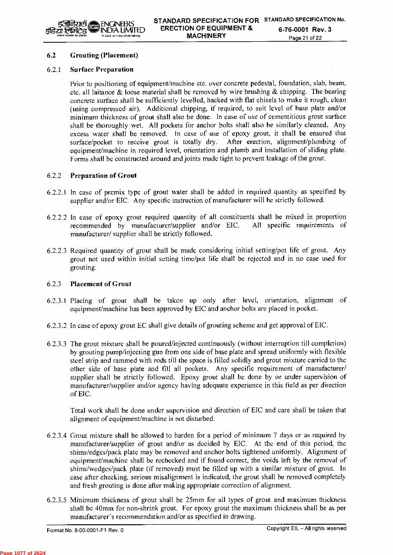
ENGINEERS STANDARD SPECIFICATION FOR STANDARD SPECIFICATION No.
INDIA LIMITED ERECTION OF EQUIPMENT & 6-76-0001 Rev. 3 IA Govt ol Inda Undertaxing) MACHINERY Page 21 of 22
triES ~5271
lori
6.2 Grouting (Placement)
6.2.1 Surface Preparation
Prior to positioning of equipment/machine etc. over concrete pedestal, foundation, slab, beam, etc. all laitance & loose material shall be removed by wire brushing & chipping. The bearing concrete surface shall be sufficiently levelled, hacked with flat chisels to make it rough, clean (using compressed air). Additional chipping, if required, to suit level of base plate and/or minimum thickness of grout shall also be done. In case of use of cementitious grout surface shall be thoroughly wet. All pockets for anchor bolts shall also be similarly cleaned. Any excess water shall be removed. In case of use of epoxy grout, it shall be ensured that surface/pocket to receive grout is totally dry. After erection, alignment/plumbing of equipment/machine in required level, orientation and plumb and installation of sliding plate. Forms shall be constructed around and joints made tight to prevent leakage of the grout.
6.2.2 Preparation of Grout
6.2.2.1 In case of premix type of grout water shall be added in required quantity as specified by supplier and/or EIC. Any specific instruction of manufacturer will be strictly followed.
6.2.2.2 In case of epoxy grout required quantity of all constituents shall be mixed in proportion recommended by manufacturer/supplier and/or EIC. All specific requirements of manufacturer/ supplier shall be strictly followed.
6.2.2.3 Required quantity of grout shall be made considering initial setting/pot life of grout. Any grout not used within initial setting time/pot life shall be rejected and in no case used for grouting.
6.2.3 Placement of Grout
6.2.3.1 Placing of grout shall be taken up only after level, orientation, alignment of equipment/machine has been approved by EIC and anchor bolts are placed in pocket.
6.2.3.2 In case of epoxy grout EC shall give details of grouting scheme and get approval of EIC.
6.2.3.3 The grout mixture shall be poured/injected continuously (without interruption till completion) by grouting pump/injecting gun from one side of base plate and spread uniformly with flexible steel strip and rammed with rods till the space is filled solidly and grout mixture carried to the other side of base plate and fill all pockets. Any specific requirement of manufacturer/ supplier shall be strictly followed. Epoxy grout shall be done by or under supervision of manufacturer/supplier and/or agency having adequate experience in this field as per direction of EIC.
Total work shall be done under supervision and direction of EIC and care shall be taken that alignment of equipment/machine is not disturbed.
6.2.3.4 Grout mixture shall be allowed to harden for a period of minimum 7 days or as required by manufacturer/supplier of grout and/or as decided by EIC. At the end of this period, the shims/edges/pack plate may be removed and anchor bolts tightened uniformly. Alignment of equipment/machine shall be rechecked and if found correct, the voids left by the removal of shims/wedges/pack plate (if removed) must be filled up with a similar mixture of grout. In case after checking, serious misalignment is indicated, the grout shall be removed completely and fresh grouting is done after making appropriate correction of alignment.
6.2.3.5 Minimum thickness of grout shall be 25mm for all types of grout and maximum thickness shall be 40mm for non-shrink grout. For epoxy grout the maximum thickness shall be as per manufacturer's recommendation and/or as specified in drawing.
Copyright EIL — All rights reserved Format No. 8-00-0001-F1 Rev. 0
Page 1077 of 2624

ladaa4 5•T
ENGINEERS STANDARD SPECIFICATION FOR STANDARD SPECIFICATION No.
INDIA LIMITED ERECTION OF EQUIPMENT & 6-76-0001 Rev. 3 oA Gov' of India Undo( taningf MACHINERY
Page 22 of 22
7.0 REFERENCE EIL STANDARDS/ SPECIFICATIONS
6-14-0003 Installation Procedure for Trays & Tower Internals
6-14-0011 Specification for Packing the Column
6-14-0016 Standard Specification for Review of Site Installation of Column Internals.
6-79-0011 Standard Specification for Corrosion Protection Tape Coating for Underground Steel Piping.
6-79-0020 Standard Specification for Surface Preparation and Protective Coating (New Construction)
7-12-0001 Vessel Tolerances.
7-12-0002 Support for Horizontal Vessel
7-12-0003 Wooden Pillow for Saddle Support
7-12-0004 Skirt Base Details
7-12-0024 Lifting Lug Top Head Type
7-14-0001 Construction Tolerance for Welded Supports for Tray / Tower Internals
Format No. 8-00-0001-F1 Rev. 0 Copyright EIL—All rights reserved
Page 1078 of 2624

ATTACHMENT – VI
Page 1079 of 2624
Date Purpose
0 28.04.2015 Issued as Standard
Rev.No
'3-DJ
Prepared Checkedby by
/k MD SC Standards StandardsCommittee BureauConvenor Chairman
Approved by
151MTRY
*igiriaRteg,ENGINEERSINDIA LIMITED(A Govt of India Undertaking)
CALIBRATION REQUIREMENTS OFMONITORING AND MESURING DEVICES AT
CONSTRUCTION SITES
STANDARD No.
7-82-0002 Rev. 0Page 1 of 5
11-3=fro-r r4-4- urT PdRicril cHILIA
armeicbdi
CALIBRATION REQUIREMENTS OFMONITORING AND MEASURING
DEVICES AT CONSTRUCTION SITES
Format No. 8-00-0001-F2 Rev. 0 Copyright EIL — All rights reserved
Page 1080 of 2624

lafaZIE'T5.ge1105ieg
141R7f ERP12 051.740,71)
ENGINEERS CALIBRATION REQUIREMENTS OFINDIA LIMITED MONITORING AND MEASURING DEVICES(AGO
of In
Undertaking) AT CONSTRUCTION SITES
STANDARD No.
7-82-0002 Rev. 0Page 2 of 5
Abbreviations:
ABS ABS Consultancy
BIS Bureau of Indian Standards
BV Bureau Veritas
CELL Certification Engineers International Ltd.
DNV Det Norske Veritas
IRS Indian Registrar for Shipping
LRS Llyod's Register Group Limited
NABL National Accreditation Board for Testing and Calibration Laboratories
PMI Positive Material Identification
Construction Standards Committee
Convenor: Sh. M Deshpande, ED (Construction)
Members: Sh. S N Bhatnagar, GM (Construction)Sh. Rakesh Nanda, GM (Piping)Sh. Rajeev Jain, DGM, (C&P)Sh. Janak Kishore , DGM (Projects)Sh. Ravindra Kumar , AGM (Construction)Sh. D Jana, AGM (Construction)
Format No. 8-00-0001-F2 Rev. 0
Copyright EIL — An rights reserved
Page 1081 of 2624

ENGINEERS CALIBRATION REQUIREMENTS OFINDIA UMITED MONITORING AND MEASURING DEVICESIAGovt of Inda Undertalong) AT CONSTRUCTION SITES
STANDARD No.7-82-0002 Rev. 0
Page 3 of 5e.if fetiaieUIffllerr eleasteaxamni)
Requirement for control of monitoring and measuring devices.
SI.No. Description Calibration requirements Frequency Remarks
A. Civil-SurveyTheodolite To check for permanent
adjustments by traversingand observing the closingerror
once in a year orproject durationwhichever is earlier
Record to bemaintained(See note below)
Levels To check by Backsight/Foresight readings, thetemporary adjustments oflevel
Every use Record tobe maintained(See note below)
A.3. Steel measurementtapes
---- ---- "Freemans"make or BISapproved makeshall be used.Mutilated, or
broken tapesshall not beused.
c. Marking on thetape shall belegible
A.4. Cross staff --- --- Same as 3b&3cabove
Distomat Actual PhysicalVerification at Site
Before usingfirst time at site
Records to bemaintained
Total Station To check for permanentadjustments by traversingand observing the closingerror,etc.
once in a year orproject durationwhichever is earlier
Record to bemaintained(See note below)
B. Civil Laboratory
All balances-Mechanical
Check for zero error Whenever used ---
WeighBatcher/BatchingPlant
Calibration of scales Once in threeMonths
Records to bemaintained
Cube testingmachine
Calibration certificate frommanufacturers or fromreputed calibrating agency.
As permanufacturerspecification oronce a yearwhichever is earlier
Records to bemaintained
Moisture Meter Calibration of scales 6 months Records to bemaintained
Note:
If Error is found, it has to be sent to manufacturers or their authorized agents forrectification and certification. Reputed calibrating agency shall be NABLaccredited for relevant testing.
Format No. 8-00-0001-F2 Rev. 0
Copyright EIL — All rights reserved
Page 1082 of 2624

ENGINEERS CALIBRATION REQUIREMENTS OF STANDARD No.
INDIA LIMITED MONITORING AND MEASURING DEVICES 7-82-0002 Rev. 0AT CONSTRUCTION SITES Page 4 of 5
1.27.1eResrv mows° (A Govt. of India Undertaking)
Sl.No. Description Calibration requirements Frequency Remarks
C. Mechanical/ Electrical/Welding
C.1 Pressure Gauges Calibration certificate fromreputed laboratories orcalibrate by dead weighttesters with standard weightsor with master Gauge
Once in 6 months Records to bemaintained
C.2 Dial gauges Check for Zero Error Whenever used ---C.3 Dead Weight
TesterCalibration frommanufacturer or reputedCalibrating agency.Calibration certificate shallnot be older than one monthfrom the date ofmobilization.
As permanufacturer'srecommendation oronce in a six monthwhichever isearlier.
Records(Calibrationcertificate) tobe maintained
C.4 Vernier caliper/screw gauge
Check for Zero error Whenever used ---
C.5 Holiday tester Calibration frommanufacturer or reputedcalibrating agency or bycalibrating by zeep meter.
Once in 6 months Records tobe maintained
C.6 Elcometer Check with standard testfilms supplied by themanufactures
Before use Records tobe maintained
C.7 Universal TestingMachine
Calibration Certificatefrom any reputed third partyinspection agency. viz,CEIL, LRS, BV, ABS, DNVor IRS.
As permanufacturer'srecommendation oronce a yearwhichever is earlier
Records tobe maintained
C.8 Charpy V-notchImpact testingmachine
Calibration Certificatefrom any reputed third partyinspection agency. viz,CEIL, LRS, BV, ABS, DNVor IRS.
As permanufacturer'srecommendation oronce in a yearwhichever is earlier
Records to bemaintained
C.9 Hardness TestingMachine
Check with the standard testblock supplied with themachine as permanufacturer'sRecommendation
Before use Records to bemaintained
C.10 Chemical Analysis,ex :PMI etc.
Check with thestandard samples
Before use Records to bemaintained
C.11 Various Digitaland Analogmeters
Calibration Certificate fromreputed laboratories or themanufacturer
Once in SixMonths or as permanufacturer'srecommendationwhichever isearlier.
Records to bemaintained
Note:
If Error is found, it has to be sent to manufacturers or their authorized agents forrectification and certification. Reputed calibrating agency shall be NABLaccredited for relevant testing.
Format No. 8-00-0001-F2 Rev. 0 Copyright EIL — All rights reserved
Page 1083 of 2624
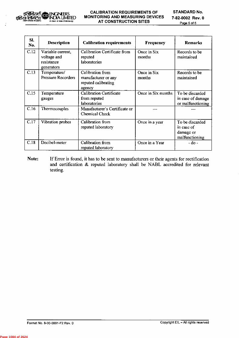
lalfteq ENGINEERS CALIBRATION REQUIREMENTS OF STANDARD No.
INDIA LIMITED MONITORING AND MEASURING DEVICES 7-82-0002 Rev. 0eigem Eitateg1.41V, eleCAU mom) (A Govt of India Undertaking) AT CONSTRUCTION SITES Page 5 of 5
SI.No.
Description Calibration requirements Frequency Remarks
C.12 Variable current,voltage andresistancegenerators
Calibration Certificate fromreputedlaboratories
Once in Sixmonths
Records to bemaintained
C.13 Temperature/Pressure Recorders
Calibration frommanufacturer or anyreputed calibratingagency
Once in Sixmonths
Records to bemaintained
C.15 Temperaturegauges
Calibration Certificatefrom reputedlaboratories
Once in Six months To be discardedin case of damageor malfunctioning
C.16 Thermocouples Manufacturer's Certificate orChemical Check
--- ---
C.17 Vibration probes Calibration fromreputed laboratory
Once in a year To be discardedin case ofdamage ormalfunctioning
C.18 Decibel-meter Calibration fromreputed laboratory
Once in a Year - do -
Note: If Error is found, it has to be sent to manufacturers or their agents for rectificationand certification & reputed laboratory shall be NABL accredited for relevanttesting.
Format No. 8-00-0001-F2 Rev. 0
Copyright EIL — All rights reserved
Page 1084 of 2624

ATTACHMENT – VII
Page 1085 of 2624

Format No. EIL -1641-1924 Rev1 Copyrights EIL – All rights reserved
OBSERVATION ON QUALITY ASPECT
Format No: A672-00-014-19-41-0005-F1 Rev 0
OBSERVATION ON QUALITY ASPECTS
Job No: Name of Work: No: FOI/LOA No: Issued To : M/s Date of Issue: Location Of Work: Item Of Work: Details Of Observation( Deficiency)
Recommended Course Of Action
Time Allowed For Correction
Issued By: Name : Designation: Signature:
Received by: Name: Signature: Date and Time:
Corrective Action Report By Contractor/Vendor: Name Date: Signature: Distribution Before Resolution: RCM/ Area Coordinator /QA Mgr: Verification Of Resolution By Issuer/Area Coordinator/RCM(EIL): Name: Date: Signature: Distribution After Resolution: RCM/ Area Coordinator /QA Mgr:
Page 1086 of 2624

ATTACHMENT – VIII
Page 1087 of 2624

Format No. EIL -1641-1924 Rev1 Copyrights EIL – All rights reserved
Format No: A672-00-014-19-41-0005-F2 Rev 0
OBSERVATION ON SAFETY ASPECT
OBSERVATION ON SAFETY ASPECTS
Job No: Name of Work: No: FOI/LOA No: Issued To : M/s Date of issue: Location Of Work: Item Of Work: Details Of Lapses/Shortfalls/Hazards Identified
Recommended Course Of Action Suspension of work required till resolution. (Yes/No) Time Allowed For Correction:
Issued By: Name : Designation: Signature:
Received by: Name: Signature: Date and Time:
Corrective Action Report By Contractor/Vendor: Date: Name And Signature: Distribution Before Resolution: RCM/ Area Coordinator/QA Mgr : Verification Of Resolution By Issuer/Area Coordinator/RCM (EIL): Name: Date: Signature: Distribution After Resolution: : RCM/ Area Coordinator /QA Mgr:
Page 1088 of 2624

TECHNICAL COMPLIANCE FORMAT CONSTRUCTION DIVISION
FOR COMPRESSED AIR & CRYOGENIC NITROGEN PLANT PACKAGE
Document No. A672-00-014-19-41-TC01 Rev 1 Page 1 of 2
Copyright EIL – All rights reserved
TECHNICAL COMPLIANCE FORMAT
(CONSTRUCTION DIVISION)
COMPRESSED AIR AND CRYOGENIC NITROGEN PLANT PACKAGE
PROJECT : INTEGRATED METHANOL & ACETIC ACID PROJECT
OWNER : ASSAM PETROCHEMICALS LIMITED PMC : ENGINEERS INDIA LTD. JOB NO. : A672
1 01.01.2018 REVISED FOR BID PKR RK CGM (C)
0 09.10.2015 ISSUED FOR BID AKS RK GM(C)
Rev. No Date Purpose Prepared
by Checked
by Approved
by
Page 1089 of 2624

TECHNICAL COMPLIANCE FORMAT CONSTRUCTION DIVISION
FOR COMPRESSED AIR & CRYOGENIC NITROGEN PLANT PACKAGE
Document No. A672-00-014-19-41-TC01 Rev 1 Page 2 of 2
Copyrights EIL – All rights reserved
Bidder must furnish answers/clarifications/confirmations of all the following queries and submit along with offer.
SL. NO. COMMENT/QUERY
BIDDER'S CONFIRMATION/
ANSWER 1. Bidder to confirm that requirement of Health, Safety and
Environment (HSE) as per specification 6-82-0001 are taken into consideration.
2. Bidder to confirm that required construction equipments to meet the contract schedule shall be mobilized by him without any time & cost implications.
3. Bidder to confirm that required construction personnel for supervision to meet the contract schedule shall be deployed by him meeting the requirement of qualification and experience (refer Doc. No 7-82-0003 in this regard) without any time & cost implications.
4. Bidder to confirm that Construction Management of this job shall be done by him and shall not be sub-contracted to any other agency.
Bidder’s Signature and Stamp
Page 1090 of 2624

Inspection Methodology for supply portion of
Package/tender Items
No: A672-9-18-42-1001-R 1 Page 1of 12
Format No. EIL-1641-1924 Rev.1 Copyright EIL – All rights reserved
INSPECTION METHODOLOGY FOR SUPPLY PORTION OF PACKAGE /TENDER ITEMS
PROJECT : INTEGRATED METHANOL AND ACETIC ACID PROJECT OWNER : ASSAM PETROCHEMICALS LIMITED CONSULTANT : ENGINEERS INDIA LTD. JOB NO. : A672
1 01-01-2016 ISSUED AFTER REVISION KK RKS SCG
0 10-08-2015 ISSUED FOR IMPLEMENTATION KK S.M(I)
RKS DGM
SCG GM(I)
Rev. No Date Purpose Prepared
by Checked
by Approved
by
Page 1091 of 2624
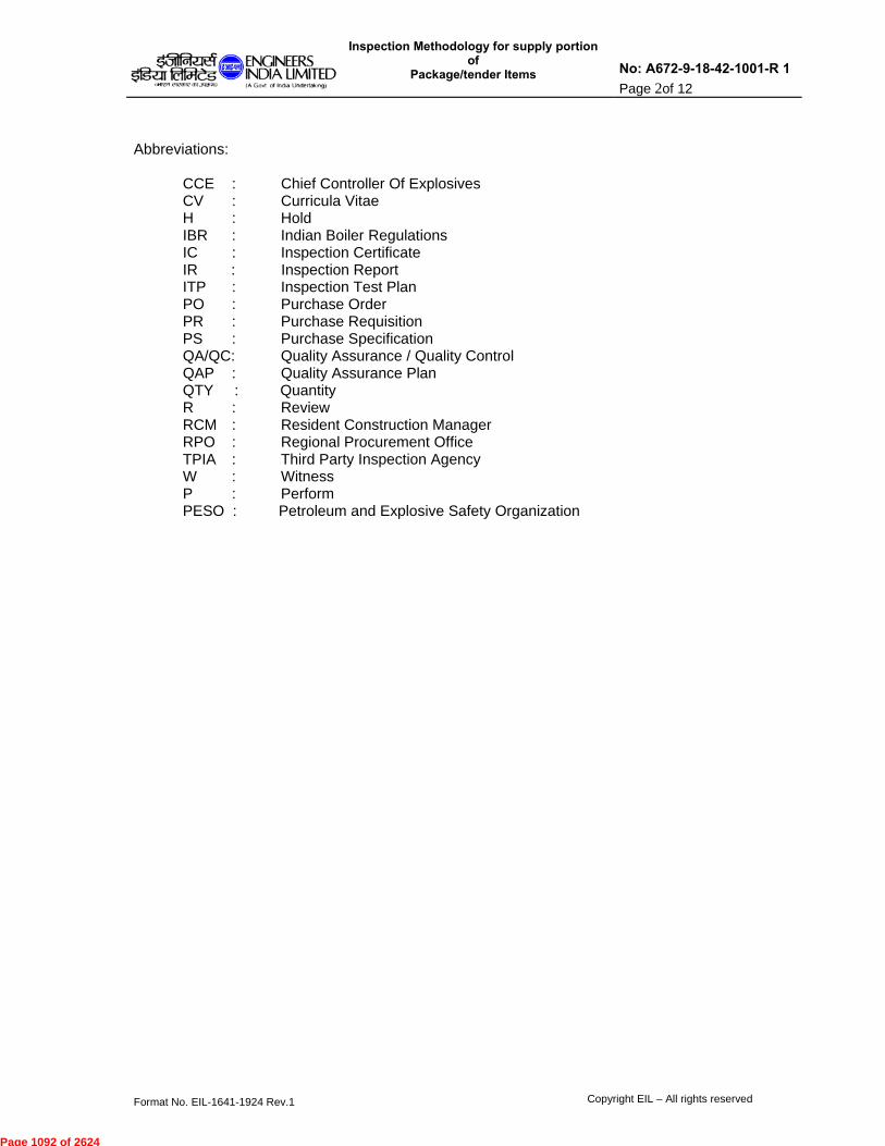
Inspection Methodology for supply portion of
Package/tender Items
No: A672-9-18-42-1001-R 1 Page 2of 12
Format No. EIL-1641-1924 Rev.1 Copyright EIL – All rights reserved
Abbreviations:
CCE : Chief Controller Of Explosives
CV : Curricula Vitae H : Hold IBR : Indian Boiler Regulations IC : Inspection Certificate IR : Inspection Report ITP : Inspection Test Plan PO : Purchase Order PR : Purchase Requisition PS : Purchase Specification QA/QC: Quality Assurance / Quality Control QAP : Quality Assurance Plan QTY : Quantity R : Review RCM : Resident Construction Manager RPO : Regional Procurement Office TPIA : Third Party Inspection Agency W : Witness P : Perform PESO : Petroleum and Explosive Safety Organization
Page 1092 of 2624

Inspection Methodology for supply portion of
Package/tender Items
No: A672-9-18-42-1001-R 1 Page 3of 12
Format No. EIL-1641-1924 Rev.1 Copyright EIL – All rights reserved
CONTENTS
Clause Title 1.0 Introduction
2.0 Purpose
3.0 Scope
4.0 References
5.0 Definitions
6.0 General 7.0 Categorization 8.0 Implementation of QA / QC Requirements 9.0 Quality Assurance Plan / Inspection and Test Plan 10.0 Inspection
11.0 Inspection Certificate
12.0 Final Documents 13.0 Status & Monitoring Report 14.0 Audit of Contractor’s Quality System ANNEXURE 1. Matrix for Inspection and Certification Responsibility A672-9-1842-1001 F1 2 Format for Status of Supply Items A672-9-1842-1001 F2
Page 1093 of 2624

Inspection Methodology for supply portion of
Package/tender Items
No: A672-9-18-42-1001-R 1 Page 4of 12
Format No. EIL-1641-1924 Rev.1 Copyright EIL – All rights reserved
1.0 INTRODUCTION
This document describes the Inspection Methodology to be used for inspection of equipment and materials to be supplied for the project complies with the specifications and Quality Standards laid down in the Tender / Contract.
2.0 PURPOSE
The purpose of this document is to detail out the Inspection Methodology to be adopted for ensuring the quality of the equipment and materials being supplied and defining the roles of various agencies involved and the quality system to be adhered to.
3.0 SCOPE
This document is applicable for inspection of all equipment and material procured, for the packages to be supplied by the PACKAGE CONTRACTOR. For foreign contractors, consultant role shall be limited to approval of categorization plan and approval of QAP/ITP.
4.0 REFERENCES
Bid / Contract Document 5.0 DEFINITIONS
5.1 OWNER Owner shall mean the project owner ASSAM PETROCHEMICALS LIMITED
5.2 CONSULTANT Consultant, namely Engineers India Limited (EIL).
5.3 Package CONTRACTOR.
Package CONTRACTOR means any party whose scope includes Engineering, Procurement, Construction and Commissioning of the Unit / Facilities / System on Lump Sum basis, covered under the specified scope of work as per the Contract document. CONTACTOR, EPCC CONTRACTOR and Package CONTRACTOR are considered synonymous. 5.4 SUPPLIER
Supplier means any party supplying any of the equipment, material, products and services to the PACKAGE CONTRACTOR. Vendor, Seller, Agent are considered synonymous to Supplier.
5.5 SUB SUPPLIER
Page 1094 of 2624
Inspection Methodology for supply portion of
Package/tender Items
No: A672-9-18-42-1001-R 1 Page 5of 12
Format No. EIL-1641-1924 Rev.1 Copyright EIL – All rights reserved
Sub supplier means any party on whom supplier suborders materials and items (like tubes, forgings , pumps, vessels, valves etc) and whose role is defined in ITPs.
5.6 SITP- Standard Inspection and test plan is ITP attached with tender document. ITPs attached contains stages of Inspection & scope of Inspection.
5.7 QUALITY ASSURANCE PLAN (QAP) / INSPECTION AND TEST PLAN (ITP) It is a document generated by the supplier/ sub-supplier based on the SITP
attached with tender document elsewhere with complete listing of various inspection stages, tests, material certification requirements and parties involved with their respective roles in inspection; indicating the requirements of Hold (H), Witness (W) Inspection, and Review (R) of Quality control documents / records for an item. Wherever SITP is not available in tender, supplier/sub-supplier to generate QAP /ITP based on applicable codes/standards. .
5.7.1 HOLD POINT
A Hold Point is a stage designated in the ITP/QAP, which requires Witness Inspection by TPIA and / or CONSULTANT/OWNER before supplier can proceed with further processing, except where prior written permission for further processing or waiver of Witness Inspection by CONSULTANT / OWNER is obtained.
5.7.2 WITNESS POINT
A Witness point is a stage designated in the ITP/QAP, which requires witness inspection by TPIA and / or CONSULTANT/OWNER Package CONTRACTOR / Supplier shall perform the activity after proper notification has been given to TPIA / CONSULTANT and OWNER for witnessing the activity. The CONTRACTOR/ Supplier is not obliged to hold further processing, if TPIA / CONSUTANT and / or OWNER are not available to witness the activity or does not provide the comments before the date notified with proper notification period.
5.7.3 REVIEW POINT
A review point is a stage designated in the ITP/QAP which requires the concerned agencies i.e. CONTRACTOR / TPIA / CONSULTANT/OWNER, to verify the documents for their correctness and to confirm that the said documents meet the requirements laid down.
5.8 THIRD PARTY INSPECTION AGENCY (TPIA)
Third Party Inspection Agency means an inspection agency appointed by the package CONTRACTOR for carrying out Inspection and witness of tests of equipment and material being procured by the CONTRACTOR for the Project.
5.9 INSPECTION CATEGORY
Inspection category determines the scope of Inspection for the Supplier/ sub-supplier, TPIA, CONSULTANT / OWNER for various equipment and material depending upon their use, serviceability, safety criteria and complexity.
5.10 REGIONAL PROCUREMENT OFFICE (RPO)
Page 1095 of 2624

Inspection Methodology for supply portion of
Package/tender Items
No: A672-9-18-42-1001-R 1 Page 6of 12
Format No. EIL-1641-1924 Rev.1 Copyright EIL – All rights reserved
Inspection office ofCONSULTANT, located at various locations within India, to carry out inspection of equipment / materials procured from within the country.
5.11 QUALITY CONTROL RECORDS
These are the documents, which demonstrate achievement of required Quality and effective operation of quality systems during manufacturing of an item. These include following as a minimum:
Material Test Certificates Visual and dimensional inspection records Stage Inspection Records / Test Reports Procedure Qualification Records Calibration Records Quality Assurance Plan and relevant records. PMI reports, Hydro test reports. Type test reports, routine test report, acceptance test Factory acceptance test reports Any other test reports as specified in
relevant codes / specifications.
6.0 GENERAL 6.1 The package CONTRACTOR shall maintain an effective Quality Assurance
System, to ensure that all equipment and material supplied for the Project meet the required Quality standards and specifications.These documents shall cover the following, as minimum:
Quality Assurance Manual including Organogram, CV of their quality staff and
standard Quality Plan for supply of equipment and material from the Supplier. Procedure for Coordination with Supplier, TPIA, CONSULTANT and OWNER. Procedure for flow of documents, information. Non-conformity control in case of deviation from specifications observed
during manufacturing of items and shall be reported in designated “Waiver / Deviation Request” format of CONSULTANT and approval shall be sought before processing.
Procedure for Expediting and Monitoring the manufacturing and delivery of all items.
Final Clearance Procedure for equipment and material for dispatch from suppliers’ works.
Standard Formats for Inspection reports, inspection certificates, expediting, status & monitoring of orders etc.
Package CONTRACTOR shall deploy Reputed TPI agency for inspection of items at their cost. for carrying out inspection of all equipment and material at suppliers’ works. Involvement of the appointed TPIA shall be reflected in the QAP, to be submitted by Package CONTRACTOR for each item. TPI shall be out of following: 1) Certification Engineers International Limited(CEIL ) 2) Lloyds Register 3) DNV 4) Bureau Veritas 5) TUV
6.2 Inspection by package contractor/ TPIA is not required for following items, but, shall be procured from reputed manufacturers only. The items shall be accepted based
Page 1096 of 2624
Inspection Methodology for supply portion of
Package/tender Items
No: A672-9-18-42-1001-R 1 Page 7of 12
Format No. EIL-1641-1924 Rev.1 Copyright EIL – All rights reserved
on the manufacturer’s Test Certificates / Guarantee Certificates, duly reviewed and accepted by the Head of Quality Control of Package CONTRACTOR. Cement Reinforcement bars Structural steel material & plates as per IS-2062. Hand railing material Wrapping & Coating material Paints Chemicals and Cleaning agents Oil lubricants Insulation material Earthing material Hardware used at Site for Electrical and Instrumentation items Any other non critical hardware Loose spares
6.3 Percentage of checking by package contractor/ TPIA shall be specified in the QAP /
ITP in case of bulk items.
6.4 All equipment and material shall be procured from the Suppliers approved by
CONSULTANT / OWNER only.
6.5 In exceptional cases where in any bought out item is offered for inspection outside the manufacturer’s works. , package CONTRACTOR shall ensure that all requisite facilities including instruments / gauges for inspection are made available to the inspection authority.
6.6 Package CONTRACTOR shall submit following documents in advance to TPIA &
CONSULTANT, for carrying out witness inspection or testing as per approved QAP at supplier’s/Sub-Supplier works:
Un priced copy of each Purchase Order Approved Purchase Specification Drawings approved in code 1 Agreed Deviations Approved QAP / ITP
7.0 CATEGORIZATION
Various equipment and materials to be procured by the package CONTRACTOR /Module manufacturer depending upon their criticality, shall be categorised into three different categories namely A, B and C for carrying out inspection and testing at suppliers’ works. The package CONTRACTOR shall submit at the time of Kick Off Meeting, the “Categorization Plan for inspection” of all equipment and materials to be procured by them for approval, to CONSULTANT and OWNER immediately after award of the contract. The role of the package CONTRACTOR, TPIA and CONSULTANT in the various activities related to inspection of the equipment / materials sourced by the CONTRACTOR shall be as indicated in the attached “Matrix of Inspection and Certification Responsibility”. (Format no. A672-9-1842-1001 F1) 7.1 Based on the Inspection categorisation plan approved by CONSULTANT / OWNER,
package CONTRACTOR shall submit QAPs / ITPs generated by Suppliers, for all items to CONSULTANT / OWNER for approval, prior to commencement of
Page 1097 of 2624

Inspection Methodology for supply portion of
Package/tender Items
No: A672-9-18-42-1001-R 1 Page 8of 12
Format No. EIL-1641-1924 Rev.1 Copyright EIL – All rights reserved
manufacturing activities. The ITP shall be first reviewed and vetted by the CONTRACTOR’S Quality Assurance Manager and approved by TPIA appointed, before submission to CONSULTANT / OWNER.
8.0 IMPLEMENTATION OF QA / QC REQUIREMENTS
8.1 The QA / QC procedures to be adopted by the package CONTRACTOR for the Project shall be discussed during the Kick - Off Meeting with CONSULTANT / OWNER.
8.2 During performance of the activities, the package CONTRACTOR shall-
i) Implement approved QA / QC Procedures.
ii) Evolve a comprehensive system of planned and documented Internal Quality
Audit, to verify whether all activities complied with detailed procedures, specifications, guidelines etc. and to determine the effectiveness of Quality System.
Scope of such internal audits shall be furnished to CONSULTANT for review / comments. Verification documents shall be generated during audit and submitted periodically to CONSULTANT.
iii) Get similar QA system including audit, implemented at their sub-supplier’/supplier’
works. Quality Control records from these suppliers shall be reviewed and certified for compliance by Quality Assurance Manager of package CONTRACTOR before submitting to CONSULTANT / OWNER.
9.0 QUALITY ASSURANCE PLAN / INSPECTION AND TEST PLAN (QAP / ITP)
CONSULTANTS’s Inspection and Test Plans for major items are attached to the bid document. These ITPs are indicative and generic only. Based on these ITPs, package CONTRACTOR / Supplier shall generate detailed ITPs applicable to the specific item ordered. Wherever CONSULTANT’s ITP is not attached, the package CONTRACTOR / Supplier shall generate the detailed ITP. The ITP shall give complete listing of stages of inspection, final inspection, tests and material certification requirements for the item, meeting all requirements specified in the Contract Document / Approved PS / Approved Drawings & Data sheets and shall clearly indicate Hold (H), Witness (W) Inspection, Review (R) stages of inspection to be carried out by TPIA, CONSULTANT and OWNER. For the supplier, all the stages of inspection shall be HOLD points and no stage shall be offered to TPIA / CONSULTANT/ OWNER without having performed/witnessed such stages. For the standard ITP’s enclosed the stage under the supplier stands suitably modified. The ITP thus generated shall identify and include the following as minimum: Sequence of all inspection and test activities related to the item manufactured, specific
procedures, methods and work instructions to be applied to each activity in manufacturing of the item. This will include but not limited to material identification, qualification of welding, welders, welding operators, NDT procedures & personnel, Post Weld Heat Treatment procedures, Positive Material Identification (PMI) including that of welds @ at least 10% at random, visual / dimensional checks at least 10% at random , pressure tests, performance tests, string tests, strip tests, respective acceptance criteria and pre-shipment clearing procedures etc. as the case may be.
Products or services to be sub-contracted, including the relevant quality controls to be applied
Page 1098 of 2624
Inspection Methodology for supply portion of
Package/tender Items
No: A672-9-18-42-1001-R 1 Page 9of 12
Format No. EIL-1641-1924 Rev.1 Copyright EIL – All rights reserved
Incoming, in-process and final inspection requirements. Identification of product from applicable drawings, specifications or other documents
during all stages of production, delivery and installation and to ensure that each product which is going in to the process of manufacture has proper identification throughout the process including final output.
Inspection and test records maintained for each stage of manufacturing. All inspection stages such as Hold (H), Witness (W) and Review (R) to be followed and
attended by responsible agencies according to approved inspection category of item shall be marked. For inspection stages, attached ITPs can be referred.
Traceability requirements as applicable. Quality Records required.
Package CONTRACTOR / TPIA shall ensure that all personnel engaged in performing the activities have requisite qualification and relevant work experience wherever required. Specialised operators shall be qualified and certified.
NDT operators employed, if any, shall be certified as per ASNT/ISNT and shall have valid certificates.
10.0 INSPECTION 10.1 For items procured from outside India by package CONTRACTOR, Witness of
Inspection or Testing at supplier’s works (located outside India) shall not be carried out by CONSULTANT, unless otherwise informed specifically by the CONSULTANT
/ OWNER during execution of the contract. Package contractor to arrange TPIA for imported items.
10.2 In case Supplier, package CONTRACTOR or TPIA find any deviation or non-
conformity with respect to the agreed specifications, during manufacturing of the item and where corrective action is not feasible, the CONTRACTOR shall report the same to CONSULTANT in the designated “Waiver / Deviation Request” format and seek prior approval from CONSULTANT, before proceeding with the job.
10.3 Package CONTRACTOR shall notify in writing to the CONSULTANT and OWNER, at least two weeks (Ten working days) in advance of the date and the place at which the items will be ready for witnessing of inspection / testing by CONSULTANTand / or OWNER. In case any postponement becomes necessary, the CONTRACTOR shall provide written notification at least 48 hours prior to the original scheduled date.
10.4 TPIA shall issue an Inspection Certificate after satisfactory completion of all
required ‘H’, ‘W’, & ‘R’ stages of Inspection by all parties concerned as per approved ITP and after ensuring compliance to specified requirements of all relevant applicable documents. The Inspection Certificate shall give reference of the approved documents including ITP referred for inspection and tests carried out and short supplies, if any.
10.5 Package CONTRACTOR after satisfying that all inspection requirements as per
approved ITP and applicable specifications / documents have been taken care by package contractor/ TPIA, shall submit copy of the Inspection Certificate and all Quality control records to CONSULTANT in requisite copies along with Statutory Certificates if any, such as IBR, PESO etc. duly endorsed by their Quality Control Manager.
Page 1099 of 2624
Inspection Methodology for supply portion of
Package/tender Items
No: A672-9-18-42-1001-R 1 Page 10of 12
Format No. EIL-1641-1924 Rev.1 Copyright EIL – All rights reserved
10.6 The CONTRACTOR shall ensure that all items covered by IBR/PESO regulations
are inspected at the manufacturer’s works and duly certified by competent authority.
10.7 Package contractor/ TPIA shall check the calibration status and traceability of all instruments used by the supplier, for testing. In case, TPIA uses their own instruments for testing purposes, similar certification shall be ensured.
10.8 Material/ equipment shall be inspected only after receipt of drawings / data sheets approved by CONSULTANT in code 2 however despatch clearance shall be after code 1 approval.
10.9 100 % PMI test at Supplier’s shop for Column internals including structured packing
and demister pads, Refractory lugs for critical equipment like process heaters, pressure vessels etc. and wire mesh shall be carried out and witnessed by TPIA.
10.10 Dimensional check up to a minimum of 10% should be done for all bulk items
at supplier’s shop and witnessed by package contractor/ TPIA/ CONSULTANT as per approved ITP.
10.11 All bulk items like pipes , fittings , fasteners etc shall be colour coded as per instructions given in the specifications, by the Supplier and witnessed by Package contractor/TPIA.
10.12 Package contractor/TPIA shall carry out physical verification of all spares and check
their quantity, quality, model etc. to confirm compliance to requirements. The CONTRACROR shall obtain prior waiver from CONSULTANT and /or OWNER, in case the spares are not to be checked by TPIA in specific case. However, TPIA shall issue INSPECTION CERTIFICATE for such spares also.
10.13 Contractor/Package Supplier if executing work thru pre-fabricated modules at shop
or yard, modules shall be inspected and tested as per approved ITP/QAP.
10.14 Notice for witness of Testing by Owner , the package CONTRACTOR shall give at least 2 weeks (10 working days) notice in case of indigenously procured equipment and 6 weeks (30 working days) notice in case of imported equipment, to enable the OWNER for completing necessary formalities.
10.15 Ware-house Inspection: package CONTRACTOR will carry out in-ward
inspection of all equipment / materials in their warehouse at site. The CONTRACTOR shall issue any equipment / material for use at site, only after acceptance by CONSULTANT / OWNER.
10.16 CONSULTANT / OWNER shall have access to the CONTRACTOR’s ware-house to verify / inspect any inward equipment / material at their discretion. CONTRACTOR shall extend necessary facilities for same. Package CONTRACTOR as a minimum, shall have Digital Thickness Meter and PMI Instrument as per CONSULTANT Specification 6- 81-0001, at the Ware house for checking the bulk items such as pipes , fittings, Flanges etc. The list of documents which the package CONTRACTOR shall submit to CONSULTANT / OWNER for this purpose, shall be as indicated in clause 6.6 of this document, relevant Inspection Certificate along with attachments mentioned there in. The CONTRACTOR shall ensure that necessary facilities for inspection, including testing of Pressure Relief Valves, calibration of Control Valves are available at the warehouse. Control Valves, Pressure Reducing Valves, Pressure Safety Valves can be issued for installation,
Page 1100 of 2624

Inspection Methodology for supply portion of
Package/tender Items
No: A672-9-18-42-1001-R 1 Page 11of 12
Format No. EIL-1641-1924 Rev.1 Copyright EIL – All rights reserved
only after Leak Testing and Calibration of Set- Pressure duly witnessed by CONSULTANT.
10.17 In case any item is found not complying with the specifications laid down in the
contract, it shall be the responsibility of the package CONTRACTOR, to ensure replacement / rectification of the equipment / material, as decided by CONSULTANT / OWNER.
11.0 INSPECTION CERTIFICATE
Package CONTRACTOR shall submit to CONSULTANT, copy of each Inspection Certificate (IC) / Inspection Release Note (IRN) issued by Package contractor/ TPIA, along with all attachments mentioned therein. The IC / IRN shall include the following as minimum: Job No. / Project Title / PO. No. / Purchase Specification No., Date of inspection and
Status of the visit - Initial / Intermediate / Final. Item Tag No. / Name / Total quantity ordered / released / offered for inspection and accepted during the visit. Manufacturer’s Name, Package contractor’s name, CONSULTANT & OWNER Date & Place of Inspection, name of Inspection Agency and Inspection Authority.
Reference of Documents with Revision status.(It shall be clearly indicated in the
inspection certificate that “inspection has been carried out based on code 1 drawings and approved ITP”.)
Verification of calibration documents. Details of Inspection carried out. Results of Inspection. Deviations, if any.
IC/IRN issued by the Package contractor/ TPIA shall be accompanied with the following as minimum:
- Works Certificate with details of Hydrostatic Test and PMI / Leak Tests (if
applicable) for Fabricated equipment - Works Certificate with details of Performance Test, Mechanical Run Test (if
specified in PR) and String Test (if applicable) for Rotating Equipment - Works Certificate with details of acceptance tests, calibration and Certificate of
statutory approvals if applicable. - Works Certificate with details of Mechanical tests, PMI and Helium Leak tests if
applicable, for all bulk items such as pipes, valves, fittings, fasteners and gaskets. Package contractor shall distribute the Inspection Certificate to the following officials:
1. Project Manager, EIL 2. Inspection Monitor of EIL at HO 3. Resident Construction Manager (RCM) of EIL 4. Package Contractor’s Warehouse in-charge
Contact details of all concerned will be intimated after kick off meeting.
Immediately after dispatch, the package CONTRACTOR shall submit one set of all documents listed in the “Vendor Data Requirement” sheet attached with the PR/ Contract, to RCM of CONSULTANT.
12.0 FINAL DOCUMENTS.
Page 1101 of 2624

Inspection Methodology for supply portion of
Package/tender Items
No: A672-9-18-42-1001-R 1 Page 12of 12
Format No. EIL-1641-1924 Rev.1 Copyright EIL – All rights reserved
On completion of each order, Supplier shall submit the final documents to the owner thru
CONSULTANT, as per “Supplier Data Requirement” and in requisite number of copies, as detailed in the Contract document. The final documents supplied shall be duly endorsed by the TPIA as ‘VERIFIED AND CERTIFIED FOR COMPLETENESS OF DOCUMENTATION AS PER SUPPLIER DATA REQUIREMENT’.
13.0 STATUS & MONITORING REPORT
Package CONTRACTOR shall closely monitor the manufacturing progress at Supplier’s works for various orders and expedite timely delivery of all items at site. If required and found necessary, visits to Supplier shops by CONSULTANT / OWNER and meetings with Suppliers shall be organised by the package CONTRACTOR. In case of any delay in supply of the items by any supplier, the package CONTRACTOR shall initiate remedial actions for expediting delivery of the items. Package CONTRACTOR shall submit status report of all procurement items and related information, to the Inspection Coordinator of CONSULTANT on a FORTNIGHTLY basis, strictly as per the attached format A672-9-1842-1001 F2.
14.0 AUDIT OF CONTRACTOR’S QUALITY SYSTEM
CONSULTANT will carry out periodic audit of the Quality System of the Package CONTRACTOR, at quaterly interval, from the date of award of Contract. Such audits may include visits to the Suppliers’ works, which shall be coordinated by the Package CONTRACTOR. In the event of any inadequacies / non-conformities in the Quality System noticed byCONSULTANT, the CONTRACTOR shall take immediate corrective measures and submit documentary evidence for satisfactory implementation of the corrective measures. Non compliance to the system will lead to rejection of the material.
Page 1102 of 2624
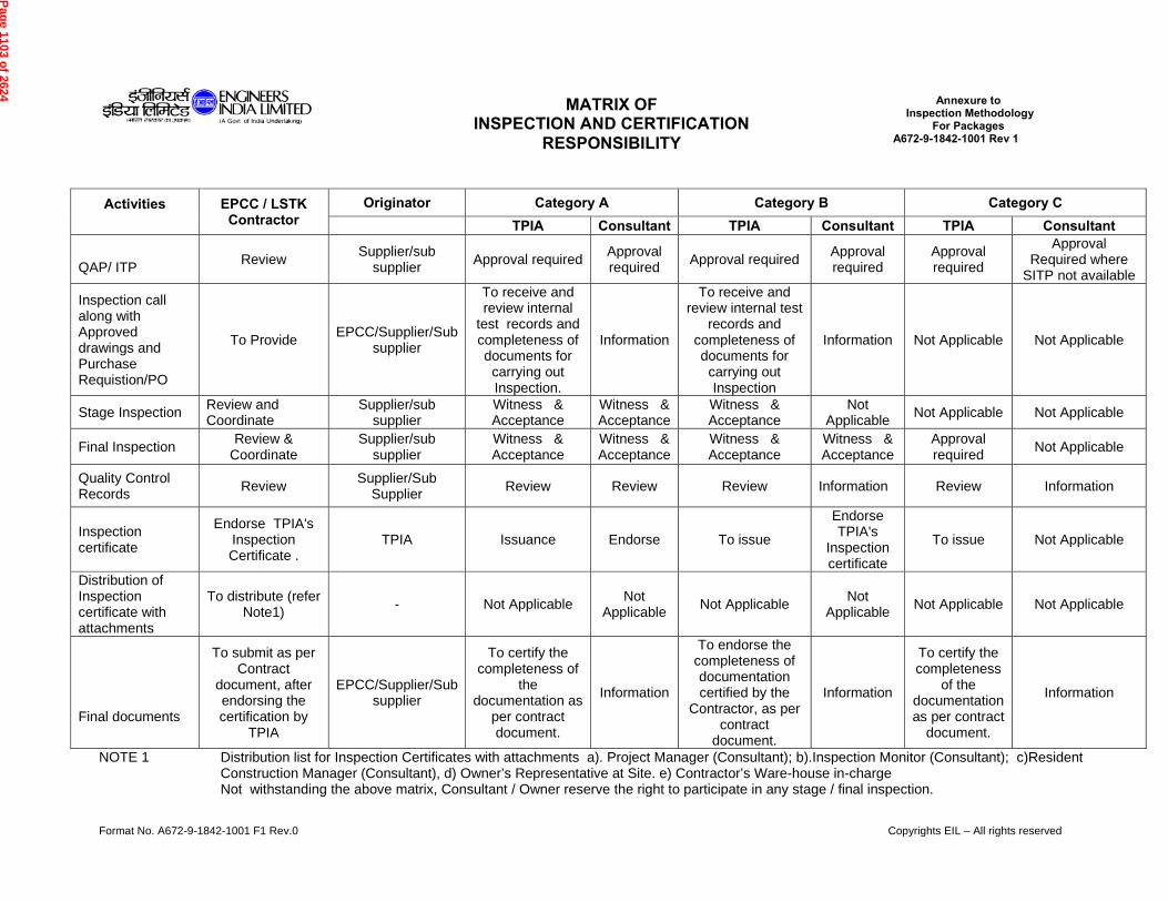
Format No. A672-9-1842-1001 F1 Rev.0 Copyrights EIL – All rights reserved
MATRIX OF INSPECTION AND CERTIFICATION
RESPONSIBILITY
Annexure to Inspection Methodology
For Packages A672-9-1842-1001 Rev 1
Activities
EPCC / LSTK Contractor
Originator Category A Category B Category C TPIA Consultant TPIA Consultant TPIA Consultant
QAP/ ITP Review Supplier/sub
supplier Approval required Approval required Approval required Approval
required Approval required
Approval Required where
SITP not available
Inspection call along with Approved drawings and Purchase Requistion/PO
To Provide EPCC/Supplier/Sub supplier
To receive and review internal
test records and completeness of documents for
carrying out Inspection.
Information
To receive and review internal test
records and completeness of documents for
carrying out Inspection
Information Not Applicable Not Applicable
Stage Inspection Review and Coordinate
Supplier/sub supplier
Witness & Acceptance
Witness & Acceptance
Witness & Acceptance
Not Applicable Not Applicable Not Applicable
Final Inspection Review & Coordinate
Supplier/sub supplier
Witness & Acceptance
Witness & Acceptance
Witness & Acceptance
Witness & Acceptance
Approval required Not Applicable
Quality Control Records Review Supplier/Sub
Supplier Review Review Review Information Review Information
Inspection certificate
Endorse TPIA's Inspection Certificate .
TPIA Issuance Endorse To issue
Endorse TPIA's
Inspection certificate
To issue Not Applicable
Distribution of Inspection certificate with attachments
To distribute (refer Note1) - Not Applicable Not
Applicable Not Applicable Not Applicable Not Applicable Not Applicable
Final documents
To submit as per Contract
document, after endorsing the certification by
TPIA
EPCC/Supplier/Sub supplier
To certify the completeness of
the documentation as
per contract document.
Information
To endorse the completeness of documentation certified by the
Contractor, as per contract
document.
Information
To certify the completeness
of the documentation as per contract
document.
Information
NOTE 1
Distribution list for Inspection Certificates with attachments a). Project Manager (Consultant); b).Inspection Monitor (Consultant); c)Resident Construction Manager (Consultant), d) Owner’s Representative at Site. e) Contractor’s Ware-house in-charge Not withstanding the above matrix, Consultant / Owner reserve the right to participate in any stage / final inspection.
Pag
e 1103 of 2624
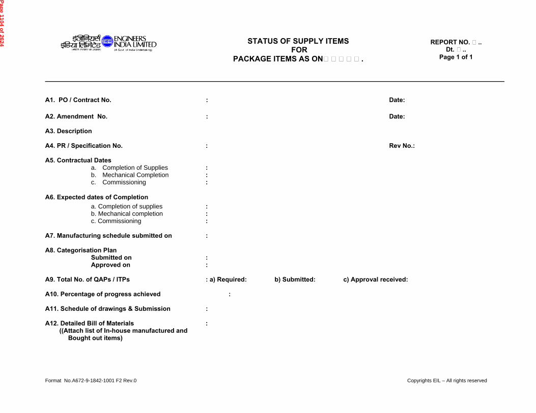
Format No.A672-9-1842-1001 F2 Rev.0 Copyrights EIL – All rights reserved
STATUS OF SUPPLY ITEMS FOR
PACKAGE ITEMS AS ON…………….
REPORT NO. ….. Dt. …..
Page 1 of 1
A1. PO / Contract No. : Date: A2. Amendment No. : Date: A3. Description A4. PR / Specification No. : Rev No.: A5. Contractual Dates
a. Completion of Supplies : b. Mechanical Completion : c. Commissioning :
A6. Expected dates of Completion a. Completion of supplies : b. Mechanical completion : c. Commissioning : A7. Manufacturing schedule submitted on : A8. Categorisation Plan
Submitted on : Approved on :
A9. Total No. of QAPs / ITPs : a) Required: b) Submitted: c) Approval received: A10. Percentage of progress achieved : A11. Schedule of drawings & Submission : A12. Detailed Bill of Materials : ((Attach list of In-house manufactured and
Bought out items)
Pag
e 1104 of 2624
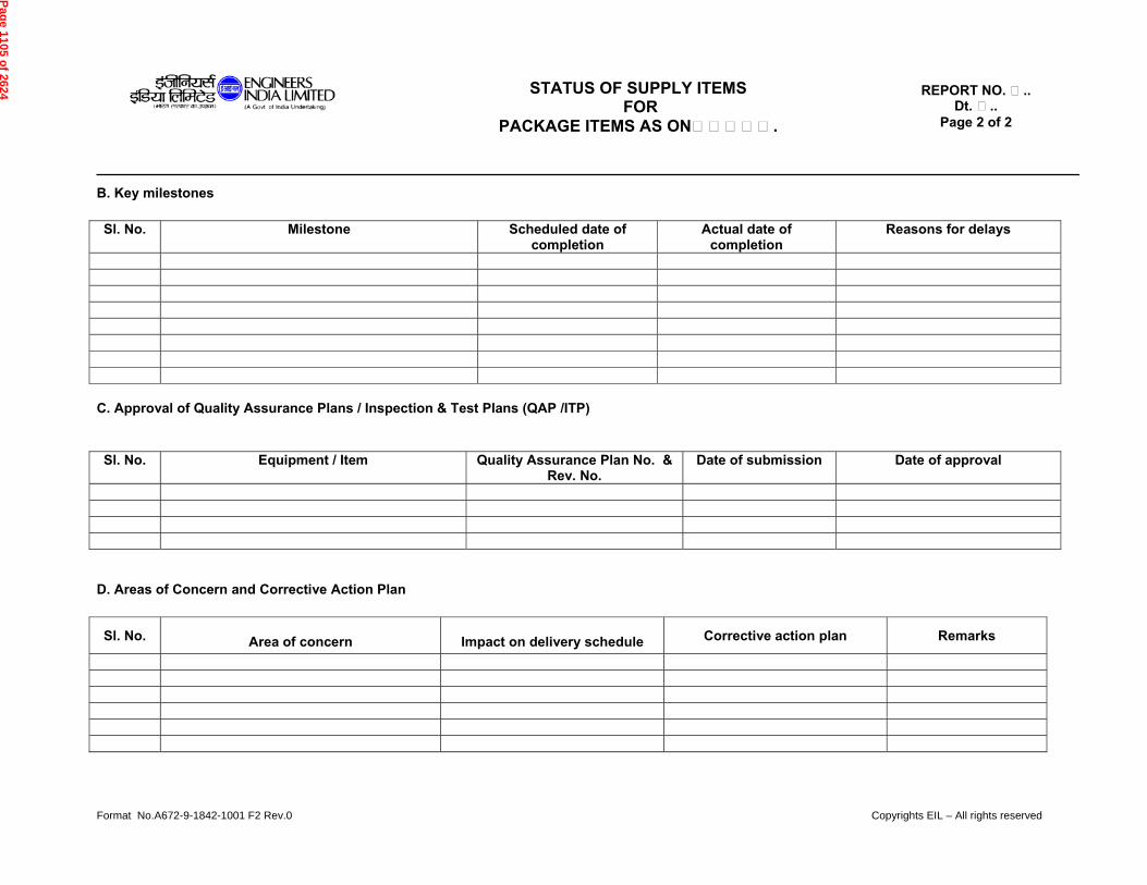
Format No.A672-9-1842-1001 F2 Rev.0 Copyrights EIL – All rights reserved
STATUS OF SUPPLY ITEMS FOR
PACKAGE ITEMS AS ON…………….
REPORT NO. ….. Dt. …..
Page 2 of 2
B. Key milestones Sl. No. Milestone Scheduled date of
completion Actual date of
completion Reasons for delays
C. Approval of Quality Assurance Plans / Inspection & Test Plans (QAP /ITP) Sl. No. Equipment / Item Quality Assurance Plan No. &
Rev. No. Date of submission Date of approval
D. Areas of Concern and Corrective Action Plan
Sl. No. Area of concern Impact on delivery schedule Corrective action plan Remarks
Pag
e 1105 of 2624
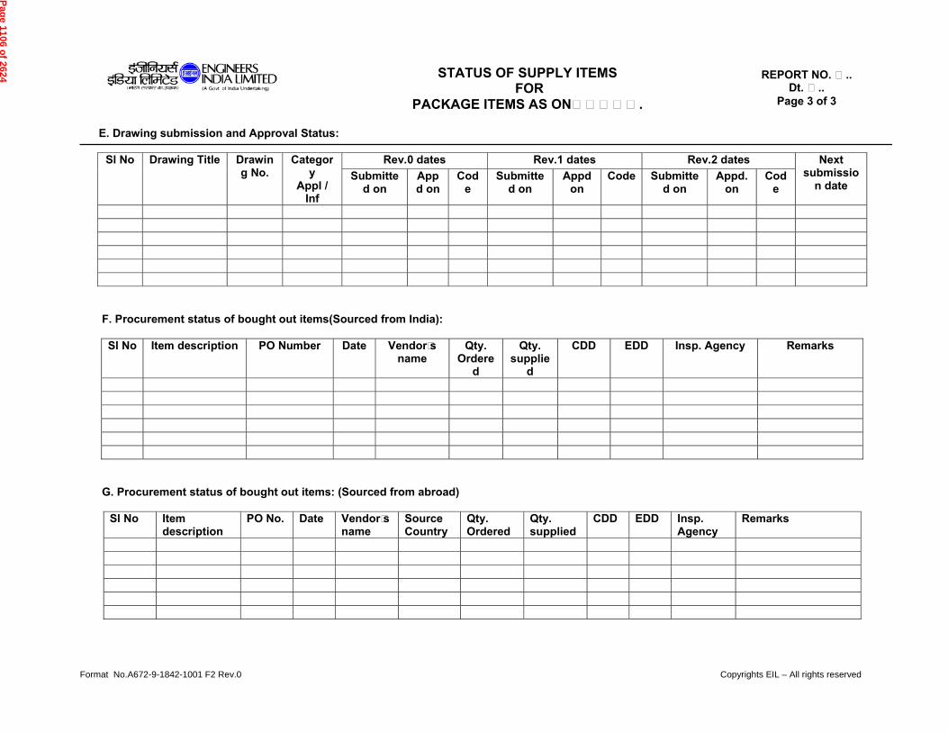
Format No.A672-9-1842-1001 F2 Rev.0 Copyrights EIL – All rights reserved
STATUS OF SUPPLY ITEMS FOR
PACKAGE ITEMS AS ON…………….
REPORT NO. ….. Dt. …..
Page 3 of 3
E. Drawing submission and Approval Status:
Sl No Drawing Title Drawing No.
Category
Appl / Inf
Rev.0 dates Rev.1 dates Rev.2 dates Next submissio
n date Submitte
d on Appd on
Code
Submitted on
Appd on
Code Submitted on
Appd. on
Code
F. Procurement status of bought out items(Sourced from India):
Sl No Item description PO Number Date Vendor’s
name Qty.
Ordered
Qty. supplie
d
CDD EDD Insp. Agency Remarks
G. Procurement status of bought out items: (Sourced from abroad)
Sl No Item description
PO No. Date Vendor’s name
Source Country
Qty. Ordered
Qty. supplied
CDD EDD Insp. Agency
Remarks
Pag
e 1106 of 2624
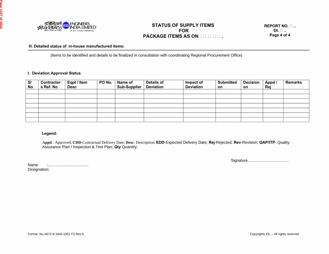
Format No.A672-9-1842-1001 F2 Rev.0 Copyrights EIL – All rights reserved
STATUS OF SUPPLY ITEMS FOR
PACKAGE ITEMS AS ON…………….
REPORT NO. ….. Dt. …..
Page 4 of 4
H. Detailed status of in-house manufactured items: (Items to be identified and details to be finalized in consultation with coordinating Regional Procurement Office) I. Deviation Approval Status Sl No
Contractor’s Ref. No
Eqpt / Item Desc
PO No. Name of Sub-Supplier
Details of Deviation
Impact of Deviation
Submitted on
Decision on
Appd / Rej
Remarks
Legend: Appd.- Approved; CDD-Contractual Delivery Date; Desc- Description; EDD-Expected Delivery Date; Rej-Rejected; Rev-Revision; QAP/ITP- Quality Assurance Plan / Inspection & Test Plan; Qty-Quantity; Signature………………………….. Name :…………………………. Designation:
Pag
e 1107 of 2624
SITE & UTILITY DATA
500 TPD METHANOL & 200 TPD FORMALIN PLANT PROJECT, APL,
NAMRUP ASSAM
DOCUMENT No.
A672-000-86-41-SD-0001 Rev 0
Page 1 of 3
1 05.01.18 Issued with Tender MNK SSR NA
0 15.10.15 Issued with Tender MNK AK RV
Rev. No
Date Purpose Prepared
by Checked
by Approved
by
Format No. EIL-1641-1924 Rev. 1 Copyright EIL – All rights reserved
SITE & UTILITY DATA
PROJECT : 500 TPD METHANOL & 200 TPD FORMALIN PLANT PROJECT
UNIT : 014 ( IA/PA AND CRYOGENIC NITROGEN PLANT)
CLIENT : ASSAM PETROCHEMICALS LTD., NAMRUP, ASSAM
CONSULTANT : ENGINEERS INDIA LTD.
JOB NO. : A672
Page 1108 of 2624
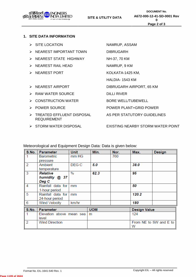
SITE & UTILITY DATA
DOCUMENT No.
A672-000-12-41-SD-0001 Rev 0
Page 2 of 3
Format No. EIL-1641-540 Rev. 1 Copyright EIL – All rights reserved
1. SITE DATA INFORMATION
SITE LOCATION NAMRUP, ASSAM
NEAREST IMPORTANT TOWN DIBRUGARH
NEAREST STATE HIGHWAY NH-37, 70 KM
NEAREST RAIL HEAD NAMRUP, 9 KM
NEAREST PORT KOLKATA-1425 KM,
HALDIA- 1543 KM
NEAREST AIRPORT DIBRUGARH AIRPORT, 65 KM
RAW WATER SOURCE DILLI RIVER
CONSTRUCTION WATER BORE WELL/TUBEWELL
POWER SOURCE POWER PLANT+GRID POWER
TREATED EFFLUENT DISPOSAL AS PER STATUTORY GUIDELINES
REQUIREMENT
STORM WATER DISPOSAL EXISTING NEARBY STORM WATER POINT
Meteorological and Equipment Design Data: Data is given below:
Page 1109 of 2624
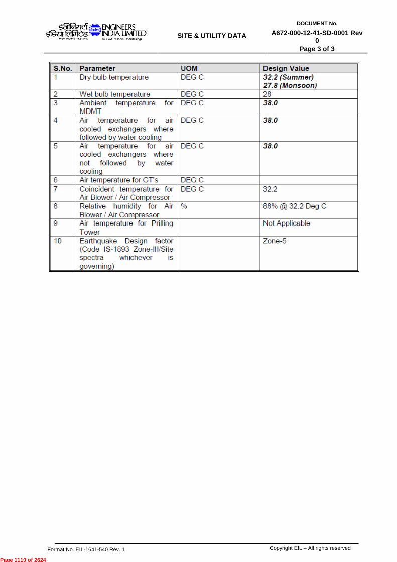
SITE & UTILITY DATA
DOCUMENT No.
A672-000-12-41-SD-0001 Rev 0
Page 3 of 3
Format No. EIL-1641-540 Rev. 1 Copyright EIL – All rights reserved
Page 1110 of 2624

PROJECT EXECUTION & ASSURANCE PLAN 500TPD METHANOL & 200 TPD FORMALIN PLANT, PROJECT, APL, NAMRUP ASSAM
DOCUMENT No.
A672-000-86-41-PCR-001 Rev. 0
Page 1 of 33
Format No. EIL-1641-1924 Rev.1 Copyright EIL – All rights reserved
PROJECT EXECUTION & ASSURANCE PLAN PROJECT : 500 TPD METHANOL & 200 TPD FORMALIN
PLAT, PROJECT OWNER : ASSAM PETROCHEMICALS LTD., NAMRUP,
ASSAM EPCM : ENGINEERS INDIA LTD. JOB NO. : A672
0 05.01.2018 ISSUED WITH TENDER/PACKAGE MNK SSR NA
Rev. No
Date Purpose Prepared by
Checked by
Approved by
Page 1111 of 2624

PROJECT EXECUTION & ASSURANCE PLAN 500TPD METHANOL & 200 TPD FORMALIN PLANT, PROJECT, APL, NAMRUP ASSAM
DOCUMENT No.
A672-000-86-41-PCR-001 Rev. 0
Page 2 of 33
Format No. EIL-1641-1924 Rev.1 Copyright EIL – All rights reserved
CONTENTS
1.0 PROJECT PROCEDURES 2.0 ORGANISATION 3.0 COMMUNICATION 4.0 COORDINATION
5.0 MEETINGS
6.0 PROCUREMENT & SUBCONTRACTING 7.0 COST CONTROL AND MONITORING 8.0 DOCUMENT CONTROL 9.0 CONTRACT CLOSING
Enclosures: - Annexure I: Check List for Contract Closing Annexure-II: Contractor Demobilization Check List
Page 1112 of 2624
PROJECT EXECUTION & ASSURANCE PLAN 500TPD METHANOL & 200 TPD FORMALIN PLANT, PROJECT, APL, NAMRUP ASSAM
DOCUMENT No.
A672-000-86-41-PCR-001 Rev. 0
Page 3 of 33
Format No. EIL-1641-1924 Rev.1 Copyright EIL – All rights reserved
1.0 PROJECT PROCEDURES 1.1 GENERAL
CONTRACTOR shall prepare and submit to OWNER/EIL upon the dates stated hereafter, drafts of various PROJECT PROCEDURES. The Project Procedures shall comprise planning, organization and control and other documents necessary for the efficient co-ordination of the work.
CONTRACTOR shall submit various project procedures for OWNER/EIL comments / approval after award as detailed below. OWNER/EIL will respond with any comments within ten (10) days. CONTRACTOR shall revise and reissue the project Procedures for approval within seven (7) days upon which it shall be put into effect.
1.2 CONTENTS OF THE PROJECT PROCEDURES
The Project Procedures shall include, but not be limited to, the following items which shall be submitted for approval upon or before the dates stated.
14 days after EFFECTIVE DATE
Execution methodology – identifying sub-contracting wherever planned.
Contractor’s organization chart and resumes of key personnel forming part of the organization chart.
Documents distribution chart forming part of the communication procedure.
Documentation control procedure.
Level 1 schedule overall bar chart and “S” curves forming part of the planning and progress control procedure.
Quality Assurance Manual and Quality assurance plan specific to this contract forming part of the QA/QC procedure.
21 Days after EFFECTIVE DATE
Name of agencies proposed for sub-contracting different works along with required backup details.
Meetings procedure
Reporting procedure including examples of : Weekly Report Monthly Report
Engineering Procedure
Procurement and subcontracting procedure including examples of:-
Purchase order
Inspection expediting monitoring procedure
Layout drawings of warehouses and open storage areas at worksite.
Warehousing & storage procedure.
Procedure for establishing temporary facilities, site office, lay down areas, arranging facilities at site for OWNER/EIL
Pre-commissioning and commissioning procedure
QA/QC Procedure including - Quality control and inspection plan - QA Audit schedule
Safety manual and procedures
Access control procedure for underground works
Emergency response procedure
Page 1113 of 2624
PROJECT EXECUTION & ASSURANCE PLAN 500TPD METHANOL & 200 TPD FORMALIN PLANT, PROJECT, APL, NAMRUP ASSAM
DOCUMENT No.
A672-000-86-41-PCR-001 Rev. 0
Page 4 of 33
Format No. EIL-1641-1924 Rev.1 Copyright EIL – All rights reserved
Invoicing Procedure including examples of : - Invoice Register - Invoice - Change order/Deviation permit
1.3 The names and addresses of approved subcontractors shall be included in the Project
Procedures upon approval by OWNER/EIL.
2.0 ORGANISATION 2.1 OWNER’S/EIL ORGANISATION
2.1.1 OWNER/EIL shall forward to CONTRACTOR an organization chart showing
OWNER/EIL organization relevant to the contract, for inclusion in the Project procedures. Updated organization chart shall be submitted immediately following any revision.
2.1.2 OWNER/EIL shall appoint their representative who shall administer and co-ordinate
OWNER’s/EIL obligations during the course of the contract including the issuance of instructions, orders and certificates.
2.2 CONTRACTOR’S ORGANISATION 2.2.1 CONTRACTOR shall provide detailed structure of its project team, the personnel for
each functions, showing the position, names and locations which it intends for the execution of the work. The structure of the team could vary in its terms of numbers/ field of expertise/ location of work for different phases of the work. An organization chart of the overall project structure shall be provided and a separate organization chart showing Home Office structure, Site Office structure and any other organization that may assist the CONTRACTOR for the execution of the project. Organization chart shall indicate names, key personnel/ show their line of responsibility & reporting positions.
CONTRACTOR’s Organization Chart shall be updated as and when there are changes in CONTRACTOR’s personnel. Any changes in such personnel shall be notified in writing to OWNER/EIL for approval prior to the change.
2.2.2 CONTRACTOR shall upon effective date, or in no event later than 5 days after effective
date, appoint a representative who shall have full authority to act on behalf of CONTRACTOR in receiving instructions and in the administration of the contract. CONTRACTOR shall notify OWNER/EIL in writing, of any proposed change of CONTRACTOR’s representative ten days prior to the effective date of such proposed changes. Such proposed change shall be subject to approval by OWNER/EIL.
2.2.3 CONTRACTOR shall upon OWNER/EIL request furnish all information concerning
CONTRACTOR, his Sub-contractors and their representative assigned personnel and agents as may be required for submission to any applicable governmental agency, authority or regulatory body.
3.0 COMMUNICATION 3.1 GENERAL
This correspondence procedure shall be applied for all communication among OWNER/EIL and CONTRACTOR
Page 1114 of 2624
PROJECT EXECUTION & ASSURANCE PLAN 500TPD METHANOL & 200 TPD FORMALIN PLANT, PROJECT, APL, NAMRUP ASSAM
DOCUMENT No.
A672-000-86-41-PCR-001 Rev. 0
Page 5 of 33
Format No. EIL-1641-1924 Rev.1 Copyright EIL – All rights reserved
3.2 CORRESPONDENCE REQUIREMENT
This procedure is prepared for the general system of correspondence among related parties involved in execution of work. Correspondence on technical matters like clarification on technical specifications, drawing/ documents reviewed etc. shall be between EIL (HO) and CONTRACTOR with copies to OWNER (HO& SITE). All correspondence on contractual/commercial related issues shall be between OWNER & CONTRACTOR and copy to EIL (H.O, Central coordination office at site). Correspondence on construction related matters shall be between EIL (SITE) and CONTRACTOR with copies to EIL (HO), OWNER (HO & SITE).
3.3 TYPE OF CORRESPONDENCE
Correspondence may be classified as follows:
1. Letter
A letter will be issued to other party to represent party’s intention of proposal, approval, acceptance, objection, conditioning or other commitments. The contents entered into the form of the official letter shall be deemed as definite decision or intention, which may affect or correspond to the contractual situation. Priority letter message shall be sent by e-mail / facsimile first and followed by mail in parallel. Each letter shall be limited to one subject in principle.
2. E-mail communication
E-mail address of all responsible persons authorized to correspond for this project should be available with all the parties for effective and fast mode of communication. E-mail will be used to communicate in writing on any matter and it shall be used as and when it is actually issued with authorized e-mail Id of responsible person of originator. 3. Facsimile
Facsimile may also be used to communicate in writing on any matter and it shall be used as and when it is actually issued with authorized signature of responsible person of originator. 4. Transmittals
Documents/drawings shall be sent with a transmittal, listing all the documents covered under the transmittal in duplicate. The list of document shall include document title, document number, revision number, number of sheets, type of document, purpose such as for Review / Information etc. Acknowledgement copy of the transmittal shall be signed by addressee returned to the originator as an acknowledgement of receipts of documents. Preferably one hard copy and one soft copy will be provided.
5. Minutes of Meeting Minutes of meeting shall be issued for confirmation of discussions made in all official meetings. Minutes of meetings between OWNER/EIL and CONTRACTOR shall be prepared by the CONTRACTOR maximum within 2 days of the meeting. After review, OWNER/EIL shall issue the minutes 2 days thereafter for signature of all parties involved. Project Manager of each party is responsible for distribution of the minutes of the meeting.
Page 1115 of 2624

PROJECT EXECUTION & ASSURANCE PLAN 500TPD METHANOL & 200 TPD FORMALIN PLANT, PROJECT, APL, NAMRUP ASSAM
DOCUMENT No.
A672-000-86-41-PCR-001 Rev. 0
Page 6 of 33
Format No. EIL-1641-1924 Rev.1 Copyright EIL – All rights reserved
3.4 LETTER HEADING & NUMBERING SYSTEM
All correspondence shall be issued under a specific subject heading which shall have contract number and title as follows: 500 TPD METHANOL & 200 TPD FORMALIN PLANT, PROJECT, APL, NAMRUP ASSAM EIL PROJECT NO. A672 PACKAGE / TENDER TITLE CONTRACT No All correspondence shall bear a unique identification reference number to maintain a uniform system for the entire project with CONTRACTORS which may be made up as follows.
EL-ES /A672/ L / / Abbreviation under the numbers explained as below 1. From - To (see NOTE B) 2. Job No. 3. Type of correspondence (See NOTE A) 4. Serial number of the message NOTE-A L LETTER F FACSIMILE DT DOCUMENT TRANSMITTAL E E-MAIL NOTE-B IH OWNER (HO) IS OWNER (SITE) EL EIL (HO) ES EIL SITE OFFICE CL CONTRACTOR (HO) CS CONTRACTOR SITE OFFICE
FOR OWNER IH-ES / A672 / L / / 001 (1) (2) (3) (4) Abbreviations under the numbers explained as above: FOR CONTRACTOR All letters from CONTRACTOR’s office shall follow and use the prefixes as given above with their own numbering system. Note: The above numbering system is for present package / tender only. A separate numbering system shall be followed by EIL and Owner as per the agreed co-ordination procedure.
3.5 DOCUMENTS REGISTER
OWNER/EIL and CONTRACTOR’s representative shall keep an up to date register of correspondence received from the other party in order to check that all documentation has been properly received. The register should also have cross-reference for incoming
Page 1116 of 2624
PROJECT EXECUTION & ASSURANCE PLAN 500TPD METHANOL & 200 TPD FORMALIN PLANT, PROJECT, APL, NAMRUP ASSAM
DOCUMENT No.
A672-000-86-41-PCR-001 Rev. 0
Page 7 of 33
Format No. EIL-1641-1924 Rev.1 Copyright EIL – All rights reserved
replies in order that an open items listing of unanswered correspondence can be developed and jointly reviewed and confirmed on a monthly basis.
3.6 RELATIONS WITH AUTHORITIES, CERTIFYING AGENCIES ETC.
All contacts with the Authorities, Certifying Agencies etc. shall be organized by the CONTRACTOR in cooperation with OWNER. Scheduling of meetings with such bodies shall be arranged by the CONTRACTOR in cooperation with OWNER, and CONTRACTOR shall give written notice to OWNER at least two weeks in advance of the required meeting date. Minutes shall be prepared and distributed according to OWNER’s instruction.
3.7 PUBLICATION OF DOCUMENTS
All draft press releases, information hand-outs and photographs for publication relating to the contract shall be submitted for review and approval of owner prior to release.
3.8 TELEPHONE CONVERSATIONS-FILE NOTES
Significant points raised in telephone conversations with OWNER, OWNER REPRESENTATIVE/EIL or their parties shall be recorded by CONTRACTOR through a letter with proper numbering.
3.9 COMMUNICATION WITH OWNER’S OTHER CONTRACTORS
Communication with OWNER’s other contractors shall be via OWNER. OWNER may choose to hold worksite coordination meetings either regularly or as required to discuss any points requiring cooperation/ coordination. OWNER shall chair such meetings. The requirements detailed above are complimentary to and do not relieve the CONTRACTOR of his obligations of the contractor for scheduling and coordination of all interfaces.
4.0 COORDINATION 4.1 PURPOSE 4.1.1 This procedure has been prepared with the objective of defining systematic and orderly
administrative relationship among the related parties for the 500 TPD METHANOL & 200 TPD FORMALIN PLANT, PROJECT, APL, NAMRUP, ASSAM.
4.1.2 This procedure stipulates execution of administrative relationship amongst the various
parties. 4.1.3 This procedure may be modified by mutual agreement among the parties concerned to
cater to changed requirements or for the convenience of the various parties. 4.2 SCOPE
This document contains the detailed procedure for the following: Addresses of parties involved and their representatives. Communication and general correspondence Coordination meetings Deliverables and approvals Documentation
Page 1117 of 2624
PROJECT EXECUTION & ASSURANCE PLAN 500TPD METHANOL & 200 TPD FORMALIN PLANT, PROJECT, APL, NAMRUP ASSAM
DOCUMENT No.
A672-000-86-41-PCR-001 Rev. 0
Page 8 of 33
Format No. EIL-1641-1924 Rev.1 Copyright EIL – All rights reserved
4.3 ADDRESSES OF PARTIES AND THEIR REPRESENTATIVES
Address of parties and their representatives involved with the project are to be as follows: APL
Head Office Address : M/s ASSAM PETROCHEMICALS LIMITED, NAMRUP,
ASSAM AND SITE OFFICE .
Representative’s Name : Mr. A.C.BARMAN
Designation : GM (PROJECTS)
Telephone No. :
E-mail : [email protected]
Copy to:
Name : Mr. S.K BORA
E-mail : [email protected]
EIL
Home office address : Engineers India Ltd.
Tower 2, 4TH Floor,
R&D Complex, Sector-16
Gurgaon, Haryana, Pin-122001
Representative Name : Sh. Neeraj Agarwal
Designation : Additional GM Projects
Representative’s Phone : 0124-380-3504
Representative’s e-mail : [email protected]
Copy to:
Copies of email shall be marked to the following Project Team Members:
Name : Sh. SS.roy
Email id : [email protected]
Name : Sh. Manish Kothiri
Email Id : [email protected]
EIL’s Site office address
Resident Construction Manager:
Name : To be informed later
Address :
Telephone No. :
Page 1118 of 2624
PROJECT EXECUTION & ASSURANCE PLAN 500TPD METHANOL & 200 TPD FORMALIN PLANT, PROJECT, APL, NAMRUP ASSAM
DOCUMENT No.
A672-000-86-41-PCR-001 Rev. 0
Page 9 of 33
Format No. EIL-1641-1924 Rev.1 Copyright EIL – All rights reserved
CONTRACTOR Home Office Address To be informed later Representative’s Name -do- & Designation -do- Facsimile No. (FAX) -do- Telephone No. -do- E-mail -do-
4.4 COMMUNICATION AND GENERAL CORRESPONDENCE i) Project Manager of EIL is the sole contact with Owner as well
other parties for all activities of the Project. Therefore all correspondence between EIL and Owner/other parties shall be directly done with/by Project Manager or by his authorized representative(s). With parties, namely vendors and contractors, the correspondence is done by others under intimation to Project Manager as per functional responsibilities. However, depending upon the exigencies of the situation, Project Manager can directly correspond with these outside parties also. Copies of the relevant correspondence shall be appropriately marked to the concerned parties as applicable.
ii) For signatory for communication, Project Manager may authorize the Project Co-
coordinator to sign the letters. Project Manager will correspond on important issues of contract, schedules etc. as deemed necessary.
iii) Contractor shall submit for Owner’s/EIL review/approval, during kick off meeting a
procedure for coordination and communication between the Contractor and the Owner/EIL to ensure a proper flow of information. Such a procedure shall define -
Project organization: - Contractor organization chart with Owner interfaces - Work locations Communication: - Abbreviations - Owner/EIL Contractor representatives - Owner/EIL and Contractor addresses - Correspondence with others - Transmittal notes - Means of transmission - Document distribution chart identifying nature of documents, originators and
addresses, number of copies required. - Tracking, scheduling and management of documents methodology. The Contractor will inform Owner about the system or software proposed for document management. However the system should be such so as to be compatible with OWNER/EIL system for smooth flow of communication.
4.5 PROJECT COORDINATION MEETINGS
EIL or Owner may take lead to organize the project coordination and/or progress review meeting between OWENR/EIL and Contractor for the purpose of smooth project execution. Agenda, place and time of the meetings shall be communicated in advance and agreed to between the parties.
4.6 DRAWING/DOCUMENTS TO BE REVIEWED BY OWNER/EIL
Page 1119 of 2624

PROJECT EXECUTION & ASSURANCE PLAN 500TPD METHANOL & 200 TPD FORMALIN PLANT, PROJECT, APL, NAMRUP ASSAM
DOCUMENT No.
A672-000-86-41-PCR-001 Rev. 0
Page 10 of 33
Format No. EIL-1641-1924 Rev.1 Copyright EIL – All rights reserved
Contractor shall prepare and submit drawings/documents for review/approval by OWNER/EIL.
5.0 MEETINGS 5.1 KICK-OFF MEETING
Within fifteen (15) days of the EFFECTIVE DATE, a kick-off meeting will be held between OWNER, EIL and CONTRACTOR at a venue decided by OWNER. The meeting will cover following aspects:
Contract execution methodology / philosophy, in line with the Project requirement as mentioned in Bid document.
CONTRACTOR’s understanding of his Scope, Project Design basis and responsibility.
Site/Meteorological Data
Review of Statutory and Interface requirements.
Engineering Design Basis
Review of Work Breakdown Structure (WBS)
Review of Level – 1 Contract Master Schedule
Review of Progress Measurement Methodology and Weightages at various levels of WBS and Progress Reporting Philosophy.
Finalization of 3 months Front End Schedule
Project Coordination Procedures, Documentation procedure, Engineering Coordination Procedure
Organization Chart (both Home Office and Site)
Document Listing and Schedule
Invoicing Procedure
Import Clearance (if applicable)
Vendor list and sub-contracts
Review of Drawings/Documents by ONWER/EIL
QA/QC
Documents for CENVAT
Vendor shop inspection and expediting
Transportation and handling including Oversized Dimensional Consignment (ODC)
Construction Site related issues
Construction Methodology and Schemes including heavy lifts erection etc. 5.2 WEEKLY MEETINGS
OWNER/EIL may hold weekly progress review meetings at the work site and during the initial phase of the work at CONTRACTOR’s engineering or other work center, with CONTRACTOR in order to evaluate progress, identify problems and discuss other matters relevant to the work and to review CONTRACTOR’s weekly report.
5.3 MONTHLY MEETING
OWNER/EIL shall hold monthly meetings with CONTRACTOR to review and evaluate the overall status and progress of the work and other matters relating to the work and to review CONTRACTOR’s monthly report.
Page 1120 of 2624

PROJECT EXECUTION & ASSURANCE PLAN 500TPD METHANOL & 200 TPD FORMALIN PLANT, PROJECT, APL, NAMRUP ASSAM
DOCUMENT No.
A672-000-86-41-PCR-001 Rev. 0
Page 11 of 33
Format No. EIL-1641-1924 Rev.1 Copyright EIL – All rights reserved
Regular attendees shall be as agreed between OWNER / EIL and CONTRACTOR. In addition, the CONTRACTOR shall upon request provide appropriate representation covering the relevant items of the meeting.
The agenda for the monthly meeting shall as far as possible be settled by mutual agreement five (5) working days before the meeting. Indicative agenda items for the meeting are as below:
o Presentation by Contractor on project status and major problems o Monthly programme v/s progress status / statistics (Physical and
Financial) o Major hold ups / slippage o Completion outlook o Areas of concern and critical issues o Recovery action plan o Status of long lead / critical items
5.4 SPECIAL MEETING
OWNER / EIL or CONTRACTOR may from time to time request a meeting to be held in order to discuss a matter of an urgent nature and which cannot be left until the weekly or monthly meeting, covering a specific matter, requiring a dedicated meeting.
In such circumstances, the party requesting the meeting shall contact the other party and agree upon the agenda, attendees and timing of such meeting. Such arrangements are subject to approval of OWNER.
5.5 OTHER MEETINGS PRE-AWARD MEETINGS CONTRACTOR shall hold a Pre-Award Meeting with the selected vendor or sub-
contractor (for major / critical works / equipment / package items) prior to CONTRACTOR’s award of a purchase order or sub-contract to ensure conformance to all contractual requirements.
CONTRACTOR-VENDOR OR SUB-CONTRACTOR MEETINGS CONTRACTOR shall hold regular meetings with each vendor or sub-contractor in
accordance with the agreed procedures. MECHANICAL COMPLETION / PRE-COMMISSIONING/ COMMISSIONING MEETINGS Brief daily meeting shall be held during the mechanical completion and pre-
commissioning / commissioning period with an agenda covering: o Work in progress for the past 24 hours; o Scheduled progress for the next 24 hours; o Review of resources; o Safety, work permits; and o Technical queries or problems
OWNER/EIL ATTENDANCE CONTRACTOR shall give a minimum of three (3) days prior notice of all meetings
identified above to OWNER/EIL. OWNER/EIL shall attend any such meeting as it deems necessary.
Page 1121 of 2624

PROJECT EXECUTION & ASSURANCE PLAN 500TPD METHANOL & 200 TPD FORMALIN PLANT, PROJECT, APL, NAMRUP ASSAM
DOCUMENT No.
A672-000-86-41-PCR-001 Rev. 0
Page 12 of 33
Format No. EIL-1641-1924 Rev.1 Copyright EIL – All rights reserved
OWNER/EIL shall have the right, at its own discretion, to attend any such meeting. MANAGEMENT MEETINGS
Senior management meetings may take place between OWNERS / EIL senior management and CONTRACTOR senior management as agreed between the parties. As a minimum CONTRACTOR should arrange for a quarterly meeting (once in three months) to be held with participation of CONTRACTOR and OWNER / EIL senior management attendance. The purpose of such review meetings will be to monitor project status, highlight problem areas and obtain CONTRACTOR and OWNER / EIL commitment to implement any necessary actions in order to maintain the agreed schedule. The venue of such meetings will be at CONSULTANT home office location during engineering phase and at the work site during Construction phase.
5.6 ARRANGEMENT, CONDUCT AND CHAIRING OF MEETINGS
Unless otherwise instructed by OWNER, meetings shall be held in CONTRACTOR’S offices and shall be organized by CONTRACTOR and chaired by OWNER.
5.7 MINUTES OF MEETING (MOM) CONTRACTOR shall prepare the minutes of all meetings between OWNER/EIL and
CONTRACTOR.
The minutes of meeting shall include:
o Date and venue of meeting o List of persons present, indicating Companies represented o Objective of meeting o Record Note of discussions o Record of actions agreed, with name of party responsible for execution of o each action and the date for completion of the action, indicated in a separate
action column (only parties / attending the meeting shall be specifically mentioned).
o Date of issue o Distribution
For ease of reference, minutes of meetings shall be divided into paragraphs with sub-headings indicating the various topics discussed. CONTRACTOR shall submit the MOM for all meetings to OWNER / EIL for review and APPROVAL prior to formal issue.
The MOM shall be prepared and distributed to the participants and other designated, within one (1) working days for all meetings except for the daily meetings, for which MOM will be issued at the end of the meeting.
Minutes of meetings between OWNER/EIL and CONTRACTOR shall be numbered consecutively.
5.8 ALTERNATE LOCATION OF MEETINGS
Any meeting may be convened at any other place, e.g. OWNER / EIL offices, sub-contractor’s offices, government offices etc. according to the wishes of the OWNER/EIL should it believe this to be useful to the progress of the contract.
Page 1122 of 2624
PROJECT EXECUTION & ASSURANCE PLAN 500TPD METHANOL & 200 TPD FORMALIN PLANT, PROJECT, APL, NAMRUP ASSAM
DOCUMENT No.
A672-000-86-41-PCR-001 Rev. 0
Page 13 of 33
Format No. EIL-1641-1924 Rev.1 Copyright EIL – All rights reserved
NOTE: This section should be read in conjunction with Project Planning, Scheduling, Monitoring and Control System” forming part of this bidding document.
6.0 PROCUREMENT & SUBCONTRACTING 6.1 PROCUREMENT
6.1.1 The costs of all equipments, bulk materials and services as well as all packing costs,
insurance, import and export permits, shipping and transportation costs, handling costs,
port charges, duties and taxes imposed on locally available and or locally assembled
equipment and material import licenses, permits, customs clearances and costs of all
kinds associated with the procurement of equipment, materials and services shall be the
responsibility of CONTRACTOR.
6.1.2 Within twenty one (21) days following effective date, CONTRACTOR shall submit his
proposed Procurement schedule relating to the bidding, evaluation, purchasing,
expediting, inspection and transport of materials and equipment to be incorporated in the
work and covering but not limited to, the activities described herein for approval and
incorporation in the Project Procedure.
6.1.3 CONTRACTOR shall follow its regular purchasing practices and procedures except as
the requirement of the contract, including this section, require modification to such
practices and procedures.
Procurement Plan – CONTRACTOR shall prepare and submit to OWNER/EIL a
Procurement Plan which outlines organization, methodologies and procedure to be
implemented by CONTRACTOR for carrying out all procurement and related activities
required by the contract. The plan shall include a sample of each standard form to be
used for such activities.
6.1.4 CONTRACTOR shall prepare and issue Procurement and Material status Report on
weekly/ fortnightly basis, incorporating critical data and information from each detailed
purchasing report. The exact format and content of this summary report shall be subject
to approval of OWNER/EIL.
6.1.5 OWNER/EIL reserves the right, on a case by case basis and upon notice to
CONTRACTOR, to deviate the review procedure specified herein.
6.1.6 OWNER/EIL reserves the right to attend any CONTRACTOR meetings with
CONTRACTOR’S/Sub contractor’s or vendors. CONTRACTOR shall give OWNER/EIL
sufficient notice to allow OWNER/ EIL to attend such meeting. Upon OWNER’s request
at any stage of design, fabrication or installation, CONTRACTOR shall organize and
attend meetings with sub contractors or vendors.
6.1.7 Within one month of the effective date, CONTRACTOR shall produce a list of items to be
imported with their estimated value. Each month, or at any other time OWNER/EIL
requires, this list shall be updated with latest quantities and estimated actual or forecast
costs.
Page 1123 of 2624
PROJECT EXECUTION & ASSURANCE PLAN 500TPD METHANOL & 200 TPD FORMALIN PLANT, PROJECT, APL, NAMRUP ASSAM
DOCUMENT No.
A672-000-86-41-PCR-001 Rev. 0
Page 14 of 33
Format No. EIL-1641-1924 Rev.1 Copyright EIL – All rights reserved
6.2 PURCHASE ORDERS
6.2.1 CONTRACTOR will take prior approval of important PR from OWNER/EIL.
6.2.2 Purchase orders shall include, when appropriate, a statement that the Material
concerned is subject to the requirement of applicable law or statutory regulation and
shall include the relevant procedure to be followed by the vendor.
Purchase Orders shall include, when appropriate, a statement that the Material
concerned is subject to inspection by CONTRACTOR, Third Party and OWNER/EIL and
that CONTRACTOR and OWNER/ EIL shall have access to the vendor’s works during all
stages of manufacturing and testing.
6.2.3 Contractor shall give close consideration to the need for standardization to restrict the
number of types and sizes of items in the complex in order to simplify maintenance and
reduce spare requirements.
6.2.4 Contractor shall specify the same oil and grease for all equipments lubrication to the
extent possible.
6.2.5 Contractor shall ensure that all required documentation for final importation of materials
& work to the facilities is prepared and submitted to owner/consultant or appropriate
authority in timely manner prior to the intended date of importation.
6.2.6 Purchase Orders shall include, when appropriate, a statement that vendors shall ensure
the availability of spare parts in accordance with the provision of Technical
specification/Contract.
6.2.7 CONTRACTOR shall ensure that vendors furnish for review and for final documentation,
all drawings, bills of materials, manuals, certificates and other information necessary to
define the equipment and the performance of the equipment as required by contract.
6.2.8 This information shall be incorporated, where relevant, in the equipment dossiers, and
the current status of receipt of such information shall be given in the Materials Status
Reports.
6.2.9 Report immediately to OWNER/EIL all change, which will affect material quality and
recommend any necessary corrective actions to be taken.
6.2.10 Ensure that vendors/sub contractors are aware of procedure and rules regarding taxes
and duties applicable for goods/equipment supplied/WORK executed and furnish proper
documentation to OWNER to enable them to avail benefit of VAT and other tax/duties
benefit.
6.2.11 The purchase order placed by CONTRACTOR shall include, but not be limited to the
following:
Project name and location
Identification of ASSAM PETROCHEMICALS LIMITED as OWNER
Page 1124 of 2624

PROJECT EXECUTION & ASSURANCE PLAN 500TPD METHANOL & 200 TPD FORMALIN PLANT, PROJECT, APL, NAMRUP ASSAM
DOCUMENT No.
A672-000-86-41-PCR-001 Rev. 0
Page 15 of 33
Format No. EIL-1641-1924 Rev.1 Copyright EIL – All rights reserved
OWNER approved specifications, drawings, data sheets, etc (purchase
Specification)
Quality program requirements
Vendor data submittal requirements
Terms and conditions of purchase
Inspection requirement including Third Party & OWNER /EIL
Tagging, packing and shipping instruction
Storage instruction
Agreed delivery date
Warranty/guarantee terms
Guarantee period required
Provision for training
Reference to QA requirements, Indicative Quality Plan
After sales services location
Name of manufacturer(s) etc.
In addition, the purchase order shall include requirement for vendor to provide
Production/delivery schedule
Spare parts interchangeability report (SPIR) FORM
Equipment record cards/Data Folder – item wise
Operating/maintenance manuals
Spares list with unit rates
6.3 REQUISITIONS AND REQUESTS FOR QUOTATIONS
6.3.1 CONTRACTOR and its sub-contractors shall prepare all Requisitions and Requests for
Quotation for all equipment, materials and subcontracts in accordance with the project
specifications and procurement schedule.
Specific categories of equipment, material and subcontract, requisitions and Requests
for Quotation shall be issued to OWNER/EIL for review as specified in the contract
document.
6.3.2 Requisitions and Requests for Quotation shall cover requirements for items including
Scope of work, including transportation and installation, and training for OWNER’s
personnel.
Rates for services, such as Commissioning Assistance Services,
vendor/manufacturer representative services, priced recommendations for two years
operation and maintenance spare parts.
Equipment and ancillary system particular specifications, data sheets and drawings,
battery limits of the supply.
Design basis, environmental conditions and applicable general specifications
Delivery schedule and milestones, including shop tests;
Schedules, suborders, fabrication, shop testing, packing, transportation & delivery to
contractor.
Page 1125 of 2624
PROJECT EXECUTION & ASSURANCE PLAN 500TPD METHANOL & 200 TPD FORMALIN PLANT, PROJECT, APL, NAMRUP ASSAM
DOCUMENT No.
A672-000-86-41-PCR-001 Rev. 0
Page 16 of 33
Format No. EIL-1641-1924 Rev.1 Copyright EIL – All rights reserved
Vendor documentation requirement schedule as per requirements of the Contract,
including the following:
- List and address of sub-vendors
- Final documents
- Calculations
- Logic diagrams, One line diagrams, P & ID’s
- Quality Assurance/Quality control/Inspections
- Welding procedures & welder qualification records
- Test procedures & reports
- List of Equipments to be certified
- All applicable certificates
- Long term preservation procedures
- Handling, transportation, installation, instructions
- Mechanical completion, commissioning and start up procedures
- Operating &maintenance instructions
- Spare parts requirements
- Spare part recommendations for commissioning and start up and two years
operation and maintenance
- Special tools and handling device requirements
- Deviation permit duly approved by Owner/Owner representative
- Vendor installation, commissioning & start up assistance and training
requirements
- Purchase order or subcontract contractual terms & conditions
- Equipment lifetime spares pricing and availability undertaking requirement
6.4 OWNER/EIL REVIEW OF PURCHASE ORDER
CONTRACTOR shall forward Purchase Order together with attached documentation,
without pricing details, to OWNER/EIL for information.
6.5 LIST OF VENDORS
6.5.1 List of approved vendors and other stipulation on vendor list is included in contract
document. Contractor is required to strictly adhere to these requirements.
6.5.2 OWNER may, at its discretion, delete or add any vendor or subcontractor from the list of
approved vendors and subcontractors at any time during the performance of the work.
6.5.3 Bid evaluation and vendor or subcontractor selection
CONTRACTOR shall perform its bid evaluations as follows:
After receipt of bids, CONTRACTOR shall review and check the bids for conformity with
technical, contractual terms and conditions and Project requirements. CONTRACTOR
shall then prepare its unpriced preliminary bid evaluation summary of all technical,
contractual and Project requirements indicating CONTRACTOR’s recommended short
list of bidders with reasons for such recommendation.
CONTRACTOR shall then carry out complete price evaluation of the short listed bidders.
6.6 PURCHASE ORDER CONTROL REGISTER
Page 1126 of 2624
PROJECT EXECUTION & ASSURANCE PLAN 500TPD METHANOL & 200 TPD FORMALIN PLANT, PROJECT, APL, NAMRUP ASSAM
DOCUMENT No.
A672-000-86-41-PCR-001 Rev. 0
Page 17 of 33
Format No. EIL-1641-1924 Rev.1 Copyright EIL – All rights reserved
CONTRACTOR shall establish and maintain a purchase order control register. This
register shall include all purchase orders issued for all items of material and equipment
to be incorporated in the work. CONTRACTOR shall be capable of generating reports
from the register for Indian and imported items separately.
The Purchase Order Control Register shall show for each Purchase Order and for each
item the following information.
Purchase order number
Material Requisition/Purchase Requisition number
Date of invitation of Bid
Date of Bid Receipt
Bid Opening Date
Date of unpriced final bid evaluation to OWNER
Date of Purchase Order.
Date of Order Confirmation
Name/Address of vendor
Brief Description of materials and equipment purchased, together with
Specific identification reference
Ex shop delivery date
Expected delivery at worksite
Shipping details
Latest purchase order amendment No.
Expediting details
Status of Purchase order
Inspection Status
This Register shall be updated and issued monthly in hard copy, together with two (2)
monthly updated diskette copies of the register to OWNER/ EIL.
6.7 INSPECTION AND MONITORING
Inspection and monitoring requirement along with inspection methodology shall be as
detailed in bidding document.
6.8 TRANSPORT
CONTRACTOR shall organize and co-ordinate the transport of all materials and
equipment and maintain records of latest status.
Prior to transportation to worksite of any and all parts or components of the facilities, by
sea, special means or any other mode of transportation, CONTRACTOR shall obtain all
necessary approvals from marine or insurance surveyors or any other statutory body
with respect to the means and procedures to be used during packing, weighing, load out,
sea fastening, transportation, off-loading and the like.
Regardless of such approvals, CONTRACTOR shall be solely responsible for the
adequacy of preparation for the packing, weighing, load out, sea fastening,
Page 1127 of 2624

PROJECT EXECUTION & ASSURANCE PLAN 500TPD METHANOL & 200 TPD FORMALIN PLANT, PROJECT, APL, NAMRUP ASSAM
DOCUMENT No.
A672-000-86-41-PCR-001 Rev. 0
Page 18 of 33
Format No. EIL-1641-1924 Rev.1 Copyright EIL – All rights reserved
transportation, off loading and the like to any and all parts of components of the facilities
to worksite in accordance with the requirements of the agreement.
At all stages of the work, CONTRACTOR shall ensure the proper identification of all bulk
material equipment and supplies CONTRACTOR shall provide OWNER with all
applicable certificates and documentation upon delivery of such items at worksite.
Bulk material equipment and supplies shall be properly packed and secured so as to
satisfactorily reach their destination.
Packing cases, boxes, tins, wrappings and other packaging materials supplied by
CONTRACTOR shall be non returnable.
CONTRACTOR shall on a timely basis dispatch and deliver any and all bulk material
equipment and supplies to the locations required for the performance of the work and
maintenance of the contract master schedule.
CONTRACTOR shall be responsible for the selection of the means of transportation of
all bulk material equipment and supplies.
CONTRACTOR shall arrange and carry out its responsibility and supervision of the
transportation of all bulk material equipment and supplies from the point of fabrication to
worksite.
CONTRACTOR undertakes to properly store and maintains any and all bulk material
equipment and supplies in accordance with the agreement and the best professional
practices and shall protect such bulk material equipment and supplies against weather
hazards, water, humidity, fire, theft, vandalism and the like.
CONTRACTOR shall at all times use every means to prevent any damage or loss
whatsoever to bulk material equipment and supplies.
All purchase items shall be properly boxed and shipped to worksite to meet the Project
Schedule. CONTRACTOR shall expedite all forwarding of bulk material equipment and
supplies.
CONTRACTOR shall be responsible for organizing and coordinating packing, marking
and transportation of equipment and materials to the worksite such work shall include:
Preparing of packing, marking, shipping and documentation specifications.
Inspecting of packing, marking, loading and off loading.
Developing plans and procedures for freight forwarding, handling and
Customs clearance of equipment and materials to ensure that all materials
Arrive at the worksite on time.
Organizing and securing the acceptance of the marine transport
Conditions of heavy equipment by a marine surveyor
Organizing and ensuring of off loading and ground transportation of
Equipment and material to the worksite
Page 1128 of 2624

PROJECT EXECUTION & ASSURANCE PLAN 500TPD METHANOL & 200 TPD FORMALIN PLANT, PROJECT, APL, NAMRUP ASSAM
DOCUMENT No.
A672-000-86-41-PCR-001 Rev. 0
Page 19 of 33
Format No. EIL-1641-1924 Rev.1 Copyright EIL – All rights reserved
Preparing maintaining and issuing a monthly shipping progress report and
Monthly shipping forecast in a format reviewed by OWNER
Arranging for the importation of all materials and equipment, for receiving
and off loading at worksite, and for obtaining all necessary licenses, insurance
certificates and any other required documents; and
Arranging for the use of harbor facilities in India for the off loading of all
Required equipment and materials
CONTRACTOR shall provide all shipping documents including for VAT requirement
which OWNER may require related to CONTRACTOR’s shipments.
CONTRACTOR shall be responsible for all customs handling and payment of customs
dues and port dues and shall maintain a register of customs entry references for the
material received at site.
6.9 RECEIVING, INSPECTION AND STORAGE OF MATERIALS AT SITE
CONTRACTOR shall be responsible for receiving, handling, storage and safekeeping of all materials and equipment required for performance of the work. CONTRACTOR’s procedures shall include provisions for storage and protection of material and equipment, including detailed drawings of warehouses and open storage areas.
CONTRACTOR shall comply with vendor’s recommendations regarding storage and
protection of items.
CONTRACTOR shall comply with statutory regulations for storage of any material
covered under Explosives Rules.
CONTRACTOR field supervision staff shall supervise and coordinate material arrival at
site, inspect it to check the compliance with the purchase orders and related
specifications classify, store, maintain and finally release them to the sub contractors at
the proper time of installation.
Field Warehousing procedure foresees the following duties and functions:
Receive the materials, which arrive at jobsite and issue the “Daily Material Receipt
report”.
Check adherence in quantity and in characteristics of each item with the
indications specified in the relative packing list or bill.
Control that no damage has occurred during transportation.
After inspection, store materials arrived in good conditions and in accordance with
the purchase order issuing the “Jobsite Receipt Report”.
Periodically control materials, parts, components and equipment to be installed, in
order to guarantee proper maintenance during storage, and to minimize the risk of
damage during withdrawal and handling.
This shall include:
Page 1129 of 2624

PROJECT EXECUTION & ASSURANCE PLAN 500TPD METHANOL & 200 TPD FORMALIN PLANT, PROJECT, APL, NAMRUP ASSAM
DOCUMENT No.
A672-000-86-41-PCR-001 Rev. 0
Page 20 of 33
Format No. EIL-1641-1924 Rev.1 Copyright EIL – All rights reserved
Procedures for segregation of items which are not in conformance with requirements
in order to prevent their inadvertent use or installation until non-conformance is
resolved (i.e. repaired, rejected, etc.);
Instructions for appropriate preservation to avoid damage, deterioration or loss.
Quality control approval for withdrawal and handling methods for particular
equipment and materials
Prepare and keep up to date a complete file of “Record Card” for materials received
or delivered to sub contractors.
Deliver to sub contractors the materials to be erected upon presentation of the
“Delivery Voucher” signed by CONTRACTOR’s supervisors.
Issue the “Irregular Material Supply Report” for those materials which might arrive
not in accordance with the purchase order and/or damaged. In case of damaged
material, the damage will be declared to the carrier which will be requested to sign
the “Irregular Material Supply Report” that will constitute a qualified proof for the
attribution of the responsibilities and for application with the insurance Company.
The same procedure will be followed for non compliance on quantities delivered (in
excess or missing).
Issue final reports on surplus material status existing in the warehouse at the end of
works.
In accordance with the criteria outlined above, CONTRACTOR shall prepare & finalize
forms to be used in performing the field warehousing activity.
Daily Material Receipt Report
Jobsite Receipt Report
Irregular Material supply Report
Record Card
Delivery Voucher.
Final forms and detailed procedures shall be agreed upon between the OWNER and the
CONTRACTOR before the starting of the field construction activities.
6.10 LOCATION OF MATERIALS AND EQUIPMENT
CONTRACTOR shall maintain records of movement of all materials and equipment.
6.11 IMPORTED MATERIALS AND EQUIPMENTS
CONTRACTOR shall ensure compliance with documentation procedures, regulations
and maintenance of records in accordance with Indian Tax Excise, Customs and Import
Laws. CONTRACTOR is required to establish and maintain a proper system equipped
with personnel having expertise in tax, excise, customs and import regulations.
CONTRACTOR shall be responsible for obtaining the complete detailed importation
procedures from appropriate Customs Authorities and for clearing Customs for the
importation, exportation and re-exportation of any CONTRACTOR items and
construction equipment.
Page 1130 of 2624
PROJECT EXECUTION & ASSURANCE PLAN 500TPD METHANOL & 200 TPD FORMALIN PLANT, PROJECT, APL, NAMRUP ASSAM
DOCUMENT No.
A672-000-86-41-PCR-001 Rev. 0
Page 21 of 33
Format No. EIL-1641-1924 Rev.1 Copyright EIL – All rights reserved
CONTRACTOR shall request customs inspection with sufficient advance notice to
ensure no disruption in the contract master schedule. CONTRACTOR shall assist
customs authorities in such inspection and shall transmit any necessary documentation
to Customs Authorities.
As necessary, CONTRACTOR shall ensure co-ordination and shall work with Customs
Authorities and any vendor or sub contractors in order to implement the importation
procedures in the most efficient manner.
7.0 COST CONTROL AND MONITORING 7.1 BILLING SCHEDULE
Contractor to furnish the Billing Schedule within one month of award for Owner/Consultant approval.
7.2 PROJECT COST CONTROL AND MONITORING Project cost control and monitoring activities is required to be performed by
Owner/Consultant during execution of Contract. Contractor is required to furnish relevant information on cost status, change orders, if any, deviation permits (if any) and master cash flow schedule and cash flow on monthly basis.
Contractor to include a chapter of cost control in the monthly progress report and shall
highlight the cost, change order, deviation permit and cash flow status. The contents of each of section are as follows.
7.3 COST STATUS
Cost status of the Contract shall be projected suitably in a tabular form with a break-up of costs under the heads of original contract value, approved change orders, approved deviation permits, pending change orders, pending deviation permits, current forecast, invoice to-date and payment to-date. Formats in this regard shall be submitted for approval of EIL/OWNER after the award of the contract.
7.4 CHANGE ORDER / DEVIATION PERMIT
For Change Order/Deviation Permit, the CONTRACTOR shall prepare and submit necessary document containing reason for change/deviation, estimated cost along with rate analysis and quotation/documentary support, sketches and drawings and impact on schedule.
The CONTRACTOR will maintain Change Order and Deviation Permit registers that will form part of their monthly progress report. The registers will list all the change orders/deviation permits and indicate their approval, cancellation or rejection status. Formats in this regard shall be submitted for approval of EIL/OWNER after the award of the contract.
7.5 CASH FLOW
The CONTRACTOR shall submit a Master Cash Flow Schedule within a month of award of the Contract. The cash flow projections from zero date shall be made on the basis of
Page 1131 of 2624
PROJECT EXECUTION & ASSURANCE PLAN 500TPD METHANOL & 200 TPD FORMALIN PLANT, PROJECT, APL, NAMRUP ASSAM
DOCUMENT No.
A672-000-86-41-PCR-001 Rev. 0
Page 22 of 33
Format No. EIL-1641-1924 Rev.1 Copyright EIL – All rights reserved
billing schedule. CONTRACTOR shall use separate sheets for Rupee and Foreign Currency components.
CONTRACTOR shall also submit, along with Monthly Progress Report, Monthly Cash Flow Report on the same basis as mentioned above. Updating of the report every month shall be based on project progress and payment status. Break-up of projections for each cost head as per billing schedule shall be furnished at the beginning and thereafter on quarterly basis. Formats in this regard shall be submitted for approval of EIL/OWNER after the award of the contract
8.0 DOCUMENT CONTROL
8.1 GENERAL
This chapter details out the type of drawings and documents to be generated by the CONTRACTOR at different stages of the Project.
The CONTRACTOR must recognize that efficient handling of drawings and documents
prepared by him under the contract is the key to the timely completion of the plant.
The CONTRACTOR shall ensure that all drawings and documents to be submitted by
him to the OWNER and/or EIL shall be of professional quality and conforming to the
contractual requirements.
The CONTRACTOR shall institute a formal drawing control system, which will be
documented and submitted to the OWNER/EIL for review or approval.
Compliance to the requirements as spelt in this document on drawings and documents is
mandatory and is non-negotiable.
The drawings/documents as generated by the CONTRACTOR at various stages of the Project will be in the category of
(i) Review
(ii) Information/Records
The listing of drawings and documents required for submission under different
categories is enclosed elsewhere in the Contract. However, submission drawings/
documents under different categorization will in no way relieve the CONTRACTOR of his
responsibility to conform drawings/documents, specification to contractual requirements.
Computer aided design and drafting only shall be used, manual drafting is not
permitted.
The CONTRACTOR /sub-vendors etc. shall only use standard, approved and well-
established PC based computer programs/software packages available in the market.
CONTRACTOR shall bring out the list of all such packages in the Offer, for each
discipline, if not specified in the tender, for evaluation of the bid.
DOCUMENTS/ DRAWINGS to be submitted by CONTRACTOR for review to the
OWNER/ EIL are to be uploaded through EIL eDMS (Electronic Document Management
System) along with hardcopies. Two (2) complete sets (A4 & A3) and four (4) Complete
set for Document size above A3 of the Document/ Drawing are to be submitted in hard
copies along with all input/output data, soft file of these documents in native also needs
to be submitted by CONTRACTOR. Each CAD document should specify the name of the
Page 1132 of 2624

PROJECT EXECUTION & ASSURANCE PLAN 500TPD METHANOL & 200 TPD FORMALIN PLANT, PROJECT, APL, NAMRUP ASSAM
DOCUMENT No.
A672-000-86-41-PCR-001 Rev. 0
Page 23 of 33
Format No. EIL-1641-1924 Rev.1 Copyright EIL – All rights reserved
software package used and it shall be ensured that the CD is operable on any PC
system.
No Manual Drafted Calculations and documents are permitted.
The CONTRACTOR shall vet all documents; including documents of his sub-vendors
before submission to the OWNER/EIL for review .Contractor shall duly stamp & sign the
hardcopies of documents submitted by him as proof of his vetting. Document received
without contractor’s vetting will be returned without review / approval. Also, the
CONTRACTOR will not only rectify any inaccuracies / mistakes found during review but
the CONTRACTOR shall remain liable for bearing charges towards efforts spent by
OWNER / EIL for discussing the same. Delay owing to these shall be to the account of
CONTRACTOR.
Review of the drawings/documents by the OWNER/EIL would be only limited to there
view of compatibility with basic designs and concepts. There view by the OWNER/ EIL
shall not be construed by the CONTRACTOR as limiting any of his responsibilities and
liabilities for mistakes and deviations from the requirements, specified under these
specifications and drawings.
Only AUTOCAD release2007 or later versions shall be used for drawings, data sheets
and al graphic works. For all text related documents, MSWord 2000 only shall be used.
CONTRACTOR shall furnish 3D modelling of package/plant with dynamic walk-through
facility to check any interference, requirement of safety, operation and maintenance
for getting approval from OWNER/EIL. Contractor shall demonstrate their capability
through walk-through of one of such 3Dmodels developed by them. CONTRACTOR
shall carry out the 3 D Modelling in accordance to the specification provided in Annexure
I to this document.
Such modelling could be done through an agency approved, which has proven track
record for 3Dmodelling of packages of similar complexities.
Drawings shall be prepared on the DRAWING FORMAT as provided to successful
bidder. Excepting the Title block of (A0, and A1 sizes) drawings which shall be bi-lingual
(English and Hindi) all notes, markings and dimensioning on the drawings shall be in
English.
All the dimensions shall be in metric units.
Subsequent submissions of reviewed (commented) Drawings/Documents by the
CONTRACTOR shall be along with a document-wise compliance report, with separate
listing of compliance/status for each of the comments. If required comments given by the
OWNER/EIL shall be discussed and finalized within agreed schedule.
The schedule of submission of Drawings/ Documents (DCI) shall be in accordance
with Project plans only. The detailed list of documents/ documents proposed to be
submitted for the OWNER/ EIL review (for different categories) shall be prepared by
the CONTRACTOR for review of OWNER/EIL. This activity is to be completed and
submitted at the time of KOM (Kick off Meeting).
Sequenceofsubmissionofalldrawingsanddocumentsisessentialforproperreview of
documents andtimelycompletionoftheProjectandistobestrictlyadheredto.Incase sequence
is not maintained, OWNER/EIL will not review the documents submitted and
responsibility of timely execution of Package shall be to CONTRACTOR’s accounts.
Page 1133 of 2624

PROJECT EXECUTION & ASSURANCE PLAN 500TPD METHANOL & 200 TPD FORMALIN PLANT, PROJECT, APL, NAMRUP ASSAM
DOCUMENT No.
A672-000-86-41-PCR-001 Rev. 0
Page 24 of 33
Format No. EIL-1641-1924 Rev.1 Copyright EIL – All rights reserved
The CONTRACTOR shall maintain latest record of drawings & document status and
make regular issue of drawing/ documents index (discipline wise), on fortnightly/
monthly basis, as agreed, with copies to EIL Site, HO and OWNER indicating schedule
date of submission, submission date of various revisions and date of review with code. 8.2 Category of Documents and Cycle Time
The handling of documents by OWNER/EIL/CONTRACTOR shall be as follows: 8.2.1 OWNER’s/ EIL's Review
A detailed document list clearly identifying the class of review to be performed against
each document shall be developed. Following classes of review shall be followed for all
the documents engineered by the CONTRACTOR:
Review The documents shall be reviewed by OWNER/EIL with respect to specifications, guidelines and details provided in the Tender Package. Upon review of the document, Review Codes will be indicated in the documents based on the compliance to tender requirements. Code-1/Code-2/Code-3 will be accorded to such documents.
Information/Records
Then CONTRACTOR shall submit documents for OWNER’s/ EIL information/records and proceed with the work. Inadequacies/ in accuracies noticed at any stage of the Project on such documents/drawings shall be brought to the attention/ notice of the CONTRACTORforcorrectionsandincorporationinworks.Thesecorrections,asmade by the Contractor, shall be to the Contractor’s account and would not have any cost or time impact to the OWNER.
The documents falling under review category shall in general, except for drawings
requiring multi-disciplinary rev iew, be returned with comments within 10 working days.
Documents submitted without meeting pre-requisite requirements will be returned
without review.
The period of ten working days shall be reckoned from the date of receiving the
documents at OWNER/EIL Review Centre. Receiving date shall be considered as date
entered by EIL.
However, documents where multi-disciplinary activity is involved, the CONTRACTOR,
shall visit OWNER / EIL design office for discussion for expeditious review of
documents, after submission of these for OWNER/EIL review.
In absence of visit of CONTRACTOR’S engineering team at OWNER’s/ EIL office review
time shall be15working days.
The information/records category documents/ drawings shall be retained for records
only. 8.2.2 CONTRACTOR’S Review
The following cycle time shall be adopted for the incorporation of comments by the CONTRACTOR
Page 1134 of 2624

PROJECT EXECUTION & ASSURANCE PLAN 500TPD METHANOL & 200 TPD FORMALIN PLANT, PROJECT, APL, NAMRUP ASSAM
DOCUMENT No.
A672-000-86-41-PCR-001 Rev. 0
Page 25 of 33
Format No. EIL-1641-1924 Rev.1 Copyright EIL – All rights reserved
Review of comments by CONTRACTOR: 7 days OWNER/EIL/CONTRACTOR discussion on comments, if required: 7 days Incorporation of comments in drawings and resubmission: 7 days
CONTRACTOR shall revert on unacceptable comment, if any, within 7 days from the date of release of documents by OWNER/EIL In absence of any rebuttal by CONTRACTOR all comments will be deemed as acceptable to CONTRACTOR.
8.3 Review of Bid Evaluation Report 8.3.1 The CONTRACTOR shall ensure that all equipments are ordered on vendors who are
capable of supplying the equipments and meet all specifications. 8.3.2 CONTRACTOR shall submit a comprehensive bid evaluation report and
recommendation for procurement of major equipment to OWNER/EIL prior to award of
purchase order.
The report shall incorporate, but is not limited to:
Names and addresses of the companies invited to quote or bid.
Recommended supplier.
Reason for selection.
Evaluation of Vendor quality system.
Scheduled award date.
Quoted delivery date.
Reason(s) for rejecting unsuccessful bidders whether it is technical, commercial,
delivery etc.
8.3.3 Review of Purchase Requisition
CONTRACTOR shall forward Purchase Requisition (Technical Part) for items as
mentioned in the VDR, together with attached documentation, without pricing details, to
OWNER/EIL for review .Such review by OWNER / EIL shall not relieve CONTRACTOR
of any of his obligations under the Contract.
All subsequent changes to Purchase Requisition following review of the original shall be
subject to prior APPROVAL. Where requisitions specify a particular make or brand of
equipment to be used followed by the statement “or PURCHASER approved equal”,
any such “equal” proposed by the supplier shall be submitted for APPROVAL of
OWNER/EIL. 8.4 Control and Monitoring of documents review and submission
OWNER’s review
A document logging system shall be established within EIL through eDMS (Electronics
Document Management System) to monitor the review cycle. This log shall be updated
on real time basis.
In case review requires more than stipulated cycle time for any document,
CONTRACTOR shall be informed for the same
Submissions
EIL is using electronic document management system (eDMS) for document workflows and storage.
Page 1135 of 2624

PROJECT EXECUTION & ASSURANCE PLAN 500TPD METHANOL & 200 TPD FORMALIN PLANT, PROJECT, APL, NAMRUP ASSAM
DOCUMENT No.
A672-000-86-41-PCR-001 Rev. 0
Page 26 of 33
Format No. EIL-1641-1924 Rev.1 Copyright EIL – All rights reserved
All vendor documents shall be submitted and reviewed through eDMS. To facilitate document exchange with the vendors a separate vendor portal for the successful bidder will be provided at the time of award.
Discipline wise Document Control Index (DCI) based on VDR in MR/Tender will be created by vendor through the vendor portal in the format available in the portal.
DCI shall be submitted and will be approved by EIL. All document submission on the vendor portal shall be against the approved DCI only.
During the course of engineering any unscheduled documents if required to be submitted shall be as approved by EIL.
Drawing schedule shall indicate the following as minimum: - Schedule/Actual submission to OWNER/ EIL - Category of submission
- Receipt of comments from OWNER/EIL
- Category of return status from OWNER/EIL
- Issue date for Construction Detailed listing of documents (discipline-wise) that are scheduled to be submitted or
resubmitted incorporating OWNER / EIL’s comments shall be provided by
CONTRACTOR in the weekly meetings. Contractor may ensure that drawings /
documents are submitted as per the agreed schedule only. Bunching of documents / out
of sequence submissions and consequential delay of documents and approval there of
shall be exclusively attributable to CONTRACTOR.
Details regarding EIL eDMS (Electronic Document Management System) shall be
furnished to Successful bidder. Documents to Boiler Regulation authorities, where applicable, shall be submitted on
getting the documents reviewed by OWNER / EIL. To any other agencies, documents shall be submitted under intimation to OWNER/ EIL.
8.5 As-Built Drawings
As-built drawings and documents will have to be generated within one month of
completion of activities on respective items of work.
CONTRACTOR shall furnish editable (native) electronic files of all the drawings under their scope to OWNER / EIL certified as "As Built Issue." These documents also need to be submitted through eDMS.
Upon completion of identifiable units or components of the fabrication, construction and installation phase of the project, the CONTRACTOR will complete all the related plans to the"AsBuilt"stageincludingallVendordrawingsandfurnishOWNER/EILwiththe following:
a) 6 complete sets of full size prints of the drawings and 4 sets of reduced size
prints.
b) 6 complete bound sets of Manufacturer’s specifications including design
calculations.
c) As Built Drawing generated specifically for this job in electronic media (AutoCAD
2007 or above). d) All vendor drawings & documents either in AutoCAD or in scanned images
stored in electronic media.
Page 1136 of 2624

PROJECT EXECUTION & ASSURANCE PLAN 500TPD METHANOL & 200 TPD FORMALIN PLANT, PROJECT, APL, NAMRUP ASSAM
DOCUMENT No.
A672-000-86-41-PCR-001 Rev. 0
Page 27 of 33
Format No. EIL-1641-1924 Rev.1 Copyright EIL – All rights reserved
e) All operating & maintenance instructions in electronic media or in scanned images converted in electronic media.
f) 6 complete sets in hard binders of the Manufacturer’s data book including
certified prints and data for all items including test reports. Data Book shall be complete with index as tag numbers associated with Manufacturer’s data shown. Equipment data shall include as a minimum requirement the principal and description of operation, drawings and dimensions, spare parts lists and un- priced purchase orders and bill of materials.
g) 6 bound copies each of the Spare Parts data book and the Lubricants inventory
schedule. h) The CONTRACTOR’S and OWNER’s representatives at the site shall sign
6 complete sets of field records. i) Original approvals and related drawings and documents from the statutory
authority.
j) Copies of correspondence with the statutory authorities.
8.6 Pre-Requisites Needed from Contractor 8.6.1 At the kick-off meeting, the CONTRACTOR must submit discipline wise list of documents
and drawings index in the specified format. 8.6.2 The Drawing Index (discipline wise) shall include description of drawings/documents,
category of drawings, scheduled date of submission, actual date of submission, review code received with dates. This shall be updated fortnightly / monthly, as agreed by CONTRACTOR and copies issued to EIL site and H.O. as well as OWNER. Drawings submitted before finalization of drawing index shall be rejected.
8.6.3 CONTRACTOR shall separately submit list of drawings/documents involving multi-
disciplinary reviews, considering the EIL departmental activities furnished in the
contractduringthekickoffmeetingitself.Theyarealsohighlightedinthediscipline- wise
document list. 8.6.4 Critical and typical drawings/documents having impact on schedule and quality should
only be identified for such timely reviews. This shall be adopted after receipt of
drawings/documents indexes from the CONTRACTOR at the kick-off meeting with
mutual understanding of the CONTRACTOR/concerned specialist/OWNER. 8.6.5 All requirements specified in the Bid Package/contract is with the intent of providing a
safe, user-friendly plant conforming to all applicable codes, standards, regulations, etc.
It is CONTRACTOR’S responsibility to comply with the bid package. To monitor the
same, OWNER/EIL shall select a few critical documents/drawings for review and leave
there status Information/Record Category.
Any deviation on such Information/Record category drawings/documents and on review
category drawings observed later or in execution at site during site visit/technical review
by OWNER/EIL shall be taken seriously. Contractor shall rectify the same at his own
cost and time. 8.6.6 CONTRACTOR shall plan submission progressively so that no bunching takes place in
any discipline.
Page 1137 of 2624

PROJECT EXECUTION & ASSURANCE PLAN 500TPD METHANOL & 200 TPD FORMALIN PLANT, PROJECT, APL, NAMRUP ASSAM
DOCUMENT No.
A672-000-86-41-PCR-001 Rev. 0
Page 28 of 33
Format No. EIL-1641-1924 Rev.1 Copyright EIL – All rights reserved
8.6.7 Review period shall be reckoned from the “Date of Receipt” of documents/drawings at
EIL Office to the “Date of Receiving” the reviewed documents by the CONTRACTOR at
EIL Review Centre. CONTRACTOR shall monitor submission and receipt.
8.6.8 Documents/drawings received prior to holiday/week end shall be accounted as received
on the following working day and the review period committed shall include only working
days.
8.6.9 Quality of drawings / documents is essence for a timely review. If major comments /
deviations to the agreed design basis are noticed, the drawing shall be rejected in
Code-3. (CONTRACTOR cannot proceed with construction with drawings/ documents
reviewed in Code-3). 8.6.10 Sequence of submission of drawings is essential for proper review of documents and
timely completion of the project and the same is to be adhered to. In case sequence is
not maintained, the documents submitted shall not be approved /reviewed by OWNER/
EIL and the responsibility of timely execution of the plant shall remain to
CONTRACTOR’S accounts. 8.6.11 Piping/Instrument & other engineering drawings/documents shall be issued only after the
corresponding P&IDs &Process documents coming under review category are first
reviewed by the concerned department inCode-2asa minimum.
8.6.12 In principle CONTRACTOR is not expected to revise drawings/ documents already
reviewed in Code-1.
a) If it is of utmost necessity to revise or add some minor details in Code-1drawings,
CONTRACTOR shall highlight such revisions by marking “CLOUD” to such
additions/alterations. CONTRACTOR is also needed to provide a “BLOCK” in the
drawing indicating reasons of such changes and to insert another “Review Block”
.EIL shall put relevant code for such revisions only “Code marking given by EIL
on such revisions shall not change the category of drawing.
b) Any major change in Code-1 drawing shall call for preparation of new drawing. 8.6.13 based on the confidence gained on CONTRACTOR’S quality of drawings/documents
already submitted, “Review Category” drawings could be retained as
Information/Records and vice versa at the discretion of OWNER/EIL. This however, does
not change the category of drawings. 8.6.14 Once a document is already reviewed in Code-2, subsequent submission due to non-
incorporation of comments shall not be accounted for any contractual commitment of
approval/review period from EIL. CONTRACTOR is expected to comply with EIL’s
comments in the next revision after Code-2 and is required to submit a compliance
report accordingly 8.6.15 Deviation permit, submitted for seeking deviation, shall be separately identified and shall
not be considered as a document for timely approval/review. 8.6.16 When EIL deploys engineers at the CONTRACTOR’S work centre following shall be
satisfied:
- Reviews limited to identify long delivery/schedule critical items only. - Readiness of documents/drawings shall be ensured by the CONTRACTOR. - Presence of lead engineers of all disciplines of the CONTRACTOR.
Page 1138 of 2624

PROJECT EXECUTION & ASSURANCE PLAN 500TPD METHANOL & 200 TPD FORMALIN PLANT, PROJECT, APL, NAMRUP ASSAM
DOCUMENT No.
A672-000-86-41-PCR-001 Rev. 0
Page 29 of 33
Format No. EIL-1641-1924 Rev.1 Copyright EIL – All rights reserved
8.6.17 If OWNER / EIL highlights any necessary rectifications required in the construction at the
time of Technical Review/Audit, construction executed based on Reviewed drawings not
complying with Bid requirement, CONTRACTOR shall rectify without any impact of time
and cost to OWNER. 8.6.18 CONTRACTOR shall submit designs drawings for review only after the corresponding
GA/Equipment data sheets etc. have been co-coordinated in his office and reviewed by
OWNER/EIL engineers at least in Code 2.SuchOWNER/EIL reviewed drawings shall be
furnished along with drawings/designs for timely review. 8.6.19 CONTRACTOR shall open an engineering office in India for speedy document
submission and to help faster review of the drawings & documents:
8.7 Approved for Construction Drawings
Drawings reviewed under Code2 & Code 1required for execution at site shall be arranged by CONTRACTOR to EIL(RCM),CONTRACTOR’S RCM and APL Namrup (site).
- “Approved for Construction” stamped / sticker drawings shall be issued by
CONTRACTOR for execution. - “Approved for Construction” stamp / sticker separately on the reviewed print and not
on the Title block. - Without changing Revision Number, CONTRACTOR to arrange adequate number of
prints of documents and drawings to CONTRACTOR’S RCM, 2 copies to EIL RCM and one copy to APL, Namrup (site) with transmittal.
- Copies of only reviewed or final documents like design calculations, design basis etc.
shall be sent to EIL (RCM) for records. - Copy of such transmittal shall be sent to EIL (HO) & APL (Namrup) for records.
8.8 Activity Sequence for Drawing Approval
CONTRACTOR shall establish an electronic mail system compatible with that of
OWNER/EIL for document/data transfer.
The drawings requiring OWNER/ EIL’s review shall be uploaded on eDMS of EIL and E-
mail intimation, regarding uploading to be forwarded to OWNER / EIL.
CONTRACTOR shall establish a local office having facility of telephone, fax and
electronic mail system for receiving documents and drawings from outstation.
On uploading the drawings/documents through eDMS, CONTRACTOR shall send an
Email Intimation for the same to OWNER/EIL. However, hard copies in numbers as
mentioned in section 1.0 of this document shall be sent by CONTRACTOR to
OWNER/EIL by courier or by hand delivery.
After review, OWNER/EIL shall send back the drawings/documents t h rough eDMS
wi th Email intimation to CONTRACTORS.
It shall be the responsibility of CONTRACTOR’S representative to transmit the
drawings/documents to their design office/vendor works.
Page 1139 of 2624

PROJECT EXECUTION & ASSURANCE PLAN 500TPD METHANOL & 200 TPD FORMALIN PLANT, PROJECT, APL, NAMRUP ASSAM
DOCUMENT No.
A672-000-86-41-PCR-001 Rev. 0
Page 30 of 33
Format No. EIL-1641-1924 Rev.1 Copyright EIL – All rights reserved
CONTRACTOR shall also establish electronic system at site to receive all drawings and
documents with all printing and scanning facilities
The reviewed drawings shall be transmitted to site by CONTRACTOR.
Necessary printing / plotting and distribution of documents and drawings to RCM
(CONTRACTOR), RCM (EIL) and APL is the responsibility of CONTRACTOR.
9.0 CONTRACT CLOSING
9.1 GENERAL 9.1.1 After completing the works in all respects as specified elsewhere in the Contract,
Contractor is required to complete the following activities but not limited to the same for closing of the contract.
9.1.2 Payment against contractor’s final bill shall be recommended/ processed upon the
satisfactory completion of activities pertaining to closing of the Contract. 9.2 REQUIREMENTS FOR CONTRACT CLOSING
The Contractor shall be required to ensure compliance of Checklist of Contract Closing (Refer Annexure I) on completion of work in all respect along with the submission of final bill.
9.3 CHECKLIST FOR CONTRACT CLOSE-OUT
The broad indicative checklist is enclosed in the annexure II. However, Contractor to prepare his own exhaustive check-list including detailed procedure for Contract close-out and get it reviewed by EIL/Owner before implementation.
9.4 DOCUMENTATION
Documents as specified under clause no.2 are to be submitted to EIL/Owner along with the final bill.
9.5 TIME FRAME FOR CONTRACT CLOSURE The Contractor shall be required to submit the documents for those activities which are
completed before mechanical completion including Q.A. documents, statutory authorities approvals, as built drawings etc. concurrent to mechanical completion/commissioning but not later than one month after mechanical completion/commissioning (as per contract provision).
Balance documents such as completion certificate performance guarantee test, No dues
certificate, No claim certificate submission of guarantees etc. excluding final completion
certificate are to be submitted within seven working days after the Performance test (as
per scope).
Page 1140 of 2624

PROJECT EXECUTION & ASSURANCE PLAN 500TPD METHANOL & 200 TPD FORMALIN PLANT, PROJECT, APL, NAMRUP ASSAM
DOCUMENT No.
A672-000-86-41-PCR-001 Rev. 0
Page 31 of 33
Format No. EIL-1641-1924 Rev.1 Copyright EIL – All rights reserved
Annexure I
CHECKLIST FOR CONTRACT CLOSING DATE
PROJECT: OWNER : NAME OF CONTRACTOR: CONSULTANT: CONTRACT No.:
ITEM DESCRIPTION SIGNATURE WITH DATE REMARKS
CONTRACTOR CONSULTANT OWNER
Certificate for successful Completion, Commissioning and Performance test as per bid
Copy of owner’s approval for final time extension/ request of final time extension by contractor
Completion certificate (overall).
Submission of completion documents as per bid.
Variation (Excess-Saving) statement
Reconciliation of Free Issue Material (if any) and surplus./Statement of non-stipulated items issued including recoveries
Site clearing as per contract.
Supply of spares as per contract .Verification of spares & handing over of spare to owner
Submission of operating manuals.
Submission of any balance documents to the owner for claiming VAT Benefits…, as applicable
Submission of Guarantees as specified in contract.
Approval from Statutory Authorities and Government bodies.
Approval from EIL/Owner for extra claims, if any.
Settlement of cost towards extra items /rebate/ deviation/deletion
Page 1141 of 2624
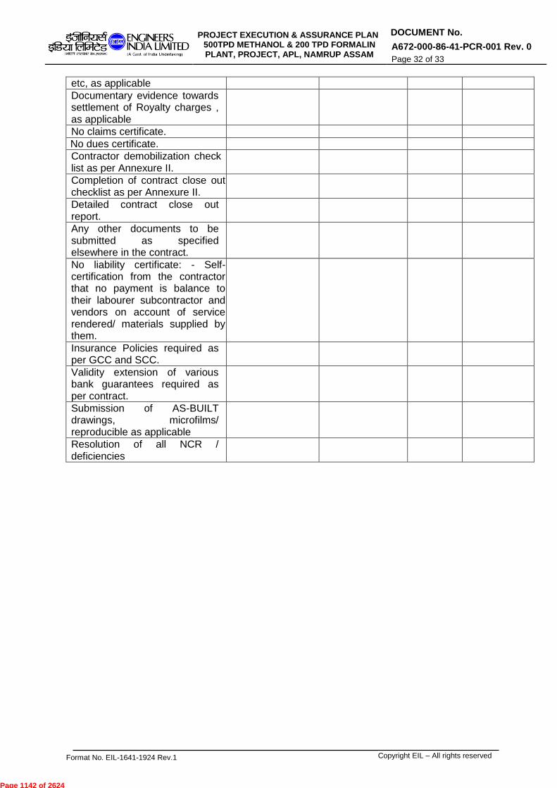
PROJECT EXECUTION & ASSURANCE PLAN 500TPD METHANOL & 200 TPD FORMALIN PLANT, PROJECT, APL, NAMRUP ASSAM
DOCUMENT No.
A672-000-86-41-PCR-001 Rev. 0
Page 32 of 33
Format No. EIL-1641-1924 Rev.1 Copyright EIL – All rights reserved
etc, as applicable
Documentary evidence towards settlement of Royalty charges , as applicable
No claims certificate.
No dues certificate.
Contractor demobilization check list as per Annexure II.
Completion of contract close out checklist as per Annexure II.
Detailed contract close out report.
Any other documents to be submitted as specified elsewhere in the contract.
No liability certificate: - Self-certification from the contractor that no payment is balance to their labourer subcontractor and vendors on account of service rendered/ materials supplied by them.
Insurance Policies required as per GCC and SCC.
Validity extension of various bank guarantees required as per contract.
Submission of AS-BUILT drawings, microfilms/ reproducible as applicable
Resolution of all NCR / deficiencies
Page 1142 of 2624
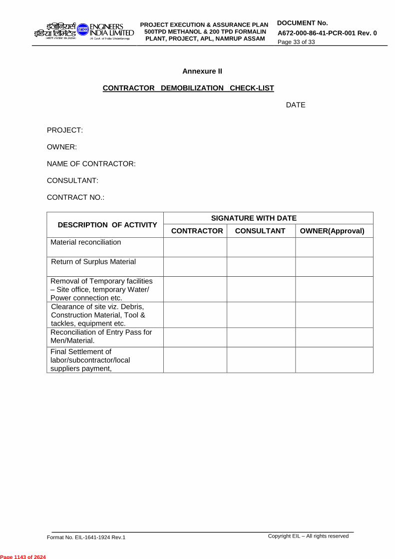
PROJECT EXECUTION & ASSURANCE PLAN 500TPD METHANOL & 200 TPD FORMALIN PLANT, PROJECT, APL, NAMRUP ASSAM
DOCUMENT No.
A672-000-86-41-PCR-001 Rev. 0
Page 33 of 33
Format No. EIL-1641-1924 Rev.1 Copyright EIL – All rights reserved
Annexure II
CONTRACTOR DEMOBILIZATION CHECK-LIST
DATE
PROJECT: OWNER: NAME OF CONTRACTOR: CONSULTANT: CONTRACT NO.:
DESCRIPTION OF ACTIVITY SIGNATURE WITH DATE
CONTRACTOR CONSULTANT OWNER(Approval)
Material reconciliation
Return of Surplus Material
Removal of Temporary facilities – Site office, temporary Water/ Power connection etc.
Clearance of site viz. Debris, Construction Material, Tool & tackles, equipment etc.
Reconciliation of Entry Pass for Men/Material.
Final Settlement of labor/subcontractor/local suppliers payment,
Page 1143 of 2624
-----------------------------------------------------------------------------------------------------------------------------------------------------------------------------------Format No. EIL -1641-1924 Rev. 1 Copyright EIL – Right reserved
VENDER LIST FOR COMPRESSED AIR AND
CRYOGENIC NITROGEN PLANT PACKAGE
Document No.
A672-014-86-41-VL-0003 Rev.0
Page 1 of 03
VENDOR LIST FOR COMPRESSED AIR AND CRYOGENIC NITROGEN PLANT PACKAGE
PROJECT: INTEGRATED METHANOL & ACETIC ACID
PROJECT OWNER: ASSAM PETROCHEMICALS LTD. PMC: ENGINEERS INDIA LIMITED (EIL) EIL JOB NO.: A672
0 05.01.2018 ISSUED FOR TENDER MNK SSR NA
Rev. No. Date Purpose Prepared by Checked by Approved by
Page 1144 of 2624

-----------------------------------------------------------------------------------------------------------------------------------------------------------------------------------Format No. EIL -1641-1924 Rev. 1 Copyright EIL – Right reserved
VENDER LIST FOR COMPRESSED AIR AND
CRYOGENIC NITROGEN PLANT PACKAGE
Document No.
A672-014-86-41-VL-0003 Rev.0
Page 2 of 03
VENDOR LIST
1.0 Contractor shall necessarily procure all material / equipment forming permanent part of the package / unit from vendors as per enclosed vendor list. This shall include sub-ordered items / components also.
2.0 Contractor may procure bought out material from any supplier as per approved vendor list,
however current validity, range of approval, work load, stability and solvency shall be verified by Contractor before placement of order on the supplier.
3.0 Contractor shall make an independent assessment of capability of the selected vendor(s)
for timely deliveries of material / equipment. Any delays in deliveries by vendor (s) shall not be entertained as a cause of time and cost implication.
4.0 Contractor is also required to ensure that equipment qualification criteria, wherever
applicable, as specified elsewhere in the bid document, is also simultaneously met. 5.0 Vendors on EIL / APL holiday / negative / dormant list shall not be considered for ordering.
Contractor to note that during the implementation stage, should any Vendor listed in the vendor list be put in holiday / negative / dormant list, APL / EIL reserve the right to inform Contractor and Contractor shall ensure that no subsequent orders, from the time of issuance of the message from EIL/APL, shall be placed on such vendor. However it shall remain an exclusive responsibility of Contractor to ensure that the vendor, to whom the enquiries are being issued / order is being placed, is not on EIL holiday / negative / dormant list. This requirement shall be followed by Contractor without any time and cost implication to the EIL/APL.
6.0 During the implementation stage should Contractor discover that there are new vendor(s)
for a particular item which have been additionally enlisted with EIL and Contractor desires to consider them for ordering, the same may be brought to the attention of APL / EIL for seeking approval. Order can be placed on such vendor only after written approval from EIL/APL, to be obtained by Contractor prior to placement of order. However, EIL/APL shall, in no way, be responsible for delays, if any, on this account.
7.0 In an eventuality that Contractor encounters state of no response from vendors enlisted in
the enquiry document and sourcing from alternate vendor(s) is required. In such case Contractor shall furnish documentary evidence of regret from the approved vendors and
requisite documentation supplementing the credentials alongwith proven Past Track Record of the proposed additional vendor(s) to EIL / APL for approval. Order can be
placed on such vendor only after written approval from EIL/APL, to be obtained by Contractor prior to placement of order. It shall be Contractor’s exclusive responsibility to meet the quality, time schedule of delivery from the proposed alternate vendor. EIL/APL shall, in no way, be responsible for delays, if any, on this account.
8.0 For items not covered in the approved vendor list, Contractor shall prepare list of proposed
supplier(s)/vendor(s) and submit the same for EIL/ PL approval. Contractor shall submit complete credentials & proven Past Track Record (PTR) of the proposed supplier(s)/ vendor(s). Order shall be placed only after written approval of EIL / APL, to be obtained by Contractor before placing order. Non-acceptance of a particular proposed vendor due
to any reasons whatsoever shall not be a cause of time and cost implication. It shall be Contractor’s exclusive responsibility to meet the quality, time schedule of delivery from the
Page 1145 of 2624

-----------------------------------------------------------------------------------------------------------------------------------------------------------------------------------Format No. EIL -1641-1924 Rev. 1 Copyright EIL – Right reserved
VENDER LIST FOR COMPRESSED AIR AND
CRYOGENIC NITROGEN PLANT PACKAGE
Document No.
A672-014-86-41-VL-0003 Rev.0
Page 3 of 03
proposed alternate vendor. EIL/APL shall, in no way, be responsible for delays, if any, on this account.
9.0 At any stage of the project, if it comes to the notice of EIL / APL that Contractor has
procured material / equipment, intentionally or unintentionally whatsoever, from an unapproved vendor and / or items not falling in approved range of vendor(s), EIL/APL shall have the right to reject such material / equipment and Contractor shall be liable to replace the same without any time and cost implication to the EIL/APL.
10.0 Vendor list for the following items is enclosed in this section.
i) MACHINERY EQUIPMENT (PACKAGED) ii) MACHINERY EQUIPMENT (ROTATING) iii) PIPING iv) INSTRUMENTATION v) ELECTRICAL vi) STATIC EQUIPMENT
11.0 List of vendors appearing anywhere else in the contract document in case of duplication of
the items at two or more places (except for the vendors list provided by process Licensor, if applicable) shall not be considered by Contractor and shall be superseded by the vendor list enclosed herewith
12.0 In case the name of Vendor be changed due to change in their Company or Corporate
shareholding, Contractor to submit requisite documentation and obtain written approval from EIL/APL prior to placement of order.
13.0 Any approval of a vendor shall not release the Contractor from any of his obligations under
the contract; neither shall any such approval signify nominations or instruction to use such a vendor. All approved vendors are deemed to have been freely chosen by the Contractor at his own risk.
14.0 For approved vendors list for fabricated equipment (Vessels, Column, Heat Exchangers
and Ejectors etc.), where not appearing in enquiry document, bidder shall approach EIL for approved vendor list after finalization of design data of particular equipment. EIL vendor list is for fabrication alone. Where mechanical design of the equipment is included in Contractor’s scope, Contractor shall either himself or through his detailed engineering sub-contractor shall be responsible for designing and obtaining approval / review of mechanical design calculations as per codes / specifications / requirements specified elsewhere in the enquiry document, from EIL/APL.
Page 1146 of 2624
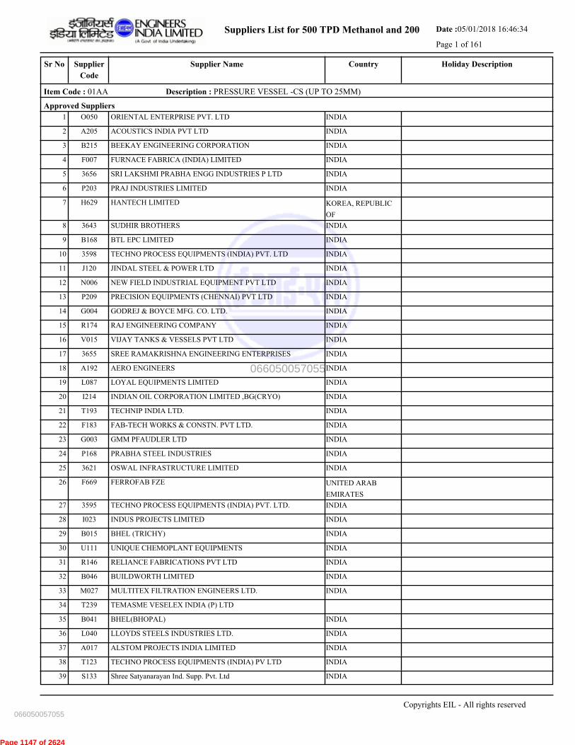
Suppliers List for 500 TPD Methanol and 200 Date :05/01/2018 16:46:34
Page 1 of 161
CountrySupplier NameSr No Holiday DescriptionSupplier
Code
Item Code : 01AA Description : PRESSURE VESSEL -CS (UP TO 25MM)
Approved Suppliers
1 ORIENTAL ENTERPRISE PVT. LTD INDIAO050
2 ACOUSTICS INDIA PVT LTD INDIAA205
3 BEEKAY ENGINEERING CORPORATION INDIAB215
4 FURNACE FABRICA (INDIA) LIMITED INDIAF007
5 SRI LAKSHMI PRABHA ENGG INDUSTRIES P LTD INDIA3656
6 PRAJ INDUSTRIES LIMITED INDIAP203
7 HANTECH LIMITED KOREA, REPUBLIC
OF
H629
8 SUDHIR BROTHERS INDIA3643
9 BTL EPC LIMITED INDIAB168
10 TECHNO PROCESS EQUIPMENTS (INDIA) PVT. LTD INDIA3598
11 JINDAL STEEL & POWER LTD INDIAJ120
12 NEW FIELD INDUSTRIAL EQUIPMENT PVT LTD INDIAN006
13 PRECISION EQUIPMENTS (CHENNAI) PVT LTD INDIAP209
14 GODREJ & BOYCE MFG. CO. LTD. INDIAG004
15 RAJ ENGINEERING COMPANY INDIAR174
16 VIJAY TANKS & VESSELS PVT LTD INDIAV015
17 SREE RAMAKRISHNA ENGINEERING ENTERPRISES INDIA3655
18 AERO ENGINEERS INDIAA192
19 LOYAL EQUIPMENTS LIMITED INDIAL087
20 INDIAN OIL CORPORATION LIMITED ,BG(CRYO) INDIAI214
21 TECHNIP INDIA LTD. INDIAT193
22 FAB-TECH WORKS & CONSTN. PVT LTD. INDIAF183
23 GMM PFAUDLER LTD INDIAG003
24 PRABHA STEEL INDUSTRIES INDIAP168
25 OSWAL INFRASTRUCTURE LIMITED INDIA3621
26 FERROFAB FZE UNITED ARAB
EMIRATES
F669
27 TECHNO PROCESS EQUIPMENTS (INDIA) PVT. LTD. INDIA3595
28 INDUS PROJECTS LIMITED INDIAI023
29 BHEL (TRICHY) INDIAB015
30 UNIQUE CHEMOPLANT EQUIPMENTS INDIAU111
31 RELIANCE FABRICATIONS PVT LTD INDIAR146
32 BUILDWORTH LIMITED INDIAB046
33 MULTITEX FILTRATION ENGINEERS LTD. INDIAM027
34 TEMASME VESELEX INDIA (P) LTDT239
35 BHEL(BHOPAL) INDIAB041
36 LLOYDS STEELS INDUSTRIES LTD. INDIAL040
37 ALSTOM PROJECTS INDIA LIMITED INDIAA017
38 TECHNO PROCESS EQUIPMENTS (INDIA) PV LTD INDIAT123
39 Shree Satyanarayan Ind. Supp. Pvt. Ltd INDIAS133
Copyrights EIL - All rights reserved
066050057055
066050057055
Page 1147 of 2624
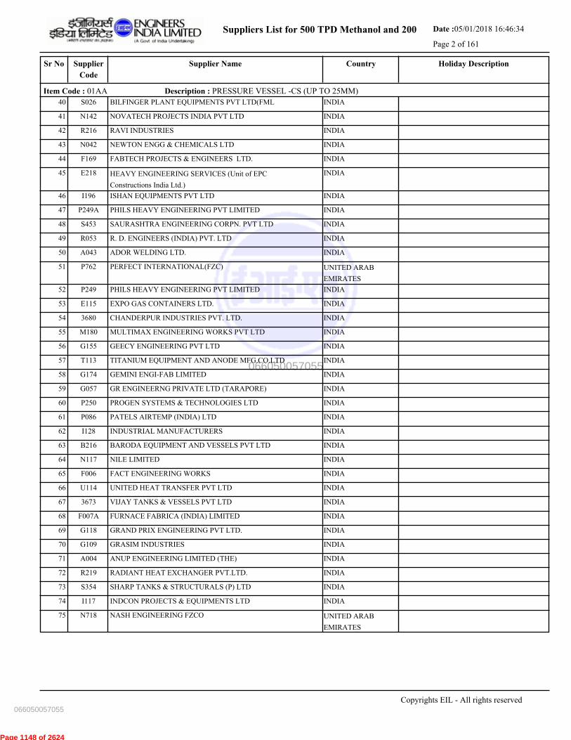
Suppliers List for 500 TPD Methanol and 200 Date :05/01/2018 16:46:34
Page 2 of 161
CountrySupplier NameSr No Holiday DescriptionSupplier
Code
Item Code : 01AA Description : PRESSURE VESSEL -CS (UP TO 25MM)
40 BILFINGER PLANT EQUIPMENTS PVT LTD(FML INDIAS026
41 NOVATECH PROJECTS INDIA PVT LTD INDIAN142
42 RAVI INDUSTRIES INDIAR216
43 NEWTON ENGG & CHEMICALS LTD INDIAN042
44 FABTECH PROJECTS & ENGINEERS LTD. INDIAF169
45 HEAVY ENGINEERING SERVICES (Unit of EPC
Constructions India Ltd.)
INDIAE218
46 ISHAN EQUIPMENTS PVT LTD INDIAI196
47 PHILS HEAVY ENGINEERING PVT LIMITED INDIAP249A
48 SAURASHTRA ENGINEERING CORPN. PVT LTD INDIAS453
49 R. D. ENGINEERS (INDIA) PVT. LTD INDIAR053
50 ADOR WELDING LTD. INDIAA043
51 PERFECT INTERNATIONAL(FZC) UNITED ARAB
EMIRATES
P762
52 PHILS HEAVY ENGINEERING PVT LIMITED INDIAP249
53 EXPO GAS CONTAINERS LTD. INDIAE115
54 CHANDERPUR INDUSTRIES PVT. LTD. INDIA3680
55 MULTIMAX ENGINEERING WORKS PVT LTD INDIAM180
56 GEECY ENGINEERING PVT LTD INDIAG155
57 TITANIUM EQUIPMENT AND ANODE MFG.CO.LTD INDIAT113
58 GEMINI ENGI-FAB LIMITED INDIAG174
59 GR ENGINEERNG PRIVATE LTD (TARAPORE) INDIAG057
60 PROGEN SYSTEMS & TECHNOLOGIES LTD INDIAP250
61 PATELS AIRTEMP (INDIA) LTD INDIAP086
62 INDUSTRIAL MANUFACTURERS INDIAI128
63 BARODA EQUIPMENT AND VESSELS PVT LTD INDIAB216
64 NILE LIMITED INDIAN117
65 FACT ENGINEERING WORKS INDIAF006
66 UNITED HEAT TRANSFER PVT LTD INDIAU114
67 VIJAY TANKS & VESSELS PVT LTD INDIA3673
68 FURNACE FABRICA (INDIA) LIMITED INDIAF007A
69 GRAND PRIX ENGINEERING PVT LTD. INDIAG118
70 GRASIM INDUSTRIES INDIAG109
71 ANUP ENGINEERING LIMITED (THE) INDIAA004
72 RADIANT HEAT EXCHANGER PVT.LTD. INDIAR219
73 SHARP TANKS & STRUCTURALS (P) LTD INDIAS354
74 INDCON PROJECTS & EQUIPMENTS LTD INDIAI117
75 NASH ENGINEERING FZCO UNITED ARAB
EMIRATES
N718
Copyrights EIL - All rights reserved
066050057055
066050057055
Page 1148 of 2624
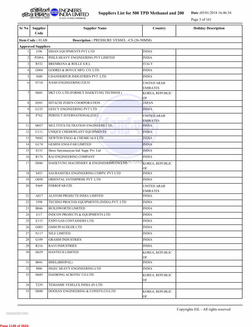
Suppliers List for 500 TPD Methanol and 200 Date :05/01/2018 16:46:34
Page 3 of 161
CountrySupplier NameSr No Holiday DescriptionSupplier
Code
Item Code : 01AB Description : PRESSURE VESSEL -CS (26-50MM)
Approved Suppliers
1 ISHAN EQUIPMENTS PVT LTD INDIAI196
2 PHILS HEAVY ENGINEERING PVT LIMITED INDIAP249A
3 BREMBANA & ROLLE S.R.L ITALYR532
4 GODREJ & BOYCE MFG. CO. LTD. INDIAG004
5 CHANDERPUR INDUSTRIES PVT. LTD. INDIA3680
6 NASH ENGINEERING FZCO UNITED ARAB
EMIRATES
N718
7 DKT CO. LTD (FORMLY DAEKYUNG TECHNOS ) KOREA, REPUBLIC
OF
D681
8 HITACHI ZOSEN COORPORATION JAPANH501
9 GEECY ENGINEERING PVT LTD INDIAG155
10 PERFECT INTERNATIONAL(FZC) UNITED ARAB
EMIRATES
P762
11 MULTITEX FILTRATION ENGINEERS LTD. INDIAM027
12 UNIQUE CHEMOPLANT EQUIPMENTS INDIAU111
13 NEWTON ENGG & CHEMICALS LTD INDIAN042
14 GEMINI ENGI-FAB LIMITED INDIAG174
15 Shree Satyanarayan Ind. Supp. Pvt. Ltd INDIAS133
16 RAJ ENGINEERING COMPANY INDIAR174
17 DAEKYUNG MACHINERY & ENGINEERING CO.LTD KOREA, REPUBLIC
OF
D686
18 SAURASHTRA ENGINEERING CORPN. PVT LTD INDIAS453
19 ORIENTAL ENTERPRISE PVT. LTD INDIAO050
20 FERROFAB FZE UNITED ARAB
EMIRATES
F669
21 ALSTOM PROJECTS INDIA LIMITED INDIAA017
22 TECHNO PROCESS EQUIPMENTS (INDIA) PVT. LTD INDIA3598
23 BUILDWORTH LIMITED INDIAB046
24 INDCON PROJECTS & EQUIPMENTS LTD INDIAI117
25 EXPO GAS CONTAINERS LTD. INDIAE115
26 GMM PFAUDLER LTD INDIAG003
27 NILE LIMITED INDIAN117
28 GRASIM INDUSTRIES INDIAG109
29 RAVI INDUSTRIES INDIAR216
30 HANTECH LIMITED KOREA, REPUBLIC
OF
H629
31 BHEL(BHOPAL) INDIAB041
32 ISGEC HEAVY ENGINEERING LTD INDIAI006
33 DAEBONG ACROTEC CO.LTD KOREA, REPUBLIC
OF
D685
34 TEMASME VESELEX INDIA (P) LTDT239
35 DOOSAN ENGINEERING & CONSTN.CO.LTD KOREA, REPUBLIC
OF
D680
Copyrights EIL - All rights reserved
066050057055
066050057055
Page 1149 of 2624

Suppliers List for 500 TPD Methanol and 200 Date :05/01/2018 16:46:34
Page 4 of 161
CountrySupplier NameSr No Holiday DescriptionSupplier
Code
Item Code : 01AB Description : PRESSURE VESSEL -CS (26-50MM)
36 LARSEN & TOUBRO LTD INDIAL032
37 PHILS HEAVY ENGINEERING PVT LIMITED INDIAP249
38 BEEKAY ENGINEERING CORPORATION INDIAB215
39 BILFINGER PLANT EQUIPMENTS PVT LTD(FML INDIAS026
40 GR ENGINEERNG PRIVATE LTD (TARAPORE) INDIAG057
41 PRABHA STEEL INDUSTRIES INDIAP168
42 ISGEC HITACHI ZOSEN LTD INDIAI203
43 VIJAY TANKS & VESSELS PVT LTD INDIAV015
44 JINDAL STEEL & POWER LTD INDIAJ120
45 SHARP TANKS & STRUCTURALS (P) LTD INDIAS354
46 KCP LIMITED INDIAK035
47 NEW FIELD INDUSTRIAL EQUIPMENT PVT LTD INDIAN006
48 INDUSTRIAL MANUFACTURERS INDIAI128
49 PRECISION EQUIPMENTS (CHENNAI) PVT LTD INDIAP209
50 R. D. ENGINEERS (INDIA) PVT. LTD INDIAR053
51 HEAVY ENGINEERING SERVICES (Unit of EPC
Constructions India Ltd.)
INDIAE218
52 PATELS AIRTEMP (INDIA) LTD INDIAP086
53 TECHNO PROCESS EQUIPMENTS (INDIA) PVT. LTD. INDIA3595
54 KNM PROCESS SYSTEMS SDN BHD MALAYSIAK633
55 PRAJ INDUSTRIES LIMITED INDIAP203
56 FAB-TECH WORKS & CONSTN. PVT LTD. INDIAF183
57 GRAND PRIX ENGINEERING PVT LTD. INDIAG118
58 LLOYDS STEELS INDUSTRIES LTD. INDIAL040
59 VIJAY TANKS & VESSELS PVT LTD INDIA3673
60 BHEL (TRICHY) INDIAB015
61 OFMECO SPA ITALYO557
62 ANUP ENGINEERING LIMITED (THE) INDIAA004
63 FABTECH PROJECTS & ENGINEERS LTD. INDIAF169
64 TECHNO PROCESS EQUIPMENTS (INDIA) PV LTD INDIAT123
65 INDUS PROJECTS LIMITED INDIAI023
Copyrights EIL - All rights reserved
066050057055
066050057055
Page 1150 of 2624

Suppliers List for 500 TPD Methanol and 200 Date :05/01/2018 16:46:34
Page 5 of 161
CountrySupplier NameSr No Holiday DescriptionSupplier
Code
Item Code : 01CO Description : HEAT EXCHANGER (AL.BRAZED FIN TYPE)
Approved Suppliers
1 HANGZHOU ZHONGTAI CRYOGENIC TECHN.CORPN CHINAH655
2 LINDE AG GERMANYL514
3 KOBE STEEL LTD JAPANK507
4 FIVES CRYO( FMRLY NORDON CRYOGENIE) FRANCEF663
5 SUMITOMO PRECISION PRODUCTS CO LTD JAPANS700
Copyrights EIL - All rights reserved
066050057055
066050057055
Page 1151 of 2624

Suppliers List for 500 TPD Methanol and 200 Date :05/01/2018 16:46:34
Page 6 of 161
CountrySupplier NameSr No Holiday DescriptionSupplier
Code
Item Code : 02A- Description : GASKET (IMPORTED)
Approved Suppliers
1 MOORSIDE MACHINING CO LTD UNITED
KINGDOM
M570
2 FLEXITALLIC LTD UNITED
KINGDOM
F543
Copyrights EIL - All rights reserved
066050057055
066050057055
Page 1152 of 2624
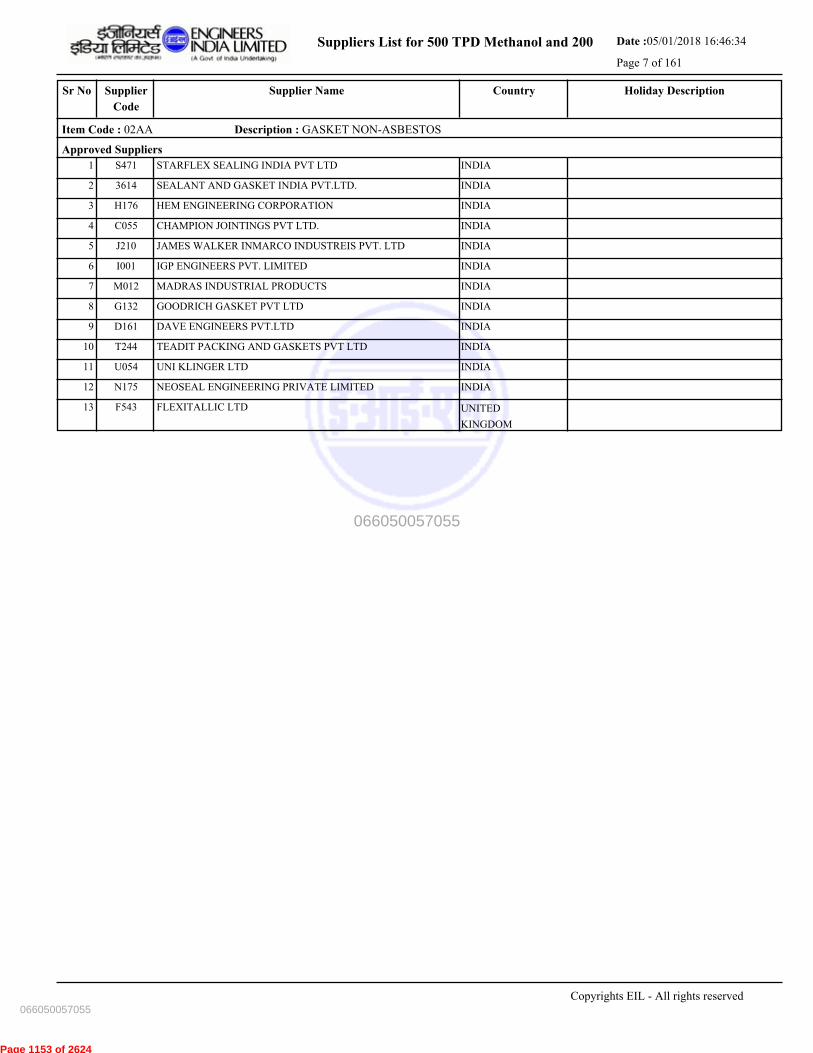
Suppliers List for 500 TPD Methanol and 200 Date :05/01/2018 16:46:34
Page 7 of 161
CountrySupplier NameSr No Holiday DescriptionSupplier
Code
Item Code : 02AA Description : GASKET NON-ASBESTOS
Approved Suppliers
1 STARFLEX SEALING INDIA PVT LTD INDIAS471
2 SEALANT AND GASKET INDIA PVT.LTD. INDIA3614
3 HEM ENGINEERING CORPORATION INDIAH176
4 CHAMPION JOINTINGS PVT LTD. INDIAC055
5 JAMES WALKER INMARCO INDUSTREIS PVT. LTD INDIAJ210
6 IGP ENGINEERS PVT. LIMITED INDIAI001
7 MADRAS INDUSTRIAL PRODUCTS INDIAM012
8 GOODRICH GASKET PVT LTD INDIAG132
9 DAVE ENGINEERS PVT.LTD INDIAD161
10 TEADIT PACKING AND GASKETS PVT LTD INDIAT244
11 UNI KLINGER LTD INDIAU054
12 NEOSEAL ENGINEERING PRIVATE LIMITED INDIAN175
13 FLEXITALLIC LTD UNITED
KINGDOM
F543
Copyrights EIL - All rights reserved
066050057055
066050057055
Page 1153 of 2624

Suppliers List for 500 TPD Methanol and 200 Date :05/01/2018 16:46:34
Page 8 of 161
CountrySupplier NameSr No Holiday DescriptionSupplier
Code
Item Code : 02AB Description : GASKET METALLIC & SOFT IRON
Approved Suppliers
1 GOODRICH GASKET PVT LTD INDIAG132
2 IGP ENGINEERS PVT. LIMITED INDIAI001
3 MADRAS INDUSTRIAL PRODUCTS INDIAM012
4 STARFLEX SEALING INDIA PVT LTD INDIAS471
5 MICRO PRECISION PRODUCTS PVT LTD INDIAM010
Copyrights EIL - All rights reserved
066050057055
066050057055
Page 1154 of 2624
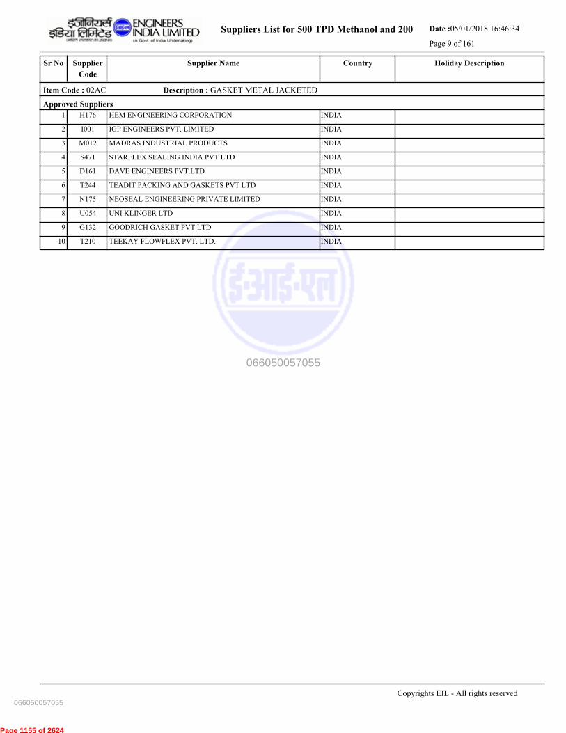
Suppliers List for 500 TPD Methanol and 200 Date :05/01/2018 16:46:34
Page 9 of 161
CountrySupplier NameSr No Holiday DescriptionSupplier
Code
Item Code : 02AC Description : GASKET METAL JACKETED
Approved Suppliers
1 HEM ENGINEERING CORPORATION INDIAH176
2 IGP ENGINEERS PVT. LIMITED INDIAI001
3 MADRAS INDUSTRIAL PRODUCTS INDIAM012
4 STARFLEX SEALING INDIA PVT LTD INDIAS471
5 DAVE ENGINEERS PVT.LTD INDIAD161
6 TEADIT PACKING AND GASKETS PVT LTD INDIAT244
7 NEOSEAL ENGINEERING PRIVATE LIMITED INDIAN175
8 UNI KLINGER LTD INDIAU054
9 GOODRICH GASKET PVT LTD INDIAG132
10 TEEKAY FLOWFLEX PVT. LTD. INDIAT210
Copyrights EIL - All rights reserved
066050057055
066050057055
Page 1155 of 2624

Suppliers List for 500 TPD Methanol and 200 Date :05/01/2018 16:46:34
Page 10 of 161
CountrySupplier NameSr No Holiday DescriptionSupplier
Code
Item Code : 02AD Description : GASKET SPIRAL WOUND
Approved Suppliers
1 CHAMPION JOINTINGS PVT LTD. INDIAC055
2 IGP ENGINEERS PVT. LIMITED INDIAI001
3 DAVE ENGINEERS PVT.LTD INDIAD161
4 TEEKAY FLOWFLEX PVT. LTD. INDIAT210
5 STARFLEX SEALING INDIA PVT LTD INDIAS471
6 NEOSEAL ENGINEERING PRIVATE LIMITED INDIAN175
7 BOMBAY CHEMICAL EQUIPMENTS INDIAB144
8 JAMES WALKER INMARCO INDUSTREIS PVT. LTD INDIAJ210
9 TEADIT PACKING AND GASKETS PVT LTD INDIAT244
10 HEM ENGINEERING CORPORATION INDIAH176
11 MADRAS INDUSTRIAL PRODUCTS INDIAM012
12 UNI KLINGER LTD INDIAU054
13 GOODRICH GASKET PVT LTD INDIAG132
Copyrights EIL - All rights reserved
066050057055
066050057055
Page 1156 of 2624

Suppliers List for 500 TPD Methanol and 200 Date :05/01/2018 16:46:34
Page 11 of 161
CountrySupplier NameSr No Holiday DescriptionSupplier
Code
Item Code : 02AG Description : GASKET-PTFE(GLASS FILLED)
Approved Suppliers
1 STARFLEX SEALING INDIA PVT LTD INDIAS471
2 GOODRICH GASKET PVT LTD INDIAG132
3 TEADIT PACKING AND GASKETS PVT LTD INDIAT244
4 DIP-FLON ENGINEERING & CO. INDIAD097
Copyrights EIL - All rights reserved
066050057055
066050057055
Page 1157 of 2624

Suppliers List for 500 TPD Methanol and 200 Date :05/01/2018 16:46:34
Page 12 of 161
CountrySupplier NameSr No Holiday DescriptionSupplier
Code
Item Code : 02BA Description : HOSE- RUBBER (STEAM/GAS/AIR/WATER/CHEM.)
Approved Suppliers
1 RM APPLIED ENGINEERS INDIAR204
2 SWAGELOK CO. UNITED STATESS773
3 GAYTRI INDUSTRIAL CORPORATION INDIAG052
4 HELIFLEX HYDRAULICS & ENGG.CO. INDIAH184
5 DEWAS HYDROQUIP PVT LTD INDIAD144
6 SRIDHAR ENGG. & RUBER PRODUCTS PVT LTD. INDIAS254
7 INSAP ENGINEERS PVT. LTD INDIAI207
8 PIX TRANSMISSIONS LIMITED INDIAP316
Copyrights EIL - All rights reserved
066050057055
066050057055
Page 1158 of 2624
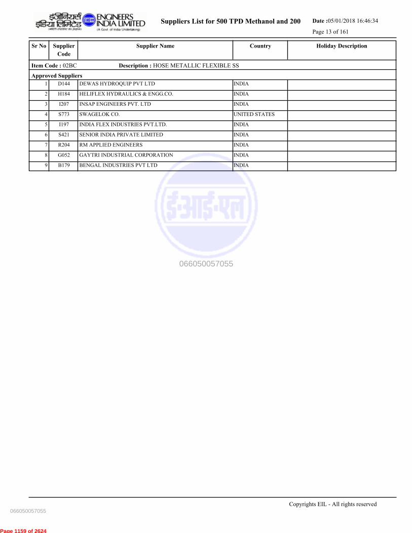
Suppliers List for 500 TPD Methanol and 200 Date :05/01/2018 16:46:34
Page 13 of 161
CountrySupplier NameSr No Holiday DescriptionSupplier
Code
Item Code : 02BC Description : HOSE METALLIC FLEXIBLE SS
Approved Suppliers
1 DEWAS HYDROQUIP PVT LTD INDIAD144
2 HELIFLEX HYDRAULICS & ENGG.CO. INDIAH184
3 INSAP ENGINEERS PVT. LTD INDIAI207
4 SWAGELOK CO. UNITED STATESS773
5 INDIA FLEX INDUSTRIES PVT.LTD. INDIAI197
6 SENIOR INDIA PRIVATE LIMITED INDIAS421
7 RM APPLIED ENGINEERS INDIAR204
8 GAYTRI INDUSTRIAL CORPORATION INDIAG052
9 BENGAL INDUSTRIES PVT LTD INDIAB179
Copyrights EIL - All rights reserved
066050057055
066050057055
Page 1159 of 2624
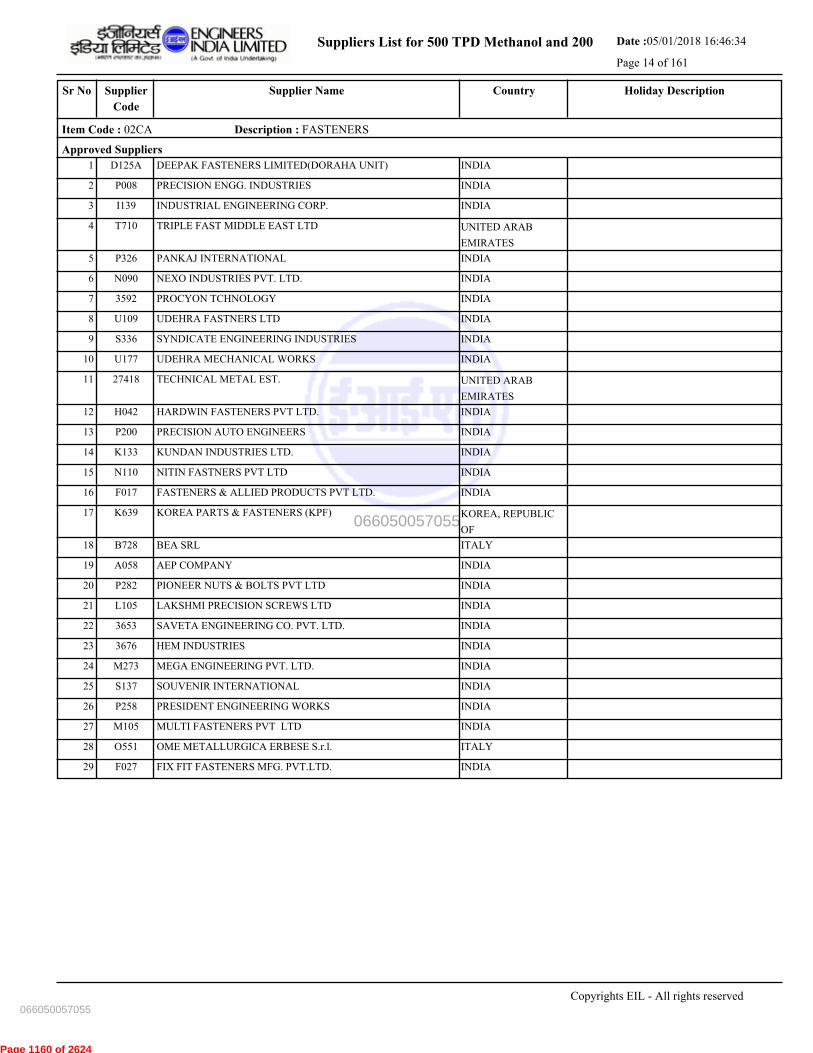
Suppliers List for 500 TPD Methanol and 200 Date :05/01/2018 16:46:34
Page 14 of 161
CountrySupplier NameSr No Holiday DescriptionSupplier
Code
Item Code : 02CA Description : FASTENERS
Approved Suppliers
1 DEEPAK FASTENERS LIMITED(DORAHA UNIT) INDIAD125A
2 PRECISION ENGG. INDUSTRIES INDIAP008
3 INDUSTRIAL ENGINEERING CORP. INDIAI139
4 TRIPLE FAST MIDDLE EAST LTD UNITED ARAB
EMIRATES
T710
5 PANKAJ INTERNATIONAL INDIAP326
6 NEXO INDUSTRIES PVT. LTD. INDIAN090
7 PROCYON TCHNOLOGY INDIA3592
8 UDEHRA FASTNERS LTD INDIAU109
9 SYNDICATE ENGINEERING INDUSTRIES INDIAS336
10 UDEHRA MECHANICAL WORKS INDIAU177
11 TECHNICAL METAL EST. UNITED ARAB
EMIRATES
27418
12 HARDWIN FASTENERS PVT LTD. INDIAH042
13 PRECISION AUTO ENGINEERS INDIAP200
14 KUNDAN INDUSTRIES LTD. INDIAK133
15 NITIN FASTNERS PVT LTD INDIAN110
16 FASTENERS & ALLIED PRODUCTS PVT LTD. INDIAF017
17 KOREA PARTS & FASTENERS (KPF) KOREA, REPUBLIC
OF
K639
18 BEA SRL ITALYB728
19 AEP COMPANY INDIAA058
20 PIONEER NUTS & BOLTS PVT LTD INDIAP282
21 LAKSHMI PRECISION SCREWS LTD INDIAL105
22 SAVETA ENGINEERING CO. PVT. LTD. INDIA3653
23 HEM INDUSTRIES INDIA3676
24 MEGA ENGINEERING PVT. LTD. INDIAM273
25 SOUVENIR INTERNATIONAL INDIAS137
26 PRESIDENT ENGINEERING WORKS INDIAP258
27 MULTI FASTENERS PVT LTD INDIAM105
28 OME METALLURGICA ERBESE S.r.l. ITALYO551
29 FIX FIT FASTENERS MFG. PVT.LTD. INDIAF027
Copyrights EIL - All rights reserved
066050057055
066050057055
Page 1160 of 2624
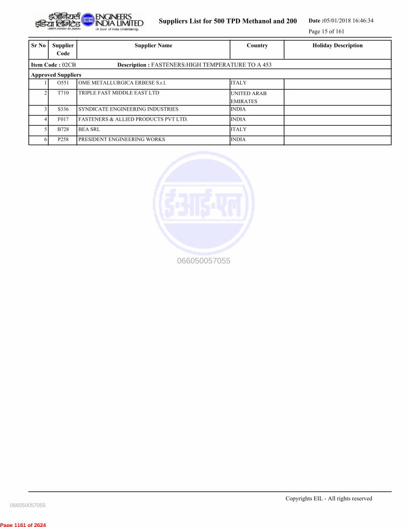
Suppliers List for 500 TPD Methanol and 200 Date :05/01/2018 16:46:34
Page 15 of 161
CountrySupplier NameSr No Holiday DescriptionSupplier
Code
Item Code : 02CB Description : FASTENERS:HIGH TEMPERATURE TO A 453
Approved Suppliers
1 OME METALLURGICA ERBESE S.r.l. ITALYO551
2 TRIPLE FAST MIDDLE EAST LTD UNITED ARAB
EMIRATES
T710
3 SYNDICATE ENGINEERING INDUSTRIES INDIAS336
4 FASTENERS & ALLIED PRODUCTS PVT LTD. INDIAF017
5 BEA SRL ITALYB728
6 PRESIDENT ENGINEERING WORKS INDIAP258
Copyrights EIL - All rights reserved
066050057055
066050057055
Page 1161 of 2624

Suppliers List for 500 TPD Methanol and 200 Date :05/01/2018 16:46:34
Page 16 of 161
CountrySupplier NameSr No Holiday DescriptionSupplier
Code
Item Code : 02DB Description : SPRING SUPPORTS
Approved Suppliers
1 TECHNO INDUSTRY INDIAT246A
2 PIPING & ENERGY PRODUCTS ( P ) LTD INDIAP018
3 TECHNO INDUSTRY INDIAT246
4 PIPE SUPPORTS CO INDIAP338
5 CA.S.T.IM.2000 SRL ITALYC748
6 UNISON ETECH CO.LTD KOREA, REPUBLIC
OF
U584
7 SPRING SUPPORTS MFG CO INDIAS168
8 PIPE HANGERS & SUPPORTS PVT LTD INDIAP273
9 PIPE SUPPORTS ASIA LTD THAILANDP705
Copyrights EIL - All rights reserved
066050057055
066050057055
Page 1162 of 2624
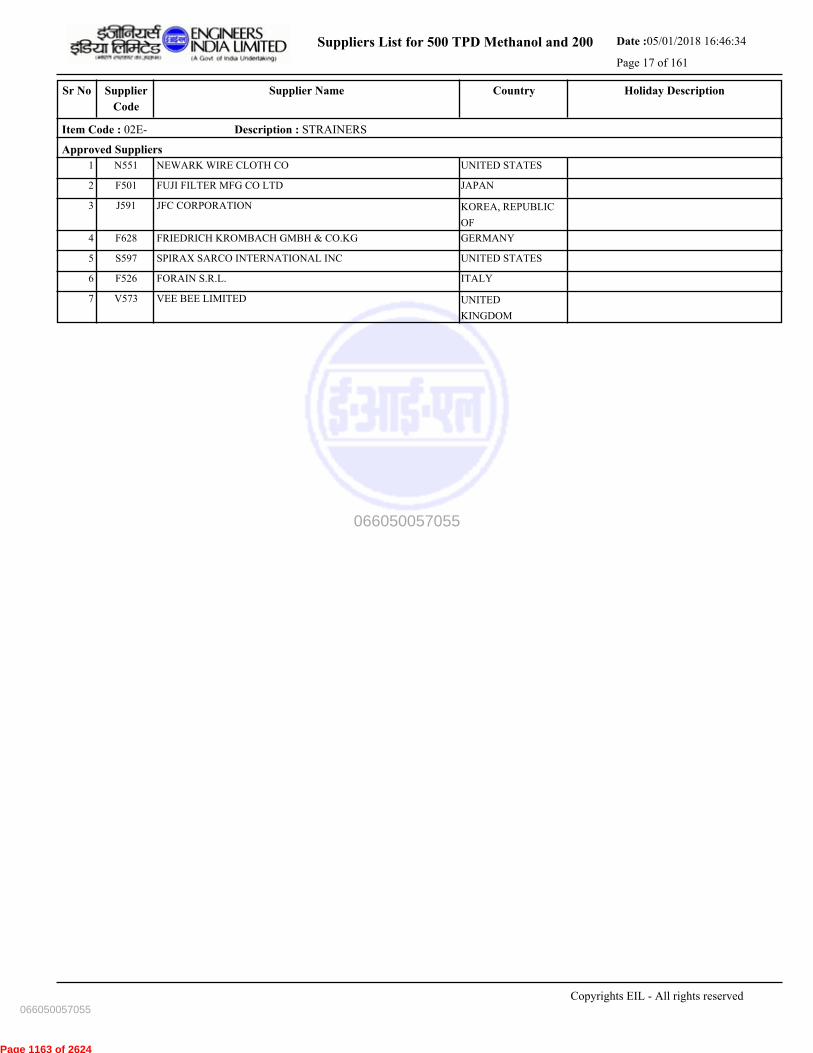
Suppliers List for 500 TPD Methanol and 200 Date :05/01/2018 16:46:34
Page 17 of 161
CountrySupplier NameSr No Holiday DescriptionSupplier
Code
Item Code : 02E- Description : STRAINERS
Approved Suppliers
1 NEWARK WIRE CLOTH CO UNITED STATESN551
2 FUJI FILTER MFG CO LTD JAPANF501
3 JFC CORPORATION KOREA, REPUBLIC
OF
J591
4 FRIEDRICH KROMBACH GMBH & CO.KG GERMANYF628
5 SPIRAX SARCO INTERNATIONAL INC UNITED STATESS597
6 FORAIN S.R.L. ITALYF526
7 VEE BEE LIMITED UNITED
KINGDOM
V573
Copyrights EIL - All rights reserved
066050057055
066050057055
Page 1163 of 2624

Suppliers List for 500 TPD Methanol and 200 Date :05/01/2018 16:46:34
Page 18 of 161
CountrySupplier NameSr No Holiday DescriptionSupplier
Code
Item Code : 02EA Description : STRAINERS (FAB/CAST/FORGED)
Approved Suppliers
1 MULTITEX FILTRATION ENGINEERS LTD. INDIAM027
2 BOMBAY CHEMICAL EQUIPMENTS INDIAB144
3 GUJARAT OTOFILT INDIAG097
4 ESCO STEAMCON PVT. LTD. INDIAE026
5 LEADER VALVES LTD INDIAL004
6 FORBES MARSHALL STEAM SYSTEMS PVT. LTD. INDIAS341
7 GRAND PRIX ENGINEERING PVT LTD. INDIAG118
8 PENNANT ENGINEERING PVT LTD INDIAP192
9 SUNGOV ENGINEERING PVT LTD INDIAS132
10 VERMEER PROCESS TECHNOLOGY B.V NETHERLANDSV621
11 FORBES MARSHALL PVT. LTD.- PUNE INDIAF181
12 DOUGLAS CHERO SPA ITALYD679
Copyrights EIL - All rights reserved
066050057055
066050057055
Page 1164 of 2624

Suppliers List for 500 TPD Methanol and 200 Date :05/01/2018 16:46:34
Page 19 of 161
CountrySupplier NameSr No Holiday DescriptionSupplier
Code
Item Code : 02EB Description : STEAM TRAPS-BUCKET/TH.DYN/TH.STAT/FLOAT
Approved Suppliers
1 FORBES MARSHALL PVT. LTD.- PUNE INDIAF181
2 GESTRA AG (FLOWSERVE GROUP) GERMANYG544
3 PENNANT ENGINEERING PVT LTD INDIAP192
4 UNI KLINGER LTD INDIAU054
5 ESCO STEAMCON PVT. LTD. INDIAE026
6 ARMSTRONG INTERNATIONAL PVT LTD. INDIAA376
7 FORBES MARSHALL STEAM SYSTEMS PVT. LTD. INDIAS341
8 LEADER VALVES LTD INDIAL004
Copyrights EIL - All rights reserved
066050057055
066050057055
Page 1165 of 2624
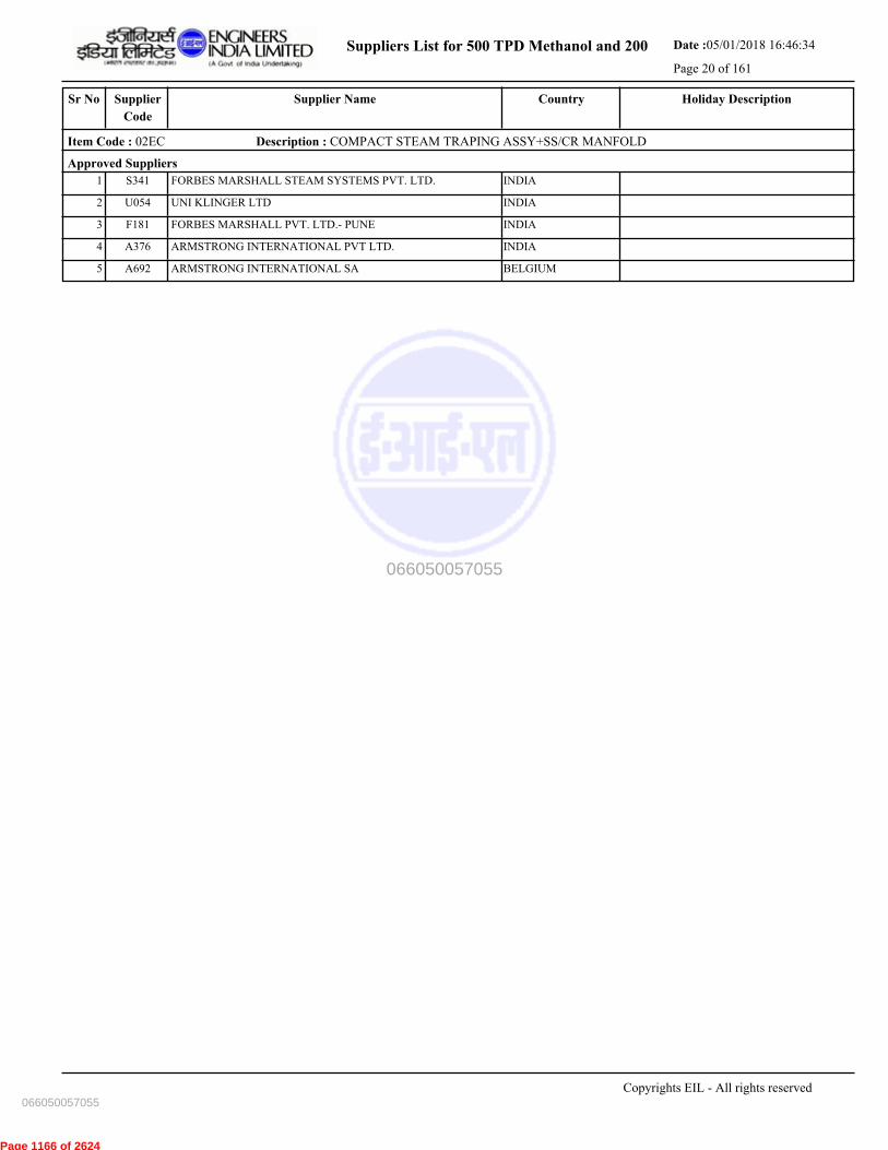
Suppliers List for 500 TPD Methanol and 200 Date :05/01/2018 16:46:34
Page 20 of 161
CountrySupplier NameSr No Holiday DescriptionSupplier
Code
Item Code : 02EC Description : COMPACT STEAM TRAPING ASSY+SS/CR MANFOLD
Approved Suppliers
1 FORBES MARSHALL STEAM SYSTEMS PVT. LTD. INDIAS341
2 UNI KLINGER LTD INDIAU054
3 FORBES MARSHALL PVT. LTD.- PUNE INDIAF181
4 ARMSTRONG INTERNATIONAL PVT LTD. INDIAA376
5 ARMSTRONG INTERNATIONAL SA BELGIUMA692
Copyrights EIL - All rights reserved
066050057055
066050057055
Page 1166 of 2624
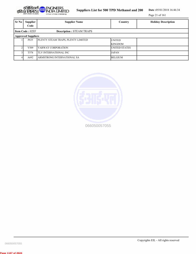
Suppliers List for 500 TPD Methanol and 200 Date :05/01/2018 16:46:34
Page 21 of 161
CountrySupplier NameSr No Holiday DescriptionSupplier
Code
Item Code : 02EF Description : STEAM TRAPS
Approved Suppliers
1 PLENTY STEAM TRAPS, PLENTY LIMITED UNITED
KINGDOM
P635
2 YARWAY CORPORATION UNITED STATESY509
3 TLV INTERNATIONAL INC JAPANT578
4 ARMSTRONG INTERNATIONAL SA BELGIUMA692
Copyrights EIL - All rights reserved
066050057055
066050057055
Page 1167 of 2624
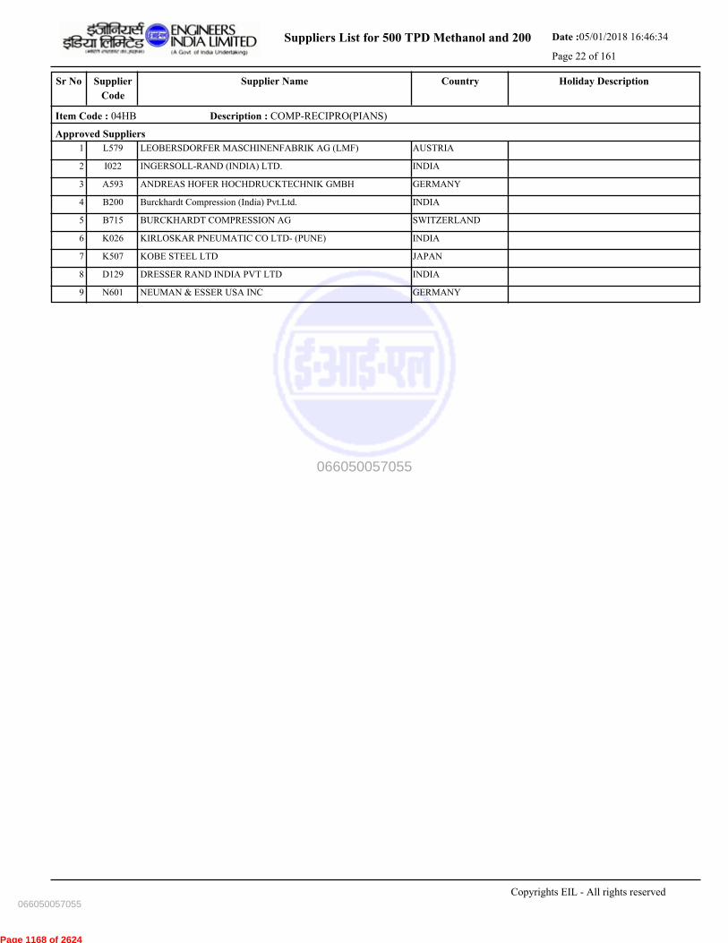
Suppliers List for 500 TPD Methanol and 200 Date :05/01/2018 16:46:34
Page 22 of 161
CountrySupplier NameSr No Holiday DescriptionSupplier
Code
Item Code : 04HB Description : COMP-RECIPRO(PIANS)
Approved Suppliers
1 LEOBERSDORFER MASCHINENFABRIK AG (LMF) AUSTRIAL579
2 INGERSOLL-RAND (INDIA) LTD. INDIAI022
3 ANDREAS HOFER HOCHDRUCKTECHNIK GMBH GERMANYA593
4 Burckhardt Compression (India) Pvt.Ltd. INDIAB200
5 BURCKHARDT COMPRESSION AG SWITZERLANDB715
6 KIRLOSKAR PNEUMATIC CO LTD- (PUNE) INDIAK026
7 KOBE STEEL LTD JAPANK507
8 DRESSER RAND INDIA PVT LTD INDIAD129
9 NEUMAN & ESSER USA INC GERMANYN601
Copyrights EIL - All rights reserved
066050057055
066050057055
Page 1168 of 2624

Suppliers List for 500 TPD Methanol and 200 Date :05/01/2018 16:46:34
Page 23 of 161
CountrySupplier NameSr No Holiday DescriptionSupplier
Code
Item Code : 04IB Description : COMP-CENT.P.I.G(PIA)
Approved Suppliers
1 ATLAS COPCO COMPTEC LLC (USA) UNITED STATESA672
2 KOBE STEEL LTD JAPANK507
3 KIRLOSKAR PNEUMATIC CO LTD- (PUNE) INDIAK026
4 GARDNER DENVER WITTIG GMBH GERMANYG619
5 MITSUBISHI HEAVY INDUSTRIES LTD JAPANM502
6 CAMERON INTERNATIONAL CORPORATION UNITED STATESC711
7 MAN TURBOMASCHINEN AG GERMANYM696
8 FS-ELLIOTT CO. LLC UNITED STATESF647
9 HOWDEN COMPRESSORS UNITED
KINGDOM
H509
10 INGERSOLL-RAND (INDIA) LTD. INDIAI022
11 ATLAS COPCO (INDIA) LTD INDIAA060A
Copyrights EIL - All rights reserved
066050057055
066050057055
Page 1169 of 2624
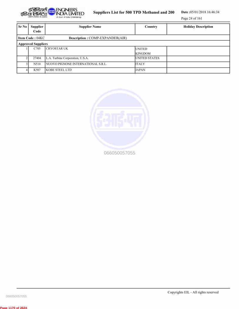
Suppliers List for 500 TPD Methanol and 200 Date :05/01/2018 16:46:34
Page 24 of 161
CountrySupplier NameSr No Holiday DescriptionSupplier
Code
Item Code : 04KC Description : COMP-EXPANDER(AIR)
Approved Suppliers
1 CRYOSTAR UK UNITED
KINGDOM
C705
2 L.A. Turbine Corporation, U.S.A. UNITED STATES27404
3 NUOVO PIGNONE INTERNATIONAL S.R.L. ITALYN510
4 KOBE STEEL LTD JAPANK507
Copyrights EIL - All rights reserved
066050057055
066050057055
Page 1170 of 2624
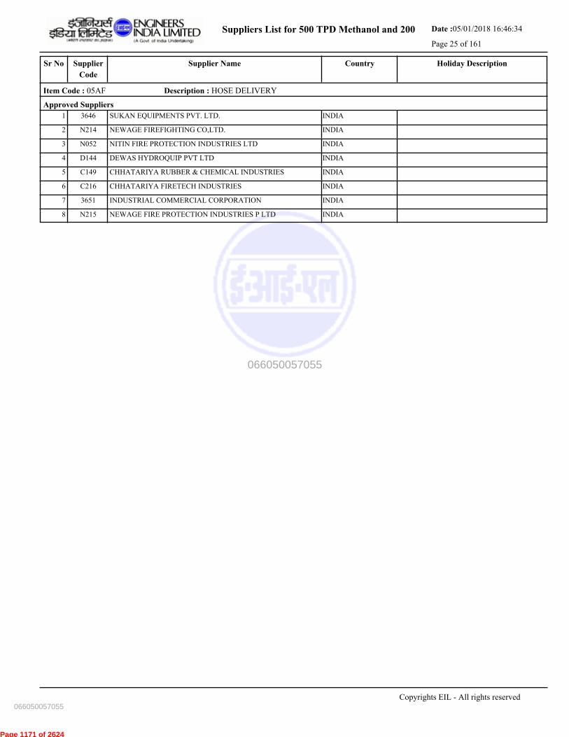
Suppliers List for 500 TPD Methanol and 200 Date :05/01/2018 16:46:34
Page 25 of 161
CountrySupplier NameSr No Holiday DescriptionSupplier
Code
Item Code : 05AF Description : HOSE DELIVERY
Approved Suppliers
1 SUKAN EQUIPMENTS PVT. LTD. INDIA3646
2 NEWAGE FIREFIGHTING CO,LTD. INDIAN214
3 NITIN FIRE PROTECTION INDUSTRIES LTD INDIAN052
4 DEWAS HYDROQUIP PVT LTD INDIAD144
5 CHHATARIYA RUBBER & CHEMICAL INDUSTRIES INDIAC149
6 CHHATARIYA FIRETECH INDUSTRIES INDIAC216
7 INDUSTRIAL COMMERCIAL CORPORATION INDIA3651
8 NEWAGE FIRE PROTECTION INDUSTRIES P LTD INDIAN215
Copyrights EIL - All rights reserved
066050057055
066050057055
Page 1171 of 2624

Suppliers List for 500 TPD Methanol and 200 Date :05/01/2018 16:46:34
Page 26 of 161
CountrySupplier NameSr No Holiday DescriptionSupplier
Code
Item Code : 05AG Description : FIRE HOSE ACCESSORIES
Approved Suppliers
1 BRIJBASI HI-TECH UDYOG INDIAB027
2 SUKAN EQUIPMENTS PVT. LTD. INDIA3646
3 UNITED FIRE EQUIPMENTS PVT. LTD. INDIAU185
4 SUPREMEX EQUIPMENTS INDIAS081
5 NEWAGE FIRE PROTECTION INDUSTRIES P LTD INDIAN215
6 SHAH BHOGILAL JETHALAL & BROTHERS INDIAS313
7 GUNNEBO INDIA LIMITED INDIAG165
8 VIMAL FIRE CONTROLS PVT LTD INDIAV072
9 ASCO STRUMECH PVT.LTD. INDIAA077
Copyrights EIL - All rights reserved
066050057055
066050057055
Page 1172 of 2624

Suppliers List for 500 TPD Methanol and 200 Date :05/01/2018 16:46:34
Page 27 of 161
CountrySupplier NameSr No Holiday DescriptionSupplier
Code
Item Code : 06AC Description : REFRIGERATION SYSTEM - PROCESS
Approved Suppliers
1 VOLTAS LIMITED INDIAV004
2 YORK INDIA LTD (A JOHNSON CONTROLS CO.) INDIAY010
3 AUSTCOLD REFRIGERATION PTY LTD. AUSTRALIAA737
4 SYSTEMS & COMPONENTS (INDIA) PVT. LTD. INDIAS337
5 KIRLOSKAR PNEUMATIC CO LTD- (PUNE) INDIAK026
Copyrights EIL - All rights reserved
066050057055
066050057055
Page 1173 of 2624
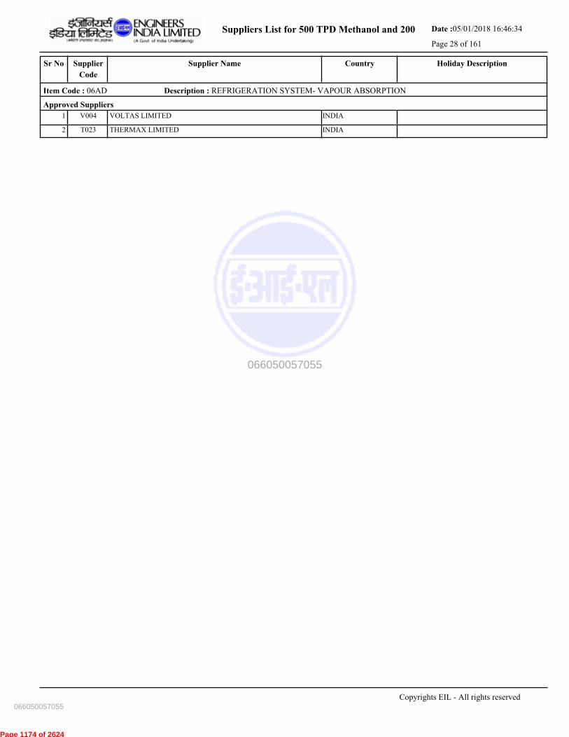
Suppliers List for 500 TPD Methanol and 200 Date :05/01/2018 16:46:34
Page 28 of 161
CountrySupplier NameSr No Holiday DescriptionSupplier
Code
Item Code : 06AD Description : REFRIGERATION SYSTEM- VAPOUR ABSORPTION
Approved Suppliers
1 VOLTAS LIMITED INDIAV004
2 THERMAX LIMITED INDIAT023
Copyrights EIL - All rights reserved
066050057055
066050057055
Page 1174 of 2624
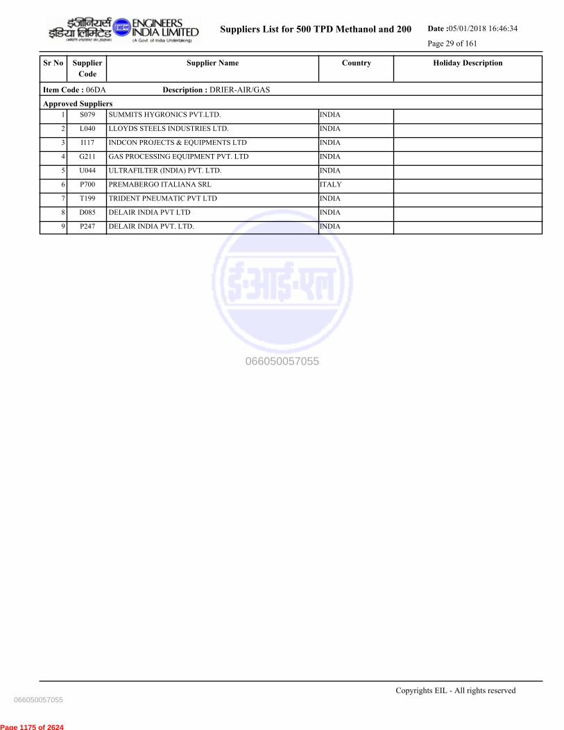
Suppliers List for 500 TPD Methanol and 200 Date :05/01/2018 16:46:34
Page 29 of 161
CountrySupplier NameSr No Holiday DescriptionSupplier
Code
Item Code : 06DA Description : DRIER-AIR/GAS
Approved Suppliers
1 SUMMITS HYGRONICS PVT.LTD. INDIAS079
2 LLOYDS STEELS INDUSTRIES LTD. INDIAL040
3 INDCON PROJECTS & EQUIPMENTS LTD INDIAI117
4 GAS PROCESSING EQUIPMENT PVT. LTD INDIAG211
5 ULTRAFILTER (INDIA) PVT. LTD. INDIAU044
6 PREMABERGO ITALIANA SRL ITALYP700
7 TRIDENT PNEUMATIC PVT LTD INDIAT199
8 DELAIR INDIA PVT LTD INDIAD085
9 DELAIR INDIA PVT. LTD. INDIAP247
Copyrights EIL - All rights reserved
066050057055
066050057055
Page 1175 of 2624
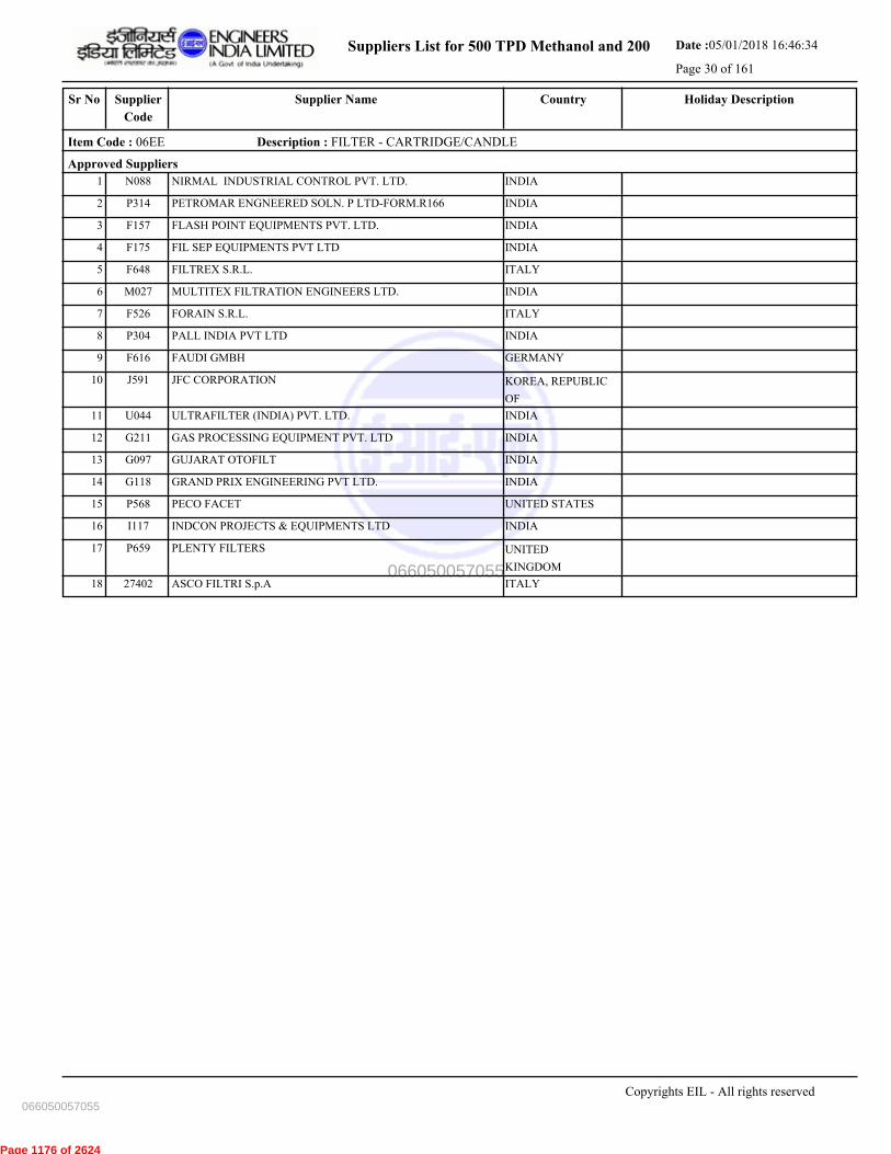
Suppliers List for 500 TPD Methanol and 200 Date :05/01/2018 16:46:34
Page 30 of 161
CountrySupplier NameSr No Holiday DescriptionSupplier
Code
Item Code : 06EE Description : FILTER - CARTRIDGE/CANDLE
Approved Suppliers
1 NIRMAL INDUSTRIAL CONTROL PVT. LTD. INDIAN088
2 PETROMAR ENGNEERED SOLN. P LTD-FORM.R166 INDIAP314
3 FLASH POINT EQUIPMENTS PVT. LTD. INDIAF157
4 FIL SEP EQUIPMENTS PVT LTD INDIAF175
5 FILTREX S.R.L. ITALYF648
6 MULTITEX FILTRATION ENGINEERS LTD. INDIAM027
7 FORAIN S.R.L. ITALYF526
8 PALL INDIA PVT LTD INDIAP304
9 FAUDI GMBH GERMANYF616
10 JFC CORPORATION KOREA, REPUBLIC
OF
J591
11 ULTRAFILTER (INDIA) PVT. LTD. INDIAU044
12 GAS PROCESSING EQUIPMENT PVT. LTD INDIAG211
13 GUJARAT OTOFILT INDIAG097
14 GRAND PRIX ENGINEERING PVT LTD. INDIAG118
15 PECO FACET UNITED STATESP568
16 INDCON PROJECTS & EQUIPMENTS LTD INDIAI117
17 PLENTY FILTERS UNITED
KINGDOM
P659
18 ASCO FILTRI S.p.A ITALY27402
Copyrights EIL - All rights reserved
066050057055
066050057055
Page 1176 of 2624
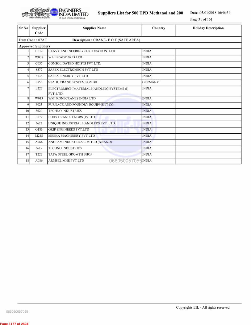
Suppliers List for 500 TPD Methanol and 200 Date :05/01/2018 16:46:34
Page 31 of 161
CountrySupplier NameSr No Holiday DescriptionSupplier
Code
Item Code : 07AC Description : CRANE- E.O.T (SAFE AREA)
Approved Suppliers
1 HEAVY ENGINEERING CORPORATION LTD INDIAH012
2 W.H.BRADY &CO.LTD INDIAW005
3 CONSOLIDATED HOISTS PVT LTD. INDIAC035
4 SAFEX ELECTROMECH PVT LTD INDIAS377
5 SAFEX ENERGY PVT LTD INDIAS138
6 STAHL CRANE SYSTEMS GMBH GERMANYS853
7 ELECTROMECH MATERIAL HANDLING SYSTEMS (I)
PVT. LTD.
INDIAE227
8 WMI KONECRANES INDIA LTD. INDIAW013
9 FURNACE AND FOUNDRY EQUIPMENT CO. INDIAF023
10 TECHNO INDUSTRIES INDIA3620
11 EDDY CRANES ENGRS (P) LTD INDIAE072
12 UNIQUE INDUSTRIAL HANDLERS PVT. LTD. INDIA3622
13 GRIP ENGINEERS PVT.LTD INDIAG183
14 MEEKA MACHINERY PVT LTD INDIAM248
15 ANUPAM INDUSTRIES LIMITED (ANAND) INDIAA266
16 TECHNO INDUSTRIES INDIA3619
17 TATA STEEL GROWTH SHOP INDIAT222
18 ARMSEL MHE PVT LTD INDIAA086
Copyrights EIL - All rights reserved
066050057055
066050057055
Page 1177 of 2624
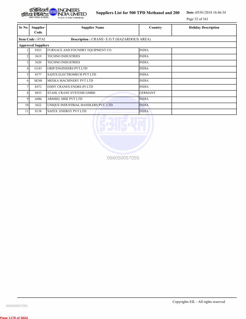
Suppliers List for 500 TPD Methanol and 200 Date :05/01/2018 16:46:34
Page 32 of 161
CountrySupplier NameSr No Holiday DescriptionSupplier
Code
Item Code : 07AI Description : CRANE- E.O.T (HAZARDOUS AREA)
Approved Suppliers
1 FURNACE AND FOUNDRY EQUIPMENT CO. INDIAF023
2 TECHNO INDUSTRIES INDIA3619
3 TECHNO INDUSTRIES INDIA3620
4 GRIP ENGINEERS PVT.LTD INDIAG183
5 SAFEX ELECTROMECH PVT LTD INDIAS377
6 MEEKA MACHINERY PVT LTD INDIAM248
7 EDDY CRANES ENGRS (P) LTD INDIAE072
8 STAHL CRANE SYSTEMS GMBH GERMANYS853
9 ARMSEL MHE PVT LTD INDIAA086
10 UNIQUE INDUSTRIAL HANDLERS PVT. LTD. INDIA3622
11 SAFEX ENERGY PVT LTD INDIAS138
Copyrights EIL - All rights reserved
066050057055
066050057055
Page 1178 of 2624
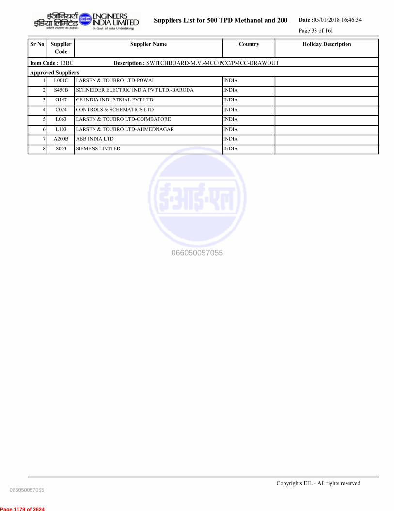
Suppliers List for 500 TPD Methanol and 200 Date :05/01/2018 16:46:34
Page 33 of 161
CountrySupplier NameSr No Holiday DescriptionSupplier
Code
Item Code : 13BC Description : SWITCHBOARD-M.V.-MCC/PCC/PMCC-DRAWOUT
Approved Suppliers
1 LARSEN & TOUBRO LTD-POWAI INDIAL001C
2 SCHNEIDER ELECTRIC INDIA PVT LTD.-BARODA INDIAS450B
3 GE INDIA INDUSTRIAL PVT LTD INDIAG147
4 CONTROLS & SCHEMATICS LTD INDIAC024
5 LARSEN & TOUBRO LTD-COIMBATORE INDIAL063
6 LARSEN & TOUBRO LTD-AHMEDNAGAR INDIAL103
7 ABB INDIA LTD INDIAA200B
8 SIEMENS LIMITED INDIAS003
Copyrights EIL - All rights reserved
066050057055
066050057055
Page 1179 of 2624

Suppliers List for 500 TPD Methanol and 200 Date :05/01/2018 16:46:34
Page 34 of 161
CountrySupplier NameSr No Holiday DescriptionSupplier
Code
Item Code : 13GA Description : CONTROL STATIONS- WEATHERPROOF
Approved Suppliers
1 FLAMEPROOF EQUIPMENTS PVT.LTD INDIAF036
2 FCG POWER INDUSTRIES PVT LTD INDIA3681
3 ELECTRICAL EQUIPMENT CORPORATION INDIAE111
4 FCG FLAMPROOF CONTROL GEARS P. LTD(C-157 INDIAF165
5 FLEXPRO ELECTRICALS PVT LTD INDIAF024
6 FCG POWER INDUSTRIES PVT LTD INDIAF141
7 EX-PROTECTA INDIAE024
8 PEPPERL & FUCHS MANUFACTURING (INDIA)
PRIVATE LIMITED
INDIAG159
9 SUDHIR SWITCHGEARS PVT LTD INDIAS158
10 BALIGA LIGHTING EQUIPMENTS (P) LIMITED INDIAB024
Copyrights EIL - All rights reserved
066050057055
066050057055
Page 1180 of 2624
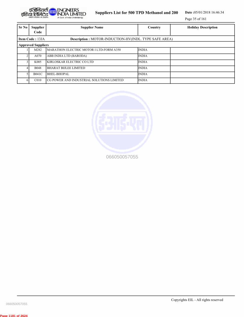
Suppliers List for 500 TPD Methanol and 200 Date :05/01/2018 16:46:34
Page 35 of 161
CountrySupplier NameSr No Holiday DescriptionSupplier
Code
Item Code : 13JA Description : MOTOR-INDUCTION-HV(INDL. TYPE SAFE AREA)
Approved Suppliers
1 MARATHON ELECTRIC MOTOR I LTD-FORM A350 INDIAM282
2 ABB INDIA LTD (BARODA) INDIAA070
3 KIRLOSKAR ELECTRIC CO LTD INDIAK005
4 BHARAT BIJLEE LIMITED INDIAB048
5 BHEL-BHOPAL INDIAB041C
6 CG POWER AND INDUSTRIAL SOLUTIONS LIMITED INDIAC010
Copyrights EIL - All rights reserved
066050057055
066050057055
Page 1181 of 2624

Suppliers List for 500 TPD Methanol and 200 Date :05/01/2018 16:46:34
Page 36 of 161
CountrySupplier NameSr No Holiday DescriptionSupplier
Code
Item Code : 13JD Description : MOTOR INDUCTION-MV (INDL.TYPE SAFE AREA)
Approved Suppliers
1 ABB INDIA LTD-FARIDABAD INDIAA310
2 KIRLOSKAR ELECTRIC CO LTD INDIAK005
3 BHARAT BIJLEE LIMITED INDIAB048
4 LAXMI HYDRAULICS PVT LTD INDIAL065
5 MARATHON ELECTRIC MOTOR I LTD-FORM A350 INDIAM282
6 SIEMENS LIMITED INDIAS003
7 CG POWER & INDUSTRIAL SOLUTIONS LTD. INDIA3668
8 ABB INDIA LTD (BANGALORE) INDIAA200
Copyrights EIL - All rights reserved
066050057055
066050057055
Page 1182 of 2624
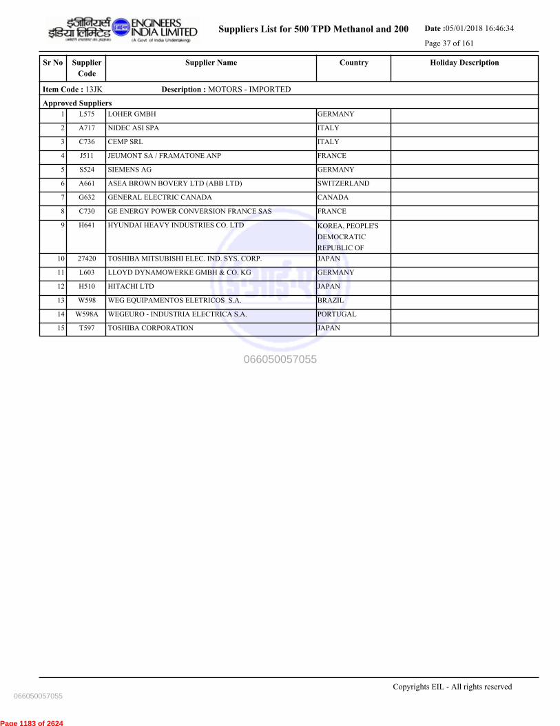
Suppliers List for 500 TPD Methanol and 200 Date :05/01/2018 16:46:34
Page 37 of 161
CountrySupplier NameSr No Holiday DescriptionSupplier
Code
Item Code : 13JK Description : MOTORS - IMPORTED
Approved Suppliers
1 LOHER GMBH GERMANYL575
2 NIDEC ASI SPA ITALYA717
3 CEMP SRL ITALYC736
4 JEUMONT SA / FRAMATONE ANP FRANCEJ511
5 SIEMENS AG GERMANYS524
6 ASEA BROWN BOVERY LTD (ABB LTD) SWITZERLANDA661
7 GENERAL ELECTRIC CANADA CANADAG632
8 GE ENERGY POWER CONVERSION FRANCE SAS FRANCEC730
9 HYUNDAI HEAVY INDUSTRIES CO. LTD KOREA, PEOPLE'S
DEMOCRATIC
REPUBLIC OF
H641
10 TOSHIBA MITSUBISHI ELEC. IND. SYS. CORP. JAPAN27420
11 LLOYD DYNAMOWERKE GMBH & CO. KG GERMANYL603
12 HITACHI LTD JAPANH510
13 WEG EQUIPAMENTOS ELETRICOS S.A. BRAZILW598
14 WEGEURO - INDUSTRIA ELECTRICA S.A. PORTUGALW598A
15 TOSHIBA CORPORATION JAPANT597
Copyrights EIL - All rights reserved
066050057055
066050057055
Page 1183 of 2624

Suppliers List for 500 TPD Methanol and 200 Date :05/01/2018 16:46:34
Page 38 of 161
CountrySupplier NameSr No Holiday DescriptionSupplier
Code
Item Code : 13OC Description : CABLES-MEDIUM VOLTAGE-POWER-PVC
Approved Suppliers
1 POLYCAB WIRES PVT LTD INDIAP254
2 UNIVERSAL CABLES LTD INDIAU003
3 Special Cables Pvt. Ltd. INDIA3602
4 CORDS CABLE INDUSTRIES LTD INDIAC145
5 HAVELLS INDIA LTD INDIAH060
6 KEI INDUSTRIES LIMITED INDIAK082
7 TORRENT POWER LIMITED INDIAT124
8 ASSOCIATED FLEXIBLES & WIRES [P] LTD INDIAA132
9 SRIRAM CABLES PVT LTD INDIAS025
10 FINOLEX CABLES LTD. INDIAF013
11 KEC INTERNATIONAL LTD-SILVASSA (F-R133) INDIAK190
12 KEI INDUSTRIES LIMITED INDIA3669
13 GEMSCAB INDUSTRIES LTD INDIAG156
Copyrights EIL - All rights reserved
066050057055
066050057055
Page 1184 of 2624

Suppliers List for 500 TPD Methanol and 200 Date :05/01/2018 16:46:34
Page 39 of 161
CountrySupplier NameSr No Holiday DescriptionSupplier
Code
Item Code : 13OD Description : CABLES:CONTROL-PVC
Approved Suppliers
1 SRIRAM CABLES PVT LTD INDIAS025
2 HAVELLS INDIA LTD INDIAH060
3 TORRENT POWER LIMITED INDIAT124
4 FINOLEX CABLES LTD. INDIAF013
5 Special Cables Pvt. Ltd. INDIA3602
6 KEI INDUSTRIES LIMITED INDIA3669
7 ASSOCIATED FLEXIBLES & WIRES [P] LTD INDIAA132
8 CORDS CABLE INDUSTRIES LTD INDIAC145
9 GEMSCAB INDUSTRIES LTD INDIAG156
10 POLYCAB WIRES PVT LTD INDIAP254
11 SUYOG ELECTRICALS LTD INDIAS304
12 KEI INDUSTRIES LIMITED INDIAK082
13 ICON CABLE LTD. INDIAI211
14 NORTH EASTERN CABLES PVT LTD INDIAN112
15 KEC INTERNATIONAL LTD-SILVASSA (F-R133) INDIAK190
16 CMI LIMITED INDIAC019
17 ASSOCIATED CABLES PVT LTD INDIAA034
18 ELKAY TELELINKS LTD.- INDIAE063
19 THERMO CABLES LTD (FORM. T-150) INDIAT212
20 UNIVERSAL CABLES LTD INDIAU003
21 SCOT INNOVATION WIRES & CABLES PVT LTD INDIAS073
22 DELTON CABLES LIMITED INDIAD012
Copyrights EIL - All rights reserved
066050057055
066050057055
Page 1185 of 2624
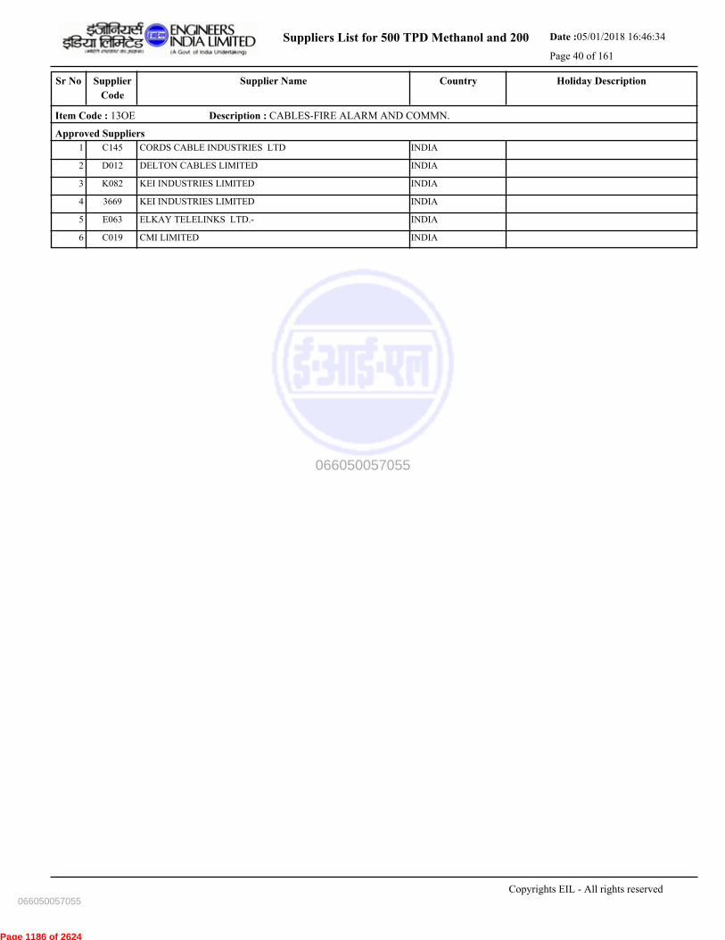
Suppliers List for 500 TPD Methanol and 200 Date :05/01/2018 16:46:34
Page 40 of 161
CountrySupplier NameSr No Holiday DescriptionSupplier
Code
Item Code : 13OE Description : CABLES-FIRE ALARM AND COMMN.
Approved Suppliers
1 CORDS CABLE INDUSTRIES LTD INDIAC145
2 DELTON CABLES LIMITED INDIAD012
3 KEI INDUSTRIES LIMITED INDIAK082
4 KEI INDUSTRIES LIMITED INDIA3669
5 ELKAY TELELINKS LTD.- INDIAE063
6 CMI LIMITED INDIAC019
Copyrights EIL - All rights reserved
066050057055
066050057055
Page 1186 of 2624

Suppliers List for 500 TPD Methanol and 200 Date :05/01/2018 16:46:34
Page 41 of 161
CountrySupplier NameSr No Holiday DescriptionSupplier
Code
Item Code : 13WB Description : A.C. VARIABLE SPEED DRIVE
Approved Suppliers
1 VACON OYJ FINLANDV593
2 LARSEN & TOUBRO LTD-MAHAPE INDIAL001A
3 SIEMENS AG GERMANYS524
4 NIDEC ASI SPA ITALY27425
5 HITACHI HIREL POWER ELECTRONICS PVT. LTD INDIAH010A
6 ASEA BROWN BOVERY LTD (ABB LTD) SWITZERLANDA661
7 HITACHI LTD JAPANH510
8 KARL E BRINKMANN GMBH GERMANYK636
9 MEIDENSHA CORP JAPANM593
10 DANFOSS INDUSTRIES PVT LTD INDIAD137
11 TOSHIBA CORPORATION JAPANT597
12 GE ENERGY POWER CONVERSION FRANCE SAS FRANCEC730
13 ROCKWELL AUTOMATION INDIA PVT LTD INDIAR178
14 VACON CONTROLS AND DRIVES PVT. LTD INDIAV152
15 SIEMENS LTD - NASHIK INDIAS003A
16 ABB INDIA LTD INDIAA200B
17 BALDOR ELECTRIC COMPANY (FORMLY. R564) UNITED STATESB727
18 EUROTHERM DEL INDIA LIMITED INDIAE140
19 CG POWER AND INDUSTRIAL SOLUTIONS LIMITED INDIA3672
Copyrights EIL - All rights reserved
066050057055
066050057055
Page 1187 of 2624
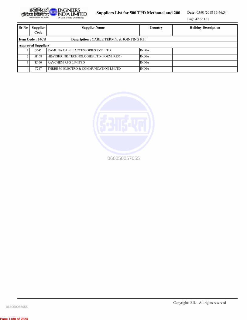
Suppliers List for 500 TPD Methanol and 200 Date :05/01/2018 16:46:34
Page 42 of 161
CountrySupplier NameSr No Holiday DescriptionSupplier
Code
Item Code : 14CB Description : CABLE TERMN. & JOINTING KIT
Approved Suppliers
1 YAMUNA CABLE ACCESSORIES PVT. LTD. INDIA3645
2 HEATSHRINK TECHNOLOGIES LTD (FORM. R136) INDIAH168
3 RAYCHEM RPG LIMITED INDIAR160
4 THREE M ELECTRO & COMMUNCATION I.P.LTD INDIAT217
Copyrights EIL - All rights reserved
066050057055
066050057055
Page 1188 of 2624

Suppliers List for 500 TPD Methanol and 200 Date :05/01/2018 16:46:34
Page 43 of 161
CountrySupplier NameSr No Holiday DescriptionSupplier
Code
Item Code : 14CD Description : CONTACTORS
Approved Suppliers
1 SCHNEIDER ELECTRIC INDIA P LTD-HYDERABAD INDIAS450A
2 ABB INDIA LTD (BANGALORE) INDIAA200
3 GE INDIA INDUSTRIAL PVT LTD INDIAG147
4 SIEMENS LIMITED INDIAS003
5 LARSEN & TOUBRO LTD-AHMEDNAGAR INDIAL103
Copyrights EIL - All rights reserved
066050057055
066050057055
Page 1189 of 2624
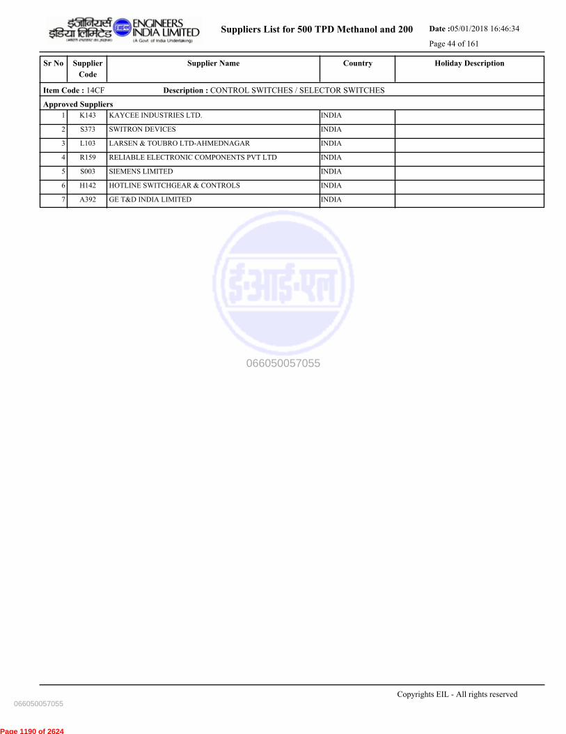
Suppliers List for 500 TPD Methanol and 200 Date :05/01/2018 16:46:34
Page 44 of 161
CountrySupplier NameSr No Holiday DescriptionSupplier
Code
Item Code : 14CF Description : CONTROL SWITCHES / SELECTOR SWITCHES
Approved Suppliers
1 KAYCEE INDUSTRIES LTD. INDIAK143
2 SWITRON DEVICES INDIAS373
3 LARSEN & TOUBRO LTD-AHMEDNAGAR INDIAL103
4 RELIABLE ELECTRONIC COMPONENTS PVT LTD INDIAR159
5 SIEMENS LIMITED INDIAS003
6 HOTLINE SWITCHGEAR & CONTROLS INDIAH142
7 GE T&D INDIA LIMITED INDIAA392
Copyrights EIL - All rights reserved
066050057055
066050057055
Page 1190 of 2624
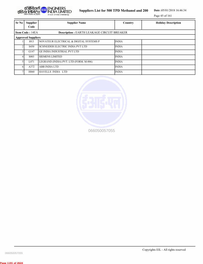
Suppliers List for 500 TPD Methanol and 200 Date :05/01/2018 16:46:34
Page 45 of 161
CountrySupplier NameSr No Holiday DescriptionSupplier
Code
Item Code : 14EA Description : EARTH LEAKAGE CIRCUIT BREAKER
Approved Suppliers
1 NOVATEUR ELECTRICAL & DIGITAL SYSTEMS P INDIAI013
2 SCHNEIDER ELECTRIC INDIA PVT LTD INDIAS450
3 GE INDIA INDUSTRIAL PVT LTD INDIAG147
4 SIEMENS LIMITED INDIAS003
5 LEGRAND (INDIA) PVT. LTD (FORM. M-006) INDIAL071
6 ABB INDIA LTD INDIAA372
7 HAVELLS INDIA LTD INDIAH060
Copyrights EIL - All rights reserved
066050057055
066050057055
Page 1191 of 2624

Suppliers List for 500 TPD Methanol and 200 Date :05/01/2018 16:46:34
Page 46 of 161
CountrySupplier NameSr No Holiday DescriptionSupplier
Code
Item Code : 14FA Description : FUSES
Approved Suppliers
1 SIEMENS LIMITED INDIAS003
2 GE INDIA INDUSTRIAL PVT LTD INDIAG147
3 LARSEN & TOUBRO LTD-AHMEDNAGAR INDIAL103
4 NOVATEUR ELECTRICAL & DIGITAL SYSTEMS P INDIAI013
5 COOPER BUSSMAN INDIA PVT LTD INDIAC194
Copyrights EIL - All rights reserved
066050057055
066050057055
Page 1192 of 2624

Suppliers List for 500 TPD Methanol and 200 Date :05/01/2018 16:46:34
Page 47 of 161
CountrySupplier NameSr No Holiday DescriptionSupplier
Code
Item Code : 14HA Description : HEAVY DUTY SWITCHES
Approved Suppliers
1 SIEMENS LIMITED INDIAS003
2 LARSEN & TOUBRO LTD-AHMEDNAGAR INDIAL103
3 NOVATEUR ELECTRICAL & DIGITAL SYSTEMS P INDIAI013
Copyrights EIL - All rights reserved
066050057055
066050057055
Page 1193 of 2624

Suppliers List for 500 TPD Methanol and 200 Date :05/01/2018 16:46:34
Page 48 of 161
CountrySupplier NameSr No Holiday DescriptionSupplier
Code
Item Code : 14IA Description : INSTRUMENT TRANSFORMERS CT & PT (MV)
Approved Suppliers
1 PRAGATI ELECTRICALS PVT LTD INDIAP228
2 NARAYAN POWERTECH PVT LTD INDIAN119
3 KALPA ELECTRIKAL PVT LTD INDIAK149
4 GILBERT & MAXWELL ELECTRICALS PVT LTD INDIAG135
5 PRECISE ELECTRICALS INDIAP237
6 SILKAANS ELECTRICALS MFG.CO.PVT.LTD INDIAS372
Copyrights EIL - All rights reserved
066050057055
066050057055
Page 1194 of 2624

Suppliers List for 500 TPD Methanol and 200 Date :05/01/2018 16:46:34
Page 49 of 161
CountrySupplier NameSr No Holiday DescriptionSupplier
Code
Item Code : 14LB Description : LIGHTING FIXTURE & ACCESORY-NON HZARDOUS
Approved Suppliers
1 BAJAJ ELECTRICALS LTD INDIAB011
2 PHILIPS ELECTRONICS INDIA LIMITED INDIAP037
3 CG POWER AND INDUSTRIAL SOLUTIONS LIMITED INDIAC010
Copyrights EIL - All rights reserved
066050057055
066050057055
Page 1195 of 2624

Suppliers List for 500 TPD Methanol and 200 Date :05/01/2018 16:46:34
Page 50 of 161
CountrySupplier NameSr No Holiday DescriptionSupplier
Code
Item Code : 14LC Description : LIGHTING & POWER PANELS (SAFE AREA)
Approved Suppliers
1 HAVELLS INDIA LTD INDIAH060
2 ABB INDIA LTD INDIAA372
3 NOVATEUR ELECTRICAL & DIGITAL SYSTEMS P INDIAI013
Copyrights EIL - All rights reserved
066050057055
066050057055
Page 1196 of 2624

Suppliers List for 500 TPD Methanol and 200 Date :05/01/2018 16:46:34
Page 51 of 161
CountrySupplier NameSr No Holiday DescriptionSupplier
Code
Item Code : 14MA Description : MCB
Approved Suppliers
1 SIEMENS LIMITED INDIAS003
2 STANDARD ELECTRICALS LTD INDIAS393
3 SCHNEIDER ELECTRIC INDIA PVT LTD INDIAS450
4 ABB INDIA LTD INDIAA372
5 LEGRAND (INDIA) PVT. LTD (FORM. M-006) INDIAL071
6 NOVATEUR ELECTRICAL & DIGITAL SYSTEMS P INDIAI013
7 HAVELLS INDIA LTD INDIAH060
8 INDIANA CURRENT CONTROL LTD INDIAI168
Copyrights EIL - All rights reserved
066050057055
066050057055
Page 1197 of 2624
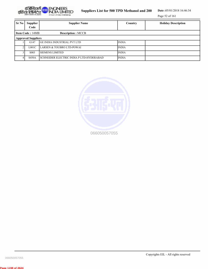
Suppliers List for 500 TPD Methanol and 200 Date :05/01/2018 16:46:34
Page 52 of 161
CountrySupplier NameSr No Holiday DescriptionSupplier
Code
Item Code : 14MB Description : MCCB
Approved Suppliers
1 GE INDIA INDUSTRIAL PVT LTD INDIAG147
2 LARSEN & TOUBRO LTD-POWAI INDIAL001C
3 SIEMENS LIMITED INDIAS003
4 SCHNEIDER ELECTRIC INDIA P LTD-HYDERABAD INDIAS450A
Copyrights EIL - All rights reserved
066050057055
066050057055
Page 1198 of 2624
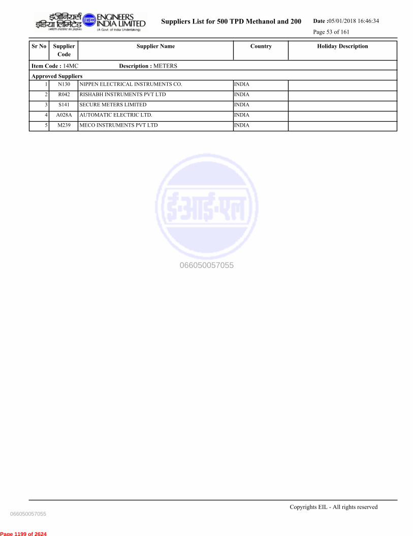
Suppliers List for 500 TPD Methanol and 200 Date :05/01/2018 16:46:34
Page 53 of 161
CountrySupplier NameSr No Holiday DescriptionSupplier
Code
Item Code : 14MC Description : METERS
Approved Suppliers
1 NIPPEN ELECTRICAL INSTRUMENTS CO. INDIAN130
2 RISHABH INSTRUMENTS PVT LTD INDIAR042
3 SECURE METERS LIMITED INDIAS141
4 AUTOMATIC ELECTRIC LTD. INDIAA028A
5 MECO INSTRUMENTS PVT LTD INDIAM239
Copyrights EIL - All rights reserved
066050057055
066050057055
Page 1199 of 2624

Suppliers List for 500 TPD Methanol and 200 Date :05/01/2018 16:46:34
Page 54 of 161
CountrySupplier NameSr No Holiday DescriptionSupplier
Code
Item Code : 14PB Description : PUSH BUTTON AND INDICATING LAMPS
Approved Suppliers
1 LARSEN & TOUBRO LTD-POWAI INDIAL001C
2 HOTLINE SWITCHGEAR & CONTROLS INDIAH142
3 TEKNIC ELECTRIC (I) PVT. LTD. INDIAT166
4 SCHNEIDER ELECTRIC INDIA P LTD-HYDERABAD INDIAS450A
5 SHRI TULSI SWITCHGEARS PVT LTD INDIAS365
6 SIEMENS LIMITED INDIAS003
7 ESSEN DEINKI INDIAE173
8 PRECIFINE PRODUCTS PVT. LTD. INDIAP291
Copyrights EIL - All rights reserved
066050057055
066050057055
Page 1200 of 2624

Suppliers List for 500 TPD Methanol and 200 Date :05/01/2018 16:46:34
Page 55 of 161
CountrySupplier NameSr No Holiday DescriptionSupplier
Code
Item Code : 14SA Description : FUSE SWITCH COMBINATION
Approved Suppliers
1 STANDARD ELECTRICALS LTD INDIAS393
2 LARSEN & TOUBRO LTD-AHMEDNAGAR INDIAL103
3 NOVATEUR ELECTRICAL & DIGITAL SYSTEMS P INDIAI013
4 GE INDIA INDUSTRIAL PVT LTD INDIAG147
5 SIEMENS LIMITED INDIAS003
6 HAVELLS INDIA LTD INDIAH060
Copyrights EIL - All rights reserved
066050057055
066050057055
Page 1201 of 2624

Suppliers List for 500 TPD Methanol and 200 Date :05/01/2018 16:46:34
Page 56 of 161
CountrySupplier NameSr No Holiday DescriptionSupplier
Code
Item Code : 14TA Description : TIMERS
Approved Suppliers
1 ELECTRONIC AUTOMATION PVT LTD INDIAE151
2 SIEMENS LIMITED INDIAS003
3 LARSEN & TOUBRO LTD-AHMEDNAGAR INDIAL103
Copyrights EIL - All rights reserved
066050057055
066050057055
Page 1202 of 2624
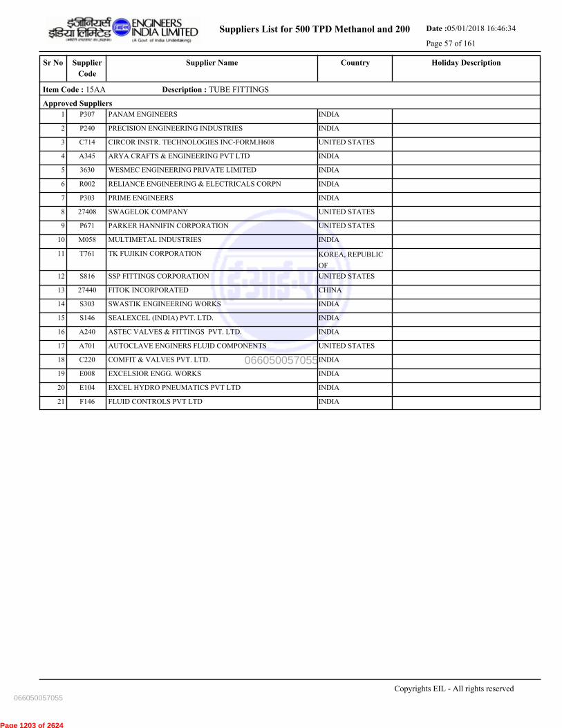
Suppliers List for 500 TPD Methanol and 200 Date :05/01/2018 16:46:34
Page 57 of 161
CountrySupplier NameSr No Holiday DescriptionSupplier
Code
Item Code : 15AA Description : TUBE FITTINGS
Approved Suppliers
1 PANAM ENGINEERS INDIAP307
2 PRECISION ENGINEERING INDUSTRIES INDIAP240
3 CIRCOR INSTR. TECHNOLOGIES INC-FORM.H608 UNITED STATESC714
4 ARYA CRAFTS & ENGINEERING PVT LTD INDIAA345
5 WESMEC ENGINEERING PRIVATE LIMITED INDIA3630
6 RELIANCE ENGINEERING & ELECTRICALS CORPN INDIAR002
7 PRIME ENGINEERS INDIAP303
8 SWAGELOK COMPANY UNITED STATES27408
9 PARKER HANNIFIN CORPORATION UNITED STATESP671
10 MULTIMETAL INDUSTRIES INDIAM058
11 TK FUJIKIN CORPORATION KOREA, REPUBLIC
OF
T761
12 SSP FITTINGS CORPORATION UNITED STATESS816
13 FITOK INCORPORATED CHINA27440
14 SWASTIK ENGINEERING WORKS INDIAS303
15 SEALEXCEL (INDIA) PVT. LTD. INDIAS146
16 ASTEC VALVES & FITTINGS PVT. LTD. INDIAA240
17 AUTOCLAVE ENGINERS FLUID COMPONENTS UNITED STATESA701
18 COMFIT & VALVES PVT. LTD. INDIAC220
19 EXCELSIOR ENGG. WORKS INDIAE008
20 EXCEL HYDRO PNEUMATICS PVT LTD INDIAE104
21 FLUID CONTROLS PVT LTD INDIAF146
Copyrights EIL - All rights reserved
066050057055
066050057055
Page 1203 of 2624
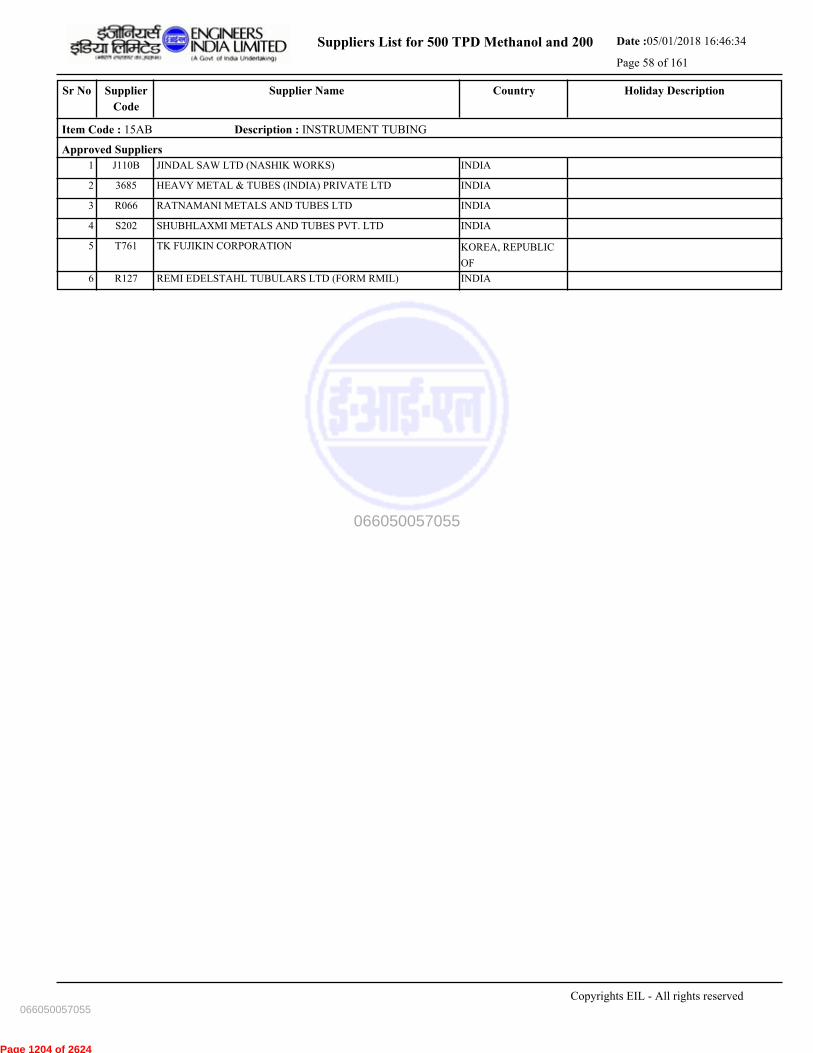
Suppliers List for 500 TPD Methanol and 200 Date :05/01/2018 16:46:34
Page 58 of 161
CountrySupplier NameSr No Holiday DescriptionSupplier
Code
Item Code : 15AB Description : INSTRUMENT TUBING
Approved Suppliers
1 JINDAL SAW LTD (NASHIK WORKS) INDIAJ110B
2 HEAVY METAL & TUBES (INDIA) PRIVATE LTD INDIA3685
3 RATNAMANI METALS AND TUBES LTD INDIAR066
4 SHUBHLAXMI METALS AND TUBES PVT. LTD INDIAS202
5 TK FUJIKIN CORPORATION KOREA, REPUBLIC
OF
T761
6 REMI EDELSTAHL TUBULARS LTD (FORM RMIL) INDIAR127
Copyrights EIL - All rights reserved
066050057055
066050057055
Page 1204 of 2624
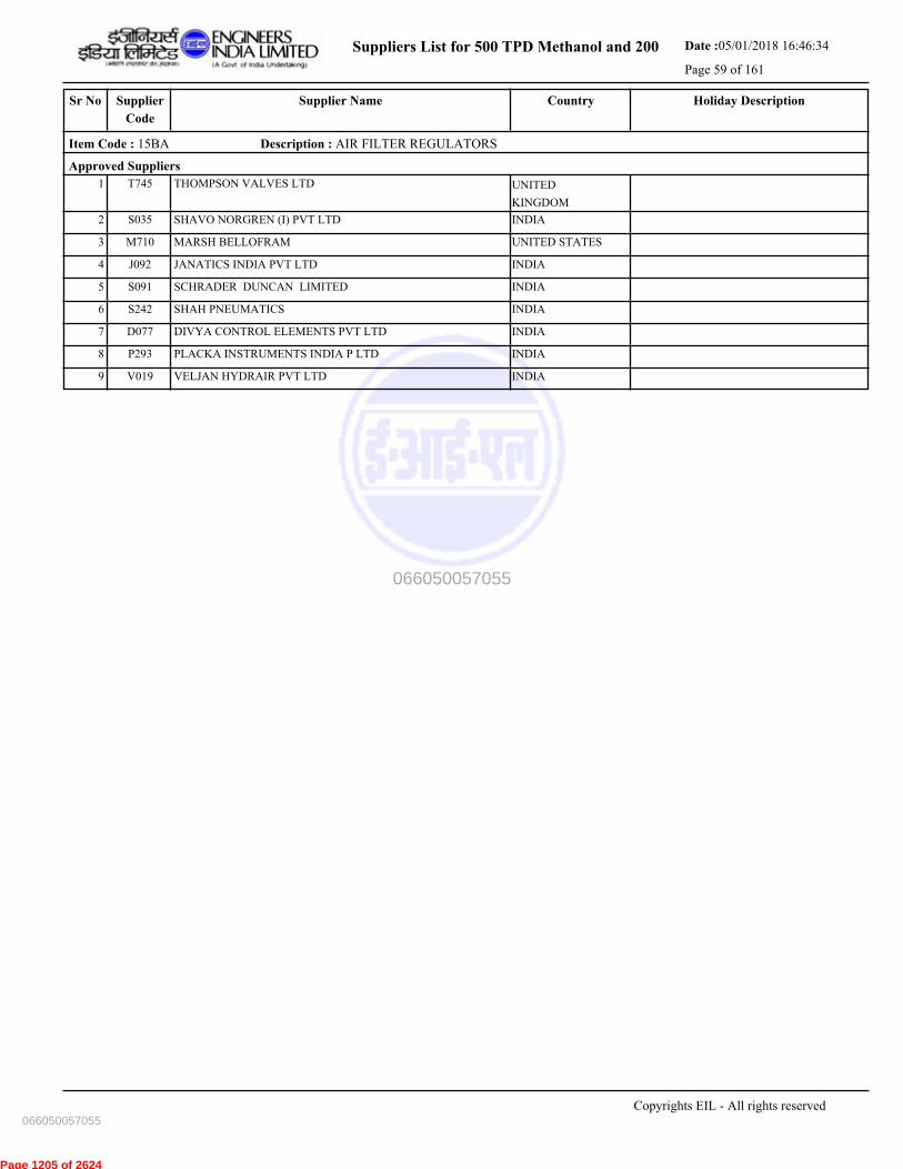
Suppliers List for 500 TPD Methanol and 200 Date :05/01/2018 16:46:34
Page 59 of 161
CountrySupplier NameSr No Holiday DescriptionSupplier
Code
Item Code : 15BA Description : AIR FILTER REGULATORS
Approved Suppliers
1 THOMPSON VALVES LTD UNITED
KINGDOM
T745
2 SHAVO NORGREN (I) PVT LTD INDIAS035
3 MARSH BELLOFRAM UNITED STATESM710
4 JANATICS INDIA PVT LTD INDIAJ092
5 SCHRADER DUNCAN LIMITED INDIAS091
6 SHAH PNEUMATICS INDIAS242
7 DIVYA CONTROL ELEMENTS PVT LTD INDIAD077
8 PLACKA INSTRUMENTS INDIA P LTD INDIAP293
9 VELJAN HYDRAIR PVT LTD INDIAV019
Copyrights EIL - All rights reserved
066050057055
066050057055
Page 1205 of 2624

Suppliers List for 500 TPD Methanol and 200 Date :05/01/2018 16:46:34
Page 60 of 161
CountrySupplier NameSr No Holiday DescriptionSupplier
Code
Item Code : 15BB Description : MACHINE MONITORING SYSTEMS
Approved Suppliers
1 GE Oil & Gas India Pvt. Ltd. INDIAG147A
2 PROGNOST SYSTEMS GMBH GERMANY27464
3 SHINKAWA ELECTRIC COMPANY LTD. JAPANS814
4 ROCKWELL AUTOMATION INDIA PVT LTD INDIAR178
Copyrights EIL - All rights reserved
066050057055
066050057055
Page 1206 of 2624

Suppliers List for 500 TPD Methanol and 200 Date :05/01/2018 16:46:34
Page 61 of 161
CountrySupplier NameSr No Holiday DescriptionSupplier
Code
Item Code : 15CA Description : THERMO COUPLE EXTN.CABLES
Approved Suppliers
1 CORDS CABLE INDUSTRIES LTD INDIAC145
2 KEI INDUSTRIES LIMITED INDIAK082
3 DELTON CABLES LIMITED INDIAD012
4 T C COMMUNICATION PVT. LTD. INDIAT243
5 THERMO CABLES LTD (FORM. T-150) INDIAT212
6 ASSOCIATED FLEXIBLES & WIRES [P] LTD INDIAA132
7 KEI INDUSTRIES LIMITED INDIA3669
8 UDEY PYROCABLES PVT. LTD. INDIAU015
9 ASSOCIATED CABLES PVT LTD INDIAA034
Copyrights EIL - All rights reserved
066050057055
066050057055
Page 1207 of 2624

Suppliers List for 500 TPD Methanol and 200 Date :05/01/2018 16:46:34
Page 62 of 161
CountrySupplier NameSr No Holiday DescriptionSupplier
Code
Item Code : 15CB Description : SIGNAL CABLES
Approved Suppliers
1 CMI LIMITED INDIAC019
2 SUYOG ELECTRICALS LTD INDIAS304
3 POLYCAB WIRES PVT LTD INDIAP254
4 LEONI KERPEN GMBH GERMANYL612
5 CORDS CABLE INDUSTRIES LTD INDIAC145
6 KEI INDUSTRIES LIMITED INDIAK082
7 KEI INDUSTRIES LIMITED INDIA3669
8 ASSOCIATED CABLES PVT LTD INDIAA034
9 THERMO CABLES LTD (FORM. T-150) INDIAT212
10 KEC INETRNATIONAL - MYSORE INDIAK190B
11 ELKAY TELELINKS LTD.- INDIAE063
12 LEONI CABLE SOLUTIONS(INDIA) PVT PTD. INDIA3662
13 ASSOCIATED FLEXIBLES & WIRES [P] LTD INDIAA132
14 T C COMMUNICATION PVT. LTD. INDIAT243
15 DELTON CABLES LIMITED INDIAD012
16 UDEY PYROCABLES PVT. LTD. INDIAU015
Copyrights EIL - All rights reserved
066050057055
066050057055
Page 1208 of 2624
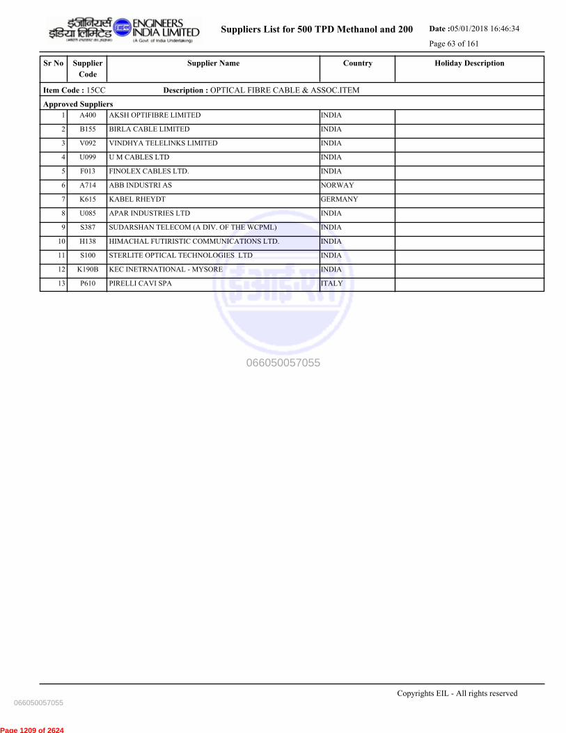
Suppliers List for 500 TPD Methanol and 200 Date :05/01/2018 16:46:34
Page 63 of 161
CountrySupplier NameSr No Holiday DescriptionSupplier
Code
Item Code : 15CC Description : OPTICAL FIBRE CABLE & ASSOC.ITEM
Approved Suppliers
1 AKSH OPTIFIBRE LIMITED INDIAA400
2 BIRLA CABLE LIMITED INDIAB155
3 VINDHYA TELELINKS LIMITED INDIAV092
4 U M CABLES LTD INDIAU099
5 FINOLEX CABLES LTD. INDIAF013
6 ABB INDUSTRI AS NORWAYA714
7 KABEL RHEYDT GERMANYK615
8 APAR INDUSTRIES LTD INDIAU085
9 SUDARSHAN TELECOM (A DIV. OF THE WCPML) INDIAS387
10 HIMACHAL FUTIRISTIC COMMUNICATIONS LTD. INDIAH138
11 STERLITE OPTICAL TECHNOLOGIES LTD INDIAS100
12 KEC INETRNATIONAL - MYSORE INDIAK190B
13 PIRELLI CAVI SPA ITALYP610
Copyrights EIL - All rights reserved
066050057055
066050057055
Page 1209 of 2624

Suppliers List for 500 TPD Methanol and 200 Date :05/01/2018 16:46:34
Page 64 of 161
CountrySupplier NameSr No Holiday DescriptionSupplier
Code
Item Code : 15CD Description : FIELD BUS SIGNAL CABLES
Approved Suppliers
1 LEONI KERPEN GMBH GERMANYL612
2 ASSOCIATED FLEXIBLES & WIRES [P] LTD INDIAA132
3 LAPP INDIA PVT LTD INDIA3663
4 CORDS CABLE INDUSTRIES LTD INDIAC145
5 BELDEN INC UNITED STATESB735
Copyrights EIL - All rights reserved
066050057055
066050057055
Page 1210 of 2624

Suppliers List for 500 TPD Methanol and 200 Date :05/01/2018 16:46:34
Page 65 of 161
CountrySupplier NameSr No Holiday DescriptionSupplier
Code
Item Code : 15CE Description : SIGNAL CABLE - FIRE RESISTANT
Approved Suppliers
1 KEI INDUSTRIES LIMITED INDIA3669
2 ELKAY TELELINKS LTD.- INDIAE063
3 CORDS CABLE INDUSTRIES LTD INDIAC145
4 ASSOCIATED FLEXIBLES & WIRES [P] LTD INDIAA132
5 SUYOG ELECTRICALS LTD INDIAS304
6 KEI INDUSTRIES LIMITED INDIAK082
7 POLYCAB WIRES PVT LTD INDIAP254
8 THERMO CABLES LTD (FORM. T-150) INDIAT212
Copyrights EIL - All rights reserved
066050057055
066050057055
Page 1211 of 2624
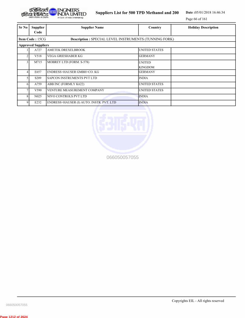
Suppliers List for 500 TPD Methanol and 200 Date :05/01/2018 16:46:34
Page 66 of 161
CountrySupplier NameSr No Holiday DescriptionSupplier
Code
Item Code : 15CG Description : SPECIAL LEVEL INSTRUMENTS (TUNNING FORK)
Approved Suppliers
1 AMETEK DREXELBROOK UNITED STATESA727
2 VEGA GRIESHABER KG GERMANYV518
3 MOBREY LTD (FORM. S-578) UNITED
KINGDOM
M715
4 ENDRESS+HAUSER GMBH+CO. KG GERMANYE657
5 SAPCON INSTRUMENTS PVT LTD INDIAS209
6 ABB INC (FORMLY K622) UNITED STATESA759
7 VENTURE MEASUREMENT COMPANY UNITED STATESV590
8 NIVO CONTROLS PVT LTD INDIAN025
9 ENDRESS+HAUSER (I) AUTO. INSTR. PVT. LTD INDIAE232
Copyrights EIL - All rights reserved
066050057055
066050057055
Page 1212 of 2624

Suppliers List for 500 TPD Methanol and 200 Date :05/01/2018 16:46:34
Page 67 of 161
CountrySupplier NameSr No Holiday DescriptionSupplier
Code
Item Code : 15DB Description : COPPER TUBES(COATED,BARE)
Approved Suppliers
1 RAJCO METAL INDUSTRIES P LTD(FORM.H092) INDIAR177
2 MULTIMETALS LIMITED INDIAM048
3 MEHTA TUBES LIMITED INDIAM288
Copyrights EIL - All rights reserved
066050057055
066050057055
Page 1213 of 2624

Suppliers List for 500 TPD Methanol and 200 Date :05/01/2018 16:46:34
Page 68 of 161
CountrySupplier NameSr No Holiday DescriptionSupplier
Code
Item Code : 15DC Description : CONTROL VALVE POSITIONER
Approved Suppliers
1 SAMSON CONTROLS PVT LTD INDIAS442
2 FLOWSERVE INDIA CONTROL PVT LTD-BANGALOR INDIAF176
Copyrights EIL - All rights reserved
066050057055
066050057055
Page 1214 of 2624

Suppliers List for 500 TPD Methanol and 200 Date :05/01/2018 16:46:34
Page 69 of 161
CountrySupplier NameSr No Holiday DescriptionSupplier
Code
Item Code : 15EA Description : SOLENOID VALVES
Approved Suppliers
1 ALCON ALEXANDER CONTROLS LIMITED UNITED
KINGDOM
A588
2 ROTEX AUTOMATION LTD. INDIA3661
3 THOMPSON VALVES LTD UNITED
KINGDOM
T745
4 ASCO JOUCOMATIC LTD UNITED
KINGDOM
A555
5 ROTEX AUTOMATION LTD. INDIAR021
6 ASCO JOUCOMATIC SA FRANCEA721
7 ASCO NUMATICS (INDIA) P. LIMITED INDIAA167
8 AVCON CONTROLS PVT. LTD. INDIAA052
9 PRECISION INSTRUMENT COMPANY INDIAP217
10 VERSA BV NETHERLANDSV542
11 SCHRADER DUNCAN LIMITED INDIAS091
12 HERION WERKE GERMANYH554
Copyrights EIL - All rights reserved
066050057055
066050057055
Page 1215 of 2624

Suppliers List for 500 TPD Methanol and 200 Date :05/01/2018 16:46:34
Page 70 of 161
CountrySupplier NameSr No Holiday DescriptionSupplier
Code
Item Code : 15EB Description : CONTROL VALVES
Approved Suppliers
1 ARCA REGLER GMBH GERMANYA529
2 KENT INTROL UK LTD (FORM. A-718) UNITED
KINGDOM
K624
3 ITALVALV S.N.C ITALYI586
4 SPX VALVES & CONTROLS (FORMERLY DEZURIK) UNITED STATESS793
5 FLOWSERVE PTE LTD SINGAPOREF636
6 BELLINO SRL ITALY27461
7 SEVERN GLOCON INDIA PVT LTD INDIAS023
8 CCI VALVE TECHNOLOGY GMBH CZECH REPUBLICC731
9 KSB MIL CONTROLS LIMITED INDIAM055
10 METSO FLOW CONTROL OY FINLANDM700
11 KOSO INDIA PVT LTD (FORM.K176) INDIAK179A
12 SEVERN GLOCON LTD UNITED
KINGDOM
S505
13 GE Oil & Gas India Pvt. Ltd. INDIAD127
14 SAMSON CONTROLS PVT LTD INDIAS442
15 EMERSON PROCESS MANGMNT CHENNAI PVT. LTD INDIAE179A
16 SAMSON AG MESS-UND REGELTECHNIK GERMANYS510
17 WEIR VALVES & CONTROLS UK LTD UNITED
KINGDOM
W5941
18 FORBES MARSHALL ARCA P LTD.(FORMRLY A214 INDIAF151
19 MOTOYAMA ENGG WORKS LTD JAPANM561
20 FLOWSERVE INDIA CONTROL PVT LTD-BANGALOR INDIAF176
21 AST APPARECCHI DI SICUREZZA E TENUTA SPA ITALYA761
22 DRESSER PRODUITS INDUSTRIELS FRANCED649
Copyrights EIL - All rights reserved
066050057055
066050057055
Page 1216 of 2624
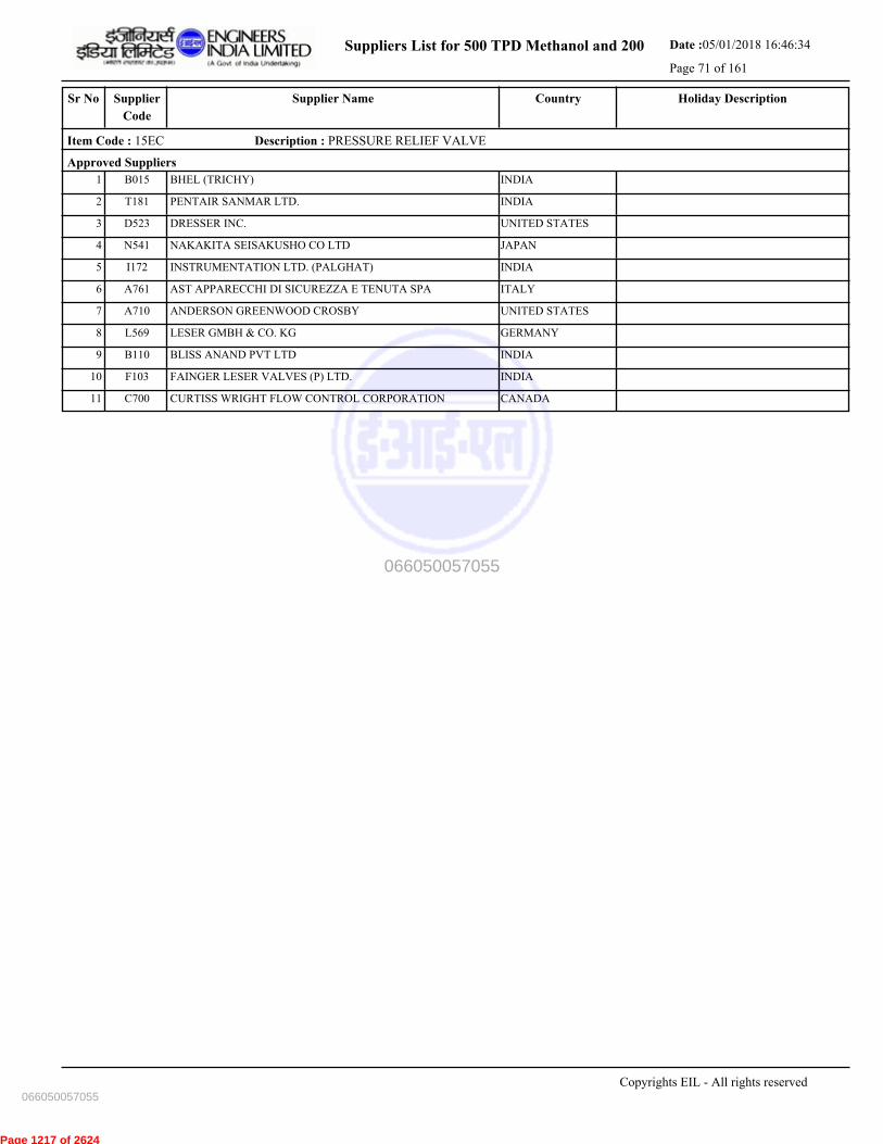
Suppliers List for 500 TPD Methanol and 200 Date :05/01/2018 16:46:34
Page 71 of 161
CountrySupplier NameSr No Holiday DescriptionSupplier
Code
Item Code : 15EC Description : PRESSURE RELIEF VALVE
Approved Suppliers
1 BHEL (TRICHY) INDIAB015
2 PENTAIR SANMAR LTD. INDIAT181
3 DRESSER INC. UNITED STATESD523
4 NAKAKITA SEISAKUSHO CO LTD JAPANN541
5 INSTRUMENTATION LTD. (PALGHAT) INDIAI172
6 AST APPARECCHI DI SICUREZZA E TENUTA SPA ITALYA761
7 ANDERSON GREENWOOD CROSBY UNITED STATESA710
8 LESER GMBH & CO. KG GERMANYL569
9 BLISS ANAND PVT LTD INDIAB110
10 FAINGER LESER VALVES (P) LTD. INDIAF103
11 CURTISS WRIGHT FLOW CONTROL CORPORATION CANADAC700
Copyrights EIL - All rights reserved
066050057055
066050057055
Page 1217 of 2624
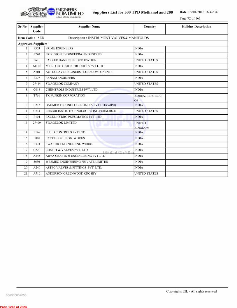
Suppliers List for 500 TPD Methanol and 200 Date :05/01/2018 16:46:34
Page 72 of 161
CountrySupplier NameSr No Holiday DescriptionSupplier
Code
Item Code : 15ED Description : INSTRUMENT VALVES& MANIFOLDS
Approved Suppliers
1 PRIME ENGINEERS INDIAP303
2 PRECISION ENGINEERING INDUSTRIES INDIAP240
3 PARKER HANNIFIN CORPORATION UNITED STATESP671
4 MICRO PRECISION PRODUCTS PVT LTD INDIAM010
5 AUTOCLAVE ENGINERS FLUID COMPONENTS UNITED STATESA701
6 PANAM ENGINEERS INDIAP307
7 SWAGELOK COMPANY UNITED STATES27414
8 CHEMTROLS INDUSTRIES PVT. LTD. INDIAC015
9 TK FUJIKIN CORPORATION KOREA, REPUBLIC
OF
T761
10 BAUMER TECHNOLOGIES INDIA PVT.LTD(W058) INDIAB213
11 CIRCOR INSTR. TECHNOLOGIES INC-FORM.H608 UNITED STATESC714
12 EXCEL HYDRO PNEUMATICS PVT LTD INDIAE104
13 SWAGELOK LIMITED UNITED
KINGDOM
27409
14 FLUID CONTROLS PVT LTD INDIAF146
15 EXCELSIOR ENGG. WORKS INDIAE008
16 SWASTIK ENGINEERING WORKS INDIAS303
17 COMFIT & VALVES PVT. LTD. INDIAC220
18 ARYA CRAFTS & ENGINEERING PVT LTD INDIAA345
19 WESMEC ENGINEERING PRIVATE LIMITED INDIA3630
20 ASTEC VALVES & FITTINGS PVT. LTD. INDIAA240
21 ANDERSON GREENWOOD CROSBY UNITED STATESA710
Copyrights EIL - All rights reserved
066050057055
066050057055
Page 1218 of 2624
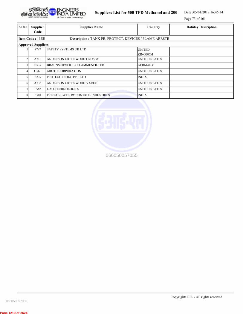
Suppliers List for 500 TPD Methanol and 200 Date :05/01/2018 16:46:34
Page 73 of 161
CountrySupplier NameSr No Holiday DescriptionSupplier
Code
Item Code : 15EE Description : TANK PR. PROTECT. DEVICES / FLAME ARRSTR
Approved Suppliers
1 SAFETY SYSTEMS UK LTD UNITED
KINGDOM
S797
2 ANDERSON GREENWOOD CROSBY UNITED STATESA710
3 BRAUNSCHWEIGER FLAMMENFILTER GERMANYB537
4 GROTH CORPORATION UNITED STATESG568
5 PROTEGO INDIA PVT LTD INDIAP205
6 ANDERSON GREENWOOD VAREC UNITED STATESA733
7 L & J TECHNOLOGIES UNITED STATESL562
8 PRESSURE &FLOW CONTROL INDUSTRIES INDIAP318
Copyrights EIL - All rights reserved
066050057055
066050057055
Page 1219 of 2624

Suppliers List for 500 TPD Methanol and 200 Date :05/01/2018 16:46:34
Page 74 of 161
CountrySupplier NameSr No Holiday DescriptionSupplier
Code
Item Code : 15EF Description : ON-OFF VALVES
Approved Suppliers
1 METSO FLOW CONTROL OY FINLANDM700
2 ROTEX MANUFACTURERS & ENGINEERS P LTD. INDIAR199
3 ITALVALV S.N.C ITALYI586
4 FLOWSERVE PTE LTD SINGAPOREF636
5 PENTAIR VALVES & CONTROLS INDIA PVT LTD INDIAT198
6 PERRIN GMBH GERMANYP689
7 CAMERON ITALY SRL (FORM. D659) ITALYC718
8 SAMSON AG MESS-UND REGELTECHNIK GERMANYS510
9 PIBIVIESSE S. R. L. ITALYP544
10 MICROFINISH VALVES PVT LIMITED INDIAM094
11 VIRGO VALVES & CONTROLS PVT LTD. INDIAV088
12 MOTOYAMA ENGG WORKS LTD JAPANM561
13 VALVTECHNOLOGIES INC. UNITED STATES27465
14 WEIR VALVES & CONTROLS UK LTD UNITED
KINGDOM
W5941
15 METSO INDIA PRIVATE LIMITED INDIA3679
16 KITAMURA VALVE MANUFACTURING CO LTD JAPANK511
17 FLOWSERVE INDIA CONTROLS PVT. LTD. INDIAF176A
18 L & T VALVES LIMITED INDIAL001
19 EL-O-MATIC INDIA (PVT) LTD. INDIAE141
20 KOSO INDIA PVT. LIMITED INDIAK179B
21 KITZ CORPORATION OF EUROPE S.A. SPAINK620
22 BRAY CONTROLS INDIA PVT LTD INDIA3613
23 TYCO VALVES & CONTROLS UNITED STATEST733
24 SPX VALVES & CONTROLS (FORMERLY DEZURIK) UNITED STATESS793
Copyrights EIL - All rights reserved
066050057055
066050057055
Page 1220 of 2624
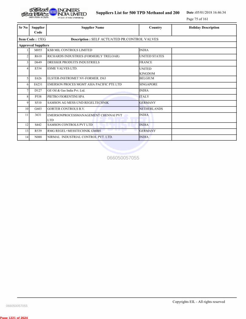
Suppliers List for 500 TPD Methanol and 200 Date :05/01/2018 16:46:34
Page 75 of 161
CountrySupplier NameSr No Holiday DescriptionSupplier
Code
Item Code : 15EG Description : SELF ACTUATED PR.CONTROL VALVES
Approved Suppliers
1 KSB MIL CONTROLS LIMITED INDIAM055
2 RICHARDS INDUSTRIES (FORMERLY TRELOAR) UNITED STATESR610
3 DRESSER PRODUITS INDUSTRIELS FRANCED649
4 ESME VALVES LTD. UNITED
KINGDOM
E534
5 ELSTER-INSTROMET NV-FORMER. I563 BELGIUME626
6 EMERSON PROCES MGMT ASIA PACIFIC PTE LTD SINGAPOREE6231
7 GE Oil & Gas India Pvt. Ltd. INDIAD127
8 PIETRO FIORENTINI SPA ITALYP538
9 SAMSON AG MESS-UND REGELTECHNIK GERMANYS510
10 GORTER CONTROLS B.V. NETHERLANDSG603
11 EMERSONPROCESSMANAGEMENT CHENNAI PVT
LTD
INDIA3631
12 SAMSON CONTROLS PVT LTD INDIAS442
13 RMG REGEL+MESSTECHNIK GMBH GERMANYR539
14 NIRMAL INDUSTRIAL CONTROL PVT. LTD. INDIAN088
Copyrights EIL - All rights reserved
066050057055
066050057055
Page 1221 of 2624

Suppliers List for 500 TPD Methanol and 200 Date :05/01/2018 16:46:34
Page 76 of 161
CountrySupplier NameSr No Holiday DescriptionSupplier
Code
Item Code : 15EN Description : SPECIAL CONTROL VALVES-MIXED
Approved Suppliers
1 METSO FLOW CONTROL OY FINLANDM700
2 WEIR VALVES & CONTROLS UK LTD UNITED
KINGDOM
W5941
3 PENTAIR VALVES & CONTROLS INDIA PVT LTD INDIAT198
4 ITALVALV S.N.C ITALYI586
5 FLOWSERVE PTE LTD SINGAPOREF636
6 GE Oil & Gas India Pvt. Ltd. INDIAD127
7 KITAMURA VALVE MANUFACTURING CO LTD JAPANK511
8 EMERSON PROCESS MANGMNT CHENNAI PVT. LTD INDIAE179A
9 EMERSON PROCES MGMT ASIA PACIFIC PTE LTD SINGAPOREE6232
10 TYCO VALVES & CONTROLS UNITED STATEST733
11 SAMSON AG MESS-UND REGELTECHNIK GERMANYS510
12 DRESSER PRODUITS INDUSTRIELS FRANCED649
13 MOTOYAMA ENGG WORKS LTD JAPANM561
14 KOSO INDIA PVT. LIMITED INDIAK179B
15 SPX VALVES & CONTROLS (FORMERLY DEZURIK) UNITED STATESS793
Copyrights EIL - All rights reserved
066050057055
066050057055
Page 1222 of 2624
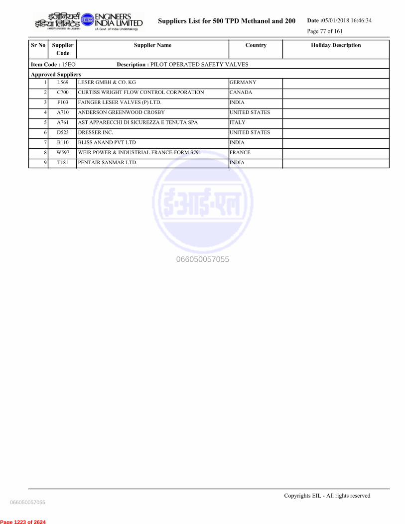
Suppliers List for 500 TPD Methanol and 200 Date :05/01/2018 16:46:34
Page 77 of 161
CountrySupplier NameSr No Holiday DescriptionSupplier
Code
Item Code : 15EO Description : PILOT OPERATED SAFETY VALVES
Approved Suppliers
1 LESER GMBH & CO. KG GERMANYL569
2 CURTISS WRIGHT FLOW CONTROL CORPORATION CANADAC700
3 FAINGER LESER VALVES (P) LTD. INDIAF103
4 ANDERSON GREENWOOD CROSBY UNITED STATESA710
5 AST APPARECCHI DI SICUREZZA E TENUTA SPA ITALYA761
6 DRESSER INC. UNITED STATESD523
7 BLISS ANAND PVT LTD INDIAB110
8 WEIR POWER & INDUSTRIAL FRANCE-FORM S791 FRANCEW597
9 PENTAIR SANMAR LTD. INDIAT181
Copyrights EIL - All rights reserved
066050057055
066050057055
Page 1223 of 2624
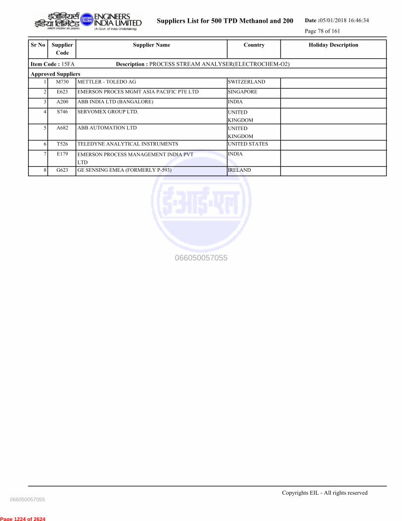
Suppliers List for 500 TPD Methanol and 200 Date :05/01/2018 16:46:34
Page 78 of 161
CountrySupplier NameSr No Holiday DescriptionSupplier
Code
Item Code : 15FA Description : PROCESS STREAM ANALYSER(ELECTROCHEM-O2)
Approved Suppliers
1 METTLER - TOLEDO AG SWITZERLANDM730
2 EMERSON PROCES MGMT ASIA PACIFIC PTE LTD SINGAPOREE623
3 ABB INDIA LTD (BANGALORE) INDIAA200
4 SERVOMEX GROUP LTD. UNITED
KINGDOM
S746
5 ABB AUTOMATION LTD UNITED
KINGDOM
A682
6 TELEDYNE ANALYTICAL INSTRUMENTS UNITED STATEST526
7 EMERSON PROCESS MANAGEMENT INDIA PVT
LTD
INDIAE179
8 GE SENSING EMEA (FORMERLY P-593) IRELANDG623
Copyrights EIL - All rights reserved
066050057055
066050057055
Page 1224 of 2624

Suppliers List for 500 TPD Methanol and 200 Date :05/01/2018 16:46:34
Page 79 of 161
CountrySupplier NameSr No Holiday DescriptionSupplier
Code
Item Code : 15FH Description : WATER QUALITY ANALYSERS (PH)
Approved Suppliers
1 METTLER - TOLEDO AG SWITZERLANDM730
2 EMERSON PROCESS MANAGEMENT INDIA PVT
LTD
INDIAE179
3 ABB INDIA LTD (BANGALORE) INDIAA200
4 FORBES MARSHALL PVT. LTD.- PUNE INDIAF181
5 EMERSON PROCES MGMT ASIA PACIFIC PTE LTD SINGAPOREE623
6 ENDRESS+HAUSER (I) PVT. LTD. INDIAE187
7 YOKOGAWA INDIA LIMITED INDIAY006
8 ABB AUTOMATION LTD UNITED
KINGDOM
A682
9 ENDRESS+HAUSER CONDUCTA GMBH+CO GERMANYE656
10 HONEYWELL INC. UNITED STATESH621
11 YOKOGAWA ELECTRIC CORPORATION JAPANY501
12 HONEYWELL AUTOMATION INDIA LTD. INDIAH150
13 INVENSYS SOFTWARE SYSTEMS (S) PTE LTD SINGAPOREI590
14 HACH COMPANY UNITED STATESH638
Copyrights EIL - All rights reserved
066050057055
066050057055
Page 1225 of 2624
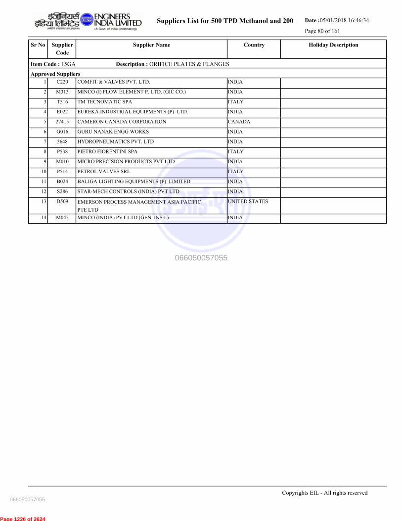
Suppliers List for 500 TPD Methanol and 200 Date :05/01/2018 16:46:34
Page 80 of 161
CountrySupplier NameSr No Holiday DescriptionSupplier
Code
Item Code : 15GA Description : ORIFICE PLATES & FLANGES
Approved Suppliers
1 COMFIT & VALVES PVT. LTD. INDIAC220
2 MINCO (I) FLOW ELEMENT P. LTD. (GIC CO.) INDIAM313
3 TM TECNOMATIC SPA ITALYT516
4 EUREKA INDUSTRIAL EQUIPMENTS (P) LTD. INDIAE022
5 CAMERON CANADA CORPORATION CANADA27415
6 GURU NANAK ENGG WORKS INDIAG016
7 HYDROPNEUMATICS PVT. LTD INDIA3648
8 PIETRO FIORENTINI SPA ITALYP538
9 MICRO PRECISION PRODUCTS PVT LTD INDIAM010
10 PETROL VALVES SRL ITALYP514
11 BALIGA LIGHTING EQUIPMENTS (P) LIMITED INDIAB024
12 STAR-MECH CONTROLS (INDIA) PVT LTD INDIAS286
13 EMERSON PROCESS MANAGEMENT ASIA PACIFIC
PTE LTD
UNITED STATESD509
14 MINCO (INDIA) PVT LTD (GEN. INST.) INDIAM045
Copyrights EIL - All rights reserved
066050057055
066050057055
Page 1226 of 2624
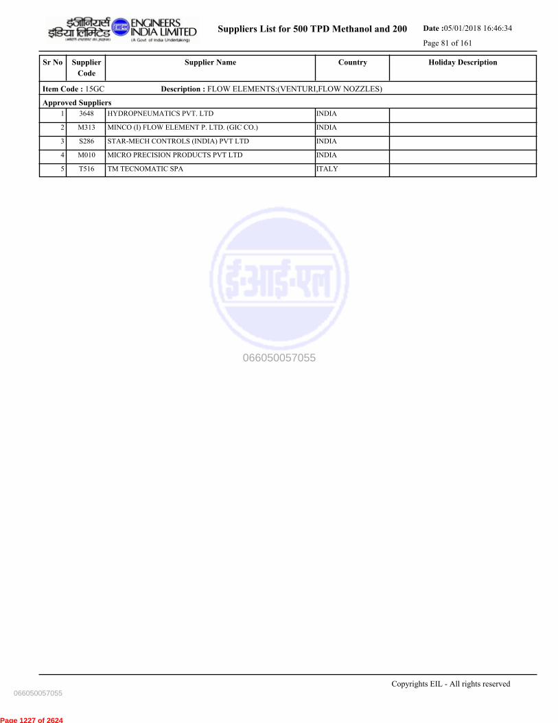
Suppliers List for 500 TPD Methanol and 200 Date :05/01/2018 16:46:34
Page 81 of 161
CountrySupplier NameSr No Holiday DescriptionSupplier
Code
Item Code : 15GC Description : FLOW ELEMENTS:(VENTURI,FLOW NOZZLES)
Approved Suppliers
1 HYDROPNEUMATICS PVT. LTD INDIA3648
2 MINCO (I) FLOW ELEMENT P. LTD. (GIC CO.) INDIAM313
3 STAR-MECH CONTROLS (INDIA) PVT LTD INDIAS286
4 MICRO PRECISION PRODUCTS PVT LTD INDIAM010
5 TM TECNOMATIC SPA ITALYT516
Copyrights EIL - All rights reserved
066050057055
066050057055
Page 1227 of 2624
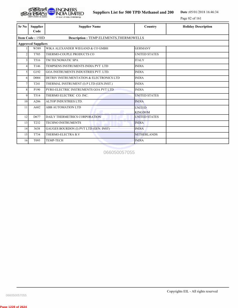
Suppliers List for 500 TPD Methanol and 200 Date :05/01/2018 16:46:34
Page 82 of 161
CountrySupplier NameSr No Holiday DescriptionSupplier
Code
Item Code : 15HD Description : TEMP.ELEMENTS,THERMOWELLS
Approved Suppliers
1 WIKA ALEXANDER WIEGAND & CO GMBH GERMANYW589
2 THERMO-COUPLE PRODUCTS CO UNITED STATEST705
3 TM TECNOMATIC SPA ITALYT516
4 TEMPSENS INSTRUMENTS INDIA PVT LTD INDIAT146
5 GOA INSTRUMENTS INDUSTRIES PVT. LTD. INDIAG192
6 DETRIV INSTRUMENTATION & ELECTRONICS LTD INDIAD004
7 THERMAL INSTRUMENT (I) P LTD (GEN.INST.) INDIAT241
8 PYRO-ELECTRIC INSTRUMENTS GOA PVT LTD INDIAP190
9 THERMO ELECTRIC CO. INC. UNITED STATEST514
10 ALTOP INDUSTRIES LTD. INDIAA206
11 ABB AUTOMATION LTD UNITED
KINGDOM
A682
12 DAILY THERMETRICS CORPORATION UNITED STATESD677
13 TECHNO INSTRUMENTS INDIAT232
14 GAUGES BOURDON (I) PVT LTD (GEN. INST) INDIA3638
15 THERMO-ELECTRA B.V NETHERLANDST734
16 TEMP-TECH INDIAT095
Copyrights EIL - All rights reserved
066050057055
066050057055
Page 1228 of 2624
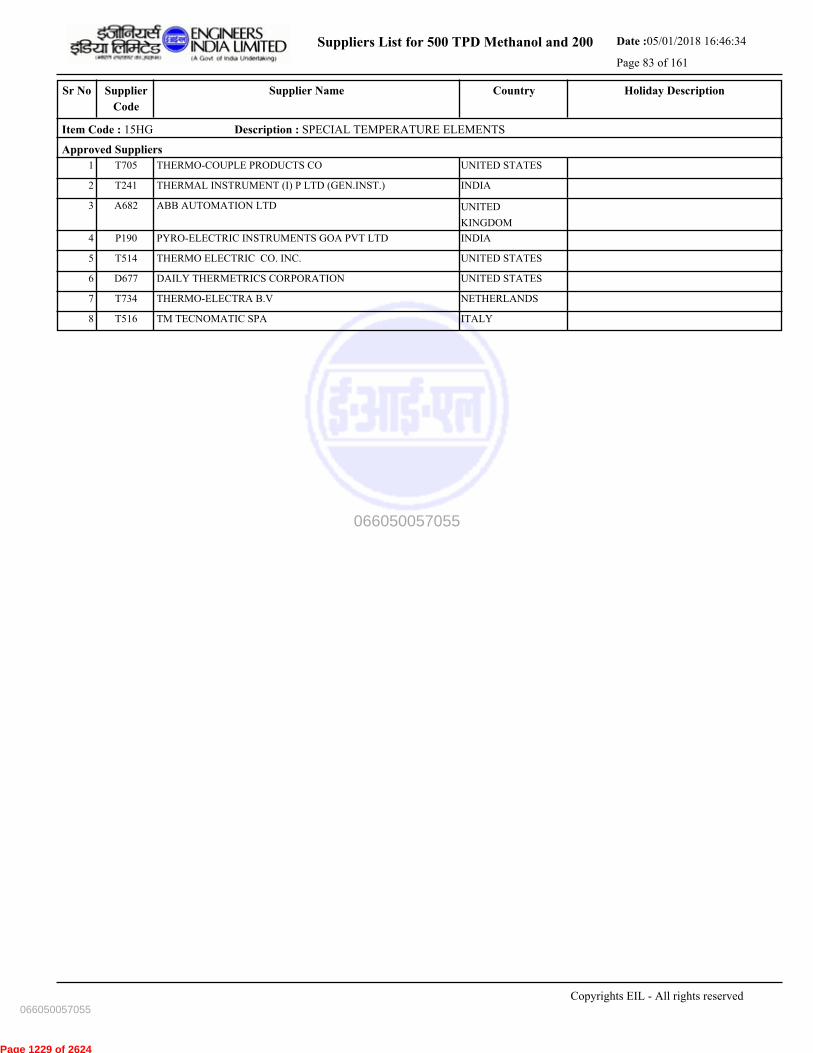
Suppliers List for 500 TPD Methanol and 200 Date :05/01/2018 16:46:34
Page 83 of 161
CountrySupplier NameSr No Holiday DescriptionSupplier
Code
Item Code : 15HG Description : SPECIAL TEMPERATURE ELEMENTS
Approved Suppliers
1 THERMO-COUPLE PRODUCTS CO UNITED STATEST705
2 THERMAL INSTRUMENT (I) P LTD (GEN.INST.) INDIAT241
3 ABB AUTOMATION LTD UNITED
KINGDOM
A682
4 PYRO-ELECTRIC INSTRUMENTS GOA PVT LTD INDIAP190
5 THERMO ELECTRIC CO. INC. UNITED STATEST514
6 DAILY THERMETRICS CORPORATION UNITED STATESD677
7 THERMO-ELECTRA B.V NETHERLANDST734
8 TM TECNOMATIC SPA ITALYT516
Copyrights EIL - All rights reserved
066050057055
066050057055
Page 1229 of 2624
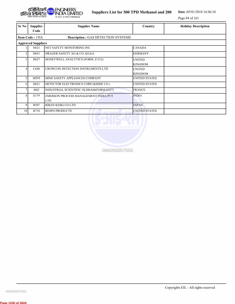
Suppliers List for 500 TPD Methanol and 200 Date :05/01/2018 16:46:34
Page 84 of 161
CountrySupplier NameSr No Holiday DescriptionSupplier
Code
Item Code : 15IA Description : GAS DETECTION SYSTEMS
Approved Suppliers
1 NET SAFETY MONITORING INC CANADAN621
2 DRAGER SAFETY AG & CO. KGAA GERMANYD651
3 HONEYWELL ANALYTICS (FORM. Z-512) UNITED
KINGDOM
H637
4 CROWCON DETECTION INSTRUMENTS LTD UNITED
KINGDOM
C648
5 MINE SAFETY APPLIANCES COMPANY UNITED STATESM595
6 DETECTOR ELECTRONICS CORP.(KIDDE CO.) UNITED STATESD621
7 INDUSTRIAL SCIENTIFIC OLDHAM(FORM.O527) FRANCEI602
8 EMERSON PROCESS MANAGEMENT INDIA PVT
LTD
INDIAE179
9 RIKEN KEIKI CO LTD JAPANR587
10 RESPO PRODUCTS UNITED STATESR710
Copyrights EIL - All rights reserved
066050057055
066050057055
Page 1230 of 2624
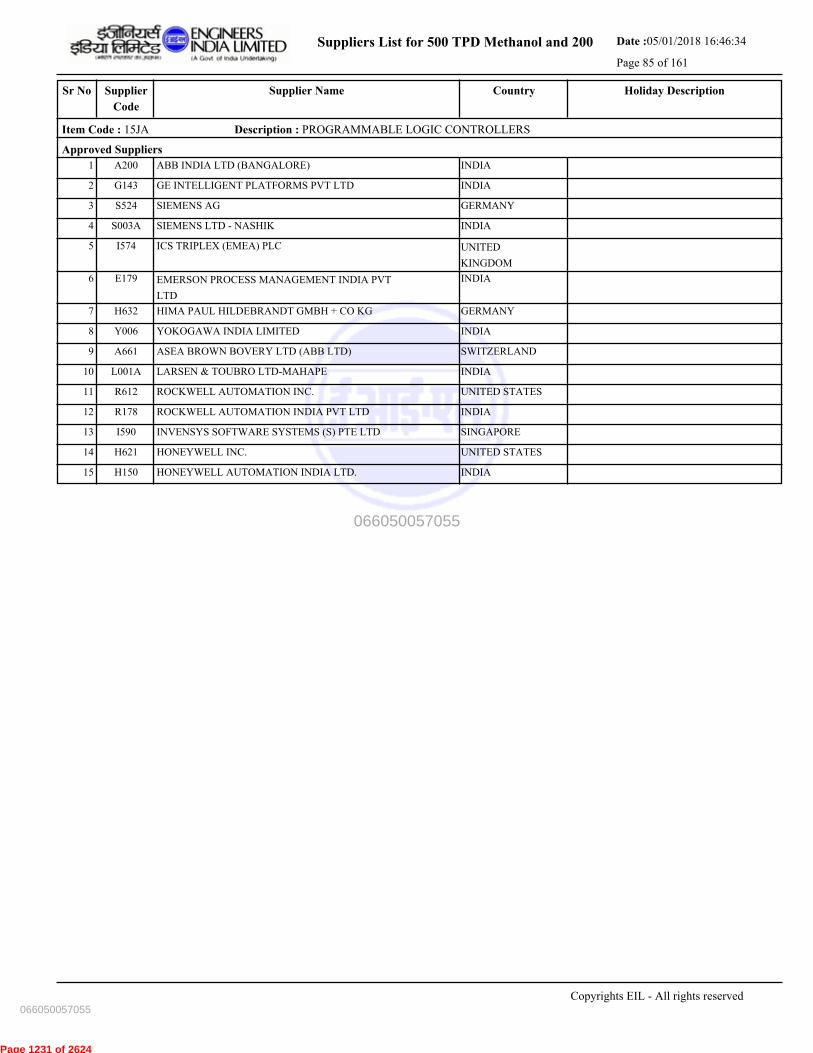
Suppliers List for 500 TPD Methanol and 200 Date :05/01/2018 16:46:34
Page 85 of 161
CountrySupplier NameSr No Holiday DescriptionSupplier
Code
Item Code : 15JA Description : PROGRAMMABLE LOGIC CONTROLLERS
Approved Suppliers
1 ABB INDIA LTD (BANGALORE) INDIAA200
2 GE INTELLIGENT PLATFORMS PVT LTD INDIAG143
3 SIEMENS AG GERMANYS524
4 SIEMENS LTD - NASHIK INDIAS003A
5 ICS TRIPLEX (EMEA) PLC UNITED
KINGDOM
I574
6 EMERSON PROCESS MANAGEMENT INDIA PVT
LTD
INDIAE179
7 HIMA PAUL HILDEBRANDT GMBH + CO KG GERMANYH632
8 YOKOGAWA INDIA LIMITED INDIAY006
9 ASEA BROWN BOVERY LTD (ABB LTD) SWITZERLANDA661
10 LARSEN & TOUBRO LTD-MAHAPE INDIAL001A
11 ROCKWELL AUTOMATION INC. UNITED STATESR612
12 ROCKWELL AUTOMATION INDIA PVT LTD INDIAR178
13 INVENSYS SOFTWARE SYSTEMS (S) PTE LTD SINGAPOREI590
14 HONEYWELL INC. UNITED STATESH621
15 HONEYWELL AUTOMATION INDIA LTD. INDIAH150
Copyrights EIL - All rights reserved
066050057055
066050057055
Page 1231 of 2624

Suppliers List for 500 TPD Methanol and 200 Date :05/01/2018 16:46:34
Page 86 of 161
CountrySupplier NameSr No Holiday DescriptionSupplier
Code
Item Code : 15KA Description : PRESSURE GAUGES
Approved Suppliers
1 GOA INSTRUMENTS INDUSTRIES PVT. LTD. INDIAG192
2 BADOTHERM PROCESS INSTRUMENTS B.V. NETHERLANDSB696
3 BUDENBERG GAUGE CO. LTD UNITED
KINGDOM
B618
4 GAUGES BOURDON (I) PVT. LTD. (GEN.INST) INDIAG115
5 H.GURU INDUSTRIES INDIAH099
6 AN INSTRUMENTS PVT LTD INDIAA053
7 WIKA ALEXANDER WIEGAND & CO GMBH GERMANYW589
8 WALCHANDNAGAR INDUSTRIES LTD(TIWAC
DIVN)
INDIAW064
9 BAUMER TECHNOLOGIES INDIA PVT.LTD(W058) INDIAB213
10 H GURU INSTRUMENTS(SOUTH INDIA)PVT. LTD INDIAH081
11 PRECISION MASS PRODUCTS PVT. LTD. INDIAA362
12 WIKA INSTRUMENTS INDIA PVT LTD INDIAW061
13 MANOMETER (INDIA) PVT. LTD. INDIAM029
Copyrights EIL - All rights reserved
066050057055
066050057055
Page 1232 of 2624

Suppliers List for 500 TPD Methanol and 200 Date :05/01/2018 16:46:34
Page 87 of 161
CountrySupplier NameSr No Holiday DescriptionSupplier
Code
Item Code : 15KB Description : DRAFT GAUGES
Approved Suppliers
1 BADOTHERM PROCESS INSTRUMENTS B.V. NETHERLANDSB696
2 GAUGES BOURDON (I) PVT. LTD. (GEN.INST) INDIAG115
3 SWITZER PROCESS INSTRUMENTS PVT. LTD. INDIAS087
4 AN INSTRUMENTS PVT LTD INDIAA053
5 BUDENBERG GAUGE CO. LTD UNITED
KINGDOM
B618
6 WIKA ALEXANDER WIEGAND & CO GMBH GERMANYW589
Copyrights EIL - All rights reserved
066050057055
066050057055
Page 1233 of 2624
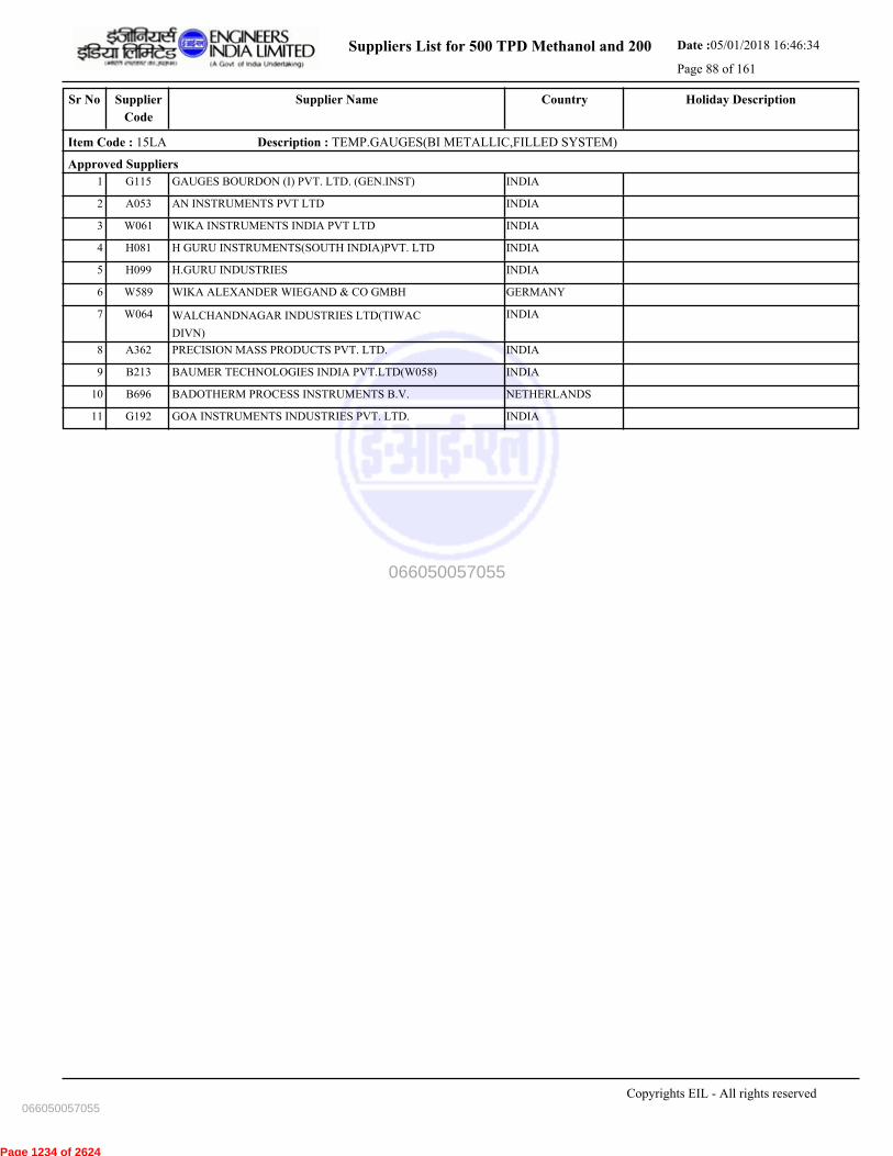
Suppliers List for 500 TPD Methanol and 200 Date :05/01/2018 16:46:34
Page 88 of 161
CountrySupplier NameSr No Holiday DescriptionSupplier
Code
Item Code : 15LA Description : TEMP.GAUGES(BI METALLIC,FILLED SYSTEM)
Approved Suppliers
1 GAUGES BOURDON (I) PVT. LTD. (GEN.INST) INDIAG115
2 AN INSTRUMENTS PVT LTD INDIAA053
3 WIKA INSTRUMENTS INDIA PVT LTD INDIAW061
4 H GURU INSTRUMENTS(SOUTH INDIA)PVT. LTD INDIAH081
5 H.GURU INDUSTRIES INDIAH099
6 WIKA ALEXANDER WIEGAND & CO GMBH GERMANYW589
7 WALCHANDNAGAR INDUSTRIES LTD(TIWAC
DIVN)
INDIAW064
8 PRECISION MASS PRODUCTS PVT. LTD. INDIAA362
9 BAUMER TECHNOLOGIES INDIA PVT.LTD(W058) INDIAB213
10 BADOTHERM PROCESS INSTRUMENTS B.V. NETHERLANDSB696
11 GOA INSTRUMENTS INDUSTRIES PVT. LTD. INDIAG192
Copyrights EIL - All rights reserved
066050057055
066050057055
Page 1234 of 2624
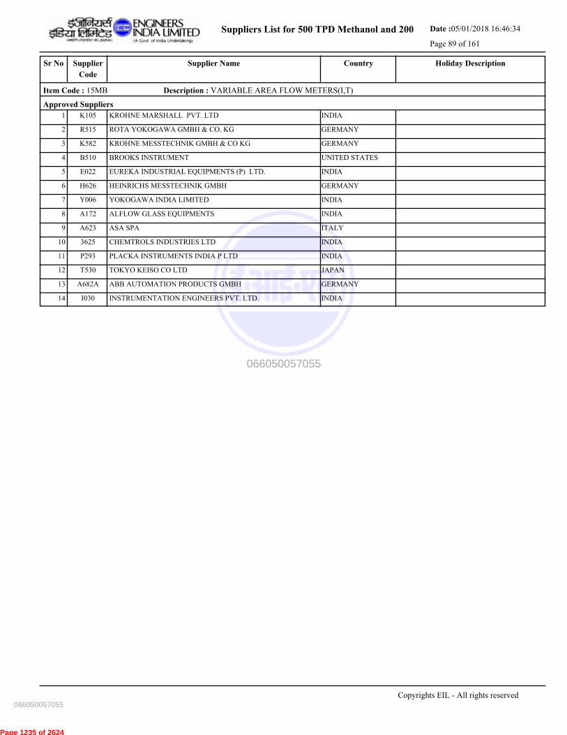
Suppliers List for 500 TPD Methanol and 200 Date :05/01/2018 16:46:34
Page 89 of 161
CountrySupplier NameSr No Holiday DescriptionSupplier
Code
Item Code : 15MB Description : VARIABLE AREA FLOW METERS(I,T)
Approved Suppliers
1 KROHNE MARSHALL PVT. LTD INDIAK105
2 ROTA YOKOGAWA GMBH & CO. KG GERMANYR515
3 KROHNE MESSTECHNIK GMBH & CO KG GERMANYK582
4 BROOKS INSTRUMENT UNITED STATESB510
5 EUREKA INDUSTRIAL EQUIPMENTS (P) LTD. INDIAE022
6 HEINRICHS MESSTECHNIK GMBH GERMANYH626
7 YOKOGAWA INDIA LIMITED INDIAY006
8 ALFLOW GLASS EQUIPMENTS INDIAA172
9 ASA SPA ITALYA623
10 CHEMTROLS INDUSTRIES LTD INDIA3625
11 PLACKA INSTRUMENTS INDIA P LTD INDIAP293
12 TOKYO KEISO CO LTD JAPANT530
13 ABB AUTOMATION PRODUCTS GMBH GERMANYA682A
14 INSTRUMENTATION ENGINEERS PVT. LTD. INDIAI030
Copyrights EIL - All rights reserved
066050057055
066050057055
Page 1235 of 2624
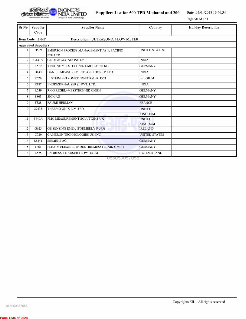
Suppliers List for 500 TPD Methanol and 200 Date :05/01/2018 16:46:34
Page 90 of 161
CountrySupplier NameSr No Holiday DescriptionSupplier
Code
Item Code : 15ND Description : ULTRASONIC FLOW METER
Approved Suppliers
1 EMERSON PROCESS MANAGEMENT ASIA PACIFIC
PTE LTD
UNITED STATESD509
2 GE Oil & Gas India Pvt. Ltd. INDIAG147A
3 KROHNE MESSTECHNIK GMBH & CO KG GERMANYK582
4 DANIEL MEASUREMENT SOLUTIONS P LTD INDIAD143
5 ELSTER-INSTROMET NV-FORMER. I563 BELGIUME626
6 ENDRESS+HAUSER (I) PVT. LTD. INDIAE187
7 RMG REGEL+MESSTECHNIK GMBH GERMANYR539
8 SICK AG GERMANYS803
9 FAURE HERMAN FRANCEF528
10 THERMO ONIX LIMITED UNITED
KINGDOM
27433
11 FMC MEASUREMENT SOLUTIONS-UK UNITED
KINGDOM
F640A
12 GE SENSING EMEA (FORMERLY P-593) IRELANDG623
13 CAMERON TECHNOLOGIES US, INC UNITED STATESC720
14 SIEMENS AG GERMANYS5241
15 FLEXIM FLEXIBLE INDUSTRIEMESSTECNIK GMBH GERMANYF661
16 ENDRESS + HAUSER FLOWTEC AG SWITZERLANDE525
Copyrights EIL - All rights reserved
066050057055
066050057055
Page 1236 of 2624
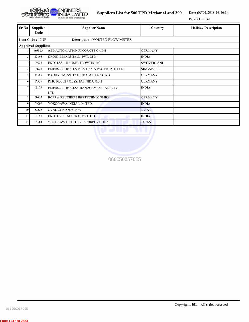
Suppliers List for 500 TPD Methanol and 200 Date :05/01/2018 16:46:34
Page 91 of 161
CountrySupplier NameSr No Holiday DescriptionSupplier
Code
Item Code : 15NF Description : VORTEX FLOW METER
Approved Suppliers
1 ABB AUTOMATION PRODUCTS GMBH GERMANYA682A
2 KROHNE MARSHALL PVT. LTD INDIAK105
3 ENDRESS + HAUSER FLOWTEC AG SWITZERLANDE525
4 EMERSON PROCES MGMT ASIA PACIFIC PTE LTD SINGAPOREE623
5 KROHNE MESSTECHNIK GMBH & CO KG GERMANYK582
6 RMG REGEL+MESSTECHNIK GMBH GERMANYR539
7 EMERSON PROCESS MANAGEMENT INDIA PVT
LTD
INDIAE179
8 BOPP & REUTHER MESSTECHNIK GMBH GERMANYB617
9 YOKOGAWA INDIA LIMITED INDIAY006
10 OVAL CORPORATION JAPANO523
11 ENDRESS+HAUSER (I) PVT. LTD. INDIAE187
12 YOKOGAWA ELECTRIC CORPORATION JAPANY501
Copyrights EIL - All rights reserved
066050057055
066050057055
Page 1237 of 2624

Suppliers List for 500 TPD Methanol and 200 Date :05/01/2018 16:46:34
Page 92 of 161
CountrySupplier NameSr No Holiday DescriptionSupplier
Code
Item Code : 15NI Description : MASS FLOW METERS
Approved Suppliers
1 YOKOGAWA INDIA LIMITED INDIAY006
2 ENDRESS + HAUSER FLOWTEC AG SWITZERLANDE525
3 MAGNETROL INTERNATIONAL N.V BELGIUMM508
4 BROOKS INSTRUMENT UNITED STATESB510
5 RHEONIK MESSTECHNIK GMBH GERMANYR604
6 ENDRESS+HAUSER (I) PVT. LTD. INDIAE187
7 Endress+Hauser Flowtec (India) Pvt Ltd INDIA3599
8 ABB AUTOMATION PRODUCTS GMBH GERMANYA682A
9 EMERSON PROCES MGMT ASIA PACIFIC PTE LTD SINGAPOREE623
10 HEINRICHS MESSTECHNIK GMBH GERMANYH626
11 KURZ INSTRUMENTS INC UNITED STATESK616
12 FOX THERMAL INSTRUMENT INC. UNITED STATESF641
13 KROHNE MESSTECHNIK GMBH & CO KG GERMANYK582
14 ROTA YOKOGAWA GMBH & CO. KG GERMANYR515
15 FLUID COMPONENTS INTERNATIONAL LLC UNITED STATESF576
16 BRONKHORST HIGH TECH BV NETHERLANDSB621
17 EMERSON PROCESS MANAGEMENT INDIA PVT
LTD
INDIAE179
Copyrights EIL - All rights reserved
066050057055
066050057055
Page 1238 of 2624

Suppliers List for 500 TPD Methanol and 200 Date :05/01/2018 16:46:34
Page 93 of 161
CountrySupplier NameSr No Holiday DescriptionSupplier
Code
Item Code : 15OA Description : GAUGE GLASSES & COCKS
Approved Suppliers
1 CHEMTROLS SAMIL (INDIA) PVT LTD INDIAC201
2 NIHON KLINGAGE CO LTD JAPANN520
3 PRATOLINA INSTRUMENTS PVT LTD INDIAP017
4 BLISS ANAND PVT LTD INDIAB110
5 PUNE TECHTROL PVT LTD INDIAP239
6 SIGMA INSTRUMENTS CO INDIAS036
7 LEVCON INSTRUMENTS PVT LTD INDIAL009
8 JERGUSON GAUGE & VALVE UNITED STATESJ543
9 NISAN SCIENTIFIC PROCESS EQUIP. P LTD INDIAN141
10 KLINGER SPA ITALYK637
11 CESARE BONNETTI S.P.A. ITALYC716
12 GAUGES BOURDON (I) PVT LTD (GEN. INST) INDIA3638
Copyrights EIL - All rights reserved
066050057055
066050057055
Page 1239 of 2624
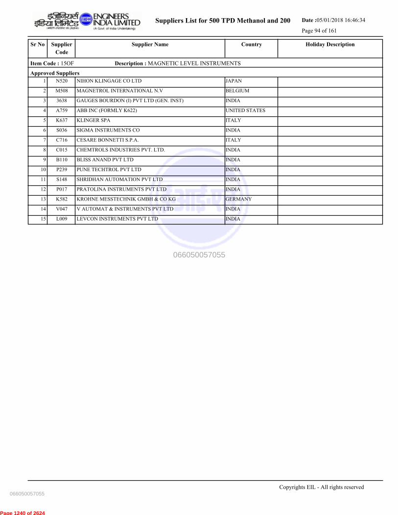
Suppliers List for 500 TPD Methanol and 200 Date :05/01/2018 16:46:34
Page 94 of 161
CountrySupplier NameSr No Holiday DescriptionSupplier
Code
Item Code : 15OF Description : MAGNETIC LEVEL INSTRUMENTS
Approved Suppliers
1 NIHON KLINGAGE CO LTD JAPANN520
2 MAGNETROL INTERNATIONAL N.V BELGIUMM508
3 GAUGES BOURDON (I) PVT LTD (GEN. INST) INDIA3638
4 ABB INC (FORMLY K622) UNITED STATESA759
5 KLINGER SPA ITALYK637
6 SIGMA INSTRUMENTS CO INDIAS036
7 CESARE BONNETTI S.P.A. ITALYC716
8 CHEMTROLS INDUSTRIES PVT. LTD. INDIAC015
9 BLISS ANAND PVT LTD INDIAB110
10 PUNE TECHTROL PVT LTD INDIAP239
11 SHRIDHAN AUTOMATION PVT LTD INDIAS148
12 PRATOLINA INSTRUMENTS PVT LTD INDIAP017
13 KROHNE MESSTECHNIK GMBH & CO KG GERMANYK582
14 V AUTOMAT & INSTRUMENTS PVT LTD INDIAV047
15 LEVCON INSTRUMENTS PVT LTD INDIAL009
Copyrights EIL - All rights reserved
066050057055
066050057055
Page 1240 of 2624

Suppliers List for 500 TPD Methanol and 200 Date :05/01/2018 16:46:34
Page 95 of 161
CountrySupplier NameSr No Holiday DescriptionSupplier
Code
Item Code : 15OG Description : SPL. LEVEL INSTRUMENTS-GUIDED WAVE RADAR
Approved Suppliers
1 ENDRESS+HAUSER (I) AUTO. INSTR. PVT. LTD INDIAE232
2 EMERSON PROCESS MANAGEMENT INDIA PVT
LTD
INDIAE179
3 KROHNE MESSTECHNIK GMBH & CO KG GERMANYK582
4 ABB INC (FORMLY K622) UNITED STATESA759
5 MAGNETROL INTERNATIONAL N.V BELGIUMM508
6 ENDRESS+HAUSER GMBH+CO. KG GERMANYE657
7 L & J TECHNOLOGIES UNITED STATESL562
8 VEGA GRIESHABER KG GERMANYV518
Copyrights EIL - All rights reserved
066050057055
066050057055
Page 1241 of 2624

Suppliers List for 500 TPD Methanol and 200 Date :05/01/2018 16:46:34
Page 96 of 161
CountrySupplier NameSr No Holiday DescriptionSupplier
Code
Item Code : 15OS Description : TANK LEVEL INSTRUMENT (SERVO TYPE)
Approved Suppliers
1 ENRAF B.V. (GR. COMPANY OF HONEYWELL) NETHERLANDSE550
2 SBEM PVT LTD INDIAS006
3 ENDRESS+HAUSER (I) PVT. LTD. INDIAE187
4 TOKYO KEISO CO LTD JAPANT530
5 ENDRESS+HAUSER YAMANASHI CO. LTD. JAPANE625
6 L & J TECHNOLOGIES UNITED STATESL562
Copyrights EIL - All rights reserved
066050057055
066050057055
Page 1242 of 2624
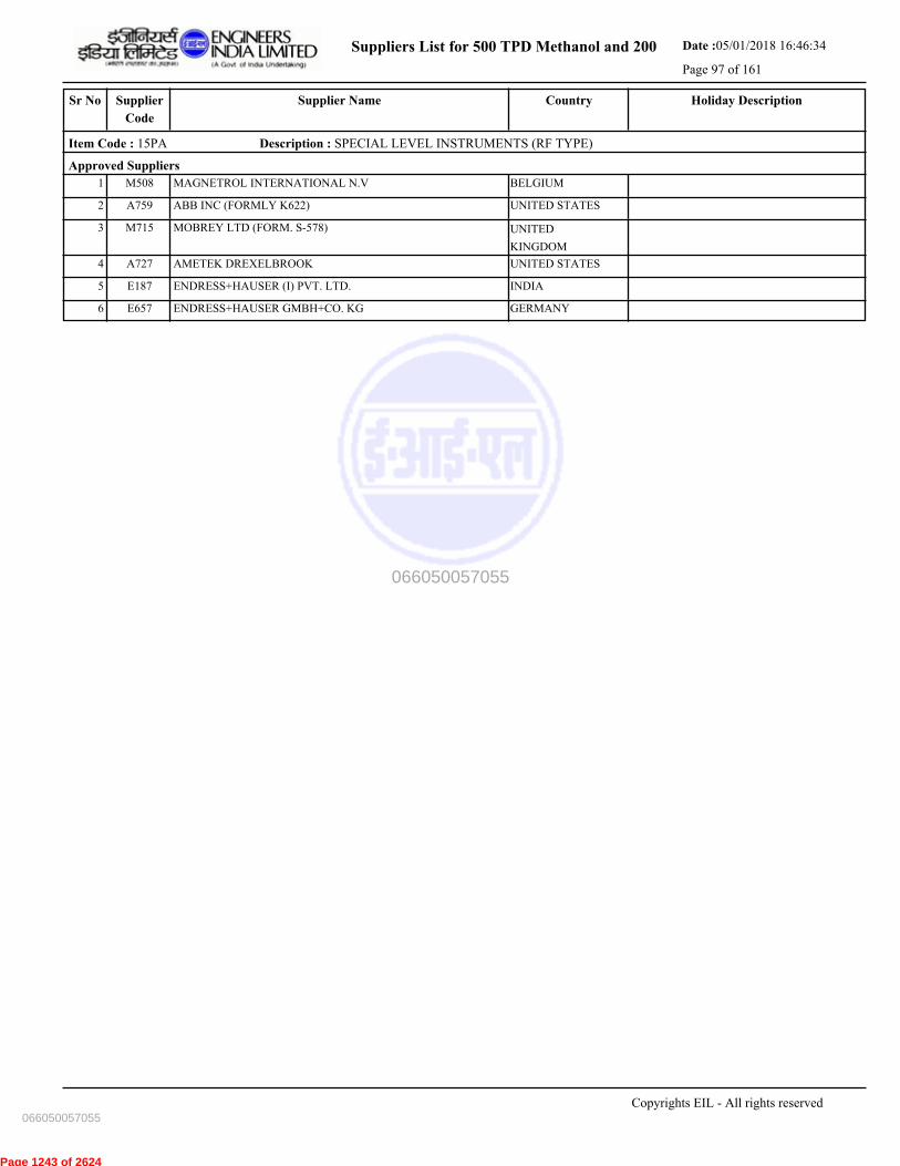
Suppliers List for 500 TPD Methanol and 200 Date :05/01/2018 16:46:34
Page 97 of 161
CountrySupplier NameSr No Holiday DescriptionSupplier
Code
Item Code : 15PA Description : SPECIAL LEVEL INSTRUMENTS (RF TYPE)
Approved Suppliers
1 MAGNETROL INTERNATIONAL N.V BELGIUMM508
2 ABB INC (FORMLY K622) UNITED STATESA759
3 MOBREY LTD (FORM. S-578) UNITED
KINGDOM
M715
4 AMETEK DREXELBROOK UNITED STATESA727
5 ENDRESS+HAUSER (I) PVT. LTD. INDIAE187
6 ENDRESS+HAUSER GMBH+CO. KG GERMANYE657
Copyrights EIL - All rights reserved
066050057055
066050057055
Page 1243 of 2624

Suppliers List for 500 TPD Methanol and 200 Date :05/01/2018 16:46:34
Page 98 of 161
CountrySupplier NameSr No Holiday DescriptionSupplier
Code
Item Code : 15PB Description : SPECIAL LEVEL INSTRUMENTS (CAP.& COND.)
Approved Suppliers
1 VEGA GRIESHABER KG GERMANYV518
2 MOBREY LTD (FORM. S-578) UNITED
KINGDOM
M715
3 ENDRESS+HAUSER GMBH+CO. KG GERMANYE657
4 MAGNETROL INTERNATIONAL N.V BELGIUMM508
5 VENTURE MEASUREMENT COMPANY UNITED STATESV590
6 LEVELSTATE SYSTEMS LTD UNITED
KINGDOM
L570
7 SBEM PVT LTD INDIAS006
8 NARVIK - YARWAY B.V NETHERLANDSN614
9 YARWAY CORPORATION UNITED STATESY509
10 ENDRESS+HAUSER (I) PVT. LTD. INDIAE187
11 AMETEK DREXELBROOK UNITED STATESA727
Copyrights EIL - All rights reserved
066050057055
066050057055
Page 1244 of 2624

Suppliers List for 500 TPD Methanol and 200 Date :05/01/2018 16:46:34
Page 99 of 161
CountrySupplier NameSr No Holiday DescriptionSupplier
Code
Item Code : 15RA Description : LOOP POWERED INDICATORS
Approved Suppliers
1 ENDRESS + HAUSER WETZER INDIA PVT LTD INDIA3615
2 MTL INSTRUMENTS PVT LTD INDIAM154
3 EMERSON PROCESS MANAGEMENT INDIA PVT
LTD
INDIAE179
4 BEKA ASSOCIATES LTD UNITED
KINGDOM
B713
5 YOKOGAWA INDIA LIMITED INDIAY006
6 ENDRESS+HAUSER WETZER GMBH+ CO.KG GERMANYE641
7 HONEYWELL AUTOMATION INDIA LTD. INDIAH150
Copyrights EIL - All rights reserved
066050057055
066050057055
Page 1245 of 2624

Suppliers List for 500 TPD Methanol and 200 Date :05/01/2018 16:46:34
Page 100 of 161
CountrySupplier NameSr No Holiday DescriptionSupplier
Code
Item Code : 15RD Description : FIELD INSTRUMENTS (P,DP,F,L,T,TD)
Approved Suppliers
1 ABB AUTOMATION PRODUCTS GMBH GERMANYA682A
2 EMERSON PROCESS MANAGEMENT INDIA PVT
LTD
INDIAE179
3 ENDRESS+HAUSER WETZER GMBH+ CO.KG GERMANYE641
4 HONEYWELL AUTOMATION INDIA LTD. INDIAH150
5 ABB INDIA LTD (BANGALORE) INDIAA200
6 ENDRESS + HAUSER WETZER INDIA PVT LTD INDIA3615
7 EMERSON PROCES MGMT ASIA PACIFIC PTE LTD SINGAPOREE623
8 ENDRESS+HAUSER GMBH+CO. KG GERMANYE657
9 YOKOGAWA ELECTRIC CORPORATION JAPANY501
10 HONEYWELL INC. UNITED STATESH621
11 FUJI ELECTRIC SYSTEMS CO. LTD JAPANF644
12 YOKOGAWA INDIA LIMITED INDIAY006
Copyrights EIL - All rights reserved
066050057055
066050057055
Page 1246 of 2624
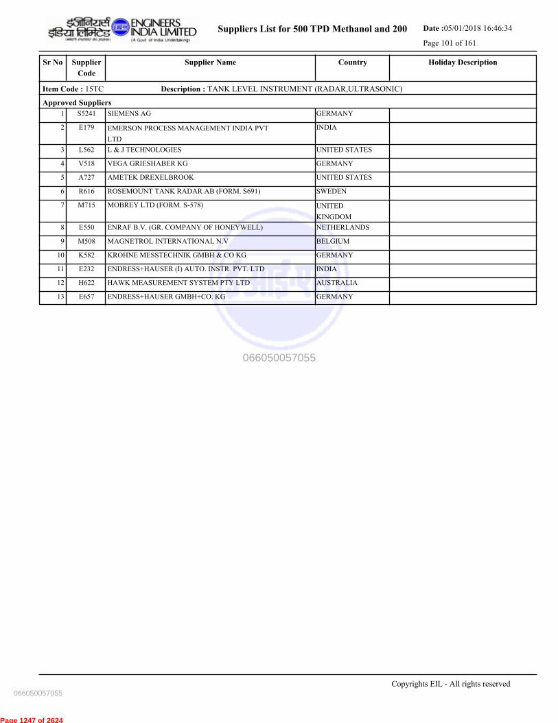
Suppliers List for 500 TPD Methanol and 200 Date :05/01/2018 16:46:34
Page 101 of 161
CountrySupplier NameSr No Holiday DescriptionSupplier
Code
Item Code : 15TC Description : TANK LEVEL INSTRUMENT (RADAR,ULTRASONIC)
Approved Suppliers
1 SIEMENS AG GERMANYS5241
2 EMERSON PROCESS MANAGEMENT INDIA PVT
LTD
INDIAE179
3 L & J TECHNOLOGIES UNITED STATESL562
4 VEGA GRIESHABER KG GERMANYV518
5 AMETEK DREXELBROOK UNITED STATESA727
6 ROSEMOUNT TANK RADAR AB (FORM. S691) SWEDENR616
7 MOBREY LTD (FORM. S-578) UNITED
KINGDOM
M715
8 ENRAF B.V. (GR. COMPANY OF HONEYWELL) NETHERLANDSE550
9 MAGNETROL INTERNATIONAL N.V BELGIUMM508
10 KROHNE MESSTECHNIK GMBH & CO KG GERMANYK582
11 ENDRESS+HAUSER (I) AUTO. INSTR. PVT. LTD INDIAE232
12 HAWK MEASUREMENT SYSTEM PTY LTD AUSTRALIAH622
13 ENDRESS+HAUSER GMBH+CO. KG GERMANYE657
Copyrights EIL - All rights reserved
066050057055
066050057055
Page 1247 of 2624

Suppliers List for 500 TPD Methanol and 200 Date :05/01/2018 16:46:34
Page 102 of 161
CountrySupplier NameSr No Holiday DescriptionSupplier
Code
Item Code : 15TE Description : SPEED TANSMITTERS
Approved Suppliers
1 PEPPERL + FUCHS GMBH GERMANYP649
2 HANS TURCK GMBH & CO. KG GERMANYH620
3 ASEA BROWN BOVERY LTD (ABB LTD) SWITZERLANDA661
4 JAPAN SERVO CO LTD JAPANJ531
Copyrights EIL - All rights reserved
066050057055
066050057055
Page 1248 of 2624

Suppliers List for 500 TPD Methanol and 200 Date :05/01/2018 16:46:34
Page 103 of 161
CountrySupplier NameSr No Holiday DescriptionSupplier
Code
Item Code : 15UA Description : CONTROL PANEL & ACCESSORIES
Approved Suppliers
1 RADHA KRISHNA CONTROLS INDIAR084
2 ACCUSONIC CONTROLS PVT LTD INDIAA212
3 CONTROL SYSTEMS ENGINEERS INDIA3626
4 POSITRONICS PVT LTD INDIAP134
5 PYROTECH ELECTRONICS PVT LTD INDIAP214
6 PRIMA AUTOMATION INDIA PVT LTD INDIAP213
7 ELECTRONIC INSTRMNTATION & CONTROL P LTD INDIAE184
8 INDUSTRIAL CONTROLS & APPLIANCES PVT LTD INDIAI010
9 ELECTRONIC CORPORATION OF INDIA LTD. INDIAE004
10 IRIS AUTOMATION PVT LTD INDIAI206
Copyrights EIL - All rights reserved
066050057055
066050057055
Page 1249 of 2624
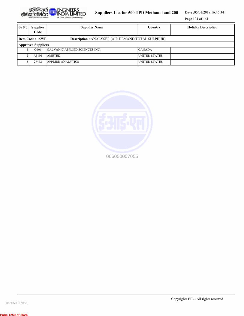
Suppliers List for 500 TPD Methanol and 200 Date :05/01/2018 16:46:34
Page 104 of 161
CountrySupplier NameSr No Holiday DescriptionSupplier
Code
Item Code : 15WB Description : ANALYSER (AIR DEMAND/TOTAL SULPHUR)
Approved Suppliers
1 GALVANIC APPLIED SCIENCES INC. CANADAG606
2 AMETEK UNITED STATESA5101
3 APPLIED ANALYTICS UNITED STATES27462
Copyrights EIL - All rights reserved
066050057055
066050057055
Page 1250 of 2624
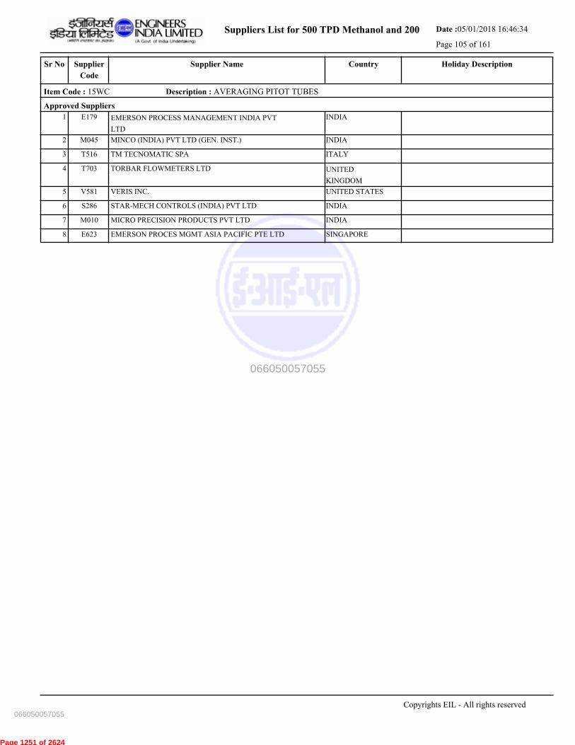
Suppliers List for 500 TPD Methanol and 200 Date :05/01/2018 16:46:34
Page 105 of 161
CountrySupplier NameSr No Holiday DescriptionSupplier
Code
Item Code : 15WC Description : AVERAGING PITOT TUBES
Approved Suppliers
1 EMERSON PROCESS MANAGEMENT INDIA PVT
LTD
INDIAE179
2 MINCO (INDIA) PVT LTD (GEN. INST.) INDIAM045
3 TM TECNOMATIC SPA ITALYT516
4 TORBAR FLOWMETERS LTD UNITED
KINGDOM
T703
5 VERIS INC. UNITED STATESV581
6 STAR-MECH CONTROLS (INDIA) PVT LTD INDIAS286
7 MICRO PRECISION PRODUCTS PVT LTD INDIAM010
8 EMERSON PROCES MGMT ASIA PACIFIC PTE LTD SINGAPOREE623
Copyrights EIL - All rights reserved
066050057055
066050057055
Page 1251 of 2624

Suppliers List for 500 TPD Methanol and 200 Date :05/01/2018 16:46:34
Page 106 of 161
CountrySupplier NameSr No Holiday DescriptionSupplier
Code
Item Code : 15YA Description : ALARM ANNUNCIATORS
Approved Suppliers
1 ELECTRONIC CORPORATION OF INDIA LTD. INDIAE004
2 INSTALARM INSTRUMENTS PVT LTD. INDIAI083
3 RONAN ENGINEERING COMPANY UNITED STATESR540
4 MTL INSTRUMENTS PVT LTD INDIAM154
5 IDEC IZUMI CORPORATION JAPANI545
6 MINILEC (INDIA) PVT LTD INDIAM171
7 PROCON INSTRUMENTATION PVT LTD INDIAP014
Copyrights EIL - All rights reserved
066050057055
066050057055
Page 1252 of 2624

Suppliers List for 500 TPD Methanol and 200 Date :05/01/2018 16:46:34
Page 107 of 161
CountrySupplier NameSr No Holiday DescriptionSupplier
Code
Item Code : 15ZA Description : RUPTURE DISCS
Approved Suppliers
1 REMBE GMBH SAFETY+CONTROL GERMANYR519
2 FIKE CORPORATION-USA UNITED STATESF575
3 BS & B SAFETY SYSTEMS (INDIA) LTD INDIAB017
Copyrights EIL - All rights reserved
066050057055
066050057055
Page 1253 of 2624
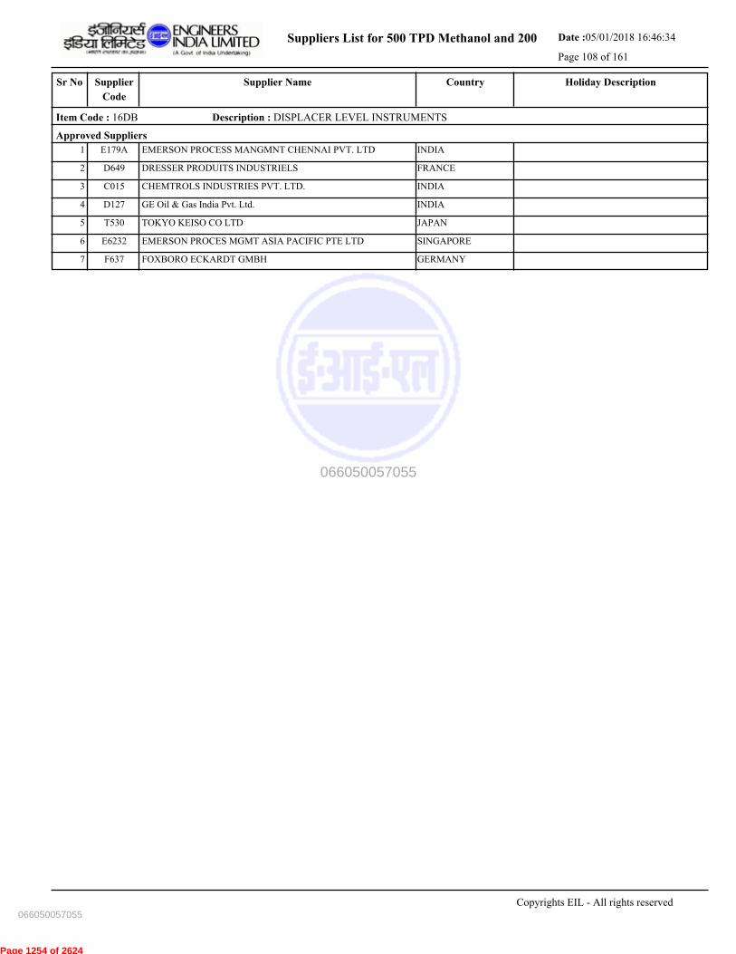
Suppliers List for 500 TPD Methanol and 200 Date :05/01/2018 16:46:34
Page 108 of 161
CountrySupplier NameSr No Holiday DescriptionSupplier
Code
Item Code : 16DB Description : DISPLACER LEVEL INSTRUMENTS
Approved Suppliers
1 EMERSON PROCESS MANGMNT CHENNAI PVT. LTD INDIAE179A
2 DRESSER PRODUITS INDUSTRIELS FRANCED649
3 CHEMTROLS INDUSTRIES PVT. LTD. INDIAC015
4 GE Oil & Gas India Pvt. Ltd. INDIAD127
5 TOKYO KEISO CO LTD JAPANT530
6 EMERSON PROCES MGMT ASIA PACIFIC PTE LTD SINGAPOREE6232
7 FOXBORO ECKARDT GMBH GERMANYF637
Copyrights EIL - All rights reserved
066050057055
066050057055
Page 1254 of 2624
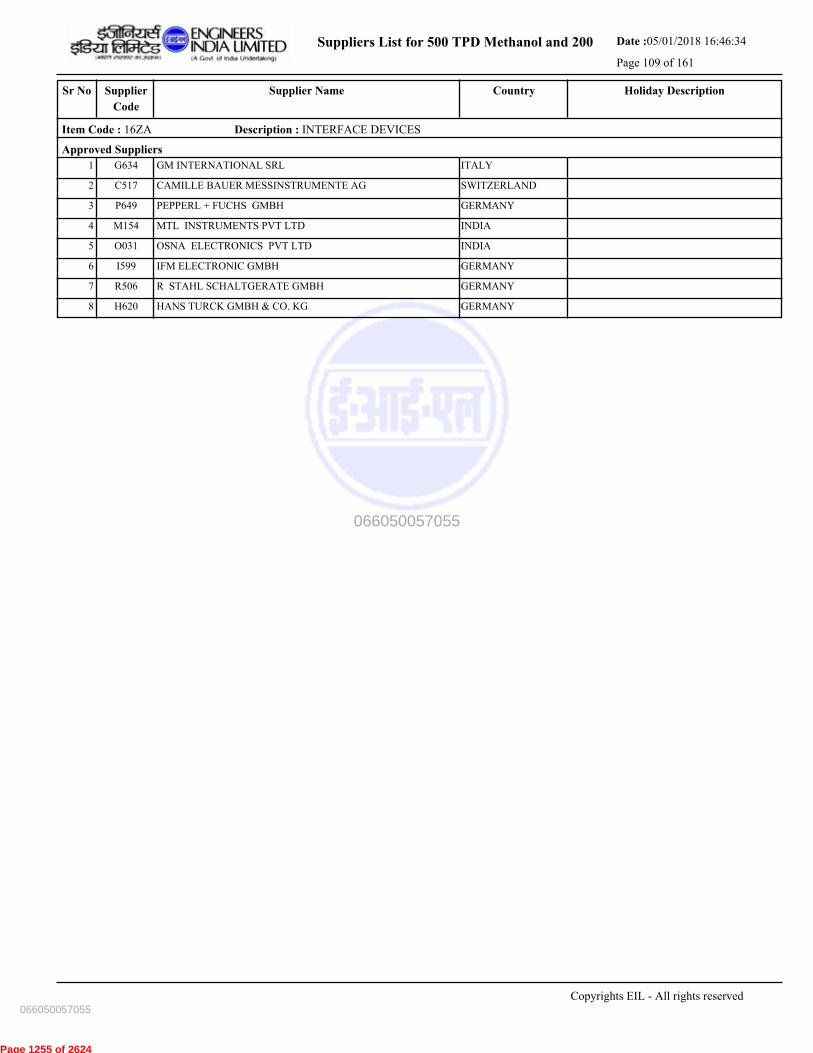
Suppliers List for 500 TPD Methanol and 200 Date :05/01/2018 16:46:34
Page 109 of 161
CountrySupplier NameSr No Holiday DescriptionSupplier
Code
Item Code : 16ZA Description : INTERFACE DEVICES
Approved Suppliers
1 GM INTERNATIONAL SRL ITALYG634
2 CAMILLE BAUER MESSINSTRUMENTE AG SWITZERLANDC517
3 PEPPERL + FUCHS GMBH GERMANYP649
4 MTL INSTRUMENTS PVT LTD INDIAM154
5 OSNA ELECTRONICS PVT LTD INDIAO031
6 IFM ELECTRONIC GMBH GERMANYI599
7 R STAHL SCHALTGERATE GMBH GERMANYR506
8 HANS TURCK GMBH & CO. KG GERMANYH620
Copyrights EIL - All rights reserved
066050057055
066050057055
Page 1255 of 2624

Suppliers List for 500 TPD Methanol and 200 Date :05/01/2018 16:46:34
Page 110 of 161
CountrySupplier NameSr No Holiday DescriptionSupplier
Code
Item Code : 30PFD Description : VALVE PLUG PRESSURE BALANCED (FS)
Approved Suppliers
1 ZHEJIANG FLOWTECH MACHINERY CO.LTD CHINAZ639
2 FLOWSERVE INDIA CONTROLS PVT LTD-MMN INDIAF193
3 HAWA VALVES (INDIA) PVT LTD INDIAH175
4 GALLI & CASSINA SPA ITALYG608
5 FLOWSERVE PTE (MFR. SERCK) UNITED
KINGDOM
F636B
Copyrights EIL - All rights reserved
066050057055
066050057055
Page 1256 of 2624
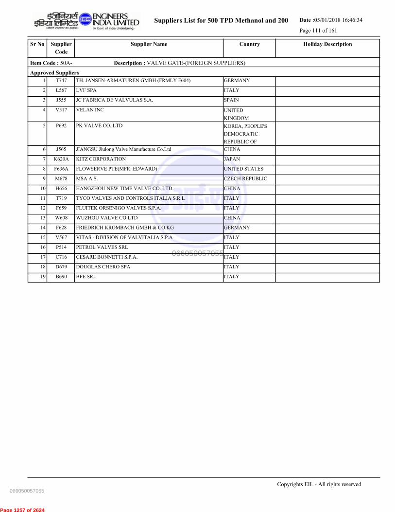
Suppliers List for 500 TPD Methanol and 200 Date :05/01/2018 16:46:34
Page 111 of 161
CountrySupplier NameSr No Holiday DescriptionSupplier
Code
Item Code : 50A- Description : VALVE GATE-(FOREIGN SUPPLIERS)
Approved Suppliers
1 TH. JANSEN-ARMATUREN GMBH (FRMLY F604) GERMANYT747
2 LVF SPA ITALYL567
3 JC FABRICA DE VALVULAS S.A. SPAINJ555
4 VELAN INC UNITED
KINGDOM
V517
5 PK VALVE CO.,LTD KOREA, PEOPLE'S
DEMOCRATIC
REPUBLIC OF
P692
6 JIANGSU Jiulong Valve Manufacture Co.Ltd CHINAJ565
7 KITZ CORPORATION JAPANK620A
8 FLOWSERVE PTE(MFR. EDWARD) UNITED STATESF636A
9 MSA A.S. CZECH REPUBLICM678
10 HANGZHOU NEW TIME VALVE CO. LTD. CHINAH656
11 TYCO VALVES AND CONTROLS ITALIA S.R.L ITALYT719
12 FLUITEK ORSENIGO VALVES S.P.A. ITALYF659
13 WUZHOU VALVE CO LTD CHINAW608
14 FRIEDRICH KROMBACH GMBH & CO.KG GERMANYF628
15 VITAS - DIVISION OF VALVITALIA S.P.A ITALYV567
16 PETROL VALVES SRL ITALYP514
17 CESARE BONNETTI S.P.A. ITALYC716
18 DOUGLAS CHERO SPA ITALYD679
19 BFE SRL ITALYB690
Copyrights EIL - All rights reserved
066050057055
066050057055
Page 1257 of 2624

Suppliers List for 500 TPD Methanol and 200 Date :05/01/2018 16:46:34
Page 112 of 161
CountrySupplier NameSr No Holiday DescriptionSupplier
Code
Item Code : 50AA Description : VALVE GATE CAST
Approved Suppliers
1 MH VALVES PVT LTD. INDIAM227
2 T.S. PUMPS AND VALVES PVT.LTD INDIAT238
3 SHAYBURG VALVES PVT LTD INDIAS139
4 SAKHI ENGINEERS PVT. LTD. INDIAS070
5 HAWA VALVES (INDIA) PVT LTD INDIAH175
6 FRIEDRICH KROMBACH GMBH & CO.KG GERMANYF628
7 L & T VALVES LIMITED INDIAL001
8 SHALIMAR VALVES PVT LTD INDIAS315
9 KSB PUMPS LTD (COIMBATTORE) INDIAK088
10 CESARE BONNETTI S.P.A. ITALYC716
11 BOTELI VALVE GROUP CO. CHINAB725
12 NEWAY VALVE (SUZHOU) CO LTD CHINAN626
13 Velan Valves India Pvt Ltd INDIA3593
14 OSWAL INDUSTRIES LTD INDIAO035
15 PEE INDUSTRIAL VALVES PVT. LTD. INDIAP188
16 SHENJIANG VALVE CO LTD CHINAS850
17 EXPERT ENGINEERING ENTERPRISES INDIAE211
18 CRI PUMPS PVT LTD (UNIT-VALVES) INDIAC229
19 AMPO, S.COOP (POYAM VALVES) SPAINA715
20 NILON VALVES PRIVATE LIMITED INDIA3623
21 LEADER VALVES LTD INDIAL004
22 LAZARO ITUARTE INTERNATIONAL,SA SPAINL564
23 FLOTEK INDUSTRIES INDIA3640
24 Z & J TECHNOLOGIES GMBH GERMANYZ507
25 AMPO VALVES INDIA PVT LTD INDIAA389
26 BHEL (TRICHY) INDIAB015
27 MSA A.S. CZECH REPUBLICM678
28 FLOWSERVE PTE(MFR. EDWARD) UNITED STATESF636A
29 MICON ENGINEERS (HUBLI) PVT LTD INDIAM295
30 GM ENGINEERING PVT. LTD. INDIAG186
31 STEEL STRONG VALVES INDIA PVT LTD INDIAS360
32 INTERVALVE POONAWALLA LIMITED INDIAI125
33 FLUIDLINE VALVES CO.PVT LTD INDIAF065
34 XOMOX SANMAR LTD-PACIFIC VALVES DIVISION INDIAX104
35 SUZHOU VIZA VALVE CO.,LTD CHINAS822
36 NITON VALVE INDUSTRIES PRIVATE LTD . INDIAN016
37 STEEL STRONG VALVES INDIA PVT LTD INDIA3636
38 FORWARD ALLOYS & CASTINGS INDIAF138
39 HAWA ENGINEERS LTD INDIAH108
40 FOURESS ENGINEERING (INDIA) PRIVATE LIMITED INDIAF002
Copyrights EIL - All rights reserved
066050057055
066050057055
Page 1258 of 2624
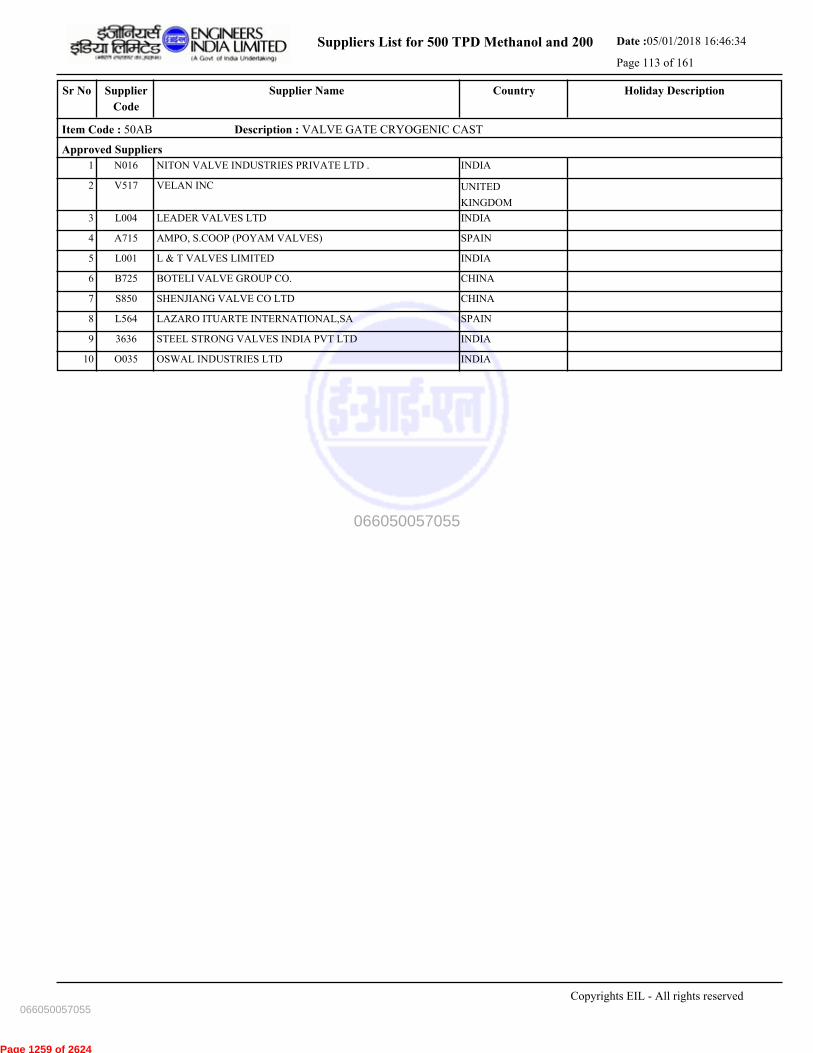
Suppliers List for 500 TPD Methanol and 200 Date :05/01/2018 16:46:34
Page 113 of 161
CountrySupplier NameSr No Holiday DescriptionSupplier
Code
Item Code : 50AB Description : VALVE GATE CRYOGENIC CAST
Approved Suppliers
1 NITON VALVE INDUSTRIES PRIVATE LTD . INDIAN016
2 VELAN INC UNITED
KINGDOM
V517
3 LEADER VALVES LTD INDIAL004
4 AMPO, S.COOP (POYAM VALVES) SPAINA715
5 L & T VALVES LIMITED INDIAL001
6 BOTELI VALVE GROUP CO. CHINAB725
7 SHENJIANG VALVE CO LTD CHINAS850
8 LAZARO ITUARTE INTERNATIONAL,SA SPAINL564
9 STEEL STRONG VALVES INDIA PVT LTD INDIA3636
10 OSWAL INDUSTRIES LTD INDIAO035
Copyrights EIL - All rights reserved
066050057055
066050057055
Page 1259 of 2624
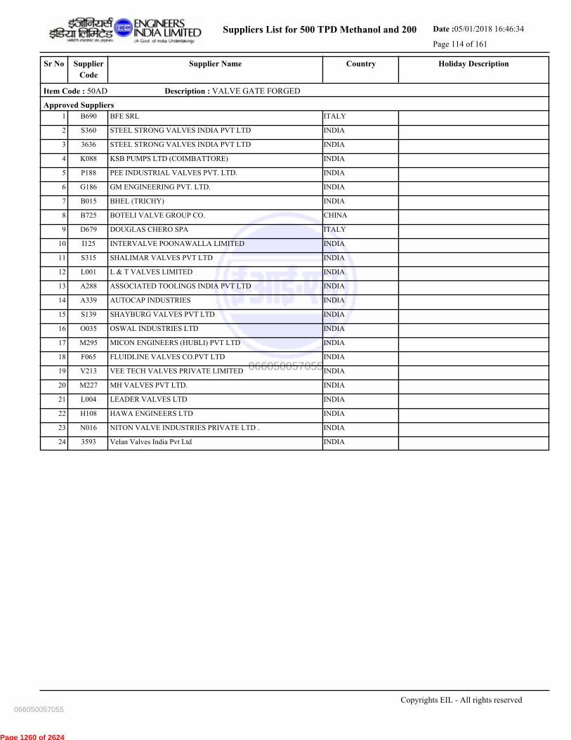
Suppliers List for 500 TPD Methanol and 200 Date :05/01/2018 16:46:34
Page 114 of 161
CountrySupplier NameSr No Holiday DescriptionSupplier
Code
Item Code : 50AD Description : VALVE GATE FORGED
Approved Suppliers
1 BFE SRL ITALYB690
2 STEEL STRONG VALVES INDIA PVT LTD INDIAS360
3 STEEL STRONG VALVES INDIA PVT LTD INDIA3636
4 KSB PUMPS LTD (COIMBATTORE) INDIAK088
5 PEE INDUSTRIAL VALVES PVT. LTD. INDIAP188
6 GM ENGINEERING PVT. LTD. INDIAG186
7 BHEL (TRICHY) INDIAB015
8 BOTELI VALVE GROUP CO. CHINAB725
9 DOUGLAS CHERO SPA ITALYD679
10 INTERVALVE POONAWALLA LIMITED INDIAI125
11 SHALIMAR VALVES PVT LTD INDIAS315
12 L & T VALVES LIMITED INDIAL001
13 ASSOCIATED TOOLINGS INDIA PVT LTD INDIAA288
14 AUTOCAP INDUSTRIES INDIAA339
15 SHAYBURG VALVES PVT LTD INDIAS139
16 OSWAL INDUSTRIES LTD INDIAO035
17 MICON ENGINEERS (HUBLI) PVT LTD INDIAM295
18 FLUIDLINE VALVES CO.PVT LTD INDIAF065
19 VEE TECH VALVES PRIVATE LIMITED INDIAV213
20 MH VALVES PVT LTD. INDIAM227
21 LEADER VALVES LTD INDIAL004
22 HAWA ENGINEERS LTD INDIAH108
23 NITON VALVE INDUSTRIES PRIVATE LTD . INDIAN016
24 Velan Valves India Pvt Ltd INDIA3593
Copyrights EIL - All rights reserved
066050057055
066050057055
Page 1260 of 2624
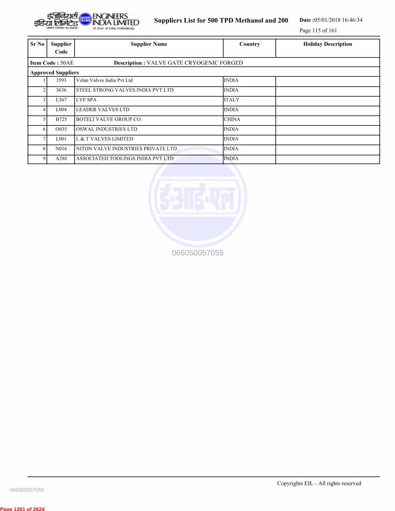
Suppliers List for 500 TPD Methanol and 200 Date :05/01/2018 16:46:34
Page 115 of 161
CountrySupplier NameSr No Holiday DescriptionSupplier
Code
Item Code : 50AE Description : VALVE GATE CRYOGENIC FORGED
Approved Suppliers
1 Velan Valves India Pvt Ltd INDIA3593
2 STEEL STRONG VALVES INDIA PVT LTD INDIA3636
3 LVF SPA ITALYL567
4 LEADER VALVES LTD INDIAL004
5 BOTELI VALVE GROUP CO. CHINAB725
6 OSWAL INDUSTRIES LTD INDIAO035
7 L & T VALVES LIMITED INDIAL001
8 NITON VALVE INDUSTRIES PRIVATE LTD . INDIAN016
9 ASSOCIATED TOOLINGS INDIA PVT LTD INDIAA288
Copyrights EIL - All rights reserved
066050057055
066050057055
Page 1261 of 2624

Suppliers List for 500 TPD Methanol and 200 Date :05/01/2018 16:46:34
Page 116 of 161
CountrySupplier NameSr No Holiday DescriptionSupplier
Code
Item Code : 50AH Description : VALVE GATE GUNMETAL/BRASS/BRONZE
Approved Suppliers
1 ZOLOTO INDUSTRIES INDIAZ12
2 SANT VALVES PVT LTD INDIAS416
3 H. SARKER & COMPANY INDIAH030
4 LEADER VALVES LTD INDIAL004
Copyrights EIL - All rights reserved
066050057055
066050057055
Page 1262 of 2624

Suppliers List for 500 TPD Methanol and 200 Date :05/01/2018 16:46:34
Page 117 of 161
CountrySupplier NameSr No Holiday DescriptionSupplier
Code
Item Code : 50AI Description : VALVE GATE (MOTOR OPERATED)
Approved Suppliers
1 BHEL (TRICHY) INDIAB015
2 INTERVALVE POONAWALLA LIMITED INDIAI125
3 KSB PUMPS LTD (COIMBATTORE) INDIAK088
4 Velan Valves India Pvt Ltd INDIA3593
5 XOMOX SANMAR LTD-PACIFIC VALVES DIVISION INDIAX104
6 LEADER VALVES LTD INDIAL004
7 Z & J TECHNOLOGIES GMBH GERMANYZ507
8 BOTELI VALVE GROUP CO. CHINAB725
9 STEEL STRONG VALVES INDIA PVT LTD INDIAS360
10 FLUIDLINE VALVES CO.PVT LTD INDIAF065
11 OSWAL INDUSTRIES LTD INDIAO035
12 CESARE BONNETTI S.P.A. ITALYC716
13 AMPO, S.COOP (POYAM VALVES) SPAINA715
14 MSA A.S. CZECH REPUBLICM678
15 L & T VALVES LIMITED INDIAL001
16 STEEL STRONG VALVES INDIA PVT LTD INDIA3636
17 AMPO VALVES INDIA PVT LTD INDIAA389
18 FRIEDRICH KROMBACH GMBH & CO.KG GERMANYF628
19 FLOWSERVE PTE(MFR. EDWARD) UNITED STATESF636A
20 NITON VALVE INDUSTRIES PRIVATE LTD . INDIAN016
21 GM ENGINEERING PVT. LTD. INDIAG186
Copyrights EIL - All rights reserved
066050057055
066050057055
Page 1263 of 2624

Suppliers List for 500 TPD Methanol and 200 Date :05/01/2018 16:46:34
Page 118 of 161
CountrySupplier NameSr No Holiday DescriptionSupplier
Code
Item Code : 50B- Description : VALVE GLOBE-(FOREIGN SUPPLIERS)
Approved Suppliers
1 MSA A.S. CZECH REPUBLICM678
2 BFE SRL ITALYB690
3 WUZHOU VALVE CO LTD CHINAW608
4 PK VALVE CO.,LTD KOREA, PEOPLE'S
DEMOCRATIC
REPUBLIC OF
P692
5 LVF SPA ITALYL567
6 FLOWSERVE PTE(MFR. EDWARD) UNITED STATESF636A
7 PETROL VALVES SRL ITALYP514
8 DOUGLAS CHERO SPA ITALYD679
9 TYCO VALVES AND CONTROLS ITALIA S.R.L ITALYT719
10 FLUITEK ORSENIGO VALVES S.P.A. ITALYF659
11 VELAN INC UNITED
KINGDOM
V517
12 KITZ CORPORATION JAPANK620A
13 FRIEDRICH KROMBACH GMBH & CO.KG GERMANYF628
14 VITAS - DIVISION OF VALVITALIA S.P.A ITALYV567
15 JC FABRICA DE VALVULAS S.A. SPAINJ555
16 JIANGSU Jiulong Valve Manufacture Co.Ltd CHINAJ565
Copyrights EIL - All rights reserved
066050057055
066050057055
Page 1264 of 2624
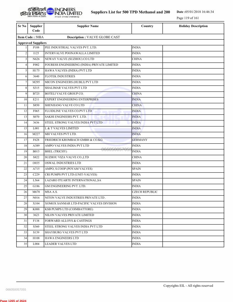
Suppliers List for 500 TPD Methanol and 200 Date :05/01/2018 16:46:34
Page 119 of 161
CountrySupplier NameSr No Holiday DescriptionSupplier
Code
Item Code : 50BA Description : VALVE GLOBE CAST
Approved Suppliers
1 PEE INDUSTRIAL VALVES PVT. LTD. INDIAP188
2 INTERVALVE POONAWALLA LIMITED INDIAI125
3 NEWAY VALVE (SUZHOU) CO LTD CHINAN626
4 FOURESS ENGINEERING (INDIA) PRIVATE LIMITED INDIAF002
5 HAWA VALVES (INDIA) PVT LTD INDIAH175
6 FLOTEK INDUSTRIES INDIA3640
7 MICON ENGINEERS (HUBLI) PVT LTD INDIAM295
8 SHALIMAR VALVES PVT LTD INDIAS315
9 BOTELI VALVE GROUP CO. CHINAB725
10 EXPERT ENGINEERING ENTERPRISES INDIAE211
11 SHENJIANG VALVE CO LTD CHINAS850
12 FLUIDLINE VALVES CO.PVT LTD INDIAF065
13 SAKHI ENGINEERS PVT. LTD. INDIAS070
14 STEEL STRONG VALVES INDIA PVT LTD INDIA3636
15 L & T VALVES LIMITED INDIAL001
16 MH VALVES PVT LTD. INDIAM227
17 FRIEDRICH KROMBACH GMBH & CO.KG GERMANYF628
18 AMPO VALVES INDIA PVT LTD INDIAA389
19 BHEL (TRICHY) INDIAB015
20 SUZHOU VIZA VALVE CO.,LTD CHINAS822
21 OSWAL INDUSTRIES LTD INDIAO035
22 AMPO, S.COOP (POYAM VALVES) SPAINA715
23 CRI PUMPS PVT LTD (UNIT-VALVES) INDIAC229
24 LAZARO ITUARTE INTERNATIONAL,SA SPAINL564
25 GM ENGINEERING PVT. LTD. INDIAG186
26 MSA A.S. CZECH REPUBLICM678
27 NITON VALVE INDUSTRIES PRIVATE LTD . INDIAN016
28 XOMOX SANMAR LTD-PACIFIC VALVES DIVISION INDIAX104
29 KSB PUMPS LTD (COIMBATTORE) INDIAK088
30 NILON VALVES PRIVATE LIMITED INDIA3623
31 FORWARD ALLOYS & CASTINGS INDIAF138
32 STEEL STRONG VALVES INDIA PVT LTD INDIAS360
33 SHAYBURG VALVES PVT LTD INDIAS139
34 HAWA ENGINEERS LTD INDIAH108
35 LEADER VALVES LTD INDIAL004
Copyrights EIL - All rights reserved
066050057055
066050057055
Page 1265 of 2624
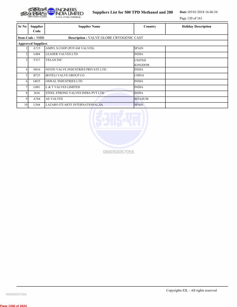
Suppliers List for 500 TPD Methanol and 200 Date :05/01/2018 16:46:34
Page 120 of 161
CountrySupplier NameSr No Holiday DescriptionSupplier
Code
Item Code : 50BB Description : VALVE GLOBE CRYOGENIC CAST
Approved Suppliers
1 AMPO, S.COOP (POYAM VALVES) SPAINA715
2 LEADER VALVES LTD INDIAL004
3 VELAN INC UNITED
KINGDOM
V517
4 NITON VALVE INDUSTRIES PRIVATE LTD . INDIAN016
5 BOTELI VALVE GROUP CO. CHINAB725
6 OSWAL INDUSTRIES LTD INDIAO035
7 L & T VALVES LIMITED INDIAL001
8 STEEL STRONG VALVES INDIA PVT LTD INDIA3636
9 AE VALVES BELGIUMA764
10 LAZARO ITUARTE INTERNATIONAL,SA SPAINL564
Copyrights EIL - All rights reserved
066050057055
066050057055
Page 1266 of 2624
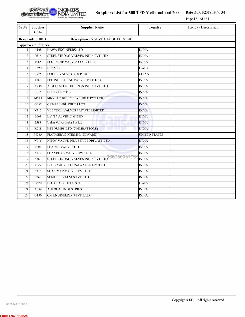
Suppliers List for 500 TPD Methanol and 200 Date :05/01/2018 16:46:34
Page 121 of 161
CountrySupplier NameSr No Holiday DescriptionSupplier
Code
Item Code : 50BD Description : VALVE GLOBE FORGED
Approved Suppliers
1 HAWA ENGINEERS LTD INDIAH108
2 STEEL STRONG VALVES INDIA PVT LTD INDIA3636
3 FLUIDLINE VALVES CO.PVT LTD INDIAF065
4 BFE SRL ITALYB690
5 BOTELI VALVE GROUP CO. CHINAB725
6 PEE INDUSTRIAL VALVES PVT. LTD. INDIAP188
7 ASSOCIATED TOOLINGS INDIA PVT LTD INDIAA288
8 BHEL (TRICHY) INDIAB015
9 MICON ENGINEERS (HUBLI) PVT LTD INDIAM295
10 OSWAL INDUSTRIES LTD INDIAO035
11 VEE TECH VALVES PRIVATE LIMITED INDIAV213
12 L & T VALVES LIMITED INDIAL001
13 Velan Valves India Pvt Ltd INDIA3593
14 KSB PUMPS LTD (COIMBATTORE) INDIAK088
15 FLOWSERVE PTE(MFR. EDWARD) UNITED STATESF636A
16 NITON VALVE INDUSTRIES PRIVATE LTD . INDIAN016
17 LEADER VALVES LTD INDIAL004
18 SHAYBURG VALVES PVT LTD INDIAS139
19 STEEL STRONG VALVES INDIA PVT LTD INDIAS360
20 INTERVALVE POONAWALLA LIMITED INDIAI125
21 SHALIMAR VALVES PVT LTD INDIAS315
22 SEMPELL VALVES PVT LTD INDIAS268
23 DOUGLAS CHERO SPA ITALYD679
24 AUTOCAP INDUSTRIES INDIAA339
25 GM ENGINEERING PVT. LTD. INDIAG186
Copyrights EIL - All rights reserved
066050057055
066050057055
Page 1267 of 2624
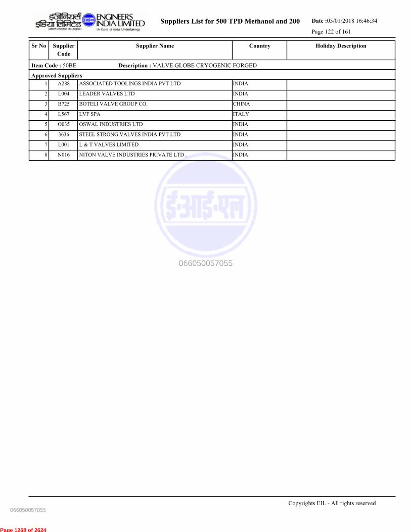
Suppliers List for 500 TPD Methanol and 200 Date :05/01/2018 16:46:34
Page 122 of 161
CountrySupplier NameSr No Holiday DescriptionSupplier
Code
Item Code : 50BE Description : VALVE GLOBE CRYOGENIC FORGED
Approved Suppliers
1 ASSOCIATED TOOLINGS INDIA PVT LTD INDIAA288
2 LEADER VALVES LTD INDIAL004
3 BOTELI VALVE GROUP CO. CHINAB725
4 LVF SPA ITALYL567
5 OSWAL INDUSTRIES LTD INDIAO035
6 STEEL STRONG VALVES INDIA PVT LTD INDIA3636
7 L & T VALVES LIMITED INDIAL001
8 NITON VALVE INDUSTRIES PRIVATE LTD . INDIAN016
Copyrights EIL - All rights reserved
066050057055
066050057055
Page 1268 of 2624

Suppliers List for 500 TPD Methanol and 200 Date :05/01/2018 16:46:34
Page 123 of 161
CountrySupplier NameSr No Holiday DescriptionSupplier
Code
Item Code : 50BH Description : VALVE GLOBE GUNMETAL/BRASS/BRONZE
Approved Suppliers
1 LEADER VALVES LTD INDIAL004
2 SANT VALVES PVT LTD INDIAS416
3 H. SARKER & COMPANY INDIAH030
Copyrights EIL - All rights reserved
066050057055
066050057055
Page 1269 of 2624

Suppliers List for 500 TPD Methanol and 200 Date :05/01/2018 16:46:34
Page 124 of 161
CountrySupplier NameSr No Holiday DescriptionSupplier
Code
Item Code : 50C- Description : VALVE CHECK- (FOREIGN SUPPLIERS)
Approved Suppliers
1 MSA A.S. CZECH REPUBLICM678
2 CESARE BONNETTI S.P.A. ITALYC716
3 HANGZHOU NEW TIME VALVE CO. LTD. CHINAH656
4 FLOWSERVE PTE(MFR. EDWARD) UNITED STATESF636A
5 JIANGSU Jiulong Valve Manufacture Co.Ltd CHINAJ565
6 FRIEDRICH KROMBACH GMBH & CO.KG GERMANYF628
7 FLUITEK ORSENIGO VALVES S.P.A. ITALYF659
8 LVF SPA ITALYL567
9 WUZHOU VALVE CO LTD CHINAW608
10 PK VALVE CO.,LTD KOREA, PEOPLE'S
DEMOCRATIC
REPUBLIC OF
P692
11 JC FABRICA DE VALVULAS S.A. SPAINJ555
12 PETROL VALVES SRL ITALYP514
13 BFE SRL ITALYB690
14 TYCO VALVES AND CONTROLS ITALIA S.R.L ITALYT719
15 TOM WHEATLEY VALVE OPERATIONS UNITED STATEST645
16 VITAS - DIVISION OF VALVITALIA S.P.A ITALYV567
17 DOUGLAS CHERO SPA ITALYD679
18 TAKAMISAWA VALVE CO LTD(ENQ TO MEC
CORPN
JAPANT541
19 VELAN INC UNITED
KINGDOM
V517
Copyrights EIL - All rights reserved
066050057055
066050057055
Page 1270 of 2624

Suppliers List for 500 TPD Methanol and 200 Date :05/01/2018 16:46:34
Page 125 of 161
CountrySupplier NameSr No Holiday DescriptionSupplier
Code
Item Code : 50CA Description : VALVE CHECK CAST
Approved Suppliers
1 SHAYBURG VALVES PVT LTD INDIAS139
2 STEEL STRONG VALVES INDIA PVT LTD INDIAS360
3 LEADER VALVES LTD INDIAL004
4 SAKHI ENGINEERS PVT. LTD. INDIAS070
5 SUZHOU VIZA VALVE CO.,LTD CHINAS822
6 FRIEDRICH KROMBACH GMBH & CO.KG GERMANYF628
7 KSB PUMPS LTD (COIMBATTORE) INDIAK088
8 PEE INDUSTRIAL VALVES PVT. LTD. INDIAP188
9 CRI PUMPS PVT LTD (UNIT-VALVES) INDIAC229
10 HAWA VALVES (INDIA) PVT LTD INDIAH175
11 SHALIMAR VALVES PVT LTD INDIAS315
12 LAZARO ITUARTE INTERNATIONAL,SA SPAINL564
13 BOTELI VALVE GROUP CO. CHINAB725
14 XOMOX SANMAR LTD-PACIFIC VALVES DIVISION INDIAX104
15 INTERVALVE POONAWALLA LIMITED INDIAI125
16 STEEL STRONG VALVES INDIA PVT LTD INDIA3636
17 FORWARD ALLOYS & CASTINGS INDIAF138
18 OSWAL INDUSTRIES LTD INDIAO035
19 AMPO, S.COOP (POYAM VALVES) SPAINA715
20 FLUIDLINE VALVES CO.PVT LTD INDIAF065
21 NILON VALVES PRIVATE LIMITED INDIA3623
22 GESTRA AG (FLOWSERVE GROUP) GERMANYG544
23 T.S. PUMPS AND VALVES PVT.LTD INDIAT238
24 MICON ENGINEERS (HUBLI) PVT LTD INDIAM295
25 MSA A.S. CZECH REPUBLICM678
26 NITON VALVE INDUSTRIES PRIVATE LTD . INDIAN016
27 HAWA ENGINEERS LTD INDIAH108
28 MH VALVES PVT LTD. INDIAM227
29 NEWAY VALVE (SUZHOU) CO LTD CHINAN626
30 AMPO VALVES INDIA PVT LTD INDIAA389
31 FLOTEK INDUSTRIES INDIA3640
32 SHENJIANG VALVE CO LTD CHINAS850
33 GM ENGINEERING PVT. LTD. INDIAG186
34 FOURESS ENGINEERING (INDIA) PRIVATE LIMITED INDIAF002
35 CESARE BONNETTI S.P.A. ITALYC716
36 L & T VALVES LIMITED INDIAL001
37 BHEL (TRICHY) INDIAB015
38 Velan Valves India Pvt Ltd INDIA3593
Copyrights EIL - All rights reserved
066050057055
066050057055
Page 1271 of 2624
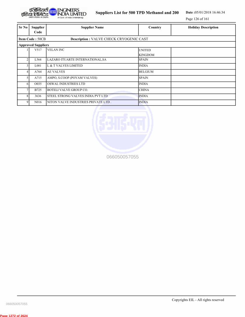
Suppliers List for 500 TPD Methanol and 200 Date :05/01/2018 16:46:34
Page 126 of 161
CountrySupplier NameSr No Holiday DescriptionSupplier
Code
Item Code : 50CB Description : VALVE CHECK CRYOGENIC CAST
Approved Suppliers
1 VELAN INC UNITED
KINGDOM
V517
2 LAZARO ITUARTE INTERNATIONAL,SA SPAINL564
3 L & T VALVES LIMITED INDIAL001
4 AE VALVES BELGIUMA764
5 AMPO, S.COOP (POYAM VALVES) SPAINA715
6 OSWAL INDUSTRIES LTD INDIAO035
7 BOTELI VALVE GROUP CO. CHINAB725
8 STEEL STRONG VALVES INDIA PVT LTD INDIA3636
9 NITON VALVE INDUSTRIES PRIVATE LTD . INDIAN016
Copyrights EIL - All rights reserved
066050057055
066050057055
Page 1272 of 2624
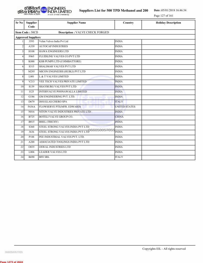
Suppliers List for 500 TPD Methanol and 200 Date :05/01/2018 16:46:34
Page 127 of 161
CountrySupplier NameSr No Holiday DescriptionSupplier
Code
Item Code : 50CD Description : VALVE CHECK FORGED
Approved Suppliers
1 Velan Valves India Pvt Ltd INDIA3593
2 AUTOCAP INDUSTRIES INDIAA339
3 HAWA ENGINEERS LTD INDIAH108
4 FLUIDLINE VALVES CO.PVT LTD INDIAF065
5 KSB PUMPS LTD (COIMBATTORE) INDIAK088
6 SHALIMAR VALVES PVT LTD INDIAS315
7 MICON ENGINEERS (HUBLI) PVT LTD INDIAM295
8 L & T VALVES LIMITED INDIAL001
9 VEE TECH VALVES PRIVATE LIMITED INDIAV213
10 SHAYBURG VALVES PVT LTD INDIAS139
11 INTERVALVE POONAWALLA LIMITED INDIAI125
12 GM ENGINEERING PVT. LTD. INDIAG186
13 DOUGLAS CHERO SPA ITALYD679
14 FLOWSERVE PTE(MFR. EDWARD) UNITED STATESF636A
15 NITON VALVE INDUSTRIES PRIVATE LTD . INDIAN016
16 BOTELI VALVE GROUP CO. CHINAB725
17 BHEL (TRICHY) INDIAB015
18 STEEL STRONG VALVES INDIA PVT LTD INDIAS360
19 STEEL STRONG VALVES INDIA PVT LTD INDIA3636
20 PEE INDUSTRIAL VALVES PVT. LTD. INDIAP188
21 ASSOCIATED TOOLINGS INDIA PVT LTD INDIAA288
22 OSWAL INDUSTRIES LTD INDIAO035
23 LEADER VALVES LTD INDIAL004
24 BFE SRL ITALYB690
Copyrights EIL - All rights reserved
066050057055
066050057055
Page 1273 of 2624
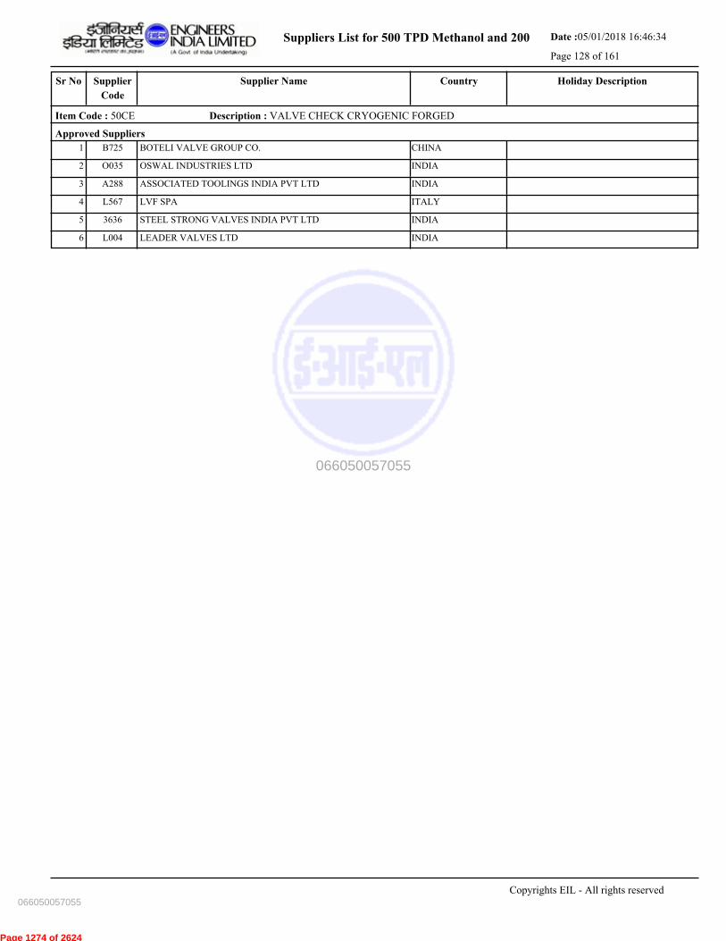
Suppliers List for 500 TPD Methanol and 200 Date :05/01/2018 16:46:34
Page 128 of 161
CountrySupplier NameSr No Holiday DescriptionSupplier
Code
Item Code : 50CE Description : VALVE CHECK CRYOGENIC FORGED
Approved Suppliers
1 BOTELI VALVE GROUP CO. CHINAB725
2 OSWAL INDUSTRIES LTD INDIAO035
3 ASSOCIATED TOOLINGS INDIA PVT LTD INDIAA288
4 LVF SPA ITALYL567
5 STEEL STRONG VALVES INDIA PVT LTD INDIA3636
6 LEADER VALVES LTD INDIAL004
Copyrights EIL - All rights reserved
066050057055
066050057055
Page 1274 of 2624

Suppliers List for 500 TPD Methanol and 200 Date :05/01/2018 16:46:34
Page 129 of 161
CountrySupplier NameSr No Holiday DescriptionSupplier
Code
Item Code : 50CH Description : VALVE CHECK GUNMETAL/BRASS/BRONZE
Approved Suppliers
1 H. SARKER & COMPANY INDIAH030
2 SANT VALVES PVT LTD INDIAS416
3 LEADER VALVES LTD INDIAL004
Copyrights EIL - All rights reserved
066050057055
066050057055
Page 1275 of 2624
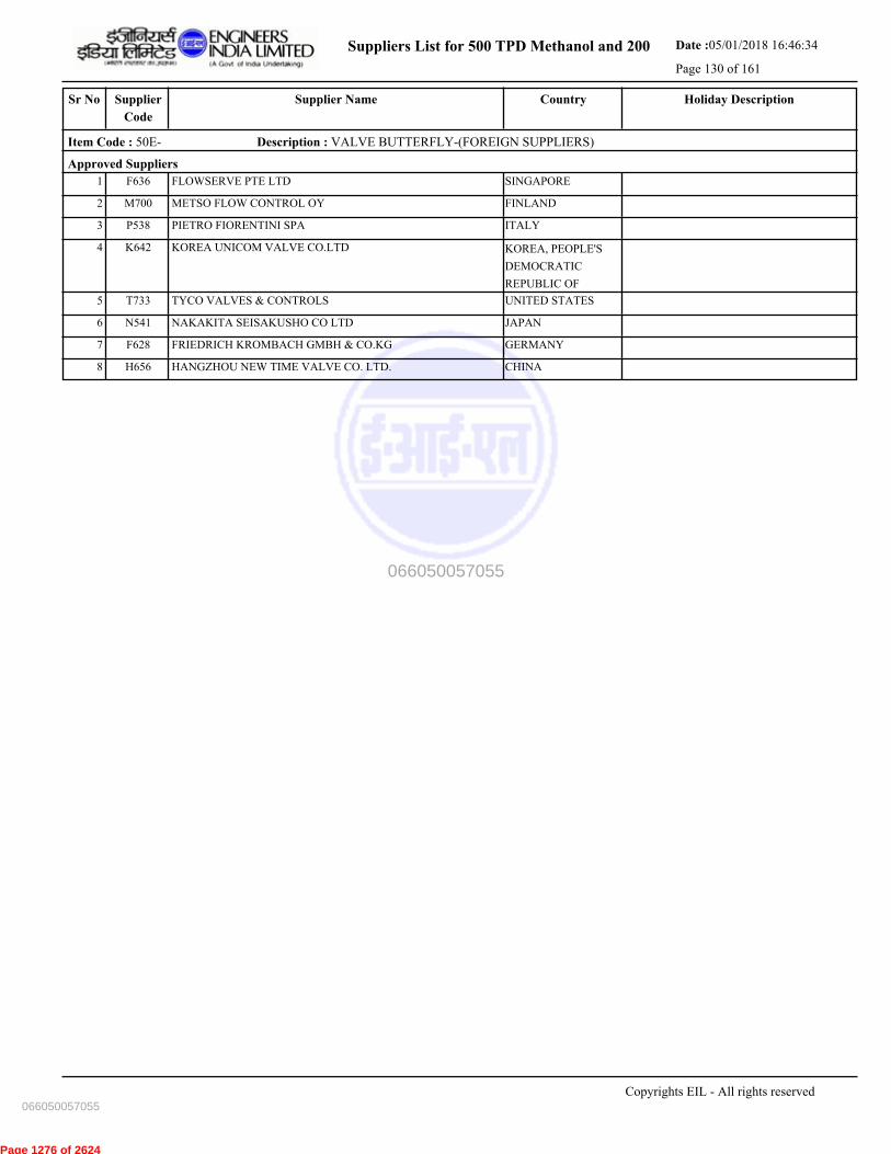
Suppliers List for 500 TPD Methanol and 200 Date :05/01/2018 16:46:34
Page 130 of 161
CountrySupplier NameSr No Holiday DescriptionSupplier
Code
Item Code : 50E- Description : VALVE BUTTERFLY-(FOREIGN SUPPLIERS)
Approved Suppliers
1 FLOWSERVE PTE LTD SINGAPOREF636
2 METSO FLOW CONTROL OY FINLANDM700
3 PIETRO FIORENTINI SPA ITALYP538
4 KOREA UNICOM VALVE CO.LTD KOREA, PEOPLE'S
DEMOCRATIC
REPUBLIC OF
K642
5 TYCO VALVES & CONTROLS UNITED STATEST733
6 NAKAKITA SEISAKUSHO CO LTD JAPANN541
7 FRIEDRICH KROMBACH GMBH & CO.KG GERMANYF628
8 HANGZHOU NEW TIME VALVE CO. LTD. CHINAH656
Copyrights EIL - All rights reserved
066050057055
066050057055
Page 1276 of 2624

Suppliers List for 500 TPD Methanol and 200 Date :05/01/2018 16:46:34
Page 131 of 161
CountrySupplier NameSr No Holiday DescriptionSupplier
Code
Item Code : 50EB Description : VALVE BUTTERFLY - CCS
Approved Suppliers
1 ORTON S.R.L ITALYO538
2 NEWAY VALVE (SUZHOU) CO LTD CHINAN626
3 METSO FLOW CONTROL OY FINLANDM700
4 L & T VALVES LIMITED INDIAL001
5 INSTRUMENTATION LTD. (PALGHAT) INDIAI172
6 FLOWSERVE PTE LTD SINGAPOREF636
7 FOURESS ENGG.(INDIA) LTD.(BLR.WORK ) INDIAF030
8 PENTAIR VALVES & CONTROLS INDIA PVT LTD INDIAT198
9 BRAY CONTROLS UNITED STATESB729
10 BRAY CONTROLS INDIA PVT LTD INDIA3613
11 MASCOT VALVES PVT LIMITED (FMLY VALFLO) INDIAM015
12 FLOWSERVE INDIA CONTROLS PVT LTD-MMN INDIAF193
13 DELVAL FLOW CONTROLS PRIVATE LIMITED INDIAD146
14 INTERVALVE POONAWALLA LIMITED INDIAI125
15 FLUIDLINE VALVES CO.PVT LTD INDIAF065
16 DEMBLA VALVES LIMITED INDIA3616
17 FLOTEK INDUSTRIES INDIA3640
18 STAFFORD CONTROLS LIMITED INDIAS487
19 LEADER VALVES LTD INDIAL004
20 FRIEDRICH KROMBACH GMBH & CO.KG GERMANYF628
21 GM ENGINEERING PVT. LTD. INDIAG186
22 DEMBLA VALVES LTD. INDIAD037
23 CRANE PROCESS FLOW TECHNOLOGIES IND. LTD INDIAC186
24 ADVANCE VALVES PVT LTD. INDIAA315
25 HAWA ENGINEERS LTD INDIAH108
Copyrights EIL - All rights reserved
066050057055
066050057055
Page 1277 of 2624
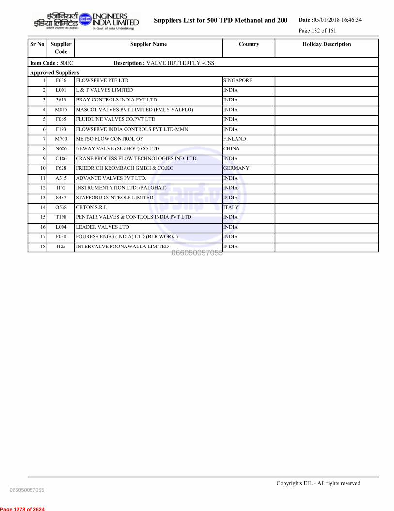
Suppliers List for 500 TPD Methanol and 200 Date :05/01/2018 16:46:34
Page 132 of 161
CountrySupplier NameSr No Holiday DescriptionSupplier
Code
Item Code : 50EC Description : VALVE BUTTERFLY -CSS
Approved Suppliers
1 FLOWSERVE PTE LTD SINGAPOREF636
2 L & T VALVES LIMITED INDIAL001
3 BRAY CONTROLS INDIA PVT LTD INDIA3613
4 MASCOT VALVES PVT LIMITED (FMLY VALFLO) INDIAM015
5 FLUIDLINE VALVES CO.PVT LTD INDIAF065
6 FLOWSERVE INDIA CONTROLS PVT LTD-MMN INDIAF193
7 METSO FLOW CONTROL OY FINLANDM700
8 NEWAY VALVE (SUZHOU) CO LTD CHINAN626
9 CRANE PROCESS FLOW TECHNOLOGIES IND. LTD INDIAC186
10 FRIEDRICH KROMBACH GMBH & CO.KG GERMANYF628
11 ADVANCE VALVES PVT LTD. INDIAA315
12 INSTRUMENTATION LTD. (PALGHAT) INDIAI172
13 STAFFORD CONTROLS LIMITED INDIAS487
14 ORTON S.R.L ITALYO538
15 PENTAIR VALVES & CONTROLS INDIA PVT LTD INDIAT198
16 LEADER VALVES LTD INDIAL004
17 FOURESS ENGG.(INDIA) LTD.(BLR.WORK ) INDIAF030
18 INTERVALVE POONAWALLA LIMITED INDIAI125
Copyrights EIL - All rights reserved
066050057055
066050057055
Page 1278 of 2624
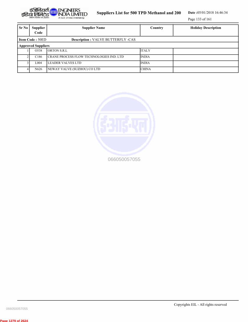
Suppliers List for 500 TPD Methanol and 200 Date :05/01/2018 16:46:34
Page 133 of 161
CountrySupplier NameSr No Holiday DescriptionSupplier
Code
Item Code : 50ED Description : VALVE BUTTERFLY -CAS
Approved Suppliers
1 ORTON S.R.L ITALYO538
2 CRANE PROCESS FLOW TECHNOLOGIES IND. LTD INDIAC186
3 LEADER VALVES LTD INDIAL004
4 NEWAY VALVE (SUZHOU) CO LTD CHINAN626
Copyrights EIL - All rights reserved
066050057055
066050057055
Page 1279 of 2624
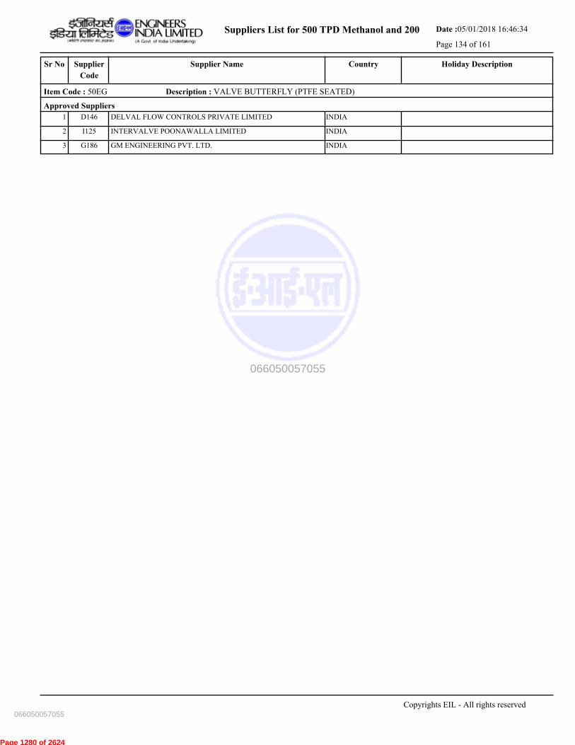
Suppliers List for 500 TPD Methanol and 200 Date :05/01/2018 16:46:34
Page 134 of 161
CountrySupplier NameSr No Holiday DescriptionSupplier
Code
Item Code : 50EG Description : VALVE BUTTERFLY (PTFE SEATED)
Approved Suppliers
1 DELVAL FLOW CONTROLS PRIVATE LIMITED INDIAD146
2 INTERVALVE POONAWALLA LIMITED INDIAI125
3 GM ENGINEERING PVT. LTD. INDIAG186
Copyrights EIL - All rights reserved
066050057055
066050057055
Page 1280 of 2624

Suppliers List for 500 TPD Methanol and 200 Date :05/01/2018 16:46:34
Page 135 of 161
CountrySupplier NameSr No Holiday DescriptionSupplier
Code
Item Code : 50G- Description : VALVE PLUG-(FOREIGN SUPPLIERS)
Approved Suppliers
1 FLOWSERVE PTE (MFR. SERCK) UNITED
KINGDOM
F636B
2 HANGZHOU NEW TIME VALVE CO. LTD. CHINAH656
3 FLOWSERVE PTE LTD SINGAPOREF636
Copyrights EIL - All rights reserved
066050057055
066050057055
Page 1281 of 2624

Suppliers List for 500 TPD Methanol and 200 Date :05/01/2018 16:46:34
Page 136 of 161
CountrySupplier NameSr No Holiday DescriptionSupplier
Code
Item Code : 50GA Description : VALVE PLUG CONCENTRIC- CCS (F.S & N.F.S)
Approved Suppliers
1 RASAII FLOW LINES PVT LTD. INDIAR123
2 CHEMTROLS SAMIL (INDIA) PVT LTD INDIAC201
3 XOMOX SANMAR LIMITED INDIAX001
4 FLOWSERVE INDIA CONTROLS PVT LTD-MMN INDIAF193
5 GALLI & CASSINA SPA ITALYG608
6 ZHEJIANG FLOWTECH MACHINERY CO.LTD CHINAZ639
7 FLOWSERVE PTE (MFR. SERCK) UNITED
KINGDOM
F636B
8 FLOWSERVE PTE LTD SINGAPOREF636
9 GM ENGINEERING PVT. LTD. INDIAG186
Copyrights EIL - All rights reserved
066050057055
066050057055
Page 1282 of 2624

Suppliers List for 500 TPD Methanol and 200 Date :05/01/2018 16:46:34
Page 137 of 161
CountrySupplier NameSr No Holiday DescriptionSupplier
Code
Item Code : 50GB Description : VALVE PLUG CONCENTRIC -CSS (F.S & N.F.S)
Approved Suppliers
1 RASAII FLOW LINES PVT LTD. INDIAR123
2 FLOWSERVE INDIA CONTROLS PVT LTD-MMN INDIAF193
3 XOMOX SANMAR LIMITED INDIAX001
4 CHEMTROLS SAMIL (INDIA) PVT LTD INDIAC201
5 FLOWSERVE PTE (MFR. SERCK) UNITED
KINGDOM
F636B
6 FLOWSERVE PTE LTD SINGAPOREF636
Copyrights EIL - All rights reserved
066050057055
066050057055
Page 1283 of 2624

Suppliers List for 500 TPD Methanol and 200 Date :05/01/2018 16:46:34
Page 138 of 161
CountrySupplier NameSr No Holiday DescriptionSupplier
Code
Item Code : 50GC Description : VALVE PLUG CONCENTRIC-CAS(F.S. & N.F.S.)
Approved Suppliers
1 FLOWSERVE PTE (MFR. SERCK) UNITED
KINGDOM
F636B
2 XOMOX SANMAR LIMITED INDIAX001
3 FLOWSERVE PTE LTD SINGAPOREF636
Copyrights EIL - All rights reserved
066050057055
066050057055
Page 1284 of 2624

Suppliers List for 500 TPD Methanol and 200 Date :05/01/2018 16:46:34
Page 139 of 161
CountrySupplier NameSr No Holiday DescriptionSupplier
Code
Item Code : 50GQ Description : VALVE PLUG MULTIPORT - NON FIRE SAFE
Approved Suppliers
1 FLOWSERVE PTE LTD SINGAPOREF636
2 XOMOX SANMAR LIMITED INDIAX001
3 FLOWSERVE PTE (MFR. SERCK) UNITED
KINGDOM
F636B
Copyrights EIL - All rights reserved
066050057055
066050057055
Page 1285 of 2624

Suppliers List for 500 TPD Methanol and 200 Date :05/01/2018 16:46:34
Page 140 of 161
CountrySupplier NameSr No Holiday DescriptionSupplier
Code
Item Code : 55AA Description : FLANGE- CARBON STEEL
Approved Suppliers
1 PARAMOUNT FORGE INDIAP242A
2 ITM S.R.L. ITALYI604
3 JAI AUTO PVT LTD. INDIA3628
4 VILMAR SA ROMANIAV633
5 VALVITALIA SPA-TECNOFORGE DIVISION ITALYV608A
6 BRUCK GMBH ENSHEIM GERMANYB745
7 R.N.GUPTA & CO. LTD INDIAR186
8 CHW FORGE PVT LTD (FR. CHAUDHRY HAMMER) INDIAC044
9 P.K.TUBES & FITTINGS PVT.LTD. INDIAP315
10 KISAAN DIETECH PVT LTD INDIAK189
11 SANGHVI FORGINGS & ENGINEERING LTD INDIAS394
12 METAL FORGINGS PVT LTD INDIAM011
13 HILTON METAL FORGING LIMITED INDIAH172
14 KISAAN STEEL (P) LTD INDIAK180
15 M.S. FITTINGS MFG. CO PVT LTD INDIAM057
16 BHARAT FORGE LTD. INDIAB020
17 TRIVENI REFRACTORIES PVT LTD INDIAT245
18 KUNJ FORGINGS PVT LTD INDIAK108
19 PRADEEP METAL LIMITED INDIAP215
20 CD ENGINEERING CO. INDIAC142
21 MELESI OFFICINE AMBROGIO MELESI & C.SRL ITALYM680
22 KOREA FLANGE CO., LTD. KOREA, REPUBLIC
OF
K638
23 MAASS FLANGE INDIA PVT. LTD INDIAM308
24 OFFICINE NICOLA GALPERTI & FIGLIO S.P.A. ITALYN593
25 LAL METAL FORGE LTD INDIAL089
26 BRITEX ENGINEERING WORKS INDIA3617
27 ANANDMAYEE FORGINGS PVT LTD INDIAA066
28 ULMA FORJA S.COOP. SPAINU537
29 CD INDUSTRIES (PROP KISAAN ENGINEERING
WORKS PVT. LIMITED)
INDIAC159
30 PARAMOUNT FORGE INDIAP242
31 PROMAT BD LTD MIDDLE EAST UNITED
KINGDOM
P708
32 UTSAH ENGINEERING PVT LTD(A CD ENGG COMP INDIAU116
33 ABASI ENGINEERING WORKS INDIAA074
34 GOOD LUCK ENGINEERING CO. INDIAG182
35 R D FORGE INDIAR205
36 ECHJAY INDUSTRIES PVT LTD. (RAJKOT) INDIAE016
37 JAV FORGINGS (P) LTD INDIAJ067
38 FIVEBROS FORGINGS PVT.LTD. INDIAF180
Copyrights EIL - All rights reserved
066050057055
066050057055
Page 1286 of 2624

Suppliers List for 500 TPD Methanol and 200 Date :05/01/2018 16:46:34
Page 141 of 161
CountrySupplier NameSr No Holiday DescriptionSupplier
Code
Item Code : 55AA Description : FLANGE- CARBON STEEL
39 OFFICINE SANTAFEDE SRL ITALYO595
Copyrights EIL - All rights reserved
066050057055
066050057055
Page 1287 of 2624

Suppliers List for 500 TPD Methanol and 200 Date :05/01/2018 16:46:34
Page 142 of 161
CountrySupplier NameSr No Holiday DescriptionSupplier
Code
Item Code : 55AC Description : FLANGE-STAINLESS STEEL
Approved Suppliers
1 LAL METAL FORGE LTD INDIAL089
2 ULMA FORJA S.COOP. SPAINU537
3 P.K.TUBES & FITTINGS PVT.LTD. INDIAP315
4 OFFICINE NICOLA GALPERTI & FIGLIO S.P.A. ITALYN593
5 JAV FORGINGS (P) LTD INDIAJ067
6 METAL FORGINGS PVT LTD INDIAM011
7 CHW FORGE PVT LTD (FR. CHAUDHRY HAMMER) INDIAC044
8 KISAAN DIETECH PVT LTD INDIAK189
9 OFFICINE SANTAFEDE SRL ITALYO595
10 CD INDUSTRIES (PROP KISAAN ENGINEERING
WORKS PVT. LIMITED)
INDIAC159
11 MAASS FLANGE INDIA PVT. LTD INDIAM308
12 R D FORGE INDIAR205
13 MAASS FLANGE CORPORATION UNITED STATESM726
14 PARAMOUNT FORGE INDIAP242
15 SANGHVI FORGINGS & ENGINEERING LTD INDIAS394
16 FIVEBROS FORGINGS PVT.LTD. INDIAF180
17 GOOD LUCK ENGINEERING CO. INDIAG182
18 HILTON METAL FORGING LIMITED INDIAH172
19 ECHJAY INDUSTRIES PVT LTD. (RAJKOT) INDIAE016
20 VILMAR SA ROMANIAV633
21 UTSAH ENGINEERING PVT LTD(A CD ENGG COMP INDIAU116
22 VIRAJ PROFILES LIMITED INDIAV189
23 MELESI OFFICINE AMBROGIO MELESI & C.SRL ITALYM680
24 BHARAT FORGE LTD. INDIAB020
25 KOREA FLANGE CO., LTD. KOREA, REPUBLIC
OF
K638
26 PARAMOUNT FORGE INDIAP242A
27 PRADEEP METAL LIMITED INDIAP215
28 CHANDAN STEEL LTD INDIAC227
29 VALVITALIA SPA-TECNOFORGE DIVISION ITALYV608A
30 KISAAN STEEL (P) LTD INDIAK180
31 ANANDMAYEE FORGINGS PVT LTD INDIAA066
32 CD ENGINEERING CO. INDIAC142
33 KUNJ FORGINGS PVT LTD INDIAK108
34 BRUCK GMBH ENSHEIM GERMANYB745
Copyrights EIL - All rights reserved
066050057055
066050057055
Page 1288 of 2624

Suppliers List for 500 TPD Methanol and 200 Date :05/01/2018 16:46:34
Page 143 of 161
CountrySupplier NameSr No Holiday DescriptionSupplier
Code
Item Code : 60A- Description : PIPES-FOREIGN AGENTS/STOCKIST/TRADERS
Approved Suppliers
1 PETROGAS PIPING MIDDLE EAST FZCO UNITED ARAB
EMIRATES
P698
2 HART BV NETHERLANDSH648
3 KIRTANLAL INTERNATIONAL DMCC UNITED ARAB
EMIRATES
K648
4 HORST KURVERS GMBH UNITED
KINGDOM
H549
5 AMERICAN PIPING PRODUCTS INC UNITED STATESA753
6 INTERNATIONAL INDUSTRIAL EQPT FZCO. UNITED ARAB
EMIRATES
I609
7 GERAB NATIONAL ENTERPRISE L.L.C UNITED ARAB
EMIRATES
G616
8 ARROW PIPES & FITTINGS FZCO UNITED ARAB
EMIRATES
A748
9 COMMERCIALE TUBI ACCIAIO SPA ITALYC727
10 TECHNICAL PARTS ESTABLISHMENT UNITED ARAB
EMIRATES
T696
11 VAN LEEUWEN BUIZEN FRANCEV569
12 BARTHEL KESSELROHRE BOILERTUBES GMBH GERMANYB721
13 BUHLMANN ROHR-FITTINGS-STAHLHANDEL
GMBH
GERMANYB741
14 SIDECO SPA ITALYS743
15 EDGEN MURRAY FZE UNITED ARAB
EMIRATES
E631
16 IGAWARA INDL. SERVICES & TRADING PTE LTD JAPANI594
17 MEZON STAINLESS STEEL FZE UNITED ARAB
EMIRATES
M734
18 Peeraj General Trading CO (LLC) UNITED ARAB
EMIRATES
P686
19 OFFSHORE ENGINEERING & MARKETING LTD. UNITED ARAB
EMIRATES
O554
20 MARDALE PIPES PLUS LIMITED UNITED
KINGDOM
M658
Copyrights EIL - All rights reserved
066050057055
066050057055
Page 1289 of 2624

Suppliers List for 500 TPD Methanol and 200 Date :05/01/2018 16:46:34
Page 144 of 161
CountrySupplier NameSr No Holiday DescriptionSupplier
Code
Item Code : 60AF Description : PIPE-CARBON STEEL TO INDIAN STANDARDS
Approved Suppliers
1 NEZONE TUBES LIMITED INDIAN118
2 LALIT PIPES AND PIPES LTD. INDIAL061
3 ASIAN MILLS PVT LTD INDIAA332
4 SWASTIK PIPES LTD INDIAS214
5 WELSPUN CORP LIMITED (DAHEJ) INDIAW056
6 INDUS TUBES LIMITED INDIAI147
7 ZENITH BIRLA (INDIA) LIMITED INDIAZ14
8 ASRANI TUBES LIMITED INDIAA366
9 RAMA STEEL TUBES LTD. INDIAR193
10 MUKAT TANKS & VESSELS PVT LTD INDIAM188
11 ASIAN TUBES LTD. INDIAA397
12 SURYA ROSHNI LTD INDIAS281
13 NORTH EASTERN TUBES LIMITED INDIAN116
14 MAHARASHTRA SEAMLESS LTD. INDIAM187
15 RAVINDRA TUBES LIMITED INDIAR198
16 APL APOLLO TUBES LTD (ER.BIHAR TUBES LTD INDIAA380
17 UTKARSH INDIA LIMITED INDIAU105
18 SAMSHI PIPE INDUSTRIES LIMITED INDIAS106
19 RATNAMANI METALS AND TUBES LTD INDIAR066
20 GOODLUCK INDIA LIMITED INDIAG145
21 JINDAL (INDIA) LIMITED INDIAJ115
22 JINDAL SAW LTD (KOSI WORKS) INDIAJ110A
23 LAL BABA SEAMLESS TUBES PVT. LTD INDIAL127
24 JCO GAS PIPE LIMITED INDIA3611
25 A.S.T. PIPES PVT. LTD.(AST GROUP) INDIAA341
26 PRATIBHA INDUSTRIES LIMITED INDIAP317
27 JINDAL PIPES LTD INDIAJ015
28 WELSPUN CORP LIMITED (ANJAR) INDIAW056A
29 P S STEEL TUBES LTD INDIAP331
30 MAN INDUSTRIES (INDIA) LTD INDIAM217A
31 DADU PIPES (P) LTD INDIAD145
32 JINDAL INDUSTRIES LTD INDIAJ111
33 ESSAR STEEL INDIA LIMITED INDIAE139
Copyrights EIL - All rights reserved
066050057055
066050057055
Page 1290 of 2624
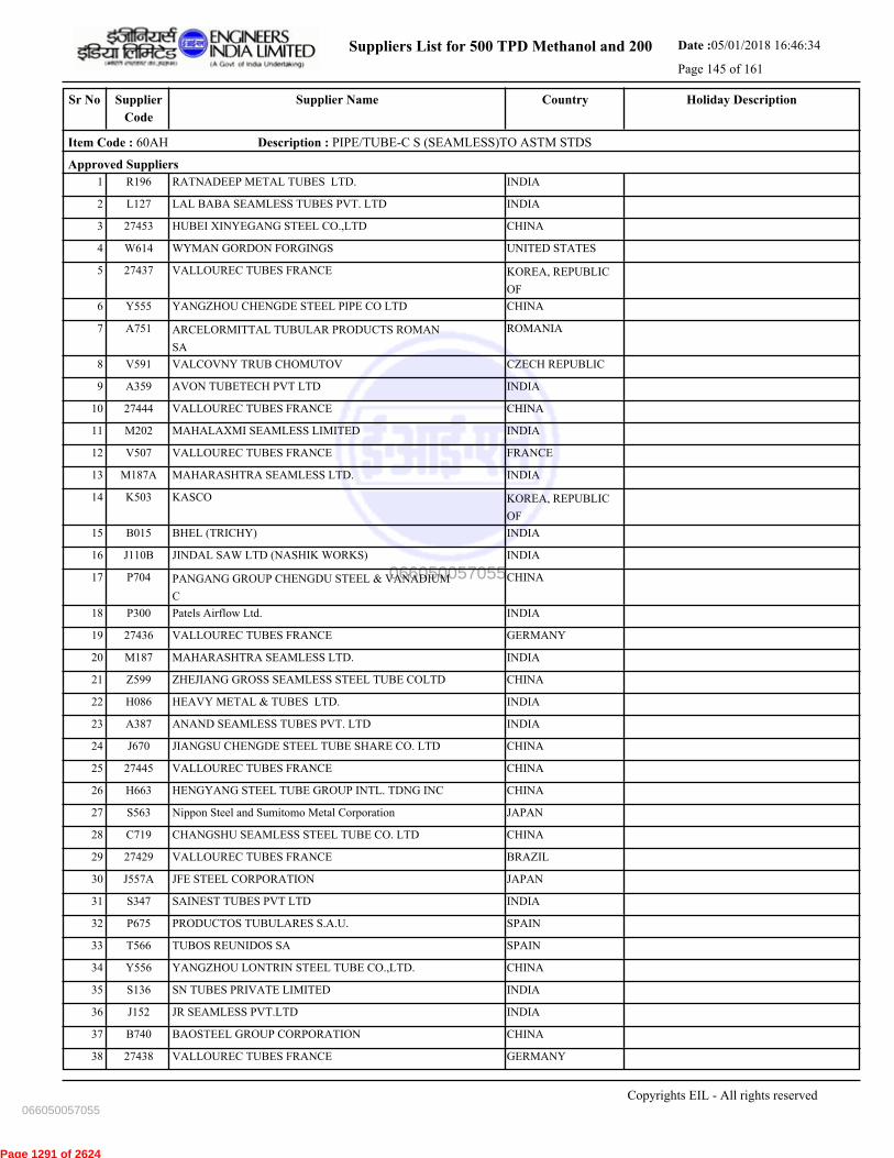
Suppliers List for 500 TPD Methanol and 200 Date :05/01/2018 16:46:34
Page 145 of 161
CountrySupplier NameSr No Holiday DescriptionSupplier
Code
Item Code : 60AH Description : PIPE/TUBE-C S (SEAMLESS)TO ASTM STDS
Approved Suppliers
1 RATNADEEP METAL TUBES LTD. INDIAR196
2 LAL BABA SEAMLESS TUBES PVT. LTD INDIAL127
3 HUBEI XINYEGANG STEEL CO.,LTD CHINA27453
4 WYMAN GORDON FORGINGS UNITED STATESW614
5 VALLOUREC TUBES FRANCE KOREA, REPUBLIC
OF
27437
6 YANGZHOU CHENGDE STEEL PIPE CO LTD CHINAY555
7 ARCELORMITTAL TUBULAR PRODUCTS ROMAN
SA
ROMANIAA751
8 VALCOVNY TRUB CHOMUTOV CZECH REPUBLICV591
9 AVON TUBETECH PVT LTD INDIAA359
10 VALLOUREC TUBES FRANCE CHINA27444
11 MAHALAXMI SEAMLESS LIMITED INDIAM202
12 VALLOUREC TUBES FRANCE FRANCEV507
13 MAHARASHTRA SEAMLESS LTD. INDIAM187A
14 KASCO KOREA, REPUBLIC
OF
K503
15 BHEL (TRICHY) INDIAB015
16 JINDAL SAW LTD (NASHIK WORKS) INDIAJ110B
17 PANGANG GROUP CHENGDU STEEL & VANADIUM
C
CHINAP704
18 Patels Airflow Ltd. INDIAP300
19 VALLOUREC TUBES FRANCE GERMANY27436
20 MAHARASHTRA SEAMLESS LTD. INDIAM187
21 ZHEJIANG GROSS SEAMLESS STEEL TUBE COLTD CHINAZ599
22 HEAVY METAL & TUBES LTD. INDIAH086
23 ANAND SEAMLESS TUBES PVT. LTD INDIAA387
24 JIANGSU CHENGDE STEEL TUBE SHARE CO. LTD CHINAJ670
25 VALLOUREC TUBES FRANCE CHINA27445
26 HENGYANG STEEL TUBE GROUP INTL. TDNG INC CHINAH663
27 Nippon Steel and Sumitomo Metal Corporation JAPANS563
28 CHANGSHU SEAMLESS STEEL TUBE CO. LTD CHINAC719
29 VALLOUREC TUBES FRANCE BRAZIL27429
30 JFE STEEL CORPORATION JAPANJ557A
31 SAINEST TUBES PVT LTD INDIAS347
32 PRODUCTOS TUBULARES S.A.U. SPAINP675
33 TUBOS REUNIDOS SA SPAINT566
34 YANGZHOU LONTRIN STEEL TUBE CO.,LTD. CHINAY556
35 SN TUBES PRIVATE LIMITED INDIAS136
36 JR SEAMLESS PVT.LTD INDIAJ152
37 BAOSTEEL GROUP CORPORATION CHINAB740
38 VALLOUREC TUBES FRANCE GERMANY27438
Copyrights EIL - All rights reserved
066050057055
066050057055
Page 1291 of 2624
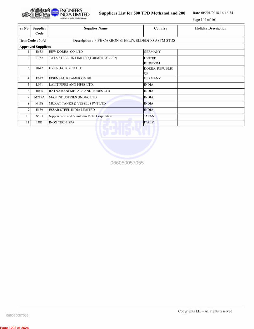
Suppliers List for 500 TPD Methanol and 200 Date :05/01/2018 16:46:34
Page 146 of 161
CountrySupplier NameSr No Holiday DescriptionSupplier
Code
Item Code : 60AI Description : PIPE-CARBON STEEL(WELDED)TO ASTM STDS
Approved Suppliers
1 EEW KOREA CO. LTD GERMANYE633
2 TATA STEEL UK LIMITED(FORMERLY C702) UNITED
KINGDOM
T752
3 HYUNDAI RB CO.LTD KOREA, REPUBLIC
OF
H642
4 EISENBAU KRAMER GMBH GERMANYE627
5 LALIT PIPES AND PIPES LTD. INDIAL061
6 RATNAMANI METALS AND TUBES LTD INDIAR066
7 MAN INDUSTRIES (INDIA) LTD INDIAM217A
8 MUKAT TANKS & VESSELS PVT LTD INDIAM188
9 ESSAR STEEL INDIA LIMITED INDIAE139
10 Nippon Steel and Sumitomo Metal Corporation JAPANS563
11 INOX TECH. SPA ITALYI583
Copyrights EIL - All rights reserved
066050057055
066050057055
Page 1292 of 2624

Suppliers List for 500 TPD Methanol and 200 Date :05/01/2018 16:46:34
Page 147 of 161
CountrySupplier NameSr No Holiday DescriptionSupplier
Code
Item Code : 60AK Description : PIPE/TUBE-SS(S.LESS & WELDED)TO ASTM STD
Approved Suppliers
1 WILH SCHULZ GmbH GERMANYW510
2 SURAJ LIMITED INDIAS406
3 ZHEJIANG STELLAR PIPE IND. CO LTD. CHINAZ598
4 SANDVIK AB SWEDENS594
5 ZHEJIANG JIULI HI-TECH METALS CO., LTD. CHINAZ515
6 SANDVIK ASIA PVT. LIMITED (AHMEDABAD) INDIAS445
7 PRODUCTOS TUBULARES S.A.U. SPAINP675
8 ARVIND PIPES & FITTINGS IND PVT LTD INDIAA262
9 RATNAMANI METALS AND TUBES LTD INDIAR066
10 SANDVIK MATERIALS TECHNOLOGY (CHINA),CO, CHINAS857
11 INOX TECH. SPA ITALYI583
12 SHUBHLAXMI METALS AND TUBES PVT. LTD INDIAS202
13 DIVINE TUBES PVT LTD INDIA3649
14 SHALCO INDUSTRIES PVT LTD INDIA3665
15 RATNADEEP METAL TUBES LTD. INDIAR196
16 KRYSTAL STEEL MFG.PVT.LTD. INDIAK186
17 HAILONG (ZHANGJIAGANG) INDUSTRY CO., LTD CHINAH651
18 MAXIM TUBES COMPANY PVT LTD INDIAM287
19 REMI EDELSTAHL TUBULARS LTD (FORM RMIL) INDIAR127
20 APEX TUBES PVT LTD INDIAA275
21 CENTRAVIS PRODUCTION UKRAINE PJSC UKRAINE27443
22 TUBACEX TUBOS INOXIDABLES SAU SPAINT551
23 BHANDARI FOILS AND TUBES LTD. INDIAB194
24 SALZGITTER MANNESMANN ST
DEUTSCHLANDGMBH
FRANCES842
25 GIEMINOX TECTUBI RACCORDI SRL ITALYG624
26 HUADI STEEL GROUP CO.,LTD CHINA27447
27 SEAH STEEL CORPORATION KOREA, REPUBLIC
OF
27457
28 CHANGSHU WALSIN SPECIALTY STEEL CO.,LTD CHINAC738
29 Nippon Steel and Sumitomo Metal Corporation JAPANS563
30 STEAMLINE INDUSTRIES Ltd INDIAS129
31 JINDAL SAW LTD (NASHIK WORKS) INDIAJ110B
32 SCODA TUBES LTDS098
33 Patels Airflow Ltd. INDIAP300
34 JIANGSU WUJIN STAINLESS STEEL PIPE GROUP CHINAJ628
35 SOSTA GMBH GERMANYS823
36 CHANDAN STEEL LTD INDIAC227
37 HEAVY METAL & TUBES (INDIA) PRIVATE LTD INDIA3685
38 MBM TUBES PVT LTD INDIAM307
39 SCHOELLER-BLECKMANN EDELSTAHLROHR AUSTRIAS732
Copyrights EIL - All rights reserved
066050057055
066050057055
Page 1293 of 2624

Suppliers List for 500 TPD Methanol and 200 Date :05/01/2018 16:46:34
Page 148 of 161
CountrySupplier NameSr No Holiday DescriptionSupplier
Code
Item Code : 60AK Description : PIPE/TUBE-SS(S.LESS & WELDED)TO ASTM STD
40 IBF S P A ITALYI597
41 SCORODITE STAINLESS (INDIA) PVT. LTD. INDIAS499
42 TUBACEX PRAKASH INDIA PVT. LTD. INDIAP260
Copyrights EIL - All rights reserved
066050057055
066050057055
Page 1294 of 2624
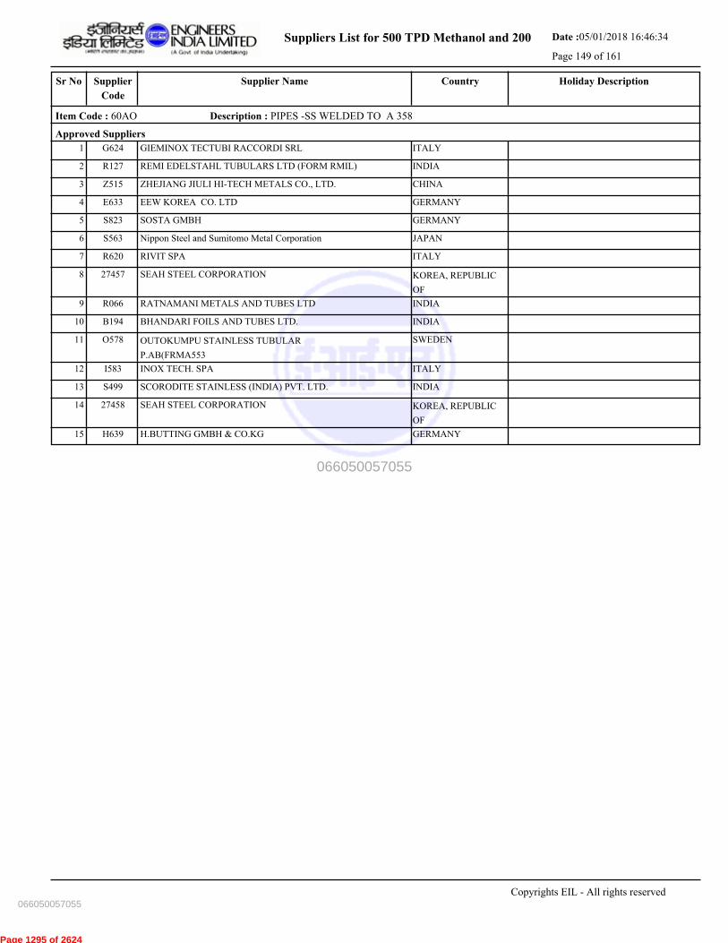
Suppliers List for 500 TPD Methanol and 200 Date :05/01/2018 16:46:34
Page 149 of 161
CountrySupplier NameSr No Holiday DescriptionSupplier
Code
Item Code : 60AO Description : PIPES -SS WELDED TO A 358
Approved Suppliers
1 GIEMINOX TECTUBI RACCORDI SRL ITALYG624
2 REMI EDELSTAHL TUBULARS LTD (FORM RMIL) INDIAR127
3 ZHEJIANG JIULI HI-TECH METALS CO., LTD. CHINAZ515
4 EEW KOREA CO. LTD GERMANYE633
5 SOSTA GMBH GERMANYS823
6 Nippon Steel and Sumitomo Metal Corporation JAPANS563
7 RIVIT SPA ITALYR620
8 SEAH STEEL CORPORATION KOREA, REPUBLIC
OF
27457
9 RATNAMANI METALS AND TUBES LTD INDIAR066
10 BHANDARI FOILS AND TUBES LTD. INDIAB194
11 OUTOKUMPU STAINLESS TUBULAR
P.AB(FRMA553
SWEDENO578
12 INOX TECH. SPA ITALYI583
13 SCORODITE STAINLESS (INDIA) PVT. LTD. INDIAS499
14 SEAH STEEL CORPORATION KOREA, REPUBLIC
OF
27458
15 H.BUTTING GMBH & CO.KG GERMANYH639
Copyrights EIL - All rights reserved
066050057055
066050057055
Page 1295 of 2624

Suppliers List for 500 TPD Methanol and 200 Date :05/01/2018 16:46:34
Page 150 of 161
CountrySupplier NameSr No Holiday DescriptionSupplier
Code
Item Code : 60B- Description : PIPES- INDIAN STOCKIST
Approved Suppliers
1 EVERGREEN SEAMLESS PIPES & TUBES PVT. LT INDIAE214
2 SHIB DASS AND SONS PRIVATE LIMITED INDIA3609
Copyrights EIL - All rights reserved
066050057055
066050057055
Page 1296 of 2624

Suppliers List for 500 TPD Methanol and 200 Date :05/01/2018 16:46:34
Page 151 of 161
CountrySupplier NameSr No Holiday DescriptionSupplier
Code
Item Code : 60NB Description : PIPE-WELDED ALLOY STEEL
Approved Suppliers
1 LALIT PIPES AND PIPES LTD. INDIAL061
2 HYUNDAI RB CO.LTD KOREA, REPUBLIC
OF
H642
3 EEW KOREA CO. LTD GERMANYE633
4 RATNAMANI METALS AND TUBES LTD INDIAR066
5 INOX TECH. SPA ITALYI583
6 RIVIT SPA ITALYR620
7 EISENBAU KRAMER GMBH GERMANYE627
Copyrights EIL - All rights reserved
066050057055
066050057055
Page 1297 of 2624
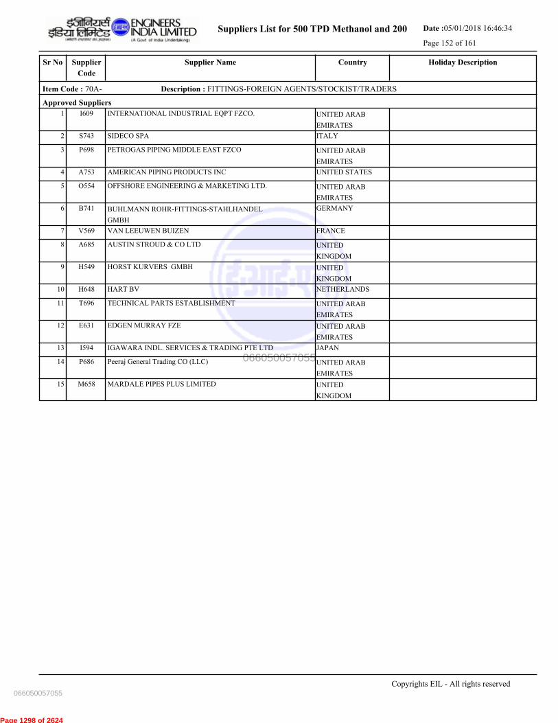
Suppliers List for 500 TPD Methanol and 200 Date :05/01/2018 16:46:34
Page 152 of 161
CountrySupplier NameSr No Holiday DescriptionSupplier
Code
Item Code : 70A- Description : FITTINGS-FOREIGN AGENTS/STOCKIST/TRADERS
Approved Suppliers
1 INTERNATIONAL INDUSTRIAL EQPT FZCO. UNITED ARAB
EMIRATES
I609
2 SIDECO SPA ITALYS743
3 PETROGAS PIPING MIDDLE EAST FZCO UNITED ARAB
EMIRATES
P698
4 AMERICAN PIPING PRODUCTS INC UNITED STATESA753
5 OFFSHORE ENGINEERING & MARKETING LTD. UNITED ARAB
EMIRATES
O554
6 BUHLMANN ROHR-FITTINGS-STAHLHANDEL
GMBH
GERMANYB741
7 VAN LEEUWEN BUIZEN FRANCEV569
8 AUSTIN STROUD & CO LTD UNITED
KINGDOM
A685
9 HORST KURVERS GMBH UNITED
KINGDOM
H549
10 HART BV NETHERLANDSH648
11 TECHNICAL PARTS ESTABLISHMENT UNITED ARAB
EMIRATES
T696
12 EDGEN MURRAY FZE UNITED ARAB
EMIRATES
E631
13 IGAWARA INDL. SERVICES & TRADING PTE LTD JAPANI594
14 Peeraj General Trading CO (LLC) UNITED ARAB
EMIRATES
P686
15 MARDALE PIPES PLUS LIMITED UNITED
KINGDOM
M658
Copyrights EIL - All rights reserved
066050057055
066050057055
Page 1298 of 2624

Suppliers List for 500 TPD Methanol and 200 Date :05/01/2018 16:46:34
Page 153 of 161
CountrySupplier NameSr No Holiday DescriptionSupplier
Code
Item Code : 71AA Description : FITTING BLOCK FORGED-CARBON STEEL
Approved Suppliers
1 VIJAY CYCLE & STEEL INDUSTRIES INDIAV157
2 KEONSAE HIGH PRESSURE CO.LTD. KOREA, REPUBLIC
OF
K645
3 TK CORPORATION KOREA, REPUBLIC
OF
T746
4 U I PIPE FITTINGS PVT LTD INDIAU144
5 EBY FASTENERS INDIAE060
6 MUNRO & MILLER FITTINGS LTD UNITED
KINGDOM
M507
7 PROMAT BD LTD MIDDLE EAST UNITED
KINGDOM
P708
8 FITTINOX SRL ITALYF624
9 CHERO PIPING SPA ITALYC724
10 CSA FITTINGS INDIAC209
11 FLASH FORGE PVT LTD INDIAF130
12 HILTON METAL FORGING LIMITED INDIAH172
13 ITM S.R.L. ITALYI604
14 TUBE BEND (CALCUTTA) PVT LTD INDIAT050
15 LEADER VALVES LTD INDIAL004
16 P.K.TUBES & FITTINGS PVT.LTD. INDIAP315
17 M.S. FITTINGS MFG. CO PVT LTD INDIAM057
18 WILH SCHULZ GmbH GERMANYW510
19 M.E.G.A SPA ITALYM731
Copyrights EIL - All rights reserved
066050057055
066050057055
Page 1299 of 2624
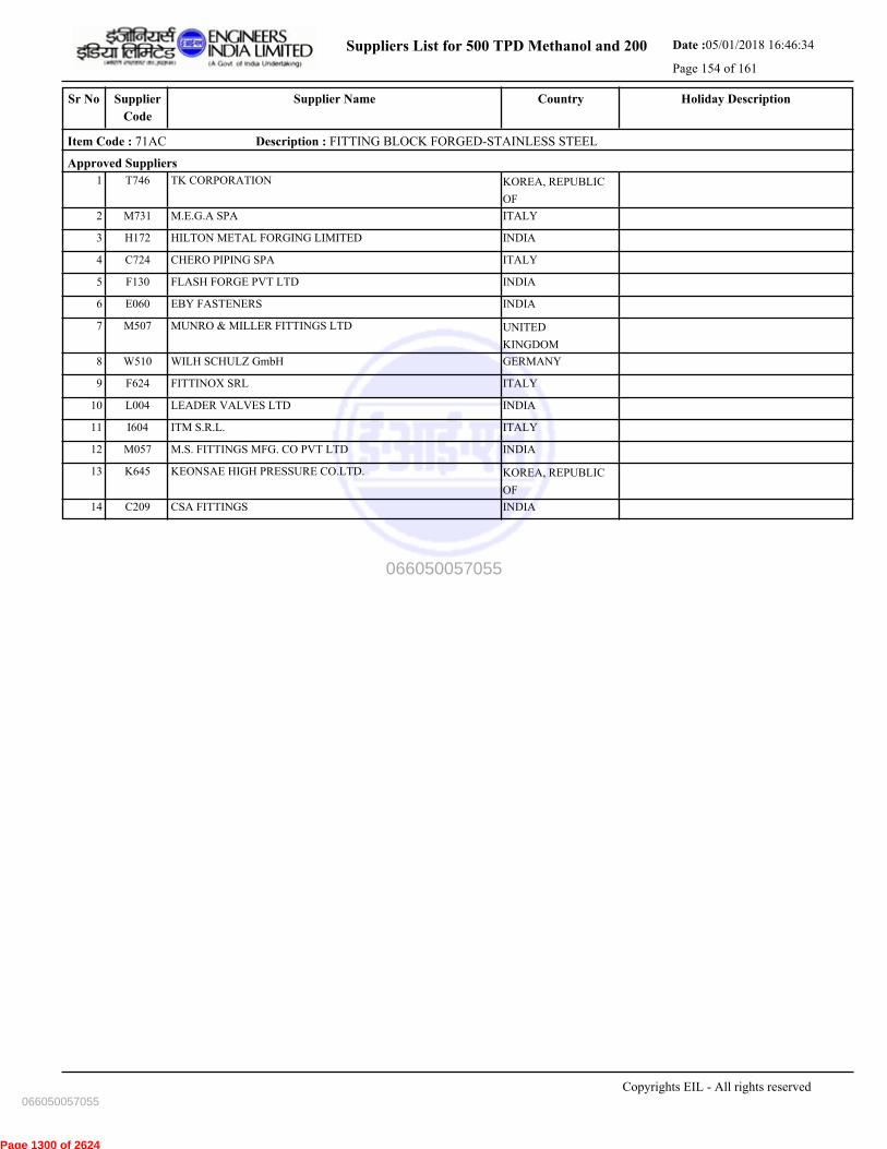
Suppliers List for 500 TPD Methanol and 200 Date :05/01/2018 16:46:34
Page 154 of 161
CountrySupplier NameSr No Holiday DescriptionSupplier
Code
Item Code : 71AC Description : FITTING BLOCK FORGED-STAINLESS STEEL
Approved Suppliers
1 TK CORPORATION KOREA, REPUBLIC
OF
T746
2 M.E.G.A SPA ITALYM731
3 HILTON METAL FORGING LIMITED INDIAH172
4 CHERO PIPING SPA ITALYC724
5 FLASH FORGE PVT LTD INDIAF130
6 EBY FASTENERS INDIAE060
7 MUNRO & MILLER FITTINGS LTD UNITED
KINGDOM
M507
8 WILH SCHULZ GmbH GERMANYW510
9 FITTINOX SRL ITALYF624
10 LEADER VALVES LTD INDIAL004
11 ITM S.R.L. ITALYI604
12 M.S. FITTINGS MFG. CO PVT LTD INDIAM057
13 KEONSAE HIGH PRESSURE CO.LTD. KOREA, REPUBLIC
OF
K645
14 CSA FITTINGS INDIAC209
Copyrights EIL - All rights reserved
066050057055
066050057055
Page 1300 of 2624
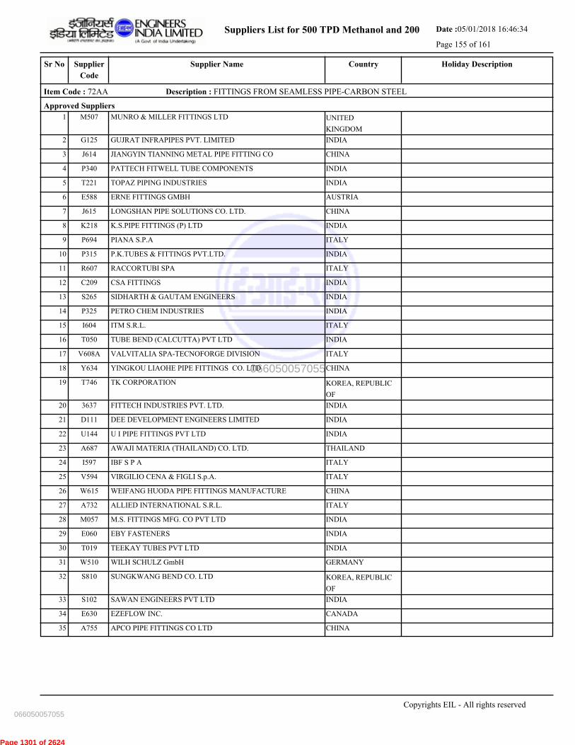
Suppliers List for 500 TPD Methanol and 200 Date :05/01/2018 16:46:34
Page 155 of 161
CountrySupplier NameSr No Holiday DescriptionSupplier
Code
Item Code : 72AA Description : FITTINGS FROM SEAMLESS PIPE-CARBON STEEL
Approved Suppliers
1 MUNRO & MILLER FITTINGS LTD UNITED
KINGDOM
M507
2 GUJRAT INFRAPIPES PVT. LIMITED INDIAG125
3 JIANGYIN TIANNING METAL PIPE FITTING CO CHINAJ614
4 PATTECH FITWELL TUBE COMPONENTS INDIAP340
5 TOPAZ PIPING INDUSTRIES INDIAT221
6 ERNE FITTINGS GMBH AUSTRIAE588
7 LONGSHAN PIPE SOLUTIONS CO. LTD. CHINAJ615
8 K.S.PIPE FITTINGS (P) LTD INDIAK218
9 PIANA S.P.A ITALYP694
10 P.K.TUBES & FITTINGS PVT.LTD. INDIAP315
11 RACCORTUBI SPA ITALYR607
12 CSA FITTINGS INDIAC209
13 SIDHARTH & GAUTAM ENGINEERS INDIAS265
14 PETRO CHEM INDUSTRIES INDIAP325
15 ITM S.R.L. ITALYI604
16 TUBE BEND (CALCUTTA) PVT LTD INDIAT050
17 VALVITALIA SPA-TECNOFORGE DIVISION ITALYV608A
18 YINGKOU LIAOHE PIPE FITTINGS CO. LTD CHINAY634
19 TK CORPORATION KOREA, REPUBLIC
OF
T746
20 FITTECH INDUSTRIES PVT. LTD. INDIA3637
21 DEE DEVELOPMENT ENGINEERS LIMITED INDIAD111
22 U I PIPE FITTINGS PVT LTD INDIAU144
23 AWAJI MATERIA (THAILAND) CO. LTD. THAILANDA687
24 IBF S P A ITALYI597
25 VIRGILIO CENA & FIGLI S.p.A. ITALYV594
26 WEIFANG HUODA PIPE FITTINGS MANUFACTURE CHINAW615
27 ALLIED INTERNATIONAL S.R.L. ITALYA732
28 M.S. FITTINGS MFG. CO PVT LTD INDIAM057
29 EBY FASTENERS INDIAE060
30 TEEKAY TUBES PVT LTD INDIAT019
31 WILH SCHULZ GmbH GERMANYW510
32 SUNGKWANG BEND CO. LTD KOREA, REPUBLIC
OF
S810
33 SAWAN ENGINEERS PVT LTD INDIAS102
34 EZEFLOW INC. CANADAE630
35 APCO PIPE FITTINGS CO LTD CHINAA755
Copyrights EIL - All rights reserved
066050057055
066050057055
Page 1301 of 2624
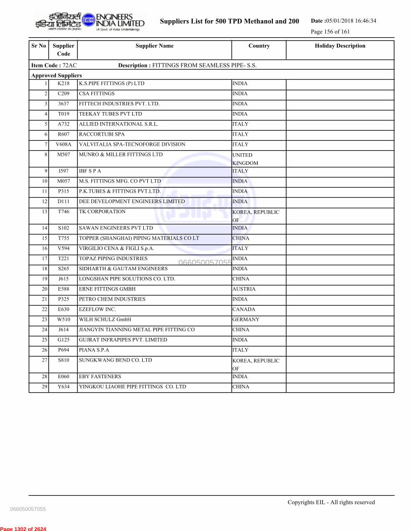
Suppliers List for 500 TPD Methanol and 200 Date :05/01/2018 16:46:34
Page 156 of 161
CountrySupplier NameSr No Holiday DescriptionSupplier
Code
Item Code : 72AC Description : FITTINGS FROM SEAMLESS PIPE- S.S.
Approved Suppliers
1 K.S.PIPE FITTINGS (P) LTD INDIAK218
2 CSA FITTINGS INDIAC209
3 FITTECH INDUSTRIES PVT. LTD. INDIA3637
4 TEEKAY TUBES PVT LTD INDIAT019
5 ALLIED INTERNATIONAL S.R.L. ITALYA732
6 RACCORTUBI SPA ITALYR607
7 VALVITALIA SPA-TECNOFORGE DIVISION ITALYV608A
8 MUNRO & MILLER FITTINGS LTD UNITED
KINGDOM
M507
9 IBF S P A ITALYI597
10 M.S. FITTINGS MFG. CO PVT LTD INDIAM057
11 P.K.TUBES & FITTINGS PVT.LTD. INDIAP315
12 DEE DEVELOPMENT ENGINEERS LIMITED INDIAD111
13 TK CORPORATION KOREA, REPUBLIC
OF
T746
14 SAWAN ENGINEERS PVT LTD INDIAS102
15 TOPPER (SHANGHAI) PIPING MATERIALS CO LT CHINAT755
16 VIRGILIO CENA & FIGLI S.p.A. ITALYV594
17 TOPAZ PIPING INDUSTRIES INDIAT221
18 SIDHARTH & GAUTAM ENGINEERS INDIAS265
19 LONGSHAN PIPE SOLUTIONS CO. LTD. CHINAJ615
20 ERNE FITTINGS GMBH AUSTRIAE588
21 PETRO CHEM INDUSTRIES INDIAP325
22 EZEFLOW INC. CANADAE630
23 WILH SCHULZ GmbH GERMANYW510
24 JIANGYIN TIANNING METAL PIPE FITTING CO CHINAJ614
25 GUJRAT INFRAPIPES PVT. LIMITED INDIAG125
26 PIANA S.P.A ITALYP694
27 SUNGKWANG BEND CO. LTD KOREA, REPUBLIC
OF
S810
28 EBY FASTENERS INDIAE060
29 YINGKOU LIAOHE PIPE FITTINGS CO. LTD CHINAY634
Copyrights EIL - All rights reserved
066050057055
066050057055
Page 1302 of 2624

Suppliers List for 500 TPD Methanol and 200 Date :05/01/2018 16:46:34
Page 157 of 161
CountrySupplier NameSr No Holiday DescriptionSupplier
Code
Item Code : 73E- Description : FITTINGS TO IS-1239
Approved Suppliers
1 VIJAY CYCLE & STEEL INDUSTRIES INDIAV157
2 M.S. FITTINGS MFG. CO PVT LTD INDIAM057
3 CSA FITTINGS INDIAC209
Copyrights EIL - All rights reserved
066050057055
066050057055
Page 1303 of 2624
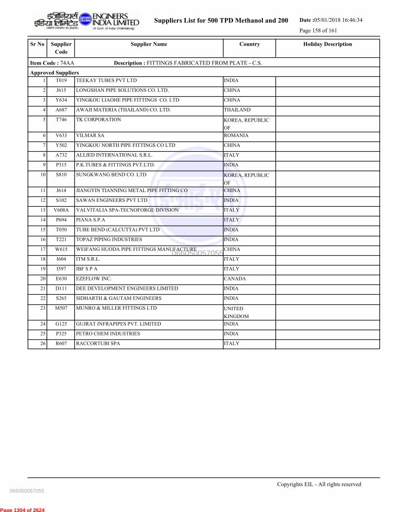
Suppliers List for 500 TPD Methanol and 200 Date :05/01/2018 16:46:34
Page 158 of 161
CountrySupplier NameSr No Holiday DescriptionSupplier
Code
Item Code : 74AA Description : FITTINGS FABRICATED FROM PLATE - C.S.
Approved Suppliers
1 TEEKAY TUBES PVT LTD INDIAT019
2 LONGSHAN PIPE SOLUTIONS CO. LTD. CHINAJ615
3 YINGKOU LIAOHE PIPE FITTINGS CO. LTD CHINAY634
4 AWAJI MATERIA (THAILAND) CO. LTD. THAILANDA687
5 TK CORPORATION KOREA, REPUBLIC
OF
T746
6 VILMAR SA ROMANIAV633
7 YINGKOU NORTH PIPE FITTINGS CO LTD CHINAY502
8 ALLIED INTERNATIONAL S.R.L. ITALYA732
9 P.K.TUBES & FITTINGS PVT.LTD. INDIAP315
10 SUNGKWANG BEND CO. LTD KOREA, REPUBLIC
OF
S810
11 JIANGYIN TIANNING METAL PIPE FITTING CO CHINAJ614
12 SAWAN ENGINEERS PVT LTD INDIAS102
13 VALVITALIA SPA-TECNOFORGE DIVISION ITALYV608A
14 PIANA S.P.A ITALYP694
15 TUBE BEND (CALCUTTA) PVT LTD INDIAT050
16 TOPAZ PIPING INDUSTRIES INDIAT221
17 WEIFANG HUODA PIPE FITTINGS MANUFACTURE CHINAW615
18 ITM S.R.L. ITALYI604
19 IBF S P A ITALYI597
20 EZEFLOW INC. CANADAE630
21 DEE DEVELOPMENT ENGINEERS LIMITED INDIAD111
22 SIDHARTH & GAUTAM ENGINEERS INDIAS265
23 MUNRO & MILLER FITTINGS LTD UNITED
KINGDOM
M507
24 GUJRAT INFRAPIPES PVT. LIMITED INDIAG125
25 PETRO CHEM INDUSTRIES INDIAP325
26 RACCORTUBI SPA ITALYR607
Copyrights EIL - All rights reserved
066050057055
066050057055
Page 1304 of 2624
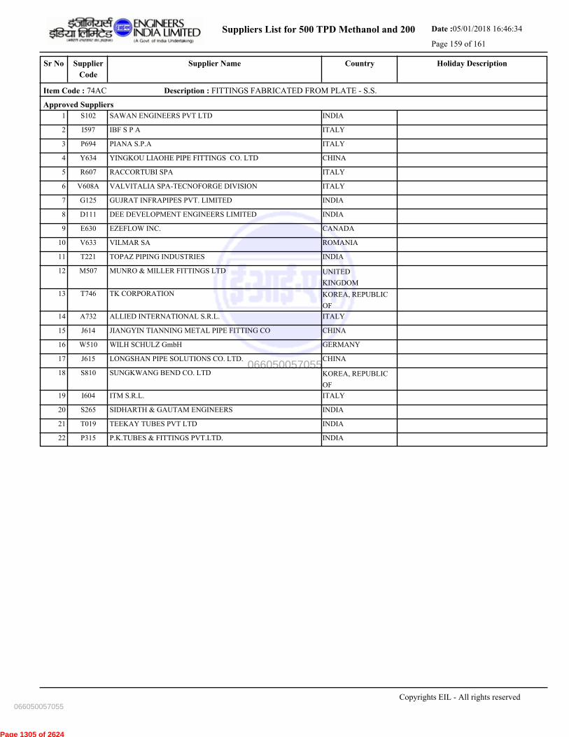
Suppliers List for 500 TPD Methanol and 200 Date :05/01/2018 16:46:34
Page 159 of 161
CountrySupplier NameSr No Holiday DescriptionSupplier
Code
Item Code : 74AC Description : FITTINGS FABRICATED FROM PLATE - S.S.
Approved Suppliers
1 SAWAN ENGINEERS PVT LTD INDIAS102
2 IBF S P A ITALYI597
3 PIANA S.P.A ITALYP694
4 YINGKOU LIAOHE PIPE FITTINGS CO. LTD CHINAY634
5 RACCORTUBI SPA ITALYR607
6 VALVITALIA SPA-TECNOFORGE DIVISION ITALYV608A
7 GUJRAT INFRAPIPES PVT. LIMITED INDIAG125
8 DEE DEVELOPMENT ENGINEERS LIMITED INDIAD111
9 EZEFLOW INC. CANADAE630
10 VILMAR SA ROMANIAV633
11 TOPAZ PIPING INDUSTRIES INDIAT221
12 MUNRO & MILLER FITTINGS LTD UNITED
KINGDOM
M507
13 TK CORPORATION KOREA, REPUBLIC
OF
T746
14 ALLIED INTERNATIONAL S.R.L. ITALYA732
15 JIANGYIN TIANNING METAL PIPE FITTING CO CHINAJ614
16 WILH SCHULZ GmbH GERMANYW510
17 LONGSHAN PIPE SOLUTIONS CO. LTD. CHINAJ615
18 SUNGKWANG BEND CO. LTD KOREA, REPUBLIC
OF
S810
19 ITM S.R.L. ITALYI604
20 SIDHARTH & GAUTAM ENGINEERS INDIAS265
21 TEEKAY TUBES PVT LTD INDIAT019
22 P.K.TUBES & FITTINGS PVT.LTD. INDIAP315
Copyrights EIL - All rights reserved
066050057055
066050057055
Page 1305 of 2624
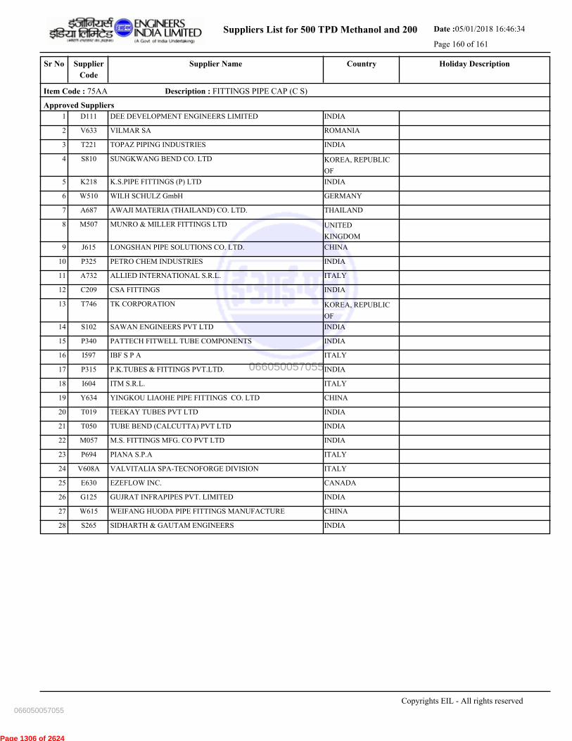
Suppliers List for 500 TPD Methanol and 200 Date :05/01/2018 16:46:34
Page 160 of 161
CountrySupplier NameSr No Holiday DescriptionSupplier
Code
Item Code : 75AA Description : FITTINGS PIPE CAP (C S)
Approved Suppliers
1 DEE DEVELOPMENT ENGINEERS LIMITED INDIAD111
2 VILMAR SA ROMANIAV633
3 TOPAZ PIPING INDUSTRIES INDIAT221
4 SUNGKWANG BEND CO. LTD KOREA, REPUBLIC
OF
S810
5 K.S.PIPE FITTINGS (P) LTD INDIAK218
6 WILH SCHULZ GmbH GERMANYW510
7 AWAJI MATERIA (THAILAND) CO. LTD. THAILANDA687
8 MUNRO & MILLER FITTINGS LTD UNITED
KINGDOM
M507
9 LONGSHAN PIPE SOLUTIONS CO. LTD. CHINAJ615
10 PETRO CHEM INDUSTRIES INDIAP325
11 ALLIED INTERNATIONAL S.R.L. ITALYA732
12 CSA FITTINGS INDIAC209
13 TK CORPORATION KOREA, REPUBLIC
OF
T746
14 SAWAN ENGINEERS PVT LTD INDIAS102
15 PATTECH FITWELL TUBE COMPONENTS INDIAP340
16 IBF S P A ITALYI597
17 P.K.TUBES & FITTINGS PVT.LTD. INDIAP315
18 ITM S.R.L. ITALYI604
19 YINGKOU LIAOHE PIPE FITTINGS CO. LTD CHINAY634
20 TEEKAY TUBES PVT LTD INDIAT019
21 TUBE BEND (CALCUTTA) PVT LTD INDIAT050
22 M.S. FITTINGS MFG. CO PVT LTD INDIAM057
23 PIANA S.P.A ITALYP694
24 VALVITALIA SPA-TECNOFORGE DIVISION ITALYV608A
25 EZEFLOW INC. CANADAE630
26 GUJRAT INFRAPIPES PVT. LIMITED INDIAG125
27 WEIFANG HUODA PIPE FITTINGS MANUFACTURE CHINAW615
28 SIDHARTH & GAUTAM ENGINEERS INDIAS265
Copyrights EIL - All rights reserved
066050057055
066050057055
Page 1306 of 2624
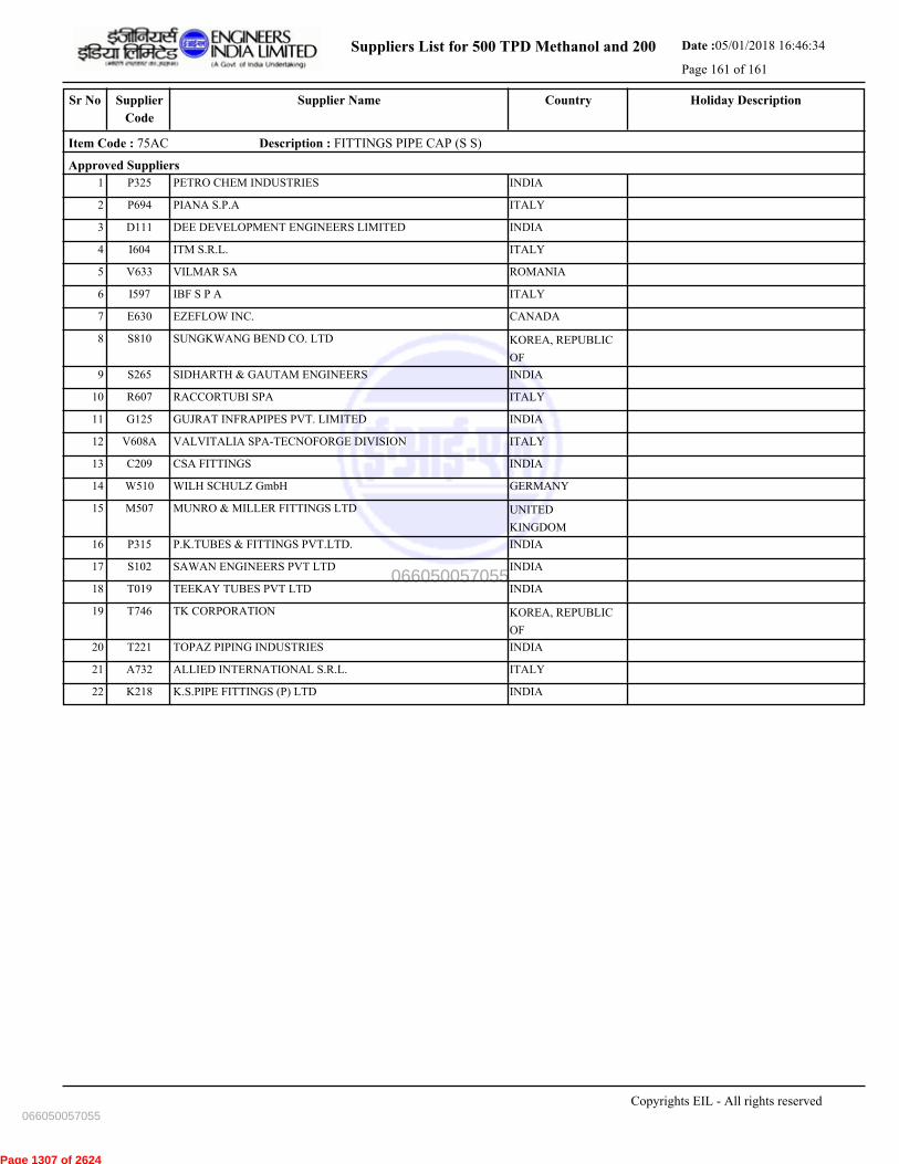
Suppliers List for 500 TPD Methanol and 200 Date :05/01/2018 16:46:34
Page 161 of 161
CountrySupplier NameSr No Holiday DescriptionSupplier
Code
Item Code : 75AC Description : FITTINGS PIPE CAP (S S)
Approved Suppliers
1 PETRO CHEM INDUSTRIES INDIAP325
2 PIANA S.P.A ITALYP694
3 DEE DEVELOPMENT ENGINEERS LIMITED INDIAD111
4 ITM S.R.L. ITALYI604
5 VILMAR SA ROMANIAV633
6 IBF S P A ITALYI597
7 EZEFLOW INC. CANADAE630
8 SUNGKWANG BEND CO. LTD KOREA, REPUBLIC
OF
S810
9 SIDHARTH & GAUTAM ENGINEERS INDIAS265
10 RACCORTUBI SPA ITALYR607
11 GUJRAT INFRAPIPES PVT. LIMITED INDIAG125
12 VALVITALIA SPA-TECNOFORGE DIVISION ITALYV608A
13 CSA FITTINGS INDIAC209
14 WILH SCHULZ GmbH GERMANYW510
15 MUNRO & MILLER FITTINGS LTD UNITED
KINGDOM
M507
16 P.K.TUBES & FITTINGS PVT.LTD. INDIAP315
17 SAWAN ENGINEERS PVT LTD INDIAS102
18 TEEKAY TUBES PVT LTD INDIAT019
19 TK CORPORATION KOREA, REPUBLIC
OF
T746
20 TOPAZ PIPING INDUSTRIES INDIAT221
21 ALLIED INTERNATIONAL S.R.L. ITALYA732
22 K.S.PIPE FITTINGS (P) LTD INDIAK218
Copyrights EIL - All rights reserved
066050057055
066050057055
Page 1307 of 2624

Page 1308 of 2624

Page 1309 of 2624

Page 1310 of 2624
Page 1311 of 2624

Page 1312 of 2624

Page 1313 of 2624
Page 1314 of 2624
Page 1315 of 2624
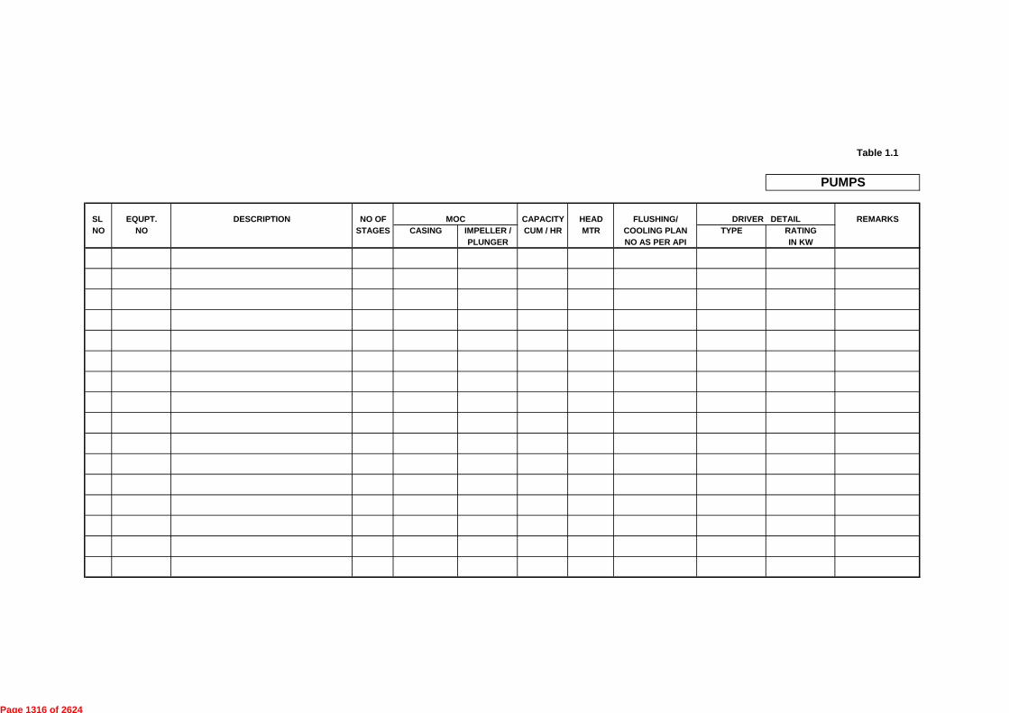
Table 1.1
SL EQUPT. DESCRIPTION NO OF MOC CAPACITY HEAD FLUSHING/ DRIVER DETAIL REMARKS
NO NO STAGES CASING IMPELLER / CUM / HR MTR COOLING PLAN TYPE RATING
PLUNGER NO AS PER API IN KW
PUMPS
Page 1316 of 2624

TECHNICAL INFORMATION REQUIRED FOR ASSESSING QUANTUM OF WORK
PROJECT INTEGRATED METHANOL & ACETIC ACID PROJECT
PACKAGE COMPRESSED AIR & CRYOGENIC NITROGEN PLANT PACKAGE
ITEM VESSELS
SL EQUPT. DESCRIPTION MOC SHELL COMPONENT WT INTERNAL REMARKS
NO NO MAIN THK. SUPRT CS AS SS OTHER WEIGHT DETAIL
VSL/CLMN MM KGS KGS KGS KGS KGS KGS
A VESSELS
LP AIR RECEIVER
HP AIR RECEIVER
The information being sought in this section is specifically from the purpose of assessing quantum of work and not from any contractual angle. Data being indicated here should be
true to the best ofinformation available / worked out by bidder.
TOTAL QTY., WEIGHT AND MOC TO BE
Page 1317 of 2624
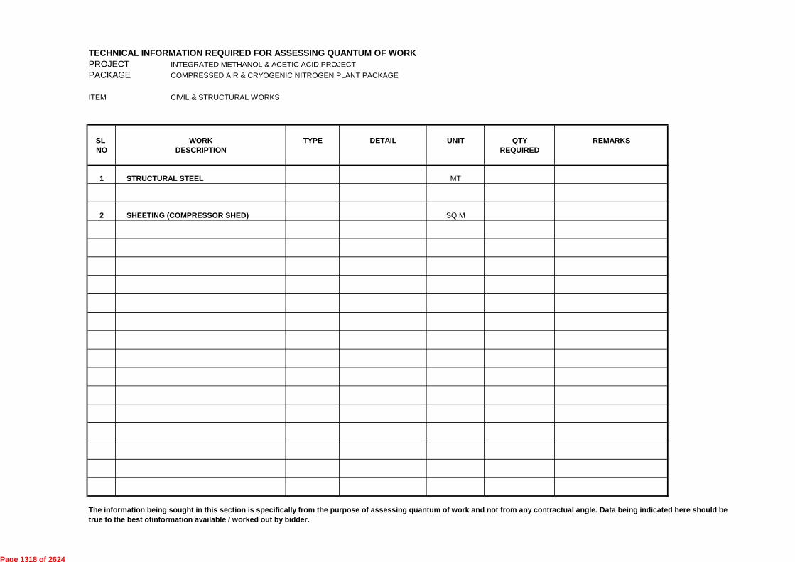
TECHNICAL INFORMATION REQUIRED FOR ASSESSING QUANTUM OF WORK
PROJECT INTEGRATED METHANOL & ACETIC ACID PROJECT
PACKAGE COMPRESSED AIR & CRYOGENIC NITROGEN PLANT PACKAGE
ITEM CIVIL & STRUCTURAL WORKS
SL WORK TYPE DETAIL UNIT QTY REMARKS
NO DESCRIPTION REQUIRED
1 STRUCTURAL STEEL MT
2 SHEETING (COMPRESSOR SHED) SQ.M
The information being sought in this section is specifically from the purpose of assessing quantum of work and not from any contractual angle. Data being indicated here should be
true to the best ofinformation available / worked out by bidder.
Page 1318 of 2624
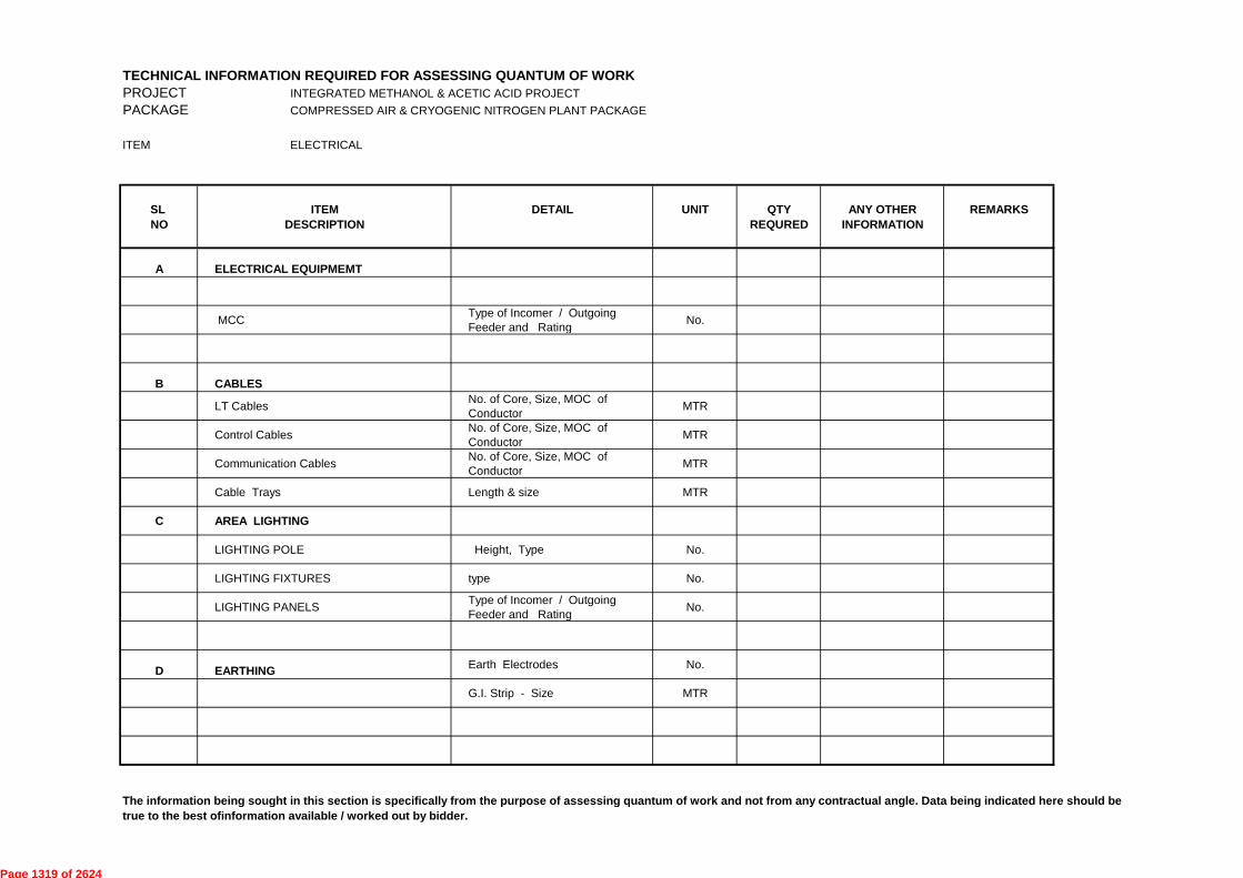
TECHNICAL INFORMATION REQUIRED FOR ASSESSING QUANTUM OF WORK
PROJECT INTEGRATED METHANOL & ACETIC ACID PROJECT
PACKAGE COMPRESSED AIR & CRYOGENIC NITROGEN PLANT PACKAGE
ITEM ELECTRICAL
SL ITEM DETAIL UNIT QTY ANY OTHER REMARKS
NO DESCRIPTION REQURED INFORMATION
A ELECTRICAL EQUIPMEMT
MCCType of Incomer / Outgoing
Feeder and RatingNo.
B CABLES
LT CablesNo. of Core, Size, MOC of
ConductorMTR
Control CablesNo. of Core, Size, MOC of
ConductorMTR
Communication CablesNo. of Core, Size, MOC of
ConductorMTR
Cable Trays Length & size MTR
C AREA LIGHTING
LIGHTING POLE Height, Type No.
LIGHTING FIXTURES type No.
LIGHTING PANELSType of Incomer / Outgoing
Feeder and RatingNo.
D EARTHINGEarth Electrodes No.
G.I. Strip - Size MTR
The information being sought in this section is specifically from the purpose of assessing quantum of work and not from any contractual angle. Data being indicated here should be
true to the best ofinformation available / worked out by bidder.
Page 1319 of 2624
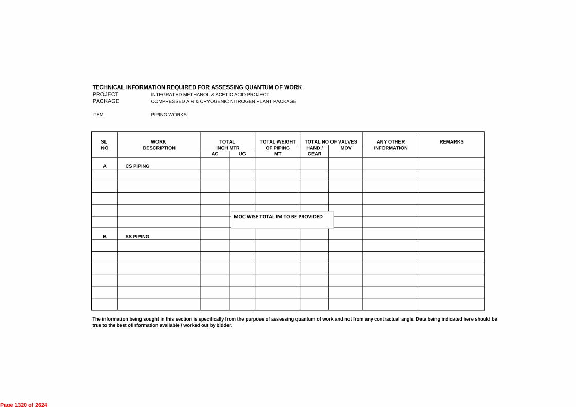
TECHNICAL INFORMATION REQUIRED FOR ASSESSING QUANTUM OF WORK
PROJECT INTEGRATED METHANOL & ACETIC ACID PROJECT
PACKAGE COMPRESSED AIR & CRYOGENIC NITROGEN PLANT PACKAGE
ITEM PIPING WORKS
SL WORK TOTAL TOTAL WEIGHT TOTAL NO OF VALVES ANY OTHER REMARKS
NO DESCRIPTION INCH MTR OF PIPING HAND / MOV INFORMATION
AG UG MT GEAR
A CS PIPING
B SS PIPING
The information being sought in this section is specifically from the purpose of assessing quantum of work and not from any contractual angle. Data being indicated here should be
true to the best ofinformation available / worked out by bidder.
MOC WISE TOTAL IM TO BE PROVIDED
Page 1320 of 2624

TECHNICAL INFORMATION REQUIRED FOR ASSESSING QUANTUM OF WORK
PROJECT INTEGRATED METHANOL & ACETIC ACID PROJECT
PACKAGE COMPRESSED AIR & CRYOGENIC NITROGEN PLANT PACKAGE
ITEM INSTRUMENTATION
SL ITEM TYPE DETAIL UNIT QTY REMARKS
NO DESCRIPTION REQURED
A INSTRUMENTS
1 ANALYSERS TYPE NOS.
2 CONTROL VALVES GLOBE/BALL/BUTTERFLY/PLUG SIZE,MOC, NOS
3 FIELD INSTRUMENTS DIRECT/DIAPH.SEALED TYPE, MOC NOS
4 FLOW INSTRUMENTS TYPE,SIZE NOS
5 LEVEL INSTRUMENTS TYPE,SIZE NOS
6 TEMPERATURE INSTRUMENTS NOS
7 PLCNO.OF I/O COUNTS
NOS
B CABLES
Control, Signal , Alarm/ Fibre Optic cable/ Serial Link Cable SIZE & SPECIFICATIONS MTR
C ERECTION MATERIALS
1 JN. BOXES SIZE NOS
2 CABLE TRAYS & DUCTS TYPE, SIZE & MOC MTR
The information being sought in this section is specifically from the purpose of assessing quantum of work and not from any contractual angle. Data being indicated here should be
true to the best ofinformation available / worked out by bidder.
Page 1321 of 2624

STANDARD No.
7-12-0017 Rev. 5Page 1 of 2
OturqrENGINEERS
601NDIA LIMITED(A Govt. of Indio Undortoking)
SIGHT GLASSES FOR
PRESSURE VESSELS
I NO.-3mm NPTTELL—TALE HOLE GLASS
tfl
15
P No.-14 HOLESSS OR CS SHELL HEAD CLAD SHELL HEAD
SISIZE I(NB) -
LP h STUD SIZEt CR HGDESIGN PRESSURE < 10 Kg / cm2g
75 254 19 M 16 2391 10 20 120.52450 152 50 92 38M 16 85 23 258 19156 16 28 190.5100 157 38 29100 230
DESIGN PRESSURE < 20 Kg / cm2gM 16 23 25127 19 8227 91 14 20 8165 50 92 3850
105 25 298 22 M 2040 37 156 22 28 200255 100 157100
GLASS1 N0.-3mm NPTTELL—TALE HOLE
SEE VESSEL DRG.
STUD SIZEI LSIZE(NB)
FLG.I.D. SD t W C P hX R T G0
DESIGN PRESSURE < 10 Kg / cm2g2891 10 120.5 4 19 M 16 10024 30 50 2050 152 62 78 92
19 M 16 115 28100 156 16 28 190.5 8100 230 116 135 157 29 38DESIGN PRESSURE . 20 Kg / cm2g
110 2850 91 14 20 127 8 19 M 16165 84 92 27 3850 62M 20 145 32157 37 53 100 156 22 28 200 8 22100 255 116 146
THE ABOVE ARRANGEMENT IS APPLICABLE FOR THE FOLLOWING CONDITIONS.DESIGN PRESSURE 20 Kg/cm2gDESIGN TEMPERATURE < 200•C
III) MAXIMUM TEMPERATURE DIFFERENTIAL 140*C( AMBIENT TO FLUID )
AKM I SC DMRKT5 30.07.2011 REAFFIRMED AND REISSUED AS STANDARD PORELVCDNN AKM4 11.09.2006 REAFFIRMED AND REISSUED AS STANDARD POREL
Stds. Committee Stds. BureauConvenor Chairman
Approved by
Checkedby
Preparedby
Rev.No. Date Purpose
Copyright EIL - All rights reservedFormat No. 8-00-0001-F4 Rev.0
Page 1322 of 2624

16NOS.-15 0 HOLES
COVER FLANGE GLASS GASKET(NOTE-9)
PAD FLANGE
16NOS.—M12TAPPED HOLES
16
39R
1110.-3mm NPTTELL-TAIL
HOLE
ENGNEERSfit INDIA LIMTED
(A Govt. of Indio Undortoldng)
SIGHT GLASSES FOR
PRESSURE VESSELS
STANDARD No.
7-12-0017 Rev. 5Page 2 of 2
THE ABOVE ARRANGEMENT IS APPLICABLE FOR THE FOLLOWING CONDITIONS.DESIGN PRESSURE . 5.0 Kg/cm2gDESIGN TEMPERATURE 200'C
III) MAXIMUM TEMPERATURE DIFFERENTIAL . 140*C( AMBIENT TO FLUID )
NOTESALL DIMENSIONS ARE IN mm UNLESS OTHERWISE STATED.IN CASE OF CONFLICT ENGINEERING DRAWING SHALL GOVERN.TYPE OF SIGHT GLASS SHALL BE TOUGHENED BOROSILICATE AND SHALL BE TESTEDAS PER IS : 5428 / BS 3463.FOR APPLICATION OUTSIDE THE LIMITS SPECIFIED ON THE STANDARDS, MANUFACTURER'SPROVEN DESIGN FOR THE COMPLETE SIGHT GLASS ASSEMBLY SHALL BE USED.UNLESS OTHERWISE SPECIFIED, GASKET MATERIAL SHALL BE COMPRESSED ARAMIDE GASKET ORCOMPRESSED FIBRE ASBESTOS—FREE GASKET.THE INDICATED SIGHT GLASS THICKNESSES ARE MINIMUM. NEGATIVE TOLERANCE IS NOT PERMITTED.REFER ENGINEERING DRAWING FOR TYPE AND MATERIAL OF NOZZLE COMPONENTS.GLASS AND SEAT FACE SHALL BE POLISHED PERFECTLY.
9. PROVIDE GASKET ON EITHER SIDE OF SIGHT GLASS.
5 30.07.2011 REAFFIRMED AND REISSUED AS STANDARD
4 11.09.2006 REAFFIRMED AND REISSUED AS STANDARD
Rev.
No. Date Purpose
POREL KT A M / SC DMPOREL DNN AKM VC
Preparedby
Checkedby
Stds. CommitteeConvenor
Stds. BureauChairman
Approved byFormat No. 8-00-0001-F4 Rev.0 Copyright EIL - All rights reserved
Page 1323 of 2624

TYPE t 1 t2 L3 t3
A 10 10 170 12B 10 12 250 12C 12 16 300 16D 16 20 350 20E 20 20 400 20
110
140I 250
PARALLEL TO VESSELTYPE - C. D. E AXIS (TYP)
HOLE FORSLIDING SUPPORT
I L 1 I L1 I Li
L2 I
D/18
EARTHING
30 30 0 HOLES FORM 24 BOLTS
2-60 VENTHOLE (TYP.)(REF. NOTE-5)
ORMOENGNEERSNDIA UWE)IA Govt. of India Undertaking)
SUPPORT FOR
HORIZONTAL VESSEL
STANDARD No.7-12-0002 Rev. 5
Page 1 of 1
L3 D LB H t../ L2 TYPEMAX.
ieSADDLE(M. TON)
APPROX.SADDLE(KGS.)
D/18 10OR
150 10300 260 300 50 200 A 4.4 17350 280 325 55 210 A 4.8 18\
\ x
-w Ts. .wV) '''
_ilI
tii +400 330 350 75 250 A 4.5 20450 370 375 95 300 A 3.6 2211YM OF 500 450 450 125 370 A 14.9 40
170IrIIR0PER KM
it600 560 500 175 470 A 13.2 50L1 L/ EARTHING 700 650 550 225 570 A 11.0 55I 1
2800 750 600 275 670 A 10.6 65. I =J 26 0 HOLES FOX
M 20 BOLTS
IUD 1000
900 850 650 300 760 A 11.0 75:950 700 330 820 B 12.3 85
1200 1100 800 375 960 B 19.4 130TYPE - A1400 1250 900 465 1150 B 19.7 140HOLE FOR
SLIDING SUPPORT 1600 1450 1000 370 1300 C 23.3 1651800 1600 1100 410 1450 C 39.1 260
D/189R 2000 1750 1200 445 1600 C 43.5 290O
1102200 1950 1300 495 1800 D 49.1 295■
i 111 2400 2150 1450 545 2000 D 53.5 390
11__.ki iii II1
..1N- It
2600 2300 1550 585 2150 D 52.9 4402800 2500 1650 620 2300 E 52.7 475
L i Li 1 0 3000 2670 1750 670 2500 E 64.9 6003200 2800 1850 710 2600 E 63.8 620I- I EARTHING 250L3400 3000 1950 760 2800 E 64.9 63026 0 HOLES FOR3600 3200 2050 830 3000 E 60.5 72530 M 20 BOLTS111111
DUD 3800 3350 2150 845 3150 E 61.0 7454000 3550 2250 895 3300 E 60.6 820TYPE - B ,
HOLE FORSLIDING SUPPORT
NOTESALL DIMENSIONS ARE IN mm UNLESS OTHERWISE STATED.VESSEL DIAMETER 'D' REFERS TO THE OUTER DIAMETER OF THE SHELL.FOR INTERMEDIATE DIAMETERS TAKE THE IMMEDIATE NEAREST DIAMETER SUPPORT.WELDING SHALL BE DONE ALL AROUND AND SHALL BE CONTINUOUS FILLET WELD. WELD SIZE SHALLBE 6 mm FOR VESSELS UPTO 1400 mm DIA. AND 8 mm FOR VESSELS ABOVE 1400 mm DIA.PROVIDE 2 NO. 60 VENT HOLES IN SADDLE WRAPPER PLATE. THESE HOLES SHALL BE PROVIDED DIAGONALLYOPPOSITE AND BE LEFT UNPLUGED AND SHALL BE FILLED WITH HARD GREASE ONLY.WHERE EARTHING LUG CANNOT BE PUT AT AN ELEVATION OF 400 mm ABOVE THE SADDLE BASE PLATEIT SHALL BE LOCATED AS HIGH AS POSSIBLE.EARTHING LUGS ARE NOT TO BE PAINTED OR GALVANIZED.DETAIL, DIMENSIONS AND NOTES IN ENGINEERING DRAWING TAKE PRECEDENCE OVER THOSE SHOWN HERE.MATERIALS SHALL BE AS PER ENGINEERING DRAWING.EARTHING LUG SHALL BE AS PER STANDARD 7-12-0026
e611'5 30.06.2011 REAFFIRMED AND REISSUED AS STANDARD POREL RKT A M/SC DM
4 08.09.2006 REAFFIRMED AND REISSUED AS STANDARD POREL DNN AKM VC
Rev.No. Date Purpose
Prepared Checkedby by
Stds. Committee Stds. BureauConvenor Chairman
Approved by Format No. 8-00-0001-F4 Rev.0 Copyright EIL - All rights reserved
Page 1324 of 2624

STANDARD SPECFICATIN NO.
£ -18-9
panss!-ed pue pesp\au
penss!--eu pue pes!ned
penss!-ed pue pas!ned
uo4enieweldw! penssi
0 'Aei:1 Ld-1000-00-8 '0N lewiod Z
O
<
c o
O
ZOOZ't0'OE
171.0Z'1.0'0£
LOOZ•60'8Z
JJ
JJ
G)
JJ
cn
(/)
D)
O.
0 0
. cn
CD
0
9 3 oe
O
o
03 CD c
pemesei s41161.1 11V —113 446uAdoo
W
Aq peAcuddv
G)
JJ
JJ
Pag
e 13
25 o
f 26
24

.71
'r7
1-'8
','
-rim
nnnnco
tz>
,-dnnn
-0(
r-'4n-
cisH
mtrim
m7, >w
-ci
zJ,H
,H
H
r
.1r-
'2 l
m
.,
m
>
■)'--' '
-' 5-
' E'
" "
" "
!(.
-.)nc
-.)noi>
ezi>
,,
,, '
,','
('--i)
' •-g';
(1"?-, .c") 'c,.. ''2 ,p,-n
cpc ,(4
4.
,P-1,—aa
'8,-
p,,cc
,...,, _
cmC
D..-1":1
110
",=1
-;~M
AD
0,4
`<
?":1-'''
5 9
C
) 9+
(%
' 4. (
DC)
-1:1
,- (-
) 2
,_,CD
r) :=
'-: ,
-; (--)..,
.-',,,
o
,,,,,,,_
?,3
-.
n o P
0 .-05
(:)-
5rrl.
P0000->
F;
orr
i o
:8'.,
»25,(1.9,,,,,,
,2- .o
'-,
2,)
-zo
o
o
,-i v, "
CD
"]
( 0
-
■-r '-t
S:
L C
D 0
'C-r
(-)—
,...; (
5 sH
<,9
in
9-8
-9';,thR2
'3A
■H
■E'-) ,
FD' '
r_er) $7
,; *
■-•
■-r
■-1 n
(1):
:.
.lo
co
c/D
o o
-t-
,-+ .
...,)
lw :z
o =
cl''?
(,)
•,. co
c" =
.--,o ,)
~. •
■-d
,.-
-....
CD
ril
•-•
' .
C)
0
AD
H C
r':
.-: >e
,,, ..-
cn.
,a, •
CI WF
. ,.,
y4
A v]
..
rp .-
. •
(-)
(=r,
n ,
1-11
9.,) r
iD
rri
0,E)
Aj
, '"
• cir
n
b
0
-t.
o
7z:1
' CD
CD
AQ
7
. cn
Cn
CD
~ •
rri
3 "
0
45.
(-)
Inspection Standards Committee
uldno 3 S
44
. .
dx
CD
<1)
-o
crtz
C")
■-1 (
") <
tri
o H
n
—
o.
rj
5
5
cr
s)
H
-c
STANDARD SPECIFICATION NO.
00
0 .AGd Ld-1000-00-8 oN 4eW.I0d
Copyright EI L — All rights reserved
z z
o
o 2:J
z
O
(1) (-)
(")
-<
H H
7:i
to 't
't 't
"t
't Z
Z Z
44
44
2,1,,
00
,5,.
..12.
p,pcn
a,_
3.....
CD '-•
• ei)
c,.,
'''sz
lHzi
cl.
rz" (
..)4) 3
. °-:
.:<
., 4
r: r)
(D' O
'-‘
' 51
'. '"C
h.r1)
cp
,...4
,4.
CD pD
n
CFO
Sw
(-)
1Z 0
)
t-1
.--s
= R
"g
D)s-d
n5
D??,-
'61
)
fw c
o
.., eps-0
,..
-t.
‹j* ‘ 9
. ■-•
■-cs
,, ,
-C 4
co
9,2
.
.'"
Ic'
.,,,_
,,,..,
.....
c ..
-bn
:D
t-zy
°- 0.
-b n
_,'"
co .-,
.., cp
,-0
r,
›(-13
- F) (
I) n
4'
c .)
- ■ - c
l)
7 :
c i) . -
, cl
, - - 3
c),
,.(-.4
0,0
t,,T,1
n
:;:-:
E,'
- -
= —
g-
'-•''
°
o
n
-O
CIO
n
cn
..-t-4
"0
r+
,-,
• ,y
... •-
■ CI
) .--
C
D
~,--■,.
'-' •
Cl.,
'—' '-
' • 0
•-• "
LD
. C DH
,
- i -H *
nH Hr>
ril c
) :::
' • ,2
cD
CL.
C
n ,-,-
CD
4(4
n -
•
-i- c
:
cr)
,--o-
5.,(
-DV
DC
D‹-
r-
0
CIA
'100
er
Onv)
5"Z '5
94
_-,-.
,I,
..t
CD
'-' •
>
•
'-•
PD
■=h
,__,
.-■.)
CrO
rpn
2.
C")
'Z'
à AD
n -
. .<
5-
o
a...-
1
cro
CD"
o
,-- •
AD
cn"
AD
V)
• "c :)' •
o n iS-D. 4- o o
sum3mitaaqqy
Pag
e 13
26 o
f 26
24

0 lked L3-1-000-00-8 'oN Teuuod pamasai sN6p ity — ii3 }146pAcloo STANDARD SPECIFICATION NO.
:adODS O'I
INSPECTION AND TEST REQUIREMENTS:
This Inspection and Test Plan covers the minimum testing requirements of Industrial type control stations.
PO/PR & Standards referred there in /Job specifications / Approved documents
■—•
4=.
C=
t,-)
■—•
tià
i=:,
1,-.)
;—'
t.)
0 ~
0
C'
l 0
r
Industrial type Control Station
Final Inspection
›.- CD cs- Inprocess Inspection
Incoming material like castings, Push Button, terminals, glass, ammeter, voltmeter, knob, switch, etc
Material Inspection Procedure
STAGE/ACTIVITY
Acceptance Tests:-
•
Visual
•
Dimensions, Threads
•
Workmanship
•
Paint Shade
•
Marking on each piece for Tag no. etc.
•
Terminal sizes, Lugs size(where required)
•
Cable Gland size
Visual, Dimension, Bill of water
Physical & Chemical Properties, Material Certificate, Accuracy, Make etc.
n :
> n t=i i-1
cp
-
o o -, o o
o o
QUANTUM OF CHECK
.
s- c„
ro
-z2;
,_,r)
ccoCD
n
c)
,-
, cn
.-
t r-
r-
Ci.
■.-3 ,-
,'-'
•
lA
Supplier' s Test Records
Supplier's Test Records/ Independent lab TC
r=1 n 0
X
SUB SUPPLIER
SCOPE OF INSPECTION
Z
SUPPLIER
i I
ril
'g ..,, 5:
Pag
e 13
27 o
f 26
24
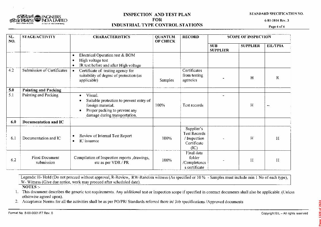
O
(')
rD
CD o C
IC7
rD
›FDt
("D
(19-
o ". •
(1)
cn
CD
CD
•
cn
cn
■-1
-cs
et)
,•=c
C1)
cn
cD
cn
s'"1:1 o
CID
":■7
0
cn
■-+)
o
CD
CD
cn
CD
rD
Cr
cn
cn(") r-ch
cn
-tcs
ris
rs
cn
'c7n—
cr
•<•--; • ccr
ris7.
(D
rn
cn
0 •Aed 23-1000-00-9 oN paniesai IIV —113 P16pAcloo STANDARD SPECIFICATION NO.
£ *Aall 1-18-9
cn i\.,
cr, .__,
c■ ::.
Lnt
;—
fili
7=
-i=,
i‘J
Z (
/)
o r
Final Document submission
Documentation and IC
Documentation and IC
Painting and Packing Painting and Packing
Submission of Certificates
STAGE/ACTIVITY
Compilation of Inspection reports ,drawings, etc as per VDR / PR
•
Review of Internal Test Report
•
IC issuance •
Visual.
•
Suitable protection to prevent entry of foreign material.
•
Proper packing to prevent any damage during transportation.
•
Certificate of testing agency for suitability of degree of protection (as applicable)
•
Electrical Operation test & BOM
•
High voltage test
•
IR test before and after High voltage
CHARACTERISTICS
..._. .
o
__, .
©
_ .
.
..-
Samples
QUANTUM OF CHECK
Final data folder
/Completenes s certificate
Supplier' s Test Records / Inspection Certificate
(IC)
Test records
Certificates from testing agencies
RECORD
SUB SUPPLIER
SCOPE OF INSPECTION
z z
z z
SUPPLIER
z z
EIL/TPIA
Pag
e 13
28 o
f 26
24

HORIZONTAL VESSEL(ELEVATION)
q_
derfalb13\aSEERSINDIA maw STANDARD BOLT HOLE ORIENTATIONamegi.wegammo (A Govt. of India Undertaking)
STANDARD No.
7-12-0015 Rev. 5
Page 1 of 1
VERTICAL VESSEL(PLAN)
NOTESANY DEVIATION FROM THIS ARRANGEMENT WILL BE INDICATED IN ENGINEERING DRAWING.
BOLT HOLES TO STRADDLE CENTRE LINES INDICATED ( BY q. ) ABOVE.
5 23.05.2011 REAFFIRMED AND REISSUED AS STANDARD POREL KT
Rev. Prepared CheckedDate Purpose
No. by by
Stds. Committee Stds. BureauConvenor Chairman
Approved byFormat No. 8-00-0001-F4 Rev.0 Copyright EIL - All rights reserved
Page 1329 of 2624

Page 1330 of 2624
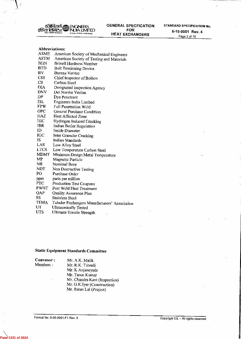
Page 1331 of 2624
Page 1332 of 2624

Page 1333 of 2624

Page 1334 of 2624
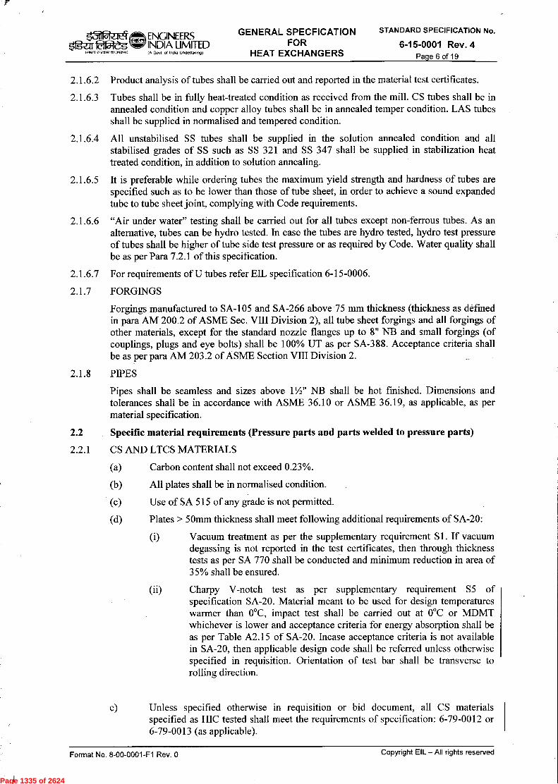
Page 1335 of 2624
Page 1336 of 2624
Page 1337 of 2624
Page 1338 of 2624
Page 1339 of 2624

Page 1340 of 2624
Page 1341 of 2624

Page 1342 of 2624
Page 1343 of 2624

Page 1344 of 2624
Page 1345 of 2624
Page 1346 of 2624
Page 1347 of 2624
Page 1348 of 2624

ENGINEER 5fgzrr ealeg INDIA LIMI
STED
lanen ~1,(7.3Aan-A, (A Govt of India Undertaking)
SPECIFICATION FOR ELECTRICS OF OFFSITE
PACKAGE UNITS
STANDARD SPECIFICATION No.
6-51-0092 Rev. 4 Page 1 of 16
'31-rcF RYR
SPECIFICATION FOR ELECTRICS OF
OFFSITE PACKAGE UNITS
4 21/11/13 Revised and Issued as standard specification VB' VK UAPJMS SC
3 25/04/08 Revised and Issued as standard specification RS IKG JMS VC
2 12/11/02 Revised and Issued as standard specification IKG AAN VPS
1 29/04/97 Revised and Issued as standard specification JMS VPS SG
Issued as standard specification 0 03/01/86 CSM VPS GNT Recomposed in Nov.'95
SKG
AS
Rev. No Date Purpose Prepared Checked
by by
Standards Standards Committee Bureau Convenor Chairman
Approved by
Format No. 8-00-0001-F1 Rev. 0
Copyright EIL — All rights reserved
Page 1349 of 2624

ENGINEERS Ig`«-af lalZ5 INDIA LIMITED
IA Govt of Intlia Undettakingf
SPECIFICATION FOR ELECTRICS OF OFFSITE
PACKAGE UNITS
STANDARD SPECIFICATION No.
6-51-0092 Rev. 4 Page 2 of 16
1~1 Cit',7,1, as.~,
Abbreviations: AC Alternating current ASB Auxiliary Service Board BIS Bureau of Indian Standard CEA Central Electricity Authority CIMFR Central Institute of Mines and Fuel Research CT Current Transformer DC Direct current DCDB Direct Current Distribution Board DGMS Directorate General of Mines Safety EIL Engineers India Limited ELCB Earth Leakage Circuit Breaker FM Factory Mutual GI Galvanized Iron HRC High Rupturing Capacity HV High Voltage IE Indian Electricity IEC International Electrotechnical Commission IEEE Institute of Electrical & Electronics Engineer IP Ingress Protection IS Indian Standard KW Kilo Watt LCIE Laboratoire Central des Industries Electriques LDB Lighting Distribution Board MCB Miniature Circuit Breaker MCC Motor Control Centre MCCB Moulded Case Circuit Breaker MDB Main Distribution Board MS Mild Steel MV Medium Voltage NEC National Electric Code NEMA National Electrical Manufacturers Association PCC Power Control Centre PMCC Power- Cum- Motor Control Centre PVC Poly Vinyl Chloride UL Underwriter's Laboratories UPS Uninterrupted Power Supply V Volt VDE Verband Deutscher Elektrotechniker
Electrical Standards Committee
Convenor: Mr. U. A. Patro
Members: Mr. B. R. Bhogal Ms. S. Anand Mr. Parag Gupta Mr. A. K. Chaudhary (Inspection) Ms. N. P. Guha (Project)
Format No. 8-00-0001-F1 Rev. 0
Copyright EIL — All rights reserved
Page 1350 of 2624

Ogur 22&g I art2r1 twcnrt (1.~.1)
ENGINEERS INDIA LIMITED I A Govt of Inola Undertaking)
SPECIFICATION FOR ELECTRICS OF OFFSITE
PACKAGE UNITS
STANDARD SPECIFICATION No.
6-51-0092 Rev. 4 Page 3 of 16
CONTENTS
1.0 SCOPE 4
2.0 CODES AND STANDARDS 4
3.0 GENERAL REQUIREMENTS 4
4.0 SITE CONDITIONS 5
5.0 AREA CLASSIFICATION AND EQUIPMENT SELECTION 5
6.0 POWER SYSTEM DESIGN 6
7.0 EQUIPMENT SPECIFICATIONS 9
8.0. CABLING SYSTEM 11
9.0 LIGHTING SYSTEM 12
10.0 EARTHING SYSTEM 14
11.0 INSPECTION, TESTING AND COMMISSIONING 16
Format No. 8-00-0001-F1 Rev. 0 Copyright EIL — All rights reserved
Page 1351 of 2624

k.711'-' ,1..I ENGINEERS $1g-ar 22&g INDIA LIMITED
IA Govt of InOla Undertaking)
SPECIFICATION FOR ELECTRICS OF OFFSITE
PACKAGE UNITS
STANDARD SPECIFICATION No.
6-51-0092 Rev. 4 Page 4 of 16 1.11?7, ~5171,01~73)
1.0 SCOPE
1.1
This specification along with job specifications (if any) defines the requirements for design, engineering, procurement, installation, testing and commissioning of the electrical facilities for the package unit as indicated in the data sheet.
1.2 It is not intended to cover all aspect of system design but to indicate the basic requirements only. Vendor shall ensure that detailed design and installation is carried out as per gond engineering practices, relevant codes and shall meet the requirements of safety, reliability, ease of maintenance and operation, aesthetics, scope for future expansion and maximum interchangeability of the equipment. Vendor shall acquaint himself with EIL standards and specifications as deemed necessary for proper execution of the work.
1.3 Compliance with this specification and /or review of any of the vendor documents shall not relieve the vendor of his responsibility towards his contractual obligation with regard to the completeness and satisfactory operation of the plant.
2.0 CODES AND STANDARDS
All electrical equipment and complete installation shall meet the requirement of this specification and data sheet in addition to the relevant Indian Standards / code of practices, EIL Standards, Statutory regulations and sound engineering practices. Complete system shall also conform to the latest revisions of following:
a) CEA Regulations b) Fire insurance Regulations. c) Indian Petroleum rules and any other regulations laid down by chief Controller of
Explosives. d) The factory Act and any other regulations laid down by Factory inspectorate. e) Regulations laid down by local statutory authorities and CEA/ Electrical Inspectorate.
f) Oil Mines regulations (For Projects under DGMS jurisdiction)
2.1 In case of imported equipments, standards of the country of origin shall be applicable if these standards are equivalent or stringent than the applicable Indian standards.
2.2 Obtaining approvals from statutory authorities for materials, plant design/ drawings and complete installation shall be the responsibility of the vendor.
2.3 Where Indian Standards do not exist, the relevant IEC, British or German (VDE)/ IEEE/NEMA standards shall apply. Any other standard may also be followed provided it is equivalent to or more stringent than the applicable Indian standards.
2.4 In case of any contradiction between various referred standard / specification /datasheet and statutory regulations, most stringent requirement shall prevail. However owner's decision in this regard will be final and binding.
3.0 GENERAL REQUIREMENTS
3.1 The offered equipment shall be brand new with state of art technology and proven field track record. No prototype equipment shall be offered.
Format No. 8-00-0001-F1 Rev. 0 Copyright EIL - All rights reserved
Page 1352 of 2624
ENGINEER.S
5fg-a18115-eg INDIA LIMITED
,1,7Nc• ,T573,70,1
(A Govt of India Undettakng)
SPECIFICATION FOR ELECTRICS OF OFFSITE
PACKAGE UNITS
STANDARD SPECIFICATION No.
6-51-0092 Rev. 4 Page 5 of 16
3.2 Vendor shall ensure availability of spare parts and maintenance support services for the offered equipment at least for 15 years from the date of supply.
3.3 Vendor shall give a notice of at least one year to the end user of equipment and EIL before phasing out the product/ spares to enable the end user for placement of order for spares and services.
4.0 SITE CONDITIONS
The equipment shall be suitable for continuous operation under the site conditions specified elsewhere. If not specifically mentioned, a design ambient temperature of maximum 40°C and an altitude not exceeding 1000 meters above mean sea Level shall be considered for design purpose.
5.0 AREA CLASSIFICATION AND EQUIPMENT SELECTION
5.1 In case of storage, handling or processing of flammable material within the battery limits of the package unit, area classification shall be carried out in line with IS-5572, Petroleum rules and DGMS guidelines as applicable. Area Classification drawing prepared by the vendor shall indicate the zone of hazardous area and the gas group. A hazard source list prepared by the vendor shall include the list of all flammable materials handled along with their properties like flash point, ignition temperature, explosive limits etc.
5.2 A11 the electrical equipment installed in hazardous areas shall be selected as per IS-5571, where applicable, and shall meet the requirements of relevant IS, IEC or NEC Standards and statutory regulations. However, electrical equipment for Zone-2 areas as a minimum shall be Ex `e'/ Ex 'n' type as specified in data sheet, subject to the same being acceptable to the concerned statutory authorities. Increased safety (Type Ex `e') equipment shall not be used in zone-1 areas. Ordinary industrial electrical equipment (even though permitted for use in Div.2 area as per NEC, USA) shall not be used in Zone-2 areas.
5.3 Electrical equipments for hazardous areas shall have test certificates issued by recognised independent test house (CIMFR/BASEEFA/LCIE/PTB/UL/FM OR equivalent). All indigenous equipment shall conform to Indian standards and shall be certified by Indian testing agencies. A11 equipment (indigenous & imported) shall also have valid statutory approvals as applicable for the specified locations.
5.4 Electrical equipment for hazardous areas shall generally be suitable for gas group II A, II B and temp. class T3 as applicable to the selected type of explosion protection. In case of hydrogen or hydrocarbon mixtures having more than 30% hydrogen, the gas group to be considered shall be IIC.
5.5 As additional safety features, the following requirements for electrical equipment shall be followed :
(i) All electric motors for agitators/mixers and metering pumps handling flammable material shall be flameproof type irrespective of the area being classified as zone-2 or zone-1.
(ii) All electric motors for vertical sump pumps handling flammable material shall be flameproof type.
(iii) Irrespective of the area classification (whether zone-1 or zone-2), all lighting fixtures within the storage areas shall be flameproof type.
Format No. 8-00-0001-F1 Rev. 0 Copyright EIL — All rights reserved
Page 1353 of 2624

ENGINEERS 1n WrdgO INDIA LIMITED
(A Govt of ind. Undenak.g)
SPECIFICATION FOR ELECTRICS OF OFFSITE
PACKAGE UNITS
STANDARD SPECIFICATION No.
6-51-0092 Rev. 4 Page 6 of 16
qn,3(ArA,
Irrespective of the area classification (whether zone-1 or zone-2), all motors and lighting fittings within the pump house near the offsite tank farm and within the loading/unloading gantries shall be of flameproof type. All emergency/critical lighting fixtures and associated junction boxes in hazardous areas (whether zone-1 and zone-2) shall be flameproof type. Ex-n motors shall be without prestart ventilation as permitted by Indian Standard unless any other type is specified by Process Licensor except for following cases as listed below:
> Ex-de motors shall be used in Zone-2 areas for HV motors for centrifugal compressors.
> Ex-de motors shall be used in Zone-2 areas for motors having frequent start/stop requirements e.g. EOT cranes, Elevators, MOV actuators etc.
(vii) Ex-de or Ex-p motors shall be used in Zone-2 areas for application having average starting frequency more than 1 per week, where rating of motor is more than 100KW.
(viii) Ex-p motors shall be used for large rating motors where either Ex-n or Ex-de motors are not available.
(ix) Increase safety (Ex-e) terminal box are also acceptable in flameproof equipments.
5.6 Irrespective of area classification (i.e. whether zone-1 or zone-2) all power junction boxes shall be flameproof type.
5.7 All hazardous area equipment (except motors) shall be provided with cast light metal alloy enclosure.
6.0 POWER SYSTEM DESIGN
The distribution system shall be designed in accordance with project specifications/data sheets and shall ensure continuity /reliability of supply, flexibility of operation and safety. All the components of electrical system must be sized to suit the maximum load, under the most severe operating conditions.
6.1 Capacity of Electrical Plant All components of the Electrical System shall be sized to suit the maximum load under the most severe operating conditions. Accordingly, the maximum simultaneous consumption of power, required by continuously operating loads shall be considered and additional margin shall be taken into account for intermittent service (30%) / standby (10%) loads, if any. In addition to above 10% spare capacity shall also be considered for future load growth.
6.2 System Voltages and Frequency
Voltage levels and variations for electrical distribution system and equipment utilisation voltages shall be as per Project specifications/Data sheets unless otherwise specified. System frequency shall be 50Hz.
Format No. 8-00-0001-F1 Rev. 0 Copyright EIL — All rights reserved
Page 1354 of 2624

k5dR-.1t4
1.7271 2,2,512TA ~I)
ENGINEERS INDIA LIMITED (A Govt of inaia Uncle(takoog)
SPECIFICATION FOR ELECTRICS OF OFFSITE
PACKAGE UNITS
STANDARD SPECIFICATION No.
6-51-0092 Rev. 4 Page 7 of 16
6.3 Voltage Drops
6.3.1 The maximum voltage drops in various sections of the electrical system under steady state conditions at full load shall be within the limits stated in the following table:
Sl.
No SYSTEM ELEMENT
MAXIMUM PERMISSIBLE VOLTAGE DROP
a) Busduct or cable between transformer secondary and Switchboard
0.5%
b) Cable between PCC/PMCC and MCC or auxiliary switchboard i) MCC /Auxiliary Switchboard near PCC/PMCC
ii) MCC/Auxiliary Switchboard situated remote from PCC/PMCC
0.5%
2 to 2.5%
c) Cables between HV Switchboard and HV Motor 3%
d) Cable between PCC/PMCC and motor 5.5%
e) Cable between MCC (situated near PCC/PMCC) and motors
5%
f) Cable between MCC (situated remote from PCC/PMCC) and motors
3%
g) Cable between Auxiliary Switchboard and Lighting Panel 1 to 1.5%
h) Circuit between lighting panels and lighting points 4%
i) DC Supply Circuit (Electrical Controls) 5%
j) DCDB to Control Room 2% (Note -1)
k) UPS outgoing circuit 5% (Note - 1)
Note-1
Minimum voltage available across any instrument in the field shall be as per instrumentation design basis. Distribution system for instrumentation supplies shall be designed accordingly. In case of any conflict between electrical design basis and instrumentation design basis, the latter shall govern regarding instrumentation power supplies.
Format No. 8-00-0001-F1 Rev. 0 Copyright EIL — All rights reserved
Page 1355 of 2624

ENGINEERS Ogzir Offleg INDIA LIMITED
(A GoN of ind. Undenak.9)
SPECIFICATION FOR ELECTRICS OF OFFSITE
PACKAGE UNITS
STANDARD SPECIFICATION No.
6-51-0092 Rev. 4 Page 8 of 16
laazn rc,crx 051~1
6.3.2 The maximum voltage drop at various buses during start-up of large motor and/or motor re-acceleration conditions shall be within the limits stated below :
S. No
SYSTEM ELEMENT OPERATING CONDITION
MAX. PERMISSIBLE VOLTAGE DROP
a) At the busbars of the worst affected Switchboard
Start -up of the large HV motor with other loads on the bus or reacceleration of a group of HV motors (Simultaneous start-up or group reacceleration of MV motors is not envisaged)
15 %
b) At the busbars of the worst affected MV Switchboard (PCC/ PMCC/MCC).
Start up of large MV motor with other loads on the bus, or reacceleration of a group of MV motors.
10 %
c) Cables between HV Switchboard and motor
Motor start-up or reacceleration 5 %
d) Cables between MV switchboard (PCC/ PMCC/MCC) and motor
Motor start-up or reacceleration 15 %
Notes:
a) The voltage available at the motor terminals during start-up must be sufficient to ensure positive starting or reacceleration of the motor (even with the motor fully loaded, if required), without causing any damage to the motor.
b) For medium voltage motors, the voltage available at the motor terminals must not be less than 75% of the rated value during start-up or reacceleration.
c) For high voltage motors, the voltage available at the motor terminals must not be less than 80% of the rated value during start-up or reacceleration.
6.4 Sub-station/MCC Room
6.4.1 Sub-station or MCC room, wherever required shall be located in a safe area close to load centre. The building shall be sized to take care of present and future needs and to maintain adequate clearances between equipment for ease of maintenance. Clearance around equipment shall be maintained as per CEA regulations, 2010 & equipment supplier's recommendation whichever is higher.
6.4.2 Battery banks (Ni-cd & Lead Acid) shall be located in a separate adequately ventilated room along with necessary exhaust system and water connection with sink. Floor of the battery room and walls upto 1.5m height shall have acid/alkali resistant protective material coating/tiling. However VRLA batteries may be installed in the same room with other equipments.
Format No. 8-00-0001-F1 Rev. 0 Copyright EIL — All rights reserved
Page 1356 of 2624
ENGINEER.S INDIA LIMITED (A Govt of India Undertalong)
SPECIFICATION FOR ELECTRICS OF OFFSITE
PACKAGE UNITS
STANDARD SPECIFICATION No.
6-51-0092 Rev. 4 Page 9 of 16
■S-11 (s'z.110fjleg
fmwm rfronftonao2m1)
6.4.3 Chemical resistant type, wall mounted Light fittings shall be provided inside battery room. Lighting switch / sockets for the battery room shall be provided outside the room. Battery room shall be provided with minimum two exhaust fan with louvers installed in opposite walls.
6.4.4 Adequate safety equipment such as insulating mats, exit signs, shock/fire hazard charts, first aid boxes, portable fire extinguishers etc. shall be provided in the sub-station/MCC room as per statutory regulations.
7.0 EQUIPMENT SPECIFICATIONS
All equipment shall be new and supplied by approved reputed manufacturers. Equipment requiring specialised maintenance or operation shall be avoided as far as possible and prototype equipment shall not be accepted. All equipment shall be complete with all necessary weather and anticorrosion protection including tropicalization to prevent damage due to climate, saline atmosphere, dust and corrosive vapours.
Certain minimum requirements for the major equipments shall be as follows.
7.1 High Voltage Motors
All high voltage motors shall meet the requirements given in the enclosed data sheets and EIL standard specifications.
7.2 Medium Voltage Motors
All medium voltage motors shall meet the requirements given in the enclosed data sheets and EIL standard specifications.
7.3 Medium Voltage Switchboards and Busduct
7.3.1 Medium voltage switchboard shall be in fixed/draw out execution as specified in the data sheets and shall conform to EIL standard specification.
7.3.2 Medium voltage bus-duct shall conform to EIL standard specification. Proper Sealing arrangement shall be provided at the wall where busduct enters the switchgear room.
7.3.3 Main bus bars shall have rating at least equal to the maximum demand under any circuit configuration plus a provision for 10% future load growth. Incomers of these switchboards shall be designed to cater to the complete load including 10% margin for future load growth.
7.3.4 Spare outgoing feeders shall be provided in all switchboards. At least one number of each rating and type or 20% whichever is more shall be provided as spare.
7.3.5 Circuit breakers / contactors controlling motor feeders shall have a rating of at least 125% of the maximum continuous rating of the connected motors.
7.3.6 Separate feeders shall be provided in the switchboard for each load/motor. However, as an exception maximum two numbers welding receptacles may be connected to one power feeder.
7.3.7 All incomers to same switchboard shall be of equal rating. All circuit breakers shall be of single break type having one pole per phase.
Format No. 8-00-0001-F1 Rev. 0 Copyright EIL — All rights reserved
Page 1357 of 2624
ENGINEERS $1gur eajeg U INDIA LIMITED
IA Govt of India Undertaking)
SPECIFICATION FOR ELECTRICS OF OFFSITE
PACKAGE UNITS
STANDARD SPECIFICATION No.
6-51-0092 Rev. 4 Page 10 of 16
talt-vn etvvorVan~
7.3.8 Each short circuit interrupting device shall be designated to have breaking capacity equal to or higher than the maximum value of the short circuit current at the point of installation. MCCBs with backup fuses shall not be acceptable.
7.3.9 Air circuit breakers shall be provided in MV switchboards for all feeders rated above 400 A.
7.3.10 Transducers shall be provided in various switchboards for providing 4-20mA output to DCS/PLC/ECS, as required.
7.3.11 Circuit breakers/Switch fuse units for capacitors shall have a current rating of at least 135% of the capacitor rated current. Circuit breakers capability to interrupt applicable capacitive current shall be specifically verified.
7.3.12 The switchboard components viz. circuit breakers, main horizontal and vertical busbars, busbar joints, busbar supports etc. shall be designed to withstand the maximum expected short circuit level for minimum 1 sec.
7.3.13 Moulded Case Circuit Breakers for power feeders shall have ' built in' short circuit and thermal overload releases. The rated service short-circuit breaking capacity (Ics) of MCCBs shall be more than or equal to the specified fault level.
7.3.14 For motor above 5.5 KW, CTs shall be provided in the switchgear for ammeter on the local control station / local control panel, unless otherwise specified.
7.3 .15 The Power Control Centre (PCC) shall generally include incomers, bus coupler, outgoing breaker feeders, large TPN Switch fuse feeders and motor feeders of rating 75KW & above unless otherwise specified in data sheets.
7.3.16 The Motor Control Centre (MCC) shall generally include motor feeders of rating upto and including 55 KW unless otherwise specified in data sheets. The maximum rating of busbar shall be limited to 800 Amps. In case of MCC having two incomers, necessary tie switch shall be provided for bus sectionalising. Heavy duty type load break switches/ACB shall be used for incoming and tie feeders and these shall have suitable interlocks and shall be designed to withstand the specified short circuit level for minimum 1 sec. All motor starters shall be DOL type unless otherwise specified.
7.3.17 The Auxiliary Service Board (ASB) and/or lighting distribution board containing mainly switch fuse units may be in fixed/drawout execution as specified in data sheets. Where required, contactor controlled feeders shall be provided to feed lighting panels.
7.4 Local Control Stations
Each motor shall be provided with a local control station in the field near the motor. The local control station shall have die-cast aluminium / sheet steel enclosure with IP - 55 protection for safe area and shall be flameproof type with cast light metal alloy enclosure for installation in hazardous area. The control station shall include START /STOP push buttons, ammeter for motors rated above 5.5KW, local/remote selector switch, breaker control switch, cable glands, Auto/Manual selector switches etc, as required. STOP push button shall have stay put feature except in the case of critical drives such as lube oil pump etc. Each push button shall have one normally open & one normally close contact and shall be complete with necessary inscription plates. Outdoor control stations shall have necessary canopies. Motors installed at elevated platforms (such as cooling tower fan, air fan cooler etc.) shall be provided with a stop push button at ground level in addition to one near motor. Control stations shall conform to EIL standard specification.
Format No. 8-00-0001-F1 Rev. 0 Copyright EIL — All rights reserved
Page 1358 of 2624

ENGINEERS INDIA LIMITED f A Govt of India Uncle(tak.ng)
SPECIFICATION FOR ELECTRICS OF OFFSITE
PACKAGE UNITS
STANDARD SPECIFICATION No.
5g- Er 2fj:ljeg 1~1 r.ro,rr nn,xmai
6-51-0092 Rev. 4 Page 11 of 16
7.5 Welding Receptacles
The welding receptacles shall be industrial heavy duty type rated for 415 V, 60 Amp, three phase system, complete with scraping earthing facilities, necessary interlocks and associated plugs. The receptacles shall be weatherproof type and additionally flameproof type for hazardous areas. Adequate number of welding receptacles shall be provided at suitable locations to ensure accessibility with a 50 meters length of trailing cable to any point within battery limits of the package unit.
7.6 Hazardous Area Lighting Fixtures & Accessories
Lighting Fixtures and accessories for installation in hazardous areas shall be suitable for Zone-1 or Zone-2 area as required, gas group IIA/IIB/IIC and temp. Class 'T3' unless specified otherwise. All equipments shall conform to EIL standard specifications.
8.0 CABLING SYSTEM
8.1 All Power and control cables shall meet the requirements of EIL standard specification.
8.2 The power and control cables shall have the following minimum overall cross sectional areas:
a. Medium voltage power 2.5mm2 (copper conductor up to 16mm2 and aluminium conductor beyond 16mm2)
b. Control cables 2.5mm2 (copper)
c. Lighting cables 2.5mm2 (copper)
8.3 Cables shall be sized based on the maximum continuous load current and the voltage drop. The derating due to ambient air temperature, ground temperature, grouping and proximity of cables with each other etc. shall be taken into account.
8.4 Cables shall be laid above or below grade as indicated in the data sheets. Cables for firewater pumps up to the pump house shall be taken through underground sand filled trench.
8.5 Above ground cables shall be well supported on cable trays and suitably protected against mechanical damage. Routing shall be decided to avoid interference with hot surfaces or places subject to undue fire risk. Above ground cables shall preferably be laid in overhead cable trays along the pipe rack/pipe sleepers wherever available. Wherever pipe rack/pipe sleepers are not available, cables shall be laid in above ground cable trays on separate sleepers/rack.
8.6 Below grade cables in paved areas shall be in concrete lined trenches with concrete covers having proper slope and suitable drainage arrangement to avoid water collection. In unpaved areas cables shall be in lined trenches or directly buried in ground as specified elsewhere. In hazardous areas and transformer bays trenches shall be completely filled up with sand. Concrete lined cable trenches shall be sealed against ingress of liquid and gases wherever the trenches leave a hazardous area or enter control room or substation. The cable trenches shall be sized depending upon the number and voltage grade of cables. Where underground cables cross roadways, pipe sleepers at grade etc., they shall be protected by being drawn through PVC sleeves/ducts to provide a permanent crossing. Pipes laid for mechanical protection shall be sealed at both ends.
Format No. 8-00-0001-F1 Rev. 0 Copyright EIL — All rights reserved
Page 1359 of 2624

ENGINEERS 5gur INDIA LIMITED
.11?-rt e0crx0,1~,11
IP Govt of india Undertaking
SPECIFICATION FOR ELECTRICS OF OFFSITE
PACKAGE UNITS
STANDARD SPECIFICATION No.
6-51-0092 Rev. 4 Page 12 of 16
8.7 High voltage, medium voltage, control and signal cables shall be separated from each other by adequate spacing or running through independent pipes, trenches or cable trays as applicable. Cable trays, racks and trenches shall be sized to allow for 20% future cables. Cable installation shall provide minimum cable bending radii as recommended by cable manufacturer.
8.8 Cable route markers shall be installed at every 30m interval all along the routes of directly buried cable trench and also at locations where the direction of cable trench changes.
8.9 All cable trays and accessories shall be prefabricated and hot dip galvanized as per standard specification unless otherwise specified. Top cable tray shall be covered.
8.10 All power and control cables shall be of low smoke type and shall be in continuous lengths without intermediate joints. Where joints are unavoidable, there shall be provided with the permission of Engineer-in-charge. In any case joints shall not be located in classified areas All cables shall carry tag number for easy identification. In case of control cables all cores shall be identified at both ends by their terminal numbers using PVC ferrules as per interconnection diagrams.
8.11 All cables shall be terminated by means of single / double compression type cable glands and tinned copper crimping type lugs. All cable entries shall be through bottom/side only unless otherwise specified.
8.12 Unless otherwise specified, cable glands shall be of nickel plated brass/aluminium for multi core/single core cables respectively . The single compression type cable glands shall be used for indoor panels/equipment. The cable glands for outdoor terminations shall be weather protected, double compression type. Cable glands forming a part of relevant FLP enclosure shall be FLP type, tested by CIMFR or any other recognized independent testing laboratory and approved by CCoE or any other statutory authority as applicable. Indigenous FLP glands shall have valid BIS license as per the requirements of statutory authorities. All cable glands shall conform to the requirements of latest IS/IEC-60079-0.
9.0 LIGHTING SYSTEM
9.1 Lighting system shall consist of lighting transformer ( if specified ), lighting distribution board, lighting panels/power panels, fixtures, junction boxes, 3 pin 5 A / 15A convenience socket outlets, cable glands etc. all conforming to the required area classification and environmental conditions.
9.2 Illumination levels shall not be less than the levels mentioned below for specific areas.
Control room, Laboratory Office area/operator/UPS room Switchgear room / Rack room Cable cellar General process area Cooling tower Battery room Compressor area Pump house, sheds Loading areas and staircases Roads and tank farm
: 500 lux : 300 lux : 200 lux : 70 lux : 60 lux : 60 lux : 150 lux : 150 lux : 100 lux : 60 lux : 10 lux
Format No. 8-00-0001-F1 Rev. 0 Copyright EIL — All rights reserved
Page 1360 of 2624

5g-a 1812eg (~1 «fi~l)
ENGINEERS INDIA LIMITED IA Govt of india UndettaNingt
SPECIFICATION FOR ELECTRICS OF OFFSITE
PACKAGE UNITS
STANDARD SPECIFICATION No.
6-51-0092 Rev. 4 Page 13 of 16
9.3 Lighting design shall conform to relevant Indian / International codes & standards, IES hand book & shall take into consideration the requirements from point of view of safety & ease in operation & maintenance. A maintenance factor of 0.8 shall be assumed for lighting illumination level calculations for normal areas. However for dusty area maintenance factor as per relevant codes and standards shall be considered. Co-efficient of utilisation shall be calculated as per fixture type and areas. It shall be vendor's responsibility to demonstrate the illumination levels as indicated above using luxmeter. If the illumination levels are found to be below the specified values, the vendor shall provide additional lighting fixtures and install them in uniformity to achieve the illumination level. Dark patches and uneven illumination shall be avoided.
9.4 HPMV lamps shall generally be used for outdoor plant & pump house/ Compressor house lighting. Keeping in view the restrike time lag, necessary incandescent/CFL lamps shall be judiciously distributed throughout the plant area to avoid complete darkness in case of voltage dip/black out condition. Fluorescent lamps shall be used for indoor lighting for non-process buildings and control room. Safe area street lighting shall employ sodium vapour lamps. All chemical handling facilities shall be provided with chemical resistant fixtures. Low pressure sodium vapour lamps shall not be installed in hazardous areas. All ballasts shall be with copper winding and capacitor for power factor improvement (to 0.95) shall be provided with fixtures as applicable. Tall structures shall have aviation obstruction lighting as per statutory requirements. All lighting fixtures shall be supplied complete with control gear and lamps. Special fixtures, wherever required to meet operational requirements, aesthetics etc. shall also be provided by the vendor. Make of lighting fixture shall be embossed on each lighting fixture.
9.5 Lighting wiring between panels and lighting fixtures shall be done by PVC insulated, 3 core (phase, neutral and earth) armoured cables except for non-plant buildings which shall be through concealed conduit. All lighting cables shall be 3x2.5 mm2, 660 / 1100 V grade, copper conductor, PVC insulated, armoured type. Conduit wiring shall be done in 25 mm dia minimum 16 gauge black enamelled steel surface conduit or PVC concealed conduit, with 660 V grade PVC insulated copper wire of min, size 2.5 mm2 for fixtures / 5A receptacles and 4 mm2 for power sockets. Not more than seven wires shall be accommodated in each conduit. All lighting fittings/ convenience outlets shall be earthed through the third wire / separate core in conduit /cable. All cable / wire shall be BIS approved.
9.6 On walkway, platforms and other outdoor areas, lighting fixtures shall be nearer to landing of stairs or ladders, gauges, flow meters, panel boards and other equipment requiring good illumination. In pump and compressor areas and other locations at ground level, lighting fixtures shall be mounted preferably 4 meters above floor level. Where this is impracticable, the minimum height of any lighting fixture shall not be less than 2.5 meters. Socket outlets in process plant areas shall be approximately 1200 mm above grade and 300 mm above grade in office area. Lighting /power panels shall be mounted such that the top of the panel is 1800 mm above finished grade. Control gears of light fixtures with separate control gear shall be mounted at suitable height from ground/platform for easy access / maintenance.
9.7 In addition to the normal lighting system, emergency lighting shall be provided to allow for personnel safety, plant operation and safe shutdown during normal lighting system failure.
Emergency lighting system shall be fed from a separate emergency lighting panel. Generally 20-25% of total lighting fixtures shall be fed from AC emergency supply.
9.8 Critical lighting shall be provided for emergency escape routes, such as substation, control rooms etc. and strategic locations where specific safety/shutdown operation are to be carried out. Where DC supply is not available, emergency lighting units fed by a self contained battery and charger operating on 240V AC supply shall be provided.
Format No. 8-00-0001-F1 Rev. 0 Copyright EIL — All rights reserved
Page 1361 of 2624
ENGINEER.S $1ezrr OfZg INDIA LIMITED
IA Govt of India Undertaking)
SPECIFICATION FOR ELECTRICS OF OFFSITE
PACKAGE UNITS
STANDARD SPECIFICATION No.
6-51-0092 Rev. 4 Page 14 of 16 c-I,r4t'Ail~111
9.9 All lighting circuits and convenience receptacles shall be fed from lighting/power panels. Where large numbers of lighting/power panels are required, independent Main/lighting distribution board (MDB/LDB) with energy metering facility shall be provided. MDB/LDB shall be dust and vermin proof and shall be provided with switch fuse units (HRC)/ MCCB as incomer and outgoing feeders where fault level is more than 9 KA. It shall be fabricated out of 14 SWG sheet steel. MDB/LDBs shall have sufficient space between gland plate and terminals for easy termination and dressing of cables. Lighting and power panels shall be fed from LDB/MDB through 415/415V, dry type lighting transformer wherever included in the scope of work. In case of oil mine installations secondary side voltage shall be 240V between phases.
9.10 Lighting and power panels shall be provided with MCB and ELCB as incomer and Miniature Circuit Breakers (MCBs) for outgoing feeder to control and protection of lighting circuits. MCBs shall not be loaded beyond 80% of rated capacity. A minimum of 25% MCB in each panel shall be kept as spares. Two pole MCBs shall be used for controlling lighting circuits in hazardous areas. Power and lighting panels for safe area shall be of 14 gauge sheet steel construction and shall be suitable for surface or flush mounting. A hinged door to cover the operations knobs shall be provided. These panels shall be flush mounting in the buildings with operating Knobs projecting out. Outdoor panels shall be housed in outdoor weather protected KIOSK with IP55 protection. Flameproof lighting and power panels shall conform to EIL standard specification.
9.11 All outdoor lighting shall be automatically controlled by means of photoelectric cell or synchronous timers as specified in enclosed data sheets with manual overriding control. If not specifically mentioned therein, synchronous timers shall be used for control of outdoor lighting. Normally about 8-10 fixtures shall be wired in each circuit. Lighting feeders requiring automatic control shall be provided with contactors of suitable rating.
9.12 Sufficient number of 5A and 15 A receptacles shall be provided within the Sub-station, MCC room, and other rooms /buildings as required. 24V, 5A Flameproof sockets with built in 240V/24V transformers shall be provided near the manholes of vessels inside the process units. Adequate no. (at least 20% of the sockets provided) of 24V, 5A Flameproof sockets connected with extension cord & a 60w hand lamp shall be supplied loose. The flameproof plugs, sockets and hand lamps shall confirm to enclosed EIL standard Specifications.
9.13 Adequate number of ceiling fans shall be provided in offices and rooms allocated for operating and maintenance personnel etc. In places where ceiling fans are provided, lighting fixtures shall be suspended below fan level with the help of conduits/chains to avoid shadows on the floor.
9.14 Switches for control of lighting/exhaust fan in battery room shall be provided outside the battery room. Minimum of two exhaust fans shall be provided in the battery room and lighting fittings shall be mounted on the walls.
10.0 EARTHING SYSTEM
10.1 Earthing system design and installation shall generally be as per IS: 3043. All metallic non current carrying parts of electrical apparatus, current and potential transformer secondaries, columns, vessels, towers, stacks, storage tanks, loading racks etc. shall be earthed at least by two distinct separate earth conductors from the earth plate connected to the main earthing loop.
Format No. 8-00-0001-F1 Rev. 0 Copyright EIL — All rights reserved
Page 1362 of 2624
ENGINEERS 5-a f&2e-g INDIA LIMITED
4.27, ~1,1"7 ,I11
IA Govt al Intho Undertaking)
SPECIFICATION FOR ELECTRICS OF OFFSITE
PACKAGE UNITS
STANDARD SPECIFICATION No.
6-51-0092 Rev. 4 Page 15 of 16
10.2 The main grid conductor shall be hot dip galvanized MS flat unless otherwise specified. The amount of galvanising shall be min. 610 g/m2. The main earth loop shall be laid at a depth of 500 mm below grade Level.
10.3 Earthing conductor shall be laid around the package unit area. Horizontal conductors shall be laid in both longitudinal and transverse direction to facilitate the earthing of various equipment in most economical and reliable manner.
10.4 The cable trays in offsite/utility/process areas shall be earthed at an interval of approx. 30 m with the help of risers emerging from main earthing conductors laid below/adjacent to structures carrying cable trays.
10.5 Joints and tappings in the main loop shall be made in such a way that reliable and good electrical connections are permanently ensured. All joints below grade shall be welded and suitably protected by giving two coats of bitumen and covered with hessian tape.
10.6 Adequate number of 65 mm dia. 3 m long GI pipe earth electrodes with earth pit shall be provided. All earth electrodes shall preferably be driven to a sufficient depth to reach permanently moist soil. Package unit earth grid shall have provisions for interconnection to owner's main plant earth grid.
10.7 Multiple earth connection shall be taken from suitably located earth plates connected to earth loop. All hardware used for earthing installation shall be hot dip galvanized or zinc passivated. Spring washers shall be used for all earthing connections of equipment. Unless otherwise specified, earth connections to individual equipment shall be done in accordance with standard equipment earthing schedule. Earthing connections to equipments shall be made by means of specially provided bolts and lugs.
10.8 Lightning protection shall be provided for Equipment, structures & buildings as per IS-2309. Self conducting structures may not be provided with aerial rod and down conductors but shall be connected to the earthing grid at minimum two points of the base. An independent earthing network shall be provided for lightning protection and this shall be bonded with the main earthing network minimum at two points at the buried electrodes.
10.9 All utility, process pipelines shall be bonded and earthed on entering/leaving any hazardous area. In addition, steel pipe racks shall be earthed at every 24 meters.
10.10 The resistance value of an earthing system to the general mass of earth shall be as follows:
10.10.1 For the electrical system and equipment a value that ensure the operation of the protective device in the electrical circuit but not in excess of 5 ohms. However for Generating stations & large sub-stations this value shall not be more than 1 ohm. The main earthing network shall be connected to the plant-earthing network at minimum two points.
10.10.2 For lightning protection, the value of 5 ohms as earth resistance shall be desirable, but in no case it shall be more than 10 ohms.
Format No. 8-00-0001-F1 Rev. 0 Copyright EIL — All rights reserved
Page 1363 of 2624

ENQNEERS $1fg-a 051eg INDIA LIMITED
IA Govt of Incha Undeltakong)
SPECIFICATION FOR ELECTRICS OF OFFSITE
PACKAGE UNITS
STANDARD SPECIFICATION No.
6-51-0092 Rev. 4 Page 16 of 16
,:tren rxmit t171~)
11.0 INSPECTION, TESTING AND COMMISSIONING
11.1 All the equipment shall be tested and inspected at vendor works before despatch to ensure compliance with the enclosed EIL specifications and applicable codes and standard and agreed quality assurance/testing plan.
11.2 The owner or his authorised representative may visit the works during manufacture of various electrical equipment/materials to assess the progress of work as well as to ascertain that only quality raw materials are used for the same. He shall be given full assistance to carry out inspection. Owner's representative shall be given minimum two weeks advance notice for witnessing the final testing.
11.3 Field tests as per the approved procedures/procedures available with engineer-in-charge or his authorised representative shall be performed on the electrical system/ equipment before its being put into service. All test equipment shall be arranged by the vendor. Test reports shall be approved by the Engineer-in-charge before acceptance of the complete plant and equipment.
Format No. 8-00-0001-F1 Rev. 0 Copyright EIL — All rights reserved
Page 1364 of 2624

CONTROL STATION BOLTED TO M.S. FLAT
FIRE PROOFING
STEEL COLUMN
2NOS. 75X1OMM M.S. FLAT WELDED TO STEEL COLUMN VIEW A-A
(FOR CONCRETE COLUMN)
25x25x6 MM ANGLE WELDED TO ISMC 100 CHANNEL A= 150 MM (MIN) FOR INDOOR LOCATION
{300 MM (MIN) FOR OUTDOOR LOCATION
N CONTROL STATION
CABLE GLAND
G.I. CLAMP 300
CABLE
COLUMN
SEALING COMPOUND / BUSHING
G.I. CLAMP F.F.L. (PAVED AREA)
• 4
STEEL COLUMN
40
0 (
TOP
OF
CO
NTR
OL
STA
TIO
N)
2NOS. 75X1OMM M.S. FLAT WELDED TO STEEL COLUMN
CONTROL VIEW A-A BOLTED TOSTATION
(FOR STEEL COLUMN M.S. FLAT
WITHOUT FIRE PROOFING)
R=12D OF PIPE
G.I. PIPE SEE NOTE-2
CONCRETE COLUMN
75X10 MM M.S. FLAT BENT TO SHAPE & FIXED TO COLUMN WITH 10MM DIA. ANCHOR FASTNER
L
ENGINEERS INDIA LIMITED (A Govt. of India Undertaking)
INSTALLATION DETAILS FOR CONTROL STATION
ON CONCRETE / STEEL COLUMN IN PAVED AREA
STANDARD No.
7-51-0307 Rev.4
Page 1 of
NOTES:- 1. ALL DIMENSIONS ARE IN MM. 2. SIZE OF PIPE SLEEVE SHALL
VIEW A-A (FOR STEEL COLUMN WITH FIRE PROOFING)
BE AS PER LAYOUT DRAWINGS. CONTROL STATION BOLTED TO ANGLE
4 21.11.13 REAFFIRMED & ISSUED AS STANDARD
3 15.12.08 REAFFIRMED & ISSUED AS STANDARD
Rev.
No. Date Purpose
v cA,V
BP FA/SA UAP/JMS SC BP RKS/NS JMS VC
Prepared
by
Checked
by
Stds. Committee Convenor
Stds. Bureau Chairman
Approved by Copyright EIL - All rights reserved Format No. 8-00-0001-F4 Rev.O
Page 1365 of 2624

01We?Sg7k1t5tr,
ENGINEERSINDIA LIMITEDA Got of India undertaking)
MATERIAL REQUIREMENTS FORCARBON STEEL COMPONENTS
USED IN SOUR SERVICE INPETROLEUM
REFINERY ENVIRONMENT
STANDARD SPECIFICATION No.6-79-0013 Rev. 1
Page 1 of 6
tirecrrt Rtoi it1 cimicitu i TrTK tirchiTRYITru trk A-r4 chick tack,' aNzgl
timul aTerw
MATERIAL REQUIREMENTS FORCARBON STEEL COMPONENTS USED
IN SOUR SERVICE INPETROLEUM REFINERY
ENVIRONMENTS
1 07.10.11 SPECIFICATION AR SG PPL DM0 07.10.04 ISSUED AS STANDARD SPECIFICATION GM VRK KKM SKG
Standards StandardsRev. Prepared Checked Committee BureauNo Date Purpose by by Convenor Chairman
Approved by
REVISED & REISSUED AS STANDARD
Format No. 8-00-0001-F1 Rev. 0 Copyright EIL — All rights reserved
Page 1366 of 2624
In$jg",C1T 'Meg.
ENGINEERSINDIA LIMITEDIA Govl of India undertaking)
MATERIAL REQUIREMENTS FORCARBON STEEL COMPONENTS
USED IN SOUR SERVICE INPETROLEUM
REFINERY ENVIRONMENT
STANDARD SPECIFICATION No.6-79-0013 Rev. 1
Page 2 of 6
Abbreviations:
ANSI : American National Standards Institute
API : American Petroleum Institute
ASME : American Society of Mechanical Engineers
ASTM : American Society for Testing and Materials
ISO : International Organization for Standardization
NACE : National Association of Corrosion Engineers
SMMS Standards Committee:
Convener: Mr. PP Lahiri
Members: Mr. A AminMr. GS HegdeMr. R ChaudhuryMr. S GhosalMr. P SahaMr. R Nanda (Piping)Mr. AK Gupta (HMTD)Mr. S Mukherjee (Construction)Mr. R Muthulingam (Inspection)Mr. Raj Kishore (Pipeline)Mr. AR Purushottam (POSD)Mr. MP Jain (Projects)
Format No. 8-00-0001-F1 Rev. 0 Copyright EIL — All rights reserved
Page 1367 of 2624
1511*Zret:te ENGINEERSsig7 wegwINDIA LIMITEDIA earl of India Undenakurp)
MATERIAL REQUIREMENTS FORCARBON STEEL COMPONENTS
USED IN SOUR SERVICE INPETROLEUM
REFINERY ENVIRONMENT
STANDARD SPECIFICATION No.6-79-0013 Rev. 1
Page 3 of 6
CONTENTS
1.0 SCOPE 4
2.0 REFERENCED CODES/STANDARDS 4
3.0 GENERAL REQUIREMENTS 4
4.0 MATERIAL SPECIFICATION 5
5.0 PRODUCT SPECIFIC REQUIREMNTS 5
6.0 POST WELD HEAT TREATMENT (PWHT) AND HARDNESS REQUIREMENT 6
Format No. 8-00-0001-F1 Rev. 0 Copyright EIL — All rights reserved
Page 1368 of 2624
[email protected] INDIA LIMITED
IA Gan ol Intha undedakingl
MATERIAL REQUIREMENTS FORCARBON STEEL COMPONENTS
USED IN SOUR SERVICE INPETROLEUM
REFINERY ENVIRONMENT
STANDARD SPECIFICATION No.
6-79-0013 Rev. 1Page 4 of 6
1.0 SCOPE
1.1 In general, for refinery services, NACE Standard MR 0103 shall be applicable. For services
where HIC (Hydrogen Induced Cracking) resistant carbon steel is specifically mentioned inthe Process Documents, this specification shall be followed.
1.2 This specification lays down the requirements related to the chemical composition,manufacture, fabrication and testing requirements for carbon steel components intended to beused in sour service in petroleum refinery environments. These requirements are specified inorder to make the carbon steel component resistant to the various forms of material damage ina sour environment, such as Sulfide Stress Cracking (SSC), Hydrogen Induced Cracking(HIC), Stress Oriented Hydrogen Induced Cracking (SOHIC), Blistering etc. Theserequirements can be used for resisting Alkaline Stress Corrosion Cracking (ASCC) also. Thisspecification is applicable for corrosive petroleum refining facilities.
1.3 The service medium is defined as "Sour" when the service environment conforms to one ofthe following conditions, as defined in NACE Standard MR0103.
Service environments containing free water (in liquid phase) and:
>50 ppmw dissolved H 2 S in the free water.
Free water pH < 4 and some dissolved H 2S present.
Free water pH >7.6 and 20 ppmw dissolved hydrogen cyanide (HCN) in the water andsome dissolved H 2 S present.
>0.003 MPa absolute (0.05 psia) partial pressure H2S in the gas in processes with a gasphase.
2.0 REFERENCED CODES/STANDARDS
NACE MR 0103 ASTM A 694 ASTM A 770NACE RP 0472 ASTM A 216 ASTM A 370NACE Publication 8X194 & 8X294 ASTM A 106 ASTM A 578NACE TM 0284 API 5 L ASME SEC II PART CASTM A 20 API 6 A ASME SEC VIII-DIV.IASTM A 516 ASTM E 18 ASME SEC IXASTM A 105 ASTM E 45 ANSI B 16.34ASTM A 234 ASTM E 92 ANSI B 31.3
All ASTM Standard designations shall be applicable for corresponding ASME designationswhich would be read as ASME SA XXX instead of ASTM A XXX.
3.0 GENERAL REQUIREMENTS
3.1 The steel for sour service shall be manufactured by either basic oxygen or electric arc furnaceroute and shall be fully killed and fine grained.
3.2 Carbon steel shall not contain intentional additions of elements such as lead, selenium orsulphur to improve machinability.
3.3 Carbon steel shall be used in one of the following heat treatment conditions.
Format No. 8-00-0001-F1 Rev. 0 Copyright EIL —All rights reserved
Page 1369 of 2624

I5ilfaZre?at ENGINEERSs'gar Ea rew INDIA LIMITED
MATERIAL REQUIREMENTS FORCARBON STEEL COMPONENTS
USED IN SOUR SERVICE INPETROLEUM
REFINERY ENVIRONMENT
STANDARD SPECIFICATION No.
6-79-0013 Rev. 1
Page 5 of 6
Hot-rolled;Annealed;Normalised;Normalised and tempered;Normalised, austenitised, quenched and tempered;Austenitised, quenched and tempered.
3.4 All material after cold forming shall be thermally stress relieved to meet a hardnessrequirement of 200 BHN maximum.
3.5 All products shall be free of low temperature transformation microstructures such as bainitebands or islets of martensite.
4.0 MATERIAL SPECIFICATION
All items are required to conform to the chemical composition of the respective specificationas listed below.
Plate: SA-516 Gr.60
Pipe: SA-106 Gr. B or SA-333 Gr.1 or 6
Forgings: SA-105 or SA-350 Gr.LF1 or LF2 or SA-266 Class 1
Fittings: SA-234 Gr. WCB or SA-420 Gr.WPL6
Castings: SA-216 Gr. WCA, WCB or WCC or SA-352 Gr. LCA, LCB or LCC
Tubing: SA-179 or SA-214
5.0 PRODUCT SPECIFIC REQUIREMNTS
5.1 Plates and rolled products
All rolled products such as plates and sheets and fittings / pipes made of rolled products shallmeet the following specific requirements.
5.1.1 The steel shall be made through a clean steel making route and shall have minimum ofinclusions.
5.1.2 The sulphur level shall be restricted to 0.003 wt%.
5.1.3 The steel shall be calcium treated for inclusion morphology control and the Ca/S ratio shallbe in the range of 2 to 3. When sulphur content is less than 0.0015%, then Ca/S ratio is notapplicable and calcium can be present up to 50 ppm.
5.1.4 For plates including and above 25mm thick, through-thickness tensile testing shall be carriedout in accordance with ASTM A770, with minimum reduction in area being 35% asdetermined in accordance with ASTM A370, on one plate per heat.
5.1.5 No repair welding shall be permitted on plated.
Format No. 8-00-0001-F1 Rev. 0 Copyright EIL —All rights reserved
Page 1370 of 2624

tillaZleTeell ENGINEERSsigzir tatReglite INDIA LIMITED
IA Gent 01 Intha undeftakingi
MATERIAL REQUIREMENTS FORCARBON STEEL COMPONENTS
USED IN SOUR SERVICE INPETROLEUM
REFINERY ENVIRONMENT
STANDARD SPECIFICATION No.6-79-0013 Rev. 1
Page 6 of 6
5.1.6 When the fabrication of the components from the previously HIC tested plates involves noheavy wall thickness reduction or material flow, such as bending, spinning or welding, nofresh HIC test would be required on the final product. However, for fabrication of productswhere heavy reduction of thickness and heavy flow of material is encountered while formingsuch as like forging, extrusion or drawing, metallographic examination of the final productshall be required to be carried out to ensure absence of elongated inclusions.
5.1.7 The plates shall be procured only from pre-qualified manufacturers.
5.2 Pre-qualification criteria for vendors with prior experience track record
Vendors/manufacturers who have proven track record of supplying materials for sour serviceapplications in petroleum refineries to any of the reputed operating companies/EngineeringConsultants or Process Licensors such as UOP/ IFP/ EXXON/ BP/ CHEVRON/ IOCL/ HPCL/BPCL/ EIL will be considered as 'pre-qualified vendors/manufacturers', on production of therelevant Purchase Orders and test certificates, certified by a witnessing third party inspectionagency such as DNV/Lloyds/BV/ABSTECH/TUV/SGS/CEIL for the conformance of thematerials to the respective materials specification of the mentioned operators / engineeringconsultants. For pre-qualified vendors, Clause No.5.4 is not applicable.
5.3 Pre-qualification criteria for New Vendors with out track record
A vendor who has no track record of supplying sour service materials to any of the reputedengineering consultants/operators, as mentioned in Clause 5.2 above, shall be considered as anew vendor and shall be required to carry out HIC test as detailed out in Clause 5.4 for pre-qualification by any one of the reputed third party inspection agencies like Lloyds, BV, CEIL,DNV or TUV etc..
5.4 Hydrogen Induced Cracking (HIC) Test
The requirements for HIC test shall be as follows.
This test is required for vendor pre-qualification only.
This test shall be performed on a set of three specimens representing each productionbatch/heat of rolled products in accordance with NACE TM 0284 with the followingacceptance criteria:
Crack Length Ratio (CLR) 10.0%Crack Sensitivity Ratio (CSR) 1%
(iii) In case of failure of any one of the specimens, three more specimens from the sameproduct shall be retested and all the specimens shall meet the acceptance criteria. In caseof failure of any retest sample, the material shall be considered unacceptable.
6.0 POST WELD HEAT TREATMENT (PWHT) AND HARDNESS REQUIREMENT
All the weld joints, irrespective of thickness, shall be given a post weld heat treatment. Thetemperature range for PWHT shall be 595-650°C. Other aspects such as rate of heating,holding time etc. for PWHT shall be as per ASME Sec.VIII, Div.I /ANSI B31.3 requirements.The hardness of the weldment after PWHT shall be 200 BHN maximum.
Format No. 8-00-0001-F1 Rev. 0 Copyright EIL—All rights reserved
Page 1371 of 2624
JKB
VK N DUARI
ARVIND V KUMAR CHATURVEDI
SCJ
AS
AKG
AS
GB
JS
SD
JKB
SD
MLB
JS
JS
STANDARD SPECIFICATION No.
6-75-0002 Rev. 6 Page 1 of 15 Nr, 03,2r.,171Nom.I
0 el ENGINEERS STANDARD SPECIFICATION 51gzif laWg w INDIA LIMITED FOR FLOOR FINISHING
iA Govt of India Undellakog)
TO- t ucbiul
G-1 ct)
STANDARD SPECIFICATION FOR
FLOOR FINISHING
Prepared Checked by by
6 03.03.15
5 06.07.10
4 21.03.07
3 12.03.99
2 16.03.94
Rev. No
Date
REVISED & ISSUED AS STANDARD SPECIFICATION
REVISED & ISSUED AS STANDARD SPECIFICATION
REVISED & ISSUED AS STANDARD SPECIFICATION
REAFFIRMED AS STANDARD SPECIFICATION
REVISED & ISSUED AS STANDARD SPECIFICATION
Purpose
Standards Standards Committee GM (E) Bureau Convenor Chairman
PKM (Addn GM) S CHANDA
Approved by
Format No. 8-00-0001-F1 Rev. 0 Copyright EIL — All rights reserved
Page 1372 of 2624
'i7llIci el ENGINEERS STANDARD SPECIFICATION FOR STANDARD SPECIFICATION No.
ligof fdfireg INDIA LIMITED FLOOR FINISHING 6-75-0002 Rev. 6 IA Govt of India Undeftakingt
Page 2 of 15 4417R ofoo, ‘7,1,7,140471
Abbreviations:
ASTM : American Society for Testing and Materials
BS British Standards
IS • Indian Standards
PVC • Polyvinyl Chloride
Architectural Standards Committee Convenor : Mr. J.K.Bhagchandani Members : Mr. Samir Das
Ms. Jyotsna Shridhar Mr. Rajesh Gujral Mr. R.K. Bhandari (Projects) Mr. Ravindra Kumar (Construction)
Copyright EIL — All rights reserved Format No. 8-00-0001-F1 Rev. 0
Page 1373 of 2624
STANDARD SPECIFICATION No. 0 el ENGINEERS STANDARD SPECIFICATION FOR
cZS INDIA LIMITED FLOOR FINISHING 6-75-0002 Rev. 6
751 ¢r 1
CONTENTS
1.0 GENERAL 4
2.0 CEMENT CONCRETE FLOORING 4
3.0 CEMENT CONCRETE GRANOLITHIC FLOORING 5
4.0 HEAVY DUTY FLOORING 6
5.0 PRECAST HYDRAULICALLY PRESSED CEMENT TILES 7
6.0 CEMENT PLASTER SKIRTING 8
7.0 PRECAST HYDRAULICALLY PRESSED TERRAZZO TILES 8
8.0 TILE WORK 10
9.0 KOTA STONE FINISH 10
10.0 MARBLE STONE FINISH 12
11.0 PVC FINISH 13
12.0 ACID RESISTANT TILES 14
13.0 EPDXY FLOOR 8.z. WALL COATING SYSTEM 15
14.0 MEASUREMENT AND RATE 15
IA Govt of India Undertaking)
Page 3 of 15
Copyright EIL — All rights reserved Format No. 8-00-0001-F1 Rev. 0
Page 1374 of 2624

STANDARD SPECIFICATION No. ENGINEERS STANDARD SPECIFICATION FOR
Ifgal 056 INDIA LIMITED FLOOR FINISHING 6-75-0002 Rev. 6 IA Govt of India Undertaking)
Page 4 of 15 eive51,0b1.3421,111
1.0 GENERAL
1.1 Reference shall be made to the following Indian Standards for any further information etc. not covered in this Specification. In case of any contlict/contradiction, provision of this Specification shall override.
IS: 4971
IS: 1237
IS: 2571
IS: 4631
IS: 3462
IS: 5318
IS: 3461
IS: 1443
IS: 5491
IS: 4441
IS: 4443
IS: 1196
IS: 13753
Recommendations for selection of Industrial floor finishes.
Specification for Cement concrete flooring tiles.
Code of practice for laying in situ cement concrete flooring.
Code of practice for laying of epoxy resin floor toppings.
Code of practice for unbaked flexible PVC flooring.
Code of practice for laying of flexible PVC sheet and tile flooring.
Specification for PVC asbestos floor tiles.
Code of practice for laying and finishing of cement concrete flooring
Code of practice for laying in situ granolithic concrete floor topping.
Code of practice for use of silicate type Chemical resistant mortars.
Code of practice for use of resin type chemical resistant mortar.
Code of practice for laying Bitumen Mastic Flooring
Specification for dust pressed Ceramic tiles with water absorption of E >10%, Group (13111)
1.2 Sub base concrete shall be provided prior to laying the specified floor finish wherever indicated. Sub base concrete shall be provided on Ground floor slab and suspended floors (before floor finishing) as per the drawings. The sub base concrete shall be of specified thickness and shall be provided with zero or required slope as required. Floors in Verandahs, Courtyards, Kitchens, Baths shall have slope ranging from 1:36 or 1:48 depending upon locations and as indicated in drawings or as decided by the Engineer-in-charge. Floors in water closet portions shall have slope of 1:30 or as decided by site-in-charge. On ground floor, plinth masonry off-set shall be depressed accordingly to allow the base concrete to rest on it.
This base concrete shall normally be 1:3:6 (to achieve the required slope as described above); however the mix shall be 1:2:4 wherever conduits, raceways, service pipes etc. are to be embedded/ laid.
2.0 CEMENT CONCRETE FLOORING
2.1 General
Cement concrete flooring shall consist of a sub-base, a base course and finishing layer of floor finish.
2.2 Workmanship
2.2.1 Base Course
Base course shall be of cement concrete of specified mix and thickness.
The floor space on which base course is to be laid shall be cleaned, washed and divided into square/ rectangular or as per designed panels to prevent cracks in the floor finish. No dimension of the panels shall exceed 2 meters and the area of a panel shall not be more than 2 square meters. Base course shall be laid on alternate panels. The borders of the panels shall
Copyright EIL — All rights reserved Format No. 8-00-0001-F1 Rev. 0
Page 1375 of 2624
0 el ENGINEERS STANDARD SPECIFICATION FOR STANDARD SPECIFICATION No. Igaf fai5itg INDIA LIMITED FLOOR FINISHING 6-75-0002 Rev. 6
.1, Wer,i, as] 3,0-73 I
Page 5 of 15
have mitred joints at the corners of the room and intermediate joints shall be in straight line with panel joints.
The panels shall be bound by glass/PVC/stainless steel strips etc. as specified. These shall be fixed in position with their top at proper level, giving slope wherever required.
The flooring shall butt against masonry of wall which shall not be plastered. When the base course is to be laid on hardened base, the sub-base shall be roughened by steel wire brushing and cleaned. Before laying the base course, neat and thick cement slurry @ 2 kg of cement per square meter of area shall be brushed into the prepared sub base surface.
Cement concrete shall be placed in position and beaten with wooden plank and finished smooth. Beating shall cease as soon as surface is found covered with cream of mortar. Necessary slope shall be provided. The cement concrete mix shall be used within 30 minutes of its preparation.
2.2.2 Floor Finishing
Finishing of the surface shall follow immediately after the completion of base course. The base course shall be free of excessive moisture before starting the floor finishing. Use of dry cement, cement sand mixture sprinkled on the surface to stiffen the concrete or absorb excessive moisture shall not be permitted.
While the concrete is still green, cement @ 2 kg per square meter of floor area shall be mixed with water to form thick slurry and spread over the surface. The cement slurry shall then be properly processed and finished smooth without any trowel mark.
The junction of floor with wall plaster, cladding, skirting shall be rounded off uniformly upto a radius of 25mm unless otherwise mentioned.
2.2.3 Curing
Each finished portion of floor, on completion shall be kept wet with ponding for a minimum period of 10 days.
3.0 CEMENT CONCRETE GRANOLITHIC FLOORING
3.1 General
Cement concrete granolithic flooring shall consist of a sub-base, a base course and finishing layer of floor finish.
3.2 Workmanship
Workmanship shall in general conform to IS: 5491.
3.2.1 Base Course (Under layer)
Base course shall be of cement concrete of specified mix and thickness.
The floor space on which base course is to be laid shall be cleaned, washed and divided into square/ rectangular or as per designed panels to prevent cracks in the floor finish. No dimension of the panels shall exceed 2 meter and the area of a panel shall not be more than 2 square meters. Base course shall be laid on alternate panels. The borders of the panels shall have mitred joints at the corners of the room and intermediate joints shall be in straight line with panel joints.
The panels shall be bound by glass/PVC/stainless steel strips etc. as specified. These shall be fixed in position with their top at proper level, giving slope wherever required.
The flooring shall butt against masonry of wall which shall not be plastered. When the base course is to be laid on hardened base, the sub-base shall be roughened by steel wire brushing
Format No. 8-00-0001-F1 Rev. 0
Copyright EIL — All rights reserved
Page 1376 of 2624

71210 ENGINEERS STANDARD SPECIFICATION FOR STANDARD SPECIFICATION No.
ligaf id15ift INDIA LIMITED FLOOR FINISHING 6-75-0002 Rev. 6 ,A Go, of Undeft.ngl
Page 6 of 15
and cleaned. Before laying the base course, neat and thick cement slurry @ 2 kg of cement per square meter of area shall be brushed into the prepared sub base surface.
Cement concrete shall be placed in position and beaten with wooden plank and finished smooth. Beating shall cease as soon as surface is found covered with cream of mortar. Necessary slope shall be provided. The cement concrete mix shall be used within 30 minutes of its preparation.
3.2.2 Floor Finishing
Finishing of the surface shall follow immediately after the completion of base course. The base course shall be free of excessive moisture before starting the floor finishing. Use of dry cement, cement sand mixture sprinkled on the surface to stiffen the concrete or absorb excessive moisture shall not be permitted.
While the concrete is still green, cement 4. 2 kg per square meter of floor area shall be mixed with water to form thick slurry and spread over the surface. The cement slurry shall then be properly processed and finished smooth without any trowel mark.
The junction of floor with wall plaster, cladding, skirting shall be rounded off uniformly upto a radius of 25mm unless otherwise mentioned.
3.2.3 Wearing Top Layer
The top layer shall consist of cement mortar of specified mix and thickness finished smooth with cement slurry. The top layer shall be laid over first layer within 15 minutes of laying the first layer. The cement and aggregates for the top layer shall be mixed dry. After mixing, sufficient quantity of washed sand and water shall be added to make the mix plastic but not flowing. The top and bottom layer shall firmly grip together.
3.2.4 Curing
Each finished portion of floor, on completion shall be kept wet with ponding for a minimum period of 10 days.
4.0 HEAVY DUTY FLOORING
4.1 General
Heavy duty Flooring shall consist of a sub-base, a base course and a finishing layer of floor finish.
4.2 Workmanship
4.2.1 Base Course
Base course shall consist of one layer of cement concrete of specified mix and thickness laid on sub-base in panels in accordance with clause no. 2.2.1.
4.2.2 Floor Finish
Finishing layer shall be of cement, hardener and stone aggregate mix of specified thickness laid over the base course. Unless otherwise mentioned, one part of approved quality hardener and four parts of cement by weight shall be mixed dry. This dry mixture shall be mixed with stone aggregate 6mm nominal size or as otherwise specified in the ratio of I hardener and cement mixture: 2 stone aggregate by volume. Just enough water shall then be added to the mix.
The mixture so obtained shall then be laid on the base course within 2 to 4 hours of latter's laying. It shall be firmly pressed into bottom concrete so as to have a good bond with it. After the starting of initial setting, the surface shall be finished smooth and true with steel floats without any float mark.
Copyright EIL — All rights reserved Format No. 8-00-0001-F1 Rev. 0
Page 1377 of 2624
ll~iri~ ENGINEERS STANDARD SPECIFICATION FOR STANDARD SPECIFICATION No.
IfgaT Rii-eg INDIA LIMITED FINISHING 6-75-0002 Rev. 6 IA Govt of India Undertaking)
Page 7 of 15 iNtZrl AledAV,A.3ALTI I
The junction of floor with wall plaster, cladding, skirting shall be rounded off uniformly upto a radius of 25mm unless otherwise mentioned.
4.2.4 Curing
Each finished portion of floor, on completion shall be kept wet with ponding for a minimum period of 10 days.
5.0 PRECAST HYDRAULICALLY PRESSED CEMENT TILES
5.1 Materials
5.1.1 Cement Concrete Tiles
Cement concrete tiles shall conform to IS: 1237 and shall be factory made of approved shade, and thickness.
5.1.2 Pigments
Pigments to be admixed with mortar or for grouting the joints shall conform to Table -1 of IS: 2114.
5.1.3 Cement Mortar
Cement mortar shall be of specified mix and thickness.
5.2 Workmanship
Workmanship shall in general conform to IS: 1443. The base on which tiles are to be laid shall be cleaned of all dust, dirt and properly wetted by applying neat and thick cement slurry @ 2 kg of cement per square meter of area without allowing water pools. Cement mortar of specified thickness shall then be spread over the base for two rows of tiles and 3-5 metres in length. The mortar shall be laid in slope as per requirements and thickness of mortar shall not be less than 10mm at any place. The top of the mortar shall be kept rough so that cement slurry can be absorbed. Laying shall be from centre & proceed outwards in two directions at 900. Cut tiles of uniform sizes shall be laid along periphery, if necessary. Neat cement slurry of honey like consistency @ 4.4 kg of cement per Square meter shall be spread over the mortar bed for laying 20 tiles at a time. The tiles shall then be fixed in this grout one after the other, each tile being gently tapped and properly bedded in line and level. The Joints shall not exceed 1.5mm in width. After the day's work, the excess cement slurry on top and the joints shall be cleaned with broom stick and washed before the slurry sets hard. Next day, the joints shall be filled with the cement grout to match the shade of the tile.
Tiles along the periphery shall be continued under the wall plaster, skirting or dado.
For skirting/dado/risers on the brick masonry wall, the joints shall be raked out to a depth of at least 15mm while the masonry is being laid. In case of concrete work, the surface shall be hauled and roughened with wire brushes. The wall surface shall be uniformly and evenly covered with backing of cement mortar 1:3 (1 cement: 3 coarse sand by volume) of specified thickness. Before hardening of the cushioning mortar, back of each tile shall be covered with a neat layer of cement slurry @ 4.4 kg of cement per square meter and edges with white cement with or without pigment to match the shade of tiles and the tiles then shall be pressed on the backing and tapped.
The tiles shall be corrected to proper planes with joints truly vertical in required pattern and butt jointed. The fixing shall be done from bottom upward. The top of skirting and dado shall be truly horizontal.
5.3 Curing, Polishing and Finishing
The day after the tiles are laid all joints shall be cleaned with a wire brush to a depth of 5 mm and all dust and loose mortar removed and cleaned. Joints shall then be grouted with white
Copyright EIL — All rights reserved Format No. 8-00-0001-F1 Rev. 0
Page 1378 of 2624

ENGINEERS STANDARD SPECIFICATION FOR STANDARD SPECIFICATION No.
INDIA LIMITED FLOOR FINISHING 6-75-0002 Rev. 6 IA Govt of Ind. Uneertakog)
Page 8 of 15
cement mixed with pigment to match the shade of the tiles. The same cement slurry then shall be applied to the entire surface of the tiles in a thin coat to protect the surface from abrasive damage and fill the pin holes that may exist on the surface.
The flooring shall be cured for 7 days by keeping it wet with ponding.
Grinding shall be commenced after a minimum period of 7 days when the tiles and the joints are properly set. Grinding shall be done by machines. First grinding shall be done with carborundum stones of 60 grade grit fitted in the machine. Water shall be profusely used during grinding. When the chips show up and the floor has been uniformly rubbed, it shall be cleaned with water baring all pin holes. It shall then be covered with a thin coat of grey/white cement mixed with pigments to match with colour of the flooring. This grout shall be kept moist for a week. Thereafter the second grinding shall be done with carborundum stone of 120 grit. Final grinding shall be done the day after the second grinding with carborundum stone of 320 grit using water in abundance. The floor shall be washed clean with water, oxalic acid powder shall then be dusted at 33 gms/sq. m. on the surface rubbed with machine fitted hessian bobs or rubbed hard with woolen rags. The floor shall then be washed clean and dried with a soft cloth or linen. If any tile is disturbed or damaged, it shall be refitted or replaced and properly jointed and polished.
6.0 CEMENT PLASTER SKIRTING
6.1 Material
Cement mortar shall be of specified mix and thickness. 6.2 Workmanship
The surface on which the skirting is to be applied shall be prepared and skirting of specified thickness shall be laid. The joints shall be raked out to a depth of at least 15mm in masonry walls. In case of concrete walls, the surface shall be roughened by hacking. Skirting with specified mortar and to specified thickness shall be laid immediately after the surface is prepared. It shall be laid along with the border or adjacent panels of floor.
Finishing of skirting shall be done simultaneously with the borders of the adjacent panels of floor. The cement to be applied in the form of thick slurry for smooth finishing shall be @ 2 kg of cement per litre of water applied over an area of 1 square meter.
7.0 PRECAST HYDRAULICALLY PRESSED TERRAZZO TILES
7.1 Materials
7.1.1 Terrazzo Tiles
Terrazzo tiles shall be of specified thickness, texture and shade and shall generally conform in all respects to IS: 1237. The tiles shall be factory made with 10mm down size stone aggregates, white & ordinary cement mix (1 white cement : 6 ordinary cement by volume) and pigments conforming to IS: 2114. Tablel.
7.1.2 Pigments
Pigments to be mixed with mortar or for grouting the joints shall conform to Table -1 of IS: 2114.
7.1.3 Cement Mortar
Cement mortar shall be of specified mix and thickness.
7.2 Workmanship
Workmanship shall in general conform to IS: 1443. The base on which tiles are to be laid shall be cleaned of all dust, dirt and properly wetted by applying neat and thick cement slurry @ 2 kg of cement per Square meter of area without allowing water pools. Cement mortar of
k5-111-aeAtif
1ga 16Vieg I.TR MTMI, JUM-Si
Copyright EIL — All rights reserved Format No. 8-00-0001-F1 Rev. 0
Page 1379 of 2624
01 ENGINEERS STANDARD SPECIFICATION FOR STANDARD SPECIFICATION No.
Ogar tif5leg INDIA LIMITED FLOOR FINISHING 6-75-0002 Rev. 6
Govt et ■ ndo Undertaking)
Page 9 of 15 kritrOgt7 ,REPIRI
specified thickness shall then be spread over the base for two rows of tiles and 3-5 metres in length. The mortar shall be laid in slope as per requirements and thickness of mortar shall not be less than 10mm at any place. The top of the mortar shall be kept rough so that cement slurry can be absorbed. Laying shall be from centre & proceed outwards in two directions at 90°. Cut tiles of uniform sizes shall be laid along periphery, if necessary. Neat cement slurry of honey like consistency @ 4.4 kg of cement per Square meter shall be spread over the mortar bed for laying required number of tiles at a time. The tiles shall then be fixed in this grout one after the other, each tile being gently tapped and properly bedded in line and level. The Joints shall not exceed 1.5mm in width. After the day's work, the excess cement slurry on top and the joints shall be cleaned and washed before the slurry sets hard. Next day, the joints shall be filled with the cement grout to match the shade of the tile.
Tiles along the periphery shall be continued under the wall plaster, skirting or dado.
For skirting/dado/risers on the brick masonry wall, the joints shall be raked out to a depth of at least 12mm while the masonry is being laid. In case of concrete work, the surface shall be hauled and roughened with wire brushes. The wall surface shall be uniformly and evenly covered with backing of cement mortar 1:3 (I cement: 3 coarse sand by volume) of specified thickness. Before hardening of the cushioning mortar, back of each tile shall be covered with a neat layer of cement slurry @ 4.4 kg of cement per Square meter and edges with white cement with or without pigment to match the shade of tiles and the tiles then shall be pressed on the backing and tapped.
For vertical surfaces, the tiles shall be corrected to proper planes with joints truly vertical in required pattern and butt jointed. The fixing shall be done from bottom upward. The top of skirting and dado shall be truly horizontal.
7.3 Curing, Polishing and Finishing
The day after the tiles are laid all joints shall be cleaned with a wire brush to a depth of 5 mm and all dust and loose mortar removed and cleaned. Joints shall then be grouted with grey or white cement mixed with or without pigment to match the shade of the tiles. The same cement slurry then shall be applied to the entire surface of the tiles in a thin coat to protect the surface from abrasive damage and fill the pin holes that may exist on the surface.
The tiles shall be cured for 7 days by keeping it wet.
Grinding shall be commenced after a minimum period of 7 days when the tiles and the joints are properly set. Grinding shall be done by machines. First grinding shall be done with carborundum stones of 60 grade grit fitted in the machine. Water shall be profusely during grinding. When the chips show up and the floor has been uniformly rubbed, it shall be cleaned with water baring all pin holes. It shall then be covered with a thin coat of grey/white cement mixed with pigments to match with colour of the flooring. This grout shall be kept moist for a week. Thereafter the second grinding shall be done with carborundum stone of 120 grit. Final grinding shall be done the day after the second grinding with carborundum stone of 320 grit using water in abundance. The floor shall be washed clean with water, oxalic acid powder shall then be dusted at 33 gms/sq. m. on the surface rubbed with machine fitted hessian bobs or rubbed hard with woolen rags. The floor shall then be washed clean and dried with a soft cloth or linen. If any tile is disturbed or damaged, it shall be refitted or replaced and properly jointed and polished.
Copyright EIL — All rights reserved Format No. 8-00-0001-F1 Rev. 0
Page 1380 of 2624

STANDARD SPECIFICATION No. ENGINEERS STANDARD SPECIFICATION FOR INDIA LIMITED FLOOR FINISHING 6-75-0002 Rev. 6 (A co, of India Uncle/Ming)
Page 10 of 15
r ICIWs ,1771471.751,1lIMN
8.0 TILE WORK
8.1 Materials
8.1.1 Tiles
A. Ceramic Tiles
Ceramic tiles shall be of specified size, thickness and approved colour/ design/ texture, of first quality and shall conform to IS 13753.
B. Vitrified Tiles
Vitrified tiles shall be of specified size, thickness and approved colour/ design/ texture, of first quality and shall conform to EN 176.
8.1.2 Pigments
Pigments to be admixed with mortar or for grouting the joints shall conform to Table -1 of IS: 2114.
8.2 Workmanship
The tiles shall be laid over a coating of specified adhesive (as per approved manufacturer's specifications) laid on base floor/wall plaster. The joints of the tiles shall be cleaned off and all dust and loose mortar removed. The joints then shall be flush pointed with cement paste (white cement and pigment conforming to IS: 2114, Table-I) or any other joint fixing compound as recommended by Tile Manufacturer matching the shade of tiles.
Tiles shall be laid as per desired pattern. Joints shall be uniform kept as thin as possible and in straight lines. Cut tiles shall be permitted only in unavoidable cases as directed by Engineer-In- Charge.
The base on which tiles are to be laid shall be cleaned of all dust, dirt and properly wetted by applying neat and thick cement slurry @ 3 kg of cement per Square meter of area.
For flooring, laying shall be generally from centre & proceed outwards in two directions at 90°
For vertical surfaces, the tiles shall be corrected to proper planes with joints truly vertical in required pattern and butt jointed. The fixing shall be done from bottom upward. The top of skirting and dado shall be truly horizontal.
9.0 KOTA STONE FINISH
9.1 Materials
The Kota Stone slabs shall be of selected quality and shade, hard, sound, dense, homogenous in texture, free from cracks, decay, weathering and flakes. These shall be machine cut to the requisite size and thickness and chisel dressed.
The slabs shall have the top (exposed) face polished before being brought to site. Before starting the work, the contractor shall get the samples of slabs approved by Engineer-in-charge.
9.2 Workmanship
9.2.1 Dressing of Slabs
Each slab shall be machine cut and rubbed to the required size and shape and fine chisel dressed at all edges to full depth so that a straight edge laid along the side of the stone shall be in full contact with it. All angles and edges of the slabs shall be true, square and free from chippings giving a plane and smooth surface.
Format No. 8-00-0001-F1 Rev. 0
Copyright EIL — All rights reserved
Page 1381 of 2624

0 el ENGINEERS STANDARD SPECIFICATION FOR STANDARD SPECIFICATION No.
Ogar fafreg INDIA LIMITED FLOOR FINISHING 6-75-0002 Rev. 6 1.7T 751,0571
Page 11 of 15
9.2.2 Preparation of Surface
Cement mortar of specified thickness and mix shall be laid over the base after making it rough, cleaning & wetting thoroughly and applying neat and thick cement slurry @ 2 kg of cement per square meter of area to receive the mortar. The mortar shall be laid for fixing one
slab at a time.
In case of skirting/ dado/ risers, the joints shall be raked out to a depth of at least 12mm in masonry walls. In case of concrete surface, the surface shall be hacked and roughened with wire brushes. The surface shall be cleaned thoroughly, washed with water and kept wet before laying kota stone.
9.2.3 Laying
The slab shall be washed clean before laying.
A. Laying in floor
It shall be laid over cement mortar bedding, pressed, and tapped gently to bring it in level. It shall be then lifted and laid aside. Top surface of the mortar then shall be corrected by adding fresh mortar at hollows and depressions. The mortar then shall be allowed to harden and cement slurry of honey like consistency @ 4.4.kg of cement per square meter shall be spread over the mortar. The edges of the slabs shall be buttered with white cement with pigment grout to match the shade of the slabs. The slabs shall then be gently placed in position and tapped with wooden mallets till it is properly bedded in level. The joints shall be as fine as possible. Surplus cement on the surface of the slab shall be removed. The slabs in flooring shall continue under the plaster/skirting. The finished surface shall be true to levels and slopes as instructed by the Engineer-in-Charge.
The slabs shall be laid in patterns as per drawings and size. Cut size may be used along periphery as required. The joints shall be uniform and in perfect line.
B. Laying in skirting/ dado/ risers
The slabs shall be held in position by suitable temporary measure such as wooden/ bamboo supports, temporary hook etc. as approved by Engineer-In- Charge. The outer face of the slabs shall be checked for plane and plumb and corrected. The joints shall be as fine as possible and shall be filled with neat cement paste/ grout with white cement and pigment to match the colour of the slabs. The joints shall thus be left to harden and then the rear gap between the slabs and backing surface shall be packed with cement mortar of specified mix and thickness. Temporary supports shall be removed after the mortar filling in the gap has acquired sufficient strength. The top line of the skirting/ dado/ risers shall be truly horizontal and joints truly vertical.
Joints in treads and platforms shall be permitted only at curvature or when width/ length is more than 0.6/ 2 metres respectively. Number of joints in each direction shall not be more than one number for every 2 metres length beyond the initial 2 meter length.
9.3 Polishing and Finishing
Grinding/ polishing shall be commenced after a minimum period of 7 days when the stone and the joints are properly set. Grinding shall be done by machines. Grinding/ polishing shall be done with carborundum stone of 320 grit using water in abundance. The stone shall be washed clean with water, oxalic acid powder shall then be dusted at 33 gms/sq. m. on the surface rubbed with machine fitted hessian bobs or rubbed hard with woolen rags. The surface shall then be washed clean and dried with a soft cloth or linen & polished with mansion polish. If any stone is disturbed or damaged, it shall be refitted or replaced and properly jointed and polished.
Copyright EIL — All rights reserved Format No. 8-00-0001-F1 Rev. 0
Page 1382 of 2624
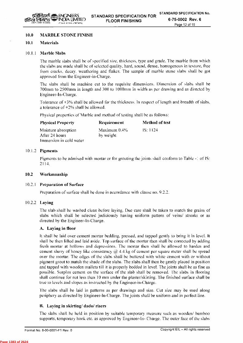
q_.1 M ENGINEERS STANDARD SPECIFICATION FOR STANDARD SPECIFICATION No.
ig-ZifiaWeg ',II, INDIA LIMITED FLOOR FINISHING 6-75-0002 Rev. 6 ,i27S317 NA., IA Go, of India Undertaking)
Page 12 of 15
10.0 MARBLE STONE FINISH
10.1 Materials
10.1.1 Marble Slabs
The marble slabs shall be of specified size, thickness, type and grade. The marble from which the slabs are made shall be of selected quality, hard, sound, dense, homogenous in texture, free from cracks, decay, weathering and flakes. The sample of marble stone slabs shall be got approved from the Engineer-in-Charge.
The slabs shall be machine cut to the requisite dimensions. Dimension of slabs shall be 700mm to 2500mm in length and 300 to 1000mm in width as per drawing and as directed by Engineer-In-Charge.
Tolerance of +3% shall be allowed for the thickness. In respect of length and breadth of slabs, a tolerance of +2% shall be allowed.
Physical properties of Marble and method of testing shall be as follows:
Physical Property
Requirement
Method of test
Moisture absorption
Maximum 0.4%
IS: 1124
After 24 hours
by weight Immersion in cold water
10.1.2 Pigments
Pigments to be admixed with mortar or for grouting the joints shall conform to Table -1 of IS: 2114.
10.2 Workmanship
10.2.1 Preparation of Surface
Preparation of surface shall be done in accordance with clause no. 9.2.2.
10.2.2 Laying
The slab shall be washed clean before laying. Due care shall be taken to match the grains of slabs which shall be selected judiciously having uniform pattern of veins/ streaks or as directed by the Engineer-In-Charge.
A. Laying in floor
It shall be laid over cement mortar bedding, pressed, and tapped gently to bring it in level. It shall be then lifted and laid aside. Top surface of the mortar then shall be corrected by adding fresh mortar at hollows and depressions. The mortar then shall be allowed to harden and cement slurry of honey like consistency @ 4.4.kg of cement per square meter shall be spread over the mortar. The edges of the slabs shall be buttered with white cement with or without pigment grout to match the shade of the slabs. The slabs shall then be gently placed in position and tapped with wooden mallets till it is properly bedded in level. The joints shall be as fine as possible. Surplus cement on the surface of the slab shall be removed. The slabs in flooring shall continue for not less than 10 mm under the plaster/skirting. The finished surface shall be true to levels and slopes as instructed by the Engineer-in-Charge.
The slabs shall be laid in patterns as per drawings and size. Cut size may be used along periphery as directed by Engineer-In-Charge. The joints shall be uniform and in perfect line.
B. Laying in skirting/ dado/ risers
The slabs shall be held in position by suitable temporary measure such as wooden/ bamboo supports, temporary hook etc. as approved by Engineer-In- Charge. The outer face of the slabs
Format No. 8-00-0001-F1 Rev. 0
Copyright EIL — All rights reserved
Page 1383 of 2624

STANDARD SPECIFICATION No. ENGINEERS STANDARD SPECIFICATION FOR INDIA LIMITED FLOOR FINISHING 6-75-0002 Rev. 6 ■A Go, of ■ ntha Undeffak,^9/
Page 13 of 15
shall be checked for plane and plumb and corrected. The joints shall be as fine as possible and shall be filled with neat cement paste/ grout with white cement and pigment to match the colour of the slabs. The joints shall thus be left to harden and then the rear gap between the slabs and backing surface shall be packed with cement mortar of specified mix and thickness. Temporary supports shall be removed after the mortar filling in the gap has acquired sufficient strength. The top line of the skirting/ dado/ risers shall be truly horizontal and joints truly vertical.
10.3 Curing
The finished surface shall be cured for a minimum period of 7 days.
10.4 Polishing and Finishing
Unevenness at the meeting edges of slabs shall be removed by fine chiseling.
The day after the tiles are laid all joints shall be cleaned with a wire brush to a depth of 5 mm and all dust and loose mortar removed and cleaned. Joints shall then be grouted with grey or white cement mixed with or without pigment to match the shade of the stones.
Grinding shall be commenced after a minimum period of 7 days when the stones and the joints are properly set. Grinding shall be done by machines. First grinding shall be done with carborundum stones of 60 grade grit fitted in the machine. Water shall be profusely during grinding. When the chips show up and the floor has been uniformly rubbed, it shall be cleaned with water baring all pin holes. The second grinding shall be done with carborundum stone of 120 grit. Final grinding/polishing shall done the day after the second grinding with carborundum stone of 320 grit using water in abundance. The surface shall be washed clean with water, oxalic acid powder shall then be dusted at 33 gms/sq. m. on the surface rubbed with machine fitted hessian bobs or rubbed hard with woolen rags. The surface shall then be washed clean and dried with a soft cloth or linen. If any stone is disturbed or damaged, it shall be refitted or replaced and properly jointed and polished.
11.0 PVC FINISH
11.1 Material
11.1.1 PVC Roll/ Tiles
PVC Roll/ tiles shall be homogenous, asbestos free, approved texture, colour, pattern and specified thickness. PVC rolls shall conform to IS: 3462 and PVC tiles shall conform to IS: 3462
11.1.2 Antistatic PVC Roll/Tile
Antistatic P.V.C. roll/ tiles shall conform to B.S.2050, Table-2.
11.1.3 Adhesive
Adhesive shall be neoprene based rubber adhesive of approved make as recommended by PVC Manufacture.
11.2 Workmanship
The sub floor on which PVC finish is to be laid shall be prepared in accordance with PVC Manufacturer's recommendation. The sub floor shall be made permanently smooth, firm, free of cracks and dry. If required, suitable leveling compound of minimum 3 mm thickness shall be applied over sub floor.
P.V.C. rolls/tiles shall be brought to the temperature of the area in which it is to be laid and stacked suitably near the site in accordance with manufacturer's recommendation.
‘.5ilfaeJerf fat s
NWil ATI. MT.
Format No. 8-00-0001-F1 Rev. 0
Copyright EIL — All rights reserved
Page 1384 of 2624
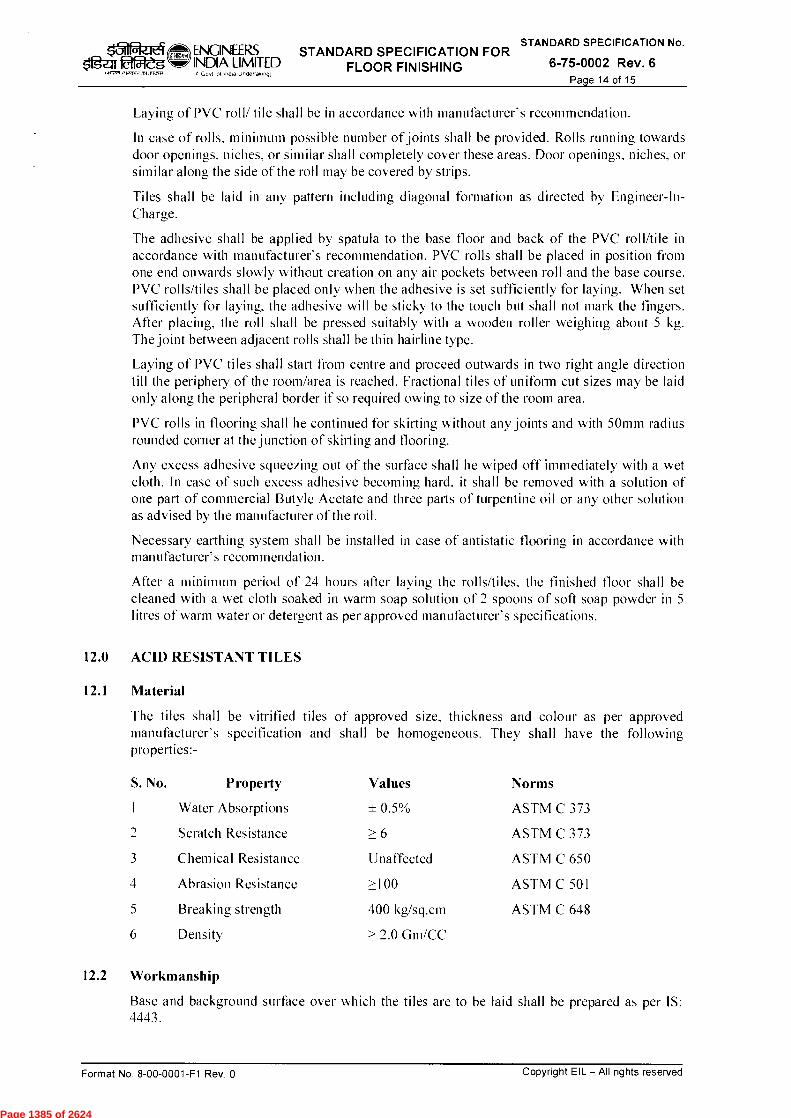
STANDARD SPECIFICATION No. ENGINEERS STANDARD SPECIFICATION FOR oaf054-"eg INDIA LIMITED FLOOR FINISHING 6-75-0002 Rev. 6
.Hr., 711
Page 14 of 15
Laying of PVC roll/ tile shall be in accordance with manufacturer's recommendation.
In case of rolls, minimum possible number of joints shall be provided. Rolls running towards door openings, niches, or similar shall completely cover these areas. Door openings, niches, or similar along the side of the roll may be covered by strips.
Tiles shall be laid in any pattern including diagonal formation as directed by Engineer-In-Charge.
The adhesive shall be applied by spatula to the base floor and back of the PVC roll/tile in accordance with manufacturer's recommendation. PVC rolls shall be placed in position from one end onwards slowly without creation on any air pockets between roll and the base course. PVC rolls/tiles shall be placed only when the adhesive is set sufficiently for laying. When set sufficiently for laying, the adhesive will be sticky to the touch but shall not mark the fingers. After placing, the roll shall be pressed suitably with a wooden roller weighing about 5 kg. The joint between adjacent rolls shall be thin hairline type.
Laying of PVC tiles shall start from centre and proceed outwards in two right angle direction till the periphery of the room/area is reached. Fractional tiles of uniform cut sizes may be laid only along the peripheral border if so required owing to size of the room area.
PVC rolls in flooring shall he continued for skirting without any joints and with 50mm radius rounded corner at the junction of skirting and flooring.
Any excess adhesive squeezing out of the surface shall he wiped off immediately with a wet cloth. In case of such excess adhesive becoming hard, it shall be removed with a solution of one part of commercial Butyle Acetate and three parts of turpentine oil or any other solution as advised by the manufacturer of the roll.
Necessary earthing system shall be installed in case of antistatic flooring in accordance with manufacturer's recommendation.
After a minimum period of 24 hours after laying the rolls/tiles, the finished floor shall be cleaned with a wet cloth soaked in warm soap solution of 2 spoons of soft soap powder in 5 litres of warm water or detergent as per approved manufacturer's specifications.
12.0 ACID RESISTANT TILES
12.1 Material
The tiles shall be vitrified tiles of approved size, thickness and colour as per approved manufacturer's specification and shall be homogeneous. They shall have the following properties:-
S. No. Property Values Norms
1 Water Absorptions ± 0.5% ASTM C 373
2 Scratch Resistance > 6 ASTM C 373
3 Chemical Resistance Unaffected ASTM C 650
4 Abrasion Resistance >100 ASTM C 501
5 Breaking strength 400 kg/sq.cm ASTM C 648
6 Density > 2.0 Gm/CC
12.2 Workmanship
Base and background surface over which the tiles are to be laid shall be prepared as per IS: 4443.
Format No. 8-00-0001-F1 Rev. 0
Copyright EIL — All rights reserved
Page 1385 of 2624

ENGINEERS STANDARD SPECIFICATION FOR STANDARD SPECIFICATION No.
falgrarg INDIA LIMITED FINISHING 6-75-0002 Rev. 6 Govt of ■ ntl. Unne/takg)
Tiles shall be fixed on the prepared surface over a bitumen priming layer, bitumen mastic layer and resin type chemical resistant mortar in accordance with manufacturer's recommendation. The bitumen shall conform to IS: 702 and laying of bitumen mastic shall conform to IS: 1196.
Joints shall be allowed to set for 24 hours. The floor shall then be washed as per manufacturer's specifications to totally remove all marks from tile surface.
13.0 EPDXY FLOOR & WALL COATING SYSTEM
13.1 Material
The epoxy floor and wall coating system shall generally consist of the following basic components of composition and thickness as mentioned in the item descriptions:
13.1.1 Primer Coat
Primer coat shall be suitable for base surface and compatible with successive layers/ coating over it for specified applications in accordance with the approved manufacturer's recommendations.
13.1.2 Screed/ Underlayer
The screed/ underlayer (for flooring) shall consist of combination of fillers and hardeners and shall be suitable and compatible for application of top/ finishing coat over it for specified application in accordance with the approved manufacturer's recommendations.
13.1.3 Top/ Finishing Coat
Top/ finishing coat shall be applied over screed/ underlayer in case of flooring. For walls/ vertical surfaces, top/ finishing coat shall be applied over primer coat as recommended by approved manufacturer. Top/ finishing coat shall be suitable for specified application.
13.2 Workmanship
Workmanship shall be in accordance with manufacturer's specifications.
14.0 MEASUREMENT AND RATE
Measurement and rate for flooring for item rate tenders shall be in Square meter in general unless otherwise mentioned.
Length and breadth shall be measured before laying skirting, dado or wall plaster. No deduction shall be made nor extra paid for voids not exceeding 0.20 sqm. Deductions for ends of dissimilar materials or other articles embedded shall not be made for areas not exceeding 0.10 sqm.
The flooring done either with strips (in one operation) or without strips (in alternate panels) shall be treated as same and measured together.
Page 15 of 15
Copyright EIL — All rights reserved Format No. 8-00-0001-F1 Rev. 0
Page 1386 of 2624
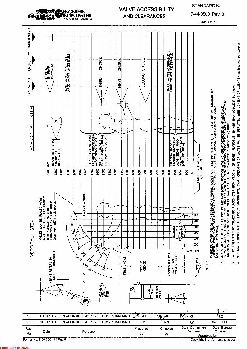
STANDARD No.
7-44-0503 Rev. 3
Page 1 of 1
VALVE ACCESSIBILITY
AND CLEARANCES $11gMOBsIGNEERS
N/A LINVIED (A Govt. of Indio Undertaking)
RN
SC RN
SC
DM ND
3 01.07.15 REAFFIRMED & ISSUED AS STANDARD SH
2 10.07.10 REAFFIRMED Sc ISSUED AS STANDARD PK
Rev.
No. Date Purpose
Prepared Checked
by by
Stds. Committee Stds. Bureau Convenor Chairman
Approved by Copyright EIL - All rights reserved Format No. 8-00-0001-F4 Rev .O
[ I
, /
/ LAR
C
0,L
m
7
LA
Kta
0 0 0 0 0 0 0 0 0 0 4
•
N N N
0 0 0 0 0 0 0 0 0 0 0 0 0 0 0 0 0 0 0 0 0 0 0 0 0 0 0 CO N CO N * M N •-• 0 0 0 0 0 0 0 0 Ot OD f`t.
0 ID * N
O O
005
009 ce 0
Lal )- 1-)
Lai Z Z _J < 0
Z WVl
Z 4
UJW
ce O
00
UJ
I=
Lii
0 -U3 tat Z
IAJ
00
00£
U
00Z
0
U re a. 0
I-
C N 0 C
OP
ER
ATI
ON
OF
VA
LV
ES
MA
Y B
E P
ER
MIT
TE
D W
ITH
CO
NSE
NT
OF
CU
EN
T'S
/ O
PE
RA
TIN
G P
ER
SON
NE
L.
RE
QU
IRE
S T
HA
T V
AL
VE
S B
E P
LA
CE
D O
VE
R H
IGH
(3.
00 m
OR
MO
RE
) P
LA
TFO
RM
S, R
AT
HE
R T
HA
N A
DJA
CEN
T T
O T
HE
M.
ER
TA
INS
CA
SE
S D
UE
TO
LA
YO
UT
CO
NS
TRA
INTS
, CH
AIN
- N Po 4
ce ce
LLI 0.
X Z o w ppW
Page 1387 of 2624
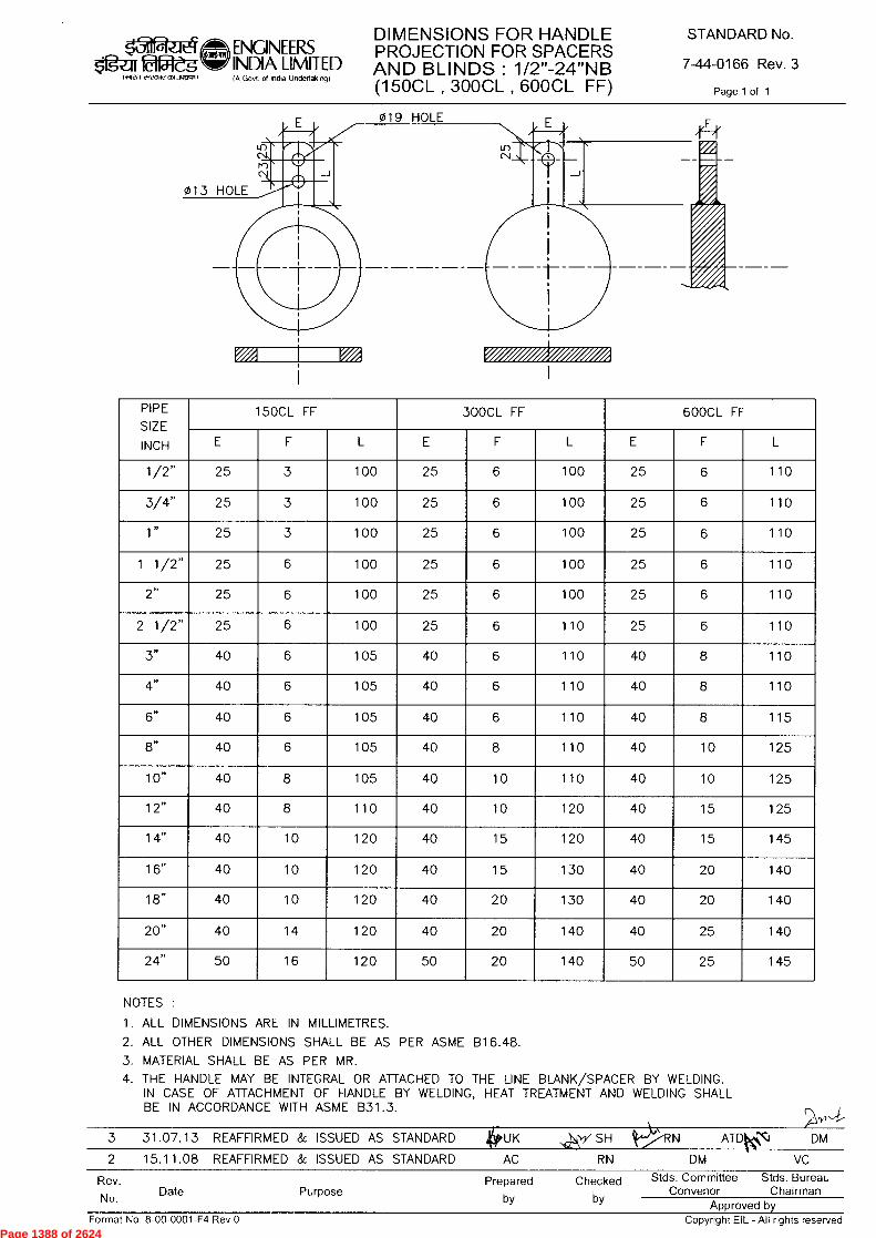
019 HOLE
013 HOLE
ENGINEERS INDIA LIMITED
DIMENSIONS FOR HANDLE PROJECTION FOR SPACERS AND BLINDS : 1/2"-24"NB (150CL , 300CL , 600CL FF)
STANDARD No.
7-44-0166 Rev. 3
Page 1 of 1
( igen tYeCOle CYR Jgcr.-1)
(A Govt of India Undertaking)
PIPE
SIZE
INCH
15OCL FF 300CL FF 600CL FF
E F L E F L E F L
1/2" 25 3 100 25 6 100 25 6 110
3/4" 25 3 100 25 6 100 25 6 110
1" 25 3 100 25 6 100 25 6 110
1 1/2" 25 6 100 25 6 100 25 6 110
2" 25 6 100 25 6 100 25 6 110
2 1/2" 25 6 100 25 6 110 25 6 110
3" 40 6 105 40 6 110 40 8 110
4" 40 6 105 40 6 110 40 8 110
6" 40 6 105 40 6 110 40 8 115
8" 40 6 105 40 8 110 40 10 125
10" 40 8 105 40 10 110 40 10 125
12" 40 8 110 40 10 120 40 15 125
14" 40 10 120 40 15 120 40 15 145
16" 40 10 120 40 15 130 40 20 140
18" 40 10 120 40 20 130 40 20 140
20" 40 14 120 40 20 140 40 25 140
24" 50 16 120 50 20 140 50 25 145
(;v4
3 31.07.13 REAFFIRMED & ISSUED AS STANDARD 4UK ,scr * SH ORN ATDK) DM
2 15.11.08 REAFFIRMED & ISSUED AS STANDARD AC RN DM VC
Rev. No. Date Purpose
Prepared Checked
by by
Stds. Committee Stds. Bureau Convenor Chairman
Approved by Format No. 8-00-0001-F4 Rev.O
Copyright EIL - All rights reserved
NOTES :
1. ALL DIMENSIONS ARE IN MILLIMETRES.
2. ALL OTHER DIMENSIONS SHALL BE AS PER ASME B16.48.
3. MATERIAL SHALL BE AS PER MR. 4. THE HANDLE MAY BE INTEGRAL OR ATTACHED TO THE LINE BLANK/SPACER BY WELDING.
IN CASE OF ATTACHMENT OF HANDLE BY WELDING, HEAT TREATMENT AND WELDING SHALL BE IN ACCORDANCE WITH ASME 831.3.
Page 1388 of 2624

122 aarn51
ENGINEERS INDIA LIMITED IA Govt of India Undertak.ng)
STANDARD SPECIFICATION FOR HEALTH, SAFETY &
ENVIRONMENT MANAGEMENT AT CONSTRUCTION SITES
STANDARD SPECIFICATION No.
6-82-0001 Rev. 6
Page 1 of 87
1-11-1 ul -f-zffl 'zr{
WkcIT 1141<ui
3T4tT9' irq
STANDARD SPECIFICATION FOR HEALTH, SAFETY & ENVIRONMENT
(HSE) MANAGEMENT AT CONSTRUCTION SITES
6 26/02/2014 REVISED & UPDATED SM J RKD SC
5 19/12/2012 REVISED & UPDATED SM SM RKD DM
4 13/02/2008 REVISED & UPDATED AS RK SCB VC
3 17/07/2007 REVISED & UPDATED AS MPJ VNP VC
2 11/08/2005 REVISED & UPDATED MPJ MPJ VNP VJN
Standards Standards Comm ittee Bureau
Rev Date Purpose Prepared by Checked by Convenor Chairman
Approved by
Format No. 8-00-0001-F1 Rev. 0 Copyright EIL — All rights reserved
Page 1389 of 2624

STANDARD SPECIFICATION FOR HEALTH, SAFETY &
ENVIRONMENT MANAGEMENT AT CONSTRUCTION SITES
STANDARD SPECIFICATION No.
6-82-0001 Rev. 6 Page 2 of 87
Format No. 8-00-0001-F1 Rev. 0 Copyright EIL – All rights reserved
Abbreviations: AERB : Atomic Energy Regulatory Board ANSI : American National Standards Institute BARC : Bhabha Atomic Research Centre BS : British Standard EIL : Engineers India Limited ELCB : Earth Leakage Circuit Breaker EPC : Engineering, Procurement and Construction EPCC : Engineering, Procurement, Construction and Commissioning ESI : Employee State Insurance GCC : General Conditions of Contract GM : General Manager GTAW : Gas Tungsten Arc Welding HOD : Head of Department HSE : Health, Safety & Environment HV : High Voltage IS : Indian Standard IE : Indian Electricity JSA : Job Safety Analysis LOTO : Lock Out & Tag Out LPG : Liquefied Petroleum Gas LSTK : Lump Sum Turn Key MV : Medium Voltage PPE : Personal Protective Equipment RCM : Resident Construction Manager or Site-in-Charge, as applicable ROW : Right of Way SCC : Special Conditions of Contract SLI : Safe Load Indicator TBM : Tool Box Talks Construction Standards Committee Convenor : Sh. RK Das, ED(Construction) Members : Sh. M.Deshpande, GM (C) Sh. M. Natarajan, GM (C&P) Sh Rakesh Nanda, DGM (Piping)
Sh. S Mukherjee, DGM (Construction) Sh. Janak Kishore, DGM (Projects) Sh. D. Jana, AGM (Construction)
Page 1390 of 2624
STANDARD SPECIFICATION FOR HEALTH, SAFETY &
ENVIRONMENT MANAGEMENT AT CONSTRUCTION SITES
STANDARD SPECIFICATION No.
6-82-0001 Rev. 6 Page 3 of 87
Format No. 8-00-0001-F1 Rev. 0 Copyright EIL – All rights reserved
CONTENTS CLAUSE TITLE PAGE NO.
1.0 Scope 5 2.0 References 5
3.0 Requirement of Health, Safety and Environment (HSE) Management System to be complied by Bidders
5
3.1 Management Responsibility 5
3.1.1 HSE Policy & Objective 5 3.1.2 Management System 5
3.1.3 Indemnification 6
3.1.4 Deployment & Qualification of Safety Personnel
6
3.1.5 Implementation, Inspection & Monitoring 7
3.1.6 Behavior Based Safety 8
3.1.7 Awareness 9 3.1.8 Fire prevention & First-Aid 9
3.1.9 Documentation 9 3.1.10 Audit 10 3.1.11 Meetings 10
3.1.12 Intoxicating drinks & drugs and smoking 11
3.1.13 Penalty 11
3.1.14 Accident/Incident investigation 14
3.2 House Keeping 14 3.3 HSE Measures 15
3.3.1 Construction Hazards 15
3.3.2 Accessibility 16
3.3.3 Personal Protective Equipments (PPEs) 16
3.3.4 Working at height 17
3.3.5 Scaffoldings 18
3.3.6 Electrical installations 19
3.3.7 Welding/Gas cutting 21
3.3.8 Ergonomics and tools & tackles 22
3.3.9 Occupational Health 22 3.3.10 Hazardous substances 23
3.3.11 Slips, trips & falls 23
3.3.12 Radiation exposure 23 3.3.13 Explosives/Blasting operations 24 3.3.14 Demolition/Dismantling 24 3.3.15 Road Safety 24 3.3.16 Welfare measures 25 3.3.17 Environment Protection 25 3.3.18 Rules & Regulations 26
Contd to page 4 …
Page 1391 of 2624
STANDARD SPECIFICATION FOR HEALTH, SAFETY &
ENVIRONMENT MANAGEMENT AT CONSTRUCTION SITES
STANDARD SPECIFICATION No.
6-82-0001 Rev. 6 Page 4 of 87
Format No. 8-00-0001-F1 Rev. 0 Copyright EIL – All rights reserved
CONTENTS (contd. from page 3)
3.3.19 Weather Protection 26 3.3.20 Communication 26 3.3.21 Confined Space Entry 27 3.3.22 Heavy Lifts 27 3.3.23 Key performance indicators 27 3.3.24 Unsuitable Land Conditions 28 3.3.25 Under Water Inspection 28 3.3.26 Excavation 28 3.4 Tool Box talks 29 3.5 Training & Induction Programme 30 3.6 Additional safety requirements for working Inside a running 31 3.7 Self Assessment and Enhancement 32 3.8 HSE Promotion 32 3.9 LOTO for isolation of energy source 32
4.0 Details of HSE Management System by Contractor 4.1 On Award of Contract 33 4.2 During Job Execution 33 4.3 During short listing of the sub-contractors 34
5.0 Records 35Appendices
1. Standards/Codes on HSE Appendix-A 2. Details of First AID Box Appendix-B 3. Types of Fire Extinguishers & their Appln. Appendix-C 4. Indicative List of statutory Acts & Rules Appendix-D 5. Construction Hazards and their mitigation Appendix-E 6. Training subjects / topics Appendix-F 7. Construction Power Board ( typ) Appendix-G 8. List of HSE procedures Appendix-H
Attachments (Reporting Formats) I. Safety Walk through Report HSE-1 Rev.0 II. Accident/Incident Report HSE-2 Rev.0 III. Suppl. Accident/Incident Investigation Report HSE-3 Rev.0 IV. Near Miss Incident Report/Dangerous occurrence HSE-4 Rev.0 V. Monthly HSE Report HSE-5 Rev.0 VI. Permit for Working at height HSE-6 Rev.0 VII. Permit for Working in Confined Space HSE-7 Rev.0 VIII. Permit for Radiation work HSE-8 Rev.0 IX. Permit for Demolishing/ Dismantling HSE-9 Rev.0 X Daily Safety Checklist HSE-10 Rev.0 XI Housekeeping assessment & compliance HSE-11 Rev.0
XII Inspection of temporary electrical booth / installation HSE-12 Rev.0 XIII Inspection for scaffolding HSE-13 Rev.0 XIV Permit for erection / modification & dismantling of
scaffolding HSE-14 Rev.0
XV Permit for heavy lift/critical erection HSE-15 Rev.0 XVI Permit Energy Isolation & De-Isolation HSE-16 Rev 0 XVI Permit for Excavation HSE-17 Rev 0
Page 1392 of 2624
STANDARD SPECIFICATION FOR HEALTH, SAFETY &
ENVIRONMENT MANAGEMENT AT CONSTRUCTION SITES
STANDARD SPECIFICATION No.
6-82-0001 Rev. 6 Page 5 of 87
Format No. 8-00-0001-F1 Rev. 0 Copyright EIL – All rights reserved
1.0 SCOPE
This specification establishes the Health, Safety and Environment (HSE) management requirement to be complied by Contractors/Vendors including their sub-contractors/sub vendors during construction. This specification is not intended to replace the necessary professional judgment needed to design & implement an effective HSE system for construction activities and the contractor is expected to fulfill HSE requirements in this specification as a minimum. It is expected that contractor shall implement best HSE practices beyond whatever are mentioned in this specification. Requirements stipulated in this specification shall supplement the requirements of HSE Management given in relevant Act(s)/legislations, General Conditions of Contract (GCC), Special Conditions of Contract (SCC) and Job (Technical) Specifications. Where different documents stipulate different requirements, the most stringent shall apply.
2.0 REFERENCES The document should be read in conjunction with following: - General Conditions of Contract (GCC) - Special Conditions of Contract (SCC) - Building and other construction workers Act, - Indian Factories Act - Job (Technical) specifications - Relevant International / National Codes (refer Appendix-A for standards/codes on HSE) - Relevant State & National Statutory requirements. - Operating Manuals Recommendation of Manufacturer of various construction Machineries
3.0 REQUIREMENTS OF HEALTH, SAFETY & ENVIRONMENT (HSE) MANAGEMENT SYSTEM TO BE COMPLIED BY BIDDERS
3.1 Management Responsibility
3.1.1 HSE Policy & Objectives The Contractor should have a documented HSE policy duly & objectives to demonstrate commitment of their organization to ensure health, safety and environment aspects in their line of operations. HSE Policy of the contractor shall be made available to Owner / EIL at the place of execution of specific contract works, as a valid document.
3.1.2 Management System The HSE management system of the Contractor shall cover the HSE requirements & commitments to fulfill them, including but not limited to what are specified under clause 1.0 and 2.0 above. The Contractor shall obtain the approval of its site specific HSE Plan from EIL / Owner prior to commencement of any site works. Corporate as well as Site management of the Contractor shall ensure compliance of their HSE Plan at work sites in its entirety & in true spirit.
Page 1393 of 2624

STANDARD SPECIFICATION FOR HEALTH, SAFETY &
ENVIRONMENT MANAGEMENT AT CONSTRUCTION SITES
STANDARD SPECIFICATION No.
6-82-0001 Rev. 6 Page 6 of 87
Format No. 8-00-0001-F1 Rev. 0 Copyright EIL – All rights reserved
3.1.3 Indemnification Contractor shall indemnify & hold harmless, Owner/EIL & their representatives, free from any
and all liabilities arising out of non-fulfillment of HSE requirements or its consequences.
3.1.4 Deployment & qualifications of Safety personnel The Contractor shall designate/deploy various categories of HSE personnel at site as indicated below in sufficient number. In no case, deployment of safety Supervisor / Safety Steward shall substitute deployment of Safety Officer / Safety Engr what is indicated in relevant statute of BOCW Act i.e deployment of safety officer/Safety Engineer is compulsory at project site. The Safety supervisors, Safety stewards etc. would facilitate the HSE tasks at grass root level for construction sites and shall assist Safety Officer / Engineers. a) Safety Steward For every 250 workmen, one safety steward shall be deployed. As a minimum, he shall preferably possess School leaving Certificate (of Class XII with
Physics & Chemistry etc.) and trained in fire-fighting as well as in safety/occupational health related subjects, with minimum two year of practical experience in construction work environment and preferably have adequate knowledge of the language spoken by majority of the workers at the construction site.
b) Safety Supervisor For every 500workmen, one safety Supervisor shall be deployed. As a minimum, he shall possess a recognized Degree in Science (with Physics &
Chemistry) or a diploma in Engg. or Tech. with minimum Two years of practical experience in construction work environment and should possess requisite skills to deal with construction safety & fire related day-to-day issues.
c) Safety Officer / Safety Engineer
One for every 1000 workers or part thereof shall be deployed.
Safety officer/Engineer Should Possess following Qualification & Experience :
(i) Recognized degree in any branch of Engg. or Tech. or Architecture with practical experience of working in a building or other construction work in supervisory capacity for a period of not less than two years, or possessing recognized diploma in any branch of Engg. or Tech with practical experience of building or other construction work in supervisory capacity for a period of not less than five years.
(ii) Recognized degree or diploma in Industrial safety with one paper in Construction
Safety (iii) Preferably have adequate knowledge of the language spoken by majority of the
workers at the construction site.
Alternately
(i) Person possessing Graduation Degree in Science with Physics & Chemistry and degree or diploma in Industrial Safety (from any Indian institutes recognized by
Page 1394 of 2624
STANDARD SPECIFICATION FOR HEALTH, SAFETY &
ENVIRONMENT MANAGEMENT AT CONSTRUCTION SITES
STANDARD SPECIFICATION No.
6-82-0001 Rev. 6 Page 7 of 87
Format No. 8-00-0001-F1 Rev. 0 Copyright EIL – All rights reserved
AICTE or State Council of Tech. Education of any Indian State) with practical experience of working in a building, plant or other construction works (as Safety Officer, in line with Indian Factories Act, 1958) for a period of not less than five years, may be considered as Safety Officer, in case Owner/Client of the project agrees for /approves the same.
d) HSE In-Charge
In case there is more than one Safety Officer at any project construction site, one of them, who is senior most by experience (in HSE discipline), may be designated as HSE In-Charge. Duties & responsibilities of such person shall be commensurate with that of relevant statute and primarily to coordinate with top management of Client and contractors.
In case the statutory requirements i.e. State or Central Acts and / or Rules as applicable like the Building and Other Construction Workers’ Regulation of Employment and Conditions of Service- Act,1996 or State Rules (wherever notified), the Factories Act, 1948 or Rules (wherever notified), etc. are more stringent than above clarifications, the same shall be followed. Contractors shall ensure physical availability of safety personnel at the place of specific work location, where Hot Work Permit is required / granted. No work shall be started at any of the project sites until above safety personnel & concerned Site Engineer of Contractor are physically deployed at site. The Contractor shall submit a HSE organogram clearly indicating the lines of responsibility and reporting system and elaborate the responsibilities of safety personnel in their HSE Plan. The Contractor shall verify & authenticate credentials of such safety personnel and furnish Bio-Data/ Resume/ Curriculum Vitae of the safety personnel as above for EIL/Owner’s approval, at least 1 month before the mobilization. The Contractor, whenever required, shall arrange submission of original testimonials/certificates of their Safety personnel, to EIL/Owner (for verification/scrutiny, etc.) Imposition / Realization of penalty shall not absolve the Contractor from his/her responsibility of deploying competent safety officer at site. Adequate planning and deployment of safety personnel shall be ensured by the Contractor so that field activities do not get affected because of non-deployment of competent & qualified safety people in appropriate numbers.
3.1.5 Implementation, Inspection/Monitoring
The Contractor shall be fully responsible for planning, reporting, implementing and
monitoring all HSE requirements and compliance of all laws & statutory requirements. The Contractor shall also ensure that the HSE requirements are clearly understood &
implemented conscientiously by their site personnel at all levels at site. The Contractor shall ensure physical presence of their field engineers / supervisors, during
the continuation of their contract works / site activities including all material transportation activities. Physical absence of experienced field engineers / supervisors of Contractor at critical work spot during the course of work, may invite severe penalization as per the discretion of EIC, including halting / stoppage of work.
Contractor shall furnish their annual Inspection Plan, with regard to project issues /subjects, frequency and performers to EIL/Owner.
The Contractor shall regularly review inspection report internally and implement all practical steps / actions for improving the status continuously.
Page 1395 of 2624
STANDARD SPECIFICATION FOR HEALTH, SAFETY &
ENVIRONMENT MANAGEMENT AT CONSTRUCTION SITES
STANDARD SPECIFICATION No.
6-82-0001 Rev. 6 Page 8 of 87
Format No. 8-00-0001-F1 Rev. 0 Copyright EIL – All rights reserved
The Contractor shall ensure important safety checks right from beginning of works at every work site locations and to this effect format No: HSE-10 “Daily Safety Check List” shall be prepared by field engineer & duly checked by safety personnel for conformance.
The Contractor shall carry out inspection to identify various unsafe conditions of work sites/machinery/equipments as well as unsafe acts on the part of workmen/supervisor/engineer while carrying out different project related works.
Adequate records for all inspections shall be maintained by the Contractor and the same shall be furnished to EIL/Owner, whenever sought.
The Contractor shall not carry-out work by engaging single worker anywhere without any supervisor anytime during day or night.
To demonstrate involvement/commitment of site management of Contractor, at least one Safety Walk through in a month shall be carried out by Contractor’s head of site (along with his area manager/field engineers) and a report shall be furnished to EIL/Owner as per format No: HSE-1” Safety walk through report” followed by compliance for unsatisfactory remarks.
As a general practice lifting tools/tackles, machinery, accessories etc. shall be inspected, tested and examined by competent people (approved by concerned State authorities) before being used at site and also at periodical interval (e.g. during replacement,extension, modification, elongation/reduction of machine/parts, etc.) as per relevant statutes. Hydra, cranes, lifting machinery, mobile equipments / machinery / vehicles, etc. shall be inspected regularly by only competent / experienced personnel at site and requisite records for such inspections shall be maintained by every contractor. Contractor shall also maintain records of maintenance of all other site machinery (e.g. generators, rectifiers, compressors, cutters, etc.) & portable tools/equipments being used at project related works (e.g. drills, abrasive wheels, punches, chisels, spanners, etc.). The Contractor shall not make use of arbitrarily fabricated ‘derricks’ at project site for lifting / lowering of construction materials.
Site facilities /temporary. installations, e.g. batching plant, cement godown, DG-room, temporary electrical panels/distribution boards, shot-blasting booth, fabrication yards, etc. and site welfare facilities, like labour colonies, canteen/pantry, rest-shelters, motor cycle/bicycle-shed, site washing facilities, First-aid centers, urinals/toilets, etc. should be periodically inspected by Contractor (preferably utilizing HR/Admn. personnel to inspect site welfare facilities) and records to be maintained.
3.1.6 Behaviour Based Safety
The contractor shall develop a system to implement Behaviour-Based Safety (BBS)
through which work groups can identify, measure and change the behaviours of employees and workers
The BBS process shall include the following: - Identify the behaviours critical to obtaining required safety performance. - Communicate the behaviours and how they are performed correctly to all - Observe the work force and record safe/at risk behaviours. Intervene with workers
to give positive reinforcement when safe behaviours are observed. Provide coaching/correction when at risk behaviours are observed
- Collect and record observation data - Summarize and analyze observation data - Communicate observation data and analysis results to all employees - Provide recognition or celebrate when safe behaviour improvements occur - Change behaviours to be observed or change activators or change consequences as
appropriate. - Communicate any changes to workforce
Contractor through its own HSE committee shall implement the above process. The necessary procedures and reporting formats shall be developed by the contractor for
approval by EIL/Owner.
Page 1396 of 2624
STANDARD SPECIFICATION FOR HEALTH, SAFETY &
ENVIRONMENT MANAGEMENT AT CONSTRUCTION SITES
STANDARD SPECIFICATION No.
6-82-0001 Rev. 6 Page 9 of 87
Format No. 8-00-0001-F1 Rev. 0 Copyright EIL – All rights reserved
The HSE committee of contractor shall observe individual’s behavior for safe practices adapted for utilization/execution of work for following as a minimum:- - PPE - Tools & equipment - Hazard Identification & control - House keeping - Confined space entry - Hot works - Excavation - Loading & unloading - Work At height - Stacking & storage - Ergonomics - Procedures
3.1.7 Awareness and Motivation
The Contractor shall promote and develop awareness on Health, Safety and Environment
protection among all personnel working for the Contractor. Regular awareness programs and fabrication shop / work site meetings at least on monthly
basis shall be arranged on HSE activities to cover hazards/risks involved in various operations during construction.
Contractor to motivate & encourage the workmen & supervisory staff by issuing / awarding them with tokens/ gifts/ mementos/ monetary incentives / certificates, etc.
Contractor shall assess & recognize the behavioral change of its site engineers / supervisors periodically and constantly motivate / encourage them to implement HSE practices at project works
3.1.8 Fire prevention & First-Aid The Contractor shall arrange suitable First-aid measures such as First Aid Box (Refer
Appendix-B for details), trained personnel/nurse (male) to administer First Aid, stand-by Ambulance vehicle and
The Contractor shall arrange installation of fire protection measures such as adequate number of steel buckets with sand & water and adequate number of appropriate portable fire extinguishers (Refer Appendix-C for details) to the satisfaction of EIL/Owner.
The Contractor shall deploy trained supervisory personnel / field engineers to cater to any emergency situation.
In case the number of workers exceeds 500, the Contractor shall position an Ambulance / vehicle and nurse on round the clock basis very close to the worksite.
The Contractor shall arrange FIRE DRILL at each site at least once in three months, involving site workmen and site supervisory personnel & engineers. The Contractor shall maintain adequate record of such fire drills at project site
3.1.9 Documentation
The Contractor shall evolve a comprehensive, planned and documented system covering the following as a minimum for implementation and monitoring of the HSE requirements and the same shall be submitted for approval by owner/EIL. - HSE Organogram - Site specific HSE Plan - Safety Procedures, forms and Checklist. Indicative list of HSE procedures is attached as
Appendix :H - Inspections and Test Plan - Risk Assessment & Job Safety Analysis for critical works.
Page 1397 of 2624
STANDARD SPECIFICATION FOR HEALTH, SAFETY &
ENVIRONMENT MANAGEMENT AT CONSTRUCTION SITES
STANDARD SPECIFICATION No.
6-82-0001 Rev. 6 Page 10 of 87
Format No. 8-00-0001-F1 Rev. 0 Copyright EIL – All rights reserved
The monitoring for implementation shall be done by regular inspections and compliance of the observations thereof. The Contractor shall get similar HSE requirements implemented at his sub-contractor(s) work site/office. However, compliance of HSE requirements shall be the responsibility of the Contractor. Any review/approval by EIL/Owner shall not absolve contractor of his responsibility/liability in relation to fulfilling all HSE requirements.
3.1.10 Audit
The Contractor shall submit an Audit Plan to EIL/Owner indicating the type of audits and covering following as minimum: Internal HSE audits regularly at least on quarterly basis by engaging internal qualified
auditors (viz safety officers/Construction personnel having 5 years experience in construction safety and Lead Auditor Course :OSHA 18001certification).
External HSE audits regularly at least on every six months by engaging qualified external auditors (viz safety officers/Construction personnel having 10 years experience in construction safety and Lead Auditor Course :OSHA 18001certification).
All HSE shortfalls/ non-conformances on HSE matters brought out during review/audit, shall be resolved forthwith ( generally within a week) by Contractor & compliance report shall be submitted to EIL/Owner. In addition to above audits by contractor, the contractor’s work shall be subjected to HSE audit by EIL/Owner at any point of time during the pendency of contract. The CONTRACTOR shall take all actions required to comply with the findings of the Audit Report and issue regular Compliance Reports for the same to OWNER/ EIL till all the findings of the Audit Report are fully complied. Failure to carry-out HSE Audits & its compliance (internal & external) by Contractor, shall invite penalization.
3.1.11 Meetings The Contractor shall ensure participation of his top most executive at site (viz. Resident
Construction Manager / Resident Engineer / Project Manager / Site-in-Charge) in Safety Committee / HSE Committee meetings arranged by EIL/Owner usually on monthly basis or as and when called for. In case Contractor’s top most executive at site is not in a position to attend such meeting, he shall inform EIL/Owner in writing before the commencement of such meeting indicating reasons of his absence and nominate his representative – failure to do so may invite very stringent penalization against the specific Contractor, as deemed fit in Contract. The obligation of compliance of any observations during the meeting shall be always time bound. The Contractor shall always assist EIL/Owner to achieve the targets set by them on HSE management during the project implementation.
In addition, the Contractor shall also arrange internal HSE meetings chaired by his top most
executive at site on weekly basis and maintain records. Such internal HSE meetings shall essentially be attended by field engineers / supervisors (& not by safety personnel only) of the Contractor and its associates. Records of such internal HSE meetings shall be maintained by the Contractor for review by EIL/Owner or for any HSE Audits.
Agenda of internal HSE meeting should broadly cover: -
Page 1398 of 2624

STANDARD SPECIFICATION FOR HEALTH, SAFETY &
ENVIRONMENT MANAGEMENT AT CONSTRUCTION SITES
STANDARD SPECIFICATION No.
6-82-0001 Rev. 6 Page 11 of 87
Format No. 8-00-0001-F1 Rev. 0 Copyright EIL – All rights reserved
a) Confirmation of record notes / minutes of previous meeting b) Discussion on outstanding subjects of previous points / subjects, if any c) Incidents / Accidents (of all types) at project site, if any d) Current topics related to site activities / subjects of discussion e) House keeping f) Behavioral Safety g) Information / views / deliberations of members / site sub Contractors h) Report from Owner / Client i) Status of Safety awareness, Induction programs & Training programs
The time frame for such HSE meeting shall be religiously maintained by one and all.
3.1.12 Intoxicating drinks & drugs and Smoking
The Contractor shall ensure that his staff members & workers (permanent as well casual)
shall not be in a state of intoxication during working hours and shall abide by any law relating to consumption & possession of intoxicating drinks or drugs in force.
The Contractor shall not allow any workman to commence any work at any locations of project activity who is/are influenced / effected with the intake of alcohol, drugs or any other intoxicating items being consumed prior to start of work or working day.
Awareness about local laws on this issue shall form part of the Induction Training and compulsory work-site discipline.
The Contractor shall ensure that all personnel working for him comply with “No-Smoking”
requirements of the Owner as notified from time to time. Cigarettes, lighters, auto ignition tools or appliances as well as intoxicating drugs, dry tobacco powder, etc. shall not be allowed inside the project / plant complex.
Smoking shall be permitted only inside smoking booths exclusively designated &
authorized by the Owner/EIL.
3.1.13 Penalty The Contractor shall adhere consistently to all provisions of HSE requirements. In case of non-compliances and also for repeated failure in implementation of any of the HSE provisions, EIL/Owner may impose stoppage of work without any cost & time implication to the Owner and/or impose a suitable penalty. The amount of penalty to be levied against defaulted Contractor shall be up to a cumulative limit of 2.0% (Two percent) of the contract value for Item Rate or Composite contracts with an overall ceiling of 1, 00, 00, 000 (Rupees One crore) 0.5% (Zero decimal five percent) of the contract value for LSTK, OBE, EPC, EPCC or Package contracts with an overall ceiling of 10, 00.00.000 (Rupees ten crores) This penalty shall be in addition to all other penalties specified elsewhere in the contract. The decision of imposing stop-work-instruction and imposition of penalty shall rest with EIL/Owner. The same shall be binding on the Contractor. Imposition of penalty does not make the Contractor eligible to continue the work in unsafe manner. The amount of penalty applicable for the Contractor on different types of HSE violations is specified below:
Page 1399 of 2624
STANDARD SPECIFICATION FOR HEALTH, SAFETY &
ENVIRONMENT MANAGEMENT AT CONSTRUCTION SITES
STANDARD SPECIFICATION No.
6-82-0001 Rev. 6 Page 12 of 87
Format No. 8-00-0001-F1 Rev. 0 Copyright EIL – All rights reserved
Sl. No. Violation of HSE norms Penalty Amount
1. For not using personal protective equipment (Helmet, Shoes, Goggles, Gloves, Full body harness, Face shield, Boiler suit, etc.)
Rs 500/- per day/ Item / Person.
2. Working without Work Permit/Clearance Rs 20000/- per occasion
3 Execution of work without deployment of requisite field engineer / supervisor at work spot
Rs. 5000/- per violation per day
4. Unsafe electrical practices (not installing ELCB, using poor joints of cables, using naked wire without top plug into socket, laying wire/cables on the roads, electrical jobs by incompetent person, etc.)
Rs 10000/- per item per day.
5. Working at height without full body harness, using non-standard/ rejected scaffolding and not arranging fall protection arrangement as required, like hand-rails, life-lines, Safety Nets etc.
Rs. 10000/- per case per day.
6. Unsafe handling of compressed gas cylinders (No trolley, jubilee clips double gauge regulator, and not keeping cylinders vertical during storage/handling, not using safety cap of cylinder).
Rs 500/- per item per day.
7. Use of domestic LPG for cutting purpose / not using flash back arresters on both the hoses/tubes on both ends.
Rs. 3000/- per occasion.
8. No fencing/barricading of excavated areas / trenches.
Rs. 3000/- per occasion.
9. Not providing shoring/strutting/proper slope and not keeping the excavated earth at least 1.5M away from excavated area.
Rs.5, 000/- per occasion.
10. Non display of scaffold tags, caution boards, list of hospitals, emergency services available at work locations.
Rs.1000/- per occasion per day
11. Traffic rules violations like over speeding of vehicles, rash driving, talking on mobile phones during vehicle driving, wrong parking, not using seat belts, vehicles not fitted with reverse horn / warning alarms / flicker lamps during foggy weather.
Rs. 2000/- per occasion per day
12. Absence of Contractor’s RCM/SIC or his nominated representative (prior approval must be taken for each meeting for nomination) from site HSE meetings whenever called by EIL/Owner & failure to nominate his immediate deputy (in the site-organogram) for such HSE meetings.
Rs10000/- per meeting.
13. Failure to maintain HSE records by Contractor Safety personnel, in line with approved HSE Plan/Procedures/Contract specifications..
Rs 10000/- per month.
14. Failure to conduct daily site safety inspection (by Contractor’s safety engineers/safety officers), internal HSE meeting, internal HSE Awareness/Motivation Program, Site HSE Training and HSE audit at predefined frequencies (as approved in HSE Plan).
Rs.10000/- per occasion.
Page 1400 of 2624

STANDARD SPECIFICATION FOR HEALTH, SAFETY &
ENVIRONMENT MANAGEMENT AT CONSTRUCTION SITES
STANDARD SPECIFICATION No.
6-82-0001 Rev. 6 Page 13 of 87
Format No. 8-00-0001-F1 Rev. 0 Copyright EIL – All rights reserved
Sl. No. Violation of HSE norms Penalty Amount
15. Failure to submit the monthly HSE report by 5th of subsequent month to Project’s Engineer-in-Charge / Owner
Rs. 10000/- per occasion and Rs. 1000/- per day of further delay.
16. Poor House Keeping Rs. 5000/- per occasion per subject
17. Failure to report & follow up accident (including Near Miss) reporting system within specific time-frame.
Rs. 20000/- per occasion
18. Degradation of environment (not confining toxic spills, spilling oil/lubricants onto ground)
Rs10000/- per occasion
19. Not medically examining the workers before allowing them to work at height / to work in confined space / to work in shot-blasting / to work for painting / to work in bitumen or asphalt works, not providing ear muffs while allowing them to work in noise polluted areas, made them to work in air polluted areas without respiratory protective devices, etc.
Rs 5000/- per occasion per worker
20. Violation of any other safety condition as per job HSE plan / work permit and HSE conditions of contract (e.g. using crowbar on cable trenches, improper welding booth, not keeping fire extinguisher ready at hot work site, unsafe rigging practices, non-availability of First-Aid box at site, not using hood with respiratory devices by blaster for shot//grit blasting, etc.)
Rs. 5000/- per occasion
21. Failure to carry-out Safety audit in time (internal & external), close-out of identified shortfalls of Observations of Safety Aspects(OSA),etc
Rs. 20,000/- per occasion
22. Carrying out sand blasting instead of grit/shot blasting
Rs. 50,000/- per day
23. Failure to deploy adequately qualified and competent Safety Officer
Rs. 10000/- per day per Officer
24. Utilization of hydra/ back-hoe loader for material shifting or any other unauthorized /unsafe lifting works
Rs 25,000/- per occasion
25. Any incident / accident at project site has been caused because of willful negligence or gross violation of safety measures / provisions on the part of the Contractor or any of its sub-agencies
Rs 10,00,000/-per occasion
26. Any violation not covered above To be decided by EIL/Owner.
The Contractor shall make his field engineers/supervisors fully aware of the fact that they
keep track with the site workmen for their behavior and compliance of various HSE requirements. Safety lapses / defects of project construction site shall be attributable to the concerned job supervisor / engineer of the Contractor, (who remains directly responsible for safely executing field works). For repeated HSE violations, concerned job supervisor / engineer shall be reprimanded or appropriate action, as deemed fit, shall be initiated (with an information to EIL & Owner) by the concerned Contractor.
Page 1401 of 2624
STANDARD SPECIFICATION FOR HEALTH, SAFETY &
ENVIRONMENT MANAGEMENT AT CONSTRUCTION SITES
STANDARD SPECIFICATION No.
6-82-0001 Rev. 6 Page 14 of 87
Format No. 8-00-0001-F1 Rev. 0 Copyright EIL – All rights reserved
Contractor shall initiate verbal warning shall be given to the worker/employee during his first HSE violation. A written warning shall be issued on second violation and specific training shall be arranged / provided by the Contractor to enhance HSE awareness/skill including feedback on the mistakes/ flaws. Any further violation of HSE stipulations by the erring individuals shall call for his forthright debar from the specific construction site. A record of warnings for each worker/employee shall be maintained by the Contractor, like by punching their cards / Gate passes or by displaying their names at the Project entry gate. Warnings, penalizations, appreciations etc. shall be discussed in HSE Committee meetings by site Head of the Contractor.
3.1.14 Accident/ Incident investigation All accidents / incidents shall be informed to EIL/Owner at least telephonically by Contractor immediately and in writing within 24 hours on Format No. HSE-2 as applicable , by Contractor. Thereafter, a Supplementary Accident / Incident investigation Report on Format No. HSE-3 shall be submitted to EIL/Owner within 72 hours. Near Miss incident(s),Dangerous accidents/incident shall also be reported on Format No. HSE-4 within 24 hours. The accident/ incident shall be investigated by a team of Contractor’s senior Site personnel (involving Site-in-Charge or at least by his deputy) for establishing root-cause and recommending corrective & preventive actions. Findings shall be documented and suitable actions taken to avoid recurrences shall be communicated to EIL/Owner. Owner/EIL shall have the liberty to independently investigate such occurrences and the Contractor shall extend all necessary help and cooperation in this regard. EIL/Owner shall have the right to share the content of this report with the outside world.
3.2 House Keeping The Contractor shall ensure that a high degree of house keeping is maintained and shall ensure inter alia; the followings: a) All surplus earth and debris are removed/disposed off from the working areas to designated
location(s). b) Unused/surplus cables, steel items and steel scrap lying scattered at different places within
the working areas are removed to identify location(s). c) All wooden scrap, empty wooden cable drums and other combustible packing materials,
shall be removed from work place to identified location(s). d) Roads shall be kept clear and materials like pipes, steel, sand, boulders, concrete, chips and
bricks etc shall not be allowed on the roads to obstruct free movement of men & machineries.
e) Fabricated steel structural, pipes & piping materials shall be stacked properly for erection. f) Water logging on roads shall not be allowed. g) No parking of trucks/trolleys, cranes and trailers etc shall be allowed on roads, which may
obstruct the traffic movement. h) Utmost care shall be taken to ensure over all cleanliness and proper upkeep of the working
areas. i) Trucks carrying sand, earth and pulverized materials etc. shall be covered while moving
within the plant area/ or these materials shall be transported with top surface wet. j) The contractor shall ensure that the atmosphere in plant area and on roads is free from
particulate matter like dust, sand, etc. by keeping the top surface wet for ease in breathing. k) At least two exits for any unit area shall be assured at all times – same arrangement is
preferable for digging pits / trench excavation / elevated work platforms / confined spaces etc.
l) Welding cables and the power cable must be segregated and properly stored and used .The same shall be laid away from the area of movement and shall be free from obstruction.
m) Schedule for upkeep/cleaning of site to be firmed up and implemented on regular basis
Page 1402 of 2624
STANDARD SPECIFICATION FOR HEALTH, SAFETY &
ENVIRONMENT MANAGEMENT AT CONSTRUCTION SITES
STANDARD SPECIFICATION No.
6-82-0001 Rev. 6 Page 15 of 87
Format No. 8-00-0001-F1 Rev. 0 Copyright EIL – All rights reserved
The Contractor shall carry-out regular checks (minimum one per fortnight) as per format No: HSE-11 for maintaining high standard of housekeeping and maintain records for the same.
3.3 HSE Measures
3.3.1 Construction Hazards The Contractor shall ensure identification of all Occupational Health, Safety & Environmental hazards in the type of work he is going to undertake and enlist mitigation measures. Contractor shall carry out Job Safety Analysis (JSA)/Risk Analysis specifically for high risk jobs/crtical jobs like a) Working at height (+2.0 Mts height) for cold (incl. colour washing, painting, insulation
etc.) & hot works. b) Work in confined space, c) Deep excavations & trench cutting (depth > 2.0 mts.) d) Operation & Maintenance of Batching Plant. e) Shuttering / concreting (in single or multiple pour) for columns, parapets & roofs. f) Erection & maintenance of Tower Crane. g) Erection of structural steel members / roof-trusses / pipes at height more than 2.0 Mts. with
or without crane. h) Erection of pipes (full length or fabricated) at height more than 2.0 Mts. height with Crane
of 100T capacity. i) All lifts using 100T Crane plus mechanical pulling. j) All lifts using two cranes in unison (Tandem Lifting). k) Any lift exceeding 80% capacity of the lifting equipments (hydra, crane etc.). l) Laying of pipes (isolated or fabricated) in deep narrow trenches – manually or
mechanically. m) Maintenance of crane / extension or reduction of crane-boom on roads or in yards. n) Erection of any item at >2.0 Mts. height using 100T crane or of higher capacity o) Hydrostatic test of pipes, vessels & columns and water-flushing. p) Radiography jobs (in-plant & open field) q) Work in Live Electrical installations / circuits r) Handling of explosives & Blasting operations s) Demolishing / dismantling activities t) Welding / gas cutting jobs at height (+2.0 Mts.) u) Lifting / placing roof-girders at height (+2.0 Mts.) v) Lifting & laying of metallic / non-metallic sheet over roof/structures. w) Lifting of pipes, gratings, equipments/vessels at heights (+2.0 Mts) with & without using
cranes x) Calibration of equipment, instruments and functional tests at yards / work-sites. y) Operability test of Pump, Motors (after coupling) & Compressors. z) Cold or Hot works inside Confined Space. aa) Transportation & shifting of ODC consignments into project areas. bb) Working in “charged/Live” elect. Panels cc) Stress Relieving works (Electrically or by Gas-burners). dd) Pneumatic Tests ee) Card board blasting ff) Chemical cleaning
and take feedback from EIL/Owner. The necessary HSE measures devised shall be put in to place, prior to start of an activity & also shall be maintained during the course of works, by the Contractor. Copies of such JSAs shall be kept available at work sites by the Contractor to enable all concerned carrying out checks / verification.
Page 1403 of 2624
STANDARD SPECIFICATION FOR HEALTH, SAFETY &
ENVIRONMENT MANAGEMENT AT CONSTRUCTION SITES
STANDARD SPECIFICATION No.
6-82-0001 Rev. 6 Page 16 of 87
Format No. 8-00-0001-F1 Rev. 0 Copyright EIL – All rights reserved
A list of typical construction hazards along with their effects & preventive measures is given in Appendix-E.
3.3.2 Accessibility The Contractor shall provide safe means of access(in sufficient numbers) & efficient exit to
any working place including provisions of suitable and sufficient scaffolding at various stages during all operations of the work for the safety of his workmen and EIL/Owner.
The Contractor shall implement use of all measures including use of “life line”, “fall-
arresters”, “retractable fall arresters” , “safety nets” etc. during the course of using all safe accesses & exits, so that in no case any individual remains at risk of slip & fall during their travel.
The access to operating plant / project complex shall be strictly regulated. Any person or
vehicle entering such complex shall undergo identification check, as per the procedures in force / requirement of EIL/Owner.
Accessibility to ‘confined space’ shall be governed by specific system / regulation, as established at project site.
3.3.3 Personal Protective Equipments (PPEs)
The Contractor shall ensure that all their staff, workers and visitors including their sub-
contractor(s) have been issued (records to be kept) & wear appropriate PPEs like nape strap type safety helmets preferably with head & sweat band with ¾” cotton chin strap (made of industrial HDPE), safety shoes with steel toe cap and antiskid sole, full body harness (CЄ marked and conforming to EN361), protective goggles, gloves, ear muffs, respiratory protective devices, etc. All these gadgets shall conform to applicable IS Specifications/CE or other applicable international standards. The Contractor shall implement a regular regime of inspecting physical conditions of the PPEs being issued / used by the workmen of their own & also its sub-agencies and the damaged / unserviceable PPEs shall be replaced forthwith.
Owner/EIL may issue a comprehensive color scheme for helmets to be used by various
agencies. The Contractor shall follow the scheme issued by the owner/EIL and shall choose any colour other than white (for Owner) or blue (for EIL) All HSE personnel shall preferably wear dark green band on their helmet so that workmen can approach them for guidance during emergencies. HSE personnel shall preferably wear such dresses with fluorescent stripes, which are noticeable during night, when light falls on them.
For shot blasting, the usage of protective face shield and helmets, gauntlet and protective
clothing is mandatory. Such protective clothing should conform relevant IS Specification. For off-shore jobs/contracts, contractor shall provide PPEs (new) of all types to EIL &
Owner's personnel, at his (contractor's) cost. All personnel shall wear life jacket at all time. An indicative list of HSE standards/codes is given under Appendix-A. Contractor shall ensure procurement & usage of following safety equipments/ accessories
(conforming to applicable IS mark / CE standard) by their staff, workmen & visitors including their subcontractors all through the span of project construction / pre-commissioning/ Commissioning:-‘
Page 1404 of 2624

STANDARD SPECIFICATION FOR HEALTH, SAFETY &
ENVIRONMENT MANAGEMENT AT CONSTRUCTION SITES
STANDARD SPECIFICATION No.
6-82-0001 Rev. 6 Page 17 of 87
Format No. 8-00-0001-F1 Rev. 0 Copyright EIL – All rights reserved
a. PPEs (Helmet, Spectacle, Ear-muff, Face shield, Hand gloves, Safety Shoes, Gum boot)
b. Barricading tape / warning signs c. Rechargeable Safety torch (flame-proof) d. Safety nets (with tie-chords) e. Fall arresters f. Portable ladders (varying lengths) g. Life-lines (steel wire-rope, dia not less than 8.0 mm) h. Full body harness (double lanyard) i. Lanyard j. Karabiner k. Retractable fall arresters (various length) l. Portable fire extinguishers (DCP type) – 5 kg capacity m. Portable Multi Gas detector n. Sound level meter o. Digital Lux meter p. Fire hoses & flow nozzles q. Fire blankets / Fire retardant cloth (with eyelets)
3.3.4 Working at height
The Contractor shall issue permit for working (PFW) at height after verifying and
certifying the checkpoints as specified in the attached permit (Format No. HSE-6). He shall also undertake to ensure compliance to the conditions of the permit during the currency of the permit including adherence of personal protective equipments. Contractor’s Safety Officer shall verify compliance status of the items of permit document after implementation of action is completed by Contractor’s execution / field engineers at work site. Job Safety Analysis (JSA) for specific works at height duly commented by EIL/Owner, shall be kept attached with particular Permit for Work (PFW) at site for ready reference & follow-up.
Such PFW shall be initially issued for one single shift or expected duration of normal work
and extended further for balance duration, if required. EIL/Owner can devise block-permit system at any specific area, in consultation with project specific HSE Committee to specify the time-period of validity of such PFW or its renewal. This permit shall be applicable in areas where specific clearance from Owner’s operation Deptt. /Safety Deptt. is not required. EIL / Owner’s field Engineers/Safety Officers/Area Coordinators may verify and counter sign this permit (as an evidence of verification) during the execution of the job.
All personnel shall be medically examined & certified by registered doctor, confirming
their ‘medical fitness for working at height. The fitness examination shall be done once in six months.
In case work is undertaken without taking sufficient precautions as given in the permit, EIL
/Owner Engineers may exercise their authority to cancel such permit and stop the work till satisfactory compliance/rectification is arranged made. Contractors are expected to maintain a register for issuance of permit and extensions thereof including preserving the used permits for verification during audits etc.
The Contractor shall arrange (at his cost) and ensure use of Fall Arrester Systems by his
workers. Fall arresters are to be used while climbing/descending tall structures or vessels / columns etc. These arresters should lock automatically against the anchorage line, restricting free fall of the user. The device is to be provided with a double security opening system to ensure safe attachment or release of the user at any point of rope. In order to
Page 1405 of 2624
STANDARD SPECIFICATION FOR HEALTH, SAFETY &
ENVIRONMENT MANAGEMENT AT CONSTRUCTION SITES
STANDARD SPECIFICATION No.
6-82-0001 Rev. 6 Page 18 of 87
Format No. 8-00-0001-F1 Rev. 0 Copyright EIL – All rights reserved
avoid shock, the system should be capable of keeping the person in vertical position in case of a fall.
The Contractor shall ensure that Full body harnesses conforming EN361 and having
authorized CЄ marking is used by all personnel while working at height. The lanyards and life lines should have enough tensile strength to take the load of the worker in case of a fall. One end of the lanyard shall be firmly tied with the harnesses and the other end with life line. The harness should be capable of keeping the workman vertical in case of a fall, enabling him to rescue himself.
The Contractor shall provide Roof Top Walk Ladders for carrying out activities on sloping
roofs in order to reduce the chances of slippages and falls. The Contractor shall ensure that a proper Safety Net System is used wherever the hazard of
fall from height is present. The safety net, preferably a knotted one with mesh ropes conforming to IS 5175/ ISO 1140 shall have a border rope & tie cord of minimum 12mm dia. The Safety Net shall be located not more than 6.0 meters below the working surface extending on either side up to sufficient margin to arrest fall of persons working at different heights.
In case of accidental fall of person on such Safety Net, the bottom most portion of Safety
Net should not touch any structure, object or ground. The Contractor shall ensure positive isolation while working at different levels like in the
pipe rack areas. The working platforms with toe boards & hand rails shall be sufficiently strong & shall have sufficient space to hold the workmen and tools & tackles including the equipments required for executing the job. Such working platforms shall have mid-rails, to enable people work safely in sitting posture.
3.3.5 Scaffoldings & Barricading
Suitable scaffoldings shall be provided to workmen for all works that cannot be safely done
from the ground or from solid construction except such short period work that can be safely done using ladders or certified (by 3rd party competent person) man-basket. When a ladder is used, an extra workman shall always be engaged for holding the ladder.
The Contractor shall ensure that the scaffolds used during construction activities shall be
strong enough to take the designed load. Main Contractor shall always furnish duly approved construction-design details of scaffold & SWL (from competent designers) free of charge, before they are being installed / constructed at site. Owner/EIL reserves the right to ask the Contractor to submit certification and or design calculations from his Head office / Design/ Engineering expert regarding load carrying capacity of the scaffoldings.
All scaffolds shall be inspected by a competent Scaffolding Inspector of the Contractor. He
shall paste a GREEN tag (duly signed by competent Scaffolding Inspector) on each scaffold found safe and a RED tag (duly signed by competent Scaffolding Inspector) on each scaffold found unsafe. Scaffolds with GREEN tag only shall be permitted to be used and Scaffolds with RED ones shall immediately be made inaccessible. Work being found continuing on scaffolds with RED tag shall be considered unauthorized work by Contractor and may invite penalization from EIL/Owner. For every 120-125 m2 /m3 area / volume or its parts thereof minimum one TAG shall be provided.
The Contractor shall ensure positive barricading (indicative as well as protective) of the excavated, radiography, heavy lift, high pressure hydrostatic & pneumatic testing and other such areas. Sufficient warning signs shall be displayed along the barricading areas.
Page 1406 of 2624

STANDARD SPECIFICATION FOR HEALTH, SAFETY &
ENVIRONMENT MANAGEMENT AT CONSTRUCTION SITES
STANDARD SPECIFICATION No.
6-82-0001 Rev. 6 Page 19 of 87
Format No. 8-00-0001-F1 Rev. 0 Copyright EIL – All rights reserved
Scaffolding shall be constructed using foot seals or base plates only.
3.3.6 Electrical installations
All electrical installations/ connections shall be carried out as per the provisions of latest revision of following codes/standards, in addition to the requirements of Statutory Authorities and IE/applicable international rules & regulations:
- OISD STD 173 : Fire prevention & protection system for electrical installations - SP 30 (BIS) : National Electric Code
All electrical installations shall be approved by the concerned statutory authorities. All temporary electrical installations / facilities shall be regularly checked by the
licensed/competent electricians of the Contractor and appropriate records shall be maintained in format no: HSE-12” Inspection of temporary electrical booth/installation at project construction site”. Such inspection records are to be made available to EIL/Owner, whenever asked for.
3.3.6.1 The Contractor shall meet the following requirements:
a. Shall make Single Line Diagram (SLD) for providing connection to each equipments & machinery and the same (duly approved by EIL/Owner) shall be pasted on the front face of DBs (distribution boards) or JBs (Junction boxes) at every site. ( A typical Switch Board Sketch is attached as Appendix -G )
b. Ensure that electrical systems and equipment including tools & tackles used during
construction phase are properly selected, installed, used and maintained as per provisions of the latest revision of the Indian Electrical/ applicable international regulations.
c. Shall deploy qualified & licensed electricians for proper & safe installation and for regular
inspection of construction power distribution system/points including their earthing. A copy of the license shall be submitted to EIL / Owner for records. Availability of at least one competent (ITI qualified) / licensed electrician (by State Elec. authorities) shall be ensured at site round the clock to attend to the normal/emergency jobs.
d. All switchboards / welding machines shall be kept in well-ventilated & covered shed/ with
rain shed protection. The shed shall be elevated from the existing ground level to avoid water logging inside the shed . Installation of electrical switch board must be done taking care of the prevention of shock and safety of machine.
e. No flammable materials shall be used for constructing the shed. Also flammable materials
shall not be stored in and around electrical equipment / switchboard. Adequate clearances and operational space shall be provided around the equipment.
f. Fire extinguishers and insulating mats shall be provided in all power distribution centers. g. Temporary electrical equipment shall not be employed in hazardous area without obtaining
safety permit. h. Proper housekeeping shall be done around the electrical installations. i. All temporary installations shall be tested before energizing, to ensure proper earthing,
bonding, suitability of protection system, adequacy of feeders/cables etc.
Page 1407 of 2624
STANDARD SPECIFICATION FOR HEALTH, SAFETY &
ENVIRONMENT MANAGEMENT AT CONSTRUCTION SITES
STANDARD SPECIFICATION No.
6-82-0001 Rev. 6 Page 20 of 87
Format No. 8-00-0001-F1 Rev. 0 Copyright EIL – All rights reserved
j. All welders shall use hand gloves irrespective of holder voltage. k. Multilingual (Hindi, English and local language) caution boards, shock treatment charts and
instruction plate containing location of isolation point for incoming supply, name & telephone No. of contact person in emergency shall be provided in substations and near all distribution boards / local panels.
l. Operation of earth leakage device shall be checked regularly by temporarily connecting
series test lamp (2 bulbs of equal rating connected in series) between phase and earth. ELCB tester /test meter shall be used for testing ELCBs
m. Regular inspection of all installations at least once in a month. (Ref. Format HSE-12).
3.3.6.2 The following features shall also be ensured for all electrical installations during construction
phase by the contractor: Each installation shall have a main switch with a protective device, installed in an
enclosure adjacent to the metering point. The operating height of the main switch shall not exceed 1.5 M. The main switch shall be connected to the point of supply by means of armoured cable.
The outgoing feeders shall be double or triple pole switches with fuses / MCBs. Loads in a
three phase circuit shall be balanced as far as possible and load on neutral should not exceed 20% of load in the phase.
The installation shall be adequately protected against overload, short circuit and earth
leakage by the use of suitable protective devices. Fuses wherever used shall be HRC type. Use of rewirable fuses shall be strictly prohibited. The earth leakage device shall have an operating current not exceeding 30 mA.
All connections to the hand tools / welding receptacles shall be taken through proper
switches, sockets and plugs. All single phase sockets shall be minimum 3 pin type only. All unused sockets shall be
provided with socket caps. Only 3 core (P+N+E) overall sheathed flexible cables with minimum conductor size of 1.5
mm2 copper shall be used for all single phase hand tools. Only metallic distribution boxes with double earthing shall be used at site. No wooden
boxes shall be used. All power cables shall be terminated with compression type cable glands. Tinned copper
lugs shall be used for multi-strand wires / cables. Cables shall be free from any insulation damage. Minimum depth of cable trench shall be 750 mm for MV & control cables and 900 mm for
HV cables. These cables shall be laid over a sand layer and covered with sand, brick & soil for ensuring mechanical protection. Cables shall not be laid in waterlogged area as far as practicable. Cable route markers shall be provided at every 25 M of buried trench route. When laid above ground, cables shall be properly cleated or supported on rigid poles of at least 2.1 M high. Minimum head clearance of 6 meters shall be provided at road crossings.
Page 1408 of 2624
STANDARD SPECIFICATION FOR HEALTH, SAFETY &
ENVIRONMENT MANAGEMENT AT CONSTRUCTION SITES
STANDARD SPECIFICATION No.
6-82-0001 Rev. 6 Page 21 of 87
Format No. 8-00-0001-F1 Rev. 0 Copyright EIL – All rights reserved
Under ground road crossings for cables shall be avoided to the extent feasible. In any case no under ground power cable shall be allowed to cross the roads without pipe sleeve.
All cable joints shall be done with proper jointing kit. No taped/ temporary joints shall be
used. An independent earthing facility should preferably be established within the temporary
installation premises. All appliances and equipment shall be adequately earthed. In case of armoured cables, the armour shall be bonded to the earthing system.
All cables and wire rope used for earth connections shall be terminated through tinned
copper lugs. In case of local earthing, earth electrodes shall be buried near the supply point and earth
continuity wire shall be connected to local earth plate for further distribution to various appliances. All insulated wires for earth connection shall have insulation of green colour.
Separate core shall be provided for neutral. Earth / Structures shall not be used as a neutral
in any case. ON/OFF position of all switches shall be clearly designated / painted for easy isolation in
emergency.
3.3.7 Welding/ Gas cutting Contractor shall ensure that flash back arrestors conforming to BS: 6158 or equivalent are
installed on all gas cylinders as well as at the torch end of the gas hose, while in use. All cylinders shall be mounted on trolleys and provided with a closing key. Empty &
filled-up gas cylinders shall be stored separately with TAG, protecting them from direct sun or rain. Minimum 2 nos. of Portable DCP type fire extinguishers (10 kg) shall be maintained at the gas cylinder stores. Stacking & storing of compressed gas cylinders shall be arranged away from DG set, hot works, Elect. Panels / Elec. boards, etc
The burner and the hose placed downstream of pressure reducer shall be equipped with Flash Back Arrester/Non Return Valve device.
The hoses for acetylene and oxygen cylinders must be of different colours. Their connections to cylinders and burners shall be made with a safety collar.
At end of work, the cylinders in use shall be closed and hoses depressurized. Cutting of metals using gases, other than oxygen & acetylene, shall require written
concurrence from Owner. All welding machines shall have effective earthing at least at distinctly isolated two points. In order to help maintain good housekeeping, and to reduce fire hazard, live electrode bits
shall be contained safely and shall not be thrown directly on the ground. The hoses of Acetylene and Oxygen shall be kept free from entanglement & away from
common pathways / walkways and preferably be hanged overhead in such a manner which can avoid contact with cranes, hydra or other mobile construction machinery.
Hot spatters shall be contained / restricted appropriately (by making use of effective fire-retardant cloth/fabric) and their flying-off as well as chance of contact with near-by flammable materials shall be stopped.
The Contractor shall arrange adequate systems & practices for accumulation / collection of metal & other scraps and remnant electrodes and their safe disposal at regular interval so as to maintain the fabrication and other areas satisfactorily clean & tidy.
All gas cylinders must have a cylinder cap on at all times when not in use.
Page 1409 of 2624
STANDARD SPECIFICATION FOR HEALTH, SAFETY &
ENVIRONMENT MANAGEMENT AT CONSTRUCTION SITES
STANDARD SPECIFICATION No.
6-82-0001 Rev. 6 Page 22 of 87
Format No. 8-00-0001-F1 Rev. 0 Copyright EIL – All rights reserved
3.3.8 Ergonomics and tools & tackles The Contractor shall assign to his workmen, tasks commensurate with their qualification,
experience and state of health. All lifting tools, tackles, equipment, accessories including cranes shall be tested
periodically by statutory/competent authority for their condition and load carrying capacity. Valid test & fitness certificates from the applicable authority shall be submitted to Owner/EIL for their review/acceptance before the lifting tools, tackles, equipment, accessories and cranes are used.
The contractor shall not be allowed to use defective equipment or tools not adhering to safety norms.
Contractor shall arrange non-sparking tools for project construction works in operating plant areas / hydrocarbon prone areas.
Wherever required the Contractor shall make use of Elevated Work Platforms (EWP) or Aerial Work Platforms (mobile or stationary) to avoid ergonomical risks and workmen shall be debarred to board such elevated platform during the course of their shifting / transportation.
Contractor shall ensure installation of Safe Load Indicator (SLI) on all cranes (while in use) to minimize overloading risk. SLI shall have capability to continuously monitor and display the load on the hook, and automatically compare it with the rated crane capacity at the operating condition of the crane. The system shall also provide visual and audible warnings at set capacity levels to alert the operator in case of violations.
The contractor shall be responsible for safe operations of different equipments mobilized and used by him at the workplace like transport vehicles, engines, cranes, mobile ladders, scaffoldings, work tools, etc.
The Contractor shall arrange periodical training for the operators of hydra, crane, excavator, mobile machinery, etc. at site by utilizing services from renowned manufacturers
3.3.9 Occupational Health
The contractor shall identify all operations that can adversely affect the health of its
workers and issue & implement mitigation measures. For surface cleaning operations, sand blasting shall not be permitted even if not explicitly
stated elsewhere in the contract. To eliminate radiation hazard, Tungsten electrodes used for Gas Tungsten Arc Welding
shall not contain Thorium. Appropriate respiratory protective devices(hood with respiratory devices) shall be used to
protect workmen from inhalation of air borne contaminants like silica, asbestos, gases, fumes, etc.
Workmen shall be made aware of correct methods for lifting, carrying, pushing & pulling
of heavy loads. Wherever possible, manual handling shall be replaced by mechanical lifting equipments.
For jobs like drilling/demolishing/dismantling where noise pollution exceeds the specified
limit of 85 decibels, ear muffs shall be provided to the workers. To avoid work related upper limb disorders (WRULD) and backaches, Display Screen
Equipments' workplace stations shall be carefully designed & used with proper sitting postures. Power driven hand-held tools shall be maintained in good working condition to
Page 1410 of 2624
STANDARD SPECIFICATION FOR HEALTH, SAFETY &
ENVIRONMENT MANAGEMENT AT CONSTRUCTION SITES
STANDARD SPECIFICATION No.
6-82-0001 Rev. 6 Page 23 of 87
Format No. 8-00-0001-F1 Rev. 0 Copyright EIL – All rights reserved
minimize their vibrating effects and personnel using these tools shall be taught how to operate them safely & how to maintain good blood circulation in hands.
The Contractor shall arrange health check up (by registered medical practitioner) for all the
workers at the time of induction. Health check may have to be repeated if the nature of duty assigned to him is changed necessitating health check or doubt arises about his wellness. EIL/Owner reserves the right to ask the contractor to submit medical test reports. Regular health check-ups are mandatory for the workers assigned with Welding, Radiography, Blasting, Painting, Heavy Lift and Height (>2m) jobs. All the health check-ups shall be conducted by registered Medical practitioner and records are to be maintained by the Contractor.
The Contractor shall ensure vaccination of all the workers including their families, during
the course of entire project span.
3.3.10 Hazardous substances Hazardous, inflammable and/or toxic materials such as solvent coating, thinners, anti-
termite solutions, water proofing materials shall be stored in appropriate containers preferably with lids having spillage catchment trays and shall be stored in a good ventilated area. These containers shall be labeled with the name of the materials highlighting the hazards associated with its use and necessary precautions to be taken. Respective MSDS (Material Safety Data Sheet) shall be made available at site & may be referred whenever problem arises.
Where contact or exposure of hazardous materials are likely to exceed the specified limit or
otherwise have harmful effects, appropriate personal protective equipments such as gloves, goggles/face-shields, aprons, chemical resistant clothing, respirator, etc. shall be used.
The work place shall be checked prior to start of activities to identify the location, type and
condition of any asbestos materials which could be disturbed during the work. In case asbestos material is detected, usage of appropriate PPEs by all personnel shall be ensured and the matter shall be reported immediately to EIL/ Owner.
3.3.11 Slips, trips & falls
The contractor shall establish a regular cleaning and basic housekeeping programme that covers all aspects of the workplace to help minimize the risk of slips, trips & falls. The contractor shall take positive measures like keeping the work area tidy, storing waste in suitable containers & harmful items separately, keeping passages, stairways, entrances & exits especially emergency ones clear, cleaning up spillages immediately and replacing damaged carpet/ floor tiles, mats & rugs at once to avoid slips, trips & falls.
3.3.12 Radiation exposure All personnel exposed to physical agents such as ionizing & non-ionizing radiation,
including ultraviolet rays or similar other physical agents shall be provided with adequate shielding or protection commensurate with the type of exposure involved.
For Open Field Radiography works , requirements of Bhabha Atomic Research Centre
(BARC)/ Atomic Energy Regulatory Board (AERB) shall be followed. The Contractor shall implement an effective system of control (as described in the AERB
regulations) at site for handling radiography-sources & for avoiding its misuse & theft.
Page 1411 of 2624
STANDARD SPECIFICATION FOR HEALTH, SAFETY &
ENVIRONMENT MANAGEMENT AT CONSTRUCTION SITES
STANDARD SPECIFICATION No.
6-82-0001 Rev. 6 Page 24 of 87
Format No. 8-00-0001-F1 Rev. 0 Copyright EIL – All rights reserved
The contractor shall generate the Format No: HSE-8 “Permit for radiation work” before start of work.
In case the radiography work has to be carried out at day time, suitable methodology to be
used so that other works, people are not affected.
3.3.13 Explosives/Blasting operations Blasting operations shall be carried out as per latest Explosive Rules (Indian / International)
with prior permission. The Contractor shall obtain license from Chief Controller of Explosives (CCoE) for collection, transportation, storage of explosives as well as for carrying out blasting operations.
The Contractor shall prepare exclusive method statement (in cognizance with statutory requirements) for diffusing unfired explosives, if any, at project site before carrying out actual task. Nowhere blasting shall be carried out by the Contractor or its agency without the involvement of competent supervisor and licensed blaster / shot blaster.
3.3.14 Demolition/ Dismantling
The contractor shall adhere to safe demolishing/ dismantling practices at all stages of work
to guard against unsafe working practices. The contractor shall disconnect service lines (power, gas supply, water, etc.)/ make
alternate arrangements prior to start of work and restore them, if required as directed by EIL/ Owner at no extra cost.
Before carrying out any demolition/ dismantling work, the contractor shall take prior approval of EIL/Owner and generate the Format No.HSE-9. For revamp jobs in operating plants where location of underground utilities is not known with certainty, the contractor shall depute an experienced engineer for supervision and shall make adequate arrangements for Fire fighting & First-Aid during the execution of these activities.
The Contractor shall arrange approved Job Safety Analysis (JSA) / Method Statement for the specific demolition / dismantling task and corresponding action plan commensurate with hazards / risks associated therein. In no case any activity related to demolition / dismantling shall be carried out by the Contractor without engaging own supervision / field engineer.
3.3.15 Road Safety
The Contractor shall ensure adequately planned road transport safety management system. The vehicles shall be fitted with reverse warning alarms & flashing lights / fog-lights and
usage of seat belts shall be ensured. The Contractor shall also ensure a separate pedestrian route for safety of the workers and
comply with all traffic rules & regulations, including maintaining speed limit of 20 kmph or indicated by owner for all types of vehicles / mobile machinery. The maximum allowable speed shall be adhered to.
In case of an alert or emergency, the Contractor must arrange clearance of all the routes, roads, access. The Contractor shall deploy sufficient number of traffic controllers at project site routes / roads/ accesses, to alert reversing movement of vehicles & machinery as well as pedestrians.
Dumpers, Tippers, etc. shall not be allowed to carry workers within the plant area and also
to & from the labour colony to & from project sites. Hydras shall only be allowed for handling the materials at fabrication/ storage yards and in
no case shall be allowed to transport the materials over project / plant roads.
Page 1412 of 2624

STANDARD SPECIFICATION FOR HEALTH, SAFETY &
ENVIRONMENT MANAGEMENT AT CONSTRUCTION SITES
STANDARD SPECIFICATION No.
6-82-0001 Rev. 6 Page 25 of 87
Format No. 8-00-0001-F1 Rev. 0 Copyright EIL – All rights reserved
The Contractor shall not deploy any such mobile machinery / equipments, which do not have competent operator and / or experienced banks-man / signal-man. Such machinery / equipments shall have effective limit-switches, reverse-alarm, front & rear-end lights etc. and shall be maintained in good working order.
The Contractor shall not carry-out maintenance of vehicles / mobile machinery occupying
space on project / plant roads and shall always arrange close supervision for such works. For pipeline jobs, the contractor shall submit a comprehensive plan covering transportation,
loading / unloading of pipes, movement of side booms, movement of vehicles on the ROW, etc.
Contractor’s shall arrange /install visible road signs, diversion boards, caution boards, etc
on project roads for safe movement of men and machinery.
3.3.16 Welfare measures Contractor shall, at the minimum, ensure the following facilities at work sites: A crèche at site where 10 or more female workers are having children below the age of 6
years. Adequately ventilated / illuminated rooms at labour camps & its hygienic up-keeping. Reasonable canteen facilities at site and in labour camps at appropriate location depending
upon site conditions. Contractor shall make use of “industrial” variety of LPG cylinder & satisfactory illumination at the canteens. Necessary arrangement for efficient disposal of wastes from canteens & urinals /toilets shall also be made and regular review shall be made to maintain the ambience satisfactorily hygienic & shall also comply with all applicable statutory requirements.
Adequately lighted & ventilated Rest rooms at site (separate for male workers and female workers).
Urinals, Toilets, drinking water, washing facilities, adequate lighting at site and labour camps, commensurate with applicable Laws / Legislation.
3.3.17 Environment Protection
Contractor shall ensure proper storage and utilization methodology of materials that are detrimental to the environment. Where required, Contractor shall ensure that only the environment friendly materials are selected and emphasize on recycling of waste materials, such as metals, plastics, glass, paper, oil & solvents. The waste that cannot be minimized, reused or recovered shall be stored and disposed of safely. In no way, toxic spills shall be allowed to percolate into the ground. The contractor shall not use the empty areas for dumping the wastes. The contractor shall strive to conserve energy and water wherever feasible. The contractor shall ensure dust free environment at workplace by sprinkling water on the ground at frequent intervals. The air quality parameters for dust, poisonous gases, toxic releases, harmful radiations, etc. shall be checked by the contractor on daily basis and whenever need arises. The contractor shall not be allowed to discharge chemicals, oil, silt, sewage, sullage and other waste materials directly into the controlled waters like surface drains, streams, rivers, ponds. A discharge plan suggesting the methods of treating the waste before discharging shall be submitted to EIL/Owner for approval.
Page 1413 of 2624
STANDARD SPECIFICATION FOR HEALTH, SAFETY &
ENVIRONMENT MANAGEMENT AT CONSTRUCTION SITES
STANDARD SPECIFICATION No.
6-82-0001 Rev. 6 Page 26 of 87
Format No. 8-00-0001-F1 Rev. 0 Copyright EIL – All rights reserved
For pipeline jobs, top soil shall be stacked separately while making ROW through fields. This fertile soil shall be placed back on top after backfilling. For offshore construction barges, arrangements shall be made for safe disposal of human, food & other wastes and applicable laws in this regard shall be followed.
3.3.18 Rules & Regulations All persons deployed at site shall be knowledgeable of and comply with the environmental laws, rules & regulations relating to the hazardous materials, substances and wastes. Contractor shall not dump, release or otherwise discharge or disposes off any such materials without the express authorization of EIL/Owner. An indicative list of Statutory Acts & Rules relating to HSE is given under Appendix-D.
3.3.19 Weather Protection Contractor shall take appropriate measures to protect workers from severe storms, rain, solar radiations, poisonous gases, dust, etc. by ensuring proper usage of PPEs like Sun glasses, Sun screen lotions, respirators, dust masks, etc. and rearranging/ planning the construction activities to suit the weather conditions. Effective arrangement (without creating inconvenience to project facilities & permanent installations) for protecting workmen from hailstorm, drizzle in the form of temporary shelter shall be made at site.
3.3.20 Communication All persons deployed at the work site shall have access to effective means of communication so that any untoward incident can be reported immediately and assistance sought by them. All health & safety information shall be communicated in a simple & clear language easily understood by the local workforce. For information to all, typical subjects that should be communicated are: - Inside the company (Top to down) a. Quality Policy b. HSE Policy contents c. Environment Policy d. HSE Objectives e. Safety Cardinal Rules f. HSE Target – reached or missed g. Praises & Warnings to personnel for HSE Management h. Safety Walk Through Reports and safety defects / shortfalls (by management) i. HSE Audit results j. Revised Statutory Health & Safety provisions, if any k. H & S publicity l. Suggestions Inside the Company (Bottom to up) a. Complaints b. Compliances on safety defects / shortfalls c. Suggestions d. Proposals for changes & improvements e. HSE Reports (including near-miss reports)
Page 1414 of 2624
STANDARD SPECIFICATION FOR HEALTH, SAFETY &
ENVIRONMENT MANAGEMENT AT CONSTRUCTION SITES
STANDARD SPECIFICATION No.
6-82-0001 Rev. 6 Page 27 of 87
Format No. 8-00-0001-F1 Rev. 0 Copyright EIL – All rights reserved
3.3.21 Confined Space Entry
The contractor shall generate a work permit (Format No. HSE -7) before entering a confined space. People, who are permitted to enter into confined space, must be medically examined & certified by registered doctor, confirming their ‘medical fitness for working in confined space’. All necessary precautions mentioned therein shall be adhered to. An attendant shall be positioned outside a confined space for extending help during an emergency. All appropriate PPEs and air quality parameters shall be checked before entering a confined space. It shall be ensured that the piping of the equipment which has to be opened is pressure- free by checking that blinds are in place, vents are open and volume is drained. Inside confined space works, only electrical facilities / installations of 24V shall be permitted. Contactor shall ensure usage of safe & suitable arrangement of oxygen supply for individual workmen (during the course of work in confined space), if oxygen concentration is found to be less than 19.5% (v/v) there.
3.3.22 Heavy Lifts
The contractor shall submit detailed rigging studies plan for EIL/ Owner approval prior to lifting equipment which cannot be erected with a crane of approx. 100 MT capacity due to constraints of its dimensions, location of foundation height, approach & weight.
Contractor shall generate the format no:HSE-15 “Permit for heavy lift/critical erection” Prior to actual lifting activities, contractor shall check the validity of the crane inspection
certificate issued by statutory/ competent authority. This requirement shall also apply to all rigging equipments utilized for the job.
The contractor shall, at all times, be responsible for all rigging activities. The Contractor shall ensure medical fitness of all workmen who are engaged / involved in
erection of equipments, vessels etc. and such fitness checks shall be carried-out every six months interval with the help of a registered medical practitioner & record shall be maintained
Adequate safety measures such as positive barricading, usage of appropriate PPEs, permit
to work, etc. shall be taken during all heavy or critical lifts. For lifting any material (irrespective of shape, size or volume), at any height, it is always
advisable to prepare a Plan of Erection (PoE) taking into consideration hazards & risks associated therein – this can enable people to put their own experiences of various natures & side-by-side establish a practical method for risk-free erection / lifts. The contractor shall prepare PoE & shall document the same, when risks are identified as “medium” or “high” and the same shall be approved by its competent / qualified engineer.
3.3.23 Key Performance Indicators
The contractor shall measure an activity in both leading & trailing indicators for statistical and performance measurement. The activities pertaining to key performance indicators are covered in Monthly HSE Report (Format No. HSE-5). The contractor shall try to achieve a statistically fair record and strive for its continual improvement. Leading Indicators viz:-: - Number of Safety Inductions carried-out at site (for workmen & staff members) - Number of HSE inspections carried out - Number of “Safety Walk Through” carried-out by site-head.
Page 1415 of 2624

STANDARD SPECIFICATION FOR HEALTH, SAFETY &
ENVIRONMENT MANAGEMENT AT CONSTRUCTION SITES
STANDARD SPECIFICATION No.
6-82-0001 Rev. 6 Page 28 of 87
Format No. 8-00-0001-F1 Rev. 0 Copyright EIL – All rights reserved
- Number of HSE shortfalls / lapses identified per contractor & closed-out in time. - Number of Safety Meetings conducted (in-house / with contractors) - Number of HSE Audits made (internal & external) vis-à-vis non conformances raised - Number of HSE Awareness / Motivational program conducted by contractors - Number of HSE Trainings conducted at site for supervisors & workmen - Study of Near miss case reported - Encouragements / Awards / Recognitions to workmen, job supervisors & field engineers. - Suggestions for improvement Trailing Indicators viz:-: - Calculation of HSE statistics viz frequency rate, severity rate, LTA free manhours,etc - Analysis of incidents / accidents (nature, severity, types etc.) - Study of Incident / Accident with respect to :-
Variety Period of the year / project span Timings of the incident / accident Age profile of victims Body parts involved Penalty levied for causing incident / accident
3.3.24 Unsuitable Land Conditions
Contractor shall take appropriate measures and necessary work permits/clearances if work is to be done in or around marshy areas, river crossings, mountains, monuments, etc. The Contractor shall make right assessment and take all necessary action for developing work areas to make them safe & suitable for crane operations or other vehicular movement before carrying out any project related activity / operation. Contractor shall take all necessary actions to make the surroundings of its site establishments (site office, stores, lay-down area etc.) work-worthy safe and secure.
3.3.25 Under Water Inspection Contractor shall ensure that boats and other means used for transportation, surveying & investigation works shall be certified seaworthy by a recognized classification society. It shall be equipped with all life saving devices like life jackets, adequate fire protection arrangements and shall posses communication facilities like cellular phones, wireless, walkie-talkie. All divers used for seabed surveys, underwater inspections shall have required authorized license, suitable life saving kit. Number of hours of work by divers shall be limited as per regulations. EIL/ Owner shall have the right to inspect the boat and scrutinize documents in this regard.
3.3.26 Excavation
The Contractor shall obtain permission from competent authorities prior to excavation wherever required. The Contractor shall locate the position of buried utilities (water line, cable route, etc.) by referring to project / plant drawing / in consultation with EIL/Owner. The Contractor shall start digging manually to locate the exact position of buried utilities & thereafter use mechanical means. The Contractor shall keep soil heaps at least 1.5 M away from edge or a distance equal to depth of pit (whichever is more)
Page 1416 of 2624

STANDARD SPECIFICATION FOR HEALTH, SAFETY &
ENVIRONMENT MANAGEMENT AT CONSTRUCTION SITES
STANDARD SPECIFICATION No.
6-82-0001 Rev. 6 Page 29 of 87
Format No. 8-00-0001-F1 Rev. 0 Copyright EIL – All rights reserved
The Contractor shall maintain sufficient “angle of repose” during excavation – shall also provide slope or suitable bench as decided by EIL / Owner. The Contractor shall arrange “battering” or “benching” wherever required for preventing collapse of edge of excavations. The Contractor shall identify & arrange de-watering pump or well-point system to prevent earth collapse due to heavy rain / influx of underground water. The Contractor shall arrange protective fencing / barricading with warning signal around excavated pits, trenches, etc. along with minimum 2 (two) entries, exits / escape ladders. The Contractor must avoid “underpinning” / under-cutting to prevent collapse of chunk of earth during excavation The Contractor shall use “stoppers” to prevent over-run of vehicle wheels at the edge of excavated pits / trenches. The Contractor shall arrange strengthening of “shoring” & “strutting” proactively to avoid collapse of earth / edges due to vehicular movement in close proximity of excavated areas / pits / trenches, etc.
3.4 Tool Box Talks (TBT) Contractor shall conduct daily TBT with workers prior to start of work and shall maintain proper record of the meeting. A suggested format is given below. The TBT is to be conducted by the immediate supervisor of the workers The Contractor shall conduct TBT before start of every morning or evening shift or night shift activities, for alerting the workers on specific hazards and their appropriate dos & don’ts. The Contractor shall provide sufficient rests to the site workmen and their foremen to avert fatigue & thereby endangering their lives during the course of site works.
TOOL BOX TALK RECORDING SHEET Date & Time Work Location Subject (Nature of work) Presenter Hazards involved Precautions to be taken
Worker's Name Signature Section
Remarks, in any
The topics during TBT shall include - Hazards related to work assigned on that day and precautions to be taken. - Any forthcoming HSE hazards/events/instruction/orders, etc. The above record can be kept in local language, which workers can read. These records shall be made available to EIL/ Owner whenever demanded.
Page 1417 of 2624
STANDARD SPECIFICATION FOR HEALTH, SAFETY &
ENVIRONMENT MANAGEMENT AT CONSTRUCTION SITES
STANDARD SPECIFICATION No.
6-82-0001 Rev. 6 Page 30 of 87
Format No. 8-00-0001-F1 Rev. 0 Copyright EIL – All rights reserved
3.5 Training & Induction Programme Initial induction of workers into Construction oriented activities and appraising them about
the methodology of works and how to carry-out safely and the same should not be inter mixed with Tool Box Talks or HSE Training. In this regard careful action should be made & maintained for imparting HSE induction to every individual, irrespective of his task/designation/level of employment, whereas, HSE Training should be imparted to specific person/group of people who are to carry-out that specific task more than once – for example, Riggers must be trained for working at heights, welders must be trained for work in confined space, fitters/carpenters, mesons must be trained for work at heights, etc.
Contractor shall conduct Safety induction programme on HSE for all his workers and
maintain records. The Gate Pass shall be issued only to those workers who successfully qualify the Safety induction programme.
The Contractor shall brief the visitors about the HSE precautions which are required to be
taken before their proceeding to site and make necessary arrangements to issue appropriate PPEs like Aprons, hard hats, ear-plugs, goggles & safety shoes etc., to his visitors. The Contractor shall always maintain relevant acknowledgement from visitor on providing him brief information on HSE actions.
Contractor shall ensure that all his personnel possess appropriate training to carry out the
assigned job safely. The training should be imparted in a language understood by them and should specifically be trained about
- Potential hazards to which they may be exposed at their workplace - Measures available for prevention and elimination of these hazards
The topics during training shall cover, at the minimum: -
- Why safety should be considered during work - explanation - Education about hazards and precautions required - Employees’ duties & responsibilities - Emergency and evacuation plan - HSE requirements during project activities - Fire fighting and First-Aid - Use of PPEs - Occupational health issues – dos & don’ts - Local laws on intoxicating drinks, drugs, smoking in force - Common environmental subjects – lighting, ventilation, vibration, smoke/fumes etc.
Records of the training shall be kept and submitted to EIL/ Owner. The Contractor shall make regular program for conducting Safety Training on various
topics related to various activities & their safe-guarding utilizing experienced persons / outside agency / faculty. A program for Safety Training (indicative list as per Appendix –F) shall be furnished by the Contractor in its HSE Plan .
For offshore and jetty jobs, contractor shall ensure that all personnel deployed have
undergone a structured sea survival training including use of lifeboats, basket landing, use of radio communication etc. from an agency acceptable to Owner/EIL.
Page 1418 of 2624
STANDARD SPECIFICATION FOR HEALTH, SAFETY &
ENVIRONMENT MANAGEMENT AT CONSTRUCTION SITES
STANDARD SPECIFICATION No.
6-82-0001 Rev. 6 Page 31 of 87
Format No. 8-00-0001-F1 Rev. 0 Copyright EIL – All rights reserved
3.6 ADDITIONAL SAFETY REQUIREMENTS FOR WORKING INSIDE A RUNNING PLANT As a minimum, the contractor shall ensure adherence to following safety requirements while working in or in the close vicinity of an operating plant: a) Contractor shall obtain permits for Hot work, Cold work, Excavation and Confined Space
from Owner in the prescribed format. b) The contractor shall monitor record and compile list of his workers entering the operational
plant/unit each day and ensure & record their return after completing the job. c) Contractor’s workers and staff members shall use designated entrances and proceed by
designated routes to work areas only assigned to them. The workers shall not be allowed to enter units' area, tanks area, pump rooms, etc. without work authorization permit.
d) Work activities shall be planned in such a way so as to minimize the disruption of other
activities being carried out in an operational plant/unit and activities of other contractors. e) The contractor shall submit a list of all chemicals/toxic substances that are intended to be
used at site and shall take prior approval of the Owner. f) Specific training on working in a hydrocarbon plant shall be imparted to the work force and
mock drills shall be carried out for Rescue operations/First-Aid measures. g) Proper barricading/cordoning of the operational units/plants shall be done before starting
the construction activities. No unauthorized person shall be allowed to trespass. The height and overall design of the barricading structure shall be finalized in consultation with the Owner and shall be got approved from the Owner.
h) Care shall be taken to prevent hitting underground facilities such as electrical cables,
hydrocarbon piping during execution of work. i) Barricading with water curtain shall be arranged in specific/critical areas where
hydrocarbon vapors are likely to be present such as near horton spheres or tanks. Positioning of fire tenders (from owner) shall also be ensured during execution of critical activities.
j) Emergency evacuation plan shall be worked out and all workmen shall be apprised about
evacuation routes. Mock drill operations may also be conducted. k) Flammable gas test shall be conducted prior to any hot work using appropriate measuring
instruments. Sewers, drains, vents or any other gas escaping points shall be covered with flame retardant tarpaulin.
l) Respiratory devices shall be kept handy while working in confined zones where there is a
danger of inhalation of poisonous gases. Constant monitoring of presence of Gas/ Hydrocarbon shall be done.
m) Clearance shall be obtained from all parties before starting hot tapping, patchwork on live
lines and work on corroded tank roof. n) Positive isolation of line/equipment by blinding for welding/cutting/grinding shall be done.
Closing of valve will not be considered sufficient for isolation.
Page 1419 of 2624

STANDARD SPECIFICATION FOR HEALTH, SAFETY &
ENVIRONMENT MANAGEMENT AT CONSTRUCTION SITES
STANDARD SPECIFICATION No.
6-82-0001 Rev. 6 Page 32 of 87
Format No. 8-00-0001-F1 Rev. 0 Copyright EIL – All rights reserved
o) Welding spatters shall be contained properly and in no case shall be allowed to fall on the ground containing oil. Similar care shall be taken during cutting operations.
p) The vehicles, cranes, engines, etc. shall be fitted with spark arresters on the exhaust pipe
and got it approved from Safety Department of the Owner. q) Plant air should not be used to clean any part of the body or clothing or use to blow off dirt
on the floor. r) Gas detectors should be installed in gas leakage prone areas as per requirement of Owner's
plant operation personnel. s) Experienced full time safety personnel shall be exclusively deployed to monitor safety
aspects in running plants.
3.7 Self Assessment And Enhancement The contractor shall develop a method of check & balance through self assessment & enhancement techniques and shall explore the opportunities for continual improvement in the HSE system.
3.8 HSE Promotion The contractor shall encourage his workforce to promote HSE efforts at workplace by way of organizing workshops/seminars/training programmes, celebrating HSE awareness weeks & National Safety Day, conducting quizzes & essay competitions, distributing pamphlets, posters & material on HSE, providing incentives for maintaining good HSE practices and granting incentives / bonus for completing the job without any lost time accident.
3.9 Lock Out and Tag Out (LOTO) for isolation of energy source
Contractor shall follow the LOTO/Isolation procedure of owner for all energy source isolations installed/under purview by /of owner ie. “Brown field”
For all the other energy source (not under purview of client/owner) i.e “Green field” Contractor shall develop a system to ensure the isolation of equipments, pipelines, Vessel, electrical panels from the energy source covering following as minimum:- - Identification of all energy source viz electrical, mechanical, hydraulic, pneumatic,
chemical, thermal, gravitational, radiation and other forms of stored or kinetic energy.
- Establishing the energy isolation devices viz: manually operated electrical circuit breakers, disconnection switches, blind flanges, etc
- Installation of Lock Out devices for preventing the inadvertent release of stored energy and Tag Out devices ( “Danger”, “Do Not operate” or Do not Remove” tags) to indicate that testing, maintenance or servicing is underway and the device cannot be operated until the tag out device is removed.
- Lock Out and Tag out log book - Permit for isolation and de-isolation of energy source as per format NO: HSE-16 - Availability of competent persons like experienced operators at substations, pump
house, units, etc, ; supervisors,etc. Contractor shall ensure that all the sources are locked out and tagged properly before giving
clearance to start the job. After the completion of job, contractor shall ensure all tools and tackles are removed
and nobody is present in the working area and signing on LOTO log book.
Page 1420 of 2624

STANDARD SPECIFICATION FOR HEALTH, SAFETY &
ENVIRONMENT MANAGEMENT AT CONSTRUCTION SITES
STANDARD SPECIFICATION No.
6-82-0001 Rev. 6 Page 33 of 87
Format No. 8-00-0001-F1 Rev. 0 Copyright EIL – All rights reserved
Only on confirmation of above the contractor will remove their lock and tag from the isolation points and give instructions for energizing the same. Only the person carrying out the task shall himself carry the key for the lock in /Lock out.
4.0 DETAILS OF HSE MANAGEMENT SYSTEM BY CONTRACTOR 4.1 On Award Of Contract
The Contractor shall submit a comprehensive Health, Safety and Environment Plan or programme for approval by EIL/Owner prior to start of work. The Contractor shall participate in the pre-start meeting with EIL/Owner to finalize HSE Plans which shall including the following: - HSE policy & Objectives - Job procedure to be followed by the Contractor for construction activities including
handling of equipments, scaffolding, electric installations, etc. describing the risks involved, actions to be taken and methodology for monitoring each activity. Indicative list of procedures is enclosed as Annexure-H
- EIL/Owner review/audit requirement. - Organization structure along with responsibility and authority, on HSE activities. - Administrative & disciplinary steps involving implementation of HSE requirements - Emergency evacuation plan/ procedures for site and labour camps - Job Safety Analysis for high risk jobs - Procedures for reporting & investigation of accidents and near misses. - HSE Inspection - HSE Training programmes at project site - HSE Awareness programmes, at project site - Reference to Rules, Regulations and statutory requirements. - HSE documentation viz reporting, analysis & record keeping.
4.2 During Job Execution
Contractor shall implement approved Health, Safety and Environment management programme including but not limited to as brought out under para 3.0. Contractor shall also ensure: to arrange workmen compensation insurance, registration under ESI Act, third party
liability insurance, registration under BOCW Act, etc, as applicable. to arrange all HSE permits before start of activities (as applicable), like permits for hot
work, working at heights (Refer Format No. HSE-6), confined space (Refer Format No. HSE-7), Radiation Work Permit (Refer Format No. HSE-8), Demolishing/ Dismantling Work Permit (Refer Format No. HSE-9),Permit for erection/modification & dismantling of scaffolding(Refer Format No:HSE-14), Permit for heavy lift/critical erection (Refer Format No:HSE-15) ,Permit for energy Isolation & De-isolation” (HSE-16) ,storage of chemical / explosive materials & its use and implement all precautions mentioned therein. In this regard, requirements of Oil industry Safety Directorate Standard No. Std -105 "Work Permit Systems” shall be complied with while working in existing Oil or Gas processing plants. List of the persons involved shall be maintained as annexure to the work permit issued for a particular activity.
to submit, timely, the completed checklist on HSE activities in Format No.HSE-1, Monthly
HSE report in Format No.HSE-5 (use of web based package (www.eil.co.in/conthse) is compulsory wherever the facility is available else a hard copy is to be submitted), accident/ incident reports, investigation reports etc. as per EIL/Owner requirements. Compliance of instructions on HSE shall be done by Contractor and informed urgently to EIL/Owner.
Page 1421 of 2624

STANDARD SPECIFICATION FOR HEALTH, SAFETY &
ENVIRONMENT MANAGEMENT AT CONSTRUCTION SITES
STANDARD SPECIFICATION No.
6-82-0001 Rev. 6 Page 34 of 87
Format No. 8-00-0001-F1 Rev. 0 Copyright EIL – All rights reserved
that his top most executive at site attends all the Safety Committee/HSE meetings arranged
by EIL/Owner and carries out safety walk through regularly. Only in case of his absence from site that a second senior most person shall be nominated by him, in advance, and communicated to EIL/Owner for performing the above tasks.
display at site office and at prominent locations HSE Policy, caution boards, list of
hospitals, emergency services available, safety signs like Men at work, Speed Limits, Hazardous Area, various do’s & don’ts, etc.
provide posters, banners for safe working to promote safety consciousness. identify, assess, analyze & mitigate the construction hazards & incorporate relevant control
measures before actually executing site works. (HIRAC = Hazard Identification, Risk Analysis and Control).
arrange testing, examination, inspection of own as well as borrowed construction
equipments / machinery (stationary & mobile) before being used at site and also at periodical interval, through own resources and also by 3rd party competent agencies (as deemed fit in statutes). Records of such test, examination etc. shall be maintained & shall be submitted to EIL/Owner as & when asked for.
carryout audits/inspection (internal & external) at his works as well as sub contractor works
as per approved HSE plan/procedure/programme & submit the compliance reports of identified shortfalls for EIL/Owner review.
arranging HSE training for site workmen (of his own & sub contractors) through internal or
external faculty at periodical intervals. assistance & cooperate during HSE audits by EIL/Owner or any other 3rd party and submit
compliance report. generate & submit of HSE records/report as per this specification. apprise EIL/Owner on HSE activities at site regularly. carry-out all dismantling activities safely, with prior approval of EIL/Owner representative. The Contractor shall ensure that “Hot works” and painting works do not continue at the
same place / location at project site for which chance or probability of “fire” incident exists.
4.3 During Short Listing Of The Sub-Contractors
The contractor shall review the HSE management system of the sub-contractors in line with the requirements given in this specification. The contractor shall be held responsible for the shortcomings observed in the HSE management system of the sub-contractor(s) during execution of the job.
Page 1422 of 2624
STANDARD SPECIFICATION FOR HEALTH, SAFETY &
ENVIRONMENT MANAGEMENT AT CONSTRUCTION SITES
STANDARD SPECIFICATION No.
6-82-0001 Rev. 6 Page 35 of 87
Format No. 8-00-0001-F1 Rev. 0 Copyright EIL – All rights reserved
5.0 RECORDS
At the minimum, the contractor shall maintain/ submit HSE records in the following reporting formats/:
Safety Walk Through Report HSE-1 Accident/ Incident Report HSE-2 Supplementary Accident/ Incident Investigation report HSE-3 Near Miss Incident Report HSE-4 Monthly HSE Report HSE-5 Permit for working at height HSE-5 Permit for working in confined space HSE-7 Permit for radiation work HSE-8 Permit for demolishing/ dismantling HSE-9 Daily Safety checklist HSE-10
House keeping Assessment & compliance HSE-11
Inspection of temporary electrical booth/installation HSE-12
Inspection for scaffolding HSE-13
Permit for erection/modification &dismantling of scaffolding HSE-14
Permit for heavy lift/critical erection. HSE-15
Permit for Energy isolation and de-isolation. HSE-16
Permit for Excavation HSE-17
Inspection reports of Equipment/tools/tackles * Report of Toolbox talks As indicated in
specification PPE issue report/register * Site inspection reports * Training records *
(*) The formats shall be developed in consultation with EIL/Owner
Page 1423 of 2624
STANDARD SPECIFICATION FOR HEALTH, SAFETY &
ENVIRONMENT MANAGEMENT AT CONSTRUCTION SITES
STANDARD SPECIFICATION No.
6-82-0001 Rev. 6 Page 36 of 87
Format No. 8-00-0001-F1 Rev. 0 Copyright EIL – All rights reserved
APPENDIX-A (Sheet 1 of 2)
A. IS CODES ON HSE SP: 53 Safety code for the use, Care and protection of hand operated tools. IS: 838 Code of practice for safety & health requirements in electric and gas welding
and cutting operations IS: 1179 Eye & Face precautions during welding, equipment etc. IS: 1860 Safety requirements for use, care and protection of abrasive grinding wheels. IS: 1989 (Pt -II) Leather safety boots and shoes IS: 2925 Industrial Safety Helmets IS: 3016 Code of practice for fire safety precautions in welding & cutting operation. IS: 3043 Code of practice for earthing IS: 3764 Code of safety for excavation work IS: 3786 Methods for computation of frequency and severity rates for industrial injuries
and classification of industrial accidents IS: 3696 Safety Code of scaffolds and ladders IS: 4083 Recommendations on stacking and storage of construction materials and
components at site IS: 4770 Rubber gloves for electrical purposes IS: 5121 Safety code for piling and other deep foundations IS: 5216 (Pt-I) Recommendations on Safety procedures and practices in electrical works IS: 5557 Industrial and Safety rubber lined boots IS: 5983 Eye protectors IS: 6519 Selection, care and repair of Safety footwear IS: 6994 (Pt-I) Industrial Safety Gloves (Leather & Cotton Gloves) IS: 7293 Safety Code for working with construction Machinery IS: 8519 Guide for selection of industrial safety equipment for body protection IS: 9167 Ear protectors IS: 11006 Flash back arrestor (Flame arrestor) IS: 11016 General and safety requirements for machine tools and their operation IS: 11057 Specification for Industrial safety nets IS: 11226 Leather safety footwear having direct moulded rubber sole IS: 11972 Code of practice for safety precaution to be taken when entering a sewerage
system IS: 13367 Code of practice-safe use of cranes IS: 13416 Recommendations for preventive measures against hazards at working place
Page 1424 of 2624

STANDARD SPECIFICATION FOR HEALTH, SAFETY &
ENVIRONMENT MANAGEMENT AT CONSTRUCTION SITES
STANDARD SPECIFICATION No.
6-82-0001 Rev. 6 Page 37 of 87
Format No. 8-00-0001-F1 Rev. 0 Copyright EIL – All rights reserved
APPENDIX-A
(Sheet 2 of 2)
B. INTERNATIONAL STANDARDS ON HSE Safety Glasses : ANSI Z 87.1, ANSI ZZ 87.1, AS 1337, BS 2092,
BS 1542, BS 679, DIN 4646/ 58311 Safety Shoes : ANSI Z 41.1, AS 2210, EN 345 Hand Gloves : BS 1651 Ear Muffs : BS 6344, ANSI S 31.9 Hard Hat : ANSI Z 89.1/89.2, AS 1808 , BS 5240, DIN 4840 Goggles : ANSI Z 87.1 Face Shield : ANSI Z 89.1 Breathing Apparatus : BS 4667, NIOSH Welding & Cutting : ANSI Z 49.1 Safe handling of compressed: P-1 (Compressed Gas Association Gases in cylinders 1235
Jefferson Davis Highway, Arlington VA 22202 - USA)
Full body harness : EN-361 Lanyard : EN-354 Karabiner : EN-362 and EN-12275
Page 1425 of 2624

STANDARD SPECIFICATION FOR HEALTH, SAFETY &
ENVIRONMENT MANAGEMENT AT CONSTRUCTION SITES
STANDARD SPECIFICATION No.
6-82-0001 Rev. 6 Page 38 of 87
Format No. 8-00-0001-F1 Rev. 0 Copyright EIL – All rights reserved
APPENDIX-B DETAILS OF FIRST AID BOX
------------------------------------------------------------------------------------------------------------------------ SL. DESCRIPTION QUANTITY NO. ------------------------------------------------------------------------------------------------------------------------
1. Small size Roller Bandages, 1 Inch Wide (Finger Dressing small) 6 Pcs. 2. Medium size Roller Bandages, 2 Inches Wide (Hand & Foot Dressing) 6 Pcs. 3. Large size Roller Bandages, 4 Inches Wide (Body Dressing Large) 6 Pcs. 4. Large size Burn Dressing (Burn Dressing Large) 4 Pkts. 5. Cotton Wool (20 gms packing) 4 Pkts. 6. Antiseptic Solution Dettol (100 ml.) or Savlon 1 Bottle 7. Mercurochrome Solution (100 ml.) 2% in water 1 Bottle 8. Ammonia Solution (20 ml.) 1 Bottle 9. A Pair of Scissors 1 Piece 10. Adhesive Plaster (1.25 cm X 5 m) 1 Spool 11. Eye pads in Separate Sealed Pkt. 4 pcs. 12. Tourniqut 1 No. 13. Safety Pins 1 Dozen 14. Tinc. Iodine/ Betadin (100 ml.) 1 Bottle 15. Polythene Wash cup for washing eyes 1 No. 16. Potassium Permanganate (20 gms.) 1 Pkt. 17. Tinc. Benzoine (100 ml.) 1 Bottle 18. Triangular Bandages 2 Nos. 19. Band Aid Dressing 5 Pcs. 20. Iodex/Moov (25 gms.) 1 Bottle 21. Tongue Depressor 1 No. 22. Boric Acid Powder (20 gms.) 2 Pkt. 23. Sodium Bicarbonate (20 gms.) 1 Pkt. 24. Dressing Powder (Nebasulf) (10 gms.) 1 Bottle 25. Medicinal Glass 1 No. 26. Duster 1 No. 27. Booklet (English & Local Language) 1 No. each 28. Soap 1 No. 29. Toothache Solution 1 No. 30. Vicks (22 gms.) 1 Bottle 31. Forceps 1 No. 32. Note Book 1 No. 33. Splints 4 Nos. 34. Lock 1 Piece 35. Life Saving/Emergency/Over-the counter Drugs As decided at site ----------------------------------------------------------------------------------------------------------------- Box size: 14" x 12" x 4" ----------------------------------------------------------------------------------------------------------------- Note : The medicines prescribed above are only indicative. Equivalent medicines can also be used. A prescription, in this regard, shall be required from a qualified Physician.
Page 1426 of 2624

STANDARD SPECIFICATION FOR HEALTH, SAFETY &
ENVIRONMENT MANAGEMENT AT CONSTRUCTION SITES
STANDARD SPECIFICATION No.
6-82-0001 Rev. 6 Page 39 of 87
Format No. 8-00-0001-F1 Rev. 0 Copyright EIL – All rights reserved
APPENDIX-C
TYPE OF FIRES VIS-À-VIS FIRE EXTINGUISHERS
Fire Extinguisher Fire
Water
Foam
CO2
Dry Powder
Multi purpose (ABC)
Originated from paper, clothes, wood
can control minor surface fires
can control minor surface fires
Inflammable liquids like alcohol, diesel, petrol, edible oils, bitumen
Originated from gases like LPG, CNG, H2
Electrical fires
LEGEND : : CAN BE USED : NOT TO BE USED Note: Fire extinguishing equipment must be checked at least once a year and after every use by an authorized person. The equipment must have an inspection label on which the next inspection date is given. Type of extinguisher shall clearly be marked on it.
Page 1427 of 2624
STANDARD SPECIFICATION FOR HEALTH, SAFETY &
ENVIRONMENT MANAGEMENT AT CONSTRUCTION SITES
STANDARD SPECIFICATION No.
6-82-0001 Rev. 6 Page 40 of 87
Format No. 8-00-0001-F1 Rev. 0 Copyright EIL – All rights reserved
APPENDIX-D
List of Statutory Acts & Rules Relating to HSE
- The Indian Explosives Act and Rules
- The Motor Vehicle Act and Central Motor Vehicle Rules
- The Factories Act and concerned Factory Rules
- The Petroleum Act and Petroleum Rules
- The Workmen Compensation Act
- The Gas Cylinder Rules and the Static & Mobile Pressure Vessels Rules
- The Indian Electricity Act and Rules
- The Indian Boiler Act and Regulations
- The Water (Prevention & Control & Pollution) Act
- The Water (Prevention & Control of Pollution) Cess Act
- The Mines & Minerals (Regulation & Development) Act
- The Air (Prevention & Control of Pollution) Act
- The Atomic Energy Act
- The Radiation Protection Rules
- The Indian Fisheries Act
- The Indian Forest Act
- The Wild Life (Protection) Act
- The Environment (Protection) Act and Rules
- The Hazardous Wastes (Management & Handling) Rules
- The Manufacturing, Storage & import of Hazardous Chemicals Rules
- The Public Liability Act
- The Building and Other Construction Workers (Regulation of Employment and Condition of service) Act
- Other statutory acts Like EPF, ESIS, Minimum Wage Act.
Page 1428 of 2624

STANDARD SPECIFICATION FOR HEALTH, SAFETY &
ENVIRONMENT MANAGEMENT AT CONSTRUCTION SITES
STANDARD SPECIFICATION No.
6-82-0001 Rev. 6 Page 41 of 87
Format No. 8-00-0001-F1 Rev. 0 Copyright EIL – All rights reserved
APPENDIX-E (Sheet 1 of 12)
CONSTRUCTION HAZARDS, THEIR EFFECTS & PREVENTIVE MEASURES
ACTIVITY TYPE OF HAZARD
EFFECT OF HAZARD PREVENTIVE MEASURES
(A) EXCAVATION
Pit Excavation upto 3.0m
Falling into pit Personal injury Provide guard rails/ barricade with warning signal Provide at least two entries/ exits. Provide escape ladders.
Earth Collapse Suffocation/ Breathlessness Buried
Provide suitable size of shoring and strutting, if required. Keep soil heaps away from the edge equivalent to 1.5m or depth of pit whichever is more. Don't allow vehicles to operate too close to excavated areas. Maintain at least 2m distance from edge of cut. Maintain sufficient angle of repose. Provide slope not less than 1:1 and suitable bench of 0.5m width at every 1.5m depth of excavation in all soils except hard rock. Battering/benching the sides.
Contact with buried electric cables
Gas/ Oil Pipelines
Electrocution Explosion
Obtain permission from competent authorities, prior to excavation, if required. Locate the position of buried utilities by referring to plant drawings. Start digging manually to locate the exact position of buried utilities and thereafter use mechanical means.
Pit Excavation beyond 3.0m
Same as above plus Flooding due to excessive rain/ underground water
Can cause drowning situation
Prevent ingress of water Provide ring buoys Identify and provide suitable size dewatering pump or well point system
Digging in the vicinity of existing Building/ Structure
Building/Structure may collapse Loss of health & wealth
Obtain prior approval of excavation method from local authorities. Use under-pining method Construct retaining wall side by side.
Movement of vehicles/ equipments close to the edge of cut.
May cause cave-in or slides. Persons may get buried.
Barricade the excavated area with proper lighting arrangements Maintain at least 2m distance from edge of cut and use stop blocks to prevent over-run Strengthen shoring and strutting
Page 1429 of 2624
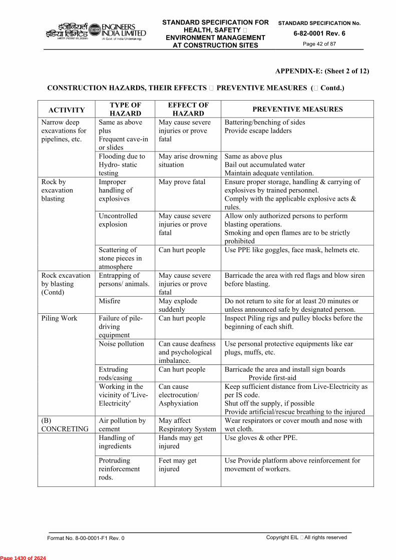
STANDARD SPECIFICATION FOR HEALTH, SAFETY &
ENVIRONMENT MANAGEMENT AT CONSTRUCTION SITES
STANDARD SPECIFICATION No.
6-82-0001 Rev. 6 Page 42 of 87
Format No. 8-00-0001-F1 Rev. 0 Copyright EIL – All rights reserved
APPENDIX-E: (Sheet 2 of 12)
CONSTRUCTION HAZARDS, THEIR EFFECTS & PREVENTIVE MEASURES (…Contd.)
ACTIVITY TYPE OF HAZARD
EFFECT OF HAZARD PREVENTIVE MEASURES
Narrow deep excavations for pipelines, etc.
Same as above plus Frequent cave-in or slides
May cause severe injuries or prove fatal
Battering/benching of sides Provide escape ladders
Flooding due to Hydro- static testing
May arise drowning situation
Same as above plus Bail out accumulated water Maintain adequate ventilation.
Rock by excavation blasting
Improper handling of explosives
May prove fatal
Ensure proper storage, handling & carrying of explosives by trained personnel. Comply with the applicable explosive acts & rules.
Uncontrolled explosion
May cause severe injuries or prove fatal
Allow only authorized persons to perform blasting operations. Smoking and open flames are to be strictly prohibited
Scattering of stone pieces in atmosphere
Can hurt people Use PPE like goggles, face mask, helmets etc.
Rock excavation by blasting (Contd)
Entrapping of persons/ animals.
May cause severe injuries or prove fatal
Barricade the area with red flags and blow siren before blasting.
Misfire May explode suddenly
Do not return to site for at least 20 minutes or unless announced safe by designated person.
Piling Work Failure of pile-driving equipment
Can hurt people Inspect Piling rigs and pulley blocks before the beginning of each shift.
Noise pollution Can cause deafness and psychological imbalance.
Use personal protective equipments like ear plugs, muffs, etc.
Extruding rods/casing
Can hurt people Barricade the area and install sign boards Provide first-aid
Working in the vicinity of 'Live-Electricity'
Can cause electrocution/ Asphyxiation
Keep sufficient distance from Live-Electricity as per IS code. Shut off the supply, if possible Provide artificial/rescue breathing to the injured
(B) CONCRETING
Air pollution by cement
May affect Respiratory System
Wear respirators or cover mouth and nose with wet cloth.
Handling of ingredients
Hands may get injured
Use gloves & other PPE.
Protruding reinforcement rods.
Feet may get injured
Use Provide platform above reinforcement for movement of workers.
Page 1430 of 2624
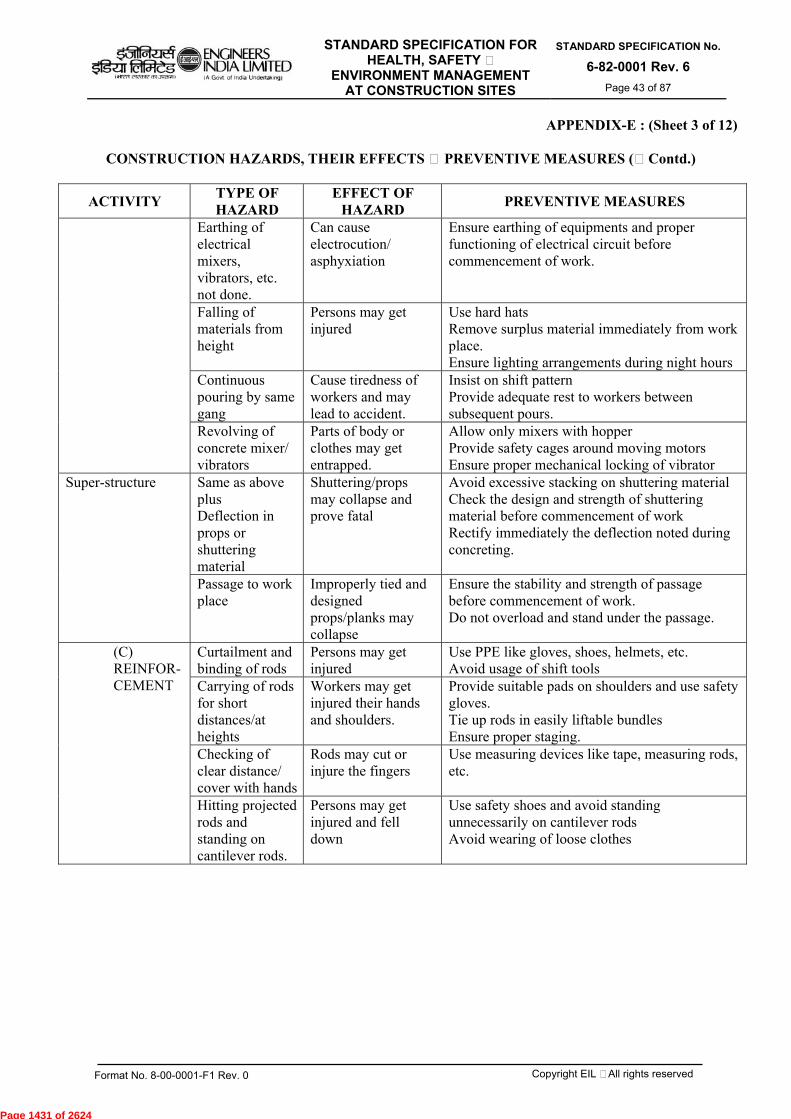
STANDARD SPECIFICATION FOR HEALTH, SAFETY &
ENVIRONMENT MANAGEMENT AT CONSTRUCTION SITES
STANDARD SPECIFICATION No.
6-82-0001 Rev. 6 Page 43 of 87
Format No. 8-00-0001-F1 Rev. 0 Copyright EIL – All rights reserved
APPENDIX-E : (Sheet 3 of 12)
CONSTRUCTION HAZARDS, THEIR EFFECTS & PREVENTIVE MEASURES (…Contd.)
ACTIVITY TYPE OF HAZARD
EFFECT OF HAZARD PREVENTIVE MEASURES
Earthing of electrical mixers, vibrators, etc. not done.
Can cause electrocution/ asphyxiation
Ensure earthing of equipments and proper functioning of electrical circuit before commencement of work.
Falling of materials from height
Persons may get injured
Use hard hats Remove surplus material immediately from work place. Ensure lighting arrangements during night hours
Continuous pouring by same gang
Cause tiredness of workers and may lead to accident.
Insist on shift pattern Provide adequate rest to workers between subsequent pours.
Revolving of concrete mixer/ vibrators
Parts of body or clothes may get entrapped.
Allow only mixers with hopper Provide safety cages around moving motors Ensure proper mechanical locking of vibrator
Super-structure Same as above plus Deflection in props or shuttering material
Shuttering/props may collapse and prove fatal
Avoid excessive stacking on shuttering material Check the design and strength of shuttering material before commencement of work Rectify immediately the deflection noted during concreting.
Passage to work place
Improperly tied and designed props/planks may collapse
Ensure the stability and strength of passage before commencement of work. Do not overload and stand under the passage.
(C) REINFOR- CEMENT
Curtailment and binding of rods
Persons may get injured
Use PPE like gloves, shoes, helmets, etc. Avoid usage of shift tools
Carrying of rods for short distances/at heights
Workers may get injured their hands and shoulders.
Provide suitable pads on shoulders and use safety gloves. Tie up rods in easily liftable bundles Ensure proper staging.
Checking of clear distance/ cover with hands
Rods may cut or injure the fingers
Use measuring devices like tape, measuring rods, etc.
Hitting projected rods and standing on cantilever rods.
Persons may get injured and fell down
Use safety shoes and avoid standing unnecessarily on cantilever rods Avoid wearing of loose clothes
Page 1431 of 2624

STANDARD SPECIFICATION FOR HEALTH, SAFETY &
ENVIRONMENT MANAGEMENT AT CONSTRUCTION SITES
STANDARD SPECIFICATION No.
6-82-0001 Rev. 6 Page 44 of 87
Format No. 8-00-0001-F1 Rev. 0 Copyright EIL – All rights reserved
APPENDIX-E: (Sheet 4 of 12)
CONSTRUCTION HAZARDS, THEIR EFFECTS & PREVENTIVE MEASURES (…Contd.)
ACTIVITY TYPE OF HAZARD
EFFECT OF HAZARD PREVENTIVE MEASURES
Falling of material from height
May prove fatal Use helmets Provide safety nets
Transportation of rods by trucks/ trailers
Protruded rods may hit the persons
Use red flags/lights at the ends Do not protrude the rods in front of or by the side of driver's cabin. Do not extend the rods 1/3rd of deck length or 1.5m whichever is less
(D)WELDING AND GAS CUTTING
Welding radiates invisible ultraviolet and infra-red rays
Radiation can damage eyes and skin.
Use specified shielding devices and other PPE of correct specifications. Avoid thoriated tungsten electrodes for GTAW
Improper placement of oxygen and acetylene cylinders
Explosion may occur Move out any leaking cylinder Keep cylinders in vertical position Use trolley for transportation of cylinders and chain them Use flashback arrestors
Leakage/ cuts in hoses
May cause fire Purge regulators immediately and then turn off Never use grease or oil on oxygen line connections and copper fittings on acetylene linesInspect regularly gas carrying hoses Always use red hose for acetylene & other fuel gases and black for oxygen
Opening-up of cylinder
Cylinder may burst Always stand back from the regulator while opening the cylinder Turn valve slowly to avoid bursting Cover the lug terminals to prevent short circuiting
Welding of tanks, container or pipes storing flammable liquids
Explosion may occur Empty & purge them before welding Never attach the ground cable to tanks, container or pipe storing flammable liquids Never use LPG for gas cutting
Page 1432 of 2624
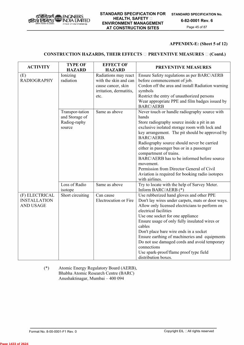
STANDARD SPECIFICATION FOR HEALTH, SAFETY &
ENVIRONMENT MANAGEMENT AT CONSTRUCTION SITES
STANDARD SPECIFICATION No.
6-82-0001 Rev. 6 Page 45 of 87
Format No. 8-00-0001-F1 Rev. 0 Copyright EIL – All rights reserved
APPENDIX-E: (Sheet 5 of 12)
CONSTRUCTION HAZARDS, THEIR EFFECTS & PREVENTIVE MEASURES …(Contd.)
ACTIVITY TYPE OF HAZARD
EFFECT OF HAZARD PREVENTIVE MEASURES
(E) RADIOGRAPHY
Ionizing radiation
Radiations may react with the skin and can cause cancer, skin irritation, dermatitis, etc.
Ensure Safety regulations as per BARC/AERB before commencement of job. Cordon off the area and install Radiation warning symbols Restrict the entry of unauthorized persons Wear appropriate PPE and film badges issued by BARC/AERB
Transpor-tation and Storage of Radiog-raphy source
Same as above Never touch or handle radiography source with hands Store radiography source inside a pit in an exclusive isolated storage room with lock and key arrangement. The pit should be approved by BARC/AERB. Radiography source should never be carried either in passenger bus or in a passenger compartment of trains. BARC/AERB has to be informed before source movement. Permission from Director General of Civil Aviation is required for booking radio isotopes with airlines.
Loss of Radio isotope
Same as above Try to locate with the help of Survey Meter. Inform BARC/AERB (*)
(F) ELECTRICAL INSTALLATION AND USAGE
Short circuiting Can cause Electrocution or Fire
Use rubberized hand gloves and other PPE Don't lay wires under carpets, mats or door ways. Allow only licensed electricians to perform on electrical facilities Use one socket for one appliance Ensure usage of only fully insulated wires or cables Don't place bare wire ends in a socket Ensure earthing of machineries and equipments Do not use damaged cords and avoid temporary connections Use spark-proof/flame proof type field distribution boxes.
(*) Atomic Energy Regulatory Board (AERB), Bhabha Atomic Research Centre (BARC) Anushaktinagar, Mumbai – 400 094
Page 1433 of 2624
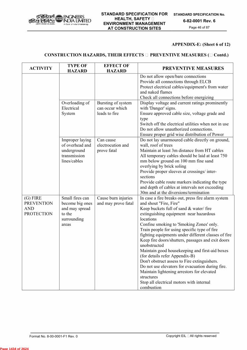
STANDARD SPECIFICATION FOR HEALTH, SAFETY &
ENVIRONMENT MANAGEMENT AT CONSTRUCTION SITES
STANDARD SPECIFICATION No.
6-82-0001 Rev. 6 Page 46 of 87
Format No. 8-00-0001-F1 Rev. 0 Copyright EIL – All rights reserved
APPENDIX-E: (Sheet 6 of 12)
CONSTRUCTION HAZARDS, THEIR EFFECTS & PREVENTIVE MEASURES (…Contd.)
ACTIVITY TYPE OF HAZARD
EFFECT OF HAZARD PREVENTIVE MEASURES
Do not allow open/bare connections Provide all connections through ELCB Protect electrical cables/equipment's from water and naked flames Check all connections before energizing
Overloading of Electrical System
Bursting of system can occur which leads to fire
Display voltage and current ratings prominently with 'Danger' signs. Ensure approved cable size, voltage grade and type Switch off the electrical utilities when not in use Do not allow unauthorized connections. Ensure proper grid wise distribution of Power
Improper laying of overhead and underground transmission lines/cables
Can cause electrocution and prove fatal
Do not lay unarmoured cable directly on ground, wall, roof of trees Maintain at least 3m distance from HT cables All temporary cables should be laid at least 750 mm below ground on 100 mm fine sand overlying by brick soling Provide proper sleeves at crossings/ inter- sections Provide cable route markers indicating the type and depth of cables at intervals not exceeding 30m and at the diversions/termination
(G) FIRE PREVENTION AND PROTECTION
Small fires can become big ones and may spread to the surrounding areas
Cause burn injuries and may prove fatal
In case a fire breaks out, press fire alarm system and shout "Fire, Fire" Keep buckets full of sand & water/ fire extinguishing equipment near hazardous locations Confine smoking to 'Smoking Zones' only. Train people for using specific type of fire fighting equipments under different classes of fire Keep fire doors/shutters, passages and exit doors unobstructed Maintain good housekeeping and first-aid boxes (for details refer Appendix-B) Don't obstruct assess to Fire extinguishers. Do not use elevators for evacuation during fire. Maintain lightening arrestors for elevated structures Stop all electrical motors with internal combustion
Page 1434 of 2624

STANDARD SPECIFICATION FOR HEALTH, SAFETY &
ENVIRONMENT MANAGEMENT AT CONSTRUCTION SITES
STANDARD SPECIFICATION No.
6-82-0001 Rev. 6 Page 47 of 87
Format No. 8-00-0001-F1 Rev. 0 Copyright EIL – All rights reserved
APPENDIX-E : (Sheet 7 of 12)
CONSTRUCTION HAZARDS, THEIR EFFECTS & PREVENTIVE MEASURES (…Contd.)
ACTIVITY TYPE OF HAZARD
EFFECT OF HAZARD PREVENTIVE MEASURES
Move the vehicles from dangerous locations Remove the load hanging from the crane booms Remain out of the danger areas.
Improper selection of Fire extinguisher
It may not extinguish the fire
Ensure usage of correct fire extinguisher meant for the specified fire (for details refer Appendix-C). Do not attempt to extinguish Oil and electric fires with water. Use foam cylinders/CO2/sand or earth.
Improper storage of highly inflammable substances
Same as above Maintain safe distance of flammable substances from source of ignition Restrict the distribution of flammable materials to only min. necessary amount Construct specifically designed fuel storage facilities Keep chemicals in cool and dry place away from heat. Ensure adequate ventilation Before welding operation, remove or shield the flammable material properly Store flammable materials in stable racks, correctly labeled preferably with catchment trays. Wipe off the spills immediately
Short circuiting of electrical system
Same as above Can cause Electrocution
Don't lay wires under carpets, mats or door waysUse one socket for one appliance. Use only fully insulated wires or cables Do not allow open/bare connections Provide all connections through ELCB Ensure earthing of machineries and equipments
(H) VEHICULAR MOVEMENT
Crossing the Speed Limits (Rash driving)
Personal injury Obey speed limits and traffic rules strictly Always expect the unexpected and be a defensive driver Use seat belts/helmets Blow horn at intersections and during overtaking operations. Maintain the vehicle in good condition Do not overtake on curves, bridges and slopes
Adverse weather condition
Same as Above Read the road ahead and ride to the left Keep the wind screen and lights clean Do not turn at speed. Recognize the hazard, understand the defense and act correctly in time.
Page 1435 of 2624
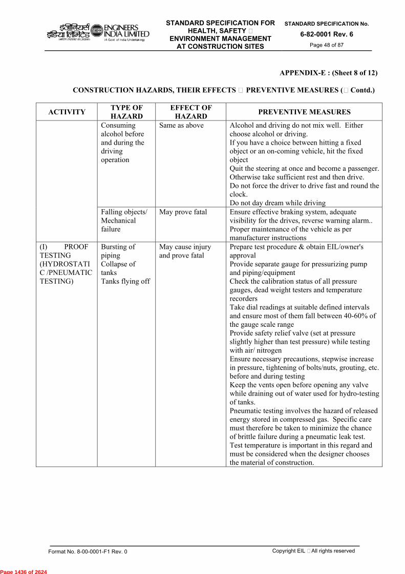
STANDARD SPECIFICATION FOR HEALTH, SAFETY &
ENVIRONMENT MANAGEMENT AT CONSTRUCTION SITES
STANDARD SPECIFICATION No.
6-82-0001 Rev. 6 Page 48 of 87
Format No. 8-00-0001-F1 Rev. 0 Copyright EIL – All rights reserved
APPENDIX-E : (Sheet 8 of 12)
CONSTRUCTION HAZARDS, THEIR EFFECTS & PREVENTIVE MEASURES (…Contd.)
ACTIVITY TYPE OF HAZARD
EFFECT OF HAZARD PREVENTIVE MEASURES
Consuming alcohol before and during the driving operation
Same as above Alcohol and driving do not mix well. Either choose alcohol or driving. If you have a choice between hitting a fixed object or an on-coming vehicle, hit the fixed object Quit the steering at once and become a passenger. Otherwise take sufficient rest and then drive. Do not force the driver to drive fast and round the clock. Do not day dream while driving
Falling objects/ Mechanical failure
May prove fatal Ensure effective braking system, adequate visibility for the drives, reverse warning alarm.. Proper maintenance of the vehicle as per manufacturer instructions
(I) PROOF TESTING (HYDROSTATIC /PNEUMATIC TESTING)
Bursting of piping Collapse of tanks Tanks flying off
May cause injury and prove fatal
Prepare test procedure & obtain EIL/owner's approval Provide separate gauge for pressurizing pump and piping/equipment Check the calibration status of all pressure gauges, dead weight testers and temperature recorders Take dial readings at suitable defined intervals and ensure most of them fall between 40-60% of the gauge scale range Provide safety relief valve (set at pressure slightly higher than test pressure) while testing with air/ nitrogen Ensure necessary precautions, stepwise increase in pressure, tightening of bolts/nuts, grouting, etc. before and during testing Keep the vents open before opening any valve while draining out of water used for hydro-testing of tanks. Pneumatic testing involves the hazard of released energy stored in compressed gas. Specific care must therefore be taken to minimize the chance of brittle failure during a pneumatic leak test. Test temperature is important in this regard and must be considered when the designer chooses the material of construction.
Page 1436 of 2624

STANDARD SPECIFICATION FOR HEALTH, SAFETY &
ENVIRONMENT MANAGEMENT AT CONSTRUCTION SITES
STANDARD SPECIFICATION No.
6-82-0001 Rev. 6 Page 49 of 87
Format No. 8-00-0001-F1 Rev. 0 Copyright EIL – All rights reserved
APPENDIX-E : (Sheet 9 of 12)
CONSTRUCTION HAZARDS, THEIR EFFECTS & PREVENTIVE MEASURES (…Contd.)
ACTIVITY TYPE OF HAZARD
EFFECT OF HAZARD PREVENTIVE MEASURES
A pressure relief device shall be provided, having a set pressure not higher than the test pressure plus the lesser of 345 KPa (50 psi) or 10% of the test pressure. The gas used as test fluid, if not air, shall be nonflammable and nontoxic.
(J) WORKING AT HEIGHTS
Person can fall down
May sustain severe injuries or prove fatal
Provide guard rails/barricade at the work place Use PPE like full body harness, life line, helmets, safety shoes, etc. Obtain a permit before starting the work at height above 3 meters Fall arrest and safety nets, etc. must be installed Provide adequate working space (min. 0.6 m) Tie/weld working platform with fixed support Use roof top walk ladder while working on a slopping roofs Avoid movement on beams
May hit the scrap/material stacked at the ground or in between
Keep the work place neat and clean Remove the scrap immediately
Material can fall down
May hit the workers working at lower levels and prove fatal
Same as above plus Do not throw or drop materials or equipment from height. I.e. do not bomb materials All tools to be carried in a tool-kit Bag or on working uniform Remove scrap from the planks Ensure wearing of helmet by the workers working at lower levels
(K) CONFINED SPACES
Suffocation/ drowning
Unconsciousness, death
Use respiratory devices, if reqd. Avoid over crowding inside a confined space Provide Exhaust fans for ventilation Do not wear loose clothes, neck ties, etc Fulfill conditions of the permit
Page 1437 of 2624

STANDARD SPECIFICATION FOR HEALTH, SAFETY &
ENVIRONMENT MANAGEMENT AT CONSTRUCTION SITES
STANDARD SPECIFICATION No.
6-82-0001 Rev. 6 Page 50 of 87
Format No. 8-00-0001-F1 Rev. 0 Copyright EIL – All rights reserved
APPENDIX-E: (Sheet 10 of 12)
CONSTRUCTION HAZARDS, THEIR EFFECTS & PREVENTIVE MEASURES (…Contd.)
ACTIVITY TYPE OF HAZARD
EFFECT OF HAZARD PREVENTIVE MEASURES
Check for presence of hydrocarbons, O2 level Obtain work permit before entering a confined space Ensure that the connected piping of the equipment which is to be opened is pressure free, fluid has been drained, vents are open and piping is positively isolated by a blind flange
Presence of foul smell and toxic substances
Inhalation can pose threat to life
Same as above plus Check for hydrocarbon and Aromatic compounds before entering a confined space Depute one person outside the confined space for continuous monitoring and for extending help in case of an emergency
Ignition/ flame can cause fire
Person may sustain burn injuries or explosion may occur
Keep fire extinguishers at a hand distance Remove surplus material and scrap immediately Do not smoke inside a confined space Do not allow gas cylinders inside a confined space Use low voltage (24V) lamps for lighting Use tools with air motors or electric tools with max. voltage of 24V Remove all equipments at the end of the day
(L) HANDLING AND LIFTING EQUIPMENTS
Failure of load lifting and moving equipments
Can cause accident and prove fatal
Avoid standing under the lifted load and within the operating radius of cranes Check periodically oil, brakes, gears, horns and tyre pressure of all moving machinery Check quality, size and condition of all chain pulley blocks, slings, U-clamps, D-shackles, wire ropes, etc. Allow crane to move only on hard, firm and leveled ground. Allow lifting slings as short as possible and check gunny packings at the friction points Do not allow crane to tilt its boom while moving Install Safe Load Indicator Ensure certification by applicable authority
Page 1438 of 2624
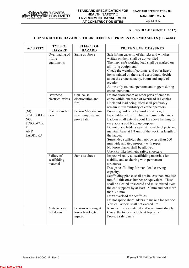
STANDARD SPECIFICATION FOR HEALTH, SAFETY &
ENVIRONMENT MANAGEMENT AT CONSTRUCTION SITES
STANDARD SPECIFICATION No.
6-82-0001 Rev. 6 Page 51 of 87
Format No. 8-00-0001-F1 Rev. 0 Copyright EIL – All rights reserved
APPENDIX-E : (Sheet 11 of 12)
CONSTRUCTION HAZARDS, THEIR EFFECTS & PREVENTIVE MEASURES (…Contd.)
ACTIVITY TYPE OF HAZARD
EFFECT OF HAZARD PREVENTIVE MEASURES
Overloading of lifting equipments
Same as above Safe lifting capacity of derricks and winches written on them shall be got verified The max. safe working load shall be marked on all lifting equipments Check the weight of columns and other heavy items painted on them and accordingly decide about the crane capacity, boom and angle of erection Allow only trained operators and riggers during crane operation.
Overhead electrical wires
Can cause electrocution and fire
Do not allow boom or other parts of crane to come within 3m reach of overhead HT cables Hook and load being lifted shall preferably remain in full visibility of crane operators.
(M) SCAFFOLDING, FORMWORK AND LADDERS
Person can fall down
Person May sustain severe injuries and prove fatal
Provide guard rails for working at height Face ladder while climbing and use both hands. Ladders shall extend about 1m above landing for easy access and tying up purpose Do not place ladders against movable objects and maintain base at 1/4 unit of the working length of the ladder. Suspended scaffolds shall not be less than 500 mm wide and tied properly with ropes No loose planks shall be allowed Use PPE, like helmets, safety shoes,etc
Failure of scaffolding material
Same as above Inspect visually all scaffolding materials for stability and anchoring with permanent structures. Design scaffolding for max. load carrying capacity. Scaffolding planks shall not be less than 50X250 mm full thickness lumber or equivalent. These shall be cleated or secured and must extend over the end supports by at least 150mm and not more than 300mm Don't overload the scaffolds Do not splice short ladders to make a longer one. Vertical ladders shall not exceed 6m.
Material can fall down
Persons working at lower level gets injured
Remove excess material and scrap immediately Carry the tools in a tool-kit bag only Provide safety nets
Page 1439 of 2624
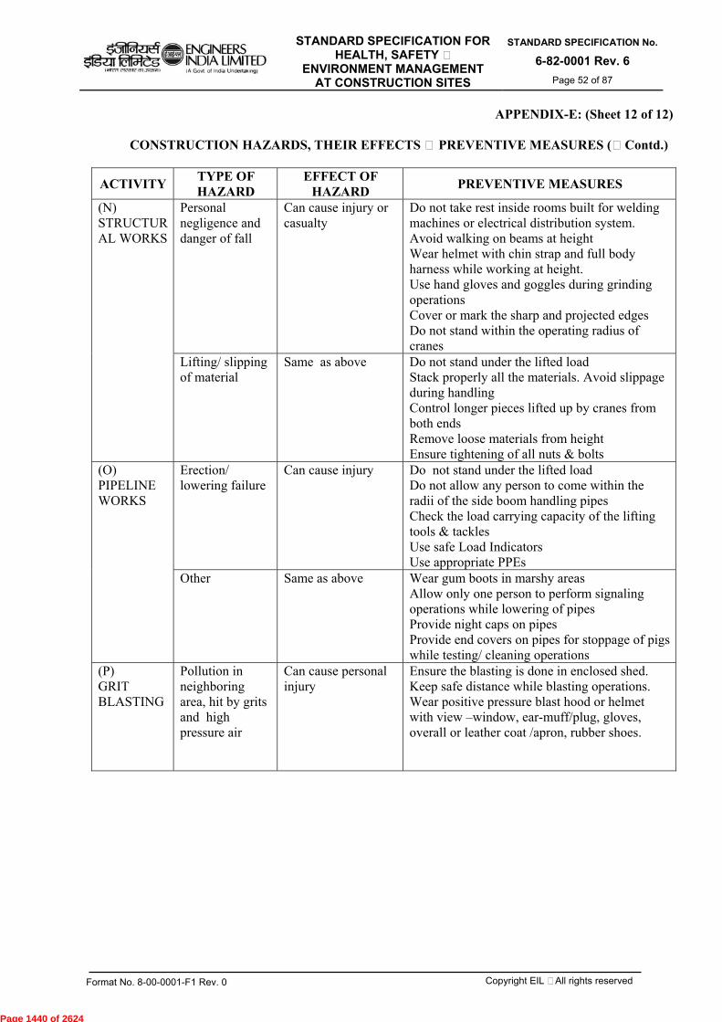
STANDARD SPECIFICATION FOR HEALTH, SAFETY &
ENVIRONMENT MANAGEMENT AT CONSTRUCTION SITES
STANDARD SPECIFICATION No.
6-82-0001 Rev. 6 Page 52 of 87
Format No. 8-00-0001-F1 Rev. 0 Copyright EIL – All rights reserved
APPENDIX-E: (Sheet 12 of 12)
CONSTRUCTION HAZARDS, THEIR EFFECTS & PREVENTIVE MEASURES (…Contd.)
ACTIVITY TYPE OF HAZARD
EFFECT OF HAZARD PREVENTIVE MEASURES
(N) STRUCTURAL WORKS
Personal negligence and danger of fall
Can cause injury or casualty
Do not take rest inside rooms built for welding machines or electrical distribution system. Avoid walking on beams at height Wear helmet with chin strap and full body harness while working at height. Use hand gloves and goggles during grinding operations Cover or mark the sharp and projected edges Do not stand within the operating radius of cranes
Lifting/ slipping of material
Same as above Do not stand under the lifted load Stack properly all the materials. Avoid slippage during handling Control longer pieces lifted up by cranes from both ends Remove loose materials from height Ensure tightening of all nuts & bolts
(O) PIPELINE WORKS
Erection/ lowering failure
Can cause injury Do not stand under the lifted load Do not allow any person to come within the radii of the side boom handling pipes Check the load carrying capacity of the lifting tools & tackles Use safe Load Indicators Use appropriate PPEs
Other Same as above Wear gum boots in marshy areas Allow only one person to perform signaling operations while lowering of pipes Provide night caps on pipes Provide end covers on pipes for stoppage of pigs while testing/ cleaning operations
(P) GRIT BLASTING
Pollution in neighboring area, hit by grits and high pressure air
Can cause personal injury
Ensure the blasting is done in enclosed shed. Keep safe distance while blasting operations. Wear positive pressure blast hood or helmet with view –window, ear-muff/plug, gloves, overall or leather coat /apron, rubber shoes.
Page 1440 of 2624
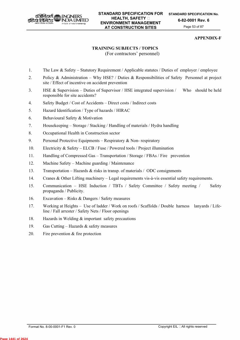
STANDARD SPECIFICATION FOR HEALTH, SAFETY &
ENVIRONMENT MANAGEMENT AT CONSTRUCTION SITES
STANDARD SPECIFICATION No.
6-82-0001 Rev. 6 Page 53 of 87
Format No. 8-00-0001-F1 Rev. 0 Copyright EIL – All rights reserved
APPENDIX-F
TRAINING SUBJECTS / TOPICS (For contractors’ personnel)
1. The Law & Safety – Statutory Requirement / Applicable statutes / Duties of employer / employee
2. Policy & Administration – Why HSE? / Duties & Responsibilities of Safety Personnel at project site / Effect of incentive on accident prevention
3. HSE & Supervision – Duties of Supervisor / HSE integrated supervision / Who should be held responsible for site accidents?
4. Safety Budget / Cost of Accidents – Direct costs / Indirect costs
5. Hazard Identification / Type of hazards / HIRAC
6. Behavioural Safety & Motivation
7. Housekeeping – Storage / Stacking / Handling of materials / Hydra handling
8. Occupational Health in Construction sector
9. Personal Protective Equipments – Respiratory & Non- respiratory
10. Electricity & Safety – ELCB / Fuse / Powered tools / Project illumination
11. Handling of Compressed Gas – Transportation / Storage / FBAs / Fire prevention
12. Machine Safety – Machine guarding / Maintenance
13. Transportation – Hazards & risks in transp. of materials / ODC consignments
14. Cranes & Other Lifting machinery – Legal requirements vis-à-vis essential safety requirements.
15. Communication – HSE Induction / TBTs / Safety Committee / Safety meeting / Safety propaganda / Publicity.
16. Excavation – Risks & Dangers / Safety measures
17. Working at Heights – Use of ladder / Work on roofs / Scaffolds / Double harness lanyards / Life-line / Fall arrester / Safety Nets / Floor openings
18. Hazards in Welding & important safety precautions
19. Gas Cutting – Hazards & safety measures
20. Fire prevention & fire protection
Page 1441 of 2624
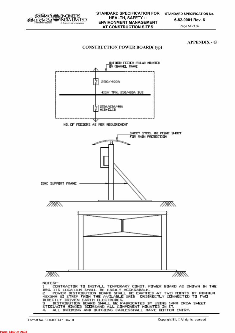
STANDARD SPECIFICATION FOR HEALTH, SAFETY &
ENVIRONMENT MANAGEMENT AT CONSTRUCTION SITES
STANDARD SPECIFICATION No.
6-82-0001 Rev. 6 Page 54 of 87
Format No. 8-00-0001-F1 Rev. 0 Copyright EIL – All rights reserved
APPENDIX - G
CONSTRUCTION POWER BOARD( typ)
Page 1442 of 2624
STANDARD SPECIFICATION FOR HEALTH, SAFETY &
ENVIRONMENT MANAGEMENT AT CONSTRUCTION SITES
STANDARD SPECIFICATION No.
6-82-0001 Rev. 6 Page 55 of 87
Format No. 8-00-0001-F1 Rev. 0 Copyright EIL – All rights reserved
APPENDIX-H
LIST OF PROCEDURES (MINIMUM) TO BE FORMING PART OF HSE PLAN:-
A. HSE Management Procedures:
HSE Risk Management (including JSA/HIRA) HSE Legal Compliance and Other Requirements HSE Objectives & Performance HSE Training and Competence (including Induction) HSE Motivation & Award Scheme HSE Audits HSE Meetings HSE Sub Contractor Management HSE Emergency Management HSE Incidents Reporting and Management HSE Reports HSE Management System Review HSE Change Management HSE procedure for Behaviour based Safety First Aid & Management Roles, Responsibility, accountabilities and Authorities
B. Job procedures/Safe Operating procedures
Setting Up Site & Signage’s Handling of Electrical Appliances Working at Height Confined Space Entry Permit to Work (including hot works) Housekeeping Lifting Operations Transportation of materials including Manual Handling Compressed Air Tools and Units Earthmoving Operations & excavation Scaffolding Fire Prevention/Protection Hazardous Substance handling & Storage Radiation Hazard Personal Protective Equipment
Page 1443 of 2624

STANDARD SPECIFICATION FOR HEALTH, SAFETY &
ENVIRONMENT MANAGEMENT AT CONSTRUCTION SITES
STANDARD SPECIFICATION No.
6-82-0001 Rev. 6 Page 56 of 87
Format No. 8-00-0001-F1 Rev. 0 Copyright EIL – All rights reserved
FORMAT NO. : HSE-1 REV 0 (Sheet 1 of 6)
SAFETY WALK-THROUGH REPORT (Name & signature of walk through performer to be inserted at the bottom of each page)
Project : _____________ Report no. : ___________ Date : _____________ Contractor : ___________ Inspection by :_____________ Owner : ___________ Frequency : Monthly Job no. : ___________ Note : Write ‘NA’ wherever the item is not applicable
SL. NO. ITEM Satisafctory
/ Yes
Non satisfactory/
No Remarks Action
1. HOUSEKEEPING a) Waste containers provided and used
b) Sanitary facilities adequate and Clean
c) Passageways and Walkways Clear
d) General neatness of working areas
e) Other
2. PERSONNEL PROTECTIVE EQUIPMENT
a) Goggles; Shields
b) Face protection
Hearing protection
Foot protection
e) Hand protection
f) Respiratory Masks etc.
g) Full body harness conforming to CЄ, EN 361
h) Hard hat (HDPE)
i) Other
3. EXCAVATIONS/OPENINGS
a) Openings properly covered or barricaded
b) Excavations shored
c) Excavations barricaded
d) Overnight lighting provided
e) Other
Safety walk-through performer (Name & Signature)……………………………………………..
Page 1444 of 2624

STANDARD SPECIFICATION FOR HEALTH, SAFETY &
ENVIRONMENT MANAGEMENT AT CONSTRUCTION SITES
STANDARD SPECIFICATION No.
6-82-0001 Rev. 6 Page 57 of 87
Format No. 8-00-0001-F1 Rev. 0 Copyright EIL – All rights reserved
FORMAT NO. : HSE-1 REV 0
(Sheet 2 of 6)
SL. NO. ITEM Satisafctory
/ Yes
Non satisfactory/
No Remarks Action
4. WELDING & GAS CUTTING
a) Gas cylinders chained upright
b) Cables and hoses not obstructing
c) Screens or shields used
d) Flammable materials protected
e) Live electrode bits contained properly
f) Fire extinguisher (s) accessible
g) Other
5. SCAFFOLDING & BARRICADING
a) Fully decked platforms
b) Guard and intermediate rails in place
c) Toe boards in place
d) Adequate shoring
e) Adequate access
f) Positive barricading for critical activities
g) Installation of warning signs
h) Other
6. LADDERS
a) Extension side rails 1 m above
b) Top of landing
c) Properly secured
d) Angle + 700 from horizontal
e) Other
Safety walk-through performer (Name & Signature)……………………………………………..
Page 1445 of 2624
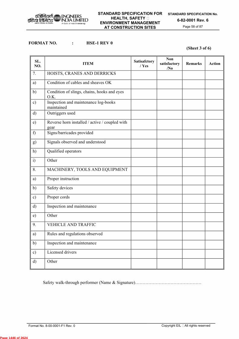
STANDARD SPECIFICATION FOR HEALTH, SAFETY &
ENVIRONMENT MANAGEMENT AT CONSTRUCTION SITES
STANDARD SPECIFICATION No.
6-82-0001 Rev. 6 Page 58 of 87
Format No. 8-00-0001-F1 Rev. 0 Copyright EIL – All rights reserved
FORMAT NO. : HSE-1 REV 0
(Sheet 3 of 6)
SL. NO. ITEM Satisafctory
/ Yes
Non satisfactory
/No Remarks Action
7. HOISTS, CRANES AND DERRICKS
a) Condition of cables and sheaves OK
b) Condition of slings, chains, hooks and eyes O.K.
c) Inspection and maintenance log-books maintained
d) Outriggers used
e) Reverse horn installed / active / coupled with gear
f) Signs/barricades provided
g) Signals observed and understood
h) Qualified operators
i) Other
8. MACHINERY, TOOLS AND EQUIPMENT
a) Proper instruction
b) Safety devices
c) Proper cords
d) Inspection and maintenance
e) Other
9. VEHICLE AND TRAFFIC
a) Rules and regulations observed
b) Inspection and maintenance
c) Licensed drivers
d) Other
Safety walk-through performer (Name & Signature)………………………………………
Page 1446 of 2624
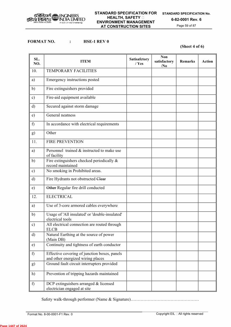
STANDARD SPECIFICATION FOR HEALTH, SAFETY &
ENVIRONMENT MANAGEMENT AT CONSTRUCTION SITES
STANDARD SPECIFICATION No.
6-82-0001 Rev. 6 Page 59 of 87
Format No. 8-00-0001-F1 Rev. 0 Copyright EIL – All rights reserved
FORMAT NO. : HSE-1 REV 0
(Sheet 4 of 6)
SL. NO. ITEM Satisafctory
/ Yes
Non satisfactory
/No Remarks Action
10. TEMPORARY FACILITIES
a) Emergency instructions posted
b) Fire extinguishers provided
c) Fire-aid equipment available
d) Secured against storm damage
e) General neatness
f) In accordance with electrical requirements
g) Other
11. FIRE PREVENTION
a) Personnel trained & instructed to make use of facility
b) Fire extinguishers checked periodically & record maintained
c) No smoking in Prohibited areas.
d) Fire Hydrants not obstructed Clear
e) Other Regular fire drill conducted
12. ELECTRICAL
a) Use of 3-core armored cables everywhere
b) Usage of 'All insulated' or 'double-insulated' electrical tools
c) All electrical connection are routed through ELCB
d) Natural Earthing at the source of power (Main DB)
e) Continuity and tightness of earth conductor
f) Effective covering of junction boxes, panels and other energized wiring places
g) Ground fault circuit interrupters provided
h) Prevention of tripping hazards maintained
f) DCP extinguishers arranged & licensed electrician engaged at site
Safety walk-through performer (Name & Signature)…………………………………………
Page 1447 of 2624

STANDARD SPECIFICATION FOR HEALTH, SAFETY &
ENVIRONMENT MANAGEMENT AT CONSTRUCTION SITES
STANDARD SPECIFICATION No.
6-82-0001 Rev. 6 Page 60 of 87
Format No. 8-00-0001-F1 Rev. 0 Copyright EIL – All rights reserved
FORMAT NO. : HSE-1 REV 0 (Sheet 5 of 6)
SL. NO. ITEM Satisafctory
/ Yes
Non satisfactory
/No Remarks Action
14. HANDLING AND STORAGE OF MATERIALS
a) Safely stored or stacked b) Passageways clear / free from obstructions c) Fire fighting facility in place 15. FLAMMABLE GASES AND LIQUIDS
a) Containers clearly identified / protected from fire
b) Safe storage & transportation arrangement made
c) Fire extinguishers positioned nearby d) Facilities kept away from electric spark, hot
spatters & ignition source.
16. WORKING AT HEIGHT a) Approved Erection plan and work permit in
place
b) Safe access, Safe work platform & Safety nets provided
c) Life lines, Fall arrester, Full body harness and with double lanyards used;
d) Health Check record available for workers going up?
e) Protective handrails arranged around floor openings
17. CONFINED SPACE a) Work Permit obtained from requisite
authority
b) Test for toxic gas and sufficient availability of oxygen conducted & status
c) Supervisor present at site & at least one person outside the confined space for monitoring deputed
d) Availability of safe means of entry, exit and ventilation (register for entry & exit maintained)
e) Fire extinguisher and first-aid facility ensured
f) Lighting provision made by using 24V Lamp
g) Proper usage of PPEs ensured
18. RADIOGRAPHY a) Proper storage and handling of source as per
BARC/ AERB guidelines (authorized radiographer available)
b) Work permit obtained
Safety walk-through performer (Name & Signature)…………………………………………
Page 1448 of 2624
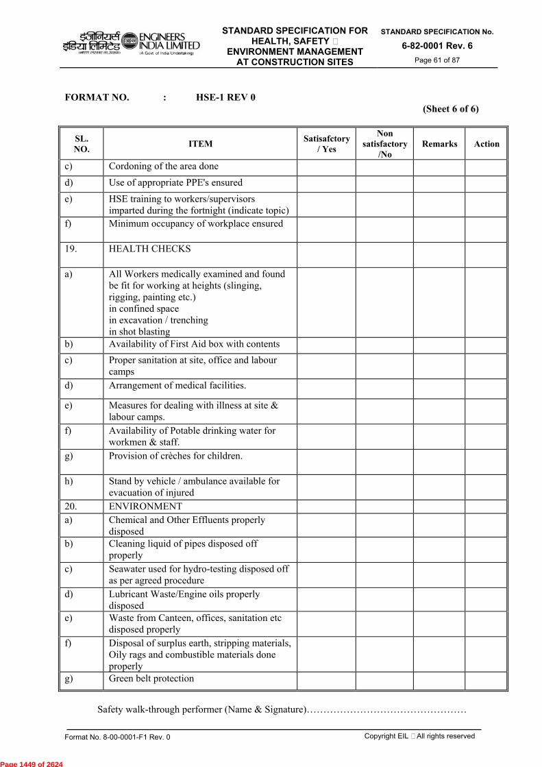
STANDARD SPECIFICATION FOR HEALTH, SAFETY &
ENVIRONMENT MANAGEMENT AT CONSTRUCTION SITES
STANDARD SPECIFICATION No.
6-82-0001 Rev. 6 Page 61 of 87
Format No. 8-00-0001-F1 Rev. 0 Copyright EIL – All rights reserved
FORMAT NO. : HSE-1 REV 0
(Sheet 6 of 6)
SL. NO. ITEM Satisafctory
/ Yes
Non satisfactory
/No Remarks Action
c) Cordoning of the area done
d) Use of appropriate PPE's ensured
e) HSE training to workers/supervisors imparted during the fortnight (indicate topic)
f) Minimum occupancy of workplace ensured
19. HEALTH CHECKS
a) All Workers medically examined and found be fit for working at heights (slinging, rigging, painting etc.) in confined space in excavation / trenching in shot blasting
b) Availability of First Aid box with contents
c) Proper sanitation at site, office and labour camps
d) Arrangement of medical facilities.
e) Measures for dealing with illness at site & labour camps.
f) Availability of Potable drinking water for workmen & staff.
g) Provision of crèches for children.
h) Stand by vehicle / ambulance available for evacuation of injured
20. ENVIRONMENT a) Chemical and Other Effluents properly
disposed
b) Cleaning liquid of pipes disposed off properly
c) Seawater used for hydro-testing disposed off as per agreed procedure
d) Lubricant Waste/Engine oils properly disposed
e) Waste from Canteen, offices, sanitation etc disposed properly
f) Disposal of surplus earth, stripping materials, Oily rags and combustible materials done properly
g) Green belt protection
Safety walk-through performer (Name & Signature)…………………………………………
Page 1449 of 2624
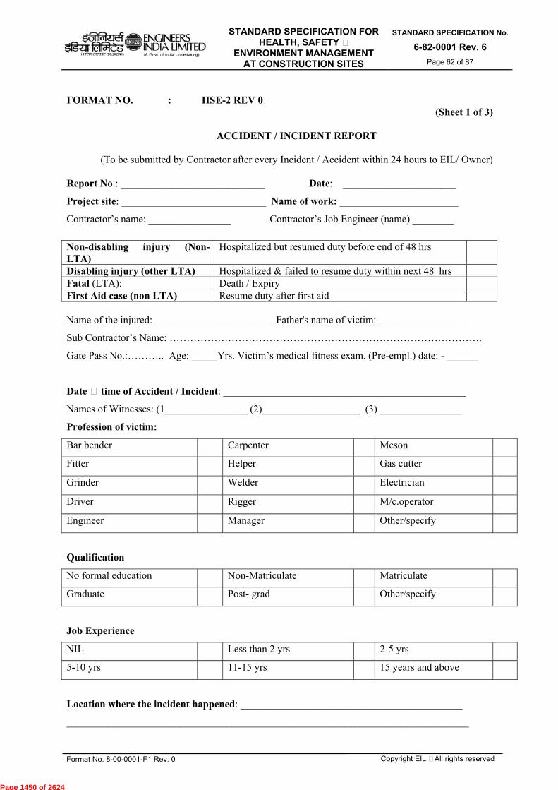
STANDARD SPECIFICATION FOR HEALTH, SAFETY &
ENVIRONMENT MANAGEMENT AT CONSTRUCTION SITES
STANDARD SPECIFICATION No.
6-82-0001 Rev. 6 Page 62 of 87
Format No. 8-00-0001-F1 Rev. 0 Copyright EIL – All rights reserved
FORMAT NO. : HSE-2 REV 0
(Sheet 1 of 3)
ACCIDENT / INCIDENT REPORT
(To be submitted by Contractor after every Incident / Accident within 24 hours to EIL/ Owner)
Report No.: ____________________________ Date: ______________________
Project site: ____________________________ Name of work: _______________________
Contractor’s name: ________________ Contractor’s Job Engineer (name) ________
Name of the injured: _______________________ Father's name of victim: _________________
Sub Contractor’s Name: ……………………………………………………………………………….
Gate Pass No.:……….. Age: _____Yrs. Victim’s medical fitness exam. (Pre-empl.) date: - ______
Date & time of Accident / Incident: _______________________________________________
Names of Witnesses: (1________________ (2)___________________ (3) ________________
Profession of victim:
Bar bender Carpenter Meson
Fitter Helper Gas cutter
Grinder Welder Electrician
Driver Rigger M/c.operator
Engineer Manager Other/specify
Qualification
No formal education Non-Matriculate Matriculate
Graduate Post- grad Other/specify
Job Experience
NIL Less than 2 yrs 2-5 yrs
5-10 yrs 11-15 yrs 15 years and above
Location where the incident happened: ___________________________________________
______________________________________________________________________________
Non-disabling injury (Non-LTA)
Hospitalized but resumed duty before end of 48 hrs
Disabling injury (other LTA) Hospitalized & failed to resume duty within next 48 hrs Fatal (LTA): Death / Expiry First Aid case (non LTA) Resume duty after first aid
Page 1450 of 2624
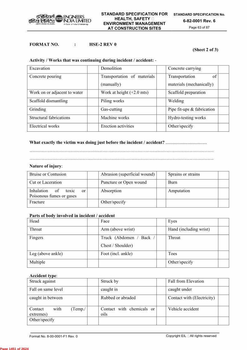
STANDARD SPECIFICATION FOR HEALTH, SAFETY &
ENVIRONMENT MANAGEMENT AT CONSTRUCTION SITES
STANDARD SPECIFICATION No.
6-82-0001 Rev. 6 Page 63 of 87
Format No. 8-00-0001-F1 Rev. 0 Copyright EIL – All rights reserved
FORMAT NO. : HSE-2 REV 0
(Sheet 2 of 3)
Activity / Works that was continuing during incident / accident: -
Excavation Demolition Concrete carrying
Concrete pouring Transportation of materials
(manually)
Transportation of
materials (mechanically)
Work on or adjacent to water Work at height (+2.0 mts) Scaffold preparation
Scaffold dismantling Piling works Welding
Grinding Gas-cutting Pipe fit-ups & fabrication
Structural fabrications Machine works Hydro-testing works
Electrical works Erection activities Other/specify
What exactly the victim was doing just before the incident / accident? ....................................
………………………………………………………………………………………………………….
………………………………………………………………………………………………………….
Nature of injury:
Bruise or Contusion Abrasion (superficial wound) Sprains or strains
Cut or Laceration Puncture or Open wound Burn
Inhalation of toxic or Poisonous fumes or gases
Absorption Amputation
Fracture Other/specify
Parts of body involved in incident / accident Head Face Eyes
Throat Arm (above wrist) Hand (including wrist)
Fingers Truck (Abdomen / Back /
Chest / Shoulder)
Throat
Leg (above ankle) Foot (incl. ankle) Toes
Multiple Other/specify
Accident type: Struck against Struck by Fall from Elevation
Fall on same level caught in caught under
caught in between Rubbed or abraded Contact with (Electricity)
Contact with (Temp./ extremes)
Contact with chemicals or oils
Vehicle accident
Other/specify
Page 1451 of 2624
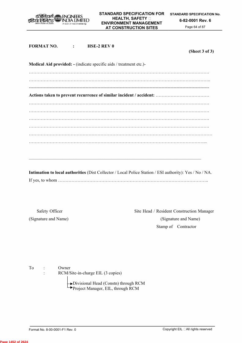
STANDARD SPECIFICATION FOR HEALTH, SAFETY &
ENVIRONMENT MANAGEMENT AT CONSTRUCTION SITES
STANDARD SPECIFICATION No.
6-82-0001 Rev. 6 Page 64 of 87
Format No. 8-00-0001-F1 Rev. 0 Copyright EIL – All rights reserved
FORMAT NO. : HSE-2 REV 0 (Sheet 3 of 3)
Medical Aid provided: - (indicate specific aids / treatment etc.)-
………………………………………………………………………………………………………….
…………………………………………………………………………………………………………..
-------------------------------------------------------------------------------------------------------------------------
Actions taken to prevent recurrence of similar incident / accident: ………………………………
………………………………………………………………………………………………………….
………………………………………………………………………………………………………….
………………………………………………………………………………………………………….
………………………………………………………………………………………………………….
……………………………………………………………………………………………………………
………………………………………………………………………………………………………...
_____________________________________________________________________________
Intimation to local authorities (Dist Collector / Local Police Station / ESI authority): Yes / No / NA.
If yes, to whom ………………………………………………………………………………………..
Safety Officer Site Head / Resident Construction Manager
(Signature and Name) (Signature and Name)
Stamp of Contractor
To : Owner : RCM/Site-in-charge EIL (3 copies) Divisional Head (Constn) through RCM
Project Manager, EIL, through RCM
Page 1452 of 2624

STANDARD SPECIFICATION FOR HEALTH, SAFETY &
ENVIRONMENT MANAGEMENT AT CONSTRUCTION SITES
STANDARD SPECIFICATION No.
6-82-0001 Rev. 6 Page 65 of 87
Format No. 8-00-0001-F1 Rev. 0 Copyright EIL – All rights reserved
FORMAT NO. : HSE-3 REV 0
(Sheet 1 of 5)
SUPPLEMENTARY INCIDENT / ACCIDENT INVESTIGATION REPORT TICK THE APPROPRIATE ONE AS APPLICABLE (furnish within 72 hours)
Supplementary to Incident / Accident Report No: ______ (Copy enclosed) Report No.: ____________________________ Date: ______________________
Project site: ____________________________ Name of work: _______________________
Contractor’s name: ________________ Contractor’s Job Engineer (name) ________
Name of the injured: _______________________ Father's name of victim: _________________
Sub Contractor’s Name: ……………………………………………………………………………….
Gate Pass No.:……….. Age: _____Yrs. Victim’s medical fitness exam. (Pre-empl.) date: - ______
Date & time of Accident / Incident: _______________________________________________
Names of Witnesses: (1________________ (2)___________________ (3) ________________
Profession of victim:
Bar bender Carpenter Meson
Fitter Helper Gas cutter
Grinder Welder Electrician
Driver Rigger M/c.operator
Engineer Manager Other/specify
Qualification
No formal education Non-Matriculate Matriculate
Graduate Post- grad Other/specify
Job Experience
NIL Less than 2 yrs 2-5 yrs
5-10 yrs 11-15 yrs 15 years and above
Location where the incident happened: ___________________________________________
______________________________________________________________________________
Non-disabling injury (Non-LTA)
Hospitalized but resumed duty before end of 48 hrs
Disabling injury (other LTA) Hospitalized & failed to resume duty within next 48 hrs Fatal (LTA): Death / Expiry First Aid case (non LTA) Resume duty after first aid
Page 1453 of 2624
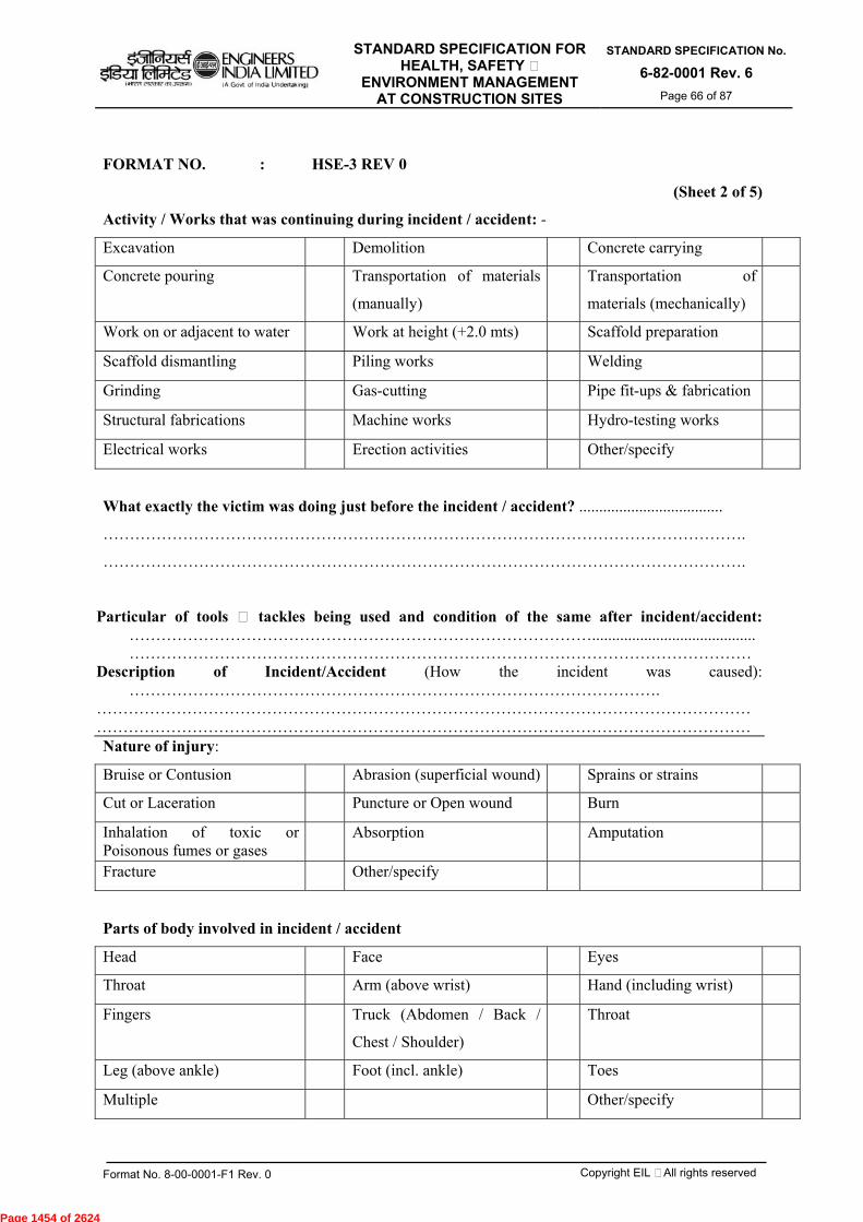
STANDARD SPECIFICATION FOR HEALTH, SAFETY &
ENVIRONMENT MANAGEMENT AT CONSTRUCTION SITES
STANDARD SPECIFICATION No.
6-82-0001 Rev. 6 Page 66 of 87
Format No. 8-00-0001-F1 Rev. 0 Copyright EIL – All rights reserved
FORMAT NO. : HSE-3 REV 0
(Sheet 2 of 5)
Activity / Works that was continuing during incident / accident: -
Excavation Demolition Concrete carrying
Concrete pouring Transportation of materials
(manually)
Transportation of
materials (mechanically)
Work on or adjacent to water Work at height (+2.0 mts) Scaffold preparation
Scaffold dismantling Piling works Welding
Grinding Gas-cutting Pipe fit-ups & fabrication
Structural fabrications Machine works Hydro-testing works
Electrical works Erection activities Other/specify
What exactly the victim was doing just before the incident / accident? ....................................
………………………………………………………………………………………………………….
………………………………………………………………………………………………………….
Particular of tools & tackles being used and condition of the same after incident/accident: …………………………………………………………………………….........................................
……………………………………………………………………………………………………… Description of Incident/Accident (How the incident was caused):
………………………………………………………………………………………. …………………………………………………………………………………………………………… …………………………………………………………………………………………………………… Nature of injury:
Bruise or Contusion Abrasion (superficial wound) Sprains or strains
Cut or Laceration Puncture or Open wound Burn
Inhalation of toxic or Poisonous fumes or gases
Absorption Amputation
Fracture Other/specify
Parts of body involved in incident / accident
Head Face Eyes
Throat Arm (above wrist) Hand (including wrist)
Fingers Truck (Abdomen / Back /
Chest / Shoulder)
Throat
Leg (above ankle) Foot (incl. ankle) Toes
Multiple Other/specify
Page 1454 of 2624
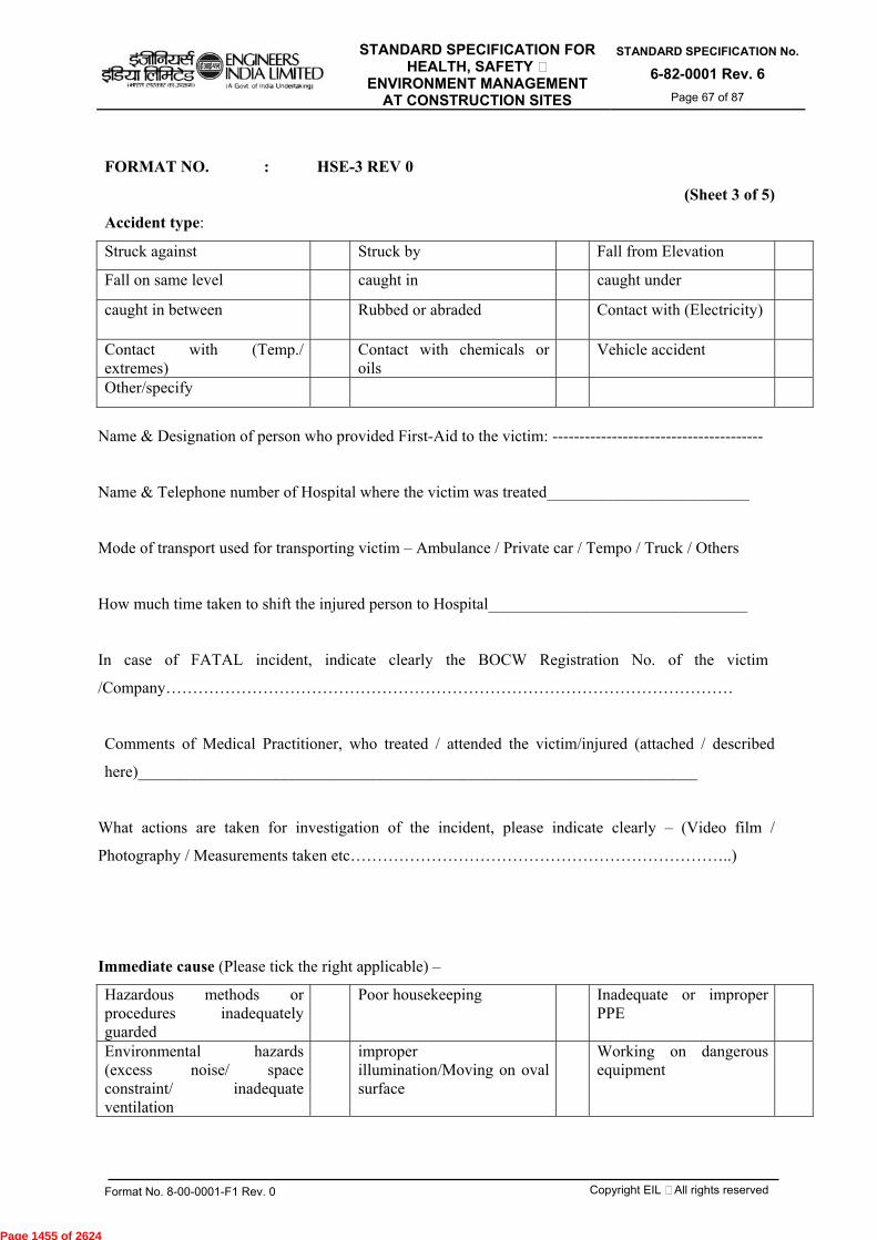
STANDARD SPECIFICATION FOR HEALTH, SAFETY &
ENVIRONMENT MANAGEMENT AT CONSTRUCTION SITES
STANDARD SPECIFICATION No.
6-82-0001 Rev. 6 Page 67 of 87
Format No. 8-00-0001-F1 Rev. 0 Copyright EIL – All rights reserved
FORMAT NO. : HSE-3 REV 0
(Sheet 3 of 5)
Accident type:
Struck against Struck by Fall from Elevation
Fall on same level caught in caught under
caught in between Rubbed or abraded Contact with (Electricity)
Contact with (Temp./ extremes)
Contact with chemicals or oils
Vehicle accident
Other/specify
Name & Designation of person who provided First-Aid to the victim: ---------------------------------------
Name & Telephone number of Hospital where the victim was treated_________________________
Mode of transport used for transporting victim – Ambulance / Private car / Tempo / Truck / Others
How much time taken to shift the injured person to Hospital________________________________
In case of FATAL incident, indicate clearly the BOCW Registration No. of the victim
/Company……………………………………………………………………………………………
Comments of Medical Practitioner, who treated / attended the victim/injured (attached / described
here)_____________________________________________________________________
What actions are taken for investigation of the incident, please indicate clearly – (Video film /
Photography / Measurements taken etc……………………………………………………………..)
Immediate cause (Please tick the right applicable) –
Hazardous methods or procedures inadequately guarded
Poor housekeeping Inadequate or improper PPE
Environmental hazards (excess noise/ space constraint/ inadequate ventilation
improper illumination/Moving on oval surface
Working on dangerous equipment
Page 1455 of 2624
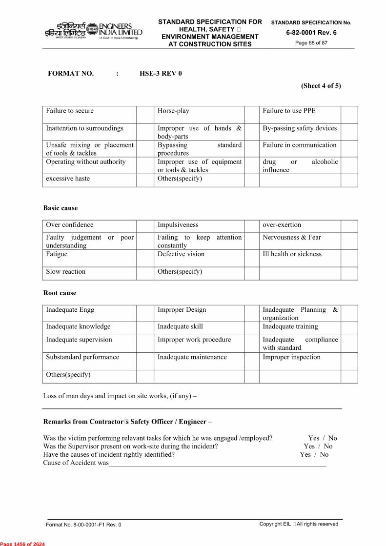
STANDARD SPECIFICATION FOR HEALTH, SAFETY &
ENVIRONMENT MANAGEMENT AT CONSTRUCTION SITES
STANDARD SPECIFICATION No.
6-82-0001 Rev. 6 Page 68 of 87
Format No. 8-00-0001-F1 Rev. 0 Copyright EIL – All rights reserved
FORMAT NO. : HSE-3 REV 0
(Sheet 4 of 5)
Failure to secure Horse-play Failure to use PPE
Inattention to surroundings Improper use of hands & body-parts
By-passing safety devices
Unsafe mixing or placement of tools & tackles
Bypassing standard procedures
Failure in communication
Operating without authority Improper use of equipment or tools & tackles
drug or alcoholic influence
excessive haste Others(specify)
Basic cause Over confidence Impulsiveness over-exertion
Faulty judgement or poor understanding
Failing to keep attention constantly
Nervousness & Fear
Fatigue Defective vision Ill health or sickness
Slow reaction Others(specify)
Root cause Inadequate Engg Improper Design Inadequate Planning &
organization
Inadequate knowledge Inadequate skill Inadequate training
Inadequate supervision Improper work procedure Inadequate compliance with standard
Substandard performance Inadequate maintenance Improper inspection
Others(specify)
Loss of man days and impact on site works, (if any) – Remarks from Contractor’s Safety Officer / Engineer –
Was the victim performing relevant tasks for which he was engaged /employed? Yes / No Was the Supervisor present on work-site during the incident? Yes / No Have the causes of incident rightly identified? Yes / No Cause of Accident was_____________________________________________________________
Page 1456 of 2624
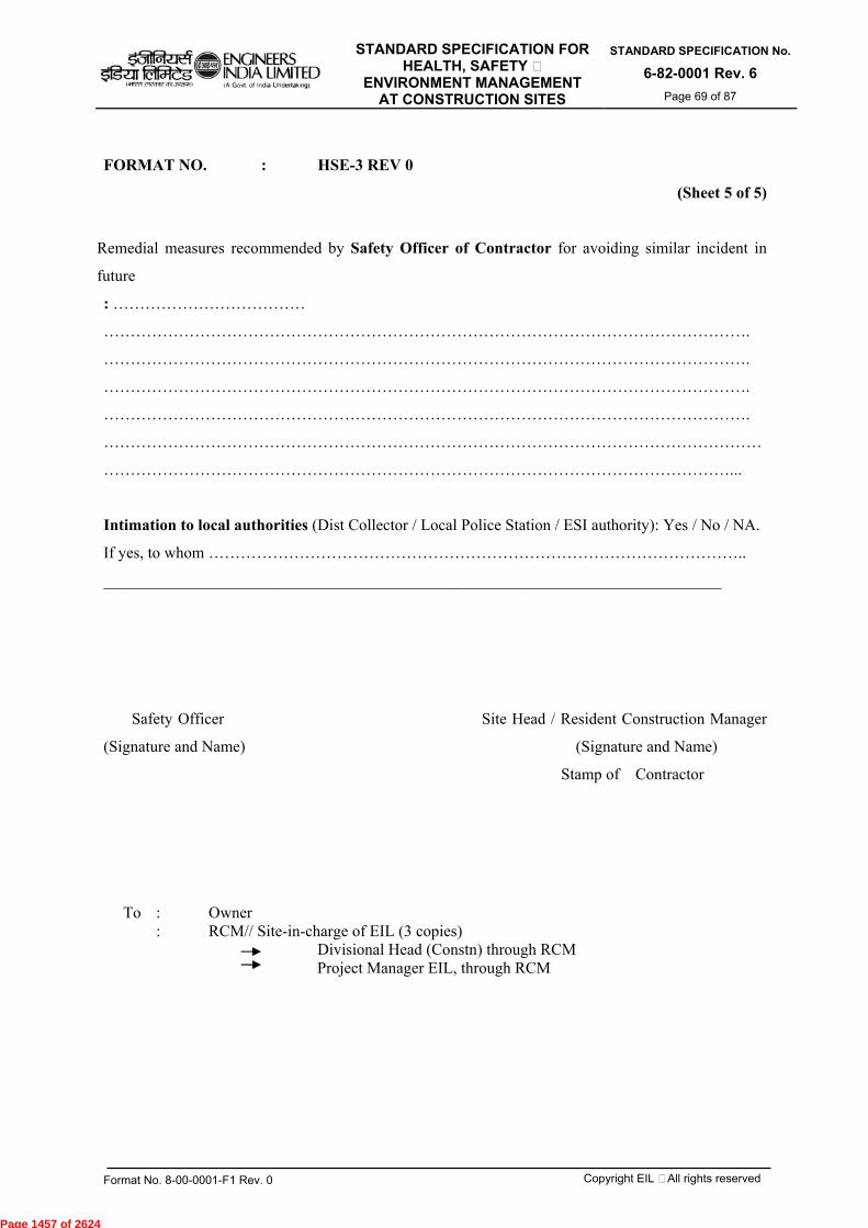
STANDARD SPECIFICATION FOR HEALTH, SAFETY &
ENVIRONMENT MANAGEMENT AT CONSTRUCTION SITES
STANDARD SPECIFICATION No.
6-82-0001 Rev. 6 Page 69 of 87
Format No. 8-00-0001-F1 Rev. 0 Copyright EIL – All rights reserved
FORMAT NO. : HSE-3 REV 0
(Sheet 5 of 5)
Remedial measures recommended by Safety Officer of Contractor for avoiding similar incident in
future
: ………………………………
………………………………………………………………………………………………………….
………………………………………………………………………………………………………….
………………………………………………………………………………………………………….
………………………………………………………………………………………………………….
……………………………………………………………………………………………………………
………………………………………………………………………………………………………...
Intimation to local authorities (Dist Collector / Local Police Station / ESI authority): Yes / No / NA.
If yes, to whom ………………………………………………………………………………………..
_____________________________________________________________________________
Safety Officer Site Head / Resident Construction Manager
(Signature and Name) (Signature and Name)
Stamp of Contractor
To : Owner
: RCM// Site-in-charge of EIL (3 copies) Divisional Head (Constn) through RCM Project Manager EIL, through RCM
Page 1457 of 2624
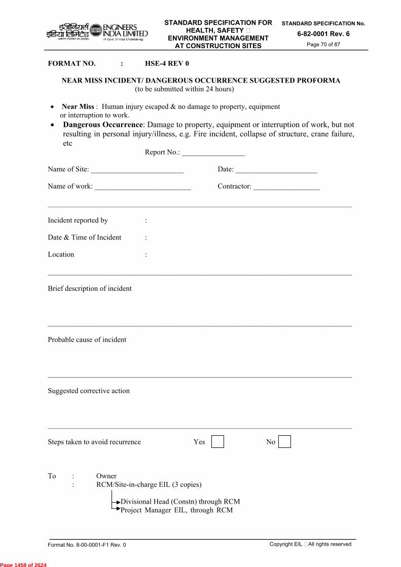
STANDARD SPECIFICATION FOR HEALTH, SAFETY &
ENVIRONMENT MANAGEMENT AT CONSTRUCTION SITES
STANDARD SPECIFICATION No.
6-82-0001 Rev. 6 Page 70 of 87
Format No. 8-00-0001-F1 Rev. 0 Copyright EIL – All rights reserved
FORMAT NO. : HSE-4 REV 0
NEAR MISS INCIDENT/ DANGEROUS OCCURRENCE SUGGESTED PROFORMA (to be submitted within 24 hours) Near Miss : Human injury escaped & no damage to property, equipment
or interruption to work. Dangerous Occurrence: Damage to property, equipment or interruption of work, but not
resulting in personal injury/illness, e.g. Fire incident, collapse of structure, crane failure, etc
Report No.: _________________ Name of Site: _________________________ Date: ______________________ Name of work: __________________________ Contractor: __________________ __________________________________________________________________________________ Incident reported by : Date & Time of Incident : Location : __________________________________________________________________________________ Brief description of incident __________________________________________________________________________________ Probable cause of incident __________________________________________________________________________________ Suggested corrective action __________________________________________________________________________________ Steps taken to avoid recurrence Yes No To : Owner : RCM/Site-in-charge EIL (3 copies)
Divisional Head (Constn) through RCM Project Manager EIL, through RCM
Page 1458 of 2624

STANDARD SPECIFICATION FOR HEALTH, SAFETY &
ENVIRONMENT MANAGEMENT AT CONSTRUCTION SITES
STANDARD SPECIFICATION No.
6-82-0001 Rev. 6 Page 71 of 87
Format No. 8-00-0001-F1 Rev. 0 Copyright EIL – All rights reserved
FORMAT NO. : HSE-5 REV 0 MONTHLY HEALTH, SAFETY & ENVIRONMENT (HSE) REPORT
(To be submitted by each Contractor) Actual work start Date: _______________ For the Month of: __________________ Project: ____________________________ Report No: ________________________ Name of the Contractor: ______________ Status as on : ______________________ Name of Work : _____________________ Job No : __________________________ (Contractor in consultation with EIL shall generate the reports through web based package(www.eil.co.in/conthse) only.
ITEM UPTO
PREVIOUS MONTH
THIS MONTH CUMULATIVE
1) Average number of Staff & Workmen (average daily headcount, not man days)
2) Man-hours worked 3) Number of Induction programmes conducted 4) Number of HSE meetings organized at site 5) Number of HSE awareness programmes conducted at site 6) Number of Tool Box Talks conducted 7) Number of Lost Time Accidents (LTA) Fatal
Other LTA 8) Number of Loss Time Injuries (LTI) Fatalities
Other LTI 9) Number of Non-Loss Time Accidents 10) Number of First Aid Cases 11) Number of Near Miss Incidents 12) No. of unsafe acts/ practices detected 13) No. of disciplinary actions taken against staff/ workmen
14) Man-days lost due to accidents 15) LTA Free man-hours i.e. LTA free man-hours counted from the Last LTA (enter date: ……….)
16) Frequency Rate (No. of LTA per 2 lacs man-hours worked)
17) Severity Rate (No. of man days lost per 2 lacs man-hours worked)
18) Loss Time Injury Frequency (No. of LTI per 2 lacs man-hours worked)
19) No. of activities for which Job Safety Analysis (JSA) completed 20) No. of incentives/ awards given 21) No. of occasions on which penalty imposed by EIL/ Owner
22) No. of Audits conducted
23) No. of pending NCs in above Audits 24) Compensation cases raised with Insurance 25) Compensation cases resolved and paid to workmen 26) Whether workmen compensation policy taken Yes No 27) Whether workmen compensation policy is valid Yes No 28) Whether workmen registered under ESI Act, as applicable Yes No Remarks, if any Date: Prepared by Safety Officer Approved by Site Head / Resident Construction Manager (Signature and Name) (Signature and Name)
To : - OWNER - RCM EIL (2 copies)
Page 1459 of 2624

STANDARD SPECIFICATION FOR HEALTH, SAFETY &
ENVIRONMENT MANAGEMENT AT CONSTRUCTION SITES
STANDARD SPECIFICATION No.
6-82-0001 Rev. 6 Page 72 of 87
Format No. 8-00-0001-F1 Rev. 0 Copyright EIL – All rights reserved
FORMAT NO. : HSE-6 REV 0 PERMIT FOR WORKING AT HEIGHTS (ABOVE 2.0 METER)
(In duplicate to be issued daily for site and for office) Permit No…………….. Name of Main Contractor…………………… Name of work executing agency / sub agency / vendor:…………………………………………………... Date……………… Exact Location of work…………………………………… Nature of work ……………………………………..Duration of work (from) ………… (to) ………....... Number of workers covered within this permit…………………………………………………………… (List enclosed with name & gate pass numbers.)
Sl. No. Items / Subjects Status of compliance
(Yes / No) 1 Work areas / Equipments inspected
2 Work area cordoned off
3 Adequate lighting is provided
4 Precautions against public traffic taken
5 Concerned persons in & around have been alerted & cautioned
6 Hazards / risks involved in routine / non-routine task assessed and control measures have been implemented at specific task
7 ELCB provided for electrical connection & found working
8 Ladder safely attached / fixed
9 Scaffoldings are checked and TAGs are found used correctly
10 Working platforms are provided and are found sound /safe for use
11 Safe access & egress arrangements (e.g. ladders, fall arresters, life-lines etc.) are satisfactorily incorporated
12 a. Openings on platform / floors are effectively cordoned / covered
b. Safety Nets are provided wherever required
13
Use of following safety gadgets by people working at area under this permit, is checked and found satisfactory - Safety helmet Safety harness (full body) with double lanyard Safety Shoes Safety gloves Safety goggles
14 Housekeeping of work area found satisfactorily tidy / clean & clear
15 Adequate measures have been taken for works being continued at the ground level, when simultaneous works are permitted overhead at that very location.
16 Materials are not thrown from heights on to ground
17 Medical examination of workers are made & found satisfactory
18 Responsible job engineer / supervisor found physically present at work spot for overall administration of work as well as safety of people.
Above items have been checked & compliance has been found in place. Hence work is permitted to start / continue at the above-mentioned location. Work shall not start till identified lapses are rectified. Additional Precautions, if any ……………………………………………………………. ……………………………………………………………………………………………..
Work Permit issued by Verification By Contractor Engineer/RCM Contractor Safety Officer AT THE END OF THE DAY/WORK: All works at height are completed & workmen have returned safely from work location at (time)………….. (date)……………
(Sig. Contractor Engineer)
Page 1460 of 2624

STANDARD SPECIFICATION FOR HEALTH, SAFETY &
ENVIRONMENT MANAGEMENT AT CONSTRUCTION SITES
STANDARD SPECIFICATION No.
6-82-0001 Rev. 6 Page 73 of 87
Format No. 8-00-0001-F1 Rev. 0 Copyright EIL – All rights reserved
FORMAT NO. : HSE-7 REV 0
CONFINED SPACE ENTRY PERMIT Project site ___________________________ Sr.No. _________________________ Name of the work ______________________ Date ___________________________ Name of Contractor ____________________ Nature of work ___________________ Exact location of work _____________
Safety Requirements POSITIVE ISOLATION OF THE VESSEL IS MANDATORY
(A) Has the equipment been ?
Y NR Y NR Y NR Isolated from
power/steam/air water flushed &/or
steamed radiation sources
removed isolated from liquid or
gases Man ways open &
ventilated proper lighting
provided depressurized &/or
drained cont. inert gas flow
arranged
blanked/ blinded/ disconnected
adequately cooled
(B) Expected Residual Hazards lack of O2 combustible gas/ liquid H2S / toxic gases corrosive chemicals pyrophoric iron / scales electricity / static heat/ steam / frost high humidity ionizing radiation (C) Protection Measures gloves ear plug / muff goggles / face shield protective clothing dust / gas / air line mask personal gas alarm grounded air duct/blower
/AC attendant with SCBA/air
mask rescue
equipment/team Fire fighting arrangements safety harness & lifeline communication
equipment
Authorization / Renewal (It is safe to enter the confined space)
No. of persons allowed
Name of persons allowed
Signature Time SignatureContractor's Supervisor
Contractor's Safety Officer
From To Workman
Permit Closure : (A) Entry was closed stopped will continue on ... (B) Site left in a safe condition Housekeeping done (C) Multilock removed key transferred Ensured all men have come out Man-ways barricaded Remarks, if any:
Page 1461 of 2624
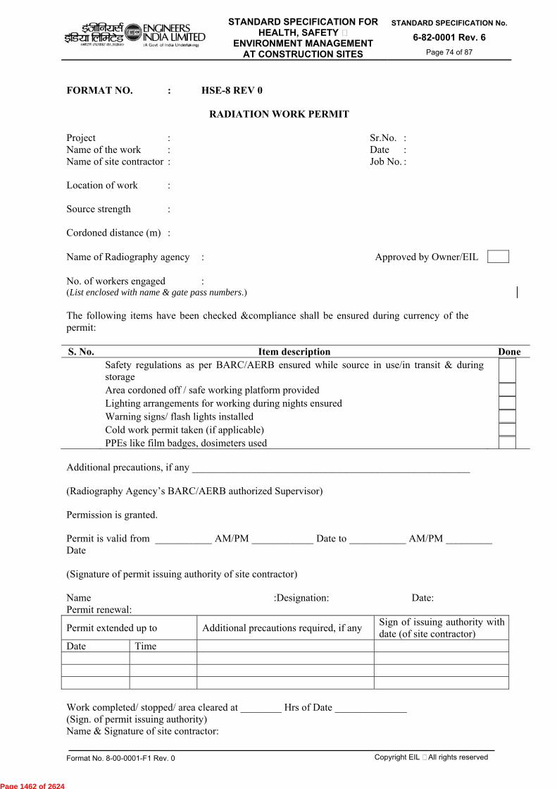
STANDARD SPECIFICATION FOR HEALTH, SAFETY &
ENVIRONMENT MANAGEMENT AT CONSTRUCTION SITES
STANDARD SPECIFICATION No.
6-82-0001 Rev. 6 Page 74 of 87
Format No. 8-00-0001-F1 Rev. 0 Copyright EIL – All rights reserved
FORMAT NO. : HSE-8 REV 0
RADIATION WORK PERMIT
Project : Sr.No. : Name of the work : Date : Name of site contractor : Job No. : Location of work : Source strength : Cordoned distance (m) : Name of Radiography agency : Approved by Owner/EIL No. of workers engaged : (List enclosed with name & gate pass numbers.) The following items have been checked &compliance shall be ensured during currency of the permit: S. No. Item description Done Safety regulations as per BARC/AERB ensured while source in use/in transit & during
storage
Area cordoned off / safe working platform provided Lighting arrangements for working during nights ensured Warning signs/ flash lights installed Cold work permit taken (if applicable) PPEs like film badges, dosimeters used Additional precautions, if any ______________________________________________________ (Radiography Agency’s BARC/AERB authorized Supervisor) Permission is granted. Permit is valid from ___________ AM/PM ____________ Date to ___________ AM/PM _________ Date (Signature of permit issuing authority of site contractor) Name :Designation: Date: Permit renewal:
Permit extended up to Additional precautions required, if any Sign of issuing authority with date (of site contractor)
Date Time Work completed/ stopped/ area cleared at ________ Hrs of Date ______________ (Sign. of permit issuing authority) Name & Signature of site contractor:
Page 1462 of 2624
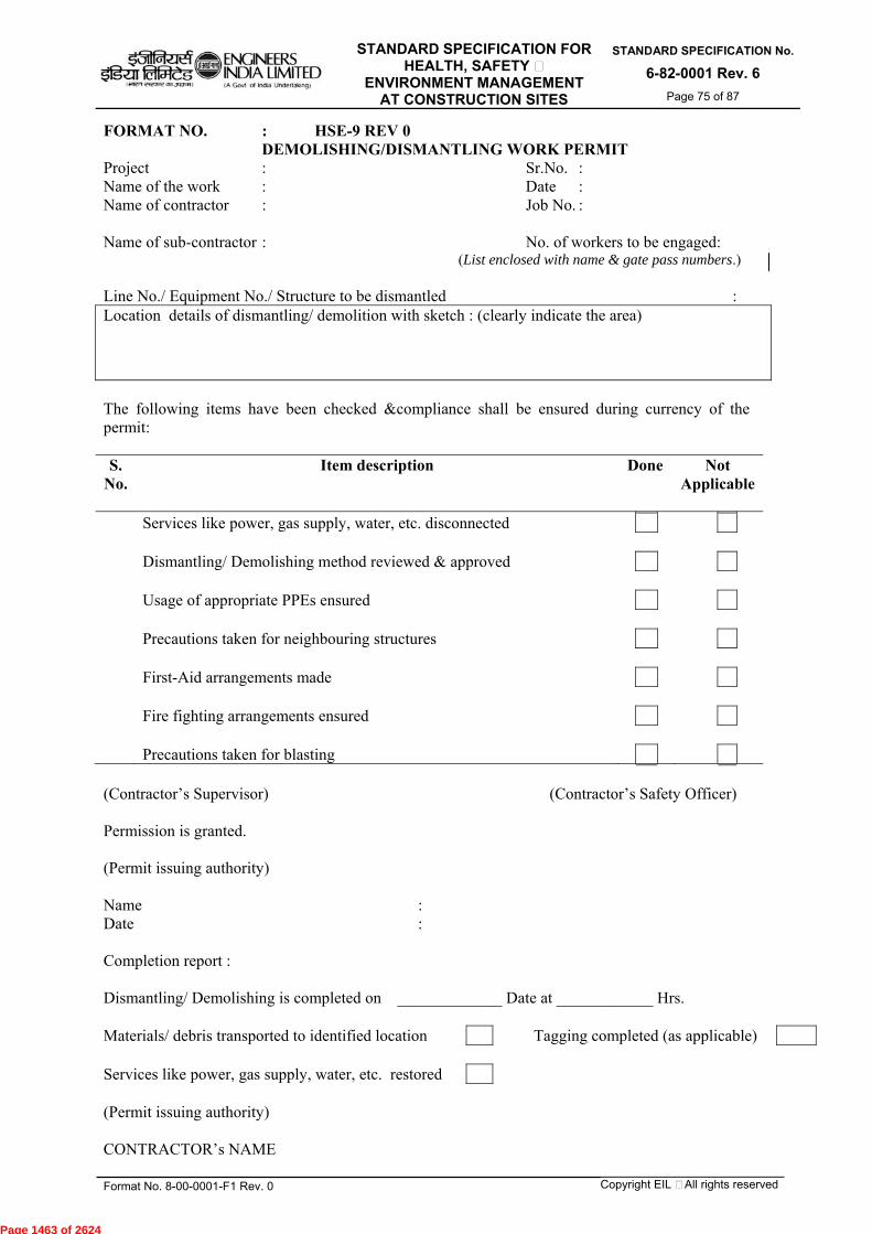
STANDARD SPECIFICATION FOR HEALTH, SAFETY &
ENVIRONMENT MANAGEMENT AT CONSTRUCTION SITES
STANDARD SPECIFICATION No.
6-82-0001 Rev. 6 Page 75 of 87
Format No. 8-00-0001-F1 Rev. 0 Copyright EIL – All rights reserved
FORMAT NO. : HSE-9 REV 0 DEMOLISHING/DISMANTLING WORK PERMIT
Project : Sr.No. : Name of the work : Date : Name of contractor : Job No. : Name of sub-contractor : No. of workers to be engaged:
(List enclosed with name & gate pass numbers.) Line No./ Equipment No./ Structure to be dismantled : Location details of dismantling/ demolition with sketch : (clearly indicate the area) The following items have been checked &compliance shall be ensured during currency of the permit: S.
No. Item description Done Not
Applicable
Services like power, gas supply, water, etc. disconnected Dismantling/ Demolishing method reviewed & approved Usage of appropriate PPEs ensured Precautions taken for neighbouring structures First-Aid arrangements made Fire fighting arrangements ensured Precautions taken for blasting (Contractor’s Supervisor) (Contractor’s Safety Officer) Permission is granted. (Permit issuing authority) Name : Date : Completion report : Dismantling/ Demolishing is completed on _____________ Date at ____________ Hrs. Materials/ debris transported to identified location Tagging completed (as applicable) Services like power, gas supply, water, etc. restored (Permit issuing authority) CONTRACTOR’s NAME
Page 1463 of 2624
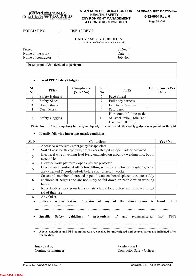
STANDARD SPECIFICATION FOR HEALTH, SAFETY &
ENVIRONMENT MANAGEMENT AT CONSTRUCTION SITES
STANDARD SPECIFICATION No.
6-82-0001 Rev. 6 Page 76 of 87
Format No. 8-00-0001-F1 Rev. 0 Copyright EIL – All rights reserved
FORMAT NO. : HSE-10 REV 0
DAILY SAFETY CHECKLIST (To make use of before start of day’s work)
Project : Sr.No. : Name of the work : Date : Name of contractor : Job No. :
Description of Job decided to perform : -
Use of PPE / Safety Gadgets
Sl. No PPEs Compliance
(Yes / No) Sl. No PPEs Compliance (Yes
/ No) 1 Safety Helmets 6 Face Shield 2 Safety Shoes 7 Full body harness 3 Hand Gloves 8 Fall Arrest System 4 Dust Musk 9 Safety net
5 Safety Goggles
10 Horizontal life-line made of steel wire, (dia not less than 8.0 mm.)
(Serial No. 1 & 2 are compulsory for everyone. Specify & ensure use of other safety gadgets as required for the job)
Identify following important unsafe conditions: -
Sl. No Conditions Yes / No 1 Access to work site / emergency escape clear 2 Soil / Loose earth kept away from excavated pit / slope / ladder provided
3 Electrical wire / welding lead lying entangled on ground / welding m/c. booth accessible
4 Elevated work platform / open ends are protected
5 Ground area cordoned off before lifting works or erection at height / ground area checked & cordoned-off before start of height works
6 Structural members / erected pipes / wooden boards/pieces etc. are safely anchored at heights and are not likely to fall down on people when working beneath
7 Rope ladders tied-up on tall steel structures, long before are removed to get rid of their use
8 Any Other Indicate actions taken, if status of any of the above items is found “No”
……………………………… ………………………………………………………………………………………………………………. Specific Safety guidelines / precautions, if any (communicated thro’ TBT)
…………………………… ……………………………………………………………………………………………………………… ……………………………………………………………………………………………………………… Above conditions and PPE compliances are checked by undersigned and correct status are indicated after
verification Inspected by Verification By Contractor Engineer Contractor Safety Officer
Page 1464 of 2624

STANDARD SPECIFICATION FOR HEALTH, SAFETY &
ENVIRONMENT MANAGEMENT AT CONSTRUCTION SITES
STANDARD SPECIFICATION No.
6-82-0001 Rev. 6 Page 77 of 87
Format No. 8-00-0001-F1 Rev. 0 Copyright EIL – All rights reserved
FORMAT NO. : HSE-11 REV 0 (Sheet 1 of 2)
HOUSEKEEPING ASSESSMENT & COMPLIANCE
Project : Sr.No. : Name of the work : Date : Name of contractor : Job No. : Name of contractor : Fortnightly
Sl No. Subjects of Review Satisafctory/
Yes Non
satisfactory/No Remarks Action
1. Cleanliness at the Main entry / access of site
2. Ground condition / floor areas free from water-logging / oil spillage
3. Ground & elevated floors free from rubbish / wastes / accumulated debris / scraps.
4. Manholes / openings are covered / fenced
5. Trenches are barricaded / walkways are in place
6. Drains are cleaned / not choked / not occupied by dumped materials
7. Sufficient CAUTION boards / instructions displayed
8. Construction machinery are maintained & parked in orderly manner.
9. Movement of site people are not obstructed because of dumping / storing of construction materials
10. Access / egress to Electrical Distribution Boards / Panels clear from wires / cables / earth-strips etc.
11. Electrical panel rooms / sheds / MCC / Control rooms / Substations etc. are clean & tidy and not used for storing dress / clothes, tiffin-box or bicycles.
12. Passage behind Elec. panels are free for access
13. Fire extinguishers / fire-buckets are accessible without any difficulty.
14. Stair-steps, platforms & landings are clear & tidy
15. Sheds / rooms & work areas have got sufficient illumination as well as ventilation
16. Cables / Wires / welding leads are routed / hanged appropriately & are not creating unsafe condition.
17. Stacking / storing of insulation materials or their packing.
18. Removal or cleanliness of left-over sand, concrete, brick-bats, insulation-materials, excess earth, wastes etc.
19. Storing / stacking of sand, metal chips, re-bars, steel pipes, valves, fittings etc.
20. One escape route at ground & minimum two escape routes at elevation available,
Page 1465 of 2624
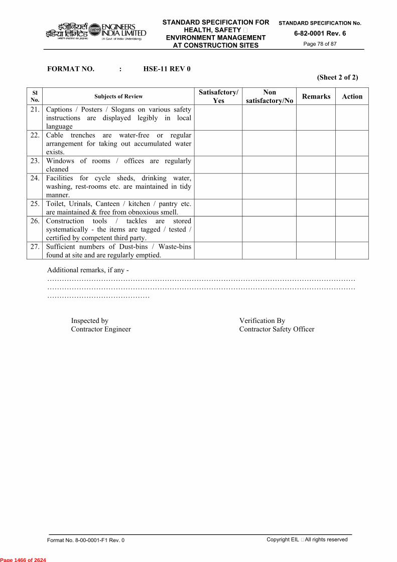
STANDARD SPECIFICATION FOR HEALTH, SAFETY &
ENVIRONMENT MANAGEMENT AT CONSTRUCTION SITES
STANDARD SPECIFICATION No.
6-82-0001 Rev. 6 Page 78 of 87
Format No. 8-00-0001-F1 Rev. 0 Copyright EIL – All rights reserved
FORMAT NO. : HSE-11 REV 0 (Sheet 2 of 2)
Sl No. Subjects of Review Satisafctory/
Yes Non
satisfactory/No Remarks Action
21. Captions / Posters / Slogans on various safety instructions are displayed legibly in local language
22. Cable trenches are water-free or regular arrangement for taking out accumulated water exists.
23. Windows of rooms / offices are regularly cleaned
24. Facilities for cycle sheds, drinking water, washing, rest-rooms etc. are maintained in tidy manner.
25. Toilet, Urinals, Canteen / kitchen / pantry etc. are maintained & free from obnoxious smell.
26. Construction tools / tackles are stored systematically - the items are tagged / tested / certified by competent third party.
27. Sufficient numbers of Dust-bins / Waste-bins found at site and are regularly emptied.
Additional remarks, if any - ……………………………………………………………………………………………………………… ……………………………………………………………………………………………………………………………………………………
Inspected by Verification By Contractor Engineer Contractor Safety Officer
Page 1466 of 2624
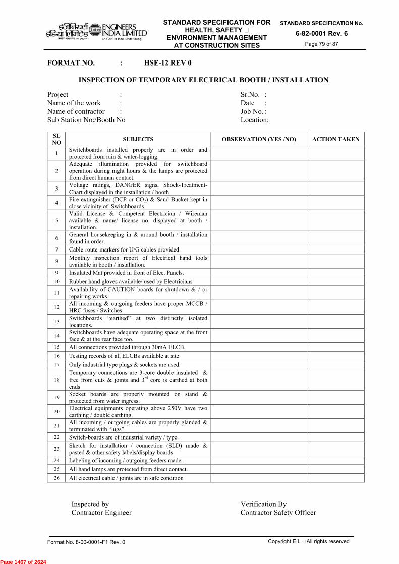
STANDARD SPECIFICATION FOR HEALTH, SAFETY &
ENVIRONMENT MANAGEMENT AT CONSTRUCTION SITES
STANDARD SPECIFICATION No.
6-82-0001 Rev. 6 Page 79 of 87
Format No. 8-00-0001-F1 Rev. 0 Copyright EIL – All rights reserved
FORMAT NO. : HSE-12 REV 0
INSPECTION OF TEMPORARY ELECTRICAL BOOTH / INSTALLATION
Project : Sr.No. : Name of the work : Date : Name of contractor : Job No. : Sub Station No:/Booth No Location:
SL NO SUBJECTS OBSERVATION (YES /NO) ACTION TAKEN
1 Switchboards installed properly are in order and protected from rain & water-logging.
2 Adequate illumination provided for switchboard operation during night hours & the lamps are protected from direct human contact.
3 Voltage ratings, DANGER signs, Shock-Treatment-Chart displayed in the installation / booth
4 Fire extinguisher (DCP or CO2) & Sand Bucket kept in close vicinity of Switchboards
5 Valid License & Competent Electrician / Wireman available & name/ license no. displayed at booth / installation.
6 General housekeeping in & around booth / installation found in order.
7 Cable-route-markers for U/G cables provided.
8 Monthly inspection report of Electrical hand tools available in booth / installation.
9 Insulated Mat provided in front of Elec. Panels. 10 Rubber hand gloves available/ used by Electricians
11 Availability of CAUTION boards for shutdown & / or repairing works.
12 All incoming & outgoing feeders have proper MCCB / HRC fuses / Switches.
13 Switchboards “earthed” at two distinctly isolated locations.
14 Switchboards have adequate operating space at the front face & at the rear face too.
15 All connections provided through 30mA ELCB. 16 Testing records of all ELCBs available at site 17 Only industrial type plugs & sockets are used.
18 Temporary connections are 3-core double insulated & free from cuts & joints and 3rd core is earthed at both ends
19 Socket boards are properly mounted on stand & protected from water ingress.
20 Electrical equipments operating above 250V have two earthing / double earthing.
21 All incoming / outgoing cables are properly glanded & terminated with “lugs”.
22 Switch-boards are of industrial variety / type.
23 Sketch for installation / connection (SLD) made & pasted & other safety labels/display boards
24 Labeling of incoming / outgoing feeders made. 25 All hand lamps are protected from direct contact. 26 All electrical cable / joints are in safe condition
Inspected by Verification By Contractor Engineer Contractor Safety Officer
Page 1467 of 2624

STANDARD SPECIFICATION FOR HEALTH, SAFETY &
ENVIRONMENT MANAGEMENT AT CONSTRUCTION SITES
STANDARD SPECIFICATION No.
6-82-0001 Rev. 6 Page 80 of 87
Format No. 8-00-0001-F1 Rev. 0 Copyright EIL – All rights reserved
FORMAT NO. : HSE-13 REV 0 (Sheet 1 of 2)
INSPECTION FOR SCAFFOLDING
Project : Sr.No. : Name of the work : Date : Name of contractor : Job No. :
Sl. No Description Yes No N.A Actions
taken 1 Whether work permit is obtained to take up work at height above 1.5 Mts?
2 Whether atmospheric condition is “stormy” or “raining” and works at heights have been permitted?
3 Whether steel pipes scaffoldings are used for units /off-site areas?
4 Whether scaffolding has been erected on rigid/firm/leveled surfaces / ground? Whether “foot-seals” or “base-plates” are used beneath the up-rights (vertical steel pipes)
5 Whether scaffold construction is as per IS specification with toe-board and hand-rails (top-rail as well as mid-rail)?
6 Whether distance between two successive up-rights are less than 2.5 Mts (height of scaffold & load carrying capacity governs the distance between two uprights)
7 Whether all uprights are extended at least 900 mm above the top most working platform (to enable fitting of handrails)?
8 Whether vertical distance of two successive ledgers is satisfactory? (varying between 1.3 Mts. To 2.1 Mts)
9 Whether the peripheral areas of working at height are cordoned-off? (for avoiding accident to people arising out of dropped / deflected materials)
10 Whether platform is provided? Is it safely approachable?
11 Whether end of scaffold platform / board are extended beyond transoms? (125mm to 150 mm)
12 Whether CE / IS approved quality and worthy conditioned full-body safety harness (with double lanyard & karabiners) are used while working at heights?
13 Whether life-line of safety harness is anchored to an independent secured support capable of withstanding load of a falling person?
14 Whether the area around the scaffold is cordoned off to prohibit the entry of unauthorized person / vehicle?
15 Whether clamps used are of good condition, of adequate strength and free from defects?
16 Whether ladder is placed at secured and leveled surface? 17 Whether water-pass and oil-spills are avoided around the scaffold structure? 18 Whether ladder is extended 1.5mts. above the landing point at height? 19 Whether more than one access/egress provided to the scaffold?
20 Whether ladder used are of adequate length and overlapping of short ladders avoided?
21 Whether metallic ladders are placed much away from near-by electrical transmission line?
22 Whether rungs of ladder are inspected and found in good order? 23 Whether fall-arresters provided on both the access/egress routes?
24 Whether diagonal (cross) bracings are provided at regular interval on the scaffold?
25 Whether working platform on the scaffold has been made free from “jolt” or “gap”?
26 Whether tools or materials are removed after completion of the day’s job at heights?
27 Whether a valid Permit for Work (PFW) is obtained before taking up work over asbestos or fragile roof?
28 Whether sufficient precaution is taken while working on fragile roof?
Page 1468 of 2624
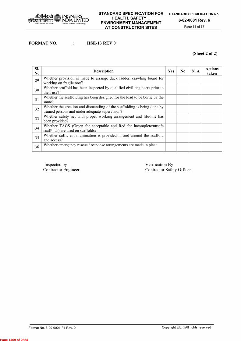
STANDARD SPECIFICATION FOR HEALTH, SAFETY &
ENVIRONMENT MANAGEMENT AT CONSTRUCTION SITES
STANDARD SPECIFICATION No.
6-82-0001 Rev. 6 Page 81 of 87
Format No. 8-00-0001-F1 Rev. 0 Copyright EIL – All rights reserved
FORMAT NO. : HSE-13 REV 0
(Sheet 2 of 2)
Sl. No Description Yes No N. A Actions
taken
29 Whether provision is made to arrange duck ladder, crawling board for working on fragile roof?
30 Whether scaffold has been inspected by qualified civil engineers prior to their use?
31 Whether the scaffolding has been designed for the load to be borne by the same?
32 Whether the erection and dismantling of the scaffolding is being done by trained persons and under adequate supervision?
33 Whether safety net with proper working arrangement and life-line has been provided?
34 Whether TAGS (Green for acceptable and Red for incomplete/unsafe scaffolds) are used on scaffolds?
35 Whether sufficient illumination is provided in and around the scaffold and access?
36 Whether emergency rescue / response arrangements are made in place
Inspected by Verification By Contractor Engineer Contractor Safety Officer
Page 1469 of 2624
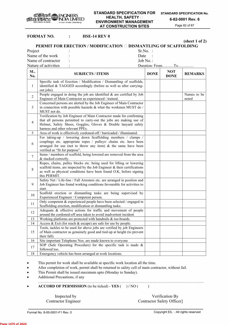
STANDARD SPECIFICATION FOR HEALTH, SAFETY &
ENVIRONMENT MANAGEMENT AT CONSTRUCTION SITES
STANDARD SPECIFICATION No.
6-82-0001 Rev. 6 Page 82 of 87
Format No. 8-00-0001-F1 Rev. 0 Copyright EIL – All rights reserved
FORMAT NO. : HSE-14 REV 0 (sheet 1 of 2)
PERMIT FOR ERECTION / MODIFICATION & DISMANTLING OF SCAFFOLDING Project : Sr.No. : Name of the work : Date : Name of contractor : Job No. : Nature of activities : Duration: From………To…………
SL. No. SUBJECTS / ITEMS DONE NOT
DONE REMARKS
1 Specific task of Erection / Modification / Dismantling of scaffolds, identified & TAGGED accordingly (before as well as after carrying-out jobs).
2 People engaged in doing the job are identified & are certified by Job Engineer of Main Contractor as experienced / trained.
Names to be noted
3 Concerned persons are alerted by the Job Engineer of Main Contractor in connection with possible hazards & what the workmen MUST do / MUST not do.
4
Verification by Job Engineer of Main Contractor made for confirming that all persons permitted to carry-out the jobs are making use of Helmet, Safety Shoes, Goggles, Gloves & Double lanyard safety harness and other relevant PPEs.
5 Area of work is effectively cordoned-off / barricaded / illuminated.
6
For taking-up / lowering down Scaffolding members / clamps / couplings etc. appropriate ropes / pulleys/ chains etc. have been arranged for use (not to throw any item) & the same have been verified as “fit for purpose”.
7 Items / members of scaffold, being lowered are removed from the area & stacked correctly.
8
Ropes, chains, pulley blocks etc. being used for lifting or lowering scaffold items, are inspected by the Job Engineer & their certifications as well as physical conditions have been found O.K, before signing this PERMIT.
9 Safety Net / Life-line / Fall Arresters etc. are arranged in position and Job Engineer has found working conditions favourable for activities to start.
10 Scaffold erection or dismantling tasks are being supervised by Experienced Engineer / Competent person.
11 Only competent & experienced people have been selected / engaged in Scaffolding erection, modification or dismantling tasks.
12 Adequate & effective actions for traffic and movement of people around the cordoned-off area taken to avoid inadvertent incident
13 Working platforms are protected with handrails & toe-boards. 14 Access & Exit (for reach & escape) are safe for use by people.
15 Tools, tackles to be used for above jobs are verified by job Engineers of Main contractor as genuinely good and tied-up at height (to prevent their fall).
16 Site important Telephone Nos. are made known to everyone
17 SOP (Safe Operating Procedure) for the specific task is made & followed too.
18 Emergency vehicle has been arranged at work locations.
This permit for work shall be available at specific work location all the time. After completion of work, permit shall be returned to safety cell of main contractor, without fail. This Permit shall be issued maximum upto (Monday to Sunday). Additional Precautions, if any
………………………………………………………………………………………………………………… ACCORD OF PERMISSION (to be ticked) - YES ( ) / NO ( )
Inspected by Verification By Contractor Engineer Contractor Safety Officer]
Page 1470 of 2624

STANDARD SPECIFICATION FOR HEALTH, SAFETY &
ENVIRONMENT MANAGEMENT AT CONSTRUCTION SITES
STANDARD SPECIFICATION No.
6-82-0001 Rev. 6 Page 83 of 87
Format No. 8-00-0001-F1 Rev. 0 Copyright EIL – All rights reserved
FORMAT NO. : HSE-14 REV 0
(sheet 2of 2)
Everyday Site working conditions & performance of workmen shall be assessed / checked by Contractor Site Engr. and Safety Officer shall verify the same .
Name / Sign. MONDAY TUESDAY WEDNESDAY THURSDAY FRIDAY SATURDAY SUNDAY
Site Engr.
Safety Off.
Page 1471 of 2624
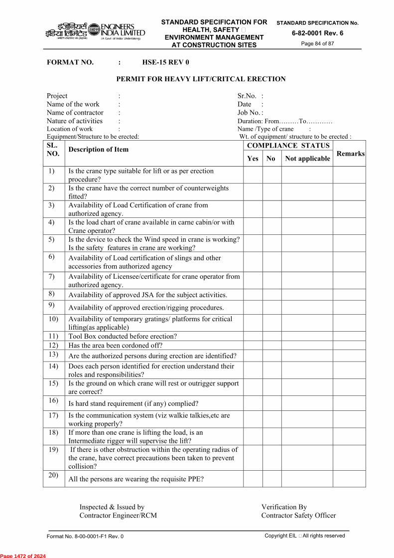
STANDARD SPECIFICATION FOR HEALTH, SAFETY &
ENVIRONMENT MANAGEMENT AT CONSTRUCTION SITES
STANDARD SPECIFICATION No.
6-82-0001 Rev. 6 Page 84 of 87
Format No. 8-00-0001-F1 Rev. 0 Copyright EIL – All rights reserved
FORMAT NO. : HSE-15 REV 0
PERMIT FOR HEAVY LIFT/CRITCAL ERECTION
Project : Sr.No. : Name of the work : Date : Name of contractor : Job No. : Nature of activities : Duration: From………To………… Location of work : Name /Type of crane : Equipment/Structure to be erected: Wt. of equipment/ structure to be erected : SL. NO.
Description of Item
COMPLIANCE STATUSRemarks
Yes No Not applicable
1) Is the crane type suitable for lift or as per erection procedure?
2) Is the crane have the correct number of counterweights fitted?
3) Availability of Load Certification of crane from authorized agency.
4) Is the load chart of crane available in carne cabin/or with Crane operator?
5) Is the device to check the Wind speed in crane is working? Is the safety features in crane are working?
6) Availability of Load certification of slings and other accessories from authorized agency
7) Availability of Licensee/certificate for crane operator from authorized agency.
8) Availability of approved JSA for the subject activities.
9) Availability of approved erection/rigging procedures.
10) Availability of temporary gratings/ platforms for critical lifting(as applicable)
11) Tool Box conducted before erection? 12) Has the area been cordoned off? 13) Are the authorized persons during erection are identified?
14) Does each person identified for erection understand their roles and responsibilities?
15) Is the ground on which crane will rest or outrigger support are correct?
16) Is hard stand requirement (if any) complied?
17) Is the communication system (viz walkie talkies,etc are working properly?
18) If more than one crane is lifting the load, is an Intermediate rigger will supervise the lift?
19) If there is other obstruction within the operating radius of the crane, have correct precautions been taken to prevent collision?
20) All the persons are wearing the requisite PPE?
Inspected & Issued by Verification By Contractor Engineer/RCM Contractor Safety Officer
Page 1472 of 2624
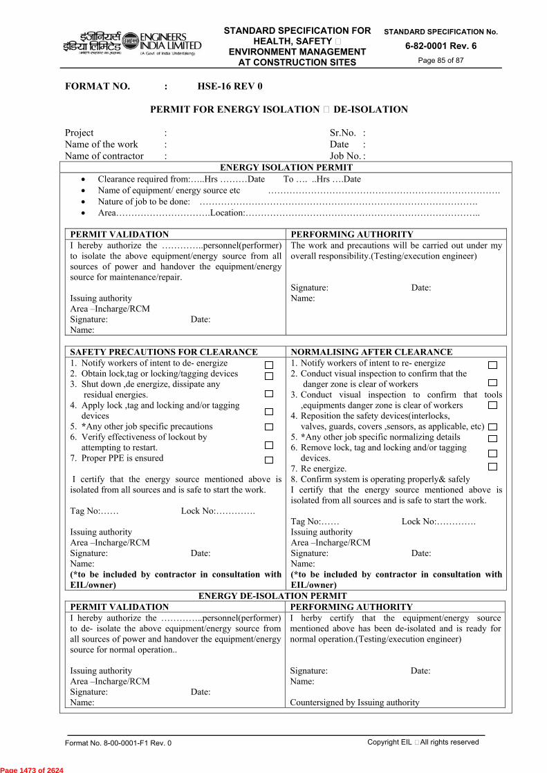
STANDARD SPECIFICATION FOR HEALTH, SAFETY &
ENVIRONMENT MANAGEMENT AT CONSTRUCTION SITES
STANDARD SPECIFICATION No.
6-82-0001 Rev. 6 Page 85 of 87
Format No. 8-00-0001-F1 Rev. 0 Copyright EIL – All rights reserved
FORMAT NO. : HSE-16 REV 0
PERMIT FOR ENERGY ISOLATION & DE-ISOLATION
Project : Sr.No. : Name of the work : Date : Name of contractor : Job No. :
ENERGY ISOLATION PERMIT Clearance required from:…..Hrs ………Date To …. ..Hrs ….Date Name of equipment/ energy source etc …………………………………………………………………. Nature of job to be done: ………………………………………………………………………………. Area………………………….Location:…………………………………………………………………..
PERMIT VALIDATION PERFORMING AUTHORITY I hereby authorize the …………..personnel(performer) to isolate the above equipment/energy source from all sources of power and handover the equipment/energy source for maintenance/repair. Issuing authority Area –Incharge/RCM Signature: Date: Name:
The work and precautions will be carried out under my overall responsibility.(Testing/execution engineer) Signature: Date: Name:
SAFETY PRECAUTIONS FOR CLEARANCE NORMALISING AFTER CLEARANCE 1. Notify workers of intent to de- energize 2. Obtain lock,tag or locking/tagging devices 3. Shut down ,de energize, dissipate any
residual energies. 4. Apply lock ,tag and locking and/or tagging
devices 5. *Any other job specific precautions 6. Verify effectiveness of lockout by
attempting to restart. 7. Proper PPE is ensured
I certify that the energy source mentioned above is isolated from all sources and is safe to start the work. Tag No:…… Lock No:………….
Issuing authority Area –Incharge/RCM Signature: Date: Name: (*to be included by contractor in consultation with EIL/owner)
1. Notify workers of intent to re- energize 2. Conduct visual inspection to confirm that the
danger zone is clear of workers 3. Conduct visual inspection to confirm that tools
,equipments danger zone is clear of workers 4. Reposition the safety devices(interlocks,
valves, guards, covers ,sensors, as applicable, etc) 5. *Any other job specific normalizing details 6. Remove lock, tag and locking and/or tagging
devices. 7. Re energize. 8. Confirm system is operating properly& safely I certify that the energy source mentioned above is isolated from all sources and is safe to start the work. Tag No:…… Lock No:…………. Issuing authority Area –Incharge/RCM Signature: Date: Name: (*to be included by contractor in consultation with EIL/owner)
ENERGY DE-ISOLATION PERMIT PERMIT VALIDATION PERFORMING AUTHORITY I hereby authorize the …………..personnel(performer) to de- isolate the above equipment/energy source from all sources of power and handover the equipment/energy source for normal operation.. Issuing authority Area –Incharge/RCM Signature: Date: Name:
I herby certify that the equipment/energy source mentioned above has been de-isolated and is ready for normal operation.(Testing/execution engineer) Signature: Date: Name: Countersigned by Issuing authority
Page 1473 of 2624

STANDARD SPECIFICATION FOR HEALTH, SAFETY &
ENVIRONMENT MANAGEMENT AT CONSTRUCTION SITES
STANDARD SPECIFICATION No.
6-82-0001 Rev. 6 Page 86 of 87
Format No. 8-00-0001-F1 Rev. 0 Copyright EIL – All rights reserved
FORMAT NO. : HSE-17 REV 0
PERMIT FOR EXCAVATION (depth 2m and above)
(Sheet 1of 2) Project : Sr.No. : Name of the work : Date : Name of contractor : Job No. : Job Description : Location: Size of excavation :
SL. NO.
Description of Item
COMPLIANCE STATUS RemarksYes No Not
applicable 1) Suitable and sufficient risk assessments and method statements
has been carried to ensure that the work shall be undertaken in accordance with specification and standard.
2) Are plans/details of underground services available and the same has been reviewed?
3) Has survey done to locate the services/obstacles, etc.
4) Has the live services (electrical, water line, air line, telephone line,etc) has been disabled for carrying out the job.
5) Is adequate barriers/fences to protect the excavation are in place?
6) Is Adequate warning signs are in place? 7) Is Assessment of ground conditions done and remedial action (if
any) taken?
8) Safe access / egress (e.g. ramp / steps / ladders etc.) provided for site workmen & supervisors.
9) Is the excavation work being undertaken in proximity of structure, etc ? If Yes, it’s effect is considered?
10) Availability of competent person for supervising the excavation work?
11) Adequate safe arrangement to prevent collapse of edges (e.g. shoring / strutting / benching / sloping etc.) made at site.
12) Hard barricades (at least 1.0M away from edge & for excavation near site access roads) with warning signs/caution boards are provided
13) Accumulation / passage-ways of water at periphery of excavation / trench stopped/ restricted.
14) Is the equipment being used for excavation has been checked for adequacy and is in good working condition having all the safety features?
15) Age & fitness of workmen ensured by medical test before engagement in job ?
16) Arrangement of Monitoring of possible oxygen deficiency or obnoxious gases done & action taken?
PERMIT GRANTED - Yes / No
(List enclosed with name & gate pass numbers.) Name & Signature of Site Engr Name & Signature of Safety Officer Contractor (Initiator) Contractor (Issuing authority)
Page 1474 of 2624

STANDARD SPECIFICATION FOR HEALTH, SAFETY &
ENVIRONMENT MANAGEMENT AT CONSTRUCTION SITES
STANDARD SPECIFICATION No.
6-82-0001 Rev. 6 Page 87 of 87
Format No. 8-00-0001-F1 Rev. 0 Copyright EIL – All rights reserved
FORMAT NO. : HSE-17 REV 0
PERMIT FOR EXCAVATION (Sheet 2of 2)
NOTES: -
1. Slopes or benches for excavation beyond 2.0M depth shall be designed & approved by Contractor’s site head.
2. Excavated earth to be kept at least 1.5M away from edges
3. Safety helmets, Safety shoes or gum-boots, gloves, goggles, Face shield, Safety Harness shall be essential PPEs.
4. Permit shall be made in duplicate and original shall be available at site of work. 5. Permit shall be issued for maximum one week only (Monday to Sunday) 6. After completion of works, permit shall be closed & preserved for record purpose
GRANT OF PERMIT AND EXTENSIONS
Sl. No.
Validity period From ____To ____
Working Time From _____To _____
Initiator (site Engr. of Main
Contractor)
Issuing authority (Safety Officer
of Main Contractor)
Review by EIL / Owner (Remarks
with date
1.
2.
3.
4.
5.
6.
7.
Additional safety instructions if any: - 1.
2.
3.
Page 1475 of 2624
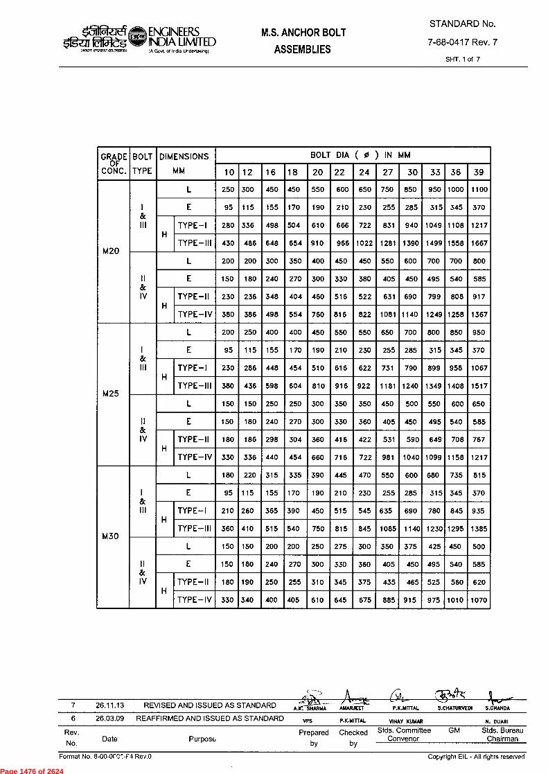
S.CHANDA P.K.MITTAL
+9-4;
S.CHATURVEDI A. . SHARMA AMARJEET 7 26.11.13 REVISED AND ISSUED AS STANDARD
6 26.03.09 REAFFIRMED AND ISSUED AS STANDARD VPS P.K.MITTAL VINAY KUMAR N. DUARI
Rev.
No. Date Purpose
Prepared Checked Stds. Committee GM Stds. Bureau Convenor Chairman
by by
Copyright EIL - All rights reserved Format No. 8-00-0f0".-F4 Rev.0
GRADE OF
CONC.
BOLT
TYPE
DIMENSIONS
MM
BOLT DIA ( 0 ) IN MM
10 12 16 18 20 22 24 27 30 33 36 39
M20
I 8c III
L 250 300 450 450 550 600 650 750 850 950 1000 1100
E 95 115 155 170 190 210 230 255 285 315 345 370
H TYPE —I 280 336 498 504 610 666 722 831 940 1049 1108 1217
TYPE —III 430 486 648 654 910 966 1022 1281 1390 1499 1558 1667
II 8c IV
L 200 200 300 350 400 450 450 550 600 700 700 800
E 150 180 240 270 300 330 380 405 450 495 540 585
H TYPE —II 230 236 348 404 460 516 522 631 690 799 808 917
TYPE—IV 380 386 498 554 760 816 822 1081 1140 1249 1258 1367
M25
I & 111
L 200 250 400 400 450 550 550 650 700 800 850 950
E 95 115 155 170 190 210 230 255 285 315 345 370
H TYPE —1 230 286 448 454 510 616 622 731 790 899 958 1067
TYPE —III 380 436 598 604 810 916 922 1181 1240 1349 1408 1517
II & IV
L 150 150 250 250 300 350 350 450 500 550 600 650
E 150 180 240 270 300 330 360 405 450 495 540 585
H TYPE —II 180 186 298 304 360 416 422 531 590 649 708 767
TYPE —IV 330 336 440 454 660 716 722 981 1040 1099 1158 1217
M30
1 8c III
L 180 220 315 335 390 445 470 550 600 680 735 815
E 95 115 155 170 190 210 230 255 285 315 345 370
H TYPE —I 210 260 365 390 450 515 545 635 690 780 845 935
TYPE —III 360 410 515 540 750 815 845 1085 1140 1230 1295 1385
II 8c IV
L 150 150 200 200 250 275 300 350 375 425 450 500
E 150 180 240 270 300 330 360 405 450 495 540 585
H TYPE—II 180 190 250 255 310 345 375 435 465 525 560 620
TYPE—IV 330 340 400 405 610 645 675 885 915 975 1010 1070
ENGINEERS 51gu fê45 INDIA LIMITED
IA Govt of India Undertakong)
M.S. ANCHOR BOLT
ASSEMBLIES
STANDARD No.
7-68-0417 Rev. 7
SHT. 1 of 7
I alWrf ri.em2 057,isn.1)
Page 1476 of 2624
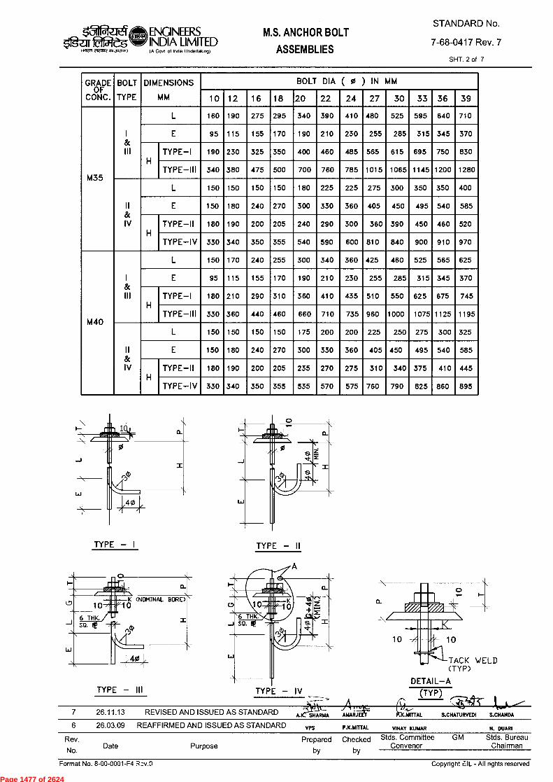
6 26.03.09 REAFFIRMED AND ISSUED AS STANDARD VPS P.K.MITTAL V1NAY KUMAR N. DUARI
Rev.
No. Date Purpose
Prepared Checked Stds. Committee GM Stds. Bureau Convenor Chairman
by by
Copyright EIL - All rights reserved Format No. 8-00-0001-F4 Rcv.0
GRADE OF
CONC.
BOLT
TYPE
DIMENSIONS
MM
BOLT DIA ( 0 ) IN MM
10 12 16 18 20 22 24 27 30 33 36 39
M35
I 8c III
L 160 190 275 295 340 390 410 480 525 595 640 710
E 95 115 155 170 190 210 230 255 285 315 345 370
H TYPE —I 190 230 325 350 400 460 485 565 615 695 750 830
TYPE—III 340 380 475 500 700 760 785 1015 1065 1145 1200 1280
II 8c IV
L 150 150 150 150 180 225 225 275 300 350 350 400
E 150 180 240 270 300 330 360 405 450 495 540 585
H TYPE—II 180 190 200 205 240 290 300 360 390 450 460 520
TYPE—IV 330 340 350 355 540 590 600 810 840 900 910 970
M 40
I & III
L 150 170 240 255 300 340 360 425 460 525 565 625
E 95 115 155 170 190 210 230 255 285 315 345 370
H TYPE —I 180 210 290 310 360 410 435 510 550 625 675 745
TYPE—III 330 360 440 460 660 710 735 960 1000 1075 1125 1195
II & IV
L 150 150 150 150 175 200 200 225 250 275 300 325
E 150 180 240 270 300 330 360 405 450 495 540 585
H TYPE—II 180 190 200 205 235 270 275 310 340 375 410 445
TYPE—IV 330 340 350 355 535 570 575 760 790 825 860 895
7 26.11.13 REVISED AND ISSUED AS STANDARD YX1_
A.K: SHARMA
ENGINEERS Og-a OfZ5 INDIA LIMITED
IA Govt of Incha Undertaking)
M.S. ANCHOR BOLT
ASSEMBLIES
STANDARD No.
7-68-0417 Rev. 7
SHT. 2 of 7 2i2O5-feasl.smo.-0
elie
■ Ile■
il
TYPE — I
0_
0K (NOMINAL BORE)
TYPE — III
t'4,».■ tata
TYPE — II
TYPE — IV
o I—
a.
A1:4-- AMARJEET
TACK WELD (TYP)
DETAIL—A
(TYP)
.ANTTAL S.CHATURVEDI S.CHANDA
Page 1477 of 2624

ENGINEERS INDIA LIMITED IA Govt. of India Undertakingt
M.S. ANCHOR BOLT
ASSEMBLIES
STANDARD No.
7-68-0417 Rev. 7
SHT. 3 of 7
BO
LT
DIA
( 0
) IN
MM
N r,
II, o .-
in ro .-
in ro
(1) o ro
o o
000r0000000>(>000
csi Cs1
co 0 rO rO
tO tri 00
0 00
.4. N
00 to
0 0 0 I-
.- co N ,-
0 rO l*,
(0 ro
O O ..- Csi
O o CO
O tO N
O 0 Cf>
U") co .- .-
O ro >L")
tO in
tr) rs. (0 ...
O in N
O -rr N
'et (1)
0 O 0>
1- N. .--
0 N >0)
LO in
O O 0/
O in r.
O CO N
0 O 00
in N 0
O N K>
to 10
tn N tf,
O O N
O .1' N
0 cD
O a>
tn -.
a> N
tn 1-«
in N
O r.
U:> N
000000000001000 O CO
10 O
0> N
in 1-- N)
in ti,
->1. N
(c) tr)
0 O co
ifl ■,) O .-
0 N. N
10 et
0 O tn .-
0 in tt,
0 sl• N
O 11, r...
in co 0)
O N. N
to et
tn N N ..-
O O CD
O O N
N i.n
0 >n N
u, r. a,
0 <0 CsI
>r) "zr
o in 0,"> 1-
o 0 LO
o ,4. N
0 Lf> LD
11, N 00
0 U:› N
tn •ct
10 1... O 1-
0 14, 11,
in co 1.-
03 •ct
0 0 N
o a,
ro N
•rt 0 N -
rn ll,
er N
000000010000010 0 (0
o CO
ro N
vi 0 O
O tn
co
in 'et
O tn CD
.-
...a. CO
O N LNI
(o ro
O O ..-
O O 11,
O O N
O tn tn
in ..d. N
O N N
Qa /")
in p. cr>
O Lf> .1'
O LID .-
N "Cr
0 O CD
cla r.
1- N
I,) tn O
tn et
O N
CDOCD000000t0 0 00 O tn
0/ 10
.- N
K> lo CO
O el•
u, .-
e> pr)
tn et
0 .-
0 .-
••It •-•
in in
N r.
0 N
>") 00000N0 0 00 0 100 0 000
in 0>
o •Ll'
O N
0 tn
N 10
0 N
C'') 11, N
tn I**)
CD .--
..., Sli Pf)
0 U) et
0 CO
10 a)
0 Pei •-
0 tn vi
CO O CD
0 CO .-
N >..>
o ir, r..
0 tt, s,
0 cD .--
0 11, .4-
0 •-• CD
O LO .-
N c."
O O CD
O O >/)
10 N .-
P•r) ri)
0 if, et
0 ceD
CD 00
0 N .--
0 10 vi
CO 0> u,
0 N .--
CO N
0 O (C)
lf> vi
0 1D
000030 •J• .-
N O in
c> tf)
o in 't
o co
o co -
.- in et
oo>no co u,
in -
in O
ir, N
O
-rt
Lf>
u->
O
.--
tn N
If> N vi
N. N
o in "."
0 co
LI, r■
LI, o .-
0 in *
0 co tn
o •rr .--
tn 00
tn c‘i
0
.*
0
1n
0
.-
tn C‘I
in N ro
..:1- Csl O 0 W")
o cep
O r■
in 0
O
>," 0
N
et
O
.- tn C`l
t0 0 et
O 0 re,
If> .- et
O 0 .-
O Cs1
tn N PO
N N
0 O r`)
0 co
ci, to
o cn
o o ro
0 .- -er
o rO --
0 N
o o *
0 o 1.")
0 r- *
0 O .--
o N
co N Oc)
0 N
00 O 0,
tn iD O 1,1
CO 0000000
cn 1,1
O .--
t's1 in I,>
o 1,>
O .4-
0000in
.- oN1--
N
CO .-
0 tn
0 in
0 (1)
11, 1••••
0 0 N
.- Ch N
0 0 .-
LO •-•
O 0 N
O cn N
O O .-
LO •-
co 0 it,
0 tn
If> if>
0 P.
0 tf> .--
et K> N
,-, ..,,`""
u, .-
0 tn •-•
to 1,) N
o 0/
co .-
C•1 1-
tn .-
tn et 00L000NON
to u, .--
N N
CO •-• 0 tn ..-
if> CV N
0 00
N .--
C) ..-
lf> •-
Lf> sl• 00000000
tn II, .-
.- N
CO .- II, .- 0000
.- N
CO
DIM
EN
SIO
NS
MM
CD
SIN
GLE
NU
T
DO
UB
LE N
UT
CD= 3 -:2-1-10CDM 3 t3
-..J -J (,)
SLEE
VE
THRE
ADED
(T)
LEN
GTH
LLI -I 0 >-
a_
CO I-
>
0>i - -
> X -
0 ck; I- _ X
> >
6.3
>
- >
= > >
> eki
>
- >
- - >
GR
AD
E
OF
C
ON
C. tn kr)
C.1 1+->
cS ci 't r..1 I.r> ckS i = =
= = O N N
ck$ rf)
7 26.11.13 REVISED AND ISSUED AS STANDARD A.K. SHARMA AMARJECT
P.K.MITTAL S.CHATURVEDI S.CHANDA
6 26.03.09 REAFFIRMED AND ISSUED AS STANDARD VPS P.K.MITTAL V1NAY KUMAR N. DUARI
Rev.
No. Date Purpose
Prepared Checked Stds. Committee GM Stds. Bureau Convenor Chairman
by by
Format No. 8 .00-0001-F4 Rev.0
Copyright EIL - All rights reserverI
Page 1478 of 2624
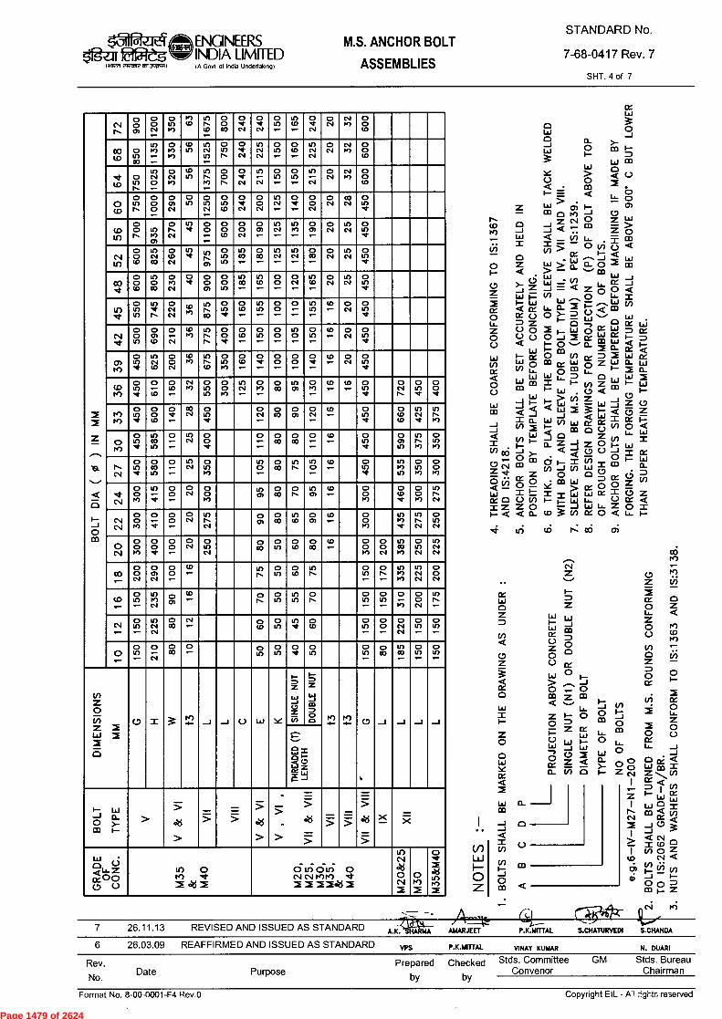
ENGINEERS INDIA LIMITED $'>gu2didg
It~ rlecnft asidnenan IA Govt of India Undertakong)
STANDARD No.
7-68-0417 Rev. 7
SHT. 4 of 7
M.S. ANCHOR BOLT
ASSEMBLIES
M.S
. R
OU
ND
S C
ON
FOR
MIN
G
a_ >- 0 m
w wo > < O
• m = < u_
cri I- 0 r.) --1 0 Z N 0 Z •ct •-
Vi L.,_ , ±- > 0 v) o
cc .••••■ _I Lj < • a_ a..
....., a:, o 1
> > w
w = w U) u. W ~1 = o
< (n z o oL.,_ ,,, ,-... 1.1i Ll. CL i i::
0 ‘.<.., '...‘ CO
o >- W I- 3 LIJ M
(3 -11- L.Lj WC1 i: o dl L.i I- 0 `-' ch_ 1-- cp
• 0
- O N ix CD rX 1"" 0 Z Lij F- L..., 0 m LA-
L,- 0 Li Z }- I- vt Z mLa . (.5 < ,_ > V) Z J 4t L.d I-
Ld <
LLI • _1
-I < Ld LLI V> EC Z (x I- V>
o_Z z O I-°
0 0 Z fl)
N
•
J
-
w I CD 0 0 0
IZ Y m > cr 0 0 I = w r£C.> Z 1- LL i-
1. LAJ1- t /Y 0 <Z r>
u3 N: cc; cri
SH
AL
L B
E T
AC
K W
ELD
ED
o 0 ce < o w N Z I Z < M v) ce w
< N 0 <
-I
> <- N °
I N 0 U;) cs, < ci) a; -J
o ▪ Z
•
0 LL
CO
NFO
RM
TO
IS:1
363
AN
D IS
:313
8.
PO
SIT
ION
BY
TE
MP
LATE
BE
FOR
E C
ON
CR
ETIN
G.
CO
AR
SE C
ON
FO
RM
ING
TO
IS:1
367
5.
AN
CH
OR
BO
LT
S SH
AL
L B
E SE
T A
CC
UR
AT
EL
Y A
ND
HE
LD
IN
FOR
GIN
G. T
HE
FO
RG
ING
TE
MP
ER
ATU
RE
SH
ALL
BE
AB
OV
E 9
00*
C B
UT
LO
WER
TH
AN
SU
PER
HE
ATI
NG
TE
MP
ER
ATU
RE
.
BO
LTS
SH
AL
L B
E MA
RK
ED
ON
TH
E D
RAW
ING
AS
UN
DER
C.)
03
PRO
JEC
TIO
N A
BO
VE
CO
NC
RET
E
Z
1-
-J
O 0 - J 0
Z CO
LL 1-
Z LAJ
LAJ -J w
Z < (7) a TY
PE O
F B
OLT
O
O
O Z
BO
LT D
IA (
0 )
IN
MM
0.1 r,
o 0 n,
0 0 N •-
0 115 1,)
t.,) LD
U)
CO .-
0
CO
O
N
0
N
0 Iff .-
If) tO .-
O met N
0 N
N t.')
O o tO
co o U) 00
U) ce> .- •-•
O ■••) w>
tl, Lf)
U) N U) •-
O lf) N
O •.I• N
U) N N
O 115 .-
O tD .-
U) N N
O N
N Io)
O O te•
••ct (D
0 ir) r•-
U) N 0 •-•
O N 0,
ID to
U) N N) .-
O 0 N
O el• N
U) .- N
o if) .-
o u) .-
U) .- N
O N
N pe)
O o CO
C) (4,
o Lf) r•••
o 0 0
O Co N
o ir)
o
N
O U>
O N
O 0 N
in N .-
o
-
o 0 N
O N
co N
0 in el•
(;) Li.)
o 0 r.
11) N) ch
o N N
Ir) l'
0 O .- .-
0 0 tD
0 0 N
0 0) .-
V) N .-
II, N) ..-
0 0) .-
C) N
if) N
0 Lf) d•
cti ,r,
o 0 CD
U) N CO
O ID N
U) ••••
,n N ot
O if) tn
U) CO -
o CO -
tn N -
U) N -
o CO -
o N
U) N
O If) ...
00 ..,*
0
1.0 0
tf) 0 CO
O N) N
O •It
O 0 0)
0 0 If)
U) CO .-
Lf> CO .-
O 0 ••••
0 N ...
If) cl> .-
O N
if) N
0 if) •./
i() •,t
O LI, U)
tr) •el' N
O N N
,.., ...- - ,
in m
o if) el•
O U>
U) cf)
O 0
O .-
U) 11)
ID .--
O N
O u> ,t
..4.
O
in
O
CD
O
N
CD N)
Lf> r■ r...
0 o 'd'
O l0 ■-•
O Lf) •-•
0 O •-•
1/5 o •-
O u> •-
11, .--.
O N
0 in •d•
CII, i.c.)
O Lf> -.1.
tf> N U>
O 0 N
CD l',"
U)
(0
0 11, N)
O CD .-
O ..1>
O 0 -
O 0 .-
O ..ct •-•
CD ..-
O N
0 cf) •I•
LT) 1,1)
0 Lf) *
0 .- u>
O CD .-
Csi N)
0 LI) U)
0 O I.)
LI, N •-•
O N) .-
O co
U') o
0 K> ._
(D .-
11, -
0 tr> ,C
O N t•••
0 U) •.t
0 0 •cl•
tf) c•f)
o U) ••4C
0 0 CO
o •cl• .-
c0
N
0 Lr> .1.
0 N .-
0 oD
0 Ot
0 N .-
CO .-
0 tr) *
0 CO CO
if) N •ttl•
Lf) t••• tt,
o ,,,r)
0 10 *
if) CO U)
0 t- -
in N
o 0 ,t
o .- _
c> CO
o CO
o •- _
CD •-• tr,
.1.
0 o) It)
I, 1,1
o U') I,)
r•-• Ni
0 11) 'cl•
0 U)
0 .- .-
U) N
O U') N)
tf) 0 .--
0 10
U) N
V) 0 .-
tO •-•
O el•
1f)
U)
0 Cr)
0 0 N)
-.4- csi
0 o >c)
U) - •ct
0 o t-
0
N
0 0 >,,
u, et
0 CO
0 N
it) ch
CO -
0 o K>
0 CD •4'
0 0 I.")
LO l's N
NI Ni
0 0 C,)
0
•.I• t-ONN
0
.-
0 tf>
NI
0 co
0 CO
Lf) (1) 0)
O.- 0 N)
c,) •••
r.. N
0 Lr> N
O LN1
0 0 1A)
0 0 ..J.
0 0 .-
CsI 0 0
in N
o co
O cf)
O li,
0 CO 0
r•> CO
0
N
U) N)
0
N
U)
N
03 ,..-
0 0 N
0 Cf> N
0 O .-
LO ,-
tr) t...
o U")
o CD
In I,-
o Lf> ,-
N .-
o >() m)
N NI
0 N
to 0 if) .-
tr) N) N
,-, n.,-- -
CD •-•
0 N.
0 ir>
lf) in
0 N OU)
.- OU) •-•
O - M)
0 o N
If) N. .-
N ..-
0 u") .-
in N NI
0 c0
N •-•
o co
0 11)
in "I•
o (1)
o tf) .-
o 0 .-
o N N
o U)
o U")
CD 0 if) ■-•
0 .- N
0 CO
0 .-
o o)
0 if)
0 ..1•
0 Lf)
0 cf)
o co
II) OD
0 U")
0 U")
DIM
EN
SIO
NS
MM
U S 3 -2- --I - -1 (.) L L • I Y S IN
GL
E N
UT
DO
UB
LE N
UT
t3
t3
G
_I _I _I _I
THRE
AD
ED (T
) LE
NG
TH
I- LLI -J ct. O )- m 1—
> >
..>3 >
> — —
V &
VI
>
- cks
> = >
- _
— -- >
cks — _ >
>< _ )7(
GR
A
OFD
E
C
ON
C.
II) 0 i•r) -4-
ek;
ci tri civi o cNINP,),4) .4-
u) N «kS o N
o 14*/
M35
&M
40
. talfiLt. 26.11.13 REVISED AND ISSUED AS STANDARD 4t7a
A.K. HA 1AA AMARJEET P.K.MITTAL S.CHATURVEDI S.CHANDA
6 26.03.09 REAFFIRMED AND ISSUED AS STANDARD VPS
P.K.MITTAL
VINAY KUMAR
N. DUARI
Rev.
No. Date Purpose
Prepared Checked Stds. Committee GM Stds. Bureau Convenor Chairman
by by
Format No. 8-00-0001-F4 R.ev.0
Copyright EIL - A'l re3erved
Page 1479 of 2624

ENGINEERS 51gz-z Wes INDIA LIMITED
lafwnetravtasksvsnitt
IA Govt of Indo Godeftakm9)
M.S. ANCHOR BOLT
ASSEMBLIES
STANDARD No.
7-68-0417 Rev. 7
6 rnrn VELD SQ. FL
TYPE - V TYPE - VI
lja
1E1
IuI lil
6 THK, 2 sQ. FL
C> 6 WELD ALROUND Al LTY
P>
(NOMINAL BORE> 10
6 THK. SQ, Ft_
ON BOTH SIDES DF le
(NOMINAL BORE> 10
—SQ. Ft_
TYPE - VII TYPE - VIII
TYPE - IX
TYPE - XII
26.11.13 REVISED AND ISSUED AS STANDARD A.K: SHARMA AMARJE P.K.M AL S.CHATURVEDI S.CHANDA
SHT. 5 of 7
GAP BETWEEN SLEEVE & BOLT SHALL BE FILLED WITH GROUT
6 26.03.09 REAFFIRMED AND ISSUED AS STANDARD VPS
P.K.MITrAL
VINAY KUMAR
N. DUARI
Rev.
No. Date Purpose
Prepared Checked Stds. Committee GM Stds. Bureau Convenor Chairman
by by
8 THK.
Format Nc. 8-00-0001-F4 Rev.0
Copyright FIL - AlI rights reserved
Page 1480 of 2624
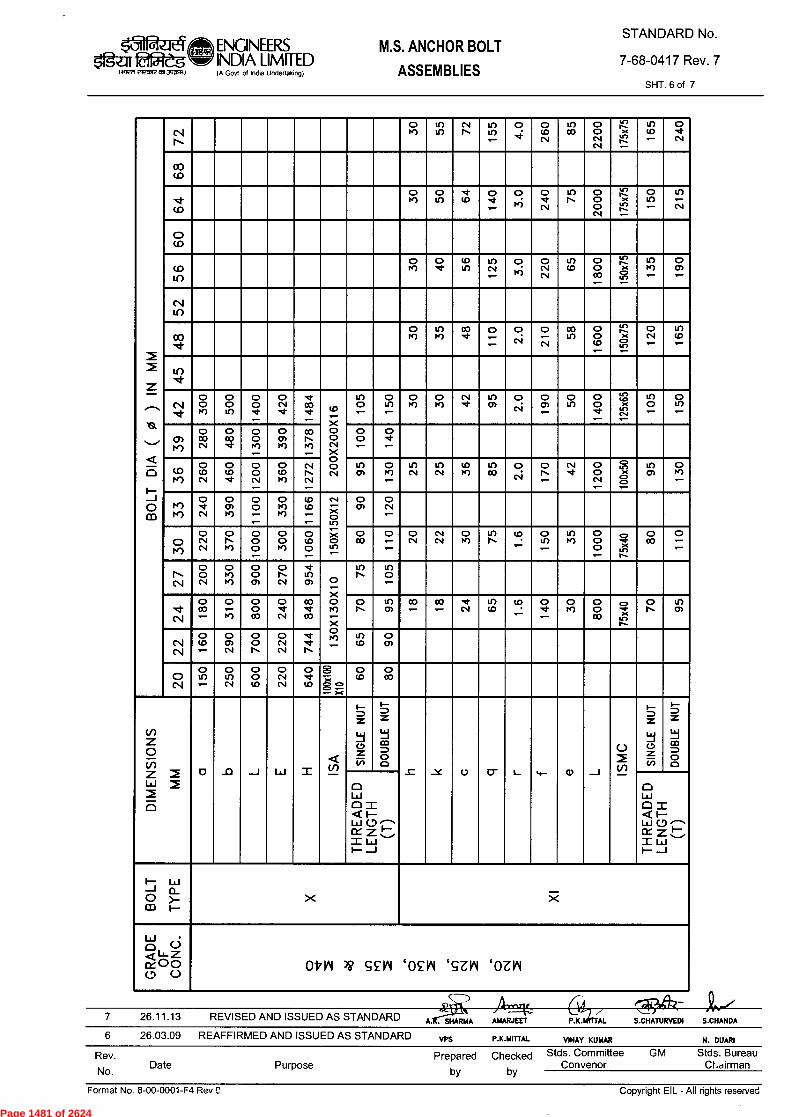
26.11.13 REVISED AND ISSUED AS STANDARD P.K. AL S.CHATURVEDI S.CHANDA A. SHARMA AMARJEET
6 26.03.09 REAFFIRMED AND ISSUED AS STANDARD VPS N. DUARI P.K.14ITTAL VINAY KUMAR
Rev.
No. Date Purpose
Prepared Checked Stds. Committee GM Stds. Bureau Convenor Chairman
by by
Copyright EIL - All rights reserved Format No. 8-00-0001-F4 Rev C
0:11 fadjeg Ii1127f eleamlE151~11
ENGINEERS INDIA LIMITED 1,4 Govt of India Undertakong)
M.S. ANCHOR BOLT
ASSEMBLIES
STANDARD No.
7-68-0417 Rev. 7
SHT. 6 of 7
BO
LT
DIA
(
9$ ) IN
MM
N N
o r4)
cr) Lr)
cv N.
cr) in ...-
o o (D
N in CO
0 0 N N
rs' ;:4 .-
?.e. u) .-
o
N
00 (0
■cl. (0
0 re>
0 in (D
0 el•
0 , „ . ; o N 0
N
K.,.. 2 , .. (
gz .-
o i (*) —
in N
0 (.0
(.0 11)
o P,r) O ' (1)
(1) in N
O • P')
O N N
co CO
o O oo —
r...) ....x •,-i; —
in P4') .-
O O) .-
N Lf)
oO 0 re)
U) rt)
co ..* o .- .--
O ...; '. ,
o --- N
co Li,
O 0 (D .-
r_ 25 ;-r-5 .-
o N .--
cr> (.0 .-
tn •Cl•
c.io ,d.
o r4,
o O in
oo O .:1»
Ns- co.zI- (f)
X O 0 CNI X 0 c, (.1
U) O .-
o n .-
O r4)
O fe)
cv ,it
Lr, (7)
o c,i
o O)
o Lc)
o 0 ...1- .-
',2 .?.,5 ._cc .-..::
U) O .--
O Lr> .--
0) 1,r) 0 c0 N
0 a) '.:1'
0 0 re) .-
O 0) f4)
co P.-. Pf) .-
O 0 .-
O •d• •--
tO K)
O co N
O co ‘t
O O N
O (r, K>
cs.I N. N
un cn O
rn in N
kn N
(10 P,")
1!) CO
0 • CV
0 N
N d•
0 O N .-
,9.' >< 2, .-
cn 0)
O K> .-
74, 1...)
0
cNi 0 cn re)
0 O .-
0 r4) r4)
1D co ..- ,-
c`l — g an X O in
O) 0 Csi
0 r.r)
O N N
O N tr)
O 0 o
O 0 Pr)
O (C> o
O 00
O .-- .--
O N
cm N
O re)
in N
co ' ,-
O If) ,-
un Pr> O O c, -.I- r- 0
O 03 O .-
N. c■I 0 o c‘f
0 0, P4)
0 o O) 0 r- CV
u) O) o x o r4) .- X 0 re) .-
r. o
"CP c,i o CO
o m)
o O CO
o d- N
co •,:t 00
o I.
co O)
co .-
CO .- •—
vt N
11) (C>
(D •
•-•
0 vt
0 74)
0 0 CO
c, "M•
c N..
0 N.
In O)
N c.,1
0 LO •-• O 0)
N 0 0 N
0 N N
,c1» vt N
Lf) (C>
0 O)
O c•si
tn •--
Ln N
000008 O Lc) csi
N ...4- to ..;-. c, ■=> .=, >.
0 <0
0 CO
DIM
EN
SIO
NS
MM
C, -CI -J LLI 2 < tn
SIN
GLE
NU
T
D OU
BL
E N
UT
C c o _ - ) -
(..)
(/) .__
SIN
GLE
NU
T
DO
UB
LE N
UT
TH
RE
AD
ED
LE
NG
TH
(T
)
TH
RE
AD
ED
LE
NG
TH
(T
)
I— LJ _J /2 0 >- CD I—
X _ X
GR
AD
E
OF
C
ON
C.
OP VI )2 S£111 ̀0£11 ̀SZIN ̀OZN
Page 1481 of 2624

ENGINEERS
faffleg INDIA LIMITED
lai(2R oftmi2as7J,n.0
(A Govt. of India Uncleitaking)
M.S. ANCHOR BOLT
ASSEMBLIES
STANDARD No.
7-68-0417 Rev. 7
SHT. 7 of 7
NUT NUT
WASHER WASHER
BASE PLATE BASE PLATE GRDUT GRDUT
CONC. TDP CDNC. TOP
SEE DETAIL Ol SQ. PDCKET
BOX OF 16 GAUGE MS PLATE
n ISA--I
( >
VIEW A — A
TYPE — X
(* AS PER DESIGN REQUIREMENT)
ISMC
I I 1 I 11 11
I I
L_J 11. J
VIEW B - B
6 26.03.09 REVISED AND ISSUED AS STANDARD
Rev.
No. Date
Purpose
VPS P.K.MITTAL VINAY KUMAR N. DUARI
Prepared Checked Stds. Committee GM Stds. Bureau Chairman
by by Convenor
DETAIL - (i)
(FOR FORGED BOLT HEAD)
TYPE - XI
7 26.11.13 REVISED AND ISSUED AS STANDARD A.K. SHARMA AMARJE P.K.MITTAL S.CHATURVEDI S.CHANDA
Format No. 8-00-0001-F4 Rev.O
Copyright EIL - All rights reserved
Page 1482 of 2624

STANDARD SPECIFICATION ENGINEERS FOR COLD INSULATION OF ogur faf--Z5 INDIA LIMITED VESSELS, PIPING AND
Govt ol Inffia Underiffitingi
STANDARD SPECIFICATION No.
6-44-0003 Rev. 2
Page 1 of 32 EQUIPMENT
14T-4fST U$41. t-ffl .r4zià'gR "tq
STANDARD SPECIFICATION FOR COLD INSULATION OF VESSELS,
PIPING AND EQUIPMENT
\
41 41 '.411-‘.‘ 2 10.07.14 Reaffirmed & Issued as Standard Specification RN/PPL SC
1 09.07.08 Revised & Issued as Standard Specification RN PPL DM VC
0 15.01.82 Issued as Standard Specification NKM DB RSG
Standards Standards
Rev. No
Date Purpose Prepared
by Checked
by
Committee Convenor
Bureau
Chairman
Approved by
Format No. 8-00-0001-F1 Rev. 0 Copyright EIL — All rights reserved
Page 1483 of 2624

~_it4 5Ig-ar OWs
ENGINEERS INDIA LIMITED IA Govt of India Undertalong)
STANDARD SPECIFICATION FOR COLD INSULATION OF
VESSELS, PIPING AND EQUIPMENT
STANDARD SPECIFICATION No.
6-44-0003 Rev. 2
Page 2 of 32
Abbreviations:
ASTM : American Society for Testing and Materials
DFT : Dry Film Thickness
GI Galvanized Iron
IS Indian Standard
PIR : Rigid Poly Isocyanurate
PUF : Poly Urethane Foam
S.S. Stainless Steel
SWG : Standard Wire Gauge
Piping Standards Committee
Convenor : Mr. R. Nanda
Members : Mr. M. Ismaeel Mr. Amrendra Kumar Mr. G. Balaji Mr. K.J. Harinarayanan (HMTD) Mr. P P Lahiri / Mr. S. Ghoshal (SMMS) Mr. S. Mukherjee (Construction) Mr. K.V.K. Naidu (Projects)
Format No. 8-00-0001-F1 Rev. 0
Copyright EIL — All rights reserved
Page 1484 of 2624
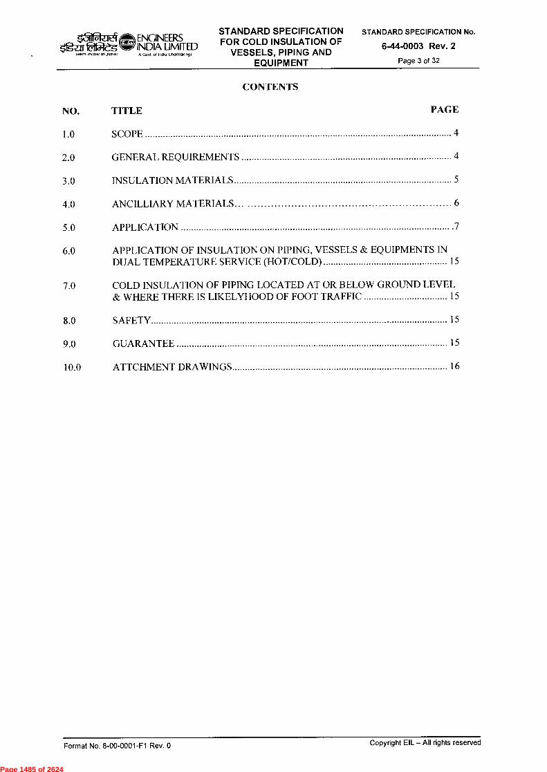
ENGINEERS tffil-eg INDIA LIMITED
1.1r,
IA Govt ol Indu Undertatungt
STANDARD SPECIFICATION FOR COLD INSULATION OF
VESSELS, PIPING AND EQUIPMENT
STANDARD SPECIFICATION No.
6-44-0003 Rev. 2
Page 3 of 32
CONTENTS
NO. TITLE PAGE
1.0 SCOPE 4
2.0 GENERAL REQUIREMENTS 4
3.0 INSULATION MATERIALS 5
4.0 ANCILLIARY MATERIALS 6
5.0 APPLICATION 7
6.0 APPLICATION OF INSULATION ON PIPING, VESSELS & EQUIPMENTS IN DUAL TEMPERATURE SERVICE (HOT/COLD) 15
7.0 COLD INSULATION OF PIPING LOCATED AT OR BELOW GROUND LEVEL & WHERE THERE IS LIKELYHOOD OF FOOT TRAFFIC 15
8.0 SAFETY 15
9.0 GUARANTEE 15
10.0 ATTCHMENT DRAWINGS 16
Format No. 8-00-0001-F1 Rev. 0 Copyright EIL — All rights reserved
Page 1485 of 2624
ENQNEERS INDIA LIMITED IA Govt ot lnOia Undertaking)
STANDARD SPECIFICATION FOR COLD INSULATION OF
VESSELS, PIPING AND EQUIPMENT
STANDARD SPECIFICATION No.
6-44-0003 Rev. 2
Page 4 of 32
g-af 1~, vteavvon3tIooit
1.0 SCOPE
This specification covers technical requirements and procedure for the application of self extinguishing type insulation PUF/PIR and Mineral Wool to vessels, equipments, heat exchangers, pumps, piping and instruments, in temperature range of (+)120°C to (-)110°C.
2.0 GENERAL REQUIREMENTS
2.1 Insulation shall be provided on all vessels, equipments, heat exchangers, piping and instruments etc. containing fluids or vapour, for which it is necessary to :
a. Maintain low temperature for process control. b. Avoid surface condensation.
2.2 All applications of insulation shall be made in accordance with this specification. Contractor shall submit with his proposal, information on intended practices of insulation application, which are not covered in this specification, for approval of the Engineer-in-Charge. This information shall include all the details and sketches including those for the following :
a. Removable insulation housings; b. Flashing details; c. Additional Insulation supports; d. Vessel head insulation supports; e. Expansion joints; f. Vessel insulation details; g. Exchanger removable housings; h. Machinery removable housings etc.
2.3 Protection of Materials During Storage
Insulation materials must be protected against any damage, from delivery to finish cladding. Decking and covering with tarpaulins alone are not considered sufficient protection from weather for any length of time and shall not be permitted. Insulation material slabs and sections shall be stored on a flat surface in a horizontal position. Insulation material shall never be stacked directly on the ground. The contractor shall provide covered storage for insulation materials as directed by the Engineer-in-Charge.
2.4 Protection of Partially Completed Jobs
All precautions shall be taken to ensure that each day's work is vapour sealed and cladded during erection and before being left over-night to prevent seepage of water into the materials and getting trapped. The system shall be protected by tarpaulins, water shed and other protective means.
2.5 Hydrostatic Test
Insulation shall be applied on vessels, heat exchangers, piping and other equipment only after successful completion of hydrostatic test. In case insulation work starts before completion of hydrostatic test, all welded and mechanical joints shall be left exposed for testing and subsequently insulated after successful completion of the hydrostatic test.
2.6 Co-ordination with Other Agencies
Contractor shall work in close co-ordination with the erection Contractor. Wherever temporary supports are provided the Contractor shall remove there and provide the necessary
Format No. 8-00-0001-F1 Rev. 0
Copyright EIL — All rights reserved
Page 1486 of 2624
,31 Ogu22-eg
Istwt vivatot 4,1,3~1)
ENGINEERS INDIA LIMITED IA Govt ol Incha Undettakingt
STANDARD SPECIFICATION FOR COLD INSULATION OF
VESSELS, PIPING AND EQUIPMENT
STANDARD SPECIFICATION No.
6-44-0003 Rev. 2
Page 5 of 32
insulating blocks (wood/PUF etc.) as per support standard or as specified in the bid package/tender.
2.7 Extent of Insulation
2.7.1 Items requiring Insulation
a. Items requiring insulation are specified in the piping line schedule and equipment/vessel/heat exchanger data sheets.
b. All attachments and projections such as vessel supports, structural steel attached to vessels, piping hanger supports, instrument lead lines, branch lines like vents, drains and instrument connections connected directly to cold insulated piping, vessels and equipment shall be cold insulated upto a distance of 4 times the adjoining insulation thickness.
c. All flanged joints, manhole covers, etc. shall be cold insulated with removable box insulation. For insulation of manhole covers refer Drg. No. 09.
2.7.2 Items not requiring insulation
a. Bonnet of valves above the packing glands. b. Nameplates, stampings and code inspection plates on vessels & equipment
3.0 INSULATION MATERIALS
3.1 General
All materials used for insulation, fixing sealing and protection shall be new and shall conform to the details given below and in clause 4.0. All insulating materials whether dry or wet shall be non-corrosive to the surfaces insulated.
3.2 Insulation material for insulating piping, vessels and equipment in Cold and Dual temperature (Cold/Hot) service shall be as given below :
Operating temperature range Insulation material
-110°C to +120°C Polyurethane foam (PUF/PIR)
Note: Detailed Job Specification shall be prepared for materials other than PUF & for the temperature beyond the limits as specified in clause 1.1.
3.3 Form of insulation shall be as follows :
Pipes upto 400 NB Preformed pipe sections
Pipes upto 450 NB Preformed pipe sections/Radial lags
Vessel Shells Radial lags
Vessel heads Preformed sections or slabs contoured to the profile of vessel heads.
Equipments Radial lags or slabs as applicable to form, contour of the service to be insulated.
3.4 Dimensions of preformed sections for piping insulation shall be defined by the outside diameter and insulation thickness. Tolerances for preformed sections shall be as under:
Format No. 8-00-0001-F1 Rev. 0
Copyright EIL —All rights reserved
Page 1487 of 2624

.311 Og-ar 02-eg
1.4R, ,I,Dr2,151.3~)
ENGINEERS 1NDIA LIMITED IA Govt of InOia Undenalongt
STANDARD SPECIFICATION FOR COLD INSULATION OF
VESSELS, PIPING AND EQUIPMENT
STANDARD SPECIFICATION No.
6-44-0003 Rev. 2
Page 6 of 32
Outside diameter -0%, + 5% Concentricity + 3% O.D. Bore + 2mm, -0 mm Length, width and thickness of slabs + 2mm
3.5 The material used shall not disintegrate, settle, change its form or composition in a detrimental way at the service conditions.
3.6 The insulating material shall be chemically inert, moisture free, rot and vermin proof.
3.7 Preformed half sections and slabs shall be provided having their longitudinal and circumferential faces flat and smooth so as to mate with the mating sections of the whole face area. Ends of the preformed half sections shall be flat and perpendicular to the centre line.
3.8 Polyurethane Foam
3.8.1 The insulation material shall be rigid preformed cellular urethane foam of self extinguishing type in accordance with ASTM C 591, Type II, Grade 2. The foam shall be formulated in such a way that it shall be of a self extinguishing quality which under no circumstances shall cause fire to spread.
3.8.2 Composition
The insulation material shall be produced by reacting poly Isocyanates with polyhydroxy compounds and expanded with a blowing agent. The finished foam in the form of slabs or half sections shall be of uniform closed cell structures, free from unreacted materials, shrinkage and distortion.
3.8.3 Density
The density of finished foam shall be within 35.0 kg/m3 to 40 kg/m3 and shall be determined in accordance with ASTM C-302.
3.8.4 Thermal Conductivity
Thermal conductivity of the Polyurethane foam slabs and sections shall not exceed 0.019 K Cal/hr. m°c (0.16 BTU/ft2 hr°F/in) at 10°C mean temperature after ageing. The thermal conductivity shall be tested by the method prescribed in ASTM C335.
3.8.5 Closed Cell Content
The closed cell content shall be at least 95% by volume.
4.0 ANCILLIARY MATERIALS
4.1 Wire-netting, Lacing & Binding Wire
Wire netting shall be galvanized 24 SWG x 20mm to secure insulation blocks. Lacing and stitching wires shall be 20 and 22 SWG galvanized iron wire respectively.
4.2 Bands
Bands shall be of Aluminum, of dimensions 20mm width x 24 SWG, unless specified otherwise.
Format No. 8-00-0001-F1 Rev. 0
Copyright EIL — All rights reserved
Page 1488 of 2624
Ogz:Er ,ètRP, rtvow ottJotn•O
11 ENGINEERS INDIA LIMITED Ifit Govt ol India Undertaking)
STANDARD SPECIFICATION FOR COLD INSULATION OF
VESSELS, PIPING AND EQUIPMENT
STANDARD SPECIFICATION No.
6-44-0003 Rev. 2
Page 7 of 32
4.3 Adhesives
The adhesive to be used for bonding insulation sections shall be Foster Fire Resistive Adhesive 81-33.
4.4 Vapour Seal
The vapour seal shall be Foster Fire Retardant Mastic 60-30.
4.5 Filler Material
PUF/PIR or Mineral Wool mixed with specified adhesive shall be packed rightly so as to fill all irregular voids and at contraction joints.
4.6 Joint Sealer
The joint sealer to be used for sealing insulation joints and at flashing of insulation shall be Foster Foam Seal Sealer 30-45.
4.7 Glass Cloth
The glass cloth to be used for vapour barrier reinforcement, shall be open weave 10 mesh Glass Cloth having glass fibre thickness of 5 mils.
4.8 Aluminium sheets for cladding of Vapour barrier on the insulation shall be as follows:
Application Aluminium Sheet Gauge
a. Pipe Vessels and Equipment 26 SWG upto 500mm Nominal dia
b. Pipe Vessels and Equipment 24 SWG above 500mm Nominal dia
c. For Valves, flanges and 22 SWG other areas where mechanical damage is likely to occur
4.9 Anti-Corrosive Paint
One coat @ 65-75g DFT of primer, inorganic zinc silicate shall be applied on all carbon steel and alloy steel piping and equipment before application of cold insulation. Items made of stainless steel and other non-ferrous alloys shall not be painted but shall be wrapped with 0.1mm aluminium foil before application of cold insulation unless specified otherwise.
4.10 Bituminized Roofing Felt
Bituminized self finishing roofing felt shall conform to IS: 1322, type 3, grade 1.
5.0 APPLICATION
5.1 General
The following applies to all types of cold insulated equipment and piping:
Format No. 8-00-0001-F1 Rev. 0 Copyright EIL — All rights reserved
Page 1489 of 2624
ENGINEERS INDIA LIMITED IA Govt ol Indo Undertakngt
STANDARD SPECIFICATION FOR COLD INSULATION OF
VESSELS, PIPING AND EQUIPMENT
STANDARD SPECIFICATION No.
6-44-0003 Rev. 2
Page 8 of 32
02—eg laiRn vtvcortott,O1O■N)
5.1.1 Surface Preparation
The surfaces of tanks, vessels, piping and valves etc. on which cold insulation is to be applied shall be free of dust, loose paint or any other foreign matter. The surface irregularities shall be filled up with the approved filler. One coat of anticorrosive primer (as per clause 4.9) shall be applied over the carbon/Alloy Steel surfaces to be insulated and allowed to dry before application of insulation.
5.1.2 Insulation Thickness and Limit
Insulation thickness shall be in accordance with the equipment data sheets and piping line schedule. Insulation thickness on item covered in clause 2.7.1a & 2.7.1b shall be equivalent to that on adjoining piping and equipment.
5.1.3 Vapour Barrier for Polyurethane Insulation
A 3.0 mm (wet) thick coating of vapour seal mastic shall be applied to the surface of the insulation as soon as possible after erection, to reduce the time the insulation is exposed to the weather to a minimum. Whilst this coat is still wet, glass cloth shall be laid over the surface and embedded in the mastic. Care shall be taken to ensure that the glass cloth is laid smooth and free from wrinkles, and that no pockets of air are trapped beneath the surface. At junctions in the glass cloth, the overlap shall not be less than 75mm. A second 3mm thick coat of mastic shall be applied after approximately twelve hours. When dry this coating shall be a minimum of 1.50mm thick. Care must be taken, however to ensure that the individual coats are not greater than 3mm (especially in corners), otherwise some cracking of dried coat may result. The total dry film thickness of vapour seal shall not be less than 2.5mm with a tolerance of -0% to +50%. The mastic shall not be applied over wet insulation or until the adhesive is dry. During this drying time the insulation shall be protected from the weather by tarpaulin or similar materials approved by the Engineer-in-Charge.
Where joints have been left uninsulated, a complete vapour seal as specified above shall be applied to the exposed end of the insulation and flashed weather tight on to the metal.
5.1.4 Vapour barrier shall be protected by cladding with aluminium sheets. Joints in aluminium sheet shall be staggered and suitably sealed with an approved sealer. Aluminium cladding shall not be applied until the vapour barrier has completely dried and its solvents have dissipated. Self tapping screws shall not be used to secure aluminium cladding as they may puncture the vapour barrier.
5.1.5 Expansion / Contraction Joints
When specified on a pipe line or vessel drawing or where deemed necessary to allow movement and contraction of the pipe or vessel without producing random cracking of the insulation, contraction joints shall be provided in the insulation. At contraction joint location, provision shall be made in aluminium cladding to accommodate contraction of pipe or vessel.
The following steps shall be taken:
a. Both longitudinal and circumferential joints in insulation shall be staggered.
b. Contraction joints shall be provided at an interval depending on pipe or vessel material contraction/expansion co-efficient and temperature. Unless otherwise specified contraction joints shall be provided at an interval of 6.0m on straight run of pipes or vessels operating at temperatures (-)40°C & below.
Format No. 8-00-0001-F1 Rev. 0 Copyright EIL — All rights reserved
Page 1490 of 2624
STANDARD SPECIFICATION FOR COLD INSULATION OF
VESSELS, PIPING AND EQUIPMENT
STANDARD SPECIFICATION No.
6-44-0003 Rev. 2
Page 9 of 32
fs'zfl 02—eg v-k,or1Othfootat,
(1@, ENGINEERS INDIA LIMITED IA Govt of Indo UnOeflakovg)
c. Contraction joints in horizontal vessel insulation shall be close to support points while on vertical pipes & vessels, the same shall be provided at support ring location and at an interval of 4.0m straight run.
d. A contraction joint shall consist of 12mm gap in the Insulation, loosely packed with filler material, as applicable, described under clause 4.5 to a depth of 6mm less than the adjacent insulation thickness. 6mm gap thus left shall be filled up by approved non-setting compound (Foster Foam seal 30-45 sealer or equivalent) and finished smooth with the surface of insulation. Vapour barrier which shall cover the joint shall be applied only after the compound has dried. Expn/contraction joint details in insulation for `horizontal & vertical pipes' & for `expansion bellows' are given in Drg. Nos 10.1 to 10.4.
5.1.6 Stainless Steel Piping & Equipment
All pipes, vessels and equipment of stainless steel construction shall be wrapped with O.lmm thick aluminium foil with an overlap of 50mm having barium chromate sealer interposed in the joint prior to application of insulation. Foil shall be secured in position by aluminium bands, taking every precaution to avoid formation of pin holes or cracking in the aluminium foil. Cladding shall be done after the insulation and vapour barrier exactly the same way as for other pipes and equipment.
5.1.7 For all pipes, vessels, equipments etc. lying in a corrosive environment where Sulphur Dioxide or other corrosive media are likely to be present, stainless steel bands/clips shall be used to secure aluminium cladding in position.
5.1.8 Field Welding
Field welding of clips or other insulation supports on any vessel or piping, subjected to the pressure of operating fluid shall not be permitted. However, field welding on non pressure parts, to install insulation supports etc. can be permitted with prior approval of the Engineer-in-Charge, but extreme care shall be taken so that welding does not result in decrease of metal thickness or excessive burning of metal.
5.2 Application- Vessels & Equipment
5.2.1 General
Individual vessel and tank drawings indicate the location of insulation supports or anchorage, wherever required, to facilitate application of insulation and securing of insulation shall be provided by the contractor at his own cost. A11 surfaces shall be prepared as described in Clause 5.1.1 before application of insulation.
5.2.2 Single Layer Insulation
Insulation radial lags/preformed sections of handy sizes shall be installed on to the surfaces of vessels adhering to each other with applicable joint sealer and secured in position by G.1. wire netting and aluminium bands at an interval of 225mm. There shall be no through joints and the insulation shall not be bonded to the vessel.
5.2.3 Multilayer Insulation
The inner layer of insulation shall be bonded to the vessel with the applicable adhesive. Subsequent layers of insulation shall be bonded to the preceding layer, with the applicable adhesive. The joint sealer shall be applied to the ends and edges of all sections, including those in the inner most layer to seal all joints. Care shall be taken to ensure that the adhesive
Format No. 8-00-0001-F1 Rev. 0 Copyright EIL —All rights reserved
Page 1491 of 2624
_Jil ENGINEERS jr 02-eg INDIA LIMITED 1~1 twort,..Tros.) IH Govt of Ind. Undert.k.9)
STANDARD SPECIFICATION FOR COLD INSULATION OF
VESSELS, PIPING AND EQUIPMENT
STANDARD SPECIFICATION No.
6-44-0003 Rev. 2
Page 10 of 32
is evenly spread over the entire surface of the application and the insulation is closely butted to each other both longitudinally and circumferentially.
All the layers except the final shall be secured in position by metallic bands at an interval of 225 mm while the final layer shall be first secured with G.I. wire net and then with metallic bands at an interval of 225mm. Bands shall be staggered on successive layers. There shall be no through joints in the insulation.
5.2.4 Filling
All the cracks and voids in the main insulation shall be filled up with applicable filler material, as described under clause 4.5.
5.3 Vertical Vessels
5.3.1 Shell (Cylindrical)
Slabs in handy sizes as given below shall be applied resting onto the supports with joints tightly butted, staggered & adhering to each other with applicable adhesive and secured in position by circumferential metallic bands at a pitch of 225mm.
For vessels upto 2.5m O.D. - Radial lags of suitable width
For vessels over 2.5m O.D. - Radial lags. However the procedure given below can be used as an alternative.
Flat insulation slabs of width not more than 300mm shall be cut longitudinally to have notch (es) of suitable size spaced at suitable spacing, so as to form a radial segment suitable for the profile of the vessel shell. However extreme care shall be taken to ensure that no air pockets are formed in the finished insulation. All insulation joints shall be sealed with applicable joint sealer.
Where more than one layer is used, each layer shall be banded separately as given in Clause 5.2.3. Method of application shall be as given in Drg. No. 01. When mineral wool insulation is used, notches shall not be cut as the insulation itself is semi rigid and can be pressed to form contour of the shell.
5.3.2 Top Heads
Shaped insulation sections shall be installed on top head, banded and butted tightly to each other. Insulation shall be held in position by making use of galvanized iron floating ring (25mm x 0.6mm) placed over the insulation and positioned in the centre of the head so as not to touch the nozzle at the vortex. The insulation shall be held in position by use of radial metallic bands, one end of which shall be fastened to floating ring and the other end shall be anchored to the band(s) placed around the cylindrical section close to the head. Radial bands shall be spaced on 300mm centres measured around the circumference of the vessel.
The final layer of insulation shall be held in position also by metallic wire net laced at the nozzle location by 2-3 loops of 10 SWG galvanized wire and to the wire net over insulation on the shell at the cylindrical section close to the head.
When there is no nozzle at the top at the Vortex, the insulation shall be held in position by wire netting and metallic bands stretched over the head and anchored on the cylindrical section close to the head by circumferential metallic band(s) on the shell and near the head.
Format No. 8-00-0001-F1 Rev. 0 Copyright EIL — All rights reserved
Page 1492 of 2624

STANDARD SPECIFICATION FOR COLD INSULATION OF
VESSELS, PIPING AND EQUIPMENT
■31 ENGINEERS 5ga 22-dg INDIA LIMITED
Govi of Indie Undeltaking)
STANDARD SPECIFICATION No.
6-44-0003 Rev. 2
Page 11 of 32
5.3.3 Bottom Heads
In all the skirt supported vessels, insulation supports are provided inside the skirt as indicated in the equipment drawings, Drg No. 15.
Floating ring and wire loops around the nozzle and bands shall be used to support downward facing of insulation. Such a floating ring shall be positioned centrally around the nozzle but over the insulation by radial bands anchored to the lagging support angle ring fixed inside the skirt at a pitch of 300mm measured over the support angle ring.
If nozzle is not existing, metallic bands shall be stretched across the bottom head and anchored with lagging support angle ring inside the skirt. All the wire ends of wire netting shall be cut short and turned into the insulation.
5.4 Horizontal Vessels
The insulation radial lags of handy sizes shall be installed in close contact with the faces to be insulated and held in position by G.I. wire netting and metallic bands at a pitch of 225mm. Where more than one layer is required, each layer shall be banded separately. The bands for successive layers shall not coincide with each other, wire netting on the final layer shall be applied and ends shall be laced together by lacing wire before putting the metallic bands as per Clause 5.2.3.
Insulation sections on the vessel heads shall be secured in position by wire netting and metallic bands stretched across the heads and anchored to circumferential metallic band(s) on the shell near the heads. Anchoring of bands measured on the circumference of shell shall be of a pitch of 225mm max. Method of application of insulation shall be as given in Drg No. 02.
5.5 Tank Insulation
Material and method of application for tanks shall be the same as specified for vessels. Flat aluminium sheets for weather proofing shall be used exactly in the same manner as specified for other vessels.
5.6 Spherical Vessels
Insulation of spherical vessels shall be performed as shown in Drg No. 03. Before commencing the application of insulation, the contractor shall ensure that exterior surfaces have been prepared in accordance with clause 5.1.1. Shaped insulation to fit curvature of sphere shall be bonded to the vessel with applicable adhesive. A11 insulation joints shall be sealed with applicable joint sealer. The inner layer of insulation shall be held in position by 20mm x 20 SWG aluminium bands of 300mm max. centres of the equator. These bands are tied up with the rings provided as per EI1 std 7-13-0034. The bands being staggered on successive layers and the clips of the bands being recessed into the insulation. Over the outer layer galvanized wire netting shall be spread over and laced together.
5.7 Vapour Barrier
Vapour barrier shall be applied on all the vessels described above as per the procedure outlined in Clause 5.1.3.
Copyright EIL — All rights reserved Format No. 8-00-0001-F1 Rev. 0
Page 1493 of 2624
(31 ENGINEERS 22-eg INDIA LIMITED
Ift Govt ol India Undertak,ng)
STANDARD SPECIFICATION FOR COLD INSULATION OF
VESSELS, PIPING AND EQUIPMENT
STANDARD SPECIFICATION No.
6-44-0003 Rev. 2
Page 12 of 32
5.8 Metal Sheet Finishing
5.8.1 Horizontal Vessels
The insulation shall be covered with aluminium sheeting with all the longitudinal and circumferential joints having an overlap of minimum 50mm. All longitudinal and circumferential joints shall be sealed with suitable approved bituminized mastic sealer. Aluminium sheeting shall be secured in position by metallic bands on the shell at a max. pitch of 425mm. All the longitudinal joints with overlap of 50mm in the aluminium sheet shall be kept below the horizontal plane passing through the axis of the vessel to prevent water or other spillage from entering into the insulation.
Jacketing for dished heads shall be fabricated from radial segments with the radial overlap of minimum 50mm. The sheeting shall be secured in position by radial tensioned metallic bands stretched over the heads. One end of each band is anchored to the circumferential band(s) on the shell while the other is fastened (pop riveted) to 6mm dia. Floating rod ring which can be replaced by 6mm thick strip (G.I.) rolled in the form of a ring. Radial metallic bands, measured over the circumference of shell, shall be at a pitch of 300mm. All the sheet metal joints shall be properly sealed with approved sealing mastic.
5.8.2 Vertical Vessels
The aluminium sheeting shall be adequately rolled and installed over the insulation such that all the longitudinal joints are staggered. All the longitudinal and circumferential joints shall have an overlap of 50mm minimum and suitably sealed with approved mastic sealer. Aluminium sheeting shall be secured in position by tensioned metallic bands installed circumferentially at a max. pitch of 425mm.
a. Top Heads
Insulation shall be covered with flat aluminium jackjet fabricated in segmental form with lapped joints properly sealed with approved mastic sealer. Over-lapping of sheet metal joints shall not be less than 50mm. Aluminium jacket shall be secured in position by radial tensioned metallic bands anchored to the circumferential band(s) of vessel on one side and fastened to 6mm dia. floating rod ring, centralized at the vortex of head on the other side. 6mm thick metallic (G.I.) strip rolled into a ring can be a substitute for 6mm dia. Rod. Pitch of radial bands measured over the circumferential bands of shell shall be max. 300mm.
b. Bottom Heads
Aluminium sheeting shall be installed exactly in the same manner as indicated for top heads.
5.8.3 Spherical Vessels
Cladding of each hemisphere of spherical vessel shall be done with aluminium sheets placed horizontally and a thick circumferential tensioned band (6mm thick) shall be used at the equator to hold the radial metallic bands.
5.8.4 Others
Openings in metal jackets for nozzles, manways, brackets etc. shall be cut as close as possible for a snug fit.
Format No. 8-00-0001-F1 Rev. 0 Copyright EIL — All rights reserved
Page 1494 of 2624

1 Og-ar fffit'dg
ll lawR 2,,ATC ,151~1)
Cf.@ ENGINEERS INDIA LIMITED IA Govt ot Indla Undellakmg)
STANDARD SPECIFICATION FOR COLD INSULATION OF
VESSELS, PIPING AND EQUIPMENT
STANDARD SPECIFICATION No.
6-44-0003 Rev. 2
Page 13 of 32
5.9 Flashing
All openings through insulation finish shall be flashed weather tight particularly where connections are not insulated. Flashing shall be carried out as per details given in Drg Nos 14.1 & 14.2. Skirt supported vessels shall have the skirt insulated inside and outside for at least 600mm below the tangent line or such that temp. of adjacent non insulated surfaces of the skirt shall not be below dew point. Proper flashing and sealing shall be done on skirt where insulation and subsequent metal finish terminates as given in Drg No. 15.
5.10 Exchanger Insulation
Exchanger shells except for channels and channel covers shall be insulated and weather proofed as specified for vessels.
Exchanger channels and channel covers including flange bolting shall be insulated with removable aluminium covers lined with insulation slabs of required thickness.
5.11 Machinery
In general, removable aluminium boxes lined with slab insulation of required thickness shall be used for insulation of machinery after giving a coat of anticorrosive paint. The contractor shall submit details of individual pieces of equipment depending on the nature of items to be insulated to the Engineer-in Charge of site for approval.
5.12 Application — Piping
5.12.1 General
Insulation shall be applied on after ensuring that piping to be insulated is properly installed, supported and tested. Refer Drg No. 04 for application of insulation.
5.12.2 Horizontal Piping
a. Piping surface shall be cleaned of loose rust, mill scale, grease, dust or any other foreign contaminants. Surface preparation shall be done in accordance with clause 5.1.1.
b. The insulation shall be applied to pipes in half round sections in reasonably handy sizes.
Where insulation thickness required is greater than 50mm or that the metal temp. is below (-) 40°C, multilayer construction shall be followed with all the joints staggered in successive layers.
c. The inner layer of insulation shall be bonded to the piping with applicable adhesive. Subsequent layers of insulation shall be bonded to the preceding layers with the above adhesive. Joint sealer shall be applied to the ends and edges of all sections for sealing all longitudinal and circumferential joints. Adhesive shall be applied evenly and the half sections shall be closely butted to each other both longitudinally and circumferentially.
d. All the insulation layers except the final shall be secured in position by metallic bands at an interval of 225mm, while the final layer shall first be secured with G.I. wire netting and then with metallic bands at an interval of 225mm. Bands shall be staggered on successive layers.
e. Insulation of piping shall be stopped short of flanges to allow for withdrawal of bolts. For fittings, the insulation shall be completed by applying cut segments of the same insulation sections used for pipes.
Format No. 8-00-0001-F1 Rev. 0 Copyright EIL — All rights reserved
Page 1495 of 2624

ENGINEERS INDIA LIMITED IA Govt ol Incha Undertalungt
STANDARD SPECIFICATION FOR COLD INSULATION OF
VESSELS, PIPING AND EQUIPMENT
STANDARD SPECIFICATION No.
6-44-0003 Rev. 2
Page 14 of 32
f. Any cracks of irregularities in the external surface of insulation sections shall be filled up by applicable filler material, as described under clause 4.5.
g. For long run of pipes, the ends of insulation sections shall be sealed off at 12m intervals and vapour barrier carried down upto the metal surface.
h. Contraction joints shall be provided at an interval of 6.0m unless otherwise specified as per Clause 5.1.5.
5.12.3 Vapour Barrier
Vapour barrier shall be applied over the insulation as outlined in Clause 5.1.3.
5.12.4 Metal Sheet Finishing
Vapour barrier (after it has dried) shall be protected by cladding it with specified Aluminium sheeting. All joints between adjacent aluminium sheets shall be staggered and grooved with a minimum overlap of 25mm, and suitably sealed with approved sealer. The longitudinal joints shall have single grooves while the circumferential joints shall have two grooves. Aluminium or G.I. bands/clips at an interval of 425mm shall be used to secure the aluminium cladding in position. Self tapping screws shall not be used.
For pipes, vessels and equipments lying in a corrosive environment where Sulphur Dioxide is likely to be present, stainless steel bands/clips spaced at invervals of 425mm shall be used to secure the aluminium cladding in position.
5.12.5 Vertical Piping
Insulation, vapour barrier and metal sheet finishing shall be performed as specified for horizontal piping. Contraction joints shall be provided in accordance with clause 5.1.5.
Insulation support/spacer rings shall be provided at an interval of 4.0m (if other insulation supports are not already existing on the pipe) as shown in Drg No. 05.
5.12.6 Pipe Supports & Hangers
In all the supporting arrangements of both horizontal and vertical piping, dry hard wood pipe support bearing blocks coated with fire retardant paint/mastic or PUF, as applicable, shall be used. Metal cradles, metal pipe supports and hangers shall be attached to outside of the pipe support bearing blocks and not directly to bore pipe. Provision shall be made to prevent seepage of water into the insulation from pipe hangers.
5.12.7 Flanges & Valves
Removable covers shall be provided over all flanges and valves. Insulation shall be performed as per the details given in Drg 7 & 8. Loose fill mineral wool backed up by slab insulation of thickness equal to that an adjacent pipe shall be applied. Aluminium covers over the valves and flanges shall be fitted with quick release clips. This application shall be proposed for each case by the insulation contractor and approved by the Engineer-in-Charge.
5.12.8 Refrigerant Traced Lines
a. The lines to be refrigerant traced shall be given in the line schedule and also shall be given in layout drawings and isometrics.
Format No. 8-00-0001-F1 Rev. 0 Copyright EIL — All rights reserved
Page 1496 of 2624
ENGINEERS INDIA LIMITED IA Govl ol Incha Undertalfing)
STANDARD SPECIFICATION FOR COLD INSULATION OF
VESSELS, PIPING AND EQUIPMENT
STANDARD SPECIFICATION No.
6-44-0003 Rev. 2
Page 15 of 32
OgZiff faf<feg IMZI e1vcoo1,1~.11
b. When lines are traced with one or more tracers, insulation shall be of sufficient size to house the assembly without distortion or damage to the insulation.
c. The refrigerant traced assemblies shall be first wrapped with specified wire netting, thus ensuring tracer pipe wearing tightly against the line refrigerant — traced.
d. Application of insulation shall be exactly the same as for piping described earlier and as given in Drg. No. 13.
e. Application of vapour barrier and cladding with aluminium sheet shall also be same as for piping described earlier.
6.0 APPLICATION OF INSULATION ON PIPING, VESSELS & EQUIPMENT IN DUAL TEMPERATURE SERVICE (HOT/COLD)
PUF/PIR shall be insulation material for dual temperature service for the temperature range as specified in clause 3.2. Application of the same shall be in accordance with the procedure laid down in clause 5.0, for piping, vessels and equipment, as applicable. Other forms of insulation materials may be used if specified in the `JOB SPECIFICATIONS'.
7.0 COLD INSULATION OF PIPING LOCATED AT OR BELOW GROUND LEVEL AND WHERE THERE IS A LIKELYHOOD OF FOOT TRAFFIC
7.1 Material of insulation shall be preformed sections of Polyurethane, as indicated in clause 3.3.
7.2 For Polyurethane insulation material, application shall be carried out in accordance with the procedure specified in clause 5.0, for piping, vessels and equipment, as applicable, except that instead of providing aluminium cladding over the final layer of vapour barrier, the procedure laid down in clause 7.3 shall be adopted.
7.3 Bituminized self finishing roofing felt shall be wrapped over the final layer of vapour barrier after it has fully dried, with an overlap of minimum 50mm both on longitudinal and circumferential joints.
7.3.1 The roofing felt shall be secured with the specified galvanized iron wire netting, laced with 20 SWG galvanized iron wire.
7.3.2 3mm thick Bitumen Emulsion mastic shall be applied for water and weather proofing.
7.3.3 When bitumen emulsion has completely dried, the surfaces shall be painted with two coats of bitumen based aluminium paint.
8.0 SAFETY
The insulation contractor shall provide adequate protective appliances like hand gloves, masks, glasses etc. to the workmen carrying out the insulation work, to protect them from inhaling and touching insulation dust and fibres.
9.0 GUARANTEE
9.1 The insulation contractor shall submit along with the tender, authentic test certificates confirming that the insulation materials offered conform to the requirements of this specification and the Standards mentioned therein. Any deviations shall be clearly stated.
9.2 The insulation contractor shall guarantee the following :
Format No. 8-00-0001-F1 Rev. 0 Copyright EIL —All rights reserved
Page 1497 of 2624

k31 ENGINEERS fg-ar 22-g INDIA LIMITED
IA Govt of India Uode,1.■ong) wnri ertawm1J,,Rn-R)
STANDARD SPECIFICATION FOR COLD INSULATION OF
VESSELS, PIPING AND EQUIPMENT
STANDARD SPECIFICATION No.
6-44-0003 Rev. 2
Page 16 of 32
9.2.1 The insulation and ancillary materials are new and unused and conform to the Standards mentioned in the Specification.
9.2.2 The operating thermal conductivity shall be as specified.
9.2.3 The workmanship in execution of the insulation works shall be in accordance with sound engineering practice.
10.0 ATTACHMENT DRAWINGS
S.No. Description Drawing 1 Vertical Vessels- Cold insulation with Aluminium
cladding on shell, top and bottom heads DRAWING. No. 01
2 Horizontal Vessels- Cold insulation with Aluminium cladding
DRAWING. No. 02
3 Cold insulation for Spherical Vessels DRAWING. No. 03
4. Typical Cold insulation for Horizontal Pipes DRAWING. No. 04
5. Insulation Supports for Vertical Pipes DRAWING. No. 05 6. Method of Insulating feet of Vessels DRAWING. No. 06 7. Typical Cold Insulation for Flanged Joints DRAWING. No. 07 8. Typical Cold Insulation for Valves DRAWING. No. 08
9. Cold Insulation for Manholes DRAWING. No. 09
10. Multilayer Insulation Contraction Joint- Horizontal Vessels & Piping
DRAWING. No. 10.1
11. Single layer Insulation Contraction Joint- Horizontal Vessels & Piping
DRAWING. No. 10.2
12. Contraction Joint- Mechanical Expansion DRAWING. No. 10.3 13. Contraction Joint- Vertical Vessels & Piping DRAWING. No. 10.4 14. Supports for Block Insulation DRAWING. No. 11.1 15. Clips on Heads and Inside of Skirt for Block Insulation DRAWING. No. 11.2 16. Details of Spacer Ring DRAWING. No. 12 17. Refrigerant Tracing Insulation DRAWING. No. 13 18. Method of Lagging Flanged Joints of Vessels DRAWING. No. 14.1
& 14.2 19. Method of Insulating Vessel Skirt (Alternative for Half
or Full Insulation of Skirt) DRAWING. No. 15
Format No. 8-00-0001-F1 Rev. 0 Copyright EIL — All rights reserved
Page 1498 of 2624
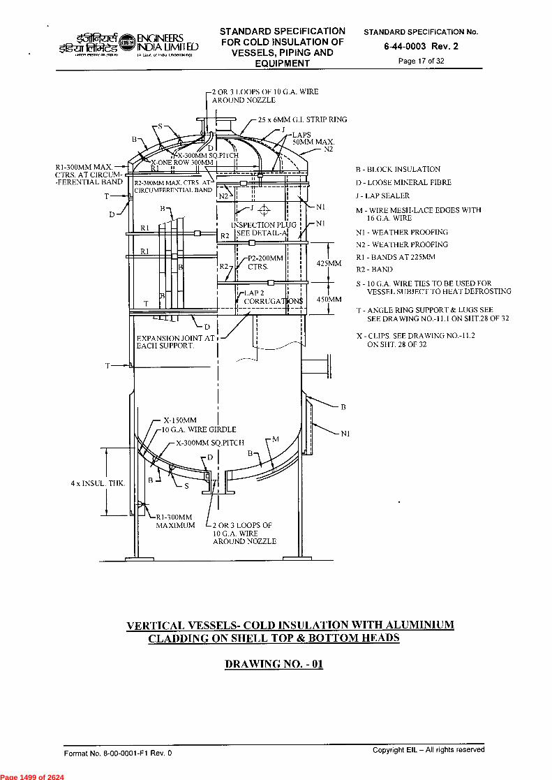
R1-300MM MAX. CTRS. AT CIRCUM--FERENTIAL BAND
X-300MM SQ.PITCH X-ONE ROW 300MM I I; R1 11 11 \, 1___11__
25 x 6MM G.I. STRIP RING
• 11,
`. l N .
LAPS 50MM MAX.
N2
R2-300MM MAX. CTRS. AT CIRCUMFERENTIAL BAND
N2 \ -r 1:
X-150MM 10 G.A. WIRE GIRDLE
X-300MM SQ.PITCH
DI
Og-2;rr~ INWR OfrtfOre 4113V0,)
ENGINEERS INDIA LIMITED IA GoN of Inclfa Ilndellakngf
STANDARD SPECIFICATION FOR COLD INSULATION OF
VESSELS, PIPING AND EQUIPMENT
STANDARD SPECIFICATION No.
6-44-0003 Rev. 2
Page 17 of 32
R1
R1
2 OR 3 LOOPS OF 10 G.A. WIRE AROUND NOZZLE
•- N1
INSPECTION PLUG /- N1 SEE DETAIL-A
P2-200MM CTRS. 425MM
v-LAP 2 l CORRUGATiON$
-4-
B - BLOCK INSULATION
D - LOOSE MINERAL FIBRE
J - LAP SEALER
M - WIRE MESH-LACE EDGES WITH 16 G.A. WIRE
N1 - WEATHER PROOFING
N2 - WEATHER PROOFING
R1 - BANDS AT 225MM
R2 - BAND
S - 10 G.A. WIRE TIES TO BE USED FOR VESSEL SUBJECT TO HEAT DEFROSTING
450MM
T - ANGLE RING SUPPORT & LUGS SEE SEE DRAWING NO.-11.1 ON SHT.28 OF 32
EXPANSION JOINT AT EACH SUPPORT.
X - CLIPS. SEE DRAWING NO.-11.2 ON SHT. 28 OF 32
B
N1
4 x INSUL. THK.
>r\-R1-300MM MAXIMUM 2 OR 3 LOOPS OF
10 G.A. WIRE AROUND NOZZLE
VERTICAL VESSELS- COLD INSULATION WITH ALUMINIUM CLADDING ON SHELL TOP & BOTTOM HEADS
DRAWING NO. - 01
n-
Copyright EIL —All rights reserved Format No. 8-00-0001-F1 Rev. 0
Page 1499 of 2624

FOR S.13, N1, N2. R1. R2 & J REFER SHT. 17 OF 32
N2
J.
N2 D 425MM o TACK
WELD\
ON VESSELS 1800MM 0 & OVER PROVIDE 6MM BAR SUPPORT WIDTH TO BE EQUAL TO BLOCK THICKNESS LESS 12 MM.
LAPS 50MM MIN.
R1-300MM MAX. CENTRES AT CIRCUMEEREN1., BAND rB
X-300MM SQ. - PITCH
RI-BANDS AT 225MM
,312.1t4 fgLar0f51-2g
ENGINEERS INDIA LIMITED IA Govt of InOia Uncleflakoogi
STANDARD SPECIFICATION FOR COLD INSULATION OF
VESSELS, PIPING AND EQUIPMENT
STANDARD SPECIFICATION No.
6-44-0003 Rev. 2
Page 18 of 32
HORIZONTAL VESSELS - COLD INSULATION WITH ALUMINIUM CLADDING
DRAWING NO.-02
Format No. 8-00-0001-F1 Rev. 0 Copyright EIL — All rights reserved
Page 1500 of 2624
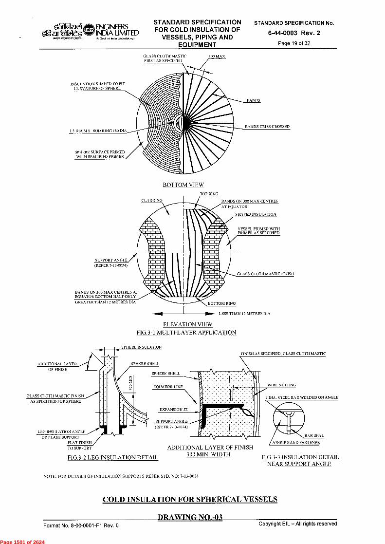
GLASS CLOTH MASTIC FIRST AS SPECIFIED
INSULATION SHAPED TO FIT CURVATURE OF SPHERE
300 MAX
BANDS
BANDS CRISS CROSSED 1.5 DIA M.S. ROD RING 180 DIA
SPHERE SURFACE PRIMED WITH SPECIFIED PRIMER
CLADDING
SHAPED INSULATION
VESSEL PRIMED WITH PRIMER AS SPECIFIED
GLASS CLOTH MASTIC FINISH
...„,;.„,
N.. .~.•■■ ___. ~~, a===• IM/ M• M~W /M M~• M •1=1ffia • MMEI~ MI M~M ffimma ~ffi IME ■:_■■ =11111M E111~11 11•11~1 IM• 111111~111•4, 111=111•••■ IENIIIMIEMB
IMINEMM• 11•I=1/
do, fflr
SUPPORT ANGLE (REFER 7-13-0034)
BANDS ON 300 MAX CENTRES AT EQUATOR BOTTOM HALF ONLY.
GREATER THAN 12 METRES DIA. w BOTTOM RING
BANDS ON 300 MAX CENTRES
AT EQUATOR
WIRE NETTING
6 DIA. STEEL BAR WELDED ON ANGLE
BAR SEAL
ANGLE BAND FASTENER
STANDARD SPECIFICATION FOR COLD INSULATION OF
VESSELS, PIPING AND EQUIPMENT
STANDARD SPECIFICATION No.
6-44-0003 Rev. 2
Page 19 of 32
ENGINEERS 5fgar fa2-dg INDIA LIMITED
vlvotrlOtIstattft
IA Govt of incha undenakng)
BOTTOM VIEW
TOP RING
LESS THAN 12 METRES DIA
ELEVATION VIEW
FIG.3-1 MULTI-LAYER APPLICATION
SPHERE INSULATION
FINISH AS SPECIFIED, GLASS CLOTH MASTIC
EXPANSION .1T
GLASS CLOTH MASTIC FINISH
AS SPECIFIED FOR SPHERE
1114
ADDITIONAL LAYER SPHERE SHELL
OF FINISH
LEG INSULATION ANGLE
OR PLATE SUPPORT
FLAT FINISH
TO SUPPORT
SPHERE SHELL
EQUATOR LINE
(REFER 7-13-0034)
SUPPORT ANGLE
ADDITIONAL LAYER OF FINISH 300 MIN. WIDTH FIG.3-3 INSULATION DETAIL
NEAR SUPPORT ANGLE FIG.3-2 LEG INSULATION DETAIL
NOTE: FOR DETAILS OF INSULATION SUPPORTS REFER STD. NO: 7-13-0034
COLD INSULATION FOR SPHERICAL VESSELS
DRAWING NO.-03 Copyright EIL —All rights reserved Format No. 8-00-0001-F1 Rev. 0
Page 1501 of 2624
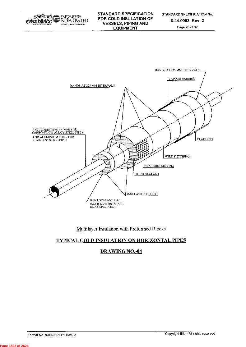
k31 ENGINEERS $gar 22-eg INDIA LIMITED
IA Govt of Inche Undertakng) .7,7 rrrmrr ,111,10.11
BANDS AT 425 MM INTERVALS
VAPOUR BARRIER
BANDS AT 225 MM INTERVALS
ANTI-CORROSIVE PRIMER FOR CARBON/ LOW ALLOY STEEL PIPES
AND ALUMINIUM FOIL - FOR STAINLESS STEEL PIPES CLADDING
WIRE STITCHING
HEX. WIRE NETTING
JOINT SEALANT
INSULATION BLOCKS
JOINT SEALANT FOR INNER LAYERS (SHALL BE AS SPECIFIED)
STANDARD SPECIFICATION FOR COLD INSULATION OF
VESSELS, PIPING AND EQUIPMENT
STANDARD SPECIFICATION No.
6-44-0003 Rev. 2
Page 20 of 32
Multilayer Insulation with Preformed Blocks
TYPICAL COLD INSULATION ON HORIZONTAL PIPES
DRAWING NO.-04
Format No. 8-00-0001-F1 Rev. 0 Copyright EIL —All rights reserved
Page 1502 of 2624

DETAIL - A
CLADDING
BAND
3 MILL BOARD
SUPPORT RING
(SPACING OF SUPPORT RINGS)
4.0 M RIVET
SPACER RING
(FOR DETAILS REFER DRG. NO-12)
DETAIL - A
INSULATION SUPPORT FOR
VERTICAL PIPING
I 0(TYP)
HOLE FOR 6 MM BOLT & NUT
6 MM
CLADDING
METALLIC BAND
ENGINEERS
dift INDIA LIMITED
er,Awan.3~0 IA Govt ot Indo Undertalfing)
STANDARD SPECIFICATION FOR COLD INSULATION OF
VESSELS, PIPING AND EQUIPMENT
STANDARD SPECIFICATION No.
6-44-0003 Rev. 2
Page 21 of 32
VIEW C-C
LEGEND:
A DIMENSIONS TO MATCH O.D. OF PIPE OR O.D. OF VESSEL
S INSULATION THICKNESS
SUPPORT RING FOR VERTICAL INSULATED PIPING DRAWING NO.-05
Format No. 8-00-0001-F1 Rev. 0 Copyright EIL - All rights reserved
Page 1503 of 2624
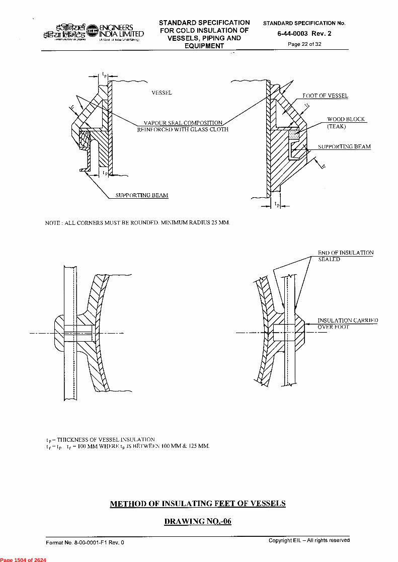
FOOT OF VESSEL
VAPOUR SEAL COMPOSITION REINFORCED WITH GLASS CLOTH
WOOD BLOCK (TEAK)
VESSEL
SUPPORTING BEAM
SUPPORTING BEAM
‘-31
oloo>t >
ENGINEERS INDIA LIMITED IA Govt o7 India Undedaong)
STANDARD SPECIFICATION FOR COLD INSULATION OF
VESSELS, PIPING AND EQUIPMENT
STANDARD SPECIFICATION No.
6-44-0003 Rev. 2
Page 22 of 32
NOTE : ALL CORNERS MUST BE ROUNDED. MINIMUM RADIUS 25 MM.
END OF INSULATION SEALED
INSULATION CARRIED OVER FOOT
t p = THICKNESS OF VESSEL INSULATION t f = t p tf = 100 MM WHERE t p IS BETWEEN 100 MM & 125 MM.
METHOD OF INSULATING FEET OF VESSELS
DRAWING NO.-06
Format No. 8-00-0001-F1 Rev. 0 Copyright EIL —All rights reserved
Page 1504 of 2624
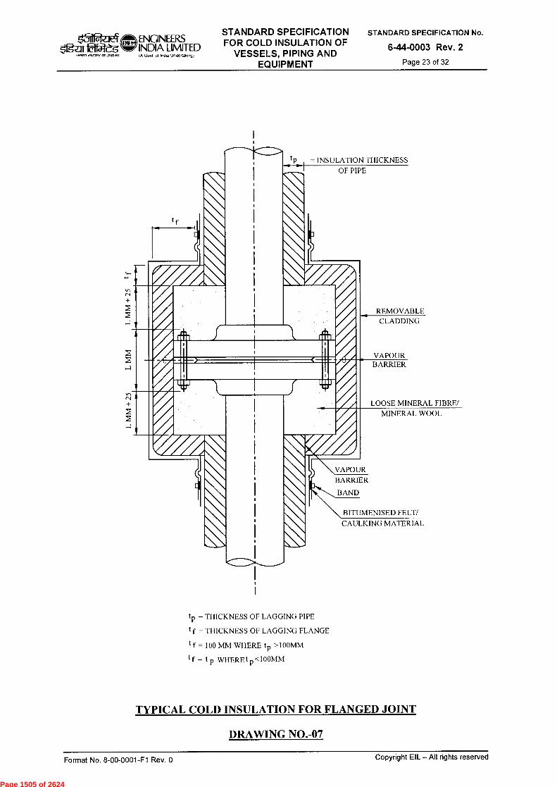
tp = INSULATION THICKNESS OF PIPE
II
REMOVABLE CLADDING
VAPOUR BARRIER
LOOSE MINERAL FIBRE/
MINERAL WOOL
\VAPOUR BARRIER
BAND
BITUMENISED FELT/
CAULKING MATERIAL
t = THICKNESS OF LAGGING PIPE
t f = THICKNESS OF LAGGING FLANGE
tf = 100 MM WHERE tp >100MM
tf = tp WHEREt p <100MM
tf
TYPICAL COLD INSULATION FOR FLANGED JOINT
DRAWING NO.-07
STANDARD SPECIFICATION FOR COLD INSULATION OF
VESSELS, PIPING AND EQUIPMENT
STANDARD SPECIFICATION No.
6-44-0003 Rev. 2
Page 23 of 32
t31 ENGINEERS 02-egd INDIA LIMITED
IA Govt of Indo Undertaking)
Copyright EIL —All rights reserved Format No. 8-00-0001-F1 Rev. 0
Page 1505 of 2624
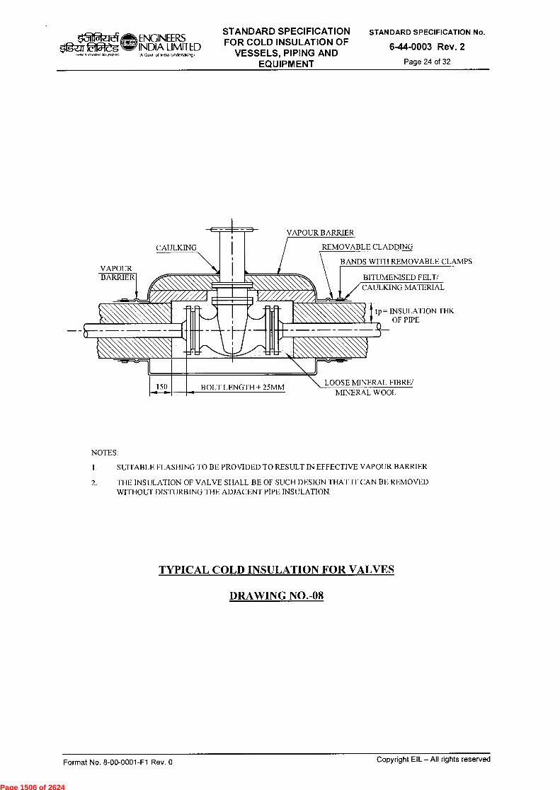
VAPOUR BARRIER
ENGINEERS INDIA LIMITED IA Govt of lnOa tindertakingt
STANDARD SPECIFICATION FOR COLD INSULATION OF
VESSELS, PIPING AND EQUIPMENT
STANDARD SPECIFICATION No.
6-44-0003 Rev. 2
Page 24 of 32 IN1,71,119,,,171.71~)
VAPOUR BARRIER
CAULKING REMOVABLE CLADDING
n\ C BITUMENISED FELT/
MATERIAL
BANDS WITH REMOVABLE CLAMPS
tp= INSULATION THK OF PIPE
1. 150 LOOSE MINERAL FIBRE/ MINERAL WOOL
BOLT LENGTH + 25MM
NOTES:
1. SUITABLE FLASHING TO BE PROVIDED TO RESULT IN EFFECTIVE VAPOUR BARRIER
2. THE INSULATION OF VALVE SHALL BE OF SUCH DESIGN THAT IT CAN BE REMOVED WITHOUT DISTURBING THE ADJACENT PIPE INSULATION.
TYPICAL COLD INSULATION FOR VALVES
DRAWING NO.-08
Copyright EIL — AII rights reserved Format No. 8-00-0001-F1 Rev. 0
Page 1506 of 2624
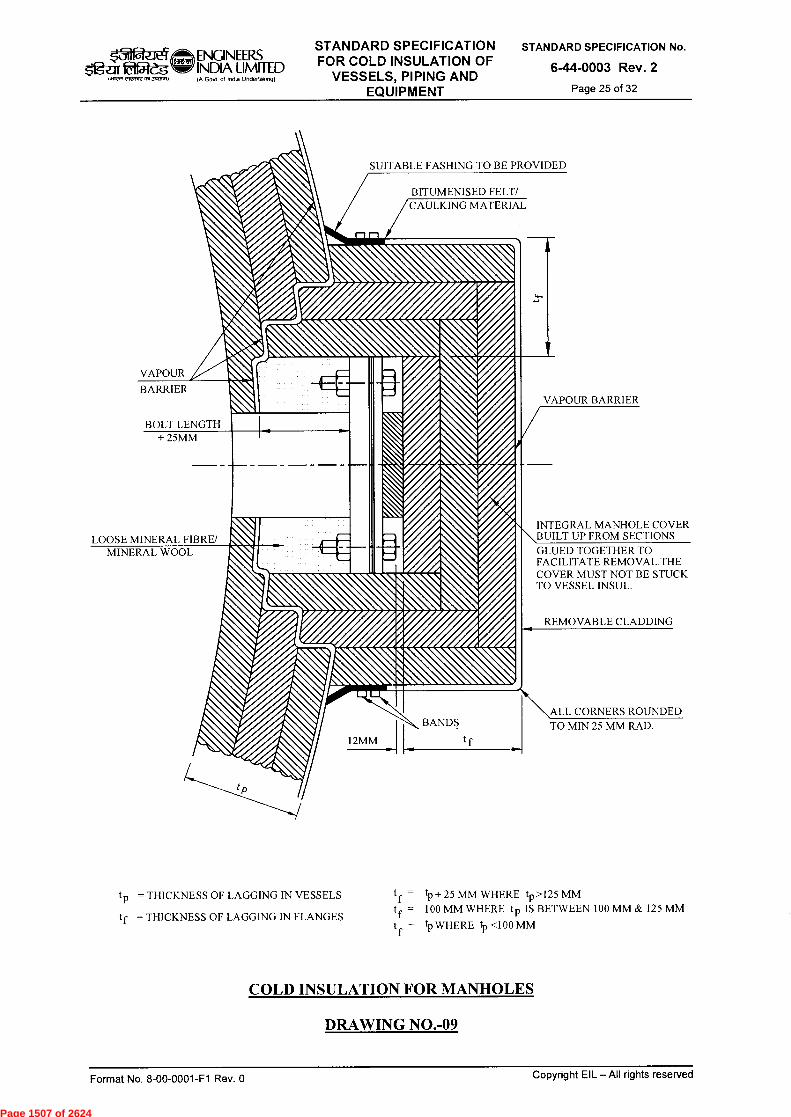
BITUMENISED FELT/ CAULKING MATERIAL
kil ...1 ENGINEERS INDIA LIMITED IA Govt of Indka Underfalonot
STANDARD SPECIFICATION FOR COLD INSULATION OF
VESSELS, PIPING AND EQUIPMENT
STANDARD SPECIFICATION No.
6-44-0003 Rev. 2
Page 25 of 32 '. INRT C1,4,,,1,1 1
SUITABLE FASHING TO BE PROVIDED
VAPOUR
BARRIER VAPOUR BARRIER
BOLT LENGTH + 25MM
LOOSE MINERAL FIBRE/ MINERAL WOOL
INTEGRAL MANHOLE COVER BUILT UP FROM SECTIONS
GLUED TOGETHER TO FACILITATE REMOVAL.THE COVER MUST NOT BE STUCK TO VESSEL INSUL.
REMOVABLE CLADDING
\ALL CORNERS ROUNDED
12MM 1 t f
t p = THICKNESS OF LAGGING IN VESSELS tf = tp + 25 MM WHERE tp >125 MM
tf = THICKNESS OF LAGGING IN FLANGES t f = 100 MM WHERE tp IS BETWEEN 100 MM & 125 MM
tf
= tp WHERE tp <100 MM
COLD INSULATION FOR MANHOLES
DRAWING NO.-09
BANDS TO MIN 25 MM RAD.
Copyright EIL — All rights reserved Format No. 8-00-0001-F1 Rev. 0
Page 1507 of 2624
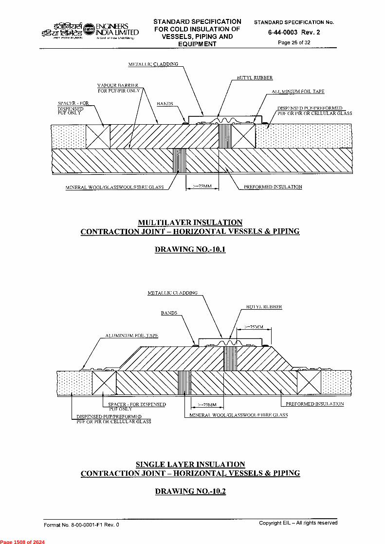
VAPOUR BARRIER FOR PUF/PIR ONLY ALUMINIUM FOIL TAPE
SPACER-FOR DISPENSED PUF ONLY
DISPENSED PUF/PREFORMED PUF OR PIR OR CELLULAR GLASS
BUTYL RUBBER
BANDS
MINERAL WOOL/GLASSWOOL/FIBRE GLASS >=75MM PREFORMED INSULATION
BUTYL RUBBER
/ >=75MM
ALUMINIUM FOIL TAPE
BANDS
PREFORMED INSULATION SPACER - FOR DISPENSED PUF ONLY
DISPENSED PUF/PREFORMED PUF OR PIR OR CELLULAR GLASS
MINERAL WOOL/GLASSWOOL/FIBRE GLASS
ENGINEERS STANDARD SPECIFICATION FOR COLD INSULATION OF
VESSELS, PIPING AND EQUIPMENT
STANDARD SPECIFICATION No.
6-44-0003 Rev. 2
Page 26 of 32
5gar 1.71771 rrmrcd51~ )
INDIA LIMITED IA Govt ol India Undenalong)
METALLIC CLADDING
MULTILAYER INSULATION CONTRACTION JOINT — HORIZONTAL VESSELS & PIPING
DRAWING NO.-10.1
METALLIC CLADDING
SINGLE LAYER INSULATION CONTRACTION JOINT — HORIZONTAL VESSELS & PIPING
DRAWING NO.-10.2
Format No. 8-00-0001-F1 Rev. 0 Copyright EIL —All rights reserved
Page 1508 of 2624
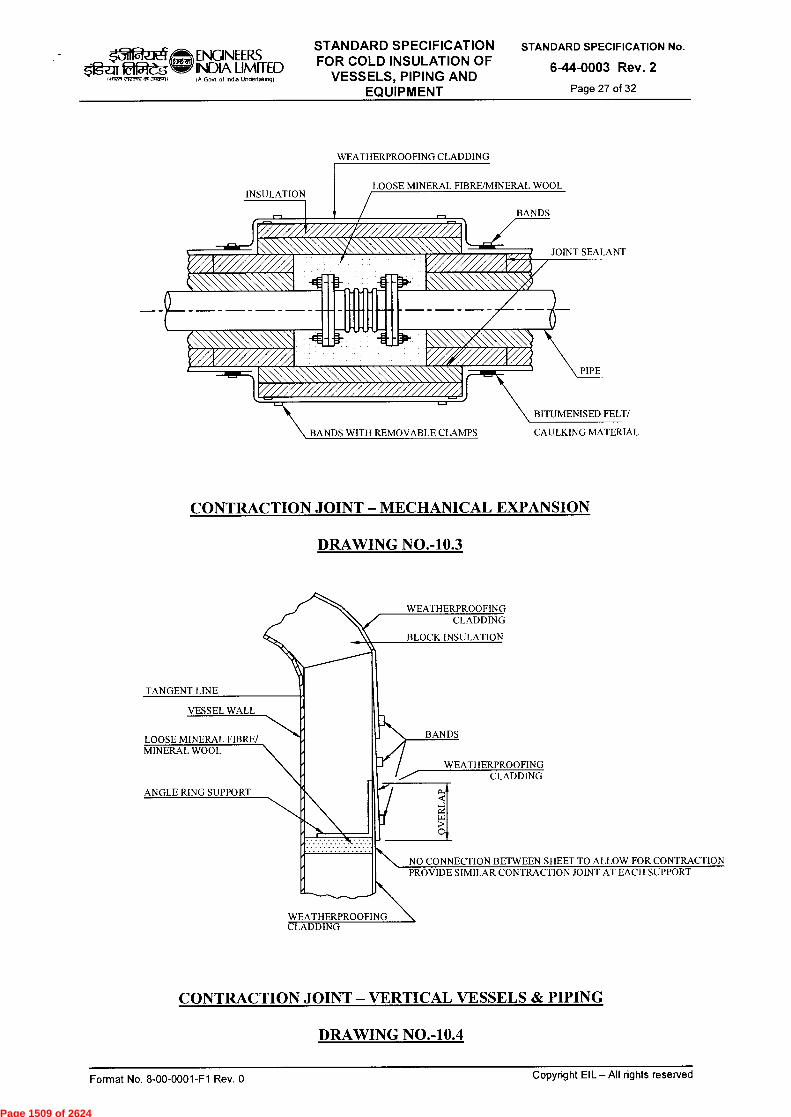
BITUMENISED FELT/
CAULKING MATERIAL BANDS WITH REMOVABLE CLAMPS
LOOSE MINERAL F BRE/MINERAL WOOL
BANDS
JOINT SEALANT
PIPE
INSULATION
arICIW5 1.7n ,i,cnrt a93~1)
ENGINEERS INDIA LIMITED IA Govt of Ind. Undertalong)
STANDARD SPECIFICATION FOR COLD INSULATION OF
VESSELS, PIPING AND EQUIPM ENT
STANDARD SPECIFICATION No.
6-44-0003 Rev. 2
Page 27 of 32
WEATHERPROOFING CLADDING
CONTRACTION JOINT — MECHANICAL EXPANSION
DRAWING NO.-10.3
TANGENT LINE
VESSEL WALL
LOOSE MINERAL FIBRE/ MINERAL WOOL
ANGLE RING SUPPORT
WEATHERPROOFING CLADDING
BLOCK INSULATION
BANDS
WEATHERPROOFING CLADDING
0
NO CONNECTION BETWEEN SHEET TO ALLOW FOR CONTRACTION PROVIDE SIMILAR CONTRACTION JOINT AT EACH SUPPORT
WEATHERPROOFING CLADDING
CONTRACTION JOINT — VERTICAL VESSELS & PIPING
DRAWING NO.-10.4
Copyright EIL — All rights reserved Format No. 8-00-0001-F1 Rev. 0
Page 1509 of 2624

TOP TANGENT LINE
z O
..71`1r&Ject ENGINEEFZS INDIA LIMITED
taffiztm 292zow3t~? IA Govt ot InOta Uneettakto9)
STANDARD SPECIFICATION FOR COLD INSULATION OF
VESSELS, PIPING AND EQUIPMENT
STANDARD SPECIFICATION No.
6-44-0003 Rev. 2
Page 28 of 32
OUTSIDE OF VESSEL
NOMINAL BLOCK INSULATION THICKNESS
BAND
6MM ANGLE RING (WELD ENDS) DO NOT WELD TO LUGS - T
10 MM PLATE LUGS 900 MM CENTRES (MINIMUM OF 3) - T
2725 MM SPACING (OR LESS)
12
SUPPORTS FOR BLOCK INSULATION DRAWING NO.-11.1
OUTSIDE OF HEAD OR INSIDE OF SKIRT
# 10 GA. WIRE 75 MM LONG OR 12 MM OR 6 MM SQ. BLANK NUT - S
CLIPS ON HEADS AND INSIDE SKIRT FOR BLOCK INSULATION DRAWING NO-11.2
12 6 MM
WELD BOTH SIDE
Copyright EIL All rights reserved Format No. 8-00-0001-F1 Rev. 0
Page 1510 of 2624

CIRCUMFERENTIAL DISTANCE NOT MORE THAN 300mm
DETAIL- A
25 x 3 MM MILD STEEL FLAT CERAMIC FIBRE(CF) MILL BOARD
INSULATION THICKNESS
MINIMUM 3 STAYS TO BE PROVIDED
DETAIL-B
SPACER RING 3 THK
BOARD
INSULATION THK LESS MILL BOARD
THICKNESS
— 2 SHEETS OF 3 THK CF MILL BOARD
RIVET 5 MM
CF MILLBOARD
60 MACHINE BOLT
01.111111.111111111111H'';'..».°11
CF MILL 50
'Z' SHAPED LUG
CF CLOTH 3 MM THK., 2 NOS INTERPOSED
k31 ENGINEERS 0151-eg• INDIA LIMITED
IA Gosi 01 Ind. Unde,tak.g)
STANDARD SPECIFICATION FOR COLD INSULATION OF
VESSELS, PIPING AND EQUIPMENT
STANDARD SPECIFICATION No.
6-44-0003 Rev. 2
Page 29 of 32
5 MM MILD STEEL RIVET
DETAIL - B
DETAIL - A
DETAIL OF SPACER RING
DRAWING NO.-12
Copyright EIL — All rights reserved Format No. 8-00-0001-F1 Rev. 0
Page 1511 of 2624
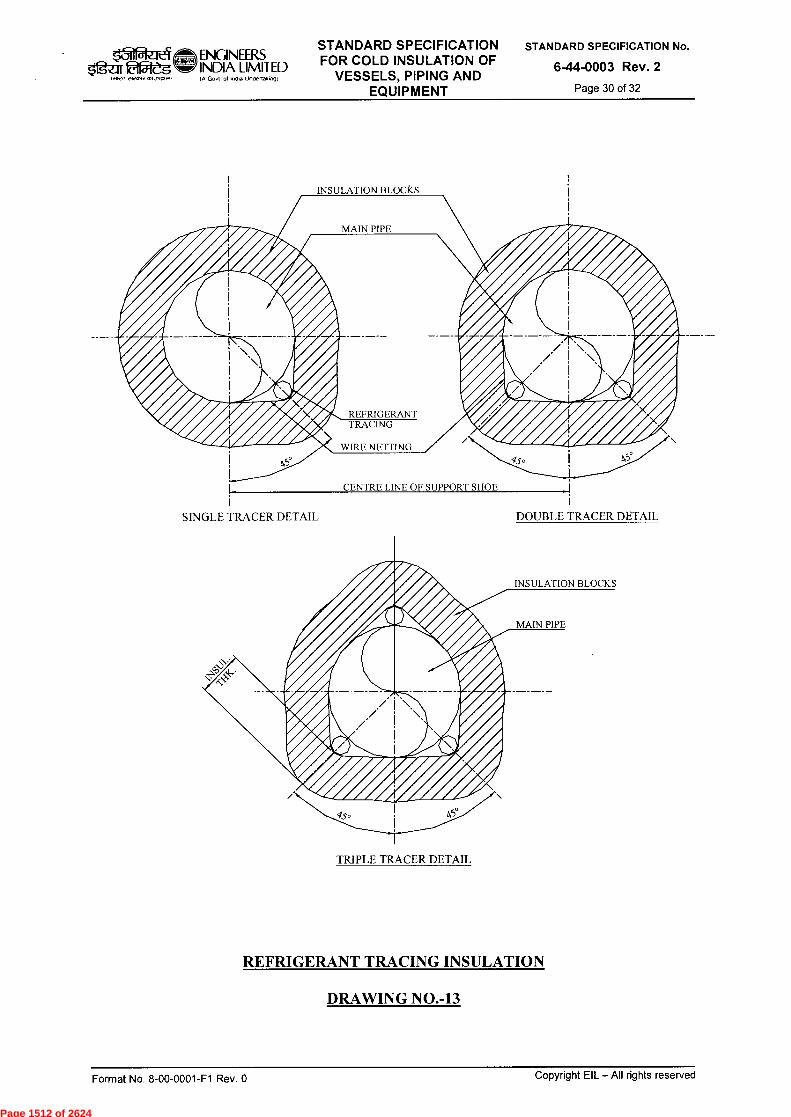
INSULATION BLOCKS
INSULATION BLOCKS
SINGLE TRACER DETAIL DOUBLE TRACER DETAIL
~, t̀7111
OXR, F2Otrzv91~tt
ENGINEERS INDIA LIMITED Ift Govt of InOia Undertakvogt
STANDARD SPECIFICATION FOR COLD INSULATION OF
VESSELS, PIPING AND EQUIPMENT
STANDARD SPECIFICATION No.
6-44-0003 Rev. 2
Page 30 of 32
CENTRE LINE OF SUPPORT SHOE
TRIPLE TRACER DETAIL
REFRIGERANT TRACING INSULATION
DRAWING NO.-13
Format No. 8-00-0001-F1 Rev. 0 Copyright EIL — All rights reserved
Page 1512 of 2624

MIN
INSULATION
BANDS
L MIN. + 12MM
VESSEL OR PIPE
z ti 25
MM
CO
N
■
L + 25 MM L + 25 MM
PIPE
7-1111\ BITUMENISED FELT/ CAULKING MATERIAL
JOINT SEALANT
DRAWING NO.-14.1 [4]
H
ALL CORNERS ROUNDED TO FLANGES LAGGING (IN SECTION) MUST VAPOUR SEAL NOT STICK TO VESSEL LAGGING BUT COMPOSITION REINF.
MUST BE SECURED WITH BANDS WITH GLASS CLOTH
SE
LF
AD
HE
S
FILLED BY BLOWN BITUMEN MIXED WITH LOOSE PUF
VESSEL
25MM MINIMUM RADIUS
$*rga 92ès tffwv vrvottV Ot1,1025vit
ENGINEERS INDIA LIMITED IA Govt of Indta Unflettolong)
STANDARD SPECIFICATION FOR COLD INSULATION OF
VESSELS, PIPING AND EQUIPMENT
STANDARD SPECIFICATION No.
6-44-0003 Rev. 2
Page 31 of 32
LOOSE MINERAL FIBRE/MINERAL WOOL
Tp = THICKNESS OF LAGGING ON PIPE OR VESSEL SHELL PLATE AND END PLATE
Tf = THICKNESS OF LAGGING ON PIPE FLANGE OR VESSEL FLANGE
Tf = Tp - 25 MM WHERE Tp>= 125 MM
Tf = 100 MM WHERE Tp IS BETWEEN 100 & 125 MM
Tf = Tp WHERE Tp <=100 MM
DRAWING NO.-14.2
METHOD OF LAGGING FLANGED JOINTS OF VESSEL
Format No. 8-00-0001-F1 Rev. 0
Copyright EIL — All rights reserved
Page 1513 of 2624
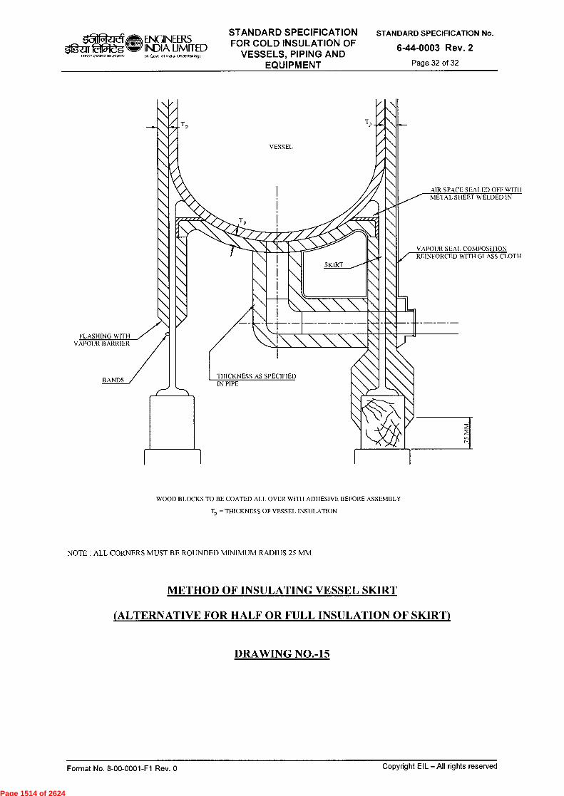
ENGINEERS g2-11215V-eg INDIA LIMITED
I A Govt of Intha Undertakingt ,rcnr, 95, JW".4)
THICKNESS AS SPECIFIED IN PIPE
VESSEL
AIR SPACE SEALED OFF WITH METAL SHEET WELDED IN
VAPOUR SEAL COMPOSITION REINFORCED WITH GLASS CLOTH
\ \ SKIRT
\
\ \
\ . \ \ \ \\
'1\\\\\
1
/FLASHING WITH
VAPOUR BARRIER
BANDS
STANDARD SPECIFICATION FOR COLD INSULATION OF
VESSELS, PIPING AND EQUIPMENT
STANDARD SPECIFICATION No.
6-44-0003 Rev. 2
Page 32 of 32
WOOD BLOCKS TO BE COATED ALL OVER WITH ADHESIVE BEFORE ASSEMBLY
T = THICKNESS OF VESSEL INSULATION
NOTE : ALL CORNERS MUST BE ROUNDED MINIMUM RADIUS 25 MM
METHOD OF INSULATING VESSEL SKIRT
(ALTERNATIVE FOR HALF OR FULL INSULATION OF SKIRT)
DRAWING NO.-15
Format No. 8-00-0001-F1 Rev. 0 Copyright EIL — All rights reserved
Page 1514 of 2624
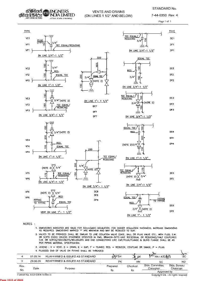
v< RN / AT4k--{ • SC 4 01.09.14 REAFFIRMED & ISSUED AS STANDARD
Rev.
No. Date Purpose
Copyright EIL - All rights reserved Format No. 8-00-0001-F4 Rev.O
VENTS AND DRAINS (ON LINES 1 1/2" AND BELOW)
STANDARD No.
7-44-0350 Rev. 4
Page 1 of 1
PK RN SC ND
Prepared Checked Stds. Committee Stds. Bureau Convenor Chairman
by by Approved by
VC4
VF4
VP4
(NOTE 2) X 3/4"
TEE EQUAL/ REDUCINIG
• ••
ON LINE 3/4"-1 1/2"
EQUAL TEE FITTING TO FITTING
(NOTE 2) x 3/4"
RED.
VENT ON LINE 1"- 1 1/2"
200
TEE EQUAL/
REDUCING
3/4"
!(NOTE 2)
ON LINE 3/4"- 1 1/2"
DC8
DF8
DP8
• \
REDUCING
in TEE EQUAL N
_ (NOTE 2) 3/4"
ON LINE 3/4"-1 1/2"
ON LINE 1"- 1 1/2"
ON LINE 1.-1 1/2"
DC5
DF5
FITTING TO FITTING
DC6
DF6
VF5
VP5
VF6
VP6
ON LINE 1"- 1 1/2"
DC7
DF7
DP7
TEE EQUALLI, REDUCING o
3/4" u"
ON LINE 3/4"-1 1/2"
EQUAL TEE
3/4" lon
_L_L
ON LINE 3/4"-1 1/2"
TEE EQUAL REDUCING
3/4 "4 (NOTE 2)
ON LINE 3/4""-1 1/2"
TYPE
PLUG (TYP)or,
\
VC1
3/4" TEE EQUAL REDUCING
ON LINE 3/4"-1 1/2"
o
3/4"
RED
EQUAL TEE
ON LINE 1"-1 1/2"
3/4"(NOTE 2)
TEE EQUAL REDUCIN
VP3
VF1
VP1
VC2
VF2
VP2
VC3
VF3
TYPE
DC1
DF1
DP1
DC2
DF2
DP2
DC3
DF3
DP3
DC4
DF4
DP4
ON LINE 3/4"-1 1/2"
ON LINE 1"-1 1/2"
Ogar (411UR efraf12 t1513g4»411
ENGINEERS INDIA LIMITED (f> Govt of Incha Undertalong)
3 29.06.09 REAFFIRMED & ISSUED AS STANDARD
Page 1515 of 2624
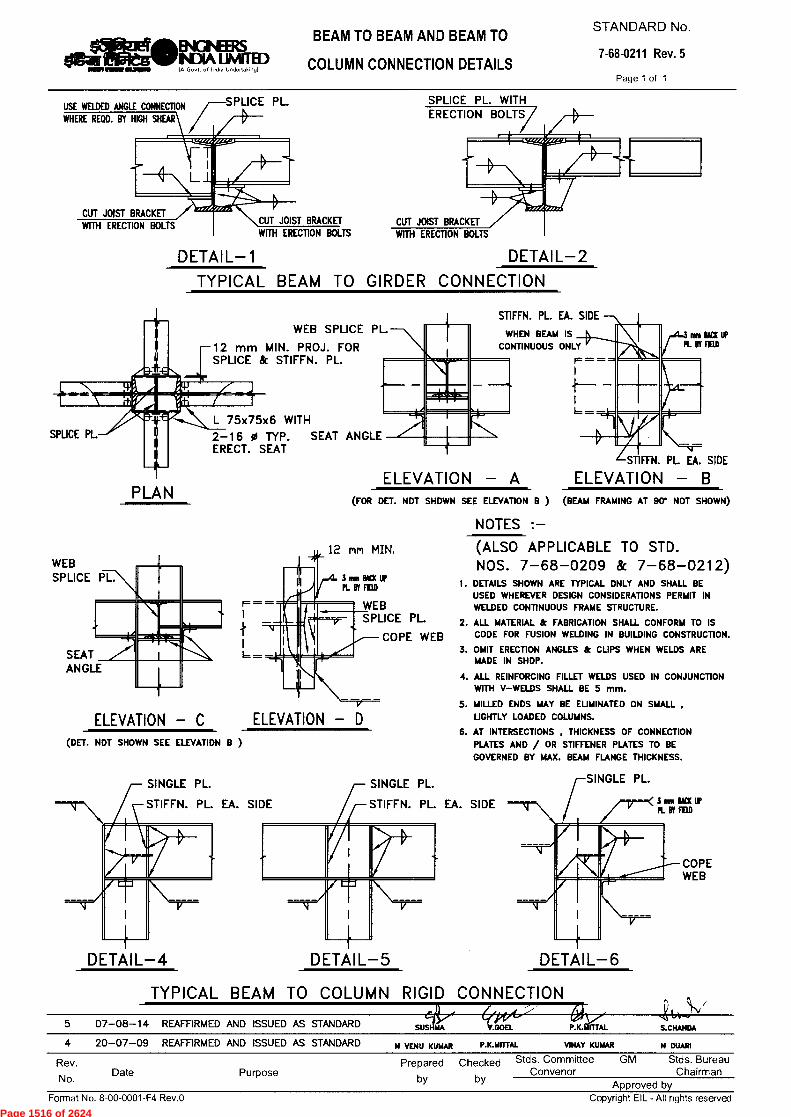
USE WELDED ANGLE CONNECTION WHERE REQD. BY HIGH SHEAR
CUT JOIST BRACKET CUT JOIST BRACKET WITH ERECTION BOLTS WITH ERECTION BOLTS WITH ERECTION BOLTS
CUT JOIST BRACKET
12 rnrn MIN, WEB SPLICE PL.
F = =
^1.
SEAT ANGLE
3 iriu BACK IP PL W FED
WEB SPLICE PL.
COPE WEB
ELEVATION - C ELEVATION (DET. NOT SHOWN SEE ELEVATION B )
SINGLE PL.
STIFFN. PL. EA. SIDE STIFFN. PL. EA. SIDE
014~B•IGNEERS NDIA LIMETED IA Govt. of India Undertaking)
BEAM TO BEAM AND BEAM TO
COLUMN CONNECTION DETAILS
STANDARD No.
7-68-0211 Rev. 5
Page 1 of 1
DETAIL-1 DETAIL-2
TYPICAL BEAM TO GIRDER CONNECTION
STIFFN. PL. EA. SIDE
fffil BACK UP PL BY fIID
WHEN BEAM IS CONTINUOUS ONLY
WEB SPLICE PL.
12 mm MIN. PROJ. FOR SPLICE & STIFFN. PL.
SPLICE PL L 75x75x6 WITH 2-16 0 TYP. SEAT ANGLE ERECT. SEAT
STIFFN. PL EA. SIDE
ELEVATION - A
ELEVATION - (FOR DET. NOT SHOWN SEE ELEVATION B ) (BEAM FRAMING AT 90* NOT SHOWN)
NOTES :— (ALSO APPLICABLE TO STD. NOS. 7-68-0209 & 7-68-0212)
1. DETAILS SHOWN ARE TYPICAL ONLY AND SHALL BE USED WHEREVER DESIGN CONSIDERATIONS PERMIT IN WELDED CONTINUOUS FRAME STRUCTURE.
2. ALL MATERIAL & FABRICATION SHALL CONFORM TO IS CODE FOR FUSION WELDING IN BUILDING CONSTRUCTION.
3. OMIT ERECTION ANGLES & CIJPS WHEN WELDS ARE MADE IN SHOP.
4. ALL REINFORCING FILLET WELDS USED IN CONJUNCTION WITH V—WELDS SHALL BE 5 mm.
5. MILLED ENDS MAY BE ELJMINATED ON SHALL , LJGHTLY LOADED COLUMNS.
6. AT INTERSECTIONS , THICKNESS OF CONNECTION PLATES AND / OR STIFFENER PLATES TO BE GOVERNED BY MAX. BEAM FLANGE THICKNESS.
PLAN
DETAIL-4
DETAIL-5 DETAIL-6
TYPICAL BEAM TO COLUMN RIGID CONNECTION
5 07-08-14 REAFFIRMED AND ISSUED AS STANDARD SUS MA V.GOEL P.K.IiriTAL
S.CHANDA
4 20-07-09 REAFFIRMED AND ISSUED AS STANDARD N VENU KUMAR P.K.MITTAL
VINAY KUMAR N DUARI
Rev.
No. Date Purpose
Prepared Checked Stds. Committee GM Stds. Bureau Convenor Chairman
by by Approved by
Format No. 8-00-0001-F4 Rev.O
Copyright EIL - All rights reserved
Page 1516 of 2624
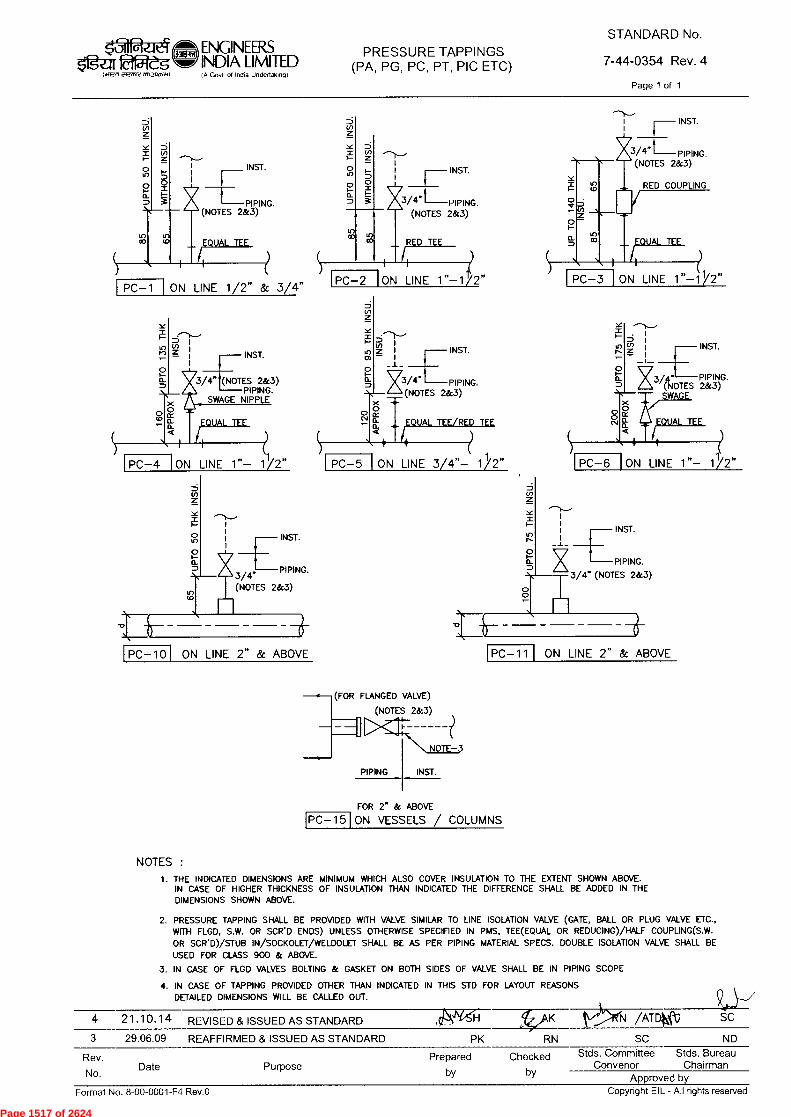
PC-2
X3/4" PIPING. (NOTES 2&3)
PIPING
PC-1 ON LINE 1/2" & 3/4" PC-3 ON LINE 1"-11/ "
PC —10 ON LINE 2" & ABOVE
PC-15 FOR & ABOVE
ON VESSELS / COLUMNS
50 TH
K IN
SU
.
3/4" PIPING. (NOTES 2&3)
INST. _L
95
TH
K I
NS
U.
0 C•1
PC-5 ON LINE 3/4''— 1/2"
(FOR FLANGED VALVE)
(NOTES 2&3)
1
ii=6.111 PC-1 1 ON LINE 2" & ABOVE
v
50 TH
K IN
S
INST.
PIPING. (NOTES 2&3)
ON LINE 1"-1/2"
INST.
INST.
3/4" PIPING. (NOTES 2&3)
RED COUPLING
o_
1 INST.
PC-6 ON LINE 1"—
PIPING. (NOTES 2&3) WAG
V3/4'. (NOTES 2&3) PIP ING.
SWAGE NIPPLE
10
PC-4 ON LINE 1"—
INST.
3/4" PIPING.
(NOTES 2&3)
NOTE-3
INST.
7iF277 Cirm11 en1,5oat.o
ENGINEERS INDIA LIMITED IA Govt ot locho Unaortak,og)
PRESSURE TAPPINGS (PA, PG, PC, PT, PIC ETC)
STANDARD No.
7-44-0354 Rev. 4
Page 1 of 1
NOTES : 1. THE INDICATED DIMENSIONS ARE MINIMUM WHICH ALSO COVER INSULATION TO THE EXTENT SHOWN ABOVE.
IN CASE OF HIGHER THICKNESS OF INSULATION THAN INDICATED THE DIFFERENCE SHALL BE ADDED IN THE DIMENSIONS SHOWN ABOVE.
2. PRESSURE TAPPING SHALL BE PROVIDED WITH VALVE SIMILAR TO LINE ISOLATION VALVE (GATE, BALL OR PLUG VALVE ETC., WITH FLGD, S.W. OR SCR'D ENDS) UNLESS OTHERWISE SPECIFIED IN PMS, TEE(EQUAL OR REDUCING)/HALF COUPLING(S.W. OR SCR'D)/STUB IN/SOCKOLET/WELDOLET SHALL BE AS PER PIPING MATERIAL SPECS. DOUBLE ISOLATION VALVE SHALL BE USED FOR CLASS 900 & ABOVE.
3. IN CASE OF FLGD VALVES BOLTING & GASKET ON BOTH SIDES OF VALVE SHALL BE IN PIPING SCOPE
4. IN CASE OF TAPPING PROVIDED OTHER THAN INDICATED IN THIS STD FOR LAYOUT REASONS DETAILED DIMENSIONS WILL BE CALLED OUT.
4 21.10.14 REVISED & ISSUED AS STANDARD fri/AK /ATDW SC
3 29.06.09 REAFFIRMED & ISSUED AS STANDARD PK RN SC ND
Rev.
No. Date Purpose
Prepared Checked
by by
Stds. Committee Stds. Bureau Convenor Chairman
Approved by
Format No. 8-00-0001-F4 Rev.0 Copyright EIL - All rights reserved
Page 1517 of 2624
Page 1518 of 2624
Page 1519 of 2624

Page 1520 of 2624
Page 1521 of 2624

Page 1522 of 2624
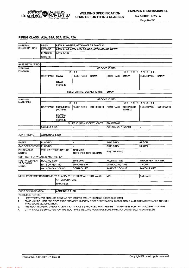
Page 1523 of 2624
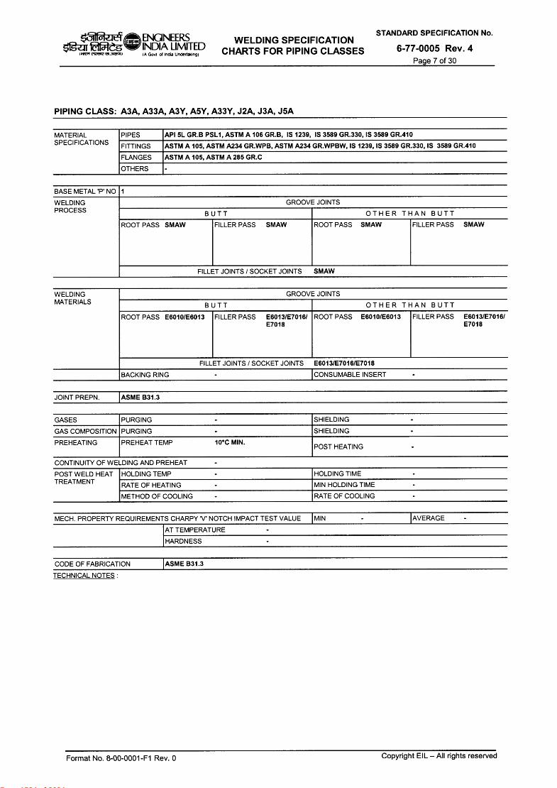
Page 1524 of 2624
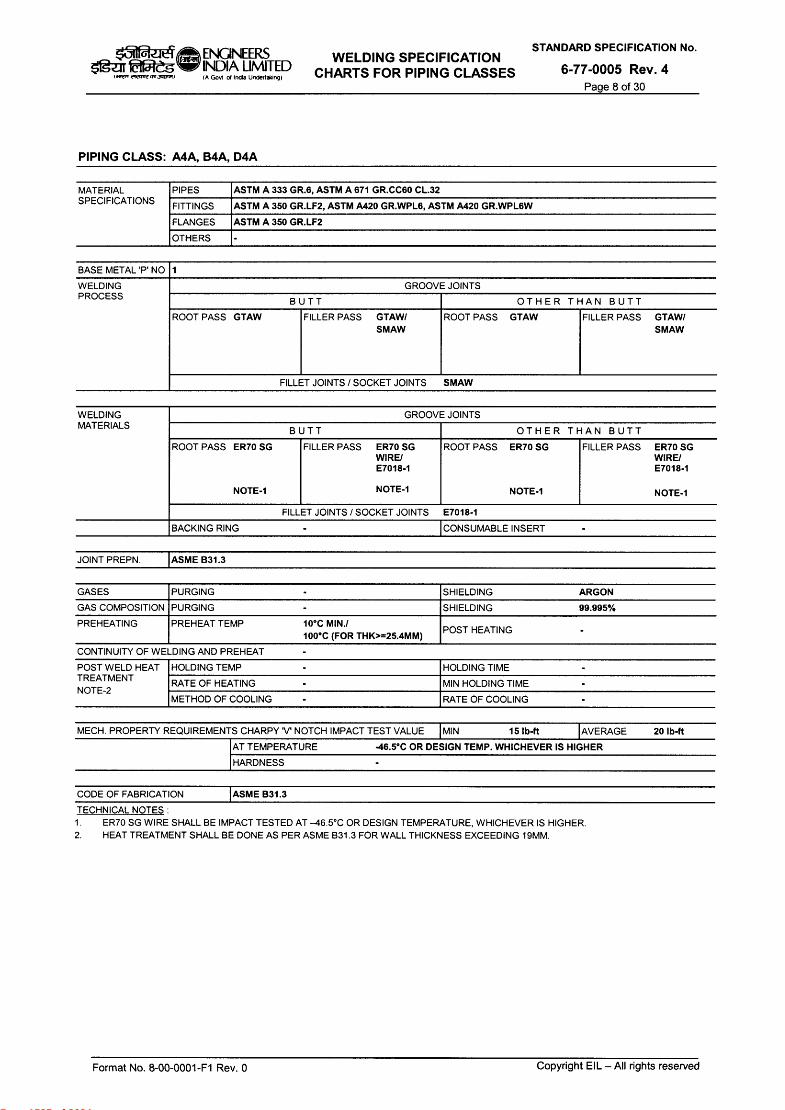
Page 1525 of 2624
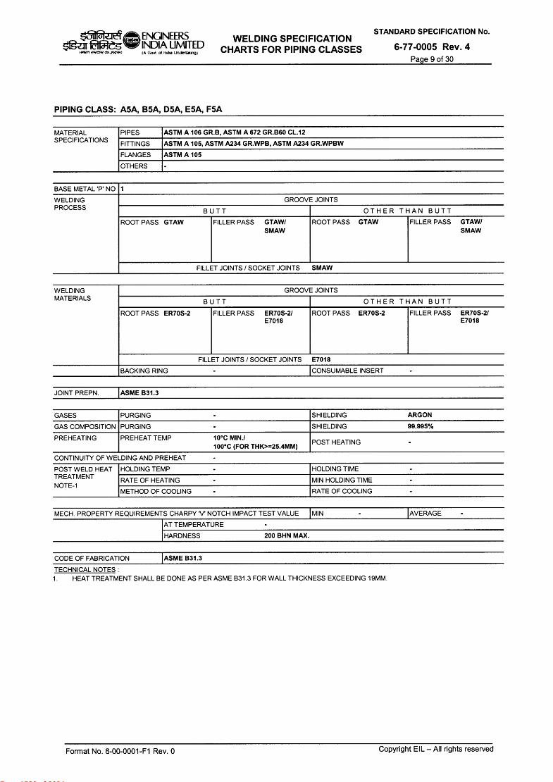
Page 1526 of 2624
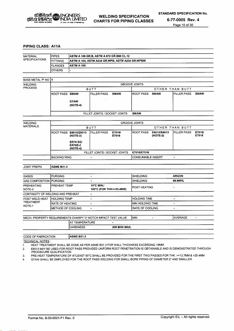
Page 1527 of 2624

Page 1528 of 2624

Page 1529 of 2624
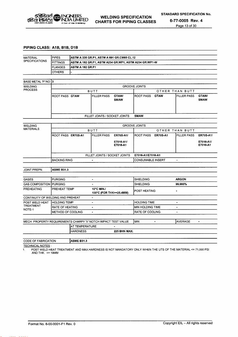
Page 1530 of 2624
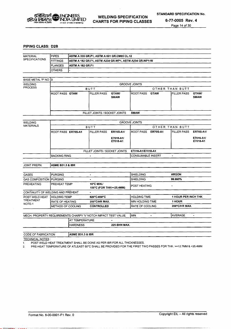
Page 1531 of 2624
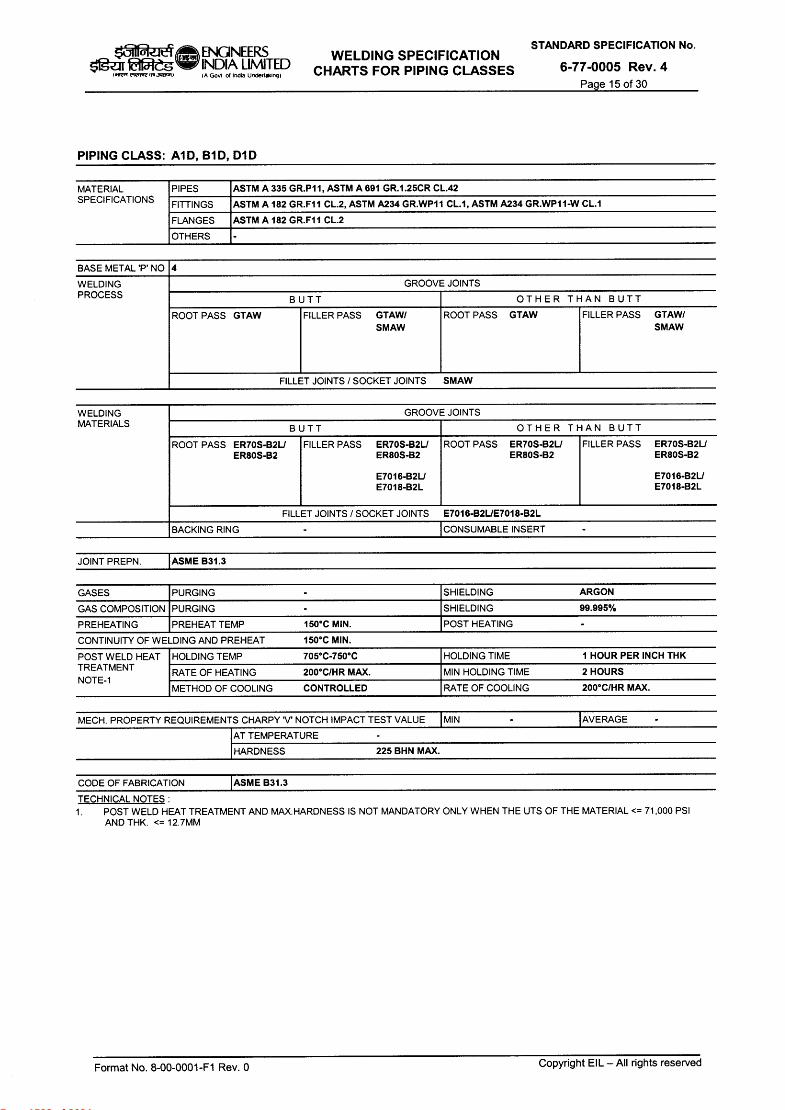
Page 1532 of 2624
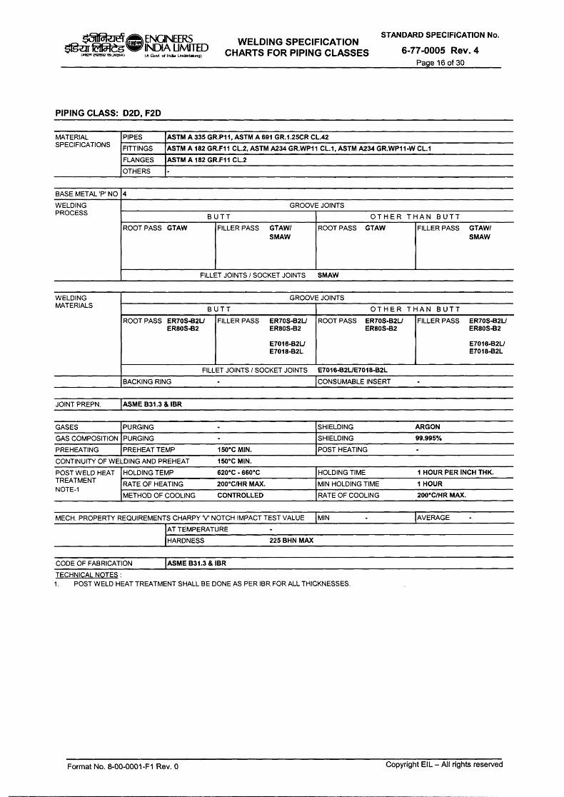
Page 1533 of 2624
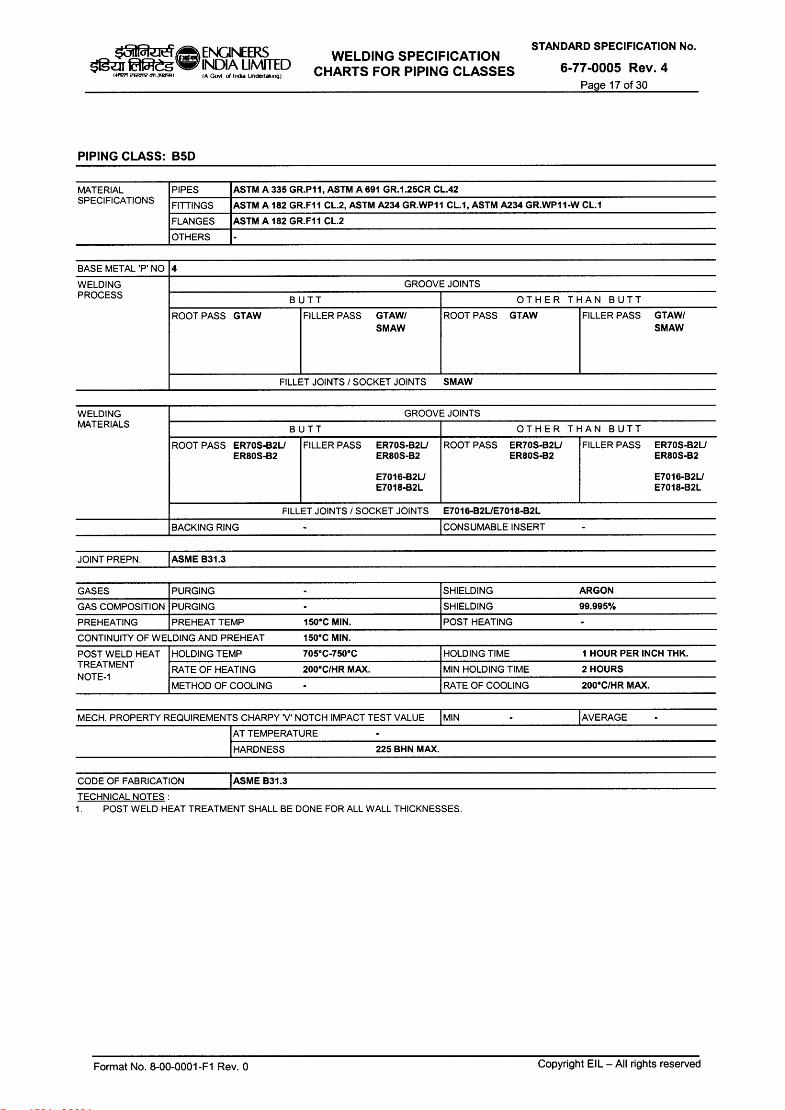
Page 1534 of 2624
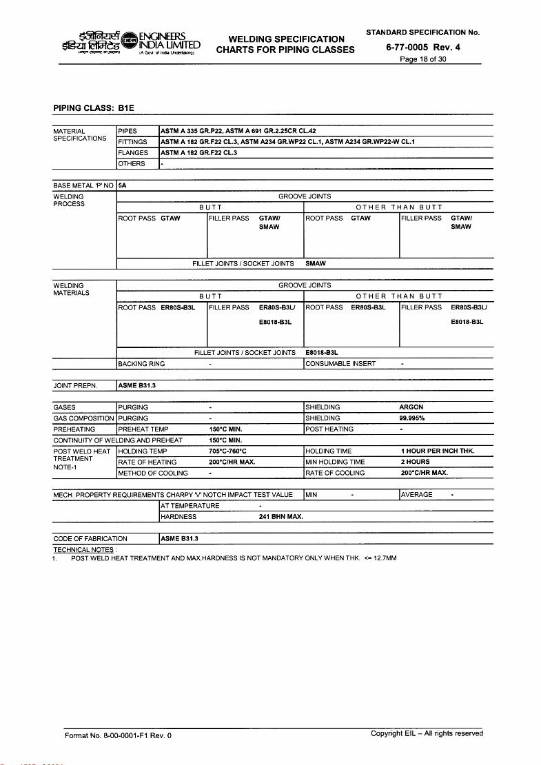
Page 1535 of 2624

Page 1536 of 2624

Page 1537 of 2624
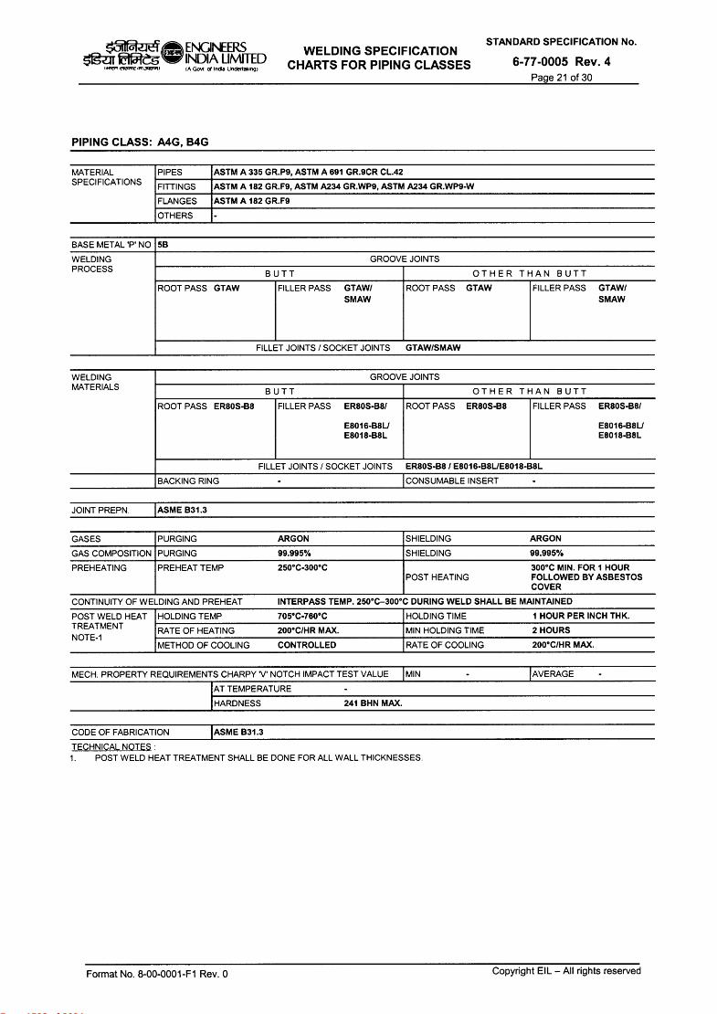
Page 1538 of 2624

Page 1539 of 2624
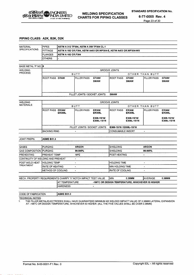
Page 1540 of 2624

Page 1541 of 2624

Page 1542 of 2624

Page 1543 of 2624

Page 1544 of 2624
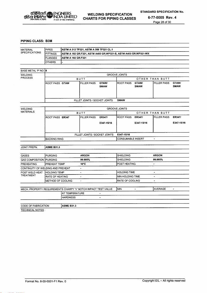
Page 1545 of 2624
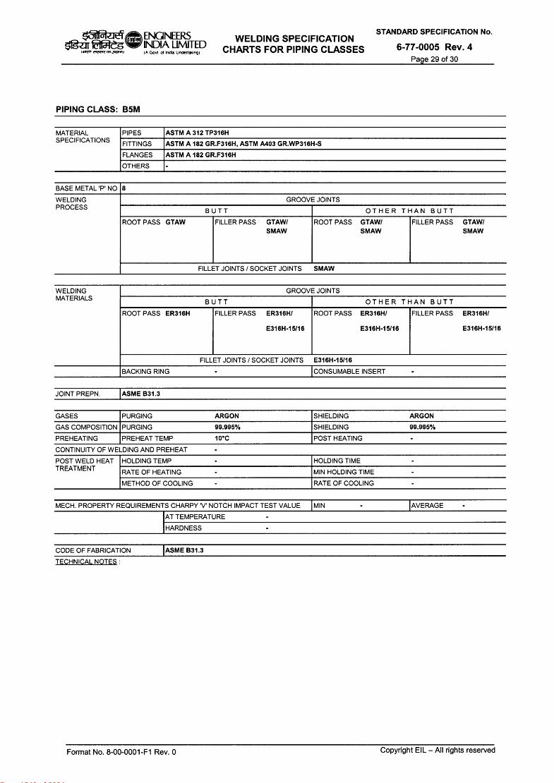
Page 1546 of 2624
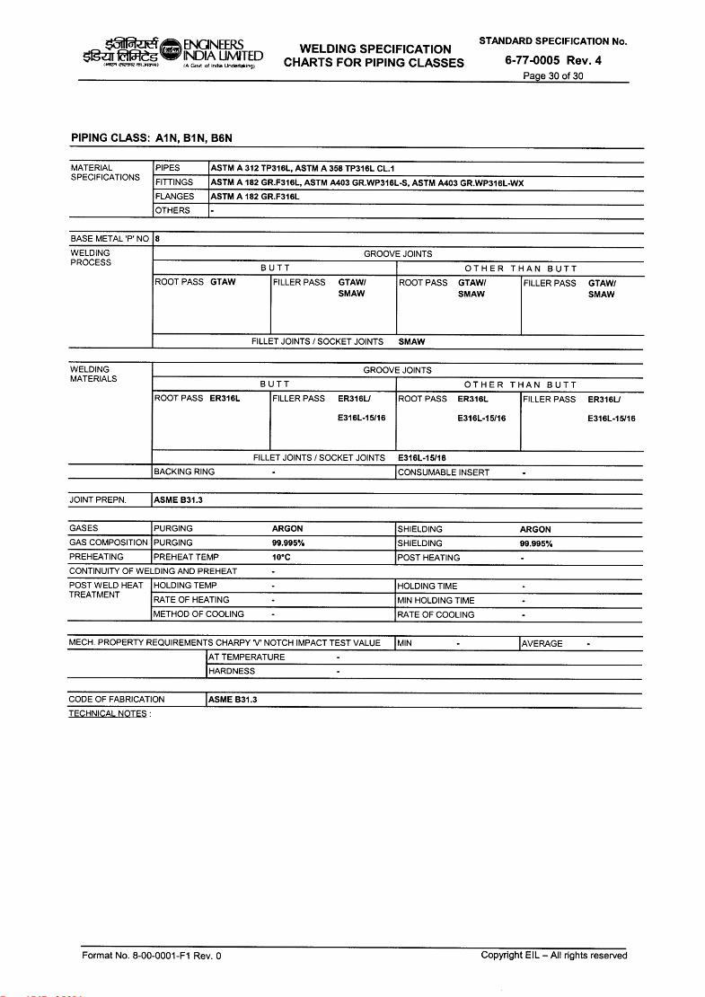
Page 1547 of 2624

INSPECTION AND TEST PLAN STANDARD SPECIFICATION No.
FOR 6-81-0011 Rev. 3
PRESSURE VESSELS/ COLUMNS CARBON STEEL Page 1 of 7
k31 ENGINEERS INDIA LIMITED
erednedia (A Govt of India Undertaking)
copsil 1-ael ,‹ tuRT / c4;1(14-1-1 ftteur a Iteur
INSPECTION AND TEST PLAN FOR
PRESSURE VESSELS/ COLUMNS CARBON STEEL
kVilIP—t'
3 09.09.2013 REVISED AND RE-ISSUED TKK RKS /
SCG r—. DM
2 15.07.2011 REVISED AND RE-ISSUED HP SCG AKC DM
1 28.09.2007 REVISED AND RE-ISSUED PD RB MVKK VC
0 10.12.2002 ISSUED FOR IMLEMENTATION NKN SPS AKB GRR
Rev. No. Date Purpose
Prepared by
Checked by
Convenor Standards Committee
Chairman Standards Bureau
Approved by
Format No. 8-00-0001-F7 Rev. 0 Copyright EIL — All rights reserved
Page 1548 of 2624
5 ENGINEERS INDIA LIMITED IA Goer or Incite Undertaking)
f tar eic,7,1, m JVCD.,
INSPECTION AND TEST PLAN FOR
PRESSURE VESSELS/ COLUMNS CARBON STEEL
STANDARD SPECIFICATION No.
6-81-0011 Rev.3
Page 2 of 7
Abbreviations:
CEIL Certification Engineers International Limited MRT Mechanical Run Test
CIMFR Central Institute of Mining & Fuel Research NDT Non Destructive Testing
CE Carbon Equivalent NPSH Net Positive Suction Head
DFT Dry Film Thickness PO Purchase Order
DPT Dye Penetrant Testing PESO Petroleum Explosive Safety Organization
DHT De-hydrogen Heat Treatment PQR Procedure Qualification Record
ERTL Electronics Regional Test Laboratory PR Purchase Requisition
FCRI Fluid Control Research Institute PMI Positive Material Identification
HT Heat Treatment RT Radiography Testing
HIC Hydrogen Induced Cracking SSCC Sulphide Stress Corrosion Cracking
ITP Inspection and Test Plan TC Test Certificate
IP Ingress Protection TPI or TPIA Third Party Inspection Agency
IHT Intermediate Heat Treatment UT Ultrasonic Testing
IC Inspection Certificate VDR Vendor Data Requirement
IGC Inter Granular Corrosion WPS Welding Procedure Specification
MPT/MT Magnetic Particle Testing WPQ Welders Performance Qualification
MTC Material Test Certificate
Inspection Standards Committee
Convenor : Mr. S C Gupta
Members:
Mr. R.K. Singh
Mr. Rajeev Kumar Mr. Himangshu Pal Mr.Neeraj Mathur
Mr. T Kamalakannan Mr. Deepak Gupta (Project) Mr. Mayank Jain
Format No. 8-00-0001-F7 Rev. 0
Copyright EIL — All rights reserved
Page 1549 of 2624
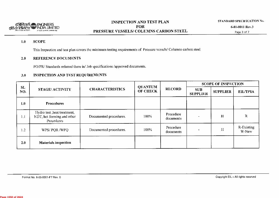
k31 ENGINEERS Ogar lat5reg w INDIA LIMITED
IA Govt 01 India Undertaking)
INSPECTION AND TEST PLAN FOR
PRESSURE VESSELS/ COLUMNS CARBON STEEL
STANDARD SPECIFICATION No.
6-81-0011 Rev.3
Page 3 of 7 tarn R elecnre,51,1,15.1,
1.0 SCOPE
This Inspection and test plan covers the minimum testing requirements of Pressure vessels/ Columns carbon steel
2.0 REFERENCE DOCUMENTS
PO/PR/ Standards referred there in/ Job specifications /approved documents.
3.0 INSPECTION AND TEST REQUIREMENTS
SL NO.
STAGE/ ACTIVITY CHARACTERISTICS QUANTUM OF CHECK
RECORD
SCOPE OF INSPECTION
SUB SUPPLIER
SUPPLIER EIL/TPIA
1.0 Procedures
1.1 Hydro test ,heat treatment,
NDT, hot forming and other Procedures
Documented procedures. 100% Procedure documents
- H R
1.2 WPS/ PQR /WPQ Documented procedures. 100% Procedure documents
- H R-Existing
W-New
2.0 Materials inspection
Format No. 8-00-0001-F7 Rev. 0
Copyright EIL — All rights reserved
Page 1550 of 2624
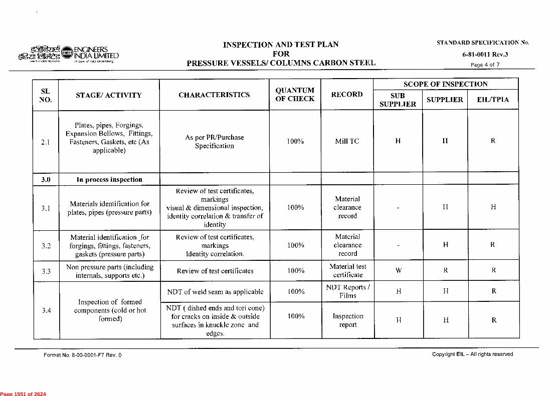
ENGINEERS INDIA LIMITED IA Govt of India Undertaking)
INSPECTION AND TEST PLAN FOR
PRESSURE VESSELS/ COLUMNS CARBON STEEL
STANDARD SPECIFICATION No.
6-81-0011 Rev.3
Page 4 of 7
SL NO.
STAGE/ ACTIVITY CHARACTERISTICS QUANTUM OF CHECK
RECORD
SCOPE OF INSPECTION
SUB SUPPLIER
SUPPLIER EIL/TPIA
2.1
Plates, pipes, Forgings, Expansion Bellows, Fittings, Fasteners, Gaskets, etc (As
applicable)
As per PR/Purchase Specification
100% Mill TC H H R
3.0 In process inspection
3.1 Materials identification for
plates, pipes (pressure parts)
Review of test certificates, markings
visual & dimensional inspection, identity correlation & transfer of
identity
100% Material clearance
record - H H
3.2 Material identification for forgings, fittings, fasteners,
gaskets (pressure parts)
Review of test certificates, markings
Identity correlation. 100%
Material clearance
record - H R
3.3 Non pressure parts (including
internals, supports etc.) Review of test certificates 100%
Material test certificate
W R R
3.4 Inspection of formed
components (cold or hot formed)
NDT of weld seam as applicable 100% NDT Reports /
Films H H R
NDT ( dished ends and tori cone) for cracks on inside & outside surfaces in knuckle zone and
edges.
100% i Inspection report
H H R
Copyright EIL — All rights reserved Format No. 8-00-0001-F7 Rev. 0
Page 1551 of 2624
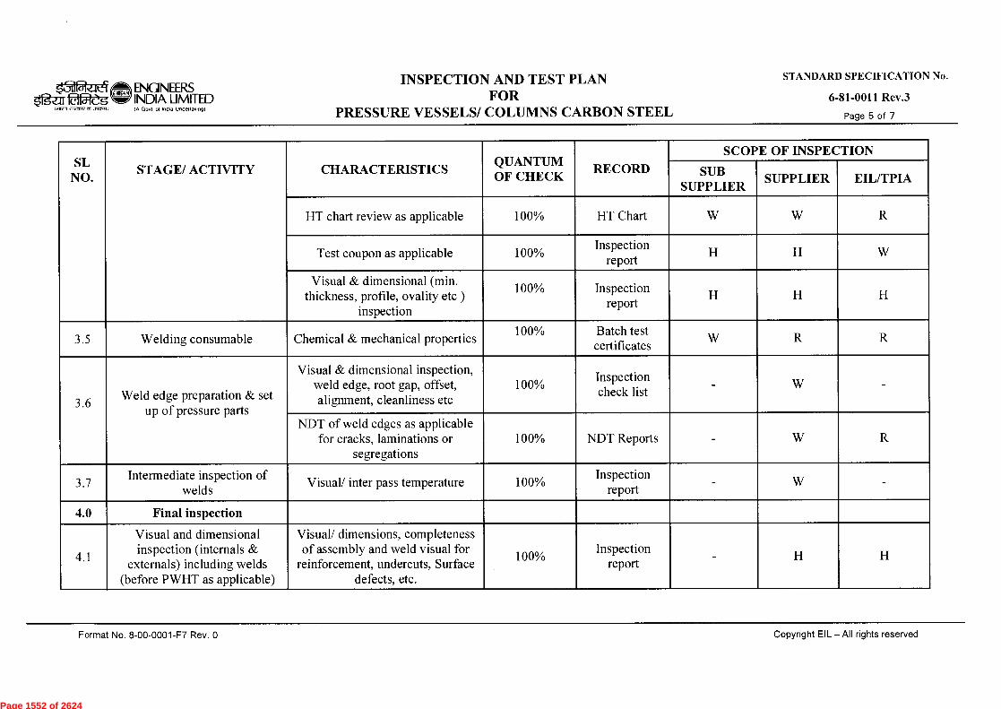
ENGINEERS ligar 254-dg INDIA LIMITED
(11109 ert-MTE 051079M)
IA Govt 01 India Undettaktngt
INSPECTION AND TEST PLAN FOR
PRESSURE VESSELS/ COLUMNS CARBON STEEL
STANDARD SPECIFICATION No.
6-81-0011 Rev.3
Page 5 of 7
SL NO.
CHARACTERISTICS QUANTUM OF CHECK
RECORD
SCOPE OF INSPECTION
SUB SUPPLIER
SUPPLIER EIL/TPIA STAGE/ ACTIVITY
HT chart review as applicable 100% HT Chart W W R
Test coupon as applicable 100% Inspection
report H H W
Visual & dimensional (min. thickness, profile, ovality etc )
inspection
100% report
Inspection H H H
3.5 Welding consumable Chemical & mechanical properties 100% Batch test
certificates W R R
3.6 Weld edge preparation & set
up of pressure parts
Visual & dimensional inspection, weld edge, root gap, offset, alignment, cleanliness etc
100% check list
Inspection - W
NDT of weld edges as applicable for cracks, laminations or
segregations 100% NDT Reports - W R
3.7 Intermediate inspection of
welds Visual/ inter pass temperature 100%
Inspection report
- W -
4.0 Final inspection
4.1
Visual and dimensional inspection (internals &
externals) including welds (before PWHT as applicable)
Visual/ dimensions, completeness of assembly and weld visual for
reinforcement, undercuts, Surface defects, etc.
100% Inspection
report - H H
Format No. 8-00-0001-F7 Rev. 0
Copyright EIL — All rights reserved
Page 1552 of 2624
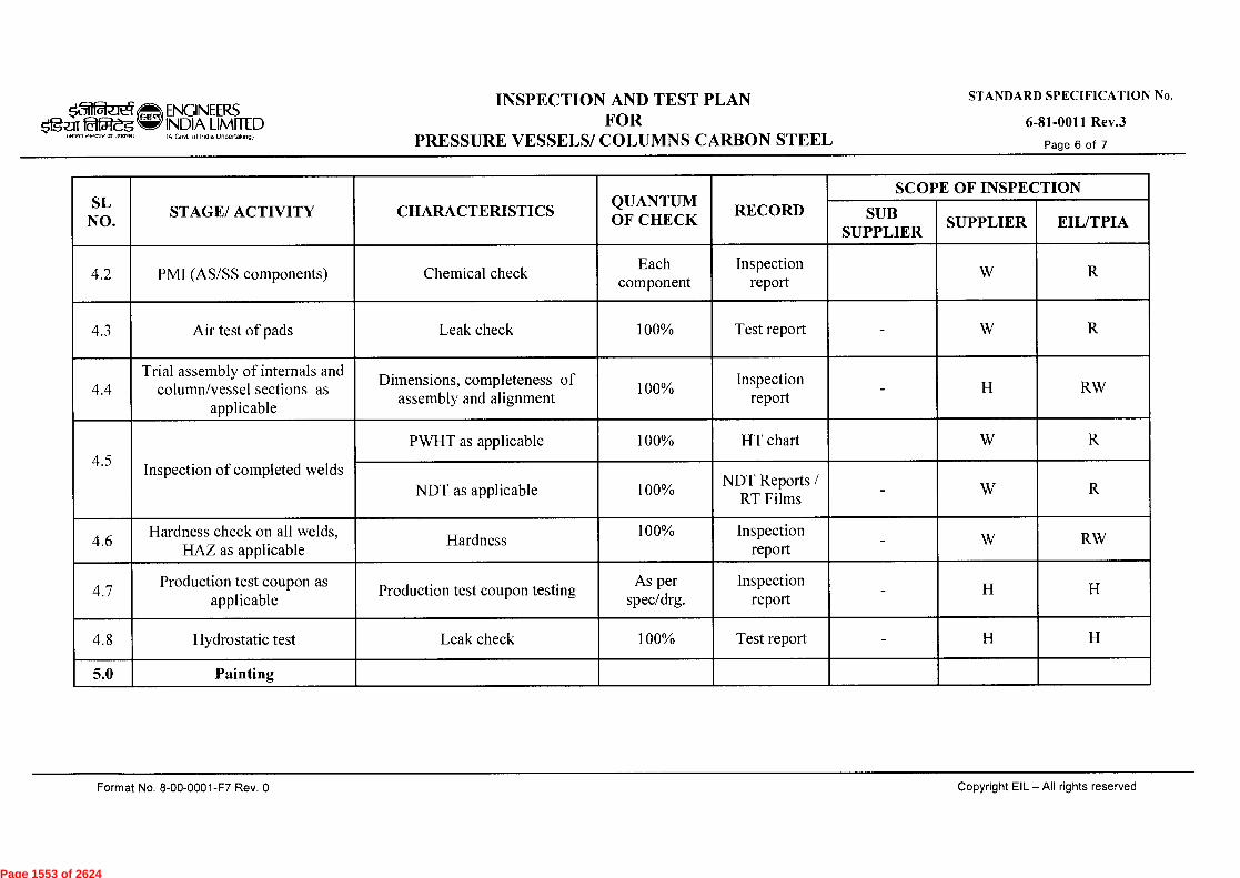
ENGINEERS
laf54-g INDIA LIMITED
wren' eteoredt13traMi
IA Govt of India Undertaking)
INSPECTION AND TEST PLAN FOR
PRESSURE VESSELS/ COLUMNS CARBON STEEL
STANDARD SPECIFICATION No.
6-81-0011 Rev.3
Page 6 of 7
SL NO.
STAGE/ ACTIVITY CHARACTERISTICS QUANTUM OF CHECK
RECORD
SCOPE OF INSPECTION
SUB SUPPLIER
SUPPLIER EIL/TPIA
4.2 PMI (AS/SS components) Chemical check Each
component Inspection
report W R
4.3 Air test of pads Leak check 100% Test report - W R
4.4 Trial assembly of internals and
column/vessel sections as applicable
Dimensions, completeness of assembly and alignment
100% Inspection
report - H RW
4.5 Inspection of completed welds
PWHT as applicable 100% HT chart W R
NDT as applicable 100% NDT Reports /
RT Films - W R
4.6 Hardness check on all welds,
HAZ as applicable Hardness
100% Inspection report
- W RW
4.7 Production test coupon as
applicable Production test coupon testing
As per spec/drg.
Inspection report
- H H
4.8 Hydrostatic test Leak check 100% Test report - H H
5.0 Painting
Format No. 8-00-0001-F7 Rev. 0
Copyright EIL — All rights reserved
Page 1553 of 2624

sfig-ar 0154-eg tan7 knreee avattli
ENGINEERS INDIA LIMITED (A Govt of India Undertaking)
INSPECTION AND TEST PLAN FOR
PRESSURE VESSELS/ COLUMNS CARBON STEEL
STANDARD SPECIFICATION No.
6-81-0011 Rev.3
Page 7 of 7
SL NO.
STAGE/ ACTIVITY CHARACTERISTICS QUANTUM OF CHECK
RECORD
SCOPE OF INSPECTION
SUB SUPPLIER
SUPPLIER EIL/TPIA
5.1 Final painting
Visual inspection (after surface preparation and final painting for workmanship, uniformity) DFT
check
100% Inspection
report - H
6.0 Documentation and IC
6.1 Final stamping, review of inspection documents and
issue of IC
Verifying stamping details and review of inspection documents
100% IC /
Inspection reports
- H H
6.2 Final documents as per PR Verification & compilation of inspection & test records for
submission to customer 100%
Final dossier
- H H
Legend: H- Hold (Do not proceed without approval), P-Perform, RW - Random Witness (As specified or 10% ( min.1 no. of each size and type of Bulk item)), R-Review, W-Witness (Give due notice, work may proceed after scheduled date).
NOTES (As applicable):
1. This document describes the generic test requirements. Any additional test or Inspection scope if specified in contract documents shall also be applicable. (Unless otherwise agreed upon)
2. Acceptance Norms for all the activities shall be as per PO/PR/STANDARDS referred there in /Job Specification /Approved Documents.
Format No. 8-00-0001-F7 Rev. 0
Copyright EIL —All rights reserved
Page 1554 of 2624

NATURAL SOIL (BACK FILLING)
EARTH STRIP SPECIFIED)
BRICK
SAND/STONE DUST
M.V. POWER CABLES
CONTROL CABLES
ENGNEERS TYPICAL SECTION OF CABLE TRENCH
f212e.5 IND1A LIMI I ED IN Govt. of lncfio Undertoking}
UNPAVED AREAS
STANDARD No.
7-51-0302 Rev. 4
Page 1 of 1
(.41Miffl,WM.3.1~)
F.G.L.
NATURAL SOIL (BACK FILLING)
EARTH STRIP SPECIFIED)
BRICKS
M.V. CABLES
SAND/STONE DUST
CONTROL CABLES u")
0 0 tf, 0
tr)
O O
H.V. CABLES / 001 200 I 300 11001100{101
/ 900
200 MIN. OR TWICE THE 0.D. OF CABLE
TYPICAL SECTION WITH H.V. AND M.V. CABLES
TYPICAL SECTION WITH M.V. CABLES
NOTES:- 1. ALL DIMENSIONS ARE IN MM.
2. LEAVE SPACE FOR LATER ADDITION OF AT LEAST 2 CABLES OR 15% AVERAGE SPARE SPACE FOR FUTURE EXPANSION.
3. IF FIRE ALARM AND COMMUNICATION CABLES ARE LAID IN THE SAME TRENCH A CLEARANCE OF 300 MM (MIN.) FROM ELECTRIC POWER CABLES SHALL BE PROVIDED.
?5\4rt 4 21.11.13 REVISED & REISSUED AS STANDARD BP FA/SA UAP/JMS SC 3 15.12.08 REAFFIRMED & ISSUED AS STANDARD BP RKS/NS JMS VC
Rev. No. Date Purpose
Prepared by
Checked by
Stds. Committee Convenor
Stds. Bureau Chairman
Approved by Format No. 8-00-0001-F4 Rev.O Copyright EIL - All rights reserved
Page 1555 of 2624

Page 1556 of 2624
Page 1557 of 2624

Page 1558 of 2624
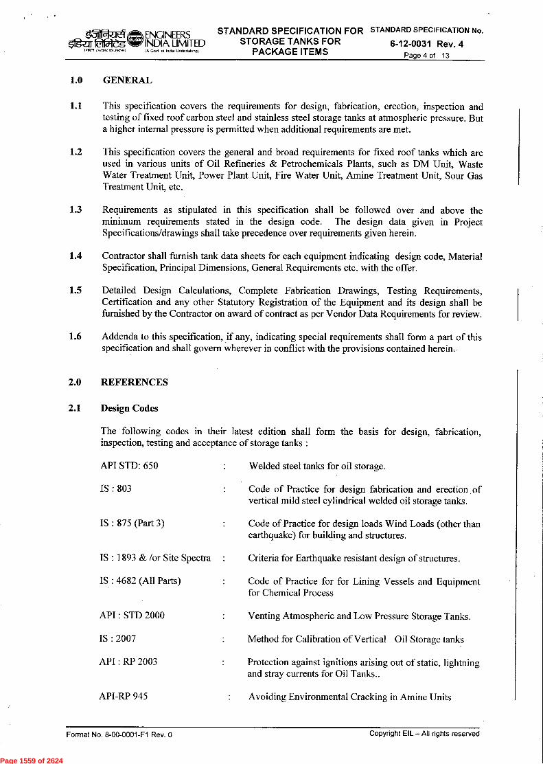
Page 1559 of 2624

Page 1560 of 2624
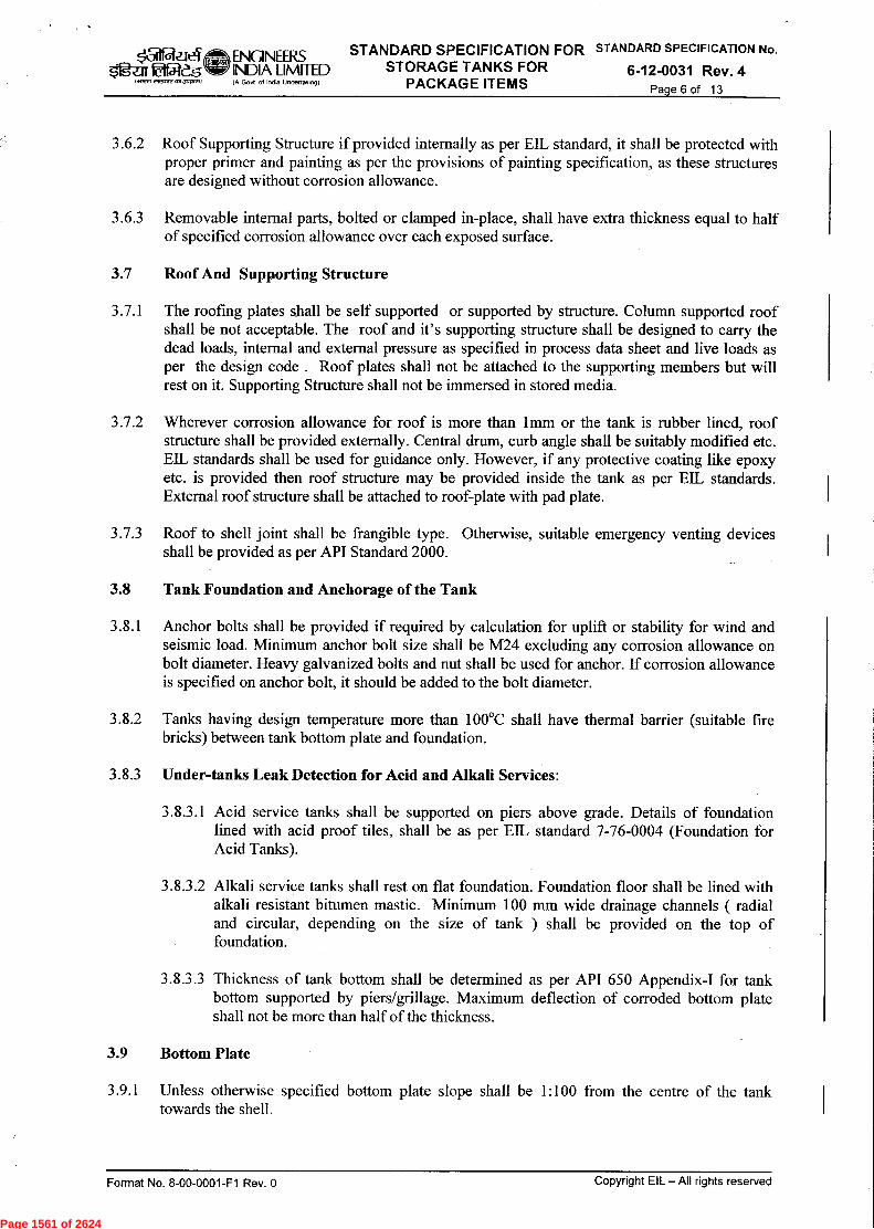
Page 1561 of 2624
Page 1562 of 2624
Page 1563 of 2624
Page 1564 of 2624
Page 1565 of 2624
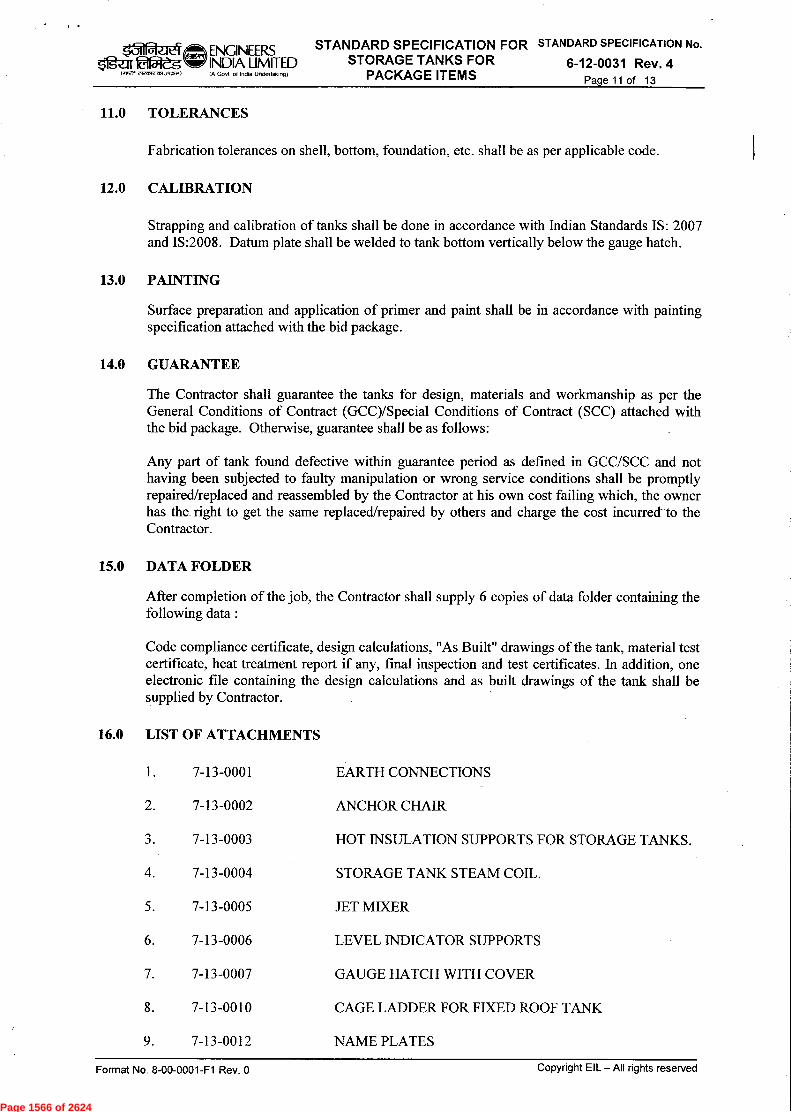
Page 1566 of 2624
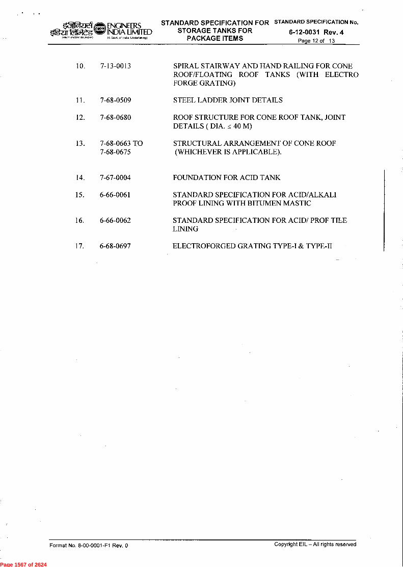
Page 1567 of 2624
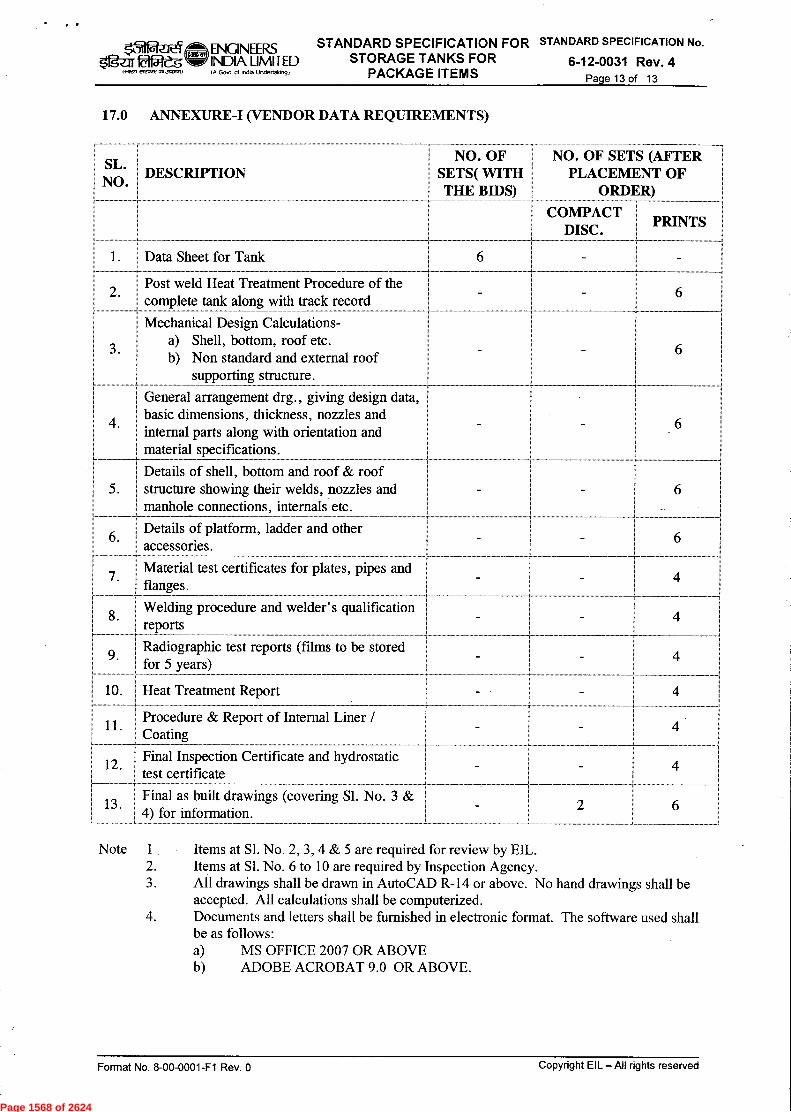
Page 1568 of 2624
Page 1569 of 2624

Page 1570 of 2624

Page 1571 of 2624
Page 1572 of 2624
Page 1573 of 2624
Page 1574 of 2624
Page 1575 of 2624

Page 1576 of 2624

Page 1577 of 2624
Page 1578 of 2624
Page 1579 of 2624
Page 1580 of 2624

Page 1581 of 2624
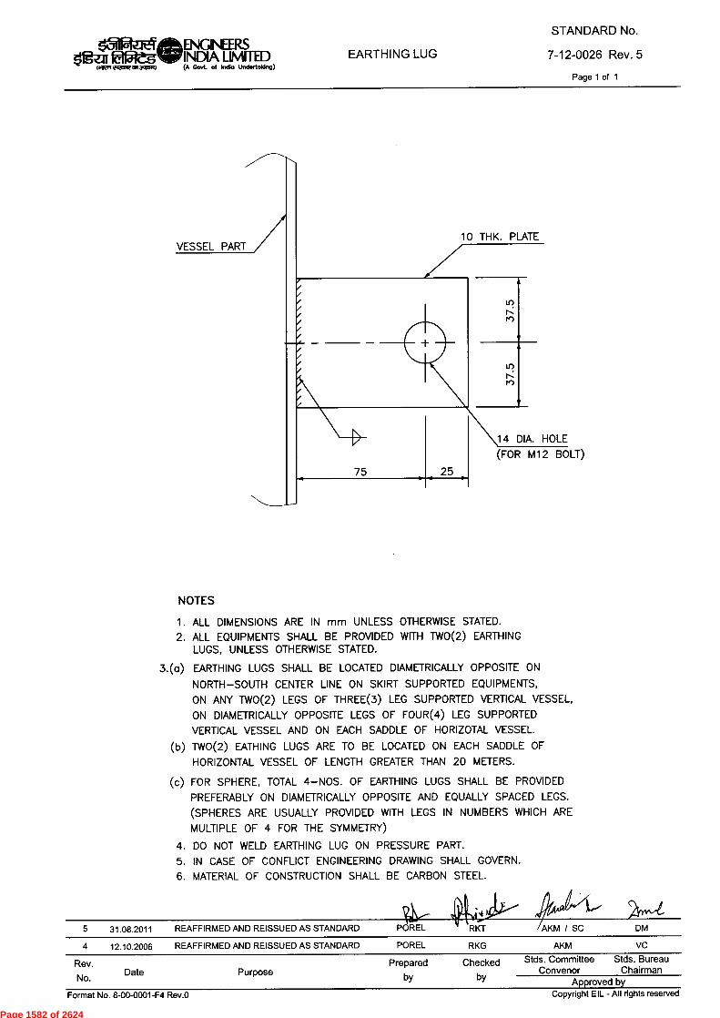
75 25
10 THK. PLATEVESSEL PART
tr.)N
•
14 DIA. HOLE(FOR M12 BOLT)
Rev.No. Date Purpose
Prepared Checkedby by
Stds. Committee Stds. BureauConvenor Chairman
Approved by
15iiitaEqM ENGINEERS41gen fafReg W INDIA LIMITED(..1921751¢tef3ACIFE0 (A Govt. of Indio Undertaking)
EARTHING LUGSTANDARD No.
7-12-0026 Rev. 5Page 1 of 1
NOTESALL DIMENSIONS ARE IN mm UNLESS OTHERWISE STATED.ALL EQUIPMENTS SHALL BE PROVIDED WITH TWO(2) EARTHINGLUGS, UNLESS OTHERWISE STATED.
3.(a) EARTHING LUGS SHALL BE LOCATED DIAMETRICALLY OPPOSITE ONNORTH—SOUTH CENTER LINE ON SKIRT SUPPORTED EQUIPMENTS,ON ANY TWO(2) LEGS OF THREE(3) LEG SUPPORTED VERTICAL VESSEL,ON DIAMETRICALLY OPPOSITE LEGS OF FOUR(4) LEG SUPPORTEDVERTICAL VESSEL AND ON EACH SADDLE OF HORIZOTAL VESSEL.TWO(2) EATHING LUGS ARE TO BE LOCATED ON EACH SADDLE OFHORIZONTAL VESSEL OF LENGTH GREATER THAN 20 METERS.
FOR SPHERE, TOTAL 4— NOS. OF EARTHING LUGS SHALL BE PROVIDEDPREFERABLY ON DIAMETRICALLY OPPOSITE AND EQUALLY SPACED LEGS.(SPHERES ARE USUALLY PROVIDED WITH LEGS IN NUMBERS WHICH AREMULTIPLE OF 4 FOR THE SYMMETRY)DO NOT WELD EARTHING LUG ON PRESSURE PART.IN CASE OF CONFLICT ENGINEERING DRAWING SHALL GOVERN.
6. MATERIAL OF CONSTRUCTION SHALL BE CARBON STEEL.
5 31.08.2011 REAFFIRMED AND REISSUED AS STANDARD POREL • RKT AKM / SC DM4 12.10.2006 REAFFIRMED AND REISSUED AS STANDARD POREL RKG AKM VC
Format No. 8-00-0001-F4 Rev.0 Copyright EIL - All rights reserved
Page 1582 of 2624

0—J
V)
10 R
BRACKET
NAME PLATE0
r-
o 0:N
N
0MANUFACTURER NAME PLATE
<TYP2 V •
200
230
0N
EIL NAME PLATE
4-
+
Rev.No. Date Purpose
Prepared Checkedby by
Stds. Committee Stds. BureauConvenor Chairman
Approved by
STANDARD No.
ge4151Wt7-1e71 legOINDIA LIMITED BRACKET FOR NAME PLATE 7-12-0029 Rev. 5
(NM meow wawa) (A Govt. of Indio Undertaking)Page 1 of 1
NOTESI. ALL DIMENSIONS ARE IN inn UNLESS OTHERWISE STATED.2, BRACKET MATERIAL SHALL BE SAME AS SHELL MATERIAL.
5 31.08.2011 REAFFIRMED AND REISSUED AS STANDARD POREL RKT PKM / SC DM
4 12.10.2006 REAFFIRMED AND REISSUED AS STANDARD POREL RKG AKM VC
Format No. 8-00-0001-F4 Rev.0 Copyright EIL - All rights reserved
Page 1583 of 2624

HALF P PE OF NOMINALPIPE SIZE = 2d **6 (5)
2—FLATS *6 (5) THK.(NOT REQUIRED FOR'd' < 150 NB)
TYPE-1 TYPE-2
VESSEL INSIDE ii VESSEL INSIDE (7)
4rm. \
aka
d 2 50 MIN.
**6 (5)
ENGNEERSliglirgelNDIA LIMITED(A Govt. of Indio Undertaking)
INLET DEFLECTOR BAFFLESTANDARD No.
7-12-0020 Rev. 5Page 1 of 1
NOTESALL DIMENSIONS ARE IN mm UNLESS OTHERWISE STATED.CC = 30' UNLESS OTHERWISE STATED (TO BE ADJUSTED TO PREVENTBLOWING INTO SEAL PAN).MATERIALS SHALL BE AS PER ENGINEERING DRAWING.IN CASE OF CONFLICT ENGINEERING DRAWING SHALL GOVERN.
5. DIMENSIONS IN BRACKETS ARE FOR STAINLESS STEEL.
* 6. INDICATED THICKNESS OF INTERNAL BAFFLE PLATE IS MINIMUM TOWHICH TWICE THE CORROSION ALLOWANCE IS TO BE ADDED.
**7. ALL FILLET WELD SIZE SHALL BE OF 6MM MINIMUM TO WHICH THECORROSSION ALLOWANCE IS TO BE ADDED.
5 30.07.2011 REAFFIRMED AND REISSUED AS STANDARD POREL 1021< KM / SC DM
4 11.09.2006 REVISED AND REISSUED AS STANDARD POREL DNN AKM VC
Rev.No. Date Purpose
Prepared Checkedby by
Stds. Committee Stds. BureauConvenor Chairman
Approved byFormat No. 8-00-0001-F4 Rev.0 Copyright EIL - All rights reserved
Page 1584 of 2624

6 DIA. HOLE(TYP•)
10 TYP
r•J
FOR VESSEL DIAMETER ABOVE 600,PROVIDE 30X6 THK. FLATS WITHHEIGHT EQUAL TO INSULATIONTHK. AT 600 CIRCULAR PITCHNOTE-7)
100 MIN. S
M6 x 4OLG. G.I. BOLTSTACK WELDED AT 600 PITCH
60 HOLE AT600 PITCH
CORRUGATED SHEET3 THK. X 20 0.DNEOPRENE WASHER2 THK. ALUMINIUMWASHER
`A'
2-M6 BOLTSx25LG. G.I.BOLTS ANDNUTS (TYP.)
10 DIA. LOOSERING (TYP.)
T.L
100 MIN. (TYP.)
3 THK.ASBESTOS SHEET
6 THK. ANGLE RINGS(WELD ENDS)
8 THK. T-CLEATS AT1000 PITCH(MINIMUM3 CLEATS PER RING)
(TP)
DETAIL—X(FOR HOT INSUSLATED
40)VESSELS)
(WHERE =>
10
VIEW - 'A'
010 HOLE ONANGLE LEG
VIEW — 'B'
SKIRT PIPE G‘111SUPPORT
ANGLE LEGSUPPORT
M12 SQUARE NUTS TACK WELDON INSIDE AND OUTSIDE OFSKIRT ON 450 TRIANGULAR PITCHFOR FIRE PROOFING (SEE DETAIL-Y)(REFER NOTE-8)
D
W.LN o bT.L
600 MIN. FOR VESSELSINSULATED FOR TEMP.ABOVE 400'C.
5 X COLD INSULATIONTHICKNESS ( MIN 600MM)
r•-■ ry rJ W.L.
a_711=-J b
DETAIL—Y
15MAZIEq ENGINIEER.SfaglegVOY INDIA LIMITED
IMAM FRWIU ter MAAR) (A Govt. of India Undertaking)
FIRE PROOFINGAND
INSULATION SUPPORTS
STANDARD No.
7-12-0025 Rev. 5Page 1 of 2
INSULATION THICKNESS (S)
SECTION 'C—C'
5 31.08.2011 REAFFIRMED AND REISSUED AS STANDARD
4 12.10.2006 REAFFIRMED AND REISSUED AS STANDARD POREL
M12 SQUARE NUTS TACKWELDED AS SHOWN INSEC.D-D FOR FIRE PROOFING(REFER NOTE-8)
RKG AKM
DM
VC
Rev.No. Date Purpose
Preparedby
Checkedby
Stds. Committee Stds. BureauConvenor Chairman
Approved byFormat No. 8-00-0001-F4 Rev.0
Copyright EIL - All rights reserved
Page 1585 of 2624
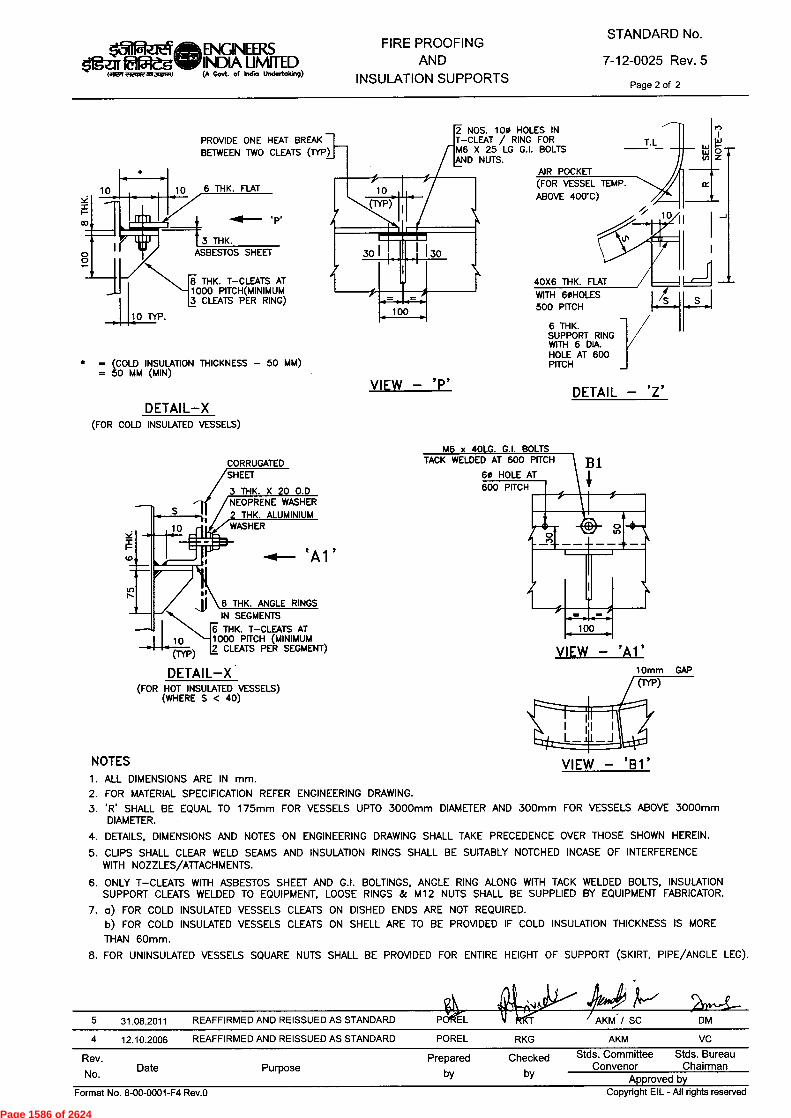
PROVIDE ONE HEAT BREAKBETWEEN TWO CLEATS (TYP)
14.1
0z
40X6 THK. FLATWITH 60HOLES500 PITCH
6 THK.SUPPORT RINGWITH 6 DIA.HOLE AT 600PITCH
DETAIL — 'Z' VIEW — 'P'
AIR POCKET(FOR VESSEL TEMP.ABOVE 400T)
DETAIL-X
6 THK. FLAT10
3 THK. ASBESTOS SHEET
8 THK. T—CLEATS AT1000 PITCH(MINIMUM3 CLEATS PER RING)
10 TYP.
* = 5(C0OLD INSULATION THICKNESS — 50 MM)
= MM (MIN)
2 NOS. 100 HOLES INT—CLEAT / RING FORM6 X 25 LG G.I. BOLTSAND NUTS.
wwto
M6 x 40LG. G.I. BOLTSTACK WELDED AT 600 PITCH
60 HOLE AT600 PITCH
B1
Rev.No. Date Purpose
Prepared Checkedby by
Stds. Committee Stds. BureauConvenor Chairman
Approved by
S
CORRUGATED "SHEET
3 THK. X 20 0.DNEOPRENE WASHER2 THK. ALUMINIUMWASHER
A
6 THK. ANGLE RINGSIN SEGMENTS
6 THK. T—CLEATS AT10 1000 PITCH (MINIMUM
2 CLEATS PER SEGMENT)(TYP)
DETAIL-X (FOR HOT INSULATED VESSELS)
(WHERE S < 40)
fs'INPIZIEgMENIGINEERS
EPIegilir INDIA LIMITEDWWI E9210121BTWO (A Govt. of India Undertaking)
FIRE PROOFINGAND
INSULATION SUPPORTS
STANDARD No.
7-12-0025 Rev. 5Page 2 of 2
(FOR COLD INSULATED VESSELS)
VIEW - 'Al'10mm GAP(rY1')
NOTES VIEW - 'Bl ALL DIMENSIONS ARE IN mm.FOR MATERIAL SPECIFICATION REFER ENGINEERING DRAWING.'R' SHALL BE EQUAL TO 175mm FOR VESSELS UPTO 3000mm DIAMETER AND 300mm FOR VESSELS ABOVE 3000mmDIAMETER.DETAILS, DIMENSIONS AND NOTES ON ENGINEERING DRAWING SHALL TAKE PRECEDENCE OVER THOSE SHOWN HEREIN.CLIPS SHALL CLEAR WELD SEAMS AND INSULATION RINGS SHALL BE SUITABLY NOTCHED INCASE OF INTERFERENCEWITH NOZZLES/ATTACHMENTS.ONLY T—CLEATS WITH ASBESTOS SHEET AND G.I. BOLTINGS, ANGLE RING ALONG WITH TACK WELDED BOLTS, INSULATIONSUPPORT CLEATS WELDED TO EQUIPMENT, LOOSE RINGS & M12 NUTS SHALL BE SUPPLIED BY EQUIPMENT FABRICATOR.a) FOR COLD INSULATED VESSELS CLEATS ON DISHED ENDS ARE NOT REQUIRED.b) FOR COLD INSULATED VESSELS CLEATS ON SHELL ARE TO BE PROVIDED IF COLD INSULATION THICKNESS IS MORETHAN 60mm.FOR UNINSULATED VESSELS SQUARE NUTS SHALL BE PROVIDED FOR ENTIRE HEIGHT OF SUPPORT (SKIRT, PIPE/ANGLE LEG).
5 31.08.2011 REAFFIRMED AND REISSUED AS STANDARD
4 12.10.2006 REAFFIRMED AND REISSUED AS STANDARD POREL RKG AKM VC
Format No. 8-00-0001-F4 Rev.0 Copyright EIL - All rights reserved
Page 1586 of 2624
C,
O panss!-ag pue pasinax
6"'
uoguwawaidui! Joj panssi
panss!-a-H pur paspka->i
0 AoTI L3-1000-00-8 "Igw-10.4
ry
O
O
O
t•••.,
00
c)
c,
pamasal s4q6P IIV —113 lq6pAclo3
CO
STANDARD SPECFICATION NO.
cs,
Pag
e 15
87 o
f 26
24
:suop.mnoacmy
£ 'AaR IS01-18-9
STANDARD SPECIFICATION NO. .A9d L3-1000-00-8 '0N iewiod
Inspection Standards Committee
uldno .3.s -JN
pamaseJ s4LI6P IIV —113 11160doo 1-' `
-' '-'
s'-'
'
'' '"
"
r T
r
5 5 t
C
NC
] n rri
nto
to
>
Hn
nr(:1
—t
nxH
HH
ti —
tc >
l -
rr
o
rn
-, rIrl
(-)
~ri
(-)
0
r—, 7,
,,
•
c
cm c c
,.<
'.11 <
" , . -1.1—
' . . . ttt1
! I ,
! _so, -- 9n
, , ),9 . .
_ ,r 1)( - : ›?
)1 ,. Dc >
: ee. 1):7'>
-s
.—..
Cl
.. cp
CD
C:Jo
,_,,_t
o ` -
5 9
< „, ) 8 . , .
, ,9--
. .
rri —
H=. t=,
,"7" on
. 2
- >
L 4
,,:3,,-,- ,
,, ,,E,,,,
.(5,
v, -,
-
•
5.? ö
c
) °
co , --
'"C
) cs)
—
-s
co
0 C
C
".
til
(...) 5
_0
..„ao ,.,z
t ..Ti c.
-,
ci)
H '-
'
CD
■-• ..
.,~ fl
cD
C
-. -
• C
o -
. -
-1
-t
•
r)
iiN) "-
co (
•-)
C C
.•
.- —
r••
9'
■-3
,=,.
ct
ro C
D c
p C
) .-
rri
, c,.,
9_,
po
--
-t
Cm. ■
-•1
cA
(,,-zr <
7;
1,)
Ci)
0
(17 n
,>"-
5. H
(Dr)
co
(I4 -
t 0
(1)
.
co
C 0
t,t
• 0
H
(.D•H
,..-4-C)
r)
Co
C)..
, ct)
C " ■
r- cm
v)
•-i•)
c
C4
co 0
C
v)
■-t.
,
e-1-
cp
cn
0 0
<-P
- ,-*
(-.)
p,, p2
_, .5,.
-
4 ,
rii
r.
,_
,,, 5.
.0
.-,
o ,_, a
ro
D.<
' •
eD
•
,-. •
'«Cf.) .
, AD
AD
CD
--3
CD
5' 7,
'0 C
.,
F).
Olc
i 0
•
C
C
v)
.-
c
'* -'
'87
-, co
s2
.--.
cm ,-
,- cn
. '') 0-
■-s, o ril
(
•
-)
-t
cir
o
1:0
Fo ..
c)
5 o
to 5
,-
L'
('-:',*
cp 9
rc
$2 'Ci
) . rD
,-,
.
cn
rri
5'
PD
.0
o,---r
-' C
-• cD
C
co
C
C„. > 5 :=,, o-
■-3
zJ,c
o
tri
H
zb
0 y
H
H
(-)
.<
H H
,C
1'-d
'-d'td
'-d'-d
'-dZ
ZZ
4
co
,--
CD :A
) 0
0
- <tl_,
_) ,,
• , c
) n ....
(0 C
D C
D ,-
,
‘..,
,-+
.2'
cn
■-• ■ -
, ,-
. C
l.•
” -1
. . C
L, A
•D ,.
-' ,-
, . 0
0
o-t
n"
cA Q
. C
L C
L c
l) P
' 0.•
3. =
. .--
co
C-
'5.
,-..•
'"C
CD
,_,"-"
0 ..-
t cID
nC
na ,
:-
'-'.
R- Q
., iii
s...,
o •
-•
r--■ .-t
,-, -
1 ....
o ,-
et
, Cn
crq
p_
i $:, D
,,,,-,
n 5
- CD
cpCn 5
1 ,.
.,
CA
rD
•
c r
o e
n A
)
(11:
•
1 ,.,'"°
,....,'.-1 '..i
. 'r.)
. '-.
. 1P-
, 0. ‘
-,-- 4
co ,T
h rii gv'
,...,
c
-, c ,
„„ q
--1 _
_, -)
,.
,..,_ ()
co- ,c
) rri
a 0, r)
co
n
ct)
0.
.. •-•
-) (..
) CD
AD
Fi)' -c
) ><
c)
-,-
. u
p o
..i° c
o 7
c) t-'
w) v
, 5,-
■-3 2"
,8_.
-t
p3 -0
CD
■-t
o
Cl. C
1) A
D '0
ci)
P)
...-j)-
-. o
o"
,. r
) ,.„
C
C ,
.0 c
r' C
cp
vp
C
Co
. -s
-t-
,-
• 0-'-'
'• rj
•
o t
ra c
) ri
l 0
:R. p
t (19-
s4D
(,,
.-1
-•
(-)
- •
<
ro
- eD
C/")
CD
o
CIR
CD
4 (•4
' ° ,.
g.
a)-'• r)
'')
5'
6"
-o
R
Cf4
rD
•
0
AD
Ci)
-._• c
) Po
c)
-• .
0
C C
+
r)
•'"
`-<
-t
-1
C
C
., "
cp
,-
,- 6
Cf
4 O
C
v)
C
o
1S3,1,
Pag
e 15
88 o
f 26
24
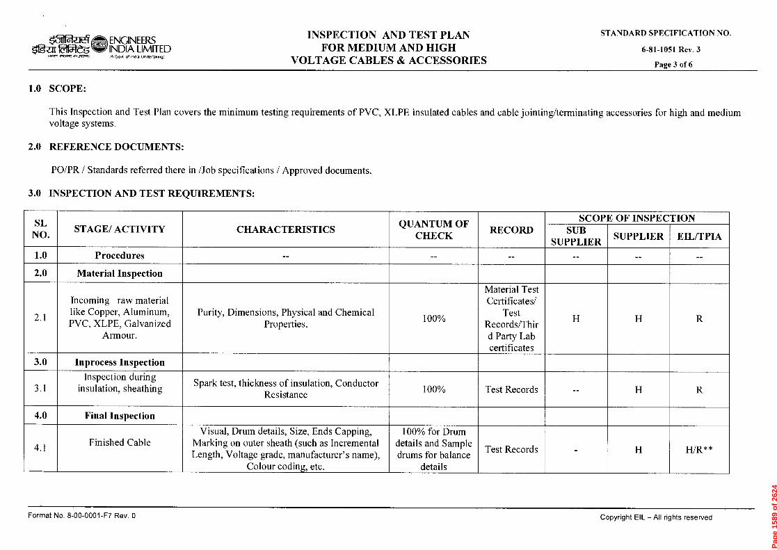
0 •nal{ Ld-6000-00-8 'oN 4eWJOd PaMaSeJ S41-16P IIV —113 4460c100
3.0 INSPECTION AND TEST REQUIREMENTS:
PO/PR / Standards referred there in /Job specifications / Approved documents.
t•J O
:adODS O'I
-AaH
STANDARD SPECIFICATION NO. ■—
■
4.0
(....)
.,--,
t>> 7::::,
tN)
■--,
If.)
C5
1•••■
■=,
7C
ln
0
Finished Cable
Final Inspection
Inspection during insulation, sheathing
Inprocess Inspection
Incoming raw material like Copper, Aluminum, PVC, XLPE, Galvanized
Armour.
Material Inspection
Procedures
STAGE/ ACTIVITY
Visual, Drum details, Size, Ends Capping, Marking on outer sheath (such as Incremental Length, Voltage grade, manufacturer's name),
Colour coding, etc.
Spark test, thickness of insulation, Conductor Resistance
Purity, Dimensions, Physical and Chemical Properties.
■
CHARACTERISTICS
100% for Drum details and Sample drums for balance
details
.--,
C>
0,
,::'
,-
0
0
c:'
' 1
QUANTUM OF CHECK
Test Records
Test Records
Material Test Certificates/
Test Records/Thir d Party Lab certificates
n 0 g
X
SUB SUPPLIER
SCOPE OF INSPECTION
x x
x . ,
SUPPLIER
x
EIL/TPIA
Pag
e 15
89 o
f 26
24
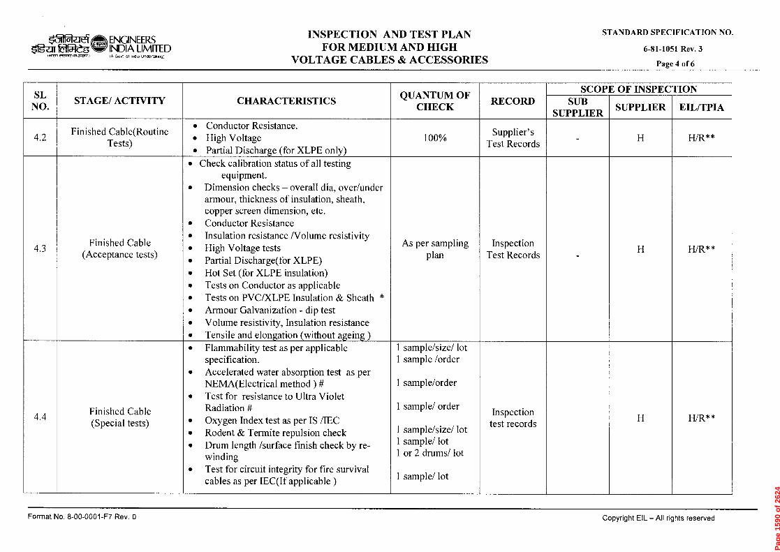
0 'A32:1 Ld-1,000-00-9 oN 4eLtuod patuasai sp.161J IIV —113 41-160doo
£ 'Anf IS01-18-9
STANDARD SPECIFICATION NO. :P
. i..
..)
i•-)
C
) t
«I
C/D
'"" •
CD
E7D
v)
1:0
-4. c
r `.
..■
FD-.
r)
....
r> c
'-cS ■-
■•• $2,
3 CD
C
r e-.
CD
s..
...,
Finished Cable(Routine Tests)
STAGE/ ACTIVITY
• Flammability test as per applicable specification.
•
Accelerated water absorption test as per NEMA(Electrical method ) #
•
Test for resistance to Ultra Violet Radiation #
•
Oxygen Index test as per IS /IEC
•
Rodent & Termite repulsion check
•
Drum length /surface finish check by re-winding
•
Test for circuit integrity for fire survival cables as per IEC(If applicable )
•
Check calibration status of all testing equipment.
•
Dimension checks — overall dia, over/under armour, thickness of insulation, sheath, copper screen dimension, etc.
•
Conductor Resistance
•
Insulation resistance /Volume resistivity
•
High Voltage tests
•
Partial Discharge(for XLPE)
•
Hot Set (for XLPE insulation)
•
Tests on Conductor as applicable
•
Tests on PVC/XLPE Insulation & Sheath *
•
Armour Galvanization - dip test
•
Volume resistivity, Insulation resistance
•
Tensile and elon:ation (without a:ein: ) •
Conductor Resistance.
•
High Voltage
•
Partial Discharge (for XLPE only)
CHARACTERISTICS
,--,
cn
."1:
$
CD
----
-
ET.
•-t
-
,—,
■—■
■—■
■—■
o
ll)
Cn
cn
t■-)
(=
»t1
»Z
S
1::
$
.1
CD
CD
<D
.-
----....
----..
----...
a>""
E;i .
.9,
,4), ,-
r- cp
C
l.
-----
ro a-;
,__,
,.,
.--4-
0
■—■
cn
'.0
CD
o
Q.,
"
ri>
-t
---,
■—■
■—■
(1)
CI)
IZS
»0
CD
n ----
- (1)
0
,---
■-s
N
0..
(1)
CD
----
,-t
■—
■ 0
>
-Q
rp
'zi
-t
'E g
o' li
..- .
C1C7
-.
c>
c>
QUANTUM OF CHECK
v) •—r-
cn
-t .
..(j
CD
n r)
r) c>
-.
cn
CD
5'
cn
■—r-
cn
-ri
7ZJ c
p CD
n
r) .-■-
Q
.. C.
I)
Supplier's Test Records
n
CD
SUB SUPPLIER
SCOPE OF INSPECTION
SUPPLIER
Z
--__
. ,..
.,,,
:i
*
•..8,
EIL/TPIA
Pag
e 15
90 o
f 26
24

- Samples must include min 1 No of each type),
* r
) *
CD
o
<1>
CD
• —
o H
rD cr
•
‘<
1=1
o x
E
("D
r)
• (
• "
O
o
D
("D
-6
• D
(1
)
crcra
CD
C
L,
CD
er,
CD
<
ro
?").•
c",
)" CD
■-
■ • t-
+
ro
F4
H
c7"
rit's s:0
co
s:0•-
•
•<
-cs E-4
CD
0
0
cn
cr
rt)
(,)
CD
(
•
7,
ro
CD
•
(1)
cr
‘-<
rrl
▪
ro
• ‘
CD
rD
Co.
e+
rD
(,)
rD
DZ
1. 1:
$ cr CD
0 nal{ L3-1.000-00-9 '0N Tewiod pemasai s41.16!J IIV 713 11-150doo
STANDARD SPECIFICATION NO. C
I1
i‘.)
9:7 \
,--,
01
0
C11
0
-A.
0"
4A.
b'l
Z C
A
C
Final Document submission
Documentation and IC
Documentation and IC
Painting
Cable accessories
Finished Cable (Type tests **)
STAGE/ ACTIVITY
Compilation of Inspection reports ,drawings, etc as per VDR / PR •
Review of Routine, Acceptance, Type test reports.
•
IC issuance
•
Visual
•
Dimensions
•
Type tests** as per IS/IEC
•
Dielectric Retention.
•
Type tests on PVC insulation and Sheath
•
High Voltage test (Water Immersion)
•
Dielectric power factor tests as function of voltage, temperature. (XLPE cables)
•
Heating cycle test (XLPE Cables)
•
Im .ulse withstand test (XLPE cables
CHARACTERISTICS
CD
0
0
CD
c:›
1 1
e
Sample
C/)
QUANTUM OF CHECK
Final data folder
/Completenes s certificate
Supplier TC & IC
Test Records
'--3
CD
C/)
■--
rb r)
o
21,
r.)
ril o n SUB
SUPPLIER
SCOPE OF INSPECTION
, X
x
SUPPLIER
Z
, , x
7:1
EIL/TPIA
Pag
e 15
91 o
f 26
24
0 •AGd LA-6000-00-9 'oN teu.00d
t•..)
r)
r)
CD
0 C
IA
"
{.D1)
'
0
SO
•
H
c7 •
cp
CD cn r[,
v,
CD
CD
CD
CD
O
t=1
ci)
Copyright EIL — All rights reserved
cn
CD
cn
CD
co
CD
co
c.h
CD
-s
vs
0 >
‘-<
0..
ci)
01.
13,7
Er.
AD
cn
CD
■—t
CD
o
-s .
CD
c,,n1
CD
CD
ri)
c)
'1:21
CD
cn CD
C
D
CD
. CD
CD
CD.
0
0
CD
O
CD
Q_
CD
>1:t
`LS
• r=0
CD
£.̂all
STANDARD SPECIFICATION NO.
Pag
e 15
92 o
f 26
24

0 30.06.86 ISSUED AS STANDARD SPECIFICATION.
Rev.No Date Purpose
STANDARD SPECIFICATION FOR
ala_it.4 ENGINEERS INSTRUMENTATION OFOgar0154'dg INDIA LIMITED
,A Govt of Indla Undertaking) PACKAGE UNITS
STANDARD SPECIFICATION No.
6-52-0052 Rev. 3Page 1 of 58
Ada fry
*o-t-§al21mm ITFTW fq fff -km RT
STANDARD SPECIFICATION FORINSTRUMENTATION OF PACKAGE
UNITS
3 16.03.15 REVISED AND REISSUED
2 29.06.09 REVISED AND REISSUED
1 25.06.97 REVISED AND REISSUED.
RG RP TGM ND
RK BRS RB AS
RK RB AKV AK
Preparedby
Checkedby
StandardsCommitteeConvenor
StandardsBureau
Chairman
Approved by
Copyright EIL — All rights reservedFormat No. 8-00-0001-F1 Rev. 0
Page 1593 of 2624
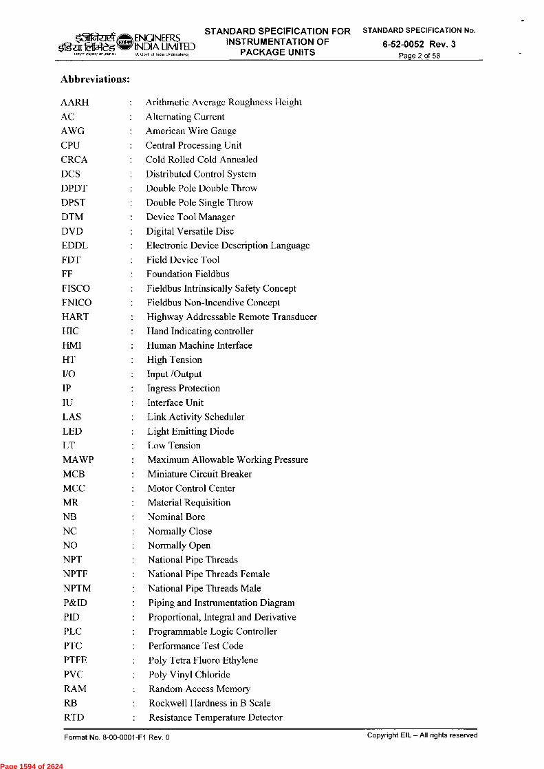
&STANDARD SPECIFICATION FOR
INDIA LIMITEDENGINEERS INSTRUMENTATION OF$'1gal• faiW IA Govt of India Undeflaking) PACKAGE UNITS
STANDARD SPECIFICATION No.
6-52-0052 Rev. 3Page 2 of 58
Abbreviations:
AARH •. Arithmetic Average Roughness Height
AC :. Alternating Current
AWG American Wire Gauge
CPU Central Processing Unit
CRCA :. Cold Rolled Cold Annealed
DCS •. Distributed Control System
DPDT :. Double Pole Double Throw
DPST :. Double Pole Single Throw
DTM Device Tool Manager
DVD Digital Versatile Disc
EDDL Electronic Device Description Language
FDT :. Field Device Tool
FF :. Foundation Fieldbus
FISCO :. Fieldbus Intrinsically Safety Concept
FNICO •. Fieldbus Non-Incendive Concept
HART •. Highway Addressable Remote Transducer
HIC Hand Indicating controller
HMI Human Machine Interface
HT •. High Tension
110 •. Input /Output
IP •. Ingress Protection
IU •. Interface Unit
LAS •. Link Activity Scheduler
LED Light Emitting Diode
LT Low Tension
MAWP •. Maximum Allowable Working Pressure
MCB :. Miniature Circuit Breaker
MCC •. Motor Control Center
MR •. Material Requisition
NB -. Nominal Bore
NC Normally Close
NO Normally Open
NPT National Pipe Threads
NPTF •. National Pipe Threads Female
NPTM •. National Pipe Threads Male
P&ID -. Piping and Instrumentation Diagram
PID :. Proportional, Integral and Derivative
PLC •. Programmable Logic Controller
PTC •. Performance Test Code
PTFE :. Poly Tetra Fluoro Ethylene
PVC :. Poly Vinyl Chloride
RAM :. Random Access Memory
RB •. Rockwell Hardness in B Scale
RTD :. Resistance Temperature Detector
Copyright EIL — All rights reservedFormat No. 8-00-0001-F1 Rev. 0
Page 1594 of 2624
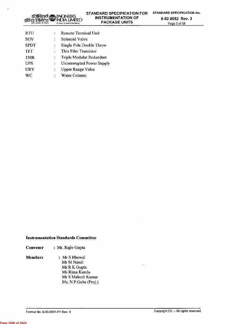
ENGINEERSSTANDARD SPECIFICATION FOR STANDARD SPECIFICATION No.
INDIA LIMITEDINSTRUMENTATION OF 6-52-0052 Rev. 3
Govt of India UrvIertaktng) PACKAGE UNITS Page 3 of 58
n31
Oe.11 tlf5iegIvIten eivtutzmatmissif
RTU
SOV
SPDT
TFT
TMR
UPS
URV
WC
Remote Terminal Unit
• Solenoid Valve
• Single Pole Double Throw
• Thin Film Transistor
Triple Modular Redundant
• Uninterrupted Power Supply
Upper Range Value
Water Column
Instrumentation Standards Committee
Convener : Mr. Rajiv Gupta
Members : Mr S BhowalMr M NandiMr R K GuptaMs Rima KunduMr S Mahesh KumarMs. N.P.Guha (Proj.)
Format No. 8-00-0001-F1 Rev. 0 Copyright EIL —All rights reserved
Page 1595 of 2624
STANDARD SPECIFICATION FOR STANDARD SPECIFICATION No.ENGINEERS INSTRUMENTATION OFINDIA LIMITED 6-52-0052 Rev. 3IA Govt of hrhA Unde,taong) PACKAGE UNITS Page 4 of 58
43*slgar WesNV, rieaxt
CONTENTS
PART I GENERAL SPECIFICATION OF INSTRUMENTATION 5
1.0 GENERAL 6
2.0 DESIGN PHILOSOPHY 12
3.0 SPARES PHILOSOPHY 19
4.0 GENERAL SPECIFICATION OF INSTRUMENTS 20
5.0 LIST OF DOCUMENTS ATTACHED 46
PART II SPECIFICATION FOR MATERIAL, INSTALLATION, TESTING ANDCOMMISSIONING 47
1.0 INSTALLATION MATERIALS 48
2.0 INSTALLATION 54
3.0 TESTING AND CALIBRATION 56
4.0 COMMISSIONING 58
ANNEXURES:
ANNEXURE — IANNEXURE — II
MATERIAL SELECTION CHARTBLANK FORMATS
Copyright EIL — All rights reservedFormat No. 8-00-0001-F1 Rev. 0
Page 1596 of 2624
0 e1 ENGINEERSSTANDARD SPECIFICATION FOR STANDARD SPECIFICATION No.
OQzll taRcg INDIA LIMITEDINSTRUMENTATION OF 6-52-0052 Rev. 3
Govt Ind. unciertakog) PACKAGE UNITS Page 5 of 58n AVIRot ottratte On avast.
PART I
GENERAL SPECIFICATION OF
INSTRUMENTATION
Format No. 8-00-0001-F1 Rev. 0 Copyright EIL — All rights reserved
Page 1597 of 2624
ENGINEERSSTANDARD SPECIFICATION FOR STANDARD SPECIFICATION No.
$1g-ar laf5tegr.tea v/vore attow)i)
INSTRUMENTATION OFINDIA LIMITED 6-52-0052 Rev. 3IA GovtofIndia Undertaking) PACKAGE UNITS Page 6 of 58
1.0 GENERAL
1.1 Scope
1.1.1 This specification together with the attachments covers the design and engineering ofinstruments, control systems, accessories and materials, along with special test equipments,where the supply is part of a package being supplied by vendor. This specification is generaland all instruments/systems included may not be required for the proposed package. Thescope shall be as defined in the scope of supply of Instrumentation.
1.1.2 The detailed scope of work, specific job requirements, exclusions, deviations, additions etc.if any, will be indicated in Scope of Supply of Instrumentation and Job Specification ofInstrumentation included in the material requisition.
1.1.3 This specification provides only the qualitative specifications of commonly usedinstruments. Specifications of Instruments not covered in this specification shall besubmitted by vendor for review by Purchaser.
1.1.4 Vendor shall be fully responsible for design, material selection, sizing and selection of theproper instruments for their system. The compliance to this specification does not absolvethe vendor of the responsibility towards contractual obligations with regards tocompleteness, proper selection, satisfactory operation and easy maintenance of the unit.
1.1.5 All items, as offered, shall be field proven and should have completed trouble freesatisfactory operation for a period of minimum 6 months on the bid due date in the similarapplication with the process conditions similar to those as specified in the purchaser's datasheets. Items with proto-type design or items not meeting provenness criteria specifiedabove shall not be offered
1.1.6 In the event of any conflict between this specifications, data sheets, related standards, codesetc., the vendor shall refer the matter to the purchaser for clarification and only afterobtaining the same should proceed with the manufacturing/engineering of the item inquestion. DCS/ PLC is not included in this specification. Vendor shall refer specificationsattached separately in case DCS/ PLC is included in scope of supply.
1.2 Bids
1.2.1 Vendor shall provide the following information along with their offer:
Compliance to Complete Material Requisition/Tender.
Utility requirements including Power consumption and Instrument air supplyconsumption. The offer shall indicate the power requirement for Uninterrupted PowerSupply (UPS), Non-UPS and DC power clearly indicating the locations for each.
Estimated heat load for the equipment located in control room.
Control room size and layout (Tentative)
1.2.2 Vendor shall clearly define the operational philosophy proposed, which shall be in line withrequirements specified in the job specification. Vendor shall also clearly indicate theprovision of control panels and control systems required for the package along with offer.
1.2.3 Documents like Instrument list and typical specifications and any other details if submittedby vendor in their bid, shall not be reviewed and shall be retained for records only. All suchdetails shall be submitted by vendor only after the finalisation of P&ID (Piping andInstrument Diagram) during detail engineering. No implication shall be admissible on the
Format No. 8-00-0001-F1 Rev. 0
Copyright EL — All rights reserved
Page 1598 of 2624
ENGINEERSSTANDARD SPECIFICATION FOR STANDARD SPECIFICATION No.
Og.r..1101Wteg INDIA LIMITED INSTRUMENTATION OF 6-52-0052 Rev. 3IA Govt of InOta UndettakIngt PACKAGE UNITS Page 7 of 58
basis of these documents and vendor shall be responsible for completeness and correctnessof the same with respect to Purchase Requisition/Tender.
1.2.4 Vendor's offer, catalogues, drawings, instrument manuals etc. shall be in English.
1.2.5 In addition to mandatory spares, commissioning and consumables indicated elsewhere inthis specification, Vendor shall also quote recommended spares for 2 years normal operationfor the complete instrument and control system for the offered package.
1.3 Applicable National/International Standards:
1.3.1 Design and terminology shall comply, as a minimum, with the latest edition of followingcodes, standard practices and publications, unless otherwise specified:
AGA American Gas Association, Gas Measurement CommitteeReport No.3 Orifice Metering of Natural Gas and Other Related
Hydrocarbon Fluids — Concentric, Square-Edged OrificeMeters
Report No.7 - Measurement of Natural Gas by Turbine Meter
AG181 Foundation Fieldbus System Engineering Guidelines
ASME American Society of Mechanical Engineers.1.20.1 Pipe Threads.16.5 Pipe Flanges and Flanged Fittings: NPS 1/2 through NPS 24
Metric/Inch Standard16.47-B Large diameter Steel Flanges: NPS 26 Through NPS 60
Metric/Inch Standard16.20 Ring Joint Gaskets and Grooves for Steel Pipe Flanges.
ANSI/FCI American National Standards Institute/Fluid Controls Institute70.2 Control valve seat leakage classification.
API American Petroleum InstituteRP 520 Sizing, Selection and Installation of Pressure Relieving
System in Refineries.Part-I - Sizing and SelectionPart-II - Installation
RP 521 Guide for Pressure Relieving and Depressurising Systems.RP 526 Flanged Steel Safety Relief Valves.RP 527 Seat Tightness of Pressure Relief Valves.MPMS Manual of Petroleum Measurement Standards.RP 551 Process Measurement Instrumentation.
Part 1 - Process Control and Instrumentation.RP 552 Transmission SystemsRP 554 Process Instrumentation and ControlRP 555 Process AnalysersS 2000 Venting Atmospheric and low pressure storage tank.S 670 Machinery Protection Systems
ASME American Society of Mechanical Engineers.ASME Boiler and Pressure Vessel Code (BPVC), Section VIII,Division 1: Rules for Construction of Pressure Vessels.
PTC 19.3 TW :2010 & ERATA 2012THERMOWELLS Performance Test
MFC-3M Measurement of Fluid Flow in Pipes using Orifice, Nozzleand Venturi
Format No. 8-00-0001-F1 Rev. 0
Copyright EIL — All rights reserved
Page 1599 of 2624
STANDARD SPECIFICATION FOR
tgz1T tte--'egENGINEERSINDIA LIMITED
INSTRUMENTATION OF(A Go. of WO UndeffOk,o9) PACKAGE UNITS
STANDARD SPECIFICATION No.
6-52-0052 Rev. 3Page 8 of 58 1.1¢F, eironeffoJoso•i)
MFC-14M Measurement of Fluid Flow in Pipes using Small BorePrecision Orifice Meters
ASTM American Society for Tests and Materials
BS
British StandardsEN 50288-7 Multi Element Metallic Cables used in Analogue and Digital
Communication and Control — Part-7 : Sectionalspecification for Instrumentation and Control cables
EN 10204
IBR
IEC International600796008560332
6052960534-260584-260751
6128561000-4
6115861804-3
Electrotechnical Commission.Electrical Apparatus for Explosive Gas atmosphere.Electrical Insulation — Thermal Evaluation and DesignationTests on electric and optical fibre cables under fire conditions- Part 1-1: Test for vertical flame propagation for a singleinsulated wire or cable - ApparatusParts and SectionsClassification of degree of protection provided by enclosures.Industrial Process Control Valves-Flow capacity.Thermocouples — TolerancesIndustrial Platinum Resistance Thermometer and PlatinumResistance SensorsIndustrial Process Control Safety of Analyser HousesElectromagnetic compatibility for Industrial Processmeasurement and Control equipmentFoundation Fieldbus SpecificationsFunctional blocks for process control — part 3 ElectronicDevice Description Language (EDDL)
Inspection Document for Metallic Products
Indian Boiler Regulations.
IS
Indian Standard5
Colours for ready mixed paints.319
Specification for free cutting Brass bars, rods and sections1239
Mild steel tubes, tubulars and other wrought steel fittings1271
Specification of Thermal Evaluation and Classification ofElectrical Insulation
1554
PVC insulated (heavy duty) electric cables-workingPart I voltage upto and including 1100V
2074
Ready mixed paints, air drying, red oxide- zinc chrome.3624
Specification for pressure and vacuum gauges5831
PVC insulation and sheath of electric cables7358
Specifications for Thermocouples8784
Thermocouple compensating cables
ISA
International Society of AutomationS-5.2 Binary logic diagrams for process operations.S 7.0.01 Quality standard for Instrument AirS-75.xx Standards related to Control Valves
ISO 5167 Measurement of fluid flow by means of orifice plates, nozzles and venturitubes inserted in circular cross-section conduits
ITK Interoperability Test Kit (latest version)
Format No. 8-00-0001-F1 Rev. 0
Copyright EIL — All rights reserved
Page 1600 of 2624

1 ENGINEERSSTANDARD SPECIFICATION FOR STANDARD SPECIFICATION No.
k3 tif5lreg INDIA LIMITED INSTRUMENTATION OF 6-52-0052 Rev. 3
(A Gov/ of India Untlertakolg) PACKAGE UNITS Page 9 of 58.W1
NACE National Association of Corrosion Engineers
NEC National Electric Code
NEMA National Electrical Manufacturer's Association
NFPA-496 National Fire Protection Association - Purged and pressurised enclosures forelectrical equipment
OSHA Occupational Safety and Health Authorit.
SAMA Scientific Apparatus Maker's Association
1.4 Drawing and Data
1.4.1 Detailed drawings, data and catalogues required from the vendor shall be as per VendorData Requirement attached elsewhere in the Material Requisition / Tender.
1.4.2 The minimum requirements expected from the various documents listed in Vendor DataRequirement shall be as follows:
1.4.2.1 Document Control Index (DCI)
This document lists out all drawings and documents prepared and/or submitted by vendor topurchaser after placement of order through vendor portal. Following information shall beavailable in this document:
Name and number of each drawing and document listed.
Expected and Actual date of submission to purchaser.
c) Review category of the documents
1.4.2.2 Instrument Index
Instrument Index lists out all instruments appearing on the P&ID without any exception. Itis a basic instrument document which is necessary for the smooth execution of a job and isalso a reference document after the completion of job. Instrument Index shall be prepared inEIL Format. In case, any other format is used, it must contain all information as listed inthis format as a minimum.
1.4.2.3 Sub Vendor List (for Instruments and Accessories)
This document shall list out all instrument items and accessories including control systemalong with the name of the sub-vendors from whom vendor is likely to procure these items.Instrument Sub-vendor shall meet the enlistment conditions of Ell, approval at the time ofplacing the order on sub-vendor for the Project Approved Vendor List. The EIL approvalconditions are available with the Sub-Vendors. Vendor shall follow the approvalrequirement.
For Instruments / items not covered in the vendor list, Vendor shall get approval frompurchaser/ owner for the vendors proposed, prior to the placement of order. In such cases thesub-vendors suggested shall be manufacturer of repute and it shall meet the provennesscriteria specified in this document.
1.4.2.4 Instrument Sizing Calculations
Instrument sizing calculations provide information regarding sizing (as per standardsspecified else-where in this document), type, selection and other related information.
03/1
Format No. 8-00-0001-F1 Rev. 0
Copyright EIL — All rights reserved
Page 1601 of 2624

STANDARD SPECIFICATION FOR ENGINEERS
INDIA LIMITEDINSTRUMENTATION OF51:4231a5teg
1.1771 rirc.t .,,J,12M11 IAGoNatIWOUndfr,dkiO, PACKAGE UNITS
STANDARD SPECIFICATION No.
6-52-0052 Rev. 3Page 10 of 58
Following sizing calculations shall be applicable, in general, duly approved by the authorityindicated in Vendor's Standard Quality Plan;
Control valve including noise and velocity.
Pressure relief valves/pilot operated pressure relief valves/rupture disc/breathervalve/flame arrester.
Flow element including orifice plates, averaging pitot tubes, venturi, flow nozzle etc.
Utility consumption calculation including power supply (UPS/Non UPS), Instrumentair, steam for tracing, cooling water, nitrogen etc.
Cable sizing calculations for power cables.
Intrinsically safe loop calculation for proper selection of cables considering variousentity parameters.
Segment loading calculations.
Thermowell wake frequency calculations as pe ASME PTC 19.3 TW-2010
1.4.2.5 Utility Requirements
This document lists out the following information regarding utilities required by the vendor;
List of utilities required i.e. Power (UPS, Non UPS), Instrument air, Cooling water,steam for tracing, Nitrogen etc.
Location and estimated/actual requirement at each location. The requirement shall belisted as minimum/normal/maximum.
Incase of AC power, the In-rush current with duration and power factor shall also beindicated for each location.
In case of cooling requirement of any instrument/equipment, vendor shall provide thedetail of pressure/flow requirement with location.
1.4.2.6 Nozzle Elevation for Level Instruments
Nozzle elevation for level Instruments represent the nozzle elevation, nozzle sizes andrating, requirement of stand-pipes, type of level instrument etc. for all the vessels, columns,exchangers and tanks.
1.4.2.7 Purchase Requisition (PR)
Purchase Requisition shall contain following information as a minimum but updated in linewith the finally accepted offer of the successful vendor including:-
Instrument specifications including detailed instrument data sheet and specialrequirements, if any
Testing and Inspection requirements
Vendor data requirements
Other related documents like Standard Specifications, Quality Assurance requirements etc.
1.4.2.8 Functional Schematics
Functional Schematics details out the functionality of all the loops shown on the P&IDincluding their correlation. The schematic shows all the hardware necessary to configure aloop including their physical location, their interconnection and important software blocks asapplicable to make a loop complete. Similar loops may be combined under the samefunctional schematic.
Format No. 8-00-0001-F1 Rev. 0
Copyright EIL — All rights reserved
Page 1602 of 2624
STANDARD SPECIFICATION FOR STANDARD SPECIFICATION No. ENGINEERS
tg‘-ar Oa& INDIA LIMITEDINSTRUMENTATION OF 6-52-0052 Rev. 3
PACKAGE UNITS Page 11 of 58 erraretraJwom, IA Gort of intha Under/along)
1.4.2.9 Logic Diagrams
Logic diagram is a logic representation of process interlock and shutdown system and detailsout the functionality, in a schematic form, as either process cause and effect table shown onthe P&ID or in a separate write-up. The schematic shall be prepared based on ISA S5.2 — ABinary Logic Diagrams for Process Operations and shall show the physical location ofInput/output devices, their interconnection with functional blocks, bench status of allelectrical devices etc. The schematic shall also be supplemented with operationalrequirements like startup and process bypasses, reset and shut down push buttons, selectorswitches, status lamp etc.
1.4.2.10 Segment Drawing
The FF segment drawing provides the complete segment design details indicating all thedevices of a segment, the Tag names, device control/monitoring functional requirements,spur length, FF Junction box barriers connectivity, termination details, location of JB etc.
1.4.2.11 Instrument Loop drawings
Each loop shall have a separate Instrument Loop drawing which shall show each componentfrom field device to final receiver including physical location; initiating device, its terminalnumber; junction box with its terminal number; cable number with pair number/polarity;receiver instrument terminals/cabinet terminals; system functional blocks of loop insimplified manner (without configuration details).
1.4.2.12 Control Room Layout
Control room layout drawing shall show the location of control panels, system cabinets,marshalling racks and other auxiliary cabinets, consoles with monitors, hard wired consoles,printers, non-system panels/cabinets including panels/cabinets for packages, LEL panel, firealarms panels or any other equipment required to be installed in control room. The layoutshall be prepared on control room architectural drawing and shall also show layout ofequipment in engineering room/computer room etc.
1.4.2.13 Panel Front Arrangement
This drawing shall show the arrangement of panel mounted instruments like indicatinginstruments, alarm annunicator, indicating lamps, push buttons/switches etc. including theirapproximate sizes and their mounting locations.
1.4.2.14 Configuration Diagram
This drawing is a graphical representation of all major hardwares required in a configurablecontrol system which are necessary to meet all the expected functional requirements.
1.4.2.15 Dynamic Graphic Display Drawings
These drawings provide a graphic representation of P&ID's arranged in a sequence whichwhen displayed on the HMI, shall provide easy and logical operational views.
1.4.2.16 Input/ Output Assignment
This document indicates the physical assignment of various I/O modules and their respectivechannels to various physical inputs and outputs.
1.4.2.17 Instrument Duct/ Tray/ Trench Layout
Copyright EIL — All rights reservedFormat No. 8-00-0001-F1 Rev. 0
Page 1603 of 2624

STANDARD SPECIFICATION FOR ENGINEERS
g INDIA LIMITEDINSTRUMENTATION OFOgar tif5te
t412,, ,-trotte ott3O0A1 Govt 0 Indo Uncle„a„n, PACKAGE UNITS
STANDARD SPECIFICATION No.
6-52-0052 Rev. 3Page 12 of 58
Instrument duct/tray trench drawing shows the routing of main instrument duct/tray trench inthe unit/plant. The drawing shall be prepared on plot-plan/ Equipment layout and shall showthe size, cross-section at various locations, general notes, symbols, reference drawings andthe control room entry.
1.4.2.18 Instrument Location Plans
Instrument Location Plans shall show the location of instruments, location of tapping points,location of local panels, junction boxes, main cable trenches, instrument air distributionscheme etc. These drawings are prepared on equipment layout drawings in 1:50 or 1:100scale depending on density of instruments.
1.4.2.19 Instrument Cable Schedule
The instrument cable schedule shall show all instrument and power cables required forcomplete instrumentation. The document shall show tag number, cable number, type, lengthand size of cables, type of junction box, identity of local panel, control room panel/cabinetlocation etc. The document shall also show the size of terminals considered for powerjunction boxes and the dimensions of cable considered by the contractor.
The cable schedule document shall include all single & multi pair cables indicatingterminations of instruments, field junction boxes and respective termination in satellite rackroom cabinets. The instrument cable schedule shall be prepared on ElL format.
1.4.2.20 3D Modelling:
Whenever 3D modeling is included in package vendor's scope, it shall include the followinginstrumentation items as a minimum:
Instrument Cable Duct.
Analyser shelter/ cabinet.
Local Control Panels.
Prefabricated Hook-ups
Gas Detectors
CCTV
Instrument Junction Boxes
Instrument Stanchions and Canopy
2.0 DESIGN PHILOSOPHY
2.1 Instrumentation shall be complete in every respect in accordance with latest approvedP&IDs for the safe, efficient and easy operation, start up and shut down of the plant.
2.2 All instruments and equipments shall be suitable for use in a hot, humid and tropicalindustrial climate in which corrosive gases and/or chemicals may be present. As aminimum, all instruments and enclosures in field shall be metallic construction, dust proofand weatherproof to IP-65 as per IS/IEC-60529 and secure against the ingress of fumes,dampness, insects and vermin. All external surfaces shall be suitably treated to provideprotection against corrosive plant atmosphere.
2.3 The design of electronic instruments shall be in compliance with the electromagneticcompatibility requirements as per IEC 61000-4 'Electromagnetic compatibility for IndustrialProcess measurement and Control equipment.
Format No. 8-00-0001-F1 Rev. 0
Copyright EIL — All rights reserved
Page 1604 of 2624

STANDARD SPECIFICATION FORn 31 ENGINEERS INSTRUMENTATION OF
Ifgar idtareg INDIA LIMITED
1.1E'A 292tATUOT.AVA/ IA Govt of InOta Undertak.ng) PACKAGE UNITS
STANDARD SPECIFICATION No.
6-52-0052 Rev. 3Page 13 of 58
2.4 Instrument Requirements for Classified Area:
Certified Intrinsically Safe (IS) equipment as per IEC-60079-11 shall be used, ingeneral, in hazardous area, for conventional loops.
Field instruments in fieldbus loops shall be designed and certified as per the hazardousarea protection specified in Job Specification.
In case intrinsically safe equipment is not available, flameproof enclosures as per IEC-60079-01 may be considered.
Junction boxes, cable glands and accessories required for flameproof instruments shallalso be certified flameproof.
All non flameproof panels and cabinets installed in classified area shall be purged as perrequirements specified in NFPA-496, as a minimum.
Other type of protection specified in IEC-60079 shall not be used.
2.5 Statutory Approvals
Contractor shall be responsible for obtaining all statutory approvals, as applicable, forall instruments and control systems.
In addition, equipments/instruments/systems located in the hazardous area shall becertified by the local statutory authorities for their use in the area of their installation. Ingeneral following certification shall be given:
For all intrinsically safe/ FISCO/FINICO/ explosion proof/flameproof equipments/instruments/systems or equipments with any other type of protection allowable asper this package which are manufactured abroad and certified by any statutoryauthority like Laboratorie Central Des Industries Electriques (LCIE), BritishApproval Service for Electrical Equipment in Flammable Atmospheres (Baseefa),Canadian Standards Association (CSA), Factory Mutual(FM), Underwriterslaboratories(UL) etc. for compliance to ATEX directives or other equivalentstandards. All these equipments/ instruments/systems shall additionally have theapproval of Petroleum and Explosives Safety Organisation (PESO)/ ChiefController of Explosives (CCE), Nagpur, if installed in INDIA and the same ismandatory.
For all flame proof equipments manufactured locally (indigenously), the testingshall be carried out by any of the approved test house like Central Institute ofMining & Fuel research (CIMFR)/ Electronics Regional Testing Laboratory(ERTL) etc. The equipment shall in addition bear the valid approval fromPetroleum and Explosives Safety Organisation (PESO)/ Chief Controller ofExplosives (CCE), Nagpur and a valid BIS license.
iii) For all intrinsically safe equipment manufactured locally (indigenously), thetesting shall be carried out by any of the approved test house like Central Instituteof Mining & Fuel research(CIMFR)/ Electronics Regional TestingLaboratory(ERTL) etc. The equipment shall in addition bear the valid approvalfrom Petroleum and Explosives Safety Organisation (PESO)/ Chief Controller ofExplosives (CCE), Nagpur.
c) Approvals other than above shall neither be offered nor will these be acceptable.
2.6 Following units of measurement shall be applicable, unless indicated specifically otherwise:
Flow
Liquid
M3/11
Steam
kg/hFormat No. 8-00-0001-F1 Rev. 0
Copyright EIL — All rights reserved
Page 1605 of 2624
STANDARD SPECIFICATION FOR
50Z:Eq ENGINEERSINDIA LIMITED INSTRUMENTATION OF51gaf Weg
n oqR ,Neant CIA ,141,0, A GoK otino undertak.9) PACKAGE UNITS
STANDARD SPECIFICATION No.
6-52-0052 Rev. 3Page 14 of 58
Gas & Vapour Nm3/h
PressureNacuum Gauge kg/cm2g
mm of H2O
Vacuum kg/cm2
mm of H2O
Temperature °C
Level
Analysis
ppm
Conductivity micro siemens
Viscosity mPa.s (cP)
2.7 Local control loops shall be avoided. In case these are unavoidable, these shall be electronicfield mounted manual loading station only.
2.8 Ranges for instruments shall be selected in general, such that in normal process operationthe indication is between 35% to 65% of the range i.e. middle 30% of the full workingrange.
2.9 Field mounted direct actuated Flow and Temperature switches shall not be used. Instead,transmitters shall be used along with flow element/temperature element. Process switchesshall not be considered unless its use is unavoidable and the same shall be subject topurchaser's approval. In case switch has been considered, same shall be provided withsealed micro switch contacts rated for the specified application. Also contacts shall be SPDTtype unless otherwise specified. Contacts used in intrinsically safe applications shall besuitable for the application.
2.10 Intrinsically Safe System Requirements (for Non Fieldbus Instruments)
Following points must be considered while designing an intrinsically safe system;
All intrinsic safety barriers shall be active type isolating barriers only, with three portisolation.
Barriers must be selected based on entity concept. Cable parameters shall also beconsidered while matching entity parameters.
Each instrument in the hazardous area and the intrinsic safe barrier shall be certified forintrinsic safety by any statutory authority.
Each input and output in a loop shall have separate barrier. No barrier shall be sharedbetween two loops or input/outputs.
Any device required to be connected to any intrinsically safe loop in the hazardous sidepermanently or temporarily shall also be certified intrinsically safe.
Configuration tools whenever required for any intrinsically safe item, which forms partof the intrinsically safe item, shall also be certified intrinsically safe.
2.11 Power Supplies and their Distribution
a) Power supply shall be made available at the following voltage levels, unless otherwisespecified:0 For Instruments, Control Systems, 240V AC/110V AC
Analyzers
Format No. 8-00-0001-F1 Rev. 0
Copyright EIL — All rights reserved
Page 1606 of 2624
STANDARD SPECIFICATION FORENGINEERSINDIA LIMITED
INSTRUMENTATION OFIA Govt of India Undertaking)
n31Igar
OIRT ,12,V77 aRJQCITA)
STANDARD SPECIFICATION No.
6-52-0052 Rev. 3Page 15 of 58 PACKAGE UNITS
Solenoid Valves, Relays, lamps
24V DC/110V DC ±10%/
240 AC/ 110 V AC UPS
Input interrogation voltage
24V DC/110V DC ±10%
0 Panel/cabinets lighting 240V AC Non-UPS ± 10%
In case 24 V DC is required for Input interrogation, relays and lamps, any other vendorsupplied instruments/ electronics), same shall be considered by the vendor using dualredundant power packs (110 V AC to 24 V DC converter). 24 V DC feeders shall not beprovided by Purchaser unless indicated specifically in the job specifications.
All instruments, control systems (PLC and DCS) and analyser system shall be able tooperate at the following UPS specification:
Voltage level 240V AC/110V AC ± 10%
Frequency 50 Hz ±3 Hz
Switch over time : 5 milli seconds.
Power feeders shall be supplied to the vendor at only one location. All furtherdistribution within the package shall be taken care of by the vendor. Number and size ofpower feeders shall be informed during detail engineering. Vendor shall provideadequate number and size of terminals and cable glands required.
d) Instrument power circuits shall be individually protected and isolated from fault withthe help of fuses and DPST switches. Power supply to the individual instrument shallbe disconnected with the help of DPST switch and protected with the help of fuses.Miniature circuit breakers (MCB's) may be selected in place of switch fuse unit in caseprotection is provided for overload protection.
2.12 Alarm Philosophy
Alarms shall be provided to give audible and visual warning of any process andmachine malfunction in the package.
All trips shall have a pre-trip warning alarm in addition to alarm at the trip condition.
Package alarms including pre-trip warning alarms and trip alarms (shutdown alarms)shall be annunciated on the local panel as per approved P&ID.
Rotating equipments shall have the status indication provided on the local panel as perapproved P&ID.
e) 'Fail-safe' type with normally closed alarm contacts shall be used.
2.13 All line or equipment mounted instruments like control valves, pressure relief valves,thermo-wells, orifice flanges, level instruments etc., installed on pipes and vessels underIBR shall be certified by IBR or their authorized representative.
2.14 Location of process connections shall be from the side or from the top of the processequipment but not from the bottom. This requirement is applicable to both pipes and vessels.The location of lower side connection for level measurement when necessary shall beextended inside the equipment with the approval of purchaser to prevent plugging due to dirtor other suspended solids. In addition, the connections shall be short, vertical or horizontaland without any pockets.
2.15 Material of construction of instruments shall be as per the material selection chart, attachedas Annexure I of this specification, as a minimum. However vendor is responsible to ensurethat the selected material is consistent with temperature, pressure, corrosion conditions andother process requirements.
Format No. 8-00-0001-F1 Rev. 0 Copyright EIL — All rights reserved
Page 1607 of 2624

STANDARD SPECIFICATION FOR'a ENGINEERS
INDIA LIMITEDINSTRUMENTATION OF$T4Zif laWeg
my', twaxt ...5,... IA Govt 07 Groba Undenak,r,g ) PACKAGE UNITS
STANDARD SPECIFICATION No.
6-52-0052 Rev. 3Page 16 of 58
2.16 Field Transmitters
2.16.1 SMART Field Transmitters:
2.16.1.1 The field transmitters in all conventional loops shall be smart type only unless specifiedotherwise. Field transmitters for flow, pressure, temperature, differential pressure and levelapplications shall be yoke mounted type unless specified otherwise. Meter electronics usedfor flow measurement etc. shall include all the associated items like pre-amplifier, converter,transmitter, integrator, integral output meter etc.
2.16.1.2 Field transmitter shall be intrinsically safe and meter electronics shall be intrinsically safe, ingeneral. In case, intrinsically safe is not available from the approved vendor list enclosedwith this MR/tender, flameproof enclosure is acceptable. In case sensor/ pick up coil isintrinsically safe, suitable barrier shall be provided and installed in flameproof enclosure.
2.16.1.3 These transmitters shall be 2 wire systems having 4 - 20 mA DC output with superimposeddigital signal having simultaneous analog and digital communication with HARTcommunication protocol, unless otherwise specified.
2.16.1.4 The transmitter shall be microprocessor based and it shall incorporate a non-volatile memorywhich shall store complete configuration data of transmitter and sensor characterization. Allnecessary signal conversions, including conversion to produce output with the requiredprotocol shall be carried out in the transmitter electronics. The configuration data of theinstruments shall be stored in a non-volatile memory such that this remains unchangedbecause of power fluctuations or power off condition. In case vendor standard instrumenthas battery backed RAM, vendor to ensure that battery drain alarm is provided as diagnosticmaintenance message.
2.16.1.5 Transmitter shall also run complete diagnostic subroutines and shall provide diagnosticalarm messages for sensor as well as transmitter healthiness. In the event of detectionfailure, the output shall be driven to a predefined value, which shall be field configurable.
2.16.1.6 Universal hand held configurator / terminal for the configuration and maintenance ofinstruments with HART output shall be provided for all HART based smart instruments.
2.16.2 Fieldbus Field Transmitter and devices:
2.16.2.1 Fieldbus transmitters/ devices shall be provided, if specified, in fieldbus loops.
2.16.2.2 Field bus based transmitter/ devices shall meet the following requirements;
All instruments must satisfy the requirements of the fieldbus registration laboratorywith applicable checkmark like foundation field bus, profibus etc as specified in JobSpecification.
All instruments shall be polarity in-sensitive. Also transmitter shall be LAS capability.Line plugging detection facility shall be provided, whenever specified in data sheet.
All instruments shall have Analog Input (AI) block and Proportional, Integration andDifferential (PID) control block, as a minimum.
All instruments must be interoperable and shall have valid interoperability testclearance like ITK latest version for foundation field bus or equivalent for profibus PA,as applicable.
The field bus instruments shall support peer to peer communication with two wirecommunication and bus powered supply.
All instruments shall support EDDL or FDT/DTM requirements.
Format No. 8-00-0001-F1 Rev. 0
Copyright EIL — All rights reserved
Page 1608 of 2624

ENGINEERSSTANDARD SPECIFICATION FOR
INSTRUMENTATION OF
Ogen ttliteg INDIA LIMITED
.AF,,,,AIA' AAJAA,A) IA Govt Ind Undertaking) PACKAGE UNITS
STANDARD SPECIFICATION No.
6-52-0052 Rev. 3Page 17 of 58
Internal software shall be configured by the vendor including the following informationsuch as serial number, Device Tag (Tag Number) and Process description
All instruments shall be capable of supporting incremental Device descriptor (DD) forextra functionality and for software revisions in device memory.
Soft copy of the Device Descriptor (DD) files for configuring the FF device parametersand common file format (CFF) files for integrating the device into the system shall beprovided by the bidder for offline configuration by System vendor immediately afterdespatch.
Fieldbus based field indicator shall be able to indicate all signals available in thefieldbus segment, selectively.
2.16.2.3 The fieldbus / devices provided shall be able to communicate with latest universal fieldbuscommunicator.
2.16.3 Accuracy of transmitters (Pressure & Differential pressure), smart as well as fieldbus basedshall be as follows:
Type of Transmitter Range of Transmitter Accuracy for the rangeability of 1:10
Direct 760 mm WC and above Equal to or better than ±0.075%
Direct Less than 760 mm WC Equal to or better than ±0.15%
Diaphragm seal 500 mm WC and above Equal to or better than ±0.25%
Diaphragm seal Less than 500 mm WC Equal to or better than ±0.5%
The accuracy is defined as the combined effect of repeatability, linearity and hysteresis.
2.16.4 Transmitter shall update the output at least 8 times a second unless otherwise specified.
Unless specified otherwise in purchaser's specification, transmitter response time shall be asfollows:
For transmitter range of 760 mm WC and above, the response time shall be equal to orbetter than 500 milliseconds.
For transmitter range below 760mm WC, the response shall be equal to or better than 1second.
The response time of the transmitter shall be considered as the sum of dead time and 63.2%step response time of the transmitter.
2.16.5 Unless specified otherwise, the over-range/static pressure protection of the transmitter shallbe as follows;
Range of Transmitter
Over range/ static pressure <N1>
Pressure Transmitter(kg/cm2)
Differential PressureTransmitter (kg/cm2)
0 < (V < 250 mm WC 20 20
250 < ®< 1000 mm WC 45 52
1000 < ®< 5000 mm WC 45 70
Format No. 8-00-0001-F1 Rev. 0 Copyright EIL — All rights reserved
Page 1609 of 2624
STANDARD SPECIFICATION FORENGINEERS INSTRUMENTATION OF5/gZif 2151eg w INDIA LIMITED(A Govt of India Unclenaking) PACKAGE UNITS
STANDARD SPECIFICATION No.
6-52-0052 Rev. 3Page 18 of 58
5000 < ®< 10000 mm WC 45 160
1 < ®< 10 kg/cm2 52 160
10 < 0 < 100 kg/cm2 160 210
> 100 kg/cm2 210 210
<N1> However if the Over range/ static pressure value specified above is less than themaximum/ design pressure of service conditions, offered instrument shall be suitable for themaximum/ design pressure.
2.16.6 Diaphragm seal DP transmitters in flow measurement with a DP of less than 250 mmWCshall be avoided and alternate type of flow meters shall be provided for such cases suitable tothe process condition.
2.16.7 All transmitters shall have vent and drain facility and the same shall be provided with metallicplugs. All the cable entries shall also be provided with metallic plugs.
2.17 Instrument Connections
2.17.1 The connections of instruments installed on vessels, tanks, standpipes and piping shall be asper following EIL Standards.
7-52-0001 Instrument Connections on Vessels and tanks.
7-52-0002 Instrument connection on Piping.
2.17.2 Pneumatic instrument connections for signal and air supply shall be 1/4" NPT (F).
2.17.3 Electrical cable entry connection shall be 1/2" NPT (F)/ 3/4"NPT (F) as per the cable size.Suitable cable gland shall be used.
2.17.4 End connections shall meet the following, unless, otherwise specified:
Threaded end connection shall be NPT as per ASME B1.20.1.
Flanged end connection shall be as per ASME B16.5 or ASME B16.47B or AWWAC207 Cl D as per related Piping Specification.
When Flanges are Raised Face (RF) type, the face finish shall be as per ASME B 16.5and shall be as follows:
125 AARH : 125 to 250 microinch AARH
63 AARH : 32 to 63 micro inch AARH
Grooves of ring type joint flanges shall be octagonal as per ASME B 16.20 andgroove finish shall be as follows:
63 AARH : 32 to 63 micro inch AARH
2.18 Instrument Air Supply
2.18.1 Air supply at pressure specified elsewhere shall be made available to the vendor at thebattery limit for distribution to the instruments.
2.18.2 Pneumatic Instruments shall operate on air supply of 1.4 kg/cm2g and shall havetransmission and output signal of 0.2 to 1.0 kg/cm2g.
Format No. 8-00-0001-F1 Rev. 0 Copyright EIL — All rights reserved
Page 1610 of 2624

15iF4TE? ENGINEERSSTANDARD SPECIFICATION FOR
Vligieg INDIA LIMITEDINSTRUMENTATION OF
Govt of India Undertaking) PACKAGE UNITS
STANDARD SPECIFICATION No.
6-52-0052 Rev. 3Page 19 of 58
2.18.3 Instrument air quality shall be as per ISA- S 7.0.01and free from corrosive, hazardous andtoxic contaminants.
2.19 Interface with Main Control Room
2.19.1 Wherever applicable, instrument junction boxes shall be provided as interface betweenpurchaser and vendor. Marshalling details between purchaser-vendor cabling shall be shownwith corresponding junction box termination number allocated against appropriatepurchaser's/vendor's instrument tag number in the format provided by purchaser.
2.19.2 Direct signals from package/package skid
All signals from package skid/battery limit to purchaser's control room shall be terminatedin the junctions boxes located at the battery limit. Separate junction boxes shall be used forthe following type of signals:
Fieldbus based Signals
Intrinsically Safe Analog Inputs/Outputs (4-20mA)
Non -intrinsically Safe Analog Inputs/Outputs (4-20mA)
Intrinsically Safe Thermocouple Inputs
Intrinsically Safe RTD Inputs
Intrinsically Safe contact Inputs
Non-Intrinsically Safe contact Inputs
Intrinsically safe contact Outputs
Non-Intrinsically Safe contact Outputs
DCS and PLC signals shall be further segregated and shall in no case be mixed up.
2.19.3 Repeat Signals from Package Local Panel
Where signals as indicated in Clause 2.19.2 is less in number and do not justifyseparate junction boxes, all such signals may be routed via local control panel.
All such signals shall be terminated on separate terminal strips in the local controlpanel. The terminal strips shall be segregated as per Clause 2.19.2.
c) Intrinsically safe barriers for all such signals, wherever required, shall be provided.
The above shall only be considered with prior approval from purchaser.
3.0 SPARES PHILOSOPHY
3.1 Mandatory Spares
Unless specified otherwise, the following mandatory spares shall be provided by vendor.
3.1.1 Predefined Mandatory Spares
Mandatory spares shall be ware-house spares and shall be supplied as loose items.
3.1.1.1 Higher of 10% or minimum one of each type (range, type, material and rating ) of completeinstruments for commonly used instruments such as transmitter, gauges, temperatureelements, switches, probes.
Format No. 8-00-0001-F1 Rev. 0
Copyright EIL — All rights reserved
Page 1611 of 2624
STANDARD SPECIFICATION FOR STANDARD SPECIFICATION No.ENGINEERS INSTRUMENTATION OFINDIA LIMITED 6-52-0052 Rev. 3(A Govt of Me Unde,fakng) PACKAGE UNITS Page 20 of 58
Ifgzrr tlf5t-eg1.1,1 evecnre aA,NmN,
3.1.1.2 For Control valve one set of packing and bonnet gasket with tag, one set of stem seal o-ringfor each actuator and piston o-ring additionally for each piston actuated valve, line bolting(set of studs and nut) and set of gasket with each tag no.
3.1.2 Commissioning Spares
Vendor shall be responsible to supply all spares which are found necessary to replace whileperforming pre-commissioning and commissioning activities and this includes systemoriented items (hardware / software).
3.1.3 Consumable spares
Vendor shall supply consumable spares for six months of normal operation.
3.1.4 Engineering Spares
3.1.4.1 For Control system, installed spare module of higher of 10% or minimum one ofinput/output modules (including termination panels, if applicable) to enhance the systemfunctional requirements of control system.
3.1.4.2 For Hardwired console / Local control panel:
A minimum of 20% spare windows with alarm modules shall be provided in alarmannunciator.
A minimum of 20% spare status lamps / switches / pushbuttons / terminals or one no ofeach type, whichever is higher, shall be provided.
For pneumatic panels, 10% spare instrument air header branch lines and 15% sparebulkheads and tapping points shall be provided in each panel.
Control panels shall have additional spare-space as per clause 4.2.8 of this specification.
3.2 Spares for 2 years normal operation
Vendor shall supply a list of recommended spare parts for each instrument and systemrequired for two (2) years of normal operation. These spares shall be quoted separately.
4.0 GENERAL SPECIFICATION OF INSTRUMENTS
4.1 Panel Board Instruments
4.1.1 Alarm Annunciator shall either be solid state type or microprocessor based programmabletype with plug in modules and integral power supply. Window display shall be back lightedincandescent lamps or cluster LED type integral power supply. For window display withback lighted incandescent lamps two numbers of incandescent lamps of minimum 5 watteach shall be provided for each window. For cluster type LED display, the number ofLED's in the cluster matrix windows shall be sufficient to provide illumination level of atleast 150 lumens. The circuit shall be designed in such a way that removal/failure of onelamp or LED from a window/ cluster shall not hamper functioning of that particularwindow/display. The annunciator lamps shall be replaceable from the front of the enclosurepanel. In general, dedicated alarm logic module shall be used for each alarm input.However, when micro processor based alarm Annunciator is offered failure of onemicroprocessor shall not affect more than four alarm windows.
Intrinsically safe annunciator circuit, when used, shall have power supply unit in a safe area.Annunciator alarm sequence shall be as per F3A of ISA.
Copyright EIL — All rights reservedFormat No. 8-00-0001-F1 Rev. 0
Page 1612 of 2624
STANDARD SPECIFICATION FOR STANDARD SPECIFICATION No.
$fgaf tiaeg ENGINEERS
INDIA LIMITEDINSTRUMENTATION OF 6-52-0052 Rev. 3
IA Govt 01 India Undertaking) PACKAGE UNITS Page 21 of 58lanTer 212a7 CANTRI
The design of the alarm annunciator system shall be such that transient alarms of less than330 milliseconds duration shall be automatically rejected.
4.2 Panel Design
4.2.1 All panels shall be supplied in pre-tubed/pre-wired condition and shall be completely testedat manufacturer's works prior to dispatch.
4.2.2 Panels shall be free standing type. Panels with instruments mounted on the front shall befabricated from 3 mm thick cold rolled steel sheet. If the same is not available, 4 mm thickhot rolled steel sheet shall be used. All other panels shall be fabricated from 2mm thick coldrolled steel sheet. Angle iron framework shall use a minimum section of 50 x 50 x 4 mmangle. Panel painting procedure shall include blast cleaning, grinding, chemical cleaning,surface finishing by suitable filler and two coats of high grade lacquer with wet blastingwherever required. Two coats of paint in the panel colour shall be provided for non-glossyhigh satin finish. Final coat shall be given after assembly at site.
Unless otherwise specified, exterior/interior portion of all panels and closed cabinets shallhave a colour as per RAL-7035. Channel base shall be of black colour.
4.2.3 Panel shall be enclosed cubicle type with each section of typically 2100 mm high, 1200 mmwide and 800 mm deep mounted on 100 mm channel base.
4.2.4 Enclosed cubicle panels shall have removable hinged doors for easy maintenance andaccessibility of the instruments. Doors shall be double leaved type with handle and shall beprovided with lock and key. Adequate illumination shall be provided inside the panel. Alllight fittings shall be suitable for 240 V, 50 Hz AC. Power supply greater than 240 V shallalso not enter the control panel.
4.2.5 All cable entries to the panel shall be from panel bottom only using cable glands of adequatesize. Cable gland plate thickness shall be a minimum of 3 mm cold rolled cold annealed(CRCA) as a minimum. All unused cable entries must be plugged.
4.2.6 Space heater shall be provided where condensation is expected. The space heater providedshall be with temperature cut off and manual control.
4.2.7 The design of panel shall incorporate provision for expansion by installing adequate sparecapacity. Each panel shall be designed to accommodate the following additional equipment,as a minimum:
20% of panel front/inside mounted instruments including lamps, push buttons,switches, relays etc.
20% additional power feeders each provided with switch fuse assembly.
20% additional spare windows in alarm annunciators.
20% spare cable entry points.
4.2.8 Panel layout shall be designed considering ease of operation. No push button or hand switchshall be located below 600 mm. Instrument mounting heights, in general, shall be as follows:
Electronic Instruments Bottom row 1100 mm
Middle row 1350 mm
Top row 1600 mm
Annunciators 1950 mm
c) Electric push buttons/ 700 mm
Copyright EIL — All rights reservedFormat No. 8-00-0001-F1 Rev. 0
Page 1613 of 2624
ENGINEERSSTANDARD SPECIFICATION FOR STANDARD SPECIFICATION No.
,r_Jt4 INSTRUMENTATION OFPACKAGE UNITS
6-52-0052 Rev. 3Page 22 of 58
5"gar faf51--eg1.12M c'crg, ern ,1-45411
INDIA LIMITEDA Govt of inda Undenaking)
switches, lamps etc.
4.2.9 The internal panel layout shall be designed considering proper approach for instruments,terminals and other accessories for maintenance, easy removal and online calibration. Noinstrument, terminals, power distribution box etc shall be mounted on the panel side platesinside the panel.
4.2.10 All lamps, status as well as alarm, shall be provided with lamp test facility. One single lamptest push button shall be used for each panel. Logic for lamp test shall not be implementedthrough relay logic in the panel.
4.2.11 Colour Scheme
Status Lamps
On/Open/Permissive Green
Off/Close/Emergency Red
Alarms
Normal/Pre-trip alarms Amber
Shutdown alarms Red
e) Push/Pull buttons
On/Open Green
Off/Close Red
Emergency shut-down (ESD) Red
(Push-button with cover/
Mushroom push button)
4.2.12 Panel Piping and Tubing
4.2.12.1 The instrument air header shall be adequately sized with 1/2" branches, SS packless isolationvalves and shall be complete with suitable dual filter-cum-air reducing station.
4.2.12.2 Panel tubing from the bulk head to the panel instruments and instrument air supply to thepanel instruments shall be of 6 mm x lmm thick SS 316L tubing.
4.2.12.3 The tubing shall be laid in plastic slotted ducts. Panel air header and tube fittings shall be ofSS 316.
4.2.12.4 Each tube shall be identified at both the terminating ends.
4.2.13 Panel Wiring
4.2.13.1 Open terminals shall generally be avoided. Terminal strips shall preferably be mounted in anenclosure. Fused terminal may be used wherever necessary. All terminals shall be ofmechanical screw clamp/screwless type with pressure plates as per the job specification.Self-insulating crimping wire lugs shall be used for all terminations on terminal blocks,whereas forked tongue type or lug with eyehole type shall be used for termination onscrewed terminals such as on relays, push buttons, lamp etc. Terminal blocks shall be ratedfor 600 V.
4.2.13.2 A minimum of 1 mm2 multi stranded PVC insulated copper conductor shall be used ingeneral. All wiring shall be laid in the PVC troughs. No trough shall be more than 70%full.
Format No. 8-00-0001-F1 Rev. 0
Copyright EIL — All rights reserved
Page 1614 of 2624
ENGINEERSSTANDARD SPECIFICATION FOR STANDARD SPECIFICATION No.
INDIA LIMITED INSTRUMENTATION OF 6-52-0052 Rev. 3(A Govt ol India Undedaking) PACKAGE UNITS Page 23 of 58 zroaretraarasso
4.2.13.3 Wires carrying measurement signals associated with thermocouples, resistancethermometers and other low level signals shall be routed in separate troughs/wire ways andnot alongwith power cables. Power wiring and control wiring shall be separated by not lessthan 150 mm. The crossing, if unavoidable, shall be as close to right angles as possible.
4.2.13.4 Extension cables/wires shall be used for all thermocouple inputs. These wires shall berouted in separate troughs/wire-ways.
4.2.13.5 All intrinsically safe wires shall be routed in separate wire ways from non-intrinsically safeand power wiring. Intrinsically safe wiring and terminals shall be light blue in colour andshall be separated from non-intrinsically safe terminals atleast by 50 mm.
4.2.13.6 All incoming power feeders shall be terminated on separate terminals suitable for theincoming feeder size. These shall be located at the bottom of the panel and shall be suitablycovered for protection against accidental shorting and for human safety.
4.2.13.7 Power supply shall be made available at one point. Further power distribution network shallbe designed such that a single power fault in any instrument branch system shall not cause atrip of the entire system. Each consumer shall be provided with a separate switch and fusefor isolation and protection of the system.
4.2.14 Electrical Wiring
All the cabinets, consoles and panels shall be completely wired. Interconnections shallpreferably be done with the help of pre-tracked cables. Vendor may follow their standardwiring practices, however the requirements specified herein must be complied.
All wiring shall conform to API RP 552- Transmission Systems. Different signal levelcables shall be routed with separation distances as recommended by code.
All wiring inside racks, cabinets, and back of the panels shall be housed in covered,non-flammable plastic raceways arranged to permit easy assembly to variousinstruments for maintenance, adjustments, repair and removal.
All wiring in the raceways shall be properly clamped. All incoming cable shall beterminated by vendor at marshalling rack with cable glanding including supply ofcable glands. Total wiring cross-sectional area shall not exceed 50% of the racewaycross sectional area.
Separate wiring raceways shall be used for power supply wiring, DC and low levelsignal wiring, and intrinsically safe wiring. Parallel runs of AC and DC wiring closerthan 300mm shall be avoided.
Vendor can alternately offer prefabricated cables for interconnection betweendifferent cabinets and panels.
Wire termination shall be done using self-insulating crimping lugs. More than twowires shall not be terminated on one side of single terminal. The use of shorting linksfor looping shall not be done.
g)
No splicing is allowed in between wire / cable straight run.
4.2.15 Terminals and Terminal Blocks
Terminals shall be non-hygroscopic type made up of unbreakable, fire-retardant, safeextinguishable, halogen free polyamide compound.
Terminals shall be suitable for wires up to 2.5 sq. mm base solid or strandedconductor in general. For power cables, higher size terminals shall be used.
c) The metal parts of terminals shall be of high quality (pure electrolytic) copper andshall be tin or nickel plated (of thickness up to 15 micron).
Copyright EIL — All rights reservedFormat No. 8-00-0001-F1 Rev. 0
Page 1615 of 2624

ENGINEERSSTANDARD SPECIFICATION FOR STANDARD SPECIFICATION No.
Ogar Weg INDIA LIMITED INSTRUMENTATION OF 6-52-0052 Rev. 3( A Govt of Indo Undertaking) PACKAGE UNITS Page 24 of 58
The spring material for all terminals shall be chrome nickel spring steel of high tensilestrength and of excellent corrosion resistance. All terminal / terminal blocks shall beDIN Rail mounted type and shall be easily removable. The size of the terminal blocks/ terminals of different types shall be consistent and identical.
All terminal blocks shall be mounted on suitable anodised metallic or plastic stand-off.
f) Terminal strips shall be arranged group-wise for incoming and outgoing cablesseparately. Terminal blocks for intrinsically safe wiring shall be separate. 20% spareterminals shall be provided, as a minimum, preferably in each terminal strip.
4.2.16 Following design philosophy shall be followed while deciding the internal layout of panels,as a minimum;
Distance between terminal strip and 100 mm (min.)+ trough
side of the panel upto 50 terminals width
Distance between two adjacent terminal : 100mm (min.)+trough
strips width
Distance between gland plate and 300mm (min.)
bottom of the strip
Distance of terminal strip 100mm (min.)
from instrument/trough/panel top
4.3 Local Control Panel (LCP)
4.3.1 Local control panel for the package units shall be installed within the battery limit of thepackage considering operational and maintenance requirements and accessibility. In case ofskid mounted packages, panel shall be located away from the skid.
In case local control panel is housed outdoor i.e. not in a local control room, it shall bedesigned to meet IP-55 requirements. In addition, panel must be provided with a rain cumsun shade/canopy.
4.3.2 Local control panel/panels shall be totally enclosed cubicles. Panel sizing shall be carriedout based on equipment being installed keeping in view the maintenance clearances andeasiness of operation. Although the panel dimensions shall be guided by the actualrequirements, typical dimensions shall be 2100 mm height x 1200 mm width x 1000 mmdepth. In any case, vendor shall not proceed with panel manufacturing before getting priorapproval from the purchaser.
4.3.3 Local control panels located in the hazardous area shall either be purged type or flame proofEx'd' or weather proof with Ex'd' components such as lamps, push buttons, switches etc. asspecified in job specification. In case pressurized panels are specified the same shall bepurged and pressurized as per NFPA 496 requirements to render space within the panel nonhazardous. For panels located in IEC Zone 2, hazardous area type Z purging shall be usedwith a purge fail alarm in main control room. In case, panels are located in Zone 1, thepower shall be cut off on perssurisation failure as per x-purge requirements of NFPA-496.
An alarm shall be provided on local panel and a contact shall be provided for remoteannunciation, whenever the panel pressurization falls below 2.5 mm of H2O. A protectivedevice to protect the panel from over pressure must be provided.
Format No. 8-00-0001-F1 Rev. 0
Copyright EIL — All rights reserved
Page 1616 of 2624

STANDARD SPECIFICATION FOR STANDARD SPECIFICATION No.
Lrr faiteg ENGINEERSINDIA LIMITED
INSTRUMENTATION OF 6-52-0052 Rev. 3IA Govt of India undeoalong) PACKAGE UNITS Page 25 of 58
4.3.4 Panel pressurisation with start-up panel purging scheme shall be fully automatic however itshall be started manually from a push button. Solenoid valves and differential pressureswitch required for panel purging shall be flameproof, however other items like relays,switches/pushbuttons, timers etc. shall be located in a flameproof housing. Other items likevalves, restriction orifice plates, dual filter regulators, pressure gauges, rotameters etcrequired for pressurization shall also be located in the non-pressurized section of the panel.
4.3.5 It shall be possible to switch off incoming power to panel from panel front. All such poweron/off switches shall be flameproof type.
In addition, all those devices and terminals, which cannot be powered off from on/offswitches shall also be located inside flameproof enclosures.
4.3.6 All hinges, screws and other non-painted metallic parts shall be of stainless steel material.
4.3.7 All other requirements as specified in clause 4.2 of this specification shall also be applicablefor local control panels.
4.3.8 Whenever weatherproof local panel is provided by vendor for classified area, the AlarmAnnunciator shall be intrinsically safe and push button, lamps; selector switches shall beflame-proof "Exd" type mounted on LCP. IS Barriers/ relays for IS alarm annunciator shallbe supplied by vendor along with IS annunciator and potential free non-flameproof contactfor the same shall be considered from the PLC / DCS/ control systems. The IS power supplymodule for alarm annunciator shall be installed in a flameproof box in local panel by bidder.For Lamps, wet contact shall be considered from the PLC/ control system and the lamp testlogic shall be realised in PLC/ control system. The Power supply distribution box inside theLocal Panel shall also be flame-proof "Exd'. IS PCs for display of loop powered indicatorsshall be used in weather-proof local panels in case no. of tag local display more than Fivetags. The same IS PC can also be used for local display of vibration and temperaturemonitoring system parameters at field instead of separate display unit at field. For 5 or lessnumber of tags for local indication, normal IS loop powered indicators shall be provided onweather proof local panel.
Intrinsically Safe (IS) type with minimum 15" Display (Remote interactive PC terminal) unitcertified suitable for the hazardous area shall be mounted on the panel front of local controlpanel of the package, wherever IS PC is considered. All local control panel mounted fieldremote output indicators, wherever required as per approved P&IDs, shall be displayed inthis remote PC. Single serial interface (RS 485 with Modbus RTU protocol) correspondingto these signals from control system shall be considered and vendor's scope shall include allnecessary converters, power supply module, connectors at both ends along with serialcommunication cables for connecting to serial interface cards.
The PC terminal shall be equipped with necessary keyboard suitable for specified hazardousarea.
4.4 Local Gauge Board
4.4.1 Local gauge board shall be used to install skid-mounted instruments like pressure gauges,temperature gauges and transmitters.
4.4.2 Location of local gauge boards, when provided, shall be decided to allow easy access at therear and front for all instruments and accessories for maintenance and operation.
4.4.3 Gauge board shall be constructed from 3 mm stainless steel sheet with other necessary SSsupporting structure.
.1771 eletnfr IN OW,
Format No. 8-00-0001-F1 Rev. 0
Copyright EIL — All rights reserved
Page 1617 of 2624
STANDARD SPECIFICATION FORENGINEERSINDIA LIMITED
INSTRUMENTATION OFIA Go, 01 Indo undertakng)1.117,enflz751..07-415.3,
STANDARD SPECIFICATION No.
6 -52-0052 Rev. 3Page 26 of 58 PACKAGE UNITS
4.4.4 Local gauge board shall be supplied with all instruments installed and completely intubed/wired condition before shipment.
4.4.5 All pressure transmitters and gauges shall be provided with block and bleed valves securelyfastened. Identification tags shall be securely fastened for easy identification. Wherever localtemperature indicator is required with temperature transmitter, Loop powered indicator shallbe provided.
4.5 Temperature Instruments
4.5.1 Thermowells
All temperature elements shall be provided with thermowells fabricated out of bar stockof minimum SS 316 material as per EIL Standard 7-52-0035. The base of thethermowells shall be chosen to fit the instrument without air gap for minimizingmeasurement lag.
Built-up thermowells shall be used in low pressure and low velocity services like infired heaters and also where thermowell immersion lengths greater than 500 mm arerequired.
Immersion length of thermowells shall be as follows:
Line Size Immersion length
From 4" to 6" 280 mm
From 8" to 20" 320 mm
>20" and Vessels / columns 400 mm
In special applications, not covered above, vendor shall decide the immersion lengthbased on actual requirements. Immersion length is based on 200 mm length betweenflange face and outer wall of pipe and 200 mm length between flange face and outerwall of the vessel.
Any pipe line less than 4" nominal bore shall be blown to 4" size to install thermowell.
e) Thermowell flange and well material shall be as per material selection chart.
0 The vibration analysis shall be carried out as per PTC 19.3 TW:2010 (latest version)and corrective measures shall be taken as necessary.
4.5.2 Temperature Gauges
Local temperature gauges shall be in general bimetallic type. The temperature bulbshall be of stainless steel construction. The gauge connection shall be all anglesadjustable. Gas filled type shall be used when measuring range is beyond the limits ofBimetallic gauge or thermowell length exceeds 550 mm or in applications involvingexcessive vibrations. Mercury filled type temperature gauge shall not be used.
All local temperature gauges shall have 150 mm dial size. The bulb size shall beselected to suit the thermowell.
Cases shall be minimum 304 SS and weatherproof to IP-65 as per IS/IEC-60529.
Temperature gauges shall have accuracy of ±1% URV (upper range value).
e) Bimetallic type dial thermometers shall be avoided where excessive vibrations areenoniinterett, clich ac reriprnrating rnmpreccor clicrharr Only filled type with
Format No. 8-00-0001-F1 Rev. 0 Copyright EIL — All rights reserved
Page 1618 of 2624

ENGINEERSSTANDARD SPECIFICATION FOR STANDARD SPECIFICATION No.
INDIA LIMITEDINSTRUMENTATION OF 6-52-0052 Rev. 3
I A Govt of lode Unoertakng) PACKAGE UNITS Page 27 of 58 Igar
0171, rirove JOOf AI
capillary extension shall be used in such cases. Capillary tubing shall be a minimum of304 SS with stainless steel flexible armouring, and PVC covering over armour. Filledtype gauges shall be manufactured as per relevant SAMA class.
f) Thermometer stem adjustable gland with union connection and bushing shall besuitable for 1/2" NPTF connection.
4.5.3 Temperature Elements
a) For remote temperature indication/recording/control/switch etc., resistance temperaturedetector (RTD) shall be used upto 400 deg C (operating) and above 400 deg C(operating) thermocouples shall be used. Elements shall be spring loaded, mineralinsulated and shall have stainless steel sheath as a minimum.
Thermocouple assemblies shall be furnished with weatherproof screw type heads as perEIL Standard 7-52-0036.
Thermocouples shall be as per IEC-60584-2 and shall have a wire size of 18 AWG forsingle and 20 AWG for duplex thermocouples. These shall be magnesium oxide (MgO)filled grounded type, unless necessary otherwise. The type of thermocouple shall beselected based on temperature. The selection of type shall be as per followingguidelines:
Copper-Constantan (ISA-Type-T) (-) 200 to 200°C
Chromel-Constantan (ISA-Type-E) (-) 200 to 600°C
lion- Constantan (ISA-Type-J) 0 to 600°C
Chromel-Alumel (ISA-Type-K) 600 to 1200°C
Platinum Rhodium-Platinum (ISA Type-S) 600 to 1600°C
The design of thermocouple assemblies shall be such that replacement on line ispossible.
RTD (Resistance Temperature Detecter) shall be platinum element 3 wire type with100 ohms resistance at 0°C calibrated as per 1EC 60751. RTD shall be used within atemperature range of -200 to 650°C. Three-wire system shall be adopted in connectingthe element.
0 RTD shall be used where accuracies of the order of 0.25% or better and smallermeasuring spans are required.
g) Duplex element sensors shall be supplied. Two separate cable entries shall be providedwith plugs.
4.5.4 Temperature Transmitter
Temperature transmitters shall have a built-in linearising function to produce an outputlinear to temperature range.
The Temperature transmitters with RTD shall have an accuracy of 0.075% of URV as aminimum for range above 350° C, 0.15% of URV for temperature range 350° C to 150°C and 0.25% for calibrated range below 150° C.
The Temperature transmitters with cold junction compensation for thermocouple shallhave an accuracy of 0.25% of URV as a minimum for range above 350° C, 0.5% ofURV for temperature range between 350° C to 150° C and 0.75% for calibrated rangebelow 150° C.
Copyright EIL — All rights reservedFormat No. 8-00-0001-F1 Rev. 0
Page 1619 of 2624

0 el ENGINEERSSTANDARD SPECIFICATION FOR STANDARD SPECIFICATION No.
$fgar 0151-'eg INDIA LIMITED INSTRUMENTATION OF 6-52-0052 Rev. 3(A Govt of (Ado UndertAk(A9t PACKAGE UNITS Page 28 of 58 71/FR c.1,4,n 1 ,1,1 070519
c) Transmitters shall be provided with dual compartment.
4.5.5 Burn out protection must be provided with temperature transmitters. Upscale or downscaleprotection shall be decided based on its application to ensure fail-safe operation.
4.6 Pressure Instruments
4.6.1 Pressure Gauges
Pressure gauge dial shall be white with black figures. The dial face shall be markedwith pressure element material. Pointers shall have micrometer adjustment.
Pressure gauges shall be weatherproof with dial size of 150 mm and shall have featureslike over range protection (at least 130% of max. operating pressure) and blowoutdiscs. Glass shall be shatter proof. Pressure gauge sensing element shall be of SS 316and movement of SS 304, as a minimum.
Pressure gauges shall have an accuracy of ±1% of URV as a minimum. Differentialpressures gauges, diaphragm seal pressure gauges and draft gauges may have anaccuracy of ±2% of URV.
Over range protector and pulsation dampener, whenever used, shall be of SS 304, as aminimum. Pulsation damepner shall be used for all pulsating services. It shall befloating pin type, externally mounted and externally adjustable.
Pressure gauges with range 0-100 kg/cm 2g and more shall have safety type solid frontcase.
Connection shall normally be 1/2" NPTM bottom.
Cases shall be minimum 304 SS and weatherproof to IP-65 as per IS/IEC-60529.
Ranges shall be so specified that the gauge normally operates in the middle third of thescale and shall conform to IS-3624 standard dials, wherever possible.
Diaphragm seals shall be furnished where plugging of the element may occur or wheresuitable material is not available in highly corrosive services. When chemical seals arerequired, they shall be of the clean out type with flushing connection.
Where vibrations and pressure fluctuations are expected, glycerin filled type andsnubber shall be used.
k) Receiver pressure gauges for local transmitter output indication shall have 100 mm dialwith stainless steel element and 1/4" NPTM connection.
1) The pressure element shall be bourdon, diaphragm or bellows depending upon processcondition. Single diaphragm type Differential pressure gauges shall not be considered,Instead double diaphragm type or bellows shall be considered.
4.6.2 Pressure/Differential Pressure Transmitters
Pressure/differential pressure transmitter shall have electronic state-of-art capacitanceor any other type of sensor meeting all functional specifications as per clause 2.16.Element material for transmitters shall be 316 SS, as a minimum.
All transmitters shall have an integral output meter. Remote mounted meters may beprovided if required in addition.
Copyright EIL — All rights reservedFormat No. 8-00-0001-F1 Rev. 0
Page 1620 of 2624

1 ENGINEERSSTANDARD SPECIFICATION FOR STANDARD SPECIFICATION No.
t_7 •)7- INSTRUMENTATION OF Of5teS' v INDIA LIMITED 6-52-0052 Rev. 3Govt of India Undenakno PACKAGE UNITS Page 29 of 58
c) Diaphragm seal element with capillary shall be used for congealing, corrosive andhighly viscous services.
4.6.3 Pressure Switches
Process switches shall not be considered unless its use is unavoidable and the sameshall be subject to purchaser's approval
Pressure switches shall have either diaphragm or bellow type of process element withSS 316 material of construction as a minimum. Switch type shall be sealed micro-typewith contact rating suitable for specific application. Also contacts shall be SPDT typeunless otherwise specified. Contacts used in intrinsically safe applications shall besuitable as per the process condition.
Pressure switches shall be blind type with 1/2 NPTF process connection and shall beoperative in full-specified range. The switch differential shall be selected as peroperating conditions.
Pressure switches shall have repeatability of ±0.5% of URV, as a minimum. Pressureswitch shall have over range protection of at least 130% of maximum working pressure.The set pressure shall fall in the middle third (between 35% to 65%) of the adjustablerange in general. Set point shall be field adjustable.
4.7 Level Instruments
4.7.1 Level gauges
All gauge glasses shall be steel armoured reflex or transparent type with body and covermaterial of forged carbon steel as a minimum and shall have tempered borosilicate glasswith asbestos or other suitable gasket. Transparent type of gauges shall be providedwith integral illuminators operating at 240 V 50 H z supply and shall be suitable forelectrical area classification specified. All gauge glasses must have a rating equal to ormore than the vessel design pressure and temperature.
Reflex type will be used for clean and colourless liquids, except liquids level interface.For low temperature, low boiling point service, large chamber type will be used.Transparent type will be used on acid, caustic, dirty or viscous, coloured liquids andliquid interface. Transparent type with Mica or Kel-F shields shall be used for treatedwater, boiler and condensate services, and for corrosive liquids, which will attack glass.Tubular gauge glasses shall, in general, not be used in Hydrocarbon/hazardous services.They may be used for non-hazardous services at ambient temperature and low pressures(less than 10 kg/cm2g operating).
Large chamber gauges with frost shields shall be provided for cold services below 0° C.Heating jacket shall be provided for viscous liquids with 1/2" flanged connection.
All gauges shall have top and bottom chamber connections, unless otherwise specified.However side-side chamber connection is acceptable where nozzle installation is aconstraint. In addition each gauge shall be provided with ball check valves and pipeunion.
e) The visible range of level gauge shall be selected to cover the complete operating levelas well as measuring range of the other level instruments provided for the samepurpose. In general, the visible length and C to C distance of the top and bottom levelgauges shall be selected from the following:
Visible length Centre to Centre Length
Format No. 8-00-0001-F1 Rev. 0
Copyright EIL -All rights reserved
Page 1621 of 2624
n31 ENGINEERSSTANDARD SPECIFICATION FOR STANDARD SPECIFICATION No.
idigte'g INDIA LIMITEDINSTRUMENTATION OF 6-52-0052 Rev. 3
IA Govt of India OnctertaAng) PACKAGE UNITS Page 30 of 58
220 470
470 720
720 970
980 1230
1230 1480
1490 1740
For side-side level gauge C to C distance shall be 10 mm less than visible length.
0 For level gauging in very viscous, corrosive liquids, liquids with crystals and highpressure service, float operated magnetic gauges with 2" (50 mm) flanged endconnections, shall be used. C to C length of single magnetic level gauge shall not bemore than 2500mm.
4.7.2 Level Transmitter
Guided Wave Radar type instruments with external cage and side-side connectionsshall normally be used for level and for interface level measurement upto 2400 mm.
Guided wave radar inst shall have ±3mm accuracy.
Differential pressure transmitter shall be used for level measurement above 2400 mm,for services requiring purge or where liquid might boil in external portion.
Differential Pressure transmitters for use on corrosive or fouling service shall generallybe diaphragm wafer with extended filled capillary type. Flush or extended diaphragmtype differential pressure transmitter shall be considered for special applications only.Diaphragm material shall normally be stainless steel or any other special alloy.
e) For sump levels, Guided wave radar or non- contact type radar level instrument shall beused depending on the application within accuracy ± 3mm.
0 Generally for top mounted level transmitters, internal guided wave radar typeinstruments shall be used for level measurement upto 3000mm. Above that non-contacttype radar shall be used.
g) Level transmitters shall meet all requirements specified in clause 2.16.
4.7.3 Other Special types of level instruments like ultrasonic, hydrostatic, nucleonic, capacitance,conductivity type shall be used as necessitated by application requirements.
4.7.4 For high pressure steam drum application at least one number conductivity type (Hydrastepor equivalent) level instrument shall be provided. Also level gauges shall be of bi-color typefor such application.
4.7.5 For solid level measurement, type of instrument shall be ultrasonic/electromechanical/capacitance/nucleonic/non-contact type radar as per the processcondition. The actual type selection shall be carried out based on the provenness of theselected type for similar type of application.
4.8 Tank Level Instruments
a) Each tank shall be provided with minimum 2 types of tank level instruments operatingon different principles like one servo and other one radar (Antenna) type.
Format No. 8-00-0001-F1 Rev. 0
Copyright EIL — All rights reserved
Page 1622 of 2624
STANDARD SPECIFICATION FOR STANDARD SPECIFICATION No..111 ENGINEERSlagleg^w INDIA LIMITED INSTRUMENTATION OF 6-52-0052 Rev. 3
A Govt of Indld uneenaw.ng ) PACKAGE UNITS Page 31 of 58
Radar type transmitter shall be provided with ±3 mm accuracy for storage tanks and ±1mm for custody transfer. Whenever ±3.0 mm accuracy is required, process connectionon vessel/ tank/ equipment for non-contact radar gauge can be 4" with 4" Carbon Steel/ Stainless Steel (depending on the pipe schedule requirement) still well. Howeverwherever ±1.0 mm accuracy is required (e.g. in custody application), processconnection on vessel/ tank/ equipment for non-contact radar gauge shall be 8" with 8"Carbon Steel / Stainless Steel (depending on the pipe schedule requirement) still well.For viscous service, nozzle connection shall be 24".
Servo type instruments shall have 6" process connection with 6" diameter still well,with accuracy ±3 mm for storage tanks and ±1 mm for custody transfer. Raising orlowering of displacer for calibration shall be possible on-line with the design of still-well.
The wetted material like float, displacer, tape, wire etc. shall generally be 316 SS.
The accessories for servo-controlled level gauge shall include isolation ball valves forpressurized tanks and calibration/maintenance chamber for all tanks. Each calibrationchamber shall be provided with a viewable window of blast proof glass. Thecalibration chamber can be either integral to the instrument or separate. Whenevercalibration chamber is separate i.e. not integral to the tank level instrument, the materialof construction of calibration chamber shall be stainless steel. The calibration chambershall also permit insertion / removal of displacer for maintenance without removing theinstruments.
f) Servo and Radar type instruments shall be capable of providing serial output as pervendor standard protocol or field bus protocol as per IEC-61158 in addition to analog4-20 mA DC current output. These instruments shall also be capable of accepting inputfrom multi element tank temperature sensors (thermocouple/ RTD), water cut probesand transmit the same as a part of serial signal from the transmitter. Multi-element tanktemperature sensors when used shall be provided with 3" stillwell and 3" processconnection.
4.9 Flow Instruments
The selection of flow measurement instruments shall be based on the requirement ofaccuracy, repeatability, location, physical properties of the flowing fluids handled, pressuredrop and ease of maintenance.
In-line flow instruments shall have a direction of flow indication clearly marked and easilyvisible in the final installed position.
Flow switches shall not be used without prior approval from the purchaser.
4.9.1 Orifice Plates
a) Flow measurement shall normally be carried out by using thin square edged concentricorifice plate mounted between a pair of weld neck flanges of minimum 300 poundsANSI rating for line size 2" and above. Flange taps shall be used for line sizes upto 14"while D-D/2 taps shall be used for line sizes more than 14". The material of the orificeplates shall be normally 316 SS, as a minimum.
Quadrant edge or quarter circle orifice plates shall be used for highly viscous liquidsand for pipe Reynold number below 10,000.
0.11277 29226,2 JP41.71,
Format No. 8-00-0001-F1 Rev. 0 Copyright EIL — All rights reserved
Page 1623 of 2624
STANDARD SPECIFICATION FOR
af-aeltii ENGINEERS INSTRUMENTATION OF
fg-ar jEtoteg INDIA LIMITED
eleage0,01-0.1, AGoo 0 Indo Unelettak.g) PACKAGE UNITS
STANDARD SPECIFICATION No.
6-52-0052 Rev. 3Page 32 of 58
Conical entrance type of orifice plates shall preferably be used for very highly viscousliquids upto throat Reynolds number of 250. These plates shall be fabricated as perFlow Measurement Hand Book by RW Miller.
Vent and Drain holes shall be provided for bore dia above 25.4 mm.
b) Sizing of orifice plate shall be carried out in accordance with ISO-5167 (LatestEdition). For orifice plates not covered in ISO 5167, sizing methods shall be ASMEMFC-14M (latest Edition) or AGA Report No. 3 or 'Flow measurement-EngineeringHandbook' by RW Miller.
Honed metering runs or integral orifice type transmitter shall be used in line size with1.5" (40 mm) nominal diameter or below.
Upstream and downstream straight length shall be provided based on maximum d/Dratio of 0.75, in general. Where it is difficult to meet this requirement, the actual d/Dratio can be considered for reducing the straight length as permitted by the codes. Flowstraighteners are to be considered, where straight runs are difficult to achieve otherwise.
f) Meter taps shall be horizontal for liquids, condensible vapours and steam. The tapsshall be on top for gas, non-condensible vapour, or liquids which boil at or below themaximum design ambient temperature at operating pressure. Where piping clearancesare a factor, taps may be located upto 45 degree below the horizontal center line forcondensible vapour and liquid. The taps may be located upto 60 degree from verticalfor gas, non-condensible vapour and steam.
4.9.2 Venturi Flowmeters
Venturi shall be designed and constructed as per ISO 5167-4 (Latest Edition) or ASMEMFC-3M.
The Venturi Flow element shall be classical, machined, non truncated type.
c) Impulse piping connection for venturi tubes shall be provided with 1/2" NPTFconnection, unless otherwise specified in the data sheet.
Venturi tube shall be forged/cast construction in general. However fabricatedconstruction shall also be acceptable, wherever allowed as per ISO-5167.
Venturi tube shall be provided with Annular chamber / Piezo-metric Ring. Material ofconstruction of Annular chamber / Piezo-metric Ring shall be same as material ofVenturi tube.
Material of construction of Venturi tube shall be SS316 as a minimum. Material ofconstruction for Throat, Divergent section and Convergent section shall also be SS316as a minimum. Flanges shall be provided as per the material specified in the datasheet.
Flow calibration for those Venturi tubes, which are necessitated due to their installationsoutside the limits as defined in ISO 5167 for D (Pipe Inside Diameter), beta andReynolds numbers shall be considered in the base quote
4.9.3 Averaging Pitot Tube
Averaging pitot tube in general shall not be considered unless specifically required by thepurchaser. Averaging pitot tube shall meet the following requirements:
a) The flow sensor shall be continuous averaging velocity head producing type of pitottube with four or more equal averaging pitot tube sensing ports or continuous slots to
Format No. 8-00-0001-F1 Rev. 0
Copyright EIL — All rights reserved
Page 1624 of 2624
STANDARD SPECIFICATION FOR STANDARD SPECIFICATION No.t31 ENGINEERS2151-eg INDIA LIMITED INSTRUMENTATION OF 6-52-0052 Rev. 3
IA Govt of India Undertaing) PACKAGE UNITS Page 33 of 58
suit line velocity profile. The sensor shall also incorporate a rear port for themeasurement of line static pressure.
Averaging pitot tube shall be of 3" flanged connection with isolation ball valve.
The insert retract mechanism shall be provided to allow on line removal and insertionof the average Pitot tube under maximum pressure and flow condition.
Vibration analysis for each averaging pitot tube element shall be done for the indicatedflow condition to ensure that the averaging pitot tube is of sufficient thickness andstrength to withstand the vibration effects created due to Karman vortex shedding in thefluid stream.
The free end of the averaging Pitot tube shall be pressure supported at the pipe wall.However, for the large pipe sizes and where vibration analysis recommends therequirement of end support, the end support/weld cap support shall be provided.
f) The offered averaging pitot tubes shall have ±1% accuracy of actual value andrepeatability of ±0.1% of actual value.
4.9.4 Variable area Flow Meters
Variable area flow meters or rotameters shall be provided as per the P&ID or whererangeability in flow precludes the use of an orifice. Variable area flow meters shall be as perISA-RP 16.1, 16.2, 16.3, 16.4, 16.5 and 16.6. Metal tube rotameters shall be used for allfluids. External devices for indicating or transmitting shall be magnetically coupled to thefloat or extension.
Glass tube rotameters shall not be used unless it is necessitated for low range or for lowpressure utility services for local indication and where line size is 1-1/2" (40mm) or lesswith the approval of purchaser.
Reducer shall be considered, in case the size of the flowmeter is less than the line size.
4.9.5 Mass Flow Meters
The mass flow meters shall meet the following requirement:
Flow meter shall be of in-line mounting design and shall be of flanged bodyconstruction with stainless steel as minimum material of construction.
The mass flow meter shall be provided with the external flow tube housing. In allsuch cases, the flow tube housing shall have provision to monitor housing pressurecontinuously.
The mass flow meter shall have high vibration immunity.
The meter electronics shall be protected against transients induced by lighting andpower supply surges. Transient protection electronics shall preferably be provided inthe terminal block.
e) Flow meter electronics shall be microprocessor based and shall include pre-amplifier,converter, transmitter electronics and integral output meter. The indication on theoutput meter shall be digital with engineering units.
0 The mass flow meter shall be capable of computing field density and shall incorporatetemperature sensor flow fluid temperature measurement. Whenever required, the flowmeter electronics shall have capabi lity to compute vnliimPtri, flow rates.
Format No. 8-00-0001-F1 Rev. 0 Copyright EIL — All rights reserved
WIRT FREW OA JG53,711
Page 1625 of 2624

STANDARD SPECIFICATION FORaf aWeg
'e--1 ENGINEERSINDIA LIMITED
INSTRUMENTATION OF$'1g- f
>men etro,te =Jot:ow Govt of India Uottertok n og) PACKAGE UNITS
STANDARD SPECIFICATION No.
6-52-0052 Rev. 3Page 34 of 58
The meter electronics shall be protected against transients induced by lightning andpower supply surges. Transient protection electronics shall preferably be provided inthe terminal block. The transient protection shall meet the requirements specified inIEC-60587.
Unless specified otherwise in the job specification, the performance requirements forthe mass flow meter shall be as follows:
Flow meter accuracy: + 0.2% of mass flow rate for liquid service.
± 0.5% of mass flow rate for gas / vapourservice.
Flow meter repeatability: ± 0.1% of mass flow rate for liquid service.
± 0.25% of mass flow rate for gas / vapourservice.
The performance requirements specified above excludes the effect of zero stability ofthe flow meter on these parameters.
Flow accuracy shall be maintained between the minimum and maximum flow. Whereonly normal flow is specified, the maximum and minimum flows considered for thepurpose of sizing shall be:
Maximum flow = 1.4 times the normal flow
Minimum flow = 0.4 times the normal flow
When only maximum flow is specified minimum flow shall be considered as 0.2times the maximum flow for sizing the meter.
The maximum pressure drop at meter maximum shall not exceed the allowablepressure drop across the meter specified in the data sheet.
The meter shall be selected such that both accuracy and allowable pressure differentialacross the meter are complied.
4.9.6 Ultrasonic flowmeter
Ultrasonic flow measurement shall be considered where non-intrusive flow measuring isrequired.
The Ultrasonic flow meter shall be based on transit time technology.
The design used shall provide maximum reliability, maximum on-line performance andminimum maintenance. It shall be immune to other impurities in the fluid stream.
Ultrasonic flow meters and the meter runs/flow conditioners shall be rated for the maximumdesign pressure.
Spool piece type Ultrasonic flow meters shall have flanged end connections. Weld joints, ifany, shall be of radiographic quality.
Meter Sizing:
Selected meter size shall ensure that flow meter operates within 85% of their standard rangeconsidering density and viscosity of the fluid. Extended range shall not be referred for themeter selection.
Vendor to ensure the velocity in the Ultrasonic flow meter and meter run shall not exceedmaximum permissible velocity.
4.9.7 Target meters shall be considered for highly viscous hydrocarbon streams such as asphalt,tar, polymers etc.
Format No. 8-00-0001-F1 Rev. 0
Copyright EIL — All rights reserved
Page 1626 of 2624

STANDARD SPECIFICATION FOR STANDARD SPECIFICATION No.
Oa&ENGINEERSINDIA LIMITED
INSTRUMENTATION OF 6-52-0052 Rev. 3—.mom.° IA ODA of loOla Underlaiong) PACKAGE UNITS Page 35 of 58
4.9.8 Vortex meter shall be considered where high rangeability is the prime requirement.
4.9.9 Differential Pressure type flow transmitter shall meet all the requirements specified in clause2.16.
4.9.10 Wedge flow meter shall be considered in slurry services or where powder deposits may form.However, Diaphragm seal type DP transmitter shall be provided along with wedge flowmeter duly calibrated with both sensor and the transmitter.
4.10 Control Valves
4.10.1 Control valves shall normally be globe type. Other valve types like butterfly, ball, rotaryplug, angle or 3way etc., shall be selected as per service and process requirements.
4.10.2 Control valve sizing shall be carried out as per ISA S75-01. The valve shall permit upto150% of normal flow or 110% of maximum flow, whichever is higher. In general, controlvalves shall be sized so that the valve opening is as noted below:
At max. flow about 90% open
At normal flow about 75% open
At minimum flow about 20% open.
4.10.3 Flanged control valves shall be used. Body material, body rating and flange rating shall beas per piping specifications. However body and flange rating shall be minimum 300#.
4.10.4 Minimum control valve body size shall be 1" in general. Reduced trims can also beconsidered.
4.10.5 For globe valves trim characteristics shall be equal percentage type unless requiredotherwise. Control valve plugs shall be heavy top guided for single seated valves. Cageguiding may be used in clean applications.
4.10.6 Anti-cavitation trim shall be selected wherever cavitation is expected in the valve. Forflashing services and hardened trim shall be used and anti-cavitation trim shall not beprovided.
4.10.7 Noise from control valve during operation shall be limited to OSHA specified level orbetter. The maximum allowable noise is 85 dBA SPL (Sound Pressure Level). Sourcetreatment for noise may be performed by using special trims like low noise trims, in casenoise exceeds the specified level. Other methods based on merit are also permissible.
4.10.8 Valve seat leakage shall be minimum class IV as per ANSI/FCI 70.2 unless tight shutoffrequirement is required as per the P&ID.
4.10.9 Flanged bolted type gland packing boxes shall be used. Packing shall normally be PTFE onliquid and gas service up to 200°C (design). Graphite/grafoil shall be used above200°C(design) temperature. Asbestos based packing material shall not be used.
4.10.10 Bellows seal shall be used where it is required to isolate the packing from the process fluidor where no leakage to atmosphere can be tolerated like toxic, explosive and precious fluids.
4.10.11 Material used for trim shall be minimum SS 316, with guide bushing of hardened stainlesssteel like 440 C, 17-4 PH. For higher pressure drops (more than 10 kg/cm 2) or erosive andslurry services and in general for all steam services, flashing and cavitating services, plugand seat shall be stellited.
Format No. 8-00-0001-F1 Rev. 0
Copyright EIL — All rights reserved
Page 1627 of 2624

71116STANDARD SPECIFICATION FOR STANDARD SPECIFICATION No.
ligfa0INDIA LIMITEDENGINEERS INSTRUMENTATION OF 6-52-0052 Rev. 3IA Govt Of Ind. Undettekvt9) PACKAGE UNITS Page 36 of 58 vilrvvt rirove on,tootto
Special cases may require 17-4 PH seat ring and 440 C solid plugs or other materials likeHastelloy, Monel etc.
4.10.12 Valve actuator shall be pneumatic spring opposed diaphragm type, in general. Piston typeactuators may be used for very high shut off pressure requirements. Additional equipmentincluding volume bottle necessary to meet fail safe condition shall also be included in casedouble acting piston type actuator is selected. In either case, actuator shall be able towithstand maximum shut-off pressure (1.5 times of design pressure) with the minimuminstrument air pressure specified.
4.10.13 Whenever limit switches are specified as inductive proximity type, these shall meetNAMUR (DIN-19234) requirements.
4.10.14 Solenoid valves, wherever used, shall be universal and continuous rated type with class Hcoil insulation. These shall be SS body as a minimum.
4.10.15 Self-actuating regulators for flow, pressure and temperature shall be used where loads areconstant and requirements of precision and accurate controls are not stringent.
4.10.16 The actuator shall be painted as below:
Direct action (open on air failure) valves - Green
Reverse acting (close on air failure) valve - Yellow
Actuator for shutdown valves - Red
Items like air volume tanks etc., supplied as an accessory along with the actuators, shall bepainted as per corresponding actuator.
4.11 ON-OFF VALVE
4.11.1 On-off valves shall have flanged end connections integral to the valve body. Top entry valvedesign shall not be offered unless specifically indicated. Body rating of valve shall beminimum 300g.
Whenever flangeless on-off valve body design is specified, following shall apply:
Wafer type or lug type body design for butterfly type on-off valves body size up to6 inches.
Lug type body design for butterfly type of on-off valve body size more than 6inches.
4.11.2 For on-off valves with fire safe design, flanged body construction shall only be acceptable.
4.11.3 For all services where full port valves are specified, following shall apply:
Port size shall be equal to line size for rating up to ASME Class 1500.
Port size shall not be less than one size than the line size for rating ASME Class2500 and above.
4.11.4 For steam jacketed valves, the body and port size shall be one size lower than the on-offvalve end connections.
4.11.5 On-off valve body, bonnet, bottom flange, line flanges and other pressure containingassemblies shall be of the same material of construction as specified for valve body.
Copyright EIL — All rights reservedFormat No. 8-00-0001-F1 Rev. 0
Page 1628 of 2624

STANDARD SPECIFICATION FOR STANDARD SPECIFICATION No. ENGINEERS
$igar faaeg INDIA LIMITEDINSTRUMENTATION OF 6-52-0052 Rev. 3
eieaR? IA Govt of Inda UndertaI.9) PACKAGE UNITS Page 37 of 58
4.11.6 In case of ball-type of on-off valves;
The valve design shall ensure valve seat and body protection against thermal expansionof the entrapped fluid when the on-off valve is fully close.
For size up to 4" and rating up to ASME Class 300, the on-off valve shall have floatingball design. For ratings ASME Class 600 and above, floating ball is acceptable forsizes less than 2". For higher sizes trunion mounted ball design shall be provided.
4.11.7 Rotary type on-off valves like Ball valves, butterfly valves etc. shall have blow out proofshaft guiding design.
4.11.8 Guide bushing shall be of a sufficiently hard material to resist side thrust on the plug orshaft.
4.11.9 Vendor shall be responsible for trim design and selection of the on-off valve. However, itmust meet the following minimum requirements:
The valve characteristics shall be quick-opening (on-off) type.
Vendor shall select proper material pairs, surface finish, hardness and clearances toavoid galling.
Valves operating under extreme temperature conditions, vendor shall considerincreased clearances at room temperature and seal welding of threaded seat ringsetc whenever required. Hard facing of trim including guide bushing shall beconsidered for all valves operating at high temperatures (i.e. temperature more than200°C). For very low temperature application, material used shall have adequatecold impact strength.
For all on-off valves including 3-way type of valves, stem and plug shall bedetachable and shall be attached together by suitable threaded design secured witha pin to avoid plug rotation during operation.
4.11.10 Trim material and actuator colour shall be as specified for the control valve.
4.11.11 Leakage class of on-off valves shall be as specified in data sheet, where no class isspecified it shall be Class IV.
4.11.12 For on-off valves specified with Class VI / bubble tight (as per API) leakage class,vendor shall select the soft seat (elastomer) material suitable for the process conditionsi.e., shut off pressure, maximum temperature and process fluid. Metal seated on-offvalves meeting the leakage class shall also be acceptable.
4.11.13 For application in vacuum service, vendor to provide inverted packing design suitable forvacuum service. For pressure-cum-vacuum service, the on-off valve shall have dualpacking design suitable for the application. Dual packing design shall also be providedfor on-off valves in toxic service, with a facility to connect inert fluid between thepackings.
4.11.14 Valve actuator shall be designed to move the valve to the failure position as specified.For failure position specified as 'fail-locked', vendor shall provide air reservoir with allrequired accessories to meet the fail lock position of the valve.
4.11.15 Whenever double acting springless type of actuator is unavoidable, all accessories likepilot valves, booster relays, non-return valve, pressure gauge, volume tank etc. shall beprovided to ensure desired action on air failure.
Copyright EIL — All rights reservedFormat No. 8-00-0001-F1 Rev. 0
Page 1629 of 2624
fel5reg1.1,11 eiverenv,gdoei
STANDARD SPECIFICATION FORENGINEERSINDIA LIMITED
INSTRUMENTATION OFIA Govt of India Undertaking) PACKAGE UNITS
STANDARD SPECIFICATION No.
6-52-0052 Rev. 3Page 38 of 58
4.11.16 The volume tank shall be of carbon steel construction and sized as per ASME SectionVIII with design pressure of 10kg/cm2g as a minimum. Each volume bottle shall be sizedfor a minimum of 3 valve strokes
4.11.17 The actuator casings and diaphragms shall be designed for minimum twice the maximumpneumatic operating pressure of the on-off valve.
4.11.18 Vendor shall be fully responsible for sizing and selection of correct actuator, while sizingthe actuator vendor shall consider minimum actuator thrust equal to two times (2) thetotal force induced by shut off condition and the force required to overcome packingfriction.
4.11.19 Wherever the valves are indicated as fire safe, they shall be tested for fire safe as per BS6755 (Part-2) when the valves are supplied with metal-to-metal seats and shall be testedas per API 607 latest edition when the valves are provided with soft seats.
4.11.20 Wherever fire safe actuator and controls have been asked for, actuators and allaccessories such as solenoid valves, air volume bottles etc. shall meet the fire proofrequirement to ensure normal valve operation even during and after exposure to fire.Vendor shall clearly define the schemes they propose to achieve the above requirementsand ensure that the proposed schemes shall meet the requirement in terms of type ofexposure and exposure time of the testing procedure given in BS 6755/API 607.
4.11.21 Vendor shall furnish type test certificate duly witnessed by third party inspection agencylike M/S LRIS,BV,DNV,TUV etc. for fire safe testing of valve, actuator and controls forthe offered models.
4.12 Smart Type and Field Bus Type Positioners
Digital smart positioners or field bus type of positioners with diagnostic capabilities shall beprovided as per job specific requirement. These shall meet the following minimumrequirements:
The positioner sensor and sensing mechanism shall be rugged and shall not be affectedby the line/valve vibration. The performance of the positioners shall be immune toabove vibration.
The positioner's output and input range shall be field adjustable without any hardwaremodification. The output from the positioners shall be available for both single actingas well as double acting actuator.
Each positioner shall be operable, configurable and accessible through HARTcompatible hand held configurator/field bus configurator as applicable. Smartpositioners shall also have dedicated buttons for the above functions.
Control valve's operating signatures in the form of hard copy and soft copy for eachcontrol valve provided with smart positioners shall be supplied. The necessary softwarefor advanced control valve diagnostics like seat ring condition, gland packing condition,actuator leakage etc. shall also be included.
Fieldbus positioner shall have the capability to perform functions like PID etc.
All positioners shall have metallic casing and cover.
4.13 Pressure Relief Valves and Rupture Discs
Format No. 8-00-0001-F1 Rev. 0
Copyright EIL — All rights reserved
Page 1630 of 2624

4Th\STANDARD SPECIFICATION FOR
ENGINEERSINDIA LIMITED
INSTRUMENTATION OFSTANDARD SPECIFICATION No.
6-52-0052 Rev. 3Page 39 of 58
/511=4TA/gar tiOleg
deter ?Wage ‘151 Wadi, IA Govt of India Undertaking) PACKAGE UNITS
4.13.1 Pressure Relief Valves
4.13.1.1 All pressure relieving devices shall be designed in accordance with ASME code for 'Boilersand Pressure Vessels', API-521 and Indian Boiler Regulations. The pressure relief valvesizing shall be as per API 520. For mixed phase fluids, sizing shall be as per Leung-Omegamethod (or Diers) sizing shall be followed. The orifice sizing, area and designation, valvesize and rating shall be as per API RP 526.
4.13.1.2 Pressure relief valves shall be full nozzle full lift type except for thermal relief valves.
4.13.1.3 Conventional valves shall be specified for constant back pressure while bellows seal typevalves shall be specified for variable back pressure. Pilot operated pressure relief valvesshall be used when Back pressure is greater than 50% of set pressure or when the differencebetween operating pressure and set pressure is within 10% of the set pressure.
4.13.1.4 Lifting lever shall be specified for steam, air or water above 65 degree service. Open bonnetshall be used for steam service.
4.13.1.5 The percentage accumulation in case of pressure relief valves/safety valves shall be asfollows:
Steam Service
- ASME SEC I(steam generation/consumption) 3%
- IBR (Before steam let-down station) 5%
- IBR (Distribution & utilities) and 10%
ASME Section VIII
Gas, Vapour or liquid for process service 10%
Liquid for thermal Relief 25/ 10% (as per Process requirement)
Fire exposure on unfired vessels 21%
4.13.1.6 3/4" x 1" threaded (NPT) modified nozzle type valves with typically 0.38 cm 2 orifice sizeshall be specified for thermal relief. However, if discharge is connected to flare or withvariable back pressure more than 10% of set pressure, 1D2 flanged valves as per API-526as a minimum to be provided.
4.13.1.7 The body material shall, as a minimum, be as per piping specifications. Nozzle and discmaterial shall be SS 316 as a minimum with machined stainless steel guide and spindle.Whenever semi nozzle designs are unavoidable, body material shall be atleast same asnozzle and disc material.
4.13.1.8 The spring material of pressure relief valves shall be as follows unless otherwise necessarybecause of process conditions;
(-)29° C to 230° C Carbon steel with weather protective coating.
above 230°C Tungsten alloy steel.
Below (—)29° C 316 Stainless Steel
4.13.1.9 Flanged connection shall be for standard sizes 1" or larger.
4.13.1.10 Where permissible, screwed connections shall be used on sizes 3/4" and below.
Format No. 8-00-0001-F1 Rev. 0
Copyright EIL — All rights reserved
Page 1631 of 2624

STANDARD SPECIFICATION FORENGINEERSINDIA LIMITED
INSTRUMENTATION OFligodaalez STANDARD SPECIFICATION No.
6-52-0052 Rev. 3Page 40 of 581.111,1 IA Govt of India Undertaking) PACKAGE UNITS
4.13.2 Rupture Disc
4.13.2.1 Rupture discs shall be reverse buckling type, in general and shall be supplied in pre-torquedholder assembly, which shall fit inside the inner diameter of the bolt circle of standardflanges. Disc material shall be compatible with the vessel contents and shall be consistentwith the bursting requirements. Inconel discs shall be used above 100°C if compatible withthe process fluid.
4.13.2.2 When rupture disc is used upstream of a pressure relief valve, a pressure gauge shall beprovided on the downstream of the disc to indicate any rupture of the disc in addition to anexcess flow check valve. In addition combination capacity factor of 0.9 shall be used forsizing unless the combination has been tested and approved for any other combinationcapacity factor.
4.13.2.3 The bursting tolerance of the rupture disc shall be 5% of the specified bursting pressure orless, unless otherwise specified.
4.13.2.4 Vendor shall consider 5 nos. rupture discs (1 for testing + 1 for installation + 3 nos. spare) ofthe same specifications.
4.14 Interlock and Shutdown System
4.14.1 Interlock and Shutdown System shall be an independent system with its own dedicatedprimary element except for orifice flow measurement. For orifice flow element, separate setof tapping for each flow transmitter for shut down / interlock shall be considered.
4.14.2 The system shall be designed fail safe and shall meet the following requirements, as aminimum:
All initiating contacts shall be close (except limit switches for which contact shall closewhen the limit reaches) under normal conditions and shall open under abnormalconditions.
All relays and solenoid valves shall be energised under normal conditions and shall de-energize under abnormal conditions.
c) If desired, because of operational or maintenance requirements, adequate trip by-passfacilities are to be provided with warning lights to indicate that the trip has beenbypassed. Trip bypass alarms shall be provided in local as well as in remote location.All such by-pass switches shall be key-operated type.
4.14.3 Each shutdown circuit and solenoid valve shall be provided with a switch-fuse unitseparately.
4.15 Instrumentation for Rotating Equipments
Rotating Equipment vendor shall be completely responsible for providing adequateinstrumentation for safe and efficient operation of the machine. The commonly usedinstruments are being detailed out in the following clauses, however this does not absolvethe vendor of providing additional instrumentation, if required.
4.15.1 Anti surge and performance control system (ASC)
a) Vendor shall be fully responsible for the complete design of Anti surge/performancecontrol system (ASC) including selection of type of flow element, controller Algorithm,type of explosion protection, type and operating timings of final control element. Vendorshall guarantee the performance of machine with the offered ASC system. Whereverrequired, ASC system shall be designed in such a way that it is capable of correcting the
Format No. 8-00-0001-F1 Rev. 0
Copyright EIL — All rights reserved
Page 1632 of 2624
STANDARD SPECIFICATION FORENGINEERSINDIA LIMITED
INSTRUMENTATION OFSTANDARD SPECIFICATION No.
6-52-0052 Rev. 3Page 41 of 58
Ogar tlf5legORR 21W I SR JWIf Govt of India Undertaking) PACKAGE UNITS
compressor operating point so as to avoid surge in order to protect machine from possibledamage, to minimize process upsets and to minimize recirculation.
ASC system shall typically consist of but not limited to flow element, flow transmitter,differential pressure transmitter, ASC controller, control valve and other accessories asfelt necessary by the vendor.
Vendor shall supply all the hardware and software related to the operation and safety ofthe equipment. This shall include but not limited to the following;
Design and operation of surge control loop scheme based on offered equipmentperformance.
Supply of all hardwares in antisurge control loop including dedicated controller,transmitters, measuring elements, final control element etc.
Fast response transmitter and control valve etc. as required.
Algorithm required for antisurge/ Performance control application.
The ASC shall be a dedicated single loop controller on proprietary Hardware Platform orsingle/multi loop controllers of common hardware platform such as PLC. The single loopcontroller shall be dedicated controller for each Anti-surge or Performance controlapplication/Tag. Dedicated panel mounted facia shall be provided. The ASC systemwhen provided on common hardware platform shall be with redundant configuration asminimum viz-dual processor, dual input/output, redundant communication & dual powersupply system. The multiloop controller/system shall be dedicated for Anti-surge/Performance applications/Tags of each machine/each machine tag. Unless specifiedotherwise dedicated panel facia for each application shall be provided to mount onhardwired console in control room
It should be able to accept 4-20 mA signal from field or from HIC at purchaser DCS orat LCP as a manual override to anti-surge control system with bump less transfer.
0 Auto-manual operation with bump less transfer shall be provided.
The controller response time (total time to read input, processing time and output) shallbe as per the machine dynamics and safety and shall be of the order of max. 40-milisec.Any faster response required based on machine dynamics shall be considered byvendor. The input sampling interval shall be as per machine dynamics within thecontroller response time as above. The processor cycle time shall be considered to meetthe overall response time.
The ASC shall be field proven, specific to the make of machine and for the similarapplication in hydrocarbon industries. Vendor shall provide the proven track record forthe offered ASC meeting the above.
The anti surge/performance control algorithm shall be implemented using standardfirmware in the controller/processor system.
The algorithm developed by vendor shall be specific for given application, surgecontrol, performance, load sharing etc. and shall be field proven for the compressormake.
k) The algorithm implemented in the system shall be protected against anymodifications/changes.
Format No. 8-00-0001-F1 Rev. 0
Copyright EIL — All rights reserved
Page 1633 of 2624
STANDARD SPECIFICATION FOR STANDARD SPECIFICATION No.
tia-egENGINEERSINDIA LIMITED
INSTRUMENTATION OF 6-52-0052 Rev. 3rir<Nt ...rwn. IA Govt of InOla Undertakmg) PACKAGE UNITS Page 42 of 58
The configuration shall be stored in non-volatile memory or battery back-up forconfiguration shall be provided (minimum 48 hours) in case of volatile memory alongwith battery drain indication.
In case of ASC on common hardwired platform separate configurator with necessaryhard ware/ soft ware shall be provided for application programming.
Anti surge controller shall not be used for performing any other machine related interlocks/logics.
All the instruments (transmitters, Positioner and temperature elements and / ortransmitters) connected with anti-surge control loop shall be flame proof "EExd" typesuitable for the area as specified. The suitability of smart transmitter/ Positioner shall beconfirmed by vendor and to be provided accordingly.
p) The ASC system vendor shall be fully responsible for the sizing and selection of the anti-surge valve. Vendor to provide the sizing calculations duly vetted by ASC systemmanufacturer.
4.15.2 Machine Monitoring System (MMS)
Machine Monitoring system shall be provided for continuous monitoring and indication ofmachine parameters like vibration & axial displacement, bearing and winding temperature,key-phasor etc.
4.15.2.1 Vibration and displacement monitoring system shall be as per API-670. The extent and typeof monitoring shall be as defined elsewhere. However, vendor shall furnish any additionalrequirements for monitoring deemed essential by them with reasons. Two probes at 90degree apart for each location shall be provided and connected to same dual channel monitorfor vibration monitoring.
4.15.2.2 The machine monitoring system shall be provided with preferably built in intrinsically safebarrier and shall be duly mounted in separate panel. However, separate terminal blocks shallbe provided for terminating the field cables for maintenance purpose. Direct cabletermination on modules shall not be considered.
4.15.2.3 For MMS the display unit shall be provided at local control panel with necessary statutorycertification. Alternatively purged enclosure is also acceptable with necessary certification.
4.15.2.4 The sensing probe shall be accessible for adjustment, repair and replacement withoutdismantling the machine.
4.15.2.5 Vendor shall provide hardwired Voted contact output of each parameter for Pre trip and tripalarms for alarms/ interlock in purchaser's control system. The alarms/trips of the channelswithin each monitor/ Module can be grouped together and common pre-trip alarm andcommon trip contact for each monitor/ Module shall be provided. 4-20 mA signals fromVibration & Temperature Monitoring System racks to DCS system are not requiredseparately, unless specified and vendor to ensure that all the parameters are availablethrough serial interface. For multi racks, vendor shall provide common serial interfacethrough multi drop link.
4.15.2.6 In addition to this, it shall be provided with necessary hardware (communication gatewaymodule) including the cable for serial data communication from monitoring system topurchaser's DCS for machine monitoring through purchaser's DCS via redundant serialdata interface. This serial link shall be RS 422 / RS 485 with MODBUS RTU protocol.Vendor shall furnish all details like pin configuration and tag number wise MODBUSaddress mapping list etc. for smooth interfacing of this communication link with DCS.
Format No. 8-00-0001-F1 Rev. 0
Copyright EIL — All rights reserved
Page 1634 of 2624

STANDARD SPECIFICATION FORn-11 ENGINEERS INSTRUMENTATION OF
lig-aria5teg INDIA LIMITED
Wren c-lecm,...71iII.1, IA Govt of India Undo,'along) PACKAGE UNITS
STANDARD SPECIFICATION No.
6-52-0052 Rev. 3Page 43 of 58
Vendor shall also provide necessary hardware and software for providing raw data toconditioning monitoring system for each rack.
4.15.2.7 Vendor shall also supply one common laptop based configuration unit for the package unitwith required configuration software (refer clause 4.17) and hardware for configuration ofMMS system including the serial communication cable required between configuration unit(laptop) & MMS monitors.
4.15.2.8 Key Phasor
Key phasor system shall be provided by vendor for performing analysis of vibration signalsto determine machine malfunctions. It shall consist of a proximity probe and transmitter,extension cable etc. and other accessories to make the system complete. Vendor shallprovide necessary reference on the shaft to determine one-per-turn occurrence.
4.15.2.9 Vibration and Axial Displacement Monitoring
Monitors shall be four channel types and shall meet the following specifications as aminimum:
Continuous channel monitoring with each channel input from one probe. Readoutscale shall read higher of the sensors.
Each channel shall have two independent alarm levels one for pre trip alarm and onefor each trip and that can be set continuously over measurement range. Two relaycontacts for each pre-trip alarm and trip alarm per channel shall be provided.
Broken sensor failure detection without causing shut down.
LED lamps on monitor front for each channel to indicate pre-trip alarm, trip-alarm andcircuit fault conditions.
e) Selector switches on monitor front to read vibration/ displacement pre-trip alarm andtrip set points for each channel shall be provided.
4.15.2.10 Bearing & Winding Temperature Monitoring
a) Sensor shall be three wires RTD element of platinum having 100 ohms resistance at0°C.
The temperature sensor, cables, terminal heads, junction boxes etc. shall be capable ofwithstanding the mechanical vibration and environment of a rotating machineryatmosphere.
c) Bearing and Winding temperature shall be monitored by means of a temperaturemonitor. It shall meet following requirements:
Accept RTD inputs (platinum, I 00ohm at 0°C).
Continuous six channel monitoring with each channel input from each RTD.Read out scale shall read higher of the six temperatures.
Each channel shall have two independent alarm levels one for pre-trip alarm andone for trip alarm and that can be set continuously over measurement range.
Broken sensor failure detection without causing shut down.
Format No. 8-00-0001-F1 Rev. 0
Copyright EIL — All rights reserved
Page 1635 of 2624
STANDARD SPECIFICATION FORk3u ENGINEERS INSTRUMENTATION OF
$earfat51-eg INDIA LIMITED
101FR etormt J4317.. ∎ (A Govt of n 000 UncW n tak.9) PACKAGE UNITS
STANDARD SPECIFICATION No.
6-52-0052 Rev. 3Page 44 of 58
Selector switches on monitor front, to read temperature, pre-trip alarm and trip setpoints for each channel shall be provided.
Analog output 4-20 mA DC isolated signals shall be provided for each channelfor remote indication, if specified.
4.15.2.11 Wherever MMS is not specified, vendor shall provide suitable transmitter for all thevibration and axial displacement, temperature, key phasor to provide 4-20mA signal topurchaser's control system.
4.15.3 Speed Governor System
4.15.3.1 Digital microprocessor based system mounted in standalone cabinet and located in rack roomshall be provided. Fault tolerant triple modular redundant (TMR) system shall be suppliedunless otherwise specified in Job Specification.
4.15.3.2 HMI for operator interface shall be supplied loose with all mounting accessories for mountingthis HMI in purchaser's hardwired console in general. This shall include all basic features ofgovernor to enable operator to do all control and monitoring operations from console itself
4.15.3.3 This shall include features like assignable speed range, adjustable speed set point, remotespeed set point input, digital speed indication, adjustable speed ramp, override for testing theexternal over speed trip system etc.
4.15.3.4 It should be able to accept 4-20 mA signal from HIC at purchaser's DCS or LCP as a manualoverride to governor and pass on the same, after a bump less auto / manual selection andlocal / remote selector switches configured in speed governor (shall be possible throughHMI) to governor valve as manual control.
4.15.3.5 Vendor shall provide all hardware & software in the system (including the cable for serialdata communication from system to purchaser's DCS) for serial communication link for alldata transfer from governor to purchaser's DCS. This serial link shall be RS 422 / RS 485with MODBUS RTU protocol, vendor shall furnish all details like pin configuration and tagnumber wise MODBUS address mapping list etc. For smooth interfacing of thiscommunication link with DCS.
4.15.4 Accumulator of Lube Oil System
4.15.4.1 If accumulators are used with nitrogen for lube oil dampening at the desired pressure to meetthe system requirement the following instrumentation with the accumulator to be providedby vendor:
Accumulator shall have charge kit with isolation valves and connection hoses.
Standard nitrogen cylinders available in India are at pressure of 140 kg/cm 2g withstandard connection sizes. Vendor shall provide the complete regulator system withprotection for charging nitrogen from nitrogen cylinder to accumulator at the desiredpressure. Regulator shall be suitable for the inlet pressure variation of 140 to 150kg/cm2g while charging with suitable inlet connection to match the Nitrogen cylinderconnection. Regulator system shall have pressure indicator, regulator, relief valve,needle valve etc. as a minimum. Material of construction shall be stainless steel.
4.15.5 The compressor loading-unloading scheme for reciprocating compressors shall be providedas per the minimum requirements specified in the job specifications. Manual as well asautomatic schemes shall be provided.
Format No. 8-00-0001-F1 Rev. 0 Copyright EIL — All rights reserved
Page 1636 of 2624
k31 ENGINEERSSTANDARD SPECIFICATION FOR STANDARD SPECIFICATION No.
lig-aria51-eg INDIA LIMITEDINSTRUMENTATION OF 6-52-0052 Rev. 3
IA Govt O, India tinee11ak.9) PACKAGE UNITS Page 45 of 581.112n 22nTre Tl JWISIC
4.15.6 Emergency switch shall be provided in the local panel/local. All such switches shall have aprotective cover to avoid inadvertent shutdown.
4.15.7 Vendor shall provide the following common alarms for purchaser:
Common machine pre-trip alarms.
Common machine trip alarm.
4.16 System Cabinets, Racks and Consoles
4.16.1 All system cabinets, marshalling racks and hardwired consoles shall be free standing andenclosed cubicles type. All these items shall have bottom cable entry.
4.16.2 Cabinets shall be fabricated from cold rolled steel sheet (CRCA) of minimum 2.0mmthickness suitably reinforced to prevent warping and buckling. Doors shall be fabricated outof 1.6 mm thick CRCA sheet. Cabinets having modular construction and with basic framestructure of heavy duty aluminium shall also be acceptable.
4.16.3 Cabinet/Console finish shall include sand blasting, grinding, chemical cleaning, surfacefinishing by suitable filler and two coats of high-grade lacquer with sanding between coats.Two coats of paint in the cabinet colour and a final coat after assembly at site, shall be givenfor non-glossy high satin finish.
4.16.4 In order to remove dissipated heat effectively vent louvers backed by wire fly screen shall beprovided. Further, ventilation fans shall be provided wherever required. High temperatureannunciation shall be provided on operator console.
4.16.5 Illumination shall be provided for all cabinets by fluorescent lamps, which shall be operatedby door switch.
4.16.6 All cabinets/racks/consoles shall be adequately sized to avoid any congestion. Wiring shallbe done as per guidelines provided in clause 4.2.14 of this specification.
4.16.7 The height and colour of the cabinets shall be inline with other equipments being installed inthe control room.
4.17 System software / License
Systems (like PLC, ASC, Speed Governor etc.) software shall include the operating systemand application program. The application program shall include software for performingfunctions like interlock and shutdown logic, programming/program modification,documentation etc. Two copies of application program and two sets of licensed systemsoftware shall be supplied. The program language shall be English.
The licenses and application program shall allow:
Monitoring of system program for troubleshooting purpose.
Carrying out any modifications to the PLC/system program if need arises (engineeringlicense with proper validity)
Troubleshooting of any system related failures.
Monitoring of the system healthiness
The system shall be supplied with programming tools and related accessories.
Copyright EIL —All rights reservedFormat No. 8-00-0001-F1 Rev. 0
Page 1637 of 2624
ENGINEERSSTANDARD SPECIFICATION FOR
INSTRUMENTATION OF$fg-af fafgrdg INDIA LIMITEDtsflKa t'leage I A Go, of India UndertaNng) PACKAGE UNITS
STANDARD SPECIFICATION No.
6-52-0052 Rev. 3Page 46 of 58
5.0 LIST OF DOCUMENTS ATTACHED
7-52-0001 Instrument connections on vessels, standpipes and tanks
7-52-0002 Instrument connections on piping.
7-52-0035 Thermowell
7-52-0041 Orifice Plates and Flanges -Dimensional details.
7-52-0254 Duct Fabrication — Bolted Construction Details
Copyright EIL — All rights reservedFormat No. 8-00-0001-F1 Rev. 0
Page 1638 of 2624

ENGINEERSSTANDARD SPECIFICATION FOR STANDARD SPECIFICATION No.
INDIA LIMITEDINSTRUMENTATION OF 6-52-0052 Rev. 3
IA Govt 01 Ind. Undenakmg) PACKAGE UNITS Page 47 of 58
oi el51gar015ieg
Wan
PART II
SPECIFICATION FOR MATERIAL, INSTALLATION,TESTING AND COMMISSIONING
Format No. 8-00-0001-F1 Rev. 0 Copyright EIL — All rights reserved
Page 1639 of 2624

STANDARD SPECIFICATION FOR STANDARD SPECIFICATION No.
Oar INDIAENGINEERSINDIA LIMITED
INSTRUMENTATION OF 6-52-0052 Rev. 3A Go„ of India Undellaktng) PACKAGE UNITS Page 48 of 58 1#112,1 eiecnte ,,o++1,
1.0 INSTALLATION MATERIALS
1.1
Vendor shall ensure and supply all erection hardware required for the installation ofcomplete instrumentation which form a part of the package unit. This includes items likecables, cable glands, junction boxes, instrument valves and manifolds, mounting accessories,impulse piping/tubing, pipe/tube fittings, pneumatic signal tubes, air line pipes and fittings,filter regulators, steam/electrical tracing, insulation materials, cable duct and trays, conduits,prefabricated canopies for instruments, identification tags, structural material required forinstrument supports and trays etc.
1.2 Clause 1.1 above broadly covers the items required for any typical plant, however vendorshall supply all necessary items to make the installation and commissioning work completein all respect, irrespective of whether these have been explicitly included in their scope ornot.
1.3 Salient feature and minimum requirement for some of the main installation materials isbeing described in the following paragraphs. For items for which no specification has beenprovided, vendor may follow their own specifications and prevailing international standards.
1.4 Cables
1.4.1 All cables shall have PVC insulated primary insulation of cable shall be 85°C PolyvinyleChloride type as per IS-5831 and inner and outer sheath of cable shall be flame retardantmade of extruded PVC Type ST-2 at 90°C as per IS-5831. Oxygen index of PVC shall beover 30% at 27 °C+2 °C and temperature index shall be over 250°C. However, Polyethylene(PE) insulation shall be provided in IIC area classification.
1.4.2 In general cables shall be flame retardant as per standard IEC 60332 Part 3 Cat.A. However,cables with fire-safe valves shall be fire resistant also as per the following.
1.4.2.1 The insulation grade shall be 650 V/1100 V as a minimum and shall meet insulationresistance, voltage and spark test requirements as per BS-5308 Part-II.
1.4.2.2 All cables shall be twisted and armoured. Armour over inner jacket shall be of galvanisedsteel wire/flat as per IS-1554 part I.
1.4.3 For signal and control cables, inner jacket colour shall be black. Outer jacket colour shall belight blue for intrinsically safe application and black for others. For thermocouple extensioncables the inner and outer jacket colour shall be as per IEC.
1.4.4 Maximum DC resistance of the conductor of the completed cable shall not exceed thefollowing:
12.3 ohms/km at 20°C for cables with 1.5 mm2 conductor.
39.7 ohms/km at 20°C for cables with 0.5 mm2 conductor.
1.4.5 The mutual capacitance of the pair or adjacent cores shall not exceed 250 pF/m at afrequency of 1 kHz whereas the same shall not exceed 100 pF/m for PE insulated cables.The capacitance between any core and screen shall not exceed 400 pF/ m at a frequency of 1kHz.
1.4.6 L/R ratio of adjacent cores shall not exceed 40 [tH/Q for cables with 1.5 mm 2 conductor and25 p,H / Q for cables with 0.5 mm 2 conductor.
1.4.7 The drain wire resistance including shield shall not exceed 30 ohms/km.
Copyright EIL — All rights reservedFormat No. 8-00-0001-F1 Rev. 0
Page 1640 of 2624
STANDARD SPECIFICATION FOR STANDARD SPECIFICATION No.
51g-al lagtegENGINEERSINDIA LIMITED INSTRUMENTATION OF 6-52-0052 Rev. 3
IMIR712.12ERROA,Sn. IA Govt Of India Undertaking) PACKAGE UNITS Page 49 of 58
1.4.8 A pair of communication wire shall be provided for multipair/multitraid cables. Each wireshall be 0.5 mm2 of plain annealed single or multi-strand copper conductor with 0.4 mmthick 85°C PVC insulation. Insulation shall be green and red colour coded.
1.4.9 Each multipair cables shall have 20% pairs as spare.
1.4.10 Running length of the cable shall be printed on the outer sheath at least at every 5 metreinterval.
1.4.11 Signal Cables
Single pair shielded signal/alarm cables shall be used between field instruments andjunction boxes/local control panels.
Multipair individually and overall shielded signal/alarm cables shall be used betweenjunction boxes/local control panels and control room, in general.
The single pair and triad cables shall be of 1 5 mm 2 conductor size made of electrolyticcopper conductor of 7 strands with each strand of 0.53 mm diameter, multipair cableswith 0.5 mm2 conductor size shall have 16 strands of annealed electrolytic grade copperconductor with each strand of 0.2 mm diameter, multi triad cable or multi pair cablewith 1 5 mm2 conductor shall have 7 strands with each strand of 0.53 mm diameter, asper the job specification.
Shield shall be aluminium backed mylar/polyester tape bonded together with themetallic side down helically applied with either side having 25% overlap and 100%coverage. The minimum shield thickness shall be 0.05 mm in case of single pair/traidand 0.075 mm incase of multipair/triad cable.
Drain wire shall be provided for individual pair and overall shield which shall be 0.5mm2 multi stranded bare tinned annealed copper conductor. The drain wire shall be incontinuous contact with aluminium side of the shield.
All multi pair cables shall have 6 pair/12 pairs only while multitriad cable shall have 6triads/8 triads only.
1.4.12 Control Cables
Single pair control cables shall be used between field mounted solenoid valves andjunction boxes/local control panels and shall meet the requirements specified in para1.4.11 above.
Multipair control cables shall be used between junction boxes/local control panel andcontrol room mounted devices in general. These cables shall have only overallshielding.
c) These control cables shall have 1.5 sq mm conductor size with 7 stranded conductors ofannealed electrolytic grade copper, with each strand of 0.53 mm diameter.
1.4.13 Fieldbus Cables
Fieldbus cables shall be 16AWG (1.31 mm 2) for trunk and 18 AWG (0.82mm 2 ) forspur twisted in pair individually and overall shielded with aluminium mylar tape withdrain wire and armoured. Other parameters shall be as per Type A defined in IEC-61158-2.
Fieldbus cables shall be single pair or two pairs.
Field bus cable shall be field proven for FF applications.
Fieldbus cable shall comply with H1 cable test specification FF 844.
e) Outer jacket color shall be orange with 3 longitudinal blue stripes for spur cables andblack stripes for trunk cables.
Format No. 8-00-0001-F1 Rev. 0 Copyright EIL — All rights reserved
Page 1641 of 2624

STANDARD SPECIFICATION FOR STANDARD SPECIFICATION No.
OgZrf Oa&ENGINEERS
INDIA LIMITEDINSTRUMENTATION OF 6-52-0052 Rev. 3
,..-e t-,,05,0,,.,4,, IA Govt of India undertaking) PACKAGE UNITS Page 50 of 58
1.4.14 Thermocouple Extension Cables
Single pair shielded thermocouple extension cables shall be used betweenthermocouple head and junction boxes/ transmitters/local control panel mountedinstruments.
Multipair individually and overall shielded thermocouple extension cables shall be usedbetween junction boxes and control room mounted devices.
The type of thermocouple extension cables shall be compatible with thermocoupleused. In addition the colour coding of the primary insulation shall be as per IS-8784-1987 (R2004).
The cable shall have 16 AWG and 20AWG solid conductors for single and multipairsrespectively.
All thermocouple extension cable shall be matched and calibrated in accordance withIEC-60584-2.
Shield shall be aluminium backed by mylar/polyester tape bonded together helicallyapplied with the metallic side down with either side having 25% overlap and 100%coverage. Minimum shield thickness shall be 0.05 mm for single pair and 0.075 mm formultipair cable. Drain wire shall be similar to individual pair and shall be in continuouscontact with the aluminium side of the overall shield.
Inductance shall not exceed 4mH/Km. However for J-type thermocouple inductancecould be 8 mH/km.
Electrostatic noise rejection ratio shall be over 76dB.
i) All multi-pair cables shall have 6 pairs/12 pairs only.
1.4.17 Power Supply and Other Cables
a) All power supply cables shall be as per IS-1554 Part I and shall have copper/aluminiumconductors depending on conductor size. Minimum conductor size shall be 2.5 mm2 ofcopper conductor. For higher sizes (above 16 mm2), aluminium conductor can beconsidered. All these cables shall be PVC insulated and armoured.
1.4.18 Any other special cable required for instruments shall also be supplied as per therequirement. Vendor shall ensure that these cables are armoured type and shall meet all otherrequirements specified in para 1.4.1 through 1.4.10, as applicable.
1.5 Cable Glands
Vendor shall supply all cable glands required for glanding the above mentioned cablesat field instrument side, local control panel side, junction boxes side and at control roomside.
All cables glands shall be of nickel-plated brass and shall be double compression typesuitable for armoured cables.
Flame proof glands wherever required shall be supplied with Ex (d) certification.
PVC Cable shrouds shall be provided with all the cable glands.
1.6 Junction Boxes (Non-Fieldbus loops)
Vendor shall supply junction boxes as per the cables selected, wherever required. Theseshall be of die cast aluminium alloy (min. LM-6) body and shall be weather proof toIP65 as a minimum.
These boxes shall have terminals suitable for minimum 4.0 mm 2 cable terminationmounted on rails. 20% spare terminals shall be supplied in each junction box.
Format No. 8-00-0001-F1 Rev. 0
Copyright EIL — All rights reserved
Page 1642 of 2624
n31 ENGINEERSSTANDARD SPECIFICATION FOR
INSTRUMENTATION OF2151eg INDIA UMITED
IA Govf of lixha Undertaking, PACKAGE UNITS
STANDARD SPECIFICATION No.
6-52-0052 Rev. 3Page 51 of 58I NIR71 2.12M2 JP415.1,
Telephone sockets and plugs shall be provided in junction boxes.
Flame proof junction boxes shall be used in explosion proof/ flame-proof instrumentscircuits and supplied with Ex (d) certification. All such boxes shall be weatherproofalso.
e) Each junction box shall have a minimum 12 numbers of entries with 20% or 2 Nos. asspare entries for branch cable and minimum 2 numbers of entries for multipair cablewith 1 No. spare. All entries shall be provided with suitable plugs.
0 Suitable 3-way power junction box shall be considered for higher size of incomerpower cable, which is not matching with the terminals provided in the control panel.
1.7 Junction Boxes for Fieldbus Loops
1.7.1 For Fieldbus segment, junction box shall be used for mounting the wiring/ terminal blocks toterminate the trunk and spurs in the fieldbus networks.
Unless otherwise specified, vendor must use the following type of terminal blocks:
For all FISCO signals Weatherproof terminal blocks
For all safe signals Weather proof terminal blocks
For all Explosion proof signals Explosion proof/Flameproof terminal blocks
1.7.2 Junction box for Fieldbus field barrier concept:
Fiedbus junction boxes with field barrier assembly/ assemblies shall be provided. Not morethan 12 spurs shall be considered in one junction box. Each junction shall not have morethan two segments and no. of field barrier assemblies shall be considered accordingly. Fieldbarrier assemblies in a segment shall be multidropped (shall not be daisy chained in a trunk).Only one closed loop can be considered per segment. Remaining spur connections in thesegment can be used for open loop. For multi field barrier assembly in a junction box, Fieldbarrier assemblies shall be DIN rail mounted. Vendor shall terminate the spare pair of trunkcable in DIN rail mounted terminal in junction box. One field barrier assembly shall contain:
Isolation facilities (EEx de) for isolating the field barrier assembly from fieldbustrunk.
Not more than 6 spur / barriers connections and Not more than one field device ineach spur connection.
Internal short circuit protection for each spur (short circuit current <= 45 mA)
LED indicator for each spur short circuit.
Each spur shall be galvanically isolated from trunk.
Fieldbus terminator for each segment shall be inside junction box.
1.7.3 Housing of the fieldbus junction boxes shall be electropolished type SS 316.
1.7.4 Surge protectors on the field side shall be provided whenever specifically mentioned in jobspecification either within the FFJB or along with the instrument.
1.7.5 Sufficient spacing shall be provided inside the Junction Boxes for mounting of field barrierassemblies, termination and routing of Trunk/ Spur cables to the barrier/Megablocks,sufficient space shall be provided for installing terminator etc. inside the Junction Box.
1.7.6 For spur and trunk cables, 20 % addition cable entries must be provided. Unused entriesshall be plugged.
Format No. 8-00-0001-F1 Rev. 0
Copyright EIL — All rights reserved
Page 1643 of 2624

ENGINEERSSTANDARD SPECIFICATION FOR
INSTRUMENTATION OF
$2-41- tif5ileg INDIA LIMITED
Riven riecat AA saatdr (A Govt 0 India Undertaking) PACKAGE UNITS
STANDARD SPECIFICATION No.
6-52-0052 Rev. 3Page 52 of 58
1.7.7 Each junction box shall be provided with sufficient entries with weatherproof, flameproofplugs, as required. Trunk and spur entries shall be from the bottom.
1.8 Instrument Valves and Manifolds
Vendor shall supply instrument valves (miniature type) and valve manifolds whereverrequired.
The hydrostatic test pressure for instrument miniature valves shall be 153 Kg/cm2g forpipe class upto 600 and whereas for Instrument air lines, it shall be 41 Kg/cm2g. Allvalves and manifolds shall be forged type only.
c) Valve body and trim material shall be 316 SS unless otherwise specified. Superior trimmaterial shall be selected as required by process conditions. Packing material in generalshall be of PTFE.
1.9 Impulse Piping/Tubing
Vendor shall supply 1/2" OD x 0.065" thick ASTM A 269 TP 316 L stainless steelseamless tubes as a minimum for impulse lines.
Where the pressure (operating) exceeds 70kg/cm2g or if piping is specified as impulseline, seamless pipes of size '/2" NB of required thickness shall be supplied with materialas per piping class.
Seamless tubes shall have a hardness of max 80 RB as typical.
Steam tracing shall be 10 mm OD copper tubes of electrolytic grade copper.
e) Instrument air tubing shall be 6 mm SS316L.
1.10 Pipes and Tube Fittings
Vendor shall supply flareless compression type of tube fitting and of three piececonstruction.
The fitting/ferrule hardness shall not be less than RB 90 so as to ensure a minimumhardness difference of 5 to 10 between tube and fittings. The fitting/ferrule shall be ofSS316 material.
Socket-weld type forged pipe fittings of suitable material and rating shall be suppliedfor pipe fittings as per Piping Material Specification. The minimum rating shall be 3000Lbs. Weld neck fittings shall be used where socket weld type are not allowed by pipingclass.
Brass fittings, wherever used as per job specification, shall be suitable for use oncopper tubes conforming to ASTM B68 /B68M hardness not exceeding RB 50. Allfitting parts shall be manufactured from Brass as per IS-319 bar stock or equivalent andshall be nickel plated.
e) All threaded fittings shall have NPT threads as per ANSI/ASME B 1.20.1 only.
1.11 Pneumatic Signal Tubes
Vendor shall supply 6mm OD x 1mm thick SS316L tube for pneumatic signal tubes.
Vendor shall avoid use of intermediate connections and shall estimate single length foreach instrument location.
Format No. 8-00-0001-F1 Rev. 0
Copyright EIL - All rights reserved
Page 1644 of 2624

ENGINEERSSTANDARD SPECIFICATION FOR STANDARD SPECIFICATION No.= INSTRUMENTATION OFOgar Rift INDIA LIMITED 6-52-0052 Rev. 3
PACKAGE UNITS Page 53 of 58
1.12 Instrument Air Lines Fittings and Valves
Seamless galvanised, inside and outside, carbon steel pipes used for instrument airdistribution shall be as per IS 1239 class Heavy. In view of difficulty in bending suchpipes, elbows shall be used wherever bending is expected or A106 Gr B pipe shall besupplied.
Galvanised forged screwed carbon steel screwed fittings of 2000 lbs rating fittings shallbe used.
c) Isolation valves on instrument air service shall be packless gland type full bore ballvalves. .
1.13 Air Filter Regulators
Instrument air filter regulator of suitable size, range and capacity shall be supplied foreach pneumatic instrument.
The body of the filter shall be anodised aluminium.
c) The filter shall have 5 micron sintered bronze filter element and shall be provided withmanual drain and 2" nominal size pressure gauge.
1.14 Cable Trays and Cable Ducts
All cables on the main pipe rack shall be laid in cable duct. Cable ducts shall be ofgalvanised mild steel with SS bolts and shall be fabricated as per 'Duct Fabrication-bolted Construction Details' standard No. 7-52-0254.
All branch cables/tubes shall run on cable trays.
These cable trays shall be made out of galvanised mild steel sheets of 2.5 mmthickness. Ladder trays shall be of galvanised mild steel. 50 mm x 50 mm x 6mm thickangle shall be used as a minimum.
The width shall be so selected that 50% of tray space is available for future use.
Suitable SS wire cable clamps shall be supplied for binding the cables/tubes at every500 mm. Nuts/Bolts used for cable trays fixing shall be SS.
FRP cable trays shall be provided when specified.
1.15 Instrument Support/Structural Steel
a) Vendor shall supply instrument stands, stanchions and other structural steel materialrequired for supporting the cable trays, impulse lines and instruments.
1.16 Heat Tracing and Insulation
Heat tracing and insulation of line mounted instrument impulse lines shall be carriedout as per line specifications. Similar philosophy shall also be followed for equipmentmounted instruments. However, impulse lines for instruments/level instrument incongealing, viscous services shall also be stream traced even though thepipe/equipment not traced.
Instruments mounted on jacketed lines and jacketed equipments shall be jacketed only.In case the jacketing of any particular instrument item is not possible, heat tracing maybe selected after intimation to Owner/ Owner Representative before proceeding ahead.
c) For all steam traced lines and steam jackets, a suitable type of steam trap must beprovided for proper and efficient tracing. Separate dedicated steam trap shall be usedfor each instrument. Steam trap shall preferably be located on ground level with its
Format No. 8-00-0001-F1 Rev. 0
Copyright EIL — All rights reserved
Page 1645 of 2624

ENGINEERSSTANDARD SPECIFICATION FOR STANDARD SPECIFICATION No.
Ogal" fa5reg INDIA LIMITEDINSTRUMENTATION OF 6-52-0052 Rev. 3
lama viva, 451 07-0,t1, A Govt of India Undettakogl PACKAGE UNITS Page 54 of 58
outlet connected to drain funnel or as advised elsewhere in the package. Eachinstrument to be traced shall be provided with steam isolation valve.
Wherever electric tracing is shown in the approved P&ID and selected for instrumentsand instrument lines, this must be suitable for the line temperature rating.
Steam tracing shall be avoided inside any room/ or shelter. The heat tracing requiredfor analyzers shall be carried out by electrical tracing using prefabricated tube tracers.
0 Insulation of all in-line instruments like control valves, safety valves etc. shall be doneas per the line requirements. Also all direct equipment mounted instruments like levelgauge, displacer/float type instruments etc. shall be properly insulated as per insulationrequirements of the equipment on which these are installed.
The insulation with 25 mm dia. Sodium silicate inhibited ceramic fiber rope (fiber glass/ SS wire braided) by spiral winding in position, wrapping the rope around piping so asto cover the piping completely without leaving any gap, application of two layers ofself adhesive aluminum foil tape (min 0.1 mm thick) spirally wound over the ropesurface with the joints in two layers staggered. Ceramic fibre rope shall be of minimumdensity 250 kg/m3 shall be made up of ceramic fibre insulation with other properties ofceramic fibre rope confirming to 3.2.3 (1) of specification "6-44-0002 for hotinsulation" work.
Steam tracing shall be considered for instrument impulse line for cryogenic services(i.e. operating temperature is less than 0° C).
2.0 INSTALLATION
2.1 Vendor shall be completely responsible for installation of all instruments within their batterylimit, in line with the installation standards (typical) furnished alongwith packagespecification.
2.2 Whenever installation is beyond the scope of vendor/contractor, purchaser shall install theinstruments as per the details/documents/drawings provided by the vendor/contractor.However, in such a case it must be ensured that complete installation materials shall besupplied.
2.3 All direct mounted instruments like thermocouples, thermowells, temperature gauges,pressure gauges, pressure switches etc. shall be installed in such a way that they have goodreadability and accessibility.
2.4 The capillary of all capillary type instruments shall be supported properly and shall beprotected against mechanical damage.
2.5 All pressure/differential pressure instruments shall be provided with block and bleed/ by-pass, drain/vent valves etc as per the installation standards, and shall have accessibility.
2.6 All primary piping/tubing (impulse lines) shall have a slope of 1 in 12 on the horizontal run.
2.7 All welding shall be carried out as per the relevant codes with proper electrodes. Any testing(non destructive) like DP test and radiography on root weld and final weld shall be carriedout as applicable. All consumables shall be part of vendor's scope of supply. Any pre/postweld treatment as required by the relevant codes shall be carried out.
2.8 All threaded joints shall be joined by PTFE tapes only.
2.9 All impulse lines shall be supported at regular intervals.
2.10 Instrument drain/vent connections shall be piped to safe area like oily water sewer or abovepipe racks to avoid accumulation of hazardous fluid in the plant atmosphere.
Format No. 8-00-0001-F1 Rev. 0 Copyright EIL — All rights reserved
Page 1646 of 2624
ENGINEERSSTANDARD SPECIFICATION FOR STANDARD SPECIFICATION No.
Igar lagleg INDIA LIMITED INSTRUMENTATION OF 6-52-0052 Rev. 3IA GoA of Incha Undeffak,N) PACKAGE UNITS Page 55 of 5829-075,2 .770.1)
2.11 Steam tracing wherever required shall be carried out by 10 mm OD x 1 mm thick copertubes and condensate traps shall be provided to collect all the condensate and shall be pipedto the nearest pipe drain funnels.
2.12 All tubes/cables shall be properly laid on cable trays, which shall be supported at regularintervals.
2.13 Separate routing or physical separation shall be maintained between signal, shut down andpower cables.
2.14 Wherever intrinsically safe system cabling is employed, the minimum separation of 150 mmshall be adhered between IS (intrinsically safe) and non- IS signal cables.
2.15 The cases of instruments shall be earthed by earthing wire to the nearest earth bus bar forsafety reasons.
2.16 In case the cables are to be buried or laid in concrete trench the same shall be carried out byvendor. In case civil work is carried out by purchaser, requirement of trenches shall beprovided with prior intimation to client.
2.17 Painting of angle trays, instrument supports and all structural supports shall be painted asunder :-
a) The surface to be painted shall be thoroughly cleaned with brush and sand paper toremove all scales. After cleaning, one coat of red oxide zinc chromate primer shall begiven conforming to IS-2074 and allowed to dry. One coat of final paint shall beapplied.
Second and final coats of paint of final colour shall be given before handing over theplant/ commissioning.
2.18 Installation of Systems ( MMS, Analysers etc.)
2.18.1 The system as applicable shall be installed by the system vendor who would be responsiblefor installation and termination of interconnecting cables in the system racks/cabinets. Allinterconnecting cables shall be identified and the individual cores/wires shall be properlyidentified using ferrules. Direct-cross ferruling method shall be used for identification.
2.18.2 All system communication cables shall be laid in covered GI (galvanised iron) trays awayfrom power cables. Prefabricated cables shall be avoided for interconnection if these are tobe routed out side the cabinets. If unavoidable these should be laid in covered GI trays.
2.18.3 All panels/cabinets shall be properly leveled and secured firmly with the base supportingstructure. However, the consoles and printer stands need not be secured to base structure.
2.18.4 Grounding
Each cabinet, console and other equipment supplied as a part of system shall haveearthling lugs which shall be secured to the 'AC mains earthing bus'.
All circuit grounds, shields and drain wires shall be connected to the 'system ground'bus which is isolated from 'AC mains earth'. This bus shall typically be 25 mm wideand 6 mm thick of copper.
The total resistance of system ground shall be less than 5 ohms unless otherwiserecommended by system manufacturer.
c) Safety barriers, if used, shall be secured to 'Safety ground' which shall have typicallyground resistance of less than 1 ohm. The bus shall be designed considering a fault levelof 0.5 A at 250V r.m.s. per barrier.
Copyright EIL — All rights reservedFormat No. 8-00-0001-F1 Rev. 0
Page 1647 of 2624

STANDARD SPECIFICATION FOR ENGINEERS
INDIA LIMITEDINSTRUMENTATION OF$tgar Mieg
t.AF,t t-tv,,,,A,Afo, 0 IA Govt of India UndeltakIng) PACKAGE UNITS
STANDARD SPECIFICATION No.
6-52-0052 Rev. 3Page 56 of 58
2.18.5 All other installation guidelines as recommended by system manufacturer shall be followed.
3.0 TESTING AND CALIBRATION
3.1 All impulse lines shall be tested hydrostatically at 1.5 times the design pressure / maximumoperating pressure. Ensure that instrument and vessel/piping is isolated during this test.
3.2 In case of special instruments/items where hydrotesting is not permitted due to serviceconditions, the impulse lines testing shall be carried out by using air or nitrogen.
3.3 After pressure testing, all these impulse lines shall be drained and dried with dry air for 15minutes to remove any traces of moisture, oil and dust.
3.4 Instrument air lines shall be duly tested for any leak after pressurising and isolating the mainroot valve by soap solution and bubbler unit. After isolation, the rate of fall in pressure shallbe less than 1 kPa for every 4.4 metre (1 psi for each 100 feet) of tubing for a test period of 2minutes.
3.5 All instrument cables shall be tested for continuity and insulation. While meggering thecables for insulation testing, ensure that all instruments and barriers are isolated at both ends.The megger testing at site is not required to be carried out for the field bus cables andthermocouple extension cables. However, for field bus cables and thermocouple extensioncables, the loop resistance and capacitance shall be checked by the contractor before andafter the completion of cable laying.
3.6 All instruments supplied by the vendor shall be calibrated using proper test equipment.
3.7 All instruments shall be calibrated for 0%, 25%, 50%, 75%, 100% and vice versa.
3.8 All temperature gauges shall be calibrated using temperature baths.
3.9 All thermocouple activated instruments shall be calibrated by generating millivolts by apotentiometer.
3.10 All transmitters shall be calibrated as per instrument ranges.
3.11 All displacer type level transmitters shall be calibrated with water or suitable fluids andcorrected for specific gravity.
3.12 All alarm and trip switches shall be calibrated over the entire range, finally set and checkedfor alarm/trip points and reset points as per the alarm/trip set point schedule. After setting,these shall be sealed.
3.13 All control valves, prior to stroke checking, shall be externally cleaned thoroughly. The fullstroke of valve shall be checked for opening and closing. Any adjustment required forobtaining full stroke and reducing hysteresis shall be carried out. The hysteresis shall not bemore than 1% URV (upper range value) with positioners and 5% URV without positioners.
3.14 Solenoid valve shall be checked functionally for its operation and also compatibility withrespect to barrier.
3.15 Safety valves and relief valves shall be set/ tested by using dry air/nitrogen. Leakage if anyshall be removed by proper lapping of seat and disc.
3.16 All electronic/pneumatic receiver instruments shall be calibrated as per the manufacturer'sinstructions. Controllers shall be aligned properly.
Format No. 8-00-0001-F1 Rev. 0
Copyright EIL — All rights reserved
Page 1648 of 2624
STANDARD SPECIFICATION FORENGINEERS INSTRUMENTATION OF
elf ttaieg INDIA LIMITED(A Govt India UnOettak nngt PACKAGE UNITS
STANDARD SPECIFICATION No.
6-52-0052 Rev. 3Page 57 of 58141FR ,I,CP1149,710.0
3.17 All special instruments like analyzer shall be checked and calibrated as per manufacturer'sinstructions. Prior to testing, all analyzer sample lines shall be thoroughly cleaned by carbontetra chloride or any other cleaning liquid. After cleaning, these lines shall be thoroughlypurged with dry nitrogen.
3.18 No oil should be used in oxygen and chlorine service lines.
3.19 The accuracy of overall loop shall be within 1% for electronic and 1.5% for pneumaticloops.
3.20 After performing the calibration of all instruments, the entire loop shall be checked forproper operation.
3.21 The entire shutdown scheme shall be simulated from the process trip switches/ controlsystem and the scheme shall be tested for its proper operation prior to start up of the unit.
3.22 If no instrument air is available vendor shall provide necessary nitrogen cylinders withsuitable regulators to carry out the above activity.
3.23 Testing Of Systems
3.23.1 All the system functions shall be checked thoroughly for proper functioning. These shallinclude but not limited to the following tests:
Visual and mechanical.
Complete system configuration loading.
Demonstration of all system functions.
Checking of all systems displays.
Checking of correct functioning of all keyboards.
Demonstration of all system diagnostics.
Checking of proper functioning of all printers, hardcopy unit, and printing of all reports.
Checking of all disc drives.
Complete checking of logic system, loading of user's program and checkout of results.
Checking of correct changeover of the back-up/redundant units in case of failure ofmain units.
Vendor shall also carryout the system checks as per respective items specifications whereverprovided along with package.
3.23.2 The input signals shall be simulated by disconnecting the field wires for all inputs. Wherevercontrol room mounted Transmitters/Converters/Receiver switches are used, the functioningof same shall also be checked.
3.24 Loop Checking
3.24.1 Loop checking shall be carried out by vendor, which shall include proper functioning andinterconnection of all items in the loop.
3.24.2 All input signals shall be generated in the field and corresponding reading shall be checkedat all corresponding displays.
All the outputs shall be checked in the field, by physical verification of valve stroke oroperation of solenoid valve/pick-up of electrical contactor.
Format No. 8-00-0001-F1 Rev. 0
Copyright EIL — All rights reserved
Page 1649 of 2624

STANDARD SPECIFICATION FOR STANDARD SPECIFICATION No.
Ogar faajegENGINEERSINDIA LIMITED
INSTRUMENTATION OF 6-52-0052 Rev. 3,A Govt of Indo Unclertakow PACKAGE UNITS Page 58 of 58
3.24.3 After loop checking is completed, vendor shall connect back any terminals and connectionsremoved during loop checking.
3.24.4 For fieldbus loops the segment verification shall be carried out by DCS vendor. Any fieldside modifications required shall be carried out by vendor.
4.0 COMMISSIONING
4.1 This activity shall be carried out in a systematic manner so as to avoid any accident to plantand operating personnel.
4.2 During the plant start up all the instruments calibration, controller alignment, trip pointsettings shall be trimmed so as to meet the operation requirements.
4.3 Prior to guarantee run of any package unit, the vital instruments as required by vendor haveto be recalibrated and the results recorded.
Format No. 8-00-0001-F1 Rev. 0
Copyright EIL — All rights reserved
Page 1650 of 2624
ENGINEERS MATERIAL SELECTION CHARTOgar faiRegWf INDIA LIMITED
AMA' WORM) IA Go. of Indus Und.slung)
Annexure ItoSTANDARD SPECIFICATION NO.
6-52-0052 Rev. 3Page 1 of 5
1.0 GENERAL
1.1
Material selection chart defines the base material requirements for major instrumentitems. The materials have been specified as per 'piping class' in which theseinstruments are installed. Additional requirements like stelliting etc. shall be selectedbased on process conditions.
1.2 Although materials as specified in Material Selection Chart shall be acceptable, ingeneral, this does not absolve vendor of the responsibility of proper selection ofmaterial as per the fluid being handled and process conditions.
1.3 For all instruments in sour service requiring NACE as per Piping class, all materialsof construction shall meet the requirements specified in NACE MR 01-03 latestedition. In addition, any other requirements if specified in respective piping class,shall also be complied.
1.4 Impulse pipe material shall be as per the corresponding piping class. However, forImpulse tubing material shall be 316L SS, as a minimum. Better material shall beselected wherever required.
1.5 This gives details of selection criteria for most of the common EIL Piping Classes.However, variations may exist from these in jobs and also new piping classes mayarise. In those circumstances, the material selection shall be based on the relevant jobpiping classes and evaluation of actual requirements.
1.6 For testing requirement like Radiography, IBR, NACE, Hydrogen testing, Post weldheat treatment, etc shall be followed as per piping material specification for therespective piping class.
Copyright EIL - All rights reservedFormat No. 8-00-0001-F1 Rev. 0
Page 1651 of 2624

fiPzrekgi:—:h ENGINEERS
iaReg INDIA LIMI1BD MATERIAL SELECTION CHART
14917A 2120,1,61JAMI, in Govt Of InOta una,isonsi
Annexure I toSTANDARD SPECIFICATION NO.
6-52-0052 Rev3Page 2 of 5
SL.NO
PIPING CLASS
CONTROL VALVE PRESSURE RELIEF VALVE
Body TrimBody /Bonnet
Nozzle /disc
Bellow
1. A1A,A3A,A5A, A6A, A8A, A9A,AI OA, A14A, A19A, A22A, A28A,B IA, B5A, B6A, B9A, B I3A,B19A, B28A
A216Gr. WCB
SS316 A216Gr. WCB
SS316 SS316L
2. A16A, A23A, A26A, A68A, B16A,B23A, B24A, B26A, B68A •
A216Gr. WCB *
SS 316L* A216 Gr.WCB *
SS 316L*
Inconnel*
3. D23A, D26A A216Gr. WCB *
SS 316LStellited*
A216 Gr.WCB *
SS 316L*
Inconnel*
4. A2A, B2A, B21A, DI A, D9A,D19A, D2A, D5A, ElA, E2A, FIA,F2A, F5A
A216Gr. WCB
SS 316Stellited
A216Gr. WCB
SS 316 SS 316L
A4A, B4A, D4A A352Gr. LCB
SS 316 A352Gr. LCB
SS 316 SS 3I6L
AlB, BIB, D1B, D2B A217Gr. WC1
SS316Stellited
A217Gr. WC1
SS316stellited
SS316L
7. AID, BID, B5D, D1D, D2D, F2D A217Gr. WC6
SS316Stellited
A217Gr. WC6
SS316stellited
SS316L
8. A4F, B3F, B4F A217Gr. C5
SS 321 A217Gr. C5
SS 321 SS321
9. A4G, B4G A217 Gr. C12 SS321 A217Gr.C12
SS321 SS321
10. D4G A217 Gr. C12 SS321Stellited
A217Gr.C12
SS321 SS321
A1H, BIH, DIH A352Gr. LC3
SS 316Stellited
A352Gr. LC3
SS 316stellited
SS 316L
AIK, A2K,A3K, A22K, BIK, B2K,D2K
A351Gr. CF8
SS 316 A351Gr. CF8
SS 316 SS 316L
D2K A351Gr. CF8
SS 316Stellited
A351Gr. CF8
SS 316 SS 3I6L
B25K A351Gr. CF3
SS 316LStellited
A351Gr. CF3
SS 316Lstellited
SS 316L
15. B18K, D18K A351Gr. CF8
SS316 A351Gr.CF8
SS316 SS 316L
16, AIM, BIM A351Gr. CF8M
SS 316 A351Gr. CF8M
SS 316 SS 316L
AIN, BIN, B6N A351Gr. CF3M
SS 316L A351GrCF3M
SS 316L SS 316L
A26N A351Gr. CF3M*
SS 3I6L* A351GrCF3M*
SS 3I6L* Inconnel*
D26N A351Gr. CF3M*
SS 316LStellited*
A351GrCF3M*
SS 316L* Inconnel*
B4K, B5K A351Gr. CF1OM
SS 304HStellited
A351 Gr.CFIOM
SS 316 SS 316L
21. A70M, A74M, B70M, B74M A351Gr.CF8C
SS 321 A351Gr.CF8C
SS 321 SS 321
22 D25M A351Gr.CF8C
SS 347Stellited
A351Gr.CF8C
SS 347Stellited
SS 347
23. AllK, B11K A351Gr. CF3 SS316L A351GrCF3
SS316L SS 316L
Format No. 8-00-0001-F1 Rev. 0 Copyright EIL — All rights reserved
Page 1652 of 2624

latitzieift ENGINEERSitaieg W INDIA LIMITED
MOM evim2fenaae1oo IA Goa of Inclo Undeotalang)MATERIAL SELECTION CHART
Annexure ItoSTANDARD SPECIFICATION NO.
6-52-0052 Rev3Page 3 of 5
S.NO
PIPING CLASSORIFICE/SENIOR ORIFICE FIELD TRANSMITTER
Flange/Body Plate Body Sensor
AlA, A3A, A6A, A8A, A9A, A10A,A14A, A19A, A22A, B1A, B21A, B6A,B9A, B13A, B19A, D1A, D9A, D19A,E1A, F1A,
A105 SS 316 SS 316 SS 316L
A16A, A23A, A26A, A68A, B16A, B23A,B24A, B26A, B68A, D23A, D26A
A105 * SS 316L* SS 316* SS 316L*
A2A, B2A, D2A, E2A, F2A, A105 SS 316 SS 316 SS 316L
A4A, B4A, D4A A350 GrLF2 SS 316 SS 316 SS 316L
AlB, B1B, D1B, D2B A182GrF1
SS316 SS316 SS316L
AID, BID, B5D, DID,D2D, F2D
A182GrF11
SS316 SS316 SS316L
A4F, B3F, B4F A182GrF5
SS 321 SS316 SS321 orHastelloy-C
A4G, B4G, D4G A182GrF9
SS 321 SS316 SS321 orHastelloy-C
AlH, B1H, D1H A350GrLF3
SS316 SS316 SS316L
A1K, A2K, A3K, A22K, B1K, B2K, D2K A182GrF304
SS 316 SS 316 SS 316L
B25K A182GrF304L
SS 316L SS 316 SS 3I6L
B18K, D18K A182GrF304
SS316 SS316 SS316L
AIM, BIM A182GrF316
SS 316 SS 316 SS321 orHastelloy-C
AIN, A26N*, B1N, B6N, D26N* A182GrF316L
SS 316L SS 316 SS 316L
A5A, B5A, D5A, F5A, F25ANote-1
A105 SS316 SS 316 SS316L withgold plated
B4K, B5K A182GrF304H
SS 316 SS 316 SS 316L
A70M, A74M, B70M, B74M A182GrF321 SS321 SS316 SS321 orHastelloy- C
D25M A 1 82GrF347 SS347 SS316 SS316L withgold plated
19. AllK, B11K A182GrF304L SS316L SS316 SS316L
Format No. 8-00-0001-F1 Rev. 0
Copyright EIL - All rights reserved
Page 1653 of 2624
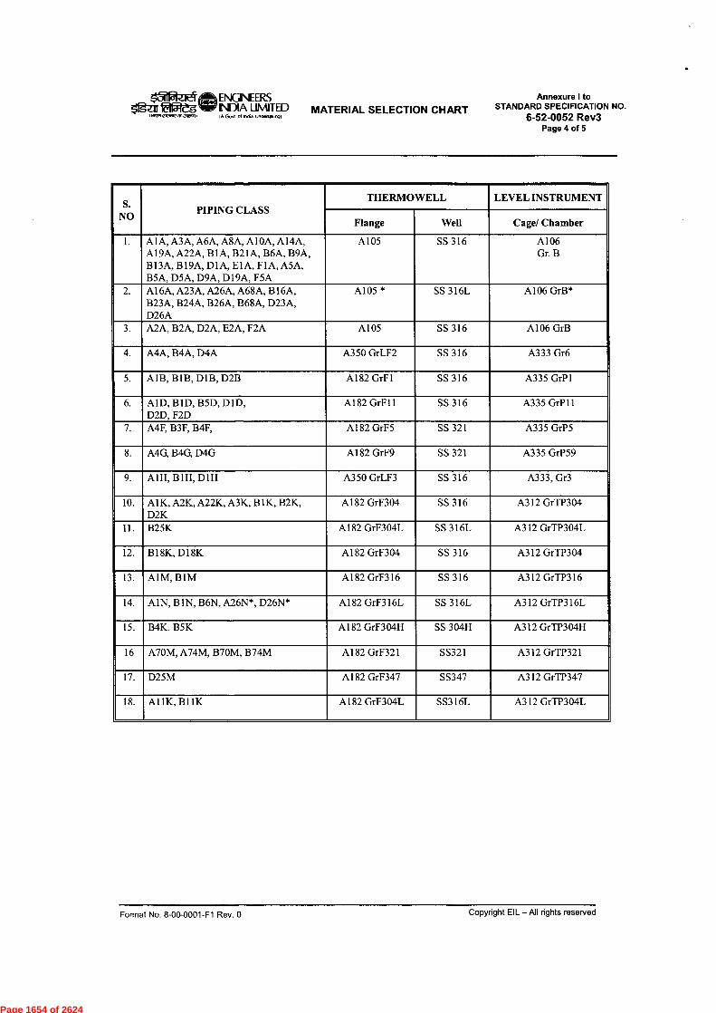
101 ifft ENGINEERSItgar ial5tegW INDIA LIMITED
IA Govl ol Inda Undertalorg)
Annexure I toSTANDARD SPECIFICATION NO.
6-52-0052 Rev3Page 4 of 5
MATERIAL SELECTION CHART1.27121OMOOnaOarfl,
S.NO
PIPING CLASSTHERMOWELL LEVEL INSTRUMENT
Flange Well Cage/ Chamber
A1A, A3A, A6A, A8A, Al OA, A14A,A19A, A22A, B1A, B21A, B6A, B9A,B13A, B19A, D1A, E1A, F1A, A5A,B5A, D5A, D9A, D19A, F5A
A105 SS 316 A106Gr. B
A16A, A23A, A26A, A68A, B16A,B23A, B24A, B26A, B68A, D23A,D26A
A105 * SS 316L A106 GrB*
A2A, B2A, D2A, E2A, F2A A105 SS 316 A106 GrB
A4A, B4A, D4A A350 GrLF2 SS 316 A333 Gr6
A1B, B1B, D1B, D2B A182 GrF1 SS 316 A335 GrP1
AID, B1D, B5D, D1D,D2D, F2D
A182 GrF11 SS 316 A335 GrP11
A4F, B3F, B4F, A182 GrF5 SS 321 A335 GrP5
A4G, B4G, D4G A182 GrF9 SS 321 A335 GrP59
A1H, B1H, D1H A350 GrLF3 SS 316 A333, Gr3
A1K, A2K, A22K, A3K, B 1K, B2K,D2K
A182 GrF304 SS 316 A312 GrTP304
B25K A182 GrF304L SS 316L A312 GrTP304L
B18K,D18K A182 GrF304 SS 316 A312 GrTP304
AIM, BIM A182 GrF316 SS 316 A312 GrTP316
AIN, BIN, B6N, A26N*, D26N* A182 GrF316L SS 316L A312 GrTP316L
15. B4K, B5K A182 GrF304H SS 304H A312 GrTP304H
16 A70M, A74M, B70M, B74M A182 GrF321 SS321 A312 GrTP321
D25M A182 GrF347 SS347 A312 GrTP347
AUK, B11K A182 GrF304L SS316L A312 GrTP304L
Format No. 8-00-0001-F1 Rev. 0 Copyright EIL - All rights reserved
Page 1654 of 2624
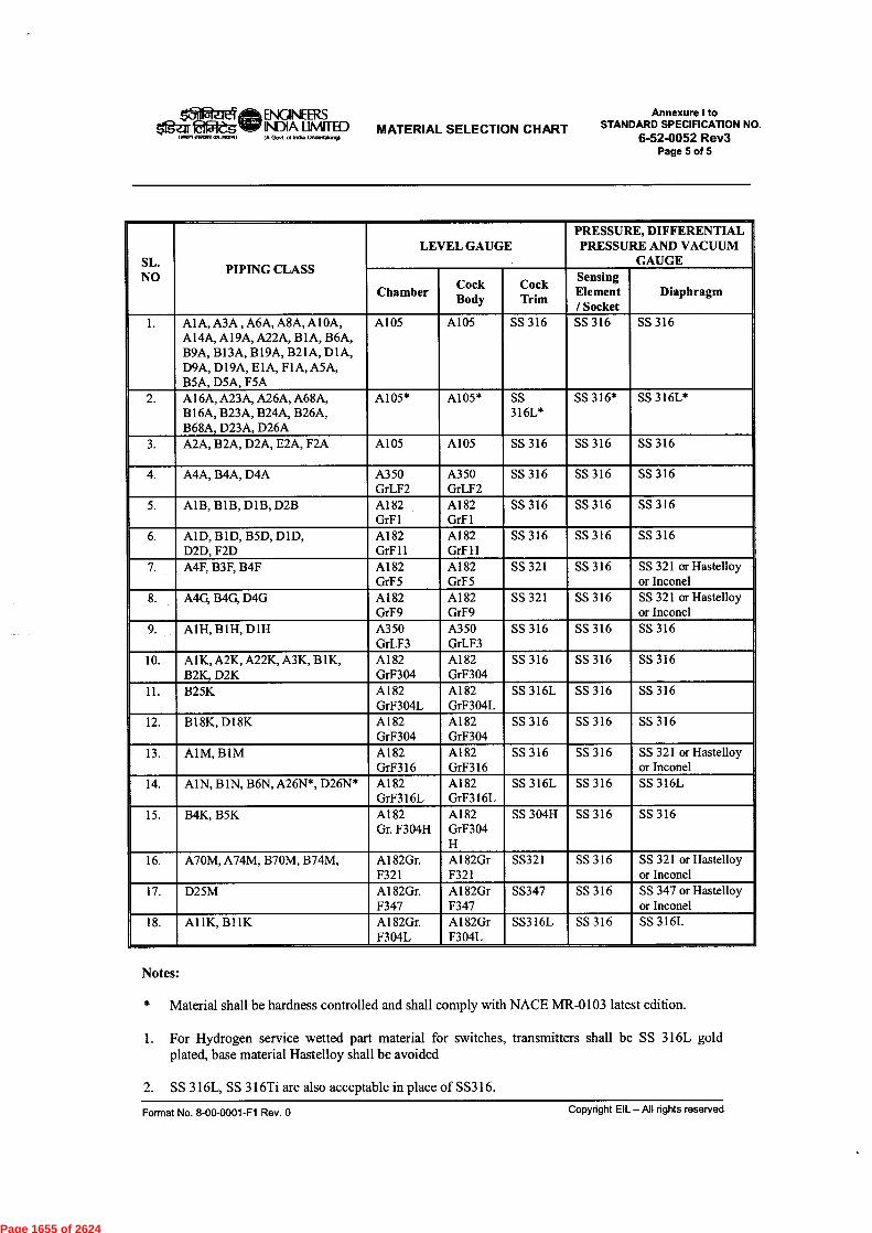
laffkle/ ift ENGINEERSOgeil Eifilegyr INDIA LIMITED
Govt ol India U.d.ak.n9)MATERIAL SELECTION CHART
Annexure ItoSTANDARD SPECIFICATION NO.
6-52-0052 Rev3Page 5 of 5
SL.NO PIPING CLASS
LEVEL GAUGEPRESSURE, DIFFERENTIALPRESSURE AND VACUUM
GAUGE
Chamber CockBody
CockTrim
SensingElement/ Socket
Diaphragm
Al A, A3A , A6A, A8A,A10A,A14A, A19A, A22A, B IA, B6A,B9A, B13A, B19A, B21A, D1A,D9A, D19A, E1A, F1A,A5A,BSA, D5A, F5A
A105 A105 SS 316 SS 316 SS 316
Al 6A, A23A, A26A, A68A,B16A, B23A, B24A, B26A,B68A, D23A, D26A
A105* A105* SS316L*
SS 316* SS 316L*
A2A, B2A, D2A, E2A, F2A A105 A105 SS 316 SS 316 SS 316
A4A, B4A, D4A A350GrLF2
A350GrLF2
SS 316 SS 316 SS 316
AlB, B1B, D1B, D2B A182GrF1
A182GrF1
SS316 SS316 SS316
AID, BID, B5D, DID,D2D, F2D
A182GrF11
A182GrF11
SS316 SS316 SS316
A4F, B3F, B4F A182GrF5
A182GrF5
SS 321 SS 316 SS 321 or Hastelloyor Inconel
A4G, B4G, D4G A182GrF9
A182GrF9
SS 321 SS 316 SS 321 or Hastelloyor Inconel
AlH, B1H, DIH A350GrLF3
A350GrLF3
SS 316 SS 316 SS 316
A1K,A2K, A22K,A3K, B1K,B2K, D2K
A182GrF304
A182GrF304
SS 316 SS 316 SS 316
B25K A182GrF304L
A182GrF304L
SS 3I6L SS 316 SS 316
B18K, D18K A182GrF304
A182GrF304
SS 316 SS 316 SS 316
AIM, BIM A182GrF316
A182GrF316
SS 316 SS 316 SS 321 or Hastelloyor Inconel
AIN, BIN, B6N, A26N*, D26N* A182GrF316L
A182GrF316L
SS 316L SS 316 SS 316L
B4K, B5K A182Gr. F304H
A182GrF304H
SS 304H SS 316 SS 316
A70M,A74M, B70M, B74M, A182Gr.F321
A182GrF321
SS321 SS 316 SS 321 or Hastelloyor Inconel
D25M A182Gr.F347
Al 82GrF347
SS347 SS 316 SS 347 or Hastelloyor Inconel
AUK, BlIK A182Gr.F304L
A182GrF304L
SS316L SS 316 SS 316L
Notes:
* Material shall be hardness controlled and shall comply with NACE MR-0103 latest edition.
For Hydrogen service wetted part material for switches, transmitters shall be SS 316L goldplated, base material Hastelloy shall be avoided
SS 316L, SS 316Ti are also acceptable in place of SS316.
Format No. 8-00-0001-F1 Rev. 0 Copyright EIL — All rights reserved
Page 1655 of 2624

15IPZEC (ft-- ENGINEERS STANDARD SPECIFICATION FOR$ fliAegW7- INDIA LIMITED PACKAGE UNITS
IA Govt al India UncleMO.9)
ANNEXURE4I TO STANDARDSPECIFICATION No.6-52-0052 Rev. 3
Page 1 of 9
ANNEXURE-Il
Format of Instrumentation Index
Format of Point Data Base
Format for Functional Schematics
Format For cable Schedule (Non-FF)
Format For cable Schedule (FF)
Format for Logic Diagram
Format for Electrical/Instrumentation interface
Format for FF instrument details
Format No. 8-00-0001-F1 Rev. 0 Copyright EIL — All rights reserved
Page 1656 of 2624

a.a.
Ca
XCD
g
-.?
0
Eo;..,
-,-rng
-F.g
,1'-1 .;f,,g.... '. .. 8 E ''e. `4 .0o cjj4.
,.. 73o •-;
a6
,..., i Z'-' Z
1/..
i '4" 61: -5 zcn `,..4
g
00 =°
= 1F
e2 6ea T.73 7.2 wl
o 5a - 6...: es Z3 ea
6zac.:,
-atco) 6as ZesCI0 ..2io.
6z
6 ,..o z C72 a >
fig g ..5-.4 .s
to.t.T.7
ooto0.
i0
36,
6eoza
E-•
Page 1657 of 2624

00
0
9
F
a
0
n2
•
2...
2 :
n
512
Page 1658 of 2624
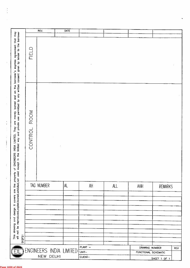
>, ..-m a)_c g
E5 0_0 -0
-a).-• .0C .....a)
0 20 I.-i_ 13.)
0" 17
0 C
0)WX2_' -0a. 0Xa) a)>co cr.'- ...--m3
cm
Oms._ co.- 0°
_oa> cr
0-.,L
c 3o >,a cc 0D x
a)C 1;1m0 -n-•O :'-'
Ex i-62_,_0E t)
z0I- 42)0 -5>, .>m r:
eL.cI-- .0
ci 5Lu1— >,m `i)LIas
Z € ee
z E(I) 0w =u., 4-Luz -c
Z a-ill E
4- X0 11'
>, -,i,,,C. 03CD0.0 -..).- 00- C
m .150r e_._13
a) a0
xQ)
CO -61- 00 C> 00 00 n
-0•-• W
'O.c 0O) 0
"f7) -60 0
-0 z0
-o 12c 1-20 a.
wo) ,--c_ q,
3 .c)0I-4.•0 0
C03 •-
...C- = U3I- i LI-N
cr)
REV. DATE
fp
0_J
Li....-
00CY
_J
0
Cri--.—z
0C..)
TAG NUMBER AL AH ALL AHH REMARKS
AM. PLANT — DRAWING NUMBER REV
EIL ENGINEERS INDIA LIMITED UNIT— FUNCTIONAL SCHEMATIC
NOW NEW DELHI CLIENT—SHEET 1 OF 1
Page 1659 of 2624

L->, a)_c 3-.0 oL...... ,0.c -0.....
a)c ....
EE 2a)C. 1.-I.- Q)0, -00 c
a)inco >,a) .0i..a_x ca) 0
>2) Ci,
1_0 c3 a)Om%._ c6- 8.0
c0 0-C -•-•
c i0
>,'0 CC 00 >,-oo .,,,,C ,0 -4-•0
1. a-a)E 1'wL Q)
v0
>n .>CO 0...
-CI-..0
W°8LLII– >,
0J3
Q00Z-E— =(.1) a)I:t .0W".-4.1Z .0Z.-.5 4-•Z CI-LLI CD,._ X0 g)>, ZL._ (0ID=0.0 4-•L. 0CL cCD 154,-C 4,..... :ao LEL- X0 Q)
CO .6I- 0C> 00 00 -
75.C 0,.( -6a) a>
0o-0c 20 cl.
a)0) i-c 0R _aoI_ .....-o octo:-E F InI– i c,-
>In
REV. DATE
a_II-J-J
0
......-.I
0
I—=
0C.)
TAG NUMBER AL AH ALL AHH REMARKS
Aill&D.
E- 11 7. ) ENGINEERS INDIA LIMITEDNEW DELI-II
PLANT — DRAWING NUMBER REV
UNIT— FUNCTIONAL SCHEMATIC
CLIENT— SHEET 1 OF 1
Page 1660 of 2624
uia_>-I-a.00_,
Z
oo
cS
;'I'"'
k'i
k'
0z2
tLe0
..7,
!7-
...,
gz es.is
g t ,sEi °
5 s .5i & 1,'1":/-
ti ..
i Imm
‘-,te &
P
3on3
m 9
3 ,1k E0 x.L ' • °5 .3-
o
tiji'
a.
ti g,
.2.
r ?.
i
1 fc0is g-e.:-..4',
3
gzg,5t
I 2 g
.c Fi i2
0z
z 1U
0 ui.7.- z5 ila u,
a,_z2=
1— xt,- ti 80 3 g
a a3 Z.
. 4
i 1 t—.z50.
—.-„,z50
CIw1--—
-J _< I— –I0 WZ O0IX IllLLI ZWZ(.9zw
E,
..4
I"
2-
'-•:-''
1E. E
i, tr .. E
,,,
V=
9
Page 1661 of 2624

m78-.-."Co'
m<--›-0.IVE1
ti-13
ga,t,,,, 1
o- n
g I, .I 1g a
11I
i 1 1 I e I
1 I
ig„1 3i gi c: 11,c pI i1 :
E3 r
1zir 1131 t
11;11q a11
I 1is I
zM*0
r-z—
M
zmMXc—z0
>r-K=Im0
-na3
r—owe
023ZID
o0C7 co c
Mc=5.CT
(1)
el.=
--I13co
CnP" CD
0CIF136
FT
(J)c3=cl)-.=.
tla
3
0
0=r.I. --I0—
0
0 acrCD
U)0=CDQ.CCD
M ,fa .
(7-7 a - o= f-g §x
= : g E
=o 2
z 0o ..
S.'9-
z
0—1
_1 c5 0 to
] o x
,<-0CD
01.1
MZZ
Ti71
cz7.-1
r-CD
325 ''
_,. -0 o K .r.— n)fi)cP..rt. 0- .7.-
CT
11111111111--T- P 2
•co
4wEII-P g
5an
z
00
a—X00
--..cncozo- —.-. a)OXA. ..
X
200,-, ••••3
-
cigwEP•
—I 53 z . P 5,
23
M-1
e IF, I
3
f),
g"'zP
9—m
C
F, §-co
--oz...... 0g
, CO-<
5z .,o g •
.5
00.0i--x*-0&zp
01X0Z F p z.,
.
>—0;91—
-, z CDP p
--I
30)
32geZ2
KF, a
(I_
a
*z0
Z
0la.r)fi @ZTP a
70CD3a)R- CA
Page 1662 of 2624
Lu-n
0
1.1W
11/ co
<<uz0t= 9<2ga
pl
6
CD
M
G z2.c)0 2.
6Z.13
23=
W.
a. M
0Z
<m-,
uia0°MIIII-co-,
m0o(X(3jix
Z00
z<
z0P.a2o
Øw0_1mc.)2
re0ct1_zo
I-Om-)
-,
2Oolc
.1-a..)......200ce8.28
1-LUzco—<0LLLLchU0U-Ja_coo
Z
°cc1..
0
0z0<F- iIll I--J 0M Z< iii0 -1
w0002LLI,--W-IM.:t0
• 0zre<o.
re01.-0Lu1—0rea.W0reCoCO....ctW_re<Im
ci20ct
awaCI.
9
—
a>O_,ui
.-n r r.) o- IN m cr <-I r4 rn V'
I I 1a-1 n4 m el. ..-1 ni m V' •• IN rfl .1.
ii 8 g
1 g 1.i.Eci dc2
LIII-
?z .....1/1-J
us-Jm<0m 01--<l-
V z
cous0CID
co --'—I—<0o
00w0us-Jma0
0zo<I—2omu..
0P..
,c:3us soauLa,oi-0.2I-
u o .0 0o ,„2 Fa'I- <- 0
Page 1663 of 2624
I—
Z
I-1-1X
LA
_1L.L.,
J0IX
Z0
_I<E
ZI—I1-1-
dzoa-
ciz00g.
Li05,:i
55
_lZ13
a <414C.,<4
A
01....100,-1
,_zLi'wd
-1CIcox›-cn
Z0I—I
I—
0_I—I
IXUV)LA
1=1
UI—I
l_D0_J
E
....U
g
I0
i
M64
1
NP.
i1
C.)
LA
U
>w1=1
LDZ
1--<DI—
0<
_J.asz)-(n 0
gra
U
i
m ,:t1-a i1- ixce, o, z0
cn _1
6 VO LA
zo
a
9
ciz0
0O
6I-
W6.=.)6>u
W <o E
0ZPiCE
IX -J
1 1
BgØzea
dZ
0QF-
ort x Lez-v SOS-Ii91 — 113JOMOIJOGI 914 01 Jopuoi oto dq uomb IUDSUOD IJONIJM AUD poqmwied ion 91DA/Jd pUD ADM mum otn UI visoxo pawl lou 'pommqxo 'pouooi 'po!doo 'p000poicloi oq ;ou
tog logy luouJooJBo 1190JdX9 9-19/A0JJOU ayl pUD pouool AIMMILLI 9JD 941 "alunn VION1 SH33NION3 APodcud eta JD 9.19A00 ufqoop Dip puo buunuP ;NI
Page 1664 of 2624

.e 2"6 .4,1
e••
0
E
0
E
0.
t soa
00
es.0
000
89
z
0 U00 §
O
`6'
0zro
.<
3
0
00
oS 2
2 t
zE.
1
Cl)
U
dz
6."5 0
Z
z
1;'
00
a
E
LL
pi•
Page 1665 of 2624
F
-1r000Z
ILI ..c15
0aaXI
o 5.1.aI22 m> cv-Ia
g0(2.i3..c3
aa
xa.F.E0
... 0 i-9.
=m.0. 0...0cro
fm2- o* a_-.,1 liag51.
a5cr to
C593agel
r43
o03,3g0a8.3 -I5.01e aCDiita.
.-aaa84:t23P.
c.5ZICTa5co
a0g1
55-' 5rn 5.-'m Q. *a
a55-.0P..Ig. °3§•;!.3,.ake"-„,88a§.5'a5gs.gidIco
5
89.\n 3.ai5am
2 cig,c4--rj,a:t D >...0
0.E or.0cg5--gsi .g..
2,t5cr2o. m''59,,
5craca••ZFr;
''cg2 II .
m:cog
8a5?a;2a3
Q :i 2,,3",a't%'aaid8i Icii..z-4o. eo
co—a
3 aa5a,5.
a5'gsca.a0
0ai:gv-g.gI ....CIag:g0
t ag550g5"(1)r...1
af, s--Fi03 a5ao05... a-6-05 II.1!"5"..
5J
a.,„-aen
itca.t
2,35EnS
'80a. e.
.acr811Z' aF.E0 . 55 53co0a0II7.
-8g
5a
at"1a
a aO.a a1
a,I.3II.'3
530...0 ,=a e738
=',Itaa2 .13.-2,g
_q'*.:0.-coit1
a-0
2ifiqsaRi6
;..Z
?10Cn-8XI oo•7-CI.3
eo
9.10
-, -.4, 0,
-. _.-4 01
_. _.01 A
-33-J.C339..1-•
-a -n0<0 Co-.I 03C73 A43 f0
cnZo
-.Zco
Z 8-g 3It. 5
o.8
CaE5o
08
a
0z2F.' m
3z.
0-0- 0iiia-: *
0$if
,..e2
C
aC)
1a
730 < 01W s.5' 2 a
aa73
3am-11XI m1
g
a.0 „,g.- a
f(q ,33 g.2.
-n-ng
1 1a8A-11 -11LT
r-0 aa
cY.-n-II
c ;
.885
7..<3
a0*.7>r.araafro=a,
Page 1666 of 2624
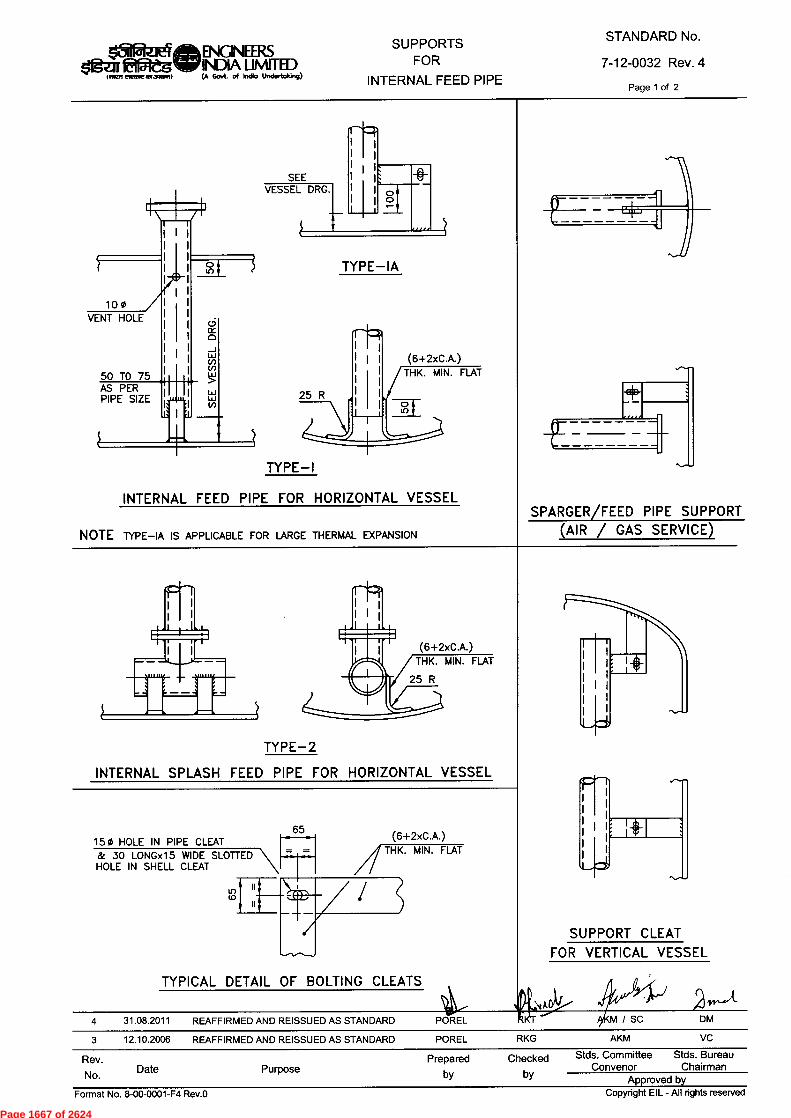
(6+2xC.A.)THK. MIN. FLAT
25 R
65 (6+2xC.A.)THK. MIN. FLAT
15 0 HOLE IN PIPE CLEAT & 30 LONGx15 WIDE SLOTTEDHOLE IN SHELL CLEAT
(6+2xC.A.)THK. MIN. FLAT
SUPPORT CLEAT FOR VERTICAL VESSEL
Rev.No. Date Purpose
Prepared Checkedby by
Stds. Committee Stds. BureauConvenor Chairman
Approved by
laftetitErsiGINEaSdgar faMegvir INDIA UMIT1ED
INET! meow =mom) to Govt. of India Undertaking)
SUPPORTSFOR
INTERNAL FEED PIPE
STANDARD No.7-12-0032 Rev. 4
Page 1 of 2
TYPE—IA
SEE VESSEL DRG. 00
100VENT HOLE
50 TO 75AS PERPIPE SIZE
£I I '•
TYPE-1
INTERNAL FEED PIPE FOR HORIZONTAL VESSEL
NOTE TYPE—IA IS APPLICABLE FOR LARGE THERMAL EXPANSION
SPARGER/FEED PIPE SUPPORT (AIR / GAS SERVICE)
TYPE-2 INTERNAL SPLASH FEED PIPE FOR HORIZONTAL VESSEL
TYPICAL DETAIL OF BOLTING CLEATS
4 31.08.2011 REAFFIRMED AND REISSUED AS STANDARD POREL3 12.10.2006 REAFFIRMED AND REISSUED AS STANDARD POREL RKG
Format No. 8-00-0001-F4 Rev.0 Copyright EIL - All rights reserved
Page 1667 of 2624

SHELL
TS
20 MIN.
REINFORCEMENT PAD L(NOTE-6)
10 N•F
0.5GIf)
11I I
D (NB) 50
3MMCLEARANCE
REINFORCEMENT PAD(NOTE-6)
TYPE—A(FOR PIPES UPTO 250NB)
lig ILIANifAsam(A Govt. of Indio Undertaking)
SUPPORTSFOR
INTERNAL FEED PIPE
STANDARD No.
7-12-0032 Rev. 4Page 2 of 2
TYPE—B(FOR PIPES ABOVE 250NB)
INTERNAL FEED PIPE FOR VERTICAL VESSEL/COLUMN
PIPE N.B. BOLT SIZET
E F GCA=O CA=1.5D CA=3 CA=5 CA=7
50 — 80 M 12 6 10 12 16 20 60 40 60
100 — 200 M 16 10 14 16 20 25 100 50 100
250 — OVER M 16 14 18 20 25 28 150 100 150
NOTESALL DIMENSIONS ARE IN mm UNLESS OTHERWISE STATED.IN CASE OF CONFLICT VESSEL ENGG. DRAWING SHALL GOVERN.MATERIAL OF CLEATS SHALL BE AS PER VESSEL ENGG. DRAWING.ALL FILLET WELDS TO BE ALL AROUND & SIZE OF WELDS ARE (6+1xC.A.) MINIMUM UNLESS OTHERWISE STATED.ALL INTERNAL BOLTS SHALL BE MIN. M 12 SIZE AND OF STAINLESS STEEL WITH DOUBLE NUTS.REINFORCING PAD SHALL BE LARGER BY 50mm ALL AROUND THAN BRACKET CLEATS. NO PAD IS REQUIRED FORVESSELS WITH WALL THICKNESS GREATER THAN 25mm.
)?•./ 4 31.08.2011 REAFFIRMED AND REISSUED AS STANDARD POREL K 4/KM / SC DM
3 12.10.2006 REAFFIRMED AND REISSUED AS STANDARD POREL RKG AKM VC
Rev.No. Date Purpose
Prepared Checkedby by
Stds. Committee Stds. BureauConvenor Chairman
Approved by Format No. 8-00-0001-F4 Rev.O
Copyright EIL - All rights reserved
Page 1668 of 2624
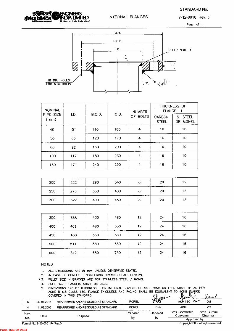
STANDARD No.
7-12-0018 Rev. 5Page 1 of 1
INTERNAL FLANGESOM/IENGNEERSNDIA UMRED(A Govt. of India Undertaking)
O.D.
B.C.D.
I.D. REFER NOTE-4
18 DIA. HOLESFOR M16 BOLTS
NOMINALPIPE SIZE
(mm)I.D. B.C.D. O.D. NUMBER
OF BOLTS
THICKNESS OFFLANGE t
CARBONSTEEL
S. STEELOR MONEL
40 51 110 160 4 16 10
50 63 120 170 4 16 10
80 92 150 200 4 16 10
100 117 180 230 4 16 10
150 171 240 290 4 16 10
200 222 290 340 8 20 12
250 276 350 400 8 20 12
300 327 400 450 8 20 12
350 358 430 480 12 24 16
400 409 480 530 12 24 16
450 460 530 580 12 24 16
500 511 580 630 12 24 16
600 612 680 730 12 24 16
NOTESALL DIMENSIONS ARE IN mm UNLESS OTHERWISE STATED.IN CASE OF CONFLICT ENGINEERING DRAWING SHALL GOVERN.
* 3. FILLET SIZE IN BRACKET ARE FOR STAINLESS STEEL / MONEL.FULL FACED GASKETS SHALL BE USED.DIMENSIONS EXCEPT THICKNESS FOR INTERNAL FLANGES OF SIZE 25NB OR LESS SHALL BE AS PERASME 816.5 CLASS 150. FLANGE THICKNESS AND FACING SHALL BE EQUIVALENT TO 4 NB LANGECOVERED IN THIS STANDARD.
5 30.07.2011 REAFFIRMED AND REISSUED AS STANDARD POREL4 11.09.2006 REAFFIRMED AND REISSUED AS STANDARD POREL DNN
Rev. Prepared CheckedNo. Date Purpose by by
2 14-4AK / SC '' DM
AKM VCStds. Committee Stds. Bureau
Convenor Chairman Approved by
Copyright EIL - All rights reservedFormat No. 8-00-0001-F4 Rev.0
Page 1669 of 2624
ENGINEERS INSPECTION AND TEST PLAN
STANDARD SPECIFICATION No.
$1=g-ZIE fa5le'S.
INDIA LIMITED
FOR
6-81-0009 Rev. 3 IA Govt of India Undertaking)
HEAT EXCHANGERS Page 1 of 7
c 1-1
fiteTur trtuur EW-9-r
INSPECTION AND TEST PLAN FOR
HEAT EXCHANGERS
Cbt -Y-L-
3 09.09.2013 REVISED AND RE-ISSUED TKK G DM
2 15.07.2011 REVISED AND RE-ISSUED HP SCG AKC DM
1 25.10.2005 GENERAL REVISION TSSR PRV SY VC
0 01.11.02 ISSUED FOR IMPLEMENTATION NKN SPS AKB GRR
Rev. No. Date Purpose Prepared
by Checked
by
Standards Committee Convenor
Standards Bureau Chairman
Approved by
Format No. 8-00-0001-F7 Rev. 0 Copyright EIL — All rights reserved
Page 1670 of 2624
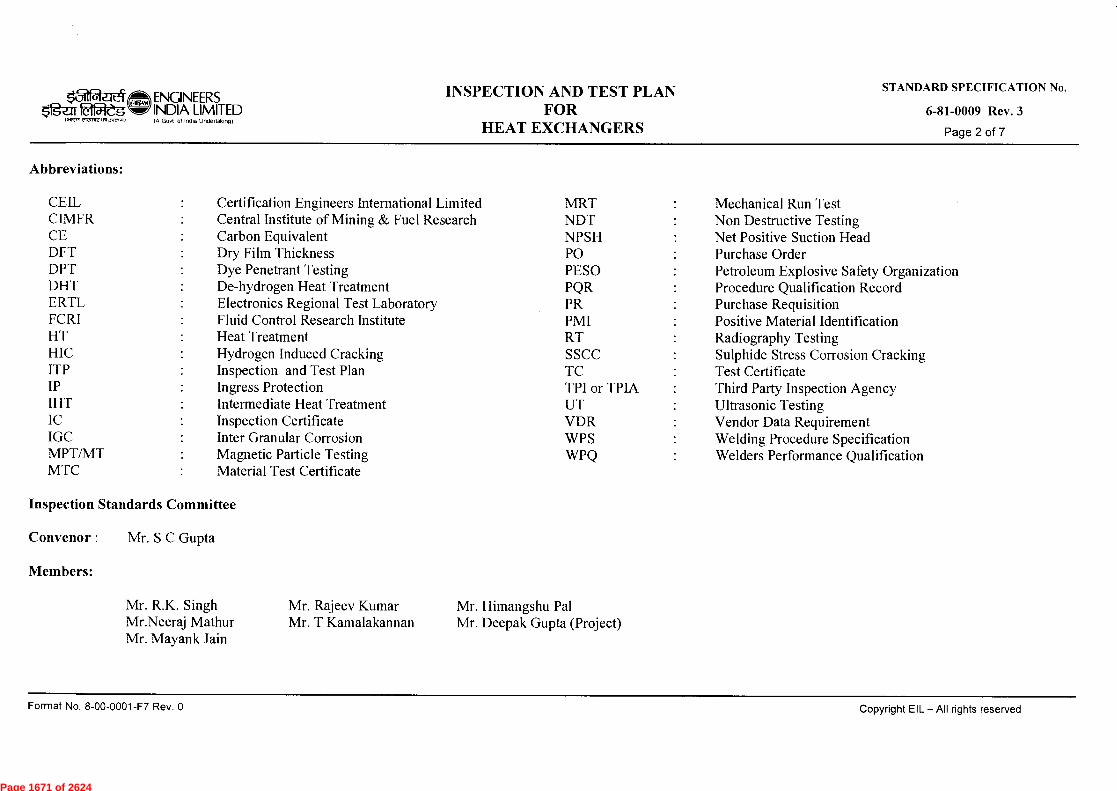
$1g-ez 051-eg ,4-17R rieoxecrINCI5.0
ENGINEERS INDIA LIMITED IA Goof of India Undertaking)
INSPECTION AND TEST PLAN FOR
HEAT EXCHANGERS
STANDARD SPECIFICATION No.
6-81-0009 Rev. 3
Page 2 of 7
Abbreviations:
CEIL Certification Engineers International Limited MRT Mechanical Run Test CIMFR Central Institute of Mining & Fuel Research NDT Non Destructive Testing CE Carbon Equivalent NPSH Net Positive Suction Head DFT Dry Film Thickness PO Purchase Order DPT Dye Penetrant Testing PESO Petroleum Explosive Safety Organization DHT De-hydrogen Heat Treatment PQR Procedure Qualification Record ERTL Electronics Regional Test Laboratory PR Purchase Requisition FCRI Fluid Control Research Institute PMI Positive Material Identification HT Heat Treatment RT Radiography Testing HIC Hydrogen Induced Cracking SSCC Sulphide Stress Corrosion Cracking ITP Inspection and Test Plan TC Test Certificate IP Ingress Protection TPI or TPIA Third Party Inspection Agency IHT Intermediate Heat Treatment UT Ultrasonic Testing IC Inspection Certificate VDR Vendor Data Requirement IGC Inter Granular Corrosion WPS Welding Procedure Specification MPT/MT Magnetic Particle Testing WPQ Welders Performance Qualification MTC Material Test Certificate
Inspection Standards Committee
Convenor : Mr. S C Gupta
Members:
Mr. R.K. Singh
Mr. Rajeev Kumar Mr. Himangshu Pal Mr.Neeraj Mathur
Mr. T Kamalakannan Mr. Deepak Gupta (Project) Mr. Mayank Jain
Format No. 8-00-0001-F7 Rev. 0
Copyright EIL — All rights reserved
Page 1671 of 2624
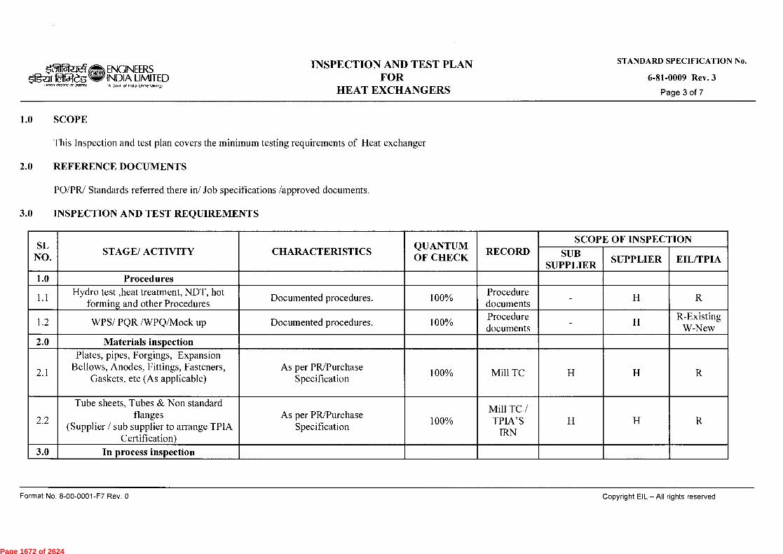
k_71 ENGINEERS INSPECTION AND TEST PLAN
STANDARD SPECIFICATION No.
tiff INDIA LIMITED
FOR
6-81-0009 Rev. 3 IA Govt of India Undertaking)
HEAT EXCHANGERS
Page 3 of 7
1.0 SCOPE
This Inspection and test plan covers the minimum testing requirements of Heat exchanger
2.0 REFERENCE DOCUMENTS
PO/PR/ Standards referred there in/ Job specifications /approved documents.
3.0 INSPECTION AND TEST REQUIREMENTS
SL NO.
STAGE/ ACTIVITY CHARACTERISTICS QUANTUM OF CHECK
RECORD SCOPE OF INSPECTION
SUB SUPPLIER
SUPPLIER EIL/TPIA
1.0 Procedures
1.1 Hydro test ,heat treatment, NDT, hot forming and other Procedures Documented procedures. 100%
Procedure documents
- H R
1.2 WPS/ PQR /WPQ/Mock up Documented procedures. 100% Procedure documents
- H R-Existing
W-New
2.0 Materials inspection
2.1
Plates, pipes, Forgings, Expansion Bellows, Anodes, Fittings, Fasteners,
Gaskets, etc (As applicable) As per PR/Purchase
Specification 100% Mill TC H H R
2.2
Tube sheets, Tubes & Non standard flanges
(Supplier / sub supplier to arrange TPIA Certification)
As per PR/Purchase Specification
100% Mill TC / TPIA'S
IRN H H R
3.0 In process inspection
Format No. 8-00-0001-F7 Rev. 0
Copyright EIL — All rights reserved
Page 1672 of 2624
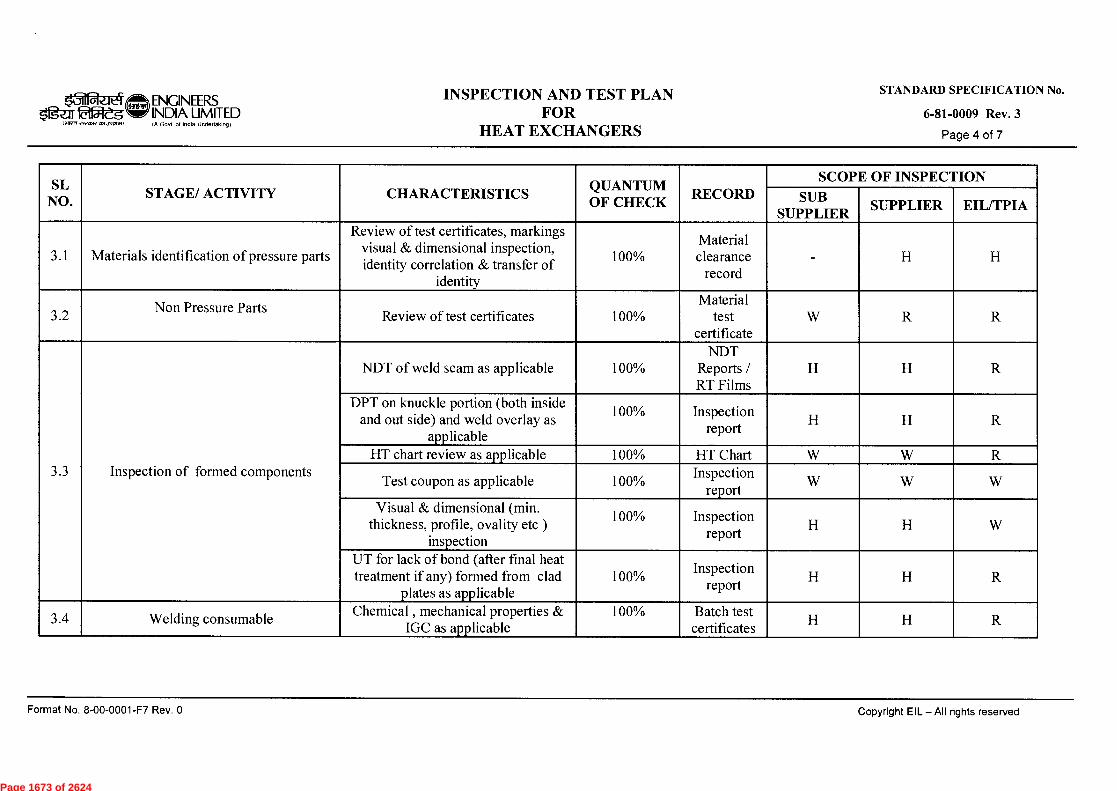
ei ENGINEERS INDIA LIMITED
• I el eage Z1,1 IA Govt of India Undertaking)
STANDARD SPECIFICATION No.
6-81-0009 Rev. 3
Page 4 of 7
INSPECTION AND TEST PLAN FOR
HEAT EXCHANGERS
SL NO.
STAGE/ ACTIVITY CHARACTERISTICS QUANTUM OF CHECK
RECORD SCOPE OF INSPECTION
SUB SUPPLIER
SUPPLIER EIL/TPIA
3.1 Materials identification of pressure parts
Review of test certificates, markings visual & dimensional inspection, identity correlation & transfer of
identity
100% Material clearance
record - H H
3.2 Non Pressure Parts
Review of test certificates 100% Material
test certificate
W R R
3.3 Inspection of formed components
NDT of weld seam as applicable 100% NDT
Reports / RT Films
H H R
DPT on knuckle portion (both inside and out side) and weld overlay as
applicable
100% Inspection report
H H R
HT chart review as applicable 100% HT Chart W W R
Test coupon as applicable 100% Inspection
report W W W
Visual & dimensional (min. thickness, profile, ovality etc )
inspection
100% report
Inspection H H W
UT for lack of bond (after final heat treatment if any) formed from clad
plates as applicable 100%
report
Inspection H H R
3.4 Welding consumable Chemical , mechanical properties &
IGC as applicable 100% Batch test
certificates H H R
Format No. 8-00-0001-F7 Rev. 0
Copyright EIL —All rights reserved
Page 1673 of 2624
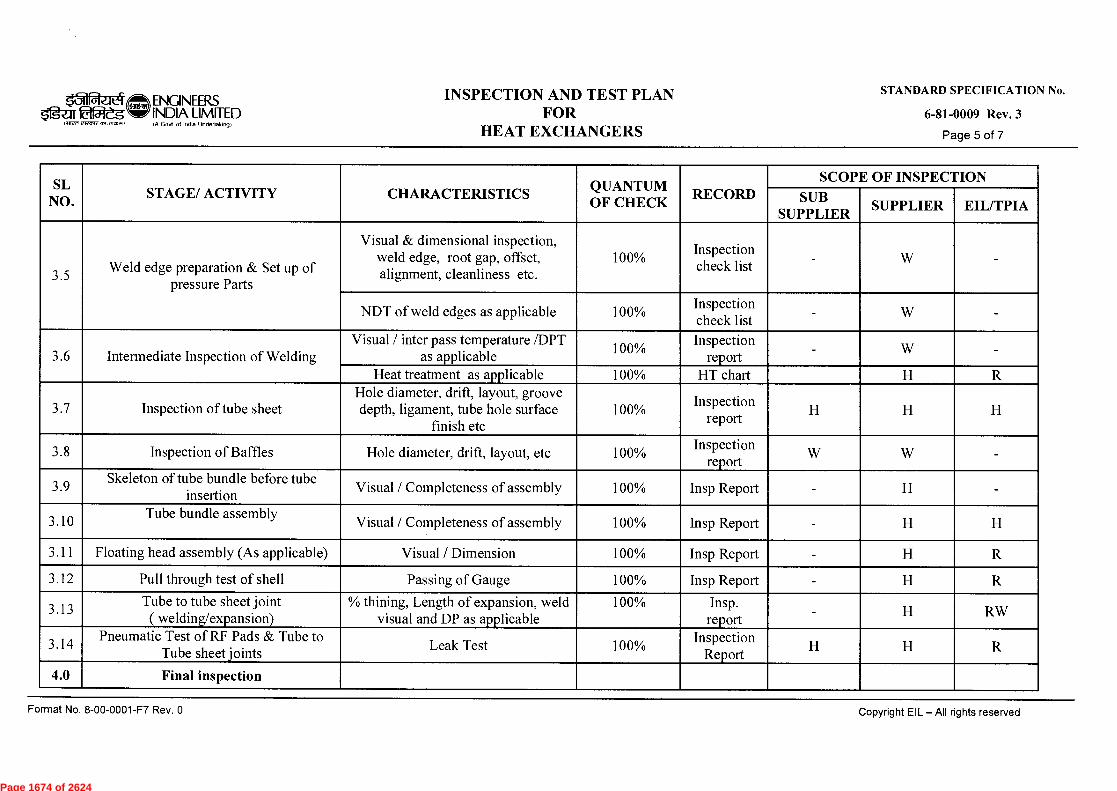
rwart ..3mcn.o
STANDARD SPECIFICATION No.
6-81-0009 Rev. 3
Page 5 of 7
4oi ENGINEERS 51gar 25:leg INDIA LIMITED
IA Govt of India Undertaking)
INSPECTION AND TEST PLAN FOR
HEAT EXCHANGERS
SL NO.
STAGE/ ACTIVITY CHARACTERISTICS QUANTUM OF CHECK
RECORD SCOPE OF INSPECTION
SUB SUPPLIER
SUPPLIER EIL/TPIA
3.5 Weld edge preparation & Set up of
pressure Parts
Visual & dimensional inspection, weld edge, root gap, offset, alignment, cleanliness etc.
100% Insp Inspection check list
- W
NDT of weld edges as applicable 100% Inspection Insp check list
- W -
3.6 Intermediate Inspection of Welding Visual / inter pass temperature /DPT
as applicable 100 % Inspection
report - W -
Heat treatment as applicable 100% HT chart H R
3.7 Inspection of tube sheet Hole diameter, drift, layout, groove depth, ligament, tube hole surface
finish etc 100%
report
Inspection H H H
3.8 Inspection of Baffles Hole diameter, drift, layout, etc 100% Inspection Insp
report W W -
3.9 Skeleton of tube bundle before tube
insertion Visual / Completeness of assembly 100% Insp Report - H -
3.10 Tube bundle assembly Visual / Completeness of assembly 100% Insp Report - H H
3.11 Floating head assembly (As applicable) Visual / Dimension 100% Insp Report - H R
3.12 Pull through test of shell Passing of Gauge 100% Insp Report - H R
3.13 Tube to tube sheet joint ( welding/expansion)
% thining, Length of expansion, weld visual and DP as applicable
100% Insp. report
- H RW
3.14 Pneumatic Test of RF Pads & Tube to Tube sheet joints Leak Test 100%
Inspection Report
H H R
4.0 Final inspection
Format No. 8-00-0001-F7 Rev. 0
Copyright EIL — All rights reserved
Page 1674 of 2624

ENGINEERS INSPECTION AND TEST PLAN
STANDARD SPECIFICATION No.
ligaroot,cg w INDIA LIMITED
FOR
6-81-0009 Rev. 3 1.11VM el,M1.1151,PRISTI1
IA Govt 01 Ind. Undertaking)
HEAT EXCHANGERS Page 6 of 7
SL NO.
STAGE/ ACTIVITY CHARACTERISTICS QUANTUM OF CHECK
RECORD SCOPE OF INSPECTION
SUB SUPPLIER
SUPPLIER EIL/TPIA
4.1
Visual and dimensional inspection (internals & externals) including welds of shell, channel shell, shell cover shell
etc. (before PWHT as applicable)
Visual/ dimensions, completeness of assembly and weld visual for
reinforcement, undercuts, Surface defects, etc.
100% Inspection
report - H H
4.2 PMI as applicable Chemical check Each
component and weld
Inspection report
- H R
4.3 Inspection of completed welds
PWHT as applicable 100% HT chart H R
NDT as applicable Spot/100% NDT report / RT films
- H R
Production test coupon testing as applicable
as per specification /
drawing
Inspection report
- H H
Weld chemical for undiluted chemistry as applicable
Each component
for each welding process.
Inspection report
- H R
Hardness for weld /HAZ as applicable
As per spec. Inspection
report H RW
4.4 Hydrostatic test (As applicable) Leak check 100% Inspection
report - H H
4.5 Drying and nitrogen filling Visual/ gas pressure 100% Inspection
report - W -
Format No. 8-00-0001-F7 Rev. 0
Copyright EIL — All rights reserved
Page 1675 of 2624

ENGINEERS INSPECTION AND TEST PLAN
STANDARD SPECIFICATION No.
$1g-af faiteg INDIA LIMITED
FOR
6-81-0009 Rev. 3 erterr,
IA Gcnit of India Undertaking)
HEAT EXCHANGERS
Page 7 of 7
SL NO. STAGE/ ACTIVITY CHARACTERISTICS
QUANTUM OF CHECK
RECORD SCOPE OF INSPECTION
SUB SUPPLIER SUPPLIER EIL/TPIA
5.0 Painting
5.1 Final painting (As applicable)
Visual inspection (after surface preparation and final painting for workmanship, uniformity) DFT
check
100% Inspection
report - H
6.0 Documentation and IC
6.1 Final stamping, review of inspection documents and issue of IC
Verifying stamping details and review of inspection documents
100% IC /
Inspection reports
- H H
6.2 Final documents as per PR Verification & compilation of inspection & test records for
submission to customer 100%
Final dossier
- H H
Legend: H- Hold (Do not proceed without approval), P-Perform, RW - Random Witness (As specified or 10% ( min.1 no. of each size and type of Bulk item)), R-Review, W-Witness (Give due notice, work may proceed after scheduled date).
NOTES (As applicable► :
1. This document describes the generic test requirements. Any additional test or Inspection scope if specified in contract documents shall also be applicable. (Unless otherwise agreed upon)
2. Acceptance Norms for all the activities shall be as per PO/PR/STANDARDS referred there in /Job Specification /Approved Documents.
Format No. 8-00-0001-F7 Rev. 0
Copyright EIL — All rights reserved
Page 1676 of 2624

WELD UNENOTCH TOCLEAR WELD
TANGENT UNE
6mm THK. COVERPLATE
Y
S./
O00_to
O
w
HOLE DIA = BOLT DIA +
6rnn\ 91-11-E
diaMO
ENGINMS
INDIA UMMEDIA Govt. of India Undertaking)
PIPE LEG SUPPORTSTANDARD No.7-12-0007 Rev. 5
Page 1 of 1
NOTESALL DIMENSIONS ARE IN mm UNLESS OTHERWISE STATED.FOR DESIGN OF SUPPORT, FOLLOWINGS PARAMETERS HAVE BEEN CONSIDERED.
WIND PRESSURE 200 Kg/m2SHAPE FACTOR 0.7BASIC SEISMIC CO—EFFICENT (a0) 0.08SOIL FOUNDATION SYSTEM FACTOR ( /3 ) 1.5IMPORTANCE FACTOR (I) 2.0EMPTY WEIGHT WITH WIND LOADING OR HYDROSTATIC WEIGHTWITH SEISMIC LOADING.
HEIGHT AND NUMBER OF LEG SUPPORTS AND SIZE OF ANCHOR BOLTSSHALL BE AS PER ENGINEERING DRAWING.MINIMUM BOLT SIZE SHALL BE M 20.MAXIMUM INSULATION THICKNESS CONSIDERED IS 150 mm.IN CASE OF CONFLICT ENGINEERING DRAWING SHALL GOVERN.ALL FILLET WELDS SHALL BE 6 mm MINIMUM.MATERIALS SHALL BE AS PER ENGINEERING DRAWING.EARTHING LUG SHALL BE AS PER STANDARD 7-12-0026.SUITABLE PAD FOR SS VESSEL SHALL BE PROVIDED.
SUPPORT BASE DETAIL
LEG PIPE SIZE A B C E tMAXIMUM ALLOWABLE LOAD PER LEG (Kgs)MAXIMUM HEIGHT OF SUPPORT (L) IN METERS
2.0 2.5 3.050NB x EXTRA STRONG 120 230 140 36 20 2300 2050 1800
80NB x EXTRA STRONG 180 250 160 36 25 5700 5500 4900
100NB x EXTRA STRONG 230 310 185 42 25 9000 8600 8300
150NB x EXTRA STRONG 320 370 235 44 25 18500 18000 17500
0--645 30.06.2011 REAFFIRMED AND REISSUED AS STANDARD POREL KT
KM/SC DMAKM VC
4 08.09.2006 REAFFIRMED AND REISSUED AS STANDARD POREL DNN
Rev.No. Date Purpose
Prepared Checkedby by
Stds. Committee Stds. BureauConvenor Chairman
Approved by Format No. 8-00-0001-F4 Rev.O Copyright EIL - All rights reserved
Page 1677 of 2624

REDUCER 50 DIA. G.I. PIPE (MEDIUM)
Page 1 of 1
LIGHTING FIXTURE
MOUNTING HEIGHT
(30° IF MOUNTING HEIGHT IS MORE THAN 5 METRES)
REDUCER 50/25 AND 25 DIA. NIPPLE
WEATHER PROOF JUNCTION BOX (SEE DETAIL-1)
M.S. CLAMPS
WALL OR COLUMN
0 0
0 o to
/--- REDUCER 50/25 AND 25 DIA. NIPPLE
iUSE CABLE GLANDS FOR CABLE WIRING (SEE NOTE-2)
WIRES IN G.I. PIPE
CONDUIT OR CABLE
COVER FIXED WITH BRASS MACHINE SCREWS
DETAIL-1 JUNCTION BOX (WEATHER PROTECTED)
Format No. 8-00-0001-F4 Rev.0
FA/SA UAP/JMS DM 15.12.08 REAFFIRMED & ISSUED AS STANDARD BP RKS/NS
Rev.
No.
17.07.13 REAFFIRMED & ISSUED AS STANDARD
Date Purpose Prepared
by Checked
by
Stds. Committee Stds. Bureau Convenor Chairman
Approved by Copyright EIL - All riahts rpnprvori
JMS VC
k74 11 1r Braes
1.11FR Fet,re 2613,PA1Ji)
ENGINEERS TYPICAL INSTALLATION OF INDIA LIMITED WEATHER PROOF LIGHT FIXTURE
STANDARD No.
7-51-0224 Rev.4 (A Govt. of India Undertaking)
MOUNTED ON WALLS OR COLUMNS
NOTES:- 1. ALL DIMENSIONS ARE IN MM. 2.
PROPER SEALING SHALL BE ENSURED TO PREVENT INGRESS OF WATER. 3.
WHERE FIRE PROOFING COLUMNS / STRUCTURES ARE ENCOUNTERED RECEPTACLE, JUNCTION BOX AND CABLE SHALL BE INSTALLED ON A SUITABLE DEEP LEGGED ANGLE IRON FRAME / DISTANCE BRACKET.
Page 1678 of 2624
Page 1679 of 2624

Page 1680 of 2624
Page 1681 of 2624

Page 1682 of 2624
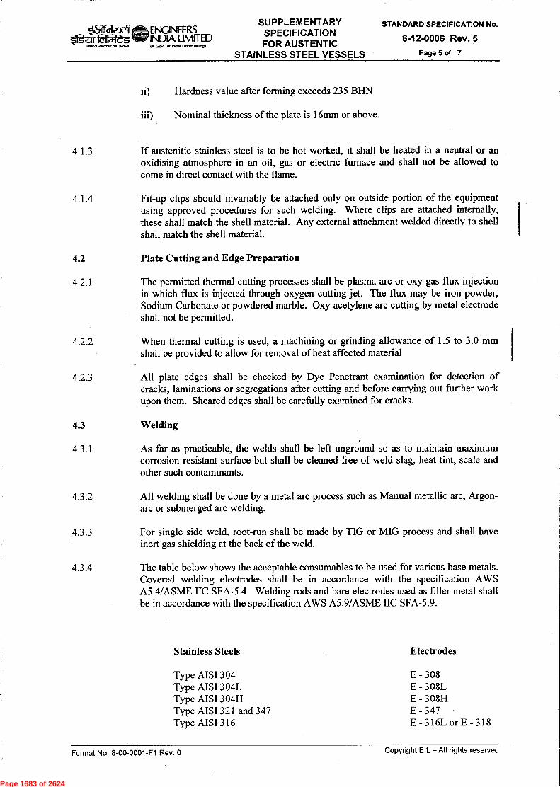
Page 1683 of 2624

Page 1684 of 2624

Page 1685 of 2624
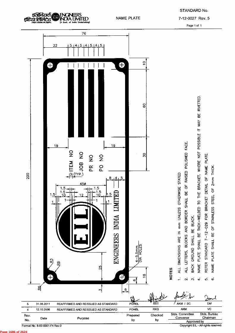
Rev.No. Date Purpose
Prepared Checkedby by
Stds. Committee Stds. BureauConvenor Chairman
Approved byCopyright EIL - All rights reservedFormat No. 8-00-0001-F4 Rev.0
6
"CE
co
6 . . z 1-Li,I- u_ E< Y 01- E0
1
ce Ztm
1
C.) Li -4Z
CD 6 C■1°)
1—
< o LL.
Lo 1-- 1 o
cr)
_J
w —_1 CD CO
< _1 N _1
co N Li,
1
2 J _1V) < 0 <
I CC I0 V-) < (1)Z 0
0
o Lu Z WW..
1-- <
ix ,- nV0 CL 0_
crY L.L1 L.Li LO
<CC ) <2 1 - 1 ..1L 1 "iCO Z O Z
< —.1 csj
L1— ,_ww
occ
oI _1
w 1— 1—w Ww
I-o T0 Y i—I- 0 v)
N
_I(/) _1MI <
0Z .— C■I ri 4 6 tO
aw 0 IX V)tr) L.LI CO U)La 0 w_1 __I Ix _I
D o
04.0 ,,11. ^44.4)
2
//Vvt'4
KT AKM / SC DM
RKG AKM VC
5 31.08.2011 REAFFIRMED AND REISSUED AS STANDARD POREL
4 12.10.2006 REAFFIRMED AND REISSUED AS STANDARD POREL
EEZ aww<
(/)Z0U)
WwmE
NAME PLATEINIURFIEVWC1X3,111.1.1)
STANDARD No.
7-12-0027 Rev. 5
Page 1 of 1
18iatER7 ENGINEERS,Igej. &Aft INDIA LIMITED
(A Govt. of Indio Undertaking)
Page 1686 of 2624
Page 1687 of 2624

Page 1688 of 2624

Page 1689 of 2624

Page 1690 of 2624

Page 1691 of 2624

+0.0
REFER PARA 3.121 dc 3.122 OF TEMA
±3 ADDITION NO LONGITUDIANAL ELEMENT OF THE INSIDE SURFACE SHALL HAVE A BOW OF MORE THAN 1mm. PER METRE OF LENGTH UP TO MAX. OF 3mm.
Format No. 8-00-0001-F4 Rev.O Copyright EIL - All rights reserved
1 _
Mo
±3
ENCNEERS UMITFD
11111.11.1•1111~10 (A Govt. of India Undertoking)
±16
TOLERANCES
(SHELL & TUBE EXCHANGERS)
±6
STANDARD No.
7-15-0019 Rev. 4
Page 1 of 3
±3
±3
fn0 + I
LIGAMENT BETWEEN HOLES WILL BE SAME AS LIGAMENT BETWEEN HOLES IN TUBE SHEET ( AS PER TEMA )
±6
±1.5 FOR EXPANDED I
+1
FOR WELDED
3
+0.8 —0.
to
-H
-...JMPINGEMENT PIATE
E—A
+0.8 —0.0
±0.8
±6(MAX.) (NOTE-4)
iqg +l
SECTION—AA
U—TUBE BUNDLE OVERALL LENGTH ±12
+0.8 —0.0
±3
BAFFLE
TAKE (-1 TOLERANCE WHEN TAKE (+) TOLERANCE WHEN CUT IS ON THE ( OF TUBES re=5_11U2EMEEILT±LE=
DETAIL—B TUBE SHEET / (TYPICAL) .Q1:16fflELSME13
Rev.
No. Date Purpose
4 06.05.14 REAFFIRMED AND REISSUED AS STANDARD 661D KA RKT
3 27.01.09 REAFFIRMED AND REISSUED AS STANDARD VPR RKG AKM
Prepared Checked
by by
VC
Stds. Committee Stds. Bureau Convenor Chairman
Approved by
Page 1692 of 2624
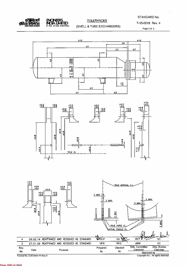
TOLERANCES
(SHELL & TUBE EXCHANGERS)
STANDARD No.
7-15-0019 Rev. 4
Page 2 of 3
Rev. No. Date Purpose
Prepared Checked
by by
Stds. Committee Stds. Bureau Convenor Chairman
Approved by
RKT
AKM VC
±3 ±3
±3 ±3
00
—+ I
+2.0 —0.0
+8:8
rAri
±0.8 +0.0 +0.0
—0.8 r---1 -0 •8
le I
1n1 .c:D
ii-1 c0 + I co
d 0
-H -H
4 06.05.14 REAFFIRMED AND REISSUED AS STANDARD 4P6CP KA
3 27.01.09 REAFFIRMED AND REISSUED AS STANDARD VPR RKG
vt.
fI L
+3.0 —0.0
+0.8 —0.0
+0.0 —0.8
cc! 0 -H
L
+
+I-H
. —0+2
+0.8
3 MAX. I
I
TRUE VERTICAL C.
Format No. 8-00-0001-F4 Rev.0 Copyright EIL - AII rights reserved
ENGNEERS 11431A UMITED
somnewormowe (A Govt. ot Indlo UndortokIng)
Page 1693 of 2624

NENGNIA IRS ID UMITED
1:1111.1~1V111~0 (A Govl. of Indlo Undertoking)
TOLERANCES
(SHELL & TUBE EXCHANGER)
STANDARD No.
7-15-0019 Rev. 4
Page 3 of 3
1.0 FOR NOZZLE 4- dc UNDER
2.0 FOR NOZZLE 6" TO 10" INCL 2.5 FOR NOZZLE 12" TO 16" INCL 3.0 FOR NOZZLE 18" dc ABOVE
1.
11' ! ACTUAL NOZZLE Q
TRUE HORIZ Q
TRUE VERT q_
+1.0 —0.0
00
GENERAL NOTES: —
CUMULATIVE TOLERANCES ON CONSECUTIVE DIMENSIONS SHALL BE LIMITED BY OVERALL DIMENSION TOLERANCE.
2. SPECIFIC TOLERANCES DESIRED FOR ANY PART SHALL BE SHOWN ON THE DRAWING AND SHALL BE GIVEN PREFRENCE TO THOSE GIVEN IN THIS STANDARD.
3. TUBE HOLE TOLERANCES SHALL BE AS PER TEMA.
4. ONLY WHEN NUMBER OF BAFFLE PITCHES EXCEED EIGHT.
L3'
4 06.05.14 REAFFIRMED AND REISSUED AS STANDARD ;1--"G(6P KA RKT 'N3s/ Ofr
.-SC
3 27.01.09 REAFFIRMED AND REISSUED AS STANDARD VPR RKG AKM VC
Rev. Prepared Checked Stds. Committee Stds. Bureau
No. Date Purpose by by
Convenor Chairman Approved by
Fnrrnat Nn R-nn-nnni-F4 RAV n Cnnvrinht Fll - All rinhts rpsnrvnri
Page 1694 of 2624

* 30*(MIN.)
1.5 t(MIN.) (TYP)
c
SELF REINFORCED NOZZLE
OgMONO MRSINDIA WITH)(A Govt. of India Undertaking)
S. R. NOZZLE NECK
STANDARD No.
7-12-0037 Rev. 3
Page 1 of 1
NOTES :— SELF REINFORCED WELD ENDSDESIGNDESIGN CALCULATION FOR ALL THE DIMENSIONS OF S.R. NOZZLES / WELD
ENDS SHALL BE APPROVED BY EIL.
ANY DEVIATION IN THE OVERALL PROJECTION FROM THE SPECIFIED DESIGNDATA SHALL BE MADE ONLY AFTER OBTAINING PRIOR APPROVAL FROM EIL.
FLANGES MAY BE FORGED INTEGRALLY WITH S.R. NOZZLE NECK.
I.D. OF FORGING SHALL BE AS SPECIFIED ON ENGG. DATA SHEET.
* 5. APPLICABLE FOR ASME SEC. VIII DIV.1 EQUIPMENT ONLY.
6. ALL SHARP CORNERS SHALL BE ROUNDED—OFF SMOOTH.
44,„;,,tj
3 23.05.2011 REAFFIRMED AND REISSUED AS STANDARD POREL RKT
Rev. Prepared Checked Stds. Committee Stds. Bureau
No. Date Purpose by by Convenor Chairman Approved by
Format No. 8-00-0001-F4 Rev.0 Copyright EIL - All rights reserved
Page 1695 of 2624

• •••• •-•• . ;(4-ti • •••••• •••
' = - - • ',••••
Hx200 300 IMx1001104
LIFTING HOOK
TOP OF TRENCH
• F.G.L. (UNPAVED AREA)
(SEE NOTE-5)
M.V. POWER CABLES CONTROL CABLES BRICK
SAND
H.V. POWER CABLES
REMOVABLE CONCRETE COVER (SEE NOTE-4)
1.0
EARTH STRIP (IF SPECIFIED)
G.I. PIPE FOR CABLE (AS REQUIRED)
o cl
ENGNEERS $4gar 02e.5 Y INDIA LIMITED
(A Govt. of Indto Undertoking)
SECTION OF
RCC CABLE TRENCH
STANDARD No.
7-51-0303 Rev. 5
Page 1 of 1
RCC CABLE TRENCH WITHOUT RACKS
LIFTING HOOK F.F.L. (PAVED AREA)
(SEE NOTE-5)
REMOVABLE CONCRETE COVER (SEE NOTE-4)
o o -
tr)
_ O
EARTH STRIP (IF SPECIFIED)
G.I. PIPE FOR CABLE AS REQUIRED (TYPICAL)
< ' INSERT PLATE BY STRUCT. (TYPICAL)
••••••.'•. MS ANGLE CABLE SUPPORT ARRANGEMENT @ 600 MM BY STRUCTURE (TYPICAL) 800
600
( 800
RCC CABLE TRENCH WITH RACKS N : 1. ALL DIMENSIONS ARE IN MM.
2. WIDTH OF RACKS ON ONE SIDE OR BOTH SIDES SHALL BE DECIDED AS PER JOB REQUIREMENT.
3. THE EXACT HEIGHT OF OPENING IN TRENCH WALL FOR G.I. PIPE FOR TAKING CABLE SHALL BE SUITABLY DECIDED AT SITE.
4. THE REMOVABLE CONCRETE COVERS SHALL BE SEALED WITH MASTIC ASPHALT FILLER / BITUMEN TO PREVENT INGRESS OF WATER / HYDROCARBONS IN CABLE TRENCH.
5. TOP OF THE TRENCH SHALL BE 100 MM ABOVE FINISHED GRADE LEVEL (F.G.L.) IN CASE OF UNPAVED AREAS AND SHALL BE FLUSHED WITH FINISHED FLOOR LEVEL (F.F.L.) IN CASE OF PAVED AREAS.
6. MINIMUM GAP OF 250MM SHALL BE PROVIDED BETWEEN FA / COMMUNICATION / TELEPHONE CABLES AND ALL OTHER POWER / CONTROL CABLES.
" r
SC
5 21.11.13 REVISED & REISSUED AS STANDARD BP FA/SA UAP/JMS
4 15.12.08 REVISED & ISSUED AS STANDARD BP RKS/NS JMS VC
Rev.
No. Date Purpose by
Checked
by
Stds. Committee Stds. Bureau Convenor Chairman
Approved by Copyright EIL - All rights reserved Format No. 8-00-0001-F4 Rev.O
Page 1696 of 2624
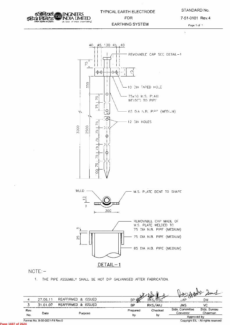
M.S. PLATE BENT TO SHAPE
40I I I45 130 45I 40
I I I I I/
i
10 DIA TAPED HOLE
75x10 M.S. PLATEWELDED TO PIPE
65 DIA N.B. PIPE (MEDIUM)
12 DIA HOLES
REMOVABLE CAP SEE DETAIL-1
ENGINEERS$'1g-ar 0156 INDIA LIMITED
to C;ovt. of India Undartaking)
TYPICAL EARTH ELECTRODEFOR
EARTHING SYSTEM
STANDARD No.
7-51-0101 Rev.4
Page 1 of 11441-ert errave aN 3U1:17.1)
300
REMOVABLE CAP MADE OFM.S. PLATE WELDED TO75 DIA N.B. PIPE (MEDIUM)
75 DIA N.B. PIPE (MEDIUM)
65 DIA N.B. PIPE (MEDIUM)
DETAIL-1
NOTE:-
1. THE PIPE ASSEMBLY SHALL BE HOT DIP GALVANISED AFTER FABRICATION.
Id, Ai4 27.06.11 REAFFIRMED & ISSUED BP qi XS/rSer UAP DM3 31.01.07 REAFFIRMED & ISSUED BP RKS/AKJ JMS VC
Rev. Prepared Checked Stds. Committee Stds. BureauNo. Date Purpose by by Convenor Chairman
Approved byFormat No. 8-00-0001-F4 Rev.O Copyright EIL - All rights reserved
Page 1697 of 2624
Page 1698 of 2624
Page 1699 of 2624
Page 1700 of 2624

Page 1701 of 2624
Page 1702 of 2624
Page 1703 of 2624
Page 1704 of 2624

Page 1705 of 2624

Page 1706 of 2624

Page 1707 of 2624
Page 1708 of 2624
Page 1709 of 2624

Page 1710 of 2624
Page 1711 of 2624

CD
z `)
00
0 •Aad Ld-1000-00-8 'oN TelLIJOJ
pansspi puu pas!na-a
panss!a-H pue pas!nax
uouuwawaidw! Joj panssi
4")
ro
•-o
07
n
Copyright EIL — All rights reserved
.nau 8101-18-9
STANDARD SPECIFICATION No.
Aq peAwddy
n
Pag
e 17
12 o
f 26
24
0 •AGd L3-1000-00-9 'oN WW.103 paniesaJ spABP IIV —113 11-160doo
suolimAaiciqy
11 STANDARD SPECIFICATION No.
AD
CfQ ta
CD
0
.nan 8101-18-9
cCDii 5.
2
wepiglox aai
uldno .D.s
44
:--$
)-3
P,D
t." 5
5i 5
<__
,.. :5
". c
rq v
)
n)
(-9
m
(19
'-cs.
a-ld
rd.
.PD
,-+
-,
s),) ...
c
H
6,, 0
,-
r cn
,-r
crtz
,.. t
-s-1
-.
CD C
D AD
4 ›-
SD n
d •
:,)
•-
(1)
cl., c
p
o
d•••
-, C
D ,
s),)
s:,)
-,-
Q-•
5
. »9_
, d
Fc' )
,,,-' i5
,' •-
3 „"
n)
='D
-
,-+
c) -
w)
Q-•
,_
, -•
-:
CD
rp
<D•-3
AD
.-r
v) •
-+
n
‹-t-c
o •- d
-,
d
• s'''
•-••
-, CD
44
CfQ
(")
7G"'
C)
'-'-
$w v
)
. .
co
•--
cm
C7
{1:)) 5"
..,,,$„
,,.
z.-„, .
-'== r.,:.
.0 .
co
c)
r)
itc
C) C,
Qn
C)
cn "
H
'-1 :Z
Z4
4
_
-,
-
n
CFQ
rZZ
S 'E
r.• c
z). , o
.. —
'5
' -".
•-• o
- '"
'-'e'
j'-
' ;
cn
oc/2
- ,-.
zn C
rQ ,,
1D
) ,..
,,a. »
6›
4 z
ICD
c, b -
, co
4 4 ~
,-4. <
;
rd ■•
• •-1
P `
---
•—■ ,
sy
13
<
'ti
CD
■ -t ,..
.p
Pà.. -69
),(7pil.U0;g") .-
.„
,,, , „,, ,f2. H„Ho
„ __.2,
0 eD
■ --
CD
fl) ,--0,,
.OIL,
,..,(
D
o
>" c
:, cr
a o
-.
rD C
f) CD
v)
v)
eD
.-
t-
'"0
,,.
0 C
I)
5 •
■-+
....
Ci
rD ›
'
:'i
AD
,f,
n
Ciq
CD
CL
CrD
D •
'—n
CIQ
A)
.=i
(.7-, ,
c)
D))
CD k
s
CD
c)
>,:-4i , A
) e)
5
' 5:
,) o
c),-'-
AD
'-(5.
•
C1.• C
R ...
,-
0.-
r•1.
AD
4444 n
>.`ri
9 Y1 P1 n n
HE4r=1
c)
(-)
c)
rl
Pag
e 17
13 o
f 26
24

0 Aed Ld-1000-00-9 'oN Iewioj pamasai IIV —113 11160doo
INSPECTION AND TEST REQUIREMENTS
PO/PR/ Standards referred there in/ Job specifications /Approved documents.
This Inspection and Test Plan covers the minimum testing requirements of fixed / draw out type MV Switchboards.
J)
11 s 'AaH 8I01-18-9
STANDARD SPECIFICATION No. N
,-
, N
Z:
::.
I-,
::=>
zC
i)
0
Incoming Material like Insulators, Bus Bars, Fabricated
items, Bus bar sleeves and supports, Instrument
Transformers, Relays, Indicating Instruments, Switches, Breakers,
Contactors etc.
Material Inspection
Procedures
STAGE/ ACTIVITY
Visual, Dimensional, operational checks, Manufacturer's test certificates etc. as applicable
CHARACTERISTICS
■-■
C.;‹ CD
CD
QUANTUM OF CHECK
0
°
c.,
_(')
. ,--
i H
,z, „,
CD
'-'
< U'
■-t
-
4
,_,_
(13 Ap
9,
. i
ril
o
SUB SUPPLIER
SCOPE OF INSPECTION
Z
SUPPLIER
7zi
EIL/TPIA
Pag
e 17
14 o
f 26
24
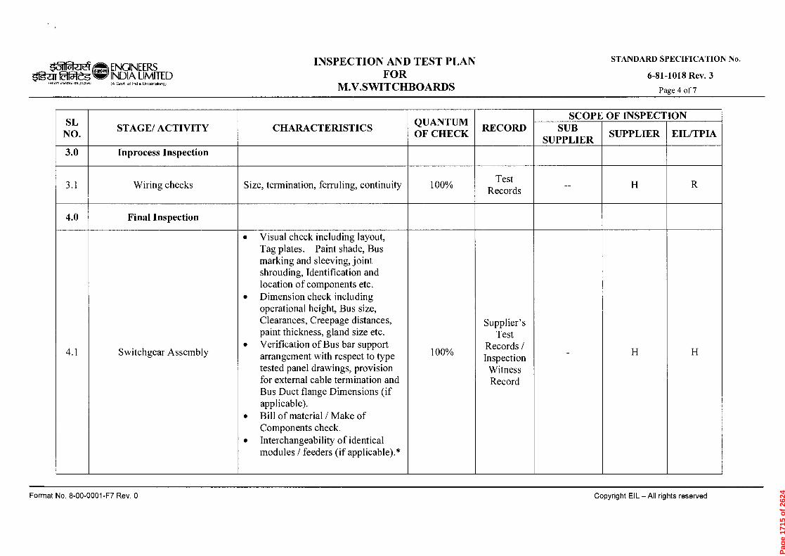
0 Al '92 Ld-1000-00-8 'oN 4e1.1.1.10d patuesai s;46P IIV — 113 4L460doo STANDARD SPECIFICATION No.
£ 'AaH 8101-18-9
4A.
,---,
&
©
U.)
—
C■à
GD+
z C
A
C.)
C/)
CTA CD
AD
.-
t
›•
vp
CD
Cr
.‘--.
Final Inspection
Wiring checks
Inprocess Inspection
STAGE/ ACTIVITY
. .
.
.
.
■■ (•
-) tz,
$,,,
er, <:•
•,, F.,;
..<
›zs
(-) o
e ,•
; ,...D.,
■H
<
o , c
) -.1
:1
-, .
n)
P2 -' 1
:s
-.
c)
'"' "
' CD
CD
9- .(
-tt) •-
• '-'
C4
CD
FID
::'• •
p
) 5
:0 o ,-,
crq
- o
-0
o "(--
,.. Izi
><
S:2
- cg
? '-,:h.
'-t
AD
CD
r-2-•
''. '
. '0
AD
C
T.
C)
'-'' :'D
CD
'-0
o
2,
5 -' 6"
' - -
'
°
2 ,' T .
c4
1:,D
E
cr
r)
•.1
:,,
„_
.)..
c)
3 ,...,-.
5 .
CrC
i (1
),-
2.,
c'D
,-•
---
crg
CD
p0
o
'-c;)-
....' °
:,)
8 o
cl.Q
$2
CC'
CD
,••D'h
CD
■-r-
'<DD# s
'.-'
~-•
CD
.C'
')
•-•
mon
".
• (..
,
:''
l'")
cl. '-'
CD
•""‘
5). or' -
"I'
cl. S
r,: r,
tz.)
crq
AD
...
t -1
.) (.,
) ■-
s - .
et>
n o "'
r-c)
--
co
—
-- ,
cr
;:..,
-• .
cp c
rQ.
o
"
'","«
--
c"i)'
5 C
° e
rc? °
-1i
-. o
C/1
r)
-• -
cs J
-4.
o
,>2A
•c
E. E
. ,-
-; o r a
...
<,-5-
'(.11
Cl)
AD
IDO
5.
o
.z; •
C:
L,
; ,,,
::).)
5 .-=
crq ,
, cr'
cfQ
b:)
(-)
(I)
p, 0,
-,,.. c-,)
-•
,..—
. ,...-+
... >Z
3 .•
CD
,--■ •
. -t
cn
cl
.,
cn
,...s.-
cn
co c-,
. >"0
CD
0
cn
;:.
,-. C
) cn
F,-
,• 7,. t
A ,....--:
n
o
'-.
P+
'-
i')
'8' •
94 0
'-''
eD
•-r-
1,'-
' •
,-t-
::,D
5-
,....-
F)
. —
5
-0 ,
t2
cpcm
9
-,-1"
10
'a.
,, o
—
.o ,
.. cr
;»
C''. ,..-
o
r)
°
,,7.,.
C/)
‘..-1
-
&D
5
›-C,
CD
*
C.
Size, termination, ferruling, continuity
CHARACTERISTICS
,_,
C)
C)
<::'
•—•
C)
CC
)
•:‘,
QUANTUM OF CHECK
5-'
C4
o
co
-• -
cs
o
o
■-3
c) o
co
'1:
0
r)
.-t
l./1
•••••
•
cl..
r„)
E')•
c.
)
----
cn
7:J
CD
, o "
CD C/1
ci..
cn
r)
CD
1 1
SUB SUPPLIER
SCOPE OF INSPECTION
SUPPLIER EIL/TPIA
Pag
e 17
15 o
f 26
24

0 •AGd Ld-L000-00-9 '0N 48W.103 pamesai sp46P IIV —113 446pAclo3 STANDARD SPECIFICATION No.
£ *Aall
C r.
C/)
F-) '
rD
AD
>
v)
CD
cr'
‘,.
...,
----
, c)
o
5.
s:....,
STAGE/ ACTIVITY
°
(I)
cn
.
co
0
ch",...
6')
AD
Ck." «
0
Cfg (I)
•
,-- •
Z
,,-'--"."
,..,_
:=,-F:
`• -5
co
0" ö
cp
o
.t.',-
'-'t
C)
pp
■--+. ''"
' cn
p
H
, (-)
>.
" ,
,,,""
■-3 $"
' ,-.
c,,
'4). 'li
CD $:,,
pl
cr
CT
CD
.....-
$,,,
, Cr
Ci ...t
C
D
co
¢..
• .
.
■-L■
.L■
cp
-t
,,::
5 0'..
-‹ ,•-
.., .
cn
,...., ̀
-<
co "
g ---»
-ci
-: :,,
c,., -
v)
~ .
°
cs
rD
~t
,--+
L:
'-c2
• (-
)
'''. °
—
r) c)
C:
1' s'-'<i
) 3 CD.
.. !.
g
-
.-1,
• (-
) *
■-t ,cp
..,
t_
_, z-
0- ',7
4- co
cr
0 5
. ,--
t- ■-t
(.,
.-, -
lzo
....
• .--
t 0
,-r
- 0
0
.91
A)
CD
„
crQ
-., -
<
• •
.
'-ê's
5
(0`4 ̀
4r)
'." C
) c)c)
g
g- 4
'à>
'à'' c)
''''
) :0
'( 7"
; .-
• .
$ : 0
r_- p_. -
» -
S «.■ .
. - .■ .
p,
cr ;.
-... -cs
-'s
5 0
o -•.,
,--
,. '5
— ...
- •
cn
ri) °
t:li
c)
co
-
t.) f=, AD
-
(")
. *
''')
-t Q
. o
.n
c)
.- •
'-'+
' '"'
•
=''
''
—
1=0 c
:'• CD
»~
AD
(I)
'-
,-'
7.,"
rt)
,--1-
CD
C)‹.)-
' CD
ci)
C
L,
" ,-
5
- -
c
e '' ° ( /
' - '" 5"
'. ,+
2,
0 tl'
a A
D
1:,, ci
., ,,.
, ,..
, or)
,_, cr
, ,-
'
o
t.,) '—
' •
H
'')
<—
. ,-
'-{
:i b-1
CFQ fl)
PO
C>
63
■-t
cn cA
o
.-- 0 ~s
...
.. .-
+ 0
—
CD
pD
» t
:S ,.., r,,, ■••
+ .
o
0.,C
D
,-.t
w
C)
~ •
AD
" 0
C/Q/11
, ,,
CL
.
CHARACTERISTICS
I,
CD
C')
QUANTUM OF CHECK
9
CD
0—, •
'-ct
ir, ,--
CD
c>
.-
C)
..-t
(1)
■-+ . ?
1)
c)
0
■-s
0.,
cn
--
--
,H
rD
cn
,--
n C
g
SUB SUPPLIER
SCOPE OF INSPECTION
SUPPLIER ~
1"0
~
>
Pag
e 17
16 o
f 26
24
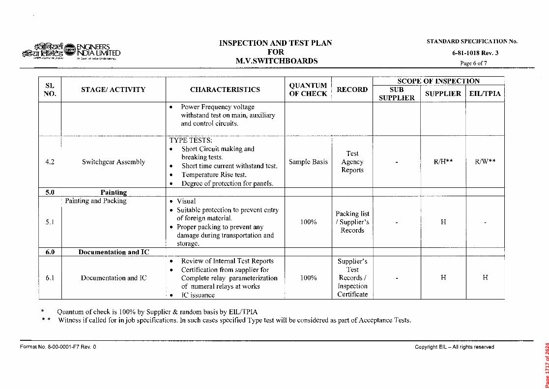
0 'rad 2A-1000-00-8 'oN 4eLwod pamaseJ s4L16!.1 IIV —113 lg6uAdoo
rg
>
r r
STANDARD SPECIFICATION No.
'Aa2I 8101-18-9
cn
—,
cn
O
th
—
th
O
-1.
i‘..)
z c
4
0
Documentation and IC
Documentation and IC
Painting and Packing Painting
Switchgear Assembly
STAGE/ ACTIVITY
•
Review of Internal Test Reports
•
Certification from supplier for Complete relay parameterization of numeral relays at works
•
IC issuance
• Visual
• Suitable protection to prevent entry of foreign material.
•
Proper packing to prevent any damage during transportation and storage.
TYPE TESTS:
•
Short Circuit making and breaking tests.
•
Short time current withstand test.
•
Temperature Rise test.
•
De:.ree of .rotection for .anels.
•
Power Frequency voltage withstand test on main, auxiliary and control circuits.
CHARACTERISTICS
—,
o
<: "'
100%
Sample Basis
QUANTUM OF CHECK
Supplier' s Test
Records / Inspection Certificate
c, .
,:i
`t
—• •
Clg
P
. CD
..•
•
CD
'10
o
cn
IC<C
i CD
o
`-<
H
o
cn
—,
>
r)
C
g
SUB SUPPLIER
SCOPE OF INSPECTION
Z
*
SUPPLIER
* *
t '1' i
) — i
. d
› . -
Pag
e 17
17 o
f 26
24
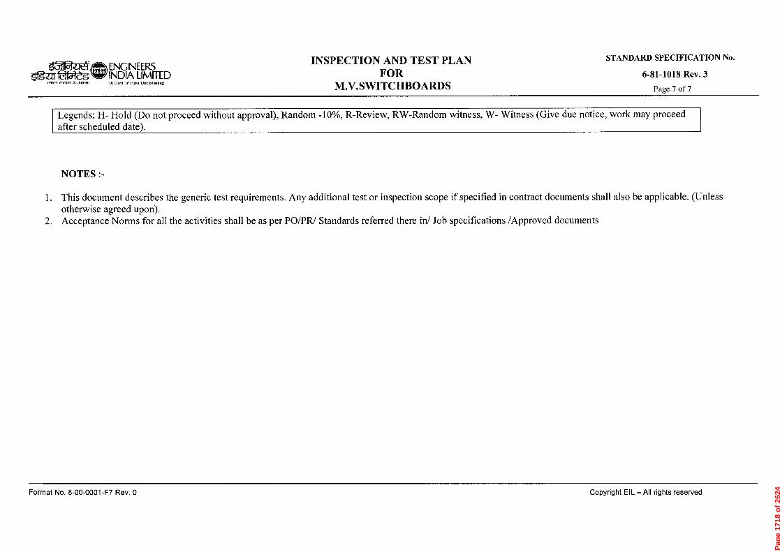
lo••••
••■
rn-
o
Cr
CD
'1Z3 CD
CD
C4 cn
STANDARD SPECIFICATION No.
£ *Aall 8I01-18-9
0 'Aed L3-1000-00-8 '0N TeLwoj pamasaJ sp.i6p IIH —113 ;1160d00
(
CD
CK) CD
r)
‹-4-
—.
CD<
-t
. <--
,-. r)
5
..-
., cn
ro
cn
cn
,--s
A)
CD
,-t
c
CD
,==s
E.
CD
1%)
CD
CD
..-r
- ■-t
cn
'"
d
C >
--.
....
`-<
A)
CL
F):'')
■-+
.....
0
C)..
A)
A)
.-s
1:).
■-+
cn
CD
,-1
cn
CD
0
■-t-
,--)
CD
■-t
...
ri)
CL 5-
ri)
r)
CD
.-t-
.-t
CD
0.
....
cn
,—,
C)
0
CD
0 cr' C
D
cn
...
''CS
■-r)
CD
4.in
r)
r)
sl)
'..—
s:L
o
—.
ro
, r)
o
,-s~t
0
!W
r)
<
e-4
- rD
C
L
0
a.,
r)
o
r)
rt)
CD
P-t-
cn
cn
cn
Pag
e 17
18 o
f 26
24
r"_111 Reig $'g?;ir
ENGINEERS INDIA LIMITED IA Govt of Ilioia Undertakingt
SPECIFICATION FOR ELECTRICAL EQUIPMENT
INSTALLATION
STANDARD SPECIFICATION No.
6-51-0081 Rev. 4 Page 1 of 15
fqxja ̀CID Tzrp-ir9r NfffhT
SPECIFICATION FOR ELECTRICAL EQUIPMENT
INSTALLATION
4 21.05.14 REAFFIRMED & ISSUED AS SPECIFICATION FA SA BRB SC
3 25.04.08 REVISED & ISSUED AS SPECIFICATION RKS SSM JMS VC
2 28.02.03 REVISED & ISSUED AS SPECIFICATION HKM RSG VPS SKG
1 26.08.97 REVISED & ISSUED AS STANDARD SPECIFICATION
RR VPS SG AS
0 28.08.81 ISSUED AS STANDARD SPECIFICATION RR RR SGG
Rev. No
Date Purpose Prepared
by Checked
by
Standards Committee Convenor
Standards Bureau
Chairman
Approved by
Format No. 8-00-0001-F1 Rev. 0
Copyright EIL — All rights reserved
Page 1719 of 2624

$11gui&W-eg rycnrc ~I)
ENGINEERS INDIA LIMITED IA Govt of India Undeffoloogf
SPECIFICATION FOR ELECTRICAL EQUIPMENT
INSTALLATION
STANDARD SPECIFICATION No.
6-51-0081 Rev. 4 Page 2 of 15
Abbreviations:
AC Alternating Current ACDB AC Distribution Board AL Aluminium BIS Bureau of Indian Standards CCoE Chief Controller of Explosives CD Compact Disc CEA Central Electricity Authority CIMFR Central Institute of Mining and Fuel Research CT Current Transformer CTC Carbon Tetrachloride CU Copper DC Direct Current DCDB DC Distribution Board DGMS Directorate General of Mines and Safety Ex(d) Flameproof FRP Fibre Reinforced Plastic HV High Voltage IR Insulation Resistance IS India Standard LV Low Voltage HMI Human Machine Interface MV Medium Voltage OISD Oil Industry Safety Directorate OSR Oil Surge Relay OTI Oil Temperature Indicator PF Power Factor PI Polarisation index PRV Pressure relief Valve PT Potential Transformer SLD Single Line Diagram UPS Uninterrupted Power Supply VRLA Valve Regulated Lead Acid WTI Winding Temperature Indicator
Electrical Standards Committee
Convener: Mr. B.R. Bhogal
Members: Ms. S. Anand Mr. Parag Gupta Mr. M. K. Sahu Mr. A.K. Choudhury (Inspection)
Ms. N.P. Guha (Projects)
Format No. 8-00-0001-F1 Rev. 0 Copyright EIL — All rights reserved
Page 1720 of 2624
‘3-11R_Jt4 ENGINEERS INDIA LIMITED
SPECIFICATION FOR ELECTRICAL EQUIPMENT
INSTALLATION
STANDARD SPECIFICATION No.
6-51-0081 Rev. 4 Page 3 of 15
orrrn c,craddaJnadfan IA Govt of India Undeftalong)
CONTENTS
1.0 SCOPE 4
2.0 CODES AND STANDARDS 4
3.0 INSTALLATION OF EQUIPMENT 4
4.0 EQUIPMENT COMMISSIONING 14
5.0 LIST OF CONSTRUCTION EQUIPMENT 14
Copyright EIL — All rights reserved Format No. 8-00-0001-F1 Rev. 0
Page 1721 of 2624
ENGINEERS $11g-a 22-g INDIA LIMITED
aiT7ii CRI dYtn.
(A Govt of lochA UnderfAk(.9)
SPECIFICATION FOR ELECTRICAL EQUIPMENT
INSTALLATION
STANDARD SPECIFICATION No.
6-51-0081 Rev. 4 Page 4 of 15
1.0 SCOPE
This specification defines the requirements for the installation, field inspection, testing and commissioning of electrical equipment, forming part of electrical power distribution and utilisation system, including Communication and Fire alarm system.
2.0 CODES AND STANDARDS
2.1 The work shall be carried out in the best workmanlike manner in conformity with this specification, EIL Installation Standards, layout drawings and to the following specifications/ codes of practice of Bureau of Indian Standards and OISD standards.
SP-30 (BIS) National Electrical Code.
IS:7816 Guide for testing Insulation resistance of rotating machines.
IS:10028 (Part-2) Code of practice for selection, Installation and maintenance of transformers; Part 2 : Installation.
OISD 137 Inspection of Electrical Equipment.
OISD 147 Inspection and safe practices during electrical installations
2.2 In addition to the above it shall be ensured that the installation conforms to the requirements of the following as applicable:
a. CEA Regulations.
b. Regulations laid down by CEA/Electrical Inspectorate.
c. Regulations laid down by CCoE/DGMS (as applicable).
d. The petroleum rules (Ministry of Industry Government of India).
e. Any other regulations laid down by central/state/local authorities and Insurance agencies.
3.0 INSTALLATION OF EQUIPMENT
Prior to start of installation of the electrical equipment, Contractor shall verify that equipment and complete materials have been received. Handling, shifting to required site location, installation, testing and commissioning of all electrical equipment shall be done by contractor with utmost care. Manufacturer's instructions and the requirements given in their technical manuals shall be strictly adhered. The substation/switchgear room wherein the equipment shall be installed shall be kept clean, dry and free from all debris. Panel floor cutouts not in immediate use shall be suitably covered to avoid any mishap. When handling the switchboard panels, care shall be taken to observe the correct lifting arrangements and to make sure that slings are attached to the manufacturer's designated lifting points,where applicable. No parts shall be subjected to undue strains or sudden stresses which could cause damage to the equipment.
The lifting position mark indicated on packing casing shall be adhered to strictly, for keeping it in required vertical position.
Contractor shall check and report to the Engineer-in-charge about any damaged item and / or missing component for getting the same replaced as per specifications. During installation, all accessories and loose items shall also be inspected by the contractor before their assembly/mounting.
Format No. 8-00-0001-F1 Rev. 0 Copyright EIL — All rights reserved
Page 1722 of 2624

ENGINEERS INDIA LIMITED (A Govt ol InOla Undedalong)
SPECIFICATION FOR ELECTRICAL EQUIPMENT
INSTALLATION
STANDARD SPECIFICATION No.
6-51-0081 Rev. 4 Page 5 of 15
Otait 1~,.r2",1,77,1713,21,)
3.1 Switchboards and Bus Ducts
3.1.1 The term switchboard here includes all HV / MV/ LV switchboard panels, motor control centers, power and lighting distribution boards, UPS panels, ACDB, Battery charger panels, DCDB etc.
The switchboard panels shall be handled with care, avoiding any impact to the equipment. Dragging of the panels directly on floor shall be avoided. Roller bars may be used for shifting of panels. Use of a crane and trailer shall be made for handling of equipment. The switchboard panels shall be properly supported on the truck or trailer by means of ropes to avoid any chance of tilting. The switchboards shall be lifted after ensuring that panel supports, nuts and bolts are all intact and tightened. While lifting the panels in packed conditions, utmost care shall be taken to avoid any damage to insulators, bushings, metering and protective equipment and if specified in the tender document tyre mounted hydraulic trolley shall be used.
The panels shall be preferably kept inside the packing cases till foundations are ready. Proper rain/sun/dust protection shall be ensured till switchboards are installed.
3.1.2 The switchboard panels shall be installed on prepared foundations or floor cutouts. Steel base channels shall be welded to inserts provided in floor slab. Cross members shall be provided at the junctions of each shipping section and other places as required.. It shall be ensured that the base plate level of HV switchboard shall match with the finished floor level.
The foundation pockets and the grouted bolts shall be cured for a minimum period of 48 hours. Proper level of base frames shall be maintained throughout and shall be checked with water level/spirit level. Steel Shims shall be provided below base frame wherever required.
3.1.3 The switchboard panels shall be taken out from the packed cases and shifted one by one to their proper place. Al1 the panels shall be assembled, aligned and leveled. Alignment of panels shall be checked in both longitudinal and lateral directions. It shall be ensured that panel to panel coupling bolts, bus bar links etc. fit properly without any strain on any part. No new holes for jointing of the panels other than those recommended by the vendor shall be drilled. No gaps shall be left between the panels. Gap if any found between panels shall be suitably sealed using sealing compound or T-profile. The lifting, racking in and out operation of the breaker and all other motions shall be free from any obstruction.
The panels shall be checked for correct vertical position using Plumb line and spirit levels. The switchboard panels shall be tack welded at suitable intervals to base channel.
After erection of switchboard panels, all uncovered portions of floor cutouts shall be covered with 6 mm thick removable chequered plates finished with floor level. The design of the chequered plates shall be such that the maximum allowable deflection is L/200 (where L is the span of the chequered plates in meters) for a live load of 500 kg./sq. meters.
Additional stiffer shall be provided at the bottom if required. Suitable lifting arrangements shall be provided for chequered plates. The chequered plates shall be painted with a coat of red oxide zinc chromate primer after proper surface preparation as per specifications. Where specified, panels' cutouts provided for future use shall be filled with lean concrete.
3.1.4 After completion of Installation of switchboards, all the cubicles, switchboard components such as switches, starters, CT and PT chambers, bus bar chamber shall be cleaned and checked for tightness of all the components.
Vacuum circuit breakers shall be checked for integrity of bottle seals. A11 loosely supplied items shall be fitted up. Bus bar sections or links shall be inserted and where specified, of high
Format No. 8-00-0001-F1 Rev. 0 Copyright EIL All rights reserved
Page 1723 of 2624

ENGINEERS Ordie'g INDIA LIMITED
IA Govt of Intha Undertaking)
SPECIFICATION FOR ELECTRICAL EQUIPMENT
INSTALLATION
STANDARD SPECIFICATION No.
6-51-0081 Rev. 4 Page 6 of 15 eivavv'dv~)
voltage equipment shall be insulated. Interconnection wiring between shipping sections shall be done by contractor.
All the wiring connections shall also be checked. Contact resistance of all bus bar joints and contactors shall be checked. Insulator shall be checked for any damage. All the starters, switches, contacts shall be cleaned with CTC where required.
A11 the moving parts shall be checked for easy and free movement. Hinges of panel doors shall be lubricated to give free and noise less movement. A11 openings shall be kept completely closed to avoid ingress of any foreign particles inside the panel.
Functional scheme verification of individual feeder shall be carried out and minor wiring modifications in the panel wiring, if required shall be done as per the directions of Engineer-in-charge. Special attention shall be paid to CT circuits' polarity, wiring continuity and correctness in the protection as well as measurement circuits. Auto transfer scheme shall be simulated and verified. During the course of scheme verification tests, defective components if any shall be taken out, after bringing to the notice of Engineer-in-charge. The same shall be replaced by component supplied by owner.
3.1.5 Where switchboard is damp or having a low IR value due to damaged insulators/ bushings/any other insulated parts, or any other reason, the entire switchboard shall be dried-up according to the instruction of the Engineer-in-charge for the IR value to improve to a safe level for commissioning. Care shall be taken to protect the surrounding insulation from direct local heating during the drying up process.
3.1.6 All the metering instruments, protective relays and other relays and contactors shall be tested as per manufacturer's recommendations and according to the instructions of the Engineer-in-charge. Protection relays shall be inserted and connected and settings adjusted as required by the Engineer- in- charge
3.1.7 All moving parts, of closing/tripping mechanism, racking in and racking out mechanism, spouts and shutter closing mechanism shall be checked for proper operation. A11 the auxiliary contacts of breaker shall be checked-up, cleaned and contact pressure measured.
3.1.8 All the control wiring, PTs, bushings, bus bars, other live parts of switchgear, incoming and outgoing cables shall be meggered.
3.1.9 Electrical simulation tests shall be carried out for all the protective, alarm and annunciation relays and external interfaces to ascertain proper functioning.
3.1.10 Safety insulation mats of approved make and of required voltage grade shall be provided in the sub-station.
3.1.11 Pre-Commissioning Check List
Before commissioning any switchboard, following points shall be checked and ensured for safe energising of the switchboard:
i. That the installation of equipment to be commissioned is complete in all respects with its auxiliaries and all other mounting including earthing. Openings in floor within and outside panels have been sealed off. All cover and door gaskets are intact to make the enclosure vermin proof.
ü. That all the metering instruments have been checked and found in working order. Indicating lamps are healthy and are in correct position. All power and control fuses are of proper rating.
Format No. 8-00-0001-F1 Rev. 0 Copyright EIL — All rights reserved
Page 1724 of 2624
ENGINEERS g INDIA LIMITED
(A GoV1 ol Ind. Unde(l.k,n91
SPECIFICATION FOR ELECTRICAL EQUIPMENT
INSTALLATION
STANDARD SPECIFICATION No.
6-51-0081 Rev. 4 Page 7 of 15
iii. That the polarity test and ratio test of all the PTs and CTs is complete and phase sequence of CTs conforms to the correct vector group connections. Wiring continuity and correctness are ensured in the protection and measurement circuits. Polarity of D.C. supply for all the circuits is correct.
iv. That the high voltage tests of incoming and outgoing cables have been conducted and results are satisfactory.
v. That all the protective relays including both conventional and microprocessor based numerical relays and thermal overload relays/electronic motor protection relays have been tested for secondary injection tests. (Primary injection tests shall be carried out for differential protection, Restricted Earth fault protection at full / reduced current to ensure correctness of complete wiring). Relay settings, status indications, fault annunciations, data logging, display of switchboard SLDs shall be verified from HMI in case the same is provided.
vi. That IR Value has been recorded for bus bars, circuit breaker, incoming and outgoing cables, control wiring and potential transformers. Where required joint resistance of bus bars have been recorded and found to be satisfactory. All the surroundings and panels have been cleaned and temporary earth leads have been removed.
vii. Following tests shall be ensured for all CTs
- Insulation resistance test
Ratio test through primary injection
Polarity test
Knee point voltage for class PS CTs
viii. Following tests shall be ensured for all PTs
Insulation resistance test
Ratio test through primary injection
- Polarity test
ix. Following tests shall be ensured for all breakers
- Insulation resistance test
- Breaker closing, opening sequence using 3 pole timers
- High voltage test both in open and close condition for HV breaker
Contact resistance of all three poles using 100A DC Kit
x. Following tests shall be ensured for all meters
- Calibration of meters
Functional verification and settings
xi. Following tests shall be ensured for all relays
Secondary injection test
- Relay settings
Timing check with timers
- Any other test recommend by the supplier
xii. Following tests shall be ensured for all bus bars
- Tightness of all nuts/bolts using Torque wrench
IR value
- Contact resistance using 100A DC Kit
- Cleaning of bus bar chamber using vacuum cleaner
- Conducting jelly shall be applied on AL/CU joints as per manufacturer's recommendations
- HV test in case of HV switchboard
Format No. 8-00-0001-F1 Rev. 0 Copyright EIL — All rights reserved
Page 1725 of 2624
k31naf t I ENGINEERS $1gzir INDIA LIMITED
Ift Govt of Incha Undertaking)
SPECIFICATION FOR ELECTRICAL EQUIPMENT
INSTALLATION
STANDARD SPECIFICATION No.
6-51-0081 Rev. 4 Page 8 of 15
1~7tYleaHt an .3~1
xiii Following tests/Checks shall also be performed on the switchboards
Functional verification of individual feeders including all spare feeders
Simulation test for under voltage tripping of related feeders such as motor feeder, capacitor feeders etc
Verification of control supply schemes
Stability test for all differential protections
Simulation test for bus auto/manual change over scheme
Checks for all panel illuminations, indicating lamps, sockets
All upstream and down stream interlocks
3.1.12 Bus Ducts
The bus ducts as per issued drawings will be supplied in parts and all the parts shall be assembled and the bus bar connections shall be made at site. The insulators in bus ducts shall be inspected for any possible damage during transit and the defective ones shall be replaced. The insulators shall be cleaned. Contact surface of bus bars, bus bar bolts and nuts shall be thoroughly cleaned. Petroleum jelly shall then be applied and bolted connection made. The bus duct enclosure shall be checked for earth continuity and then earthed at two places. The bus duct shall be properly supported between switchgear and transformer. The opening in the wall where the bus duct enters the switchgear room shall be completely sealed to avoid rain water entry. Expansion joints, flexible connections etc. supplied by the manufacturer of the bus duct shall be properly connected. The bus duct levelling shall be checked with spirit level and pendulum weight.
Pre-commissioning check list
Before commissioning any bus duct, following points shall be checked and ensured for safe energising of the bus ducts
All joints are tightened using torque trench Cleaning of bus duct chamber with vacuums cleaner Silica gel breather shall be connected if supplied. If required, silica gel shall be reactivated as per the instruction of engineer in charge. Space heater circuit shall be checked and tripping through thermostat shall be ensured Contact resistance shall be measured for all phases/neutral using 100A DC kit High voltage test in case of HV bus ducts
3.2 Transformers
Transformers on receipt at site shall be unloaded by means of crane or lifting devices of adequate capacity. All lifting lugs shall be used to avoid unbalanced lifting and undue stresses on lugs. Lifting lugs if any provided for partial lifting (e.g. for active part, conservator) etc. shall not be used for lifting complete transformer. Parts other than those identified for lifting of the transformer shall not be used for lifting. While slinging, care shall be taken to avoid slings touching other parts.
3.2.1 Before lifting transformer, it shall be ensured that all cover bolts are tightened fully. In case when it is necessary to use jacks for lifting, projections provided for the purposes of jacking shall be used . Lifting jacks shall not be used under the valves or radiator tubes. For transporting transformers from stores to site, the transformers shall be loaded on a suitable capacity truck or trailer. The transformers shall be properly supported by steel ropes and stoppers on the trailer to avoid tilting of the transformers in transit due to jerks and vibrations. At no instance, the transformer shall be kept on bare ground. Where it is not possible to
Format No. 8-00-0001-F1 Rev. 0
Copyright EIL — All rights reserved
Page 1726 of 2624

k5-11 ENGINEERS
Og-LITI&2eg INDIA LIMITED aiWn 4,1 .3~1/
(A Govt ol Indla Undertaking)
SPECIFICATION FOR ELECTRICAL EQUIPMENT
INSTALLATION
STANDARD SPECIFICATION No.
6-51-0081 Rev. 4 Page 9 of 15
unload the transformer directly on a foundation, it shall be unloaded on a properly built wooden sleeper platform. A transformer shall never be left without putting stoppers to the wheels.
3.2.2 Transformers shall be examined, for any sign of damage in transit. Particular attention shall be given to the following in this regard.
i. Dents on tank wall or cooling tubes, radiators ü. Damage to protruding parts like valves, sight glass etc.
Loosening of bolts due to vibration in transit. iv. Cracked or broken bushings. v. Oil leakage particularly along welds.
If any thing adverse is noted, the same shall be brought to the notice of Engineer- in- charge.
3.2.3 Contractor shall examine the transformer base, oil pit, fire walls and foundations made by the civil contractor. It shall be ensured that oil spills can not propagate along cable trenches. Any discrepancy noted will be brought to the notice of Engineer- in- charge. Transformers shall be placed on channels or rails over concrete foundations. The transformers shall be levelled, aligned and checked for free movement on the channels or rails. Stoppers shall be provided to the transformers immediately to prevent any movement. Normally transformers upto 1000 kVA rating shall be received duly fitted with radiator tubes, conservator tanks, valves, wheels and other accessories. While the transformers of above 1000 kVA rating may be supplied with loose accessories. All the accessories like radiators, cooling fans, valves, conservator tanks, explosion vent pipe, bushings and other devices which are supplied in different packages shall be checked for any transit damage and cleaned thoroughly before fixing on the transformer. All loosely supplied parts shall be assembled as per manufacturer's instruction manuals/ drawings and documents. All the connections for CTs bushings and other wiring shall be checked for tightness and correctness before replacing the lid or tightening all the bolts. Gravels shall be filled in the transformer bay, soak pit as per requirement.
3.2.4 Topping of transformer with oil
Before topping up with oil, transformer shall be fitted with all accessories such as valves, gauges, thermometers etc. Oil samples shall be taken from each drum and tested for determination of dielectric strength. Any sign of leakage of the barrel or of its having been opened shall be recorded and reported. It is necessary to filter the oil before the transformers are filled. It shall be ensured in oil filling operation that no air pockets are left in the tank and that no dust or moisture enters the oil. All air vents shall be opened. Oil shall be filled through a streamline oil filter using metal hose. To prevent aeration of the oil, the transformer tank shall be filled through the bottom drain valve. In a transformer with conservator tank, the rate of oil flow shall be reduced when the level is almost upto the bottom of the main cover to prevent internal pressure from rupturing the pressure relief-pipe diaphragm. Sufficient time shall be allowed for the oil to permeate the transformers and also for the locked -up air bubbles to escape. Any air accumulation in the buchholz relay shall be released.
3.2.5 Transformer Oil
i. Sample of oil from the transformer shall be taken from the bottom of the tank.
ii. Testing of Oil For dielectric test, the oil shall be tested as described in IS: 335. The oil shall also be tested for acidity in accordance with the methods prescribed.
3.2.6 Drying out of the transformers, if required, shall be carried out and record maintained in accordance with IS: 10028. Normally a streamline filter shall be used for drying-up. IR value
Format No. 8-00-0001-F1 Rev. 0 Copyright EIL — All rights reserved
Page 1727 of 2624
01 ENGINEERS
ogur 015:1&g INDIA LIMITED
14~ ,le'crn( 0,1 3,121,1) (A Govt of India Undettakingi
SPECIFICATION FOR ELECTRICAL EQUIPMENT
INSTALLATION
STANDARD SPECIFICATION No.
6-51-0081 Rev. 4 Page 10 of 15
versus time of both windings along with OTI/WTI and filtrations machine temperature curve for IR value Vs time shall also be plotted and recorded during the drying-up process.
Precautions when drying
i. The maximum sustained temperature to which transformer oil may be subjected shall be limited to 80° C.
ü. The transformer shall be carefully monitored throughout the drying out process and all observations shall be carefully recorded.
Drying out shall be continued so that the insulation resistance as prescribed in the standard code of practice is attained and the value remains constant for more than 12 hours. However, a minimum number of cycles shall be done for each transformer as found necessary by the Engineer-in-charge. Generally a Megger reading of 2 megohms / kV at 60° C temperature. with a 5 kV Megger may be a rough indication for stopping the dehydration.
3.2.7 The following work on transformers shall be performed by the contractor if specifically called for:
i. Before finally commissioning the transformer it may sometimes be desired to run it for a few hours on short-circuit, applying a low voltage, approximately equal to the impedance voltage of the transformer. During this process, regular readings of the insulation resistance of the winding to earth and winding to winding and temperature against time shall be recorded.
ü. Testing of radiator tubes for any leakage and rectifying these by welding / brazing.
3.2.8 Pre-commissioning Check List
Before commissioning of any transformer, the following points shall be checked for safe energisation of the transformer:
i. All the accessories have been fixed properly and transformer body and neutral are properly earthed. The transformer dehydration is over and results are satisfactory and approved by the Engineer-in-charge. In case transformers are idle for more than one month after dehydration, transformer oil has been given at least two circulations.
ü. Oil level, in the transformer conservator tank and all the bushings is upto the marked point and the oil has been tested for dielectric strength and acidity.
Silicagel is in reactivated condition. The breather pipe is clear from any blocking and contains oil upto the proper level.
iv. The explosion vent diaphragm does not have any dents. Accumulation of any oil and air had been released.
v. Operation of off-load and on-load tap changers on all the tap positions is satisfactory. The mechanical parts of the on-load tap changer are lubricated. Motor IR value has been taken and found satisfactory. Tap position mechanical indicator on the transformer and tap position indication meter on the control panel are reading the same tap positions. Tap changer limit switches are operating satisfactorily on the maximum and minimum tap positions. On-load tap changer contact pressure and resistance is as per manufacturers recommendations. Oil level of tap changer tank is upto the required level and oil has been tested for dielectric strength. The tap setting on which the off load tap switch is locked shall be recorded. Generally the off-load tap switch shall be kept on nominal tap.
Format No. 8-00-0001-F1 Rev. 0 Copyright EIL — All rights reserved
Page 1728 of 2624

ENGINEERS INDIA LIMITED (A Govt of India Unde(tak,ngj
SPECIFICATION FOR ELECTRICAL EQUIPMENT
INSTALLATION
STANDARD SPECIFICATION No.
6-51-0081 Rev. 4 Page 11 of 15
51gzu 2a1-"dg c-wert ams..)
vi. Buchholz relay has been tested and checked up for any friction in the movement, and floats are free. All the other protective relays, alarm and annunciation relays have been tested.
vii. Metering equipment has been tested and polarity test of PT's and transformer winding is satisfactory. Phase sequence and connections have been checked for proper vector group.
viii. Ratio test and winding resistance on all the tap positions is satisfactory.
ix. Gaps of arcing horns for the bushings where provided are in order and earth connections for the surge diverters have been checked.
x. Winding and oil temperature thermometer pockets contain oil and the winding and oil temperature settings on dial gauges are in order.
xi. Transformers fitted with fans for forced air cooling have been checked up for starting and stopping of the fans both in manual and auto mode and air-displacement has been verified.
xii. Simulation tests for all external interface connection alarm, annunciation and trip circuits have been checked and are in order.
xiii. Insulation resistance of all the control circuits and IR value of the transformer windings and all the incoming and outgoing cables have been checked.
xiv. Valves in the cooling system and valve between the buchholz relay and the conservator tank are in open position.
xv. Setting of all the protective relays is at the desired value and DC Trip supply is healthy.
xvi. Magnetic, current and magnetic balance test have been conducted
xvii Simulation test for WTI,OTI,PRV,OSR
xviii Settings of WTI/OTI as per the instruction of the manufacturer
xix Earth resistance value for the neutral earthing
3.2.9 Observations after Commissioning
After switching on the transformer the following points shall be observed and recorded.
i. The inrush magnetizing current and no-load current.
ü. Alarm, if any, or if any relay flag has operated.
Voltage and current on all the three phases.
iv. Transformer hum or abnormal noise.
v. Circulation of oil and leakages.
vi. Record current, voltage, cooling air temperature, winding temperature and oil temperature readings, hourly for 24 hours.
vii. Cable end boxes for any over-heating.
3.3. HV and MV MOTORS
3.3.1 All the motors generally would be erected by the mechanical contractor.
3.3.2 Electrical contractor shall keep the motor space heater energised as per the directions of Engineer-in-charge. Electrical contractor shall measure the insulation resistance of motor windings and PI in case of HV motors. Insulation resistance of the motors shall be measured between the winding of the machine and its frame by means of a 500 / 1000 V Meggar in case of 415 V motors. A minimum value of 1 megohm for 415 V motors shall be considered a safe value. In case of lower I.R. Value, the insulation value shall be improved by any of the following methods as directed by the Engineer-in-charge.
Format No. 8-00-0001-F1 Rev. 0 Copyright EIL — All rights reserved
Page 1729 of 2624

ENGINEERS Og'zIr faf-Zs INDIA LIMITED
IA Govt ot Intha Undertakmg
SPECIFICATION FOR ELECTRICAL EQUIPMENT
INSTALLATION
STANDARD SPECIFICATION No.
6-51-0081 Rev. 4 Page 12 of 15 ei2LIW,R13,,g1,11)
i. Blowing hot air from external source.
ii. Putting the motor in oven.
iii. Placing heaters or lamps around and inside after making suitable guarding and covering arrangements so as to conserve the heat.
In case the insulation is low, the following method of drying has to be adopted, after consultation with Engineer-in-charge. During drying the temperature rise of winding shall not exceed the permissible value for the class of insulation used.
i. By locking the motor so that it can not rotate and then applying such a low voltage to the stator terminals so as to pass full load current in the stator keeping the stator winding temperature below 90° C . In this case a close watch shall be kept for any possible overheating and I.R. Values vs. temperature shall be plotted and heating continued till I.R. value becomes steady.
ü. By blasting hot air from external source, Maximum temperature of winding while drying shall be 70° C to 80° C (thermometer) or 90° C to 95° C by resistance method. Heating shall be done slowly first till steady temperature of winding is reached after 4 to 5 hours, and for large machines after 10 hours. A record has to be kept for drying process, with half an hour readings and, till steady temperature is reached. In case it is essential, the drying process can be supplemented by blower.
3.3.3 It shall be ensured that the motor leads are correctly connected in the terminal box, as indicated in the `Name Plate'. The covers of all terminal boxes shall be properly fixed, the gaskets intact. The control circuit shall be tested for proper functioning as per circuit diagram.
3.3.4 In case of synchronous machines, slip rings and brush gear shall be polished and brushes shall be fixed in their holders with clearance and pressure as recommended by the manufacturers.
3.3.5 Before commissioning, the ventilation and cooling system of the motor must be inspected. In case of motor with forced ventilation the air inlet shall be examined to ensure that it is free from moisture and any foreign material. It shall also be ensured that recommended flow and pressure of air is available to produce the required cooling effect.
3.3.6 The motor control gear shall also be carefully examined, the over-load settings may be reduced or time lags bypassed from protective gear to ensure rapid tripping of switchgear in event of faults. The direction of rotation of a new motor specially of large capacity , and phase sequence of supply shall be kept in view while joining and connecting to the motor terminals
3.3.7 Finally the motor shall be started on no-load after decoupling, and shall be allowed to run for a minimum period of 4 hours, or for a time as instructed by Engineer-in-charge. Attention shall be given to the proper running of the bearings, vibration or unusual noises if any. Voltage, starting current, no load current, stator winding and bearing temperature shall be recorded after every 1 hour during this test. Direction of rotation shall be checked and recorded. Normally the motors run in clockwise direction as viewed from the driving end with reference to the phase sequence R, Y, B.
3.3.8 After switching off the motor, the insulation resistance of the motor shall be recorded under hot and cold conditions.
3.3.9 If the no load test run is found satisfactory, the motor shall be allowed to run for 8 hours and all readings shall be recorded.
3.3.10 The following work on motors, may be performed by the contractor if specifically called for.
Format No. 8-00-0001-F1 Rev. 0 Copyright EIL — All rights reserved
Page 1730 of 2624
■31 $'fgu Offleg
1.2T
ENGINEERS INDIA LIMITED (A Govt of India Untleltakmgl
SPECIFICATION FOR ELECTRICAL EQUIPMENT
INSTALLATION
STANDARD SPECIFICATION No.
6-51-0081 Rev. 4 Page 13 of 15
i. The proper level of bearing oil has to be checked. The condition of grease in bearings shall be checked and in case it is necessary, complete replacement of bearing with specified grade of grease after proper cleaning of the bearing shall have to be done. Wherever external greasing facility exists, the condition of grease may be checked by pumping some new grease of specified grade at start. If the grease coming out is deteriorated grease shall be replaced.
ü. All the motors, motor exciter set and induction generators directly coupled or coupled through reduction gears shall be checked for abnormal vibration, if any Large rated HV motors with journal type bearings are liable to get damaged from shock, rough handling during transit. Any minor defect in a race or roller may give rise to considerable amount of vibration and noise. Contractor shall check and bring to the attention of Engineer-in-charge any defect noticed in this regard.
Due care shall be taken to avoid any damage to bearing insulation wherever provided.
3.4. Batteries/Battery charger
Battery (Lead acid, Nickel Cadmium or VRLA type as specified) shall be erected on stands and insulators supplied by the manufacturer of the batteries. The installation shall be done as per the layout drawings and manufacturer's instructions. Electrolyte if required / as applicable shall be filled as per manufacturer's instructions. Interrow connections shall be made with the leads supplied by the manufacturer. Functional check shall be done on the battery charger including battery charging and discharging, recharging as per the recommendation of the manufacturer.
3.5. Neutral Earthing Resistor
The neutral earthing resistor shall be inspected for any damage to the resistor grid and other components. The resistor shall be levelled and installed. All covers etc. shall be checked for tightness to ensure that the enclosure of the resistor is dust, vermin and weatherproof. Earthing conductors shall be taken from the out end terminal of the resistor, for connection to earth electrodes and to the main grid. Check such as IR, operation of space heater, earth resistance shall be done before the commissioning.
3.6 Welding Receptacles
The welding receptacles shall be erected on steel/concrete structures as per the drawings. In isolated places a separate support shall be fabricated and installed.
3.7 Push Button/Control Stations
The push buttons / control stations shall be installed near to the motors to be controlled. Individual channel supports shall be installed as per EIL standard. If control stations for hazardous areas are to be supplied by contractor, these shall be of Ex (d) type, tested by CIMFR and approved by CCoE or other applicable certifying authorities. All outdoor push buttons / control stations shall preferably have integral canopies for additional weather protection. The canopy shall be made of 2 mm thick galvanized sheet steel or FRP where these are not integral with the equipment.
3.8 Gang operated Isolators/outdoor Disconnectors
The isolators shall be transported to site in the dismantled condition. All the insulators may be also supplied loose. The contractor shall inspect, clean, assemble and install the isolator on the base structure previously fabricated, erected and levelled by him. The operating mechanism
Format No. 8-00-0001-F1 Rev. 0 Copyright EIL — All rights reserved
Page 1731 of 2624

■31 ENGINEERS 5ga. 22-- g INDIA LIMITED
Govt of Incha Undertalongt
SPECIFICATION FOR ELECTRICAL EQUIPMENT
INSTALLATION
STANDARD SPECIFICATION No.
6-51-0081 Rev. 4 Page 14 of 15
shall be installed on the structure and connected to the isolator poles. The operating mechanism shall be tested by slowly bringing the isolator to the closed position and carrying out the necessary adjustment as per the manufacturer's instructions. The earthing switches, frames and operating handle etc. shall be earthed.
3.9 Contractor shall provide the following items in substation, as per CEA Regulations.
3.9.1 Fire buckets filled with clean dry sand and ready for immediate use for extinguishing fires and fere extinguisher (carbon dioxide, dry chemical extinguisher etc.) suitable for dealing with electric fires shall be conspicuously marked and kept.
3.9.2 First aid boxes containing ointments and medicines for immediate treatment of injuries (As prescribed by Indian Red Cross Society or equivalent).
3.9.3 Instructions of restoration of persons suffering from electric shock in English, Hindi and Local language of the district shall be affixed in a conspicuous place.
3.9.4 Danger boards (HV., MV.) shall be provided on transformer bay gate, switchboards, entrance to switchgear room and at other places as required by Engineer-in-charge.
3.10 The Communication system and Fire alarm system panels and equipment shall be installed complying to manufacturer's instructions. The location of field station (call back station unit, break glass unit, telephone set etc.) shown on the drawing are indicative. The exact location shall be decided at site by contractor in consultation with Engineer-in-charge. Correct type of equipment with regard to hazardous protection as specified on drawing shall be adhered to by contractor, for installation.
4.0 EQUIPMENT COMMISSIONING
4.1 Field inspection, testing and commissioning of the complete electrical installation shall be carried out as per EIL specification no. 6-51-0087.
After the equipment is installed properly in accordance with drawings and specifications, contractor shall carry out all pre-commissioning checks and tests as per EIL format in the presence of Engineer-in-charge and test readings shall be recorded and furnished to EIL in triplicate.
4.2 All equipment layout drawings shall be marked by the Contractor for "AS BUILT STATUS" and two sets of hard copies shall be submitted to EIL.
5.0 LIST OF CONSTRUCTION EQUIPMENT
The contractor shall have all necessary construction equipment, tools and tackles and testing instruments to carry out the erection works and to commission the system as specified. These shall include but not be limited to the following, and these shall be brought to site by contractor before the start of work.
5.1 Equipment
i. Portable grinder.
ü. Portable welding machine.
üi Portable gas cutting / welding set.
iv. Pipe threading machine.
v. Pipe bending machine (hydraulic).
Format No. 8-00-0001-F1 Rev. 0 Copyright EIL — All rights reserved
Page 1732 of 2624
ENGINEERS $11g-a[R6 UINDIA LIMITED
IA Govt or Indo Undertaking)
SPECIFICATION FOR ELECTRICAL EQUIPMENT
INSTALLATION
STANDARD SPECIFICATION No.
6-51-0081 Rev. 4 Page 15 of 15 (.T-rn an,ram
vi. Portable drill machine suitable to take up drilling for different sizes as per requirement.
vii Dewatering pump sets (diesel driven).
viii. Power Hacksaw.
ix. Conduit dye set.
x. Hydraulic crimping machine with round/hexagonal dye set.
xi. Hand crimping tool.
xii. Portable electric blowers, vacuum cleaners.
xiii. Miscellaneous items such as slings, pulleys, tarpaulins, wooden sleepers, ladders. etc. as required.
xiv. Safety belts, safety goggles, and gloves.
xv. Separate tool kit for each Electrician.
xvi. Hydraulic/Hand held grease gun
5.2 Test Instruments
i. Insulation tester 1000 V hand driven.
ü. Insulation tester 2500 V motor/hand driven.
Insulation tester 5000 V motor/hand driven
iv. Phase sequence indicator.
v. Earth Resistance tester.
vi. Single phase variac
vii. 3 phase variac of adequate capacity.
viii. Secondary and primary injection testing kit.
ix. Multimeter, both analogue and digital
x. Portable Ammeters, Wattmeters, P.F. meters.
xi. Portable Voltmeters.
xii. Clip on meters of different ranges.
xiii. Tacho-meter.
xiv. Kelvins double bridge for measurement of very low resistance.
xv. D.C. high -pot test kit.
xvi. A.C. high -pot test kit.
xvii. Oil filtration machine of adequate capacity.
xviii. Lux Meter to measure illumination levels.
xix. Breaker timing 3 pole kit
xx. Timers
xxi. 100A DC milli volt drop(Contact resistance) kit
xxii. Vibration measuring Instrument
xxiii. Thermo meters
Format No. 8-00-0001-F1 Rev. 0 Copyright EIL — All rights reserved
Page 1733 of 2624

CD
0
CD
0
m (4
) o.) c 0 a
so
. a
3 0.)
0 na:i LA-L.000-00-8 'oN leituod
N
41.0Z*60 40
LOOZ Z 117Z
L.OZ10.91.
0
CD
panss!-a}:j pue pas!AaH
panssi-e pue pasha){
panssl-e pue pes!Aa8
panssl-e pue pes!Aej
CD
CD
0.
CD
CD
6c-) CD
0.
(f)
CD
pa/U9Sal siLl6p — 713 Iu6uAdoo
CD
0
0
0
C)
7
A
7
Aq paAwddv
ON NOLLVOI3133dS OINONVIS
9 -nab Z£01.-1.8-9
mu )
m
C) m
E
0
< -n
>
1— 0
z
— > m
gl )
E
0
-I
1- >
Z
Pag
e 17
34 o
f 26
24
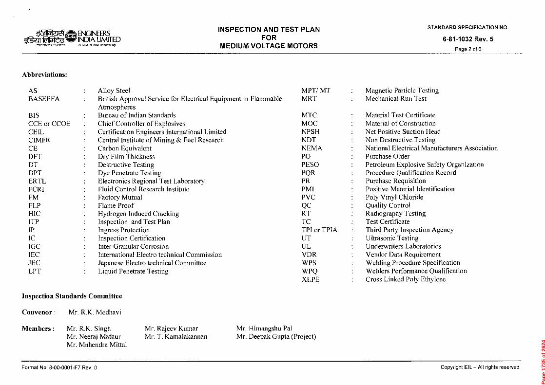
peaH uogons ong!sod Tax
1AI 1'001403B IELIO1T01\1
Jam) asegoind
!ZI
co
CD
CDcn
■-r
0
0
0 .A921 L3-1.000-00-8 'oN
4
eD
co co
Inspection Standards Committee
PvelIP31A1 •11A1
paniasal sly6u IIV — 113 11-160c100
:suo►e►toaqqy
s ADZ
r=r-r
, w rn
m •
cn
13
0
E -
4
5
o z
-I 0 2
•
p3
0
m
m
•Cn
0
-I
C4- -0
Cn
0)
tCD CD
N
.) 0 0)
'ON NOLLVOI3103dS ONVONVIS
g •neu Z£0 -b8-9
t--'
pj' =
,.,
. =
= =
t., *
T1
"r1
-7-1
cri r
z,
trd
inn
nn
o::
i>to
>
..-0- •
- 0
AD
mi- -
I —
a- •-
•- - .
=
• tri
= =
-t
=
o 4
'6'. (I
) (I
H 1
.,0
c4 6
. =
•-m
h co
-0
cD
rn,
i
•
g. (
(i)-) (.
7. P
■ ta
, -,
-4 0
,,
=4
=.
,,L,-..
=
0-, 5
0 ,
-, c
, =
H -
• .,
0
•-••
-I
•
crq
H a
y —
CD
—
.--
• AD
-c--t
2 =
v9
Q-
c4D
cn
/2„,
7....
CM
e,
0 .
- •
cn •
•-••
- '-•
) =
0 ,..1.)
CA,
C./)
CD
0 0
•
0 0
m
,--,'
("")
PD) r
ri
P
. ct
4. 6
. "d
-4
a
, ,...
.3 Gi
g '1
5
. ,
4
z--).
= 0
=
i,-7. C
CM
Fi.
=
CD
AD
AD
"''
E' m
-cn
5- • 5
5' ,
CD
=
.Z'.
=
" C
rg F
ir (
.1)
:1•-
c, ...
. cf)
0
n
FD
. Cr
g -t
O
P
cr
5, o
P
CD
v)
rrl
(-)
co
Fr
o
AD-1
FD s
3-
0
-'•
0
fm,
-,
co
,?
7d
F-
-cl.
CDC
AD
7'
cn C
'" co
- •
m
5'
AD
..0)
0
■=r
=-•
0
co
cr ?-17
r" .
0 .
0
r"
■ mmi r)
<
P:J
Er,
I C
D r
l C7
'71
cp
'd
'1
7 0
n
7d0
4 H
4 5>"
0
CD
CD
C1
/=
■—
t- ■
—• .
cn
.-t
0 •
-t-
= C
L .
1
■-1
4- C
I: P
.4- 0 0
-8 ca
. C
Z t
r
a . D
P
o ca
,n
cD
. 0
t/D
-1
-..
< .
...
= C
D _
t-
-4
=
0
,ty
m
<
IDD
CL
0
b-•
; C
P4 u.-
-, 1
. =
ID
D -
"
—
CD c D" ' F
. , ,
. .9
AD
(-)
=
F--
•
>., —
-0
‘<
0 =
C
D m
t 0 •
-t-
•CD
AD
m
co
an
=`
X
•E
md
S
., ?„?
r- (
44. v
, F;
4-3
0 =
'' 4
-1 =
AD
TZ
0 --
Cr is
mD-
DI.
o
AD
■-•
'0
-0
0
CD
..1.
•.:.1.
• '7 i
C<-
PD
`= I =
0 G
0 0
■-•
• cl
, O
0
• -,
. =
cD
01
-. 0
w <
:R
.
rd 0
cD
C./)
0
AD
O
. C
M
CD
= m
CD
'< '0
2
co C
"•
= C
D
>
■-• •
Z
Au
.-'---h
1 =
AD
En m
cfp
uc
t o
0
co
pa
co k.
.-
CD
■-- •
0
=
e-
+
(-)
o •
-,.
'-<
=
-I
AD
5
a.
CR
O a
Pp
=
=
N -- •
O
t-̀71
E E-
)" ("
)
,
-.) (m
.:In
n(-
) to
cd
>
.0
4(7-
r.;
(")
"id -
-3 "
ri r
d 5
rd n
46
;4 >
ci)
,7z2, E
l --]
H
,t
Emi
rri
cA
rd
g
rTi
r)
'-r1
r)
>
O
ml
Pag
e 17
35 o
f 26
24
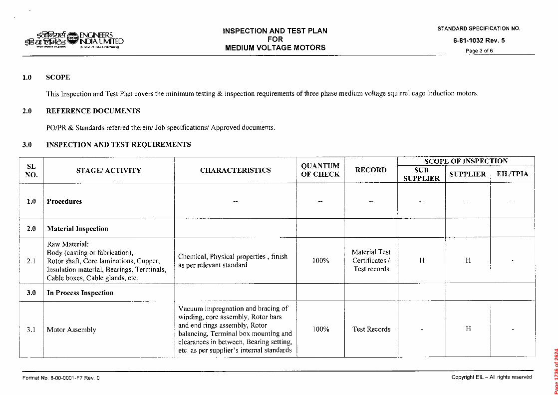
0 .A9:1 L'*1000-00-8 ON W111.103 pamasai sly6IJ IIV —113 11.16pAdo0
simawallmOni 1S 11 (my NOLLDIJSKI
PO/PR & Standards referred therein/ Job specifications/ Approved documents .
g i=1 g z n m O n
4 ril ,-i
This Inspection and Test Plan covers the minimum testing & inspection requi rements of three phase medium voltage squirrel cage induction motors .
Fa
0
"0
n)
(.0
0
Oa
0
a) E
m
v _ E
0
I— -
n
-1O
>
x
0
m
g
0
—i
0
X
Cn
9 -A81:1 Z£0VL8-9
z cn
m
c-)
—I 5 z
>
z
0
--1
m
cn
--1
-a I- D
z 'ON NOIIV3IA103dS CINVCINVIS
W
I,
3.0
IN )
1....
2.0
I ■ A
7::::+
SL NO.
Motor Assembly
In Process I nspection
Raw Material : Body (casting or fabrication) , Rotor shaft, Core l aminations, Copper, Insulation material, Bearings, Terminals, Cable boxes, Cable glands, etc .
Material Inspection
Proced ures
STAGE/ ACTIVITY
Vacuum impregnation and bracing of winding, core assembly, Rotor bars and end rings assembly, Rotor balancing, Terminal box mounting and clearances i n between, Beari ng setti ng, etc . as per supplier' s internal standards
Chemical, Physical properties , finish as per relevant standard
CHARACTERISTICS
1 -
-.
0
0
oN"--:'
100%
1 1
QUANTUM OF CHECK
Test Record s
Material Test Certificates / Test records
RECORD
e =
1 1
SUB SUPPLIER
SCOPl
SUPPLIER
E OF INSPECTION
■ 1
EIL/TPIA
Pag
e 17
36 o
f 26
24
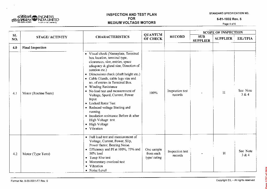
0 'A32:1 LA-W00-00-9 ON leuuod pa' esai sp.16!-I IIV -113 I46pAdo0
9 -"tau ZEOL-L13-9
'ON NOLLVOIJ133dS aavaNvis
.4,
Q_
4,
4.0
SL NO.
Motor (Type Tests)
4
2-, 0 .-, PzJ
0 .5-, '-'•
0 H
0 (,) r7
V) ,.....'
Final Inspection
STAGE/ ACTIVITY
•
Full load test and measurement of Voltage , Current, Power, Slip , Power factor, Beari ng Noise .
•
Efficiency and Pf at 1 00%, 75% and 50% load
•
Temp Rise test
•
Momentary overload test
•
Vibration
•
Noise Level
• <
--1 SW
...7...7'•
L.,
=
••
• •
• •
• •
• 5 <
Z
5 a
Z
7v
r'''
R
n '8
e-9 S
Cr <
64
• 6-Q-
• c..)
=
a
ci-.))
- . .
.....
:-,
p
,•
,..4_
(70"
CD
(:)
• =
="
= =
-,-
—
0
Cr
■er
..C
) ai
Z
'-'"
'-'•
C
f-F
AD
0
CL
CD
■-•
• ::0
...
-. po
< <
F4
=
C)
CL
CrqP
b-
=°
A)
°'-''
0
0 5
- CP
P a
,..CD
01. -
onv)
=00
20
C
M =
,,—
,—
, ...
PO
c4
(71)
r-t.
$'37) '
5
co ‘-
‹ co
,-F =
a
Fp' -,
, <
0 X
I "
= cc)
5.
co
q C
fQ
co
0
,--,
7.0
a?
Fo-
c4
r) R
° -
CD
CD
cr
Pr
0
V)
CL
s:__.,
c/D
‘?
0
,-
Al
"
CD
P
.--, •
=
cn
.-- •
' =
..-
N
■-1- ,
----,
Ej F
)(i)
trq
H
i:1"
= •
o CD
cA
) lo
CD
Z
R)
(i)
,__)
c/)
=
$1
) .-
-r =
C
/) (4
n
=
, a
p
o ,-,
=
CD
=
tt •
co fa)
q
fr'wo
,--
-,/o
.-I
co
(/
) ,...
r. rD
(c)
N.
. =1
• P
'IC
I M
I CD
CA
.
cD
co
B' •
= =
5
cm
P
- y)
.,-/
- ES
. 0
A)
(c)
=)
tz)
(4 ;C
s F.D4
' trc
, .'"
"
1:1)
'17
ci)
=.
''''• '0
co
co"
= o
co
g i
( 19 •
crg .
c o"
FL°
ot.
co '"
x
o 2
AD
.1
0
1))
,?:,,"
.-- •
0
g
='
'-11
0. C
O
=
'""
CD
,--r-
=
C)
0
•-1
•:...,
CHARACTERISTICS
`.' "1
0
. -,
Q)
SI)
0
n
,-+ p
5-
g.
-ti
CfQ
CT'
'CS
3.....
c,
C
) c::"
QUANTUM OF CHECK
c,
-, ts
co
co 0 0
o
'"-.
-t
6
0-
=
vt
F'D -,v)
5
c, "
io
CD
co 0 g
o
5.
ta.
=
v,
,.
0
et
...,-
RECORD
t t
SUB SUPPLIER I
SCOPl
X
SUPPLIER
E OF INSPEC'
C/)
CD
t....) ,
R°
z 4=,
2, o
C/)
CD
(4.)
co R
° z
-4.
2, o
EIL/TPIA
LION
Pag
e 17
37 o
f 26
24
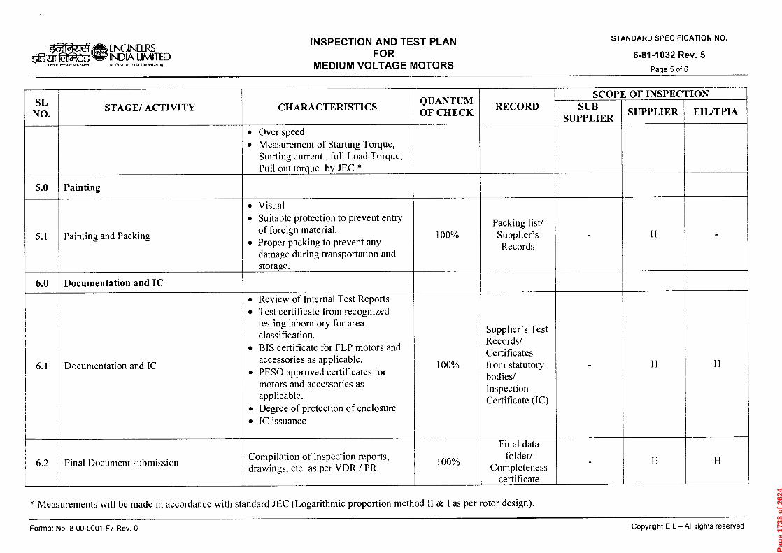
•Cl
)m
rri
•
-D
E '6
E
<
0
0 z
r' -
n
-I 0
> Z
m
O
Cl)
-1
C) •
>
Ci)
Z
—0
th
0 cn
'ON NOLLVOIA133dS Cl21VCINV1S
9 .nati Z£01.-1.8-9
01
i,....)
cp,
—
6.0
v,
—
5.0
SL NO.
Final Document submission
Documentation and IC
Documentation and IC
Painting and Packing
Painting
STAGE/ ACTIVITY
Compilation of Inspection reports , drawings, etc. as per VDR / PR
•Review of Internal Test Reports •
Test certificate from recognized testing laboratory for area classification .
•
BIS certificate for FLP motors and accessories as applicable .
•
PESO approved certificates for motors and accessories as applicable .
•
Degree of protection of enclosure
•
IC issuance
•
Visual
•
Suitable protection to prevent entry of foreign material .
•
Proper packing to prevent any damage during transportation and storage .
•
Over speed
•
Measurement of Starting Torque , Starting current , full Load Torque , Pull out torque by JEC *
CHARACTERISTICS
100%
c
c)
0
100%
QUANTUM OF CHECK
Final data folder/
Completeness certificate
cDrA
Co
nn
=
-•
CO
Fij •
.--
' • 0
"10
:I
t
011
" '—
: 0
e-.
.. -
-..
r-t-
0
ta.
FD
pa
o
■.-
i• ̀—'
CD
=
C
rD
cn
F.).
'..'
CD
CA
or—t-
Packing li st/ Supplier' s Records
RECORD
1 i
1
SUB SUPPLIER
SCOP1
x
x
SUPPLIER
x1
EIL/TPIA
TION
0 '^92:I LA-1.000-00-8 ON leWJOd pamasai sT461-1 IIV —113 ;q61.1Ado0
* Measurements will be made in accord ance with standard JEC (Logarithmic proportion method II & I as per rotor design) .
Pag
e 17
38 o
f 26
24
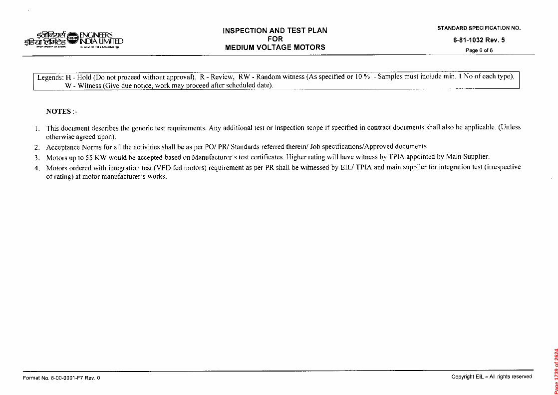
0 'Aa21 Ld-1000-00-8 ON 4ew.iod pamasai s1461.1 Ily —113 146pAdo3
CD
CrtD
C
c4
O_ CD
'H.
0
•••• •
,C=r) CD
CI.
0
o
•
r)
OCD
CL
.
-F).•
°
Og
;7)
'CS
•"
"CS
pa
o,:•-
•"'
0
CD
CD
e-•
a.
•pC
1 CD
ca n
<
— •
co
CD
•PZ
I
co 's
CL
7t
A
D A
D
CD
cl
•0
C
CD
C)
CD
0 - Samples must include min. 1 No of each type) ,
CD
CD
0
g •net! ZEO6-68-9
"ON NOLLVOld103dS 421VONV1S
H
IsJ
4 0 0 C
D
"1:23 C
co
0
0
cu
cn
$11 CD
co
co
0
fao
CD
CD
co
0
Cr
`CI 0(1)
0
AD
0
C
"CI co
0
C C CD
c/)
OH
CD
rn
. 0
(7
) o
CD
•CD
(74
rD
co
a a
.
-0
CA
co
o
•5-
: CD
co
(CD C
CD
(4
CD
0
C
CD
C
C
;I)
0
C
co
(/)
0
-o
C)
C
(4
0
-0
co
-C
CD
0
CD
C)
0
C
IDD'1
C)
0
C) C
co C
C
(4
0
cr co C- C $1,
-0
Pag
e 17
39 o
f 26
24

ENGINEERS INDIA LIMITED
ofroxe , (A Govt of India Undeflaking,
INSPECTION AND TEST PLAN FOR
STAINLESS STEEL PRESSURE VESSELS / COLUMNS
STANDARD SPECIFICATION No.
6-81-0014 Rev. 3
Page 1 of 7
,t-le),ti \Lao tiTR:r coio44ti
fttuur a trtaTur
INSPECTION AND TEST PLAN FOR
STAINLESS STEEL PRESSURE VESSELS / COLUMNS
3 09.09-2013 REVISED AND RE-ISSUED TKK KS
2 15.07.2011 REVISED AND RE-ISSUED HP SCG
1 15.07.08 REVISED AND RE-ISSUED NKR SSL
0 19.07.02 ISSUED FOR IMPLEMENTATION NKN SPS
Rev. No. Date Purpose
Prepared by
Checked by
Approved by
AKC
SKP
AKB
DM
DM
VC
GRR
Convenor Chairman Standards Committee Standards Bureau
Format No. 8-00-0001-F7 Rev. 0 Copyright El L — All rights reserved
Page 1740 of 2624
51?-ar laf5i-eg 1.17,7 eic,Pre JC.5.1
ENGINEERS INDIA LIMITED IA Govt of India Undertaking)
INSPECTION AND TEST PLAN FOR
STAINLESS STEEL PRESSURE VESSELS / COLUMNS
STANDARD SPECIFICATION No.
6-81-0014 Rev 3
Page 2 of 7
Abbreviations:
CEIL Certification Engineers International Limited MRT Mechanical Run Test CIMFR Central Institute of Mining & Fuel Research NDT Non Destructive Testing CE Carbon Equivalent NPSH Net Positive Suction Head DFT Dry Film Thickness PO Purchase Order DPT Dye Penetrant Testing PESO Petroleum Explosive Safety Organization DHT De-hydrogen Heat Treatment PQR Procedure Qualification Record ERTL Electronics Regional Test Laboratory PR Purchase Requisition FCRI Fluid Control Research Institute PMI Positive Material Identification HT Heat Treatment RT Radiography Testing HIC Hydrogen Induced Cracking SSCC Sulphide Stress Corrosion Cracking ITP Inspection and Test Plan TC Test Certificate IP Ingress Protection TPI or TPIA Third Party Inspection Agency IHT Intermediate Heat Treatment UT Ultrasonic Testing IC Inspection Certificate VDR Vendor Data Requirement IGC Inter Granular Corrosion WPS Welding Procedure Specification MPT/MT Magnetic Particle Testing WPQ Welders Performance Qualification MTC Material Test Certificate
Inspection Standards Committee
Convenor : Mr. S C Gupta
Members:
Mr. R.K. Singh
Mr. Rajeev Kumar Mr. Himangshu Pal Mr.Neeraj Mathur
Mr. T Kamalakannan Mr. Deepak Gupta (Project) Mr. Mayank Jain
Format No. 8-00-0001-F7 Rev. 0
Copyright EIL — All rights reserved
Page 1741 of 2624

ENGINEERS 2154-es INDIA LIMITED
10 Govt Al India Undertaking)
INSPECTION AND TEST PLAN FOR
STAINLESS STEEL PRESSURE VESSELS / COLUMNS
STANDARD SPECIFICATION No.
6-81-0014 Rev 3
Page 3 of 7
1.0 SCOPE
This Inspection and Test Plan covers the minimum testing requirements of Pressure vessels/ Columns stainless steel
2.0 REFERENCE DOCUMENTS
PO/PR/ Standards referred there in/ Job specifications /Approved documents.
3.0 INSPECTION AND TEST REQUIREMENTS
SL NO. STAGE/ ACTIVITY CHARACTERISTICS QUANTUM OF CHECK
RECORD SCOPE OF INSPECTION
SUB SUPPLIER
SUPPLIER EIL/TPIA
1.0 Procedures
1.1 Hydro test ,heat treatment, NDT,
hot forming, and other Procedures
Documented procedures. 100% Procedure
Documents - H R
1.2 WPS/ PQR /WPQ Documented procedures. 100% Procedure documents
- H R-Existing
W-New
2.0 Materials Inspection
2.1
Plates, pipes, forging, fittings , etc
(Supplier / sub supplier to arrange TPIA Certification)
As per PR / Purchase specification 100% Mill test
certificates and TPI reports
H H R
2.2 Expansion Bellows, Fasteners,
Gaskets, etc (As applicable) As per PR/Purchase
Specification 100% Mill TC H H R
Format No. 8-00-0001-F7 Rev. 0
Copyright EIL — All rights reserved
Page 1742 of 2624
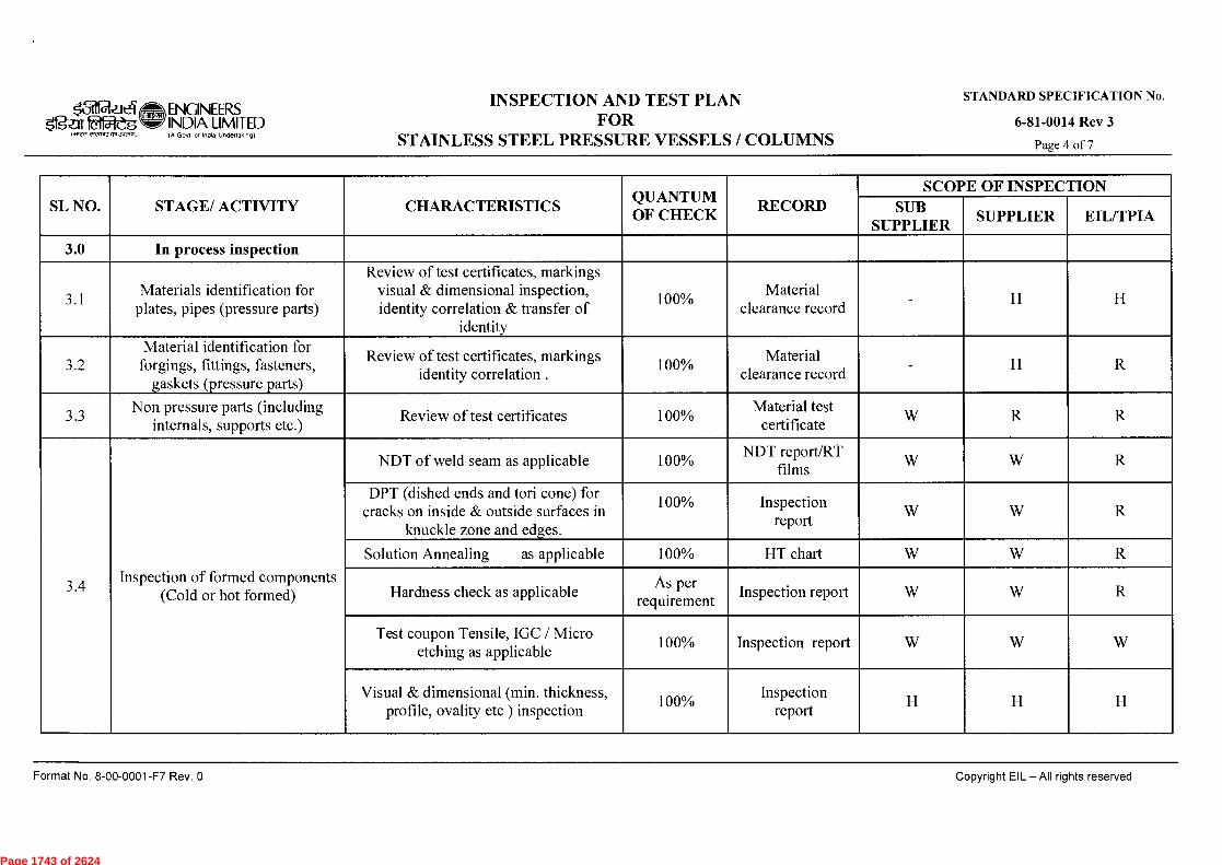
k̀ilif-aziel ENGINEERS
Ogzir taijteg INDIA LIMITED
INRR armor Jr21.11
IA Govt A India Undertaking)
INSPECTION AND TEST PLAN FOR
STAINLESS STEEL PRESSURE VESSELS / COLUMNS
STANDARD SPECIFICATION No.
6-81-0014 Rev 3
Page 4 of 7
SL NO. STAGE/ ACTIVITY CHARACTERISTICS QUANTUM OF CHECK
RECORD SCOPE OF INSPECTION
SUB SUPPLIER
SUPPLIER EIL/TPIA
3.0 In process inspection
3.1 Materials identification for
plates, pipes (pressure parts)
Review of test certificates, markings visual & dimensional inspection, identity correlation & transfer of
identity
100% Material
clearance record - H H
3.2 Material identification for
forgings, fittings, fasteners, gaskets (pressure parts)
Review of test certificates, markings identity correlation .
100% Material
clearance record H R
3.3 Non pressure parts (including
internals, supports etc.) Review of test certificates 100%
Material test certificate
W R R
3.4 Inspection of formed components
(Cold or hot formed)
NDT of weld seam as applicable 100% NDT report/RT
films W W R
DPT (dished ends and tori cone) for cracks on inside & outside surfaces in
knuckle zone and edges.
100% report
Inspection W W R
Solution Annealing as applicable 100% HT chart W W R
Hardness check as applicable As per
requirement Inspection report W W R
Test coupon Tensile, IGC / Micro etching as applicable
100% Inspection report W W W
Visual & dimensional (min. thickness, profile, ovality etc ) inspection
100% Inspection
report H H H
Format No. 8-00-0001-F7 Rev. 0
Copyright EIL - All rights reserved
Page 1743 of 2624
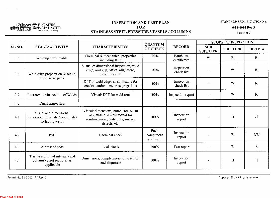
E ~w ENGINEERS
$fgaI fa5t&G INDIA LIMITED IA 000 01 India Undenakindi
INSPECTION AND TEST PLAN FOR
STAINLESS STEEL PRESSURE VESSELS / COLUMNS
STANDARD SPECIFICATION No.
6-81-0014 Rev 3
Page 5 of 7 1.17n ,107-+Yer ‘7,1,70,./
SL NO. STAGE/ ACTIVITY CHARACTERISTICS QUANTUM OF CHECK
RECORD SCOPE OF INSPECTION
SUB SUPPLIER
SUPPLIER EIL/TPIA
3.5 Welding consumable Chemical & mechanical properties
including IGC 100% Batch test
certificates W R R
3.6 Weld edge preparation & set up of pressure parts
Visual & dimensional inspection, weld edge, root gap, offset, alignment,
cleanliness etc 100%
Inspection Insp check list
W R
DPT of weld edges as applicable for cracks, laminations or segregations
100% Inspection check list
- W R
3.7 Intermediate Inspection of Welds Visual/ DPT for weld root 100% Inspection report W R
4.0 Final inspection
4.1 Visual and dimensional
inspection (internals & externals) including welds
Visual/ dimensions, completeness of assembly and weld visual for
reinforcement, undercuts, surface defects, etc.
report
100% Inspection
rt - H H
4.2 PMI Chemical check Each
component and weld
Inspection report
- W RW
4.3 Air test of pads Leak check 100% Test report - W R
4.4 Trial assembly of internals and
column/vessel sections as applicable
Dimensions, completeness of assembly and alignment
100% Inspection
report - H H
Format No. 8-00-0001-F7 Rev. 0
Copyright EIL — AII rights reserved
Page 1744 of 2624

15111a_At.-1 $1=g-ari&Wg
1.7F, c`feage 051.3rglr.
ENGINEERS INDIA LIMITED (A Govl ai Indo Undertaking)
INSPECTION AND TEST PLAN FOR
STAINLESS STEEL PRESSURE VESSELS / COLUMNS
STANDARD SPECIFICATION No.
6-81-0014 Rev 3
Page 6 of 7
SL NO. STAGE/ ACTIVITY CHARACTERISTICS QUANTUM OF CHECK
RECORD SCOPE OF INSPECTION
SUB SUPPLIER
SUPPLIER EIL/TPIA
4.5 Inspection of completed welds
PWHT as applicable 100% HT chart W R
Hardness test as applicable 100% Inspection report - W R
Production test coupon testing including IGC and micro etching as applicable
100% Inspection report - H H
NDT as applicable 100% NDT report/RT
films - W R
4.6 Water Quality Check Chloride Content 100% Inspection report - H R
4.7 Hydrostatic test Leak check 100% Test report - H H
4.8 Pickling/ passivation (inside and
outside surface) , drying of equipment
Visual inspection for cleanliness 100% Inspection report - W R
4.9 Drying and Nitrogen Filling (as
applicable) Nitrogen Pressure 100% Inspection report - W -
5.0 Painting
5.1 Final painting for carbon steel
portion (As applicable)
Visual inspection (after surface preparation and final painting for
workmanship, uniformity) DFT check 100% Inspection report - H -
Format No. 8-00-0001-F7 Rev. 0
Copyright EIL — All rights reserved
Page 1745 of 2624
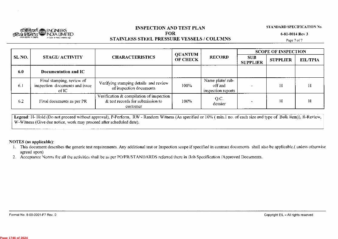
k31 _.1 ENGINEERS fg-af 1a15rdg INDIA LIMITED
(A Govf of India Undeflok,og)
INSPECTION AND TEST PLAN FOR
STAINLESS STEEL PRESSURE VESSELS / COLUMNS
STANDARD SPECIFICATION No.
6-81-0014 Rev 3
Page 7 of 7
SL NO. STAGE/ ACTIVITY CHARACTERISTICS QUANTUM OF CHECK
RECORD SCOPE OF INSPECTION
SUB SUPPLIER
SUPPLIER EIL/TPIA
6.0 Documentation and IC
6.1 Final stamping, review of
inspection documents and issue of IC
Verifying stamping details and review of inspection documents
100% Name plate/ rub-
off and inspection reports
- H H
6.2 Final documents as per PR Verification & compilation of inspection
& test records for submission to customer
100% .C.
doQssier - H H
Legend: H- Hold (Do not proceed without approval), P-Perform, RW - Random Witness (As specified or 10% ( min.1 no. of each size and type of Bulk item)), R-Review, W-Witness (Give due notice, work may proceed after scheduled date).
NOTES (as applicable): 1. This document describes the generic test requirements. Any additional test or Inspection scope if specified in contract documents shall also be applicable.( unless otherwise
agreed upon) 2. Acceptance Norms for all the activities shall be as per PO/PR/STANDARDS referred there in /Job Specification /Approved Documents.
Format No. 8-00-0001-F7 Rev. 0
Copyright EIL - All rights reserved
Page 1746 of 2624
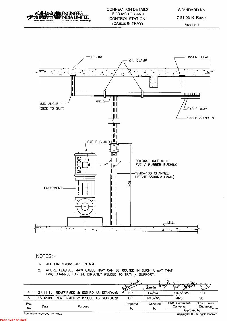
Rev. No. Date Purpose
Prepared Checked by by
Stds. Committee Stds. Bureau Convenor Chairman
Approved by
ENGINEERS INDIA LIWIITED (A Govf. of locno Undoftokb9)
CONNECTION DETAILS FOR MOTOR AND
CONTROL STATION (CABLE IN TRAY)
STANDARD No.
7-51-0314 Rev. 4
Page 1 of 1 laiRrt ~13re ral.~.1)
CEILING
INSERT PLATE
A
n.
M.S. ANGLE
(SIZE TO SUIT)
CL I O O
OBLONG HOLE WITH PVC / RUBBER BUSHING
ISMC-100 CHANNEL HEIGHT 3500MM (MAX.)
0
CABLE TRAY
CABLE SUPPORT
CABLE GLAND
1 I 11
WELD
c c EQUIPMENT
F.F.L.
NOTES:- 1. ALL DIMENSIONS ARE IN MM.
2. WHERE FEASIBLE MAIN CABLE TRAY CAN BE ROUTED IN SUCH A WAY THAT ISMC CHANNEL CAN BE DIRECTLY WELDED TO TRAY / SUPPORT.
>d)'"'
4 21.11.13 REAFFIRMED & ISSUED AS STANDARD G BP FA/SA UAP/JMS SC 3 13.02.09 REAFFIRMED & ISSUED AS STANDARD BP RKS/NS JMS VC
Format No. 8-00-0001-F4 Rev.O Copyright EIL - All rights reserved
Page 1747 of 2624
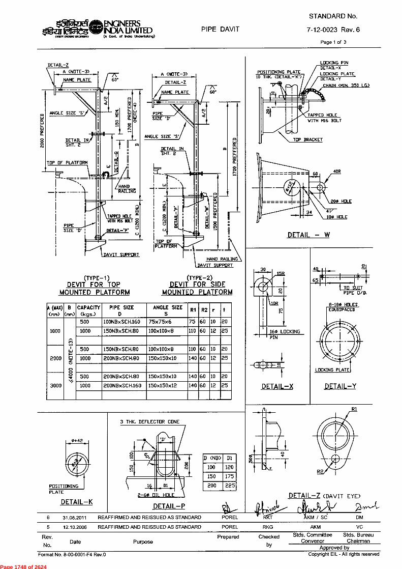
Rev.No. Date Purpose
Prepared Checkedby
Stds. Committee Stds. BureauConvenor Chairman
Approved byCopyright EIL - All rights reservedFormat No. 8-00-0001-F4 Rev.0
(TYPE-1)DEVIT FOR TOP
MOUNTED PLATFORM
(TYPE-2)
DEVIT FOR SIDEMOUNTED PLATFORM
LOCKING PINDETAIL-XLOCKING PLATEDETAIL-Y
POSITIONING PLATE10 THK. (DETAIL 'K')
DETAIL-ZA (NOTE-3)NAME PLATE 60'
ANGLE SIZE 'SI
DETAIL INSHT. 2
TOP OF PLATFORM
I
TAPPED HOLE z
WITH M16 DOLT 8cuDETAIL-70
1.--1)DAVIT SUPPORT
aq
HAND RAILING
PIPE SIZE 'D' 1
WL_
X IXa- Zo
In co0N
1
0
, TOP OFI PLATFORM
ANGLE SIZE 'S'
HAND RAILING
r=•
L.
A (MAX)
Cm)B
(rim)CAPACITY
Ckgs.)PIPE SIZE
DANGLE SIZE
S R1 R2 r t
1000
(CiI'—200::/.
500 100NBxSCH.160 75x75x6 75 60 10 20
1000 150NBxSCH.80 100x100x8 110 60 12 25
2000
500 150NBxSCH.80 100x100x8 110 60 10 20
1000 200NBxSCH.80 150x150x10 140 60 12 25
3000
500 200NBxSCH.80 150x150x10 140 60 10 20
1000 200NBxSCH.160 150x150x12 140 60 12 25
mw
TAPPED HOLEWITH M16 BOLT
TOP BRACKET
a •
DETAIL — W
4Q N
65 TO SUITPIPE O/D.
8-180 HOLESEQUISPACED
LOCKING PLATE
DETAIL—Y
6 31.08.2011 REAFFIRMED AND REISSUED AS STANDARD
5 12.10.2006 REAFFIRMED AND REISSUED AS STANDARD
4---POREL
POREL
DETAIL—Z (DAVIT EYE)
KM / SC DM
AKM VCRKG
R1
160 LOCKINGPIN
DETAIL—X
POSITIONINGPLATE
DETAIL—K
3 THK. DEFLECTOR CONE
DETAIL—P
PIPE DAVIT(WM
STANDARD No.
7-12-0023 Rev. 6
Page 1 of 3
lagE1eMENGINEERSeg fiffleellir INDIA LIMITED
(A Govt. of India Undertaking)
D (NB) D1
100 120
150 175
225200
Page 1748 of 2624
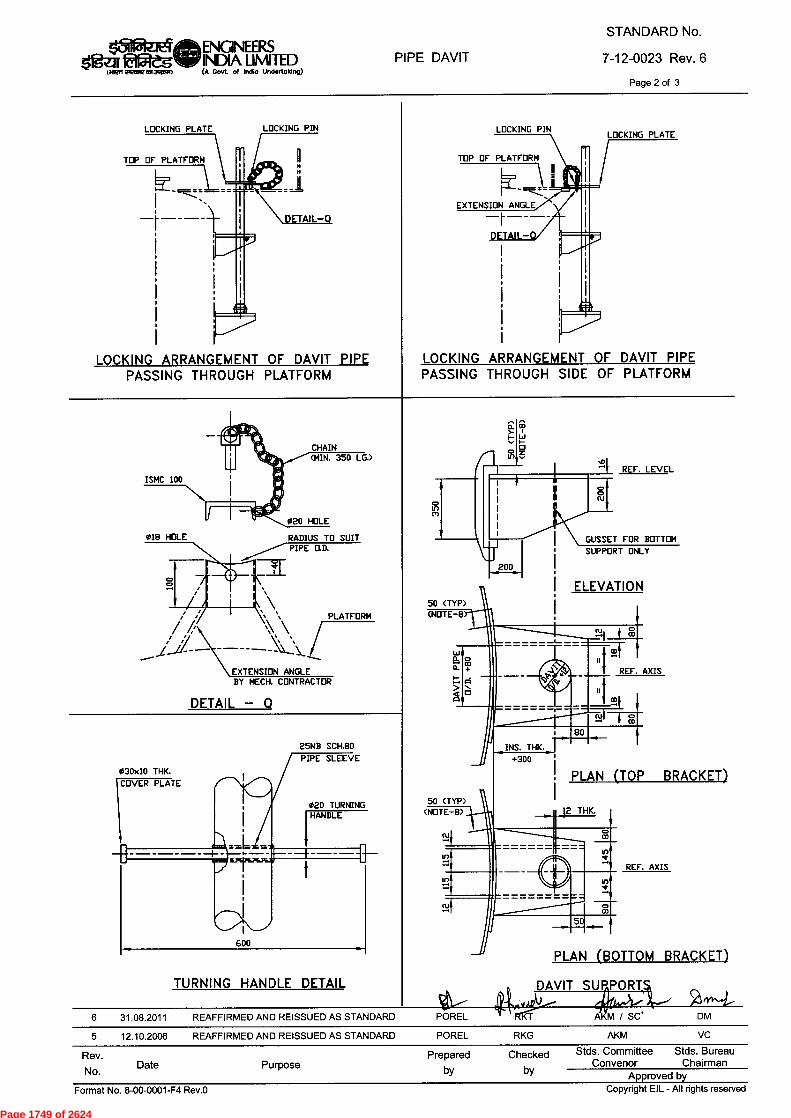
Copyright EIL - All rights reservedFormat No. 8-00-0001-F4 Rev.0
Rev.No.
Date PurposePrepared Checked
by by
Stds. Committee Stds. BureauConvenor Chairman
Approved by
LOCKING PLATE
TOP OF PLATFORM
—
DETAIL-
LOCKING ARRANGEMENT OF DAVIT PIPEPASSING THROUGH PLATFORM
LOCKING PIN LOCKING PIN
TOP OF PLATFORM
EXTENSION ANGLE— -
LOCKING PLATE
LOCKING ARRANGEMENT OF DAVIT PIPEPASSING THROUGH SIDE OF PLATFORM
CHAIN(MIN. 350 LG.)
RADIUS TO SUIT PIPE O.D.
N \PLATFORM
EXTENSION ANGLE BY MECH. CONTRACTOR
DETAIL — Q
25NB SCH.80PIPE SLEEVE
020 TURNING
030x10 THK.
6 31.08.2011
5 12.10.2006 REAFFIRMED AND REISSUED AS STANDARD
50 (TYP)(NOTE-8
REF. AXIS
80INS. THK.
+300
12
PLAN (TOP BRACKET)
THK.
AXIS
BRACKET)
REF.in
0
(BOTTOMPLAN
DAVIT SUPPORT ..../
RKT 447CAIM DM
RKG AKM VC
POREL
POREL
REF, LEVEL
GUSSET FOR BOTTOMSUPPORT ONLY
ELEVATION
REAFFIRMED AND REISSUED AS STANDARD
ISMC 100
018 HOLE
TURNING HANDLE DETAIL
PIPE DAVITMen
STANDARD No.
7-12-0023 Rev. 6Page 2 of 3
laNzieMENGINEF_RS*Iges Of5legNW INDIA LIMITED
(A Govt. of India Undertaking)
Page 1749 of 2624
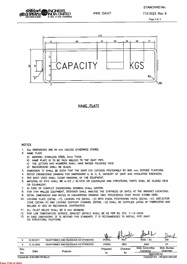
PIPE DAVIT(A Govt. of Indio Undortoldng)
STANDARD No.712-0023 Rev. 6
Page 3 of 3
IfilfazieM ENGLIINEERSejr fafflegNIF INDIA MITED
170
15 25 10 20 17
2 CAPACITY
KGS
17 60
to
NAME PLATE
NOTESALL DIMENSIONS ARE IN mm UNLESS OTHERWISE STATED.NAME PLATE
MATERIAL STAINLESS STEEL 2mm THICK.NAME PLATE IS TO BE TACK WELDED TO THE DAVIT PIPE.THE LETTERS AND NUMBERS SHALL HAVE RAISED POLISHED FACE.BACKGROUND SHALL BE BLACK.
DIMENSION 'A' SHALL BE SUCH THAT THE DAVIT EYE EXTENDS PREFERABLY BY 900 mm OUTSIDE PLATFORM.REFER ENGINEERING DRAWING FOR DIMENSIONS A, B, C, E, CAPACITY OF DAVIT AND INSULATION THICKNESS.THE DAVIT USED SHALL CLEAR HANDRAIL OF THE EQUIPMENT.MATERIAL OF PIPE SHALL BE A-53 / IS:1978 OR EQUIVALENT AND STRUCTURAL PARTS SHALL BE IS:2062 GR.BOR EQUIVALENT.IN CASE OF CONFLICT ENGINEERING DRAWING SHALL GOVERN.FOR THIN WALLED EQUIPMENT, DESIGNER SHALL ANALYSE THE STIFFNESS OF SHELL AT THE BRACKET LOCATIONS.DETAIL DIMENSIONS AND NOTES IN ENGINEERING DRAWING TAKE PRECEDENCE OVER THOSE SHOWN HERE.LOCKING PLATE (DETAIL —Y), LOCKING PIN (DETAIL —X) WITH CHAIN, POSITIONING PLATE (DETAIL —K), DEFLECTORCONE (DETAIL—P) AND LOCKING SUPPORT CHANNEL (DETAIL —Q) SHALL BE SUPPLIED LOOSE BY FABRICATOR ANDWELDED AT SITE BY MECHANICAL CONTRACTOR.ALL FILLET WELDS SHALL BE 6 mm MINIMUM.FOR LOW TEMPERATURE SERVICE, BRACKET DETAILS SHALL BE AS PER EIL STD. 7-12-0034
13. IN CASE DIMENSIONS 'B' IS BEYOND THIS STANDARD, IT IS RECOMMENDED TO INSTALL PIPE DAVITON STRUCTURAL PLATFORM.
-1(j491Ak.
KT KM / SC
t-/DM
RKG AKM VC
6 31.08.2011 REAFFIRMED AND REISSUED AS STANDARD POREL
5 12.10.2006 REAFFIRMED AND REISSUED AS STANDARD POREL
Rev.No. Date Purpose
Prepared Checkedby by
Stds. Committee Stds. BureauConvenor Chairman
Approved byFormat No. 8-00-0001-F4 Rev.O Copyright EIL - All rights reserved
Page 1750 of 2624

Page 1751 of 2624

Page 1752 of 2624

Page 1753 of 2624
Page 1754 of 2624
Page 1755 of 2624

Page 1756 of 2624
Page 1757 of 2624
\k.
CV/'' 7,Q
UAP/JMS SC
JMS VC
VPS SKG
SG AS
SKG RCPC
Standards Standards Comm ittee Bureau Convenor Chairman
Approved by
STANDARD SPECIFICATION No.
6-51-0031 Rev. 5 Page 1 of 18
SPECIFICATION FOR HIGH VOLTAGE INDUCTION MOTORS
ENGINEERS $ig-ar ffieg INDIA LIMITED
(A Govt of India Undeftalongl
d-wci 5c1-k111 r("R
f~r SPECIFICATION
FOR HIGH VOLTAGE
INDUCTION MOTORS
t '4•1■,. -
5 20.11.13 REVISED AND ISSUED AS STANDARD SPECIFICATION
SA BRB
4 26.09.07 REVISED AND ISSUED AS STANDARD SPECIFICATION
SD BRB
3 09.04.02 REVISED AND RE-ISSUED UG AAN
2 01.02.97 REVISED AND ISSUED AS STANDARD SPECIFICATION
AAN VPS
1 30.01.89 ISSUED AS STANDARD SPECIFICATION VPS VPS
Rev. No Date Purpose Prepared
by Checked by
Format No. 8-00-0001-F1 Rev. 0 Copyright EIL — All rights reserved
Page 1758 of 2624

ENGINEERS SPECIFICATION STANDARD SPECIFICATION No.
$1&:1T12-&g INDIA LIMITED FOR HIGH VOLTAGE INDUCTION 6-51-0031 Rev. 5 (A Govt of incha Undeltaking) MOTORS Page 2 of 18
1.1127f c.-W■srxeMIJVCISA)
Abbreviations:
BIS Bureau of Indian Standard BS British Standards CIMFR Central Institute of Mines and Fuel Research CT Current Transformer EIL Engineers India Limited FM Factory Mutual FRP Fiberglass Reinforced Plastic IEC International Electro-technical Commission IEEE Institute of Electrical & Electronics Engineers IS Indian Standard JEC Japanese Electro-technical Committee LCIE Laboratoire Central des Industries Electriques LRWT Locked Rotor Withstand Time NEMA National Electrical Manufacturers Association PO Purchase Order PVC Poly Vinyl Chloride p.u. per unit r.m.s Root Mean Square RPM Revolutions per Minute TETV Totally enclosed Tube Ventilated UL Underwriter's Laboratories VDE Verband Deutscher Elektrotechniker CEA Central Electricity Authority DOL Direct On line VFD Variable Frequency drive OEM Original Equipment manufacturers TPIA Third party Inspection Agency PESO Petroleum & Explosives safety organisation
Electrical Standards Committee
Convenor: Mr. UA Patro
Members: Mr. BR Bhogal Ms. S. Anand Mr. Parag Gupta Mr. A.K. Chaudhary Ms. N.P. Guha
Copyright EIL - All rights reserved Format No. 8-00-0001-F1 Rev. 0
Page 1759 of 2624
ENGINEERS SPECIFICATION STANDARD SPECIFICATION No.
INDIA LIMITED FOR HIGH VOLTAGE INDUCTION 6-51-0031 Rev. 5 Go" of India Undedok,nd) MOTORS Page 3 of 18
CONTENTS
1.0 SCOPE .4
2.0 CODES AND STANDARDS 4
3.0 GENERAL REQUIREMENTS .5
4.0 OPERATING CONDITIONS ..5
5.0 PERFORMANCE 7
6.0 CONSTRUCTION DETAILS 7
7.0 CONTROL, ALARM AND TRIP DEVICES 13
8.0 MISCELLANEOUS ACCESSORIES 14
9.0 NOISE LEVEL 16
10.0 MOTOR VIBRATIONS 16
11.0 CRITICAL SPEEDS 16
12.0 PAINTING 16
13.0 INSPECTION AND TESTING 16
14.0 CERTIFICATION . 17
15.0 PACKING AND DESPATCH 18
Format No. 8-00-0001-F1 Rev. 0 Copyright EIL — All rights reserved
Page 1760 of 2624

ENGINEERS SPECIFICATION STANDARD SPECIFICATION No.
$1g-ar IMf7111~1
6 INDIA LIMITED FOR HIGH VOLTAGE INDUCTION 6-51-0031 Rev. 5 IA Govl of India Undetalong) MOTORS Page 4 of 18
iffUn cv,er+W ,151~)
1.0 SCOPE
This specification covers the design, manufacture, testing, packing and supply of high voltage squirrel cage induction motors.
2.0 CODES AND STANDARDS
2.1 The squirrel cage induction motors and their components shall comply with the latest editions of following standards issued by BIS (Bureau of Indian Standards) unless otherwise specified:
IS - 5 Colours for ready mixed paints and enamels IS - 325Three phase induction motors IS - 1271 Thermal evaluation and classification of electrical insulation IS - 2071 Methods of high voltage testing IS - 2253 Designation for type & construction and mounting arrangement of
rotating electrical machines IS - 2968 Dimensions of slide rails for electrical motors IS - 4029 Guide for testing of three phase induction motors IS - 4889 Method of determination of efficiency of rotating electrical machines IS - 6362 Designation of methods of cooling of rotating electrical machines IS - 7816 Guide for testing insulation resistance of rotating machines IS - 8223 Dimensions and output series for rotating electrical machines IS — 8789 Values of performance characteristics for three phase induction motors IS - 12065 Permissible limits of noise level for rotating Electrical Machines IS - 12075 Mechanical vibration of Rotating Electrical Machines with shaft heights
56 mm and higher measurement, evaluation and limits of vibration severity
IS - 13529 Guide on effects of unbalanced voltages on the performance of three phase induction motors
IS - 13555 Guide for selection and application of three phase induction motors for different types of driven equipments
IS - 14222 Impulse voltage withstands levels of rotating electrical machines with form-wound stator coils
IS - 14568 Dimension and output series for rotating electrical machines, frame numbers 355 to 1000 and flange numbers 1180 to 2360
IS / IEC60079-0 Electrical apparatus for explosive gas atmospheres (General Requirements) IS/IEC60079-1 Equipment protection by Flame proof enclosures "d'. IS/IEC60079-2 Explosive protection by pressurized enclosure "p" IS/IEC60079-7 Explosive atmospheres-Equipment protection by increased safety —"e" IS/IEC60079-15 Electrical apparatus for explosive gas atmospheres Construction, test &
marking of type of protection "n" IS/ IEC: 60529 Degree of protection provided by enclosures (IP Code)
IS/IEC-60034-1 Rotating Electrical machines Rating & Performance.
IS/IEC-60034-5 Degrees of protection provided by enclosure for rotating electrical machinery.
IS/IEC 60034-8: Terminal marking and direction of rotation for rotating electrical machinery.
2.2 In case of imported motors, standards of the country of origin shall be applicable if these standards are equivalent or stringent than the applicable Indian Standards.
2.3 The motors shall also conform to the provisions of CEA regulations and other statutory regulations currently in force in the country.
Copyright EIL — All rights reserved Format No. 8-00-0001-F1 Rev. 0
Page 1761 of 2624
ENGINEERS SPECIFICATION STANDARD SPECIFICATION No.
INDIA LIMITED FOR HIGH VOLTAGE INDUCTION 6-51-0031 Rev. 5 t31
$1g-ar fafe5 Govt of India Undedaking) MOTORS Page 5 of 18
2.4 In case Indian Standards are not available, standards issued by IEC/BS/VDE/IEEE/JEC/NEMA or equivalent agency shall be applicable.
2.5 In case of any conflict between requirements specified in various applicable documents, the most stringent one shall prevail. However, owner's decision in this regard shall be final and binding.
3.0 GENERAL REQUIREMENTS
3.1 The offered equipment shall be brand new with state of the art technology and proven field track record. No prototype equipment shall be offered.
3.2 Vendor shall ensure availability of spare parts and maintenance support services for the offered equipment at least for 10 years from the date of supply.
3.3 Vendor shall give a notice of at least one year to the end user of equipment and EIL before phasing out the product/spares to enable the end user for placement of order for spares and services.
4.0 OPERATING CONDITIONS
4.1 Ambient Conditions
Motors shall be suitable for operating satisfactorily in humid and corrosive atmospheres found in refineries, fertilizer, petrochemical and metallurgical plants. Service conditions shall be as specified in the motor data sheet. If not specifically mentioned therein, a design ambient temperature of 40°C and an altitude not exceeding 1000 meters above mean sea level shall be taken into consideration.
4.2 Frequency and Voltage variations.
Unless otherwise agreed, motors shall be designed for continuous operation at rated output under the following conditions:
a) The terminal voltage differing from its rated value by not more than ± 6 % or b) The frequency differing from its rated value by not more than ± 3 % c) Any combination of (a) and (b)
4.3 Starting
a) Motors shall be designed for direct on line starting or other method of starting as specified in datasheet.
b) Motors shall be designed for re-acceleration with full load after a momentary loss of voltage with the possibility of application of 100% of the rated voltage when the residual voltage has dropped down to 50% and is in phase opposition to the applied voltage.
c) Motors shall be designed to allow the minimum number of starts on full load indicated in Table below:-
Min. Number of starts Up to 500 KW
500 to 1000 KW
Above 1000 KW
No. of consecutive start-ups with initial temperature of the motor at ambient level (cold.)
3 3 2
Copyright EIL — AII rights reserved Format No. 8-00-0001-F1 Rev. 0
Page 1762 of 2624

ENGINEERS SPECIFICATION STANDARD SPECIFICATION No.
$'gar 92es INDIA LIMITED FOR HIGH VOLTAGE INDUCTION 6-51-0031 Rev. 5 IA Govt of India Undenaking) MOTORS Page 6 of 18 .417,
2~ ,P727.4
No. of consecutive start-ups with initial temperature of the motor at 2 2 1
full load operating level (hot)
d) Unless otherwise specified, the locked rotor withstand time under hot condition at 100% voltage (time tE for increased safety i.e. Ex e motor) shall be minimum 5 seconds more than the starting time at 100 % voltage, under specified load conditions.
4.4 Unless otherwise stated in the motor data sheet, motors shall be suitable for starting at 80% of the rated voltage against the torque speed characteristics of the driven equipment.
a) Starting torque and minimum torque of the motor shall be compatible with the speed torque characteristics of the driven equipment under specified starting and operating conditions.
b) For heavy duty drives such as blowers, crushers, compressors etc., high starting torque motors shall be provided.
This shall be checked against the speed torque characteristics of the load and the thermal withstand characteristics of the motors.
4.5 The pull out torque at rated voltage shall be not less than 175 percent of the rated load torque with no negative tolerance. In case of motors driving equipments with pulsating loads (e.g. reciprocating compressors), the minimum value of the pull out torque at 80% of rated voltage shall be more than the peak value of the pulsating torque and the current pulsation shall be limited to 40%.
Unless otherwise agreed, the pull out torque shall not exceed 300% of the rated load torque.
4.6 Direction of rotation
Motors shall preferably be suitable for either direction of rotation. In case unidirectional fan is provided for motors, direction of rotation for which the motor is designed shall be permanently indicated by means of an arrow. Any alteration required for obtaining a change in the direction of rotation such as reversal of the fan, must be clearly specified. Motors which are suitable for only one direction of rotation shall have this direction of rotation clearly indicated on the motor together with the phase sequence of the terminals associated with this rotation in indelible marking. Motors suitable for bi-directional rotation shall be provided with a double headed arrow. Directional arrow should be manufactured from corrosion resistant material.
Normally, clockwise rotation is desired as observed from the driving (coupling) end, when the terminals ABC are connected to a supply giving a terminal phase sequence in the order ABC. Counter clockwise rotation of the motor shall be obtained by connecting the supply to terminals so that the phase sequence corresponds to the reversed alphabetical sequence of the terminal letters. Ample space shall be provided at the terminal box for interchanging external leads C and A for this purpose.
Copyright EIL — All rights reserved Format No. 8-00-0001-F1 Rev. 0
Page 1763 of 2624

ENGINEEFZS SPECIFICATION STANDARD SPECIFICATION No.
$1fg-ar 2faidg INDIA LIMITED FOR HIGH VOLTAGE INDUCTION 6-51-0031 Rev. 5 Ift Govt of Intha Undertakingt MOTORS Page 7 of 18
1.11277 232,7,retTR,~3)
5.0 PERFORMANCE
5.1 Motors shall be rated for continuous duty (S1 ), unless otherwise specified.
5.2 Motors shall have adequate torque to accelerate the load from zero to full speed under the specified starting and operating conditions.
5.3 Starting current shall be 500% subject to IS/IEC tolerance for motors up to 1000 kW. For motors above 1000 kW, it shall be agreed with purchaser for each case.
5.4 In particular cases, when the starting current is to be limited, care shall be taken such that the design values of torque meets the load requirement while at the same time complying with clause 4.3 above of this specification.
5.5 In particular cases, when the starting with reduced voltage is specified, care shall be taken such that the design values of torque meets the load requirement while at the same time complying with clause 4.4 and 4.5 above of this specification.
5.6 Motors fed by variable frequency drive shall additionally meet the following requirements:
5.6.1 The motors shall be suitable for the current wave forms produced by the power supply including harmonics generated by the drive.
5.6.2 The motors shall be designed to operate continuously at any speed over the range (1— 100%) of rated speed or as specified in data sheet. The characteristics shall be based on the application — in terms of constant torque / variable torque as per the driven equipment. Additional cooling fan shall be provided if required to limit the temperature rise to specified limits.
5.6.3 The motors shall withstand torque pulsation resulting from harmonics generated by the solid state power supply.
5.6.4 The motors required to be transferred to DOL bypass mode shall be rated for specified variations in line voltage and frequency.
6.0 CONSTRUCTION DETAILS
6.1 Windings
6.1.1 Motors shall be provided with class-F insulation. The permissible temperature rise above the specified ambient temperature shall be limited to those specified in the applicable Indian Standards for class-B insulation.
6.1.2 The windings, along with the stator, shall be tropicalised and shall be vacuum impregnated(resin poor type). Winding shall be adequately braced to prevent any relative movement during operation. In this respect, special care shall be taken for the stator windings of direct-on-line starting squirrel cage motors. Insulation shall be provided between coils of different phases which lie together.
6.1.3 Core laminations must be capable of withstanding burnout for rewind at 400°C without damage or loosening.
Copyright EIL — All rights reserved Format No. 8-00-0001-F1 Rev. 0
Page 1764 of 2624

11 ENGINEERS SPECIFICATION STANDARD SPECIFICATION No.
FOR HIGH VOLTAGE INDUCTION 6-51-0031 Rev. 5 5g-a 1&2e-g INDIA LIMITED CI,CP1t,R1~1) IA Govt of Inche Undertahrng) MOTORS Page 8 of 18
In case of motors driving equipment with pulsating loads, special attention shall be paid to the joints of rotor bars and end rings to avoid premature failures due to induced fatigue stresses.
For Ex n and Ex e motors, the conductor insulation must be carried right up to the terminal clamp.
6.1.4 Motors shall be designed to withstand impulse voltages specified in applicable Indian Standards/relevant IEC. The wave shape shall be as per IS/relevant IEC.
6.1.5 Windings of motors shall be star connected. For VFD fed motors, the main winding connected in `Delta' can also be considered acceptable subject to motor manufacturer having adequate proven track record.
6.2 Terminals, terminal boxes and cable entries
6.2.1 The ends of the winding shall be brought out into a terminal box. The terminations shall be by means of clamp type bushing or bushings with adequately sized bolted terminals. Line terminals shall be properly insulated from the frame with material resistant to tracking.
6.2.2 The terminal box shall be located on the right hand side viewed from the driving (coupling) end. Unless otherwise specified, the terminal box shall be suitable for side cable entry. The size of the cable end boxes shall be large enough to provide a minimum distance of 600 mm between cable gland plate and terminal lug.
6.2.3 The neutral point of the star windings shall also be brought out to a separate terminal box. This shall house the current transformers for differential protection of motors wherever required and shall be located on the opposite side of main terminal box.
6.2.4 The main and neutral terminal box shall be of fabricated sheet steel. The main terminal box shall be phase segregated type, unless otherwise agreed.
Motors can have elastimold phase insulated terminals in a common box. Ex d type (flame proof) motors can have phase insulated terminal box of Exd rating whereas Ex p type (pressurized) motors can have phase insulated terminal box of Ex d/Ex p rating. Ex d (Flameproof) motors with non phase segregated & non phase insulated flameproof terminal box duly tested at independent test laboratory can be considered acceptable subject to motor manufacturer having adequate proven track record.
6.2.5 The terminal box must be of robust construction, with necessary clearance, creepage distances between live parts and between live parts to earth considering air insulation and without any compound filling.
6.2.6 The terminal box shall be provided with pressure relief flaps/devices for increase safety i.e. Ex e motors, non-sparking i.e. Ex n motors and safe area motors, as per manufacturer's standard.
6.2.7 The terminal box shall be capable of withstanding the fault current for a period of 0.25 seconds specified in the motor data sheet.
6.2.8 Appropriate phase markings as per IS shall be provided inside the terminal box. The markings shall be non-removable and indelible.
Format No. 8-00-0001-F1 Rev. 0
Copyright EIL — All rights reserved
Page 1765 of 2624
ENGINEERS SPECIFICATION STANDARD SPECIFICATION No.
Og-u02eg INDIA LIMITED FOR HIGH VOLTAGE 1NDUCTION 6-51-0031 Rev. 5 (A Govt of ■rttha Undertalon91 MOTORS Page 9 of 18
1~1 rrrmrr en 3,70.1)
6.2.9 The terminal box shall be provided with entries for suitable cable glands corresponding to the size of the specified cables. Equipment and accessories provided shall conform to the hazardous area classification and the environmental conditions as specified in the motor data sheet.
6.2.10 An adequately sized earth terminal shall be provided for cable armour termination. It is essential that all metal parts (mounting rail and cable glands) are bonded and connected to the earth system. Bonding straps are also required across joints on non-active parts.
6.2.11 Separate terminal boxes shall be provided for space heaters, resistance temperature detectors and vibration probes.
6.2.12 Main and neutral terminal box covers must be provided with handles to facilitate easy removal.
6.3 Motor casing and type of enclosure
6.3.1 All Motors shall be suitable for installation directly outdoor and must have degree of protection corresponding to IP-55 as per IS.
6.3.2 All internal and external metallic parts, which can come into contact with cooling air (Piping, air supply and discharge conduits, protective grills air deflectors, filters and supports etc.) shall be of corrosion resistant material or appropriately treated to resist corrosive agents which may be present in the atmosphere. Screws and bolts shall be of rust proof material or protected against corrosion.
6.3.3 Effective equipotential bonding straps to guard against the occurrence of sparks due to presence of circulating currents shall be provided in type Ex n, Ex e and Ex p motors.
6.4 Bearing and lubrication
6.4.1 Motors shall have grease lubricated ball or roller type bearings or of the manufacturer's standard type. However, 2 pole motors above 750 kW rating shall be provided with sleeve bearings as a minimum. Sleeve bearings when provided shall be of proven design.
6.4.2 The bearings shall be chosen to give a minimum L- 10 rating life of 5 yrs. (40,000 hrs) at rated operating conditions.
(The L -10 rating life is the number of hours at constant speed that 90 % of a group of identical bearings will complete or exceed before the first evidence of the failure ).
6.4.3 Where bearing supports are attached to the motor casing adequate bracing shall be provided on these supports to reduce vibrations and ensure long life of the bearings. Bearings shall be adequate to absorb axial thrust in either direction produced by the motor itself or due to shaft expansion.
6.4.4 Motor bearings exposed to high temperatures (e.g. motors for hot oil/boiler feed pumps) shall have adequate provisions for cooling of bearings.
6.4.5 Vertical motors shall be provided with thrust bearings suitable for the load imposed by the driven equipment.
6.4.6 Motors shall be designed to permit removing/replacement of bearings.
Copyright EIL — All rights reserved Format No. 8-00-0001-F1 Rev. 0
Page 1766 of 2624
ENGINEERS SPECIFICATION STANDARD SPECIFICATION No.
$1g-ar INDIA LIMITED FOR HIGH VOLTAGE INDUCTION 6-51-0031 Rev. 5 (A Govt of India Undettaking) MOTORS Page 10 of 18
vnrnav on.intatIO
6.4.7 Grease lubricated bearings
Bearings shall be capable of grease injection from outside without removal of covers. The bearing boxes shall be provided with labyrinth seals, to prevent loss of grease or entry of dust or moisture. When grease nipples are provided, these shall be associated, where necessary, with appropriately located relief devices, which ensure passage of grease through the bearings.
The motors shall have facility for on-line greasing.
6.4.8 Sleeve bearings
Sleeve type bearings shall be fitted with oil rings for continuous lubrication. The oil reservoirs shall have a form suitable for allowing settling of any solids or residual particles contained in the oil.
The covers shall be provided with suitable openings for adding and draining oil, together with an overflow plug and level indication. The shaft shall have perfect seals so as to prevent entry of dust or moisture.
6.4.9 Forced lubrication bearings
The oil lubrication system shall be independent of the driven machine. Common lubrication system for the driven equipment and the motor can be accepted provided it is separate from the seal oil system. The common lubrication system shall be provided with suitable degassing equipments to extract gas reducing the probability of gas entering the motor.
In the independent lubrication system, oil supply shall be guaranteed by one of the following methods:
With a mechanical pump co-axial with the motor and supplemented by a separate electric motor driven pump for initial lubrication during start up and stopping operations.
With a separate electric motor driven pump. In this case the lubricating system shall consist of two identical motor driven pumps, one running and one acting as standby.
In addition to the pumps, the lubrication system shall be supplied complete with the following as a minimum:
a) An oil cooler of shell and tube type with tubes of inhibited admiralty brass. Internal coolers shall not be accepted. To prevent the oil from being contaminated, if the cooler fails, the oil side operating pressure shall be higher than the water side operating pressure.
b) An austenitic stainless steel oil reservoir with the following characteristic :
The capacity to avoid frequent filling, to provide adequate allowance for system rundown and to provide a retention time of at least 3 minutes to settle Provision to eliminate air and minimize flotation of foreign matter to the pump suction
Copyright EIL — All rights reserved Format No. 8-00-0001-F1 Rev. 0
Page 1767 of 2624

ENGINEERS SPECIFICATION FOR HIGH VOLTAGE
STANDARD SPECIFICATION No. ■31
$.1gzff 02&g INDIA LIMITED INDUCTION 6-51-0031 Rev. 5 ‘1,1,3~ IA Govt ot Ind,a UnclertaNingt MOTORS Page 11 of 18
Fill connections, reflex type level indicators and breathers suitable for outdoor use Sloped bottoms and connections for complete drainage Clean out openings as large as is practicable A bypass line that returns below the oil level to eliminate aeration and static electricity A thermostat with two electrical contacts for alarm & tripping in case of high oil temperature
c) A supply and return system
d) A duplex full flow filter with replaceable elements and filtration of 25 tm nominal or finer as recommended by the bearing manufacturer. Filter cartridge material shall be corrosion resistant. Metal mesh or sintered metal filter elements shall not be acceptable. The filter shall not be equipped with a relief valve or an automatic bypass
e) The motor driven auxiliary pumps shall be provided with suction stainer and an automatic/manual control system arranged to start automatically on low oil pressure and with manual shutdown only
0 Sight flow indicators in each bearing drain line
g) Temperature gauges (with thermowells) in the reservoir, after the oil cooler and each bearing drain line
h) Low oil pressure alarm and shutdown switches
i) A pressure gauge (valved for removal) for each pressure level and a pressure differential indicator to measure filter pressure drop
j) Thermostatically controlled electric immersion heater with a sheath of austenitic stainless steel for heating the charge capacity of oil before start-up in cold weather. The heating device shall have sufficient capacity to heat the oil in the reservoir from the specified minimum site ambient temperature to the start-up temperature, as required by the manufacturer, within 12 hours. The watt density of heater shall not exceed 2.33 watts per sq. mm.
k) The oil pumps shall have steel casings unless they are enclosed in a reservoir. All other oil containing pressure components shall be steel.
A control panel shall be provided for operation & control of the lubrication system. The control panel shall include fuses, electrical contactors and thermal relays for the protection and operation of the motor driven pumps, push-buttons, auxiliary relays and timer relays for the automatic and manual starting up and shutting down of the oil pump.
Equipment and accessories provided shall conform to the hazardous area and the environmental conditions specified in the motor data Sheet.
Armoured cables suitable for high temperature duty shall be used for extemal electrical connections between the control panel and the lubrication system.
Format No. 8-00-0001-F1 Rev. 0
Copyright EIL — All rights reserved
Page 1768 of 2624
■31 ENGINEERS SPECIFICATION STANDARD SPECIFICATION No.
51g-ar 051eg INDIA LIMITED FOR HIGH VOLTAGE INDUCTION 6-51-0031 Rev. 5 GoN of Indu UnOeflaking) MOTORS Page 12 of 18
t-Ircort'as■ JOONO
6.4.10 Bearing Insulation-Shaft Voltage
Induced voltage at the shaft end of the motor at no load shall not exceed 250 mV r.m.s. for roller and ball bearings and 400 mV r.m.s. for sleeve bearings. The non driving end bearing shall be insulated from the motor frame to avoid circulating current.
The insulated bearing end shield or pedestal shall bear a prominent warning and manufacturer shall provide detailed drawings showing insulation arrangement.
6.5 Cooling System
All motors shall preferably be self-ventilated. Motors with higher outputs having manufacturer's standard designs using forced ventilation cooling or closed circuit cooling employing external coolants may also be considered.
6.5.1 Self Ventilated Motors
A11 motors shall be fan cooled. The fans shall be of corrosion resistant material and appropriately protected. For fertilizer plants, brass or bronze are not permitted materials. The material of fan for motors to be used in hazardous areas shall be anti-static and non-sparking type.
Motors for installation in dusty atmospheres or in the presence of sand, fuels or other suspended solid particles in the air shall be fitted with filters for the cooling air. The filters shall be easily accessible for inspection and removable for cleaning and re-use. The material of the filters and supports trays shall be rust proof or protected against oxidation or corrosion.
6.5.2 Motors with forced ventilation
Motors with forced ventilation shall be equipped with two motor driven fans each capable of supplying the full quantity of cooling air required by the motor at full load.
Where air cooler design permits provision of one fan only; the second fan shall be supplied loose. Cooler design shall allow easy replacement of fan in such case.
The ventilating system shall include the flanges for the air intake and the mating flanges for the discharge ducts. An airflow indicator as described in paragraph 7.3 (a) shall also be provided.
Motors and fans used for forced ventilation shall conform to the hazardous area classification and environmental conditions specified in the motor data sheet.
6.5.3 Motors with closed circuit cooling with water to air heat exchangers
The material of the heat exchangers shall be corrosion resistant (e.g. cupro-nickel alloy, muntz metal, admiralty brass) and suitable for the type of water used. The heat exchangers shall be designed for minimum water pressure of 5 kg / cm 2 and with head losses not greater than 0.5 kg / cm 2, unless otherwise agreed.
The heat exchangers shall be arranged by the side(s) of the motor, if possible. Screens shall be provided to protect the motor windings from water leaks or leakage in the tubes. Suitable drains shall be fitted for draining water in case of leakage. The cooling system
Copyright EIL — All rights reserved Format No. 8-00-0001-F1 Rev. 0
Page 1769 of 2624

ENGINEERS SPECIFICATION STANDARD SPECIFICATION No.
Og'w £42es INDIA LIMITED FOR HIGH VOLTAGE INDUCTION 6-51-0031 Rev. 5 IA Govt of Undertak,o9) MOTORS Page 13 of 18
(.1127,,,,man.3~1
shall include the trip and alarm devices mentioned in paragraph 7.3 (b). Heat exchangers for identical motors shall be interchangeable.
6.5.4 Motors with closed circuit cooling with air to air heat exchangers
The heat exchanger tubes shall be of steel or extruded aluminium. All exposed surfaces of the heat exchanger and of the motors shall be safeguarded against corrosion by immersion in varnish followed by baking.
Joints between the heat exchanger and the main body of the motor shall be sealed by weather-proof gaskets.
6.6 Rotor
The rotor shall be of squirrel cage type, dynamically balanced to provide a low vibration level and a long service Life to the bearings. The accepted values of vibrations for a motor at rated voltage and speed shall not exceed those given in the IS. The shaft ends shall be provided with suitably threaded hole or holes to facilitate the assembly or removal of couplings and bearing races.
6.7 Shaft extension
Motors shall be provided with a single, bare shaft extension with key way and key. Motor shaft shall be sized to withstand 10 times the rated design torque.
6.8 Lifting hooks
All motors shall be provided with lifting facility (i.e. hooks etc.) of adequate capacity.
For motors provided with heat exchangers, lifting facility shall also be provided for the heat exchanger.
6.9 Earth terminals
Two earth terminals shall be provided on the frame of each motor at diametrically opposite points. Minimum size of the stud shall be 12 mm. Necessary nuts and spring washers shall be provided for earth connection. These earth terminals shall be in addition to the earth terminals provided in the terminal box for earthing of the armour.
7.0 CONTROL, ALARM AND TRIP DEVICES
All electrical contacts for the devices described below (e.g. at sections 7.3 & 7.4) shall have a current carrying capacity not lower than 5 A and a minimum interrupting capacity of 1 A at 220 V DC or 5 A at 240 V AC.
The contacts shall be located in explosion proof or totally sealed housing according to the type of motor enclosure. The cable ends shall be brought together to the terminal box. Any external connections between the housing containing the relay contacts and the terminal box shall be carried out by insulated copper wires in steel conduits or by PVC insulated, armoured, copper conductor cables with cable entries through double compression type cable glands.
Copyright EIL — All rights reserved Format No. 8-00-0001-F1 Rev. 0
Page 1770 of 2624
ENGINEERS SPECIFICATION STANDARD SPECIFICATION No.
5-fg-ar Ofdleg INDIA LIMITED FOR HIGH VOLTAGE INDUCTION 6-51-0031 Rev. 5 IA Govt of Indw Undertaking) MOTORS Page 14 of 18
tmZrt ofsfewfut~)
7.1 Measurement of winding temperature
Motors with outputs greater than 750 KW or those provided with filters for cooling air irrespective of output shall be provided with platinum resistance temperature measuring devices of 100 ohms resistance at 0°C and a temperature co-efficient of 3.85 x 10 -3 located in suitable positions to measure the winding temperature. A minimum of three (one per phase) detectors shall be provided between the coil sides to measure the winding temperature and three (one per phase ), preferably at the base of the slots, to measure core temperature, each placed 120° apart. TETV motors may not be provided with core temperature detectors.
A separate terminal box shall be provided for the temperature detectors for hook up with a remote located control / monitoring unit.
7.2 Measurement of bearing temperature
Motors with sleeve type self-lubricated bearing shall be provided with :
a) Two mercury bulb type, indicating dial thermometers for checking of bearing temperatures.
b) For motors with output greater than 750 KW, a resistance type of temperature measuring device shall be provided for bearings with connections terminating in the common terminal box for winding temperature detectors.
7.3 Measurement of cooling medium for heat exchangers
Motors with forced ventilation and those with air water heat exchangers shall be provided with: a) An airflow circulation indicator with electrical trip contacts that operate if the
flow of cooling air is interrupted or is inadequate. b) A cooling water flow circulation indicator with electrical trip contacts, which
close if the flow of cooling water is interrupted or is inadequate. The indicator shall be located on the discharge piping of the heat exchanger.
7.4 Pressurization Control Panel
All pressurized motors (Type Ex p) shall be provided with a control panel for controlling the initial purging and pressurization of the motor. The pressurization control panel shall be mounted on the motor itself and shall be suitable for the hazardous area classification specified in the motor data sheet.
The panel shall be complete with but not limited to the following items : Timers
-
Push buttons for purging/pressurization
-
Solenoid valves/dampers Indicating lamps for purging ON, purging OVER etc. Pressure switches and flow switches with alarm and trip contacts.
8.0 MISCELLANEOUS ACCESSORIES
8.1 Current transformers
Unless otherwise specified, motors rated 1500 KW and above shall have differential protection and shall be equipped with current transformers suitably designed for installation in the neutral terminal box.
Copyright EIL — All rights reserved Format No. 8-00-0001-F1 Rev. 0
Page 1771 of 2624
ENGINEERS SPECIFICATION STANDARD SPECIFICATION No.
$'gzrr IMfdleg INDIA LIMITED FOR HIGH VOLTAGE INDUCTION 6-51-0031 Rev. 5 IA Govt of looia Undedakongi MOTORS Page 15 of 18
e../cnfc',771~1)
Unless otherwise specified, the CTs shall be supplied along with the motor and mounted in the terminal box, which shall be suitable for housing the CTs and providing the necessary connections. CT terminals shall be brought out to a separate auxiliary terminal box.
These transformers shall have a secondary current of 1 A, and the characteristics of the CTs (Vk, RcT and Im) shall be finalized at detailed engineering stage in consultation with the purchaser. CT ratio shall be as indicated in the motor data sheet.
8.2 Anti condensation heaters
All motors shall be provided with 240 V anti-condensation heaters, sized and located so as to prevent condensation of moisture during shut down periods. The heaters shall remain 'ON' when the motor is not in service and shall not cause damage to the windings.
Motors with heaters installed in hazardous atmospheres (Zone-1 or Zone-2), shall conform to the provisions of applicable Indian standards and temperature classification specified in the motor data sheet.
The heater leads shall be brought out to a separate terminal box of the same specification and grade of protection as the main power terminal box.
A warning label with indelible red inscription shall be provided on the motor to indicate that the heater supply shall be isolated before carrying out any work on the motor.
8.3 Special tools and spanners
Motors with special features (e.g. motors with single bearing, explosion proof and increased safety motors) shall be provided with a set of spanners and special tools, required for dismantling and maintenance of the motor.
8.4 Motors shall be supplied complete with double compression Nickel plated brass (or Aluminum, if specifically required) cable glands, crimp type tinned Cu cable lugs for all power, space heater and auxiliary cables (for the specified cable sizes) and first filling of lube oil for forced lubricated bearings.
8.5 Auxiliary motors, if any, shall be as per relevant Indian / International standards and shall be suitable for the hazardous classification as specified in the motor data sheet.
8.6 Name plates
A stainless steel name plate manufactured from series 300 stainless steel and having information as per IS shall be provided on each motor. In addition to the motor rating plate, a separate number plate for motor tag number shall be fixed in a readily visible position. This number shall be as per the motor data sheets.
Additional information as stipulated in applicable Standards shall be included in the name plate for motors meant for use in hazardous atmospheres.
Copyright EIL — All rights reserved Format No. 8-00-0001-F1 Rev. 0
Page 1772 of 2624
ENGINEERS SPECIFICATION STANDARD SPECIFICATION No.
off INDIA LIMITED FOR HIGH VOLTAGE INDUCTION 6-51-0031 Rev. 5 Govt 01 In0. Undeltaking) MOTORS Page 16 of 18
9.0 NOISE LEVEL
The permissible noise level shall not exceed the stipulations laid down in IS.
10.0 MOTOR VIBRATION
Motor vibrations at bearing housing shall be within the limits of IS, unless otherwise specified for the driven equipment. Limits of shaft vibration for motors with sleeve bearings shall be as per IEC-60034-14. Two and four pole motors having sleeve bearings with forced oil lubrication shall be provided with proximity probes to measure the shaft vibration adjacent and relative to the bearings.
11.0 CRITICAL SPEEDS
The first actual critical speed of stiff rotors shall not be lower than 125% of the synchronous speed. For flexible rotors, this shall be between 60% and 80% of the synchronous speed. The second actual synchronous speed shall be above 125% of the synchronous speed.
12.0 PAINTING
All metal surfaces shall undergo manufacturer's standard cleaning /painting cycle. After preparation of the under surface, the equipment shall be painted with two coats of epoxy based final paint. Color shade of final paint shall be 632 of IS: 5/ RAL-7035. All unpainted steel parts shall be suitably treated to prevent rust formation. If these parts are moving elements, then these shall be greased.
13.0 INSPECTION AND TESTING
13.1 All tests shall be carried out at manufacturer's shop under his care and expense.
13.2 The manufacturer shall submit all internal test records of the tests carried out by him on the bought-out items, motor sub-assembly and complete motor assembly.
13.3 All the type, routine and other acceptance tests shall be witnessed by EIL Inspector/TPIA (appointed by OEM supplier.)
13.4 Tests certificates duly signed by the EIL Inspector/TPIA (appointed by OEM supplier.) shall be a part of final documentation. The following type tests (on one motor of each rating and frame size) shall be carried out as per applicable Indian Standards and shall form part of acceptance testing : a) Full load test and measurement of voltage, current, power & slip b) Measurement of starting torque, starting current, full load torque and pull out
torque c) Measurement of efficiency and p.f. at 100%, 75% and 50% load d) Temperature rise test e) Momentary overload test f) Tan delta test g) Measurement of noise level i) Over speed test i) Measurement of radial & axial clearance between fan & stationary parts &
measurement of radial air gap (if provision for measurement is not available in fully assembled motor stage records/calculations to be reviewed by Inspection)
til2R c0vente11,1,11r0,-.0
Format No. 8-00-0001-F1 Rev. 0
Copyright EIL — All rights reserved
Page 1773 of 2624
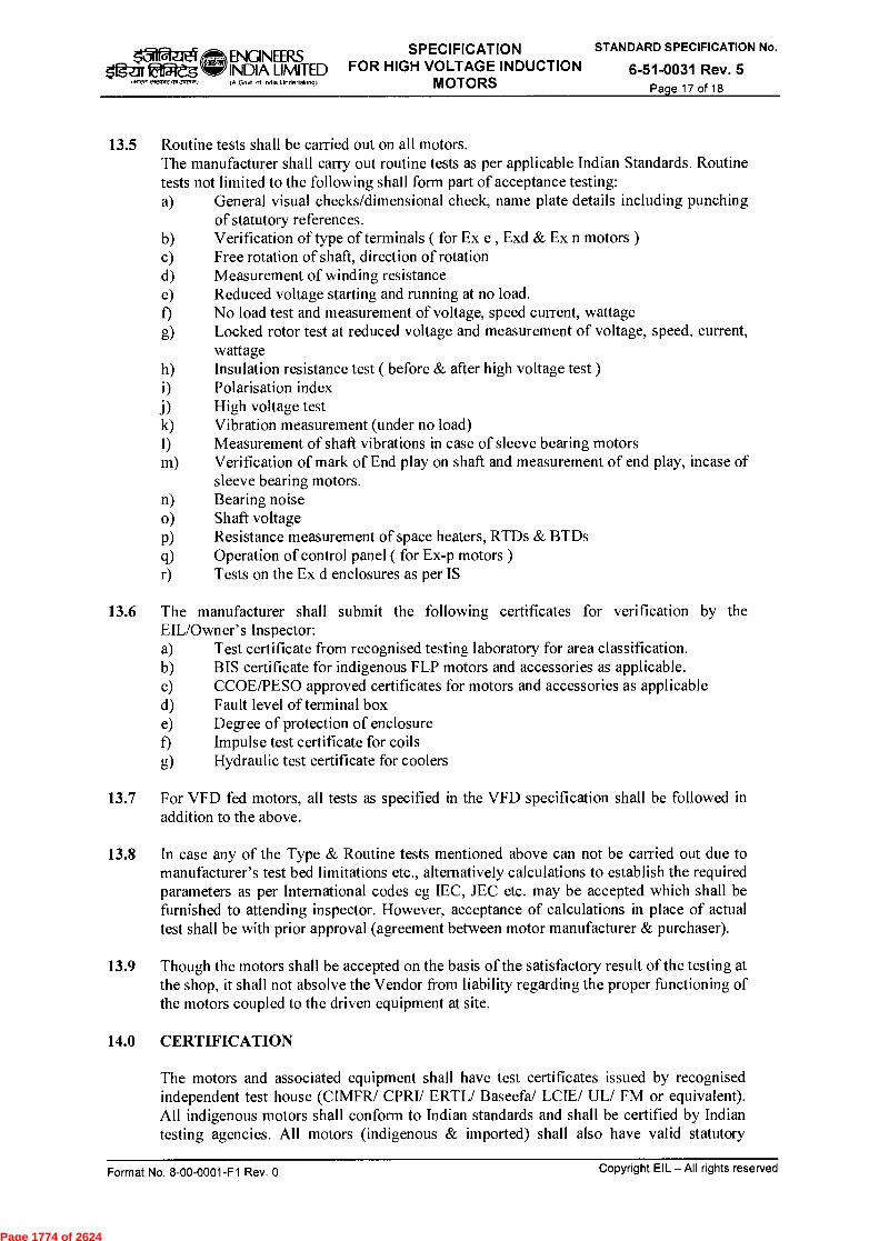
ENGINEERS SPECIFICATION STANDARD SPECIFICATION No.
INDIA LIMITED FOR HIGH VOLTAGE INDUCTION 6-51-0031 Rev. 5 A Govt of Incha Undertakm91 MOTORS Page 17 of 18
$ifg-ar ca C1,4>T2 J‘rcr.4
13.5 Routine tests shall be carried out on all motors. The manufacturer shall carry out routine tests as per applicable Indian Standards. Routine tests not limited to the following shall form part of acceptance testing: a) General visual checks/dimensional check, name plate details including punching
of statutory references. b) Verification of type of terminals ( for Ex e , Exd & Ex n motors ) c) Free rotation of shaft, direction of rotation d) Measurement of winding resistance e) Reduced voltage starting and running at no load. f) No load test and measurement of voltage, speed current, wattage
g) Locked rotor test at reduced voltage and measurement of voltage, speed, current, wattage
h) Insulation resistance test ( before & after high voltage test ) i) Polarisation index j) High voltage test k) Vibration measurement (under no load) I) Measurement of shaft vibrations in case of sleeve bearing motors m) Verification of mark of End play on shaft and measurement of end play, incase of
sleeve bearing motors. n) Bearing noise o) Shaft voltage p) Resistance measurement of space heaters, RTDs & BTDs q) Operation of control panel ( for Ex-p motors ) r) Tests on the Ex d enclosures as per IS
13.6 The manufacturer shall submit the following certificates for verification by the EIL/Owner's Inspector: a) Test certificate from recognised testing laboratory for area classification. b) BIS certificate for indigenous FLP motors and accessories as applicable. c) CCOE/PESO approved certificates for motors and accessories as applicable d) Fault level of terminal box e) Degree of protection of enclosure f) Impulse test certificate for coils g) Hydraulic test certificate for coolers
13.7 For VFD fed motors, all tests as specified in the VFD specification shall be followed in addition to the above.
13.8 In case any of the Type & Routine tests mentioned above can not be carried out due to manufacturer's test bed limitations etc., altematively calculations to establish the required parameters as per International codes eg IEC, JEC etc. may be accepted which shall be furnished to attending inspector. However, acceptance of calculations in place of actual test shall be with prior approval (agreement between motor manufacturer & purchaser).
13.9 Though the motors shall be accepted on the basis of the satisfactory result of the testing at the shop, it shall not absolve the Vendor from liability regarding the proper functioning of the motors coupled to the driven equipment at site.
14.0 CERTIFICATION
The motors and associated equipment shall have test certificates issued by recognised independent test house (CIMFR/ CPRI/ ERTL/ Baseefal LCIE/ UL/ FM or equivalent). All indigenous motors shall conform to Indian standards and shall be certified by Indian testing agencies. All motors (indigenous & imported) shall also have valid statutory
Copyright EIL — All rights reserved Format No. 8-00-0001-F1 Rev. 0
Page 1774 of 2624

31 ENGINEERS SPECIFICATION STANDARD SPECIFICATION No.
Ogu 2f51-'dg INDIA LIMITED FOR HIGH VOLTAGE INDUCTION 6-51-0031 Rev. 5 (A Govt ol InOia Undedaking) MOTORS Page 18 of 18
,~ s-frcnr2 M,3,1-0.1)
approvals (e.g. PESO, DGMS etc. as applicable for the specified location. All indigenous flameproof motors shall have valid BIS license and marking as required by statutory authorities.
15.0 PACKING AND DESPATCH
All the equipment shall be divided into several sections for protection and ease of handling during transportation. The equipment shall be properly packed for transportation by ship/rail or trailer. The equipment shall be wrapped in polythene sheets before being placed in crates/cases to prevent damage to finish. Crates/cases shall have skid bottom for handling. Special notations such as Tragile', `This side up', `Centre of gravity', `Weight', `Owner's particulars', `PO Nos.' etc. shall be clearly marked on the package together with other details as per purchaser order.
The equipment may be stored outdoors for long periods before installation. The packing shall be completely suitable for outdoor storage in areas with heavy rains/high ambient temperature, unless otherwise agreed.
Copyright EIL — All rights reserved Format No. 8-00-0001-F1 Rev. 0
Page 1775 of 2624
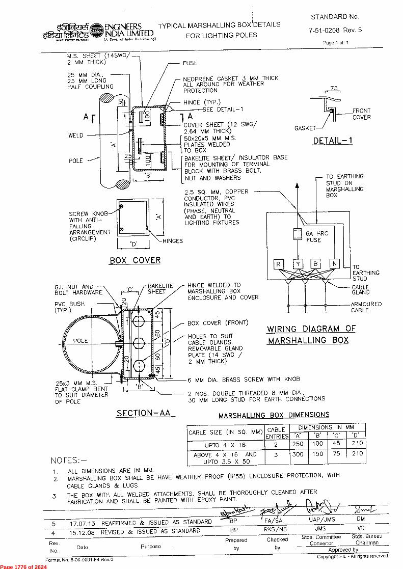
M.S. SHEET (14SWG/ 2 MM THICK)
25 MM DIA., 25 MM LONG HALF COUPLING
WELD
POLE
SCREW KNOB WITH ANTI—FALLING ARRANGEMENT (CIRCLIP)
'D' j HINGES
BOX COVER
ENGINEERS TYPICAL MARSHALLING BOX DETAILS INDIA LIMITED FOR LIGHTING POLES (A Govt. of Indio Undertaking)
STANDARD No.
7-51-0208 Rev. 5
Page 1 of 1
FUSE
NEOPRENE GASKET 3 MM THICK ALL AROUND FOR WEATHER PROTECTION
HINGE (TYP.) -SEE DETAIL-1 A
COVER SHEET(12 SWG/ 2.64 MM THICK) 50x20x5 MM M.S. PLATES WELDED TO BOX BAKELITE SHEET/ INSULATOR BASE FOR MOUNTING OF TERMINAL BLOCK WITH BRASS BOLT, NUT AND WASHERS
2.5 SQ. MM, COPPER CONDUCTOR, PVC INSULATED WIRES (PHASE, NEUTRAL AND EARTH) TO LIGHTING FIXTURES
75
GASKET
DETAIL-1
FRONT COVER
TO EARTHING STUD ON MARSHALLING BOX
G.I. NUT AND BOLT HARDWARE
PVC BUSH (TYP.)
BAKELITE HINGE WELDED TO SHEET MARSHALLING BOX
ENCLOSURE AND COVER
BOX COVER (FRONT)
HOLES TO SUIT CABLE GLANDS. REMOVABLE GLAND PLATE (14 SWG / 2 MM THICK)
TO EARTHING STUD
CABLE GLAND
ARMOURED CABLE
WIRING DIAGRAM OF MARSHALLING BOX
'C'
25x3 MM M.S. FLAT CLAMP BENT L TO SUIT DIAMETER OF POLE
SECTION-AA
NOTES:-
6 MM DIA. BRASS SCREW WITH KNOB
2 NOS. DOUBLE THREADED 8 MM DIA., 30 MM LONG STUD FOR EARTH CONNECTIONS
MARSHALLING BOX DIMENSIONS
CABLE SIZE (IN SQ. MM) CABLE ENTRIES
DIMENSIONS IN MM
'A' 'B' 'C"D'
UPTO 4 X 16 2 250 100 45 210
ABOVE 4 X 16 AND 3 300 150 75 210
UPTO 3.5 X 50
1. ALL DIMENSIONS ARE IN MM.
2. MARSHALLING BOX SHALL BE HAVE WEATHER PROOF (IP55) ENCLOSURE PROTECTION, WITH
CABLE GLANDS & LUGS.
3. THE BOX WITH ALL WELDED ATTACHMENTS, SHALL BE THOROUGHLY CLEANED AFTER FABRICATION AND SHALL BE PAINTED WITH EPDXY PAINT.
5 17.07.13 REAFFIRMED & ISSUED AS STANDARD BP FA/SA UAP/J MS DM
4 15.12.08 REVISED & ISSUED AS STANDARD BP RKS/NS JMS VC
Prepared Checked Stds. Committee Stds. Bureau
Date Purpose Convenor Chairman by by Approved by
Rev.
No. Copyright EIL - All rights reserved
Format No. 8-00-0001-F4 Rev.O
Page 1776 of 2624
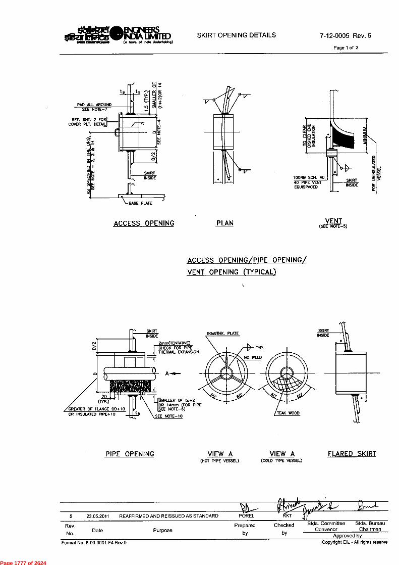
SKIRTINSIDE
100NB SCH. 4040 PIPE VENIEQUISPACED
VENT(SEE NOTE-5)
NPAD ALL AROUND
SEE NOTE-7
REF. SHE 2 FORCOVER PLT. DETAIL
SKIRTINSIDE
BASE PLATE
ACCESS OPENING PLAN
SKIRTINSIDE
cv II 2mm(TENTATIVE)CHECK FOR PIPETHERMAL EXPANSION.
80x6THK. PLATE
OR INSULATED PIPE+10S
MALLER OF tx+2OR 14mm (FOR PIPESEE NOTE-6)
SEE NOTE-10
.C110Eet/IINGNEEI6dliturletuleGNIFINDIA UMITED
oimmumwommose (A Govt. of Indio Undertaking)
SKIRT OPENING DETAILS 7-12-0005 Rev. 5
Page 1 of 2
ACCESS OPENING/PIPE OPENING/VENT OPENING (TYPICAL)
PIPE OPENING VIEW A VIEW A FLARED SKIRT(HOT TYPE VESSEL)
(COLD TYPE VESSEL)
5 23.05.2011 REAFFIRMED AND REISSUED AS STANDARD POREL
KT
Rev. PreparedDate PurposeNo. by
Checkedby
Stds. Committee Stds. BureauConvenor Chairman
Approved by Format No. 8-00-0001-F4 Rev.0
Copyright EIL - All rights reserve
Page 1777 of 2624
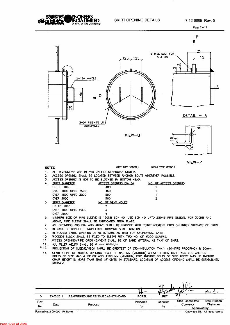
Page 2 of 2
P
2-120 HANDLE
3-50 PINS-15 LGEQUISPACED
VIEW—Q
6 WIDE SLOT FOR
1
5 23.05.2011 REAFFIRMED AND REISSUED AS STANDARD POREL RKT
0.4014"XeWhINGNEERSOBZIPPleSNIFINDIALIMITED
mom mime illoamPO (A Govt. of Indio Undertaking)SKIRT OPENING DETAILS 7-12-0005 Rev. 5
VIEW—PNOTES (HOT TYPE VESSEL) (COLD TYPE VESSEL)
ALL DIMENSIONS ARE IN mm UNLESS OTHERWISE STATED.ACCESS OPENING SHALL BE LOCATED BETWEEN ANCHOR BOLTS WHEREVER POSSIBLE.ACCESS OPENING IS NOT TO BE BLOCKED BY BOTTOM HEAD.SKIRT DIAMETER ACCESS OPENING DIA.(D) NO. OF ACCESS OPENINGUP TO 1000 400 1OVER 1000 UPTO 1500 450 1OVER 1500 UPTO 3000 500 1OVER 3000 500 2SKIRT DIAMETER NO. OF VENT HOLESUP TO 1000 2OVER 1000 UPTO 2000 3OVER 2000 4MINIMUM SIZE OF PIPE SLEEVE IS 150NB SCH 40. USE SCH 40 UPTO 250NB PIPE SLEEVE. FOR 300NB ANDABOVE, PIPE SLEEVE SHALL BE FABRICATED FROM PLATE.ALL OPENINGS 300 DIA. AND ABOVE SHALL BE PROVIDE WITH REINFORCEMENT PADS ON INNER SURFACE OF SKIRT.IN CASE OF CONFUCT ENGINEERING DRAWING SHALL GOVERN.IN FLARED SKIRT, OPENING DETAIL IS SAME AS THAT FOR CYLINDRICAL SKIRT.WOODEN BLOCK SHALL BE FIXED TO SLEEVE WITH TWO NO. OF WOOD SCREWS.
ACCESS OPENING/PIPE OPENING/VENT SHALL BE OF SAME MATERIAL AS THAT OF SKIRT.ALL FILLET WELDS SHALL BE 6 mm MINIMUM.
* 13. PROJECTION OF SLEEVE/NECK SHALL BE GREATEST OF (30+INSULATION THK.), (30+FIRE PROOFING) & 50mm.
14. CENTER LINE OF ACCESS OPENING SHALL BE 850 MM (MINIMUM) ABOVE BOTTOM BASE RING FOR ANCHORBOLTS OF SIZE M45 & BELOW AND 1100 MM (MINIMUM) FOR ANCHOR BOLTS OF SIZE ABOVE M45. IF ANCHORCHAIR HEIGHT IS MORE THAN THAT OF GIVEN IN STANDARD. LOCATION OF ACCESS OPENING SHALL BE ESTABLISHEDSUITABLY.
Rev.
No.Date Purpose
Preparedby
Checked Stds. Committee Stds. Bureau
bConvenor Chairman y Approved by
Format No. 8-00-0001-F4 Rev.0 Copyright EIL - All rights reserve
Page 1778 of 2624

laRtze ENGINEERS fafRegNIFINDIA LIMITED TOP HEAD TYPE
iiiw ecReelVaX3,10543) (A Govt. of Indio Undertaking)
(FOR VERTICAL VESSELS / COLUMNS)
STANDARD No.7-12-0024 Rev. 7
Page 1 of 1
LIFTING LUG
SECTION XX
MAX. ERECTION WT. OF VESSEL (TONNES) 410 25 45 90 140 180
THICKNESS OF PLATE (MINIMUM) T 12 28 40 50 70 80
WIDTH W 200 230 300 400 500 610
LENGTH L 400+E 460+E 580+E 750+E 900+E 1080+E
DIAMETER OF HOLE D 60 75 75 100 130 150
HEIGHT OF NOTCH & SIDE WELD H 130 130 150 200 250 300
RADIUS OF NOTCH R 40 40 50 75 90 100
WELD SIZE ( SEE NOTE 5 ) A 10 14 20 30 38 46
BOTTOM OF BRACE TO TOP OF LUG F 200 230 300 400 500 600
BOTTOM OF BRACE TO T.L OF HEAD E SEE NOTE 2
T.L. OF VESSEL TO BOTTOM OF LUG B 200 230 280 350 400 480
C 30 40 50 70 90 100
TOP OF LUG TO Q OF HOLE J 90 90 115 150 180 230
K 30 40 50 70 80 100
NO. OF LUGS 2 2 2 2 2 2
NOTES1. ALL DIMENSIONS ARE IN mm UNLESS OTHERWISE STATED.
*2. DIMENSION 'E' IS TO BE DETERMINED BY THE SHAPE OF HEAD IN CONJUNCTION WITH DIMENSION 'K'.DETAIL, DIMENSIONS AND NOTES GIVEN IN ENGINEERING DRAWING TAKE PRECEDENCE OVER THOSE SHOWN HERE.FOR THIN WALLED EQUIPMENTS, DESIGNER SHALL ANALYSE THE STIFFENESS OF SHELL AT THE LIFTING LUG LOCATION.IF PADS ARE USED ON STAINLESS STEEL EQUIPMENTS THE SIZE OF FILLET WELD BETWEEN SHELL AND STAINLESSSTEEL PAD SHALL BE ANALYSED.MATERIAL SHALL BE COMPATIBLE WITH HEAD MATERIAL.FOR INTERMEDIATE ERECTION WEIGHT, NEXT HIGHER SIZE OF LIFTING LUG SHALL BE USED.LIFTING LUG SHALL BE MACHINED TO COVER OFFSET BETWEEN OUTER DIAMETERS OF SHELL AND HEAD.
*IAIF7 31.08.2011 REAFFIRMED AND REISSUED AS STANDARD POREL RKT AKM SC DM
6 12.10.2006 REAFFIRMED AND REISSUED AS STANDARD POREL RKG AKM VC
Rev.No. Date Purpose
Prepared Checkedby by
Stds. Committee Stds. BureauConvenor Chairman
Approved byFormat No. 8-00-0001-F4 Rev.O Copyright EIL - All rights reserved
Page 1779 of 2624
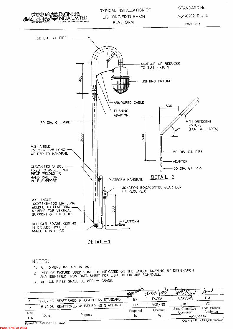
ADAPTOR OR REDUCER TO SUIT FIXTURE
LIGHTING FIXTURE
VIP
ARMOURED CABLE 500
BUSHING ADAPTOR
FLUORESCENT FIXTURE (FOR SAFE AREA)
0 0
50 DIA. G.I. PIPE
ADAPTOR
PLATFORM HANDRAIL DETAIL-2
JUNCTION BOX/CONTOL GEAR BOX (IF REQUIRED)
0 0 Li)
PLATFORM
Purpose Date Rev.
No.
VC RKS/NS JMS 4 17.07.13 REAFFIRMED & ISSUED AS STANDARD
3 15.12.08 REAFFIRMED & ISSUED AS STANDARD
Format No. 8-00-0001-F4 Rev.O
FA/SA UAP/JM DM
Stds. Committee Stds. Bureau Convenor Chairman
Approved by Copyright EIL - All rights reserved
BP
BP
Prepared Checked
by by
(31
517Z1119Rtg (44re woven.)
ENGINEERS INDIA LIMITED (A Govt. of India Undertaking)
TYPICAL INSTALLATION OF
LIGHTING FIXTURE ON
PLATFORM
STANDARD No.
7-51-0202 Rev. 4
Page 1 of 1
50 DIA. G.I. PIPE
50 DIA. G.I. PIPE
M.S. ANGLE 75x75x6-125 LONG WELDED TO HANDRAIL
GLAVANISED U BOLT FIXED TO ANGLE IRON PIECE WELDED TO HAND RAIL FOR POLE SUPPORT
M.S. ANGLE 100X75X6-100 MM LONG WELDED TO PLATFORM MEMBER FOR VERTICAL SUPPORT OF THE POLE
0 0
0 0 0 C•1
50 DIA. G.I. PIPE
0
REDUCER 50/25 RESTING IN DRILLED HOLE OF ANGLE IRON PIECE
DETAIL-1
NOTES:- 1. ALL DIMENSIONS ARE IN MM.
2. TYPE OF FIXTURE USED SHALL BE INDICATED ON THE LAYOUT DRAWING BY DESIGNATION AND IDENTIFIED FROM DATA SHEET FOR LIGHTING FIXTURE SCHEDULE.
3. ALL G.I. PIPES SHALL BE MEDIUM GRADE.
Page 1780 of 2624
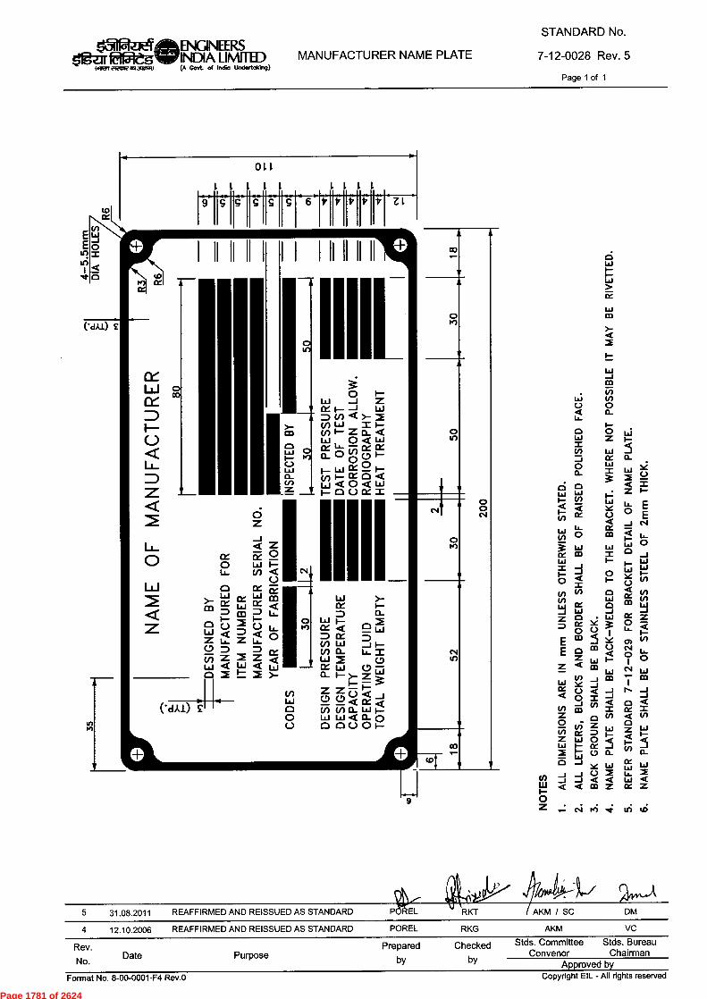
15iffazlee...111E1f5teg(llETI FIUME 115r3911771)
ENGINEERINDIA LIMI
STED
(A Govt. of Indio Undertaking)MANUFACTURER NAME PLATE
STANDARD No.
7-12-0028 Rev. 5Page 1 of 1
I-
fY
CO)-
W_1m1.5
L...; V)
C.) o
Q 0_Li_
I-
o o Liw
Z I—=La 5
Zi cc o_
0 Li)
a. = La0
M
ico a —7"
La La Z I-I- VI
-
1..J La.IX I- 0
IX C Efi)t -J N
,_ ixtaJ
in 0 00
a u.i—La
W W 0
CZ CD I JLa I— i— LaX -1 Lai LaI- -I I- 6< (n'-x
0 0 0 < 0V) w ct)m wLai IX 0-I ILI _i JZ 0 • I-Li ce= ix le 0 z
0 I LL 4'11-
E m -1 le a) V)
E 0 m .4() " L.
z ,, 1.- 0 o1Z < m N WW
V) __I co ,_ mLa le ..„ I
IX 0 < -J N _1
Q 0 i —I _1
_1 vi 4I 0 ..t
V1 m I cc ZZ 0 in ..t v)
..:= v, Z oLi) ce = Lai Z 1-61
I- < I-Z Lai 0 5
5w i— ce 1—
m 1- 0 0_ 0 0_
L i WXIC La La
Cl)-J 2< 2-J J () 4 Lull- 41
I- < < CO Z IX Z
0
Z Csi Iii 4 ui (IS
,/0/49-4-1"/ 5/44-k
5 31.08.2011 REAFFIRMED AND REISSUED AS STANDARD POREL RKT AKM / SC DM
4 12.10.2006 REAFFIRMED AND REISSUED AS STANDARD POREL RKG AKM VC
Rev.No. Date Purpose
Preparedby
Checkedby
Stds. CommitteeConvenor
Stds. BureauChairman
Approved byFormat No. 8-00-0001-F4 Rev.0
Copyright EIL - All rights reserved
Page 1781 of 2624
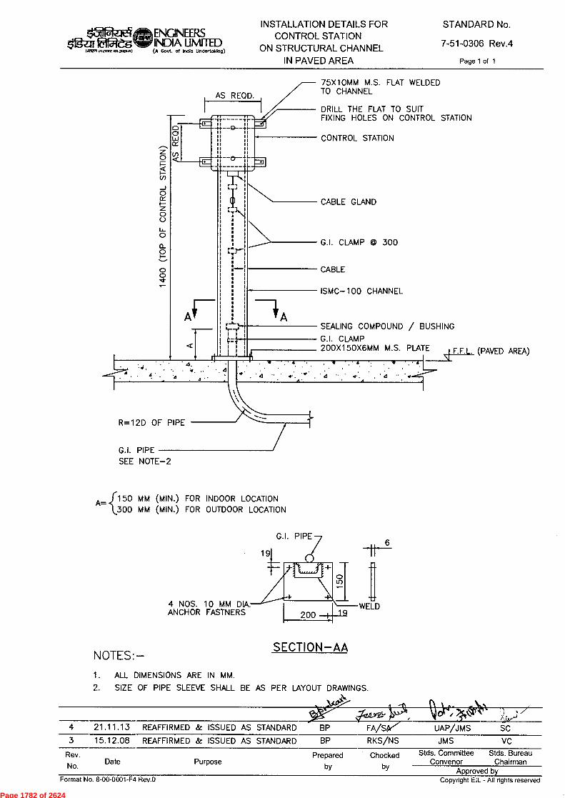
G.I. PIPE
4 NOS. 1 0 MM DIA. ANCHOR FASTNERS 200 I
WELD 19
ENGNEERS INDIA LIMI I IL) (A Govt. of Indio Undertoking)
INSTALLATION DETAILS FOR CONTROL STATION
ON STRUCTURAL CHANNEL IN PAVED AREA
STANDARD No.
7-51-0306 Rev.4
Page 1 of 1
AS REQD.
z O
cn
0
0
0 o_ 0
o 0
75X1OMM M.S. FLAT WELDED TO CHANNEL
DRILL THE FLAT TO SUIT FIXING HOLES ON CONTROL STATION
CONTROL STATION
CABLE GLAND
G.I. CLAMP
300
CABLE
ISMC— 1 00 CHANNEL
SEALING COMPOUND BUSHING
G.I. CLAMP 200X150X6MM M.S. PLATE F.F.L. (PAVED AREA)
R=12D OF PIPE
G.I. PIPE SEE NOTE-2
A= 150 MM (MIN.) FOR INDOOR LOCATION {300 MM (MIN.) FOR OUTDOOR LOCATION
NOTES:- SECTION-AA
1. ALL DIMENSIONS ARE IN MM.
2. SIZE OF PIPE SLEEVE SHALL BE AS PER LAYOUT DRAWINGS.
4 21 .1 1.1 3 REAFFIRMED & ISSUED AS STANDARD BP FA/S UAP/J MS
3 1 5.12.08 REAFFIRMED & ISSUED AS STANDARD
BP
RKS/NS
JMS
VC
Rev. No. Date Purpose
Prepared Checked by by
Stds. Committee Stds. Bureau Convenor Chairman
Approved by
Format No. 8-00-0001-F4 Rev.O Copyright EIL - All rights reserved
Page 1782 of 2624

STANDARD No.
7-12-0019 Rev. 5
Page 1 of 1
VORTEX BREAKERSBsICNEERSWA LIMITS)
Man VIRINVINOMPINI (A Govt. of Indio Undertaking)
tow
50
60 DRAIN HOLE FLUSHWITH VESSEL WALLUNLINED NOZZLE (TYP.)
50 FOR NOZZLES UPTO 250 NBAND 80 FOR NOZZLES ABOVE250 NB
---CLAD/WELD OVERLAYED NOZZLE(TYP)
4=10z
TYPE — 1A
3D0
60 DRAIN HOLE FLUSHWITH VESSEL WALL
TYPE — 1B
TYPE — 2A FOR NOZZLE NB 100
TYPE — 2B
PLAN VIEW FOR 1B AND 2B
FOR NOZZLE NB < 100
VESSELMATERIAL
CARBON STEEL/LOW ALLOY STEELALLOY / ALLOY CLAD/
ALLOY LINED CONCRETE LINED(NOTE-3b)
CORROSIONALLOWANCE 1.5 3 4.5 6 — —
THICKNESS 't' 6 8 12 14 5 5
WELD SIZE 'W' 6 6 8 8 5 5
NOTESALL DIMENSIONS ARE IN mm UNLESS OTHERWISE STATED.IN CASE OF CONFLICT ENGINEERING DRAWING SHALL GOVERN.
3.a) FOR ALLOY LINED VESSELS, THE BAFFLE MATERIAL SHALL BE SAME AS ALLOY LINING.b) FOR CONCRETE LINED VESSELS, THE BAFFLE MATERIAL SHALL BE ALLOY AS SPECIFIED
IN ENGINEERING DRAWING.REFER ENGINEERING DRAWING FOR DIMENSION 'B'.
DENOTES NOMINAL BORE SIZE OF SUBJECT NOZZLE.
5 30.07.2011 REAFFIRMED AND REISSUED AS STANDARD
4 11.09.2006 REAFFIRMED AND REISSUED AS STANDARD
Rev.
No. Date Purpose
POREL KT DMPOREL DNN AKM VC
Preparedby
Checkedby
Stds. CommitteeConvenor
Stds. BureauChairman
Approved byCopyright EIL - All rights reservedFormat No. 8-00-0001-F4 Rev.O
Page 1783 of 2624
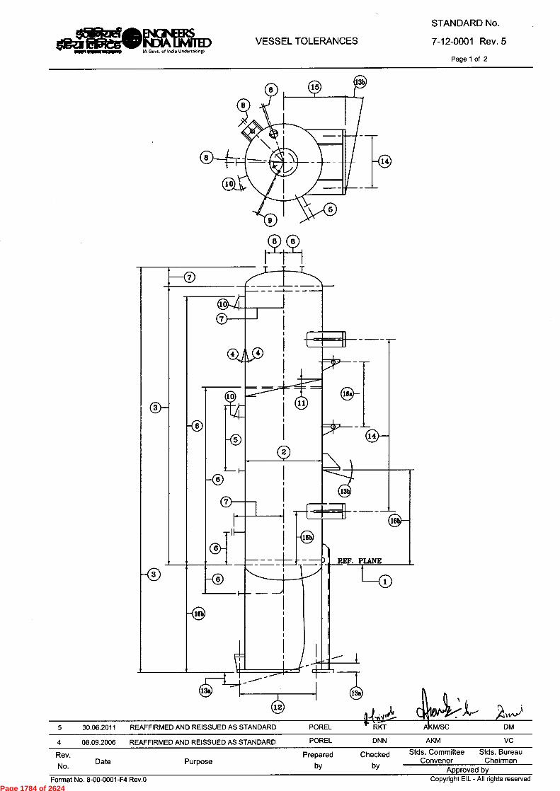
Offr ENGINEERSegeINDIA LIAM
(A Govt. of India Undertaking'
VESSEL TOLERANCESSTANDARD No.7-12-0001 Rev. 5
Page 1 of 2
REF. PLANE
ir4
5 30.06.2011 REAFFIRMED AND REISSUED AS STANDARD POREL RKT A M/SC DM
4 08.09.2006 REAFFIRMED AND REISSUED AS STANDARD POREL DNN AKM VC
Rev.No. Date Purpose
Preparedby
Checkedby
Stds. CommitteeConvenor
Stds. BureauChairman
Approved by
L -
Or
—U-
Format No. 8-00-0001-F4 Rev.0 Copyright EIL - All rights reservedPage 1784 of 2624
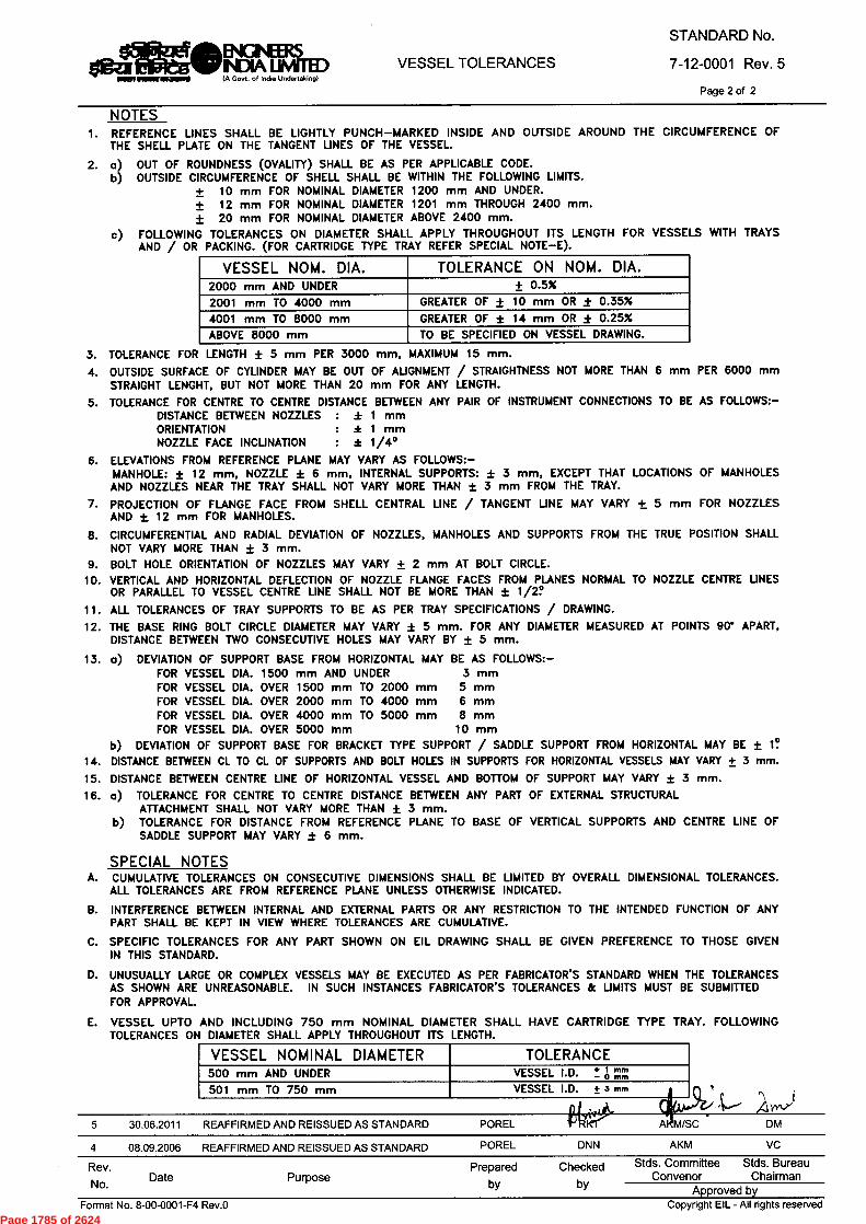
daMOENGINEERSINDIA MIMED/A Govt. of India Undertakingl
VESSEL TOLERANCESSTANDARD No.7-12-0001 Rev. 5
Page 2 of 2
NOTESREFERENCE LINES SHALL BE LIGHTLY PUNCH—MARKED INSIDE AND OUTSIDE AROUND THE CIRCUMFERENCE OFTHE SHELL PLATE ON THE TANGENT LINES OF THE VESSEL
a) OUT OF ROUNDNESS (OVALITY) SHALL BE AS PER APPLICABLE CODE.b) OUTSIDE CIRCUMFERENCE OF SHELL SHALL BE WITHIN THE FOLLOWING LIMITS.
10 mm FOR NOMINAL DIAMETER 1200 mm AND UNDER.12 mm FOR NOMINAL DIAMETER 1201 mm THROUGH 2400 mm.20 mm FOR NOMINAL DIAMETER ABOVE 2400 mm.
c) FOLLOWING TOLERANCES ON DIAMETER SHALL APPLY THROUGHOUT ITS LENGTH FOR VESSELS WITH TRAYSAND / OR PACKING. (FOR CARTRIDGE TYPE TRAY REFER SPECIAL NOTE—E).
VESSEL NOM. DIA. TOLERANCE ON NOM. DIA.2000 mm AND UNDER ± 0.5%2001 mm TO 4000 mm GREATER OF ± 10 mm OR ± 0.35%4001 mm TO 8000 mm GREATER OF t 14 mm OR ± 0.25%ABOVE 8000 mm TO BE SPECIFIED ON VESSEL DRAWING.
TOLERANCE FOR LENGTH t 5 mm PER 3000 mm, MAXIMUM 15 mm.OUTSIDE SURFACE OF CYLINDER MAY BE OUT OF ALIGNMENT / STRAIGHTNESS NOT MORE THAN 6 mm PER 6000 mmSTRAIGHT LENGHT, BUT NOT MORE THAN 20 mm FOR ANY LENGTH.
5. TOLERANCE FOR CENTRE TO CENTRE DISTANCE BETWEEN ANY PAIR OF INSTRUMENT CONNECTIONS TO BE AS FOLLOWS:—DISTANCE BETWEEN NOZZLES : * 1 mmORIENTATION : * 1 mmNOZZLE FACE INCLINATION : * 1/4°
ELEVATIONS FROM REFERENCE PLANE MAY VARY AS FOLLOWS:—MANHOLE: ± 12 mm, NOZZLE t 6 mm, INTERNAL SUPPORTS: t 3 mm, EXCEPT THAT LOCATIONS OF MANHOLESAND NOZZLES NEAR THE TRAY SHALL NOT VARY MORE THAN ± 3 mm FROM THE TRAY.PROJECTION OF FLANGE FACE FROM SHELL CENTRAL LINE / TANGENT LINE MAY VARY + 5 mm FOR NOZZLESAND ± 12 mm FOR MANHOLES.CIRCUMFERENTIAL AND RADIAL DEVIATION OF NOZZLES, MANHOLES AND SUPPORTS FROM THE TRUE POSITION SHALLNOT VARY MORE THAN ± 3 mm.BOLT HOLE ORIENTATION OF NOZZLES MAY VARY ± 2 mm AT BOLT CIRCLE.VERTICAL AND HORIZONTAL DEFLECTION OF NOZZLE FLANGE FACES FROM PLANES NORMAL TO NOZZLE CENTRE UNESOR PARALLEL TO VESSEL CENTRE UNE SHALL NOT BE MORE THAN t 1/2?ALL TOLERANCES OF TRAY SUPPORTS TO BE AS PER TRAY SPECIFICATIONS / DRAWING.THE BASE RING BOLT CIRCLE DIAMETER MAY VARY t 5 mm. FOR ANY DIAMETER MEASURED AT POINTS 90' APART,DISTANCE BETWEEN TWO CONSECUTIVE HOLES MAY VARY BY ± 5 mm.
a) DEVIATION OF SUPPORT BASE FROM HORIZONTAL MAY BE AS FOLLOWS:—FOR VESSEL DIA. 1500 mm AND UNDER 3 mmFOR VESSEL DIA. OVER 1500 mm TO 2000 mm 5 mmFOR VESSEL DIA. OVER 2000 mm TO 4000 mm 6 mmFOR VESSEL DIA. OVER 4000 mm TO 5000 mm 8 mmFOR VESSEL DIA. OVER 5000 mm 10 mm
b) DEVIATION OF SUPPORT BASE FOR BRACKET TYPE SUPPORT / SADDLE SUPPORT FROM HORIZONTAL MAY BE ± 1?DISTANCE BETWEEN CL TO CL OF SUPPORTS AND BOLT HOLES IN SUPPORTS FOR HORIZONTAL VESSELS MAY VARY ± 3 mm.DISTANCE BETWEEN CENTRE UNE OF HORIZONTAL VESSEL AND BOTTOM OF SUPPORT MAY VARY ± 3 mm.
16. a) TOLERANCE FOR CENTRE TO CENTRE DISTANCE BETWEEN ANY PART OF EXTERNAL STRUCTURALATTACHMENT SHALL NOT VARY MORE THAN t 3 mm.
b) TOLERANCE FOR DISTANCE FROM REFERENCE PLANE TO BASE OF VERTICAL SUPPORTS AND CENTRE LINE OFSADDLE SUPPORT MAY VARY ± 6 mm.
SPECIAL NOTESCUMULATIVE TOLERANCES ON CONSECUTIVE DIMENSIONS SHALL BE LIMITED BY OVERALL DIMENSIONAL TOLERANCES.ALL TOLERANCES ARE FROM REFERENCE PLANE UNLESS OTHERWISE INDICATED.
INTERFERENCE BETWEEN INTERNAL AND EXTERNAL PARTS OR ANY RESTRICTION TO THE INTENDED FUNCTION OF ANYPART SHALL BE KEPT IN VIEW WHERE TOLERANCES ARE CUMULATIVE.
SPECIFIC TOLERANCES FOR ANY PART SHOWN ON EIL DRAWING SHALL BE GIVEN PREFERENCE TO THOSE GIVENIN THIS STANDARD.
UNUSUALLY LARGE OR COMPLEX VESSELS MAY BE EXECUTED AS PER FABRICATOR'S STANDARD WHEN THE TOLERANCESAS SHOWN ARE UNREASONABLE. IN SUCH INSTANCES FABRICATOR'S TOLERANCES & UMITS MUST BE SUBMITTEDFOR APPROVAL.
E. VESSEL UPTO AND INCLUDING 750 mm NOMINAL DIAMETER SHALL HAVE CARTRIDGE TYPE TRAY. FOLLOWINGTOLERANCES ON DIAMETER SHALL APPLY THROUGHOUT ITS LENGTH.
VESSEL NOMINAL DIAMETER TOLERANCE500 mm AND UNDER VESSEL I.D. + 1 mm501 mm TO 750 mm VESSEL I.D. ± 3 mm A
5 30.06.2011 REAFFIRMED AND REISSUED AS STANDARD POREL AKM/SC DM
4 08.09.2006 REAFFIRMED AND REISSUED AS STANDARD POREL DNN AKM VC
Rev. Prepared Checked Stds. Committee Stds. BureauNo. Date Purpose by by
Convenor ChairmanApproved by
Format No. 8-00-0001-F4 Rev.0 Copyright EIL - All rights reservedPage 1785 of 2624

240 ROD
PIPE 'El' SCH. 8000
TELL TALE HOLE
3N0.—M16 SS JACK SCREWSON BOLT CIRCLE DIAMETER
( SEE NOTE-3 )
B(OD)420 1.5 THK. S.S. WASHER
30 VENT
1
1
6R 15
IM16
BUNDFLANGE
eitiM INGINEEIZSOINDIA LIMMED(A Govt. of India Undertaking)
MANHOLE WITH DAVITSTANDARD No.7-12-0010 Rev. 6
Page 1 of 2
20 0 x 25 LG. SNAPHEAD RIVET
1NO. 60DRAIN HOLE
DETAIL 'X'
DETAIL OF EYE BOLT
TYP. DETAIL FOR SR MANHOLE DETAIL OF JACK SCREW
jk4j6;.11?l''-6 30.06.2011 REAFFIRMED AND REISSUED AS STANDARD POREL KM/SC DM
5 11.09.2006 REAFFIRMED AND REISSUED AS STANDARD POREL DNN AKM VC
Rev.No. Date Purpose
Preparedby
Checkedby
Stds. Committee Stds. BureauConvenor Chairman
Approved byFormat No. 8-00-0001-F4 Rev.0 Copyright EIL - All rights reserved
Page 1786 of 2624

B(O0)+20PIPE 'B' SCH. 80
1 0 THK. RIB
0
0
350
VESSEL INSIDE
20R
Rev.No. Date Purpose
Prepared Checkedby by
Stds. Committee Stds. BureauConvenor Chairman
Approved by
Olar ENGINEERSgeINIDIA LIAM/A Govt. of India Undertaking)
MANHOLE WITH DAVITSTANDARD No.7-12-0010 Rev. 6
Page 2 of 2
1.5 THK.S.S. WASHER
HAND
260 NP4,ti
(320)40R
GRIP
10V
141"I
0
1°N—250
N//
\\\il \\
// \\1/ \\\ I I
/ \\ I III I I11 —
1111
III I //\\ // F — R
)\\\ //\ \\\\\ s... .■...--------_
ii1 // Y//1
--------------
3N0.—M16 SS JACK SCREWS ON BOLT CIRCLE DIAMETER(SEE NOTE-3)
160 ROD FOR S.S. VESSEL 200 ROD FOR C.S. ANDLOW ALLOY STEEL VESSEL
DETAIL OF HAND GRIP
20 0 x 25 LG. SNAPHEAD RIVET
30 VENT
) 1 15
1NO. 60 DRAIN HOLE
8
PIPE 'A'
DETAIL 'Y' 1 N0.-3mm NPTTELL TALE HOLE
"nm-leg■-ing10000.,200 ROD HANDLE
200 200
NOTESALL DIMENSIONS ARE IN mm UNLESS OTHERWISE STATED.DIMENSIONS IN BRACKETS ARE FOR CLASS 900.B.C.D. OF JACK SCREWS IS TO BE SUITABLY CHANGED IF MANHOLESTUDS INTERFERE WITH JACK SCREWS.THE SLEEVE PIPE 'A' SHOULD BE IN TRUE VERTICAL POSITION WITHINA TOLERANCE OF 2 1/2 DEGREE, AFTER WELDING TO THE FLANGE.EDGES SHALL BE ROUNDED OFF IF SQUARE ROD IS USEDFOR HANDGRIP.MATERIAL OF DAVIT COMPONENTS SHALL BE C.S. UNLESS OTHERWISESPECIFIED IN ENGINEERING DRAWING.ALL FILLET WELDS SHALL BE 6mm MINIMUM.THIS STANDARD IS NOT APPLICABLE FOR LOW TEMPERATURE SERVICES.
9. IN CASE OF CONFLICT ENGINEERING DRAWING SHALL GOVERN.
CLASS 1,41ZBE) A (NB) B (NB)
400 50 NB SCH. 80 40
450 50 NB SCH. 80 40150
500 65 NB SCH. 40 50
600 65 NB SCH. 40 50
400 65 NB SCH. 40 50
450 65 NB SCH. 40 50300
500 65 NB SCH. 40 50
600 90 NB SCH. 40 80
400 80 NB SCH. 40 65
450 90 NB SCH. 40 80600
500 125 NB SCH. 80 100
600 125 NB SCH. 80 100
400 125 NB SCH. 80 100
450 125 NB SCH. 80 100900
500 150 NB SCH. 80 125
600 150 NB SCH. 80 125
taj•6 30.06.2011 REAFFIRMED AND REISSUED AS STANDARD POREL
5 11.09.2006 REAFFIRMED AND REISSUED AS STANDARD POREL DNN
KM/SC DM
AKM VC
Format No. 8-00-0001-F4 Rev.0 Copyright EIL - All rights reservedPage 1787 of 2624

gfga faWs lair,i237,15,2,131,05.)
ENGINEERS INDIA LIMITED IA Govt of Indla Undertalong)
SPECIFICATION FOR FIELD INSPECTION, TESTING AND
COMMISSIONING OF ELECTRICAL INSTALLATIONS
SPECIFICATION No.
6-51-0087 Rev. 3
Page 1 of 8
-ftw #f-~ PiRkurr, -crftwr
SPECIFICATION FOR
FIELD INSPECTION, TESTING AND
COMMISSIONING OF ELECTRICAL INSTALLATIONS
3 10.6.14 REAFFIRMED & ISSUED AS STANDARD SPECIFICATION AKG SA BRB *". SC
2 03.03.09 REVISED & ISSUED AS STANDARD SPECIFICATION RKS NS JMS ND
1 14.07.03 REVISED & ISSUED AS STANDARD SPECIFICATION
HKM RSG VPS SKG
0 02.08.01 ISSUED AS STANDARD SPECIFICATION UAP RR VPS MI
Rev. No Date Purpose
Prepared by
Checked by
Standards Committee Convenor
Standards Bureau
Chairman
Approved by
Copyright EIL — All rights reserved Format No. 8-00-0001-F1 Rev. 0
Page 1788 of 2624
k31 laW5
iairerf r-freA, asl,~7,)
ENGINEERS INDIA LIMITED A GoN of Indla Undeltaking)
SPECIFICATION FOR FIELD INSPECTION, TESTING AND
COMMISSIONING OF ELECTRICAL INSTALLATIONS
SPECIFICATION No.
6-51-0087 Rev. 3 Page 2 of 8
Abbreviations:
AC Alternating Current AFC Approved for Construction BIS Bureau of Indian Standards CCOE Chief Controller of Explosives CEA Central Electricity Authority DC Direct Current DCS Distributed Control System DGMS Director General for Mines and Safety ECS Electrical Control Station GI Galvanized Iron HV High Voltage IS Indian Standard MV Medium Voltage OISD Oil Industry Safety Directorate
Electrical Standards Committee
Convenor: Mr. BR Bhogal
Members: Ms. S. Anand Mr. Parag Gupta Mr. M.K. Sahu Mr. A.K. Chaudhary (Inspection) Ms. N.P. Guha (Projects)
Format No. 8-00-0001-F1 Rev. 0 Copyright EIL — All rights reserved
Page 1789 of 2624
ENG1NEERS INDIA LIMITED IA Govt ol Ind. Undertaiong)
SPECIFICATION FOR FIELD INSPECTION, TESTING AND
COMMISSIONING OF ELECTRICAL INSTALLATIONS
SPECIFICATION No.
6-51-0087 Rev. 3
Page 3 of 8
fawres,
CONTENTS
1.0 SCOPE 4
2.0 CODES AND STANDARDS 4
3.0 FIELD INSPECTION, TESTING AND COMMISSIONING 4
4.0 RECORDS 8
Copyright EIL — All rights reserved Format No. 8-00-0001-F1 Rev. 0
Page 1790 of 2624

k`5112..itq ENGINEERS SPECIFICATION FOR FIELD INSPECTION, TESTING AND
COMMISSIONING OF ELECTRICAL INSTALLATIONS
SPECIFICATION No.
6-51-0087 Rev. 3
Page 4 of 8
$'1gz:IT ft- s I.R77 c`F,1,4, CA3PC1171)
INDIA LIMITED IA Govt of India Undertalong)
1.0 SCOPE
This specification covers the requirements for the field inspection, testing and commissioning of Electrical Equipment and Installation, forming part of electrical power distribution and utilisation system.
2.0 CODES AND STANDARDS
2.1 The field inspection, testing and commissioning of electrical equipment shall be carried out in line with this specification and the latest edition of following Indian Standards and OISD standards.
SP-30(BIS) National Electrical Code. IS 1255 Code of practice for installation and maintenance of power cables up
to & including 33 kV rating. IS-7816 Guide for testing Insulation resistance of rotating machines. IS 10810(Part 43) Method of Test for cables; Part 43 Insulation resistance. IS 10810(Part 45) Method of Test for cables; Part 45 High voltage test. IS 12729 HV Switchgears OISD 137 Inspection of Electrical Equipment. OISD 147 Inspection and safe practice during electrical installation.
2.2 In addition to the above it shall be ensured that the installation conforms to the requirements of the following as applicable:
a. CEA Regulations
b. Regulations laid down by CEA / Electrical Inspectorate.
c. Regulations laid down by Tariff Advisory Committee/Loss prevention council. d. Regulations laid down by CCoE/DGMS (as applicable). e. The petroleum rules (Ministry of Industry, Government of India). f. Any other regulations laid down by central / state / local authorities / insurance
agencies
3.0 FIELD INSPECTION, TESTING AND COMMISSIONING
3.1 Contractor shall carry out complete field inspection, testing and commissioning of electrical equipment as per Inspection & Test plans.
3.2 Before the completed installation or an addition to the existing installation is put into service, inspection / pre-commissioning checks and tests shall be carried out by contractor. In the event of defects being found out, the same shall be rectified and the installation retested as applicable.
3.3 The pre-commissioning inspection among other requirements shall include visual inspection, checking the workmanship of the installation, the rating of equipment, safety clearances, sizes of cables installed, conformance to the AFC document, soundness of switchgear bus connections, wiring properly dressed and labeled, sealing of unused cable entries, checking of all safety interlocks, control/interface functions as per requirement etc.
3.4 Visual inspection for soundness of bus bar connections of busducts, terminal connections of equipment/motor shall be carried out. It shall be ensured that no foreign materials are present inside busduct and equipment terminal boxes. After the visual inspection, all the covers of terminal boxes, inspection chambers shall be refitted with gaskets, bolts & nuts as per equipment manufacturer's instructions.
Format No. 8-00-0001-F1 Rev. 0 Copyright EIL — All rights reserved
Page 1791 of 2624
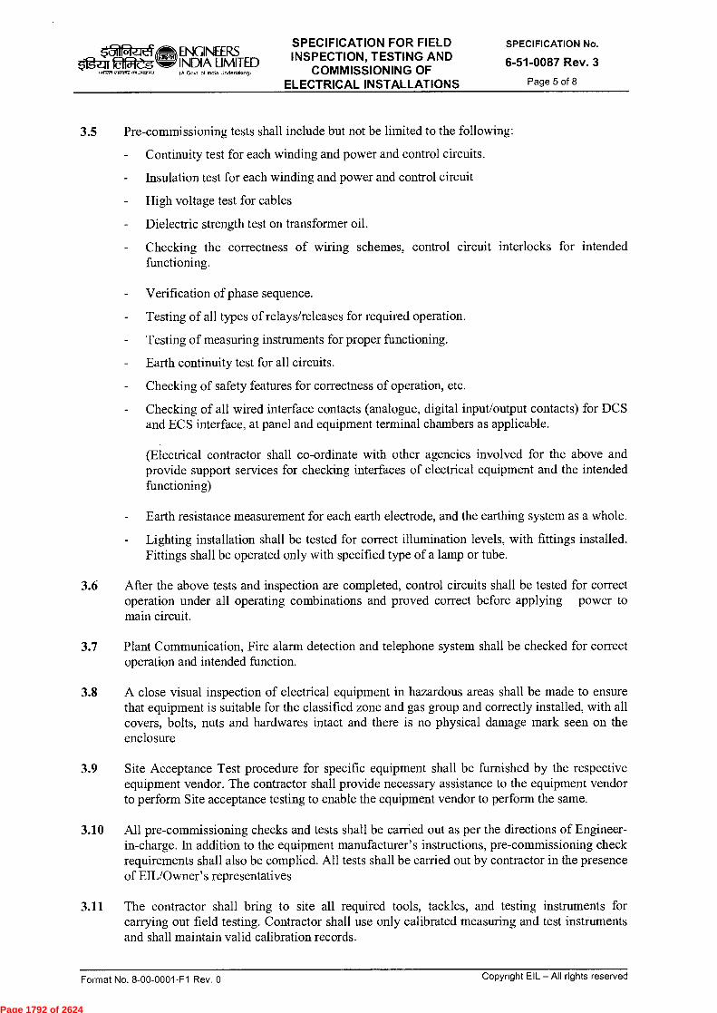
k31 ENGINEERS Og-ar 2f5:1-g INDIA LIMITED
(A GoN cd InEia Und<rlAk(A9)
SPECIFICATION FOR FIELD INSPECTION, TESTING AND
COMMISSIONING OF ELECTRICAL INSTALLATIONS
SPECIFICATION No.
6-51-0087 Rev. 3
Page 5 of 8 (~1 ~srz as,:ror.)
3.5 Pre-commissioning tests shall include but not be limited to the following:
Continuity test for each winding and power and control circuits.
Insulation test for each winding and power and control circuit
High voltage test for cables
- Dielectric strength test on transformer oil.
- Checking the correctness of wiring schemes, control circuit interlocks for intended functioning.
- Verification of phase sequence.
Testing of all types of relays/releases for required operation.
- Testing of measuring instruments for proper functioning.
- Earth continuity test for all circuits.
Checking of safety features for correctness of operation, etc.
Checking of all wired interface contacts (analogue, digital input/output contacts) for DCS and ECS interface, at panel and equipment terminal chambers as applicable.
(Electrical contractor shall co-ordinate with other agencies involved for the above and provide support services for checking interfaces of electrical equipment and the intended functioning)
Earth resistance measurement for each earth electrode, and the earthing system as a whole.
Lighting installation shall be tested for correct illumination levels, with fittings installed. Fittings shall be operated only with specified type of a lamp or tube.
3.6 After the above tests and inspection are completed, control circuits shall be tested for correct operation under all operating combinations and proved correct before applying power to main circuit.
3.7 Plant Communication, Fire alarm detection and telephone system shall be checked for correct operation and intended function.
3.8 A close visual inspection of electrical equipment in hazardous areas shall be made to ensure that equipment is suitable for the classified zone and gas group and correctly installed, with all covers, bolts, nuts and hardwares intact and there is no physical damage mark seen on the enclo sure
3.9 Site Acceptance Test procedure for specific equipment shall be furnished by the respective equipment vendor. The contractor shall provide necessary assistance to the equipment vendor to perform Site acceptance testing to enable the equipment vendor to perform the same.
3.10 All pre-commissioning checks and tests shall be carried out as per the directions of Engineer- in-charge. In addition to the equipment manufacturer's instructions, pre-commissioning check requirements shall also be complied. All tests shall be carried out by contractor in the presence of EIL/Owner' s representatives
3.11 The contractor shall bring to site all required tools, tackles, and testing instruments for carrying out field testing. Contractor shall use only calibrated measuring and test instruments and shall maintain valid calibration records.
Format No. 8-00-0001-F1 Rev. 0
Copyright EIL — All rights reserved
Page 1792 of 2624
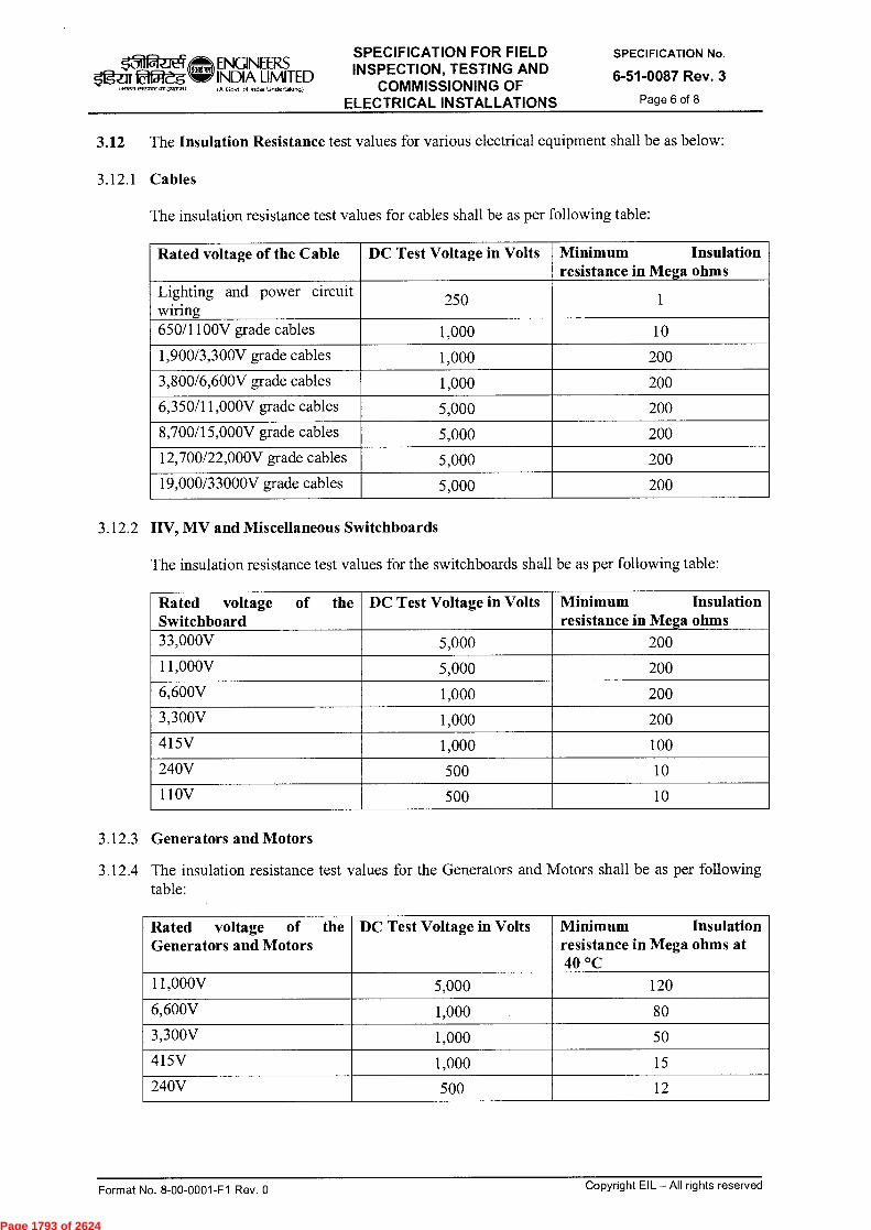
$tigzrr fa2es IN■fn
ENGINEERS INDIA LIMITED IF GoN of lndN Underfakrogf
SPECIFICATION FOR FIELD INSPECTION, TESTING AND
COMMISSIONING OF ELECTRICAL INSTALLATIONS
SPECIFICATION No.
6-51-0087 Rev. 3 Page 6 of 8
3.12 The Insulation Resistance test values for various electrical equipment shall be as below:
3.12.1 Cables
The insulation resistance test values for cables shall be as per following table:
Rated voltage of the Cable DC Test Voltage in Volts Minimum Insulation resistance in Mega ohms
Lighting and power circuit wiring
250 1
650/1100V grade cables 1,000 10
1,900/3,300V grade cables 1,000 200
3,800/6,600V grade cables 1,000 200
6,350/11,000V grade cables 5,000 200
8,700/15,000V grade cables 5,000 200
12,700/22,000V grade cables 5,000 200
19,000/33000V grade cables 5,000 200
3.12.2 IIV, MV and Miscellaneous Switchboards
The insulation resistance test values for the switchboards shall be as per following table:
Rated voltage of the Switchboard
DC Test Voltage in Volts Minimum Insulation resistance in Mega ohms
33,000V 5,000 200
11,000V 5,000 200
6,600V 1,000 200
3,300V 1,000 200
415V 1,000 100
240V 500 10
110V 500 10
3.12.3 Generators and Motors
3.12.4 The insulation resistance test values for the Generators and Motors shall be as per following table:
Rated voltage of the Generators and Motors
DC Test Voltage in Volts Minimum Insulation resistance in Mega ohms at 40 °C
11,000V 5,000 120
6,600V 1,000 80
3,300V 1,000 50
415V 1,000 15
240V 500 12
Format No. 8-00-0001-F1 Rev. 0 Copyright EIL — All rights reserved
Page 1793 of 2624
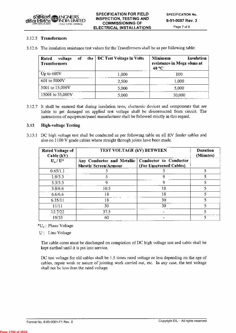
ENGINEERS SPECIFICATION FOR FIELD INSPECTION, TESTING AND
COMMISSIONING OF ELECTRICAL INSTALLATIONS
SPECIFICATION No.
6-51-0087 Rev. 3 Page 7 of 8
I f ~5 irr0n twor,on )
INDIA LIMITED in Govt ol IndU Undertalong)
3.12.5 Transformers
3.12.6 The insulation resistance test values for the Transformers shall be as per following table:
Rated voltage of the Transformers
DC Test Voltage in Volts Minimum Insulation resistance in Mega ohms at 40 °C
Up to 600V 1,000 100
601 to 5000V 2,500 1,000
5001 to 15,000V 5,000 5,000
15001 to 35,000V 5,000 10,000
3.12.7 It shall be ensured that during insulation tests, electronic devices and components that are liable to get damaged on applied test voltage shall be disconnected from circuit. The instructions of equipment/panel manufacturer shall be followed strictly in this regard.
3.13 High-voltage Testing
3.13.1 DC high voltage test shall be conducted as per following table on all HV feeder cables and also on 1100 V grade cables where straight through joints have been made.
Rated Voltage of Cable (kV)
TEST VOLTAGE (kV) BETWEEN Duration (Minutes)
U. / U* Any Conductor and Metallic Sheath/ Screen/Armour
Conductor to Conductor (For Unscreened Cables)
0.65/1.1 3 3 5
1.9/3.3 5 9 5
3.3/3.3 9 9 5
3.8/6.6 10.5 18 5
6.6/6.6 18 18 5
6.35/11 18 30 5
11/11 30 30 5
12.7/22 37.5 - 5
19/33 60 - 5
*U. : Phase Voltage
U : Line Voltage
The cable cores must be discharged on completion of DC high voltage test and cable shall be kept earthed until it is put into service.
DC test voltage for old cables shall be 1.5 times rated voltage or less depending on the age of cables, repair work or nature of jointing work carried out, etc. In any case, the test voltage shall not be less than the rated voltage.
Format No. 8-00-0001-F1 Rev. 0
Copyright EIL — All rights reserved
Page 1794 of 2624
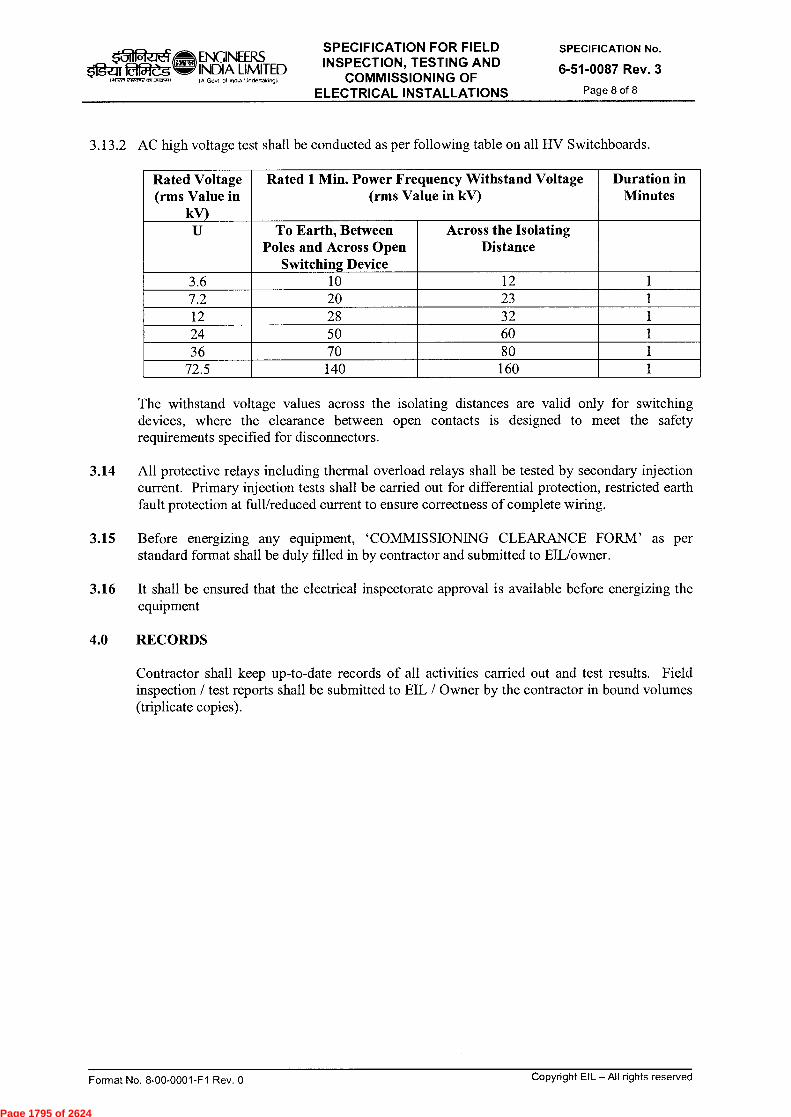
ENGINEERS mar faZ5 INDIA LIMITED
IA Gosn of Intha Undertakog)
SPECIFICATION FOR FIELD INSPECTION, TESTING AND
COMMISSIONING OF ELECTRICAL INSTALLATIONS
SPECIFICATION No.
6-51-0087 Rev. 3
Page 8 of 8 l aiWn 23~ ag,o.)
3.13.2 AC high voltage test shall be conducted as per following table on all HV Switchboards.
Rated Voltage (rms Value in
kV)
Rated 1 Min. Power Frequency Withstand Voltage (rms Value in kV)
Duration in Minutes
U To Earth, Between Poles and Across Open
Switching Device
Across the Isolating Distance
3.6 10 12 1 7.2 20 23 1 12 28 32 1 24 50 60 1 36 70 80 1
72.5 140 160 1
The withstand voltage values across the isolating distances are valid only for switching devices, where the clearance between open contacts is designed to meet the safety requirements specified for disconnectors.
3.14 All protective relays including thermal overload relays shall be tested by secondary injection current. Primary injection tests shall be carried out for differential protection, restricted earth fault protection at full/reduced current to ensure correctness of complete wiring.
3.15 Before energizing any equipment, `COMMISSIONING CLEARANCE FORM' as per standard format shall be duly filled in by contractor and submitted to EIL/owner.
3.16 It shall be ensured that the electrical inspectorate approval is available before energizing the equipment
4.0 RECORDS
Contractor shall keep up-to-date records of all activities carried out and test results. Field inspection / test reports shall be submitted to EIL / Owner by the contractor in bound volumes (triplicate copies).
Format No. 8-00-0001-F1 Rev. 0
Copyright EIL — All rights reserved
Page 1795 of 2624

CONTINUOUS RING
EARTHING LUG
A KL
BCD
[BOLT 0 + 12mmWIDE SLOT
BOLT 0+ 12mm
BCD
RADIUS+ 6mm
+V
TYPE-2(SEE NOTE-6)
SLOT DETAIL TYPE-3(FOR CONTINUOUS RING ONLY)
CHAIR CAPWASHER WELD AT SITENOTCH GUSSET TO
CLEAR WELD
W
//
ir// BOLT 0
+ 3mm
(ALL DIMENSIONS AND DETAILS ARESAME AS SHOWN FOR TYPE-2EXCEPT CONTINUOUS RING)
II
NOTCH GUSSET TOCLEAR WELD
BCD
TYPE-1
20H
n
-17 A K
I-BOLT 0+ 12mm
SKIRT BASE DETAILSSTANDARD No.7-12-0004 Rev. 6
Page 1 of 1wriumwrosame (A Govt. of India Undertaking)
BOCTO t 1 * t2 * t3 * A v B C E F H K L* W TYPE REMARKS
24 20 — 10 60 — — — — 250 75 165 101
27 20 — 10 60 — — — — 250 80 170 1030 25 25 12 55 60 150 12 60 300 80 180 10
2AND
3
33 25 25 12 58 65 150 12 70 300 80 185 1036 25 25 12 66 70 150 12 80 300 90 200 1039 32 25 12 70 70 160 14 80 300 95 215 1242 32 25 12 72 70 160 14 90 300 100 230 1245 32 25 12 80 75 160 14 90 300 105 245 1248 32 30 14 83 75 180 16 100 380 110 260 1452 38 30 14 87 80 180 16 110 380 110 275 1456 38 30 16 91 85 180 18 120 380 115 280 1460 38 35 18 95 85 200 20 120 430 125 285 1464 38 35 18 104 90 200 25 130 430 135 300 1668 42 40 20 108 90 220 25 140 450 145 320 1672 42 40 20 112 95 220 25 150 450 150 340 16
NOTESALL DIMENSIONS ARE IN mm UNLESS OTHERWISE STATED.BOLT CIRCLE DIAMETER ( BCD ), NUMBER AND SIZE OF THE BOLTS SHALL BE AS PER ENGINEERING DRAWING.
* 3. DIMENSIONS t1, t2, t3 AND 'I: ARE TO BE CHECKED IN EVERY CASE.IN CASE OF ANY CONFLICT THE ENGINEERING DRAWING SHALL GOVERN.NUMBER OF BOLTS USED IS TO BE A MULTIPLE OF 4 AND BOLTS SHALL STRADDLE VESSEL NORTH—SOUTHCENTRE LINE IN PLAN.USE CONTINUOUS RING ( CHAIR CAP ) IF DISTANCE BETWEEN CONSECUTIVE BOLTS IS LESS THAN 400 mm.CIRCULAR WASHER SHALL BE SHIPPED LOOSE AND WELDED AT SITE AFTER ANCHOR BOLTS ARE IN POSITION.
♦ 8. PREFERRED DIMENSION 'A'EARTHING LUG SHALL BE LOCATED BETWEEN THE ANCHOR BOLTS AND SHALL BE AS PER STANDARD 7-12-0026.WHEN THE ANCHOR CHAIR CAP IS NOT CONTINUOUS, THE BASE PLATE SHALL BE SUITABLY STIFFENED USINGREMOVABLE STRUCTURAL SECTIONS (BEAM/SPIDER) AT SITE DURING ERECTION.
t*/6 30.06.2011 REAFFIRMED AND REISSUED AS STANDARD POREL RKT M/SC DM
5 08.09.2006 REAFFIRMED AND REISSUED AS STANDARD POREL DNN AKM VC
PurposePrepared Checked
by byStds. Committee Stds. Bureau
Convenor ChairmanApproved by
Copyright EIL - All rights reserved
Rev.
No. Date
Format No. 8-00-0001-F4 Rev.0
Page 1796 of 2624

SPECIFICATION (31 ENGINEERS FOR la;12,5 INDIA LJMITED
(A Govt of Indo Undertaking) ELECTRICS FOR E.O.T. CRANE
STANDARD SPECIFICATION No.
6-51-0094 Rev. 4 Page 1 of 14
fq-cF rkR)kirvii4ifi *9. `CID fqfff491
SPECIFICATION FOR
ELECTRICS FOR E.O.T. CRANE
VKJ BRB 4 26.06.14 REVISED & ISSUED AS STANDARD
SPECIFICATION VB
3 20.04.09 REVISED & ISSUED AS STANDARD SPECIFICATION
DA SG JMS
2 14.11.03 REVISED & ISSUED AS STANDARD
SPECIFICATION AK RPG/AAN VPS
1 15.12.97 RE-AFFIRMED AND ISSUED AS STANDARD
SPECIFICATION NP VPS SG
0 27.01.88 ISSUED AS STANDARD SPECIFICATION ADS SG
Rev. No Date Purpose
Prepared by
Checked by
Standards Comm ittee Convenor
k‘,---si SC
ND
SKG
AS
RCPC
Standards Bureau
Chairman
Approved by
Format No. 8-00-0001-F1 Rev. 0 Copyright EIL — All rights reserved
Page 1797 of 2624

k5-'11241g
ur
( 411PR 212~ 3,1C1.1)
SPECIFICATION STANDARD SPECIFICATION No.
FOR 6-51-0094 Rev. 4 ELECTRICS FOR E.O.T. CRANE Page 2 of 14
Oam ENGINEF_RS INDIA LIMITED IA Govt of India undenaking)
Abbreviations:
AC Alternating Current BASEEFA : British Approvals Service for Electrical Equipment in Flammable Atmosphere BIS Bureau of Indian Standards BS British Standards CCE Chief Controller of Explosives CEA Central Electricity Authority CIMFR Central Institute of Mines and Fuel Research CT Current Transformer DC Direct Current DGMS Director General of Mines Safety DOL Direct On Line EIL Engineers India Limited ELCB Earth Leakage Circuit Breaker EOT Electrical Overhead Travelling FM Factory Mutual FRP Fiberglass Reinforced Plastic HPMV High Pressure Mercury Vapour HRC High Rupturing Capacity IEC International Electrotechnical Commission IEEE Institute of Electrical & Electronics Engineers IP Ingress Protection IS Indian Standard JEC Japanese Electro-technical Committee LCIE Laboratorie Central des Industries Electriques LRWT Locked Rotor Withstand Time LV Low Voltage MCB Miniature Circuit Breaker NEC National Electrical Code NEMA National Electrical Manufacturers Association OEM Original Equipment Manufacturers OISD Oil Industries Safety Directorate PEM Project Engineering Management PESO Petroleum & Explosives Safety Organisation PO Purchase Order PTB Physikalisch-Technische Bundesantalt PVC Poly Vinyl Chloride p.u. Per Unit r.m.s. Root Mean Square TEFC Totally Enclosed Fan Cooled TPN Three Phase Neutral TPIA Third Party Inspection Agency UL Underwriter's Laboratories VDE • Verband Deutscher Electrotechniker VFD Variable Frequency Drive
Electrical Standards Committee
Convenor: Mr. B. R. Bhogal Members: Ms. S. Anand
Mr. Parag Gupta Mr. M. K. Sahu Mr. A. K. Chaudhary (Inspection) Ms. N. P. Guha (Projects)
Format No. 8-00-0001-F1 Rev. 0 Copyright EIL — All rights reserved
Page 1798 of 2624

ENGINEERS INDIA LIMITED (A Govt of India Undertaking)
SPECIFICATION FOR
ELECTRICS FOR E.O.T. CRANE
STANDARD SPECIFICATION No.
6-51-0094 Rev. 4 Page 3 of 14
CONTENTS
1.0 SCOPE 4
2.0 CODES AND STANDARDS 4
3.0 GENERAL REQUIREMENTS 5
4.0 SITE CONDITIONS 6
5.0 AREA CLASSIFICATIONS AND EQUIPMENT SELECTION 6
6.0 TECHNICAL REQUIREMENTS 6
7.0 INSPECTION, TESTING AND ACCEPTANCE 14
8.0 PACKING AND DESPATCH 14
Format No. 8-00-0001-F1 Rev. 0 Copyright EIL —All rights reserved
Page 1799 of 2624
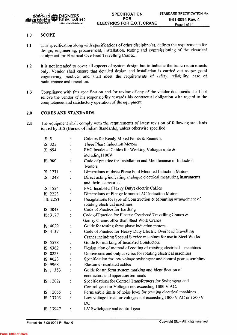
ENGINEERS Ogu fa2èg INDIA LIMITED
IA Govt ol lneha Unclertaking)
SPECIFICATION FOR
ELECTRICS FOR E.O.T. CRANE
STANDARD SPECIFICATION No.
6-51-0094 Rev. 4 Page 4 of 14
I.Wor 2~1,1,3,10s.0
1.0 SCOPE
1.1
This specification along with specifications of other discipline(s), defines the requirements for design, engineering, procurement, installation, testing and commissioning of the electrical equipment for Electrical Overhead Travelling Cranes.
1.2 It is not intended to cover all aspects of system design but to indicate the basic requirements only. Vendor shall ensure that detailed design and installation is carried out as per good engineering practices and shall meet the requirements of safety, reliability, ease of maintenance and operation.
1.3 Compliance with this specification and /or review of any of the vendor documents shall not relieve the vendor of his responsibility towards his contractual obligation with regard to the completeness and satisfactory operation of the equipment
2.0 CODES AND STANDARDS
2.1 The equipment shall comply with the requirements of latest revision of following standards issued by BIS (Bureau of Indian Standards), unless otherwise specified.
IS: 5 Colours for Ready Mixed Paints & Enamels. IS: 325 Three Phase induction Motors IS: 694 PVC Insulated Cables for Working Voltages upto &
including1100V IS: 900 Code of practice for Installation and Maintenance of Induction
Motors IS: 1231 Dimensions of three Phase Foot Mounted Induction Motors IS: 1248 Direct acting indicating analogue electrical measuring instruments
and their accessories IS: 1554 PVC Insulated (Heavy Duty) electric Cables IS: 2223 Dimensions of Flange Mounted AC Induction Motors IS: 2253 Designations for type of Construction & Mounting arrangement of
rotating electrical machines. IS: 3043 Code of Practice for Earthing IS: 3177 Code of Practice for Electric Overhead Travelling Cranes &
Gantry Cranes other than Steel Work Cranes IS: 4029 Guide for testing three phase induction motors. IS: 4137 Code of Practice for Heavy Duty Electric Overhead Travelling
Cranes including Special Service machines for use in Steel Works IS: 5578 Guide for marking of Insulated Conductors IS: 6362 Designation of method of cooling of rotating electrical machines IS: 8223 Dimensions and output series for rotating electrical machines IS: 8623 Specification for low voltage switchgear and control gear assemblies IS: 9968 Elastomer insulated cables IS: 11353 Guide for uniform system marking and identification of
conductors and apparatus terminals IS: 12021 Specifications for Control Transformers for Switchgear and
Control gear for Voltages not exceeding 1000 V AC. IS: 12065 Permissible limits of noise level for rotating electrical machines. IS: 13703 Low voltage fuses for voltages not exceeding 1000 V AC or 1500 V
DC IS: 13947 LV Switchgear and control gear
Format No. 8-00-0001-F1 Rev. 0 Copyright EIL — All rights reserved
Page 1800 of 2624
ENGINEERS 015ElegW' INDIA LIMITED
(~~1.2,17,3,~1 IA Govt of lnOa Undertalung)
SPECIFICATION FOR
ELECTRICS FOR E.O.T. CRANE
STANDARD SPECIFICATION No.
6-51-0094 Rev. 4 Page 5 of 14
IS: 14568 Dimensions and output series for rotating electrical machines, frame numbers 355 to 1000 and flange numbers 1180 to 2360
1S/IEC 60034-5 : Degrees of protection provided by the integral design of rotating electrical machines (IP code)
IS/IEC 60034-8 : Terminal marking and direction of rotation for rotating electrical machinery.
1S/IEC60079-0 : Electrical apparatus for explosive gas atmospheres (General Requirements)
IS/IEC 60079-1: Equipment protection flameproof enclosures "d" IS/IEC 60079-7: Electrical apparatus for explosive gas atmospheres Increased safety
type "e" IS:5571/IEC 60079-14 Guide for selection and installation of electrical equipment in
hazardous areas IS/IEC 60079-15 Electrical apparatus for explosive gas atmosphere
Construction, test and marking of type of protection "n" IS/IEC 60529 : Classification of degree of protection provided by enclosures (IP
Code) IS: 61241 : Electrical apparatus for use in the presence of combustible dust
2.2 In case of imported equipment, standards of the country of origin shall be applicable, if these standards are equivalent or more stringent than the applicable Indian Standards.
2.3 The electrical equipment shall meet the requirement of this specification and attached data sheets / job specifications / drawings, in addition to the relevant Indian Standards / code of practices, Statutory regulations and sound engineering practices. Complete system shall also conform to the latest revisions of following, as applicable:
a) CEA regulations, 2010. b) Fire insurance Regulations c) Indian Petroleum rules and any other regulations laid down by chief Controller of
Explosives. d) The factory Act and any other regulations laid down by Factory inspectorate. e) Regulations laid down by local statutory authorities and CEA/ Electrical Inspectorate.
0 Oil Mines regulations (For Projects under DGMS jurisdiction)
g) OISD guidelines
2.4 In case Indian Standards are not available, standards issued by IEC/ BS/ VDE/ IEEE/ JEC/NEMA or equivalent agency shall be applicable.
2.5 ln case of any conflict between requirements specified in various applicable documents, the most stringent one shall prevail. However, owner's decision in this regard shall be final and binding.
3.0 GENERAL REQUIREMENTS
3.1 The offered equipment shall be brand new with state of art technology and proven field track record. No prototype equipment shall be offered.
3.2 Vendor shall ensure availability of spare parts and maintenance support services for the offered equipment at least for 10 years from the date of supply.
3.3 Vendor shall give a notice of at least one year to the end user of equipment and EIL before phasing out the product/ spares to enable the end user for placement of order for spares and services.
Format No. 8-00-0001-F1 Rev. 0 Copyright EIL — All rights reserved
Page 1801 of 2624

ENGINEERS Ogzir181faidu INDIA LIMITED
IA GoN of Ind. UnOeflaking)
SPECIFICATION FOR
ELECTRICS FOR E.O.T. CRANE
STANDARD SPECIFICATION No.
6-51-0094 Rev. 4 Page 6 of 14
101271 29RCIRE' QA 3,747.1)
4.0 SITE CONDITIONS
The equipment shall be suitable for operation satisfactorily in humid and corrosive atmosphere found in refineries, petrochemical, fertilizer and metallurgical plants. Service conditions shall be as specified in the data sheet. If not specifically mentioned therein, a design ambient temperature of 40°C and an altitude not exceeding 1000 meters above mean sea level shall be taken into consideration
5.0 AREA CLASSIFICATIONS AND EQUIPMENT SELECTION
5.1 For cranes to be installed in hazardous areas, the electrical equipment shall be selected as per IS-5571, IEC 60079, Indian Petroleum Rules and DGMS regulations (where applicable) and shall meet the requirements of relevant IS, IEC or NEC Standards. The electrical equipment for Zone-2 areas as a minimum shall be Ex `e'/ Ex 'n' type as specified in data sheet, subject to the same being acceptable to the concerned statutory authorities. However all motors for hazardous area cranes shall be flameproof type (Ex`d') irrespective of zone of the classified area. All spark producing electrical equipment shall be Ex`d' type. Increased safety (Type Ex `e') equipment shall not be used in Zone-1 areas, but these shall be Ex`d' type. Ordinary industrial electrical equipment (even though permitted for use in Div.2 area as per NEC, USA) shall not be used in Zone-2 areas.
5.2 Electrical equipments for hazardous areas shall have test certificates issued by recognised independent test house (CIMFR/CPRI/ERTL/Baseefa /LCIE/UL/FM or equivalent). All indigenous equipment shall conform to Indian standards and shall be certified by recognised testing agencies. All equipment (indigenous & imported) shall also have valid statutory approvals (e.g. PESO, DGMS etc). as applicable for the specified location. All indigenous flameproof equipment shall have valid BIS license and marking as required by statutory authorities.
5.3 Flameproof electrical equipment shall be suitable for specified gas group and temperature Class T3 as minimum.
6.0 TECHNICAL REQUIREMENTS
The electrical equipment for EOT Cranes, shall be complete in all respects, including but not limited to, the incoming load break switch at shop floor level, power rail and collector shoe assembly /flexible trailing cable arrangement (as specified in Data Sheets), control panel(s) housing starters, breakers, control and indication devices, drive motors, starting resistors and all other devices required for safe start / stop and operation of the system. The equipment shall comply with the following requirements.
6.1 Power Supply
Power supply as specified in data sheet shall be made available by Purchaser at one point at the incoming terminals of Vendor's incoming load break switch to be located at shop floor Level. All further distribution as required for the crane shall be in the scope of the Vendor. Vendor shall design his equipment so as to be suitable for satisfactory operation considering voltage supply conditions as specified in the data sheet.
6.2 Control Supply
The voltage level for control and other applications shall be as specified in the data sheet. The control voltage and any voltage, as required, other than power supply voltage specified in the data sheet shall be arranged by Vendor.
Format No. 8-00-0001-F1 Rev. 0 Copyright EIL — All rights reserved
Page 1802 of 2624

ENGINEF_RS fs~i 22e-g INDIA LIMITED
c-~51.3~1) Govt of india undertaking)
SPECIFICATION FOR
ELECTRICS FOR E.O.T. CRANE
STANDARD SPECIFICATION No.
6-51-0094 Rev. 4 Page 7 of 14
The control transformer shall be double wound air-cooled control type of suitable rating and shall be located either in main control panel or separately housed in a suitable enclosure. The control transformer shall be provided with an earthed screen between primary and secondary winding.
One pole of control transformer secondary / control supply shall be earthed. The transformer will be provided with fuse on primary side. On secondary side, MCB shall be provided on unearthed pole and a link on the earthed pole. One end of the coil of all relays and contactors shall be connected to the earth side of the control circuit supply and this connection shall not be interrupted by any fuse or contact
Control voltage for pendant-operated cranes shall not be more than 110 V AC or DC.
6.3 Power Distribution
Power distribution shall preferably be by using bus bar power feeder arrangement for EOT cranes installed in safe area unless otherwise specified. The power distribution arrangement for EOT cranes installed in hazardous area shall be by using festooned type flexible trailing cables arrangement. Power rails shall not be used in hazardous areas.
6.3.1 Power Rails
6.3.1.1 In case of safe area installations, if specified in data sheet, the power supply to main bridge shall be through power rails supported by brackets at the building columns. The power rails shall be shrouded type. The material of power rails shall be mild steel / Al alloy (with stainless steel contact tip) / copper, as specified in data sheet. The power connections of collector shoes assembly to power rails shall be from the under side.
6.3.1.2 Double collectors shall be provided for all the three phases and earth. The collectors shall be mounted on insulated shaft and collector current rating shall be adequate for the specified site conditions.
6.3.1.3 Collector shall be provided with self-cleaning type brushes.
6.3.1.4 Light indicating unit (with indicating lamps for each phase) for "power supply ON" shall be provided on both the ends of each section of power rail.
6.3.2 Flexible Trailing Cables
The flexible trailing cable shall have braiding and shall be supported on hangers having rollers moving on I beam. Cross travel shall always be provided with festooned type cable arrangement.
6.3.3 Isolating Switches & Isolators
6.3.3.1 Cabin Operated Cranes
For cabin operated cranes a main isolating switch shall be fitted in the cabin or adjacent to it and shall be capable of isolating power supply for all power driven & associated equipment on the crane, except auxiliary connections such as warning lights, lighting, fans, air conditioning / heating circuits, communication circuits etc.
Format No. 8-00-0001-F1 Rev. 0 Copyright EIL — All rights reserved
Page 1803 of 2624
STANDARD SPECIFICATION No.
6-51-0094 Rev. 4 Page 8 of 14
71 ENGINEERS
$'fg-arl&Weg. INDIA LIMITED
1.11177 292~ 4,1~) IA Govt of India Undenaking)
SPECIFICATION FOR
ELECTRICS FOR E.O.T. CRANE
When operator's cabin is fitted to the trolley and moves in relation to the main crane structure, an isolating switch shall also be provided outside the cabin on the main bridge of the crane in addition to the isolating switch in the operator's cabin.
6.3.3.2 Pendant Controlled Cranes
On all pendant controlled cranes, means shall be provided to prevent inadvertent operation from the floor while maintenance work is being carried out on the crane. A local isolator shall be provided on the crane bridge to comply with this requirement.
6.4 Control System
The control of the crane shall be selected out of the following systems as per requirements as specified in Data Sheet / Mechanical specifications.
6.4.1 For Cabin Operated Cranes
The control system for all motions of the cabin operated crane shall be designed to ensure smooth speed control. 1n all motions, except long travel, the brakes will be de-energized when master controller is brought to 'OFF' position.
The power 'ON' indication light and emergency off push button of mushroom head shall be provided in the driver's cabin. The dead man's Pedal shall also be provided in the cabin to trip the main incoming contactor in case operator releases his foot pressure from the pedal.
6.4.2 Pendant Operated Cranes
All motions of crane shall be controlled by hand operated pendant, provided with push buttons for various motions. All push buttons shall automatically return to `off position immediately after their release Main off-push button shall be of mushroom head and lockable type, which will disconnect power supply when the crane is not being operated. The pendant shall be suspended independent of the electric cables by means of a chain or a wire rope. The metallic enclosure of pendant shall be effectively earthed. The wire rope provided for suspending pendant shall not be used as earthing connection.
6.4.3 Radio Remote Control (RRC)
The radio remote control of cranes shall be provided whenever specifically required as per mechanical specifications. Vendor shall furnish the details of radio remote control system provided. Radio remote control shall conform to IS: 3177 along with the following additional features as mentioned elsewhere also shall be provided.
a) There shall be common push button for siren and START and a separate push button for under bridge lights. Crane shall start with time delay after the siren is blown.
b) Operating range shall be 50 meters approx for radio remote.
c) Two sets of long life rechargeable batteries for the transmitter along with a battery charger shall be provided (i.e. 1 set installed battery + 1 set spare battery + 1 charger) for each radio remote.
d) Necessary operating license / permission for the RRC system on the Crane shall be arranged by the Vendor from the statutory bodies. License fee, if any, should be borne by the Vendor.
Copyright EIL —All rights reserved Format No. 8-00-0001-F1 Rev. 0
Page 1804 of 2624

ENGINEERS LIMITED
1A Govl of Ind. Undeftalong)
SPECIFICATION FOR
ELECTRICS FOR E.O.T. CRANE
STANDARD SPECIFICATION No.
6-51-0094 Rev. 4 Page 9 of 14
k31 411 Og-ar 2151eg
IiTOff 74?0,f7m1.3o~
6.4.4 The speed control system of various drives shall be designed to meet the operational requirements. The requisite speed control may be obtained by one of the following methods:
a) Rotor resistance (switching the resistances in rotor circuit for speed control in motoring mode, single phasing and super synchronous braking modes).
b) Two speed motors (if required as per crane system requirement) c) Variable stator voltage converter inverter control or variable frequency drive
using ac motors. d) Any other speed control method
Rotor resistance control shall not be used for cranes to be installed in hazardous areas.
6.4.5 The rate of acceleration on start-up and rate of stopping of various motions of the crane shall be limited to meet the operational requirements of the crane motions, as specified in Mechanical Specifications. Vendor shall provide suitable soft start / soft stoppage using electronic soft starting system or rotor resistance control (in case of slip ring motor) or other such features shall as required for all applicable motions of the crane.
6.4.6 Motion Limiting Devices
The control scheme shall include travel limiting devices for hoisting, cross travel and long travel.
For hoists, positively operated hoisting motion limiting devices shall be provided to stop the upward & downward movement when pre-determined level is reached. The limiting devices shall be regarded as a safety feature and not as a routine operational means of stopping. An additional motion-limiting device shall be provided that operates independently for both hoisting and lowering motion. The over travel / over traversing / over hoisting limiting devices shall be provided with manual resetting feature.
For cross traverse and long travel, limiting devices shall be provided to prevent the following: a) Over traversing & over travelling b) Collision where two or more crane / trolleys operate on the same track.
Back-up limit switches will cut-off the incoming power supply in the control panel. The main limit switches shall be self reset type and the back-up limit switches shall be manual reset type. Contact rating of the limit switches shall be minimum 5 A, 240 V AC.
6.5 Control Panel
6.5.1 All the components forming part of power and control circuit required for start/stop and control of various movements shall be housed in control panel made out of sheet steel of minimum 1.6 mm thickness. The doors shall be of removable type. The ventilation openings shall be screened. The degree of protection shall be minimum IP-51. Panel shall be securely fastened on the platform. At least 300 mm height shall be maintained between the bottom-most row of component and of bottom of the panel. The panel door shall be mechanically interlocked so that door cannot be opened when incoming supply is ON. However, for testing purpose interlock defeat feature also shall be provided. Terminal strip shall be provided in the panel with sufficient space underneath for easy termination of cables. Terminal strips shall be arranged horizontally and vertically for power and control circuits respectively. All components shall be marked according to circuit diagram. All control circuit wiring shall be done with FRLS type, minimum 1.5 sq. mm copper conductor up to 10A control fuse rating and 2.5 sq. mm copper conductor for 16A control fuse circuits. CT wiring shall be done with 2.5 sq. mm copper conductor. The panel shall be mounted on rubber pads. The cable entry shall be from bottom only. Supply of requisite cable glands & lugs are included in Vendor's scope.
Format No. 8-00-0001-F1 Rev. 0 Copyright EIL — All rights reserved
Page 1805 of 2624

k5-11 (l it(=" ENGINEERS $1g211~‘I'WP INDIA LIMITED
~2,513oCovO IA GOvt ol lnvha Undertaking)
SPECIFICATION FOR
ELECTRICS FOR E.O.T. CRANE
STANDARD SPECIFICATION No.
6-51-0094 Rev. 4 Page 10 of 14
6.5.2 For hazardous area EOT cranes load break switch for the incomer power supply shall be 4 Pole, and for lighting 2 pole MCB shall be used. For Safe area EOT Crane load break switch for the incomer power supply shall be 4 Pole and for lighting shall be with single pole MCBs.
6.5.3 The EOT crane shall be provided with protective equipment as per Scheme A as defined in IS: 3177, in which each motion has separate protection. Unless operational requirements demand otherwise, the scheme shall be designed to ensure that overload in any one motion does not trip the complete circuit but only the individual circuit.
6.5.4 Unless specified otherwise, motor feeders shall be provided with suitably rated heavy duty / motor duty switches, HRC fuses and contactors. Thermal overload relays shall be provided for drive motors upto 55 KW. For motors above 55 KW electronic motor protection relays of approved make shall be provided.
6.5.5 Field ammeter for motors rated 5.5KW and above shall be provided in control panel.
6.6 Control Equipment for AC Motors
The selection of contactors for AC motors shall be made on the basis of S3-40 percent rating arrived after applying appropriate service factor to the computed power of the motor. The rating of control gears such as switches, overload relays etc. shall be selected according to the computed motor power without service factor of the motion served and not on the motor power computed by the thermal requirements.
The minimum rating of the contactor shall be one and half times the full load current of the motor. The rated utilisation category for contactors shall be AC-4 as per IS: 13947.
Reversible motion contactors shall be interlocked mechanically and electrically.
6.7 Resistors
The resistors shall be of stainless steel grid type. The resistor shall be arranged in ventilated racks. For outdoor operation, the resistors shall be provided with suitable enclosure to make them weatherproof. The resistors shall be rated according to the service conditions and mechanical class of the crane. Unless specified otherwise the time duration for design of resistor shall be as per IS: 3177 as below:
Mechanism Class Short Time Rating for Time Rated Resistors (Min.)
Ml, M2 2 M3, M4, M5 5
M6, M7 10 M7, M8 To suit the service conditions
Resistors shall not be used for cranes to be installed in hazardous areas
6.8 Wiring & Cable Terminations
6.8.1 Cables used for crane wiring shall be flame retardant low smoke type and shall comply with relevant Indian standard specifications. Power cables shall be of copper upto conductor size 16 mm2 and of aluminium for conductor requirements above this size, unless specified otherwise. Control cables shall be of copper conductor only. Single strand conductors shall not be used where cable cross sectional area is more than 6 mm2
Format No. 8-00-0001-F1 Rev. 0
Copyright EIL — All rights reserved
Page 1806 of 2624

STANDARD SPECIFICATION No.
6-51-0094 Rev. 4 Page 11 of 14
k31 ENQNEERS $11gzilffieg41lev INDIA LIMITED
1411¢R OV2e0170o3oCow) IA Govt India Undeitalong)
SPECIFICATION FOR
ELECTRICS FOR E.O.T. CRANE
6.8.2 The cable and wiring system for each motion shall be independent. Main cables and controlled wiring shall be effectively separated. Separate control cables shall be used for AC circuits and DC circuits.
6.8.3 The cables shall be sized with due consideration to ambient temperature, type & duration of load, fault Level / back-up protection, grouping and disposition of cables and permissible voltage drop.
6.8.4 Power cables related to various mechanisms shall be sized higher in accordance with Table 16 of IS: 3177 as below:
Mechanism Class Stator Circuit Rating multiplied by
Rotor & Resistor Rating multiplied by
Ml, M2 2.0 2.5 M3, M4, M5 1.7 2.0
M6, M7 1.4 1.5 M8 1.1 1.1
6.8.5 The minimum size of conductor for power cables shall be 4 sq. mm copper for connections to motors and 2.5 sq. mm for other power connections. All cables shall be FRLS type PVC insulated and PVC sheathed, armoured cables as per IS: 1554. In exceptional cases, in safe area application, where unarmoured cables are used, these shall be protected using a flexible metallic conduit.
6.8.6 All cable glands shall be explosion proof double-compression type suitable for equipments / panels / motors installed in hazardous area and shall be weatherproof double compression for those installed in safe area.
6.8.6 The cableways, their supports and terminal block shall be adequately sized.
6.8.7 Cable routing shall be such that cables are not damaged during crane movement.
6.9 Motors
6.9.1 The rating of all motors shall be selected to take care of loading conditions, cyclic duration factor, service factor and derating factor for ambient temperature as per IS: 3177. The classification of crane as a whole and of each mechanism shall be as defined elsewhere in the data sheet Mechanical details. Unless specified otherwise, the motors shall have Cyclic Duration Factor (CDF) and starting class (No. of starts per hour) as per IS: 3177. Wherever, if crane has to operate in higher ambient temperatures, suitable derating factor shall be cons idered.
6.9.2 All the motors shall be of crane duty, reversible type.
6.9.3 The motors selected shall be either slip ring type or sq. cage type according to load torque and duty requirement of long travel, cross travel, hoist drive etc. so as to ensure smooth movement of load. The electronic soft starter / variable speed drive / other such system with squirrel cage motor can be provided to meet operational requirements in respect of soft start-up / soft stoppage / speed control & high starting torque.
6.9.4 All motors shall have class F insulation and temperature rise limited to Class B limits. Squirrel cage motors shall have TEFC enclosure with IP 55 degree of ingress protection. The slip ring motors shall also have dust proof enclosure preferably of IP-5X class. All motors to be installed in hazardous areas shall be flameproof type irrespective of the area classification where the crane is to be installed.
Copyright EIL — All rights reserved Format No. 8-00-0001-F1 Rev. 0
Page 1807 of 2624
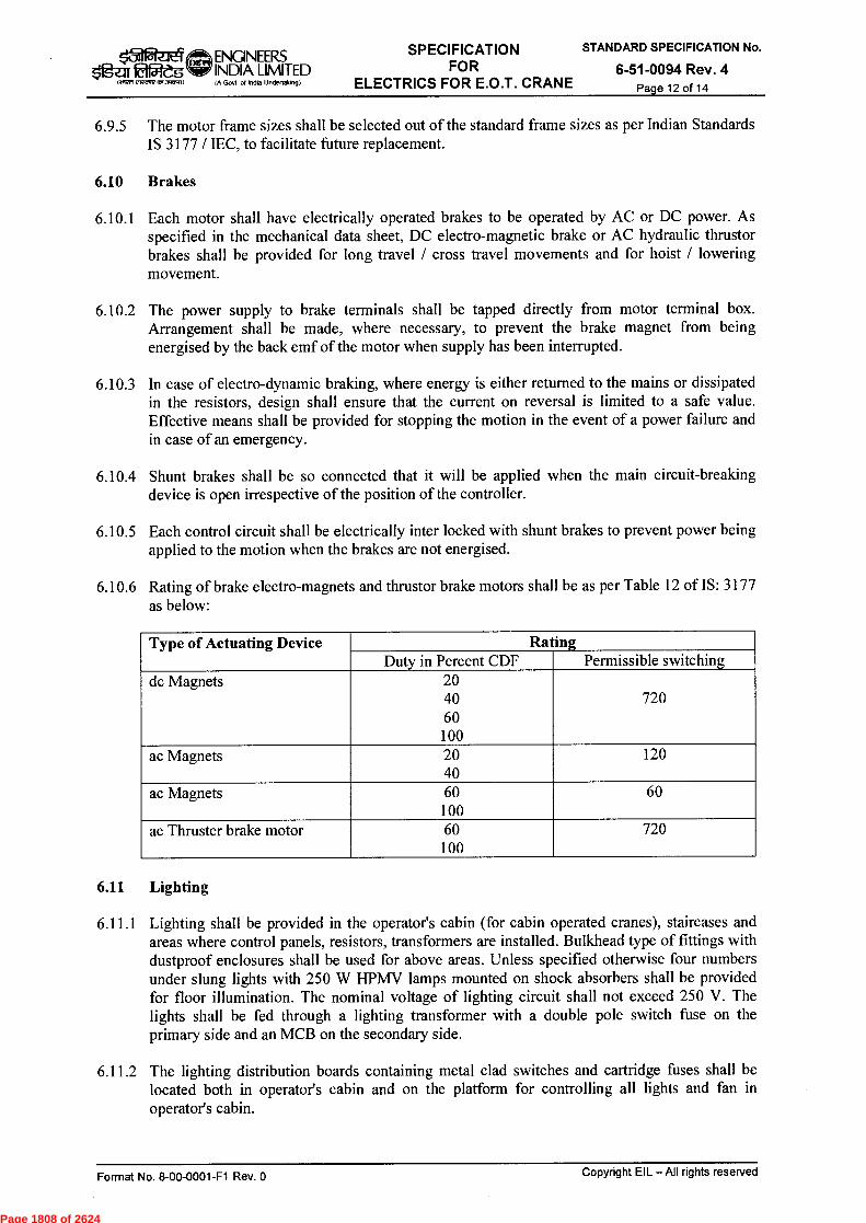
■31 ENGINEERS Og.2-3~ INDIA LIMITED
~.2,1,v~
tA Govt ot Indta Undertakog)
SPECIFICATION FOR
ELECTRICS FOR E.O.T. CRANE
STANDARD SPECIFICATION No.
6-51-0094 Rev. 4 Page 12 of 14
6.9.5 The motor frame sizes shall be selected out of the standard frame sizes as per Indian Standards IS 3177 / IEC, to facilitate future replacement.
6.10 Brakes
6.10.1 Each motor shall have electrically operated brakes to be operated by AC or DC power. As specified in the mechanical data sheet, DC electro-magnetic brake or AC hydraulic thrustor brakes shall be provided for long travel / cross travel movements and for hoist / lowering movement.
6.10.2 The power supply to brake terminals shall be tapped directly from motor terminal box. Arrangement shall be made, where necessary, to prevent the brake magnet from being energised by the back emf of the motor when supply has been interrupted.
6.10.3 In case of electro-dynamic braking, where energy is either returned to the mains or dissipated in the resistors, design shall ensure that the current on reversal is limited to a safe value. Effective means shall be provided for stopping the motion in the event of a power failure and in case of an emergency.
6.10.4 Shunt brakes shall be so connected that it will be applied when the main circuit-breaking device is open irrespective of the position of the controller.
6.10.5 Each control circuit shall be electrically inter locked with shunt brakes to prevent power being applied to the motion when the brakes are not energised.
6.10.6 Rating of brake electro-magnets and thrustor brake motors shall be as per Table 12 of IS: 3177 as below:
Type of Actuating Device Rating Duty in Percent CDF Permissible switching
dc Magnets 20 40 720 60
100 ac Magnets 20 120
40 ac Magnets 60 60
100 ac Thruster brake motor 60 720
100
6.11 Lighting
6.11.1 Lighting shall be provided in the operator's cabin (for cabin operated cranes), staircases and areas where control panels, resistors, transformers are installed. Bulkhead type of fittings with dustproof enclosures shall be used for above areas. Unless specified otherwise four numbers under slung lights with 250 W HPMV lamps mounted on shock absorbers shall be provided for floor illumination. The nominal voltage of lighting circuit shall not exceed 250 V. The lights shall be fed through a lighting transformer with a double pole switch fuse on the primary side and an MCB on the secondary side.
6.11.2 The lighting distribution boards containing metal clad switches and cartridge fuses shall be located both in operator's cabin and on the platform for controlling all lights and fan in operator's cabin.
Format No. 8-00-0001-F1 Rev. 0 Copyright EIL — All rights reserved
Page 1808 of 2624

■5-11ENGINEERS gz." INDIA LIMITED
1.777, ?:12,1A7 IA Govt of incha UndertakIng)
SPECIFICATION FOR
ELECTRICS FOR E.O.T. CRANE
STANDARD SPECIFICATION No.
6-51-0094 Rev. 4 Page 13 of 14
6.11.3 Socket outlets for hand lamps shall be provided at least one each on long travel side bridge and near electrical panels /other equipments. Hand lamps shall operate at 24 V AC supply through a separate double wound isolating 415 /24 V transformer. The isolating transformer shall have a double pole switch with fuse in each pole on the primary side and fuse in one pole of each of the secondary circuits. The socket outlets shall be metal clad industrial type.
6.11.4 Suitably rated electric bell shall be provided which shall be operated from operator's cabin / pendant push button.
6.12 Emergency Stop Push Buttons / Safety Requirements
6.12.1 Emergency Stop push buttons shall be provided on the crane bridge and in operator's cabin for cabin operated cranes. These shall be located so as to be clearly visible and readily accessible. Emergency push buttons shall be of mushroom head type (latchable in off position).
6.12.2 Emergency push buttons shall also be located at entry to crane bridge or on pendant for pendant operated cranes to cut-off incoming power, by acting to trip the main contactor/ circuit breaker.
6.12.3 When two or more cranes are operating on the same runway, collision prevention system shall be provided to stop crane movement when both cranes are 1.5 meter apart.
6.13 Earthing
6.13.1 The metal enclosures of all the electrical equipment on the crane shall have an effective earthing connection with the bridge. All equipments shall be connected to earth terminal through external aluminium earthing strip or through an extra earthing core in the supply cable.
6.13.2 The crane shall be effectively connected to earth. The crane wheels shall not be used as means of earthing.
6.13.3 In case of cranes having supply through festooned cable system, the crane shall be connected to earth by means of a separate earthing conductor, enclosed with the current carrying conductors.
6.13.4 Travelling cranes connected to the supply through collectors shall be effectively earthed through a fourth power rail or through a set of collectors sliding on the gantry rails complying with IS: 3043.
6.13.5 All electrical equipment shall have two nos. earthing terminals.
6.13.6 The runway rails shall be electrically connected to earth. The crane structure shall be made continuous by providing jumpers over riveted structures.
6.14 Painting
All metal surfaces shall undergo manufacturer's standard cleaning /painting cycle. After preparation of the under surface, the equipment shall be painted with two coats of epoxy based final paint. Colour shade of final paint shall be 632 of IS: 5/ RAL-7035. All unpainted steel parts shall be suitably treated to prevent rust formation. If these parts are moving elements, then these shall be greased.
Format No. 8-00-0001-F1 Rev. 0 Copyright EIL —All rights reserved
Page 1809 of 2624

SPECIFICATION FOR
ELECTRICS FOR E.O.T. CRANE
STANDARD SPECIFICATION No.
6-51-0094 Rev. 4 Page 14 of 14
$'1gZ11121"-Ves Govt ol India Uneterlaking)
ENGINEERS INDIA LIMITED
7.0 INSPECTION, TESTING AND ACCEPTANCE
7.1 During fabrication, the equipment shall be subject to inspection by EIL / Owner, or by an agency authorised by the Owner, to assess the progress of work, as well as to ascertain that only quality raw material is used. The manufacturer shall furnish all necessary information concerning the supply to EIL / Owner's inspectors. Minimum three weeks notice shall be given to EIL/owner for witnessing the final testing of the complete equipment.
7.2 Tests shall be carried out at the manufacturer's works under his care and expense.
7.3 Following tests shall be carried out as a minimum in the presence of Owner or his authorised representative:
7.3.1 Visual, dimensional and bill of material check.
7.3.2 Checking of correctness of wiring of circuits and continuity.
7.3.3 Electrical control, interlock and sequential operation test.
7.3.4 High voltage test, 2000 Volts to earth for one minute.
7.3.5 Insulation resistance test.
7.3.6 Routine tests according to the standards followed by the manufacturer on all electrical equipments including motors, brakes and other devices. Type test certificates shall also be submitted for these.
7.4 Certified copies of all routine tests certificates and calibration reports shall be submitted to the purchaser before despatch of the equipment.
7.5 Testing and commissioning at site, if specified, shall include following as minimum:
7.5.1 Testing of all equipment/components mounted on the cranes.
7.5.2 Testing & site commissioning (if specified) of complete protection, metering and control schemes including checking of interlocks, interconnection with connected equipment. In case of site commissioning, all testing instruments shall be brought by Vendor.
8.0 PACKING AND DESPATCH
All equipment shall be divided into several sections for protection and ease of handling during transportation. The equipment shall be properly packed for transportation by selected mode i.e. by ship / rail or trailer. The equipment shall be wrapped in polythene sheets, before being placed in the crates / cases to prevent damage to finish. Crates / cases shall have skid bottom for handling. Special notations such as `Fragile', `This side up"Centre of Gravity', `Weighe, `Owner's particulars', PO nos. etc. shall be clearly marked on the package together with other details as per purchase order.
The equipment may be stored outdoors for long periods before erection. The packing shall be completely suitable for outdoor storage in areas with heavy rains / high ambient temperature, unless otherwise agreed.
Format No. 8-00-0001-F1 Rev. 0
Copyright EIL — All rights reserved
Page 1810 of 2624

DM RKT/SC 6 07.06.2013 REVISED AND REISSUED AS STANDARD NIKHIL
5 23.05.2011 REAFFIRMED AND REISSUED AS STANDARD POREL
Rev.
No. Date Purpose
Prepared Checked
by by
Stds. Committee Stds. Bureau Convenor Chairman
Approved by Fnrmat Nn 8-110-n0(11-F4 RPV fl r.nnvrinht Fit - All rinhts msprvori
1-30 NPT TELLTALE HOLE (REFER NOTE-7)
F—
A
0 15-
O
NOMINAL PIPE SIZE
OUTSIDE DIAMETER
L (WIDTH OF PAD) C) PROJECTION 'A' SEE NOTE-4,5,9800
SHELL WELD EFF.=0.85
SHELL WELD EFF.=1.0 CLASS 150 CLASS 300 CLASS 600 CLASS 900
BELOW 3" STANDARD - - 150 150 150 150
3" 88.9 40 45 200 200 200 200
4" 114.3 50 60 200 200 200 200
6" 168.3 70 85 200 200 200 250
8" 219.0 95 110 200 200 250 250
10" 273.0 115 135 200 200 250 300
12" 323.8 135 160 200 200 250 300
14" 355.6 150 175 250 250 250 300
16" 406.4 170 200 250 250 250 300
18" 457.2 195 225 250 300 300 350
20" 508.0 215 250 250 300 300 350
24" 609.6 255 300 250 300 300 400
26" 660.4 285 330 250 300 350 450
28" 711.2 305 355 250 300 350 450
30" 762 325 380 250 300 400 450
32" 812.8 350 405 300 350 400 500
34" 863.6 370 430 300 350 400 500
36" 914.4 390 455 300 350 - -
38" 965.2 410 480 300 350 - -
40" 1016 435 505 300 350 - -
42" 1066.8 455 530 300 400 - -
44" 1117.6 475 555 300 400 - -
46" 1168.4 500 585 300 400 - -
48" 1219.2 520 610 300 400 - -
STANDARD No.
7-12-0013 Rev. 6
Page 1 of 2
NOZZLE REINFORCEMENT
AND PROJECTION
ENGN33IS INDIA LIMITED
111111171,1111,11MIND (A Govt. of loft Undertaking)
Page 1811 of 2624
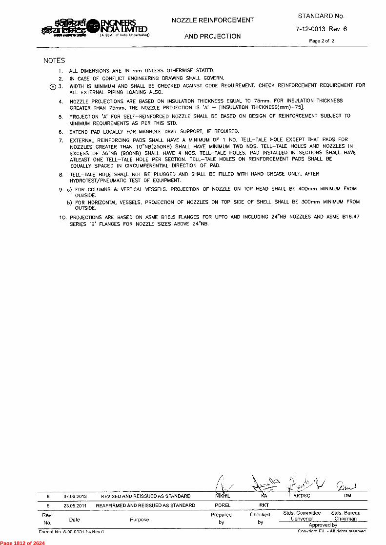
STANDARD No.
7-12-0013 Rev. 6
Page 2 of 2
NOZZLE REINFORCEMENT
AND PROJECTION
INGINEERS INDIA LIMITED
MR wow staxiso (A Govt. of India Undertaking)
NOTES
1. ALL DIMENSIONS ARE IN mm UNLESS OTHERWISE STATED.
2. IN CASE OF CONFLICT ENGINEERING DRAWING SHALL GOVERN.
C) 3. WIDTH IS MINIMUM AND SHALL BE CHECKED AGAINST CODE REQUIREMENT. CHECK REINFORCEMENT REQUIREMENT FOR ALL EXTERNAL PIPING LOADING ALSO.
4. NOZZLE PROJECTIONS ARE BASED ON INSULATION THICKNESS EQUAL TO 75mm. FOR INSULATION THICKNESS GREATER THAN 75mm, THE NOZZLE PROJECTION IS 'A' + [INSULATION THICKNESS(mm)-75].
5. PROJECTION 'A' FOR SELF—REINFORCED NOZZLE SHALL BE BASED ON DESIGN OF REINFORCEMENT SUBJECT TO MINIMUM REQUIREMENTS AS PER THIS STD.
6. EXTEND PAD LOCALLY FOR MANHOLE DAVIT SUPPORT, IF REQUIRED.
7. EXTERNAL REINFORCING PADS SHALL HAVE A MINIMUM OF 1 NO. TELL—TALE HOLE EXCEPT THAT PADS FOR NOZZLES GREATER THAN 10"NB(250NB) SHALL HAVE MINIMUM TWO NOS. TELL—TALE HOLES AND NOZZLES IN EXCESS OF 36"NB (900NB) SHALL HAVE 4 NOS. TELL—TALE HOLES. PAD INSTALLED IN SECTIONS SHALL HAVE ATLEAST ONE TELL—TALE HOLE PER SECTION. TELL—TALE HOLES ON REINFORCEMENT PADS SHALL BE EQUALLY SPACED IN CIRCUMFERENTIAL DIRECTION OF PAD.
8. TELL—TALE HOLE SHALL NOT BE PLUGGED AND SHALL BE FILLED WITH HARD GREASE ONLY, AFTER HYDROTEST/PNEUMATIC TEST OF EQUIPMENT.
9. o) FOR COLUMNS & VERTICAL VESSELS, PROJECTION OF NOZZLE ON TOP HEAD SHALL BE 400mm MINIMUM FROM OUTSIDE.
b) FOR HORIZONTAL VESSELS, PROJECTION OF NOZZLES ON TOP SIDE OF SHELL SHALL BE 300mm MINIMUM FROM OUTSIDE.
10. PROJECTIONS ARE BASED ON ASME 816.5 FLANGES FOR UPTO AND INCLUDING 24"NB NOZZLES AND ASME 816.47 SERIES 'B' FLANGES FOR NOZZLE SIZES ABOVE 24"NB.
6 07.06.2013 REVISED AND REISSUED AS STANDARD N K L
5 23.05.2011 REAFFIRMED AND REISSUED AS STANDARD POREL
RKT/SC DM
.11
RKT
Rev.
No. Date Purpose
Prepared Checked
by by
Stds. Committee Stds. Bureau Convenor Chairman
Approved by Format Nn 8-nn-onni-F4 Rpv n
nonvrinht FII - All rinhts rpsprypri
Page 1812 of 2624

0 *A0}21 Ld-1000-00-8 '0N 1.ewiod z
O <
ZOOZ170'0£
o
LOOZ"60'8Z
Z LOZ'90'6Z
tILOZ'1.0'0£
oZZ
sp
òDZ
rrn
—
rn
Enm
CJ
pamesei s1116!-1 IIV —113 4q6uAcloo
Aq peAcuddv
neo.ing spiepuels
uo!lewawaidw! Jo; panssi o
JJ
n
7t pansshed pue pas!neu
JJ
JJ panss!eu pue pasvkau
panss!au pue pes!neu
•
£.1H
STANDARD SPECIFICATION NO.
Pag
e 18
13 o
f 26
24

0 Aed L3-1000-00-8 'oN TeW.I03 patuasaJ s11-16I-1 IIV —113 TLI6Odo3
D)
CD
O
-nall
Z501-18-9
STANDARD SPECIFICATION NO. <15
°
•
1— --
, m '.)
' '?-..'
.;.-
.ij .r
i rr
l C
1 (-)
()(-)n
o:)
ed
> g
: »c
s t
rl
cr
fo
et)
■-“")r)(-)
o•c
j 'F)
' •--
3 fl;' 4
(")
-o
•--
3 '-r1 r
ri
url
r) 7
, >
C4 .1
H
t-3
t-3
cl)
fct
CD
Z ~
'11 s
=‘' ctil
trl
C
. r
.1
0
C.
0
o
(-)
'-tri ri
CA
(-) >
5
. .-
, w
0
z
z
z
rri
s::..
sz
..1
z..
r^
r)
o r.
-̀r1
'1.
1 -̀r1
tTi
1::, t5
nn
nn
eci>
ed
>
4 4
4
.... ,
,,, ,.
, —
. .
. C
D C
D C
D ~
t '-'
s ...-
0
r:L
. ■-+
4
Z
Cc " L.oD
CD
8•
PJ
C S-0
)
. '"C') ,
Ò. °
(. 8° 4
oc p.,)
- «
'.'=-r-1: rii
E- 2
> 2:'s n
o
> o5Q
4 5-
(4)
<r
-5 (
1)() ÖF
D' 6. Ê
9- 1 •
) 9_
, z
( 1 )
5- '
ri
l o
-c■
c„ -
. -.
cn
-t
c,
,-1
. H
,_,
. _•7
:, 5.
c c
i..
(')
o
t-■
w CJ
Q
S),)
CD
(1) c
o c
) --
-
w '
1-,
»4-
,
t
ril "
--,
cl.
. a c
:› c-r
n
,z,,,
-• ;c5" ,,_.D
.i 2.
,0
--
CfQ
cnCD
'-` •
rp
5 •
,--
CfQ
IDD
,-,-
■-t c)
CD
■-t-
..-r,
17., •
51
C,1)
(1)
(...,
•-t
.-t 1
:,.,
v)
'-'.c
rc?
{2
--,
e-t
- cp
CDCD
r
il 6
2') 4
cn
o
,-0 ..
.I
C)
CfQ
.--t p
< .
>5
':,7'
H
5. v
, -c
s G
. ?)-
' r)
(1)
.•-
• SD)
f-N)
5'
(4,-)
'5" o
•-s
cp
4-
CfQ
e-
i• cn
CD
..:',
• r:L
. I-
f, O
■••
• •
r) ('
-:>"
CfQ
=t-• A
) <D
' .-t
0
2')
C
r rr
i o
'-r1
w u
t •-•
c'T
o
SD)
ci
) o
c)
H7z
) •-
•
O'
-t"I
`/i'''•
cp
:)0
CD
5.
7D0
ril
0.
.-t
».0
S: T
,--t
- ci)
c..
»Es"
lw
w
et-
....
I-r1
Cr
.4t
• CT
CD
co
5
'0 w
4
CfQ
r, .,:j
.c,
r■ H
'-o n
(-) C
4xi,
orT
iot-
rrl-
c,c
psH
s-ci
.-. .t
,c)
rr
i 0
'-cs
>
rc:D' 't)p0
"--
]
'.1
H
0.
co
<-)
,..-•
f::)
<
H
H ,C
) '"
Ct
'-ct
'-ci
'-cl
'-cf
'-d 'z
i Z
Z
Z
4
CD C
D
CL. " :
+t ,="t
“
',.-' c
n •
-1 o
-$.
,- w
•-•
• c)
c)
" C
) ...
. .--
•
CcinD .8
1:: f'
-=): f
:).. c
o cl
.. ...
.., =
. ...."'
. co
0
2
o
■--■ "z
i °
t--,
■-t
R
o
■-c
s cp
'.<
< tD
D f=
3., c~
li p)
0 :
j •
5, •
(,) C
fQ .„
, s, ,
5 •
cD
cn
cn
p)
CD
cn 1W
"
• A
.
,_,'
co(-
4
CD
CD
•-1
'-' c
n
_r
g),
— c
2
cp H
-)
., ,,,
, o o
tii -
. f=
L ,
-h
A3 .-t
,.t pt nr)
r,
CD
_,) ,-
.1
Cp
.fn
D<
fn-
c)
(-)
;:,, (.4
/2
C4
cc,
,2
— -
, :)0
-cs
n -
, - .
---
o
o
cl. c
r) 1
:t.) -
• . - t
i o
'E). v
) --
• ,n
"
CfQ
.- •
cp
C)
u)
w
■-..3
■E
, ri
l r)
e.i
. <•D
C4
CD
0
CD
CD
„
.--
-c c
/D
A)
5- ,
..L.,
5 ,
-cs
n o
"
.A...
SW
FD
>
,r)
CfQ
(1)
S),)
• cn
CfQ
C)
(1)
■-n
ci.
.
-<
,.-
CD
.-- •
C)
C)
C)
Z̀'à A
) C)
0
0
c) •-
t-. ̀
s•-•,
CD
Cn
tZ1
>
AD
cn
.....
(:)(4
o
c)
-.
w
,..,,
o- .
z
aTeoljpiaD lutiaiuK
Pag
e 18
14 o
f 26
24

0 'Aed 2.3-I000-00-9 '0N 2WJO3 pamesai s}q6P IIV -113 41.160doo
3.0 INSPECTION AND TEST REQUIREMENTS
PO/PR/ Standards referred there in/Job specifications/Approved documents.
SIN1IATI13041 aDNIM:13.4M1
adops
rg
o >
2 òrm
rn £ '^a?"
STANDARD SPECIFICATION NO.
.1:.• CD
L..)
.,—'
(...)
■•:::,
l•-)
.-•-•
IN)
0
~
CD
z C
A
C.) e
'l
Final Inspection
Manufacturing Stage
In process Inspection
Incoming raw material like Copper Aluminium, PVC, PE, Jelly Compound, Armour material, etc.
Material Inspection
Procedures
STAGE/ ACTIVITY
Dimensions at various stages, Spark test, Stage Inspection
Dimensional, Purity, Physical, Chemical Properties, Tests on jelly compound as per DOT spec .
CHARACTERISTICS
■—•
Cp
C
D
.'.'"
;;
Sample
I
I
QUANTUM OF CHECK
Supplier's Test Records
Sub supplier TC/Supplier' s Test Records/
Third party Lab
o
i .
SUB SUPPLIER
SCOPE OF INSPECTION
z
z
.
SUPPLIER EIL/TPIA
Pag
e 18
15 o
f 26
24
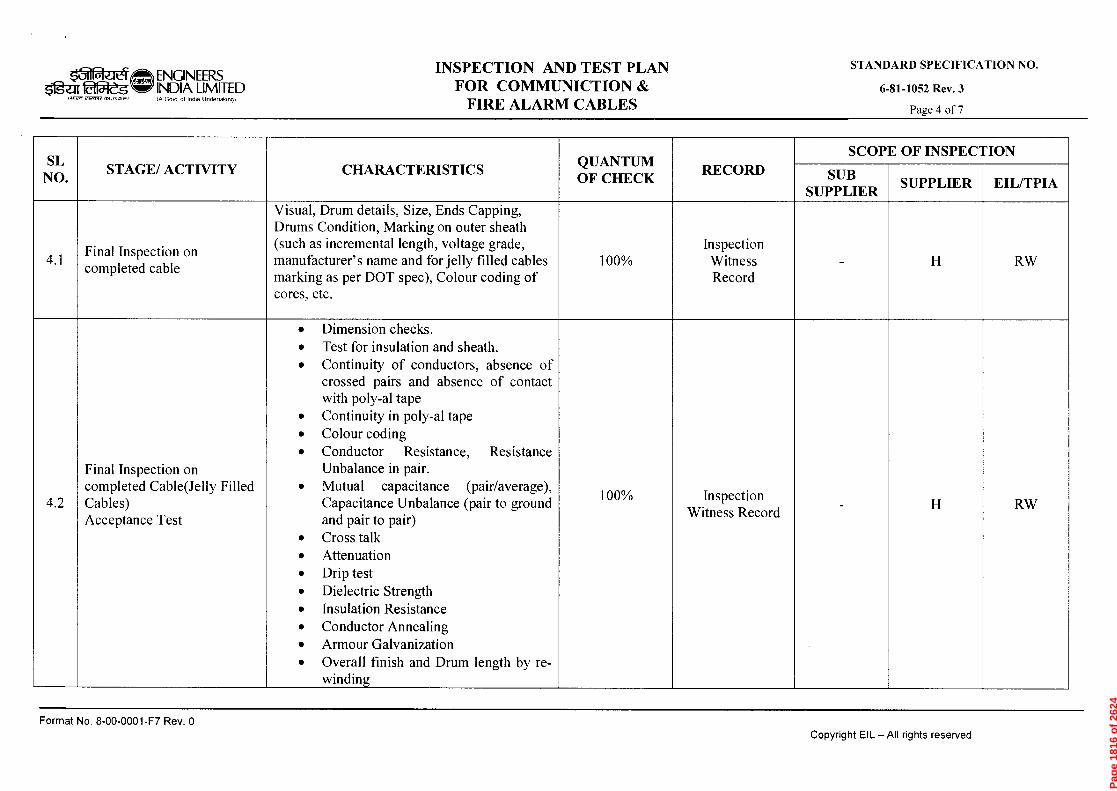
0 •AGd L3-1000-00-8 oN }ewio3 pamase., IIV —113 11160doo
£ *AaR Z501-18-9
STANDARD SPECIFICATION NO.
.4.
i,..)
.._.
z w
0 r
> c"
) r,
l-ri
c>
f>>
C)
— •
r)
cr
r2,9
r)
0..
, >1:
: n)
n)
(")
c. ,",)
H
p, •
eD
5
cr
----.o
,_,
cp =
-r1
....
(-7
tn
. Final Inspection on completed cable
STAGE/ ACTIVITY
' 0.
CfQ
• •
• •
• •
•
(:-)>
(-)5-5>
c-)
60
(-) 4
c•-•
)()(
-)5
,r)(
-)-1
c, "
. a'
) ()
0
°
,#.3 0
9
, 4
5
CD
„,
'CS
■-r-
cr
c•S'
cn ,
=
,--s
'—•
P)
0
A>
0.
,-,
rn
■--f-
„c$
(.D
.-
- ■-r ,
■-• •
„. :z
o
■-t
o
ci
'—
• '-
t ,..,
0
,-(5. -
, ci), 9
4 rz;
5-
o
e,
-I
_v).
•.---h
C
) .9,
'--,
'. 3
.
o
o ,
.--
.0
',..” .
'• o
f,,,
on
oo
c,.
, ;;,D
PO
...
C4
'-l:$
5. 5
. -,
o e,
AD ,..
..cs
,,_ ,
,, ,-
-b
Er
=1"
t■-J.
AD
15 C
f-
CT
' ,-+
• .--
, • ̀
..'
'—'
fl)
0
0
7-.
cn
,--1,
.-' •
cn
oeCi
CD
<T
) AD
ft.
CD,-r
-
C1.,
ci)
c>
lz.)
Cr tr)
_,.
,--, ,
SL)
'cl
n)
CD
0
Cn
'-t
'C, .c
, CD
C4
CD
C
T
AD
ty
CD
s'
120
■:-1 .
'-' •
AD
S
t C
r-
E
;:o.zs...
CD
cp
cr
v)
.-1"›
CD
•C
cn
Cr
Ci
CD
...
CD
cr
-t
-t
ti)
0
`-<
0
Q>
,-/-
Q>
co
Cr
Q -t
Q>
rzu
CD
C>
c)
0
?
ssr""
n
) „t.
.-
1,
Visual, Drum details, Size, Ends Capping, Drums Condition, Marking on outer sheath (such as incremental length, voltage grade, manufacturer's name and for jelly filled cables marking as per DOT spec), Colour coding of cores, etc.
CHARACTERISTICS
(=>
.—.
C>
o
QUANTUM OF CHECK
Q_-,.•
n)
v,
r.,) 'c CD
f cn
C>
co 3.
r) =
0
.a.
Inspection Witness Record
c-)
0
' 1
SUB SUPPLIER
SCOPE OF INSPECTION
Z
SUPPLIER CI'l
~
t'd
md
~
>
Pag
e 18
16 o
f 26
24
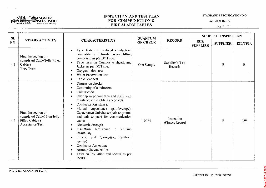
0 Aod L3-1000-00-9 'oN IeWJOd PGAJ9S9J SABP IIV -113 1-160c100
STANDARD SPECIFICATION NO.
.nall ZSOI-I8-9
-P
-P
1..)
z W
0
›.
'-'11
c)
° "
•
CD
AD
...0CD
Q
., ■-
c:
__
(i› ,-
no
o-' s
a.
'.1°,
(1)
(-) r
) ■-3
(''
pp '.
CD ,--
- cr'
0
,---. o
Z
'
0 cp
Final Inspection on completed Cable(Jelly Filled Cables) Type Tests
STAGE/ ACTIVITY
• • •
•
• •
• •
• • • •
> n
cr%
5- C
) (
- )
nc),,,o
nn
G.,.
6D
, , ,rD
t.. )
- .
c ' )
& ,
_ s )
0
cn
-C
0
0
',•
rri
iii
., 5
'4
. 'ji
« ■—
• co
(1
7
.11"
.f2
E
a
,..,
'--
.-9
0—
■••
(9
(-)
(7,
__ -,
-. 94
t•-)
cn
'Cf
r)
pD
c s
o
,..
o
•.-.
, (I
) ''
• ,--
, .
g-
r`')
:=1-''
~"
v)
=
C)
E;;
' - . o
.
=t- t
,) ‘
=
e-I, ö
o
...
.-6, •
o
cD
_.--• •
C
) , ■-
j-
5"
Po
.,„_
- (/
) ..•-
,- e)
r)
" ,-
, ta
. '-
'.
=
cn
.<
,..-
g
-
.--,
CD
AD
,-•
• CD
cp
(..
, .-
t«, i
ct
=
=
''''
o
',0
''''
(I)
u) °
sw cA
—
r)
CD
r
co
::,)
=
r)
.- •
=
' ,..<
o
,-t.
-
• (1
) cn
CI
'm
..1•
- t)
' n
7-
-
. N
Ao
'",
• ""
......,
pp
o
p.,
...•
PD
-
(4
,,,=', •
'S
.
.(5
Fài
,,'-' =
CZ
L,
CL
`...•
O'Q
1-1
-, .-
c)
r)
I.-•
•
•-,.
QD
0
cp
ci>
QD
e)
O'Q
r)
.-1
r)
«
CfQ
'LS
0
C.
AD
ci)
o
c.)
(1)
-t
• e' ,,
cn
C4
O
C.)
't:,
■•,z
3 CD
CD
=
■=i
• ~
" ~4
, ...
p.
'-:-....t
■-•■
f:).
'-..‘
...
..,
~ •
QD
■-■ •
0
(« "
. ') . q
. Cti
51
cn
5,-
QD
0
AD
li
0
. O
Q
co
=
(:;
CD
;“
-t
(D
=
sa. ::
--'
ro
•
Type tests on insulated conductors, compatibility of Insulation and filling compound as per DOT spec.
•
Type tests on Composite sheath and Jacket as per DOT spec
•
Oxygen index test
•
Water Penetration test
•
Cable bend test.
CHARACTERISTICS
■-■
CD
C
)
0
=
CD
ri)
QUANTUM OF CHECK
7-,.“ 1
-1
CD
c/D
cn
'-0 (-) --
co 'cj
•
r)
0
CL.
T.,
»0
(1)
'—'
o ,
,.,, „,-
()
'' CD
cr
) .-
-
›:
M
o
g
1 1
SUB SUPPLIER
SCOPE OF INSPECTION
x
SUPPLIER 1~
t.
d
4..
.0
~
Pag
e 18
17 o
f 26
24

0 Aed L3-1000-00-8 'oN el.tuod pamasei si.16!J IIV —113 11160doo
STANDARD SPECIFICATION NO.
o,
iv
cr,
--.
C■ ;=
f.11
C:p
.4.
o■
-1=.
iJI
cA
CD
Final Document submission
Documentation and IC
Documentation and IC
Painting
Final Inspection on completed Cable( Non Jelly Filled Cables ) Type Tests
Final Inspection on completed Cable( Non Jelly Filled Cables ) Special Test
STAGE/ ACTIVITY
Compilation of Inspection reports ,drawings, etc as per VDR / PR
•
Review of Internal Test Reports and MTCs.
• IC issuance •
Type test on conductor as per spec
•
Type tests on insulation and Sheath as per spec
•
Oxygen Index Test
•
Flammability test as per applicable specification
•
Test for Rodent & termite repulsion
•
Surface finish and drum length check by wiring
CHARACTERISTICS
rT
co
co
QUANTUM OF CHECK
Final data folder /Completeness
certificate
Supplier' s Test Records / Inspection
Certificate (IC)
Supplier' s Test Records
Inspection Witness Record
o
g
,
SUB SUPPLIER
SCOPE OF INSPECTION
x x
x x
SUPPLIER
x x
EIL/TPIA
Pag
e 18
18 o
f 26
24
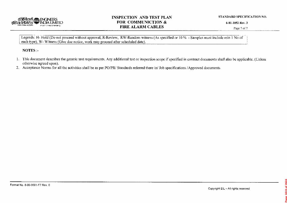
0 'Aod Ld-1.000-00-9 'oN 4etwod
Copyright EIL — All rights reserved
STANDARD SPECIFICATION NO.
Pag
e 18
19 o
f 26
24

3 (NOTE-2) 6 3 3 3 3 3+CORROSION ALLOWANCE
(NOTE-4)
TU
BE
SH
EET
TU
BE
SH
EET
TU
BE
SH
EE
T
TU
BE
SH
EE
T
0.4
DE
PT
H O
F G
RO
OV
E
0.4
DE
PTH
OF
GR
OO
VE
u_ O
c.) 07
0 O
c.)
CLADDING
EXPANDED LE
FIG.-2
4 06.05.14 REVISED AND REISSUED AS STANDARD CP
3 27.01.09 REAFFIRMED AND REISSUED AS STANDARD
VPR
SC
VC RKG AKM
TUBE HOLE PREPARATION BVGNEQZS
OfazIM INDIA LIMITED AND ROLLER EXPANDING
(A Govt. of Indla Undortoking) (SHELL & TUBE EXCHANGERS & AIR COOLED HEAT EXCHANGERS)
STANDARD No.
7-15-0006 Rev. 4
Page 1 of 1
EXPANDED LENGTH
FIG.-1
NOTES : - 1. ALL DIMENSIONS ARE IN mm UNLESS STATED OTHERWISE.
2. FOR TUBESHEET THICKNESS WHERE THE GAP BETWEEN 2ND GROOVE & BACK OF TUBE SHEET IS LOWER THAN 6 mm DELETE 2ND GROOVE.
3. FOLLOW SPECIAL CLOSE FIT AS PER TEMA / API 661 UNLESS SPECIFIED OTHERWISE.
4. FOR CORROSION ALLOWANCE LESS THAN 4 mm., INCREASE THIS DIMENSION TO TUBE SHEET THICKNESS
MINUS 18 mm. BUT NOT TO EXCEED 7 mm.
*5. CHAMFER (1X45') OR RADIUS (R=1).
Rev. No.
Date
Format No. 8-00-0001-F4 Rev.O
Purpose Prepared Checked
by by
Stds. Committee Stds. Bureau Convenor Chairman
Approved by Copyright EIL - All rights reserved
Page 1820 of 2624
Page 1821 of 2624

Page 1822 of 2624
Page 1823 of 2624
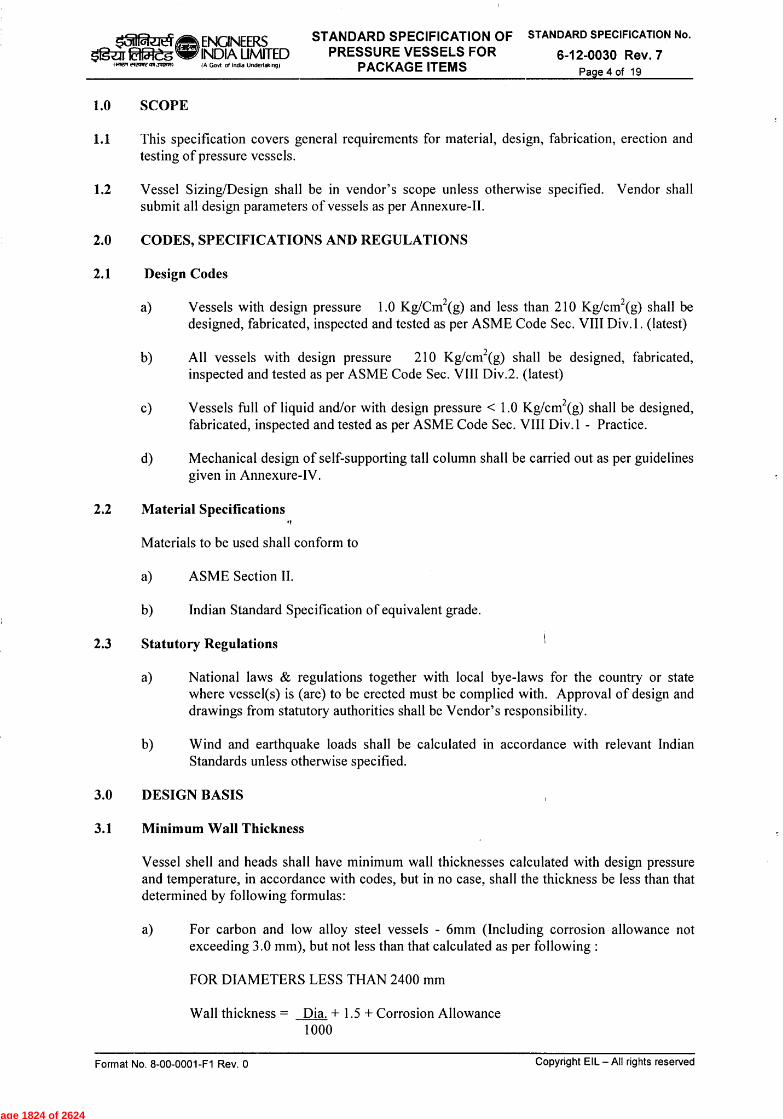
Page 1824 of 2624

Page 1825 of 2624
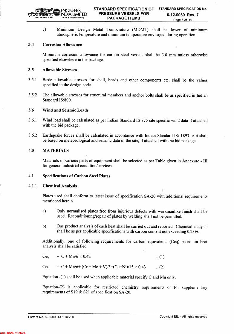
Page 1826 of 2624

Page 1827 of 2624

Page 1828 of 2624

Page 1829 of 2624

Page 1830 of 2624

Page 1831 of 2624

Page 1832 of 2624
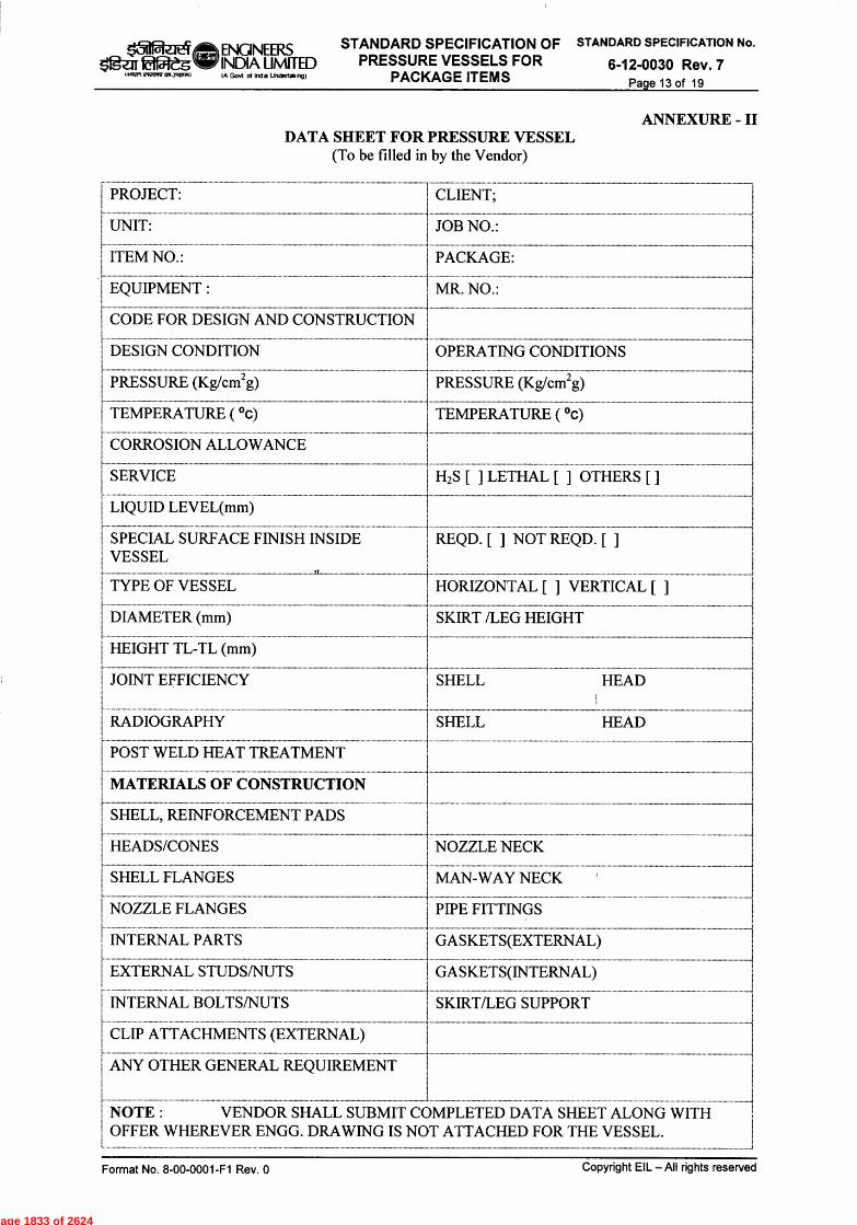
Page 1833 of 2624

Page 1834 of 2624