smarttouch: electric skin to touch the untouchable
TRANSCRIPT

Seediscussions,stats,andauthorprofilesforthispublicationat:https://www.researchgate.net/publication/8329677
SmartTouch:ElectricSkintoTouchtheUntouchable
ARTICLEinIEEECOMPUTERGRAPHICSANDAPPLICATIONS·JANUARY2004
ImpactFactor:0.91·DOI:10.1109/MCG.2004.1255807·Source:PubMed
CITATIONS
79
READS
35
4AUTHORS,INCLUDING:
HiroyukiKajimoto
TheUniversityofElectro-Communications
126PUBLICATIONS966CITATIONS
SEEPROFILE
SusumuTachi
TheUniversityofTokyo
347PUBLICATIONS3,354CITATIONS
SEEPROFILE
MasahikoInami
KeioUniversity
171PUBLICATIONS1,031CITATIONS
SEEPROFILE
Availablefrom:SusumuTachi
Retrievedon:04February2016
SmartTouch: Electric Skin to Touch the Untouchable
Hiroyuki Kajimoto(1) Masahiko Inami(2) Naoki Kawakami(1) Susumu Tachi(1) (1)Graduate School of Information Science and Technology, The University of Tokyo
{kaji, kawakami, tachi}@star.t.u-tokyo.ac.jp
(2)Department of Mechanical Engineering and Intelligent Systems, The University of Electro-Communications
Abstract A new type of Haptic AR system, SmartTouch, is
introduced. SmartTouch is composed of a thin electro-tactile display and a sensor mounted on the skin. The sensed information is converted to tactile sensation through electrical stimulation. Thus, the wearer not only makes physical contact with an object, but also can “touch” surface information of any modality, even those that are ordinarily non-touchable. The prototype of SmartTouch has optical sensors. We endeavored to realize the tactile perception of luminance information, which was achieved by imitating the sensory nerve activity with electrical stimulation.
Keywords: Tactile Display, Electrocutaneous, Tactile
Primary Colors, Augmented Reality, Augmented Haptics, SmartTouch
1. Introduction
It is indisputable that a major part of our life is the
interaction with our surroundings. In this relationship, information from the world is received through five major sensory modalities.
It is also a fundamental limitation that tiny sensory organs in charge of the respective sensations are the only gates which connect us to the world. Natural ambition arises; the ambition to acquire sensing ability beyond the usual physical limits, and to build new relationship with the world. It is the ability to see the invisible, or to hear the inaudible, often referred to as a sixth-sense.
Augmented reality (AR)[2] is an engineer's approach to this dream. In AR, artificial information is captured from the world by some sort of a sensor and displayed through existing sensing channels. Hence, we virtually
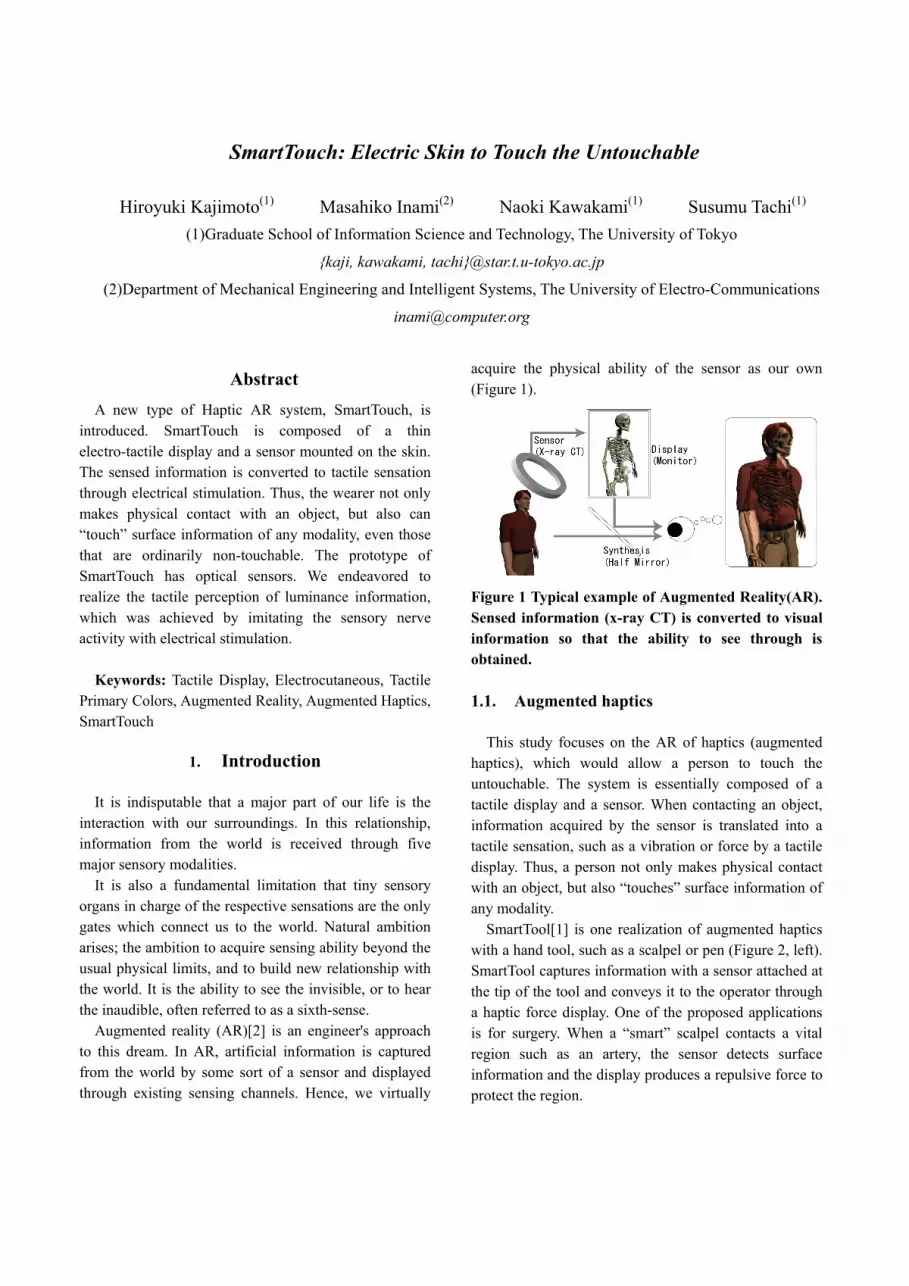
acquire the physical ability of the sensor as our own (Figure 1).
Figure 1 Typical example of Augmented Reality(AR). Sensed information (x-ray CT) is converted to visual information so that the ability to see through is obtained.
1.1. Augmented haptics
This study focuses on the AR of haptics (augmented
haptics), which would allow a person to touch the untouchable. The system is essentially composed of a tactile display and a sensor. When contacting an object, information acquired by the sensor is translated into a tactile sensation, such as a vibration or force by a tactile display. Thus, a person not only makes physical contact with an object, but also “touches” surface information of any modality.
SmartTool[1] is one realization of augmented haptics with a hand tool, such as a scalpel or pen (Figure 2, left). SmartTool captures information with a sensor attached at the tip of the tool and conveys it to the operator through a haptic force display. One of the proposed applications is for surgery. When a “smart” scalpel contacts a vital region such as an artery, the sensor detects surface information and the display produces a repulsive force to protect the region.
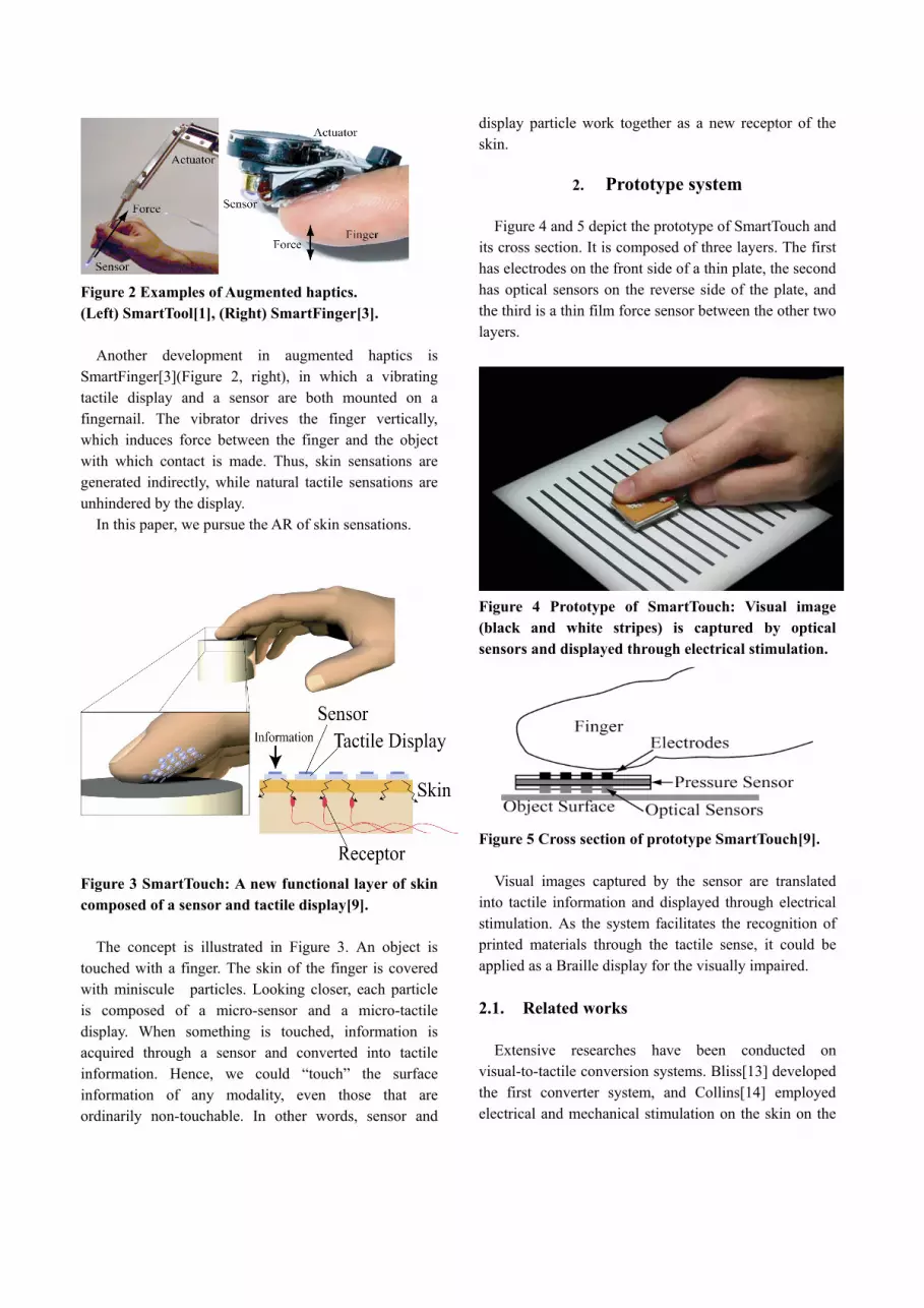
Figure 2 Examples of Augmented haptics. (Left) SmartTool[1], (Right) SmartFinger[3].
Another development in augmented haptics is
SmartFinger[3](Figure 2, right), in which a vibrating tactile display and a sensor are both mounted on a fingernail. The vibrator drives the finger vertically, which induces force between the finger and the object with which contact is made. Thus, skin sensations are generated indirectly, while natural tactile sensations are unhindered by the display.
In this paper, we pursue the AR of skin sensations.
Figure 3 SmartTouch: A new functional layer of skin composed of a sensor and tactile display[9].
The concept is illustrated in Figure 3. An object is
touched with a finger. The skin of the finger is covered with miniscule particles. Looking closer, each particle is composed of a micro-sensor and a micro-tactile display. When something is touched, information is acquired through a sensor and converted into tactile information. Hence, we could “touch” the surface information of any modality, even those that are ordinarily non-touchable. In other words, sensor and
display particle work together as a new receptor of the skin.
2. Prototype system
Figure 4 and 5 depict the prototype of SmartTouch and
its cross section. It is composed of three layers. The first has electrodes on the front side of a thin plate, the second has optical sensors on the reverse side of the plate, and the third is a thin film force sensor between the other two layers.
Figure 4 Prototype of SmartTouch: Visual image (black and white stripes) is captured by optical sensors and displayed through electrical stimulation.
Figure 5 Cross section of prototype SmartTouch[9].
Visual images captured by the sensor are translated
into tactile information and displayed through electrical stimulation. As the system facilitates the recognition of printed materials through the tactile sense, it could be applied as a Braille display for the visually impaired.
2.1. Related works
Extensive researches have been conducted on
visual-to-tactile conversion systems. Bliss[13] developed the first converter system, and Collins[14] employed electrical and mechanical stimulation on the skin on the

back. A representative commercial product, Optacon[15] was developed in the 1960s; it uses a video camera and a matrix of vibrating pins. However, the objective was for a visually impaired person to read printed material rather than to “augment” the real world. With the system, a participant must have a video camera in one hand and tactile information is displayed onto the other. In our system, the optical sensor and the tactile display are located in practically the same place and work in combination as a new skin “receptor”.
2.2. Electrical stimulation
By mounting a display directly on the skin, tactile
sensations can be presented with high spatial resolution. At the same time, the display itself is separate from the contact point with an object. But what kind of inconvenience arises consequently?
Consider a horizontal motion of the finger. When the finger moves horizontally, the contact generates a frictional force. The force is perceived at the finger as a torsional moment. As the display becomes thicker, the increased distance between the finger and the object surface generates greater torsional moment, which results in an unnatural haptic sensation (Figure 6).
Figure 6 Horizontal motion of the finger and torsional moment. F1: Finger force; F2: Friction; r: Distance between the center of the finger and skin; R: Display thickness; M: Finger torsional moment[9].
This fact highlights the merits of electrical stimulation
as a means to display tactile information. Under this paradigm, all that is needed to contact the skin is a matrix of electrodes, which can be readily fabricated into a thin wafer.
The tactile display was composed of a 4x4 matrix of stainless steel electrodes, each 1.0mm in diameter. The longitudinal and transversal pitch of the electrodes was 2.5mm and 2.0mm respectively (Figure 7, left). The electrodes applied electrical current pulses to the skin
(0.2[ms], 100-300[V], 1.0-3.0[mA] current controlled) in order to generate the tactile sensation.
Figure 7 (Left) Electrodes, (Right) Optical sensors[9]. Both electrodes and sensors were arranged at a 2.5mmx2.0mm pitch and a 4x4 matrix. The position of each electrode was strictly aligned with an optical sensor.
2.3. Optical sensor
For an optical sensor, we used a phototransistor
(SHARP PT600T, 1.6mm×1.6mm×0.8mm). We placed the sensors just beneath the electrodes so that the horizontal displacement between the stimulation point and the sensing point was less than 1.0mm.
We used printed paper as a contact object. As we did not embed a light source into the system, the paper was lit with an LED lamp from below.
In the first preliminary experiment, each sensing element was placed in direct contact with the surface of an object; so that there was some gap region between the sensors where no sensor could see. Hence, when we move the system on black and white stripes using an interval identical to that of the sensors, the sensors, in one case, could not locate the stripes; however, suddenly, they all sensed the stripes simultaneously, resulting in instability of the displayed tactile sensation. Therefore, the field of view of each sensor must be widened so that each sensor has an appropriate spatial property.
The sampling theorem states that, to reconstruct an original signal from sampled data, the original signal should not have a frequency component higher than 1/2d (d: sampling interval)[16]. From this viewpoint, the above-mentioned phenomenon is seen as an aliasing effect.
Hence, we tried to design a spatial filter by broadening the field of vision of the sensing. It was achieved by mounting spacer on the sensor substrate and keeping the
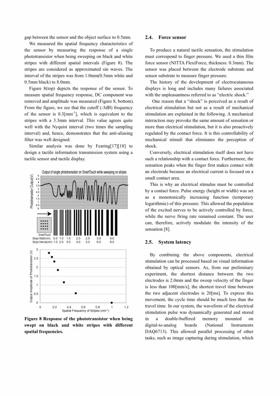
gap between the sensor and the object surface to 0.5mm. We measured the spatial frequency characteristics of
the sensor by measuring the response of a single phototransistor when being sweeping on black and white stripes with different spatial intervals (Figure 8). The stripes are considered as approximated sin waves. The interval of the stripes was from 1.0mm(0.5mm white and 0.5mm black) to 8.0mm.
Figure 8(top) depicts the response of the sensor. To measure spatial frequency response, DC component was removed and amplitude was measured (Figure 8, bottom). From the figure, we see that the cutoff (-3dB) frequency of the sensor is 0.3[mm-1], which is equivalent to the stripes with a 3.3mm interval. This value agrees quite well with the Nyquist interval (two times the sampling interval) and, hence, demonstrates that the anti-aliasing filter was well designed.
Similar analysis was done by Fearing[17][18] to design a tactile information transmission system using a tactile sensor and tactile display.
Figure 8 Response of the phototransistor when being swept on black and white stripes with different spatial frequencies.
2.4. Force sensor To produce a natural tactile sensation, the stimulation
must correspond to finger pressure. We used a thin film force sensor (NITTA FlexiForce, thickness: 0.3mm). The sensor was placed between the electrode substrate and sensor substrate to measure finger pressure.
The history of the development of electrocutaneous displays is long and includes many failures associated with the unpleasantness referred to as “electric shock.”
One reason that a “shock” is perceived as a result of electrical stimulation but not as a result of mechanical stimulation are explained in the following. A mechanical interaction may provoke the same amount of sensation or more than electrical stimulation, but it is also proactively regulated by the contact force. It is this controllability of mechanical stimuli that eliminates the perception of shock.
Conversely, electrical stimulation itself does not have such a relationship with a contact force. Furthermore, the sensation peaks when the finger first makes contact with an electrode because an electrical current is focused on a small contact area.
This is why an electrical stimulus must be controlled by a contact force. Pulse energy (height or width) was set as a monotonically increasing function (temporary logarithmic) of this pressure. This allowed the population of the excited nerves to be actively controlled by force, while the nerve firing rate remained constant. The user can, therefore, actively modulate the intensity of the sensation [8].
2.5. System latency
By combining the above components, electrical
stimulation can be processed based on visual information obtained by optical sensors. As, from our preliminary experiment, the shortest distance between the two electrodes is 2.0mm and the sweep velocity of the finger is less than 100[mm/s], the shortest travel time between the two adjacent electrodes is 20[ms]. To express this movement, the cycle time should be much less than the travel time. In our system, the waveform of the electrical stimulation pulse was dynamically generated and stored in a double-buffered memory mounted on digital-to-analog boards (National Instruments DAQ6713). This allowed parallel processing of other tasks, such as image capturing during stimulation, which
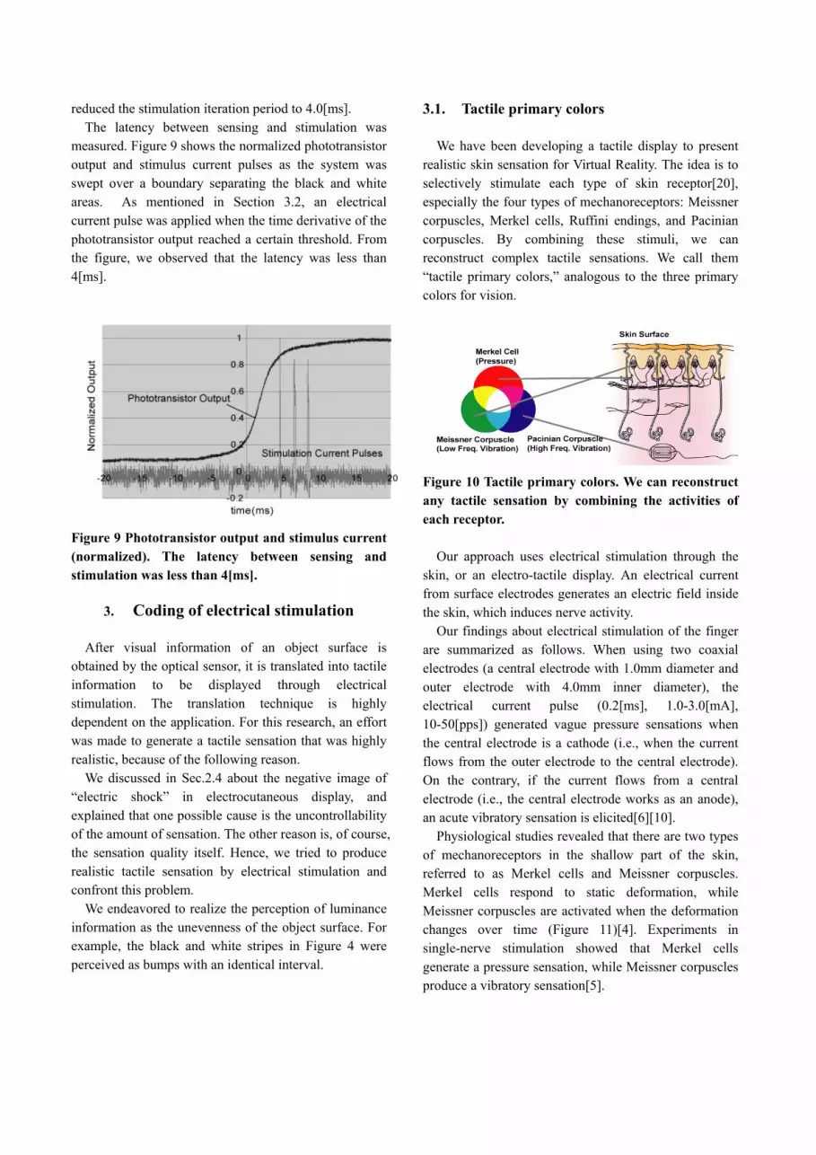
reduced the stimulation iteration period to 4.0[ms]. The latency between sensing and stimulation was
measured. Figure 9 shows the normalized phototransistor output and stimulus current pulses as the system was swept over a boundary separating the black and white areas. As mentioned in Section 3.2, an electrical current pulse was applied when the time derivative of the phototransistor output reached a certain threshold. From the figure, we observed that the latency was less than 4[ms].
Figure 9 Phototransistor output and stimulus current (normalized). The latency between sensing and stimulation was less than 4[ms].
3. Coding of electrical stimulation
After visual information of an object surface is
obtained by the optical sensor, it is translated into tactile information to be displayed through electrical stimulation. The translation technique is highly dependent on the application. For this research, an effort was made to generate a tactile sensation that was highly realistic, because of the following reason.
We discussed in Sec.2.4 about the negative image of “electric shock” in electrocutaneous display, and explained that one possible cause is the uncontrollability of the amount of sensation. The other reason is, of course, the sensation quality itself. Hence, we tried to produce realistic tactile sensation by electrical stimulation and confront this problem.
We endeavored to realize the perception of luminance information as the unevenness of the object surface. For example, the black and white stripes in Figure 4 were perceived as bumps with an identical interval.
3.1. Tactile primary colors We have been developing a tactile display to present
realistic skin sensation for Virtual Reality. The idea is to selectively stimulate each type of skin receptor[20], especially the four types of mechanoreceptors: Meissner corpuscles, Merkel cells, Ruffini endings, and Pacinian corpuscles. By combining these stimuli, we can reconstruct complex tactile sensations. We call them “tactile primary colors,” analogous to the three primary colors for vision.
Figure 10 Tactile primary colors. We can reconstruct any tactile sensation by combining the activities of each receptor.
Our approach uses electrical stimulation through the skin, or an electro-tactile display. An electrical current from surface electrodes generates an electric field inside the skin, which induces nerve activity.
Our findings about electrical stimulation of the finger are summarized as follows. When using two coaxial electrodes (a central electrode with 1.0mm diameter and outer electrode with 4.0mm inner diameter), the electrical current pulse (0.2[ms], 1.0-3.0[mA], 10-50[pps]) generated vague pressure sensations when the central electrode is a cathode (i.e., when the current flows from the outer electrode to the central electrode). On the contrary, if the current flows from a central electrode (i.e., the central electrode works as an anode), an acute vibratory sensation is elicited[6][10].
Physiological studies revealed that there are two types of mechanoreceptors in the shallow part of the skin, referred to as Merkel cells and Meissner corpuscles. Merkel cells respond to static deformation, while Meissner corpuscles are activated when the deformation changes over time (Figure 11)[4]. Experiments in single-nerve stimulation showed that Merkel cells generate a pressure sensation, while Meissner corpuscles produce a vibratory sensation[5].
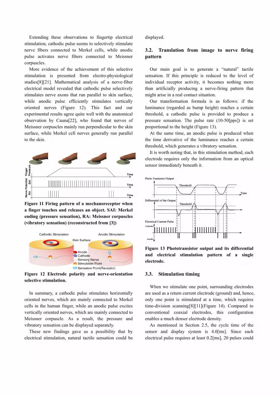
Extending these observations to fingertip electrical stimulation, cathodic pulse seems to selectively stimulate nerve fibers connected to Merkel cells, while anodic pulse activates nerve fibers connected to Meissner corpuscles.
More evidence of the achievement of this selective stimulation is presented from electro-physiological studies[8][21]. Mathematical analysis of a nerve-fiber electrical model revealed that cathodic pulse selectively stimulates nerve axons that run parallel to skin surface, while anodic pulse efficiently stimulates vertically oriented nerves (Figure 12). This fact and our experimental results agree quite well with the anatomical observation by Cauna[22], who found that nerves of Meissner corpuscles mainly run perpendicular to the skin surface, while Merkel cell nerves generally run parallel to the skin.
Figure 11 Firing pattern of a mechanoreceptor when a finger touches and releases an object. SAI: Merkel ending (pressure sensation), RA: Meissner corpuscles (vibratory sensation) (reconstructed from [3])
Figure 12 Electrode polarity and nerve-orientation selective stimulation.
In summary, a cathodic pulse stimulates horizontally
oriented nerves, which are mainly connected to Merkel cells in the human finger, while an anodic pulse excites vertically oriented nerves, which are mainly connected to Meissner corpuscle. As a result, the pressure and vibratory sensation can be displayed separately.
These new findings gave us a possibility that by electrical stimulation, natural tactile sensation could be
displayed.
3.2. Translation from image to nerve firing pattern
Our main goal is to generate a “natural” tactile
sensation. If this principle is reduced to the level of individual receptor activity, it becomes nothing more than artificially producing a nerve-firing pattern that might arise in a real contact situation.
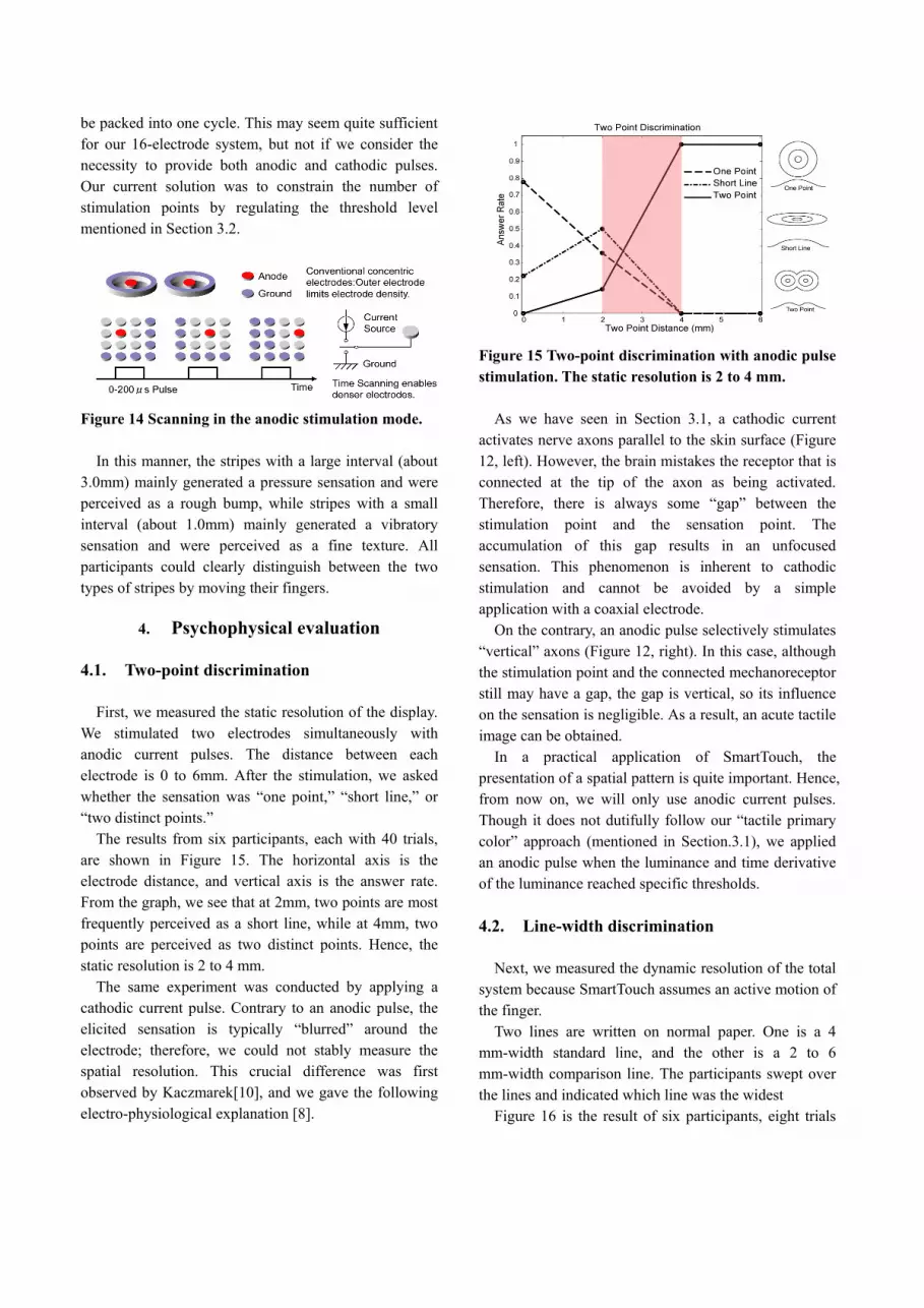
Our transformation formula is as follows: if the luminance (regarded as bump height) reaches a certain threshold, a cathodic pulse is provided to produce a pressure sensation. The pulse rate (10-50[pps]) is set proportional to the height (Figure 13).
At the same time, an anodic pulse is produced when the time derivative of the luminance reaches a certain threshold, which generates a vibratory sensation.
It is worth noting that, in this stimulation method, each electrode requires only the information from an optical sensor immediately beneath it.
Figure 13 Phototransistor output and its differential and electrical stimulation pattern of a single electrode.
3.3. Stimulation timing
When we stimulate one point, surrounding electrodes
are used as a return current electrode (ground) and, hence, only one point is stimulated at a time, which requires time-division scanning[8][11](Figure 14). Compared to conventional coaxial electrodes, this configuration enables a much denser electrode density.
As mentioned in Section 2.5, the cycle time of the sensor and display system is 4.0[ms]. Since each electrical pulse requires at least 0.2[ms], 20 pulses could
be packed into one cycle. This may seem quite sufficient for our 16-electrode system, but not if we consider the necessity to provide both anodic and cathodic pulses. Our current solution was to constrain the number of stimulation points by regulating the threshold level mentioned in Section 3.2.
Figure 14 Scanning in the anodic stimulation mode.
In this manner, the stripes with a large interval (about
3.0mm) mainly generated a pressure sensation and were perceived as a rough bump, while stripes with a small interval (about 1.0mm) mainly generated a vibratory sensation and were perceived as a fine texture. All participants could clearly distinguish between the two types of stripes by moving their fingers.
4. Psychophysical evaluation
4.1. Two-point discrimination
First, we measured the static resolution of the display.
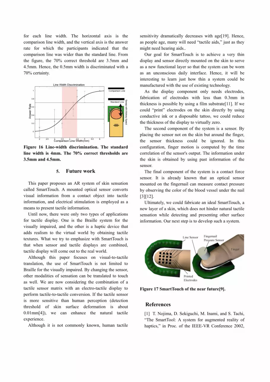
We stimulated two electrodes simultaneously with anodic current pulses. The distance between each electrode is 0 to 6mm. After the stimulation, we asked whether the sensation was “one point,” “short line,” or “two distinct points.”
The results from six participants, each with 40 trials, are shown in Figure 15. The horizontal axis is the electrode distance, and vertical axis is the answer rate. From the graph, we see that at 2mm, two points are most frequently perceived as a short line, while at 4mm, two points are perceived as two distinct points. Hence, the static resolution is 2 to 4 mm.
The same experiment was conducted by applying a cathodic current pulse. Contrary to an anodic pulse, the elicited sensation is typically “blurred” around the electrode; therefore, we could not stably measure the spatial resolution. This crucial difference was first observed by Kaczmarek[10], and we gave the following electro-physiological explanation [8].
Figure 15 Two-point discrimination with anodic pulse stimulation. The static resolution is 2 to 4 mm.
As we have seen in Section 3.1, a cathodic current
activates nerve axons parallel to the skin surface (Figure 12, left). However, the brain mistakes the receptor that is connected at the tip of the axon as being activated. Therefore, there is always some “gap” between the stimulation point and the sensation point. The accumulation of this gap results in an unfocused sensation. This phenomenon is inherent to cathodic stimulation and cannot be avoided by a simple application with a coaxial electrode.
On the contrary, an anodic pulse selectively stimulates “vertical” axons (Figure 12, right). In this case, although the stimulation point and the connected mechanoreceptor still may have a gap, the gap is vertical, so its influence on the sensation is negligible. As a result, an acute tactile image can be obtained.
In a practical application of SmartTouch, the presentation of a spatial pattern is quite important. Hence, from now on, we will only use anodic current pulses. Though it does not dutifully follow our “tactile primary color” approach (mentioned in Section.3.1), we applied an anodic pulse when the luminance and time derivative of the luminance reached specific thresholds.
4.2. Line-width discrimination
Next, we measured the dynamic resolution of the total
system because SmartTouch assumes an active motion of the finger.
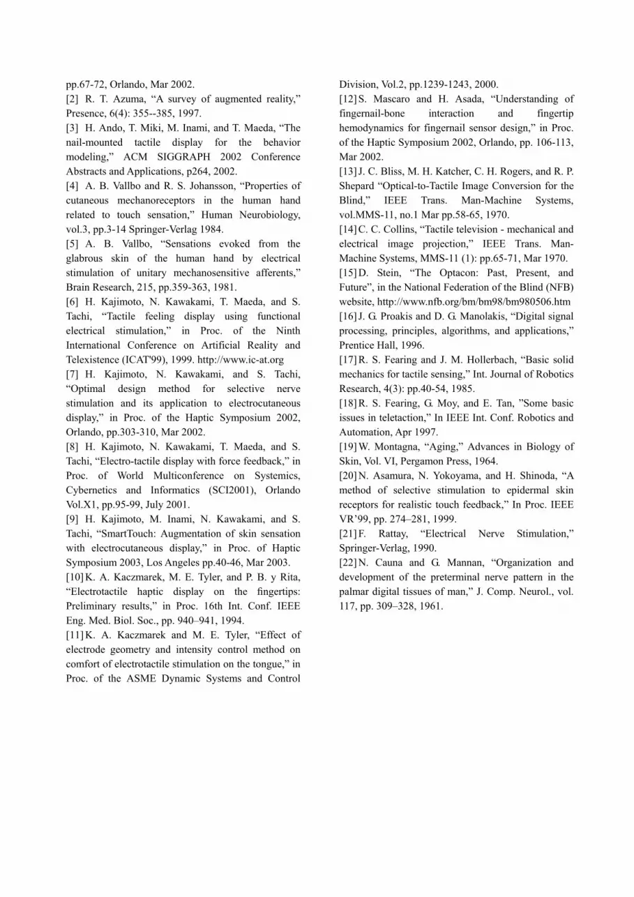
Two lines are written on normal paper. One is a 4 mm-width standard line, and the other is a 2 to 6 mm-width comparison line. The participants swept over the lines and indicated which line was the widest
Figure 16 is the result of six participants, eight trials
for each line width. The horizontal axis is the comparison line width, and the vertical axis is the answer rate for which the participants indicated that the comparison line was wider than the standard line. From the figure, the 70% correct threshold are 3.5mm and 4.5mm. Hence, the 0.5mm width is discriminated with a 70% certainty.
Figure 16 Line-width discrimination. The standard line width is 4mm. The 70% correct thresholds are 3.5mm and 4.5mm.
5. Future work This paper proposes an AR system of skin sensation
called SmartTouch. A mounted optical sensor converts visual information from a contact object into tactile information, and electrical stimulation is employed as a means to present tactile information.
Until now, there were only two types of applications for tactile display. One is the Braille system for the visually impaired, and the other is a haptic device that adds realism to the virtual world by obtaining tactile textures. What we try to emphasize with SmartTouch is that when sensor and tactile displays are combined, tactile display will come out to the real world.
Although this paper focuses on visual-to-tactile translation, the use of SmartTouch is not limited to Braille for the visually impaired. By changing the sensor, other modalities of sensation can be translated to touch as well. We are now considering the combination of a tactile sensor matrix with an electro-tactile display to perform tactile-to-tactile conversion. If the tactile sensor is more sensitive than human perception (detection threshold of skin surface deformation is about 0.01mm[4]), we can enhance the natural tactile experience.
Although it is not commonly known, human tactile
sensitivity dramatically decreases with age[19]. Hence, as people age, many will need “tactile aids,” just as they might need hearing aids..
Our goal for SmartTouch is to achieve a very thin display and sensor directly mounted on the skin to serve as a new functional layer so that the system can be worn as an unconscious daily interface. Hence, it will be interesting to learn just how thin a system could be manufactured with the use of existing technology.
As the display component only needs electrodes, fabrication of electrodes with less than 0.3mm in thickness is possible by using a film substrate[11]. If we could “print” electrodes on the skin directly by using conductive ink or a disposable tattoo, we could reduce the thickness of the display to virtually zero.
The second component of the system is a sensor. By placing the sensor not on the skin but around the finger, the sensor thickness could be ignored. In this configuration, finger motion is computed by the time correlation of the sensor's output. The information under the skin is obtained by using past information of the sensor.
The final component of the system is a contact force sensor. It is already known that an optical sensor mounted on the fingernail can measure contact pressure by observing the color of the blood vessel under the nail [3][12].
Ultimately, we could fabricate an ideal SmartTouch, a new layer of a skin, which does not hinder natural tactile sensation while detecting and presenting other surface information. Our next step is to develop such a system.
Figure 17 SmartTouch of the near future[9].
References [1] T. Nojima, D. Sekiguchi, M. Inami, and S. Tachi, “The SmartTool: A system for augmented reality of haptics,” in Proc. of the IEEE-VR Conference 2002,
pp.67-72, Orlando, Mar 2002. [2] R. T. Azuma, “A survey of augmented reality,” Presence, 6(4): 355--385, 1997. [3] H. Ando, T. Miki, M. Inami, and T. Maeda, “The nail-mounted tactile display for the behavior modeling,” ACM SIGGRAPH 2002 Conference Abstracts and Applications, p264, 2002. [4] A. B. Vallbo and R. S. Johansson, “Properties of cutaneous mechanoreceptors in the human hand related to touch sensation,” Human Neurobiology, vol.3, pp.3-14 Springer-Verlag 1984. [5] A. B. Vallbo, “Sensations evoked from the glabrous skin of the human hand by electrical stimulation of unitary mechanosensitive afferents,” Brain Research, 215, pp.359-363, 1981. [6] H. Kajimoto, N. Kawakami, T. Maeda, and S. Tachi, “Tactile feeling display using functional electrical stimulation,” in Proc. of the Ninth International Conference on Artificial Reality and Telexistence (ICAT'99), 1999. http://www.ic-at.org [7] H. Kajimoto, N. Kawakami, and S. Tachi, “Optimal design method for selective nerve stimulation and its application to electrocutaneous display,” in Proc. of the Haptic Symposium 2002, Orlando, pp.303-310, Mar 2002. [8] H. Kajimoto, N. Kawakami, T. Maeda, and S. Tachi, “Electro-tactile display with force feedback,” in Proc. of World Multiconference on Systemics, Cybernetics and Informatics (SCI2001), Orlando Vol.X1, pp.95-99, July 2001. [9] H. Kajimoto, M. Inami, N. Kawakami, and S. Tachi, “SmartTouch: Augmentation of skin sensation with electrocutaneous display,” in Proc. of Haptic Symposium 2003, Los Angeles pp.40-46, Mar 2003. [10] K. A. Kaczmarek, M. E. Tyler, and P. B. y Rita, “Electrotactile haptic display on the fingertips: Preliminary results,” in Proc. 16th Int. Conf. IEEE Eng. Med. Biol. Soc., pp. 940–941, 1994. [11] K. A. Kaczmarek and M. E. Tyler, “Effect of electrode geometry and intensity control method on comfort of electrotactile stimulation on the tongue,” in Proc. of the ASME Dynamic Systems and Control
Division, Vol.2, pp.1239-1243, 2000. [12] S. Mascaro and H. Asada, “Understanding of fingernail-bone interaction and fingertip hemodynamics for fingernail sensor design,” in Proc. of the Haptic Symposium 2002, Orlando, pp. 106-113, Mar 2002. [13] J. C. Bliss, M. H. Katcher, C. H. Rogers, and R. P. Shepard “Optical-to-Tactile Image Conversion for the Blind,” IEEE Trans. Man-Machine Systems, vol.MMS-11, no.1 Mar pp.58-65, 1970. [14] C. C. Collins, “Tactile television - mechanical and electrical image projection,” IEEE Trans. Man- Machine Systems, MMS-11 (1): pp.65-71, Mar 1970. [15] D. Stein, “The Optacon: Past, Present, and Future”, in the National Federation of the Blind (NFB) website, http://www.nfb.org/bm/bm98/bm980506.htm [16] J. G. Proakis and D. G. Manolakis, “Digital signal processing, principles, algorithms, and applications,” Prentice Hall, 1996. [17] R. S. Fearing and J. M. Hollerbach, “Basic solid mechanics for tactile sensing,” Int. Journal of Robotics Research, 4(3): pp.40-54, 1985. [18] R. S. Fearing, G. Moy, and E. Tan, ”Some basic issues in teletaction,” In IEEE Int. Conf. Robotics and Automation, Apr 1997. [19] W. Montagna, “Aging,” Advances in Biology of Skin, Vol. VI, Pergamon Press, 1964. [20] N. Asamura, N. Yokoyama, and H. Shinoda, “A method of selective stimulation to epidermal skin receptors for realistic touch feedback,” In Proc. IEEE VR’99, pp. 274–281, 1999. [21] F. Rattay, “Electrical Nerve Stimulation,” Springer-Verlag, 1990. [22] N. Cauna and G. Mannan, “Organization and development of the preterminal nerve pattern in the palmar digital tissues of man,” J. Comp. Neurol., vol. 117, pp. 309–328, 1961.