smart cooperative relay schemes in lte-advanced system
TRANSCRIPT
Smart Cooperative Relay Schemes in LTE-Advanced
System Saransh Malik
Chonnam National University South Korea
+82-62-530-0654
Dahee No
Chonnam National University South Korea
+82-62-530-0654
Dae Jin Kim
Chonnam National University South Korea
+82-62-530-1756
Sangmi Moon Chonnam National University
South Korea +82-62-530-0654
Se Young Kim
Chonnam National University South Korea
+82-62-530-0758
Intae Hwang Chonnam National University
South Korea +82-62-530-0654
Bora Kim Chonnam National University
South Korea +82-62-530-0654
Jin Lee
Chonnam National University South Korea
+82-62-530-0758
ABSTRACT Cooperative relaying is considered as the most cost-efficient
method in 3GPP LTE-Advanced in terms of coverage
prolongation and transmission efficiency. In this paper, we
analyze the best performing cooperative relaying scheme between
the Amplify– and–Forward (AF) and Decode-and–Forward (DF)
schemes for LTE-Advanced systems. The comparison between AF
and DF Relay Nodes (RN) is important because both approaches
are currently under consideration for 3GPP LTE-Advanced (LTE-
A). The performance analysis of these two relay nodes considers
the criteria of: (1) Linear equalization techniques such as Zero
Forcing (ZF) and Minimum Mean Square Error (MMSE) and (2)
Cooperative Diversity using 2x2 Multiple Input and Multiple
Output (MIMO) Alamouti scheme also termed as Space
Frequency and Block Coding. Simulation results show that the Bit
Error Rate (BER) performance of AF RN and DF RN improves in
LTE-Advanced system and that DF RN clearly outperforms AF
RN.
Categories and Subject Descriptors
G.4 [MATLAB]: Workspace, structure, functions ,text scripting,
graph plotter.
General Terms
Algorithms, Documentation, Performance, Design,
Experimentation, standardization, theory.
Keywords Amplify-and-Forward (AF), Decode-and-Forward (DF), Zero
Forcing (ZF), Minimum Mean Square Error (MMSE),
Cooperative diversity , MIMO,OFDM, LTE-Advanced.
1. INTRODUCTION The Long Term Evolution–Advanced (LTE-A) is the latest and
the fastest data transmission technology proposed by the third
Generation Partnership Project (3GPP) which fulfills the 4G
requirements specified by the International Telecommunication
Union (ITU-R)[1]. LTE-A focuses on a cell planning strategy in
order to achieve better selection criteria based on either signal-to-
noise-ratio (SNR) or SINR. Thus, we perform 3GPP compliant
simulations in order to evaluate the effects of different strategies
on system performance.
Deploying decode and forward relay nodes (RNs) is a
promising solution in LTE-Advanced networks for meeting the
growing demand and challenging requirements for coverage
extension and capacity enhancement [2]. RNs are diverse in
functionality and mode of operation. Amplify-and-Forward (AF)
relays have been used just as a stop gap relay implementation, but
it is a well known fact that AF relays amplify not only the desired
signal but also both interference and noise. Decode and- Forward
(DF) relays, detect the desired signal and then encode and forward
it. Therefore, DF relays seem an appropriate choice for
interference limited environments. The system considered in this
paper is half duplex.
In this paper, we look at the design and implementation of
AF RN and DF RN in order to reduce the complexity and gain
coverage extension while keeping the same power constraint. We
investigate cooperative relay detection schemes and cooperative
diversity schemes within the LTE-A framework. Schemes in
conventional systems are compared with LTE-A link transmission
Permission to make digital or hard copies of all or part of this work for
personal or classroom use is granted without fee provided that copies are
not made or distributed for profit or commercial advantage and that
copies bear this notice and the full citation on the first page. To copy
otherwise, or republish, to post on servers or to redistribute to lists,
requires prior specific permission and/or a fee.
ICUIMC’12, February 20–22, 2012, Kuala Lumpur, Malaysia.
Copyright 2012 ACM 978-1-4503-1172-4…$10.00.
parameters of the proposed schemes. In these schemes we use an
evolved NodeB (eNB) base station, the relay node RN and User
equipment (UE) destination node.
Our comparison and analysis is based on using AF and
DF protocols on a single hop relay node. We analyze the link
connection with a phase-I eNB to the RN and UE , then again for
a phase-II RN with UE. The performance is evaluated in terms of
the detection technique‟s zero forcing, MMSE and the
cooperative diversity using block coding technique with 2x2
MIMO at the eNB , RN and the UE with LTE-A.
The paper is organized as follows: Section 2 presents the
theoretical analysis of the cooperative relaying schemes AF and
DF in conventional systems. In Section 3, we evaluate cooperative
relay detection methods in LTE–A systems. The performances are
categorized by linear detection methods applied to LTE-A
Parameters. In Section 4, a comparison of cooperative diversity
with conventional relay protocols in a LTE-A framework is made.
In Section 5,we present the performance analysis results
supporting our proposal and finally, section 6 contains the
conclusions and future enhancement of our work.
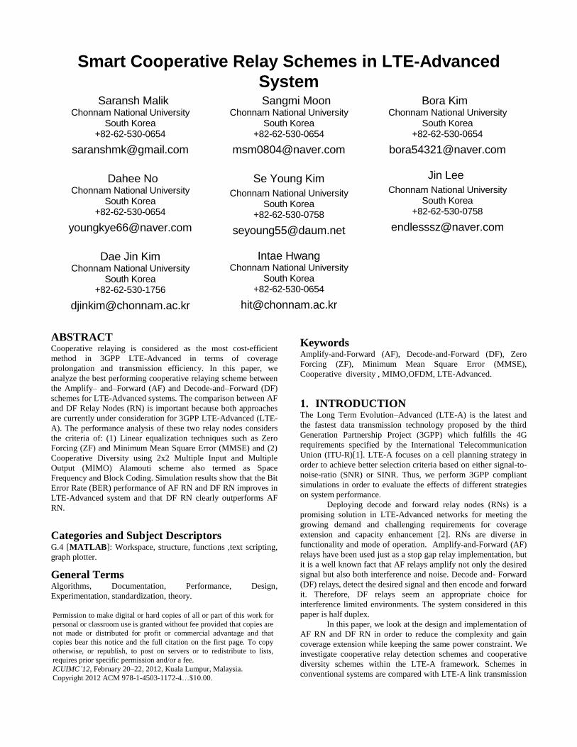
2. Cooperative Relaying Schemes in
Conventional Systems The conventional relaying schemes such as Amplify-and-Forward
(AF) and Decode-and-Forward (DF) are stated as the backbone of
relay communication. The system we consider assumes a half
duplex transmission scheme. Both relay node works in half duplex
and the performance is considered as unchanged at the link level
[3].Figure 1. shows the model of half duplex transmission in relay
systems. In phase I the eNB transmits full signals and these
signals are received by both the RN and the UE. In phase II the
UE receives another signal from the relay node. The signal nature
of the signal from the relay node depends on the type of protocol
followed by the relay node.
Figure 1. Half Duplex Relay Transmission.
The relay may simply amplify the received signal and
forward it, as in Amplify-and-Forward (AF), or it may first
decode the received information and then forward the encoded
symbols to the destination, which is referred to as Decode-
and-Forward (DF).
2.1 Cooperative Relaying Scheme: Amplify-
and-Forward (AF) Amplify-and-Forward (AF) is the simplest way of cooperating.
Each user in this method receives a noisy version of the signal
transmitted by its partner. As the name implies, the user then
amplifies and retransmits this noisy version. The base station
combines the information sent by the user and partner, and makes
a final decision on the transmitted bit. Although noise is amplified
by cooperation, the base station receives two independently faded
versions of the signal and can make better decisions on the
detection of information. In amplify-and-forward it is assumed
that the base station knows the inter user channel coefficients for
optimal decoding, so some mechanism of exchanging or
estimating this must be incorporated into any implementation.
Here we assume that the power of the signal retransmitted at the
relay node is scaled uniformly with respect to all the bits in the
package, such that the average (re-)transmission energy per signal
equals ES. In time slot 1, the signals received at the relay and the
destinations are [4]
(1)
and the amplification factor is given as –
Where n0 and ni, D, i = 1,2 denote the zero-mean complex AWGN
at the inter-user channel and home channel with variances equal
to N1/2 and N0/2 per dimension, respectively. IN time slot 2, the
equivalent signal to be retransmitted by the relay contains a unit
average power (2) of:
(2)
The relays signal at destination is given as (3)
(3) Where n is the zero mean complex Gaussian Noise with variance
per dimension. At, the destination we receive
using the maximal ratio combination rule before
decoding.
2.2 Cooperative Relaying Scheme: Decode-
and –Forward (DF) The signal transmission in DF mode for the first time slot is the
same as that of the AF mode (see 2 and 3). During time slot 2, the
relay first demodulates and decodes the received signal. Upon
success, it re-encodes the data (possibly using a different code)
and forwards it to the destination [5]. Hence, the destination
receives:
(4)
In the outage case, where the relay fails to decode the data
correctly, it cannot help its partner in the current round of
cooperation. It may select to either stay silent (to save energy) or
transmits its own data (to improve the channel utilization) [5].
The mutual information between the source and the destination is
limited by the mutual information of the weakest link between the
source–relay and the combined channel from the source–
destination and relay–destination. More specifically, the mutual
information for decode-and-forward transmission in terms of
channel fades can be given by -
(5)
where , the min operator in the above equation takes into account
the fact that the relay only transmits if decoded correctly, and
hence the performance is limited by the weakest link between the
source–destination and source–relay.
Since, the channel is affected by Rayleigh Flat fading, the
above random variables are all exponential random variables with
a parameter of one. Averaging over the channel conditions, the
outage probability for decode-and-forward at high SNR is given
by
(6)
From (8), it can be seen that fixed relaying has the
advantage of easy implementation, but the disadvantage of low
bandwidth efficiency. This is because half of the channel
resources are allocated to the relay for transmission, which
reduces the overall rate. This is especially true when the source–
destination channel is not so bad, because under this scenario a
high percentage of the packets transmitted by the source to the
destination can be received correctly by the destination and the
relay‟s transmissions are wasted.
3. Cooperative Relay Detection Methods in
LTE-Advanced Systems In selecting the techniques for equalization we must compare the
performance of the receiver and check the signal error
performance of each relay node implementation [6].
3.1 AF and DF with ZF The source, relay and destination nodes are equipped with Ns, Nr,
and Nd antennas, respectively. All data streams are transmitted
through the relay and the direct link, which is considered to fade
with increasing distance and time delay from source to destination.
Hs,r , Hr,d and Hs,d are the channel matrices for the source-relay
and the relay destination links with the dimensions NrxNs and
NdxNr, respectively.
Figure 2. Source to Relay to Destination Functional Block
Diagram in the Equalization
The communication process between the source and
destination nodes is completed in two time slots. In the first slot,
the Nsx1 source signal vector s is transmitted to the relay and
destination. The received signal at the relay node can be written as
(7)
where, yr and vr are the received signal and the additive Gaussian
noise vectors at the relay node, respectively. In the second slot,
the source node remains silent and the relay node multiplies the
received signal vector by the NrxNr relay amplifying matrix F and
transmits the amplified signal vector xr to the destination node.
Thus,
(8)
where, H = Hr,d .F. Hs,r is the equivalent MIMO channel and
v = Hr,dFvr + vd is the equivalent noise. The ZF linear detector
with the constraint WHH=IN is given by (9)
(9)
In AF transmission, we simply multiply the amplification factor
while using the relay as shown in Figure 2. In the next step, to
achieve the desired value at the destination we multiply the value
of W from the relay and destination using MRC.
For DF, we need to calculate the channel fading and then
calculating the SNR threshold value at the relay node. Then the
OFDM system decodes the received signal and send it back at the
destination.
W is also known as the pseudo-inverse for a general mxn
matrix and (.)-1 indicates a simple matrix inversion. In order for a
pseudo-inverse to exist, Nd must be greater than or equal to Ns.
For the AF, we multiply the value of the received version with the
amplified value (3).which gives us the amplified value of the
signal at the receiver. Similarly, in the case of DF we use (6) with
the given values of W and we can get the equalized value at the
receiver.
3.2 AF and DF with MMSE The transmission mode is similar for both transmission schemes
only the values of the channel matrix changes. For the equalized
value of MMSE at the destination node we basically depend on
the mode of transmission from the relay and from the source node.
MMSE uses
(10)
Where, C = Hr;dFFHHHr;d + INd is the noise covariance.
For AF, we multiply the system matrix with the MMSE channel
matrix. The system enhances the noise due to the amplification
factor but due to channel inversion a noise reduction is still
observed.
In DF, due to the increase in the delay of computation we detect
the signal at the receiver and we multiply the channel matrix by
equation (10).
(11)
In order to receive the exact value . Power comparison helps us to
analyze the exact value of the BER.
Due to the enhancement of noise and interference
increases in the error are expected but these are damped later by
re-encoding .The effect of channel fades increases within time as
the node is considered as a cell end so a large delay is noticed in
the direct link.
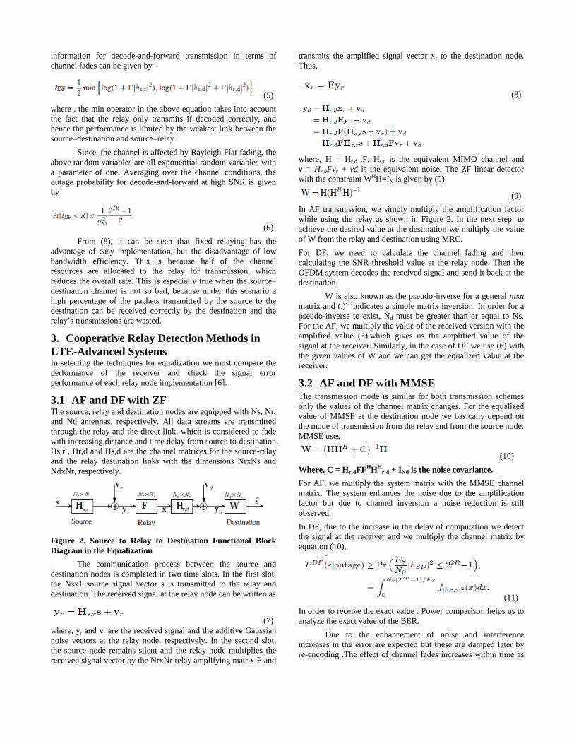
4. Cooperative Diversity in LTE-Advanced
System In half duplex, DF relaying, resources used on the access link can
be reused among n RNs within the overlaying macro cell. It
should be noted that LTE‟s space-frequency domain split of
physical resource blocks (PRBs) in the relaying system is done for
simplicity. In order to maintain exact simulation results we
exclusively use the frequency. By assuming equal resource
consumption in RNs, , the values of the power will be constant at
both relay node and the destination node.
Cooperation leads to an interesting trade-off in code rates
and transmit power. In the case of power, one may argue on one
hand that more power is needed because each user, when in
cooperative mode, is transmitting for both users. On the other
hand, the baseline transmits power for both users will be reduced
because of diversity. In the face of this trade-off, one hopes for a
net reduction of transmit power, if everything else is constant
[7].This is shown in the figure 3,
Figure 3. SFBC Mode in a Half-Duplex Transmission
We now consider, the case of a 2 transmit antennas and 2
receiver antennas in an Alamouti scheme, which will be used in
our proposed cooperative scheme. A cooperative relay-based 2× 2
Alamouti scheme is presented in figure 4. In this scheme we use
the, three-node system shown in figure 3. .The 2×2 Alamouti
scheme is considered between any two nodes in figure 4 (i.e., S-R,
R-D, and S-D). During the first stage of cooperation, the source
(S) sends the symbols x1,x2 using antenna 1 and 2, respectively,
during the first time slot and sends –x*2,x*1 and during the
second time slot.
Figure 4. SFBC mechanism for 2x2 MIMO System
The relay and the destination antennas receive the
symbols transmitted during the first stage. Then, the relay
generates two decision variables V(1)1,R and V(1)
2,R (superscripts
show it is stage 1 ) [8].
(12)
(13)
Then the relay decision variables V(1)1,R and V(1)
2,R , are given as
(15)
In the same time domain another two decision variables, V(1)1,D
and V(1)2,D , are generated at the destination during the first
cooperative stage and given as -
(16)
In the second stage, the relay sends its own decision variables
V(2)1,D and V(2)
2,D to the destination using the second stage time
slot. The destination uses Alamouti decoding to generate
(17)
where,
(18)
The effective decision variables (i.e., N1,eff and N2,eff ) are
then sent to the ML detector to recover the transmitted symbols x1
and x2, respectively. The most important characteristic of an
Alamouti scheme is that no feedback from the receiver to
transmitter is required for channel state information (CSI) to
obtain full transmit diversity. It also has identical performance as
MRC if the total radiated power is doubled from that used in
maximum ratio combining (MRC).
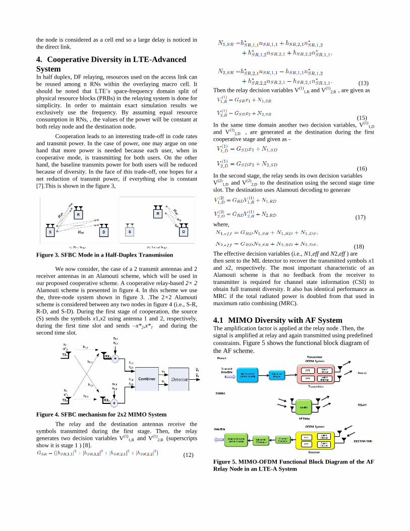
4.1 MIMO Diversity with AF System The amplification factor is applied at the relay node .Then, the
signal is amplified at relay and again transmitted using predefined
constraints. Figure 5 shows the functional block diagram of
the AF scheme.
Figure 5. MIMO-OFDM Functional Block Diagram of the AF
Relay Node in an LTE-A System
The amplification factor beta is given by the coefficients of the
channel and the noise variance. The magnitude of the square of
the channel shows the channel gain multiplication at a relay node.
To satisfy the transmitted power per source symbol
constraint of P = P1 + P2. The received signal at the
destination after the k-th relay transmission is given by
(19)
The interference in this technique is enhanced a lot more therefore
the performance may not excel. The LTE-A parameters help us to
resolve this problem. The interference cancellation among
subcarriers is well resolved in LTE-A system which helps to
improvise the amplification of noise and interference at the relay
node and the destination node. Therefore. when the signal is
amplified at the relay the noise level does not interfere with the
data subcarriers due to the long Cyclic Prefix size of the
subcarriers.
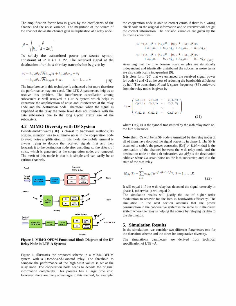
4.2 MIMO Diversity with DF System Decode-and-Forward (DF) is closest to traditional methods; its
original intention was to eliminate noise in the cooperation node
to avoid noise amplification. In this mode, the mobile terminal is
always trying to decode the received signals first and then
forwards it to the destination node after encoding, so the effects of
noise, which is generated at the cooperation node, are removed.
The merit of this mode is that it is simple and can easily be to
various channels.
Figure 6. MIMO-OFDM Functional Block Diagram of the DF
Relay Node in LTE-A Systems
Figure 6, illustrates the proposed scheme in a MIMO-OFDM
system with a Decode-and-Forward relay. The threshold to
compare the performance of the high SNR values is set at the
relay node. The cooperation node needs to decode the original
information completely. This process has a large time cost.
However, there are many advantages to this method, for example:
the cooperation node is able to correct errors if there is a wrong
check code in the original information and so receiver will not get
the correct information. The decision variables are given by the
following equations:
(20)
Assuming that the time domain noise samples are statistically
independent and identically distributed the subcarrier noise terms
are also statistically independent [9].
It is clear form (20) that we enhanced the received signal power
for both x1 and x2 at the cost of reducing the bandwidth efficiency
by half. The transmitted K and N space–frequency (SF) codeword
from the relay nodes is given by –
(21)
where Cr(k, n) is the symbol transmitted by the n-th relay node on
the k-th subcarrier.
Note that: Cr will be in SF code transmitted by the relay nodes if
all of them have decoded the signal correctly in phase 1. The SF is
assumed to satisfy the power constraint ||Cr||2 F≤ K.Hrn ,d(k) is the
attenuation of the channel between the n-th relay node and the
destination node on the k-th subcarrier, vrn ,d(k) is the destination
additive white Gaussian noise on the k-th subcarrier, and it is the
state of the n-th relay.
(22)
It will equal 1 if the n-th relay has decoded the signal correctly in
phase 1, otherwise, it will equal 0.
The simulation results will justify the use of higher order
modulation to recover for the loss in bandwidth efficiency. The
simulation in the next section assumes that the power
consumption in the cooperative system is the same as in the direct
system where the relay is helping the source by relaying its data to
the destination.
5. Simulation Results In the simulations, we consider two different Parameters one for
the detection scheme and the other for cooperative diversity.
The simulations parameters are derived from technical
specification of LTE –A .
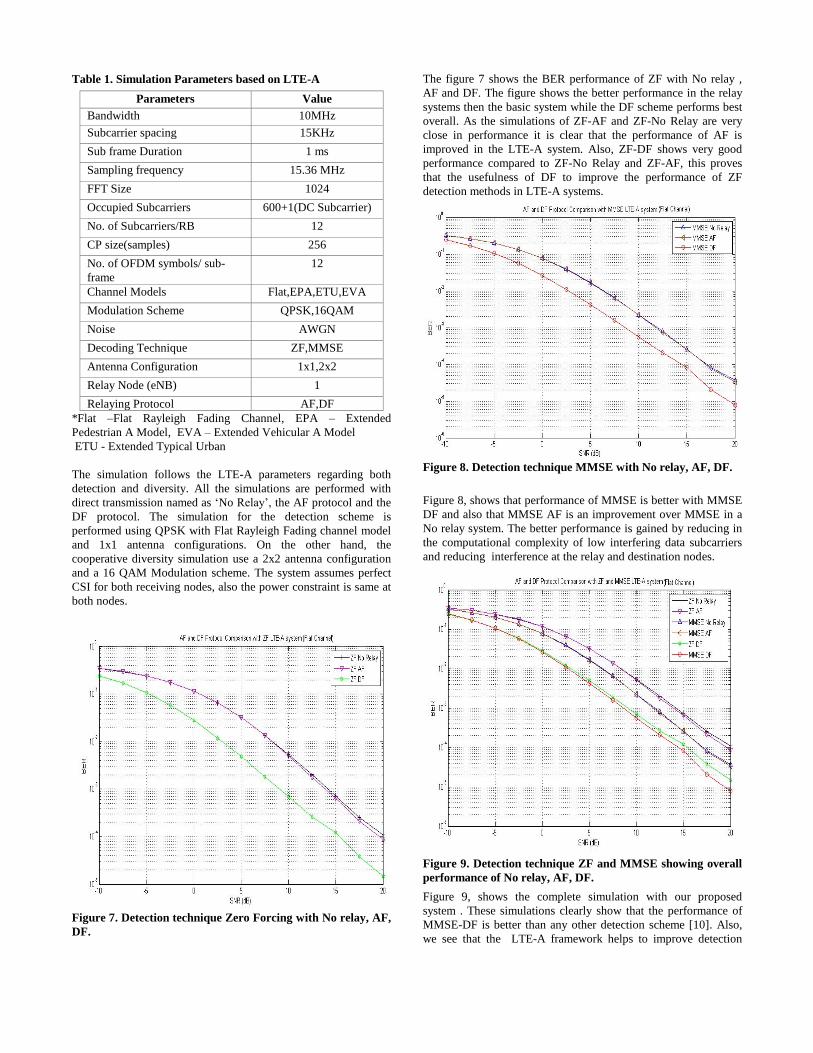
Table 1. Simulation Parameters based on LTE-A
Parameters Value
Bandwidth 10MHz
Subcarrier spacing 15KHz
Sub frame Duration 1 ms
Sampling frequency 15.36 MHz
FFT Size 1024
Occupied Subcarriers 600+1(DC Subcarrier)
No. of Subcarriers/RB 12
CP size(samples) 256
No. of OFDM symbols/ sub-
frame
12
Channel Models Flat,EPA,ETU,EVA
Modulation Scheme QPSK,16QAM
Noise AWGN
Decoding Technique ZF,MMSE
Antenna Configuration 1x1,2x2
Relay Node (eNB) 1
Relaying Protocol AF,DF
*Flat –Flat Rayleigh Fading Channel, EPA – Extended
Pedestrian A Model, EVA – Extended Vehicular A Model
ETU - Extended Typical Urban
The simulation follows the LTE-A parameters regarding both
detection and diversity. All the simulations are performed with
direct transmission named as „No Relay‟, the AF protocol and the
DF protocol. The simulation for the detection scheme is
performed using QPSK with Flat Rayleigh Fading channel model
and 1x1 antenna configurations. On the other hand, the
cooperative diversity simulation use a 2x2 antenna configuration
and a 16 QAM Modulation scheme. The system assumes perfect
CSI for both receiving nodes, also the power constraint is same at
both nodes.
Figure 7. Detection technique Zero Forcing with No relay, AF,
DF.
The figure 7 shows the BER performance of ZF with No relay ,
AF and DF. The figure shows the better performance in the relay
systems then the basic system while the DF scheme performs best
overall. As the simulations of ZF-AF and ZF-No Relay are very
close in performance it is clear that the performance of AF is
improved in the LTE-A system. Also, ZF-DF shows very good
performance compared to ZF-No Relay and ZF-AF, this proves
that the usefulness of DF to improve the performance of ZF
detection methods in LTE-A systems.
Figure 8. Detection technique MMSE with No relay, AF, DF.
Figure 8, shows that performance of MMSE is better with MMSE
DF and also that MMSE AF is an improvement over MMSE in a
No relay system. The better performance is gained by reducing in
the computational complexity of low interfering data subcarriers
and reducing interference at the relay and destination nodes.
Figure 9. Detection technique ZF and MMSE showing overall
performance of No relay, AF, DF.
Figure 9, shows the complete simulation with our proposed
system . These simulations clearly show that the performance of
MMSE-DF is better than any other detection scheme [10]. Also,
we see that the LTE-A framework helps to improve detection
scheme system performance when a relay system is implemented.
Summarizing the performance: MMSE –DF > ZF-DF>MMSE-
AF=MMSE-No Relay>ZF-AF>ZF-No Relay.
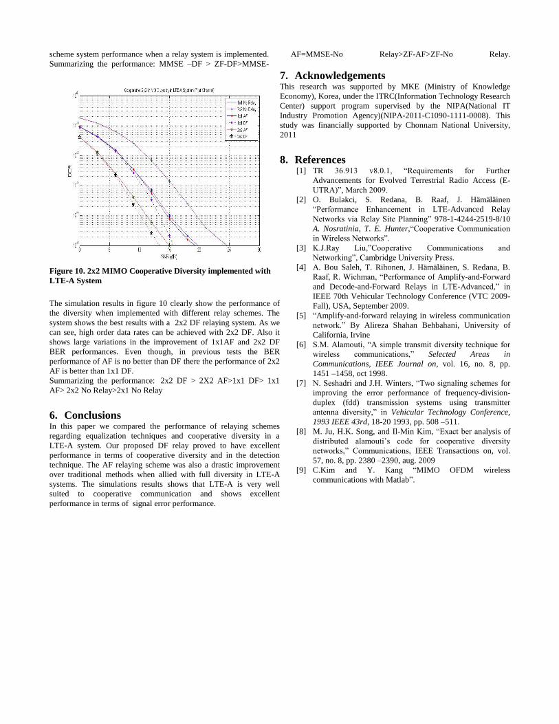
Figure 10. 2x2 MIMO Cooperative Diversity implemented with
LTE-A System
The simulation results in figure 10 clearly show the performance of
the diversity when implemented with different relay schemes. The
system shows the best results with a 2x2 DF relaying system. As we
can see, high order data rates can be achieved with 2x2 DF. Also it
shows large variations in the improvement of 1x1AF and 2x2 DF
BER performances. Even though, in previous tests the BER
performance of AF is no better than DF there the performance of 2x2
AF is better than 1x1 DF.
Summarizing the performance: 2x2 DF > 2X2 AF>1x1 DF> 1x1
AF> 2x2 No Relay>2x1 No Relay
6. Conclusions In this paper we compared the performance of relaying schemes
regarding equalization techniques and cooperative diversity in a
LTE-A system. Our proposed DF relay proved to have excellent
performance in terms of cooperative diversity and in the detection
technique. The AF relaying scheme was also a drastic improvement
over traditional methods when allied with full diversity in LTE-A
systems. The simulations results shows that LTE-A is very well
suited to cooperative communication and shows excellent
performance in terms of signal error performance.
7. Acknowledgements This research was supported by MKE (Ministry of Knowledge
Economy), Korea, under the ITRC(Information Technology Research
Center) support program supervised by the NIPA(National IT
Industry Promotion Agency)(NIPA-2011-C1090-1111-0008). This
study was financially supported by Chonnam National University,
2011
8. References [1] TR 36.913 v8.0.1, “Requirements for Further
Advancements for Evolved Terrestrial Radio Access (E-
UTRA)”, March 2009.
[2] O. Bulakci, S. Redana, B. Raaf, J. Hämäläinen
“Performance Enhancement in LTE-Advanced Relay
Networks via Relay Site Planning” 978-1-4244-2519-8/10
A. Nosratinia, T. E. Hunter,“Cooperative Communication
in Wireless Networks”.
[3] K.J.Ray Liu,”Cooperative Communications and
Networking”, Cambridge University Press.
[4] A. Bou Saleh, T. Rihonen, J. Hämäläinen, S. Redana, B.
Raaf, R. Wichman, “Performance of Amplify-and-Forward
and Decode-and-Forward Relays in LTE-Advanced,” in
IEEE 70th Vehicular Technology Conference (VTC 2009-
Fall), USA, September 2009.
[5] “Amplify-and-forward relaying in wireless communication
network.” By Alireza Shahan Behbahani, University of
California, Irvine
[6] S.M. Alamouti, “A simple transmit diversity technique for
wireless communications,” Selected Areas in
Communications, IEEE Journal on, vol. 16, no. 8, pp.
1451 –1458, oct 1998.
[7] N. Seshadri and J.H. Winters, “Two signaling schemes for
improving the error performance of frequency-division-
duplex (fdd) transmission systems using transmitter
antenna diversity,” in Vehicular Technology Conference,
1993 IEEE 43rd, 18-20 1993, pp. 508 –511.
[8] M. Ju, H.K. Song, and Il-Min Kim, “Exact ber analysis of
distributed alamouti‟s code for cooperative diversity
networks,” Communications, IEEE Transactions on, vol.
57, no. 8, pp. 2380 –2390, aug. 2009
[9] C.Kim and Y. Kang “MIMO OFDM wireless
communications with Matlab”.