alternatives of buchholz relay and more robust schemes for transformer internal fault protection...
TRANSCRIPT
Alternatives of Buchholz relay and more robust schemes for
Transformer internal fault protection
Nishant kumar, Sayan Majumdar, Vikash Prakash Verma, Tanmoy Mulo, Souransu Nandi
Department of Electrical Engg., National institute of Technology, Durgapur, West Bengal, India Email: [email protected],[email protected], [email protected],
[email protected] , [email protected]
Abstract: Transformer is an expensive and one of the most important electrical machines. A Buchholz relay is
used to monitor large transformers for oil loss or insulation breakdown. The relay is located in an inclined pipe
between the transformer and its oil conservation tank (located above the transformer). The Buchholz Relay is
used as a protective device sensitive to the effects of a dielectric failure inside the equipment. However, the
Buchholz relay has a few disadvantages. The relay produces a trip signal during earthquakes and is costly as
well. Thus it is generally used only in the protection of power transformers. This paper suggests three modern
and adaptive methods which are cheaper, efficient and robust. An additional merit is the Control signal (it can
be controlled directly from the control room). The three types of methods are 1. Floating Body Mechanism
based Relay circuit (N1), 2. Piezoelectric based relay circuit (N2), and 3. ULTRASONIC SENSOR based relay
circuit (N3). These three methods are more applicable and reliable than Buchholz relay. The main advantage of
these methods is that the relays are easy to manufacture for different sizes of transformers and controlling in all
these three methods are outside the chamber containing the oil.
1. INTRODUCTION: -
The Buchholz relay was developed in 1921 by Max Buchholz, Oberrat (senior councillor) at Preußische
Elektrizitäts-AG (Prussian electricity supply company) in Kassel[6]. The Buchholz Relay is used as a protective
device sensitive to the effects of dielectric failure inside the equipment. In Buchholz relay there is a chamber
which is placed between the main transformer tank and the conservator. When the transformer is heated or when
any fault occurs, a flammable gas is produced which tries to occupy the upper space of the chamber containing
the oil. The occupation of the flammable gas in the upper space will be possible only when the level of
transformer oil goes down [11]. When a small fault occurs then the level of transformer oil slightly goes down.
When the level of oil goes down, the mercury switch connected to the alarm switch goes down and gets
connected with the conductive hinge which is just beside the mercury switch [6]. Alarm sounds on completion
of the circuit through conductive hinge and arcing is produced. In the same way when a large fault occurs, the
level of transformer oil goes down considerably due to occupancy of a large amount of flammable air in the
upper section of the chamber. Consequently, the mercury switch connected to the trip circuit goes down. Due to
this it touches the hinge which is beside that. This results in the completion and activation of the trip circuit
causing arcing and tripping of the transformer. Hence the above method protects the transformer from Buchholz
relay faults. In Buchholz relay, the upper part of chamber comprises one test cock which is used to test the
quality of air produced by heating of the transformer. This helps to measure the quantity of methane, ethane and
many several components by which we analyse the condition of the transformer. One drain valve is also present
in lower part of chamber to take out the transformer oil in case of fault and emergency.
However, in Buchholz relay the disadvantage is that generally it produces a trip signal in
minor earthquakes [7] and it is costly. Thus Buchholz relay is only used in power transformer protection.
Presently automated systems are being used to control from a single place (Control room). We propose three
methods which are cheaper than Buchholz relay. The construction of Buchholz relay is more complicated than
our methods. These methods are easy to repair, more robust and efficient. The controlling part like alarm circuit
and trip circuit is always outside of the chamber which is easy to handle. Hence manufacturing for different
sizes of transformer becomes simpler
The first method is the Floating body Mechanism based Relay circuit (N1), in which there is a chamber
between the transformer main tank and conservator. The upper part of the chamber consists of a fibre made disk
floating on oil. The disk can slide up and down according to the pressure. It is connected to a vertical control rod
which in turn is connected to a control circuit. According to the displacement of control rod, the situation of
alarm or trip can be decided.
The second method is the Piezoelectric based relay circuit (N2
in the upper part of chamber. In piezoelectric
voltage or potential applied across it [10]
force applied by the flammable gas and in
flammable gas. According to the amount of voltage
The third method is the
chamber consists of an ultrasonic sensor which
measured height is divided into three part
conditions of the transformer. According to operating condition, the
2. FLOATING BODY MECHANISM BASED RELAY CIRCUIT
In this scheme, we introduce a less dense
floating body a metallic control rod is pivoted, which provide
the transformer due to any fault creates pressure inside the relay chamber which pushes the disk.
of the floating body will be utilised
information about the different situation
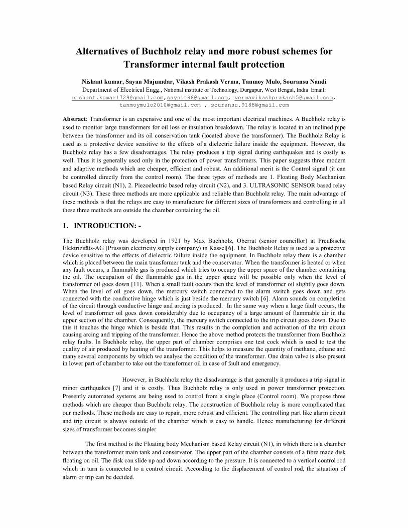
Fig.1 Floating body Mechanism based Relay circuit (N1)
2.1 Construction and Operation:
In this relay, one floating disk (Fibre
down with the support of an elastic air ti
placed between transformer main tank and the conservator
collecting the gas sample. A drain valve is present at the bottom of the chamber.
vertical control rod which is connected with a control circuit
lengths are dN, dA, and dT , two diode (d1 and d2) and one voltage source(V).
into three zones, namely the Normal zone
no fault occurs, the connecting point of
relay from taking any action; transformer operation smoothly goes
of gas is produced in the transformer [11]. This gas
inside the relay. Consequently, a force
(dA). The circuit gets completed (V - d
condition ,huge amount of gas is produced
Piezoelectric based relay circuit (N2), where a piezoelectric substance is used
piezoelectric substances, the force produced is directly proportional to the
[10]. When a small fault occurs, low voltage is produced due to a small
flammable gas and in large fault high voltage is produced due to a large force applied by
ccording to the amount of voltage, the control circuit will perform the operation.
the ULTRASONIC SENSOR based relay circuit (N3). The
consists of an ultrasonic sensor which measures the level of transformer oil in relay chamber
measured height is divided into three parts which decides the operating condition, i.e. normal, alarm and trip
ing to operating condition, the control circuit performs the operation
FLOATING BODY MECHANISM BASED RELAY CIRCUIT (N1)
introduce a less dense material (Fibre) which can float above oil easily
body a metallic control rod is pivoted, which provides input in control circuit. The gas produced inside
the transformer due to any fault creates pressure inside the relay chamber which pushes the disk.
over here. The different position of the floating body
situations inside.
Floating body Mechanism based Relay circuit (N1)
Construction and Operation:
disk) is used above the oil layer [8]. This disk can move freely up and
air tight seal so that the gas does not leak outside the chamber
placed between transformer main tank and the conservator. One test cock is also connected with
A drain valve is present at the bottom of the chamber. Fibre disk is conne
vertical control rod which is connected with a control circuit. Control circuit consists of three plate
, two diode (d1 and d2) and one voltage source(V). The whole operation is divided
zone (dN), the Alarm zone (dA) and the Tripping zone (dT). Initially when
the connecting point of the control rod contact remains within dN region which prevents the
transformer operation smoothly goes on. In case of a fault condition
[11]. This gas comes into the relay chamber and increases the
acts on the fibre disk and the connecting point reaches the
dA – A – V) via alarm (A) causing a siren. In case of any
produced which develops a higher pressure on the fibre
piezoelectric substance is used
is directly proportional to the
d due to a small
force applied by the
control circuit will perform the operation.
The upper part of
the level of transformer oil in relay chamber. The
, alarm and trip
the operation.
[8]. Above this
gas produced inside
This movement
floating body will give us
can move freely up and
outside the chamber. Chamber is
One test cock is also connected with the disk for
is connected with a
three plates whose
hole operation is divided
). Initially when
which prevents the
fault condition, some amount
and increases the pressure
es the Alarm zone
case of any severe fault
ibre disk causing
connecting point of control rod to move up to the
feed as well as a trip circuit feed. This causes
from oil leakage one leakage protection
any fault occurs due to the leakage of oil,
and touches the leakage protection metallic plate “L”
causing both the trip circuit and the alarm circuit
samples. Another drain valve similar to
2.2 Generalise Mathematical Calculation
Let us assume (since according to transformer and manufacture this value
Mass of floating body with control rod
Range of Pressure for Normal condition
Range of Pressure for Alarm condition
Range of Pressure for Tripping condition
dN ∝∝∝∝ � ����
� ; dA ∝∝∝∝ �
��
Net Applied force on the disk (F) = P*πr
From this calculation, for different
chamber, we can set different length of region (
3. PIEZOELECTRIC BASED RELAY CIRCUIT
Piezoelectricity is the charge that accumulates in certain solid materials in response to applied mechanical stress.
The word piezoelectricity means electricity resulting from pressure
which means to squeeze or press, and electric
charge. The piezoelectric effect is understood as the linear electromechanical interaction between the
mechanical and the electrical state in crystalline materials with no
piezoelectricity is utilised for measuring the voltage which is directly proportional to the force which is
developed in the piezoelectric substance due
upon the amount of flammable gas developed in the upper section of the chamber
fault developed in the transformer.
move up to the dT region. Both the diodes d1 and d2 conduct an a
This causes all the operation related to the transformer to stop.
leakage protection metallic plate “L” is placed above the chamber as shown in figure
of oil, the connecting point of the fibre disk comes down from
protection metallic plate “L”. This means that the floating body hangs
alarm circuit to conduct. Here a test cock is also provided
rain valve similar to the Buchholz Relay is present below the chamber.
Mathematical Calculation
(since according to transformer and manufacture this value will vary)
with control rod =MF, and radius of the disk = r,
Range of Pressure for Normal condition ≡ (0 ↔ PN),
Range of Pressure for Alarm condition ≡ (PN ↔ PA),
Tripping condition≡ (PA ↔ PT),
���
; dT ∝∝∝∝ � ��
��
�
Net Applied force on the disk (F) = P*πr2
- MF*g Where P is the applied pressure.
for different transformer ratings, according to generated pressure and size of relay
different length of region ( dN, dA, dT ).
PIEZOELECTRIC BASED RELAY CIRCUIT (N2)
Piezoelectricity is the charge that accumulates in certain solid materials in response to applied mechanical stress.
means electricity resulting from pressure [9]. It is derived from the Greek
electric or electron, which stands for amber, an ancient source of electric
understood as the linear electromechanical interaction between the
mechanical and the electrical state in crystalline materials with no inversion symmetry. The above property of
piezoelectricity is utilised for measuring the voltage which is directly proportional to the force which is
developed in the piezoelectric substance due to the pressure of flammable gas [10]. The amount of force
developed in the upper section of the chamber [11], which
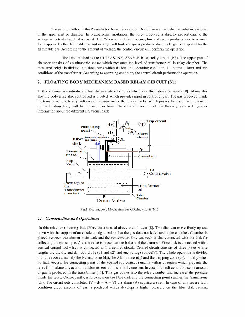
Fig.2 Piezoelectric based relay circuit (N2)
conduct an alarm signal
stop. For protection
placed above the chamber as shown in figure.1. If
from dN position
s on the L plate
is also provided to collect gas
P is the applied pressure.
pressure and size of relay
Piezoelectricity is the charge that accumulates in certain solid materials in response to applied mechanical stress.
Greek word piezo,
ient source of electric
understood as the linear electromechanical interaction between the
he above property of
piezoelectricity is utilised for measuring the voltage which is directly proportional to the force which is
amount of force depend
depends on the
3.1 Construction
Here, by the above figure 2, it can be seen that there is a chamber present between transformer tank and
conservator just like the Buchholz relay. In the entry section of the chamber from the transformer main tank
there is a flap valve which is used to restrict the fast entry of the flammable gases. In the lower part of the
chamber there is a drain valve through which transformer oil can be ejected and in the upper part, a piezoelectric
plate is present, connected to the amplifier. In the piezoelectric plate there is a test cock to test the gas sample
for the percentage of methane, ethane and other components in the flammable gas. The amplifier is connected to
the coil which is energised according to the voltage produced by the amplifier. When the coil is energised, the
control rod comes down due to the magnetic property of the coil. The amount of voltage determines the distance
by which it comes down. When a high voltage is provided, both the trip circuit and the alarm circuit get
completed due to large downward motion of the control rod. When the voltage is low, due to small downward
motion of the control rod, only the alarm circuit gets completed.
3.2 Working Principle
Piezoelectric sensors have proven to be versatile tools for the measurement of various processes. Here, we use
piezoelectric plate to protect the transformer from faults which are either small or heavy. The whole operation is
divided in three zones: Normal zone (dN), Alarm zone (dA) and Tripping zone (dT). In normal condition, when
no fault occurs, the force acting on the piezoelectric plate is zero. Thus voltage is not generated and the coil is
not energized. The connecting point of the control rod remains within the dN region causing no action to be
taken by the relay; the operation goes on smoothly. When a small fault occurs, low amount of flammable gas
[11] comes in the upper section of the chamber and exerts less pressure on the piezoelectric plate. This pressure
generates a low voltage [9]. Through the amplifier, the voltage is amplified and given across the coil, which
generates a small electromagnetic force causing the control rod to come down in the alarm zone on the dA plate.
The alarm circuit gets completed and produces a siren. Similarly when large faults occur, a higher voltage is
generated. Through the amplifier the voltage is transmitted to the coil which energises it by a larger amount. The
control rod comes down to the trip zone, on the dT plate, completing both the trip circuit and the alarm circuit.
Trip circuit stops the operation and the alarm circuit produce a siren to inform the situation. Thus the
Piezoelectric based relay circuit protects the transformer from internal faults.
3.3 Generalise Mathematical Calculation
Let us assume (since according to transformer and manufacture this value will vary)
Radius of the piezoelectric disk = r,
Range of Voltage for Normal condition ≡ (0 ↔ VN),
Range of Voltage for Alarm condition ≡ (VN ↔ VA),
Range of Voltage for Tripping condition≡ (VA ↔ VT),
dN ∝∝∝∝ � �v��
� ; dA ∝∝∝∝ � �v
��
� ; dT ∝∝∝∝ � �v
��
��
Net Applied force on the disk (F) = P*πr2 Where P is the applied pressure.
From this calculation for different transformer rating, according to generated voltage and size of relay
chamber, we can set different length of region ( dN, dA, dT ).
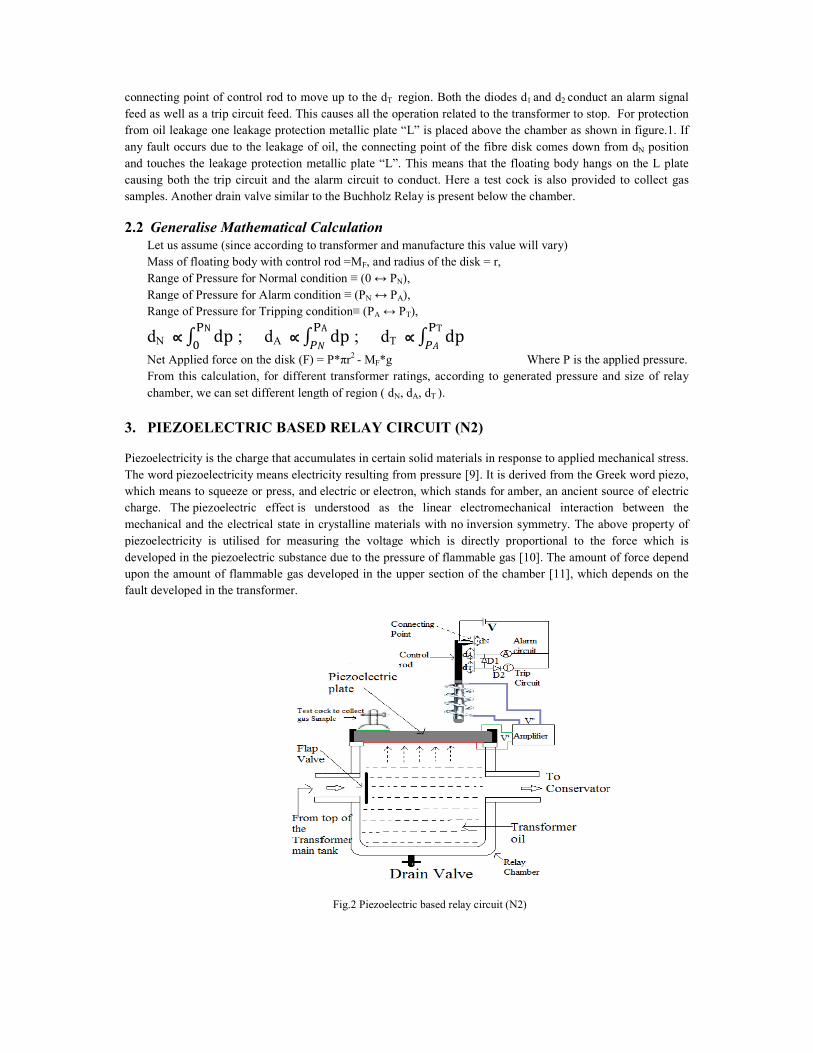
4. ULTRASONIC SENSOR BASED RELAY CIRCUIT (N3)
In this particular scheme ultrasonic sensor has been used to measure the depth of the oil in the relay chamber.
For this purpose a transmitter and a receiver of Ultrasonic sensor is placed on the upper layer of the relay
chamber. Beside the ultrasonic sensor, a test cock is present to collect the test samples, which is used for the
analysis of faults. The output of the sensor goes through an amplifier to the coil. This voltage energizes the coil.
The output voltage depends on the measured depth of the oil. A metal control rod is present inside the turns. The
scheme also consist a trip circuit and an alarm circuit. This gets excited according to the output signal from the
sensor. There are also two valves: flap valve and drain valve.
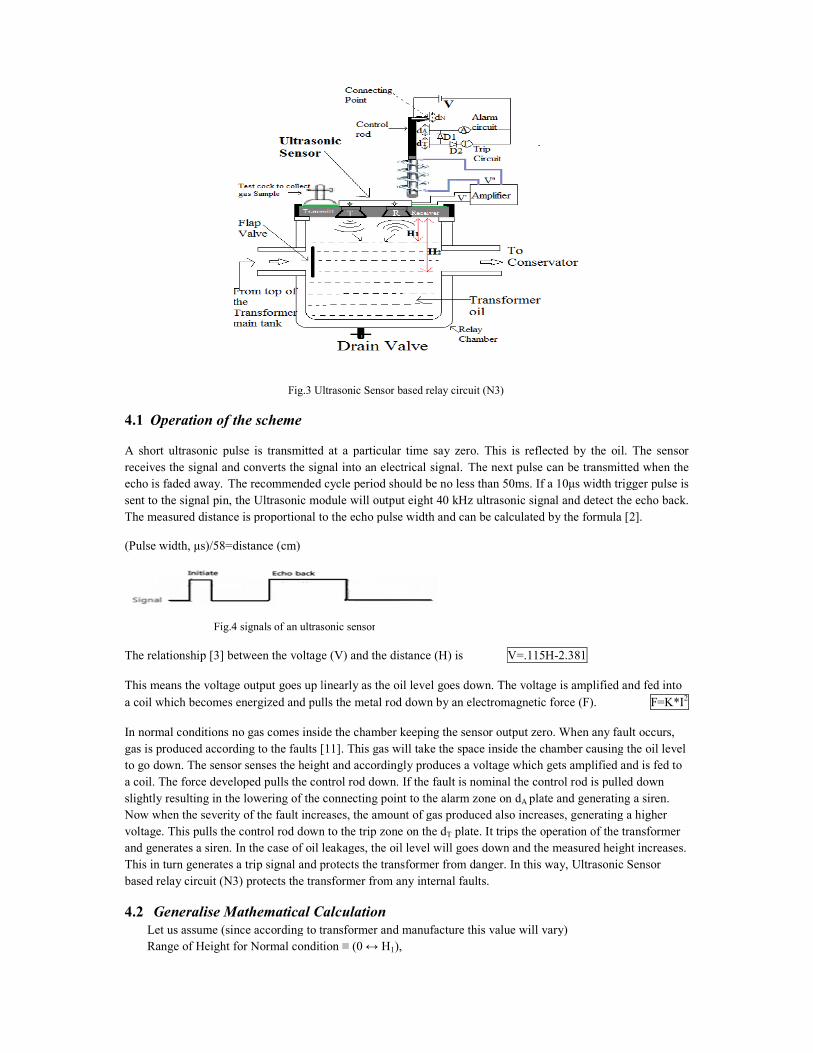
Fig.3 Ultrasonic Sensor based relay circuit (N3)
4.1 Operation of the scheme
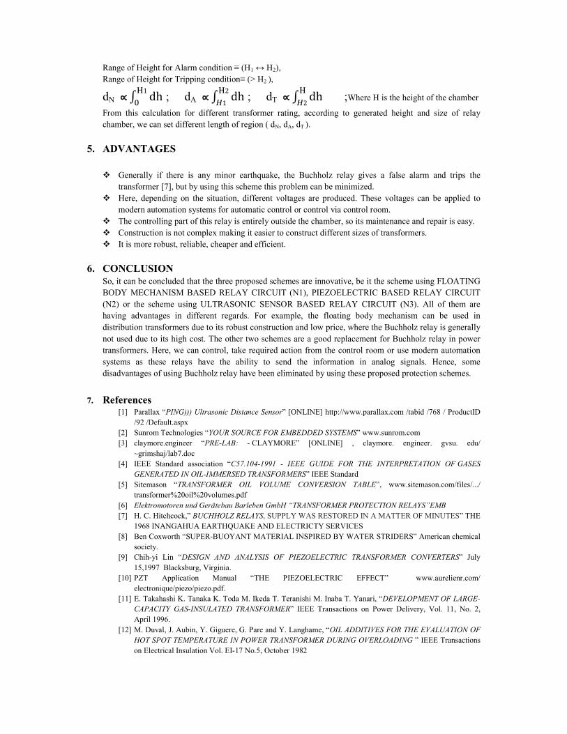
A short ultrasonic pulse is transmitted at a particular time say zero. This is reflected by the oil. The sensor
receives the signal and converts the signal into an electrical
echo is faded away. The recommended
sent to the signal pin, the Ultrasonic module will output eight 40 kHz ultrasonic signal and d
The measured distance is proportional to the echo pulse width and can be calculated by the formula [2].
(Pulse width, µs)/58=distance (cm)
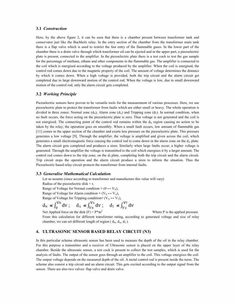
Fig.4 signals of an ultrasonic sensor
The relationship [3] between the voltage
This means the voltage output goes up linearly
a coil which becomes energized and pull
In normal conditions no gas comes inside the chamber
gas is produced according to the faults [11]
to go down. The sensor senses the height
a coil. The force developed pulls the control rod down
slightly resulting in the lowering of the
Now when the severity of the fault increases, the amount of gas
voltage. This pulls the control rod down
and generates a siren. In the case of oil leakage
This in turn generates a trip signal and protect
based relay circuit (N3) protects the transformer from any internal fault
4.2 Generalise Mathematical Calculation
Let us assume (since according to transformer and manufacture this value will vary)
Range of Height for Normal condition
Ultrasonic Sensor based relay circuit (N3)
A short ultrasonic pulse is transmitted at a particular time say zero. This is reflected by the oil. The sensor
receives the signal and converts the signal into an electrical signal. The next pulse can be transmitted when the
cycle period should be no less than 50ms. If a 10µs width trigger pulse is
sent to the signal pin, the Ultrasonic module will output eight 40 kHz ultrasonic signal and detect the echo back.
The measured distance is proportional to the echo pulse width and can be calculated by the formula [2].
Fig.4 signals of an ultrasonic sensor
between the voltage (V) and the distance (H) is V=.115H-2.381
linearly as the oil level goes down. The voltage is amplified and fed into
a coil which becomes energized and pulls the metal rod down by an electromagnetic force (F).
inside the chamber keeping the sensor output zero. When any fault
[11]. This gas will take the space inside the chamber causing
height and accordingly produces a voltage which gets amplified
control rod down. If the fault is nominal the control rod is pull
ulting in the lowering of the connecting point to the alarm zone on dA plate and generating
Now when the severity of the fault increases, the amount of gas produced also increases, generating
down to the trip zone on the dT plate. It trips the operation of the transformer
n the case of oil leakages, the oil level will goes down and the measured height increase
trip signal and protects the transformer from danger. In this way, Ultrasonic Sensor
the transformer from any internal faults.
Mathematical Calculation
(since according to transformer and manufacture this value will vary)
Range of Height for Normal condition ≡ (0 ↔ H1),
A short ultrasonic pulse is transmitted at a particular time say zero. This is reflected by the oil. The sensor
The next pulse can be transmitted when the
cycle period should be no less than 50ms. If a 10µs width trigger pulse is
etect the echo back.
The measured distance is proportional to the echo pulse width and can be calculated by the formula [2].
he voltage is amplified and fed into
F=K*I2
any fault occurs,
causing the oil level
amplified and is fed to
pulled down
generating a siren.
ing a higher
of the transformer
measured height increases.
Ultrasonic Sensor
Range of Height for Alarm condition ≡ (H1 ↔ H2),
Range of Height for Tripping condition≡ (> H2 ),
dN ∝∝∝∝ � �h�1
� ; dA ∝∝∝∝ � �h
�2
�1 ; dT ∝∝∝∝ � �h
�
�2 ;Where H is the height of the chamber
From this calculation for different transformer rating, according to generated height and size of relay
chamber, we can set different length of region ( dN, dA, dT ).
5. ADVANTAGES
� Generally if there is any minor earthquake, the Buchholz relay gives a false alarm and trips the
transformer [7], but by using this scheme this problem can be minimized.
� Here, depending on the situation, different voltages are produced. These voltages can be applied to
modern automation systems for automatic control or control via control room.
� The controlling part of this relay is entirely outside the chamber, so its maintenance and repair is easy.
� Construction is not complex making it easier to construct different sizes of transformers.
� It is more robust, reliable, cheaper and efficient.
6. CONCLUSION
So, it can be concluded that the three proposed schemes are innovative, be it the scheme using FLOATING
BODY MECHANISM BASED RELAY CIRCUIT (N1), PIEZOELECTRIC BASED RELAY CIRCUIT
(N2) or the scheme using ULTRASONIC SENSOR BASED RELAY CIRCUIT (N3). All of them are
having advantages in different regards. For example, the floating body mechanism can be used in
distribution transformers due to its robust construction and low price, where the Buchholz relay is generally
not used due to its high cost. The other two schemes are a good replacement for Buchholz relay in power
transformers. Here, we can control, take required action from the control room or use modern automation
systems as these relays have the ability to send the information in analog signals. Hence, some
disadvantages of using Buchholz relay have been eliminated by using these proposed protection schemes.
7. References [1] Parallax “PING))) Ultrasonic Distance Sensor” [ONLINE] http://www.parallax.com /tabid /768 / ProductID
/92 /Default.aspx
[2] Sunrom Technologies “YOUR SOURCE FOR EMBEDDED SYSTEMS” www.sunrom.com
[3] claymore.engineer “PRE-LAB: - CLAYMORE” [ONLINE] , claymore. engineer. gvsu. edu/
~grimshaj/lab7.doc
[4] IEEE Standard association “C57.104-1991 - IEEE GUIDE FOR THE INTERPRETATION OF GASES
GENERATED IN OIL-IMMERSED TRANSFORMERS” IEEE Standard
[5] Sitemason “TRANSFORMER OIL VOLUME CONVERSION TABLE”, www.sitemason.com/files/.../
transformer%20oil%20volumes.pdf
[6] Elektromotoren und Gerätebau Barleben GmbH “TRANSFORMER PROTECTION RELAYS”EMB
[7] H. C. Hitchcock,” BUCHHOLZ RELAYS, SUPPLY WAS RESTORED IN A MATTER OF MINUTES” THE
1968 INANGAHUA EARTHQUAKE AND ELECTRICTY SERVICES
[8] Ben Coxworth “SUPER-BUOYANT MATERIAL INSPIRED BY WATER STRIDERS” American chemical
society.
[9] Chih-yi Lin “DESIGN AND ANALYSIS OF PIEZOELECTRIC TRANSFORMER CONVERTERS” July
15,1997 Blacksburg, Virginia.
[10] PZT Application Manual “THE PIEZOELECTRIC EFFECT” www.aurelienr.com/
electronique/piezo/piezo.pdf.
[11] E. Takahashi K. Tanaka K. Toda M. Ikeda T. Teranishi M. Inaba T. Yanari, “DEVELOPMENT OF LARGE-
CAPACITY GAS-INSULATED TRANSFORMER” IEEE Transactions on Power Delivery, Vol. 11, No. 2,
April 1996.
[12] M. Duval, J. Aubin, Y. Giguere, G. Pare and Y. Langhame, “OIL ADDITIVES FOR THE EVALUATION OF
HOT SPOT TEMPERATURE IN POWER TRANSFORMER DURING OVERLOADING ” IEEE Transactions
on Electrical Insulation Vol. EI-17 No.5, October 1982