slope stability analyses in stiff fissured clays
TRANSCRIPT
SLOPE STABILITY ANALYSES IN STIFF FISSURED CLAYS
By Timothy D. Starkl and Hisham T. Eid/ Associate Members, ASCE
ABSTRACT: Results of torsional ring shear, direct shear, and triaxial compression tests on cohesive soils revealthat the fully softened shear strength is stress-dependent and related t~ ~he type o~ clay mineral an~ quantity. ofclay-size particles. An empirical relationship for the fully softened !nctlOn ang!e IS p~esen~ed that IS a functIOnof liquid limit, clay-size fractio~, an? effective normal. stress: S~udl.es. of first-time slIdes, I.e., slopes that havenot undergone previous sliding, m stiff fissured clay with a lIquid lImit between 41 and 130% suggest that themobilized shear strength along the failure surface can be lower than .the full~ soft~ned shear stren~th. Re~~m
mendations are presented for estimating the mobilized shear strength In first-time slides based on SOli plast~clty.
Soils with a liquid limit greater than 30% exhibit a large differen~e between the fully softened ~d residualfriction angles. In these soils, the presence or absence of a pre-existmg shear surface should be clanfied.
INTRODUCTION
Investigations by Skempton et al. (1969) and Skempton(1977) indicate that the development of a fissure can result insoftening of surrounding overconsolidated clay. The softeningcorresponds to an increase in water content caused by soildilation under the imposed shear stress. Softening reduces theeffective stress cohesion component of the Mohr-Coulombshear strength parameters but does not cause orientation ofclay particles or reduction in friction angle (Skempton 1970).Consequently, Skempton (1977) suggests that the shearstrength available in a fissure corresponds to the fully softenedcondition. Skempton (1970) concluded that the fully softenedshear strength is numerically equal to the drained peak strengthof a normally consolidated specimen.
After studying case histories involving slopes in brown London clay, Skempton (1977) proposed that slopes that have notundergone previous sliding (first-time slides) could be designed using a fully softened shear strength. Based on a number of case histories, Skempton (1964, 1977) also suggestedthat slopes that have undergone 1-2 m of shear displacementshould be designed using the drained residual shear strength.Therefore, the drained residual shear strength pertains toslopes that contain a pre-existing shear surface, such as oldlandslides or soliflucted slopes, bedding shears in folded strata,sheared joints, or faults. The objectives of the present studyare to investigate the effect of clay mineralogy, clay-size fraction, and effective normal stress on the fully softened shearstrength of cohesive soils, and to propose a design procedurefor stiff fissured clay slopes that have not undergone previoussliding.
SOIL DESCRIPTION AND TEST PROCEDURE
Most heavily overconsolidated clays, mudstones, or shalespossess diagenetic bonding that results in aggregates of individual clay particles. The degree of mudstone or shale aggregation that survives a particular sample preparation procedurehas an important influence on the measured index properties,such as liquid limit and clay-size fraction (La Gatta 1970;Townsend and Banks 1974). Since the liquid limit and claysize fraction are used to infer clay mineralogy and quantity of
'Assoc. Prof. of Civ. Engrg., Univ. of Illinois, Newmark Civ. Engrg.Lab. MC-250, 205 N. Mathews Ave., Urbana, IL 61801-2352.
'Post-doctoral Res. Assoc. of Civ. Engrg., Univ. of II1inois, N.Mathews Ave., Urbana, IL.
Note. Discussion open until September 1, 1997. To extend the closingdate one month, a written request must be filed with the ASCE Managerof Journals. The manuscript for this paper was submitted for review andpossible publication on July II, 1994. This paper is part of the JOUTlIQl
of Geotechnical and Geoenvironmental Engineering, Vol. 123, No.4,April, 1997. ©ASCE, ISSN 1090-0241/97/0004-0335-0343/$4.00 +$.50 per page. Paper No. 8838.
particles smaller than 0.002 mm, respectively, the mudstoneor shale particles were disaggregated by ball-milling a representative air-dried sample until all particles passed U.S. Standard Sieve No. 200 (Mesri and Cepeda-Diaz 1986). Remoldedsilt and clay specimens (soil numbers: 1,2,4, and 11 in Table1) were obtained by air-drying a representative sample, crushing it with a mortar and pestle, and processing it through U.S.Standard Sieve No. 40. Ball-milling was not used for thesespecimens because they naturally have disaggregated particles,and it would have changed the gradation of the soil. In bothcases, distilled water was added to the processed soil until aliquidity index of about 1.5 was obtained. The sample wasthen allowed to rehydrate for at least one week in a moistroom.
A modified Bromhead ring shear apparatus (Stark and Eid1993) was used for testing the 24 soils listed in Table 1. Theoriginal ring shear apparatus is described by Bromhead (1979).The rehydrated remolded soil paste was placed into the annularspecimen container using a spatula. The top of the specimenwas planed flush with the top of the specimen container usinga surgical razor blade. It should be noted that the liquid limit,plastic limit, and clay-size fraction of the specimens were measured using the ball-milled mudstone and shale, or the sievedsilt and clay samples.
For each soil, three remolded normally consolidated specimens were sheared at effective normal stresses of 50, 100, and400 kPa in the modified ring shear apparatus. This range ofnormal stress was chosen to represent the normal stresses thatare typically encountered in first-time failures of slopes andembankments. A shear displacement rate of 0.018 mm/minwas used to provide a drained condition during shear. Thisdisplacement rate is based on values of the coefficient of consolidation evaluated from oedometer tests. The procedure described by Gibson and Henkel (1954), and a degree of consolidation of 99.5% was used to estimate the draineddisplacement rate for the high-plasticity shales. Faster displacement rates could have been used for some of the claysand silts. However, to avoid possible rate effects, a displacement rate of 0.018 mm/min was used for all 24 soils.
The fully softened shear strength was measured after theremolded specimen was consolidated to the desired normalstress. Consolidation of specimens to a normal stress of 400kPa was performed in two stages. The specimen was first consolidated to a normal stress of 200 kPa. Settlement of the loading platen, which causes wall friction during shear, was eliminated by lowering the outer ring and inner core of thespecimen container that surround the annular specimen (Starkand Eid 1993). The specimen was then consolidated to a normal stress of 400 kPa. This two-stage loading to 400 kPa minimizes the potential for overconsolidating the specimen duringthe unloading process required to lower the outer ring andinner core. For normal stresses of 50 and 100 kPa, settlement
JOURNAL OF GEOTECHNICAL AND GEOENVIRONMENTAL ENGINEERING / APRIL 1997/335
J. Geotech. Geoenviron. Eng., 1997, 123(4): 335-343
Dow
nloa
ded
from
asc
elib
rary
.org
by
Uni
vers
ity o
f Il
linoi
s at
Urb
ana
on 0
7/10
/16.
Cop
yrig
ht A
SCE
. For
per
sona
l use
onl
y; a
ll ri
ghts
res
erve
d.
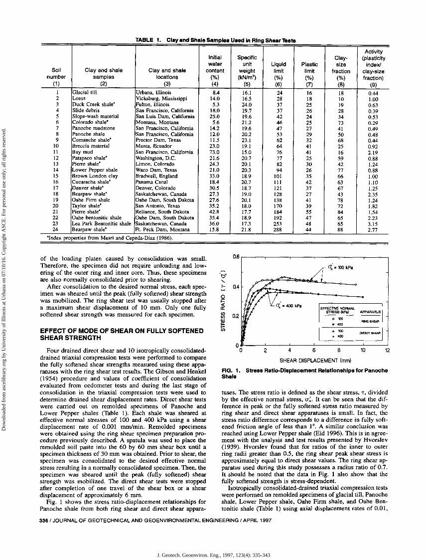
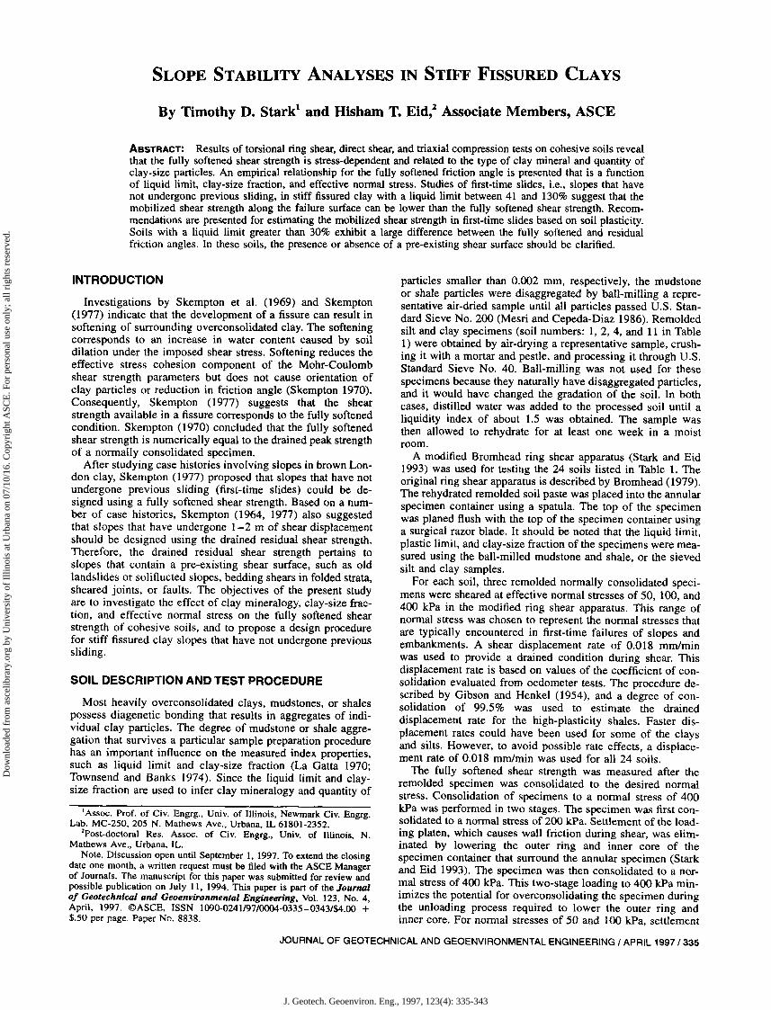
TABLE 1. Clay and Shale Samples Used In Ring Shear Tests
ActivityInitial Specific Clay- (plasticitywater unit Liquid Plastic size index!
Soil Clay and shale Clay and shale content weight limit limit fraction clay-sizenumber samples locations (%) (kN/m3
) (%) (%) (%) fraction)(1 ) (2) (3) (4) (5) (6) (7) (8) (9)
1 Glacial till Urbana, Illinois 8.4 16.1 24 16 18 0.442 Loess Vicksburg, Mississippi 14.0 16.5 28 18 10 1.003 Duck Creek shale" Fulton, Illinois 5.3 24.0 37 25 19 0.634 Slide debris San Francisco, California 18.0 19.7 37 26 28 0.395 Slope-wash material San Luis Dam, California 25.0 19.6 42 24 34 0.536 Colorado shale" Montana, Montana 5.6 21.2 46 25 73 0.297 Panoche mudstone San Francisco, California 14.2 19.6 47 27 41 0.498 Panoche shale San Francisco, California 12.0 20.2 53 29 50 0.489 Comanche shale" Proctor Dam, Texas 11.5 23.1 62 32 68 0.44
10 Breccia material Manta, Ecuador 23.0 19.1 64 41 25 0.9211 Bay mud San Francisco, California 73.0 15.0 76 41 16 2.1912 Patapsco shale" Washington, D.C. 21.6 20.7 77 25 59 0.8813 Pierre shale" Limon, Colorado 24.3 20.1 82 30 42 1.2414 Lower Pepper shale Waco Dam, Texas 21.0 20.3 94 26 77 0.8815 Brown London clay Bradwell, England 33.0 18.9 101 35 66 1.0016 Cucaracha shale" Panama Canal 18.4 20.7 111 42 63 1.1017 Denver shale" Denver, Colorado 30.5 18.7 121 37 67 1.2518 Bearpaw shale" Saskatchewan, Canada 27.3 19.0 128 27 43 2.3519 Oahe Firm shale Oahe Dam, South Dakota 27.6 20.1 138 41 78 1.2420 Taylor shale" San Antonio, Texas 35.2 18.0 170 39 72 1.8221 Pierre shale" Reliance, South Dakota 42.8 17.7 184 55 84 1.5422 Oahe bentonitic shale Oahe Dam, South Dakota 35.4 18.9 192 47 65 2.2323 Lea Park Bentonitic shale Saskatchewan, Canada 36.0 17.3 253 48 65 3.1524 Bearpaw shale" Ft. Peck Dam, Montana 15.8 21.8 288 44 88 2.77
"Index properties from Mesri and Cepeda-Diaz (1986).
SHEAR DISPLACEMENT (mm)
FIG. 1. Stress Ratio-Displacement Relationships for PanocheShale
tuses. The stress ratio is defined as the shear stress, T, dividedby the effective normal stress, (J'~. It can be seen that the difference in peak or the fully softened stress ratio measured byring shear and direct shear apparatuses is small. In fact, thestress ratio difference corresponds to a difference in fully softened friction angle of less than 1°. A similar conclusion wasreached using Lower Pepper shale (Eid 1996). This is in agreement with the analysis and test results presented by Hvorslev(1939). Hvorslev found that for ratios of the inner to outerring radii greater than 0.5, the ring shear peak shear stress isapproximately equal to direct shear values. The ring shear apparatus used during this study possesses a radius ratio of 0.7.It should be noted that the data in Fig. 1 also show that thefully softened strength is stress-dependent.
Isotropically consolidated-drained triaxial compression testswere performed on remolded specimens of glacial till, Panocheshale, Lower Pepper shale, Oahe Firm shale, and Oahe Bentonitic shale (Table 1) using axial displacement rates of 0.01,
of the loading platen caused by consolidation was small.Therefore, the specimen did not require unloading and lowering of the outer ring and inner core. Thus, these specimensare also normally consolidated prior to shearing.
After consolidation to the desired normal stress, each specimen was sheared until the peak (fully softened) shear strengthwas mobilized. The ring shear test was usually stopped aftera maximum shear displacement of 10 mm. Only one fullysoftened shear strength was measured for each specimen.
EFFECT OF MODE OF SHEAR ON FULLY SOFTENEDSHEAR STRENGTH
Four drained direct shear and 10 isotropically consolidateddrained triaxial compression tests were performed to comparethe fully softened shear strengths measured using these apparatuses with the ring shear test results. The Gibson and Henkel(1954) procedure and values of coefficient of consolidationevaluated from oedometer tests and during the last stage ofconsolidation in the triaxial compression tests were used todetermine drained shear displacement rates. Direct shear testswere carried out on remolded specimens of Panoche andLower Pepper shales (Table I). Each shale was sheared ateffective normal stresses of 100 and 400 kPa using a sheardisplacement rate of 0.001 mm/min. Remolded specimenswere obtained using the ring shear specimen preparation procedure previously described. A spatula was used to place theremolded soil paste into the 60 by 60 mm shear box until aspecimen thickness of 30 mm was obtained. Prior to shear, thespecimen was consolidated to the desired effective normalstress resulting in a normally consolidated specimen. Then, thespecimen was sheared until the peak (fully softened) shearstrength was mobilized. The direct shear tests were stoppedafter completion of one travel of the shear box or a sheardisplacement of approximately 6 mm.
Fig. 1 shows the stress ratio-displacement relationships forPanoche shale from both ring shear and direct shear appara-
0.6
'be.....~ 0.4
0
~(/)
0.2(/)wa:l-(/)
00
0; =100 kPa
EFFECTIVE NORMAl.STRESS (kPa) APPARAnJS
° 100FIlNG &HEAR
••00
'" 100 DIRECT SHEAR••00
2 4 6 8 10 12
336/ JOURNAL OF GEOTECHNICAL AND GEOENVIRONMENTAL ENGINEERING / APRIL 1997
J. Geotech. Geoenviron. Eng., 1997, 123(4): 335-343
Dow
nloa
ded
from
asc
elib
rary
.org
by
Uni
vers
ity o
f Il
linoi
s at
Urb
ana
on 0
7/10
/16.
Cop
yrig
ht A
SCE
. For
per
sona
l use
onl
y; a
ll ri
ghts
res
erve
d.
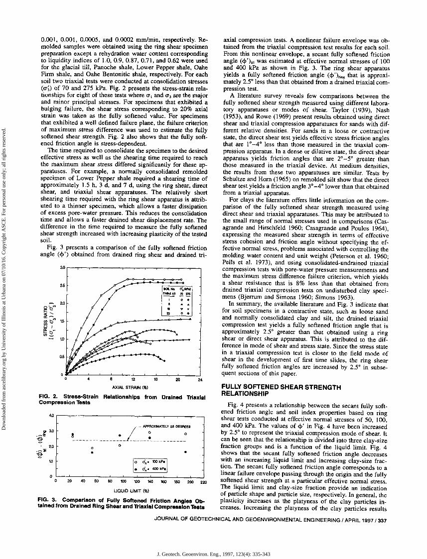
4.0 r----,,-----,---,.---r--,---r--,---,--..,....---,-----.
oo 20 ~ ~ ~ m ~ ~ ~ ~ ~ m
LIQUID LIMIT (...)
FIG. 3. Comparison of FUlly Softened Friction Angles Ob.tained from Drained Ring Shear and Triaxial Compression Tests
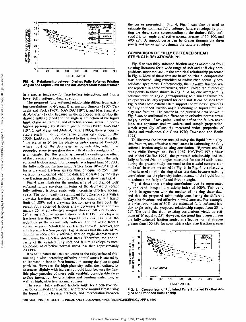
Fig. 4 presents a relationship between the secant fully softened friction angle and soil index properties based on ringshear tests conducted at effective normal stresses of 50, 100,and 400 kPa. The values of 4>' in Fig. 4 have been increasedby 2S to represent the triaxial compression mode of shear. Itcan be seen that the relationship is divided into three clay-sizefraction groups and is a function of the liquid limit. Fig. 4shows that the secant fully softened friction angle decreaseswith an increasing liquid limit and increasing clay-size fraction. The secant fully softened friction angle corresponds to alinear failure envelope passing through the origin and the fullysoftened shear strength at a particular effective normal stress.The liquid limit and clay-size fraction provide an indicationof particle shape and particle size, respectively. In general, theplasticity increases as the platyness of the clay particles increases. Increasing the platyness of the clay particles results
axial compression tests. A nonlinear failure envelope was obtained from the triaxial compression test results for each soil.From this nonlinear envelope, a secant fully softened frictionangle (<\>')tri was estimated at effective normal stresses of 100and 400 kPa as shown in Fig. 3. The ring shear apparatusyields a fully softened friction angle (<\>')ring that is approximately 2,50 less than that obtained from a drained triaxial compression test.
A literature survey reveals few comparisons between thefully softened shear strength measured using different laboratory apparatuses or modes of shear. Taylor (1939), Nash(1953), and Rowe (1969) present results obtained using directshear and triaxial compression apparatuses for sands with different relative densities. For sands in a loose or contractivestate, the direct shear test yields effective stress friction anglesthat are 10 _40 less than those measured in the triaxial compression apparatus. In a dense or dilative state, the direct shearapparatus yields friction angles that are 20 _5 0 greater thanthose measured in the triaxial device. At medium densities,the results from these two apparatuses are similar. Tests bySchultze and Horn (1965) on remolded silt show that the directshear test yields a friction angle 30 _4 0 lower than that obtainedfrom a triaxial apparatus.
For clays the literature offers little information on the comparison of the fully softened shear strength measured usingdirect shear and triaxial apparatuses. This may be attributed tothe small range of normal stresses used in comparisons (Casagrande and Hirschfeld 1960; Casagrande and Poulos 1964),expressing the measured shear strength in terms of effectivestress cohesion and friction angle without specifying the effective normal stress, problems associated with controlling themolding water content and unit weight (Peterson et al. 1960;Pells et al. 1973), and using consolidated-undrained triaxialcompression tests with pore-water pressure measurements andthe maximum stress difference failure criterion, which yieldsa shear resistance that is 8% less than that obtained fromdrained triaxial compression tests on undisturbed clay specimens (Bjerrum and Simons 1960; Simons 1963).
In summary, the available literature and Fig. 3 indicate thatfor soil specimens in a contractive state, such as loose sandand normally consolidated clay and silt, the drained triaxialcompression test yields a fully softened friction angle that isapproximately 2.5 0 greater than that obtained using a ringshear or direct shear apparatus. This is attributed to the difference in mode of shear and stress state. Since the stress statein a triaxial compression test is closer to the field mode ofshear in the development of first time slides, the ring shearfully softened friction angles are increased by 2.5 0 in subsequent sections of this paper.
FULLY SOFTENED SHEAR STRENGTHRELATIONSHIP
24
•
20
10 dn " 100 kP. II. Un- 400 kPal
o
•
4
~ . L ~OXIMAmY2Jjoea.:ES
---------------- -----~-----------o
ao
25d,-10m
0 •2.0
0'b'" " ·~~ 0 •~ b'" 15WIf= b-en_
W
05
0.001, 0.001, 0.0005, and 0.0002 mm/min, respectively. Remolded samples were obtained using the ring shear specimenpreparation except a rehydration water content correspondingto liquidity indices of 1.0, 0.9, 0.87, 0.71, and 0.62 were usedfor the glacial till, Panoche shale, Lower Pepper shale, OaheFirm shale, and Oahe Bentonitic shale, respectively. For eachsoil two triaxial tests were conducted at consolidation stresses(O'i) of 70 and 275 kPa. Fig. 2 presents the stress-strain relationships for eight of these tests where 0'1 and 0'3 are the majorand minor principal stresses. For specimens that exhibited abulging failure, the shear stress corresponding to 20% axialstrain was taken as the fully softened value. For specimensthat exhibited a well defined failure plane, the failure criterionof maximum stress difference was used to estimate the fullysoftened shear strength. Fig. 2 also shows that the fully softened friction angle is stress-dependent.
The time required to consolidate the specimen to the desiredeffective stress as well as the shearing time required to reachthe maximum shear stress differed significantly for these apparatuses. For example, a normally consolidated remoldedspecimen of Lower Pepper shale required a shearing time ofapproximately 1.5 h, 3 d, and 7 d, using the ring shear, directshear, and triaxial shear apparatuses. The relatively shortshearing time required with the ring shear apparatus is attributed to a thinner specimen, which allows a faster dissipationof excess pore-water pressure. This reduces the consolidationtime and allows a faster drained shear displacement rate. Thedifference in the time required to measure the fully softenedshear strength increased with increasing plasticity of the testedsoil.
Fig. 3 presents a comparison of the fully softened frictionangle (<\>') obtained from drained ring shear and drained tri-
8 12 16
AXIAL STRAIN (...)
FIG. 2. Stress-Strain Relationships from Drained TriaxialCompression Tests
to
2' 3.0
~c
2.0
~:s
JOURNAL OF GEOTECHNICAL AND GEOENVIRONMENTAL ENGINEERING / APRIL 1997/337
J. Geotech. Geoenviron. Eng., 1997, 123(4): 335-343
Dow
nloa
ded
from
asc
elib
rary
.org
by
Uni
vers
ity o
f Il
linoi
s at
Urb
ana
on 0
7/10
/16.
Cop
yrig
ht A
SCE
. For
per
sona
l use
onl
y; a
ll ri
ghts
res
erve
d.
CI CLAY MINERALS
. ~~
~_.. e ...
"~..,.~ ".C1""~~~ _.0 ~50
i,~ it'- --..._-_ ..
•.....~- ...-.--.-_--:!-~-----_ D -- __!.__ --_ _ __
.- -----.------=---.:..: ...CI --~
5
COMPARISON OF FULLY SOFTENED SHEARSTRENGTH RELATIONSHIPS
the curves presented in Fig. 4. Fig. 4 can also be used toestimate the nonlinear fully softened failure envelope by plotting the shear stress corresponding to the drained fully softened friction angle at effective normal stresses of 50, 100, and400 kPa. A smooth curve can be drawn through the threepoints and the origin to estimate the failure envelope.
Fig. 5 shows fully softened friction angles assembled fromexisting literature for a wide range of soft and stiff clay compositions superimposed on the empirical relationship presentedin Fig. 4. Most of these data are based on triaxial compressiontests conducted using remolded or undisturbed normally consolidated specimens. Unfortunately, the clay-size fraction wasnot reported in some references, which limited the number ofdata points to those shown in Fig. 5. Also, one average fullysoftened friction angle (corresponding to a linear failure envelope) was usually reported for each soil. It can be seen fromFig. 5 that these external data support the proposed groupingof fully softened friction angle according to liquid limit andclay-size fraction. The scatter of the published data shown inFig. 5 can be attributed to differences in effective normal stressrange, number of test points used to define the failure envelope, test apparatus and procedure, and sample preparation,which especially affects the measured index properties ofshales and mudstones (La Gatta 1970; Townsend and Banks1974).
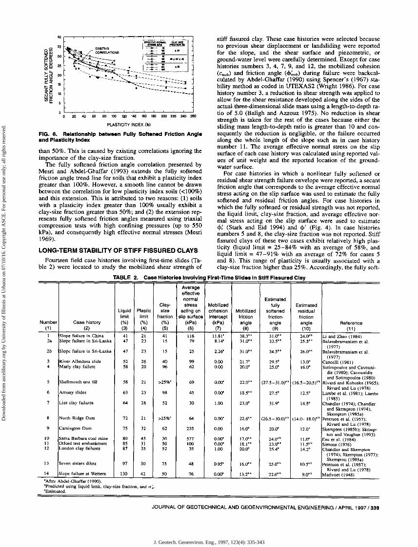
To illustrate the importance of using the liquid limit, claysize fraction, and effective normal stress in estimating the fullysoftened friction angle existing correlations (Bjerrum and Simons 1960; Terzaghi and Peck 1967; NAVFAC 1971; Mesriand Abdel-Ghaffar 1993), the proposed relationship and thefully softened friction angles measured for the 24 soils testedduring the present study corrected to the triaxial compressionmode of shear are presented in Fig. 6. In Fig. 6, the plasticityindex is used to plot the ring shear test data because existingcorrelations use the plasticity index, instead of the liquid limit,to estimate the fully softened friction angle.
Fig. 6 shows that existing correlations can be representedby one trend lineup to a plasticity index of 100%. This trendline is in agreement with the median of the ring shear data,and thus the proposed relationship considering the differentclay-size fractions and effective normal stresses. For example,at a plasticity index of 60%, the estimated fully softened friction angle using the proposed relationship ranges from 20° to29°. The trend line from existing correlations yields an estimate of </>' equal to 25°. However, the trend line overestimatesthe fully softened friction angles at effective normal stressesgreater than 100 kPa for soils with a clay-size fraction greater
.... ------- --.---- ....
EFfEC1'IVE NORMAL OLAY IIZE~_ """""'l!!
~-· ....... ·-11
~:~ ::::::::: ,.-<>- ..
.... A ---6-- 111 .,a,...tt.............-... ..:::::::!-:.~--'...~..---I......... i' .. ",,_ _-......_ 1110 ~ID.~............................ _ -.-- - - ...... - 4CllI
............ - .---------.:;------• • ...... _-.!. .--
--i:::::::l
40
0(;)35
WWZW 30~ffi00 25cn~
>-~ 20::Ie);jZ... < 15
~~(,)~ 10wQcnff 5
ol.--'-----'--'--L-..l.----''--''---'-----'--'--L-..l.----'_.l...--'--o ~ ~ W ~ ~ ~ ~ ~
LIQUID LIMIT (96)
FIG. 4. Relationship between Drained Fully Softened FrictionAngles and Liquid Limit for Triaxial Compression Mode of Shear
in a greater tendency for face-to-face interaction, and thus alower fully softened shear strength.
The proposed fully softened relationship differs from existing correlations of </>', e.g., Bjerrum and Simons (1960), Terzaghi and Peck (1967), NAVFAC (1971), and Mesri and Abdel-Ghaffar (1993), because in the proposed relationship thedrained fully softened friction angle is a function of the liquidlimit, clay-size fraction, and effective normal stress. In correlations presented by Bjerrum and Simons (1960), NAVFAC(1971), and Mesri and Abdel-Ghaffar (1993), there is considerable scatter in </>' for the range of plasticity index of 10100%. Ladd et al. (1977) referred to this scatter by stating that"the scatter in </>' for the plasticity index range of 15-40%,where most of the data exist is considerable, which hasprompted some to question the worth of such correlations." Itis anticipated that this scatter is caused by omitting the effectof the clay-size fraction and effective normal stress on the fullysoftened friction angle. For example, at a liquid limit of 120%,the fully softened friction angle ranges from 18°-28° (Fig. ~)
for a clay-size fraction greater than or equal to 25%. ThiSvariation is explained when the data are separated by the claysize fraction and effective normal stress as shown in Fig. 4.
Fig. 4 also illustrates the nonlinearity of the drai?ed fullysoftened failure envelope in terms of the decrease 10 secantfully softened friction angle with increasing e~fectiv.e no~al
stress. The nonlinearity is significant for coheSive SOlIs With aclay-size fraction greater than 25%. For example, at a liquidlimit of 100% and a clay-size fraction greater than 50%, thesecant fully softened friction angle decreases from approximately 25° at an effective normal stress of 50 kPa to ab~ut
19° at an effective normal stress of 400 kPa. For claY-Sizefractions less than 20% and liquid limits less than 80%, thereduction in the secant fully softened friction angle from anormal stress of 50-400 kPa is less than 2°_3°. However, forall clay-size fraction groups, Fig. 4 shows that the rate of ~e
duction in secant fully softened friction angle decreases Withincreasing the effective normal stress. Therefore, the nonlinearity of the drained fully softened failure envelope ~s mostnoticeable at effective normal stress less than approximately200 kPa.
It is anticipated that the reduction in the fully softened friction angle with increasing effective normal stress is caused byan increase in face-to-face interaction among the plate-shapedparticles. However, for high-plasticity soils, the nonlinearitydecreases slightly with increasing liquid limit because the flexible platy particles of these soils establish considerable face-to-face interaction by orientation and bending under low, as 00 40 80 120 160 200 240 280 320
well as high, effective normal stresses. LIQUID LIMIT (96)The secant fully softened friction angle for a cohesive ~oil
can be estimated for a particular effective normal stress us10g FIG. 5. Comparison of Published Fully Softened Friction An-the liquid limit, clay-size fraction, and interpolation between gles and Proposed Relationship
338/ JOURNAL OF GEOTECHNICAL AND GEOENVIRONMENTAL ENGINEERING / APRIL 1997
J. Geotech. Geoenviron. Eng., 1997, 123(4): 335-343
Dow
nloa
ded
from
asc
elib
rary
.org
by
Uni
vers
ity o
f Il
linoi
s at
Urb
ana
on 0
7/10
/16.
Cop
yrig
ht A
SCE
. For
per
sona
l use
onl
y; a
ll ri
ghts
res
erve
d.
PLASTICITY INDEX (%)
oL--l--'_--'-----'_-"----l._-'-----'-_.L--'-_'---l--'o 20 40 60 ao 100 120 140 160 1ao 200 220 240 260
FIG. 6. Relationship between Fully Softened Friction Angleand Plasticity Index
than 50%. This is caused by existing correlations ignoring theimportance of the clay-size fraction.
The fully softened friction angle correlation presented byMesri and Abdel-Ghaffar (1993) extends the fully softenedfriction angle trend line for soils that exhibit a plasticity indexgreater than 100%. However, a smooth line cannot be drawnbetween the correlation for low plasticity index soils «100%)and this extension. This is attributed to two reasons: (l) soilswith a plasticity index greater than 100% usually exhibit aclay-size fraction greater than 50%; and (2) the extension represents fully softened friction angles measured using triaxialcompression tests with high confining pressures (up to 550kPa), and consequently high effective normal stresses (Mesri1969).
LONG-TERM STABILITY OF STIFF FISSURED CLAYS
stiff fissured clay. These case histories were selected becauseno previous shear displacement or landsliding were reportedfor the slope, and the shear surface and piezometric, orground-water level were carefully determined. Except for casehistories numbers 3, 4, 7, 9, and 12, the mobilized cohesion(cmob) and friction angle (<I>.'nOb) during failure were backcalculated by Abdel-Ghaffar (1990) using Spencer's (1967) stability method as coded in UTEXAS2 (Wright 1986). For casehistory number 3, a reduction in shear strength was applied toallow for the shear resistance developed along the sides of theactual three-dimensional slide mass using a length-to-depth ratio of 5.0 (Baligh and Azzouz 1975). No reduction in shearstrength is taken for the rest of the cases because either thesliding mass length-to-depth ratio is greater than 10 and consequently the reduction is negligible, or the failure occurredalong the whole length of the slope such as in case historynumber 11. The average effective normal stress on the slipsurface of each case history was calculated using reported values of unit weight and the reported location of the groundwater surface.
For case histories in which a nonlinear fully softened orresidual shear strength failure envelope were reported, a secantfriction angle that corresponds to the average effective normalstress acting on the slip surface was used to estimate the fullysoftened and residual friction angles. For case histories inwhich the fully softened or residual strength was not reported,the liquid limit, clay-size fraction, and average effective normal stress acting on the slip surface were used to estimate<1>: (Stark and Eid 1994) and <1>' (Fig. 4). In case historiesnumbers 5 and 8, the clay-size fraction was not reported. Stifffissured clays of these two cases exhibit relatively high plasticity (liquid limit = 25-84% with an average of 58%, andliquid limit = 47-91% with an average of 72% for cases 5
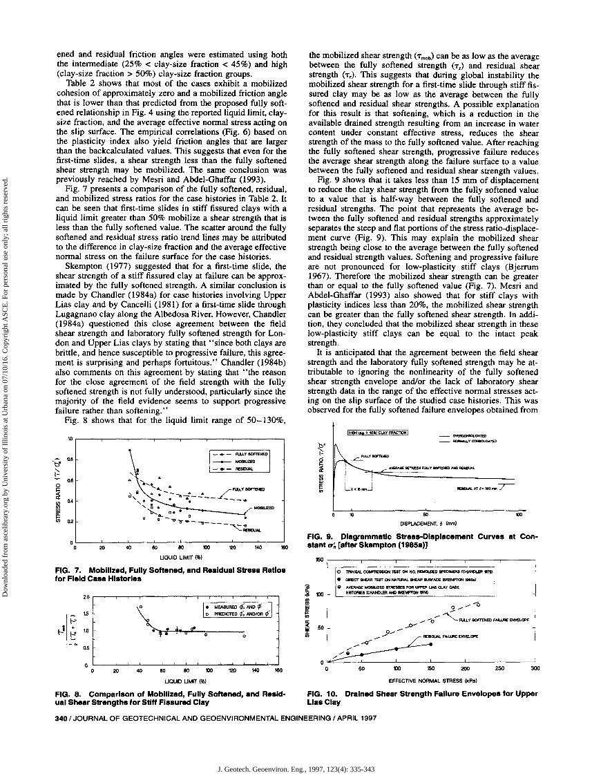
Fourteen field case histories involving first-time slides (Ta- and 8). This range of plasticity is usually associated with able 2) were located to study the mobilized shear strength of clay-size fraction higher than 25%. Accordingly, the fully soft-
TABLE 2 Case Histories Involving First-Time Slides In Stiff Fissured Clay
Averageeffectivenormal Estimated
Clay- stress Mobilized fully EstimatedLiquid Plastic size acting on cohesion Mobilized softened residuallimit limit fraction slip surface intercept friction friction friction
Number Case history (%) (%) (%) (kPa) (kPa) angle angle angle Reference(1 ) (2) (3) (4) (5) (6) (7) (8) (9) (10) (11 )
1 Slope failure in China 41 21 41 116 11.81' 38.3°' 31.00 b 24.O"b Li and Zhao (1984)2a Slope failure in Sri-Lanka 47 23 15 79 8.14' 31.0°' 33.5Ob 25.5Ob Balasubramaniam et al.
(1977)2b Slope failure in Sri-Lanka 47 23 15 25 2.26' 31.0° , 34.50 b 26.00b Balasubramaniam et aI.
(1977)3 River Albedosa slide 52 26 40 99 0.00 21.7° 29.5° 13.0° Cancelli (1981)4 Marly clay failure 58 20 96 62 0.00 20.0° 25.0" 16.0° Sotiropoulos and Cavouni-
dis (1980); Cavounidisand Sotiropoulos (1980)
5 Shellmouth test fill 58 21 >25%' 69 0.00" 22.0" (27.5 - 31.0)" (16.5-20.5)Ob Rivard and Kohuska (1965);Rivard and Lu (1978)
6 Amuay slides 63 23 98 45 0.00" 18.5" 27.5° 12,S' Lambe et aI. (1981); Lambe(1985)
7 Lias clay failures 64 28 52 30 1.00 23.0° 31.9' 14,S' Chandler (1974); Chandlerand Skempton (1974);Skempton (1985a)
8 North Ridge Dam 72 21 >25%' 64 0.00' 22.6" (26.5 - 30.0)" (14.0-18.0)'b Peterson et al. (1957);Rivard and Lu (1978)
9 Carsington Dam 75 32 62 235 0.00 16.0° 20.0" 12.0° Skempton (1985b); Skemp-ton and Vaughan (1993)
10 Santa Barbara coal mine 80 45 30 577 0.00" 17.0" 24.0" 11.0° Esu et al. (1984)II Otford test embankment 85 31 50 100 0.00" 18.1" 23.0" 11.5Ob Simons (1976)12 London clay failures 87 35 52 35 1.00 20.0° 25.4° 14.2° Chandler and Skempton
(1974); Skempton (1977);Skempton (1985a)
13 Seven sisters dikes 97 30 75 48 0.95' 16.0'" 25.0" 1O.5Ob Peterson et al. (1957);Rivard and Lu (1978)
14 Slope failure at Wettem 130 42 50 76 0.00" 13.2" 22.0" 9.0" Marivoet (1948)
'After Abdel-Ghaffar (1990).'Predicted using liquid limit. clay-size fraction. and IT;.'Estimated.
JOURNAL OF GEOTECHNICAL AND GEOENVIRONMENTAL ENGINEERING / APRIL 1997/339
J. Geotech. Geoenviron. Eng., 1997, 123(4): 335-343
Dow
nloa
ded
from
asc
elib
rary
.org
by
Uni
vers
ity o
f Il
linoi
s at
Urb
ana
on 0
7/10
/16.
Cop
yrig
ht A
SCE
. For
per
sona
l use
onl
y; a
ll ri
ghts
res
erve
d.
ened and residual friction angles were estimated using boththe intermediate (25% < clay-size fraction < 45%) and high(clay-size fraction> 50%) clay-size fraction groups.
Table 2 shows that most of the cases exhibit a mobilizedcohesion of approximately zero and a mobilized friction anglethat is lower than that predicted from the proposed fully softened relationship in Fig. 4 using the reported liquid limit, claysize fraction, and the average effective normal stress acting onthe slip surface. The empirical correlations (Fig. 6) based onthe plasticity index also yield friction angles that are largerthan the backcalculated values. This suggests that even for thefirst-time slides, a shear strength less than the fully softenedshear strength may be mobilized. The same conclusion waspreviously reached by Mesri and Abdel-Ghaffar (1993).
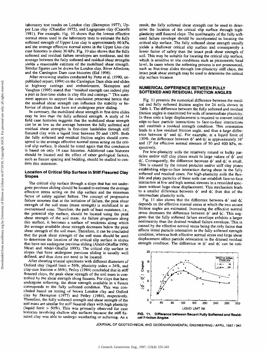
Fig. 7 presents a comparison of the fully softened, residual,and mobilized stress ratios for the case histories in Table 2. Itcan be seen that first-time slides in stiff fissured clays with aliquid limit greater than 50% mobilize a shear strength that isless than the fully softened value. The scatter around the fullysoftened and residual stress ratio trend lines may be attributedto the difference in clay-size fraction and the average effectivenormal stress on the failure surface for the case histories.
Skempton (1977) suggested that for a first-time slide, theshear strength of a stiff fissured clay at failure can be approximated by the fully softened strength. A similar conclusion ismade by Chandler (1984a) for case histories involving UpperLias clay and by Cancelli (1981) for a first-time slide throughLugagnano clay along the Albedosa River. However, Chandler(1984a) questioned this close agreement between the fieldshear strength and laboratory fully softened strength for London and Upper Lias clays by stating that "since both clays arebrittle, and hence susceptible to progressive failure, this agreement is surprising and perhaps fortuitous." Chandler (1984b)also comments on this agreement by stating that "the reasonfor the close agreement of the field strength with the fullysoftened strength is not fully understood, particularly since themajority of the field evidence seems to support progressivefailure rather than softening."
Fig. 8 shows that for the liquid limit range of 50-130%,
the mobilized shear strength (Tmob) can be as low as the averagebetween the fully softened strength (Ts) and residual shearstrength (T,). This suggests that during global instability themobilized shear strength for a first-time slide through stiff fissured clay may be as low as the average between the fullysoftened and residual shear strengths. A possible explanationfor this result is that softening, which is a reduction in theavailable drained strength resulting from an increase in watercontent under constant effective stress, reduces the shearstrength of the mass to the fully softened value. After reachingthe fully softened shear strength, progressive failure reducesthe average shear strength along the failure surface to a valuebetween the fully softened and residual shear strength values.
Fig. 9 shows that it takes less than 15 mm of displacementto reduce the clay shear strength from the fully softened valueto a value that is half-way between the fully softened andresidual strengths. The point that represents the average between the fully softened and residual strengths approximatelyseparates the steep and flat portions of the stress ratio-displacement curve (Fig. 9). This may explain the mobilized shearstrength being close to the average between the fully softenedand residual strength values. Softening and progressive failureare not pronounced for low-plasticity stiff clays (Bjerrum1967). Therefore the mobilized shear strength can be greaterthan or equal to the fully softened value (Fig. 7). Mesri andAbdel-Ghaffar (1993) also showed that for stiff clays withplasticity indices less than 20%, the mobilized shear strengthcan be greater than the fully softened shear strength. In addition, they concluded that the mobilized shear strength in theselow-plasticity stiff clays can be equal to the intact peakstrength.
It is anticipated that the agreement between the field shearstrength and the laboratory fully softened strength may be attributable to ignoring the nonlinearity of the fully softenedshear strength envelope and/or the lack of laboratory shearstrength data in the range of the effective normal stresses acting on the slip surface of the studied case histories. This wasobserved for the fully softened failure envelopes obtained from
10080
DISPlACEMENT. 6 (nvn)
10
IH.... !!t!) _ CLAY FAACroOiil
150 ,....-----,---,----,----..,.-------,----,
FIG. 9. Diagrammatic Stress-Displacement Curves at Constant (J'~ [after Skempton (1985a»180140
MOelUZED
120
_ ... -- A.U.Y SOFTENED
---+-- MOBILlZED
- • - FtE8DUAl.
80 80 100
L10UID LIMIT (..,)
,.A ""6.....6-
........ 4... A Fll.l'( SOFTENED6. • -- A A L0, ~4----,.. .. --- ..
'~. O.··...----_Jc s... _ IJ •
D 'It ~ .. - -a- __ - 'C:...w.
4020
to
'be Q.8
~0.8
0
~0.4
lJlw
~ 02
00
FIG. 7. Mobilized, Fully Softened, and Residual Stress Ratiosfor Field Case Histories
o • MEASURED </>: AND ¢'~ 0 PReDICTED ¢; AND/OR";
~ri:'--'l""'.trO""cJ>-=-0----0
30025020015010050
o~=___ __L .L____L .L______'_ ___'
o
o TRIAXIAL COt.tPRE88tON TEST ON N.C. REMOLDED IPECfMEN8 (CHANDLER '$'7'2)
• OAECT SHEAR TEST ON NATUW. SHEAR SURFACE (SKEt,F"T(lN~
Q AYfNiIJE. MOBlJZEO 8TAE88E8 FOR UPPER UA8 CLAY CASEHl8TOAIEI ICIW'«EA _ llKElAPTON 1174)
14012010080804020
2.0
1.5
.......~1 +
1.0~
_IN o.s
00
L10UID LIMIT (..,)
FIG. 8. Comparison of Mobilized, Fully Softened, and Residual Shear Strengths for Stiff Fissured Clay
EFFECTIVE NORMAL STRESS (kPa)
FIG. 10. Drained Shear Strength Failure Envelopes for UpperLias Clay
340 / JOURNAL OF GEOTECHNICAL AND GEOENVIRONMENTAL ENGINEERING / APRIL 1997
J. Geotech. Geoenviron. Eng., 1997, 123(4): 335-343
Dow
nloa
ded
from
asc
elib
rary
.org
by
Uni
vers
ity o
f Il
linoi
s at
Urb
ana
on 0
7/10
/16.
Cop
yrig
ht A
SCE
. For
per
sona
l use
onl
y; a
ll ri
ghts
res
erve
d.
NUMERICAL DIFFERENCE BETWEEN FULLYSOFTENED AND RESIDUAL FRICTION ANGLES
8040
20
116
12
:s-8
:e.4
00
result, the fully softened shear strength can be used to determine the location of the critical slip surface through highplasticity stiff fissured clays. The nonlinearity of the fully softened failure envelope should be incorporated in locating thecritical slip surface. The fuIIy softened shear strength usuaIIyyields a shallower critical slip surface and consequently alower factor of safety than the intact peak shear strength ofsoil. This may be suitable for locating the critical slip surface,which is sensitive to site conditions such as piezometric headlevel. In cases where the softening process is not pronounced,such as first-time slides through low-plasticity stiff clays, theintact peak shear strength may be used to determine the criticalslip surface location.
Fig. 11 presents the numerical difference between the residual and fully softened friction angles for 24 soils shown inTable 1. The difference between the fully softened and residualfriction angles is maximized for soils of intermediate plasticity.In these soils a large displacement is required to convert initialedge-to-face particle interactions to face-to-face interactionsand establish a residual strength condition. This orientationleads to a low residual friction angle, and thus a large difference between <1>' and <1>;. For example, at a liquid limit of130%, the difference between <1>' and <1>; is approximately 16°and 12° for effective normal stresses of 50 and 400 kPa, respectively.
For low-plasticity soils the relatively rotund or bulky particles and/or stiff clay plates result in large values of <1>' and<1>:. Consequently, the difference between <1>' and <1>: is small.This is caused by the rotund particles and/or stiff clay platesestablishing edge-to-face interaction during shear in the fuIIysoftened and residual cases. For high-plasticity soils the flexible and platy particles of these soils can establish face-to-faceinteraction at low and high normal stresses in a remolded specimen without large shear displacement. This mechanism leadsto a smaIIer difference between <1>' and <1>; than that of theintermediate plasticity soils.
Fig. I I also shows that the difference between <1>' and <1>:depends on the effective normal stress at which the two secantfriction angles are estimated. Increasing the effective normalstress decreases the difference between <1>' and <\>;. This suggests that the fully softened failure envelope exhibits a largernonlinearity than the drained residual failure envelope. This iscaused by the effective normal stress being the only factor thataffects initial particle orientation in the fully softened strengthcondition, whereas both effective normal stress and large sheardisplacement affect particle orientation in the drained residualstrength condition. The difference in <1>' and <1>: can be esti-
120 160 200 240 280 320
LIQUID LIMIT (%)
FIG. 11. Difference between Secant Fully Softened and Residual Friction Angles
Location of Critical Slip Surface in Stiff Fissured ClaySlopes
The critical slip surface through a slope that has not undergone previous sliding should be located to estimate the averageeffective stress acting on the slip surface and the minimumfactor of safety against failure. The concept of progressivefailure assumes that at the initiation of failure, the peak shearstrength of the soil mass (mass strength) is mobilized in anoverstressed zone. Therefore, the path of least resistance, i.e.,the potential slip surface, should be located using the peakshear strength of the soil mass. As failure progresses alongthis surface, it becomes a surface of weakness along whichthe average available shear strength decreases below the peakshear strength of the soil mass. Therefore, it can be concludedthat the peak shear strength of the soil mass should be usedto determine the location of the critical slip surface in slopesthat have not undergone previous sliding (Abdel-Ghaffar 1990;Mesri and Abdel-Ghaffar 1993). The critical slip surface inslopes that have undergone previous sliding is usually welldefined, and thus does not need to be located.
After shearing triaxial specimens with different diameters ofOxford clay (liquid limit = 56%, plasticity index = 34%, andclay-size fraction = 56%), Petley (1984) concluded that in stifffissured clays, the peak shear strength of the soil mass is controlled by the shear strength along fissures. For clays that haveundergone softening, the shear strength available in a fissurecorresponds to the fully softened condition. This was concluded based on testing of brown London clay and Oxfordclay by Skempton (1977) and Petley (1984), respectively.Therefore, the fully softened strength and shear strength of thesoil mass are similar for stiff fissured clays with high plasticity(liquid limit > 50%). This was primarily observed for casehistories involving shallow slip surfaces because the stiff fissured clay was able to undergo weathering or softening. As a
laboratory test results on London clay (Skempton 1977), Upper Lias clay (Chandler 1972), and Lugagnano clay (Cancelli1981). For example, Fig. 10 shows that the lowest effectivenormal stress used in the laboratory tests to estimate the fullysoftened strength of Upper Lias clay is approximately 60 kPa,and the average effective normal stress in the Upper Lias claycase histories is about 30 kPa. Fig. 10 also shows that the fullysoftened and residual failure envelopes are nonlinear, and theaverage between the fully softened and residual shear strengthsyields a reasonable estimate of the mobilized shear strength.Similar figures can be drawn for London clay, River Albedosa,and the Carsington Dam case histories (Eid 1996).
After reviewing studies conducted by Potts et al. (1990, unpublished report; 1994) on the Carsington Dam slide and slidesin highway cuttings and embankments, Skempton andVaughan (1995) stated that "residual strength can indeed playa part in first-time slides in clay fills and cuttings." This statement appears to support the conclusion presented herein thatthe residual shear strength can influence the stability or behavior of slopes that have not undergone prior sliding.
In summary, the mobilized shear strength in first-time slidesmay be less than the fully softened strength. A study of 14field case histories suggests that the mobilized shear strengthcan be as low as the average between the fully softened andresidual shear strengths in first-time landslides through stifffissured clay with a liquid limit between 50 and 130%. Boththe fully softened and residual friction angles should correspond to the average effective normal stress acting on the critical slip surface. It Should be noted again that this conclusionis based on only 14 case histories. Additional case historiesshould be located and the effect of other geological factors,such as fissure spacing and bedding, Should be studied to confirm this statement.
JOURNAL OF GEOTECHNICAL AND GEOENVIRONMENTAL ENGINEERING / APRIL 1997/341
J. Geotech. Geoenviron. Eng., 1997, 123(4): 335-343
Dow
nloa
ded
from
asc
elib
rary
.org
by
Uni
vers
ity o
f Il
linoi
s at
Urb
ana
on 0
7/10
/16.
Cop
yrig
ht A
SCE
. For
per
sona
l use
onl
y; a
ll ri
ghts
res
erve
d.
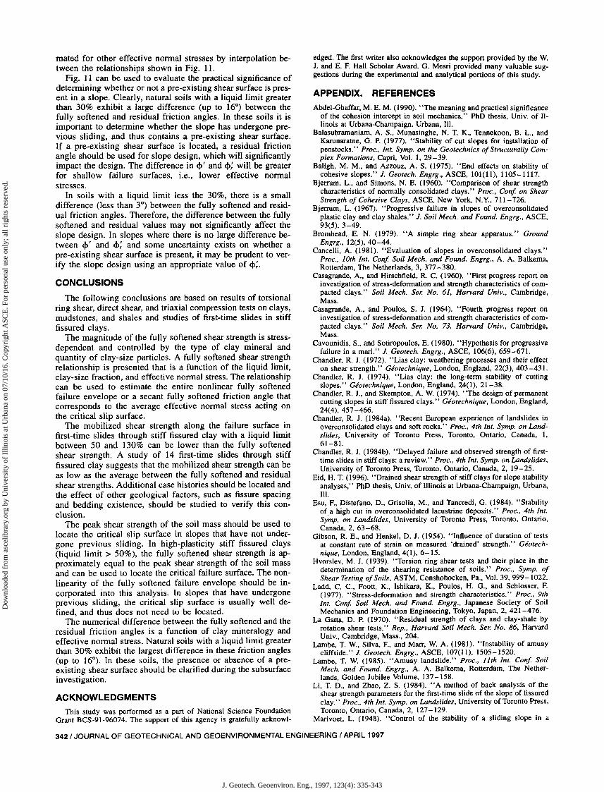
mated for other effective normal stresses by interpolation between the relationships shown in Fig. II.
Fig. II can be used to evaluate the practical significance ofdetermining whether or not a pre-existing shear surface is present in a slope. Clearly, natural soils with a liquid limit greaterthan 30% exhibit a large difference (up to 16°) between thefully softened and residual friction angles. In these soils it isimportant to determine whether the slope has undergone previous sliding, and thus contains a pre-existing shear surface.If a pre-existing shear surface is located, a residual frictionangle should be used for slope design, which will significantlyimpact the design. The difference in </>' and </>: will be greaterfor shallow failure surfaces, i.e., lower effective normalstresses.
In soils with a liquid limit less the 30%, there is a smalldifference (less than 3°) between the fully softened and residual friction angles. Therefore, the difference between the fullysoftened and residual values may not significantly affect theslope design. In slopes where there is no large difference between </>' and </>: and some uncertainty exists on whether apre-existing shear surface is present, it may be prudent to verify the slope design using an appropriate value of </>:.
CONCLUSIONS
The following conclusions are based on results of torsionalring shear, direct shear, and triaxial compression tests on clays,mudstones, and shales and studies of first-time slides in stifffissured clays.
The magnitude of the fully softened shear strength is stressdependent and controlled by the type of clay mineral andquantity of clay-size particles. A fully softened shear strengthrelationship is presented that is a function of the liquid limit,clay-size fraction, and effective normal stress. The relationshipcan be used to estimate the entire nonlinear fully softenedfailure envelope or a secant fully softened friction angle thatcorresponds to the average effective normal stress acting onthe critical slip surface.
The mobilized shear strength along the failure surface infirst-time slides through stiff fissured clay with a liquid limitbetween 50 and 130% can be lower than the fully softenedshear strength. A study of 14 first-time slides through stifffissured clay suggests that the mobilized shear strength can beas low as the average between the fully softened and residualshear strengths. Additional case histories should be located andthe effect of other geological factors, such as fissure spacingand bedding existence, should be studied to verify this conclusion.
The peak shear strength of the soil mass should be used tolocate the critical slip surface in slopes that have not undergone previous sliding. In high-plasticity stiff fissured clays(liquid limit> 50%), the fully softened shear strength is approximately equal to the peak shear strength of the soil massand can be used to locate the critical failure surface. The nonlinearity of the fully softened failure envelope should be incorporated into this analysis. In slopes that have undergoneprevious sliding, the critical slip surface is usually well defined, and thus does not need to be located.
The numerical difference between the fully softened and theresidual friction angles is a function of clay mineralogy andeffective normal stress. Natural soils with a liquid limit greaterthan 30% exhibit the largest difference in these friction angles(up to 16°). In these soils, the presence or absence of a preexisting shear surface should be clarified during the subsurfaceinvestigation.
ACKNOWLEDGMENTSThis study was performed as a part of National Science Foundation
Grant BCS-91-96074. The support of this agency is gratefully acknowl-
edged. The first writer also acknowledges the support provided by the W.J. and E. F. Hall Scholar Award. G. Mesri provided many valuable suggestions during the experimental and analytical portions of this study.
APPEND~. REFERENCES
Abdel-Ghaffar, M. E. M. (1990). "The meaning and practical significanceof the cohesion intercept in soil mechanics," PhD thesis, Univ. of Illinois at Urbana-Champaign, Urbana, Ill.
Balasubramaniam, A. S., Munasinghe, N. T. K., Tennekoon, B. L., andKarunaratne, G. P. (1977). "Stability of cut slopes for installation ofpenstocks." Proc., Int. Symp. on the Geotechnics of Structurally Complex Formations, Capri, Vol. I, 29-39.
Baligh, M. M., and Azzouz, A. S. (1975). "End effects on stability ofcohesive slopes." J. Geotech. Engrg., ASCE, 101(11), 1105-1117.
Bjerrum, L., and Simons, N. E. (1960). "Comparison of shear strengthcharacteristics of normally consolidated clays," Proc., Con! on ShearStrength of Cohesive Clays, ASCE, New York, N.Y., 711-726.
Bjerrum, L. (1967). "Progressive failure in slopes of overconsolidatedplastic clay and clay shales." J. Soil Mech. and Found. Engrg., ASCE,93(5),3-49.
Bromhead, E. N. (1979). "A simple ring shear apparatus," GroundEngrg., 12(5), 40-44.
Cancelli, A. (1981). "Evaluation of slopes in overconsolidated clays."Proc., 10th Int. Con! Soil Mech. and Found. Engrg., A. A. Balkema,Rotterdam, The Netherlands, 3, 377 -380.
Casagrande, A., and Hirschfield, R. C. (1960). "First progress report oninvestigation of stress-deformation and strength characteristics of compacted clays," Soil Mech. Ser. No. 61, Harvard Univ., Cambridge,Mass.
Casagrande, A., and Poulos, S. J. (1964). "Fourth progress report oninvestigation of stress-deformation and strength characteristics of compacted clays," Soil Mech. Ser. No. 73, Harvard Univ., Cambridge,Mass.
Cavounidis, S., and Sotiropoulos, E. (1980). "Hypothesis for progressivefailure in a marl," J. Geotech. Engrg., ASCE, 106(6),659-671.
Chandler, R. J. (1972). "Lias clay: weathering processes and their effecton shear strength." Geotechnique, London, England, 22(3),403-431.
Chandler, R. J. (1974). "Lias clay: the long-term stability of cuttingslopes," Geotechnique, London, England, 24(1), 21-38.
Chandler, R. J., and Skempton, A. W. (1974). "The design of permanentcutting slopes in stiff fissured clays," Geotechnique, London, England,24(4),457-466.
Chandler, R. J. (1984a). "Recent European experience of landslides inoverconsolidated clays and soft rocks." Proc., 4th Int. Symp. on Landslides, University of Toronto Press, Toronto, Ontario, Canada, I,61-81.
Chandler, R. J. (1984b). "Delayed failure and observed strength of firsttime slides in stiff clays: a review," Proc., 4th Int. Symp. on Landslides,University of Toronto Press, Toronto, Ontario, Canada, 2, 19-25.
Eid, H. T. (1996). "Drained shear strength of stiff clays for slope stabilityanalyses," PhD thesis, Univ. of Illinois at Urbana-Champaign, Urbana,Ill.
Esu, F., Distefano, D., Grisolia, M., and Tancredi, G. (1984). "Stabilityof a high cut in overconsolidated lacustrine deposits." Proc., 4th Int.Symp. on Landslides, University of Toronto Press, Toronto, Ontario,Canada, 2, 63-68.
Gibson, R. E., and Henkel, D. J. (1954). "Influence of duration of testsat constant rate of strain on measured 'drained' strength." Geotechnique, London, England, 4(1), 6-15.
Hvorslev, M. J. (1939). "Torsion ring shear tests and their place in thedetermination of the shearing resistance of soils," Proc., Symp. ofShear Testing ofSoils, ASTM, Conshohocken, Pa., Vol. 39,999-1022.
Ladd, C. C., Foott, K., Ishikara, K., Poulos, H. G., and Schlosser, F.(1977). "Stress-deformation and strength characteristics." Proc., 9thInt. Con! Soil Mech. and Found. Engrg., Japanese Society of SoilMechanics and Foundation Engineering, Tokyo, Japan, 2, 421-476.
La Gatta, D. P. (1970). "Residual strength of clays and clay-shale byrotation shear tests," Rep., Harvard Soil Mech. Ser. No. 86, HarvardUniv., Cambridge, Mass., 204.
Lambe, T. w., Silva, F., and Marr, W. A. (1981). "Instability of amuaycliffside," J. Geotech. Engrg., ASCE,107(1l), 1505-1520.
Lambe, T. W. (1985). "Amuay landslide," Proc., 11th Int. Conf. SoilMech. and Found. Engrg., A. A. Balkema, Rotterdam, The Netherlands, Golden Jubilee Volume, 137 -158.
Li, T. D., and Zhao, Z. S. (1984). "A method of back analysis of theshear strength parameters for the first-time slide of the slope of fissuredclay." Proc., 4th Int. Symp. on Landslides, University of Toronto Press,Toronto, Ontario, Canada, 2, 127-129.
Marivoet, L. (1948). "Control of the stability of a sliding slope in a
342/ JOURNAL OF GEOTECHNICAL AND GEOENVIRONMENTAL ENGINEERING / APRIL 1997
J. Geotech. Geoenviron. Eng., 1997, 123(4): 335-343
Dow
nloa
ded
from
asc
elib
rary
.org
by
Uni
vers
ity o
f Il
linoi
s at
Urb
ana
on 0
7/10
/16.
Cop
yrig
ht A
SCE
. For
per
sona
l use
onl
y; a
ll ri
ghts
res
erve
d.
railway cut near Wetteren." Proc., 2nd Int. Conf. Soil Mech. andFound. Engrg., Vol. 2, 38-42.
Mesri, G. (1969). "Engineering properties of montmorillonite," PhD thesis, Univ. of Illinois at Urbana-Champaign, Urbana, Ill.
Mesri, G., and Cepeda-Diaz, A. F. (1986). "Residual shear strength ofclays and shales." Geotechnique, London, England, 36(2), 269-274.
Mesri, G., and Abdel-Ghaffar, M. E. M. (1993). "Cohesion intercept ineffective stress-stability analysis." J. Geotech. Engrg., ASCE, 119(8),1229-1249.
Nash, K. L. (1953). "The shearing resistance of a fine closely gradedsand." Proc., 3rd Int. Conf. Soil Mech. and Found. Engrg., ImprimerieBerichthaus, Zurich, Switzerland, I, 160-164.
NAVFAC. (1971). Design manual: soil mechanics,foundations, and earthstructures, NAVFAC, DM-7. Department of The Navy, Naval FacilitiesEngineering Command, Alexandria, Va.
Pells, P. J. N., Maurenbrecher, P. M., and Elges, H. F. W. K. (1973)."Validity of results from the direct shear test." Proc., 8th Int. Conf.Soil Mech. and Found. Engrg., The U.S.S.R. National Society for SoilMechanics and Foundation Engineering, Moscow, Russia, 1,333-338.
Peterson, R., Iverson, N. L., and Rivard, P. J. (1957). "Studies of severaldam failures on clay foundations." Proc., 4th Int. Conf. Soil Mech. andFound. Engrg., Butterworths Publications Ltd., London, England, 2,348-352.
Peterson, R., Jasper J. L., Rivard, P. J., and Iverson, N. L. (1960). "Limitation of laboratory shear strength in evaluating stability of highlyplastic clays." Proc., Conf. on Shear Strength of Cohesive Clays,ASCE, New York, N.Y., 765-791.
Petley, D. J. (1984). "Shear strength of over-consolidated fissured clay."Proc., 4th Int. Symp. on Landslides, University of Toronto Press, Toronto, Ontario, Canada, 2, 167 -172.
Potts, D. M., Dounias, G. T., and Vaughan, P. R. (1990). "Finite elementanalysis of progressive failure of Carsington embankment." Geotechnique, London, England, 40(1), 79-101.
Potts, D. M., Kovacevic, N., and Vaughan, P. R. (1994). "The design ofslopes for highway cuttings and embankments." Contract Rep. 5530Crowthome: Transport Res. Lab.
Rivard, P. J., and Kohuska, A. (1965). "Shellmouth Dam test fill." Can.Geotech. J., Ottawa, Canada, 2, 198-21 I.
Rivard, P. J., and Lu, Y. (1978). "Shear strength of soft fissured clays."Can. Geotech. J., Ottawa, Canada, 15(3), 382-390.
Rowe, P. W. (1969). "The relation between the shear strength of sandsin triaxial compression, plane strain, and direct shear." Geotechnique,London, England, 19(1), 75-86.
Schultze, E., and Horn, A. (1965). "The shear strength of silts." Proc.,6th Int. Conf. Soil Mech. and Found. Engrg., University of TorontoPress, Toronto, Ontario, Canada, 1, 350-353.
Simons, N. E. (1963). "The influence of stress path on triaxial test re-
suits." Proc., ofAm. Soc. for Testing and Mat., ASTM, Conshohocken,Pa., No. 361, 361.
Simons, N. E. (1976). "Field studies of the stability of embankments onclay foundations." Bjerrum Memorial Volume, NGI, Oslo, Norway,183-209.
Skempton, A. W. (1964). "Long-term stability of clay slopes." Geotechnique, London, England, 14(2),77-101.
Skempton, A. w., Schuster, R. L., and Petley, D. J. (1969). "Joints andfissures in the London clay at Wraysburg and Edgware." Geotechnique, London, England, 19(2),205-217.
Skempton, A. W. (1970). "First-time slides in over-consolidated clays."Geotechnique, London, England, 20(3), 320-324.
Skempton, A. W. (1977). "Slope stability of cuttings in brown Londonclay." Proc., 9th Int. Conj. Soil Mech. and Found. Engrg., JapaneseSociety of Soil Mechanics and Foundation Engineering, Tokyo, Japan,3,261-270.
Skempton, A. W. (1985a). "Residual strength of clays in landslides,folded strata and the laboratory." Geotechnique, London, England,35(1), 3-18.
Skempton, A. W. (1985b). "Geotechnical aspects of the Carsington Damfailure." Proc., 11th Int. Conf. Soil Mech. and Found. Engrg., A. A.Balkema, Rotterdam, The Netherlands, 2581-2591.
Skempton, A. w., and Vaughan, P. R. (1993). "The failure of CarsingtonDam." Geotechnique, London, England, 43(1), 151-173.
Skempton, A. W., and Vaughan, P. R. (1995). "The failure of CarsingtonDam." Geotechnique, London, England, 45(4), 719-739.
Sotiropoulos, E., and Cavounidis, S. (1980). "A case of minor slopefailure in Marly clay, in Epirus, Greece." J. Civ. Engrg. Des., 2(2),209-219.
Spencer, E. (1967). "A method of analysis of the stability of embankments assuming parallel inter-slice forces." Geotechnique, London,England, 17(1), 11-26.
Stark, T. D., and Eid, H. T. (1993). "Modified Bromhead ring shearapparatus." ASTM Geotech. J., 16(1), 100-107.
Stark, T. D., and Eid, H. T. (1994). "Drained residual strength of cohesivesoils." J. Geotech. Engrg., ASCE, 120(5), 332-362.
Taylor, D. W. (1939). "A comparison of results of direct shear and cylindrical compression test." Proc., of Am. Soc. for Testing and Mat.,ASTM, Conshohocken, Pa., 1058.
Terzaghi, K., and Peck, R. B. (1967). Soil mechanics in engineering practice, 2nd Ed., John Wiley & Sons, Inc., New York, N.Y.
Townsend, F. C., and Banks, D. C. (1974). "Preparation effects on clayshale classification indexes." Proc., of Nat. Meeting on Water Resour.Engrg., ASCE, New York, N.Y., 21-25.
Wright, S. G. (1986). "UTEXAS2: a computer program for slope stabilitycalculations." Geotechnical engineering software GS86-1. Dept. ofCiv. Engrg., Univ. of Texas at Austin, Austin, Tex., pp. 109.
JOURNAL OF GEOTECHNICAL AND GEOENVIRONMENTAL ENGINEERING / APRIL 1997/343
J. Geotech. Geoenviron. Eng., 1997, 123(4): 335-343
Dow
nloa
ded
from
asc
elib
rary
.org
by
Uni
vers
ity o
f Il
linoi
s at
Urb
ana
on 0
7/10
/16.
Cop
yrig
ht A
SCE
. For
per
sona
l use
onl
y; a
ll ri
ghts
res
erve
d.