sketch-based interaction for designing precise laser cut items
TRANSCRIPT
Sketch-based Interaction for DesigningPrecise Laser Cut Items
Gabriel Goehring Johnson
September 2012
School of ArchitectureCarnegie Mellon University
Pittsburgh, PA 15213
Thesis Committee:Mark D. Gross (School of Architecture, CMU), Chair
Jason I. Hong (Human Computer Interaction Institute, CMU)Ellen Yi-Luen Do (Georgia Institute of Technology)
Submitted in partial fulfillment of the requirementsfor the degree of Doctor of Philosophy.
Copyright © 2012 Gabriel Goehring Johnson

Keywords: Sketching, Design, Pen Computing, Laser Cutters, Rapid Prototyping, SBIM,Interaction Design, HCI

For Uncle Jim

iv
AbstractDesigners typically sketch during concept development, and use computer
modeling software to finalize their ideas. Both tools—pencil and computer—arewell-suited for their task. Sketching is fast, fluid, and lets people explore ideasefficiently; computation lets users make structured, detailed digital models. Butin practice, design does not progress directly from idea to final product. Instead,designers use paper, then software, return to sketching to develop or changeconcepts, turn back to the computer to implement changes, and so on. Thetransition between between pencils and pixels is time-consuming.
Rapid fabrication and prototyping is a design area of increasing importance.Machines like laser cutters and 3D printers are becoming more common, andordinary people are increasingly interested in these machines to design and makethings. Current design software is made for professionals, not hobbyists. Foravocational rapid prototyping machine users, software is the bottleneck.
This thesis presents Sketch It, Make It (SIMI), a sketch-based modeling toolthat lets non-experts design precise items for laser cutting by sketching. Thisremoves the need to transition between sketches and formal CAD models. SIMIusers make line work, issue commands, create geometric constraints, and pro-duce “cut files” for production on a laser cutter—entirely with a stylus. Thereare no modes (like line mode, erase mode) in SIMI: the meaning of user input isrecognized by analyzing pen strokes and context.
Researchers have long sought to infer user intention by looking at sketches.The work presented in this thesis treats sketch recognition largely as an interac-tion design problem, rather than an artificial intelligence problem. Sketch-basedtechniques were developed to provide efficient user experience in specific con-texts, including the laser cutter domain and the other sketch-based interactiontechniques found in SIMI.
Two evaluations were used to measure SIMI’s performance. First, a work-shop involving sixty undergraduate architecture students was carried out. Thestudents used SIMI and provided feedback on its technical performance and theirown attitude about the software. Next, a task/tool analysis of SIMI and anothercommon tool compares the steps needed to perform a simple design task.

vi
AcknowledgmentsWhen I was ten years old, I liked to play trek on my dad’s CP/M computer.
The goal was to control the Enterprise to blow up Klingons. To shoot, type anangle: 90 for up, 270 for down. But it was tricky when the bad guy was at aweird angle. One morning my dad stepped in to show me a thing or two.
He showed me how to think about spatial relationships with circles andtriangles. He explained the calculator’s weirder buttons (e.g. arc tan). If Iknew he was subversively teaching math, I wouldn’t have been interested. Buthis trick worked. Math was no longer just a chore foisted on me at school. Ithad a use—math can be used to blow up Klingons.
When I was twelve, I decided to write a book. My mom patiently read my(terrible) drafts, but she encouraged me to stick with it to completion. I kept onwith it, and finished after two years. She keeps a copy of the final version forpotential blackmail purposes.
I first want to thank my parents. Dennis Johnson taught me how to be a nerd.Pat Goehring showed me that encouragement and tenacity were vital ingredientsto finishing epic projects (even if that project is horrible). Throughout graduateschool my parents have been absolutely amazing. My sister Kelly and I are luckyto have them.
My high school teachers Tom Lippert, Al Naylor, and Loren Flater were thefirst to challenge me as an adult. Steve Shanley and Justin Beahm were mybandmates: we taught one another collaboration while producing an amazingnoise. Jeff Rusnak suavely convinced me to move to Colorado after one year atthe University of Northern Iowa.
At the University of Colorado, Clayton Lewis was the first to direct me intoresearch. He introduced me to Gerhard Fischer, who brought me into his group,the Center for LifeLong Learning and Design (L3D). My first mentor there wasJonathan Ostwald, who taught me the value of characterizing and recordingfailure. Tammy Sumner and Leysia Palen were always available to talk about myprojects and long-term goals. Without Tammy and Leysia’s encouragement Iwouldn’t have considered grad school. Leysia introduced me to Mark and Ellen.Eric Scharff and Rogerio dePaula were L3D graduate students who gave me theirperspectives on research and life in grad school (they could not scare me off).
Casey Jones was an unending supply of encouragement as I applied for gradschool. Her “Mr. Smarty Pants” routine convinced me that maybe I really didhave business going back to school.
At Carnegie Mellon, I was fortunate to be in the same cohort as Eric “Tiller”Schweikardt, Tony Tang, Sora Key, Yeonjoo Oh, and Shaun Moon. Susan Finger,Jason Hong, Sara Kiesler and Carolyn Rose gave much-needed guidance duringthese early years. Martin Brynskov and Martin Ludvigsen injected some much-needed Danishness and intellectual vibes to our lab.
My mentor at Google was Brian Brewington. Beyond nerdy math and pro-gramming tricks, he introduced me to photography. Jeff Nickerson was anamazing mentor during my year at Stevens Tech. He can take a lot of creditfor keeping me in the research game. Kumiyo Nakakoji has an uncanny abilityto see things differently and clearly, and to inspire me to work even harder.Karolina Glowacka was an amazing friend who was able to explain advanced AIand statistics topics while helping me to decimate the beer supply. She was anexcellent sounding board and bogon-filter for my many off-the-wall ideas.
The most recent set of Codelabbers are a vibrant community of weirdos andbrainiacs. My thesis would not have happened without these people around:Zack Jacobson-Weaver, Deren Guler, Madeline Gannon, Hyunjoo Oh, AndrewViny, Cheng Xu, Huaishu Peng, Kuan-Ju Wu, Rita Shewbridge, and Hiro Yoshida.In particular, Tobias Sonne (another Dane!), deserves credit for sparking theCodelab community, even though he was only around for one semester. Just asI was leaving, Nick Durrant and Gill Wildman entered the scene and gave me afinal boost.
Very special thanks goes out to my committee. Mark and Ellen brought meto CMU and provided a great environment. Even after she went to GeorgiaTech, Ellen was always available to collaborate or provide a much-needed joltof reality. For the past two years, Jason has stepped up to play a central role inmy PhD, by always being available to talk, and by bringing me into his weeklystudent meetings. Mark has been more than a thesis advisor: he changed theway I view the world. I’m pretty sure that is a good thing, but the jury is still out.
Of course I could not finish this without thanking Sputnik, the coolest PuertoRican Beach Mutt in the history of the world. He’s been with me throughoutthe entire development of my thesis system and has kept me sane (mostly)throughout. In fact, he’s curled up next to me as I type this. Good boy.
viii
Contents
1 Introduction 11.1 Thesis Statement and Contributions . . . . . . . . . . . . . . . . . . . . . . 21.2 Intended Audience . . . . . . . . . . . . . . . . . . . . . . . . . . . . . . . 31.3 Motivation . . . . . . . . . . . . . . . . . . . . . . . . . . . . . . . . . . . . 31.4 Thesis Structure . . . . . . . . . . . . . . . . . . . . . . . . . . . . . . . . . 4
2 Related Work 52.1 Design for Rapid Fabrication . . . . . . . . . . . . . . . . . . . . . . . . . . 5
2.1.1 Rapid Fabrication Machines . . . . . . . . . . . . . . . . . . . . . . 62.1.2 Current Design Tools for Laser Cutting . . . . . . . . . . . . . . . . 7
2.2 Design Sketching . . . . . . . . . . . . . . . . . . . . . . . . . . . . . . . . 82.2.1 Prototyping and Fidelity . . . . . . . . . . . . . . . . . . . . . . . . 92.2.2 Sketches as a Symbol System . . . . . . . . . . . . . . . . . . . . . 102.2.3 Summary: Traditional Sketching and Computation . . . . . . . . . . 12
2.3 Hardware: Tablets and Pens . . . . . . . . . . . . . . . . . . . . . . . . . . 132.4 Sketching Systems for Fabrication . . . . . . . . . . . . . . . . . . . . . . . 142.5 Sketch Recognition . . . . . . . . . . . . . . . . . . . . . . . . . . . . . . . 16
2.5.1 Recognition Accuracy . . . . . . . . . . . . . . . . . . . . . . . . . . 162.5.2 When to Invoke Recognition . . . . . . . . . . . . . . . . . . . . . . 172.5.3 What Should be Recognized . . . . . . . . . . . . . . . . . . . . . . 172.5.4 Segmentation and Grouping . . . . . . . . . . . . . . . . . . . . . . 202.5.5 Overview of Recognition Techniques . . . . . . . . . . . . . . . . . 212.5.6 Hard-coded Recognizers . . . . . . . . . . . . . . . . . . . . . . . . 212.5.7 Pattern Matching . . . . . . . . . . . . . . . . . . . . . . . . . . . . 222.5.8 Managing Ambiguity . . . . . . . . . . . . . . . . . . . . . . . . . . 23
3 Formative Studies 253.1 Tiny Ethnography . . . . . . . . . . . . . . . . . . . . . . . . . . . . . . . . 25
ix
3.2 Interviews . . . . . . . . . . . . . . . . . . . . . . . . . . . . . . . . . . . . 263.3 Artifact Analysis . . . . . . . . . . . . . . . . . . . . . . . . . . . . . . . . . 29
4 Sketch It, Make It: Overview 314.1 Rapid Fabrication and Laser Cutting . . . . . . . . . . . . . . . . . . . . . . 324.2 Motivating Scenario: Picture Frame Holder . . . . . . . . . . . . . . . . . . 334.3 Technical Challenges Met By SIMI . . . . . . . . . . . . . . . . . . . . . . . 344.4 Coherent Sketch Based Interaction . . . . . . . . . . . . . . . . . . . . . . . 35
4.4.1 “The Mode Problem” . . . . . . . . . . . . . . . . . . . . . . . . . . 364.4.2 Conversational Interface . . . . . . . . . . . . . . . . . . . . . . . . 37
4.5 Recognition Architecture . . . . . . . . . . . . . . . . . . . . . . . . . . . . 374.5.1 Dynamic Recognizers . . . . . . . . . . . . . . . . . . . . . . . . . . 394.5.2 Pen Up Recognizers . . . . . . . . . . . . . . . . . . . . . . . . . . 394.5.3 Deferred Recognizers . . . . . . . . . . . . . . . . . . . . . . . . . . 404.5.4 Discussion of Recognition Architecture . . . . . . . . . . . . . . . . 41
4.6 Model: Geometry, Constraints, Cutouts . . . . . . . . . . . . . . . . . . . . 414.6.1 Constraint Solving . . . . . . . . . . . . . . . . . . . . . . . . . . . 44
5 Sketch It, Make It: Details 495.1 Ink Parsing . . . . . . . . . . . . . . . . . . . . . . . . . . . . . . . . . . . . 49
5.1.1 Curvature . . . . . . . . . . . . . . . . . . . . . . . . . . . . . . . . 505.1.2 Isolate Corners . . . . . . . . . . . . . . . . . . . . . . . . . . . . . 515.1.3 Identify Segment Types . . . . . . . . . . . . . . . . . . . . . . . . . 52
5.2 Dynamic Recognizers . . . . . . . . . . . . . . . . . . . . . . . . . . . . . . 555.2.1 Erase . . . . . . . . . . . . . . . . . . . . . . . . . . . . . . . . . . 555.2.2 Undo and Redo . . . . . . . . . . . . . . . . . . . . . . . . . . . . . 585.2.3 Flow Selection . . . . . . . . . . . . . . . . . . . . . . . . . . . . . 60
5.3 Pen Up Recognizers . . . . . . . . . . . . . . . . . . . . . . . . . . . . . . . 615.3.1 Removing Hooks . . . . . . . . . . . . . . . . . . . . . . . . . . . . 615.3.2 Latching . . . . . . . . . . . . . . . . . . . . . . . . . . . . . . . . . 615.3.3 Pan and Zoom . . . . . . . . . . . . . . . . . . . . . . . . . . . . . 645.3.4 Select Points and Segments . . . . . . . . . . . . . . . . . . . . . . 65
5.4 Deferred Recognizers . . . . . . . . . . . . . . . . . . . . . . . . . . . . . . 655.4.1 Same Length . . . . . . . . . . . . . . . . . . . . . . . . . . . . . . 675.4.2 Same Angle . . . . . . . . . . . . . . . . . . . . . . . . . . . . . . . 685.4.3 Right Angle . . . . . . . . . . . . . . . . . . . . . . . . . . . . . . . 68
x
6 Summative Evaluation 716.1 Workshop . . . . . . . . . . . . . . . . . . . . . . . . . . . . . . . . . . . . 716.2 Task-Tool Analysis . . . . . . . . . . . . . . . . . . . . . . . . . . . . . . . 73
7 Conclusion 777.1 Justification of Feature Choices . . . . . . . . . . . . . . . . . . . . . . . . . 787.2 Implications to Related Areas . . . . . . . . . . . . . . . . . . . . . . . . . . 78
7.2.1 Rapid Fabrication and Maker Communities . . . . . . . . . . . . . . 787.2.2 Interaction Design . . . . . . . . . . . . . . . . . . . . . . . . . . . 797.2.3 Sketch Based Interaction and Modeling . . . . . . . . . . . . . . . . 80
7.3 Future Work . . . . . . . . . . . . . . . . . . . . . . . . . . . . . . . . . . . 807.3.1 Common Feature Requests . . . . . . . . . . . . . . . . . . . . . . . 817.3.2 Machine Learning Improvements . . . . . . . . . . . . . . . . . . . 817.3.3 Domain Specific Improvements . . . . . . . . . . . . . . . . . . . . 827.3.4 Beyond Laser Cutting . . . . . . . . . . . . . . . . . . . . . . . . . . 82
7.4 Looking Forward . . . . . . . . . . . . . . . . . . . . . . . . . . . . . . . . 83
Bibliography 85
xi

xii
List of Figures
1.1 SIMI on a Wacom Cintiq . . . . . . . . . . . . . . . . . . . . . . . . . . . . 2
2.1 Advanced 3D CAD Software . . . . . . . . . . . . . . . . . . . . . . . . . . 72.2 Project Management and Architecture Sketches . . . . . . . . . . . . . . . . 92.3 Overloaded Semantics and Ambiguity . . . . . . . . . . . . . . . . . . . . . 102.4 Dense and Replete Sketches . . . . . . . . . . . . . . . . . . . . . . . . . . 112.5 Pen vs. Mouse . . . . . . . . . . . . . . . . . . . . . . . . . . . . . . . . . 142.6 Annotating a Blueprint . . . . . . . . . . . . . . . . . . . . . . . . . . . . . 152.7 Gestalt Perceptual Organization . . . . . . . . . . . . . . . . . . . . . . . . 21
3.1 Translating Paper Sketch to Computer Model . . . . . . . . . . . . . . . . . 273.2 Sketch From Designer Interview . . . . . . . . . . . . . . . . . . . . . . . . 283.3 Feature Analysis of Laser Cut Items . . . . . . . . . . . . . . . . . . . . . . 293.4 Two Common Notch Types . . . . . . . . . . . . . . . . . . . . . . . . . . 30
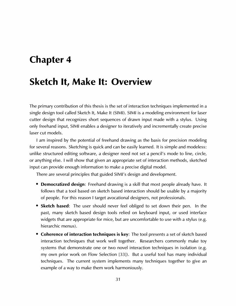
4.1 Declining Laser Cutter Prices . . . . . . . . . . . . . . . . . . . . . . . . . . 324.2 Picture Frame Stand . . . . . . . . . . . . . . . . . . . . . . . . . . . . . . . 334.3 Interaction Steps to Make A Picture Frame . . . . . . . . . . . . . . . . . . 344.4 SIMI Recognition Architecture . . . . . . . . . . . . . . . . . . . . . . . . . 384.5 Segment Types . . . . . . . . . . . . . . . . . . . . . . . . . . . . . . . . . 424.6 Constraint Solver Illustration . . . . . . . . . . . . . . . . . . . . . . . . . . 454.7 Constraint Solver Minimal vs. Full Randomness . . . . . . . . . . . . . . . . 47
5.1 Euclidean vs. Curvilinear Distance . . . . . . . . . . . . . . . . . . . . . . . 505.2 Curvature . . . . . . . . . . . . . . . . . . . . . . . . . . . . . . . . . . . . 505.3 Curvature Clusters and Corners . . . . . . . . . . . . . . . . . . . . . . . . 515.4 Blobs: Overlap vs. Gap . . . . . . . . . . . . . . . . . . . . . . . . . . . . . 545.5 Spline and Blob Control Points . . . . . . . . . . . . . . . . . . . . . . . . . 565.6 Erase Gesture . . . . . . . . . . . . . . . . . . . . . . . . . . . . . . . . . . 565.7 Flow Selection . . . . . . . . . . . . . . . . . . . . . . . . . . . . . . . . . . 60
xiii
5.8 Hook Removal . . . . . . . . . . . . . . . . . . . . . . . . . . . . . . . . . 615.9 Four Kinds of Latching . . . . . . . . . . . . . . . . . . . . . . . . . . . . . 625.10 Pan/Zoom Widget . . . . . . . . . . . . . . . . . . . . . . . . . . . . . . . . 645.11 Delayed Recognizer Example . . . . . . . . . . . . . . . . . . . . . . . . . . 665.12 Same Length Constraints . . . . . . . . . . . . . . . . . . . . . . . . . . . . 675.13 Same Angle . . . . . . . . . . . . . . . . . . . . . . . . . . . . . . . . . . . 685.14 Right Angle . . . . . . . . . . . . . . . . . . . . . . . . . . . . . . . . . . . 69
6.1 Workshop Survey Results . . . . . . . . . . . . . . . . . . . . . . . . . . . . 726.2 Laser-cut Table Sold on Ponoko . . . . . . . . . . . . . . . . . . . . . . . . 75
xiv
List of Tables
2.1 Sketch Recognition Topics . . . . . . . . . . . . . . . . . . . . . . . . . . . 162.2 Elements to Recognize . . . . . . . . . . . . . . . . . . . . . . . . . . . . . 19
4.1 Segment Types . . . . . . . . . . . . . . . . . . . . . . . . . . . . . . . . . 424.2 Constraint Types . . . . . . . . . . . . . . . . . . . . . . . . . . . . . . . . 43
5.1 Erase Gesture Parameters . . . . . . . . . . . . . . . . . . . . . . . . . . . 595.2 Latching Summary . . . . . . . . . . . . . . . . . . . . . . . . . . . . . . . 645.3 Right Angle Gesture Parameters . . . . . . . . . . . . . . . . . . . . . . . . 70
6.1 Task-Tool Protocol Analysis Categories . . . . . . . . . . . . . . . . . . . . 746.2 Action Frequency . . . . . . . . . . . . . . . . . . . . . . . . . . . . . . . . 74
xv

xvi
Chapter 1
Introduction
Nearly everything around us has been designed and built. With mass production, a singledesign can be replicated many times. This keeps prices low and quality consistent, but usersmust be content with what the designer and manufacturer have done.
But what if the user could indicate exactly what they want for the same price and quality?Machines like 3D printers, CNC mills, and laser cutters are beginning to give a glimpse ofwhat the future might hold. Today, a knowledgeable person can design and “print” partson rapid prototyping machines. If the designer wants to change something, they simplyprint a revision. While this is currently not as cost-effective as buying an “almost goodenough” mass-produced product, it does enable the user to directly engage with designingand making.
Rapid prototyping is a new technological phenomenon with economic and social con-sequences. The machinery that enables regular people to “print” objects at home wasunavailable ten years ago: either it was too expensive, or it had not yet been invented.
Current prototyping machinery is still too expensive for most people to buy for personaluse. But this will likely change in the coming years as more machines become available. Themarket for rapid fabrication machines is growing quickly: according to industry analysts,the market for laser cutters will exceed $3.8 billion by 2015, and the 3D printer market willreach $3.1 billion by 2016 [19, 77].
Today’s machines produce adequate (but not typically compelling) output. This is quicklychanging as price decreases while quality improves. We are witnessing the start of atechnology that enables new activities—some that we can predict, but others that we cannot yet clearly see. It is conceivable that we are witnessing the beginning of a shift from aneconomy entirely based on mass production to one that includes mass customization.
Rapid fabrication gives many people the ability to design and build things when therewas no opportunity before. In the mass production model, people are merely consumers.
1
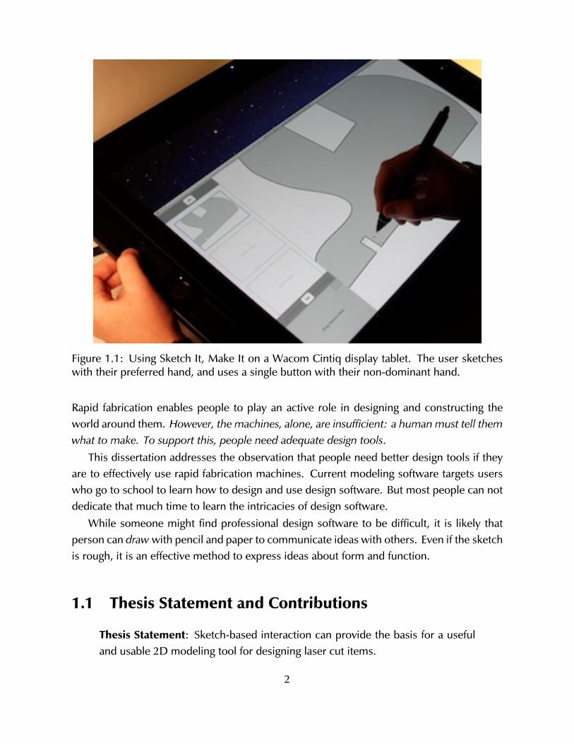
Figure 1.1: Using Sketch It, Make It on a Wacom Cintiq display tablet. The user sketcheswith their preferred hand, and uses a single button with their non-dominant hand.
Rapid fabrication enables people to play an active role in designing and constructing theworld around them. However, the machines, alone, are insufficient: a human must tell themwhat to make. To support this, people need adequate design tools.
This dissertation addresses the observation that people need better design tools if theyare to effectively use rapid fabrication machines. Current modeling software targets userswho go to school to learn how to design and use design software. But most people can notdedicate that much time to learn the intricacies of design software.
While someone might find professional design software to be difficult, it is likely thatperson can draw with pencil and paper to communicate ideas with others. Even if the sketchis rough, it is an effective method to express ideas about form and function.
1.1 Thesis Statement and Contributions
Thesis Statement: Sketch-based interaction can provide the basis for a usefuland usable 2D modeling tool for designing laser cut items.
2
Researchers have attempted to leverage sketching as a computational medium for atleast half a century. But we have not seen this effort move beyond academic laboratories. Acritical element missing from this body of work is the lack of a system of interaction designfor sketch-based tools.
I offer several Contributions to support my thesis. First, I present a coherent set ofsketch-based interaction techniques that enables users to make precise designs with astylus. Second, I develop several new interaction techniques including Flow Selection [33].Last, I offer a recognition and disambiguation architecture that supports fast and user-friendlyinteraction design.
These contributions are embodied in a useful and usable modeling tool called Sketch It,Make It (SIMI) that lets people design precise items for laser cutters.
1.2 Intended Audience
This work is aimed primarily at researchers interested in sketch-based modeling—particularlythose developing sketch recognizers or interactive sketch-based software systems. Thisincludes people working on topics traditionally found in computer science (e.g. artificialintelligence or computer graphics) as well the human-computer interaction and interactiondesign communities. Beyond motivating the work (sketch-based interaction) and domain(designing for laser cutters), a reader could implement any of the techniques describedherein. The target audience may be in academia, but it is hoped that commercial softwaretools can start to incorporate some of the novel interaction exemplified by SIMI.
Further, members of the physical hacking or tangible interaction worlds may be interestedin learning how their trade can benefit from improved design tools.
1.3 Motivation
This work is motivated by academic and practical perspectives. From an academic perspec-tive, I am motivated to find a way to bring greater coherence to the field of sketch-basedmodeling with a compelling example of a useful and usable sketching system that exhibitsa set of mutually harmonious interaction techniques. There are dozens of sketch-basedsystems that demonstrate recognition algorithms, corner-finding methods, and interactiontechniques, among other topics. But as I have said, sketch-based tools don’t exist outsideresearch labs. Because researchers rarely share, or have complete documentation or work-ing examples to use as a starting point, they must typically build their work from scratch.Consequently, researchers interested in one topic (e.g. making new interactive widgets for
3
sketching) must spend a substantial amount of time implementing functions that are nottheir research focus (e.g. ink parsing). Although it might occasionally be a useful learn-ing strategy to re-invent the wheel, I view the focus on side-topics as a largely needlessdistraction.
The practical motivation behind this work is the observation (shared by many people)that current computer-based design tools are hard to use, and that “natural” techniques likedrawing, speaking, and gesturing are potentially great methods to design with computers.It would be a wonderful turn of events if such a natural, easy-to-use tool were availableto designers. I believe one of the critical steps to making this a reality is to develop anappropriate system of interaction. For example, such a system to interact with (drive) acar involves foot pedals, a steering wheel, and dashboard indicators and knobs. It wouldbe inappropriate (and dangerous) to force automobile drivers to control their cars witha standard PC setup: keyboard and mouse, complete with software updates and dialogboxes. But this is the approach that many researchers take when developing sketch-baseddesign tools. It is convenient, but inappropriate. This dissertation offers an example of anappropriate interaction for sketch-based design tools.
1.4 Thesis Structure
This chapter introduced the domain of rapid fabrication and the culture of hacking andmaking that is associated with it. I discussed the field of sketch-based modeling andintroduced my tool, Sketch It, Make It (SIMI), a digital modeling tool for designing preciseitems for laser cutters. The following chapters are outlined as follows.
Chapter 2 covers background information about rapid fabrication and laser cutting, andprovides a brief survey of the literature on computational support for sketch-based modelingin design. Next, in Chapter 3 I describe formative investigations that informed developmentof my tool: observations and interviews with designers, and an analysis of some of theartifacts made with current design tools and laser cutters.
Two chapters are devoted to discussing SIMI. Chapter 4 introduces the tool and presentsusage scenarios: why and how somebody uses it. This is an overview of the system. Chapter5 details individual interaction techniques and other technical aspects to the system likelyto be useful to others.
Chapter 6 presents several evaluations of SIMI, including results of a quantitative eval-uation involving 60 undergraduate architecture students. Last, in Chapter 7, I discuss theimplications SIMI has on digital modeling tools and sketch-based design. I also describesome additional questions that warrant future work.
4
Chapter 2
Related Work
This chapter discusses design (focusing on rapid fabrication and laser cutting) and researchon physical and computationally-supported sketching.
2.1 Design for Rapid Fabrication
A growing community of self-described makers design and build many kinds of physicalthings [18]. Some are electronic or robotic gizmos, while others are made from traditionalcraft material. These “new makers” [25] are empowered by rapid fabrication machines like3D printers and laser cutters.
It is possible that we are beginning to see a shift from an economy based on mass-production (in factories) to one that includes mass-customization (in homes, schools, andcommunity centers) [75]. Rapid fabrication machines continue to decline in price whileimproving in quality. A new sector of businesses use rapid fabrication to cater to theneeds of hobbyist designers as well as people that need highly customized goods [58]. Forexample, companies such as Ponoko fabricate and send users physical output based ondigital models uploaded over the web.
Rapid prototyping machines are used in many domains: mechanical engineering, ar-chitecture, craft work, industrial design—just to name a few. While many users of thesemachines are professional, a growing population of Makers are not necessarily educated (ina traditional sense) to design and build things. Instead, members of this group might bebetter described as hobbyists or semi-professionals. They are smart and motivated, but donot necessarily have a great abundance of time or money.
5
2.1.1 Rapid Fabrication Machines
The software modeling tool discussed later in this thesis targets laser cutters, which are oneparticular type of rapid fabrication machine. I will first describe the broader area of rapidfabrication to situate the specific machine in question.
There are several related (but not necessarily interchangeable) names for machineryto in this space. Numerical Control (NC) machines were introduced in the 1950s thatran programs encoded on punched tape. Computer Numerical Control (CNC) introducesa computer, capable of performing conditional execution soon followed. Modern CNCmachines are found anywhere from large automobile factories (e.g. as sophisticated robots)to the home-brewed 3D printer set up in the hobbyist’s garage.
When applied to CNC machines, the terms “rapid fabrication” and “rapid prototyping”refer to their role in a design process. While industrial CNC robots are engaged in large-scaleproduction work, rapid fabrication machines are used primarily by designers to explore ideasand construction (preceding large-scale production, if it happens at all). Because of theirrole in the design process it is critical that these devices are faster and cheaper than usinghuman labor with manual machinery.
The type, quality, and composition of the output depends not only on the machine, butalso on the designer’s skill in creating suitable instructions. A CNC mill, for example, couldbe used to create a customized office desk. But in order to build the parts comprising thedesk, somebody must give the machine a digital model that indicates not only where themill will cut, but how the cut will be made.
A mill may operate with 3 or more axes: it can move on the x/y plane, and up and down(z-axis). Some models have additional axes that allow the tool head to move in other ways,such as rotation. The tool path is therefore an important consideration when designing formost types of computer controlled manufacturing machines. In many (but not all) cases,software tools can compute tool paths automatically. Designers must consider a machine’scapabilities.
Laser cutters can be thought of as a very fast, strong, and precise automated razor blade,cutting through flat material (paper, wood, plastic, metal, etc.) from directly above. Manyitems can be made entirely with a laser cutter, aside from the occasional screw or glue.
SIMI targets design for laser cutters. This tool was chosen for several reasons. First,problems related to tool paths are nearly non-existent. Second, a laser cutter executesquickly, which supports a faster loop of coding, testing, and debugging. Fabricating atoothbrush holder takes about five minutes on a typical laser cutter, but a 3D printer wouldtake four hours to make a similar object. Last, laser cutters are among the more popularrapid fabrication machines.
6
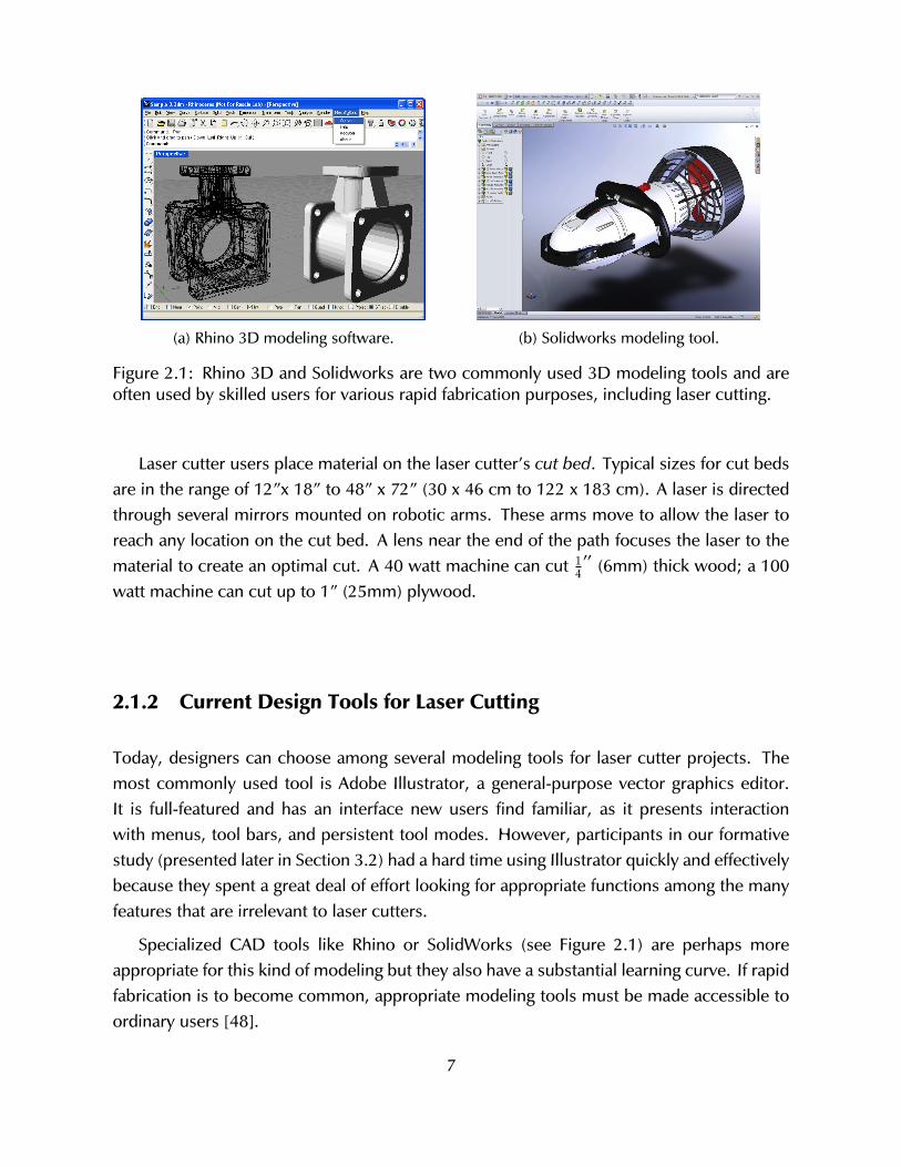
(a) Rhino 3D modeling software. (b) Solidworks modeling tool.
Figure 2.1: Rhino 3D and Solidworks are two commonly used 3D modeling tools and areoften used by skilled users for various rapid fabrication purposes, including laser cutting.
Laser cutter users place material on the laser cutter’s cut bed. Typical sizes for cut bedsare in the range of 12”x 18” to 48” x 72” (30 x 46 cm to 122 x 183 cm). A laser is directedthrough several mirrors mounted on robotic arms. These arms move to allow the laser toreach any location on the cut bed. A lens near the end of the path focuses the laser to thematerial to create an optimal cut. A 40 watt machine can cut 1
4′′ (6mm) thick wood; a 100
watt machine can cut up to 1” (25mm) plywood.
2.1.2 Current Design Tools for Laser Cutting
Today, designers can choose among several modeling tools for laser cutter projects. Themost commonly used tool is Adobe Illustrator, a general-purpose vector graphics editor.It is full-featured and has an interface new users find familiar, as it presents interactionwith menus, tool bars, and persistent tool modes. However, participants in our formativestudy (presented later in Section 3.2) had a hard time using Illustrator quickly and effectivelybecause they spent a great deal of effort looking for appropriate functions among the manyfeatures that are irrelevant to laser cutters.
Specialized CAD tools like Rhino or SolidWorks (see Figure 2.1) are perhaps moreappropriate for this kind of modeling but they also have a substantial learning curve. If rapidfabrication is to become common, appropriate modeling tools must be made accessible toordinary users [48].
7
2.2 Design Sketching
People commonly sketch when problem solving. Some sketches are personal, others collab-orative. Some help people make quick calculations and are quickly forgotten while othersserve longer-term purposes. For professional designers, sketching is a process to thinkabout problems. Just as importantly, a sketch (the result of the process) is a record thatcommunicates ideas [14].
Design can be seen as an iterative process of problem-framing and exploring possiblesolutions within the current conception of the problem. A sketch is not a contract: it is aproposal that can be modified, erased, built upon. The rough look of hand-made sketchessuggests their provisional nature.
Some theories of cognition give the human mind two distinct tasks: to perceive theworld via our senses, and to reason about what our senses provide. In contrast, the latepsychologist Rudolf Arnheim argues that perception and thinking are inseparable: “Unlessthe stuff of the senses remains present the mind has nothing to think with” [3]. Visualthinking is valuable in evaluating what is and designing what might be. Sketching allowspeople to give form to notions that are otherwise imaginary; the act of seeing fuels theprocess of reasoning.
Sketching plays a crucial role in the practice of design. It helps people think aboutproblems and offers an inexpensive but effective way to communicate ideas to others. Thepractice of sketching is nearly ubiquitous: One recent study of interaction designers andHCI practitioners found that 97% of those surveyed began projects by sketching [51]. Wemust understand the purpose and practice of sketching as it is done without computation ifwe hope to effectively support it with computation.
While designing, we iteratively explore and refine the problem definition and proposedsolutions. Sketching supports this creative search process. We set out on our designtask with some high-level goals. However, due to the ill-structured [70] and “wicked”nature of design [60], we encounter unforeseen opportunities and constraints as designingprogresses. Those opportunities and constraints may be implicit in the original problemdescription, but designers expose them as they explore. The discoveries are incorporatedinto the understanding of the problem and potential solutions. Design problems are “notthe sort of problems or puzzles that provide all the necessary and sufficient information fortheir solution [11].” So it goes with sketching. We draw different views of our model, whichallows us to perceive the problem in new ways.
Designers engage in a sort of “conversation” with their sketches in a tight cycle ofdrawing, understanding, and interpreting [67]. Goldschmidt describes this as switching
8
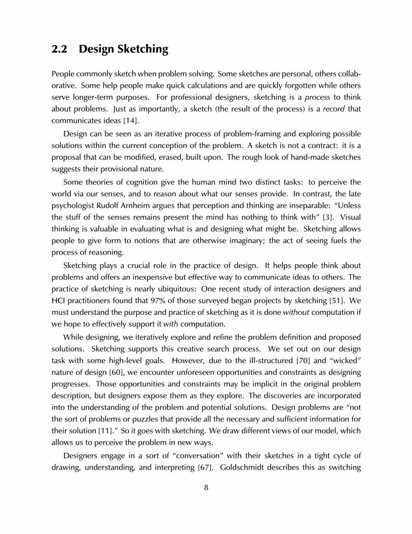
(a) Project management diagram showingtask precedence of two projects. Hastilydrawn boxes and arrows represent ab-stract activities.
(b) An architect’s floor plan sketch. It in-cludes text, spatial information, and sym-bols representing household items like apiano or dining table.
Figure 2.2: Sketches vary in domain and in the visual characteristics of marks.
between two reasoning modes: “seeing that” and “seeing as” [21]. Seeing that is the processof recognizing the literal, descriptive properties of the drawing. Seeing as is figurative andtransformative, allowing the designer to re-interpret parts of the sketch in different ways.Care must be taken to support this conversation when developing sketch-based modelingtools. If the system interprets drawings too aggressively or at the wrong time, it may preventthe human designer from seeing alternative meanings; recognize too little and the softwareis no better than paper.
2.2.1 Prototyping and Fidelity
Newman and Landay’s ethnographies of web designers focused on how designers useinformal techniques [53]. They found that designers always sketch at the beginning of aweb design project, exploring numerous high-level options. Frequently this early sketchingphase is accompanied with construction of low-fidelity prototypes made on paper or withsimple software tools like Microsoft PowerPoint. As the design progresses and designersincrementally add details, they move to higher fidelity models. Client meetings are animportant forcing function in web design projects. When meeting with clients, designerswant to show polished prototypes produced with computer software. Therefore designersused electronic tools earlier in the process than they would otherwise have preferred.
9
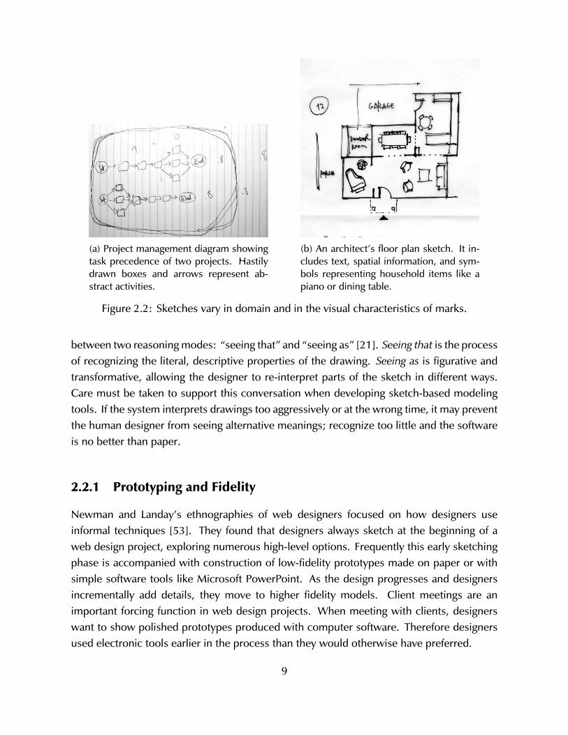
(a) Overloaded semantics:The cloud and tree have simi-lar shapes but different mean-ings due to context.
(b) Ambiguity: A small addi-tion changes our interpreta-tion. The object at left may bea cloud or a thought bubble.
(c) More information givesmore confidence about objectidentity. Text in the cloud in-dicates a thought bubble.
Figure 2.3: Overloaded semantics and ambiguity.
Today most software tools support incremental refinement and specification of detailsbut do not adequately support idea generation or exploration [73]. Designers who beginusing software tools in the early phases of design tend to make superficial explorations ofpossible solutions. Further, because tools are poor for exploration but good for specifyingdetails (font, line weight, and color), designers tend to focus on nuances that are not yetimportant. Observing that current tools are inadequate for creative pursuits, researchershave developed calligraphic tools such as SILK and DENIM, which aim to support the earlyphases of design [45, 46].
Paper sketches dominate the early phases of design as people generate new ideas, in aprocess Goel terms “lateral transformations” [20]. But as soon as the web designer believeshe or she will make incremental revisions (which Goel calls “vertical transformations”) theyswitch to a computer tool.
2.2.2 Sketches as a Symbol System
Goodman provides a comprehensive framework for analyzing the properties of varioussymbol systems, including sketches [22]. Goel places sketching in Goodman’s framework,noting that sketches have overloaded semantics, they are ambiguous, dense, and replete [20].These properties describe one particular sense of sketching in which the drawer’s marks maybe idiosyncratic. It is critical to understand these properties when developing sketch-baseddesign software.
Sketches have “overloaded semantics”: The same symbol may mean different thingsdepending on context. Further, a sketched symbol may be “ambiguous”, meaning thatthe symbol affords more than one plausible interpretation. Figure 2.3 illustrates these
10
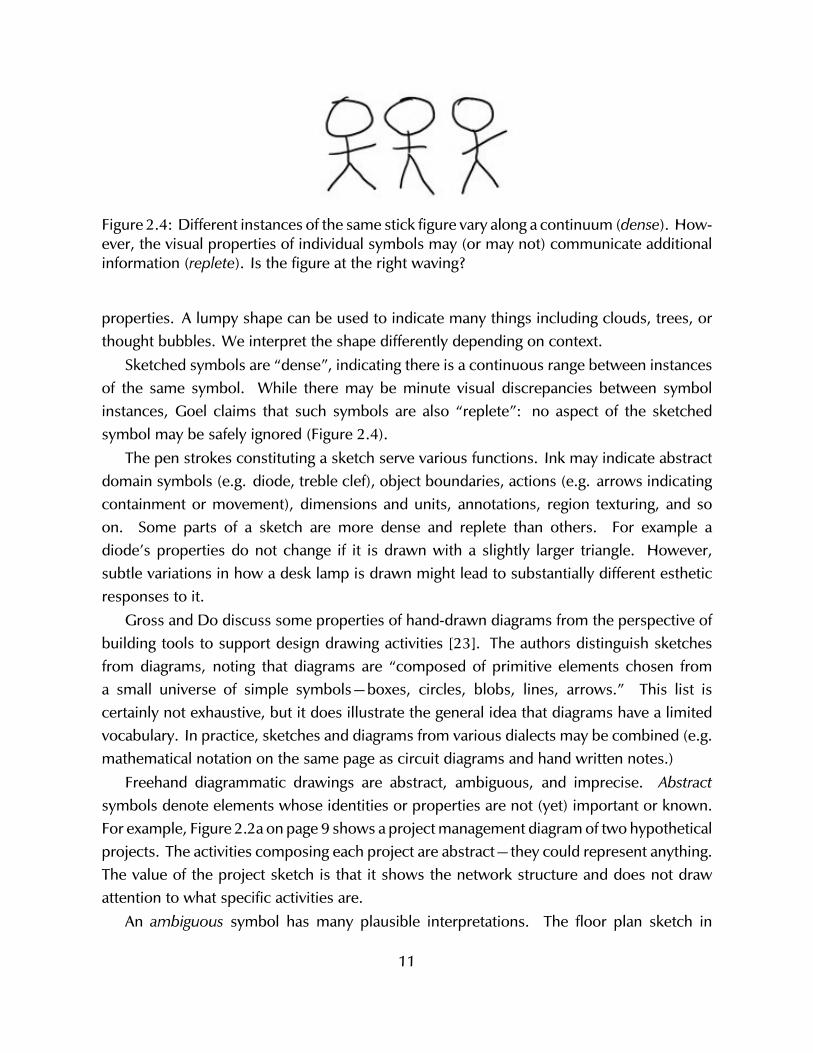
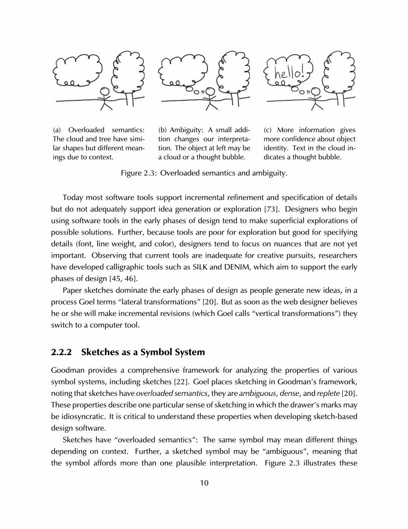
Figure 2.4: Different instances of the same stick figure vary along a continuum (dense). How-ever, the visual properties of individual symbols may (or may not) communicate additionalinformation (replete). Is the figure at the right waving?
properties. A lumpy shape can be used to indicate many things including clouds, trees, orthought bubbles. We interpret the shape differently depending on context.
Sketched symbols are “dense”, indicating there is a continuous range between instancesof the same symbol. While there may be minute visual discrepancies between symbolinstances, Goel claims that such symbols are also “replete”: no aspect of the sketchedsymbol may be safely ignored (Figure 2.4).
The pen strokes constituting a sketch serve various functions. Ink may indicate abstractdomain symbols (e.g. diode, treble clef), object boundaries, actions (e.g. arrows indicatingcontainment or movement), dimensions and units, annotations, region texturing, and soon. Some parts of a sketch are more dense and replete than others. For example adiode’s properties do not change if it is drawn with a slightly larger triangle. However,subtle variations in how a desk lamp is drawn might lead to substantially different estheticresponses to it.
Gross and Do discuss some properties of hand-drawn diagrams from the perspective ofbuilding tools to support design drawing activities [23]. The authors distinguish sketchesfrom diagrams, noting that diagrams are “composed of primitive elements chosen froma small universe of simple symbols—boxes, circles, blobs, lines, arrows.” This list iscertainly not exhaustive, but it does illustrate the general idea that diagrams have a limitedvocabulary. In practice, sketches and diagrams from various dialects may be combined (e.g.mathematical notation on the same page as circuit diagrams and hand written notes.)
Freehand diagrammatic drawings are abstract, ambiguous, and imprecise. Abstractsymbols denote elements whose identities or properties are not (yet) important or known.For example, Figure 2.2a on page 9 shows a project management diagram of two hypotheticalprojects. The activities composing each project are abstract—they could represent anything.The value of the project sketch is that it shows the network structure and does not drawattention to what specific activities are.
An ambiguous symbol has many plausible interpretations. The floor plan sketch in
11
Figure 2.2b shows several rectangles indicating rooms, furniture, shelves, or counters.Human observers can confidently disambiguate the intended meaning of some rectangles,but others remain unclear. The bottom-right of the sketch shows two armchairs and a sofawith an ambiguous rectangle in the middle that could plausibly represent either a rug or acoffee table.
Last, freehand diagrams are imprecise. Imprecision allows designers to work with roughvalues (e.g. “about two meters wide”) and avoid premature commitment. Imprecision alsoindicates that the design is by no means final.
The notational properties of sketches make them powerful tools for supporting visualthinking. Designers may leverage ambiguities in their sketches to see new meanings,for example. However, these same properties present challenges for accurate softwarerecognition.
The degree to which a drawing is ambiguous, imprecise, and abstract varies amonginstances, and people might interpret them differently. A rough sketch is useful to designers,especially for brainstorming and incremental development of ideas. But in order for thesketch to be transformed into a finished product (e.g. as a digital model supplied to a rapidmanufacturing device), it must be made unequivocal, precise, and concrete. The processof moving from the informal sketch to the formal specification involves drawings that aresemi-ambiguous, partially precise, and with some abstractions given definite identities.
2.2.3 Summary: Traditional Sketching and Computation
If we hope to effectively support sketching with computation, we must first understand thepractical aspects of traditional sketching.
Sketching is an important—perhaps necessary—tool for doing design. It gives a way toquickly make provisional drawings, which help us efficiently make sense of spatial, relationalinformation. Sketches let us make marks that are as vague or specific as needed. Becausesketched elements can be ambiguous, rough drawings have different interpretations. Wemay reflect on sketches to see new meaning in existing marks. People sketch in part becausethey don’t know exactly what they are making: sketching facilitates exploration.
Low-fidelity prototypes are especially important as tools to test ideas during early design.This is because they are easy to make, allowing designers to quickly expose problems beforecommitting to decisions. Sketching is a common method of creating such prototypes.
In order for computers to recognize sketches, we must develop techniques to transformimprecisely made marks into discrete symbols. However, some of the properties that makea sketch useful for a human (overloaded semantics, ambiguous, imprecise, etc.) complicatethe task of computer recognition.
12
2.3 Hardware: Tablets and Pens
Now that I’ve discussed the role of sketching in design, and some of the cognitive aspects offreehand drawing, I will now present topics involved in supporting sketching with computers.This section discusses hardware people might use to give input to a sketching system, andthe next enumerates software topics for processing it.
Researchers in sketch recognition and interaction typically use tablet devices such asa Wacom Bamboo or Cintiq. Some surfaces, like the Bamboo, simply sense stylus inputbut do not display feedback. These “blind” tablets require the user to look at one place(their computer display) but draw on another surface. This can lead to hand-eye coordinationtrouble. The Cintiq, and various Tablet PC computers, combine display and sensing surfaces.In this case, the user’s pen comes into contact with a drawing plane that is separated fromthe display plane by only a few millimeters. When the user views the display at an angle,this parallax difference can be annoying, but it is certainly better than the situation with blindtablets.
Input surfaces that are intended to be used with fingers or hands offer different interactionexperiences than pen-oriented drawing surfaces. For example, users may trace shapeswith a single finger, use two fingers to zoom in or out, or use whole-hand gestures forissuing other commands. These interaction techniques provide opportunities for developinginnovative sketching applications, as demonstrated by work by Hinckley et. al at MicrosoftResearch [30].
Regardless of sensing technology, these devices allow users to provide input in a waythat is much closer to handwriting and freehand sketching than a mouse allows. Althoughpen and mouse input share many properties (both allow users to interact with 2D displays)they have several key differences.
Mouse input affords motion sensing while pen input affords position sensing [29]. Inother words, while mice produce the relative change in (x, y) locations, pens directly provideabsolute (x, y) locations. Users can configure tablets to report relative position, therebybehaving like a mouse.
Form is also extremely important. A stylus affords people to use the fine motor abilitiesof their fingers to control the tip of the pen, whereas hand and forearm muscles dominatemouse usage. Fingers can be used to move the mouse, but not with the same dexteritypossible with a pen. Depending on the type of work, a pen may be ergonomically superiorto a mouse, or the other way around.
Some styluses have buttons. While buttons are an indispensable part of a mouse, theyare often difficult to use on the barrel of a pen [59]. The force of a mouse button click
13
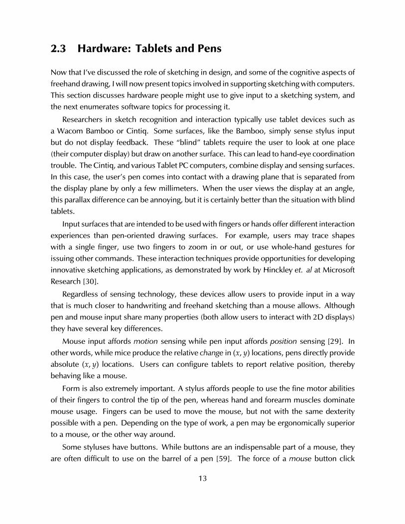
(a) Force vector for mouse buttonpress is perpendicular to the plane thedevice rests on. It will therefore notmove much.
(b) Pressing a stylus button is morelikely to cause unwanted pen tipmovement because it is at an acuteangle to the drawing surface plane.
Figure 2.5: The force required to press a mouse button compared with a stylus button.
is orthogonal to the device’s plane of use and has negligible effect on target accuracy.However, pressing buttons on a stylus can move the tip of the pen, making it difficult toaccurately press the button while pointing at particular objects (see Figure 2.5). Further,pressing a button on a computer stylus usually requires the user to adjust the pen in hand.This action may be distracting and uncomfortable for long term use.
2.4 Sketching Systems for Fabrication
Sketch It, Make It is a sketch-based tool for rapid fabrication. This section discusses similardesign tools that let people design objects for physical fabrication.
Makers of physical things sketch throughout their process. In the early phases, sketchingis used to explore ideas, develop concepts, and gradually give detail as the final productcomes into focus. Later, people annotate renderings and blueprints with freehand edits toindicate desired changes. An example of late-phase sketching is shown in Figure 2.6. Thereis a strong tradition in physical design domains to sketch throughout the process—fromconcept generation through fabrication.
Designers often create perspective drawings of 3D objects. This is a common activity onpaper, so it is an appealing activity to support. There are two primary approaches to sketching3D objects: either draw in perspective, or draw 2D planar diagrams that correspond to a3D product. Some researchers combine these approaches.
14
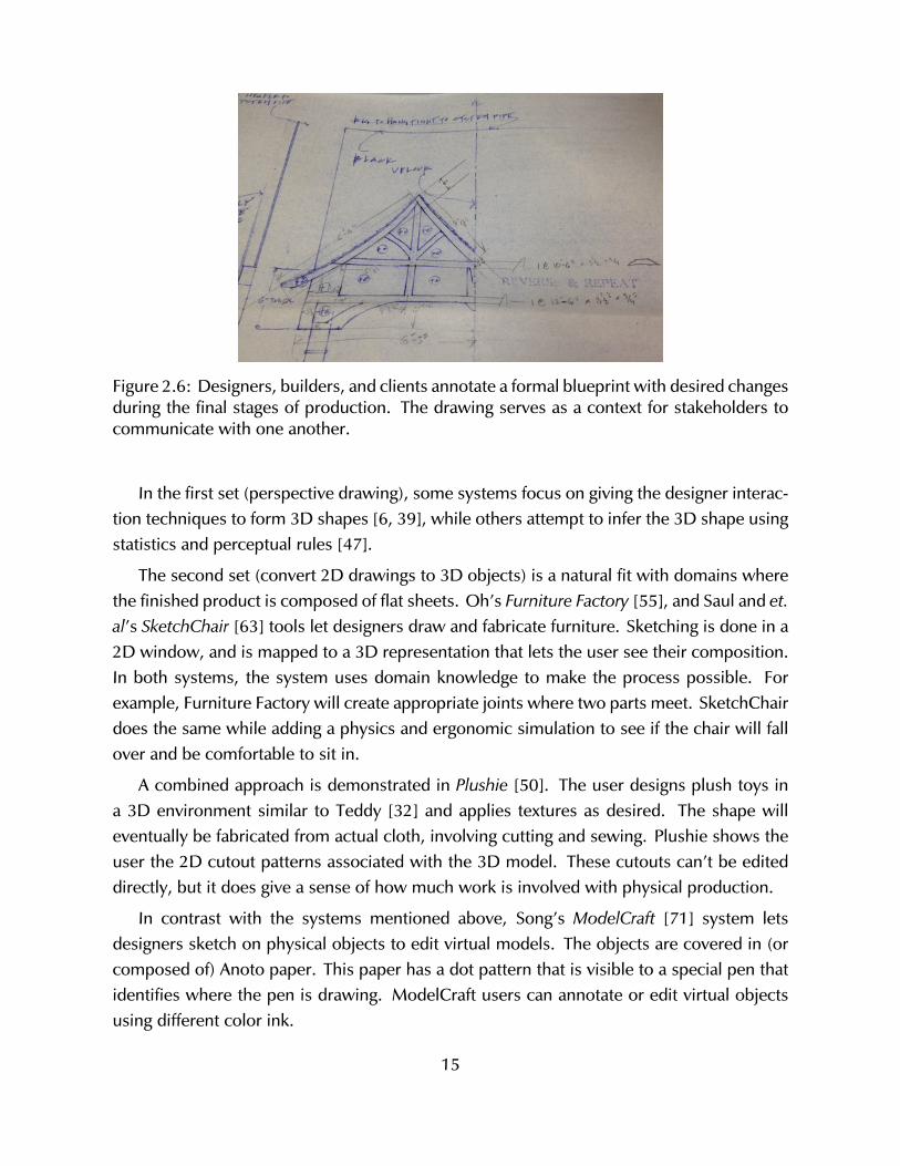
Figure 2.6: Designers, builders, and clients annotate a formal blueprint with desired changesduring the final stages of production. The drawing serves as a context for stakeholders tocommunicate with one another.
In the first set (perspective drawing), some systems focus on giving the designer interac-tion techniques to form 3D shapes [6, 39], while others attempt to infer the 3D shape usingstatistics and perceptual rules [47].
The second set (convert 2D drawings to 3D objects) is a natural fit with domains wherethe finished product is composed of flat sheets. Oh’s Furniture Factory [55], and Saul and et.al’s SketchChair [63] tools let designers draw and fabricate furniture. Sketching is done in a2D window, and is mapped to a 3D representation that lets the user see their composition.In both systems, the system uses domain knowledge to make the process possible. Forexample, Furniture Factory will create appropriate joints where two parts meet. SketchChairdoes the same while adding a physics and ergonomic simulation to see if the chair will fallover and be comfortable to sit in.
A combined approach is demonstrated in Plushie [50]. The user designs plush toys ina 3D environment similar to Teddy [32] and applies textures as desired. The shape willeventually be fabricated from actual cloth, involving cutting and sewing. Plushie shows theuser the 2D cutout patterns associated with the 3D model. These cutouts can’t be editeddirectly, but it does give a sense of how much work is involved with physical production.
In contrast with the systems mentioned above, Song’s ModelCraft [71] system letsdesigners sketch on physical objects to edit virtual models. The objects are covered in (orcomposed of) Anoto paper. This paper has a dot pattern that is visible to a special pen thatidentifies where the pen is drawing. ModelCraft users can annotate or edit virtual objectsusing different color ink.
15
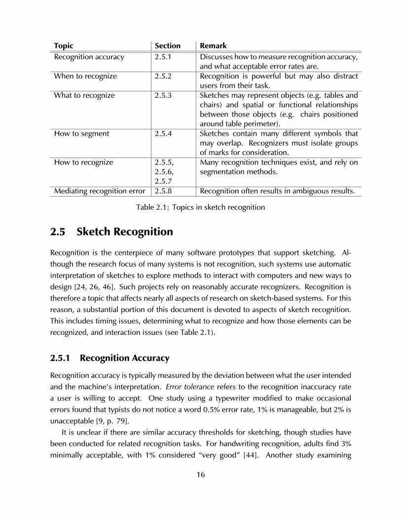
Topic Section RemarkRecognition accuracy 2.5.1 Discusses how to measure recognition accuracy,
and what acceptable error rates are.When to recognize 2.5.2 Recognition is powerful but may also distract
users from their task.What to recognize 2.5.3 Sketches may represent objects (e.g. tables and
chairs) and spatial or functional relationshipsbetween those objects (e.g. chairs positionedaround table perimeter).
How to segment 2.5.4 Sketches contain many different symbols thatmay overlap. Recognizers must isolate groupsof marks for consideration.
How to recognize 2.5.5,2.5.6,2.5.7
Many recognition techniques exist, and rely onsegmentation methods.
Mediating recognition error 2.5.8 Recognition often results in ambiguous results.
Table 2.1: Topics in sketch recognition
2.5 Sketch Recognition
Recognition is the centerpiece of many software prototypes that support sketching. Al-though the research focus of many systems is not recognition, such systems use automaticinterpretation of sketches to explore methods to interact with computers and new ways todesign [24, 26, 46]. Such projects rely on reasonably accurate recognizers. Recognition istherefore a topic that affects nearly all aspects of research on sketch-based systems. For thisreason, a substantial portion of this document is devoted to aspects of sketch recognition.This includes timing issues, determining what to recognize and how those elements can berecognized, and interaction issues (see Table 2.1).
2.5.1 Recognition Accuracy
Recognition accuracy is typically measured by the deviation between what the user intendedand the machine’s interpretation. Error tolerance refers to the recognition inaccuracy ratea user is willing to accept. One study using a typewriter modified to make occasionalerrors found that typists do not notice a word 0.5% error rate, 1% is manageable, but 2% isunacceptable [9, p. 79].
It is unclear if there are similar accuracy thresholds for sketching, though studies havebeen conducted for related recognition tasks. For handwriting recognition, adults find 3%minimally acceptable, with 1% considered “very good” [44]. Another study examining
16
user acceptance of hand gesture recognition error rates found users would tolerate mis-recognition up to 10% when equivalent keyboard commands could be employed [40].
This is a substantial spread in acceptable error tolerance rates: 1% for typewriters,3% for handwriting recognition, and 10% for hand gestures. One possible explanation isthat people have higher expectations for typewriters (where there is a direct, deterministicmapping between input and output) compared with recognition based interaction, becausewe understand that it is possible the system might not understand.
2.5.2 When to Invoke Recognition
It is important that sketching systems aid design exploration and not simply computerizeit [52]. For example, a sketch recognition system might zealously identify parts of the user’sdrawing as it is made, replacing the rough sketch with lines or curves. This removes theopportunity for reflection and re-interpretation that is so important to the early phases ofdesign [21, 66, 73]. Premature recognition may interrupt the designer’s flow of thought andinterfere with the task at hand. Instead we may want the computer to eavesdrop silently,and provide help only when we need it.
A system can provide the user feedback of sketch recognition on different occasions:(1) in mid-stroke, (2) immediately after the pen is lifted, (3) when the system infers thatfeedback may be appropriate, (4) only upon request, or (5) never. Many interfaces attemptimmediate recognition of gestures for invoking commands, such as with marking menus [42]or PDA device character input [56]. This is commonly called eager recognition [7]. Othersystems [2, 23, 31] perform recognition in the background, deferring judgment until ad-equate information is available. This is termed lazy recognition. Most modern researchprototypes take this approach. Last, some systems wait until the user explicitly requestsrecognition [45], or avoid recognition entirely [16]. Combinations of these approaches arecommon.
2.5.3 What Should be Recognized
Different kinds of design drawings (“model ink”) in many domains might be recognized:artistic sketches, study sketches, drawings, diagrams, schematics, blueprints, and so on. Inaddition to model ink comprising those drawing types, user input may be interpreted as acommand (“command ink”). The particular rules about what should be recognized dependson the domain (architecture or circuit design), kind of model (floor plan or timing diagram),and other application-specific requirements. Sketches often contain hand-written labels orannotations, which are common targets of pen based recognition.
17

Diagrams usually have a domain-specific grammar describing how vocabulary itemsrelate [43]. For example, boxes may connect to other boxes via lines, those lines may havearrowheads to indicate direction. Diagrams are good candidates for recognition becausethe various elements and their relations can be described formally. Table 2.2 summarizesvarious recognizable classes.
18

“Wha
t”to
reco
gniz
eEx
ampl
esRe
mar
kG
enre
Mat
hem
atic
algr
aph,
ar-
chite
ctur
alflo
orpl
an,
web
site
layo
ut,
circ
uit
desi
gn
Itm
aybe
suffi
cien
tto
reco
g-ni
zea
sket
chis
ofa
cert
ain
kind
with
out
aski
ngth
eus
er.
The
prog
ram
coul
das
sum
eth
esk
etch
isin
ace
rtai
ndo
mai
n.C
hara
cter
s(w
ritin
g)Al
phan
umer
ics,
mat
hsy
mbo
lsU
sual
lyw
ithot
her
char
acte
rs,
inw
ords
and
sent
ence
s.G
eom
etric
shap
esD
ots,
lines
,re
ctan
gles
,bl
obs
Geo
met
ricsh
apes
are
ofte
ndr
awn
inre
latio
nto
othe
rs.
Spat
ialf
eatu
res
Ais
cont
aine
din
,is
abov
e,is
larg
erth
anB
Spat
ial
rela
tions
amon
gel
e-m
ents
may
influ
ence
reco
gni-
tion.
Entit
ies
Dom
ain-
spec
ific
nota
tion
such
asdi
odes
,tr
ansi
s-to
rs
Con
text
ualc
lues
can
help
dis-
ambi
guat
ese
man
tics
ofdo
-m
ain
sym
bols
.Ar
tistic
nuan
ceSh
adow
s,te
xtur
es,c
olor
Ink
that
mod
ifies
anex
istin
gel
-em
ent,
perh
aps
sugg
estin
g3D
shap
e.C
omm
ands
Obj
ect
sele
ctio
n,de
lete
,co
py,m
ove,
etc.
Com
man
din
ksp
ecifi
esop
era-
tions
onth
edr
awin
g.In
tent
ion
Dra
win
g’sf
unct
ion
orbe
-ha
vior
,e.
g.circuit
breaker
Requ
ires
deta
iled
dom
ain
know
ledg
ean
dre
ason
ing.
Tabl
e2.
2:Ki
nds
ofel
emen
tsto
bere
cogn
ized
19
2.5.4 Segmentation and Grouping
Segmentation and Grouping are related processes of breaking down user input and findingrelated ink. Segmentation involves partitioning undifferentiated sketch input into parts(analogous to identifying word boundaries in speech recognition [9]). Grouping is theprocess of forming logical collections of data (analogous to determining which spokenwords compose a phrase or sentence).
It is sometimes appropriate to break apart continuous pen strokes into multiple segments,for example in recognizing letter boundaries in cursive writing, or finding corners in con-tinuous pen strokes. Alternately, it may be necessary to group related strokes to recognizecompound objects such as a triangle drawn with three distinct strokes. To further compli-cate matters, there may be a number of reasonable ways to segment user input [49], basedon information such as pen speed, stroke order, perceptual qualities, domain knowledge orcurvature [41].
The technical challenge is simplified if the system requires users to complete each symbolbefore moving on to another, or if each symbol must be drawn using a conventional strokeorder. However, such requirements work against the goal of supporting unconstrained,fluid sketching.
A common and effective method for segmenting ink incorporates time data. Sezgin’sapproach combines stylus velocity with curvature to identify locations of interest such ascorners, or places where the drawer may be taking extra care to be precise [12, 68]. Wolin’sMergeCF corner finder extends this approach by initially over-fitting the stroke with cornersand iteratively removing them to arrive at a better fit. SIMI’s ink processing algorithm isbased on these.
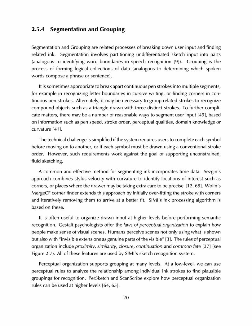
It is often useful to organize drawn input at higher levels before performing semanticrecognition. Gestalt psychologists offer the laws of perceptual organization to explain howpeople make sense of visual scenes. Humans perceive scenes not only using what is shownbut also with “invisible extensions as genuine parts of the visible” [3]. The rules of perceptualorganization include proximity, similarity, closure, continuation and common fate [37] (seeFigure 2.7). All of these features are used by SIMI’s sketch recognition system.
Perceptual organization supports grouping at many levels. At a low-level, we can useperceptual rules to analyze the relationship among individual ink strokes to find plausiblegroupings for recognition. PerSketch and ScanScribe explore how perceptual organizationrules can be used at higher levels [64, 65].
20
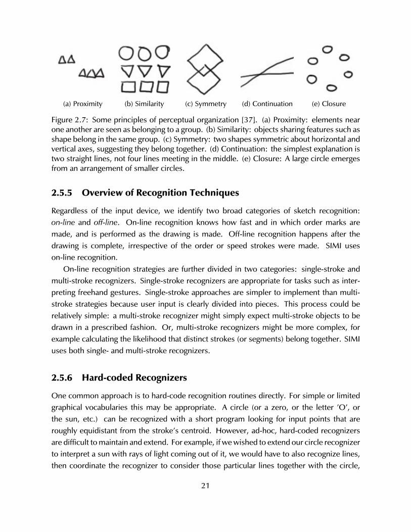
(a) Proximity (b) Similarity (c) Symmetry (d) Continuation (e) Closure
Figure 2.7: Some principles of perceptual organization [37]. (a) Proximity: elements nearone another are seen as belonging to a group. (b) Similarity: objects sharing features such asshape belong in the same group. (c) Symmetry: two shapes symmetric about horizontal andvertical axes, suggesting they belong together. (d) Continuation: the simplest explanation istwo straight lines, not four lines meeting in the middle. (e) Closure: A large circle emergesfrom an arrangement of smaller circles.
2.5.5 Overview of Recognition Techniques
Regardless of the input device, we identify two broad categories of sketch recognition:on-line and off-line. On-line recognition knows how fast and in which order marks aremade, and is performed as the drawing is made. Off-line recognition happens after thedrawing is complete, irrespective of the order or speed strokes were made. SIMI useson-line recognition.
On-line recognition strategies are further divided in two categories: single-stroke andmulti-stroke recognizers. Single-stroke recognizers are appropriate for tasks such as inter-preting freehand gestures. Single-stroke approaches are simpler to implement than multi-stroke strategies because user input is clearly divided into pieces. This process could berelatively simple: a multi-stroke recognizer might simply expect multi-stroke objects to bedrawn in a prescribed fashion. Or, multi-stroke recognizers might be more complex, forexample calculating the likelihood that distinct strokes (or segments) belong together. SIMIuses both single- and multi-stroke recognizers.
2.5.6 Hard-coded Recognizers
One common approach is to hard-code recognition routines directly. For simple or limitedgraphical vocabularies this may be appropriate. A circle (or a zero, or the letter ’O’, orthe sun, etc.) can be recognized with a short program looking for input points that areroughly equidistant from the stroke’s centroid. However, ad-hoc, hard-coded recognizersare difficult to maintain and extend. For example, if we wished to extend our circle recognizerto interpret a sun with rays of light coming out of it, we would have to also recognize lines,then coordinate the recognizer to consider those particular lines together with the circle,
21
and ensure that the lines are positioned and angled correctly. Further, sketch recognitionapplications must be able to discern different kinds of elements. Recognizers for theseelements may conflict. A new recognizer may cause an existing recognizer to stop workingcorrectly, leading to maintenance, debugging, and testing problems.
SIMI uses hard-coded recognizers in situations when performance is critical (e.g. erasingand undo/redo).
2.5.7 Pattern Matching
Another strategy for representing classes is to create a library of pattern templates. Theseapproaches can be separated into two groups: those that use visual templates, and thosethat use textual templates.
Template matching strategies are often feature-based. Features include properties suchas stroke length, stroke path, minimum or maximum angle, or aspect ratio. The systemholds a library of templates, each of which has feature values. The system computes featurevalues for user input, and compares those values with those contained in the library. SIMIuses textual templates, but not the visual kind.
Examples of the visual template method include the Ledeen recognizer [54], the Rubinerecognizer [61], Kara’s recognizer [38], and the $1 Recognizer [76].
Textual templates may be described using a programming language [5, 10, 27, 57]. Thesenotations have two primary strengths. First, humans can read (and edit) them. For example,a television symbol may be described with natural language as “a square with a slightlysmaller circle positioned at its center.” A formal symbolic language for that statement is stillquite legible (assuming one understands the function semantics):
(define television
(and (centered square circle)
(slightly-smaller circle square)))
Another strength of this kind of notation is that it allows the developer to describe entitiesat a level of abstraction that accommodates variability between entity instances. An abstracttriangle is a three-sided, two-dimensional shape whose internal angles add up to 180◦. Aparticular triangle may have side lengths of 3, 4, and 5, and be oriented so that its long edgeis horizontal. We may define triangles and other entities as abstractly or concretely as thelanguage allows.
Many of the recognizers in SIMI use textual templates roughly based on the approachesdescribed by Hammond [27] and Alvarado [1, Chapter 4].
22
2.5.8 Managing Ambiguity
Futrelle’s classification scheme of types of ambiguity in diagrams includes two high-levelcategories: lexical and structural ambiguity [17]. Lexical ambiguity refers to the “word”level, when the meaning of a particular symbol is in question. Structural ambiguity refers toconfusion arising from the composition of symbols.
Shilman augments this scheme with two additional types of ambiguity that arise insketch recognition: label and attribute ambiguity [69]. Label ambiguity is present when thesymbol’s identity is unclear. For example, a quickly drawn rectangle might be interpreted asa circle. Attribute ambiguity refers to the features of a sketched element: the exact locationof a quickly drawn rectangle’s corner may be unclear.
BURLAP [49] is a calligraphic application based on SILK [45] that enables people todraw user interfaces. As the user draws, BURLAP forms a list of plausible interpretations.At some point the system may need to pick one interpretation. Mankoff et. al call thisprocess mediation, performed by agents called mediators. Some mediators may engagethe user by displaying a pick-list of choices or visually indicating the ambiguity. Othermediators automatically execute and do not involve the user. SIMI uses this automatic wayto disambiguate contending interpretations.
Another way to manage ambiguity is to prevent it from arising in the first place. Somesketching systems let designers model 3D objects. Recognizing 3D topology from a 2Dsketch is difficult because of Z ambiguity: for any point on the (x, y) plane, there is aninfinite number of possible z values. In Kara’s automotive styling system [39], designers usespecific sketch-based interaction techniques to achieve unambiguous z values. By contrast,Lipson’s 3D modeling sketching tool [47] does not impose special techniques on the user,and instead attempts to derive z values by searching a space of possible interpretationsweighted by past observations of 3D-to-2D reverse projections.
The two 3D modeling systems described in the preceding paragraph use different ap-proaches to manage ambiguity: In Kara’s system, the approach is interaction design; inLipson’s, it is based on perception and statistics. Researchers have found success with bothapproaches. SIMI is entirely based on interaction design.
23

24
Chapter 3
Formative Studies
The previous chapter covered background literature and prior work by other researchers.This chapter presents original work studying design culture, specifically related to rapidfabrication with laser cutters.
This chapter presents three studies. First, I give observations of people working at aprofessional design studio. It gives a firsthand account of processes that real designersuse when practicing their craft. Second, to better understand the tasks and problemsdesigners face when designing for laser cutters, I conducted two related formative studies. Iinterviewed people with experience designing laser cut artifacts and watched them work. Inaddition, I surveyed and analyzed laser-cut items found on community web sites to identifycommon features.
3.1 Tiny Ethnography
I arranged to “be a fly on the wall” at a MAYA Design, well-respected design firm in thePittsburgh area. This was done to observe how designers work. I spent about twenty hoursat the company observing and interviewing designers who work there. This study wasinspired by Bucciarelli’s ethnographies of engineers [8]. While this work pre-dates my focuson design for laser cutters, it does provide a solid connection between my narrow topic andthe broader context of design practice.
A professional studio is notably different from an educational design studio. For example,companies face many issues that are not generally present in an academic institution. Theseinclude billable hours, interacting with paying customers, significant differences in age andexperience level of collaborators, and so on.
This company’s culture places high value on collaborative whiteboard sessions. At anytime, the majority of the whiteboard surfaces throughout the office have some sort of
25
scribbling on them. Most whiteboard sessions were by two or more people gathered inconversation. The scribbles served to represent objects that are sometimes labeled withmarkers, but usually just described verbally. In this way, collaborative whiteboard drawingsare multi-modal design artifacts, because part of their value is static (the sketch), whileanother part is transient (the conversation) [35]. Whiteboard sessions are consistent withFerguson’s talking sketches [14].
Four of the five designers I interviewed showed me their paper sketches. About halfof these drawings were made when the designer was alone (Ferguson’s thinking sketch),and the rest resulted from collaborative sessions like the whiteboard events describedabove. Some paper sketches were diagrammatic (using formal or semi-formal notation),while others were renderings of some physical object like a building or electronic gadget.Interestingly, those same designers were less inclined to show computational models (likeIllustrator files) because they felt the sketches contained the “real” work.
While designers typically did not volunteer to show computational artifacts, they wereinclined to show me printed versions of their computational models. Nearly all of theseprinted pages were annotated with handwriting and sketches, sometimes by more than oneperson. They use a process of iterating between virtual and paper representations of theirwork. The designers would edit a computational model with a high-functionality applicationsuch as Photoshop, then print a paper copy for personal or group use. Then they woulddraw or write directly on that page as they explored variations or made refinements. If apaper-based editing session was useful, the designers would then manually transfer thesechanges back into their application. The process of printing, editing, and manually mergingchanges was common. This pattern recurs in the following section on laser cutter users.
3.2 Interviews
Six designers were interviewed from different backgrounds, including mechanical engineer-ing, graphic design, and architecture. This was done to learn about their work practices andto understand how they use their tools. All had experience designing objects to be madewith a laser cutter.
Each session lasted approximately one hour, split evenly between an interview andusing software. Meetings took place in participant workplaces, where they were asked todescribe their design process and to show sketches, demonstrations, or videos of their work.Although there were differences in their process, each followed the same overall pattern.
The designers all said they began by thinking about a problem and sketching on paper.They made drawings to think about how to “frame” the project (what it is for). Other
26
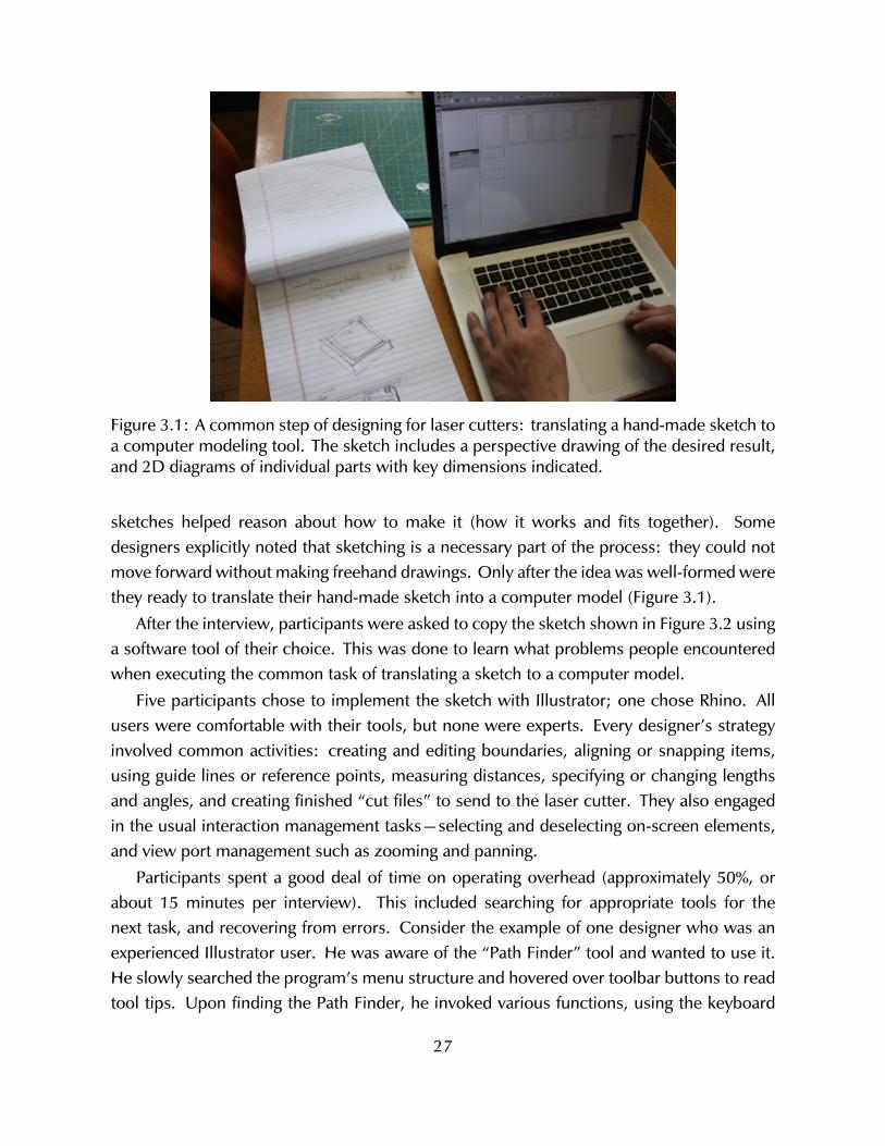
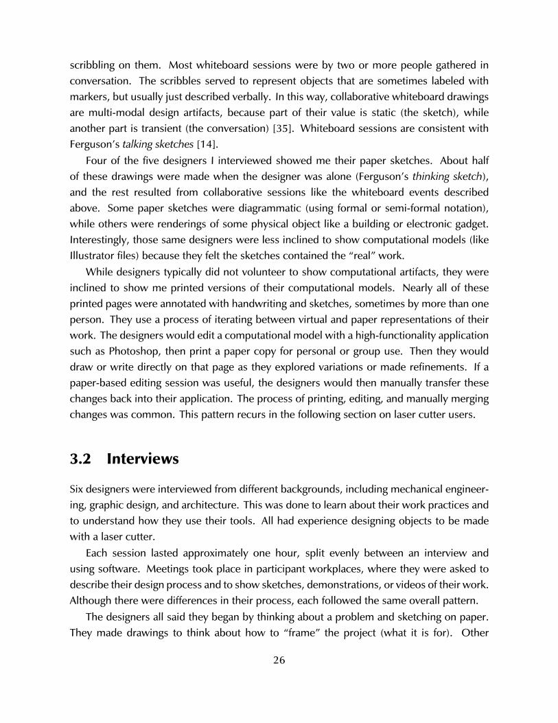
Figure 3.1: A common step of designing for laser cutters: translating a hand-made sketch toa computer modeling tool. The sketch includes a perspective drawing of the desired result,and 2D diagrams of individual parts with key dimensions indicated.
sketches helped reason about how to make it (how it works and fits together). Somedesigners explicitly noted that sketching is a necessary part of the process: they could notmove forward without making freehand drawings. Only after the idea was well-formed werethey ready to translate their hand-made sketch into a computer model (Figure 3.1).
After the interview, participants were asked to copy the sketch shown in Figure 3.2 usinga software tool of their choice. This was done to learn what problems people encounteredwhen executing the common task of translating a sketch to a computer model.
Five participants chose to implement the sketch with Illustrator; one chose Rhino. Allusers were comfortable with their tools, but none were experts. Every designer’s strategyinvolved common activities: creating and editing boundaries, aligning or snapping items,using guide lines or reference points, measuring distances, specifying or changing lengthsand angles, and creating finished “cut files” to send to the laser cutter. They also engagedin the usual interaction management tasks—selecting and deselecting on-screen elements,and view port management such as zooming and panning.
Participants spent a good deal of time on operating overhead (approximately 50%, orabout 15 minutes per interview). This included searching for appropriate tools for thenext task, and recovering from errors. Consider the example of one designer who was anexperienced Illustrator user. He was aware of the “Path Finder” tool and wanted to use it.He slowly searched the program’s menu structure and hovered over toolbar buttons to readtool tips. Upon finding the Path Finder, he invoked various functions, using the keyboard
27
(a) Users tried to replicate this sketched part.
(b) Drawing of the part in context.
Figure 3.2: Participants were asked to model this using software of their choice.
shortcut (Control-Z) to undo after each failed attempt, as he searched for the correct modewithin the subcommand palette. This process lasted approximately 80 seconds.
Occasionally participants used features in unorthodox ways. For example, to removean unwanted segment of a polyline, one participant (a graphic designer) created an opaquewhite rectangle to obscure it, rather than erase it. (“Don’t tell anyone I did this”, he said).
Similar episodes are common: a person should know the ‘correct’ action, but takes analternate approach. Although the alternative achieves the intended effect, it might be lessefficient (more operations, longer execution time) or introduce unwanted complexity (e.g.the white rectangle).
28
SymmetryRepeating geometry
Right angleFinger Joints
Rounded Corners
Notch JointsSingle FlatFasteners
Raster Etch
85%
80%
72%
45%
43%
32%
25%
18%
15%
Splines 36%
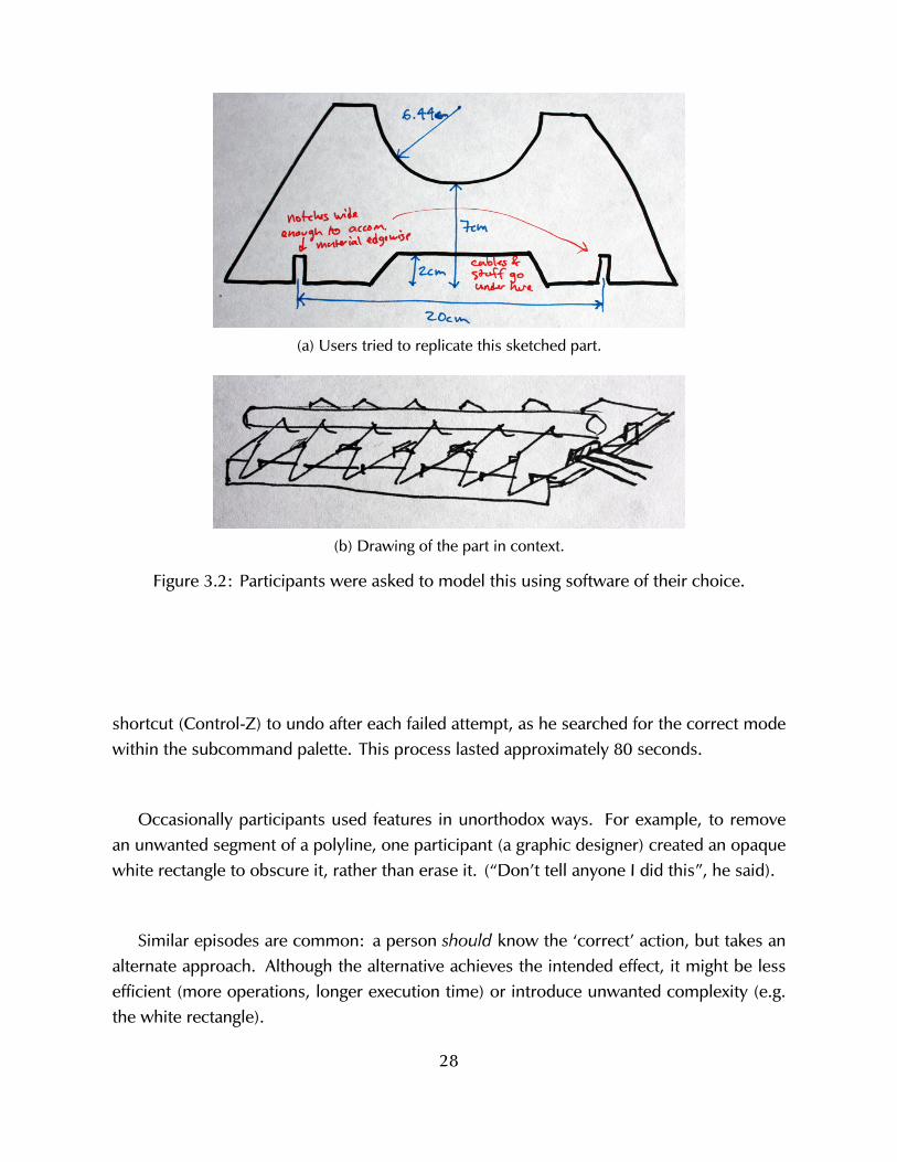
Figure 3.3: Frequency of features of 55 laser-cut designs found on Ponoko and Thingiverse.
In short, most common tasks and problems belong to three main groups:
• Defining geometry: Creating/editing boundaries, aligning items, creating and usingguide lines or reference points, measuring distances, and specifying lengths or angles.
• Managing the editing tool: Selecting/deselecting objects, view port management, find-ing and entering tool modes, and recovering from errors.
• Cut file: Finalizing the cut file by creating copies of items when more than one isneeded, and positioning stencils.
3.3 Artifact Analysis
The formative study of work practices from the previous section helps us understand howpeople create laser cut items. To learn more about the characteristics of those objects (whatpeople create), I analyzed finished items from two web-based communities of laser cutterusers.
Many users are motivated by the opportunity to share their work with others. Ponokoand Thingiverse are two currently popular web sites for selling or sharing items that canbe made with rapid fabrication machines. In early 2012, Ponoko offers thousands of user-designed items for sale, mostly produced by laser cutting. Thingiverse is a warehouse ofdigital models of 3D-printable objects and designs for laser cutters. From these two sitesI selected a total of 55 laser-cut designs. On Ponoko, the most recent 45 laser cut itemswere chosen. On Thingiverse, ten objects with the “laser cutter” were selected. Figure 3.3summarizes the feature analysis of these 55 projects.
Each project was characterized using ten properties, based on my own experience de-
29
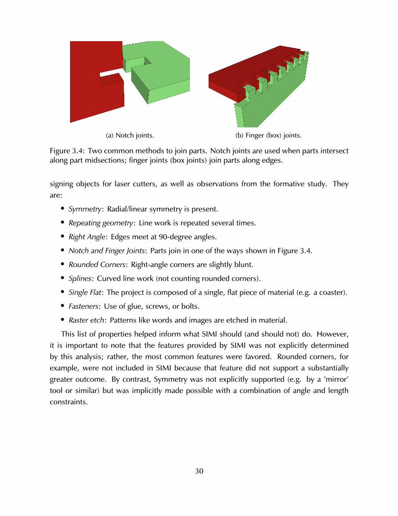
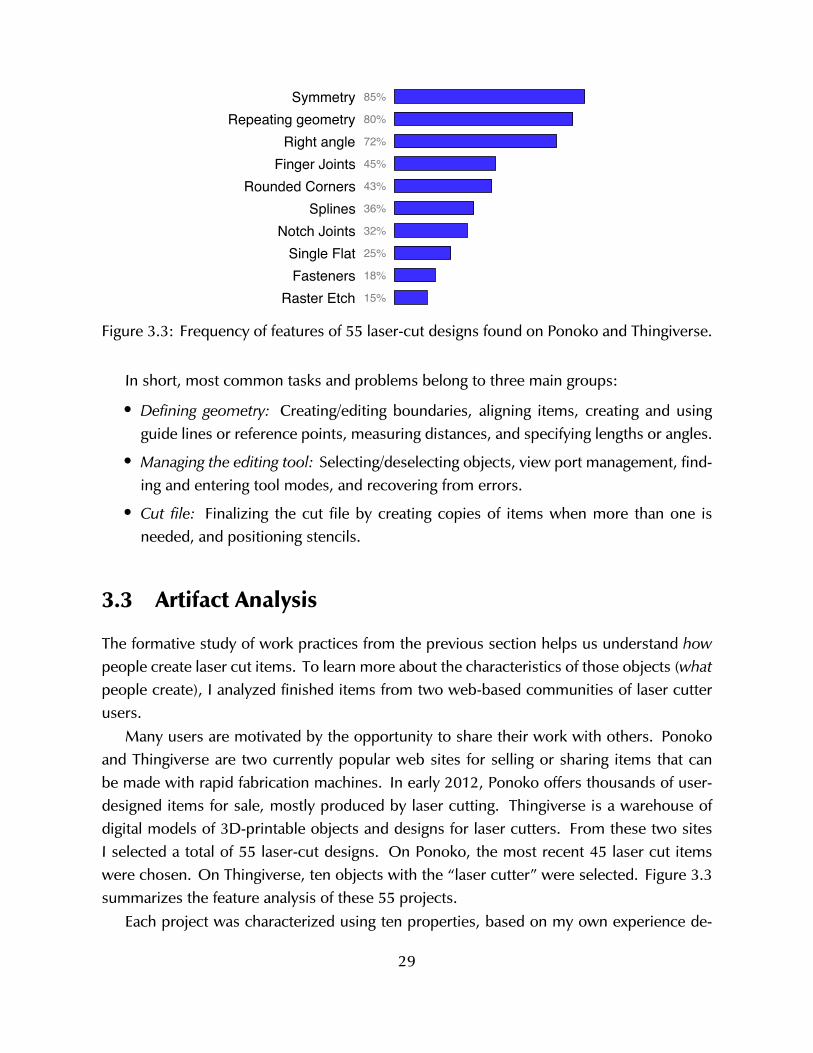
(a) Notch joints. (b) Finger (box) joints.
Figure 3.4: Two common methods to join parts. Notch joints are used when parts intersectalong part midsections; finger joints (box joints) join parts along edges.
signing objects for laser cutters, as well as observations from the formative study. Theyare:
• Symmetry: Radial/linear symmetry is present.
• Repeating geometry: Line work is repeated several times.
• Right Angle: Edges meet at 90-degree angles.
• Notch and Finger Joints: Parts join in one of the ways shown in Figure 3.4.
• Rounded Corners: Right-angle corners are slightly blunt.
• Splines: Curved line work (not counting rounded corners).
• Single Flat: The project is composed of a single, flat piece of material (e.g. a coaster).
• Fasteners: Use of glue, screws, or bolts.
• Raster etch: Patterns like words and images are etched in material.
This list of properties helped inform what SIMI should (and should not) do. However,it is important to note that the features provided by SIMI was not explicitly determinedby this analysis; rather, the most common features were favored. Rounded corners, forexample, were not included in SIMI because that feature did not support a substantiallygreater outcome. By contrast, Symmetry was not explicitly supported (e.g. by a ’mirror’tool or similar) but was implicitly made possible with a combination of angle and lengthconstraints.
30
Chapter 4
Sketch It, Make It: Overview
The primary contribution of this thesis is the set of interaction techniques implemented in asingle design tool called Sketch It, Make It (SIMI). SIMI is a modeling environment for lasercutter design that recognizes short sequences of drawn input made with a stylus. Usingonly freehand input, SIMI enables a designer to iteratively and incrementally create preciselaser cut models.
I am inspired by the potential of freehand drawing as the basis for precision modelingfor several reasons. Sketching is quick and can be easily learned. It is simple and modeless:unlike structured editing software, a designer need not set a pencil’s mode to line, circle,or anything else. I will show that given an appropriate set of interaction methods, sketchedinput can provide enough information to make a precise digital model.
There are several principles that guided SIMI’s design and development.
• Democratized design: Freehand drawing is a skill that most people already have. Itfollows that a tool based on sketch based interaction should be usable by a majorityof people. For this reason I target avocational designers, not professionals.
• Sketch based: The user should never feel obliged to set down their pen. In thepast, many sketch based design tools relied on keyboard input, or used interfacewidgets that are appropriate for mice, but are uncomfortable to use with a stylus (e.g.hierarchic menus).
• Coherence of interaction techniques is key: The tool presents a set of sketch basedinteraction techniques that work well together. Researchers commonly make toysystems that demonstrate one or two novel interaction techniques in isolation (e.g.my own prior work on Flow Selection [33]). But a useful tool has many individualtechniques. The current system implements many techniques together to give anexample of a way to make them work harmoniously.
31
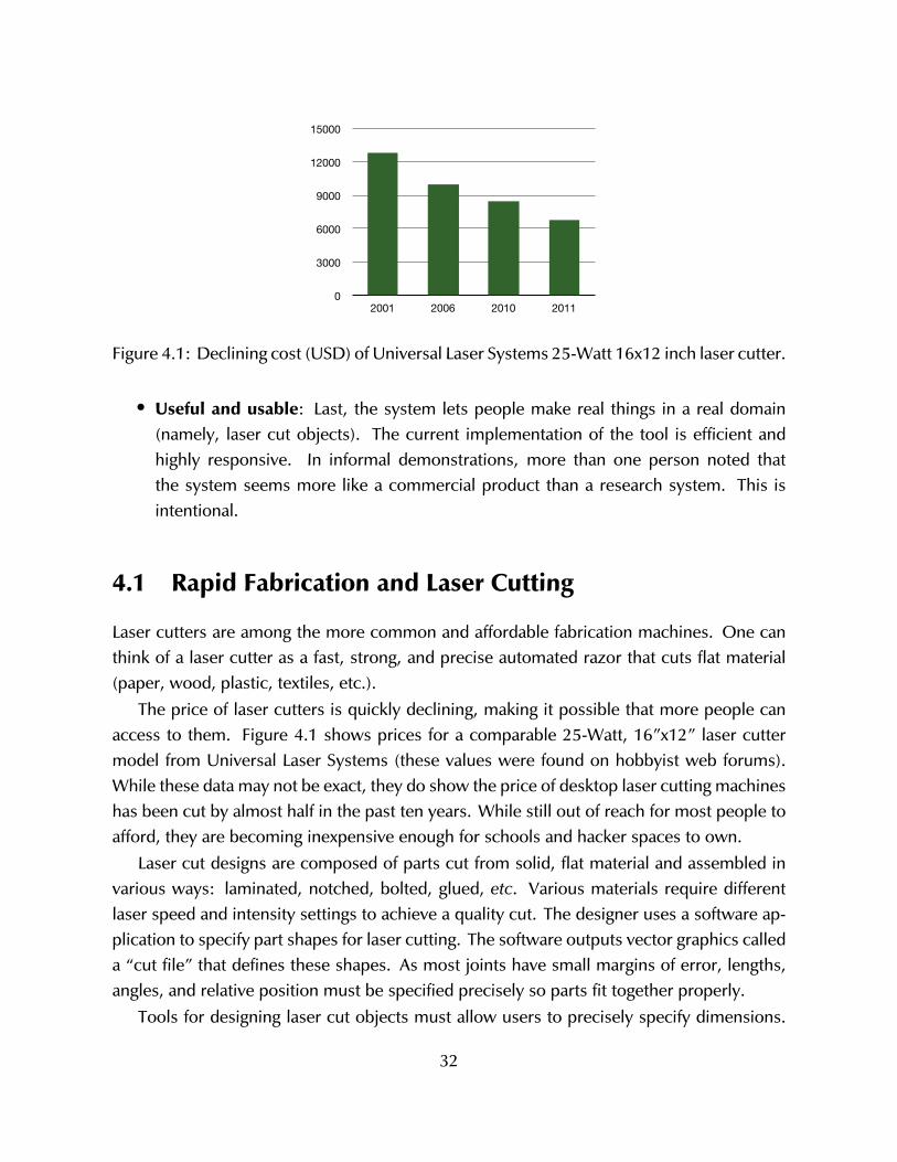
0
3000
6000
9000
12000
15000
2001 2006 2010 2011
Figure 4.1: Declining cost (USD) of Universal Laser Systems 25-Watt 16x12 inch laser cutter.
• Useful and usable: Last, the system lets people make real things in a real domain(namely, laser cut objects). The current implementation of the tool is efficient andhighly responsive. In informal demonstrations, more than one person noted thatthe system seems more like a commercial product than a research system. This isintentional.
4.1 Rapid Fabrication and Laser Cutting
Laser cutters are among the more common and affordable fabrication machines. One canthink of a laser cutter as a fast, strong, and precise automated razor that cuts flat material(paper, wood, plastic, textiles, etc.).
The price of laser cutters is quickly declining, making it possible that more people canaccess to them. Figure 4.1 shows prices for a comparable 25-Watt, 16”x12” laser cuttermodel from Universal Laser Systems (these values were found on hobbyist web forums).While these data may not be exact, they do show the price of desktop laser cutting machineshas been cut by almost half in the past ten years. While still out of reach for most people toafford, they are becoming inexpensive enough for schools and hacker spaces to own.
Laser cut designs are composed of parts cut from solid, flat material and assembled invarious ways: laminated, notched, bolted, glued, etc. Various materials require differentlaser speed and intensity settings to achieve a quality cut. The designer uses a software ap-plication to specify part shapes for laser cutting. The software outputs vector graphics calleda “cut file” that defines these shapes. As most joints have small margins of error, lengths,angles, and relative position must be specified precisely so parts fit together properly.
Tools for designing laser cut objects must allow users to precisely specify dimensions.
32
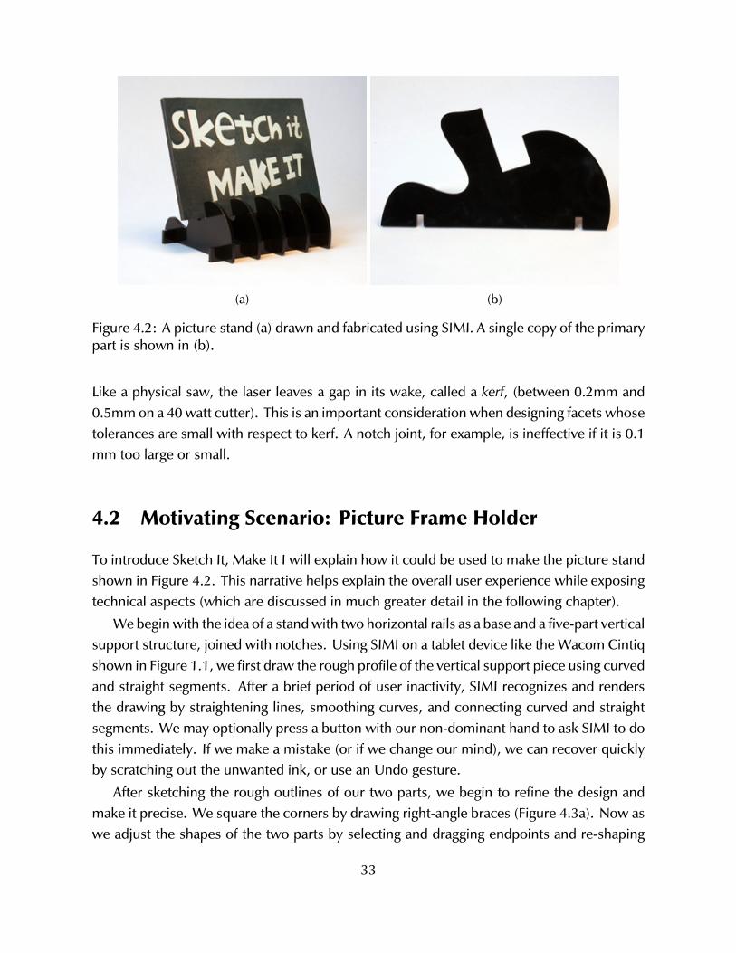
(a) (b)
Figure 4.2: A picture stand (a) drawn and fabricated using SIMI. A single copy of the primarypart is shown in (b).
Like a physical saw, the laser leaves a gap in its wake, called a kerf, (between 0.2mm and0.5mm on a 40 watt cutter). This is an important consideration when designing facets whosetolerances are small with respect to kerf. A notch joint, for example, is ineffective if it is 0.1mm too large or small.
4.2 Motivating Scenario: Picture Frame Holder
To introduce Sketch It, Make It I will explain how it could be used to make the picture standshown in Figure 4.2. This narrative helps explain the overall user experience while exposingtechnical aspects (which are discussed in much greater detail in the following chapter).
We begin with the idea of a stand with two horizontal rails as a base and a five-part verticalsupport structure, joined with notches. Using SIMI on a tablet device like the Wacom Cintiqshown in Figure 1.1, we first draw the rough profile of the vertical support piece using curvedand straight segments. After a brief period of user inactivity, SIMI recognizes and rendersthe drawing by straightening lines, smoothing curves, and connecting curved and straightsegments. We may optionally press a button with our non-dominant hand to ask SIMI to dothis immediately. If we make a mistake (or if we change our mind), we can recover quicklyby scratching out the unwanted ink, or use an Undo gesture.
After sketching the rough outlines of our two parts, we begin to refine the design andmake it precise. We square the corners by drawing right-angle braces (Figure 4.3a). Now aswe adjust the shapes of the two parts by selecting and dragging endpoints and re-shaping
33
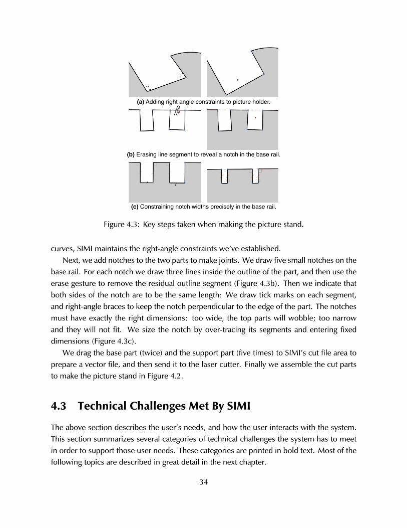
(a) Adding right angle constraints to picture holder.
(b) Erasing line segment to reveal a notch in the base rail.
(c) Constraining notch widths precisely in the base rail.
Figure 4.3: Key steps taken when making the picture stand.
curves, SIMI maintains the right-angle constraints we’ve established.Next, we add notches to the two parts to make joints. We draw five small notches on the
base rail. For each notch we draw three lines inside the outline of the part, and then use theerase gesture to remove the residual outline segment (Figure 4.3b). Then we indicate thatboth sides of the notch are to be the same length: We draw tick marks on each segment,and right-angle braces to keep the notch perpendicular to the edge of the part. The notchesmust have exactly the right dimensions: too wide, the top parts will wobble; too narrowand they will not fit. We size the notch by over-tracing its segments and entering fixeddimensions (Figure 4.3c).
We drag the base part (twice) and the support part (five times) to SIMI’s cut file area toprepare a vector file, and then send it to the laser cutter. Finally we assemble the cut partsto make the picture stand in Figure 4.2.
4.3 Technical Challenges Met By SIMI
The above section describes the user’s needs, and how the user interacts with the system.This section summarizes several categories of technical challenges the system has to meetin order to support those user needs. These categories are printed in bold text. Most of thefollowing topics are described in great detail in the next chapter.
34
A fundamental task is ink parsing. While the pen is down, the system looks for gesturessuch as erasing. When the user lifts the pen, the ink is parsed to identify corners andsegments, and other recognizable elements.
SIMI must be able to dependably recognize user input, which often depends on theink parsing just mentioned. Input is often made quickly and inaccurately, so occasionalrecognition errors can not be avoided. There are several kinds of recognized elements.Input might be line work that specifies the model’s geometry. Or, input might be identifiedas a gesture that edits the model by removing ink or adding constraints. Last, input mightbe as part of a multi-stroke phrase that controls the modeling environment (e.g. undo/redo,zooming, or panning).
There is one recognizer per recognizable pattern. Each recognizer has access to themodel state, but they do not communicate directly with each other. Inevitably more thanone recognizer will signal a positive result, so it is necessary for SIMI to disambiguate(or resolve) contending recognition results. For example, the user may draw two shortstrokes that are recognized as both a right angle symbol and a same-length gesture. Toresolve this ambiguity, SIMI uses a series of tests that involve context (e.g. if the input iscorrectly positioned in a corner or not) as well as static precedence rules that defer to theinterpretation that causes the least trouble in the event it is wrong.
The user’s work is stored as a data model consisting of points, segments (e.g. line, arc),and high-level constraints (e.g. right angle, same length). SIMI lets the user edit the model tocreate, merge, or erase these elements. The constraint engine is closely associated with thedata model. It lets the designer indicate geometric rules that the system will try to maintain,even as the user edits the model. SIMI’s constraint engine is an iterative, numerical solverusing a relaxation method in the tradition of Sketchpad [72].
When it is time for the user’s work to be given to a laser cutter, the designer asks SIMIto generate a cut file. This is a 2D vector graphics file specifying geometry of cutouts. Thecurrent implementation is a rather simplistic “typewriter” algorithm—it uses the boundingbox of each cutout, placing one next to the other from left to right, and moving to the next“line” when placing a piece would extend beyond the material bounds.
4.4 Coherent Sketch Based Interaction
Sketch It, Make It presents a fluid interface for making laser cut parts. The smooth interactionis made possible by combining many sketch-based techniques into a set of interactionmethods that work very well together. The fluidity is not the result of any one technique,nor is it simply the result of throwing several existing methods together.
35
The interaction techniques offered by SIMI were carefully tuned to work with one another.Each gesture is as distinct from the others as possible. The distinction is either syntactic(e.g. a circle is distinct from two short lines) or contextual (e.g. a large circle around aclosed shape is distinct from a small circle around loose segment endpoints.) This does notcompletely avoid recognition error but it does mitigate it because the gestures are not oftenconfused with one another.
SIMI gives visual feedback when appropriate which helps to resolve possible conflicts.For example, a selected point is rendered as a colored dot, and changes the cursor to a handsymbol to indicate the can move the point by dragging. Without visual feedback that thepoint is selected, or that the pen is near enough, it was easy to inadvertently draw line workwhen the user intends to move the point.
The interaction techniques have conservative failure states. The automatic latching algo-rithm is a good example. The auto-latcher has parameters describing the maximum distancebetween points and relative segment angles. These parameters were set to err on the sideof not latching segments together, because the consequences of latching inappropriately areworse than not latching when the user wanted. To recover from a missed automatic latchopportunity, SIMI provides a very simple latching gesture.
SIMI’s interaction differs from standard design tools and other sketch based modelingprototypes in several ways. Some of these differences are discussed in the sections below.
4.4.1 “The Mode Problem”
A traditional design tool like Adobe Illustrator is built around the concept of input modessuch as select, draw line, or fill color. Users activate modes by selecting a menu option,clicking an on-screen widget, or pressing a keyboard button. The program interprets userinput in terms of the active tool. Sometimes users are unaware of which mode the programis in, or are unsure how to change to the desired mode. Managing modes often introducescognitive load by forcing users to think about the tool rather than their work. This is called“the mode problem” [74].
SIMI lacks persistent mode. The user can always draw on any part of the drawing canvas,and the input’s meaning is determined via recognition: an input stroke might be an erasurescribble or a right angle symbol or a straight line that completes a shape. There is no ‘erasemode’, no ‘right angle mode’, and no ’draw line mode’. Some operations, such as flowselection, include transient mode changes where the meaning of user input is interpreteddifferently based on recent interaction. For this reason it is not strictly correct to label SIMI’sinteraction as modeless.
36
4.4.2 Conversational Interface
One property that characterizes sketch based systems is when recognition is performed (seeSection 2.5.2). Many sketch based design tools operate in batch mode, where a substantialamount of raw ink (e.g. dozens of strokes, or more) is analyzed at the same time. Therationale for this approach is that recognizers have more data (unrecognized ink) to workwith and can use statistical methods to generate the most likely interpretations for the entiresketch. The larger the sample, the more statistical confidence the recognizer can have.
SIMI takes a different approach involving short sequences of input followed by recogni-tion that fix the meaning of input by graphically representing results. Because the meaningof on-screen elements are known, the next round of recognition can use that knowledge toprovide unambiguous contextual clues. As the user and system take turns on such a regularbasis, I call this a conversational interface. The user and the system constantly check eachother’s states to ensure that meaning is shared.
4.5 Recognition Architecture
SIMI’s recognizers operate at three different times. First, Dynamic recognizers (like Erase)operate while the pen is down. A second class of recognizers are invoked when the pen islifted. If there are positive results from these PenUp recognizers, action is taken immediately.An example of this kind is latching. The third kind of recognizer is triggered after a periodof inactivity (currently 1.5 seconds). The user may optionally press a button with their non-dominant hand to recognize input as needed. The recognizers include those that establishconstraints like right angles, or create line work like circles and splines. This last type iscalled Deferred because it does not happen immediately after the pen lifts.
Each recognizer class addresses a different need. Dynamic recognizers allow the userto make gestures that must be recognized (and possibly acted upon) as they are made,when timing is very important. Pen Up recognizers allow the user to make distinct gesturesthat are acted on immediately, eliminating lag and making the interface seem much moreresponsive. The Pen Up recognizers are reserved for common actions that are unlikely tointerrupt the user when their associated actions are taken. By their nature, both Dynamicand Pen Up recognizers must work on single stroke gestures. Last, Deferred recognizersoperate on one or more strokes. Their related actions might distract the user if they wereinvoked immediately upon lifting the stylus. The overall recognition architecture is illustratedin Figure 4.4.
37
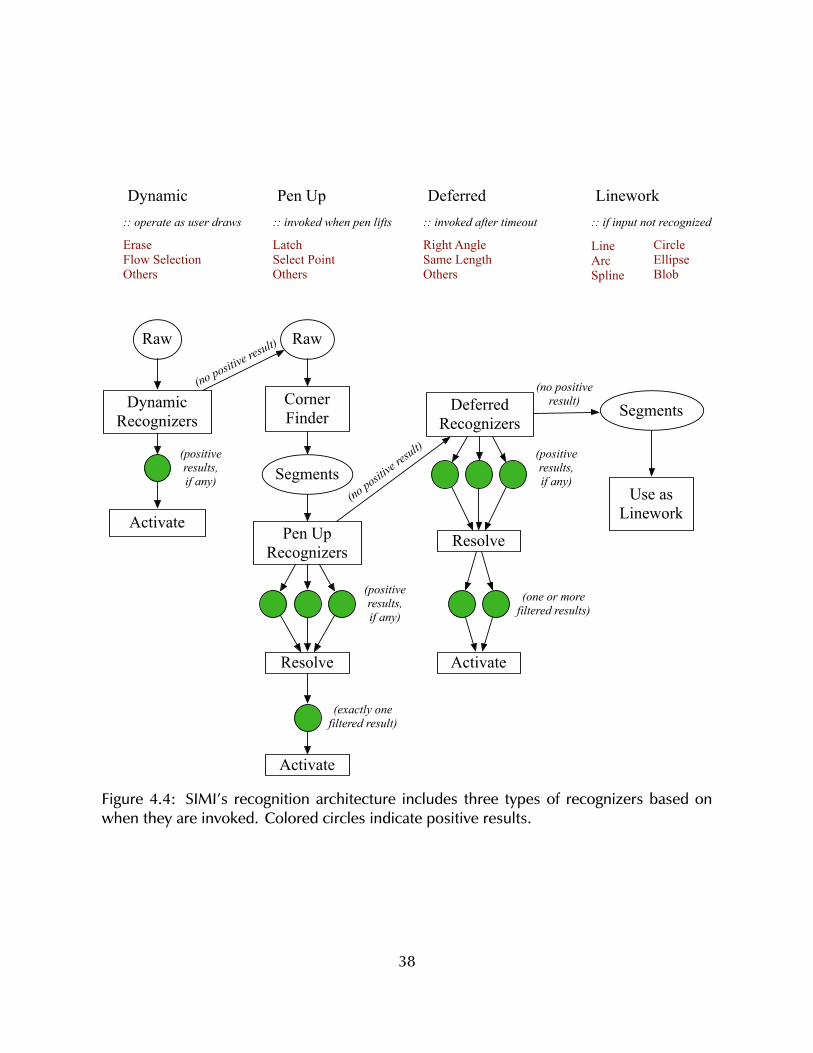
Raw
Dynamic Recognizers
Raw
Corner Finder
Pen Up Recognizers
Segments
Resolve
Activate
Deferred Recognizers
Resolve
Activate
Segments
Use as LineworkActivate
Dynamic
Erase Flow SelectionOthers
:: operate as user draws
Pen Up
LatchSelect PointOthers
:: invoked when pen lifts
Deferred
Right AngleSame LengthOthers
:: invoked after timeout
Linework
LineArcSpline
CircleEllipseBlob
:: if input not recognized
(positive results,if any)
(positive results,if any)
(positive results,if any)
(exactly onefiltered result)
(one or morefiltered results)
(no positive
result)
(no positive result)
(no positive result)
Figure 4.4: SIMI’s recognition architecture includes three types of recognizers based onwhen they are invoked. Colored circles indicate positive results.
38
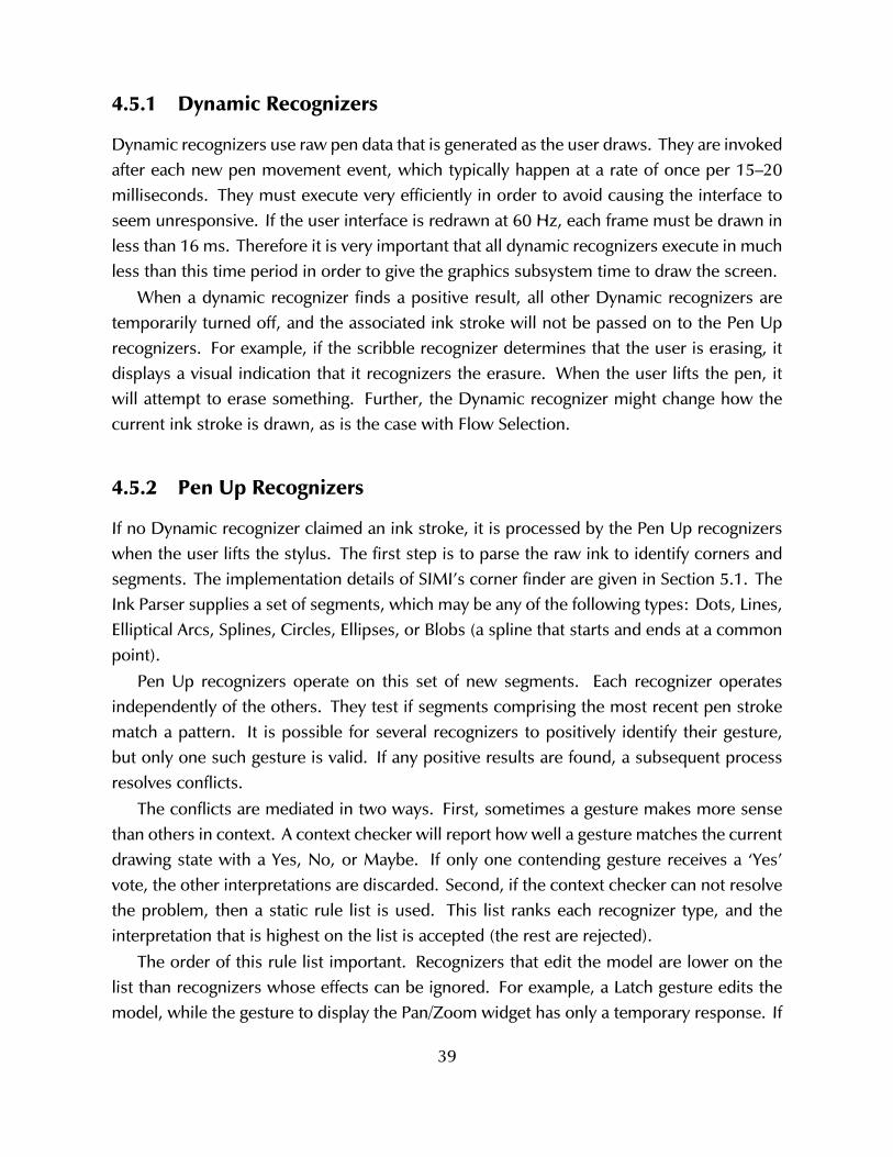
4.5.1 Dynamic Recognizers
Dynamic recognizers use raw pen data that is generated as the user draws. They are invokedafter each new pen movement event, which typically happen at a rate of once per 15–20milliseconds. They must execute very efficiently in order to avoid causing the interface toseem unresponsive. If the user interface is redrawn at 60 Hz, each frame must be drawn inless than 16 ms. Therefore it is very important that all dynamic recognizers execute in muchless than this time period in order to give the graphics subsystem time to draw the screen.
When a dynamic recognizer finds a positive result, all other Dynamic recognizers aretemporarily turned off, and the associated ink stroke will not be passed on to the Pen Uprecognizers. For example, if the scribble recognizer determines that the user is erasing, itdisplays a visual indication that it recognizers the erasure. When the user lifts the pen, itwill attempt to erase something. Further, the Dynamic recognizer might change how thecurrent ink stroke is drawn, as is the case with Flow Selection.
4.5.2 Pen Up Recognizers
If no Dynamic recognizer claimed an ink stroke, it is processed by the Pen Up recognizerswhen the user lifts the stylus. The first step is to parse the raw ink to identify corners andsegments. The implementation details of SIMI’s corner finder are given in Section 5.1. TheInk Parser supplies a set of segments, which may be any of the following types: Dots, Lines,Elliptical Arcs, Splines, Circles, Ellipses, or Blobs (a spline that starts and ends at a commonpoint).
Pen Up recognizers operate on this set of new segments. Each recognizer operatesindependently of the others. They test if segments comprising the most recent pen strokematch a pattern. It is possible for several recognizers to positively identify their gesture,but only one such gesture is valid. If any positive results are found, a subsequent processresolves conflicts.
The conflicts are mediated in two ways. First, sometimes a gesture makes more sensethan others in context. A context checker will report how well a gesture matches the currentdrawing state with a Yes, No, or Maybe. If only one contending gesture receives a ‘Yes’vote, the other interpretations are discarded. Second, if the context checker can not resolvethe problem, then a static rule list is used. This list ranks each recognizer type, and theinterpretation that is highest on the list is accepted (the rest are rejected).
The order of this rule list important. Recognizers that edit the model are lower on thelist than recognizers whose effects can be ignored. For example, a Latch gesture edits themodel, while the gesture to display the Pan/Zoom widget has only a temporary response. If
39
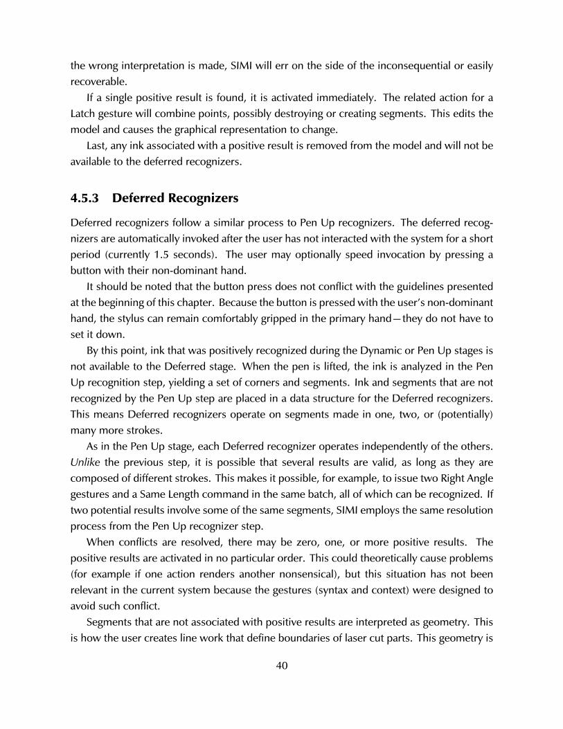
the wrong interpretation is made, SIMI will err on the side of the inconsequential or easilyrecoverable.
If a single positive result is found, it is activated immediately. The related action for aLatch gesture will combine points, possibly destroying or creating segments. This edits themodel and causes the graphical representation to change.
Last, any ink associated with a positive result is removed from the model and will not beavailable to the deferred recognizers.
4.5.3 Deferred Recognizers
Deferred recognizers follow a similar process to Pen Up recognizers. The deferred recog-nizers are automatically invoked after the user has not interacted with the system for a shortperiod (currently 1.5 seconds). The user may optionally speed invocation by pressing abutton with their non-dominant hand.
It should be noted that the button press does not conflict with the guidelines presentedat the beginning of this chapter. Because the button is pressed with the user’s non-dominanthand, the stylus can remain comfortably gripped in the primary hand—they do not have toset it down.
By this point, ink that was positively recognized during the Dynamic or Pen Up stages isnot available to the Deferred stage. When the pen is lifted, the ink is analyzed in the PenUp recognition step, yielding a set of corners and segments. Ink and segments that are notrecognized by the Pen Up step are placed in a data structure for the Deferred recognizers.This means Deferred recognizers operate on segments made in one, two, or (potentially)many more strokes.
As in the Pen Up stage, each Deferred recognizer operates independently of the others.Unlike the previous step, it is possible that several results are valid, as long as they arecomposed of different strokes. This makes it possible, for example, to issue two Right Anglegestures and a Same Length command in the same batch, all of which can be recognized. Iftwo potential results involve some of the same segments, SIMI employs the same resolutionprocess from the Pen Up recognizer step.
When conflicts are resolved, there may be zero, one, or more positive results. Thepositive results are activated in no particular order. This could theoretically cause problems(for example if one action renders another nonsensical), but this situation has not beenrelevant in the current system because the gestures (syntax and context) were designed toavoid such conflict.
Segments that are not associated with positive results are interpreted as geometry. Thisis how the user creates line work that define boundaries of laser cut parts. This geometry is
40
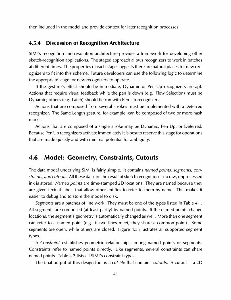
then included in the model and provide context for later recognition processes.
4.5.4 Discussion of Recognition Architecture
SIMI’s recognition and resolution architecture provides a framework for developing othersketch-recognition applications. The staged approach allows recognizers to work in batchesat different times. The properties of each stage suggests there are natural places for new rec-ognizers to fit into this scheme. Future developers can use the following logic to determinethe appropriate stage for new recognizers to operate.
If the gesture’s effect should be immediate, Dynamic or Pen Up recognizers are apt.Actions that require visual feedback while the pen is down (e.g. Flow Selection) must beDynamic; others (e.g. Latch) should be run with Pen Up recognizers.
Actions that are composed from several strokes must be implemented with a Deferredrecognizer. The Same Length gesture, for example, can be composed of two or more hashmarks.
Actions that are composed of a single stroke may be Dynamic, Pen Up, or Deferred.Because Pen Up recognizers activate immediately it is best to reserve this stage for operationsthat are made quickly and with minimal potential for ambiguity.
4.6 Model: Geometry, Constraints, Cutouts
The data model underlying SIMI is fairly simple. It contains named points, segments, con-straints, and cutouts. All these data are the result of sketch recognition—no raw, unprocessedink is stored. Named points are time-stamped 2D locations. They are named because theyare given textual labels that allow other entities to refer to them by name. This makes iteasier to debug and to store the model to disk.
Segments are a patches of line work. They must be one of the types listed in Table 4.1.All segments are composed (at least partly) by named points. If the named points changelocations, the segment’s geometry is automatically changed as well. More than one segmentcan refer to a named point (e.g. if two lines meet, they share a common point). Somesegments are open, while others are closed. Figure 4.5 illustrates all supported segmenttypes.
A Constraint establishes geometric relationships among named points or segments.Constraints refer to named points directly. Like segments, several constraints can sharenamed points. Table 4.2 lists all SIMI’s constraint types.
The final output of this design tool is a cut file that contains cutouts. A cutout is a 2D
41
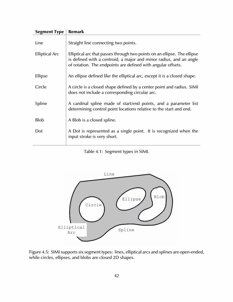
Segment Type Remark
Line Straight line connecting two points.
Elliptical Arc Elliptical arc that passes through two points on an ellipse. The ellipseis defined with a centroid, a major and minor radius, and an angleof rotation. The endpoints are defined with angular offsets.
Ellipse An ellipse defined like the elliptical arc, except it is a closed shape.
Circle A circle is a closed shape defined by a center point and radius. SIMIdoes not include a corresponding circular arc.
Spline A cardinal spline made of start/end points, and a parameter listdetermining control point locations relative to the start and end.
Blob A Blob is a closed spline.
Dot A Dot is represented as a single point. It is recognized when theinput stroke is very short.
Table 4.1: Segment types in SIMI.
Line
EllipticalArc Spline
CircleEllipse Blob
Figure 4.5: SIMI supports six segment types: lines, elliptical arcs and splines are open-ended,while circles, ellipses, and blobs are closed 2D shapes.
42
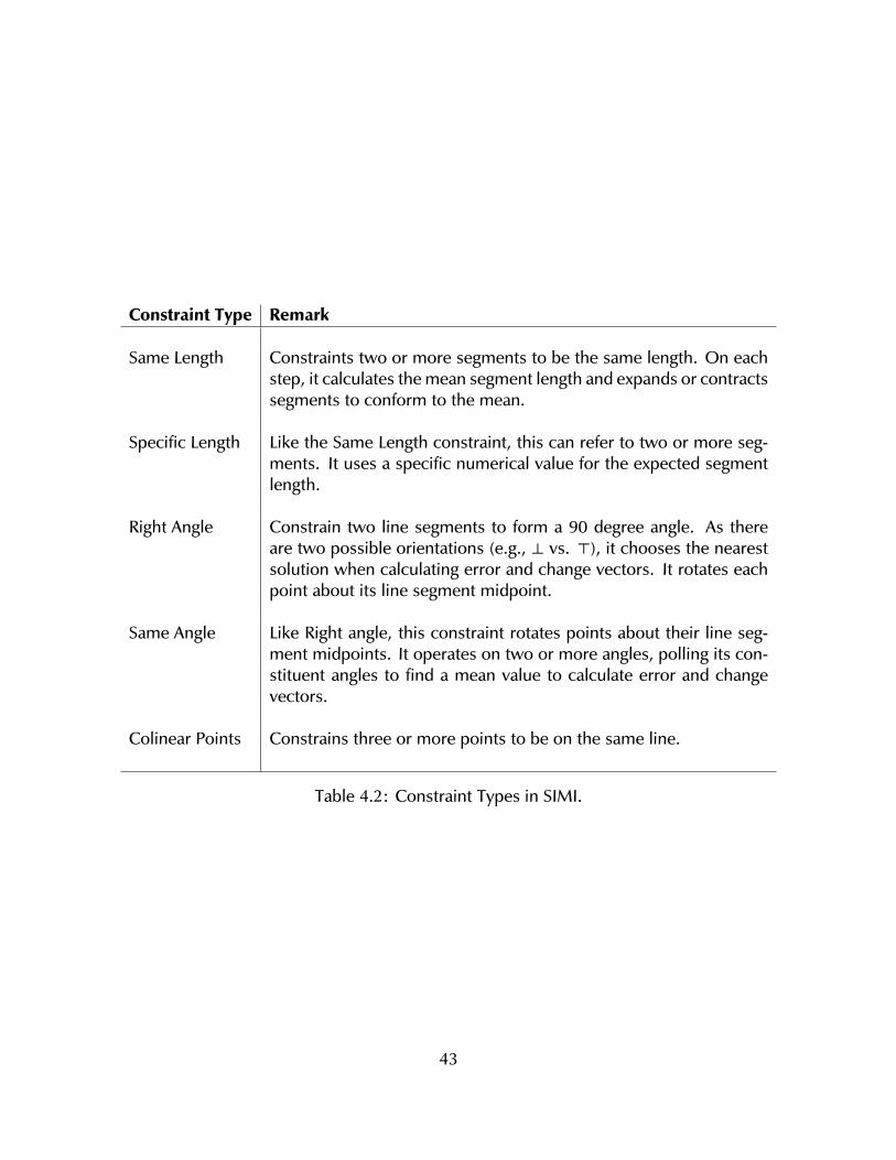
Constraint Type Remark
Same Length Constraints two or more segments to be the same length. On eachstep, it calculates the mean segment length and expands or contractssegments to conform to the mean.
Specific Length Like the Same Length constraint, this can refer to two or more seg-ments. It uses a specific numerical value for the expected segmentlength.
Right Angle Constrain two line segments to form a 90 degree angle. As thereare two possible orientations (e.g., ⊥ vs. >), it chooses the nearestsolution when calculating error and change vectors. It rotates eachpoint about its line segment midpoint.
Same Angle Like Right angle, this constraint rotates points about their line seg-ment midpoints. It operates on two or more angles, polling its con-stituent angles to find a mean value to calculate error and changevectors.
Colinear Points Constrains three or more points to be on the same line.
Table 4.2: Constraint Types in SIMI.
43
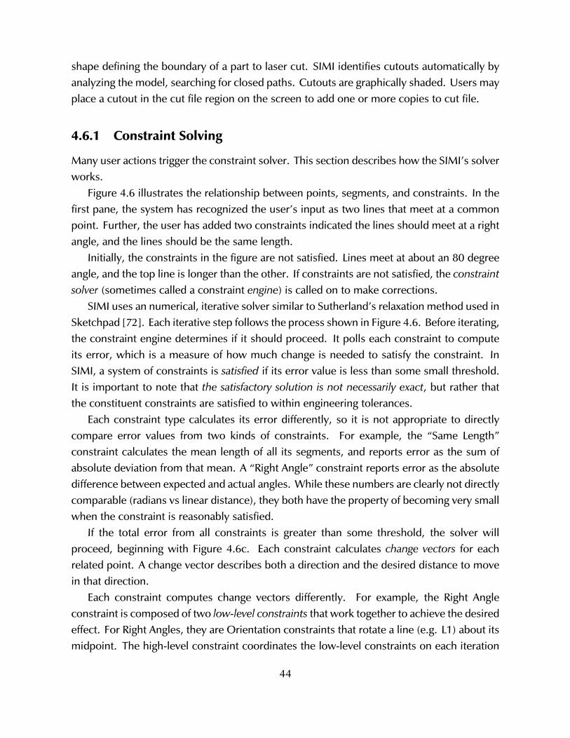
shape defining the boundary of a part to laser cut. SIMI identifies cutouts automatically byanalyzing the model, searching for closed paths. Cutouts are graphically shaded. Users mayplace a cutout in the cut file region on the screen to add one or more copies to cut file.
4.6.1 Constraint Solving
Many user actions trigger the constraint solver. This section describes how the SIMI’s solverworks.
Figure 4.6 illustrates the relationship between points, segments, and constraints. In thefirst pane, the system has recognized the user’s input as two lines that meet at a commonpoint. Further, the user has added two constraints indicated the lines should meet at a rightangle, and the lines should be the same length.
Initially, the constraints in the figure are not satisfied. Lines meet at about an 80 degreeangle, and the top line is longer than the other. If constraints are not satisfied, the constraintsolver (sometimes called a constraint engine) is called on to make corrections.
SIMI uses an numerical, iterative solver similar to Sutherland’s relaxation method used inSketchpad [72]. Each iterative step follows the process shown in Figure 4.6. Before iterating,the constraint engine determines if it should proceed. It polls each constraint to computeits error, which is a measure of how much change is needed to satisfy the constraint. InSIMI, a system of constraints is satisfied if its error value is less than some small threshold.It is important to note that the satisfactory solution is not necessarily exact, but rather thatthe constituent constraints are satisfied to within engineering tolerances.
Each constraint type calculates its error differently, so it is not appropriate to directlycompare error values from two kinds of constraints. For example, the “Same Length”constraint calculates the mean length of all its segments, and reports error as the sum ofabsolute deviation from that mean. A “Right Angle” constraint reports error as the absolutedifference between expected and actual angles. While these numbers are clearly not directlycomparable (radians vs linear distance), they both have the property of becoming very smallwhen the constraint is reasonably satisfied.
If the total error from all constraints is greater than some threshold, the solver willproceed, beginning with Figure 4.6c. Each constraint calculates change vectors for eachrelated point. A change vector describes both a direction and the desired distance to movein that direction.
Each constraint computes change vectors differently. For example, the Right Angleconstraint is composed of two low-level constraints that work together to achieve the desiredeffect. For Right Angles, they are Orientation constraints that rotate a line (e.g. L1) about itsmidpoint. The high-level constraint coordinates the low-level constraints on each iteration
44
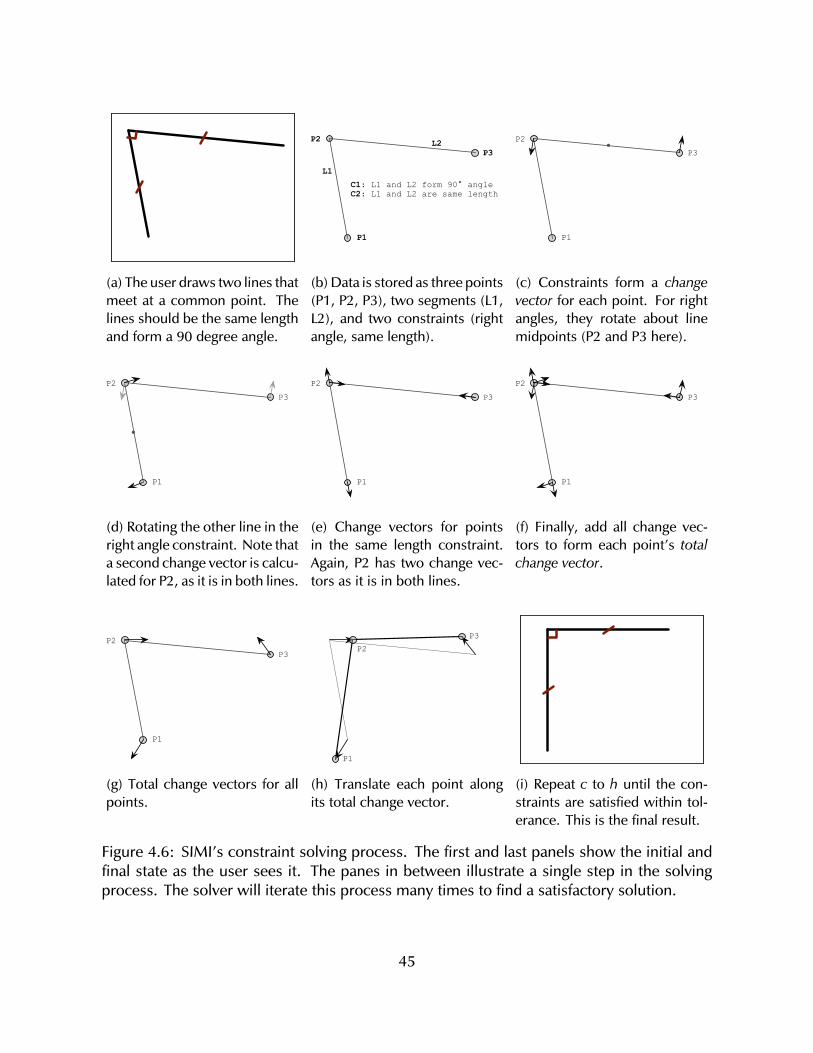
(a) The user draws two lines thatmeet at a common point. Thelines should be the same lengthand form a 90 degree angle.
L1
L2
P1
P2P3
C1: L1 and L2 form 90° angleC2: L1 and L2 are same length
(b) Data is stored as three points(P1, P2, P3), two segments (L1,L2), and two constraints (rightangle, same length).
P1
P2P3
(c) Constraints form a changevector for each point. For rightangles, they rotate about linemidpoints (P2 and P3 here).
P1
P2P3
(d) Rotating the other line in theright angle constraint. Note thata second change vector is calcu-lated for P2, as it is in both lines.
P1
P2P3
(e) Change vectors for pointsin the same length constraint.Again, P2 has two change vec-tors as it is in both lines.
P1
P2P3
(f) Finally, add all change vec-tors to form each point’s totalchange vector.
P1
P2P3
(g) Total change vectors for allpoints.
P1
P2P3
(h) Translate each point alongits total change vector.
(i) Repeat c to h until the con-straints are satisfied within tol-erance. This is the final result.
Figure 4.6: SIMI’s constraint solving process. The first and last panels show the initial andfinal state as the user sees it. The panes in between illustrate a single step in the solvingprocess. The solver will iterate this process many times to find a satisfactory solution.
45

by supplying a rotation parameter based on their current and desired angles.In this case, the low-level constraints operate on L1 (points P1 and P2) and L2 (P2 and
P3). Because P2 is involved in both L1 and L2, it will be rotated twice, as shown in panel d.Named points accumulate related change vectors. The accumulation process continues untilpanel f, when all constraints have computed change vectors. P2 has a total of four—twofrom the Right Angle constraint, and two from the Same Length constraint.
The next step is to add each point’s change vectors into a total change vector, whichdescribes the direction it could move (panel g).
The last step is to translate each point along its total change vector (panel h). It is likely(and common) that the iterative process will get ‘stuck’ in a loop where points oscillatebetween two or more states. To avoid this, SIMI moves each point a random distance bymultiplying its total change vector by random number between zero and one.
46
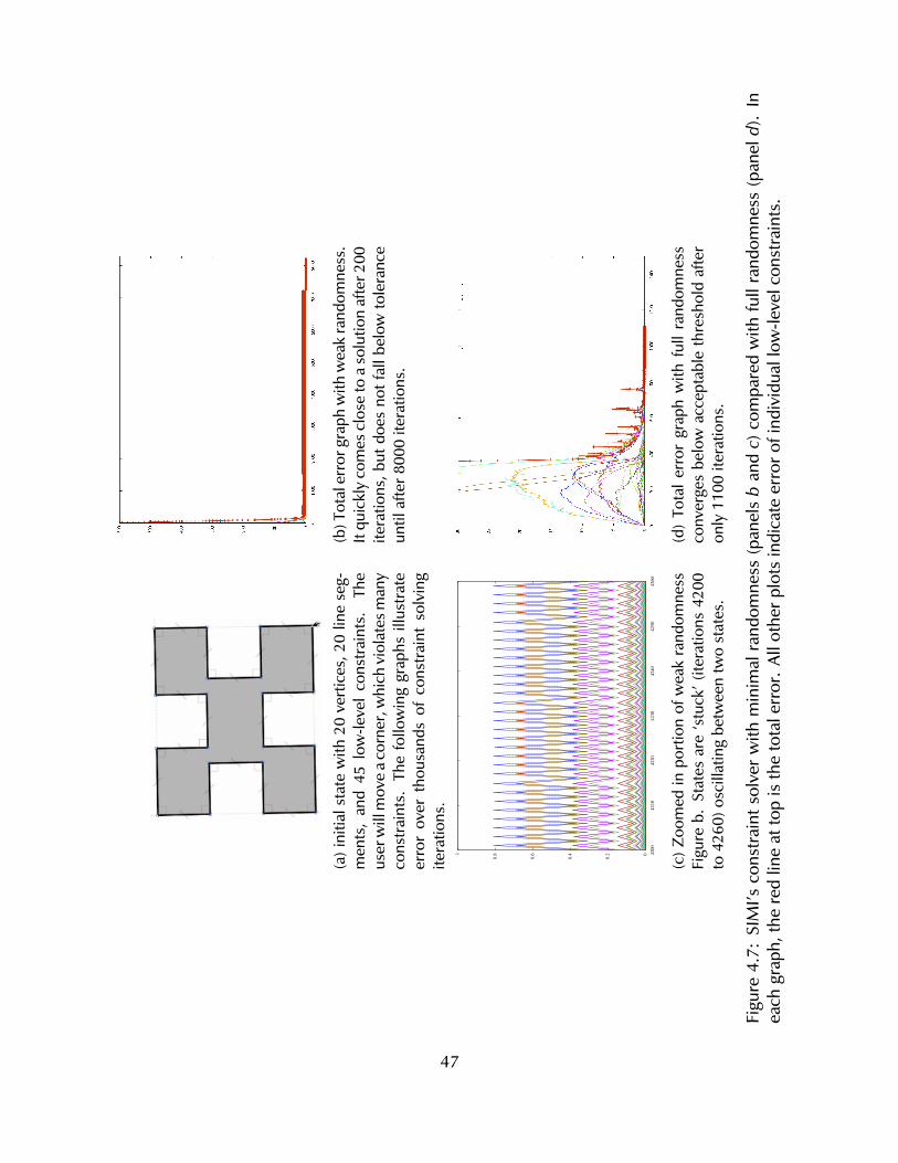
(a)i
nitia
lsta
tew
ith20
vert
ices
,20
line
seg-
men
ts,
and
45lo
w-le
vel
cons
trai
nts.
The
user
will
mov
eac
orne
r,w
hich
viol
ates
man
yco
nstr
aint
s.Th
efo
llow
ing
grap
hsill
ustr
ate
erro
rov
erth
ousa
nds
ofco
nstr
aint
solv
ing
itera
tions
.
(b)T
otal
erro
rgra
phw
ithw
eak
rand
omne
ss.
Itqu
ickl
yco
mes
clos
eto
aso
lutio
naf
ter2
00ite
ratio
ns,b
utdo
esno
tfal
lbel
owto
lera
nce
until
afte
r800
0ite
ratio
ns.
(c)Z
oom
edin
port
ion
ofw
eak
rand
omne
ssFi
gure
b.St
ates
are
‘stu
ck’(
itera
tions
4200
to42
60)o
scill
atin
gbe
twee
ntw
ost
ates
.
(d)
Tota
lerr
orgr
aph
with
full
rand
omne
ssco
nver
ges
belo
wac
cept
able
thre
shol
daf
ter
only
1100
itera
tions
.
Figu
re4.
7:SI
MI’s
cons
trai
ntso
lver
with
min
imal
rand
omne
ss(p
anel
sb
andc)
com
pare
dw
ithfu
llra
ndom
ness
(pan
eld)
.In
each
grap
h,th
ere
dlin
eat
top
isth
eto
tale
rror
.All
othe
rplo
tsin
dica
teer
roro
find
ivid
uall
ow-le
velc
onst
rain
ts.
47
Figure 4.7 illustrates the need for randomness in SIMI’s constraint engine. The user hasdrawn a cutout that contains 20 vertices, 20 line segments, and several high-level constraintscomprising 45 low-level constraints. When the user moves a corner, the constraint solveris invoked to satisfy the system. The upper right graph shows the solver approaching asolution fairly quickly, but getting ‘stuck’ for several thousand iterations, taking about fiveseconds to settle down. During this time, the on-screen representation jitters. In this case,weak randomness is used, and it is applied only to the total change vectors. The effect ofthe randomness increases over time. However, this approach was not satisfactory becauseit took too long and caused visual jitter.
This problem was addressed by modifying the constraint solver to apply randomness toeach individual change vector. For vertices with more than one change vector, this meansthe total change vector’s direction is subject to randomness, as well as its magnitude. Theoverall results are satisfactory, as the system of constraints is satisfied in about 1/8 of thenumber of iterations compared with the weak random case.
48
Chapter 5
Sketch It, Make It: Details
The previous chapter gave an overview of SIMI’s architecture, including an introduction ofSIMI’s recognition process. (Section 4.5). This chapter gives details on how each recognizerworks.
First, SIMI’s corner finding and segmentation strategy is described. This process isnecessary to most recognition, and is what produces geometric output like lines and arcs.Next, the three types of recognizers are described: including Dynamic, Pen Up, and Deferredrecognizers. All sketch based interaction techniques are detailed in these sections.
5.1 Ink Parsing
Ink parsing is the process of identifying useful characteristics of freehand digital input,hereafter referred to as ‘raw ink’, ‘rough ink’, or simply ‘ink’. Characteristics include thelocations of corners, curvature at specific points, and the likely identities of segments likelines or curves. Raw ink points are recorded as (x, y, t) coordinates that specify where apoint is and it was created.
In the following sections, there are two different ways to measure distance: Euclideanand Curvilinear (see Figure 5.1). Euclidean distance is the measurement most people arefamiliar with: this is how far apart two points are on the 2D plane. Curvilinear distancefollows the ink stroke path. In the figure, points A and B are close together in the Euclideansense, but are farther apart in the Curvilinear sense. The Euclidean and Curvilinear midpointsare also depicted in Figure 5.1.
SIMI’s ink parsing strategy is simpler than many other approaches found in literature onsketch-based interfaces and modeling (SBIM). Others, like the strategies taken by Sezgin [68]or Wolin [78], combine both time and curvature information when corner finding. SIMI’sapproach for corner-finding relies only on curvature, but still achieves good results.
49
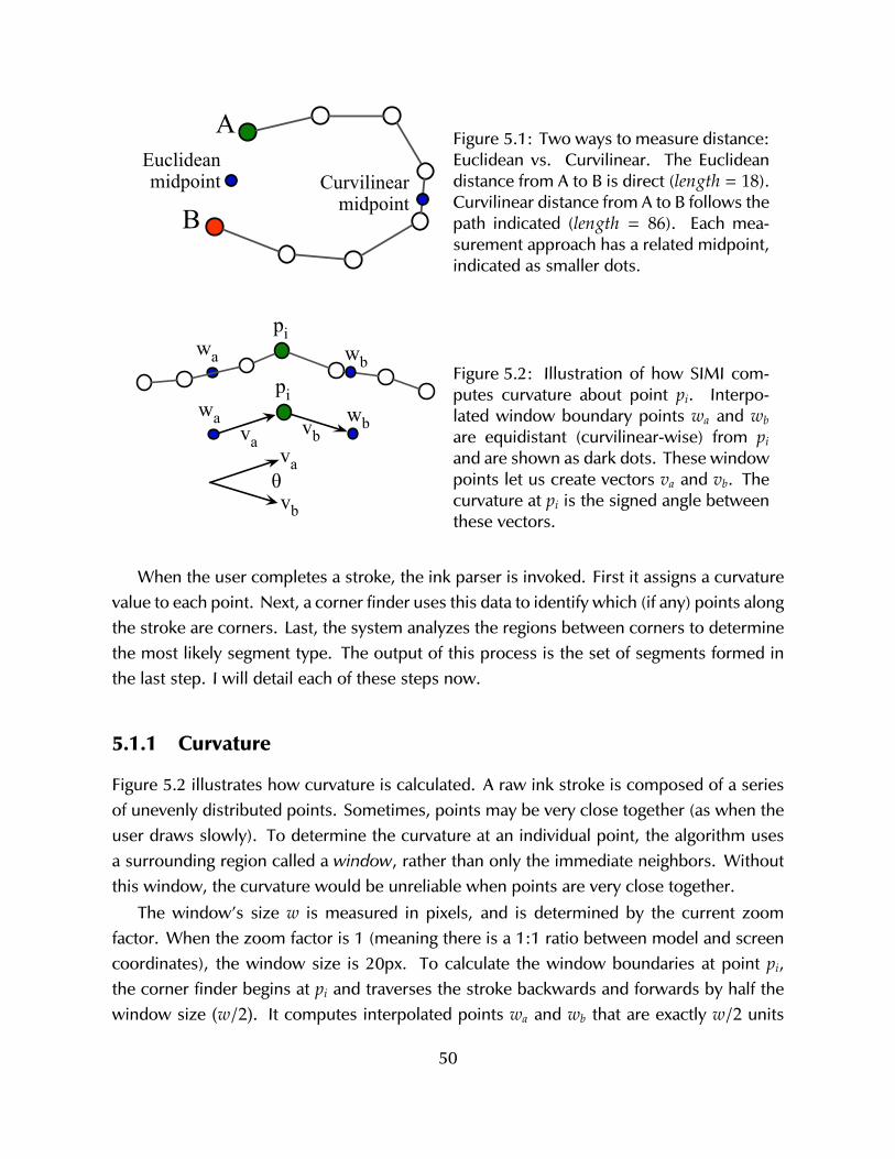
A
B
Euclideanmidpoint Curvilinear
midpoint
Figure 5.1: Two ways to measure distance:Euclidean vs. Curvilinear. The Euclideandistance from A to B is direct (length = 18).Curvilinear distance from A to B follows thepath indicated (length = 86). Each mea-surement approach has a related midpoint,indicated as smaller dots.
wbwapi
vbvawb
piwa
va
vb!
Figure 5.2: Illustration of how SIMI com-putes curvature about point pi. Interpo-lated window boundary points wa and wb
are equidistant (curvilinear-wise) from pi
and are shown as dark dots. These windowpoints let us create vectors va and vb. Thecurvature at pi is the signed angle betweenthese vectors.
When the user completes a stroke, the ink parser is invoked. First it assigns a curvaturevalue to each point. Next, a corner finder uses this data to identify which (if any) points alongthe stroke are corners. Last, the system analyzes the regions between corners to determinethe most likely segment type. The output of this process is the set of segments formed inthe last step. I will detail each of these steps now.
5.1.1 Curvature
Figure 5.2 illustrates how curvature is calculated. A raw ink stroke is composed of a seriesof unevenly distributed points. Sometimes, points may be very close together (as when theuser draws slowly). To determine the curvature at an individual point, the algorithm usesa surrounding region called a window, rather than only the immediate neighbors. Withoutthis window, the curvature would be unreliable when points are very close together.
The window’s size w is measured in pixels, and is determined by the current zoomfactor. When the zoom factor is 1 (meaning there is a 1:1 ratio between model and screencoordinates), the window size is 20px. To calculate the window boundaries at point pi,the corner finder begins at pi and traverses the stroke backwards and forwards by half thewindow size (w/2). It computes interpolated points wa and wb that are exactly w/2 units
50
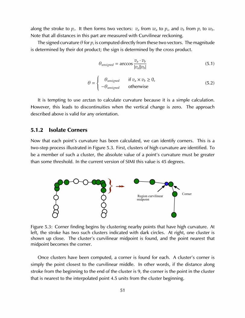
along the stroke to pi. It then forms two vectors: va from wa to pi, and vb from pi to wb.Note that all distances in this part are measured with Curvilinear reckoning.
The signed curvature θ for pi is computed directly from these two vectors. The magnitudeis determined by their dot product; the sign is determined by the cross product.
θunsigned = arccosva · vb
|va||vb|(5.1)
θ =
θunsigned if va × vb ≥ 0,−θunsigned otherwise
(5.2)
It is tempting to use arctan to calculate curvature because it is a simple calculation.However, this leads to discontinuities when the vertical change is zero. The approachdescribed above is valid for any orientation.
5.1.2 Isolate Corners
Now that each point’s curvature has been calculated, we can identify corners. This is atwo-step process illustrated in Figure 5.3. First, clusters of high curvature are identified. Tobe a member of such a cluster, the absolute value of a point’s curvature must be greaterthan some threshold. In the current version of SIMI this value is 45 degrees.
Region curvilinear midpoint
Corner}
Figure 5.3: Corner finding begins by clustering nearby points that have high curvature. Atleft, the stroke has two such clusters indicated with dark circles. At right, one cluster isshown up close. The cluster’s curvilinear midpoint is found, and the point nearest thatmidpoint becomes the corner.
Once clusters have been computed, a corner is found for each. A cluster’s corner issimply the point closest to the curvilinear middle. In other words, if the distance alongstroke from the beginning to the end of the cluster is 9, the corner is the point in the clusterthat is nearest to the interpolated point 4.5 units from the cluster beginning.
51

In addition to the corners discover in this process, the stroke’s first and last points arealso included as ‘corners’. This is for the convenience of the next step where segments areidentified.
5.1.3 Identify Segment Types
The last step in ink parsing is to identify segment types. Table 4.1 in the previous chapterdescribes the possible segment types. For each segment type there is a correspondingsegment finder. The segment finders for ‘open’ types (Line, Arc, Spline) operate on regionsbetween corners. The remaining segment finders are identified by examining the raw inkdirectly, and do not use corner data.
Like semantic sketch recognizers, it is possible for multiple segment finders to positivelyidentify ink—e.g. a segment might be an arc, or it might be a line. To mitigate this, segmentfinders operate on a priority system. The priority is: Dot, Circle, Ellipse, Blob, Line, Arc,and Spline. In other words, if the Dot finder identifies a dot, there is no possibility of theassociated ink being identified as a Circle.
Dot Finder
The dot finder examines the entire ink stroke. If the entire stroke was made in less thansome threshold value (currently 180 milliseconds), it is always considered a dot. Otherwise,it continues by computing the convex hull of all stroke points. Two properties of the hullare used next: the area and the aspect ratio. If the ratio defined by ratio = area/aspect is lessthan 120, it is a dot. If not, there is one final check to make. The stroke’s point density iscomputed. This is the number of points in the original ink stroke, divided by the hull’s area.If ratio/(0.3 + density) is less than 120, it is a dot.
Circle and Ellipse Finder
Circles, Ellipses, and (in the next part) Blobs are the three closed segment types. A segmentis closed if the beginning and end points are close, relative to the overall length of the stroke.More formally given start and end points pstart and pend:
closeness =EuclidianDistance(pstart, pend)
CurvilinearDistance(pstart, pend)
closed =
true if closeness ≤ .1,f alse otherwise
(5.3)
52
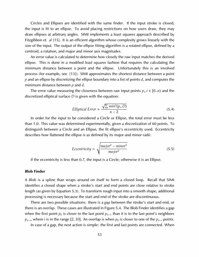
Circles and Ellipses are identified with the same finder. If the input stroke is closed,the input is fit to an ellipse. To avoid placing restrictions on how users draw, they maydraw ellipses at arbitrary angles. SIMI implements a least squares approach described byFitzgibbon et. al [15]. It is an efficient algorithm whose complexity grows linearly with thesize of the input. The output of the ellipse fitting algorithm is a rotated ellipse, defined by acentroid, a rotation, and major and minor axis magnitudes.
An error value is calculated to determine how closely the raw input matches the derivedellipse. This is done in a modified least squares fashion that requires the calculating theminimum distance between a point and the ellipse. Unfortunately this is an involvedprocess (for example, see [13]). SIMI approximates the shortest distance between a pointp and an ellipse by discretizing the ellipse boundary into a list of points d, and computes theminimum distance between p and d.
The error value measuring the closeness between raw input points pi, i ∈ [0..n) and thediscretized elliptical surface D is given with the equation:
Elliptical Error =
√∑min2(pi,D)n − 2
(5.4)
In order for the input to be considered a Circle or Ellipse, the total error must be lessthan 1.0. This value was determined experimentally, given a discretization of 60 points. Todistinguish between a Circle and an Ellipse, the fit ellipse’s eccentricity used. Eccentricitydescribes how flattened the ellipse is as defined by its major and minor radii:
Eccentricity =
√major2
−minor2
major2 (5.5)
If the eccentricity is less than 0.7, the input is a Circle; otherwise it is an Ellipse.
Blob Finder
A Blob is a spline than wraps around on itself to form a closed loop. Recall that SIMIidentifies a closed shape when a stroke’s start and end points are close relative to strokelength (as given by Equation 5.3). To transform rough input into a smooth shape, additionalprocessing is necessary because the start and end of the stroke are discontinuous.
There are two possible situations: there is a gap between the stroke’s start and end, orthere is an overlap. These cases are illustrated in Figure 5.4. The Blob Finder identifies a gapwhen the first point p0 is closer to the last point pn−1 than it is to the last point’s neighborspn−i, where i is in the range [2..10]. An overlap is when p0 is closer to one of the pn−i points.
In case of a gap, the next action is simple: the first and last points are connected. When
53
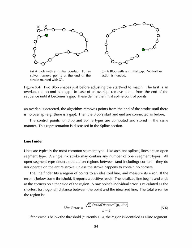
(a) A Blob with an initial overlap. To re-solve, remove points at the end of thestroke marked with X’s.
(b) A Blob with an initial gap. No furtheraction is needed.
Figure 5.4: Two Blob shapes just before adjusting the start/end to match. The first is anoverlap, the second is a gap. In case of an overlap, remove points from the end of thesequence until it becomes a gap. These define the initial spline control points.
an overlap is detected, the algorithm removes points from the end of the stroke until thereis no overlap (e.g. there is a gap). Then the Blob’s start and end are connected as before.
The control points for Blob and Spline types are computed and stored in the samemanner. This representation is discussed in the Spline section.
Line Finder
Lines are typically the most common segment type. Like arcs and splines, lines are an opensegment type. A single ink stroke may contain any number of open segment types. Allopen segment type finders operate on regions between (and including) corners—they donot operate on the entire stroke, unless the stroke happens to contain no corners.
The line finder fits a region of points to an idealized line, and measure its error. If theerror is below some threshold, it reports a positive result. The idealized line begins and endsat the corners on either side of the region. A raw point’s individual error is calculated as theshortest (orthogonal) distance between the point and the idealized line. The total error forthe region is:
Line Error =
√∑OrthoDistance2(pi, line)
n − 2(5.6)
If the error is below the threshold (currently 1.5), the region is identified as a line segment.
54
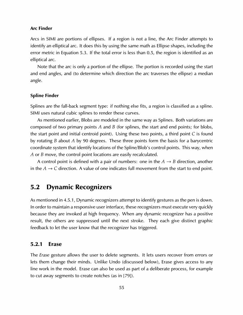
Arc Finder
Arcs in SIMI are portions of ellipses. If a region is not a line, the Arc Finder attempts toidentify an elliptical arc. It does this by using the same math as Ellipse shapes, including theerror metric in Equation 5.3. If the total error is less than 0.5, the region is identified as anelliptical arc.
Note that the arc is only a portion of the ellipse. The portion is recorded using the startand end angles, and (to determine which direction the arc traverses the ellipse) a medianangle.
Spline Finder
Splines are the fall-back segment type: if nothing else fits, a region is classified as a spline.SIMI uses natural cubic splines to render these curves.
As mentioned earlier, Blobs are modeled in the same way as Splines. Both variations arecomposed of two primary points A and B (for splines, the start and end points; for blobs,the start point and initial centroid point). Using these two points, a third point C is foundby rotating B about A by 90 degrees. These three points form the basis for a barycentriccoordinate system that identify locations of the Spline/Blob’s control points. This way, whenA or B move, the control point locations are easily recalculated.
A control point is defined with a pair of numbers: one in the A → B direction, anotherin the A→ C direction. A value of one indicates full movement from the start to end point.
5.2 Dynamic Recognizers
As mentioned in 4.5.1, Dynamic recognizers attempt to identify gestures as the pen is down.In order to maintain a responsive user interface, these recognizers must execute very quicklybecause they are invoked at high frequency. When any dynamic recognizer has a positiveresult, the others are suppressed until the next stroke. They each give distinct graphicfeedback to let the user know that the recognizer has triggered.
5.2.1 Erase
The Erase gesture allows the user to delete segments. It lets users recover from errors orlets them change their minds. Unlike Undo (discussed below), Erase gives access to anyline work in the model. Erase can also be used as part of a deliberate process, for exampleto cut away segments to create notches (as in [79]).
55
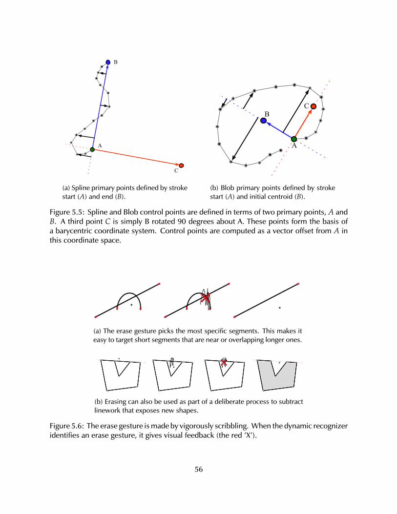
A
B
C
(a) Spline primary points defined by strokestart (A) and end (B).
A
BC
(b) Blob primary points defined by strokestart (A) and initial centroid (B).
Figure 5.5: Spline and Blob control points are defined in terms of two primary points, A andB. A third point C is simply B rotated 90 degrees about A. These points form the basis ofa barycentric coordinate system. Control points are computed as a vector offset from A inthis coordinate space.
(a) The erase gesture picks the most specific segments. This makes iteasy to target short segments that are near or overlapping longer ones.
(b) Erasing can also be used as part of a deliberate process to subtractlinework that exposes new shapes.
Figure 5.6: The erase gesture is made by vigorously scribbling. When the dynamic recognizeridentifies an erase gesture, it gives visual feedback (the red ’X’).
56
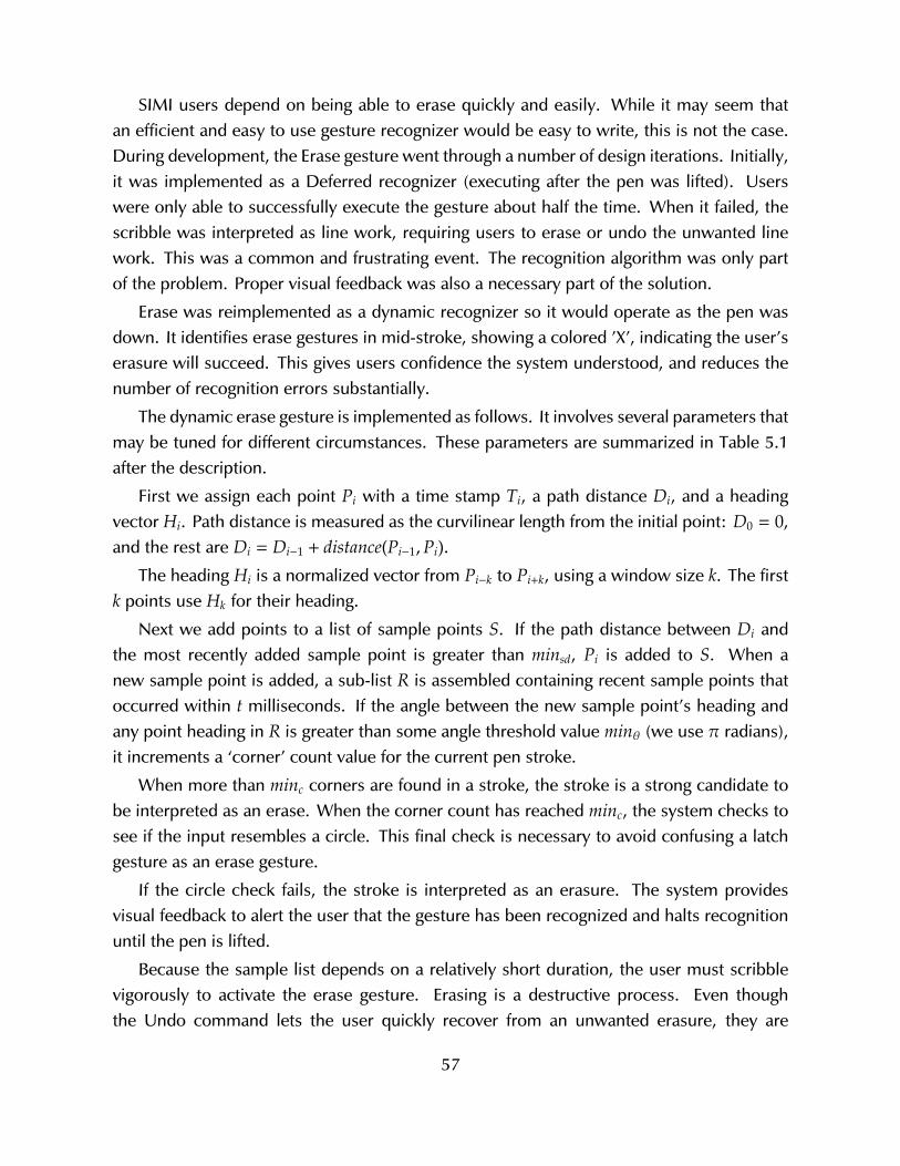
SIMI users depend on being able to erase quickly and easily. While it may seem thatan efficient and easy to use gesture recognizer would be easy to write, this is not the case.During development, the Erase gesture went through a number of design iterations. Initially,it was implemented as a Deferred recognizer (executing after the pen was lifted). Userswere only able to successfully execute the gesture about half the time. When it failed, thescribble was interpreted as line work, requiring users to erase or undo the unwanted linework. This was a common and frustrating event. The recognition algorithm was only partof the problem. Proper visual feedback was also a necessary part of the solution.
Erase was reimplemented as a dynamic recognizer so it would operate as the pen wasdown. It identifies erase gestures in mid-stroke, showing a colored ’X’, indicating the user’serasure will succeed. This gives users confidence the system understood, and reduces thenumber of recognition errors substantially.
The dynamic erase gesture is implemented as follows. It involves several parameters thatmay be tuned for different circumstances. These parameters are summarized in Table 5.1after the description.
First we assign each point Pi with a time stamp Ti, a path distance Di, and a headingvector Hi. Path distance is measured as the curvilinear length from the initial point: D0 = 0,and the rest are Di = Di−1 + distance(Pi−1,Pi).
The heading Hi is a normalized vector from Pi−k to Pi+k, using a window size k. The firstk points use Hk for their heading.
Next we add points to a list of sample points S. If the path distance between Di andthe most recently added sample point is greater than minsd, Pi is added to S. When anew sample point is added, a sub-list R is assembled containing recent sample points thatoccurred within t milliseconds. If the angle between the new sample point’s heading andany point heading in R is greater than some angle threshold value minθ (we use π radians),it increments a ‘corner’ count value for the current pen stroke.
When more than minc corners are found in a stroke, the stroke is a strong candidate tobe interpreted as an erase. When the corner count has reached minc, the system checks tosee if the input resembles a circle. This final check is necessary to avoid confusing a latchgesture as an erase gesture.
If the circle check fails, the stroke is interpreted as an erasure. The system providesvisual feedback to alert the user that the gesture has been recognized and halts recognitionuntil the pen is lifted.
Because the sample list depends on a relatively short duration, the user must scribblevigorously to activate the erase gesture. Erasing is a destructive process. Even thoughthe Undo command lets the user quickly recover from an unwanted erasure, they are
57
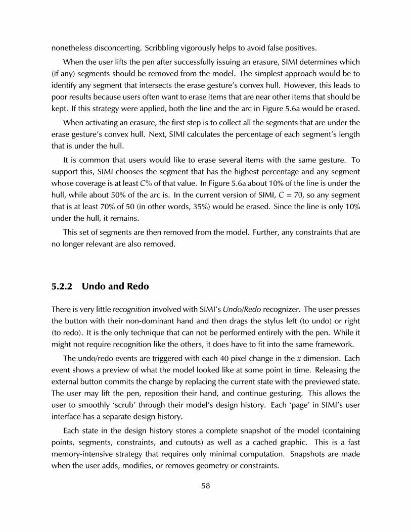
nonetheless disconcerting. Scribbling vigorously helps to avoid false positives.
When the user lifts the pen after successfully issuing an erasure, SIMI determines which(if any) segments should be removed from the model. The simplest approach would be toidentify any segment that intersects the erase gesture’s convex hull. However, this leads topoor results because users often want to erase items that are near other items that should bekept. If this strategy were applied, both the line and the arc in Figure 5.6a would be erased.
When activating an erasure, the first step is to collect all the segments that are under theerase gesture’s convex hull. Next, SIMI calculates the percentage of each segment’s lengththat is under the hull.
It is common that users would like to erase several items with the same gesture. Tosupport this, SIMI chooses the segment that has the highest percentage and any segmentwhose coverage is at least C% of that value. In Figure 5.6a about 10% of the line is under thehull, while about 50% of the arc is. In the current version of SIMI, C = 70, so any segmentthat is at least 70% of 50 (in other words, 35%) would be erased. Since the line is only 10%under the hull, it remains.
This set of segments are then removed from the model. Further, any constraints that areno longer relevant are also removed.
5.2.2 Undo and Redo
There is very little recognition involved with SIMI’s Undo/Redo recognizer. The user pressesthe button with their non-dominant hand and then drags the stylus left (to undo) or right(to redo). It is the only technique that can not be performed entirely with the pen. While itmight not require recognition like the others, it does have to fit into the same framework.
The undo/redo events are triggered with each 40 pixel change in the x dimension. Eachevent shows a preview of what the model looked like at some point in time. Releasing theexternal button commits the change by replacing the current state with the previewed state.The user may lift the pen, reposition their hand, and continue gesturing. This allows theuser to smoothly ‘scrub’ through their model’s design history. Each ‘page’ in SIMI’s userinterface has a separate design history.
Each state in the design history stores a complete snapshot of the model (containingpoints, segments, constraints, and cutouts) as well as a cached graphic. This is a fastmemory-intensive strategy that requires only minimal computation. Snapshots are madewhen the user adds, modifies, or removes geometry or constraints.
58
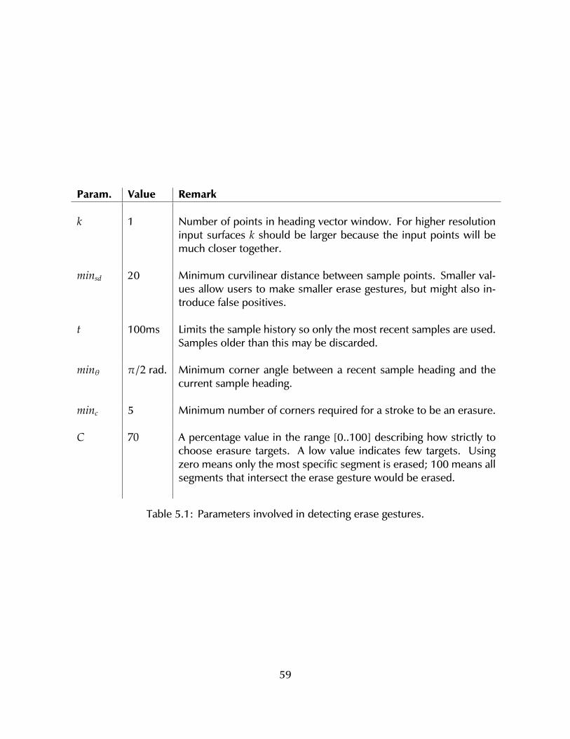
Param. Value Remark
k 1 Number of points in heading vector window. For higher resolutioninput surfaces k should be larger because the input points will bemuch closer together.
minsd 20 Minimum curvilinear distance between sample points. Smaller val-ues allow users to make smaller erase gestures, but might also in-troduce false positives.
t 100ms Limits the sample history so only the most recent samples are used.Samples older than this may be discarded.
minθ π/2 rad. Minimum corner angle between a recent sample heading and thecurrent sample heading.
minc 5 Minimum number of corners required for a stroke to be an erasure.
C 70 A percentage value in the range [0..100] describing how strictly tochoose erasure targets. A low value indicates few targets. Usingzero means only the most specific segment is erased; 100 means allsegments that intersect the erase gesture would be erased.
Table 5.1: Parameters involved in detecting erase gestures.
59
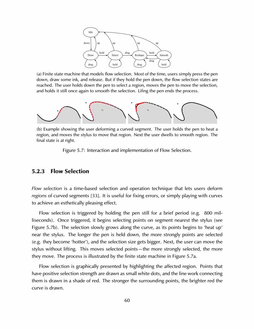
Idle
SmoothReshapeSelectDrawhold drag hold
drag draghold hold
down upupup
drag
up
(a) Finite state machine that models flow selection. Most of the time, users simply press the pendown, draw some ink, and release. But if they hold the pen down, the flow selection states arereached. The user holds down the pen to select a region, moves the pen to move the selection,and holds it still once again to smooth the selection. Lifing the pen ends the process.
(b) Example showing the user deforming a curved segment. The user holds the pen to heat aregion, and moves the stylus to move that region. Next the user dwells to smooth region. Thefinal state is at right.
Figure 5.7: Interaction and implementation of Flow Selection.
5.2.3 Flow Selection
Flow selection is a time-based selection and operation technique that lets users deformregions of curved segments [33]. It is useful for fixing errors, or simply playing with curvesto achieve an esthetically pleasing effect.
Flow selection is triggered by holding the pen still for a brief period (e.g. 800 mil-liseconds). Once triggered, it begins selecting points on segment nearest the stylus (seeFigure 5.7b). The selection slowly grows along the curve, as its points begins to ‘heat up’near the stylus. The longer the pen is held down, the more strongly points are selected(e.g. they become ‘hotter’), and the selection size gets bigger. Next, the user can move thestylus without lifting. This moves selected points—the more strongly selected, the morethey move. The process is illustrated by the finite state machine in Figure 5.7a.
Flow selection is graphically presented by highlighting the affected region. Points thathave positive selection strength are drawn as small white dots, and the line work connectingthem is drawn in a shade of red. The stronger the surrounding points, the brighter red thecurve is drawn.
60
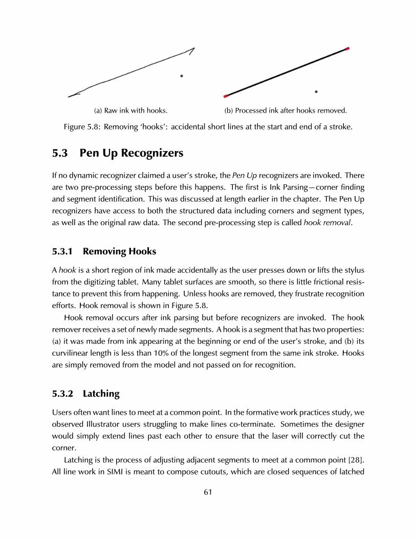
(a) Raw ink with hooks. (b) Processed ink after hooks removed.
Figure 5.8: Removing ‘hooks’: accidental short lines at the start and end of a stroke.
5.3 Pen Up Recognizers
If no dynamic recognizer claimed a user’s stroke, the Pen Up recognizers are invoked. Thereare two pre-processing steps before this happens. The first is Ink Parsing—corner findingand segment identification. This was discussed at length earlier in the chapter. The Pen Uprecognizers have access to both the structured data including corners and segment types,as well as the original raw data. The second pre-processing step is called hook removal.
5.3.1 Removing Hooks
A hook is a short region of ink made accidentally as the user presses down or lifts the stylusfrom the digitizing tablet. Many tablet surfaces are smooth, so there is little frictional resis-tance to prevent this from happening. Unless hooks are removed, they frustrate recognitionefforts. Hook removal is shown in Figure 5.8.
Hook removal occurs after ink parsing but before recognizers are invoked. The hookremover receives a set of newly made segments. A hook is a segment that has two properties:(a) it was made from ink appearing at the beginning or end of the user’s stroke, and (b) itscurvilinear length is less than 10% of the longest segment from the same ink stroke. Hooksare simply removed from the model and not passed on for recognition.
5.3.2 Latching
Users often want lines to meet at a common point. In the formative work practices study, weobserved Illustrator users struggling to make lines co-terminate. Sometimes the designerwould simply extend lines past each other to ensure that the laser will correctly cut thecorner.
Latching is the process of adjusting adjacent segments to meet at a common point [28].All line work in SIMI is meant to compose cutouts, which are closed sequences of latched
61
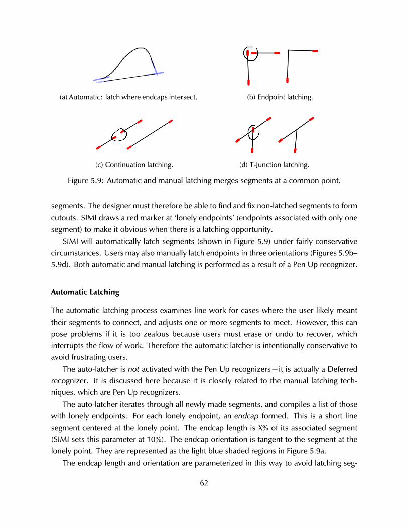
(a) Automatic: latch where endcaps intersect. (b) Endpoint latching.
(c) Continuation latching. (d) T-Junction latching.
Figure 5.9: Automatic and manual latching merges segments at a common point.
segments. The designer must therefore be able to find and fix non-latched segments to formcutouts. SIMI draws a red marker at ‘lonely endpoints’ (endpoints associated with only onesegment) to make it obvious when there is a latching opportunity.
SIMI will automatically latch segments (shown in Figure 5.9) under fairly conservativecircumstances. Users may also manually latch endpoints in three orientations (Figures 5.9b–5.9d). Both automatic and manual latching is performed as a result of a Pen Up recognizer.
Automatic Latching
The automatic latching process examines line work for cases where the user likely meanttheir segments to connect, and adjusts one or more segments to meet. However, this canpose problems if it is too zealous because users must erase or undo to recover, whichinterrupts the flow of work. Therefore the automatic latcher is intentionally conservative toavoid frustrating users.
The auto-latcher is not activated with the Pen Up recognizers—it is actually a Deferredrecognizer. It is discussed here because it is closely related to the manual latching tech-niques, which are Pen Up recognizers.
The auto-latcher iterates through all newly made segments, and compiles a list of thosewith lonely endpoints. For each lonely endpoint, an endcap formed. This is a short linesegment centered at the lonely point. The endcap length is X% of its associated segment(SIMI sets this parameter at 10%). The endcap orientation is tangent to the segment at thelonely point. They are represented as the light blue shaded regions in Figure 5.9a.
The endcap length and orientation are parameterized in this way to avoid latching seg-
62
ments that do not visually appear to meet. This approach was inspired by the gestalt principleof common fate.
Next, each endcap is intersected with nearby endcaps from either new or existing lonelypoint endcaps (with their own length and orientations). When two endcaps intersect, theauto-latcher reports a positive result, and the two related segments will merge. The mergingprocess is discussed below, after the manual latchers.
Manual Latching
There are three ways users manually latch segments together, illustrated in Figure 5.9. Theyare activated by the same recognizer, but the action taken is distinguished by the particularconfiguration of segments below the gesture.
The three kinds of manual latching are: endpoint, continuation, and T-Junction, but thegesture (a small lasso, discussed shortly) is the same for all of them. The meaning of thelatch gesture depends on what the user targets: in other words, what elements are beneaththe user’s input? If the user targets two endpoints, it is either an endpoint latch (when thetwo segments are not close to the same orientation) or a continuation latch (when they areabout the same orientation). If the user targets an endpoint and the mid-section of anothersegment, it is a T-Junction.
The encircle gesture is recognized as follows. The gesture curvilinear length must beless than a threshold (currently 200 px). This helps distinguish line work (which tends to belarge) from latch gestures (which are small). Second, the input must be closed using logicsimilar to the closed segment type finders (e.g. Blob Finder). In this context the input isclosed if any of the last 10% of points were within 7 pixels of the initial point.
Merging Segments
If either the automatic or manual latching algorithm found a positive result, two segmentsmust be merged. Table 5.2 summarizes the inputs, where the merge occurs, and theresults. In each case, two segments are merged, but the output depends on the latch type.Automatic and endpoint latching result in two segments that have been joined at segmentends. Continuation latching results in a single segment—the two original segments arereplaced by one longer one. With T-Junction latching, one segment is split in the interiorregion into two segments, and the other segment is merged with them where the splitoccurred.
Points and segments are created and destroyed in this process. This must be reflected inthe model. Any constraints that referenced a deleted segment must be re-evaluated to see
63
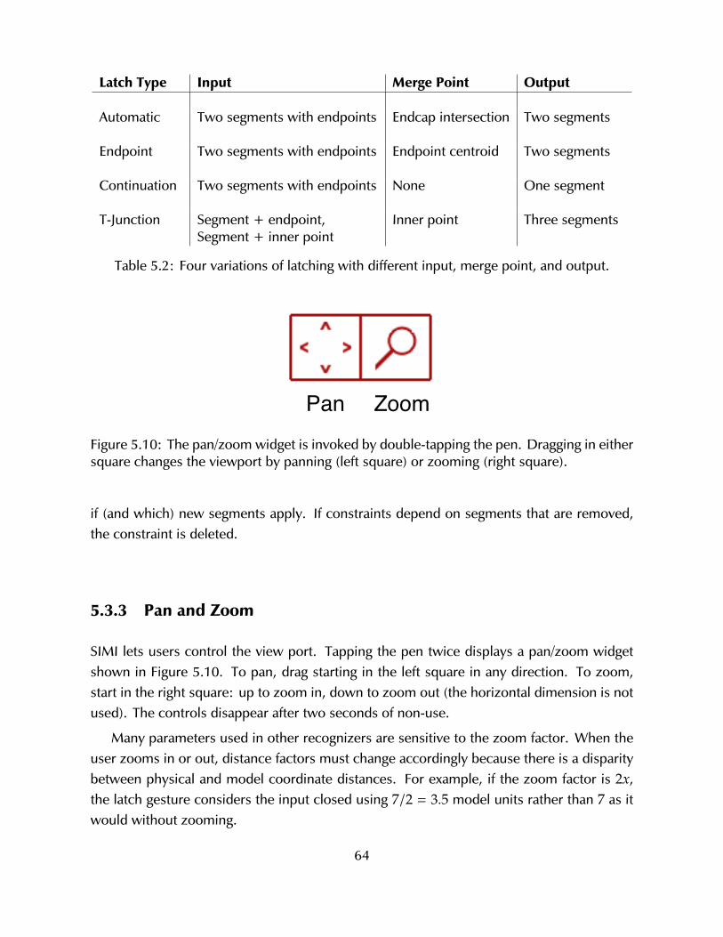
Latch Type Input Merge Point Output
Automatic Two segments with endpoints Endcap intersection Two segments
Endpoint Two segments with endpoints Endpoint centroid Two segments
Continuation Two segments with endpoints None One segment
T-Junction Segment + endpoint,Segment + inner point
Inner point Three segments
Table 5.2: Four variations of latching with different input, merge point, and output.
Pan ZoomFigure 5.10: The pan/zoom widget is invoked by double-tapping the pen. Dragging in eithersquare changes the viewport by panning (left square) or zooming (right square).
if (and which) new segments apply. If constraints depend on segments that are removed,the constraint is deleted.
5.3.3 Pan and Zoom
SIMI lets users control the view port. Tapping the pen twice displays a pan/zoom widgetshown in Figure 5.10. To pan, drag starting in the left square in any direction. To zoom,start in the right square: up to zoom in, down to zoom out (the horizontal dimension is notused). The controls disappear after two seconds of non-use.
Many parameters used in other recognizers are sensitive to the zoom factor. When theuser zooms in or out, distance factors must change accordingly because there is a disparitybetween physical and model coordinate distances. For example, if the zoom factor is 2x,the latch gesture considers the input closed using 7/2 = 3.5 model units rather than 7 as itwould without zooming.
64
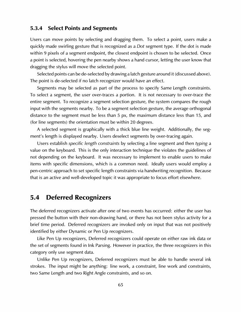
5.3.4 Select Points and Segments
Users can move points by selecting and dragging them. To select a point, users make aquickly made swirling gesture that is recognized as a Dot segment type. If the dot is madewithin 9 pixels of a segment endpoint, the closest endpoint is chosen to be selected. Oncea point is selected, hovering the pen nearby shows a hand cursor, letting the user know thatdragging the stylus will move the selected point.
Selected points can be de-selected by drawing a latch gesture around it (discussed above).The point is de-selected if no latch recognizer would have an effect.
Segments may be selected as part of the process to specify Same Length constraints.To select a segment, the user over-traces a portion. It is not necessary to over-trace theentire segment. To recognize a segment selection gesture, the system compares the roughinput with the segments nearby. To be a segment selection gesture, the average orthogonaldistance to the segment must be less than 5 px, the maximum distance less than 15, and(for line segments) the orientation must be within 20 degrees.
A selected segment is graphically with a thick blue line weight. Additionally, the seg-ment’s length is displayed nearby. Users deselect segments by over-tracing again.
Users establish specific length constraints by selecting a line segment and then typing avalue on the keyboard. This is the only interaction technique the violates the guidelines ofnot depending on the keyboard. It was necessary to implement to enable users to makeitems with specific dimensions, which is a common need. Ideally users would employ apen-centric approach to set specific length constraints via handwriting recognition. Becausethat is an active and well-developed topic it was appropriate to focus effort elsewhere.
5.4 Deferred Recognizers
The deferred recognizers activate after one of two events has occurred: either the user haspressed the button with their non-drawing hand, or there has not been stylus activity for abrief time period. Deferred recognizers are invoked only on input that was not positivelyidentified by either Dynamic or Pen Up recognizers.
Like Pen Up recognizers, Deferred recognizers could operate on either raw ink data orthe set of segments found in Ink Parsing. However in practice, the three recognizers in thiscategory only use segment data.
Unlike Pen Up recognizers, Deferred recognizers must be able to handle several inkstrokes. The input might be anything: line work, a constraint, line work and constraints,two Same Length and two Right Angle constraints, and so on.
65
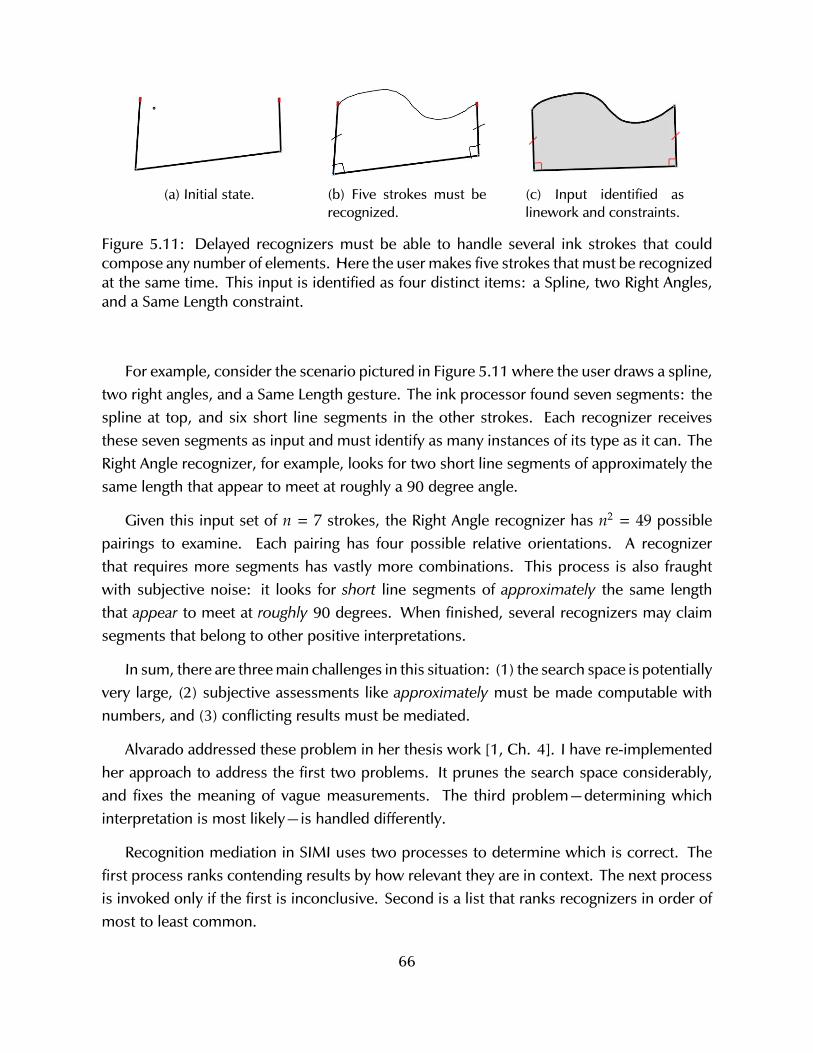
(a) Initial state. (b) Five strokes must berecognized.
(c) Input identified aslinework and constraints.
Figure 5.11: Delayed recognizers must be able to handle several ink strokes that couldcompose any number of elements. Here the user makes five strokes that must be recognizedat the same time. This input is identified as four distinct items: a Spline, two Right Angles,and a Same Length constraint.
For example, consider the scenario pictured in Figure 5.11 where the user draws a spline,two right angles, and a Same Length gesture. The ink processor found seven segments: thespline at top, and six short line segments in the other strokes. Each recognizer receivesthese seven segments as input and must identify as many instances of its type as it can. TheRight Angle recognizer, for example, looks for two short line segments of approximately thesame length that appear to meet at roughly a 90 degree angle.
Given this input set of n = 7 strokes, the Right Angle recognizer has n2 = 49 possiblepairings to examine. Each pairing has four possible relative orientations. A recognizerthat requires more segments has vastly more combinations. This process is also fraughtwith subjective noise: it looks for short line segments of approximately the same lengththat appear to meet at roughly 90 degrees. When finished, several recognizers may claimsegments that belong to other positive interpretations.
In sum, there are three main challenges in this situation: (1) the search space is potentiallyvery large, (2) subjective assessments like approximately must be made computable withnumbers, and (3) conflicting results must be mediated.
Alvarado addressed these problem in her thesis work [1, Ch. 4]. I have re-implementedher approach to address the first two problems. It prunes the search space considerably,and fixes the meaning of vague measurements. The third problem—determining whichinterpretation is most likely—is handled differently.
Recognition mediation in SIMI uses two processes to determine which is correct. Thefirst process ranks contending results by how relevant they are in context. The next processis invoked only if the first is inconclusive. Second is a list that ranks recognizers in order ofmost to least common.
66
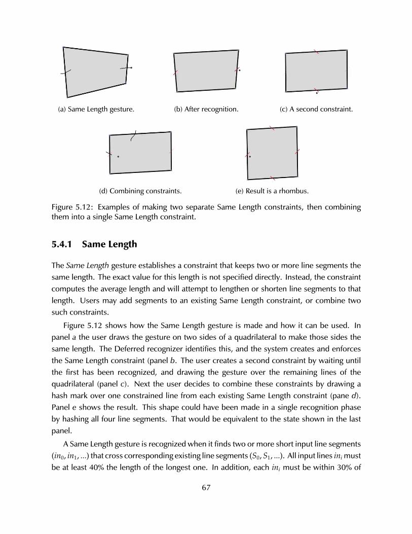
(a) Same Length gesture. (b) After recognition. (c) A second constraint.
(d) Combining constraints. (e) Result is a rhombus.
Figure 5.12: Examples of making two separate Same Length constraints, then combiningthem into a single Same Length constraint.
5.4.1 Same Length
The Same Length gesture establishes a constraint that keeps two or more line segments thesame length. The exact value for this length is not specified directly. Instead, the constraintcomputes the average length and will attempt to lengthen or shorten line segments to thatlength. Users may add segments to an existing Same Length constraint, or combine twosuch constraints.
Figure 5.12 shows how the Same Length gesture is made and how it can be used. Inpanel a the user draws the gesture on two sides of a quadrilateral to make those sides thesame length. The Deferred recognizer identifies this, and the system creates and enforcesthe Same Length constraint (panel b. The user creates a second constraint by waiting untilthe first has been recognized, and drawing the gesture over the remaining lines of thequadrilateral (panel c). Next the user decides to combine these constraints by drawing ahash mark over one constrained line from each existing Same Length constraint (pane d).Panel e shows the result. This shape could have been made in a single recognition phaseby hashing all four line segments. That would be equivalent to the state shown in the lastpanel.
A Same Length gesture is recognized when it finds two or more short input line segments(in0, in1, ...) that cross corresponding existing line segments (S0,S1, ...). All input lines ini mustbe at least 40% the length of the longest one. In addition, each ini must be within 30% of
67
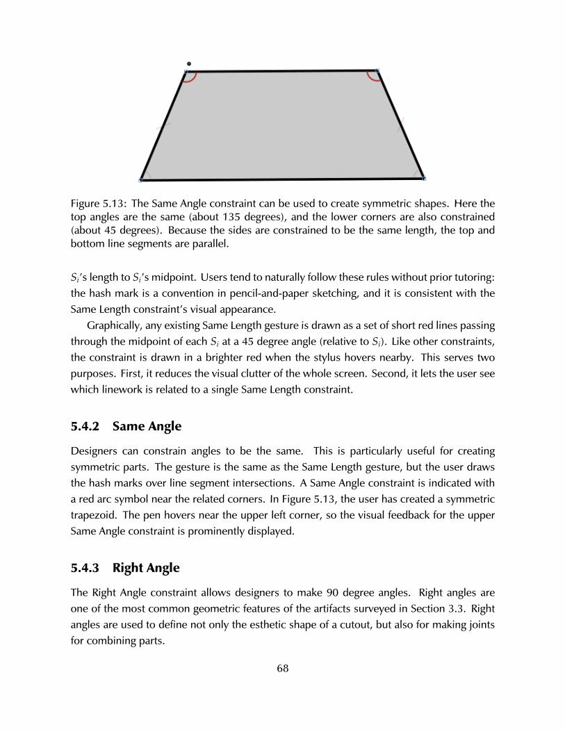
Figure 5.13: The Same Angle constraint can be used to create symmetric shapes. Here thetop angles are the same (about 135 degrees), and the lower corners are also constrained(about 45 degrees). Because the sides are constrained to be the same length, the top andbottom line segments are parallel.
Si’s length to Si’s midpoint. Users tend to naturally follow these rules without prior tutoring:the hash mark is a convention in pencil-and-paper sketching, and it is consistent with theSame Length constraint’s visual appearance.
Graphically, any existing Same Length gesture is drawn as a set of short red lines passingthrough the midpoint of each Si at a 45 degree angle (relative to Si). Like other constraints,the constraint is drawn in a brighter red when the stylus hovers nearby. This serves twopurposes. First, it reduces the visual clutter of the whole screen. Second, it lets the user seewhich linework is related to a single Same Length constraint.
5.4.2 Same Angle
Designers can constrain angles to be the same. This is particularly useful for creatingsymmetric parts. The gesture is the same as the Same Length gesture, but the user drawsthe hash marks over line segment intersections. A Same Angle constraint is indicated witha red arc symbol near the related corners. In Figure 5.13, the user has created a symmetrictrapezoid. The pen hovers near the upper left corner, so the visual feedback for the upperSame Angle constraint is prominently displayed.
5.4.3 Right Angle
The Right Angle constraint allows designers to make 90 degree angles. Right angles areone of the most common geometric features of the artifacts surveyed in Section 3.3. Rightangles are used to define not only the esthetic shape of a cutout, but also for making jointsfor combining parts.
68
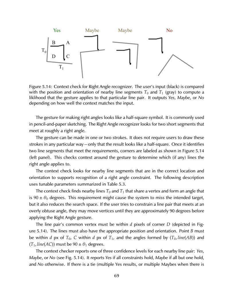
AB
CDT0
T1
Yes Maybe Maybe No
Figure 5.14: Context check for Right Angle recognizer. The user’s input (black) is comparedwith the position and orientation of nearby line segments T0 and T1 (gray) to compute aliklihood that the gesture applies to that particular line pair. It outputs Yes, Maybe, or Nodepending on how well the context matches the input.
The gesture for making right angles looks like a half-square symbol. It is commonly usedin pencil-and-paper sketching. The Right Angle recognizer looks for two short segments thatmeet at roughly a right angle.
The gesture can be made in one or two strokes. It does not require users to draw thesestrokes in any particular way—only that the result looks like a half-square. Once it identifiestwo line segments that meet the requirements, corners are labeled as shown in Figure 5.14(left panel). This checks context around the gesture to determine which (if any) lines theright angle applies to.
The context check looks for nearby line segments that are in the correct location andorientation to supports recognition of a right angle constraint. The following descriptionuses tunable parameters summarized in Table 5.3.
The context check finds nearby lines T0 and T1 that share a vertex and form an angle thatis 90 ± θ0 degrees. This requirement might cause the system to miss the intended target,but it also reduces the search space. If the user tries to constrain a line pair that meets at anoverly obtuse angle, they may move vertices until they are approximately 90 degrees beforeapplying the Right Angle gesture.
The line pair’s common vertex must be within d pixels of corner D (depicted in Fig-ure 5.14). The lines must also have the appropriate position and orientation. Point B mustbe within d px of T0, C within d px of T1, and the angles formed by (T0, line(AB)) and(T1, line(AC)) must be 90 ± θ1 degrees.
The context checker reports one of three confidence levels for each nearby line pair: Yes,Maybe, or No (see Fig. 5.14). It reports Yes if all constraints hold, Maybe if all but one hold,and No otherwise. If there is a tie (multiple Yes results, or multiple Maybes when there is
69

Param Threshold Remark
θ0 20 Maximum angle formed by target segmentsT0 and T1.
θ1 20 Maximum angle formed by a target segmentsand part of the right angle gesture.
d 10 Maximum distance between feature points.
Table 5.3: Parameters used in Right Angle context checking.
not a Yes result) the one whose T0–T1 intersection is closest to point D is chosen.
70
Chapter 6
Summative Evaluation
I evaluated Sketch It, Make It in two ways. First, I tested SIMI with 60 undergraduatearchitecture students. The objective was to test if (and how well) SIMI’s sketch-basedinteraction could be used to make precisely-defined designs for fabrication. Second, a task-tool analysis compares the strategy of an experienced SIMI user (me) for making an objectwith that of an experienced Illustrator user. This was done to compare how these starklydifferent tools require designers to work.
6.1 Workshop
I held a workshop with 60 undergraduate architecture students to gather qualitative feedbackabout how easy or difficult SIMI is to learn and use. The workshop was held in 30-minutesessions over two days in a room equipped with iMacs and Wacom Intuos tablets. Regret-tably, these tablets do not display output, so users’ eyes are not focused on the same physicallocation as the pen tip—leading to significant hand-eye coordination challenges. More costlydisplay tablets like the Cintiq (Figure 1.1) avoid this problem, but were unavailable for theworkshop.
Initially, students complained that the tablet hardware was difficult to use, but most ofthe tablet-related trouble went away after about ten minutes. Then they quickly learned tomake line work and constraints. At first they had trouble erasing and selecting points, butsoon learned to make these gestures.
I expected students to have difficulty using SIMI because the hardware (tablets) andinteraction paradigm (sketch-based modeling) were both new to them. However, by thesecond day, most questions and comments regarded missing features, not about how touse the system.
After the workshop, students were offered an extra credit assignment to complete a short
71
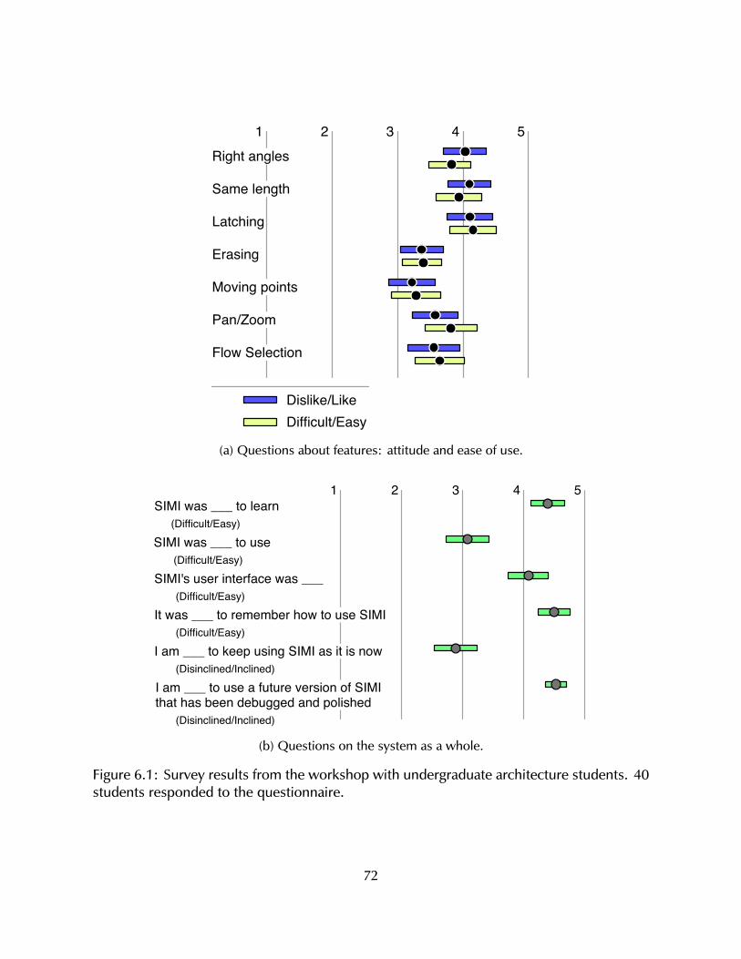
Right angles
Same length
Latching
Erasing
Moving points
Pan/Zoom
Flow Selection
1 2 3 4 5
Dislike/LikeDifficult/Easy
(a) Questions about features: attitude and ease of use.
1 2 3 4 5SIMI was ___ to learn
(Difficult/Easy)
SIMI was ___ to use(Difficult/Easy)
SIMI's user interface was ___(Difficult/Easy)
It was ___ to remember how to use SIMI(Difficult/Easy)
I am ___ to keep using SIMI as it is now(Disinclined/Inclined)
I am ___ to use a future version of SIMI that has been debugged and polished
(Disinclined/Inclined)
(b) Questions on the system as a whole.
Figure 6.1: Survey results from the workshop with undergraduate architecture students. 40students responded to the questionnaire.
72
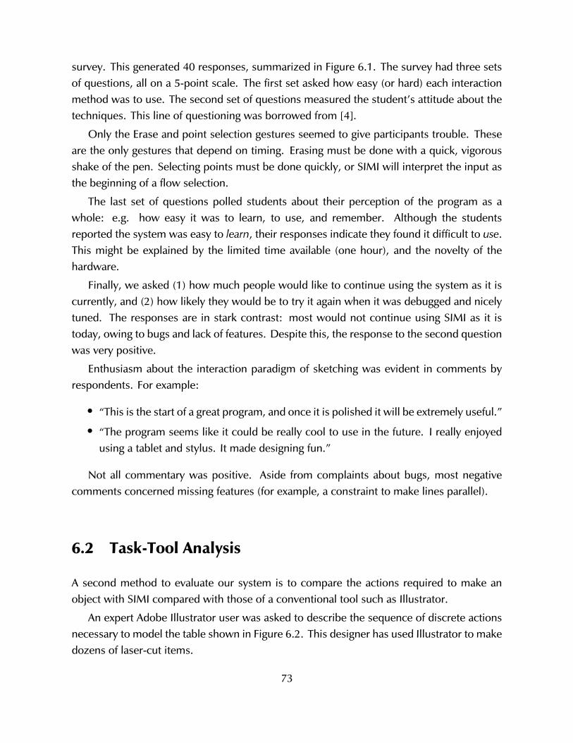
survey. This generated 40 responses, summarized in Figure 6.1. The survey had three setsof questions, all on a 5-point scale. The first set asked how easy (or hard) each interactionmethod was to use. The second set of questions measured the student’s attitude about thetechniques. This line of questioning was borrowed from [4].
Only the Erase and point selection gestures seemed to give participants trouble. Theseare the only gestures that depend on timing. Erasing must be done with a quick, vigorousshake of the pen. Selecting points must be done quickly, or SIMI will interpret the input asthe beginning of a flow selection.
The last set of questions polled students about their perception of the program as awhole: e.g. how easy it was to learn, to use, and remember. Although the studentsreported the system was easy to learn, their responses indicate they found it difficult to use.This might be explained by the limited time available (one hour), and the novelty of thehardware.
Finally, we asked (1) how much people would like to continue using the system as it iscurrently, and (2) how likely they would be to try it again when it was debugged and nicelytuned. The responses are in stark contrast: most would not continue using SIMI as it istoday, owing to bugs and lack of features. Despite this, the response to the second questionwas very positive.
Enthusiasm about the interaction paradigm of sketching was evident in comments byrespondents. For example:
• “This is the start of a great program, and once it is polished it will be extremely useful.”
• “The program seems like it could be really cool to use in the future. I really enjoyedusing a tablet and stylus. It made designing fun.”
Not all commentary was positive. Aside from complaints about bugs, most negativecomments concerned missing features (for example, a constraint to make lines parallel).
6.2 Task-Tool Analysis
A second method to evaluate our system is to compare the actions required to make anobject with SIMI compared with those of a conventional tool such as Illustrator.
An expert Adobe Illustrator user was asked to describe the sequence of discrete actionsnecessary to model the table shown in Figure 6.2. This designer has used Illustrator to makedozens of laser-cut items.
73
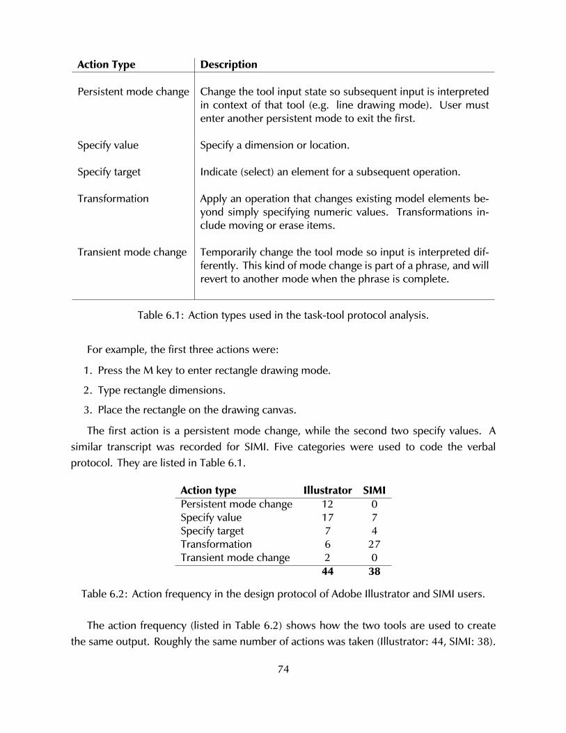
Action Type Description
Persistent mode change Change the tool input state so subsequent input is interpretedin context of that tool (e.g. line drawing mode). User mustenter another persistent mode to exit the first.
Specify value Specify a dimension or location.
Specify target Indicate (select) an element for a subsequent operation.
Transformation Apply an operation that changes existing model elements be-yond simply specifying numeric values. Transformations in-clude moving or erase items.
Transient mode change Temporarily change the tool mode so input is interpreted dif-ferently. This kind of mode change is part of a phrase, and willrevert to another mode when the phrase is complete.
Table 6.1: Action types used in the task-tool protocol analysis.
For example, the first three actions were:
1. Press the M key to enter rectangle drawing mode.
2. Type rectangle dimensions.
3. Place the rectangle on the drawing canvas.
The first action is a persistent mode change, while the second two specify values. Asimilar transcript was recorded for SIMI. Five categories were used to code the verbalprotocol. They are listed in Table 6.1.
Action type Illustrator SIMIPersistent mode change 12 0Specify value 17 7Specify target 7 4Transformation 6 27Transient mode change 2 0
44 38
Table 6.2: Action frequency in the design protocol of Adobe Illustrator and SIMI users.
The action frequency (listed in Table 6.2) shows how the two tools are used to createthe same output. Roughly the same number of actions was taken (Illustrator: 44, SIMI: 38).
74
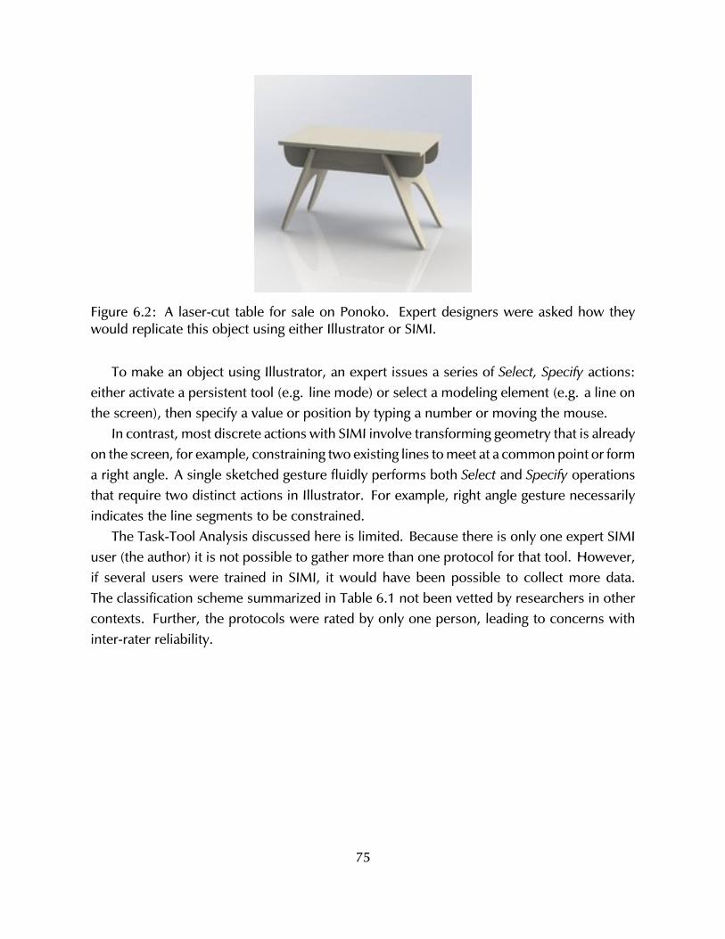
Figure 6.2: A laser-cut table for sale on Ponoko. Expert designers were asked how theywould replicate this object using either Illustrator or SIMI.
To make an object using Illustrator, an expert issues a series of Select, Specify actions:either activate a persistent tool (e.g. line mode) or select a modeling element (e.g. a line onthe screen), then specify a value or position by typing a number or moving the mouse.
In contrast, most discrete actions with SIMI involve transforming geometry that is alreadyon the screen, for example, constraining two existing lines to meet at a common point or forma right angle. A single sketched gesture fluidly performs both Select and Specify operationsthat require two distinct actions in Illustrator. For example, right angle gesture necessarilyindicates the line segments to be constrained.
The Task-Tool Analysis discussed here is limited. Because there is only one expert SIMIuser (the author) it is not possible to gather more than one protocol for that tool. However,if several users were trained in SIMI, it would have been possible to collect more data.The classification scheme summarized in Table 6.1 not been vetted by researchers in othercontexts. Further, the protocols were rated by only one person, leading to concerns withinter-rater reliability.
75

76
Chapter 7
Conclusion
Rapid fabrication—3D printing, laser cutting, and many other processes—can support de-signers in ways that were not possible even ten years ago. But to realize this promise,machine access is not enough. Users need effective and appropriate design tools.
Sketching is often cited as a common and necessary part of the design process in manydomains. Beginning in the early 1960s with Sutherland’s Sketchpad system [72], researchershave developed sketching systems in many areas, like mechanical engineering [47], website design [46], and furniture production [55, 63]. During this time there has been a greatdeal of work on sketch recognition and on isolated sketch-based interaction techniques. Butthere has been little effort in exploring how all this fundamental work can be integrated andpresented as a coherent and useful whole to address real-world design.
This thesis explored the role of sketch based interaction techniques as a basis for rapidfabrication design tools. I bridged the gap between an academic treatment of sketch-baseddesign and a real-world useful and usable system. This work has included a literaturereview in design and computational support for sketching (Chapter 2 and the survey withmy committee [34]). Chapter 3 explored the domain of design for laser cutting by studyingboth artist and the artifact. Last, Chapters 4 and 5 detailed my Sketch It, Make It systemthat provides a solid example of how a sketch based system can present a set of sketchrecognizers and (most importantly) interaction techniques to enable real people to do realwork in a way that was previously not actualized.
While I have made a prototype that many observers find compelling, there is still morework to do. It raises interesting ideas about what else is possible with this form of interaction,and questions remain unresolved.
In this chapter I discuss how my work with SIMI can serve as a starting point for furtherwork. First I discuss the rationale for providing the particular feature set embodied in thissoftware. Next I discuss the implications SIMI has on several areas of research. Last, I
77
describe the most obvious next steps that I would like to take.
7.1 Justification of Feature Choices
SIMI includes a set of interaction techniques that let users perform actions to create, edit,and build precision models for laser cutting. This particular collection chosen because it (a)provided a minimal set of features to be useful, (b) it covered a range of functions and (c)demonstrated a variety of sketch recognition types.
Some traditional software features were intentionally left out. For example, Copy andPaste is nearly ubiquitous in interactive systems, but it is not found in SIMI. It is oftenbeneficial to discard long-standing assumptions of what is necessary to explore alternateways to proceed. By omitting Copy and Paste, I had to focus on making it as easy aspossible to create geometry and constraints. It is possible to create a ‘copy’ of geometryusing standard SIMI actions. This helps to keep the application simple.
7.2 Implications to Related Areas
This research has implications to several areas, including rapid fabrication hardware andsurrounding communities, interaction design, and research on sketch-based interaction andmodeling.
7.2.1 Rapid Fabrication and Maker Communities
Laser cutters, 3D printers, CNC mills and so forth are called rapid prototyping machinesbecause they facilitate fast machine-work. Often, software design tools are the bottleneck ina designer’s work/build process. While experienced professionals might master the softwareto use rapid fabrication machines quickly, the majority of current (and certainly potential)users have not. Sketch based interaction might be one part of a new kind democratizeddesign software that lets hobbyists and amateurs design and make with rapid fabricationmachines.
Inexpensive, widely available, and easy-to-use rapid fabrication hardware and softwarehas interesting consequences. Economically, it suggests a future where people can simply“print” new objects like door knobs as needed—obviously a topic of concern for hardwarestores and manufacturers. Socially, it gives regular people the ability to play an active role inthe design, function, and production of everyday things—which is concerning to professionaldesigners and engineers. While it is difficult to envision a world without hardware stores (or
78
designers and engineers), desktop design and fabrication will have serious, unpredictable,and positive consequences.
7.2.2 Interaction Design
Sketch based interaction may be paired with other input paradigms to achieve unique resultsthat would not be possible in isolation. While sketching, the user’s non-dominant hand isfree to perform other tasks. This can be leveraged to develop new ways to design.
Touch input is a current topic of importance, with touch-sensitive devices like tabletsand smart phones dominating the consumer electronics market. Sketching, paired withtouch, has recently been shown to give compelling results [30]. New technologies, such asvoice recognition or Microsoft’s distance-sensing Kinect, offer additional avenues that mightbe appropriate to mix with sketch-based input. Virtual reality hardware—special glassesthat simulate 3D projection, volumetric displays, etc.—could be used to immerse designersin augmented reality design tools that let people draw anywhere in physical space [36].These topics have been covered to various degrees, but the sketch interaction componenthas always been ad-hoc. This thesis gives a solid example of one way to support suchinteraction. Input paradigms that pair sketching with something else (touch, gesture, VR)have hardly been explored enough to consider them known topics.
Currently, sketch interaction is limited to devices that explicitly support pen interaction.But ongoing advances in sensing technology (e.g. Touche [62]) may allow arbitrary surfacesto accept sketch and touch input. Further, projection and display technology continues toadvance. When every available wall and tabletop can display graphics and recognize sketchinput, that has serious consequences for the future of interaction and design.
The recognition and resolution architecture from Chapter 4 might be useful to researchersand developers working on other kinds of recognition-based systems. For example, multi-touch devices or Kinect-style hand or body recognition could use the staged approach tosimplify the recognition process. However, because there are multiple contemporaneoussample points to consider, future developers might have to extend the architecture discussedhere.
Perhaps most importantly, the staged recognition architecture lets designers interactwith computers using easy-to-make gestures that richly specify an action, to which objects,and in which way. This seems to reduce users’ cognitive load by removing the need to enterpersistent modes or the needs to set up sequences of atomic operations to achieve a desiredoutcome. Additional work on this topic is warranted.
79
7.2.3 Sketch Based Interaction and Modeling
This thesis claims that SIMI exemplifies sketch-based interaction techniques that work welltogether. However, the particular set is tuned to the laser cutter domain and to the featuresSIMI provides. How can future researchers generalize this contribution?
The recognition and resolution architecture from Section 4.5 guides programmers andinteraction designers to develop new techniques and applications. While a programmingstructure is helpful, there are other important aspects to consider when designing newsketching gestures.
I provide several heuristics for developing sketch-based interaction techniques in otherapplications:
Leverage context. Gesture syntax can be overloaded by letting context determine mean-ing. For example, a circle drawn around two unlatched end points is semantically differentfrom a circle drawn around a cutout. Overloading gestures means less work for the pro-grammer, and fewer gestures for the user to learn and remember. However, care must betaken to ensure that the contexts are separate enough that they will not be confused.
Substantial shape differences improve recognition and user experience. Strive to developgestures that are substantially different from one another. It is tempting to create manygestures that are different in subtle ways because it is easy to program the related recognizers.However, users will have a difficult time remembering and executing these subtly differentgestures.
Rely on visual reinforcement and physical metaphors. SIMI’s right angle constraint ap-pearance echos the gesture used to create it. When there is not a visual, the gesture shouldmake physical sense: the circle gesture used to latch points together feels like tying thepoints together with a string; the erase gesture is based on scratching over unwanted markson physical paper.
Make use of the staged recognition architecture. Some gestures should be acted uponimmediately, while others could (or should) be deferred until later. For dynamic recognizers,effective visual feedback is critical. While the staged architecture eases programming, itstrue purpose is to improve user experience.
7.3 Future Work
The most interesting research leaves more questions than it answered. Having built a usefuland useful system for laser cut designs, much of the feedback I receive focuses on additionalfeatures. Observers commonly would like to see a tool like SIMI for some other domain,
80
such as for 3D modeling.
7.3.1 Common Feature Requests
It is likely that Sketch It, Make It (or something like it) will be made into a commercial productsoon. We have accumulated a long list of feature requests that can serve as a starting pointfor the next set of additional features.
Users like the paper-like feel of the tool, and would prefer to have the ability to add inkthat is not recognized. This enables designers to explore freely, as they would on paper,while still having the ability to use these unrecognized portions in future work.
Handwriting recognition is another commonly requested feature. This was intentionallynot included in the current prototype because it would have required a substantial timeinvestment without a correspondingly substantial pay-out. Handmade numbers and textcould be applied to give dimensions and labels to parts of a drawing.
Users also request additional constraints, for example making two lines parallel, ormaking an object appear at the midpoint between two others. This would allow a wider andricher range of output.
Another feature that would likely make SIMI much more useful is the ability to assemble3D constructions from 2D parts. This would let users see the relationship between the 2Dparts they have designed and the final 3D output. This can be useful, for example, to identifystylistic or assembly problems before spending time and material on the laser cutter.
7.3.2 Machine Learning Improvements
SIMI was built on the idea that it is generally better to give users interaction techniques tostate their intentions, rather than using machine learning routines to deduce what the userwants. However, there are a number of cases where machine learning could be used tomake the overall user experience better.
Each user has a drawing style that is different from any other. The differences can besubtle, or might be substantial. In keeping with the paper-like interface, an intelligent agentcould watch the user draw and learn their particular style and preferences. For example, ifa user consistently fails to make the erase gesture correctly, their preferred erasure gesturecould be learned and applied (without asking). The user could also teach the system newgestures entirely, providing new syntax directly.
Sometimes companies or other organizations adopt conventions. These conventionsmay be common within that community but not typically found outside. SIMI could learnthese social norms, and understand when to apply them.
81
7.3.3 Domain Specific Improvements
Laser cutters and similar machines (water jet, plasma, CNC mills) share common properties.If the software could account for these properties, the user could incorporate them into theirdesigns. An obvious property of laser cutters is the kerf—the width of the cut path. Thelaser cutter used throughout SIMI’s development typically leaves a kerf of approximately0.4mm. When designing press-fit notches for rigid material that is 3mm thick, the kerf sizeis a significant concern. If the tool understood that certain geometry was sensitive to kerfthickness, the software could save the user time and material costs by making more accuratecuts.
The press-fit notch just mentioned is just one type of joint. Currently SIMI does notinclude a concept of joints. If it did, the user would be able to indicate where joints shouldexist, between which parts, what the material properties are—and the software would takecare of the rest.
Using material is another important consideration, both because it costs money, andbecause supplies are often limited. For example, Ponoko sells 15”x15” squares of acrylicfor between $8 and $28 depending on thickness. To make more efficient use of material,the software could perform intelligent cut file layout with a shape-packing algorithm. If thesystem knows where a piece of material has holes, the algorithm could also place new partson used material, saving a lot of money.
Assemblies often have a lot of parts, and it can frustrate users when trying to determinewhich part goes where. The tool could etch part numbers (or joint labels) into the materialto aid assembly.
7.3.4 Beyond Laser Cutting
In this work, I set out to demonstrate how a set of interaction techniques designed to be usedtogether to make a useful and usable system, and show that sketch-based interaction shouldbe taken seriously, particularly as a paradigm for doing design. To do this I picked a specificdomain—laser cutting—but there are other domains that would have been appropriate aswell.
3D modeling is an obvious choice. Physical objects are necessarily three dimensional,and designers often sketch them in perspective. There are interesting challenges associatedwith “3D sketching”, and many others are working on these research topics.
2D applications will be easier to write based on SIMI’s current implementation. Graphicdesign applications for illustrations, diagrams, logos, T-shirt designs, or cartooning areappropriate areas for SIMI’s interaction.
82
Teachers famously draw on chalk boards or whiteboards to illustrate concepts in manyareas, from physics to mathematics. A sketch-based education system might be a useful toolfor teaching STEM topics at all levels—primary, secondary, and post-secondary education.
The techniques presented in this dissertation could potentially be used in any domainthat makes use of structured or semi-structured diagrams. It could be used to think aboutideas, generate concepts. Or it could be a communication tool used to work with others inongoing design projects. Or sketch-based design could simply be used as a fast, efficientmethod of specifying the designer’s intent to create finished output.
7.4 Looking Forward
Nearly everything in our environment was deliberately designed and built by a humanbeing. An artifact’s users are not often the same people that designed or built it. The recentintroduction and success of affordable, fast fabrication machinery suggests the gulf betweendesigners and users may narrow as desktop manufacturing lets ordinary people design andbuild things on their own. One remaining bottleneck is software: access to fabricationmachinery is not enough. Democratized fabrication requires democratized design tools.People need design software that is easy to use and gives the means to express ideas. Butfor ordinary people, current CAD software is not an option. It is expensive, hard to learn,and hard to use.
The sketch-based interaction presented in this thesis explicitly supports design for lasercut items. This is provided as an example of a (potentially) much larger space of sketch-based modeling tools. Many other application areas were mentioned above, such as STEMapplications for students, 3D modeling, animation, and business diagrams. This line ofresearch is important not simply because it enables users to do one thing marginally betterthan before. It is important because it will empower people to design and make many kindsof things that were previously impossible. Democratized design is a powerful idea, and theconsequences are far-reaching.
83

84
Bibliography
[1] Christine Alvarado. Multi-domain Sketch Understanding. PhD thesis, MassachusettsInstitute of Technology, 2004. 2.5.7, 5.4
[2] Christine Alvarado and R. Davis. Sketchread: A multi-domain sketch recognitionengine. In UIST ’04: Proceedings of the 17th annual ACM symposium on User interfacesoftware and technology, 2004. 2.5.2
[3] Rudolf Arnheim. Visual Thinking. Faber and Faber, London, 1969. 2.2, 2.5.4
[4] Seok-Hyung Bae, Ravin Balakrishnan, and Karan Singh. EverybodyLovesSketch: 3Dsketching for a broader audience. In Proceedings of the 22nd annual ACM symposiumon User Interface Software and Technology, UIST ’09, pages 59–68, New York, NY,USA, 2009. ACM. 6.1
[5] O. Bimber, L. M. Encarnacao, and A. Stork. A multi-layered architecture for sketch-based interaction within virtual environments. Computers and Graphics, 24:851–867,2000. 2.5.7
[6] Mark Bloomenthal, Robert Zeleznik, Russell Fish, Loring Holden, Andrew Forsberg,Richard Riesenfeld, Matt Cutts, Samuel Drake, Henry Fuchs, and Elaine Cohen.SKETCH-N-MAKE: Automated machining of CAD sketches. In Proceedings of ASMEDETC’98, pages 1–11, 1998. 2.4
[7] Dorothea Blostein, Edward Lank, Arlis Rose, and Richard Zanibbi. User interfaces foron-line diagram recognition. In GREC ’01: Selected Papers from the Fourth Interna-tional Workshop on Graphics Recognition Algorithms and Applications, pages 92–103,London, UK, 2002. Springer-Verlag. 2.5.2
[8] Louis Bucciarelli. Designing Engineers. MIT Press, Boston, MA, 1994. 3.1
[9] R. Cole, J. Mariani, H. Uszkoreit, A. Zaenen, and V. Zue. Survey of the State of the Artin Human Language Technology. Center for Spoken Language Understanding CSLU,Carnegie Mellon University, 1995. 2.5.1, 2.5.4
[10] G. Costagliola, V. Deufemia, F. Ferrucci, and C. Gravino. Exploiting XPG for visual lan-
85
guages definition, analysis and development. Electronic Notes in Theoretical ComputerScience, 82(3):612–627, 2003. 2.5.7
[11] Nigel Cross. The nature and nurture of design ability. Design Studies, 11(3):127–140,1990. 2.2
[12] Randall Davis. Sketch understanding: toward natural interaction toward natural inter-action. In SIGGRAPH ’06: ACM SIGGRAPH 2006 Courses, page 4, New York, NY, USA,2006. ACM. 2.5.4
[13] David Eberly. Distance from a point to an ellipse, an ellipsoid, or a hyperellipsoid.Technical report, Geometric Tools, LLC, 2011. 5.1.3
[14] Eugene S. Ferguson. Engineering and the Mind’s Eye. MIT Press, 1992. 2.2, 3.1
[15] M. Fitzgibbon, A. W.and Pilu and R. B. Fisher. Direct least-squares fitting of ellipses.IEEE Trans. Pattern Analysis and Machine Intelligence, 21(5):476–480, 1999. 5.1.3
[16] Kenneth D. Forbus, Jeffrey Usher, and Vernell Chapman. Sketching for military coursesof action diagrams. In Proceedings of Intelligent User Interfaces ’03, 2003. 2.5.2
[17] R.P. Futrelle. Ambiguity in visual language theory and its role in diagram parsing. VisualLanguages, 1999. Proceedings. 1999 IEEE Symposium on, pages 172–175, 1999. 2.5.8
[18] Neil Gershenfeld. Fab: The coming revolution on your desktop—from personal com-puters to personal fabrication. Basic Books, 2005. 2.1
[19] Global Industry Analysts. Laser cutter market to exceed $3.8b by 2015.http://goo.gl/Raelc, 2010. 1
[20] Vinod Goel. Sketches of Thought. MIT Press/A Bradford Book, Cambridge, MA, 1995.2.2.1, 2.2.2
[21] G. Goldschmidt. The dialectics of sketching. Creativity Research Journal, 4(2):123–143,1991. 2.2, 2.5.2
[22] Nelson Goodman. Languages of Art: An Approach to a Theory of Symbols. 2nd ed.Hackett, Indianapolis, Indiana, 1976. 2.2.2
[23] Mark D. Gross and Ellen Yi-Luen Do. Ambiguous intentions: A paper-like interface forcreative design. In UIST ’04: ACM Conference on User Interface Software Technology,pages 183–192, Seattle, WA, 1996. 2.2.2, 2.5.2
[24] Mark D. Gross and Ellen Yi-Luen Do. Drawing on the back of an envelope. Computersand Graphics, 24(6):835–849, 2000. 2.5
[25] Mark D. Gross and Ellen Yi-Luen Do. Educating the new makers: Cross-disciplinarycreativity. Leonardo, 42(3):210–215, 2009. 2.1
86
[26] John Grundy and John Hosking. Supporting generic sketching-based input of diagramsin a domain-specific visual language meta-tool. In ICSE ’07: International Conference onSoftware Engineering, pages 282–291, Washington, DC, 2007. IEEE Computer Society.2.5
[27] Tracy Hammond and Randall Davis. LADDER, a sketching language for user interfacedevelopers. Elsevier, Computers and Graphics, 29:518–532, 2005. 2.5.7
[28] Christopher F. Herot. Graphical input through machine recognition of sketches. InSIGGRAPH ’76: Proceedings of the 3rd annual conference on Computer graphics andinteractive techniques, pages 97–102, New York, NY, USA, 1976. ACM. 5.3.2
[29] Ken Hinckley. Input technologies and techniques. In Andrew Sears and Julie A. Jacko,editors, Handbook of Human-Computer Interaction. Lawrence Erlbaum & Associates,2006. 2.3
[30] Ken Hinckley, Koji Yatani, Michel Pahud, Nicole Coddington, Jenny Rodenhouse, AndyWilson, Hrvoje Benko, and Bill Buxton. Pen + touch = new tools. In Proceedings ofthe 23nd annual ACM symposium on User interface software and technology, UIST ’10,pages 27–36, New York, NY, USA, 2010. ACM. 2.3, 7.2.2
[31] Takeo Igarashi and John F. Hughes. A suggestive interface for 3d drawing. In UIST’01: Proceedings of the 14th annual ACM symposium on User interface software andtechnology, pages 173–181, New York, NY, USA, 2001. ACM. 2.5.2
[32] Takeo Igarashi, Satoshi Matsuoka, and Hidehiko Tanaka. Teddy: A sketching interfacefor 3d freeform design. In ACM SIGGRAPH’99, pages 409–416, Los Angeles, California,1999. 2.4
[33] Gabe Johnson, Mark D Gross, and Ellen Yi-Luen Do. Flow selection: A time-basedselection and operation technique for sketching tools. In 2006 Conference on AdvancedVisual Interfaces, pages 83–86, Venice, Italy, 2006. 1.1, 4, 5.2.3
[34] Gabe Johnson, Mark D. Gross, Jason Hong, and Ellen Yi-Luen Do. Computationalsupport for sketching in design: a review. Foundations and Trends in Human-ComputerInteraction, 2(1):1–93, 2009. 7
[35] Wendy Ju, Arna Ionescu, Lawrence Neeley, and Terry Winograd. Where the wild thingswork: capturing shared physical design workspaces. In CSCW ’04: Proceedings of the2004 ACM conference on Computer supported cooperative work, pages 533–541, NewYork, NY, USA, 2004. ACM. 3.1
[36] Thomas Jung, Mark D. Gross, and Ellen Yi luen Do. Light pen—-sketching light in 3D.In In Proc. of CAAD Futures, pages 327–338, 2003. 7.2.2
87
[37] Gaetano Kanizsa. Organization in Vision: Essays on Gestalt Perception. Praeger, NewYork, 1979. 2.5.4, 2.7
[38] Levent Burak Kara and Thomas F. Stahovich. An image-based, trainable symbol rec-ognizer for hand-drawn sketches. Computers and Graphics, 29(4):501–517, 2005.2.5.7
[39] Levent Burak Kara, Chris M. D’Eramo, and Kenji Shimada. Pen-based styling design of3d geometry using concept sketches and template models. In SPM ’06: Proceedings ofthe 2006 ACM symposium on Solid and physical modeling, pages 149–160, New York,NY, USA, 2006. ACM. 2.4, 2.5.8
[40] Maria Karam and M. C. Schraefel. Investigating user tolerance for errors in vision-enabled gesture-based interactions. In AVI ’06: Proceedings of the working conferenceon Advanced visual interfaces, pages 225–232, New York, NY, USA, 2006. ACM. 2.5.1
[41] Dae Hyun Kim and Myoung-Jun Kim. A curvature estimation for pen input segmentationin sketch-based modeling. Computer-Aided Design, 38(3):238–248, 2006. 2.5.4
[42] Gordon Kurtenbach and William Buxton. Issues in combining marking menus and directmanipulation techniques. In Symposium on User Interface Software and Technology,pages 137–144. ACM, 1991. 2.5.2
[43] F. Lakin, J. Wambaugh, L. Leifer, D. Cannon, and C. Sivard. The electronic design note-book: Performing medium and processing medium. Visual Computer: InternationalJournal of Computer Graphics, 5(4), 1989. 2.5.3
[44] Mary LaLomia. User acceptance of handwritten recognition accuracy. In CHI ’94:Conference companion on Human factors in computing systems, pages 107–108, NewYork, NY, USA, 1994. ACM. 2.5.1
[45] James A. Landay. SILK: Sketching interfaces like krazy. In ACM CHI 1996, pages398–399, Vancouver, Canada, 1996. 2.2.1, 2.5.2, 2.5.8
[46] James Lin, Mark Newman, Jason Hong, and J.A. Landay. DENIM: Finding a tighter fitbetween tools and practice for web site design. In CHI Letters, pages 510–517, 2000.2.2.1, 2.5, 7
[47] H. Lipson and M. Shpitalni. Correlation-based reconstruction of a 3D object froma single freehand sketch. In AAAI 2002 Spring Symposium (Sketch UnderstandingWorkshop), 2002. 2.4, 2.5.8, 7
[48] Hod Lipson and Melba Kurman. Factory@Home: The emerging economy of personalmanufacturing. Report Commissioned by the Whitehouse Office of Science & Tech-nology Policy, 2010. 2.1.2
88
[49] Jennifer Mankoff. Providing integrated toolkit-level support for ambiguity inrecognition-based interfaces. In CHI ’00: CHI ’00 extended abstracts on Human factorsin computing systems, pages 77–78, New York, NY, USA, 2000. ACM. 2.5.4, 2.5.8
[50] Yuki Mori and Takeo Igarashi. Plushie: An interactive design system for plush toys. InProceedings of SIGGRAPH 2007. ACM, 2007. 2.4
[51] Brad Myers, Sun Young Park, Yoko Nakano, Greg Mueller, and Andrew Ko. Howdesigners design and program interactive behaviors. In Paolo Bottoni, Mary BethRosson, and Mark Minas, editors, Proceedings of IEEE Symposium on Visual Languagesand Human-Centric Computing, pages 177–184, 2008. 2.2
[52] N. Negroponte. Soft Architecture Machines. MIT Press, Cambridge, MA, 1975. 2.5.2
[53] Mark W. Newman and James A. Landay. Sitemaps, storyboards, and specifications: asketch of web site design practice. In DIS ’00: Proceedings of the 3rd conference onDesigning interactive systems, pages 263–274, New York, NY, USA, 2000. ACM. 2.2.1
[54] W.M. Newman and R.F. Sproull. Principles of Interactive Computer Graphics, 2nd ed.McGraw-Hill, 1979. 2.5.7
[55] Yeonjoo Oh, Gabe Johnson, Mark D. Gross, and Ellen Yi-Luen Do. The Designosaurand the Furniture Factory: Simple software for fast fabrication. In 2nd Int. Conf. onDesign Computing and Cognition (DCC06), 2006. 2.4, 7
[56] Palm, Inc. Palm digital pda. http://www.palm.com/, 2007. 2.5.2
[57] Boris Pasternak and Bernd Neumann. Adaptable drawing interpretation using object-oriented and constraint-based graphic specification. In Proceedings of the InternationalConference on Document Analysis and Recognition (ICDAR ’93), 1993. 2.5.7
[58] Eric Paulos, Sunyoung Kim, and Stacey Kuznetsov. From Social Butterfly to Engaged Cit-izen, chapter The Rise of the Expert Amateur: Citizen Science and Micro-Volunteerism.MIT Press, 2012. 2.1
[59] Beryl Plimmer. Experiences with digital pen, keyboard and mouse usability. Journal onMultimodal User Interfaces, 2(1):13–23, July 2008. 2.3
[60] Horst Rittel and Melvin Webber. Dilemmas in a general theory of planning. PolicySciences, 4:155–169, 1973. 2.2
[61] Dean Rubine. Specifying gestures by example. SIGGRAPH Computer Graphics, 25(4):329–337, 1991. 2.5.7
[62] Munehiko Sato, Ivan Poupyrev, and Chris Harrison. Touché: enhancing touchinteraction on humans, screens, liquids, and everyday objects. In Proceedings of the
89
2012 ACM annual conference on Human Factors in Computing Systems, CHI ’12, pages483–492, New York, NY, USA, 2012. ACM. 7.2.2
[63] Greg Saul, Manfred Lau, Jun Mitani, and Takeo Igarashi. SketchChair: An all-in-onechair design system for end users. In Proceedings of the 5th International Conferenceon Tangible, Embedded and Embodied Interaction (TEI2011), 2011. 2.4, 7
[64] Eric Saund and Thomas P. Moran. A perceptually-supported sketch editor. In ACMSymposium on User Interface Software and Technology (UIST ’94), Marina del Rey, CA,1994. 2.5.4
[65] Eric Saund, James Mahoney, David Fleet, Dan Larner, and Edward Lank. Perceptualorganization as a foundation for intelligent sketch editing. In AAAI Spring Symposium onSketch Understanding, pages 118–125. American Association for Artificial Intelligence,2002. 2.5.4
[66] D. A. Schon. The Reflective Practitioner. Basic Books, 1983. 2.5.2
[67] D. A. Schon and G. Wiggins. Kinds of seeing and their functions in designing. DesignStudies, 13(2):135–156, 1992. 2.2
[68] T. Sezgin, T. Stahovich, and R. Davis. Sketch based interfaces: Early processing forsketch understanding. In The Proceedings of 2001 Perceptive User Interfaces Workshop(PUI’01), 2001. 2.5.4, 5.1
[69] Michael Shilman, Hanna Pasula, Stuart Russell, and Richard Newton. Statistical visuallanguage models for ink parsing. In AAAI Sketch Understanding Symposium, 2001.2.5.8
[70] H. A. Simon. The structure of ill structured problems. Artificial Intelligence, 4(3):181–201, 1973. 2.2
[71] Hyunyoung Song, Francois Guimbretiere, and Hod Lipson. ModelCraft: Capturingfreehand annotations and edits on physical 3d models. In UIST ’06: Proceedings of the19th annual ACM symposium on User interface software and technology, 2006. 2.4
[72] Ivan Sutherland. SketchPad: A man-machine graphical communication system. InSpring Joint Computer Conference, pages 329–345, 1963. 4.3, 4.6.1, 7
[73] Michael Terry and Elizabeth D. Mynatt. Recognizing creative needs in user interfacedesign. In C & C ’02: Proceedings of the ACM Conference on Creativity and Cognition,2002. 2.2.1, 2.5.2
[74] L. Tesler. The smalltalk environment. Byte, 6:90–147, 1981. 4.4.1
[75] The Economist. A factory on your desk. http://www.economist.com/node/14299512.
90

September 2009. 2.1
[76] Jacob O. Wobbrock, Andrew D. Wilson, and Yang Li. Gestures without libraries, toolkitsor training: a $1 recognizer for user interface prototypes. In UIST ’07: Proceedingsof ACM Symposium on User Interface Software and Technology, pages 159–168, NewYork, NY, USA, 2007. ACM. 2.5.7
[77] Wohlers Associates. 3D printing to reach $3.1b by 2016. http://goo.gl/PEDrj. 1
[78] Aaron Wolin, Brandon Paulson, and Tracy Hammond. Sort, merge, repeat: An al-gorithm for effectively finding corners in hand-sketched strokes. In Proceedings ofEurographics 6th Annual Workshop on Sketch-Based Interfaces and Modeling, 2009.5.1
[79] Robert C. Zeleznik, Andrew Bragdon, Chu-Chi Liu, and Andrew Forsberg. Lineogram-mer: creating diagrams by drawing. In UIST ’08: Proceedings of the 21st annual ACMsymposium on User interface software and technology, pages 161–170, New York, NY,USA, 2008. ACM. 5.2.1
91