simultaneous stereo particle image velocimetry and double-pulsed planar laser-induced fluorescence...
TRANSCRIPT

Combustion and Flame 150 (2007) 201–209www.elsevier.com/locate/combustflame
Simultaneous stereo particle image velocimetry anddouble-pulsed planar laser-induced fluorescence of
turbulent premixed flames
Sergei A. Filatyev ∗, Mathew P. Thariyan, Robert P. Lucht, Jay P. Gore
School of Mechanical Engineering, Purdue University, West Lafayette, IN 47907, USA
Received 26 October 2006; received in revised form 22 February 2007; accepted 22 February 2007
Available online 31 May 2007
Abstract
A new technique was developed and applied to the study of flame structure and flame–vortex interaction inturbulent premixed flames. Turbulent premixed flames were probed using simultaneous stereo particle image ve-locimetry (PIV) and a double-pulsed acetone planar laser-induced fluorescence system (PLIF). Two double-pulsedNd:YAG lasers operating at 532 and 266 nm were used for the PIV and acetone PLIF measurements, respectively.The stereo PIV images were acquired using two double-frame CCD cameras, and two ICCD cameras were usedto capture the PLIF signal. The diagnostic system was applied to study turbulent methane–air stoichiometric pre-mixed flames at relatively high Reynolds numbers. Flame merging and the creation of pockets of both productsand reactants were detected, and a very strong interaction between the flame front and the vortex structures wassuggested in the simultaneous PIV/PLIF images. Double-pulsed PLIF data obtained for different time delays al-lowed statistical study of flame development. Three-dimensional turbulent fluxes of mean progress variable wereobtained. It was shown that the fluxes obey the gradient diffusion hypothesis. The proposed diagnostic increasesflexibility and range of measurements available for premixed flames.© 2007 The Combustion Institute. Published by Elsevier Inc. All rights reserved.
Keywords: Laser diagnostics; Simultaneous PIV/PLIF; Acetone PLIF; Turbulent premixed flames
1. Introduction
Turbulent premixed flame structures exhibit com-plex dependence on local gas velocity, curvature, andflame strain [1,2]. To understand local flame behavior,it is important to measure the flame speed propaga-tion, the local gas velocity, and the flame shape ona time-resolved basis. Several papers in the past have
* Corresponding author. Fax: +1 765 494 0530.E-mail address: [email protected] (S.A. Filatyev).
0010-2180/$ – see front matter © 2007 The Combustion Institute.doi:10.1016/j.combustflame.2007.02.005
addressed different aspects of the structure of turbu-lent premixed flames. Planar laser-induced fluores-cence (PLIF) is frequently used to investigate turbu-lent premixed flame structure, and PIV is frequentlyused to measure velocity fields. Some simultaneousPLIF and PIV image acquisition experiments havebeen reported. Some of the earliest work in combiningPIV and PLIF was performed in propane/biacetyl/airflames [3]. In this study, biacetyl PLIF was used forreactant zone visualization. Simultaneous PIV veloc-ity measurements and PLIF imaging of the CH radical
Published by Elsevier Inc. All rights reserved.

202 S.A. Filatyev et al. / Combustion and Flame 150 (2007) 201–209
Fig. 1. Schematic of simultaneous double-pulsed acetone PLIF and stereoscopic PIV arrangement.
was demonstrated both for nonpremixed flames [4]and for premixed flames [5]. Simultaneous PIV andOH PLIF measurements have been demonstrated aswell [6–8]. Simultaneous CH and OH PLIF measure-ments have also been demonstrated [9–11]. While theCH radical provides a convenient flame marker due tothe narrowness of its concentration profile, OH rad-ical images are useful for clarifying the location ofreactants and products. Simultaneous stereo PIV andCH/OH PLIF measurements in turbulent premixedflames were recently performed [12]. It was shownin this study that the out-of-plane velocity componentis a significant factor and must be measured. Two-dimensional cinema PIV of lifted turbulent jet flameswas used to investigate the time-dependent flame–vortex interaction and the effect of the velocity fieldon flame propagation [13].
In the present work, the technique of simultaneousdouble-pulsed acetone PLIF/stereoscopic PIV imag-ing was used for the first time. Acetone is routinelyused as a marker of fuel to study the behavior ofdifferent fuels, especially in internal combustion en-gines [14]. Acetone is destroyed in the flames, soacetone PLIF can be used for reactant zone visual-ization. In the double-pulsed acetone PLIF technique,two acetone PLIF images are acquired with a shortand adjustable time delay between the pulses. Thistechnique was used to study changes in the cross-sectional area of the reaction zone and in the positionof the flame boundary. Stereo PIV was used to obtainall three components of the gas velocity field. Simul-taneous application of the two techniques is shown tobe a powerful method for investigation of turbulentpremixed flames.
2. Experimental methods
A schematic diagram of the experimental appara-tus for simultaneous stereo PIV and double-pulsedacetone PLIF is shown in Fig. 1. For the acetonePLIF measurements, a Spectra-Physics Quanta-RayPIV 400-10 Nd:YAG laser was used in the double-pulsed PIV mode. The fourth harmonic output ofthe laser (266 nm, 10 Hz, 50 mJ/pulse) was usedfor double-pulsed acetone PLIF measurements ratherthan for PIV measurements. Acetone absorbs stronglyin the UV near 266 nm, but the LIF spectrum isstrongly shifted and peaks in the blue. The fluores-cence signal was detected using two Roper ScientificPI-MAX ICCD cameras (512 × 512 pixels) equippedwith Tamron AF 28-300 mm F3.5/6.3 lenses. Onlythe visible portion of the acetone LIF spectrum wasdetected; scattered light at 266 nm was blocked com-pletely by the glass windows of the combustion cham-ber. Therefore, it was not necessary to install trans-mission filters on the PLIF cameras. The cameraswere located on the same side of the laser sheet andacquired LIF emitted at 85◦ and 95◦ with respect tothe direction of laser sheet propagation. The angleswere set with as small deviation from a 90◦ angleas possible to ensure that all region of interest stayedwithin the depth of field of the cameras and were infocus. The depths of field of PLIF and PIV measure-ments were 6 and 3 mm, respectively.
The stereo-PIV system includes a Blue Sky PIVlaser (Nd:YAG laser, 532 nm, 120 mJ/pulse), two TSIPIVCAM 10-30 CCD cameras (1000 × 1016 pixels),a TSI 610032/610034 synchronizer, and a TSI 600067frame grabber. Nikon AF Micro-Nikkor 105 mm

S.A. Filatyev et al. / Combustion and Flame 150 (2007) 201–209 203
Fig. 2. Timing diagram for simultaneous double-pulsed ace-tone PLIF and stereoscopic PIV.
F/2.8 lenses were used to collect the PIV signal. TSIInsight 3G software was used to analyze PIV images.The Al2O3 particles used for seeding of the flow were0.5 µm in diameter.
The visible and UV laser beams were combinedusing a 532 nm/266 nm short-wave-pass dichroicmirror. The same fused silica lenses were used to cre-ate both the PIV and PLIF laser sheets. The dimen-sions of the 266-nm laser sheet were estimated to be60×0.4 mm, and the dimensions of the 532-nm sheetwas estimated to be 70 × 1 mm.
Time synchronization is important to obtain mean-ingful measurements of the motion of flame structureand of the corresponding velocity field. The correcttiming is also needed to eliminate the effect of LIF onthe PIV data and the effect of Al2O3 particle Mie scat-tering on the PLIF data. The system timing was con-trolled using two Stanford Research Systems DG535digital delay generators. A detailed timing diagram isshown in Fig. 2. The PIV cameras and the laser werecontrolled by the TSI software and required only onetrigger for the whole sequence. All PIV-related de-lay times were set in the software itself. The timedelay between the two PIV laser pulses was set at30 µs. The first 266-nm laser pulse was fired in be-tween PIV pulses at 15 µs after the first PIV laserpulse. The optimal firing time for the second PLIFpulse was found to be 300 to 400 µs after the firstpulse, based on how effectively the flame structurescan be tracked. The turbulent time scale based on theintegral length scale was 2 ms, which is five timeslarger than 400 µs. This justifies the use of the cho-sen delays. Both PLIF cameras were operated with anintensifier gate width of 1 µs to eliminate PIV parti-cle light scattering. To eliminate flame emission andLIF signal interferences, narrowband 532-nm inter-ference transmission filters were installed on the PIVcameras.
The premixed turbulent burner shown in Fig. 3was used for the present study. The fuel is mixed withair in the burner plenum. The burner has eight fueltubes in the plenum that are oriented radially and haveholes in the top surfaces. The fuel and air mixturethen flows through an expanding section. The inlet di-ameter of the expansion section is 25.4 mm and theoutlet diameter is 86 mm. The length of the exten-sion portion is 86 mm. The swirler provides additionalflame stabilization but does not impose any detectableswirling motion on the flow. The swirl number was0.01 in the experiment. For the experiments reportedhere, a stoichiometric methane–air mixture with flowrate 360 L/min and Reynolds number 19,000 basedon the burner throat diameter was used. The meanvelocity of the reactants was 12 m/s. Turbulence in-tensity levels of 20% were achieved. PLIF and PIVimages were acquired in three different planes. Oneplane was at the center of the burner, the second planewas 7.5 mm off center in the direction normal to thelaser sheet, and the third was 15 mm off center.
Two different seeding methods were used for theacetone PLIF measurements. Acetone was added tothe fuel line and the air line in different experiments.The PLIF results did not show any significant dif-ferences for fuel-line and air-line seeding, which in-dicated that the reactants were fully premixed. Thefinal set of data was obtained for the case of seedingacetone in the air. Acetone flow seeding was variedto study the effect of acetone seeding on the flamestructure. Acetone concentration was reduced untilreactant area did not change more than 5% while ace-tone concentration was reduced by half. Reactant areashape was also monitored for any significant visualchanges. The data was taken when acetone level was9% of fuel concentration. Seeding uniformity wasconfirmed by taking images of the cold flow.
3. Data analysis
To register the PLIF images with the PIV im-ages, the same calibration target (used for stereoPIV calibrations) was imaged on all cameras. Cal-ibration points in the PLIF images were detected.A fourth-order polynomial was fit through the calibra-tion points. This also accounted for image distortiondue to optical aberrations and the fact that PLIF cam-eras were not set exactly at right angles to the lasersheet. A similar procedure was performed using theTSI PIV software to analyze the stereo PIV data.
Based on the lens system magnification and theICCD camera pixel size, an area of 0.1 × 0.1 mm wasimaged on a single pixel. The PLIF spatial resolutionwas therefore estimated to be 0.2 × 0.2 × 0.4 mm.A new sub pixel deformation algorithm [15] was em-

204 S.A. Filatyev et al. / Combustion and Flame 150 (2007) 201–209
Fig. 3. Burner design.
ployed for a PIV interrogation box of 16 × 16 pixelswith 50% overlap. The stereo PIV resolution wastherefore 1.1×1.1×1 mm with vectors located every0.55 mm. The algorithm is designed to work with highvelocity and density gradients. It provides a peak find-ing error of less than 0.1 pixel.
A threshold technique was used in processingthe PLIF images to detect the reactant zone and theflame boundaries. The images were processed usinga thresholding algorithm such that zero was assignedto premixed reactants and one was assigned to theproducts. The flame position was defined as the posi-tion of the boundaries. The acetone signal is stronglyaffected by the temperature. When the gas tempera-ture reaches 850 K, the acetone fluorescence quantumyield drops by a factor of more than 3 [16]. Fig. 4shows reactant areas with sharp boundaries, whichindicates a small flame preheated zone. The largetemperature gradients help to determine the flameboundary without ambiguity. The noise did not have asignificant effect on the results, since signal-to-noiseratio (SNR) was above 3. This provided sharp bound-aries between reactants and products that could be de-termined with an accuracy of 2 pixels (0.2 mm) withina broad range of threshold levels. To avoid errors dueto the discrete nature of the images, the boundarieswere smoothed by fitting polynomials through thedata. The two-dimensional curvature was computedusing the smoothed profiles. The flame curvature wasconsidered positive if the center of the curvature waslocated in the products. The polynomial order waschosen based on the accuracy of the approximation.Positions of points with known location in space onthe target image were checked using the polynomialfit. The error was less than 0.05 mm. The length scale
of the polynomial fit was chosen to be 0.4 mm. Thisis larger than pixel size, which avoids significant er-ror due to digitization of PLIF images. At the sametime, it was chosen to be smaller than the character-istic length scale of the flame surface. Change of theparameters within the range specified above did nothave any significant effect on the curvature PDF.
4. Results
Simultaneous double-pulsed acetone PLIF andstereo PIV allow us to investigate different aspectsof flame motion and the interaction of the reactionzone with the velocity field. Fig. 4 shows three setsof double-pulsed PLIF images for three different po-sitions of the laser sheet. The time delay between theleft and the right frames was 400 µs. The reactant ar-eas are seen to move upward due to upward gas flowpropagation and the fact that the flame propagationspeed is less than the gas velocity. The frame timeseparation was short enough for the flame to main-tain its basic shape. At the same time, small detailsof the flame shape are visibly different. The first pairof images shows the PLIF images taken in the centerplane. The reactant area is mostly continuous, withonly a couple of small pockets of the reactants. Thehighlighted rectangular area shows an example of re-actant area reduction and creation of an elongatedfinger. The second pair of images show that PLIF im-ages were acquired 7.5 mm away from the centerline.The flame surface appears much more wrinkled com-pared to the first set. The flame areas look thinner,with more isolated reactant pockets. Areas devoid ofreactants but surrounded by them are present. The

S.A. Filatyev et al. / Combustion and Flame 150 (2007) 201–209 205
Fig. 4. Acetone PLIF images passing through (A) the burner axis, (B) 7.5 mm, and (C) 15 mm away from the axis. Time delaybetween the first and the second image was 400 µs for all three cases.
rectangular area shows how the elongated areas be-come even thinner between the first and the secondimages. The third pair of images shows PLIF im-ages acquired 15 mm away from the centerline. Onlyreactant pockets are observed. The rectangular areashows flame merging (“neck pinching”) and the cre-ation of a pocket of the reactants. Pocket formationnormally goes through several stages. At the begin-ning, long fingers of the wrinkled flame surface arecreated. These fingers have shapes similar to thoseobserved in the past flame–vortex interaction studies[17–20]. Then parts of the flame propagate towardeach other forming a neck that burns through forminga pocket. Fig. 4 clearly shows the use of the double-pulsed PLIF technique to capture flame merging andflame pinching, which results in reactant pocket cre-ation.
The technique of simultaneous PLIF/PIV is usedto observe instantaneous flame–vortex interactions asshown in Figs. 5 and 6. The blue (red) color in-dicates clockwise (counterclockwise) rotation. Theflame front obtained from the acetone PLIF images isshown in black. Rectangular areas with vortices in theproximity of the flame are highlighted in Fig. 5. Theflame exhibits significant wrinkling in these areas.
This may suggest that these clockwise rotating vor-tices roll and wrinkle the flame, increasing its surfacearea. Fig. 6 also shows the presence of large eddiesnear flame boundaries. It shows that the interaction ofvortices with the flame may cause the flame surface towrinkle. Flame surface wrinkles in the current workare comparable in size to those reported in Ref. [5].Although the present vortices have no more than halfof the vorticity value of Ref. [5], they are much largerthan those of Ref. [5]. An increase in the vortex sizeresults in an increase in residence time near the flamepossibly ensuring a similar wrinkling effect.
Since curvature affects premixed flame propaga-tion, it is important to find flame curvature distri-bution for future modeling. Fig. 7 shows a plot ofthe probability density function (PDF) of flame cur-vature; 150 images were used to produce the flamecurvature PDF plot. The flame curvature values rangebetween −3 and 3 mm−1. The PDF was centered nearzero with a mean value of 0.0025 mm−1, which indi-cated that it is almost equally probable to find bothpositive and negative curvature values. Similar resultshave been obtained in other experimental and numer-ical studies [5,12,21–28] using different methods forflame position detection.

206 S.A. Filatyev et al. / Combustion and Flame 150 (2007) 201–209
Fig. 5. Image of the flame boundary and the turbulent ed-dies. Mean velocity was subtracted from the shown in-planevelocity vectors. Data were taken 7.5 mm away from the cen-terline.
Fig. 6. Image of the flame boundary and the turbulent ed-dies. Mean velocity was subtracted from the shown in-planevelocity vectors. Data were taken 7.5 mm away from the cen-terline.
Fig. 7. Probability distribution function of flame boundarycurvature.
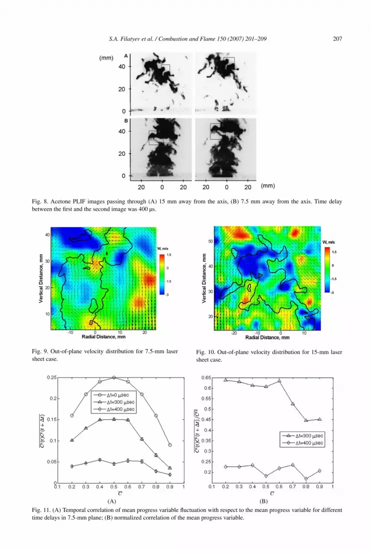
Double-pulsed images also reveal three-dimen-sional flame propagation. The PLIF images in Fig. 8(rectangular zones) show thickening of the reactant
zone, which results in negative flame propagation.Some experimental studies [13,29] reported negativeflame propagation before. Chen and Im [30] and Granet al. [31] also observed negative propagation speedsin numerical simulations. These negative speeds werefound in regions of high positive curvature with dif-fusive flux greater in magnitude than the adverse con-vective flux. The most probable explanation for thenegative flame propagation is out-of-plane motion.As can be seen from Figs. 9 and 10, the stereo PIVmeasurements show large out-of-plane velocity fluc-tuations of 2–3 m/s. This suggests a highly three-dimensional shape for the flame surface.
Double-pulsed PLIF allows a statistical study ofreactant zone evolution with time. Temporal cor-relation of reactant progress variable fluctuationsc′(t)c′(t + �t) can be obtained for different valuesof the time delay �t . Fig. 11A shows temporal cor-relations for three available time delays, 0, 300, and400 µs, versus mean progress variable c̄. The corre-lation reaches a maximum value near c̄ = 0.5 andgoes down to zero as c̄ approaches zero and one.Fig. 11A shows that the correlation decreases withthe increase in the time delay. Zero time delay is ex-pected to have a maximum correlation value, sinceregions of c = 1 (products) will be correlated withthemselves. For nonzero time delays, some productregions will be correlated with reactant regions. Thiswill cancel the contribution of those product regionsto the correlation. To quantify the reduction in cor-
relation, a normalized correlation c′(t)c′(t + �t)/c′2
is plotted in Fig. 11B. It is interesting to note that cor-relation stays near a constant value for c̄ ranging from0.2 to 0.8 for both time delays.
Turbulent premixed combustion is often modeledusing a transport equation for the mean progress vari-able c̃. The turbulent flux of mean progress variableρu′′
ic′′/ρ is very important in determining the struc-
ture of the turbulent flame brush [32]. Normally, it isdetermined using a standard gradient diffusion modelas follows,
(1)ρu′′c′′
ρ= −DT ∇ c̃,
where DT is a positive coefficient of turbulent dif-fusion. Expression (1) shows that turbulent flux ispointing in the direction of the reactants. On the otherhand, the Bray–Moss–Libby (BML) model [33] pre-dicts that
(2)ρu′′c′′
ρ= c̃(1 − c̃)(uP − uR),
where uP and uR are conditioned mean velocitiesof the products and the reactants, respectively. Equa-tion (2) suggests a possibility of countergradient tur-bulent diffusion when the turbulent flux is directed
S.A. Filatyev et al. / Combustion and Flame 150 (2007) 201–209 207
Fig. 8. Acetone PLIF images passing through (A) 15 mm away from the axis, (B) 7.5 mm away from the axis. Time delaybetween the first and the second image was 400 µs.
Fig. 9. Out-of-plane velocity distribution for 7.5-mm lasersheet case.
Fig. 10. Out-of-plane velocity distribution for 15-mm lasersheet case.
(A) (B)
Fig. 11. (A) Temporal correlation of mean progress variable fluctuation with respect to the mean progress variable for differenttime delays in 7.5-mm plane; (B) normalized correlation of the mean progress variable.

208 S.A. Filatyev et al. / Combustion and Flame 150 (2007) 201–209
Fig. 12. Three components of turbulent flux of mean progress variable with respect to the mean progress variable in the 7.5-mmplane.
toward products. Direct numerical simulation [34,35]and experimental [6,7] studies found that counter-gradient diffusion takes place at low relative turbu-lence (u′/SL < 2). A transition to gradient diffusionis observed as u′/SL increases from 2 to 9. Previ-ously simultaneous PIV/OH-PLIF was used to obtaintwo components of the turbulent fluxes [6–8]. Currentwork employs stereo PIV, which together with ace-tone PLIF allows us to obtain all three components ofthe turbulent fluxes. In the present study, relative tur-bulence, u′/SL, was found to be equal to 6. Fig. 12shows that all three components of the turbulent flux(normalized by the unstretched laminar burning ve-locity) in the 7.5-mm plane multiplied by the signof the corresponding mean progress variable gradi-ent component are negative; i.e., the flux behaves inaccordance with gradient diffusion. These results areconsistent with methane–air flame results of Ref. [6].Out-of-plane mean progress variable gradient com-ponent was estimated using finite difference betweencenter and 7.5-mm planes.
5. Summary and conclusions
A new simultaneous double-pulsed acetone PLIFand stereo PIV technique was developed to inves-tigate turbulent flame behavior. A stereoscopic PIVsystem was combined with two ICCD cameras anda double-pulsed Nd:YAG laser operated at 266 nm tocapture two time-delayed acetone PLIF images. Theexperimental system was applied to a study of a tur-bulent stoichiometric methane–air flame at relatively
high Reynolds number. Acquisition of the two time-delayed acetone PLIF images allowed the study ofturbulent flame propagation and flame front develop-ment. Flame merging and pocket formation were ob-served. Double-pulsed PLIF data obtained for differ-ent time delays allow statistical study of the flame de-velopment. The simultaneous PIV/PLIF images sug-gest a very strong interaction between the flame frontand the vortex structures. The use of stereo PIVto measure the out-of-plane velocity component andcapture the strong three-dimensional velocity fluctua-tions provides better understanding of flame interac-tions with turbulence. The combination of stereo PIVand PLIF allows us to obtain three-dimensional tur-bulent fluxes. It was shown that the fluxes obey thegradient diffusion hypothesis. The proposed diagnos-tic increases the flexibility and range of measurementsavailable for premixed flames.
References
[1] N. Peters, Turbulent Premixed Combustion, CambridgeUniv. Press, Cambridge, UK, 2000.
[2] T. Poinsot, D. Veynante, Theoretical and NumericalCombustion, Edwards, Philadelphia, 2001.
[3] J.H. Frank, K.M. Lyons, M.B. Long, Combust.Flame 107 (1) (1996) 1–12.
[4] J.M. Donbar, J.F. Driscoll, C.D. Carter, Combust.Flame 125 (4) (2001) 1239–1257.
[5] S.A. Filatyev, J.F. Driscoll, C.D. Carter, J.M. Donbar,Combust. Flame 141 (1–2) (2005) 1–21.
[6] J.H. Frank, P.A.M. Kalt, R.W. Bilger, Combust.Flame 116 (1–2) (1999) 220–232.

S.A. Filatyev et al. / Combustion and Flame 150 (2007) 201–209 209
[7] P.A.M. Kalt, J.H. Frank, R.W. Bilger, Proc. Combust.Inst. 27 (1998) 751–758.
[8] Y.-C. Chen, R.W. Bilger, Proc. Combust. Inst. 28(2000) 521–528.
[9] J.M. Donbar, J.F. Driscoll, C.D. Carter, Combust.Flame 122 (1–2) (2000) 1–19.
[10] A. Ratner, J.F. Driscoll, J.M. Donbar, C.D. Carter, J.D.Mullin, Proc. Combust. Inst. 28 (2000) 245–252.
[11] K.A. Watson, K.M. Lyons, C.D. Carter, J.M. Donbar,Proc. Combust. Inst. 29 (2002) 1905–1912.
[12] M. Tanahashi, S. Murakami, G.-M. Choi, Y. Fukuchi,T. Miyauchi, Proc. Combust. Inst. 30 (2005) 1665–1672.
[13] A. Upatnieks, J.F. Driscoll, S.L. Ceccio, Proc. Com-bust. Inst. 29 (2002) 1897–1903.
[14] C. Schulz, V. Sick, Prog. Energy Combust. Sci. 31(2005) 75–121.
[15] S.T. Wereley, L. Gui, Exp. Fluids 34 (2003) 42–51.[16] M.C. Thurber, F. Grisch, B.J. Kirby, M. Votsmeier,
R.K. Hanson, Appl. Opt. 37 (1998) 4963–4978.[17] J.H. Chen, T. Echekki, W. Kollmann, Combust.
Flame 116 (1–2) (1999) 15–48.[18] C.J. Mueller, J.F. Driscoll, D.L. Reuss, M.C. Drake,
M.E. Rosalik, Combust. Flame 112 (3) (1998) 342–358.
[19] J.O. Sinibaldi, J.F. Driscoll, C.J. Mueller, J.M. Don-bar, C.D. Carter, Combust. Flame 133 (3) (2003) 323–334.
[20] H.N. Najm, P.S. Wyckoff, Combust. Flame 110 (1–2)(1997) 92–112.
[21] D.C. Haworth, T.J. Poinsot, J. Fluid Mech. 244 (1992)405–436.
[22] T. Echekki, J.H. Chen, Combust. Flame 106 (1–2)(1996) 184–202.
[23] C. Rutland, J. Ferziger, S. El Tahry, Proc. Combust.Inst. 23 (1990) 621–627.
[24] C.J. Rutland, A. Trouve, Combust. Flame 94 (1–2)(1993) 41–57.
[25] M. Baum, T. Poinsot, D. Haworth, N. Darabiha, J. FluidMech. 281 (1994) 1–32.
[26] J. Lee, T.-W. Lee, D. Nye, D. Santavicca, Combust.Flame 100 (1–2) (1995) 161–168.
[27] T.-W. Lee, G. North, D. Santavicca, Combust. Sci.Technol. 84 (1992) 121–132.
[28] T.-W. Lee, G. North, D. Santavicca, Combust.Flame 93 (4) (1993) 445–456.
[29] E.F. Hasselbrink Jr., M.G. Mungal, Proc. Combust.Inst. 27 (1998) 867–873.
[30] J.H. Chen, H.G. Im, Proc. Combust. Inst. 27 (1998)819–826.
[31] I.R. Gran, T. Echekki, J.H. Chen, Proc. Combust.Inst. 26 (1996) 323–329.
[32] K.N.C. Bray, Proc. R. Soc. London Ser. A 451 (1995)231–256.
[33] K.N.C. Bray, P.A. Libby, J.B. Moss, Combust.Flame 61 (1985) 87–102.
[34] S. Zhang, C.J. Rutland, Combust. Flame 102 (1995)447–461.
[35] D. Veynante, A. Trouve, K.N.C. Bray, T. Mantel,J. Fluid Mech. 332 (1997) 263–293.