sidac-s power supplies
TRANSCRIPT
Siemens LV 10 · 2004
13/2 Introduction
SIDAC-Snon-stabilized power supplies
based on safety isolating transformersFiltered for supplying solid-state controllers
13/3 - General data13/6 - Single-phase13/9 - Three-phase
Unfiltered for supplying general loads13/12 - General data13/13 - Single-phase13/14 - Three-phase
Stabilized power supplies
for specific loads and systems13/15 SIDAC-S load power supplies
LOGO!Power power supplies13/16 - Single-phase
SITOP power supplies13/17 - Single-phase13/18 - Single-, two- and three-phase13/19 - Uninterruptible
13/20 Project planning aids
SIDAC-S Power Supplies
Siemens LV 10 · 200413/2
SIDAC-S Power Supplies
Introduction
13
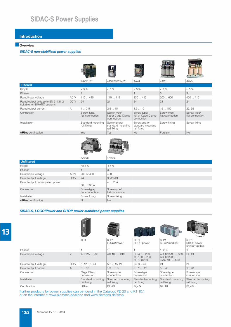
■ Overview
SIDAC-S non-stabilized power supplies
SIDAC-S, LOGO!Power and SITOP power stabilized power supplies
Further products for power supplies can be found in the Catalogs PD 20 and KT 10.1 or on the Internet at www.siemens.de/sidac and www.siemens.de/sitop.
4AV21/23 4AV20/22/24/26 4AV4 4AV3 4AV5FilteredRipple < 5 % < 5 % < 5 % < 5 % < 5 %
Phases 1 1 1 3 3
Rated input voltage AC V 115 ... 415 115 ... 415 230 ... 415 200 ... 600 400 ... 415
Rated output voltage to EN 61131-2 suitable for SIMATIC systems
DC V 24 24 24 24 24
Rated output current A 1 ... 3.5 2.5 ... 15 1.5 ... 10 15 ... 150 25, 35
Connection Screw-type/flat connection
Screw-type/flat or Cage Clamp connection
Screw-type/flat or Cage Clamp connection
Screw-type/flat connection
Screw-type/flat connection
Installation Standard mounting rail fixing
Screw and/or standard mounting rail fixing
Screw and/or standard mounting rail fixing
Screw fixing Screw fixing
CUUS certification Yes Yes No Partially No
4AV98 4AV96UnfilteredRipple 48.3 % < 5 %
Phases 1 3
Rated input voltage AC V 230 or 400 400
Rated output voltage DC V 24 30-27-24
Rated output current/rated power50 ... 500 W
4 ... 25 A
Connection Screw-type/flat connection
Screw-type/flat connection
Installation Screw fixing Screw fixing
CUUS certification No No
4FD 6EP1 LOGO!Power
6EP1 SITOP power
6EP1SITOP modular
6EP1SITOP power uninterruptible
Phases 1 1 1 1, 2, 3 1
Rated input voltage V AC 115 ... 230 AC 100 ... 240 DC 48 ... 220, AC 120 ... 230, AC 120/230
AC 120/230 ... 500, AC 120/230, 3 AC 400 ... 500
DC 24
Rated output voltage DC V 5, 12, 15, 24 5, 12, 15, 24 24, 3 ... 52 24 24
Rated output current A 3 ... 10 1.3 ... 6.3 0.375 ... 20 5 ... 40 15, 40
Connection Cage Clamp connection
Screw-type connection
Screw-type connection
Screw-type connection
Screw-type connection
Installation Standard mounting rail fixing
Standard mounting rail fixing
Standard mounting rail fixing
Standard mounting rail fixing
Standard mounting rail fixing
Certification CuUS u, Cu u, Cu u, Cu u, Cu
Siemens LV 10 · 2004 13/3
SIDAC-S Non-Stabilized Power SuppliesBased on Safety Isolating Transformers
Filtered for supplying solid-state controllers:General data
13
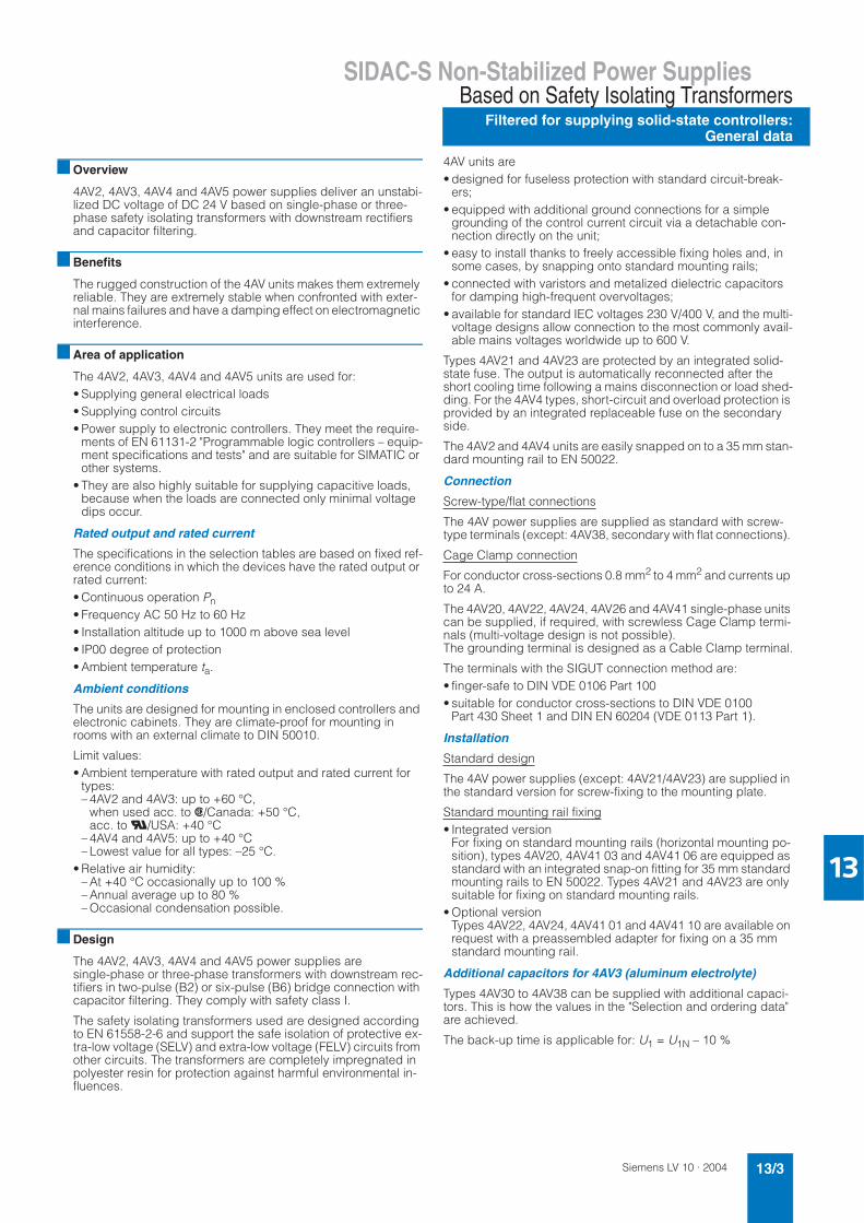
■ Overview
4AV2, 4AV3, 4AV4 and 4AV5 power supplies deliver an unstabi-lized DC voltage of DC 24 V based on single-phase or three-phase safety isolating transformers with downstream rectifiers and capacitor filtering.
■ Benefits
The rugged construction of the 4AV units makes them extremely reliable. They are extremely stable when confronted with exter-nal mains failures and have a damping effect on electromagnetic interference.
■ Area of application
The 4AV2, 4AV3, 4AV4 and 4AV5 units are used for: • Supplying general electrical loads • Supplying control circuits• Power supply to electronic controllers. They meet the require-
ments of EN 61131-2 "Programmable logic controllers – equip-ment specifications and tests" and are suitable for SIMATIC or other systems.
• They are also highly suitable for supplying capacitive loads, because when the loads are connected only minimal voltage dips occur.
Rated output and rated current
The specifications in the selection tables are based on fixed ref-erence conditions in which the devices have the rated output or rated current:• Continuous operation Pn• Frequency AC 50 Hz to 60 Hz• Installation altitude up to 1000 m above sea level• IP00 degree of protection• Ambient temperature ta.
Ambient conditions
The units are designed for mounting in enclosed controllers and electronic cabinets. They are climate-proof for mounting in rooms with an external climate to DIN 50010.
Limit values:• Ambient temperature with rated output and rated current for
types:– 4AV2 and 4AV3: up to +60 °C,
when used acc. to s/Canada: +50 °C, acc. to U/USA: +40 °C
– 4AV4 and 4AV5: up to +40 °C – Lowest value for all types: –25 °C.
• Relative air humidity: – At +40 °C occasionally up to 100 % – Annual average up to 80 % – Occasional condensation possible.
■ Design
The 4AV2, 4AV3, 4AV4 and 4AV5 power supplies are single-phase or three-phase transformers with downstream rec-tifiers in two-pulse (B2) or six-pulse (B6) bridge connection with capacitor filtering. They comply with safety class I.
The safety isolating transformers used are designed according to EN 61558-2-6 and support the safe isolation of protective ex-tra-low voltage (SELV) and extra-low voltage (FELV) circuits from other circuits. The transformers are completely impregnated in polyester resin for protection against harmful environmental in-fluences.
4AV units are• designed for fuseless protection with standard circuit-break-
ers;• equipped with additional ground connections for a simple
grounding of the control current circuit via a detachable con-nection directly on the unit;
• easy to install thanks to freely accessible fixing holes and, in some cases, by snapping onto standard mounting rails;
• connected with varistors and metalized dielectric capacitors for damping high-frequent overvoltages;
• available for standard IEC voltages 230 V/400 V, and the multi-voltage designs allow connection to the most commonly avail-able mains voltages worldwide up to 600 V.
Types 4AV21 and 4AV23 are protected by an integrated solid-state fuse. The output is automatically reconnected after the short cooling time following a mains disconnection or load shed-ding. For the 4AV4 types, short-circuit and overload protection is provided by an integrated replaceable fuse on the secondary side.
The 4AV2 and 4AV4 units are easily snapped on to a 35 mm stan-dard mounting rail to EN 50022.
Connection
Screw-type/flat connections
The 4AV power supplies are supplied as standard with screw-type terminals (except: 4AV38, secondary with flat connections).
Cage Clamp connection
For conductor cross-sections 0.8 mm2 to 4 mm2 and currents up to 24 A.
The 4AV20, 4AV22, 4AV24, 4AV26 and 4AV41 single-phase units can be supplied, if required, with screwless Cage Clamp termi-nals (multi-voltage design is not possible).The grounding terminal is designed as a Cable Clamp terminal.
The terminals with the SIGUT connection method are:• finger-safe to DIN VDE 0106 Part 100• suitable for conductor cross-sections to DIN VDE 0100
Part 430 Sheet 1 and DIN EN 60204 (VDE 0113 Part 1).
Installation
Standard design
The 4AV power supplies (except: 4AV21/4AV23) are supplied in the standard version for screw-fixing to the mounting plate.
Standard mounting rail fixing• Integrated version
For fixing on standard mounting rails (horizontal mounting po-sition), types 4AV20, 4AV41 03 and 4AV41 06 are equipped as standard with an integrated snap-on fitting for 35 mm standard mounting rails to EN 50022. Types 4AV21 and 4AV23 are only suitable for fixing on standard mounting rails.
• Optional version Types 4AV22, 4AV24, 4AV41 01 and 4AV41 10 are available on request with a preassembled adapter for fixing on a 35 mm standard mounting rail.
Additional capacitors for 4AV3 (aluminum electrolyte)
Types 4AV30 to 4AV38 can be supplied with additional capaci-tors. This is how the values in the "Selection and ordering data" are achieved.
The back-up time is applicable for: U1 = U1N – 10 %
Siemens LV 10 · 200413/4
SIDAC-S Non-Stabilized Power Supplies
Filtered for supplying solid-state controllers: General data
Based on Safety Isolating Transformers
13
■ Functions
The 4AV power supplies meet the requirements of EN 61131-2, irrespective of the load (no load up to rated current) and also ir-respective of fluctuations of the mains supply (+6 % to –10 % to IEC 60038).
Despite variations in these parameters, the electronic control is supplied with the permissible operating voltage without having to select suitable tappings on the transformer to step up or step
down the DC output voltage according to load and mains condi-tions. The transformers are dimensioned in their voltage stability for this application.
Any number of units of the same type can be connected in par-allel if a higher current level is required. The total current in this case must not exceed 90 % of the individual rated currents.
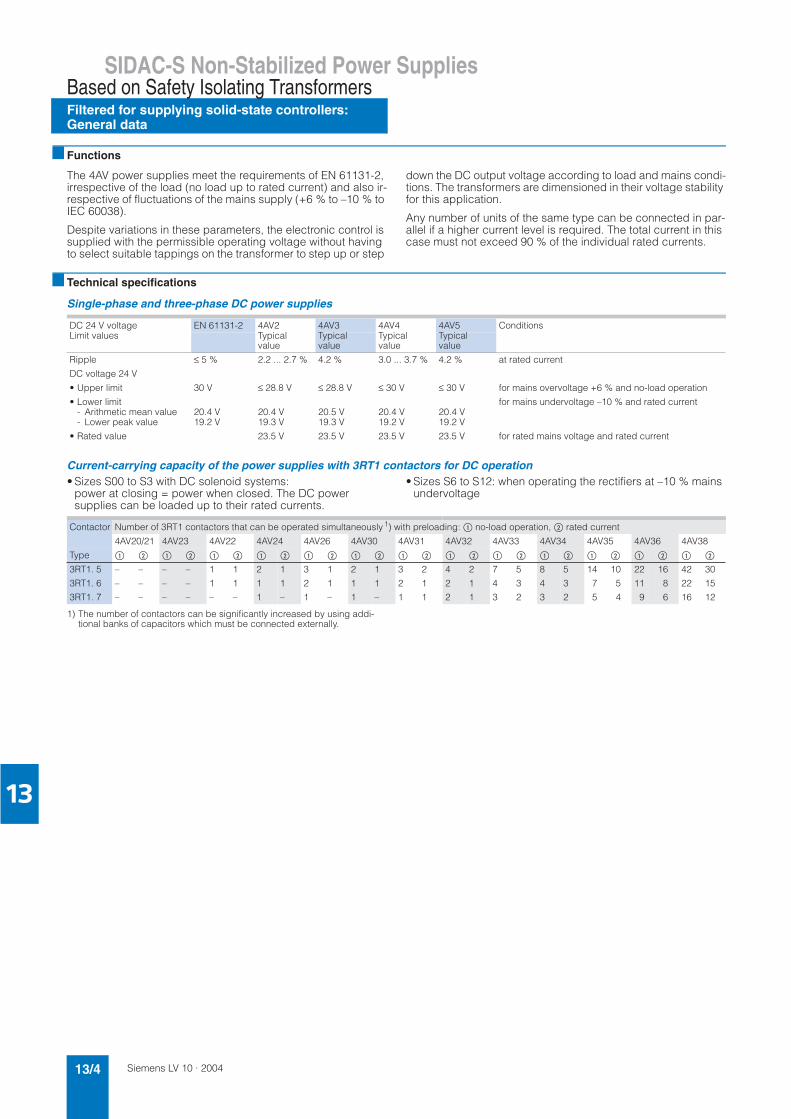
■ Technical specifications
Single-phase and three-phase DC power supplies
Current-carrying capacity of the power supplies with 3RT1 contactors for DC operation• Sizes S00 to S3 with DC solenoid systems:
power at closing = power when closed. The DC power supplies can be loaded up to their rated currents.
• Sizes S6 to S12: when operating the rectifiers at –10 % mains undervoltage
1) The number of contactors can be significantly increased by using addi-tional banks of capacitors which must be connected externally.
DC 24 V voltage EN 61131-2 4AV2 4AV3 4AV4 4AV5 ConditionsLimit values Typical
valueTypicalvalue
Typical value
Typical value
Ripple ≤ 5 % 2.2 ... 2.7 % 4.2 % 3.0 ... 3.7 % 4.2 % at rated current
DC voltage 24 V
• Upper limit 30 V ≤ 28.8 V ≤ 28.8 V ≤ 30 V ≤ 30 V for mains overvoltage +6 % and no-load operation
• Lower limit for mains undervoltage –10 % and rated current- Arithmetic mean value 20.4 V 20.4 V 20.5 V 20.4 V 20.4 V- Lower peak value 19.2 V 19.3 V 19.3 V 19.2 V 19.2 V
• Rated value 23.5 V 23.5 V 23.5 V 23.5 V for rated mains voltage and rated current
Contactor Number of 3RT1 contactors that can be operated simultaneously 1) with preloading: $ no-load operation, % rated current
4AV20/21 4AV23 4AV22 4AV24 4AV26 4AV30 4AV31 4AV32 4AV33 4AV34 4AV35 4AV36 4AV38
Type $ % $ % $ % $ % $ % $ % $ % $ % $ % $ % $ % $ % $ %
3RT1. 5
3RT1. 6
3RT1. 7
–
–
–
–
–
–
–
–
–
–
–
–
1
1
–
1
1
–
2
1
1
1
1
–
3
2
1
1
1
–
2
1
1
1
1
–
3
2
1
2
1
1
4
2
2
2
1
1
7
4
3
5
3
2
8
4
3
5
3
2
14
7
5
10
5
4
22
11
9
16
8
6
42
22
16
30
15
12
Siemens LV 10 · 2004 13/5
SIDAC-S Non-Stabilized Power SuppliesBased on Safety Isolating Transformers
Filtered for supplying solid-state controllers:General data
13
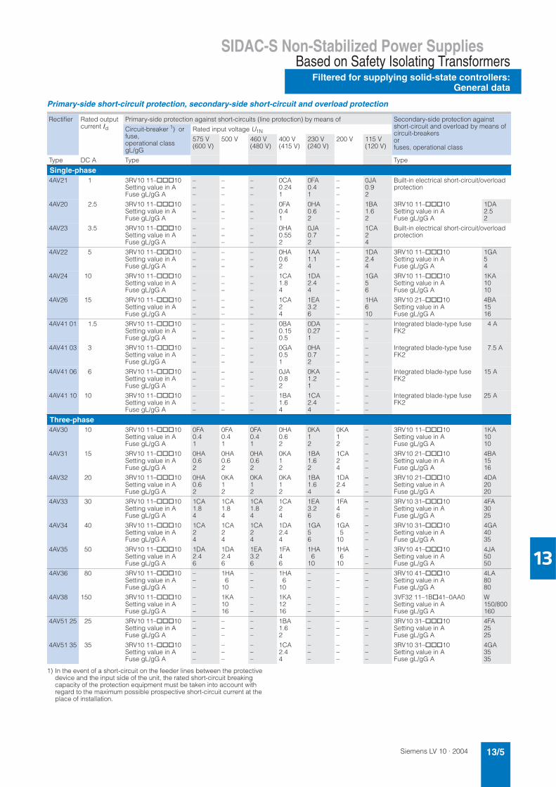
Primary-side short-circuit protection, secondary-side short-circuit and overload protection
1) In the event of a short-circuit on the feeder lines between the protective device and the input side of the unit, the rated short-circuit breaking capacity of the protection equipment must be taken into account with regard to the maximum possible prospective short-circuit current at the place of installation.
Rectifier Rated output current Id
Primary-side protection against short-circuits (line protection) by means of Secondary-side protection against short-circuit and overload by means of circuit-breakers orfuses, operational class
Circuit-breaker 1) or fuse,operational class gL/gG
Rated input voltage U1N
575 V (600 V)
500 V 460 V(480 V)
400 V(415 V)
230 V(240 V)
200 V 115 V(120 V)
Type DC A Type Type
Single-phase4AV21 1 3RV10 11–@@@10
Setting value in AFuse gL/gG A
–––
–––
–––
0CA0.241
0FA0.41
–––
0JA0.92
Built-in electrical short-circuit/overload protection
4AV20 2.5 3RV10 11–@@@10Setting value in AFuse gL/gG A
–––
–––
–––
0FA0.41
0HA0.62
–––
1BA1.62
3RV10 11–@@@10Setting value in AFuse gL/gG A
1DA2.52
4AV23 3.5 3RV10 11–@@@10Setting value in AFuse gL/gG A
–––
–––
–––
0HA0.552
0JA0.72
–––
1CA24
Built-in electrical short-circuit/overload protection
4AV22 5 3RV10 11–@@@10Setting value in AFuse gL/gG A
–––
–––
–––
0HA0.62
1AA1.14
–––
1DA2.44
3RV10 11–@@@10Setting value in AFuse gL/gG A
1GA54
4AV24 10 3RV10 11–@@@10Setting value in AFuse gL/gG A
–––
–––
–––
1CA1.84
1DA2.44
–––
1GA56
3RV10 11–@@@10Setting value in AFuse gL/gG A
1KA1010
4AV26 15 3RV10 11–@@@10Setting value in AFuse gL/gG A
–––
–––
–––
1CA24
1EA3.26
–––
1HA610
3RV10 21–@@@10Setting value in AFuse gL/gG A
4BA1516
4AV41 01 1.5 3RV10 11–@@@10Setting value in AFuse gL/gG A
–––
–––
–––
0BA0.150.5
0DA0.271
–––
–––
Integrated blade-type fuse FK2
4 A
4AV41 03 3 3RV10 11–@@@10Setting value in AFuse gL/gG A
–––
–––
–––
0GA0.51
0HA0.72
–––
–––
Integrated blade-type fuse FK2
7.5 A
4AV41 06 6 3RV10 11–@@@10Setting value in AFuse gL/gG A
–––
–––
–––
0JA0.82
0KA1.21
–––
–––
Integrated blade-type fuse FK2
15 A
4AV41 10 10 3RV10 11–@@@10Setting value in AFuse gL/gG A
–––
–––
–––
1BA1.64
1CA2.44
–––
–––
Integrated blade-type fuse FK2
25 A
Three-phase4AV30 10 3RV10 11–@@@10
Setting value in AFuse gL/gG A
0FA0.41
0FA0.41
0FA0.41
0HA0.62
0KA12
0KA12
–––
3RV10 11–@@@10Setting value in AFuse gL/gG A
1KA1010
4AV31 15 3RV10 11–@@@10Setting value in AFuse gL/gG A
0HA0.62
0HA0.62
0HA0.62
0KA12
1BA1.62
1CA24
–––
3RV10 21–@@@10Setting value in AFuse gL/gG A
4BA1516
4AV32 20 3RV10 11–@@@10Setting value in AFuse gL/gG A
0HA0.62
0KA12
0KA12
0KA12
1BA1.64
1DA2.44
–––
3RV10 21–@@@10Setting value in AFuse gL/gG A
4DA2020
4AV33 30 3RV10 11–@@@10Setting value in AFuse gL/gG A
1CA1.84
1CA1.84
1CA1.84
1CA24
1EA3.26
1FA46
–––
3RV10 31–@@@10Setting value in AFuse gL/gG A
4FA3025
4AV34 40 3RV10 11–@@@10Setting value in AFuse gL/gG A
1CA24
1CA24
1CA24
1DA2.44
1GA56
1GA5
10
–––
3RV10 31–@@@10Setting value in AFuse gL/gG A
4GA4035
4AV35 50 3RV10 11–@@@10Setting value in AFuse gL/gG A
1DA2.46
1DA2.46
1EA3.26
1FA46
1HA6
10
1HA6
10
–––
3RV10 41–@@@10Setting value in AFuse gL/gG A
4JA5050
4AV36 80 3RV10 11–@@@10Setting value in AFuse gL/gG A
–––
1HA6
10
–––
1HA6
10
–––
–––
–––
3RV10 41–@@@10Setting value in AFuse gL/gG A
4LA8080
4AV38 150 3RV10 11–@@@10Setting value in AFuse gL/gG A
–––
1KA1016
–––
1KA1216
–––
–––
–––
3VF32 11–1B@41–0AA0Setting value in AFuse gL/gG A
W150/800160
4AV51 25 25 3RV10 11–@@@10Setting value in AFuse gL/gG A
–––
–––
–––
1BA1.62
–––
–––
–––
3RV10 31–@@@10Setting value in AFuse gL/gG A
4FA2525
4AV51 35 35 3RV10 11–@@@10Setting value in AFuse gL/gG A
–––
–––
–––
1CA2.44
–––
–––
–––
3RV10 31–@@@10Setting value in AFuse gL/gG A
4GA3535
Siemens LV 10 · 200413/6
SIDAC-S Non-Stabilized Power Supplies
Filtered for supplying solid-state controllers: Single-phase
Based on Safety Isolating Transformers
13
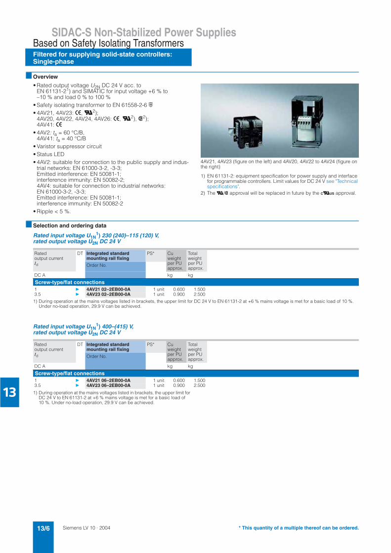
■ Overview
• Rated output voltage U2N DC 24 V acc. to EN 61131-21) and SIMATIC for input voltage +6 % to –10 % and load 0 % to 100 %
• Safety isolating transformer to EN 61558-2-6 ·• 4AV21, 4AV23: >, U2);
4AV20, 4AV22, 4AV24, 4AV26: >, U2), s2); 4AV41: >
• 4AV2: ta = 60 °C/B, 4AV41: ta = 40 °C/B
• Varistor suppressor circuit• Status LED• 4AV2: suitable for connection to the public supply and indus-
trial networks: EN 61000-3-2, -3-3; Emitted interference: EN 50081-1;interference immunity: EN 50082-2; 4AV4: suitable for connection to industrial networks: EN 61000-3-2, -3-3;Emitted interference: EN 50081-1;interference immunity: EN 50082-2
• Ripple < 5 %.
4AV21, 4AV23 (figure on the left) and 4AV20, 4AV22 to 4AV24 (figure on the right)
1) EN 61131-2: equipment specification for power supply and interface for programmable controllers. Limit values for DC 24 V see "Technical specifications".
2) The U/s approval will be replaced in future by the CUUS approval.
■ Selection and ordering data
Rated input voltage U1N1) 230 (240)–115 (120) V,
rated output voltage U2N DC 24 V
1) During operation at the mains voltages listed in brackets, the upper limit for DC 24 V to EN 61131-2 at +6 % mains voltage is met for a basic load of 10 %. Under no-load operation, 29.9 V can be achieved.
Rated input voltage U1N1) 400–(415) V,
rated output voltage U2N DC 24 V
1) During operation at the mains voltages listed in brackets, the upper limit for DC 24 V to EN 61131-2 at +6 % mains voltage is met for a basic load of 10 %. Under no-load operation, 29.9 V can be achieved.
Ratedoutput currentId
DT Integrated standard mounting rail fixing
PS* Cuweightper PU approx.
Total weightper PU approx.
Order No.
DC A kg kg
Screw-type/flat connections1 } 4AV21 02–2EB00-0A 1 unit 0.600 1.5003.5 } 4AV23 02–2EB00-0A 1 unit 0.900 2.500
Ratedoutput currentId
DT Integrated standard mounting rail fixing
PS* Cuweightper PU approx.
Total weightper PU approx.
Order No.
DC A kg kg
Screw-type/flat connections1 } 4AV21 06–2EB00-0A 1 unit 0.600 1.5003.5 } 4AV23 06–2EB00-0A 1 unit 0.900 2.500
* This quantity of a multiple thereof can be ordered.
Siemens LV 10 · 2004 13/7
SIDAC-S Non-Stabilized Power SuppliesBased on Safety Isolating Transformers
Filtered for supplying solid-state controllers:Single-phase
13
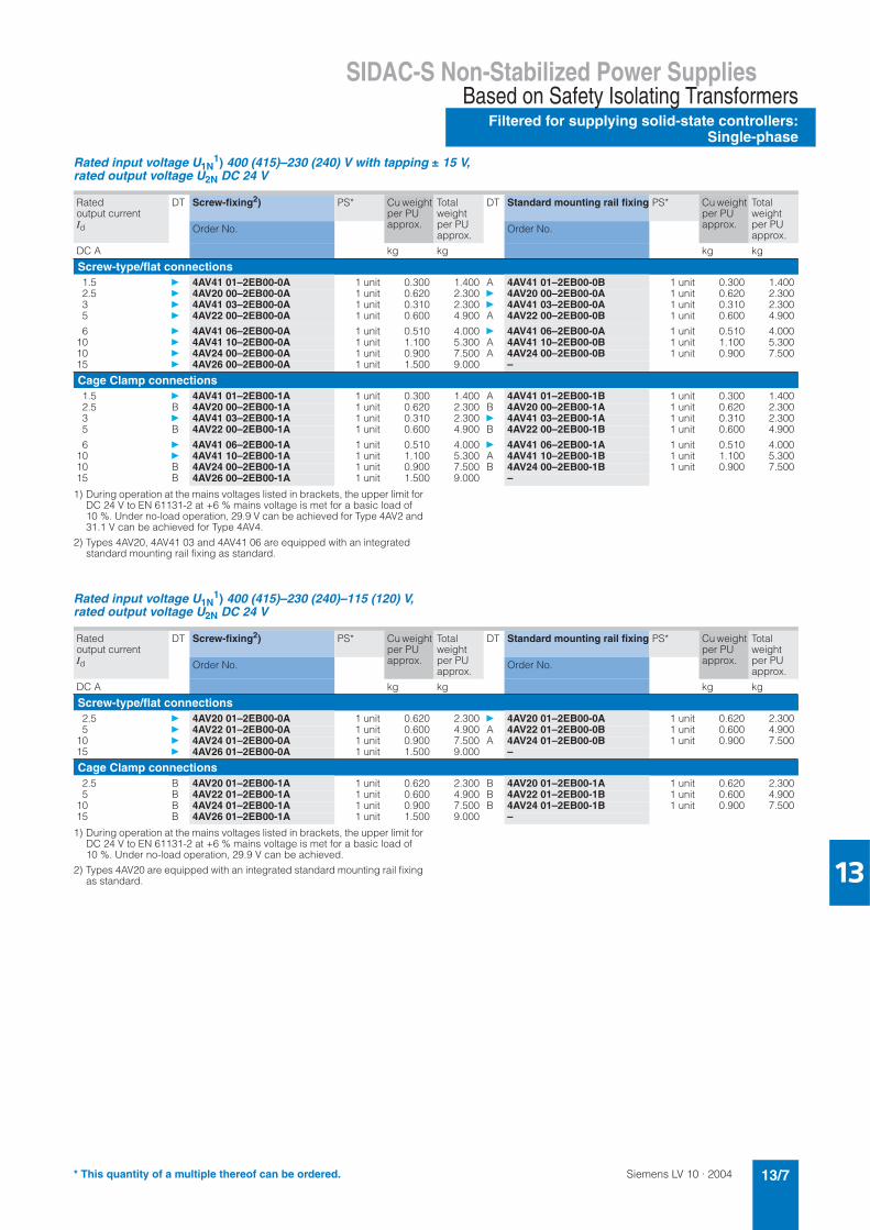
Rated input voltage U1N1) 400 (415)–230 (240) V with tapping ± 15 V,
rated output voltage U2N DC 24 V
1) During operation at the mains voltages listed in brackets, the upper limit for DC 24 V to EN 61131-2 at +6 % mains voltage is met for a basic load of 10 %. Under no-load operation, 29.9 V can be achieved for Type 4AV2 and 31.1 V can be achieved for Type 4AV4.
2) Types 4AV20, 4AV41 03 and 4AV41 06 are equipped with an integrated standard mounting rail fixing as standard.
Rated input voltage U1N1) 400 (415)–230 (240)–115 (120) V,
rated output voltage U2N DC 24 V
1) During operation at the mains voltages listed in brackets, the upper limit for DC 24 V to EN 61131-2 at +6 % mains voltage is met for a basic load of 10 %. Under no-load operation, 29.9 V can be achieved.
2) Types 4AV20 are equipped with an integrated standard mounting rail fixing as standard.
Ratedoutput currentId
DT Screw-fixing2) PS* Cu weight per PU approx.
Total weightper PU approx.
DT Standard mounting rail fixing PS* Cu weight per PU approx.
Total weightper PU approx.
Order No. Order No.
DC A kg kg kg kg
Screw-type/flat connections1.5 } 4AV41 01–2EB00-0A 1 unit 0.300 1.400 A 4AV41 01–2EB00-0B 1 unit 0.300 1.4002.5 } 4AV20 00–2EB00-0A 1 unit 0.620 2.300 } 4AV20 00–2EB00-0A 1 unit 0.620 2.3003 } 4AV41 03–2EB00-0A 1 unit 0.310 2.300 } 4AV41 03–2EB00-0A 1 unit 0.310 2.3005 } 4AV22 00–2EB00-0A 1 unit 0.600 4.900 A 4AV22 00–2EB00-0B 1 unit 0.600 4.900
6 } 4AV41 06–2EB00-0A 1 unit 0.510 4.000 } 4AV41 06–2EB00-0A 1 unit 0.510 4.00010 } 4AV41 10–2EB00-0A 1 unit 1.100 5.300 A 4AV41 10–2EB00-0B 1 unit 1.100 5.30010 } 4AV24 00–2EB00-0A 1 unit 0.900 7.500 A 4AV24 00–2EB00-0B 1 unit 0.900 7.50015 } 4AV26 00–2EB00-0A 1 unit 1.500 9.000 –
Cage Clamp connections1.5 } 4AV41 01–2EB00-1A 1 unit 0.300 1.400 A 4AV41 01–2EB00-1B 1 unit 0.300 1.4002.5 B 4AV20 00–2EB00-1A 1 unit 0.620 2.300 B 4AV20 00–2EB00-1A 1 unit 0.620 2.3003 } 4AV41 03–2EB00-1A 1 unit 0.310 2.300 } 4AV41 03–2EB00-1A 1 unit 0.310 2.3005 B 4AV22 00–2EB00-1A 1 unit 0.600 4.900 B 4AV22 00–2EB00-1B 1 unit 0.600 4.900
6 } 4AV41 06–2EB00-1A 1 unit 0.510 4.000 } 4AV41 06–2EB00-1A 1 unit 0.510 4.00010 } 4AV41 10–2EB00-1A 1 unit 1.100 5.300 A 4AV41 10–2EB00-1B 1 unit 1.100 5.30010 B 4AV24 00–2EB00-1A 1 unit 0.900 7.500 B 4AV24 00–2EB00-1B 1 unit 0.900 7.50015 B 4AV26 00–2EB00-1A 1 unit 1.500 9.000 –
Ratedoutput currentId
DT Screw-fixing2) PS* Cu weight per PU approx.
Total weightper PU approx.
DT Standard mounting rail fixing PS* Cu weight per PU approx.
Total weightper PU approx.
Order No. Order No.
DC A kg kg kg kg
Screw-type/flat connections2.5 } 4AV20 01–2EB00-0A 1 unit 0.620 2.300 } 4AV20 01–2EB00-0A 1 unit 0.620 2.3005 } 4AV22 01–2EB00-0A 1 unit 0.600 4.900 A 4AV22 01–2EB00-0B 1 unit 0.600 4.900
10 } 4AV24 01–2EB00-0A 1 unit 0.900 7.500 A 4AV24 01–2EB00-0B 1 unit 0.900 7.50015 } 4AV26 01–2EB00-0A 1 unit 1.500 9.000 –
Cage Clamp connections2.5 B 4AV20 01–2EB00-1A 1 unit 0.620 2.300 B 4AV20 01–2EB00-1A 1 unit 0.620 2.3005 B 4AV22 01–2EB00-1A 1 unit 0.600 4.900 B 4AV22 01–2EB00-1B 1 unit 0.600 4.900
10 B 4AV24 01–2EB00-1A 1 unit 0.900 7.500 B 4AV24 01–2EB00-1B 1 unit 0.900 7.50015 B 4AV26 01–2EB00-1A 1 unit 1.500 9.000 –
* This quantity of a multiple thereof can be ordered.
Siemens LV 10 · 200413/8
SIDAC-S Non-Stabilized Power Supplies
Filtered for supplying solid-state controllers: Single-phase
Based on Safety Isolating Transformers
13
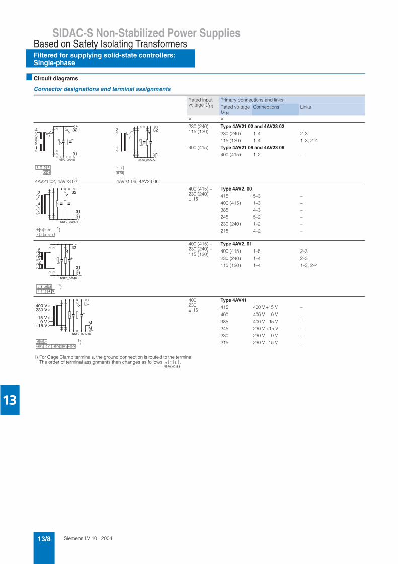
■ Circuit diagrams
Connector designations and terminal assignments
1) For Cage Clamp terminals, the ground connection is routed to the terminal. The order of terminal assignments then changes as follows .
Rated input voltage U1N
Primary connections and links
Rated voltage U1N
Connections Links
V V
4AV21 02, 4AV23 02 4AV21 06, 4AV23 06
230 (240) – 115 (120)
Type 4AV21 02 and 4AV23 02
230 (240)
115 (120)
1–4
1–4
2–3
1–3, 2–4
400 (415) Type 4AV21 06 and 4AV23 06
400 (415) 1–2 –
400 (415) – 230 (240)± 15
Type 4AV2. 00
415
400 (415)
385
245
230 (240)
215
5–3
1–3
4–3
5–2
1–2
4–2
–
–
–
–
–
–
400 (415) – 230 (240) – 115 (120)
Type 4AV2. 01
400 (415)
230 (240)
115 (120)
1–5
1–4
1–4
2–3
2–3
1–3, 2–4
400230± 15
Type 4AV41
415
400
385
245
230
215
400 V +15 V
400 V 0 V
400 V –15 V
230 V +15 V
230 V 0 V
230 V –15 V
–
–
–
–
–
–
1
23
4
31
32
NSF0_00045c
1 2 3 4
32 31
1
2
31
32
NSF0_00046c
32 31
1 2
NSF0_00047b
31
32
1
32
4
5 31
1 2 3
31 31 32
4 5
1)
45
31
32
123
31
NSF0_00048b
1 2 3 4 5
31 31 32 1)
NSF0_00178a
+15 V
M
L+
M
M M L+
400 V230 V
-15 V 0 V+15 V
0 V -15 V 230 V 400 V
1)
1 2NSF0_00183
Siemens LV 10 · 2004 13/9
SIDAC-S Non-Stabilized Power SuppliesBased on Safety Isolating Transformers
Filtered for supplying solid-state controllers:Three-phase
13
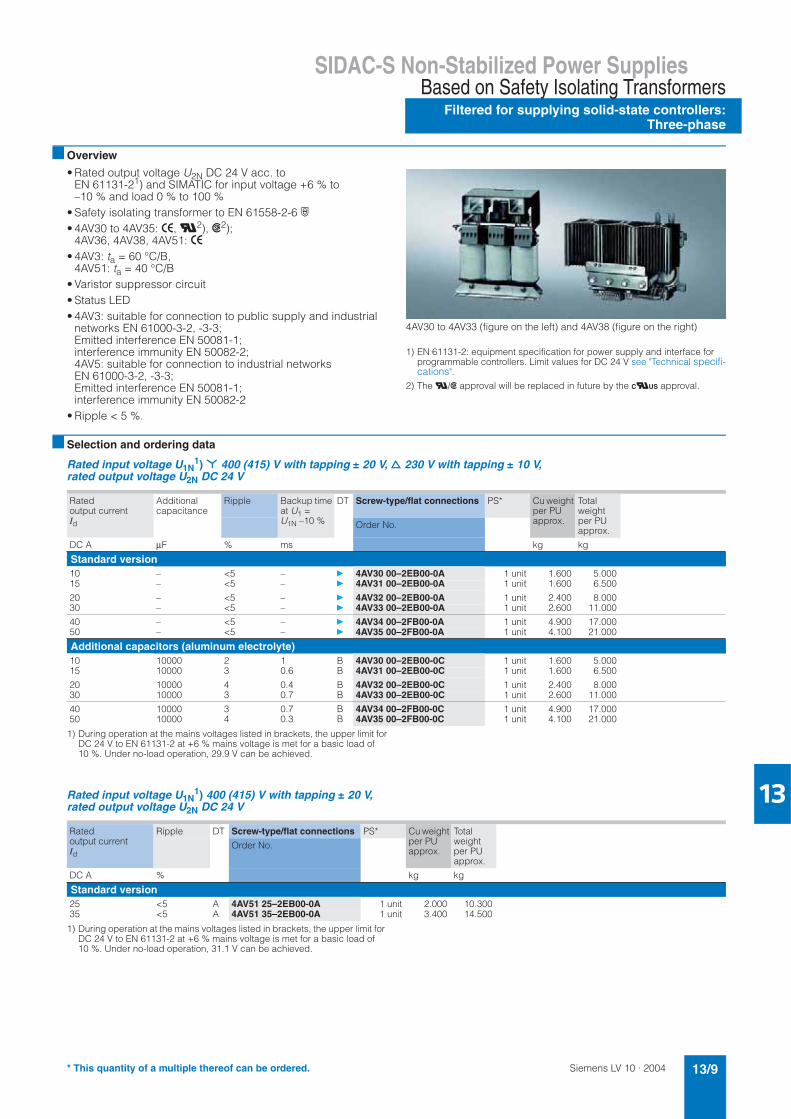
■ Overview
• Rated output voltage U2N DC 24 V acc. to EN 61131-21) and SIMATIC for input voltage +6 % to –10 % and load 0 % to 100 %
• Safety isolating transformer to EN 61558-2-6 ·• 4AV30 to 4AV35: >, U2), s2);
4AV36, 4AV38, 4AV51: >• 4AV3: ta = 60 °C/B,
4AV51: ta = 40 °C/B• Varistor suppressor circuit• Status LED• 4AV3: suitable for connection to public supply and industrial
networks EN 61000-3-2, -3-3; Emitted interference EN 50081-1;interference immunity EN 50082-2;4AV5: suitable for connection to industrial networks EN 61000-3-2, -3-3;Emitted interference EN 50081-1;interference immunity EN 50082-2
• Ripple < 5 %.
4AV30 to 4AV33 (figure on the left) and 4AV38 (figure on the right)
1) EN 61131-2: equipment specification for power supply and interface for programmable controllers. Limit values for DC 24 V see "Technical specifi-cations".
2) The U/s approval will be replaced in future by the CUUS approval.
■ Selection and ordering data
Rated input voltage U1N1) * 400 (415) V with tapping ± 20 V, d 230 V with tapping ± 10 V,
rated output voltage U2N DC 24 V
1) During operation at the mains voltages listed in brackets, the upper limit forDC 24 V to EN 61131-2 at +6 % mains voltage is met for a basic load of 10 %. Under no-load operation, 29.9 V can be achieved.
Rated input voltage U1N1) 400 (415) V with tapping ± 20 V,
rated output voltage U2N DC 24 V
1) During operation at the mains voltages listed in brackets, the upper limit for DC 24 V to EN 61131-2 at +6 % mains voltage is met for a basic load of 10 %. Under no-load operation, 31.1 V can be achieved.
Ratedoutput currentId
Additionalcapacitance
Ripple Backup time at U1 = U1N –10 %
DT Screw-type/flat connections PS* Cu weight per PU approx.
Total weight per PU approx.
Order No.
DC A µF % ms kg kg
Standard version10 – <5 – } 4AV30 00–2EB00-0A 1 unit 1.600 5.00015 – <5 – } 4AV31 00–2EB00-0A 1 unit 1.600 6.500
20 – <5 – } 4AV32 00–2EB00-0A 1 unit 2.400 8.00030 – <5 – } 4AV33 00–2EB00-0A 1 unit 2.600 11.000
40 – <5 – } 4AV34 00–2FB00-0A 1 unit 4.900 17.00050 – <5 – } 4AV35 00–2FB00-0A 1 unit 4.100 21.000
Additional capacitors (aluminum electrolyte)10 10000 2 1 B 4AV30 00–2EB00-0C 1 unit 1.600 5.00015 10000 3 0.6 B 4AV31 00–2EB00-0C 1 unit 1.600 6.500
20 10000 4 0.4 B 4AV32 00–2EB00-0C 1 unit 2.400 8.00030 10000 3 0.7 B 4AV33 00–2EB00-0C 1 unit 2.600 11.000
40 10000 3 0.7 B 4AV34 00–2FB00-0C 1 unit 4.900 17.00050 10000 4 0.3 B 4AV35 00–2FB00-0C 1 unit 4.100 21.000
Ratedoutput currentId
Ripple DT Screw-type/flat connections PS* Cu weight per PU approx.
Total weightper PU approx.
Order No.
DC A % kg kg
Standard version25 <5 A 4AV51 25–2EB00-0A 1 unit 2.000 10.30035 <5 A 4AV51 35–2EB00-0A 1 unit 3.400 14.500
* This quantity of a multiple thereof can be ordered.
Siemens LV 10 · 200413/10
SIDAC-S Non-Stabilized Power Supplies
Filtered for supplying solid-state controllers: Three-phase
Based on Safety Isolating Transformers
13
Rated input voltage U1N1) 500–400 (415) V,
rated output voltage U2N DC 24 V
1) During operation at the mains voltages listed in brackets, the upper limit for DC 24 V to EN 61131-2 at +6 % mains voltage is met for a basic load of 10 %. Under no-load operation, 29.9 V can be achieved.
Rated input voltage U1N1) 575 (600)–500–460 (480)–400 (415)–230 (240)–200 V,
rated output voltage U2N DC 24 V
1) During operation at the mains voltages listed in brackets, the upper limit for DC 24 V to EN 61131-2 at +6 % mains voltage is met for a basic load of 10 %. Under no-load operation, 29.9 V can be achieved.
Ratedoutput currentId
Additionalcapacitance
Ripple Backup time at U1 = U1N –10 %
DT Screw-type/flat connections PS* Cu weight per PU approx.
Total weight per PU approx.
Order No.
DC A µF % ms kg kg
Standard version15 – <5 – } 4AV31 01–2EB00-0A 1 unit 1.600 6.50030 – <5 – } 4AV33 01–2EB00-0A 1 unit 2.600 11.000
50 – <5 – } 4AV35 01–2FB00-0A 1 unit 4.100 21.000
80 – <5 – } 4AV36 01–2EB00-0A 1 unit 8.600 32.000150 – <5 – } 4AV38 01–2EB00-0A 1 unit 14.400 46.000
Additional capacitors (aluminum electrolyte)15 10000 3 0.6 B 4AV31 01–2EB00-0C 1 unit 1.600 6.50030 10000 3 0.7 B 4AV33 01–2EB00-0C 1 unit 2.600 11.000
50 10000 4 0.3 B 4AV35 01–2FB00-0C 1 unit 4.100 21.000
80 2 × 10000 4 0.2 B 4AV36 01–2EB00-0C 1 unit 8.600 32.000150 3 × 10000 4 0.2 B 4AV38 01–2EB00-0C 1 unit 14.400 46.000
Ratedoutput currentId
Additionalcapacitance
Ripple Backup time at U1 = U1N –10 %
DT Screw-type/flat connections PS* Cu weight per PU approx.
Total weight per PU approx.
Order No.
DC A µF % ms kg kg
Standard version9 – <5 – } 4AV30 02–2EB00-0A 1 unit 1.600 5.000
13.5 – <5 – } 4AV31 02–2EB00-0A 1 unit 1.600 6.500
18 – <5 – } 4AV32 02–2EB00-0A 1 unit 2.400 8.00027 – <5 – } 4AV33 02–2EB00-0A 1 unit 2.600 11.000
36 – <5 – } 4AV34 02–2FB00-0A 1 unit 4.900 17.00045 – <5 – } 4AV35 02–2FB00-0A 1 unit 4.100 21.000
Additional capacitors (aluminum electrolyte)9 10000 2 1 B 4AV30 02–2EB00-0C 1 unit 1.600 5.000
13.5 10000 3 0.6 B 4AV31 02–2EB00-0C 1 unit 1.600 6.500
18 10000 4 0.4 B 4AV32 02–2EB00-0C 1 unit 2.400 8.00027 10000 3 0.7 B 4AV33 02–2EB00-0C 1 unit 2.600 11.000
36 10000 3 0.7 B 4AV34 02–2FB00-0C 1 unit 4.900 17.00045 10000 4 0.3 B 4AV35 02–2FB00-0C 1 unit 4.100 21.000
* This quantity of a multiple thereof can be ordered.
Siemens LV 10 · 2004 13/11
SIDAC-S Non-Stabilized Power SuppliesBased on Safety Isolating Transformers
Filtered for supplying solid-state controllers:Three-phase
13
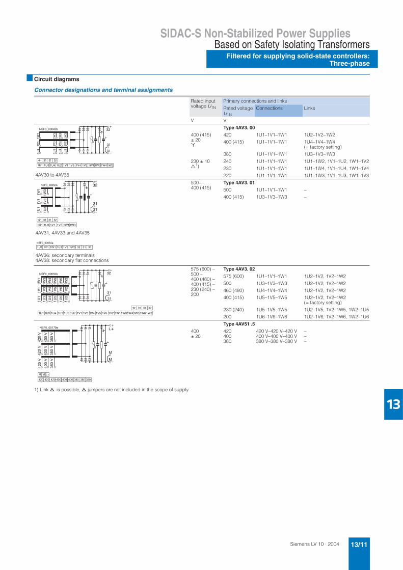
■ Circuit diagrams
Connector designations and terminal assignments
1) Link d is possible, d jumpers are not included in the scope of supply.
Rated input voltage U1N
Primary connections and links
Rated voltage U1N
Connections Links
V V
4AV30 to 4AV35
Type 4AV3. 00
400 (415)± 20 ,
420
400 (415)
380
1U1–1V1–1W1
1U1–1V1–1W1
1U1–1V1–1W1
1U2–1V2–1W2
1U4–1V4–1W4(= factory setting)
1U3–1V3–1W3
230 ± 10|
1)240
230
220
1U1–1V1–1W1
1U1–1V1–1W1
1U1–1V1–1W1
1U1–1W2, 1V1–1U2, 1W1–1V2
1U1–1W4, 1V1–1U4, 1W1–1V4
1U1–1W3, 1V1–1U3, 1W1–1V3
4AV31, 4AV33 and 4AV35
4AV36: secondary terminals 4AV38: secondary flat connections
500–400 (415)
Type 4AV3. 01
500
400 (415)
1U1–1V1–1W1
1U3–1V3–1W3
–
–
575 (600) – 500 – 460 (480) – 400 (415) – 230 (240) – 200
Type 4AV3. 02
575 (600)
500
460 (480)
400 (415)
230 (240)
200
1U1–1V1–1W1
1U3–1V3–1W3
1U4–1V4–1W4
1U5–1V5–1W5
1U5–1V5–1W5
1U6–1V6–1W6
1U2–1V2, 1V2–1W2
1U2–1V2, 1V2–1W2
1U2–1V2, 1V2–1W2
1U2–1V2, 1V2–1W2 (= factory setting)
1U2–1V5, 1V2–1W5, 1W2–1U5
1U2–1V6, 1V2–1W6, 1W2–1U6
Type 4AV51 .5
400± 20
420400380
420 V–420 V–420 V400 V–400 V–400 V380 V–380 V–380 V
–––
31
32
31
1U1
1U3
1U4
1U2
1V1
1V3
1V4
1V2
1W1
1W3
1W4
1W2
NSF0_00049b
1V31U2 1V11U41U1 1U3 1W21W31W41W11V4 1V2
31 31 32
NSF0_00052a
1W1
1V1
1U1 31
32
31
1W3
1V3
1U3
1W31V3 1W11V11U1 1U3
31 31 32
� � �� � � � � �� � �� � � � � � � � � �� �
� � � � � � � � �
1U1 31
32
31
1U3
1U4
1U5
1U6
1U2
1V1
1V3
1V4
1V5
1V6
1V2
1W1
1W3
1W4
1W5
1W6
1W2
NSF0_00055b
1U21U5 1U61U41U1 1U3 1V21V5 1V61V41V1 1V3 1W21W5 1W61W41W11W3
31 31 32
�
�
�����
�����
� ���
� � � � � � ! " �
�����
�����
� ���
�����
�����
� ���
#
� � �
� �
� � � � � � � � � � � � � � � � � � � � �
#
Siemens LV 10 · 200413/12
SIDAC-S Non-Stabilized Power Supplies
Unfiltered for supplying general loads:General data
Based on Safety Isolating Transformers
13
■ Overview
The 4AV98 and 4AV96 power supplies comprise single-phase or three-phase safety isolating transformers to EN 61558-2-6 with downstream bridge connection rectifiers without capacitor filter-ing.
■ Area of application
Single-phase units
The single-phase 4AV98 units are especially suitable for supply-ing resistive and inductive loads whose rated voltages place no special demands with regard to ripple.
Three-phase units, also for VW
The 4AV96 three-phase units are designed and approved in ac-cordance with the VW equipment specifications.
Rated output and rated current
The specifications in the selection tables are based on fixed ref-erence conditions in which the devices have the rated output or rated current:• Continuous duty Pn• Frequency AC 50 Hz to 60 Hz• Installation altitude up to 1000 m above sea level• IP00 degree of protection• Ambient temperature ta.
Ambient conditions
The devices are climate-proof for use in rooms with an external climate to DIN 50010.
Limit values:• Ambient temperature
– At rated power or rated current: +50 °C– Minimum value –25 °C.
• Relative air humidity– At +40 °C occasionally up to 100 %– Annual average up to 80 %– Occasional condensation possible.
■ Design
The 4AV98 and 4AV96 power supplies are single-phase or three-phase transformers with downstream bridge rectifiers without capacitor filtering. They comply with safety class I. The safety isolating transformers used have been designed according to EN 61558-2-6. The transformers are completely impregnated with polyester resin for protection against harmful environmental influences.
The terminals with the SIGUT connection method are• finger-safe to DIN VDE 0106 Part 100• suitable for conductor cross-sections to DIN VDE 0100
Part 430 Sheet 1 and EN 60204 (VDE 0113 Part 1).
4AV98 single-phase power supplies
The integrated rectifier in a two-pulse bridge connection sup-plies an unstabilized, unfiltered DC voltage with an arithmetic mean value of DC 24 V and a ripple of 48.3 %.• Short-circuit and overload protection on the output side with
top-mounted fuse• Varistor suppressor circuit
4AV96 three-phase power supplies
The integrated rectifier in a six-pulse bridge connection supplies an unstabilized, unfiltered DC voltage with an arithmetic mean value of DC 30/27/24 V and a ripple of < 5 %.• Shield winding between input and output winding• Varistor suppressor circuit • In accordance with VW equipment specification.
Siemens LV 10 · 2004 13/13
SIDAC-S Non-Stabilized Power SuppliesBased on Safety Isolating Transformers
Unfiltered for supplying general loads:Single-phase
13
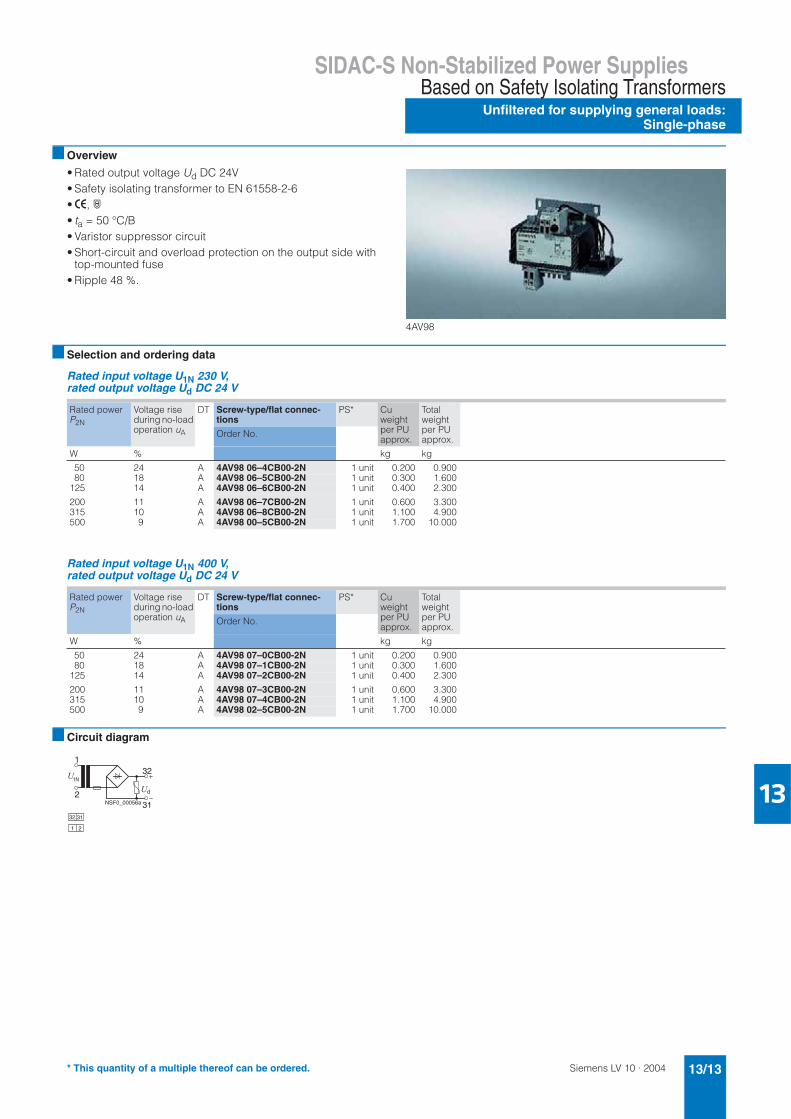
■ Overview
• Rated output voltage Ud DC 24V• Safety isolating transformer to EN 61558-2-6•>, ·• ta = 50 °C/B• Varistor suppressor circuit• Short-circuit and overload protection on the output side with
top-mounted fuse• Ripple 48 %.
4AV98
■ Selection and ordering data
Rated input voltage U1N 230 V, rated output voltage Ud DC 24 V
Rated input voltage U1N 400 V, rated output voltage Ud DC 24 V
■ Circuit diagram
Rated power P2N
Voltage rise during no-load operation uA
DT Screw-type/flat connec-tions
PS* Cuweightper PU approx.
Total weightper PU approx.
Order No.
W % kg kg
50 24 A 4AV98 06–4CB00-2N 1 unit 0.200 0.90080 18 A 4AV98 06–5CB00-2N 1 unit 0.300 1.600
125 14 A 4AV98 06–6CB00-2N 1 unit 0.400 2.300
200 11 A 4AV98 06–7CB00-2N 1 unit 0.600 3.300315 10 A 4AV98 06–8CB00-2N 1 unit 1.100 4.900500 9 A 4AV98 00–5CB00-2N 1 unit 1.700 10.000
Rated power P2N
Voltage rise during no-load operation uA
DT Screw-type/flat connec-tions
PS* Cuweightper PU approx.
Total weightper PU approx.
Order No.
W % kg kg
50 24 A 4AV98 07–0CB00-2N 1 unit 0.200 0.90080 18 A 4AV98 07–1CB00-2N 1 unit 0.300 1.600
125 14 A 4AV98 07–2CB00-2N 1 unit 0.400 2.300
200 11 A 4AV98 07–3CB00-2N 1 unit 0.600 3.300315 10 A 4AV98 07–4CB00-2N 1 unit 1.100 4.900500 9 A 4AV98 02–5CB00-2N 1 unit 1.700 10.000
2
132
1N
d
31NSF0_00056a
1 2
32 31
* This quantity of a multiple thereof can be ordered.
Siemens LV 10 · 200413/14
SIDAC-S Non-Stabilized Power Supplies
Unfiltered for supplying general loads:Three-phase
Based on Safety Isolating Transformers
13
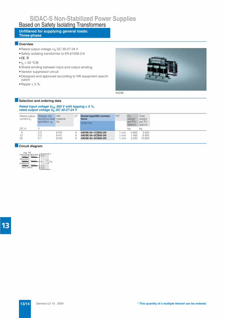
■ Overview
• Rated output voltage Ud DC 30-27-24 V• Safety isolating transformer to EN 61558-2-6•>, ·• ta = 50 °C/B• Shield winding between input and output winding• Varistor suppressor circuit• Designed and approved according to VW equipment specifi-
cation• Ripple < 5 %.
4AV96
■ Selection and ordering data
Rated input voltage U1N 400 V with tapping ± 5 %, rated output voltage Ud DC 30-27-24 V
■ Circuit diagram
Rated output current Id
Voltage rise during no-load operation uA
VWmaterialNo.
DT Screw-type/flat connec-tions
PS* Cu weight per PU approx.
Total weightper PU approx.
Order No.
DC A V kg kg
4 3.5 6142 A 4AV96 04–1CB00-2N 1 unit 0.800 3.50012 3.3 6141 A 4AV96 04–5CB00-2N 1 unit 1.400 6.90025 3.1 6145 A 4AV96 04–2CB00-2N 1 unit 2.500 10.600
+5%U-5%N
+5%V-5%
+5%W-5%
3027 24V-PE1N
d
NSF0_00057a
* This quantity of a multiple thereof can be ordered.
Siemens LV 10 · 2004 13/15
Stabilized Power SuppliesFor Specific Loads and Systems
SIDAC-S load power supplies
13
■ Overview
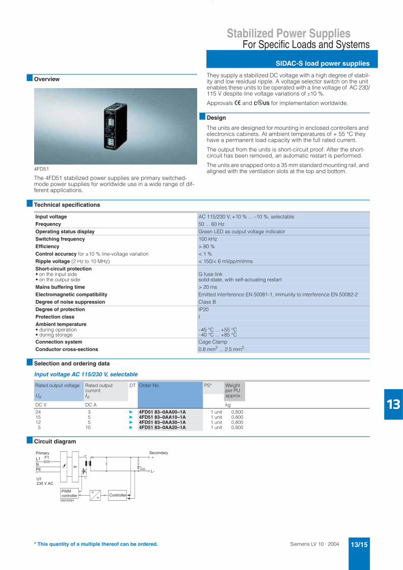
4FD51
The 4FD51 stabilized power supplies are primary switched-mode power supplies for worldwide use in a wide range of dif-ferent applications.
They supply a stabilized DC voltage with a high degree of stabil-ity and low residual ripple. A voltage selector switch on the unit enables these units to be operated with a line voltage of AC 230/115 V despite line voltage variations of ±10 %.
Approvals > and CuUS for implementation worldwide.
■ Design
The units are designed for mounting in enclosed controllers and electronics cabinets. At ambient temperatures of + 55 °C they have a permanent load capacity with the full rated current.
The output from the units is short-circuit proof. After the short-circuit has been removed, an automatic restart is performed.
The units are snapped onto a 35 mm standard mounting rail, and aligned with the ventilation slots at the top and bottom.
■ Technical specifications
■ Selection and ordering data
Input voltage AC 115/230 V, selectable
■ Circuit diagram
Input voltage AC 115/230 V, +10 % ... –10 %, selectableFrequency 50 ... 60 HzOperating status display Green LED as output voltage indicatorSwitching frequency 100 kHzEfficiency > 80 %Control accuracy for ±10 % line-voltage variation < 1 %Ripple voltage (2 Hz to 10 MHz) < 150/< 6 mVpp/mVrmsShort-circuit protection• on the input side G fuse link• on the output side solid-state, with self-actuating restartMains buffering time > 20 msElectromagnetic compatibility Emitted interference EN 50081-1, immunity to interference EN 50082-2Degree of noise suppression Class BDegree of protection IP20Protection class IAmbient temperature• during operation –45 °C ... +55 °C• during storage –40 °C ... +85 °CConnection system Cage ClampConductor cross-sections 0.8 mm2 ... 2.5 mm2
Rated output voltage
Ud
Rated output current Id
DT Order No. PS* Weight per PU approx.
DC V DC A kg
24 3 } 4FD51 83–0AA00–1A 1 unit 0,80015 5 } 4FD51 83–0AA10–1A 1 unit 0,80012 5 } 4FD51 83–0AA30–1A 1 unit 0,800
5 10 } 4FD51 83–0AA20–1A 1 unit 0,800
��������
�
�
����
� ��
��
���������������������
���������������
������ �!
* This quantity of a multiple thereof can be ordered.
Siemens LV 10 · 200413/16
Stabilized Power Supplies
LOGO!Power suppliesSingle-phase
For Specific Loads and Systems
13
■ Overview
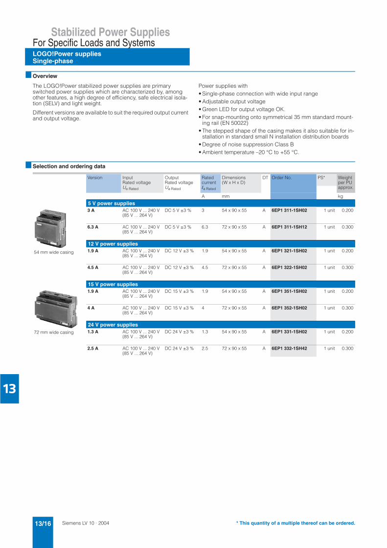
The LOGO!Power stabilized power supplies are primary switched power supplies which are characterized by, among other features, a high degree of efficiency, safe electrical isola-tion (SELV) and light weight.
Different versions are available to suit the required output current and output voltage.
Power supplies with• Single-phase connection with wide input range• Adjustable output voltage• Green LED for output voltage OK.• For snap-mounting onto symmetrical 35 mm standard mount-
ing rail (EN 50022) • The stepped shape of the casing makes it also suitable for in-
stallation in standard small N installation distribution boards• Degree of noise suppression Class B• Ambient temperature –20 °C to +55 °C.
■ Selection and ordering data
Version Input Rated voltageUe Rated
OutputRated voltageUa Rated
Ratedcurrent Ia Rated
Dimensions(W x H x D)
DT Order No. PS* Weight per PU approx.
A mm kg
5 V power supplies
54 mm wide casing
3 A AC 100 V ... 240 V(85 V ... 264 V)
DC 5 V ±3 % 3 54 x 90 x 55 A 6EP1 311-1SH02 1 unit 0.200
6.3 A AC 100 V ... 240 V(85 V ... 264 V)
DC 5 V ±3 % 6.3 72 x 90 x 55 A 6EP1 311-1SH12 1 unit 0.300
12 V power supplies1.9 A AC 100 V ... 240 V
(85 V ... 264 V)DC 12 V ±3 % 1.9 54 x 90 x 55 A 6EP1 321-1SH02 1 unit 0.200
4.5 A AC 100 V ... 240 V(85 V ... 264 V)
DC 12 V ±3 % 4.5 72 x 90 x 55 A 6EP1 322-1SH02 1 unit 0.300
15 V power supplies
72 mm wide casing
1.9 A AC 100 V ... 240 V(85 V ... 264 V)
DC 15 V ±3 % 1.9 54 x 90 x 55 A 6EP1 351-1SH02 1 unit 0.200
4 A AC 100 V ... 240 V(85 V ... 264 V)
DC 15 V ±3 % 4 72 x 90 x 55 A 6EP1 352-1SH02 1 unit 0.300
24 V power supplies1.3 A AC 100 V ... 240 V
(85 V ... 264 V)DC 24 V ±3 % 1.3 54 x 90 x 55 A 6EP1 331-1SH02 1 unit 0.200
2.5 A AC 100 V ... 240 V(85 V ... 264 V)
DC 24 V ±3 % 2.5 72 x 90 x 55 A 6EP1 332-1SH42 1 unit 0.300
* This quantity of a multiple thereof can be ordered.
Siemens LV 10 · 2004 13/17
Stabilized Power SuppliesFor Specific Loads and Systems
SITOP power suppliesSingle-phase
13
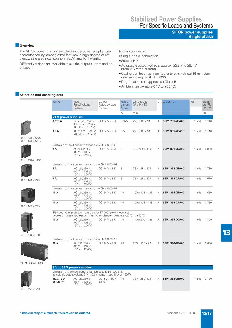
■ Overview
The SITOP power primary switched-mode power supplies are characterized by, among other features, a high degree of effi-ciency, safe electrical isolation (SELV) and light weight.
Different versions are available to suit the output current and ap-plication.
Power supplies with • Single-phase connection• Status LED• Adjustable output voltage, approx. 22.8 V to 26.4 V
(from 2 A rated current)• Casing can be snap-mounted onto symmetrical 35 mm stan-
dard mounting rail (EN 50022)• Degree of noise suppression Class B• Ambient temperature 0 °C to +60 °C.
■ Selection and ordering data
Version Input Rated voltageUe Rated
OutputRated voltageUa Rated
Ratedcurrent Ia Rated
Dimensions(W x H x D)
DT Order No. PS* Weight per PU approx.
A mm kg
24 V power supplies
6EP1 731-2BA006EP1 331-2BA10
0.375 A DC 48 V ... 220 V(DC 30 V ... 264 V,AC 30 V ... 187 V)
DC 24 V ±2 % 0.375 22.5 x 80 x 91 A 6EP1 731-2BA00 1 unit 0.140
0.5 A AC 120 V ... 230 V(AC 93 V ... 264 V)
DC 24 V ±2 % 0.5 22.5 x 80 x 91 A 6EP1 331-2BA10 1 unit 0.110
6EP1 331-2BA00
Limitation of input current harmonics to EN 61000-3-2
2 A AC 120/230 V(93 V ... 132 V/ 187 V ... 264 V)
DC 24 V ±3 % 2 50 x 125 x 125 A 6EP1 331-2BA00 1 unit 0.380
6EP1 333-2.A00
Limitation of input current harmonics to EN 61000-3-2
5 A AC 120/230 V(93 V ... 132 V/ 187 V ... 264 V)
DC 24 V ±3 % 5 75 x 125 x 125 A 6EP1 333-2BA00 1 unit 0.750
5 A AC 120/230 V(93 V ... 132 V/ 187 V ... 264 V)
DC 24 V ±3 % 5 75 x 125 x 125 A 6EP1 333-2AA00 1 unit 0.570
6EP1 334-2.A00
Limitation of input current harmonics to EN 61000-3-2
10 A AC 120/230 V(85 V ... 132 V/187 V ... 264 V)
DC 24 V ±3 % 10 100 x 125 x 135 A 6EP1 334-2BA00 1 unit 1.080
10 A AC 120/230 V(85 V ... 132 V/187 V ... 264 V)
DC 24 V ±3 % 10 100 x 125 x 135 A 6EP1 334-2AA00 1 unit 0.780
6EP1 334-2CA00
IP65 degree of protection, adapted for ET 200X; wall mounting;degree of noise suppression Class A; ambient temperature –20 °C ... +55 °C
10 A AC 120/230 V(93 V ... 132 V/ 187 V ... 264 V)
DC 24 V ±3 % 10 140 x 270 x 126 A 6EP1 334-2CA00 1 unit 1.700
6EP1 336-2BA00
Limitation of input current harmonics to EN 61000-3-2
20 A AC 120/230 V(93 V ... 132 V/ 187 V ... 264 V)
DC 24 V ±3 % 20 280 x 125 x 92 A 6EP1 336-2BA00 1 unit 2.400
3 V ... 52 V power supplies
6EP1 353-2BA00
Limitation of the input current harmonics to EN 61000-3-2, adjustable output voltage 3 V ... 52 V, output max. 10 A or 120 W
max. 10 A or 120 W
AC 120/230 V(85 V ... 132 V/170 V ... 264 V)
DC 3 V ... 52 V ±1 %
10 75 x 125 x 125 A 6EP1 353-2BA00 1 unit 0.750
* This quantity of a multiple thereof can be ordered.
Siemens LV 10 · 200413/18
Stabilized Power Supplies
SITOP power suppliesSingle-, two- and three phase
For Specific Loads and Systems
13
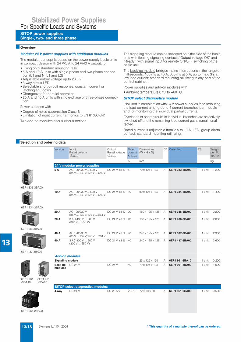
■ Overview
Modular 24 V power supplies with additional modules
The modular concept is based on the power supply basic units in compact design with 24 V/5 A to 24 V/40 A output, for• Fixing onto standard mounting rails• 5 A and 10 A units with single-phase and two-phase connec-
tion (L1 and N, L1 and L2)• Adjustable output voltage up to 28.8 V• 3-way status LED• Selectable short-circuit response, constant current or
latching shutdown• Changeover for parallel operation• 20 A and 40 A units with single-phase or three-phase connec-
tion.
Power supplies with• Degree of noise suppression Class B• Limitation of input current harmonics to EN 61000-3-2
Two add-on modules offer further functions.
The signaling module can be snapped onto the side of the basic unit; with floating signaling contacts "Output voltage OK" and "Ready"; with signal input for remote ON/OFF switching of the basic unit.
The back-up module bridges mains interruptions in the range of milliseconds. 100 ms at 40 A, 800 ms at 5 A, up to max. 3 s at low load current; standard mounting rail fixing in any part of the control cabinet.
Power supplies and add-on modules with• Ambient temperature 0 °C to +60 °C.
SITOP select diagnostics module
It is used in combination with 24 V power supplies for distributing the load current among up to 4 current branches per module and for monitoring the individual partial currents.
Overloads or short-circuits in individual branches are selectively switched off and the remaining load current paths remain unaf-fected.
Rated current is adjustable from 2 A to 10 A, LED, group alarm contact, standard mounting rail fixing.
■ Selection and ordering data
Version Input Rated voltage Ue Rated
OutputRated voltage Ua Rated
Ratedcurrent Ia Rated
Dimensions(W x H x D)
DT Order No. PS* Weight per PU approx.
A mm kg
24 V modular power supplies
6EP1 333-3BA00
5 A AC 120/230 V ... 500 V(85 V ... 132 V/176 V ... 550 V)
DC 24 V ±3 % 5 70 x 125 x 125 A 6EP1 333-3BA00 1 unit 1.200
6EP1 334-3BA00
10 A AC 120/230 V ... 500 V(85 V ... 132 V/176 V ... 550 V)
DC 24 V ±3 % 10 90 x 125 x 125 A 6EP1 334-3BA00 1 unit 1.400
6EP1 .36-3BA00
20 A AC 120/230 V(85 V ... 132 V/176 V ... 264 V)
DC 24 V ±3 % 20 160 x 125 x 125 A 6EP1 336-3BA00 1 unit 2.200
20 A 3 AC 400 V ... 500 V(320 V ... 550 V)
DC 24 V ±3 % 20 160 x 125 x 125 A 6EP1 436-3BA00 1 unit 2.000
6EP1 .37-3BA00
40 A AC 120/230 V(85 V ... 132 V/176 V ... 264 V)
DC 24 V ±3 % 40 240 x 125 x 125 A 6EP1 337-3BA00 1 unit 2.900
40 A 3 AC 400 V ... 500 V(320 V ... 550 V)
DC 24 V ±3 % 40 240 x 125 x 125 A 6EP1 437-3BA00 1 unit 2.600
Add-on modules
6EP1 961 6EP1 961-3BA10 -3BA00
Signaling module 25 x 125 x 125 A 6EP1 961-3BA10 1 unit 0.200
Back-upmodules
DC 24 V DC 24 V 40 70 x 125 x 125 A 6EP1 961-3BA00 1 unit 1.000
SITOP select diagnostics modules
6EP1 961-2BA00
4-way DC 24 V DC 23.5 V 2 ... 10 72 x 90 x 90 A 6EP1 961-2BA00 1 unit 0.500
* This quantity of a multiple thereof can be ordered.

Siemens LV 10 · 2004 13/19
Stabilized Power SuppliesFor Specific Loads and Systems
SITOP power suppliesUninterruptible
13
■ Overview
DC 24 V uninterruptible power supplies
Mains failures of a longer duration can be buffered without any interruption at all by combining a DC UPS module with at least one battery module and a SITOP power supply.
DC UPS modules with• Degree of noise suppression Class B• Ambient temperature 0 °C to +60 °C.
Battery modules• 2.5 Ah: ambient temperature –40 °C to +60 °C• 3.2 Ah to 12 Ah: ambient temperature +5 °C to +40 °C.
■ Selection and ordering data
DC UPS modules
Battery modules
Version InputRated voltageUe Rated
Output Rated voltageUa Rated
Ratedcurrent Ia Rated
Dimensions(W x H x D)
DT Order No. PS* Weight per PU approx.
A mm kg
6EP1 931-2EC.1
15 A DC 24 V (22 V ... 27.5 V)
DC 24 V (mains operation: 22 V ... 27.5 V, battery operation: 27.0 V ... 18.5 V)
15 75 x 125 x 125 A 6EP1 931-2EC01 1 unit 0.400
15 A with RS 232interface
A 6EP1 931-2EC11 1 unit 0.450
6EP1 931-2FC01
40 A DC 24 V (23.5 V ... 26 V)
DC 24 V (mains operation: 23.5 V ... 26 V, battery operation: 27.0 V ... 18.5 V)
40 220 x 130 x 65 A 6EP1 931-2FC01 1 unit 1.200
Version Chargingvoltageat +25 °C UCharge
Ratedoutput voltage Ua Rated
Dimensions(W x H x D)
DT Order No. PS* Weight per PU approx.
mm kg
For 15 A DC UPS modules
6EP1 935-6MD31
2.5 Ah/hightemperature rechargeable battery
DC 27.7 V DC 24 V (end of charge voltage: 27.7 V, exhaustive dis-chargeprotection: 18.5 V)
265 x 151 x 91 A 6EP1 935-6MD31 1 unit 3.800
6EP1 935-6MD11
3.2 Ah DC 27.0 V DC 24 V (end of charge voltage: 27.0 V, exhaustive dis-charge protection: 18.5 V)
190 x 151 x 82 A 6EP1 935-6MD11 1 unit 3.800
For 15 A and 40 A DC UPS modules
6EP1 935-6ME21
7 Ah DC 27.0 V DC 24 V (end of charge voltage: 27.0 V, exhaustive dis-charge protection: 18.5 V)
186 x 168 x 121 A 6EP1 935-6ME21 1 unit 6.000
6EP1 935-6MF01
12 Ah DC 27.0 V DC 24 V (end of charge voltage: 27.0 V, exhaustive dis-charge protection: 18.5 V)
253 x 118 x 121 A 6EP1 935-6MF01 1 unit 9.000
* This quantity of a multiple thereof can be ordered.
Siemens LV 10 · 200413/20
SIDAC-S Power Supplies
Project planning aids
13
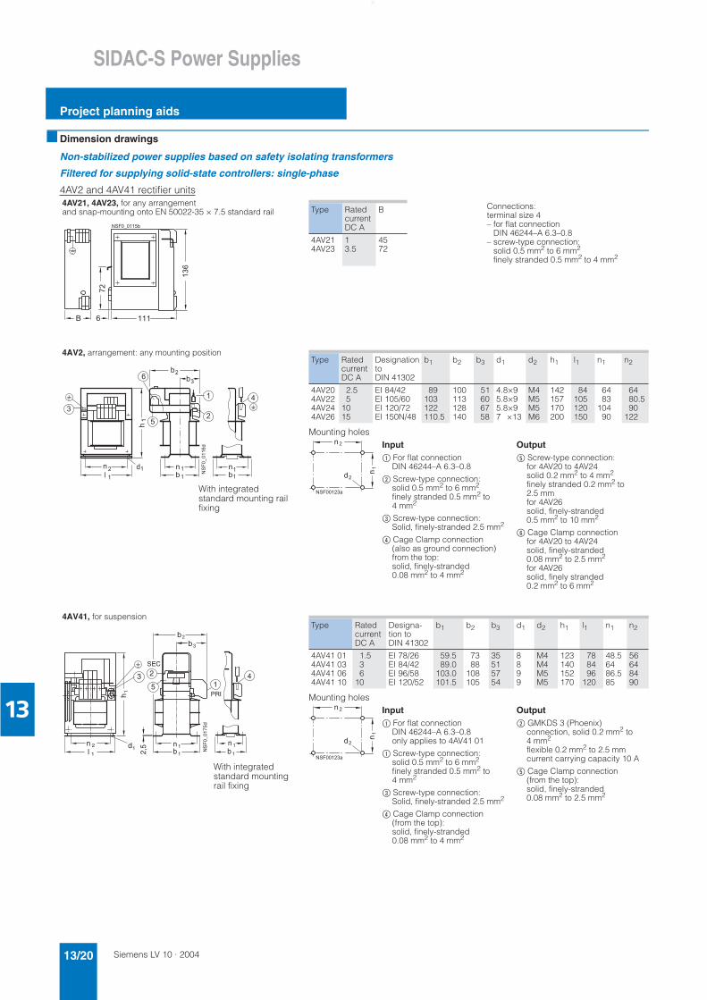
■ Dimension drawings
Non-stabilized power supplies based on safety isolating transformers
Filtered for supplying solid-state controllers: single-phase
4AV2 and 4AV41 rectifier units4AV21, 4AV23, for any arrangement and snap-mounting onto EN 50022-35 × 7.5 standard rail
4AV2, arrangement: any mounting position
4AV41, for suspension
� � �
!�
� � � � � � � �
�
���
$
Connections:terminal size 4 – for flat connection DIN 46244–A 6.3–0.8
– screw-type connection: solid 0.5 mm2 to 6 mm2
finely stranded 0.5 mm2 to 4 mm2
Type Ratedcurrent DC A
B
4AV214AV23
13.5
4572
�
�
%�
�
�
�
�
�
�
��������
��
�
��
�
�
�
�
� �
�
�
�
�
�
With integrated standard mounting rail fixing
Mounting holes
Type Ratedcurrent DC A
DesignationtoDIN 41302
b1 b2 b3 d1 d2 h1 l1 n1 n2
4AV204AV224AV244AV26
2.55
1015
EI 84/42EI 105/60EI 120/72EI 150N/48
89103122110.5
100113128140
51606758
4.8×95.8×95.8×97 ×13
M4M5M5M6
142157170200
84105120150
6483
10490
6480.590
122
Input$ For flat connection
DIN 46244–A 6.3–0.8
% Screw-type connection: solid 0.5 mm2 to 6 mm2
finely stranded 0.5 mm2 to 4 mm2
& Screw-type connection: Solid, finely-stranded 2.5 mm2
( Cage Clamp connection (also as ground connection) from the top: solid, finely-stranded 0.08 mm2 to 4 mm2
���������
��
��
��
Output) Screw-type connection:
for 4AV20 to 4AV24solid 0.2 mm2 to 4 mm2
finely stranded 0.2 mm2 to 2.5 mm for 4AV26 solid, finely-stranded 0.5 mm2 to 10 mm2
* Cage Clamp connection for 4AV20 to 4AV24 solid, finely-stranded 0.08 mm2 to 2.5 mm2
for 4AV26 solid, finely stranded 0.2 mm2 to 6 mm2
2
n 1
h
bdn
l NS
F0_
0175
d
3
1
2 1
1
SEC
12,5
31
PRI
n 1b 1
45
b2b
With integrated standard mounting rail fixing
Mounting holes
Type Ratedcurrent DC A
Designa-tion to DIN 41302
b1 b2 b3 d1 d2 h1 l1 n1 n2
4AV41 014AV41 034AV41 064AV41 10
1.536
10
EI 78/26EI 84/42EI 96/58EI 120/52
59.589.0
103.0101.5
7388
108105
35515754
8899
M4M4M5M5
123140152170
788496
120
48.56486.585
56648490
Input$ For flat connection
DIN 46244–A 6.3–0.8 only applies to 4AV41 01
$ Screw-type connection: solid 0.5 mm2 to 6 mm2
finely stranded 0.5 mm2 to 4 mm2
& Screw-type connection: Solid, finely-stranded 2.5 mm2
( Cage Clamp connection (from the top): solid, finely-stranded 0.08 mm2 to 4 mm2
���������
��
��
��
Output% GMKDS 3 (Phoenix)
connection, solid 0.2 mm2 to 4 mm2
flexible 0.2 mm2 to 2.5 mm current carrying capacity 10 A
) Cage Clamp connection (from the top): solid, finely-stranded 0.08 mm2 to 2.5 mm2
Siemens LV 10 · 2004 13/21
SIDAC-S Power Supplies
Project planning aids
13
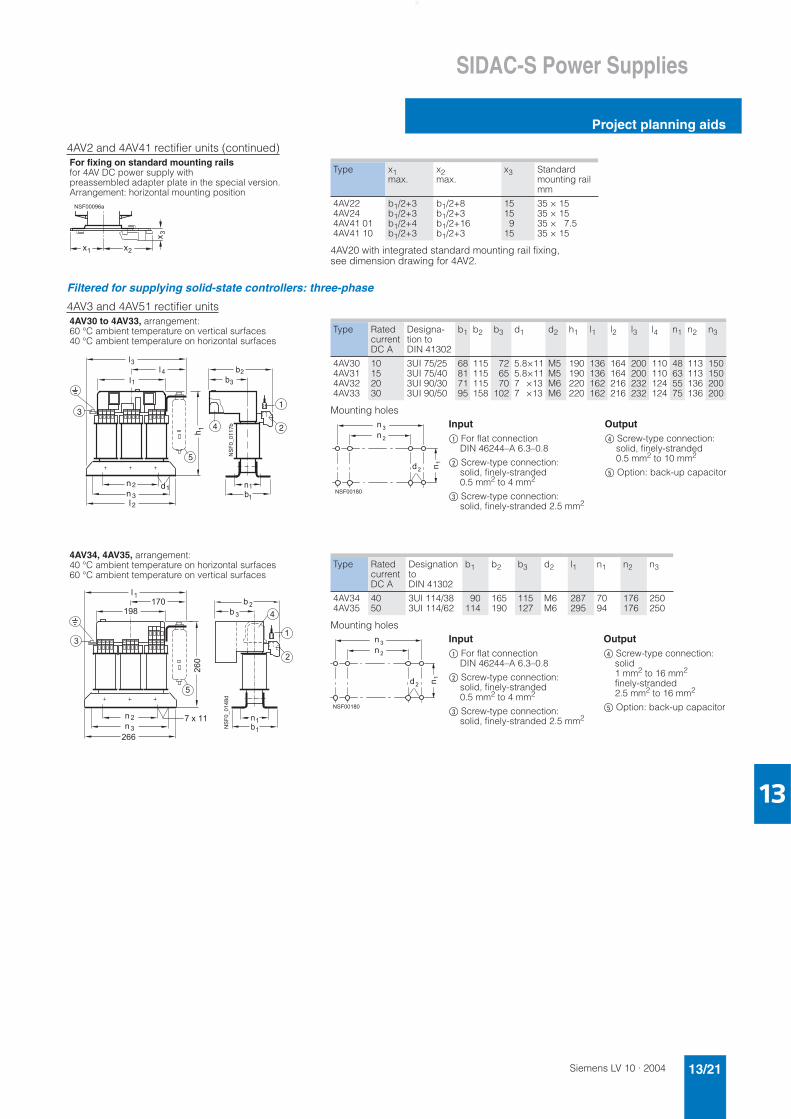
4AV2 and 4AV41 rectifier units (continued)
Filtered for supplying solid-state controllers: three-phase
4AV3 and 4AV51 rectifier units
For fixing on standard mounting railsfor 4AV DC power supply with preassembled adapter plate in the special version. Arrangement: horizontal mounting position������"��
#� #�
#�
4AV20 with integrated standard mounting rail fixing, see dimension drawing for 4AV2.
Type x1max.
x2max.
x3 Standard mounting rail mm
4AV224AV244AV41 014AV41 10
b1/2+3b1/2+3b1/2+4b1/2+3
b1/2+8b1/2+3b1/2+16b1/2+3
1515
915
35 × 1535 × 1535 × 7.535 × 15
4AV30 to 4AV33, arrangement: 60 °C ambient temperature on vertical surfaces40 °C ambient temperature on horizontal surfaces
4AV34, 4AV35, arrangement: 40 °C ambient temperature on horizontal surfaces60 °C ambient temperature on vertical surfaces
l 3
b1
2n 3l 2
d1
NS
F0_
0117
b 2
13
4
n1
b2b3l1
l 4
h 1
5
n
Mounting holes
Type Ratedcurrent DC A
Designa-tion to DIN 41302
b1 b2 b3 d1 d2 h1 l1 l2 l3 l4 n1 n2 n3
4AV304AV314AV324AV33
10152030
3UI 75/253UI 75/403UI 90/303UI 90/50
68817195
115115115158
726570
102
5.8×115.8×117 ×137 ×13
M5M5M6M6
190190220220
136136162162
164164216216
200200232232
110110124124
48635575
113113136136
150150200200
Output( Screw-type connection:
solid, finely-stranded 0.5 mm2 to 10 mm2
) Option: back-up capacitor
Input$ For flat connection
DIN 46244–A 6.3–0.8
% Screw-type connection:solid, finely-stranded 0.5 mm2 to 4 mm2
& Screw-type connection:solid, finely-stranded 2.5 mm2
�
� ��
�
�
��
������$�
�
��
� � �
� � � � � �
����� ��
�
�
�
�
���
�
�
�
� � �
� � �
�
�
�
�
��
�
�
Mounting holes
Type Ratedcurrent DC A
Designation toDIN 41302
b1 b2 b3 d2 l1 n1 n2 n3
4AV344AV35
4050
3UI 114/383UI 114/62
90114
165190
115127
M6M6
287295
7094
176176
250250
Output( Screw-type connection:
solid1 mm2 to 16 mm2
finely-stranded2.5 mm2 to 16 mm2
) Option: back-up capacitor
Input$ For flat connection
DIN 46244–A 6.3–0.8
% Screw-type connection:solid, finely-stranded 0.5 mm2 to 4 mm2
& Screw-type connection:solid, finely-stranded 2.5 mm2
�
� �
�
�
�
��
����
Siemens LV 10 · 200413/22
SIDAC-S Power Supplies
Project planning aids
13
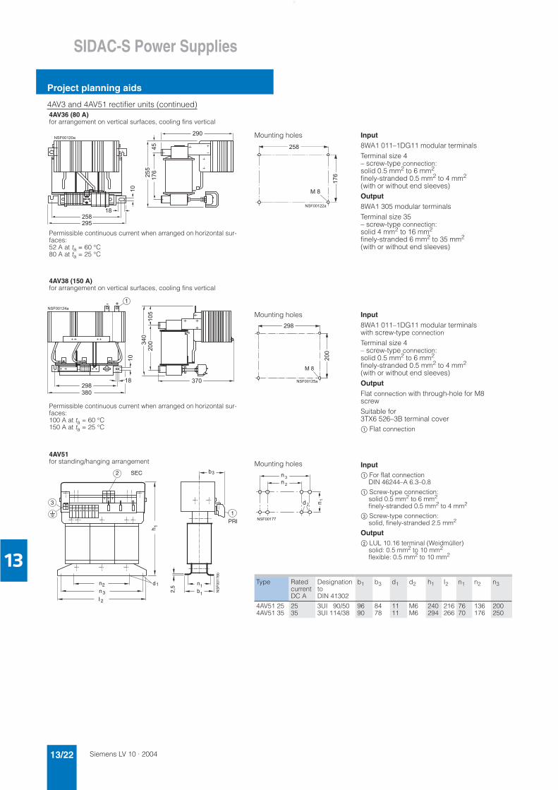
4AV3 and 4AV51 rectifier units (continued)4AV36 (80 A)for arrangement on vertical surfaces, cooling fins vertical
Permissible continuous current when arranged on horizontal sur-faces:52 A at ta = 60 °C80 A at ta = 25 °C
4AV38 (150 A)for arrangement on vertical surfaces, cooling fins vertical
Permissible continuous current when arranged on horizontal sur-faces:100 A at ta = 60 °C150 A at ta = 25 °C
4AV51for standing/hanging arrangement
��
� �
���
�
������
������
�� Mounting holes
��
��
� �
�������
Input8WA1 011–1DG11 modular terminalsTerminal size 4 – screw-type connection:solid 0.5 mm2 to 6 mm2
finely-stranded 0.5 mm2 to 4 mm2
(with or without end sleeves)Output8WA1 305 modular terminalsTerminal size 35 – screw-type connection:solid 4 mm2 to 16 mm2
finely-stranded 6 mm2 to 35 mm2
(with or without end sleeves)
��
�
�������
�
�
��
���
���
�
Mounting holes
��
�������
���
Input8WA1 011–1DG11 modular terminals with screw-type connection
Terminal size 4 – screw-type connection:solid 0.5 mm2 to 6 mm2
finely-stranded 0.5 mm2 to 4 mm2
(with or without end sleeves)OutputFlat connection with through-hole for M8 screwSuitable for 3TX6 526–3B terminal cover$ Flat connection
2
n1
h
bnnl
NS
F00
176b
3b
2
3
2
1
SEC
12,5d1
3
1PRI
Mounting holes
�
� �
�
�
�
��
����
Input$ For flat connection
DIN 46244–A 6.3–0.8
$ Screw-type connection: solid 0.5 mm2 to 6 mm2
finely-stranded 0.5 mm2 to 4 mm2
& Screw-type connection: solid, finely-stranded 2.5 mm2
Output% LUL 10.16 terminal (Weidmüller)
solid: 0.5 mm2 to 10 mm2
flexible: 0.5 mm2 to 10 mm2
Type Ratedcurrent DC A
Designationto DIN 41302
b1 b3 d1 d2 h1 I2 n1 n2 n3
4AV51 254AV51 35
2535
3UI 90/503UI 114/38
9690
8478
1111
M6M6
240294
216266
7670
136176
200250
Siemens LV 10 · 2004 13/23
SIDAC-S Power Supplies
Project planning aids
13
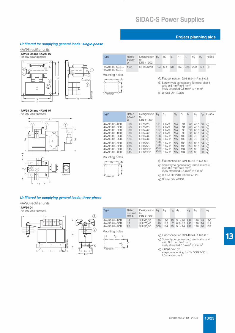
Unfiltered for supplying general loads: single-phase
4AV98 rectifier units
Unfiltered for supplying general loads: three-phase
4AV96 rectifier units
4AV98 00 and 4AV98 02 for any arrangement
4AV98 06 and 4AV98 07 for any arrangement
1
3
b1
n2
l 1n1
d1
h1
2
1
NS
F00
128
Mounting holes
Type RatedpowerW
DesignationtoDIN 41302
b1 d1 d2 h1 l1 n1 n1 Fuses
4AV98 00-5CB..,4AV98 02-5CB..
500 EI 150N/48 193 6.4 M6 160 228 200 174 &
$ Flat connection DIN 46244–A 6.3–0.8
% Screw-type connection: Terminal size 4 solid 0.5 mm2 to 6 mm2
finely stranded 0.5 mm2 to 4 mm2
& D fuse DIN 49360
��
� � � �
�����
b2 43
1
b1
h1
h1
1n1l 1
6
n 2
NSF00126
d 1
Mounting holes
Type RatedpowerW
DesignationtoDIN 41302
b1 d1 d2 h1 l1 n1 n2 Fuses
4AV98 06–4CB..4AV98 07–0CB..4AV98 06–5CB..4AV98 07–1CB..4AV98 06–6CB..4AV98 07–2CB..
50508080
125125
EI 78/26EI 78/26EI 84/42EI 84/42EI 96/44EI 96/44
121121127127138138
4.8×94.8×94.8×94.8×95.8×115.8×11
M4M4M4M4M5M5
91919595
106106
76769393
100100
48.548.563.563.57373
565664648484
&&&&&&
4AV98 06–7CB..4AV98 07–3CB..4AV98 06–8CB..4AV98 07–4CB..
200200315315
EI 96/58EI 96/58EI 120/52EI 120/52
138138204204
5.8×115.8×115.8×115.8×11
M5M5M5M5
106106134134
115115107107
86.586.58585
84849090
&&((
$ Flat connection DIN 46244–A 6.3–0.8
% Screw-type connection: terminal size 4 solid 0.5 mm2 to 6 mm2
finely stranded 0.5 mm2 to 4 mm2
& G fuse DIN VDE 0820 Part 22
( D fuse DIN 49360
��
� � � �
�����
4AV96 04for any arrangement
� �
�� ���� ��
��
�
�
�
��
������
Mounting holes
Type Ratedcurrent DC A
DesignationtoDIN 41302
b1 b2 b3 d1 d2 h1 n1 n2
4AV96 04–1CB..4AV96 04–5CB..4AV96 04–2CB..
41225
3UI 60/303UI 75/403UI 90/50
180149300
90112114
157
35
5 ×106.5×129 ×14
M4M6M8
140190190
499490
90111139
$ Flat connection DIN 46244–A 6.3–0.8
% Screw-type connection: terminal size 4 solid 0.5 mm2 to 6 mm2
finely stranded 0.5 mm2 to 4 mm2
& 4AV96 04–1CB: snap-on mounting for EN 50022–35 × 7.5 standard rail
��
��
��
������
Siemens LV 10 · 200413/24
SIDAC-S Power Supplies
Project planning aids
13
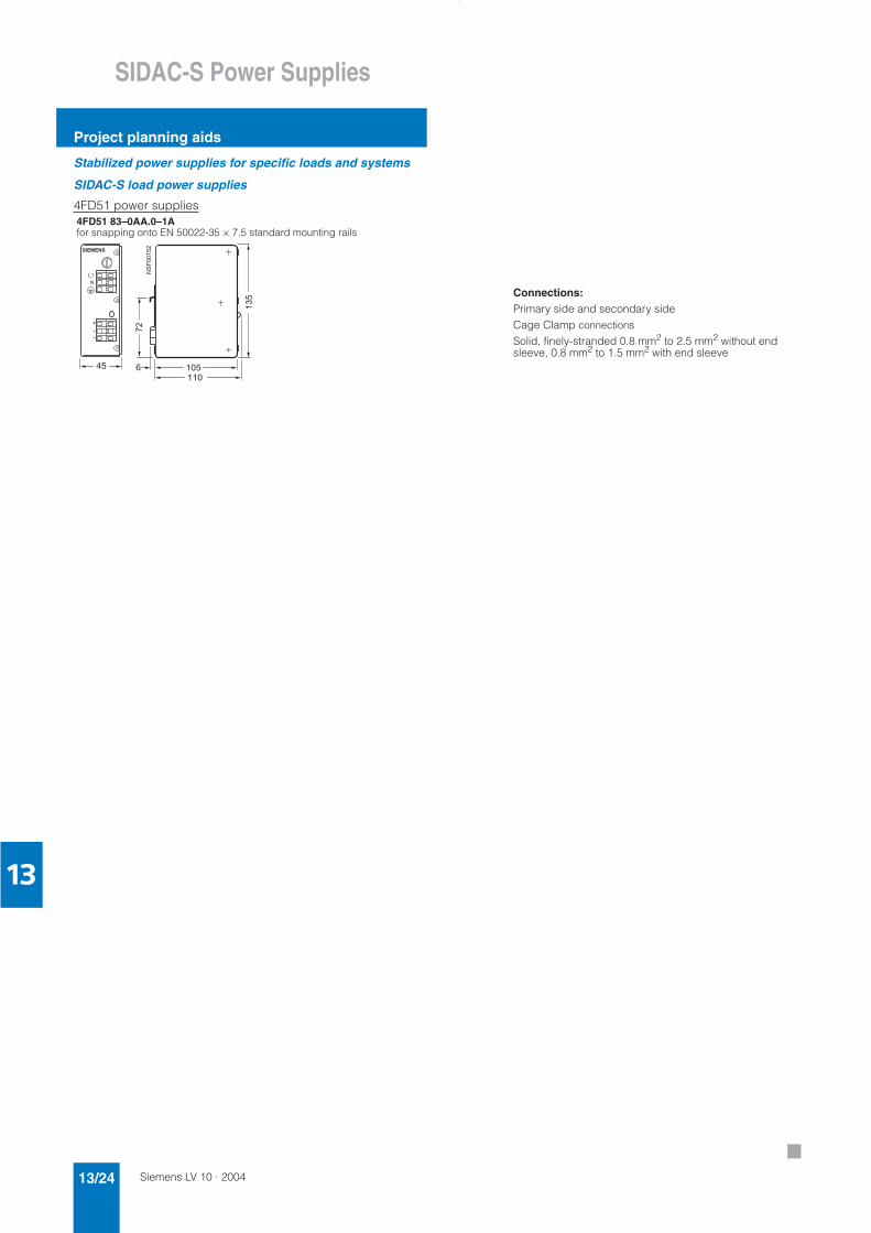
Stabilized power supplies for specific loads and systems
SIDAC-S load power supplies
4FD51 power supplies4FD51 83–0AA.0–1Afor snapping onto EN 50022-35 × 7.5 standard mounting rails
��
�
�
���
��
������
��
�
�������
�
�
��
�
Connections:Primary side and secondary sideCage Clamp connectionsSolid, finely-stranded 0.8 mm2 to 2.5 mm2 without end sleeve, 0.8 mm2 to 1.5 mm2 with end sleeve
7