operator's manual - kepco power supplies
TRANSCRIPT

MODEL
OPERATOR’S MANUAL
IMPORTANT NOTES:
1) This manual is valid for the following Model and associated serial numbers:
MODEL SERIAL NO. REV. NO.
2) A Change Page may be included at the end of the manual. All applicable changes andrevision number changes are documented with reference to the equipment serial num-bers. Before using this Instruction Manual, check your equipment serial number to identifyyour model. If in doubt, contact your nearest Kepco Representative, or the Kepco Docu-mentation Office in New York, (718) 461-7000, requesting the correct revision for yourparticular model and serial number.
3) The contents of this manual are protected by copyright. Reproduction of any part can be
made only with the specific written permission of Kepco, Inc. Data subject to change without notice.
KEPCO® THE POWER SUPPLIER™
ORDER NO. REV. NO.
KEPCO, INC. 131-38 SANFORD AVENUE FLUSHING, NY. 11355 U.S.A. TEL (718) 461-7000 FAX (718) 767-1102email: [email protected] World Wide Web: http://www.kepcopower.com
KEPCO INC.An ISO 9001 Company.
©2010, KEPCO, INCP/N 243-0879-R15
TMA 4882-27POWER MODULE CONTROLLER
INTERACTIVE DIGITALLY CONTROLLEDPOWER MODULE SYSTEM
TMA 4882-27POWER MODULE
CONTROLLER


228-1348 DC-COMP/INST 021910 A
Declaration of Conformity
Application of Council directives: 73/23/EEC (LVD)93/68/EEC (CE mark)
Standard to which Conformity is declared:
EN61010-1:1993 (Safety requirements for electrical equipment for measurement, control and laboratory use)
Manufacturer's Name and Address: KEPCO INC.131-38 SANFORD AVENUE FLUSHING, N.Y. 11355 USA
Importer's Name and Address:
Type of Equipment: Component Power Supply
Model No.: [PRODUCT MODEL NUMBER]
Year of Manufacture:
I, the undersigned, declare that the product specified above, when used in conjunction with the condi-tions of conformance set forth in the product instruction manual, complies with the requirements of the Low Voltage Directive 73/23/EEC, which forms the basis for application of the CE Mark to this product.
Place: KEPCO Inc.131-38 Sanford Ave.Flushing, N.Y.11355 USA
Date:
Saul Kupferberg(Full Name)
VP OF SALES(position)
REPRESENTATIVE COPY
B 228-1372 COND/CONFORM 021910
Conditions of ConformanceProgramming Module
When this product is used in applications governed by the requirements of the EEC, the following restric-tions and conditions apply:
1. For European applications, requiring compliance to the Low Voltage Directive, 73/23/EEC, this power supply is considered a component product, designed for “built in” applications. Because it is incom-plete in construction, the end product enclosure must provide for compliance to any remaining electri-cal safety requirements and act as a fire enclosure. (EN61010-1 Cl. 6, Cl. 7, Cl.8, Cl. 9 and EN61010-1 annex F)
2. This power supply is designed for stationary installation either within an equipment rack or a KEPCO Rack Adapter RA 55 or CA 400.
3. This power supply is considered a Class 1 (earthed) product, and as such depends upon proper con-nection to protective earth for safety from electric shock. (EN61010-1 Cl. 6.5.4)
4. This power supply is intended for use as part of equipment meant for test, measurement and labora-tory use, and is designed to operate from single phase, three wire power systems. This equipment must be installed in a specifically designed KEPCO rack adapter and within a suitably wired equipment rack, utilizing a three wire (grounded) mains connection. See wiring section of this manual for com-plete electrical wiring instructions. (EN61010-1 Cl. 6.5.4 and Cl.6.10.1)
5. This power supply has secondary output circuits that are considered SELV.
6. This power supply employs a supplementary circuit protector in the form of a fuse mounted within its enclosure. The fuse protects the power supply itself from damage in the event of a fault condition. For complete circuit protection of the end product, as well as the building wiring, it is required that a pri-mary circuit protection device be fitted to the branch circuit wiring. (EN61010-1 Cl. 9.6.2)
7. Hazardous voltages are present within this power supply during normal operation. All operator adjust-ments to the product are made via externally accessible switches, controls and signal lines as speci-fied within the product operating instructions. There are no user or operator serviceable parts within the product enclosure. Refer all servicing to qualified and trained Kepco service technicians.

228-1369 SAFETY - (MST) 021910 C/(D Blank)
SAFETY INSTRUCTIONS
1. Installation, Operation and Service PrecautionsThis product is designed for use in accordance with EN 61010-1 and UL 3101 for Installation Category 2, Pollution Degree 2. Hazardous voltages are present within this product during normal operation. The product should never be operated with the cover removed unless equivalent protection of the operator from accidental contact with hazardous internal voltages is provided.
2. Grounding
This product is a Class 1 device which utilizes protective earthing to ensure operator safety.
3. Electric Shock HazardsThis product outputs hazardous voltage and energy levels as a function of normal operation. Operators must be trained in its use and exercise caution as well as common sense during use to prevent accidental shock.
There are no operator serviceable parts or adjustments within the product enclosure. Refer all servicing to trained service technician.
Source power must be removed from the product prior to performing any servicing.
This product is designed for use with nominal a-c mains voltages indicated on the rating nameplate.
The PROTECTIVE EARTHING CONDUCTOR TERMINAL must be properly con-nected prior to application of source power to the product (see instructions on instal-lation herein) in order to ensure safety from electric shock.
PROTECTIVE EARTHING CONDUCTOR TERMINAL - This symbol indicates the point on the product to which the protective earthing conductor must be attached.
EARTH (GROUND) TERMINAL - This symbol is used to indicate a point which is connected to the PROTECTIVE EARTHING TERMINAL. The component installer/assembler must ensure that this point is connected to the PROTECTIVE EARTH-ING TERMINAL.
CHASSIS TERMINAL -This symbol indicates frame (chassis) connection, which is supplied as a point of convenience for performance purposes (see instructions on grounding herein). This is not to be confused with the protective earthing point, and may not be used in place of it.
This symbol appears adjacent to any external terminals at which hazardous voltage levels as high as 500V d-c may exist in the course of normal or single fault condi-tions.This symbol appears adjacent to any external terminals at which hazardous voltage levels in excess of 500V d-c may exist in the course of normal or single fault condi-tions.
!
!
!
!
!


TMA 4882-27 SVC 021910 i
TABLE OF CONTENTS
SECTION PAGE
SECTION 1 - INTRODUCTION1.1 Scope of Manual ..................................................................................................................................... 1-11.2 General Description................................................................................................................................. 1-11.3 Specifications .......................................................................................................................................... 1-11.4 Accessories ............................................................................................................................................. 1-5
SECTION 2 - INSTALLATION2.1 Unpacking and Inspection ....................................................................................................................... 2-12.2 Installation ............................................................................................................................................... 2-12.2.1 Set (GPIB) Device Address, Configure RS 232................................................................................. 2-12.2.1.1 Using GPIB Only.......................................................................................................................... 2-12.2.1.2 Using RS 232 Only ...................................................................................................................... 2-22.2.1.3 Using both GPIB addressing and RS 232.................................................................................... 2-22.2.1.4 RS 232 Connections .................................................................................................................... 2-22.2.2 Start-up Language/Compatibility Mode/GPIB Addressing Default .................................................... 2-42.2.3 Set Shield Ground Jumper ................................................................................................................ 2-52.2.4 Go To Local (GTL) Enable/Inhibit ...................................................................................................... 2-52.2.5 Final System Interconnections........................................................................................................... 2-62.3 Rear Terminations on the TMA 4882-27 ................................................................................................. 2-6
SECTION 3 - OPERATION3.1 Local Operation ....................................................................................................................................... 3-13.2 Auxiliary Signals ...................................................................................................................................... 3-13.2.1 Emergency Output Shutdown............................................................................................................ 3-13.2.2 Discrete Fault Line............................................................................................................................. 3-13.2.3 +5V Output ........................................................................................................................................ 3-13.3 Remote Operation ................................................................................................................................... 3-13.4 IEEE 488 (GPIB) Bus Protocol ................................................................................................................ 3-23.4.1 String Parsing .................................................................................................................................... 3-23.5 RS232-C Operation................................................................................................................................. 3-43.5.1 RS 232 With GPIB addressing .......................................................................................................... 3-43.5.2 Serial INterface.................................................................................................................................. 3-43.5.3 RS 232 Implementation ..................................................................................................................... 3-53.5.3.1 Echo Mode................................................................................................................................... 3-63.5.3.2 Prompt Method ............................................................................................................................ 3-63.5.3.3 XON XOFF Method...................................................................................................................... 3-63.5.3.4 Special Commands...................................................................................................................... 3-73.5.4 Programming Techniques to Optimize Power Supply performance .................................................. 3-73.6 SCPI Programming ................................................................................................................................. 3-83.6.1 SCPI Messages................................................................................................................................. 3-83.6.2 Common Commands/Queries ........................................................................................................... 3-83.6.3 SCPI Subsystem Command/Query Structure.................................................................................... 3-83.6.4 Program Message Structure.............................................................................................................. 3-93.6.4.1 Keyword ....................................................................................................................................... 3-103.6.4.2 Keyword Separator ...................................................................................................................... 3-123.6.4.3 Query Indicator ............................................................................................................................ 3-123.6.4.4 Data ............................................................................................................................................. 3-123.6.4.5 Data Separator............................................................................................................................. 3-123.6.4.6 Message Unit Separator .............................................................................................................. 3-12

ii TMA 4882-27 SVC 021910
TABLE OF CONTENTS
SECTION PAGE
3.6.4.7 Root Specifier.............................................................................................................................. 3-123.6.5 Addressing Multiple Power Supplies................................................................................................. 3-123.6.6 Understanding The Command Structure .......................................................................................... 3-133.6.7 Program Message Syntax Summary ................................................................................................ 3-143.6.8 Status Reporting ............................................................................................................................... 3-143.6.8.1 Status Reporting Structure.......................................................................................................... 3-153.6.8.2 Operational Status Register ........................................................................................................ 3-153.6.8.3 QUEStionable Status Register.................................................................................................... 3-153.6.8.4 Multiple Logical Instruments........................................................................................................ 3-173.6.9 SCPI Program Example.................................................................................................................... 3-183.7 CIIL Programming................................................................................................................................... 3-193.8 Calibration............................................................................................................................................... 3-193.9 Maintenance ........................................................................................................................................... 3-19
APPENDIX A - SCPI COMMON COMMAND/QUERY DEFINITIONS
A.1 Introduction ............................................................................................................................................. A-1A.2 *CLS — Clear Status Command ............................................................................................................ A-1A.3 *ESE — Standard Event Status Enable Command................................................................................ A-1A.4 *ESE? — Standard Event Status Enable Query..................................................................................... A-1A.5 *ESR? — Event Status Register Query.................................................................................................. A-2A.6 *IDN? — Identification Query.................................................................................................................. A-2A.7 *OPC — Operation Complete Command ............................................................................................... A-2A.8 *OPC? — Operation Complete Query .................................................................................................... A-2A.9 *OPT? — Options Query ........................................................................................................................ A-3A.10 *RST — Reset Command....................................................................................................................... A-3A.11 *SRE — Service Request Enable Command ........................................................................................ A-4A.12 *SRE? — Service Request Enable Query .............................................................................................. A-4A.13 *STB? — Status Byte Register Query ................................................................................................... A-4A.14 *TRG — Trigger Command ................................................................................................................... A-4A.15 *TST? — Self Test Query ....................................................................................................................... A-5A.16 *WAI — Wait-to-Continue Command ..................................................................................................... A-5
APPENDIX B - SCPI COMMAND/QUERY DEFINITIONS
B.1 Introduction ............................................................................................................................................. B-1B.2 INITiate[:IMMediate] Command ............................................................................................................. B-1B.3 INITiate:CONTinuous Command ........................................................................................................... B-1B.4 INITiate:CONTinuous? Query................................................................................................................ B-2B.5 INSTrument:CATalog? Query ................................................................................................................ B-2B.6 INSTrument[:NSELect] Command......................................................................................................... B-2B.7 INSTrument[:SELect] Command ........................................................................................................... B-2B.8 INSTrument[:SELect]? Query ................................................................................................................ B-3B.9 INSTrument:STATe Command .............................................................................................................. B-3B.10 MEASure[:SCALar]:CURRent[:DC]? Query........................................................................................... B-3B.11 MEASure[:VOLTage][:SCALar][:DC]? Query ......................................................................................... B-4B.12 OUTPut[:STATe] Command ................................................................................................................... B-4B.13 OUTPut[:STATe]? Query ........................................................................................................................ B-4B.14 [SOURce:]CURRent[:LEVel][:IMMediate][:AMPlitude] Command ........................................................ B-4B.15 [SOURce:]CURRent[:LEVel][:IMMediate][:AMPlitude]? Query ............................................................. B-4B.16 [SOURce:]CURRent:[:LEVel]TRIGgered[:AMPlitude] Command ......................................................... B-5B.17 [SOURce:]CURRent:[:LEVel]TRIGgered[:AMPlitude]? Query .............................................................. B-5B.18 [SOURce:]VOLTage[:LEVel][:IMMediate][:AMPlitude] Command......................................................... B-6B.19 [SOURce:]VOLTage[:LEVel][:IMMediate][:AMPlitude]? Query ............................................................. B-6B.20 [SOURce:]VOLTage:[:LEVel]TRIGgered[:AMPlitude] Command.......................................................... B-6B.21 [SOURce:]VOLTage:[:LEVel]TRIGgered[:AMPlitude]? Query............................................................... B-6

TMA 4882-27 SVC 021910 iii
TABLE OF CONTENTS
SECTION PAGE
B.22 [SOURce:]FUNCtion:MODE Command................................................................................................. B-7B.23 STATus:OPERation:CONDition? Query................................................................................................ B-7B.24 STATus:OPERation:ENABle Command................................................................................................ B-7B.25 STATus:OPERation:ENABle? Query .................................................................................................... B-7B.26 STATus:OPERation[:EVENt]? Query .................................................................................................... B-7B.27 STATus:PRESet Command................................................................................................................... B-8B.28 STATus:QUEStionable[:EVENt]? Query ............................................................................................... B-8B.29 STATus:QUEStionable:CONDition? Query........................................................................................... B-9B.30 STATus:QUEStionable:ENABle Command........................................................................................... B-9B.31 STATus:QUEStionable:ENABle? Query................................................................................................ B-9B.32 STATus:QUEStionable:INSTrument[1]? Query .................................................................................... B-9B.33 STATus:QUEStionable:INSTrument2? Query ...................................................................................... B-10B.34 STATus:QUEStionable:INSTrument[1]:ENABle Command.................................................................. B-10B.35 STATus:QUEStionable:INSTrument[1]:ENABle Query......................................................................... B-10B.36 STATus:QUEStionable:INSTrument2:ENABle Command.................................................................... B-10B.37 STATus:QUEStionable:INSTrument2:ENABle? Query......................................................................... B-10B.38 STATus:QUEStionable:INSTrument:ISUM? Query .............................................................................. B-11B.39 STATus:QUEStionable:INSTrument:ISUM:ENABle Command............................................................ B-11B.40 STATus:QUEStionable:INSTrument:ISUM:ENABle? Query................................................................. B-11B.41 SYSTem:COMMunication:GPIB:ADDRess Command ......................................................................... B-11B.42 SYSTem:COMMunication:SERial:BAUD Command............................................................................. B-11B.43 SYSTem:COMMunication:SERial:ECHO Command ............................................................................ B-11B.44 SYSTem:COMMunication:SERial:PACE Command ............................................................................. B-11B.45 SYSTem:COMMunication:SERial:PROMpt Command ......................................................................... B-11B.46 SYSTem:ERRor[:NEXT]? Query............................................................................................................ B-12B.47 SYSTem:ERRor:CODE? Query ............................................................................................................. B-12B.48 SYSTem:ERRor:CODE:ALL? Query...................................................................................................... B-12B.49 SYSTem:LANGuage Command ............................................................................................................ B-12B.50 SYSTem:SET Command........................................................................................................................ B-12B.51 SYSTem:VERSion? Query..................................................................................................................... B-12
APPENDIX C - CIIL COMMAND DEFINITIONS

LIST OF FIGURES
FIGURE TITLE PAGE
iv TMA 4882-27 SVC 021910
1-2 Remotely Controlled Power Supply Configurations Using Kepco Products............................................... 1-21-3 TMA 4882-27 Controller Outline Drawing .................................................................................................. 1-31-4 Controller to Power Module Interface (Typical) .......................................................................................... 1-42-1 TMA 4882-27 Configuration Controls......................................................................................................... 2-52-2 TMA 4882-27 Front and Rear Panels ........................................................................................................ 2-73-1 RS 232 Implementation.............................................................................................................................. 3-53-2 Tree Diagram of SCPI Commands Used with TMA 4882-27 Controller .................................................... 3-93-3 Message Structure ..................................................................................................................................... 3-113-4 Status Reporting Structure ......................................................................................................................... 3-163-5 Expansion of QUEStionable Register for Multiple Logical Instruments...................................................... 3-183-6 Typical Example Of TMA 4882-27 Controller Program Using SCPI Commands ....................................... 3-19A-1 GPIB Commands ....................................................................................................................................... A-3A-2 Using the *WAIt-to-continue Command ..................................................................................................... A-5B-1 Use of INSTrument:CATalog Query .......................................................................................................... B-2B-2 Identifying and Selecting Devices on BITBUS ........................................................................................... B-3B-3 Programming the Output ............................................................................................................................ B-5B-4 Programming Current................................................................................................................................. B-6B-5 Using Status Commands and Queries ....................................................................................................... B-8C-1 FNC — Function Command ....................................................................................................................... C-1C-2 INX — Initiate Op Code Command ............................................................................................................ C-2C-3 FTH — Fetch Command ............................................................................................................................ C-2C-4 SET Command........................................................................................................................................... C-3C-5 OPN, CLS — Open, Close Relay Commands ........................................................................................... C-4C-6 RST — Reset Command............................................................................................................................ C-4C-7 CNF, IST — Confidence Test, Internal Self Test Commands .................................................................... C-4C-8 STA — Status Command ........................................................................................................................... C-5C-9 GAL — Go to Alternate Language Command............................................................................................ C-6
TMA 4882-27 SVC 021910 v
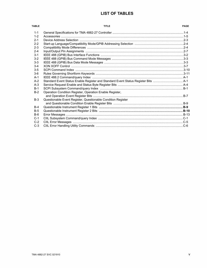
LIST OF TABLES
TABLE TITLE PAGE
1-1 General Specifications for TMA 4882-27 Controller ....................................................................................1-41-2 Accessories .................................................................................................................................................1-52-1 Device Address Selection ...........................................................................................................................2-32-2 Start-up Language/Compatibility Mode/GPIB Addressing Selection ..........................................................2-42-3 Compatibility Mode Differences ..................................................................................................................2-42-4 Input/Output Pin Assignments ....................................................................................................................2-73-1 IEEE 488 (GPIB) Bus Interface Functions ..................................................................................................3-23-2 IEEE 488 (GPIB) Bus Command Mode Messages .....................................................................................3-33-3 IEEE 488 (GPIB) Bus Data Mode Messages ..............................................................................................3-33-4 XON XOFF Control .....................................................................................................................................3-73-5 SCPI Command Index ................................................................................................................................3-103-6 Rules Governing Shortform Keywords ........................................................................................................3-11A-1 IEEE 488.2 Command/query Index ........................................................................................................... A-1A-2 Standard Event Status Enable Register and Standard Event Status Register Bits ................................... A-1A-3 Service Request Enable and Status Byte Register Bits ............................................................................. A-4B-1 SCPI Subsystem Command/query Index .................................................................................................. B-1B-2 Operation Condition Register, Operation Enable Register,
and Operation Event Register Bits .......................................................................................................... B-7B-3 Questionable Event Register, Questionable Condition Register
and Questionable Condition Enable Register Bits .................................................................................. B-9B-4 Questionable Instrument Register 1 Bits ...................................................................................................B-9B-5 Questionable Instrument Register 2 Bits ...................................................................................................B-10B-6 Error Messages .......................................................................................................................................... B-13C-1 CIIL Subsystem Command/query Index ....................................................................................................C-1C-2 CIIL Error Messages ..................................................................................................................................C-5C-3 CIIL Error Handling Utility Commands .......................................................................................................C-6

vi TMA 4882-27 021910
FIGURE 1-1. TMA 4882-27 POWER MODULE CONTROLLER

TMA4882-27 SVC 021910 1-1
SECTION 1 - INTRODUCTION
1.1 SCOPE OF MANUAL
This manual contains the specifications and instructions for the installation and operation of theModel TMA 4882-27 Power Module Controller (Figure 1-1), manufactured by Kepco, Inc., Flush-ing, N.Y. U.S.A. Parts lists and schematic diagrams are included in Section 4.
1.2 GENERAL DESCRIPTION
The Kepco model TMA 4882-27 is a Power Module Controller which consists of a Single-BoardComputer (SBC) and interface card housed in a 1-23/32” high by 19” wide by 15” deep case; ithas the capability to program, control and monitor the outputs of up to 27 Kepco MAT, MBT,MST or BOP power supplies (power modules). The TMA 4882-27 communicates with its Hostcomputer over the IEEE 488 bus (GPIB) using either CIIL (Control Interface Intermediate Lan-guage) or SCPI (Standard Commands for Programmable Instruments) Languages. An auxiliaryinput port allows for communication via the RS 232-C (EIA 232) standard serial communicationsbus. The TMA 4882-27 communicates with the MAT, MBT, MST or BOP series using theIEEE1118 two-wire serial bus, hereafter referred to as the Control Bus, which allows controlover distances up to a maximum of 1000 feet (300 meters) (see Figure 1-2).
The IEEE 488 GPIB interface functions implemented by the controller are defined by the IEEE488 Standard, and described in Table 3-1.
Connection to the power module is done through the control bus, which is accessible via a 9 pinD type connector, provided on the rear panel. The interconnection to the Host Computer on theGPIB is made via an IEEE 488 standard cable. If the serial port is used for communicationsbetween the controller and a computer terminal, a 9 pin null-modem RS 232-C connector/cableis required.
An opto-isolated, active high or non-isolated, active low, emergency output shut-down input isprovided on the 15 pin D type female connector located on the rear panel. On the same connec-tor, two additional lines provide a normally open contact indicating the proper functioning of theinternal microsystem (Discrete Fault Line). If either a serious malfunction or catastrophic error inthe TMA 4882-27 occurs, the contacts will close (see PAR. 3.2). A Status Monitor Reset connec-tor, available as an accessory (see Table 1-2), allows the Discrete Fault line to reset all unitsconnected to the Control Bus (see PAR. 3.2.2).
1.3 SPECIFICATIONS (REFER TO FIGURE 1-3 AND TABLE 1-1)
The Host Computer can set the output voltage with current limit, or the output current with volt-age limit. The Host Computer can then have the TMA 4882-27 read back the actual output volt-age and current delivered by each of the power modules to their respective loads. The TMA4882-27 is continually polling all of the power modules on the Control Bus for flags of cata-strophic and noncatastrophic errors. All data transmissions over the GPIB are ASCII encoded.The values for the command parameters can be written in integer, decimal or scientific notation.The responses from the TMA 4882-27 are detailed in Section 3 of this manual.
FIGURE 0-1.

1-2 TMA4882-27 SVC 021910
FIG
UR
E 1-
2.
REM
OTE
LY C
ON
TRO
LLED
PO
WER
SU
PPLY
CO
NFI
GU
RA
TIO
NS
USI
NG
KEP
CO
PR
OD
UC
TS
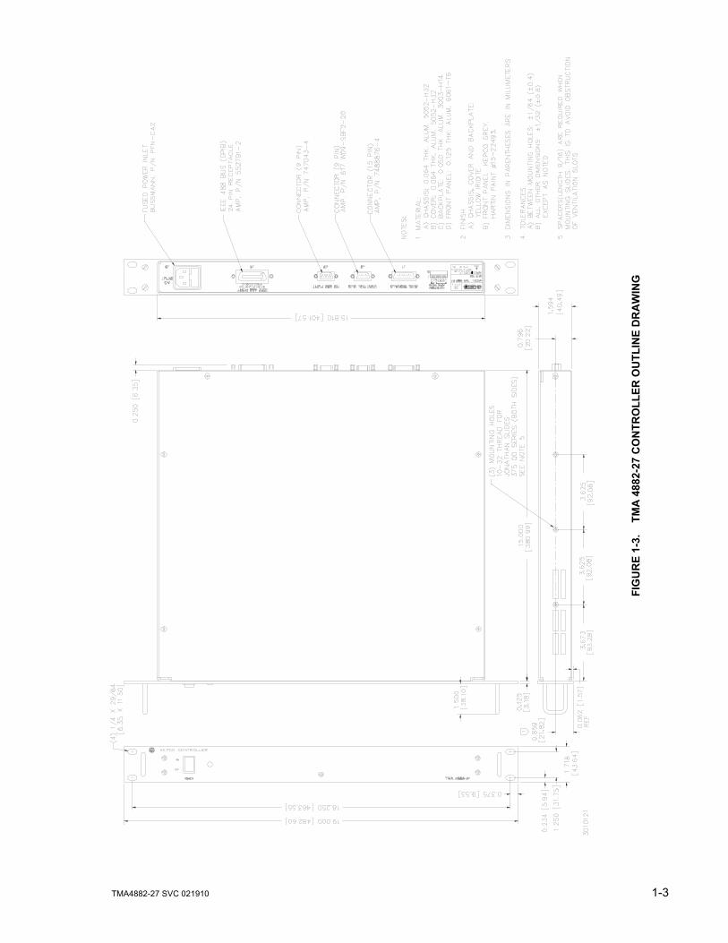
TMA4882-27 SVC 021910 1-3
FIG
UR
E 1-
3.
TM
A 4
882-
27 C
ON
TRO
LLER
OU
TLIN
E D
RA
WIN
G

1-4 TMA4882-27 SVC 021910
.
FIGURE 1-4. CONTROLLER TO POWER MODULE INTERFACE (TYPICAL)
TABLE 1-1. GENERAL SPECIFICATIONS FOR TMA 4882-27 CONTROLLERFEATURE SPECIFICATION
A-C Input Requirements 95 to 264V a-c, 47 to 63 Hz, approximately 50 Watts maximum
Ambient Operating Temperature Range 0 to +55° C
Storage Temperature Range –20 to +75° C
Dimensions 1-23/32” H x 19” W x 15” D
Color (front panel) Kepco gray, Hartin Paint No. 15-22493
Mounting 19” Rack (inserts are provided for chassis slide mounting)
TMA4882-27 SVC 021910 1-5/1-6
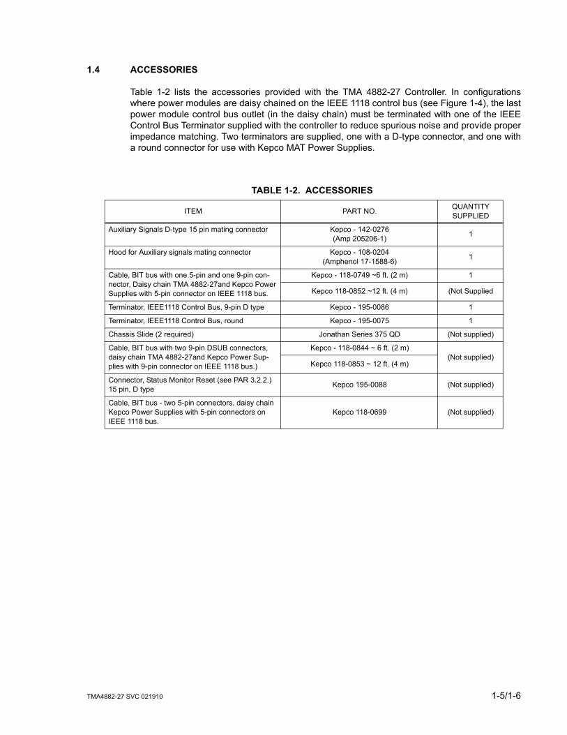
1.4 ACCESSORIES
Table 1-2 lists the accessories provided with the TMA 4882-27 Controller. In configurationswhere power modules are daisy chained on the IEEE 1118 control bus (see Figure 1-4), the lastpower module control bus outlet (in the daisy chain) must be terminated with one of the IEEEControl Bus Terminator supplied with the controller to reduce spurious noise and provide properimpedance matching. Two terminators are supplied, one with a D-type connector, and one witha round connector for use with Kepco MAT Power Supplies.
TABLE 1-2. ACCESSORIES
ITEM PART NO. QUANTITY SUPPLIED
Auxiliary Signals D-type 15 pin mating connector Kepco - 142-0276(Amp 205206-1) 1
Hood for Auxiliary signals mating connector Kepco - 108-0204(Amphenol 17-1588-6) 1
Cable, BIT bus with one 5-pin and one 9-pin con-nector, Daisy chain TMA 4882-27and Kepco Power Supplies with 5-pin connector on IEEE 1118 bus.
Kepco - 118-0749 ~6 ft. (2 m) 1
Kepco 118-0852 ~12 ft. (4 m) (Not Supplied
Terminator, IEEE1118 Control Bus, 9-pin D type Kepco - 195-0086 1
Terminator, IEEE1118 Control Bus, round Kepco - 195-0075 1
Chassis Slide (2 required) Jonathan Series 375 QD (Not supplied)
Cable, BIT bus with two 9-pin DSUB connectors, daisy chain TMA 4882-27and Kepco Power Sup-plies with 9-pin connector on IEEE 1118 bus.)
Kepco - 118-0844 ~ 6 ft. (2 m)(Not supplied)
Kepco 118-0853 ~ 12 ft. (4 m)
Connector, Status Monitor Reset (see PAR 3.2.2.) 15 pin, D type Kepco 195-0088 (Not supplied)
Cable, BIT bus - two 5-pin connectors, daisy chain Kepco Power Supplies with 5-pin connectors on IEEE 1118 bus.
Kepco 118-0699 (Not supplied)


TMA 4882-27 021910 2-1
SECTION 2 - INSTALLATION
2.1 UNPACKING AND INSPECTION
The Model TMA 4882-27 has been carefully inspected and tested prior to packing. Inspect theshipping carton upon receipt for evidence of damage during transit. Save the original packingmaterial. If any indication of damage is found, file a claim immediately with the responsibletransport service.
For repairs of a product damaged in shipment, contact the Kepco Factory Representative near-est you or the Kepco Sales Department directly for further instruction.
2.2 INSTALLATION
The installation and set-up procedure for the TMA 4882-27 consists of the following steps:
1. Set Device Address Selector and/or configure RS 232 port (PAR. 2.2.1).
2. Select start-up language (SCPI or CIIL), GPIB addressing (Primary/Secondary) and Com-patibility Mode (PAR. 2.2.2).
3. Set Shield Ground Jumper (PAR. 2.2.3).
4. Select GTL (Go To Local) command inhibit/enable (PAR. 2.2.4).
5. Perform final system interconnections (PAR. 2.2.5).
2.2.1 SET (GPIB) DEVICE ADDRESS, CONFIGURE RS 232 (SEE FIGURE 2-1)
A single set of DIP switches, accessible at the rear panel (Figure 2-1), are used both to set theGPIB Device Address (the factory default is 6) and to configure the RS 232 port. The followingparagraphs explain how to proceed if using GPIB only (PAR. 2.2.1.1), RS 232 only (PAR.2.2.1.2) or both (PAR. 2.2.1.3). RS 232 connections are explained in PAR. 2.2.1.4) and RS 232operation is described in PAR. 3.5
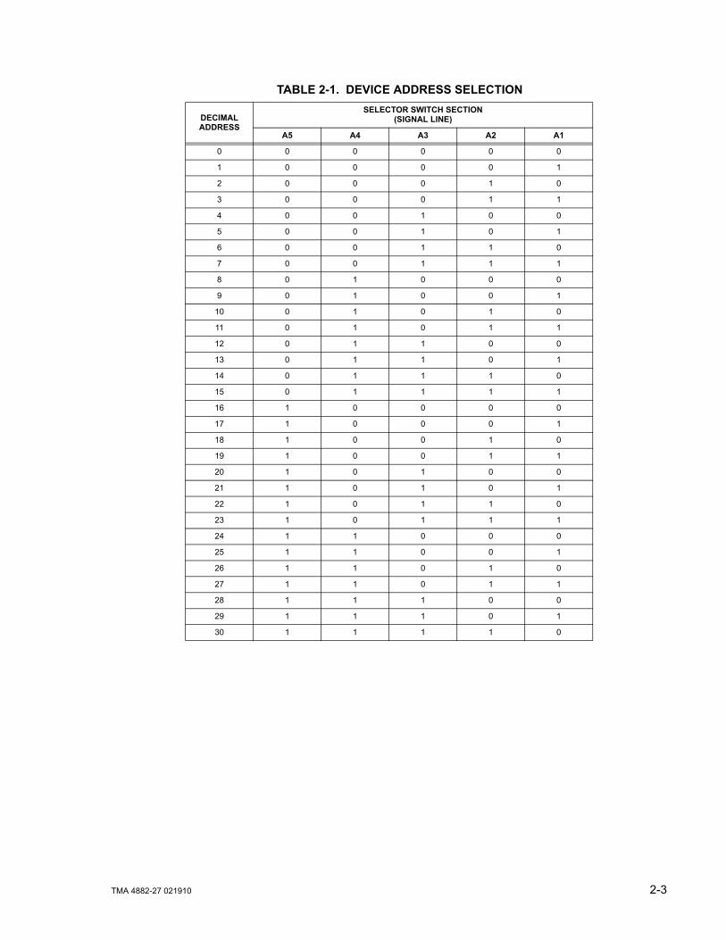
The Device Address for the TMA 4882-27 is initially set by means of DIP switches accessible atthe rear panel (Figure 2-1). The Device Address is the permanent Listener or Talker address ofthe TMA 4882-27 on the GPIB. It is factory preset to address 6. If a different Device Address isrequired in your system, proceed as follows. There are 31 (0-30) possible choices (See Table 2-1).
2.2.1.1 USING GPIB ONLY
The Device Address is the permanent Listener and Talker address of the MST 488-27 on theGPIB. It is factory preset to address 6. If a different Device Address is required in your system,proceed as follows. There are 31 (0-30) possible choices (See Table 2-1).
1. Place TMA 4882-27 power module controller with the rear panel facing you.
2. The Device Address DIP switches are positions A1 through A5 (from left to right). Theseswitches are preset by Kepco to address 6. For other device addresses set them accordingto Table 2-1.
2-2 TMA 4882-27 021910
2.2.1.2 USING RS 232 ONLY
If the default configuration (9600 baud, Echo = on, XON = off) is acceptable, leave DIP switchpositions 1-5 as is. To change from the default configuration, install an external jumper betweenRTS and CTS on the RS 232 cable at the TMA 4882-27. The RS 232 Port can now be config-ured using the DIP switches. Place TMA 4882-27 controller with rear panel unit facing you. TheDevice Address DIP switches are positions 1 through 5 (from left to right, see Figure 2-1).
• Baud Rate: Sw Pos 4/5 (00 = 9600, 11 = 19200, 10 = 4800, 01 = 2400)
• Echo: Sw Pos 3 (1 = enable, 0 = disable)
• XON: Sw Pos 2 (1 = disable, 0 = enable)
2.2.1.3 USING BOTH GPIB ADDRESSING AND RS 232
The same switches are used to configure the RS 232 port and establish the GPIB address; pro-ceed as follows to use both.
1. First, configure the RS 232 port. The default configuration (9600 baud, Echo = on, XON =off) corresponds to a GPIB address of 6. If this is acceptable, no further configuration is nec-essary. Proceed to step 2 to change the RS 232 configuration. If the RS 232 configuration isOK but the GPIB address needs to be changed, proceed to step 3.
2. For an RS 232 configuration other than the default, refer to PAR. 2.2.1.2. If the GPIB addressthat corresponds to the RS 232 configuration needs to be changed, proceed to step 3.
3. To change the GPIB address without changing the RS 232 configuration, use the RS 232port to send the "syst:comm:gpib:addr n" command (where n = the desired GPIB address).This allows the DIP switches to determine the RS 232 configuration while the software com-mand establishes the GPIB address.
2.2.1.4 RS 232 CONNECTIONS
Since the TMA 4882-27 uses a 9-pin male connector, it is classified as a Data Terminal Equip-ment (DTE) in accordance with the RS 232 Standard (equipment using a female connector isclassified as Data Communication Equipment, DCE).
Either a DTE-to-DTE or a null modem cable is required to connect the TMA 4882-27 to an IBM-PC compatible computer. This cable has only three wires and connects RXD at one end to TXDat the other end. The RS232-C port control lines (Table 2-4) are used to activate special featureby means of jumpers at the TMA 4882-27; refer to Table 2-2 and PAR. 2.2.1 for details. Refer toPAR. 3.5 for RS 232 operation. NOTE: Be sure the cable used has no unintended internal con-nections, particularly between RTS and CTS.
TMA 4882-27 021910 2-3
TABLE 2-1. DEVICE ADDRESS SELECTION
DECIMALADDRESS
SELECTOR SWITCH SECTION(SIGNAL LINE)
A5 A4 A3 A2 A1
0 0 0 0 0 0
1 0 0 0 0 1
2 0 0 0 1 0
3 0 0 0 1 1
4 0 0 1 0 0
5 0 0 1 0 1
6 0 0 1 1 0
7 0 0 1 1 1
8 0 1 0 0 0
9 0 1 0 0 1
10 0 1 0 1 0
11 0 1 0 1 1
12 0 1 1 0 0
13 0 1 1 0 1
14 0 1 1 1 0
15 0 1 1 1 1
16 1 0 0 0 0
17 1 0 0 0 1
18 1 0 0 1 0
19 1 0 0 1 1
20 1 0 1 0 0
21 1 0 1 0 1
22 1 0 1 1 0
23 1 0 1 1 1
24 1 1 0 0 0
25 1 1 0 0 1
26 1 1 0 1 0
27 1 1 0 1 1
28 1 1 1 0 0
29 1 1 1 0 1
30 1 1 1 1 0

2-4 TMA 4882-27 021910
2.2.2 START-UP LANGUAGE/COMPATIBILITY MODE/GPIB ADDRESSING DEFAULT (SEE FIG-URE 2-1)
Program Mode Bits P1 (DIP switch position adjacent to Address Selector Switch A5, see Figure2-1) and P2 (right-most position) control the start-up command language, secondary GPIBaddressing with SCPI, and Compatibility Mode as defined in Table 2-2.
Language - Selection is provided to choose either SCPI or CIIL command language. If SCPI isselected, you can also choose to implement either primary or secondary GPIB addressing. CIILis select by changing P1 to 1 and P2 to 0. SCPI selection with secondary addressing is selectedby changing P1 to 0 and P2 to 1.
Compatibility Mode - Certain features of the TMA 4882-27 can be configured to be fully 488.2/SCPI compatible (Mode 0) or to be backward compatible with previous Kepco products (Mode1). Differences between Mode 0 and Mode 1 functionality are explained in Table 2-3.
TABLE 2-2. START-UP LANGUAGE/COMPATIBILITY MODE/GPIB ADDRESSING SELECTION
P1 P2 LANGUAGE COMPATIBILTY MODE(See Table 2-3) GPIB ADDRESSING
0* 0* SCPI MODE 1 Primary
0 1 SCPI MODE 1 Secondary
1 0 CIIL Not Applicable Not Applicable
1 1 SCPI MODE 0 Primary
* Factory Default Configuration = P1 and P2 set to 0.
TABLE 2-3. COMPATIBILITY MODE DIFFERENCES
FUNCTION MODE 0(fully 488.2/SCPI compatible)
MODE 1(backward compatible with previous Kepco products)
Device ClearClears internal registers but leaves output voltage and current unchanged.
Clears internal registers, sets output voltage and current to zero, sets output to OFF, and, if unit incorporates relays, opens relays.
Status Uses Status Instrument Registers. Does not use Status Instrument Registers.
PON enable All status register enables are set to 0. All status register enables are set to 32767.
SYST:VERS? Returns 1997.0. Returns blank string.

TMA 4882-27 021910 2-5
FIGURE 2-1. TMA 4882-27 CONFIGURATION CONTROLS
2.2.3 SET SHIELD GROUND JUMPER (SEE FIGURE 2-1)
The TMA 4882-27 is shipped from the factory with the Control Bus cable shield grounded to theTMA 4882-27 chassis. In some cases, however, it may be desirable to break this connection toeliminate system “ground loops.” The jumper which sets the Shield Ground state is accessibleafter the cover is removed:
• JUMPER INSTALLED = shield grounded (factory default)
• JUMPER REMOVED = shield not grounded
2.2.4 GO TO LOCAL (GTL) ENABLE/INHIBIT (SEE FIGURE 2-1)
The TMA 4882-27 is shipped from the factory with the GTL command enabled. Removal of theIEEE 488 cable while the unit is executing a read or write command may be interpreted as aGTL command. This possibility can be eliminated by inhibiting the GTL command. To inhibit theGTL command, the Go To Local jumper (accessible after the cover is removed), must beremoved
• JUMPER INSTALLED = GTL command enabled (factory default)
• JUMPER REMOVED = GTL command inhibited

2-6 TMA 4882-27 021910
2.2.5 FINAL SYSTEM INTERCONNECTIONS
1. Connect the TMA 4882-27 to the GPIB and/or RS 232-C bus.
2. Connect all the power modules to the Control Bus.
3. Connect all power module outputs to their respective loads.
4. Connect source power to TMA 4882-27 and all power modules.
2.3 REAR TERMINATIONS ON THE TMA 4882-27 (SEE FIGURE 2-2)
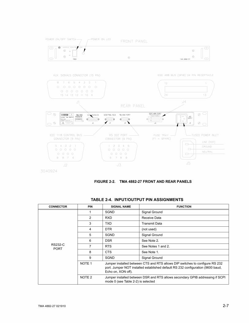
a. AC Input (J5). The TMA 4882-27 can be powered from an ac source within the range of 95 to264V. A fuse tray to the left of J5 contains a 2.5A fuse, F1 (SAN-O Corp. P/N MT4 2.5A,Kepco P/N 141-0087). A spare fuse is stored on the inside of the fuse tray cover.
b. The IEEE 488 BUS (J4). This port is terminated with a 24 pin IEEE 488 connector and con-forms mechanically and electrically to the IEEE 488 standard. Refer to Table 2-4 for pinassignments. (NOTE: Removal of the IEEE 488 cable while the unit is operating can be inter-preted as a GTL (Go To Local) command (see PAR. 2.2.4).
c. The RS 232-C Port (J3). This port is a standard 9 pin RS 232-C (male) connector. Refer toTable 2-4 for pin assignments and PAR. 2.2.1.4 for additional information.
d. Control Bus Interface (J2). This port is a 9 pin D-type female receptacle. Refer to Table 2-4for pin assignments.
e. Auxiliary Signals Connector (J1). This port is a 15 pin D-type female receptacle. Refer toTable 2-4 for pin assignments.
TMA 4882-27 021910 2-7
FIGURE 2-2. TMA 4882-27 FRONT AND REAR PANELS
TABLE 2-4. INPUT/OUTPUT PIN ASSIGNMENTS CONNECTOR PIN SIGNAL NAME FUNCTION
RS232-CPORT
1 SGND Signal Ground
2 RXD Receive Data
3 TXD Transmit Data
4 DTR (not used)
5 SGND Signal Ground
6 DSR See Note 2.
7 RTS See Notes 1 and 2.
8 CTS See Note 1.
9 SGND Signal Ground
NOTE 1 Jumper installed between CTS and RTS allows DIP switches to configure RS 232 port. Jumper NOT installed established default RS 232 configuration (9600 baud, Echo on, XON off).
NOTE 2 Jumper installed between DSR and RTS allows secondary GPIB addressing if SCPI mode 0 (see Table 2-2) is selected

2-8 TMA 4882-27 021910
IEEE 488 PORT
1 DI01 I/O Line
2 DI02 I/O Line
3 DI03 I/O Line
4 DI04 I/O Line
5 EOI End or Identify
6 DAV Data Valid
7 NRFD Not Ready for Data
8 NDAC Not Data Accepted
9 IFC Interface Clear
10 SRQ Service Request
11 ATN Attention
12 SHIELD Shield
13 DI05 I/O Line
14 DI06 I/O Line
15 DI07 I/O Line
16 DI08 I/O Line
17 REN Remote Enable
18 GND Ground (signal common)
19 GND Ground (signal common)
20 GND Ground (signal common)
21 GND Ground (signal common)
22 GND Ground (signal common)
23 GND Ground (signal common)
24 LOGIC GND Logic Ground
CONTROL BUS
1, 2, 6, 7 GND Ground
3, 4, 5 CONTROL BUS IEEE 1118 (2-Wire Differential Interface)
8, 9 CONTROL BUS IEEE 1118 (2-Wire Differential Interface)
AUX. SIGNALS
1, 7. 8 Emergency Shut-down - Isolated Input Cathode (–)
2, 5, 6 Emergency Shut-down - Isolated Input Anode (+)
3, 4 +5v Output (Through 390 Ohm)
9, 11 Ground
10 Emergency Shut-down Input - Non Isolated
12, 13 Discrete Fault Line - Relay Contact Pin 1
14, 15 Discrete Fault Line - Relay Contact Pin 2
TABLE 2-4. INPUT/OUTPUT PIN ASSIGNMENTS (CONTINUED) CONNECTOR PIN SIGNAL NAME FUNCTION
TMA 4882-27 021910 3-1
SECTION 3 - OPERATION
3.1 LOCAL OPERATION
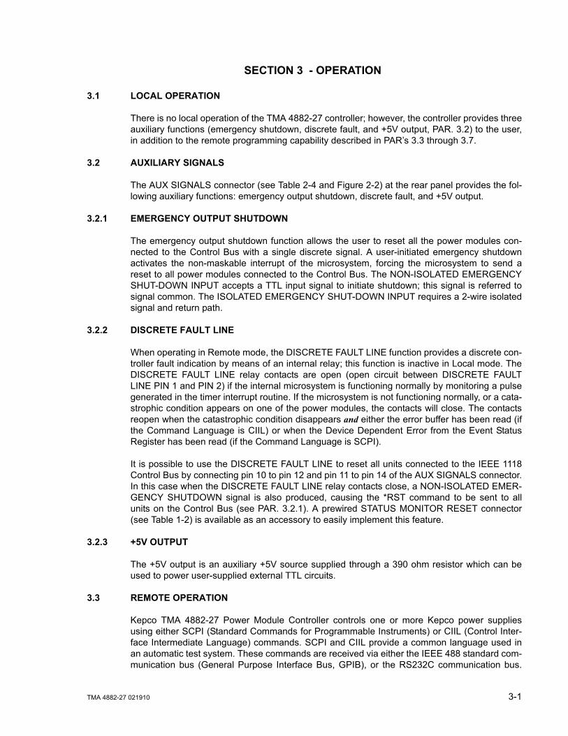
There is no local operation of the TMA 4882-27 controller; however, the controller provides threeauxiliary functions (emergency shutdown, discrete fault, and +5V output, PAR. 3.2) to the user,in addition to the remote programming capability described in PAR’s 3.3 through 3.7.
3.2 AUXILIARY SIGNALS
The AUX SIGNALS connector (see Table 2-4 and Figure 2-2) at the rear panel provides the fol-lowing auxiliary functions: emergency output shutdown, discrete fault, and +5V output.
3.2.1 EMERGENCY OUTPUT SHUTDOWN
The emergency output shutdown function allows the user to reset all the power modules con-nected to the Control Bus with a single discrete signal. A user-initiated emergency shutdownactivates the non-maskable interrupt of the microsystem, forcing the microsystem to send areset to all power modules connected to the Control Bus. The NON-ISOLATED EMERGENCYSHUT-DOWN INPUT accepts a TTL input signal to initiate shutdown; this signal is referred tosignal common. The ISOLATED EMERGENCY SHUT-DOWN INPUT requires a 2-wire isolatedsignal and return path.
3.2.2 DISCRETE FAULT LINE
When operating in Remote mode, the DISCRETE FAULT LINE function provides a discrete con-troller fault indication by means of an internal relay; this function is inactive in Local mode. TheDISCRETE FAULT LINE relay contacts are open (open circuit between DISCRETE FAULTLINE PIN 1 and PIN 2) if the internal microsystem is functioning normally by monitoring a pulsegenerated in the timer interrupt routine. If the microsystem is not functioning normally, or a cata-strophic condition appears on one of the power modules, the contacts will close. The contactsreopen when the catastrophic condition disappears and either the error buffer has been read (ifthe Command Language is CIIL) or when the Device Dependent Error from the Event StatusRegister has been read (if the Command Language is SCPI).
It is possible to use the DISCRETE FAULT LINE to reset all units connected to the IEEE 1118Control Bus by connecting pin 10 to pin 12 and pin 11 to pin 14 of the AUX SIGNALS connector.In this case when the DISCRETE FAULT LINE relay contacts close, a NON-ISOLATED EMER-GENCY SHUTDOWN signal is also produced, causing the *RST command to be sent to allunits on the Control Bus (see PAR. 3.2.1). A prewired STATUS MONITOR RESET connector(see Table 1-2) is available as an accessory to easily implement this feature.
3.2.3 +5V OUTPUT
The +5V output is an auxiliary +5V source supplied through a 390 ohm resistor which can beused to power user-supplied external TTL circuits.
3.3 REMOTE OPERATION
Kepco TMA 4882-27 Power Module Controller controls one or more Kepco power suppliesusing either SCPI (Standard Commands for Programmable Instruments) or CIIL (Control Inter-face Intermediate Language) commands. SCPI and CIIL provide a common language used inan automatic test system. These commands are received via either the IEEE 488 standard com-munication bus (General Purpose Interface Bus, GPIB), or the RS232C communication bus.
3-2 TMA 4882-27 021910
(Refer to Table 2-4 for input/output signal allocations.) The commands then program theselected Kepco power supply via a serial control bus.
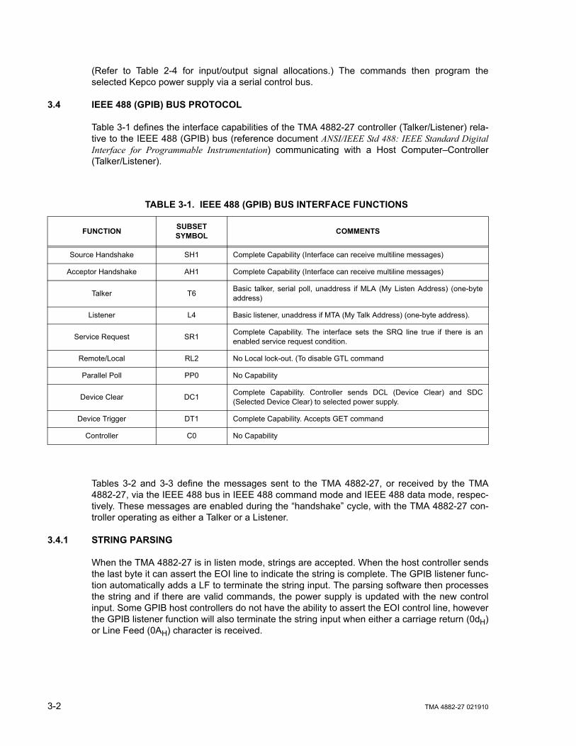
3.4 IEEE 488 (GPIB) BUS PROTOCOL
Table 3-1 defines the interface capabilities of the TMA 4882-27 controller (Talker/Listener) rela-tive to the IEEE 488 (GPIB) bus (reference document ANSI/IEEE Std 488: IEEE Standard DigitalInterface for Programmable Instrumentation) communicating with a Host Computer–Controller(Talker/Listener).
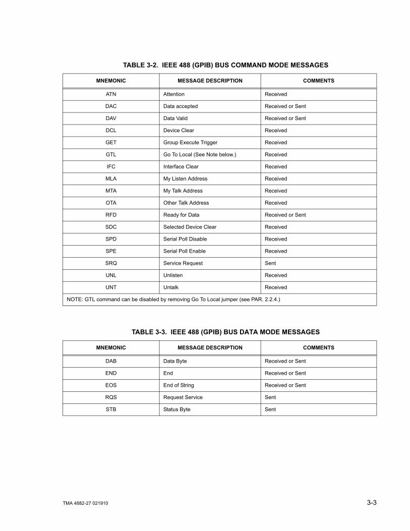
Tables 3-2 and 3-3 define the messages sent to the TMA 4882-27, or received by the TMA4882-27, via the IEEE 488 bus in IEEE 488 command mode and IEEE 488 data mode, respec-tively. These messages are enabled during the “handshake” cycle, with the TMA 4882-27 con-troller operating as either a Talker or a Listener.
3.4.1 STRING PARSING
When the TMA 4882-27 is in listen mode, strings are accepted. When the host controller sendsthe last byte it can assert the EOI line to indicate the string is complete. The GPIB listener func-tion automatically adds a LF to terminate the string input. The parsing software then processesthe string and if there are valid commands, the power supply is updated with the new controlinput. Some GPIB host controllers do not have the ability to assert the EOI control line, howeverthe GPIB listener function will also terminate the string input when either a carriage return (0dH)or Line Feed (0AH) character is received.
TABLE 3-1. IEEE 488 (GPIB) BUS INTERFACE FUNCTIONS
FUNCTION SUBSET SYMBOL COMMENTS
Source Handshake SH1 Complete Capability (Interface can receive multiline messages)
Acceptor Handshake AH1 Complete Capability (Interface can receive multiline messages)
Talker T6 Basic talker, serial poll, unaddress if MLA (My Listen Address) (one-byteaddress)
Listener L4 Basic listener, unaddress if MTA (My Talk Address) (one-byte address).
Service Request SR1 Complete Capability. The interface sets the SRQ line true if there is anenabled service request condition.
Remote/Local RL2 No Local lock-out. (To disable GTL command
Parallel Poll PP0 No Capability
Device Clear DC1 Complete Capability. Controller sends DCL (Device Clear) and SDC(Selected Device Clear) to selected power supply.
Device Trigger DT1 Complete Capability. Accepts GET command
Controller C0 No Capability
TMA 4882-27 021910 3-3
TABLE 3-2. IEEE 488 (GPIB) BUS COMMAND MODE MESSAGES
MNEMONIC MESSAGE DESCRIPTION COMMENTS
ATN Attention Received
DAC Data accepted Received or Sent
DAV Data Valid Received or Sent
DCL Device Clear Received
GET Group Execute Trigger Received
GTL Go To Local (See Note below.) Received
IFC Interface Clear Received
MLA My Listen Address Received
MTA My Talk Address Received
OTA Other Talk Address Received
RFD Ready for Data Received or Sent
SDC Selected Device Clear Received
SPD Serial Poll Disable Received
SPE Serial Poll Enable Received
SRQ Service Request Sent
UNL Unlisten Received
UNT Untalk Received
NOTE: GTL command can be disabled by removing Go To Local jumper (see PAR. 2.2.4.)
TABLE 3-3. IEEE 488 (GPIB) BUS DATA MODE MESSAGES
MNEMONIC MESSAGE DESCRIPTION COMMENTS
DAB Data Byte Received or Sent
END End Received or Sent
EOS End of String Received or Sent
RQS Request Service Sent
STB Status Byte Sent
3-4 TMA 4882-27 021910
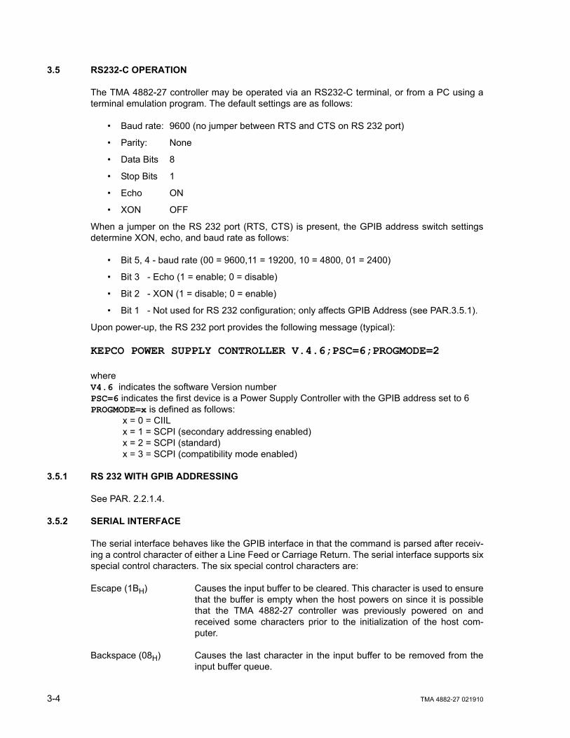
3.5 RS232-C OPERATION
The TMA 4882-27 controller may be operated via an RS232-C terminal, or from a PC using aterminal emulation program. The default settings are as follows:
• Baud rate: 9600 (no jumper between RTS and CTS on RS 232 port)
• Parity: None
• Data Bits 8
• Stop Bits 1
• Echo ON
• XON OFF
When a jumper on the RS 232 port (RTS, CTS) is present, the GPIB address switch settingsdetermine XON, echo, and baud rate as follows:
• Bit 5, 4 - baud rate (00 = 9600,11 = 19200, 10 = 4800, 01 = 2400)
• Bit 3 - Echo (1 = enable; 0 = disable)
• Bit 2 - XON (1 = disable; 0 = enable)
• Bit 1 - Not used for RS 232 configuration; only affects GPIB Address (see PAR.3.5.1).
Upon power-up, the RS 232 port provides the following message (typical):
KEPCO POWER SUPPLY CONTROLLER V.4.6;PSC=6;PROGMODE=2
whereV4.6 indicates the software Version numberPSC=6 indicates the first device is a Power Supply Controller with the GPIB address set to 6PROGMODE=x is defined as follows:
x = 0 = CIILx = 1 = SCPI (secondary addressing enabled)x = 2 = SCPI (standard)x = 3 = SCPI (compatibility mode enabled)
3.5.1 RS 232 WITH GPIB ADDRESSING
See PAR. 2.2.1.4.
3.5.2 SERIAL INTERFACE
The serial interface behaves like the GPIB interface in that the command is parsed after receiv-ing a control character of either a Line Feed or Carriage Return. The serial interface supports sixspecial control characters. The six special control characters are:
Escape (1BH) Causes the input buffer to be cleared. This character is used to ensurethat the buffer is empty when the host powers on since it is possiblethat the TMA 4882-27 controller was previously powered on andreceived some characters prior to the initialization of the host com-puter.
Backspace (08H) Causes the last character in the input buffer to be removed from theinput buffer queue.

TMA 4882-27 021910 3-5
Carriage Return (0DH) Causes the input buffer to be parsed by the TMA 4882-27 controller.
Line Feed (0AH) Causes the input buffer to be parsed by the TMA 4882-27controller.
> and < The > character turns on the echo mode upon receipt of the character.The < character turns off the echo mode. The message “echo off“ or“echo on“ will be displayed to confirm this.
3.5.3 RS 232 IMPLEMENTATION
The following paragraphs are provided to help the user understand how the RS 232 serial inter-face is implemented in the TMA 4882-27. Since the RS 232 protocol does not use a parity bit,the echo mode is the default method used to ensure reliable communication between the com-mand originator (computer) and the TMA 4882-27 power supply controller, thus avoiding a morecomplex “handshake” protocol.
When the TMA 4882-27 controller is in the RS 232 echo mode it returns all data sent to the hostcontroller. The TMA 4882-27 provides two additional options that allow handshake communica-tion: the Prompt method and the XON XOFF method. In standard echo mode the controllermust verify that each character is echoed back by the TMA 4882-27. As shown in Figure 3-1,there are times when the TMA 4882-27 does not echo back the character from the controller,requiring that the controller resend the character. By using the handshake options (prompt andXON XOFF) the host controller can ensure that serial data interrupts occurring after parsing ofthe incoming message do not result in lost data.
Figure 3-1 illustrates the default echo mode, the prompt method and the XON XOFF methoddescribed in the following paragraphs.
FIGURE 3-1. RS 232 IMPLEMENTATION
Only four control characters (characters between 00H and 1FH) are acknowledged by the powersupply:
• Carriage Return (CR, 0DH)
• Line Feed (LF, 0AH)
• Back Space (BS, 08H)
• Escape (ESC, 01BH)

3-6 TMA 4882-27 021910
BS deletes the last character entered, with the exception of CR or LF characters. Either the CRor LF character acts as the line terminator, initiating parsing of the ASCII data sent to the TMA4882-27 by the command originator. When the line is parsed and the commands are sent to theindividual power supplies via the IEEE 1118 bus, the TMA 4882-27 sends the line terminatorsequence CR LF to the command originator.
The ESC character is used for synchronization, causing the TMA 4882-27 to reset its input buf-fer and return a CR LF sequence.
All non-control characters are sent via the serial port of the command originator. The controlcharacter BS is echoed as BS Space BS. Only the first control character is returned in responseto either a CR LF or LF CR character sequence (see Figure 3-1).
3.5.3.1 ECHO MODE
Echo mode is the default method of ensuring data is transferred without errors. Each byte (char-acter) is echoed back to the sender where it is verified as the same character that was just sent.If the character is incorrect or missing, the sender sends the character again until the correctcharacter is verified as having been received.
All non-control characters are sent via the serial port of the command originator. The controlcharacter BS is echoed as BS Space BS. Only the first control character is returned in responseto either a CR LF or LF CR character sequence (see Figure 3-1).
3.5.3.2 PROMPT METHOD
The command originator sends a message line (command) to the TMA 4882-27 and waits untilthe prompt sequence CR LF > (3EH, 6210) is received. The TMA 4882-27 sends the promptsequence CR LF > to the command originator indicating the power supply is ready to receivethe next command and data will not be lost. The prompt method is similar to the echo methoddescribed above, except that the command originator does not have to compare each characterand repeat any characters dropped while the IEEE 1118 bus (BITBUS) is active. The operationof the TMA 4882-27 is identical for echo mode and prompt mode; implementation of promptmode is at the command originator.
3.5.3.3 XON XOFF METHOD
The XON XOFF method allows the TMA 4882-27 to control when the command originator isallowed to send data. The command originator can only send data after the XON (transmissionon) character (011H) has been received; the command originator stops sending data afterreceiving the XOFF (transmission off) character (013H), and waits until the XON character isreceived before sending additional data. The XON XOFF method can be implemented indepen-dently of the echo method using the special commands described below (PAR 3.5.3.4).

TMA 4882-27 021910 3-7
Control characters, either CR or LF, are returned as XOFF CR if echo mode is on, and as XOFFif echo mode is off. XOFF stops data from the command originator and the TMA 4882-27returns the normal sequence of CR LF (if echo mode is enabled).
3.5.3.4 SPECIAL COMMANDS
The serial parser supports the command RSMODE to allow quick changes to RS 232 protocol.
RSMODEn This command is used to implement the XON XOFF method and control whetherecho mode is on or off. The RSMODE sequence is followed by a number n: 0,through 5, defined in Table 3-4. This command must be the first command on aline.
3.5.4 PROGRAMMING TECHNIQUES TO OPTIMIZE POWER SUPPLY PERFORMANCE
Kepco's auto-crossover digital supplies can operate in either voltage mode with current limit, orcurrent mode with voltage limit. The operating mode is determined by the voltage and currentcommands received, as well as the load. Each time voltage and current commands arereceived, the unit must evaluate the commands and the load conditions to determine the properoperating mode. Reducing the number of times this evaluation must be made is desirablebecause Kepco's digital auto-crossover supplies employ two separate feedback loops. Eachtime there is a potential mode change, there is always an uncontrolled period of a few millisec-onds while the two feedback loops compete for control of the output. By changing only theactive parameter (e.g., voltage for voltage mode), there is no doubt as to what the operatingmode will be, so the unit is never uncontrolled, response is quick and no transients are possible.Recommended programming techniques are:
1. Minimize programmed mode (voltage or current) changes. Unless absolutely required by thetest parameters, allow the power supply to automatically switch modes as determined by theload. This will improve response time and reduce undesirable transients. For those powersupplies that employ relays (Kepco's MBT with “R” option, MAT and MST) this will alsoincrease the life of the relay.
2. Once the mode (voltage or current) is programmed, program the active parameter to zeroand the complementary limit parameter to the maximum anticipated for application. Thenprogram only the active parameter. The active parameter is the parameter that controls theoutput, e.g., voltage controls the output in voltage mode.
TABLE 3-4. XON XOFF CONTROL
VALUE OF n ECHO PROMPT XON XOFF
0 OFF OFF DISABLED
1 ON ON DISABLED
2 OFF ON DISABLED
3 OFF OFF ENABLED
4 ON ON ENABLED
5 OFF ON ENABLED
3-8 TMA 4882-27 021910
3. Never program both the active and complementary limit parameter to zero. This can result inlong response times. Set the active parameter to zero and the complementary limit parame-ter to a minimum, e.g., 10% of maximum, to ensure that the active mode is defined.
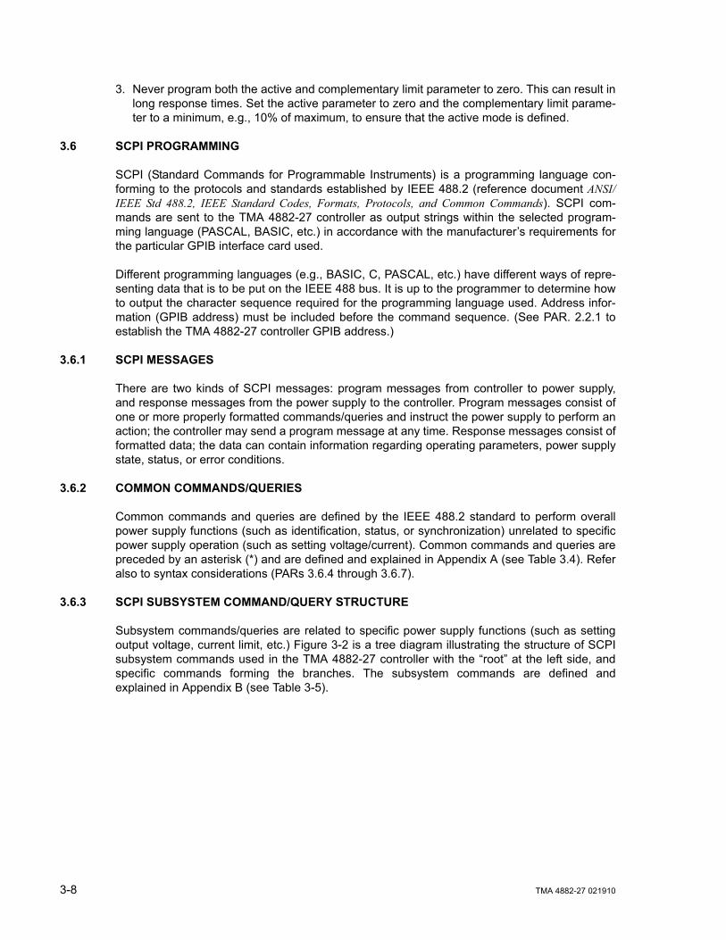
3.6 SCPI PROGRAMMING
SCPI (Standard Commands for Programmable Instruments) is a programming language con-forming to the protocols and standards established by IEEE 488.2 (reference document ANSI/IEEE Std 488.2, IEEE Standard Codes, Formats, Protocols, and Common Commands). SCPI com-mands are sent to the TMA 4882-27 controller as output strings within the selected program-ming language (PASCAL, BASIC, etc.) in accordance with the manufacturer’s requirements forthe particular GPIB interface card used.
Different programming languages (e.g., BASIC, C, PASCAL, etc.) have different ways of repre-senting data that is to be put on the IEEE 488 bus. It is up to the programmer to determine howto output the character sequence required for the programming language used. Address infor-mation (GPIB address) must be included before the command sequence. (See PAR. 2.2.1 toestablish the TMA 4882-27 controller GPIB address.)
3.6.1 SCPI MESSAGES
There are two kinds of SCPI messages: program messages from controller to power supply,and response messages from the power supply to the controller. Program messages consist ofone or more properly formatted commands/queries and instruct the power supply to perform anaction; the controller may send a program message at any time. Response messages consist offormatted data; the data can contain information regarding operating parameters, power supplystate, status, or error conditions.
3.6.2 COMMON COMMANDS/QUERIES
Common commands and queries are defined by the IEEE 488.2 standard to perform overallpower supply functions (such as identification, status, or synchronization) unrelated to specificpower supply operation (such as setting voltage/current). Common commands and queries arepreceded by an asterisk (*) and are defined and explained in Appendix A (see Table 3.4). Referalso to syntax considerations (PARs 3.6.4 through 3.6.7).
3.6.3 SCPI SUBSYSTEM COMMAND/QUERY STRUCTURE
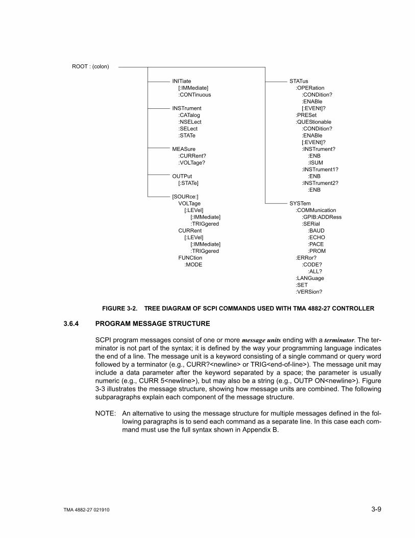
Subsystem commands/queries are related to specific power supply functions (such as settingoutput voltage, current limit, etc.) Figure 3-2 is a tree diagram illustrating the structure of SCPIsubsystem commands used in the TMA 4882-27 controller with the “root” at the left side, andspecific commands forming the branches. The subsystem commands are defined andexplained in Appendix B (see Table 3-5).
TMA 4882-27 021910 3-9
FIGURE 3-2. TREE DIAGRAM OF SCPI COMMANDS USED WITH TMA 4882-27 CONTROLLER
3.6.4 PROGRAM MESSAGE STRUCTURE
SCPI program messages consist of one or more message units ending with a terminator. The ter-minator is not part of the syntax; it is defined by the way your programming language indicatesthe end of a line. The message unit is a keyword consisting of a single command or query wordfollowed by a terminator (e.g., CURR?<newline> or TRIG<end-of-line>). The message unit mayinclude a data parameter after the keyword separated by a space; the parameter is usuallynumeric (e.g., CURR 5<newline>), but may also be a string (e.g., OUTP ON<newline>). Figure3-3 illustrates the message structure, showing how message units are combined. The followingsubparagraphs explain each component of the message structure.
NOTE: An alternative to using the message structure for multiple messages defined in the fol-lowing paragraphs is to send each command as a separate line. In this case each com-mand must use the full syntax shown in Appendix B.
INITiate[:IMMediate]:CONTinuous
INSTrument:CATalog:NSELect:SELect:STATe
MEASure:CURRent?:VOLTage?
OUTPut[:STATe]
[SOURce:]VOLTage
[:LEVel][:IMMediate]:TRIGgered
CURRent [:LEVel]
[:IMMediate]:TRIGgered
FUNCtion:MODE
ROOT : (colon)
STATus:OPERation
:CONDition?:ENABle[:EVENt]?
:PRESet:QUEStionable
:CONDition?:ENABle[:EVENt]?:INSTrument?
:ENB:ISUM
:INSTrument1?:ENB
:INSTrument2?:ENB
SYSTem:COMMunication
:GPIB:ADDRess:SERial
:BAUD:ECHO:PACE:PROM
:ERRor?:CODE?
:ALL?:LANGuage:SET:VERSion?
3-10 TMA 4882-27 021910
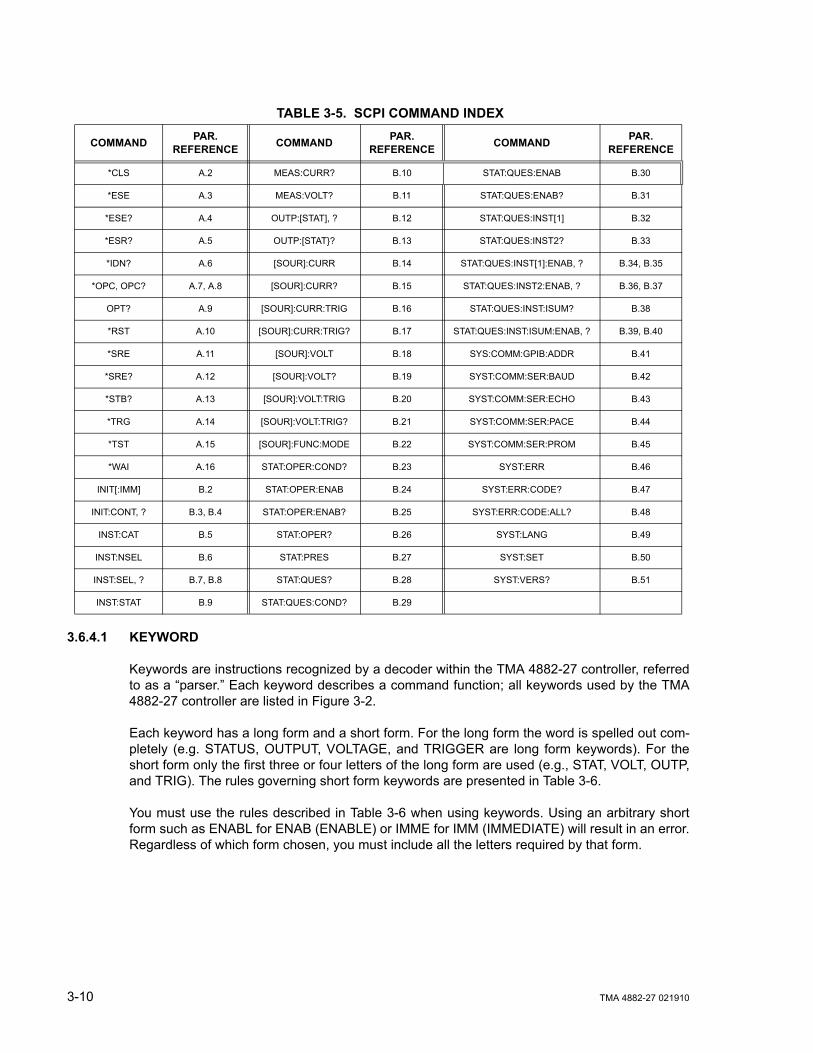
3.6.4.1 KEYWORD
Keywords are instructions recognized by a decoder within the TMA 4882-27 controller, referredto as a “parser.” Each keyword describes a command function; all keywords used by the TMA4882-27 controller are listed in Figure 3-2.
Each keyword has a long form and a short form. For the long form the word is spelled out com-pletely (e.g. STATUS, OUTPUT, VOLTAGE, and TRIGGER are long form keywords). For theshort form only the first three or four letters of the long form are used (e.g., STAT, VOLT, OUTP,and TRIG). The rules governing short form keywords are presented in Table 3-6.
You must use the rules described in Table 3-6 when using keywords. Using an arbitrary shortform such as ENABL for ENAB (ENABLE) or IMME for IMM (IMMEDIATE) will result in an error.Regardless of which form chosen, you must include all the letters required by that form.
TABLE 3-5. SCPI COMMAND INDEX
COMMAND PAR. REFERENCE COMMAND PAR.
REFERENCE COMMAND PAR. REFERENCE
*CLS A.2 MEAS:CURR? B.10 STAT:QUES:ENAB B.30
*ESE A.3 MEAS:VOLT? B.11 STAT:QUES:ENAB? B.31
*ESE? A.4 OUTP:[STAT], ? B.12 STAT:QUES:INST[1] B.32
*ESR? A.5 OUTP:[STAT}? B.13 STAT:QUES:INST2? B.33
*IDN? A.6 [SOUR]:CURR B.14 STAT:QUES:INST[1]:ENAB, ? B.34, B.35
*OPC, OPC? A.7, A.8 [SOUR]:CURR? B.15 STAT:QUES:INST2:ENAB, ? B.36, B.37
OPT? A.9 [SOUR]:CURR:TRIG B.16 STAT:QUES:INST:ISUM? B.38
*RST A.10 [SOUR]:CURR:TRIG? B.17 STAT:QUES:INST:ISUM:ENAB, ? B.39, B.40
*SRE A.11 [SOUR]:VOLT B.18 SYS:COMM:GPIB:ADDR B.41
*SRE? A.12 [SOUR]:VOLT? B.19 SYST:COMM:SER:BAUD B.42
*STB? A.13 [SOUR]:VOLT:TRIG B.20 SYST:COMM:SER:ECHO B.43
*TRG A.14 [SOUR]:VOLT:TRIG? B.21 SYST:COMM:SER:PACE B.44
*TST A.15 [SOUR]:FUNC:MODE B.22 SYST:COMM:SER:PROM B.45
*WAI A.16 STAT:OPER:COND? B.23 SYST:ERR B.46
INIT[:IMM] B.2 STAT:OPER:ENAB B.24 SYST:ERR:CODE? B.47
INIT:CONT, ? B.3, B.4 STAT:OPER:ENAB? B.25 SYST:ERR:CODE:ALL? B.48
INST:CAT B.5 STAT:OPER? B.26 SYST:LANG B.49
INST:NSEL B.6 STAT:PRES B.27 SYST:SET B.50
INST:SEL, ? B.7, B.8 STAT:QUES? B.28 SYST:VERS? B.51
INST:STAT B.9 STAT:QUES:COND? B.29

TMA 4882-27 021910 3-11
To identify the short form and long form in this manual, keywords are written in upper case let-ters to represent the short form, followed by lower case letters indicating the long form (e.g.,IMMediate, EVENt, and OUTPut). The parser, however, is not sensitive to case (e.g., outp,OutP, OUTPUt, ouTPut, or OUTp are all valid).
FIGURE 3-3. MESSAGE STRUCTURE
TABLE 3-6. RULES GOVERNING SHORTFORM KEYWORDS
IF NUMBER OF LETTERS IN LONGFORM KEYWORD IS:
AND FOURTH LETTERIS A VOWEL?
THEN SHORT FORM CONSISTS OF: EXAMPLES
4 OR FEWER (DOES NOT MATTER) ALL LONG FORM LETTERS MODE
5 OR MORE
NO THE FIRST FOURLONG FORM LETTERS MEASure, OUTPut, EVENt
YES THE FIRST THREELONG FORM LETTERS LEVel, IMMediate, ERRor
CURR:LEV 3.5;:OUTP ON;:CURR?<NL>
MESSAGE TERMINATOR
KEYWORD
QUERY INDICATOR
ROOT SPECIFIER
MESSAGE UNIT SEPARATOR
DATA
KEYWORD
KEYWORD
KEYWORD SEPARATOR
KEYWORD
MESSAGE UNIT SEPARATOR
DATA
MESSAGE UNIT
DATA SEPARATOR
DATA SEPARATOR
ROOT SPECIFIER

3-12 TMA 4882-27 021910
3.6.4.2 KEYWORD SEPARATOR
If a command has two or more keywords, adjacent keywords must be separated by a colon (:)which acts as the keyword separator (e.g., CURR:LEV:TRIG). The colon can also act as a rootspecifier (paragraph 3.6.4.7).
3.6.4.3 QUERY INDICATOR
The question mark (?) following a keyword is a query indicator. This changes the command intoa query. If there is more than one keyword in the command, the query indicator follows the lastkeyword. (e.g., VOLT? and MEAS:CURR?).
3.6.4.4 DATA
Some commands require data to accompany the keyword either in the form of a numeric valueor character string. Data always follows the last keyword of a command or query (e.g.,VOLT:LEV:TRIG 14 or SOUR:VOLT? MAX
Some data is required to be boolean. Boolean data represents either an on or off condition. TheTMA 4882-27 accepts either ON or 1 for the true (on) state and either OFF or 0 for the false (off)state (e.g. OUTPUT OFF is the same as OUTPUT 0).
3.6.4.5 DATA SEPARATOR
Data must be separated from the last keyword by a space (e.g., VOLT:LEV:TRIG 14 orSOUR:VOLT? MAX
3.6.4.6 MESSAGE UNIT SEPARATOR
When two or more message units are combined in a program message, they must be separatedby a semicolon (;) (e.g., VOLT 15;MEAS:VOLT? and CURR 12; CURR:TRIG 12.5).
3.6.4.7 ROOT SPECIFIER
The root specifier is a colon (:) that precedes the first keyword of a program message. Thisplaces the parser at the root (top left, Figure 3-2) of the command tree. Note the differencebetween using the colon as a keyword separator and a root specifier in the following examples:
VOLT:LEV:IMM 16 Both colons are keyword separators.
:CURR:LEV:IMM 4 The first colon is the root specifier, the other two are keyword separators.
VOLT:LEV 6;:CURR:LEV 15 The second colon is the root specifier, the first and third are key-word separators
:INIT ON;:TRIG;:MEAS:CURR?;VOLT? The first three colons are root specifiers.
3.6.5 ADDRESSING MULTIPLE POWER SUPPLIES
Power supplies on the IEEE 1118 bus are selected by node address, also referred to as nodenumber or channel number. Refer to the applicable manuals for the power modules connectedto the IEEE 1118 bus to set each power module to a unique node number, from 1 to 31 (a maxi-mum of 27 power modules may be connected to the bus).

TMA 4882-27 021910 3-13
The node number may follow any part of a SCPI command. Note that there must be no spacepreceding the node number
e.g., meas2:volt? or meas:volt2? both measure output voltage of the power supply at nodenumber 2.
e.g., func3:mode volt or func:mode3 volt both set the power supply at node number 3 tocommanded voltage mode.
e.g., stat1:ques? or stat:ques1? or stat:ques:cond1? all read Questionable Registerstatus of the power supply at node number 1.
Upon power turn-on, commands sent without a node (channel) number will go to the defaultnode address (1) until another node number is specified. Once another node number is speci-fied, the new number becomes the default until another is specified.
NOTE: An alternate means of selecting the node, is to use IEEE 488 secondary addressing,where the secondary address is the power supply node address (refer to PAR. toenable this feature).
The node selected can also be changed using the INSTrument:SELect <N> command.This allows subsequent commands to operate on the specified node (e.g. INST:SEL 10causes node 10 to be selected).
3.6.6 UNDERSTANDING THE COMMAND STRUCTURE
Understanding the command structure requires an understanding of the subsystem commandtree illustrated in Figure 3-2. The “root” is located at the top left corner of the diagram. Theparser goes to the root if:
• a message terminator is recognized by the parser• a root specifier is recognized by the parser
Optional keywords are enclosed in brackets [ ] for identification; optional keywords can be omit-ted and the power supply will respond as if they were included in the message. The root levelkeyword [SOURce] is an optional keyword. Starting at the root, there are various branches orpaths corresponding to the subsystems. The root keywords for the TMA 4882-27 controller are:INITiate, :MEASure, :OUTPut, [:SOURce], :STATus, and :SYSTem. Because the [SOURce]keyword is optional, the parser moves the path to the next level, so that VOLTage, CURRent,and FUNCtion commands are at the root level.
Each time the parser encounters a keyword separator, the parser moves to the next indentedlevel of the tree diagram. As an example, the STATus branch is a root level branch that hasthree sub-branches: OPERation, PRESet, and QUEStionable. The following illustrates howSCPI code is interpreted by the parser:
STAT:PRES<NL>The parser returns to the root due to the message terminator.
STAT:OPER?;PRES<NL>The parser moves one level in from STAT. The next command is expected at the level defined
3-14 TMA 4882-27 021910
by the colon in front of OPER?. Thus you can combine the following message unitsSTAT:OPER? and STAT:PRES;
STAT:OPER:COND?;ENAB 16<NL>After the OPER:COND? message unit, the parser moves in one level from OPER, allowing theabbreviated notation for STAT:OPER:ENAB.
3.6.7 PROGRAM MESSAGE SYNTAX SUMMARY
• Common commands begin with an asterisk (*).
• Queries end with a question mark (?).
• Program messages consist of a root keyword and, in some cases, one or more messageunits separated by a colon (:) followed by a message terminator. Several message unitsof a program message may be separated by a semicolon (;) without repeating the rootkeyword.
• If a program message has more than one message unit, then a colon (:) must precedethe next keyword in order to set the parser back to the root (otherwise the next keywordwill be taken as a subunit of the previous message unit).
e.g., the command meas:volt?;curr? will read output voltage and output currentsince both volt? and curr? are interpreted as subunits of the meas command.
• Several commands may be sent as one message; a line feed terminates the message.Commands sent together are separated by a semicolon (;). The first command in a mes-sage starts at the root, therefor a colon (:) at the beginning is not mandatory.
e.g., the command meas:volt?;:curr? will read output voltage and programmed cur-rent since the colon preceding curr? indicates that curr? is not part of the meas com-mand and starts at the root.
• UPPER case letters in mnemonics are mandatory (short form). Lower case letters mayeither be omitted, or must be specified completely (long form)e.g., INSTrument (long form) has the same effect as INST (short form).
• Commands/queries may be given in upper/lower case (long form)e.g., SoUrCe is allowed.
• Text shown between brackets [] is optional.e.g., :[SOUR]VOLT:[LEV] TRIG has the same effect as :VOLT TRIG
3.6.8 STATUS REPORTING
The status reporting of the TMA 4882-27 follows the SCPI and IEEE 488.2 requirements. Theserial poll response of the TMA 4882-27 provides summary bits of the status and error reportingsystem. The simplest status report is the command valid reporting and data availability, Thissuccessful decoding of a command string generates no error and is indicated by the bit 3 of theserial poll response being a zero. The setting of bit 4 in the status byte indicates data is avail-able to the controller in response a command query message.

TMA 4882-27 021910 3-15
3.6.8.1 STATUS REPORTING STRUCTURE
The status reporting of the TMA 4882-27 uses four status registers, illustrated in Figure 3-4.These registers are the Questionable, Operation, Standard Event and Service Request regis-ters. The Questionable and Operation registers are 16 bit registers and the Standard Event andService Request registers are 8 bits. These four registers are referred to as condition registers.Each of the four condition registers is associated with two related registers: an event registerwhich holds unlatched events reported in realtime by the instrument and is cleared by readingthe register, and an enable register which allows the contents of the event register to be passedthrough to set the associated condition register.
A zero to one transition of a condition register is added to the event register if the specific bit inthe enable register is also a 1. Reading an event register clears all of the bits found in the eventregister. If any bits are set in an event register, the following condition register bit is then set. Forexample, if the STAT:QUES:ENB (enable) register has bit 0 set and a voltage error is detected,the event registers bit 0 is set. The 1 in the event register causes bit 3 of the status byte to beasserted. The Service Request register is ANDed with its enable register for all bits except bit 6.The result is placed in bit 6 of the Service Request register. If bit 6 is a 1 (true), it causes theTMA 4882-27 to assert the SRQ line to the host controller.
Figure 3-4 also shows that if the error/event queue is not empty, bit 3 is set in the ServiceRequest register and bit 4 indicates that a message is available in the output buffer.
3.6.8.2 OPERATIONAL STATUS REGISTER
The OPERational condition register contains conditions which are a part of the instrument’s nor-mal operation. The definition of each of these bits (condition register) is as follows:
• 1 through 7 - Not Used — always zero.
• 8 - Constant Voltage — 1 indicates the instrument is in constant voltage mode.
• 9 - Relay — 1 indicates the power supply relay is closed.
• 10 - Constant Current — 1 indicates the instrument is in constant current mode.
• 11 through15 - Not Used — always zero.
3.6.8.3 QUESTIONABLE STATUS REGISTER
The QUEStionable condition register (see Figure 3-4) contains status bits representing data/sig-nals which give an indication of the quality of various aspects of the signal.
A bit set in the QUEStionable condition register indicates that the data currently being acquiredor generated is of questionable quality due to some condition affecting the parameter associ-ated with that bit.
• 8 - Voltage Mode — 1 indicates the instrument is in Voltage mode.
• 9 - Relay — 1 indicates the power supply relay is closed, unit is supplying power at out-put terminals.
• 10 - Current Mode — 1 indicates the Power Supply is in Current mode. Changes in thisbit do not affect the event register.
• 14 - Command warning — This bit indicates a non-fatal warning that relates to the instru-

3-16 TMA 4882-27 021910
ment’s interpretation of a command, query, or on or more parameters of a specific com-mand or query. The power supply sets this bit for
– MEAS:VOLT? 10,1 — The 10 is the number of digits and the 1 is the range. Sincethis capability is not implemented in Kepco power supplies, the Command Warningbit is set.
– INST:SEL 2 sent to a single power supply. Trying to select unit 2 when only onepower supply is connected causes the Command Warning bit to be set.
FIGURE 3-4. STATUS REPORTING STRUCTURE

TMA 4882-27 021910 3-17
3.6.8.4 MULTIPLE LOGICAL INSTRUMENTS
The TMA 4882-27 is a SCPI device that supports multiple logical instruments; it allows a choicebetween two methods of status reporting. The status reporting default upon powerup treats theunit as a single channel instrument. When multiple channels are in use, a SCPI compliant statusstructure can be selected which provides an INSTrument summary status register and an indi-vidual instrument ISUMmary for each logical instrument. These registers are equivalent to theStatus Questionable register of a single channel instrument and are also found in the STATusQuestionable register for the selected channel. The contents of the STATus Questionable regis-ter can also contain the summary of all instruments as shown in Figure 3-5.
The selection of the status reporting structure is controlled by the SYStem:SET SI (InstrumentStructure) command, either SI0 (off) or SI1 (on). The power-up default is the off condition. Toenable the SCPI compliant mode of operation for multiple logical instruments the user mustsend SYSTem:SET SI1 to the TMA 4882-27 during initialization. The SI1 state is not remem-bered when the unit is turned off. To return to the standard method of reporting the selecteddevice’s status without turning the unit off, send SYSTem:SET SI0.The state of the powerpower supply upon power up for language (SCPI/CIIL), compatibility and GPIB addressing isselected by DIP switches P1 and P2 (see PAR. 2.2.2 and Table 2-2).
When the TMA 4882-27 is set up for SCPI compliant status reporting for multiple channels, thespecific instrument’s Questionable register is found in the STAT:QUES:INST:ISUM<n> register.This register has the same bit structure as the single channel Questionable register. The ISUMenable register is ANDed with the bits of the channel’s ISUM register and its bit is placed in theINST register. The Questionable register bits are the logical OR-ing of all channels’ Question-able ISUM register. This is shown in figure 3-5.
The ISUMmary registers set the INSTrument register, which in turn sets bit 13 of the QUEStion-able or OPERation status register. This is shown pictorially in Figure 3-5.
The STATUS:QUESTIONABLE and STATUS:QUESTIONABLE:CONDITION registers are thesame in this mode of status reporting. The condition register indicates the status of the variousevent registers and bits set are only cleared if the source of the bit is cleared.

3-18 TMA 4882-27 021910
FIGURE 3-5. EXPANSION OF QUESTIONABLE REGISTER FOR MULTIPLE LOGICAL INSTRUMENTS
3.6.9 SCPI PROGRAM EXAMPLE
Figure 3-6 is an example of a program using SCPI commands to program an MST Power Sup-ply. The program illustrated is for a configuration using an IBM PC or compatible with a NationalInstruments GPIB interface card. (It will be necessary to consult the manufacturer’s data toachieve comparable functions with an interface card from a different manufacturer.) This pro-gram sets output voltage (Voltage mode) or voltage limit (Current mode) to 5V, and current limit(Voltage mode) or output current (Current mode) to 1A, then reads the measured (actual) volt-age and current, then prints the measurements.

TMA 4882-27 021910 3-19/(3-20 Blank)
FIGURE 3-6. TYPICAL EXAMPLE OF TMA 4882-27 CONTROLLER PROGRAM USING SCPI COMMANDS
3.7 CIIL PROGRAMMING
The CIIL command language is used on early models of Kepco power supplies and controllers.The command functions are included here for compatibility with other equipment programmedwith CIIL commands. The CIIL command set for the TMA 4882-27 Controller is defined andexplained in Appendix C.
3.8 CALIBRATION
The TMA 4882-27 requires no calibration.
3.9 MAINTENANCE
No preventive or scheduled maintenance is required.
/**************************************************************************//* Sample Program For KEPCO power supply, using National Instruments *//* GPIB interface card and IBM PC or compatible computer *//**************************************************************************/
#include <stdio.h>#include "decl.h"
char rd_str[80]; // Input bufferchar dat_str[80]; // Output bufferint bd,adr;
main() {adr = ibfind("DEV6"); // Open DEV6 (defined by IBCONF)bd = ibfind ("GPIB0"); // Open GPIB cardibsic (bd); // Send Interface Clearibsre(bd,1); // Set remote line true
strcpy(dat_str,"VOLT 5;CURR 1"); // Define a set commandstrcat(dat_str,"\r\n"); // Append delimiteribwrt(adr,dat_str,strlen(dat_str)); // Send string to power supply
strcpy(dat_str,"MEAS:VOLT?;CURR?"); // Define a measure commandstrcat(dat_str,"\r\n"); // Append delimiteribwrt(adr,dat_str,strlen(dat_str)); // Send string to power supply
strset(rd_str,'\0'); // Clear input bufferibrd(adr,rd_str,64); // Read result of measureprintf("received : %s\n",rd_str); // Print voltage and current
}


TMA4882-27 021910 A-1
APPENDIX A - SCPI COMMON COMMAND/QUERY DEFINITIONS
A.1 INTRODUCTION
This appendix defines the IEEE 488.2 common commands and queries used with the TMA4882-27 Controller. Common commands and queries are preceded by an asterisk (*) and aredefined and explained in Figures A-1 through A-14, arranged in alphabetical order. Table A-1provides a quick reference of all IEEE 488.2 common commands and queries used in the TMA4882-27 Controller.
A.2 *CLS — CLEAR STATUS COMMAND *CLSSyntax: *CLS
Description: Clears status data. Clears the error queue of the instrument. It also clears the following registerswithout affecting the corresponding Enable Registers: Standard Event Status Register (ESR), Opera-tion Status Event Register, Questionable Status Event Register, and Status Byte Register (STB).Related commands: *OPC, *OPC?. (See example, Figure A-1.)
A.3 *ESE — STANDARD EVENT STATUS ENABLE COMMAND *ESESyntax: *ESE <integer> where <integer> = positive whole number: 0 to 255 per Table A-2.
Default Value: 0
Description: This command programs the standard Event Status Enable register bits. The contents functionas a mask to determine which events of the Event Status Register (ESR) are allowed to set the ESB(Event Summary Bit) of the Status Byte Register. Enables the Standard events to be summarized inthe Status Byte register (1 = set = enable function, 0 = reset = disable function). All of the enabledevents of the standard Event Status Enable register are logically OR-ed to cause ESB (bit 5) of theStatus Byte Register to be set (1 = set = enable, 0 = reset = disable). (See example, Figure A-1.)
A.4 *ESE? — STANDARD EVENT STATUS ENABLE QUERY *ESE?Syntax: *ESE? Return value: Integer> value per Table A-2.
TABLE A-1. IEEE 488.2 COMMAND/QUERY INDEXCOMMAND PAR. COMMAND PAR.
*CLS A.2 *RST A.10
*ESE, ? A.3, A.4 *SRE, ? A.11, A.12
*ESR? A.5 *STB? A.13
*IDN? A.6 *TRG A.14
*OPC, ? A.7, A.8 *TST? A.15
*OPT A.9 *WAI A.16
TABLE A-2. STANDARD EVENT STATUS ENABLE REGISTER AND STANDARD EVENT STATUS REGISTER BITS
CONDITION PON NU CME EXE DDE QUE NU OPC
BIT 7 6 5 4 3 2 1 0
VALUE 128 64 32 16 8 4 2 1
PON Power OnNU (Not Used)CME Command ErrorEXE Execution ErrorDDE Device Dependent ErrorQUE Query ErrorOPC Operation Complete
A-2 TMA4882-27 021910
Description: Returns the mask stored in the Standard Event Status Enable Register. Contents of StandardEvent Status Enable register (*ESE) determine which bits of Standard Event Status register (*ESR)are enabled, allowing them to be summarized in the Status Byte register (*STB). All of the enabledevents of the Standard Event Status Enable Register are logically OR-ed to cause ESB (bit 5) of theStatus Byte Register to be set (1 = set = enable function, 0 = reset = disable function). (See example,Figure A-1.)
A.5 *ESR? — EVENT STATUS REGISTER QUERY *ESR?Syntax: *ESR?
Return value: <integer> (Value = contents of Event Status register as defined in Table A-2.)
Description: Causes the power supply to return the contents of the Standard Event Status register. After ithas been read, the register is cleared. The Standard Event Status register bit configuration isdefined in Table A-2(1 = set, 0 = reset). Related Commands: *CLS, *ESE, *OPC. (See example, Fig-ure A-1.)
A.6 *IDN? — IDENTIFICATION QUERY *IDN?Syntax: *IDN?
Return value: Character string
Description: Identifies the instrument. This query requests identification. The string contains the manufacturername, model, SN, firmware revs. The SN field is normally used for the serial #, but since serial #s arenot stored in memory, the channel # is given instead. The firmware revision consists of the controllerrev. and power module rev. separated by a ‘-'. If no module is present at the selected channel, PSC(Power Supply Controller) is given as the model. Supported models include MAT, MBT, and MST Thecharacter string contains the following fields: <Manufacturer>, <Model>, <Serial Number>, <Firmwarerevision> where: <Manufacturer> = KEPCO, <Model> = BOP, <Serial Number> = MM,DD,YY-SSS(MM - month, DD - day, YY - year, SSS - serial number in that day) <Firmware revision>=n.m (n.mrevision, e.g, 1.0) (See example, Figure A-1.)
The model identified in the *IDN? query after power up of the controller is the device connected to theBITBUS with an address of 1. If no device is set to be address 1 then the power up IDN string returnedwill contain the model identifier of PSC. The model identifier reflects the type of power supply at a spe-cific BITBUS address. figure B-3 shows an example of the model identifier after specifying any device.
A.7 *OPC — OPERATION COMPLETE COMMAND *OPCSyntax: *OPC
Description: Causes power supply to set status bit 0 (Operation Complete) when pending operations arecomplete This command sets Standard Event Status Register bit 0 (see Table A-2) to “1” when all pre-vious commands have been executed and changes in output level have been completed. This com-mand does not prevent processing of subsequent commands, but bit 0 will not be set until all pendingoperations are completed. (1 = set = enable function, 0 = reset = disable function). (See example, Fig-ure A-1.) As an example, the controller sends command(s), then sends *OPC. If controller then sends*ESR?, the power supply responds with either a “0” (if the power supply is busy executing the pro-grammed commands), or a “1” (if the previously programmed commands are complete). (See exam-ple, Figure A-1.)
A.8 *OPC? — OPERATION COMPLETE QUERY *OPC?Syntax: *OPC?
Return value: <1> (ASCII) placed in output queue when power supply has completed operation.
Description: Indicates when pending operations have been completed.When all pending operations are com-plete (all previous commands have been executed and changes in output level have been completed)a “1” is placed in the Output Queue. Subsequent commands are inhibited until the pending operationsare completed. *OPC? is intended to be used at the end of a command line so that the application pro-gram can monitor the bus for data until it receives the “1” from the power supply Output Queue. (Seeexample, Figure A-1.)

TMA4882-27 021910 A-3
A.9 *OPT? — OPTIONS QUERY *OPT?Syntax: *OPT?
Returns string determined by power supply model.
Description: Causes the power supply to return an ASCII string which defines the functionality of the powersupply. The functionality is defined as follows:
FIGURE A-1. GPIB COMMANDS
A.10 *RST — RESET COMMAND *RSTSyntax: *RST
Description: Resets power supply to the power on default state. The power supply is programmed to the poweron values of the following parameters: CURR[:LEV][:IMM] = 0, VOLT[:LEV][:IMM] = 0, OUTP[:STAT]= OFF. If the power supply is in either an overvoltage or overcurrent state, this condition is reset by*RST. (See example, Figure A-1.)
STRING DATA MEANING
RI1 Indicates unit has the ability to modify the DCL response.
CHN Indicates multiple channel device is enabled
DS0 Display present, no text capability.
CIIL Unit supports CIIL commands
*CLS Power supply clears status data.*ESE 60 Power supply enables bits 5, 4, 3 and 2, allowing command error, execution
error, device dependent error and query error to set the Event Status Summary bit when an STB command is executed.
*ESE? Returns 60, (value of the mask) verifying that bits 5, 4, 3 and 2 are enabled.*ES Unknown command will set command error (Bit 5).*ESR? Returns 32 (bit 5 set), indicating Command Error has occurred since the last
time the register was read.*IDN? Controller returns character string: “KEPCO,TMC,1,V3.0-3.0”*OPC Allows status bit 0 to be set when pending operations completeVOLT 21;CURR 3 Sets output voltage to 21V, output current to 3A*ESR Returns 129 (128 + 1, power on, bit 7 = 1, operation complete, bit 1 = 1)*ESR Returns 0 (event status register cleared by prior *ESR?)VOLT 15;CURR 5;*OPC? Sets output voltage to 15V, output current to 5A, puts “1” on output bus when
command operations are complete.*RST Power supply reset to power on default state.*SRE 40 When ESB or QUES bits are set (Table A-3), the Request for Service bit will
be set.*SRE? Returns the value of the mask (40).*STB? For example, the Power supply responds with 96 (64 + 32) if MSS and the
Event Status Byte (Table A-3) summary bit have been set. The power supply returns 00 if no bits have been set.
VOLT 25 Power supply voltage commanded to 25V.VOLT:TRIG 12 Programs power supply voltage to 12V when *TRG received.INIT Trigger event is initialized.*TRG Power supply reverts to commanded output voltage of 12V.*TST? Power supply executes self test and responds with 0 if test completed
successfully, with 1 if test failed.

A-4 TMA4882-27 021910
A.11 *SRE — SERVICE REQUEST ENABLE COMMAND *SRESyntax: *SRE<integer> where <integer> = value from 0 - 255 per Table A-3, except bit 6 cannot be pro-
grammed.
Description: Sets the condition of the Service Request Enable register. The Service Request Enable registerdetermines which events of the Status Byte Register are summed into the MSS (Master Status Sum-mary) and RQS (Request for Service) bits. RQS is the service request bit that is cleared by a serialpoll, while MSS is not cleared when read. A “1” (1 = set = enable, 0 = reset = disable) in any ServiceRequest Enable register bit position enables the corresponding Status Byte bit to set the RQS andMSS bits. All the enabled Service Request Enable register bits then are logically OR-ed to cause Bit 6of the Status Byte Register (MSS/RQS) to be set. Related Commands: *SRE?, *STB?. (See exam-ple, Figure A-1.)
A.12 *SRE? — SERVICE REQUEST ENABLE QUERY *SRE?Syntax: *SRE? Response: <integer> = value from 0 - 255 per Table A-3.
Description: Reads the Service Enable Register. Used to determine which events of the Status Byte Register areprogrammed to cause the power supply to generate a service request (1 = set = function enabled, 0 =reset = function disabled). Related Commands: *SRE, *STB? (See example, Figure A-1.)
A.13 *STB? — STATUS BYTE REGISTER QUERY *STB?Syntax: *STB? Response: <integer> value from 0 to 255 per Table A-3.
Description: Reads Status Byte Register without clearing it. This Query reads the Status Byte Register (bit 6 =MSS) without clearing it (1 = set = function enabled, 0 = reset = function disabled). The register iscleared only when subsequent action clears all set bits. MSS is set when the power supply has oneore more reasons for requesting service. (A serial poll also reads the Status Byte Register, except thatbit 6 = RQS, not MSS; and RQS will be reset.) Related Commands: *SRE, *SRE?. (See example, Fig-ure A-1.)
A.14 *TRG — TRIGGER COMMAND *TRGSyntax: *TRG
Description: Triggers the power supply to be commanded to preprogrammed values of output current andvoltage. When the trigger is armed (checked by examining WTG bit in Status Operational Conditionregister) *TRG generates a trigger signal. The trigger will change the output of the power supply to theoutput voltage and current levels specified by VOLT:TRIG and CURR:TRIG commands and clear theWTG bit in the Status Operation Condition register. If INIT:CONT has been issued, the triggersubsystem is immediately rearmed for subsequent triggers, and the WTG bit is again set to1. *TRG or GET are both addressed commands (only devices selected as listeners will exe-cute the command).Related Commands: ABOR, INIT, TRIG, CURR:TRIG, VOLT:TRIG. (Seeexample, Figure A-1.)
TABLE A-3. SERVICE REQUEST ENABLE AND STATUS BYTE REGISTER BITS
CONDITION OPER MSSRQS ESB MAV QUES ERR
QUE NU NU
BIT 7 6 5 4 3 2 1 0
VALUE 128 64 32 16 8 4 2 1
OPER Operation Status SummaryMSS Master Status SummaryRQS Request for ServiceESB Event Status Byte summaryMAV Message availableQUES QUEStionable Status SummaryERR QUE 1 or more errors occurred (see
PAR. B.46)NU (Not Used)

TMA4882-27 021910 A-5
A.15 *TST? — SELF TEST QUERY *TST?Syntax: *TST? Returned value: 0 or n (0 = pass test, n = fail test) where n = address of failed unit(s)
Description: Power Supply test.This query causes the power supply to do a self test and provide the controllerwith pass/fail results. The *TST? command performs the following tasks on relay equipped units:
• Sets output off (disconnects Relays).
• Sets the output to a max positive level, measures the voltage reported to the A to D converter.
• Sets the output to 0, measures the output.
• Swaps the output relays to make the output negative.
• Sets the output to max negative level and measures the output.
• Set output to 0 and sets output relays to positive value.
For power supplies which do not have relays (e.g, MBT and BOP), the levels indicated above will actu-ally appear at the power supply output.
Errors (e.g., voltage error or relay error) are reported over the Bit bus. These errors update flags in thestatus Questionable register in the controller. If the power supply’s questionable register is 0, it is con-sidered to have passed and if it is non-zero it has failed. An error on any power supply connected tothe controller is reported as the address of the power supply. if, for example, there are three powersupplies connected and *TST? is executed, all power supplies perform the test and the response willbe 0 if all pass. If device 2 fails, the response would be 2. If devices 2 and 3 fail the response would be2,3.
The user can determine if there was a Relay error or a voltage setting error by sending STAT:QUESn?to the device, replacing n with the number returned in response to *TST?. For example,STAT:QUES1? should be sent if the *TST? response was a 1. A voltage error is reported in the ques-tionable register if there is a problem in setting an output.
If the unit fails, it is recommended that the test be executed a second time after reading theSTAT:QUES register. This is recommended because if the error was already set in the status ques-tionable register It is possible for a unit that fails *TST? may pass when retested.
A.16 *WAI — WAIT-TO-CONTINUE COMMAND *WAI?Syntax: **WAI Returned value: 0 or 1 (0 = pass test, 1 = fail test)
Description: Causes the power supply to wait until all previously issued commands and queries are com-plete before executing subsequent commands or queries. This command can be used to guaran-tee sequential execution of commands and queries. When all pending operations are complete (allprevious commands have been executed, changes in output level have been completed), the WAIcommand is completed and execution of subsequent commands can continue.
Example:
FIGURE A-2. USING THE *WAIT-TO-CONTINUE COMMAND
VOLT 10;:*WAI;:volt 15 The *WAI command ensures that the power supply output actually goes to 10V before being set to 15V

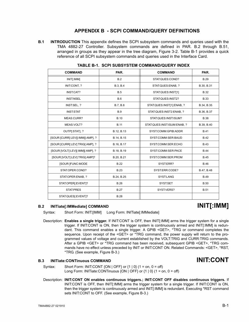
TMA4882-27 021910 B-1
APPENDIX B - SCPI COMMAND/QUERY DEFINITIONS
B.1 INTRODUCTION This appendix defines the SCPI subsystem commands and queries used with theTMA 4882-27 Controller. Subsystem commands are defined in PAR. B.2 through B.51,arranged in groups as they appear in the tree diagram, Figure 3-2. Table B-1 provides a quickreference of all SCPI subsystem commands and queries used in the Interface Card.
B.2 INITiate[:IMMediate] COMMAND INIT[:IMM]Syntax: Short Form: INIT:[IMM] Long Form: INITiate[:IMMediate]
Description: Enables a single trigger. If INIT:CONT is OFF, then INIT[:IMM] arms the trigger system for a singletrigger. If INIT:CONT is ON, then the trigger system is continuously armed and INIT[:IMM] is redun-dant. This command enables a single trigger. A GPIB <GET>, *TRG or command completes thesequence. Upon receipt of the <GET> or *TRG command, the power supply will return to the pro-grammed values of voltage and current established by the VOLT:TRIG and CURR:TRIG commands.After a GPIB <GET> or *TRG command has been received, subsequent GPIB <GET>, *TRG com-mands have no effect unless preceded by INIT or INIT:CONT ON. Related Commands: <GET>, *RST,*TRG. (See example, Figure B-3.)
B.3 INITiate:CONTinuous COMMAND INIT:CONTSyntax: Short Form: INIT:CONT {ON | OFF} or {1 | 0} (1 = on, 0 = off)
Long Form: INITiate:CONTinuous {ON | OFF} or {1 | 0} (1 = on, 0 = off)
Description: INIT:CONT ON enables continuous triggers.; INIT:CONT OFF disables continuous triggers. IfINIT:CONT is OFF, then INIT[:IMM] arms the trigger system for a single trigger. If INIT:CONT is ON,then the trigger system is continuously armed and INIT[:IMM] is redundant. Executing *RST commandsets INIT:CONT to OFF. (See example, Figure B-3.)
TABLE B-1. SCPI SUBSYSTEM COMMAND/QUERY INDEXCOMMAND PAR. COMMAND PAR.
INIT[:IMM] B.2 STAT:QUES:COND? B.29
INIT:CONT, ? B.3, B.4 STAT:QUES:ENAB, ? B.30, B.31
INST:CAT? B.5 STAT:QUES:INST[1] B.32
INST:NSEL B.6 STAT:QUES:INST2? B.33
INST:SEL, ? B.7, B.8 STAT:QUES:INST[1]:ENAB, ? B.34, B.35
INST:STAT B.9 STAT:QUES:INST2:ENAB, ? B.36, B.37
MEAS:CURR? B.10 STAT:QUES:INST:ISUM? B.38
MEAS:VOLT? B.11 STAT:QUES:INST:ISUM:ENAB, ? B.39, B.40
OUTP[:STAT], ? B.12, B.13 SYST:COMM:GPIB:ADDR B.41
[SOUR:]CURR[:LEV][:IMM][:AMP], ? B.14, B.15 SYST:COMM:SER:BAUD B.42
[SOUR:]CURR[:LEV]:TRIG[:AMP], ? B.16, B.17 SYST:COMM:SER:ECHO B.43
[SOUR:]VOLT[:LEV][:IMM][:AMP], ? B.18, B.19 SYST:COMM:SER:PACE B.44
[SOUR:]VOLT[:LEV]:TRIG[:AMP]? B.20, B.21 SYST:COMM:SER:PROM B.45
[SOUR:]FUNC:MODE B.22 SYST:ERR? B.46
STAT:OPER:COND? B.23 SYST:ERR:CODE? B.47, B.48
STAT:OPER:ENAB, ? B.24, B.25 SYST:LANG B.49
STAT:OPER[:EVENT]? B.26 SYST:SET B.50
STAT:PRES B.27 SYST:VERS? B.51
STAT:QUES[:EVENT]? B.28
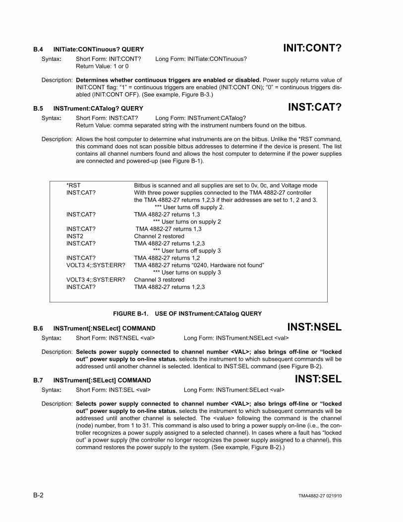
B-2 TMA4882-27 021910
B.4 INITiate:CONTinuous? QUERY INIT:CONT?Syntax: Short Form: INIT:CONT? Long Form: INITiate:CONTinuous?
Return Value: 1 or 0
Description: Determines whether continuous triggers are enabled or disabled. Power supply returns value ofINIT:CONT flag: “1” = continuous triggers are enabled (INIT:CONT ON); “0” = continuous triggers dis-abled (INIT:CONT OFF). (See example, Figure B-3.)
B.5 INSTrument:CATalog? QUERY INST:CAT?Syntax: Short Form: INST:CAT? Long Form: INSTrument:CATalog?
Return Value: comma separated string with the instrument numbers found on the bitbus.
Description: Allows the host computer to determine what instruments are on the bitbus. Unlike the *RST command,this command does not scan possible bitbus addresses to determine if the device is present. The listcontains all channel numbers found and allows the host computer to determine if the power suppliesare connected and powered-up (see Figure B-1).
FIGURE B-1. USE OF INSTrument:CATalog QUERY
B.6 INSTrument[:NSELect] COMMAND INST:NSELSyntax: Short Form: INST:NSEL <val> Long Form: INSTrument:NSELect <val>
Description: Selects power supply connected to channel number <VAL>; also brings off-line or “lockedout” power supply to on-line status. selects the instrument to which subsequent commands will beaddressed until another channel is selected. Identical to INST:SEL command (see Figure B-2).
B.7 INSTrument[:SELect] COMMAND INST:SELSyntax: Short Form: INST:SEL <val> Long Form: INSTrument:SELect <val>
Description: Selects power supply connected to channel number <VAL>; also brings off-line or “lockedout” power supply to on-line status. selects the instrument to which subsequent commands will beaddressed until another channel is selected. The <value> following the command is the channel(node) number, from 1 to 31. This command is also used to bring a power supply on-line (i.e., the con-troller recognizes a power supply assigned to a selected channel). In cases where a fault has “lockedout” a power supply (the controller no longer recognizes the power supply assigned to a channel), thiscommand restores the power supply to the system. (See example, Figure B-2).)
*RST Bitbus is scanned and all supplies are set to 0v, 0c, and Voltage modeINST:CAT? With three power supplies connected to the TMA 4882-27 controller
the TMA 4882-27 returns 1,2,3 if their addresses are set to 1, 2 and 3. *** User turns off supply 2.
INST:CAT? TMA 4882-27 returns 1,3*** User turns on supply 2
INST:CAT? TMA 4882-27 returns 1,3INST2 Channel 2 restored INST:CAT? TMA 4882-27 returns 1,2,3
*** User turns off supply 3INST:CAT? TMA 4882-27 returns 1,2VOLT3 4;:SYST:ERR? TMA 4882-27 returns “0240, Hardware not found”
*** User turns on supply 3VOLT3 4;:SYST:ERR? Channel 3 restoredINST:CAT? TMA 4882-27 returns 1,2,3
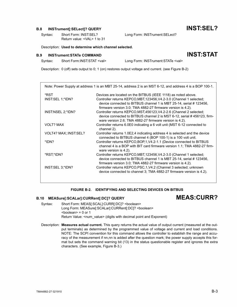
TMA4882-27 021910 B-3
B.8 INSTrument[:SELect]? QUERY INST:SEL?Syntax: Short Form: INST:SEL? Long Form: INSTrument:SELect?
Return value: <VAL> 1 to 31
Description: Used to determine which channel selected.
B.9 INSTrument:STATe COMMAND INST:STATSyntax: Short Form:INST:STAT <val> Long Form: INSTrument:STATe <val>
Description: 0 (off) sets output to 0; 1 (on) restores output voltage and current. (see Figure B-2)
FIGURE B-2. IDENTIFYING AND SELECTING DEVICES ON BITBUS
B.10 MEASure[:SCALar]:CURRent[:DC]? QUERY MEAS:CURR?Syntax: Short Form: MEAS[:SCAL]:CURR[:DC]? <boolean>
Long Form: MEASure[:SCALar]:CURRent[:DC]? <boolean><boolean> = 0 or 1Return Value: <num_value> (digits with decimal point and Exponent)
Description: Measures actual current. This query returns the actual value of output current (measured at the out-put terminals) as determined by the programmed value of voltage and current and load conditions.NOTE: The SCPI convention for this command allows the controller to establish the range and accu-racy of the measurement if nn,nn is added after the question mark; the power supply accepts this for-mat but sets the command warning bit (13) in the status questionable register and ignores the extracharacters. (See example, Figure B-3.)
Note: Power Supply at address 1 is an MBT 25-14, address 2 is an MST 6-12, and address 4 is a BOP 100-1.
*RST Devices are located on the BITBUS (IEEE 1118) as noted above.INST:SEL 1;*IDN? Controller returns KEPCO,MBT,123456,V4.2-3.0 (Channel 1 selected;
device connected to BITBUS channel 1 is MBT 25-14, serial # 123456, firmware version 3.0; TMA 4882-27 firmware version is 4.2).
INST:NSEL 2;*IDN? Controller returns KEPCO,MST,456123,V4.2-2.6 (Channel 2 selected; device connected to BITBUS channel 2 is MST 6-12, serial # 456123, firm-ware version 2.6; TMA 4882-27 firmware version is 4.2).
VOLT? MAX Controller returns 6.0E0 indicating a 6 volt unit (MST 6-12 connected to channel 2).
VOLT4? MAX;:INST:SEL? Controller returns 1.0E2,4 indicating address 4 is selected and the device connected to BITBUS channel 4 (BOP 100-1) is a 100 volt unit.
*IDN? Controller returns KEPCO,BOP,1,V4.2-1.1 (Device connected to BITBUS channel 4 is a BOP with BIT card firmware version 1.1; TMA 4882-27 firm-ware version is 4.2).
*RST;*IDN? Controller returns KEPCO,MBT,123456,V4.2-3.0 (Channel 1 selected; device connected to BITBUS channel 1 is MBT 25-14, serial # 123456, firmware version 3.0; TMA 4882-27 firmware version is 4.2).
INST:SEL 3;*IDN? Controller returns KEPCO,PSC,1,V4.2 (Channel 3 selected; unknown device connected to channel 3; TMA 4882-27 firmware version is 4.2).

B-4 TMA4882-27 021910
B.11 MEASure[:VOLTage][:SCALar][:DC]? QUERY MEAS:VOLT?Syntax: Short Form: MEAS[:SCAL]:VOLT[:DC]? <boolean>
Long Form: MEASure[:SCALar]:VOLTage[:DC]? <boolean><boolean> = 0 or 1Return Value: <num_value> (digits with decimal point and Exponent)
Description: Measures actual voltage. This query returns the actual value of output voltage (measured at the out-put terminals) as determined by the programmed value of voltage and current and load conditions.NOTE: The SCPI convention for this command allows the controller to establish the range and accu-racy of the measurement if nn,nn is added after the question mark; the power supply accepts this for-mat but sets the command warning bit (13) in the status questionable register and ignores the extracharacters. (See example, Figure B-3.)
B.12 OUTPut[:STATe] COMMAND OUTPSyntax: Short Form: OUTP[:STAT] <boolean> Long Form: OUTPut[:STATe] <boolean>
<boolean>=(0 or OFF, 1 or ON)OUTP <boolean>(@n1,n2,n3) Open or close multiple channels, n1, n2, n3 = channel numbersOUTP <boolean>(@n1:n2) Open or close a range of channels, n1 = low, n2 = high channel number
Description: Enables or disables the power supply output. Upon power up the output is enabled (OUTP ON).When OUTP OFF is executed, the programmed values of voltage and current are saved, then voltageand current are programmed to 0. When OUTP ON is executed, the power supply output is restored tothe previously saved programmed values. The saved values of voltage and current can be viewed byVOLT? and CURR? queries. Related Commands: OUTP?. (See example, Figure B-3. Multiple chan-nel examples: OUTP OFF(@5,7) closes channels 5 and 7, OUTP ON(@4:7) opens channels 4, 5, 6,and 7.
B.13 OUTPut[:STATe]? QUERY OUTP?Syntax: Short Form: OUTP[:STAT]? Long Form: OUTPut[:STATe]?
Return Value: <int_value> (0 or 1)
Description: Indicates whether power supply output is enabled or disabled. Returns 0 if output disabled,returns 1 if output enabled. Related Commands: OUTP. (See example, Figure B-3.)
B.14 [SOURce:]CURRent[:LEVel][:IMMediate][:AMPlitude] COMMAND CURRSyntax: Short Form: [SOUR:]CURR[:LEV][:IMM][:AMP] <exp_value>
Long Form: [SOURce:]CURRent[:LEVel][:IMMediate][:AMPlitude] <exp_value><exp_value> = digits with decimal point and Exponent, e.g., 2.71E+1 for 27.1
Description: Sets programmed current level at power supply output. This command programs output current toa specific value; actual output current will depend on load conditions. If the value exceeds the maxi-mum for the model being programmed, error message -222,”Data out of range” is posted in outputqueue. (See example, Figure B-3.)
B.15 [SOURce:]CURRent[:LEVel][:IMMediate][:AMPlitude]? QUERY CURR?Syntax: Short Form: [SOUR:]CURR[:LEV][:IMM][:AMP]? MIN, MAX
Long Form: [SOURce:]CURRent[:LEVel][:IMMediate][:AMPlitude]? MIN, MAXReturn Value:<exp_value> = digits with decimal point and Exponent, e.g., 2.71E+1 for 27.1
Description: Returns either the programmed value, maximum value, or minimum value of current. TheCURR? query returns the programmed value of current. Actual output current will depend on load con-ditions. The CURR?MAX query returns the maximum current allowed for a particular model. CURR?Returns programmed current value. CURR? MAX returns maximum current allowed for power supply.CURR? MIN returns minimum current allowed for power supply (always 0). Related Commands:CURR. (See example, Figure B-3.)
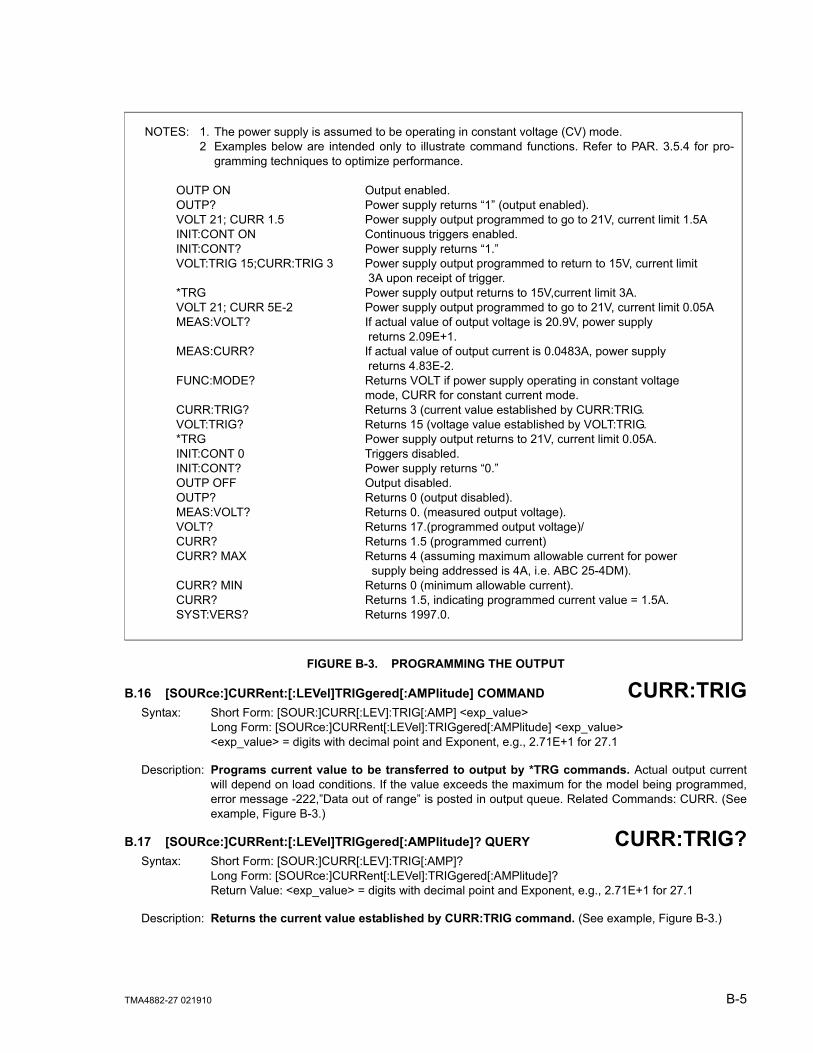
TMA4882-27 021910 B-5
FIGURE B-3. PROGRAMMING THE OUTPUT
B.16 [SOURce:]CURRent:[:LEVel]TRIGgered[:AMPlitude] COMMAND CURR:TRIGSyntax: Short Form: [SOUR:]CURR[:LEV]:TRIG[:AMP] <exp_value>
Long Form: [SOURce:]CURRent[:LEVel]:TRIGgered[:AMPlitude] <exp_value><exp_value> = digits with decimal point and Exponent, e.g., 2.71E+1 for 27.1
Description: Programs current value to be transferred to output by *TRG commands. Actual output currentwill depend on load conditions. If the value exceeds the maximum for the model being programmed,error message -222,”Data out of range” is posted in output queue. Related Commands: CURR. (Seeexample, Figure B-3.)
B.17 [SOURce:]CURRent:[:LEVel]TRIGgered[:AMPlitude]? QUERY CURR:TRIG?Syntax: Short Form: [SOUR:]CURR[:LEV]:TRIG[:AMP]?
Long Form: [SOURce:]CURRent[:LEVel]:TRIGgered[:AMPlitude]?Return Value: <exp_value> = digits with decimal point and Exponent, e.g., 2.71E+1 for 27.1
Description: Returns the current value established by CURR:TRIG command. (See example, Figure B-3.)
NOTES: 1. The power supply is assumed to be operating in constant voltage (CV) mode.2 Examples below are intended only to illustrate command functions. Refer to PAR. 3.5.4 for pro-
gramming techniques to optimize performance.
OUTP ON Output enabled.OUTP? Power supply returns “1” (output enabled).VOLT 21; CURR 1.5 Power supply output programmed to go to 21V, current limit 1.5AINIT:CONT ON Continuous triggers enabled.INIT:CONT? Power supply returns “1.”VOLT:TRIG 15;CURR:TRIG 3 Power supply output programmed to return to 15V, current limit
3A upon receipt of trigger.*TRG Power supply output returns to 15V,current limit 3A. VOLT 21; CURR 5E-2 Power supply output programmed to go to 21V, current limit 0.05AMEAS:VOLT? If actual value of output voltage is 20.9V, power supply
returns 2.09E+1. MEAS:CURR? If actual value of output current is 0.0483A, power supply
returns 4.83E-2.FUNC:MODE? Returns VOLT if power supply operating in constant voltage
mode, CURR for constant current mode.CURR:TRIG? Returns 3 (current value established by CURR:TRIG.VOLT:TRIG? Returns 15 (voltage value established by VOLT:TRIG.*TRG Power supply output returns to 21V, current limit 0.05A. INIT:CONT 0 Triggers disabled.INIT:CONT? Power supply returns “0.”OUTP OFF Output disabled.OUTP? Returns 0 (output disabled).MEAS:VOLT? Returns 0. (measured output voltage).VOLT? Returns 17.(programmed output voltage)/CURR? Returns 1.5 (programmed current)CURR? MAX Returns 4 (assuming maximum allowable current for power
supply being addressed is 4A, i.e. ABC 25-4DM).CURR? MIN Returns 0 (minimum allowable current).CURR? Returns 1.5, indicating programmed current value = 1.5A.SYST:VERS? Returns 1997.0.
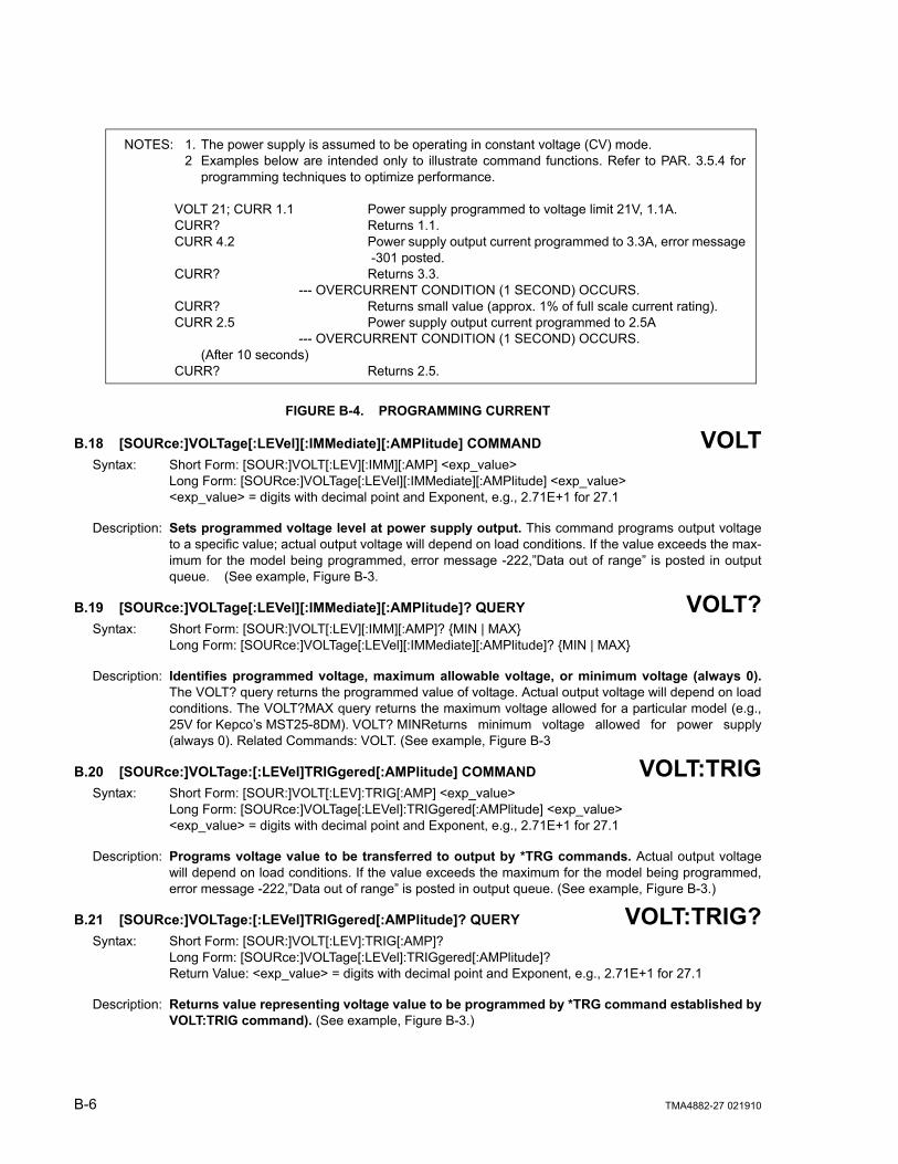
B-6 TMA4882-27 021910
FIGURE B-4. PROGRAMMING CURRENT
B.18 [SOURce:]VOLTage[:LEVel][:IMMediate][:AMPlitude] COMMAND VOLTSyntax: Short Form: [SOUR:]VOLT[:LEV][:IMM][:AMP] <exp_value>
Long Form: [SOURce:]VOLTage[:LEVel][:IMMediate][:AMPlitude] <exp_value><exp_value> = digits with decimal point and Exponent, e.g., 2.71E+1 for 27.1
Description: Sets programmed voltage level at power supply output. This command programs output voltageto a specific value; actual output voltage will depend on load conditions. If the value exceeds the max-imum for the model being programmed, error message -222,”Data out of range” is posted in outputqueue. (See example, Figure B-3.
B.19 [SOURce:]VOLTage[:LEVel][:IMMediate][:AMPlitude]? QUERY VOLT?Syntax: Short Form: [SOUR:]VOLT[:LEV][:IMM][:AMP]? {MIN | MAX}
Long Form: [SOURce:]VOLTage[:LEVel][:IMMediate][:AMPlitude]? {MIN | MAX}
Description: Identifies programmed voltage, maximum allowable voltage, or minimum voltage (always 0).The VOLT? query returns the programmed value of voltage. Actual output voltage will depend on loadconditions. The VOLT?MAX query returns the maximum voltage allowed for a particular model (e.g.,25V for Kepco’s MST25-8DM). VOLT? MINReturns minimum voltage allowed for power supply(always 0). Related Commands: VOLT. (See example, Figure B-3
B.20 [SOURce:]VOLTage:[:LEVel]TRIGgered[:AMPlitude] COMMAND VOLT:TRIGSyntax: Short Form: [SOUR:]VOLT[:LEV]:TRIG[:AMP] <exp_value>
Long Form: [SOURce:]VOLTage[:LEVel]:TRIGgered[:AMPlitude] <exp_value><exp_value> = digits with decimal point and Exponent, e.g., 2.71E+1 for 27.1
Description: Programs voltage value to be transferred to output by *TRG commands. Actual output voltagewill depend on load conditions. If the value exceeds the maximum for the model being programmed,error message -222,”Data out of range” is posted in output queue. (See example, Figure B-3.)
B.21 [SOURce:]VOLTage:[:LEVel]TRIGgered[:AMPlitude]? QUERY VOLT:TRIG?Syntax: Short Form: [SOUR:]VOLT[:LEV]:TRIG[:AMP]?
Long Form: [SOURce:]VOLTage[:LEVel]:TRIGgered[:AMPlitude]?Return Value: <exp_value> = digits with decimal point and Exponent, e.g., 2.71E+1 for 27.1
Description: Returns value representing voltage value to be programmed by *TRG command established byVOLT:TRIG command). (See example, Figure B-3.)
NOTES: 1. The power supply is assumed to be operating in constant voltage (CV) mode.2 Examples below are intended only to illustrate command functions. Refer to PAR. 3.5.4 for
programming techniques to optimize performance.
VOLT 21; CURR 1.1 Power supply programmed to voltage limit 21V, 1.1A.CURR? Returns 1.1.CURR 4.2 Power supply output current programmed to 3.3A, error message
-301 posted.CURR? Returns 3.3. --- OVERCURRENT CONDITION (1 SECOND) OCCURS.CURR? Returns small value (approx. 1% of full scale current rating).CURR 2.5 Power supply output current programmed to 2.5A --- OVERCURRENT CONDITION (1 SECOND) OCCURS.
(After 10 seconds)CURR? Returns 2.5.

TMA4882-27 021910 B-7
B.22 [SOURce:]FUNCtion:MODE COMMAND FUNC:MODESyntax: Short Form: FUNC:MODE {VOLT | CURR}
Long Form: FUNCtion:MODE {VOLT | CURR}
Description: Establishes the operating mode of the power supply. VOLT = Constant Voltage mode (CV). CURR = Constant Current mode (CC).
B.23 STATus:OPERation:CONDition? QUERY STAT:OPER:COND?Syntax: Short Form: STAT:OPER:COND? Long Form: STATus:OPERation:CONDition?
Return Value: <int_value> 0 to 1313 (256 + 512 + 1024).
Description: Returns the value of the Operation Condition Register (see Table B-2). The Operation ConditionRegister contains unlatched real-time information about the operating conditions of the power supply.Bit set to 1 = function enabled (active, true); bit reset to 0 = function disabled (inactive, false). (Seeexample, Figure B-5.)
B.24 STATus:OPERation:ENABle COMMAND STAT:OPER:ENABSyntax: Short Form: STAT:OPER:ENAB <int_value> 0 to 1313 (1 + 32 + 256 + 1024)
Long Form: STATus:OPERation:ENABle <int_value> 0 to 1313 (1 + 32 + 256 + 1024)
Description: Sets Operation Enable Register. The Operation Enable Register is a mask for enabling specific bitsin the Operation Event Register which will cause the operation summary bit (bit 7) of the Status Byteregister to be set Bit set to 1 = function enabled (active, true); bit reset to 0 = function disabled (inac-tive, false). The operation summary bit is the logical OR of all the enabled bits in the Operation Eventregister. (See example, Figure B-5.)
B.25 STATus:OPERation:ENABle? QUERY STAT:OPER:ENAB?Syntax: Short Form: STAT:OPER:ENAB? Long Form: STATus:OPERation:ENABle?
Return Value: <int_value> 0 to 1313 (1 + 32 + 256 + 1024).
Description: Reads Operation Enable Register (see Table B-2). Returns value of Operation Enable Register bits.Bit set to 1 = function enabled (active, true); bit reset to 0 = function disabled (inactive, false). (Seeexample, Figure B-5.)
B.26 STATus:OPERation[:EVENt]? QUERY STAT:OPER?Syntax: Short Form: STAT:OPER[:EVEN]? Long Form: STATus:OPERation[:EVENt]?
Return Value: <int_value> 0 to 1313 (1 + 32 + 256 + 1024).
Description: Indicates changes in conditions monitored by Operational Event Register. Returns the value ofthe Operation Event register. The Operation Event register is a read-only register which holds(latches) all events that occur. Reading the Operation Event register clears it. (See example, Figure B-5.)
TABLE B-2. OPERATION CONDITION REGISTER, OPERATION ENABLE REGISTER,AND OPERATION EVENT REGISTER BITS
CONDITION NU CC RLY CV NU NU NU NU
BIT 15-11 10 9 8 7 - 6 5 4 - 1 0
VALUE 32,768 - 2048 1024 512 256 128 - 64 32 16 -2 1
CC - POWER SUPPLY IN CONSTANT CURRENT MODECV - POWER SUPPLY IN CONSTANT VOLTAGE MODENU - NOT USEDRLY POWER SUPPLY RELAY IS CLOSED

B-8 TMA4882-27 021910
B.27 STATus:PRESet COMMAND STAT:PRESSyntax: Short Form: STAT:PRES Long Form: STATus:PRESet
Description: Disables reporting of all status events. This command sets all bits of the Operation Condition(Table B-2) and Questionable Condition Registers to 0, preventing all status events from beingreported. (See example, Figure B-5.)
FIGURE B-5. USING STATUS COMMANDS AND QUERIES
B.28 STATus:QUEStionable[:EVENt]? QUERY STAT:QUES?Syntax: Short Form: STAT:QUES[EVEN]? Long Form: STATus:QUEStionable[EVENT]?
Return Value: <int_value> actual register value
Description: Indicates questionable events that occurred since previous STAT:QUES? query. Returns thevalue of the Questionable Event register (see Table B-3). The Questionable Event register is aread-only register which holds (latches) all events. Reading the Questionable Event register clears it.(See example, Figure B-5.)
NOTE: The selected power supply is assumed to be operating in cV (constant voltage) mode.
STAT:OPER:ENAB 1056 Mask enabled for CC, WTG and bits.STAT:OPER:ENAB? Returns 1056 (32 + 1024) (CC, WTG bits set).STAT:QUES:ENAB 3 Mask enabled for OV and OC bits (1 + 2).STAT:QUES:ENAB? Returns 3 (1 + 2) indicating OV and OC bits are enabled.STAT:PRES Operation Condition and Questionable Condition registers are
reset.INIT:CONT ON Continuous triggers enabled.STAT:OPER:COND? Power supply returns 288 (256 + 32) to indicate that power
supply is constant voltage mode and Wait For Trigger is true.STAT:OPER? Returns 1057, e.g., indicating that since the last reading of the
Operation Event Register the power supply has entered Constant Current mode, the Wait Trigger was set.
STAT:OPER? Returns 0 indicating no changes since previous reading of theOperation Event register.
STAT:QUES? Returns 0 (no questionable conditions occurred since previous reading
--- OVERCURRENT CONDITION OCCURSSTAT:QUES? Returns 2 (overcurrent protection tripped since the last
STAT:QUES? query).STAT:QUES:COND? Returns 2, (Power supply still in overcurrent protection state).STAT:QUES? Returns 0, (Register cleared by previous STAT:QUES?).STAT:QUES:COND? Returns 2, (Power supply still in overcurrent protection state).SYST:ERR? Power supply returns 0,“No error” message.INST:SEL 1 Select instrument 1STAT:QUES? TMA 4882-27 responds 4 indicating instrument 1 in current mode INST:SEL 2 Select instrument 2STAT:QUES? TMA 4882-27 responds 8 indicating instrument 2 in voltage mode STAT:QUES:INST:ISUM1? TMA 4882-27 responds 4 indicating instrument 1 in current modeSTAT:QUES:INST:ISUM2? TMA 4882-27 responds 8 indicating instrument 2 in voltage mode
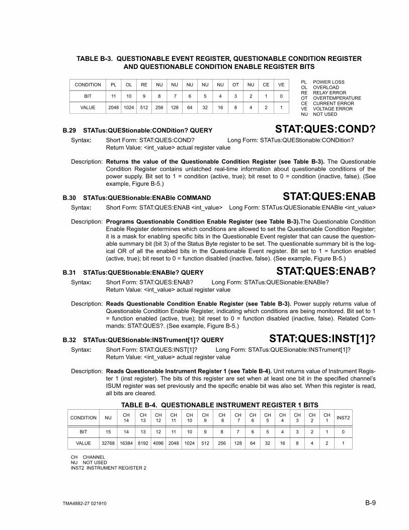
TMA4882-27 021910 B-9
B.29 STATus:QUEStionable:CONDition? QUERY STAT:QUES:COND?Syntax: Short Form: STAT:QUES:COND? Long Form: STATus:QUEStionable:CONDition?
Return Value: <int_value> actual register value
Description: Returns the value of the Questionable Condition Register (see Table B-3). The QuestionableCondition Register contains unlatched real-time information about questionable conditions of thepower supply. Bit set to 1 = condition (active, true); bit reset to 0 = condition (inactive, false). (Seeexample, Figure B-5.)
B.30 STATus:QUEStionable:ENABle COMMAND STAT:QUES:ENABSyntax: Short Form: STAT:QUES:ENAB <int_value> Long Form: STATus:QUESionable:ENABle <int_value>
Description: Programs Questionable Condition Enable Register (see Table B-3).The Questionable ConditionEnable Register determines which conditions are allowed to set the Questionable Condition Register;it is a mask for enabling specific bits in the Questionable Event register that can cause the question-able summary bit (bit 3) of the Status Byte register to be set. The questionable summary bit is the log-ical OR of all the enabled bits in the Questionable Event register. Bit set to 1 = function enabled(active, true); bit reset to 0 = function disabled (inactive, false). (See example, Figure B-5.)
B.31 STATus:QUEStionable:ENABle? QUERY STAT:QUES:ENAB?Syntax: Short Form: STAT:QUES:ENAB? Long Form: STATus:QUESionable:ENABle?
Return Value: <int_value> actual register value
Description: Reads Questionable Condition Enable Register (see Table B-3). Power supply returns value ofQuestionable Condition Enable Register, indicating which conditions are being monitored. Bit set to 1= function enabled (active, true); bit reset to 0 = function disabled (inactive, false). Related Com-mands: STAT:QUES?. (See example, Figure B-5.)
B.32 STATus:QUEStionable:INSTrument[1]? QUERY STAT:QUES:INST[1]?Syntax: Short Form: STAT:QUES:INST[1]? Long Form: STATus:QUESionable:INSTrument[1]?
Return Value: <int_value> actual register value
Description: Reads Questionable Instrument Register 1 (see Table B-4). Unit returns value of Instrument Regis-ter 1 (inst register). The bits of this register are set when at least one bit in the specified channel’sISUM register was set previously and the specific enable bit was also set. When this register is read,all bits are cleared.
TABLE B-3. QUESTIONABLE EVENT REGISTER, QUESTIONABLE CONDITION REGISTERAND QUESTIONABLE CONDITION ENABLE REGISTER BITS
CONDITION PL OL RE NU NU NU NU NU OT NU CE VE
BIT 11 10 9 8 7 6 5 4 3 2 1 0
VALUE 2048 1024 512 256 128 64 32 16 8 4 2 1
PL POWER LOSSOL OVERLOADRE RELAY ERROROT OVERTEMPERATURECE CURRENT ERRORVE VOLTAGE ERRORNU NOT USED
TABLE B-4. QUESTIONABLE INSTRUMENT REGISTER 1 BITS
CONDITION NU CH 14
CH 13
CH 12
CH 11
CH 10
CH 9
CH 8
CH 7
CH 6
CH 5
CH 4
CH 3
CH 2
CH 1 INST2
BIT 15 14 13 12 11 10 9 8 7 6 5 4 3 2 1 0
VALUE 32768 16384 8192 4096 2048 1024 512 256 128 64 32 16 8 4 2 1
CH CHANNELNU NOT USEDINST2 INSTRUMENT REGISTER 2

B-10 TMA4882-27 021910
B.33 STATus:QUEStionable:INSTrument2? QUERY STAT:QUES:INST2?Syntax: Short Form: STAT:QUES:INST2? Long Form: STATus:QUESionable:INSTrument2?
Return Value: <int_value> actual register value
Description: Reads Questionable Instrument Register 2 (see Table B-5). Unit returns value of Instrument Regis-ter 2 (inst2 register). The bits of this register are set when at least one bit in the specified channel’sISUM register was set previously and the specific enable bit was also set. When this register is read,all bits are cleared.
STAT:QUES:INST[1]:ENABB.34 STATus:QUEStionable:INSTrument[1]:ENABle COMMAND
Syntax: Short Form: STAT:QUES:INST[1]:ENAB <int_value> Long Form: STATus:QUESionable:INSTrument[1]:ENABle <int_value>
Description: Programs Questionable Instrument Register 1 Enable Register (see Table B-4). The Question-able Instrument Register 1 Enable Register is a mask which determines which channels are allowedto set Questionable Instrument Register 1.
STAT:QUES:INST[1]:ENAB?B.35 STATus:QUEStionable:INSTrument[1]:ENABle QUERY
Syntax: Short Form: STAT:QUES:INST[1]:ENAB? Long Form: STATus:QUESionable:INSTrument[1]:ENABle?Return Value: <int_value> actual register value.
Description: Reads Questionable Instrument Register 1 Enable Register (see Table B-4). Unit returns value ofQuestionable Instrument Register 1 Enable Register.
STAT:QUES:INST2:ENABB.36 STATus:QUEStionable:INSTrument2:ENABle COMMAND
Syntax: Short Form: STAT:QUES:INST2:ENAB <int_value> Long Form: STATus:QUESionable:INSTrument2:ENABle <int_value>
Description: Programs Questionable Instrument Register 2 Enable Register (see Table B-5).The Question-able Instrument Register 2 Enable Register is a mask which determines which channels are allowedto set Questionable Instrument Register 2.
STAT:QUES:INST2:ENAB?B.37 STATus:QUEStionable:INSTrument2:ENABle? QUERY
Syntax: Short Form: STAT:QUES:INST2:ENAB? Long Form: STATus:QUESionable:INSTrument2:ENABle?Return Value: <int_value> actual register value.
Description: Reads Questionable Instrument Register 2 Enable Register (see Table B-5). Unit returns value ofQuestionable Instrument Register 2 Enable Register.
TABLE B-5. QUESTIONABLE INSTRUMENT REGISTER 2 BITS
CONDITION NU CH 28
CH 27
CH 26
CH 25
CH 24
CH 23
CH22
CH21
CH 20
CH 19
CH 18
CH 17
CH 16
CH 15 NU
BIT 15 14 13 12 11 10 9 8 7 6 5 4 3 2 1 0
VALUE 32768 16384 8192 4096 2048 1024 512 256 128 64 32 16 8 4 2 1
CH CHANNELNU NOT USED

TMA4882-27 021910 B-11
B.38 STATus:QUEStionable:INSTrument:ISUM? QUERY STAT:QUES:INST:ISUM?Syntax: Short Form: STAT:QUES:INST:ISUM? Long Form: STATus:QUESionable:INSTrument:ISUM?
Return Value: <int_value> actual register value
Description: Reads ISUM Register (see Table B-3). Unit returns value of ISUM Register for selected channel Thisregister is identical in function to the QUEStionable register for the selected channel
STAT:QUES:INST:ISUM:ENABB.39 STATus:QUEStionable:INSTrument:ISUM:ENABle COMMAND
Syntax: Short Form: STAT:QUES:INST:ISUM:ENAB <int_value> Long Form: STATus:QUESionable:INSTrument:ISUM:ENABle <int_value>
Description: Programs Questionable Instrument ISUM Enable Register (see Table B-3).The QuestionableInstrument ISUM Enable Register is a mask which determines which conditions are allowed to set theQuestionable Instrument ISUM Register for the selected channel.
STAT:QUES:INST:ISUM:ENAB?B.40 STATus:QUEStionable:INSTrument:ISUM:ENABle? QUERY
Syntax: Short Form: STAT:QUES:INST:ISUM:ENAB? Long Form: STATus:QUESionable:INSTrument:ISUM:ENABle? Return Value: <int_value> actual register value
Description: Reads ISUM Enable Register (see Table B-3). Unit returns value of ISUM Enable Register forselected channel.
B.41 SYSTem:COMMunication:GPIB:ADDRess COMMAND SYST:COMM:GPIB:ADDRSyntax: Short Form: SYST:COMM:GPIB:ADDR<INT VAL> 1 to 30
Long Form: SYSTem:COMMunication:GPIB:ADDRess<INT VAL> 1 to 30
Description: Sets selected power supply GPIB address.
B.42 SYSTem:COMMunication:SERial:BAUD COMMAND SYST:COMM:SER:BAUDSyntax: Short Form: SYST:COMM:SER:BAUD {19200 | 9600 | 4800 | 2400}
Long Form: SYSTem:COMMunication:SERial:BAUD {19200 | 9600 | 4800 | 2400}
Description: Sets the unit to operate at the specified baud rate.
B.43 SYSTem:COMMunication:SERial:ECHO COMMAND SYST:COMM:SER:ECHOSyntax: Short Form: SYST:COMM:SER:ECHO {ON | OFF}
Long Form: SYSTem:COMMunication:SERial:ECHO {ON | OFF}
Description: Enables (ON) or disables (OFF) echo mode (see PAR. 3.5.3.3) Sending ON causes all subsequentcharacters to be echoed back. Sending OFF turns off the character echo after the nest line terminatorcharacter. The *RST command has no effect on echo status
B.44 SYSTem:COMMunication:SERial:PACE COMMAND SYST:COMM:SER:PACESyntax: Short Form: SYST:COMM:SER:PACE {NONE | XON}
Long Form: SYSTem:COMMunication:SERial:PACE {NONE | XON}
Description: Enables (XON) or disables (NONE) data flow control via the serial interface (see PAR. 3.5.3.3)
B.45 SYSTem:COMMunication:SERial:PROMPT COMMAND SYST:COMM:SER:PROMSyntax: Short Form: SYST:COMM:SER:PROM {ON | OFF}
Long Form: SYSTem:COMMunication:SERial:PROMpt {ON | OFF}
Description: Enables (ON) or disables (OFF) prompt (see PAR. 3.5.3.3). Sending ON causes the unit to return >character after the command is parsed.

B-12 TMA4882-27 021910
B.46 SYSTem:ERRor[:NEXT]? QUERY SYST:ERR?Syntax: Short Form: SYST:ERR[:NEXT]? Long Form: SYSTem:ERRor[:NEXT]?
Return Value: <int_value,string>
Description: Posts error messages to the output queue. Returns the next error number followed by its corre-sponding error message string from the instrument error queue. The error queue is a FIFO (first in firstout) buffer that stores errors as they occur. As it is read, each error is removed from the queue and thenext error message is made available. When all errors have been read, the query returns 0,”No error”.If more than 15 errors are accumulated, it will overflow. The oldest errors stay in the queue but themost recent errors are discarded. The last error in the queue will be -350,”Too many errors.” Errormessages are defined in Table B-6.
B.47 SYSTem:ERRor:CODE? QUERY SYST:ERR:CODE?Syntax: Short Form: SYST:ERR:CODE?] Long Form: SYSTem:ERRor:CODE?
Description: Returns the three character error code without the ASCII definition string. The error codes are definedin table B-6 (See example, Figure B-3.)
B.48 SYSTem:ERRor:CODE:ALL? QUERY SYST:ERR:CODE:ALL?Syntax: Short Form: SYST:ERR:CODE:ALL?] Long Form: SYSTem:ERRor:CODE:ALL?
Return Value:
Description: Returns a comma-separated list of all error codes. A maximum of 15 codes will be returned; if thequeue is empty, the power supply returns 0. The error codes are defined in table B-6
B.49 SYSTem:LANGuage COMMAND SYST:LANGSyntax: Short Form: SYST:LANG CIIL Long Form: SYSTem:LANGuage CIIL
Description: This command allows the CIIL command language to be used to program the power supply.(CIIL is included to provide compatibility with earlier Kepco equipment.) Once CIIL is selected, the CIILcommand ‘GAL’ followed by the command ‘SCPI’ must be sent for the power supply to respond toSCPI commands.
B.50 SYSTem:SET COMMAND SYST:SETSyntax: Short Form: SYSTem:SET {CM0 | CM1} Long Form: SYSTem:SET {CM0 | CM1}
Description: Sending SYST:SET CM1 sets the unit to operate in compatible mode and have all GPIB functionscompatible with software version 1.2 and lower units. Sending SYST:SET CM0 sets the unit to be fullySCPI 1997 compliant.
B.51 SYSTem:VERSIon? QUERY SYST:VERS?Syntax: Short Form: SYST:VERS? Long Form: SYSTem:VERSion?
Return Value: <int_value>.<int_value> (YYYY.V)
Description: Identifies SCPI Version implemented. Returns SCPI Version number: YYYY = year, V = Revision number for specified year (e.g 1997,0.).

TMA4882-27 021910 B-13/(B-14 Blank)
TABLE B-6. ERROR MESSAGESERROR MESSAGE EXPLANATION
0,“No error” No error
-100,“Command error” Command and data understood, but more information included which is not recognized.
-102,”Syntax error” First 4 characters recognized, subsequent characters not recognized.
-103,”Invalid separator” For example, VOLT.10 received instead of VOLT:10
-108,”Parameter Not Allowed Error” Volt12 sequence, channel number is invalid
-109,”Missing parameter” For example, VOLT instead of VOLT 21.
-111,”Header separator error” Missing space between volt and value or ; missing
-113,”Undefined header” First 4 characters could not be identified as legal command.For example, command VLT instead of VOLT
-120,”Numeric data error” Expected number but other characters were detected
-121,”Invalid character in number” Volt 1,500 (comma not allowed)
-123,”Exponent too large” Exponent E+3 or greater is invalid.
-141,”Invalid character data” For example OUTP OFD or OUTP STOP instead of OUTP OFF
-150,”String data error” Invalid characters were detected in numeric entry.For example E.1 instead of E+1 or 4d3 instead of 4.3.
-222,“Data out of range” Value exceeds power supply rating
-223,”Data format error” Multiple decimals in digit, Multiple E, etc.
-224,“Illegal parameter value” For example, OUTP 2 instead of OUTP 1
-241,”Hardware missing” Requesting device 2 status (INST:NSEL 2)
-350,”Queue overflow” More than 15 errors are in queue.
-410,”Query interrupted” New command sent before data from previous query read. Previous query data lost.
-430,”Query Deadlocked“ Over 255 characters received in single input string”

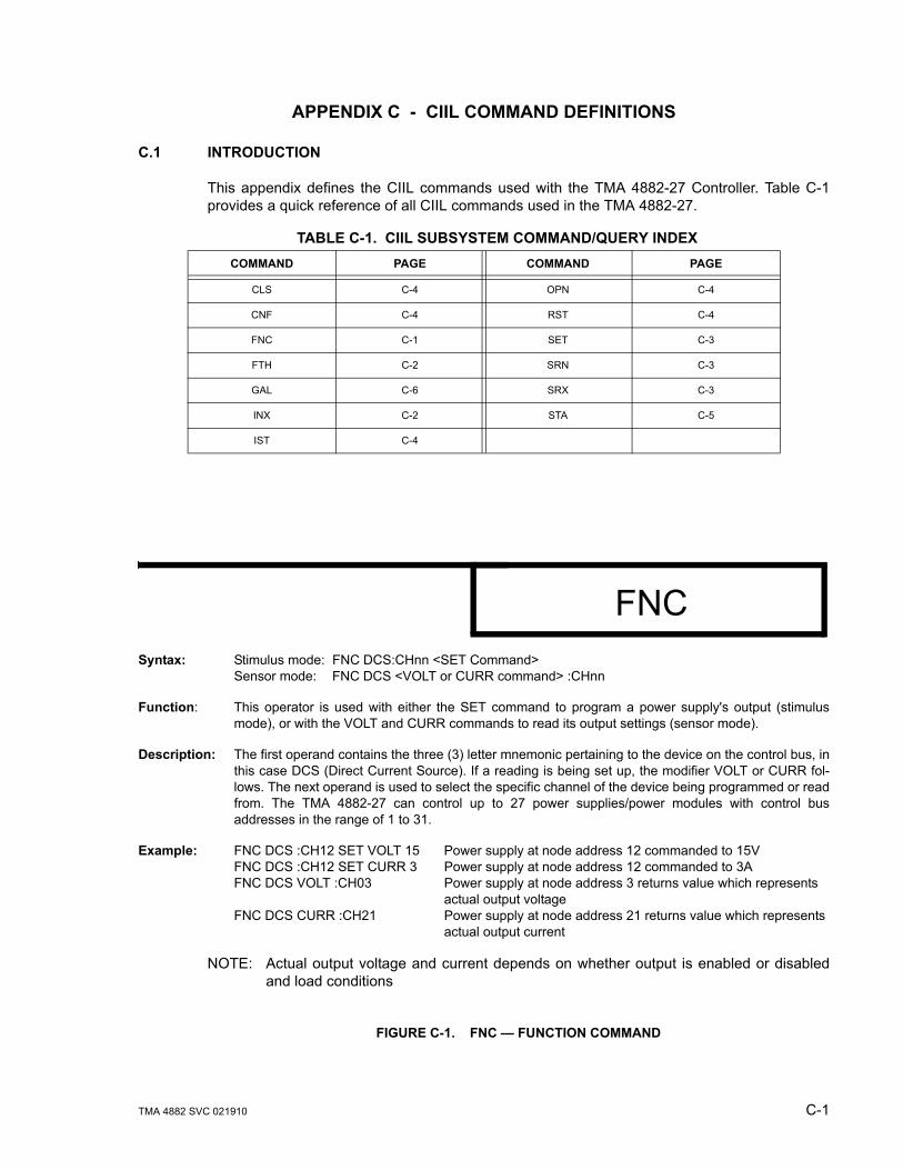
TMA 4882 SVC 021910 C-1
APPENDIX C - CIIL COMMAND DEFINITIONS
C.1 INTRODUCTION
This appendix defines the CIIL commands used with the TMA 4882-27 Controller. Table C-1provides a quick reference of all CIIL commands used in the TMA 4882-27.
FIGURE C-1. FNC — FUNCTION COMMAND
TABLE C-1. CIIL SUBSYSTEM COMMAND/QUERY INDEXCOMMAND PAGE COMMAND PAGE
CLS C-4 OPN C-4
CNF C-4 RST C-4
FNC C-1 SET C-3
FTH C-2 SRN C-3
GAL C-6 SRX C-3
INX C-2 STA C-5
IST C-4
Syntax: Stimulus mode: FNC DCS:CHnn <SET Command>Sensor mode: FNC DCS <VOLT or CURR command> :CHnn
Function: This operator is used with either the SET command to program a power supply's output (stimulusmode), or with the VOLT and CURR commands to read its output settings (sensor mode).
Description: The first operand contains the three (3) letter mnemonic pertaining to the device on the control bus, inthis case DCS (Direct Current Source). If a reading is being set up, the modifier VOLT or CURR fol-lows. The next operand is used to select the specific channel of the device being programmed or readfrom. The TMA 4882-27 can control up to 27 power supplies/power modules with control busaddresses in the range of 1 to 31.
Example: FNC DCS :CH12 SET VOLT 15 Power supply at node address 12 commanded to 15VFNC DCS :CH12 SET CURR 3 Power supply at node address 12 commanded to 3AFNC DCS VOLT :CH03 Power supply at node address 3 returns value which represents
actual output voltageFNC DCS CURR :CH21 Power supply at node address 21 returns value which represents
actual output current
NOTE: Actual output voltage and current depends on whether output is enabled or disabledand load conditions
FNC
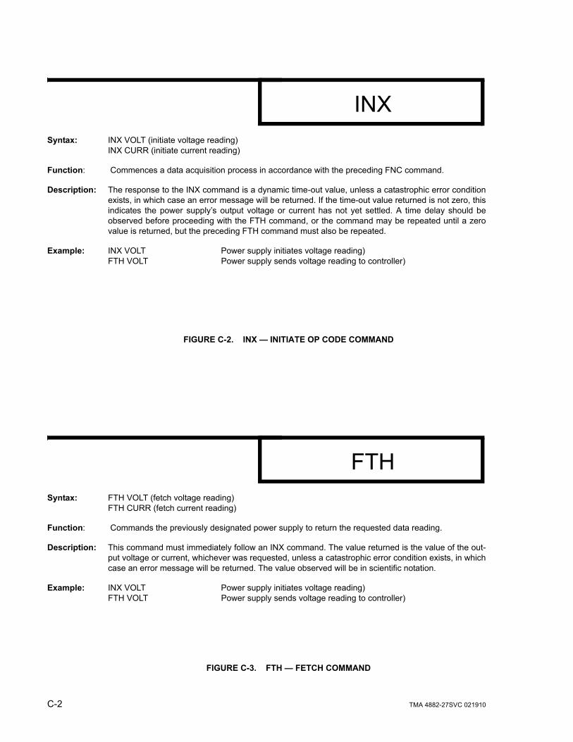
C-2 TMA 4882-27SVC 021910
FIGURE C-2. INX — INITIATE OP CODE COMMAND
FIGURE C-3. FTH — FETCH COMMAND
Syntax: INX VOLT (initiate voltage reading)INX CURR (initiate current reading)
Function: Commences a data acquisition process in accordance with the preceding FNC command.
Description: The response to the INX command is a dynamic time-out value, unless a catastrophic error conditionexists, in which case an error message will be returned. If the time-out value returned is not zero, thisindicates the power supply’s output voltage or current has not yet settled. A time delay should beobserved before proceeding with the FTH command, or the command may be repeated until a zerovalue is returned, but the preceding FTH command must also be repeated.
Example: INX VOLT Power supply initiates voltage reading)FTH VOLT Power supply sends voltage reading to controller)
INX
Syntax: FTH VOLT (fetch voltage reading)FTH CURR (fetch current reading)
Function: Commands the previously designated power supply to return the requested data reading.
Description: This command must immediately follow an INX command. The value returned is the value of the out-put voltage or current, whichever was requested, unless a catastrophic error condition exists, in whichcase an error message will be returned. The value observed will be in scientific notation.
Example: INX VOLT Power supply initiates voltage reading)FTH VOLT Power supply sends voltage reading to controller)
FTH
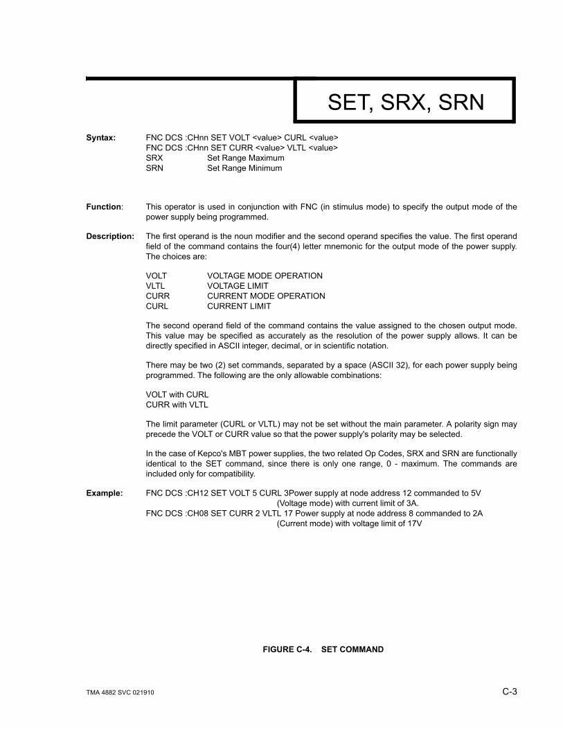
TMA 4882 SVC 021910 C-3
FIGURE C-4. SET COMMAND
Syntax: FNC DCS :CHnn SET VOLT <value> CURL <value>FNC DCS :CHnn SET CURR <value> VLTL <value>SRX Set Range MaximumSRN Set Range Minimum
Function: This operator is used in conjunction with FNC (in stimulus mode) to specify the output mode of thepower supply being programmed.
Description: The first operand is the noun modifier and the second operand specifies the value. The first operandfield of the command contains the four(4) letter mnemonic for the output mode of the power supply.The choices are:
VOLT VOLTAGE MODE OPERATIONVLTL VOLTAGE LIMITCURR CURRENT MODE OPERATIONCURL CURRENT LIMIT
The second operand field of the command contains the value assigned to the chosen output mode.This value may be specified as accurately as the resolution of the power supply allows. It can bedirectly specified in ASCII integer, decimal, or in scientific notation.
There may be two (2) set commands, separated by a space (ASCII 32), for each power supply beingprogrammed. The following are the only allowable combinations:
VOLT with CURLCURR with VLTL
The limit parameter (CURL or VLTL) may not be set without the main parameter. A polarity sign mayprecede the VOLT or CURR value so that the power supply's polarity may be selected.
In the case of Kepco's MBT power supplies, the two related Op Codes, SRX and SRN are functionallyidentical to the SET command, since there is only one range, 0 - maximum. The commands areincluded only for compatibility.
Example: FNC DCS :CH12 SET VOLT 5 CURL 3Power supply at node address 12 commanded to 5V(Voltage mode) with current limit of 3A.
FNC DCS :CH08 SET CURR 2 VLTL 17 Power supply at node address 8 commanded to 2A (Current mode) with voltage limit of 17V
SET, SRX, SRN
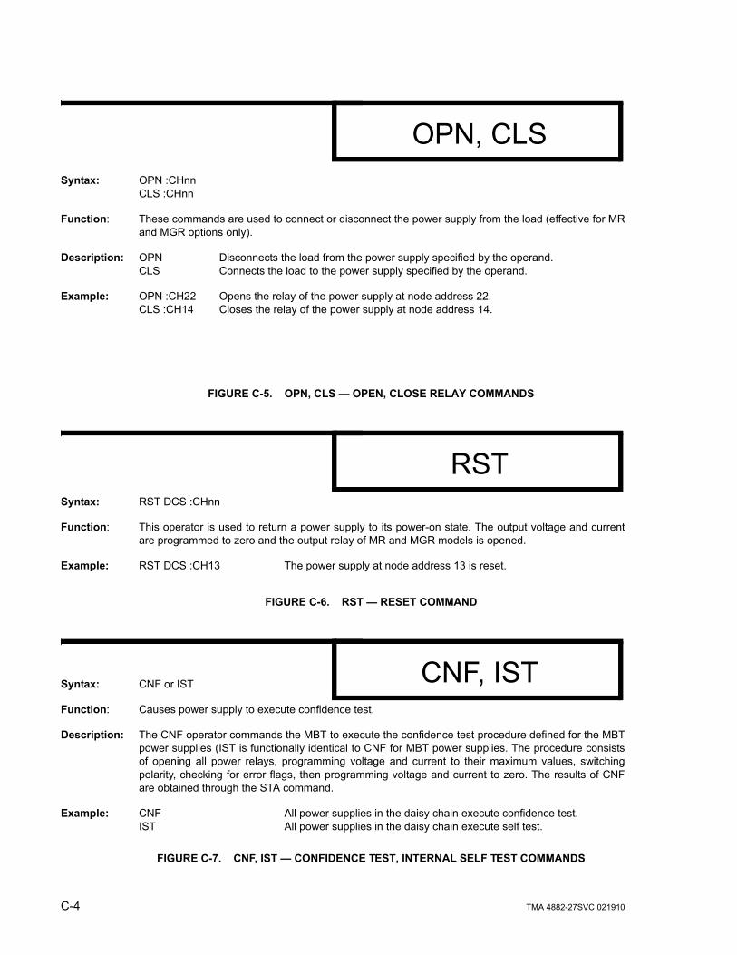
C-4 TMA 4882-27SVC 021910
FIGURE C-5. OPN, CLS — OPEN, CLOSE RELAY COMMANDS
FIGURE C-6. RST — RESET COMMAND
FIGURE C-7. CNF, IST — CONFIDENCE TEST, INTERNAL SELF TEST COMMANDS
Syntax: OPN :CHnnCLS :CHnn
Function: These commands are used to connect or disconnect the power supply from the load (effective for MRand MGR options only).
Description: OPN Disconnects the load from the power supply specified by the operand.CLS Connects the load to the power supply specified by the operand.
Example: OPN :CH22 Opens the relay of the power supply at node address 22.CLS :CH14 Closes the relay of the power supply at node address 14.
OPN, CLS
Syntax: RST DCS :CHnn
Function: This operator is used to return a power supply to its power-on state. The output voltage and currentare programmed to zero and the output relay of MR and MGR models is opened.
Example: RST DCS :CH13 The power supply at node address 13 is reset.
RST
Syntax: CNF or IST
Function: Causes power supply to execute confidence test.
Description: The CNF operator commands the MBT to execute the confidence test procedure defined for the MBTpower supplies (IST is functionally identical to CNF for MBT power supplies. The procedure consistsof opening all power relays, programming voltage and current to their maximum values, switchingpolarity, checking for error flags, then programming voltage and current to zero. The results of CNFare obtained through the STA command.
Example: CNF All power supplies in the daisy chain execute confidence test.IST All power supplies in the daisy chain execute self test.
CNF, IST

TMA 4882-27TSVC 021910 C-5
FIGURE C-8. STA — STATUS COMMAND
Syntax: STA
Function: Causes power supply to return operating status to controller.
Description: This operator commands the power supply to report its present operating status. Status is reported inthe form of a message (character string) as defined below. Any catastrophic error conditions (indicatedby * in the table below) which exist will be reported, until the error condition is corrected. As requiredby CIIL, all error messages begin with an ASCII “F” (Fault) followed by a 2 digit code, “07” (Halt). Thecode that follows (SCSnn) indicates the type of device and the channel number. The next 3 digit codedescribes the nature of the fault: “DEV” for device related errors or “MOD” for non-device errors, suchas syntax.
TABLE C-2. CIIL ERROR MESSAGESERROR MESSAGE EXPLANATION
F07 DCSnn DEV Power Loss The power supply has lost its input power. *
F07 DCSnn DEV Crowbarred (MAT, MBT) A shutdown occurred due to overvoltage or overcurrent. *
F07 DCSnn DEV Device Turned Off (BOP)
F07 DCSnn DEV Output Fault (MST)
F07 DCSnn DEV Over Temperature A shutdown occurred due to thermal causes. *
F07 DCSnn DEV Overload The voltage or current limit point was exceeded. *
F07 DCSnn DEV Voltage Fault The output voltage is not within limits (voltage mode). *
F07 DCSnn DEV Current Fault The output current is not within limits (current mode). *
F07 DCSnn DEV Relay Not Opened The power relay failed to open. *
F07 DCSnn DEV Relay Not Closed The power relay failed to close. *
F07 DCSnn DEV Polarity Error The output polarity is not correct. *
F07 DCSnn DEV Load Path Fault Open or miswired load or error sense leads detected. *
F07 DCSnn MOD Invalid Command Improper syntax was used. **
F07 DCSnn DEV Not Ready The output voltage or current has not settled. **
F07 DCSnn DEV Device Not Present The specified power supply was not present during power up or during the last DCL. **
F07 DCSnn DEV Device Not Responding The power supply has failed to communicate to the controller. **
F07 DCSnn DEV Invalid Voltage Range The programmed voltage is outside the power supply's range. **
F07 DCSnn DEV Invalid Current Range The programmed current is outside the power supply's range. **
F07 DCSnn DEV Set Modifier Error An improper SET command was sent. **
F07 DCSnn DEV Invalid Device ID The selected channel was not between 1-31. **
*Catastrophic error**Non-Catastrophic error
STA
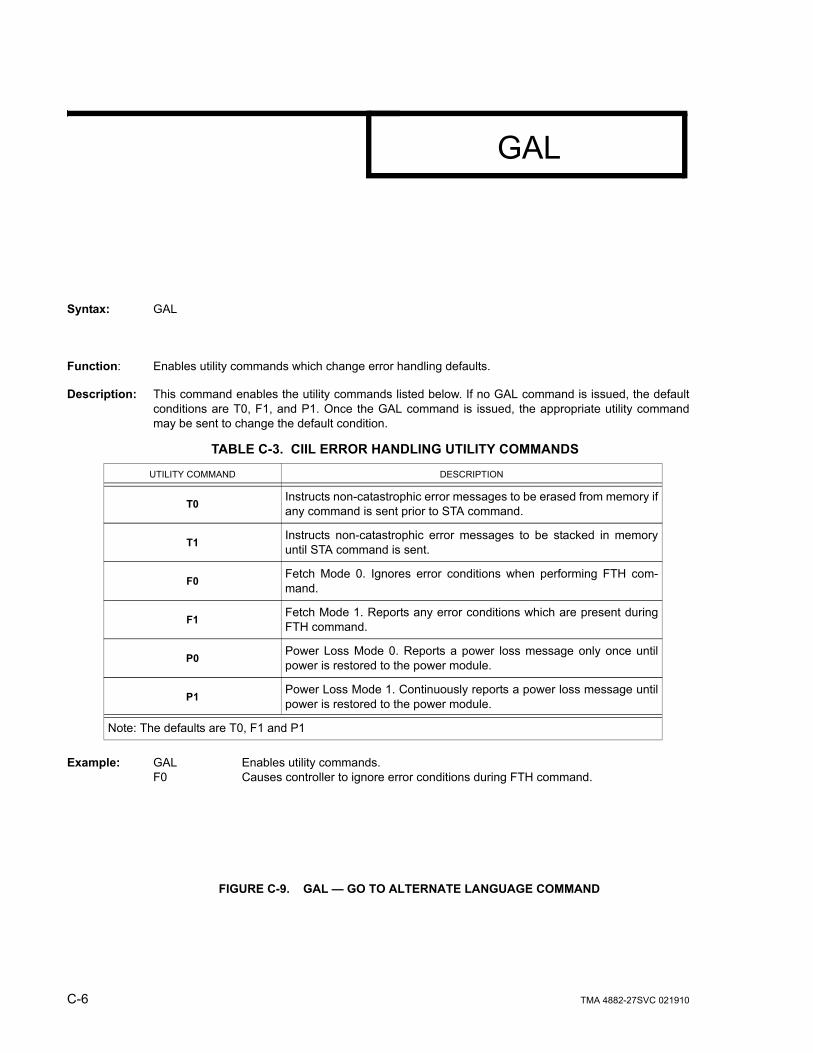
C-6 TMA 4882-27SVC 021910
FIGURE C-9. GAL — GO TO ALTERNATE LANGUAGE COMMAND
Syntax: GAL
Function: Enables utility commands which change error handling defaults.
Description: This command enables the utility commands listed below. If no GAL command is issued, the defaultconditions are T0, F1, and P1. Once the GAL command is issued, the appropriate utility commandmay be sent to change the default condition.
Example: GAL Enables utility commands.F0 Causes controller to ignore error conditions during FTH command.
TABLE C-3. CIIL ERROR HANDLING UTILITY COMMANDS
UTILITY COMMAND DESCRIPTION
T0 Instructs non-catastrophic error messages to be erased from memory ifany command is sent prior to STA command.
T1 Instructs non-catastrophic error messages to be stacked in memoryuntil STA command is sent.
F0 Fetch Mode 0. Ignores error conditions when performing FTH com-mand.
F1 Fetch Mode 1. Reports any error conditions which are present duringFTH command.
P0 Power Loss Mode 0. Reports a power loss message only once untilpower is restored to the power module.
P1 Power Loss Mode 1. Continuously reports a power loss message untilpower is restored to the power module.
Note: The defaults are T0, F1 and P1
GAL