short temporal coherence digital holography with a femtosecond frequency comb laser for multi-level...
TRANSCRIPT

Short temporal coherence digital holography
with a femtosecond frequency comb laser for
multi-level optical sectioning
Klaus Körner,1,*
Giancarlo Pedrini,1 Igor Alexeenko,
1 Tilo Steinmetz,
2 R. Holzwarth,
2
and W. Osten1
1Institut für Technische Optik and Research Center SCoPE, Pfaffenwaldring 9, Universitaet Stuttgart,70569
Stuttgart, Germany 2MenloSystems GmbH, Martinsried, Germany
Abstract: In this paper, we demonstrate how short temporal coherence
digital holography with a femtosecond frequency comb laser source may be
used for multi-level optical sectioning. The object shape is obtained by
digitally reconstructing and processing a sequence of holograms recorded
during stepwise shifting of a mirror in the reference arm. Experimental
results are presented.
©2012 Optical Society of America
OCIS codes: (090.0090) Holography; (090.1995) Digital holography; (120.3940) Metrology;
(140.3538) Lasers pulsed.
References and links
1. J. W. Goodman and R. W. Lawrence, “Digital image formation from electronically detected holograms,” Appl.
Phys. Lett. 11(3), 77–79 (1967).
2. W. S. Haddad, D. Cullen, J. C. Solem, J. W. Longworth, A. McPherson, K. Boyer, and C. K. Rhodes, “Fourier-
transform holographic microscope,” Appl. Opt. 31(24), 4973–4978 (1992).
3. U. Schnars, “Direct phase determination in hologram interferometry with use of digitally recorded holograms,”
J. Opt. Soc. Am. A 11(7), 2011–2015 (1994).
4. I. Yamaguchi and T. Zhang, “Phase-shifting digital holography,” Opt. Lett. 22(16), 1268–1270 (1997).
5. C. Wagner, S. Seebacher, W. Osten, and W. Jüptner, “Digital recording and numerical reconstruction of lensless
Fourier holograms in optical metrology,” Appl. Opt. 38(22), 4812–4820 (1999).
6. C. Wagner, W. Osten, and S. Seebacher, “Direct shape measurement by digital wavefront reconstruction and
multiwavelength contouring,” Opt. Eng. 39(1), 79–85 (2000).
7. L. Martínez-León, G. Pedrini, and W. Osten, “Applications of short-coherence digital holography in
microscopy,” Appl. Opt. 44(19), 3977–3984 (2005).
8. Y. C. Lin, C.-J. Cheng, and T. C. Poon, “Optical sectioning with a low-coherence phase-shifting digital
holographic microscope,” Appl. Opt. 50(7), B25–B30 (2011).
9. C. Yuan, H. Zhai, X. Wang, and L. Wu, “Lensless digital holography with short coherence light source for three-
dimensional surface contouring of reflecting micro objects,” Opt. Commun. 270(2), 176–179 (2007).
10. T. Udem, R. Holzwarth, and T. W. Hänsch, “Optical frequency metrology,” Nature 416(6877), 233–237 (2002).
11. P. Del’Haye, A. Schliesser, O. Arcizet, T. Wilken, R. Holzwarth, and T. J. Kippenberg, “Optical frequency comb
generation from a monolithic microresonator,” Nature 450(7173), 1214–1217 (2007).
12. T. J. Kippenberg, R. Holzwarth, and S. A. Diddams, “Microresonator-based optical frequency combs,” Science
332(6029), 555–559 (2011).
13. S. Hyun, Y.-J. Kim, Y. Kim, and S.-W. Kim, “Absolute distance measurement using the frequency comb of a
femtosecond laser,” CIRP Annals Manufacturing Technology 59(1), 555–558 (2010).
14. S. Choi, M. Yamamoto, D. Moteki, T. Shioda, Y. Tanaka, and T. Kurokawa, “Frequency-comb-based
interferometer for profilometry and tomography,” Opt. Lett. 31(13), 1976–1978 (2006).
15. T. Steinmetz, T. Wilken, C. Araujo-Hauck, R. Holzwarth, T. W. Hänsch, L. Pasquini, A. Manescau, S.
D’Odorico, M. T. Murphy, T. Kentischer, W. Schmidt, and T. Udem, “Laser frequency combs for astronomical
observations,” Science 321(5894), 1335–1337 (2008).
16. T. Wilken, C. Lovis, A. Manescau, T. Steinmetz, L. Pasquini, G. Lo Curto, T. W. Hänsch, R. Holzwarth, and T.
Udem, “High-precision calibration of spectrographs,” Mon. Not. R. Astron. Soc. 405(1), L16–L20 (2010).
17. D. Wei, S. Takahashi, K. Takamasu, and H. Matsumoto, “Analysis of the temporal coherence function of a
femtosecond optical frequency comb,” Opt. Express 17(9), 7011–7018 (2009).
18. J. Schwider, “Multiple beam Fizeau interferometer with filtered frequency comb illumination,” Opt. Commun.
282(16), 3308–3324 (2009).
#161359 - $15.00 USD Received 11 Jan 2012; revised 23 Feb 2012; accepted 12 Mar 2012; published 14 Mar 2012(C) 2012 OSA 26 March 2012 / Vol. 20, No. 7 / OPTICS EXPRESS 7237

19. K. Körner, G. Pedrini, C. Pruss, and W. Osten, German patent application 10 2011 016 660 (to be published).
20. M. Born and E. Wolf, Principles of Optics, 7nd ed. (Cambridge University Press, 2011), Chap. 10.
21. J. W. Goodman, Introduction to Fourier Optics, 2nd ed. (McGraw-Hill, 1988), Chap. 2.
22. A. Ruehl, A. Marcinkevicius, M. E. Fermann, and I. Hartl, “80 W, 120 fs Yb-fiber frequency comb,” Opt. Lett.
35(18), 3015–3017 (2010).
1. Introduction
Already in 1967 Goodman [1] has shown that holograms may be recorded by optoelectronic
devices and the physical reconstruction may be replaced by a numerical reconstruction using
a computer. Nowadays, thanks to electronic sensors (CCD, CMOS) and to modern computer
resources, the processing of holograms can be performed in a very short time [2–4]. Different
methods based on digital holography have been developed for the measurement of the shape
of smooth or rough objects. In one of these approaches, the phase difference obtained from
the reconstructions of digital holograms which were recorded while the sample is illuminated
by different wavelengths is used to calculate the 3-d shape of the object [5,6]. Short
coherence digital holography may be used as well for depth sectioning, in this case the
interference between the object and reference wave is observed only when their optical path
lengths are matched within the coherence length of the laser. The numerical reconstruction of
the hologram corresponds to a defined layer in space. The selection of the reconstructed plane
can be simply performed by mechanical shifting of a mirror which changes the path
difference between object and reference beam. Sectional images of microscopic samples are
reported in Refs. 7,8. Instead of a short coherence laser, a femtosecond pulsed laser can be
used [9]. This light source emits continuously distributed optical frequencies over a spectral
bandwidth ∆ν, thus we obtain interference only in a narrow range having c/∆ν depth, where
the path lengths of the object and reference light match each other (c is the speed of light). In
this case too, it will be necessary to scan along the whole depth of the object in order to
recover the 3-d shape.
Since several years, the femtosecond frequency comb laser (fc-laser) is applied as an
optical frequency synthesizer [10]. Further developments led to the generation of
microresonator-based frequency combs [11,12]. The fc-laser has been already used for
interferometrical absolute distance measurements [13], profilometry and tomography [14] and
has attracted considerable attention for applications in astronomy [15,16]. The analysis of the
temporal coherence function of a fc laser shows a strong periodical function that can be used
for optical metrology [17]. The application of a multiple beam Fizeau interferometer with
filtered frequency comb illumination produced by a Fabry-Pérot cavity has been
experimentally demonstrated for surface profiling [18].
In this paper we show how a fc-laser may be used in an arrangement based on digital
holography [19]. This light source delivers an elegant approach for the multiple sectioning of
the object under investigation. In contrast to conventional approaches, each hologram
reconstructs not only the section of the object where reference and object beam matches, but
as well other planes with equidistant intervals.
2. Set-up
The set-up for digital holography with a fc-laser, is shown in Fig. 1. The laser beam is at first
expanded and collimated by a telescope and later divided into two parts by a beamsplitter.
The reflected beam is directed towards the object and the transmitted beam is reflected by a
spherical mirror producing a reference wave originating from a point F. The wavefronts
reflected by the object and the mirror are recombined by the beamsplitter. The CCD camera
records the intensity due to their superposition which may be written as:
#161359 - $15.00 USD Received 11 Jan 2012; revised 23 Feb 2012; accepted 12 Mar 2012; published 14 Mar 2012(C) 2012 OSA 26 March 2012 / Vol. 20, No. 7 / OPTICS EXPRESS 7238
{ }
{ }, '
( ) ( ) 2 ( , ) ( ', ) Re [( ) / ] '
2 ( ) ( , ) Re [( ) / ] ,
R SPQ SP'Q
A A
R SRQ SPQ
A
I Q I Q I P Q I P Q d - d c dAdA
I Q I P Q d - d c dA
γ
γ
= +
+
∫
∫ (1)
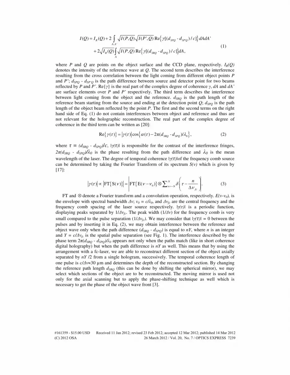
where P and Q are points on the object surface and the CCD plane, respectively. IR(Q)
denotes the intensity of the reference wave at Q. The second term describes the interference
resulting from the cross correlation between the light coming from different object points P
and P’; dSPQ - dSP’Q is the path difference between source and detector point for two beams
reflected by P and P’. Re{γ} is the real part of the complex degree of coherence γ, dA and dA’
are surface elements over P and P’ respectively. The third term describes the interference
between light coming from the object and the reference. dSRQ is the path length of the
reference beam starting from the source and ending at the detection point Q; dSPQ is the path
length of the object beam reflected by the point P. The first and the second terms on the right
hand side of Eq. (1) do not contain interferences between object and reference and thus are
not relevant for the holographic reconstruction. The real part of the complex degree of
coherence in the third term can be written as [20]:
{ } { }0Re ( ) ( ) cos ( ) 2π( )/ ,SRQ SPQd - dγ τ γ τ α τ λ= − (2)
where τ = (dSRQ - dSPQ)/c, |γ(τ)| is responsible for the contrast of the interference fringes,
2π(dSRQ - dSPQ)/λ0 is the phase resulting from the path difference and λ0 is the mean
wavelength of the laser. The degree of temporal coherence |γ(τ)|of the frequency comb source
can be determined by taking the Fourier Transform of its spectrum S(ν) which is given by
[17]:
{ } { }0( ) FT S( ) FT E( ) .N
n Nfc
nγ τ ν ν ν δ τ
ν=−
∝ = − ⊗ − ∆
∑ (3)
FT and ⊗ denote a Fourier transform and a convolution operation, respectively. E(ν-ν0), is
the envelope with spectral bandwidth ∆ν; ν0 = c/λ0, and ∆νfc are the central frequency and the
frequency comb spacing of the laser source respectively. |γ(τ)| is a periodic function,
displaying peaks separated by 1/∆νfc. The peak width (1/∆ν) for the frequency comb is very
small compared to the pulse separation (1/∆νfc). We may consider that |γ(τ)| = 0 between the
pulses and by inserting it in Eq. (2), we may obtain interference between the reference and
object wave only when the path difference (dSRQ - dSPQ) is equal to nY, where n is an integer
and Y = c/∆νfc is the spatial pulse separation (see Fig. 1). The interference described by the
phase term 2π(dSRQ - dSPQ)/λ0 appears not only when the paths match (like in short coherence
digital holography) but when the path difference is nY as well. This means that by using the
arrangement with a fc-laser, we are able to reconstruct different section of the object axially
separated by nY /2 from a single hologram, successively. The temporal coherence length of
one pulse is c/∆ν≈30 µm and determines the depth of the reconstructed section. By changing
the reference path length dSRQ (this can be done by shifting the spherical mirror), we may
select which sections of the object are to be reconstructed. The moving mirror is used not
only for the axial scanning but to apply the phase-shifting technique as well which is
necessary to get the phase of the object wave front [3].
#161359 - $15.00 USD Received 11 Jan 2012; revised 23 Feb 2012; accepted 12 Mar 2012; published 14 Mar 2012(C) 2012 OSA 26 March 2012 / Vol. 20, No. 7 / OPTICS EXPRESS 7239

beamsplitter
camera
fc-laser
object
scan (t)
telescope spherical mirror
Y/2
Y
Y/2
O
Fpulse ipulse i+1
Rb-atomic
clockbeamsplitter
camera
fc-laserfc-laser
object
scan (t)
telescope spherical mirror
Y/2
Y
Y/2
O
Fpulse ipulse i+1
Rb-atomic
clock
Fig. 1. Experimental set-up for lensless short coherence digital holography [19] with a
femtosecond fc-laser at 532 nm, referenced to a Rubidium atomic clock.
3. Experimental results
The Frequency Comb used in the experiment is based on an Yb-doped femtosecond fiber-
laser, capable of generating sub-100 fs pulses with a repetition rate of 250 ± 1 MHz and a
central wavelength of λ0 = 1064 nm. The comb’s repetition rate and offset frequency is locked
to a rubidium atomic clock with an accuracy of 5 parts in 1011
. Using Fabry-Pérot-cavities
(FPC), the repetition rate of the laser can be increased by a multiple m of the fundamental
repetition rate [16]. For the experiments described in this paper, the filter ratio was choosen to
be m = 24 resulting in ∆νfc = 5.994 GHz (Y = 50.00 mm). After subsequent amplification in an
Yb-doped fiber amplifier and frequency doubling in a LBO crystal, the resulting laser
specifications are as follows: pulse duration 100 fs, λ0 = 532 nm, output power 50 mW,
∆ν = 10 THz (∆λ≈10 nm).
The object used for our investigations is a metallic cone with half angle of 12°, 80 mm
coned length and 36 mm base diameter, see. Figure 2(a). A CCD camera (SVS16000) with
4896 x 3280 pixels, pixel size ∆ x∆ = 7.4 x 7.4 µm2, has been used to record the digital
holograms which are transferred to the computer by a GigE interface. A reconstruction
without aliasing, is possible only when the sampling theorem (see e.g. Refs. 21) is satisfied,
this requires to have a band limited intensity distribution with bandwidth less than 1/(2∆)
inside the hologram. This condition is satisfied when the speckle size on the sensor is equal to
or larger than the pixel size ∆. In the experiment the distance between the sensor and the
object was z = 500 mm and the diameter of the illuminated surface D = 36 mm, thus the
speckle size was equal to the pixel size i.e. λ0z/D = 7.4 µm = ∆. The reference wave
originates from the point F, located approximately 500 mm away from the sensor and thus the
fringes obtained from the interference between the light coming from the object and the
reference have a period which is greater than 2∆. All the conditions for a reconstruction
without aliasing are satisfied. In order to speed up the procedure, only those holograms which
were recorded by 3000 x 3000 pixels and covering a detector area L x L = 22 x 22 mm2 have
been evaluated. The lateral resolution of the reconstruction and the depth of field are given by
RL = λ0/NA = 12 µm, and DF = λ0/NA2 = 274 µm, where the numerical aperture in our case
can be approximated by NA = L/z = 0.044.
The Figs. 2(b), 2(c), 2(d) show three numerical reconstructions obtained from a single
hologram with digital focusing in three different planes, each separated by Y/2 = 25.00 mm.
In Fig. 2(b), we see a ring with small radius at the center which corresponds to the
intersection of the cone with a plane (we will call this PL-1), in the same figure there are two
other rings with larger radius describing intersections of the object with two planes (PL-2,
#161359 - $15.00 USD Received 11 Jan 2012; revised 23 Feb 2012; accepted 12 Mar 2012; published 14 Mar 2012(C) 2012 OSA 26 March 2012 / Vol. 20, No. 7 / OPTICS EXPRESS 7240

PL-3) axially spaced by 25.00 mm and 50.00 mm with respect to PL-1. The three rings appear
because we use a frequency comb, in this case |γ(τ)| is a periodic function (see Eq. (3))
displaying peaks spatially separated by Y = 50 mm, between the peaks |γ(τ)| = 0. According
to Eq. (2) this |γ(τ)| allows to obtain interference between object and reference beam only
when the path difference (dSRQ - dSPQ) is equal to nY, by processing the hologram we are able
to reconstruct sections of the object axially separated by Y/2. In Fig. 2(b), the intersection
lines of the cone with PL-2 and PL-3 are blurred since the reduced depth of focus does not
allow to reconstruct sharp profiles located at different planes. Figures 2(c) and 2(d) show that
digital focusing of the hologram allows to obtain sharp profile lines at PL-3 and PL-2,
respectively. Notice that along with the three rings some unwanted reconstructions are also
visible in the figures (in particular in Fig. 2(b) we have an unwanted ring as well, displaced
with respect to the center). The artifacts are due to the reflections inside the beamsplitter plate
or the camera protection glass, and could be removed by using components with antireflection
coatings. The multiple section reconstructions at well-defined axially spaced planes can be
obtained only by the fc-laser, and Fig. 2 clearly shows the advantage of using such a light
source. A conventional short coherence or a femtosecond laser provides single sectioning
only. Only the planes where the reconstructions are focused provide sharp profile lines, and
thus the axial location of the intersection between the object and a given plane can be
identified by digital focusing.
80
12
°
ø 36
25.0
02
5.0
0
(a)
(b)
(c) (d)
Pl-1
Pl-2
Pl-3
80
12
°
ø 36
25.0
02
5.0
0
(a)
(b)
(c) (d)
Pl-1
Pl-2
Pl-3
Fig. 2. a) Schematic of the rough metallic cone used for the investigations. b), c), d)
Reconstruction of holograms at three different planes separated by 25.00 mm.
The three reconstructed profiles obtained from a single hologram (see Fig. 2) do not allow
to get the complete 3-d shape of the object. More sections would be necessary for this
purpose which could be obtained by using a fc-laser having larger frequency comb spacing
and thus a reduced axial plane separation Y/2.
The scanning method was used to obtain more section profiles. The path length of the
reference beam was changed by shifting the reference mirror, and a sequence of holograms
was recorded. Such holograms allow the reconstruction of different sections of the object.
Figure 3 shows the 3-d shape reconstructed from 17 holograms recorded by displacing the
reference mirror by 1 mm between each hologram. Each of the 17 holograms contains at least
two profile rings (some of them three), for the evaluation only two rings have been used. Due
to the limited range of the moving stage (17 mm was the maximum displacement), the data in
the reconstructed cone volume between 17 mm and 25 mm are missing. The automatic
identification of the profile lines in the reconstructed holograms was done by using threshold
#161359 - $15.00 USD Received 11 Jan 2012; revised 23 Feb 2012; accepted 12 Mar 2012; published 14 Mar 2012(C) 2012 OSA 26 March 2012 / Vol. 20, No. 7 / OPTICS EXPRESS 7241

filters. We already pointed out that the reconstructed wavefronts contain noise (see e.g.
Fig. 2), in some cases this can create difficulties in the identification process of the contour
lines. The axial resolution is given by the step of the scanning and thus more holograms are
needed for improving the accuracy which is limited by the temporal coherence length of one
laser pulse i.e. c/∆ν ≈30 µm. The measurement uncertainty is given by different contributions
(set-up geometry, detector noise, unwanted interferences) and was approximately ± 100 µm
in our experiment.
he
ight
[mm
]
y [mm] x [mm]25
he
ight
[mm
]
y [mm] x [mm]25
Fig. 3. Numerical reconstruction of a part of the rough metallic continuous cone with a half
angle of 12°.
4. Conclusion
The results show that a set-up based on digital holography using a fc-laser can be used for
simultaneous multiple optical sectioning, such sectioning cannot be obtained by any other
holographic method. Here the measurement time can be reduced by a factor k, where k is the
number of the reconstructed sections in one hologram. In the next few years, we expect the
availability of fc-lasers based on microresonators [11,12] with larger frequency spacing ∆νfc
in the range of 1 THz. In this case the distance (Y/2) of the sectioning can be reduced to the
100 µm range. This will allow us to use the optical sectioning method for technical and
biological applications in microscopy. New developments of fc lasers will allow us to change
the frequency spacing by tuning the Fabry Perot cavity in the laser system; this will help us to
avoid the scan in the reference arm. Furthermore, by using powerful frequency comb lasers
[22], the multilevel optical sectioning method can also be extended to larger objects which
may be located far away from the detecting system (airplanes, buildings or power plant
components). The principle of dual frequency comb holography [19] can make a contribution
to absolute 3-d measurements. By using micro-optical elements or optical fibers, a rather
compact setup can be built.
Acknowledgment
The authors would like to thank Mr. Andreas Lorenz for skilled manufacturing of the test
object.
#161359 - $15.00 USD Received 11 Jan 2012; revised 23 Feb 2012; accepted 12 Mar 2012; published 14 Mar 2012(C) 2012 OSA 26 March 2012 / Vol. 20, No. 7 / OPTICS EXPRESS 7242