shipboard-helicopter operational procedures manual
TRANSCRIPT
Shipboard-Helicopter Operational
Procedures Manual
COMDTINST M3710.2D

Change Number Date of Change Date Entered by Whom EnteredRECORD OF CHANGES
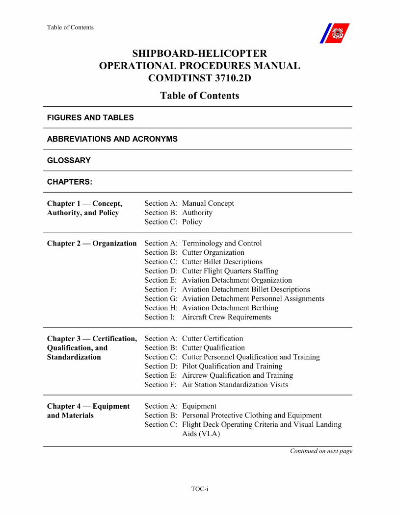
Table of Contents
TOC-i
SHIPBOARD-HELICOPTER OPERATIONAL PROCEDURES MANUAL
COMDTINST 3710.2D Table of Contents
FIGURES AND TABLES
ABBREVIATIONS AND ACRONYMS
GLOSSARY
CHAPTERS:
Chapter 1 — Concept, Authority, and Policy
Section A: Manual Concept Section B: Authority Section C: Policy
Chapter 2 — Organization
Section A: Terminology and Control Section B: Cutter Organization Section C: Cutter Billet Descriptions Section D: Cutter Flight Quarters Staffing Section E: Aviation Detachment Organization Section F: Aviation Detachment Billet Descriptions Section G: Aviation Detachment Personnel Assignments Section H: Aviation Detachment Berthing Section I: Aircraft Crew Requirements
Chapter 3 — Certification, Qualification, and Standardization
Section A: Cutter Certification Section B: Cutter Qualification Section C: Cutter Personnel Qualification and Training Section D: Pilot Qualification and Training Section E: Aircrew Qualification and Training Section F: Air Station Standardization Visits
Chapter 4 — Equipment and Materials
Section A: Equipment Section B: Personal Protective Clothing and Equipment Section C: Flight Deck Operating Criteria and Visual Landing Aids (VLA)
Continued on next page
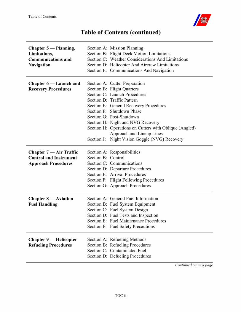
Table of Contents
TOC-ii
Table of Contents (continued)
Chapter 5 — Planning, Limitations, Communications and Navigation
Section A: Mission Planning Section B: Flight Deck Motion Limitations Section C: Weather Considerations And Limitations Section D: Helicopter And Aircrew Limitations Section E: Communications And Navigation
Chapter 6 — Launch and Recovery Procedures
Section A: Cutter Preparation Section B: Flight Quarters Section C: Launch Procedures Section D: Traffic Pattern Section E: General Recovery Procedures Section F: Shutdown Phase Section G: Post-Shutdown Section H: Night and NVG Recovery Section H: Operations on Cutters with Oblique (Angled)
Approach and Lineup Lines Section J: Night Vision Goggle (NVG) Recovery
Chapter 7 — Air Traffic Control and Instrument Approach Procedures
Section A: Responsibilities Section B: Control Section C: Communications Section D: Departure Procedures Section E: Arrival Procedures Section F: Flight Following Procedures Section G: Approach Procedures
Chapter 8 — Aviation Fuel Handling
Section A: General Fuel Information Section B: Fuel System Equipment Section C: Fuel System Design Section D: Fuel Tests and Inspection Section E: Fuel Maintenance Procedures Section F: Fuel Safety Precautions
Chapter 9 — Helicopter Refueling Procedures
Section A: Refueling Methods Section B: Refueling Procedures Section C: Contaminated Fuel Section D: Defueling Procedures
Continued on next page
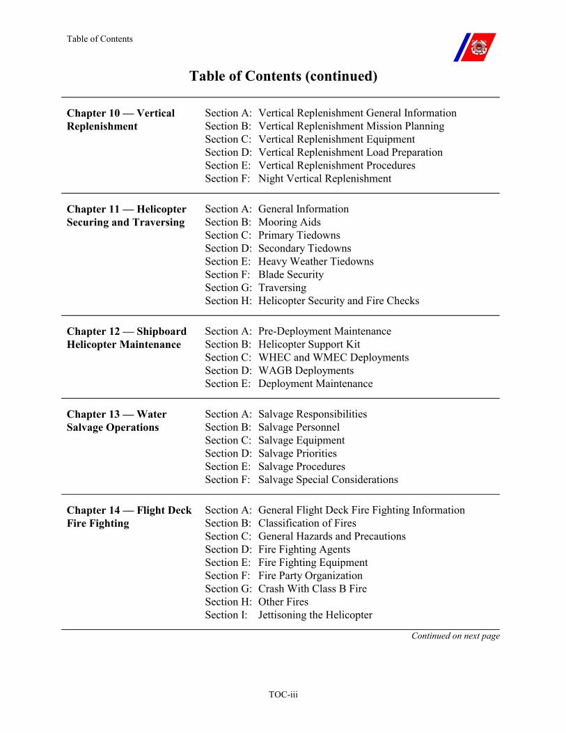
Table of Contents
TOC-iii
Table of Contents (continued)
Chapter 10 — Vertical Replenishment
Section A: Vertical Replenishment General Information Section B: Vertical Replenishment Mission Planning Section C: Vertical Replenishment Equipment Section D: Vertical Replenishment Load Preparation Section E: Vertical Replenishment Procedures Section F: Night Vertical Replenishment
Chapter 11 — Helicopter Securing and Traversing
Section A: General Information Section B: Mooring Aids Section C: Primary Tiedowns Section D: Secondary Tiedowns Section E: Heavy Weather Tiedowns Section F: Blade Security Section G: Traversing Section H: Helicopter Security and Fire Checks
Chapter 12 — Shipboard Helicopter Maintenance
Section A: Pre-Deployment Maintenance Section B: Helicopter Support Kit Section C: WHEC and WMEC Deployments Section D: WAGB Deployments Section E: Deployment Maintenance
Chapter 13 — Water Salvage Operations
Section A: Salvage Responsibilities Section B: Salvage Personnel Section C: Salvage Equipment Section D: Salvage Priorities Section E: Salvage Procedures Section F: Salvage Special Considerations
Chapter 14 — Flight Deck Fire Fighting
Section A: General Flight Deck Fire Fighting Information Section B: Classification of Fires Section C: General Hazards and Precautions Section D: Fire Fighting Agents Section E: Fire Fighting Equipment Section F: Fire Party Organization Section G: Crash With Class B Fire Section H: Other Fires Section I: Jettisoning the Helicopter
Continued on next page
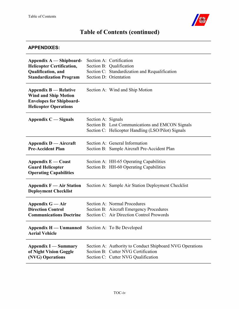
Table of Contents
TOC-iv
Table of Contents (continued)
APPENDIXES:
Appendix A — Shipboard-Helicopter Certification, Qualification, and Standardization Program
Section A: Certification Section B: Qualification Section C: Standardization and Requalification Section D: Orientation
Appendix B — Relative Wind and Ship Motion Envelopes for Shipboard-Helicopter Operations
Section A: Wind and Ship Motion
Appendix C — Signals Section A: Signals Section B: Lost Communications and EMCON Signals Section C: Helicopter Handling (LSO/Pilot) Signals
Appendix D — Aircraft Pre-Accident Plan
Section A: General Information Section B: Sample Aircraft Pre-Accident Plan
Appendix E — Coast Guard Helicopter Operating Capabilities
Section A: HH-65 Operating Capabilities Section B: HH-60 Operating Capabilities
Appendix F — Air Station Deployment Checklist
Section A: Sample Air Station Deployment Checklist
Appendix G — Air Direction Control Communications Doctrine
Section A: Normal Procedures Section B: Aircraft Emergency Procedures Section C: Air Direction Control Prowords
Appendix H — Unmanned Aerial Vehicle
Section A: To Be Developed
Appendix I — Summary of Night Vision Goggle (NVG) Operations
Section A: Authority to Conduct Shipboard NVG Operations Section B: Cutter NVG Certification Section C: Cutter NVG Qualification
Figures and Tables
1
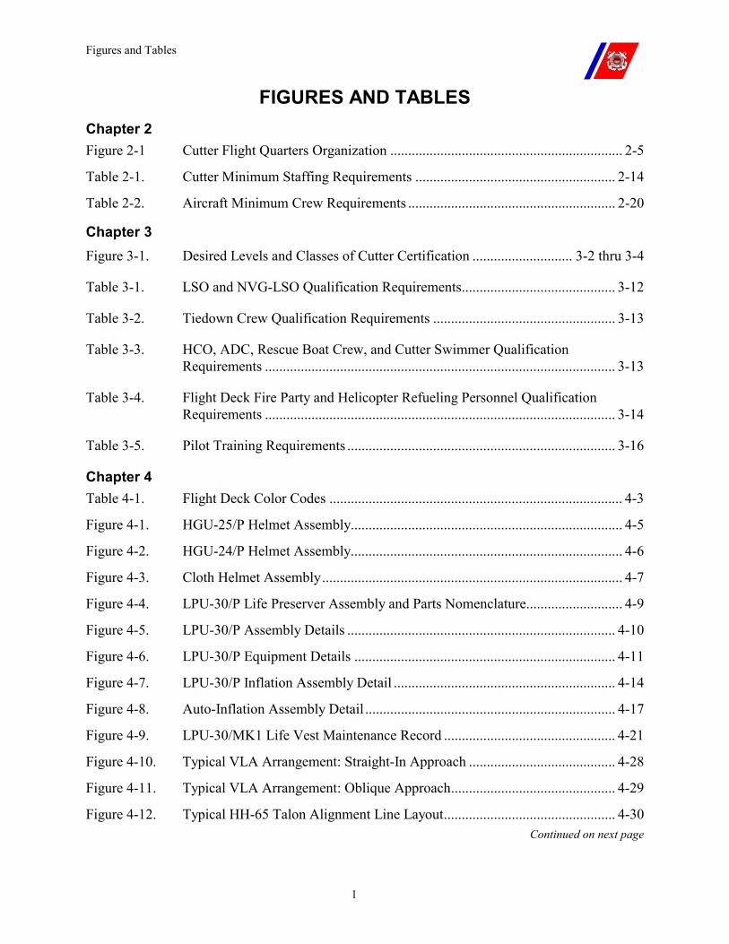
FIGURES AND TABLES
Chapter 2 Figure 2-1 Cutter Flight Quarters Organization ................................................................. 2-5
Table 2-1. Cutter Minimum Staffing Requirements ........................................................ 2-14
Table 2-2. Aircraft Minimum Crew Requirements .......................................................... 2-20
Chapter 3 Figure 3-1. Desired Levels and Classes of Cutter Certification ............................ 3-2 thru 3-4
Table 3-1. LSO and NVG-LSO Qualification Requirements........................................... 3-12
Table 3-2. Tiedown Crew Qualification Requirements ................................................... 3-13
Table 3-3. HCO, ADC, Rescue Boat Crew, and Cutter Swimmer Qualification Requirements .................................................................................................. 3-13
Table 3-4. Flight Deck Fire Party and Helicopter Refueling Personnel Qualification Requirements .................................................................................................. 3-14
Table 3-5. Pilot Training Requirements ........................................................................... 3-16
Chapter 4 Table 4-1. Flight Deck Color Codes .................................................................................. 4-3
Figure 4-1. HGU-25/P Helmet Assembly............................................................................ 4-5
Figure 4-2. HGU-24/P Helmet Assembly............................................................................ 4-6
Figure 4-3. Cloth Helmet Assembly.................................................................................... 4-7
Figure 4-4. LPU-30/P Life Preserver Assembly and Parts Nomenclature........................... 4-9
Figure 4-5. LPU-30/P Assembly Details ........................................................................... 4-10
Figure 4-6. LPU-30/P Equipment Details ......................................................................... 4-11
Figure 4-7. LPU-30/P Inflation Assembly Detail .............................................................. 4-14
Figure 4-8. Auto-Inflation Assembly Detail ...................................................................... 4-17
Figure 4-9. LPU-30/MK1 Life Vest Maintenance Record ................................................ 4-21
Figure 4-10. Typical VLA Arrangement: Straight-In Approach ......................................... 4-28
Figure 4-11. Typical VLA Arrangement: Oblique Approach.............................................. 4-29
Figure 4-12. Typical HH-65 Talon Alignment Line Layout................................................ 4-30 Continued on next page
Figures and Tables
2
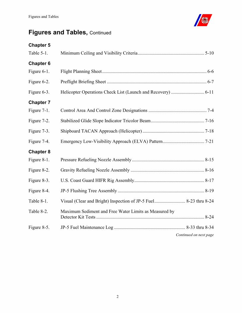
Figures and Tables, Continued
Chapter 5 Table 5-1. Minimum Ceiling and Visibility Criteria........................................................ 5-10
Chapter 6 Figure 6-1. Flight Planning Sheet ........................................................................................ 6-6
Figure 6-2. Preflight Briefing Sheet .................................................................................... 6-7
Figure 6-3. Helicopter Operations Check List (Launch and Recovery) ............................ 6-11
Chapter 7 Figure 7-1. Control Area And Control Zone Designations ................................................. 7-4
Figure 7-2. Stabilized Glide Slope Indicator Tricolor Beam............................................. 7-16
Figure 7-3. Shipboard TACAN Approach (Helicopter) .................................................... 7-18
Figure 7-4. Emergency Low-Visibility Approach (ELVA) Pattern................................... 7-21
Chapter 8 Figure 8-1. Pressure Refueling Nozzle Assembly............................................................. 8-15
Figure 8-2. Gravity Refueling Nozzle Assembly .............................................................. 8-16
Figure 8-3. U.S. Coast Guard HIFR Rig Assembly........................................................... 8-17
Figure 8-4. JP-5 Flushing Tree Assembly ......................................................................... 8-19
Table 8-1. Visual (Clear and Bright) Inspection of JP-5 Fuel.......................... 8-23 thru 8-24
Table 8-2. Maximum Sediment and Free Water Limits as Measured by Detector Kit Tests ........................................................................................... 8-24
Figure 8-5. JP-5 Fuel Maintenance Log ............................................................ 8-33 thru 8-34 Continued on next page
Figures and Tables
3
Figures and Tables, Continued
Chapter 9 Figure 9-1. HIFR Rig Sample Adapter .............................................................................. 9-11
Figure 9-2. Sample Adaptor Location ............................................................................... 9-11
Figure 9-3. HIFR Rig to D1 Nozzle Adaptor .................................................................... 9-12
Figure 9-4. HIFR Rig to D1 Nozzle Configuration ........................................................... 9-12
Figure 9-5. HIFR Hose Layout .......................................................................................... 9-17
Figure 9-6. HIFR Checklist ............................................................................................... 9-21
Chapter 10 Figure 10-1. Nest Type Tubular Steel Pallet ....................................................................... 10-4
Figure 10-2. Hoisting Sling Hooked to Cargotainer (Four (4) Attachment Points) ............ 10-5
Figure 10-3. Nylon Cargo Net, Mk 16 Mod 0 Cargo Pallet Net, and Becket...................... 10-6
Figure 10-4. Adjustable Pallet Sling.................................................................................... 10-7
Figure 10-5. Mk 105 Hoisting Sling (Multi-Pole Pendant) Attached To Two Adjustable Pallet Slings .................................................................................................... 10-8
Figure 10-6. Hoisting Sling Mk 128.................................................................................... 10-9
Figure 10-7. Cargo Hooks ................................................................................................. 10-10
Figure 10-8. Securing Cargo Net With Loose Cargo ........................................................ 10-13
Figure 10-9. Adjustable Pallet Sling Mk 85, 86, 87, and 100 ........................................... 10-15
Figure 10-10. Operation of Safety Hook ............................................................................. 10-16
Figure 10-11. Stacking Pallets in Packs .............................................................................. 10-23
Figure 10-12. Positioning Pallets in Net.............................................................................. 10-24
Figure 10-13. Sling and Pendants........................................................................................ 10-25
Figure 10-14. HCO VERTREP Checklist ........................................................................... 10-29
Continued on next page
Figures and Tables
4
Figures and Tables, Continued
Chapter 11 Figure 11-1. Wind-Sea State Table ..................................................................................... 11-3
Figure 11-2. HH-65 Primary Tiedowns............................................................................... 11-8
Figure 11-3. HH-65 Chocks And Chains ............................................................................ 11-9
Figure 11-4. HH-65 Secondary Tiedowns ........................................................................... 11-9
Figure 11-5. HH-65 Heavy Weather Tiedowns................................................................. 11-10
Figure 11-6. HH-60J Primary Tiedowns ........................................................................... 11-11
Figure 11-7. HH-60J Secondary Tiedowns ....................................................................... 11-11
Figure 11-8. HH-60J Chocks and Chains .......................................................................... 11-12
Figure 11-9. Traversing Crew Organization...................................................................... 11-29
Chapter 14 Figure 14-1. HH-65 Emergency Exits ................................................................................. 14-5
Figure 14-2. HH-60J Emergency Entrances and Exits ........................................ 14-6 thru 14-7
Appendix B Figure B-1. Launch and Recovery Limitations (General) ....................................................B-4
Figure B-2. HH-65/WMEC 210 Day Launch and Recovery Limitations ............................B-5
Figure B-3. HH-65/WMEC 210 Night Launch and Recovery Limitations..........................B-6
Figure B-4. HH-65/WMEC 270 Day Launch and Recovery Limitations ............................B-7
Figure B-5. HH-65/WMEC 270 Night Launch and Recovery Limitations..........................B-8
Figure B-6. HH-65/WMEC 282 Day Launch and Recovery Limitations ............................B-9
Figure B-7. HH-65/WMEC 282 Night Launch and Recovery Limitations........................B-10
Figure B-8. HH-65/WMEC 378 Day Launch and Recovery Limitations (Oblique Landing Lineup Line) ......................................................................B-11
Continued on next page
Figures and Tables
5
Figures and Tables, Continued
Appendix B (continued) Figure B-9. HH-65/WMEC 378 Night Launch and Recovery Limitations
(Oblique Landing Lineup Line) ......................................................................B-12
Figure B-10. HH-65/WAGB 399 Day Launch and Recovery Limitations ..........................B-13
Figure B-11. HH-65/WAGB 399 Night Launch and Recovery Limitations........................B-14
Figure B-12. HH-65/ WAGB 399 Athwartship Launch and Recovery Limitations ............B-15
Figure B-13. HH-65/ WAGB 420 Day Launch and Recovery Limitations .........................B-16
Figure B-14. HH-65/ WAGB 420 Night Launch and Recovery Limitations.......................B-17
Figure B-15. HH-65/ WAGB 420 Athwartship Launch and Recovery Limitations ............B-18
Figure B-16. Maximum Wind for Rotor Engagement/Disengagement (HH-65).................B-19
Figure B-17. SH-2F/WHEC 378 Day Launch and Recovery Limitations (Oblique Landing Lineup Line) ......................................................................B-20
Figure B-18. SH-2F/WHEC 378 Night Launch and Recovery Limitations (Oblique Landing Lineup Line) ......................................................................B-21
Figure B-19. SH-2F/WHEC 378 Day Degraded AFCS Launch and Recovery Limitations (Oblique Landing Line-Up Line).................................................B-22
Figure B-20. SH-2F/WHEC 378 Night Degraded AFCS Launch and Recovery Limitations (Oblique Landing Line-Up Line).................................................B-23
Figure B-21. HH-60J/WMEC 270 Day Launch and Recovery Limitations.........................B-24
Figure B-22. HH-60J/WMEC 270 Night Launch and Recovery Limitations ......................B-25
Figure B-23. HH-60J/WMEC 282 Day Launch and Recovery Limitations.........................B-26
Figure B-24. HH-60J/WMEC 282 Night Launch and Recovery Limitations ......................B-27
Figure B-25. HH-60J/WAGB 420 Day Launch and Recovery Limitations.........................B-28
Figure B-26. HH-60J/WAGB 420 Night Launch and Recovery Limitations ......................B-29 Continued on next page
Figures and Tables
6
Figures and Tables, Continued
Appendix C Figure C-1. Helicopter Handling (LSO/Pilot) Signals ........................................ C-4 thru C-20
Appendix D Figure D-1. Sample Aircraft Pre-Accident Plan....................................................D-4 thru D-9
Appendix E Table E-1. HH-65 Electronics Equipment ..........................................................................E-4
Table E-2. HH-60J Electronics Equipment ........................................................................E-7
Appendix F Figure F-1. Air Station Deployment Checklist ...................................................... F-2 thru F-4
Appendix G Figure G-1. Aircraft Clock Format...................................................................................... G-5
Figure G-2. Air Direction Control Prowords....................................................................... G-9
Abbreviations and Acronyms
1
ABBREVIATIONS AND ACRONYMS
A
ADC Air Direction Controller
ADCON Administrative Control
ADF Automatic Direction Finder
AEL Allowance Equipage List
AEL MK I Freewater Fuel Detector Kit
AEL MK III Contaminated Fuel Detector Kit
AFCS Automatic Heading Retention System on HH-65A Helicopters
AFFF Aqueous Film Forming Foam
AFR Air Force Regulation
AGL Above Ground Level
AIA Auto-Inflation Assembly
APU Auxiliary Power Unit
ASAC Anti-Submarine Air Controller
ASIR Aviation Ship Installation Representative
ASR Air Surveillance Radar
ASW Anti-Submarine Warfare
ATC Air Traffic Control
ATC Mobile Aviation Training Center (Mobile)
AVDET Aviation Detachment
AVGAS Aviation Gasoline
AWL Above Water Level
Continued on next page
Abbreviations and Acronyms
2
ABBREVIATIONS AND ACRONYMS, Continued
B
BMOW Boatswain’s Mate of the Watch
BRC Base Recovery Course
C
CATCH Computer Approach to a Coupled Hover
CCR Closed-Circuit Refueling
CCTV Closed Circuit Television
CIC Combat Information Center
CINC Commander in Chief (Navy)
CIWS Close-In Weapons System
CO Commanding Officer
COMSEC Communications Security
CPO Chief Petty Officer
CSC Combat Support Center
CV Aircraft Carrier
CVN Aircraft carrier, Nuclear powered
D
DDHA A mnemonic device that outlines how traffic advisories shall be passed. DDHA is: D for Direction of the air traffic from the controlled aircraft; D for Distance of the air traffic from the controlled aircraft in nautical miles; H for cardinal Heading of the air traffic; and A for Altitude of the air traffic.
DF Direction Finder
DME Distance Measuring Equipment
DoD Department of Defense
DR Dead Reckoning
Continued on next page
Abbreviations and Acronyms
3
ABBREVIATIONS AND ACRONYMS, Continued
E
ELVA Emergency Low-Visibility Approach
EMCON Emission Control
EMI Electromagnetic Interference
ETA Estimated Time of Arrival
ETR Estimated Time of Recovery
F
FAF Final Approach Fix
FDD Flight Deck Director
FOD Foreign Object Debris or Damage
FLICON ONE Flight Quarters Condition One
FLICON TWO Flight Quarters Condition Two
FLICON THREE
Flight Quarters Condition Three
FLICON FOUR Flight Quarters Condition Four
FLIR Forward-Looking Infrared
FSII Fuel System Icing Inhibitor
G GPS
Global Positioning System
H HCO Helicopter Control Officer
HCS Helicopter Control Station
HIFR Helicopter In-Flight Refueling
HPS A mnemonic device for an aircraft checkout list. HPS is H for Heading, P for Pigeons, and S for State.
Continued on next page
Abbreviations and Acronyms
4
ABBREVIATIONS AND ACRONYMS, Continued HS Health Services Technician
HSK Helicopter Support Kit
I IAF Initial Approach Fix
IAP Instrument Approach Procedures
IFF Identification Friend or Foe
IFR Instrument Flight Rules
IMC Instrument Meteorological Conditions
ICS Interphone Communication System
IP Instructor Pilot
ITO Instrument Takeoff
L LINT A mnemonic device for listing emergency information. LINT is L for
Location, I for Intention, N for Needs, and T for Tell.
L/E Law Enforcement
LORAN Long Range Aids to Navigation
LSO Landing Signal Officer
M MAB Mishap Analysis Board
MAP Missed Approach Point
MATCH Manual Approach to a Coupled Hover
MDL Maintenance Due List
MEDEVAC Medical Evacuation
MOA Memorandum of Agreement
Continued on next page
Abbreviations and Acronyms
5
ABBREVIATIONS AND ACRONYMS, Continued MSL Mean Sea Level
N NATO North Atlantic Treaty Organization
NATOPS Naval Air Training and Operational Procedures Standardization
NAVAIR Naval Air Systems Command
NAVAIRWAR-CENACDIVLKE
Naval Air Warfare Center, Aircraft Division Lakehurst
NDB Non-Directional Beacon
NHC NATO High Capacity helicopter in flight refueling rig
NI North Island helicopter in flight refueling rig. The original Wiggins HIFR rig
NICAD Nickel Cadmium battery
NSN National Stock Number
NSO Night Safety Officer
NVD Night Vision Device
NVG Night Vision Goggles
O OBA Oxygen Breathing Apparatus
OOD Officer of the Deck
OPAREA Operating Area
OPCON Operational Control
OPSEC Operational Security
OSL On-Scene Leader
OTHB Over the Horizon Boat Continued on next page
Abbreviations and Acronyms
6
ABBREVIATIONS AND ACRONYMS, Continued
P PATCH Precision Approach to a Coupled Hover
PIC Pilot in Command
PKP Purple K Powder
PLANET An acronym that corresponds to initial communication at aircraft check-in. SLANET is: P for Pilot reports souls on board and fuel state; L for Location of the aircraft relative to the ship; A for Altimeter setting; N for No communications; E for Execute and expect; and T for Tell.
PMS Preventive Maintenance System
POPDIV Polar Operations Division
POB Persons on Board
PQS Personnel Qualification Standards
PSIG Pounds per Square Inch, Gauged
PUI Pilot Under Instruction
R RAST Recovery Assist Secure and Traverse (a Navy tiedown system)
RATT Radio Teletype
RD Radarman
RF Radio Frequency
RHIB Rigid Hull Inflatable Boat
ROE Rules of Engagement
S SAR Search and Rescue
SGSI Stabilized Glide Slope Indicator
Continued on next page
Abbreviations and Acronyms
7
ABBREVIATIONS AND ACRONYMS, Continued SLAP Solar Lunar Almanac Program (NVD Ops)
SOP Standard Operating Procedure
SOPA Senior Officer Present Afloat
Surfactants Surface Active Agents
T TACAN Tactical Air Navigation
TACON Tactical Control
TALON An automatic tiedown system on HH-65 helicopters.
T&G Touch and Go.
U USC United States Code
V
VERTREP Vertical Replenishment
VFR Visual Flight Rules
VLA Visual Landing Aid
VMC Visual Meteorological Conditions
VOR Very High Frequency Omnidirectional Range Station
W WAGB Coast Guard Polar Class Icebreaker
WHEC Coast Guard High Endurance Cutter
WMEC Coast Guard Medium Endurance Cutter
Glossary
GLOSSARY-1
GLOSSARY
A
Abort To prematurely terminate the maneuver or mission in progress, usually because to continue would abnormally hazard the aircraft or the cutter.
Administrative Control (ADCON)
Direction or exercise of authority over subordinate or other organizations in respect to administrative matters, such as personnel management, supplies, services, and other matters not included in organizational missions of the subordinate or other organizations.
Air Capable Ship All ships other than CV/CVN or LPH/LHA/LHD from which aircraft can take off, be recovered, or routinely receive and transfer logistic support.
Allowance Equipage List (AEL)
A list that includes certain standard equipment required aboard cutters for flight operations.
Approach
The maneuvers performed and flight path followed to fly the helicopter from some point in space to a position over the deck where a landing can be accomplished. In general, an approach is considered to commence when the aircraft starts to descend from its last level flight altitude to the landing spot. The terms “180-degree approach,” “90-degree approach,” etc., indicate the number of degrees the aircraft must turn to reach the final approach course.
Aqueous Film Forming Foam (AFFF)
The primary flight deck fire fighting agent.
B
Bingo A term used by pilots to denote the point at which fuel becomes critical and return is imperative.
Base Recovery Course The ships magnetic heading for aircraft recovery.
Buffer Distance The distance between the tip of the turning main rotor disk and the nearest fixed obstruction above a specified height, depending on the type of helicopter.
B/2 Fuel System Icing Inhibitor Test Kit
Fuel test kit that contains a B/2 refractometer and equipment to measure the FSII content of the fuel.
Bonding The act of providing an electrical connection between two objects; i.e., aircraft and cutter, cutter and refueling truck.
Glossary
GLOSSARY-2
C
Carter Nozzle The fuel nozzle used for pressure fueling of aircraft.
Combined Contaminated Fuel Detector (CCFD)
A device consisting of the MK I Freewater Detector (FWD) and MK III Contaminated Fuel Detector (CFD) used to test fuel for both water and particulate contamination.
Closed Circuit Refueling Nozzle (CCR)
Pressure fueling nozzle used for helicopter in flight refueling operations.
Certified A cutter is certified as being materially ready for flight operations when it has passed required certification inspections.
Contaminated Fuel Detector (CFD) (MK III)
A device that tests aviation fuel for particulate contamination.
Clear and Bright A visual inspection of aviation fuel. Clear refers to clean fuel with no visible contamination or moisture. Bright refers to the fluorescent appearance of fuel that has no cloud or haze.
Clear Deck The condition that exists when the flight deck is free of obstacles and a helicopter landing is possible. This situation does not reflect the manning of flight quarters, and may exist when the cutter is not in complete readiness.
Clearance An authorization, given visually and/or verbally to the pilot, that an intended maneuver may be accomplished after ensuring that no known circumstance or situation will imperil the aircraft, other aircraft, the cutter, or personnel.
Closed Circuit Television (CCTV)
A system used to monitor flight deck operations from the Helicopter Control Officer (HCO) station on the bridge. CCTV remote monitors may also be installed in the combat information center or other locations.
Coalescer A two-stage JP-5 filter/separator.
Coarse and Fine Solid particles sometimes found in fuels that are larger than and smaller than 10 microns respectively. Generally, coarse particles can be seen with the naked eye. Fine particles, if in sufficient amounts, appear as haze or cloudiness in fuel.
Combat Information Center (CIC)
A term used on all cutter classes except for WMEC 270 class cutters, which use “Combat Support Center (CSC).”
Combat Support Center (CSC)
This term is used solely in connection with WMEC 270 class cutters, as opposed to the “CIC” aboard the other cutter classes.
Glossary
GLOSSARY-3
Composite Materials Strong, lightweight materials, usually reinforced with glass, carbon/graphite, or boron/tungsten fibers. These are used in lieu of heavier aluminum or metallic materials in the construction of modern aircraft.
Compressor Stall Loss of turbine engine power commonly associated with FOD and/or encrustation due to extended exposure to salt spray.
Control Zone A circular airspace with a radius of 5 nm around the ship that extends upward from mean sea level (MSL) to, and includes, 2,500 feet.
Crash Kit The tool kit required for aircraft entry in the event of a crash.
D
D-1 Single Point Refueling (SPR) nozzle with a 45-degree elbow.
D-1R Single Point Refueling (SPR) nozzle with a 45-degree elbow and a hose end pressure regulator.
DDHA A mnemonic device that outlines how traffic advisories shall be passed. DDHA is: D for Direction of the air traffic from the controlled aircraft; D for Distance of the air traffic from the controlled aircraft in nautical miles; H for cardinal Heading of the air traffic; and A for Altitude of the air traffic.
Deck Status Light A visual landing aid that indicates whether the helicopter is cleared to land, takeoff, start engines, and engage/disengage rotors, VERTREP or HIFR.
Delta Pattern A racetrack-shaped holding pattern used to conserve fuel while delaying the arrival of the aircraft.
Deployment The placement of a helicopter detachment on board a cutter in support of the ship’s general missions. Operational control (OPCON) and/or administrative control (ADCON) of a deployed detachment normally shifts to the cutter.
DiEGME DiEthylene Glycol Monomethyl Ether: Fuel System Icing Inhibitor (FSII) used in military aviation turbine fuels.
Detachment One or more helicopters, with associated personnel, embarked or deployed aboard a cutter.
Distance Measuring Equipment (DME)
Equipment installed with tactical air navigation (TACAN) sets, or separately, which provides visual indication of slant range from a TACAN or distance measuring equipment (DME) transmitter.
Glossary
GLOSSARY-4
Dry Fuel Fuel that contains no water
Dynamic Rollover
Dynamic rollover is the rolling motion of the helicopter fuselage around one wheel that has been effectively stopped from moving sideways. Factors that can contribute to its onset include flight deck motion, list, crosswind, wheel obstructions, lateral center of gravity (CG) displacement, main rotor thrust, and tail rotor thrust.
E
Eductor A manual proportioning device with a pickup tube mounted in-line between a salt water fire main outlet and a fire hose, which provides aqueous film forming foam (AFFF) for fire fighting when the pickup tube is inserted into a can of AFFF.
Embarkation The placement of a helicopter detachment on board a cutter for a specific mission or missions. Tactical control shifts to the cutter. OPCON and ADCON of an embarked detachment normally stay with the aircraft’s home unit.
Emergency As used in this Manual, a situation or condition that can reasonably be expected to result in the loss of life, acute physical pain, or ditching of the aircraft.
Emergency Low-Visibility Approach (ELVA)
An emergency instrument approach procedure to the ship designed to bring the helicopter into position for a safe landing.
Emission Control (EMCON)
The securing of all electromagnetic radiating equipment to avoid detection. Cutters frequently employ partial EMCON by minimizing radio communications.
Engage Rotor The positioning of appropriate controls to allow the rotor system to commence rotation with power supplied by the helicopter engine(s).
F
Flush The operation of pumping JP-5 fuel through the JP-5 fuel hose and fueling nozzle with fuel pumped from the service tank, through the service filter/separator, then the GO-NO-GO monitor, then the hose/fueling nozzle, and then returning to a storage tank via the fill connector using the service pump.
Foreign Object Damage/ Debris (FOD)
Normally used to describe any loose material that may be ingested into the engine or rotor blades, possibly causing damage to the helicopter and/or injury to personnel.
Foul Deck The condition that exists when a landing cannot be made because of obstacles or restrictions on the flight deck.
Glossary
GLOSSARY-5
Free Water Standard A color intensity comparator standard used in the Free Water Detector (FWD) for determining the free water content in aviation fuel.
FSII Fuel System Icing Inhibitor: A fuel additive that prevents formation of water ice and microbiological growth in the fuel.
FWD Free Water Detector (MK I: A device that measures the free water content of a fuel sample.
G
Gammon Fitting A common (trade) name applied to the jet test QD (quick disconnect) couplings used in refueling nozzles and other places to take fuel samples.
GO-NO-GO Fuel Monitor A canister containing several filter elements that is designed to remove both water and particulate contamination from fuel.
GO-NO-GO Fuse A filter element for the JP-5 GO-NO-GO monitor designed to prevent the passage of water and particulate contamination into the helicopter fuel system.
Grounding The act of providing an electrical connection between an object (e.g., aircraft and the ground (earth).
Ground Resonance A condition of geometric imbalance in helicopters caused by offset dynamic forces when the helicopter makes contact with the deck. If allowed to continue, destruction of the helicopter is imminent. Improper use of tiedowns can cause ground resonance.
H
HALON An electrically non-conductive gas used primarily in fighting Class B and C fires.
Heavy Weather Tiedowns Installed whenever excessive wind and/or motion is anticipated. This consists of the installation of additional secondary tiedowns.
Helicopter Control Officer (HCO)
The individual responsible for overall management of shipboard helicopter evolutions.
Helicopter Control Station (HCS)
A shipboard aircraft control tower, or, on ships not equipped with a control tower, the communications installation that serves as such.
Helicopter In-Flight Refueling (HIFR)
The procedure used to refuel helicopters while in a hover alongside the cutter.
Glossary
GLOSSARY-6
HIFR Rig A fueling rig which enables airborne (HIFR) fueling of most U.S. military helicopters. It consists of a short length of fuel hose with an attached metal saddle for hoisting and quick disconnect fittings for attachment to the fuel hose and helicopter.
Hover A condition in flight in which all relative or actual movement has ceased.
I
Illuminance The scientific name for the measurement of incident light. The unit of measurement is commonly the "footcandle" (lumens per square foot) in the English system and the "lux" (lumens per square meter) or "dekalux" (lux times 10) in the metric system. It is a photometric term that quantifies light incident on a surface or plane.
Instrument Approach An aircraft procedure that uses any combination of self-contained, land-based, or shipboard navigation and communication facilities to accomplish a safe instrument based descent to a point from which a visual landing can be made.
Instrument Flight Rules (IFR)
Flight rules established to facilitate safe navigation and separation of aircraft during instrument meteorological conditions (IMC).
Instrument Meteorological Conditions (IMC)
Meteorological conditions, expressed in terms of visibility, distance from clouds, and ceiling, during which constant reference to aircraft instruments is essential to maintain safe flight.
J
JP-5 Discussion of JP-5 fuel within the text of this manual shall pertain specifically to fuel used for the purpose of aviation fuel unless otherwise noted.
L
Landing Signal Officer (LSO)
The individual directly responsible for preparation and supervision of the flight deck during all flight operations.
Launch The complete sequence of events starting when flight quarters is set and ending when the helicopter is airborne and clear of the cutter.
Lift Off To take off or leave the deck in a controlled condition of flight.
Glossary
GLOSSARY-7
LUX The metric unit of measure for illuminance of a surface. One lux is equal to:
�� one lumen per square meter �� 0.093 foot-candles
The amount of light provided by an ordinary wax candle on a spherical surface with an area equal to one square meter one meter away from the flame.
M
Missed Approach Point (MAP)
In an instrument approach procedure, the missed approach point (MAP) is the point along the final approach course where missed approach procedures are initiated if the cutter or water surface is not in sight.
Manned After a specific FLICON is set all personnel are at their required stations.
MOGAS Automotive gasoline
N
Night Vision Device Any device (NVG, FLIR, etc.) that aids an individual’s vision at night.
Night Vision Goggles An image intensification system worn by an individual in order to enhance or improve vision at night.
Non-precision Approach Radar-controlled approach or an approach flown by reference to navigation aids in which glide slope information is not available.
NWC-2, NWC-3, NWC-4 Designations for wheel chocks used with U. S. Navy helicopters during flight quarters.
O
On-Scene Leader (OSL) The individual in charge of the flight deck fire party and rescue crew during flight quarters. The OSL takes charge of all flight deck personnel after a helo crash on deck.
Operational Control (OPCON)
The authority delegated to a commander to direct forces assigned so that the commander may accomplish specific missions or tasks that are usually limited by function, time, or location; to deploy units concerned, and to retain or assign tactical control of these units. It does not include authority to assign separate employment of components of the units concerned. Neither does it, of itself, include administrative or logistic control.
Glossary
GLOSSARY-8
Ordnance Any material or equipment carried by an aircraft that may cook off/explode strictly due to temperature during a fire.
Overhaul 1. The final phase of fire fighting, during which all of the fire is searched out and extinguished.
2. The process of preparing tiedown straps and chains for an aircraft tiedown evolution.
P
Pelican Hook The metal mechanism on the aircraft end of the high tiedown strap.
Phone Talker A term used for the person charged with establishing and maintaining communications with other flight operations stations via approved communications devices (SPP’s, radios, 1MC, etc.).
Pressure Altitude The indicated altitude of a pressure altimeter at an altimeter setting of 29.92 inches of mercury.
Pressure Refueling The process of refueling an aircraft using a single point fueling nozzle which provides a closed attachment, preventing fumes from escaping and fuel from spilling.
Primary Tiedowns A nylon strap device equipped with quick release fittings used for initial and/or temporary securing of the helicopter to the deck. By design and use, there are two types of primary tiedowns: high and low.
Proportioner A motor-driven, pressure-balanced source of AFFF for fire fighting.
Purple K Powder (PKP) A dry chemical intended for use on Class B fires.
Q
Qualified A cutter is qualified to conduct flight operations when the following conditions exist: the cutter has accomplished required training, and the cutter has the required number of qualified personnel. Cutter personnel are qualified when they have met the minimum training requirement for their individual flight quarter’s billet. Aircrew (pilots) are qualified when they have met the minimum training requirements for shipboard landings and other procedures.
Glossary
GLOSSARY-9
R
Reach Pendant A reach pendant is a nonconductive synthetic rope assembly with an attached stiffened tube and a loop on each end used during VERTREP operations for connecting a load to a helicopter cargo hook. When a nonconductive reach pendant is used, a static discharge wand is not required.
Ready The next step after MANNED. All personnel have completed their required equipment tests, are properly dressed out, and are ready to conduct the evolution.
Recirculation The operation of pumping JP-5 fuel from a tank through a filter/separator then returning to the same tank without being pumped through the GO-NO-GO filters or fuel hose.
Recovery The complete sequence of events starting when flight quarters is set and ending when the helicopter has landed and been secured on deck.
S
Secondary Tiedowns A chain-type device equipped with quick release turnbuckles used to secure the helicopter to the deck, when deck motion or length of stay requires greater security than that afforded by primary tiedowns.
Semiannual Calendar Period
The time frame used in conjunction with aviation and cutter crew currency requirements. There are two semiannual periods: 1 January through 30 June, and 1 July through 31 December.
Service Fuel (JP-5) A term used within the context of this manual for JP-5 fuel in a JP-5 service tank that has been filtered to acceptable dispensing limits and is ready to be dispensed to aircraft.
Service Tank (JP-5) A tank discussed within the context of this manual designated to be filled only with JP-5 fuel that has been filtered to acceptable aircraft fuel dispensing limits.
Ship/Helo Instructor An officer assigned to the Ship/Helicopter Training Branch at Coast Guard Aviation Training Center, Mobile, AL. Ship/Helo Instructors conduct training in all flight operations and issue flight operations qualifications to all Coast Guard cutters. In addition, they are authorized to issue aviation facilities certification to cutters not falling under the U.S. Navy certification program.
Squawk An aircraft’s transponder transmission, which can be tracked on ship’s radar.
Glossary
GLOSSARY-10
Stabilized Glide Slope Indicator (SGSI)
A visual landing aid (VLA) that provides the pilot with a visual approach angle (glide slope) to arrive at a safe position for landing.
Steady Carrier A continuous radio signal of specific frequency.
Stripping The process of removing water and other contaminants from fuel.
T
Tactical Air Navigation (TACAN)
An electronic navigation aid capable of providing a visual presentation of both azimuth and distance (DME) information.
Tactical Control (TACON) The detailed, and usually, local direction and control of movements or maneuvers necessary to accomplish missions or tasks assigned.
TALON A helicopter decklock (tiedown) system. The system consists of a grid (with no moving parts) installed in the cutter’s flight deck, and a hydraulic probe attached to the bottom of the helicopter, which is activated by the pilot to secure the helicopter to the grid.
TD-1A Designation for tiedown chain assemblies used for securing helicopters to the flight and hangar decks. They are used for secondary tiedown of HH-65A helicopters, and for primary and secondary tiedown for all other helicopters.
Touch and Go A landing followed by a takeoff, executed as a continuous maneuver. The aircraft may remain briefly on the deck, with no change in configuration, but is not tied down.
Transient The placement of a helicopter on board a cutter for a short duration and for a specific purpose such as refueling, training, logistics, etc.
V
Vari-nozzle A fire fighting nozzle that provides a variable spray pattern.
Vertical Replenishment (VERTREP)
The transfer of personnel or cargo between a cutter and a helicopter by methods other than landing; such methods include external cargo sling and hoist.
Visual Flight Rules (VFR) Flight rules established to facilitate the safe navigation and separation of aircraft during periods of good visibility.
Visual Landing Aids (VLA) All shipboard lighting and markings designed to provide visual information to assist the pilot in making a safe approach and landing.
Visual Meteorological Conditions (VMC)
Meteorological conditions expressed in terms of visibility, distance from clouds, and ceiling, during which safe flight of an aircraft is possible using outside visual references.

Glossary
GLOSSARY-11
W
Waveoff A signal or action to abort an approach or landing. A waveoff may be initiated by the LSO, the bridge, or the pilot. Compliance with a waveoff signal is mandatory.
Chapter 1: Concept, Authority, and Policy
1-i
CHAPTER 1: CONCEPT, AUTHORITY, AND POLICY Table of Contents
Introduction................................................................................................................................ 1-1
In this chapter ............................................................................................................................ 1-1
Section A. Manual Concept...................................................................................................... 1-2
A.1. Overview ............................................................................................................................ 1-2
A.2. Application......................................................................................................................... 1-2 A.2.a. Deviations.............................................................................................................................1-2 A.2.b. Waivers ................................................................................................................................1-2 A.2.c. Amendments.........................................................................................................................1-2
A.3. Warning, Cautions, and Notes ......................................................................................... 1-3
A.4. Wording ............................................................................................................................. 1-3
Section B. Authority.................................................................................................................. 1-4
B.1. Overview ............................................................................................................................ 1-4
B.2. Authority for Flights ......................................................................................................... 1-4
B.3. Authority for Clearance.................................................................................................... 1-4 B.3.a. Definition..............................................................................................................................1-4 B.3.b. Coast Guard Aircraft ............................................................................................................1-4 B.3.c. Other Agency Aircraft ..........................................................................................................1-4 B.3.d. Passenger Transportation .....................................................................................................1-5 B.3.e. Transportation of Cargo .......................................................................................................1-5
Section C. Policy........................................................................................................................ 1-6
C.1. Overview ............................................................................................................................ 1-6
C.2. General Mission Decisions................................................................................................ 1-6
C.3. Aircrew Survival and Recovery....................................................................................... 1-6
C.4. Polar Operations ............................................................................................................... 1-6
C.5. Helicopter Operations with Coast Guard Cutters ......................................................... 1-7 C.5.a. Coast Guard Helicopters.......................................................................................................1-7 C.5.b. Joint Service Procedures ......................................................................................................1-7 C.5.c. Other Military and U.S. Government Helicopters................................................................1-8 C.5.d. Other Helicopters .................................................................................................................1-9
Chapter 1: Concept, Authority, and Policy
1-ii
C.6. Landing of Coast Guard Helicopters on Other Military Ships .................................... 1-9
C.7. Landing of Coast Guard Helicopters on Non-Military Vessels .................................. 1-11
C.8. Vertical Replenishment (VERTREP)............................................................................ 1-11
C.9. Helicopter In-Flight Refueling (HIFR) ......................................................................... 1-12
C.10. Night Vision Goggle (NVG) Operations...................................................................... 1-12 C.10.a. NVG Operations Authority ..............................................................................................1-12 C.10.b. Night Vision Goggle (NVG) Requirements and Limitations...........................................1-13
C.11. Dynamic Interface Trials.............................................................................................. 1-14 C.11.a. Occasions Requiring Dynamic Interface Trials................................................................1-14 C.11.b. Coast Guard Helicopters on Coast Guard Cutters............................................................1-14 C.11.c. Navy Helicopters on Coast Guard Cutters and Coast Guard Helicopters on Navy Ships1-14 C.11.d. Coast Guard Helicopters on Other Ships .........................................................................1-14 C.11.e. Flight Operations While Towing Another Vessel ............................................................1-15
C.12. Deployment Requirements ........................................................................................... 1-15
Chapter 1: Concept, Authority, and Policy
1-1
Chapter 1: Concept, Authority, and Policy
Introduction The safe and efficient operation of helicopters from the flight decks of Coast Guard Cutters, and other air capable ships, requires a high degree of skill, training, and coordination on the part of both the cutter’s personnel as well as the aircrew. A thorough understanding of the procedures and policies involved is necessary if missions are to be accomplished and mishaps avoided.
In this chapter This chapter is divided into three (3) sections:
�� Section A: Manual Concept �� Section B: Authority �� Section C: Policy
Chapter 1: Concept, Authority, and Policy
1-2
Section A. Manual Concept
A.1. Overview This Manual provides the primary source of information for the utilization of the Shipboard-Helicopter (Ship-Helo) team on all Coast Guard missions. The Manual contains specific direction and guidance, and serves as a reference to other pertinent directives and publications.
A.2. Application The policies, standards, and procedures set forth in the Air Operations Manual, COMDTINST M3710.1 (series), and this Manual are applicable to all Coast Guard Ship-Helo operations. Questions pertaining to the content of this Manual should be referred to Commandant (G-OCA) or the Ship-Helo Branch, Aviation Training Center (ATC) Mobile.
A.2.a. Deviations Adherence to the provisions of this Manual is essential to the safety of Ship-Helo operations. Where mission urgency dictates, deviations from the provisions of this Manual are authorized, but require the concurrence of the Senior Aviator, pilot in command (PIC), and the cutter’s Commanding Officer. If a deviation occurs, Commandant (G-OCA) shall be advised via the chain of command, by message, of the nature of the deviation and the prevailing circumstances. The Ship-Helo Branch, ATC Mobile shall be an info addressee.
A.2.b. Waivers Commanding Officers of Coast Guard Cutters and air stations may request waivers to specific provisions of this Manual from Commandant (G-OCA), via the chain of command, by letter or message. Each request shall contain justification for issuing the waiver, including an analysis of its impact on mission safety. Waivers will be considered on a case-by-case basis, and will be granted only when mission safety will not be jeopardized. The Ship-Helo Branch, ATC Mobile shall be an info addressee.
A.2.c. Amendments Frequent updates will ensure that this Manual remains a useful publication. The Ship-Helo Branch, ATC Mobile, is responsible for reviewing and submitting recommended amendments. In order to provide for the free flow of useful information, direct liaison between ATC Mobile and other commands is authorized. Commands are encouraged to comment and make recommendations to ATC Mobile. An information copy of all written correspondence concerning the content of this Manual shall be forwarded to Commandant (G-OCA).
Continued on next page
Chapter 1: Concept, Authority, and Policy
1-3
Section A. Manual Concept, Continued
A.3. Warning, Cautions, and Notes
The following definitions apply to “WARNINGS,” “CAUTIONS,” and “NOTES” found throughout this Manual:
WARNING Operating procedures, techniques, practices, or conditions which may result in personal injury or loss of life if not carefully observed or followed; these warnings are enclosed in double lines.
CAUTION Operating procedures, techniques, practices, or conditions which may result in damage to equipment if not carefully observed or followed; these cautions are enclosed in double lines.
NOTE Operating procedures, techniques, practices, or conditions that are considered essential to emphasize; these notes are enclosed in double lines
A.4. Wording These words, followed by their intended meanings, are used in this Manual:
�� “Shall” has been used only when application of a procedure is mandatory.
�� “Should” has been used only when application of a procedure is highly recommended.
�� “May” and “need not” have been used only when application of a procedure is optional.
�� “Will” has been used only to indicate futurity and never to indicate any degree of requirement for, or application of, a procedure.
Chapter 1: Concept, Authority, and Policy
1-4
Section B. Authority
B.1. Overview The Commandant has primary authority for the operation of aircraft in the Coast Guard. Subordinate commanders may be delegated authority for flights to accomplish various missions.
B.2. Authority for Flights
Cutter Commanding Officers with aircraft embarked or deployed are authorized to initiate flights in support of Coast Guard missions, subject to the policy set forth in the Air Operations Manual, COMDTINST M3710.1 (series).
B.3. Authority for Clearance
B.3.a. Definition For this paragraph, clearance is defined as military permission to execute a specific aircraft movement (helicopter start and rotor engagement with intent for flight). It is not to be confused with Air Traffic Control clearance that is required for flight under instrument conditions in controlled airspace, or with clearances for evolutions conducted during the flight (takeoff, landing, helicopter in-flight refueling (HIFR), or hover for vertical replenishment (VERTREP)).
B.3.b. Coast Guard Aircraft
Chapter 2 of the Air Operations Manual, COMDTINST M3710.1 (series) provides clearance policy for Coast Guard aircraft.
�� Commanding Officers of cutters with Coast Guard aircraft under their operational control have the same responsibility and exercise the same authority to initiate flight as that granted to “Commanding Officers of aviation units.”
�� The Commanding Officer, Senior Aviator, and PIC each have the responsibility and authority to cancel a flight if, in his or her judgment, the flight cannot be started, continued, or completed without undue risk. However, once the flight is approved, the PIC has final responsibility for the safe conduct of the mission.
B.3.c. Other Agency Aircraft
Aircraft of other military and government agencies shall be granted clearance in accordance with their parent agency directives. However, cutter Commanding Officers shall refuse clearance for these aircraft if, in their judgment, safety of the cutter or cutter personnel is unduly jeopardized.
Continued on next page
Chapter 1: Concept, Authority, and Policy
1-5
Section B. Authority, Continued
B.3.d. Passenger Transportation
Cutter Commanding Officers with aircraft under their operational control may authorize transportation of passengers in categories designated for “approval by Commanding Officers.” For additional guidance, refer to the Air Operations Manual, COMDTINST M3710.1 (series).
NOTE Transportation of personnel on emergency leave does not constitute an “emergency” for purposes of this section. Such transportation shall be considered as in the same category as “logistics and other.”
B.3.e. Transportation of Cargo
Policy contained in the Air Operations Manual, COMDTINST M3710.1 (series) applies.
Chapter 1: Concept, Authority, and Policy
1-6
Section C. Policy
C.1. Overview Certain key points of policy intended to provide cutter Commanding Officers with guidance to enhance the safety and effectiveness of Ship-Helo operations are prescribed in this chapter. Other policy statements are contained throughout the Manual.
C.2. General Mission Decisions
Cutters Commanding Officers with deployed aircraft are faced with making mission decisions involving inherent risks to aircrews and valuable equipment. The Commanding Officer shall carefully weigh the urgency of each mission and assess the benefits to be gained versus the risks involved. In essence, the cutter Commanding Officer is placed in a situation similar to that of an air station Commanding Officer, but without the benefit of personal aviation experience. For this reason, the counsel of the Senior Aviator shall be solicited and considered. While not all possible contingencies can be addressed, established policy guidelines exist to assist cutter Commanding Officers in making risk-versus-gain analyses for various Ship-Helo missions. Refer to Chapter 5 of this Manual.
The Commanding Officer has over all responsibility for control of flight operations. He or she shall be cognizant and familiar with all types of flight evolutions, to include flight quarters staffing responsibilities.
C.3. Aircrew Survival and Recovery
Mission planning for any helicopter operation shall include an assessment of aircrew survivability. This assessment shall be based on the possibility that the aircrew might be forced into a survival situation during any phase of the flight. Planning shall consider whether the aircrew could be recovered within the survival time for the worst anticipated condition. Survival and rescue are discussed in the Search and Rescue Manual, COMDTINST M16130.2 (series) and the Air Operations Manual, COMDTINST M3710.1 (series), and apply to Ship-Helo mission planning. Refer to the above manuals for guidance, particularly the Air Operations Manual, COMDTINST M3710.1 (series).
C.4. Polar Operations
Icebreaker deployments by ATC Mobile Polar Operations Division (POPDIV) aviation detachments (AVDETs) are unique in terms of detachment size, duration, operating areas, and operating environment. Additional guidance for POPDIV AVDETs is contained in the ATC Mobile Polar Operations Handbook, ATC INST 16151.1 (series).
Continued on next page
Chapter 1: Concept, Authority, and Policy
1-7
Section C. Policy, Continued
C.5. Helicopter Operations with Coast Guard Cutters
C.5.a. Coast Guard Helicopters
Landing of Coast Guard helicopters is authorized on any Coast Guard Cutter, provided the following conditions are met:
�� The cutter is certified to operate with the specific model of helicopter and is qualified to conduct helicopter operations.
�� Flight deck wind and ship motion does not exceed the limits specified in Appendix B for the particular Ship-Helo combination, or the general limits specified in Appendix B, Figure B-1, if limits are not otherwise defined.
�� The PIC is qualified for shipboard operations according to the requirements of Chapter 3, or, in the case of an emergency, has a clear understanding of the cutter’s flight deck procedures.
C.5.b. Joint Service Procedures
Joint Publication 3-04.1 (Joint Tactics, Techniques, and Procedures for Shipboard Helicopter Operations) provides guidance and standard operating procedures to plan, coordinate, and conduct joint shipboard helicopter operations for U.S. Army and U.S. Air Force aircraft with U.S. Navy and U.S. Coast Guard ships. The procedures contained in Joint Publication 3-04.1 are nearly identical to those outlined in NWP 3-04.1 and COMDTINST M3710.2 (series). Coast Guard aircrews shall continue to follow procedures outlined in these service manuals.
Continued on next page
Chapter 1: Concept, Authority, and Policy
1-8
Section C. Policy, Continued
C.5.c. Other Military and U.S. Government Helicopters
Landing of U.S. Navy, U.S. Marine Corps, U.S. Army, U.S. Air Force, and non-military U.S. Government helicopters aboard Coast Guard cutters is authorized, provided that the following conditions are met:
�� The cutter is certified to operate with the specific model of helicopter and qualified to conduct helicopter operations.
�� The operational procedures contained in this Manual apply and are clearly understood by the PIC.
�� Flight deck wind and ship motion does not exceed the limits specified in Appendix B for the particular Ship-Helo combination, or the general limits specified in Appendix B, Figure B-1, if limits are not otherwise defined.
�� The helicopter’s PIC is qualified for Ship-Helo operations in accordance with parent service directives.
�� Operations are conducted only in day visual meteorological conditions (VMC), unless the PIC is specifically qualified for night and/or instrument meteorological conditions (IMC) Ship-Helo operations.
NOTE Where procedures differ between services, the procedures of the vessel’s parent service shall take precedence.
The importance of pre-mission briefs and training sessions between the aircrew and flight quarter’s personnel cannot be overemphasized. The increased risk exposure of these operations shall be counterbalanced with briefings and static, on-deck training. Serious consideration shall be given to canceling a proposed operation if no opportunity exists for at least a briefing or conference between the cutter and aircrew.
Continued on next page
Chapter 1: Concept, Authority, and Policy
1-9
Section C. Policy, Continued
C.5.d. Other Helicopters
Shipboard landings by helicopters not previously discussed in this chapter, Paragraph C.5.c are authorized, but shall be attempted only if the following conditions are met:
�� The cutter is certified to operate with the specific model of helicopter and qualified to conduct helicopter operations.
�� The procedures contained in this Manual are followed and are clearly understood by the PIC.
�� Flight deck wind and ship motion do not exceed the limits shown in Appendix B, Figure B-1.
�� The operation is conducted in day VMC. �� The note for Paragraph C.5.c. in this chapter is followed. �� The decision to install tiedowns while the rotor blades are turning
shall balance the risks of an unfamiliar aircraft and rotor blade droop with the relative wind, pitch, and roll effects on the aircraft.
C.6. Landing of Coast Guard Helicopters on Other Military Ships
Landing Coast Guard helicopters on other flight deck-equipped military ships is authorized, provided that the following conditions are met:
�� The ship is certified to conduct flight operations. �� The ship is qualified to conduct flight operations in accordance with
parent service directives. �� Flight deck wind and ship motion do not exceed the lesser of:
�� Limits specified in Appendix B for the particular Ship-Helo combination.
�� Limits shown in Appendix B, Figure B-1, if no other limits are specified in Appendix B.
�� Limits established in the directives of the ship’s parent service. �� The PIC is qualified to conduct Ship-Helo operations. �� The PIC clearly understands the ship’s flight deck arrangement and
operational procedures. �� If mooring chains are to be attached while the rotor is turning, the
vessel’s flight deck personnel understand that they are to be attached only to mooring rings on the helicopter’s main landing gear, and with sufficient slack as to prevent the possibility of ground resonance occurring.
Continued on next page
Chapter 1: Concept, Authority, and Policy
1-10
Section C. Policy, Continued
NOTE The certification requirement may be waived for urgent operational missions provided the following criteria can be met:
�� Safe landing can be accomplished with the minimum buffer distance required for the specific aircraft type. Maximum obstruction heights and minimum required buffer distances for each type of aircraft are specified in Air Capable Ships Aviation Facilities Bulletin 1 (series)
�� Obstructions to landing gear can be avoided. �� Flight deck strength is adequate. �� See note for C.5.c.
U. S. Navy Ship-Helo operational procedures are set forth in NWP 3-04.1. Flight deck dimensions and other pertinent information for U.S. Navy and Coast Guard Cutters are contained in the Shipboard Aviation Facilities Resume, NAEC-ENG-7576 (series).
Ship-Helo operational procedures for North Atlantic Treaty Organization (NATO) navies are discussed in Helicopter Operations From Ships Other Than Aircraft Carriers (HOSTAC), APP-2 (series). Flight deck dimensions and other pertinent information are contained in the HOSTAC Supplement.
IAN-HOSTAC and PAC-HOSTAC contain information on Inter-American and Pacific naval vessels.
Continued on next page
Chapter 1: Concept, Authority, and Policy
1-11
Section C. Policy, Continued
C.7. Landing of Coast Guard Helicopters on Non-Military Vessels
Landing of Coast Guard helicopters on non-military vessels is authorized only for urgent missions, provided the following conditions are met:
�� Clear approach and departure paths are provided. �� Safe landing can be accomplished with a minimum of 10 feet of
buffer distance between the rotors (including tail rotor) and the nearest obstruction above 24 inches for HH-65 helicopters, or 48 inches for HH-60J helicopters.
�� Obstructions to landing gear can be avoided. �� Landing area strength is adequate. �� Flight deck wind and ship motion do not exceed the limits shown in
Appendix B, Figure B-1. �� The PIC is qualified to conduct Ship-Helo operations. �� No attempt is made to tie down the helicopter or secure the rotors. �� The operation is conducted in VMC.
C.8. Vertical Replenishment (VERTREP)
All flight deck-equipped Coast Guard Cutters should be certified and qualified to conduct VERTREP with the Coast Guard and DoD helicopters specified in Chapter 3, Figure 3-1, and are authorized to do so. Refer to Chapter 10 for specific procedures.
Coast Guard helicopters are authorized to conduct VERTREP with appropriately certified and qualified vessels. VERTREP may be conducted with Coast Guard Cutters that are not certified or qualified provided procedures outlined in Chapter 10, Paragraph E.6 are followed.
Chapter 1: Concept, Authority, and Policy
1-12
Section C. Policy, Continued
C.9. Helicopter In-Flight Refueling (HIFR)
All flight deck-equipped Coast Guard Cutters should be certified and qualified to conduct HIFR with the Coast Guard and Navy helicopters specified in Chapter 3, Figure 3-1. Refer to Chapter 9 for specific procedures.
Coast Guard HH-65s are authorized to conduct HIFR with all HIFR-certified Coast Guard Cutters, and with those HIFR-certified U.S. Navy ships whose JP-5 systems incorporate an installed GO-NO-GO fuel monitor. Coast Guard HH-60Js have a GO-NO-GO monitor incorporated into the HIFR receptacle and are authorized to conduct HIFR with all HIFR-certified ships. Navy HIFR procedures are established in NWP 3-04.1.
WARNING HIFR shall not be used to extend the range of a Coast Guard helicopter beyond a point from which, in the event of subsequent HIFR equipment failure, a safe landing site (shipboard or ashore) could be reached.
C.10. Night Vision Goggle (NVG) Operations
The use of NVGs affords pilots, aircrews, and flight deck crews with improved night vision acuity. NVG operation provides increased safety, comfort levels, and operational capabilities over unaided flight operations at night. However, inherent NVG limitations, (i.e., field of view, depth perception, and environmental interference) require comprehensive training, awareness, and strict compliance with established procedures to ensure safe and effective NVG flight operations aboard cutters.
C.10.a. NVG Operations Authority
The NVG operation procedures in this manual apply to all NVG flight deck equipped cutters involving USCG, USN, USMC, USA, USAF, DEA, U.S. Customs, and foreign services. All cutters, units, and personnel involved in or anticipating involvement in shipboard aviation NVG operations shall be familiar with and comply with all parent service directives pertaining to NVG flight operations. In case of conflict, this manual will take precedence except as noted below.
NOTE All "special operations" shall be guided by current MOUs and LOIs. If conflict arises concerning shipboard use of NVGs for a special operation, the MOU or LOI shall take precedence over guidance or provisions of this manual.
Chapter 1: Concept, Authority, and Policy
1-13
Section C. Policy, Continued
C.10.b. Night Vision Goggle (NVG) Requirements and Limitations
Maintenance of flight deck safety is the major concern during shipboard NVG operations. NVG operations shall be conducted only when the following conditions are met:
�� All NVG operations shall be conducted during VMC (i.e. a discernable visible horizon). Minimum ceiling and visibility shall be no less than 500-feet and 3 NM, respectively. NVGs may be used in determining the presence of a visible horizon.
�� Minimum Illumination. When planning for NVG training operations, it is recommended that light levels in excess of 0.0022 lux be available during the planned training time period as determined by the USN/USMC approved Light Level Planning Calendar computer program (Solar-Lunar Almanac Program (SLAP)). NVG Operations conducted under light levels less than 0.0022 lux should be conducted only when aircrew and shipboard personnel NVG currency and proficiency requirements are met, an extensive risk assessment and management of the mission is conducted, and it is approved by the Commanding Officer. Forecasted illumination levels may be degraded by cloud cover, humidity, dust, low Moon angle, etc., which are not factored into the computer program output. A decision to fly in conditions that are less than optimal shall be tempered with sound judgment and errs on the side of safety.
�� The recommended minimum number of shipboard personnel on Coast Guard Cutters using ANVIS type NVGs is two (2), as follows: �� Landing Signal Officer (LSO) �� NVG Safety Observer (NSO)
�� It is recommended that bridge personnel use PVS-7 NVGs as required to monitor flight operations.
�� During NVG LSO qualification and while undergoing flight operations on the flight deck, a NVG LSO Instructor qualified ATT member or Ship-Helo Instructor shall wear ANVIS type NVGs when providing training and evaluation.
WARNING HIFR shall not be used to extend the range of a Coast Guard helicopter beyond a point from which, in the event of subsequent HIFR equipment failure, a safe landing site (shipboard or ashore) could be reached.
Continued on next page
Chapter 1: Concept, Authority, and Policy
1-14
Section C. Policy, Continued
C.11. Dynamic Interface Trials
Each combination of helicopter and ship have unique factors (i.e., ship obstructions, helicopter hovering characteristics, etc.) that affect the ship motion and relative wind envelopes considered safe for Ship-Helo operations. Dynamic Interface (DI) trials are conducted to determine these envelopes. All approved Ship-Helo operating envelopes are depicted in Appendix B. Operations with various ship and helicopter combinations that Dynamic Interface trials have not been conducted will be restricted to the General Launch and Recovery Limitations shown in Appendix B, Figure B-1.
C.11.a. Occasions Requiring Dynamic Interface Trials
Trials shall be conducted:
�� For any new combination of helicopter model and ship class. �� Any time a ship class receives major structural modifications to its
flight facilities that potentially change the relative wind, or pitch and roll effects on the flight deck.
�� Any time a modification is made to a model of helicopter or ship class that may affect existing limitations.
�� Any time a new procedure is established which might affect existing limitations.
C.11.b. Coast Guard Helicopters on Coast Guard Cutters
Dynamic Interface trials will be conducted as prescribed by Navy procedures.
C.11.c. Navy Helicopters on Coast Guard Cutters and Coast Guard Helicopters on Navy Ships
Dynamic interface trials will be conducted as prescribed by Navy procedures.
C.11.d. Coast Guard Helicopters on Other Ships
Dynamic Interface trials will be conducted as agreed upon by the Commandant (G-OCA) and the vessel’s parent organization.
Continued on next page
Chapter 1: Concept, Authority, and Policy
1-15
Section C. Policy, Continued
C.11.e. Flight Operations While Towing Another Vessel
There may be situations that require flight operations while towing another vessel. In these situations, extreme care shall be given to ensure safe launch and recovery of the helicopter.
On cutters with fore and aft centerline approaches, extreme care shall be given to maintain a safe distance from the towed vessel during the approach. While on approach, minimum time shall be spent between the cutter and towed vessel.
If concern exists that the towline or towed vessel hardware may part during towing, launch and recovery of the helicopter shall be terminated.
The rescue boat shall be ready at the gunwale, with the rescue crew available for immediate launch with a vessel in tow due to the limited maneuverability of the cutter during flight operations.
NOTE Training and non-operational flights are prohibited while towing another vessel. Night launch and recoveries while towing another vessel are prohibited except for urgent SAR.
C.12. Deployment Requirements
Submit a post-deployment cruise report, with a copy to G-OCA, G-SEA, G-WKS, and Ship-Helo Branch, ATC Mobile. The exact format of this report is at the discretion of each unit. However, since these reports aide in providing information regarding potential problems critical to future deployments, the following data shall be captured:
�� Aviation Facility support problems. �� The number of days the aircraft was secured in the hangar.
Reasons why the hangar was not used. (Not applicable for WMEC 210 deployments).
�� Policy issues that came up and did not appear clear based on mission tasking.
�� AVDET berthing problems. Did they affect mission completion?
�� Recommendations that could assist future deployments.
Use the Deployment Checklist provided in Appendix F for further guidance and deployment requirements.
Chapter 2: Organization
2-i
CHAPTER 2: ORGANIZATION Table of Contents
Introduction................................................................................................................................ 2-1
In this chapter ............................................................................................................................ 2-1
Section A. Terminology and Control ...................................................................................... 2-2
A.1. Embarkation Versus Deployment ................................................................................... 2-2
A.2. Control of Helicopters and Aircrew ................................................................................ 2-2
Section B. Cutter Organization ............................................................................................... 2-3
B.1. Overview ............................................................................................................................ 2-3
B.2. Bridge Organization.......................................................................................................... 2-3
B.3. Combat Information Center (CIC)/ Combat Support Center (CSC) Organization... 2-4
B.4. Flight Deck Organization ................................................................................................. 2-4 B.4.a. Fire Party ..............................................................................................................................2-4 B.4.b. Tiedown Crew ......................................................................................................................2-5 B.4.c. Helicopter Refueling Detail..................................................................................................2-6 B.4.d. Helicopter Hot Refueling Detail ..........................................................................................2-6 B.4.e. Helicopter In-Flight Refueling (HIFR) Detail ......................................................................2-6 B.4.f. Vertical Replenishment (VERTREP) Detail ........................................................................2-7 B.4.g. Rescue Boat Detail ...............................................................................................................2-7 B.4.h. Medical Detail ......................................................................................................................2-7
B.5. Communications Organization ........................................................................................ 2-8
Section C. Cutter Billet Descriptions ....................................................................................... 2-9
C.1. Overview ............................................................................................................................ 2-9
C.2. Officer of the Deck (OOD) ............................................................................................... 2-9
C.3. Rescue Boat Coxswain ...................................................................................................... 2-9
C.4. AFFF Station Operator .................................................................................................... 2-9
C.5. Helicopter Control Officer (HCO) ................................................................................ 2-10 C.5.a. HCO Phone Talker .............................................................................................................2-10 C.5.b. Lookout ..............................................................................................................................2-10
C.6. Air Direction Controller (ADC)..................................................................................... 2-11
Chapter 2: Organization
2-ii
C.7. Flight Deck Personnel ..................................................................................................... 2-11 C.7.a. Landing Signal Officer (LSO)............................................................................................2-11 C.7.b. NVG Safety Observer (NSO)..............................................................................................2-12 C.7.c. Tiedown Crew ....................................................................................................................2-12 C.7.d. On-Scene Leader (OSL) .....................................................................................................2-12 C.7.e. Hose Team Leader and Hose Team....................................................................................2-13 C.7.f. Rescue Crew .......................................................................................................................2-13 C.7.g. Engine Start Fire Guard......................................................................................................2-13
Section D. Cutter Flight Quarters Staffing............................................................................ 2-14
D.1. Cutter Crewmembers ..................................................................................................... 2-14 Landing Signals Officers (LSO) ....................................................................................................2-14 VERTREP Detail ...........................................................................................................................2-14
D.2. POPDIV AVDET Crews................................................................................................. 2-15
Section E. Aviation Detachment Organization .................................................................... 2-16
E.1. Status as Department within Cutter’s Organization ................................................... 2-16
E.2. Senior Aviator.................................................................................................................. 2-16
Section F. Aviation Detachment Billet Descriptions ............................................................ 2-17
F.1. Senior Aviator.................................................................................................................. 2-17
F.2. AVDET Members ............................................................................................................ 2-17
Section G. Aviation Detachment Personnel Assignments ................................................... 2-18
G.1. Overview .......................................................................................................................... 2-18
Section H. Aviation Detachment Berthing............................................................................ 2-19
H.1. Berthing Assignments..................................................................................................... 2-19
Section I. Aircraft Crew Requirements ................................................................................ 2-20
I.1. Overview............................................................................................................................ 2-20
Chapter 2: Organization
2-1
Chapter 2: Organization
Introduction The organizational relationship between helicopters and cutters that they operate will depend on the nature and duration of the mission, which might range from a brief series of practice operations with a single helicopter and crew to a lengthy deployment with multiple helicopters and a full AVDET.
In this chapter This chapter is divided into nine (9) sections:
�� Section A: Terminology and Control �� Section B: Cutter Organization �� Section C: Cutter Billet Descriptions �� Section D: Cutter Flight Quarters Staffing �� Section E: Aviation Detachment Organization �� Section F: Aviation Detachment Billet Descriptions �� Section G: Aviation Detachment Personnel Assignments �� Section H: Aviation Detachment Berthing �� Section I: Aircraft Crew Requirements
Chapter 2: Organization
2-2
Section A. Terminology and Control
A.1. Embarkation Versus Deployment
Generally, a helicopter and crew should be considered as “embarked” for single missions of short duration when mission requirements and length do not require the use of a Helicopter Support Kit (HSK).
A “deployed” helicopter and crew are normally provided to support the cutter for longer, more complex missions, and are accompanied by an HSK.
A.2. Control of Helicopters and Aircrew
If an AVDET is to be embarked or deployed, the ordering authority shall indicate whether the AVDET will be performing missions under the tactical control (TACON), operational control (OPCON), and/or administrative control (ADCON) of the cutter. Appendix F contains further guidance on deployments.
�� When an AVDET is embarked, OPCON and ADCON normally remain with the parent command. However, the cutter will normally exercise TACON.
�� For short deployments of approximately six (6) weeks or less, OPCON is normally transferred to the cutter, while ADCON remains with the parent command. Deploying aircrews should take health records to the cutter.
�� For long deployments of approximately six (6) weeks or greater, both OPCON and ADCON (including personnel records, health records, and leave granting authority) are normally transferred to the cutter.
�� For deployments in support of Navy missions (operational CINC deployments), if the Navy has OPCON and TACON over the cutter and assigned aircraft, then the Navy-controlling element has responsibility over AVDET missions. �� Cutter Commanding Officers and AVDET Senior Aviators shall
be cognizant that policy differences between the Navy and the Coast Guard exist. When the differences occur, and Coast Guard policy is more restrictive, Coast Guard policy shall take precedence. In any case, the AVDET shall not take on missions based on the absence of policy.
Chapter 2: Organization
2-3
Section B. Cutter Organization
B.1. Overview Each flight deck-equipped cutter shall have a Helicopter Operations Bill (see example at ATC Ship-Helo Branch web site) providing for the operation of helicopters, either deployed, embarked, or transient.
The bill shall be consistent with the organization and billet descriptions set forth in the following paragraphs.
The number of people engaged in a helicopter operation should be kept to the minimum needed to safely conduct the operation, consistent with the specific requirements of this chapter.
The Commanding Officer has overall responsibility for control of flight operations. He or she shall be cognizant and familiar with all types of flight evolutions, to include flight quarters staffing responsibilities.
The Commanding Officer is responsible for periodically reviewing the cutter’s Helicopter Operations Bill.
The overall cutter organization for flight operations is depicted in Figure 2-1.
B.2. Bridge Organization
During helicopter operations, two (2) distinct tasks require detailed attention and coordination on the bridge:
�� The safe navigation of the cutter. �� The conduct of flight operations.
To accomplish these tasks simultaneously, the normal underway bridge staff is supplemented by the Helicopter Control Officer (HCO) and if used, HCO phone talker.
Continued on next page
Chapter 2: Organization
2-4
Section B. Cutter Organization, Continued
B.3. Combat Information Center (CIC)/ Combat Support Center (CSC) Organization
During helicopter operations, the normal underway watch in the Combat Information Center (CIC) or Combat Support Center (CSC) shall be supplemented with additional personnel any time helicopter control from CIC or CSC is anticipated.
These additional personnel report to the HCO. They will normally consist of:
�� The Air Direction Controller (ADC). �� Talkers and or plotters required to support the ADC.
The ADC provides flight following at all times and traffic advisories when operating under Level I.
Refer to Chapter 7 of this Manual for additional information.
B.4. Flight Deck Organization
During flight quarters, all flight deck personnel shall be under the supervision of the LSO.
The LSO reports directly to the HCO via a reliable means of communication.
In the interest of safety, only those personnel filling a flight quarters billet specified in the Helicopter Operations Bill are permitted on weather decks exposed to the flight deck during helicopter operations. Chapter 6, Section A.4 details the cutter frame limitations for flight operations.
NOTE Additional break-in personnel may be allowed on the flight deck during helicopter operations for training purposes.
B.4.a. Fire Party The flight deck fire party shall consist of:
�� On-scene leader (OSL). �� Two (2) primary hose teams. �� A (designated) secondary hose team consisting of the tiedown team. �� Rescue crew.
The OSL supervises the fire party and reports directly to the LSO. Continued on next page
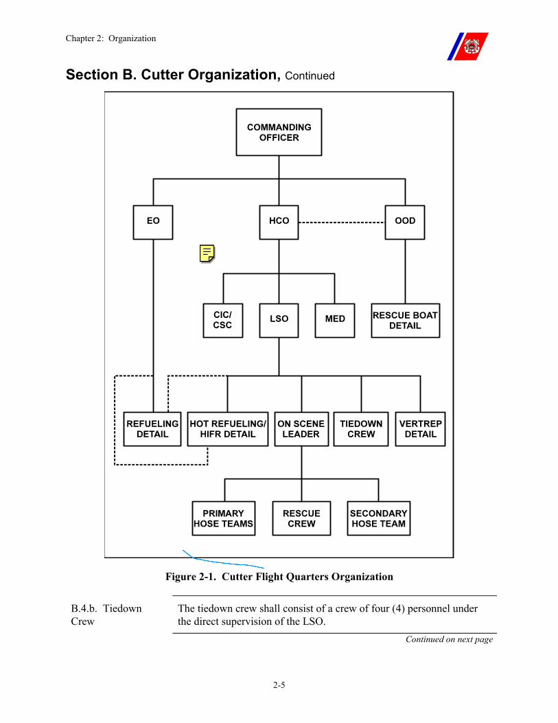
Chapter 2: Organization
2-5
Section B. Cutter Organization, Continued
Figure 2-1. Cutter Flight Quarters Organization
B.4.b. Tiedown Crew
The tiedown crew shall consist of a crew of four (4) personnel under the direct supervision of the LSO.
Continued on next page
Chapter 2: Organization
2-6
Section B. Cutter Organization, Continued
B.4.c. Helicopter Refueling Detail
The refueling detail functions under the supervision of the Engineering Officer or his or her designated representative. The detail should only muster for evolutions that require fueling or defueling. The detail shall consist of the following:
�� One (1) member stationed in the JP-5 pump room �� One (1) member stationed at the fueling station �� One (1) petty officer (usually the fuel king) on the flight deck to
fuel the helicopter and take samples from the fuel hose �� One (1) AFFF hose team serving as fire watch �� Appropriate communications between the bridge, JP-5 pump room,
fueling station, and flight deck shall be maintained
The Senior Aviator or Pilot in Command (PIC) will specify the quantity of fuel required, and the helicopter crewman shall supervise the refueling.
On WAGBs, the Aviation Department may assume responsibility for fueling operations when deployed providing completion of the appropriate PQS.
B.4.d. Helicopter Hot Refueling Detail
The helicopter hot refueling detail is under the direct supervision of the LSO. The detail shall consist of the following:
�� Helicopter fueling detail. �� (Change) One (1) fuel hose handler. �� Fire guard (in a full proximity suit) with a PKP fire extinguisher. �� The normal flight deck fire party.
B.4.e. Helicopter In-Flight Refueling (HIFR) Detail
The HIFR detail is under the direct supervision of the LSO. The HIFR detail shall consist of the following:
�� Helicopter fueling detail; �� One (1) tiedown crewmember to ground the helicopter hoist hook; �� One (1) tiedown crewmember to hook up the HIFR nozzle; �� Two (2) tiedown crewmembers to act as fuel hose handlers.
Continued on next page
Chapter 2: Organization
2-7
Section B. Cutter Organization, Continued
B.4.f. Vertical Replenishment (VERTREP) Detail
The VERTREP detail on flight deck equipped cutters is under the direct supervision of the LSO, and shall consist of:
�� One (1) grounding wand handler; �� One (1) hook-up person; �� Additional cargo handling personnel.
The VERTREP area shall be cleared of all cargo handling personnel during pickup and delivery. Refer to Chapter 10 for additional information including VERTREP to non-flight deck equipped cutters.
B.4.g. Rescue Boat Detail
The rescue boat detail is under the supervision of the OOD and shall consist of:
�� Boat lowering detail. �� Rescue boat crew, which shall include an appropriately dressed out
cutter swimmer qualified in accordance with current directives.
During flight quarters, the rescue boat crew is not required to remain on station. The detail shall maintain a readiness posture as set forth in the cutter Helicopter Operations Bill. However, the rescue boat detail is required to muster on each setting of flight quarters. The detail shall muster, brief, and ensure all gear is ready and staged during the first occurrence of each flight quarters period (i.e. morning operations, afternoon operations, etc), make a report to the HCO, and then may return to normal duties at the Commanding Officer’s discretion.
B.4.h. Medical Detail
The medical detail shall consist of either a Health Services Technician (HS) or Physician Assistant (PA).
The HS or PA is not required to muster during flight operations. The HS or PA shall acknowledge the setting of flight quarters to the HCO and then may return to normal duties. The HS or PA shall muster for flight quarters for a helicopter emergency landing or upon activation of the helicopter crash alarm.
Chapter 2: Organization
2-8
Section B. Cutter Organization, Continued
B.5. Communications Organization
The Commanding Officer shall determine the mode of communication based on the cutter’s configuration. The requirement for Phone Talkers may be eliminated if communications can be established and maintained using other reliable means. The rapid and efficient flow of information to all concerned is of primary importance during Ship-Helo operations.
Internal communications within different areas of the ship shall be established and reliable. Preferred means of communication include: consist of one (1) or a combination of the following:
�� Sound-powered phone. �� VHF or UHF Radio. �� 1MC. �� The closed circuit television (CCTV) at the HCO station shall be
fully operational and used during all Ship-Helo operations with the date time generator and video recording equipment energized.
External communications with the aircraft will normally be by radio.
Chapter 2: Organization
2-9
Section C. Cutter Billet Descriptions
C.1. Overview The following subparagraphs describe each flight operations billet and provide guidance for the selection of individuals to perform the various duties of the Helicopter Operations Bill.
Specific training requirements for each billet are set forth in Chapter 3 of this Manual and in the Cutter Training and Qualification Manual, COMDTINST M3502.4 (series).
C.2. Officer of the Deck (OOD)
In addition to normal underway duties, the OOD is responsible for maneuvering the cutter to provide the optimum relative wind and flight deck motion for Ship-Helo operations.
The OOD shall maintain a steady course and speed during rotor engagement and disengagement (any time that the rotor is in transition between 0 and 100 percent RPM), helicopter takeoff and landing, when the helicopter is not secured on deck, and during helicopter traversing.
At all other times during Ship-Helo operations, the OOD shall notify the HCO before course or speed changes.
C.3. Rescue Boat Coxswain
The rescue boat coxswain supervises the rescue boat crew and reports directly to the OOD. The coxswain shall ensure that the rescue boat is properly outfitted and crewed, to include a cutter swimmer.
C.4. AFFF Station Operator
The AFFF Station Operator is not required to remain on station throughout normal flight operations. The AFFF station shall be energized at the commencement of flight quarters and secured at the end of the evolution. The operator may return to normal duties between evolutions.
The AFFF Station Operator shall remain on station in the event of FLICON ONE for a helicopter emergency landing or upon activation of the helicopter crash alarm.
Continued on next page
Chapter 2: Organization
2-10
Section C. Cutter Billet Descriptions, Continued
C.5. Helicopter Control Officer (HCO)
The HCO exercises overall control of flight operations by ensuring that the cutter, flight deck, and helicopter are ready for each phase of the flight evolution.
The HCO shall keep the OOD informed of the requirements of the flight operations so that the cutter may be maneuvered as required to meet the needs of the helicopter as well as for safe navigation.
He or she shall:
�� Ensure radio communications are maintained with the helicopter (or radios monitored as pre-briefed for EMCON);
�� Ensure communications are maintained with the flight deck; �� Monitor and actively track flight operations via the CCTV; �� Control the flight deck VLA lighting; �� Ensure an accurate navigational plot of the helicopter’s position is
maintained.
On WAGBs, the HCO, or a designated assistant, also acts as flight follower.
C.5.a. HCO Phone Talker
If used, the HCO phone talker is a vital link between the HCO and other areas of the ship.
In addition to the qualifications normally required of a talker, the HCO phone talker shall be familiar with the special terminology associated with helicopter operations to ensure quick and accurate passage of instructions to the flight deck.
C.5.b. Lookout When conducting helicopter operations, the cutter’s lookout assumes the additional responsibility of establishing and maintaining visual contact with the helicopter whenever it is in visual range.
The lookout shall have sufficient familiarity with helicopter operations to recognize and report any unusual aircraft actions.
Continued on next page
Chapter 2: Organization
2-11
Section C. Cutter Billet Descriptions, Continued
C.6. Air Direction Controller (ADC)
The ADC is responsible for:
�� Level II and Level III helicopter operation: �� Providing flight following and traffic advisories. �� Taking the position as the radar operator trained in Air Traffic
Control (this may be an officer or petty officer possessing the aptitude and skills necessary to carry out the Level II/III controller functions described in Chapter 7.)
�� Level I: �� Exercising positive helicopter control (including radar vectors,
traffic separation, and radar approach service). (See Chapter 7).
For Level I operations, a current ADC qualified operator is required.
C.7. Flight Deck Personnel
C.7.a. Landing Signal Officer (LSO)
The LSO is in charge of the flight deck during Ship-Helo operations, and is usually an officer, but may be a chief, senior petty officer, or a member of the Aviation Department.
Only persons who exhibit good judgment, aggressive leadership, and a professional attitude shall be selected for this duty. Depth perception, visual acuity, and normal color vision are important to LSO performance.
Selected personnel shall meet the requirements for a LSO physical as set forth in the Coast Guard Medical Manual, COMDTINST M6000.1 (series).
WARNING If corrective lenses are required for vision, they shall be worn beneath goggles during Ship-Helo operations. UNDER NO CIRCUMSTANCES SHALL CORRECTIVE LENSES BE USED INSTEAD OF GOGGLES TO PROVIDE EYE PROTECTION.
Continued on next page
Chapter 2: Organization
2-12
Section C. Cutter Billet Descriptions, Continued
C.7.b. NVG Safety Observer (NSO)
The NSO will be a NVG qualified LSO. The NSO will be stationed where he or she can observe both the LSO and the tiedown crew when they perform their duties. The NSO shall maintain communication with the HCO. The NSO has the responsibility and authority to stop flight operations when an unsafe condition(s) exists.
C.7.c. Tiedown Crew The tiedown operation is critical to a safe helicopter landing and requires a coordinated and rapid team effort. Personnel selections shall be made accordingly.
The tiedown teams shall not be stationed in the catwalks.
NOTE The tiedown crew will not be stationed adjacent to the LSO. They may be designated as the secondary hose team, and positioned on the side of the hangar or ship’s superstructure off the flight deck. The tiedown crew shall also complete the Flight Deck Hoseman PQS in COMDTINST M3502.15 (series).
Personnel assigned to attach the primary high tiedowns shall be tall enough to perform this duty with ease.
C.7.d. On-Scene Leader (OSL)
The OSL is the direct supervisor of the primary and secondary hose teams and the rescue crew.
The OSL shall be well acquainted with helicopter fire fighting procedures and shall possess superior leadership skills.
Continued on next page
Chapter 2: Organization
2-13
Section C. Cutter Billet Descriptions, Continued
C.7.e. Hose Team Leader and Hose Team
The hose team leader coordinates movement and employment of the hose, as directed by the OSL.
The hose team leader shall occupy the hose handling position immediately behind the nozzleman.
�� Nozzleman: The nozzleman operates the nozzle and employs the firefighting agent.
�� Plugman/Hose Handler: Hose team member(s) who assist in the movement of the hose. If more than one hose handler is employed, the last member on the hose also serves as plugman.
�� AFFF Handler: Required only for secondary hose team.
The secondary hose team only responds in the event of FLICON ONE for a helicopter emergency landing or upon activation of the helicopter crash alarm. The secondary hose team members must be identified by name, properly trained, and not double billeted in that section.
C.7.f. Rescue Crew Personnel selected for flight deck rescue crew duty shall be capable of functioning under adverse conditions.
They may be required to extract several unconscious persons from various positions inside the helicopter. Above-average strength is a definite asset and shall be considered when selecting personnel.
C.7.g. Engine Start Fire Guard
The aircraft crewmember will act as the Fire Guard for engine and APU starts of aircraft that incorporate an engine fire extinguisher system. Both the Coast Guard HH-65 and HH-60J incorporate an internal engine fire extinguisher system. A CO2 fire extinguisher (with a 3-foot extension pipe) shall be repositioned to the flight deck to aid extinguishing the fire in the event the installed system is ineffective. This CO2 extinguisher will be available to the tiedown crew should an engine fire occur during engine start.
For engine start of aircraft without an internal fire suppression system, a member of the fire party (not the OSL) shall be stationed with a CO2 fire extinguisher (with a 3-foot extension pipe) at the side of the helicopter engine being started. He or she shall be in position to discharge the extinguisher under the direction of the helicopter aircrew.
When operating with non-CG helicopters, the ship will inquire as to the engine fire suppression capabilities of the helicopter in question before starting the engines and employ the appropriate procedures.
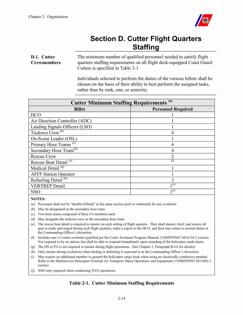
Chapter 2: Organization
2-14
Section D. Cutter Flight Quarters Staffing
D.1. Cutter Crewmembers
The minimum number of qualified personnel needed to satisfy flight quarters staffing requirements on all flight deck-equipped Coast Guard Cutters is specified in Table 2-1.
Individuals selected to perform the duties of the various billets shall be chosen on the basis of their ability to best perform the assigned tasks, rather than by rank, rate, or seniority.
Cutter Minimum Staffing Requirements (a) Billet Personnel Required
HCO 1 Air Direction Controller (ADC) 1 Landing Signals Officers (LSO) 1 Tiedown Crew (b) 4 On-Scene Leader (OSL) 1 Primary Hose Teams (c) 6 Secondary Hose Team(d) 4 Rescue Crew 2 Rescue Boat Detail (e) (f) Medical Detail (g) 1 AFFF Station Operator 1 Refueling Detail (h) 3 VERTREP Detail 1(i) NSO 1(j) NOTES: (a) Personnel shall not be “double billeted” in the same section (port or starboard) for any evolution. (b) May be designated as the secondary hose team. (c) Two hose teams composed of three (3) members each. (d) May designate the tiedown crew as the secondary hose team. (e) The rescue boat detail is required to muster on each setting of flight quarters. They shall muster, brief, and ensure all
gear is ready and staged during each flight quarters, make a report to the HCO, and then may return to normal duties at the Commanding Officer’s discretion.
(f) Includes one (1) cutter swimmer qualified per the Cutter Swimmer Program Manual, COMDTINST M16134.2 (series). Not required to be on station, but shall be able to respond immediately upon sounding of the helicopter crash alarm.
(g) The HS or PA is not required to muster during flight operations. (See Chapter 2, Paragraph B.4.h for details). (h) Only muster during evolutions when fueling or defueling is expected or at the Commanding Officer’s discretion. (i) May require an additional member to ground the helicopter cargo hook when using an electrically conductive pendant.
Refer to the Multiservice Helicopter External Air Transport: Basic Operations and Equipment, COMDTINST M13482.2 (series).
(j) NSO only required when conducting NVG operations.
Table 2-1. Cutter Minimum Staffing Requirements

Chapter 2: Organization
2-15
Section D. Cutter Flight Quarters Staffing, Continued
D.2. POPDIV AVDET Crews
When a POPDIV AVDET is on board a cutter, aviation personnel, when qualified (having completed appropriate PQS), may be used to supplement the cutter’s crew to fill flight deck billets.
Chapter 2: Organization
2-16
Section E. Aviation Detachment Organization
E.1. Status as Department within Cutter’s Organization
The Organization and Regulations Manual of each flight deck-equipped cutter shall include provisions for establishing an Aviation Department during a deployment. This organization may be partially implemented as required for each embarkation.
E.2. Senior Aviator Unless another officer is designated in writing by the ordering authority, the ranking aviator holding an Aircraft Commander designation in the type of aircraft being flown shall be the AVDET Senior Aviator.
Polar Operations AVDETs shall refer to the POPDIV Manual for additional detachment organization details.
Chapter 2: Organization
2-17
Section F. Aviation Detachment Billet Descriptions
F.1. Senior Aviator The AVDET Senior Aviator reports to:
�� The Commanding Officer concerning conduct of flight operations. �� The Executive Officer for all administrative matters.
In addition to supervising the AVDET, he or she shall perform the following duties as the Aviation Department Head:
�� Act as advisor to the Cutter Commanding Officer on all aviation matters, including flight safety.
�� Provide flights within the ability and limits of available resources in support of the mission of the cutter.
�� Provide training flights as practicable to maintain the proficiency of pilots, aircrews, and flight deck crews to meet the requirements of the Air Operations Manual, COMDTINST M3710.1 (series).
�� Determine crew requirements for each mission. �� Conduct drills, lectures, and training as practicable for cutter
personnel in all phases of Ship-Helo operations. �� Ensure adequate security of the aircraft. �� Ensure that required maintenance and corrosion control is
performed, within the limitations of available resources. �� Prepare all required records and reports �� Inspect cutter helicopter operations facilities, equipment, bills, logs,
and records. �� Complete pre-deployment checklist requirements per Appendix F.
NOTE An Aviation Department is not normally established during an embarkation of a helicopter detachment. However, the Senior Aviator should perform the above duties as appropriate for the particular mission.
F.2. AVDET Members
Other AVDET personnel shall function under the direct supervision of the Senior Aviator.
POPDIV AVDETs shall refer to the POPDIV Manual for additional billet descriptions.
Chapter 2: Organization
2-18
Section G. Aviation Detachment Personnel Assignments
G.1. Overview An AVDET shall have a minimum of two (2) pilots, (at least one (1) aircraft commander), and one (1) aircrew member. Additional personnel may be assigned as deemed necessary by the parent aviation unit.
AVDETs are normally sized only to the level necessary to perform the mission and to maintain the related equipment. Therefore, AVDET personnel should not be assigned additional or collateral duties while deployed that conflict with their primary duties of flying and maintaining a 24-hour readiness posture while underway, performance of maintenance, training, and flight planning operations.
The Senior Aviator shall have sufficient flexibility to schedule meals, work, rest, and training periods to meet this commitment.
Similarly, the Senior Aviator, within the framework of the ship’s liberty policy, shall control liberty for AVDET personnel.
However, this policy is dependent on the duration of the deployment (short (30-days) versus long (greater than 30-days)), AVDET crew size, and aircraft maintenance requirements.
The Senior Aviator shall work with the command to follow the spirit of this policy.
Chapter 2: Organization
2-19
Section H. Aviation Detachment Berthing
H.1. Berthing Assignments
Cutter berthing assignments for AVDETs should be as follows:
�� Officers: Officers should be assigned staterooms commensurate with their rank.
�� Chief Petty Officers (CPOs): CPOs should be berthed in CPO quarters.
�� Other Crew: AVDET crewmembers in paygrades E-6 and below should be berthed together where possible for crew rest concerns.
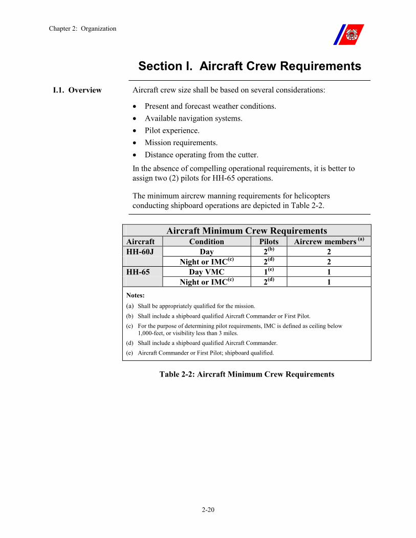
Chapter 2: Organization
2-20
Section I. Aircraft Crew Requirements
I.1. Overview Aircraft crew size shall be based on several considerations:
�� Present and forecast weather conditions. �� Available navigation systems. �� Pilot experience. �� Mission requirements. �� Distance operating from the cutter.
In the absence of compelling operational requirements, it is better to assign two (2) pilots for HH-65 operations.
The minimum aircrew manning requirements for helicopters conducting shipboard operations are depicted in Table 2-2.
Aircraft Minimum Crew Requirements
Aircraft Condition Pilots Aircrew members (a) HH-60J Day 2(b) 2 Night or IMC(c) 2(d) 2 HH-65 Day VMC 1(e) 1 Night or IMC(c) 2(d) 1 Notes: (a) Shall be appropriately qualified for the mission.
(b) Shall include a shipboard qualified Aircraft Commander or First Pilot. (c) For the purpose of determining pilot requirements, IMC is defined as ceiling below
1,000-feet, or visibility less than 3 miles. (d) Shall include a shipboard qualified Aircraft Commander. (e) Aircraft Commander or First Pilot; shipboard qualified.
Table 2-2: Aircraft Minimum Crew Requirements
Chapter 3: Certification, Qualification, and Standardization
3-i
CHAPTER 3: CERTIFICATION, QUALIFICATION, AND STANDARDIZATION
Table of Contents
Introduction................................................................................................................................ 3-1
In this chapter ............................................................................................................................ 3-1
Section A. Cutter Certification ................................................................................................ 3-2
A.1. Overview ............................................................................................................................ 3-2
A.2. Certification Training....................................................................................................... 3-4
A.3. Certification Authority ...................................................................................................... 3-5 A.3.a. NAVAIR Inspection Authority ............................................................................................3-5 A.3.b. NAVAIR Aviation Facility Inspectors.................................................................................3-5 A.3.c. NAVAIR Aviation Facility Inspection Preparation .............................................................3-5 A.3.d. NAVAIR NVG Aviation Facility Certification ...................................................................3-6 A.3.e. Commanding Officer, ATC Mobile .....................................................................................3-7 A.3.f. Casualties Affecting Certification ........................................................................................3-7
Section B. Cutter Qualification................................................................................................ 3-8
B.1. Overview ............................................................................................................................ 3-8
B.2. Qualification Authority .................................................................................................... 3-8
B.3. Initial Qualification........................................................................................................... 3-8
B.4. Maintaining Qualifications............................................................................................... 3-8
B.5. Standardization Training ................................................................................................. 3-9
B.6. Cross Qualification............................................................................................................ 3-9
Section C. Cutter Personnel Qualification and Training.................................................... 3-10
C.1. Overview .......................................................................................................................... 3-10
C.2. Qualification Requirements ........................................................................................... 3-10 C.2.a. Record Keeping ..................................................................................................................3-10 C.2.b. Maintaining Currency.........................................................................................................3-10 C.2.c. Requalification Training.....................................................................................................3-11
C.3. Personnel Qualification Standards (PQS) .................................................................... 3-11
C.4. Cross Qualification ......................................................................................................... 3-12
Chapter 3: Certification, Qualification, and Standardization
3-ii
Section D. Pilot Qualification and Training ......................................................................... 3-15
D.1. Initial and Recurrent Training ...................................................................................... 3-15
D.2. Cross Qualification ......................................................................................................... 3-15
D.3. NVG Operations.............................................................................................................. 3-15
D.4. Special Missions .............................................................................................................. 3-15
Section E. Aircrew Qualification and Training ................................................................... 3-17
E.1. Overview .......................................................................................................................... 3-17
Section F. Air Station Standardization Visits........................................................................ 3-18
E.1. Overview .......................................................................................................................... 3-18
Chapter 3: Certification, Qualification, and Standardization
3-1
Chapter 3. Certification, Qualification, and Standardization
Introduction Before conducting shipboard-helicopter (Ship-Helo) operations, the cutter’s flight operations facilities shall be certified, and the flight quarters and aircrew personnel proficient in the procedures defined in this Manual. This chapter describes:
�� Certification
�� Qualification
�� Recurrent training requirements for conducting Ship-Helo operations
In this chapter This chapter is divided into six (6) sections:
�� Section A: Cutter Certification �� Section B: Cutter Qualification �� Section C: Cutter Personnel Qualification and Training �� Section D: Pilot Qualification and Training �� Section E: Aircrew Qualification and Training �� Section F: Air Station Standardization Training
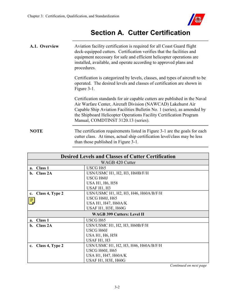
Chapter 3: Certification, Qualification, and Standardization
3-2
Section A. Cutter Certification
A.1. Overview Aviation facility certification is required for all Coast Guard flight deck-equipped cutters. Certification verifies that the facilities and equipment necessary for safe and efficient helicopter operations are installed, available, and operate according to approved plans and procedures.
Certification is categorized by levels, classes, and types of aircraft to be operated. The desired levels and classes of certification are shown in Figure 3-1.
Certification standards for air capable cutters are published in the Naval Air Warfare Center, Aircraft Division (NAWCAD) Lakehurst Air Capable Ship Aviation Facilities Bulletin No. 1 (series), as amended by the Shipboard Helicopter Operations Facility Certification Program Manual, COMDTINST 3120.13 (series).
NOTE The certification requirements listed in Figure 3-1 are the goals for each cutter class. At times, actual ship certification level/class may be less than those published in Figure 3-1.
Desired Levels and Classes of Cutter Certification
WAGB 420 Cutter a. Class 1 USCG H65 b. Class 2A USN/USMC H1, H2, H3, H60B/F/H
USCG H60J USA H1, H6, H58 USAF H1, H3
c. Class 4, Type 2 USN/USMC H1, H2, H3, H46, H60A/B/F/H USCG H60J, H65 USA H1, H47, H60A/K USAF H1, H3E, H60G
WAGB 399 Cutters: Level II a. Class 1 USCG H65 b. Class 2A USN/USMC H1, H2, H3, H60B/F/H
USCG H60J USA H1, H6, H58 USAF H1, H3
c. Class 4, Type 2 USN/USMC H1, H2, H3, H46, H60A/B/F/H USCG H60J, H65 USA H1, H47, H60A/K USAF H1, H3E, H60G
Continued on next page
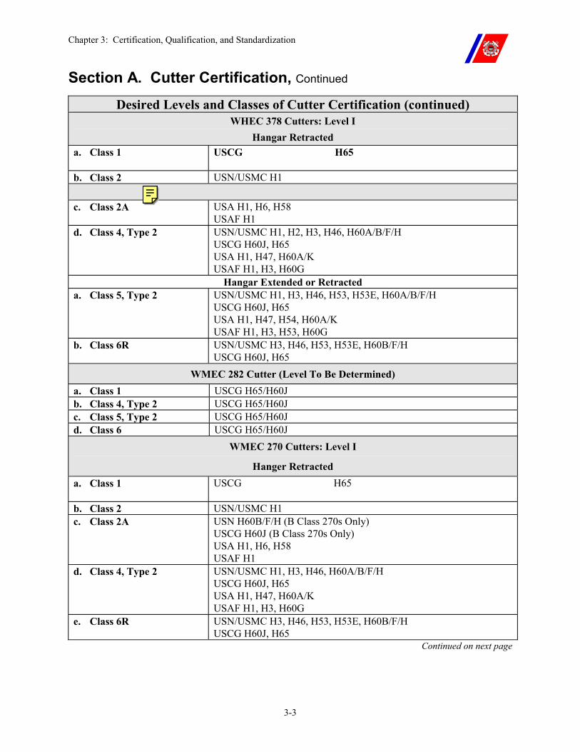
Chapter 3: Certification, Qualification, and Standardization
3-3
Section A. Cutter Certification, Continued
Desired Levels and Classes of Cutter Certification (continued) WHEC 378 Cutters: Level I
Hangar Retracted a. Class 1 USCG H65
b. Class 2 USN/USMC H1
c. Class 2A USA H1, H6, H58 USAF H1
d. Class 4, Type 2 USN/USMC H1, H2, H3, H46, H60A/B/F/H USCG H60J, H65 USA H1, H47, H60A/K USAF H1, H3, H60G
Hangar Extended or Retracted a. Class 5, Type 2 USN/USMC H1, H3, H46, H53, H53E, H60A/B/F/H
USCG H60J, H65 USA H1, H47, H54, H60A/K USAF H1, H3, H53, H60G
b. Class 6R USN/USMC H3, H46, H53, H53E, H60B/F/H USCG H60J, H65
WMEC 282 Cutter (Level To Be Determined) a. Class 1 USCG H65/H60J b. Class 4, Type 2 USCG H65/H60J c. Class 5, Type 2 USCG H65/H60J d. Class 6 USCG H65/H60J
WMEC 270 Cutters: Level I
Hanger Retracted a. Class 1 USCG H65
b. Class 2 USN/USMC H1 c. Class 2A USN H60B/F/H (B Class 270s Only)
USCG H60J (B Class 270s Only) USA H1, H6, H58 USAF H1
d. Class 4, Type 2 USN/USMC H1, H3, H46, H60A/B/F/H USCG H60J, H65 USA H1, H47, H60A/K USAF H1, H3, H60G
e. Class 6R USN/USMC H3, H46, H53, H53E, H60B/F/H USCG H60J, H65
Continued on next page
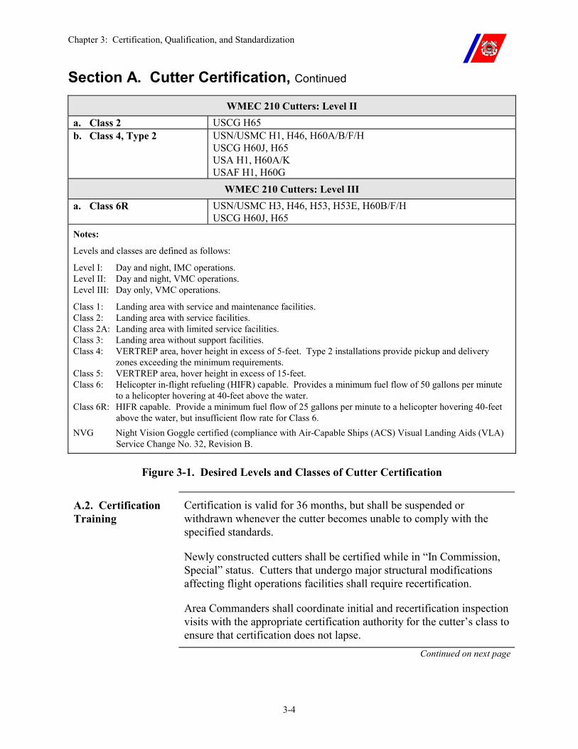
Chapter 3: Certification, Qualification, and Standardization
3-4
Section A. Cutter Certification, Continued
WMEC 210 Cutters: Level II a. Class 2 USCG H65 b. Class 4, Type 2 USN/USMC H1, H46, H60A/B/F/H
USCG H60J, H65 USA H1, H60A/K USAF H1, H60G
WMEC 210 Cutters: Level III a. Class 6R USN/USMC H3, H46, H53, H53E, H60B/F/H
USCG H60J, H65 Notes:
Levels and classes are defined as follows:
Level I: Day and night, IMC operations. Level II: Day and night, VMC operations. Level III: Day only, VMC operations.
Class 1: Landing area with service and maintenance facilities. Class 2: Landing area with service facilities. Class 2A: Landing area with limited service facilities. Class 3: Landing area without support facilities. Class 4: VERTREP area, hover height in excess of 5-feet. Type 2 installations provide pickup and delivery
zones exceeding the minimum requirements. Class 5: VERTREP area, hover height in excess of 15-feet. Class 6: Helicopter in-flight refueling (HIFR) capable. Provides a minimum fuel flow of 50 gallons per minute
to a helicopter hovering at 40-feet above the water. Class 6R: HIFR capable. Provide a minimum fuel flow of 25 gallons per minute to a helicopter hovering 40-feet
above the water, but insufficient flow rate for Class 6. NVG Night Vision Goggle certified (compliance with Air-Capable Ships (ACS) Visual Landing Aids (VLA)
Service Change No. 32, Revision B.
Figure 3-1. Desired Levels and Classes of Cutter Certification
A.2. Certification Training
Certification is valid for 36 months, but shall be suspended or withdrawn whenever the cutter becomes unable to comply with the specified standards.
Newly constructed cutters shall be certified while in “In Commission, Special” status. Cutters that undergo major structural modifications affecting flight operations facilities shall require recertification.
Area Commanders shall coordinate initial and recertification inspection visits with the appropriate certification authority for the cutter’s class to ensure that certification does not lapse.
Continued on next page
Chapter 3: Certification, Qualification, and Standardization
3-5
Section A. Cutter Certification, Continued
A.3. Certification Authority
A.3.a. NAVAIR Inspection Authority
Aviation facility certification for WAGB 420, WHEC 378, WMEC 282, WMEC 270, and WMEC 210 cutters is granted by NAVAIRWARCENACDIVLKE. Certifications issued are applicable for operations with Coast Guard, as well as Navy, Marine Corps, and other DoD helicopters.
A.3.b. NAVAIR Aviation Facility Inspectors
Certification inspections are conducted by Navy Aviation Ship Installation Representatives (ASIRs) and are scheduled through NAVAIRWARCENACDIVLKE by the cutter’s Area Commander.
A.3.c. NAVAIR Aviation Facility Inspection Preparation
In preparation for Navy certification, technical assistance visits should be requested from NAVAIRWARCENACDIVLKE via the Area Commander.
Flight operations facilities information and current certification levels for cutters certified by NAVAIRWARCENACDIVLKE are listed in Shipboard Aviation Facilities Resume, NAVAIRWARCENACDIVLKE-ENG-7576 (series)
Continued on next page
Chapter 3: Certification, Qualification, and Standardization
3-6
Section A. Cutter Certification, Continued
A.3.d. NAVAIR NVG Aviation Facility Certification
NVG Certification of Coast Guard Cutters:
�� Cutter lighting and light discipline are critical to NVG performance and the safe conduct of NVG flight operations. Lighting configurations and intensities will vary with ambient conditions and aircrew and flight deck personnel proficiency and preference. Before conducting NVG training qualification operations, each cutter VLA System shall be verified by the ATC Mobile Ship-HelicopterStandardization Branch, who will check proper installation of NVG compatible Blue Filters for the Overhead and Deck Surface Floodlights. Once inspected, the cutter will be USN NVG certified as part of their normal NAVAIR inspection. In addition to NAVAIR NVG certification, each cutter shall have the following items aboard and in serviceable condition before commencing NVG operations: �� Two (2) NVG compatible CCTV cameras. �� Three (3) sets of ANVIS style NVGs. �� Three (3) aviator style helmets (radio capable) for mounting
ANVIS style NVGs. �� A dozen sets of shatterproof clear eye protection safety devices
for the LSO and NSO. �� Appropriate number of blue Chemlights for training/operations.
(Recommend two dozen lights per flight deck evolution) �� An AVN-20/20 NVG Focusing Device or one portable NVG
Focusing lane comprised of a portable Eye Chart (which can be made from local materials generated by a computer).
�� Portable radios are for use by the LSO, NSO, and other stations. Each station shall maintain appropriate circuit discipline.
Continued on next page
Chapter 3: Certification, Qualification, and Standardization
3-7
Section A. Cutter Certification, Continued
A.3.e. Commanding Officer, ATC Mobile
Aviation facility certifications for WAGB 399 cutters pending aviation facility upgrade are granted by the ATC Mobile.
Certifications issued are applicable for operations with only Coast Guard aircraft.
Coast Guard certification inspections are conducted by instructors from Ship-Helo Branch, ATC Mobile, and are scheduled through ATC Mobile by the cutter’s Area Commander.
In preparation for this certification, technical assistance visits may be requested from ATC via the Area Commander.
In addition, ATC Mobile Ship-Helo Instructors shall review the condition of the cutter’s aviation facilities as part of a Recurrent Standardization Training Visit.
ATC Mobile Ship-Helo Instructors shall issue a suspension of a cutter’s aviation facilities certification, subject to review by G-OCA, if the cutter’s aviation facilities do not comply with applicable standards.
The suspension remains in force until the problem reported is corrected or the certification expires.
A.3.f. Casualties Affecting Certification
Casualties affecting a cutter's certification shall be reported via message to the cognizant certification authority, G-OCA, G-OCU, the Area Commander, and ATC Mobile Ship-Helo Branch. The cutter shall also downgrade their certification status to the appropriate level and class.
When the casualty is corrected, the cutter shall upgrade their certification status by notifying the cognizant certification authority via message, info G-OCA, G-OCU, Area Commander and ATC Mobile Ship-Helo Branch. The certification authority will send a message detailing the new certification status.
Chapter 3: Certification, Qualification, and Standardization
3-8
Section B. Cutter Qualification
B.1. Overview All flight deck-equipped cutters shall complete the qualification requirements of this Manual.
Qualification ensures that the cutter meets the minimum staffing requirements and that the individuals filling flight quarters billets are properly trained in standardized procedures.
The required staffing levels are specified in Chapter 2, Table 2-1.
B.2. Qualification Authority
Commanding Officer, Aviation Training Center Mobile shall qualify all flight deck equipped cutters for Ship-Helo operations.
B.3. Initial Qualification
Initial qualification training is conducted by the ATC Mobile Ship-Helo Branch following a cutter’s initial certification.
The requirements for initial qualification are listed in Appendix A.
B.4. Maintaining Qualifications
A cutter remains qualified as long as the minimum required number of qualified flight quarters personnel specified in Chapter 2, Table 2-1 are on the cutter and not more than 24 months have elapsed since the last Standardization Training Visit.
A cutter’s qualification lapses whenever these requirements are not achieved and may be suspended or withdrawn for cause.
The Area Commander shall be advised if it is anticipated that the minimum staffing requirements cannot be met due to the temporary absence of qualified personnel, or other reasons.
If a cutter’s qualification lapses either through failure to meet recurrent training requirements or through transfer of qualified personnel, it can be regained in accordance with Paragraph C.2.c of this chapter, or by assignment of qualified personnel from another cutter of the same class.
Area Commanders shall ensure cutters are provided sufficient opportunity to conduct flight operations to maintain qualification.
Continued on next page
Chapter 3: Certification, Qualification, and Standardization
3-9
Section B. Cutter Qualification, Continued
B.5. Standardization Training
Standardization training is conducted to:
�� Review and practice standard shipboard helicopter procedures; �� Introduce new procedures; and �� Assist flight quarter’s personnel maintain a high standard of
proficiency.
The Ship-Helo Branch shall conduct this training every 24 months and is normally conducted between 18 and 24 months.
Area Commanders shall coordinate the scheduling of standardization training visits to meet this requirement.
Requests for additional visits may be made when required. The cutter’s Area Commander shall provide funding for these extra visits.
B.6. Cross Qualification
Upon qualification with one (1) model of helicopter, cutters are considered qualified to conduct operations with all models of helicopters.
Before conducting operations with any model of helicopter the crew is unfamiliar with, a cutter shall complete the orientation requirements outlined in Section D of Appendix A.
Chapter 3: Certification, Qualification, and Standardization
3-10
Section C. Cutter Personnel Qualification and Training
C.1. Overview Commanding Officers shall ensure that flight quarter’s personnel are properly qualified and proficient in helicopter operations.
Personnel are qualified to perform in specific flight quarter’s billets when they have completed the training requirements set forth below. An individual remains qualified in billet as long as the recurrent requirements are met semiannually. The recurrent periods are 01 January through 30 June and 01 July through 31 December each year.
Personnel whose qualifications have lapsed shall complete the specified requalification requirements.
C.2. Qualification Requirements
Tables 3-1 through 3-5 specifies minimum training and the number of evolutions required to initially qualify, maintain currency, and requalify cutter flight quarters personnel.
Although not mandatory for qualification, courses for LSOs with an established NVG syllabus are available at U.S. Navy Fleet Training Schools. Attendance is recommended where practical.
NOTE During initial qualification or standardization training with a helicopter shut down on deck, the Ship-Helo instructor or appropriate ATT member may credit up to four (4) tiedown operations by new tiedown personnel toward day qualification.
The remaining day and night operations shall be accomplished with actual landings or an aircraft operating at 100% rotor speed on deck. TALON may be used to secure the HH-65 throughout this training evolution.
C.2.a. Record Keeping
Upon initial qualification of an individual in any flight quarter’s billet, an appropriate service record and training record entry shall be made.
C.2.b. Maintaining Currency
A qualification lapses when the recurrent requirements have not been satisfied during the preceding semiannual calendar period. Recurrent requirements exist only for Night Vision Goggle-Landing Signal Officers (NVG-LSOs), Landing Signal Officers (LSOs), Air Direction Controllers (ADCs), and Tiedown Crew personnel.
Chapter 3: Certification, Qualification, and Standardization
3-11
Section C. Cutter Personnel Qualification and Training, Continued
NOTE Periodic NVG training shall be conducted during each semi-annual period. However, each NVG qualified LSO (preferably the ATT member) will conduct one (1) hour of classroom instruction after every 90-days of non-NVG flight operations. NVG classroom training shall be documented in each member’s training record.
C.2.c. Requalification Training
Requalification training of lapsed NVG-LSOs, NSOs, and tiedown crewmembers may be conducted by a ship crewmember qualified in the same billet.
In the absence of qualified ATT NVG-LSO personnel at the unit, retraining may be accomplished by qualified ATT NVG-LSO personnel from another cutter or by a Ship-Helo instructor.
Area Commanders shall coordinate and fund this training.
C.3. Personnel Qualification Standards (PQS)
Personnel Qualification Standard (PQS) – Shipboard Helicopter Operations, COMDTINST M3502.15 (series), contains watchstation qualification requirements for cutter crewmembers assigned to duties in support of flight operations.
PQS completion is mandatory before granting initial qualifications. Continued on next page
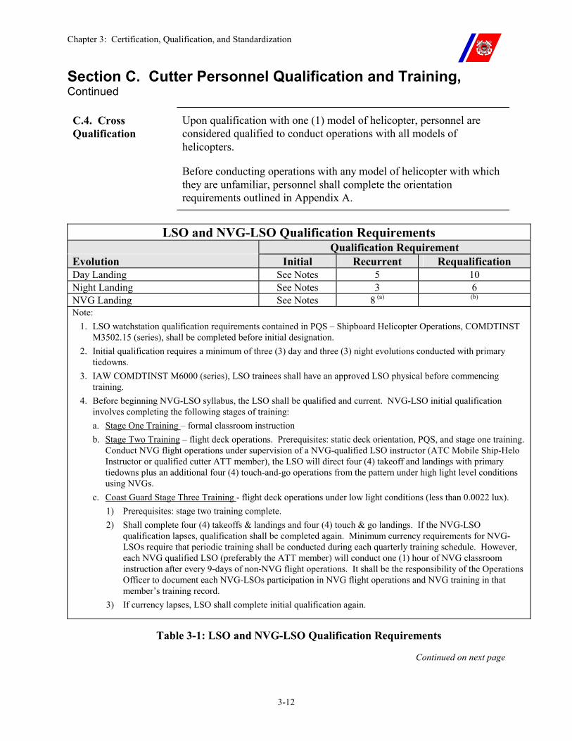
Chapter 3: Certification, Qualification, and Standardization
3-12
Section C. Cutter Personnel Qualification and Training, Continued
C.4. Cross Qualification
Upon qualification with one (1) model of helicopter, personnel are considered qualified to conduct operations with all models of helicopters.
Before conducting operations with any model of helicopter with which they are unfamiliar, personnel shall complete the orientation requirements outlined in Appendix A.
LSO and NVG-LSO Qualification Requirements
Qualification Requirement Evolution Initial Recurrent Requalification Day Landing See Notes 5 10 Night Landing See Notes 3 6 NVG Landing See Notes 8 (a) (b)
Note: 1. LSO watchstation qualification requirements contained in PQS – Shipboard Helicopter Operations, COMDTINST
M3502.15 (series), shall be completed before initial designation. 2. Initial qualification requires a minimum of three (3) day and three (3) night evolutions conducted with primary
tiedowns. 3. IAW COMDTINST M6000 (series), LSO trainees shall have an approved LSO physical before commencing
training. 4. Before beginning NVG-LSO syllabus, the LSO shall be qualified and current. NVG-LSO initial qualification
involves completing the following stages of training: a. Stage One Training – formal classroom instruction b. Stage Two Training – flight deck operations. Prerequisites: static deck orientation, PQS, and stage one training.
Conduct NVG flight operations under supervision of a NVG-qualified LSO instructor (ATC Mobile Ship-Helo Instructor or qualified cutter ATT member), the LSO will direct four (4) takeoff and landings with primary tiedowns plus an additional four (4) touch-and-go operations from the pattern under high light level conditions using NVGs.
c. Coast Guard Stage Three Training - flight deck operations under low light conditions (less than 0.0022 lux). 1) Prerequisites: stage two training complete. 2) Shall complete four (4) takeoffs & landings and four (4) touch & go landings. If the NVG-LSO
qualification lapses, qualification shall be completed again. Minimum currency requirements for NVG-LSOs require that periodic training shall be conducted during each quarterly training schedule. However, each NVG qualified LSO (preferably the ATT member) will conduct one (1) hour of NVG classroom instruction after every 9-days of non-NVG flight operations. It shall be the responsibility of the Operations Officer to document each NVG-LSOs participation in NVG flight operations and NVG training in that member’s training record.
3) If currency lapses, LSO shall complete initial qualification again.
Table 3-1: LSO and NVG-LSO Qualification Requirements
Continued on next page
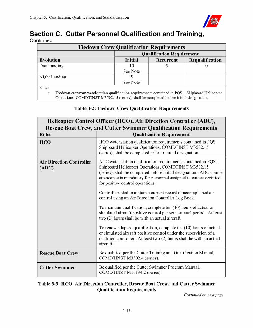
Chapter 3: Certification, Qualification, and Standardization
3-13
Section C. Cutter Personnel Qualification and Training, Continued
Tiedown Crew Qualification Requirements Qualification Requirement Evolution Initial Recurrent Requalification Day Landing 10
See Note 5 10
Night Landing 5 See Note
Note: �� Tiedown crewman watchstation qualification requirements contained in PQS – Shipboard Helicopter
Operations, COMDTINST M3502.15 (series), shall be completed before initial designation.
Table 3-2: Tiedown Crew Qualification Requirements
Helicopter Control Officer (HCO), Air Direction Controller (ADC), Rescue Boat Crew, and Cutter Swimmer Qualification Requirements
Billet Qualification Requirement HCO HCO watchstation qualification requirements contained in PQS –
Shipboard Helicopter Operations, COMDTINST M3502.15 (series), shall be completed prior to initial designation
Air Direction Controller (ADC)
ADC watchstation qualification requirements contained in PQS - Shipboard Helicopter Operations, COMDTINST M3502.15 (series), shall be completed before initial designation. ADC course attendance is mandatory for personnel assigned to cutters certified for positive control operations.
Controllers shall maintain a current record of accomplished air control using an Air Direction Controller Log Book.
To maintain qualification, complete ten (10) hours of actual or simulated aircraft positive control per semi-annual period. At least two (2) hours shall be with an actual aircraft.
To renew a lapsed qualification, complete ten (10) hours of actual or simulated aircraft positive control under the supervision of a qualified controller. At least two (2) hours shall be with an actual aircraft.
Rescue Boat Crew Be qualified per the Cutter Training and Qualification Manual, COMDTINST M3502.4 (series).
Cutter Swimmer Be qualified per the Cutter Swimmer Program Manual, COMDTINST M16134.2 (series).
Table 3-3: HCO, Air Direction Controller, Rescue Boat Crew, and Cutter Swimmer Qualification Requirements
Continued on next page
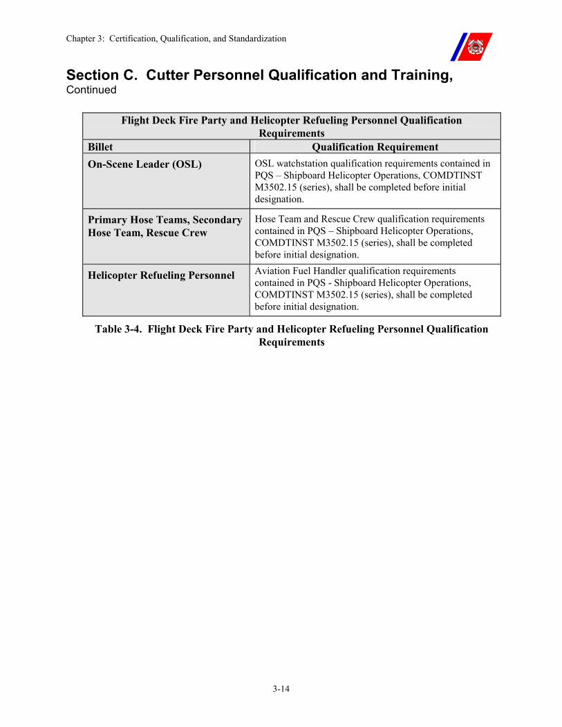
Chapter 3: Certification, Qualification, and Standardization
3-14
Section C. Cutter Personnel Qualification and Training, Continued
Flight Deck Fire Party and Helicopter Refueling Personnel Qualification Requirements
Billet Qualification Requirement On-Scene Leader (OSL) OSL watchstation qualification requirements contained in
PQS – Shipboard Helicopter Operations, COMDTINST M3502.15 (series), shall be completed before initial designation.
Primary Hose Teams, Secondary Hose Team, Rescue Crew
Hose Team and Rescue Crew qualification requirements contained in PQS – Shipboard Helicopter Operations, COMDTINST M3502.15 (series), shall be completed before initial designation.
Helicopter Refueling Personnel Aviation Fuel Handler qualification requirements contained in PQS - Shipboard Helicopter Operations, COMDTINST M3502.15 (series), shall be completed before initial designation.
Table 3-4. Flight Deck Fire Party and Helicopter Refueling Personnel Qualification Requirements
Chapter 3: Certification, Qualification, and Standardization
3-15
Section D. Pilot Qualification and Training
D.1. Initial and Recurrent Training
Table 3-5 lists minimum requirements for qualification to operate a Coast Guard helicopter on a ship. Initial qualification for Coast Guard pilots shall be conducted in Coast Guard helicopters on Coast Guard cutters under the supervision of a shipboard qualified unit IP.
Training in landings and takeoffs should be conducted under various pitch, roll, and wind conditions until a high level of proficiency is attained. The Coast Guard standard qualification syllabus developed for the type of helicopter flown shall be used.
After initial qualification, landings on any military ship certified for helicopter operations may be credited towards currency requirements.
Qualifications shall lapse if the recurrent training requirements are not met during the preceding semiannual calendar period.
A shipboard qualified aircraft commander can be used for all shipboard pilot training other than initial qualification.
D.2. Cross Qualification
A pilot previously shipboard qualified in one (1) model of helicopter shall complete the requalification requirements specified in Table 3-5 to become qualified in another model helicopter.
Pilots previously shipboard qualified in other military branches shall complete the initial qualification requirements specified in Table 3-5.
D.3. NVG Operations
Pilots shall complete the NVG Shipboard Landing Syllabus with a qualified Shipboard NVG IP before commencing NVG flight operations. This syllabus provides standardized training for a pilot's initial qualification for NVG Shipboard landings. This syllabus represents the minimum requirement. Initial qualifications for pilots will be accomplished with a unit IP who is NVG Shipboard qualified and current. The pilot under instruction shall be NVG Level III qualified and shipboard night current before beginning the flight phase. The specific initial qualification and currency requirements are described in Table 3-5.
D.4. Special Missions
An aircraft commander shall be assigned as PIC of aircraft on difficult or unusual mission, or on flights carrying non-mission essential personnel.
Continued on next page
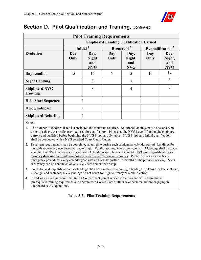
Chapter 3: Certification, Qualification, and Standardization
3-16
Section D. Pilot Qualification and Training, Continued Pilot Training Requirements
Shipboard Landing Qualification Earned Initial 1 Recurrent 2 Requalification 3 Evolution Day
Only Day, Night and
NVG
Day Only
Day, Night,
and NVG
Day Only
Day, Night,
and NVG
Day Landing 15 15 5 5 10 10
Night Landing 8 3 6
Shipboard NVG Landing
8 4 8
Helo Start Sequence 1
Helo Shutdown 1
Shipboard Refueling 1
Notes: 1. The number of landings listed is considered the minimum required. Additional landings may be necessary in
order to achieve the proficiency required for qualification. Pilots shall be NVG Level III and night shipboard current and qualified before beginning the NVG Shipboard Syllabus. NVG Shipboard Initial qualification shall be conducted with a NVG certified Coast Guard Cutter.
2. Recurrent requirements may be completed at any time during each semiannual calendar period. Landings for day-only recurrency may be either day or night. For day and night recurrency, at least 3 landings shall be made at night. For NVG recurrency, at least four (4) landings shall be made at night. NVG-aided qualification and currency does not constitute shipboard unaided qualification and currency. Pilots shall also review NVG emergency procedures every calendar year with an NVG IP (within 15-months of the previous review). NVG recurrency can be conducted on any NVG certified cutter or ship.
3. For initial and requalification, day landings shall be completed before night landings. (Change: delete sentence)(Change: add sentence) NVG landings do not count for night currency or requalification.
4. Non-Coast Guard aircrews shall train IAW pertinent parent service directives and will ensure that all prerequisite training requirements to operate with Coast Guard Cutters have been met before engaging in Shipboard NVG Operations.
Table 3-5. Pilot Training Requirements
Chapter 3: Certification, Qualification, and Standardization
3-17
Section E. Aircrew Qualification and Training
E.1. Overview Although no specific qualification requirements exist for helicopter crewmembers, familiarization training in shipboard operations is strongly encouraged. This should include:
�� Static refueling; �� Hot refueling; �� HIFR; �� Secondary and heavy weather tiedowns; �� Blade folding and unfolding; and �� Helicopter traversing and hangaring �� Night Vision Goggle Shipboard Operations.
Chapter 3: Certification, Qualification, and Standardization
3-18
Section F. Air Station Standardization Visits
E.1. Overview All Rotary Wing Air Stations are required to receive formal classroom training in shipboard helicopter operational procedures every 24 months from ATC Mobile Instructors.
Air Station Commanding Officers shall ensure maximum participation by pilots and aircrew during these training visits.
Chapter 4: Equipment and Materials
4-i
CHAPTER 4: EQUIPMENT AND MATERIALS Table of Contents
Introduction................................................................................................................................ 4-1
In this chapter ............................................................................................................................ 4-1
Section A. Equipment ............................................................................................................... 4-2
A.1. Overview ............................................................................................................................ 4-2
A.2. Aircraft............................................................................................................................... 4-2
Section B. Personal Protective Clothing and Equipment...................................................... 4-3
B.1. Overview ............................................................................................................................ 4-3
B.2. Cranial Helmet .................................................................................................................. 4-3 B.2.a. Assembly ..............................................................................................................................4-4 B.2.b. Maintenance .........................................................................................................................4-4
B.3. Jersey .................................................................................................................................. 4-7
B.4. Life Vest ............................................................................................................................. 4-8 B.4.a. Outer Cover ..........................................................................................................................4-8 B.4.b. Outer Cover Dye Marker and Velcro Bladder ...................................................................4-12 B.4.c. Bladder................................................................................................................................4-13
B.4.c.(1). Manual Inflation Assembly ...............................................................................4-13 B.4.c.(2). Automatic Inflation Assembly...........................................................................4-14
B.4.d. Installing the Bladder in the Cover.....................................................................................4-15 B.4.e. Updated Auto-Inflation Assembly (AIA) ...........................................................................4-16 B.4.f. Auto Inflation Assemblies (AIAs) in Aircraft ....................................................................4-16 B.4.g. Survival Equipment Installation .........................................................................................4-18 B.4.h. Maintenance Requirements ................................................................................................4-19
B.4.h.(1). Annual Functional Check..................................................................................4-19 B.4.h.(2). Quarterly Inspections ........................................................................................4-20
B.5. Safety Shoes ..................................................................................................................... 4-22
B.6. Goggles ............................................................................................................................. 4-22
B.7. Flash Hoods and Gloves.................................................................................................. 4-22
B.8. Proximity Suits ................................................................................................................ 4-22
B.9. Cutter Swimmer Equipment .......................................................................................... 4-22
Section C. Flight Deck Operating Criteria and Visual Landing Aids (VLA) .................... 4-23
Chapter 4: Equipment and Materials
4-ii
C.1. Overview .......................................................................................................................... 4-23
C.2. Flight Deck Surface......................................................................................................... 4-23 C.2.a. Non-Skid Surface................................................................................................................4-23 C.2.b. Marking and Color Topping...............................................................................................4-24 C.2.c. Delamination ......................................................................................................................4-24 C.2.d. Non-Skid Cosmetic Appearance ........................................................................................4-24
C.3. In-Deck and Bulkhead Tiedown Fittings...................................................................... 4-24
C.4. Deck Edge Protection (Safety Nets and Catwalks) ...................................................... 4-25
C.5. Landing Area Markings ................................................................................................. 4-25 C.5.a. Peripheral Lines..................................................................................................................4-25 C.5.b. Touchdown Circle ..............................................................................................................4-25 C.5.c. Landing Spot.......................................................................................................................4-25 C.5.d. Landing Lineup Line ..........................................................................................................4-26 C.5.e. Vertical Replenishment (VERTREP)/ Hover Line ............................................................4-26 C.5.f. Helicopter In-Flight Refueling (HIFR) Marking ................................................................4-26 C.5.g. TALON Alignment Lines...................................................................................................4-26
C.6. Hangar Area Markings .................................................................................................. 4-27 C.6.a. Hangar Deck Markings.......................................................................................................4-27 C.6.b. Hangar Door Markings.......................................................................................................4-27 C.6.c. TALON Alignment Line Marking......................................................................................4-27 C.6.d. Hangar Access Line(s) and Wheel Spot Marking..............................................................4-27
C.7. Obstacle Clearance Criteria........................................................................................... 4-27 C.7.a. Helicopter Landing Area Obstructions...............................................................................4-27
C.8. Lighting and Visual Approach Equipment .................................................................. 4-31 C.8.a. Homing Beacon (White).....................................................................................................4-31 C.8.b. Deck Edge Lights (Red) .....................................................................................................4-31 C.8.c. Deck Lineup Lights ............................................................................................................4-32 C.8.d. Helicopter In-Flight Refueling (HIFR) Heading Lights (Yellow/Red)..............................4-32 C.8.e. Obstruction Lights (Blue)...................................................................................................4-32 C.8.f. Overhead Flood Lights (Yellow/Red).................................................................................4-32 C.8.g. NVG Overhead Floodlights (Blue/Green). ........................................................................4-33 C.8.h. Deck Surface Floodlights. ..................................................................................................4-33 C.8.i. Hangar or Structure Wash Floodlights (Red)......................................................................4-34 C.8.j. Deck Status Light System ...................................................................................................4-34 C.8.k. Stabilized Glide Slope Indicator (SGSI) ............................................................................4-35 C.8.l. Wave-off Lights ..................................................................................................................4-35 C.8.m. Additional Lights...............................................................................................................4-35 C.8.n. Forward Extended Lineup Device......................................................................................4-35
C.9. Minimum Lighting.......................................................................................................... 4-36
C.10. Cutter Navigation and Superstructure Lighting........................................................ 4-36

Chapter 4: Equipment and Materials
4-iii

Chapter 4: Equipment and Materials
4-iv
Chapter 4: Equipment and Materials
4-1
Chapter 4. Equipment and Material
Introduction This chapter covers the equipment and materials required for all Coast Guard flight deck-equipped cutters.
In this chapter This chapter is divided into four (4) sections:
�� Section A: Equipment �� Section B: Personal Protective Clothing and Equipment �� Section C: Flight Deck Operating Criteria and Visual Landing Aids �� Section D: Helicopter Maintenance and Support Equipment
Chapter 4: Equipment and Materials
4-2
Section A. Equipment
A.1. Overview Specific equipment and material requirements for all Coast Guard flight deck-equipped cutters are contained in Naval Air Warfare Center, Aircraft Division Lakehurst (NAVAIRWARCENACDIVLKE) Air Capable Ship Aviation Facilities Bulletin No. 1 (series) as amended by the Shipboard Helicopter Operations Facility Certification Program Manual, COMDTINST 3120.13 (series), and the Coast Guard Shipboard Aviation Allowance Equipage List (AEL).
Additional requirements are listed throughout this Manual.
All equipment and material shall be available and working properly for a cutter to be certified.
Equipment and material discrepancies affecting certification shall be reported immediately to the cutter’s operational commander, Commandant (G-OCA and G-OCU), ATC Mobile (Ship-Helo Branch), and NAVAIRWARCENACDIVLKE.
Operations in the affected certification categories shall be suspended until the discrepancies are resolved.
A.2. Aircraft Minimum equipment and material standards for Coast Guard helicopters conducting shipboard operations are contained in the appropriate flight handbook and maintenance publications.
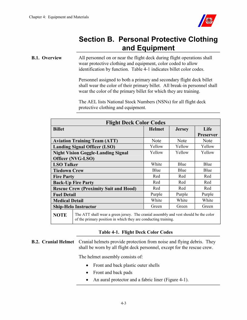
Chapter 4: Equipment and Materials
4-3
Section B. Personal Protective Clothing and Equipment
B.1. Overview All personnel on or near the flight deck during flight operations shall wear protective clothing and equipment, color coded to allow identification by function. Table 4-1 indicates billet color codes.
Personnel assigned to both a primary and secondary flight deck billet shall wear the color of their primary billet. All break-in personnel shall wear the color of the primary billet for which they are training.
The AEL lists National Stock Numbers (NSNs) for all flight deck protective clothing and equipment.
Flight Deck Color Codes
Billet Helmet Jersey Life Preserver
Aviation Training Team (ATT) Note Note Note Landing Signal Officer (LSO) Yellow Yellow Yellow Night Vision Goggle-Landing Signal Officer (NVG-LSO)
Yellow Yellow Yellow
LSO Talker White Blue Blue Tiedown Crew Blue Blue Blue Fire Party Red Red Red Back-Up Fire Party Red Red Red Rescue Crew (Proximity Suit and Hood) Red Red Red Fuel Detail Purple Purple Purple Medical Detail White White White Ship-Helo Instructor Green Green Green
NOTE The ATT shall wear a green jersey. The cranial assembly and vest should be the color of the primary position in which they are conducting training.
Table 4-1. Flight Deck Color Codes
B.2. Cranial Helmet Cranial helmets provide protection from noise and flying debris. They shall be worn by all flight deck personnel, except for the rescue crew.
The helmet assembly consists of:
�� Front and back plastic outer shells �� Front and back pads �� An aural protector and a fabric liner (Figure 4-1).
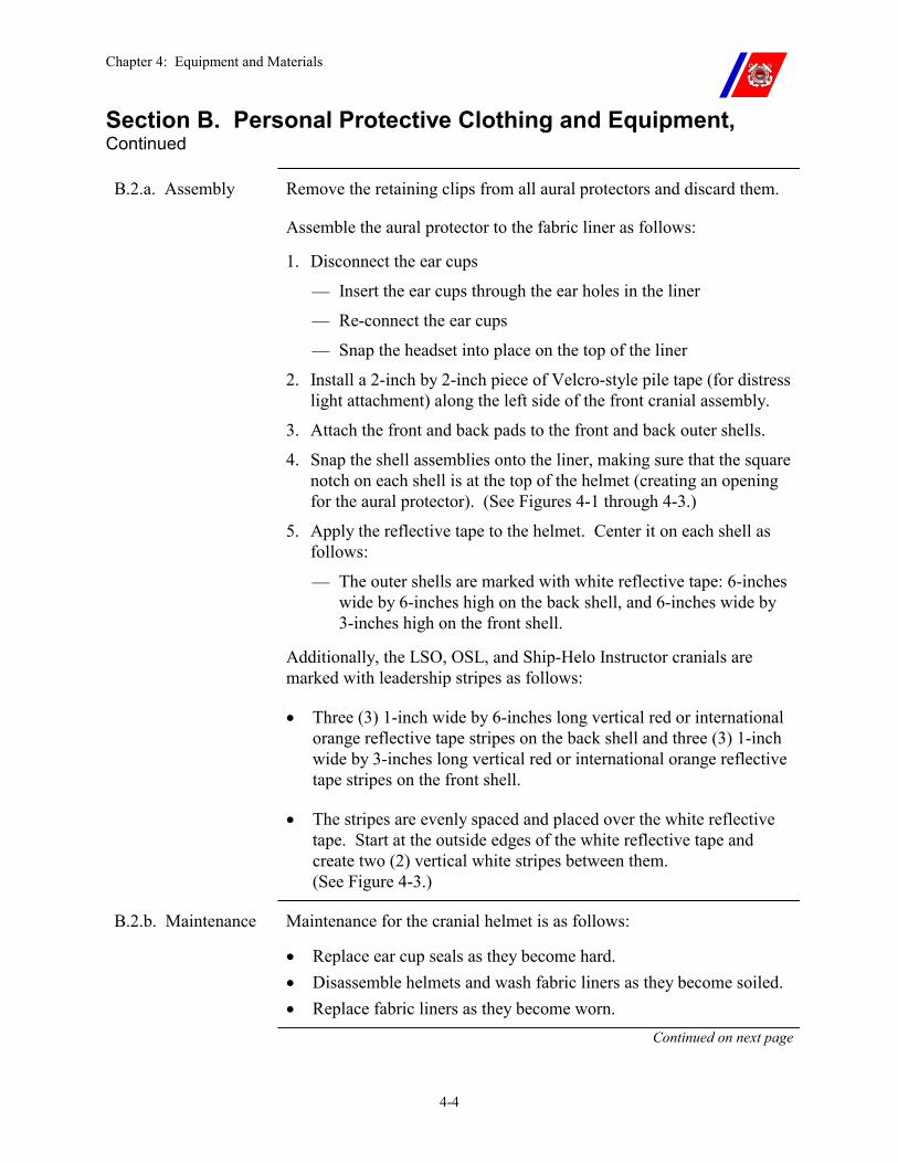
Chapter 4: Equipment and Materials
4-4
Section B. Personal Protective Clothing and Equipment, Continued
B.2.a. Assembly Remove the retaining clips from all aural protectors and discard them.
Assemble the aural protector to the fabric liner as follows:
1. Disconnect the ear cups
�� Insert the ear cups through the ear holes in the liner
�� Re-connect the ear cups
�� Snap the headset into place on the top of the liner
2. Install a 2-inch by 2-inch piece of Velcro-style pile tape (for distress light attachment) along the left side of the front cranial assembly.
3. Attach the front and back pads to the front and back outer shells.
4. Snap the shell assemblies onto the liner, making sure that the square notch on each shell is at the top of the helmet (creating an opening for the aural protector). (See Figures 4-1 through 4-3.)
5. Apply the reflective tape to the helmet. Center it on each shell as follows:
�� The outer shells are marked with white reflective tape: 6-inches wide by 6-inches high on the back shell, and 6-inches wide by 3-inches high on the front shell.
Additionally, the LSO, OSL, and Ship-Helo Instructor cranials are marked with leadership stripes as follows:
�� Three (3) 1-inch wide by 6-inches long vertical red or international orange reflective tape stripes on the back shell and three (3) 1-inch wide by 3-inches long vertical red or international orange reflective tape stripes on the front shell.
�� The stripes are evenly spaced and placed over the white reflective tape. Start at the outside edges of the white reflective tape and create two (2) vertical white stripes between them. (See Figure 4-3.)
B.2.b. Maintenance Maintenance for the cranial helmet is as follows:
�� Replace ear cup seals as they become hard. �� Disassemble helmets and wash fabric liners as they become soiled. �� Replace fabric liners as they become worn.
Continued on next page
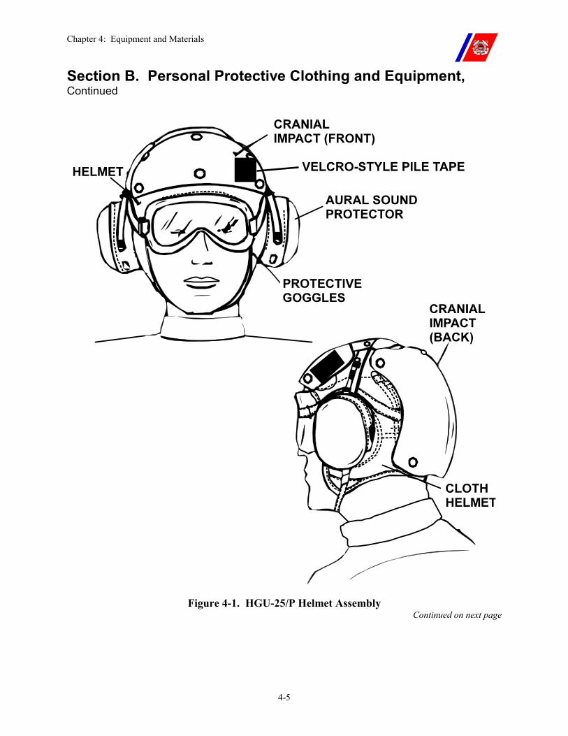
Chapter 4: Equipment and Materials
4-5
Section B. Personal Protective Clothing and Equipment, Continued
Figure 4-1. HGU-25/P Helmet Assembly Continued on next page
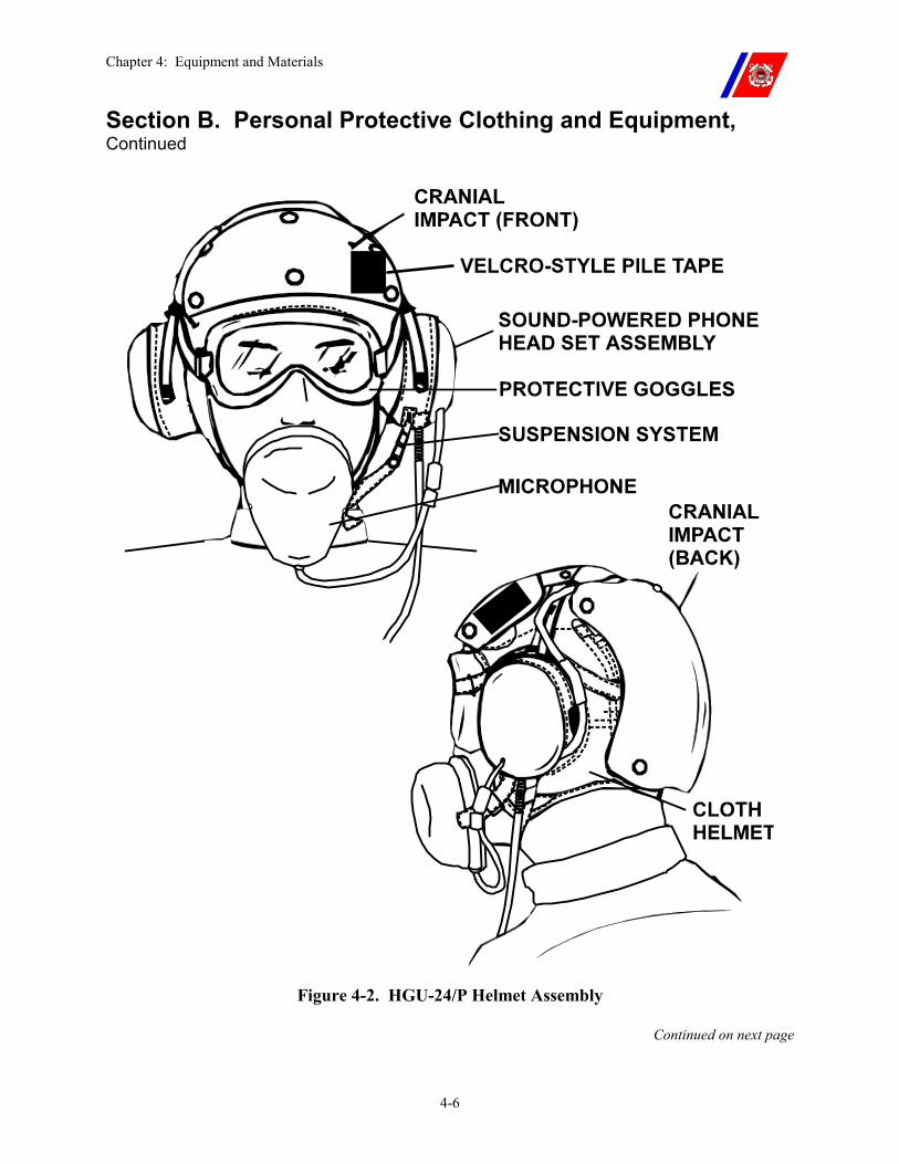
Chapter 4: Equipment and Materials
4-6
Section B. Personal Protective Clothing and Equipment, Continued
Figure 4-2. HGU-24/P Helmet Assembly
Continued on next page
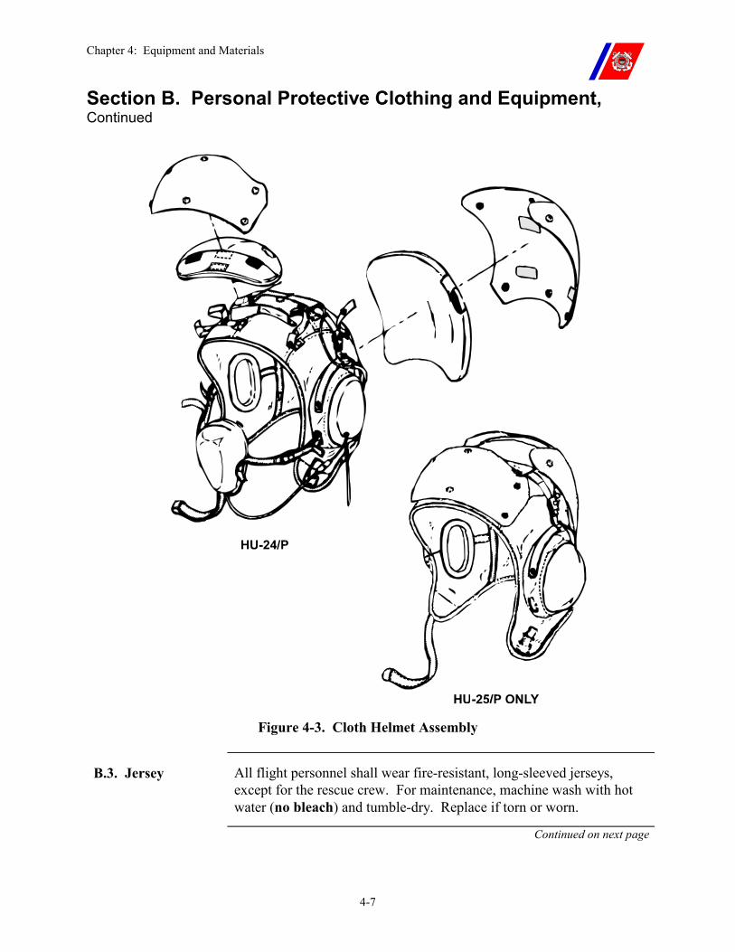
Chapter 4: Equipment and Materials
4-7
Section B. Personal Protective Clothing and Equipment, Continued
Figure 4-3. Cloth Helmet Assembly
B.3. Jersey All flight personnel shall wear fire-resistant, long-sleeved jerseys, except for the rescue crew. For maintenance, machine wash with hot water (no bleach) and tumble-dry. Replace if torn or worn.
Continued on next page
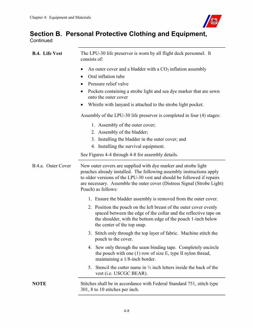
Chapter 4: Equipment and Materials
4-8
Section B. Personal Protective Clothing and Equipment, Continued
B.4. Life Vest The LPU-30 life preserver is worn by all flight deck personnel. It consists of:
�� An outer cover and a bladder with a CO2 inflation assembly �� Oral inflation tube �� Pressure relief valve �� Pockets containing a strobe light and sea dye marker that are sewn
onto the outer cover �� Whistle with lanyard is attached to the strobe light pocket.
Assembly of the LPU-30 life preserver is completed in four (4) stages:
1. Assembly of the outer cover; 2. Assembly of the bladder; 3. Installing the bladder in the outer cover; and 4. Installing the survival equipment.
See Figures 4-4 through 4-8 for assembly details.
B.4.a. Outer Cover New outer covers are supplied with dye marker and strobe light pouches already installed. The following assembly instructions apply to older versions of the LPU-30 vest and should be followed if repairs are necessary. Assemble the outer cover (Distress Signal (Strobe Light) Pouch) as follows:
1. Ensure the bladder assembly is removed from the outer cover.
2. Position the pouch on the left breast of the outer cover evenly spaced between the edge of the collar and the reflective tape on the shoulder, with the bottom edge of the pouch 1-inch below the center of the top snap.
3. Stitch only through the top layer of fabric. Machine stitch the pouch to the cover.
4. Sew only through the seam binding tape. Completely encircle the pouch with one (1) row of size E, type II nylon thread, maintaining a 1/8-inch border.
5. Stencil the cutter name in ½ inch letters inside the back of the vest (i.e. USCGC BEAR).
NOTE Stitches shall be in accordance with Federal Standard 751, stitch type 301, 8 to 10 stitches per inch.
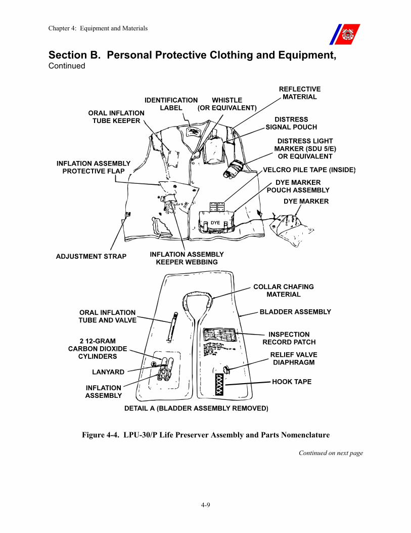
Chapter 4: Equipment and Materials
4-9
Section B. Personal Protective Clothing and Equipment, Continued
Figure 4-4. LPU-30/P Life Preserver Assembly and Parts Nomenclature
Continued on next page
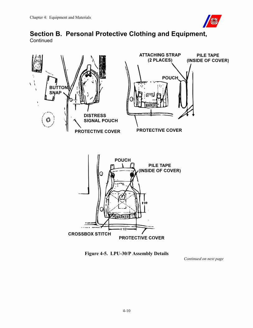
Chapter 4: Equipment and Materials
4-10
Section B. Personal Protective Clothing and Equipment, Continued
Figure 4-5. LPU-30/P Assembly Details Continued on next page
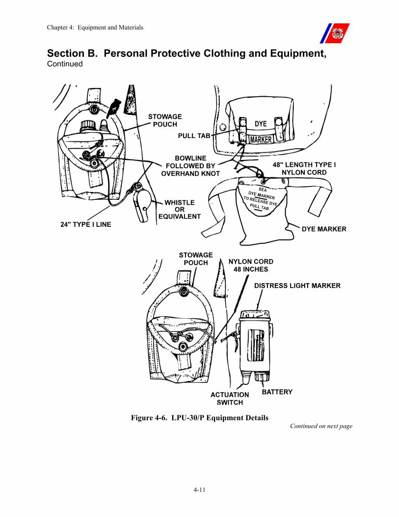
Chapter 4: Equipment and Materials
4-11
Section B. Personal Protective Clothing and Equipment, Continued
Figure 4-6. LPU-30/P Equipment Details Continued on next page
Chapter 4: Equipment and Materials
4-12
Section B. Personal Protective Clothing and Equipment, Continued
B.4.b. Outer Cover Dye Marker and Velcro Bladder
Dye Marker Pouch:
1. Ensure the bladder assembly is removed from the outer cover.
2. Cut off the loose portions of the attaching straps located on the outside back of the pouch. Make the cut just above the top row of horizontal stitching securing the straps to the pouch.
3. Sear the ends of the strap to prevent them from fraying.
4. Using end nippers, remove the snap eyelets and studs (inside and outside) from the back of the pouch.
5. Daub MIL-A-5540B adhesive around the holes in the fabric to keep them from fraying. Allow the adhesive to dry.
6. Center the pouch on the lower left side of the outer cover, with the top edge of the pouch (when closed) even with the top edge of the stitching that attaches the Velcro pile tape to the inside of the cover.
7. Ensure stitching only through the top layer of fabric. Machine stitch the pouch to the cover, sewing a 2-inch by 4-inch cross-box-stitch pattern through the back of the pouch, using size E, type II nylon thread.
Velcro Bladder Restraints:
1. Ensure a 1-inch by 4-inch strip of Velcro-style pile tape is installed on the inside of the protective cover.
2. If not, install the required Velcro strip using size E type II nylon thread to sew Velcro to cover starting 3-inches from the bottom, in the center of the front left inside cover.
WARNING MIL-A-5540B is a polychloroprene adhesive and is flammable and toxic to the eyes, skin, and respiratory tract. Skin and eye protection are required. Avoid repeated or prolonged contact. Use only with adequate ventilation.
NOTE Pouch installation is not necessary on newer-model vest covers that feature integral strobe light and dye marker pockets.
NOTE It may be necessary to relocate the CO2 restraining strap to ensure it is properly positioned to function properly depending on the cover and inflator assembly combination.
Chapter 4: Equipment and Materials
4-13
Section B. Personal Protective Clothing and Equipment, Continued
B.4.c. Bladder 1. If a protective shipping cover is installed on the pressure relief valve, remove and discard it.
2. Ensure that a 2-inch by 4-inch Velcro-style hook tape is installed on the bladder; if not, use adhesive NSN 8040-00-515-2246) to install the strips on the left front side of the bladder.
3. Ensure that the Velcro pieces hold the bladder assembly in place to prevent twisting.
B.4.c.(1). Manual Inflation Assembly
1. Attach the manual inflation assembly to the bladder as follows:
�� Remove and discard the two (2) set screws from the side of the inflation assembly;
�� Remove the retaining nut from the inflation assembly stem on the bladder;
�� Slide the small I.D. gasket over the stem until it is positioned in the notch at the bottom of the stem;
�� Slide the inflation assembly all the way onto the stem, ensuring proper alignment;
�� Slide the large I.D. gasket onto the stem; and
�� Install the retaining nut and torque to eight (8) (+/-1) inch pounds, being careful not to damage the gasket.
2. With the actuation lever down, pass one (1) strand of uncoated 0.0159-inch Type-S shear wire (NSN 6145-00-838-9444) through the hole in the inflation assembly body and secure it with two (2) twists.
3. Place the actuation lever up against the body of the inflation assembly with one (1) end of the shear wire over it and one end under it.
4. Secure the wire by twisting both ends together a minimum of four (4) times, and trim off the excess.
5. Install the CO2 cylinders hand tight, being careful not to cross-thread them. (See Figure 4-7.)
Continued on next page
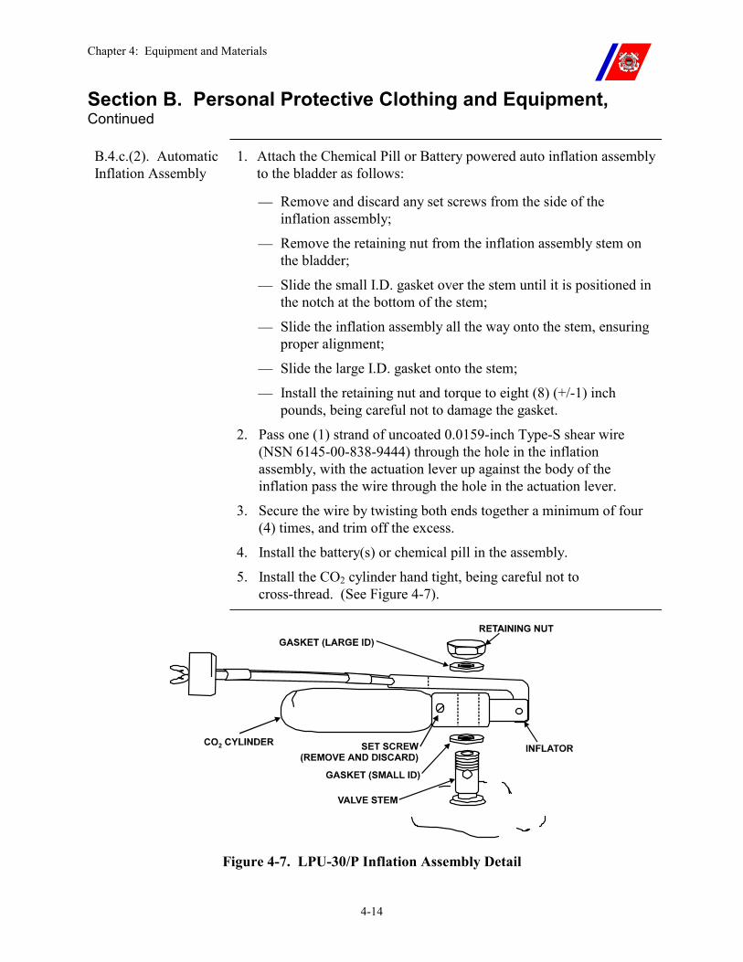
Chapter 4: Equipment and Materials
4-14
Section B. Personal Protective Clothing and Equipment, Continued
B.4.c.(2). Automatic Inflation Assembly
1. Attach the Chemical Pill or Battery powered auto inflation assembly to the bladder as follows:
�� Remove and discard any set screws from the side of the inflation assembly;
�� Remove the retaining nut from the inflation assembly stem on the bladder;
�� Slide the small I.D. gasket over the stem until it is positioned in the notch at the bottom of the stem;
�� Slide the inflation assembly all the way onto the stem, ensuring proper alignment;
�� Slide the large I.D. gasket onto the stem;
�� Install the retaining nut and torque to eight (8) (+/-1) inch pounds, being careful not to damage the gasket.
2. Pass one (1) strand of uncoated 0.0159-inch Type-S shear wire (NSN 6145-00-838-9444) through the hole in the inflation assembly, with the actuation lever up against the body of the inflation pass the wire through the hole in the actuation lever.
3. Secure the wire by twisting both ends together a minimum of four (4) times, and trim off the excess.
4. Install the battery(s) or chemical pill in the assembly.
5. Install the CO2 cylinder hand tight, being careful not to cross-thread. (See Figure 4-7).
Figure 4-7. LPU-30/P Inflation Assembly Detail
Chapter 4: Equipment and Materials
4-15
Section B. Personal Protective Clothing and Equipment, Continued
B.4.d. Installing the Bladder in the Cover
With the bladder and cover laid out right side up:
1. Install the bladder:
�� Start with the bottom of the side of the bladder that does not have the inflation assembly, and
�� Go up through the opposite side of the cover, through the collar, and down the other side of the cover.
2. Make sure the bladder does not become twisted during installation.
3. Insert the oral inflation tube through its hole in the outer cover, and position it under the keeper. Ensure the tube is locked closed.
4. Insert the bladder assembly through its hole in the cover, and if using the manual inflation assembly, position only one of the CO2 cylinders under the keeper.
5. Secure both snaps or the Velcro cover.
NOTE If using the dual cylinder manual inflation assembly, position only one (1) of the CO2 cylinders under the restraining strap. This will prevent the strap from sliding over the actuation lever if the bladder shifts, which could prevent proper actuation. The chemical pill and battery operated auto inflation assemblies use one large CO2 cylinder and it should be restrained using the strap.
WARNING Do NOT remove and re-attach the inflation assembly after inserting bladder into outer cover. A faulty seal will result if fabric from the cover becomes pinched between the inflation assembly and the bladder.
Continued on next page
Chapter 4: Equipment and Materials
4-16
Section B. Personal Protective Clothing and Equipment, Continued
B.4.e. Updated Auto-Inflation Assembly (AIA)
In addition to the older style twin cylinder inflation assembly, two (2) types of auto-inflation assemblies (AIA) are available. (See Figure 4-8.)
It is designed to be installed on the same bladders. These inflation assemblies are compatible only with the MK1 vest cover with integral pouches.
The AIA will not fit older vests. The newer vest covers have an extended inflation assembly cover flap designed to accommodate the longer cylinder of the AIA.
There are two (2) manufacturers of the battery operated assemblies. Installation and performance of the two (2) assemblies is the same; however, the power source, which has a life of three (3) years, is different: one unit uses two (2) 6-volt batteries and the other uses one (1) 12-volt battery.
The chemical pill activated assembly is also designed to fit the existing bladder stem. It uses the larger CO2 cylinder, and like the battery powered assembly, will only fit in the new cover equipped with integral pouches and extended cover flap.
CAUTION When installing the AIA on the bladder, it is imperative that the inflation assembly retaining nut be torqued between 8 and 10 inch-pounds. An improperly torqued nut may result in leakage when inflating.
B.4.f. Auto Inflation Assemblies (AIAs) in Aircraft
The AIAs were not designed to be worn in aircraft. Automatic inflation of the assembly in a ditching situation could trap the wearer in a submerged aircraft.
To prevent inadvertent use, stencil the following directly on the inflation assembly cover flap or on a white or reflective piece of material which is then sewn on the inflation assembly cover flap:
WARNING!
AUTOMATIC INFLATION ASSEMBLY
INSTALLED
DO NOT USE ABOARD AIRCRAFT
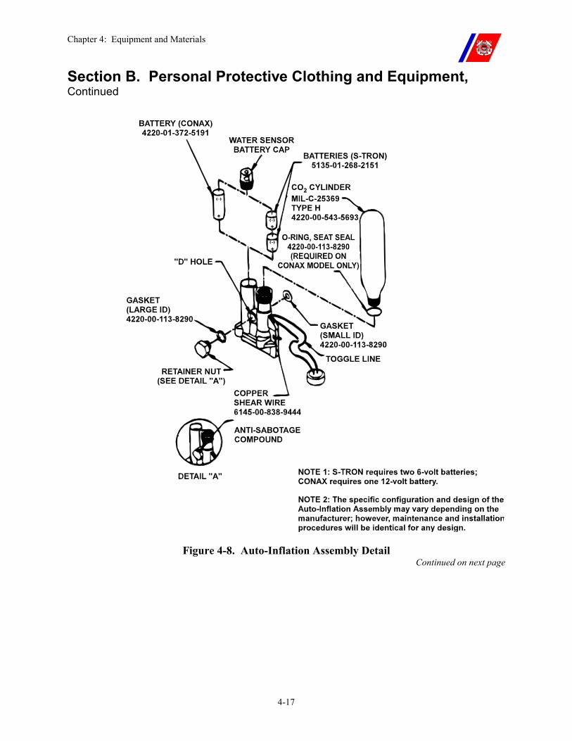
Chapter 4: Equipment and Materials
4-17
Section B. Personal Protective Clothing and Equipment, Continued
Figure 4-8. Auto-Inflation Assembly Detail Continued on next page
Chapter 4: Equipment and Materials
4-18
Section B. Personal Protective Clothing and Equipment, Continued
B.4.g. Survival Equipment Installation
Strobe Light:
1. Remove and discard the protective plastic switch cover from the strobe light (if supplied.)
2. Apply a 2-inch by 2-inch piece of Velcro-style hook tape to one (1) side of the light. Install the battery(s) and test.
3. Tie one (1) end of a 48-inch length of Type I nylon cord (MIL-C-5040) using a bowline followed by an overhand knot to one of the brackets on the strobe light, and to the grommets on the outside of the pocket.
4. Stow the light and cord in the pouch, with the light’s dome facing down, and snap the cover shut.
Whistle:
1. Tie one (1) end of a 24-inch length of Type I nylon cord (MIL-C-5040) to the whistle.
2. On older model vests (with sewn-on strobe pouches),
�� Tie the other end through the grommets on the outside of the strobe light pouch. Use a bowline followed by an overhand knot to stow the whistle on top of the strobe light.
3. On newer versions of the vest (with integral pockets),
�� Tie the other end through the grommets on the outside of the inflation assembly cover, using a bowline followed by an overhand knot, stowing the whistle and cord in the installed pocket at the top of the cover.
4. The cord shall be routed inside of the inflation assembly cover.
5. In addition to the conventional whistle, there is also a flat orange whistle designed to fit in the small, flat pocket in the inflation assembly cover flap. This whistle is attached to the tape on the pocket with 24-inches of nylon cord secured with a bowline knot and installed in the flat pocket.
Dye Marker:
1. Tie one (1) end of a 48-inch length of Type I nylon cord (MIL-C-5040) to the center grommet on the dye marker. Tie the other end through the pull-tab on the left side of the pouch, using a bowline followed by an overhand knot.
2. Stow the dye marker and cord in the pouch and snap it shut.
Chapter 4: Equipment and Materials
4-19
Section B. Personal Protective Clothing and Equipment, Continued
B.4.h. Maintenance Requirements
LPU-30 Life Preserver maintenance consists of quarterly inspections and annual functional tests.
Each life preserver shall be individually identified and tracked in a preventive maintenance system (PMS) program.
The LPU-30/MK1 Maintenance Log, shown in Figure 4-9, is required and shall be retained on file for three (3) years.
Ensure the cutter name is stenciled in ½ inch letters inside the back of the vest (i.e. USCGC BEAR).
B.4.h.(1). Annual Functional Check
Once a year, at the beginning of the quarterly inspection, conduct a functional check of the life preserver.
1. Remove the bladder from the outer cover and inflate it by activating the CO2 inflation assembly.
�� Check for leaks around the inflation assembly.
�� Leave the bladder inflated for four (4) hours. Ensure the bladder maintains pressure.
�� Deflate the bladder through the oral inflation tube. Reset and rewire the actuation lever, install new CO2 cylinders, and reinstall the bladder in the outer cover. (See this chapter, Paragraph B.4.d.)
2. Complete the quarterly inspection.
3. Record the functional check and inspection in the LPU-30 PMS log. The LPU-30/MK1 Maintenance Log, shown in Figure 4-9, is required and shall be retained on file for three (3) years.
Continued on next page
Chapter 4: Equipment and Materials
4-20
Section B. Personal Protective Clothing and Equipment, Continued B.4.h.(2). Quarterly Inspections
The following inspections shall be completed on each life preserver once a quarter:
1. Check the condition of the life preserver cover for wear and cleanliness.
�� Make necessary repairs to tears in the fabric. Replace the cover if beyond repair.
�� Soiled covers may be washed with mild soap and water after removing the bladder and the contents of the pouches; do not use bleach.
2. Remove the CO2 cylinder(s) and check that they are not expended.
�� Replace the cylinders and hand tighten. Ensure not to damage the threads on the inflation assembly.
�� Inspect and, if necessary, replace the shear wire around the actuation lever. (See this chapter, Paragraph B.4.c.)
3. Inflate the bladder with one (1) psig air through the oral inflation tube. Check for twists in the bladder as it is inflated.
�� Leave the bladder inflated for four (4) hours. Ensure the bladder maintains pressure.
�� After four (4) hours, increase the pressure to a maximum of two (2) psig to test the pressure relief valve. It should relieve at 1.5 (+/-0.25) psig.
�� Deflate the bladder through the oral inflation tube, then rotate the screw lock on the tube to lock the valve closed, and replace the tube beneath the keeper.
4. Check that the strobe light, dye marker, and whistle are not missing.
�� Test the strobe light and ensure proper operation.
�� Replace the battery(s) every two (2) years or sooner if required.
�� Check the condition of the dye marker, and replace it if it shows signs of leakage.
�� Ensure that the knots are tight on all of the lanyards.
5. If using the automatic inflation device, ensure the battery voltage is tested. The battery voltage shall be 11.7 VDC or above.
6. Record the inspection in the LPU-30 PMS log. The LPU-30/MK1 Maintenance Log, shown in Figure 4-9, is required and shall be retained on file for three (3) years.
Continued on next page
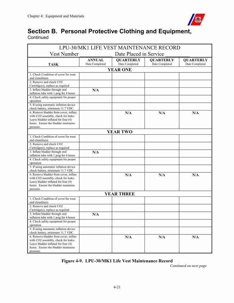
Chapter 4: Equipment and Materials
4-21
Section B. Personal Protective Clothing and Equipment, Continued
LPU-30/MK1 LIFE VEST MAINTENANCE RECORD Vest Number ____________ Date Placed in Service _________
TASK
ANNUAL Date Completed
QUARTERLY Date Completed
QUARTERLY Date Completed
QUARTERLY Date Completed
YEAR ONE 1. Check Condition of cover for wear and cleanliness
2. Remove and check CO2 Cartridge(s), replace as required
3. Inflate bladder through oral inflation tube with 1 psig for 4 hours
N/A
4. Check safety equipment for proper operation
5. If using automatic inflation device check battery, minimum 11.7 VDC
6. Remove bladder from cover, inflate with CO2 assembly, check for leaks. Leave bladder inflated for four (4) hours. Ensure the bladder maintains pressure.
N/A N/A N/A
YEAR TWO 1. Check Condition of cover for wear and cleanliness
2. Remove and check CO2 Cartridge(s), replace as required
3. Inflate bladder through oral inflation tube with 1 psig for 4 hours
N/A
4. Check safety equipment for proper operation
5. If using automatic inflation device check battery, minimum 11.7 VDC
6. Remove bladder from cover, inflate with CO2 assembly, check for leaks. Leave bladder inflated for four (4) hours. Ensure the bladder maintains pressure.
N/A N/A N/A
YEAR THREE 1. Check Condition of cover for wear and cleanliness
2. Remove and check CO2 Cartridge(s), replace as required
3. Inflate bladder through oral inflation tube with 1 psig for 4 hours
N/A
4. Check safety equipment for proper operation
5. If using automatic inflation device check battery, minimum 11.7 VDC
6. Remove bladder from cover, inflate with CO2 assembly, check for leaks. Leave bladder inflated for four (4) hours. Ensure the bladder maintains pressure.
N/A N/A N/A
Figure 4-9. LPU-30/MK1 Life Vest Maintenance Record Continued on next page
Chapter 4: Equipment and Materials
4-22
Section B. Personal Protective Clothing and Equipment, Continued
B.5. Safety Shoes Rubber-soled, full ankle-length boots with steel toes shall be worn by all flight deck personnel, except for the rescue crew. Rescue crew equipment is described in Chapter 14.
Replace boots when the soles wear out, the heels become loose, or the leather becomes torn.
B.6. Goggles All flight deck personnel, except for the rescue crew, shall wear protective goggles. Rescue crew equipment is described in Chapter 14.
Dark lenses are used for day operations and clear lenses for night operations.
Lenses designed for protection from laser light alter and eliminate red light and shall not be worn.
For maintenance, replace lenses when they become scratched or cracked. Both lenses shall be readily available to personnel.
B.7. Flash Hoods and Gloves
Flash hoods and gloves shall be worn by all fire party personnel and helicopter refueling teams (static and hot refueling), and are recommended for all other flight deck personnel.
For maintenance, machine wash with hot water and tumble-dry. Replace if worn or torn.
B.8. Proximity Suits Proximity suits for rescue crews are described in Chapter 14.
B.9. Cutter Swimmer Equipment
The cutter swimmer’s equipment is normally stored in a flyer’s kit bag, and should include the following:
�� Full wet suit (shorty wet suit may be used when water temperature permits).
�� Mask, snorkel, and fins. �� Swimmer’s harness. �� Safety line (600-feet of ¼ inch polyethylene line) on a reel. �� Diver’s rescue knife. �� V-blade or J-blade knife, for strap cutting. �� SAR-1 life vest, with whistle and strobe light.
Continued on next page
Chapter 4: Equipment and Materials
4-23
Section C. Flight Deck Operating Criteria and Visual Landing Aids (VLA)
C.1. Overview Operating criteria and visual landing aids (VLA) include:
�� Deck surface, and all landing area markings;
�� Clearances, lighting, visual approach equipment; and
�� Accessories that permit a helicopter to operate safely from or in conjunction with a cutter.
Operations with less than the minimum VLA imposed by this chapter are not permitted except with written authorization from Commandant (G-OCA).
C.2. Flight Deck Surface
Flight deck and hangar decks shall be coated with a non-skid surface, as outlined in the Coatings and Color Manual, COMDTINST M10360.3 (series), and the NAVAIRWARCENACDIVLKE Air Capable Ship Aviation Facilities Bulletin No. 1 (series).
NOTE Only Epoxy, roll-on, non-skid is authorized for use on Coast Guard Cutters.
C.2.a. Non-Skid Surface
The surface shall show a pattern of peaks and ridges.
�� The ridge profile shall be continuous and reasonably uniform. �� Peaks and ridges shall be generally in the same direction (fore and
aft preferred), approximately 1/2-inch to 1-inch apart, and approximately 1/16-inch to 3/32-inches high.
Aggregate shall present a rough uniformly coarse appearance over the entire surface with no loosely bound clumps of particles.
All weld seams shall be cross-rolled from a minimum of three (3) inches on either side of the weld.
All equipment not to be painted with non-skid shall be adequately taped or covered.
Non-skid shall be applied up to six (6) inches of the deck coaming. This will allow water to flow easily along the flight deck edge into the drains. All areas that are not non-skidded shall be painted.
Continued on next page
Chapter 4: Equipment and Materials
4-24
Section C. Flight Deck Operating Criteria and Visual Landing Aids (VLA), Continued
C.2.b. Marking and Color Topping
Flight deck marking and non-skid locations shall be in accordance with applicable VLA guidance drawings.
�� The marking and color topping shall be compatible with the paint system and from the same manufacturer.
�� Color topping shall be used for VLA and safety markings only.
NOTE Use of color topping for cosmetic purposes is prohibited and cause for rejection of the non-skid installation and withdrawal of certification or authorization to conduct flight operations.
C.2.c. Delamination There shall be no evidence of delamination of the non-skid. If delamination is present, the delaminated area shall be satisfactorily repaired before flight deck certification.
C.2.d. Non-Skid Cosmetic Appearance
Cleaning, touch up, and re-marking of the non-skid shall be accomplished in accordance with the Coatings and Color Manual, COMDTINST M10360.3 (series). Non-skid may be washed with a cleaner approved by the coating’s manufacturer to remove stains, chalking, and residual oil, in order to maintain the cosmetic appearance.
Use of color topping for cosmetic purposes is prohibited and cause for rejection of the non-skid installation and withdrawal of certification and authorization to conduct flight operations.
C.3. In-Deck and Bulkhead Tiedown Fittings
Deck and bulkhead fittings shall be installed and tested in accordance with NAVAIRWARCENACDIVLKE Air Capable Ship Aviation Facilities Bulletin No. 1 (series).
New or replacement deck fittings (constructed or installed after the issuance of this instruction) shall be in-deck bar-type.
WARNING The tail stinger on the HH-65 can become embedded in raised deck tiedown fittings, and may result in injury to personnel and/or loss of the aircraft.
Continued on next page
Chapter 4: Equipment and Materials
4-25
Section C. Flight Deck Operating Criteria and Visual Landing Aids (VLA), Continued
C.4. Deck Edge Protection (Safety Nets and Catwalks)
Deck edge protection shall be installed and tested in accordance with NAVAIRWARCENACDIVLKE Air Capable Ship Aviation Facilities Bulletin No. 1 (series), as amended by the Shipboard Helicopter Operations Facility Certification Program Manual, COMDTINST 3120.13 (series).
New or replacement deck edge protection (installed after the issuance of this instruction) shall be in accordance with NAVSEA drawings 803-5000902 or 803-51484097 (group).
Nylon webbing used in catwalks shall be IAW MIL-W-23223A.
C.5. Landing Area Markings
Flight deck markings provide required obstacle clearance for helicopter operations and assist the pilots and LSO with situational awareness during launch and recovery. They shall be in accordance with the appropriate NAVAIR drawing.
All portions of any equipment that impinges on a VLA marking shall be painted white, so that the VLA marking appears to be continuous. Typical VLA arrangements are shown in Figures 4-10 and 4-12.
C.5.a. Peripheral Lines
These lines outline the helicopter landing area and indicate the clear (obstruction-free) deck area.
C.5.b. Touchdown Circle
The 24-foot diameter touchdown circle indicates the area that the helicopter’s forward wheels or skid supports must touch down.
No obstructions above deck level, including raised deck tiedown fittings, are permitted inside the touchdown circle.
NOTE The HH-65 shall be landed with both the nose wheel and the main landing gear inside the touchdown circle to ensure proper rotor obstruction clearance and positioning of the tail stinger over the flight deck.
C.5.c. Landing Spot A 4-foot diameter solid white dot is located in the center of the touchdown circle.
Continued on next page
Chapter 4: Equipment and Materials
4-26
Section C. Flight Deck Operating Criteria and Visual Landing Aids (VLA), Continued
C.5.d. Landing Lineup Line
Solid white lines through the landing spot indicate the approach path for landings.
Helicopters landed on the appropriate lineup line with the forward wheels or skid supports within the landing circle will have all other wheels on deck, and will be clear of all obstructions.
The landing lineup line(s) may be oriented fore and aft, at an angle (oblique), or athwartships (WAGB only). The fore and aft lineup line is extended up the superstructure.
C.5.e. Vertical Replenishment (VERTREP)/ Hover Line
There is a white “T-Line” through the landing circle that provides obstacle clearance for the helicopter.
The helicopter’s main and tail rotor hubs must remain at or aft of this line during VERTREP operations. The VERTREP area is aft of the VERTREP Line.
This area is used for pickup and delivery of cargo.
C.5.f. Helicopter In-Flight Refueling (HIFR) Marking
Cutters capable of HIFR display the letter “H” at the aft port corner of the flight deck.
C.5.g. TALON Alignment Lines
A set of two (2) white lines are painted on the starboard side of the flight deck to enable the aircrew to assist the pilot with fore-and-aft positioning of the aircraft over the TALON grid.
�� Each line is 12-inches wide, begins at the deck edge, and extends 30-inches inboard.
�� The aft line shall be painted in a position so that the forward edge of the line is 11-inches forward of a line drawn tangent to the forward edge of the TALON grid.
�� The forward line shall be painted in a position so that the aft edge of the line is 82-inches forward of a line drawn tangent to the forward edge of the TALON grid. (See Figure 4-12.)
Continued on next page
Chapter 4: Equipment and Materials
4-27
Section C. Flight Deck Operating Criteria and Visual Landing Aids (VLA), Continued
C.6. Hangar Area Markings
C.6.a. Hangar Deck Markings
Hangar area markings provide specific information for helicopter traversing and parking, and shall be in accordance with Air Capable Ship Aviation Facilities Bulletin No. 1 (series).
C.6.b. Hangar Door Markings
On cutters with vertically activated doors, the lower 2-feet of the door (exterior and interior) is painted with alternating yellow and red stripes. This provides a visual indication that the door has been fully retracted before helicopter movement into and out of the hangar.
Doors that leave yellow or red stripes visible in the fully retracted position shall have black alignment stripes painted in the upper corners of the doorway, on the door (exterior and interior), and on the adjacent track or bulkhead to indicate “full” retraction for adequate helicopter traversing clearance. Each alignment stripe segment shall be 2-inches wide, 6-inches long and readily visible from the deck.
C.6.c. TALON Alignment Line Marking
On TALON equipped cutters with oblique approach requirements, a 12-inch wide black stripe is painted down the center of the hangar door to aid in lateral alignment of the helicopter.
C.6.d. Hangar Access Line(s) and Wheel Spot Marking
These markings are used to park helicopters in the hangar and for guiding helicopters into and out of the hangar.
C.7. Obstacle Clearance Criteria
Flight deck markings meet the minimum obstacle clearance criteria established in the Air Capable Ship Aviation Facilities Bulletin No.1 (series), to provide a minimum safe deck area in which to operate helicopters.
C.7.a. Helicopter Landing Area Obstructions
The helicopter landing area is the area outlined by the white peripheral lines. Obstructions within the area but outside the touchdown circle are smoothly contoured, and do not exceed 4 ½-inches in height.
No obstructions above deck height exist within the touchdown circle.
WARNING Stowage of items on the flight deck shall not be permitted during flight operations.
Continued on next page
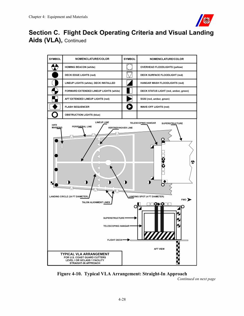
Chapter 4: Equipment and Materials
4-28
Section C. Flight Deck Operating Criteria and Visual Landing Aids (VLA), Continued
Figure 4-10. Typical VLA Arrangement: Straight-In Approach Continued on next page
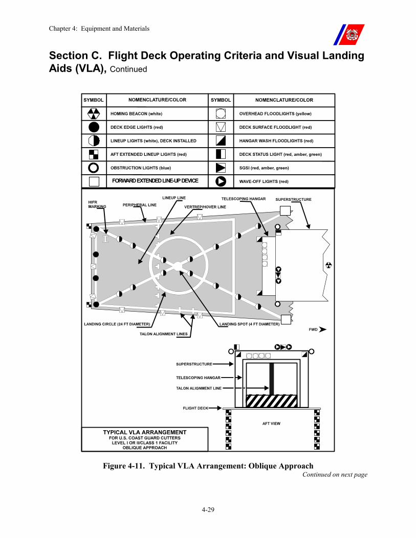
Chapter 4: Equipment and Materials
4-29
Section C. Flight Deck Operating Criteria and Visual Landing Aids (VLA), Continued
FORWARD EXTENDED LINE-UP DEVICE
Figure 4-11. Typical VLA Arrangement: Oblique Approach Continued on next page
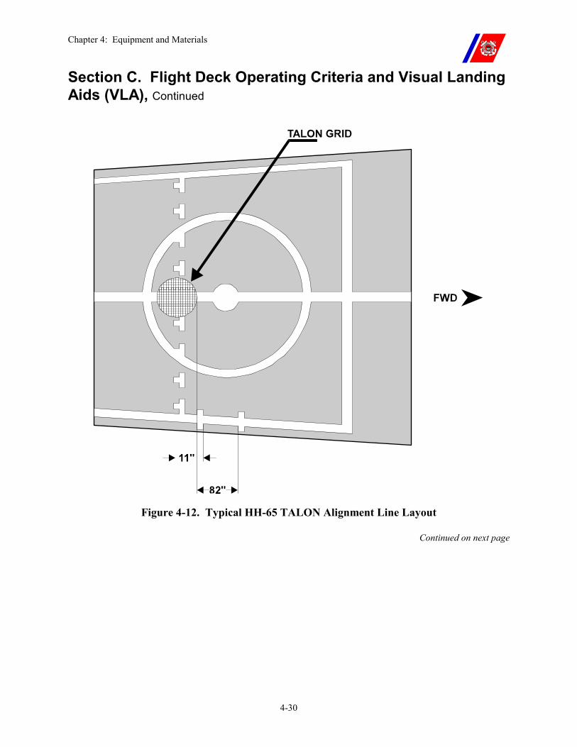
Chapter 4: Equipment and Materials
4-30
Section C. Flight Deck Operating Criteria and Visual Landing Aids (VLA), Continued
Figure 4-12. Typical HH-65 TALON Alignment Line Layout
Continued on next page
Chapter 4: Equipment and Materials
4-31
Section C. Flight Deck Operating Criteria and Visual Landing Aids (VLA), Continued
C.8. Lighting and Visual Approach Equipment
Lighting and visual approach equipment shall be installed in accordance with applicable NAVAIR drawings, which are based upon the requirements of NAVAIRWARCENACDIVLKE Air Capable Ship Aviation Facilities Bulletin No. 1 (series), as modified by the Shipboard Helicopter Operations Facility Certification Program Manual, COMDTINST 3120.13 (series). The VLA equipment is designed to provide sufficient lighting over the landing area to allow the pilot to land or take off visually, provide reflected lighting on the superstructure forward of the landing area to allow for maximum depth perception, and provide other lights as required to aid the pilot in cutter location and orientation.
Lighting not specifically addressed in the following paragraphs shall not be used during flight operations.
C.8.a. Homing Beacon (White)
The homing beacon provides a visual guide to aid the pilot in locating the cutter at night and during periods of low visibility.
During normal NVG operations, the homing beacon shall remain secured.
The beacon is a flashing white light located as high up on the mast as feasible and positioned so that it may be readily seen at all azimuth angles.
The beacon produces approximately 90 white flashes per minute.
C.8.b. Deck Edge Lights (Red)
These lights provide the pilot with a visual indication of the deck edge on the landing approach path.
During NVG operations, Deck Edge Lighting is optional and shall be set at the lowest level possible (if used.)
Continued on next page
Chapter 4: Equipment and Materials
4-32
Section C. Flight Deck Operating Criteria and Visual Landing Aids (VLA), Continued
C.8.c. Deck Lineup Lights
These lights assist the pilot in finding the cutter, determining the cutter orientation at night, and during periods of low visibility.
�� Deck Installed (white). These lights are installed in the flight deck parallel to the landing line-up line(s). Lights can be set on either steady illumination, or to strobe sequentially from aft to forward.
�� Forward Extended (white). These lights extend the line of deck installed lights forward, above the flight deck level. See this chapter, Paragraph C.8.n.
�� Aft Extended (red). A vertical drop-line light bar assembly extends the line of the deck installed lights aft, below the flight deck level.
�� Line up Lights. During NVG operations, the Line up Lights are optional and shall be set at the lowest level possible (if used.)
C.8.d. Helicopter In-Flight Refueling (HIFR) Heading Lights (Yellow/Red)
Three (3) lights, mounted along the port superstructure above the flight deck, provide a visual reference to assist the pilot in maintaining proper position during HIFR operations.
�� Yellow lenses are used during peacetime, �� Red lenses are installed in time of war. �� HIFR Lights are not used during NVG operations.
HIFR Lights are not installed on WMEC 210 cutters.
C.8.e. Obstruction Lights (Blue)
Obstruction lights mark hazards and are installed at the top and outboard limits of shipboard structures closest to the operating area.
Obstruction lights are not used during NVG operations.
C.8.f. Overhead Floodlights (Yellow/Red)
�� Typical Installation. These lights are installed above and forward of the operating area to provide light for visual hovering over the landing area. The lights are aimed at the forward peripheral line (as depicted in Figures 4-10 and 4-11).
�� Yellow lenses are used during peacetime,
�� Red lenses are installed in time of war.
�� WAGB 399 cutters. The overhead floodlights are red.
�� The overhead floodlights (yellow/red) are not to be used during NVG operations.
Continued on next page
Chapter 4: Equipment and Materials
4-33
Section C. Flight Deck Operating Criteria and Visual Landing Aids (VLA), Continued
C.8.g. NVG Overhead Floodlights (Blue/Green).
�� Typical Installation. These lights are installed above and forward of the operating area to provide light for visual hovering over the landing area. The lights are aimed at the forward peripheral line (as depicted in Figures 4-10 and 4-11).
C.8.h. Deck Surface Floodlights.
�� Typical Installation. These lights are installed around and illuminate the landing area. (See Figures 4-10 and 4-11.) They are aimed, in conjunction with the overhead floodlights, to provide best possible illumination while keeping spill-over (illumination beyond the deck edge) at a minimum.
The lights are equipped with an installed clear lens and removable red lens. Additional blue/green NVG compatible lenses are supplied with the NVG conversion package. Cutters not certified for NVG operations shall have the red lens installed at all times. Cutters certified for NVG operations shall have blue/green lens installed at all times.
All parts of the deck surface floodlights that protrude over any VLA marking shall be painted white to provide continuity of VLA markings.
�� HIFR/VERTREP Guards. Only the light closest to the “H” requires guards. The stock may be attached by either bolts or pop rivets. The guards, when installed, shall not alter the illumination characteristics of the light or the flight deck.
�� WAGB 399 cutters. These lights are not installed. Illumination is provided by two white utility floodlights, one mounted at each aft flight deck corner.
The lights are mounted to provide for movement horizontally and vertically for positioning and shall not extend more than 18-inches above the deck. They are lined up on the point where the aft part of the landing circle crosses the fore and aft lineup line, and are aimed at the deck about 3-feet in front of the light fixture.
Glare shields minimize interference with the vision of the LSO and tiedown crew.
NOTE Because of their optical characteristics, red lenses may appear red, orange, or amber when the lights are energized.
Continued on next page
Chapter 4: Equipment and Materials
4-34
Section C. Flight Deck Operating Criteria and Visual Landing Aids (VLA), Continued
C.8.i. Hangar or Structure Wash Floodlights (Red).
�� Typical Installation. These lights illuminate the aft face of the hangar or superstructure, and help improve the depth perception of the pilots.
The lights are equipped with an installed clear lens and removable red lens. Additional blue/green NVG compatible lenses are supplied with the NVG conversion package. Cutters not certified for NVG operations shall have the red lens installed at all times. Cutters certified for NVG operations shall have blue/green lens installed at all times.
�� WAGB 399 cutters. These lights are not installed. Illumination is provided by the utility floodlights described in this chapter, Paragraph C.8.h.
The superstructure is illuminated by light reflected off the deck.
NOTE Because of their optical characteristics, the red lenses may appear red, orange, or amber when the lights are energized.
C.8.j. Deck Status Light System
This system has a fixture consisting of three (3) lights (red, amber, and green) and produces approximately 90 flashes per minute.
The Deck Status Light allows the HCO to provide visual indications to the helicopter crew and flight deck personnel of aircraft clearance to land, takeoff, start engine, engage rotors, or cleared for an evolution.
The fixture is installed on the upper aft port corner of the hangar or superstructure. It can be readily seen by the pilot while preparing for takeoff and during the approach and landing evolution.
The Deck Status Light shall not be used during NVG operations.
In conjunction with LSO signals and radio messages:
�� A green light signifies clearance for a particular evolution(s).
�� Red signifies not cleared for a particular evolution(s).
�� Amber signifies cleared to start or secure engines and engage or disengage rotors.
This system is not installed on WAGB 399 cutters. Continued on next page
Chapter 4: Equipment and Materials
4-35
Section C. Flight Deck Operating Criteria and Visual Landing Aids (VLA), Continued
C.8.k. Stabilized Glide Slope Indicator (SGSI)
The SGSI provides the pilot with a visual tri-colored indication of the proper approach path to the cutter at night and during low visibility.
This system is not installed on WMEC 210 or WAGB 399 cutters.
The SGSI shall not be used during NVG operations.
C.8.l. Wave-off Lights
Wave-off lights flash at approximately 90 flashes per minute and provide the pilot with a visual signal to abort an approach or landing.
The HCO or the LSO can activate the lights.
The Wave-off lights shall not be energized during NVG operations.
This system is not installed on WMEC 210 or WAGB 399 cutters.
WARNING The use of Wave-off lights during NVG operations is prohibited. Activation of this system will cause complete NVG washout resulting in temporary blinding of all personnel using NVG devices.
C.8.m. Additional Lights
Other lights, including deck lighting, cargo lights, and searchlights trained into the water can aid the pilots in visual orientation upon pilot requests.
CAUTION Any lighting not specifically approved for use during NVG operations shall not be energized during NVG operations.
C.8.n. Forward Extended Lineup Device
The forward extended lineup device provides a forward extension of the oblique line-up line and gives the pilot final positioning information for the touchdown maneuver.
The light can have lights or reflective tape to aid night operations.
The device extends beyond the deck edge and above the flight deck level and the elevation angle is limited by obstacle clearance criteria.
Continued on next page
Chapter 4: Equipment and Materials
4-36
Section C. Flight Deck Operating Criteria and Visual Landing Aids (VLA), Continued
C.9. Minimum Lighting
For night training, night operations, and periods of low visibility, all efforts shall be made to provide all the lights previously discussed. Cutters shall carry adequate spare bulbs for the VLA system.
If mission urgency requires and the cutter Commanding Officer and pilot in command (PIC) agree that safety will not be compromised:
�� Any one overhead floodlight, any one deck surface floodlight, and/or any one (1) hangar or superstructure wash floodlight may be inoperative.
�� Up to 20 percent of the in-deck and/or extended lineup lights may be inoperative if no two adjacent lights are inoperative.
One (1) HIFR heading light may be inoperative for a night operation.
C.10. Cutter Navigation and Superstructure Lighting
Cutter lighting and light discipline critically affect NVG performance and the safe conduct of NVG flight operations. Lighting configurations and intensities will vary with ambient conditions and aircrew and flight deck personnel proficiency and preference. Before conducting NVG operations, each cutter's lighting package shall be USN certified for NVG operations by NAVAIR, Lakehurst, NJ. In addition to NAVAIR certification, each cutter shall have the following items aboard before commencing NVG operations:
�� Two (2) NVG compatible Closed Circuit Television (CCTV) cameras (low lux rating).
�� Three (3) sets of ANVIS NVGs. �� Three (3) sound powered or radio compatible helmets capable of
mounting ANVIS NVGs. �� Three (3) or more sets of shatterproof clear safety goggles. Goggles
shall fit under NVG and provide a complete seal around the eyes. �� Appropriate number of blue Chemlights for training or operations.
Recommend two dozen lights per flight deck evolution. �� Portable NVG Focusing lane comprised of portable Eye Chart (can
be made from local materials).
CAUTION Operating navigation lights on DIM or OFF settings does not conform to nautical rules of the road. Close coordination will be necessary, both intraship and intership, when use of navigation lighting requires modification.
Chapter 5: Planning, Limitations, Communications, and Navigation
5-i
CHAPTER 5: PLANNING, LIMITATIONS, COMMUNICATIONS AND NAVIGATION
Table of Contents
Introduction................................................................................................................................ 5-1
In this chapter ............................................................................................................................ 5-1
Section A. Mission Planning .................................................................................................... 5-2
A.1. Overview ............................................................................................................................ 5-2
A.2. Mission Planning Session ................................................................................................. 5-3 A.2.a. NVG Operations Planning Overview...................................................................................5-4
A.2.a.(1). NVG Operations Objective......................................................................................5-4 A.2.a.(2). NVG L/E Objective..................................................................................................5-4 A.2.a.(3). NVG Operations Environmental Considerations.....................................................5-5
A.3. International, Special Use, or Foreign Airspace ............................................................ 5-5
Section B. Flight Deck Motion Limitations ............................................................................ 5-6
B.1. Overview ............................................................................................................................ 5-6
B.2. Pitch and Roll .................................................................................................................... 5-6
B.3. List ...................................................................................................................................... 5-6
B.4. Heave and Yaw.................................................................................................................. 5-7
Section C. Weather Considerations and Limitations ............................................................ 5-8
C.1. Overview ............................................................................................................................ 5-8
C.2. Wind ................................................................................................................................... 5-8
C.3. Ceiling and Visibility ........................................................................................................ 5-9 C.3.a. Visual Meteorological Conditions (VMC) versus Instrument Meteorological Conditions (IMC) ...............................................................................................................................................5-9 C.3.b. Reduced Weather Operations...............................................................................................5-9 C.3.c. Minimum Ceiling and Visibility Criteria .............................................................................5-9
C.4. Weather Observations and Reports .............................................................................. 5-10 C.4.a. Weather Planning Observations .........................................................................................5-11 C.4.b. Current Weather Observations...........................................................................................5-12 C.4.c. Pre-Departure Weather Observations.................................................................................5-12
Section D. Helicopter and Aircrew Limitations ................................................................... 5-13
Chapter 5: Planning, Limitations, Communications, and Navigation
5-ii
D.1. Overview .......................................................................................................................... 5-13
D.2. Helicopter Limitations.................................................................................................... 5-13
D.3. Aircrew Use ..................................................................................................................... 5-13 D.3.a. Duty....................................................................................................................................5-13 D.3.b. Crew Mission Time............................................................................................................5-13
Section E. Communications and Navigation ........................................................................ 5-14
E.1. Overview .......................................................................................................................... 5-14
E.2. Voice Communications ................................................................................................... 5-14 E.2.a. Cutter Internal Communications.........................................................................................5-14 E.2.b. Cutter External Communications .......................................................................................5-15 E.2.c. Helicopter Internal Communications..................................................................................5-15 E.2.d. Helicopter External Communications ................................................................................5-15
E.3. Visual Signals................................................................................................................... 5-16 E.3.a. Day Shapes and Navigational Lights..................................................................................5-16 E.3.b. HOTEL Flag.......................................................................................................................5-16 E.3.c. Deck Status Light ...............................................................................................................5-16 E.3.d. Landing Signal Officer (LSO) Signal Devices...................................................................5-17 E.3.e. Wave-off Lights..................................................................................................................5-17 E.3.f. LSO and Pilot Hand Signals ...............................................................................................5-17 E.3.g. Emission Control (EMCON) and Lost Communications Signals ......................................5-18
E.4. Helicopter Operational Status Reports ......................................................................... 5-18
E.5. Lost Communications Procedures (Cutter) .................................................................. 5-19 E.5.a. Initial Indicators..................................................................................................................5-19 E.5.b. 15-Minutes Overdue...........................................................................................................5-19 E.5.c. 30-Minutes Overdue ...........................................................................................................5-20 E.5.d. Reaching Fuel Endurance...................................................................................................5-20 E.5.e. If Helicopter Arrives Overhead ..........................................................................................5-20
E.6. Lost Communications Procedures (Aircraft) ............................................................... 5-21
E.7. TACAN/DME .................................................................................................................. 5-21
Chapter 5: Planning, Limitations, Communications, and Navigation
5-1
Chapter 5. Planning, Limitations, Communications
and Navigation
Introduction This chapter establishes criteria essential to the safety of flight operations conducted from or with Coast Guard Cutters.
In this chapter This chapter is divided into five (5) sections:
�� Section A: Mission Planning �� Section B: Flight Deck Motion Limitations �� Section C: Weather Considerations and Limitations �� Section D: Helicopter and Aircrew Limitations �� Section E: Communications and Navigation
Chapter 5: Planning, Limitations, Communications, and Navigation
5-2
Section A. Mission Planning
A.1. Overview Careful and thorough mission planning is required for safe and effective Ship-Helo operations.
The primary element of good mission planning is an assessment of the purpose and objectives of each mission, weighed against the risks to which personnel and equipment will be exposed. Factors shall be analyzed, such as:
�� Aircrew and equipment capabilities and limitations, �� Illumination levels for NVG operations, �� Weather, flight deck motion, and �� Aircrew survivability.
Changing factors shall also be analyzed, such as:
�� Rapid variations in weather conditions, or �� Malfunctions of helicopter or shipboard equipment, which can
seriously affect the outcome of the flight and will require a reevaluation of the mission plan.
While not all possible contingencies can be addressed, the operational parameters delineated in this chapter and the guidance provided by the Risk Assessment Chart in the Air Operations Manual, COMDTINST M3710.1 (series), establish guidelines that should assist cutter Commanding Officers and/or controlling agencies in their mission planning process.
Continued on next page
Chapter 5: Planning, Limitations, Communications, and Navigation
5-3
Section A. Mission Planning, Continued
A.2. Mission Planning Session
A mission planning session shall be conducted between the cutter’s Operations Officer (for deployed helicopters) or controlling agency (for land-based helicopters, see Chapter 7, Paragraph A.5), and the Senior Aviator or the PIC for the mission.
The purpose and objectives of the mission shall be discussed and weighed against the risks that personnel and equipment will be exposed. A planned itinerary shall be developed that accounts for:
�� The cutter’s intentions during the flight �� The pattern to be flown by the helicopter, including:
�� Magnetic courses �� Leg distances and times �� Turn points �� Total expected flight time �� Intended launch and recovery points
�� Other factors to be discussed include: �� Present and forecast weather �� Routine takeoff data �� Tactical procedures (i.e., code words and confidential datums) �� Communications and EMCON) plan �� Navigation and flight following equipment and methods �� Alternate landing sites and fuel required to reach them
�� Mission Situational Awareness Factors include: �� Airspace Clearances �� Training Itinerary during Mission �� Sunset and Sunrise �� Water Temperature and Survivability Factor �� Solar Lunar Almanac Program (SLAP) �� Other Surface and Air Assets �� Current Certification Status �� Hazards (cliffs, oil rigs, military exercise, etc.) �� Final Risk Assessment
Continued on next page
Chapter 5: Planning, Limitations, Communications, and Navigation
5-4
Section A. Mission Planning, Continued
A.2.a. NVG Operations Planning Overview
This section on NVG planning is to assist pilots planning NVG operation(s). The considerations are broad in scope to enable all participants to use this section as a guideline for any NVG operation or training sortie.
A.2.a.(1). NVG Operations Objective
Whether a training or operational mission, pilots shall know their ultimate objective or goal.
A.2.a.(2). NVG L/E Objective
When planning NVG operations, consideration should be given to how effective the L/E objective is under the cover of darkness.
�� Detection capability at night. Visual or optical with NVGs to include image intensification systems and thermal systems as well as radar or electronic capabilities.
�� Weapons system capabilities at night.
�� Possible use of artificial illumination. Continued on next page
Chapter 5: Planning, Limitations, Communications, and Navigation
5-5
Section A. Mission Planning, Continued
A.2.a.(3). NVG Operations Environmental Considerations
Environmental conditions require scrutiny when planning for any NVG operations. The following environmental conditions and how they will affect the entire flight shall be considered:
�� Illumination - Ambient and artificial illumination determined by SLAP. �� Solar and Lunar Lux - Determines the amount of ambient light. �� Lunar Elevation and Azimuth - You can determine shadowing
along the route and in the objective area by knowing the relative position of the moon and using the shadow formula.
�� Solar Elevation and Azimuth - Determines the effects of a rising or setting sun. Solar Lux will degrade NVG performance during civil and nautical twilight (sun is within 12-degrees below horizon) when the sun enters the NVG view. If operations require aircraft positioning into a rising or setting sun, plan missions so that the sun is at least 15-degrees below the horizon.
�� Weather - Weather will influence NVG operations. SLAP does not consider weather. It is the Mission Commander's responsibility to set go/no-go weather criteria. Particular areas of interest are: �� Cloud Cover - This affects ambient light levels and creates
shadows cast by clouds that can create visual illusions. �� Atmospheric Obscurants - These phenomena include haze, fog,
snow, rain, smoke, dust, etc. that reduce NVG detection ranges. �� Terrain - The planner should not only look at contour of the terrain
for possible shadowing, but also the relative reflectivity of the terrain. Ultimately, terrain contrast will drive NVG performance and the visual cues that are available for NVG operations.
A.3. International, Special Use, or Foreign Airspace
Aviation flight planning in or near international, special use, or foreign airspace may require precise coordination with sufficient lead time. The consequences of inadequate or improper flight planning may cause a political incident and can place the aircrew in a dangerous situation. Commanding Officers shall ensure pre-mission planning, and, in particular, that changes in missions are properly coordinated to preclude these problems. Normally, cutter CIC or CSC and operations personnel do not possess the expertise or aviation charts to conduct the in-depth planning required, so close coordination with the AVDET is essential.
Chapter 5: Planning, Limitations, Communications, and Navigation
5-6
Section B. Flight Deck Motion Limitations
B.1. Overview Flight deck motion includes the resulting effect of pitch, roll, list, heave, and yaw. The combined effect of two or more of these forces may produce accelerating forces independent of their individual values that exceed the structural and/or aerodynamic limits of the helicopter.
The pilot shall evaluate overall deck motion before attempting a takeoff or landing. The determination to conduct operations remains a matter of judgment. Where doubt exists, it is better to cancel or postpone the operation in the absence of compelling requirements.
Flight deck motion limits are listed in Appendix B for several specific combinations of helicopters and ships. If limits are not specifically indicated for a particular ship and helicopter combination, the general limits shown in Appendix B, Figure B-1 shall apply.
WARNING During non-TALON landings, efficient coordination by the flight deck crew to rapidly secure the helicopter is critical in accepting maximum limitations listed in Appendix B.
NOTE Bubble-type clinometers, installed on the Bridge or Helicopter Control Station (HCS), shall be used to measure pitch, roll, and list (used to establish limits).
B.2. Pitch and Roll Most flight deck motion is caused by the movement of a vessel about the pitch and roll axes. The motion causes the plane of the landing surface to constantly change in relation to the helicopter, making landing and takeoffs more difficult.
CAUTION If the motion is sufficiently severe, parts of the airframe such as the tail, horizontal stabilizer, lateral fins, etc. can come in contact with the deck, causing severe damage and possible injury to personnel.
B.3. List Whenever possible, a vessel’s list shall be eliminated before helicopter landing or takeoff. During operations with no visual horizon, list can cause the pilot(s) to suffer from vertigo (spatial disorientation).
If list cannot be eliminated, the direction and amount shall be included in the total roll reported when passing the “numbers” to the pilot.
WARNING List can be a major contributor to helicopter dynamic rollover.
Continued on next page
Chapter 5: Planning, Limitations, Communications, and Navigation
5-7
Section B. Flight Deck Motion Limitations, Continued
B.4. Heave and Yaw
Heave and yaw can have an adverse effect during takeoff and landing, and shall be taken into account when evaluating deck motion.
�� Heave is the vertical displacement of the vessel independent of movement about the pitch axis, while
�� Yaw is the lateral displacement of a vessel independent of the roll axis.
Combinations of heave and yaw results in a figure-eight motion of the flight deck that can seriously complicate the timing of touchdown or takeoff. Both are unpredictable, and can cause helicopter structural damage during landing even though pitch and roll are within limits.
Chapter 5: Planning, Limitations, Communications, and Navigation
5-8
Section C. Weather Considerations and Limitations
C.1. Overview Existing and forecast weather may be a limiting factor in Ship-Helo operations.
Wind, coverage and thickness of cloud layers, visibility, temperature, sea state, precipitation, and distance to a suitable alternate landing site shall be considered in determining if the mission will proceed, and whether the flight will require one (1) or two (2) pilots.
C.2. Wind Wind direction and velocity have a significant effect on helicopter performance.
�� True wind affects the helicopter’s groundspeed over the route of flight.
�� Relative wind affects the efficiency (and therefore the power produced by) of the helicopter’s rotor system. Excessive relative wind velocity can produce turbulence downwind of the vessel’s superstructure. It can also be hazardous while engaging or disengaging the helicopter’s rotor system and folding, unfolding, or removing or installing the helicopter’s rotor blades. Relative wind envelopes for specific ship and helicopter combinations are shown in Appendix B. A general launch and recovery envelope is provided in the absence of a specific envelope as shown in Appendix B, Figure B-1.
Whenever possible, a course should be steered that produces the best combination of relative wind and flight deck motion.
WARNING Attempts to takeoff or land with relative wind beyond prescribed limits may result in abrupt, excessive, and uncontrollable helicopter yaw, pitch, or roll, and/or loss of altitude. Attempts to engage the rotor system in excessive winds may result in rotor blades contacting the fuselage or deck.
NOTE Relative wind, pitch, and roll shall be monitored frequently during takeoff and landing evolutions. Significant changes shall be reported to the helicopter. The HCO is responsible for ensuring that limits are not exceeded.
Continued on next page
Chapter 5: Planning, Limitations, Communications, and Navigation
5-9
Section C. Weather Considerations and Limitations, Continued
C.3. Ceiling and Visibility
The ceiling and visibility minimums above which a cutter may conduct Ship-Helo operations are dependent on the cutter certification and qualification level.
Cutters certified and qualified for Level III shall only conduct day operations in visual meteorological conditions (VMC).
Those certified and qualified for Level II shall only conduct day and night operations in VMC.
Cutters possessing Level I certification and qualification may conduct day and night operations in VMC or instrument meteorological conditions (IMC).
C.3.a. Visual Meteorological Conditions (VMC) versus Instrument Meteorological Conditions (IMC)
For purposes of this Manual, a ceiling (defined as the cloud base height of the lowest layer of clouds affecting more than 50 percent of the sky in the operating area) of 500-feet and visibility of one (1) mile (500/1) are considered the minimum conditions which will allow Level II or III (VMC) operations.
Ceilings and visibility of less than 500/1 require Level I (IMC) operations, except in cases of national defense, emergency, or where the saving of life is probable.
C.3.b. Reduced Weather Operations
CG helicopters working only with Coast Guard Cutters may lower the Level II ceiling limits for Advisory Control to 300-feet with visibility remaining at 1 mile or greater (300/1), while remaining clear of clouds. Routine operations to these lower levels are dependent on aircraft mechanical status, a risk assessment, and approval between the CO and Senior Aviator.
C.3.c. Minimum Ceiling and Visibility Criteria
These criteria for each operational category are set forth in Table 5-1, and shall apply to all Coast Guard Ship-Helo operations.
See Chapter 7 for additional information on operations below 500/1.
NOTE Two (2) pilots are required if the weather conditions for any portion of a flight are forecast to be below a ceiling of (Change) 500 feet or three (3) miles visibility.
Two (2) pilots are also required if any portion of the flight is to be conducted before sunrise or after sunset. (See Chapter 2, Table 2-2.)
Continued on next page
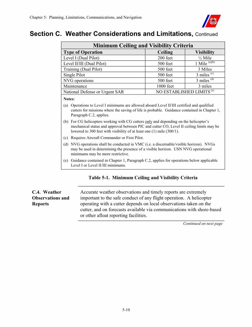
Chapter 5: Planning, Limitations, Communications, and Navigation
5-10
Section C. Weather Considerations and Limitations, Continued Minimum Ceiling and Visibility Criteria
Type of Operation Ceiling Visibility Level I (Dual Pilot) 200 feet ½ Mile Level II/III (Dual Pilot) 500 feet 1 Mile (a)(b) Training (Dual Pilot) 500 feet 3 Miles Single Pilot 500 feet 3 miles (c) NVG operations 500 feet 3 miles (d) Maintenance 1000 feet 3 miles National Defense or Urgent SAR NO ESTABLISHED LIMITS (e) Notes: (a) Operations to Level I minimums are allowed aboard Level II/III certified and qualified
cutters for missions where the saving of life is probable. Guidance contained in Chapter 1, Paragraph C.2, applies.
(b) For CG helicopters working with CG cutters only and depending on the helicopter’s mechanical status and approval between PIC and cutter CO, Level II ceiling limits may be lowered to 300 feet with visibility of at least one (1) mile (300/1).
(c) Requires Aircraft Commander or First Pilot. (d) NVG operations shall be conducted in VMC (i.e. a discernable/visible horizon). NVGs
may be used in determining the presence of a visible horizon. USN NVG operational minimums may be more restrictive.
(e) Guidance contained in Chapter 1, Paragraph C.2, applies for operations below applicable Level I or Level II/III minimums.
Table 5-1. Minimum Ceiling and Visibility Criteria
C.4. Weather Observations and Reports
Accurate weather observations and timely reports are extremely important to the safe conduct of any flight operation. A helicopter operating with a cutter depends on local observations taken on the cutter, and on forecasts available via communications with shore-based or other afloat reporting facilities.
Continued on next page
Chapter 5: Planning, Limitations, Communications, and Navigation
5-11
Section C. Weather Considerations and Limitations, Continued
C.4.a. Weather Planning Observations
When a rendezvous with a helicopter is planned, the cutter should provide the following on-scene information to the PIC before the departure of the helicopter for the cutter:
�� Height of lowest cloud base layer and percent of sky coverage. �� Horizontal visibility. �� Wind direction and velocity. Velocities sustained for less than one
(1) minute should be reported as gusts. �� Barometric pressure in inches of mercury (i.e. 29.92). �� Air and water temperature. �� Maximum pitch and roll on selected recovery heading. �� Status of flight following radar. �� Status of flight deck lighting (night operations). �� Present latitude, longitude, and intended course. �� Frequencies, EMCOM, and Lost Communications intentions. �� Other air and surface assets. �� Status and frequency of the TACAN/DME. �� Latitude and longitude coordinates of rendezvous point. �� Discernable or visible horizon (NVG operations). �� Minimum illumination levels (NVG lux limits) �� Any remarks or noteworthy atmospheric phenomena.
NOTE When planning NVG training operations, it is recommended that light levels in excess of 0.0022 lux be available during the training time period as determined by the USN/USMC approved Light Level Planning Calendar computer program SLAP. NVG Operations conducted under light levels less than 0.0022 lux should be conducted when aircrew and shipboard personnel NVG currency and proficiency requirements are met, extensive risk assessment and management of the mission is conducted, and is approved by the Commanding Officer. Forecasted illumination levels may be degraded by cloud cover, humidity, dust, low Moon angle, etc., which are not factored into the computer program output. A decision to fly in conditions that are less than optimal shall be tempered with sound judgment and errs on the side of safety.
CAUTION The pilot shall receive real-time weather information even if EMCON procedures must be relaxed to pass the information.
Chapter 5: Planning, Limitations, Communications, and Navigation
5-12
Section C. Weather Considerations and Limitations, Continued
C.4.b. Current Weather Observations
During Ship-Helo operations when the helicopter is not within visual range of the cutter, bridge personnel shall monitor weather and sea conditions, keeping the helicopter pilot and CIC or CSC informed of any significant changes.
CIC or CSC personnel shall be prepared to provide the helicopter with range and magnetic course to the cutter or nearest suitable landing site whenever it appears that weather may become a factor.
C.4.c. Pre-Departure Weather Observations
Before the helicopter departs to another cutter or a shore landing site, the cutter will ascertain the existing and forecast weather at destination, and at an alternate destination if required or desired by the PIC.
For purposes of this requirement, destination is defined as the first point of intended landing.
Chapter 5: Planning, Limitations, Communications, and Navigation
5-13
Section D. Helicopter and Aircrew Limitations
D.1. Overview To enhance the effectiveness of the Ship-Helo team, certain helicopter and aircrew limitations must be understood and applied.
D.2. Helicopter Limitations
Each type of helicopter has different characteristics, equipment, and limitations. A basic knowledge of these features is necessary to provide the cutter’s Commanding Officer with a basis for his or her decisions. A listing of Coast Guard helicopter operating features and limitations is provided in Appendix E.
Information on Navy helicopters can be found in NWP 3-04.1 (series).
D.3. Aircrew Use Because of the high degree of fatigue that results from flying a helicopter, certain limits have been placed on the flight hours that may be accumulated by aircrews. There are limits established for daily, weekly, monthly, and yearly periods.
In order to safely perform future flight duties, aircrews shall receive off-duty time after exceeding certain flight time and/or crew mission hours. Specific mandatory rest and flight time limitations are established in the Air Operations Manual, COMDTINST M3710.1 (series).
The definitions of duty and crew mission time in the following paragraphs apply to aviation personnel deployed or embarked aboard a cutter.
D.3.a. Duty A person is on duty when engaged in the performance of any official Coast Guard business to include cutter work, maintenance, or flight related duties. This includes time subject to immediate recall for aircrew or other assignment.
D.3.b. Crew Mission Time
Crew mission time commences and accrues IAW the guidelines established in the Air Operations Manual, COMDTINST M3710.1 (series).
Chapter 5: Planning, Limitations, Communications, and Navigation
5-14
Section E. Communications and Navigation
E.1. Overview A complete communications network is an essential element of Ship-Helo operations. Operations with less than a complete communications network shall be limited to urgent missions approved by the Commanding Officer and PIC, and conducted with caution.
E.2. Voice Communications
There are several different systems on the cutter and the aircraft that allow essential information transfer during Ship-Helo operations. Voice communications shall be operational during any FLICON.
E.2.a. Cutter Internal Communications
During FLICON ONE, FLICON THREE, and FLICON FOUR, communications shall be established and maintained on the bridge, on the flight deck, and in CIC or CSC (and at the AFFF and flight control stations on WMEC 270s).
For FLICON FOUR, communications with the JP-5 pump room and helicopter fueling station shall also be established.
During helicopter static refueling, communications shall be established on the bridge or HCS, on the flight deck, in the JP-5 pump room, and at the refueling stations. If sound powered telephones are used, all stations shall be connected on the same circuit.
The 1MC is used to transmit both general and emergency information during any FLICON.
Continued on next page
Chapter 5: Planning, Limitations, Communications, and Navigation
5-15
Section E. Communications and Navigation, Continued
E.2.b. Cutter External Communications
Primary external communications between the HCO or CIC and/or CSC and the helicopter are conducted via radio using the appropriate UHF, VHF-AM, or VHF-FM frequencies.
When communications cannot be carried out via these “line of sight” or short-range frequencies, communications will be carried out on appropriate HF-SSB or HF-AM frequencies (subject to NAVAIR certification restrictions).
Primary, secondary, and tertiary frequencies, as well as any special communications procedures shall be determined in accordance with the appropriate section of the Radio Frequency Plan, COMDTINST M2400.1 (series). These frequencies shall provide the capability of maintaining regular status reports required by this chapter, Paragraph E.4.
Radio frequencies and any mission-specific procedures shall be briefed between the helicopter crew and CIC or CSC or the HCO before each flight, or, for flights not originating on the cutter, upon initial radio contact.
The capability for two-way communications between the helicopter and the cutter are required for all operations except national defense or urgent SAR Ship-Helo operations.
E.2.c. Helicopter Internal Communications
Primary helicopter internal communication is through the Inter-Communication System (ICS). Because of the high noise level, direct verbal communications are impossible between pilots and crewmembers.
NOTE An operating ICS is mandatory for hot refueling, HIFR, and VERTREP.
E.2.d. Helicopter External Communications
Primary external communications shall be as specified in this chapter, Paragraph E.2.b. However, aircraft transmissions on VHF-FM are limited to 1,000 feet above ground level (AGL) or lower, as set forth in appropriate directives and Chapter 17 of the Telecommunications Manual, COMDTINST M2000.3 (series).
This restriction shall be observed in all but emergency situations. Continued on next page
Chapter 5: Planning, Limitations, Communications, and Navigation
5-16
Section E. Communications and Navigation, Continued
E.3. Visual Signals Visual signals are used during Ship-Helo operations to provide a secondary means of communication between the HCO and the flight deck, between the cutter and the helicopter, and between vessels.
E.3.a. Day Shapes and Navigational Lights
The “vessel restricted in ability to maneuver” day shapes and lights (at night) are shown during flight operations.
E.3.b. HOTEL Flag The ATP-1 tactical signal HOTEL flag is displayed when conducting flight operations in company with other U. S. and North Atlantic Treaty Organization (NATO) vessels. HOTEL may also be used as a means of communicating with the helicopter during EMCON. (See Chapter 5, Paragraph E.3.g.)
E.3.c. Deck Status Light
The Deck Status Light is controlled by the HCO to provide the pilot with a visual indication of start engine, engage rotors, takeoff, landing, T&G, HIFR, VERTREP, and rotor shutdown clearances.
The Deck Status Light may also be used to communicate with the helicopter during EMCON. (See this chapter, Paragraph E.3.g.)
�� An amber light indicates clearance to start engines and engage or disengage rotors (ship’s maneuvering is restricted);
�� A red light signifies that the helicopter is not cleared; and �� A green light indicates that it is cleared for the evolution and when
the tiedowns are in the process of being installed. �� If the Deck Status Light fails during a training or operational
mission, the HOTEL flag (day) and/or homing beacon (night) may be used to complete the current flight operation.
NOTE Deck Status Light shall not be used during NVG operations.
Continued on next page
Chapter 5: Planning, Limitations, Communications, and Navigation
5-17
Section E. Communications and Navigation, Continued
E.3.d. Landing Signal Officer (LSO) Signal Devices
See Appendix C for LSO signals.
�� Launch/Recovery and VERTREP Signals. “Bare-handed” signals are used in daytime (gloves may be worn). Amber lighted wands are used at night, except for NVG operations.
�� HIFR Signals. Red and green devices (flags or paddles) are used during daytime, and red and green/blue lighted wands at night, to indicate that JP-5 is or is not being pumped.
�� NVG Signal Devices. Due to the possibility of causing significant NVG washout, all signaling devices used for NVG operations shall be NVG compatible and shall be tested for compatibility with NVGs before each NVG operation. Examples (not limited to) are: �� Blue Chemlights (preferred). �� Blue NVG filter inserts for flashlights or wands, and cones
masked with four vertical slits. �� Infrared Chemlights.
E.3.e. Wave-off Lights
The Wave-off lights may be activated by the HCO or the LSO. They provide the pilots with a visual signal to abort an approach or landing.
WARNING Compliance by the pilot with the “Wave-off” signal is MANDATORY.
WARNING The “Wave-off” lighting system shall not be energized during NVG operations.
E.3.f. LSO and Pilot Hand Signals
The LSO and pilot hand signals, as depicted in Appendix C, are the primary method of communication between the LSO and the helicopter during all flight deck evolutions.
Lighted wands are used at night.
WARNING All signals from the LSO to the helicopter are advisory, with the exception of the “Wave-off,” “Emergency Breakaway,” and “Hold” signals, which are MANDATORY.
Continued on next page
Chapter 5: Planning, Limitations, Communications, and Navigation
5-18
Section E. Communications and Navigation, Continued
E.3.g. Emission Control (EMCON) and Lost Communications Signals
During periods of EMCON or lost communications between the cutter and the helicopter, clearances are given via the Deck Status Light.
On cutters without an operational Deck Status Light, the HOTEL flag (during daylight), the flashing white homing beacon on the mast (at night), and the LSO provide this information.
�� The HOTEL flag at the dip (halfway up) or the homing beacon illuminated signifies that the helicopter is not cleared for the evolution.
�� When the HOTEL flag is hoisted close up or the flashing beacon is turned off, the helicopter is cleared for the evolution.
�� Clearance for NVG EMCON operations, engine start and rotor engagement is signaled by the LSO.
CAUTION The Homing beacon shall not be used during NVG EMCON procedures.
E.4. Helicopter Operational Status Reports
Cutters shall normally maintain the radio guard for the helicopters they control. Because of the hazards associated with operating over water and in areas with poor navigational aid coverage, operational status reports shall be made as follows:
�� At a minimum, the helicopter shall report (or otherwise signal as pre-briefed during EMCON operations) “Operations Normal” to the cutter every 15 minutes.
�� If the cutter does not have radar or visual contact with the helicopter, the report shall also include the position and heading information, in accordance with Chapter 7, Paragraphs F.3 and F.4.
�� When appropriate, the helicopter shall also report “feet wet” or “feet dry.”
Continued on next page
Chapter 5: Planning, Limitations, Communications, and Navigation
5-19
Section E. Communications and Navigation, Continued
WARNING The ADC or HCO shall inform the helicopter in the event radar contact is lost, or other shipboard position fixing equipment (JMCIS/JOTS, TACAN, DF, etc.) becomes unreliable. The helicopter shall inform the cutter of aircraft equipment failures that may reduce navigation, position fixing, or communications capability. Use of dead reckoning (DR) as the sole source of helicopter position fixing is prohibited unless visual contact with the cutter can be maintained. For missions involving national defense, emergency, or where the saving life is probable (see Chapter 1, Paragraph C.2), a waiver may be granted by the cutter’s Commanding Officer.
E.5. Lost Communications Procedures (Cutter)
When the cutter cannot establish communications with the helicopter and is not in visual or radar contact with it, the cutter shall initiate lost communications procedures indicated below.
E.5.a. Initial Indicators
When the helicopter misses an “Operations Normal” report by five (5) minutes or communications cannot be established on primary radio frequency, attempts shall be made on secondary, tertiary, and guard frequencies to regain contact.
E.5.b. 15-Minutes Overdue
When the helicopter is 15-minutes overdue on an “Operations Normal” report, the cutter shall initiate the UNCERTAINTY phase, as follows:
�� Set a course for the last known or estimated position of helicopter. �� If communications equipment permits, monitor UHF guard
frequency (243.0 MHz) for ELT or voice transmissions, while continuing attempts to communicate on pre-designated primary, secondary, and tertiary frequencies. Monitor VHF-FM (CH 16/15) for Class C EPIRB signal.
�� Activate the TACAN on the pre-briefed frequency. �� At night, turn on the flashing homing beacon, SGSI, and flight deck
lineup lights. Also, turn on the search light(s) and train skyward if practicable.
�� Notify the SAR coordinator. �� Activate appropriate sections of the SAR Bill.
Continued on next page
Chapter 5: Planning, Limitations, Communications, and Navigation
5-20
Section E. Communications and Navigation, Continued
E.5.c. 30-Minutes Overdue
When the helicopter is 30-minutes overdue, the cutter shall proceed to the ALERT phase. In addition to continuing the action listed above, the following shall be accomplished:
�� Make best possible speed for last known position of helicopter. �� Continue to monitor all appropriate frequencies for signals from
emergency communications equipment carried on the helicopter, including Class C EPIRB (CH 16/15), and the appropriate survival radio (ELT 243.0 MHz and 121.5 MHz).
�� Request appropriate additional SAR forces from the SAR Coordinator.
�� Initiate immediate response procedures contained in the Aircraft Pre-Accident Plan.
�� Make all preparations for recovery to be ready if the helicopter arrives overhead.
E.5.d. Reaching Fuel Endurance
When the helicopter’s fuel endurance time is reached, the cutter shall proceed to the DISTRESS phase. In addition to continuing the action listed above, the following shall be accomplished:
�� Issue and/or request that the SAR coordinator issues an urgent marine information broadcast. Continue attempts to communicate with the helicopter.
�� Contact any other vessels in the area for possible assistance. �� Initiate secondary response procedures contained in the Aircraft
Pre-Accident Plan.
E.5.e. If Helicopter Arrives Overhead
If the helicopter arrives overhead, recover using visual signals as described in this chapter, Paragraph E.3.g. Advise the SAR coordinator to stand down.
Continued on next page
Chapter 5: Planning, Limitations, Communications, and Navigation
5-21
Section E. Communications and Navigation, Continued
E.6. Lost Communications Procedures (Aircraft)
When the helicopter loses communications with the cutter, the pilot shall:
�� If in visual contact with the cutter or if the cutter’s position is known, abort the mission (unless mission urgency dictates continuing), and return to the cutter. Enter and maintain a holding pattern over the cutter until landing clearance is received.
�� If the cutter’s position is unknown, abort the mission (unless mission urgency dictates continuing), and proceed to the nearest suitable landing area. �� Advise the cutter by the most expeditious means available. �� If unable to ascertain that the cutter has been notified, advise the
cognizant SAR coordinator. �� If a safe landing area cannot be reached with remaining fuel,
proceed towards the last known position of the cutter via the last position reported by the aircraft to the cutter.
�� Once the cutter is located, enter and maintain a holding pattern over the cutter until landing clearance is received.
E.7. TACAN/DME When the helicopter is out of visual range of the cutter and is not receiving navigational information from land-based facilities, the cutter shall activate the TACAN/DME on the pre-briefed frequency, unless pre-briefed EMCON procedures are in effect.
Regardless of EMCON, the TACAN/DME shall be activated any time requested by the pilot or when communications are assumed to have been lost. The cutter’s call sign shall be transmitted three (3) times in succession at least every two (2) minutes.
Cutters without automatic keying devices shall transmit a steady carrier.
Chapter 6: Launch and Recovery Procedures
6-i
CHAPTER 6: LAUNCH AND RECOVERY PROCEDURES Table of Contents
Introduction................................................................................................................................ 6-1
In this chapter ............................................................................................................................ 6-1
Section A. Cutter Preparation ................................................................................................. 6-2
A.1. Overview ............................................................................................................................ 6-2
A.2. Safety Precautions............................................................................................................. 6-2
A.3. Operations Department .................................................................................................... 6-3
A.4. Engineering Department .................................................................................................. 6-3
A.5. Deck Department .............................................................................................................. 6-4
A.6. Aviation Department ........................................................................................................ 6-5
A.7. Preflight Briefing............................................................................................................... 6-5
COMMUNICATIONS: ............................................................................................................. 6-7
Section B. Flight Quarters........................................................................................................ 6-8
B.1. Conditions .......................................................................................................................... 6-8
B.2. Flight Quarters Condition One (FLICON ONE) ........................................................... 6-8
B.2.a. Officer of the Deck (OOD)...................................................................................... 6-8 B.2.b. Rescue Boat Coxswain............................................................................................ 6-9 B.2.c. Helicopter Control Officer (HCO). ......................................................................... 6-9 B.2.d. CIC Air Direction Controller (ADC) .................................................................... 6-12 B.2.e. Landing Signal Officer (LSO) ............................................................................... 6-13 B.2.f. Tiedown Crew........................................................................................................ 6-14 B.2.g. On-Scene Leader (OSL) ........................................................................................ 6-14 B.2.h. Hose Team ............................................................................................................ 6-15 B.2.i. Rescue Crew .......................................................................................................... 6-15 B.2.j. Medical Detail........................................................................................................ 6-15 B.2.k. Pilot in Command (PIC)........................................................................................ 6-16 B.2.l. Foam Machinery or Fire Monitor Crew................................................................. 6-16 B.2.m. Night Vision Goggle Safety Officer (NSO) .......................................................... 6-16
B.3. Flight Quarters Condition Two (FLICON TWO) ....................................................... 6-17
B.4. Flight Quarters Condition Three (FLICON THREE)................................................. 6-17
Chapter 6: Launch and Recovery Procedures
6-ii
B.5. Flight Quarters Condition Four (FLICON FOUR) ..................................................... 6-18
Section C. Launch Procedures............................................................................................... 6-19
C.1. Overview .......................................................................................................................... 6-19
C.2. Engine Starting................................................................................................................ 6-19
C.2.a. Engine Starting with External Power. ................................................................... 6-20 C.2.b. Engine Starting with Helicopter Battery ............................................................... 6-21
C.3. Rotor Engagement .......................................................................................................... 6-21
C.4. Helicopter Systems, Equipment, and Communications Checks................................. 6-22
C.5. Takeoff Clearance........................................................................................................... 6-22
C.6. Takeoff Procedures without TALON............................................................................ 6-25
C.7. Takeoff Procedures Using TALON............................................................................... 6-26
C.7.a. Primary Tiedown Use with TALON ..................................................................... 6-27
C.8. Athwartships Takeoff ..................................................................................................... 6-28
C.9. Single Pilot Takeoff......................................................................................................... 6-28
C.10. Night and NVG Takeoff ............................................................................................... 6-29
C.11. Initial Operations Normal Report ............................................................................... 6-31
Section D. Traffic Pattern ...................................................................................................... 6-32
D.1. Normal Pattern................................................................................................................ 6-32
D.2. Box Pattern ...................................................................................................................... 6-32
D.3. NVG Pattern ..................................................................................................................... 6-33
Section E. General Recovery Procedures.............................................................................. 6-34
E.1. Overview .......................................................................................................................... 6-34
E.2. Pre-Approach Phase........................................................................................................ 6-34
E.3. Approach Phase............................................................................................................... 6-35
E.3.a. Approach Phase – Pilot Actions ............................................................................ 6-35 E.3.b. Approach Phase – Helicopter Control Officer (HCO) and Landing Signal Officer (LSO) Actions................................................................................................................... 6-36
Chapter 6: Launch and Recovery Procedures
6-iii
E.4. Cutter Delay in Recovery................................................................................................ 6-38
E.5. Landing Procedures ........................................................................................................ 6-39
E.6. Athwartships Recovery Procedures............................................................................... 6-40
E.7. TALON Procedures ........................................................................................................ 6-41
E.7.a. TALON Malfunctions and Missed-grid Procedures.............................................. 6-41 E.7.b. Single or Multiple Touch-and-Go (T&G) Evolutions with TALON .................... 6-42
E.8. Primary Tiedown Procedures ........................................................................................ 6-44
E.9. Touch-and-Go (T&G) Procedures................................................................................. 6-45
E.9.a. Single or Multiple Touch-and-Go(s) (T&G) ......................................................... 6-45
E.10. Wave-off ......................................................................................................................... 6-47
E.10.a. Wave-off Situations............................................................................................. 6-47 E.10.b. Wave-off Procedures ........................................................................................... 6-48
Section F. Shutdown Phase .................................................................................................... 6-49
F.1. Overview........................................................................................................................... 6-49
F.2. Rotor and Engine Shutdown .......................................................................................... 6-49
Section G. Post-Shutdown...................................................................................................... 6-50
G.1. General............................................................................................................................. 6-50
Section H. Night and NVG Recovery .................................................................................... 6-51
H.1. Overview.......................................................................................................................... 6-51
Section I. Operations on Cutters with Oblique (Angled) Approach and Lineup Lines... 6-53
I.1. Helicopter Oblique Procedures....................................................................................... 6-53
I.2.a. Helicopters Aligned Fore-and-Aft .......................................................................... 6-54
I.2. Cutter Oblique Procedures.............................................................................................. 6-55
I.3. Relative Wind and Ship Motion Envelopes ................................................................... 6-55
Section J. Night Vision Goggle (NVG) Recovery ................................................................. 6-56
J.1. Overview ............................................................................................................................ 6-56

Chapter 6: Launch and Recovery Procedures
6-iv
Chapter 6: Launch and Recovery Procedures
6-1
Chapter 6. Launch and Recovery Procedures
Introduction The procedures set forth in this chapter are for operations involving Coast Guard Cutters and Coast Guard helicopters.
Operations with elements of other services or nations may require modification of these procedures.
Procedures relating solely to other types of ships or helicopters are noted as such.
In this chapter This chapter is divided into ten (10) sections:
�� Section A: Cutter Preparation �� Section B: Flight Quarters �� Section C: Launch Procedures �� Section D: Traffic Pattern �� Section E: General Recovery Procedures �� Section F: Shutdown Phase �� Section G: Post-Shutdown �� Section H: Night and NVG Recovery �� Section I: Operations Aboard Cutters With Oblique (Angled)
Approach and Lineup Lines �� Section J: Night Vision Goggle (NVG) Operations
Chapter 6: Launch and Recovery Procedures
6-2
Section A. Cutter Preparation
A.1. Overview The cutter should prepare for helicopter operations sufficiently in advance of launch or recovery to ensure readiness before arrival or departure of the helicopter.
If a deficiency is discovered during preparations that will delay achieving readiness, the pilot in command (PIC) or the controlling activity shall be notified by the most expeditious means.
A.2. Safety Precautions
The following precautions shall be observed when operating with helicopters:
�� Except in cases of emergency, pilots shall not disengage rotors or stop engines with proper signal from the LSO.
�� Helicopters shall not be launched or recovered nor shall rotors be engaged or disengaged while the ship is turning.
�� Personnel required to be in the area of helicopters that are disengaging rotors shall stand next to the fuselage or outside the rotor arc.
�� A helicopter shall not be flown over another helicopter when landing.
�� Helicopters shall never be towed or pushed while rotors are engaged or while the ship is turning.
�� The Wave-off, hold, and emergency breakaway signals are mandatory and shall be executed immediately.
�� Helicopters shall not be ground taxied on the flight deck. �� When changing pilots or hot refueling, the aircraft shall be
chocked or have the tiedowns attached. �� Aircraft shall be chocked (minimum) for passenger loading and
unloading when a cutter is moored pierside or hove to in the ice. Underway cutters shall use TALON or primary tiedowns before transferring passengers.
�� Because of the limited size of the landing area, aircraft shall not be loaded or unloaded while an aircraft is landing or launching on an adjacent spot.
�� When staging deck cargo, the HCO should ensure that sufficient clear space is available for possible emergency landing. Complete staging of the flight deck is permissible, provided another ready deck is available.
Chapter 6: Launch and Recovery Procedures
6-3
Section A. Cutter Preparation, Continued
A.3. Operations Department
The following are duties of the Operations Department.
�� Conduct mission planning session (Chapter 5, Paragraph A.2). �� Advise affected personnel of future flight operations. �� Conduct a preflight briefing (this chapter, Paragraph A.7). �� Determine optimum course and speed for the planned operation. �� Make weather observations (Chapter 5, Paragraph C.4). �� Tune and test all communications, navigation (TACAN), and flight
following equipment. �� Energize the SGSI (night and/or IMC.) �� Check operation of both flight deck closed circuit televisions
(CCTVs), date time generator, and recording system. �� Designate the ready boat. �� Conduct FOD walk down of all weather decks above the flight
deck. �� Break out day shapes and HOTEL flag. �� Report accomplishment and any deficiencies to the OOD.
A.4. Engineering Department
The following are duties of the Engineering Department:
�� Ensure proper operation of the JP-5 aviation fuel system. �� Conduct tests of JP-5 aviation fuel. �� Energize fire pump and align AFFF system for flight operations. �� Break out fire fighting and crash rescue equipment (Chapter 14). �� Ensure that helicopter starting power is available, if required. �� Report accomplishment and any deficiencies to the OOD.
Continued on next page
Chapter 6: Launch and Recovery Procedures
6-4
Section A. Cutter Preparation, Continued
A.5. Deck Department
The following are duties of the Deck Department.
�� Secure All Weather Doors and Hatches �� WHEC 378: Aft of frame 190 �� WMEC 210: Aft of frame 90 �� WMEC 270: Aft of frame 103 �� WMEC 282: Aft of frame 25 �� WAGB 400: Aft of frame 141 �� WAGB 420: Aft of frame 96
�� If hangar equipped, retract hangar and close hangar door. �� Inspect, lower, and check the security of the safety nets or catwalks
including flight deck net pins attached to a wire lanyard. �� Lower and/or remove flight deck lifeline stanchions. �� Remove maintenance floodlights, if installed. �� Lower flagstaff. �� Remove canvas covers from all equipment and machinery in the
immediate vicinity of flight deck. Check that all other covers are securely lashed.
�� Remove all gasoline stored within 25-feet of the flight deck peripheral marking that is exposed on any weather deck.
�� Conduct FOD walk down of the flight deck and fantail. Remove or securely tie down any objects that may become airborne from the helicopter rotor wash. Wash down the flight deck and fantail, if necessary.
�� Assist AVDET with the helicopter traversing and preparation for launch, if applicable.
�� Prepare the ready boat for lowering (recommend placing boat at the rail).
�� Check all lighting and visual approach equipment (all lights are required for night training operations). Activate Wave-off lights from the flight deck and HCO station to check for proper operation.
�� Report accomplishment and any deficiencies to the OOD.
WARNING For launch, recovery, refueling, HIFR, and VERTREP (except for Class 5, Type 2 operations aboard WHEC 378 cutters), the hangar shall be retracted and the hangar door closed.
Continued on next page
Chapter 6: Launch and Recovery Procedures
6-5
Section A. Cutter Preparation, Continued
NOTE For any Class 5, Type 2 operations, and for HIFR with all helicopters except the H-53E, the hangar on WHEC 378 cutters may be extended with the door closed.
If an alternative method for helicopter rescue during launch and recovery is immediately available, the Commanding Officer may waive the need for the ready boat.
A.6. Aviation Department
The following are duties of the Aviation Department.
�� Assist in development of mission plan (Chapter 5). �� Participate in preflight briefing (Paragraph A.7 of this chapter). �� Ensure that the helicopter is ready for flight. �� Assign and brief the flight crew. If hangar equipped, supervise
retraction of the hangar and opening and closing of the hangar door. �� Review daily aviation fuel testing results. �� Report accomplishment and any deficiencies to the OOD.
A.7. Preflight Briefing
A mission briefing shall be conducted before setting flight quarters.
One (1) or both pilots, the Operations Officer, the HCO, LSO, the CICO (or ADC), flight briefer and an engineering representative should be present.
The briefer shall fill out a Flight Planning Sheet and a Preflight Briefing Sheet, which shall be reviewed at the briefing. Cutters may generate a custom planning or briefing sheet that shall contain at a minimum the items depicted in Figures 6-1 and 6-2.
�� The HCO shall finalize the flight planning sheet after setting FLICON ONE and deliver it to the pilot via messenger or by radio (if desired).
Continued on next page
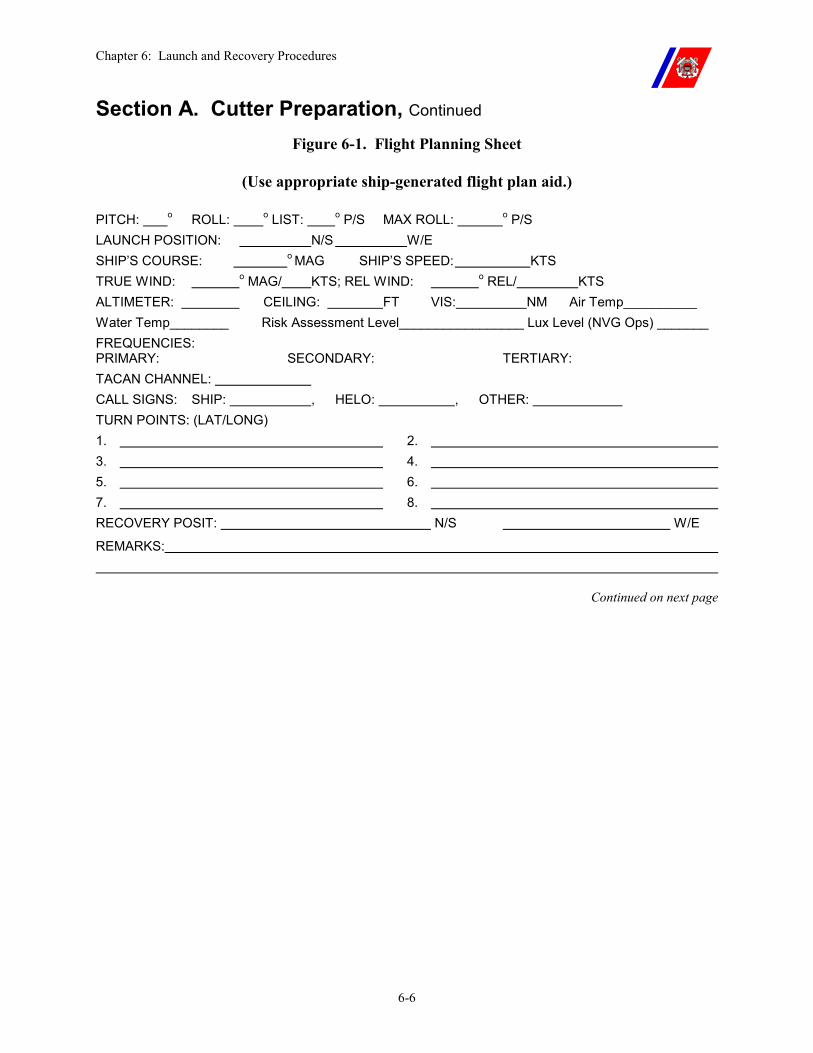
Chapter 6: Launch and Recovery Procedures
6-6
Section A. Cutter Preparation, Continued Figure 6-1. Flight Planning Sheet
(Use appropriate ship-generated flight plan aid.)
PITCH: o ROLL: o LIST: o P/S MAX ROLL: o P/S LAUNCH POSITION: N/S W/E SHIP’S COURSE: o MAG SHIP’S SPEED: KTS TRUE WIND: o MAG/ KTS; REL WIND: o REL/ KTS ALTIMETER: CEILING: FT VIS: NM Air Temp__________ Water Temp________ Risk Assessment Level_________________ Lux Level (NVG Ops) _______ FREQUENCIES: PRIMARY: SECONDARY: TERTIARY: TACAN CHANNEL: CALL SIGNS: SHIP: , HELO: , OTHER: TURN POINTS: (LAT/LONG) 1. 2. 3. 4. 5. 6. 7. 8. RECOVERY POSIT: N/S W/E
REMARKS:
Continued on next page
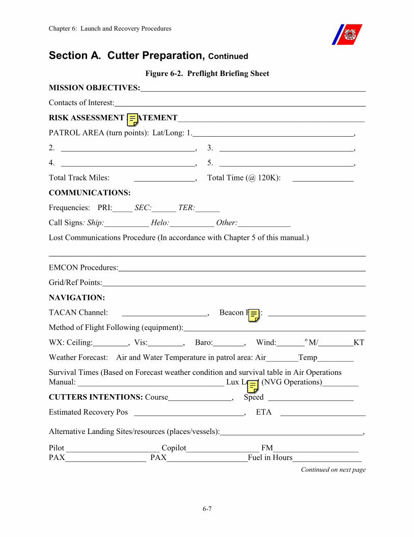
Chapter 6: Launch and Recovery Procedures
6-7
Section A. Cutter Preparation, Continued Figure 6-2. Preflight Briefing Sheet
MISSION OBJECTIVES:
Contacts of Interest:
RISK ASSESSMENT STATEMENT______________________________________________
PATROL AREA (turn points): Lat/Long: 1. ,
2. , 3. ,
4. , 5. ,
Total Track Miles: , Total Time (@ 120K):
COMMUNICATIONS:
Frequencies: PRI:_____ SEC:______ TER:______
Call Signs: Ship:___________ Helo:___________ Other:_____________
Lost Communications Procedure (In accordance with Chapter 5 of this manual.)
EMCON Procedures:
Grid/Ref Points:
NAVIGATION:
TACAN Channel: , Beacon Freq:
Method of Flight Following (equipment):
WX: Ceiling: , Vis: , Baro: , Wind: o M/ KT
Weather Forecast: Air and Water Temperature in patrol area: Air________Temp_________
Survival Times (Based on Forecast weather condition and survival table in Air Operations Manual: ____________________________________ Lux Level (NVG Operations)_________
CUTTERS INTENTIONS: Course , Speed
Estimated Recovery Pos , ETA
Alternative Landing Sites/resources (places/vessels): ,
Pilot _______________________ Copilot__________________ FM_____________________ PAX____________________ PAX____________________Fuel in Hours_________________
Continued on next page
Chapter 6: Launch and Recovery Procedures
6-8
Section B. Flight Quarters
B.1. Conditions Upon completion of required preparations, any of four (4) conditions may be set, depending on the planned operation.
B.2. Flight Quarters Condition One (FLICON ONE)
FLICON ONE shall be set for launch and recovery. The following specific actions shall be accomplished in addition to any special requirements of the mission, cutter, or helicopter.
B.2.a. Officer of the Deck (OOD)
�� Report completion of required preparations to HCO and Commanding Officer. Request permission from the Commanding Officer to set flight quarters.
�� Maneuver cutter to appropriate heading and speed, as recommended by HCO. (See Appendix B for relative wind and ship motion operating envelopes.)
�� Set flight quarters. Order the smoking lamp out on all weather decks. Hoist day shapes and HOTEL flag as appropriate.
�� Maintain heading and speed during landings, takeoffs, when the helicopter is not secured on deck, and when the rotor is turning at less than 100 percent (Deck Status Light: AMBER). If it becomes necessary to maneuver, advise the HCO immediately.
�� Report the readiness of the rescue boat crew or alternate rescue resource to the HCO. Launch the rescue boat (if desired).
WARNING Any changes in the cutter heading or speed during rotor engagement or sharp changes in heading resulting in ship heel greater than 10 degrees may cause excessive rotor blade deflection, resulting in a blade strike to the airframe.
CAUTION Changes in the cutter heading of more than a few degrees while the helicopter is on deck with the rotor and stabilization equipment engaged may cause large tail rotor control inputs, resulting in over-stress of the tail section or other aircraft damage.
NOTE The OOD and HCO may be the same person when the cutter is moored pier side or hove to in the ice.
NOTE A port relative wind is preferred for HH-65 operations.
Continued on next page
Chapter 6: Launch and Recovery Procedures
6-9
Section B. Flight Quarters, Continued
B.2.b. Rescue Boat Coxswain
�� Muster Boat Crew and Cutter Swimmer (swimmer should be dressed out). Maintain readiness posture in accordance with Chapter 2, Table 2-1.
�� Inspect equipment and prepare ready boat for launching. �� Report readiness to OOD. �� Maintain readiness posture as set forth in the Helicopter Operations
Bill.
B.2.c. Helicopter Control Officer (HCO).
�� Man the Helicopter Control Station (HCS). �� Be familiar with the Safety Precautions in this chapter,
Paragraph A.2. �� Receive the Rescue Boat Crew readiness report from the OOD.
Receive all other readiness reports via the HCO phone talker, if used.
�� Provide the OOD with recommended heading and speed for the operation.
�� Supervise preparation of HCO phone talker (if used), including a communications check.
�� Illuminate the “RED” Deck Status Light (except during NVG operations).
�� Energize appropriate flight deck lighting and/or visual approach equipment (night, NVG and/or IMC)
�� Once cutter is on desired heading, verify that flight deck motion and wind are within limits (Appendix B).
�� Ensure that all necessary communications, navigation (TACAN), and flight following equipment are energized.
�� Ensure that CCTVs, date time generator, and video recording equipment are energized and operational to record all phases of flight operations.
�� When the cutter is ready for helicopter launch or recovery, request permission from the Commanding Officer to commence flight operations.
�� If a helicopter is aboard, verify that the cutter is maintaining constant heading and speed, before authorizing engine start and rotor engagement. Signal clearance by illuminating “AMBER” Deck Status Light (except during NVG operations).
Continued on next page
Chapter 6: Launch and Recovery Procedures
6-10
Section B. Flight Quarters, Continued
B.2.c. Helicopter Control Officer (HCO) (continued)
�� As a minimum, provide the helicopter with the following information (the “numbers”) via a completed Preflight Briefing Sheet (Figure 6-2) via a messenger or via radio: �� Cutter magnetic heading and speed �� Cutter position (latitude and longitude) �� Magnetic wind direction and velocity �� Relative wind direction and velocity �� Current maximum pitch and roll angles and appropriate
amplifying information, such as occasional excursions, or existing list or heel. For interpreting pitch and roll limits, occasional shall be defined as a span of time sufficient for a pilot to safely execute an approach and landing in the period between excursions. The use of occasional is only authorized between sunrise and sunset.
�� Altimeter setting in inches of mercury (i.e. 29.92) (read-back from pilot required)
�� Magnetic heading and distance to nearest point of land, if appropriate
�� Ensure an accurate navigational plot of the position of the helicopter is maintained (Chapter 7, Paragraph F.4).
NOTE The HCO checklist is provided in Figure 6-3.
All flight quarter’s stations shall operate on a common communication circuit. On cutters interconnecting two (2) or more sound powered phone circuits, the requirement and procedure for interconnection shall be stated in the Helicopter Operations Bill.
Ensure that video tape recordings of each helicopter operation are retained for at least 24 hours. If a mishap occurs which requires release of a mishap message, a copy of the videotape of that mishap event shall be forwarded to the Ship-Helo Branch, ATC Mobile. In case of a mishap requiring a Mishap Investigation Board (MAB), videotape recordings shall be impounded with all other pertinent logs and records and presented to the President of the MAB.
Continued on next page
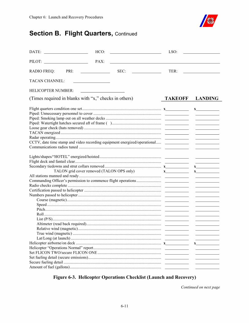
Chapter 6: Launch and Recovery Procedures
6-11
Section B. Flight Quarters, Continued
DATE: HCO: LSO:
PILOT: PAX:
RADIO FREQ: PRI: SEC: TER:
TACAN CHANNEL:
HELICOPTER NUMBER:
(Times required in blanks with “x,” checks in others) TAKEOFF LANDING
Flight quarters condition one set............................................................................. x x Piped: Unnecessary personnel to cover .................................................................. Piped: Smoking lamp out on all weather decks ...................................................... Piped: Watertight hatches secured aft of frame ( )................................................ Loose gear check (hats removed) ........................................................................... TACAN energized .................................................................................................. Radar operating....................................................................................................... CCTV, date time stamp and video recording equipment energized/operational..... Communications radios tuned ................................................................................
Lights/shapes/“HOTEL” energized/hoisted............................................................ Flight deck and fantail clear.................................................................................... Secondary tiedowns and strut collars removed ....................................................... x x
TALON grid cover removed (TALON OPS only) x x All stations manned and ready................................................................................ Commanding Officer’s permission to commence flight operations ........................ Radio checks complete ........................................................................................... Certification passed to helicopter ........................................................................... Numbers passed to helicopter .................................................................................
Course (magnetic)............................................................................................ Speed ............................................................................................................... Pitch................................................................................................................. Roll .................................................................................................................. List (P/S).......................................................................................................... Altimeter (read back required)......................................................................... Relative wind (magnetic)................................................................................. True wind (magnetic) ...................................................................................... Lat/Long (at launch) ........................................................................................
Helicopter airborne/on deck ................................................................................... x x Helicopter “Operations Normal” report.................................................................. Set FLICON TWO/secure FLICON ONE.............................................................. Set fueling detail (secure emissions)....................................................................... Secure fueling detail ............................................................................................... Amount of fuel (gallons).........................................................................................
Figure 6-3. Helicopter Operations Checklist (Launch and Recovery)
Continued on next page
Chapter 6: Launch and Recovery Procedures
6-12
Section B. Flight Quarters, Continued
WARNING It is critical that the cutter maintains a steady heading and speed while the “AMBER” Deck Status Light is illuminated (except during NVG operations, where the HCO shall pass deck status verbally to the pilot). Any changes in the cutter heading or speed during rotor engagement may cause excessive rotor blade deflection, resulting in a blade strike to the airframe.
Tiedown chains (“chocks and chains” procedure) shall not be attached to any mooring rings other than those on the landing gear. Chains attached to the fuselage with the rotor turning can cause ground resonance.
NOTE On cutters moored pier side or icebreakers hove to in the ice, the use of tiedowns and tiedown crews may be omitted with the concurrence of the Commanding Officer and the Senior Aviator. The flight deck shall be free of ice and snow to operate without tiedowns.
Roll and list are combined to determine roll angle limits. For example, if the cutter is listing to port, report to the pilot: “We have a 3 degree port list and 4 degrees roll, making a total of 7 degree roll to port.”
Always report angles from the vertical.
Pitch and roll shall be reported from inclinometer readings (used to establish limits) not from digital readouts.
Report altimeter setting in inches of mercury (i.e. 29.92). Pilots may use this information to crosscheck barometric altimeters. However, if a discrepancy exists, altimeter should be set using on-deck elevation.
In polar regions, headings expressed in degrees true may be desired.
B.2.d. CIC Air Direction Controller (ADC)
�� Report readiness to the HCO. �� Maintain radar, IFF, and/or dead reckoning (DR) plot of the
helicopter as appropriate. �� Provide communications interface, navigational assistance, and
other flight following functions, as directed by the HCO and/or CICO in conditions other than Level I.
�� Provide air traffic advisories for the helicopter, using procedures set forth in Chapter 7.
NOTE The HCO shall assume these duties on WAGBs.
Chapter 6: Launch and Recovery Procedures
6-13
Section B. Flight Quarters, Continued
B.2.e. Landing Signal Officer (LSO)
�� Be familiar with the Safety Precautions in this chapter, Paragraph A.2.
�� Ensure that all required equipment is ready. �� Ensure that all flight deck personnel are in position and properly
outfitted in protective gear. (LSO, NSO and tiedown personnel shall wear a blue Chemlight securely fastened to the life vest for NVG operations)
�� Inspect the flight deck and fantail for FOD and loose gear. �� Clear all nonessential personnel from the flight deck area. �� If a helicopter is on board, verify that strut collars and secondary
tiedowns have been removed. �� Install or remove (as appropriate) the TALON grid cover. �� Report any delays in attaining readiness to the HCO and pilot. �� Report readiness to the HCO:
�� “Flight deck manned and ready.” �� (Helicopter on board) “Secondary tiedowns removed, request
permission to start engine(s) and engage rotors.” �� (No helicopter on board) “Flight deck clear.”
CAUTION The TALON grid cover shall be removed before operations with a TALON-equipped aircraft and installed at all other times to ensure non-skid and VLA integrity.
Tiedown chains (“chocks and chains” procedure) shall not be attached to any mooring ring other than those on the landing gear. Chains attached to the fuselage with the rotor turning can cause ground resonance.
NOTE Secondary tiedowns shall be removed with permission from the bridge and the PIC, either before or during the setting of FLICON ONE.
For a launch with TALON, after attaining FLICON ONE, and with permission granted from the bridge and PIC, primary tiedowns should be removed.
When conducting tiedown crew training or training necessary for proficiency, tiedowns may be used in conjunction with TALON.
Continued on next page
Chapter 6: Launch and Recovery Procedures
6-14
Section B. Flight Quarters, Continued
B.2.f. Tiedown Crew �� Break out and don appropriate protective gear. (Tiedown personnel shall wear blue Chemlights securely fastened to the life vest for NVG operations)
�� Break out, install (if necessary), and overhaul primary tiedown assemblies (for recovery).
�� (No helicopter aboard) “Flight deck clear.” �� Take station before rotor engagement. �� Report readiness to the LSO.
NOTE During TALON operations and multiple touch-and-go landings (T&Gs), designated tiedown crew are not required to be present on the flight deck unless considered essential for safety due to weather, aircraft emergency, or when conducting tiedown crew training.
Under the above situations, the tiedown crew should muster in the same space as the fire party personnel and be ready to respond to the LSO for use of primary tiedowns when contacted via communications with the HCO phone talker, if used.
B.2.g. On-Scene Leader (OSL)
�� Designate flight deck fire hoses to use and verify necessary fire pump(s) are on line and the AFFF system is ready.
�� Requirements for use of a flight deck fire monitor and flight deck foam flooding system are found in Chapter 14, Paragraph G.2 and the Note in this chapter following Paragraph B.2.i for primary and secondary hose teams.
�� Supervise attachment of nozzles and lay out the hoses. �� Ensure all flight deck fire fighting and/or rescue personnel are
staged inside the cutter forward of and accessible to the flight deck area (may also be staged on the forecastle) donned in the appropriate protective gear. Fire fighting and/or rescue personnel should be in a position to rapidly respond to a helicopter crash by being able to hear the crash alarm clearly.
�� The primary and secondary hoses shall not be pressurized since they are unmanned.
�� Report readiness to the LSO. Continued on next page
Chapter 6: Launch and Recovery Procedures
6-15
Section B. Flight Quarters, Continued
B.2.h. Hose Team �� Don appropriate protective gear. �� Check equipment and verify nozzle settings. �� Stage in the appropriate space IAW the Helicopter Operation Bill. �� Report readiness to the OSL.
B.2.i. Rescue Crew �� Inspect crash kit and fire extinguishers. (See Chapter 14, Paragraph E.2, for composition of the crash kit.)
�� Inspect and don proximity suit trousers, boots, LPU-30(P) vests (with trouser suspenders outside of vests), hearing protection, and flight gloves (flash gloves may be used in lieu of flight gloves).
�� The jackets and hood need not be worn except when actually responding to a flight deck fire.
�� Take station inside cutter with the fire fighting party. �� Report readiness to the OSL.
NOTE The rescue crew shall lay out the primary hoses and report readiness to the LSO on cutters equipped with flight deck fire monitors when the flight deck fire fighting party is not manned during FLICON ONE.
B.2.j. Medical Detail During normal flight operations, the HS or PA is only required to acknowledge setting of flight quarters to the HCO. However, during FLICON ONE for a helicopter emergency landing or upon activation of the helicopter crash alarm, the HS or PA shall:
�� Break out and check equipment. �� Be prepared to provide triage services in staging area defined by the
Helicopter Operations Bill. �� Organize and supervise stretcher bearers if required. �� Report readiness to the HCO.
Continued on next page
Chapter 6: Launch and Recovery Procedures
6-16
Section B. Flight Quarters, Continued
B.2.k. Pilot in Command (PIC)
�� Be familiar with the Safety Precautions in this Chapter, Paragraph A.2.
�� Ensure that required preflight inspections are complete. This includes the removal of strut collars and secondary tiedowns before the aircrew boards the helicopter.
�� Ensure that a properly completed flight plan (CG-4377 or DD-175, as appropriate) has been signed.
WARNING Tiedown chains (“chocks and chains” procedure) shall not be attached to any mooring rings other than those on the landing gear. Chains attached to the fuselage with the rotor turning can cause ground resonance.
NOTE Secondary tiedowns shall be removed with permission from the bridge and the PIC, either before or during the setting of FLICON ONE.
B.2.l. Foam Machinery or Fire Monitor Crew
�� Ensure all required equipment is operational. �� Verify that the required fire pumps are on line and the AFFF system
is energized before commencing flight operations. Secure the same equipment at the conclusion of flight operations.
�� Assist rescue crew in laying out required equipment when fire parties are not manned for FLICON ONE.
�� Report readiness of Foam Machinery Station and Fire Monitor Station using the following format: “Foam Machinery Station and Fire Monitor Station manned and ready.”
NOTE Foam Machinery or Fire Monitor Crew positions are staffed on cutters with flight deck fire monitors and flight deck foam flooding systems.
B.2.m. Night Vision Goggle Safety Officer (NSO)
The NSO is required during NVG operations and is responsible for monitoring the safety of NVG operations.
Before commencing NVG operations, the NSO shall be on the flight deck properly equipped with ANVIS style NVGs. The NSO helmet shall be capable of hard mounting ANVIS style NVGs and have two-way communications capability.
The NSO shall have two-way communications with the HCO and LSO at all times. The NSO should be qualified as an NVG LSO.
Continued on next page
Chapter 6: Launch and Recovery Procedures
6-17
Section B. Flight Quarters, Continued
B.3. Flight Quarters Condition Two (FLICON TWO)
FLICON TWO may be set when an immediate takeoff or landing is not planned, or when the helicopter is secured on deck for a short period, such as during a meal break. FLICON TWO should be sequential to FLICON ONE, when a lesser readiness posture is acceptable, allowing personnel to stand down, with equipment remaining ready. FLICON ONE shall be attainable within five (5) minutes.
Normal helicopter control is from CIC during FLICON TWO.
FLICON ONE is normally maintained for of five (5) minutes after the departure of the helicopter.
B.4. Flight Quarters Condition Three (FLICON THREE)
FLICON THREE shall be set for VERTREP operations. To attain FLICON THREE, set FLICON ONE with the following variations:
�� Two (2) members of the tiedown crew shall be designated as the hookup crew: �� One to ground the hook �� The other to make the hookup (unless a non-conductive reach
type pendant is used, only hookup person is required). �� If grounding the helicopter is required, the member grounding the
hook shall be equipped with a grounding wand and Class II rated electrical gloves. This equipment is described in the cutter AEL.
�� The hookup crew can be stationed with the load or behind the LSO if desired.
�� Specific procedures for VERTREP operations are in Chapter 10, and shall be thoroughly reviewed before commencing operations.
NOTE For Night or NVG VERTREP operations, tiedown crew personnel shall wear blue Chemlights. The hookup loop on the VERTREP pendant and load shall have blue Chemlights attached.
Before any personnel movement on the flight deck under NVG operations, the overhead flood, hangar wash, and deck surface wash lights shall be set for maximum illumination.
Continued on next page
Chapter 6: Launch and Recovery Procedures
6-18
Section B. Flight Quarters, Continued
B.5. Flight Quarters Condition Four (FLICON FOUR)
FLICON FOUR shall be set for HIFR operations. To attain FLICON FOUR, set FLICON ONE and the helicopter refueling detail with the following variations:
�� The tiedown crew shall act as hookup crew and fuel hose handlers on the flight deck.
�� The JP-5 pump room shall be on the same communications circuit as the bridge and flight deck.
�� Specific procedures for HIFR operations are in Chapter 9, and shall be reviewed thoroughly before commencing operations.
NOTE For Night or NVG HIFR operations, tiedown crew personnel shall wear blue Chemlights. The hookup point on the HIFR rig and fuel hose (spaced in 10-feet increments) shall have blue Chemlights attached.
Before any personnel movement on the flight deck under NVG operations, the overhead flood, hangar wash, and deck surface wash lights shall be set for maximum illumination.
Continued on next page
Chapter 6: Launch and Recovery Procedures
6-19
Section C. Launch Procedures
C.1. Overview The following are the sequence of events and activities required for a helicopter launch.
Except as noted, it is assumed that FLICON ONE has been set, and the HCO has received permission from the Commanding Officer to commence flight operations.
C.2. Engine Starting
�� The LSO shall request permission to “start engine(s) and engage rotors” as soon as the flight deck is manned and ready.
�� The HCO verifies that the cutter is on steady heading and speed, authorizes the LSO to “start and engage,” and illuminates the “AMBER” Deck Status Light (except during NVG operations, the HCO will announce “AMBER” deck to LSO. LSO acknowledges clearance and gives hand signal for clearance to “start engines and engage rotors”).
�� This clearance gives the LSO authority to provide DC or AC (as appropriate) power to the helicopter, start the engine(s), and engage the rotors.
�� The engine(s) may be started using the helicopter battery, portable DC power cart, or cutter DC or AC power. Either is a normal procedure, and is the choice of the pilot.
WARNING OOD shall ensure that the cutter maintains steady heading and speed while the “AMBER” Deck Status Light is illuminated. Any changes in the cutter heading or speed during rotor engagement may cause excessive rotor blade deflection, resulting in a blade strike to the airframe.
NOTE Before starting engines, complete cutter readiness should be attained. However, the LSO may be authorized to “start and engage” if the flight deck has reported “manned and ready,” even though complete cutter readiness has not been attained.
HH-60J helicopters are equipped with an auxiliary power unit (APU). The APU is used to start the main engines. The APU can be started using either the aircraft battery or the cutter 400Hz/115v AC power.
An APU start may be completed before “AMBER” deck, but not before the LSO has requested and received permission from the bridge.
Continued on next page
Chapter 6: Launch and Recovery Procedures
6-20
Section C. Launch Procedures, Continued
C.2.a. Engine Starting with External Power.
�� LSO verifies that secondary tiedowns have been removed. �� LSO obtains permission from the HCO to start engine(s) and
engage rotors. �� HCO changes the Deck Status Light to “AMBER” (except
during NVG operations, after the HCO gives verbal clearance to “start engines and engage rotors,” then the LSO will give the appropriate hand signals to pilot.)
�� LSO acknowledges the “AMBER” Deck Status Light and gives the appropriate hand signals to the pilot.
�� When ready, the pilot gives the “connect external power” signal to the LSO.
�� LSO directs installation of external power. (May be accomplished during the setting of FLICON ONE).
�� At pilot’s request, LSO directs energizing external power. �� LSO signals that power is being supplied by returning the “connect
external power” signal to the pilot. �� The pilot confirms that external power is being received. �� When ready, the pilot gives a “start engine(s)” signal to the LSO. �� LSO returns the “start engine(s)” signal to the pilot. �� After engine start, the pilot gives the “disconnect external power”
signal to the LSO. �� The LSO directs external power to be disconnected and stowed.
WARNING The HCO shall verify that the secondary tiedowns have been removed before granting permission to “start and engage.”
Avoid dragging the power cable on deck (if used). The cable may be damaged thereby creating a serious electrical shock hazard.
The power cable should not be connected to or disconnected from the helicopter while energized.
The hangar door may be partially open during engine start, to facilitate stowing of the power cable. The hangar door shall be fully closed before rotor engagement.
If the power unit is equipped with a current limit switch, the switch should be OFF and the current should NOT be limited.
Continued on next page
Chapter 6: Launch and Recovery Procedures
6-21
Section C. Launch Procedures, Continued
NOTE The helicopter may use a “portable battery” to complete an external power start using the procedures in Paragraph C.2.a in this chapter.
NOTE If the cutter is not using a tiedown crew (i.e. moored pier side or icebreakers hove to in the ice), primary tiedowns may be removed:
�� With the permission of the bridge and the PIC, and �� Once the LSO is on scene and FLICON ONE is set.
C.2.b. Engine Starting with Helicopter Battery
�� LSO verifies that secondary tiedowns have been removed. �� LSO obtains permission from the HCO to start engine(s) and
engage rotors. �� HCO changes the Deck Status Light to “AMBER” (except during
NVG operations – after the HCO gives verbal clearance to “start engines and engage rotors”,
�� The LSO then provides the appropriate hand signals to pilot. �� When ready, the pilot gives a “start engine(s)” signal to the LSO. �� LSO returns the “start engine(s)” signal to the pilot.
C.3. Rotor Engagement
�� Pilot gives the “engage rotors” signal to the LSO when ready to engage.
�� LSO: �� Ensures the hangar door is closed, �� Verifies “AMBER” Deck Status Light again, �� Checks that all flight deck personnel are clear, and �� Returns “engage rotors” signal to pilot.
�� Following rotor engagement, with the rotor at approximately 100 percent the HCO changes the Deck Status Light to “RED” (except during NVG operations – when the HCO will give a verbal clearance over the radio to “engage rotors.”
�� The LSO verbally verifies “RED” Deck Status Light and then provides the appropriate hand signals to the pilot). The cutter is now free to maneuver as necessary.
CAUTION Changes in cutter heading more than a few degrees while the helicopter is on deck with the rotor and stabilization equipment engaged may cause large tail rotor control inputs. This will result in over-stress of the tail section or other damage. Pilots should not engage helicopter stabilization equipment on deck for extended periods (HH-65 only).
Continued on next page
Chapter 6: Launch and Recovery Procedures
6-22
Section C. Launch Procedures, Continued
C.4. Helicopter Systems, Equipment, and Communications Checks
�� Pilot completes systems and equipment checks (there will be an approximate five (5) minute delay for warm-up of HH-65 systems after rotor engagement.)
�� Most HH-60 systems are checked before engine start using the APU.
�� Pilot initiates communications checks on the designated frequencies.
�� Following communications checks, the HCO passes changes to the “numbers.”
C.5. Takeoff Clearance
�� Pilot completes the before-takeoff checks and advises the HCO on primary frequency (or via pre-briefed signals during EMCON operations), “Before takeoff checks complete, request permission for takeoff to port/starboard/aft.”
�� HCO verifies that complete readiness has been attained, and transmits (or signals) to the pilot, “You are cleared for takeoff to port/starboard/aft, take signals from the LSO.”
�� The HCO then illuminates the “GREEN” Deck Status Light (except during NVG operations – the LSO provides hand signals to the pilot).
�� LSO monitors HCO passing clearance “Helicopter cleared for takeoff to port/starboard/aft” to the helicopter, LSO reads back clearance and acknowledges “GREEN” Deck Status Light to HCO.
�� LSO then provides appropriate takeoff signal to pilot. Continued on next page
Chapter 6: Launch and Recovery Procedures
6-23
Section C. Launch Procedures, Continued
WARNING HCO shall verify that pitch, roll, and wind are within limits for the appropriate ship class and helicopter type (specified in Appendix B) before granting takeoff clearance.
A positive liftoff, executed with the flight deck as level as possible, reduces the risk of dynamic rollover.
Excessive flight deck motion at liftoff can cause the HH-65 lateral fins and/or tail stinger to contact the flight deck.
The helicopter shall be moved laterally clear of the cutter before commencing any forward movement, in order to maintain adequate obstacle clearance.
While moving laterally, extreme care shall be taken to ensure that the helicopter does not descend before clearing the cutter. During the initial portion of the transition to forward flight or ITO, extreme care shall be taken to ensure that the helicopter does not drift back toward the cutter or descend into the water.
During night, IMC, NVG, or in demanding takeoff conditions, no radio transmissions (except for emergencies) shall be made to the helicopter for at least one (1) minute after takeoff, or until an “operations normal” report is received. The helicopter should take off over the windward side of the cutter.
The HH-60 will continue to climb and allow the cutter to move forward underneath the helicopter and cross the fantail at approximately 50 to 70 feet. This will appear as a takeoff aft.
Where the HCO has a clear view of the flight deck (via CCTV or from a station overlooking the flight deck), Commanding Officers may elect to omit reports of flight deck conditions that are obvious to the HCO.
On cutters carrying more than one (1) helicopter, spotting of the next helicopter for launch shall be delayed until an “operations normal” report has been received from the previous helicopter.
When chocks and chains are used as primary tiedowns, the same signal and sequence shall be used to remove both chocks and chains. See Chapter 11 for specific information.
Continued on next page

Chapter 6: Launch and Recovery Procedures
6-24
Section C. Launch Procedures, Continued
CAUTION Pedal turns over flight deck shall not be conducted on takeoff unless pre-briefed and either hove to in the ice or moored pier side.
NOTE The helicopter should take off over the windward side of the cutter unless hove to in the ice or pier side and the evolution has been pre-briefed.
Continued on next page
Chapter 6: Launch and Recovery Procedures
6-25
Section C. Launch Procedures, Continued
C.6. Takeoff Procedures without TALON
�� Pilot, after receiving the takeoff clearance from the HCO, the gives the “remove tiedowns” signal to the LSO.
�� LSO after monitoring the clearance from the HCO, acknowledging the clearance verbatim to the HCO, and verifying a “GREEN” Deck Status Light, the LSO observes “remove tiedowns” signal from the pilot.
�� LSO will then give the “remove tiedowns ” signal to tiedown crew. �� Tiedown crew removes the tiedowns using the procedures listed in
Chapter 11. �� LSO, after observing all tiedowns removed and the tiedown crew
clear, gives the “tiedowns removed ready for takeoff” signal to the pilot.
�� Pilot, after observing the removed tiedowns and the LSO “tiedowns removed ready for takeoff” signal, gives the “ready for takeoff” signal to the LSO.
�� LSO responds with the “takeoff” signal in direction of takeoff clearance.
�� Pilot, after receiving the takeoff signal from the LSO, executes a vertical takeoff (timed as close as possible to 0 degrees pitch and roll) to a hover. Maintaining heading alignment with the appropriate flight deck lineup line, and keeping the nose of the helicopter behind the forward peripheral line, the pilot verifies aircraft performance in a steady hover and then slides the helicopter clear of the cutter into a position where a normal transition to forward flight, instrument takeoff (ITO), or box pattern can be initiated.
�� LSO, after the helicopter is clear of the cutter, and has begun transition to forward flight, ITO or box pattern, reports to the HCO “flight deck clear/foul, not ready,” and gives the “overhaul tiedowns” signal to the tiedown crew (Chapter 11).
�� HCO illuminates the “RED” Deck Status Light and announces “RED” deck when helicopter clears the flight deck over the communication circuit (during NVG operations – the HCO only announces “RED” deck over the communication circuit).
�� LSO, upon overhaul of tiedowns the reports to the HCO “Flight deck clear (if previously foul), ready.”
Continued on next page
Chapter 6: Launch and Recovery Procedures
6-26
Section C. Launch Procedures, Continued
C.7. Takeoff Procedures Using TALON
�� Pilot, after receiving the takeoff clearance from the HCO, gives the LSO the “ready for takeoff” signal.
�� LSO, after monitoring the clearance from the HCO, and acknowledging the clearance verbatim to the HCO, and verifying a “GREEN” Deck Status Light, responds with the “takeoff” signal to the pilot in the direction of takeoff.
�� Pilot releases the TALON probe, and delays takeoff approximately 1.5 seconds after activating the TALON release to allow the probe to lift clear of the grid. The TALON “locked” light shall be off before attempting takeoff.
�� The pilot then: �� Executes a vertical takeoff (timed as close as possible to zero
(0) degrees pitch and roll) to a hover, �� Maintains heading alignment with the appropriate flight deck
lineup line and keeps the nose of the helicopter behind the forward peripheral line,
�� Verifies aircraft performance in a steady hover and �� Then slides the helicopter clear of the cutter into a position
where a normal transition to forward flight, ITO, or box pattern can be initiated (see Chapter 6, Paragraph D.2).
�� LSO, after the helicopter is clear of the cutter and has begun transition to forward flight, ITO or box pattern, reports to the HCO: “flight deck clear/foul, ready/not ready.”
�� HCO illuminates the “RED” Deck Status Light and announces “RED” deck when helicopter clears the flight deck over the communication circuit (except during NVG operations – the HCO only announces “RED” deck over the communication circuit).
Continued on next page
Chapter 6: Launch and Recovery Procedures
6-27
Section C. Launch Procedures, Continued
C.7.a. Primary Tiedown Use with TALON
�� Primary Tiedowns may be used with TALON for tiedown crew training and proficiency.
�� When Primary Tiedowns are used when TALON is engaged, the LSO and Tiedown crew shall revert to the procedures for Takeoff and Landing without TALON found in this chapter, Paragraph C.6 and E.7. The only exception is that the LSO omits the use of the Takeoff signal once the Primary tiedowns are removed.
�� Once the LSO and Tiedown personnel have exercised the procedures outlined in this chapter, Paragraph C.6 and E.7 for training or proficiency, the LSO shall continue using procedures for Takeoff or Landing with TALON.
�� When Primary Tiedown Use with TALON training is conducted, the pilot SHALL NOT disengage the TALON at anytime.
�� Once properly briefed between the pilot, HCO and LSO – the LSO can direct the Tiedown crew to enter and exit under the rotor system multiple times without a helicopter takeoff between tiedown evolutions. The number of Primary tiedown training evolutions shall be thoroughly understood by the pilot, HCO and LSO before beginning the training.
Continued on next page
Chapter 6: Launch and Recovery Procedures
6-28
Section C. Launch Procedures, Continued
C.8. Athwartships Takeoff
Athwartships takeoffs are authorized only when hove to in the ice, moored pier side, at anchor, or when using a dynamic position system with no flight deck motion.
The procedures used are the same as those for a normal takeoff, except that the helicopter departs straight ahead.
The LSO is positioned on the forward portion of the flight deck near the edge over which the helicopter will depart.
WARNING The helicopter should be spotted in the direction of intended takeoff in the touchdown circle to ensure obstacle clearance. Pedal turns to align the aircraft with the takeoff direction may be accomplished only with concurrence of cutter Commanding Officer and PIC.
The tiedown crew handling the tiedowns on the far side of the helicopter (if used) shall be instructed to go around the nose of the helicopter when moving to and from their ready positions.
Athwartships takeoffs or landings are not authorized at night or NVG conditions.
C.9. Single Pilot Takeoff
Single pilot takeoffs should be accomplished to the side of the cutter that places the pilot closest to the superstructure or obstructions.
Continued on next page
Chapter 6: Launch and Recovery Procedures
6-29
Section C. Launch Procedures, Continued
C.10. Night and NVG Takeoff
The day, night, and NVG takeoff procedures are the same until the aircraft is clear of the cutter. The pilot should be prepared to transition to an ITO profile when unaided (if necessary) when clear of the cutter unless conducting a T&G box pattern. It may be desirable for the pilot in the outboard seat to conduct the ITO and the pilot in the inboard seat to act as Safety Pilot to ensure adequate clearance from the cutter.
All unnecessary lighting, external to or visible from the DLQ pattern, shall be secured during NVG operations. Hangar lights shall be off and/or the appropriate hangar hinge doors closed while conducting NVG operations.
Cutters should make 1MC announcements at least every 30-minutes during NVG operations to remind personnel of required light discipline. Use this example: “All hands are reminded of night vision goggle operations in progress, maintain strict light discipline throughout the ship.”
The cutter conducting NVG operations upon commencement and completion of NVG operations shall notify cutters in the proximity. Cutters or ships in proximity will adjust lighting as necessary dependent on the relative position to NVG operation to eliminate any interference with the NVG environment.
NVG compatible blue VLA lights allow a minimum amount of interference to aircrew NVGs, yet ensure adequate lighting on the flight deck for the flight deck crew. Non-NVG cutters during an emergency situation and only when NVG blue VLA lights are not installed, may use regular VLA lighting minus the Wave-off Lighting System at a minimum safe intensity for NVG aircraft with agreement between the cutter Commanding Officer and PIC.
Some shipboard operations may require additional deck lighting to augment NVG compatible blue lights under some ambient light conditions. The following operations are prohibited on “blacked out” flight decks:
�� Chocking and chaining of aircraft �� Fueling �� Ordnance (arming or de-arming and uploading or downloading) �� Passenger movement �� Aircrew changes (HOTSEAT) �� Aircraft movement
Continued on next page
Chapter 6: Launch and Recovery Procedures
6-30
Section C. Launch Procedures, Continued
C.10. Night and NVG Takeoff (continued)
During night or NVG operations, the landing or hover lights shall not be turned on until the helicopter is clear of the flight deck. The anti-collision light(s) shall not be turned on until the helicopter is established in a climb.
Only the following VLA lights are authorized during NVG operations:
�� Overhead floodlights �� Hangar wash lights �� Deck Surface lights �� Deck edge lights (at minimum illumination setting) �� Deck line-up lights (at minimum illumination setting)
During NVG operations, all other cutter lights shall be secured with the exception of cutter navigation lights.
The Wave-off lighting system SHALL BE secured during NVG operations due to the blinding effect it has on NVGs.
WARNING Simultaneous mixing of NVG and non-NVG flight operations is prohibited under normal control conditions. If the cutter is required to recover a non-NVG aircraft during NVG operations, pattern NVG aircraft should be assigned a stand-off position. Flight deck lighting will be increased to normal night intensity (SGSI on if applicable), and the non-NVG aircraft recovered.
Pilots shall not mix Generation II NVGs and Generation IV NVGs in the same cockpit when conducting Shipboard NVG Operations. Mixing of Generation II NVGs and Generation III NVGs or Generation III NVGs and Generation IV NVGs are acceptable.
In no case shall any lights be allowed to shine directly into the eyes of the pilots.
Continued on next page
Chapter 6: Launch and Recovery Procedures
6-31
Section C. Launch Procedures, Continued
NOTE Pitch, roll, and relative wind limits may be more restrictive for night or NVG operations. See Appendix B.
Cutters modified with NAVAIR approved NVG compatible shipboard flight deck lighting, such as blue light filters are not required to change overhead lighting configuration to launch and recover unaided aircraft.
However, non-NVG lighting should all be illuminated and deck lighting levels adjusted to provide the unaided aircraft with sufficient light levels to facilitate safe takeoff and landings by highlighting visual reference points.
NVG Certified cutters should ensure all interior red (night time) lighting is converted to NVG blue lighting to facilitate LSO, NSO, and aircrew eye adaptation to the night environment. Cutter conversion to NVG compatible blue lighting also ensures that any light leaks will not adversely effect NVG operations.
Studies show that blue or green lighting promotes better visual acuity and reduces eye fatigue. In interior spaces where blue or green lighting could interfere with the reading of charts, gauges, etc. due to colored lines or markings – NVG compatible white lighting is available and should be used instead of blue or green lighting.
C.11. Initial Operations Normal Report
Once the helicopter has achieved a stable flight profile with all systems functioning normally, the pilot will radio the HCO with an “operations normal” report.
If the helicopter is departing from the immediate vicinity of the cutter, control of the helicopter is passed to CIC for flight following.
Chapter 6: Launch and Recovery Procedures
6-32
Section D. Traffic Pattern
D.1. Normal Pattern
The traffic pattern is a racetrack pattern (left or right), flown visually, normally at 500-feet.
Pattern operations are not permitted if the ceiling is less than 500-feet or the visibility is less than one (1) mile.
D.2. Box Pattern In order to save time during multiple T&G landing operations, the pilot may elect to remain in a hover while maneuvering into position for successive landings.
�� After sliding clear of the cutter, the pilot reduces forward speed of the helicopter relative to the water, allowing the cutter to advance.
�� When the cutter is clear ahead of helicopter, the pilot slides the helicopter into a position aft of the cutter (aligned with the appropriate lineup line), and request clearance to land or T&G (if applicable, i.e. multiple T&G clearance).
�� When clear of the cutter, the pilot should adjust hover altitude, taking into account environmental conditions and the single-engine flight and autorotative qualities of the helicopter. Altitude would then be readjusted to that required for normal approach to the flight deck upon receipt of landing or T&G clearance.
Continued on next page
Chapter 6: Launch and Recovery Procedures
6-33
Section D. Traffic Pattern, Continued
D.3. NVG Pattern Cutter lighting and light discipline are critical to NVG performance and to the safe conduct of NVG flight operations. Lighting configurations and intensities will vary with ambient conditions and aircrew and flight deck personnel proficiency and preference. Before conducting NVG training qualification operations, each cutter lighting package shall be USN NVG certified for operations by a NAVAIR ASIR representative.
The NVG pattern does not differ from the day or night pattern. The significant difference is the pilot’s ability to discern a visible horizon using NVGs. To ensure NVG effectiveness and promote safety, the recommended minimum illumination standard for NVG training operations shall be greater than 0.0022 lux as determined by the USN/USMC approved Light Level Planning Calendar computer program – the Solar Lunar Almanac Program (SLAP).
Cutter lighting and light discipline are critical to NVG performance and the safe conduct of NVG flight operations. Lighting configurations and intensities will vary with ambient conditions and aircrew and flight deck personnel proficiency and preference.
All unnecessary lighting, external to or visible from the DLQ pattern, shall be secured during NVG operations. Hangar lights shall be off and/or appropriate hangar doors closed while conducting NVG operations. Cutters should make 1MC announcements every 30-minutes during NVG operations to remind personnel of required light discipline. Using this example: “All hands are reminded of night vision goggle operations in progress. Maintain strict light discipline throughout the ship.”
Other vessels in close proximity shall be notified by the OOD via the bridge radio of current cutter navigational lighting configuration and to warn them of the dangers that bright lights effect the safety of aircraft during NVG operations.
CAUTION Operating navigation lights in the DIM or OFF position does not conform to the nautical rules of the road. Close coordination will be necessary, both intraship and intership, when use of navigation lighting requires modification.
NOTE If delay in receiving a landing/touch-and-go clearance is anticipated while in a hover, the pilot should consider abandoning the box pattern in favor of a normal traffic pattern.
Chapter 6: Launch and Recovery Procedures
6-34
Section E. General Recovery Procedures
E.1. Overview The following are the sequence of events and activities required for a helicopter landing evolution.
Except as noted, it is assumed that preparations for helicopter operations have been made, and FLICON ONE has been set.
E.2. Pre-Approach Phase
This phase includes all actions required before the helicopter is cleared to land and commence an approach to the flight deck.
�� Helicopter passes position, number of POB, ETA, and time to fuel exhaustion (in hours plus minutes, i.e. 1+20) to the cutter.
�� If properly equipped, the cutter establishes radar contact and provides radar flight following for the helicopter per Chapter 7.
�� Cutter establishes communications with the helicopter, conducts communications checks, assumes the helicopter radio guard, and passes the “numbers” and “certification” status.
�� Cutter provides navigational assistance to the helicopter. �� If properly equipped, the cutter provides a radar-controlled
approach if requested by the helicopter.
Chapter 6: Launch and Recovery Procedures
6-35
Section E. General Recovery Procedures, Continued
E.3. Approach Phase
E.3.a. Approach Phase – Pilot Actions
The pilot: Before beginning an approach, shall complete the Pre-landing checks, and report: “Pre-landing checks complete, gear down, right or left seat landing” (for HH-60 operations only) and “Request permission to land with: �� TALON engagement, or �� TALON T&G to port/starboard, or �� A series of (number of landings) TALON T&Gs to port/starboard
or �� Primary tiedowns, or �� “Left seat” or “right seat landing” (for HH-60 only), �� T&G to port/starboard, or �� A series of (number of landings) T&G to port/starboard.
If requesting NVG landings, the pilot will also add to the request:
�� “Pre-landing checks complete, gear down, request permission for a NVG TALON landing, etc.”
For aircraft not using TALON and that will be hangared following landing, a pedal turn is authorized and should be added to the above request as follows:
�� “With pedal turn to centerline, followed by engine and rotor shutdown.” �� If the aircraft will secure engines and rotors, the pilot will also
add to the request: “Followed by engine and rotor shutdown.” Continued on next page
Chapter 6: Launch and Recovery Procedures
6-36
Section E. General Recovery Procedures, Continued
E.3.b. Approach Phase – Helicopter Control Officer (HCO) and Landing Signal Officer (LSO) Actions
The HCO advises the pilot: �� “Cleared for a NVG TALON landing” if conducting NVG ops):
�� TALON engagement, or �� TALON touch and go to port/starboard, or �� Touch and go to port/starboard, or �� A series of (number of landings) TALON touch and gos to
port/starboard �� Primary tiedowns, or �� “Left seat” or “right seat landing” (for HH-60 only), �� “Take signals from the LSO.”
�� HCO illuminates the “GREEN” Deck Status Light (except during NVG operations – LSO will give hand signals to pilot) and passes “GREEN” deck status to LSO over the radio.
�� LSO acknowledges landing clearance verbatim to HCO over the communication circuit and verifies “GREEN” Deck Status Light.
�� For oblique approaches and HH-60 landings, the LSO shall move laterally off the lineup line to keep the pilot making the landing in sight to ensure view and compliance with mandatory signals.
�� Pilot commences a normal approach to arrive in an air taxi or hover, aligned with the lineup line, approximately three (3) rotor diameters short of the flight deck at a height of 50 ft (75 ft for HH-60) AWL.
�� Once behind the cutter, the pilot makes a final evaluation of deck motion and other existing conditions.
�� LSO, before the helicopter crosses the flight deck, visually checks that the helicopter wheels are down (at night, a blue light on the nose of the HH-65 will be illuminated, except while conducting NVG operations – where the wheels being down will be apparent to the LSO).
�� If the wheels are not down, the LSO gives the “lower wheels” signal until they are lowered. HCO should also verify the wheels of the helicopter are down. If wheels remain up and the helicopter continues the approach over the flight deck, the LSO and/or HCO shall execute Wave-off signal to the helicopter.
Continued on next page
Chapter 6: Launch and Recovery Procedures
6-37
Section E. General Recovery Procedures, Continued
WARNING HCO shall verify that pitch, roll, and relative wind are within limits before granting landing clearance.
A “Wave-off signal shall be given if pilot attempts to cross the edge of the flight deck with the helicopter wheels up.
CAUTION Flight deck personnel operating with ANVIS style NVGs on the flight deck during NVG flight operations shall wear clear shatterproof non-distorting type eye protection devices that provide a complete seal around the eyes (i.e. parachute goggles).
NOTE If tiedown crews are not used, delete reference to tiedowns in the request for landing. The use of primary tiedowns shall be addressed in the preflight briefing if the flight originates on the ship or on initial contact for other flights.
During evolutions not requiring use of Primary Tiedowns, the Tiedown crew will stage inside the cutter and be accessible via communications with the HCO. Tiedown personnel staged inside cutter shall be ready to respond to the LSO for tiedown duties on short notice during flight operations when called by the HCO.
NOTE The HCO shall give the helicopter specific clearance for each landing or each series of multiple T&Gs.
Continued on next page
Chapter 6: Launch and Recovery Procedures
6-38
Section E. General Recovery Procedures, Continued
E.4. Cutter Delay in Recovery
The cutter should be at FLICON ONE no later than the scheduled recovery time as discussed during the pre-flight briefing or amended during the sortie.
If complete cutter readiness has not been attained by the time the pilot requests landing clearance, the cutter response depends on the estimated length of delay. The HCO shall be proactive and provide timely notification to the helicopter if it appears the cutter readiness will not be attained as scheduled.
�� If it appears that readiness will not be achieved by the time the helicopter arrives close aboard, the HCO shall advise the pilot: “Not ready for recovery, (provide brief explanation of reason for delay) standby.” The HCO provides the appropriate clearance when readiness is attained and without further request from the pilot.
�� For longer delays, the HCO advises the pilot of a recommended action, the nature of the delay, and the estimated duration of the delay. For example: “Continue to orbit. We are maneuvering and expect recovery in five (5) minutes.”
NOTE In case of an aircraft emergency, the Commanding Officer, at the PIC’s request, may authorize landing on a clear deck, even if complete cutter readiness has not been attained.
Continued on next page
Chapter 6: Launch and Recovery Procedures
6-39
Section E. General Recovery Procedures, Continued
E.5. Landing Procedures
�� LSO commences giving signals to assist the pilot in positioning the helicopter for landing and maintain sufficient flight deck clearance without excessive altitude.
�� Pilot verifies the “GREEN” Deck Status Light (no Deck Status Light will be visible during NVG operations) and hovers taxies over the flight deck while maintaining sufficient altitude to preclude unintentional deck contact, while keeping the closure rate under positive control.
�� LSO, when an acceptable hover is established over the landing circle, gives the “land” signal.
�� Pilot observes flight deck motion and wave period then lands when flight deck is approaching or passing through a level or horizontal attitude.
�� The landing is accomplished by maintaining position over the optimum touchdown point, aligned with the lineup line, and smoothly lowering the collective until deck contact is made. �� The pilot should not attempt a soft touchdown as this may lead
to multiple contacts and result in excessive stresses on the landing gear.
�� When deck contact is made, the pilot continues lowering the collective to the full down position, and simultaneously centers the cyclic.
�� No further flight control inputs should be made by either pilot.
WARNING All signals from the LSO to the helicopter are advisory, with the exception of the “Wave-off, hold position, and execute emergency breakaway” signals, which are MANDATORY.
Landing the HH-65 with the nose wheel forward of the touchdown circle reduces obstacle clearance, and is prohibited.
If the HH-65 is landed with the main wheels aft of the touchdown circle, the tail skid may not be over the flight deck, allowing the tail boom contact with the deck edge coaming or deck surface floodlights.
During periods of excessive pitch and/or roll, the HH-65 lateral fins may contact the flight deck before the tail skid or main landing gear.
Cyclic movement on deck may have an adverse effect on helicopter stability, and can be dangerous to flight deck personnel.
Continued on next page
Chapter 6: Launch and Recovery Procedures
6-40
Section E. General Recovery Procedures, Continued
CAUTION Prolonged periods of hovering over the flight deck, particularly in inclement weather, should be avoided.
When the helicopter is over the landing circle, LSO shall not fine tune the helicopter before landing.
NOTE Landing position varies with the type of helicopter. For most helicopters, the landing position is normally with the forward wheels or skids in the touchdown circle. For the HH-65 the landing position is with all wheels in the touchdown circle
E.6. Athwartships Recovery Procedures
Athwartships approaches are authorized on all cutters when hove to in the ice, moored pier side, at anchor, or using an operational Dynamic Positioning System, with no flight deck motion.
Athwartship landings are only authorized on WAGBs.
The athwartship procedures are the same as those for a normal landing, except the approach shall be flown on a heading perpendicular to the cutter, aligned with the center of the touchdown circle, to arrive in a 50 to 75 foot hover, and three (3) rotor diameters abeam of the flight deck.
On cutters other than WAGBs, the landing procedure shall be accomplished from the transition point where the approach terminates over the flight deck. The pilot pedal turns the helicopter to align with the appropriate lineup line with wheels in the touchdown circle. Relative wind limitations for this landing procedure are 15 knots.
HCO shall issue the following clearance: “Cleared to land with (port or starboard) athwartship approach, pedal turn, landing with (no tiedowns, primary tiedowns or TALON)… engine and rotor shutdown, take signals from the LSO.”
The LSO is positioned on the forward portion of the flight deck near the opposite edge from the one over which the helicopter will arrive.
WARNING This procedure shall be accomplished only after both the cutter Commanding Officer and PIC concur that appropriate rotor clearance and weather conditions exist to safely conduct this maneuver.
Continued on next page
Chapter 6: Launch and Recovery Procedures
6-41
Section E. General Recovery Procedures, Continued
WARNING The helicopter shall land with its centerline aligned with the center of the landing area. The forward wheels shall be in the touchdown circle to ensure adequate obstacle clearance.
The tiedown crew handling the tiedowns on the far side of the helicopter shall be instructed to go around the nose of the helicopter when moving to and from their ready position.
Obstacle clearance shall be maintained by the pilot. Subsequent to giving the “tiedowns on” signal, should the helicopter become unstable to the point where a mishap is imminent, the pilot shall shutdown the engine(s), apply the rotor brake, and secure the electrical systems.
The Athwartship Recovery Procedure shall not be used at night or during NVG operations.
E.7. TALON Procedures
TALON is required to be used as the primary means of securing the HH-65 helicopter to the flight deck and should be installed on all HH-65s scheduled to embark or deploy on Coast Guard Cutters.
The HH-65 TALON shall not be engaged while on the oblique. The system can be set to operate automatically (when weight is sensed on the main landing gear) or manually after touchdown.
�� Pilot, after touchdown (when TALON is not set for automatic engagement), verifies that the TALON probe is positioned over the grid using aircrew input and the TALON alignment lines, then activates the probe.
�� Pilot reports, “TALON engaged” by giving the appropriate signal to the LSO.
�� LSO, after visually confirming TALON engagement, returns the “TALON engaged” signal.
�� HCO illuminates the RED Deck Status Light (except during NVG operations – HCO advises pilot of deck status via radio).
E.7.a. TALON Malfunctions and Missed-grid Procedures
TALON malfunctions and missed-grid procedures shall be discussed by the cutter Commanding Officer and Aircraft Commander before conducting helicopter operations. If the TALON system malfunctions or otherwise fails to engage, the pilot may request to return to a hover for repositioning, permission for an immediate takeoff, or remain on deck to await the tiedown team with concurrence of the Commanding Officer. (Old Note converted to paragraph).
Continued on next page
Chapter 6: Launch and Recovery Procedures
6-42
Section E. General Recovery Procedures, Continued
E.7.b. Single or Multiple Touch-and-Go (T&G) Evolutions with TALON
�� Pilot, requests a "series of (number of landings) T&G landings with TALON to Port/Starboard."
�� HCO advises the pilot: "cleared for a series of (number of landings) Touch-and-go landings with TALON to Port/Starboard. Take signals from the LSO", then gives “GREEN” deck status over radio.
�� LSO monitors clearance and: �� Repeats clearance verbiage verbatim to HCO over the
communication circuit, �� Verifies “GREEN” Deck Status Light (except during NVG
operations) and �� Provides appropriate signals.
�� LSO, after landing reports, "helicopter on deck" to the HCO. �� Pilot, when ready for takeoff, verifies the "GREEN" Deck Status
Light (except during NVG operations) and gives the "ready for takeoff" signal to the LSO.
�� LSO responds with the “takeoff” signal in direction of takeoff clearance.
�� Pilot releases the TALON probe, and delays takeoff approximately 1.5 seconds after activating the TALON release to allow the probe to lift clear of the grid. The TALON “locked” light shall be off before attempting takeoff.
�� LSO, after the helicopter is clear of the cutter, and has begun its transition to forward flight, ITO, or box pattern, reports to the HCO, "helicopter away to Port/Starboard, flight deck clear/foul, ready/not ready."
�� HCO ensures that "GREEN" Deck Status Light stays illuminated (except during NVG operations – HCO will advise the pilot of a change in deck status via radio) until the helicopter completes the last takeoff of the series cleared for, and then illuminates the "RED" Deck Status Light.
Continued on next page
Chapter 6: Launch and Recovery Procedures
6-43
Section E. General Recovery Procedures, Continued
CAUTION TALON SHALL NOT BE ENGAGED ON THE OBLIQUE.
The TALON grid cover shall be removed before operations with a TALON-equipped aircraft and installed at all other times to ensure non-skid and VLA integrity.
The aircrew, when positioned over the forward aircrew seat tracks, uses the TALON alignment lines to determine the fore and aft position of the helicopter relative to the grid.
Before TALON engagement on cutters with oblique line-up lines, the helicopter shall conduct a pedal turn to align with the centerline of the cutter and TALON alignment lines (fore and aft). The landing line-up line facilitates lateral alignment of the aircraft. The pilot aligns the aircraft fore/aft using advisories from the aircrew.
NOTE The "GREEN" Deck Status Light will remain illuminated while the helicopter is on deck (except during NVG operations, “GREEN” deck status will remain in effect until otherwise stated by the HCO), unless the pilot requests to remain on deck after landing, requests primary tiedowns, etc.
NOTE Multiple T&G landing clearances will be issued in a series, (i.e. six (6) T&G.) The clearance can be cancelled at the discretion of the Commanding Officer or anytime the pilot requests anything other than the previous clearance. A T&G series shall not be extended if more landings are required.
A new clearance request shall be made for the requested deviation.
NOTE During TALON operations, the designated tiedown crew are not required on the flight deck unless considered essential for safety due to weather, aircraft emergency, or when conducting tiedown crew training.
Before launch using TALON, primary tiedowns, if installed, may be removed after successful engagement of TALON probe with concurrence of the PIC.
Continued on next page

Chapter 6: Launch and Recovery Procedures
6-44
Section E. General Recovery Procedures, Continued
E.8. Primary Tiedown Procedures
�� Pilot, after landing, gives the “tiedowns on” signal to LSO. �� LSO, upon signal from the pilot, gives the “install tiedowns” signal
to the tiedown crew. �� HCO, upon installation of the tiedowns, illuminates the “RED”
Deck Status Light (except during NVG operations – HCO will advise pilot of deck status via the radio). The cutter shall maintain heading and speed until helicopter is secure on deck.
�� Tiedown crew simultaneously attaches all tiedowns (Chapter 11.)
WARNING Once the LSO has given the “install tiedowns” signal, attempts at further flight are prohibited. The collective shall remain at the minimum pitch position and the cyclic shall remain in the neutral/centered position
NOTE On WMEC 210 cutters, if the helicopter lands outside the touchdown circle, a secure tiedown may not be possible. Accordingly, the LSO should give the “hover” signal and reposition the helicopter.
However, during conditions of heavy pitch and roll or strong winds, and if, in the estimation of the LSO, the helicopter can be reached with the tiedowns, it should be secured in the initial landing position.
Helicopters landing on cutters moored pier side or icebreakers hove to in the ice may omit the use of tiedowns and tiedown crews with the concurrence of the Commanding Officer and the Senior Aviator. However, the flight deck shall be free of ice and snow to operate without tiedowns.
Continued on next page
Chapter 6: Launch and Recovery Procedures
6-45
Section E. General Recovery Procedures, Continued
E.9. Touch-and-Go (T&G) Procedures
A T&G clearance and a multiple T&G clearance is a combination landing and takeoff clearance, and the helicopter is not secured on the deck with primary tiedowns. See this chapter, Paragraph E.7.a for TALON Malfunctions and Missed-grid Procedures.
E.9.a. Single or Multiple Touch-and-Go(s) (T&G)
�� Pilot requests, “A single or series of (number of landings) touch-and-go(s) – to port/starboard/aft.”
�� HCO advises the pilot: �� “Cleared for a touch-and-go…” or “Cleared for a series of
(number of landings) T&Gs to port/starboard/aft. Take signals from the LSO.”
�� HCO illuminates the “GREEN” Deck Status Light (except during NVG operations – HCO will advise pilot of “GREEN” or change in deck status via radio) and ensures the Deck Status Light remains “GREEN” while helicopter is on deck with the single T&G or throughout the series of multiple T&Gs.
�� LSO monitors clearance from HCO and repeats clearance verbatim, verifies “GREEN” Deck Status Light (except during NVG operations) and provides the appropriate hand signals.
�� Pilot, after landing, verifies “GREEN” Deck Status Light (except during NVG operations) and gives the “ready for takeoff” signal to the LSO.
�� LSO responds with the “takeoff” signal in the direction of the clearance.
�� LSO, after the helicopter is clear of the cutter and has begun its transition to forward flight, ITO, or box pattern, reports to the HCO – “Flight deck clear/foul.”
�� HCO ensures the “GREEN” Deck Status Light stays illuminated (except during NVG operations – HCO will advise the pilot of a change in deck status) until the helicopter completes the last takeoff cleared for, and then illuminates the “RED” Deck Status Light.
�� HCO shall keep track of the landings in the T&G series and advise the pilot via radio when one (1) landing remains in the series.
Continued on next page
Chapter 6: Launch and Recovery Procedures
6-46
Section E. General Recovery Procedures, Continued
NOTE T&G evolutions shall follow the limitations specified in Appendix B for each class of cutter. The Non-TALON limitations shall be used if a helicopter is going to complete a T&G without TALON.
A multiple T&G clearance shall be issued in a series, (i.e. six (6) T&Gs.) The clearance can be cancelled anytime at the discretion of the Commanding Officer or anytime the pilot requests something other than the series. A series shall not be extended, if more or less T&Gs are required, a new clearance will be issued for that series. A new series clearance shall also be issued if the original series is in anyway modified, i.e. the original series clearance was for eight (8) T&Gs from port to starboard and then the pilot wants two of the landings to be starboard to port. A new clearance would have to be issued authorizing two (2) T&Gs starboard to port. (See Page 6-42)
A pilot desiring TALON or tiedowns after issuance of a T&G clearance may request them via radio or hand signal (to the LSO). Once tiedowns have been requested, the takeoff portion of the T&G clearance is cancelled. A separate request shall then be made for takeoff clearance. A touch-and-go with TALON engagement is authorized and may be used as a means that pilots can practice grid engagement.
The “GREEN” Deck Status Light remains illuminated (except during NVG operations – HCO will advise the pilot of change in deck status) while the helicopter is on deck, unless the pilot requests tiedowns.
Continued on next page
Chapter 6: Launch and Recovery Procedures
6-47
Section E. General Recovery Procedures, Continued
E.10. Wave-off When it appears that continuation of an approach or landing is unsafe, a Wave-off shall be given by the HCO and/or the LSO. A Wave-off given by the HCO shall be verbal via the primary radio frequency, with simultaneous activation of the Wave-off lights.
The LSO shall give the “Wave-off” signal, at which time the LSO activates the Wave-off lights. The pilot shall be informed of the reason the Wave-off was initiated.
E.10.a. Wave-off Situations
Situations that a Wave-off is appropriate include:
�� During approach, if the pilot attempts to cross the edge of the flight deck with the helicopter wheels up.
�� A low approach that could result in the helicopter striking the edge of the deck or other obstructions.
�� A high approach which could result in the pilot losing sight of the LSO or which could require a high rate of descent to correct.
�� A fast closure rate which could result in the helicopter overrunning the flight deck, or which could require an excessive nose high/tail low attitude to stop the helicopter forward movement.
�� A change in readiness condition. This could occur as the result of encountering excessive deck motion, requirement for cutter maneuvering, power loss to the cutter resulting in a speed change, etc.
�� When the pilot is unable to establish or maintain a stable hover over the flight deck.
�� Anytime the LSO loses eye contact with the pilot for an extended period.
WARNING The Wave-off system shall not be energized during NVG operations. Inadvertent use of this system during NVG operations will cause NVGs to completely washout and temporarily blind the pilots.
NOTE Compliance by the pilot with a Wave-off signal is MANDATORY
Continued on next page
Chapter 6: Launch and Recovery Procedures
6-48
Section E. General Recovery Procedures, Continued
E.10.b. Wave-off Procedures
There is no set pattern for a Wave-off due to of many variables.
The pilot objective is to maneuver the aircraft to a safe flight condition clear of the cutter and resolve the cause of Wave-off before beginning another approach.
During periods of reduced visibility, the recommended Wave-off procedure is to maneuver the helicopter to establish a stable hover three (3) rotor diameters astern of the cutter. This location will allow the pilot to follow visual signals in the event of a communications failure or where the cutter could observe a forced landing to the water or ice.
Chapter 6: Launch and Recovery Procedures
6-49
Section F. Shutdown Phase
F.1. Overview The pilot(s) shuts down both the engines and the rotor(s) to secure the helicopter
CAUTION If the HH-65 helicopter is to remain on deck running, the pilot shall disengage the helicopter automatic flight control system (AFCS) to avoid inducing a full rudder pedal deflection should the cutter change heading.
F.2. Rotor and Engine Shutdown
�� Pilot, after successful engagement of TALON (or tiedowns have been installed) and the tiedown crew is clear, shall give the “disengage rotors” signal.
�� HCO, after confirming TALON engagement via the LSO, or observing the installation of tiedowns, verifies the cutter is maintaining heading and speed, illuminates the “AMBER” Deck Status Light (except during NVG operations – HCO will advise pilot of “AMBER” deck status).
�� LSO returns the “disengaged rotors” signal. �� Pilot, after the LSO returns the “disengaged rotors” signal,
completes the helicopter secure checklist. �� LSO, when rotor comes to a stop reports, “Helicopter is secured”
over the communication circuit. �� HCO reports to the OOD, “RED” deck status. �� HCO sets the refueling detail or secures from flight quarters as
appropriate.
WARNING Steady heading and speed shall be maintained while the “AMBER” Deck Status Light is illuminated. Any changes in the cutter heading or speed during rotor disengagement may cause excessive rotor blade deflection, resulting in a blade strike to the airframe.
Main rotor blades may dip to as low as one (1) foot above the deck during shutdown in extremely windy conditions.
Chapter 6: Launch and Recovery Procedures
6-50
Section G. Post-Shutdown
G.1. General After shutdown, when using TALON or primary tiedowns, secondary tiedowns shall also be installed.
When operating with TALON, primary and secondary tiedowns will be installed and the TALON system disengaged after aircraft shutdown if the aircraft is to remain on deck for more than one (1) hour.
If resumption of flight operations is planned within a brief period, and weather conditions permit, secondary tiedowns may be omitted at the discretion of the Senior Aviator or and the Commanding Officer.
If more than a brief stay is intended, blade boots and intake and exhaust plugs shall be installed. If inclement weather is anticipated, the blades shall be folded or removed if possible (see blade folding weather parameters outlined in Chapter 11) and the helicopter secured with secondary tiedowns, strut collars, and intake and exhaust plugs.
On cutters with hangars, the helicopter shall be secured in the hangar when no further flights are scheduled for the day in accordance with Chapter 11. If fueling is required, it should be accomplished promptly after securing to provide a lower center of gravity and prevent condensation in the helicopter fuel cells.
See Chapter 11 for further details concerning aircraft security.
Chapter 6: Launch and Recovery Procedures
6-51
Section H. Night and NVG Recovery
H.1. Overview Night or NVG pattern, approach, and landing procedures are the same as those for day operations with these exceptions:
�� Because of the difficulty discerning deck motion at night, the helicopter should cross the deck edge at a slightly higher altitude than during daylight to ensure adequate obstacle clearance.
�� Pilot, before commencing pattern operations, secures the anti-collision light.
�� Pilot, before crossing the deck edge, shall secure the flood and hover lights, to prevent whiteout of the CCTV and blinding the LSO.
The NVG pattern is essentially the same as the day and night pattern, and only differs from the previous patterns with the following:
�� The only VLA lights used are overhead floodlights, hangar wash lights, deck surface floodlights, deck line-up lights (at lowest illumination setting), and deck edge lights (at lowest illumination setting).
�� All clearances should be passed to the helicopter via radio and/or LSO signals.
�� The use of the Wave-off system is prohibited at all times. Wave-offs will be initiated verbally by the HCO and visually by the LSO.
�� All clearances will include the term NVG, i.e. “Cleared for a series of five (5) touch-and-go NVG landings. Take signals from the LSO.”
�� Light discipline aboard the cutter is critical and shall be adhered to by all personnel during flight operations.
�� Pilots can effectively use NVGs to discern a visible horizon while conducting shipboard operations. Shipboard NVG operations are not authorized when a visible horizon is not discernable to the pilot.
Continued on next page
Chapter 6: Launch and Recovery Procedures
6-52
Section H. Night and NVG Recovery, Continued
WARNING Because of the motion of the cutter, the pilot shall consciously avoid using the cutter superstructure as a horizon reference. Night operations require use of other hover cues to obtain a stabilized hover while NVGs aid pilot in discerning a visible horizon.
The use of CATCH, MATCH, PATCH, NATCH, and IAS-VS procedures (Chapter 7) are highly recommended.
Visual approaches at night are only authorized when the ceiling is 500-feet or higher, the visibility is one (1) mile or greater (500/1), and the pilot can maintain positive visual contact with the cutter and either the SGSI, if available, or the water surface. If any doubt exists as to ceiling, visibility, or visual contact, an instrument approach shall be accomplished.
In no case shall any lights be allowed to shine directly into the eyes of the pilots.
CAUTION Once the aircraft has joined the pattern for an approach, the deck lineup light strobe switch shall be set to steady as it may induce vertigo in the pilots (deck lineup lights, if used, shall be set at the lowest illumination level during NVG operations.
Once the aircraft has joined the pattern for an approach, the homing beacon shall be secured as it may induce vertigo in the pilots.
Prolonged periods of hovering over the flight deck should be avoided.
NOTE Pitch, roll, and relative wind limits may be more restrictive for night operations. See Appendix B.
Intensity of VLA and other cutter lighting should be adjusted when possible to accommodate atmospheric conditions and pilot desire.
Chapter 6: Launch and Recovery Procedures
6-53
Section I. Operations on Cutters with Oblique (Angled) Approach and Lineup
Lines I.1. Helicopter Oblique Procedures
�� The normal approach is flown aligned with the landing lineup line. Pilot landing requests shall indicate the orientation of the approach. For example, “Request landing, starboard-to-port with pedal turn for TALON,” or “Request touch-and-go, port-to-starboard.” The HCO clearance shall specify the approach orientation that the helicopter is cleared (i.e. starboard-to-port or port-to-starboard.)
�� Use of the term “on the oblique” is not necessary since it is assumed when landing without TALON. Approach procedures remain unchanged except helicopter lineup. Approaches may be made aligned with either port or starboard lineup line, as wind, seas, and operational requirements dictate.
�� When over the touchdown circle, the landing should be made without changing heading (remain aligned with the lineup line) for a landing with primary tiedowns or for a T&G without TALON.
�� Pedal turns are only authorized over the touchdown circle for the following reasons: �� A pedal turn to establish fore and aft alignment shall be
executed to facilitate TALON engagement. �� To position the helicopter for hot refueling. The aircraft should
be landed using the lineup line that places the pressure refueling receptacle closest to the superstructure. This affords a better view of the operation for the HCO, LSO, and fire party.
�� To facilitate the loading of cargo or personnel in sight of the LSO.
�� To land the helicopter with a fore and aft alignment to facilitate blade folding and/or hangaring.
�� Takeoffs are made by lifting to a hover and sliding clear of the flight deck, with the aircraft heading aligned with the lineup line, following a path perpendicular to the ship heading (instead of perpendicular to the lineup line, as is the case on cutters with straight-in approaches).
Continued on next page
Chapter 6: Launch and Recovery Procedures
6-54
Section I. Operations on Cutters with Oblique (Angled) Approach and Lineup Lines, Continued
I.1. Helicopter Oblique Procedures (continued)
�� Box patterns may be used for training purposes. Clearing the flight deck as discussed in the preceding “bullet” paragraph and constant awareness of the helicopter position relative to the CIWS (on WHEC 378 cutters) are critical. Hovering position is approximately three (3) rotor diameters from the ship on the appropriate extended lineup line, versus aft of the stern.
�� The helicopter may be aligned fore and aft for the first takeoff of a sortie or when using TALON. This alignment may be preferable at night or in reduced visibility, to allow the cross-cockpit pilot a better view of the ship. In this case, the takeoff and departure is accomplished in the same manner as aboard a cutter with a straight-in approach or lineup line.
�� The pilot sight picture is changed and offers fewer visual cues to the position of the helicopter. Exacerbating this situation is the lack of extended lineup lines or lights for either approach. As a result, pilots will most likely need to refer to the LSO advisory signals more than they might for a straight-in approach.
�� Cross-cockpit visibility in the HH-65 is limited and the workload increases for the pilot flying the cross-cockpit approach. Therefore, cross-cockpit oblique approaches (right seat flying port to starboard approach or left seat flying starboard to port approach) in the HH-65 are only authorized to be performed by an Aircraft Commander.
�� Cross-cockpit approaches in the HH-60 are prohibited.
WARNING Following a path that is perpendicular to the lineup line may result in aircraft contact with the CIWS on the fantail of WHEC 378 cutters.
The nose of the helicopter shall remain aft of the forward peripheral line to ensure adequate blade tip and obstruction clearance.
I.2.a. Helicopters Aligned Fore-and-Aft
For helicopter operations on oblique landing cutters, Appendix B wind envelope selection for helicopters aligned fore-and-aft for takeoffs or landings shall be based on the helicopters actual or intended flight path.
�� Starboard to Port envelopes are valid when arriving over the starboard deck edge or departing over the port deck edge.
�� Port to Starboard envelopes are valid when arriving over the port deck edge or departing over the starboard deck edge.
Continued on next page
Chapter 6: Launch and Recovery Procedures
6-55
Section I. Operations on Cutters with Oblique (Angled) Approach and Lineup Lines, Continued
I.2. Cutter Oblique Procedures
�� The LSO stands near the upwind corner of the superstructure or hangar in a position to maintain eye contact with the pilot. The LSO shall move left or right as necessary to maintain eye contact with the pilot to allow the pilot see the mandatory signals.
�� Tiedown personnel (when utilized) are stationed on the side of the hangar or cutter superstructure with one (1) tiedown team member to maintain visual contact with the LSO and pass signals to the remaining members.
�� Tiedown personnel (when not employed) shall be staged inside the cutter (or on the forecastle) and be in constant communications with the HCO. When needed for tiedown duties, the personnel will report to the LSO on the flight deck when notified by the HCO.
�� If the SGSI is used, it shall be aligned to the side that the approach to landing will be made.
NOTE Though only required for operations in IMC, it is good practice to align and energize the SGSI before conducting any operations at night or in marginal VMC (except NVG operations).
I.3. Relative Wind and Ship Motion Envelopes
Specific envelopes are provided in Appendix B for helicopter and ship combinations using oblique approaches. Otherwise, the envelope shown in Appendix B, Figure B-1, shall apply.
Relative winds shall be passed to the pilot as relative to the ship centerline.
Continued on next page
Chapter 6: Launch and Recovery Procedures
6-56
Section J. Night Vision Goggle (NVG)
Recovery J.1. Overview NVG pattern, approach, and landing procedures are the same as those
for night operations with these exceptions:
�� The pilot shall set position lights to dim or NVG position before entering the cutter pattern. Use of the flood and hover lights are permitted in the racetrack pattern, but shall be secured when the helicopter is lined up for landing to prevent whiteout of the CCTV and blinding of the NVG equipped LSO.
WARNING Because of the motion of the cutter, the pilot shall conscientiously avoid using the cutter’s superstructure as a horizon reference. NVGs will assist pilot in discerning a visible horizon.
The use of CATCH, MATCH, PATCH, NATCH, and IAS-VS procedures (Chapter 7) are highly recommended.
Visual approaches at night are only authorized when the ceiling is 500-feet or higher, the visibility is one (1) mile or greater (500/1), and the pilot can maintain positive visual contact with the cutter and either the SGSI, if available, or the water surface. If any doubt exists as to ceiling, visibility, or visual contact, an instrument approach shall be accomplished.
CAUTION Once the aircraft has joined the pattern for an approach, the lineup lights strobe switch shall be set to steady and to the lowest illumination setting.
Once the aircraft has joined the pattern for an approach, the homing beacon shall be secured as it may induce vertigo in the pilots under NVGs.
Prolonged periods of hovering over the flight deck should be avoided.
NOTE NVG pitch, roll, and relative wind limits are the same as for night operations. See Appendix B.
Intensity of NVG VLAs and other cutter lighting should be adjusted or secured when possible to accommodate atmospheric conditions and pilot desire.
Chapter 7: Air Traffic Control and Instrument Approach Procedures
7-i
CHAPTER 7: AIR TRAFFIC CONTROL AND INSTRUMENT APPROACH PROCEDURES
Table of Contents
Air Traffic Control and Instrument Approach Procedures .................................................. 7-1
Introduction................................................................................................................................ 7-1
In this chapter ............................................................................................................................ 7-1
Section A. Responsibilities ....................................................................................................... 7-2
A.1. Commanding Officer ........................................................................................................ 7-2
A.2. Pilot in Command (PIC)................................................................................................... 7-2
A.3. Operations Officer ............................................................................................................ 7-2
A.4. Combat Information Center Officer or Combat Support Center Officer................... 7-2
A.5. Controlling Agency (OSC, SMC, etc.)............................................................................. 7-2
Section B. Control ..................................................................................................................... 7-3
B.1. Airspace.............................................................................................................................. 7-3 B.1.a. Control Area .........................................................................................................................7-3 B.1.b. Control Zone ........................................................................................................................7-3
B.2. Control Criteria for Non-Coast Guard Helicopters....................................................... 7-5
B.3. Control Criteria for Coast Guard Helicopters ............................................................... 7-5
B.4. Advisory Control ............................................................................................................... 7-5
B.5. Positive Control ................................................................................................................. 7-6
B.6. Separation Criteria ........................................................................................................... 7-6 B.6.a. Lateral Separation.................................................................................................................7-6 B.6.b. Vertical Separation...............................................................................................................7-6 B.6.c. Traffic Reporting..................................................................................................................7-7
Section C. Communications ..................................................................................................... 7-8
C.1. Overview ............................................................................................................................ 7-8
C.2. Helicopter Control Officer (HCO) Communications .................................................... 7-8
Chapter 7: Air Traffic Control and Instrument Approach Procedures
7-ii
C.3. CIC or CSC Communications Control ........................................................................... 7-8
C.4. Electronic Emission Control (EMCON) ......................................................................... 7-8
C.5. Terminology....................................................................................................................... 7-9
Section D. Departure Procedures .......................................................................................... 7-10
D.1. Overview .......................................................................................................................... 7-10
D.2. Radio Checks ................................................................................................................... 7-10
D.3. Night Visual Meteorological Conditions (VMC).......................................................... 7-10
D.4. Instrument Meteorological Conditions (IMC) ............................................................. 7-10
D.5. Radio Frequencies and Transponder Codes ................................................................ 7-10
Section E. Arrival Procedures................................................................................................ 7-11
E.1. Overview .......................................................................................................................... 7-11
Section F. Flight Following Procedures ................................................................................ 7-12
F.1. Overview........................................................................................................................... 7-12
F.2. Cutter Responsibility....................................................................................................... 7-12
F.3. Helicopter Responsibility................................................................................................ 7-12
F.4. Flight Following Methods ............................................................................................... 7-13
F.5. Coordination and Safety ................................................................................................. 7-14
Section G. Approach Procedures........................................................................................... 7-15
G.1. Approach Criteria........................................................................................................... 7-15 G.1.a. Visual Approach.................................................................................................................7-15 G.1.b. Stabilized Glide Slope Indicator (SGSI)............................................................................7-15 G.1.c. Instrument Approach Procedures (IAPs) ...........................................................................7-16 G.1.d. Holding...............................................................................................................................7-17 G.1.e. TACAN Approach .............................................................................................................7-17 G.1.f. Radar Approaches...............................................................................................................7-17 G.1.g. Missed Approach/Wave-Off ..............................................................................................7-19 G.1.h. Helicopter Approach Minimums .......................................................................................7-19 G.1.i. CATCH/ MATCH/PATCH/ NATCH (HH-65/ HH-60J) ...................................................7-19 G.1.j. Emergency Low-Visibility Approach (ELVA) Procedures................................................7-20
G.1.j.(1). Practice ELVA...................................................................................................7-20 G.1.j.(2). ELVA Preparation .............................................................................................7-20
Chapter 7: Air Traffic Control and Instrument Approach Procedures
7-iii
G.1.j.(3). ELVA Equipment ..............................................................................................7-22 G.1.j.(4). ELVA Initial Approach Pattern.........................................................................7-22 G.1.j.(5). ELVA Landing Clearance .................................................................................7-22 G.1.j.(6). ELVA Final Approach Profile...........................................................................7-23 G.1.j.(7). ELVA Required Controller Radio Transmissions.............................................7-24 G.1.j.(8). ELVA Missed Approach Procedures ................................................................7-24
G.2. No Visual Contact; Critical Fuel ................................................................................... 7-25
G.3. Upon Making Visual Contact with the Cutter or Water ............................................ 7-25
G.4. ELVA RADAR CONTROLLER STANDARD VOICE TRANSMISSIONS........... 7-26

Chapter 7: Air Traffic Control and Instrument Approach Procedures
7-iv
Chapter 7: Air Traffic Control and Instrument Approach Procedures
7-1
Chapter 7. Air Traffic Control and Instrument Approach
Procedures
Introduction This chapter defines the Air Traffic Control doctrine to be used by cutters, including procedures for conducting flight operations in Visual Meteorological Conditions (VMC) and Instrument Meteorological Conditions (IMC), instrument approaches with helicopters, and control of aircraft working with a cutter.
It also describes pilot procedures for conducting visual and instrument approaches to cutters.
In this chapter This chapter is divided into seven (7) sections:
�� Section A: Responsibilities �� Section B: Control �� Section C: Communications �� Section D: Departure Procedures �� Section E: Arrival Procedures �� Section F: Flight Following Procedures �� Section G: Approach Procedures
Chapter 7: Air Traffic Control and Instrument Approach Procedures
7-2
Section A. Responsibilities
A.1. Commanding Officer
The Commanding Officer retains the overall responsibility for the safety of the cutter and crew. He or she shall ensure that personnel engaged in control of aircraft possess the knowledge and skills required for safe operations.
A.2. Pilot in Command (PIC)
As directed by the Air Operations Manual, COMDTINST M3710.1 (series), the PIC is responsible for the safe and orderly conduct of the flight. The success and safety of the flight depend upon his or her knowledge and adherence to the procedures contained herein.
Any deviation from these procedures or from other controlling instructions shall be reported immediately to the controlling agency.
A.3. Operations Officer
The Operations Officer shall be responsible for operational control of airborne aircraft, except when the control is assigned to another authority.
This control refers to all airborne operations not incidental to the actual launch or recovery operations.
A.4. Combat Information Center Officer or Combat Support Center Officer
The Combat Information Center Officer (CICO) or Combat Support Center Officer (CSCO) Officer is responsible for communication and navigation control of aircraft operating with the cutter. This includes providing advisory or positive control. Positive control will only be executed with an operable air search radar.
The CICO or CSCO shall ensure that the ADCs know and follow standard Air Traffic Control procedures, and are proficient in providing advisory and/or positive control.
A.5. Controlling Agency (OSC, SMC, etc.)
When planning combined cutter and aircraft operations, a controlling agency shall coordinate arrival and departure times, communications, navigation, separation of aircraft, etc.
The controlling agency shall ensure that the pilots are familiar with the control requirements established in this chapter, as well as any other special instructions and restrictions.
In the interest of safety, controlling agencies may also impose more stringent minimums (higher ceiling, greater visibility, etc.) than those contained in this Manual. This action is particularly appropriate for multi-aircraft operations.
Chapter 7: Air Traffic Control and Instrument Approach Procedures
7-3
Section B. Control
B.1. Airspace Cutters generally operate in areas of uncontrolled airspace. As the term implies, no control is exercised over either civil or military aircraft, and the “see and avoid” rule applies.
To provide a greater margin of safety for aircraft operating in conjunction with cutters, the following areas of airspace are established:
B.1.a. Control Area The area of airspace surrounding a cutter within a 50 nm radius, in which the cutter has the capability of providing either positive (under IMC with air search radar coverage) or advisory control (under VMC). (See Figure 7-1.)
NOTE No attempt shall be made by a cutter to exercise positive control of an aircraft already under the control of a different authority. Advisory control may and should be used until that authority relinquishes positive control.
NOTE Compliance with the criteria in this chapter ensures ICAO compliance for “Due Regard” procedures.
B.1.b. Control Zone The airspace within a 5 nm radius of the cutter, extending from the surface to an altitude of 2,500 feet above Mean Sea Level (MSL). (See Figure 7-1.)
In order to establish a control zone, a cutter shall be certified Level I, qualified to conduct positive control operations, and have an operating air search radar. The following limitations apply:
�� The control zone shall not overlap or adjoin the controlled airspace of another vessel or airport. If available, appropriate aeronautical charts should be consulted.
�� The control zone shall not overlap or adjoin any special use airspace (restricted area, warning area, memorandum of agreement (MOA), etc.) unless authorized by the designated controlling agency. If available, appropriate aeronautical charts should be consulted.
�� Where two (2) or more cutters are in company, only a single control zone shall be established, as directed by the Senior Officer Present Afloat (SOPA).
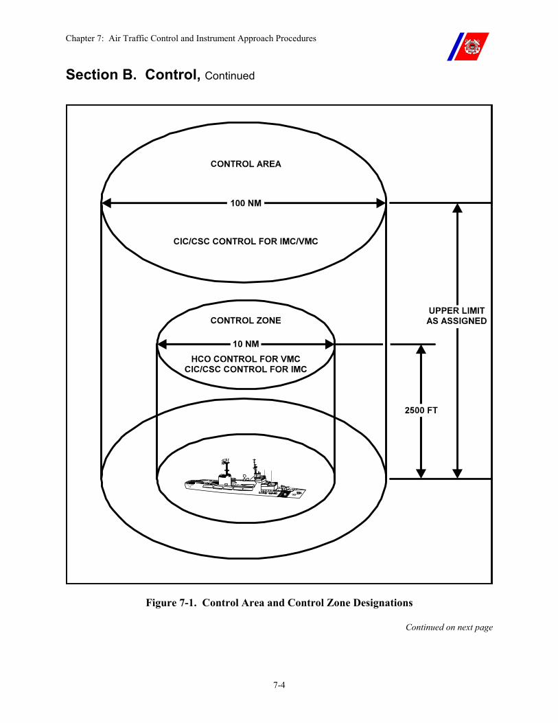
Chapter 7: Air Traffic Control and Instrument Approach Procedures
7-4
Section B. Control, Continued
Figure 7-1. Control Area and Control Zone Designations
Continued on next page
Chapter 7: Air Traffic Control and Instrument Approach Procedures
7-5
Section B. Control, Continued
WARNING Aircraft not operating in conjunction with a cutter may not be aware of the cutter’s presence or conduct of flight operations. Utmost vigilance and surveillance is required, particularly in areas near airways, airports, controlled airspace, or special use airspace.
B.2. Control Criteria for Non-Coast Guard Helicopters
The degree of control to employ during flight operations with non-Coast Guard Helicopters depends upon the weather.
�� When the ceiling and visibility are at or above 500 feet and 1 mile, respectively (500/1), either positive control or advisory control may be provided.
�� Any time the ceiling and/or visibility are below 500/1, except in cases of national defense, emergency, or when the saving of life is probable (see Chapter 1), positive control shall be provided.
B.3. Control Criteria for Coast Guard Helicopters
The degree of control to employ during flight operations with Coast Guard Helicopters depends on the weather.
�� When the ceiling and visibility are at or above 300 feet and 1 mile, respectively (300/1), either positive control or advisory control may be provided.
�� Any time the ceiling and/or visibility are below 300/1, except in cases of national defense, emergency, or when the saving of life is probable (see Chapter 1), positive control shall be provided.
B.4. Advisory Control
Advisory control consists of monitoring radio frequencies and if available, using radar to advise aircraft of other traffic and operational or hazardous areas. Advisory control shall be used anytime the cutter is conducting flight operations, or has the radio guard of an aircraft, when positive control is not required (ceiling and visibility at least 300/1).
Advisory control may be provided by either a Level I ADC or a Level II/III ADC.
WARNING The ADC is not responsible for separation of aircraft when providing advisory control.
This responsibility lies entirely with the flight crew. Radar tracking is not a prerequisite for advisory control. Therefore, other aircraft may be present near the cutter without the cutter’s knowledge.
Continued on next page
Chapter 7: Air Traffic Control and Instrument Approach Procedures
7-6
Section B. Control, Continued
B.5. Positive Control
Positive control shall be provided only by a Level I ADC using an air search radar capable of tracking all aircraft within the radar effective range. It requires both radar and radio contact with the aircraft being controlled. An aircraft is under positive control when it is complying with ADC instructions and clearances, including heading and altitude assignments and approach and departure procedures.
Except where safety of flight would be jeopardized, compliance with these instructions and procedures is mandatory.
Instructions issued by the ADC shall ensure that traffic separation is provided.
Except for operations involving national defense, emergency, or when the saving of life is probable (see Chapter 1), positive control is required for all operations when ceiling and/or visibility are less than 300/1, but may also be provided for operations when ceiling and visibility are 300/1 or greater.
WARNING Positive control does not negate the responsibility of the flight crew for maintaining traffic separation in VMC.
B.6. Separation Criteria
The ADC shall ensure adequate separation of aircraft when providing positive control. Either lateral or vertical separation shall be provided as indicated below.
These restrictions do not apply to launch and recovery operations or tactical maneuvers such as air intercepts, rendezvous, and close anti-submarine warfare (ASW) action.
B.6.a. Lateral Separation
�� At least 3 nm within 50 nm of the cutter’s radar antenna.
�� At least 5 nm beyond 50 nm from the cutter’s radar antenna.
B.6.b. Vertical Separation
�� Helicopters shall be separated by a minimum of 500-feet.
�� Helicopters shall be separated from fixed wing aircraft by a minimum of 1000-feet.
�� Fixed wing aircraft shall be separated by a minimum of 1000-feet.
NOTE The controlling authority may require greater separation of aircraft. This is particularly appropriate in reduced ceilings and/or visibility and with aircraft not squawking altitude (Mode C).

Chapter 7: Air Traffic Control and Instrument Approach Procedures
7-7
Section B. Control, Continued
B.6.c. Traffic Reporting
All air contacts passing within 10 nm of an aircraft under control of the cutter shall be reported to the pilot, even if no evasive action is anticipated. In high-density air traffic areas, pilots may elect to modify air contact reporting requirements (i.e. San Francisco Bay).
The ADC will use the appropriate communications format for traffic reporting that is set forth in Appendix G.
Chapter 7: Air Traffic Control and Instrument Approach Procedures
7-8
Section C. Communications
C.1. Overview Except under conditions of national defense or urgent SAR or when tactical situations dictate otherwise, two-way radio communications are required during all helicopter operations at night, during periods of low ceiling and visibility, and for flights beyond visual range of the cutter.
Strict radio discipline is essential. However, procedures may be adjusted to meet the needs of the mission.
Transmissions should be as brief as possible. Except as specified in this Manual, language should not vary appreciably from the standard air control phraseology detailed in the Allied Communications Operational Brevity Code Publication, ACP-165 (series).
C.2. Helicopter Control Officer (HCO) Communications
The HCO shall control communications as follows:
�� Primary control during launch and recovery. �� Secondary control of departure and approach frequencies.
C.3. CIC or CSC Communications Control
CIC or CSC shall control communications as follows:
�� Primary control of departure, approach, and air control frequencies. �� Secondary control during launch/recovery.
C.4. Electronic Emission Control (EMCON)
The Operations Officer shall be responsible for EMCON in accordance with appropriate directives.
Detailed briefings covering mission responsibilities and procedures shall be conducted before operating under EMCON conditions. All flight crewmembers, ADCs, and the LSO shall attend such briefings and familiarize themselves with all procedures.
Both the controlling cutter and the helicopter shall guard the appropriate frequencies.
Non-electronic communications procedures for performing launch, flight, arrival, and recovery operations shall be established in advance. (See Chapter 5.)
NOTE EMCON should not be utilized during Level I operations.
Continued on next page

Chapter 7: Air Traffic Control and Instrument Approach Procedures
7-9
Section C. Communications, Continued
C.5. Terminology Expeditious, standardized communications are desirable in all circumstances. ADCs and pilots should use the brevity codes listed in Appendix G.
Chapter 7: Air Traffic Control and Instrument Approach Procedures
7-10
Section D. Departure Procedures
D.1. Overview The responsibility for adherence to the assigned departure instructions rests with the PIC. However, as a minimum, CIC or CSC shall provide advisory control.
D.2. Radio Checks Before launch, radio checks on the designated frequencies, using the appropriate aircraft and cutter call signs, shall be conducted unless equipment performance requires an airborne check (i.e. HF radio).
NOTE Under EMCON conditions, the Operations Officer, with concurrence of the Senior Aviator and Commanding Officer, may authorize launch of a helicopter with abbreviated two-way radio checks, if circumstances warrant and overall safety is maintained.
D.3. Night Visual Meteorological Conditions (VMC)
After departure, the helicopter shall climb to a minimum safe altitude before commencing its turn on course. If under positive control, deviations are permitted only with the concurrence of the ADC unless required for safety of flight.
D.4. Instrument Meteorological Conditions (IMC)
After departure, the helicopter shall remain in visual contact with the surface until positive control has been established, and shall climb to a minimum of 300-feet before commencing its turn on course.
D.5. Radio Frequencies and Transponder Codes
The helicopter shall be launched using the predetermined frequency.
At night or in IMC, the helicopter shall not change frequencies or transponder codes until achieving level flight and in cruise configuration.
Radio guard channels shall be monitored at all times.
When under positive control, the helicopter shall not shift from an assigned frequency or transponder code without the concurrence of the ADC.
When under advisory control, the pilot shall inform the ADC before changing frequencies or transponder codes.
Chapter 7: Air Traffic Control and Instrument Approach Procedures
7-11
Section E. Arrival Procedures
E.1. Overview When arriving within the control area (50 nm radius) of the recovery cutter, and upon release from the previous control authority, an inbound aircraft shall contact CIC or CSC for control. The dialog format for initial contact is outlined in Appendix G.
The compulsory arrival, holding, and approach voice reports required of the pilot are as follows:
1. Arrival within controllable range and release from the previous control agency
2. Acknowledge receipt of: �� Holding or marshal instructions. �� Estimated recovery time. �� Altimeter setting, wind, weather (read back required for
altimeter setting). 3. Entering holding 4. Altitude or other assignment changes 5. Commencing approach 6. Initial approach fix (IAF) and final approach fix (FAF) or procedure
turn 7. Cutter in sight (Talley Ho) 8. Missed approach or Wave-off
WARNING Aircraft shall not enter a cutter’s control zone without specific approval from CIC or CSC.
Chapter 7: Air Traffic Control and Instrument Approach Procedures
7-12
Section F. Flight Following Procedures
F.1. Overview The combined navigational capabilities of the cutter and helicopter may vary greatly, depending on geography, visual references, and the availability or status of land-based, shipboard, and airborne navigation equipment.
Personnel and equipment capabilities shall be weighed against the particular mission objective when deciding the suitability of available navigation and flight following methods.
F.2. Cutter Responsibility
The cutter shall maintain a continuous position plot, on paper or computer, of all helicopters for which it has the radio guard. This plot shall be as accurate as possible.
Using air and/or surface search equipment, the cutter shall maintain radar contact with the helicopter to the maximum extent possible. When radar contact is established or lost, or other shipboard position fixing information (TACAN, DF, etc.) becomes unreliable, the pilot shall be advised. If radar contact is not held or is lost, the ship shall maintain a dead reckoning (DR) plot of the helicopter’s anticipated flight path, updating the plot with each helicopter position report received.
Although this plot will normally be maintained in CIC or CSC, it is the Operations Officer’s responsibility, through the OOD, to ensure that it is maintained.
F.3. Helicopter Responsibility
To enable the cutter to maintain an accurate DR plot, the pilot shall advise the cutter of their position and heading every 15-minutes.
Significant deviations from the anticipated flight path originally given to the cutter or any helicopter equipment failures that may reduce navigation capability shall be reported as they occur.
Final responsibility for the safe conduct of the flight shall rest with the PIC, using accepted navigation equipment and procedures.
Continued on next page
Chapter 7: Air Traffic Control and Instrument Approach Procedures
7-13
Section F. Flight Following Procedures, Continued
F.4. Flight Following Methods
Flight following positions and headings shall be manually recorded every 15-minutes; however, the five (5) minute DR recordings may be recorded electronically. The following are rank ordered procedures for position plots:
�� Five (5) minute shipboard radar or IFF fixes. �� Five (5) minute DR positions updated by 15-minute fixes based on
the helicopter’s Inertial Navigation System (INS) or Global Positioning System (GPS) position.
�� Five (5) minute DR positions updated by 15-minute fixes based on the helicopter’s position derived visually or from land-based navigational aids (TACAN/VOR).
�� Five (5) minute DR positions updated by 15-minute fixes based on the helicopter’s position (radial and DME) from the cutter’s TACAN.
�� Five (5) minute DR positions updated by 15-minute fixes based on the helicopter’s position, using the helicopter’s radar.
�� Five (5) minute DR positions updated every 15-minutes with the helicopter’s bearing and distance from the cutter, using the cutter’s DF equipment and DME arc.
The helicopter’s operating distance from the cutter shall be reduced appropriately as the accuracy of flight following method being used decreases.
WARNING Use of DR as the sole source of helicopter position fixing is prohibited unless visual contact with the cutter can be maintained.
For missions involving national defense, emergency, or where the saving of life is probable (see Chapter 1), a waiver may be granted by the cutter’s Commanding Officer.
Continued on next page
Chapter 7: Air Traffic Control and Instrument Approach Procedures
7-14
Section F. Flight Following Procedures, Continued
F.5. Coordination and Safety
Personnel and equipment capabilities, weather conditions, rescue capabilities and operational goals shall be considered when judging the acceptability of particular flight following methods.
Covert operations do not justify compromising acceptable navigation or flight following procedures. Benchmarks, discrete radio frequencies, pre-briefed transponder codes, etc., may be used to satisfy covert objectives without abandoning proper flight following procedures.
Both the helicopter and the cutter shall be aware of and agree upon the method of flight following to be used, and alternate methods available.
Operational checks of all navigation equipment shall be accomplished as soon as feasible.
The aircrew and all responsible personnel aboard the cutter shall be notified immediately of changes in weather conditions, cutter or helicopter malfunctions, or any other factors that may limit operations or compromise safety.
NOTE The ADC or HCO shall inform the helicopter in the event radar contact is lost.
Chapter 7: Air Traffic Control and Instrument Approach Procedures
7-15
Section G. Approach Procedures
G.1. Approach Criteria
The pilot’s weather estimate as well as the cutter observed weather shall dictate the type of control and approach required for the recovery.
G.1.a. Visual Approach
If the helicopter is operating in VMC below the cloud ceiling, a visual approach to the cutter may be utilized.
�� When the helicopter is in visual range, control shall be passed to the HCO to complete the recovery.
�� If the cutter is not prepared, the ADC or HCO shall issue orbit instructions until the cutter is ready for recovery.
G.1.b. Stabilized Glide Slope Indicator (SGSI)
The MK 1 MOD 0 SGSI system is an electro-hydraulic optical landing aid designed for ship use. With it, a pilot may visually establish and maintain the proper glide slope for a safe approach and landing.
The visual acquisition range is approximately 3-miles at night under optimum environmental conditions.
The SGSI provides a single bar of green light (1.5-degrees), amber light (1-degree), or red light (6.5-degrees) as shown in Figure 7-2. The light is projected through a 40-degree horizontal azimuth. The color of the light indicates to the pilot whether he or she is above (green), below (red), or on (amber) the proper glide slope.
�� Adjust the helicopter’s altitude to keep the amber-red interface visible to maintain a 3-degree glide slope to the cutter.
�� Fly the amber-red transition zone to minimize glideslope deviations. (Glide slope change information available.)
�� Flying in the center of the amber zone requires large changes in glide slope before the pilot notices any error.
�� Flying the amber-green transition zone would provide a steeper approach angle.
A helicopter executing an SGSI approach would normally intercept the glide slope at an altitude of approximately 350-feet and a distance of one (1) mile.
The SGSI shall be energized for all night and IMC approaches to aid the pilot in the final phase of the approach.
Continued on next page
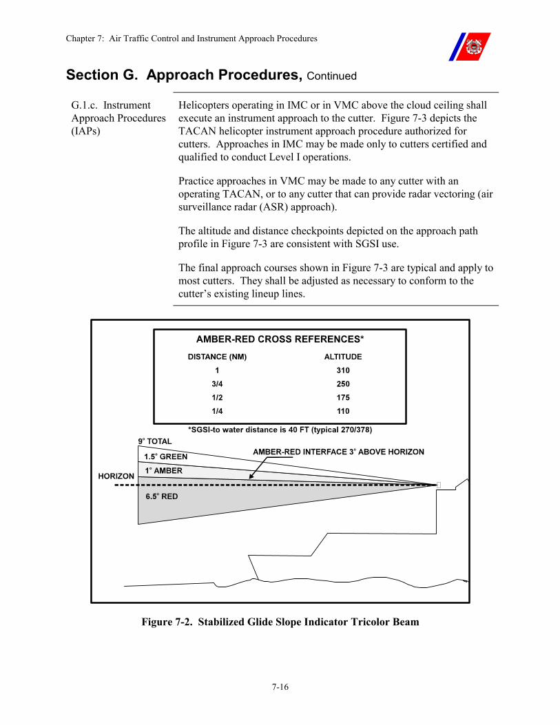
Chapter 7: Air Traffic Control and Instrument Approach Procedures
7-16
Section G. Approach Procedures, Continued
G.1.c. Instrument Approach Procedures (IAPs)
Helicopters operating in IMC or in VMC above the cloud ceiling shall execute an instrument approach to the cutter. Figure 7-3 depicts the TACAN helicopter instrument approach procedure authorized for cutters. Approaches in IMC may be made only to cutters certified and qualified to conduct Level I operations.
Practice approaches in VMC may be made to any cutter with an operating TACAN, or to any cutter that can provide radar vectoring (air surveillance radar (ASR) approach).
The altitude and distance checkpoints depicted on the approach path profile in Figure 7-3 are consistent with SGSI use.
The final approach courses shown in Figure 7-3 are typical and apply to most cutters. They shall be adjusted as necessary to conform to the cutter’s existing lineup lines.
Figure 7-2. Stabilized Glide Slope Indicator Tricolor Beam
Chapter 7: Air Traffic Control and Instrument Approach Procedures
7-17
Section G. Approach Procedures, Continued
G.1.d. Holding The primary holding pattern, depicted in Figure 7-3, is PRIMARY MARSHAL.
CIC or CSC shall specify which pattern to use in the holding instructions.
When the cutter is prepared for recovery, CIC or CSC shall clear the helicopter for the approach.
G.1.e. TACAN Approach
When cleared for the TACAN approach by CIC or CSC, the pilot proceeds to the IAF using radar vectors, TACAN information, or from holding, as depicted in Figure 7-3.
After being cleared for the approach but before reaching the IAF the pilot completes the before landing checklist.
At the IAF, the pilot reports “Commencing approach.”
Before the FAF, the pilot reports, “Pre-landing checks complete, gear down, right/left seat landing (seat position is for HH-60 only). Request permission for…(touch-and-go or securing option).”
The CIC or CSC replies with a “Clear to land” call.
At the missed approach point (MAP), the pilot reports, “Not visual, executing missed approach” and executes the prescribed missed approach, or “Visual contact,” and completes the approach and landing using SGSI, VLAs, and LSO signals.
NOTE The pilots may use NVGs during the approach.
G.1.f. Radar Approaches
The cutter’s air search radar and the radar on board the helicopter can be used with the approach profile depicted in Figure 7-3.
TACAN approach procedures apply, except that the pilot controls the helicopter’s descent based on the range and azimuth information received from the cutter or from the helicopter’s radar.
The radar operator provides a continuous update of range and azimuth information until the landing environment or SGSI is visually acquired.
Continued on next page
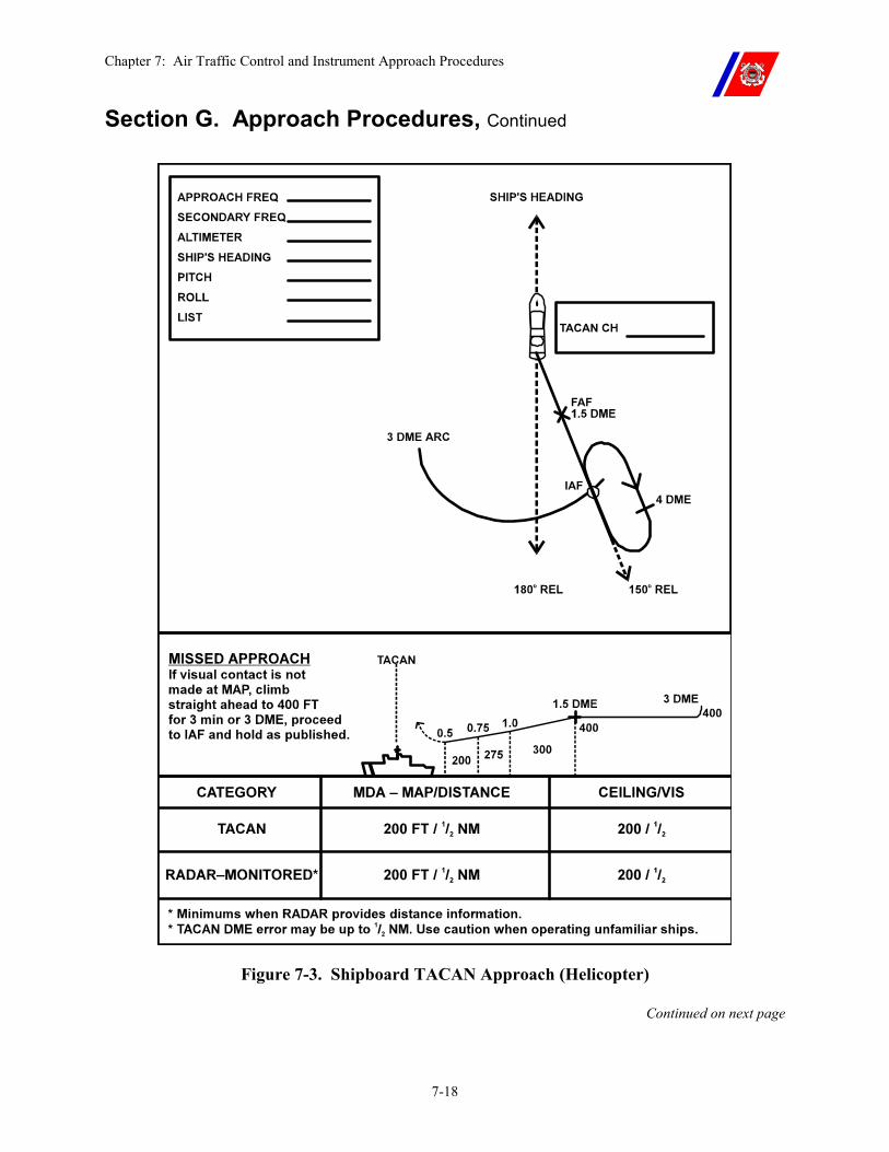
Chapter 7: Air Traffic Control and Instrument Approach Procedures
7-18
Section G. Approach Procedures, Continued
Figure 7-3. Shipboard TACAN Approach (Helicopter)
Continued on next page
Chapter 7: Air Traffic Control and Instrument Approach Procedures
7-19
Section G. Approach Procedures, Continued
G.1.g. Missed Approach/Wave-Off
If the landing environment is not in sight at the MAP and a safe landing cannot be executed, or if the pilot has been in visual contact and proceeded beyond the MAP and then loses contact, an immediate Wave-Off or missed approach shall be executed.
�� The pilot climbs to 400-feet on a heading that will allow the helicopter to clear the cutter.
�� If no instructions are received before reaching 3 nm or within 3-minutes, the pilot executes a left turn to downwind and proceeds to the designated holding point to attempt another approach.
If meteorological conditions are considered to preclude a safe landing and sufficient fuel reserves exist, the helicopter should be diverted to a more suitable landing site.
G.1.h. Helicopter Approach Minimums
Ceiling and visibility minimums for each approach are prescribed in Figure 7-3. However, the Commanding Officer, after consulting with the Senior Aviator, may establish more restrictive approach minimums that reflect significant changes in operational capabilities, such as decreased proficiency of ADC or the helicopter flight crews.
Ceiling and visibility minimums shall be observed until visual contact with the water surface or the cutter is established.
Following a missed approach, when a suitable alternate landing platform is available, pilots shall not commence an approach to the primary landing platform if the reported or observed weather is below minimums, unless it has been determined that the helicopter has sufficient fuel to proceed to the alternate landing platform.
G.1.i. CATCH/ MATCH/PATCH/ NATCH (HH-65/ HH-60J)
Coast Guard helicopters may elect to execute:
�� A Computer Approach To a Coupled Hover (CATCH) �� A Precision Approach To a Coupled Hover (PATCH) �� A Manual Approach To a Controlled Hover (MATCH) �� An NVG Aided Approach To a Controlled Hover (NATCH) �� An IAS-VS Let-down
The approach should be executed using the cutter’s TACAN as a reference point.
Continued on next page
Chapter 7: Air Traffic Control and Instrument Approach Procedures
7-20
Section G. Approach Procedures, Continued
G.1.j. Emergency Low-Visibility Approach (ELVA) Procedures
An Emergency Low-Visibility Approach (ELVA) to a cutter that is below approach minimums (200-foot ceiling and 1/2 mile visibility) is an EMERGENCY procedure.
An ELVA serves as the final instrument approach procedure after all other helicopter instrument approach options have been exhausted.
An actual ELVA shall not be attempted unless the helicopter does not have adequate fuel to divert to a precision approach-equipped facility.
The ELVA pattern and radio calls are shown on Figure 7-4.
G.1.j.(1). Practice ELVA
The primary factors which affect the quality of an ELVA are:
�� The ADCs ability, �� Accuracy of the information displayed to the ADC, and �� The pilot’s instrument flight proficiency.
Practice ELVA in VMC should be conducted often for ADC and pilot proficiency.
G.1.j.(2). ELVA Preparation
The equipment used shall be fully operable and accurately calibrated at all times; emergencies may occur at any time that require the use of:
�� Surface search radar �� Air search radar with IFF �� TACAN �� Gun fire control radar and associated computer �� Overlay or plotter �� UHF transceivers �� Anemometers �� Barometer
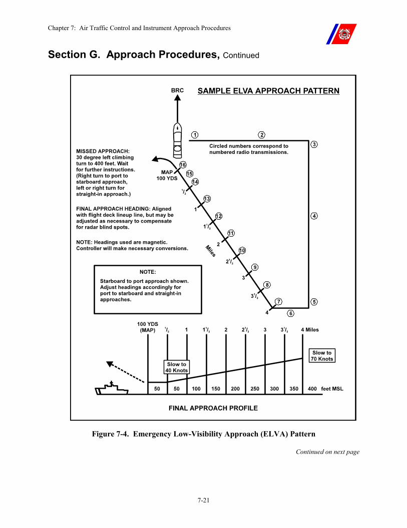
Chapter 7: Air Traffic Control and Instrument Approach Procedures
7-21
Section G. Approach Procedures, Continued
Figure 7-4. Emergency Low-Visibility Approach (ELVA) Pattern
Continued on next page
Chapter 7: Air Traffic Control and Instrument Approach Procedures
7-22
Section G. Approach Procedures, Continued
G.1.j.(3). ELVA Equipment
The radar that provides the most accurate, real-time tracking of the helicopter should be used during the ELVA.
An approach pattern overlay may also be used to assist the air controller.
�� At least one (1) UHF transceiver should be set up as a backup on the primary control frequency, and
�� At least one (1) transceiver should be set up as a secondary. �� Anemometers and the barometer shall be accurately calibrated.
Bridge personnel shall keep the controller informed of significant changes in either relative wind or barometric pressure during the approach.
An error of 0.05 inch in the barometric altimeter setting results in an altitude error of 50-feet, which is critical at the low altitudes flown during an ELVA.
G.1.j.(4). ELVA Initial Approach Pattern
The initial approach pattern is executed so that the helicopter reaches the four (4) mile gate position, at an altitude of 400-feet and airspeed of 70 knots, with all required radio transmissions (numbers 1 through 6 in Paragraph G.4 of this chapter) completed.
G.1.j.(5). ELVA Landing Clearance
In order to facilitate transition from approach profile to a safe landing, the ADC shall seek a landing clearance from the HCO as soon as practicable before or during the approach. This clearance is passed to the pilot at the 2 nm point on the final approach.
The HCO shall monitor the primary frequency but shall not, other than in an emergency; initiate communications until the aircraft is on deck.
Continued on next page
Chapter 7: Air Traffic Control and Instrument Approach Procedures
7-23
Section G. Approach Procedures, Continued
G.1.j.(6). ELVA Final Approach Profile
The helicopter shall commence the final approach at an altitude of 400-feet and an airspeed of 70 knots. Regardless of the initial approach pattern used, the final approach shall be conducted exactly the same.
This is the most critical phase of the ELVA. The ELVA final approach ADC shall have the approach plotted and actually have control of the helicopter before reaching the 4-mile gate.
For cutters with a straight-in (centerline) approach, the final approach heading should be the cutter's base recovery course, however, may be adjusted as necessary to compensate for radar blind spots.
�� For cutters with an oblique approach, the final approach heading shall be aligned with the appropriate flight deck lineup line. �� For starboard to port approaches, the heading will be the
cutter’s base recovery course minus the flight deck approach angle.
�� For port to starboard approaches, the heading will be base recovery course plus the flight deck approach angle.
Heading corrections on the final approach should be made in small increments (not more than 5-degrees, if possible).
The helicopter shall use one-half standard rate turns on final approach. The tendency to over correct shall be avoided.
The helicopter will be changing speeds during the final approach; therefore, the cutter-helicopter relative motion will change.
Continued on next page
Chapter 7: Air Traffic Control and Instrument Approach Procedures
7-24
Section G. Approach Procedures, Continued
G.1.j.(7). ELVA Required Controller Radio Transmissions
Transmissions are keyed to the helicopter’s range from the cutter, and shall be made at the appropriate time. The normal sequence and keying of voice transmissions is provided Figures 7-4 and Paragraph G.4 of this Chapter. These transmissions are the required transmissions and shall be given for each approach. Corrections to headings must be given as required.
“Filler” transmissions may be required to ensure that the maximum time between transmissions (1 minute in the pattern and 15 seconds on final) is not exceeded. Filler transmissions should give useful information to the pilot, such as assigned heading and distance from touchdown, dimensions of the flight deck, and so forth. Avoid routine radio checks as filler transmissions and do not continuously transmit, as this restricts the ability of the pilot to transmit information in an emergency.
Whenever a heading is given, ensure an altitude is also given (for example, “Turn left heading 200 (two zero zero), altitude should be 300 (three hundred) feet”).
Conversely, never give an altitude without including the assigned heading.
G.1.j.(8). ELVA Missed Approach Procedures
The pilot shall execute a missed approach if the cutter is not in sight at the designated minimums, normally 50-feet altitude and 100 yards.
During final approach phase, if the ADC loses radar contact, the pilot shall be advised, “Radar contact lost, if ship or wake not in sight, execute missed approach.”
Variables such as radar performance, ADC proficiency, aircrew factors, etc., may require the cutter’s Commanding Officer to raise these minimums so as not to unduly endanger the cutter or helicopter.
If a missed approach occurs, the pilot shall make a 30-degree turn to the left (right for port approach) and climb to 400-feet. The helicopter should then be vectored back into the ELVA pattern.
Continued on next page
Chapter 7: Air Traffic Control and Instrument Approach Procedures
7-25
Section G. Approach Procedures, Continued
G.2. No Visual Contact; Critical Fuel
If the helicopter cannot establish visual contact with the water or the cutter at 50-feet MSL, and fuel exhaustion is imminent, the helicopter shall continue with a controlled descent until establishing visual contact with the water.
Amphibious helicopters may (conditions permitting) continue descent until making contact with the water.
The helicopter should then air taxi in the direction of the best estimated position of the cutter.
WARNING It may be preferable to ditch the helicopter with power on rather than autorotate to the water following a flameout from fuel starvation.
G.3. Upon Making Visual Contact with the Cutter or Water
Continue approach and recovery in visual conditions using procedures contained in Chapter 6.
Continued on Next Page
Chapter 7: Air Traffic Control and Instrument Approach Procedures
7-26
Section G. Approach Procedures, Continued
G.4. ELVA RADAR CONTROLLER STANDARD VOICE TRANSMISSIONS
NOTE All headings shall be expressed in degrees magnetic.
1. (Initial Check-in). This will be a radar-assisted approach. I hold you radar contact on the ______ degree radial, ______ miles from the ship. Altimeter setting is ______. Weather is: (ceiling __________ feet/unrestricted), visibility ______ miles. Final approach heading will be ______ degrees. Relative wind ______ degrees at ______ knots. Maximum pitch and roll are: ______ degrees pitch and ______ degrees roll and _____ degrees list to Port/Starboard. Read back altimeter.
2. (Descend to/climb to/maintain) 400-feet. Assigned heading is ______ (degrees).
3. Lost communications procedures follow: If no transmissions are received for 1 minute in the pattern or 15 seconds on final, climb to and maintain 400-feet. Attempt contact on ______ (secondary frequency). If unable to make contact, squawk 7600 Mode 3. Execute TACAN channel ______ approach commencing at 3-miles and 400-feet on the ______ radial. Acknowledge.
4. Missed approach procedures follow: If ship or wake not in sight at missed approach point, immediately turn left/right 30-degrees, climb and maintain 400-feet, and increase airspeed to nine zero (90) knots. Report level and on airspeed, and stand by for further instructions. Acknowledge.
5. Perform landing checks. Report wheels down and locked.
6. Turn (right/left) heading ______ (degrees). Maintain 400-feet and slow to seven zero (70) knots.
7. Do not acknowledge further transmissions. On final, 4 miles. Commence gradual rate of descent to arrive at 1/2 mile at 50-feet. Maintain seven zero (70) knots. Assigned heading is ______ (degrees). Report ship in sight.
8. Three and 1/2 miles, (left of/right of/on/approaching) centerline. Turn (right/left) to ______ (degrees), (or) Assigned heading is ______ (degrees). Altitude should be 350-feet.
9. Three miles, (left of/right of/on/approaching) centerline. Turn (right/left) to ______ (degrees), (or) Assigned heading is ______ (degrees). Altitude should be 300-feet.
Continued on Next Page
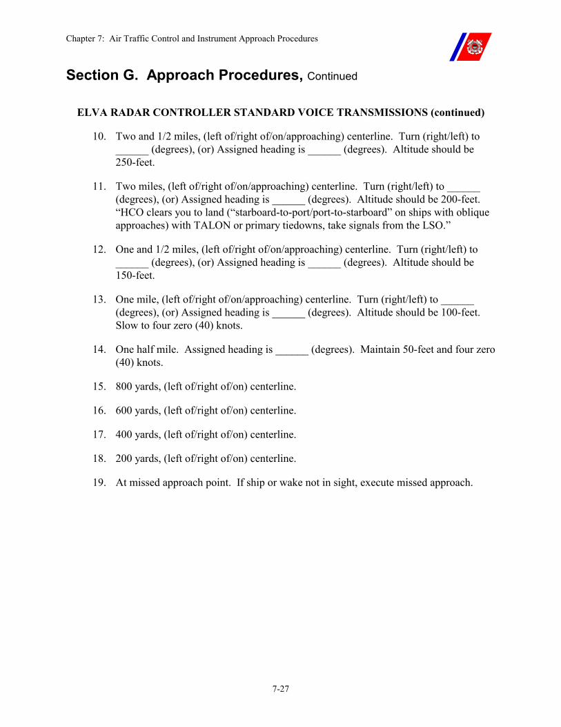
Chapter 7: Air Traffic Control and Instrument Approach Procedures
7-27
Section G. Approach Procedures, Continued
ELVA RADAR CONTROLLER STANDARD VOICE TRANSMISSIONS (continued)
10. Two and 1/2 miles, (left of/right of/on/approaching) centerline. Turn (right/left) to ______ (degrees), (or) Assigned heading is ______ (degrees). Altitude should be 250-feet.
11. Two miles, (left of/right of/on/approaching) centerline. Turn (right/left) to ______ (degrees), (or) Assigned heading is ______ (degrees). Altitude should be 200-feet. “HCO clears you to land (“starboard-to-port/port-to-starboard” on ships with oblique approaches) with TALON or primary tiedowns, take signals from the LSO.”
12. One and 1/2 miles, (left of/right of/on/approaching) centerline. Turn (right/left) to ______ (degrees), (or) Assigned heading is ______ (degrees). Altitude should be 150-feet.
13. One mile, (left of/right of/on/approaching) centerline. Turn (right/left) to ______ (degrees), (or) Assigned heading is ______ (degrees). Altitude should be 100-feet. Slow to four zero (40) knots.
14. One half mile. Assigned heading is ______ (degrees). Maintain 50-feet and four zero (40) knots.
15. 800 yards, (left of/right of/on) centerline.
16. 600 yards, (left of/right of/on) centerline.
17. 400 yards, (left of/right of/on) centerline.
18. 200 yards, (left of/right of/on) centerline.
19. At missed approach point. If ship or wake not in sight, execute missed approach.
Chapter 8: Aviation Fuel Handling
8-i
CHAPTER 8: AVIATION FUEL HANDLING Table of Contents
Introduction................................................................................................................................ 8-1
In this chapter ............................................................................................................................ 8-1
Section A. General Fuel Information ...................................................................................... 8-2
A.1. Overview ............................................................................................................................ 8-2
A.2. Jet Fuel ............................................................................................................................... 8-2 A.2.a. JP-4.......................................................................................................................................8-2 A.2.b. JP-8.......................................................................................................................................8-3 A.2.c. JP-5.......................................................................................................................................8-3
A.3. Fuel Definitions ................................................................................................................. 8-4
A.4. Types of Fuel Contamination........................................................................................... 8-4 A.4.a. Particulates ...........................................................................................................................8-5 A.4.b. Water....................................................................................................................................8-5
A.4.b.(1). Dissolved Water..................................................................................................8-5 A.4.b.(2). Entrained Water ..................................................................................................8-6 A.4.b.(3). Free Water...........................................................................................................8-6
A.4.c. Microorganisms....................................................................................................................8-7 A.4.d. Surfactants............................................................................................................................8-8 A.4.e. Miscellaneous Contaminants ...............................................................................................8-8
Section B. Fuel System Equipment.......................................................................................... 8-9
B.1. Overview ............................................................................................................................ 8-9
B.2. Strainer............................................................................................................................... 8-9
B.3. Filter-Water Separator (Coalescer)................................................................................. 8-9 B.3.a. Filter Elements .....................................................................................................................8-9
B.4. GO-NO-GO Fuel Monitor .............................................................................................. 8-10 B.4.a. Filter Replacement .............................................................................................................8-10
B.5. Static Bonding Cables ..................................................................................................... 8-10
B.6. Fuel Hose.......................................................................................................................... 8-11 B.6.a. Fuel Hose Installation.........................................................................................................8-11 B.6.b. Fuel Hose Storage and Flushing.........................................................................................8-12 B.6.c. Fuel Hose Service Life .......................................................................................................8-12 B.6.d. HIFR Rig Storage and Flushing .........................................................................................8-12
Chapter 8: Aviation Fuel Handling
8-ii
B.7. Fuel Nozzles ..................................................................................................................... 8-13
B.8. Defueling Equipment ...................................................................................................... 8-13
B.9. Detector Kits .................................................................................................................... 8-13
Section C. Fuel System Design ............................................................................................... 8-14
C.1. Overview .......................................................................................................................... 8-14
C.2. Fill and Storage System .................................................................................................. 8-14
C.3. Service System ................................................................................................................. 8-14
C.4. Stripping System ............................................................................................................. 8-17
Section D. Fuel Tests and Inspections ................................................................................... 8-19
D.1. Overview .......................................................................................................................... 8-19
D.2. Fuel Sampling Procedures.............................................................................................. 8-20
D.3. Fuel Visual Inspections (Clear and Bright Tests) ........................................................ 8-21 D.3.a. Clear and Bright Test .........................................................................................................8-21 D.3.b. Clear and Bright Test Procedure........................................................................................8-22
D.4. Detector Kit Tests............................................................................................................ 8-25 D.4.a. Detector Test Frequency ....................................................................................................8-25
D.5. Laboratory Analysis ....................................................................................................... 8-25 D.5.a. Minimum Laboratory Analysis Schedule ..........................................................................8-26 D.5.b. Minimum Laboratory Analysis Requirements...................................................................8-26
D.5.b.(1). Verifying Test Kit Results ................................................................................8-26 D.5.b.(2). Correlation Sampling Procedures .....................................................................8-27
D.5.c. Additional Sampling Procedures........................................................................................8-27 D.5.d. Sampling Equipment..........................................................................................................8-28 D.5.e. Marking Instructions ..........................................................................................................8-28 D.5.f. Shipping Instructions ..........................................................................................................8-28
D.6. Hose Inspection ............................................................................................................... 8-29
Section E. Fuel Maintenance Procedures ............................................................................. 8-30
E.1. Overview .......................................................................................................................... 8-30
E.2. Receiving Fuel.................................................................................................................. 8-30
E.3. Maintaining Fuel ............................................................................................................. 8-31 E.3.a. Fuel Settling........................................................................................................................8-31
Chapter 8: Aviation Fuel Handling
8-iii
E.3.b. Fuel Stripping .....................................................................................................................8-31 E.3.c. Fuel Filtration .....................................................................................................................8-31 E.3.d. Fuel Recirculation ..............................................................................................................8-31 E.3.e. Fuel Storage Time Limits ...................................................................................................8-32 E.3.f. Fuel Records and Logs........................................................................................................8-32
E.4. Fuel System Icing Inhibitor (FSII) ................................................................................ 8-32
E.5. Fuel Tank Cleaning......................................................................................................... 8-35
Section F. Fuel Safety Precautions ........................................................................................ 8-36
F.1. Overview........................................................................................................................... 8-36
F.2. General Procedures ......................................................................................................... 8-36
F.3. Explosive Safety ............................................................................................................... 8-36
F.4. Benzene Exposure............................................................................................................ 8-37
F.5. Radio Frequency (RF) Radiation Hazards ................................................................... 8-38
F.6. Static and Electrical Discharge Prevention................................................................... 8-38
F.7. Fuel Spills ......................................................................................................................... 8-39
F.8. Bypassing of Fuel Filters................................................................................................. 8-39

Chapter 8: Aviation Fuel Handling
8-iv
Chapter 8: Aviation Fuel Handling
8-1
Chapter 8. Aviation Fuel Handling
Introduction This chapter provides JP-5 fuel general information and establishes minimum quality and surveillance standards, testing requirements, safety precautions, and handling procedures concerning the acceptance, storage, and dispensing of aviation fuel.
In this chapter This chapter is divided into six (6) sections:
�� Section A: General Fuel Information �� Section B: System Equipment �� Section C: System Design �� Section D: Tests and Inspection �� Section E: Fuel Maintenance Procedures �� Section F: Safety Precautions
Chapter 8: Aviation Fuel Handling
8-2
Section A. General Fuel Information
A.1. Overview Turbine-powered helicopters are vulnerable to failures caused by fuel contamination because of the high fuel consumption rates and the sensitivity of fuel system components.
Insufficient knowledge or carelessness in fuel handling can result in accidents endangering lives and property. Personnel engaged in fueling have a serious responsibility and shall be thoroughly trained for the job.
Current procedures for maintaining cleanliness in jet fuel are capable of reducing contamination to very low levels when used on a continuing basis. It is essential that the performance of the contamination control system be closely monitored to detect problems as they occur. Chapter 542 of the Naval Ships Technical Manual (NSTM) contains detailed information on this subject.
WARNING Fuel system pressure shall not exceed 55-psi at the nozzle with the nozzle flow valve in the closed position. Pressures higher than 55-psi may damage the helicopter fuel system.
NOTE Any casualty to the aviation fueling facility, including faulty or inoperative system components, test equipment, and uncontrollable water or particulate contamination results in de-certification of the facility, and shall be reported in accordance with Chapter 4.
A.2. Jet Fuel There are three (3) grades of turbine or jet fuel available for use by Coast Guard helicopters. Whether supplied by DoD or through commercial sources, they generally fall into the designation of JP-4, JP-5, or JP-8, depending on the characteristics of the fuel.
A.2.a. JP-4 �� JP-4 is a blend of gasoline and kerosene with a flash point ranging from -10 degrees Fahrenheit to +80 degrees Fahrenheit.
�� It is an alternative fuel to JP-5 for turbine engine powered aircraft, and is used only at shore stations, and never on board a cutter.
�� JP-4 is more dangerous to handle than JP-5 since the vapor space above JP-4 fuel in the tank normally falls in the explosive mixture range and can be ignited by static electricity.
�� Additionally, JP-4 fires spread rapidly and are much more difficult to extinguish than those involving JP-5.
Continued on next page
Chapter 8: Aviation Fuel Handling
8-3
Section A. General Fuel Information, Continued
CAUTION Helicopters should arrive on board with only JP-5 in the tanks whenever possible.
If this is not possible, the non-JP-5 fuel load should be planned to arrive with a minimum amount in the tanks (allowing for an adequate reserve), which shall then be refueled immediately with JP-5 to the fuel level required for the next mission.
A.2.b. JP-8 JP-8 is a kerosene fuel with an intermediate flash point (100 degrees Fahrenheit).
It is not authorized for storage or use on cutters. It is found extensively at military shore facilities.
If helicopters arrive aboard cutters fueled with JP-8, no special precautions are required except that the aircraft shall not be hangared until it is topped off with JP-5.
A.2.c. JP-5 JP-5 is a kerosene fuel with a high flash point (140 degrees F) facilitating shipboard handling safety.
JP-5 is the only aviation fuel authorized for use on cutters.
JP-5 is also used extensively at shore stations.
In contrast to JP-4, contaminant removal from JP-5 is more difficult because of its higher viscosity and density. If adequate surveillance of this type fuel is not practiced, contamination is almost certain to result. The deterioration problems normally encountered are:
�� Reduction in flash point due to contamination with other fuels having a lower flash point. (As little as five (5) percent JP-4 mixed with JP-5 will lower the flash point below the allowed minimum of 140 degrees F.)
�� Reduction of Fuel System Icing Inhibitor (FSII) due to contamination with water.
�� Contamination with dirt, rust, and water. This fuel has a great affinity for these contaminates.
Continued on next page
Chapter 8: Aviation Fuel Handling
8-4
Section A. General Fuel Information, Continued
A.3. Fuel Definitions
To aid in understanding this chapter, the following definitions are provided:
�� Clear - no visible sediment or water present. �� Bright Fuel - the fluorescent appearance that has no cloud or haze. �� Dry fuel - fuel that contains no water �� Coarse and Fine particles - solids that are larger than and smaller
than 10 microns respectively. Generally, coarse particles can be seen with the naked eye. Fine particles, if in sufficient amounts, appear as haze or cloudiness.
�� Coalescers - remove water from the fuel by causing droplets to combine, making them heavier and permitting them to collect on the bottom.
�� Stripping - the process of removing water and other contaminants that settle out of fuel.
�� GO-NO-GO fuel monitor - a canister containing several filter elements that are designed to remove both water and particulate contamination from the fuel. As the elements become contaminated, they restrict the flow of fuel to the aircraft.
A.4. Types of Fuel Contamination
There are four (4) major classifications of materials commonly encountered as contaminants in aviation fuels. Each of these may be responsible for specific fuel system problems. The most serious situation occurs when more than a single type of contamination is present.
Continued on next page
Chapter 8: Aviation Fuel Handling
8-5
Section A. General Fuel Information, Continued
A.4.a. Particulates Particulates are solid contaminants that will not dissolve in fuel.
Most common are iron, rust, scale, sand, and dirt. Also included are metal particles, lint, particles of filter media, gums, resins, rubber, and other materials in particle form.
The consequences of particulate contamination in aviation fuels may be severe if such material is allowed to reach the helicopter.
�� One method for removing particulates is providing adequate settling time for solids to settle out of the fuel before it is withdrawn from the storage tanks.
�� Another method, and perhaps the best, is to recirculate the fuel through filters and/or separators.
Particulate contamination can be held well below a level of one (1) milligram per liter (mg/l) in a properly functioning fuel distribution system.
A.4.b. Water Water occurs in aviation fuels in three (3) different forms:
�� Dissolved �� Entrained �� Free water (either liquid or frozen).
Free water is the only one that can be drawn off or separated from the fuel.
Dissolved water or entrained water can, however, be reduced to free water and then drawn off or separated.
A.4.b.(1). Dissolved Water
All aviation fuels will dissolve water in varying amounts depending upon the fuel composition and temperature. This can be likened to the humidity in the air.
Lowering fuel temperatures will cause dissolved water to come out of solution as entrained water (somewhat as fog comes out of air). Except for changing to the free state upon temperature drop, dissolved water does not pose a problem to the helicopter and cannot be removed by practical means.
Continued on next page
Chapter 8: Aviation Fuel Handling
8-6
Section A. General Fuel Information, Continued
A.4.b.(2). Entrained Water
This is water suspended in tiny droplets in the fuel. Individual droplets may or may not be visible to the naked eye, but they can give the fuel a cloudy or hazy appearance depending upon their size and number.
Entrained water usually results when a water slug and fuel are violently agitated as in passing through a pump, and usually will settle out in time depending upon the droplet size, specific gravity, viscosity of the fuel, and currents within the tank.
A water haze may often be found in turbine fuels.
A.4.b.(3). Free Water This water is completely free of fuel. It can be accumulated in storage of dispensing facilities by:
�� The settling of condensed moisture from the atmosphere, �� The infiltration of water through fill lines, vents, tank connections,
etc., or �� The delivery of fuel that contains water.
Large slugs of free water can cause engine flameouts, and ice from slugs and entrained water can severely restrict fuel flow by plugging helicopter fuel filters and other mechanisms.
An adverse side effect of accumulations of undrainable water in any storage tank is the growth of microorganisms and reduction of the level of FSII.
Free water in the form of water slugs, visible water droplets, or hazy entrained water cannot be tolerated in a fuel handling system, and shall never be delivered into a helicopter.
Continued on next page
Chapter 8: Aviation Fuel Handling
8-7
Section A. General Fuel Information, Continued
A.4.c. Microorganisms
Microbiological growths can become a critical problem in turbine fuel systems. Hundreds of microorganisms species have been isolated and identified. Many microorganisms are airborne, while others are found in the soil. Fuel is constantly exposed to inoculation by this type of contamination.
Generally, these organisms are found living at the fuel and water interface, deriving their nutrients from the hydrocarbons and adding their metabolic products to the aqueous phase.
There is considerable evidence that such microbes can maintain viability even in the absence of water and upon deposition in a storage tank containing water, the organisms may begin to propagate at a very high rate.
The effects of microbiological contamination are many and varied. Both the organisms and their products tend to collect at fuel and water interfaces resulting in mats, slime, and sludge. If the interface happens to be maintained on or within a filter element, rapid plugging may occur. In addition, the latter condition may result in rapid penetration of the organisms through the filter and subsequent contamination of the fuel downstream of the filter.
Filter plugging may also result from the breakup of upstream fungal mats. In some cases, the organisms and their by-products have softened or destroyed the top coatings of integral fuel tanks and subsequently caused severe corrosion of the helicopter structure.
Because microbes thrive in water, a simple and effective method to prevent or retard their growth is to eliminate the water.
The presence of visual microbiological growth in fuel being delivered to a helicopter is a reliable indication of the presence of free water and the failure of fuel cleanup equipment.
Continued on next page
Chapter 8: Aviation Fuel Handling
8-8
Section A. General Fuel Information, Continued
A.4.d. Surfactants The term “surfactants” is a contraction of “Surface Active Agents.” These are soap or detergent-like materials that occur naturally in fuel, or may be introduced in the refining processes by inclusion of additives into the fuel, or may be washed off the internal surfaces of containers previously holding other products.
Surfactants are usually more soluble in water than in fuel and reduce the interfacial tension between water and fuel, stabilizing suspended water droplets and contaminants in the fuel.
They are attracted to the elements of the filters or separators and can make these elements ineffective.
Surfactants also tend to plate out on metal surfaces and usually will adhere to these surfaces until surfactant rich water droplets are formed. The droplets run down the side of the cutter’s tanks and form puddles in the bottom or in the sumps.
Surfactants, in large concentrations, usually appear as a tan to dark brown liquid with a sudsy-like water and fuel interface.
Surfactants alone do not constitute a great threat to helicopters. However, because of their ability to suspend water and dirt in fuel and disarm filter and/or separator action, surfactants have become one of the major contaminants in aviation fuels.
A.4.e. Miscellaneous Contaminants
Miscellaneous contaminants can include either soluble or insoluble materials. Fuel can be contaminated by mixing with other grades or types of fuels, additives, or other material.
The greatest single danger to aviation safety from contaminated fuels is contamination resulting from human error. The possibility of human error can never be eliminated, but it can be minimized through good operating procedures, frequent checks, and personnel training.
Chapter 8: Aviation Fuel Handling
8-9
Section B. Fuel System Equipment
B.1. Overview The following components are essential for adequate aviation fuel handling.
B.2. Strainer Strainers provide only gross protection for coarse solid contamination. They are usually made of wire mesh screen inside a casing.
The only strainer used in Coast Guard fuel systems is installed at the fueling nozzle. It provides a final barrier against introducing particulate contamination into the helicopter fuel system.
B.3. Filter-Water Separator (Coalescer)
This unit both filters particles and separates water from fuel. It is usually a two-stage unit, within one enclosure, in which the first stage acts as a filter and coalescer while the second stage separates the resulting larger droplets from the fuel.
The filter should be sized to hold particles of a 5-micron size.
The date of the last filter change shall be stenciled on the exterior of the units.
B.3.a. Filter Elements
The elements shall be changed every three (3) years, when one million gallons of fuel have been dispensed, or when the differential pressure between the inlet and the outlet side of the filter separator is 15-psi.
Recirculate a minimum of 2000 gallons of fuel through the new elements and ensure that the fuel is clear and bright before placing the system back in service.
CAUTION Filter elements shall be tested in accordance with accepted test procedures before installation. (See NAVSHIPTECHMAN S9086-SP-STM-000, Chapter 542.)
NOTE Elements shall also be changed under any of the following conditions:
�� A sudden drop in the pressure across the elements. �� No increase in the pressure differential after several months of
operation (it should increase slowly with use). �� When analysis of downstream samples indicate inadequate
filtration of water and/or solids. �� When significant quantities of fibrous material are detected
downstream of filter and/or separators.
Continued on next page
Chapter 8: Aviation Fuel Handling
8-10
Section B. Fuel System Equipment, Continued
B.4. GO-NO-GO Fuel Monitor
All Coast Guard shipboard aviation fuel dispensing systems are required to have a GO-NO-GO fuel monitor installed downstream of the last filter and/or separator. The filters within the GO-NO-GO canister are rated at approximately 5-microns, and monitor the fuel for both water and particulate contamination, reducing both to acceptable levels. Fuel flow is reduced as the contaminants accumulate on the filter elements. Small amounts of contamination produce a gradual reduction in the flow of fuel, while large amounts stop the flow of fuel almost immediately.
B.4.a. Filter Replacement
GO-NO-GO filter elements shall be replaced when the pressure differential across the monitor reaches 20-psi.
If a reduction in fuel flow or an increase in differential pressure across the monitor occurs while fueling the helicopter, a sample shall be taken from the helicopter and tested before resuming flight operations.
WARNING Only GO-NO-GO fuel monitors and filter elements meeting MIL-M-81380 (AS) shall be installed aboard Coast Guard Cutters.
U.S. Navy and NATO vessels may not incorporate the use of GO-NO-GO filters.
B.5. Static Bonding Cables
Static bonding cables ensure that static charges do not build up that could possibly cause a spark.
The helicopter shall be grounded to bare metal on the cutter. The gravity fueling nozzle ground wire shall be connected to the helicopter, before touching the nozzle to the fueling connector.
Static discharge wicks on the wheels or airframe cannot be substituted for the required static bonding cables between the helicopter and the cutter. (See also Paragraph F.6 in this chapter.)
Continued on next page
Chapter 8: Aviation Fuel Handling
8-11
Section B. Fuel System Equipment, Continued
B.6. Fuel Hose Only internally grounded hose specifically built for aviation fuel servicing shall be used in fuel dispensing systems. A minimum of 150-feet of hose shall be permanently stowed on the hose reel.
The internal ground of the hose shall be checked upon installation of the hose and at least quarterly thereafter, IAW the appropriate MPC.
The maximum allowable fuel hose resistance is 1.5 Ohms per foot over the entire length of hose, including the nozzle.
B.6.a. Fuel Hose Installation
Before placing a new JP-5 fueling hose in service or installing an older hose, hydrostatic test and flush the hose in accordance with the following procedures:
�� Unpack the hose and visually inspect the hose for damage.
�� Hydrostatic test the hose to 150 percent of the working pressure for 10-minutes.
�� After the hydrostatic test, extend the hose to its full length and elevate to drain the water.
�� Install the hose, place hose on reel with other new hoses or in use hoses, commence flushing. Flush until samples meet the maximum allowed contamination of two (2) milligrams per liter and five (5) parts per million of freewater.
�� The hose is now ready for use.
CAUTION If the above action is taken and the hose still delivers a higher than allowed contamination level, do not use for fueling aircraft.
Chapter 8: Aviation Fuel Handling
8-12
Section B. Fuel System Equipment, Continued
B.6.b. Fuel Hose Storage and Flushing
In order to preserve the hose service life, if a fuel hose is not expected to be used for a period of two (2) weeks or longer, it shall be stored using one of the following procedures:
Serviceable fuel hose not installed on hose reel:
�� Completely drain the hose of fuel, flush thoroughly with fresh water, drain, air dry, and cap or connect the ends.
�� Before its next use, the hose shall be thoroughly flushed with fuel, and the test and inspection procedures set forth in this chapter shall be accomplished.
Installed on hose reel:
�� Fill the hose with fuel.
�� Once a week (minimum) flush sufficient fuel to turn over at least twice the volume of all fuel in the hose, piping system, and related equipment.
�� Before fueling a helicopter, fuel shall be flushed through the hose and tested in accordance with the procedures set forth in Section D.
�� If immediate use of a new unused hose is not anticipated, it may be put directly into storage with capped or connected ends.
B.6.c. Fuel Hose Service Life
Hoses used to transfer fuel to helicopters are subject to deterioration and shall be inspected frequently.
Due to the variance in amount of use and exposure to the elements, it is impossible to establish a single standard time factor for service life.
Hoses shall be replaced as required at any time the hose is physically damaged or deterioration is detected.
B.6.d. HIFR Rig Storage and Flushing
HIFR rigs shall be stored and flushed in accordance with the hose flushing procedures outlined in Paragraph B.5.b above.
Continued on next page
Chapter 8: Aviation Fuel Handling
8-13
Section B. Fuel System Equipment, Continued
B.7. Fuel Nozzles All nozzles used to dispense fuel to helicopters shall be of the self-closing type. They shall be of non-sparking construction with an installed 100-mesh screen.
Nozzles shall be assembled to the hose with quick disconnect couplings. (See Figures 8-1 through 8-3.)
The preferred method of refueling the HH-65 or the HH-60 is pressure refueling with a single point (underwing) nozzle.
B.8. Defueling Equipment
The fueling systems on board Coast Guard Cutters were not designed with a defueling capability.
A separate pump air-driven portable pump is used to drain fuel from the helicopter.
The defueling hoses, pump, and nozzle shall meet the same internal ground continuity requirements as the refueling hose and nozzle that are specified on the cutter AEL.
B.9. Detector Kits Each flight deck-equipped cutter shall have on board, in good operating condition:
�� A contaminated fuel detector kit (AEL MK III), �� A viewer kit, free water detector (AEL MK I), and �� A B-2 anti-icing additive (FSII) test kit, including the operating
manuals.
NOTE The instructions and maintenance procedures published in the operating manuals for the AEL MK I, AEL MK III, and FSII testers are essential for obtaining accurate test results, and shall be followed exactly.
Chapter 8: Aviation Fuel Handling
8-14
Section C. Fuel System Design
C.1. Overview The JP-5 fuel system consists of three (3) subsystems consisting of independent plumbing and components.
C.2. Fill and Storage System
The fill and storage system provides for the bulk storage of JP-5 fuel. The fuel in this system can meet less stringent standards of cleanliness, and shall not be used to refuel helicopters. The system is capable of:
�� Filling the storage tanks through the fill connector. �� Circulating the fuel in each storage tank through the transfer filter
and/or separator and back to the same tank using the transfer pump (most cutters).
�� Transferring fuel from one (1) storage tank, through the transfer filter and/or separator, to another storage tank using the transfer pump.
�� Transferring fuel from either storage tank, through the transfer filter and/or separator, to the service tank using the transfer pump.
C.3. Service System The service system provides clean fuel for refueling helicopters. The system contains a pressure regulating valve to ensure system pressure does not exceed 55-psi at the nozzle. It is capable of:
�� Circulating the fuel in the service tank, through the service filter and/or separator, back to the service tank (without going through the hose or GO-NO-GO monitor) using the service pump.
�� Flushing the fuel hose and fueling nozzle with fuel pumped from the service tank, through the service filter and/or separator, then the GO-NO-GO monitor, then the hose and fueling nozzle, and then returning to a storage tank via the fill connector using the service pump.
�� Fueling the helicopter with fuel pumped from the service tank, through the service filter and/or separator, then the GO-NO-GO monitor, and then the fuel hose and fueling nozzle using the service pump.
NOTE Any fuel circulated through the JP-5 hose shall not be discharged into the JP-5 service tanks.
Continued on next page
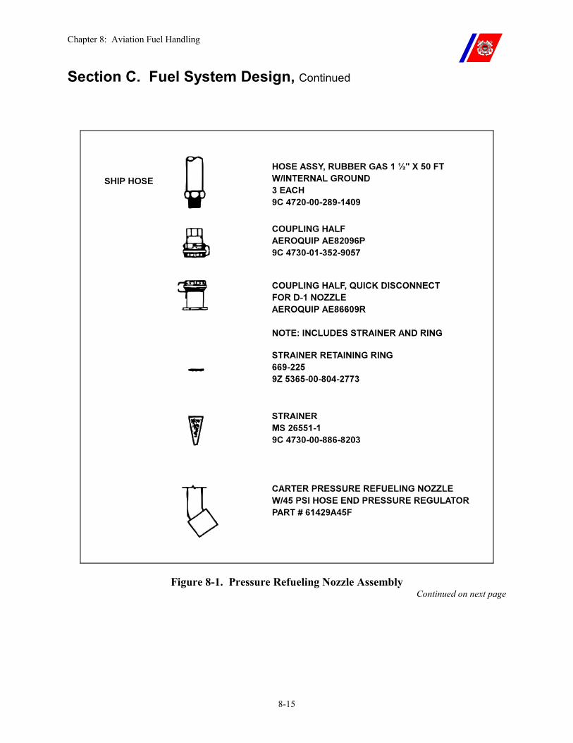
Chapter 8: Aviation Fuel Handling
8-15
Section C. Fuel System Design, Continued
Figure 8-1. Pressure Refueling Nozzle Assembly Continued on next page
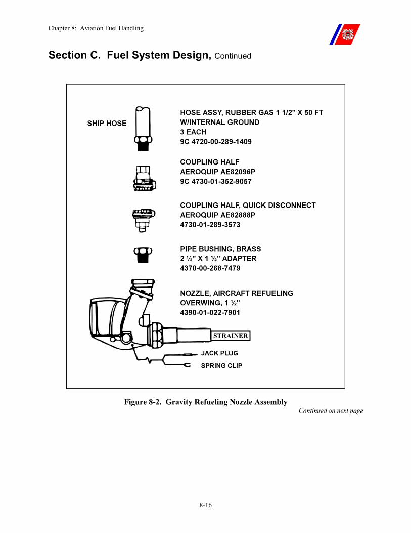
Chapter 8: Aviation Fuel Handling
8-16
Section C. Fuel System Design, Continued
Figure 8-2. Gravity Refueling Nozzle Assembly Continued on next page
STRAINER
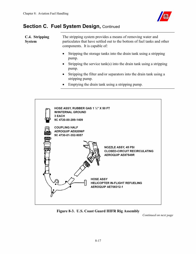
Chapter 8: Aviation Fuel Handling
8-17
Section C. Fuel System Design, Continued
C.4. Stripping System
The stripping system provides a means of removing water and particulates that have settled out to the bottom of fuel tanks and other components. It is capable of:
�� Stripping the storage tanks into the drain tank using a stripping pump.
�� Stripping the service tank(s) into the drain tank using a stripping pump.
�� Stripping the filter and/or separators into the drain tank using a stripping pump.
�� Emptying the drain tank using a stripping pump.
Figure 8-3. U.S. Coast Guard HIFR Rig Assembly Continued on next page
Chapter 8: Aviation Fuel Handling
8-18
Section C. Fuel System Design, Continued
WARNING An instruction plate and a diagram specifying the proper system alignment is provided in the JP-5 pump room. Any deviations from this alignment shall be approved by the Commanding Officer.
The JP-5 system may contain piping that bypasses the transfer and/or service filter/separators, or GO-NO-GO monitor, or cross-connects the storage, fill, and transfer systems with the service system. These bypasses and/or cross connections shall not be opened during helicopter fueling except by permission of the Commanding Officer.
The JP-5 system is positively separated from all other systems, either by removed sections of piping, or by installed in-line blanking flanges. The system shall not be re-connected to any other system except for the purpose of transferring fuel FROM the JP-5 system TO that other system.
NOTE Where system design permits, gravity stripping is an acceptable alternative to stripping by use of a pump.
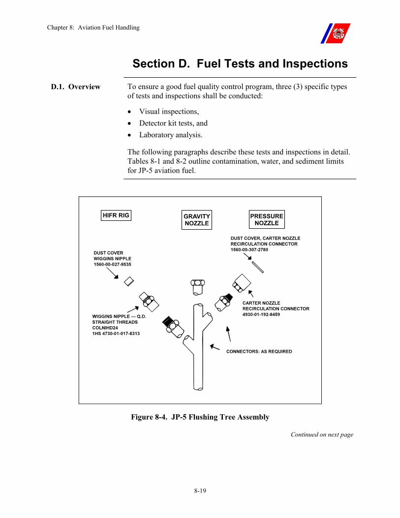
Chapter 8: Aviation Fuel Handling
8-19
Section D. Fuel Tests and Inspections
D.1. Overview To ensure a good fuel quality control program, three (3) specific types of tests and inspections shall be conducted:
�� Visual inspections, �� Detector kit tests, and �� Laboratory analysis.
The following paragraphs describe these tests and inspections in detail. Tables 8-1 and 8-2 outline contamination, water, and sediment limits for JP-5 aviation fuel.
Figure 8-4. JP-5 Flushing Tree Assembly
Continued on next page
Chapter 8: Aviation Fuel Handling
8-20
Section D. Fuel Tests and Inspections, Continued
D.2. Fuel Sampling Procedures
The proper sampling of aviation fuels is as important to quality surveillance as proper testing.
Improper containers and poorly drawn or mishandled samples can cause clear and bright tests, detector kit tests, or laboratory analysis to be meaningless, or misleading. The person assigned to take these samples shall be trained, experienced, competent, and conscientious.
To conduct a clear and bright test, or to gather fuel samples for detector kit tests, or laboratory analysis, the following procedures shall be used:
�� Use a clean glass container or laboratory beaker from one (1) quart to one (1) gallon in size. The bottle should be round, with a relatively flat bottom, and should be as clean as possible.
�� Use only clean, lint-free wiping cloths, funnels, and other items to ensure representative samples are obtained.
�� Clean the nozzle or sampling valve of any contamination. �� Rinse the sample bottle thoroughly with the type of fuel sampled
before drawing the sample for the test and/or inspection. �� Draw the sample at the highest flow rate possible, avoiding spills
and splashing. �� Cap or cover the samples to prevent contamination.
WARNING Eye protection shall be worn to prevent fuel from splashing into the eyes.
Continued on next page
Chapter 8: Aviation Fuel Handling
8-21
Section D. Fuel Tests and Inspections, Continued
D.3. Fuel Visual Inspections (Clear and Bright Tests)
Fuel delivered to the helicopter must be clear, bright, and contain no free water.
�� “Clear” means the absence of any cloud, emulsion, readily visible particulate matter, or entrained water.
�� “Bright” refers to the shiny appearance of clean, dry fuels.
The terms “clear” and “bright” are independent of natural color of the fuel. Jet fuels are not dyed and may be any color from clear to amber.
Ordinarily, a cloud or haze in fuel indicates the presence of water. Occasionally, a cloud denotes excessive amounts of fine particulate matter or finely dispersed stabilized emulsion. Fuel containing a cloud from either cause is not acceptable. If a light cloud forms when “clear and bright” fuel cools, it indicates that dissolved water has precipitated out. This “precipitation cloud” represents a very slight amount of fresh water. Even this slight amount is not acceptable in fuel to be delivered to a helicopter.
A “precipitation cloud” can be removed by a properly operating filter and/or separator. The fuel should be drained back upstream of the filter and/or separator and recirculated to remove the cloud.
Any cloud that persists in spite of recirculating the fuel must be presumed to indicate a failure or malfunction of the filter and/or separators, a source of contamination downstream of the filter and/or separator, or an improperly cleaned sample container.
D.3.a. Clear and Bright Test
The clear and bright test shall be conducted:
�� Immediately before, and after, each helicopter refueling, with samples taken from the refueling nozzle.
�� After each recirculation of fuel, with a sample taken from the appropriate tank.
�� After replacement of or maintenance on any system component (including nozzle swap out), with a sample taken from downstream of the component.
�� At any time when fuel condition is suspect, with a sample taken from the suspected source.
Continued on next page
Chapter 8: Aviation Fuel Handling
8-22
Section D. Fuel Tests and Inspections, Continued
D.3.b. Clear and Bright Test Procedure
�� Check the sample for proper color and visible contamination. �� Swirl the sample to form a vortex. All free water and sediment that
has settled will accumulate beneath the vortex. �� When a sample is being examined, move the bottle around so that
the background light is varied.
�� If a sample shows dirt and/or water, clean the bottle and filling equipment, flush the hose, and conduct the test again.
WARNING Fuel that produces samples that are cloudy, hazy, or contain sediment shall not be used in helicopters.
Continued on next page
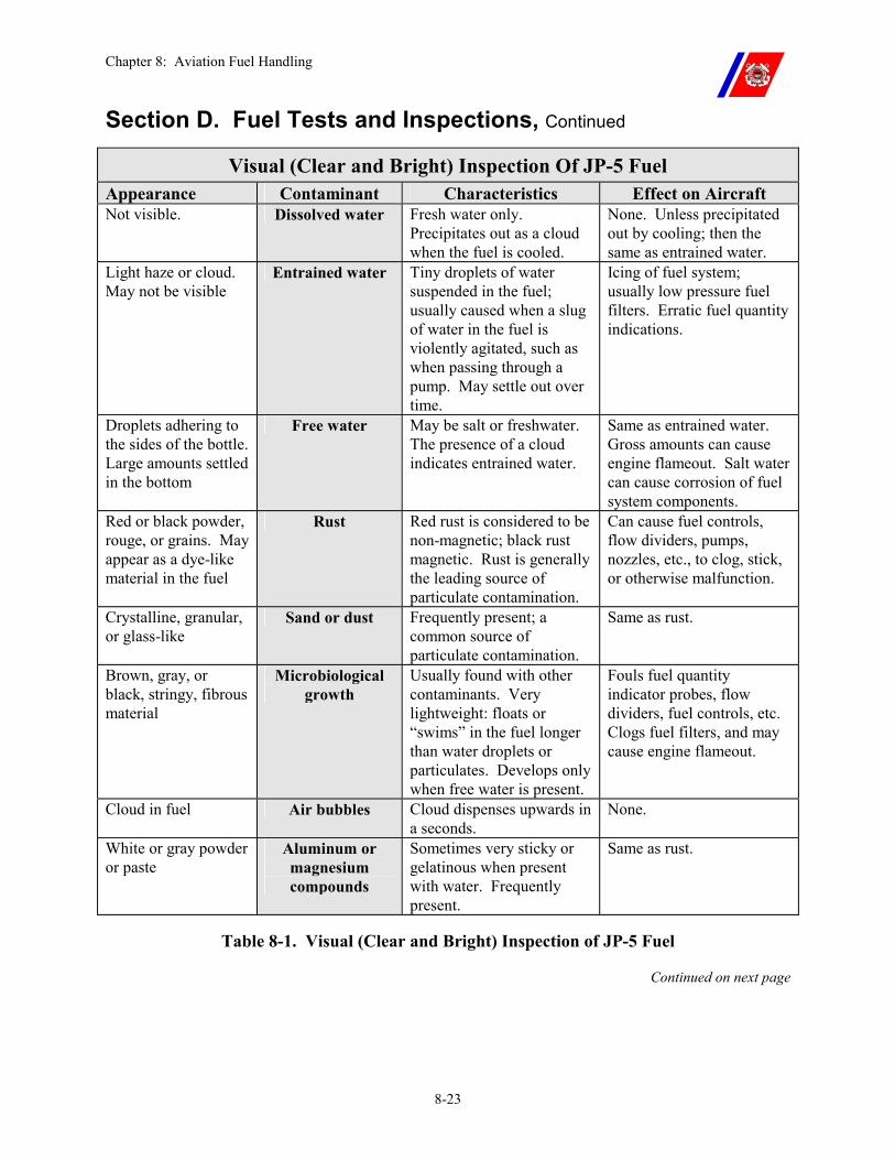
Chapter 8: Aviation Fuel Handling
8-23
Section D. Fuel Tests and Inspections, Continued
Visual (Clear and Bright) Inspection Of JP-5 Fuel Appearance Contaminant Characteristics Effect on Aircraft Not visible. Dissolved water Fresh water only.
Precipitates out as a cloud when the fuel is cooled.
None. Unless precipitated out by cooling; then the same as entrained water.
Light haze or cloud. May not be visible
Entrained water Tiny droplets of water suspended in the fuel; usually caused when a slug of water in the fuel is violently agitated, such as when passing through a pump. May settle out over time.
Icing of fuel system; usually low pressure fuel filters. Erratic fuel quantity indications.
Droplets adhering to the sides of the bottle. Large amounts settled in the bottom
Free water May be salt or freshwater. The presence of a cloud indicates entrained water.
Same as entrained water. Gross amounts can cause engine flameout. Salt water can cause corrosion of fuel system components.
Red or black powder, rouge, or grains. May appear as a dye-like material in the fuel
Rust Red rust is considered to be non-magnetic; black rust magnetic. Rust is generally the leading source of particulate contamination.
Can cause fuel controls, flow dividers, pumps, nozzles, etc., to clog, stick, or otherwise malfunction.
Crystalline, granular, or glass-like
Sand or dust Frequently present; a common source of particulate contamination.
Same as rust.
Brown, gray, or black, stringy, fibrous material
Microbiological growth
Usually found with other contaminants. Very lightweight: floats or “swims” in the fuel longer than water droplets or particulates. Develops only when free water is present.
Fouls fuel quantity indicator probes, flow dividers, fuel controls, etc. Clogs fuel filters, and may cause engine flameout.
Cloud in fuel Air bubbles Cloud dispenses upwards in a seconds.
None.
White or gray powder or paste
Aluminum or magnesium compounds
Sometimes very sticky or gelatinous when present with water. Frequently present.
Same as rust.
Table 8-1. Visual (Clear and Bright) Inspection of JP-5 Fuel
Continued on next page
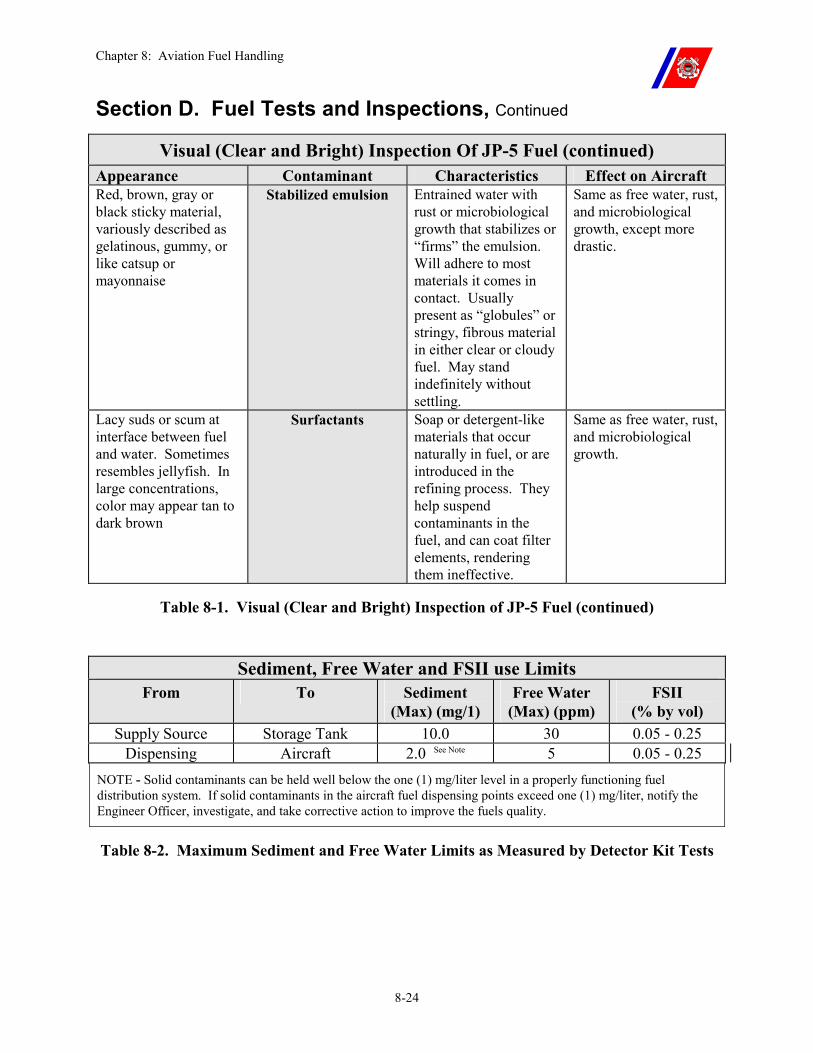
Chapter 8: Aviation Fuel Handling
8-24
Section D. Fuel Tests and Inspections, Continued
Visual (Clear and Bright) Inspection Of JP-5 Fuel (continued) Appearance Contaminant Characteristics Effect on Aircraft Red, brown, gray or black sticky material, variously described as gelatinous, gummy, or like catsup or mayonnaise
Stabilized emulsion Entrained water with rust or microbiological growth that stabilizes or “firms” the emulsion. Will adhere to most materials it comes in contact. Usually present as “globules” or stringy, fibrous material in either clear or cloudy fuel. May stand indefinitely without settling.
Same as free water, rust, and microbiological growth, except more drastic.
Lacy suds or scum at interface between fuel and water. Sometimes resembles jellyfish. In large concentrations, color may appear tan to dark brown
Surfactants Soap or detergent-like materials that occur naturally in fuel, or are introduced in the refining process. They help suspend contaminants in the fuel, and can coat filter elements, rendering them ineffective.
Same as free water, rust, and microbiological growth.
Table 8-1. Visual (Clear and Bright) Inspection of JP-5 Fuel (continued)
Sediment, Free Water and FSII use Limits From To Sediment
(Max) (mg/1) Free Water
(Max) (ppm) FSII
(% by vol) Supply Source Storage Tank 10.0 30 0.05 - 0.25
Dispensing Aircraft 2.0 See Note 5 0.05 - 0.25 NOTE - Solid contaminants can be held well below the one (1) mg/liter level in a properly functioning fuel distribution system. If solid contaminants in the aircraft fuel dispensing points exceed one (1) mg/liter, notify the Engineer Officer, investigate, and take corrective action to improve the fuels quality.
Table 8-2. Maximum Sediment and Free Water Limits as Measured by Detector Kit Tests
Chapter 8: Aviation Fuel Handling
8-25
Section D. Fuel Tests and Inspections, Continued
D.4. Detector Kit Tests
Frequent spot checks of the fuel system with the AEL MK I, AEL MK III and FSII detector kits are important for maintaining high-quality fuel.
D.4.a. Detector Test Frequency
Detector kit tests shall be conducted at the following times:
�� When replenishing the storage tanks. Take a sample from the delivery source before onloading fuel on the cutter.
�� When operating with a helicopter �� Daily: Sample from the fueling nozzle, before the first fueling.
(Except FSII) �� The service tank is refilled or topped off: Sample from the
fueling nozzle, before the next fueling. (Except FSII) �� Weekly: FSII test on a sample from the fueling nozzle.
�� When not operating with a helicopter: weekly, with a sample from the fueling nozzle (after recirculating the service tank).
�� Weekly: Sample each service tank (after recirculation). �� Weekly: Sample each storage tank (after recirculation). �� After replacement of or maintenance on any system component
(except immediate nozzle swap out) with a sample taken downstream of the component.
�� Any time when fuel condition is suspect: with a sample taken from the suspect source.
�� Any time samples are drawn for laboratory analysis. At least one (1) duplicate sample for processing through the Contaminated Fuel Detector (CFD) and one (1) duplicate sample for processing with the B2 refractometer shall be drawn and tested each time samples are drawn for submission to the laboratory for analysis. The duplicate samples shall be used to verify unit testing procedures and equipment described later in this chapter.
WARNING In the event that the detector kit tests cannot be performed, helicopters shall not be fueled.
D.5. Laboratory Analysis
Laboratory analysis of fuel samples serves two (2) purposes: to validate the results of the shipboard tests/test kits, and to provide a test for the fuel’s flash point.
Chapter 8: Aviation Fuel Handling
8-26
Section D. Fuel Tests and Inspections, Continued
D.5.a. Minimum Laboratory Analysis Schedule
Samples shall be taken for laboratory analysis as follows:
�� Immediately after replenishing the storage tanks. Sample each storage tank.
�� Quarterly. Sample each service tank through the fueling nozzle, and the storage tanks.
NOTE Every attempt shall be made to conform to the laboratory analysis testing schedule. If a cutter is unable to submit samples due to an extended underway period, they shall be submitted at the first opportunity (port call or outgoing mail service).
D.5.b. Minimum Laboratory Analysis Requirements
The following tests shall be requested when submitting samples for laboratory analysis:
�� Sediment content �� Flash point �� FSII
D.5.b.(1). Verifying Test Kit Results
Each unit shall take duplicate samples to verify that unit testing procedures and equipment are functioning properly. The routine samples described in D.5.a shall be sent to the laboratory for analysis and matching samples tested through the unit’s (cutter) equipment. Each facility shall test, record and compare results of the Contaminated Fuel Detector (CFD) test and the B2 refractometer FSII test. The difference between the laboratory results and the unit results shall fall within the following limits: �� Sediment content: No action is necessary unless the differences
between the two results are greater than 0.8 mg/l. �� FSII: Variation by as much as 0.03 percentage points is considered
acceptable.
Results outside of the limits require corrective measures to the facility equipment and/or facility sampling procedures. Verification re-testing shall be conducted during the next routine or quarterly sampling, whichever comes first.
As an immediate comparison measure, if equipment test results are suspect, duplicate samples may be verified at other facilities with like equipment. Comparison testing at facilities other than authorized fuel testing laboratories is an interim testing measure. Requirements for quarterly and routine fuel laboratory verification testing shall be conducted as scheduled.
Chapter 8: Aviation Fuel Handling
8-27
Section D. Fuel Tests and Inspections, Continued
D.5.b.(2). Correlation Sampling Procedures
The following procedures shall be used to take and process each duplicate set of samples:
�� Draw three (3) identical samples from the same tank one immediately after the other. Tank selection is not important for the three (3) identical samples. One sample will be used for the unit CFD test, another for the unit B2 test, and the third for submission to the fuel testing laboratory. Take appropriate measures to positively identify each sample if other samples are to be drawn.
�� Process one (1) of the three (3) identical samples through the unit’s CFD and one through the unit’s B2 refractometer. Record the results in the fuel maintenance log, Figure 8-5.
�� When recording the results in the log, identify the unit test results of the CFD and B2 tests with the same serial number of the matching sample sent to the laboratory.
�� When results from the laboratory are returned, record them in the log next to the corresponding sample. Compare the results by obtaining the difference of results between the unit test and the laboratory test. If the differences are within the allowed limits as stated in Paragraph D.5.b.(1), no further action is necessary.
D.5.c. Additional Sampling Procedures
Gather fuel samples for laboratory analysis using the procedures outlined in this chapter, Paragraph D.2, as well as the following:
�� Glass sampling bottles having nonmetallic caps shall be used. Inner cap seals should not contain wax, paraffin, corrosive metal, or other material liable to contaminate the fuel.
�� Leave at least 1/2 inch of expansion space in each container when drawing the samples. Do not top off the containers.
�� Cap and mark the container immediately. �� Protect the sample from light.
Continued on next page
Chapter 8: Aviation Fuel Handling
8-28
Section D. Fuel Tests and Inspections, Continued
D.5.d. Sampling Equipment
The following aviation fuel sampling and shipping containers conforming to MIL-K-23714 (WEP) are available in the supply system. These sampling kits meet all the requirements for shipment of aviation fuels by military and commercial transportation.
�� Fuel Sampling Kit, complete, NSN 8115-00-719-4111. �� Top and bottom cushioning (inner pack), NSN 8115-00-719-4825. �� Replacement Kit containing four (4) sample tags and four (4) glass
sample bottles, 32 oz. size, NSN 8115-00-717-8572. �� Bottles, glass sample, NSN 8125-00-378-9994.
D.5.e. Marking Instructions
Proper identification and accurate records of samples are necessary so the test results may be correlated with the samples submitted. The following is a suggested guide for sample identification and labeling:
�� Sample serial number (locally assigned) �� Type of fuel (JP-5) �� Name and mailing address of the cutter �� Date the sample was taken �� Where the sample was drawn (tank number, nozzle, etc.) �� Quantity of fuel represented, if applicable �� Classification of the sample (Routine or Special) �� Name of the person taking sample and Remarks
NOTE An example of a routine sample would be a periodic sample taken as part of a quality surveillance program. Special samples are those that are submitted for testing because the quality of the fuel is suspect, either as the result of a helicopter malfunction or other reasons.
D.5.f. Shipping Instructions
Samples are to be forwarded to appropriate testing facilities by the most expeditious means. A listing of these facilities is contained in NWP 3-04.1.
Samples may be delivered to the laboratory by hand when feasible. Otherwise, samples in amounts up to 10 gallons may be shipped. Samples shipped by military aircraft shall be packed in accordance with the requirements of the Joint Publication for Packaging and Handling of Dangerous Material for Transportation by Military Aircraft (AFM 71-4/DASM 4145.3/ TM 38-250/NAVSUP PUB 5051/MC P 4030.19). The sampling kit listed in this chapter, meets these requirements.
Chapter 8: Aviation Fuel Handling
8-29
Section D. Fuel Tests and Inspections, Continued
D.6. Hose Inspection
Hose inspections shall be performed weekly if a helicopter is on the cutter and monthly at other times. The inspections shall be completed during daylight hours. The weekly or monthly inspection shall be performed in accordance with the Auxiliary Department monthly MPC and the following:
�� Nozzle screens shall be inspected before the first fueling operation of the day. �� If helicopter operations are not being conducted, the screens
shall be checked every time after fuel is pumped through the hose.
�� Contaminants found on the screen should be examined closely to determine their source.
�� On new hoses, particles of rubber left in the hose during manufacture may appear for a brief period after the hose is placed in service.
�� However, if particles continue to appear on the screen after several inspections, the hose shall be considered defective and replaced.
Hose continuity shall be checked at least once quarterly in accordance with the Electrical Department quarterly MPC.
Chapter 8: Aviation Fuel Handling
8-30
Section E. Fuel Maintenance Procedures
E.1. Overview No single step or process can ensure product cleanliness. Fuel cleanup must be a continuous and progressive operation from the refinery to the helicopter, using all clean-up steps so that if one step fails, successive steps in the operation will ensure fuel cleanliness.
E.2. Receiving Fuel The following procedures shall be used when receiving JP-5 fuel from a supplier:
�� Strip all cutter tanks of free water before starting. �� Verify the flash point of the fuel by testing, or by examining the
laboratory analysis provided by the carrier. �� Leave the fuel carrier stationary at the unloading point for at least
10-minutes before on loading fuel to permit water and particulates to settle.
�� Electrically bond the cutter to the carrier. �� Provide fire protection as required by Chapter 2, Paragraph B.4.c,
and other pertinent regulations. �� Check for and drain off any free water from the carrier. �� Take fuel samples as outlined in Paragraph D.2 of this chapter.
Conduct a “clear and bright” test, evaluating the results in accordance with Table 8-1.
�� Test fuel for contamination with the AEL MK III and AEL MK I detector kits as required by Paragraph D.4 of this chapter. If the test results are not within the limits specified in Table 8-2, the fuel should not be transferred into the cutter’s tanks.
�� Ship samples for laboratory analysis in accordance with Paragraph D.5 of this chapter.
�� Check all fittings to ensure that no contamination will be introduced into the system.
�� Commence refueling.
WARNING If the flash point of the fuel cannot be verified or there is reason to suspect that it might not be at least 140-degrees F, the fuel shall not be taken on board.
Continued on next page
Chapter 8: Aviation Fuel Handling
8-31
Section E. Fuel Maintenance Procedures, Continued
E.3. Maintaining Fuel
Once the fuel is in the cutter’s aviation fuel system, it shall be systematically maintained. The following guidelines shall be followed:
E.3.a. Fuel Settling After receipt of the fuel, allow at least 3-hours of settling time per foot of fuel depth above the stripping line, then strip the tanks of water.
E.3.b. Fuel Stripping When a helicopter is on board or helicopter operations are anticipated, strip the service tank daily before recirculation.
Strip all tanks weekly when the cutter is in port, before recirculation.
At sea, increased frequency may be necessary when fuel testing shows an increase in the amount of free water.
Strip the storage tanks weekly before recirculating, and anytime before transferring fuel to the service tank.
E.3.c. Fuel Filtration If the filter and/or separators are functioning properly, contaminated fuel may be cleaned by recirculation.
E.3.d. Fuel Recirculation
When a helicopter is on board or helicopter operations are anticipated, recirculate the service tank(s) contents through the service system filter and/or separator daily.
At other times, recirculate weekly.
�� Recirculate the storage tank contents through the transfer system filter/separators weekly.
�� Ensure that all water is drained from the separators. �� Record the pressure drop across the filter/separators during each
recirculation, while at rated flow, to monitor the system for any radical change.
�� If the pressure drop decreases, the elements have likely failed and should be replaced.
Fuel shall be maintained at the MK I and MK III standards set forth in Table 8-2.
Continued on next page
Chapter 8: Aviation Fuel Handling
8-32
Section E. Fuel Maintenance Procedures, Continued
E.3.e. Fuel Storage Time Limits
There is no practical limit as to how long JP-5 fuel can be stored on a cutter provided it is kept free of contaminants.
However, fuel stored with water in it will eventually lose part or all of its FSII content and become unusable.
E.3.f. Fuel Records and Logs
Accurate records of fuel quantity, condition, and age shall be maintained. Complete and accurate operating logs for all phases of the fuel handling system should be developed to fit the needs of each particular operation. Entries in these logs shall include the daily, monthly, and quarterly checks, and information pertaining to facility maintenance, fuel receipts, inventory, and delivery.
Figure 8-5 is the required JP-5 Fuel Maintenance Log which covers all requirements of this chapter.
Requirements not covered on the front of Figure 8-5 shall be logged chronologically on the back.
E.4. Fuel System Icing Inhibitor (FSII)
JP-5 fuel obtained from military sources normally contains FSII.
The only material currently authorized for use is di-ethylene glycol monomethyl ether (diEGME). It lowers the freezing point of small quantities of free water in the fuel. This prevents the formation of ice that can clog filter elements and cause engine failure due to fuel starvation. The inhibitor also restricts bacterial growth in fuel systems.
Water removes FSII from fuel; therefore, introduction of water into a fuel system shall be avoided and free water shall be removed at any point it can accumulate. The use of FSII is mandatory.
The required level of FSII for Coast Guard aircraft is between 0.05 percent and 0.25 percent by volume.
WARNING FSII is mutagenic. Do not permit fuel spills to dry on the skin or clothing. Fuel-splashed clothing should be removed immediately and affected skin areas should be washed with soap and water.
Shipboard injection of FSII is prohibited.
NOTE If shipboard FSII falls below the acceptable limit of 0.05%, aircrews may add MIL-I-27686E (commercial name PRIST) to the helicopter fuel system.
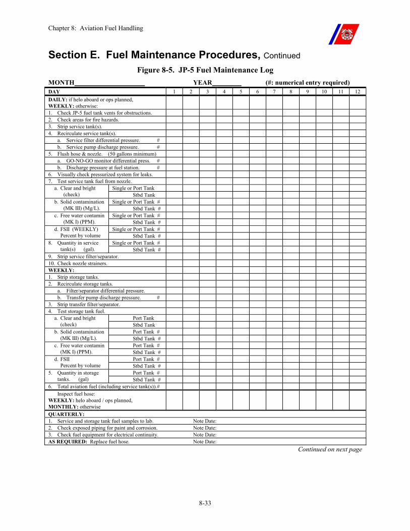
Chapter 8: Aviation Fuel Handling
8-33
Section E. Fuel Maintenance Procedures, Continued Figure 8-5. JP-5 Fuel Maintenance Log
MONTH YEAR (#: numerical entry required) DAY 1 2 3 4 5 6 7 8 9 10 11 12 DAILY: if helo aboard or ops planned, WEEKLY: otherwise:
1. Check JP-5 fuel tank vents for obstructions. 2. Check areas for fire hazards. 3. Strip service tank(s). 4. Recirculate service tank(s).
a. Service filter differential pressure. # b. Service pump discharge pressure. #
5. Flush hose & nozzle. (50 gallons minimum) a. GO-NO-GO monitor differential press. # b. Discharge pressure at fuel station. #
6. Visually check pressurized system for leaks. 7. Test service tank fuel from nozzle.
Single or Port Tank a. Clear and bright (check) Stbd Tank
Single or Port Tank # b. Solid contamination (MK III) (Mg/L). Stbd Tank #
Single or Port Tank # c. Free water contamin (MK I) (PPM). Stbd Tank #
Single or Port Tank # d. FSII (WEEKLY) Percent by volume Stbd Tank #
Single or Port Tank # 8. Quantity in service tank(s) (gal). Stbd Tank #
9. Strip service filter/separator. 10. Check nozzle strainers. WEEKLY: 1. Strip storage tanks. 2. Recirculate storage tanks.
a. Filter/separator differential pressure. b. Transfer pump discharge pressure. #
3. Strip transfer filter/separator. 4. Test storage tank fuel.
Port Tank a. Clear and bright (check) Stbd Tank
Port Tank # b. Solid contamination (MK III) (Mg/L). Stbd Tank #
Port Tank # c. Free water contamin (MK I) (PPM). Stbd Tank #
Port Tank # d. FSII Percent by volume Stbd Tank #
Port Tank # 5. Quantity in storage tanks. (gal) Stbd Tank #
6. Total aviation fuel (including service tank(s)). # Inspect fuel hose: WEEKLY: helo aboard / ops planned, MONTHLY: otherwise
QUARTERLY: 1. Service and storage tank fuel samples to lab. Note Date: 2. Check exposed piping for paint and corrosion. Note Date: 3. Check fuel equipment for electrical continuity. Note Date: AS REQUIRED: Replace fuel hose. Note Date:
Continued on next page
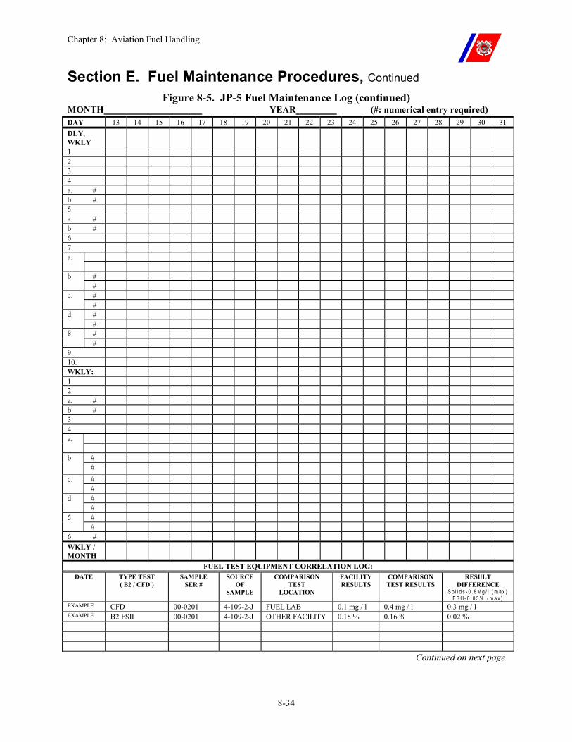
Chapter 8: Aviation Fuel Handling
8-34
Section E. Fuel Maintenance Procedures, Continued Figure 8-5. JP-5 Fuel Maintenance Log (continued)
MONTH YEAR (#: numerical entry required) DAY 13 14 15 16 17 18 19 20 21 22 23 24 25 26 27 28 29 30 31 DLY, WKLY
1. 2. 3. 4. a. # b. # 5. a. # b. # 6. 7.
a. # b. # # c. # # d. # # 8. #
9. 10. WKLY: 1. 2. a. # b. # 3. 4.
a. # b. # # c. # # d. # # 5. #
6. # WKLY / MONTH
FUEL TEST EQUIPMENT CORRELATION LOG: DATE TYPE TEST
( B2 / CFD ) SAMPLE
SER # SOURCE
OF SAMPLE
COMPARISON TEST
LOCATION
FACILITY RESULTS
COMPARISON TEST RESULTS
RESULT DIFFERENCE
S o l i d s - 0 . 8 M g / l ( m a x ) F S I I - 0 . 0 3 % ( m a x )
EXAMPLE CFD 00-0201 4-109-2-J FUEL LAB 0.1 mg / l 0.4 mg / l 0.3 mg / l EXAMPLE B2 FSII 00-0201 4-109-2-J OTHER FACILITY 0.18 % 0.16 % 0.02 %
Continued on next page
Chapter 8: Aviation Fuel Handling
8-35
Section E. Fuel Maintenance Procedures, Continued
E.5. Fuel Tank Cleaning
When it is necessary to clean the tanks for maintenance, or to remove contamination, the following procedures shall be used:
�� Drain the fuel from the tank as thoroughly as possible. �� Wash the tank with high-pressure cold fresh water before it has a
chance to dry. Do not use steam as it can damage the tank’s coating.
�� Drain and dry the tank using the stripping system or a portable air-driven pump. When dry, close the tank and refill it with JP-5 fuel.
�� Recirculate the fuel until it is clear and bright, and passes the MK I and MK III detector kit tests.
�� Flush all lines, pipes, and fittings before placing the JP-5 system back in service.
WARNING Before entering any tank, permission shall be obtained from the Engineer Officer, and the tank must be confirmed to be free of toxic vapors. Use of the proper respiratory equipment is mandatory, and a safety observer shall be standing by at the tank manhole in case of emergencies.
WARNING Do not use the service or transfer systems to drain the water from the tank. Excessive fuel contamination will result.
Chapter 8: Aviation Fuel Handling
8-36
Section F. Fuel Safety Precautions
F.1. Overview The following shall be observed in handling aviation fuels.
F.2. General Procedures
�� Keep all unnecessary personnel clear of the area during all fuel handling operations.
�� Prohibit smoking in the hangar and on weather decks during topside fuel handling (any refueling operations or flushing through the hose/tree), and at all times in the JP-5 pump room.
�� Beware of flammable vapors in empty tanks and other compartments.
�� Goggles and rubber gloves shall be worn during fuel sampling, testing, fueling, and defueling operations.
�� Do not carry “strike anywhere” matches.
�� Remove all articles from pockets that might fall into an open tank.
F.3. Explosive Safety
The presence of flammable liquid and/or explosive materials is not permitted within 25 feet of the flight deck peripheral lines, on any weather deck, during flight operations. Below the helicopter approach path, ready service lockers or magazines should not be located on exposed decks.
The Helicopter Operations Bill shall specify that all flammable liquid and/or ammunition stored in this area shall be moved before flight operations.
Continued on next page
Chapter 8: Aviation Fuel Handling
8-37
Section F. Fuel Safety Precautions, Continued
F.4. Benzene Exposure
Personnel may be exposed to benzene in the pure chemical form or as a component of another substance such as aviation fuel.
�� Avoid breathing fuel vapors. �� If dizziness occurs from breathing vapors, get the victim to fresh air
immediately, and obtain medical attention. �� Repeated or prolonged exposure to benzene, even at relatively low
concentrations, has been associated with various blood disorders ranging from anemia to leukemia.
�� The Occupational Safety and Health Administration (OSHA) has promulgated comprehensive benzene exposure standards (29 CFR, Subpart Z, Section 1910, 1028).
�� When exposed to JP-5, the following levels of protection shall be utilized: �� Less than or equal to 10 PPM: Half mask air purifying
respirator with organic vapor cartridge. �� Less than or equal to 50 PPM: Full facepiece air purifying
respirator with organic vapor cartridge. �� Less than or equal to 100 PPM: Full facepiece powered air
purifying respirator with organic vapor cartridges. �� Less than or equal to 1000 PPM: Full facepiece supplied air
respirator in positive pressure mode. �� Greater than 1000 PPM or unknown concentration: Full
facepiece self-contained breathing apparatus (SCBA) in positive pressure mode.
Continued on next page
Chapter 8: Aviation Fuel Handling
8-38
Section F. Fuel Safety Precautions, Continued
F.5. Radio Frequency (RF) Radiation Hazards
Due to the potentially disastrous consequences of a radio frequency (RF) emission creating an electrical arc, the following guidelines shall be followed during all on-deck fueling and HIFR operations, and anytime the nature of helicopter maintenance makes it prudent to take positive action to prevent the possibility of electrical arcing:
�� No emissions are permitted at power levels greater than rated transmitter power.
�� No emissions from shipboard transmitters are permitted through antennas located within 25-feet of a helicopter.
�� No emissions from shipboard transmitters with a rated power output equal to or greater than 500 watts are permitted through antennas located within 50-feet of a helicopter.
�� Shipboard radar antennas capable of main beam illumination of the helicopter shall be secured. (Other radar antennas may be energized, if required.)
�� The helicopter’s emissions control shall be in accordance with each aircraft’s flight manual.
F.6. Static and Electrical Discharge Prevention
�� Static bonding cables shall be attached only to specified grounding points on helicopters. Do not attach them to radio antennas, drains, hydraulic lines, or access doors. Do not attach them to surfaces on the landing gear other than those specified in order to avoid scratches and gouges on high strength steel parts.
�� Do not connect or disconnect batteries during fueling. �� No electrical switches should be energized during the fueling
operation itself. �� Do not perform fueling operations while an electrical storm is in the
immediate area. �� Personnel should discharge static electrical charges on their person
by contacting one of the grounding connections before conducting any fueling operations.
�� Use only explosion-proof flashlights or extension lights for inspecting hazardous areas.
Continued on next page
Chapter 8: Aviation Fuel Handling
8-39
Section F. Fuel Safety Precautions, Continued
F.7. Fuel Spills �� Clean-up fuel spills immediately.
�� Do not permit fuel spills to dry on the skin or clothing. Fuel splashed clothing should be removed immediately and affected skin areas should be washed with soap and water.
�� Do not use automatic hold-open gravity nozzles for helicopter refueling.
F.8. Bypassing of Fuel Filters
No JP-5 fuel filter may be bypassed during helicopter refueling operations without the concurrence of the Commanding Officer, Engineer Officer, and pilot in command (PIC).
Chapter 9: Helicopter Refueling Procedures
9-i
CHAPTER 9: HELICOPTER REFUELING PROCEDURES Table of Contents
Introduction................................................................................................................................ 9-1
In this chapter ............................................................................................................................ 9-1
Section A. Refueling Methods.................................................................................................. 9-2
A.1. Overview ............................................................................................................................ 9-2
A.2. Static Refueling ................................................................................................................. 9-2 A.2.a. Pressure Refueling ...............................................................................................................9-2 A.2.b. Gravity Refueling.................................................................................................................9-2
A.3. Hot Refueling..................................................................................................................... 9-2
A.4. Helicopter In Flight Refueling (HIFR)............................................................................ 9-3
Section B. Refueling Procedures.............................................................................................. 9-4
B.1. Refueling Preparation....................................................................................................... 9-4
B.2. Static Refueling Procedures ............................................................................................. 9-5
B.3. Hot Refueling or APU Assisted Refueling Procedures .................................................. 9-7
B.4. Helicopter In-Flight Refueling (HIFR) Procedures ..................................................... 9-10
B.5. Emergency Breakaway ................................................................................................... 9-19 B.5.a. Emergency Breakaway Equipment.....................................................................................9-19 B.5.b. Emergency Breakaway Procedures ....................................................................................9-20
Section C. Contaminated Fuel ............................................................................................... 9-22
C.1. General ............................................................................................................................. 9-22
Section D. Defueling Procedures ........................................................................................... 9-23
D.1. Overview .......................................................................................................................... 9-23
D.2. Pressure Defueling .......................................................................................................... 9-23 D.2.a. Pressure Defueling Procedure ............................................................................................9-24
D.3. HH-65 Gravity Defueling ............................................................................................... 9-25
D.4. Disposition of Fuel........................................................................................................... 9-25

Chapter 9: Helicopter Refueling Procedures
9-ii
Chapter 9: Helicopter Refueling Procedures
9-1
Chapter 9. Helicopter Refueling
Procedures
Introduction This chapter establishes refueling procedures for helicopters aboard Coast Guard Cutters. Care shall be exercised during fueling operations because of the potential for fire, injury to personnel, and introduction of contamination into the helicopter’s fuel system.
CAUTION Some U.S. Army helicopters have 15 psig (max) internal fuel systems. U.S. Army and U.S. Air Force closed-circuit refueling (CCR) nozzles have 15-psi pressure regulators and do not have all the safety features of the USN/USCG CCR nozzles. In addition, USN/USCG CCR nozzles have 45-psi pressure regulators. Use of the USN/USCG CCR nozzle on a 15-psi aircraft system may damage the aircraft’s fuel system. Use of the Army or Air Force CCR nozzle is prohibited unless operational necessity requires its use and a waiver is granted by G-OCA due to the nature of the operation. Gravity static refueling of these aircraft is acceptable.
In this chapter This chapter is divided into four (4) sections:
�� Section A: Refueling Methods �� Section B: Refueling Procedures �� Section C: Contaminated Fuel �� Section D: Defueling Procedures
Chapter 9: Helicopter Refueling Procedures
9-2
Section A. Refueling Methods
A.1. Overview The three (3) standard methods of refueling helicopters are static refueling, hot refueling, and HIFR.
A.2. Static Refueling
Static refueling is conducted on deck with the helicopter’s engines and rotor secured. There are two (2) methods that can be used:
�� Pressure refueling
�� Gravity refueling.
CAUTION To avoid over-pressurization of the HH-60J fuel system, static refueling should take place with 400Hz/115V AC power applied.
A.2.a. Pressure Refueling
Pressure refueling adds fuel to the helicopter through a closed connection between the pressure refueling nozzle and the helicopter’s fuel tank(s). It is the preferred method of refueling helicopters, and shall be considered the primary method of refueling on Coast Guard Cutters.
A.2.b. Gravity Refueling
Gravity refueling adds fuel to the helicopter through an open filler neck, using the gravity nozzle.
It increases the exposure of fueling personnel to benzene fumes, provides greater potential for a fuel spill, and exposes the helicopter’s fuel system to sources of outside contamination.
Gravity refueling is an alternate rather than the primary method of static refueling.
A.3. Hot Refueling Hot refueling is the process of refueling a helicopter on deck with its engine(s) and/or APU running and/or rotor(s) turning.
Helicopters equipped for pressure refueling may be hot refueled for training and operational missions.
WARNING Because of the immediate presence of an ignition source (running engine), gravity hot refueling is PROHIBITED.
CAUTION Repetitive hot refueling in the HH-65 shall be carefully considered. By lengthening the interval between thru/post flight inspections, the risk of experiencing an undetected aircraft component problem increases. This interval should not routinely exceed six hours.
Chapter 9: Helicopter Refueling Procedures
9-3
Section A. Refueling Methods, Continued
A.4. Helicopter In Flight Refueling (HIFR)
HIFR is the process of refueling a hovering helicopter, and is used to refuel helicopters too large to be accommodated on the flight deck, or when flight deck motion is out of limits.
Fuel is added to the hovering helicopter through a closed connection between the HIFR rig and the helicopter’s fuel tank(s). The HH-65, HH-60J, and most U.S. Navy helicopters use the standard HIFR rig.
Chapter 9: Helicopter Refueling Procedures
9-4
Section B. Refueling Procedures
B.1. Refueling Preparation
In anticipation of refueling operations, the following preparations shall be made:
�� Ensure that the service tank contains sufficient fuel for refueling the helicopter. If not, transfer fuel from a storage tank to the service tank.
�� Strip the service tank and service filter and/or separator of all water. �� Break out and inspect the fuel hose and nozzle. Do not drag the
hose over rough surfaces. �� Connect the hose and nozzle to the flushing tree. Flush the nozzle
for two (2) minutes or a minimum of 50 gallons, at the full rated flow of the service pump, to remove any residual contamination. Check the nozzle and hose for leaks.
�� Draw fuel samples and conduct a clear and bright test in accordance with Chapter 8. �� If the sample tests good, conduct the MK I and MK III detector
kit tests (before the day’s first refueling only). �� If the fuel does not test good, flush the hose and nozzle again,
and repeat the tests, making sure that the sampling container is clean.
�� If the fuel still does not test good, troubleshoot the system to determine the cause of the contamination.
�� Retain the clear and bright sample for inspection by the Engineer Officer and the PIC, and until completion of the next flight operation.
�� Secure the JP-5 service pump, remove the fuel nozzle from the flushing tree, and lay out or stow the hose as appropriate.
If the nozzle is disconnected, it shall be flushed again, and a clear and bright conducted before refueling the helicopter.
WARNING Any fuel leaks shall be repaired before refueling operations.
Fuel shall not be transferred to the helicopter until the samples taken from the fuel nozzle for testing are within required limits.
Eye protection shall be worn by all personnel in the area near the fuel nozzle or anytime the fuel hose is pressurized.
Continued on next page
Chapter 9: Helicopter Refueling Procedures
9-5
Section B. Refueling Procedures, Continued
NOTE The service tank should be topped off daily at the completion of the last refueling operation, so the fuel in the service tank may be recirculated sufficiently before the next refueling operation.
B.2. Static Refueling Procedures
Before refueling the helicopter, ensure that tiedowns are installed and that the engine(s) and rotor(s) are secured. Tiedowns are not required for static refueling if the vessel is moored pier side or hove to in the ice.
�� Set the helicopter refueling detail in accordance with Chapter 2. �� Pipe: “The smoking lamp is out on all weather decks.” �� Secure emissions from:
�� All antennas within 25-feet of the helicopter, �� Those antennas within 50-feet of the helicopter that transmit
with 500 watts or more of power, and �� All shipboard radar(s) capable of main beam illumination of the
helicopter. �� Present the clear and bright fuel sample to the Engineer Officer and
the PIC (or their representatives) for approval. �� Ground the helicopter to the cutter using the Shipboard Aviation
Allowance Equipage List (AEL) grounding cable. (Inspect the grounding cable for condition including the strength of the springs on the alligator clips.)
Continued on next page
Chapter 9: Helicopter Refueling Procedures
9-6
Section B. Refueling Procedures, Continued
B.2. Static Refueling Procedures (continued)
�� When all parties are satisfied with the condition of the fuel, refuel the helicopter using the following procedures:
�� Remove the fuel tank fill neck cap and pressure refueling connector cap.
�� When using the gravity refueling nozzle, attach the nozzle static bonding wire to the helicopter.
�� Attach or insert the nozzle. If using the D-1 nozzle, open the poppet valve.
�� Energize the JP-5 service pump. �� If using the D-1 nozzle, the flight mechanic shall test the high
level fuel shut-off for proper operation. If the high level fuel shut-off operates correctly, fuel to the quantity requested by the pilot. If the high level fuel shut off does not operate correctly, fueling shall be IAW the appropriate flight manual.
�� If using the gravity refueling nozzle, open the nozzle and fuel to the quantity requested by the pilot.
�� Close the nozzle, and de-energize the JP-5 service pump. �� Disconnect or remove the nozzle. �� When using the gravity refueling nozzle, disconnect the nozzle
static bonding wire. �� Replace the fuel cap(s). �� Energize the JP-5 service pump and take a clear and bright
sample. Present the sample to the Engineer Officer and the PIC (or his or her representatives) for inspection. Retain the sample until completion of the next flight operation.
�� De-energize the JP-5 service pump, and stow the fuel hose as appropriate.
�� Secure the helicopter refueling detail.
WARNING A positive ground will not be achieved if the point where the bonding wire is attached to the cutter is dirty, corroded, or painted.
CAUTION To avoid over-pressurization of the HH-60J fuel system, static pressure refueling should take place with the cutter’s 400Hz/115V AC power applied.
CAUTION During APU-assisted hot refueling, the APU is a potential fuel ignition source.
Continued on next page
Chapter 9: Helicopter Refueling Procedures
9-7
Section B. Refueling Procedures, Continued
B.3. Hot Refueling or APU Assisted Refueling Procedures
Below are the hot refueling or APU assisted refueling procedures:
�� Set FLICON ONE (Chapter 6, Paragraph B.2.) �� Set the helicopter hot refueling detail (Chapter 2, Paragraph B.4.c.) �� Secure emissions from:
�� All antennas within 25-feet of the helicopter. �� Antennas within 50-feet of the helicopter that transmit equal or
greater than 500 watts. �� Shipboard radar(s) capable of main beam illumination of the
helicopter. �� Present the clear and bright fuel sample to the Engineer Officer (or
his or her representative) for approval. �� Lay out and secure the fuel hose (with the pressure refueling nozzle
attached) along the gunwale of the flight deck on the side that will be closest to the helo pressure refueling receptacle after landing.
�� Recover the helicopter with TALON or install primary tiedowns. �� Pilot completes the required pre-fueling checklist items IAW each
aircraft’s flight manual. �� Disembark all passengers and clear them from the flight deck. �� Before hot refueling, HCO passes the AEL MK I, MK III, and FSII
results to the aircrew. �� Electrical and electronic components aboard the helicopter shall be
secured IAW the applicable helicopter flight manual. No transmissions on HF shall be made. All other radio transmissions shall be kept to a minimum.
�� Present the clear and bright sample to the aircrew, if requested. �� For APU assisted refueling, aircrew will request an APU start. �� Start APU. Flight mechanic acts as APU fireguard. �� Aircrew signals the LSO when ready to refuel. �� LSO posts the fireguard, in a full proximity suit, with a PKP fire
extinguisher, at the helicopter fueling point, and waves in the fueling team. �� One (1) member of the refueling team grounds the helicopter to
the cutter using the AEL grounding cable. (Inspect the grounding cable for condition and the strength of the springs on the alligator clips.
�� Fueling petty officer, under the supervision of the helicopter crewmember, removes the pressure refueling connector cap, attaches the nozzle, and opens the poppet valve.
Continued on next page
Chapter 9: Helicopter Refueling Procedures
9-8
Section B. Refueling Procedures, Continued
B.3. Hot Refueling or APU Assisted Refueling Procedures (continued)
�� Aircrew signals the LSO to energize the JP-5 service pump. �� LSO orders the JP-5 pump room to “Commence pumping,” and,
when confirmed, signals the aircrew. �� Fueling petty officer and helicopter crewmember immediately
check the nozzle and fuel hose for leaks. �� Helicopter crewmember tests the high level fuel shut-off for proper
operation. �� Approximately 50 lbs. before the desired fuel load, the helicopter
crewmember signals the LSO, to secure the JP-5 service pump. �� LSO orders the JP-5 pump room to “Stop pumping,” and when
confirmed, signals the aircrew. �� Fueling petty officer closes the poppet valve, disconnects the
nozzle, and replaces the fuel cap. �� LSO waves out the refueling team and fireguard (proximity suit).
The refueling team disconnects the grounding wire and secures the fuel hose to the appropriate deck edge.
�� Embark passengers. �� Reenergize the helicopter’s electrical and electronic equipment
IAW the helicopter’s flight manual. �� Launch the helicopter or secure the APU as applicable. �� Reenergize the JP-5 service pump and take a clear and bright
sample. �� Present the sample to the Engineer Officer or aircrew (or his or
her representative) for inspection. �� If the helo is launched, report the sample result findings to the
aircrew. �� Retain the sample until completion of the next flight operation.
�� De-energize the JP-5 service pump, and stow the fuel hose. �� Secure the hot refueling detail and FLICON ONE (if appropriate).
NOTE Where possible, the helicopter electrical and electronic equipment should be secured before helicopter recovery. Comply with the requirements of the appropriate helicopter flight handbook. In all cases, the helicopter’s radar shall be secured or set to standby before landing due to the radiation hazard to personnel.
Continued on next page
Chapter 9: Helicopter Refueling Procedures
9-9
Section B. Refueling Procedures, Continued
WARNING A positive ground will not be achieved if the point where the cable is attached to the cutter is dirty, corroded, or painted.
WARNING The poppet valve shall be fully open (180 degrees of travel) to prevent the possibility of a fuel spill.
WARNING In the event of a leak or fuel spill, secure the JP-5 service pump, and secure and evacuate the helicopter immediately. HELICOPTER LAUNCH IS PROHIBITED.
WARNING The high level fuel shut-off shall be operating properly to continue with hot refueling. If the shut-off is not operating, or if excessive fuel pressure (maximum of 55 psi) prevents it from operating properly, the helicopter’s fuel system can be over-filled, causing fuel to spill from the vents, increasing the risk of fire.
WARNING No HF radio transmissions shall be made before takeoff, and the radar shall remain secured or in standby until clear of the cutter due to radiation hazards.
Continued on next page
Chapter 9: Helicopter Refueling Procedures
9-10
Section B. Refueling Procedures, Continued
B.4. Helicopter In-Flight Refueling (HIFR) Procedures
The following are the HIFR procedures. Use the Figure 9-6 checklist as a guide. �� Set FLICON FOUR (Chapter 6, Paragraph B.5.)
�� Illuminate the HIFR heading lights (at night). �� If using the CG NHC HIFR rig, flush the fuel hose, HIFR rig,
and CCR nozzle as required in Paragraph B.1 of this chapter. �� (Change) After flushing, draw clear and bright sample from
the nozzle utilizing the adapter (shown in figure 9-1).
�� After drawing the sample, replace the D-1 nozzle with the CCR nozzle. (NATO helicopters will require the use of the D-1 nozzle instead of the CCR nozzle.) �� An acceptable alternative to the procedure described above is
for the cutter’s force to purchase and install a sample adaptor (shown in Figures 9-1 and 9-2) or assemble an adapter for the hose end of the D-1 nozzle utilizing spare Wiggins fittings and Aeroquip unisex coupling halves. Once assembled, the adapter can be used as a link between the CCR nozzle (fitted to the NHC HIFR rig) and the Carter (D-1) pressure refueling nozzle (attached to the JP-5 standpipe). This configuration will allow quick connection of the pressure refueling nozzle to the standpipe, attach the adapter, and then plug in the CCR nozzle. The HIFR rig can then be connected and disconnected from the JP-5 standpipe, while the clear and bright sample is taken from the Gammon fitting in the Carter nozzle (Figures 9-3 and 9-4).
�� Lay out the fuel hose as depicted in Figure 9-5. Position the bitter end of the hose, with the HIFR rig attached, in the vicinity of the HIFR “H.”
�� Break out the AEL grounding wand, insulated gloves, and LSO signal flags/paddles/wands.
�� Rig a guard line across the gap between the aft safety nets or catwalks on the port side of the flight deck.
�� Attach Chemlights to the first 50-feet of the fuel hose at approximately 10-foot intervals, starting at the hoisting saddle on the HIFR rig (night only).
�� (Change) The LSO must ensure that the HIFR rig is not pressurized and that a green line is showing on the quick disconnect coupling. This will ensure proper sealing. Also check that all fuel valves are in the open
position and that the the bale is closed.�� OOD provides a relative wind of approximately 330-345
degrees at 15 knots (or as requested by the PIC). �� LSO reports readiness to the HCO.
Continued on next page
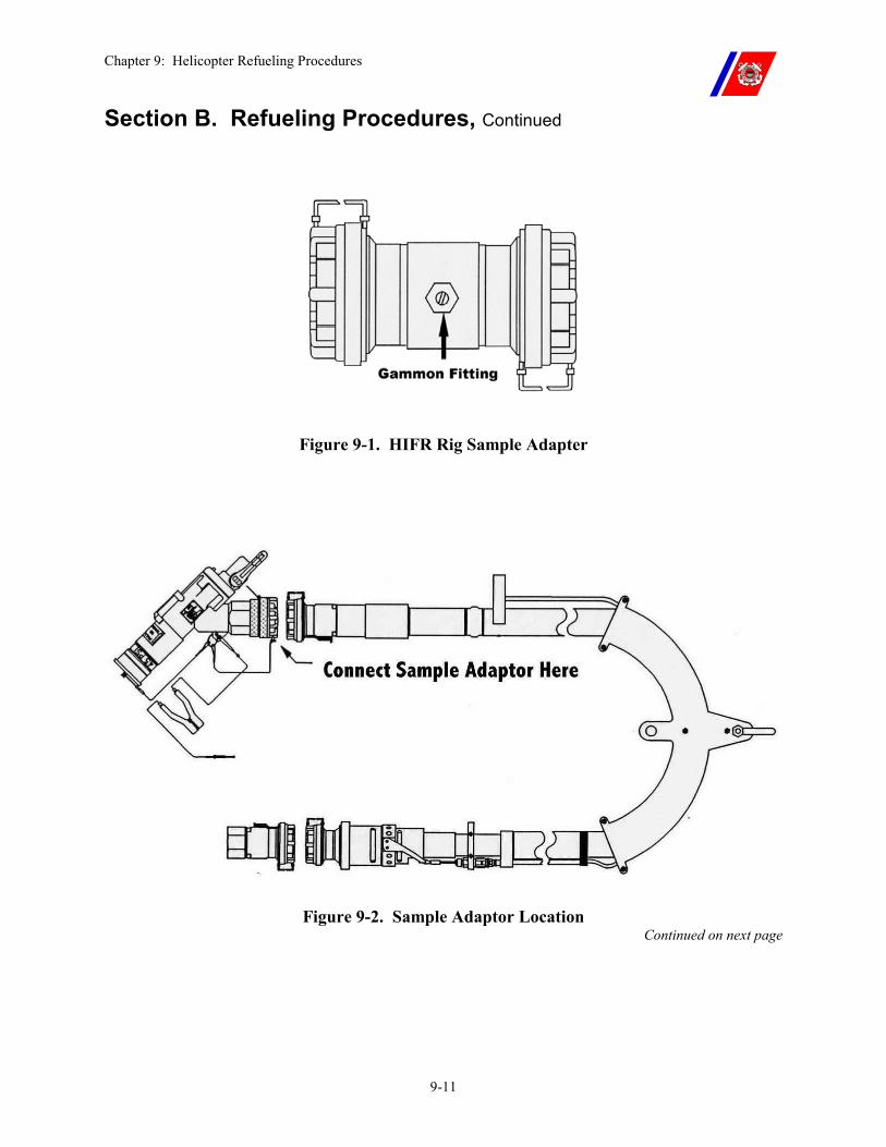
Chapter 9: Helicopter Refueling Procedures
9-11
Section B. Refueling Procedures, Continued
Figure 9-1. HIFR Rig Sample Adapter
Figure 9-2. Sample Adaptor Location Continued on next page
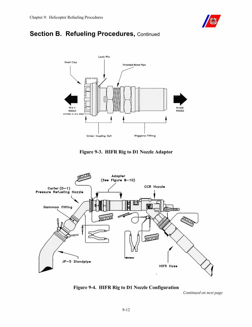
Chapter 9: Helicopter Refueling Procedures
9-12
Section B. Refueling Procedures, Continued
Figure 9-3. HIFR Rig to D1 Nozzle Adaptor
Figure 9-4. HIFR Rig to D1 Nozzle Configuration Continued on next page
Chapter 9: Helicopter Refueling Procedures
9-13
Section B. Refueling Procedures, Continued
B.4. Helicopter In-Flight Refueling (HIFR) Procedures (continued)
�� Secure emissions from: �� All antennas within 25-feet of the helicopter, �� Antennas within 50-feet of the helicopter that transmit with 500
watts or more of power, and �� Shipboard radar(s) capable of main beam illumination of the
helicopter. �� Present the clear and bright fuel sample to the Engineer Officer (or
his or her representative) for approval. �� Pilot determines the amount of fuel to be transferred to the
helicopter based on mission requirements and performance calculations, and passes the amount to the cutter by radio.
�� HCO passes the “numbers” to the helicopter, including the AEL MK I and MK III test results (in PPM and MG/L) and FSII (in percent).
�� Pilot (if desired) requests to see the clear and bright sample. (Helicopter must provide a bag to pick up the sample.)
�� Pilot completes the checklist items IAW the flight manual and, when ready, reports to the cutter: “Request permission to HIFR.”
�� HCO reports: “You are cleared to HIFR. Take signals from the LSO,” and changes the Deck Status Light to GREEN.
�� HCO phone talker passes: “Helicopter cleared to HIFR.” �� LSO sends out the hook-up team and hose handlers, and begins
giving advisory signals to the helicopter. �� Pilot, using commands from the helicopter crewmember and
advisory signals from the LSO, maneuvers into hoisting position over the HIFR “H” on the flight deck.
�� The hook-up team and hose handlers connect the HIFR rig to the hoist hook using the following procedures: �� When the hoist hook is within reach, ground the hoist hook to
the cutter using the grounding wand. �� Attach the hoist hook to the eye in the HIFR rig saddle. �� Once hook up is complete, clear the grounding wand person and
equipment from the vicinity. �� The hook up person maintains the forward hose handler
position. �� Lift the HIFR rig off the deck so that it does not drag on the
deck when hoisted.
Continued on next page
Chapter 9: Helicopter Refueling Procedures
9-14
Section B. Refueling Procedures, Continued
B.4. Helicopter In-Flight Refueling (HIFR) Procedures (continued)
�� Give a thumbs-up to the helicopter crewmember indicating that the HIFR rig is ready to be hoisted.
�� Tend the fuel hose so it does not drag across the flight deck as it is hoisted. Do not allow it to sag below the level of the flight deck
�� When the HIFR rig is clear of the deck, the pilot maneuvers the helicopter to a position abeam the HIFR “H,” clear of the side of the cutter, and maintains position using visual references (the HIFR heading lights at night).
�� Helicopter crewmember connects the HIFR rig to the helicopter: �� Raise the hoist hook until it is two-blocked. �� Connect the HIFR rig ground wire to the helicopter and connect
the HIFR rig to fueling connector, ensuring that it is securely attached.
�� Advise the pilot that the HIFR rig is connected, and, at his or her direction, signal the cutter to commence pumping.
�� Monitor the HIFR rig and hose for fuel leaks. �� Upon signal from the helicopter crewmember, the LSO orders the
JP-5 pump room to “Commence pumping.” �� The LSO uses signal flags or paddles (wands at night) to
indicate to the helicopter the status of the JP-5 service pump. �� RED OVER GREEN signifies that the pump is not energized,
and GREEN OVER RED signifies that the pump is energized. �� The LSO shall display the appropriate signal from the time the
HIFR rig is connected to the helicopter to the time it is disconnected from the rig or the helicopter receptacle unless helicopter repositioning or Breakaway signals are required.
�� The JP-5 pump room energizes the JP-5 service pump, ensures that sufficient pressure and flow rate are being provided, and reports the quantity of fuel pumped in 10-gallon increments. (On WMEC 270s, the refueling station reports the quantity of fuel pumped.)
�� HCO passes the quantity pumped to the helicopter over the radio in 10-gallon increments.
�� The pilot will not respond to fuel quantity transmissions unless specifically requested to acknowledge.
Continued on next page
Chapter 9: Helicopter Refueling Procedures
9-15
Section B. Refueling Procedures, Continued
B.4. Helicopter In-Flight Refueling (HIFR) Procedures (continued)
�� Pilot monitors the fuel quantity gauges and aircraft power requirements, and secures the transfer of fuel at 50 lbs. before the desired quantity, or 10 percent before power limitations, whichever comes first. �� Pilot directs the helicopter crewmember to stop refueling. �� Helicopter crewmember signals the cutter to stop refueling. �� LSO orders the JP-5 pump room to stop pumping, and signals
the helicopter when the pump is secured. �� Helicopter crewmember, after the pump is secured, disconnects the
HIFR rig from the refueling receptacle, disconnects the grounding wire, secures the access to the refueling receptacle, and reports when ready to commence the hoist to the pilot.
�� Pilot, using commands from the helicopter crewmember and advisories from the LSO, maneuvers the helicopter over the HIFR “H,” and holds position while the crewmember lowers the HIFR rig to the deck.
�� Hose handlers recover the hose as the helicopter moves in, and the hook-up team disconnects the hoist hook from the HIFR rig, holding onto the hook until it is retrieved by the helicopter. Do not allow the HIFR rig to fall onto the deck.
�� After the hoist hook has been disconnected, and when cleared by the helicopter crewmember, the pilot maneuvers the helicopter clear of the cutter.
�� HCO changes the Deck Status Light to RED. �� After the helicopter has departed:
�� JP-5 Fuel King replaces the CCR nozzle with the D-1 pressure refueling nozzle.
�� LSO orders the JP-5 pump room to re-energize the JP-5 service pump.
�� LSO ensures that a clear and bright sample is taken and presented to the Engineer Officer (or his or her representative) for inspection.
�� HCO reports the findings of the clear and bright test to the helicopter by radio.
�� The sample is retained until completion of the next flight operation.
Continued on next page
Chapter 9: Helicopter Refueling Procedures
9-16
Section B. Refueling Procedures, Continued
WARNING Coast Guard HH-65s are authorized to conduct HIFR with all HIFR certified Coast Guard Cutters and with those HIFR-certified U.S. Navy ships whose JP-5 systems incorporate an installed GO-NO-GO fuel monitor.
Coast Guard HH-60Js have a GO-NO-GO monitor incorporated into the HIFR receptacle and are authorized to conduct HIFR with all HIFR certified ships.
Navy HIFR procedures are established in NWP 3-04.1.
The USN version of the NHC HIFR rig does not feature a manual breakaway capability.
To complete an emergency breakaway, approximately 450 lbs. of tension will have to be applied to the rig through aircraft maneuvering. The USCG version incorporates a manual breakaway cable in addition to the automatic breakaway feature of the USN rig.
With the exception of the manual breakaway cable, the rigs are visually identical.
Continued on next page
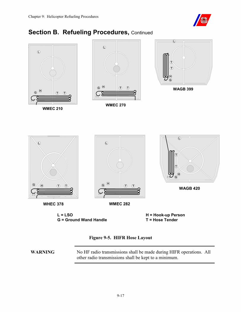
Chapter 9: Helicopter Refueling Procedures
9-17
Section B. Refueling Procedures, Continued
25
WMEC 210 WMEC 270
WAGB 399
WHEC 378
WAGB 420
WMEC 282
L = LSO H = Hook-up Person G = Ground Wand Handle T = Hose Tender
Figure 9-5. HIFR Hose Layout
WARNING No HF radio transmissions shall be made during HIFR operations. All other radio transmissions shall be kept to a minimum.
Chapter 9: Helicopter Refueling Procedures
9-18
Section B. Refueling Procedures, Continued
CAUTION Relative wind should be placed to reduce the presence of superstructure generated turbulence in the HIFR area.
WARNING Static discharge from a helicopter can exceed 200,000 volts. Injury or death can occur if the hoist hook is not properly grounded before being handled by personnel. Once grounded, the hook shall remain grounded, or static charges will immediately rebuild.
WARNING The hook-up team and hose handlers shall remain out of the bight of the hose. All personnel tending the hose shall stand forward of the hose, keeping the hose between them and the edge of the flight deck at all times. Personnel standing in the bight of the hose can be swept off the flight deck if the fuel hose should suddenly become taut.
WARNING Dragging the HIFR rig across the flight deck in even the slightest amount can cause the quick disconnect coupling between the HIFR rig and the fuel hose to disconnect.
WARNING Allowing the hose to drag in the water can cause the hose to part, causing damage to the helicopter and/or injury to personnel.
NOTE While the HIFR rig is positioned in or immediately outside the cabin, the LSO shall display the appropriate service pump signal (“AM PUMPING FUEL”/”HAVE CEASED PUMPING FUEL”) unless helicopter repositioning or Breakaway signals are required.
NOTE It is not necessary to ground the HIFR rig or hoist hook during recovery, as they are grounded through the fuel hose.
Continued on next page
Chapter 9: Helicopter Refueling Procedures
9-19
Section B. Refueling Procedures, Continued
B.5. Emergency Breakaway
B.5.a. Emergency Breakaway Equipment
Emergency breakaway capability is built into the HIFR rig. When activated, the dry disconnect coupling between the HIFR rig and the fuel hose is broken, and the hose falls away from the helicopter, while the HIFR rig remains attached.
An emergency breakaway is accomplished by the helicopter crewmember, by pulling on the emergency breakaway handle, upon command from either the pilot, HCO, or LSO.
WARNING If the hoist shear switch is activated during HIFR, the HIFR rig will be disconnected from the hoist, but will remain connected to the HIFR fueling receptacle. Damage to the helicopter and/or injury to personnel may occur.
The USN version of the NHC HIFR rig does not feature a manual breakaway capability. To complete an emergency breakaway, approximately 450 lbs. of tension will have to be applied to the rig through aircraft maneuvering. The USCG version incorporates a manual breakaway cable in addition to the automatic breakaway feature of the USN rig. With the exception of the manual breakaway cable, the rigs are visually identical.
Continued on next page
Chapter 9: Helicopter Refueling Procedures
9-20
Section B. Refueling Procedures, Continued
B.5.b. Emergency Breakaway Procedures
�� An emergency breakaway is initiated by the pilot, HCO, or LSO.
�� HCO initiates a breakaway by calling “BREAKAWAY, BREAKAWAY, BREAKAWAY” on the radio and simultaneously activating the Wave-off lights.
�� LSO initiates a breakaway by using the Emergency Breakaway Signal.
�� Pilot initiates a breakaway by ordering the helicopter crewmember to “BREAKAWAY, BREAKAWAY, BREAKAWAY.”
�� The helicopter crewmember executes the breakaway, and replies “BREAKAWAY, BREAKAWAY, BREAKAWAY.”
�� JP-5 emergency shut-off switch is activated. �� Hose handlers recover the fuel hose. �� LSO clears the flight deck for an emergency landing, and reports
“Flight deck clear” to the HCO. �� Pilot and HCO initiate action appropriate for the emergency.
WARNING Compliance with the breakaway command is MANDATORY.
CAUTION Following an emergency breakaway, the fuel hose and quick disconnect coupling shall be washed down with fresh water, and the hose and HIFR rig flushed with fuel prior to being used again.
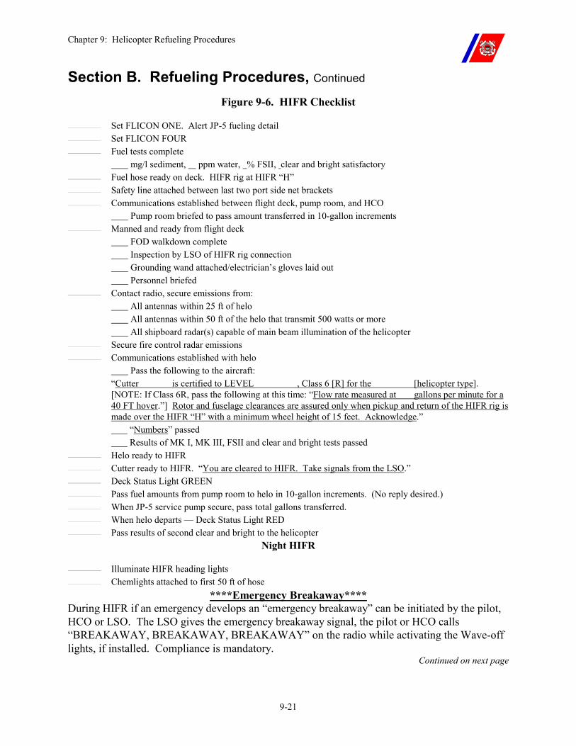
Chapter 9: Helicopter Refueling Procedures
9-21
Section B. Refueling Procedures, Continued Figure 9-6. HIFR Checklist
Set FLICON ONE. Alert JP-5 fueling detail Set FLICON FOUR Fuel tests complete mg/l sediment, ppm water, % FSII, clear and bright satisfactory Fuel hose ready on deck. HIFR rig at HIFR “H” Safety line attached between last two port side net brackets Communications established between flight deck, pump room, and HCO Pump room briefed to pass amount transferred in 10-gallon increments Manned and ready from flight deck FOD walkdown complete Inspection by LSO of HIFR rig connection Grounding wand attached/electrician’s gloves laid out Personnel briefed Contact radio, secure emissions from: All antennas within 25 ft of helo All antennas within 50 ft of the helo that transmit 500 watts or more All shipboard radar(s) capable of main beam illumination of the helicopter Secure fire control radar emissions Communications established with helo Pass the following to the aircraft: “Cutter is certified to LEVEL , Class 6 [R] for the [helicopter type].
[NOTE: If Class 6R, pass the following at this time: “Flow rate measured at gallons per minute for a 40 FT hover.”] Rotor and fuselage clearances are assured only when pickup and return of the HIFR rig is made over the HIFR “H” with a minimum wheel height of 15 feet. Acknowledge.”
“Numbers” passed Results of MK I, MK III, FSII and clear and bright tests passed Helo ready to HIFR Cutter ready to HIFR. “You are cleared to HIFR. Take signals from the LSO.” Deck Status Light GREEN Pass fuel amounts from pump room to helo in 10-gallon increments. (No reply desired.) When JP-5 service pump secure, pass total gallons transferred. When helo departs — Deck Status Light RED Pass results of second clear and bright to the helicopter
Night HIFR Illuminate HIFR heading lights Chemlights attached to first 50 ft of hose
****Emergency Breakaway**** During HIFR if an emergency develops an “emergency breakaway” can be initiated by the pilot, HCO or LSO. The LSO gives the emergency breakaway signal, the pilot or HCO calls “BREAKAWAY, BREAKAWAY, BREAKAWAY” on the radio while activating the Wave-off lights, if installed. Compliance is mandatory.
Continued on next page
Chapter 9: Helicopter Refueling Procedures
9-22
Section C. Contaminated Fuel
C.1. General If fuel in the helicopter is suspected of being contaminated, a sample shall be taken from the helicopter’s fuel tank drains and tested to verify the quality before conducting any flight operations.
If the helicopter is airborne, the suspicion of contamination shall be reported to the pilot immediately by radio. The helicopter’s mission shall be aborted, and the helicopter recovered at the closest safe landing area.
Contamination shall be suspected anytime a component in the JP-5 system fails, or if a sudden increase in pressure or decrease in flow occurs across the GO-NO-GO monitor during fueling.
Chapter 9: Helicopter Refueling Procedures
9-23
Section D. Defueling Procedures
D.1. Overview The two (2) primary requirements for defueling helicopters on cutters are to reduce the fuel load (weight) for a specific mission and to perform maintenance on the helicopter fuel system.
D.2. Pressure Defueling
The JP-5 systems on board Coast Guard Cutters do not have a defueling capability. A separate pump is needed to drain fuel from the helicopter and transfer it to the cutter. An air-operated, 25 GPM (or greater) portable pump is specified in the AEL.
Continued on next page
Chapter 9: Helicopter Refueling Procedures
9-24
Section D. Defueling Procedures, Continued
D.2.a. Pressure Defueling Procedure
Before defueling the helicopter, ensure that tiedowns are installed and that the engine(s) and rotor(s) are secured. Tiedowns are not required for defueling if the vessel is moored pier side or hove to in the ice.
�� Set the helicopter refueling detail IAW Chapter 2. The JP-5 pump room position need not be manned.
�� Pipe: "The smoking lamp is out on all weather decks."
�� Secure emissions from:
�� All antennas within 25-feet of the helicopter, �� Those antennas within 50-feet of the helicopter that transmit
with 500 watts or more of power, and �� All shipboard radar(s) capable of main beam illumination of the
helicopter. �� Ground the helicopter to the cutter using the Shipboard Aviation
AEL grounding cable. (Inspect the grounding cable for condition and the strength of the springs on the alligator clips).
�� A minimum of 10-feet of internally grounded fuel hose (a standard 50-foot hose may be used) is connected to the suction side of the pump. The other end of the hose is connected to the helicopter using the pressure refueling nozzle (with the strainer removed).
�� A second internally grounded fuel hose is then attached between the discharge side of the pump and the appropriate fill connector on the cutter as stated in section D.4. of this chapter.
�� Attach the pressure refueling nozzle to the helicopter pressure fill connection and open the poppet valve.
�� Connect low pressure air to the defueling pump and begin pumping.
�� When the helicopter is defueled, secure the pump, disconnect the air supply, and then close the nozzle poppet valve.
�� Disconnect the nozzle from the helicopter and replace all fuel cap(s).
�� Secure the helicopter refueling detail.
�� A small amount of fuel will remain in the helicopter (exact quantity varies by helicopter type) following pressure defueling.
WARNING A positive ground will not be achieved if the point where the bonding wire is attached to the cutter is dirty, corroded, or painted.
Continued on next page
Chapter 9: Helicopter Refueling Procedures
9-25
Section D. Defueling Procedures, Continued
D.3. HH-65 Gravity Defueling
The HH-65 may be gravity defueled. However the procedure is very slow, and therefore, only suited for removing small quantities of fuel (such as after pressure defueling). It enables complete removal of all fuel.
A special adapter is required, and should be part of the AVDET HSK. The adapter is attached to the drain sumps on the helicopter’s fuel cells. The adapter drains the fuel to an open container or a fuel hose connected directly to an appropriate tank.
Gravity defueling is not recommended for removing large quantities of fuel.
D.4. Disposition of Fuel
During defueling operations, the fuel must be transferred to one of the cutter fuel storage systems. The system selected to receive the fuel will depend on specific circumstances. The following guidance shall be considered when making this decision:
�� Helicopters shall never be defueled directly into the JP-5 service tank.
�� All military helicopters are authorized to use JP-4 and JP-8. Until a helicopter has been refueled several times with JP-5, the fuel in its tanks may have low flash point.
�� Low flash point fuel shall not be defueled into the cutter’s JP-5 system unless the flash point of the fuel has been tested and proven to be 140 degrees F or greater.
�� If it is determined that the helicopter has only JP-5 on board, and the fuel is not suspected of being contaminated, it can be defueled into the cutter’s JP-5 storage tanks.
�� Helicopters with low or intermediate flash point fuel or contaminated fuel on board shall be defueled into the cutter’s waste oil storage tank, or the diesel storage tanks (if approved by the Commanding Officer).
Chapter 10: Vertical Replenishment
10-i
CHAPTER 10: VERTICAL REPLENISHMENT Table of Contents
Introduction.............................................................................................................................. 10-1
In this chapter .......................................................................................................................... 10-1
Section A. Vertical Replenishment General Information ................................................... 10-2
A.1. Helicopters ....................................................................................................................... 10-2
A.2. Hazardous Materials....................................................................................................... 10-2 A.2.a. Transportation of Hazardous Materials..............................................................................10-2 A.2.b. Waivers ..............................................................................................................................10-2
A.3. VERTREP Limitations................................................................................................... 10-2
Section B. Vertical Replenishment Mission Planning ......................................................... 10-3
B.1. Overview .......................................................................................................................... 10-3
B.2. Helicopter Payload .......................................................................................................... 10-3
B.3. VERTREP Relative Wind .............................................................................................. 10-3
B.4. VERTREP Cargo Size, Shape, and Weight.................................................................. 10-3
B.5. Distance to Be Flown and Meteorological Conditions ................................................. 10-3
Section C. Vertical Replenishment Equipment.................................................................... 10-4
C.1. Overview .......................................................................................................................... 10-4
C.2. Pallets ............................................................................................................................... 10-4
C.3. Cargotainers .................................................................................................................... 10-5
C.4. Cargo Nets ....................................................................................................................... 10-6
C.5. Adjustable Pallet Slings .................................................................................................. 10-7
C.6. Hoisting Slings................................................................................................................. 10-8
C.7. Cargo Hooks .................................................................................................................... 10-9
Section D. Vertical Replenishment Load Preparation ...................................................... 10-11
D.1. Overview ........................................................................................................................ 10-11
Chapter 10: Vertical Replenishment
10-ii
D.2. VERTREP Load Weight and Identification............................................................... 10-11
D.3. VERTREP Pallet Assembly ......................................................................................... 10-11
D.4. Cargotainer Loading..................................................................................................... 10-12
D.5. Cargo Net Loading (Loose Cargo) .............................................................................. 10-12
D.6. Cargo Net Loading (Palletized Cargo)........................................................................ 10-13
D.7. Attaching Slings to Loads............................................................................................. 10-14 D.7.a. Adjustable Pallet Slings ...................................................................................................10-14 D.7.b. Hoisting Slings.................................................................................................................10-14 D.7.c. Safety Hooks ....................................................................................................................10-14
D.8. Non-Standard Loads..................................................................................................... 10-17
D.9. VERTREP Cargo Staging ............................................................................................ 10-17
Section E. Vertical Replenishment Procedures................................................................... 10-18
E.1. Overview ........................................................................................................................ 10-18
E.2. VERTREP Pick-up ....................................................................................................... 10-19
E.3. VERTREP Delivery ...................................................................................................... 10-20
E.4. Clearing the VERTREP Area ...................................................................................... 10-21
E.5. Returning VERTREP Equipment to its Custodian ................................................... 10-22 E.5.a. Pallets................................................................................................................................10-22 E.5.b. Cargo Nets and Pallets .....................................................................................................10-22 E.5.c. Cargotainers......................................................................................................................10-23 E.5.d. Hoisting Slings .................................................................................................................10-24
E.6. VERTREP with Non-Flight Deck Equipped Vessels ................................................. 10-26
Section F. Night Vertical Replenishment............................................................................ 10-27
F.1. Overview......................................................................................................................... 10-27
F.2. Factors Affecting Night VERTREP............................................................................. 10-27
F.3. VERTREP Night Procedures ....................................................................................... 10-28
Chapter 10: Vertical Replenishment
10-1
Chapter 10. Vertical Replenishment
Introduction The transfer of cargo or personnel by cargo sling or hoist is sometimes more practical than landing a helicopter on deck. Considerations are:
�� The size, shape, and weight of the cargo; �� The number and condition of personnel to be transferred; �� Flight deck stability; and �� Mission urgency.
Personnel to be transferred to or from a cutter shall be thoroughly briefed on procedures and safety precautions.
NOTE Chapter 4 of the Air Operations Manual, COMDTINST M3710.1 (series), contains policy for hoisting helicopter passengers.
In this chapter This chapter is divided into six (6) sections:
�� Section A: General Vertical Replenishment Information �� Section B: Mission Planning �� Section C: Vertical Replenishment Equipment �� Section D: Load Preparation �� Section E: Vertical Replenishment Procedures �� Section F: Night Vertical Replenishment
Chapter 10: Vertical Replenishment
10-2
Section A. Vertical Replenishment General Information
A.1. Helicopters Figure 3-1 lists the different models of helicopters that each class of Coast Guard Cutter is certified to conduct vertical replenishment (VERTREP) operations.
A.2. Hazardous Materials
A.2.a. Transportation of Hazardous Materials
Transportation of hazardous materials, both inside the aircraft and externally, shall be in accordance with Preparation of Hazardous Materials for Military Air Shipment, Air Force Regulation (AFR) 71-4.
The preferred method for transport of such cargo is by external load.
A.2.b. Waivers Waivers to the provisions of AFR 71-4 and authorization to transport hazardous materials not listed in AFR 71-4 may be requested from Commandant (G-OCA) via the chain of command.
NOTE When operating in remote areas, and when the mission concerned would be adversely affected or health and welfare of personnel would be jeopardized by the delay caused in obtaining a waiver, Commanding Officers of air capable cutters may authorize the transport of “single dagger” items (as annotated in Table 4-1 of AFR 71-4) aboard their deployed aircraft.
A.3. VERTREP Limitations
Avoid payloads weighing less than 100 lbs. due to their inherent instability in flight. Adding additional weight to “ballast” or “stabilize” the load is strongly encouraged to prevent excessive oscillations of the payload during flight.
Chapter 10: Vertical Replenishment
10-3
Section B. Vertical Replenishment Mission Planning
B.1. Overview The following are factors to consider when planning a VERTREP operation.
B.2. Helicopter Payload
Helicopter payload is the additional weight a helicopter can carry, based on its performance capability in a hover, and restricted by its maximum allowable gross weight.
Performance capability is affected by air density (density altitude) and relative wind, and is greatly enhanced on cool, dry, windy days at lower elevations.
Coast Guard helicopter payload information is contained in Appendix E.
B.3. VERTREP Relative Wind
For single rotor helicopters, a relative wind direction of 270 to 330 degrees shall be utilized when the pilot in the right seat is at the controls.
A relative wind direction of 030 to 090 degrees shall be utilized when the pilot in the left seat is at the controls. Relative wind direction is not normally a critical factor for tandem rotor helicopters.
However, regardless of the model of helicopter, a relative wind direction between 330 and 030 degrees should not be utilized because of turbulence created by the cutter’s superstructure.
B.4. VERTREP Cargo Size, Shape, and Weight
The size, shape, and weight of the cargo determine how the cargo will be transported, and the number of trips required.
Compact loads may be transported internally (subject to floor loading and center of gravity restrictions), while large, bulky loads must be externally transported.
When transporting external loads, airspeed may be greatly restricted due to the aerodynamic characteristics of the load.
B.5. Distance to Be Flown and Meteorological Conditions
The distance the cargo is to be transported and the weather conditions will determine the amount of fuel to be carried and the flight crew required. An increase in either will cause a decrease in the helicopter’s payload.
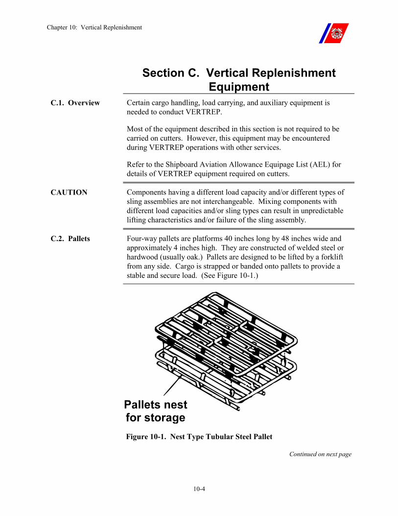
Chapter 10: Vertical Replenishment
10-4
Section C. Vertical Replenishment Equipment
C.1. Overview Certain cargo handling, load carrying, and auxiliary equipment is needed to conduct VERTREP.
Most of the equipment described in this section is not required to be carried on cutters. However, this equipment may be encountered during VERTREP operations with other services.
Refer to the Shipboard Aviation Allowance Equipage List (AEL) for details of VERTREP equipment required on cutters.
CAUTION Components having a different load capacity and/or different types of sling assemblies are not interchangeable. Mixing components with different load capacities and/or sling types can result in unpredictable lifting characteristics and/or failure of the sling assembly.
C.2. Pallets Four-way pallets are platforms 40 inches long by 48 inches wide and approximately 4 inches high. They are constructed of welded steel or hardwood (usually oak.) Pallets are designed to be lifted by a forklift from any side. Cargo is strapped or banded onto pallets to provide a stable and secure load. (See Figure 10-1.)
Figure 10-1. Nest Type Tubular Steel Pallet
Continued on next page
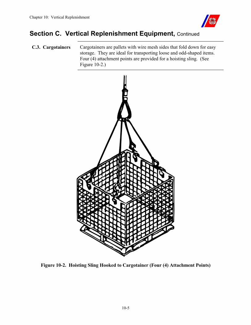
Chapter 10: Vertical Replenishment
10-5
Section C. Vertical Replenishment Equipment, Continued
C.3. Cargotainers Cargotainers are pallets with wire mesh sides that fold down for easy storage. They are ideal for transporting loose and odd-shaped items. Four (4) attachment points are provided for a hoisting sling. (See Figure 10-2.)
Figure 10-2. Hoisting Sling Hooked to Cargotainer (Four (4) Attachment Points)
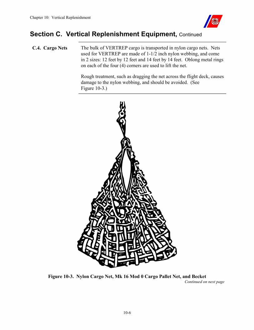
Chapter 10: Vertical Replenishment
10-6
Section C. Vertical Replenishment Equipment, Continued
C.4. Cargo Nets The bulk of VERTREP cargo is transported in nylon cargo nets. Nets used for VERTREP are made of 1-1/2 inch nylon webbing, and come in 2 sizes: 12 feet by 12 feet and 14 feet by 14 feet. Oblong metal rings on each of the four (4) corners are used to lift the net.
Rough treatment, such as dragging the net across the flight deck, causes damage to the nylon webbing, and should be avoided. (See Figure 10-3.)
Figure 10-3. Nylon Cargo Net, Mk 16 Mod 0 Cargo Pallet Net, and Becket Continued on next page
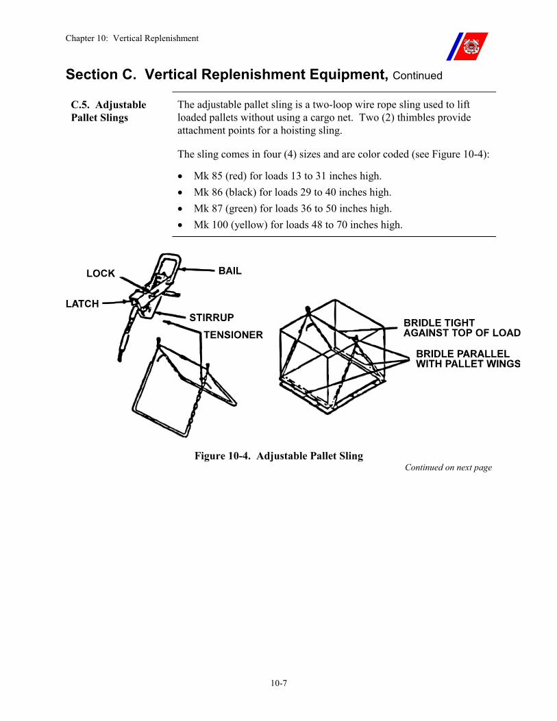
Chapter 10: Vertical Replenishment
10-7
Section C. Vertical Replenishment Equipment, Continued
C.5. Adjustable Pallet Slings
The adjustable pallet sling is a two-loop wire rope sling used to lift loaded pallets without using a cargo net. Two (2) thimbles provide attachment points for a hoisting sling.
The sling comes in four (4) sizes and are color coded (see Figure 10-4):
�� Mk 85 (red) for loads 13 to 31 inches high. �� Mk 86 (black) for loads 29 to 40 inches high. �� Mk 87 (green) for loads 36 to 50 inches high. �� Mk 100 (yellow) for loads 48 to 70 inches high.
Figure 10-4. Adjustable Pallet Sling Continued on next page
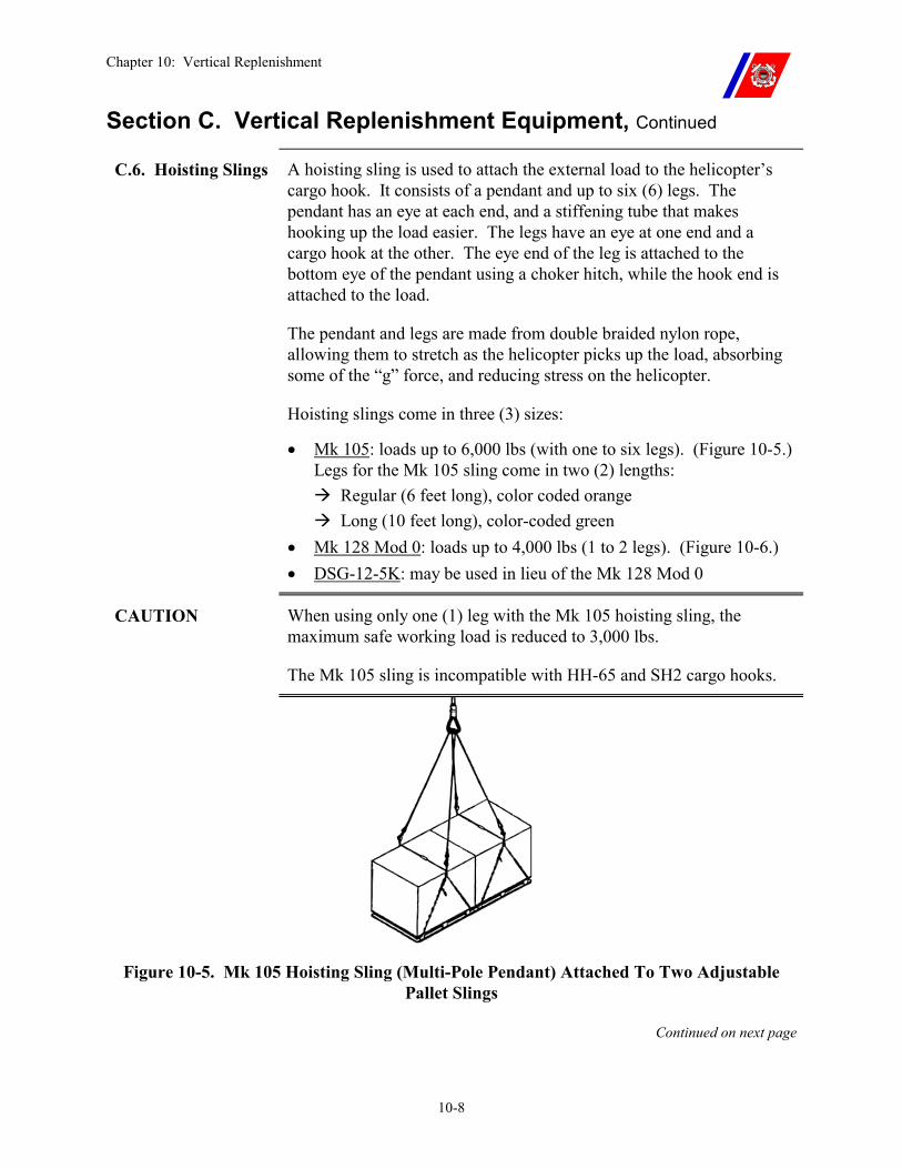
Chapter 10: Vertical Replenishment
10-8
Section C. Vertical Replenishment Equipment, Continued
C.6. Hoisting Slings A hoisting sling is used to attach the external load to the helicopter’s cargo hook. It consists of a pendant and up to six (6) legs. The pendant has an eye at each end, and a stiffening tube that makes hooking up the load easier. The legs have an eye at one end and a cargo hook at the other. The eye end of the leg is attached to the bottom eye of the pendant using a choker hitch, while the hook end is attached to the load.
The pendant and legs are made from double braided nylon rope, allowing them to stretch as the helicopter picks up the load, absorbing some of the “g” force, and reducing stress on the helicopter.
Hoisting slings come in three (3) sizes:
�� Mk 105: loads up to 6,000 lbs (with one to six legs). (Figure 10-5.) Legs for the Mk 105 sling come in two (2) lengths: ��Regular (6 feet long), color coded orange ��Long (10 feet long), color-coded green
�� Mk 128 Mod 0: loads up to 4,000 lbs (1 to 2 legs). (Figure 10-6.) �� DSG-12-5K: may be used in lieu of the Mk 128 Mod 0
CAUTION When using only one (1) leg with the Mk 105 hoisting sling, the maximum safe working load is reduced to 3,000 lbs.
The Mk 105 sling is incompatible with HH-65 and SH2 cargo hooks.
Figure 10-5. Mk 105 Hoisting Sling (Multi-Pole Pendant) Attached To Two Adjustable Pallet Slings
Continued on next page
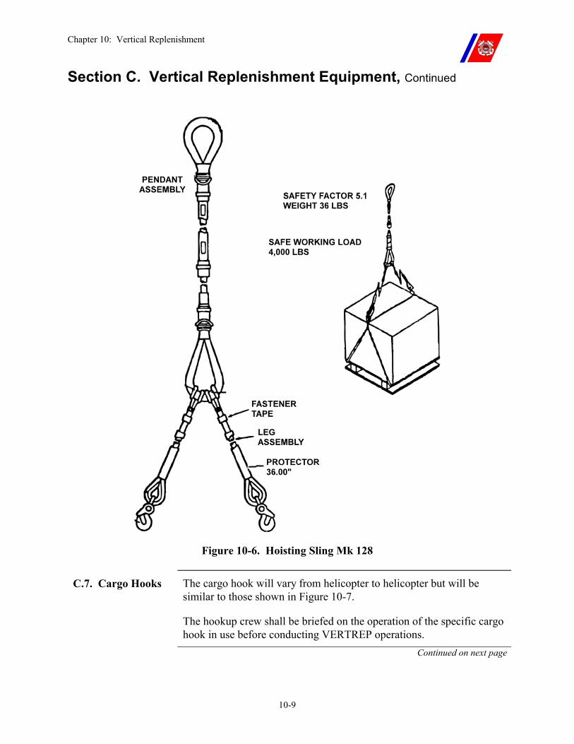
Chapter 10: Vertical Replenishment
10-9
Section C. Vertical Replenishment Equipment, Continued
Figure 10-6. Hoisting Sling Mk 128
C.7. Cargo Hooks The cargo hook will vary from helicopter to helicopter but will be similar to those shown in Figure 10-7.
The hookup crew shall be briefed on the operation of the specific cargo hook in use before conducting VERTREP operations.
Continued on next page
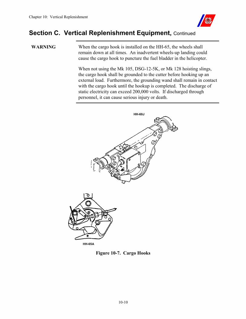
Chapter 10: Vertical Replenishment
10-10
Section C. Vertical Replenishment Equipment, Continued
WARNING When the cargo hook is installed on the HH-65, the wheels shall remain down at all times. An inadvertent wheels-up landing could cause the cargo hook to puncture the fuel bladder in the helicopter.
When not using the Mk 105, DSG-12-5K, or Mk 128 hoisting slings, the cargo hook shall be grounded to the cutter before hooking up an external load. Furthermore, the grounding wand shall remain in contact with the cargo hook until the hookup is completed. The discharge of static electricity can exceed 200,000 volts. If discharged through personnel, it can cause serious injury or death.
Figure 10-7. Cargo Hooks
Chapter 10: Vertical Replenishment
10-11
Section D. Vertical Replenishment Load Preparation
D.1. Overview The primary goal of load preparation is to provide a load that will ride safely in flight, and arrive at the destination undamaged.
External loads are subject to extremely high winds during transportation, and shall be prepared accordingly.
D.2. VERTREP Load Weight and Identification
Loads should be combined to achieve the efficient transfer of cargo. As each load is assembled, mark it with the weight and any other required information for the helicopter crew and receiver. Use chalk, a felt-tip marker, or securely attached tags. Color-coding is recommended to ease identification.
Loads can then be combined to achieve the best distribution of weight for each lift, as determined by the pilots.
CAUTION When combining loads, the loads should be of the same approximate size and weight to reduce the possibility of tipping over during pickup or delivery.
NOTE The height of the load must allow the hookup crew to complete the hookup without climbing on top of the load.
D.3. VERTREP Pallet Assembly
Loosely packed loads on pallets are safety hazards, and shall not be transported by helicopter. Pallet loads shall be prepared as follows:
�� Tightly Band pallet loads. Use sufficient banding to provide proper security. Strap loads to the pallets, using nylon straps, to prevent the loads from shifting in flight and while being moved by a forklift.
�� Interlace load layers wherever possible. �� Individually strap small boxes and crates directly to pallets to
provide a stable and secure load. �� Check the integrity of loads palletized elsewhere. Re-band or
re-strap the loads as necessary. Continued on next page
Chapter 10: Vertical Replenishment
10-12
Section D. Vertical Replenishment Load Preparation, Continued
D.4. Cargotainer Loading
Cargotainer loads shall be prepared as follows:
�� Raise and lock the sides of the cargotainer before loading the cargo. Check that the sides remain securely locked after loading.
�� Place lightweight items near the top of the cargotainer, and use strapping or some other covering to keep them secured during flight.
D.5. Cargo Net Loading (Loose Cargo)
Use cargo nets for transporting awkward-sized material that cannot be secured to a pallet. The loads shall be prepared as follows:
�� Avoid lightweight (less than 100 lbs.) loads because of their instability during flight.
�� Do not load small cartons on the bottom of the net where they could be forced out of the openings in the net.
�� Cover or secure together lightweight or small items to keep them from blowing out of the net. �� Once they are packed together, place them on top of the larger
loads. �� One method of safeguarding small items against loss in flight is
to secure the corners of the net together by taking opposite corner rings and weaving them through at least two (2) web straps in the webbing below the opposite rings. Figure 10-8 illustrates this procedure.
�� Fasten the sling leg through all four (4) corner rings. �� When the helicopter lifts the net, the weight of the load will
cinch the net tight, and prevent losing items through the net. �� Secure the net corner rings with a becket.
WARNING Lightweight loads can be blown up into the bottom of the helicopter, or fly up into the rotor blades.
Continued on next page
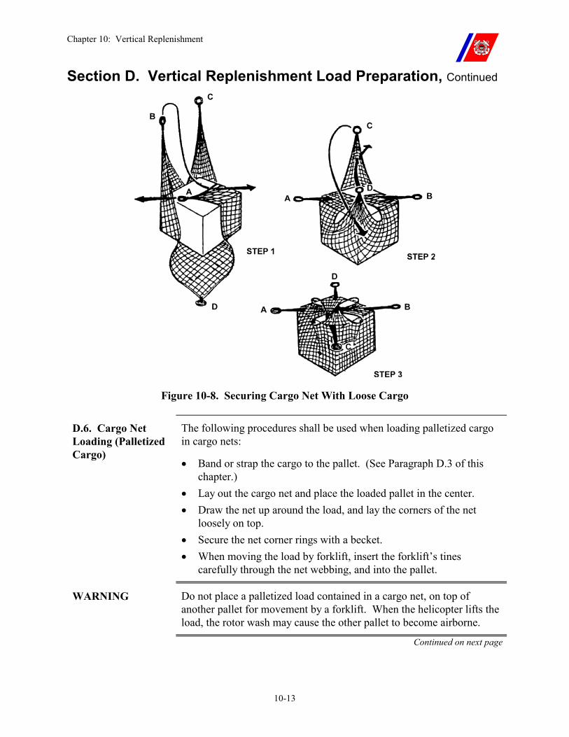
Chapter 10: Vertical Replenishment
10-13
Section D. Vertical Replenishment Load Preparation, Continued
Figure 10-8. Securing Cargo Net With Loose Cargo
D.6. Cargo Net Loading (Palletized Cargo)
The following procedures shall be used when loading palletized cargo in cargo nets:
�� Band or strap the cargo to the pallet. (See Paragraph D.3 of this chapter.)
�� Lay out the cargo net and place the loaded pallet in the center. �� Draw the net up around the load, and lay the corners of the net
loosely on top. �� Secure the net corner rings with a becket. �� When moving the load by forklift, insert the forklift’s tines
carefully through the net webbing, and into the pallet.
WARNING Do not place a palletized load contained in a cargo net, on top of another pallet for movement by a forklift. When the helicopter lifts the load, the rotor wash may cause the other pallet to become airborne.
Continued on next page
Chapter 10: Vertical Replenishment
10-14
Section D. Vertical Replenishment Load Preparation, Continued
D.7. Attaching Slings to Loads
D.7.a. Adjustable Pallet Slings
Individual, rectangular-shaped loads sized to fit a pallet (such as palletized ordnance) may be transported without using a cargo net by using a pallet sling (see Figure 10-9) as follows.
�� Select the proper sling length (color-coded) according to the height of the load.
�� Pass each loop of the sling under the overhang made by the upper boards on the sides of the pallet.
�� Pass each sling basket leg under the wings on each side of the pallet.
�� Pull the ends of the sling legs containing the swage stops through the sling tensioners until the bridle is tight across the top of the load and the slack is out of the sling.
�� Adjust the sling to center so that the lifting thimbles are of equal height from the pallet.
�� Place each tensioner over the nearest swage stop, lower the latch to the stirrup, and lock the tensioner.
D.7.b. Hoisting Slings
When attaching the hoisting sling to the load, a separate leg is used for each attachment point, and all of the extra legs are removed.
�� Cargo nets are lifted by the eye of the becket, using a single leg. �� When using the Mk 105 hoisting sling with more than one (1) leg,
ensure all of the legs are the same length. �� After the hooks are attached, ensure the legs cannot snag on the
load and tip it over during pickup.
CAUTION When using only one (1) leg with the Mk 105 hoisting sling, the maximum safe working load is reduced to 3,000 lbs.
D.7.c. Safety Hooks The safety hook is the only moving part on the hoisting sling. It is correctly operated as follows (see Figure 10-10):
�� To open the hook, grasp it in one hand, and the yoke in the other. Twist the hook and yoke sideways in opposite directions to release the locking lug; then pull the hook and yoke apart until fully open.
�� To close the hook, simply press the yoke down over the hook. Continued on next page
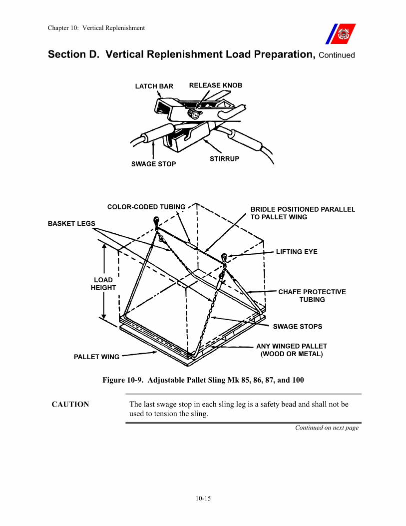
Chapter 10: Vertical Replenishment
10-15
Section D. Vertical Replenishment Load Preparation, Continued
Figure 10-9. Adjustable Pallet Sling Mk 85, 86, 87, and 100
CAUTION The last swage stop in each sling leg is a safety bead and shall not be used to tension the sling.
Continued on next page
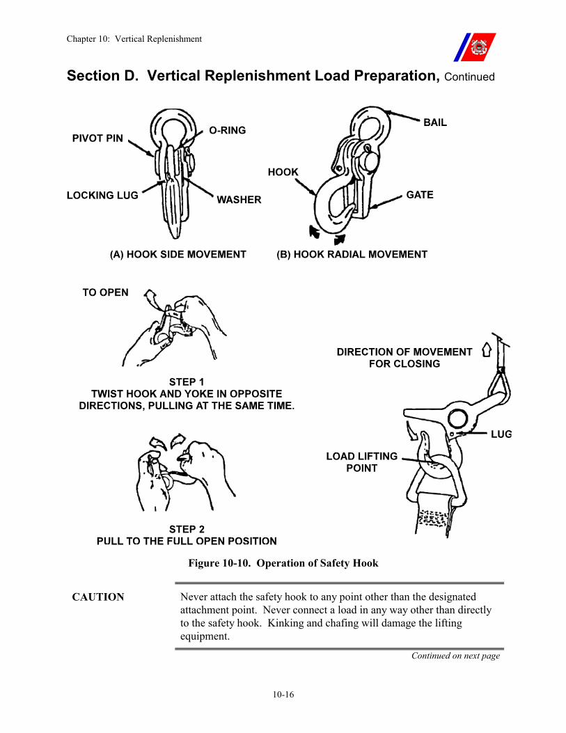
Chapter 10: Vertical Replenishment
10-16
Section D. Vertical Replenishment Load Preparation, Continued
Figure 10-10. Operation of Safety Hook
CAUTION Never attach the safety hook to any point other than the designated attachment point. Never connect a load in any way other than directly to the safety hook. Kinking and chafing will damage the lifting equipment.
Continued on next page
Chapter 10: Vertical Replenishment
10-17
Section D. Vertical Replenishment Load Preparation, Continued
D.8. Non-Standard Loads
Large, bulky, or odd-shaped loads that cannot be carried on a pallet, in a cargotainer, or in a cargo net, shall be provided with slings or lifting eyes so the hoisting sling can be attached directly to the load.
WARNING The pilot shall always be consulted before transferring any non-standard load.
CAUTION When rigging a non-standard load, carefully inspect the attachment points on the load to ensure they are intended for that purpose. What appears to be a lifting eye or attachment point may be intended for another purpose (i.e., a tiedown point), and may not be stressed for helicopter lifting.
D.9. VERTREP Cargo Staging
Before actual VERTREP operations, the maximum possible amount of cargo is staged on the flight deck.
Primary considerations in preparing and executing the flight deck cargo plan (staging) are:
�� If the helicopter is to takeoff or land, cargo shall be staged at least 10-feet outside of the peripheral lines (to provide minimum buffer distance). Otherwise, it shall be staged within the peripheral lines, aft of the VERTREP “T-Line.”
�� Sufficient room shall be left between loads for the hookup crew to move about, and to have an emergency escape route. Additionally, room between loads reduces the possibility of a load snagging an adjacent load during pickup.
�� To prevent cargo from blowing into the helicopter’s rotors, tarpaulins used to cover staged VERTREP loads shall be tied down. The loads shall then be covered by cargo nets secured to the deck.
�� Internal loads: personnel, mail, movies, and other high value items (size dependent) shall be transported internally. �� Other cargo may be transported internally, although internal
loads are usually far more time consuming than external loads. �� When a suitable landing site is not available, internal loads may
be delivered using the rescue hoist (if installed), or, in the case of very light loads, by using a hand line.
�� The typical helicopter rescue hoist has a capacity of 600 lbs.
WARNING Do not attach the hoist cable to the cutter.
Continued on next page
Chapter 10: Vertical Replenishment
10-18
Section E. Vertical Replenishment Procedures
E.1. Overview FLICON THREE is set for all VERTREP operations. (See Chapter 6, Paragraph B.4.) A HCO checklist is included in Figure 10-14.
WARNING Ensure that all staged loads are properly secured and free from FOD.
During VERTREP operations, the hangar shall be fully retracted (unless the cutter is specifically certified for VERTREP with the hangar extended).
The hangar door shall be closed during VERTREP.
Rotorwash from hovering helicopters, particularly from large helicopters, can be severe in light relative wind conditions. The LSO shall brief all personnel involved in VERTREP of this hazard before commencing operations.
Continued on next page
Chapter 10: Vertical Replenishment
10-19
Section E. Vertical Replenishment Procedures, Continued
E.2. VERTREP Pick-up
�� The helicopter will normally complete the approach into the wind, arriving in a hover just off the cutter.
�� The approach of the helicopter is announced over the cutter’s PA system (1MC).
�� All personnel clear the landing and pickup zone, except the hookup crew, which takes position alongside the LSO.
�� Before moving in to pick up each load, the pilot(s) are informed of the destination and weight of the load.
�� Pilot, when ready, transmits on the radio: “Request permission to hover for VERTREP.”
�� HCO replies: “Roger, you are cleared to hover for VERTREP. Take signals from the LSO,” then changes the Deck Status Light to “GREEN.”
�� HCO phone talker passes to the flight deck: “Helo is cleared to hover for VERTREP.”
�� LSO orders the hookup crew into position next to the load for pick up. With the hookup crew in position, the LSO begins giving advisory signals to position the helicopter over the load.
�� The pilot, using advisories from the LSO and commands from the helicopter crewman, maneuvers the helicopter over the load.
�� Once able to reach the aircraft’s cargo hook, the hookup crew grounds the hook (if required), hooks up the pendant, and returns to a position next to the LSO.
�� After the load is hooked up and the hookup crew is clear, the helicopter crewman (and LSO) gives directions (advisories) to pick up the load and to clear the cutter.
WARNING The LSO shall be stationed as far forward of the VERTREP “T-Line” as possible and shall be positioned on the side of the flight deck opposite the side toward which the helicopter nose is pointing. The pilot shall attempt to maintain visual contact with the LSO at all times. If the pilot loses sight of the LSO, he or she shall advise the helicopter crewman who will relay the LSO signals.
The hookup crew shall never stand on the load or between the load being picked up and another load.
Continued on next page
Chapter 10: Vertical Replenishment
10-20
Section E. Vertical Replenishment Procedures, Continued
WARNING When not using the Mk 105, DSG-12-5K, or Mk 128 hoisting slings, the cargo hook shall be grounded to the cutter before hooking up an external load. Furthermore, the grounding wand shall remain in contact with the cargo hook until the hookup is completed. The discharge of static electricity can exceed 200,000 volts, and, if discharged through personnel, cause serious injury or death.
NOTE Radio communications with the helicopter while it is in a hover over the VERTREP zone are distracting, and should be limited to urgent communications only.
The helicopter crewman is the primary director of the helicopter once it is in a hover over the VERTREP area. However, the LSO shall continue to give advisory signals in case of internal communications failure or other emergencies that the pilot or aircrew are unaware.
E.3. VERTREP Delivery
�� The helicopter will normally complete the approach into the wind, arriving in a hover just off the cutter.
�� When the approach of the helicopter is announced over the cutter’s PA system (1MC), all personnel will clear the VERTREP area.
�� Pilot, when ready, transmits on the radio: “Request permission to hover for VERTREP.”
�� HCO replies: “Roger, you are cleared to hover for VERTREP. Take signals from the LSO,” then changes the Deck Status Light to “GREEN.”
�� HCO phone talker passes to the flight deck: “Helo is cleared to hover for VERTREP.”
�� LSO begins giving advisory signals to position the helicopter for delivery.
�� Pilot, using advisories from the LSO and commands from the helicopter crewman, maneuvers the helicopter over the VERTREP area.
�� Helicopter crewman gives directions for spotting and lowering the load. As soon as the load is on deck, the crewman informs the pilot.
�� When the pendant slackens, the LSO signals the pilot to release the load. The pilot or crewman (as briefed) releases the cargo hook.
Continued on next page
Chapter 10: Vertical Replenishment
10-21
Section E. Vertical Replenishment Procedures, Continued
WARNING Once the helicopter has been cleared to hover, personnel shall not enter the VERTREP area until after the load is on deck. No attempt shall be made by personnel to steady the load during delivery.
WARNING The LSO shall be stationed as far forward of the VERTREP “T-Line” as possible and shall be positioned on the side of the flight deck opposite the side toward which the helicopter nose is pointing. The pilot shall attempt to maintain visual contact with the LSO at all times. If the pilot loses sight of the LSO, he or she shall advise the aircrew who will relay the LSO signals.
WARNING The pilot shall maneuver the helicopter so to be able to see and avoid all obstructions.
WARNING Releasing the load before there is slack in the pendant can cause damage to the aircraft, cutter, load, and/or injury to personnel.
NOTE The sling may not immediately release from the aircraft cargo hook. If the sling hangs up, the pilot shall initiate a slow vertical climb, gradually applying tension until it separates from the hook.
E.4. Clearing the VERTREP Area
�� After the helicopter has delivered each load and departed, cargo handlers break down the load and relocate it clear of the VERTREP area.
�� Empty nets, pallets, and cargo containers are relocated clear of the VERTREP area.
�� If the helicopter returns with another load before the previous load is cleared, and if space is available for additional cargo, the load being worked should be temporarily secured. All personnel shall then clear the area while the next load is delivered. Speed is second only to safety in clearing the VERTREP area. �� Secure loads delivered in cargo nets by pulling the net over the
load and threading a strap through the net ends. �� Secure loads delivered in cargotainers by raising and locking
the sides of the cargotainer, securely covering the top. �� Secure loads on pallets by covering them securely with a cargo
net. Continued on next page
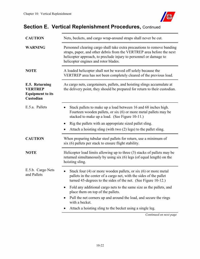
Chapter 10: Vertical Replenishment
10-22
Section E. Vertical Replenishment Procedures, Continued
CAUTION Nets, beckets, and cargo wrap-around straps shall never be cut.
WARNING Personnel clearing cargo shall take extra precautions to remove banding straps, paper, and other debris from the VERTREP area before the next helicopter approach, to preclude injury to personnel or damage to helicopter engines and rotor blades.
NOTE A loaded helicopter shall not be waved off solely because the VERTREP area has not been completely cleared of the previous load.
E.5. Returning VERTREP Equipment to its Custodian
As cargo nets, cargotainers, pallets, and hoisting slings accumulate at the delivery point, they should be prepared for return to their custodian.
E.5.a. Pallets �� Stack pallets to make up a load between 16 and 68 inches high. Fourteen wooden pallets, or six (6) or more metal pallets may be stacked to make up a load. (See Figure 10-11.)
�� Rig the pallets with an appropriate sized pallet sling. �� Attach a hoisting sling (with two (2) legs) to the pallet sling.
CAUTION When preparing tubular steel pallets for return, use a minimum of six (6) pallets per stack to ensure flight stability.
NOTE Helicopter load limits allowing up to three (3) stacks of pallets may be returned simultaneously by using six (6) legs (of equal length) on the hoisting sling.
E.5.b. Cargo Nets and Pallets
�� Stack four (4) or more wooden pallets, or six (6) or more metal pallets in the center of a cargo net, with the sides of the pallet turned 45-degrees to the sides of the net. (See Figure 10-12.)
�� Fold any additional cargo nets to the same size as the pallets, and place them on top of the pallets.
�� Pull the net corners up and around the load, and secure the rings with a becket.
�� Attach a hoisting sling to the becket using a single leg. Continued on next page
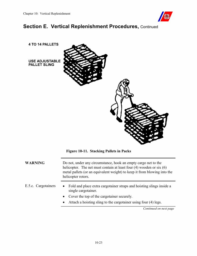
Chapter 10: Vertical Replenishment
10-23
Section E. Vertical Replenishment Procedures, Continued
Figure 10-11. Stacking Pallets in Packs
WARNING Do not, under any circumstance, hook an empty cargo net to the helicopter. The net must contain at least four (4) wooden or six (6) metal pallets (or an equivalent weight) to keep it from blowing into the helicopter rotors.
E.5.c. Cargotainers �� Fold and place extra cargotainer straps and hoisting slings inside a single cargotainer.
�� Cover the top of the cargotainer securely. �� Attach a hoisting sling to the cargotainer using four (4) legs.
Continued on next page
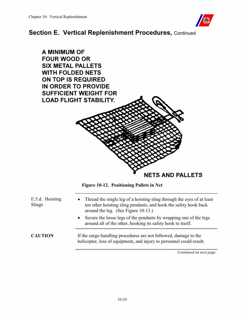
Chapter 10: Vertical Replenishment
10-24
Section E. Vertical Replenishment Procedures, Continued
Figure 10-12. Positioning Pallets in Net
E.5.d. Hoisting Slings
�� Thread the single leg of a hoisting sling through the eyes of at least ten other hoisting sling pendants, and hook the safety hook back around the leg. (See Figure 10-13.)
�� Secure the loose legs of the pendants by wrapping one of the legs around all of the other, hooking its safety hook to itself.
CAUTION If the cargo handling procedures are not followed, damage to the helicopter, loss of equipment, and injury to personnel could result.
Continued on next page
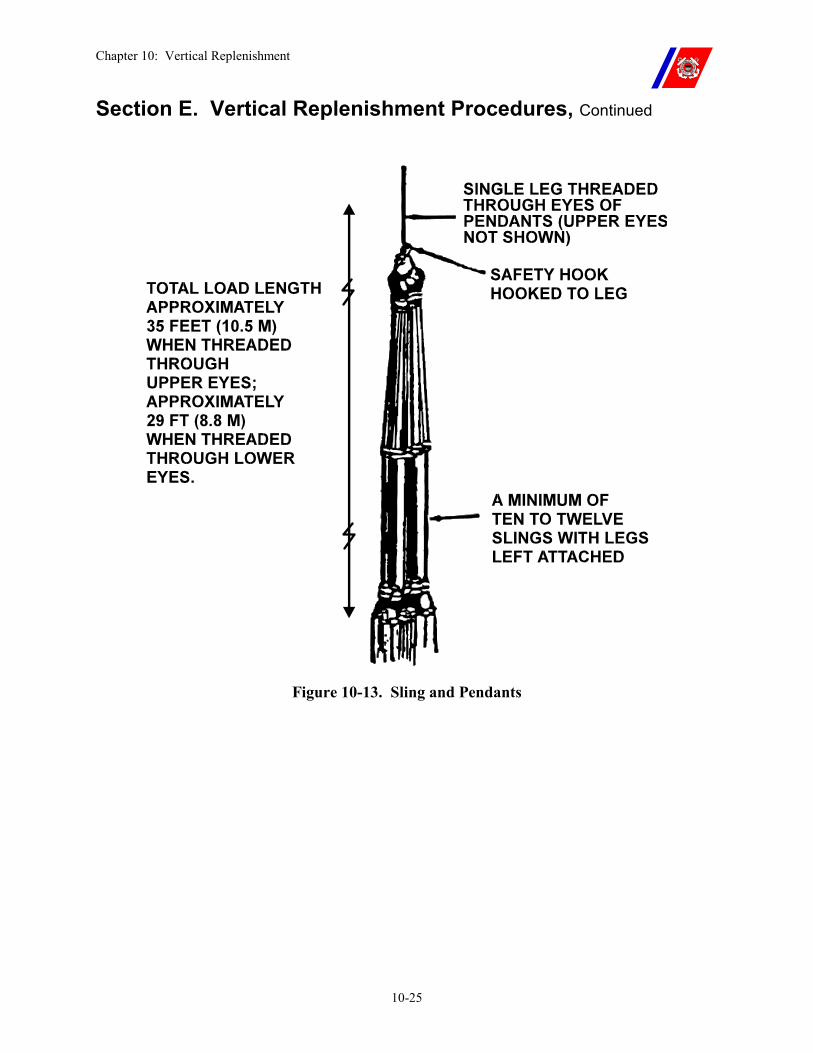
Chapter 10: Vertical Replenishment
10-25
Section E. Vertical Replenishment Procedures, Continued
Figure 10-13. Sling and Pendants
Chapter 10: Vertical Replenishment
10-26
Section E. Vertical Replenishment Procedures, Continued
E.6. VERTREP with Non-Flight Deck Equipped Vessels
VERTREP may be conducted with vessels that are not certified or qualified provided a 15-foot obstruction clearance can be maintained at all times. At least one pilot shall hold an aircraft commander designation. These operations are restricted to day VMC and should not be conducted above Sea State 4 without Air Station and Cutter Commanding Officer approval. Aircraft may continue to hoist to any vessel day or night. This policy is limited to CG Aircraft operating with CG Cutters. Before any VERTREP operations, a thorough brief shall be conducted to include at a minimum the following items:
�� Pick up and drop off areas shall be suitable to both the Cutter Commanding Officer and the Aircraft Commander
�� Procedures for hooking up and unhooking loads. �� Load weight shall be at least 100 lbs. �� Cutter shall conduct a FOD walk down of the entire topside area
before commencing operations. �� Procedures to follow in the event of an emergency. �� Relative wind direction for pick up and drop off. �� VERTREP equipment pallets, slings, nets, etc. shall be determined
before commencing operations. �� VERTREP loads shall be prepared in accordance with Paragraph
10.D of this chapter. �� Cargo should be staged before VERTREP operations. �� Ensure all VERTREP loads are properly secured and free of FOD. �� The approach of the helicopter shall be announced over the Cutter’s
PA system (1MC). �� Only personnel needed to conduct VERTREP operations should be
allowed on deck. �� Before moving in to pick up each load, the helicopter shall be
cleared by the cutter. �� The hook-up crew shall never stand on the load or between the load
being picked up and another load. �� The hook up crew shall be aware of the danger associated with
static discharge and use proper protective equipment. �� The helicopter aircrew will give directions to the pilot to position
the aircraft over the load.
Chapter 10: Vertical Replenishment
10-27
Section F. Night Vertical Replenishment
F.1. Overview The primary difference between day and night VERTREP is a reduction in the speed of the operation because of reduced visibility.
Night VERTREP is performed in the same manner as day VERTREP subject to the limitations set forth in this chapter.
VERTREP using NVGs will be conducted in the same manner as night VERTREP with the exception of NVG compatible flight deck lighting.
NOTE The final decision regarding the helicopter’s ability to safely VERTREP a particular cutter at night rests with the pilot.
F.2. Factors Affecting Night VERTREP
�� Since night flying offshore is essentially instrument flying, the helicopter shall be capable of instrument flight.
�� Adverse weather conditions further reduce night VERTREP capabilities.
�� Cutters certified for night helicopter operations (Level I and Level II) are properly lighted for VERTREP. All lighting required for night launch and recovery shall be illuminated for night VERTREP.
WARNING Under no circumstance shall flash pictures be taken during night VERTREP since the flash will temporarily blind the pilots.
WARNING For VERTREP conducted using NVGs, all NVG compatible flight deck lighting will be turned up to 100% intensity before personnel are directed to connect or disconnect the load.
Continued on next page
Chapter 10: Vertical Replenishment
10-28
Section F. Night Vertical Replenishment, Continued
F.3. VERTREP Night Procedures
The same procedures are used for both day and night VERTREP but with a wider pattern being flown and greater care and precision being exercised at night. Consequently, delivery rates at night are slower than during daylight operations. In addition:
�� The cutter maintains a course, keeping the cutter stack gases clear of the VERTREP area, and pilots avoid flying through the stack gases during the approach. Stack gases reduce visibility and may cause spatial disorientation.
�� LSO uses night signal wands for helicopter directions. �� Information concerning destination, bearing and distance, load
weight, etc., is transmitted to the helicopter by radio. �� Chemlights are worn by the hookup crew to help the helicopter
crewman identify the correct load. �� If practicable, a Chemlight shall be securely attached to the load to
aid the LSO in maintaining visual contact while ensuring the height of the load above the deck.
WARNING All Chemlights used when conducting VERTREP under NVGs will be either Infrared or blue for compatibility with the NVGs.
Continued on next page
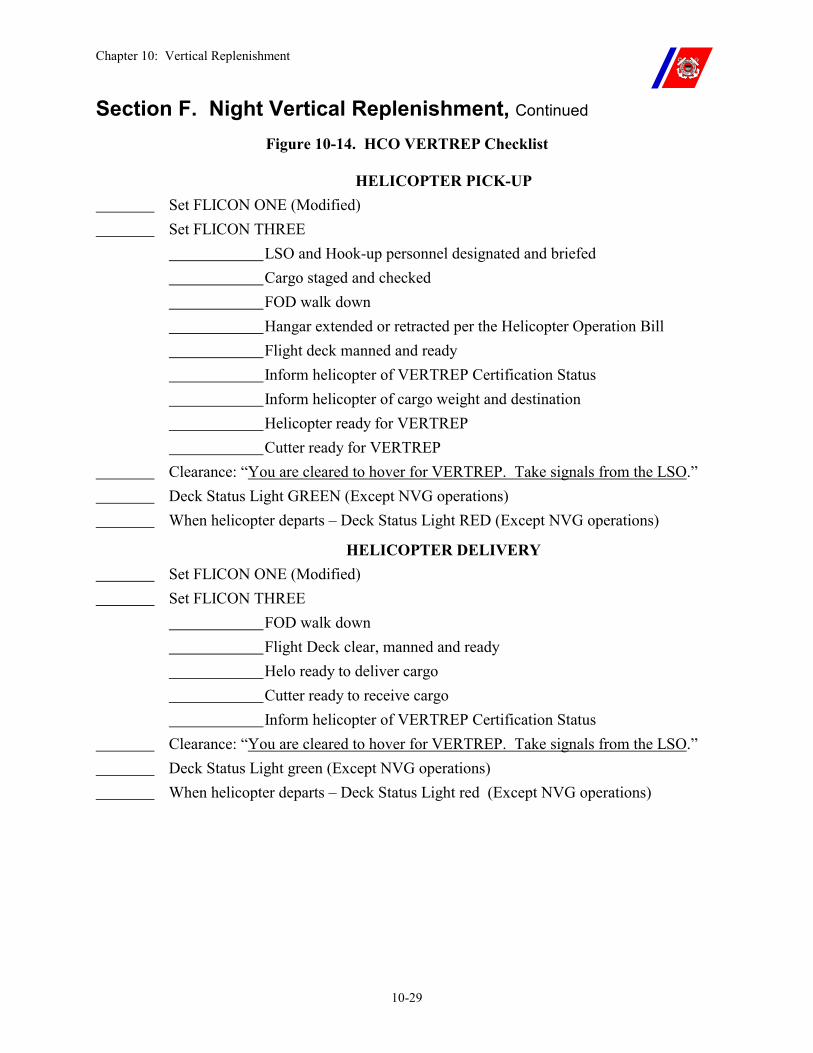
Chapter 10: Vertical Replenishment
10-29
Section F. Night Vertical Replenishment, Continued Figure 10-14. HCO VERTREP Checklist
HELICOPTER PICK-UP Set FLICON ONE (Modified) Set FLICON THREE LSO and Hook-up personnel designated and briefed Cargo staged and checked FOD walk down Hangar extended or retracted per the Helicopter Operation Bill Flight deck manned and ready Inform helicopter of VERTREP Certification Status Inform helicopter of cargo weight and destination Helicopter ready for VERTREP Cutter ready for VERTREP Clearance: “You are cleared to hover for VERTREP. Take signals from the LSO.” Deck Status Light GREEN (Except NVG operations) When helicopter departs – Deck Status Light RED (Except NVG operations) HELICOPTER DELIVERY Set FLICON ONE (Modified) Set FLICON THREE FOD walk down Flight Deck clear, manned and ready Helo ready to deliver cargo Cutter ready to receive cargo Inform helicopter of VERTREP Certification Status Clearance: “You are cleared to hover for VERTREP. Take signals from the LSO.” Deck Status Light green (Except NVG operations) When helicopter departs – Deck Status Light red (Except NVG operations)
Chapter 11: Helicopter Securing and Traversing
11-i
CHAPTER 11: HELICOPTER SECURING AND TRAVERSING Table of Contents
Introduction.............................................................................................................................. 11-1
In this chapter .......................................................................................................................... 11-1
Section A. General Information............................................................................................. 11-2
A.1. Securing for Sea .............................................................................................................. 11-2
A.2. Severe Weather Considerations..................................................................................... 11-2
Section B. Mooring Aids......................................................................................................... 11-4
B.1. Overview .......................................................................................................................... 11-4
B.2. Cutter Tiedown Points .................................................................................................... 11-4 B.2.a. Types of Tiedown Points....................................................................................................11-4 B.2.b. Tiedown Points and Equipment Compatibility ..................................................................11-4 B.2.c. TALON Grid ......................................................................................................................11-5
B.3. Helicopter Tiedown Points ............................................................................................. 11-5
B.4. Tiedown Assemblies ........................................................................................................ 11-5 B.4.a. Primary Tiedowns ..............................................................................................................11-6
B.4.a.(1). Primary Tiedown Assemblies ...........................................................................11-7 B.4.a.(2). TALON Probe ...................................................................................................11-7 B.4.a.(3). Chocks and Chains ............................................................................................11-7
B.4.b. Secondary Tiedowns ..........................................................................................................11-8 B.4.b.(1). Secondary Tiedown Use ...................................................................................11-8 B.4.b.(2). Secondary Tiedown Assemblies .......................................................................11-8
B.4.c. Heavy Weather Tiedowns ................................................................................................11-10 B.4.c.(1). HH-65 Heavy Weather Tiedowns ...................................................................11-10
B.4.d. Bulbhooks.........................................................................................................................11-11
Section C. Primary Tiedowns .............................................................................................. 11-12
C.1. HH-65 and HH-60J Primary Tiedown Procedures.................................................... 11-12
C.2. Tiedown General Procedures....................................................................................... 11-13 C.2.a. High Tiedown Overhaul ...................................................................................................11-13 C.2.b. Low Tiedown Overhaul ...................................................................................................11-14 C.2.c. HH-65 High Tiedown Procedures ....................................................................................11-14
C.2.c.(1). HH-65 High Tiedown Installation...................................................................11-15 C.2.c.(2). HH-65 High Tiedown Removal ......................................................................11-15
C.2.d. HH-65 Low Tiedown Procedures ....................................................................................11-16 C.2.d.(1). HH-65 Low Tiedown Installation ...................................................................11-16
Chapter 11: Helicopter Securing and Traversing
11-ii
C.2.d.(2). HH-65 Low Tiedown Removal.......................................................................11-16 C.2.e. HH-60J High Tiedown Procedures ..................................................................................11-17
C.2.e.(1). HH-60J High Tiedown Installation .................................................................11-17 C.2.e.(2). HH-60J High Tiedown Removal.....................................................................11-18
C.2.f. HH-60J Low Tiedown Procedures....................................................................................11-19 C.2.f.(1). HH-60J Low Tiedown Installation ..................................................................11-19 C.2.f.(2). HH-60J Low Tiedown Removal......................................................................11-19
C.2.g. Primary Tiedown Malfunctions .......................................................................................11-20 C.2.g.(1). Malfunction During Installation......................................................................11-20 C.2.g.(2). Malfunction During Removal .........................................................................11-20 C.2.g.(3). Replacing a Malfunctioning Tiedown.............................................................11-20
C.3. TALON .......................................................................................................................... 11-21 C.3.a. Tiedown Crew Availability ..............................................................................................11-21 C.3.b. TALON Probe Failure to Engage.....................................................................................11-21
C.4. Chocks and Chains ....................................................................................................... 11-22
Section D. Secondary Tiedowns........................................................................................... 11-23
D.1. Secondary Tiedown Use ............................................................................................... 11-23
D.2. Secondary Tiedown Installation .................................................................................. 11-23
D.3. Secondary Tiedown Procedures .................................................................................. 11-24
Section E. Heavy Weather Tiedowns .................................................................................. 11-25
E.1. Heavy Weather Tiedown Use....................................................................................... 11-25
E.2. Heavy Weather Tiedown Installation.......................................................................... 11-25
E.3. Heavy Weather Tiedown Procedures.......................................................................... 11-25 E.3.a. General..............................................................................................................................11-25 E.3.b. HH-65 Heavy Weather Tiedown Procedures ...................................................................11-26
Section F. Blade Security...................................................................................................... 11-27
F.1. Overview......................................................................................................................... 11-27
F.2. Blade Tip Covers (Socks).............................................................................................. 11-27
F.3. Blade Restrainers........................................................................................................... 11-27
F.4. Blade Folding ................................................................................................................. 11-27 F.4.a. Blade Folding and Unfolding Procedures.........................................................................11-28 F.4.b. Limitations........................................................................................................................11-28
WARNING ............................................................................................................................. 11-28
Chapter 11: Helicopter Securing and Traversing
11-iii
F.5. Blade Removal ............................................................................................................... 11-28 F.5.a. Blade Removal and Reinstallation Procedures.................................................................11-28 F.5.b. Blade Removal Limitations ..............................................................................................11-28
Section G. Traversing ........................................................................................................... 11-29
G.1. Hangar Equipped Cutters............................................................................................ 11-29
G.2. Non-Hangar Equipped Cutters ................................................................................... 11-29
G.3. Helicopter Manual Traversing .................................................................................... 11-29 G.3.a. Traversing Crew Organization .........................................................................................11-29
G.3.a.(1). Flight Deck Director (FDD)............................................................................11-30 G.3.a.(2). Brake Rider (BR) ............................................................................................11-30 G.3.a.(3). Tiedown Crew.................................................................................................11-30 G.3.a.(4). Push Crew .......................................................................................................11-30 G.3.a.(5). Driver ..............................................................................................................11-30
G.3.b. Traversing Preparation.....................................................................................................11-31 G.3.c. Traversing Communications ............................................................................................11-31 G.3.d. Normal Traversing (Walking Tiedowns).........................................................................11-31
G.3.d.(1). Traversing Coast Guard Helicopters ..............................................................11-32 G.3.d.(2). Traversing Navy Helicopters ..........................................................................11-33 G.3.d.(3). Traversing on WAGBs ...................................................................................11-34
G.3.e. Heavy Weather Traversing Procedures (Progressive Chains) .........................................11-34 G.3.e.(1). Heavy Weather Traversing Procedures...........................................................11-35
G.4. Automated Helicopter Traversing............................................................................... 11-36
Section H. Helicopter Security and Fire Checks............................................................... 11-37
H.1. Overview........................................................................................................................ 11-37
H.2. Security on WAGBs...................................................................................................... 11-37
H.3. Security on WHECs and WMECs .............................................................................. 11-37 H.3.a. Duties of the Officer of the Deck (OOD).........................................................................11-37 H.3.b. Duties of the First Lieutenant ..........................................................................................11-38 H.3.c. Duties of the BMOW .......................................................................................................11-38

Chapter 11: Helicopter Securing and Traversing
11-iv
Chapter 11: Helicopter Securing and Traversing
11-1
Chapter 11. Helicopter Securing and Traversing
Introduction After a helicopter has landed on a cutter, it shall be tied down to ensure its safety. TALON is the preferred method to secure the HH-65. For all other helicopters, tiedowns are initially installed as rapidly as possible, with the helicopter’s rotors turning, to provide stability in the event of excessive flight deck motion.
Additional secondary tiedowns are installed after the helicopter is shut down, to provide greater security for extended periods of stay and during periods of inclement weather.
NOTE Cutters moored pier side or icebreakers hove to in the ice, the use of tiedowns and tiedown crews may be omitted with the concurrence of the Commanding Officer and the Senior Aviator. The flight deck shall be free of ice and snow to operate without tiedowns.
In this chapter This chapter is divided into eight (8) sections:
�� Section A: General Information �� Section B: Mooring Aids �� Section C: Primary Tiedowns (including TALON) �� Section D: Secondary Tiedowns �� Section E: Heavy Weather Tiedowns �� Section F: Blade Security �� Section G: Traversing �� Section H: Helicopter Security
Chapter 11: Helicopter Securing and Traversing
11-2
Section A. General Information
A.1. Securing for Sea
On hangar-equipped cutters, the helicopter shall be moved into the hangar at the end of the day’s planned flight operation unless other Commandant directives allow otherwise to meet operational necessity (physical dimensions of the helicopter must allow for hangaring).
On cutters without hangars, the helicopter is secured for sea in the landing position.
A.2. Severe Weather Considerations
Helicopters are subject to considerable damage and significant corrosion problems when exposed to the sea environment and the elements during periods of severe weather.
When the helicopter cannot be hangared and impending weather is such that helicopter damage is reasonably foreseeable, strong consideration should be given to evacuating the helicopter to shore, if a suitable divert airfield is available and conditions permit for a safe flight. Otherwise, consideration should be given to remove those components likely to be damaged (such as rotor blades and stabilizers.)
WARNING The HH-60J cannot be traversed, which eliminates hangaring, and cannot be secured for heavy weather conditions. Commanding Officers shall evacuate the HH-60J ashore or plan to deviate around significant weather systems. Damage or loss of the aircraft is likely in seas above Sea State Three. Sea States 0-8 are defined in Figure 11-1:
Continued on next page
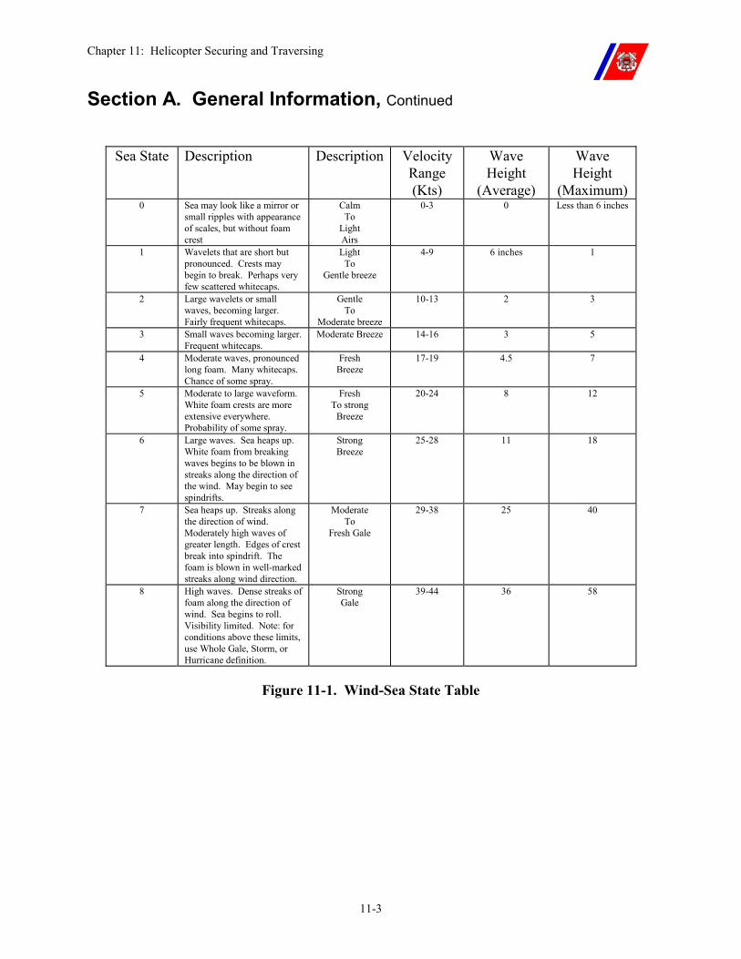
Chapter 11: Helicopter Securing and Traversing
11-3
Section A. General Information, Continued
Sea State Description Description Velocity Range (Kts)
Wave Height
(Average)
Wave Height
(Maximum) 0 Sea may look like a mirror or
small ripples with appearance of scales, but without foam crest
Calm To
Light Airs
0-3 0 Less than 6 inches
1 Wavelets that are short but pronounced. Crests may begin to break. Perhaps very few scattered whitecaps.
Light To
Gentle breeze
4-9 6 inches 1
2 Large wavelets or small waves, becoming larger. Fairly frequent whitecaps.
Gentle To
Moderate breeze
10-13 2 3
3 Small waves becoming larger. Frequent whitecaps.
Moderate Breeze 14-16 3 5
4 Moderate waves, pronounced long foam. Many whitecaps. Chance of some spray.
Fresh Breeze
17-19 4.5 7
5 Moderate to large waveform. White foam crests are more extensive everywhere. Probability of some spray.
Fresh To strong
Breeze
20-24 8 12
6 Large waves. Sea heaps up. White foam from breaking waves begins to be blown in streaks along the direction of the wind. May begin to see spindrifts.
Strong Breeze
25-28 11 18
7 Sea heaps up. Streaks along the direction of wind. Moderately high waves of greater length. Edges of crest break into spindrift. The foam is blown in well-marked streaks along wind direction.
Moderate To
Fresh Gale
29-38 25 40
8 High waves. Dense streaks of foam along the direction of wind. Sea begins to roll. Visibility limited. Note: for conditions above these limits, use Whole Gale, Storm, or Hurricane definition.
Strong Gale
39-44 36 58
Figure 11-1. Wind-Sea State Table
Chapter 11: Helicopter Securing and Traversing
11-4
Section B. Mooring Aids
B.1. Overview Mooring aids consist of those items, both permanently installed and portable, which are used for securing a helicopter on a cutter.
B.2. Cutter Tiedown Points
Reinforced tiedown points are installed in the flight deck, hangar deck, helicopter traversing areas, and hangar bulkheads.
B.2.a. Types of Tiedown Points
The following types of tiedown points are installed on cutters:
�� Flush deck bar-type fittings. �� Flush deck cloverleaf fittings (recessed mushrooms). �� Raised deck cloverleaf fittings (raised deck mushrooms). �� Coaming sockets (keyhole fittings). �� Five (5) reversible deck bolt pad eyes (Baxter bolts). �� Fixed pad eyes. �� Bulkhead bar-type fittings.
B.2.b. Tiedown Points and Equipment Compatibility
Cloverleaf fittings and coaming sockets are designed to accept bulbhooks.
Bar-type fittings are designed to accept open hooks.
Pad eyes may require shackles to make them compatible with open hooks.
NOTE WMEC 270 cutters feature both bar-type and raised cloverleaf tiedown fittings. (Change - deleted sentence) After the helicopter is shut down and secondary tiedowns have been attached, any tiedowns leading to cloverleaf fittings shall be reset with bulbhooks.
Continued on next page
Chapter 11: Helicopter Securing and Traversing
11-5
Section B. Mooring Aids, Continued
B.2.c. TALON Grid The TALON grid is a 6-foot diameter honeycomb grid made of high strength stainless steel. The TALON is mounted in a trough in the flight deck, flush with the deck, near the center of the landing circle.
The grid provides a securing point for the self-contained, hydraulically powered, pilot-activated, helicopter securing system (TALON) installed on the HH-65. A stainless steel grid cover, coated with flight deck non-skid, keeps the grid trough free of FOD, and preserves non-skid and visual landing aid (VLA) continuity during operations with non-TALON-equipped helicopters.
B.3. Helicopter Tiedown Points
Mooring rings are installed at reinforced points on the fuselage and/or landing gear for securing the helicopter.
B.4. Tiedown Assemblies
Helicopters are secured to the cutter using primary (includes TALON for the HH-65) and secondary tiedown assemblies. Figures 11-1 through 11-7 depict the tiedown configurations for HH-65 and HH-60J helicopters.
Tiedown configurations for other helicopters can be found in NWP 3-04.1.
Continued on next page
Chapter 11: Helicopter Securing and Traversing
11-6
Section B. Mooring Aids, Continued
B.4.a. Primary Tiedowns
The HH-65 shall use TALON as the first means of securing if the TALON probe is installed. Primary tiedowns are unique to the Coast Guard, and are used for providing initial security upon landing. Immediately after the pilot gives the “Tiedowns On” signal, primary tiedowns provide sufficient security for rotor disengagement and for holding the helicopter on deck during normal flight deck motion.
During flight operations not involving TALON, primary tiedowns shall be used whenever it is planned to secure the rotor, or to remain on deck for more than just a moment.
Primary tiedowns shall also be used in conjunction with secondary tiedowns for heavy weather, long term, or overnight security.
Primary tiedowns may be used in conjunction with TALON after aircraft shutdown or before aircraft startup to provide additional security. If primary tiedowns are installed in addition to TALON, they should be removed before engine start.
Primary tiedowns may be used in conjunction with TALON while the rotors are turning for purposes of tiedown crew training or proficiency. Once tiedown team proficiency is achieved and primary tiedowns are removed, the LSO and pilot shall revert to the published TALON procedures.
NOTE If the aircraft is to be spotted on the flight deck for more than one hour after shutdown or before startup, primary tiedowns shall be installed with enough slack to allow the struts to decompress, and the TALON system disengaged to release pressure on the landing gear struts. Primary tiedowns will then be tightened by hand, and secondary tiedowns shall be installed as appropriate. The TALON system will be re-engaged and secondary tiedowns removed with permission from the bridge and PIC before or during the setting of FLICON ONE.
Cutters moored pier side or icebreakers hove to in the ice may omit the use of tiedowns and tiedown crews with the concurrence of the Commanding Officer and the Senior Aviator.
The flight deck shall be completely free of ice and snow to operate or traverse helicopter without tiedowns.
Continued on next page
Chapter 11: Helicopter Securing and Traversing
11-7
Section B. Mooring Aids, Continued
B.4.a.(1). Primary Tiedown Assemblies
There are two (2) primary tiedown assemblies: the high tiedown assembly and the low tiedown assembly. Both have a rated strength of 10,000 lbs.
�� High Tiedown Assembly. The high tiedown assembly consists of: �� A quick releasing “pelican” hook with a strap tensioner, �� Long nylon strap, �� Ratchet assembly, and �� An open hook (WHEC 378, WAGB 420, and WMEC 270/282) �� Or a bulbhook (WAGB 399 and WMEC 210).
The ratchet assembly consists of a ratchet attached to a short nylon strap with a “D” ring on the other end. The hook is attached to the “D” ring using a 7/16 inch (10,000 lb. rated) shackle. The long nylon strap is threaded through both the pelican hook and the bale on the ratchet.
�� Low Tiedown Assembly. The low tiedown assembly consists of: �� An open hook connected to a ratchet assembly, �� Long nylon strap, and �� An open hook (WHEC 378, WAGB 420, and WMEC 270/282) �� Or a bulbhook (WAGB 399 and WMEC 210). The hook is
connected to a “D” ring permanently attached to one end of the nylon strap, using a 7/16 inch shackle. The free end of the strap is threaded through the bale on the ratchet.
B.4.a.(2). TALON Probe
The TALON probe is an electrically actuated (by the pilot), hydraulically operated unit designed to secure the helicopter to the cutter by engaging with the TALON grid.
When actuated, the probe extends from the underside of the helicopter, centers in one of the holes in the TALON grid, locks onto the grid, and provides a downward tensioning force of approximately 3,500 lbs.
TALON is the primary securing system for the HH-65 and shall be used in lieu of the primary tiedowns when the TALON probe is installed on the aircraft and operational.
B.4.a.(3). Chocks and Chains
The initial tiedown aboard U.S. Navy ships and on Coast Guard Cutters operating with U.S. Navy helicopters, is completed using NWC-2, NWC-3, or NWC-4 chocks; and TD-1A or TD-1B tiedown chains.
Continued on next page
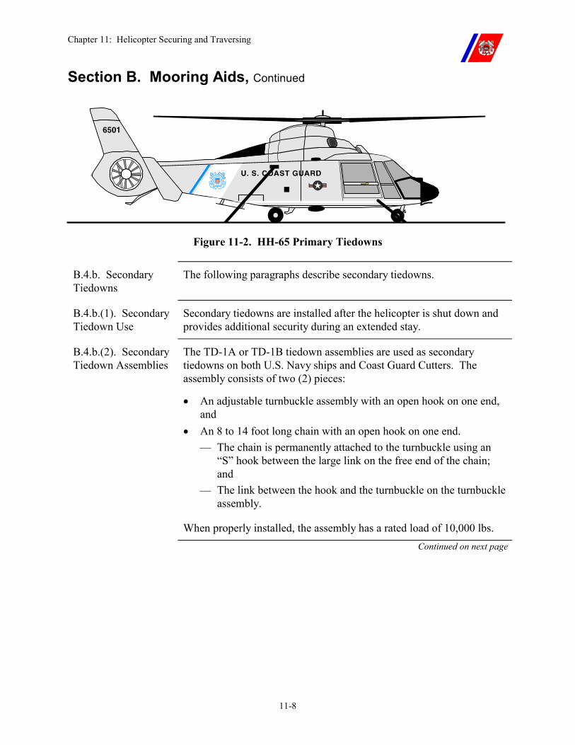
Chapter 11: Helicopter Securing and Traversing
11-8
Section B. Mooring Aids, Continued
Figure 11-2. HH-65 Primary Tiedowns
B.4.b. Secondary Tiedowns
The following paragraphs describe secondary tiedowns.
B.4.b.(1). Secondary Tiedown Use
Secondary tiedowns are installed after the helicopter is shut down and provides additional security during an extended stay.
B.4.b.(2). Secondary Tiedown Assemblies
The TD-1A or TD-1B tiedown assemblies are used as secondary tiedowns on both U.S. Navy ships and Coast Guard Cutters. The assembly consists of two (2) pieces:
�� An adjustable turnbuckle assembly with an open hook on one end, and
�� An 8 to 14 foot long chain with an open hook on one end. �� The chain is permanently attached to the turnbuckle using an
“S” hook between the large link on the free end of the chain; and
�� The link between the hook and the turnbuckle on the turnbuckle assembly.
When properly installed, the assembly has a rated load of 10,000 lbs. Continued on next page
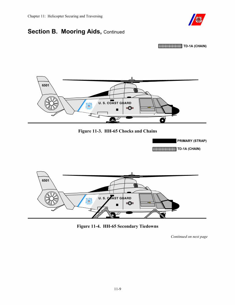
Chapter 11: Helicopter Securing and Traversing
11-9
Section B. Mooring Aids, Continued
Figure 11-3. HH-65 Chocks and Chains
Figure 11-4. HH-65 Secondary Tiedowns
Continued on next page
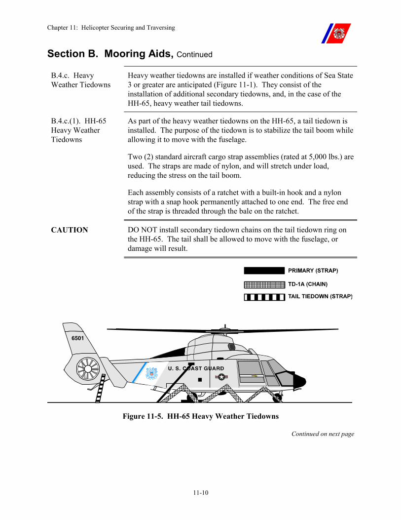
Chapter 11: Helicopter Securing and Traversing
11-10
Section B. Mooring Aids, Continued
B.4.c. Heavy Weather Tiedowns
Heavy weather tiedowns are installed if weather conditions of Sea State 3 or greater are anticipated (Figure 11-1). They consist of the installation of additional secondary tiedowns, and, in the case of the HH-65, heavy weather tail tiedowns.
B.4.c.(1). HH-65 Heavy Weather Tiedowns
As part of the heavy weather tiedowns on the HH-65, a tail tiedown is installed. The purpose of the tiedown is to stabilize the tail boom while allowing it to move with the fuselage.
Two (2) standard aircraft cargo strap assemblies (rated at 5,000 lbs.) are used. The straps are made of nylon, and will stretch under load, reducing the stress on the tail boom.
Each assembly consists of a ratchet with a built-in hook and a nylon strap with a snap hook permanently attached to one end. The free end of the strap is threaded through the bale on the ratchet.
CAUTION DO NOT install secondary tiedown chains on the tail tiedown ring on the HH-65. The tail shall be allowed to move with the fuselage, or damage will result.
Figure 11-5. HH-65 Heavy Weather Tiedowns
Continued on next page
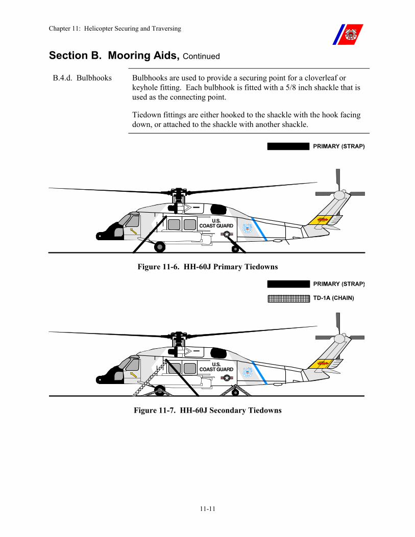
Chapter 11: Helicopter Securing and Traversing
11-11
Section B. Mooring Aids, Continued
B.4.d. Bulbhooks Bulbhooks are used to provide a securing point for a cloverleaf or keyhole fitting. Each bulbhook is fitted with a 5/8 inch shackle that is used as the connecting point.
Tiedown fittings are either hooked to the shackle with the hook facing down, or attached to the shackle with another shackle.
Figure 11-6. HH-60J Primary Tiedowns
Figure 11-7. HH-60J Secondary Tiedowns
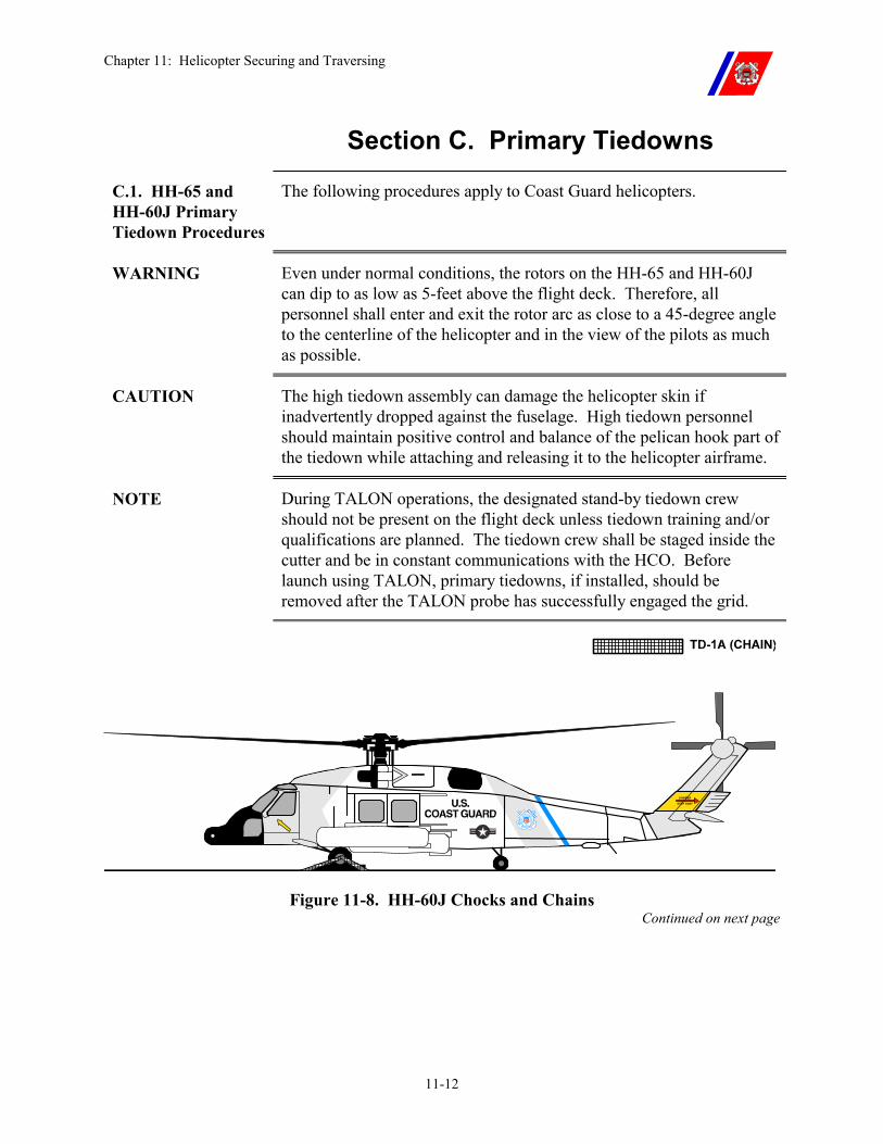
Chapter 11: Helicopter Securing and Traversing
11-12
Section C. Primary Tiedowns
C.1. HH-65 and HH-60J Primary Tiedown Procedures
The following procedures apply to Coast Guard helicopters.
WARNING Even under normal conditions, the rotors on the HH-65 and HH-60J can dip to as low as 5-feet above the flight deck. Therefore, all personnel shall enter and exit the rotor arc as close to a 45-degree angle to the centerline of the helicopter and in the view of the pilots as much as possible.
CAUTION The high tiedown assembly can damage the helicopter skin if inadvertently dropped against the fuselage. High tiedown personnel should maintain positive control and balance of the pelican hook part of the tiedown while attaching and releasing it to the helicopter airframe.
NOTE During TALON operations, the designated stand-by tiedown crew should not be present on the flight deck unless tiedown training and/or qualifications are planned. The tiedown crew shall be staged inside the cutter and be in constant communications with the HCO. Before launch using TALON, primary tiedowns, if installed, should be removed after the TALON probe has successfully engaged the grid.
Figure 11-8. HH-60J Chocks and Chains Continued on next page
Chapter 11: Helicopter Securing and Traversing
11-13
Section C. Primary Tiedowns, Continued
C.2. Tiedown General Procedures
Upon landing, high tiedowns and low tiedowns are installed simultaneously to secure the helicopter to the deck as rapidly as possible.
For takeoff, low tiedowns are removed before high tiedowns because they do not have the positive release mechanism and frequently are difficult to disconnect. Therefore, the helicopter can remain tied down (with the high tiedowns) while the low tiedowns are removed.
Although tiedown crewmembers operate from positions beside the hangar or superstructure (and within line of sight of and on either side of the LSO) they are staged inside of the cutter until needed.
The deck ends of the primary tiedowns are not attached in advance. Each tiedown crewmember selects an appropriate deck fitting, and attaches the deck end, as part of the tiedown installation process.
When the tiedowns are removed, the deck end of the tiedown is also disconnected
The specific deck fittings used are chosen so that, when installed, the forward tiedown on each side tends forward as close to a 45-degree angle from vertical as possible, and the aft tiedown on each side tends aft as close to a 45-degree angle from vertical as possible.
C.2.a. High Tiedown Overhaul
The following steps are used to overhaul the high tiedowns:
�� Reset the pelican hook. Ensure that it is latched properly. �� Completely unwind the strap from the bale of the ratchet, adjust the
strap so that approximately 1 1/2 feet of it is through the bale, and crank the ratchet until the strap is wound at least one full turn around the bale. This prevents strap slippage through the bale during installation and will ensure that there is sufficient room left on the bale to take up any slack.
�� Release the tensioner on the pelican hook and pull enough strap through the pelican hook so that the tiedown assembly can reach the helicopter tiedown point with the helicopter positioned anywhere in the landing circle.
�� Fake out the strap in approximately 4-foot lengths, and gather it up along with the pelican hook, holding them in one hand, with the hook of the deck end in the other. Hold onto the tiedown assembly in this manner during all landings.
Continued on next page
Chapter 11: Helicopter Securing and Traversing
11-14
Section C. Primary Tiedowns, Continued
C.2.b. Low Tiedown Overhaul
The following steps are used to overhaul the low tiedowns:
�� Completely unwind the strap from the bale of the ratchet. �� Pull enough strap through the bale so that the tiedown assembly can
reach the helicopter tiedown point with the helicopter positioned anywhere in the landing circle.
�� Close the ratchet handle, making sure the strap can be pulled freely through the bale.
�� Fake out the strap in approximately 4-foot lengths, and gather it up along with the ratchet, holding them in one hand, with the hook of the deck end in the other. Hold onto the tiedown assembly in this manner during all landings.
C.2.c. HH-65 High Tiedown Procedures
The high tiedown assemblies attach to the high tiedown mooring rings on the helicopter. (See Figure 11-2.)
The tensioner on the pelican hook is open when it is installed so the slack in the strap may be pulled out quickly and easily.
Continued on next page
Chapter 11: Helicopter Securing and Traversing
11-15
Section C. Primary Tiedowns, Continued
C.2.c.(1). HH-65 High Tiedown Installation
Upon receiving the “Install Tiedowns” signal from the LSO:
�� The high tiedown crewmembers proceed, in a crouch (approaching at a 45-degree angle to the helicopter in the pilots view), to the appropriate deck fitting (outboard and aft of the helicopter high mooring ring), and
�� Install the deck end of the primary tiedown, then �� Attach the high tiedowns, �� Pull the slack out of the straps at the pelican hook (while
maintaining positive control of the hook), �� Close the tensioner, and �� Secure the excess strap with half hitches, then �� Move to the deck end of the strap and ratchet out any slack that
might have developed, and �� Proceed forward to a position outboard of the low tiedown
crewmembers (outboard of the cockpit (pilot’s) doors).
When signaled by the LSO, all the tiedown crewmembers return to their position by departing at a 45-degree angle to the helicopter to their position on either side of the hangar or superstructure.
C.2.c.(2). HH-65 High Tiedown Removal
Upon receiving the first “Remove Tiedowns” signal from the LSO:
�� The high tiedown crewmembers proceed, in a crouch (approaching 45-degrees to the helicopter position and in the pilots view), to a position aft of the high tiedowns, then
�� Support the pelican hook with their inboard hand, �� Place their outboard hand on the quick release handle, and watch
the LSO, then �� Upon observing both low tiedowns removed, the LSO gives a
second “Remove Tiedowns” signal, and the high tiedown crewmembers release their pelican hook assemblies, and
�� Gather up the strap, �� Pick up the deck end of the tiedown, and
�� Move forward to a position outboard of the cockpit (pilots’) doors.
When signaled by the LSO, all the tiedown crewmembers return to their position by departing at a 45-degree angle to the helicopter to their position on either side of the hangar or superstructure.
Chapter 11: Helicopter Securing and Traversing
11-16
Section C. Primary Tiedowns, Continued
C.2.d. HH-65 Low Tiedown Procedures
The low tiedown assemblies attach to the forward low tiedown mooring rings on the helicopter. (See Figure 11-2.)
C.2.d.(1). HH-65 Low Tiedown Installation
Upon receiving the “Install Tiedowns” signal from the LSO:
�� The low tiedown crewmembers proceed, in a crouch (approaching at a 45-degree angle to the helicopter and in the pilots view), to the appropriate deck fitting (outboard and forward of the helicopter low mooring ring), and
�� Install the deck end of the primary tiedown, then �� Attach the low tiedowns to the helicopter, �� Pull the excess slack in the straps through the bales in the ratchets,
leaving enough slack in the strap to get at least one (1) full turn around the bale (this will prevent the strap from slipping),
�� Ratchet the straps tight, and �� Secure the excess strap with half hitches. �� The tiedown crewmembers crouch just outboard of the cockpit
(pilot’s) doors, watching the LSO.
When signaled by the LSO, all the tiedown crewmembers return to their position by departing the helicopter at a 45-degree angle to their position on either side of the hangar or superstructure.
C.2.d.(2). HH-65 Low Tiedown Removal
Upon receiving the first “Remove Tiedowns” signal from the LSO:
�� The low tiedown crewmembers proceed, in a crouch (approaching at a 45-degree angle to the helicopter and in the view of the pilots), to the helicopter, and
�� Disconnect the low tiedowns. �� The LSO, observing both low tiedowns removed, gives a second
“Remove Tiedowns” signal. �� The low tiedown crewmembers gather up the straps, and �� Pick up the deck ends of the tiedowns.
When signaled by the LSO, all the tiedown crewmembers return to their position by departing the helicopter at a 45-degree angle to their position on either side of the hangar or superstructure.
Continued on next page
Chapter 11: Helicopter Securing and Traversing
11-17
Section C. Primary Tiedowns, Continued
C.2.e. HH-60J High Tiedown Procedures
The high tiedown assemblies attach to the high tiedown mooring rings on the helicopter. (See Figure 11-6.)
The tensioner on the pelican hook is open when it is installed so the slack in the strap may be pulled out quickly and easily.
C.2.e.(1). HH-60J High Tiedown Installation
Upon receiving the “Install Tiedowns” signal from the LSO:
�� The high tiedown crewmembers proceed, in a crouch (approaching at a 45-degree angle to the helicopter and in the view of the pilots), to the appropriate deck fitting (outboard and forward of the helicopter high mooring ring), and
�� Install the deck end of the primary tiedown, then �� Attach the high tiedowns, �� Pull the slack out of the straps at the pelican hook, �� Close the tensioner, and �� Secure the excess strap with half hitches, then �� Move to the deck end of the strap and ratchet out any slack that
might have developed, and �� Then await the arrival of the low tiedown crewmembers.
When signaled by the LSO, all the tiedown crewmembers return to their position departing at a 45-degree angle to the helicopter to their positions on either side of the hangar or superstructure.
Continued on next page
Chapter 11: Helicopter Securing and Traversing
11-18
Section C. Primary Tiedowns, Continued
C.2.e.(2). HH-60J High Tiedown Removal
Upon receiving the first “Remove Tiedowns” signal from the LSO:
�� The high tiedown crewmembers proceed, in a crouch (approaching at a 45-degree angle to the helicopter and in the view of the pilots), to a position aft of the high tiedowns,
�� Support the pelican hook with their inboard hand, place their outboard hand on the quick release handle, and watch the LSO
�� Upon observing both low tiedowns removed, the LSO gives a second “Remove Tiedowns” signal, then
�� The high tiedown crewmembers release their pelican hook assemblies,
�� Gather up the strap, �� Pick up the deck end of the tiedown, and await the arrival of the
low tiedown crewmembers.
When signaled by the LSO, all the tiedown crewmembers return to their position by departing at a 45-degree angle to the helicopter to their positions on either side of the hangar or superstructure.
Continued on next page
Chapter 11: Helicopter Securing and Traversing
11-19
Section C. Primary Tiedowns, Continued
C.2.f. HH-60J Low Tiedown Procedures
The low tiedown assemblies attach to the aft low tiedown mooring rings on the helicopter. (See Figure 11-6.)
C.2.f.(1). HH-60J Low Tiedown Installation
Upon receiving the “Install Tiedowns” signal from the LSO:
�� The low tiedown crewmembers proceed, in a crouch (approaching at a 45-degree angle to the helicopter and in the view of the pilots), to the appropriate deck fitting (outboard and aft of the helicopter low mooring ring), and
�� Install the deck end of the primary tiedown, �� Attach the low tiedowns to the helicopter, �� Pull the excess slack in the straps through the bales in the ratchets,
leaving enough slack in the strap to get at least one full turn around the bale (this will prevent the strap from slipping),
�� Ratchet the straps tight, and �� Secure the excess strap with half hitches. �� Proceed forward to a position outboard of the cockpit (pilot’s)
doors.
When signaled by the LSO, the tiedown crewmembers return to their position by departing at a 45-degree angle to the helicopter to their positions on either side of the hangar or superstructure.
C.2.f.(2). HH-60J Low Tiedown Removal
Upon receiving the first “Remove Tiedowns” signal from the LSO:
�� The low tiedown crewmembers proceed, in a crouch (approaching at a 45-degree angle to the helicopter and in the view of the pilots), to the helicopter, and disconnect the low tiedowns.
�� The LSO, observing both low tiedowns removed, gives a second “Remove Tiedowns” signal.
�� The low tiedown crewmembers gather up the straps, �� Pick up the deck ends of the tiedowns, and �� Move forward to a position outboard of the high tiedown
crewmembers (outboard of the cockpit (pilot’s) doors), watching the LSO.
When signaled by the LSO, all of the tiedown crewmembers return to their position by departing at a 45-degree angle to the helicopter to their positions on either side of the hangar or superstructure.
Continued on Next Page
Chapter 11: Helicopter Securing and Traversing
11-20
Section C. Primary Tiedowns, Continued
C.2.g. Primary Tiedown Malfunctions
The HH-65 is considered tied down when one (1) tiedown (either a low or a high one) is installed on each side. The HH-60J must have both high tiedowns installed.
A hazardous situation will result if a malfunction of one of these critical tiedowns prevents installation, and only one side of the helicopter is effectively tied down. If this occurs, the LSO may have to immediately signal for the removal of all tiedowns (situation dependent.) After all tiedowns have been removed, the pilot requests and shall be cleared for immediate takeoff by the LSO.
C.2.g.(1). Malfunction During Installation
If the tiedown has mechanically failed and cannot be attached, the tiedown crewmember should display the tiedown to the LSO, and take it back when signaled to return to the ready position by the LSO.
C.2.g.(2). Malfunction During Removal
If a tiedown malfunctions during removal, the tiedown crewmember should attempt to disconnect it as follows:
�� High Tiedown: Loosen the strap by releasing the tensioner on the pelican hook, or by releasing the ratchet at the deck end of the tiedown assembly.
If directed by the LSO, cut the strap as close as possible to the pelican hook. Lift the hook out of the helicopter mooring ring.
�� Low Tiedown: If the ratchet cannot be released, at the direction of the LSO, cut the strap between the ratchet assembly and the helicopter.
C.2.g.(3). Replacing a Malfunctioning Tiedown
A malfunctioning tiedown shall be replaced before the next takeoff or landing evolution. A spare tiedown shall be made up and available.
Continued on Next Page
Chapter 11: Helicopter Securing and Traversing
11-21
Section C. Primary Tiedowns, Continued
C.3. TALON TALON is the preferred tiedown system for the HH-65. TALON is a pilot-activated system that replaces the primary tiedowns. (See Chapter 6, Paragraph E.7.a for further details.)
NOTE During TALON operations, designated tiedown crew shall not be present on the flight deck unless considered essential for safety due to weather, aircraft emergency, or when conducting tiedown crew proficiency training.
Before launch using TALON, primary tiedowns, if installed, should be removed after successful engagement of TALON probe.
C.3.a. Tiedown Crew Availability
Although not stationed on the flight deck, tiedown crewmen shall be immediately available in case of a mechanical failure with the TALON system. Consequently, four (4) individuals currently qualified as tiedown crewmen, shall be designated in the cutter’s Helicopter Operations Bill as standby tiedown personnel during helicopter operations involving TALON. The following are additional requirements:
�� The designated personnel shall dress out in all required flight deck clothing with the exception of the helmet and life vest, which shall be immediately available.
The designated personnel shall stage in an area that is readily accessible to the flight deck and remain on station throughout flight quarters. The Helicopter Operations Bill shall specify where these personnel are to stage and the means by which the HCO can call them to flight deck if needed.
C.3.b. TALON Probe Failure to Engage
If the TALON probe fails to engage due to equipment malfunction, the pilot may request, and at the Commanding Officer’s discretion, be cleared by the LSO, for immediate takeoff.
The HCO shall notify the standby tiedown crew. The tiedown crewmen shall don helmets and vests and proceed to their stations on either side of the hangar or superstructure.
The helicopter shall be recovered using primary tiedown procedures.
The pilot may, at his or her discretion, opt to remain on deck to await the tiedown team.
Continued on Next Page
Chapter 11: Helicopter Securing and Traversing
11-22
Section C. Primary Tiedowns, Continued
C.4. Chocks and Chains
Primary tiedowns for U.S. Navy helicopters operating aboard Coast Guard Cutters, and for Coast Guard helicopters operating aboard U.S. Navy ships, consist of wheel chocks, and tiedown chains.
Tiedowns are installed as depicted in NWP 3-04.1, and this Chapter, Figure 11-3 (HH-65) and Figure 11-8 (HH-60J).
When installing “chocks and chains,” the chocks are installed first. The chains are then attached to the mooring rings on the landing gear, and tightened. When removing “chocks and chains,” the chains are removed first.
WARNING Primary tiedown chains shall not be attached to any mooring rings other than those on the landing gear. Chains attached to the fuselage with the rotor turning can cause ground resonance.
NOTE If conditions dictate, pilots may elect to leave the chocks in place during takeoff.
Chapter 11: Helicopter Securing and Traversing
11-23
Section D. Secondary Tiedowns
D.1. Secondary Tiedown Use
Secondary tiedowns provide additional security for extended time on deck and are attached after the rotor and engines have been shut down, and shall be removed before the pilots get into the aircraft.
D.2. Secondary Tiedown Installation
The installation of secondary tiedowns on U.S. Navy helicopters shall be in accordance with NWP 3-04.1.
The installation of secondary tiedowns on Coast Guard HH-65 helicopters shall be in accordance with Figure 11-4.
The installation of secondary tiedowns on Coast Guard HH-60J helicopters shall be in accordance with Figure 11-7. This tiedown scheme provides the most possible number of tiedowns for the HH-60J and shall not be construed as meeting the requirements for securing the HH-60J for heavy weather.
WARNING With the extended pylon and left outboard external tank installed on the HH-60J, tiedown personnel will be required to step between the left main wheel and the external tank to install secondary tiedowns.
Caution shall be exercised when doing so, as some combinations of ship motion may cause the left main wheel strut to compress sufficiently to allow left external tank contact with the deck and/or possibly cause injury to tiedown personnel.
CAUTION To preclude airframe damage from uneven bending moments applied to the flexible composite construction of the HH-65, variations to the secondary tiedown attachment pattern are not authorized.
Continued on next page
Chapter 11: Helicopter Securing and Traversing
11-24
Section D. Secondary Tiedowns, Continued
D.3. Secondary Tiedown Procedures
�� The turnbuckles are attached to the helicopter mooring rings with the release mechanisms on top and the hooks pointing down.
�� Chains are led both fore and aft at approximately a 45-degree angle, and are connected to the deck tiedown points (bar type fittings) or the bulb hooks (cloverleaf fittings), with the hooks facing down.
�� Before attaching secondary tiedowns, the turnbuckle is extended to the full length.
�� The chain is connected to the turnbuckle so the bitter end of the chain comes out the top. This ensures a direct load transfer from the turnbuckle to the chain.
�� For the HH-65, the forward low primary tiedowns shall be replaced with secondary tiedowns.
�� For the HH-65, the aft high primary tiedown shall be left attached when secondary tiedowns are installed.
�� For the HH-60J, the aft low primary tiedown shall be replaced with secondary tiedowns.
�� For the HH-60J, a secondary tiedown shall be attached to the forward high tiedown ring, then forward primary shall be lead aft, and ensuring no part of the pelican hook or strap contacts any part of the aircraft.
Chapter 11: Helicopter Securing and Traversing
11-25
Section E. Heavy Weather Tiedowns
E.1. Heavy Weather Tiedown Use
If heavy weather sea states (Figure 11-1) or extended periods of inactivity are anticipated, additional tiedowns are installed, rotor blades are folded or removed, and (depending on the model of helicopter) strut collars are installed.
WARNING The HH-60J cannot be traversed, hangared, or secured for heavy weather. Commanding Officers shall evacuate the HH-60J ashore or deviate around significant weather systems. Damage or loss of the aircraft is likely in seas above Sea State 3 (see Figure 11-1 for details).
E.2. Heavy Weather Tiedown Installation
�� The installation of heavy weather tiedowns on Navy helicopters shall be in accordance with NWP 3-04.1.
�� The installation of heavy weather tiedowns on Coast Guard HH-65 helicopters shall be in accordance with Figure 11-5.
�� Heavy weather tiedowns on Coast Guard HH-60J helicopters have not been developed.
�� The Navy uses the Recovery Assist Secure and Traverse (RAST) system to land, secure, and traverse the H-60. Coast Guard Cutters do not have this system installed.
�� Secondary tiedowns applied in accordance with Figure 11-7 are sufficient up to Sea State 3 for HH-60Js.
�� Blade folding or removal and installation of strut collars shall be in accordance with the appropriate helicopter maintenance manual.
E.3. Heavy Weather Tiedown Procedures
E.3.a. General Additional tiedown chains are installed using the procedures described in Section D of this chapter.
Continued on next page
Chapter 11: Helicopter Securing and Traversing
11-26
Section E. Heavy Weather Tiedowns, Continued
E.3.b. HH-65 Heavy Weather Tiedown Procedures
�� The heavy weather tail tiedown ratchets are attached to the mooring ring under the tail boom of the helicopter, and the hooks on the straps are attached to the deck (bar type sockets), or to the bulb hooks (cloverleaf fittings) with the hooks facing down.
�� The straps are led outward and slightly aft to clear the lateral fins, at approximately a 45-degree angle from the vertical.
�� All slack is removed from the straps, but they are NOT TENSIONED.
CAUTION DO NOT install secondary tiedown chains on the tail tiedown ring on the HH-65. The tail shall be allowed to move with the fuselage, or damage will result.
Chapter 11: Helicopter Securing and Traversing
11-27
Section F. Blade Security
F.1. Overview The combination of wind and cutter motion induces main rotor blade movement, creating vibration feedback throughout the rotor and flight control systems. Shipboard deployment experience has shown that this can significantly increase the failure rate of rotor and flight control components.
F.2. Blade Tip Covers (Socks)
Anytime an HH-65 helicopter is expected to remain on deck for longer than 30-minutes with relative winds greater than 10-knots, or anytime the winds are expected to exceed 20-knots, blade socks should be installed.
Refer to the appropriate helicopter maintenance manual for proper installation procedures.
F.3. Blade Restrainers
The main rotor blades will be secured with the main rotor blade restrainer set anytime a HH-60J helicopter is to remain on deck for an extended period of time, or when actual or forecast winds exceed 45-knots Blade clamps will be installed and secured using tiedown cables.
F.4. Blade Folding Blade folding provides increased protection against damage from wind or deck motion.
On cutters with hangars, blade folding is required to hangar the helicopter (except WAGB 399 cutters, where one (1) helicopter is deployed).
Blade folding should be performed as a normal routine at the completion of the day’s flight operations.
The Maintenance Procedure Card (MPC) for each helicopter type describes the appropriate procedure.
WARNING Relative wind and cutter motion shall be minimized to reduce the hazards inherent in blade folding and unfolding.
Blade folding and unfolding in excess of established limits shall not be attempted.
Continued on next page
Chapter 11: Helicopter Securing and Traversing
11-28
Section F. Blade Security, Continued
F.4.a. Blade Folding and Unfolding Procedures
Refer to the appropriate helicopter flight handbook and maintenance manual for both manual and automatic blade folding and unfolding procedures.
F.4.b. Blade Folding Limitations
The MPC of each helicopter type establishes the limitations to conduct this evolution. The following limitations are established in the absence of any MPC limitations:
�� Wind is less than 45-knots and; �� Pitch is less than 3-degrees and roll is less than 10-degrees.
Blade folding shall not be conducted if any one of these parameters is exceeded. During all blade folding operations, a minimum of four (4) personnel are required. Consideration should be given to increasing personnel involved as the upper limits are approached.
WARNING When working near the rotor head, the use of the cranial assembly is highly recommended. A pitching or rolling deck, wet or icy surfaces, and low illumination levels all increase the chance of slips or falls. Falling from the height of rotor head could result in serious injury or death.
F.5. Blade Removal On ships not equipped with hangars, blade removal provides the best protection against damage from wind and deck motion, and may be an acceptable alternative to blade folding.
WARNING To reduce the hazards inherent in blade removal and reinstallation, relative wind and cutter motion shall be minimized. Blade removal and reinstallation in excess of established limits shall not be attempted.
F.5.a. Blade Removal and Reinstallation Procedures
Refer to the appropriate helicopter flight handbook and maintenance manual for blade removal and reinstallation procedures.
F.5.b. Blade Removal Limitations
These procedures are used when relative wind is less than 45-knots, pitch is less than 3-degrees, and roll is less than 10-degrees.
Blade removal shall not be conducted if any one of these parameters is exceeded. During all blade removal operations, a minimum of four (4) personnel are required.
As the upper limits are approached, serious consideration should be given to increasing personnel involved.
Chapter 11: Helicopter Securing and Traversing
11-29
Section G. Traversing
G.1. Hangar Equipped Cutters
Hangaring the helicopter significantly reduces corrosion and provides a safer working environment for maintenance. The helicopter shall be hangared routinely at the end of each day’s operations (unless LANTAREA or PACAREA directives provide an exception based on operational necessity).
The helicopter is normally traversed from the flight deck into the hangar by the AVDET with assistance from cutter personnel. Traversing is a relatively simple and safe operation when conducted by trained personnel using the proper equipment.
However, if care is not exercised during the operation, personnel can be injured and the helicopter damaged.
G.2. Non-Hangar Equipped Cutters
The necessity for moving a helicopter on the deck of a non-hangar equipped cutter is rare, and the movements involved will be small in comparison to those required on hangar equipped cutters. Movement should be restricted as much as is deemed safe by the Senior Aviator and Commanding Officer.
All other procedures shall be the same as on hangar equipped cutters.
G.3. Helicopter Manual Traversing
Manual traversing occurs when the helicopter is moved using either a motorized tow bar or a hand guided steering bar with personnel pushing the helicopter.
G.3.a. Traversing Crew Organization
The following personnel are required to manually traverse a helicopter (Figure 11-9).
Number of Personnel Deck Handling Crew Position
1 Flight Deck Director (FDD) 1 Driver 1 Brake Rider 4 Push crewmember 2 Tiedown crewmember
Figure 11-9 Traversing Crew Organization Continued on next page
Chapter 11: Helicopter Securing and Traversing
11-30
Section G. Traversing, Continued
G.3.a.(1). Flight Deck Director (FDD)
The flight deck director (FDD) is responsible for safely traversing the helicopter, and is in charge on the flight deck during the operation. The FDD supervises all preparations, and directs the movement and the security of the helicopter.
The FDD shall be one (1) of the pilots or the senior enlisted member of the AVDET. When a helicopter must be moved in an emergency situation and the authorized FDDs from the AVDET are not aboard and cannot be reached, the LSO, if designated by the Command, may perform this duty as long as any member of the AVDET is present.
Designation should be based on flight operations experience.
G.3.a.(2). Brake Rider (BR)
The brake rider (BR) sits in the pilot’s seat with seat belt and shoulder harness fastened. The BR operates the main wheel brakes and the nose/tail wheel locking pin during the operation. The BR shall respond instantly to all stop signals, and shall be constantly alert to the signals of the FDD.
The BR shall wear an inflatable life jacket and a cranial or helmet whenever the helicopter is moved.
The BR shall normally be a member of the AVDET.
G.3.a.(3). Tiedown Crew
The tiedown crew tends the tiedowns during the operation, and responds to the commands of the FDD.
G.3.a.(4). Push Crew The push crew provides the power required to move the helicopter. The size of the crew depends upon the weight of the helicopter.
For the HH-65, a minimum of four (4) pushers are required; one (1) at each of the pilot and copilot forward door frames, and one (1) at each of the main cabin forward door frames.
WARNING Due to the flexible composite construction of the HH-65, only these positions may be used to push the helicopter.
G.3.a.(5). Driver The driver operates the helicopter steering bar or motorized tow bar to position the helicopter.
The driver shall normally be a member of the AVDET. Continued on next page
Chapter 11: Helicopter Securing and Traversing
11-31
Section G. Traversing, Continued
G.3.b. Traversing Preparation
In preparation to traverse the helicopter, the cutter is maneuvered to provide minimum flight deck motion.
All involved personnel are equipped with whistles.
The FDD:
�� Inspects the hangar and traversing areas to ensure all trip hazards and potential obstructions are removed,
�� The hangar is fully retracted, and �� The hangar door completely open.
The FDD ensures that portable ramps (if required) are in place, and if necessary, the helicopter’s rotor blades have been folded or removed. The brake rider straps into the pilot’s seat.
WARNING Energizing or de-energizing fin stabilizers or making large inputs to the helm can cause unexpected and excessive flight deck motion.
The FDD shall be notified of any requirement to energize or de-energize fins or maneuver the cutter, and the helicopter shall be immediately secured with secondary tiedowns.
G.3.c. Traversing Communications
Communications while traversing are by voice and whistle commands.
The FDD shall obtain permission from the bridge before moving the helicopter.
Anyone recognizing a dangerous situation gives the STOP signal (one (1) long blast on the whistle) and the helicopter is immediately stopped, the parking brake set, and the tiedowns secured. The START signal (two (2) short blasts on the whistle) and all other commands are given only by the FDD.
G.3.d. Normal Traversing (Walking Tiedowns)
These procedures are used when the relative wind velocity is 45-knots or less, pitch is 4-degrees or less, and roll is 8-degrees or less.
Continued on next page
Chapter 11: Helicopter Securing and Traversing
11-32
Section G. Traversing, Continued
G.3.d.(1). Traversing Coast Guard Helicopters
�� Secondary and low primary tiedowns are removed. �� FDD checks that all personnel are ready. �� Two (2) tiedown crewmembers tend the pelican hooks (in place)
and the deck ends of the high tiedowns. �� All personnel must have whistles in their mouths so that their hands
may be free to operate equipment. �� FDD orders “nose (tail) wheel unlocked.” The brake rider unlocks
the wheel, and the driver checks that the wheel swivels freely. �� FDD orders “parking brake off.” The brake rider applies the toe
brakes and releases the parking brake. �� FDD orders “tiedowns off.” �� The pelican hook tensioners are released, slack is pulled into the
strap, and the deck ends are disconnected while the pelican hooks are held hooked to the helicopter.
�� FDD gives the START signal. �� The brake rider releases the toe brakes, and the push crew (or the
driver or winch operator) starts to move the helicopter into the hangar.
�� As the helicopter is traversed, the tiedown crewmembers walk alongside, keeping track of the closest deck mooring points.
�� The driver steers the helicopter into the hangar, keeping it centered over the hangar guideline.
�� When the helicopter is in position, the FDD gives the STOP signal. �� The brake rider applies the toe brakes and parking brake. �� The tiedowns are attached to the deck, the slack is pulled out of the
straps, and the tensioners are locked. After additional tiedowns are installed, the nose/tail wheel is locked and the steering bar is removed.
WARNING When a motorized tow bar or hand-held steering bar is not available, the nose/tail wheel shall remain locked to provide directional stability.
Except on WAGBs, the helicopter should never be turned athwartships.
NOTE Chocks are not normally used when traversing a Coast Guard helicopter.
Continued on next page
Chapter 11: Helicopter Securing and Traversing
11-33
Section G. Traversing, Continued
G.3.d.(2). Traversing Navy Helicopters
�� All but four (4) TD-1A tiedown assemblies are removed. �� FDD checks that all personnel are ready. �� Two (2) tiedown crewmembers tend a chock and TD-1A tiedown
assembly each, and two (2) other tiedown crewmembers tend an additional TD-1A assembly each.
�� All personnel must have their whistles in their mouths, so that their hands are free to operate equipment.
�� FDD orders “nose (tail) wheel unlocked.” The brake rider unlocks it, and the driver checks that the wheels swivel freely.
�� FDD orders “parking brake off.” The brake rider applies the toe brakes and releases the parking brake.
�� FDD orders “tiedowns off.” The tiedowns are loosened, then disconnected, and reset.
�� FDD gives the START signal. �� The chocks are removed. �� The brake rider releases the toe brakes, and the push crew (or the
driver) starts to move the helicopter into the hangar. �� As the helicopter is traversed, the tiedown crewmembers walk
alongside, keeping track of the closest deck mooring points. �� The driver steers the helicopter into the hangar, keeping it centered
over the hangar guideline. �� When the helicopter is in position, the FDD gives the STOP signal, �� the brake rider applies the toe brakes and parking brake, and the
chocks are installed. �� The tiedowns are attached and tightened between the nearest deck
fittings and the helicopter’s mooring rings. After additional tiedowns are installed, the nose/tail wheel is locked and the steering bar is removed.
WARNING
When a motorized tow bar or hand held steering bar is not available, the nose/tail wheel shall remain locked to provide directional stability.
Except on WAGBs, the helicopter should never be turned athwartships.
NOTE Traversing with Navy helicopters or Coast Guard helicopters on Navy ships will require two (2) additional tiedown crewmembers to tend TD-1A's and chocks.
Continued on next page
Chapter 11: Helicopter Securing and Traversing
11-34
Section G. Traversing, Continued
G.3.d.(3). Traversing on WAGBs
When two (2) helicopters are deployed on an icebreaker, the spotting sequence is dependent upon the design of the hangar and the flight deck. Each icebreaker should outline the preferred sequence in its Helicopter Operations Bill. Information required to develop this bill will be provided and updated during POPDIV deployments.
In all cases, flight deck clearance requirements shall be met.
Normal traversing of helicopters is authorized only when the icebreaker is transiting in the open ocean, through sea ice, or breaking first year ice. A risk assessment shall review the totality of the on-scene conditions, to include ice coverage, ice thickness, and anticipated conditions in making this decision. The FDD shall obtain permission from the OOD before traversing the helicopter.
WARNING Helicopters shall not be traversed on WAGBs while the cutter is breaking multi-year solid (fast) ice or while breaking or transiting through ice at night. If there is any doubt that the normal traversing procedures will not provide adequate safety to the helicopter and crew given the on-scene or anticipated conditions, then the helicopter shall be traversed when the icebreaker is hove-to in the ice.
G.3.e. Heavy Weather Traversing Procedures (Progressive Chains)
These procedures are used when:
�� The relative wind is greater than 45-knots, �� Pitch is greater than 4-degrees, or �� Roll is greater than 8-degrees.
NOTE Heavy weather traversing will require two (2) additional tiedown crewmembers to tend TD-1As.
At least four (4) TD-1A tiedown assemblies shall be attached to the helicopter and the deck at all times
Continued on next page
Chapter 11: Helicopter Securing and Traversing
11-35
Section G. Traversing, Continued
G.3.e.(1). Heavy Weather Traversing Procedures
�� Primary high tiedowns are removed (Coast Guard helicopters only). �� FDD checks that all personnel are ready.
�� Four (4) tiedown crewmembers tend a TD-1A tiedown assembly each.
�� All personnel must have their whistles in their mouths, so that their hands are free to operate equipment.
�� FDD orders “nose (tail) wheel unlocked”, the brake rider unlocks it, and the driver checks that the wheels swivels freely.
�� FDD orders “parking brake off.” The brake rider applies the toe brakes and releases the parking brake.
�� FDD orders “aft leading tiedowns off.” �� The tiedown crew loosens, releases, and overhauls the four (4)
tiedowns that tend aft. �� The forward tiedowns are loosened slightly and reset, but are
left installed. �� Enough slack should be induced to allow the aft tiedowns to
become taut first, but not so much that safety is compromised. �� FDD gives the START signal, two (2) short blasts on the whistle.
�� The brake rider releases the toe brakes, and �� The push crew moves the helicopter forward until the tiedowns
that were tending forward are tending aft. �� The driver steers the helicopter into the hangar, keeping it
centered over the hangar guideline. �� Before the tiedowns becoming taut, the FDD, or anyone on the
flight deck gives the STOP signal, one (1) blast of the whistle, and the brake rider applies the toe brakes and parking brake. �� The forward tending tiedowns are reinstalled and tightened.
The above steps are repeated until the helicopter is in position in the hangar. After additional tiedowns are installed, the nose/tail wheel is locked and the steering bar is removed.
CAUTION When being moved, ensure that the chains are in a position so as not to foul any part of the aircraft structure when tightened.
WARNING Use of a motorized tow bar during heavy weather traversing is prohibited. When a hand held steering bar is not available, the nose wheel shall remain locked to provide directional stability.
Continued on next page

Chapter 11: Helicopter Securing and Traversing
11-36
Section G. Traversing, Continued
G.4. Automated Helicopter Traversing
Automated helicopter traversing occurs when the helicopter is moved using shipboard installed traversing equipment. Currently this equipment is not installed on Coast Guard Cutters.
Chapter 11: Helicopter Securing and Traversing
11-37
Section H. Helicopter Security and Fire Checks
H.1. Overview The Senior Aviator is responsible for the security of the helicopter.
He or she shall ensure that security and fire checks are made periodically to confirm the helicopter is riding well, no fuel leaks exist, the flight deck or hangar is clear of unauthorized personnel, and any other potentially hazardous situation does not exist.
When conditions dictate, the Senior Aviator shall arrange for a live watch in the hangar.
H.2. Security on WAGBs
Security and fire checks are normally made by the Aviation Department on an icebreaker. The heavy-weather hangar watch is normally manned by an aviation rate. However, the hangar area shall be included in the normal security checks conducted by the Boatswain’s Mate of the Watch (BMOW), and any unusual conditions or occurrences shall immediately be reported to the Senior Aviator.
H.3. Security on WHECs and WMECs
Because so few aviation personnel are embarked or deployed on WHECs or WMECs, the security and fire checks, as well as the hangar watch (if required) are normally made by the cutter’s crew.
This does not relieve the Senior Aviator of the responsibility for the safety and security of the helicopter. Any unusual conditions or occurrences shall immediately be reported to the Senior Aviator.
H.3.a. Duties of the Officer of the Deck (OOD)
The following duties shall be performed by the OOD:
�� Supervise the security and fire checks. �� Keep informed of the current and forecast weather and its effect on
helicopter security. Initiate precautions and advise the senior aviator.
�� Initiate appropriate action to fight fires or alleviate any other dangerous condition that may be reported.
�� Order the smoking lamp out: �� On all weather decks during flight operations. �� On all weather decks during helicopter fueling operations. �� For helicopter engine washes. �� For helicopter maintenance ground runs. �� Within 50-feet of the helicopter.
Continued on next page
Chapter 11: Helicopter Securing and Traversing
11-38
Section H. Helicopter Security and Fire Checks, Continued
H.3.b. Duties of the First Lieutenant
The following duties shall be performed by the First Lieutenant:
�� Instruct the BMOW in: �� Use of firefighting equipment. �� Methods of turning on a fire alarm. �� The need to check helicopter security frequently.
�� Keep informed of the forecast weather and take precautions as required in the absence of the Senior Aviator.
�� Provide personnel and equipment to secure or move the helicopter, or to fold the blades.
H.3.c. Duties of the BMOW
The BMOW shall perform security checks of the helicopter and flight deck area during normal rounds, checking the following:
�� Ensure that the helicopter is properly secured. �� Ensure the telescoping hangar section closest to the helicopter tail is
chained down if the telescoping hangar braking system is not serviceable or heavy weather is expected. The telescoping hangar section shall be secured using TD-1As to mooring points on the hangar deck.
�� Enforce the no smoking regulations. �� Inspect the helicopter’s tiedowns for proper tension and make
minor adjustments as required. �� Report any unusual conditions to the OOD immediately. �� Report all fuel or oil leaks to the OOD, and break out firefighting
equipment. Clean up the spill. �� Immediately report any fires to the OOD, using all possible means
to attract attention and obtain help. After ensuring that the word is passed, if possible, confine and combat the fire until released by the damage control party.
Chapter 12: Shipboard Helicopter Maintenance
12-i
CHAPTER 12: SHIPBOARD HELICOPTER MAINTENANCE Table of Contents
Introduction.............................................................................................................................. 12-1
In this chapter .......................................................................................................................... 12-1
Section A. Pre-Deployment Maintenance ............................................................................. 12-2
A.1. General ............................................................................................................................. 12-2
Section B. Helicopter Support Kit......................................................................................... 12-3
B.1. General ............................................................................................................................. 12-3
Section C. WHEC and WMEC Deployments....................................................................... 12-4
C.1. General ............................................................................................................................. 12-4
Section D. WAGB Deployments ............................................................................................ 12-5
D.1. General ............................................................................................................................. 12-5
Section E. Deployment Maintenance..................................................................................... 12-6
E.1. Responsibility................................................................................................................... 12-6
E.2. Aircraft Flight Record (CG-4377) ................................................................................. 12-6
E.3. Scheduled Maintenance .................................................................................................. 12-6 E.3.a. Long Deployment Maintenance .........................................................................................12-6 E.3.b. Short Deployment Maintenance .........................................................................................12-6 E.3.c. Maintenance Procedure Cards (MPC)................................................................................12-7 E.3.d. Maintenance Extensions.....................................................................................................12-7
E.4. Corrosion Prevention...................................................................................................... 12-7
E.5. Special Inspections .......................................................................................................... 12-7
E.6. Maintenance Runs........................................................................................................... 12-7
E.7. Maintenance Flights........................................................................................................ 12-8
E.8. Helicopter Craning.......................................................................................................... 12-8
E.9. Maintenance Weather..................................................................................................... 12-8

Chapter 12: Shipboard Helicopter Maintenance
12-ii
Chapter 12: Shipboard Helicopter Maintenance
12-1
Chapter 12. Shipboard Helicopter Maintenance
Introduction Anytime a deployed or embarked helicopter is grounded, a valuable mission asset is lost.
Every effort should be made to provide an airframe that will require a minimum of maintenance.
Tools, parts, and mechanics should be provided for those times when maintenance is required.
The degree of maintenance capability provided will depend upon the length of the deployment and the quality of the aviation facility provided by the cutter.
In this chapter This chapter is divided into five (5) sections:
�� Section A: Pre-Deployment Maintenance �� Section B: Helicopter Support Kit (HSK) �� Section C: WHEC and WMEC Deployments �� Section D: WAGB Deployments �� Section E: Deployment Maintenance

Chapter 12: Shipboard Helicopter Maintenance
12-2
Section A. Pre-Deployment Maintenance
A.1. General Pre-deployment maintenance should include any maintenance that might come due during the deployment that is difficult to perform on a cutter.
In addition, measures should be taken to protect the helicopter from corrosion.
Chapter 12: Shipboard Helicopter Maintenance
12-3
Section B. Helicopter Support Kit
B.1. General A helicopter support kit (HSK), tailored to the specific maintenance requirements of the model of helicopter deployed and the length of the deployment, shall be provided on the cutter. The unit providing the HSK and the Senior Aviator are responsible for the HSK and must ensure that all required items are available.
Hangars shall be used primarily as a secure aircraft work and storage facility while aircraft are embarked. Common traffic and health and well-being equipment placement shall be coordinated through the Senior Aviator.
Chapter 12: Shipboard Helicopter Maintenance
12-4
Section C. WHEC and WMEC Deployments
C.1. General Deployments aboard WHEC and WMEC cutters are usually not more than 45-days, with one (1) helicopter, two (2) pilots, and two (2) or three (3) aircrew.
Maintenance requirements include:
�� Routine line servicing �� Corrosion control �� Minor repairs
On WMEC 270 cutters, facilities are provided for storage, removal, and installation of major components.
Chapter 12: Shipboard Helicopter Maintenance
12-5
Section D. WAGB Deployments
D.1. General Deployments aboard icebreakers may last as long as six (6) months, with up to two (2) helicopters, four (4) pilots, and 10 aircrew including one (1) Chief Petty Officer.
Maintenance requirements include:
�� Routine line servicing �� Corrosion control �� Repairs �� Component replacement
A more extensive HSK should be carried and consist of:
�� Assemblies �� Components �� Parts �� Supplies �� Accessories �� Tools �� Publications
The AVDET will be operating independently of any other ready source of supply most of the time and should be self-sufficient.
Chapter 12: Shipboard Helicopter Maintenance
12-6
Section E. Deployment Maintenance
E.1. Responsibility The Senior Aviator is responsible for maintenance of the deployed aircraft. The parent unit will normally provide technical assistance and parts support.
E.2. Aircraft Flight Record (CG-4377)
Before any departure, Part I of the Aircraft Flight Record shall be completed and signed to indicate that preflight and servicing requirements have been accomplished.
Part III of the form is a record of discrepancies and maintenance for each helicopter.
Completed Part I records shall be retained for a period of 90-days, and Part III records for a period of 12-months.
E.3. Scheduled Maintenance
Coast Guard helicopter maintenance inspections are scheduled at regular calendar intervals, except when flight hours are considered the critical scheduling factor.
Hourly and calendar inspection criteria are set forth in the Aircraft Computerized Maintenance System (ACMS) Maintenance Due List (MDL). ACMS provides a means of forecasting and monitoring the overall maintenance effort for the helicopter.
E.3.a. Long Deployment Maintenance
The current Coast Guard Logs and Records company will provide a six (6) month projection of maintenance requirements for each designated helicopter before deployment.
�� The parent air station shall provide the current Coast Guard Logs and Records Company with the helicopter side number, departure date, and cutter address.
�� MDLs and associated MPCs will be mailed directly to the cutter during deployments, if necessary. The parent Air Station will monitor duplicate MDLs.
E.3.b. Short Deployment Maintenance
Parent air stations will receive 90-day maintenance projections.
Continued on next page
Chapter 12: Shipboard Helicopter Maintenance
12-7
Section E. Deployment Maintenance, Continued
E.3.c. Maintenance Procedure Cards (MPC)
In either case, the requirement to return the MPCs to the current Coast Guard Logs and Records company via the parent Air Station remains the same.
Conscientious use of the ACMS during deployments is essential to the continuous and effective maintenance management provided by the current Coast Guard Logs and Records company.
E.3.d. Maintenance Extensions
Where provisions are made for extending the prescribed maintenance period, cutter Commanding Officers are authorized to do so based upon the recommendations of the Senior Aviator.
E.4. Corrosion Prevention
Corrosion is a major concern for the helicopter AVDET. Measures shall be taken to keep the helicopter clean and free of salt.
�� At the end of each day’s operation, an engine wash is required, and should be completed even if there is a shortage of fresh water on board.
�� The airframe should be washed, and the helicopter hangared.
In freezing conditions, approved cleaning compounds should be used in lieu of water.
E.5. Special Inspections
It may be necessary to increase the frequency of required periodic inspections when on a cutter due to the hostile environment.
E.6. Maintenance Runs
Maintenance engine or APU runs shall, at a minimum;
�� Have permission from the OOD. �� CCTV on and monitored. �� One (1) engine operating at a time.
Maintenance runs with rotor head engagement shall, at a minimum;
�� Have permission from the OOD. �� CCTV on and monitored. �� Have LSO on station. �� Have one (1) fire party on station with fire hose laid out or the
fire-monitor manned; �� Maintain amber deck when rotor below 100% NR.
Chapter 12: Shipboard Helicopter Maintenance
12-8
Section E. Deployment Maintenance, Continued
E.7. Maintenance Flights
Maintenance flights shall be conducted in accordance with the Air Operations Manual, COMDTINST M3710.1 (series).
While in flight, the helicopter shall be kept in sight by the cutter at all times, and the cutter shall remain at FLICON ONE to facilitate rapid recovery of the helicopter in the event of an emergency.
The Air Operations Manual, COMDTINST M3710.1 (series), sets the VMC weather condition for flight verification checks and test flights and is defined in Chapter 5 of this manual.
E.8. Helicopter Craning
Craning of helicopters off cutters or other vessels shall be in accordance with the aircraft’s home Air Station directives. The cutter shall be briefed and training held for those crewmembers involved to prevent further damage.
E.9. Maintenance Weather
The Air Operations Manual, COMDTINST M3710.1 (series), establishes the VMC weather requirement for flight verification checks and test flights. Those requirements are also defined in Chapter 5 of this manual.
Chapter 13: Water Salvage Operations
13-i
CHAPTER 13: WATER SALVAGE OPERATIONS Table of Contents
Introduction.............................................................................................................................. 13-1
In this chapter .......................................................................................................................... 13-1
Section A. Salvage Responsibilities ....................................................................................... 13-2
A.1. Overview .......................................................................................................................... 13-2
Section B. Salvage Personnel ................................................................................................. 13-3
B.1. Salvage Officer ................................................................................................................ 13-3
B.2. Divers................................................................................................................................ 13-3
B.3. Salvage Support Personnel............................................................................................. 13-3
B.4. Salvage Safety .................................................................................................................. 13-3 B.4.a. Personnel Safety .................................................................................................................13-3 B.4.b. Composite Material Safety..................................................................................................13-4
Section C. Salvage Equipment ............................................................................................... 13-5
C.1. Overview .......................................................................................................................... 13-5
Section D. Salvage Priorities .................................................................................................. 13-6
D.1. Overview .......................................................................................................................... 13-6
Section E. Salvage Procedures ............................................................................................... 13-7
E.1. Overview .......................................................................................................................... 13-7
E.2. Preserving Buoyancy....................................................................................................... 13-7
E.3. Craning............................................................................................................................. 13-7
E.4. Towing.............................................................................................................................. 13-7 E.4.a. Helicopter Towing - Upright ..............................................................................................13-8 E.4.b. Helicopter Towing - Inverted .............................................................................................13-8
E.5. Scavenging ....................................................................................................................... 13-9
E.6. Scuttling ........................................................................................................................... 13-9 E.6.a. Scuttling Procedure.............................................................................................................13-9

Chapter 13: Water Salvage Operations
13-ii
Section F. Salvage Special Considerations.......................................................................... 13-10
F.1. Overview......................................................................................................................... 13-10
Chapter 13: Water Salvage Operations
13-1
Chapter 13. Water Salvage Operations
Introduction The goal of every water salvage operation is to recover the airframe with as little damage as possible.
After the helicopter ditches and the crew has been rescued, every effort should be made to recover the airframe before it sinks.
�� If the helicopter remains upright, and the conditions are calm, it may be possible to recover it with little or no damage.
�� If the helicopter becomes inverted, the damage will be far more severe, and the risk of its sinking greatly increased.
Despite any damage, the helicopter is a vital source of information for determining the cause of the ditching and its salvage should be aggressively pursued.
In this chapter This chapter is divided into six (6) sections:
�� Section A: Salvage Responsibilities �� Section B: Salvage Personnel �� Section C: Salvage Equipment �� Section D: Salvage Priorities �� Section E: Salvage Procedures �� Section F: Salvage Special Considerations
Chapter 13: Water Salvage Operations
13-2
Section A. Salvage Responsibilities
A.1. Overview The cutter Commanding Officer is responsible for ensuring proper implementation of the salvage operation as the cognizant authority of the aircraft while deployed. In some cases, this may include coordination of the accident investigation and maintaining control until properly relieved. As with any investigation, continuity and proper chain of custody are paramount in such cases.
In cases of great distances from CONUS, this support is essential, and may require significant logistical support.
Chapter 13: Water Salvage Operations
13-3
Section B. Salvage Personnel
B.1. Salvage Officer A Salvage Officer will be assigned to supervise the recovery of the airframe.
The Aviation Engineering Officer from the parent air station is normally assigned as the Salvage Officer. However, until relieved on scene, the Senior Aviator or designee will act as the Salvage Officer.
B.2. Divers Qualified divers are required any time the helicopter is inverted. Only divers are authorized to enter an inverted helicopter.
Refer to Diving Policies and Procedures, COMDTINST 10560.4 (series), for specific guidance regarding use.
B.3. Salvage Support Personnel
The Salvage Officer will determine what additional personnel are required for the salvage operation.
B.4. Salvage Safety The mishap site presents many hazards, not all of that are associated with the aircraft itself. All hazards that could endanger personnel, the aircraft, its cargo, the environment, the site, the ship and salvage operation must be identified and protective measures taken. Prevention of additional damage to the aircraft and/or cutter is important to the salvage operation. However, it is secondary to the safety of personnel.
NOTE For additional information or guidance on handling of aircraft hazardous materials, refer to local directives, or:
�� Aeronautical Engineering Maintenance Management Manual, COMDTINST 13020.1(series)
�� NATOPS U. S. Navy Aircraft Fire Fighting and Rescue Manual, NAVAIR 00-80R-14
�� General Advanced Composite Repair Manual, AFTO (Air Force Technical Order) 1-1-690
B.4.a. Personnel Safety
Numerous hazards, both obvious and insidious, exist at a crash site. Most obvious are the fire and explosive hazards due to fuel, oils, hydraulics, battery fluids, ammunition, pyrotechnics, and the residuals they leave behind after the fire is extinguished. Not so obvious are the compressed gas cylinders such as fire extinguishing bottles, nitrogen blow down bottles for landing gear activation, landing gear oleo struts, and various accumulators.
Chapter 13: Water Salvage Operations
13-4
Section B. Salvage Personnel, Continued
WARNING Personnel shall remain upwind of crash and salvage sites or wear the appropriate protective equipment until the composite fibers have been contained. Inhalation of composite fibers resulting from aircraft fires and/or aircraft damage may be harmful to personnel. In any case, handling of broken, shredded, or mangled composite materials shall be minimized with handlers wearing gloves. See Chapter 14 for specific Personnel Protective Equipment (PPE) recommendations.
B.4.b. Composite Material Safety
In addition to the hazards above, composite materials release microscopic carbon fibers to the atmosphere when broken, shredded, or mangled. Aircraft and composite aircraft parts shall be contained by the use of polyurethane primer, spray lacquer, liquid floor wax, or light oils to achieve bonding. All facilities and equipment exposed to debris from the aircraft fire shall be vacuumed and/or washed down. Decontamination vacuuming should be conducted using industrial vacuums collected in sealed plastic (garbage) bags and disposed with locally established procedures or provided to the accident board.
Chapter 13: Water Salvage Operations
13-5
Section C. Salvage Equipment
C.1. Overview Special equipment required for the salvage of each model of helicopter is described in the appropriate maintenance manual.
This equipment should be locally manufactured and maintained on each WAGB (for the principal model of helicopter) and at air stations with helicopters assigned.
Chapter 13: Water Salvage Operations
13-6
Section D. Salvage Priorities
D.1. Overview The following priorities should be applied to any salvage operation:
�� Recover the airframe without further damage. �� Accept additional damage to the airframe in lieu of its loss. �� Scavenge as many components as possible off the airframe in the
face of its impending loss. �� Scuttle the helicopter rather than abandon it if circumstances
dictate.
Chapter 13: Water Salvage Operations
13-7
Section E. Salvage Procedures
E.1. Overview Specific salvage procedures for each helicopter model are given in their respective maintenance manuals. The manuals will normally be provided by the Salvage Officer assigned for each incident (AVDET Engineering Officer for WAGB deployments).
E.2. Preserving Buoyancy
The first step is to keep the helicopter from sinking.
If conditions permit, the first vessel on scene should add flotation (flotation collars, inflatable flotation bags, inflatable life rafts, boat fenders, etc.) to the helicopter.
Once positive buoyancy is assured, the salvage operation can proceed.
E.3. Craning Before attempting to lift the helicopter, the Salvage Officer shall ensure that the capacity of the crane exceeds the weight of the helicopter. A minimum capacity of 50 percent greater than the maximum gross weight of the helicopter is recommended.
If possible, the rotor blades should be removed, and the helicopter righted before being picked up. As the helicopter is lifted, water must be allowed to drain out. Otherwise, the capacity of the crane might be exceeded.
For specific procedures, refer to the appropriate helicopter maintenance manual or parent Air Station directive.
E.4. Towing It may be advantageous to tow the helicopter, either to a more sheltered area or to a rendezvous with a salvage vessel.
Helicopters may be towed either upright or inverted; however, inverted helicopters will require additional flotation.
The following procedures are provided as a guide. For specific procedures, refer to the appropriate helicopter maintenance manual.
Continued on next page
Chapter 13: Water Salvage Operations
13-8
Section E. Salvage Procedures, Continued
E.4.a. Helicopter Towing - Upright
Whether the helicopter is towed forward or backward depends on the helicopter model, wind and sea conditions, and the condition of the airframe.
�� Check the helicopter for watertight integrity. Add flotation if necessary to preserve buoyancy.
�� Rig a sea drogue to the helicopter to provide directional stability during the tow.
�� If possible, lower the landing gear to lower the center of gravity of the helicopter.
�� Remove the rotor blades, if practical. �� Rig a towing bridle to the helicopter at the specific points
designated for towing, and connect it to the towing hawser. �� Tow the helicopter at the slowest possible speed. �� To reduce the risk of capsizing, avoid towing the helicopter parallel
to the trough of the waves. �� Make all turns slow and wide to reduce the risk of capsizing. �� If towing at night, rig a light to the helicopter. �� Closely monitor the helicopter for changes in buoyancy.
E.4.b. Helicopter Towing - Inverted
An inverted helicopter can be towed using the same procedures prescribed for an upright helicopter. However, the risk of an inverted helicopter sinking is much greater, and, consequently, every effort shall be made to maintain positive buoyancy. Additionally, an inverted helicopter has a much greater draft. The depth of water shall be closely monitored to avoid grounding and further damaging the airframe.
Continued on next page
Chapter 13: Water Salvage Operations
13-9
Section E. Salvage Procedures, Continued
E.5. Scavenging If conditions or available facilities do not permit salvage of the entire helicopter, as many component parts as possible should be saved.
Scavenging shall be conducted with extreme caution, with a major emphasis on the safety of the personnel.
Safety lines should be attached to both the helicopter and the salvage personnel, and additional flotation should be added to increase buoyancy. After these steps have been taken, personnel in boats and/or divers can attempt to strip electronic and other readily accessible components from the helicopter.
Priority shall be given to the removal of classified equipment and/or material.
WARNING Scavenging is very hazardous, and should only be attempted in reasonable sea and weather conditions, and only after all reasonable safety precautions have been taken.
Only qualified divers shall be allowed to scavenge an inverted helicopter.
E.6. Scuttling If circumstances require that the helicopter be abandoned, and classified equipment and/or material remain aboard, the helicopter should be scuttled.
If time permits, authorization should be obtained from Commandant (G-OCA) before scuttling the helicopter.
E.6.a. Scuttling Procedure
�� Before sinking the helicopter, all safety or tending lines shall be removed.
�� Destroy the buoyancy by rupturing flotation and breaching compartments holding fuel or air.
Chapter 13: Water Salvage Operations
13-10
Section F. Salvage Special Considerations
F.1. Overview Each helicopter accident is examined in minute detail to determine the cause.
�� Both a legal investigation and a flight safety analysis are conducted. Examination of the helicopter following an accident is an important part of these proceedings.
�� Recovery of as many parts as possible is vital to an accurate investigation.
�� It is also important that as little damage or deformation as possible result from the salvage operation, as this could be easily confused with accident damage and lead to erroneous conclusions. Where additional damage or deformation cannot be avoided, it should be marked on the airframe, if feasible, and recorded in a log.
�� The record should include the names of the individuals involved, so they can be interviewed later concerning the condition of the helicopter before salvage.
Chapter 14: Flight Deck Fire Fighting
14-i
CHAPTER 14: FLIGHT DECK FIRE FIGHTING Table of Contents
Introduction.............................................................................................................................. 14-1
In this chapter .......................................................................................................................... 14-1
Section A. General Flight Deck Fire Fighting Information ................................................ 14-2
A.1. Fire Fighting Priorities ................................................................................................... 14-2
A.2. Helicopter Familiarization ............................................................................................. 14-3
A.3. Equipment Familiarization ............................................................................................ 14-3
Section B. Classification of Fires ........................................................................................... 14-4
B.1. Overview .......................................................................................................................... 14-4
B.2. Class A Fires .................................................................................................................... 14-4
B.3. Class B Fires .................................................................................................................... 14-8
B.4. Class C Fires .................................................................................................................... 14-8
B.5. Class D Fires .................................................................................................................... 14-8
Section C. General Hazards and Precautions ..................................................................... 14-10
C.1. Overview ........................................................................................................................ 14-10
C.2. Class A Combustibles ................................................................................................... 14-10
C.3. Pyrotechnics and Ordnance ......................................................................................... 14-10
C.4. Composite Materials ..................................................................................................... 14-10 C.4.a. Composite Materials Reinforced with Carbon Graphite Fibers.......................................14-11 C.4.b. Composite Materials Reinforced with Boron Tungsten Fibers .......................................14-12 C.4.c. Special Hazard Prevention Measure Involving Composite Material Fires ......................14-12
C.4.c.(1). Composite Material Immediate Action ...........................................................14-13 C.4.c.(2). Composite Material Extinguishing..................................................................14-13 C.4.c.(3). Composite Material Interim Containment.......................................................14-13 C.4.c.(4). Composite Material Special Protective Gear ..................................................14-14 C.4.c.(5). Composite Material Cleanup...........................................................................14-14
Section D. Fire Fighting Agents ........................................................................................... 14-15
D.1. Overview ........................................................................................................................ 14-15
Chapter 14: Flight Deck Fire Fighting
14-ii
D.2. Aqueous Film Forming Foam (AFFF)......................................................................... 14-15 D.2.a. AFFF Fire Fighting Efficiency.........................................................................................14-15 D.2.b. AFFF Application ............................................................................................................14-16
D.3. HALON.......................................................................................................................... 14-16 D.3.a. HALON Fire Fighting Efficiency ....................................................................................14-17 D.3.b. HALON Application........................................................................................................14-17
D.4. Carbon Dioxide (CO2) .................................................................................................. 14-18 D.4.a. CO2 Fire Fighting Efficiency ...........................................................................................14-18 D.4.b. CO2 Application...............................................................................................................14-18
D.5. Purple K Powder (PKP) ............................................................................................... 14-19 D.5.a. PKP Fire Fighting Efficiency...........................................................................................14-19 D.5.b. PKP Application ..............................................................................................................14-19
Section E. Fire Fighting Equipment.................................................................................... 14-20
E.1. Overview ........................................................................................................................ 14-20
E.2. Crash Kit........................................................................................................................ 14-20
E.3. Proximity Suits .............................................................................................................. 14-21 E.3.a. Proximity Suit Outer Garment..........................................................................................14-21
E.3.a.(1). Proximity Suit Outer Garment Maintenance...................................................14-22 E.3.b. Proximity Suit Liners .......................................................................................................14-22
E.3.b.(1). Proximity Suit Liner Maintenance ..................................................................14-22 E.3.c. Proximity Suit Face Shield ...............................................................................................14-23
E.3.c.(1). Proximity Suit Face Shield Maintenance ........................................................14-23 E.3.d. Proximity Suit Glove Liners.............................................................................................14-23
E.3.d.(1). Proximity Suit Glove Liner Maintenance .......................................................14-23
E.4. Fire Extinguishers ......................................................................................................... 14-23
E.5. Primary Hose Stations .................................................................................................. 14-24
E.6. Secondary Hose Station ................................................................................................ 14-24
Section F. Fire Party Organization ..................................................................................... 14-25
F.1. On-Scene Leader (OSL)................................................................................................ 14-25
F.2. Primary Hose Teams ..................................................................................................... 14-25
F.3. Secondary Hose Team................................................................................................... 14-25
F.4. Rescue Crew................................................................................................................... 14-26 F.4.a. Rescue Crew Function ......................................................................................................14-26 F.4.b. Hot Refueling Fire Guard .................................................................................................14-26
Chapter 14: Flight Deck Fire Fighting
14-iii
F.5. Engine Start Fire Guard, HH-65/HH-60J................................................................... 14-26
F.6. Engine Start Fire Guard, Other Helicopters .............................................................. 14-26
Section G. Crash With Class B Fire .................................................................................... 14-27
G.1. Overview ........................................................................................................................ 14-27
G.3. Flight Deck Fire Monitor Initial Response When Hose Teams Are Not Manned .. 14-27
G.4. Class B Fire Initial Response ....................................................................................... 14-28 G.4.a. On-Scene Leader (OSL)...................................................................................................14-28 G.4.b. Hose Teams......................................................................................................................14-29 G.4.c. Rescuemen .......................................................................................................................14-30 G.4.d. Cockpit Evacuation ..........................................................................................................14-32 G.4.e. Cabin Entry ......................................................................................................................14-32 G.4.f. Forced Entry .....................................................................................................................14-33
Section H. Other Fires .......................................................................................................... 14-34
H.1. Engine Compartment Fire During Start .................................................................... 14-34
H.2. Battery Fire.................................................................................................................... 14-34
H.3. Electrical Fire ................................................................................................................ 14-35
Section I. Jettisoning the Helicopter.................................................................................... 14-36
I.1. Overview.......................................................................................................................... 14-36

Chapter 14: Flight Deck Fire Fighting
14-iv
Chapter 14: Flight Deck Fire Fighting
14-1
Chapter 14. Flight Deck Fire Fighting
Introduction The purpose of this chapter is to provide information pertinent to firefighting procedures and the rescue of personnel following a helicopter crash on a cutter. Some of the information is specific in nature, while the remainder is in general terms so it may be adjusted to the needs and operating requirements of the cutter. Additional information can be found in the NATOPS Aircraft Fire Fighting and Rescue Manual (NAVAIR 00-80R-14 (series)).
In this chapter This chapter is divided into nine (9) sections:
�� Section A: General Flight Deck Fire Fighting Information �� Section B: Classification of Fires �� Section C: General Hazards and Precautions �� Section D: Fire Fighting Agents �� Section E: Fire Fighting Equipment �� Section F: Fire Party Organization �� Section G: Crash With Class B Fire �� Section H: Other Fires �� Section I: Jettisoning the Helicopter
Chapter 14: Flight Deck Fire Fighting
14-2
Section A. General Flight Deck Fire Fighting Information
A.1. Fire Fighting Priorities
The OSL shall determine the priorities for fighting the fire.
�� If the helicopter is carrying ordnance (other than small arms ammunitions), it shall be kept cool to keep it from exploding, with a hose being dedicated to each piece of ordnance.
�� Helicopter occupants may be incapacitated or trapped in the wreckage, and shall be rescued as soon as possible. Until they are rescued, they shall be protected from the fire and heat by pushing the flames back away from the helicopter.
�� The helicopter may be carrying several hundred gallons of fuel that may allow the fire to spread rapidly to other areas of the cutter. A blanket of foam shall be laid down on top of the fuel to keep the fire from spreading. The fire shall be extinguished as rapidly as possible to minimize damage.
Generally, the following priorities apply:
�� Cool ordnance �� Protect helicopter occupants �� Extract helicopter occupants �� Contain the fire �� Extinguish the fire
WARNING Detonation of ordnance on the helicopter poses the greatest danger to the cutter and personnel. When the helicopter is known to have ordnance, the first priority shall be to cool the ordnance.
NOTE Jettisoning the helicopter shall only be accomplished as a last resort, and normally only when ordnance is involved, or in the case of Class D fires.
Continued on next page
Chapter 14: Flight Deck Fire Fighting
14-3
Section A. General Flight Deck Fire Fighting Information, Continued
A.2. Helicopter Familiarization
It is vital that the fire party is thoroughly familiar with the helicopter. In this regard, there is no substitute for frequent hands-on training. Training should consist of:
�� Component familiarization (airframe construction, location of personnel)
�� Interior access �� Location of ordnance and pyrotechnics �� Battery location and disconnect procedure �� Location of fuel bladders and other sources of combustible fluids �� Auxiliary flotation equipment �� Helicopter danger areas �� Location of shut-off switches and levers in the helicopter, etc. �� Periodic crash drills
Figures 14-1 and 14-2 show the location of the emergency exits on Coast Guard helicopters.
A.3. Equipment Familiarization
Pre-planning for emergencies is extremely important. All members of the fire party shall be familiar with their duties, and with the equipment used in fighting a flight deck fire. Sound knowledge of the equipment’s designed capabilities and limitations will minimize the time required to bring an emergency under control.
Chapter 14: Flight Deck Fire Fighting
14-4
Section B. Classification of Fires
B.1. Overview A helicopter fire may consist of any or all of the four (4) Classes (A, B, C, and D). Helicopter components that support these classes of fires are:
�� The airframe construction �� The electrical and electronic components �� The fuel and lubricants �� Miscellaneous items normally carried by the helicopter
B.2. Class A Fires Class A fires on a helicopter are supported by materials such as seat cushions, soundproofing, life jackets, etc.
These fires can be extinguished by using water in either a straight stream or spray pattern.
If the fire is deep-seated, AFFF can be used as a smothering agent. Continued on next page
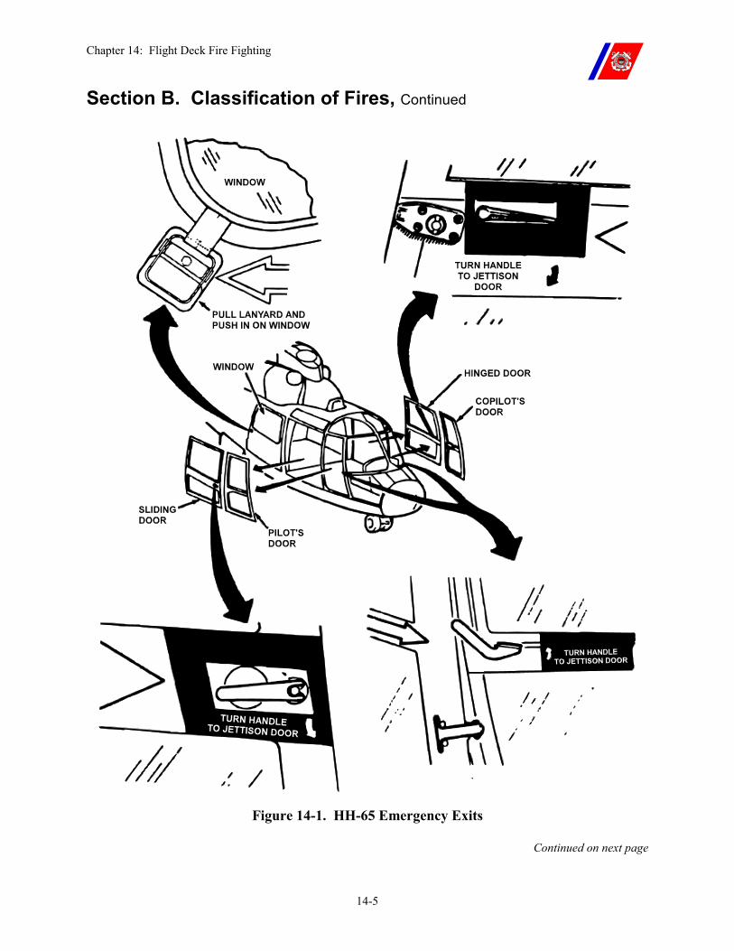
Chapter 14: Flight Deck Fire Fighting
14-5
Section B. Classification of Fires, Continued
Figure 14-1. HH-65 Emergency Exits
Continued on next page
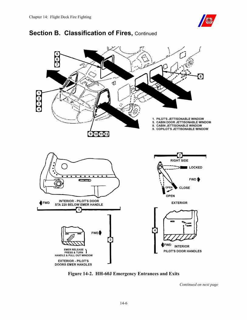
Chapter 14: Flight Deck Fire Fighting
14-6
Section B. Classification of Fires, Continued
Figure 14-2. HH-60J Emergency Entrances and Exits
Continued on next page
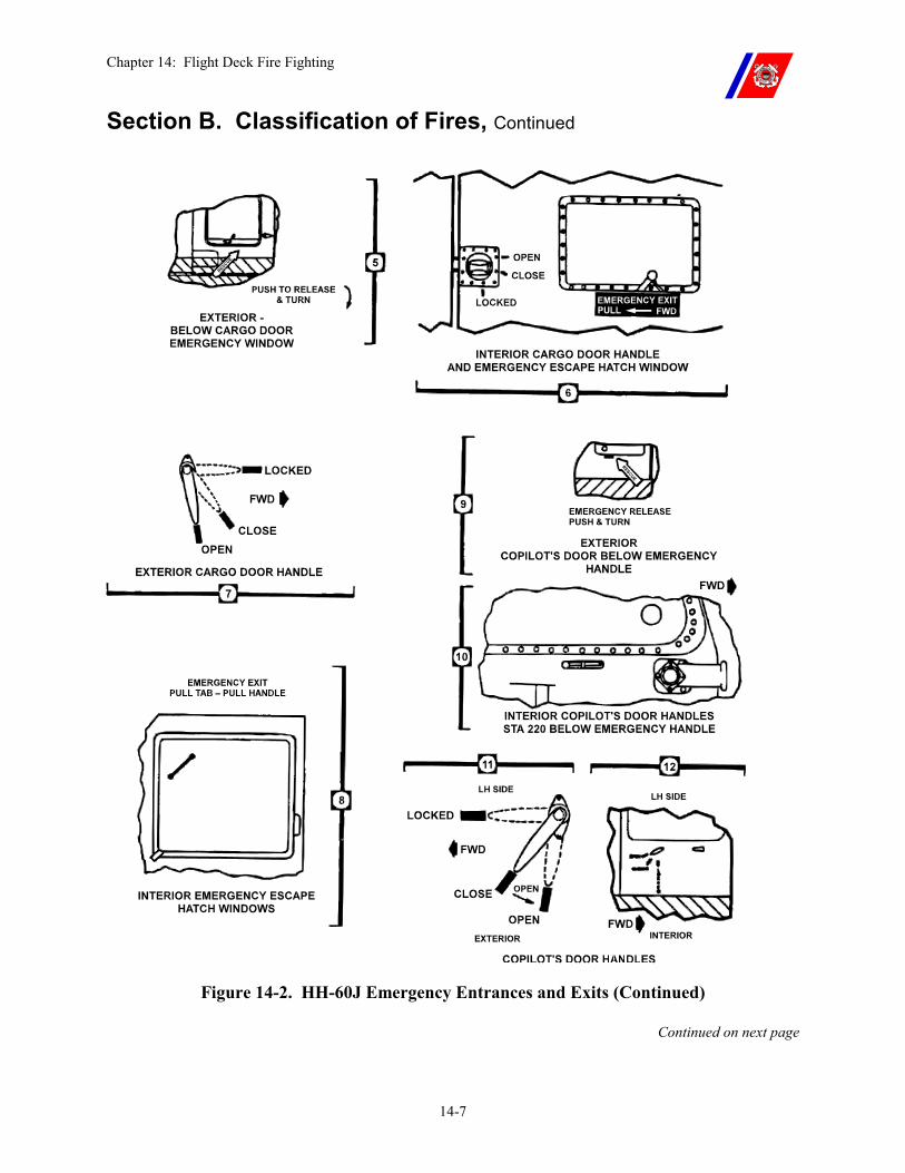
Chapter 14: Flight Deck Fire Fighting
14-7
Section B. Classification of Fires, Continued
Figure 14-2. HH-60J Emergency Entrances and Exits (Continued)
Continued on next page
Chapter 14: Flight Deck Fire Fighting
14-8
Section B. Classification of Fires, Continued
B.3. Class B Fires Class B fires are associated with the combustible liquids (fuel, oil, hydraulic fluid, grease, etc.) on helicopters. Fuel fires produce intense heat and can spread rapidly beyond the immediate flight deck area.
Fuel can be present in large quantities while hydraulic fluid, oils, and grease are present in small quantities.
These fires can be extinguished by smothering the fire using AFFF, HALON, CO2, or Purple K Powder (PKP).
B.4. Class C Fires Class C fires are associated with electrical and electronic equipment on helicopters.
These fires can be extinguished by de-energizing the electrical equipment and smothering the fire with HALON, CO2, or PKP.
WARNING Water in any form, particularly salt water, is dangerous when used on electrical equipment.
B.5. Class D Fires Class D fires are associated with combustible metals such as magnesium and titanium. These materials are used in many helicopters for weight conservation and in pyrotechnics.
Major components that may be constructed from these materials are:
�� The main transmission �� Intermediate and tail rotor �� Gear box casings �� Wheels
These materials ignite at 1200 degrees F and burn at approximately 4000 degrees F.
These fires can be extinguished by using water in large quantities from a safe distance.
Continued on next page
Chapter 14: Flight Deck Fire Fighting
14-9
Section B. Classification of Fires, Continued
WARNING To prevent eye damage, personnel should not look directly into Class D fires.
A solid stream of water should not be used because of the possibility of an explosion.
CAUTION Avoid applying AFFF on Class D Fires. AFFF is not a cooling agent. It will insulate the burning mass causing the temperature within to increase.
Chapter 14: Flight Deck Fire Fighting
14-10
Section C. General Hazards and Precautions
C.1. Overview Hazards, in addition to heat and smoke, may exist with flight deck fires.
When fighting fires, care shall be exercised to avoid exposing personnel to these hazards. Specific precautions will depend upon the materials involved.
C.2. Class A Combustibles
When helicopter cockpit and interior materials are burned or charred, they may produce toxic gases. These gases can include:
�� Carbon monoxide �� Hydrogen chloride �� Hydrogen cyanide
C.3. Pyrotechnics and Ordnance
The fire party must be aware of the type and location of all pyrotechnics and ordnance on the helicopter. These materials can detonate, even after the fire is extinguished. The OSL shall ensure that AFFF is continuously applied to these materials when exposed to the heat of a fire.
Water should not be used for cooling until the fire is extinguished, due to the tendency of water to dilute or wash away the AFFF blanket. Post-fire cooling (preferably water) shall continue for a minimum of 15-minutes to allow the material to return to a safe ambient temperature.
WARNING Extreme care shall be exercised by all personnel when fires involve pyrotechnics and/or ordnance. Personnel shall remain clear of the discharge path and exhaust blast areas of air launch weapons.
C.4. Composite Materials
A comprehensive understanding of the toxicity of fumes produced when composite materials burn is pending additional research. However, it should be presumed that the fumes are toxic because of the nature of the compounds and bonding agents used in composite construction.
WARNING Breathing smoke or fumes from composite material fires poses a serious and potentially lethal health risk to personnel.
Continued on next page
Chapter 14: Flight Deck Fire Fighting
14-11
Section C. General Hazards and Precautions, Continued
C.4.a. Composite Materials Reinforced with Carbon Graphite Fibers
Composite materials that are reinforced with carbon graphite fibers provide superior stiffness, a high strength-to-weight ratio, and ease of fabrication. As a result, this material is being used extensively in advanced aircraft to replace heavier metal components.
Carbon graphite fibers can be released into the atmosphere if their epoxy binder burns.
�� Once free, these small lightweight fibers can be transported up to several miles by air currents.
�� The fibers may penetrate human tissue and become embedded in the lungs.
�� Because of their high electrical conductivity, the fibers can also damage unprotected electrical or electronic equipment.
�� Approximately 750 degrees F will cause the epoxy binder to ignite or decompose, releasing both fiber fragments and highly toxic gases.
�� Similarly, mechanical agitation, especially an explosion, can fragment the fibers and cause them to become airborne.
The fire party shall extinguish fires involving carbon fiber reinforced composites as quickly as possible, and provide maximum containment of the debris. The containment and cleanup function is extremely important and shall be treated as a special hazard prevention measure.
Continued on next page
Chapter 14: Flight Deck Fire Fighting
14-12
Section C. General Hazards and Precautions, Continued
C.4.b. Composite Materials Reinforced with Boron Tungsten Fibers
Composite materials that are reinforced with boron tungsten fibers provide superior stiffness, a high strength to weight ratio, and ease of fabrication. They are being used to replace heavier metal components in new aircraft.
�� Boron tungsten fibers can be released into the atmosphere if their epoxy binder burns.
�� However, boron tungsten fibers pose less of a problem to unprotected electrical equipment than carbon graphite fibers because they are much heavier and thus are less likely to become airborne.
�� They are also much less electrically conductive. Loose boron tungsten fibers are stiff and sharp and thus pose handling problems.
The extinguishing, containment, and cleanup practices of boron tungsten fibers are the same as those for carbon graphite fibers.
C.4.c. Special Hazard Prevention Measure Involving Composite Material Fires
The normal sequence of events during a helicopter crash is:
�� Impact �� Fuel spill �� Ignition �� Fire or explosion
During this sequence, the release of composite fibers into the atmosphere and subsequent dispersion by smoke and air currents is very likely.
The degree of contamination (fibers released) is assumed to vary directly with the degree of the fire and force of the explosion.
WARNING In mishaps where carbon graphite fibers are suspected, helicopters shall never be used to control the fire, or be allowed to fly or hover over the site at altitudes of less than 500-feet. The rotor wash will only serve to spread the fibers.
Introduction of fibers into the helicopter’s electrical system could cause a malfunction, resulting in another serious accident.
Continued on next page
Chapter 14: Flight Deck Fire Fighting
14-13
Section C. General Hazards and Precautions, Continued
C.4.c.(1). Composite Material Immediate Action
In the event of a crash on a ship of an aircraft constructed with composite materials, the following actions shall be performed immediately to reduce hazards to personnel and equipment:
�� Secure ventilation intakes on the fantail and near the crash site. �� Maneuver the ship to direct smoke and debris away from the
superstructure and ventilation inlets.
C.4.c.(2). Composite Material Extinguishing
While the following steps are common to all flight deck fires, they take on an added importance in the case of composite material fires:
�� Approach and extinguish the fire from upwind. �� Extinguish the fire as quickly as possible. �� Maneuver the cutter to direct smoke and debris away from the
superstructure and ventilation inlets. �� After the fire is overhauled, the flight deck and all adjacent areas
shall be off-limits to personnel not directly involved in cleanup and securing of wreckage.
Rescue crewmembers shall not remove proximity suits until all parts have been rinsed with water due to the danger of composite material inhalation.
WARNING Airborne fibers from any composite system constitute a serious respiratory hazard to personnel.
C.4.c.(3). Composite Material Interim Containment
Interim containment of composite fibers is provided by spraying (wide-angle pattern) the debris with AFFF.
Containment that is more permanent is possible once the debris has cooled.
Continued on next page
Chapter 14: Flight Deck Fire Fighting
14-14
Section C. General Hazards and Precautions, Continued
C.4.c.(4). Composite Material Special Protective Gear
The following are protective gear guidelines for cleanup procedures:
�� Disposable coveralls and shoe covers may be necessary for many operations involving mishap cleanup and investigation.
�� For situations in the earlier stages of cleanup and investigation, when airborne composite levels are unknown and may be accompanied by vapors released from smoldering debris, full-face respirators, Self Contained Breathing Apparatus (SCBA), Oxygen Breathing Apparatus (OBA) should be worn.
�� For later stages of cleanup and investigation, when much of the debris has been contained and vapors are no longer being released, use of dust-fume-mist filter respirators may be appropriate.
�� Safety glasses with side shields shall be worn when full-face respirators are not used and eye contact with fibers and debris is of concern.
�� To prevent injury, gloves (leather palm preferred) shall be worn when handling any type of composite debris. If the potential exist for biohazard contamination, rubber surgical gloves should be worn under the protective leather gloves.
�� Personnel involved in cleanup, when relieved, shall remove and bag clothing for cleaning at a later date and shower thoroughly.
C.4.c.(5). Composite Material Cleanup
Cleanup will be under the direction of the Engineer Officer and the Senior Aviator as follows:
�� Maneuver the cutter so that cleanup operations are downwind of superstructure and ventilation inlets.
�� Wash down the flight deck and superstructure exposed to debris with salt water, directing the residue over the side.
�� Cover helicopter parts containing exposed composites with polyethylene sheeting, taping securely. If polyethylene sheeting is not available, as a less desirable alternative acrylic floor wax may be used as a composite fiber fixative.
�� Contaminated clothing, equipment, and helicopter parts or debris shall be vacuumed and/or washed down before further use, and before being moved inside the cutter’s structure.
�� If contamination is known or suspected to have entered the ventilation system, take immediate action to ensure that the filtration system is operating properly. If the system is not operating properly, shut it down until temporary filtration can be provided at outlets leading to compartments.
Chapter 14: Flight Deck Fire Fighting
14-15
Section D. Fire Fighting Agents
D.1. Overview Fire fighting agents available for fighting flight deck fires on Coast Guard Cutters include: AFFF, HALON, CO2, and PKP.
WARNING HALON, CO2, and PKP are all rapidly dissipated into the atmosphere. Unlike AFFF, these agents develop no vapor seal, and a fuel fire extinguished by them is likely to re-ignite.
HALON, CO2, and PKP extinguishers shall be discharged in an upright position. If the extinguisher is on its side or inverted, the siphon tube will not reach the agent, and an unsatisfactory discharge will result.
D.2. Aqueous Film Forming Foam (AFFF)
AFFF is the primary agent used to combat flight deck fires. It has proven to be a superior extinguishing agent against fuel fires.
�� AFFF concentrate consists primarily of fluorocarbon surfactant materials that are non-corrosive, and have an unlimited shelf life when stored in a protected area where the temperature ranges from 32 degrees F (0 degrees C) to 120 degrees F (48 degrees C).
�� AFFF concentrate shall meet current military specification standards (MIL-F-24385). Though AFFF concentrate by itself is non-corrosive, when mixed with seawater, the resultant AFFF solution may exhibit corrosive properties.
WARNING Failure to follow the manufacturer’s storage procedures (excessive heat or freezing) may cause AFFF to break down and separate, degrading its ability to form a vapor seal.
D.2.a. AFFF Fire Fighting Efficiency
The unique extinguishing and securing action of AFFF on flammable liquid fires results from a combination of rapid foam blanketing and vapor sealing.
When properly applied, the AFFF foam blanket rapidly yields a very thin layer of AFFF solution that floats on top of flammable liquids to extinguish the fire and form a vapor seal, which, in turn, restricts further emission of flammable vapors.
Continued on next page
Chapter 14: Flight Deck Fire Fighting
14-16
Section D. Fire Fighting Agents, Continued
D.2.b. AFFF Application
AFFF fire extinguishing efficiency is not critically dependent on the expansion of the solution.
�� It can be applied with either approved non-air aspirating nozzles or air aspirating foam nozzles.
�� However, the variable pattern fog nozzle is preferred because of the rapid pattern adjustment afforded the firefighter.
�� Additionally, these nozzles produce more AFFF foam, resulting in faster control and extinguishment of the fire.
NOTE AFFF is compatible with HALON, CO2, and PKP.
D.3. HALON HALON is a colorless, faintly sweet smelling, electrically non-conductive gas (bromochlorodifluoromethane) that leaves no residue to clean-up.
HALON is primarily used on Class B and C fires. However, it is effective on Class A fires.
Fumes from the discharge of a HALON extinguisher may produce dizziness and impaired coordination on the part of personnel. The fumes come from the natural HALON agent, and from the products of decomposition that result through exposure of the agent to the fire. Exposure to the agent is of less concern than is the exposure to the products of decomposition.
In using HALON in unventilated spaces or confined areas, operators and others should avoid breathing the gases produced by thermal decomposition.
WARNING Do not use HALON on Class D fires. It has no blanketing effect, and, if it reaches a Class D fire in the liquid state, the possibility of an explosive reaction exists.
Continued on next page
Chapter 14: Flight Deck Fire Fighting
14-17
Section D. Fire Fighting Agents, Continued
D.3.a. HALON Fire Fighting Efficiency
HALON extinguishes fires by inhibiting the chemical chain reaction of the combustion process. It is virtually non-corrosive, non-abrasive, and is at least twice as effective as CO2 on Class B fires.
HALON is five (5) times heavier than air, has the ability to penetrate hard-to-reach places, and evaporates completely, leaving no residue. HALON has a very high insulation property and has been successfully tested on electrical equipment carrying 100,000 volts.
Although the agent is retained under pressure in a liquid state and is self-expelling, a booster charge of nitrogen is added to ensure proper operation. Upon actuation, the vapor pressure causes the agent to expand so that the discharge stream consists of a mixture of liquid droplets and vapor.
D.3.b. HALON Application
Initial application shall start close to the fire. On all fires, the discharge should be directed at the base of the flames.
�� Sweep the agent stream back and forth across the leading edge of the fire, overshooting on both sides, and continue to push the leading edge of the fire back until the fire is extinguished.
These units have an effective discharge range of 10 to 30 feet, depending on ambient conditions, and a discharge time of 10 to 40 seconds, depending on the extinguisher size and application rate.
Continued on next page
Chapter 14: Flight Deck Fire Fighting
14-18
Section D. Fire Fighting Agents, Continued
D.4. Carbon Dioxide (CO2)
CO2 is a colorless, odorless gas that is approximately 1-1/2 times heavier than air.
Use of CO2 on aircraft engine fires is recommended.
CO2 is stored in rechargeable containers designed to hold pressurized carbon dioxide in liquid form at atmospheric temperatures.
WARNING Exposure to CO2 in high concentrations for extended periods can be fatal.
The use of CO2 in inert flammable atmospheres is prohibited. When a CO2 extinguisher is discharged, the liquid CO2 expanding through the nozzle and cone becomes solid (commonly called “snow”). This “snow” contacting and separating from the extinguisher cone becomes electrically charged, as does the extinguisher itself. If the charged “snow” contacts an insulated metal object, it will cause the object to become charged. Tests indicate that voltages greater than 15 kilovolts can be developed on insulated metal objects from a 1 to 2 second application of CO2 from an extinguisher. This voltage is sufficient to cause a spark, possibly resulting in an explosion.
CAUTION Agents other than CO2 may cause corrosion damage. They should be used only after the two (2) flight deck CO2 extinguishers have been fully discharged.
D.4.a. CO2 Fire Fighting Efficiency
CO2 extinguishes fires by displacing oxygen in the atmosphere to a level below the percent that is required to support combustion.
D.4.b. CO2 Application
Agent application should start at the upwind edge and be directed slowly in a side to side sweeping motion, gradually moving toward the back of the fire.
CO2 extinguishers have a limited discharge range of three (3) to eight (8) feet and a discharge time of 8 to 44 seconds, depending on the extinguisher size and application rate.
Continued on next page
Chapter 14: Flight Deck Fire Fighting
14-19
Section D. Fire Fighting Agents, Continued
D.5. Purple K Powder (PKP)
PKP is a dry chemical primarily intended for use on Class B Fires. The principal base chemical used in the production of PKP dry chemical agent, is potassium bicarbonate. Various additives are mixed with the base material to improve its stowage, flow, and water repellence characteristics.
The ingredients used in PKP are non-toxic. However, the discharge of large quantities may cause temporary breathing difficulty, may seriously interfere with visibility, and may cause disorientation.
D.5.a. PKP Fire Fighting Efficiency
The major disadvantage of PKP is that it does not produce a lasting inert atmosphere above the surface of a flammable liquid; consequently, its use will not result in permanent extinguishing if re-ignition sources are present.
PKP is an effective agent for three-dimensional fires, and is commonly used as a complementary agent in conjunction with AFFF.
Hand extinguishers can be used for mop-up of small fires in and around a helicopter.
CAUTION PKP may harden after being exposed to moisture. It is therefore important to avoid exposure to any moisture during stowage, handling, and recharging.
D.5.b. PKP Application
PKP extinguishers have a discharge range of approximately 10 to 40 feet. Discharge time varies from 8 to 60 seconds depending on extinguisher size. When used on flammable liquid fires, the powder discharge from a PKP extinguisher should be directed at the base of the flames. Best results are obtained by attacking the upwind edge of the fire and progressing forward, moving the nozzle rapidly with a side-to-side sweeping motion.
The mechanical operation of the unit shall be in accordance with the printed instructions on the extinguisher.
WARNING If PKP is directed or ingested into a helicopter engine, the aviation personnel shall be notified. PKP cannot be completely removed from a helicopter engine without disassembly to remove deposits that restrict internal cooling air passages, and reduce engine performance.
Chapter 14: Flight Deck Fire Fighting
14-20
Section E. Fire Fighting Equipment
E.1. Overview Minimum equipment and material standards for fire fighting are contained in Naval Air Warfare Center, Aircraft Division (NAVAIRWARCENACDIVLKE) Air Capable Ship Aviation Facilities Bulletin No. 1 (series) as amended by the Shipboard Helicopter Operations Facility Certification Program Manual, COMDTINST 3120.13 (series), and the Coast Guard Shipboard Aviation Allowance Equipage List (AEL). Maintenance and operation of this equipment is described in naval engineering instructions.
E.2. Crash Kit The crash kit is stored in a canvas tool roll, and shall be broken out and inspected prior to flight quarters. It contains the following tools:
�� Axe, fire (full size pick head) �� Halligan tool �� Cable cutter (with notched blade) �� Flashlight, safety, two-cell �� Hacksaw (with six spare blades) �� Knife, rescue, V-blade (with three sets of spare blades) �� Pliers, lineman �� Pliers, rib joint, water pump (10-inch) �� Saw, metal cutting �� Screwdriver, straight slot (4-inch) �� Screwdriver, straight slot (8-inch) �� Screwdriver, Phillips (4-inch) �� Screwdriver, Phillips (8-inch) �� Wrench, vice grip (10-inch) �� Wrench, adjustable (12-inch) �� Dzus key (if not on end of V-blade knife)
Continued on next page
Chapter 14: Flight Deck Fire Fighting
14-21
Section E. Fire Fighting Equipment, Continued
E.3. Proximity Suits The rescue crew wears aluminized proximity suits. The proximity suit consists of:
�� An aluminized coat and trousers, each with removable liners, �� An aluminized hood with a gold-coated face shield, the type that
does not have a front apron (used to cover breathing apparatus), �� Aluminized gloves, glove liners, and �� Knee-length rubber MA-1 fireman’s boots with safety toes and
soles shall be worn with the suit.
NOTE Only two (2) piece proximity suits are authorized for use on the flight deck.
E.3.a. Proximity Suit Outer Garment
The outer garments are normally made of 100 percent aramid fiber but may also be made of a combination of aramid and asbestos. Those containing asbestos fiber may only be used if the asbestos fiber is not exposed (the inside of the garment shall have a protective lining and the outside coating shall remain intact).
Outer garments that are locally procured and comply with NFPA 1976 requirements as specified on the manufacturer’s label are acceptable.
Continued on next page
Chapter 14: Flight Deck Fire Fighting
14-22
Section E. Fire Fighting Equipment, Continued
E.3.a.(1). Proximity Suit Outer Garment Maintenance
The heat reflectivity of the proximity suit is reduced when the aluminized coating becomes worn, stained, soiled, or damaged.
�� Coats and trousers should be hung on hangers, with suitable hanging space, to prevent the aluminized coating from creasing or cracking. If folded, the folds should be loose, since sharp folds will crack the coating.
�� Dirt and soot should be sponged off with mild soap and water, and the aluminized surface should be dried with a clean cloth, rubbing gently to avoid removing the aluminum.
�� Allow the suit to hang in a ventilated location at room temperature until it is completely dry.
�� Grease stains may be removed using dry-cleaning solvents (isopropanol or perchloroethylene react with the aluminum surface and may etch the metal). Clean the suit with water and wipe it dry, then allow the suit to hang in a ventilated location at room temperature until it is completely dry.
�� AFFF may be removed by sponging the suit clean with mild soap and water. Wipe the suit dry and hang it in a ventilated location at room temperature until it is completely dry.
�� Corrosive chemicals will react with the aluminized coating and may etch the metal. Clean the suit with water and wipe it dry. Allow the suit to hang in a ventilated location at room temperature until it is completely dry.
�� Outer garments should be replaced when the aluminized coating wears off or becomes etched, or when the fabric cracks or tears.
CAUTION The aluminized coating on a proximity suit can be damaged by AFFF if it is not washed off immediately.
E.3.b. Proximity Suit Liners
Quilted liners for the coat and trousers provide insulation against the heat of the fire. The liners are made of 100 percent aramid fiber.
Their size shall match the size of the outer garment (coat or trousers).
E.3.b.(1). Proximity Suit Liner Maintenance
When the liners become soiled, they should be removed from the outer garments, and washed in accordance with the washing instructions on the liners.
Continued on next page
Chapter 14: Flight Deck Fire Fighting
14-23
Section E. Fire Fighting Equipment, Continued
E.3.c. Proximity Suit Face Shield
The gold-coated face shield is a heat reflective shield. It is installed over the plastic faceplate in the proximity hood.
E.3.c.(1). Proximity Suit Face Shield Maintenance
The face shield shall be kept in excellent condition to maintain its heat-reflectivity. When the gold surface of the face shield becomes worn, scratched, or marred, it shall be replaced immediately. Otherwise, up to 90 percent of the heat protection offered by the face shield may be lost.
�� Keep the protective cover in place when carrying or storing the hood to minimize damage to the gold-coated surface.
�� REMOVE THE PROTECTIVE COVER BEFORE USING THE HOOD.
�� Replace worn face shields. Ensure the gold surface is on the outside as marked on the edge.
�� Avoid touching or wiping the gold surface as much as possible.
E.3.d. Proximity Suit Glove Liners
Summer-weight aviator gloves act as glove liners, providing some insulation from the heat of the fire when worn under aluminized gloves.
They also protect the rescue crewman from flash burns during crash overhaul when the aluminized glove is removed to effectively operate fittings accessing enclosed areas.
E.3.d.(1). Proximity Suit Glove Liner Maintenance
When the gloves become soiled, they should be hand-washed in warm, soapy water and drip-dried.
E.4. Fire Extinguishers
Two (2) 15 lb. CO2 and two (2) 18 lb. PKP fire extinguishers are provided immediately available to the flight deck.
An additional two (2) 15 lb. CO2 and two (2) 18 lb. PKP extinguishers are provided in the hangar.
Inspection tags and lead-wire or plastic tamper seals shall be removed from the flight deck and hangar fire extinguishers because they present a FOD hazard.
Sewing thread may be used to provide a tamper seal. Flight deck CO2 extinguishers (used for engine start fireguard) are fitted with 3-foot extension pipes between the hoses and the funnel nozzles.
The pipes are insulated to prevent injury to personnel.
Chapter 14: Flight Deck Fire Fighting
14-24
Section E. Fire Fighting Equipment, Continued
WARNING If at any time an extinguisher shows evidence of corrosion or mechanical damage, it shall be hydrostatically tested.
E.5. Primary Hose Stations
The two (2) primary hose stations, one (1) on the port side and one (1) on the starboard side, both piped to the installed motorized AFFF proportioner, are provided for flight deck fire fighting.
�� The primary hose stations are equipped with two (2) spanner wrenches and 1-½ inch fire hoses. The hose shall be long enough to reach the aft edge of the flight deck. Each hose is fitted with a 125 GPM vari-nozzle.
�� If the nozzles are of a variable flow rate design, the variable flow rate adjustment is pinned in the 125 GPM setting.
A minimum equipment list shall be permanently attached to the bulkhead at each station.
E.6. Secondary Hose Station
A secondary hose station is set up at a salt water fire station (normally on the port side), and is equipped with two (2) spanner wrenches and 1-½ inch fire hoses. The hose shall be long enough to reach the aft edge of the flight deck.
�� A 90 GPM in-line eductor is installed at the fireplug and a 95 GPM vari-nozzle is installed on the end of the hose.
�� If the nozzle is of a variable flow rate design, the variable flow rate adjustment is pinned in the 95 GPM setting.
�� A minimum of 50 gallons of AFFF concentrate shall be provided at the hose station, or in an alternate location immediately available to the hose station during flight operations.
A minimum equipment list shall be permanently attached to the bulkhead at each station.
Continued on next page
Chapter 14: Flight Deck Fire Fighting
14-25
Section F. Fire Party Organization
F.1. On-Scene Leader (OSL)
The OSL exercises complete control of the fire party during flight operations, directing both the rescue crew and the hose teams during a flight deck fire.
The OSL is normally stationed on the upwind side of the cutter, forward of the flight deck (inside the hangar on WAGBs).
F.2. Primary Hose Teams
Each primary hose team consists of a hose team leader, a nozzleman, and at least one hose tender.
The hose team leader directs the advance and/or withdrawal of the hose and application of firefighting agent by the nozzleman as directed by the OSL.
The last hose tender also acts as plugman.
F.3. Secondary Hose Team
The secondary hose team consists of a hose team leader, a nozzleman, one hose tender, and an AFFF handler. The team staffs the secondary hose in case of a fire or crash on the flight deck.
The hose team leader directs the advance and/or withdrawal of the hose and application of firefighting agent by the nozzleman as directed by the OSL.
The hose tender acts as plugman.
NOTE The tiedown crew may be designated as the secondary hose team (see Chapter 2).
Continued on next page
Chapter 14: Flight Deck Fire Fighting
14-26
Section F. Fire Party Organization, Continued
F.4. Rescue Crew The rescue crew consists of two (2) personnel clothed in proximity suits.
F.4.a. Rescue Crew Function
The primary function of the rescue crew is to extricate personnel from the helicopter following a crash or during a fire.
The rescue crew is stationed with the OSL.
WARNING The rescue crew should not stand by fully suited up during normal flight operations. If the lining of the proximity suit becomes sweat soaked, the crewmember may receive steam burns when exposed to a fire.
Boots and trousers shall be worn. The jacket, hood, and gloves shall be immediately available, but need not be worn unless actually responding to a flight deck fire.
The rescue crew shall wear an LPU-30P life vest under the trouser suspenders. They shall wear hearing protection while on station.
F.4.b. Hot Refueling Fire Guard
When standing fireguard, one (1) rescue crewmember is fully suited up. The crewmember is posted with a PKP fire extinguisher, at the helicopter’s fueling point, in position to discharge the extinguisher at the direction of the helicopter crewman.
F.5. Engine Start Fire Guard, HH-65/HH-60J
For engine start, the aircrew is stationed at the side of the helicopter on ICS. In case of an engine fire, he or she will alert the pilot and will then retrieve the 15 lb. CO2 fire extinguisher (with extension pipe) located just forward of the flight deck to aid in extinguishing the fire. The pilots will use the internal engine fire extinguisher system to complete initial fire suppression efforts.
F.6. Engine Start Fire Guard, Other Helicopters
For engine start, a member of the fire party (not the OSL) is stationed with a CO2 fire extinguisher (with extension pipe) at the side of the helicopter, in position to discharge the extinguisher when directed by the helicopter aircrew.
Chapter 14: Flight Deck Fire Fighting
14-27
Section G. Crash With Class B Fire
G.1. Overview The OOD shall activate the helicopter crash alarm and maneuver the cutter to provide wind across the flight deck (330-030 degrees relative) to protect the fire party. Once all motion and the crash alarm stops, the fire party should proceed quickly to the flight deck and follow the procedures described for their assigned duties.
The OSL shall activate the AFFF proportioner, assess the severity of the fire, and direct the necessary response.
G.2. Flight Deck Fire Monitor Option
The cutter may elect not to man the positions of OSL and the primary and secondary hose teams during FLICON ONE when all the following conditions are met:
�� The cutter has a flight deck fire monitor system. The cutter should also use the flight deck foam flooding system, if equipped (WAGB 399 Class Cutters).
�� The AFFF pump controls and the flight deck fire monitor control station are both manned, and
�� The flight deck fire monitor control station has a clear view of the flight deck “visually” or is equipped with an operable CCTV monitor that can provide the operator a clear view of the entire flight deck, and
�� The Commanding Officer and Senior Aviator concur that safety will remain adequate.
G.3. Flight Deck Fire Monitor Initial Response When Hose Teams Are Not Manned
The flight deck fire monitor operator immediately activates the AFFF system, flight deck fire monitor, and the flight deck flooding system, if equipped, directing the discharge directly on the fire site.
Rescue crew takes position at the hangar door.
Fire parties shall be piped to the flight deck to assist and serve as a backup to the flight deck fire monitors.
Continued on next page
Chapter 14: Flight Deck Fire Fighting
14-28
Section G. Crash With Class B Fire, Continued
WARNING Personnel shall exercise extreme care when fires involve pyrotechnics or ordnance. Personnel shall remain clear of the discharge path and exhaust blast areas of air launch weapons.
See this chapter, Paragraph C.4.c, for special precautions required in case of fires involving composite materials.
All equipment associated with the flight deck monitor control station shall be fully operable to use the option of not manning fire parties. If any part of the equipment fails, or if the operator loses his or her ability to view the flight deck, fire parties shall be fully manned.
G.4. Class B Fire Initial Response
On ships not equipped with flight deck fire monitors or on monitor-equipped ships when hose teams are manned:
G.4.a. On-Scene Leader (OSL)
�� Knowing POB before the helicopter lands is critical when responding to a crash.
�� After motion has stopped and debris has settled, immediately take charge of the flight deck and begin directing hose teams. Follow fire fighting priorities outlined in Paragraph A.1 of this chapter.
�� When fighting a composite aircraft fire, ensure that smoke and fumes are being blown away from the fire party. Fumes from composite fires are extremely hazardous.
�� Once the hose teams are in place, direct the hose teams to push the fire aft, inboard to outboard and from top of the aircraft to the deck.
�� When a clear path to the aircraft is established, send the rescuemen in to extract the crew from the aircraft. While the rescuemen are performing their duties, direct the hose teams to continue to advance together and fight the fire.
�� When the fire is out (on the flight deck and fantail), back hose teams out together to an appropriate location determined by the OSL. They will stand by until “Charlie” checks are complete.
�� Assign a hose team to act as a reflash watch. �� Direct the rescuemen to perform the post-fire “Charlie” checks.
Upon completion of these checks, begin post-fire clean up. �� Maintain a reflash watch for at least one (1) hour after “Charlie”
checks are completed. �� Ensure the bridge and DC Central is kept informed of the progress.
At a minimum, report: “aircrew extracted,” “fire out,” and ““Charlie” checks complete.”
Continued on next page
Chapter 14: Flight Deck Fire Fighting
14-29
Section G. Crash With Class B Fire, Continued
NOTE Avoid spraying water or AFFF on the rescuemen. The heat from the fire will “boil” the person inside when wet. However, if they are accidentally sprayed, keep them wet.
G.4.b. Hose Teams �� Proceed directly to the hose station and activate the AFFF system. �� Set nozzles to a wide “V” pattern for cooling while moving into
position outboard of the hose. �� When agent is available, reset nozzles to the narrow “V” pattern
for fighting the fire. �� When directed by OSL, attack the fire, pushing it aft along the
flight deck. Use an “L” pattern from top of the aircraft to the flight deck and then outboard to the deck edge.
�� Initial efforts should be to concentrate on clearing a path to the aircraft for the rescuemen. If the aircraft is known to have ordnance (except small arms ammunition), priority is shifted and a hose is dedicated to immediately cooling off the ordnance.
�� Once a path has been cleared, continue to push the fire aft along the flight deck.
�� Continue pushing the fire aft to the fantail. Advance as quickly as the fire allows but no faster than the opposite hose team.
�� Both hose teams should arrive at the aft edge of the flight deck at the same time. �� If the fire spreads to the fantail, alert the OSL. This information
should then be passed immediately to DC Central for action. �� Continue to fight the fire on the fantail until hose teams from
below take over. �� Once the fire is out on the flight deck and the fantail (or another
hose team is fighting the fantail fire), announce to the OSL, “Fire Out, Starboard/Port side.” �� The OSL will direct the hose teams to “Back out at the
nozzleman’s pace.” �� Hose teams will back hose teams out together to an appropriate
location determined by the OSL. �� They will remain in position to provide cover for the rescuemen
until “Charlie” checks are complete. �� The OSL will set a reflash watch with one of the hose teams at the
completion of the “Charlie” checks. A reflash watch will be maintained for at least one (1) hour.
Continued on next page
Chapter 14: Flight Deck Fire Fighting
14-30
Section G. Crash With Class B Fire, Continued
G.4.b. Hose Teams (continued)
�� In the event of a hose casualty, the following procedures should be followed: �� The affected hose team shall notify the OSL. �� The OSL will back out both hose teams. �� The good hose team will provide cover while the secondary
hose team moves into position. �� When there are two (2) operating hoses, the OSL will direct
both teams to attack the fire. �� It is imperative for both hose teams to back out until there are two
(2) working hoses. If not, the fire could circle around behind the good hose causing injury or death.
G.4.c. Rescuemen �� The following equipment is the minimum that shall be worn during
all flight quarter evolutions: �� Fire fighter’s rubber boots �� Aluminized pants �� Life vest (under suspenders) �� Hearing protection �� LPU-30 Vest
�� In the event an aircraft crashes on deck, the aluminized coat, Nomex aviator gloves, aluminized gloves and helmet shall be donned before proceeding to the flight deck.
�� Bring the “Crash Kit,” Halligan tool, and PKP fire extinguisher to the flight deck. �� Report to the OSL. �� Place the PKP extinguisher and “Crash Kit” on the deck behind
the OSL. �� Remain in close proximity to the OSL; prepare to evacuate the
aircrew when directed by the OSL. �� When directed by the OSL, proceed with the Halligan tool to the
nearest entry point of the aircraft. (See Figures 14-1 and 14-2 for Coast Guard aircraft.) Begin aircrew evacuation by following the procedures given in Paragraph G.4.d in this chapter.
�� Evacuated personnel should be taken to the stretcher bearers for further transport to a triage station.
�� When all personnel have been evacuated, inform the OSL. Remain with the OSL awaiting the post fire “Charlie” check tasking.
Continued on next page
Chapter 14: Flight Deck Fire Fighting
14-31
Section G. Crash With Class B Fire, Continued
G.4.c. Rescuemen (continued)
�� Two (2) rescuemen will conduct the “Charlie” checks; one with the Halligan tool in front, the other directly behind with a PKP fire extinguisher. The PKP extinguisher is for personnel protection; the hose teams will fight any reflash.
�� “Charlie” checks begin at the nose of the aircraft by disconnecting the battery.
�� Continue “Charlie” checks on each side of the aircraft from top to bottom using the back of the hand (wearing the aviator Nomex gloves). Any “hot” spots should be exposed using the Halligan tool.
�� If a residual fire is found, notify the OSL immediately. The fire teams will be directed to extinguish it.
�� When backing out, the rescueman with the Halligan tool will guide the rescueman with the PKP extinguisher back to the OSL. The rescueman with the PKP will always face the aircraft; the other will face forward.
�� Upon completion of one (1) side of the aircraft, (front to back, top to bottom), report to the OSL “Charlie checks complete port/starboard side.” The OSL will direct the completion of the checks.
NOTE When evacuating aircrew, disconnect the five-point harness by twisting the release mechanism. If this does not work, use the V-blade knife to cut the straps. Disconnect the helmet cord before pulling the aircrew from the aircraft.
WARNING Ordnance shall be cooled for at least 15-minutes after the fire is extinguished, before it can be considered safe. Cooling may be conducted using salt water after the fire has been completely extinguished. After the cooling period, it should be disposed in accordance with current directives.
Continued on next page
Chapter 14: Flight Deck Fire Fighting
14-32
Section G. Crash With Class B Fire, Continued
G.4.d. Cockpit Evacuation
The fastest evacuation route from the cockpit is normally through the cockpit doors or windows. They can be jettisoned by activating the emergency release handles. (See Figures 14-1 and 14-2.)
If the doors or windows do not release, use the Halligan tool to free them. If the Halligan tool is not required for rescue, place it, tines down, in a safe area such as under the aircraft or near the nose.
�� Reach into the cockpit, and release the occupant’s lap belt and shoulder harness. If difficulty is encountered, use the V-blade knife to cut the straps.
�� Unplug or cut the helmet cord. �� The best method for removing the occupant from the seat depends
upon the model of helicopter. �� If the seat is at a height at or above the rescue crewmember’s
shoulders, a fireman’s carry will probably work best. �� However, if the seat is below the height of the rescue
crewmember’s shoulders, it will probably be easier to grasp the occupant from behind under his or her arms and drag him or her out.
�� If access cannot be gained through the cockpit doors or windows, evacuation will have to take place through the main cabin. This requires the rescue crew to enter the cabin of the helicopter, proceed forward to the cockpit, extract the occupants, and exit the helicopter back through the cabin.
CAUTION When laying the Halligan tool on the deck, always lay it with the point facing down to prevent serious injury to personnel.
G.4.e. Cabin Entry Personnel in the cabin are best evacuated through the cabin door located on the right side of the helicopter.
�� The door is always opened before takeoff and landing, to provide a quick exit in case of an emergency.
�� Access can also be gained through the cabin windows, and, depending on the model of helicopter, through a ramp at the back of the cabin, or through the door on the left of the cabin. (See Figures 14-1 and 14-2.)
�� Cabin occupants are normally strapped into their seats with a lap belt, or a lap belt and shoulder harness.
Continued on next page
Chapter 14: Flight Deck Fire Fighting
14-33
Section G. Crash With Class B Fire, Continued
G.4.f. Forced Entry Forced entry is time-consuming and dangerous, and should be used only as a last resort. Occupants can be injured by the tools used to force entry. There is the danger of rupturing fuel lines and bladders, or of cutting into live electrical circuits, producing electrical shock and arcs that can ignite fuel. Figures 14-1 and 14-2 depict the various forced entry points on Coast Guard helicopters.
Chapter 14: Flight Deck Fire Fighting
14-34
Section H. Other Fires
H.1. Engine Compartment Fire During Start
An engine compartment fire can be identified by flames and smoke billowing from the engine compartment.
The fireguard should direct the full charge of the extinguisher into the engine compartment through the designated openings in the engine cowling. If the fire persists, additional fire extinguishers or AFFF should be discharged into the engine compartment until the fire is out.
CAUTION Agents other than CO2 may cause corrosion damage. They should be used only after the two (2) flight deck CO2 extinguishers have been fully discharged.
H.2. Battery Fire The helicopter uses a nickel cadmium (NICAD) battery that is subject to a condition known as a thermal runaway.
�� A thermal runaway occurs when a battery becomes overheated during recharging.
�� Once the battery reaches a certain threshold, the temperature continues to rise although recharging has stopped. �� Smoke or a burning odor coming from the battery compartment
identifies the condition. �� As the temperature of the battery increases, its casing may bulge
or buckle and the battery may catch on fire or explode. �� During a thermal runaway, a battery can become hot enough to burn
through the mounting bracket and through the skin of the helicopter.
�� DO NOT ATTEMPT TO DISCONNECT AND REMOVE A BATTERY THAT IS IN THERMAL RUNAWAY.
�� Ensure that the battery switches in the helicopter are turned off. �� Cool the battery with low velocity fog. �� If the battery explodes or is on fire, extinguish the fire with CO2. �� Once the battery has cooled sufficiently, the rescue crew (fully
suited up) should jettison it over the side. Continued on next page
Chapter 14: Flight Deck Fire Fighting
14-35
Section H. Other Fires, Continued
WARNING Under no circumstances should CO2 be discharged into the battery compartment unless visible flames are present. The static electricity generated by the discharge could cause a spark, igniting the hydrogen and oxygen gases produced by the battery.
H.3. Electrical Fire In case of an electrical fire, the pilot will immediately secure electrical power to the affected component or, if the component cannot be identified, to the helicopter.
If the fire persists, the helicopter crewmember will attempt to put it out using the onboard HALON fire extinguishers.
The OSL should direct the rescue crew (fully suited up) to respond with additional CO2 extinguishers, in case the helicopter crewmember cannot put out the fire.
Chapter 14: Flight Deck Fire Fighting
14-36
Section I. Jettisoning the Helicopter
I.1. Overview If a helicopter fire cannot be brought under control, the helicopter may be jettisoned. This should be attempted only as a last resort when the safety of the cutter is in jeopardy.
The recommended procedure for jettisoning the helicopter is for the cutter to initiate a high speed full-rudder turn, creating enough centrifugal force to roll the helicopter over the side.
WARNING Personnel on the flight deck shall be warned to clear the area before initiating any attempt to jettison the helicopter in this manner.
Appendix A: Shipboard-Helicopter Certification, Qualification, and Standardization Program
A-i
APPENDIX A: SHIPBOARD-HELICOPTER CERTIFICATION, QUALIFICATION, AND STANDARDIZATION PROGRAM
Table of Contents
Introduction............................................................................................................................... A-1
In this appendix......................................................................................................................... A-1
Section A. Certification ........................................................................................................... A-2
A.1. Certification Authority .................................................................................................... A-2 A.1.a. Commanding Officer, Naval Air Warfare Center, Aircraft Division Lakehurst (NAVAIRWARCENACDIVLKE)................................................................................................. A-2 A.1.b. Commanding Officer, Aviation Training Center Mobile ................................................... A-2
A.2. Certification Visits ........................................................................................................... A-2 A.2.a. Pre-Certification Technical Assistance............................................................................... A-2 A.2.b. Certification Inspections ..................................................................................................... A-2 A.2.c. Navy Certification Inspection Length ................................................................................. A-2 A.2.d. Coast Guard Certifications.................................................................................................. A-2
A.3. Certification Checklist..................................................................................................... A-3
Section B. Qualification........................................................................................................... A-4
B.1. Qualification Authority ................................................................................................... A-4
B.2. Qualification Requirements ............................................................................................ A-4 B.2.a. Launch and Recovery .......................................................................................................... A-4 B.2.b. On-Deck Refueling.............................................................................................................. A-4 B.2.c. Helicopter Control ............................................................................................................... A-5
B.2.c.(1). Instrument Meteorological Conditions (Level I) Qualification ......................... A-5 B.2.c.(2). Visual Meteorological Conditions (Level II or III) Qualification...................... A-5
B.2.d. Helicopter In-Flight Refueling (HIFR) (Class 6 and 6R Operations) ................................. A-5 B.2.e. Crash on Deck Drill............................................................................................................. A-5 B.2.f. Vertical Replenishment (VERTREP) .................................................................................. A-5
Section C. Standardization and Requalification................................................................... A-6
C.1. Standardization Unit ....................................................................................................... A-6
C.2. Standardization Requirements ....................................................................................... A-6 C.2.a. Landing Signal Officer (LSO) and Tiedown Team Evaluation .......................................... A-6 C.2.b. On-Deck Refueling Evaluation ........................................................................................... A-6 C.2.c. Helicopter Control Evaluation............................................................................................. A-7
C.2.c.(1). Instrument Meteorological Conditions (Level 1) Qualification Evaluation ...... A-7 C.2.c.(2). Visual Meteorological Conditions (Level II/III) Qualification Evaluation ....... A-7

Appendix A: Shipboard-Helicopter Certification, Qualification, and Standardization Program
A-ii
C.2.d. Helicopter In-Flight Refueling (HIFR) (Class 6 and 6R Operations) Evaluation............... A-7 C.2.e. Crash on Deck Drill Evaluation .......................................................................................... A-7 C.2.f. Vertical Replenishment (VERTREP) Evaluation................................................................ A-7
Section D. Orientation ............................................................................................................. A-8
D.1. Overview ........................................................................................................................... A-8
D.2. Static Helicopter Familiarization Training ................................................................... A-8
Appendix A: Shipboard-Helicopter Certification, Qualification, and Standardization Program
A-1
Appendix A: Shipboard-Helicopter Certification,
Qualification, and Standardization Program
Introduction This appendix provides information on the U.S. Coast Guard’s Shipboard-Helicopter Certification, Qualification, and Standardization Program.
In this appendix This appendix is divided into four (4) sections:
�� Section A: Certification �� Section B: Qualification �� Section C: Standardization �� Section D: Orientation
Appendix A: Shipboard-Helicopter Certification, Qualification, and Standardization Program
A-2
Section A. Certification
A.1. Certification Authority
A.1.a. Commanding Officer, Naval Air Warfare Center, Aircraft Division Lakehurst (NAVAIRWARCENACDIVLKE)
Commanding Officer, Naval Air Warfare Center, Aircraft Division (NAVAIRWARCENACDIVLKE), is responsible for certifying the aviation facilities of WAGB 420 (CGC HEALY), WHEC 378, WMEC 282 (CGC ALEX HALEY), WMEC 270, and WMEC 210 cutters. NAVAIRWARCENACDIVLKE certification is inclusive for all applicable Coast Guard and Department of Defense helicopters.
Navy certification inspections are conducted by Navy Aviation Ship Installation Representatives (ASIRs).
A.1.b. Commanding Officer, Aviation Training Center Mobile
Commanding Officer, Aviation Training Center (ATC) Mobile, is responsible for certifying the aviation facilities of WAGB 399 cutters. ATC Mobile certification applies only to operations with Coast Guard helicopters. ATC Mobile certification inspections are conducted by Ship-Helo Instructors.
A.2. Certification Visits
Certification visits are scheduled through the appropriate area commander, and are requested during the preceding quarter.
A.2.a. Pre-Certification Technical Assistance
If desired, a pre-certification technical assistance (tech-assist) visit may be requested, via the chain of command, and should be scheduled at least four (4) weeks in advance of the certification.
A.2.b. Certification Inspections
Aviation facility, NVG flight deck facility, and SGSI certifications are granted separately by NAVAIRWARCENACDIVLKE.
Certification and tech-assist visits likewise are requested from NAVAIRWARCENACDIVLKE separately for the aviation facility, NVG flight deck facility, or the SGSI by the appropriate Area Commander.
A.2.c. Navy Certification Inspection Length
Aviation facility certification lasts approximately four (4) days, NVG flight deck facility certification one (1) day, and Navy SGSI certification requires two (2) days.
A.2.d. Coast Guard Certifications
Coast Guard certifications of the WAGB 399 cutters and certification reviews are normally accomplished in three (3) days in conjunction with a standardization training visit. (See Section C of this appendix.)
Continued on next page
Appendix A: Shipboard-Helicopter Certification, Qualification, and Standardization Program
A-3
Section A. Certification, Continued
A.3. Certification Checklist
NAVAIRWARCENACDIVLKE Air Capable Ship Aviation Facilities Certification Requirements Document (Generic), NAVAIRWARCENACDIVLKE-AWS-91-859, is the checklist used by Navy inspectors.
The Coast Guard Cutter Aviation Facilities Certification Review Checklist is an abbreviated version of NAVAIRWARCENACDIVLKE-AWS91-859, and is used by ATC Mobile Ship-Helo Instructors.
Copies can be obtained by contacting the appropriate agency.
Appendix A: Shipboard-Helicopter Certification, Qualification, and Standardization Program
A-4
Section B. Qualification
B.1. Qualification Authority
Commanding Officer, ATC Mobile is responsible for initial qualification of cutters for helicopter operations. These visits are conducted by the ATC Mobile Ship-Helo Branch and require approximately four (4) days to complete.
They are scheduled through the appropriate area commander and should be requested two (2) to three (3) months in advance.
B.2. Qualification Requirements
In order to become qualified, cutters shall complete the following requirements.
NOTE A Ship-Helo instructor may elect to reduce the minimum number of evolutions required during a qualification visit, based solely on his or her judgment of ATT effectiveness and cutter crew competency. As an absolute minimum, sufficient evolutions shall be conducted to allow LSO and tiedown crew members to complete requalification requirements. (See Tables 3-1 and 3-2.)
B.2.a. Launch and Recovery
A minimum of 40 day and 20 night landings are required. The day landings should being completed before beginning the night landings.
B.2.b. On-Deck Refueling
�� Static Refueling: a minimum of one (1) static refueling evolution is required.
�� Hot Refueling: A minimum of one (1) hot refueling evolution is required.
Continued on next page
Appendix A: Shipboard-Helicopter Certification, Qualification, and Standardization Program
A-5
Section B. Qualification, Continued
B.2.c. Helicopter Control
The following are helicopter control qualification requirements.
B.2.c.(1). Instrument Meteorological Conditions (Level I) Qualification
�� Provide flight following and positive radar control during a simulated patrol, including traffic advisories or separation (lateral and vertical), heading and altitude instructions, and clearance for instrument approaches.
�� Complete at least one (1) radar approach or one (1) emergency low-visibility approach (ELVA).
NOTE The ELVA Qualification sortie shall be conducted in VMC.
B.2.c.(2). Visual Meteorological Conditions (Level II or III) Qualification
Provide flight following and advisory controls during a simulated patrol mission.
B.2.d. Helicopter In-Flight Refueling (HIFR) (Class 6 and 6R Operations)
�� Day HIFR: a minimum of one (1)day HIFR and one (1) emergency breakaway are required.
�� Night HIFR (WMEC 270/WHEC/WAGB 420): a minimum of one (1) night HIFR is required.
NOTE Applies only to HIFR (class 6 and 6R) certified cutters.
The day HIFR evolution shall be completed before the night HIFR.
B.2.e. Crash on Deck Drill
A minimum of two (2) crash on deck drills are required.
B.2.f. Vertical Replenishment (VERTREP)
A minimum of one (1) VERTREP evolution is required.
Appendix A: Shipboard-Helicopter Certification, Qualification, and Standardization Program
A-6
Section C. Standardization and Requalification
C.1. Standardization Unit
ATC Mobile Ship-Helo Branch is responsible for maintaining fleet-wide standardization and requalification in shipboard-helicopter operations.
Standardization and requalification visits, in conjunction with certification and certification reviews, are normally accomplished in three days.
They are scheduled through the appropriate area commander and should be requested two to three months in advance.
Standardization qualification certification is effective for two (2) years.
C.2. Standardization Requirements
Cutter personnel and the cutter Aviation Training Team (ATT) shall demonstrate an adequate level of proficiency in the following areas.
NOTE A Ship-Helo instructor may elect to reduce the minimum number of evolutions desired during a requalification visit, based solely on his or her judgment of ATT effectiveness and cutter crew competency.
C.2.a. Landing Signal Officer (LSO) and Tiedown Team Evaluation
The cutter ATT shall demonstrate an adequate level of proficiency evaluating the LSO conducting day and night landings and the tiedown team members performing day and night tiedown evolutions.
Normally, enough evolutions will be conducted to allow at least two (2) LSOs and tiedown teams to complete the semi-annual recurrent minimums.
C.2.b. On-Deck Refueling Evaluation
The cutter ATT shall demonstrate an adequate level of proficiency in evaluating fueling party members conducting:
�� Static pressure refueling �� Hot refueling
Continued on next page
Appendix A: Shipboard-Helicopter Certification, Qualification, and Standardization Program
A-7
Section C. Standardization and Requalification, Continued
C.2.c. Helicopter Control Evaluation
The following are helicopter control standardization and requalification requirements. The cutter ATT shall demonstrate an adequate level of proficiency in evaluating CIC flight followers and ADC personnel conducting flight following, providing radar vectors, separating aircraft, and issuing clearances for instrument approaches.
C.2.c.(1). Instrument Meteorological Conditions (Level 1) Qualification Evaluation
�� Provide flight following and positive radar control during a simulated or actual mission, including traffic advisories or separation (lateral and vertical), heading and altitude instructions, and issue clearance for an instrument approach.
�� Complete at least one (1) radar approach or one (1) emergency low-visibility approach (ELVA).
NOTE The ELVA Qualification sortie shall be conducted in VMC.
C.2.c.(2). Visual Meteorological Conditions (Level II/III) Qualification Evaluation
Provide flight following and advisory controls during a simulated patrol mission.
C.2.d. Helicopter In-Flight Refueling (HIFR) (Class 6 and 6R Operations) Evaluation
The cutter ATT shall demonstrate an adequate level of proficiency in evaluating fueling party personnel performing day or night HIFR.
C.2.e. Crash on Deck Drill Evaluation
The cutter shall perform a minimum of two (2) crash on deck drills during the visit.
The ATT shall demonstrate an adequate level of proficiency in evaluating a minimum of one (1) crash on deck drill.
C.2.f. Vertical Replenishment (VERTREP) Evaluation
A minimum of one (1) VERTREP evolution is required.
Appendix A: Shipboard-Helicopter Certification, Qualification, and Standardization Program
A-8
Section D. Orientation
D.1. Overview Before conducting operations with a model of helicopter unfamiliar to the crew, cutters shall complete the following requirements:
�� Conduct a certification review, to include waiver messages issued by Commandant (G-OCA), to ensure that the cutter is certified to operate with the specific model of helicopter.
�� Conduct a review/briefing of helicopter characteristics and procedures, including the following: �� Landing gear configuration �� Correct approach angle and landing position �� Minimum clearances �� Tiedown requirements and procedures �� Fire fighting, crash, and rescue procedures �� Fueling requirements and procedures �� Communications equipment and procedures �� HIFR and/or VERTREP equipment and procedures �� Pitch, roll, and relative wind limitations �� Helicopter danger zones
CAUTION Cutters are authorized to conduct operations with only the helicopters that they are certified. Operations with other helicopters are prohibited, unless specifically authorized by Commandant (G-OCA).
D.2. Static Helicopter Familiarization Training
If feasible, conduct static helicopter familiarization training before commencing operations). This includes the fueling detail, location of grounding and fueling points, fueling procedures, hazards, etc. The following crew members need the stated specific training:
�� Engine start fire guard: fire guard position, potential fire locations, proper procedures, safety precautions, etc.
�� Fire party: emergency access, fuel shut-off, electrical switches, battery compartment, fire hazards, etc.
�� Rescue boat crew: emergency access, flotation system and activation procedure, fuel shut-off, electrical switches, battery compartment, fire hazards, etc.
Appendix B: Relative Wind and Ship Motion Envelopes for Shipboard-Helicopter Operations
B-i
APPENDIX B: RELATIVE WIND AND SHIP MOTION ENVELOPES FOR SHIPBOARD-HELICOPTER OPERATIONS
Table of Contents
Introduction................................................................................................................................B-1
In this appendix..........................................................................................................................B-1
Section A. Wind and Ship Motion............................................................................................B-2
A.1. Flight Deck Motion and Limits........................................................................................B-2
A.2. Pitch and Roll Limits at Night .........................................................................................B-2

Appendix B: Relative Wind and Ship Motion Envelopes for Shipboard-Helicopter Operations
B-ii
Appendix B: Relative Wind and Ship Motion Envelopes for Shipboard-Helicopter Operations
B-1
Appendix B: Relative Wind and Ship Motion Envelopes
for Shipboard-Helicopter Operations
Introduction This appendix describes the flight deck motion and relative wind envelopes authorized for operations involving specific combinations of Coast Guard and Navy helicopters and cutters. For combinations other than those specifically addressed in this appendix, the general launch and recovery imitations shown in Figure B-1 apply. Envelopes for specific Coast Guard helicopter and naval vessel and Navy helicopter and cutter combinations are also depicted in Annex B to NWP 3-04.1.
In this appendix This appendix consists of Section A, Wind and Ship Motion, and Figures B-1 through B-26:
�� Figure B-1: Launch and Recovery Limitations (General) �� Figure B-2/3: HH-65/WMEC 210 Launch and Recovery Limitations �� Figure B-4/5: HH-65/WMEC 270 Launch and Recovery Limitations �� Figure B-6/7: HH-65/WMEC-282 Launch and Recovery Limitations �� Figure B-8/9: HH-65/WHEC 378 Launch and Recovery Limitations �� Figure B-10 thru 12: HH-65/WAGB 399 Launch and Recovery
Limitations �� Figure B-13 thru 15: HH-65/WAGB-420 Launch and Recovery
Limitations �� Figure B-16: Maximum Wind for Rotor Engagement/Disengagement
(HH-65) �� Figure B-17 thru 20: SH-2F/WHEC 378 Launch and Recovery
Limitations �� Figure B-21 thru 22: HH-60J/WMEC 270 Launch and Recovery
Limitations �� Figure B-23 thru 24: HH-60J/WMEC 282 Launch and Recovery
Limitations �� Figure B-25 thru 26: HH-60J/WAGB 420 Launch and Recovery
Limitations Continued on next page
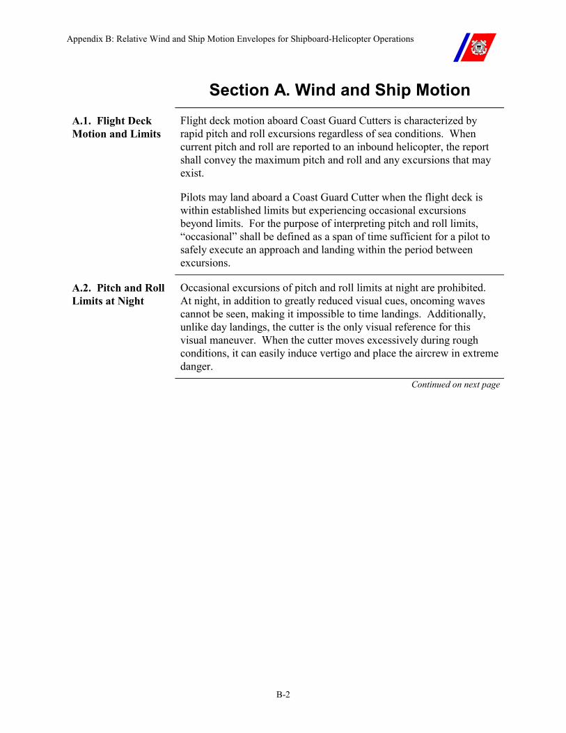
Appendix B: Relative Wind and Ship Motion Envelopes for Shipboard-Helicopter Operations
B-2
Section A. Wind and Ship Motion
A.1. Flight Deck Motion and Limits
Flight deck motion aboard Coast Guard Cutters is characterized by rapid pitch and roll excursions regardless of sea conditions. When current pitch and roll are reported to an inbound helicopter, the report shall convey the maximum pitch and roll and any excursions that may exist.
Pilots may land aboard a Coast Guard Cutter when the flight deck is within established limits but experiencing occasional excursions beyond limits. For the purpose of interpreting pitch and roll limits, “occasional” shall be defined as a span of time sufficient for a pilot to safely execute an approach and landing within the period between excursions.
A.2. Pitch and Roll Limits at Night
Occasional excursions of pitch and roll limits at night are prohibited. At night, in addition to greatly reduced visual cues, oncoming waves cannot be seen, making it impossible to time landings. Additionally, unlike day landings, the cutter is the only visual reference for this visual maneuver. When the cutter moves excessively during rough conditions, it can easily induce vertigo and place the aircrew in extreme danger.
Continued on next page
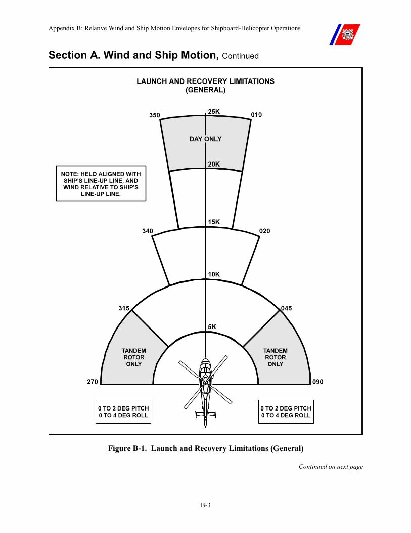
Appendix B: Relative Wind and Ship Motion Envelopes for Shipboard-Helicopter Operations
B-3
Section A. Wind and Ship Motion, Continued
Figure B-1. Launch and Recovery Limitations (General)
Continued on next page
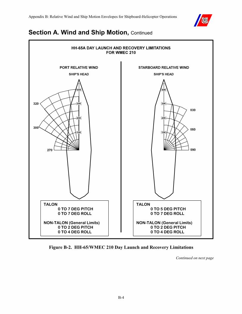
Appendix B: Relative Wind and Ship Motion Envelopes for Shipboard-Helicopter Operations
B-4
Section A. Wind and Ship Motion, Continued
TALON 0 TO 7 DEG PITCH 0 TO 7 DEG ROLL
NON-TALON (General Limits) 0 TO 2 DEG PITCH 0 TO 4 DEG ROLL
TALON 0 TO 5 DEG PITCH 0 TO 7 DEG ROLL
NON-TALON (General Limits) 0 TO 2 DEG PITCH 0 TO 4 DEG ROLL
Figure B-2. HH-65/WMEC 210 Day Launch and Recovery Limitations
Continued on next page
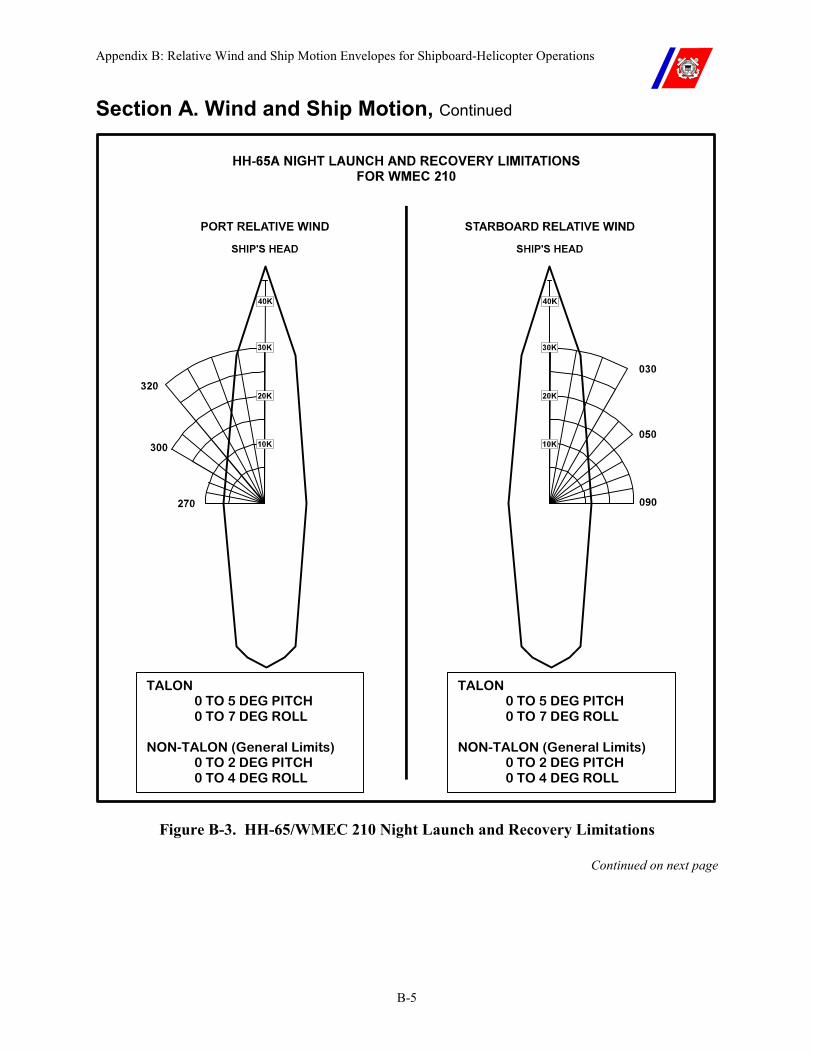
Appendix B: Relative Wind and Ship Motion Envelopes for Shipboard-Helicopter Operations
B-5
Section A. Wind and Ship Motion, Continued
TALON 0 TO 5 DEG PITCH 0 TO 7 DEG ROLL
NON-TALON (General Limits) 0 TO 2 DEG PITCH 0 TO 4 DEG ROLL
TALON 0 TO 5 DEG PITCH 0 TO 7 DEG ROLL
NON-TALON (General Limits) 0 TO 2 DEG PITCH 0 TO 4 DEG ROLL
Figure B-3. HH-65/WMEC 210 Night Launch and Recovery Limitations
Continued on next page
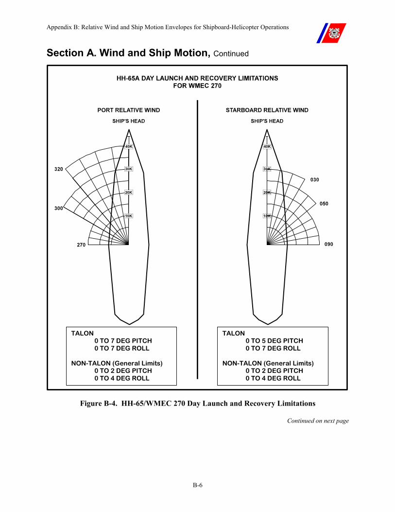
Appendix B: Relative Wind and Ship Motion Envelopes for Shipboard-Helicopter Operations
B-6
Section A. Wind and Ship Motion, Continued
TALON 0 TO 7 DEG PITCH 0 TO 7 DEG ROLL
NON-TALON (General Limits) 0 TO 2 DEG PITCH 0 TO 4 DEG ROLL
TALON 0 TO 5 DEG PITCH 0 TO 7 DEG ROLL
NON-TALON (General Limits) 0 TO 2 DEG PITCH 0 TO 4 DEG ROLL
Figure B-4. HH-65/WMEC 270 Day Launch and Recovery Limitations
Continued on next page

Appendix B: Relative Wind and Ship Motion Envelopes for Shipboard-Helicopter Operations
B-7
Section A. Wind and Ship Motion, Continued
TALON 0 TO 5 DEG PITCH 0 TO 7 DEG ROLL
NON-TALON (General Limits) 0 TO 2 DEG PITCH 0 TO 4 DEG ROLL
TALON 0 TO 5 DEG PITCH 0 TO 7 DEG ROLL
NON-TALON (General Limits) 0 TO 2 DEG PITCH 0 TO 4 DEG ROLL
Figure B-5. HH-65/WMEC 270 Night Launch and Recovery Limitations
Continued on next page
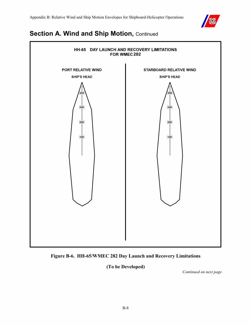
Appendix B: Relative Wind and Ship Motion Envelopes for Shipboard-Helicopter Operations
B-8
Section A. Wind and Ship Motion, Continued
282
Figure B-6. HH-65/WMEC 282 Day Launch and Recovery Limitations
(To be Developed) Continued on next page
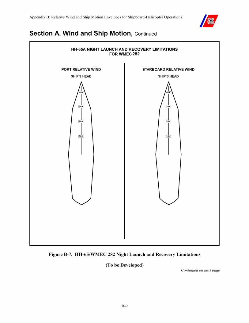
Appendix B: Relative Wind and Ship Motion Envelopes for Shipboard-Helicopter Operations
B-9
Section A. Wind and Ship Motion, Continued
282
Figure B-7. HH-65/WMEC 282 Night Launch and Recovery Limitations
(To be Developed) Continued on next page
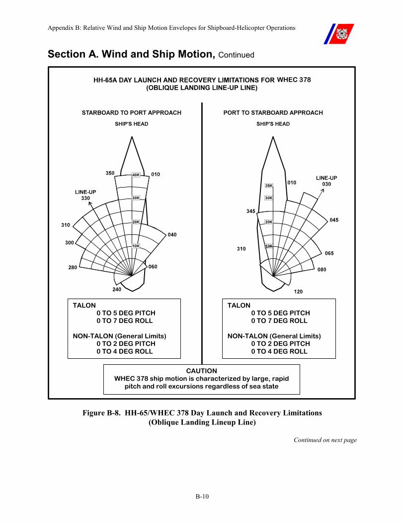
Appendix B: Relative Wind and Ship Motion Envelopes for Shipboard-Helicopter Operations
B-10
Section A. Wind and Ship Motion, Continued
TALON 0 TO 5 DEG PITCH 0 TO 7 DEG ROLL
NON-TALON (General Limits) 0 TO 2 DEG PITCH 0 TO 4 DEG ROLL
TALON 0 TO 5 DEG PITCH 0 TO 7 DEG ROLL
NON-TALON (General Limits) 0 TO 2 DEG PITCH 0 TO 4 DEG ROLL
CAUTION WHEC 378 ship motion is characterized by large, rapid
pitch and roll excursions regardless of sea state diti
WHEC 378
Figure B-8. HH-65/WHEC 378 Day Launch and Recovery Limitations (Oblique Landing Lineup Line)
Continued on next page
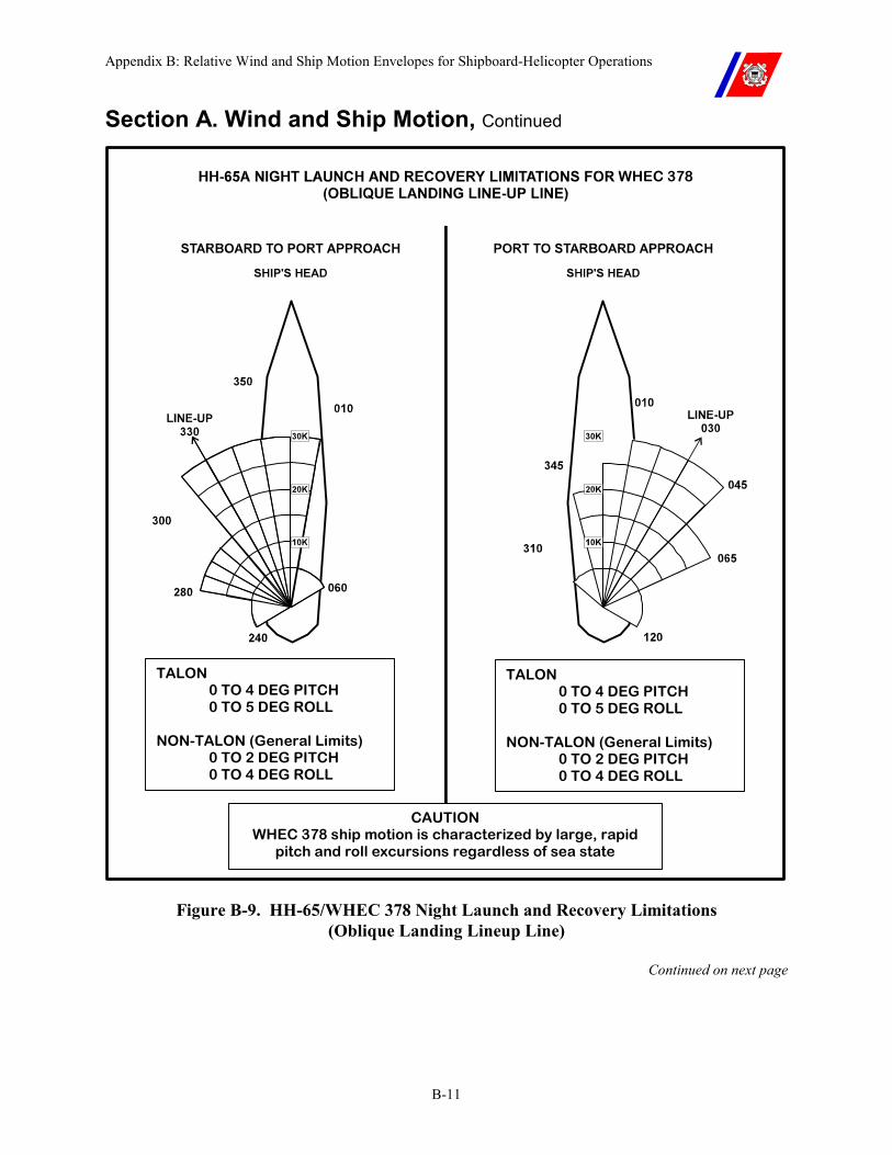
Appendix B: Relative Wind and Ship Motion Envelopes for Shipboard-Helicopter Operations
B-11
Section A. Wind and Ship Motion, Continued
TALON 0 TO 4 DEG PITCH 0 TO 5 DEG ROLL
NON-TALON (General Limits) 0 TO 2 DEG PITCH 0 TO 4 DEG ROLL
TALON 0 TO 4 DEG PITCH 0 TO 5 DEG ROLL
NON-TALON (General Limits) 0 TO 2 DEG PITCH 0 TO 4 DEG ROLL
CAUTION WHEC 378 ship motion is characterized by large, rapid
pitch and roll excursions regardless of sea state diti
WHEC 378
Figure B-9. HH-65/WHEC 378 Night Launch and Recovery Limitations (Oblique Landing Lineup Line)
Continued on next page
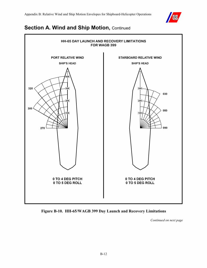
Appendix B: Relative Wind and Ship Motion Envelopes for Shipboard-Helicopter Operations
B-12
Section A. Wind and Ship Motion, Continued
HH-65 DAY LAUNCH AND RECOVERY LIMITATIONS FOR WAGB 399
Figure B-10. HH-65/WAGB 399 Day Launch and Recovery Limitations
Continued on next page
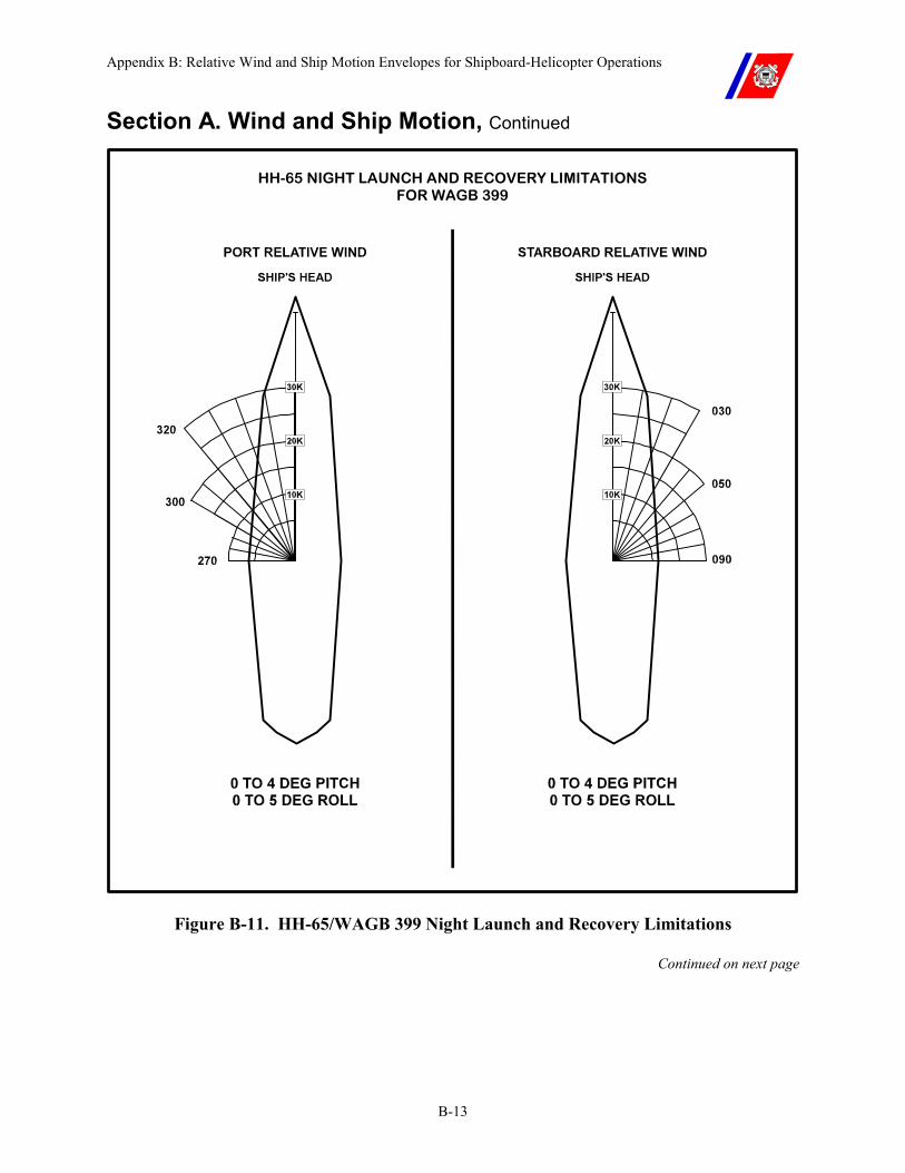
Appendix B: Relative Wind and Ship Motion Envelopes for Shipboard-Helicopter Operations
B-13
Section A. Wind and Ship Motion, Continued
HH-65 NIGHT LAUNCH AND RECOVERY LIMITATIONS FOR WAGB 399
Figure B-11. HH-65/WAGB 399 Night Launch and Recovery Limitations
Continued on next page
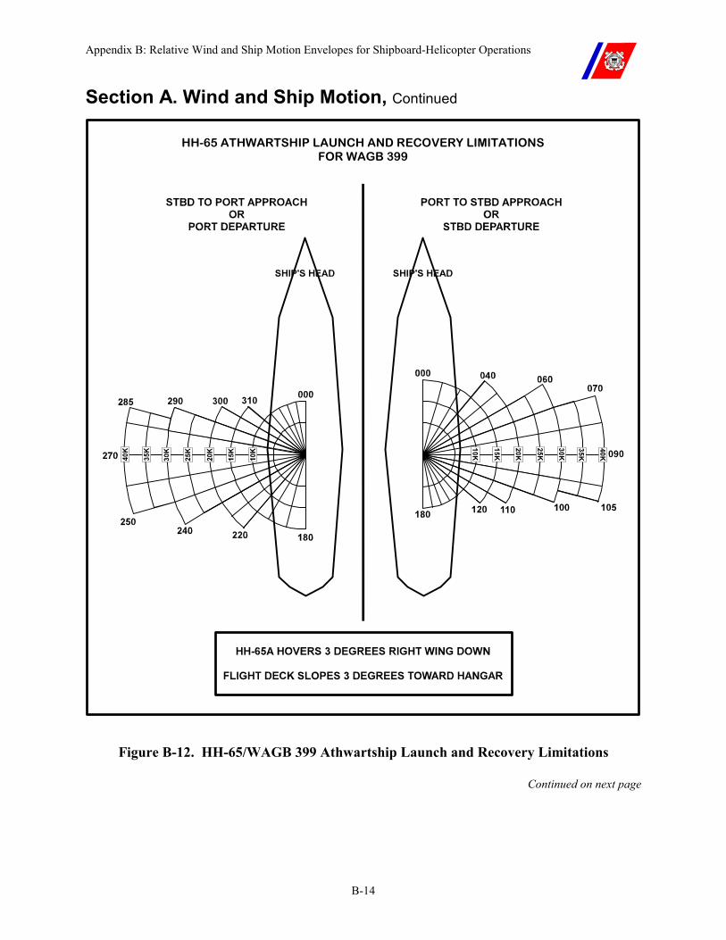
Appendix B: Relative Wind and Ship Motion Envelopes for Shipboard-Helicopter Operations
B-14
Section A. Wind and Ship Motion, Continued
HH-65 ATHWARTSHIP LAUNCH AND RECOVERY LIMITATIONS FOR WAGB 399
Figure B-12. HH-65/WAGB 399 Athwartship Launch and Recovery Limitations
Continued on next page
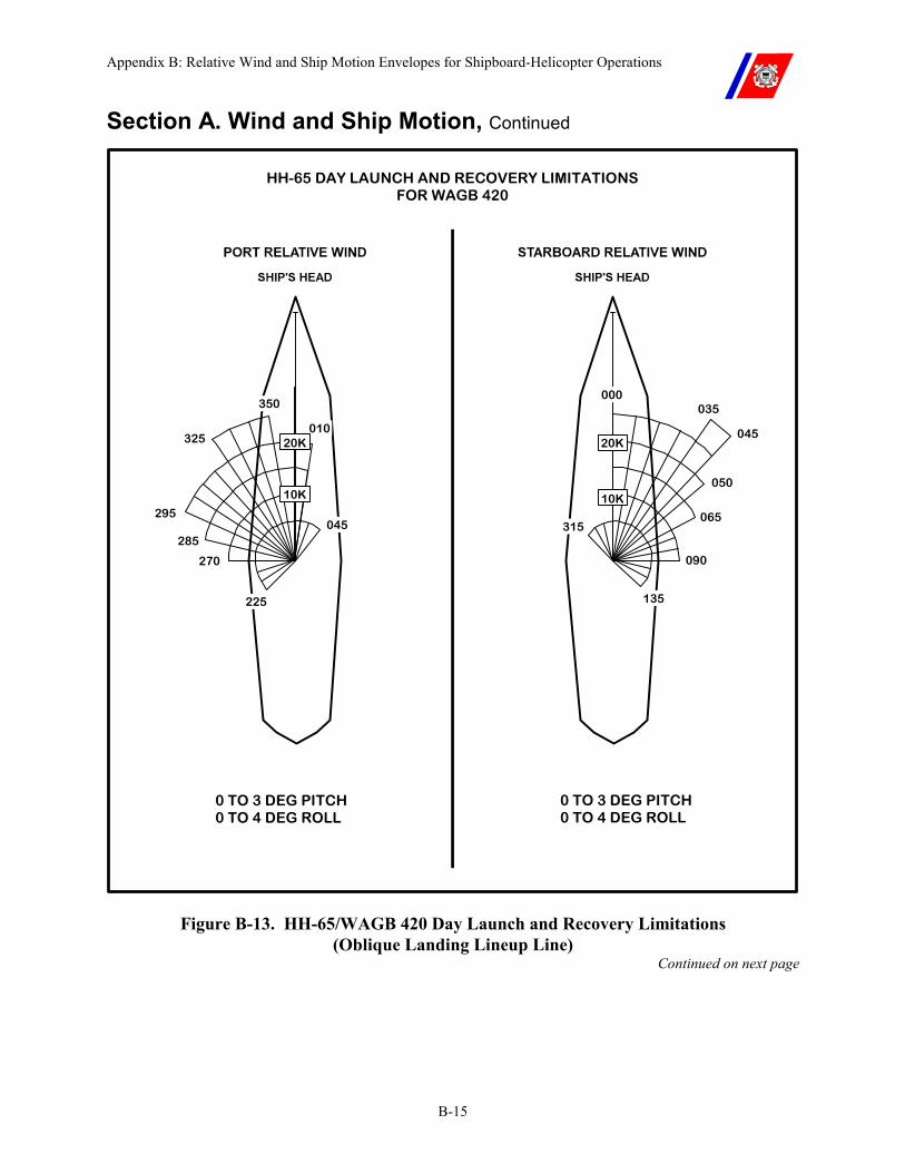
Appendix B: Relative Wind and Ship Motion Envelopes for Shipboard-Helicopter Operations
B-15
Section A. Wind and Ship Motion, Continued
HH-65 DAY LAUNCH AND RECOVERY LIMITATIONS FOR WAGB 420
0 TO 3 DEG PITCH 0 TO 4 DEG ROLL
0 TO 3 DEG PITCH 0 TO 4 DEG ROLL
295
285
270
225
045
325010
135
035
045
000
050
065
090
315
350
20K
10K
20K
10K
Figure B-13. HH-65/WAGB 420 Day Launch and Recovery Limitations (Oblique Landing Lineup Line)
Continued on next page
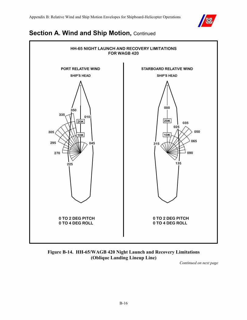
Appendix B: Relative Wind and Ship Motion Envelopes for Shipboard-Helicopter Operations
B-16
Section A. Wind and Ship Motion, Continued
HH-65 NIGHT LAUNCH AND RECOVERY LIMITATIONS FOR WAGB 420
0 TO 2 DEG PITCH 0 TO 4 DEG ROLL
0 TO 2 DEG PITCH 0 TO 4 DEG ROLL
295
305
270
225
045
335010
135
035
000
050
065
090
315
350
20K
10K
20K
10K
025
Figure B-14. HH-65/WAGB 420 Night Launch and Recovery Limitations (Oblique Landing Lineup Line)
Continued on next page
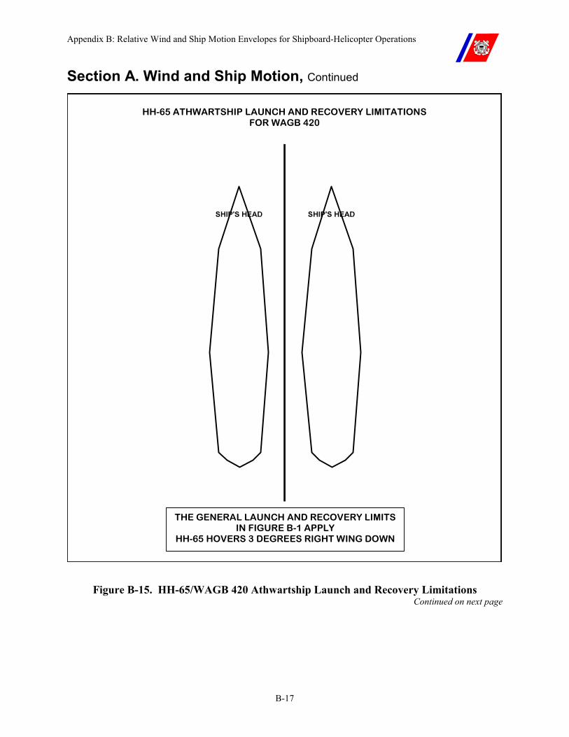
Appendix B: Relative Wind and Ship Motion Envelopes for Shipboard-Helicopter Operations
B-17
Section A. Wind and Ship Motion, Continued
HH-65 ATHWARTSHIP LAUNCH AND RECOVERY LIMITATIONS FOR WAGB 420
THE GENERAL LAUNCH AND RECOVERY LIMITS IN FIGURE B-1 APPLY
HH-65 HOVERS 3 DEGREES RIGHT WING DOWN
Figure B-15. HH-65/WAGB 420 Athwartship Launch and Recovery Limitations Continued on next page
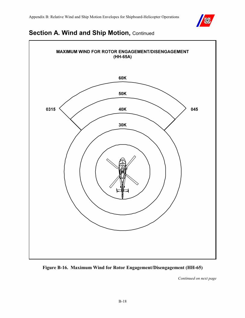
Appendix B: Relative Wind and Ship Motion Envelopes for Shipboard-Helicopter Operations
B-18
Section A. Wind and Ship Motion, Continued
Figure B-16. Maximum Wind for Rotor Engagement/Disengagement (HH-65)
Continued on next page
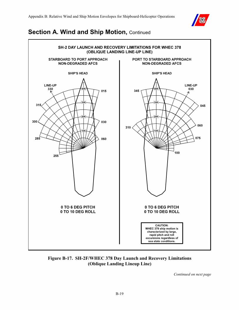
Appendix B: Relative Wind and Ship Motion Envelopes for Shipboard-Helicopter Operations
B-19
Section A. Wind and Ship Motion, Continued
Figure B-17. SH-2F/WHEC 378 Day Launch and Recovery Limitations (Oblique Landing Lineup Line)
Continued on next page
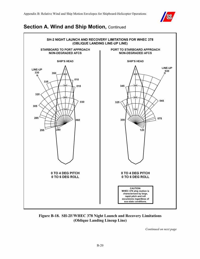
Appendix B: Relative Wind and Ship Motion Envelopes for Shipboard-Helicopter Operations
B-20
Section A. Wind and Ship Motion, Continued
Figure B-18. SH-2F/WHEC 378 Night Launch and Recovery Limitations (Oblique Landing Lineup Line)
Continued on next page
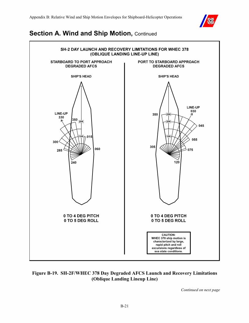
Appendix B: Relative Wind and Ship Motion Envelopes for Shipboard-Helicopter Operations
B-21
Section A. Wind and Ship Motion, Continued
Figure B-19. SH-2F/WHEC 378 Day Degraded AFCS Launch and Recovery Limitations (Oblique Landing Lineup Line)
Continued on next page
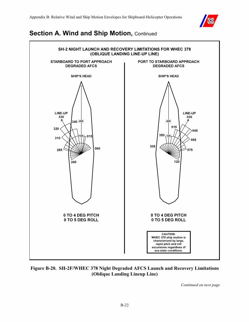
Appendix B: Relative Wind and Ship Motion Envelopes for Shipboard-Helicopter Operations
B-22
Section A. Wind and Ship Motion, Continued
Figure B-20. SH-2F/WHEC 378 Night Degraded AFCS Launch and Recovery Limitations (Oblique Landing Lineup Line)
Continued on next page
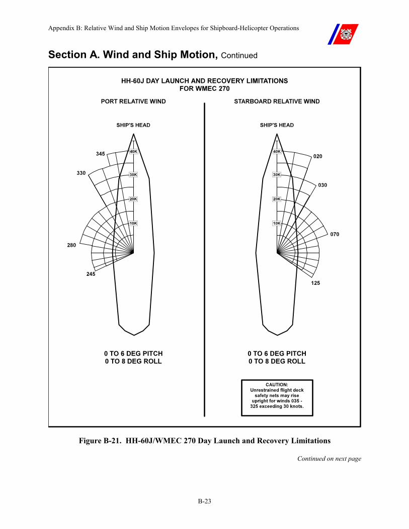
Appendix B: Relative Wind and Ship Motion Envelopes for Shipboard-Helicopter Operations
B-23
Section A. Wind and Ship Motion, Continued
Figure B-21. HH-60J/WMEC 270 Day Launch and Recovery Limitations
Continued on next page
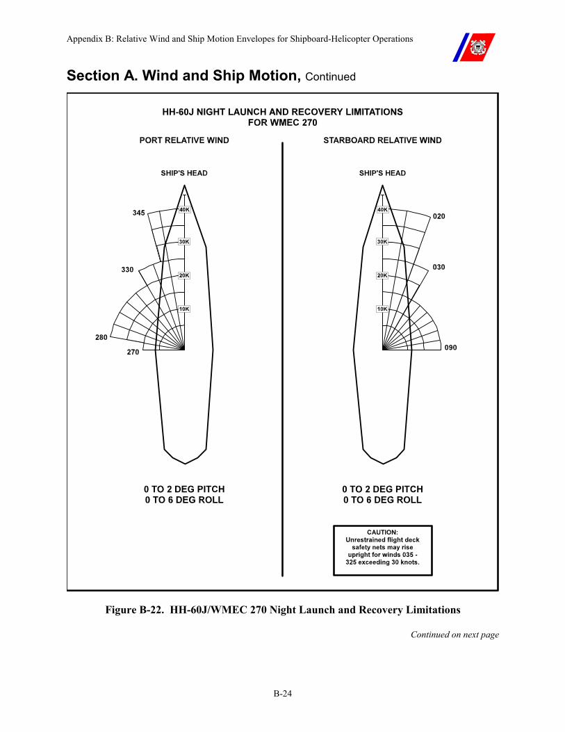
Appendix B: Relative Wind and Ship Motion Envelopes for Shipboard-Helicopter Operations
B-24
Section A. Wind and Ship Motion, Continued
Figure B-22. HH-60J/WMEC 270 Night Launch and Recovery Limitations
Continued on next page

Appendix B: Relative Wind and Ship Motion Envelopes for Shipboard-Helicopter Operations
B-25
Section A. Wind and Ship Motion, Continued
HH-60J DAY LAUNCH AND RECOVERY LIMITATIONS FOR WMEC 282
Figure B-23. HH-60J/WMEC 282 Day Launch and Recovery Limitations
(To be Developed) Continued on next page
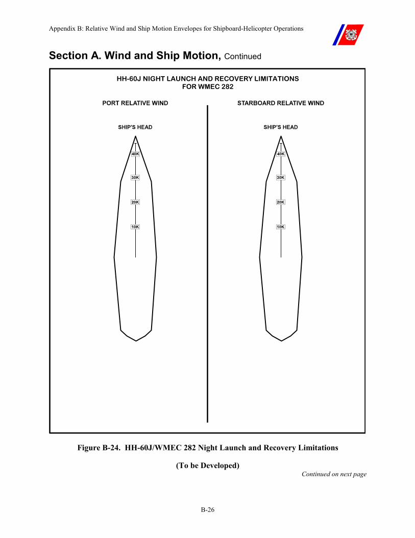
Appendix B: Relative Wind and Ship Motion Envelopes for Shipboard-Helicopter Operations
B-26
Section A. Wind and Ship Motion, Continued
HH-60J NIGHT LAUNCH AND RECOVERY LIMITATIONS FOR WMEC 282
Figure B-24. HH-60J/WMEC 282 Night Launch and Recovery Limitations
(To be Developed) Continued on next page
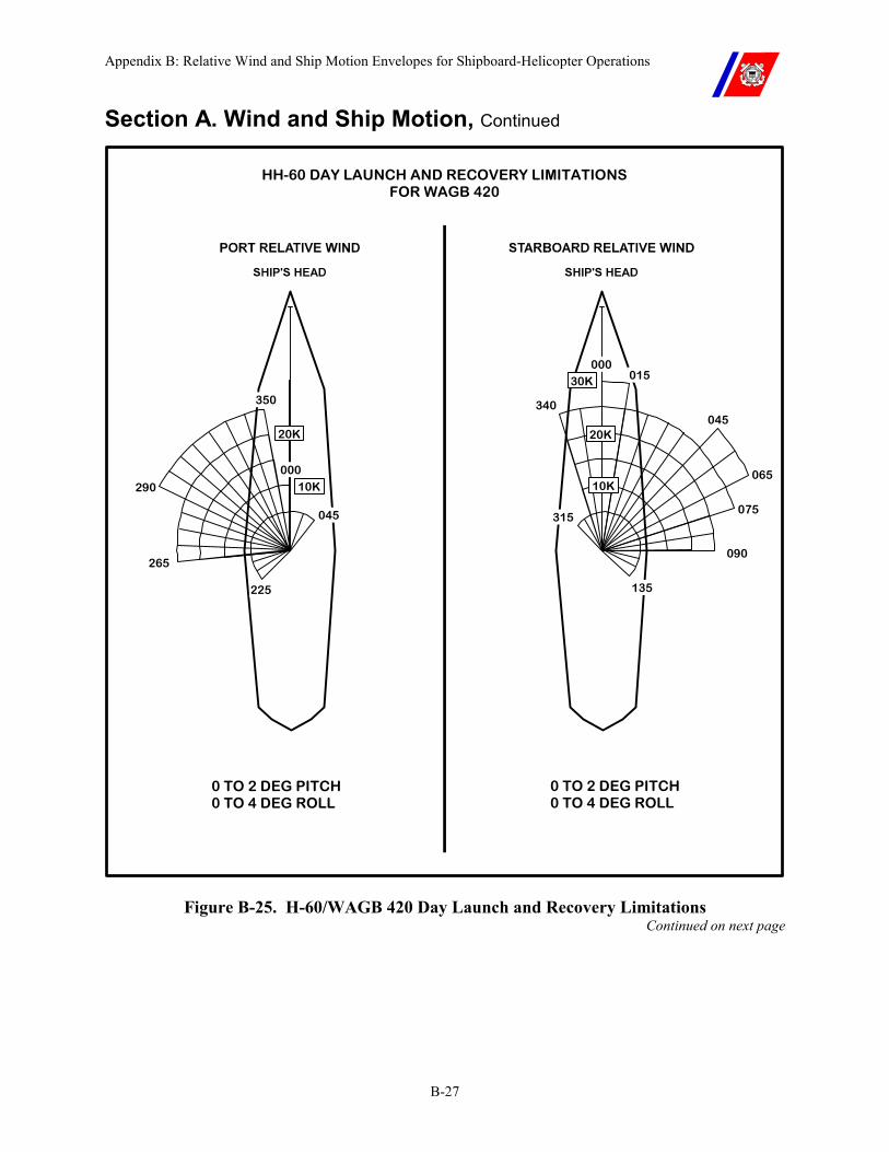
Appendix B: Relative Wind and Ship Motion Envelopes for Shipboard-Helicopter Operations
B-27
Section A. Wind and Ship Motion, Continued
HH-60 DAY LAUNCH AND RECOVERY LIMITATIONS FOR WAGB 420
0 TO 2 DEG PITCH 0 TO 4 DEG ROLL
0 TO 2 DEG PITCH 0 TO 4 DEG ROLL
290
265
225
045
135
075
045
000
065
090
315
350
20K
10K
30K
10K
20K
015
340
000
Figure B-25. H-60/WAGB 420 Day Launch and Recovery Limitations Continued on next page
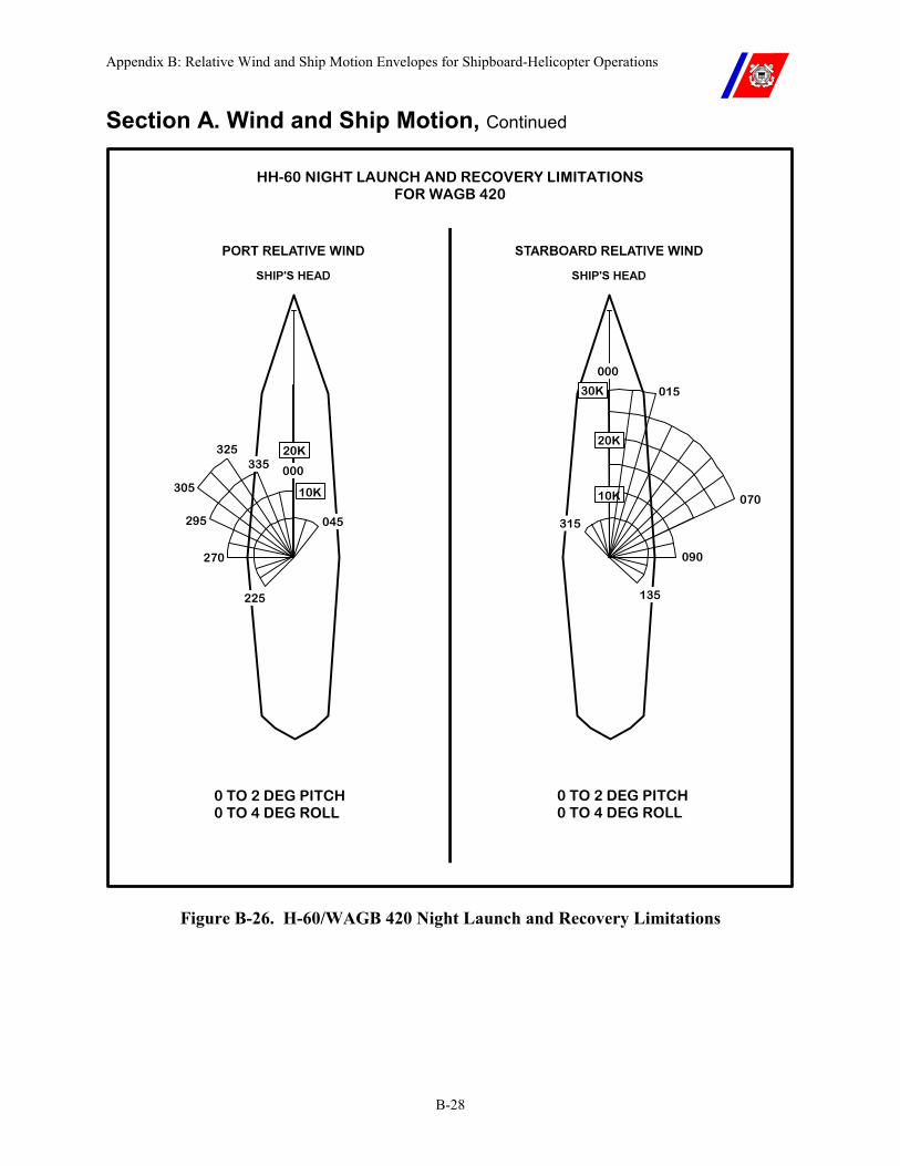
Appendix B: Relative Wind and Ship Motion Envelopes for Shipboard-Helicopter Operations
B-28
Section A. Wind and Ship Motion, Continued
HH-60 NIGHT LAUNCH AND RECOVERY LIMITATIONS FOR WAGB 420
0 TO 2 DEG PITCH 0 TO 4 DEG ROLL
0 TO 2 DEG PITCH 0 TO 4 DEG ROLL
295
305
270
225
045
325
000
135
000
070
090
315
33520K
10K
20K
10K
30K 015
Figure B-26. H-60/WAGB 420 Night Launch and Recovery Limitations
Appendix C: Signals
C-i
APPENDIX C: SIGNALS Table of Contents
Introduction............................................................................................................................... C-1
In this appendix......................................................................................................................... C-1
Section A. Signals ..................................................................................................................... C-2
A.1. Deck Status Light ............................................................................................................. C-2
A.2. NVG Compatible Signals................................................................................................. C-2
Section B. Lost Communications and EMCON Signals....................................................... C-3
B.1. Overview ........................................................................................................................... C-3 B.1.a. Pilot to Helicopter Control Officer (HCO) (Request Clearance)........................................ C-3 B.1.b. Helicopter Control Officer (HCO) to Pilot ......................................................................... C-3
Section C. Helicopter Handling (LSO/Pilot) Signals ............................................................ C-4
C.1. Overview ........................................................................................................................... C-4

Appendix C: Signals
C-ii

Appendix C: Signals
C-1
Appendix C. Signals
Introduction This appendix depicts the signals that shall be used for all shipboard-helicopter operations aboard Coast Guard cutters.
In this appendix This appendix is divided into three (3) sections:
�� Section A: Signals �� Section B: Lost Communications/EMCON Signals �� Section C: Helicopter Handling (LSO/Pilot) Signals
Appendix C: Signals
C-2
Section A. Signals
A.1. Deck Status Light
The Deck Status Light provides a means for the HCO to pass clearances to the helicopter visually. Clearance is indicated as follows:
�� Red: helicopter is not cleared.
�� Amber: helicopter is cleared to start engines and engage/disengage rotors (cutter is restricted from maneuvering with amber showing since the rotor is transitioning from 0 to 100 percent RPM, or vice versa).
�� Green: helicopter is cleared to perform the desired evolution (land, takeoff, touch-and-go/VERTREP, or HIFR).
CAUTION The Deck Status Light is not used during NVG operations.
A.2. NVG Compatible Signals
All signal devices described in this appendix (i.e. flashlight, wands, etc.) and used during NVG operations shall be NVG compatible.
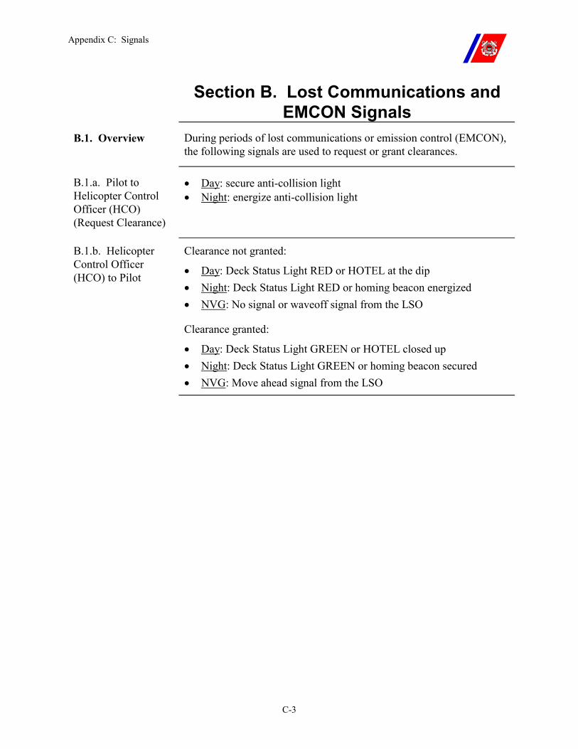
Appendix C: Signals
C-3
Section B. Lost Communications and EMCON Signals
B.1. Overview During periods of lost communications or emission control (EMCON), the following signals are used to request or grant clearances.
B.1.a. Pilot to Helicopter Control Officer (HCO) (Request Clearance)
�� Day: secure anti-collision light �� Night: energize anti-collision light
B.1.b. Helicopter Control Officer (HCO) to Pilot
Clearance not granted:
�� Day: Deck Status Light RED or HOTEL at the dip �� Night: Deck Status Light RED or homing beacon energized �� NVG: No signal or waveoff signal from the LSO
Clearance granted:
�� Day: Deck Status Light GREEN or HOTEL closed up �� Night: Deck Status Light GREEN or homing beacon secured �� NVG: Move ahead signal from the LSO
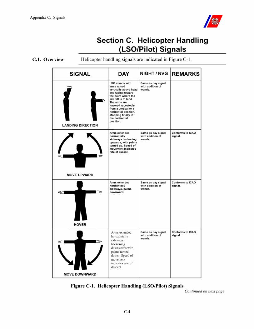
Appendix C: Signals
C-4
Section C. Helicopter Handling (LSO/Pilot) Signals
C.1. Overview Helicopter handling signals are indicated in Figure C-1.
Arms extended horozontally sideways beckoning downwards with palms turned down. Speed of movement indicates rate of descent
NIGHT / NVG
Figure C-1. Helicopter Handling (LSO/Pilot) Signals Continued on next page
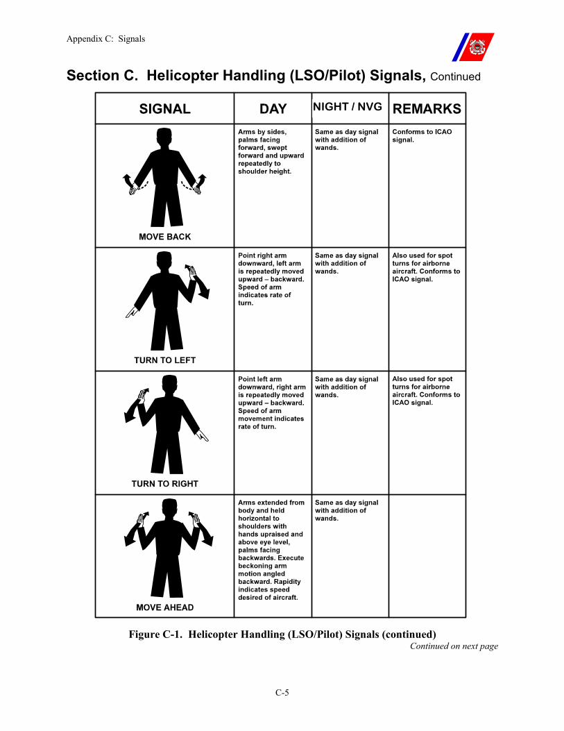
Appendix C: Signals
C-5
Section C. Helicopter Handling (LSO/Pilot) Signals, Continued
Figure C-1. Helicopter Handling (LSO/Pilot) Signals (continued) Continued on next page
NIGHT / NVG
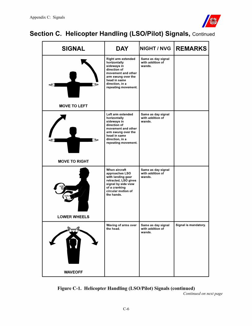
Appendix C: Signals
C-6
Section C. Helicopter Handling (LSO/Pilot) Signals, Continued
Figure C-1. Helicopter Handling (LSO/Pilot) Signals (continued) Continued on next page
NIGHT / NVG
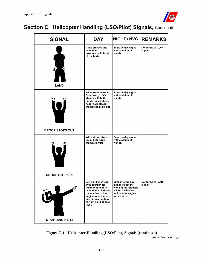
Appendix C: Signals
C-7
Section C. Helicopter Handling (LSO/Pilot) Signals, Continued
Figure C-1. Helicopter Handling (LSO/Pilot) Signals (continued) Continued on next page
NIGHT / NVG
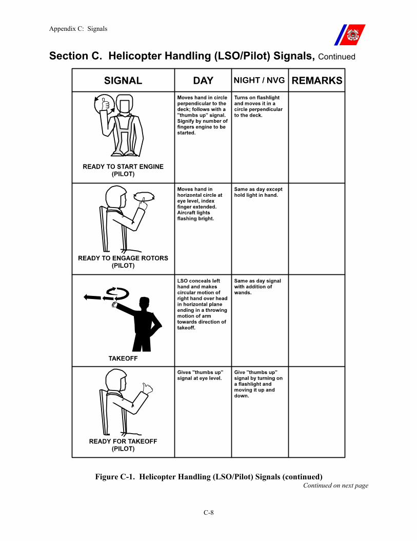
Appendix C: Signals
C-8
Section C. Helicopter Handling (LSO/Pilot) Signals, Continued
Figure C-1. Helicopter Handling (LSO/Pilot) Signals (continued) Continued on next page
NIGHT / NVG
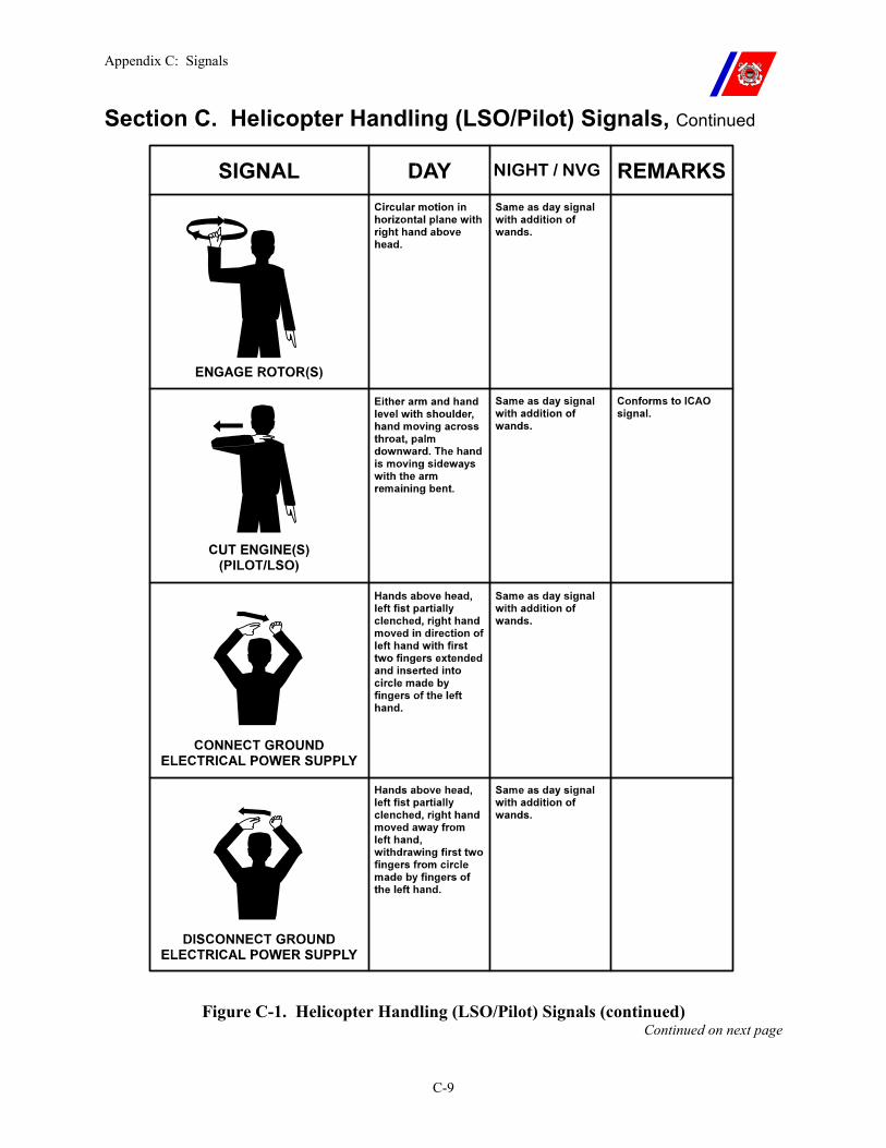
Appendix C: Signals
C-9
Section C. Helicopter Handling (LSO/Pilot) Signals, Continued
Figure C-1. Helicopter Handling (LSO/Pilot) Signals (continued) Continued on next page
NIGHT / NVG
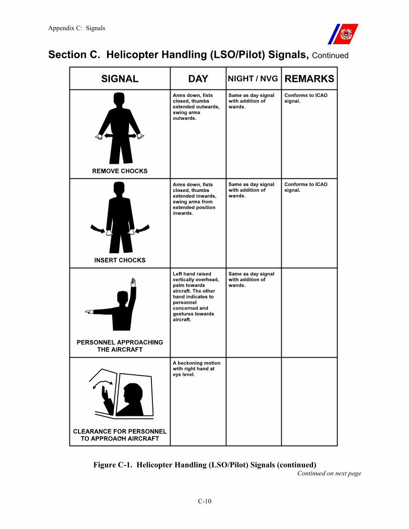
Appendix C: Signals
C-10
Section C. Helicopter Handling (LSO/Pilot) Signals, Continued
Figure C-1. Helicopter Handling (LSO/Pilot) Signals (continued) Continued on next page
NIGHT / NVG
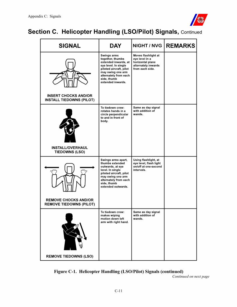
Appendix C: Signals
C-11
Section C. Helicopter Handling (LSO/Pilot) Signals, Continued
Figure C-1. Helicopter Handling (LSO/Pilot) Signals (continued) Continued on next page
NIGHT / NVG
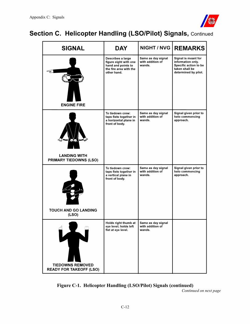
Appendix C: Signals
C-12
Section C. Helicopter Handling (LSO/Pilot) Signals, Continued
NIGHT / NVG
Figure C-1. Helicopter Handling (LSO/Pilot) Signals (continued) Continued on next page
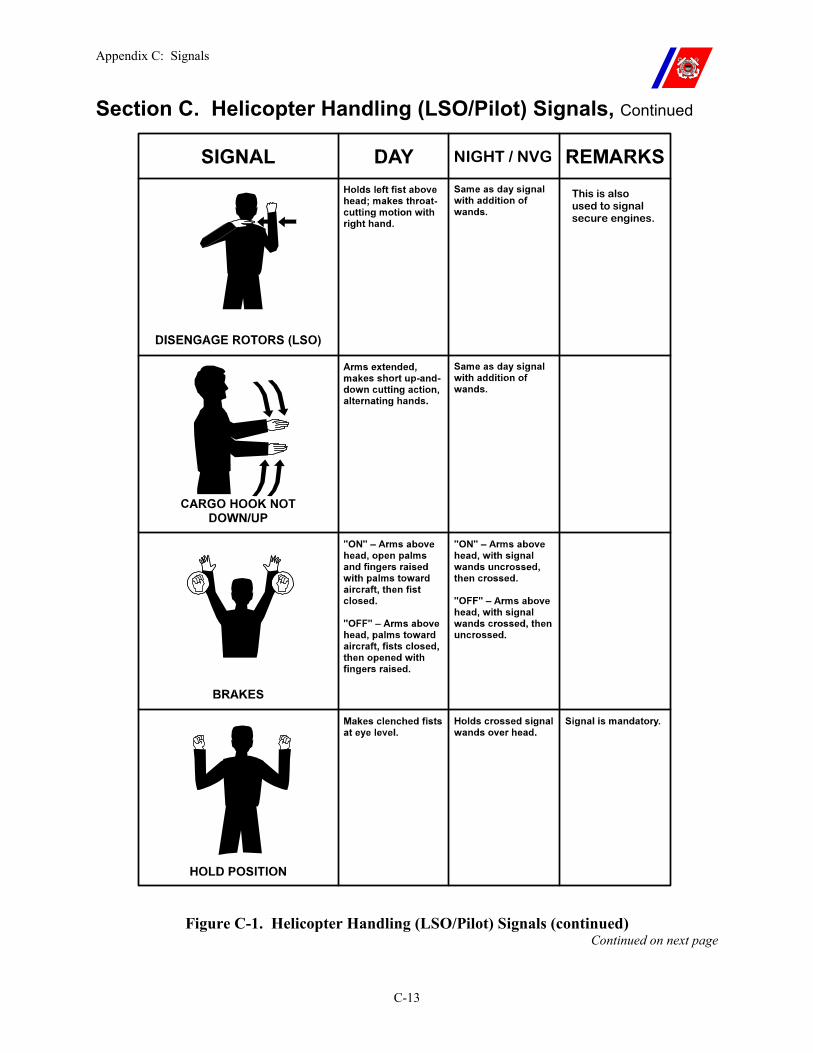
Appendix C: Signals
C-13
Section C. Helicopter Handling (LSO/Pilot) Signals, Continued
Figure C-1. Helicopter Handling (LSO/Pilot) Signals (continued) Continued on next page
NIGHT / NVG
This is also used to signal secure engines.
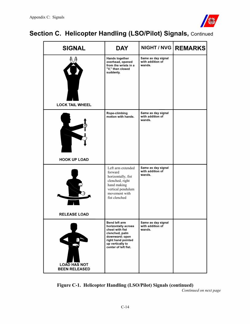
Appendix C: Signals
C-14
Section C. Helicopter Handling (LSO/Pilot) Signals, Continued
Left arm extended forward horizontally, fist clenched, right hand making vertical pendulum movement with fist clenched
NIGHT / NVG
Figure C-1. Helicopter Handling (LSO/Pilot) Signals (continued) Continued on next page
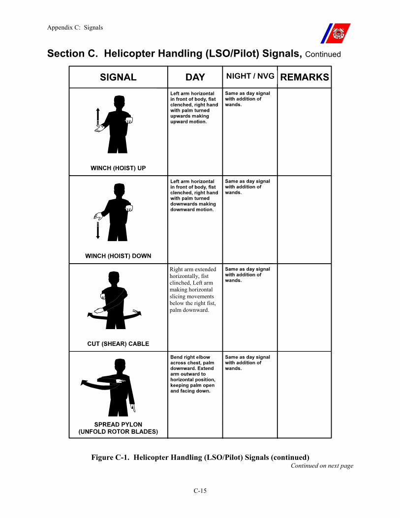
Appendix C: Signals
C-15
Section C. Helicopter Handling (LSO/Pilot) Signals, Continued
Right arm extended horizontally, fist clinched, Left arm making horizontal slicing movements below the right fist, palm downward.
NIGHT / NVG
Figure C-1. Helicopter Handling (LSO/Pilot) Signals (continued) Continued on next page
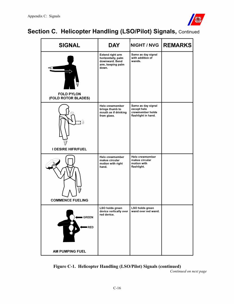
Appendix C: Signals
C-16
Section C. Helicopter Handling (LSO/Pilot) Signals, Continued
Figure C-1. Helicopter Handling (LSO/Pilot) Signals (continued) Continued on next page
NIGHT / NVG
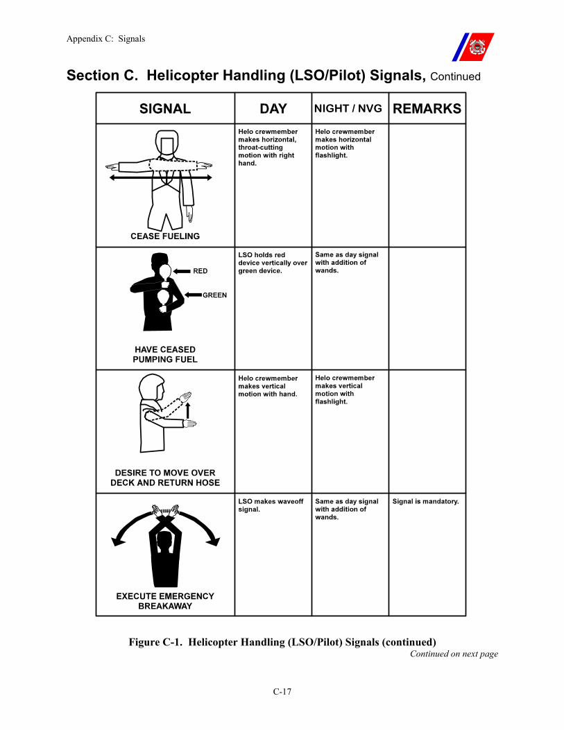
Appendix C: Signals
C-17
Section C. Helicopter Handling (LSO/Pilot) Signals, Continued
Figure C-1. Helicopter Handling (LSO/Pilot) Signals (continued) Continued on next page
NIGHT / NVG
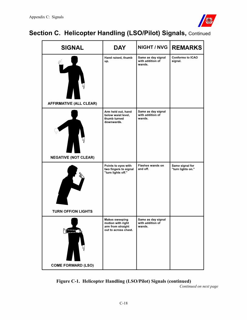
Appendix C: Signals
C-18
Section C. Helicopter Handling (LSO/Pilot) Signals, Continued
Figure C-1. Helicopter Handling (LSO/Pilot) Signals (continued) Continued on next page
NIGHT / NVG
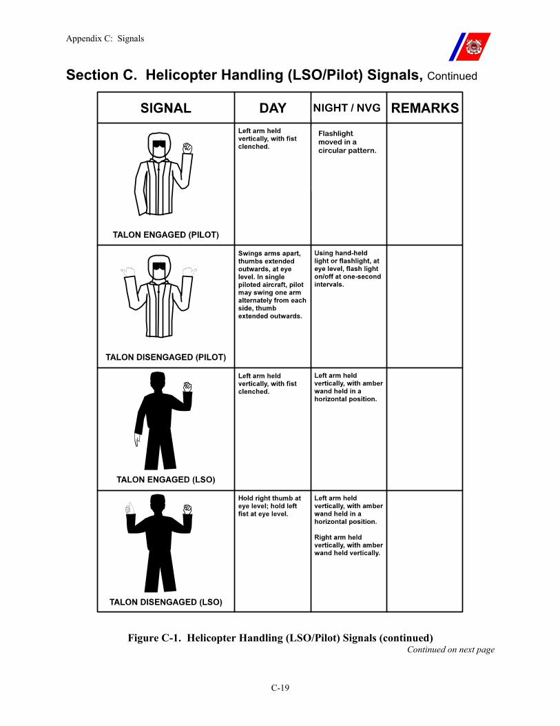
Appendix C: Signals
C-19
Section C. Helicopter Handling (LSO/Pilot) Signals, Continued
Figure C-1. Helicopter Handling (LSO/Pilot) Signals (continued) Continued on next page
NIGHT / NVG
Flashlight moved in a circular pattern.
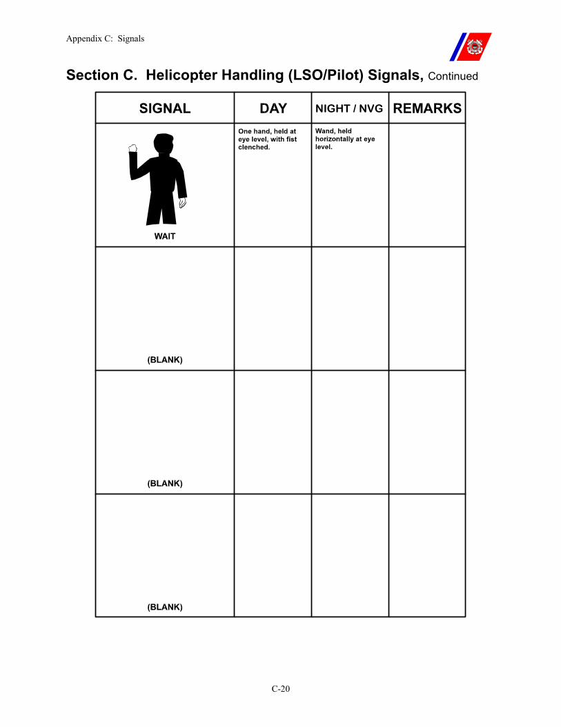
Appendix C: Signals
C-20
Section C. Helicopter Handling (LSO/Pilot) Signals, Continued
NIGHT / NVG
Appendix D: Aircraft Pre-Accident Plan
D-i
APPENDIX D: AIRCRAFT PRE-ACCIDENT PLAN Table of Contents
Introduction............................................................................................................................... D-1
In this appendix......................................................................................................................... D-1
Section A. General Information.............................................................................................. D-2
A.1. Objectives.......................................................................................................................... D-2
A.2. Scope.................................................................................................................................. D-2
Section B. Sample Aircraft Pre-Accident Plan...................................................................... D-3
B.1. Overview ........................................................................................................................... D-3

Appendix D: Aircraft Pre-Accident Plan
D-ii
Appendix D: Aircraft Pre-Accident Plan
D-1
Appendix D. Aircraft Pre-Accident Plan
Introduction Every flight deck-equipped cutter shall have an aircraft pre-accident plan, to be used in the event of an aircraft mishap.
The plan shall include individual procedures and responsibilities for key personnel aboard the cutter and should prescribe the specific actions to be taken from initial notification to completion of the mishap investigation.
A well-written, well-rehearsed pre-accident plan will ensure thorough and efficient rescue and salvage efforts as well as minimize confusion following an aircraft mishap.
A sample plan is included in Section B as Figure D-1.
In this appendix This appendix is divided into two (2) sections:
�� Section A: General Information �� Section B: Sample Aircraft Pre-Accident Plan
Appendix D: Aircraft Pre-Accident Plan
D-2
Section A. General Information
A.1. Objectives The primary consideration following an aircraft mishap is the safe recovery of personnel.
The secondary consideration is to effectively preserve all features and evidence at the mishap scene to ensure a complete and accurate analysis by the mishap analysis board (MAB).
A.2. Scope The Coast Guard Safety and Occupational Health Manual, COMDTINST M5100.47 (series) establishes the Coast Guard flight safety program and contains general information for its implementation.
In the event of a Coast Guard aircraft mishap, the cutter nearest to the scene is responsible for initiating rescue and salvage. The pre-accident plan should be implemented upon initial receipt of information of the mishap.
Even though the aircraft involved may not be assigned to the cutter, timely response will aid in saving lives and assist the MAB in determining the cause of the mishap.

Appendix D: Aircraft Pre-Accident Plan
D-3
Section B. Sample Aircraft Pre-Accident Plan
B.1. Overview A sample Aircraft Pre-Accident Plan follows as Figure D-1. Continued on next page
Appendix D: Aircraft Pre-Accident Plan
D-4
Section B. Sample Aircraft Pre-Accident Plan, Continued Figure D-1. Sample Aircraft Pre-Accident Plan
Subj: AIRCRAFT PRE-ACCIDENT PLAN
Ref: (a) Shipboard-Helicopter Operational Procedures Manual COMDTINST M3710.2 (series) (b) Air Operations Manual, COMDTINST M3710.1 (series) (c) Safety and Occupational Health Manual, COMDTINST M5100.47 (series)
1. Purpose.
This plan describes procedures and establishes responsibilities for personnel to ensure the fastest and most systematic rescue efforts possible in case of an aircraft mishap.
The plan also prescribes notification and investigative functions for designated personnel that will produce maximum results without confusion or waste of time.
2. Discussion.
The first consideration in any mishap is to remove the injured personnel as quickly as possible. When the rescue (initial response phase) is completed, the recovery of the wreckage and investigation to determine cause (secondary response phase) commences. Therefore, the pre-accident plan is broken into two sections:
a. PRIMARY RESPONSE (Crash on deck or ditch at sea)
(1) Officer of the Deck (OOD) (2) Operations Officer (3) Aviation Detachment (AVDET) (if aboard) (4) Health Services Technician or Physician Assistant (5) Fire Party (6) Ship’s Photographer (7) Ready Boat Crew/Swimmers
b. SECONDARY RESPONSE
(1) Operations Officer (2) Commanding Officer (3) Executive Officer (4) AVDET (5) Engineer Officer (6) First Lieutenant (7) Damage Control Assistant (DCA) (8) Ship Photographer
3. Action.
The specific duties of the personnel listed above are outlined in enclosure (1). The Operations Officer is responsible for the readiness and adequacy of the Pre-Accident Plan. All other miscellaneous duties not covered in this Pre-Accident Plan shall be handled in accordance with the Helicopter Operations Bill in the Ship’s Organization Manual and/or the Ship-Helicopter Operations Procedure Manual, COMDTINST M3710.2 (series).
I. R. COMMANDING Encl: (1) Personnel Duties for Aircraft Mishap
Appendix D: Aircraft Pre-Accident Plan
D-5
Section B. Sample Aircraft Pre-Accident Plan, Continued
Figure D-1. Sample Aircraft Pre-Accident Plan (continued)
Enclosure (1) to Pre-Accident Plan
PERSONNEL DUTIES FOR AIRCRAFT MISHAP
1. PRIMARY RESPONSE
Procedures listed in this section shall be initiated upon notification of a mishap. The objective is to rescue personnel, (in the event of a crash on deck with fire) control and extinguish the fire, and prevent further injury to personnel or damage to the cutter.
a. Primary Response: Crash on Deck.
(1) OOD.
(a) Sound appropriate alarms and make appropriate pipes to alert all hands that there has been a helicopter crash on deck. Ensure that the on scene leader and fire party are aware of any ordnance being carried by the aircraft. Activate the pre-accident plan.
(b) Adjust cutter heading to minimize damage from fire and adjust speed to assist fire party in containing the fire. (Make best relative wind for fire fighting on the flight deck).
(c) Ensure that proper log entries are made for each performed evolution.
(d) Make an additional pipe to have all non-billeted personnel for flight ops lay to the appropriate location for possible fire party and/or flight deck personnel augmentation.
(e) Ensure that the ready boat is ready for launch in the event of personnel overboard. (It may be wise to launch the small boat to standby alongside.)
(2) Operations Officer.
(a) Activate the Pre-Accident plan.
(b) Ensure that appropriate alarms and/or pipes have been made by OOD.
(c) Ensure that the OSL and fire parties are aware of any ordnance carried by the aircraft.
(d) Ensure that chronological log of events is maintained (include on-scene weather as close to the time of occurrence as possible).
(e) Compile data for completion of initial crash report.
(f) Request assistance from nearest USCG unit or any other resource (if appropriate).
(g) Notify SAR coordinator or operational control (OPCON) of mishap via immediate precedence message or phone patch.
(3) AVDET (if embarked). Lay to the flight deck to assist as necessary. Continued on next page
Appendix D: Aircraft Pre-Accident Plan
D-6
Section B. Sample Aircraft Pre-Accident Plan, Continued
Figure D-1. Sample Aircraft Pre-Accident Plan (continued) (4) Health Services Technician or Physician Assistant
(a) Report to the hangar or flight deck with medical bag for on-scene first aid.
(b) Ensure treatment for hypothermia is available in the hangar or on the flight deck for firefighters who have gotten wet.
(c) All injured personnel shall be moved away from the immediate crash area (if at all possible) to a safe area for treatment (not necessarily to sick bay initially).
(d) If extra personnel are needed, coordinate through OSL or flight deck phone talker.
(5) Fire Party.
(a) The OSL shall direct the rescue crew to proceed immediately to the helicopter to assist personnel with egress in the event there is no fire initially.
(b) The OSL shall ensure that the fire party is ready to attack the fire with charged hoses as soon as possible after the debris settles.
(c) The fire party shall fight the fire as directed by the OSL and in accordance with accepted fire fighting procedures.
(d) If possible, the wreckage is to be left undisturbed for examination upon arrival of the MAB. However, if burning parts endanger the cutter, they may be jettisoned over the side.
(e) The secondary hose team shall be ready to relieve or assist the primary hose teams as directed by the OSL.
(f) The DCA shall monitor and plot the fire’s progress. Damage control advice and/or augmentation orders shall come from the DCA.
(6) Ship Photographer.
(a) Lay to the flight deck with photographic equipment.
(b) Take pictures to document all evolutions.
(7) Ready Boat Crew. Boat-lowering detail and boat crew (including cutter swimmer) lay to the boat deck and stand by for directions from the OOD.
b. Primary Phase: Ditch at Sea.
(1) OOD.
(a) Immediately turn cutter toward aircraft ditch location; make best speed to the ditch position.
(b) Sound appropriate alarms and make appropriate pipes to alert all hands of the situation. Implement the Pre-Accident plan.
(c) Ensure that proper log entries are made for each performed evolution.
(d) Ensure that appropriate billets are manned. Continued on next page
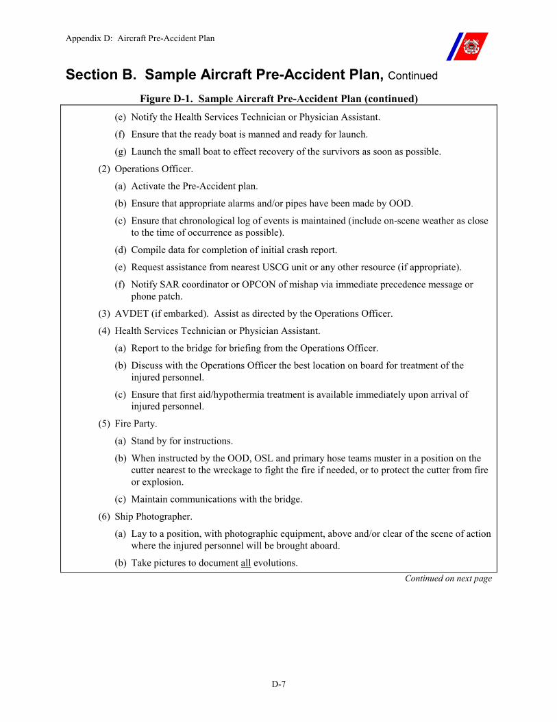
Appendix D: Aircraft Pre-Accident Plan
D-7
Section B. Sample Aircraft Pre-Accident Plan, Continued
Figure D-1. Sample Aircraft Pre-Accident Plan (continued) (e) Notify the Health Services Technician or Physician Assistant.
(f) Ensure that the ready boat is manned and ready for launch.
(g) Launch the small boat to effect recovery of the survivors as soon as possible.
(2) Operations Officer.
(a) Activate the Pre-Accident plan.
(b) Ensure that appropriate alarms and/or pipes have been made by OOD.
(c) Ensure that chronological log of events is maintained (include on-scene weather as close to the time of occurrence as possible).
(d) Compile data for completion of initial crash report.
(e) Request assistance from nearest USCG unit or any other resource (if appropriate).
(f) Notify SAR coordinator or OPCON of mishap via immediate precedence message or phone patch.
(3) AVDET (if embarked). Assist as directed by the Operations Officer.
(4) Health Services Technician or Physician Assistant.
(a) Report to the bridge for briefing from the Operations Officer.
(b) Discuss with the Operations Officer the best location on board for treatment of the injured personnel.
(c) Ensure that first aid/hypothermia treatment is available immediately upon arrival of injured personnel.
(5) Fire Party.
(a) Stand by for instructions.
(b) When instructed by the OOD, OSL and primary hose teams muster in a position on the cutter nearest to the wreckage to fight the fire if needed, or to protect the cutter from fire or explosion.
(c) Maintain communications with the bridge.
(6) Ship Photographer.
(a) Lay to a position, with photographic equipment, above and/or clear of the scene of action where the injured personnel will be brought aboard.
(b) Take pictures to document all evolutions. Continued on next page
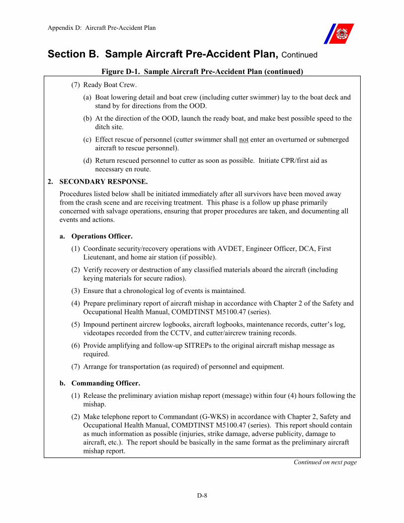
Appendix D: Aircraft Pre-Accident Plan
D-8
Section B. Sample Aircraft Pre-Accident Plan, Continued
Figure D-1. Sample Aircraft Pre-Accident Plan (continued) (7) Ready Boat Crew.
(a) Boat lowering detail and boat crew (including cutter swimmer) lay to the boat deck and stand by for directions from the OOD.
(b) At the direction of the OOD, launch the ready boat, and make best possible speed to the ditch site.
(c) Effect rescue of personnel (cutter swimmer shall not enter an overturned or submerged aircraft to rescue personnel).
(d) Return rescued personnel to cutter as soon as possible. Initiate CPR/first aid as necessary en route.
2. SECONDARY RESPONSE.
Procedures listed below shall be initiated immediately after all survivors have been moved away from the crash scene and are receiving treatment. This phase is a follow up phase primarily concerned with salvage operations, ensuring that proper procedures are taken, and documenting all events and actions.
a. Operations Officer.
(1) Coordinate security/recovery operations with AVDET, Engineer Officer, DCA, First Lieutenant, and home air station (if possible).
(2) Verify recovery or destruction of any classified materials aboard the aircraft (including keying materials for secure radios).
(3) Ensure that a chronological log of events is maintained.
(4) Prepare preliminary report of aircraft mishap in accordance with Chapter 2 of the Safety and Occupational Health Manual, COMDTINST M5100.47 (series).
(5) Impound pertinent aircrew logbooks, aircraft logbooks, maintenance records, cutter’s log, videotapes recorded from the CCTV, and cutter/aircrew training records.
(6) Provide amplifying and follow-up SITREPs to the original aircraft mishap message as required.
(7) Arrange for transportation (as required) of personnel and equipment.
b. Commanding Officer.
(1) Release the preliminary aviation mishap report (message) within four (4) hours following the mishap.
(2) Make telephone report to Commandant (G-WKS) in accordance with Chapter 2, Safety and Occupational Health Manual, COMDTINST M5100.47 (series). This report should contain as much information as possible (injuries, strike damage, adverse publicity, damage to aircraft, etc.). The report should be basically in the same format as the preliminary aircraft mishap report.
Continued on next page
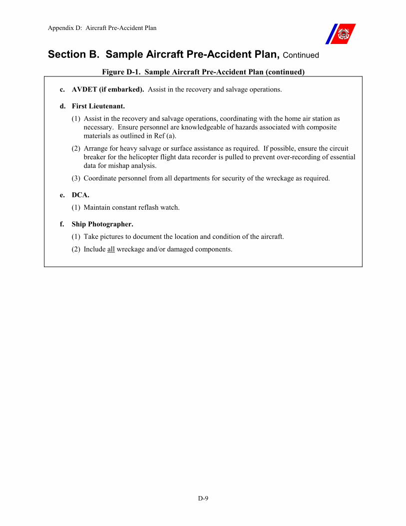
Appendix D: Aircraft Pre-Accident Plan
D-9
Section B. Sample Aircraft Pre-Accident Plan, Continued
Figure D-1. Sample Aircraft Pre-Accident Plan (continued)
c. AVDET (if embarked). Assist in the recovery and salvage operations.
d. First Lieutenant.
(1) Assist in the recovery and salvage operations, coordinating with the home air station as necessary. Ensure personnel are knowledgeable of hazards associated with composite materials as outlined in Ref (a).
(2) Arrange for heavy salvage or surface assistance as required. If possible, ensure the circuit breaker for the helicopter flight data recorder is pulled to prevent over-recording of essential data for mishap analysis.
(3) Coordinate personnel from all departments for security of the wreckage as required.
e. DCA.
(1) Maintain constant reflash watch.
f. Ship Photographer.
(1) Take pictures to document the location and condition of the aircraft.
(2) Include all wreckage and/or damaged components.
Appendix E: Coast Guard Helicopter Operating Capabilities
E-i
APPENDIX E: COAST GUARD HELICOPTER OPERATING CAPABILITIES
Table of Contents
Introduction................................................................................................................................E-1
In this appendix..........................................................................................................................E-1
Section A. HH-65 Operating Capabilities...............................................................................E-2
A.1. Overview ............................................................................................................................E-2
A.2. Airspeed .............................................................................................................................E-2
A.3. Weights...............................................................................................................................E-2
A.4. Capacities...........................................................................................................................E-2
A.5. Endurance..........................................................................................................................E-2
A.6. Aircraft Rescue and Survival Equipment.......................................................................E-3
A.7. Temperature and Altitude Restrictions ..........................................................................E-3
A.8. Electronics Equipment .....................................................................................................E-4
Section B. HH-60 Operating Capabilities...............................................................................E-5
B.1. Overview ............................................................................................................................E-5
B.2. Airspeed..............................................................................................................................E-5
B.3. Weights...............................................................................................................................E-5
B.4. Capacities ...........................................................................................................................E-5
B.5. Endurance..........................................................................................................................E-5
B.6. Aircraft Rescue and Survival Equipment.......................................................................E-6
B.7. Temperature and Altitude Restrictions ..........................................................................E-6
B.8. Electronics Equipment......................................................................................................E-7

Appendix E: Coast Guard Helicopter Operating Capabilities
E-ii
Appendix E: Coast Guard Helicopter Operating Capabilities
E-1
Appendix E. Coast Guard Helicopter Operating
Capabilities
Introduction This appendix presents the operating capabilities of the U.S. Coast Guard’s two types of helicopters, the HH-65 and the HH-60.
In this appendix This appendix is divided into two sections:
�� Section A: HH-65 Operating Capabilities �� Section B: HH-60 Operating Capabilities
Appendix E: Coast Guard Helicopter Operating Capabilities
E-2
Section A. HH-65 Operating Capabilities
A.1. Overview Some basic information on the HH-65 is provided for guidance and general planning.
Data that are more specific can be obtained from the helicopter flight manual and/or the aviation crewmembers that will perform the assigned mission.
A.2. Airspeed �� The maximum airspeed varies from 145 to 150 knots depending upon gross weight
�� The maximum sideward or rearward flight is 35 knots �� The normal cruise airspeed is 120 to 140 knots
A.3. Weights �� The basic weight is approximately 6,600 pounds, not including fuel, cargo, crew, or passengers.
�� The maximum allowable gross weight is 9,200 pounds and for shipboard operations is 8,900 pounds. However, certain conditions such as high temperature, high humidity, turbulence, high altitude, or flight deck motion may decrease the gross weight for a specific mission.
�� Normal crew and passenger weight is computed at 200 pounds per person, depending upon the individual and survival equipment required.
�� Normal mission planning fuel consumption is 600 pounds per hour. �� The hoist capacity is 600 pounds. The external cargo sling limit is
2,000 pounds. �� The maximum usable payload is approximately 2,300 pounds
distributed between the crew, fuel, passengers, and cargo.
A.4. Capacities �� Maximum fuel tank capacity is 1,972 pounds of JP-5 fuel, and �� The normal fuel load is between 1200-1500 pounds depending on
environmental conditions. JP-5 weighs approximately 6.7 pounds per gallon.
�� Hot refueling is limited to 1,500 pounds of fuel.
A.5. Endurance �� Maximum endurance is approximately three (3) to four (4) hours, and
�� Normal endurance is approximately two (2) hours. Continued on next page
Appendix E: Coast Guard Helicopter Operating Capabilities
E-3
Section A. HH-65 Operating Capabilities, Continued
A.6. Aircraft Rescue and Survival Equipment
Refer to the Air Operations Manual, COMDTINST M3710.1 (series).
A.7. Temperature and Altitude Restrictions
The major problems with cold weather operations are the preparation for flight, restricted visibility from blowing snow, icing, and adverse effects on helicopter materials and systems.
�� Wind chill on helicopter components cannot be predicted. Moisture, usually from condensation or melted snow, may freeze in critical areas.
�� The minimum ambient temperatures can be found in the flight handbook.
�� Preheating should be used before starting when temperatures are below prescribed limits.
�� Rotor wash and wind will reduce the efficiency of exposed personnel.
�� Flight decks may become icy and hazardous.
Helicopter performance at high-density altitudes is greatly reduced.
�� Operations requiring other than “transient flight” at altitudes above 10,000 feet should be attempted only after careful consideration of the requirements for the mission.
�� The Air Operations Manual, COMDTINST M3710.1 (series), restrictions on flight without oxygen shall be complied with during the flight.
Continued on next page
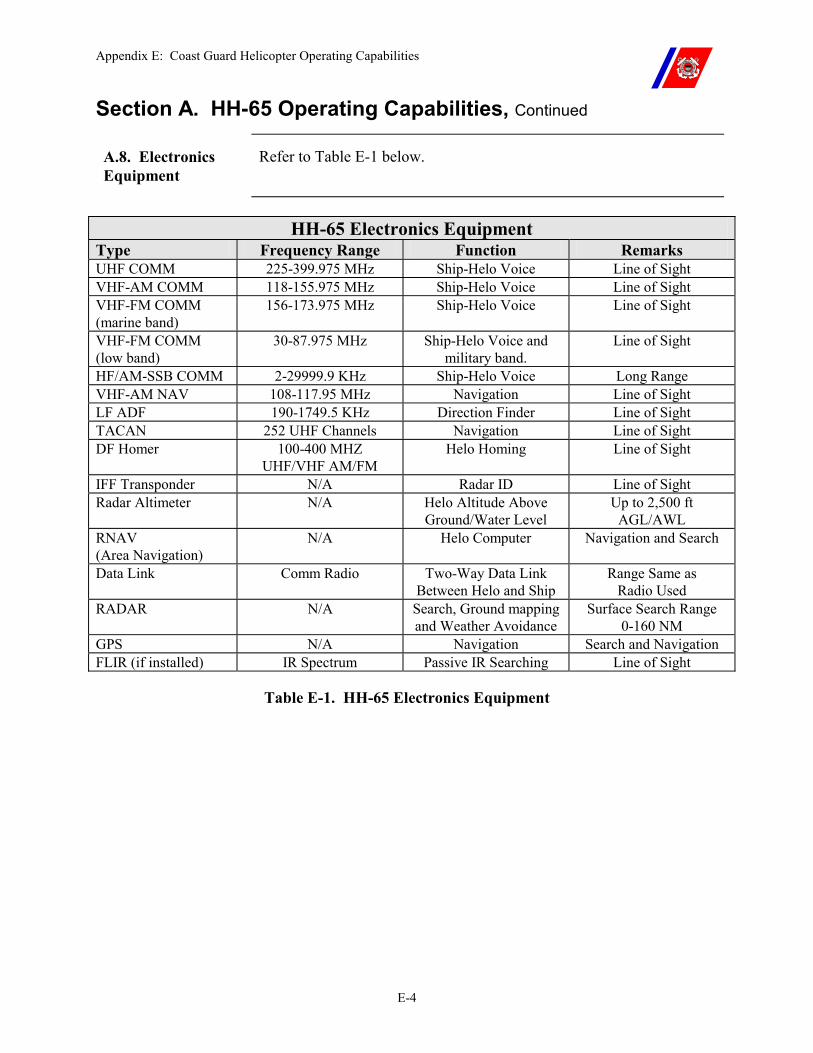
Appendix E: Coast Guard Helicopter Operating Capabilities
E-4
Section A. HH-65 Operating Capabilities, Continued
A.8. Electronics Equipment
Refer to Table E-1 below.
HH-65 Electronics Equipment
Type Frequency Range Function Remarks UHF COMM 225-399.975 MHz Ship-Helo Voice Line of Sight VHF-AM COMM 118-155.975 MHz Ship-Helo Voice Line of Sight VHF-FM COMM (marine band)
156-173.975 MHz Ship-Helo Voice Line of Sight
VHF-FM COMM (low band)
30-87.975 MHz Ship-Helo Voice and military band.
Line of Sight
HF/AM-SSB COMM 2-29999.9 KHz Ship-Helo Voice Long Range VHF-AM NAV 108-117.95 MHz Navigation Line of Sight LF ADF 190-1749.5 KHz Direction Finder Line of Sight TACAN 252 UHF Channels Navigation Line of Sight DF Homer 100-400 MHZ
UHF/VHF AM/FM Helo Homing Line of Sight
IFF Transponder N/A Radar ID Line of Sight Radar Altimeter N/A Helo Altitude Above
Ground/Water Level Up to 2,500 ft
AGL/AWL RNAV (Area Navigation)
N/A Helo Computer Navigation and Search
Data Link Comm Radio Two-Way Data Link Between Helo and Ship
Range Same as Radio Used
RADAR N/A Search, Ground mapping and Weather Avoidance
Surface Search Range 0-160 NM
GPS N/A Navigation Search and Navigation FLIR (if installed) IR Spectrum Passive IR Searching Line of Sight
Table E-1. HH-65 Electronics Equipment
Appendix E: Coast Guard Helicopter Operating Capabilities
E-5
Section B. HH-60 Operating Capabilities
B.1. Overview Some basic information on the HH-60 is provided for guidance and general planning.
Data that are more specific can be obtained from the helicopter flight manual and/or the aviation crewmembers that will perform the assigned mission.
B.2. Airspeed �� The maximum airspeed is 180 knots �� Maximum sideward/rearward flight is 35 knots �� Normal cruise airspeed is 135 to 145 knots
B.3. Weights �� The basic weight is approximately 14,300 pounds, not including fuel, cargo, crew, or passengers.
�� The maximum allowable gross weight is 21,884 pounds (for Ship-Helo use - 20,000 pounds). However, certain conditions such as high temperature, high humidity, turbulence, high altitude, or flight deck motion may decrease the gross weight for a specific mission.
�� Normal crew and passenger weight is computed at 200 pounds per person, depending upon the individual and survival equipment required.
�� Normal fuel consumption is 1200 pounds per hour. �� Hoist capacity is 600 pounds. �� The external cargo sling limit is 6,000 pounds, but normal loads
will vary between 3,000 and 4,000 pounds. �� Maximum usable payload is approximately 7,500 pounds
distributed between the crew, fuel, passengers, and cargo.
B.4. Capacities �� Maximum fuel tank capacity is in excess of 6,400 pounds of JP-5. �� Normal fuel load is 3,800 to 4,500 pounds.
B.5. Endurance �� Maximum endurance is approximately six (6) hours. �� Normal endurance is approximately 3.5 hours.
Continued on next page
Appendix E: Coast Guard Helicopter Operating Capabilities
E-6
Section B. HH-60 Operating Capabilities, Continued
B.6. Aircraft Rescue and Survival Equipment
Refer to the Air Operations Manual, COMDTINST M3710.1 (series).
B.7. Temperature and Altitude Restrictions
The major problems with cold weather operations are the preparation for flight, restricted visibility from blowing snow, icing, and adverse effects on helicopter materials and systems.
�� Wind chill to helicopter components cannot be predicted. �� Moisture, usually from condensation or melted snow, may freeze in
critical areas. �� The minimum ambient temperature can be found in the flight
handbook. �� Preheating should be used before starting when temperatures are
below prescribed limits. �� Rotor wash and wind will reduce the efficiency of exposed
personnel. �� Flight decks may become icy and hazardous.
Helicopter performance at high-density altitudes is greatly reduced.
�� Operations requiring other than “transient flight” at altitudes above 10,000 feet should be attempted only after careful consideration of the requirements for the mission.
�� The Air Operations Manual, COMDTINST M3710.1 (series), restrictions on flight without oxygen shall be complied with during the flight.
�� Missions at high altitude shall be planned for minimum ground time to avoid engine shutdown.
Continued on next page
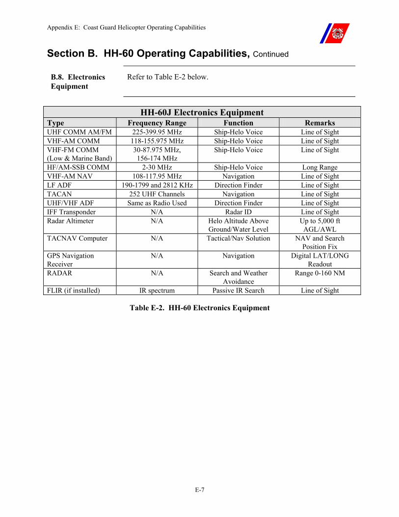
Appendix E: Coast Guard Helicopter Operating Capabilities
E-7
Section B. HH-60 Operating Capabilities, Continued
B.8. Electronics Equipment
Refer to Table E-2 below.
HH-60J Electronics Equipment
Type Frequency Range Function Remarks UHF COMM AM/FM 225-399.95 MHz Ship-Helo Voice Line of Sight VHF-AM COMM 118-155.975 MHz Ship-Helo Voice Line of Sight VHF-FM COMM (Low & Marine Band)
30-87.975 MHz, 156-174 MHz
Ship-Helo Voice Line of Sight
HF/AM-SSB COMM 2-30 MHz Ship-Helo Voice Long Range VHF-AM NAV 108-117.95 MHz Navigation Line of Sight LF ADF 190-1799 and 2812 KHz Direction Finder Line of Sight TACAN 252 UHF Channels Navigation Line of Sight UHF/VHF ADF Same as Radio Used Direction Finder Line of Sight IFF Transponder N/A Radar ID Line of Sight Radar Altimeter N/A Helo Altitude Above
Ground/Water Level Up to 5,000 ft
AGL/AWL TACNAV Computer N/A Tactical/Nav Solution NAV and Search
Position Fix GPS Navigation Receiver
N/A Navigation Digital LAT/LONG Readout
RADAR N/A Search and Weather Avoidance
Range 0-160 NM
FLIR (if installed) IR spectrum Passive IR Search Line of Sight
Table E-2. HH-60 Electronics Equipment
Appendix F: Air Station Deployment Checklist
F-i
APPENDIX F: AIR STATION DEPLOYMENT CHECKLIST Table of Contents
Introduction................................................................................................................................F-1
In this appendix..........................................................................................................................F-1
Section A. Sample Air Station Deployment Checklist ...........................................................F-2
A.1. Overview ............................................................................................................................F-2

Appendix F: Air Station Deployment Checklist
F-ii
Appendix F: Air Station Deployment Checklist
F-1
Appendix F. Air Station Deployment Checklist
Introduction Each air station shall develop and maintain a deployment checklist.
District Commanders should strive to notify air stations of upcoming deployment requirements far enough in advance to allow for adequate preparation.
A sample checklist is provided in Figure F-1 as a guide.
In this appendix This appendix consists of one (1) section:
�� Section A: Sample Air Station Deployment Checklist

Appendix F: Air Station Deployment Checklist
F-2
Section A. Sample Air Station Deployment Checklist
A.1. Overview A sample Air Station Deployment Checklist follows as Figure F-1.
A. Pre-Deployment Activities
1. Assignment of Personnel a. Deployment formation memo b. Quality assurance and maintenance release authority letters c. Pre-deployment training and briefing
(1) Ship-Helo flight procedures (2) Unplanned operations (i.e., mountain ops, beach ops) (3) Operating area weather (4) Helicopter navigation (5) Foreign Clearance Guide (6) Pertinent sections of the Coast Guard Safety and Occupational Health Manual,
COMDTINST M5100.47 (series) (7) Shipboard customs, courtesies and daily routine, etc. (8) Main rotor blade (MRB) folding and removal. (Mandatory training
requirement) (9) Airframe protective cover installation and removal (10) Traversing (Mandatory training requirement except for deployment on
non-hangar equipped cutters) (11) VERTREP and HIFR (nozzle familiarization)
d. Orders issued e. Law enforcement briefing f. Review aircrew health and vaccination records
2. Assignment of Equipment a. NVGs b. Observer’s flight equipment c. Gyro stabilized binoculars d. Camera, video recorder, film, and tapes (as required) e. Foul and Extreme weather clothing (as appropriate) f. Fly-away tool kit g. HSK
Figure F-1. Air Station Deployment Checklist Continued on next page
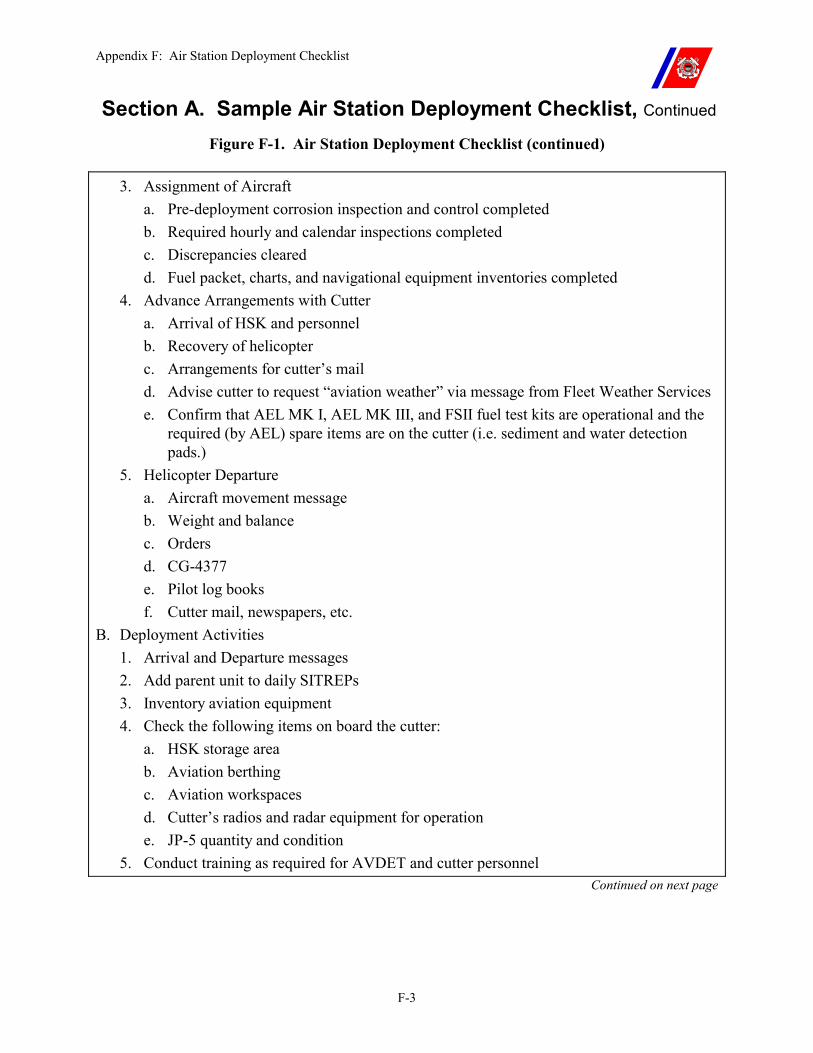
Appendix F: Air Station Deployment Checklist
F-3
Section A. Sample Air Station Deployment Checklist, Continued Figure F-1. Air Station Deployment Checklist (continued)
3. Assignment of Aircraft
a. Pre-deployment corrosion inspection and control completed b. Required hourly and calendar inspections completed c. Discrepancies cleared d. Fuel packet, charts, and navigational equipment inventories completed
4. Advance Arrangements with Cutter a. Arrival of HSK and personnel b. Recovery of helicopter c. Arrangements for cutter’s mail d. Advise cutter to request “aviation weather” via message from Fleet Weather Services e. Confirm that AEL MK I, AEL MK III, and FSII fuel test kits are operational and the
required (by AEL) spare items are on the cutter (i.e. sediment and water detection pads.)
5. Helicopter Departure a. Aircraft movement message b. Weight and balance c. Orders d. CG-4377 e. Pilot log books f. Cutter mail, newspapers, etc.
B. Deployment Activities 1. Arrival and Departure messages 2. Add parent unit to daily SITREPs 3. Inventory aviation equipment 4. Check the following items on board the cutter:
a. HSK storage area b. Aviation berthing c. Aviation workspaces d. Cutter’s radios and radar equipment for operation e. JP-5 quantity and condition
5. Conduct training as required for AVDET and cutter personnel Continued on next page
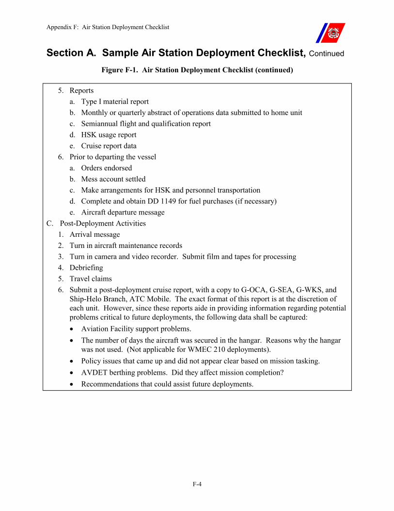
Appendix F: Air Station Deployment Checklist
F-4
Section A. Sample Air Station Deployment Checklist, Continued Figure F-1. Air Station Deployment Checklist (continued)
5. Reports
a. Type I material report b. Monthly or quarterly abstract of operations data submitted to home unit c. Semiannual flight and qualification report d. HSK usage report e. Cruise report data
6. Prior to departing the vessel a. Orders endorsed b. Mess account settled c. Make arrangements for HSK and personnel transportation d. Complete and obtain DD 1149 for fuel purchases (if necessary) e. Aircraft departure message
C. Post-Deployment Activities 1. Arrival message 2. Turn in aircraft maintenance records 3. Turn in camera and video recorder. Submit film and tapes for processing 4. Debriefing 5. Travel claims 6. Submit a post-deployment cruise report, with a copy to G-OCA, G-SEA, G-WKS, and
Ship-Helo Branch, ATC Mobile. The exact format of this report is at the discretion of each unit. However, since these reports aide in providing information regarding potential problems critical to future deployments, the following data shall be captured: �� Aviation Facility support problems. �� The number of days the aircraft was secured in the hangar. Reasons why the hangar
was not used. (Not applicable for WMEC 210 deployments). �� Policy issues that came up and did not appear clear based on mission tasking. �� AVDET berthing problems. Did they affect mission completion? �� Recommendations that could assist future deployments.
Appendix G: Air Direction Control Communications Doctrine
G-i
APPENDIX G: AIR DIRECTION CONTROL COMMUNICATIONS DOCTRINE
Table of Contents
Introduction............................................................................................................................... G-1
In this appendix......................................................................................................................... G-1
Section A. Normal Procedures................................................................................................ G-2
A.1. Aircraft Check-In............................................................................................................. G-2 A.1.a. Procedures ........................................................................................................................... G-3
A.2. Air Traffic Advisories...................................................................................................... G-4 A.2.a. Procedures ........................................................................................................................... G-4
A.3. Aircraft Check-Out.......................................................................................................... G-6 A.3.a. Procedures ........................................................................................................................... G-6
Section B. Aircraft Emergency Procedures ........................................................................... G-7
B.1. General .............................................................................................................................. G-7 B.1.a. Emergency Procedures ........................................................................................................ G-8
B.2. Aircraft Ditching .............................................................................................................. G-8
Section C. Air Direction Control Prowords........................................................................... G-9
C.1. Overview ........................................................................................................................... G-9

Appendix G: Air Direction Control Communications Doctrine
G-ii
Appendix G: Air Direction Control Communications Doctrine
G-1
Appendix G. Air Direction Control Communications
Doctrine
Introduction This appendix provides information on Air Direction Control communications.
In this appendix This appendix is divided into three (3) sections:
�� Section A: Normal Procedures �� Section B: Aircraft Emergency Procedures �� Section C: Air Direction Control Prowords
Appendix G: Air Direction Control Communications Doctrine
G-2
Section A. Normal Procedures
A.1. Aircraft Check-In
Communicating certain essential information is required between an aircraft checking in for Positive or Advisory Control and the ship’s Air Direction Controller (ADC). This initial communication should be conducted in accordance with the following format, corresponding to the acronym PLANET.
�� P — Pilot reports souls on board and fuel state. �� L — Location of the aircraft relative to the ship. �� A — Altimeter setting. ADC passes the local barometric pressure
(in inches of mercury i.e. 29.92) �� N — No communications. The ADC passes lost communications
instructions to the aircraft. �� E — Execute and expect. The ADC passes what type of air control
(Positive or Advisory) to execute and what type of approach (visual or instrument) to expect to the ship.
�� T — Tell. ADC advises the CIC watch supervisor and/or the OOD that CIC has accepted control of the aircraft and the ETA.
NOTE These check-in procedures are not required for sorties originating from the cutter. This information will have been passed during the preflight briefing.
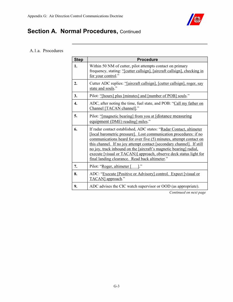
Appendix G: Air Direction Control Communications Doctrine
G-3
Section A. Normal Procedures, Continued
A.1.a. Procedures
Step Procedure 1. Within 50 NM of cutter, pilot attempts contact on primary
frequency, stating: “[cutter callsign], [aircraft callsign], checking in for your control.”
2. Cutter ADC replies: “[aircraft callsign], [cutter callsign], roger, say state and souls.”
3. Pilot: “[hours] plus [minutes] and [number of POB] souls.”
4. ADC, after noting the time, fuel state, and POB: “Call my father on Channel [TACAN channel].”
5. Pilot: “[magnetic bearing] from you at [distance measuring equipment (DME) reading] miles.”
6. If radar contact established, ADC states: “Radar Contact, altimeter [local barometric pressure]. Lost communication procedures: if no communications heard for over five (5) minutes, attempt contact on this channel. If no joy attempt contact [secondary channel]. If still no joy, track inbound on the [aircraft’s magnetic bearing] radial, execute [visual or TACAN)] approach, observe deck status light for final landing clearance. Read back altimeter.”
7. Pilot: “Roger, altimeter [ ].”
8. ADC: “Execute [Positive or Advisory] control. Expect [visual or TACAN] approach.”
9. ADC advises the CIC watch supervisor or OOD (as appropriate). Continued on next page
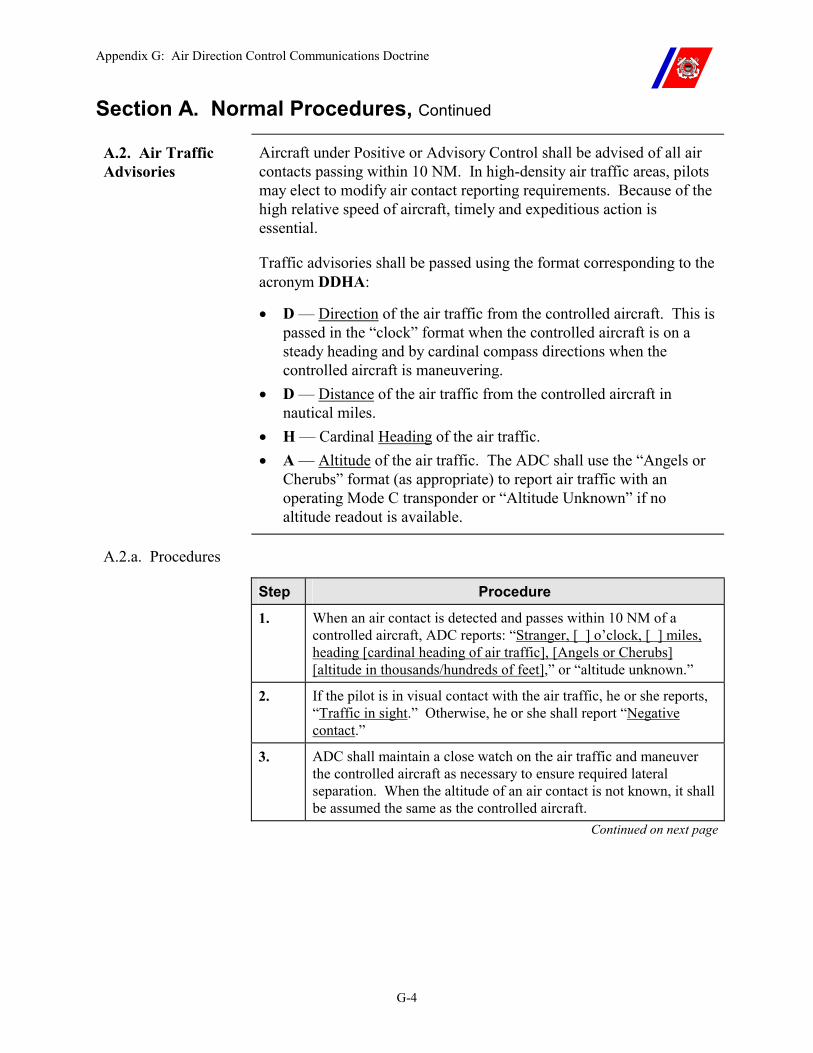
Appendix G: Air Direction Control Communications Doctrine
G-4
Section A. Normal Procedures, Continued
A.2. Air Traffic Advisories
Aircraft under Positive or Advisory Control shall be advised of all air contacts passing within 10 NM. In high-density air traffic areas, pilots may elect to modify air contact reporting requirements. Because of the high relative speed of aircraft, timely and expeditious action is essential.
Traffic advisories shall be passed using the format corresponding to the acronym DDHA:
�� D — Direction of the air traffic from the controlled aircraft. This is passed in the “clock” format when the controlled aircraft is on a steady heading and by cardinal compass directions when the controlled aircraft is maneuvering.
�� D — Distance of the air traffic from the controlled aircraft in nautical miles.
�� H — Cardinal Heading of the air traffic. �� A — Altitude of the air traffic. The ADC shall use the “Angels or
Cherubs” format (as appropriate) to report air traffic with an operating Mode C transponder or “Altitude Unknown” if no altitude readout is available.
A.2.a. Procedures
Step Procedure
1. When an air contact is detected and passes within 10 NM of a controlled aircraft, ADC reports: “Stranger, [ ] o’clock, [ ] miles, heading [cardinal heading of air traffic], [Angels or Cherubs] [altitude in thousands/hundreds of feet],” or “altitude unknown.”
2. If the pilot is in visual contact with the air traffic, he or she reports, “Traffic in sight.” Otherwise, he or she shall report “Negative contact.”
3. ADC shall maintain a close watch on the air traffic and maneuver the controlled aircraft as necessary to ensure required lateral separation. When the altitude of an air contact is not known, it shall be assumed the same as the controlled aircraft.
Continued on next page
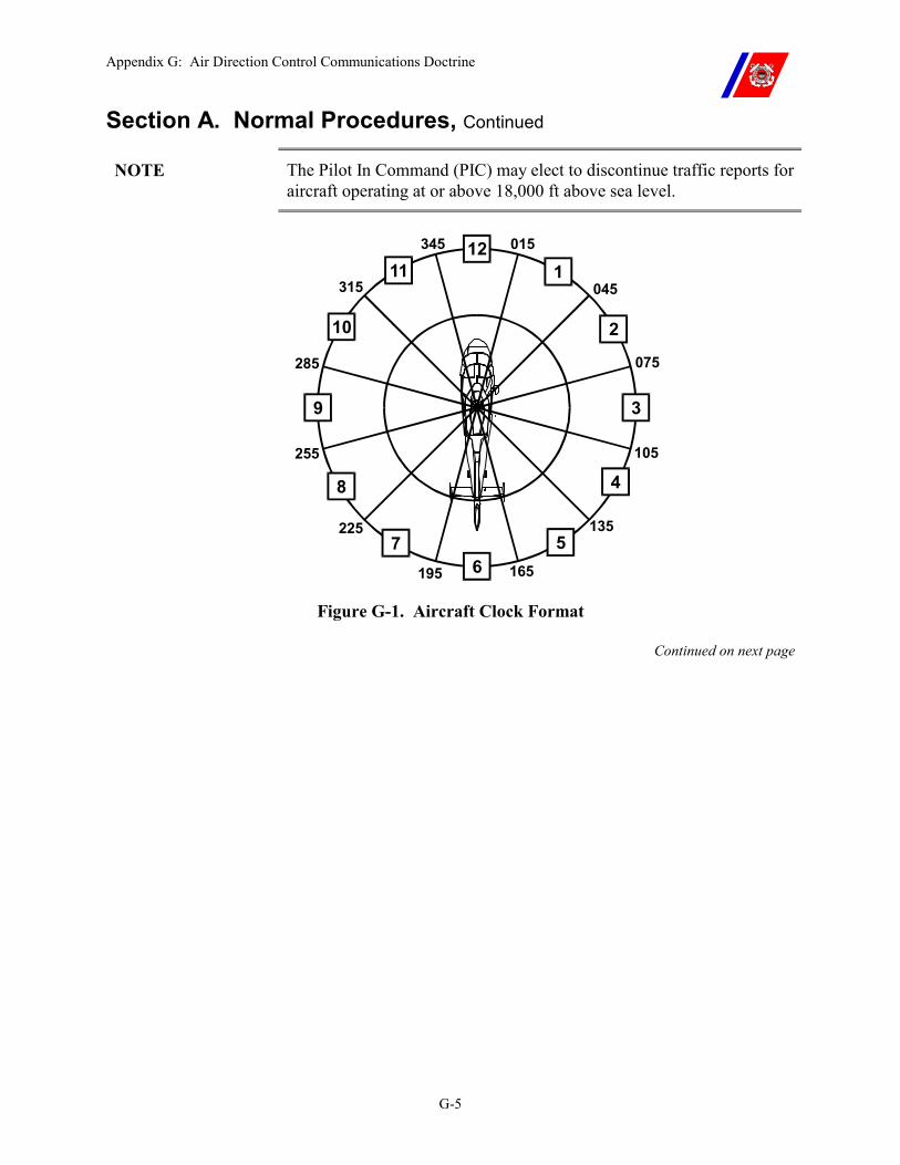
Appendix G: Air Direction Control Communications Doctrine
G-5
Section A. Normal Procedures, Continued
NOTE The Pilot In Command (PIC) may elect to discontinue traffic reports for aircraft operating at or above 18,000 ft above sea level.
12
1
2
3
4
56
7
8
9
10
11015
045
075
105
135
165195
225
255
285
315
345
Figure G-1. Aircraft Clock Format
Continued on next page
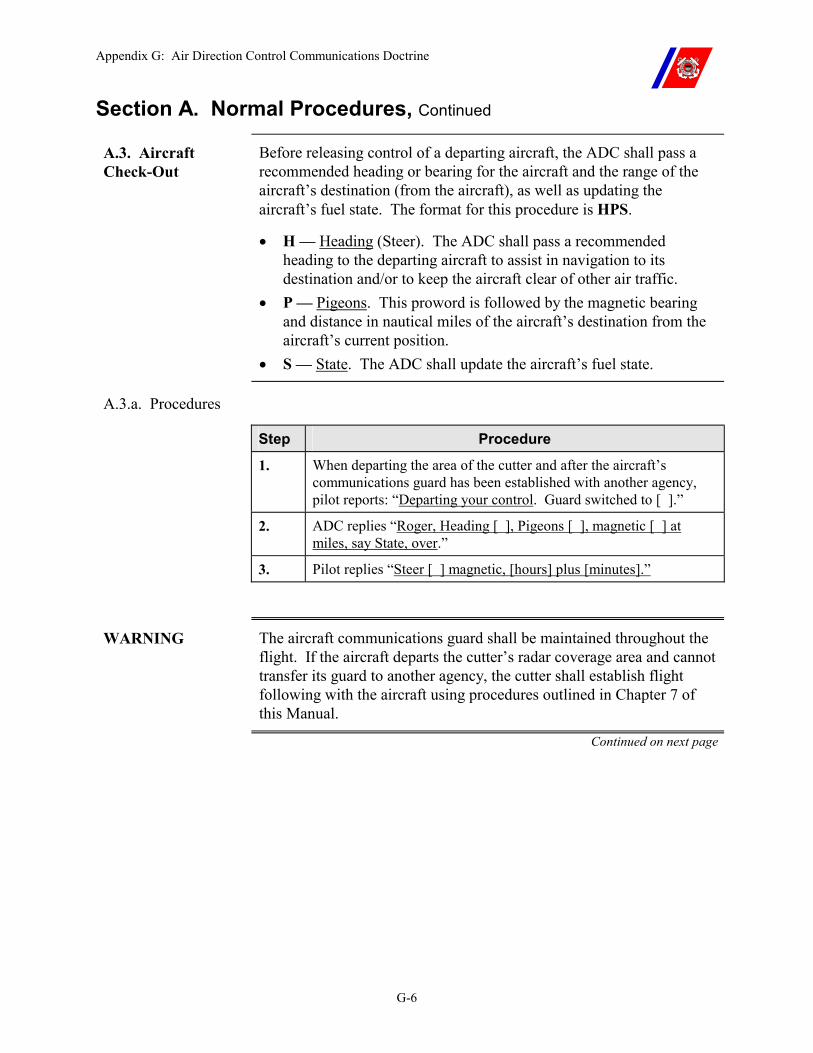
Appendix G: Air Direction Control Communications Doctrine
G-6
Section A. Normal Procedures, Continued
A.3. Aircraft Check-Out
Before releasing control of a departing aircraft, the ADC shall pass a recommended heading or bearing for the aircraft and the range of the aircraft’s destination (from the aircraft), as well as updating the aircraft’s fuel state. The format for this procedure is HPS.
�� H — Heading (Steer). The ADC shall pass a recommended heading to the departing aircraft to assist in navigation to its destination and/or to keep the aircraft clear of other air traffic.
�� P — Pigeons. This proword is followed by the magnetic bearing and distance in nautical miles of the aircraft’s destination from the aircraft’s current position.
�� S — State. The ADC shall update the aircraft’s fuel state.
A.3.a. Procedures
Step Procedure
1. When departing the area of the cutter and after the aircraft’s communications guard has been established with another agency, pilot reports: “Departing your control. Guard switched to [ ].”
2. ADC replies “Roger, Heading [ ], Pigeons [ ], magnetic [ ] at miles, say State, over.”
3. Pilot replies “Steer [ ] magnetic, [hours] plus [minutes].”
WARNING The aircraft communications guard shall be maintained throughout the flight. If the aircraft departs the cutter’s radar coverage area and cannot transfer its guard to another agency, the cutter shall establish flight following with the aircraft using procedures outlined in Chapter 7 of this Manual.
Continued on next page
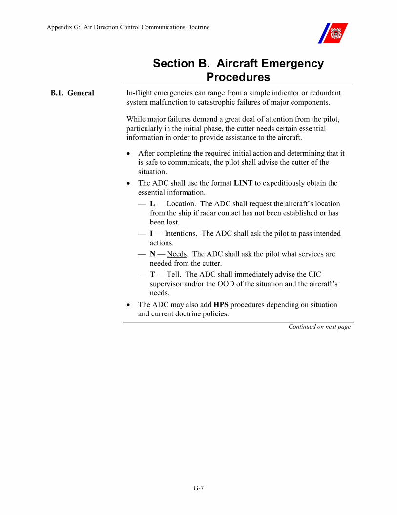
Appendix G: Air Direction Control Communications Doctrine
G-7
Section B. Aircraft Emergency Procedures
B.1. General In-flight emergencies can range from a simple indicator or redundant system malfunction to catastrophic failures of major components.
While major failures demand a great deal of attention from the pilot, particularly in the initial phase, the cutter needs certain essential information in order to provide assistance to the aircraft.
�� After completing the required initial action and determining that it is safe to communicate, the pilot shall advise the cutter of the situation.
�� The ADC shall use the format LINT to expeditiously obtain the essential information. �� L — Location. The ADC shall request the aircraft’s location
from the ship if radar contact has not been established or has been lost.
�� I — Intentions. The ADC shall ask the pilot to pass intended actions.
�� N — Needs. The ADC shall ask the pilot what services are needed from the cutter.
�� T — Tell. The ADC shall immediately advise the CIC supervisor and/or the OOD of the situation and the aircraft’s needs.
�� The ADC may also add HPS procedures depending on situation and current doctrine policies.
Continued on next page
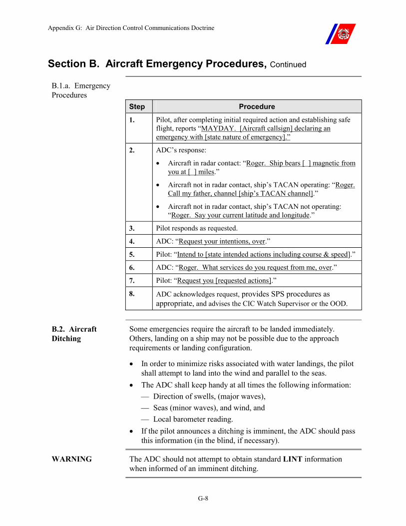
Appendix G: Air Direction Control Communications Doctrine
G-8
Section B. Aircraft Emergency Procedures, Continued
B.1.a. Emergency Procedures
Step Procedure
1. Pilot, after completing initial required action and establishing safe flight, reports “MAYDAY. [Aircraft callsign] declaring an emergency with [state nature of emergency].”
2. ADC’s response:
�� Aircraft in radar contact: “Roger. Ship bears [ ] magnetic from you at [ ] miles.”
�� Aircraft not in radar contact, ship’s TACAN operating: “Roger. Call my father, channel [ship’s TACAN channel].”
�� Aircraft not in radar contact, ship’s TACAN not operating: “Roger. Say your current latitude and longitude.”
3. Pilot responds as requested.
4. ADC: “Request your intentions, over.”
5. Pilot: “Intend to [state intended actions including course & speed].”
6. ADC: “Roger. What services do you request from me, over.”
7. Pilot: “Request you [requested actions].”
8. ADC acknowledges request, provides SPS procedures as appropriate, and advises the CIC Watch Supervisor or the OOD.
B.2. Aircraft Ditching
Some emergencies require the aircraft to be landed immediately. Others, landing on a ship may not be possible due to the approach requirements or landing configuration.
�� In order to minimize risks associated with water landings, the pilot shall attempt to land into the wind and parallel to the seas.
�� The ADC shall keep handy at all times the following information: �� Direction of swells, (major waves), �� Seas (minor waves), and wind, and �� Local barometer reading.
�� If the pilot announces a ditching is imminent, the ADC should pass this information (in the blind, if necessary).
WARNING The ADC should not attempt to obtain standard LINT information when informed of an imminent ditching.
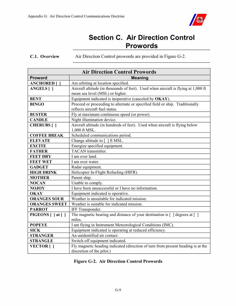
Appendix G: Air Direction Control Communications Doctrine
G-9
Section C. Air Direction Control Prowords
C.1. Overview Air Direction Control prowords are provided in Figure G-2.
Air Direction Control Prowords
Proword Meaning ANCHORED [ ] Am orbiting at location specified. ANGELS [ ] Aircraft altitude (in thousands of feet). Used when aircraft is flying at 1,000 ft
mean sea level (MSL) or higher. BENT Equipment indicated is inoperative (canceled by OKAY). BINGO Proceed or proceeding to alternate or specified field or ship. Traditionally
reflects aircraft fuel status. BUSTER Fly at maximum continuous speed (or power). CANDLE Night illumination device. CHERUBS [ ] Aircraft altitude (in hundreds of feet). Used when aircraft is flying below
1,000 ft MSL. COFFEE BREAK Scheduled communications period. ELEVATE Change altitude to [ ] ft MSL. EXCITE Energize specified equipment. FATHER TACAN transmitter. FEET DRY I am over land. FEET WET I am over water. GADGET Radar equipment. HIGH DRINK Helicopter In-Flight Refueling (HIFR). MOTHER Parent ship. NOCAN Unable to comply. NOJOY I have been unsuccessful or I have no information. OKAY Equipment indicated is operative. ORANGES SOUR Weather is unsuitable for indicated mission. ORANGES SWEET Weather is suitable for indicated mission. PARROT IFF Transponder. PIGEONS [ ] at [ ] The magnetic bearing and distance of your destination is [ ] degrees at [ ]
miles. POPEYE I am flying in Instrument Meteorological Conditions (IMC). SICK Equipment indicated is operating at reduced efficiency. STRANGER An unidentified air contact. STRANGLE Switch off equipment indicated. VECTOR [ ] Fly magnetic heading indicated (direction of turn from present heading is at the
discretion of the pilot.)
Figure G-2. Air Direction Control Prowords

Appendix H: Unmanned Aerial Vehicle
H-i
APPENDIX H: UNMANNED AERIAL VEHICLE Table of Contents
Introduction............................................................................................................................... H-1
Section A. To Be Developed ..................................................................................................... H-2
A.1. Unmanned Aerial Vehicles (UAV).................................................................................. H-2

Appendix H: Unmanned Aerial Vehicle
H-ii

Appendix H: Unmanned Aerial Vehicle
H-1
Appendix H. Unmanned Aerial Vehicles
Introduction This appendix provides information on Unmanned Aerial Vehicle (UAV) policies and procedures. This chapter will be expanded in the future.

Appendix H: Unmanned Aerial Vehicle
H-2
Section A. To Be Developed
A.1. Unmanned Aerial Vehicles (UAV)
Under development.
Appendix I: NVG Operations
I-i
APPENDIX I: SUMMARY OF NVG OPERATIONS Table of Contents
Introduction.................................................................................................................................I-1
In this appendix...........................................................................................................................I-1
Section A. Authority to conduct Shipboard NVG Operations ...............................................I-2
A.1. Authority to Conduct Shipboard NVG Operations........................................................I-2
Section B. Cutter NVG Certification.........................................................................................I-3
B.1 Certification ..........................................................................................................................I-3
B.2. Required Equipment..........................................................................................................I-3
Section C. Cutter NVG Qualification........................................................................................I-5
C.1. Qualification Requirements ...............................................................................................I-5 C.1.a. NVG LSO Training Requirements.........................................................................................I-5 C.2.a. LSO Stage Training...............................................................................................................I-6
C.2.a.(1). Stage One Requirements – Formal Classroom Training...........................................I-6 C.2.a.(2). Stage Two Requirements – Flight Deck Operations – High Light ...........................I-6 C.2.a.(3). Coast Guard Stage Three Requirements - Flight Deck Operations – Low Light......I-7
C.2.b. NVG LSO Currency Requirements.......................................................................................I-8

Appendix I: NVG Operations
I-ii
Appendix I: NVG Operations
I-1
Appendix I: Night Vision Goggle Operations
Introduction This appendix provides a summary of information on Night Vision Goggle (NVG) Operations. The use of NVGs affords pilots, aircrew, and flight deck personnel with improved visual acuity in night time conditions. NVG operations also provide increased safety, comfort levels, and operational capabilities over unaided flight operations at night. However, inherent NVG limitations, (i.e., field of view, depth perception, and environmental interference) require comprehensive training, awareness, and strict compliance with established procedures to ensure safe and effective NVG flight operations aboard the cutter.
In this appendix This appendix is divided into five (5) sections:
�� Section A: Authority to conduct NVG Operations �� Section B: Cutter NVG Certification and equipment requirements �� Section C: Cutter NVG Qualification �� Section D: Aircrew Shipboard NVG Qualifications �� Section E: Shipboard NVG Safety
Appendix I: NVG Operations
I-2
Section A. Authority to conduct Shipboard NVG Operations
A.1. Authority to Conduct Shipboard NVG Operations
These procedures apply to all flight deck equipped cutter NVG operations involving USCG, USN, USMC, USA, USAF, DEA, U.S. Customs, and foreign services. All cutters, units and personnel involved in or anticipating involvement in shipboard aviation NVG operations shall be familiar with and comply with all parent service directives pertaining to NVG flight operations. In case of conflict, this manual will take precedence.
NOTE Current MOU and LOIs shall guide all “special operations.” If conflicts arise concerning shipboard use of NVGs for a special operation, the MOU or LOI shall take precedence over the guidance and provisions of this Manual.
Appendix I: NVG Operations
I-3
Section B. Cutter NVG Certification
B.1 Certification Coast Guard Cutters shall be converted and certified by NAVAIR before conducting NVG Operations. All applicable cutter VLA lights will be outfitted with NVG compatible lenses and CCTVs will be changed out with NVG compatible cameras.
B.2. Required Equipment
The LSO shall use ANVIS style NVGs mounted to radio capable helmets to assist directing helicopter DLQs.
NVG compatible lights will be used by the LSO as signaling devices. Each tiedown team member shall wear a blue Chemlight for flight deck safety.
A NVG Safety Officer (NSO) is required for NVG operations and will use ANVIS style NVGs to backup LSO on the flight deck.
Shipboard NVGs shall be ANVIS style and with no less than three (3) pairs available (one (1) – LSO, one (1) – NSO, and one (1) – Spare or used by ATT member during initial qualification training).
NVGs. Only ANVIS or improved versions of this style are authorized for NVG flight operations aboard Coast Guard Cutters. AN/PVS-7 or similar style NVGs are not authorized for flight deck or pilot use due to the limited peripheral vision.
LSO Eye protection. When using NVGs, the LSO and NSO shall wear clear shatterproof type eye protection that provides a complete seal around the eyes (parachute goggles, etc). This type of eye protection is required to be worn by all flight deck personnel with ANVIS style goggles during NVG operations.
Continued on next page
Appendix I: NVG Operations
I-4
Section B. Cutter NVG Certification, Continued
B.2. Required Equipment (continued)
Cutter navigation and structure lighting. Each cutter shall have the following items aboard and in serviceable condition before commencing NVG operations:
�� Two (2) NVG compatible CCTV cameras. �� Three (3) sets of ANVIS style NVGs. �� Three (3) helmets (radio capable) for mounting ANVIS style NVGs. �� A dozen sets of clear shatterproof non-distorting eye protection
wear (parachute goggles). �� Appropriate number of blue Chemlights. �� Recommend two (2) dozen lights per flight operation planned. One
AN-AVN 20/20 (Hoffman box) or a portable NVG focusing lane comprised of Eye Chart (can be made from local materials).
�� Three (3) portable radios for use by the LSO, NSO, and other stations. Each station shall maintain appropriate circuit discipline.
Appendix I: NVG Operations
I-5
Section C. Cutter NVG Qualification
C.1. Qualification Requirements
The minimum number of NVG qualified personnel required to conduct Shipboard NVG Operations is two (2) comprised of the LSO and NSO.
C.1.a. NVG LSO Training Requirements
NVG LSO must complete all prerequisites and stage training requirements. Stages requirements:
�� Stage One – Formal Classroom Instruction �� Stage Two – Flight Deck Operations. The Prerequisites are:
�� Static deck orientation, PQS, and Stage One Training. �� Direct four (4) takeoff & landings with primary tiedowns and
four (4) T&Gs under high light conditions (>0.0022 lux) using NVGs.
�� Coast Guard Stage Three (USN Stage Five) – NVG launch and recovery operations under low light level conditions (< 0.0022 lux). The Prerequisites are: �� Complete Stage Two �� Direct four (4) takeoffs & landings with primary tiedowns and
four (4) T&Gs.
A qualified and current NVG LSO is required for all NVG flight operations.
NVG LSO currency requirements are:
�� Direct four (4) takeoffs and landings with primary tiedowns and four (4) T&Gs each semi-annual period. If a NVG LSO qualification lapses, the qualification must be completed again.
�� Periodic NVG LSO training should be conducted during each quarterly training period. However, each NVG qualified LSO (preferably the ATT member) will conduct one (1) hour of classroom instruction after every 90 days of non-NVG flight operations.
Continued on next page
Appendix I: NVG Operations
I-6
Section C. Cutter NVG Certification, Continued
C.2.a. LSO Stage Training
The NVG LSO Initial Qualification is achieved by LSOs completing all prerequisites and "stage" training requirements. Stages One and Two shall be completed for all personnel involved with flight operations on Coast Guard cutters.
C.2.a.(1). Stage One Requirements – Formal Classroom Training
Formal classroom training.
The LSO shall attend formal classroom training (HCO attendance is recommended) provided by ATC Mobile Ship-Helo Instructors or a qualified ATT member. Subject matter shall consist of, but not be limited to, the following areas:
1. NVG introduction
2. Night and NVG physiology
3. Environmental considerations
4. Aircrew tendencies when using NVGs
5. LSO signals and procedures (NVG and unaided)
6. Emergency procedures.
Personnel aboard cutters involved in flight operations (LSO and FSO) shall complete applicable USCG Night Vision Goggle Operator PQS.
C.2.a.(2). Stage Two Requirements – Flight Deck Operations – High Light
Flight deck operations.
The prerequisites are: Static deck orientation, PQS, and Stage One.
While under the direct supervision of an NVG qualified LSO, a LSO under instruction will direct four (4) vertical takeoffs and landings and four (4) T&Gs from the pattern under high light-level conditions (0.0022 lux or greater).
Continued on next page
Appendix I: NVG Operations
I-7
Section C. Cutter NVG Certification, Continued
C.2.a.(3). Coast Guard Stage Three Requirements - Flight Deck Operations – Low Light
Coast Guard Stage Three - NVG launch and recovery operations under low light level conditions (less than 0.0022 lux).
Prerequisites: Completion of Stage Two and have five (5) hours experience directing takeoffs and landings under Stage Two conditions.
�� Direct four (4) takeoff & landings w/primary tiedowns plus four (4) T&Gs under low light conditions (<0.0022 lux) using NVGs.
Coast Guard Stage Three NVG operations are defined as operations under low light-level conditions (less than 0.0022 lux) as defined by SLAP. The need to gain experience during Stage 2 operations is critical before conducting Stage 3 operations in low light conditions.
NOTE An NVG qualified LSO is required for all NVG flight operations up through Stage Two. Coast Guard Stage Three LSO qualifications are required to operate under low light level conditions.
The immediate shipboard flight deck environment shall be illuminated during personnel movement, ordnance operations, aircraft positioning, fueling, etc.
The Commanding Officer shall make the final determination of the cutter’s ability to support NVG operations and shall report completion of appropriate stages of qualification to G-OCA/OCU and the respective area commander.
Continued on next page
Appendix I: NVG Operations
I-8
Section C. Cutter NVG Certification, Continued
C.2.b. NVG LSO Currency Requirements
Periodic NVG LSO training should be conducted during divisional and departmental training periods. However, each NVG LSO will conduct at least one (1) hour classroom instruction or practical training on the NVGs after every 90 days of non-NVG flight operations. It is the responsibility of the ATT coordinator to document each NVG LSO participation in NVG operations and NVG training in the individual’s training record. Records should reflect (1) date of event, (2) aircraft type and air station, (3) type NVG used, (4) time actually spent using NVG in the conduct of NVG Operations. Training should consist of but not be limited to, the following areas:
1. Lighting requirement
2. LSO signals
3. Aircrew tendencies
4. Emergency procedures.
NVG LSO currency requirements are: must direct four (4) takeoffs and landings with primary tiedowns and four (4) T&Gs each semi-annual period. If NVG LSO lapses, qualification must be completed again.
Index
Index - 1
Above Ground Level Also See AGL.................................................. 5-15
ACMS......................................................... 12-6, 12-7 ADC...2-i, 2-4, 2-11, 2-14, 3-13, 5-19, 6-ii, 6-5, 6-12,
7-5, 7-6, 7-7, 7-10, 7-14, 7-15, 7-19, 7-20, 7-22, 7-23, 7-24, A-7, G-2, G-3, G-4, G-6, G-7, G-8
ADCON................................................................. 2-2 Administrative Control
Also See ADCON.............................................. 2-2 AEL .. 4-2, 4-3, 6-17, 8-13, 8-25, 8-30, 9-5, 9-7, 9-10,
9-13, 9-23, 9-24, 10-4, 14-20, F-3 AEL MK I..................8-13, 8-25, 8-30, 9-7, 9-13, F-3 AEL MK III ............................... 8-13, 8-25, 8-30, F-3 AFCS ............................................... 6-49, B-21, B-22 AFFF . 2-i, 2-6, 2-9, 2-13, 2-14, 5-14, 6-3, 6-14, 6-16,
14-ii, 14-4, 14-8, 14-9, 14-10, 14-13, 14-15, 14-16, 14-19, 14-22, 14-24, 14-25, 14-27, 14-29, 14-34
AFFF Station Operator ...........................2-i, 2-9, 2-14 AFR ..................................................................... 10-2 AGL......................................................5-15, E-4, E-7 AIA................................................................4-i, 4-16 Air Direction Controller
Also See ADC 2-i, 2-4, 2-11, 2-14, 3-10, 3-13, 6-ii, 6-12, G-2
Air Force Regulation Also See AFR .................................................. 10-2
Air Station Deployment Checklist...F-i, F-1, F-2, F-3, F-4
Air Surveillance Radar Also See ASR .................................................. 7-16
Air Traffic Control and Instrument Approach Procedures...................................................7-i, 7-1
Aircraft Clock Format .................................................... G-5 Crew Requirements ...........................2-ii, 2-1, 2-20 Emergency..........................6-14, 6-38, 6-43, 11-21 Emergency Procedures ..............G-i, G-1, G-7, G-8 Pre-Accident Plan ... 5-20, D-i, D-1, D-3, D-4, D-5,
D-6, D-7, D-8, D-9 Aircraft Clock Format .......................................... G-5 Aircraft Computerized Maintenance System
Also See ACMS............................................... 12-6 Aircraft Pre-Accident Plan ..5-20, D-i, D-1, D-3, D-4,
D-5, D-6, D-7, D-8, D-9 Aircrew. 1-i, 1-6, 2-i, 2-2, 2-20, 3-ii, 3-1, 3-17, 5-i, 5-
ii, 5-1, 5-2, 5-13, 6-29, 9-7, 9-8, I-1, I-6, I-8 Qualification and Training.................3-ii, 3-1, 3-17
Amendments....................................................1-i, 1-2 Anti-Submarine Warfare
Also See ASW ................................................... 7-6 ANVIS................. 1-13, 3-6, 4-36, 6-16, 6-37, I-3, I-4 Approach Procedures... 7-i, 7-ii, 7-iii, 7-1, 7-15, 7-16,
7-17, 7-18, 7-19, 7-20, 7-21, 7-22, 7-23, 7-24, 7-25, 7-26, 7-27 CATCH.................................. 6-52, 6-56, 7-ii, 7-19
IAS-VS ..........................................6-52, 6-56, 7-19 MATCH................................. 6-52, 6-56, 7-ii, 7-19 NATCH ................................. 6-52, 6-56, 7-ii, 7-19 PATCH.................................. 6-52, 6-56, 7-ii, 7-19
APU ...... 2-13, 6-19, 6-22, 9-i, 9-2, 9-6, 9-7, 9-8, 12-7 APU Assisted Fueling ..............................9-i, 9-7, 9-8 Aqueous Film Forming Foam
Also See AFFF .....................................14-ii, 14-15 Arrival Procedures.................................7-ii, 7-1, 7-11 ASIR............................................................. 3-6, 6-33 ASR ..................................................................... 7-16 ASW ...................................................................... 7-6 ATC 1-2, 1-6, 1-15, 2-3, 3-i, 3-7, 3-8, 3-12, 3-18, 4-2,
6-10, A-2, A-3, A-4, A-6, F-4, I-6 Athwartship ............................ 6-40, 6-41, B-14, B-17 Athwartship Launch and Recovery Limitations .B-14,
B-17 ATT .. 1-13, 3-10, 3-11, 3-12, 4-3, A-4, A-6, A-7, I-3,
I-5, I-6, I-8 Authority1-i, 1-ii, 1-1, 1-4, 1-5, 1-12, 3-i, 3-5, 3-8, A-
i, A-2, A-4, I-i, I-1, I-2 Auto-Inflation Assembly ......................4-i, 4-16, 4-17
Also See AIA....................................4-i, 4-16, 4-17 AVDET..1-4, 1-15, 2-ii, 2-1, 2-2, 2-15, 2-16, 2-17, 2-
18, 2-19, 5-5, 6-4, 9-26, 11-29, 11-30, 12-5, 12-7, 13-7, D-4, D-5, D-7, D-8, D-9, F-3, F-4 Aircrew..1-i, 1-6, 2-i, 2-2, 2-20, 3-ii, 3-1, 3-17, 5-i,
5-ii, 5-1, 5-2, 5-13, 6-29, 9-7, 9-8, I-1, I-6, I-8 Senior Aviator. 1-2, 1-4, 1-6, 2-ii, 2-2, 2-6, 2-16, 2-
17, 2-18, 5-3, 5-9, 6-12, 6-44, 6-50, 7-10, 7-19, 11-1, 11-6, 11-29, 11-37, 11-38, 12-3, 12-6, 12-7, 13-3, 14-14, 14-27
Aviation Department ..2-6, 2-11, 2-16, 2-17, 6-ii, 6-5, 11-37
Aviation Detachment Also See AVDET ...1-6, 2-ii, 2-1, 2-16, 2-17, 2-18,
2-19, D-4 Berthing .............................................2-ii, 2-1, 2-19 Billet Descriptions .............................2-ii, 2-1, 2-17 Organization ......................................2-ii, 2-1, 2-16 Personnel Assignments......................2-ii, 2-1, 2-18
Aviation Ship Installation Representative Also See ASIR........................................... 3-5, A-2
Aviation Training Center Also See ATC..............................1-2, 3-8, A-i, A-2
Aviation Training Team See Also ATT ............................................ 4-3, A-6
Benzene .......................................................8-iii, 8-37 Billets
ADC....2-i, 2-4, 2-11, 2-14, 3-13, 5-19, 6-ii, 6-5, 6-12, 7-5, 7-6, 7-7, 7-10, 7-14, 7-15, 7-19, 7-20, 7-22, 7-23, 7-24, A-7, G-2, G-3, G-4, G-6, G-7, G-8
AFFF Station Operator .......................2-i, 2-9, 2-14 Engine Start Fire Guard ...... 2-ii, 2-13, 14-iii, 14-26
Index
Index - 2
HCO... 2-i, 2-3, 2-4, 2-7, 2-8, 2-9, 2-10, 2-12, 2-14, 3-13, 4-34, 4-35, 5-8, 5-15, 5-16, 5-17, 5-19, 6-ii, 6-iii, 6-2, 6-4, 6-5, 6-8, 6-9, 6-10, 6-11, 6-12, 6-13, 6-14, 6-15, 6-16, 6-19, 6-20, 6-21, 6-22, 6-23, 6-25, 6-26, 6-27, 6-31, 6-36, 6-37, 6-38, 6-40, 6-41, 6-42, 6-43, 6-44, 6-45, 6-46, 6-47, 6-49, 6-51, 6-53, 6-55, 7-i, 7-8, 7-14, 7-15, 7-22, 7-27, 9-7, 9-10, 9-13, 9-14, 9-15, 9-19, 9-20, 9-21, 10-18, 10-19, 10-20, 10-29, 11-12, 11-21, C-i, C-2, C-3, I-6
Lookout......................................................2-i, 2-10 LSO.1-13, 2-ii, 2-4, 2-5, 2-6, 2-7, 2-11, 2-12, 2-14,
3-6, 3-11, 3-12, 4-3, 4-4, 4-25, 4-33, 4-34, 4-35, 5-ii, 5-17, 5-18, 6-ii, 6-iii, 6-2, 6-5, 6-11, 6-13, 6-14, 6-15, 6-16, 6-17, 6-19, 6-20, 6-21, 6-22, 6-25, 6-26, 6-27, 6-28, 6-31, 6-36, 6-37, 6-39, 6-40, 6-41, 6-42, 6-44, 6-45, 6-46, 6-47, 6-49, 6-51, 6-53, 6-54, 6-55, 6-56, 7-8, 7-17, 7-27, 9-7, 9-8, 9-10, 9-13, 9-14, 9-15, 9-18, 9-19, 9-20, 9-21, 10-18, 10-19, 10-20, 10-21, 10-28, 10-29, 11-6, 11-13, 11-15, 11-16, 11-17, 11-18, 11-19, 11-20, 11-21, 11-30, 12-7, A-i, A-4, A-6, C-i, C-1, C-3, C-4, C-5, C-6, C-7, C-8, C-9, C-10, C-11, C-12, C-13, C-14, C-15, C-16, C-17, C-18, C-19, C-20, I-i, I-3, I-4, I-5, I-6, I-7, I-8
OSL....2-ii, 2-4, 2-12, 2-13, 2-14, 3-14, 4-4, 6-ii, 6-14, 6-15, 14-ii, 14-iii, 14-2, 14-10, 14-25, 14-26, 14-27, 14-28, 14-29, 14-30, 14-31, 14-35, D-5, D-6, D-7
Phone Talker.......................................2-i, 2-8, 2-10 Primary Hose Team ........... 2-14, 3-14, 14-ii, 14-25 Rescuemen............................... 14-iii, 14-30, 14-31 Secondary Hose Team ....... 2-14, 3-14, 14-ii, 14-25
Blade Folding ................................11-ii, 11-27, 11-28 Blade Removal ........................................11-iii, 11-28 Blade Security ..................... 11-ii, 11-1, 11-27, 11-28 Blue Chemlight. 3-6, 4-36, 5-17, 6-14, 6-17, 6-18, I-4 BMOW ........................................ 11-iii, 11-37, 11-38 Box Pattern .. 6-iii, 6-25, 6-26, 6-29, 6-32, 6-33, 6-42,
6-45 Brake Rider11-iii, 11-29, 11-30, 11-31, 11-32, 11-33,
11-35 Cargo Net..........10-i, 10-ii, 10-6, 10-12, 10-13, 10-22 Cargotainer ......................................10-ii, 10-5, 10-12 CATCH...................................... 6-52, 6-56, 7-ii, 7-19 Caution Definition ...........................................1-i, 1-3 CCR .....................................................9-1, 9-10, 9-15 CCTV .... 2-8, 2-10, 3-6, 4-36, 6-11, 6-23, 6-51, 6-56,
12-7, 14-27, D-8, I-4 Ceiling ................................... 5-i, 5-9, 5-10, 6-7, 7-19 Certification.3-i, 3-1, 3-2, 3-3, 3-4, 3-5, 3-6, 3-7, 4-2,
4-25, 4-31, 5-3, 6-11, 10-29, 14-20, A-i, A-1, A-2, A-3, I-i, I-1, I-3, I-4, I-6, I-7, I-8 Desired Levels .....................................3-2, 3-3, 3-4
CG-4377 ..................................... 6-16, 12-i, 12-6, F-3
Chains ..1-9, 6-12, 6-13, 6-16, 6-23, 11-i, 11-ii, 11-iii, 11-7, 11-9, 11-10, 11-12, 11-22, 11-24, 11-25, 11-26, 11-34, 11-35
Checklist Air Station Deployment........ F-i, F-1, F-2, F-3, F-4 Aircraft Pre-Accident Plan .5-20, D-i, D-1, D-3, D-
4, D-5, D-6, D-7, D-8, D-9 Deployment .................1-15, F-i, F-1, F-2, F-3, F-4 ELVA Voice Transmissions .......... 7-iii, 7-26, 7-27 Flight Planning Sheet.................................. 6-5, 6-6 Fuel Records and Logs ............................8-iii, 8-32 HCO VERTREP ............................................ 10-29 Helicopter Operations...................................... 6-11 HIFR................................................................ 9-21 JP-5 Fuel Maintenance Log ...........8-32, 8-33, 8-34 LPU-30/MK1 Life Vest Maintenance Record. 4-21 Preflight Briefing Sheet .....................6-5, 6-7, 6-10
Chief Petty Officer Also See CPO ......................................... 2-19, 12-5
Chocks 6-12, 6-13, 6-16, 6-23, 11-i, 11-ii, 11-7, 11-9, 11-12, 11-22, 11-32, 11-33
CIC 2-i, 2-4, 5-5, 5-12, 5-14, 5-15, 6-ii, 6-12, 6-17, 6-31, 7-i, 7-8, 7-10, 7-11, 7-12, 7-17, A-7, G-2, G-3, G-7, G-8
CINC ..................................................................... 2-2 CIWS ................................................................... 6-54 Classification of Fires ..... 14-i, 14-1, 14-4, 14-5, 14-6,
14-7, 14-8, 14-9 Cleanup....8-7, 8-30, 14-i, 14-11, 14-12, 14-13, 14-14 Clear and Bright................ 8-ii, 8-21, 8-22, 8-23, 8-24 Closed Circuit Television
Also See CCTV .................................2-8, 4-36, 6-3 Cloth Helmet Assembly......................................... 4-7 CO ................................................................ 5-9, 5-10 CO2 . 2-13, 4-8, 4-12, 4-13, 4-14, 4-15, 4-16, 4-19, 4-
20, 4-21, 14-ii, 14-8, 14-15, 14-16, 14-17, 14-18, 14-23, 14-26, 14-34, 14-35
Coast Guard Helicopter Operating Capabilities ....E-1 Combat Information Center
Also See CIC ................................. 2-i, 2-4, 7-i, 7-2 See CIC.............................................................. 2-4
Combat Support Center Also See CSC ................................ 2-i, 2-4, 7-i, 7-2
Command G-OCA .. 1-2, 1-14, 1-15, 3-7, 4-2, 4-23, 9-1, 10-2,
13-9, A-8, F-4, I-7 G-OCU ....................................................... 3-7, 4-2 G-SEA ......................................................1-15, F-4 G-WKS .............................................1-15, D-8, F-4 LANTAREA.................................................. 11-29 PACAREA .................................................... 11-29
Commanding Officer Also See CO 1-2, 1-4, 1-5, 1-6, 1-13, 2-2, 2-3, 2-7,
2-8, 2-14, 2-17, 3-i, 3-7, 3-8, 3-10, 3-18, 4-36, 5-2, 5-5, 5-11, 5-13, 5-14, 5-19, 6-5, 6-8, 6-9, 6-11, 6-12, 6-19, 6-23, 6-28, 6-29, 6-38, 6-40, 6-
Index
Index - 3
41, 6-43, 6-44, 6-46, 6-50, 7-i, 7-2, 7-10, 7-13, 7-19, 7-24, 8-18, 8-39, 9-26, 10-2, 10-26, 11-1, 11-2, 11-6, 11-21, 11-25, 11-29, 12-7, 13-2, 14-27, A-i, A-2, A-4, D-4, D-8, I-7
Communications 2-i, 2-8, 5-ii, 5-1, 5-3, 5-11, 5-14, 5-15, 5-16, 5-17, 5-18, 5-19, 5-20, 5-21, 6-iii, 6-7, 6-11, 6-22, 7-i, 7-1, 7-8, 7-9, 9-21, 11-iii, 11-31, A-8, C-i, C-1, C-3, G-1 Prowords............................................ G-i, G-1, G-9
Composite Material13-i, 13-4, 14-i, 14-10, 14-11, 14-12, 14-13, 14-14, 14-28, D-9 Boron Tungsten ............................................. 14-12 Carbon Graphite ....................................14-i, 14-11
Concept, Authority, and Policy ............................. 1-1 Contaminated Fuel............... 8-25, 8-26, 9-i, 9-1, 9-22 Contaminated Fuel Detector Kit
Also See AEL MK III...................................... 8-13 Control...1-4, 2-i, 2-1, 2-2, 2-3, 2-10, 2-11, 3-13, 5-ii,
5-6, 5-9, 5-18, 6-ii, 6-iii, 6-9, 6-10, 6-36, 7-i, 7-ii, 7-1, 7-2, 7-3, 7-4, 7-5, 7-6, 7-7, 7-8, A-i, A-5, A-7, C-i, C-3, D-4, G-i, G-1, G-2, G-4, G-9 Flight Following ......6-7, 7-ii, 7-1, 7-12, 7-13, 7-14 Holding ............................................7-ii, 7-11, 7-17
Control Area .............................................7-i, 7-3, 7-4 Control Zone.............................................7-i, 7-3, 7-4 Corrosion Prevention...................................12-i, 12-7 CPO ..................................................................... 2-19 Cranial ............................... 4-i, 4-3, 4-4, 11-28, 11-30 Crash on Deck Drill .......................A-i, A-ii, A-5, A-7 Crash With Class B Fire .... 14-iii, 14-1, 14-27, 14-28,
14-29, 14-30, 14-31, 14-32, 14-33 Crew Mission Time ............................................. 5-13 Crew Requirements ............................................. 2-17 CSC ..2-i, 2-4, 5-5, 5-12, 5-14, 5-15, 7-i, 7-8, 7-10, 7-
11, 7-12, 7-17 Cutter
Billet Descriptions ...2-i, 2-1, 2-9, 2-10, 2-11, 2-12, 2-13
Certification ..... 3-i, 3-1, 3-2, 3-3, 3-4, 3-5, 3-6, 3-7 Desired Levels .....................................3-2, 3-3, 3-4 Flight Operations Frame Zones ......................... 6-4 Flight Quarters Staffing ........... 2-ii, 2-1, 2-14, 2-15 HIFR Hose Layout........................................... 9-17 Organization .... 2-i, 2-1, 2-3, 2-4, 2-5, 2-6, 2-7, 2-8 Personnel Qualification and Training 3-i, 3-1, 3-10,
3-11, 3-12, 3-13, 3-14 Preparation... 6-xxi, 6-1, 6-2, 6-3, 6-4, 6-5, 6-6, 6-7 Qualification ................................. 3-i, 3-1, 3-8, 3-9 TALON Grid Cover.......................6-11, 6-13, 6-43 WAGB. 3-2, 3-5, 3-7, 4-26, 4-32, 4-33, 4-34, 4-35,
6-4, 11-7, 11-27, 12-i, 12-1, 12-5, 13-5, 13-7, 14-27, A-2, A-5, B-1, B-12, B-13, B-14, B-15, B-16, B-17, B-27, B-28
WHEC .... 3-3, 3-5, 6-4, 6-5, 6-54, 11-7, 12-i, 12-1, 12-4, A-2, A-5, B-1, B-10, B-11, B-19, B-20, B-21, B-22
WMEC... 1-15, 3-3, 3-4, 3-5, 4-32, 4-35, 5-14, 6-4, 6-44, 9-14, 11-4, 11-7, 12-i, 12-1, 12-4, A-2, A-5, B-1, B-4, B-5, B-6, B-7, B-8, B-9, B-23, B-24, B-25, B-26, F-4
Day Launch and Recovery Limitations B-4, B-6, B-8, B-10, B-12, B-15, B-19, B-23, B-25, B-27
DD-175 ................................................................ 6-16 DDHA .................................................................. G-4 Dead Reckoning
Also See DR ..................................5-19, 6-12, 7-12 Deck Department............................................6-ii, 6-4 Deck Edge Lights .........................................4-ii, 4-31 Deck Lineup Lights ......................................4-ii, 4-32 Deck Status Light 4-ii, 4-34, 5-ii, 5-16, 5-18, 6-8, 6-9,
6-12, 6-19, 6-20, 6-21, 6-22, 6-25, 6-26, 6-36, 6-39, 6-41, 6-42, 6-43, 6-44, 6-45, 6-46, 6-49, 9-13, 9-15, 9-21, 10-19, 10-20, 10-29, C-i, C-2, C-3
Deck Surface Floodlights ......................3-6, 4-ii, 4-33 Defueling ............ 8-ii, 8-13, 9-i, 9-1, 9-23, 9-24, 9-26 Defueling Procedures .......... 9-i, 9-1, 9-23, 9-24, 9-26 Department of Defense
Also See DoD ................................................... A-2 Departure Procedures ............................7-ii, 7-1, 7-10 Deployment
Checklist ......................1-15, F-i, F-1, F-2, F-3, F-4 Maintenance........12-i, 12-1, 12-2, 12-6, 12-7, 12-8 Report .......................................................1-15, F-4 Requirements ................................................... 1-15
Deviations...................1-i, 1-2, 7-10, 7-12, 7-15, 8-18 DF.............................................. 5-19, 7-12, 7-13, E-4 Direction Finder
Also See DF............................................... E-4, E-7 Distance Measuring Equipment
Also See DME.................................................. G-3 DME .................................. 5-ii, 5-11, 5-21, 7-13, G-3 DoD .......................................................1-11, 3-5, 8-2 DR ............................................5-19, 6-12, 7-12, 7-13 Drill
Crash on Deck ...........................A-i, A-ii, A-5, A-7 DSG-12-5K....................................10-8, 10-10, 10-20 Dye Marker...........................................4-i, 4-12, 4-18 Dynamic Interface ........................................1-ii, 1-14 ELVA7-ii, 7-iii, 7-20, 7-21, 7-22, 7-23, 7-24, 7-26, 7-
27, A-5, A-7 Voice Transmissions...................... 7-iii, 7-26, 7-27
EMCON... 2-10, 5-ii, 5-3, 5-11, 5-16, 5-18, 5-21, 6-7, 6-22, 7-ii, 7-8, 7-10, C-i, C-1, C-3
Emergency Aircraft ...............................6-14, 6-38, 6-43, 11-21 Helicopter ................................ 2-7, 2-9, 2-13, 6-15
Emergency Breakaway ...... 5-17, 9-i, 9-19, 9-20, 9-21 Emergency Exits................................14-5, 14-6, 14-7 Emergency Low-Visibility Approach
Also See ELVA .............. 7-ii, 7-20, 7-21, A-5, A-7 Emission Control
Also See EMCON ............. 5-ii, 5-18, 7-ii, 7-8, C-3
Index
Index - 4
Engine Starting .......................... 6-ii, 6-19, 6-20, 6-21 Engineer Officer ..8-24, 8-35, 8-39, 9-4, 9-5, 9-6, 9-7,
9-8, 9-13, 9-15, 14-14, D-4, D-8 Engineering Department.................................6-ii, 6-3 Equipment..2-14, 4-i, 4-ii, 4-1, 4-2, 4-3, 4-5, 4-6, 4-7,
4-8, 4-9, 4-10, 4-11, 4-12, 4-13, 4-14, 4-15, 4-16, 4-17, 4-18, 4-19, 4-20, 4-21, 4-22, 4-31, 6-iii, 6-22, 7-ii, 7-22, 8-i, 8-ii, 8-1, 8-9, 8-10, 8-11, 8-12, 8-13, 8-28, 9-i, 9-19, 10-i, 10-ii, 10-1, 10-4, 10-5, 10-6, 10-7, 10-8, 10-9, 10-10, 10-22, 11-i, 11-4, 13-i, 13-1, 13-4, 13-5, 14-i, 14-ii, 14-1, 14-3, 14-20, 14-21, 14-22, 14-23, 14-24, E-i, E-3, E-4, E-6, E-7, F-2, G-9, I-i, I-3, I-4 Also See Safety Equipment 2-14, 4-i, 4-ii, 4-1, 4-2,
4-3, 4-5, 4-6, 4-7, 4-8, 4-9, 4-10, 4-11, 4-12, 4-13, 4-14, 4-15, 4-16, 4-17, 4-18, 4-19, 4-20, 4-21, 4-22, 4-31, 6-iii, 6-22, 7-ii, 7-22, 8-i, 8-ii, 8-1, 8-9, 8-10, 8-11, 8-12, 8-13, 8-28, 9-i, 9-19, 10-i, 10-ii, 10-1, 10-4, 10-5, 10-6, 10-7, 10-8, 10-9, 10-10, 10-22, 11-i, 11-4, 13-i, 13-1, 13-4, 13-5, 14-i, 14-ii, 14-1, 14-3, 14-20, 14-21, 14-22, 14-23, 14-24, E-i, E-3, E-4, E-6, E-7, F-2, G-9, I-i, I-3, I-4
External Power .............................................6-ii, 6-20 FAF............................................................. 7-11, 7-17 FDD 11-iii, 11-29, 11-30, 11-31, 11-32, 11-33, 11-34,
11-35 Final Approach Fix
Also See FAF................................................... 7-11 Fire
Battery .................................................14-iii, 14-34 Class A.............................. 14-i, 14-4, 14-10, 14-16 Class B... 14-i, 14-iii, 14-1, 14-8, 14-16, 14-17, 14-
19, 14-27, 14-28, 14-29, 14-30, 14-31, 14-32, 14-33
Class C....................... 5-19, 5-20, 14-i, 14-8, 14-27 Class D....................... 14-i, 14-2, 14-8, 14-9, 14-16 Electrical..............................................14-iii, 14-35 Other ............................... 14-iii, 14-1, 14-34, 14-35
Fire Fighting ............................. 14-i, 14-1, 14-2, 14-3 Agents..14-i, 14-1, 14-15, 14-16, 14-17, 14-18, 14-
19 CO2.. 2-13, 4-8, 4-12, 4-13, 4-14, 4-15, 4-16, 4-19,
4-20, 4-21, 14-ii, 14-8, 14-15, 14-16, 14-17, 14-18, 14-23, 14-26, 14-34, 14-35
Equipment.14-ii, 14-1, 14-20, 14-21, 14-22, 14-23, 14-24
Fire Party2-i, 2-4, 3-14, 4-3, 14-ii, 14-1, 14-25, 14-26, D-4, D-6, D-7
Flight Deck Fire Monitor... 6-14, 6-15, 6-16, 14-iii, 14-27, 14-28
HALON .....14-ii, 14-8, 14-15, 14-16, 14-17, 14-35 Ordnance........................... 6-29, 14-i, 14-10, 14-31 Pyrotechnics...........................................14-i, 14-10
Fire Party Organization ....... 14-ii, 14-1, 14-25, 14-26 FLICON FOUR ................ 5-14, 6-ii, 6-18, 9-10, 9-21
FLICON ONE 2-9, 2-13, 5-14, 6-ii, 6-5, 6-8, 6-11, 6-13, 6-15, 6-16, 6-17, 6-18, 6-19, 6-20, 6-21, 6-34, 6-38, 9-7, 9-8, 9-21, 10-29, 11-6, 12-8, 14-27
FLICON THREE.......... 5-14, 6-ii, 6-17, 10-18, 10-29 FLICON TWO.....................................6-ii, 6-11, 6-17 Flight Deck
Fire Fighting ......................... 14-i, 14-1, 14-2, 14-3 Flight Operations Frame Zones ......................... 6-4 Landing Lineup Line . 4-ii, 4-26, B-10, B-11, B-15,
B-16, B-19, B-20, B-21, B-22 Landing Spot.............................................4-ii, 4-25 Motion Limitations ....................... 5-i, 5-1, 5-6, 5-7 Non-Skid..........................................4-ii, 4-23, 4-24 Operating Criteria and Visual Landing Aids (VLA)
.. 4-i, 4-23, 4-24, 4-25, 4-26, 4-27, 4-28, 4-29, 4-30, 4-31, 4-32, 4-33, 4-34, 4-35, 4-36
Peripheral Lines ........................................4-ii, 4-25 TALON Alignment Lines.........................4-ii, 4-26 Touchdown Circle ....................................4-ii, 4-25
Flight Deck Color Codes ....................................... 4-3 Flight Deck Director
Also See FDD.......................... 11-iii, 11-29, 11-30 Flight Deck Fire Monitor.6-14, 6-15, 6-16, 14-iii, 14-
27, 14-28 Flight Following ..........6-7, 7-ii, 7-1, 7-12, 7-13, 7-14 Flight Following Procedures... 7-ii, 7-1, 7-12, 7-13, 7-
14 Flight Planning Sheet...................................... 6-5, 6-6 Flight Quarters.. 2-ii, 2-1, 2-5, 2-14, 2-15, 6-ii, 6-1, 6-
8, 6-9, 6-10, 6-11, 6-12, 6-13, 6-14, 6-15, 6-16, 6-17, 6-18
Flight Quarters Condition Four Also See FLICON FOUR.........................6-ii, 6-18
Flight Quarters Condition One Also See FLICON ONE .............................6-ii, 6-8
Flight Quarters Condition Three Also See FLICON THREE.......................6-ii, 6-17
Flight Quarters Condition Two Also See FLICON TWO ..........................6-ii, 6-17
FOD ..6-3, 6-4, 6-13, 9-21, 10-18, 10-26, 10-29, 11-5, 14-23
Foreign Airspace..............................................5-i, 5-5 Forms
CG-4377 ................................. 6-16, 12-i, 12-6, F-3 DD-175 ............................................................ 6-16
Forward Extended Lineup Device ................4-ii, 4-35 FSII 8-iii, 8-3, 8-6, 8-13, 8-24, 8-25, 8-26, 8-32, 8-33,
8-34, 9-7, 9-13, 9-21, F-3 Fuel
Handling ............................................................ 8-1 Hose Installation ........................................8-i, 8-11 Nozzles ......................................................8-i, 8-13 Nozzles, CCR ..................................9-1, 9-10, 9-15 Recirculation............................................8-iii, 8-31 Stripping ...................................................8-ii, 8-31 Tank Cleaning..........................................8-iii, 8-35
Index
Index - 5
Fuel Hose..............................................8-i, 8-11, 8-12 Fuel Maintenance Procedures. 8-ii, 8-1, 8-30, 8-31, 8-
32, 8-33, 8-34, 8-35 Fuel System Icing Inhibitor
Also See FSII................................... 8-iii, 8-3, 8-32 Fueling
APU Assisted........................................9-i, 9-7, 9-8 Clear and Bright............ 8-ii, 8-21, 8-22, 8-23, 8-24 Detector Test.............................................8-ii, 8-25 Dissolved Water ..........................................8-i, 8-5 Entrained Water ...........................................8-i, 8-6 Free Water ..........................................8-i, 8-6, 8-24 GO-NO-GO ..1-12, 8-i, 8-4, 8-10, 8-14, 8-18, 8-33,
9-16, 9-22 Gravity Refueling ...............................8-16, 9-i, 9-2 HIFR Hose Layout........................................... 9-17 HIFR Rig Sample Adapter............................... 9-11 HIFR Rig to D1 Nozzle Configuration............ 9-12 Hose..................................................8-i, 8-11, 8-12 Hot Refueling .2-i, 2-6, 9-i, 9-2, 9-7, 9-8, 14-ii, 14-
26, A-4 JP-4............................................. 8-i, 8-2, 8-3, 9-26 JP-5.. 1-12, 2-6, 5-14, 5-17, 6-3, 6-18, 8-i, 8-1, 8-2,
8-3, 8-11, 8-14, 8-18, 8-19, 8-23, 8-24, 8-28, 8-30, 8-32, 8-33, 8-34, 8-35, 8-36, 8-37, 8-39, 9-4, 9-6, 9-8, 9-9, 9-10, 9-14, 9-15, 9-16, 9-20, 9-21, 9-22, 9-23, 9-24, 9-26, E-2, E-5, F-3
JP-5 Flushing Tree........................................... 8-19 JP-5 Fuel Maintenance Log ...........8-32, 8-33, 8-34 JP-8............................................. 8-i, 8-2, 8-3, 9-26 Maximum Sediment and Free Water ............... 8-24 Microorganisms ...........................................8-i, 8-7 Particulates ..................................................8-i, 8-5 Pressure Refueling..............................8-15, 9-i, 9-2 Records and Logs ....................................8-iii, 8-32 Sediment ................................................. 8-24, 8-26 Static ..................................... 9-i, 9-2, 9-5, 9-6, A-4
Global Positioning System Also See GPS................................................... 7-13
G-OCA 1-2, 1-14, 1-15, 3-7, 4-2, 4-23, 9-1, 10-2, 13-9, A-8, F-4, I-7
G-OCU ........................................................... 3-7, 4-2 GPS.......................................................7-13, E-4, E-7 Gravity Refueling ...................................8-16, 9-i, 9-2 G-SEA ..........................................................1-15, F-4 G-WKS.................................................1-15, D-8, F-4 HALON .........14-ii, 14-8, 14-15, 14-16, 14-17, 14-35 Hangar Deck.................................................4-ii, 4-27 Hangar Door ..4-27, 6-4, 6-5, 6-20, 6-21, 6-33, 10-18,
11-31, 14-27 HCO...2-i, 2-3, 2-4, 2-7, 2-8, 2-9, 2-10, 2-12, 2-14, 3-
13, 4-34, 4-35, 5-8, 5-15, 5-16, 5-17, 5-19, 6-ii, 6-iii, 6-2, 6-4, 6-5, 6-8, 6-9, 6-10, 6-11, 6-12, 6-13, 6-14, 6-15, 6-16, 6-19, 6-20, 6-21, 6-22, 6-23, 6-25, 6-26, 6-27, 6-31, 6-36, 6-37, 6-38, 6-40, 6-41, 6-42, 6-43, 6-44, 6-45, 6-46, 6-47, 6-49, 6-51, 6-
53, 6-55, 7-i, 7-8, 7-14, 7-15, 7-22, 7-27, 9-7, 9-10, 9-13, 9-14, 9-15, 9-19, 9-20, 9-21, 10-18, 10-19, 10-20, 10-29, 11-12, 11-21, C-i, C-2, C-3, I-6
HCO VERTREP Checklist ................................ 10-29 HCS .......................................................5-6, 5-14, 6-9 Health Services Technician
Also See HS...............................2-7, D-4, D-6, D-7 Heave...............................................................5-i, 5-7 Heavy Weather Tiedowns11-i, 11-ii, 11-1, 11-10, 11-
25, 11-26 Helicopter
Battery ......................................................6-ii, 6-21 Blade Folding ............................11-ii, 11-27, 11-28 Blade Removal ....................................11-iii, 11-28 Corrosion Prevention ...............................12-i, 12-7 Emergency Exits.............................................. 14-5 Engine Starting ...................... 6-ii, 6-19, 6-20, 6-21 External Power .........................................6-ii, 6-20 HH-60 . 1-11, 1-12, 2-13, 2-20, 6-19, 6-22, 6-23, 6-
35, 6-36, 6-54, 7-ii, 7-17, 7-19, 8-13, 9-2, 9-3, 9-6, 9-16, 11-i, 11-ii, 11-2, 11-5, 11-11, 11-12, 11-17, 11-18, 11-19, 11-20, 11-22, 11-23, 11-24, 11-25, 11-27, 14-iii, 14-6, 14-7, 14-26, B-1, B-23, B-24, B-25, B-26, E-i, E-1, E-5, E-6, E-7
HH-60J Electronics Equipment .........................E-7 HH-65 . 1-11, 1-12, 2-13, 2-20, 3-10, 4-24, 4-25, 4-
30, 6-8, 6-21, 6-22, 6-23, 6-36, 6-39, 6-40, 6-41, 6-49, 6-54, 7-ii, 7-19, 8-13, 9-i, 9-2, 9-3, 9-16, 9-26, 10-8, 10-10, 11-i, 11-ii, 11-1, 11-5, 11-6, 11-7, 11-8, 11-9, 11-10, 11-12, 11-14, 11-15, 11-16, 11-20, 11-21, 11-22, 11-23, 11-24, 11-25, 11-26, 11-27, 11-30, 14-iii, 14-5, 14-26, B-1, B-4, B-5, B-6, B-7, B-8, B-9, B-10, B-11, B-12, B-13, B-14, B-15, B-16, B-17, B-18, E-i, E-1, E-2, E-3, E-4
HH-65 Electronics Equipment...........................E-4 Maintenance and Support Equipment................ 4-1 Maintenance Runs ...................................12-i, 12-7 Refueling Detail..................................2-i, 2-6, 2-14 Refueling Procedures......................................... 9-1 Scuttling...................................................13-i, 13-9 Securing and Traversing .................................. 11-1 Security........................... 11-iii, 11-1, 11-37, 11-38 Transponder ...................... 7-ii, 7-10, E-4, E-7, G-9
Helicopter Control Officer Also See HCO .. 2-i, 2-3, 2-10, 3-13, 6-ii, 6-iii, 6-9,
6-10, 6-36, 7-i, 7-8, C-i, C-3 Helicopter Control Station
Also See HCS ............................................. 5-6, 6-9 Helicopter Handling (LSO/Pilot) Signals .C-i, C-1, C-
4, C-5, C-6, C-7, C-8, C-9, C-10, C-11, C-12, C-13, C-14, C-15, C-16, C-17, C-18, C-19, C-20
Helicopter In-Flight Refueling Also See HIFR... 1-ii, 1-4, 1-12, 2-i, 2-6, 4-ii, 4-26,
4-32, 9-i, 9-10, 9-13, 9-14, 9-15, A-i, A-5, A-7, G-9

Index
Index - 6
Helicopter Operations Bill ...2-3, 2-4, 2-7, 2-9, 6-9, 6-10, 6-15, 8-36, 11-21, 11-34, D-4
Helicopter Operations Checklist.......................... 6-11 Helicopter Support Kit................ 2-2, 12-i, 12-1, 12-3
Also See HSK......................... 2-2, 12-i, 12-1, 12-3 HGU-24/P Helmet ................................................. 4-6 HGU-25/P Helmet ................................................. 4-5 HH-60 1-11, 1-12, 2-13, 2-20, 6-19, 6-22, 6-23, 6-35,
6-36, 6-54, 7-ii, 7-17, 7-19, 8-13, 9-2, 9-3, 9-6, 9-16, 11-i, 11-ii, 11-2, 11-5, 11-11, 11-12, 11-17, 11-18, 11-19, 11-20, 11-22, 11-23, 11-24, 11-25, 11-27, 14-iii, 14-6, 14-7, 14-26, B-1, B-23, B-24, B-25, B-26, E-i, E-1, E-5, E-6, E-7
HH-60J Electronics Equipment .............................E-7 HH-65 1-11, 1-12, 2-13, 2-20, 3-10, 4-24, 4-25, 4-30,
6-8, 6-21, 6-22, 6-23, 6-36, 6-39, 6-40, 6-41, 6-49, 6-54, 7-ii, 7-19, 8-13, 9-i, 9-2, 9-3, 9-16, 9-26, 10-8, 10-10, 11-i, 11-ii, 11-1, 11-5, 11-6, 11-7, 11-8, 11-9, 11-10, 11-12, 11-14, 11-15, 11-16, 11-20, 11-21, 11-22, 11-23, 11-24, 11-25, 11-26, 11-27, 11-30, 14-iii, 14-5, 14-26, B-1, B-4, B-5, B-6, B-7, B-8, B-9, B-10, B-11, B-12, B-13, B-14, B-15, B-16, B-17, B-18, E-i, E-1, E-2, E-3, E-4
HH-65 Electronics Equipment...............................E-4 HIFR. 1-ii, 1-4, 1-12, 1-13, 2-i, 2-6, 3-4, 3-17, 4-ii, 4-
26, 4-32, 4-33, 4-36, 5-15, 5-16, 5-17, 6-4, 6-5, 6-18, 8-i, 8-12, 8-17, 8-38, 9-i, 9-2, 9-3, 9-10, 9-11, 9-12, 9-13, 9-14, 9-15, 9-16, 9-17, 9-18, 9-19, 9-20, 9-21, A-i, A-5, A-7, A-8, C-2, F-2, G-9 Checklist .......................................................... 9-21 Hose Layout..................................................... 9-17 Rig Sample Adapter......................................... 9-11 Rig to D1 Nozzle Configuration...................... 9-12
High Tiedown..11-i, 11-ii, 11-7, 11-13, 11-14, 11-15, 11-17, 11-18, 11-20
Hoisting Sling10-i, 10-ii, 10-5, 10-8, 10-9, 10-14, 10-24
Holding ................................................7-ii, 7-11, 7-17 Homing Beacon ............................................4-ii, 4-31 Hose Team 2-ii, 2-13, 2-14, 3-14, 6-ii, 6-15, 14-ii, 14-
iii, 14-25, 14-27, 14-29, 14-30 Hot Refueling 2-i, 2-6, 4-22, 5-15, 6-2, 6-53, 9-i, 9-2,
9-6, 9-7, 9-8, 9-9, 14-ii, 14-26, A-4 HOTEL Flag.................................................5-ii, 5-16 HPS............................................................... G-6, G-7 HS........................................................2-7, 2-14, 6-15 HSK ............2-2, 9-26, 12-1, 12-3, 12-5, F-2, F-3, F-4 IAF.............................................................. 7-11, 7-17 Ice . 6-2, 6-8, 6-12, 6-21, 6-24, 6-28, 6-40, 6-44, 6-48,
8-6, 8-32, 9-5, 9-24, 11-1, 11-6, 11-34 Icebreaker ........................................1-6, 11-34, 11-37
Also See WAGB.3-2, 3-5, 3-7, 4-26, 4-32, 4-33, 4-34, 4-35, 6-4, 11-7, 11-27, 12-i, 12-1, 12-5, 13-5, 13-7, 14-27, A-2, A-5, B-1, B-12, B-13, B-14, B-15, B-16, B-17, B-27, B-28
ICS............................................................ 5-15, 14-26
IFR 1-4, 1-12, 2-6, 4-26, 4-32, 5-15, 9-10, 9-13, 9-14, 9-15, A-5, A-7, G-9
IMC 1-8, 2-20, 3-4, 5-i, 5-9, 6-3, 6-9, 6-23, 6-55, 7-ii, 7-1, 7-3, 7-10, 7-15, 7-16, G-9
Instructions Helicopter Operations Bill ... 2-3, 2-4, 2-7, 2-9, 6-9,
6-10, 6-15, 8-36, 11-21, 11-34, D-4 Instrument Approach Procedures
Also See IAP .............................. 7-i, 7-ii, 7-1, 7-16 Instrument Meteorological Conditions
Also See IMC . 1-8, 5-i, 5-9, 7-ii, 7-1, 7-10, A-i, A-5, A-7, G-9
Instrument Takeoff Also See ITO ................................................... 6-25
International Airspace......................................5-i, 5-5 ITO ........................ 6-23, 6-25, 6-26, 6-29, 6-42, 6-45 Jettisoning the Helicopter .............. 14-iii, 14-1, 14-36 JP-4................................................. 8-i, 8-2, 8-3, 9-26 JP-5..1-12, 2-6, 5-14, 5-17, 6-3, 6-18, 8-i, 8-1, 8-2, 8-
3, 8-11, 8-14, 8-18, 8-19, 8-23, 8-24, 8-28, 8-30, 8-32, 8-33, 8-34, 8-35, 8-36, 8-37, 8-39, 9-4, 9-6, 9-8, 9-9, 9-10, 9-14, 9-15, 9-16, 9-20, 9-21, 9-22, 9-23, 9-24, 9-26, E-2, E-5, F-3
JP-5 Flushing Tree............................................... 8-19 JP-5 Fuel Maintenance Log ...............8-32, 8-33, 8-34 JP-8................................................. 8-i, 8-2, 8-3, 9-26 Laboratory ................................. 8-ii, 8-19, 8-25, 8-26 Landing Lineup Line 4-ii, 4-26, B-10, B-11, B-15, B-
16, B-19, B-20, B-21, B-22 Landing Signal Officer
Also See LSO 1-13, 2-ii, 2-11, 3-10, 4-3, 5-ii, 5-17, 6-ii, 6-iii, 6-13, 6-36, A-i, A-6
Landing Spot ................................................4-ii, 4-25 LANTAREA...................................................... 11-29 Launch and Recovery Limitations (General).B-1, B-3 Launch and Recovery Procedures.......................... 6-1 Launch Procedures6-ii, 6-1, 6-19, 6-20, 6-21, 6-22, 6-
23, 6-24, 6-25, 6-26, 6-27, 6-28, 6-29, 6-30, 6-31 Limitations
Athwartship Launch and Recovery........B-14, B-17 Blade Folding ................................................ 11-28 Day Launch and Recovery.B-4, B-6, B-8, B-10, B-
12, B-15, B-19, B-23, B-25, B-27 Heave...........................................................5-i, 5-7 Launch and Recovery (General) ................B-1, B-3 Maximum Sediment and Free Water ............... 8-24 Minimum Ceiling ...............................5-i, 5-9, 5-10 Minimum Lighting ...................................4-ii, 4-36 Motion .......................................... 5-i, 5-1, 5-6, 5-7 Night Launch and Recovery ...B-5, B-7, B-9, B-11,
B-13, B-16, B-20, B-24, B-26, B-28 Pitch. 1-9, 1-14, 3-15, 5-i, 5-6, 5-7, 5-8, 5-11, 6-10,
6-11, 6-12, 6-23, 6-25, 6-26, 6-31, 6-37, 6-39, 6-44, 6-52, 6-56, 7-26, 11-28, 11-31, 11-34, A-8, B-i, B-2
Index
Index - 7
Relative Wind ..1-9, 1-14, 2-9, 5-8, 6-8, 6-10, 6-11, 6-31, 6-37, 6-40, 6-52, 6-55, 6-56, 7-22, 7-26, 9-10, 9-18, 10-3, 10-18, 10-26, 11-27, 11-28, 11-31, 11-34, A-8, B-1, D-5
Roll .. 1-9, 1-14, 3-15, 4-23, 5-i, 5-6, 5-7, 5-8, 5-11, 6-10, 6-11, 6-12, 6-23, 6-25, 6-26, 6-31, 6-37, 6-39, 6-44, 6-52, 6-56, 7-26, 11-3, 11-28, 11-31, 11-34, 14-20, 14-36, A-8, B-i, B-2
VERTREP ...............................................10-i, 10-2 VERTREP Relative Wind .......................10-i, 10-3 Wind-Sea State ................................................ 11-3
LINT............................................................. G-7, G-8 Load Preparation.10-i, 10-1, 10-11, 10-12, 10-13, 10-
14, 10-15, 10-16, 10-17 Lookout..........................................................2-i, 2-10 Lost Communications..5-ii, 5-11, 5-18, 5-19, 5-21, 6-
7, C-i, C-1, C-3 Low Tiedown...11-i, 11-ii, 11-7, 11-14, 11-16, 11-19,
11-20 LPU-30/MK1 Life Vest Maintenance Record..... 4-21 LPU-30/P....................................4-9, 4-10, 4-11, 4-14 LSO 1-13, 2-ii, 2-4, 2-5, 2-6, 2-7, 2-11, 2-12, 2-14, 3-
6, 3-11, 3-12, 4-3, 4-4, 4-25, 4-33, 4-34, 4-35, 5-ii, 5-17, 5-18, 6-ii, 6-iii, 6-2, 6-5, 6-11, 6-13, 6-14, 6-15, 6-16, 6-17, 6-19, 6-20, 6-21, 6-22, 6-25, 6-26, 6-27, 6-28, 6-31, 6-36, 6-37, 6-39, 6-40, 6-41, 6-42, 6-44, 6-45, 6-46, 6-47, 6-49, 6-51, 6-53, 6-54, 6-55, 6-56, 7-8, 7-17, 7-27, 9-7, 9-8, 9-10, 9-13, 9-14, 9-15, 9-18, 9-19, 9-20, 9-21, 10-18, 10-19, 10-20, 10-21, 10-28, 10-29, 11-6, 11-13, 11-15, 11-16, 11-17, 11-18, 11-19, 11-20, 11-21, 11-30, 12-7, A-i, A-4, A-6, C-i, C-1, C-3, C-4, C-5, C-6, C-7, C-8, C-9, C-10, C-11, C-12, C-13, C-14, C-15, C-16, C-17, C-18, C-19, C-20, I-i, I-3, I-4, I-5, I-6, I-7, I-8
Lux. 1-13, 3-12, 4-36, 5-5, 5-11, 6-6, 6-7, 6-33, I-5, I-6, I-7
MAB.................................................... 6-10, D-2, D-6 Maintenance . 1-13, 2-17, 2-18, 3-4, 4-i, 4-1, 4-2, 4-4,
4-7, 4-19, 4-20, 4-21, 4-22, 5-10, 5-13, 6-4, 8-ii, 8-1, 8-13, 8-21, 8-25, 8-27, 8-30, 8-31, 8-32, 8-33, 8-34, 8-35, 8-38, 9-23, 11-25, 11-27, 11-28, 11-29, 11-37, 12-i, 12-1, 12-2, 12-3, 12-4, 12-5, 12-6, 12-7, 12-8, 13-3, 13-5, 13-7, 14-ii, 14-20, 14-22, 14-23, D-8, F-2, F-4 Corrosion Prevention ...............................12-i, 12-7 Pre-Deployment..............................12-i, 12-1, 12-2
Maintenance Due List Also See MDL................................................. 12-6
Maintenance Runs .......................................12-i, 12-7 Manual Inflation ............................................4-i, 4-13 MAP ........................................................... 7-17, 7-19 MATCH..................................... 6-52, 6-56, 7-ii, 7-19 MDL .................................................................... 12-6 Mean Sea Level
Also See MSL............................................ 7-3, G-9
Medical ................. 2-i, 2-7, 2-11, 2-14, 4-3, 6-ii, 6-15 HS..............................................2-7, D-4, D-6, D-7 Physician Assistant ....................2-7, D-4, D-6, D-7
Medical Detail ................2-i, 2-7, 2-14, 4-3, 6-ii, 6-15 Memorandum of Agreement
Also See MOA................................................... 7-3 Minimum Lighting .......................................4-ii, 4-36 Mishap Analysis Board
Also See MAB.................................................. D-2 Missed Approach Point
Also See MAP ...............................7-17, 7-26, 7-27 Mission Planning 5-i, 5-1, 5-2, 5-3, 5-4, 5-5, 10-i, 10-
1, 10-3 Mk 105 ...............................10-8, 10-10, 10-14, 10-20 Mk 128 .................................10-8, 10-9, 10-10, 10-20 MOA...................................................................... 7-3 Mooring Aids11-i, 11-1, 11-4, 11-5, 11-6, 11-7, 11-8,
11-9, 11-10, 11-11 MSL......................................................7-3, 7-25, G-9 NATCH ..................................... 6-52, 6-56, 7-ii, 7-19 National Stock Number
Also See NSN.................................................... 4-3 NATO.......................................1-10, 5-16, 8-10, 9-10 NAVAIR... 3-i, 3-5, 3-6, 4-25, 4-31, 4-36, 5-15, 6-31,
6-33, 13-3, 14-1, I-3 NAVAIRWARCENACDIVLKE 3-5, 4-2, 4-23, 4-24,
4-25, 4-31, 14-20, A-i, A-2, A-3 Naval Air Warfare Center, Aircraft Division
Also See NAVAIRWARCENACDIVLKE3-2, 4-2, 14-20, A-i, A-2
Navigation .4-ii, 4-36, 5-ii, 5-1, 5-3, 5-14, 5-15, 5-16, 5-17, 5-18, 5-19, 5-20, 5-21, 7-13, E-4, E-7
NICAD .............................................................. 14-34 Night ..1-ii, 1-12, 1-13, 1-15, 2-20, 3-4, 3-10, 3-12, 3-
13, 3-16, 3-17, 4-3, 6-ii, 6-iii, 6-iv, 6-1, 6-16, 6-17, 6-18, 6-29, 6-30, 6-51, 6-52, 6-56, 7-ii, 7-10, 9-21, 10-ii, 10-1, 10-27, 10-28, 10-29, A-5, B-i, B-2, B-5, B-7, B-9, B-11, B-13, B-16, B-20, B-22, B-24, B-26, B-28, C-3, G-9, I-1, I-6
Night Launch and Recovery Limitations.B-5, B-7, B-9, B-11, B-13, B-16, B-20, B-24, B-26, B-28
Night Vertical Replenishment . 10-ii, 10-1, 10-27, 10-28, 10-29
Night VERTREP ......................................10-ii, 10-27 Non-Skid..............................................4-ii, 4-23, 4-24 North Atlantic Treaty Organization
Also See NATO...................................... 1-10, 5-16 Note Definition ................................................1-i, 1-3 NSN ...................................................4-13, 4-14, 8-28 NSO 1-13, 2-ii, 2-12, 2-14, 3-6, 6-ii, 6-13, 6-16, 6-31,
I-3, I-4, I-5 NSTM.................................................................... 8-2 NVG1-ii, 1-12, 1-13, 2-ii, 2-12, 2-14, 3-i, 3-ii, 3-4, 3-
6, 3-10, 3-11, 3-12, 3-15, 3-16, 4-ii, 4-3, 4-31, 4-32, 4-33, 4-34, 4-35, 4-36, 5-i, 5-2, 5-4, 5-5, 5-10, 5-11, 5-16, 5-17, 5-18, 6-iii, 6-iv, 6-1, 6-6, 6-7, 6-
Index
Index - 8
9, 6-12, 6-13, 6-14, 6-16, 6-17, 6-18, 6-19, 6-20, 6-21, 6-22, 6-23, 6-25, 6-26, 6-28, 6-29, 6-30, 6-31, 6-33, 6-35, 6-36, 6-37, 6-39, 6-41, 6-42, 6-43, 6-44, 6-45, 6-46, 6-47, 6-49, 6-51, 6-52, 6-55, 6-56, 7-19, 10-27, 10-29, A-2, C-i, C-2, C-3, I-i, I-1, I-2, I-3, I-4, I-5, I-6, I-7, I-8 ANVIS............. 1-13, 3-6, 4-36, 6-16, 6-37, I-3, I-4 Compatible Signals.....................................C-i, C-2 Lux.1-13, 3-12, 4-36, 5-5, 5-11, 6-6, 6-7, 6-33, I-5,
I-6, I-7 Pattern......................................................6-iii, 6-33 Takeoff .......................................... 6-iii, 6-29, 6-30
NVG Safety Officer Also See NSO..................................................... I-3
Oblique 4-29, 6-iv, 6-1, 6-53, 6-54, 6-55, B-10, B-11, B-15, B-16, B-19, B-20, B-21, B-22
Oblique Approaches .................6-36, 6-54, 6-55, 7-27 Obstruction Lights ........................................4-ii, 4-32 Officer of the Deck
Also See OOD 2-i, 2-9, 6-ii, 6-8, 11-iii, 11-37, D-4 On-Scene Leader
Also See OSL 2-ii, 2-12, 2-14, 3-14, 6-ii, 6-14, 14-ii, 14-iii, 14-25, 14-28
OOD .. 2-i, 2-7, 2-9, 2-10, 6-ii, 6-3, 6-4, 6-5, 6-8, 6-9, 6-19, 6-33, 6-49, 7-12, 9-10, 11-iii, 11-34, 11-37, 11-38, 12-7, 14-27, D-4, D-5, D-6, D-7, D-8, G-2, G-3, G-7, G-8
OPCON.................................................. 2-2, D-5, D-7 Operational Control
Also See OPCON ................ 1-4, 1-5, 2-2, 7-2, D-5 Operations
Athwartship ........................ 6-40, 6-41, B-14, B-17 Box Pattern ... 6-iii, 6-25, 6-26, 6-29, 6-32, 6-33, 6-
42, 6-45 Engine Starting ...................... 6-ii, 6-19, 6-20, 6-21 Flight Deck Fire Monitor... 6-14, 6-15, 6-16, 14-iii,
14-27, 14-28 Oblique Approaches .............6-36, 6-54, 6-55, 7-27 Radio Transmissions....... 6-23, 7-22, 9-7, 9-9, 9-17 Single Pilot .................................... 5-10, 6-iii, 6-28 Strut Collars.............. 6-11, 6-13, 6-16, 6-50, 11-25 Towing...........................1-ii, 1-15, 13-i, 13-7, 13-8 Traversing 11-iii, 11-1, 11-29, 11-30, 11-31, 11-32,
11-33, 11-34, 11-35, 11-36, F-2 UAV .................................................. H-i, H-1, H-2 Unmanned Aerial Vehicle ................. H-i, H-1, H-2
Operations Department...................................6-ii, 6-3 Operations Officer ..3-12, 5-3, 6-5, 7-i, 7-2, 7-8, 7-10,
7-12, D-4, D-5, D-7, D-8 Operations, NVG
Blue Chemlight3-6, 4-36, 5-17, 6-14, 6-17, 6-18, I-4
Ordnance............................... 6-29, 14-i, 14-10, 14-31 Organization .1-10, 2-i, 2-ii, 2-1, 2-3, 2-4, 2-5, 2-6, 2-
7, 2-8, 2-16, 5-16, 11-iii, 11-29, 14-ii, 14-1, 14-25, 14-26, D-4
Orientation............................................A-ii, A-1, A-8 OSL ..2-ii, 2-4, 2-12, 2-13, 2-14, 3-14, 4-4, 6-ii, 6-14,
6-15, 14-ii, 14-iii, 14-2, 14-10, 14-25, 14-26, 14-27, 14-28, 14-29, 14-30, 14-31, 14-35, D-5, D-6, D-7
Overhead Flood Lights .................................4-ii, 4-32 PATCH...................................... 6-52, 6-56, 7-ii, 7-19 Pattern
Box ..........................................................6-iii, 6-32 NVG ........................................................6-iii, 6-33
Peripheral Lines............................................4-ii, 4-25 Personal Protective Clothing 4-i, 4-1, 4-3, 4-5, 4-6, 4-
7, 4-8, 4-9, 4-10, 4-11, 4-12, 4-13, 4-14, 4-15, 4-16, 4-17, 4-18, 4-19, 4-20, 4-21, 4-22 Proximity Suit....4-i, 4-3, 4-22, 14-ii, 14-21, 14-22,
14-23 Personnel Qualification Standards
Also See PQS.............................................3-i, 3-11 Phone Talker...........................................2-i, 2-8, 2-10 Physician Assistant ........................2-7, D-4, D-6, D-7 PIC.1-2, 1-4, 1-7, 1-8, 1-9, 1-11, 2-6, 3-15, 4-36, 5-3,
5-10, 5-11, 5-12, 5-14, 6-ii, 6-2, 6-13, 6-16, 6-21, 6-28, 6-29, 6-38, 6-40, 6-43, 7-i, 7-2, 7-10, 7-12, 8-39, 9-4, 9-5, 9-6, 9-10, 11-6, G-5
Pilot in Command Also See PIC.. 1-2, 2-6, 4-36, 6-ii, 6-2, 6-16, 7-i, 7-
2, 8-39 Pilot Qualification and Training .. 3-ii, 3-1, 3-15, 3-16 Pilot Training Requirements................................ 3-16 PKP 2-6, 9-7, 14-ii, 14-8, 14-15, 14-16, 14-19, 14-23,
14-26, 14-30, 14-31 Planning, Limitations, Communications and
Navigation......................................................... 5-1 PMS............................................................ 4-19, 4-20 POB ..................................................6-34, 14-28, G-3 Polar Operations Division
Also See POPDIV ............................................. 1-6 Policy...1-i, 1-1, 1-5, 1-6, 1-7, 1-8, 1-9, 1-10, 1-11, 1-
12, 1-13, 1-14, 1-15, F-4 POPDIV...................1-6, 2-ii, 2-15, 2-16, 2-17, 11-34 Post-Shutdown......................................6-iv, 6-1, 6-50 PQS...2-6, 2-12, 2-15, 3-i, 3-11, 3-12, 3-13, 3-14, I-5,
I-6 Pre-Accident Plan5-20, D-i, D-1, D-3, D-4, D-5, D-6,
D-7, D-8, D-9 Pre-Deployment Maintenance ............12-i, 12-1, 12-2 Preflight Briefing........................... 6-ii, 6-5, 6-7, 6-10 Preflight Briefing Sheet .........................6-5, 6-7, 6-10 Pressure Refueling..................................8-15, 9-i, 9-2 Preventive Maintenance System
Also See PMS.................................................. 4-19 Primary Hose Team............... 2-14, 3-14, 14-ii, 14-25 Primary Tiedowns.. 6-iii, 6-27, 6-37, 6-44, 11-i, 11-ii,
11-1, 11-6, 11-7, 11-8, 11-11, 11-12, 11-13, 11-14, 11-15, 11-16, 11-17, 11-18, 11-19, 11-20, 11-21, 11-22
Index
Index - 9
Prowords................................................ G-i, G-1, G-9 Proximity Suit. 4-i, 4-3, 4-22, 14-ii, 14-21, 14-22, 14-
23 Purple K Powder
Also See PKP...............................14-ii, 14-8, 14-19 Push Crew................................................11-iii, 11-30 Pyrotechnics ..............................................14-i, 14-10 Qualification ... 2-9, 3-i, 3-ii, 3-1, 3-8, 3-9, 3-10, 3-11,
3-12, 3-13, 3-14, 3-15, 3-16, 3-17, A-i, A-1, A-4, A-5, A-7, I-i, I-1, I-5, I-6 Cross Qualification ............3-i, 3-ii, 3-9, 3-12, 3-15
Radio Frequency Also See RF .................5-15, 5-19, 6-47, 8-iii, 8-38
Radio Transmissions........... 6-23, 7-22, 9-7, 9-9, 9-17 RAST................................................................. 11-25 Recovery Assist Secure and Traverse
Also See RAST.............................................. 11-25 Refueling Detail......................................2-i, 2-6, 2-14 Refueling Methods ........................... 9-i, 9-1, 9-2, 9-3 Refueling Procedures..9-i, 9-1, 9-4, 9-5, 9-6, 9-7, 9-8,
9-9, 9-10, 9-11, 9-12, 9-13, 9-14, 9-15, 9-16, 9-17, 9-18, 9-19, 9-20, 9-21
Relative Wind . 1-9, 1-14, 2-9, 5-8, 6-8, 6-10, 6-11, 6-31, 6-37, 6-40, 6-52, 6-55, 6-56, 7-22, 7-26, 9-10, 9-18, 10-3, 10-18, 10-26, 11-27, 11-28, 11-31, 11-34, A-8, B-1, D-5
Relative Wind and Ship Motion Envelopes for Shipboard-Helicopter Operations .....................B-1
Requalification ..3-i, 3-11, 3-12, 3-13, 3-16, A-i, A-6, A-7
Requirements Deployment ..................................................... 1-15 Non-Military Vessels................................1-ii, 1-11 Other Helicopters................... 1-i, 1-9, 14-iii, 14-26
Rescue Boat Coxswain ..................... 2-i, 2-9, 6-ii, 6-9 Rescue Boat Detail .................................2-i, 2-7, 2-14 Rescue Crew2-ii, 2-13, 2-14, 3-14, 4-3, 6-ii, 6-15, 14-
ii, 14-26 Rescuemen................................... 14-iii, 14-30, 14-31 Responsibilites
Operations Department...............................6-ii, 6-3 Responsibilities..............7-i, 7-1, 7-2, 13-i, 13-1, 13-2
Aviation Department .2-6, 2-11, 2-16, 2-17, 6-ii, 6-5, 11-37
Deck Department ........................................6-ii, 6-4 Engineer Officer .8-24, 8-35, 8-39, 9-4, 9-5, 9-6, 9-
7, 9-8, 9-13, 9-15, 14-14, D-4, D-8 Engineering Department.............................6-ii, 6-3 Operations Officer ...3-12, 5-3, 6-5, 7-i, 7-2, 7-8, 7-
10, 7-12, D-4, D-5, D-7, D-8 RF ................................................................8-iii, 8-38 Rotor Engagement ......................6-ii, 6-21, B-1, B-18 Safety..1-2, 1-4, 1-6, 1-12, 1-13, 2-ii, 2-4, 2-12, 2-17,
3-6, 4-i, 4-ii, 4-21, 4-22, 4-24, 4-25, 4-36, 5-1, 5-11, 6-ii, 6-2, 6-4, 6-9, 6-13, 6-14, 6-16, 6-29, 6-33, 6-43, 7-ii, 7-2, 7-3, 7-6, 7-10, 7-14, 8-iii, 8-1, 8-3,
8-8, 8-35, 8-36, 8-37, 8-38, 8-39, 9-1, 9-10, 9-21, 10-ii, 10-1, 10-11, 10-14, 10-15, 10-16, 10-21, 10-24, 11-1, 11-21, 11-34, 11-35, 11-37, 13-i, 13-3, 13-4, 13-9, 13-10, 14-14, 14-20, 14-21, 14-27, 14-36, A-8, D-2, D-4, D-8, F-2, I-1, I-3 Benzene ...................................................8-iii, 8-37 Blue Chemlight3-6, 4-36, 5-17, 6-14, 6-17, 6-18, I-
4 Cleanup 8-7, 8-30, 14-i, 14-11, 14-12, 14-13, 14-14 Dye Marker.......................................4-i, 4-12, 4-18 Ice .. 6-2, 6-8, 6-12, 6-21, 6-24, 6-28, 6-40, 6-44, 6-
48, 8-6, 8-32, 9-5, 9-24, 11-1, 11-6, 11-34 NVG Compatible Signals ...........................C-i, C-2 Ordnance........................... 6-29, 14-i, 14-10, 14-31 Precautions ..6-ii, 6-2, 6-9, 6-13, 6-16, 8-iii, 8-1, 8-
36, 8-37, 8-38, 8-39 Pyrotechnics...........................................14-i, 14-10 Snow...5-5, 6-12, 6-44, 11-1, 11-6, 14-18, E-3, E-6 Whistle...................................................... 4-8, 4-18
Safety Equipment AIA............................................................4-i, 4-16 Auto-Inflation Assembly ..................4-i, 4-16, 4-17 Cloth Helmet Assembly..................................... 4-7 Corrective Lenses ............................................ 2-11 Cranial ........................... 4-i, 4-3, 4-4, 11-28, 11-30 Dye Marker.......................................4-i, 4-12, 4-18 Flight Deck Color Codes ................................... 4-3 HGU-24/P.......................................................... 4-5 HGU-25/P.......................................................... 4-5 LPU-30/P................................4-9, 4-10, 4-11, 4-14 Whistle...................................................... 4-8, 4-18
Safety Hook ...................................10-ii, 10-14, 10-16 Safety Precautions6-ii, 6-2, 6-9, 6-13, 6-16, 8-iii, 8-1,
8-36, 8-37, 8-38, 8-39 Salvage
Equipment.......................................13-i, 13-1, 13-5 Personnel .............................. 13-i, 13-1, 13-3, 13-4 Priorities .........................................13-i, 13-1, 13-6 Procedures ................... 13-i, 13-1, 13-7, 13-8, 13-9 Responsibilities...............................13-i, 13-1, 13-2
Sample Air Station Deployment Checklist F-i, F-1, F-2, F-3, F-4
Sample Aircraft Pre-Accident Plan..D-i, D-1, D-3, D-4, D-5, D-6, D-7, D-8, D-9
Scuttling.......................................................13-i, 13-9 Secondary Hose Team ........... 2-14, 3-14, 14-ii, 14-25 Secondary Tiedowns.11-i, 11-ii, 11-1, 11-8, 11-9, 11-
11, 11-23, 11-24 Senior Aviator 1-2, 1-4, 1-6, 2-ii, 2-2, 2-6, 2-16, 2-17,
2-18, 5-3, 5-9, 6-12, 6-44, 6-50, 7-10, 7-19, 11-1, 11-6, 11-29, 11-37, 11-38, 12-3, 12-6, 12-7, 13-3, 14-14, 14-27
Senior Officer Present Afloat Also See SOPA.................................................. 7-3
Separation ........................................................7-i, 7-6

Index
Index - 10
SGSI4-ii, 4-35, 5-19, 6-3, 6-30, 6-52, 6-55, 6-56, 7-ii, 7-15, 7-16, 7-17, A-2
Shipboard Aviation Allowance Equipage List Also See AEL .........................4-2, 9-5, 10-4, 14-20
Shipboard Helicopter Maintenance ..................... 12-1 Shipboard-Helicopter Certification, Qualification,
and Standardization Program........................... A-1 Shutdown Phase....................................6-iv, 6-1, 6-49 Signals2-ii, 2-14, 5-ii, 5-16, 5-17, 5-18, C-i, C-1, C-2,
C-3, C-4, C-5, C-6, C-7, C-8, C-9, C-10, C-11, C-12, C-13, C-14, C-15, C-16, C-17, C-18, C-19, C-20 NVG Compatible ........................................C-i, C-2
Single Pilot ........................................ 5-10, 6-iii, 6-28 Sling
DSG-12-5K................................10-8, 10-10, 10-20 Mk 105............................10-8, 10-10, 10-14, 10-20 Mk 128..............................10-8, 10-9, 10-10, 10-20
Snow.......5-5, 6-12, 6-44, 11-1, 11-6, 14-18, E-3, E-6 SOPA..................................................................... 7-3 Special Use Airspace .......................................5-i, 5-5 Stabilized Glide Slope Indicator
Also See SGSI ................4-ii, 4-35, 7-ii, 7-15, 7-16 Standardization . 3-i, 3-ii, 3-1, 3-7, 3-8, 3-9, 3-18, A-i,
A-1, A-6, A-7 Static Refueling ........................ 9-i, 9-2, 9-5, 9-6, A-4 Strut Collars.................. 6-11, 6-13, 6-16, 6-50, 11-25 Surface Active Agents
Also See Surfactants .......................................... 8-8 Surfactants ..............................................8-i, 8-8, 8-24 System Design . 8-ii, 8-1, 8-14, 8-15, 8-16, 8-17, 8-18 System Equipment...8-i, 8-1, 8-9, 8-10, 8-11, 8-12, 8-
13 T&G.5-16, 6-iii, 6-iv, 6-14, 6-29, 6-32, 6-35, 6-37, 6-
42, 6-43, 6-45, 6-46, 6-53, I-5, I-6, I-7, I-8 Also See Touch-and-Go ........ 6-iii, 6-iv, 6-42, 6-45
TACAN ...5-ii, 5-11, 5-19, 5-21, 6-3, 6-6, 6-7, 6-9, 6-11, 7-ii, 7-12, 7-13, 7-16, 7-17, 7-18, 7-19, 7-20, 7-26, E-4, E-7, G-3, G-8, G-9
TACON ................................................................. 2-2 Tactical Control
Also See TACON .............................................. 2-2 TALON.3-10, 4-ii, 4-26, 4-27, 4-30, 5-6, 6-iii, 6-2, 6-
11, 6-13, 6-14, 6-25, 6-26, 6-27, 6-35, 6-36, 6-40, 6-41, 6-42, 6-43, 6-45, 6-46, 6-49, 6-50, 6-53, 6-54, 7-27, 9-7, 11-i, 11-ii, 11-1, 11-5, 11-6, 11-7, 11-12, 11-21 Grid Cover .....................................6-11, 6-13, 6-43 Missed-grid.................................... 6-iii, 6-41, 6-45
TALON Alignment Line ........... 4-ii, 4-26, 4-27, 4-30 TALON Grid Cover...........................6-11, 6-13, 6-43 Tank Cleaning .............................................8-iii, 8-35 Terminology and Control .........................2-i, 2-1, 2-2 Testing
Dynamic Interface ....................................1-ii, 1-14
Tests and Inspections 8-ii, 8-1, 8-19, 8-20, 8-21, 8-22, 8-23, 8-24, 8-25, 8-26, 8-27, 8-28, 8-29 AEL MK I..............8-13, 8-25, 8-30, 9-7, 9-13, F-3 AEL MK III ........................... 8-13, 8-25, 8-30, F-3 Detector Test Frequency...........................8-ii, 8-25 Free Water ..........................................8-i, 8-6, 8-24 Laboratory ............................. 8-ii, 8-19, 8-25, 8-26 Sediment ................................................. 8-24, 8-26
Tiedown Crew . 2-i, 2-ii, 2-5, 2-6, 2-12, 2-13, 2-14, 3-10, 3-11, 3-13, 4-3, 4-33, 6-ii, 6-12, 6-13, 6-14, 6-17, 6-18, 6-21, 6-25, 6-27, 6-28, 6-37, 6-41, 6-43, 6-44, 6-49, 11-ii, 11-iii, 11-1, 11-6, 11-12, 11-13, 11-15, 11-16, 11-17, 11-18, 11-19, 11-20, 11-21, 11-30, 11-32, 11-33, 11-34, 11-35, 14-25, A-4
Tiedowns Heavy Weather .11-i, 11-ii, 11-1, 11-10, 11-25, 11-
26 High . 11-i, 11-ii, 11-7, 11-13, 11-14, 11-15, 11-17,
11-18, 11-20 Low... 11-i, 11-ii, 11-7, 11-14, 11-16, 11-19, 11-20 Primary6-iii, 6-27, 6-37, 6-44, 11-i, 11-ii, 11-1, 11-
6, 11-7, 11-8, 11-11, 11-12, 11-13, 11-14, 11-15, 11-16, 11-17, 11-18, 11-19, 11-20, 11-21, 11-22
Secondary . 11-i, 11-ii, 11-1, 11-8, 11-9, 11-11, 11-23, 11-24
Touch-and-Go............................ 6-iii, 6-iv, 6-42, 6-45 Also See T&G 5-16, 6-iii, 6-iv, 6-14, 6-29, 6-32, 6-
35, 6-37, 6-42, 6-43, 6-45, 6-46, 6-53, I-5, I-6, I-7, I-8
Touchdown Circle ........................................4-ii, 4-25 Towing...............................1-ii, 1-15, 13-i, 13-7, 13-8 Traffic Pattern............................. 6-iii, 6-1, 6-32, 6-33 Training
Crash on Deck Drill ...................A-i, A-ii, A-5, A-7 Training Requirements
Pilot.................................................................. 3-16 Transponder.........7-ii, 7-10, 7-14, E-4, E-7, G-4, G-9 Traversing....11-iii, 11-1, 11-29, 11-30, 11-31, 11-32,
11-33, 11-34, 11-35, 11-36, F-2 Traversing Crew
Brake Rider.11-iii, 11-29, 11-30, 11-31, 11-32, 11-33, 11-35
FDD .11-iii, 11-29, 11-30, 11-31, 11-32, 11-33, 11-34, 11-35
Push Crew............................................11-iii, 11-30 Tubular Steel Pallet ............................................. 10-4 UAV ...................................................... H-i, H-1, H-2 Unmanned Aerial Vehicle ..................... H-i, H-1, H-2 Vertical Replenishment
Also See VERTREP1-ii, 1-4, 1-11, 2-i, 2-7, 4-ii, 4-26, 10-i, 10-ii, 10-1, 10-2, 10-3, 10-4, 10-5, 10-6, 10-7, 10-8, 10-9, 10-10, 10-11, 10-12, 10-13, 10-14, 10-15, 10-16, 10-17, 10-18, 10-19, 10-20, 10-21, 10-22, 10-23, 10-24, 10-25, 10-26, 10-27, 10-28, 10-29, A-i, A-ii, A-5, A-7
Index
Index - 11
Equipment.10-i, 10-1, 10-4, 10-5, 10-6, 10-7, 10-8, 10-9, 10-10
Procedures 10-ii, 10-1, 10-18, 10-19, 10-20, 10-21, 10-22, 10-23, 10-24, 10-25, 10-26
VERTREP ..1-ii, 1-4, 1-11, 2-i, 2-ii, 2-7, 2-14, 3-4, 4-ii, 4-26, 4-33, 5-15, 5-16, 5-17, 6-4, 6-17, 10-i, 10-ii, 10-2, 10-3, 10-4, 10-6, 10-9, 10-11, 10-17, 10-18, 10-19, 10-20, 10-21, 10-22, 10-26, 10-27, 10-28, 10-29, A-i, A-ii, A-5, A-7, A-8, C-2, F-2 Cargo Net......10-i, 10-ii, 10-6, 10-12, 10-13, 10-22 Cargotainer ..................................10-ii, 10-5, 10-12 DSG-12-5K................................10-8, 10-10, 10-20 Hoisting Sling ..10-i, 10-ii, 10-5, 10-8, 10-9, 10-14,
10-24 Limitations...............................................10-i, 10-2 Mk 105............................10-8, 10-10, 10-14, 10-20 Mk 128..............................10-8, 10-9, 10-10, 10-20 Safety Hook ...............................10-ii, 10-14, 10-16 Tubular Steel Pallet ......................................... 10-4
Vests AIA............................................................4-i, 4-16 LPU-30/P................................4-9, 4-10, 4-11, 4-14 Manual Inflation ........................................4-i, 4-13
Visibility ............. 5-i, 5-9, 5-10, 7-ii, 7-20, 7-21, 11-3 Visual Landing Aid
Also See VLA.3-4, 4-i, 4-1, 4-23, 4-24, 4-25, 4-26, 4-27, 4-28, 4-29, 4-30, 4-31, 4-32, 4-33, 4-34, 4-35, 4-36, 11-5
Visual Meteorological Conditions Also See VMC 1-8, 5-i, 5-9, 7-ii, 7-1, 7-10, A-i, A-
5, A-7 VLA. 2-10, 3-4, 3-6, 4-i, 4-23, 4-24, 4-25, 4-26, 4-27,
4-28, 4-29, 4-30, 4-31, 4-32, 4-33, 4-34, 4-35, 4-36, 6-13, 6-29, 6-30, 6-43, 6-51, 6-52, 11-5, I-3 Additional Lights ......................................4-ii, 4-35 Deck Edge Lights .....................................4-ii, 4-31 Deck Lineup Lights ..................................4-ii, 4-32 Deck Status Light ...4-ii, 4-34, 5-ii, 5-16, 5-18, 6-8,
6-9, 6-12, 6-19, 6-20, 6-21, 6-22, 6-25, 6-26, 6-36, 6-39, 6-41, 6-42, 6-43, 6-44, 6-45, 6-46, 6-49, 9-13, 9-15, 9-21, 10-19, 10-20, 10-29, C-i, C-2, C-3
Deck Surface Floodlights ..................3-6, 4-ii, 4-33 Forward Extended Lineup Device ............4-ii, 4-35 Homing Beacon ........................................4-ii, 4-31 Obstruction Lights ....................................4-ii, 4-32 Overhead Flood Lights .............................4-ii, 4-32
VMC 1-8, 1-9, 1-11, 1-13, 2-20, 3-4, 5-i, 5-9, 5-10, 6-55, 7-ii, 7-1, 7-3, 7-6, 7-10, 7-15, 7-16, 7-20, 10-26, 12-8, A-5, A-7
VOR..................................................................... 7-13 WAGB. 3-2, 3-5, 3-7, 4-26, 4-32, 4-33, 4-34, 4-35, 6-
4, 11-7, 11-27, 12-i, 12-1, 12-5, 13-5, 13-7, 14-27, A-2, A-5, B-1, B-12, B-13, B-14, B-15, B-16, B-17, B-27, B-28 Also See Icebreaker ........................................... 1-6
WAGB Deployments..........................12-i, 12-1, 12-5 Waiver ........................ 1-2, 5-19, 7-13, 9-1, 10-2, A-8 Warning Definition..........................................1-i, 1-3 Water Salvage Operations ................................... 13-1 Wave-off.4-ii, 4-35, 5-ii, 5-17, 6-iv, 6-2, 6-4, 6-29, 6-
30, 6-36, 6-37, 6-39, 6-47, 6-48, 6-51, 7-11, 9-20, 9-21
Weather 300/1.......................................... 5-9, 5-10, 7-5, 7-6 500/1.........................................5-9, 6-52, 6-56, 7-5 Ceiling ............................... 5-i, 5-9, 5-10, 6-7, 7-19 Current .......................................................5-i, 5-12 Maintenance.............................................12-i, 12-8 Planning.....................................................5-i, 5-11 Visibility ......... 5-i, 5-9, 5-10, 7-ii, 7-20, 7-21, 11-3 Wind-Sea State ................................................ 11-3
WHEC3-3, 3-5, 6-4, 6-5, 6-54, 11-7, 12-i, 12-1, 12-4, A-2, A-5, B-1, B-10, B-11, B-19, B-20, B-21, B-22
WHEC and WMEC Deployments ......12-i, 12-1, 12-4 Whistle.......................................................... 4-8, 4-18 Wind and Ship Motion 6-iv, 6-55, B-i, B-1, B-2, B-3,
B-4, B-5, B-6, B-7, B-8, B-9, B-10, B-11, B-12, B-13, B-14, B-15, B-16, B-17, B-18, B-19, B-20, B-21, B-22, B-23, B-24, B-25, B-26, B-27, B-28
Wind-Sea State .................................................... 11-3 WMEC... 1-15, 3-3, 3-4, 3-5, 4-32, 4-35, 5-14, 6-4, 6-
44, 9-14, 11-4, 11-7, 12-i, 12-1, 12-4, A-2, A-5, B-1, B-4, B-5, B-6, B-7, B-8, B-9, B-23, B-24, B-25, B-26, F-4
Yaw .................................................................5-i, 5-7

Index
Index - 12