system reconfiguration on shipboard dc zonal electrical system
TRANSCRIPT
2005 IEEE Electric Ship Technologies Symposium
System Reconfiguration on Shipboard DC Zonal Electrical System
Dr. Mesut E Baran, Senior Member, IEEE Nikhil Mahajan, Student Member, IEEE (baran@ncszr. edu) (nikhilmahajan@ieee. org)
Department ojECE, NC Srute UniversiQ
Abstwct- In this paper, an automated agent based reconfiguration scheme has been proposed for the DC zonal Shipboard Electrical System (SES). It is shown that the scheme can reconfigure the system foHowing a disturbance in order to maintain the continuity of supply to loads. The paper identifies the main design issues, which include the number and location of the sectionalizers, primary and secondary DC bus configurations. The paper illustrates that with proper design, the automated reconfiguration can provide the expected pcrformancc with regards to continuity and quality of supply to loads.
Index Terms-Reeonfiguration, Power Distribution, protection.
I . INTRODUCTION
HE faults on the SES could be due to material casualty of T individual equipment (load, cable, or generator) or widcsprcad damage due to battle damage. For a typical zone based shipboard DC electrical distribution system, the main disturbances are the generator fault, primary DC Bus fault, rectifier fault, zone flooding, secondary DC bus fault, buck Converter fault and load damage.
For the shipboard systems, it is becoming critical that the reconfiguration can seamlessly transfer loads to an alternate source since a small intemption in power to equipment like weapons system may have catastrophic results [ 2 ] .
Many of the above mentioncd contingencies can lead to conditions of having inadequate power generation capacity to the attached loads. Therefore, connecting additional backup generators may be necessary. Load shcdding is another option when backup generation is not available. A load priority list, with the critical loads having high priority and the non-critical loads with low priority is available for a SES. Load shedding is performed by disconnecting the low-priority loads followed by disconnecting the medium priority and then the high priority loads, in that order. This is done until the generation matches or exceeds the connected loads.
The zonal architecture of the SES is unique and a proper design and choice of some of the design issues can considerably enhance the reconfigurability of the SES under faults and battle damages. The paper identifies these main design considcrations to improve the system survivability.
These considerations include the choice of number of the sectionalizers, thc location of the sectionalizers, the normal state of the sectionalizers, choice of number of gcncrators, and thc intra-zonal DC bus configuration. This papcr makes informed choices about the above mentioned design considcrations in order to enhance the system survivability.
A new Agent based System Protection scheme has bcen developed for thc DC SES in [3] to detect and isolate the disturbances. After isolating the disturbancc, the agents then collaborate with each other to reconfigure the system, The agents take protective action very fast bascd solely on the local variables and then perform reconfiguration by collaborating with each other to achieve reconfiguration globally at a system levcl. This paper focuses on this task of reconfiguration management which cnsures service continuity to the unfaulted part of the system.
11. AGENT BASED COLLABORATIVE RECONFIGURATION Reconfiguration is the action performed, typically thc
opening or closing of switches, sectionalizers and/or CBs, subsequent to the isolation of faults, to maximize power delivery to the unfaulted sections of the system, without exceeding the rated limits 141 of the system components (generators, lines etc).
A . Agent Based Reconfiguration The zonal architecture of the SES is unique and a proper
design can cons’iderably enhance the reconfigurability of the SES under faults and battlc damages. These design consideration include the choice of sectionalizers, and configuration of the primary and secondary DC buses.
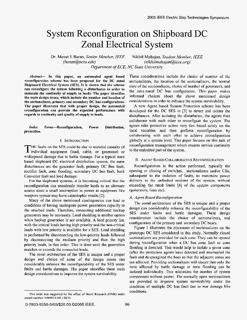
Figure I illustrates the placement of sectionalizers on thc prototype DC SES considered in this study. Normally closed sectionalizcrs are provided for each zone. They can be opened during rcconfiguration when a DC bus zone fault or zone flooding is detected. This would help to isolatc a given zone (after the protcction agents have dctected and interrupted the fault and de-cnergized the bus) so that the adjaccnt zones are not affected. Providing sectionalizers will ensure that only the zone affected by battle damage or zone flooding can be isolated individually. This minimizes the number of system components without power. The normally open sectionalizers are provided to improve system survivability undcr the condition of multiple DC bus fault due to war damage like conditions.
This work was suppofied by the office of Naval Research (ONR) under award number: N000014-00-1-0475.
0-7803-9259-0/05/$20.00 02005 IEEE. 86
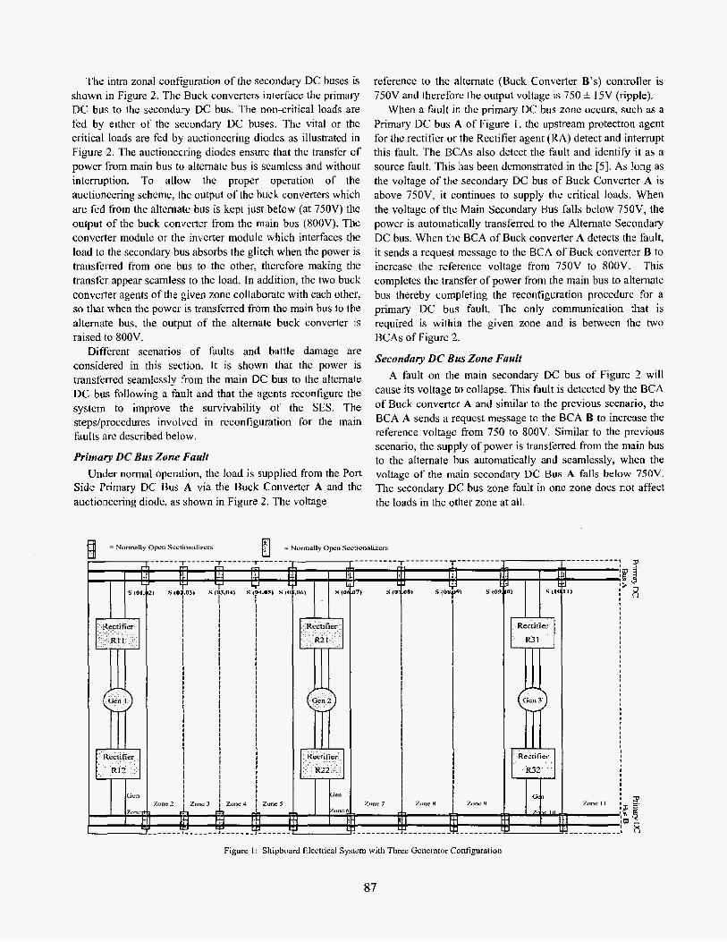
The intra zonal configuration of the secondary DC buses is shown in Figure 2. Thc Buck convertcrs interface thc primary DC bus to the secondary DC bus. The non-critical loads are fed by either of the sccondary DC buses. The vital or tbc critical loads are fcd by auctionccring diodcs as illustratcd in Figure 2. Thc auctioncering diodus ensure that the transfer of power from main bus to altcrnate bus is seamless and without interruption. To allow the proper operation of the auctioneering scheme, the output of the buck convertcrs which are fed from the alternate bus is kcpt just beLow (at 75OV) thc output of the buck converter from the main bus (SOOV). Tbc converter modulc or the inverter module which interfaces the load to the secondary bus absorbs the glitch when the power is transferred from one bus to thc other, thercfore making thc transfer appear seamless to the load. In addition, the two buck converter agents of the given zonc collaborate with each other, so that when the power is transferred from the main bus to the alternate bus, the output of the alternate buck converter is raised to XOOV.
Diffcrent scenarios of faults and battle damage are considered in this section. I t is shown that the power IS
transfcrrcd seamlessly from the main DC bus to the alternate DC bus following a fault and that the agents rcconfigure the systcm to improve the survivability of the SES. The stepsiproccdurcs involved in reconfiguration for the main faults arc described below.
Primary DC Bus Zone Fault Under normal operation, the load is supplied from the Port
Side Primary DC Bus A via the Buck Convertcr A and the auctioneering diode, as shown in Figure 2 . The voltage
reference to thc alternate (Buck Converter B's) controller is 750V and therefore the output voltage is 750 f I5V (ripple).
When a fault in the primary DC bus zonc occurs, such as a Primary DC bus A of Figure I , the upstream protection agent for the rectificr or the Rcctifier agent (RA) detect and interrupt this fault. The BCAs also detect the fault and identify it as a source fault. This has been demonstrated in the [SI. As long as the voltage of the secondary DC bus of Buck Converter A is above 750V, it continues to supply the critical loads. When the voltage of the Main Secondary Bus falls below 750V, the power is automatically transferrcd to the Altematc Secondary DC bus. When the BCA of Buck converter A dctects the fault, it sends a request message to the BCA of Buck converter B to increase the reference voltage from 750V to XOOV. This complutes the transfer of power from the main bus to alternate bus thereby completing the reconfiguration procedure for a primary DC bus fault. The only communication that is required is within the given zone and is between the two BCAs of Figurc 2.
Secondary DC Bus Zone Fault A fault on the main secondary DC bus of Figure 2 will
cause its voltage to collapse. This fault is detected by the BCA of Buck convertcr A and similar to the previous scenario, the BCA A sends a requcst message to the BCA B to increase the reference voltage from 750 to 8OOV. Similar to the previous scenario, the supply of power is transferred from the main bus to thc alternate bus automatically and seamlessly, whcn the voltagc o f the main sccondary DC Bus A falls below 750V. The sccondary DC bus zone fault in one zone does not affect the loads in the other zone at all.
Z" , Zone5 llnc hJ +
t bH II I m L u
I
Figure I : Shipboard Electrical System with Three Generator Configuration
87
Buck Converter Source Side DC Rail Fault A Buck Convcrtcr source side DC Rail fault is a fault in the
Primary DC Bus zone and the normaIly closcd (NC) scctionalizcrs cmploycd on thc primary DC Bus can bc cffectively used to isolate only the affected zone. The reconfiguration for this fault in the primary DC bus zone is, therefore, diffcrcnt from the configuration performed for a fault on the Primary DC bus.
The Buck Converter source side DC rail fault is detected and interrupted by the RAs of the upstream Rectifiers. The BCA of the buck converter locates this fault to its input DC rails. This additional information is used advantageously for reconfiguration of the system under multiple fault condition.
The reconfiguration action performed for a single fault -a Buck converter source side DC Rail fault, is similar to the DC bus fault described abovc. The interruption of thc fault by the RAs and the shutdown of the buck convertcr cause the output voltage of thc buck converter to decay. Therefore the voltage of Buck convertcr A falls below 750V and the supply of power is transferred from the port side primary DC Bus A to the starboard side primary DC bus B, thereby completing the reconfiguration for the single buck converter source side fault.
Another important scenario which adds challenge to the buck converter source side DC rail fault is the occurrence of a second successive fault on the ahemate primary DC bus B. Under such a scenario of successivc faults, where one fault is on the buck converter source side DC rail of the port sidc primary DC bus A and another bus fault on the starboard primary DC bus E, the whole system would need to be shutdown. The identification and location of the fault by the protection agents is helpful in avoiding such a catastrophic failure. For this scenario of multiplc faults, a solution is proposed so that the selective NO sectionalizers are opened to sectionalize the first fault (buck converter source sida DC rail
fault). Therefore for a successive second fault on the primary DC bus B, the power is rc-transferred back to the primary DC bus A, avoiding a total shut-down or collapsc of the system. This considerably improves the system survivability under multiple fault conditions.
This is explained by an illustration. Let us considcr that a buck input DC rail fault occurs in zone 5 of the system shown in Figure I. The R A s of rectifier R I 1 and R2 I of zone 1 detect and interrupt this fault. Thc BCA A of zone 5 also dctects this fault and identifies it to be a buck converter sourcc side DC rai1 fault. The BCA A then scnds a request messagc for to the BCA B to increase the reference voltage to XOOV. The power is thus transferred to the alternate bus B and the primary DC bus A is de-energizcd. Now, for a subscquent fault on the DC bus B of Figure 1, the complete system will be shutdown by the rectifiers RI 1, RIZ, R21 and R22. To avoid such a systcm shutdown, following the detection and location of the buck convcrtcr source side DC rail fault (of the primary DC bus A), the BCA A, scnds a request to open the sectionalizers S(04,05) and S(05,06), as soon as the R1 I and R21 have interrupted the fault and de-energizcd the bus A. The opening of the sectionalizers isolates the faulted zone 5.
For a subscquent fault on thc primary DC bus B, power can be re-transferred back to the healthy part of the primary DC bus A, sincc the opening the soctionalizers has isolated the faulted part of thc system. Hence, the agent bascd reconfiguration scheme prevents a total system collapse and improves the system survivability under war damage conditions such as multiple faults.
The opening of the above mentioned scctionalizers may also create anothcr challenge of generation-load mismatch. After the fault when the zone 5 sectionalizers have opened and isolatcd the zone, in the reconfigured system, Gen I supplies power to tho zoncs 1 through 4 whilc the Gen2 supplies powcr
Non Non Critical Critical Load? Load3
< Main Secondary -k DCBus b
- % e - ! 3 g .................. I .... El .................. 4 .... 3 a2 - . i :
i i : : . . S e C O f l d d ~ DC BUS
Critical Critical Load 1 Load 3
1 Zon1
Figure 2 : Intra Zonal Bus Configuration
88

to zones 6 and 7. It may be possible that the generation of Gcnl or Gcn2 is not sufficient to meet all the loads of zones 1-4 or 6-7 respectively. Thcreforc, when a BCA requests the opening of sectionalizers, it also initiates a load flow to match the load with the generation and if necessary a load shedding aIgorithm is initiated, as explained previously. This ensurcs that the generators of the reconfigred system are not overloaded.
Fault in Zone 9 Similar to the scenario of successivc faults discussed
abovc, another challenging fault is a fault in the Zone 9 of Figure I . Under the normal operation of the system, Gen3 supplies power to zones 8-1 1 as S (07, OX) is normally open, while, Gcnl and Gen2 supply power to Zones 1-7.
Let us assume that primary DC Bus B has becn de- energized due to a pre-existing fault. When a successive Buck converter source side DC rail fault occurs in Zone 9, the upstream rectifiers detect and interrupt the fault current and the BCA of Zone 9 identifies this fault as a source fault. The BCA also sends a request to open the sectionalizers S (OX, 09) and S (09, 10). The opening of these sectionalizers isolates the faultcd zone. But, in addition, opening of these 2 sectionalizcrs also unnecessarily interrupts power to zone 8. Therefore additional actions are needed to avoid the unnecessary interruption of power to Zone 8.
The sequcnce of actions that the BCA should take whcn a buck converter source side DC rail fault occurs in Zone 9, in order to avoid intcrruption of power to the zone 8 are:
Send a request message to the altemate BCA of the same zone to increase the refcrence voltage from 750 to XOOV, Send a request message to open the NC sectionalizcrs S(O8,OS) and Send a mcssagc to the BCA of the adjacent zones (zone 9 and zone 10) to ensure that at least one of the sectionalizers connected to those zones are closed. For this particular example, both the sectionalizers of Zone 8 are open. Therefore, in addition to these actions taken by the BCA of Zone 9, the BCA of zone 8 requests the NO sectionalizcr S (07, 08) to be closed. This ensures that power is supplied to Zone 8 via Genl and Gen2, thus maintaining the continuity of supply to all but the faulted zone. Lastly, due to the closing of the NO sectionalizcr S (07, OX) it may be possible that the generation capacity of Genl and Gen2 is insufficient to meet all the loads of Zone 1 through Zone 8. Therefore, load shedding may be required.
Generation Failure The last fault condition that is addressed here is a fault or
damage in one of the generators. The RAs of the rectifiers detect a zero input current condition and identify it as a generator fault. Whcn such a generotor fault is detected, the RAs request the closing of the NO sectionalizer S (07, OX), and initiate load shedding to match the load demand with thc generation (Gen2 and Gen3). This completes the
reconfiguration for a generation failure.
111. SIMULATION RESULTS
This section illustrates simulation results for thc system recontiguration procedures described in the previous section. Simulation rcsults are shown for two of the most common faults ~ primary DC bus fault and secondary DC bus fault. The simulations were performed in EMTDC /PSCAD [6, 71. The prototype system for reconfiguration is shown in Figure 3. It has a main primary DC bus A and altemate primary DC Bus B. Every critical load within a zone is fcd by both the intra-zonal secondary DC Buses A and B, while the non- critical loads are supplied power by only either of the secondary DC buses.
Figure 3 : Prototype System for Reconfiguration
A. Primary DC Bus Fault Simulation results for a fault on the primary DC bus A at t
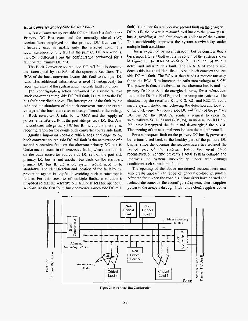
= 0.1s are shown in Figure 4. Following the fault, the output voltage of RIA, V-R1 collapses,,as shown in Figure 4(a). Correspondingly, the rectifier.. output current, I-R 1 rises as shown in Figure 4(b). The fault I s detected by the R A of RIA and it shuts down the Rectifier RIA of Figure 3. Following the shutdown, the voltages of thc secondary DC Bus A of both zones 1 and 2 (V-DCSec-lA and V-DC-Sec-2A) start decaying. This is seen in Figure 4(c) and (d). Whcn the BCA of B1A and B2A detect the source fault, thcy send a message to B1 B and B2B respcctivcly to increase the reference voltage from 750V to 80OV.
Thereforc, the voltages V-DC-Sec-1 B and V-DC-Sec-ZB increase from 750 to XOOV as scen in Figure 4(c) and (d). The BCA of BlA detects the fault at t =
0.01055s, therefore, it is seen that the loads of zone 1 see the voltage dip for a transient time interval of 0.0056s. The voltage dip is less than 8%. The BCA of B2A detects the source fault much earlier at t = O.IOls, and therefore sends the message to thc BCA of B2B to increase the voltage within 0.001s, therefore the loads o f zone 2 sce the voltage dip for about 0.001s. The rise in the voltage V-DC-Sec-ZB causes the load current to be commutated from the secondary DC bus
89
A to the secondary DC bus B. The voltagc across the loads of the zone I and zone 2 arc shown in Figure 4(e) and (0. B. Scenario 2: Secondary DC Bus Fuuli
A fault on the secondary DC bus A of zone 1 of Figure I has been simulated here. The resuIts are shown in Figure 5. Prior to the fault at t = 0.01s. the ioads of Zone 1 are fed via
+O 36 -
+U
. i
to 9 .-=.+~++w-#4,As+"-.-.,g.v.--"".-
+ 0 7 2 ' 7 -
+ O S -
to 36 -
+01a-
. .. - 2
" . . + - . *
I
t145t
I / 0114 0118
to
&ss 0<02 o io6 o 'ri -. - Time (sec) __ - . . . I
(c) Buck Converter I & 2 Output Voltage (Zone I )
L O \ l 0114 0118
._.__ _ _ . - . . I Tme (sec) " _ "
(e) Critical Load Voltage (Zone I )
Gl->RlA->BIA-) Critical Loadl (Figure 3). Following the fault, the loads ofzone 1 are transferred from primary DC Bus A to primary DC Bus B. Thcrcfore the loads are now supplicd via GI->RIB-> BIB-> Critical Loadl. The loads of zone 2 are continuously supplied from priniary DC bus A, via R2A-> B2A -> Critical Load2. This cominutation causes a docrease in current supplicd by R I A and the corresponding incrcase in
18
3 V DC Sec 2A to 91
t0.11 --- -
h +'.54 t
Figure 4 : Simulation results of reconfiguration following a Primary DC bus Fault
90
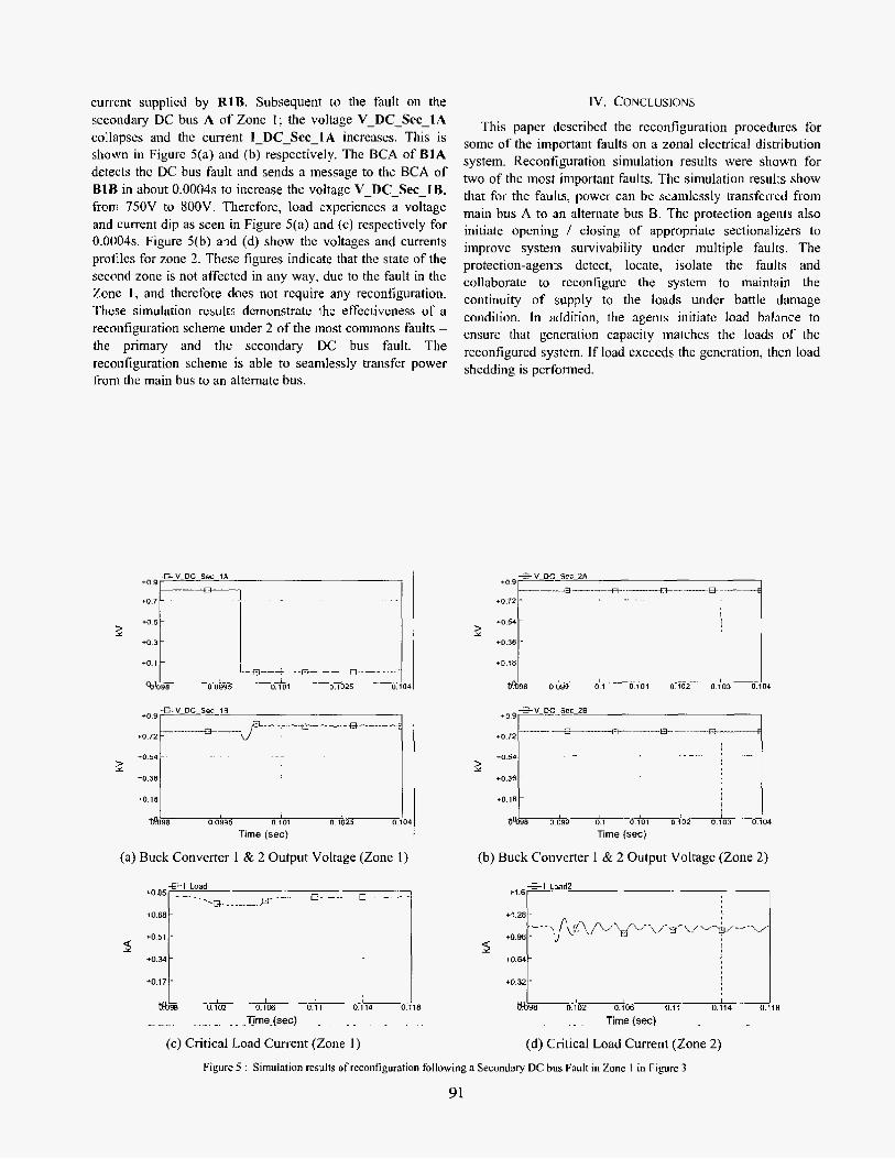
current supplicd by R1B. Subsequent to the fault on the secondary DC bus A of Zone 1; the voltage V-DC-Sec-lA collapses and the current 1-DC-Sec-lA increases. This is shown in Figure 5(a) and (b) respcctively. The BCA of B1A detects thc DC bus fault and sends a message to thc BCA of B1B in about 0.0004s to incrcase the voltage V-DC-Sec-IB, from 750V to XOOV. Tliercfore, load experiences a voltage and current dip as seen in Figure 5(a) and (c) respectively for 0.0004s. Figure 5(b) and (d) show thc voltages and currents profiles for zone 2. These figures indicate that the state of the second zone is not affected in any way, due to the fault in the Zone 1, and therefore does not rcquire any reconfiguration. These simulation results demonstrate the effcctiveiiess of a reconfiguration scheme under 2 of the most commons faults - the primary and the secondary DC bus fault. The reconfiguration scheme is able to senmlessly transfer power from thc main bus to an alternate bus.
€ V DC Scc-lE
+O +o 72 9 ' __ __ *-+L --"me -.--+-.----;
+O 54 -
TO 36
-0 i a ~
1
I t A 9 8 0 0994 0 101 0 1025 0 104
Time (sec)
G V DC-Sec 1A
+o 5
+o 3
* o 1
1. 0 101
2
0 0995
:iif??:;i k +O 36
+O 16
a% 0099 0 1 0101 0102 u t a 3 0104
Time (sec)
IV. CONCLUSIONS
This paper describcd the reconfiguration procedures for some of the important faults on a zonal electrical distribution system. Reconfiguration simulation results were shown for two of the most important faults. The simulation results show that for the faults, power can be scamlessly transferred from main bus A to an alternate bus 8. The protection agents also initiate opcning / closing of appropriate sectionalizers to improve system survivability undcr multiple faults. The protection-agents dctcct, locate, isolate the faults and collaborate to reconfigure the system to maintain the continuity of supply to the loads undcr battle damage condition. In addition, the agents initiate load balance to ensure that gencration capacity matches the loads of the reconfigured system. If load exceeds the generation, then load shedding is performed.
~~
E- -U- - - -
5 9
+a85 - -
tom- +.I 28
+051 . +O.%
+ O M -
tO 17 . +O 32
+om-
-
--- ) p ? p A & L d ? Fv\P-w+-- \/- -
-
V. REFERENCES V1. BIOGRAPI-IIES
[I] K. L. Butler, N. D. R. Sara, C. Whitcomb, H. Do Carmo, and 14. Zhang, "Shipboard systems deploy automated protection," Cmnprrrer
J. G. Ciezki and R. W. Ashton, "Selection and stability issues associatcd with a navy shipboard DC zonal electric distribution system," Power Ddiw,~.n.. IEEE Trun.wcfium on, vol. 15. pp. 665469,2000.
[3] M. Baran and N. R. Mahajan, "protection of Multi-terminal DC Distribution Systems," srhnillcd fu lEEE Trumurrions on T & D, May 2005. K. Davey and R. E. Hebner, "Reconfiguration of Shipboard Powcr Systems," IASME Ti.unsuc~ii~ns, vol. I, pp. 6, 2004. M. Baran. N. R. Mahajan. and A. W. Kelley, "Use of PEBB Convetlers as Current Limiting Circuit keakers," subnirred to IEEE Trcrrzssactium on PELS. Aug 2004. M . H. R. Centre. EiMTDC, The elecfrovwgnefic Trumicnrs & Crmfruls Simirlurion Engine: Manitoba HVDC Research Centre. 2002. M. H. R. Centre, PSCA?. Power Svsiems Compier Aided Design: Manitoba HVDC Rescarch Centre, 2003.
App/k'irlicJflS in Power', IEEE, Vol. 1 I , pp. 31-36, 1998. [Z]
141
[$]
[6]
[7]
Mesut E Barnn (S'87-M'RX) 1s Luncntly an Absocldt~ Professor at North Carolina State Unlvcmty in R.llc.tgh, NC 111: received hts Ph D from the Universiq of Calitomia. Berkeley in 1988 1j15 research interestb include analysis and control of distribution and transmission systems.
Nikhil K. Mahajan (S'0l) is currently working towar& his dodorate in electncal engineering at North Cdrulind State University. Ralcigh Hls current research IS onented towards protection of Power Elcctrunic Building BloLks His research interests are in the areas of power system protection and trrlnw"ion and computer-aided system analysis
92