ser/secr trackwork - wordpress.com
TRANSCRIPT
SER/SECR Trackwork © Dan Garrett 2016 Page 1 of 20
SER/SECR Trackwork
Dan Garrett
Published by SER-Kits 2020
Text, layout, photographs, and schematic diagrams: copyright © Dan Garrett 2020
The moral right of the author has been asserted
SER/SECR Trackwork © Dan Garrett 2016 Page 2 of 20
Contents
Historical Page
Rails 2
Sleepers 2
Chairs 3
Pointwork 4
Ballast 5
Improving model trackwork
Cosmetic improvements to Marcway
7
Control methods 8
‘Proper’ chairs at point toes 10
Cosmetic improvements to plastic sleeper track
11
Making track from scratch 11
Making soldered curves 13
Laying track 13
Ballast 14
Colouring granulated cork 15
Laying ballast 17
Alternative: Painted Ballast 18
Sidings 18

SER/SECR Trackwork © Dan Garrett 2016 Page 3 of 20
Historical Introduction
These notes are mainly abut the SER, but anyone modelling the early days of the SECR will realise that renewing track doesn’t happen overnight.
The ‘old’ main line, from Redhill to Dover, was originally laid to Cubitt’s specification with triangular sleepers and his design of chair. A pile of chairs in one of the Tonbridge Historical Society’s photos (Ref.13B) look to have been Cubitt’s and therefore possibly awaiting scrapping. When Cubitt’s track was fully replaced is a question for historians.
Little has been gathered and written up by SECSoc on the trackwork of subsequent lines such as the North Kent and Hastings Branch. A variety of sleepers and chairs were used but slowly a degree of standardisation seems to have occurred possibly from c1865. Over the years, rails and chairs became heavier and stronger.
We should remember that over any rail network, new and better practice is introduced first on busy main lines and only spreads slowly to lesser and branch lines. Displaced trackwork may be used on sidings and, after the Act introducing them, on Light Railways with their 25mph speed limit. So different types and standards of tracks existed simultaneously depending on the location.
From the early days, shingle was used as ballast, being available from beaches and pits with the main cost being transport. It was used for some eight decades into Southern Railway days, with its replacement hastened by the crash of a River tank locomotive and its train when they came off the poor quality track between Dunton Green and Sevenoaks.
Rails
The weight per yard increased from 70lb in the 1840s to 80 or 85lb in the 1860s. Rails varied in length, 18ft, 21ft, 24ft, with the longer ones becoming more available towards the end of the 19th Century. This means that the clickety-clack of bogie wheels on 60ft rails in so many elderly people’s memories is a mid 20th Century phenomenon. The sound of 4- and 6- wheel coaches on short rails would be quite different.
Sleepers
From c1865 SER sleepers were standardised at 9ft long x 10in wide x 5in deep. Different sources give different spacings, varying from 36in, 33.5in, 32in down to 30in centre-to-centre. Presumably the heavier the anticipated traffic, the closer the spacing. Equally it may be assumed that as the years went by and locomotives and vehicles increased in weight, so the spacing was reduced. At rail joints the spacing was reduced by 2in. or possibly more.
The distance between outer rails on double track lines was presumably the standard 6 feet. However it’s likely that this distance could be increased for many reasons, not least to accommodate the piers of overbridges.

SER/SECR Trackwork © Dan Garrett 2016 Page 4 of 20
Chairs
The SER had a standard rail chair and historical sources show that these were in use at least by 1882 and still in use in 1897. They may have been introduced c1865. One of the standard chairs is preserved in the Bluebell Railway museum and there are others in private collections. The base has rounded corners and two holes for trenails and pins either side of the rail.
Scale drawings have been published and look identical to the Bluebell casting. The above drawing dates from before 1882. The drawing on the next page was published in1895 but the rail length and sleeper spacing may predate that.

SER/SECR Trackwork © Dan Garrett 2016 Page 5 of 20
The SECR used heavier chairs with two holes on the outside and one inside.The following were photographed at Bromley North station in the 1960s.
SECSoc Member John Arkell has photos of a chair c1900 with the letters SE&CDR. (It took a year or two after the 1899 union of the SER and the LCDR for initials to be standardised as SE&CR)
Pointwork
The only known sources are photographic, and these are details in photos of trains and locomotives. They are difficult to interpret, as pointed out by Simon Havard in an article published in the SECSoc journal Invicta, which also has his drawings of points with interlaced and non-interlaced sleepers. A photo of Cudworth No.2 suggests that the blades or switch rails were supported by six slide chairs, the one nearest the frog (crossing) supporting a joint and fishplate. Wing- (or check-) rails to guide wheelsets through the crossing (frog) were supported on 3 sleepers suggesting a length of 8 or 9 feet.
SER/SECR Trackwork © Dan Garrett 2016 Page 6 of 20
Ballast
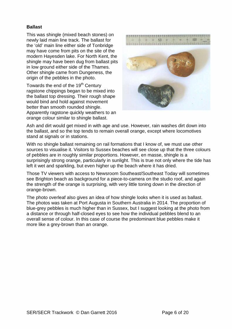
This was shingle (mixed beach stones) on newly laid main line track. The ballast for the ‘old’ main line either side of Tonbridge may have come from pits on the site of the modern Hayesden lake. For North Kent, the shingle may have been dug from ballast pits in low ground either side of the Thames. Other shingle came from Dungeness, the origin of the pebbles in the photo.
Towards the end of the 19th Century ragstone chippings began to be mixed into the ballast top dressing. Their rough shape would bind and hold against movement better than smooth rounded shingle. Apparently ragstone quickly weathers to an orange colour similar to shingle ballast.
Ash and dirt would get mixed in with age and use. However, rain washes dirt down into the ballast, and so the top tends to remain overall orange, except where locomotives stand at signals or in stations.
With no shingle ballast remaining on rail formations that I know of, we must use other sources to visualise it. Visitors to Sussex beaches will see close up that the three colours of pebbles are in roughly similar proportions. However, en masse, shingle is a surprisingly strong orange, particularly in sunlight. This is true not only where the tide has left it wet and sparkling, but even higher up the beach where it has dried.
Those TV viewers with access to Newsroom Southeast/Southeast Today will sometimes see Brighton beach as background for a piece-to-camera on the studio roof, and again the strength of the orange is surprising, with very little toning down in the direction of orange-brown.
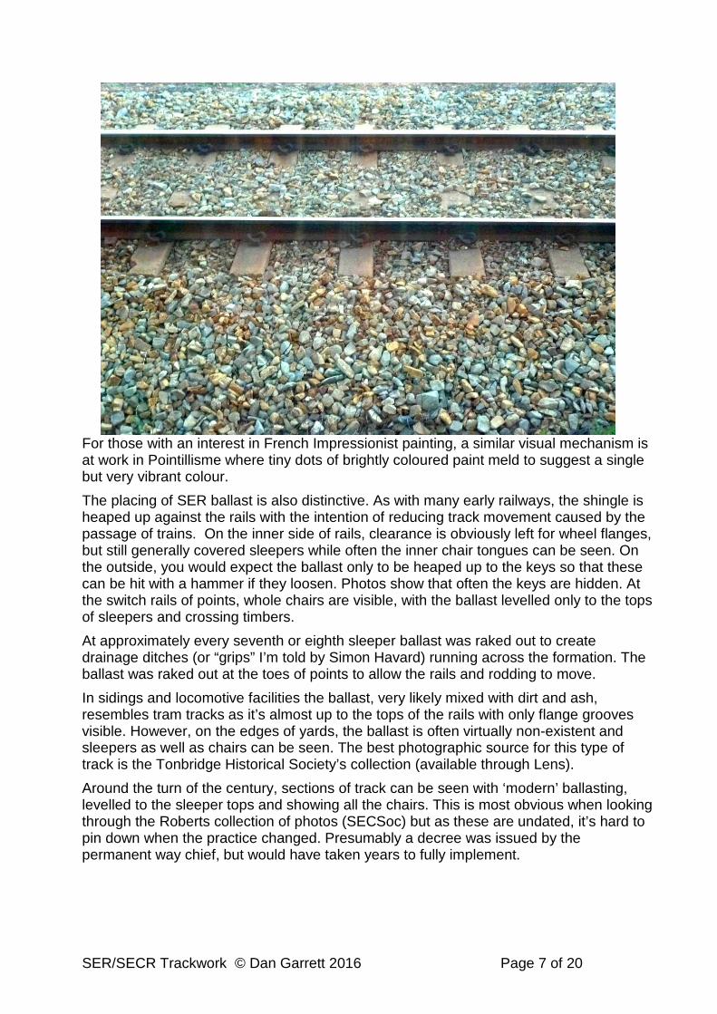
The photo overleaf also gives an idea of how shingle looks when it is used as ballast. The photos was taken at Port Augusta in Southern Australia in 2014. The proportion of blue-grey pebbles is much higher than in Sussex, but I suggest looking at the photo from a distance or through half-closed eyes to see how the individual pebbles blend to an overall sense of colour. In this case of course the predominant blue pebbles make it more like a grey-brown than an orange.
SER/SECR Trackwork © Dan Garrett 2016 Page 7 of 20
For those with an interest in French Impressionist painting, a similar visual mechanism is at work in Pointillisme where tiny dots of brightly coloured paint meld to suggest a single but very vibrant colour.
The placing of SER ballast is also distinctive. As with many early railways, the shingle is heaped up against the rails with the intention of reducing track movement caused by the passage of trains. On the inner side of rails, clearance is obviously left for wheel flanges, but still generally covered sleepers while often the inner chair tongues can be seen. On the outside, you would expect the ballast only to be heaped up to the keys so that these can be hit with a hammer if they loosen. Photos show that often the keys are hidden. At the switch rails of points, whole chairs are visible, with the ballast levelled only to the tops of sleepers and crossing timbers.
At approximately every seventh or eighth sleeper ballast was raked out to create drainage ditches (or “grips” I’m told by Simon Havard) running across the formation. The ballast was raked out at the toes of points to allow the rails and rodding to move.
In sidings and locomotive facilities the ballast, very likely mixed with dirt and ash, resembles tram tracks as it’s almost up to the tops of the rails with only flange grooves visible. However, on the edges of yards, the ballast is often virtually non-existent and sleepers as well as chairs can be seen. The best photographic source for this type of track is the Tonbridge Historical Society’s collection (available through Lens).
Around the turn of the century, sections of track can be seen with ‘modern’ ballasting, levelled to the sleeper tops and showing all the chairs. This is most obvious when looking through the Roberts collection of photos (SECSoc) but as these are undated, it’s hard to pin down when the practice changed. Presumably a decree was issued by the permanent way chief, but would have taken years to fully implement.

SER/SECR Trackwork © Dan Garrett 2016 Page 8 of 20
Improving Model Trackwork These notes are for 19th century trackwork where the ballast is banked almost up to rail level on the outside. For modellers, this can hide wrong profile chairs or solder fillets. However, transverse drainage ditches in the ballast reveal the sleepers and chairs on either side. Similarly, at the toe of points, the ballast is more or less level with sleeper tops, revealing the chairs. The following pages are to help the quality (pernickety?) historical modeller.
I’ve compiled these notes for my own use over 30 years. Dimensions etc are for 7mm scale. My own chair castings are shown, but other manufacturers make them as well and much more cheaply by using injection moulding.
1. Cosmetic Improvements to Marcway Pointwork
These notes are intended to suggest ways of improving the look of Marcway track in such cases, by using cast chairs and replacing their sleeper-wide tie-bars with the narrow profile of vertical copper-clad sleeper strip.
First, make a simple jig for better-looking tiebars as follows.
Tie-bar Jig and point control
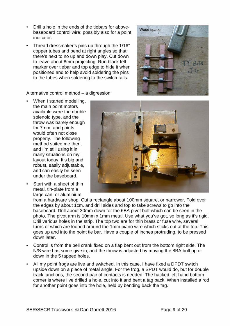
The photo shows the end result. It will be vertical in a slot in the baseboard with the bent over pins soldered to the tie-bars. There are two ways of moving it sideways. Small holes are drilled in the top corners and fine steel wire can be bent and poked in, then run in fine copper tubing to a lever at the edge of the baseboard, or to a hidden point motor. Some point motors can be fixed under the baseboard, with a wire poking up. This is the purpose of the central tube. The alternative is to make a lever under the baseboard worked by rod or cycle Bowden cable. (See later) This latter method needs the central tube, which can otherwise be omitted.
• Make the jig as follows.
• Glue lengths of approx. 50mm copper-clad sleeper strip to a wooden base. Solder a roughly 25mm length of 3/32” tube centrally, and then solder lengths of 1/16” point control tubing either side at 27mm centres
• Insert point control wire (preferably stainless steel) into end tubes with an overlap of 15mm or so; also a length of 1/16” rod into the 3/32” tube. Superglue in place
• To make tie-bar, centre a 45mm length of copper-clad sleeper strip under the sticking-out rods. Use a matchstick or slip of wood as in the photo to act as a spacer keeping the sleeper strip away from the jig. This is to avoid soldering the tie-bar tubes to it. Use 6mm lengths of the same tubes, thread them over the wires and solder to the tie-bar strip. I use an RSU, whose earth cable is attached to the large crocodile clip, but an ordinary soldering iron is fine too. Do not dwell, or the copper may peel from the formica. (See photo on next page.)
SER/SECR Trackwork © Dan Garrett 2016 Page 9 of 20
• Drill a hole in the ends of the tiebars for above-baseboard control wire; possibly also for a point indicator.
• Thread dressmaker’s pins up through the 1/16” copper tubes and bend at right angles so that there’s next to no up and down play. Cut down to leave about 8mm projecting. Run black felt marker over tiebar and top edge to hide it when positioned and to help avoid soldering the pins to the tubes when soldering to the switch rails.
Alternative control method – a digression
• When I started modelling, the main point motors available were the double solenoid type, and the throw was barely enough for 7mm. and points would often not close properly. The following method suited me then, and I’m still using it in many situations on my layout today. It’s big and robust, easily adjustable, and can easily be seen under the baseboard.
• Start with a sheet of thin metal, tin-plate from a large can, or aluminium from a hardware shop. Cut a rectangle about 100mm square, or narrower. Fold over the edges by about 1cm. and drill sides and top to take screws to go into the baseboard. Drill about 30mm down for the 6BA pivot bolt which can be seen in the photo. The pivot arm is 10mm x 1mm metal. Use what you’ve got, so long as it’s rigid. Drill various holes in the strip. The top two are for thin brass or fuse wire, several turns of which are looped around the 1mm piano wire which sticks out at the top. This goes up and into the point tie bar. Have a couple of inches protruding, to be pressed down later.
• Control is from the bell crank fixed on a flap bent out from the bottom right side. The N/S wire has some give in, and the throw is adjusted by moving the 8BA bolt up or down in the 5 tapped holes.
• All my point frogs are live and switched. In this case, I have fixed a DPDT switch upside down on a piece of metal angle. For the frog, a SPDT would do, but for double track junctions, the second pair of contacts is needed. The hacked left-hand bottom corner is where I’ve drilled a hole, cut into it and bent a tag back. When installed a rod for another point goes into the hole, held by bending back the tag.
SER/SECR Trackwork © Dan Garrett 2016 Page 10 of 20
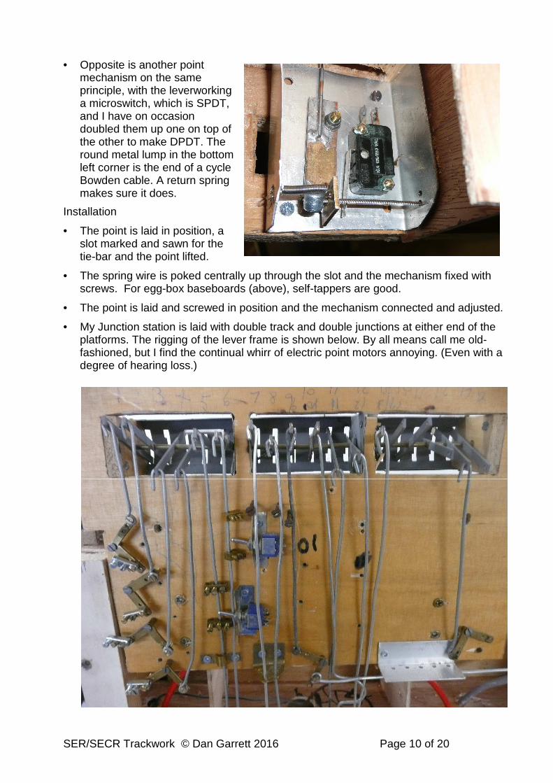
• Opposite is another point mechanism on the same principle, with the leverworking a microswitch, which is SPDT, and I have on occasion doubled them up one on top of the other to make DPDT. The round metal lump in the bottom left corner is the end of a cycle Bowden cable. A return spring makes sure it does.
Installation
• The point is laid in position, a slot marked and sawn for the tie-bar and the point lifted.
• The spring wire is poked centrally up through the slot and the mechanism fixed with screws. For egg-box baseboards (above), self-tappers are good.
• The point is laid and screwed in position and the mechanism connected and adjusted.
• My Junction station is laid with double track and double junctions at either end of the platforms. The rigging of the lever frame is shown below. By all means call me old-fashioned, but I find the continual whirr of electric point motors annoying. (Even with a degree of hearing loss.)

SER/SECR Trackwork © Dan Garrett 2016 Page 11 of 20
• Referring to the previous photo: The bell cranks on the left are for long lengths of wire rod, and they will be held in the choc-box wire connectors removed from the choc strip plastic. A couple of blue DPDT switches are worked by ‘dogs’ made from the same connectors. If the central hole is used, another switch can be placed to the left of the wire. At the bottom centre is a large Omega loop for adjustment. Very easy to squeeze in, or pull out.
Of course if you want to do the equivalent with scale size cranks and rod runs on top of the baseboard, don’t let me stop you…
Modifying the point with ‘proper’ chairs
The intention is to replicate the bare sleepers at the toe of the point, and the visible slide-rail chairs.
• Cut 40 thou styrene base ~140mm long (depends on point type and radius) and tapering to suit Marcway sleeper layout. Cut a 60 thou piece of packing and glue under the first two sleepers at the single track end (before the split).
• Remove 7 Marcway sleepers, counting the first as the one beyond the tiebar. Also tiebar. Clean rails of solder with file or burr.
• Cut 60 thou styrene sleepers, 5.83mm wide (realistically, just under 6mm). Set at 18-20mm centres from centre of remaining Marcway sleeper further apart than Marcway and more suitable for SER).
• Cut out slot for tie-bar 52mm long and 3.5mm wide, drilling ends and then cutting with Stanley knife.
• Fit chairs at toe end, superglue, drill 0.6mm and fit Lill pins
• Fit slide chairs in the same way, but only fit pins where they will not foul the tapered switch rails.
• Position the tie-bar in the slot and solder the pin turnovers into the webs of the switch rails, making sure the tops of the latter are level with the stock (outside) rails
• If desired, isolate the switch rails from the frog by cutting slots with diamond circular saw (Eileen’s) or coping saw and bond them to the stock (outside) rails with copper wire. This avoids potential short-circuits between the back of wheels and the switch rails, and doesn’t rely on physical contact to convey electricity. Better all round, but the frog must then be switched, using a lever microswitch from e.g. Radiospares under the baseboard or hidden in a nearby building.
SER/SECR Trackwork © Dan Garrett 2016 Page 12 of 20
Cosmetic improvements to plastic sleeper track
• It is time-consuming to construct track from separate chairs and sleepers, as I know to my cost. The following is a suggested simple modification for Peco and other track with plastic sleepers. which enables correct chairs to be seen either side of the cross-drains.
• Turn the track over and cut through the plastic joins between sleepers to leave them in sets of 6. This number can be adjusted depending on the sleeper spacing and rail length which changed over the years (see earlier history). Note, though, that as you reduce the frequency of sleepers, any given length of track looks shorter. So close sleepers make your layout look longer.
• Slide half of all the sleepers off and thread on two cast chairs on each rail. (It can help to taper the bottom of the rails and the webs.) A simple jig is shown in the next section.
• Repeat the above and then for the other half, so that the whole rail length has 2 pairs of chairs (for 2 new sleepers) between each set of 6 plastic originals.
• Space the sleepers and chairs evenly and lay the track in the usual way. Insert separate plain sleepers (~3mm thick) under the cast chairs and glue with e.g. Evostik.
• For added realism, you may wish to partly saw a ‘rail joint’ over each ditch (for the clack of the wheels) and solder on cosmetic fishplates. It’s extra work and I myself find the clicks from such short rail lengths annoying…
Making track from scratch
• Taper 2mm or so of one end of each rail including web
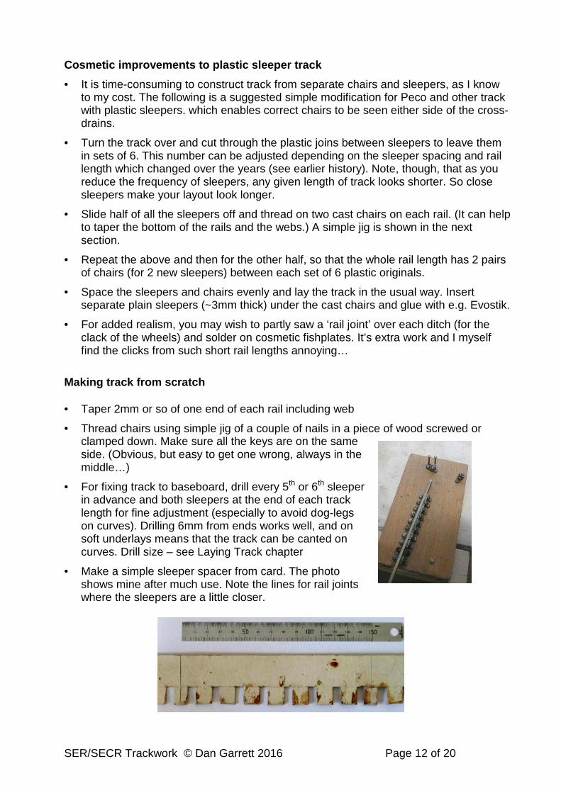
• Thread chairs using simple jig of a couple of nails in a piece of wood screwed or clamped down. Make sure all the keys are on the same side. (Obvious, but easy to get one wrong, always in the middle…)
• For fixing track to baseboard, drill every 5th or 6th sleeper in advance and both sleepers at the end of each track length for fine adjustment (especially to avoid dog-legs on curves). Drilling 6mm from ends works well, and on soft underlays means that the track can be canted on curves. Drill size – see Laying Track chapter
• Make a simple sleeper spacer from card. The photo shows mine after much use. Note the lines for rail joints where the sleepers are a little closer.
SER/SECR Trackwork © Dan Garrett 2016 Page 13 of 20
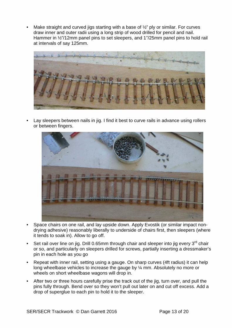
• Make straight and curved jigs starting with a base of ½” ply or similar. For curves draw inner and outer radii using a long strip of wood drilled for pencil and nail. Hammer in ½”/12mm panel pins to set sleepers, and 1”/25mm panel pins to hold rail at intervals of say 125mm.
• Lay sleepers between nails in jig. I find it best to curve rails in advance using rollers or between fingers.
• Space chairs on one rail, and lay upside down. Apply Evostik (or similar impact non-drying adhesive) reasonably liberally to underside of chairs first, then sleepers (where it tends to soak in). Allow to go off.
• Set rail over line on jig. Drill 0.65mm through chair and sleeper into jig every 3rd chair or so, and particularly on sleepers drilled for screws, partially inserting a dressmaker’s pin in each hole as you go
• Repeat with inner rail, setting using a gauge. On sharp curves (4ft radius) it can help long wheelbase vehicles to increase the gauge by ¼ mm. Absolutely no more or wheels on short wheelbase wagons will drop in.
• After two or three hours carefully prise the track out of the jig, turn over, and pull the pins fully through. Bend over so they won’t pull out later on and cut off excess. Add a drop of superglue to each pin to hold it to the sleeper.

SER/SECR Trackwork © Dan Garrett 2016 Page 14 of 20
• Allow glue to set for a couple of days in the warm. If using cosmetic fishplates, solder these and dropper wires for electrics before installing.
Making Soldered Curves
• Use a similar jig as previous. Alternatively, draw lines and use double-sided sellotape or Pritt stick to hold sleepers in position. Note that once both rails are soldered, the radius is fixed for good.
• Cut sufficient sleepers from copper circuit board strips and saw through the copper roughly in the centre, to isolate the rails from each other.
• Curve rails (18in, 450mm, is a good length) in rolling bars exactly to radius. With 6ft radius track made from 18in/450mm rail: cut approx 5.5mm from inner rail
• Tack-solder outer rail every 5th sleeper or so. Solder to be on the outside so as not to foul wheel flanges.
• Eye curve for no kinks.
• Solder remaining sleepers.
• Repeat with inner rail, setting with a track gauge. On sharp curves (4ft radius) it can help long wheelbase vehicles to increase the gauge by ¼mm. Absolutely no more or F/S wheels on short wheelbase wagons and bogies will drop in. An alternative to setting the curve on a drawing is to screw the half-finished length of track into place on the layout, adusting the curve as necessary, and then soldering the inner rail. Depends on ease of access, and rinsing acid flux off in situ.
• Solder cosmetic fishplates if using, and solder dropper wires for electrics.
• Wash off flux under the tap.
Laying track
The photo overleaf shows double track on my layout with the regular spacing of cross-drains.
• Some people lay direct onto the baseboard surface, others lay onto flat cork. My own preference is to lay onto old felt carpet underlay over the whole of the flat area of the baseboard. It has ‘give’ so that on layouts with rising or falling track, the track can be screwed down to give a transition from the level. Moreover, on sharp main line curves (mine are 4ft 6in) the inner ends of sleepers can be screwed down to give an adjustable cant to the track. The texture of the felt means that ballast or scenic texturing holds well.
• Unfortunately this old-fashioned underlay is hard/impossible to find. Might be worth experimenting with 6mm rubber or plastic foam, or with two or three layers of plastic crepe used for packaging.
• Prepare track by drilling two holes in every 6th sleeper, on the outside of rails to allow for adjusting cant. Drill a pair of sleepers at end of track lengths to avoid dog-legs on curves. Use (try Model Fixings): o No.2 screws: Clearance 2.2mm No.43. C/S head No.5 o No.4 screws: Clearance 2.7mm No.34. C/S head No.5 o Posidrive cross-head, equiv. to No.4 – 3x20mm: Clearance No.30 3.25mm. C/S
6.85mm 17/64”, “Q”.

SER/SECR Trackwork © Dan Garrett 2016 Page 15 of 20
• 4ft radius plastic-sleepered track: cut approx 27mm from inner rail per length. Eileen’s Emporium sell a narrow cutting discs about 40mm in diameter which allows for a vertical cut when in a small 12V drill.
• Double track. British practice allows a nominal 6ft between the nearest rails. On much sharper model curves this may need increasing so that the overhang of (say) a locomotive or tank engine’s buffer beams do not foul the middle overhang of a bogie coach. For 4ft radius curves I increase the distance between the rails to 45mm (6ft 5in) and this works for me. Note: if there are posts (for signal boxes) or water cranes, this distance needs to be considerably increased.
• Rail-joints: SER fishplates are 4 bolt. C&L Finescale offer a variety of methods all with a good appearance. The plastic “Locking Fishplates” work well for isolating sections and cost around 40 or 50p per length of track. Dearer than Peco, but give much less trouble, I find. C&L brass “Locking Fishplates” are almost twice as dear but will give some electrical continuity (which deteriorates over the years as they and the rails oxidise). Before these became available I used Peco code 125 rail joiners where they don’t show or can be hidden with ballast. I still use these at baseboard joints as they can be slid to one side when lifting a baseboard section. They too suffer from long-term oxidisation.
The drawback of C&L locking fishplates comes if you need to replace a section of track, for example putting a point into an existing laid and ballasted line. The fishplates can be prised off for removal, but it’s virtually impossible to use them at the replacement joints. These may have to be Peco because they can slide across after dropping the point in.
Etched fishplates are rather more trouble, especially if they have to be soldered in situ. The moral of all the above is to always backup fishplates with soldered electrical wires, either looping across the joint or dropping to a “bus-bar”.
• Platform height varies. On the earliest British railways it might be only a few inches above rail level. For 1880s SER, I’ve standardised the top of my platforms as ~20mm above rail level. The number of brick courses (approximately 12 plus edging slabs) looks right in comparison with photos. The horizontal distance from outer edge of rail to platform edge is around 16mm for this period. (Put a set-square on the track and push against the platform edge.) For curved platforms use the well-tried method of a vertical pencil against the centre of a bogie coach and the outer overhang of a long loco.
Ballast
• Colour references below assume shingle (pebbles from beaches) as used by the SER, SECR, LCDR, LBSCR and other railways through to the early years of the 20th Century. Note that on SER/SECR trackwork, the ends and centres of sleepers are
SER/SECR Trackwork © Dan Garrett 2016 Page 16 of 20
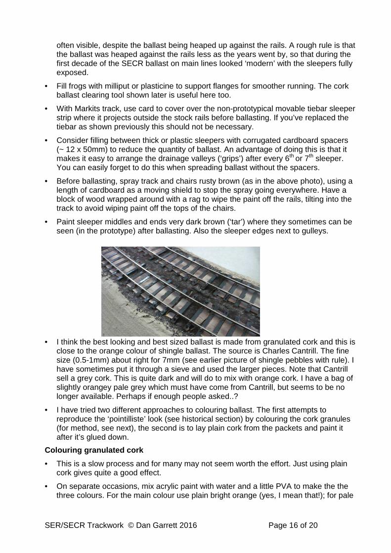
often visible, despite the ballast being heaped up against the rails. A rough rule is that the ballast was heaped against the rails less as the years went by, so that during the first decade of the SECR ballast on main lines looked ‘modern’ with the sleepers fully exposed.
• Fill frogs with milliput or plasticine to support flanges for smoother running. The cork ballast clearing tool shown later is useful here too.
• With Markits track, use card to cover over the non-prototypical movable tiebar sleeper strip where it projects outside the stock rails before ballasting. If you’ve replaced the tiebar as shown previously this should not be necessary.
• Consider filling between thick or plastic sleepers with corrugated cardboard spacers (~ 12 x 50mm) to reduce the quantity of ballast. An advantage of doing this is that it makes it easy to arrange the drainage valleys (‘grips’) after every 6th or 7th sleeper. You can easily forget to do this when spreading ballast without the spacers.
• Before ballasting, spray track and chairs rusty brown (as in the above photo), using a length of cardboard as a moving shield to stop the spray going everywhere. Have a block of wood wrapped around with a rag to wipe the paint off the rails, tilting into the track to avoid wiping paint off the tops of the chairs.
• Paint sleeper middles and ends very dark brown (‘tar’) where they sometimes can be seen (in the prototype) after ballasting. Also the sleeper edges next to gulleys.
• I think the best looking and best sized ballast is made from granulated cork and this is close to the orange colour of shingle ballast. The source is Charles Cantrill. The fine size (0.5-1mm) about right for 7mm (see earlier picture of shingle pebbles with rule). I have sometimes put it through a sieve and used the larger pieces. Note that Cantrill sell a grey cork. This is quite dark and will do to mix with orange cork. I have a bag of slightly orangey pale grey which must have come from Cantrill, but seems to be no longer available. Perhaps if enough people asked..?
• I have tried two different approaches to colouring ballast. The first attempts to reproduce the ‘pointilliste’ look (see historical section) by colouring the cork granules (for method, see next), the second is to lay plain cork from the packets and paint it after it’s glued down.
Colouring granulated cork
• This is a slow process and for many may not seem worth the effort. Just using plain cork gives quite a good effect.
• On separate occasions, mix acrylic paint with water and a little PVA to make the the three colours. For the main colour use plain bright orange (yes, I mean that!); for pale

SER/SECR Trackwork © Dan Garrett 2016 Page 17 of 20
stone, mix a little orange into white; for blue-grey mix black and white and quite a lot of blue. (See photo of actual shingle pebbles earlier)
• Spread cork granules thinly over a tray or in plastic pots. Drip the colour over. Turn the granules with a spatula or brush and repeat until they are coated. (If you have a large sheet of perforated zinc, this might replace the tray but I haven’t tried it) Don’t overdo the paint and carefully suck off the excess with a cheap plastic pipette and filter it through a plastic tea-strainer back into the paint tub.
• Allow to dry in a warm place turning if need be to stop the cork sticking to the tray.
• Turn out when nearly dry onto a ‘drying rack’ made, for example, from old thin material taped over a tray or box lid. The right hand photo (above) shows three stages: drying at the bottom, putting the dry cork through a herb mill, sieved orange cork ballast at the top.
• When dry, the cork may have clumped together. If you don’t have a herb mill, pour it bit by bit into a shoe box and try ‘grinding’ it round with a block of wood.
• You may need to re-coat the cork until you’re satisfied with the colour.
• Pour medium quantities of orange cork into a small tray or shoe-box and add a small quantity of the stone colour, and a little blue-grey until it looks like beach shingle. As a rule-of-thumb, about ½ orange, ¼ stone, and 1/8 of blue-grey. If it’s too orange, add more uncoloured cork to tone it down. Warning: don’t simply add them all together in one go, always leave some spare to modify the colour after a trial lay.

SER/SECR Trackwork © Dan Garrett 2016 Page 18 of 20
Laying ballast
• Before ballasting, run as many different items of rolling stock and locos as possible in all combinations and all directions to make sure that the track is well-laid. It’s much harder to change things/solder extra wires afterwards.
• Most modellers drip partially diluted PVA onto fine grit ballast which has been misted with water to dampen it. Cork ballast tends to float up on top of the mixture and get everywhere. The method I use is a two-stage process. Having bought a bag of the too-large ‘medium’ cork I use it along the outside of the rails (a wedge profile) to save on the fine cork which has been coloured and mixed and contains hours of fiddly effort! I coat the outside of sleepers with dilute PVA (2 or 3 of PVA to 1 of water) using a stiff paint brush, wiping it off the rails and the sleepers either side of the drainage channels. These divide the track into convenient sections and I usually do two channels at a time, either along single track or side-by-side on double. Then I sprinkle the cork on and press into the PVA with a spatula or a ½” palette knife. The track is again wiped clean with a damp cloth, taking care to hold it so as not to disturb the ballast. When dry (next day), excess cork is vacuumed off, ideally into a hand-vacuum/dust-buster with a container that can be emptied to re-use the cork. (In the photo a sandstone cutting is under way.) Remember that the ballast is not banked up at the toes of points.
• The second stage is to apply the fine ballast. I find that with cardboard spacers and larger cork outside the rails, it’s sufficient to brush dilute PVA (3 of PVA to 1 of water) overall, working it well in with a stipple action, wiping the rails. Next, I sprinkle the fine cork over it, pressing it down with a spatula and small wooden block.
• The left hand photo is a close-up of the stages. The right-hand photo shows ballasting between platforms: to the right there is dried coarse ballast; in the middle ballast is being applied after PVA; on the left the ballast is awaiting pressing down. (If you’re left-handed, you’ll probably reverse the order.) The useful home-made tool is a flat piece of scrap metal (from an old tin) cut into into a 3in. square and folded. It’s tapped with a finger to drop off lines of ballast parallel the rails. It’s a very useful funnel for all kinds of sorting, packing and spreading.
SER/SECR Trackwork © Dan Garrett 2016 Page 19 of 20
• Press a drainage channel central between the double tracks. Again, wipe off the tops of the rails. Use a rag around a block of wood so as not to disturb the cork.
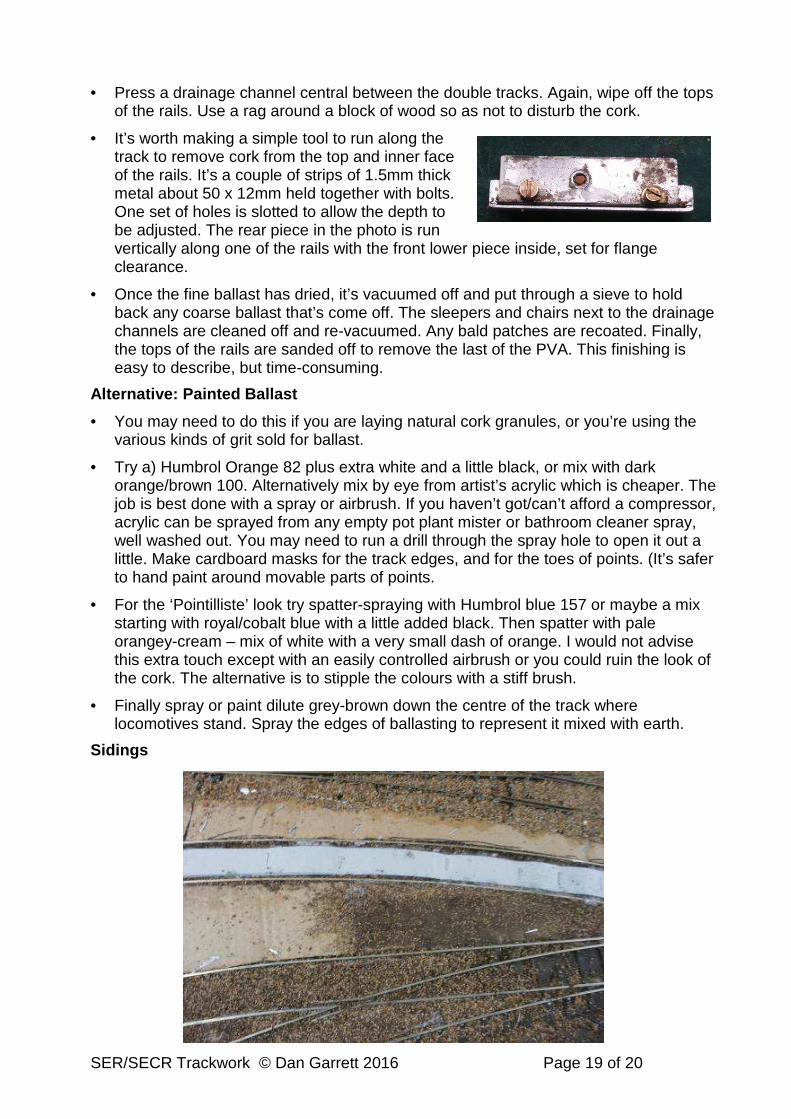
• It’s worth making a simple tool to run along the track to remove cork from the top and inner face of the rails. It’s a couple of strips of 1.5mm thick metal about 50 x 12mm held together with bolts. One set of holes is slotted to allow the depth to be adjusted. The rear piece in the photo is run vertically along one of the rails with the front lower piece inside, set for flange clearance.
• Once the fine ballast has dried, it’s vacuumed off and put through a sieve to hold back any coarse ballast that’s come off. The sleepers and chairs next to the drainage channels are cleaned off and re-vacuumed. Any bald patches are recoated. Finally, the tops of the rails are sanded off to remove the last of the PVA. This finishing is easy to describe, but time-consuming.
Alternative: Painted Ballast
• You may need to do this if you are laying natural cork granules, or you’re using the various kinds of grit sold for ballast.
• Try a) Humbrol Orange 82 plus extra white and a little black, or mix with dark orange/brown 100. Alternatively mix by eye from artist’s acrylic which is cheaper. The job is best done with a spray or airbrush. If you haven’t got/can’t afford a compressor, acrylic can be sprayed from any empty pot plant mister or bathroom cleaner spray, well washed out. You may need to run a drill through the spray hole to open it out a little. Make cardboard masks for the track edges, and for the toes of points. (It’s safer to hand paint around movable parts of points.
• For the ‘Pointilliste’ look try spatter-spraying with Humbrol blue 157 or maybe a mix starting with royal/cobalt blue with a little added black. Then spatter with pale orangey-cream – mix of white with a very small dash of orange. I would not advise this extra touch except with an easily controlled airbrush or you could ruin the look of the cork. The alternative is to stipple the colours with a stiff brush.
• Finally spray or paint dilute grey-brown down the centre of the track where locomotives stand. Spray the edges of ballasting to represent it mixed with earth.
Sidings

SER/SECR Trackwork © Dan Garrett 2016 Page 20 of 20
• In general of course, yards and sidings will be much duller because any ballast has been mixed with mud, dirt, horse dung, cattle and sheep droppings, and all sorts of other muck. The photo shows Slaters brown dirt dust mixed in with wet ballast. The white card cut and tacked inside the track is so that the ballast will be raised to give the kind of ‘tramline’ effect that can be seen in photos of SER goods yards. Between the tracks there is thicker corrugated cardboard for the same reason but to reach nearly level with the rail tops. The same can be done near coaling stages, sprinkling coal dust.
• When dry, such a mix is a sort of beigey colour, which I spray on top of uncoloured cork granules but darker in damp ruts and puddles. If you happen to have ‘accidentally’ left a few low spots, take advantage of these by dripping in some varnish to represent water. Add patches of weeds away from the tracks.
Text and photos © Dan Garrett July 2015 – July 2020