series j - itu
TRANSCRIPT
INTERNATIONAL TELECOMMUNICATION UNION
ITU-T Series JTELECOMMUNICATIONSTANDARDIZATION SECTOROF ITU
Supplement 2(11/98)
SERIES J: TRANSMISSION OF TELEVISION, SOUNDPROGRAMME AND OTHER MULTIMEDIA SIGNALS
Guidelines for the implementation of Annex A ofRecommendation J.112, "Transmission systemsfor interactive cable television services"
Example of Digital Video Broadcasting (DVB)interaction channel for cable televisiondistribution
ITU-T J-series Recommendations – Supplement 2(Previously CCITT Recommendations)

ITU-T J-SERIES RECOMMENDATIONS
TRANSMISSION OF TELEVISION, SOUND PROGRAMME AND OTHER MULTIMEDIA SIGNALS
For further details, please refer to ITU-T List of Recommendations.
General Recommendations J.1–J.9
General specifications for analogue sound-programme transmission J.10–J.19
Performance characteristics of analogue sound-programme circuits J.20–J.29
Equipment and lines used for analogue sound-programme circuits J.30–J.39
Digital encoders for analogue sound-programme signals J.40–J.49
Digital transmission of sound-programme signals J.50–J.59
Circuits for analogue television transmission J.60–J.69
Analogue television transmission over metallic lines and interconnection with radio-relaylinks
J.70–J.79
Digital transmission of television signals J.80–J.89
Ancillary digital services for television transmission J.90–J.99
Operational requirements and methods for television transmission J.100–J.109
Interactive systems for digital television distribution J.110–J.129
Transport of MPEG-2 signals on packetised networks J.130–J.139
Measurement of the quality of service J.140–J.149
Digital television distribution through local subscriber networks J.150–J.159
J series – Supplement 2 (11/98) i
SUPPLEMENT 2 TO ITU-T J-SERIES RECOMMENDATIONS
GUIDELINES FOR THE IMPLEMENTATION OF ANNEX A OFRECOMMENDATION J.112, "TRANSMISSION SYSTEMS FOR
INTERACTIVE CABLE TELEVISION SERVICES"
EXAMPLE OF DIGITAL VIDEO BROADCASTING (DVB)INTERACTION CHANNEL FOR CABLE
TELEVISION DISTRIBUTION
Source
Supplement 2 to ITU-T J-series Recommendations was prepared by ITU-T Study Group 9 (1997-2000) and wasapproved under the WTSC Resolution No. 5 procedure on the 19th of November 1998.

ii J series – Supplement 2 (11/98)
FOREWORD
ITU (International Telecommunication Union) is the United Nations Specialized Agency in the field of telecommuni-cations. The ITU Telecommunication Standardization Sector (ITU-T) is a permanent organ of the ITU. The ITU-T isresponsible for studying technical, operating and tariff questions and issuing Recommendations on them with a view tostandardizing telecommunications on a worldwide basis.
The World Telecommunication Standardization Conference (WTSC), which meets every four years, establishes thetopics for study by the ITU-T Study Groups which, in their turn, produce Recommendations on these topics.
The approval of Recommendations by the Members of the ITU-T is covered by the procedure laid down in WTSCResolution No. 1.
In some areas of information technology which fall within ITU-T’s purview, the necessary standards are prepared on acollaborative basis with ISO and IEC.
NOTE
In this Recommendation the term recognized operating agency (ROA) includes any individual, company, corporation orgovernmental organization that operates a public correspondence service. The terms Administration, ROA and publiccorrespondence are defined in the Constitution of the ITU (Geneva, 1992).
INTELLECTUAL PROPERTY RIGHTS
The ITU draws attention to the possibility that the practice or implementation of this Recommendation may involve theuse of a claimed Intellectual Property Right. The ITU takes no position concerning the evidence, validity or applicabilityof claimed Intellectual Property Rights, whether asserted by ITU members or others outside of the Recommendationdevelopment process.
As of the date of approval of this Recommendation, the ITU had not received notice of intellectual property, protected bypatents, which may be required to implement this Recommendation. However, implementors are cautioned that this maynot represent the latest information and are therefore strongly urged to consult the TSB patent database.
ITU 1999
All rights reserved. No part of this publication may be reproduced or utilized in any form or by any means, electronic ormechanical, including photocopying and microfilm, without permission in writing from the ITU.
J series – Supplement 2 (11/98) iii
CONTENTS
Page
1 Scope............................................................................................................................................................... 1
2 References....................................................................................................................................................... 1
3 Abbreviations .................................................................................................................................................. 1
4 System model.................................................................................................................................................. 3
5 Protocol stack model ....................................................................................................................................... 4
6 Specification outline........................................................................................................................................ 5
6.1 Bit rates and framing ......................................................................................................................... 6
6.2 Lower physical layer specification .................................................................................................... 7
6.3 MAC layer specification.................................................................................................................... 76.3.1 MAC reference model........................................................................................................ 76.3.2 MAC concept..................................................................................................................... 76.3.3 MAC messages .................................................................................................................. 7
7 Network architecture and services................................................................................................................... 12
7.1 Examples of services ......................................................................................................................... 12
7.2 Examples of networks with interactive services ................................................................................ 12
7.3 Possible links between servers and HFC networks............................................................................ 13
7.4 Frequency use.................................................................................................................................... 13
7.5 Impairments analysis ......................................................................................................................... 14
7.6 Dimensioning of networks................................................................................................................. 15
8 Tools provided by the physical and MAC layer.............................................................................................. 17
8.1 Capabilities and grades of NIU.......................................................................................................... 17
8.2 Upstream frequencies dynamic allocation ......................................................................................... 18
8.3 Initialization and set-up ..................................................................................................................... 19
9 Connections management................................................................................................................................ 19
9.1 Connection protocol and bandwidth assignment ............................................................................... 19
9.2 Interface between MAC and medium higher layers (ATM) .............................................................. 20
9.3 Disconnection protocol...................................................................................................................... 21
10 Simulation of error performance and error handling ....................................................................................... 21
10.1 Error performance of the physical layer ............................................................................................ 21
10.2 Traffic................................................................................................................................................ 24
10.3 Error handling.................................................................................................................................... 24

J series – Supplement 2 (11/98) 1
Supplement 2 to J-series RecommendationsJ series – Supplement 2 (11/98)
GUIDELINES FOR THE IMPLEMENTATION OF ANNEX A OFRECOMMENDATION J.112, "TRANSMISSION SYSTEMS FOR
INTERACTIVE CABLE TELEVISION SERVICES"
EXAMPLE OF DIGITAL VIDEO BROADCASTING (DVB)INTERACTION CHANNEL FOR CABLE
TELEVISION DISTRIBUTION
(Geneva, 1998)
1 Scope
This Supplement gives guidelines for use of the DVB interaction channel for Cable TV distribution systems (CATV)specification of Annex A/J.112 [2].
Hybrid Fibre Coax (HFC) networks are a sub-class of CATV networks in which the subscribers are divided into groupsby using optical transmission technology in the trunk network.
The CATV infrastructures can support the implementation of the RC for interactive services suitable for DVB systems.CATV can be used to implement interactive services in the DVB environment, providing a bidirectional communicationpath between the user terminal and the service provider.
2 References
The following ITU-T Recommendations and other references contain provisions which, through reference in this text,constitute provisions of this Recommendation. At the time of publication, the editions indicated were valid. AllRecommendations and other references are subject to revision; all users of this Recommendation are thereforeencouraged to investigate the possibility of applying the most recent edition of the Recommendations and otherreferences listed below. A list of the currently valid ITU-T Recommendations is regularly published.
[1] ITU-T Recommendation J.110 (1997), Basic principles for a worldwide common family of systems for theprovision of interactive television services.
[2] ITU-T Recommendation J.112 (1998), Transmission systems for interactive cable television services.
[3] ITU-T Recommendation J.83 (1997), Digital multi-programme systems for television, sound and data servicesfor cable distribution.
[4] ITU-T Recommendations I.363 series, B-ISDN ATM Adaptation Layer specification .
3 Abbreviations
For the purposes of this Supplement, the following abbreviations apply:
AAL 5 ATM Adaptation Layer 5
ATM Asynchronous Transfer Mode
BC Broadcast Channel
BIM Broadcast Interface Module
BRA Basic Rate Access
CATV Cable TV
2 J series – Supplement 2 (11/98)
CB radio Citizens’ Band radio
DAVIC Digital Audio Visual Council
DVB Digital Video Broadcasting Project1
EMC ElectroMagnetic Compatibility
FIP Forward Interaction Path
HFC Hybrid Fibre Coax
IB In-Band
IC Interaction Channel
ID IDentifier
IEEE Institute of Electrical and Electronics Engineers
IIM Interactive Interface Module
INA Interactive Network Adapter
IP Internet Protocol
IRD Integrated Receiver Decoder
ISDN Integrated Services Digital Network
LAN Local Area Network
LLC Link Layer Control
MAC Media Access Control
MPEG Moving Picture Expert Group
NIU Network Interface Unit
ONU Optical Node Unit
OOB Out-of-Band
OSI Open Systems Interconnection
PSTN Public Switched Telephone Network
RC Return Channel
RCC Return Channel – Cable
RIP Return Interaction Path
RMS Root Mean Square
SDH Synchronous Digital Hierarchy
SMATV Satellite Master Antenna Television
SNR Signal-to-Noise power Ratio
STB Set Top Box
STU Set Top Unit
TCP Transmission Control Protocol
TDMA Time Division Multiple Access
TS Transport Stream
_______________1 The Digital Video Broadcasting Project (DVB) is a consortium of broadcasters, manufacturers, network operators and regulatory
bodies created for designing standards for the delivery of digital television.
J series – Supplement 2 (11/98) 3
UC Upstream Channel
VCI Virtual Channel Identifier
VPI Virtual Path Identifier
4 System model
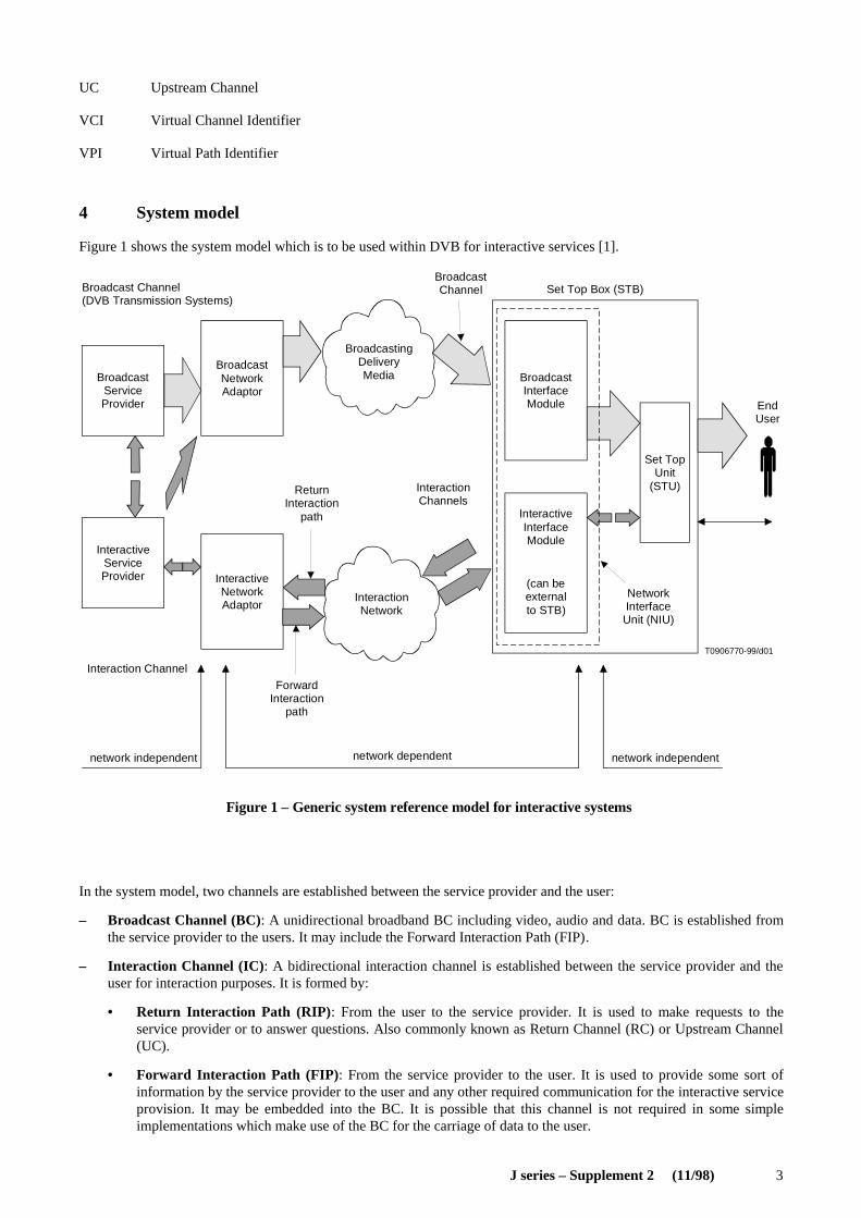
Figure 1 shows the system model which is to be used within DVB for interactive services [1].
T0906770-99/d01
Broadcast Channel(DVB Transmission Systems)
BroadcastServiceProvider
BroadcastNetworkAdaptor
BroadcastingDeliveryMedia
InteractionNetwork
InteractiveNetworkAdaptor
InteractiveServiceProvider
ReturnInteraction
path
ForwardInteraction
path
Interaction Channel
network independent network dependent network independent
InteractionChannels
BroadcastInterfaceModule
InteractiveInterfaceModule
(can beexternalto STB)
NetworkInterfaceUnit (NIU)
BroadcastChannel Set Top Box (STB)
Set TopUnit
(STU)
EndUser
Figure 1 – Generic system reference model for interactive systems
FIGURE 1/Sup2 ...[D01]
In the system model, two channels are established between the service provider and the user:
– Broadcast Channel (BC): A unidirectional broadband BC including video, audio and data. BC is established fromthe service provider to the users. It may include the Forward Interaction Path (FIP).
– Interaction Channel (IC): A bidirectional interaction channel is established between the service provider and theuser for interaction purposes. It is formed by:
• Return Interaction Path (RIP) : From the user to the service provider. It is used to make requests to theservice provider or to answer questions. Also commonly known as Return Channel (RC) or Upstream Channel(UC).
• Forward Interaction Path (FIP) : From the service provider to the user. It is used to provide some sort ofinformation by the service provider to the user and any other required communication for the interactive serviceprovision. It may be embedded into the BC. It is possible that this channel is not required in some simpleimplementations which make use of the BC for the carriage of data to the user.
4 J series – Supplement 2 (11/98)
In this Supplement the word "channel" denotes logical link and "path" corresponds to a physical link.
The user terminal is formed by the Network Interface Unit (NIU) [consisting of the Broadcast Interface Module (BIM)and the Interactive Interface Module (IIM)] and the Set Top Unit (STU). The user terminal provides interface for bothbroadcast and interaction channels. The interface between the user terminal and the interaction network is via the IIM.
The interactive system is composed of FIP (downstream) and RIP (upstream). The general concept is to use FIP to act asa transmission medium for MAC control channel and to carry a part of the downstream data. This allows the NIUs toadapt to the network and send synchronized information upstream.
RIP is divided into time slots which can be used by different users, using the technique of Time Division Multiple Access(TDMA). One MAC control channel is used to control up to 8 UCs, which are all divided into time slots. A time markerand an upstream counter at the INA is sent periodically to the NIUs, so that all NIUs work with synchronized clock andsame upstream counter value. This gives the opportunity to the INA to assign time slots to different users.
Three major access modes are provided with this system. The first one is based on contention access, which lets userssend information at any time with the risk of having a collision with other user’s transmissions. The second and thirdmodes are contention-less-based, where the INA either provides a finite amount of slots to a specific NIU, or a given bitrate requested by a NIU until the INA stops the connection on NIU’s demand. These access modes are dynamicallyshared among time slots, which allows NIUs to know when contention-based transmission is or is not allowed. This is toavoid a collision for the two contention-less-based access modes.
Periodically, the INA will indicate to new users that they have the possibility to go through sign-on procedure, in order togive them the opportunity to synchronize their clock to the network clock, without risking collisions with already activeusers. This is done by leaving a larger time interval for new users to send their information, taking into account thepropagation time required from the INA to the NIUs and back.
5 Protocol stack model
For asymmetric interactive services supporting broadcast to the home with narrowband RC, a simple communicationmodel consists of the following layers:
– Network-dependent physical layer: where all the physical (electrical) transmission parameters are defined;
– Network-dependent access mechanism layer: defines all the relevant data structures and communication protocolslike data containers, etc.;
– Network-independent application layer: the interactive application software and runtime environments (e.g. homeshopping application, script interpreter, etc.).
DVB-RCC (Annex A/J.112 [2]) addresses the lower two layers (the physical and transport), leaving the application layeropen to competitive market forces.
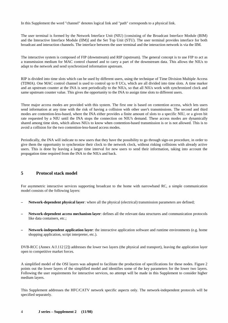
A simplified model of the OSI layers was adopted to facilitate the production of specifications for these nodes. Figure 2points out the lower layers of the simplified model and identifies some of the key parameters for the lower two layers.Following the user requirements for interactive services, no attempt will be made in this Supplement to consider highermedium layers.
This Supplement addresses the HFC/CATV network specific aspects only. The network-independent protocols will bespecified separately.
J series – Supplement 2 (11/98) 5
T0906780-99/d02
Figure 2 – Layer structure for generic system reference model
Proprietarylayers
Higher medium layers
Accessmechanism
Packet structure
ModulationChannel coding
Freq. rangeFiltering
EqualizationPower
Network-independent protocols
(Network-dependentprotocols)
FIGURE 2/Sup2 ...[D02]
6 Specification outline
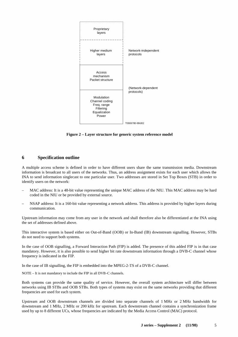
A multiple access scheme is defined in order to have different users share the same transmission media. Downstreaminformation is broadcast to all users of the networks. Thus, an address assignment exists for each user which allows theINA to send information singlecast to one particular user. Two addresses are stored in Set Top Boxes (STB) in order toidentify users on the network:
– MAC address: It is a 48-bit value representing the unique MAC address of the NIU. This MAC address may be hardcoded in the NIU or be provided by external source.
– NSAP address: It is a 160-bit value representing a network address. This address is provided by higher layers duringcommunication.
Upstream information may come from any user in the network and shall therefore also be differentiated at the INA usingthe set of addresses defined above.
This interactive system is based either on Out-of-Band (OOB) or In-Band (IB) downstream signalling. However, STBsdo not need to support both systems.
In the case of OOB signalling, a Forward Interaction Path (FIP) is added. The presence of this added FIP is in that casemandatory. However, it is also possible to send higher bit rate downstream information through a DVB-C channel whosefrequency is indicated in the FIP.
In the case of IB signalling, the FIP is embedded into the MPEG-2-TS of a DVB-C channel.
NOTE – It is not mandatory to include the FIP in all DVB-C channels.
Both systems can provide the same quality of service. However, the overall system architecture will differ betweennetworks using IB STBs and OOB STBs. Both types of systems may exist on the same networks providing that differentfrequencies are used for each system.
Upstream and OOB downstream channels are divided into separate channels of 1 MHz or 2 MHz bandwidth fordownstream and 1 MHz, 2 MHz or 200 kHz for upstream. Each downstream channel contains a synchronization frameused by up to 8 different UCs, whose frequencies are indicated by the Media Access Control (MAC) protocol.
6 J series – Supplement 2 (11/98)
Within UCs, users send packets with TDMA type access. This means that each channel is shared by many different users,who can either send packets with a possibility of collisions when this is allowed by the INA, or request transmission anduse the packets assigned by the INA to each user specifically. Assuming each upstream path can therefore accommodate alarge number of users at the same time, the upstream bandwidth can easily be used by all users present on the network atthe same time.
The TDMA technique utilizes a slotting methodology which allows the transmit start times to be synchronized to acommon clock source. Synchronizing the start times increases message throughput of this signalling channel since themessage packets do not overlap during transmission. The period between sequential start times are identified as slots.Each slot is a point in time when a message packet can be transmitted over the signalling link.
The time reference for slot location is received via the downstream channels generated at the delivery system andreceived simultaneously by all STUs. This time reference is not sent in the same way for OOB and IB signalling. Since allNIUs reference the same time base, the slot times are aligned for all NIUs. However, since there is propagation delay inany transmission network, a time base ranging method accommodates deviation of transmission due to propagation delay.
Since the TDMA signalling link is used by NIUs that are engaged in interactive sessions, the number of availablemessage slots on this channel is dependent on the number of simultaneous users. When messaging slots are not in use,an NIU may be assigned multiple message slots for increased messaging throughput. Additional slot assignments areprovided to the NIU from the downstream signalling information flow.
There are different access modes for the upstream slots:
– reserved slots with fixed rate reservation (Fixed rate access: the user has a reservation of one or several time slots ineach frame enabling, e.g. for voice, audio.);
– reserved slots with dynamic reservation (Reservation access: the user sends control information announcing hisdemand for transmission capacity. He gets grants for the use of slots.);
– contention-based slots (These slots are accessible for every user. Collision is possible and solved by a contentionresolution protocol.);
– ranging slots (These slots are used upstream to measure and adjust the time delay and the power.).
These slots may be mixed on a single carrier to enable different services on one carrier only. If one carrier is assigned toone specific service, only those slot types will be used which are needed for this service. Therefore, a terminal can besimplified to respond to only those slot types assigned to the service.
6.1 Bit rates and framing
For the interactive downstream OOB channel, a rate of 1.544 Mbit/s or 3.088 Mbit/s may be used. For downstream IBchannels, no other constraints than those specified in DVB-C (J.83 [3]) exist, but a guideline would be to use ratesmultiples of 8 kbit/s.
Downstream OOB channels continuously transmit a frame based on T1-type framing, in which some information isprovided for synchronization of upstream slots. Downstream IB channels transmit some MPEG-2-TS packets with aspecific PID for synchronization of upstream slots (at least one packet containing synchronization information shall besent in every period of 3 ms).
For upstream transmission, the INA can indicate three types of transmission rates to users – specifically 3.088 Mbit/s,1.544 Mbit/s or 256 kbit/s. The INA is responsible for indicating which rate may be used by NIUs. It would imply that allNIUs are able to either transmit with 256 kbit/s, 1.544 Mbit/s, or 3.088 Mbit/s. Only the implementation of one of thesebit rates would be mandatory.
J series – Supplement 2 (11/98) 7
Upstream framing consists of packets of 512 bits (256 symbols) which are sent in a bursty mode from the different userspresent on the network. The upstream slot rates are:
– 6000 upstream slots/s: when the upstream data rate is 3.088 Mbit/s;
– 3000 upstream slots/s: when the upstream data rate is 1.544 Mbit/s; and
– 500 upstream slots/s: when the upstream data rate is 256 kbit/s.
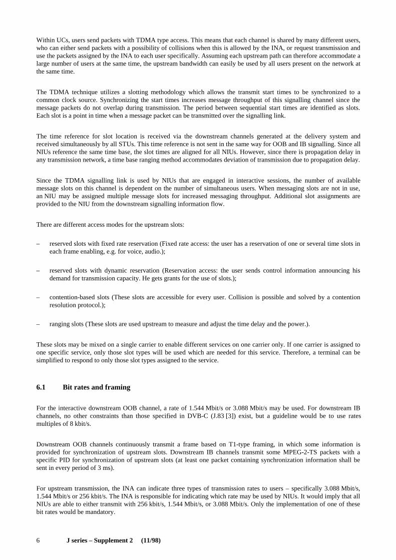
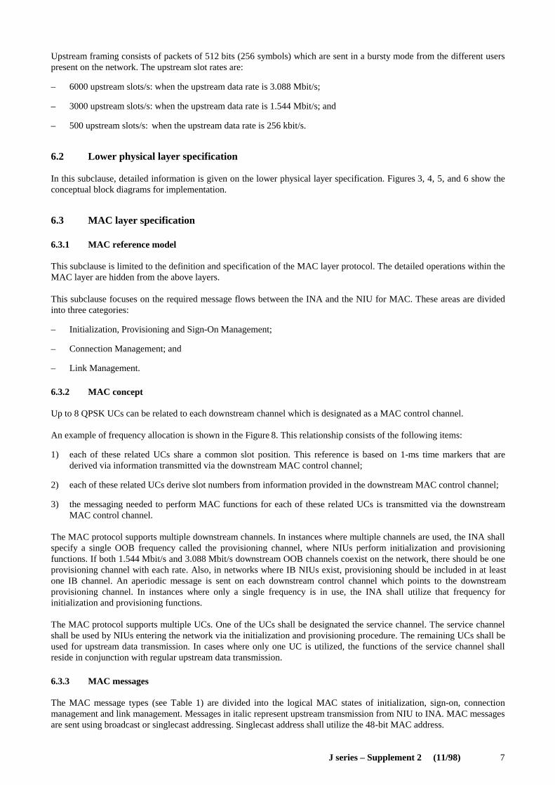
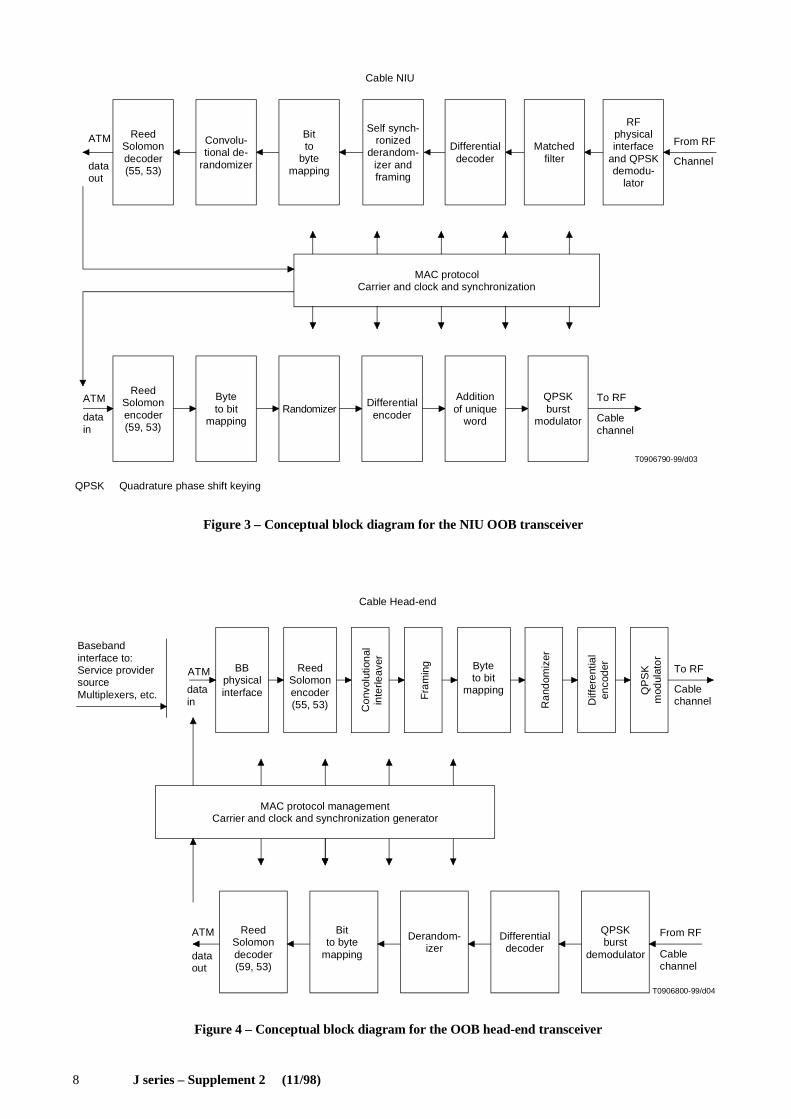
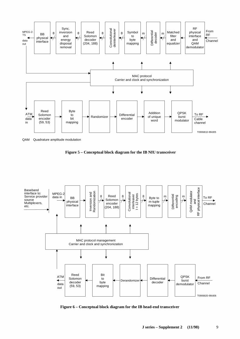
6.2 Lower physical layer specification
In this subclause, detailed information is given on the lower physical layer specification. Figures 3, 4, 5, and 6 show theconceptual block diagrams for implementation.
6.3 MAC layer specification
6.3.1 MAC reference model
This subclause is limited to the definition and specification of the MAC layer protocol. The detailed operations within theMAC layer are hidden from the above layers.
This subclause focuses on the required message flows between the INA and the NIU for MAC. These areas are dividedinto three categories:
– Initialization, Provisioning and Sign-On Management;
– Connection Management; and
– Link Management.
6.3.2 MAC concept
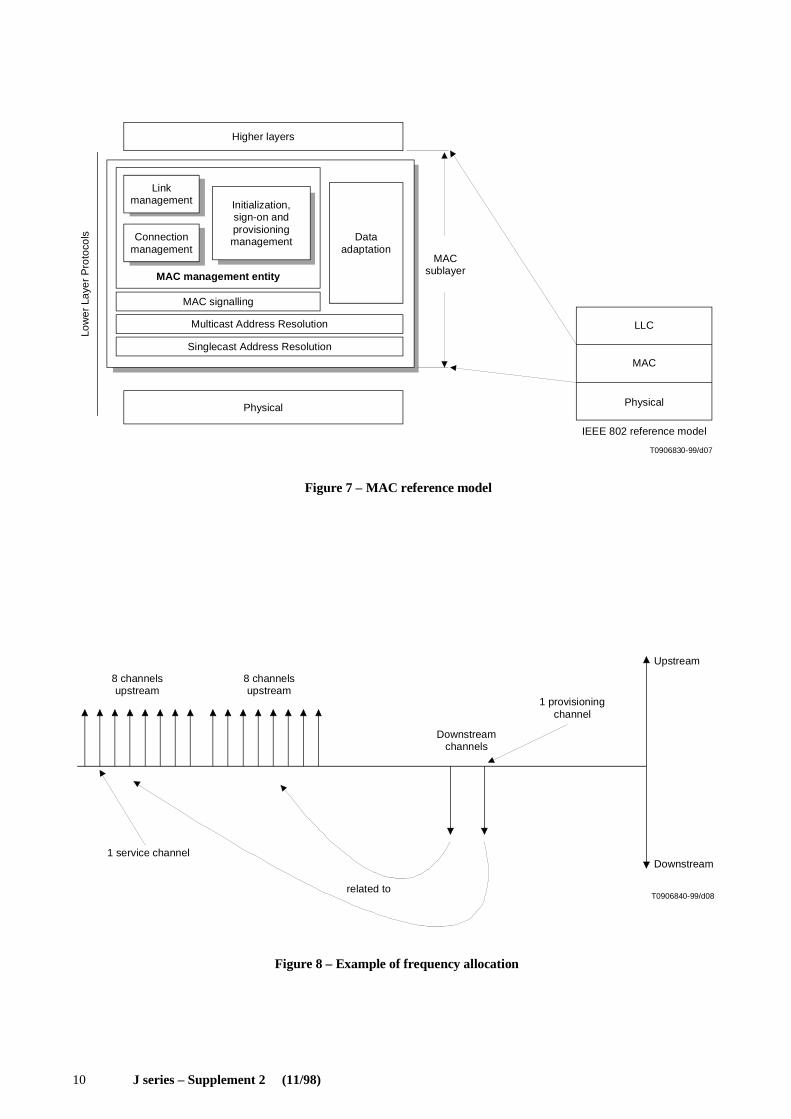
Up to 8 QPSK UCs can be related to each downstream channel which is designated as a MAC control channel.
An example of frequency allocation is shown in the Figure 8. This relationship consists of the following items:
1) each of these related UCs share a common slot position. This reference is based on 1-ms time markers that arederived via information transmitted via the downstream MAC control channel;
2) each of these related UCs derive slot numbers from information provided in the downstream MAC control channel;
3) the messaging needed to perform MAC functions for each of these related UCs is transmitted via the downstreamMAC control channel.
The MAC protocol supports multiple downstream channels. In instances where multiple channels are used, the INA shallspecify a single OOB frequency called the provisioning channel, where NIUs perform initialization and provisioningfunctions. If both 1.544 Mbit/s and 3.088 Mbit/s downstream OOB channels coexist on the network, there should be oneprovisioning channel with each rate. Also, in networks where IB NIUs exist, provisioning should be included in at leastone IB channel. An aperiodic message is sent on each downstream control channel which points to the downstreamprovisioning channel. In instances where only a single frequency is in use, the INA shall utilize that frequency forinitialization and provisioning functions.
The MAC protocol supports multiple UCs. One of the UCs shall be designated the service channel. The service channelshall be used by NIUs entering the network via the initialization and provisioning procedure. The remaining UCs shall beused for upstream data transmission. In cases where only one UC is utilized, the functions of the service channel shallreside in conjunction with regular upstream data transmission.
6.3.3 MAC messages
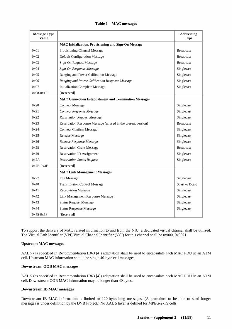
The MAC message types (see Table 1) are divided into the logical MAC states of initialization, sign-on, connectionmanagement and link management. Messages in italic represent upstream transmission from NIU to INA. MAC messagesare sent using broadcast or singlecast addressing. Singlecast address shall utilize the 48-bit MAC address.
8 J series – Supplement 2 (11/98)
T0906790-99/d03
ATM
dataout
ReedSolomondecoder(55, 53)
Bitto
bytemapping
Differentialdecoder
Matchedfilter
RFphysicalinterface
and QPSKdemodu-
lator
From RF
Channel
MAC protocolCarrier and clock and synchronization
ATM
datain
ReedSolomonencoder(59, 53)
Byteto bit
mapping
Differentialencoder
Additionof unique
word
QPSKburst
modulator
To RF
Cablechannel
Cable NIU
Convolu-tional de-
randomizer
Self synch-ronized
derandom-izer andframing
Randomizer
Figure 3 – Conceptual block diagram for the NIU OOB transceiver
QPSK Quadrature phase shift keying
FIGURE 3/Sup2 ...[D03]
FIGURE 4/Sup2 ...[D04]
T0906800-99/d04
Basebandinterface to:Service provider sourceMultiplexers, etc.
ATM
datain
BBphysicalinterface
ReedSolomonencoder(55, 53) C
onvo
l utio
nal
inte
r lea v
e r
Fra
mi n
g Byteto bit
mapping
Ran
d om
ize r
Diff
eren
tial
enco
der
QP
SK
mod
ulat
orTo RF
Cablechannel
MAC protocol managementCarrier and clock and synchronization generator
ATM
data out
ReedSolomondecoder(59, 53)
Bitto byte
mapping
Derandom-izer
Differentialdecoder
QPSKburst
demodulator
From RF
Cablechannel
Cable Head-end
Figure 4 – Conceptual block diagram for the OOB head-end transceiver
J series – Supplement 2 (11/98) 9
T0906810-99/d05
8 m8 8 8 mMPEG-2-TS
dataout
BBphysicalinterface
Sync.inversion
andenergy
disposalremoval
ReedSolomondecoder
(204, 188)
Con
volu
tiona
lde
inte
rleav
er
Symbolto
byte mapping D
iffer
entia
lde
code
r Matchedfilterand
equalizer
RFphysicalinterface
andQAM
demodulator
From RF
Channel
MAC protocolCarrier and clock and synchronization
ATM
datain
ReedSolomonencoder(59, 53)
Bytetobit
mapping
Randomizer Differentialencoder
Additionof unique
word
QPSKburst
modulator
To RF
Cablechannel
Figure 5 – Conceptual block diagram for the IB NIU transceiver
QAM Quadrature amplitude modulation
FIGURE 5/JSup2...[D05]
FIGURE 6/JSup2...[D06]
T0906820-99/d06
8 m m8 8
Basebandinterface to:Service providersourceMultiplexers,etc.
MPEG-2data in BB
physicalinterface
Inve
r sio
n an
dR
and o
miz
atio
n
ReedSolomonencoder
(204, 188)
Con
volu
tiona
lin
terle
aver
I = 1
2 by
tes
Byte tom-tuplemapping
Diff
eren
tial
enco
ding
QA
M m
odul
ato r
and
RF
phy
sica
l int
e rfa
ceTo RF
Channel
MAC protocol managementCarrier and clock and synchronization
ATM
dataout
ReedSolomondecoder(59, 53)
Bitto
bytemapping
Differentialdecoder
QPSKburst
demodulator
From RF
ChannelDerandomizer
Figure 6 – Conceptual block diagram for the IB head-end transceiver
10 J series – Supplement 2 (11/98)
T0906830-99/d07
Physical
IEEE 802 reference model
LLC
MAC
Physical
Singlecast Address Resolution
Multicast Address Resolution
MAC signalling
MACsublayer
Dataadaptation
Higher layers
Initialization,sign-on andprovisioningmanagement
Linkmanagement
Connectionmanagement
MAC management entity
Figure 7 – MAC reference model
Low
er L
ayer
Pro
toco
ls
IGURE 7/JSup2...[D07]
FIGURE 8/JSup2...[D08]
T0906840-99/d08
8 channelsupstream
8 channelsupstream
1 service channel
related to
Downstreamchannels
1 provisioningchannel
Upstream
Downstream
Figure 8 – Example of frequency allocation
J series – Supplement 2 (11/98) 11
Table 1 – MAC messages
To support the delivery of MAC related information to and from the NIU, a dedicated virtual channel shall be utilized.The Virtual Path Identifier (VPI),Virtual Channel Identifier (VCI) for this channel shall be 0x000, 0x0021.
Upstream MAC messages
AAL 5 (as specified in Recommendation I.363 [4]) adaptation shall be used to encapsulate each MAC PDU in an ATMcell. Upstream MAC information should be single 40-byte cell messages.
Downstream OOB MAC messages
AAL 5 (as specified in Recommendation I.363 [4]) adaptation shall be used to encapsulate each MAC PDU in an ATMcell. Downstream OOB MAC information may be longer than 40 bytes.
Downstream IB MAC messages
Downstream IB MAC information is limited to 120-bytes-long messages. (A procedure to be able to send longermessages is under definition by the DVB Project.) No AAL 5 layer is defined for MPEG-2-TS cells.
Message TypeValue
AddressingType
0x01
0x02
0x03
0x04
0x05
0x06
0x07
0x08-0x1F
MAC Initialization, Provisioning and Sign-On Message
Provisioning Channel Message
Default Configuration Message
Sign-On Request Message
Sign-On Response Message
Ranging and Power Calibration Message
Ranging and Power Calibration Response Message
Initialization Complete Message
[Reserved]
Broadcast
Broadcast
Broadcast
Singlecast
Singlecast
Singlecast
Singlecast
0x20
0x21
0x22
0x23
0x24
0x25
0x26
0x28
0x29
0x2A
0x2B-0x3F
MAC Connection Establishment and Termination Messages
Connect Message
Connect Response Message
Reservation Request Message
Reservation Response Message (unused in the present version)
Connect Confirm Message
Release Message
Release Response Message
Reservation Grant Message
Reservation ID Assignment
Reservation Status Request
[Reserved]
Singlecast
Singlecast
Singlecast
Broadcast
Singlecast
Singlecast
Singlecast
Broadcast
Singlecast
Singlecast
0x27
0x40
0x41
0x42
0x43
0x44
0x45-0x5F
MAC Link Management Messages
Idle Message
Transmission Control Message
Reprovision Message
Link Management Response Message
Status Request Message
Status Response Message
[Reserved]
Singlecast
Scast or Bcast
Singlecast
Singlecast
Singlecast
Singlecast

12 J series – Supplement 2 (11/98)
7 Network architecture and services
The network architecture varies substantially from place to place. This is due to the age of the network, the history of theoperator and the price of services. Most of the existing networks have an RC installed on both the fibre and the coaxialpart, and the limiting part is usually the coaxial part. It is important to note, however, that some networks are not yetinterconnected and only local interactivity is possible at the present time. In order to connect interactive service providersto INAs, an area network should be installed between INAs. DVB-RCC (Annex A/J.112 [2]) was therefore designed tohave enough flexibility to accommodate all types of services on all types of networks having RC capabilities. However,flexibility is obtained by giving a certain number of tools which do not all have to be implemented, depending on theservices that are to be offered on the networks. The following subclauses present different types of networks, services,and use of the tools provided.
7.1 Examples of services
The following list enumerates services that are already provided by DVB-C (J.83 [3]) and the new services offered byDVB-RCC (Annex A/J.112 [2]).
Digital broadcast services (DVB)
– Broadcast of audio, video, and data via a distribution network. No interaction by the user.
Interactive broadcast services (DVB-RC)
– Responses appreciated in broadcast programmes (votes, bids, games, etc.);
– Pay TV, Pay per View, Near Video on Demand (NVoD);
– Home shopping;
– Banking.
TV-based multimedia services
– Video on demand (movies, news, feature film, adverts);
– Distant learning;
– Home shopping;
– Information retrieval;
– Games.
Other services (PC-based, not covered by the DVB Project, for information)
– Data communication;
– Voice (telephony);
– Information retrieval;
– Access to online services;
– LAN emulation.
7.2 Examples of networks with interactive services
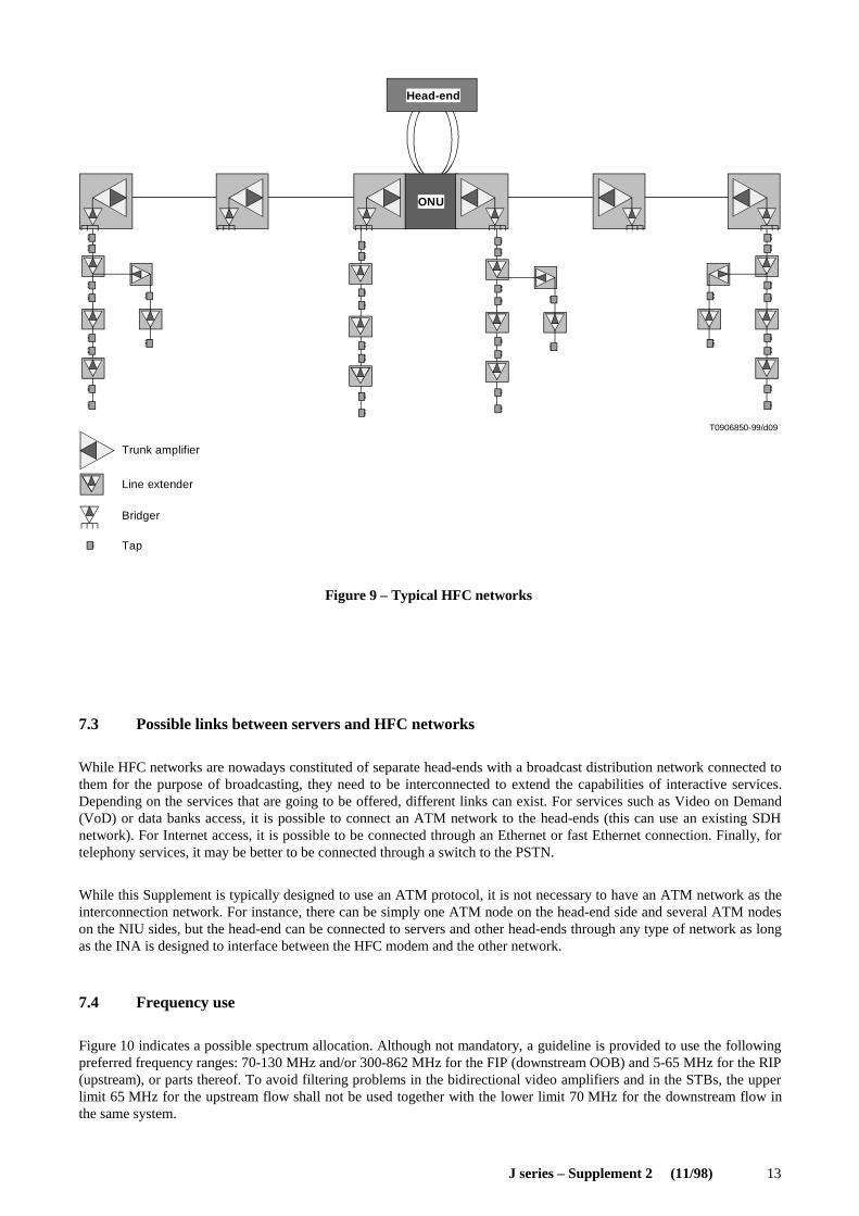
Most of the HFC networks are constituted of a fibre part and a coaxial part. Figure 9 illustrates a typical HFC networkconfiguration. The head-end delivers the signal to the Optical Node Unit (ONU), which then distributes the signal toother trunk amplifiers and finally to the coax part. The coax is then divided into several users. While the broadcasting issimply done from the head-end to all NIUs on the network, the upstream transmission is a multiplex of all NIU signals.This multiplex is defined so that the bandwidth allocation is close to optimal, depending on the services requestedby NIUs.
The relationship between Figure 1 and Figure 9 is mostly an implementation issue which depends on the network design.Clearly the INA can be put at different levels in the diagram of Figure 9. The closer it is to the broadcast networkinterface, the more NIUs shall be supported by the INA. Due to the bandwidth limitation, the INAs should probably beinstalled closer to the NIUs and an interconnection area network should support the traffic between all INAs on thenetwork connected to servers (interactive service providers). This area network is not shown in Figure 9.
J series – Supplement 2 (11/98) 13
T0906850-99/d09
Head-end
ONU
Trunk amplifier
Bridger
Tap
Line extender
Figure 9 – Typical HFC networks
FIGURE 9/JSup2...[D09]
7.3 Possible links between servers and HFC networks
While HFC networks are nowadays constituted of separate head-ends with a broadcast distribution network connected tothem for the purpose of broadcasting, they need to be interconnected to extend the capabilities of interactive services.Depending on the services that are going to be offered, different links can exist. For services such as Video on Demand(VoD) or data banks access, it is possible to connect an ATM network to the head-ends (this can use an existing SDHnetwork). For Internet access, it is possible to be connected through an Ethernet or fast Ethernet connection. Finally, fortelephony services, it may be better to be connected through a switch to the PSTN.
While this Supplement is typically designed to use an ATM protocol, it is not necessary to have an ATM network as theinterconnection network. For instance, there can be simply one ATM node on the head-end side and several ATM nodeson the NIU sides, but the head-end can be connected to servers and other head-ends through any type of network as longas the INA is designed to interface between the HFC modem and the other network.
7.4 Frequency use
Figure 10 indicates a possible spectrum allocation. Although not mandatory, a guideline is provided to use the followingpreferred frequency ranges: 70-130 MHz and/or 300-862 MHz for the FIP (downstream OOB) and 5-65 MHz for the RIP(upstream), or parts thereof. To avoid filtering problems in the bidirectional video amplifiers and in the STBs, the upperlimit 65 MHz for the upstream flow shall not be used together with the lower limit 70 MHz for the downstream flow inthe same system.
14 J series – Supplement 2 (11/98)
....
....
T0906860-99/d10
862
70-130 MHz
5-65 MHz
300-862 MHz
Freq (MHz)
Downstream
Upstream
DVB-C QAM 7/8 MHz channels
QPSK interactive 1 or 2 MHz downstream OOB channels
QPSK interactive 1 or 2 MHz or 200 kHz upstream channels
Figure 10 – Preferred frequency ranges for CATV interactive systems
FIGURE 10/JSup2...[D10]
7.5 Impairments analysis
There are different types of impairments that exist on HFC networks. These impairments can be categorized into thefollowing sections:
Transfer function
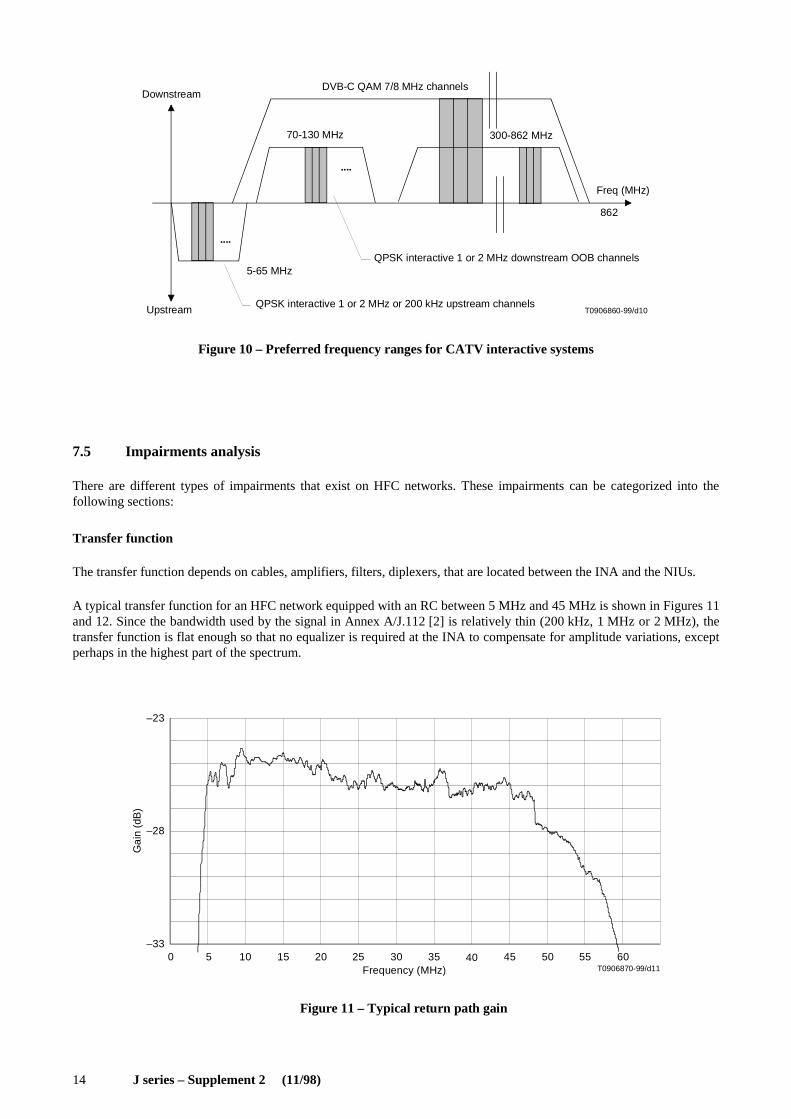
The transfer function depends on cables, amplifiers, filters, diplexers, that are located between the INA and the NIUs.
A typical transfer function for an HFC network equipped with an RC between 5 MHz and 45 MHz is shown in Figures 11and 12. Since the bandwidth used by the signal in Annex A/J.112 [2] is relatively thin (200 kHz, 1 MHz or 2 MHz), thetransfer function is flat enough so that no equalizer is required at the INA to compensate for amplitude variations, exceptperhaps in the highest part of the spectrum.
–33
–28
–23
0 5 10 15 20 25 30 35 40 45 50 55 60T0906870-99/d11Frequency (MHz)
Gai
n (d
B)
Figure 11 – Typical return path gain
FIGURE 11/JSup2...[D11]
J series – Supplement 2 (11/98) 15
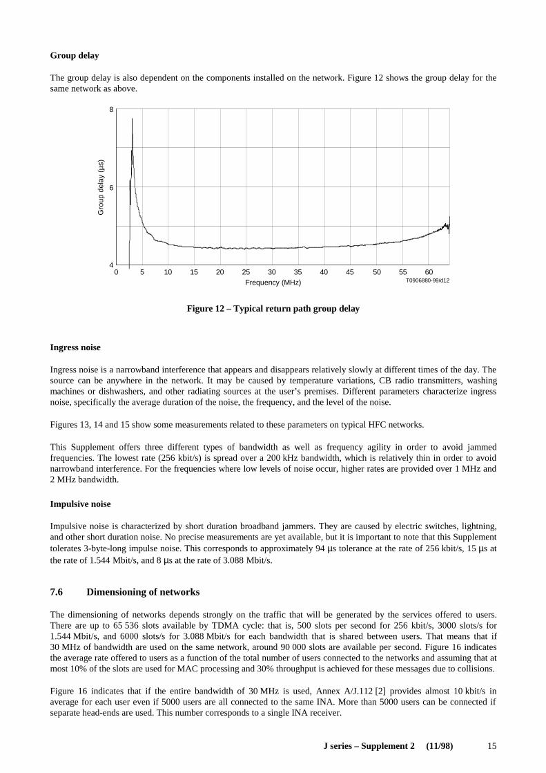
Group delay
The group delay is also dependent on the components installed on the network. Figure 12 shows the group delay for thesame network as above.
6
8
0 5 10 15 20 25 30 35 40 45 50 55 604
T0906880-99/d12Frequency (MHz)
Gro
up d
elay
(µ
s)
Figure 12 – Typical return path group delay
FIGURE 12/JSup2...[D12]
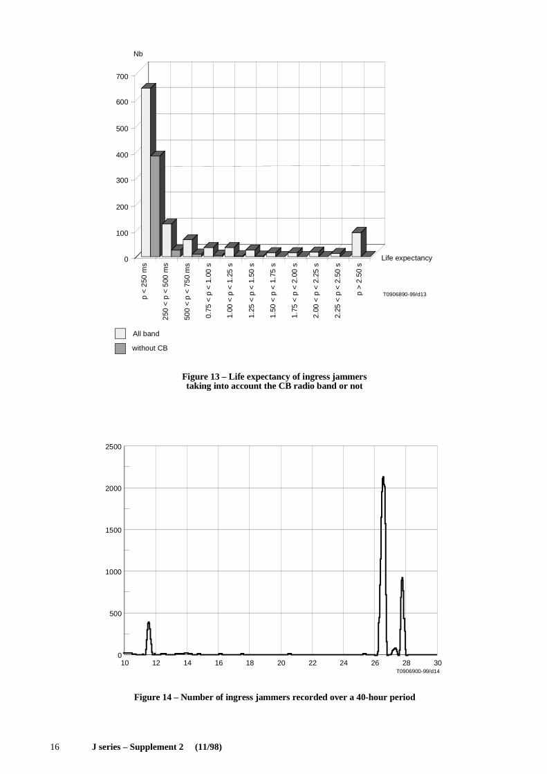
Ingress noise
Ingress noise is a narrowband interference that appears and disappears relatively slowly at different times of the day. Thesource can be anywhere in the network. It may be caused by temperature variations, CB radio transmitters, washingmachines or dishwashers, and other radiating sources at the user’s premises. Different parameters characterize ingressnoise, specifically the average duration of the noise, the frequency, and the level of the noise.
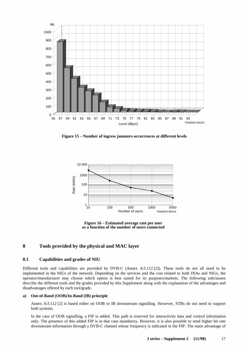
Figures 13, 14 and 15 show some measurements related to these parameters on typical HFC networks.
This Supplement offers three different types of bandwidth as well as frequency agility in order to avoid jammedfrequencies. The lowest rate (256 kbit/s) is spread over a 200 kHz bandwidth, which is relatively thin in order to avoidnarrowband interference. For the frequencies where low levels of noise occur, higher rates are provided over 1 MHz and2 MHz bandwidth.
Impulsive noise
Impulsive noise is characterized by short duration broadband jammers. They are caused by electric switches, lightning,and other short duration noise. No precise measurements are yet available, but it is important to note that this Supplementtolerates 3-byte-long impulse noise. This corresponds to approximately 94 µs tolerance at the rate of 256 kbit/s, 15 µs atthe rate of 1.544 Mbit/s, and 8 µs at the rate of 3.088 Mbit/s.
7.6 Dimensioning of networks
The dimensioning of networks depends strongly on the traffic that will be generated by the services offered to users.There are up to 65 536 slots available by TDMA cycle: that is, 500 slots per second for 256 kbit/s, 3000 slots/s for1.544 Mbit/s, and 6000 slots/s for 3.088 Mbit/s for each bandwidth that is shared between users. That means that if30 MHz of bandwidth are used on the same network, around 90 000 slots are available per second. Figure 16 indicatesthe average rate offered to users as a function of the total number of users connected to the networks and assuming that atmost 10% of the slots are used for MAC processing and 30% throughput is achieved for these messages due to collisions.
Figure 16 indicates that if the entire bandwidth of 30 MHz is used, Annex A/J.112 [2] provides almost 10 kbit/s inaverage for each user even if 5000 users are all connected to the same INA. More than 5000 users can be connected ifseparate head-ends are used. This number corresponds to a single INA receiver.
16 J series – Supplement 2 (11/98)
T0906890-99/d13
0
100
200
300
400
500
600
700
All band
without CB
Life expectancy
Nb
0.75
< p
< 1
.00
s
1.00
< p
< 1
.25
s
1.25
< p
< 1
.50
s
1.50
< p
< 1
.75
s
1.75
< p
< 2
.00
s
2.00
< p
< 2
.25
s
2.25
< p
< 2
.50
s
p >
2.50
s
p <
250
ms
250
< p
< 5
00 m
s
500
< p
< 7
50 m
s
Figure 13 – Life expectancy of ingress jammerstaking into account the CB radio band or not
FIGURE 13/JSup2...[D13]
T0906900-99/d14
0
500
1000
1500
2000
2500
10 12 14 16 18 20 22 24 26 28 30
Figure 14 – Number of ingress jammers recorded over a 40-hour period
FIGURE 14/JSup2...[D14]
J series – Supplement 2 (11/98) 17
T0906910-99/d15
0
100
200
300
400
500
600
700
800
900
1000
55 57 59 61 63 65 67 69 71 73 75 77 79 81 83 85 87 89 91 93
Nb
Level (dBµV)
Figure 15 – Number of ingress jammers occurrences at different levelsFIGURE 15/JSup2...[D15]
1
10
100
1000
10 000
10 100 500 1000 5000T0906920-99/d16Number of users
Rat
e (k
bit/s
)
Figure 16 – Estimated average rate per useras a function of the number of users connected
FIGURE 16/JSup2...[D16]
8 Tools provided by the physical and MAC layer
8.1 Capabilities and grades of NIU
Different tools and capabilities are provided by DVB-C (Annex A/J.112 [2]). These tools do not all need to beimplemented in the NIUs of the network. Depending on the services and the cost related to both INAs and NIUs, theoperator/manufacturer may choose which option is best suited for its purposes/markets. The following subclausesdescribe the different tools and the grades provided by this Supplement along with the explanation of the advantages anddisadvantages offered by each tool/grade.
a) Out-of-Band (OOB)/In-Band (IB) principle
Annex A/J.112 [2] is based either on OOB or IB downstream signalling. However, STBs do not need to supportboth systems.
In the case of OOB signalling, a FIP is added. This path is reserved for interactivity data and control informationonly. The presence of this added FIP is in that case mandatory. However, it is also possible to send higher bit ratedownstream information through a DVB-C channel whose frequency is indicated in the FIP. The main advantage of
18 J series – Supplement 2 (11/98)
the OOB solution is the possibility to dissociate broadcasting and interactive data on two separate channels, whichoffers the flexibility to the user to watch any programme on TV while doing interactive processing independently(superimposed image, separate PC connected to the STB, telephony, etc.).
In the case of IB signalling, the FIP is embedded into the MPEG-2-TS of a DVB-C channel. It is not mandatory toinclude the FIP in all DVB-C channels. The main advantage of the IB solution is to provide interactive data in thesame channel as the broadcasting channel, thus providing a better link between the interactive session and the relatedbroadcast programme.
Both systems can provide the same quality of service. Yet, the overall system architecture will differ betweennetworks using IB STBs and OOB STBs. Both types of systems may exist on the same networks under the conditionthat different frequencies are used for each system.
The main differences are the following:
– For the STB: In the case of OOB signalling, a second tuner is needed and additional demodulation functionsshall be included in the NIU. In the case of IB signalling, a MAC extracting function from the MPEG-2-TSflow shall be included in the NIU.
– For the INA: In the case of IB signalling, a MAC unit needs to be inserted between the MPEG-2 multiplexersand the QAM modulators in order to add the MAC signalling into the MPEG-2-TS flow. In the case of OOBsignalling, a QPSK modulator is part of the INA.
b) Rate downstream and upstream
There are two rates provided for OOB downstream transmission corresponding to grade A of 1.544 Mbit/s andgrade B of 3.088 Mbit/s.
In the case of IB downstream signalling, see Recommendation J.83 [3].
There are three rates provided for upstream transmission corresponding to grade A of 256 kbit/s, grade B of1.544 Mbit/s and grade C of 3.088 Mbit/s.
All combinations of the above grades upstream and downstream are allowed, but NIUs do not need to support allgrades. NIUs shall support at least one grade upstream and downstream.
Grade A may be needed upstream for HFC networks with severe ingress noise, since it requires 200 kHz bandwidthonly. The choice between 1.544 Mbit/s and 3.088 Mbit/s upstream or downstream is left to themanufacturer/operator.
c) Number of simultaneous ATM virtual connections per NIU
For each connection provided by higher layers on the INA side (VPI/VCI), a connection ID is associated at theMAC layer. The maximum number of simultaneous connections that an NIU should support is defined as follows:
– Grade A: Only one connection at a time can be handled by an NIU. In that case, all connections shall bemanaged at higher medium layers, and should all use the same VPI/VCI value identified as default connectionin this Supplement;
– Grade B: As many connections as needed, defined dynamically by the INA, following higher medium layersrequests.
NOTE – Grade A can offer the same quality of service as grade B, assuming connections are managed at the application layer, butrequires less hardware in the NIU for queuing ATM cells before transmission.
8.2 Upstream frequencies dynamic allocation
The allocation of upstream frequencies is managed by the INA. This means that the INA can use any measurement tool tofigure out which frequency is better to use at any time and can decide to switch all users present on a given frequency atany time if this frequency is too jammed for a correct reception. MAC messages are provided for this purpose. However,this Supplement does not indicate how the level of interference should be measured, and what level of interferencerequires switching. This is left up to the manufacturer, since it does not affect interoperability.
J series – Supplement 2 (11/98) 19
8.3 Initialization and set-up
Initialization and set-up comprises two major functions. The first one is the connection to the network; the second one isthe identification of the grade required. Obviously, if the connection is not made, the second function is not possible. Thefollowing algorithm summarizes what the first steps of an NIU connection are.
Lock up to the downstream control path (OOB or IB). If the operator wants to be as flexible as possible, both grades inthe downstream OOB should be offered, in which case the NIU should first try to lock to its own fastest grade. Both IBand OOB can eventually be provided by the operator at the same time, in which case the NIU should refer to its ownconfiguration to know which should be looked at first. However, the simplest solution is to impose a grade on all NIUsconnected to the network such that only one type of modulators is used at the INA premises.
The downstream control information then contains further instructions on the grade to use downstream (MACprovisioning channel message). In the case where it is different from what the NIU selected by default, the NIU shouldchange to the new frequency/grade and lock up to the new downstream frequency. On this frequency, further instructionsare given on the upstream grade to use (MAC default configuration message).
The NIU shall then wait for the MAC sign-on message from the INA before it tries to connect to the network. The INAwill then go through the connection process one user at a time by sending a singlecast Ranging and Power Calibrationmessage to the first NIU detected. This is absolutely necessary to avoid deadlock situations.
Once the NIU has gone through the whole sign-on and calibration procedure, it receives a default connection fromthe INA, and thus becomes a separate ATM node. The INA manages all bandwidth assignments, so it always controls thetraffic on the network.
9 Connections management
The goal of the MAC protocol is to provide tools for higher medium layer protocols in order to transmit and receive datatransparently and independently of the physical layer. Higher medium layer services are provided by the INA to the STU.The INA is thus responsible for indicating the transmission mode and rate to the NIU for each type of service.Specifically, for each connection provided by higher layers on the INA side (VPI/VCI), a connection ID is associated atthe MAC layer [see 8.1 c) for more details].
However, bandwidth (time slots) does not need to be assigned immediately by the INA for a given connection. Thismeans that a connection ID may exist at the NIU side without associated slot numbers.
The INA is responsible for providing transmission bandwidth to the NIUs when needed by higher layers. However, sincethe NIU shall transmit all data from the STU, the NIU is also responsible for requesting for more bandwidth if not alreadyprovided by the INA.
A default connection is initiated by the INA when STBs are first turned on. This connection can be used to send datafrom higher layers leading to further interactive connections. This connection can be associated to a zero transmissionrate (no initial bandwidth allocation).
9.1 Connection protocol and bandwidth assignment
In the ATM world, connections are virtual, that is, they specify a node-to-node path without necessarily assigningbandwidth. Specifically, for the HFC RC, the concept is the same. When a user is connected, it means that it has receiveda default connection between the INA and the NIU. Further connections can then be requested using that particularconnection and bandwidth can be requested following specific access modes.
20 J series – Supplement 2 (11/98)
Different access modes are provided to the NIUs within access regions specified by information contained in the slotboundary fields of the downstream superframes. The limits between access regions allow users to know when to send dataon contention without risks of collision with contention-less type data. The following rules define how to select accessmodes:
Data connections
When the INA assigns a connection ID to the NIU, it either specifies a slot list to be used (fixed rate access) or the NIUshall use contention or reserved access by following this algorithm:
– When the NIU shall send more cells than what was assigned by the INA, it can use contention access only if thenumber of cells to transmit is less than Maximum_contention_access_message_length (specified in the MACConnect message from the INA). In that case, it shall wait for the slot reception indicator before it is allowed to sendother cells with the same VPI/VCI value. The NIU can send one request for reservation access if the number of cellsis less than Maximum_reservation_access_message_length (specified in the MAC Connect message from the INA).If more cells shall be transmitted, the NIU shall send multiple requests for reservation access.
MAC messages
– MAC messages can be sent on contention access or reservation access. MAC messages sent upstream shall be lessthan 40 bytes long. If the MAC information exceeds 40 bytes, it shall be segmented into multiple 40-byteindependent MAC messages. Ranging access can only be used for specific MAC messages.
a) Contention access
Contention access indicates that data (MAC or bursty data traffic) is sent in the slots assigned to the contentionaccess region in the UC. It can be used either to send MAC messages or data. The VPI, VCI of the ATM cells arethen used to determine the type and direction of the data in higher layers. Contention-based access provides instantchannel allocation for the NIU.
The contention-based technique is used for multiple subscribers that will have equal access to the signalling channel.
It is probable that simultaneous transmissions will occur. For each ATM cell transmitted by the NIU, a positiveacknowledgement is sent back by the INA, utilizing the reception indicator field, for each successfully receivedATM cell. In contention-based access mode, a positive acknowledgement indicates that a collision did not occur. Acollision occurs if two or more NIUs attempt ATM cell transmission during the same slot. A collision will beassumed if a NIU does not receive a positive acknowledgement. If a collision occurs, then the NIU will retransmitusing a procedure to be defined.
b) Ranging access
Ranging access indicates that the data is sent in a slot preceded and followed by slots not used by other users. Theseslots allow users to adjust their clock depending on their distance to the INA such that their slots fall within thecorrect allocated time. They are either contention-based when the ranging control slot indicator b0 received duringthe previous superframe was 1 (or when b1 to b6 = 55 to 63), or reserved if the INA indicates to the NIU that aspecific slot is reserved for ranging.
c) Fixed rate access
NOTE – Fixed rate is called contention-less in DAVIC.
Fixed rate access indicates that data is sent in slots assigned to the fixed-rate-based access region in the UC. Theseslots are uniquely assigned to a connection by the INA. No fixed rate access can be initiated by the NIU.
d) Reservation access
Reservation access implies that data is sent in the slots assigned to the reservation region in the UC. These slots areuniquely assigned on a frame-by-frame basis to a connection by the INA. This assignment is made at the request ofthe NIU for a given connection.
J series – Supplement 2 (11/98) 21
9.2 Interface between MAC and medium higher layers (ATM)
When an NIU is first turned on, it is not identified as a single ATM node, since no connection is possible without rangingand sign-on. The set of all users is thus seen as one single node at the ATM layer. The connection used to transmit MACmessages between the INA and the NIU is the same for all users, since it is viewed by the INA as one node. The MACaddress used in the MAC messages thus identifies each user at the MAC layer, but not at the ATM layer. However, oncethe NIU is calibrated, it receives a first default connection from the INA which then identifies the user as a specific nodeat the ATM layer. From then on, the MAC layer becomes transparent to the ATM layer and messages can be sent from anATM server to each user on the network as if they were separate ATM nodes.
NOTE – The default connection is not necessarily associated to a specific bandwidth, since bandwidth can be requested on demand.
9.3 Disconnection protocol
Different types of disconnection may occur. The following list describes each event and how the system shall be designedto recover from it.
1) Soft disconnection by NIU: This disconnection happens when the user makes a request to turn its STB off. In thatcase, each connection shall be turned off by the INA after a request from the user to the server at higher layers.
2) Hard disconnection by NIU (Power outage, plug fall, etc.): This disconnection happens by accident. In that case, theidle message which is supposed to be sent by each NIU periodically (around every 10 minutes) is not received by theINA. The INA then knows that the NIU is disconnected and considers all connections to be down. In the case wherethe STB recovers before these 10 minutes, it will try to start ranging again. If the INA receives requests for rangingfrom a NIU, it automatically considers the NIU as previously disconnected and considers all previous connectionsterminated.
3) Soft disconnection by INA: If the INA needs to receive maintenance, it first needs to stop all connections witheach NIU.
4) Hard disconnection by INA: This could happen in case of a major alarm on the INA side. If the downstream stops,automatically all NIUs will reset since they do not receive control from the INA anymore. If the upstream burstdemodulator stops, then the INA will send a soft disconnection or move the users to another frequency through thedownstream control path. If the INA controller stops, then the NIUs will reset after a specific timeout at the higherlayers.
10 Simulation of error performance and error handling
10.1 Error performance of the physical layer
This subclause describes the robustness of the physical layer of the DVB-RCC upstream signal. The return paths ofcurrent CATV networks are multipoint-to-point connections. Therefore a lot of unwanted signals disturb the upstreamsignal. The physical parameters of these signals can vary considerably. The combination of all of these disturbing signalsis called ingress noise. The properties of the return paths are indicated by Signal-to-Noise power Ratios (SNRs). Toobtain such SNRs, both the signal power and the power of the ingress noise are calculated at the input of the INA. Thesecalculations are based on the transmit power levels which are recommended by the DVB-RCC (Annex A/J.112 [2]) aswell as being derived by measurement results. The resulting SNRs correspond to particular slot-loss rates.
The correlation between both was obtained by computer simulations.
Signal power
The transmit power level of the STBs is given in Annex A/J.112 [2]. The output level range is 85-122 dBµV (RMS).Since the upper boundary of 122 dBµV is very high for consumer STBs, the transmit power level of every individualSTB should be reduced to the lowest possible value. However, for reasons of EMC, the value of 122 dBµV shall not be
22 J series – Supplement 2 (11/98)
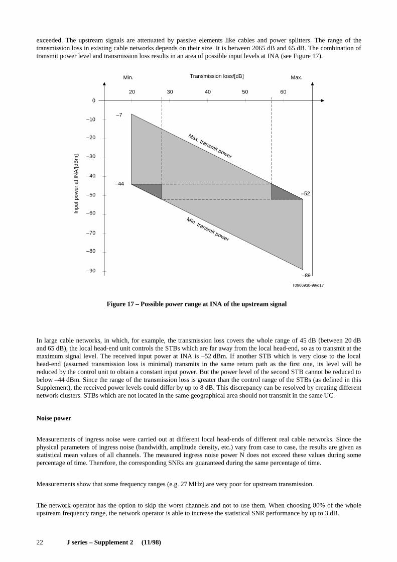
exceeded. The upstream signals are attenuated by passive elements like cables and power splitters. The range of thetransmission loss in existing cable networks depends on their size. It is between 2065 dB and 65 dB. The combination oftransmit power level and transmission loss results in an area of possible input levels at INA (see Figure 17).
–89
20 30 40 50 60
–20
–30
–40
–50
–60
–70
–80
–90
–44
–7
–52
0
T0906930-99/d17
–10
Inpu
t pow
er a
t IN
A/[d
Bm
]Transmission loss/[dB]Min. Max.
Max. transmit power
Min. transmit power
Figure 17 – Possible power range at INA of the upstream signal
FIGURE 17/JSup2...[D17]
In large cable networks, in which, for example, the transmission loss covers the whole range of 45 dB (between 20 dBand 65 dB), the local head-end unit controls the STBs which are far away from the local head-end, so as to transmit at themaximum signal level. The received input power at INA is –52 dBm. If another STB which is very close to the localhead-end (assumed transmission loss is minimal) transmits in the same return path as the first one, its level will bereduced by the control unit to obtain a constant input power. But the power level of the second STB cannot be reduced tobelow –44 dBm. Since the range of the transmission loss is greater than the control range of the STBs (as defined in thisSupplement), the received power levels could differ by up to 8 dB. This discrepancy can be resolved by creating differentnetwork clusters. STBs which are not located in the same geographical area should not transmit in the same UC.
Noise power
Measurements of ingress noise were carried out at different local head-ends of different real cable networks. Since thephysical parameters of ingress noise (bandwidth, amplitude density, etc.) vary from case to case, the results are given asstatistical mean values of all channels. The measured ingress noise power N does not exceed these values during somepercentage of time. Therefore, the corresponding SNRs are guaranteed during the same percentage of time.
Measurements show that some frequency ranges (e.g. 27 MHz) are very poor for upstream transmission.
The network operator has the option to skip the worst channels and not to use them. When choosing 80% of the wholeupstream frequency range, the network operator is able to increase the statistical SNR performance by up to 3 dB.
J series – Supplement 2 (11/98) 23
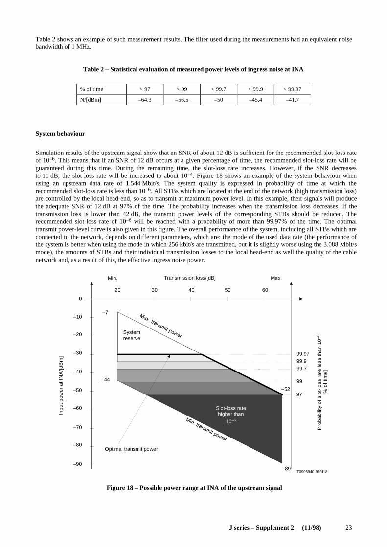
Table 2 shows an example of such measurement results. The filter used during the measurements had an equivalent noisebandwidth of 1 MHz.
Table 2 – Statistical evaluation of measured power levels of ingress noise at INA
System behaviour
Simulation results of the upstream signal show that an SNR of about 12 dB is sufficient for the recommended slot-loss rateof 10–6. This means that if an SNR of 12 dB occurs at a given percentage of time, the recommended slot-loss rate will beguaranteed during this time. During the remaining time, the slot-loss rate increases. However, if the SNR decreasesto 11 dB, the slot-loss rate will be increased to about 10–4. Figure 18 shows an example of the system behaviour whenusing an upstream data rate of 1.544 Mbit/s. The system quality is expressed in probability of time at which therecommended slot-loss rate is less than 10–6. All STBs which are located at the end of the network (high transmission loss)are controlled by the local head-end, so as to transmit at maximum power level. In this example, their signals will producethe adequate SNR of 12 dB at 97% of the time. The probability increases when the transmission loss decreases. If thetransmission loss is lower than 42 dB, the transmit power levels of the corresponding STBs should be reduced. Therecommended slot-loss rate of 10–6 will be reached with a probability of more than 99.97% of the time. The optimaltransmit power-level curve is also given in this figure. The overall performance of the system, including all STBs which areconnected to the network, depends on different parameters, which are: the mode of the used data rate (the performance ofthe system is better when using the mode in which 256 kbit/s are transmitted, but it is slightly worse using the 3.088 Mbit/smode), the amounts of STBs and their individual transmission losses to the local head-end as well the quality of the cablenetwork and, as a result of this, the effective ingress noise power.
99
97
T0906940-99/d18–89
20 30 40 50 60
–20
–30
–40
–50
–60
–70
–80
–90
–44
–7
–52
0
–10
Inpu
t pow
er a
t IN
A/[d
Bm
]
Transmission loss/[dB]Min. Max.
Optimal transmit power
Systemreserve
Pro
babi
lity
of s
lot-
loss
rat
e le
ss th
an 1
0–6
[% o
f tim
e]
99.9799.999.7
Slot-loss ratehigher than
10–6
Figure 18 – Possible power range at INA of the upstream signal
FIGURE 18/JSup2...[D18]
% of time < 97 < 99 < 99.7 < 99.9 < 99.97
N/[dBm] –64.3 –56.5 –50 –45.4 –41.7
24 J series – Supplement 2 (11/98)
10.2 Traffic
Whereas traffic is difficult to estimate without knowing the user behaviour as a function of the services offered, it isimportant to note that traffic is entirely managed by the INA and different parameters are available to modify the amountof requests sent by users on contention or reservation. This provides a very useful tool to optimize the throughput overtime depending on the traffic or number of users connected on the available bandwidth. These parameters are thefollowing:
– access modes repartition using the slot boundary fields of the control path;
– ranging slot control using the slot boundary fields of the control path;
– reservation control using the slot boundary fields of the control path;
– access mode as a function of the size of queues indicated in the MAC Connect messages.
The algorithms used to optimize the traffic are left up to the manufacturers, since they do not affect interoperability.
10.3 Error handling
Error handling is required at the different layers depending on the location of transmission errors.
If errors occur during data transmission, higher layers such as Transmission Control Protocol (TCP) in the case ofInternet Protocol (IP) packets transmission will request for retransmission. In that case, no error handling procedure isnecessary at the physical or MAC layer; more exactly, error handling procedure shall not be implemented at the MAClayer, since it may lead to deadlock situations where the higher layer and the MAC layer both request for retransmissionat the same time.
In the case of errors at the MAC layer, the situation is different. If a message that needs acknowledgement is incorrectlyreceived, the acknowledgement will not happen and the message will have to be retransmitted. If the acknowledgementitself is not received, the INA will act as if the acknowledgement was not sent and will therefore reinitiate thewhole MAC procedure.
In the case of collisions between packets coming from different users, the same applies. If a MAC message is sent and acollision occurs, then the MAC message shall be sent again. If a data message is sent on contention and a collisionoccurs, then no retransmission of that packet should be undertaken, or a deadlock situation may occur.
ITU-T RECOMMENDATIONS SERIES
Series A Organization of the work of the ITU-T
Series B Means of expression: definitions, symbols, classification
Series C General telecommunication statistics
Series D General tariff principles
Series E Overall network operation, telephone service, service operation and human factors
Series F Non-telephone telecommunication services
Series G Transmission systems and media, digital systems and networks
Series H Audiovisual and multimedia systems
Series I Integrated services digital network
Series J Transmission of television, sound programme and other multimedia signals
Series K Protection against interference
Series L Construction, installation and protection of cables and other elements of outside plant
Series M TMN and network maintenance: international transmission systems, telephone circuits,telegraphy, facsimile and leased circuits
Series N Maintenance: international sound programme and television transmission circuits
Series O Specifications of measuring equipment
Series P Telephone transmission quality, telephone installations, local line networks
Series Q Switching and signalling
Series R Telegraph transmission
Series S Telegraph services terminal equipment
Series T Terminals for telematic services
Series U Telegraph switching
Series V Data communication over the telephone network
Series X Data networks and open system communications
Series Y Global information infrastructure
Series Z Languages and general software aspects for telecommunication systems